AIR CONDITIONING
4.9L
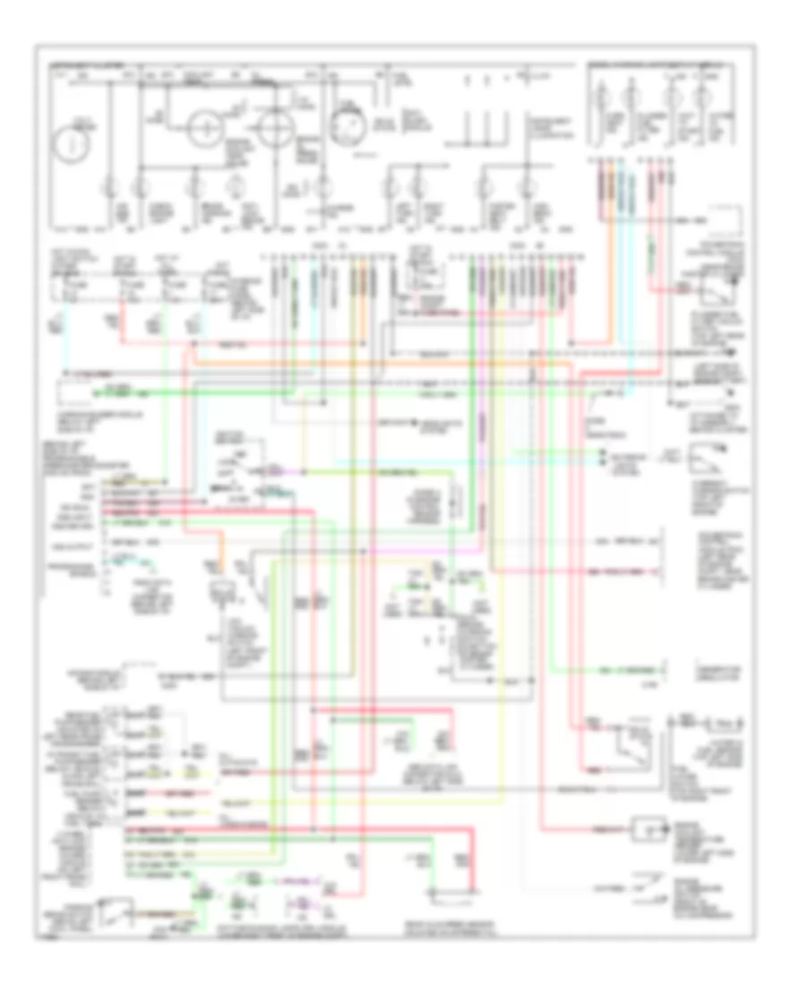
4.9L, A/C Wiring Diagram for Ford RV Cutaway E350 1996

List of elements for 4.9L, A/C Wiring Diagram for Ford RV Cutaway E350 1996:
- (behind instrument cluster)
- (behind right side of i/p)
- (left front of engine compartment)
- (left rear corner of vehicle)
- (left rear of engine compartment near brake master cylinder)
- (left side of engine compartment near battery)
- (left side of engine compartment, near battery)
- (right front of engine compartment)
- (right side of safety wall)
- 15a
- A/c pressure cut out switch
- A/c clutch cycling pressure switch
- A/c clutch diode
- A/c compressor clutch
- A/c control assembly
- Aux- iliary high blower motor relay
- Auxiliary blower motor
- Auxiliary blower motor relay (left rear corner of vehicle)
- Auxiliary blower motor resistor (left rear corner of vehicle)
- Auxiliary blower switch
- Blend door actuator (behind center of i/p)
- Blower motor
- Blower motor relay (left side of engine compartment)
- Blower motor resistor
- Def
- Engine compartment fuse panel
- Floor
- Front blower switch
- Fuse 9
- Fuse a 60a
- Fuse f 60a
- G108
- G108 (left side of engine compartment near battery)
- G202
- G206
- G404 (left rear corner of vehicle, near left tail light)
- Hot at all times
- Hot in run
- Interior fuse panel
- Lo/ rear
- Max
- Mix
- Norm
- Off
- Pcm power relay
- Power- train control module
- Rear auxiliary blower switch
- Red
- Temper- ature control switch
- Vent
- W/ rear control
- W/o rear con- trol
- Wide open throttle relay (lower left side of engine compartment)
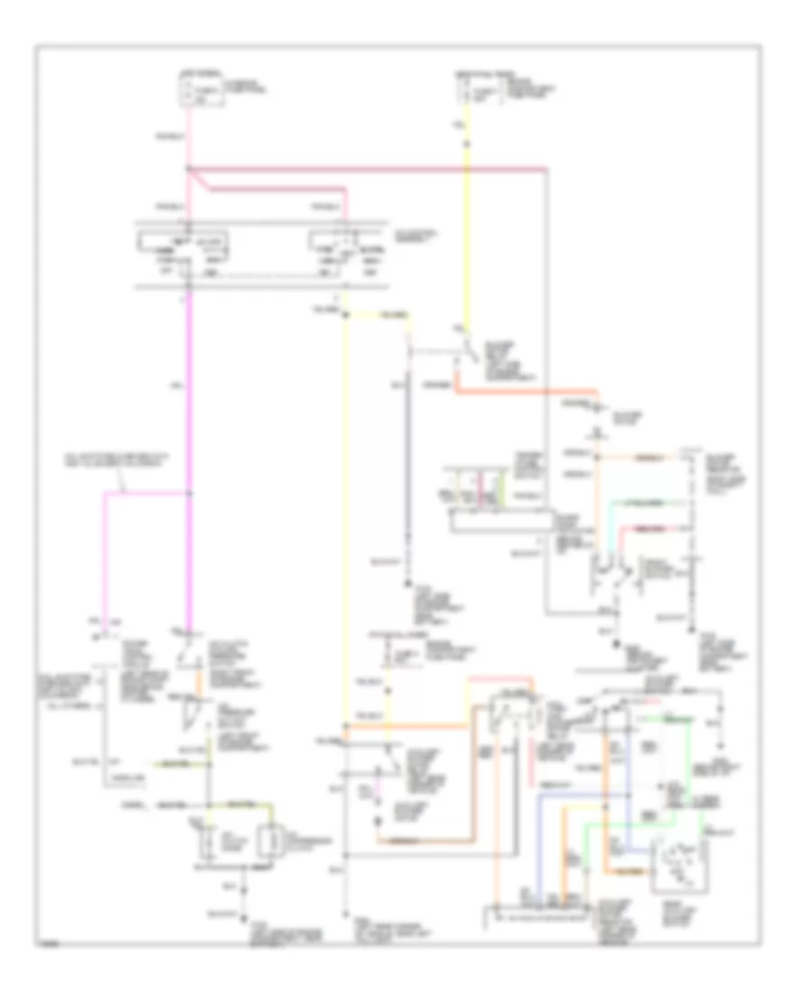
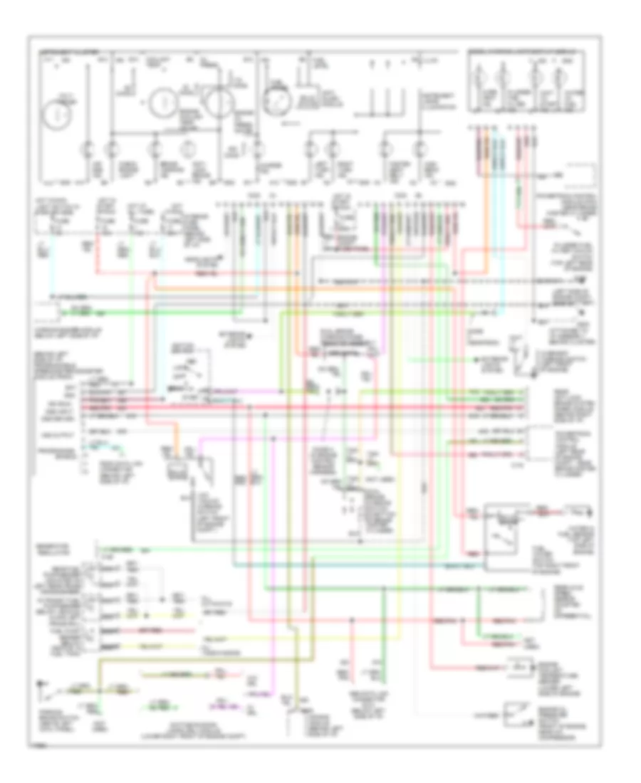
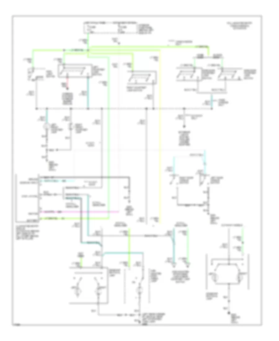
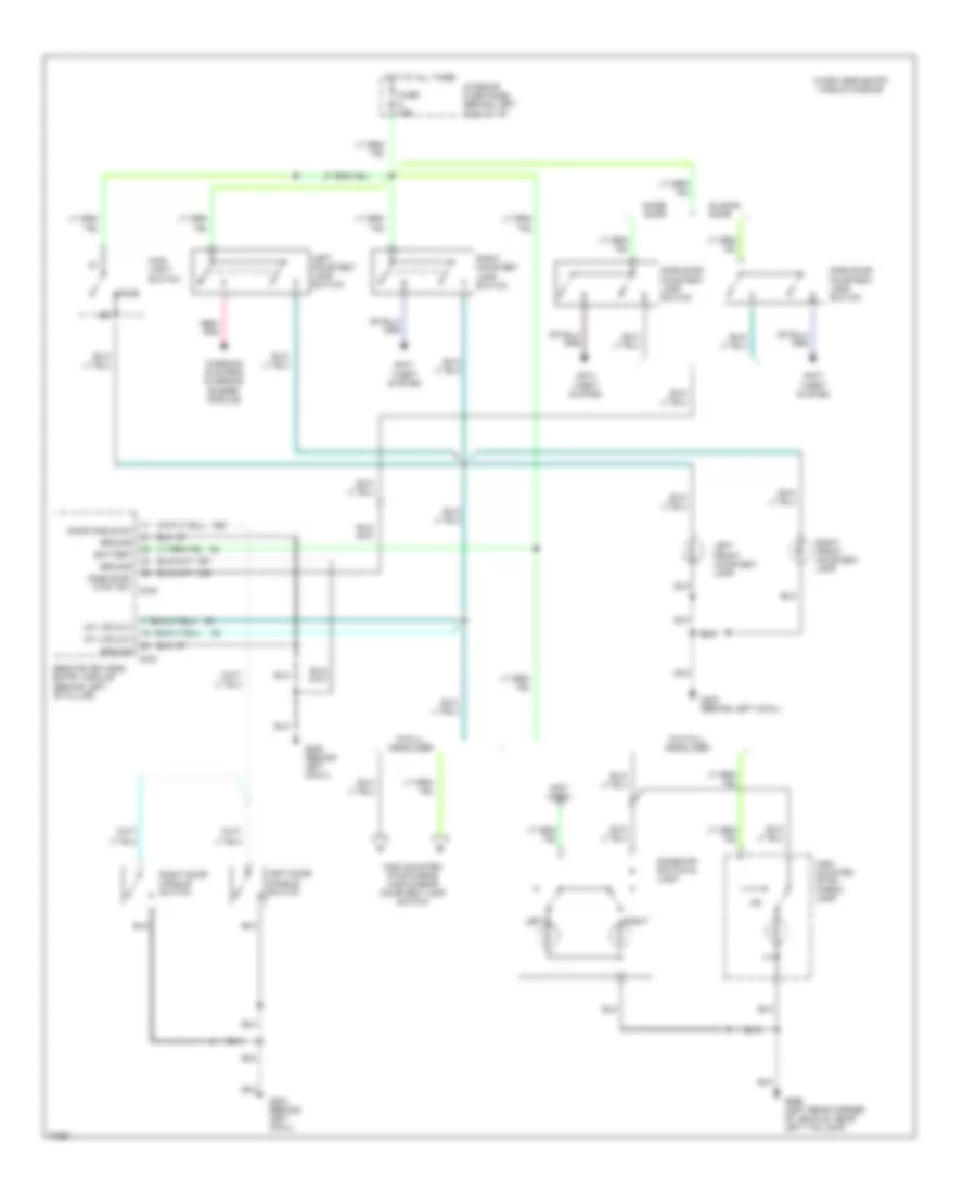
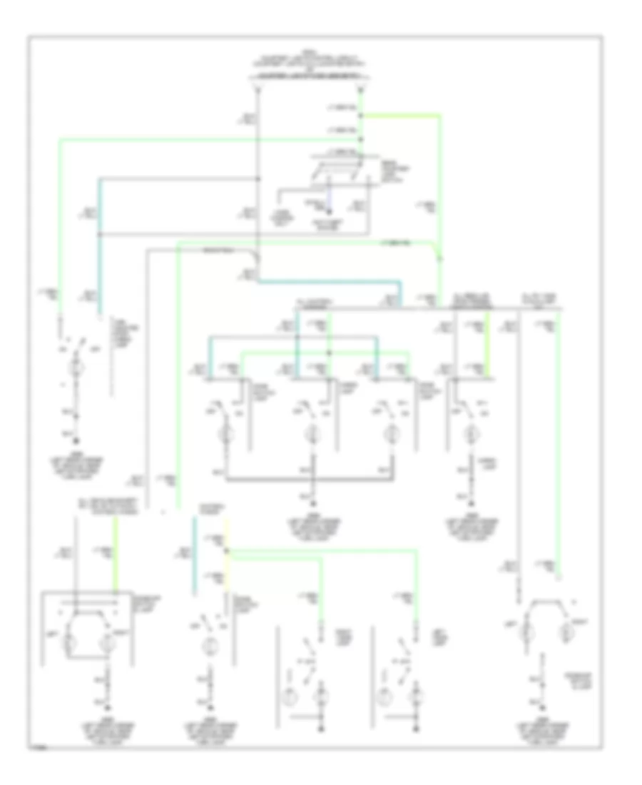
Heater Wiring Diagram for Ford RV Cutaway E350 1996
List of elements for Heater Wiring Diagram for Ford RV Cutaway E350 1996:
- (behind instrument cluster)
- (behind right side of i/p)
- (left rear corner of vehicle)
- (not used)
- (right side of safety wall)
- 15a
- 5.8l 49 states over 8600 gvw and 7.5l except california
- Aux- iliary high blower motor relay
- Auxiliary blower motor
- Auxiliary blower motor relay (left rear corner of vehicle)
- Auxiliary blower motor resistor (left rear corner of vehicle)
- Auxiliary blower switch
- Blend door actuator (behind center of i/p)
- Blower motor
- Blower motor relay (left side of engine compartment)
- Blower motor resistor
- Def
- Engine compartment fuse panel
- Floor
- Front blower switch
- Function selector switch
- Fuse 9
- Fuse a 60a
- Fuse f 60a
- G108 (left side of engine compartment near battery)
- G202
- G206
- G404 (left rear corner of vehicle, near left tail light)
- Hot at all times
- Hot in run
- Interior fuse panel
- Mix
- Off
- Power- train control module (left rear of engine compartment near brake master cylinder)
- Rear auxiliary blower switch
- Temper- ature control switch
- Vent
- W/ rear control
- W/o rear con- trol
5.8L
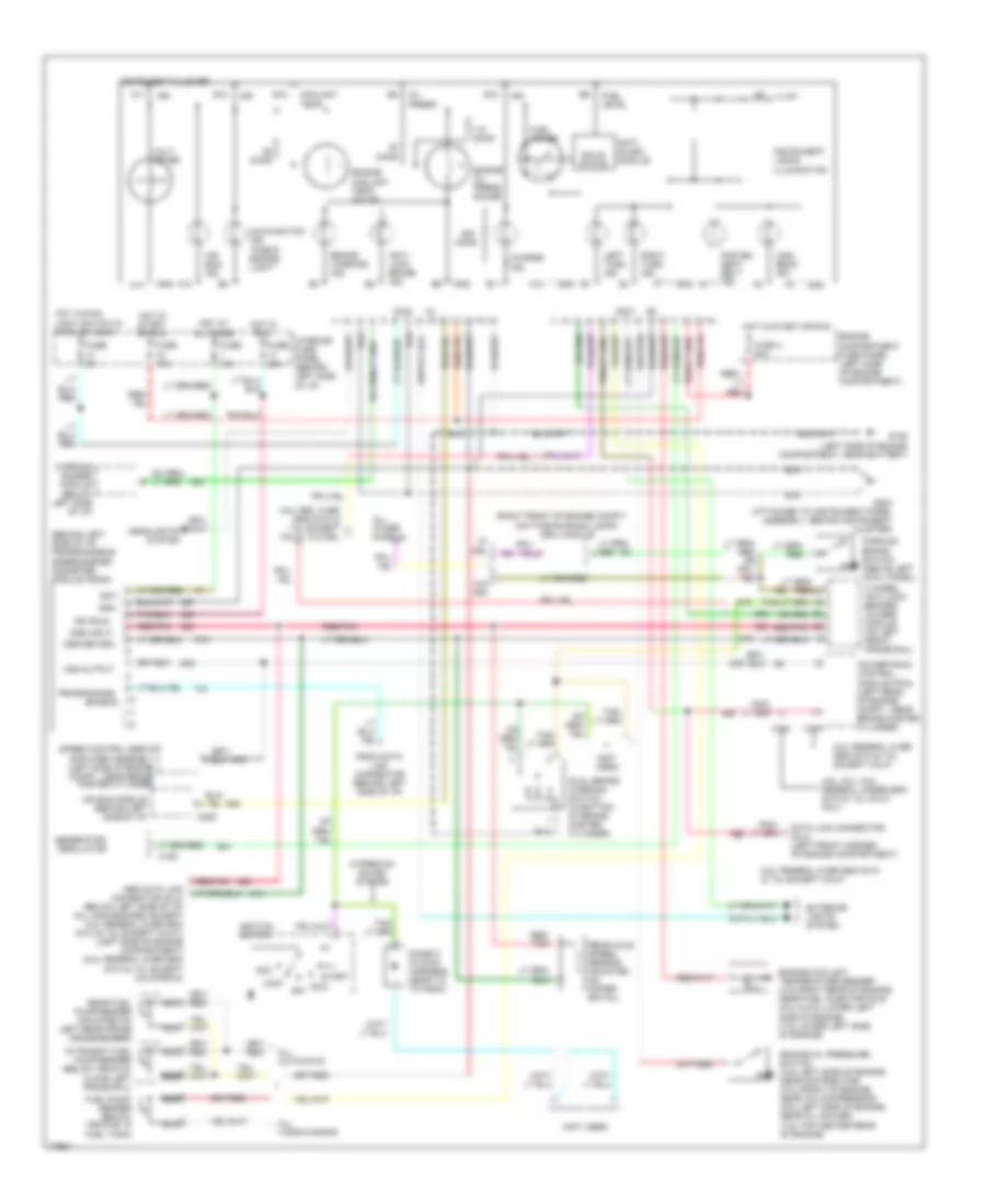
5.8L, A/C Wiring Diagram for Ford RV Cutaway E350 1996
List of elements for 5.8L, A/C Wiring Diagram for Ford RV Cutaway E350 1996:
- (5.8l 49 states over 8600 gvw and 7.5l exc. california)
- (all others)
- (behind right side of i/p)
- (left front of engine compartment)
- (left rear corner of vehicle)
- (left rear of engine compt near brake master cylinder)
- (right front of engine compartment)
- (right side of safety wall)
- 15a
- 5.8l 49 states over 8600 gvw and 7.5l except california
- A/c pressure cut out switch
- A/c clutch cycling pressure switch
- A/c clutch diode
- A/c compressor clutch
- A/c control assembly
- Aux- iliary high blower motor relay
- Auxiliary blower motor
- Auxiliary blower motor relay (left rear corner of vehicle)
- Auxiliary blower motor resistor (left rear corner of vehicle)
- Auxiliary blower switch
- Blend door actuator (behind center of i/p)
- Blower motor
- Blower motor relay (left side of engine compartment)
- Blower motor resistor
- Def
- Diesel
- Engine compartment fuse panel
- Floor
- Front blower switch
- Fuse 9
- Fuse a 60a
- Fuse f 60a
- G108 (left side of engine compartment near battery)
- G108 (left side of engine compartment, near battery)
- G202
- G206 (behind instrument cluster)
- G404 (left rear corner of vehicle, near left tail light)
- Gasoline
- Hot at all times
- Hot in run
- Interior fuse panel
- Lo/ rear
- Max
- Mix
- Norm
- Off
- Power- train control module
- Rear auxiliary blower switch
- Temper- ature control switch
- Vent
- W/ rear control
- W/o rear con- trol
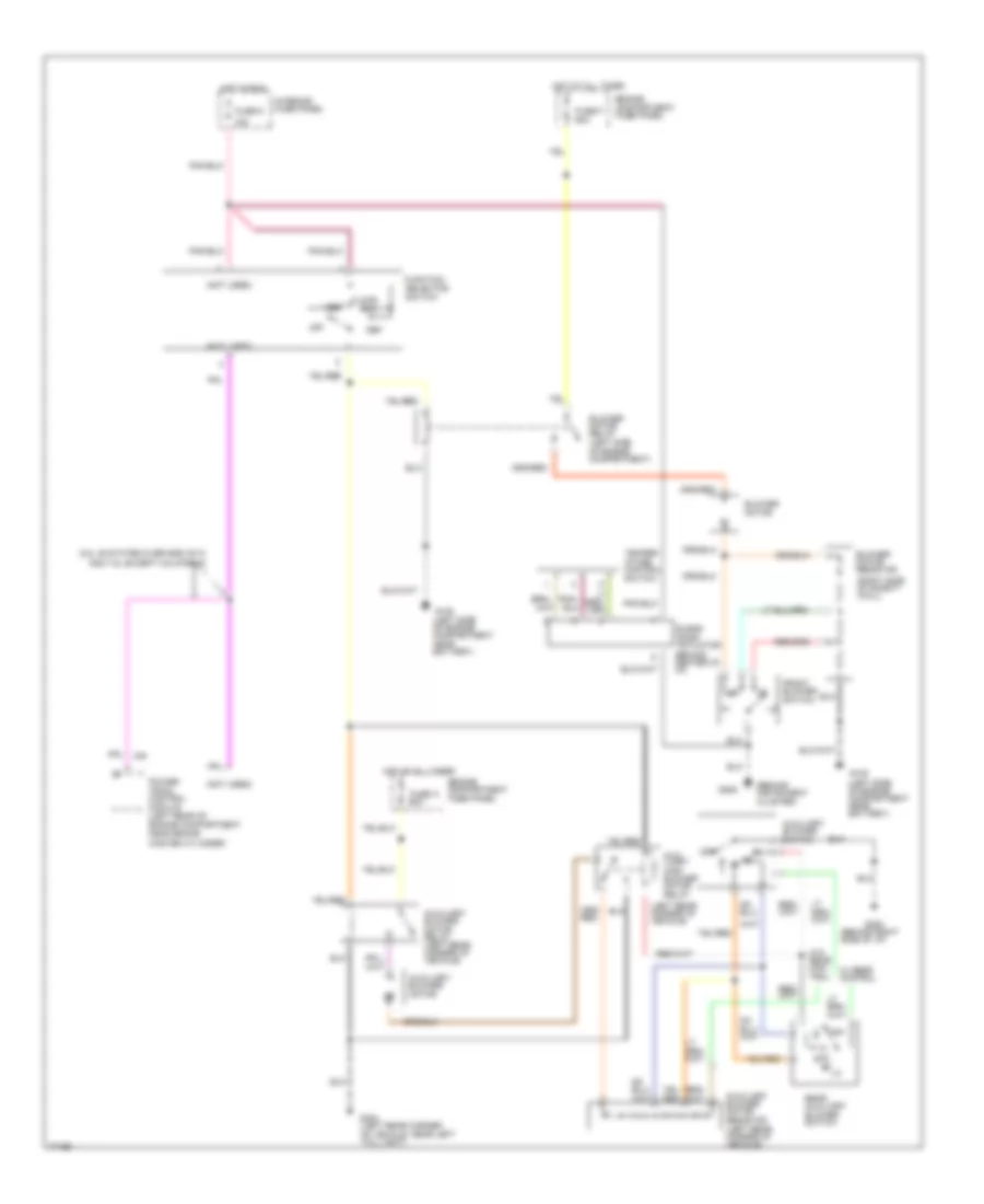
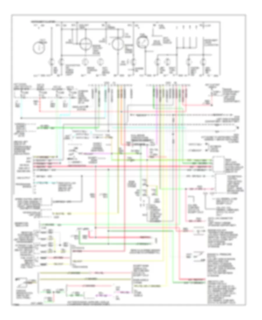
Heater Wiring Diagram for Ford RV Cutaway E350 1996
List of elements for Heater Wiring Diagram for Ford RV Cutaway E350 1996:
- (behind instrument cluster)
- (behind right side of i/p)
- (left rear corner of vehicle)
- (not used)
- (right side of safety wall)
- 15a
- 5.8l 49 states over 8600 gvw and 7.5l except california
- Aux- iliary high blower motor relay
- Auxiliary blower motor
- Auxiliary blower motor relay (left rear corner of vehicle)
- Auxiliary blower motor resistor (left rear corner of vehicle)
- Auxiliary blower switch
- Blend door actuator (behind center of i/p)
- Blower motor
- Blower motor relay (left side of engine compartment)
- Blower motor resistor
- Def
- Engine compartment fuse panel
- Floor
- Front blower switch
- Function selector switch
- Fuse 9
- Fuse a 60a
- Fuse f 60a
- G108 (left side of engine compartment near battery)
- G202
- G206
- G404 (left rear corner of vehicle, near left tail light)
- Hot at all times
- Hot in run
- Interior fuse panel
- Mix
- Off
- Power- train control module (left rear of engine compartment near brake master cylinder)
- Rear auxiliary blower switch
- Temper- ature control switch
- Vent
- W/ rear control
- W/o rear con- trol
7.3L
7.3L DI Turbo Diesel, A/C Wiring Diagram for Ford RV Cutaway E350 1996
List of elements for 7.3L DI Turbo Diesel, A/C Wiring Diagram for Ford RV Cutaway E350 1996:
- (5.8l 49 states over 8600 gvw and 7.5l exc. california)
- (all others)
- (behind right side of i/p)
- (left front of engine compartment)
- (left rear corner of vehicle)
- (left rear of engine compt near brake master cylinder)
- (right front of engine compartment)
- (right side of safety wall)
- 15a
- 5.8l 49 states over 8600 gvw and 7.5l except california
- A/c pressure cut out switch
- A/c clutch cycling pressure switch
- A/c clutch diode
- A/c compressor clutch
- A/c control assembly
- Aux- iliary high blower motor relay
- Auxiliary blower motor
- Auxiliary blower motor relay (left rear corner of vehicle)
- Auxiliary blower motor resistor (left rear corner of vehicle)
- Auxiliary blower switch
- Blend door actuator (behind center of i/p)
- Blower motor
- Blower motor relay (left side of engine compartment)
- Blower motor resistor
- Def
- Diesel
- Engine compartment fuse panel
- Floor
- Front blower switch
- Fuse 9
- Fuse a 60a
- Fuse f 60a
- G108 (left side of engine compartment near battery)
- G108 (left side of engine compartment, near battery)
- G202
- G206 (behind instrument cluster)
- G404 (left rear corner of vehicle, near left tail light)
- Gasoline
- Hot at all times
- Hot in run
- Interior fuse panel
- Lo/ rear
- Max
- Mix
- Norm
- Off
- Power- train control module
- Rear auxiliary blower switch
- Temper- ature control switch
- Vent
- W/ rear control
- W/o rear con- trol
Heater Wiring Diagram for Ford RV Cutaway E350 1996
List of elements for Heater Wiring Diagram for Ford RV Cutaway E350 1996:
- (behind instrument cluster)
- (behind right side of i/p)
- (left rear corner of vehicle)
- (not used)
- (right side of safety wall)
- 15a
- 5.8l 49 states over 8600 gvw and 7.5l except california
- Aux- iliary high blower motor relay
- Auxiliary blower motor
- Auxiliary blower motor relay (left rear corner of vehicle)
- Auxiliary blower motor resistor (left rear corner of vehicle)
- Auxiliary blower switch
- Blend door actuator (behind center of i/p)
- Blower motor
- Blower motor relay (left side of engine compartment)
- Blower motor resistor
- Def
- Engine compartment fuse panel
- Floor
- Front blower switch
- Function selector switch
- Fuse 9
- Fuse a 60a
- Fuse f 60a
- G108 (left side of engine compartment near battery)
- G202
- G206
- G404 (left rear corner of vehicle, near left tail light)
- Hot at all times
- Hot in run
- Interior fuse panel
- Mix
- Off
- Power- train control module (left rear of engine compartment near brake master cylinder)
- Rear auxiliary blower switch
- Temper- ature control switch
- Vent
- W/ rear control
- W/o rear con- trol
7.5L
7.5L, A/C Wiring Diagram for Ford RV Cutaway E350 1996
List of elements for 7.5L, A/C Wiring Diagram for Ford RV Cutaway E350 1996:
- (5.8l 49 states over 8600 gvw and 7.5l exc. california)
- (all others)
- (behind right side of i/p)
- (left front of engine compartment)
- (left rear corner of vehicle)
- (left rear of engine compt near brake master cylinder)
- (right front of engine compartment)
- (right side of safety wall)
- 15a
- 5.8l 49 states over 8600 gvw and 7.5l except california
- A/c pressure cut out switch
- A/c clutch cycling pressure switch
- A/c clutch diode
- A/c compressor clutch
- A/c control assembly
- Aux- iliary high blower motor relay
- Auxiliary blower motor
- Auxiliary blower motor relay (left rear corner of vehicle)
- Auxiliary blower motor resistor (left rear corner of vehicle)
- Auxiliary blower switch
- Blend door actuator (behind center of i/p)
- Blower motor
- Blower motor relay (left side of engine compartment)
- Blower motor resistor
- Def
- Diesel
- Engine compartment fuse panel
- Floor
- Front blower switch
- Fuse 9
- Fuse a 60a
- Fuse f 60a
- G108 (left side of engine compartment near battery)
- G108 (left side of engine compartment, near battery)
- G202
- G206 (behind instrument cluster)
- G404 (left rear corner of vehicle, near left tail light)
- Gasoline
- Hot at all times
- Hot in run
- Interior fuse panel
- Lo/ rear
- Max
- Mix
- Norm
- Off
- Power- train control module
- Rear auxiliary blower switch
- Temper- ature control switch
- Vent
- W/ rear control
- W/o rear con- trol
Heater Wiring Diagram for Ford RV Cutaway E350 1996
List of elements for Heater Wiring Diagram for Ford RV Cutaway E350 1996:
- (behind instrument cluster)
- (behind right side of i/p)
- (left rear corner of vehicle)
- (not used)
- (right side of safety wall)
- 15a
- 5.8l 49 states over 8600 gvw and 7.5l except california
- Aux- iliary high blower motor relay
- Auxiliary blower motor
- Auxiliary blower motor relay (left rear corner of vehicle)
- Auxiliary blower motor resistor (left rear corner of vehicle)
- Auxiliary blower switch
- Blend door actuator (behind center of i/p)
- Blower motor
- Blower motor relay (left side of engine compartment)
- Blower motor resistor
- Def
- Engine compartment fuse panel
- Floor
- Front blower switch
- Function selector switch
- Fuse 9
- Fuse a 60a
- Fuse f 60a
- G108 (left side of engine compartment near battery)
- G202
- G206
- G404 (left rear corner of vehicle, near left tail light)
- Hot at all times
- Hot in run
- Interior fuse panel
- Mix
- Off
- Power- train control module (left rear of engine compartment near brake master cylinder)
- Rear auxiliary blower switch
- Temper- ature control switch
- Vent
- W/ rear control
- W/o rear con- trol
ANTI-LOCK BRAKES
4.9L
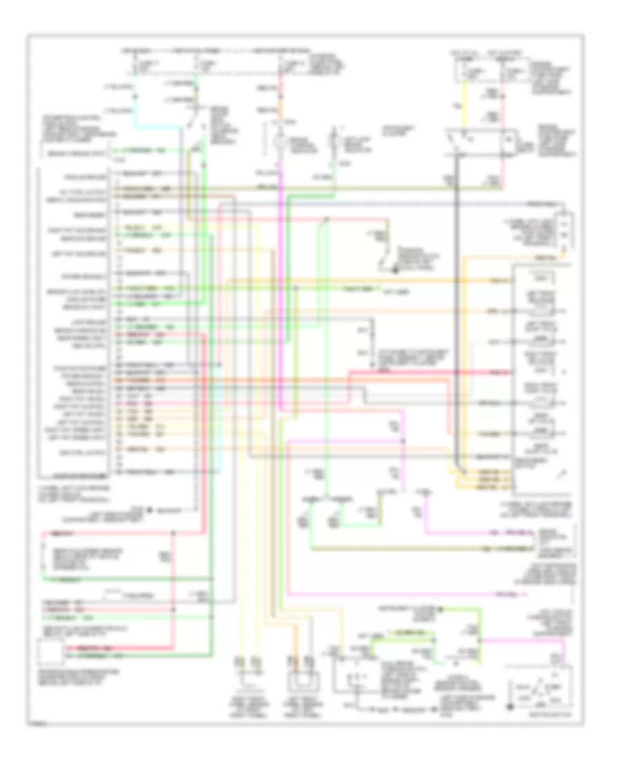
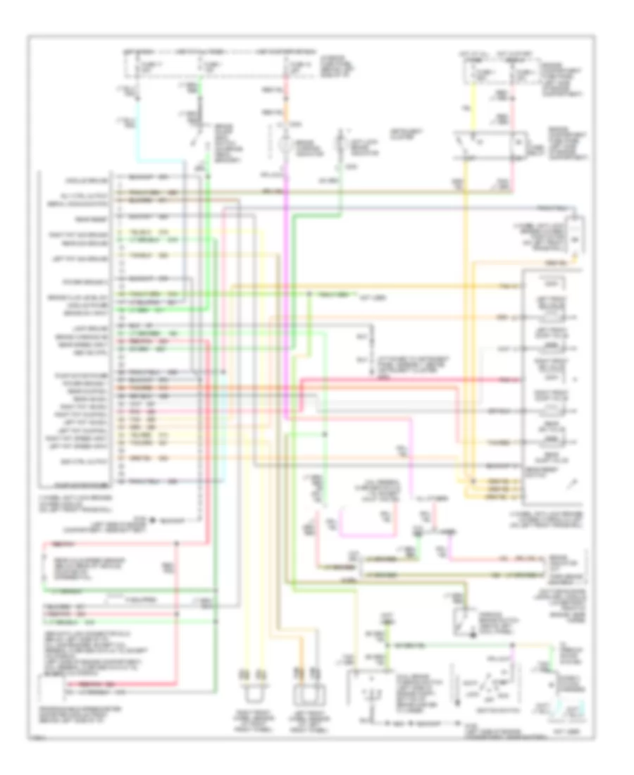
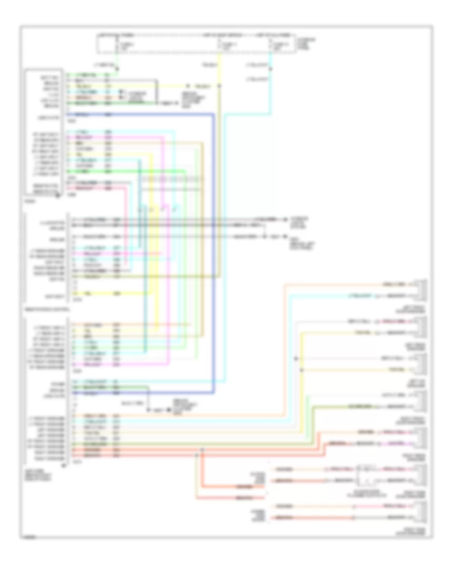
4.9L, Anti-lock Brake Wiring Diagrams, 4 Wheel ABS for Ford RV Cutaway E350 1996
List of elements for 4.9L, Anti-lock Brake Wiring Diagrams, 4 Wheel ABS for Ford RV Cutaway E350 1996:
- (attached to instrument panel assembly, behind instrument cluster) g202
- (not used)
- 4 wheel anti-lock brakes (4wabs) hydraulic unit (on left front frame rail)
- 4 wheel anti-lock brakes (4wabs) module (on left front frame rail)
- 4 wheel anti-lock brakes (4wabs) pump motor (on left front frame rail)
- 5.8l federal over 8600 gvw & 7.5l except calif. w/o drl
- Abs data link connector (dlc) (below left side of i/p) (all gas engines, except 5.8l federal over 8600 gvw & 7.5l except california) (left side of engine compartment) (5.8l federal over 8600 gvw & 7.5l except california)
- Abs ind ctrl
- Acc
- All others
- Anti-lock brake indicator
- Brake fluid level sw
- Brake indicator out
- Brake on/off (boo) switch (on brake pedal bracket)
- Brake sw input
- Brake warning ind
- Brake warning indicator
- C233
- Daytime running lamps (drl) module (lower right front of engine, near horns)
- Diode c (in main harness)
- Dual brake warning switch (left side of engine compt., bottom of brake master cylinder)
- Emf ctrl output
- Engine compartment fuse panel (left side of engine compartment)
- Fuse 1 15a
- Fuse 17 20a
- Fuse 18 15a
- Fuse u 30a
- Fuse v 60a
- G106 (left side of engine compartment, near battery)
- Hot at all times
- Hot in run
- Hot in start or run
- If equipped
- Ignition switch
- Instrument cluster
- Interior fuse panel (behind left side of i/p)
- Lamp ground
- Left fnt dump sol
- Left fnt iso sol
- Left fnt sig ground
- Left fnt speed input
- Left front dump valve
- Left front iso valve
- Left front wheel sensor (at left front wheel)
- Lock
- Module ground
- Module power
- Not used
- Off
- Park brake on input
- Parking brake switch (above left cowl panel)
- Pnk
- Power ground 1
- Power ground 2
- Programmable speedometer/ odometer module (psom) (behind left side of i/p)
- Pump motor power
- Rear axle speed sensor (below rear of vehicle, mounted on differential)
- Rear dump sol
- Rear dump valve
- Rear iso sol
- Rear iso valve
- Rear reset
- Rear reset switch
- Rear sig ground
- Rear speed input
- Red/ pnk
- Red/pnk
- Right fnt dump sol
- Right fnt iso sol
- Right fnt sig ground
- Right fnt speed input
- Right front dump valve
- Right front iso valve
- Right front wheel sensor (at right front wheel)
- Rly ctrl output
- Run
- Serial communication
- Start
- Tan
- Tan/red
- W/ premium sound system
- W/drl
- W/o drl
- Wabs relay
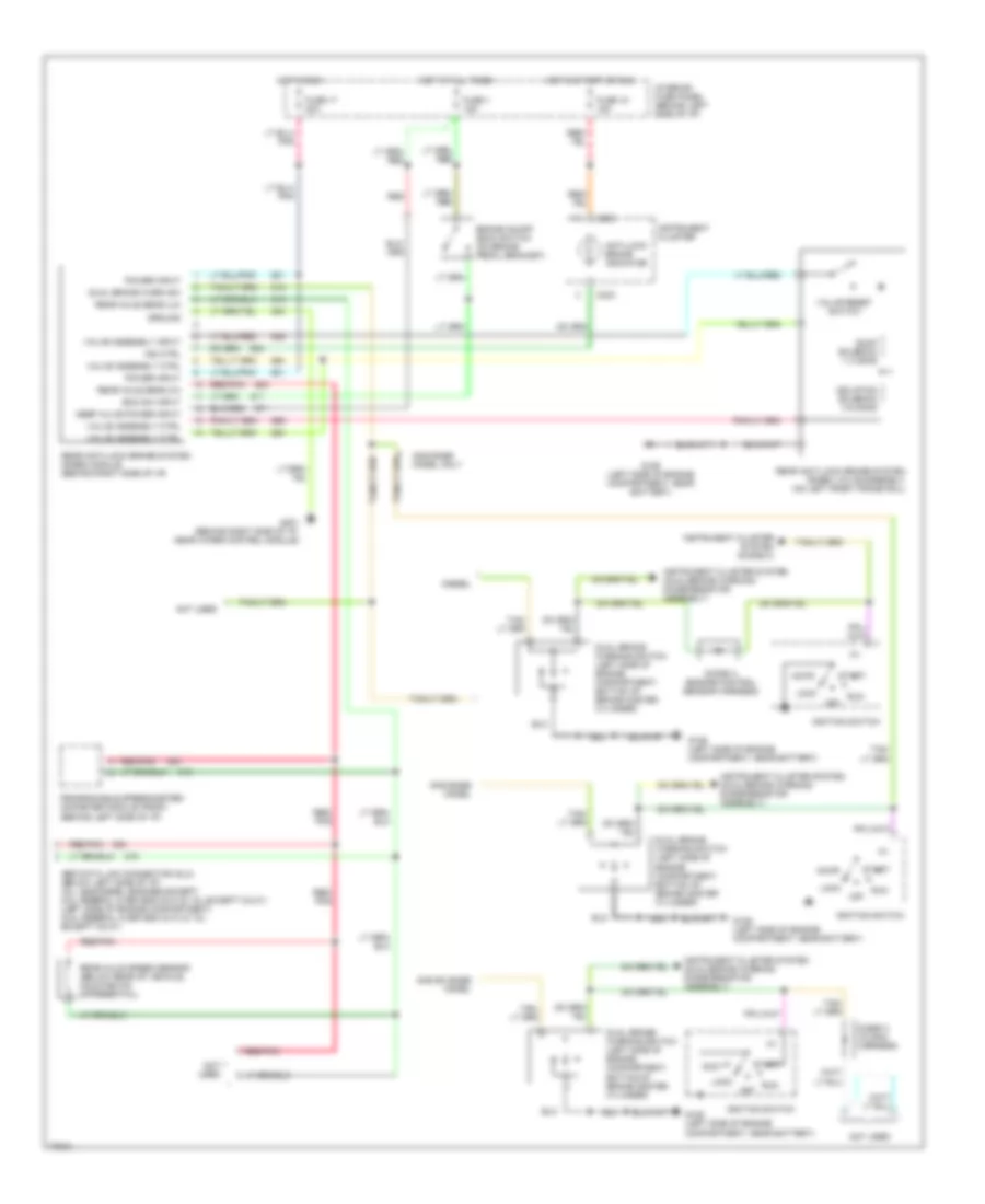
Anti-lock Brake Wiring Diagrams, Rear Wheel ABS for Ford RV Cutaway E350 1996
List of elements for Anti-lock Brake Wiring Diagrams, Rear Wheel ABS for Ford RV Cutaway E350 1996:
- Abs data link connector (dlc) (below left side of i/p) (all gas/diesel engines except 5.8l federal over 8600 gvw & 7.5l except calif.) (left side of engine compartment) (5.8l federal over 8600 gvw & 7.5l except calif.)
- Accy
- Anti-lock brake indicator
- Boo sw input
- Brake on/off (boo) switch (on brake pedal bracket)
- C233
- Diesel
- Diode a (engine control sensor harness)
- Diode c (in main harness)
- Dual brake warn sw
- Dual brake warning switch (left side of engine compartment, bottom of brake master cylinder)
- Dump solenoid 1-3 ohms
- Fuse 1 15a
- Fuse 17 20a
- Fuse 18 15a
- G106 (left side of engine compartment, near battery)
- G201 (behind right side of i/p, near wiper control module)
- Gas base model
- Gas base model only
- Gas ex base model
- Ground
- Hot at all times
- Hot in run
- Hot in start or run
- Ignition switch
- Ind ctrl
- Instrument cluster
- Instrument cluster system (diode c)
- Instrument cluster system (dual/brake warning diode/resistor assembly)
- Interior fuse panel (behind left side of i/p)
- Isolation solenoid 3-6 ohms
- Keep alive power input
- Lock
- Not used
- Off
- Power input
- Programable speedometer/ odometer module (psom) (behind left side of i/p)
- Rear anti-lock brake system (rabs) module (behind right side of i/p)
- Rear anti-lock brake system (rabs) valve assembly (on left front frame rail)
- Rear axle sens (hi)
- Rear axle sens (lo)
- Rear axle speed sensor (below rear of vehicle, mounted on differential)
- Red
- Red/ pnk
- Red/pnk
- Run
- Start
- Valve assembly ctrl
- Valve assembly input
- Valve reset switch
5.8L
5.8L, Anti-lock Brake Wiring Diagrams, 4 Wheel ABS for Ford RV Cutaway E350 1996
List of elements for 5.8L, Anti-lock Brake Wiring Diagrams, 4 Wheel ABS for Ford RV Cutaway E350 1996:
- (attached to instrument panel assembly, behind instrument cluster) g202
- (not used)
- 4 wheel anti-lock brakes (4wabs) hydraulic unit (on left front frame rail)
- 4 wheel anti-lock brakes (4wabs) module (on left front frame rail)
- 4 wheel anti-lock brakes (4wabs) pump motor (on left front frame rail)
- 5.8l federal over 8600 gvw & 7.5l except calif. w/o drl
- Abs data link connector (dlc) (below left side of i/p) (all gas engines, except 5.8l federal over 8600 gvw & 7.5l except california) (left side of engine compartment) (5.8l federal over 8600 gvw & 7.5l except california)
- Abs ind ctrl
- Acc
- All others
- Anti-lock brake indicator
- Brake fluid level sw
- Brake indicator out
- Brake on/off (boo) switch (on brake pedal bracket)
- Brake sw input
- Brake warning ind
- Brake warning indicator
- C233
- Daytime running lamps (drl) module (lower right front of engine, near horns)
- Diode c (in main harness)
- Dual brake warning switch (left side of engine compt., bottom of brake master cylinder)
- Emf ctrl output
- Engine compartment fuse panel (left side of engine compartment)
- Fuse 1 15a
- Fuse 17 20a
- Fuse 18 15a
- Fuse u 30a
- Fuse v 60a
- G106 (left side of engine compartment, near battery)
- Hot at all times
- Hot in run
- Hot in start or run
- If equipped
- Ignition switch
- Instrument cluster
- Interior fuse panel (behind left side of i/p)
- Lamp ground
- Left fnt dump sol
- Left fnt iso sol
- Left fnt sig ground
- Left fnt speed input
- Left front dump valve
- Left front iso valve
- Left front wheel sensor (at left front wheel)
- Lock
- Module ground
- Module power
- Not used
- Off
- Park brake on input
- Parking brake switch (above left cowl panel)
- Pnk
- Power ground 1
- Power ground 2
- Programmable speedometer/ odometer module (psom) (behind left side of i/p)
- Pump motor power
- Rear axle speed sensor (below rear of vehicle, mounted on differential)
- Rear dump sol
- Rear dump valve
- Rear iso sol
- Rear iso valve
- Rear reset
- Rear reset switch
- Rear sig ground
- Rear speed input
- Red/ pnk
- Red/pnk
- Right fnt dump sol
- Right fnt iso sol
- Right fnt sig ground
- Right fnt speed input
- Right front dump valve
- Right front iso valve
- Right front wheel sensor (at right front wheel)
- Rly ctrl output
- Run
- Serial communication
- Start
- Tan
- Tan/red
- W/ premium sound system
- W/drl
- W/o drl
- Wabs relay
Anti-lock Brake Wiring Diagrams, Rear Wheel ABS for Ford RV Cutaway E350 1996
List of elements for Anti-lock Brake Wiring Diagrams, Rear Wheel ABS for Ford RV Cutaway E350 1996:
- Abs data link connector (dlc) (below left side of i/p) (all gas/diesel engines except 5.8l federal over 8600 gvw & 7.5l except calif.) (left side of engine compartment) (5.8l federal over 8600 gvw & 7.5l except calif.)
- Accy
- Anti-lock brake indicator
- Boo sw input
- Brake on/off (boo) switch (on brake pedal bracket)
- C233
- Diesel
- Diode a (engine control sensor harness)
- Diode c (in main harness)
- Dual brake warn sw
- Dual brake warning switch (left side of engine compartment, bottom of brake master cylinder)
- Dump solenoid 1-3 ohms
- Fuse 1 15a
- Fuse 17 20a
- Fuse 18 15a
- G106 (left side of engine compartment, near battery)
- G201 (behind right side of i/p, near wiper control module)
- Gas base model
- Gas base model only
- Gas ex base model
- Ground
- Hot at all times
- Hot in run
- Hot in start or run
- Ignition switch
- Ind ctrl
- Instrument cluster
- Instrument cluster system (diode c)
- Instrument cluster system (dual/brake warning diode/resistor assembly)
- Interior fuse panel (behind left side of i/p)
- Isolation solenoid 3-6 ohms
- Keep alive power input
- Lock
- Not used
- Off
- Power input
- Programable speedometer/ odometer module (psom) (behind left side of i/p)
- Rear anti-lock brake system (rabs) module (behind right side of i/p)
- Rear anti-lock brake system (rabs) valve assembly (on left front frame rail)
- Rear axle sens (hi)
- Rear axle sens (lo)
- Rear axle speed sensor (below rear of vehicle, mounted on differential)
- Red
- Red/ pnk
- Red/pnk
- Run
- Start
- Valve assembly ctrl
- Valve assembly input
- Valve reset switch
7.3L
7.3L DI Turbo Diesel, Anti-lock Brake Wiring Diagrams for Ford RV Cutaway E350 1996
List of elements for 7.3L DI Turbo Diesel, Anti-lock Brake Wiring Diagrams for Ford RV Cutaway E350 1996:
- (attached to instrument panel assembly, behind instrument cluster) g202
- (left side of engine compartment, near battery) g106
- 4 wheel anti-lock brakes (4wabs) hydraulic unit (on left front frame rail)
- 4 wheel anti-lock brakes (4wabs) module (on left front frame rail)
- 4 wheel anti-lock brakes (4wabs) pump motor (on left front frame rail)
- Abs data link connector (dlc) (below left side of i/p)
- Abs ind ctrl
- Acc
- Anti-lock brake indicator
- Brake fluid level sw
- Brake indicator out
- Brake on/off (boo) switch (on brake pedal bracket)
- Brake sw input
- Brake warning ind
- Brake warning indicator
- Brake warning input
- C143
- C233
- Daytime running lamps (drl) module (lower right front of engine, near horns)
- Diode a (engine control sensor harness)
- Dual brake warning switch (left side of engine compt., bottom of brake master cylinder)
- Emf ctrl output
- Engine compartment fuse panel (left side of engine compartment)
- Fuse 1 15a
- Fuse 17 20a
- Fuse 18 15a
- Fuse u 30a
- Fuse v 60a
- G106 (left side of engine compartment, near battery)
- Hot at all times
- Hot in run
- Hot in start or run
- If equipped
- Ignition switch
- Instrument cluster
- Instrument cluster system (diode c)
- Interior fuse panel (behind left side of i/p)
- Lamp ground
- Left fnt dump sol
- Left fnt iso sol
- Left fnt sig ground
- Left fnt speed input
- Left front dump valve
- Left front iso valve
- Left front wheel sensor (at left front wheel)
- Lock
- Low vacuum warning switch (left front of engine compartment)
- Module ground
- Module power
- Not used
- Off
- Park brake on input
- Parking brake switch (above left cowl panel)
- Pnk
- Power ground 1
- Power ground 2
- Powertrain control module (pcm) (left rear of engine compartment, near brake master cylinder)
- Programmable speedometer/ odometer module (psom) (behind left side of i/p)
- Pump motor power
- Rear axle speed sensor (below rear of vehicle, mounted on differential)
- Rear dump sol
- Rear dump valve
- Rear iso sol
- Rear iso valve
- Rear reset
- Rear reset switch
- Rear sig ground
- Rear speed input
- Red/ pnk
- Red/pnk
- Right fnt dump sol
- Right fnt iso sol
- Right fnt sig ground
- Right fnt speed input
- Right front dump valve
- Right front iso valve
- Right front wheel sensor (at right front wheel)
- Rly ctrl output
- Run
- Serial communication
- Start
- Tan
- Tan/red
- W/ drl
- W/drl
- W/o drl
- Wabs relay
Anti-lock Brake Wiring Diagrams, Rear Wheel ABS for Ford RV Cutaway E350 1996
List of elements for Anti-lock Brake Wiring Diagrams, Rear Wheel ABS for Ford RV Cutaway E350 1996:
- Abs data link connector (dlc) (below left side of i/p) (all gas/diesel engines except 5.8l federal over 8600 gvw & 7.5l except calif.) (left side of engine compartment) (5.8l federal over 8600 gvw & 7.5l except calif.)
- Accy
- Anti-lock brake indicator
- Boo sw input
- Brake on/off (boo) switch (on brake pedal bracket)
- C233
- Diesel
- Diode a (engine control sensor harness)
- Diode c (in main harness)
- Dual brake warn sw
- Dual brake warning switch (left side of engine compartment, bottom of brake master cylinder)
- Dump solenoid 1-3 ohms
- Fuse 1 15a
- Fuse 17 20a
- Fuse 18 15a
- G106 (left side of engine compartment, near battery)
- G201 (behind right side of i/p, near wiper control module)
- Gas base model
- Gas base model only
- Gas ex base model
- Ground
- Hot at all times
- Hot in run
- Hot in start or run
- Ignition switch
- Ind ctrl
- Instrument cluster
- Instrument cluster system (diode c)
- Instrument cluster system (dual/brake warning diode/resistor assembly)
- Interior fuse panel (behind left side of i/p)
- Isolation solenoid 3-6 ohms
- Keep alive power input
- Lock
- Not used
- Off
- Power input
- Programable speedometer/ odometer module (psom) (behind left side of i/p)
- Rear anti-lock brake system (rabs) module (behind right side of i/p)
- Rear anti-lock brake system (rabs) valve assembly (on left front frame rail)
- Rear axle sens (hi)
- Rear axle sens (lo)
- Rear axle speed sensor (below rear of vehicle, mounted on differential)
- Red
- Red/ pnk
- Red/pnk
- Run
- Start
- Valve assembly ctrl
- Valve assembly input
- Valve reset switch
7.5L
7.5L, Anti-lock Brake Wiring Diagrams, 4 Wheel ABS for Ford RV Cutaway E350 1996
List of elements for 7.5L, Anti-lock Brake Wiring Diagrams, 4 Wheel ABS for Ford RV Cutaway E350 1996:
- (attached to instrument panel assembly, behind instrument cluster) g202
- (not used)
- 4 wheel anti-lock brakes (4wabs) hydraulic unit (on left front frame rail)
- 4 wheel anti-lock brakes (4wabs) module (on left front frame rail)
- 4 wheel anti-lock brakes (4wabs) pump motor (on left front frame rail)
- 5.8l federal over 8600 gvw & 7.5l except calif. w/o drl
- Abs data link connector (dlc) (below left side of i/p) (all gas engines, except 5.8l federal over 8600 gvw & 7.5l except california) (left side of engine compartment) (5.8l federal over 8600 gvw & 7.5l except california)
- Abs ind ctrl
- Acc
- All others
- Anti-lock brake indicator
- Brake fluid level sw
- Brake indicator out
- Brake on/off (boo) switch (on brake pedal bracket)
- Brake sw input
- Brake warning ind
- Brake warning indicator
- C233
- Daytime running lamps (drl) module (lower right front of engine, near horns)
- Diode c (in main harness)
- Dual brake warning switch (left side of engine compt., bottom of brake master cylinder)
- Emf ctrl output
- Engine compartment fuse panel (left side of engine compartment)
- Fuse 1 15a
- Fuse 17 20a
- Fuse 18 15a
- Fuse u 30a
- Fuse v 60a
- G106 (left side of engine compartment, near battery)
- Hot at all times
- Hot in run
- Hot in start or run
- If equipped
- Ignition switch
- Instrument cluster
- Interior fuse panel (behind left side of i/p)
- Lamp ground
- Left fnt dump sol
- Left fnt iso sol
- Left fnt sig ground
- Left fnt speed input
- Left front dump valve
- Left front iso valve
- Left front wheel sensor (at left front wheel)
- Lock
- Module ground
- Module power
- Not used
- Off
- Park brake on input
- Parking brake switch (above left cowl panel)
- Pnk
- Power ground 1
- Power ground 2
- Programmable speedometer/ odometer module (psom) (behind left side of i/p)
- Pump motor power
- Rear axle speed sensor (below rear of vehicle, mounted on differential)
- Rear dump sol
- Rear dump valve
- Rear iso sol
- Rear iso valve
- Rear reset
- Rear reset switch
- Rear sig ground
- Rear speed input
- Red/ pnk
- Red/pnk
- Right fnt dump sol
- Right fnt iso sol
- Right fnt sig ground
- Right fnt speed input
- Right front dump valve
- Right front iso valve
- Right front wheel sensor (at right front wheel)
- Rly ctrl output
- Run
- Serial communication
- Start
- Tan
- Tan/red
- W/ premium sound system
- W/drl
- W/o drl
- Wabs relay
Anti-lock Brake Wiring Diagrams, Rear Wheel ABS for Ford RV Cutaway E350 1996
List of elements for Anti-lock Brake Wiring Diagrams, Rear Wheel ABS for Ford RV Cutaway E350 1996:
- Abs data link connector (dlc) (below left side of i/p) (all gas/diesel engines except 5.8l federal over 8600 gvw & 7.5l except calif.) (left side of engine compartment) (5.8l federal over 8600 gvw & 7.5l except calif.)
- Accy
- Anti-lock brake indicator
- Boo sw input
- Brake on/off (boo) switch (on brake pedal bracket)
- C233
- Diesel
- Diode a (engine control sensor harness)
- Diode c (in main harness)
- Dual brake warn sw
- Dual brake warning switch (left side of engine compartment, bottom of brake master cylinder)
- Dump solenoid 1-3 ohms
- Fuse 1 15a
- Fuse 17 20a
- Fuse 18 15a
- G106 (left side of engine compartment, near battery)
- G201 (behind right side of i/p, near wiper control module)
- Gas base model
- Gas base model only
- Gas ex base model
- Ground
- Hot at all times
- Hot in run
- Hot in start or run
- Ignition switch
- Ind ctrl
- Instrument cluster
- Instrument cluster system (diode c)
- Instrument cluster system (dual/brake warning diode/resistor assembly)
- Interior fuse panel (behind left side of i/p)
- Isolation solenoid 3-6 ohms
- Keep alive power input
- Lock
- Not used
- Off
- Power input
- Programable speedometer/ odometer module (psom) (behind left side of i/p)
- Rear anti-lock brake system (rabs) module (behind right side of i/p)
- Rear anti-lock brake system (rabs) valve assembly (on left front frame rail)
- Rear axle sens (hi)
- Rear axle sens (lo)
- Rear axle speed sensor (below rear of vehicle, mounted on differential)
- Red
- Red/ pnk
- Red/pnk
- Run
- Start
- Valve assembly ctrl
- Valve assembly input
- Valve reset switch
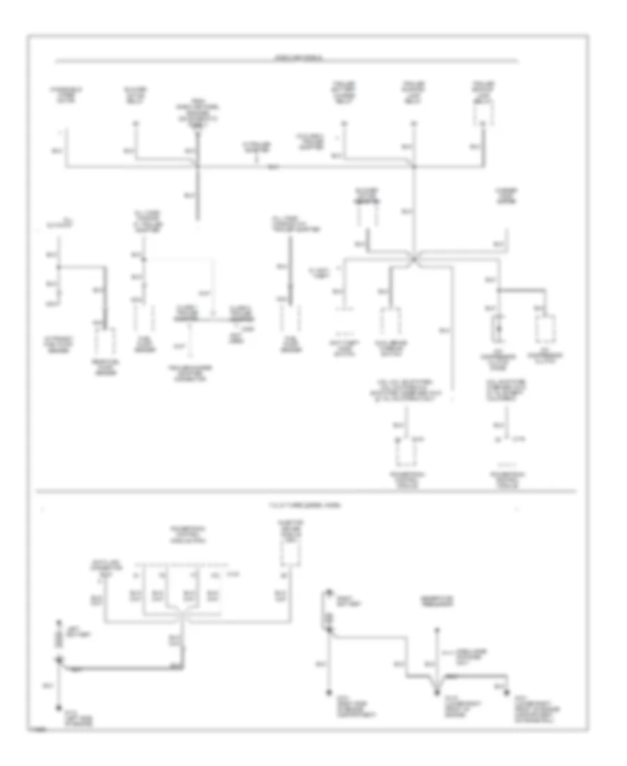
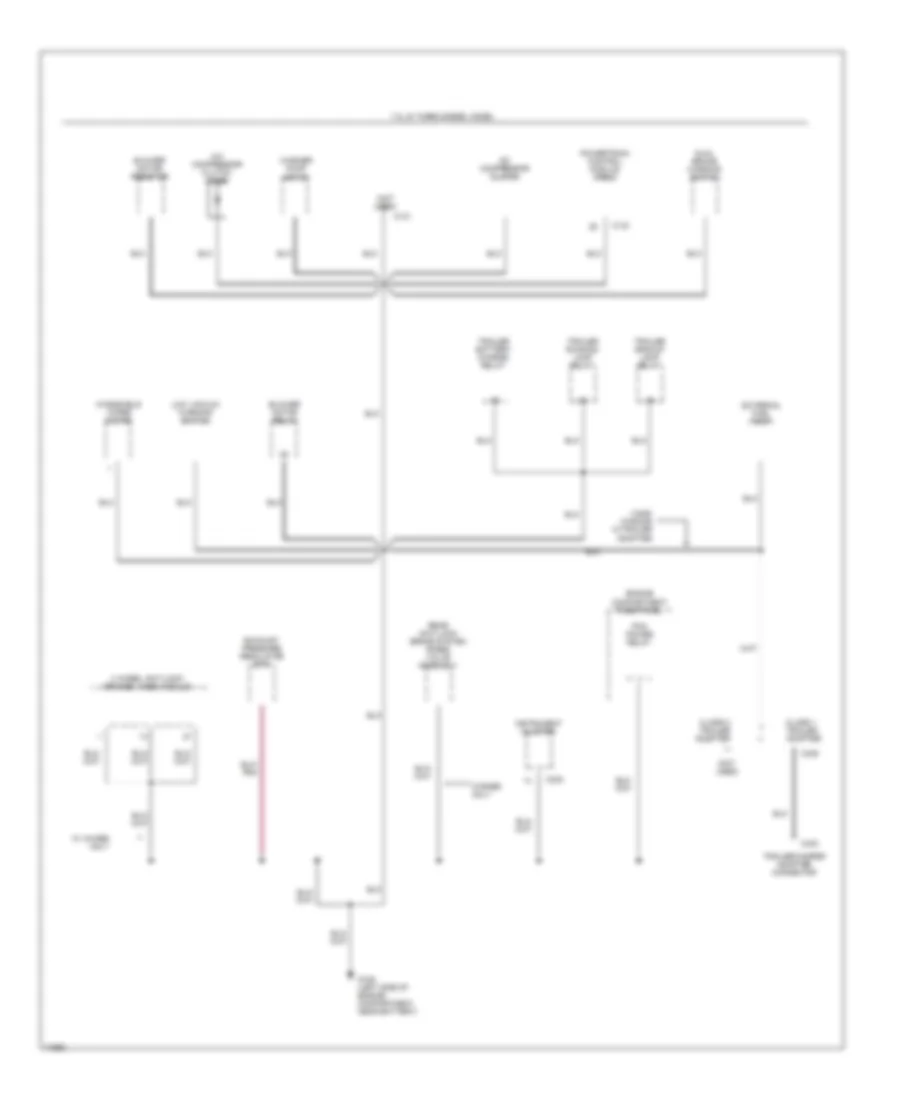
COMPUTER DATA LINES
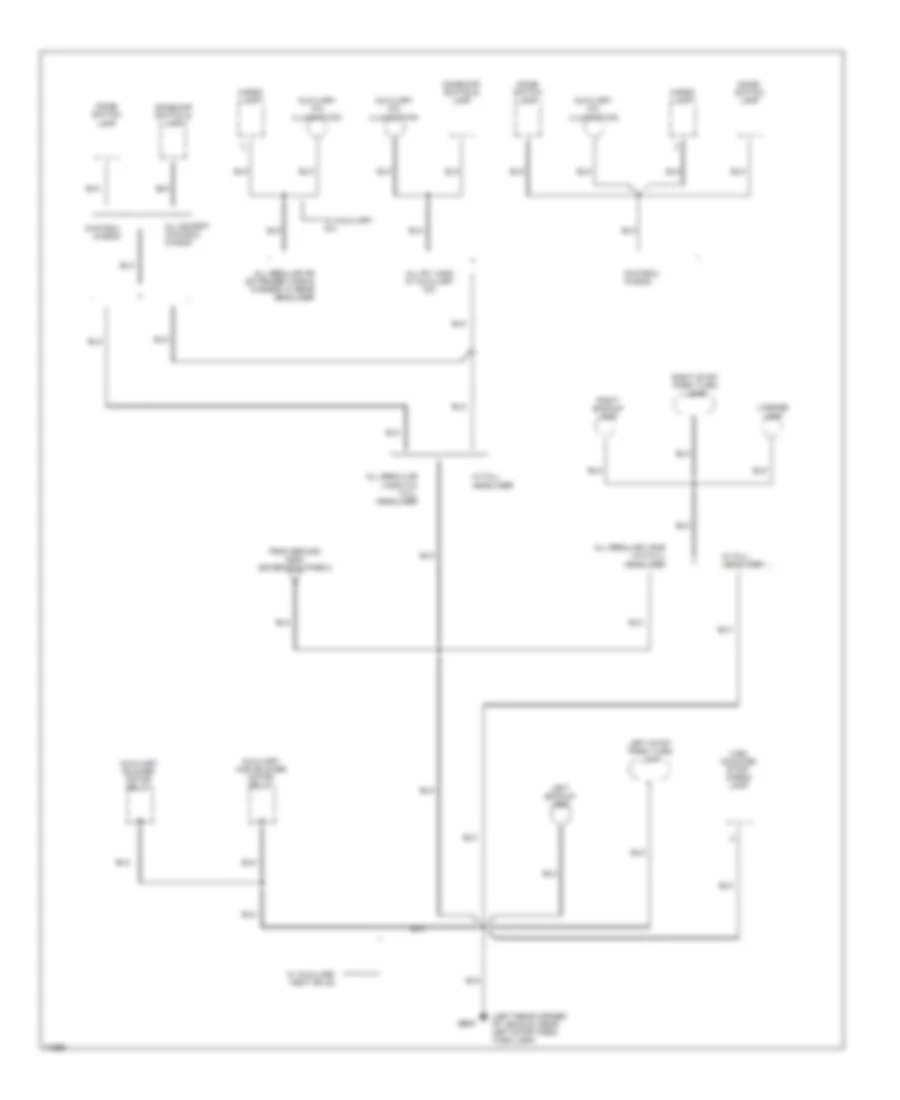
4.9L
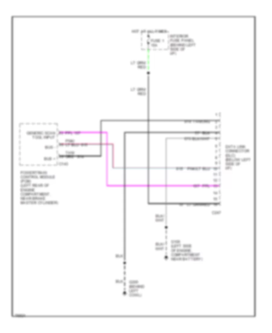
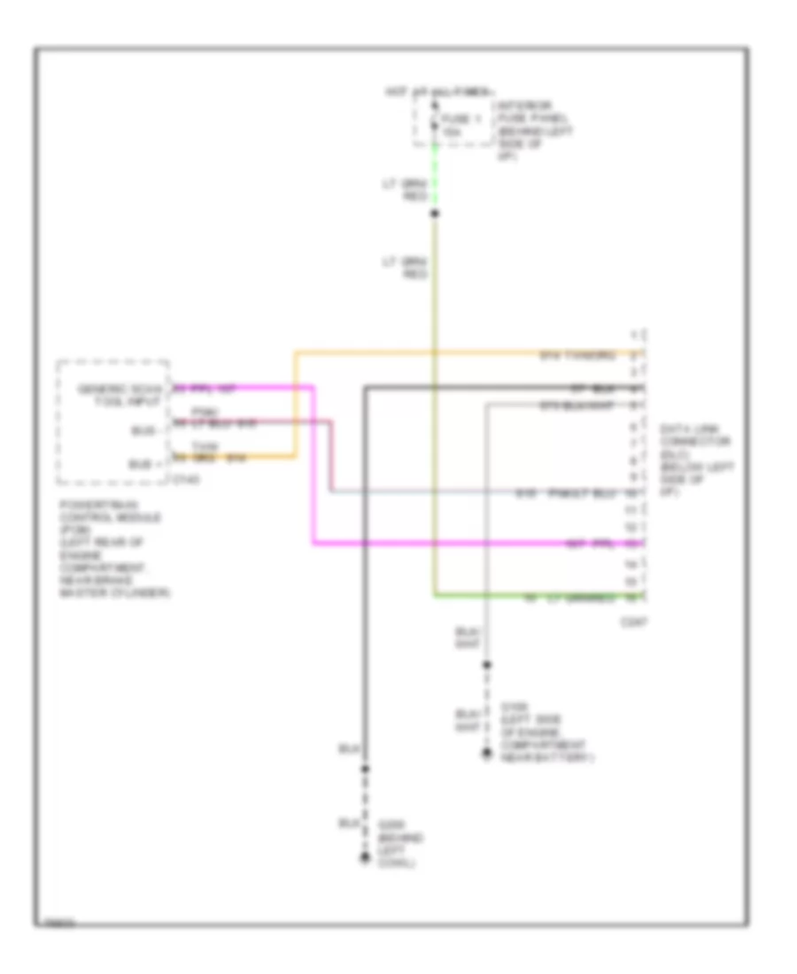
4.9L, Computer Data Lines for Ford RV Cutaway E350 1996
List of elements for 4.9L, Computer Data Lines for Ford RV Cutaway E350 1996:
- Bus +
- Bus -
- C143
- C247
- Data link connector (dlc) (below left side of i/p)
- Fuse 1 15a
- G106 (left side of engine, compartment near battery)
- G200 (behind left cowl)
- Generic scan tool input
- Hot at all times
- Interior fuse panel (behind left side of i/p)
- Powertrain control module (pcm) (left rear of engine compartment, near brake master cylinder)
5.8L
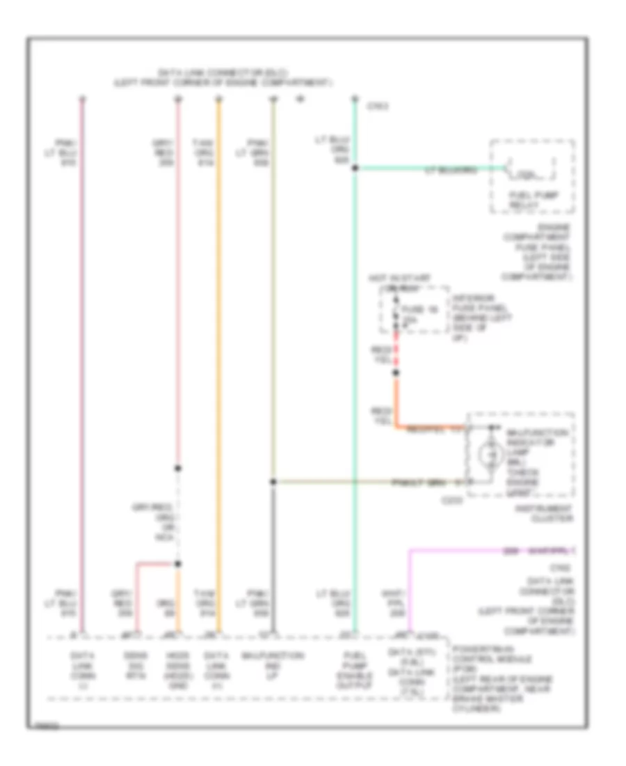
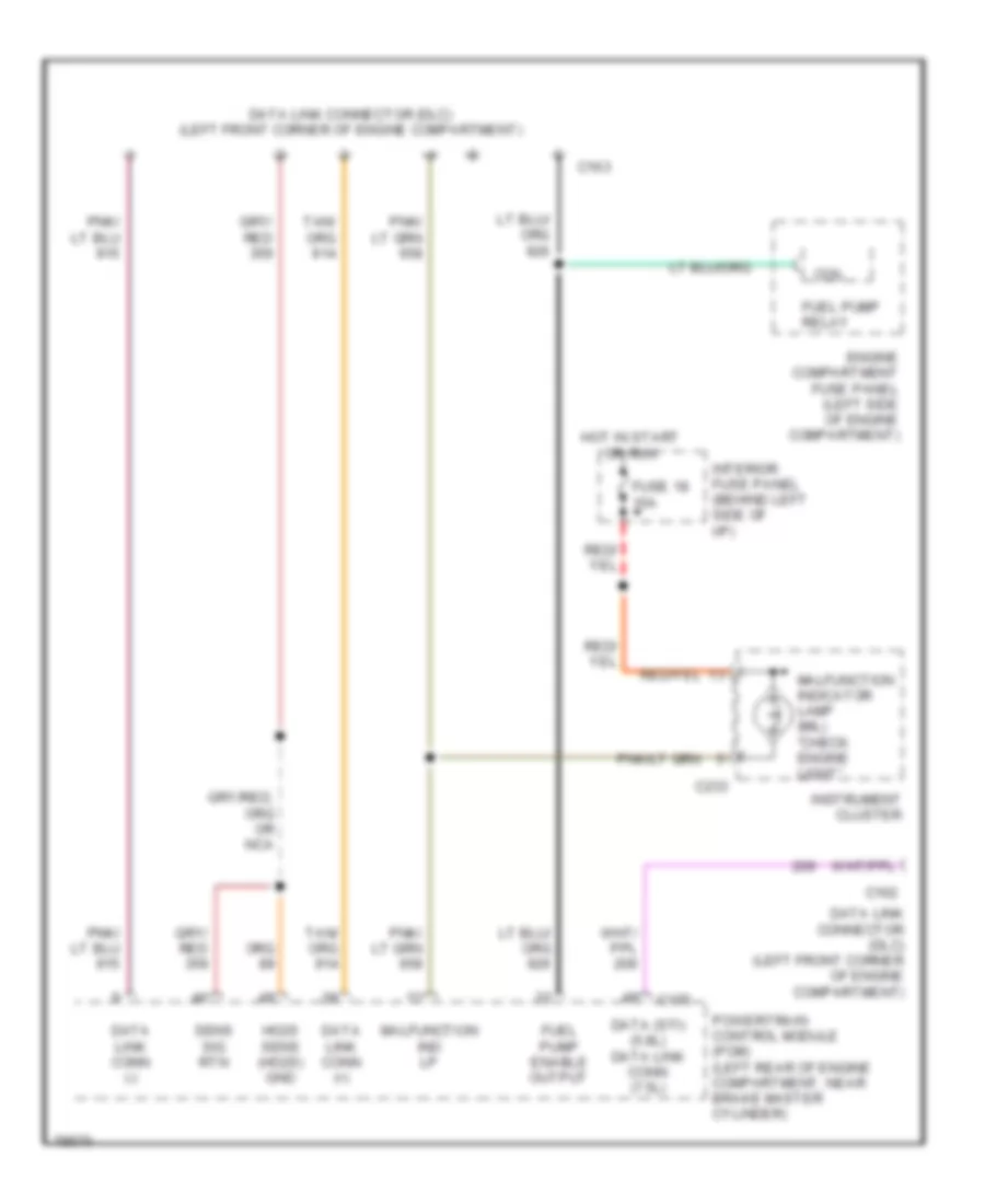
5.8L, Computer Data Lines, Federal over 8600 GVW for Ford RV Cutaway E350 1996
List of elements for 5.8L, Computer Data Lines, Federal over 8600 GVW for Ford RV Cutaway E350 1996:
- C162
- C163
- C175
- C233
- Coil
- Data (sti) (5.8l) data link conn (7.5l)
- Data link conn (+)
- Data link conn (-)
- Data link connector (dlc) (left front corner of engine compartment)
- Engine compartment fuse panel (left side of engine compartment)
- Fuel pump enable output
- Fuel pump relay
- Fuse 18 15a
- Ho2s sens (ho2s) gnd
- Hot in start or run
- Instrument cluster
- Interior fuse panel (behind left side of i/p)
- Malfunction ind lp
- Malfunction indicator lamp (mil) "check engine light"
- Powertrain control module (pcm) (left rear of engine compartment, near brake master cylinder)
- Sens sig rtn
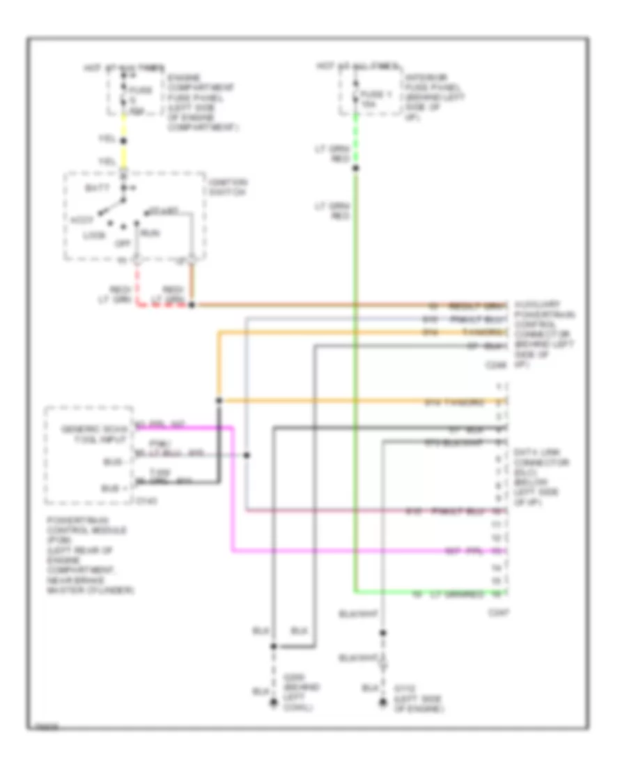
5.8L, Computer Data Lines, Federal under 8600 GVW & Calif. for Ford RV Cutaway E350 1996
List of elements for 5.8L, Computer Data Lines, Federal under 8600 GVW & Calif. for Ford RV Cutaway E350 1996:
- Bus +
- Bus -
- C143
- C247
- Data link connector (dlc) (below left side of i/p)
- Fuse 1 15a
- G106 (left side of engine, compartment near battery)
- G200 (behind left cowl)
- Generic scan tool input
- Hot at all times
- Interior fuse panel (behind left side of i/p)
- Powertrain control module (pcm) (left rear of engine compartment, near brake master cylinder)
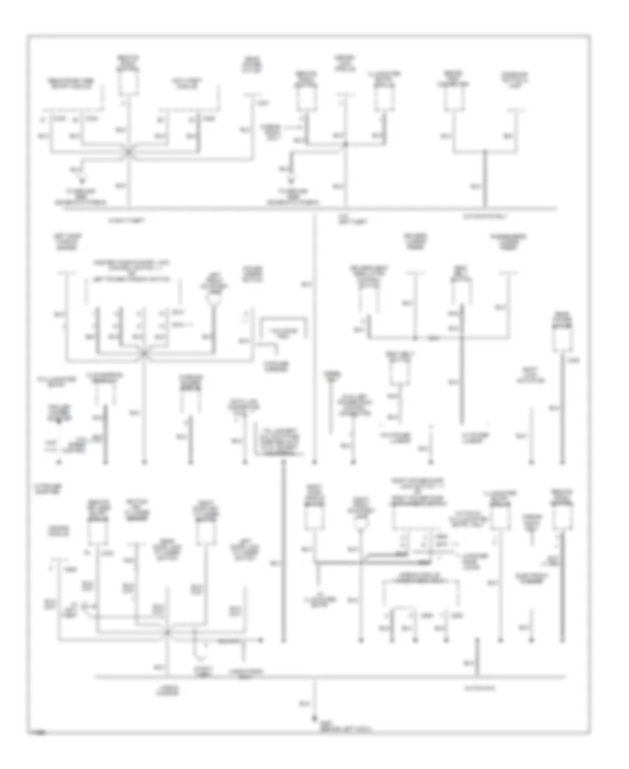
7.3L
7.3L DI Turbo Diesel, Computer Data Lines for Ford RV Cutaway E350 1996
List of elements for 7.3L DI Turbo Diesel, Computer Data Lines for Ford RV Cutaway E350 1996:
- Accy
- Auxiliary powertrain control connector (behind left side of i/p) c248
- Batt
- Bus +
- Bus -
- C143
- C247
- Data link connector (dlc) (below left side of i/p)
- Engine compartment fuse panel (left side of engine compartment)
- Fuse 1 15a
- Fuse g 60a
- G112 (left side of engine)
- G200 (behind left cowl)
- Generic scan tool input
- Hot at all times
- Ignition switch
- Interior fuse panel (behind left side of i/p)
- Lock
- Off
- Powertrain control module (pcm) (left rear of engine compartment, near brake master cylinder)
- Run
- Start
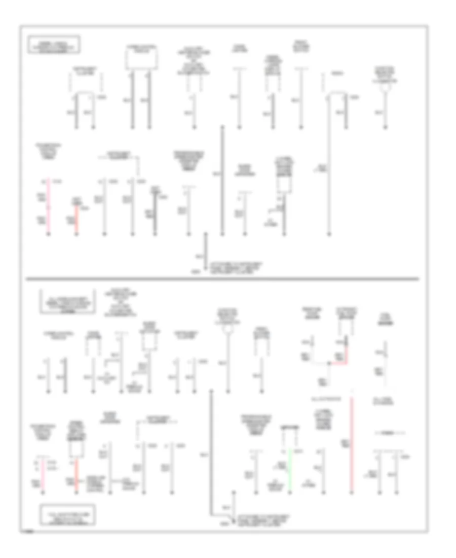
7.5L
7.5L, Computer Data Lines, California for Ford RV Cutaway E350 1996
List of elements for 7.5L, Computer Data Lines, California for Ford RV Cutaway E350 1996:
- Bus +
- Bus -
- C143
- C247
- Data link connector (dlc) (below left side of i/p)
- Fuse 1 15a
- G106 (left side of engine, compartment near battery)
- G200 (behind left cowl)
- Generic scan tool input
- Hot at all times
- Interior fuse panel (behind left side of i/p)
- Powertrain control module (pcm) (left rear of engine compartment, near brake master cylinder)
7.5L, Computer Data Lines, Federal for Ford RV Cutaway E350 1996
List of elements for 7.5L, Computer Data Lines, Federal for Ford RV Cutaway E350 1996:
- C162
- C163
- C175
- C233
- Coil
- Data (sti) (5.8l) data link conn (7.5l)
- Data link conn (+)
- Data link conn (-)
- Data link connector (dlc) (left front corner of engine compartment)
- Engine compartment fuse panel (left side of engine compartment)
- Fuel pump enable output
- Fuel pump relay
- Fuse 18 15a
- Ho2s sens (ho2s) gnd
- Hot in start or run
- Instrument cluster
- Interior fuse panel (behind left side of i/p)
- Malfunction ind lp
- Malfunction indicator lamp (mil) "check engine light"
- Powertrain control module (pcm) (left rear of engine compartment, near brake master cylinder)
- Sens sig rtn
CRUISE CONTROL
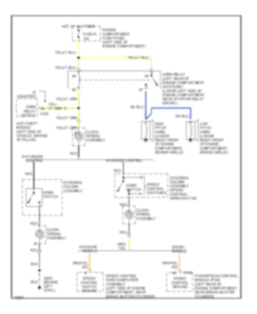
4.9L
4.9L, Cruise Control Wiring Diagram for Ford RV Cutaway E350 1996
List of elements for 4.9L, Cruise Control Wiring Diagram for Ford RV Cutaway E350 1996:
- (attached to instrument panel assembly, behind instrument cluster)
- (left side of engine compartment- 5.8l federal over 8600 gvw & 7.5l federal engines)
- (not used)
- 4 wheel anti-lock brakes (4wabs) module (on left front frame rail)
- 4-wheel abs system
- 4.9l, 5.0l, 5.8l federal under 8600 gvw & all calif. engines
- 5.8l federal over 8600 gvw & 7.5l federal engines
- Abs data link connector (dlc) (below left side of i/p- all models except 5.8l federal over 8600 gvw & 7.5l federal engines)
- Accel
- Boo switch input
- Brake on/off (boo) switch (on brake pedal bracket)
- Brake pressure input
- Brake pressure switch (left side of engine compartment, bottom of brake master cylinder)
- C143
- C175
- Clock spring assembly (top of steering column)
- Coast
- Fuse 1 15a
- Fuse 6 20a
- G202
- Ground
- Horn
- Horns system
- Hot at all times
- Hot in accy or run
- Interior fuse panel (behind left side of i/p)
- Nca
- Off
- Ohms
- Powertrain control module (pcm) (left rear of engine compartment, near brake master cylinder)
- Programmable speedometer/ odometer module (psom) (behind left side of i/p)
- Rear anti-lock brake system (rabs) module (behind right side of i/p)
- Rear axle speed input
- Rear axle speed sensor (below rear of vehicle, mounted on differential)
- Rear sensor high
- Rear sensor low
- Rear-wheel abs system
- Red/ pnk
- Red/pnk
- Resume
- Set/
- Speed control servo amplifier assembly (left rear of engine compartment, near brake master cylinder)
- Speed control/ horn switch (steering column assembly)
- Speed ctrl sw gnd
- Speed ctrl sw input
- Vehicle power
- Vehicle speed input
- Vehicle speed output
- Vehicle speed sensor or psom input (vss +)
- Wheel speed sensor high
- Wheel speed sensor low
5.8L
5.8L, Cruise Control Wiring Diagram for Ford RV Cutaway E350 1996
List of elements for 5.8L, Cruise Control Wiring Diagram for Ford RV Cutaway E350 1996:
- (attached to instrument panel assembly, behind instrument cluster)
- (left side of engine compartment- 5.8l federal over 8600 gvw & 7.5l federal engines)
- (not used)
- 4 wheel anti-lock brakes (4wabs) module (on left front frame rail)
- 4-wheel abs system
- 4.9l, 5.0l, 5.8l federal under 8600 gvw & all calif. engines
- 5.8l federal over 8600 gvw & 7.5l federal engines
- Abs data link connector (dlc) (below left side of i/p- all models except 5.8l federal over 8600 gvw & 7.5l federal engines)
- Accel
- Boo switch input
- Brake on/off (boo) switch (on brake pedal bracket)
- Brake pressure input
- Brake pressure switch (left side of engine compartment, bottom of brake master cylinder)
- C143
- C175
- Clock spring assembly (top of steering column)
- Coast
- Fuse 1 15a
- Fuse 6 20a
- G202
- Ground
- Horn
- Horns system
- Hot at all times
- Hot in accy or run
- Interior fuse panel (behind left side of i/p)
- Nca
- Off
- Ohms
- Powertrain control module (pcm) (left rear of engine compartment, near brake master cylinder)
- Programmable speedometer/ odometer module (psom) (behind left side of i/p)
- Rear anti-lock brake system (rabs) module (behind right side of i/p)
- Rear axle speed input
- Rear axle speed sensor (below rear of vehicle, mounted on differential)
- Rear sensor high
- Rear sensor low
- Rear-wheel abs system
- Red/ pnk
- Red/pnk
- Resume
- Set/
- Speed control servo amplifier assembly (left rear of engine compartment, near brake master cylinder)
- Speed control/ horn switch (steering column assembly)
- Speed ctrl sw gnd
- Speed ctrl sw input
- Vehicle power
- Vehicle speed input
- Vehicle speed output
- Vehicle speed sensor or psom input (vss +)
- Wheel speed sensor high
- Wheel speed sensor low
7.3L
7.3L DI Turbo Diesel, Cruise Control Wiring Diagram for Ford RV Cutaway E350 1996
List of elements for 7.3L DI Turbo Diesel, Cruise Control Wiring Diagram for Ford RV Cutaway E350 1996:
- (attached to instrument panel assembly, behind instrument cluster)
- (not used)
- 4 wheel anti-lock brakes (4wabs) module (on left front frame rail)
- 4-wheel abs system
- Abs data link connector (dlc) (below left side of i/p)
- Accel
- Boo switch input
- Brake on/off (boo) switch (on brake pedal bracket)
- Brake pressure switch (left side of engine compartment, bottom of brake master cylinder)
- C143
- Clock spring assembly (top of steering column)
- Coast
- Fuse 1 15a
- G202
- Ground
- Horn
- Horns system
- Hot at all times
- Interior fuse panel (behind left side of i/p)
- Nca
- Off
- Ohms
- Powertrain control module (pcm) (left rear of engine compartment, near brake master cylinder)
- Programmable speedometer/ odometer module (psom) (behind left side of i/p)
- Rear anti-lock brake system (rabs) module (behind right side of i/p)
- Rear axle speed input
- Rear axle speed sensor (below rear of vehicle, mounted on differential)
- Rear sensor high
- Rear sensor low
- Rear-wheel abs system
- Red/ pnk
- Red/pnk
- Resume
- Set/
- Speed control/ horn switch (steering column assembly)
- Speed ctrl gnd
- Speed ctrl gnd signal
- Vehicle speed output
- Vehicle speed sensor
- Wheel speed sensor high
- Wheel speed sensor low
7.5L
7.5L, Cruise Control Wiring Diagram for Ford RV Cutaway E350 1996
List of elements for 7.5L, Cruise Control Wiring Diagram for Ford RV Cutaway E350 1996:
- (attached to instrument panel assembly, behind instrument cluster)
- (left side of engine compartment- 5.8l federal over 8600 gvw & 7.5l federal engines)
- (not used)
- 4 wheel anti-lock brakes (4wabs) module (on left front frame rail)
- 4-wheel abs system
- 4.9l, 5.0l, 5.8l federal under 8600 gvw & all calif. engines
- 5.8l federal over 8600 gvw & 7.5l federal engines
- Abs data link connector (dlc) (below left side of i/p- all models except 5.8l federal over 8600 gvw & 7.5l federal engines)
- Accel
- Boo switch input
- Brake on/off (boo) switch (on brake pedal bracket)
- Brake pressure input
- Brake pressure switch (left side of engine compartment, bottom of brake master cylinder)
- C143
- C175
- Clock spring assembly (top of steering column)
- Coast
- Fuse 1 15a
- Fuse 6 20a
- G202
- Ground
- Horn
- Horns system
- Hot at all times
- Hot in accy or run
- Interior fuse panel (behind left side of i/p)
- Nca
- Off
- Ohms
- Powertrain control module (pcm) (left rear of engine compartment, near brake master cylinder)
- Programmable speedometer/ odometer module (psom) (behind left side of i/p)
- Rear anti-lock brake system (rabs) module (behind right side of i/p)
- Rear axle speed input
- Rear axle speed sensor (below rear of vehicle, mounted on differential)
- Rear sensor high
- Rear sensor low
- Rear-wheel abs system
- Red/ pnk
- Red/pnk
- Resume
- Set/
- Speed control servo amplifier assembly (left rear of engine compartment, near brake master cylinder)
- Speed control/ horn switch (steering column assembly)
- Speed ctrl sw gnd
- Speed ctrl sw input
- Vehicle power
- Vehicle speed input
- Vehicle speed output
- Vehicle speed sensor or psom input (vss +)
- Wheel speed sensor high
- Wheel speed sensor low
ENGINE PERFORMANCE
4.9L
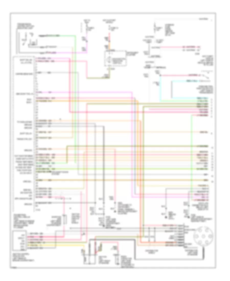
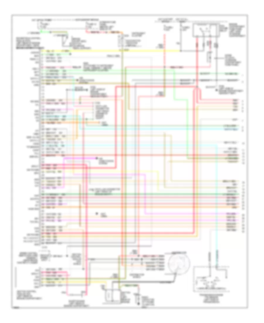
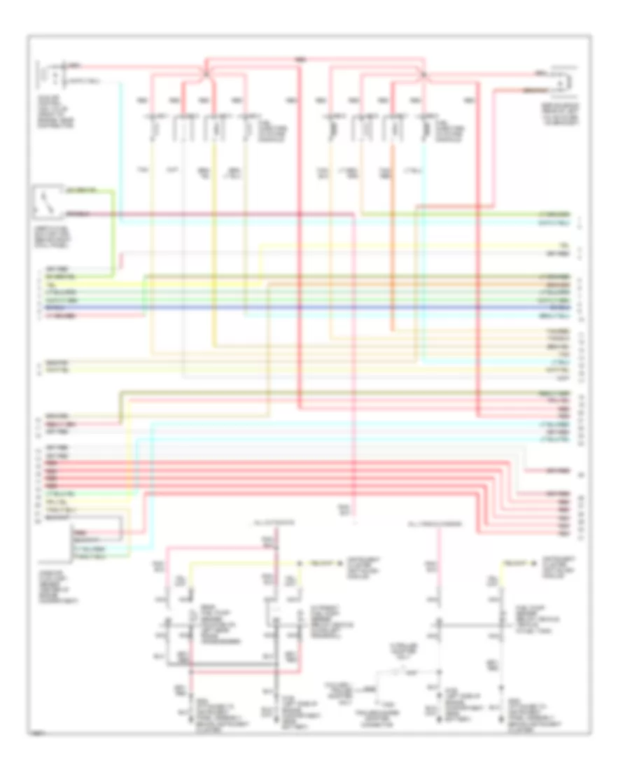
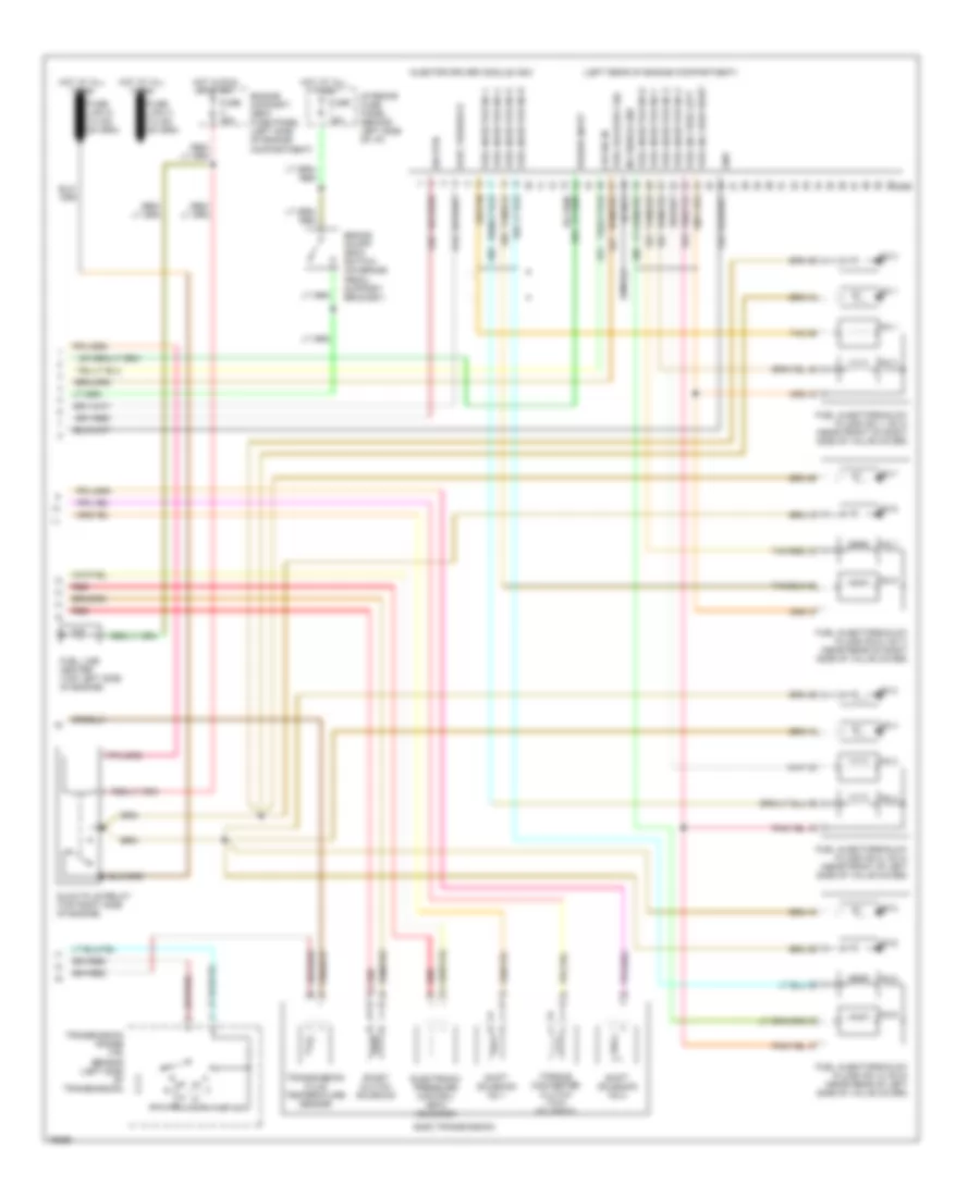
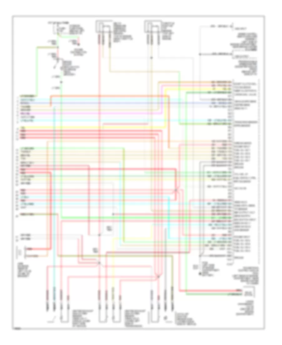
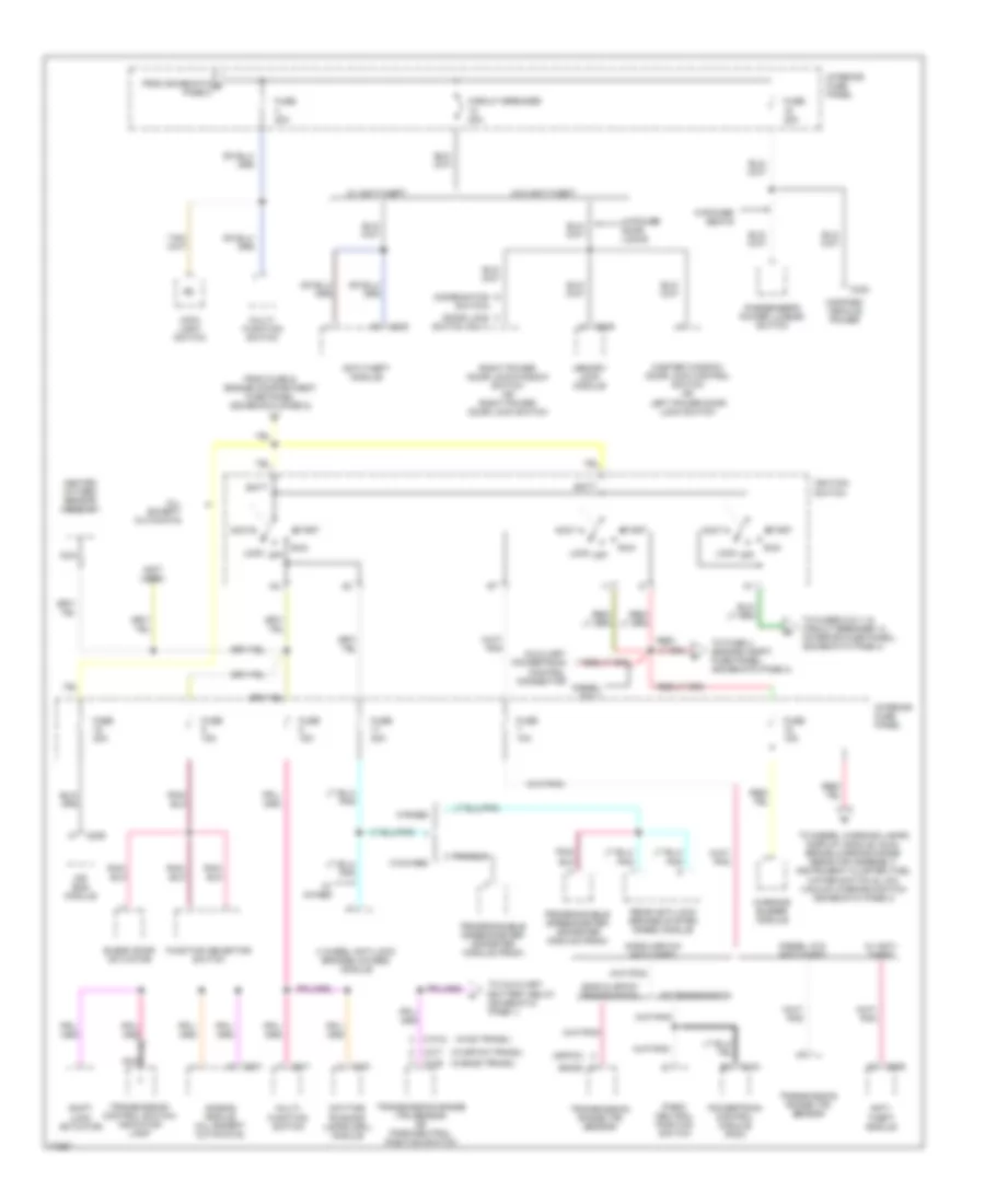
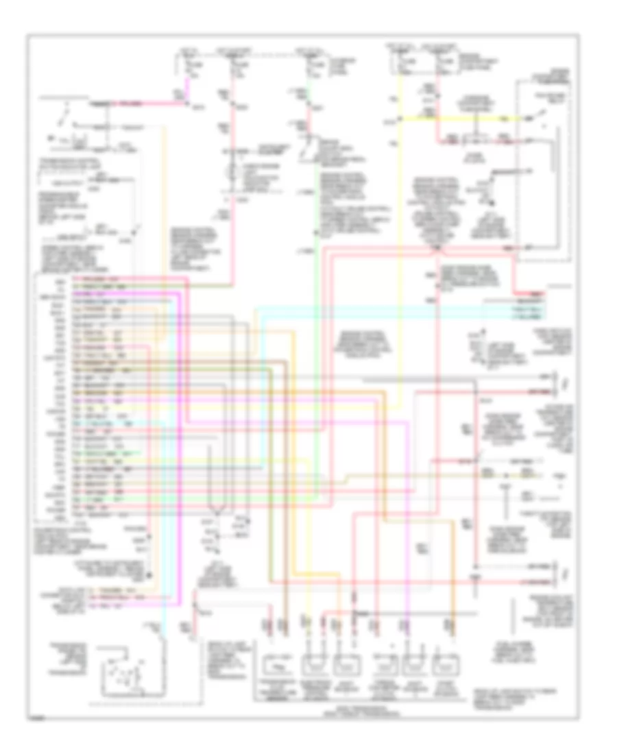
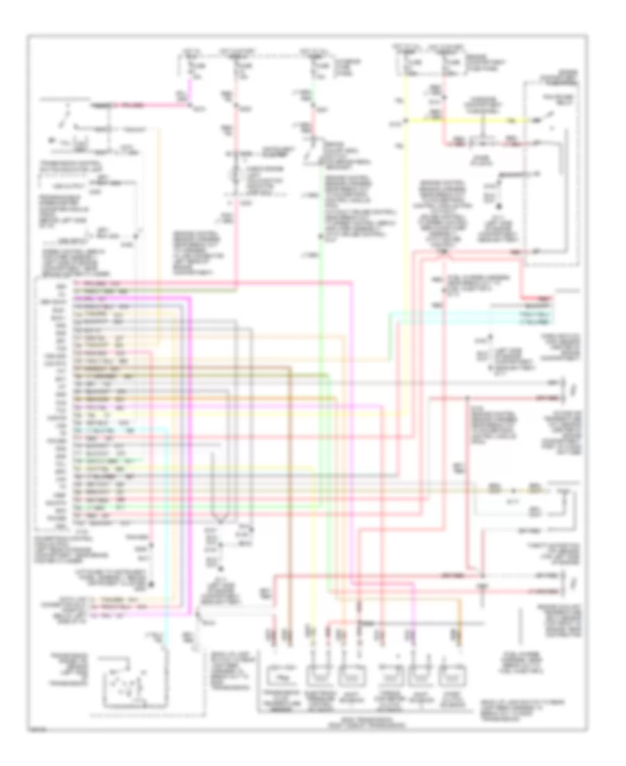
4.9L, Engine Performance Wiring Diagrams (1 of 4) for Ford RV Cutaway E350 1996
List of elements for 4.9L, Engine Performance Wiring Diagrams (1 of 4) for Ford RV Cutaway E350 1996:
- bus -
- ground
- intake air temp. fuel pump mon. a/c on input
- shift sol #1
- tfi module gnd
- trans ctrl sw
- (not used)
- Air conditioning system
- Aird sol.
- Anti-theft module (left side of vehicle, behind "b" pillar)
- Bus +
- C143
- C233
- C336
- C6 trans.
- Cat monitor sens
- Coil
- Coil wire
- Data link connector (dlc) (below left side of i/p)
- Distributor (left side of engine)
- Distributor shield
- E40d trans.
- Egr sol.
- Eng temp sens.
- Fuse 18 15a
- Fuse 5 15a
- Fuse 7 10a
- G106 (left side of engine compartment, near battery)
- G200 (behind left cowl)
- G202 (attached to instrument panel assembly, behind instrument cluster)
- Gen scan tool in
- Gnd
- Ground
- Hot in run
- Hot in start or run
- Idm
- Idm monitor
- Ign gnd
- Ignition coil (left front of engine)
- Ignition control module (icm) (left rear of engine compartment)
- Ignition control module (icm) shield
- Instrument cluster
- Interior fuse panel (behind left side of i/p)
- Malfunction indicator lamp (mil)
- Mass air flw rtn
- Mil lp ctrl
- Misfire sens gnd
- Nca
- O/d off
- Park/neutral position switch (left side of transmission)
- Pip
- Pnk
- Powertrain control module (pcm) (left rear of engine compartment, near brake master cylinder)
- Pwr
- Radio capacitor (left side of engine, attached to ignition coil)
- Shield gnd
- Shift sol #2
- Shorting bar (left rear of engine compartment)
- Spk angle pulse
- Spout
- Tc3
- Tcil
- Trans temp sens.
- Transmission control switch/ indicator lamp
- W/ anti- theft
- W/o anti- theft
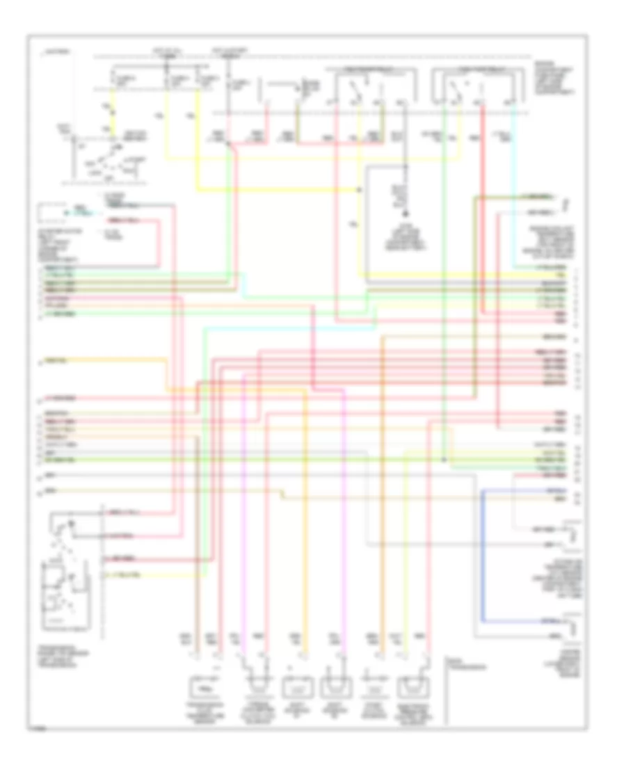
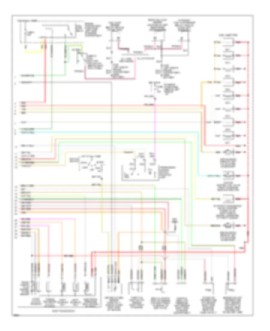
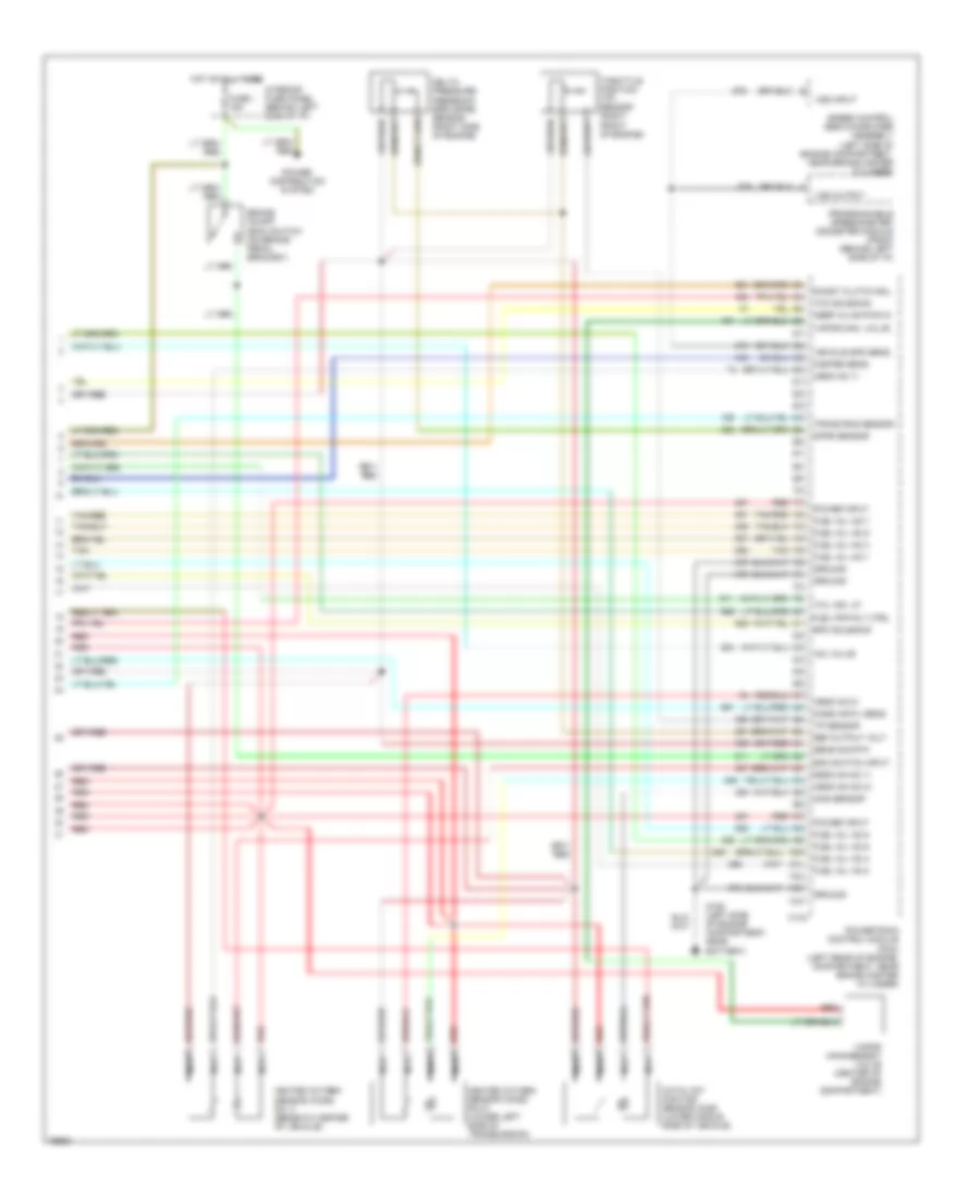
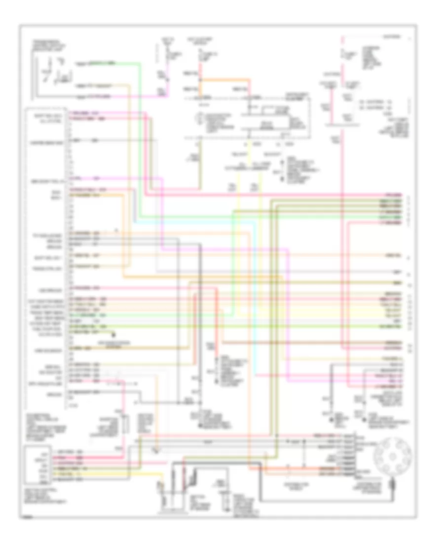
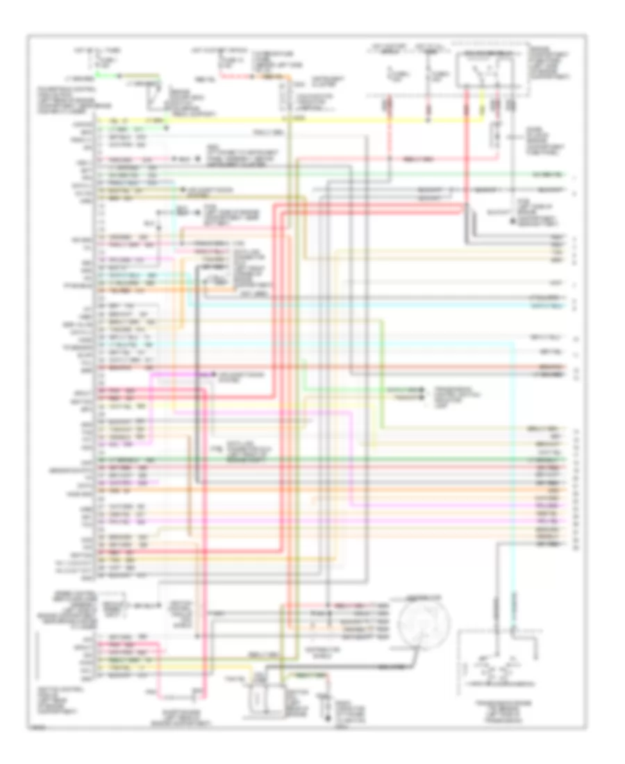
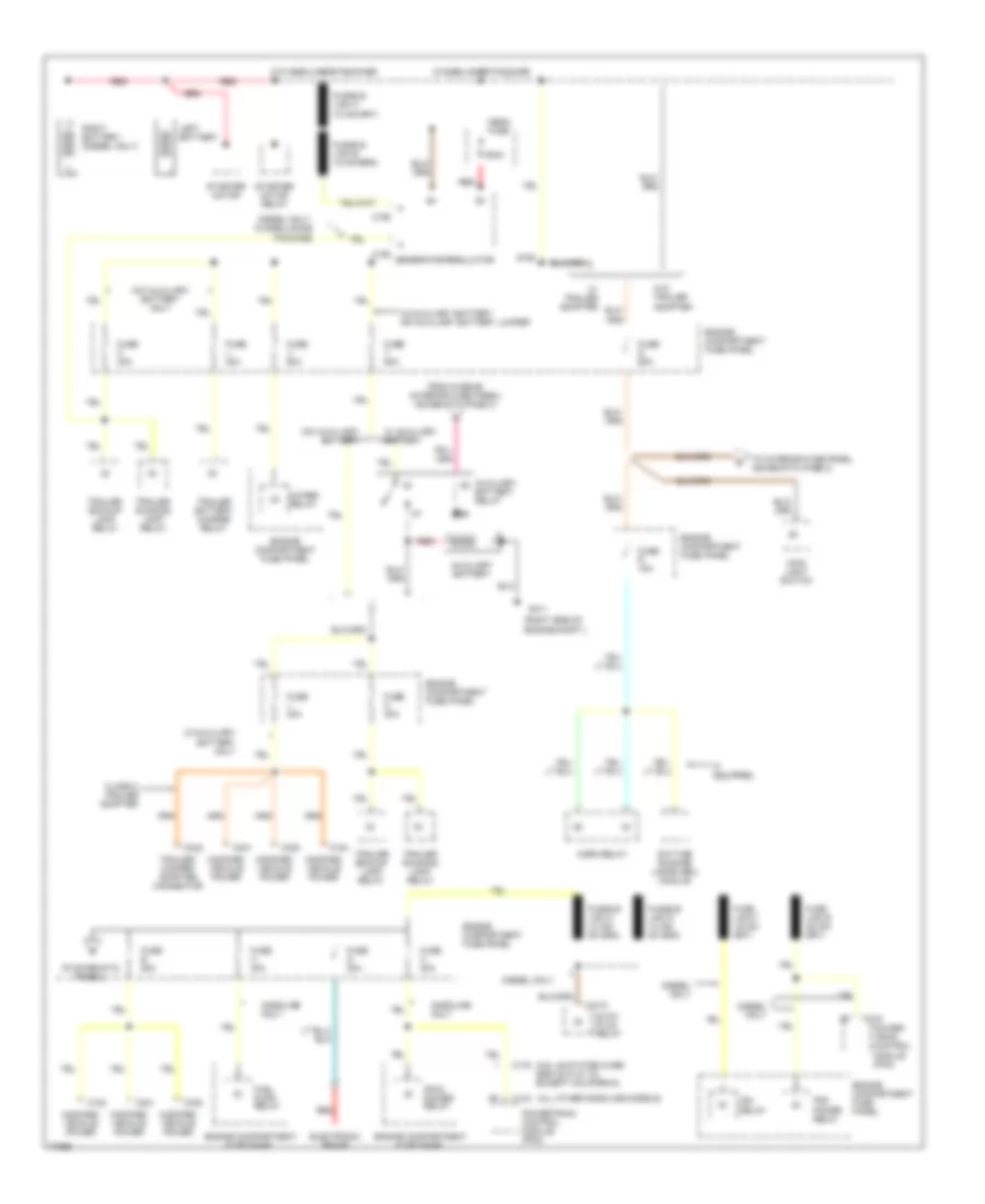
4.9L, Engine Performance Wiring Diagrams (2 of 4) for Ford RV Cutaway E350 1996
List of elements for 4.9L, Engine Performance Wiring Diagrams (2 of 4) for Ford RV Cutaway E350 1996:
- Acc
- Coast clutch solenoid
- Diode (plug- in)
- E4od transmission
- Electronic pressure control (epc) solenoid
- Engine compartment fuse panel (left side of engine compartment)
- Engine coolant temperature (ect) sensor (top front of engine, on heater outlet elbow)
- Fuel pump relay
- Fuse c 30a
- Fuse g 60a
- Fuse h 30a
- Fuse u 30a
- G106 (left side of engine compartment, near battery)
- Hot at all times
- Hot in start or run
- Ignition switch
- Intake air temperature (iat) sensor (center of engine compartment, part of clean air tube)
- Lock
- Misfire sensor (lower right front of engine)
- Off
- Pcm power relay
- Red
- Run
- Shift solenoid #1
- Shift solenoid #2
- Start
- Starter motor relay (left front corner of engine compartment)
- Torque converter clutch (tcc) solenoid
- Transmission fluid temperature sensor
- Transmission range (tr) sensor (left side of transmission)
- W/ c6 trans.
- W/ e40d trans.
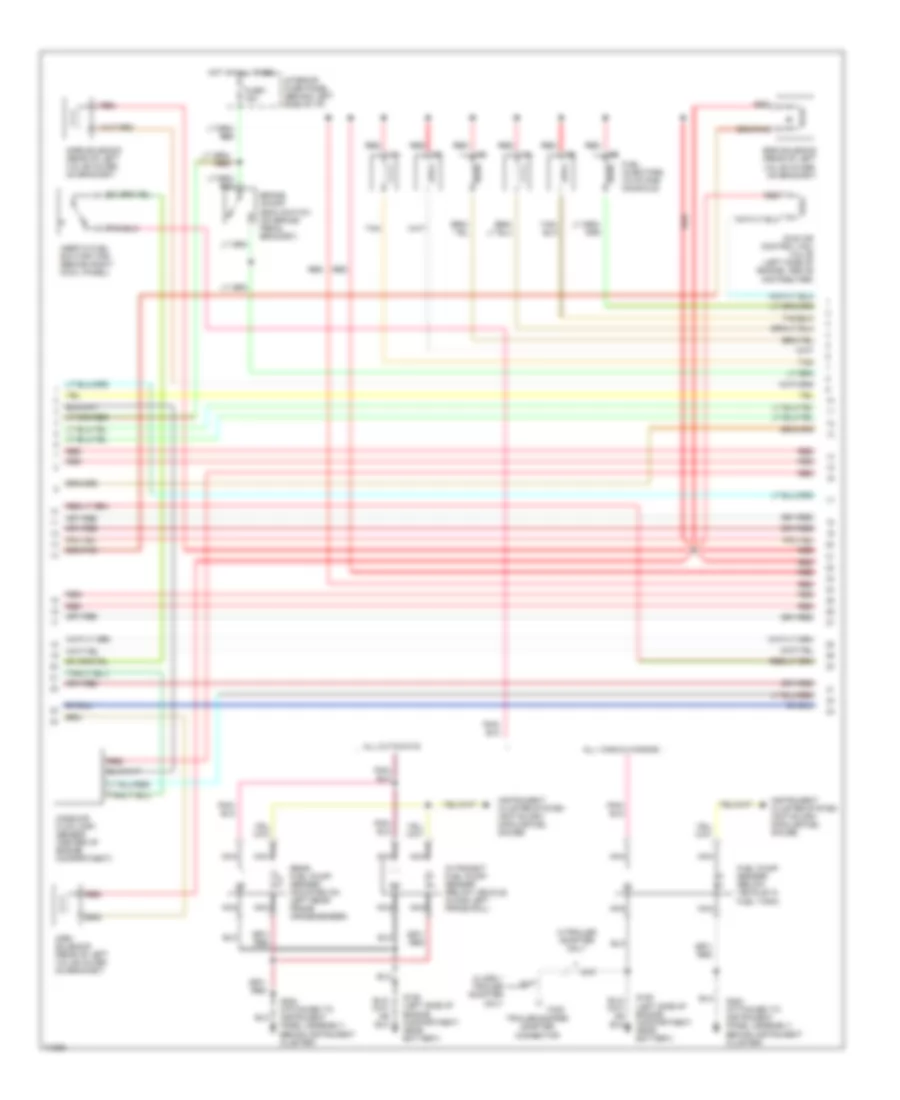
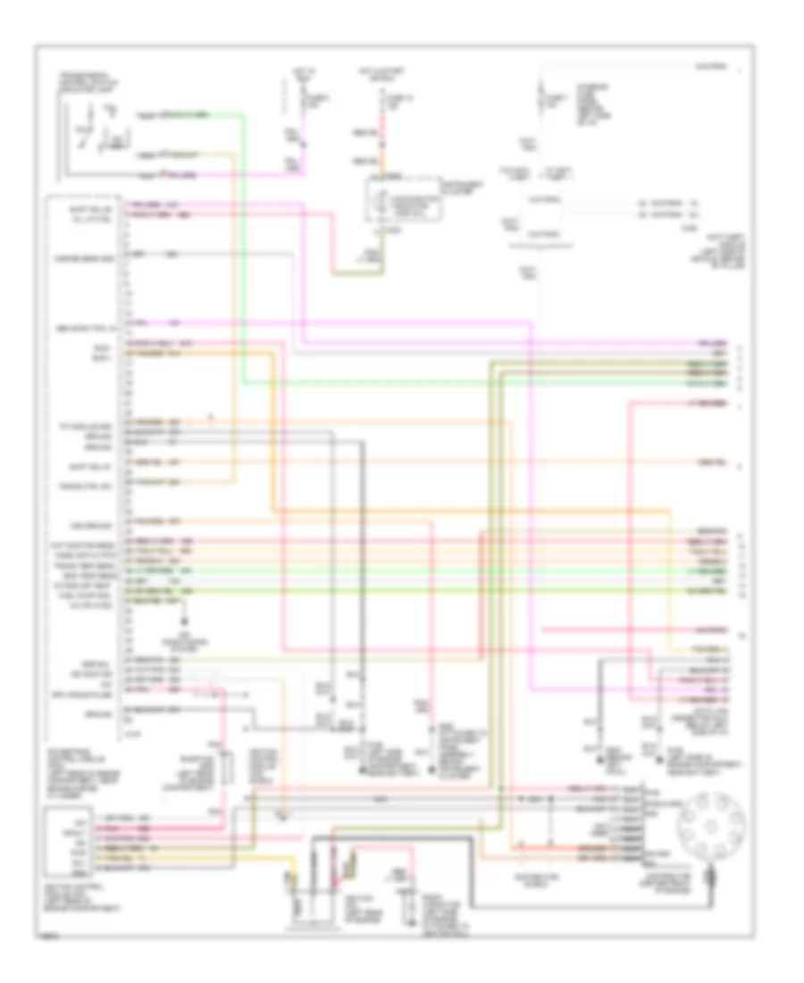
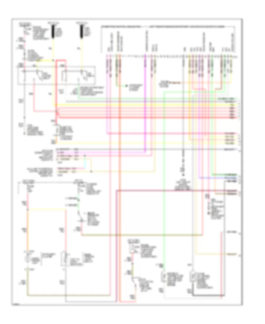
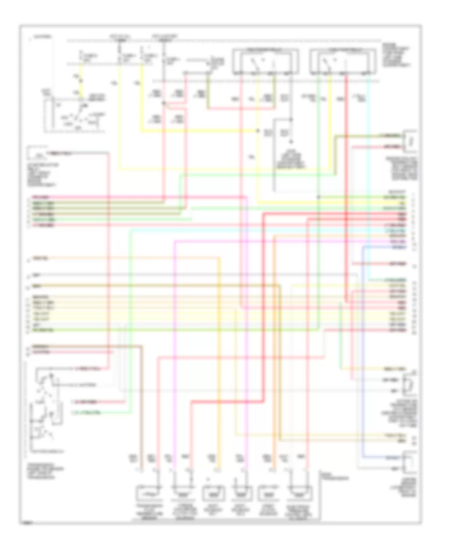
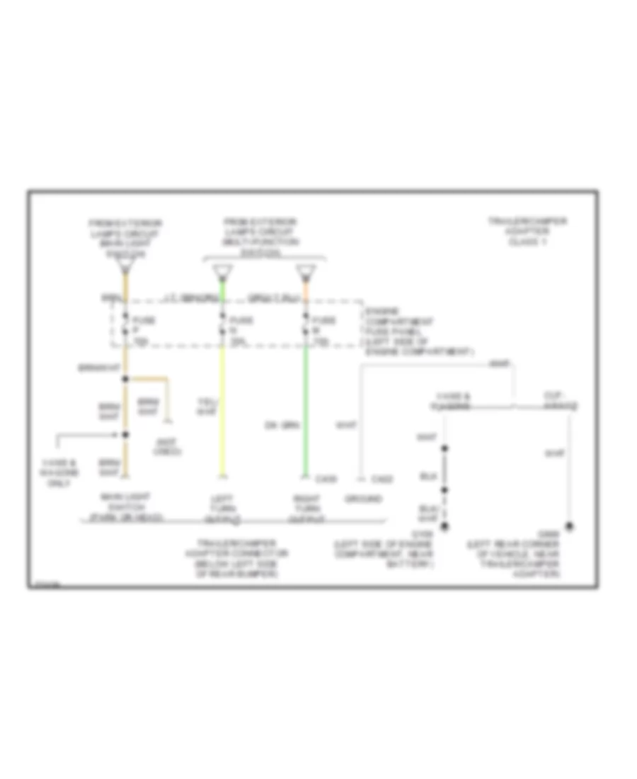
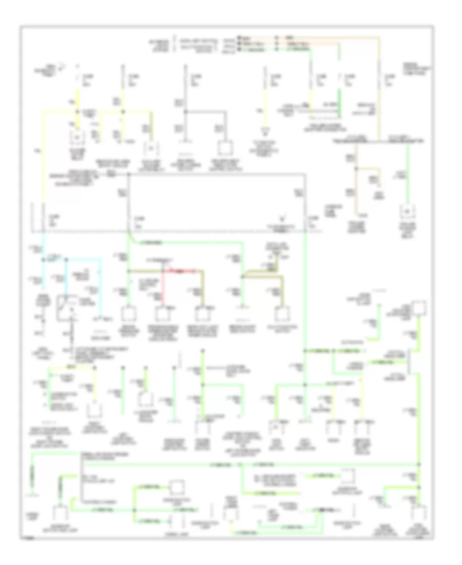
4.9L, Engine Performance Wiring Diagrams (3 of 4) for Ford RV Cutaway E350 1996
List of elements for 4.9L, Engine Performance Wiring Diagrams (3 of 4) for Ford RV Cutaway E350 1996:
- Airb solenoid (rear of left valve cover, on bracket)
- Aird solenoid (rear of left valve cover, on bracket)
- All cutaways
- All vans & wagons
- Brake on/off (boo) switch (on brake pedal bracket)
- C422
- Class 1 trailer adapter only
- Egr solenoid (rear of left valve cover, on bracket)
- Fuel injectors (in intake manifold)
- Fuel pump/ sender (below vehicle in fuel tank)
- Fuse i 15a
- G106 (left side of engine compartment, near battery)
- G202 (attached to instrument panel assembly, behind instrument cluster)
- Hot at all times
- Idle air control (iac) valve (left side of engine, above distributer)
- In-transit fuel pump/ sender (below vehicle, along left frame rail)
- Inertia fuel shutoff (ifs) (behind right cowl panel)
- Instrument cluster system (anti-slosh module/fuel gauge)
- Interior fuse panel (behind left side of i/p)
- Mass air flow (maf) sensor (center of engine compartment)
- Nca
- Rear fuel pump/ sender (mounted on left rear frame crossmember)
- Red
- Tan
- Trailer/camper adapter connector
- W/trailer adapter only
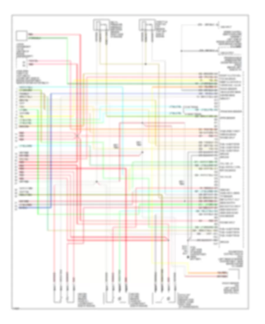
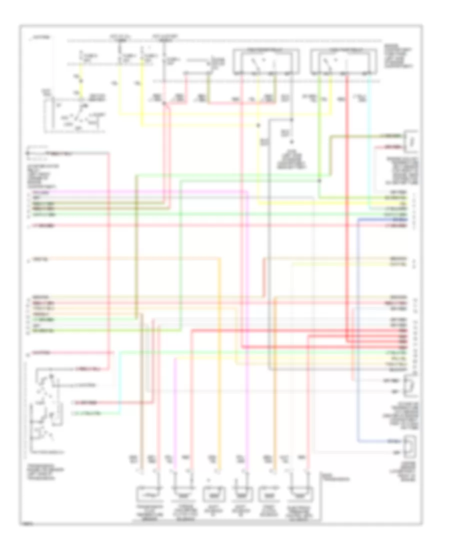
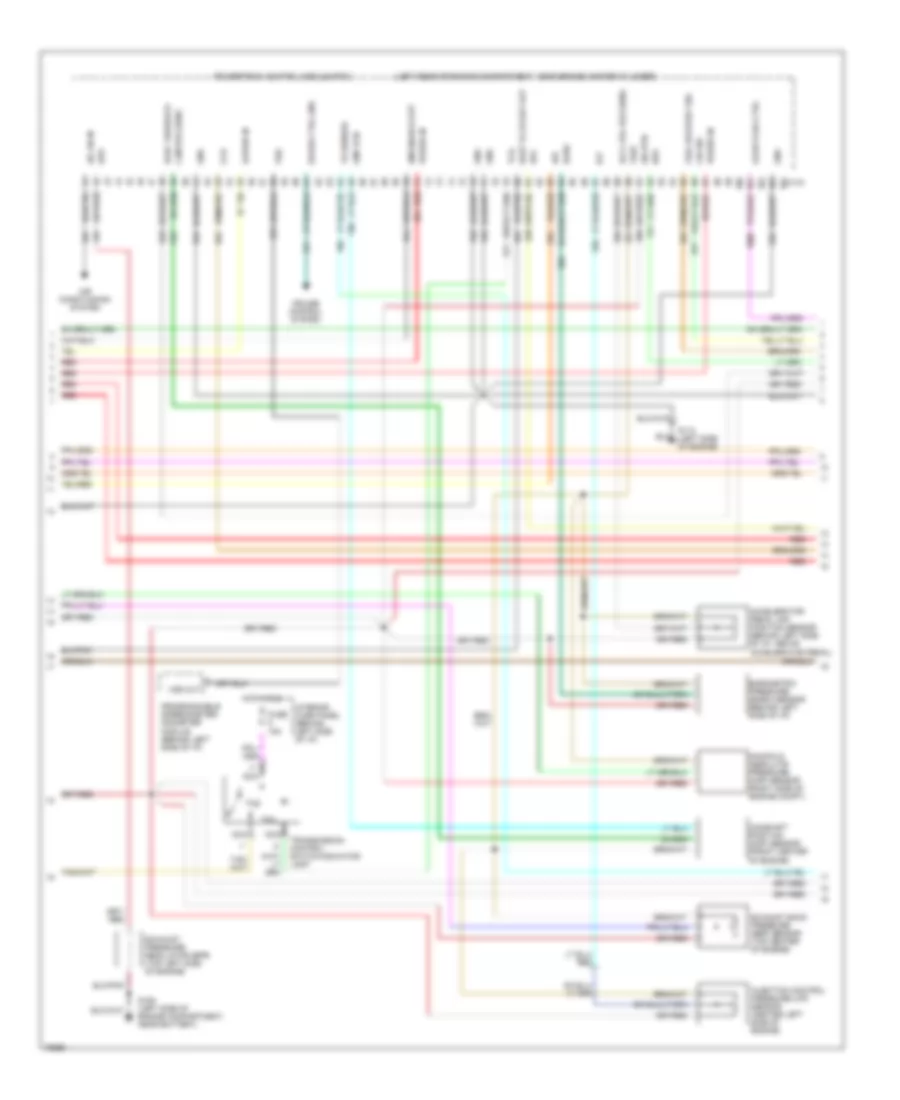
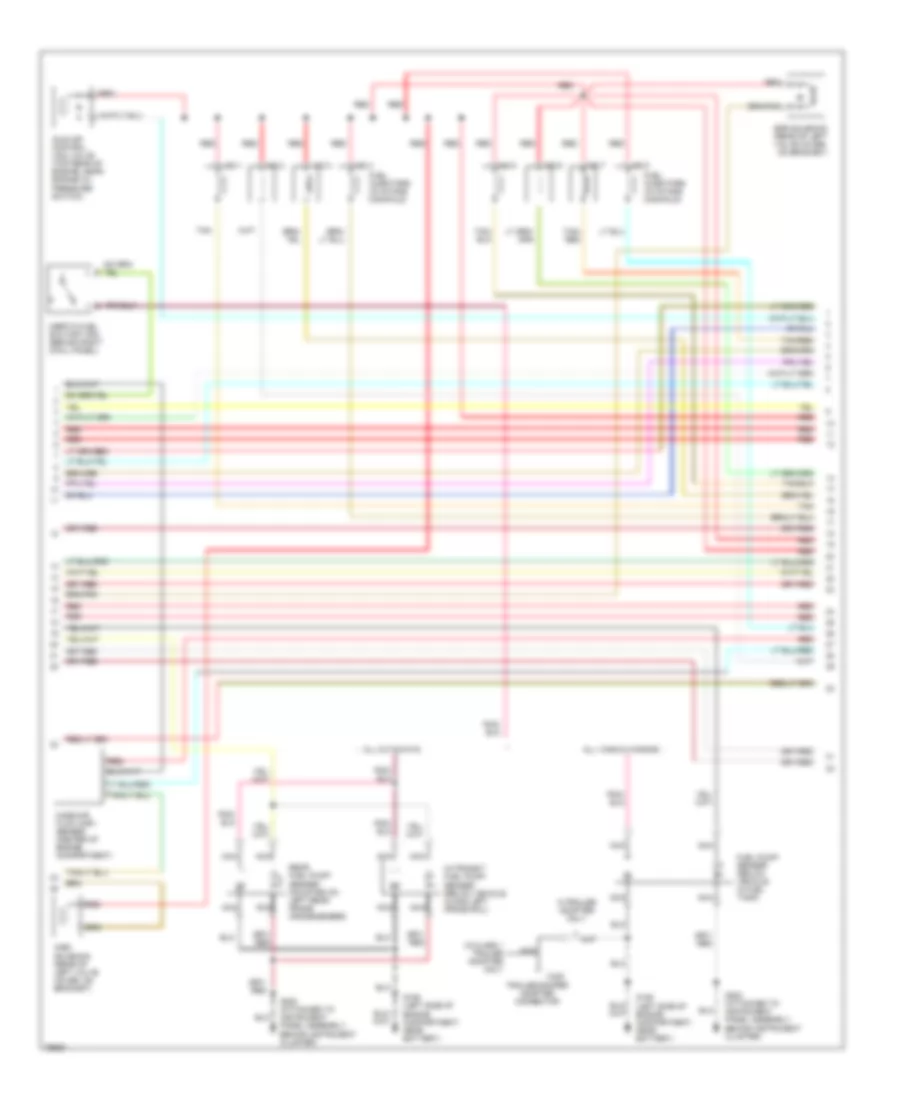
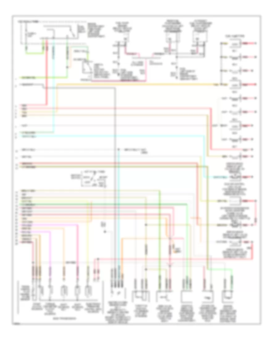
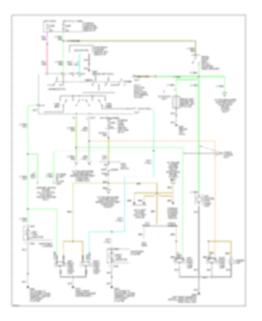
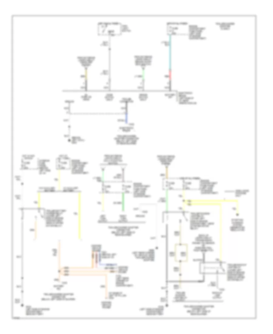
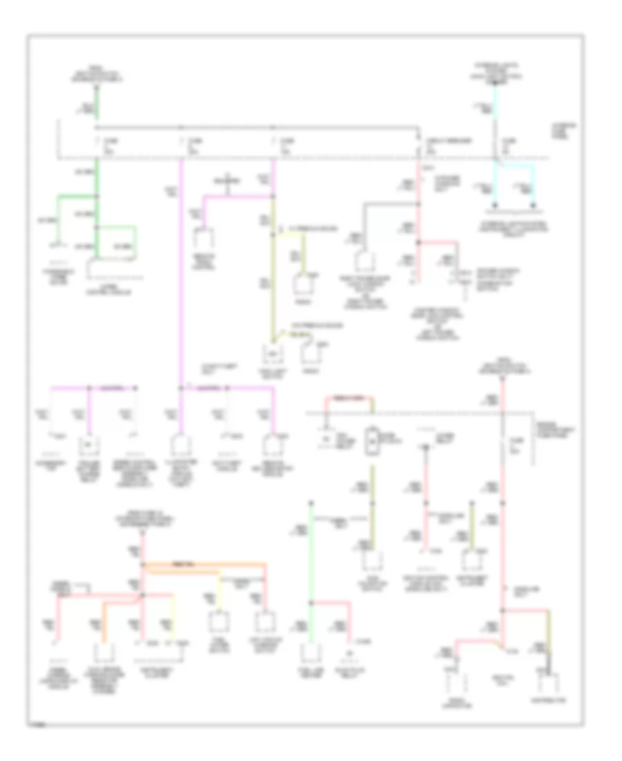
4.9L, Engine Performance Wiring Diagrams (4 of 4) for Ford RV Cutaway E350 1996
List of elements for 4.9L, Engine Performance Wiring Diagrams (4 of 4) for Ford RV Cutaway E350 1996:
- Airb solenoid
- Boo switch input
- Catalyst monitor sensor (cms) (near lower right side of transmission)
- Cms sensor
- Coast clutch sol.
- Delta pressure feedback egr (dpfe) sensor (right side of engine)
- Dpfe sensor
- Epc solenoid
- Fuel injector #1
- Fuel injector #2
- Fuel injector #3
- Fuel injector #4
- Fuel injector #5
- Fuel injector #6
- Fuel pmp rly ctrl
- G106 (left side of engine compartment, near battery)
- Ground
- Heated oxygen sensor (ho2s) #11 (lower right side of engine)
- Heated oxygen sensor (ho2s) #21 (lower right side of engine)
- Hego #11
- Hego #21
- Hego sns mn #11
- Hego sns mn #21
- Iac valve
- Keep alive pwr in
- Knock sensor
- Knock sensor (ks) (left side of engine, near ignition coil)
- Mass air fl sens.
- Misfire sens.
- Nca
- Power input
- Powertrain control module (pcm) (left rear of engine, compartment, near brake master cylinder)
- Programmable speedometer/ odometer module (psom) (behind left side of i/p)
- Red
- Ref output volt
- Sens sig rtn
- Speed control servo/amplifier assembly (left side of engine compartment, near brake master cylinder)
- Tan
- Tcc solenoid
- Tcil ind. lp.
- Throttle position (tp) sensor (top left side of engine)
- Tp sensor
- Trans rng sensor
- Vapor man. valve
- Vapor management valve (center of engine compartment)
- Vehicle spd sens.
- Vss input
- Vss output
- W/ e40d trans.
- W/c6 trans.
- Wide open throt.
- Wide open throttle (wot) relay (lower left side of engine compartment, near starter motor relay)
5.8L
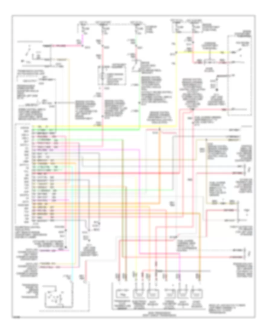
5.8L, Engine Performance Wiring Diagrams, Federal over 8600 GVW (1 of 2) for Ford RV Cutaway E350 1996
List of elements for 5.8L, Engine Performance Wiring Diagrams, Federal over 8600 GVW (1 of 2) for Ford RV Cutaway E350 1996:
- (not used)
- A/c on
- Air conditioning system
- Aird
- Boo
- Brake on/off (boo) switch (on brake pedal support)
- C162
- C163
- C175
- C233
- Canp
- Ccs
- Coil
- Coil wire
- Data (+)
- Data (-)
- Data link connector (left front corner of engine compt.)
- Data link connector (left front of engine compt.)
- Diode (plug-in) (in engine compartment fuse panel)
- Distributor
- Distributor shield
- Ect
- Egr sol
- Egr valve
- Engine compartment fuse panel (left side of engine compartment)
- Epc
- Fpm
- Fuse 1 15a
- Fuse 18 15a
- Fuse c 30a
- Fuse u 30a
- G106 (left side of engine compartment, near battery)
- G202 (attached to instrument panel assembly, behind instrument cluster)
- Gnd
- Ho2s
- Ho2s gnd
- Hot at all times
- Hot in start or run
- Iac
- Iat
- Idm
- Ign gnd
- Ign power
- Ignition coil (left rear of engine)
- Ignition control module (icm) (left rear of engine compartment)
- Ignition control module (icm) shield
- Inj 1,4,5,8 out
- Inj 2,3,6,7 out
- Instrument cluster
- Interior fuse panel (behind left side of i/p)
- Kapwr
- Malfunction indicator lamp (mil)
- Map
- Mil
- Nca
- Or
- Pcm power relay
- Pip
- Pnk
- Powertrain control module (pcm) (left rear of engine compartment, near brake master cylinder)
- Psom (+)
- Pwr
- Radio capacitor (attached to ignition coil)
- Red
- Shorting bar (left rear of engine compartment)
- Sig rtn
- Speed control servo/amplifier assembly (near brake master cylinder)
- Spout
- Ss1
- Ss2
- Sti
- Tan
- Tcc sol
- Tcil
- Tcs
- Tft
- Tr sensor
- Transmission range (tr) sensor (left side of transmission)
- Vehicle speed input
- Vref
- Vss (-)
5.8L, Engine Performance Wiring Diagrams, Federal over 8600 GVW (2 of 2) for Ford RV Cutaway E350 1996
List of elements for 5.8L, Engine Performance Wiring Diagrams, Federal over 8600 GVW (2 of 2) for Ford RV Cutaway E350 1996:
- (not used)
- Aird solenoid (rear of left valve cover, on bracket)
- All cutaways
- All vans and wagons
- Coast clutch solenoid
- Compartment, near battery)
- E40d transmission
- Egr solenoid (rear of left valve cover, on bracket)
- Egr valve (evp) position sensor (top right front of engine, on egr valve)
- Electronic pressure (epc) control solenoid
- Engine compartment fuse panel (left side of engine compartment)
- Engine coolant temperature (ect) sensor (top front of engine, near distributor, on heater tube)
- Evaporative emissions (evap) canister purge valve (right side of engine, connected to throttle body)
- Fuel injectors
- Fuel pump relay
- Fuel pump/ sender (below vehicle, in fuel tank)
- Fuse 15a
- Fuse h 30a
- G106 (left side of engine compartment, near battery)
- Heated oxygen sensor (ho2s) no.11 (middle lower right side of vehicle)
- Hot at all times
- Hot in run
- Idle air control (iac) valve (front of engine, near distributor)
- Ignition switch acc
- In-transit fuel pump/sender (below vehicle, along left frame rail)
- Inertia fuel shut off (ifs) switch (behind right cowl panel)
- Intake air temperature (iat) sensor (right side of engine, near fuel injector no.1)
- Interior fuse panel (behind left side of i/p)
- Lock
- Manifold absolute pressure (map) sensor (right side of engine compartment)
- Nca
- No.1
- No.2
- No.3
- No.4
- No.5
- No.6
- No.7
- No.8
- Od off
- Off
- Rear fuel pump sender (mounted on left rear frame crossmember)
- Red
- Run
- Shift solenoid no.1
- Shift solenoid no.2
- Start
- Tan
- Tc3
- Tcil
- Throttle position (tp) sensor (right front of engine)
- Torque converter clutch solenoid
- Trans- mission fluid temper- ature sensor
- Transmission control switch/ indicator lamp
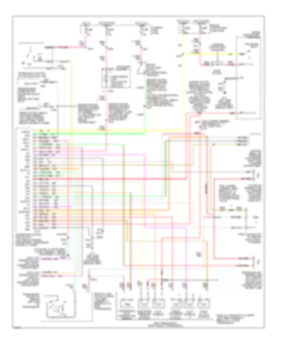
5.8L, Engine Performance Wiring Diagrams, Federal under 8600 GVW & Calif. (1 of 4) for Ford RV Cutaway E350 1996
List of elements for 5.8L, Engine Performance Wiring Diagrams, Federal under 8600 GVW & Calif. (1 of 4) for Ford RV Cutaway E350 1996:
- (not used)
- A/c on in sig
- Air conditioning system
- Anti-theft module (left side of vehicle, behind "b" pillar)
- Bus +
- Bus -
- C143
- C233
- C336
- Cat monitor sens
- Coil
- Coil wire
- Data link connector (dlc) (below left side of i/p)
- Distributor (center front of engine)
- Distributor shield
- Egr sol.
- Eng temp sens.
- Fuel pump mon.
- Fuse 18 15a
- Fuse 5 15a
- Fuse 7 10a
- G106 (left side of engine compartment, near battery)
- G200 (behind left cowl)
- G202 (attached to instrument panel assembly, behind instrument cluster)
- Gen scan tool in
- Gnd
- Ground
- Hot in run
- Hot in start or run
- Idm
- Idm monitor
- Ign gnd
- Ignition coil (left rear of engine)
- Ignition control module (icm) (left rear of engine compartment)
- Ignition control module (icm) shield
- Instrument cluster
- Intake air temp.
- Interior fuse panel (behind left side of i/p)
- Malfunction indicator lamp (mil)
- Mass air flw rtn
- Mil lp ctrl
- Misfire sens gnd
- Nca
- O/d off
- Pip
- Pnk
- Powertrain control module (pcm) (left rear of engine compartment, near brake master cylinder)
- Pwr
- Radio capacitor (left side of engine, attached to ignition coil)
- Shield gnd
- Shift sol #1
- Shift sol #2
- Shorting bar (left rear of engine compartment)
- Spk angle pulse
- Spout
- Tc3
- Tcil
- Tfi module gnd
- Trans ctrl sw
- Trans temp sens.
- Transmission control switch/ indicator lamp
- Vss ground
- W/ anti- theft
- W/o anti- theft
- Wire coil
5.8L, Engine Performance Wiring Diagrams, Federal under 8600 GVW & Calif. (2 of 4) for Ford RV Cutaway E350 1996
List of elements for 5.8L, Engine Performance Wiring Diagrams, Federal under 8600 GVW & Calif. (2 of 4) for Ford RV Cutaway E350 1996:
- Acc
- Coast clutch solenoid
- Diode (plug- in)
- E4od transmission
- Electronic pressure control (epc) solenoid
- Engine compartment fuse panel (left side of engine compartment)
- Engine coolant temperature (ect) sensor (top front of engine, near distributor, on heater tube)
- Fuel pump relay
- Fuse c 30a
- Fuse g 60a
- Fuse h 30a
- Fuse u 30a
- G106 (left side of engine compartment, near battery)
- Hot at all times
- Hot in start or run
- Ignition switch
- Intake air temperature (iat) sensor (center of engine compartment, part of clean air tube)
- Lock
- Misfire sensor (lower right front of engine)
- Off
- Pcm power relay
- Red
- Run
- Shift solenoid #1
- Shift solenoid #2
- Start
- Starter motor relay (left front corner of engine compartment)
- Torque converter clutch (tcc) solenoid
- Transmission fluid temperature sensor
- Transmission range (tr) sensor (left side of transmission)
5.8L, Engine Performance Wiring Diagrams, Federal under 8600 GVW & Calif. (3 of 4) for Ford RV Cutaway E350 1996
List of elements for 5.8L, Engine Performance Wiring Diagrams, Federal under 8600 GVW & Calif. (3 of 4) for Ford RV Cutaway E350 1996:
- All cutaways
- All vans & wagons
- C422
- Egr solenoid (rear of left valve cover, on bracket)
- Fuel injectors (in intake manifold)
- Fuel pump/ sender (below vehicle, vehicle, in fuel tank)
- G106 (left side of engine compartment, near battery)
- G202 (attached to instrument panel assembly, behind instrument cluster)
- Idle air control (iac) valve (front of engine, near distributor)
- In-transit fuel pump/ sender (below vehicle, along left frame rail)
- Inertia fuel shutoff (ifs) (behind right cowl panel)
- Instrument cluster (anti-slosh module)
- Mass air flow (maf) sensor (center of engine compartment)
- Nca
- No.1
- No.2
- No.3
- No.4
- No.5
- No.6
- No.7
- No.8
- Rear fuel pump/ sender (mounted on left rear frame crossmember)
- Red
- Tan
- Tan/ red
- Tan/red
- Trailer/camper adapter connector
- W/class 1 trailer adapter only
- W/trailer adapter only
5.8L, Engine Performance Wiring Diagrams, Federal under 8600 GVW & Calif. (4 of 4) for Ford RV Cutaway E350 1996
List of elements for 5.8L, Engine Performance Wiring Diagrams, Federal under 8600 GVW & Calif. (4 of 4) for Ford RV Cutaway E350 1996:
- Boo switch input
- Brake on/off (boo) switch (on brake pedal bracket)
- C143
- Catalyst monitor sensor (cms) (lower middle side of vehicle)
- Cms sensor
- Coast clutch sol.
- Delta pressure feedback egr (dpfe) sensor (right side of engine)
- Dpfe sensor
- Epc solenoid
- Fuel inj. no.1
- Fuel inj. no.2
- Fuel inj. no.3
- Fuel inj. no.4
- Fuel inj. no.5
- Fuel inj. no.6
- Fuel inj. no.7
- Fuel inj. no.8
- Fuel pmp rly ctrl
- Fuse i 15a
- G106 (left side of engine compartment, near battery)
- Ground
- Heated oxygen sensor (ho2s) no.11 (beneath center of vehicle)
- Heated oxygen sensor (ho2s) no.21 (lower left side of transmission)
- Hego mn no.11
- Hego mn no.21
- Hego no.11
- Hego no.21
- Hot at all times
- Iac valve
- Interior fuse panel (behind left side of i/p)
- Keep alive pwr in
- Mass air fl sens.
- Misfire sens.
- Nca
- Power distribution system
- Power input
- Powertrain control module (pcm) (left rear of engine, compartment, near brake master cylinder)
- Programmable speedometer/ odometer module (psom) (behind left side of i/p)
- Red
- Ref output volt
- Sens sig rtn
- Speed control servo/amplifier assembly (left side of engine compartment, near brake master cylinder)
- Tan
- Tan/red
- Tcc solenoid
- Tcil ind. lp.
- Throttle position (tp) sensor (right front of engine)
- Tp sensor
- Trans rng sensor
- Vapor man. valve
- Vapor management valve (center of engine compartment)
- Vehicle spd sens.
- Vss input
- Vss output
7.3L
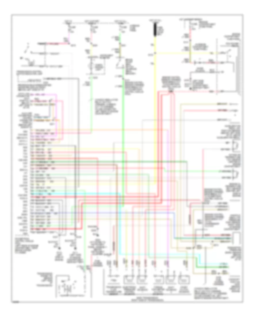
7.3L DI Turbo Diesel, Engine Performance Wiring Diagrams (1 of 3) for Ford RV Cutaway E350 1996
List of elements for 7.3L DI Turbo Diesel, Engine Performance Wiring Diagrams (1 of 3) for Ford RV Cutaway E350 1996:
- "wait to start" indicator
- (left rear of engine compartment, near brake master cylinder)
- Auxiliary powertrain control connector (behind left side of i/p)
- Brake press sw
- Brake pressure switch (bottom of master cylinder)
- Brake warning in
- Bus (+)
- Bus (-)
- C143
- C233
- C247
- C248
- Check eng light
- Check engine light
- Cruise control system
- Data link connector (dlc) (partial) (behind left side of i/p)
- Diesel warning lamps display
- Diode (plug-in) (in engine compartment fuse panel)
- Ebp
- Engine compartment fuse panel (left side of engine compartment)
- Engine oil temperature (eot) sensor (center left side of engine)
- Eot
- Fuse link e (20 ga.- gray)
- Fuse link f (16 ga.- gray)
- Fuse 15a
- Fuse u 30a
- G106 (left side of engine compartment, near battery)
- G106 (left side of engine compartment, near battery)
- G202 (attached to instrument panel assembly, behind instrument cluster)
- Generic scan tool
- Gnd
- Hot at all times
- Hot in run or start
- Iat
- Idle valid sw
- Idle validation switch (behind left side of i/p)
- Idm relay
- Injection pressure regulator (ipr) (top front of engine)
- Instrument cluster
- Instrument cluster system
- Intake air temper- ature (iat) sensor (center of engine compartment)
- Interior fuse panel (behind left side of i/p)
- Map
- Pcm power relay
- Powertrain control module (pcm)
- Red
- Red
- Speed ctrl gnd
- Ss1
- Ss2
- Tcc
- Tcs
- Tft
- Vss gnd
7.3L DI Turbo Diesel, Engine Performance Wiring Diagrams (2 of 3) for Ford RV Cutaway E350 1996
List of elements for 7.3L DI Turbo Diesel, Engine Performance Wiring Diagrams (2 of 3) for Ford RV Cutaway E350 1996:
- (left rear of engine compartment, near brake master cylinder)
- A/c on in
- Accelerator pedal (ap) position sensor (behind left side of i/p, above accelerator pedal)
- Accl pdl pos sens
- Air conditioning system
- Baro
- Barometric pressure (baro) sensor (behind left side of i/p)
- Boo
- C143
- Cam pos sens
- Camshaft position (cmp) sensor (front center of engine)
- Ccs
- Cid sig
- Cmp rtn
- Cruise control system
- Elec feedback
- Epc
- Epr
- Exhaust back pressure (ebp) sensor (top center of engine)
- Exhaust pressure regulator (epr) (top left side of engine)
- Fuel delivery sig
- Fuse 15a
- G106 (left side of engine compartment, near battery)
- G112 (left side of engine)
- Glow plug ctrl
- Gnd
- Hot in run
- Icp
- Idm enable out
- Injection control pressure (icp) sensor (center left side of engine)
- Interior fuse panel (behind left side of i/p)
- Ipr
- Kapwr in
- Manifold absolute pressure (map) sensor (right side of engine compt)
- Nca
- Power in
- Powertrain control module (pcm)
- Programmable speedometer/ odometer module (behind left side of i/p)
- Red
- Sig rtn
- Speed ctrl gnd
- Tcil
- Tcs
- Tr sensor
- Transmission control switch/indicator lamp
- Vref
- Vss
- Vss out
- Wait to start out
7.3L DI Turbo Diesel, Engine Performance Wiring Diagrams (3 of 3) for Ford RV Cutaway E350 1996
List of elements for 7.3L DI Turbo Diesel, Engine Performance Wiring Diagrams (3 of 3) for Ford RV Cutaway E350 1996:
- transmission range (tr) sensor (left side of transmission)
- (left rear of engine compartment)
- Brake on/off (boo) switch (on brake pedal support bracket)
- C299
- Cid sig in
- Coast clutch solenoid
- E40d transmission
- Elec feedback
- Electronic pressure control (epc) solenoid
- Engine compart- ment fuse panel (left side of engine compartment)
- Fuel delivery sig
- Fuel inj feed left
- Fuel inj feed right
- Fuel injector no.1
- Fuel injector no.2
- Fuel injector no.3
- Fuel injector no.4
- Fuel injector no.5
- Fuel injector no.6
- Fuel injector no.7
- Fuel injector no.8
- Fuel injectors/glow plugs (no. 6, no.8) (near rear of left side of valve cover)
- Fuel injectors/glow plugs (no.1, no.3) (near front of right side of valve cover)
- Fuel injectors/glow plugs (no.2, no.4) (near front of left side of valve cover)
- Fuel injectors/glow plugs (no.5, no.7) (near rear of right side of valve cover)
- Fuel line heater (top left side of engine)
- Fuse 15a
- Fuse u 30a
- Glow plug relay (top right side of engine)
- Gnd
- Hot at all times
- Hot in run or start
- Inj shield gnd
- Injector driver module (idm)
- Interior fuse panel (behind left side of i/p)
- Nca
- No.1
- No.2
- No.3
- No.4
- No.5
- No.6
- No.7
- No.8
- Power input
- Red
- Shift solenoid no.1
- Shift solenoid no.2
- Sig rtn
- Tan
- Tan b
- Tan/red
- Tan/red d
- Torque converter clutch (tcc) solenoid
- Transmission fluid temperature sensor
7.5L
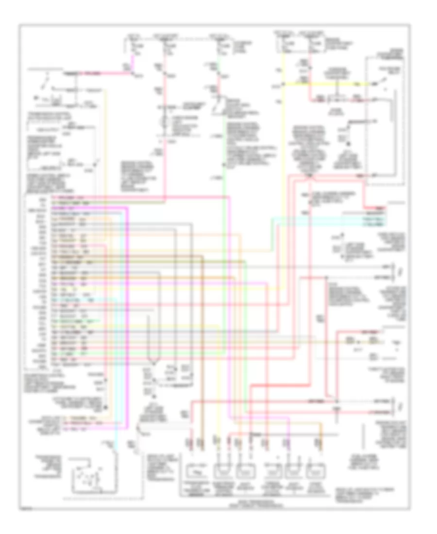
7.5L, Engine Performance Wiring Diagrams, California (1 of 4) for Ford RV Cutaway E350 1996
List of elements for 7.5L, Engine Performance Wiring Diagrams, California (1 of 4) for Ford RV Cutaway E350 1996:
- (not used)
- A/c on in sig
- Air conditioning system
- Aird solenoid
- All cutaways
- All vans/ wagons
- Anti slosh module
- Anti-theft module (left side of vehicle, behind "b" pillar)
- Bus +
- Bus -
- C143
- C232
- C233
- C336
- Cat monitor sens
- Coil
- Coil wire
- Data link connector (dlc) (below left side of i/p)
- Distributor (center front of engine)
- Distributor shield
- Egr sol.
- Eng temp sens.
- Fuel pump mon.
- Fuse 18 15a
- Fuse 5 15a
- Fuse 7 10a
- G106 (left side of engine compartment, near battery)
- G200 (behind left cowl)
- G202 (attached to instrument panel assembly, behind instrument cluster)
- Gen scan tool in
- Gnd
- Ground
- Hot in run
- Hot in start or run
- Idm
- Idm monitor
- Ign gnd
- Ignition coil (left rear of engine)
- Ignition control module (icm) (left rear of engine compartment)
- Ignition control module (icm) shield
- Instrument cluster
- Intake air temp.
- Interior fuse panel (behind left side of i/p)
- Malfunction indicator lamp (mil) (check engine light)
- Mass air flw rtn
- Mil lp ctrl
- Misfire sens gnd
- Nca
- O/d off
- Pip
- Pnk
- Powertrain control module (pcm) (left rear of engine compartment, near brake master cylinder)
- Pwr
- Radio capacitor (left side of engine, attached to ignition coil)
- Shield gnd
- Shift sol no.1
- Shift sol no.2
- Shorting bar (left rear of engine compartment)
- Solid state
- Spk angle pulse
- Spout
- Tc3
- Tcil
- Tfi module gnd
- To fuel gauge
- Trans ctrl sw
- Trans temp sens.
- Transmission control switch/ indicator lamp
- Vss ground
- W/ anti- theft
- W/o anti- theft
- Wire coil
7.5L, Engine Performance Wiring Diagrams, California (2 of 4) for Ford RV Cutaway E350 1996
List of elements for 7.5L, Engine Performance Wiring Diagrams, California (2 of 4) for Ford RV Cutaway E350 1996:
- Acc
- Coast clutch solenoid
- Coil
- Diode (plug- in)
- E4od transmission
- Electronic pressure control (epc) solenoid
- Engine compartment fuse panel (left side of engine compartment)
- Engine coolant temperature (ect) sensor (top front of engine, near distributor)
- Fuel pump relay
- Fuse c 30a
- Fuse g 60a
- Fuse h 30a
- Fuse u 30a
- G106 (left side of engine compartment, near battery)
- Hot at all times
- Hot in start or run
- Ignition switch
- Intake air temperature (iat) sensor (center of engine compartment, part of clean air tube)
- Lock
- Misfire sensor (lower right front of engine)
- Off
- Pcm power relay
- Red
- Run
- Shift solenoid no.1
- Shift solenoid no.2
- Start
- Starter motor relay (left front corner of engine compartment)
- Torque converter clutch (tcc) solenoid
- Transmission fluid temperature sensor
- Transmission range (tr) sensor (left side of transmission)
7.5L, Engine Performance Wiring Diagrams, California (3 of 4) for Ford RV Cutaway E350 1996
List of elements for 7.5L, Engine Performance Wiring Diagrams, California (3 of 4) for Ford RV Cutaway E350 1996:
- Aird solenoid (rear of left valve cover, on bracket)
- All cutaways
- All vans & wagons
- C422
- Egr solenoid (rear of left valve cover, on bracket)
- Fuel injectors (in intake manifold)
- Fuel pump/ sender (below vehicle, in fuel tank)
- G106 (left side of engine compartment, near battery)
- G202 (attached to instrument panel assembly, behind instrument cluster)
- Idle air control (iac) valve (top rear of engine, near engine oil pressure switch)
- In-transit fuel pump/ sender (below vehicle, along left frame rail)
- Inertia fuel shutoff (ifs) (behind right cowl panel)
- Mass air flow (maf) sensor (center of engine compartment)
- Nca
- No.1
- No.2
- No.3
- No.4
- No.5
- No.6
- No.7
- No.8
- Rear fuel pump/ sender (mounted on left rear frame crossmember)
- Red
- Tan
- Tan/ red
- Tan/red
- Trailer/camper adapter connector
- W/class 1 trailer adapter only
- W/trailer adapter only
7.5L, Engine Performance Wiring Diagrams, California (4 of 4) for Ford RV Cutaway E350 1996
List of elements for 7.5L, Engine Performance Wiring Diagrams, California (4 of 4) for Ford RV Cutaway E350 1996:
- Airb solenoid
- Airb solenoid (rear of left valve cover, on bracket)
- Boo switch input
- Brake on/off (boo) switch (on brake pedal bracket)
- C143
- Catalyst monitor sensor (cms) (lower middle side of vehicle)
- Cms sensor
- Coast clutch sol.
- Delta pressure feedback egr (dpfe) sensor (top of engine near throttle body)
- Dpfe sensor
- Epc solenoid
- Fuel inj. no.1
- Fuel inj. no.2
- Fuel inj. no.3
- Fuel inj. no.4
- Fuel inj. no.5
- Fuel inj. no.6
- Fuel inj. no.7
- Fuel inj. no.8
- Fuel pmp rly ctrl
- Fuse i 15a
- G106 (left side of engine compartment, near battery)
- Ground
- Heated exhaust gas oxygen sensor (hego) no.11 (middle lower right side of vehicle)
- Heated exhaust gas oxygen sensor (hego) no.21 (lower left side of transmission)
- Hego mn no.11
- Hego mn no.21
- Hego no.11
- Hego no.21
- Hot at all times
- Iac valve
- Interior fuse panel (behind left side of i/p)
- Keep alive pwr in
- Mass air fl sens.
- Misfire sens.
- Nca
- Power distribution system
- Power input
- Powertrain control module (pcm) (left rear of engine, compartment, near brake master cylinder)
- Programmable speedometer/ odometer module (psom) (behind left side of i/p)
- Red
- Ref output volt
- Sens sig rtn
- Solid state
- Speed control servo/amplifier assembly (left side of engine compartment, near brake master cylinder)
- Tan
- Tan/red
- Tcc solenoid
- Tcil ind. lp.
- Throttle position (tp) sensor (top left side of engine)
- Tp sensor
- Trans rng sensor
- Vapor man. valve
- Vapor management valve (center of engine compartment)
- Vehicle spd sens.
- Vss input
- Vss output
7.5L, Engine Performance Wiring Diagrams, Federal (1 of 2) for Ford RV Cutaway E350 1996
List of elements for 7.5L, Engine Performance Wiring Diagrams, Federal (1 of 2) for Ford RV Cutaway E350 1996:
- (not used)
- A/c on
- Acd
- Air conditioning system
- Airb
- Aird
- Boo
- Brake on/off (boo) switch (on brake pedal support)
- C162
- C163
- C233
- Ccs
- Coil
- Coil wire
- Data
- Data (+)
- Data (-)
- Data link connector (dlc) (left front corner of engine compartment)
- Data link connector (dlc) (left front of engine compt)
- Diode (plug-in) (engine compartment fuse panel)
- Distributor
- Distributor shield
- Ect
- Egr
- Egr valve
- Engine compartment fuse panel (left side of engine compartment)
- Epc
- Evap
- Fp enable
- Fpm
- Fuse 1 15a
- Fuse 18 15a
- Fuse c 30a
- Fuse u 30a
- G106 (left side of engine compartment, near battery)
- G202 (attached to instrument panel assembly, behind instrument cluster)
- Gnd
- Ho2s
- Ho2s gnd
- Hot at all times
- Hot in start or run
- Iac
- Iat
- Idm
- Ign gnd
- Ignition
- Ignition coil (left rear of engine)
- Ignition control module (icm) shield
- Ignition control module (left rear of engine compartment)
- Inj 1,4,5,8 out
- Inj 2,3,6,7 out
- Instrument cluster
- Interior fuse panel (behind left side of i/p)
- Kapwr
- Malfunction indicator lamp (mil)
- Map
- Mil
- Nca
- Pcm power relay
- Pip
- Pnk
- Powertrain control module (pcm) (left rear of engine compartment, near brake master cylinder)
- Psom (+)
- Pwr
- Radio capacitor (attached to ignition coil)
- Red
- Sensor sig rtn
- Shorting bar (left rear of engine compartment)
- Speed control servo/amplifier assembly (left side of engine compartment, near brake master cylinder)
- Spout
- Ss1
- Ss2
- Tan
- Tcc
- Tcil
- Tcs
- Tft
- Tr sensor
- Transmission control switch/ indicator lamp
- Transmission range (tr) sensor (left side of transmission)
- Vehicle speed input
- Vref
- Vss (-)
7.5L, Engine Performance Wiring Diagrams, Federal (2 of 2) for Ford RV Cutaway E350 1996
List of elements for 7.5L, Engine Performance Wiring Diagrams, Federal (2 of 2) for Ford RV Cutaway E350 1996:
- (not used)
- Acc
- Airb solenoid (rear of left valve cover on bracket) (super duty only)
- Aird solenoid (rear of left valve cover, on bracket)
- All cutaways
- All vans & wagons
- Coast clutch solenoid
- E40d transmission
- Egr solenoid (rear of left valve cover, on bracket)
- Egr valve position (evp) sensor (top of egr valve, near throttle body)
- Electronic pressure control (epc) solenoid
- Engine compartment fuse panel (left side of engine compartment)
- Engine coolant temperature (ect) sensor (top front of engine, near distributor)
- Evaporative emissions (evap) canister purge valve (left rear of engine, connected to throttle body)
- Fuel injectors
- Fuel pump relay
- Fuel pump/ sender (below vehicle in fuel tank)
- Fuse h 30a
- G106 (left side of engine compartment, near battery)
- Heated oxygen sensor (ho2s) n0.11 (super duty) (beneath center of vehicle) (except super duty) (middle lower right side of vehicle)
- Hot at all times
- Idle air control (iac) valve (top rear of engine, near engine oil pressure switch)
- Ignition switch
- In-transit fuel pump/sender (below vehicle, along left frame rail)
- Inertia fuel shutoff (ifs) switch (behind right cowl panel)
- Intake air temperature (iat) sensor (top of engine, near fuel injector no.6)
- Lock
- Manifold absolute pressure (map sensor (right side of engine compartment)
- Nca
- No.1
- No.2
- No.3
- No.4
- No.5
- No.6
- No.7
- No.8
- Off
- Rear fuel pump/sender (mounted on left rear frame crossmember)
- Red
- Run
- Shift solenoid no.1
- Shift solenoid no.2
- Start
- Tan
- Throttle position (tp) sensor) (top left of engine)
- Torque converter clutch (tcc) solenoid
- Trans- mission fluid temper- ature sensor
EXTERIOR LIGHTS
Back-up Lamps Wiring Diagram for Ford RV Cutaway E350 1996
List of elements for Back-up Lamps Wiring Diagram for Ford RV Cutaway E350 1996:
- (4r70w)
- (e40d diesel)
- (e40d gasoline) (4r70w)
- (e40d gasoline) (e40d diesel)
- (not used)
- 4r70w or e40d transmission
- C6 transmission
- Cutaways
- Fuse 15a
- G999 (left rear corner of vehicle, near left stop/ park/turn lamp)
- Hot in run
- Interior fuse panel (behind left side of i/p)
- Left backup lamp
- Park/ neutral position switch (left side of transmission)
- Right backup lamp
- To trailer/camper adapter circuit (trailer backup lamp relay)
- Transmission range (tr) sensor (left side of transmission)
- Vans & wagons
- W/class 2 trailer package
Exterior Lamps Wiring Diagram for Ford RV Cutaway E350 1996
List of elements for Exterior Lamps Wiring Diagram for Ford RV Cutaway E350 1996:
- (at base of left "b" pillar) c330
- (not used)
- Anti-theft system (anti-theft module)
- Brake on/off (boo) switch (on brake pedal bracket)
- Brake test connector (behind left "b" pillar)
- C217
- C232
- C233
- Cut- aways
- Cutaways only
- Electronic flasher (behind left side of i/p)
- Fuse 15a
- Fuse 20a
- G107 (right front corner of engine compartment)
- G200 (behind left cowl)
- G202 (attached to instrument panel assembly, behind instrument cluster)
- G999 (left rear corner of vehicle, near left/stop/ park/turn lamp)
- Hazard
- Hazard switch
- Head
- High mounted stop/ cargo lamp
- Hot at all times
- Hot in run
- Instrument cluster
- Interior fuse panel (behind left side of i/p)
- Interior fuse panel (behind left side of i/p)
- Left front park/ turn signal lamp
- Left stop/ park/
- Left turn indicator
- License lamp
- Main light switch
- Modified vehicle power (all cutaways) (w/class 2 trailer adapter only)
- Multi- function switch (right side of steering column)
- Normal
- Off
- Park r
- Right front park/ turn signal lamp
- Right stop/ park/
- Right turn indicator
- Solid state
- To trailer/ camper adapter circuit (electronic brake) (class 2 only)
- To trailer/camper adapter circuit (electronic brake) (class 2 only)
- To trailer/camper adapter circuit (engine compartment fuse panel) (fuse p)
- To trailer/camper adapter circuit (engine compartment fuse panel) (fuses n & m)
- Turn lamp
- Turn left
- Turn right
- Vans & wagons
- Vans & wagons only
- Warning systems (warning buzzer module)
Trailer Adapter/Electronic Brake Wiring Diagram for Ford RV Cutaway E350 1996
List of elements for Trailer Adapter/Electronic Brake Wiring Diagram for Ford RV Cutaway E350 1996:
- (at base of left "b" pillar) c330
- (behind left cowl) g200
- Ambulance package only
- B+ (park or head)
- Back up lamps circuit (transmission range (tr) sensor or park/neutral position switch
- Back-up lamp output
- Battery (b+)
- Brake switch input
- C184 (left rear corner of engine compartment)
- C231 (behind left side of i/p)
- C422
- Dome
- Dome switch input
- Electronic brake
- Electronic brake (left side of i/p, near airbag module)
- Engine compartment fuse panel (left side of engine compartment)
- From exterior lamps circuit (brake on/off (boo) switch)
- From exterior lamps circuit (headlamp switch)
- From exterior lights circuit (multi-function switch)
- Fuse 20a
- Fuse d 20a
- Fuse j 40a
- Fuse k 30a
- Fuse m 10a
- Fuse n 10a
- Fuse p 10a
- G106 (left side of engine compartment, near battery
- G106 (left side of engine compartment, near battery)
- G999 (left rear corner of vehicle, near trailer/camper adapter)
- Ground
- Hot at all times
- Hot in acc or run
- Interior fuse panel (behind left side of i/p)
- Left turn output
- Main light switch
- Modified vehicle power
- Nca
- Red
- Right turn output
- Starting/ charging system (generator/ regulator)
- Trailer backup lamp relay (lower left side of engine compartment, near starter motor relay)
- Trailer battery charge relay (lower left side of engine compartment, near starter motor relay)
- Trailer connector
- Trailer running lamp relay (lower left side of engine compartment, near starter motor relay)
- Trailer running lamp relay output
- Trailer/camper adapter class 2
- Trailer/camper adapter connector (below left side of bumper)
- Trailer/camper adapter connector (below left side of rear bumper)
- W/ auxiliary battery
- W/o auxiliary battery
Trailer/Camper Adapter Wiring Diagram for Ford RV Cutaway E350 1996
List of elements for Trailer/Camper Adapter Wiring Diagram for Ford RV Cutaway E350 1996:
- (not used)
- C422
- C430
- Cut- aways
- Engine compartment fuse panel (left side of engine compartment)
- From exterior lamps circuit (main light switch)
- From exterior lamps circuit (multi-function switch)
- Fuse m 10a
- Fuse n 10a
- Fuse p 10a
- G106 (left side of engine compartment, near battery)
- G999 (left rear corner of vehicle, near trailer/camper adapter)
- Ground
- Left turn output
- Main light switch (park or head)
- Right turn output
- Trailer/camper adapter class 1
- Trailer/camper adapter connector (below left side of rear bumper)
- Vans & wagons
- Vans & wagons only
GROUND DISTRIBUTION
Ground Distribution Wiring Diagram (1 of 6) for Ford RV Cutaway E350 1996
List of elements for Ground Distribution Wiring Diagram (1 of 6) for Ford RV Cutaway E350 1996:
- (right front corner of engine compartment)
- 4 wheel anti-lock brakes (4wabs) module
- 4.9l & 7.5l
- 4.9l, 5.0l (50 states), 5.8l california & 49 states under 8600 gvw & 7.5l california
- 5.0l & 5.8l
- 5.8l 49 states over 8600 gvw & 7.5l except california
- All models
- C143
- C175
- C232
- Data link connector
- Engine compartment fuse panel
- G106 (left side of engine compartment, near battery)
- G107
- G120 (right side of engine)
- Gasoline models
- Heated oxygen sensor (ho2s) #11
- Instrument cluster
- Left battery
- Left front park/turn signal lamp
- Left headlamp
- Mass airflow (maf) sensor
- Nca
- Pcm power relay
- Powertrain control module (pcm)
- Rear anti-lock brake system (rabs) valve assembly
- Right front park/turn signal lamp
- Right headlamp
- To gasoline model components (schematic page 2)
- W/ 4wabs only
- W/rear abs only
Ground Distribution Wiring Diagram (2 of 6) for Ford RV Cutaway E350 1996
List of elements for Ground Distribution Wiring Diagram (2 of 6) for Ford RV Cutaway E350 1996:
- & 7.5l california only
- (not used)
- 4.9l, 5.0l (50 states),
- 49 states under 8600 gvw
- 5.8l 49 states over 8600 gvw & 7.5l except california
- 5.8l california &
- 7.3l di turbo diesel model
- A/c compressor clutch
- A/c compressor clutch diode
- All cutaway
- All vans/ wagons w/ trailer adapter
- All vans/ wagons w/o trailer adapter
- Ambulance package only
- Anti-theft hood switch
- Blower motor relay
- Blower motor resistor
- C143
- C175
- C409
- Class 1 trailer adapter
- Class 2 trailer adapter
- Data link connector (dlc)
- Dual brake warning switch
- From gasoline model engines (on schematic page 1)
- Fuel pump/ sender
- G101 (lower right front of engine compartment, on frame rail)
- G101 (right side of engine compartment)
- G112 (left side of engine)
- G119 (lower right front of engine)
- Gasoline models
- Generator/ regulator
- In-transit fuel-pump/ sender
- Injector driver module (idm)
- Left battery
- Nca
- Powertrain control module
- Powertrain control module (pcm)
- Rear fuel pump/ sender
- Right battery
- Trailer backup lamp relay
- Trailer battery charge relay
- Trailer running lamp relay
- Trailer/camper adapter connector
- W/ anti- theft
- W/class 2 trailer adapter
- W/trailer adapter
- Washer pump motor
- Windshield wiper motor
Ground Distribution Wiring Diagram (3 of 6) for Ford RV Cutaway E350 1996
List of elements for Ground Distribution Wiring Diagram (3 of 6) for Ford RV Cutaway E350 1996:
- (not used)
- 4 wheel anti-lock brakes (4abs) module
- 7.3l di turbo diesel model
- A/c compressor clutch
- A/c compressor clutch diode
- Blower motor relay
- Blower motor resistor
- C121
- C143
- C232
- C409
- C430
- Class 1 trailer adapter
- Class 2 trailer adapter
- Dual brake warning switch
- Engine compartment fuse panel
- Exhaust pressure regulator (epr)
- External fuel pump
- G106 (left side of engine compartment, near battery)
- Instrument cluster
- Low vacuum warning switch
- Pcm power relay
- Powertrain control module (pcm)
- Rear anti-lock brake system (rabs) valve assembly
- Trailer backup lamp relay
- Trailer battery charge relay
- Trailer running lamp relay
- Trailer/camper adapter connector
- Vans/ wagons w/trailer adapter
- W/ 4wabs only
- W/rabs only
- Washer pump motor
- Windshield wiper motor
Ground Distribution Wiring Diagram (4 of 6) for Ford RV Cutaway E350 1996
List of elements for Ground Distribution Wiring Diagram (4 of 6) for Ford RV Cutaway E350 1996:
- (dlc)
- * w/o door trim
- ***
- ****
- **all except 5.8l 49 states over 8600 gvw & 7.5l except california
- Air bag module
- Airbag module (vans/wagon only)
- Anti-theft module
- Auxiliary powertrain control connector
- Brake test connector
- C208
- C209
- C332
- C333
- C334
- C336
- C337
- C512
- C513
- C605
- C610
- Clockspring assembly
- Cutaway w/illuminated entry only
- Cutaways
- Cutaways only
- Data link connector
- Diesel only
- Dome/map switch & lamp
- Driver's lumbar pump
- Driver's seat regulator control switch
- Electronic flasher
- G200 (behind left cowl)
- Ignition key cylinder sensor
- Illuminated entry module
- Left door handle switch
- Left door lock cylinder switch
- Left front courtesy lamp
- Master window/door l,ock control switch or left power window switch
- Memory lock module
- Nca
- Passenger's lumbar pump
- Power mirror switch
- Rear door lock cylinder switch
- Rear power outlet
- Remote keyless entry module
- Remote radio control
- Remote/keyless entry module
- Right door handle switch
- Right door key cylinder switch
- Right front courtesy lamp
- Right power door lock switch or right power door lock/window switch
- Seat belt switch
- Shift lock actuator
- To ground g999 (schematic page 6)
- Trailer/ camper adapter
- Vans & wagons
- Vans/wagon only
- W/ anti- theft
- W/ illuminated entry
- W/ power lumbar
- W/anti- theft
- W/anti-theft
- W/illuminated entry
- W/o anti-theft
- W/o power lumbar
- W/o speed control
- W/power door locks
- W/power mirrors
- W/rear radio only
- W/trailer adapter
- Warning buzzer module
Ground Distribution Wiring Diagram (5 of 6) for Ford RV Cutaway E350 1996
List of elements for Ground Distribution Wiring Diagram (5 of 6) for Ford RV Cutaway E350 1996:
- (attached to instrument panel assembly, behind instrument cluster)
- (not used)
- * 5.8l 49 states over 8600 gvw & 7.5l except california
- 4 wheel anti-lock brakes (4wabs) module
- All cutaways
- All models except diesel vans & wagons w/o premium sound & rabs
- All vans & wagons
- Amplifier
- Auxiliary heater blower switch or auxiliary a/c-heater blower switch
- Blend door actuator
- C143
- C175
- C213
- C224
- C232
- C233
- C234
- C302
- Cigar lighter
- Diesel vans & wagons w/o premium sound & rabs
- Diesel warning lamps display module
- Front blower switch
- Fuel pump/ sender
- Function selector switch illumination
- G202
- Gasoline models w/speed control
- In-transit fuel pump sender
- Instrument cluster
- Nca
- Powertrain control module (pcm)
- Programmable speedometer/ odometer module (psom)
- Radio
- Rear fuel pump/ sender
- Speed control servo/ amplifier assembly
- W/ 4wabs
- W/ auxiliary a/c
- W/ premium sound
- W/o premium sound
- Wiper control module
Ground Distribution Wiring Diagram (6 of 6) for Ford RV Cutaway E350 1996
List of elements for Ground Distribution Wiring Diagram (6 of 6) for Ford RV Cutaway E350 1996:
- (left rear corner of vehicle, near left stop/ park/ turn lamp)
- All except chateau wagon
- All reguilar vans w/o full headliner
- All regular or extended vans & wagons w/ rear headliner
- All regular vans w/o full headliner
- All rv vans w/ auxiliary a/c
- Auxiliary a/c illumination
- Auxiliary blower motor relay
- Auxiliary high blower motor relay
- Cargo lamp
- Chateau wagon
- Chateau wagon
- Dome/ switch lamp
- Dome/map switch & lamp
- From ground g200 (schematic page 4)
- G999
- High mounted stop/ cargo lamp
- Left backup lamp
- Left stop/ park/ turn lamp
- License lamp
- Right backup lamp
- Right stop/ park/ turn lamp
- W/ auxiliary a/c
- W/ auxiliary heat or a/c
- W/ full headliner
HEADLIGHTS
Headlight Wiring Diagram, with DRL for Ford RV Cutaway E350 1996
List of elements for Headlight Wiring Diagram, with DRL for Ford RV Cutaway E350 1996:
- ign input park bk on in
- (not used)
- 4 wheel anti-lock brakes (4wabs) module (on left front frame rail)
- Anti-theft module (left side of vehicle, behind "b" pillar)
- Battery pwr in pulsed output
- Brake warning lamp high
- Brake ind out
- Brake warning indicator
- C218
- C232
- C233
- C335
- Daytime running lamps (drl) module (lower right front of engine, near horns)
- Diesel (w/4abs)
- Diesel (w/rabs)
- Dimmer
- Drl disable
- Dual brake warning diode/ resistor assembly (in main harness, near t/o to psom module)
- Engine compartment fuse panel (left side of engine compartment)
- Flash-to- pass
- Fuse 18 15a
- Fuse 4 20a
- Fuse 5 15a
- Fuse r 15a
- Fuse s 60a
- G107 (right front corner of engine compartment)
- G202 (attached to instrument panel assembly, behind instrument cluster)
- Gasoline (w/4abs)
- Gasoline (w/rabs)
- Head
- Hi beam in out
- High beam indicator
- Hot at all times
- Hot in run
- Hot in start
- Instrument cluster
- Interior fuse panel (behind left side of i/p)
- Left headlamp
- Lo beams in
- Low vacuum warning switch (left front of engine compartment)
- Main light switch
- Multi- function switch (dimmer)
- Off
- Or run
- Park
- Parking brake switch (above left cowl panel)
- Pass
- Right headlamp
- W/4 wheel anti-lock brakes only
Headlight Wiring Diagram, without DRL for Ford RV Cutaway E350 1996
List of elements for Headlight Wiring Diagram, without DRL for Ford RV Cutaway E350 1996:
- Anti-theft module (left side of vehicle, behind 'b' pillar)
- C218
- C232
- C335
- Dimmer
- Drl jumper (left front of engine, compartment near left headlamp)
- Engine compartment fuse panel (left side of engine compartment)
- Flash- to- pass
- Fuse 4 20a
- Fuse s 60a
- G107 (right front corner of engine compartment)
- G202 (attached to instrument panel assembly, behind instrument cluster)
- Head
- Hi beam indicator
- Hot at all times
- Instrument cluster
- Interior fuse panel (behind left side of i/p)
- Left headlamp
- Low beam output
- Main light switch
- Multi- function switch (dimmer)
- Off
- Park
- Pass
- Right headlamp
- W/ drl jumper
- W/drl jumper only
- W/o drl jumper
HORN
Horn Wiring Diagram for Ford RV Cutaway E350 1996
List of elements for Horn Wiring Diagram for Ford RV Cutaway E350 1996:
- 15a
- Anti-theft module (left side of vehicle, behind "b" pillar)
- C143
- C335
- Clock- spring assembly
- Diesel models
- Engine compartment fuse panel (left side of engine compartment)
- Fuse r
- G200 (behind left cowl)
- Gasoline models
- High pitch horn (lower right front of engine compartment, behind grille)
- Horn
- Horn relay (left rear of engine compartment (gasoline) (lower left side of engine compartment, near starter relay (diesel)
- Horn switch
- Hot at all times
- If equipped
- Low pitch horn (lower right front of engine compartment, behind grille)
- Nca
- Powertrain control module (pcm) (left rear of engine compartment, near brake master cylinder)
- Relay output
- Speed control ground
- Speed control servo/amplifier assembly (left side of engine compartment, near brake master cylinder)
- Speed control switch ground
- Speed control switches
- Steering column assembly
- Steering column assembly (speed control/ horn switch)
- W/cruise control
- W/o cruise control
INSTRUMENT CLUSTER
4.9L
4.9L, Instrument Cluster Wiring Diagram, with 4 Wheel ABS for Ford RV Cutaway E350 1996
List of elements for 4.9L, Instrument Cluster Wiring Diagram, with 4 Wheel ABS for Ford RV Cutaway E350 1996:
- (a)
- (b)
- (behind left side of i/p) programmable speedometer/ odometer module (psom)
- (below left side of i/p)
- (not used)
- (right front of engine compt)
- 4 wheel anti-lock brakes (4wabs) module (on left front frame rail)
- 4.9l, 5.0l, 5.8l federal under 8600 gvw & 7.5l calif. only
- 5.8l fed. over 8600 gvw & 7.5l except calif. w/o drl
- 5.8l federal over 8600 gvw & 7.5l except calif.
- A10
- A11
- A12
- A14
- Abs data link connector (dlc) (below left side of i/p) (all gas engines: except 5.8l federal over 8600 gvw & 7.5l except calif.) '(left side of engine compartment) (5.8l federal over 8600 gvw & 7.5l except california)
- Acc
- Air bag ind.
- Air bag module (behind left side of i/p)
- All cutaways
- All other models
- All vans/wagons
- Anti- lock brake ind.
- Anti- slosh module
- B10
- B11
- B12
- B13
- Bat
- Brake warning ind.
- C143
- C175
- C190
- C209
- C232
- C233
- Charge ind.
- Coolant temp.
- Data link connector (dlc) (left front corner of engine compartment)
- Daytime running lamps (drl) module
- Diode c (in main harness, near t/o to psom)
- Dss input
- Dss return
- Dual brake warning switch (in bottom of brake master cylinder)
- Enable
- Engine compartment fuse panel (left side of engine compartment)
- Engine coolant temp. gauge
- Engine coolant temperature sender (4.9l-right rear of engine, near fuel injector no.6) (5.0l & 5.8l-lower left side of engine) (7.5l-lower left side of engine)
- Engine oil press. gauge
- Engine oil pressure switch (4.9l-left side of engine, near distributor) (5.0l-front of engine, near a/c compressor) (5.8l-left side of engine, near oil cooler) (7.5l-top center rear of engine)
- Exterior lights system
- Fasten seat belt ind.
- Fuel gauge
- Fuel level
- Fuel pump/ sender (below vehicle, in fuel tank)
- Fuse 15a
- Fuse 20a
- Fuse 5a
- Fuse u 30a
- G106 (left side of engine compartment, near battery)
- G202 (attached to instrument panel assembly, behind instrument cluster)
- Generator/ regulator
- Gnd
- Headlights
- High beam ind.
- Hot at all times
- Hot in run
- Hot in start or run
- Hot w/main light switch in park or head
- Ign
- Ign (run)
- Ignition switch
- Illum.
- In-transit fuel pump/sender (below vehicle, along left frame rail)
- Instrument cluster
- Instrument lamps illumination
- Interior fuse panel (behind left side of i/p)
- Left turn ind.
- Lock
- Malfunction ind. "check engine light"
- Nca
- Off
- Ohms
- Oil press.
- Parking brake switch (above left cowl panel)
- Powertrain control module (pcm) (left rear of engine compt., near brake master cylinder)
- Programming
- Psom data link connector (behind left side of i/p)
- Rear axle speed sensor (mounted on differ- ential)
- Rear fuel pump/sender (mounted on left rear frame crossmember)
- Red/
- Red/ pnk
- Red/pnk
- Red/pnk
- Right turn ind.
- Run
- Solid state
- Speed control servo/ amplifier assembly (left side of engine compt., near brake master cylinder)
- Start
- System
- Volt- meter
- Vss output
- W/ drl
- W/o drl
- W/premium sound system
- Warning buzzer module
4.9L, Instrument Cluster Wiring Diagram, with Rear Wheel ABS for Ford RV Cutaway E350 1996
List of elements for 4.9L, Instrument Cluster Wiring Diagram, with Rear Wheel ABS for Ford RV Cutaway E350 1996:
- in-transit fuel pump/sender (below vehicle, along left frame rail)
- rear fuel pump/sender (mounted on
- red/pnk
- (a)
- (b)
- (behind left side of i/p) programmable speedometer/ odometer module (psom)
- (below left side of i/p)
- (not used)
- 1000 ohms
- 4.9l, 5.0l, 5.8l federal under 8600 gvw & 7.5l calif. only
- 5.8l fed. over 8600 gvw & 7.5l except calif.
- 5.8l federal over 8600 gvw & 7.5l except calif.
- A10
- A11
- A12
- A14
- Abs data link connector (dlc) (below left side of i/p) (all gas engines: except 5.8l federal over 8600 gvw & 7.5l except calif.) (left side of engine compartment) (5.8l federal over 8600 gvw & 7.5l except calif)
- Acc
- Air bag ind.
- Air bag module (left side of i/p)
- All other models
- All cutaways
- All vans/wagons
- Amplifier assembly (left side of engine compt., near brake master cylinder)
- Anti- lock brake ind.
- Anti- slosh module
- B10
- B11
- B12
- B13
- Base models w/rabs
- Base models: w/rabs
- Bat
- Brake warning ind.
- C190
- C209
- C232
- C233
- Charge ind.
- Ci43
- Ci75
- Coolant temp.
- Data link connector (dlc) (left front corner of engine compartment)
- Daytime running lamps (drl) module (lower right front of engine compt)
- Diode c (in main harness, near psom)
- Dss input
- Dss return
- Dual brake warning diode/ resistor assembly
- Dual brake warning switch (in bottom of brake master cylinder)
- Enable
- Engine compartment fuse panel (left side of engine compartment)
- Engine coolant temp. gauge
- Engine coolant temperature sender (4.9l-right rear of engine, near fuel injector no.6) (5.0l & 5.8l-lower left side of engine) (7.5l-lower left side of engine)
- Engine oil press. gauge
- Engine oil pressure switch (4.9l-left side of engine, near distributor) (5.0l-front of engine, near a/c compressor) (5.8l-left side of engine, near oil cooler) (7.5l-top center rear of engine)
- Except base models
- Except base models: 5.8l fed over 8600 gvw & 7.5l except calif.
- Exterior lights system
- Fasten seat belt ind.
- Fuel gauge
- Fuel level
- Fuel pump/ sender (below vehicle, in fuel tank)
- Fuse 15a
- Fuse 20a
- Fuse 5a
- Fuse u 30a
- G106 (left side of engine compartment, near battery)
- G202 (attached to instrument panel assembly, behind instrument cluster)
- Generator/ regulator
- Gnd
- Headlights
- High beam ind.
- Hot at all times
- Hot in run
- Hot in start or run
- Hot w/main light switch in park or head
- Ign
- Ign (run)
- Ignition switch
- Illum.
- Instrument cluster
- Instrument lamps illumination
- Interior fuse panel (behind left side of i/p)
- Left rear frame crossmember)
- Left turn ind.
- Lock
- Malfunction ind. "check engine light"
- Nca
- Off
- Ohms
- Oil press.
- Parking brake switch (above left cowl panel)
- Powertrain control module (pcm) (left rear of engine compt., near brake master cylinder)
- Programming
- Psom data link connector (behind left side of i/p)
- Rear anti-lock brake (rabs) system module (behind right side of i/p)
- Rear axle speed sensor (mounted on differential)
- Red/ pnk
- Red/pnk
- Right turn ind.
- Run
- Solid state
- Speed control servo/
- Start
- System
- Volt- meter
- Vss output
- W/ drl
- W/o drl
- Warning buzzer module
5.8L
5.8L, Instrument Cluster Wiring Diagram, with 4 Wheel ABS for Ford RV Cutaway E350 1996
List of elements for 5.8L, Instrument Cluster Wiring Diagram, with 4 Wheel ABS for Ford RV Cutaway E350 1996:
- (a)
- (b)
- (behind left side of i/p) programmable speedometer/ odometer module (psom)
- (below left side of i/p)
- (not used)
- (right front of engine compt)
- 4 wheel anti-lock brakes (4wabs) module (on left front frame rail)
- 4.9l, 5.0l, 5.8l federal under 8600 gvw & 7.5l calif. only
- 5.8l fed. over 8600 gvw & 7.5l except calif. w/o drl
- 5.8l federal over 8600 gvw & 7.5l except calif.
- A10
- A11
- A12
- A14
- Abs data link connector (dlc) (below left side of i/p) (all gas engines: except 5.8l federal over 8600 gvw & 7.5l except calif.) '(left side of engine compartment) (5.8l federal over 8600 gvw & 7.5l except california)
- Acc
- Air bag ind.
- Air bag module (behind left side of i/p)
- All cutaways
- All other models
- All vans/wagons
- Anti- lock brake ind.
- Anti- slosh module
- B10
- B11
- B12
- B13
- Bat
- Brake warning ind.
- C143
- C175
- C190
- C209
- C232
- C233
- Charge ind.
- Coolant temp.
- Data link connector (dlc) (left front corner of engine compartment)
- Daytime running lamps (drl) module
- Diode c (in main harness, near t/o to psom)
- Dss input
- Dss return
- Dual brake warning switch (in bottom of brake master cylinder)
- Enable
- Engine compartment fuse panel (left side of engine compartment)
- Engine coolant temp. gauge
- Engine coolant temperature sender (4.9l-right rear of engine, near fuel injector no.6) (5.0l & 5.8l-lower left side of engine) (7.5l-lower left side of engine)
- Engine oil press. gauge
- Engine oil pressure switch (4.9l-left side of engine, near distributor) (5.0l-front of engine, near a/c compressor) (5.8l-left side of engine, near oil cooler) (7.5l-top center rear of engine)
- Exterior lights system
- Fasten seat belt ind.
- Fuel gauge
- Fuel level
- Fuel pump/ sender (below vehicle, in fuel tank)
- Fuse 15a
- Fuse 20a
- Fuse 5a
- Fuse u 30a
- G106 (left side of engine compartment, near battery)
- G202 (attached to instrument panel assembly, behind instrument cluster)
- Generator/ regulator
- Gnd
- Headlights
- High beam ind.
- Hot at all times
- Hot in run
- Hot in start or run
- Hot w/main light switch in park or head
- Ign
- Ign (run)
- Ignition switch
- Illum.
- In-transit fuel pump/sender (below vehicle, along left frame rail)
- Instrument cluster
- Instrument lamps illumination
- Interior fuse panel (behind left side of i/p)
- Left turn ind.
- Lock
- Malfunction ind. "check engine light"
- Nca
- Off
- Ohms
- Oil press.
- Parking brake switch (above left cowl panel)
- Powertrain control module (pcm) (left rear of engine compt., near brake master cylinder)
- Programming
- Psom data link connector (behind left side of i/p)
- Rear axle speed sensor (mounted on differ- ential)
- Rear fuel pump/sender (mounted on left rear frame crossmember)
- Red/
- Red/ pnk
- Red/pnk
- Red/pnk
- Right turn ind.
- Run
- Solid state
- Speed control servo/ amplifier assembly (left side of engine compt., near brake master cylinder)
- Start
- System
- Volt- meter
- Vss output
- W/ drl
- W/o drl
- W/premium sound system
- Warning buzzer module
5.8L, Instrument Cluster Wiring Diagram, with Rear Wheel ABS for Ford RV Cutaway E350 1996
List of elements for 5.8L, Instrument Cluster Wiring Diagram, with Rear Wheel ABS for Ford RV Cutaway E350 1996:
- in-transit fuel pump/sender (below vehicle, along left frame rail)
- rear fuel pump/sender (mounted on
- red/pnk
- (a)
- (b)
- (behind left side of i/p) programmable speedometer/ odometer module (psom)
- (below left side of i/p)
- (not used)
- 1000 ohms
- 4.9l, 5.0l, 5.8l federal under 8600 gvw & 7.5l calif. only
- 5.8l fed. over 8600 gvw & 7.5l except calif.
- 5.8l federal over 8600 gvw & 7.5l except calif.
- A10
- A11
- A12
- A14
- Abs data link connector (dlc) (below left side of i/p) (all gas engines: except 5.8l federal over 8600 gvw & 7.5l except calif.) (left side of engine compartment) (5.8l federal over 8600 gvw & 7.5l except calif)
- Acc
- Air bag ind.
- Air bag module (left side of i/p)
- All other models
- All cutaways
- All vans/wagons
- Amplifier assembly (left side of engine compt., near brake master cylinder)
- Anti- lock brake ind.
- Anti- slosh module
- B10
- B11
- B12
- B13
- Base models w/rabs
- Base models: w/rabs
- Bat
- Brake warning ind.
- C190
- C209
- C232
- C233
- Charge ind.
- Ci43
- Ci75
- Coolant temp.
- Data link connector (dlc) (left front corner of engine compartment)
- Daytime running lamps (drl) module (lower right front of engine compt)
- Diode c (in main harness, near psom)
- Dss input
- Dss return
- Dual brake warning diode/ resistor assembly
- Dual brake warning switch (in bottom of brake master cylinder)
- Enable
- Engine compartment fuse panel (left side of engine compartment)
- Engine coolant temp. gauge
- Engine coolant temperature sender (4.9l-right rear of engine, near fuel injector no.6) (5.0l & 5.8l-lower left side of engine) (7.5l-lower left side of engine)
- Engine oil press. gauge
- Engine oil pressure switch (4.9l-left side of engine, near distributor) (5.0l-front of engine, near a/c compressor) (5.8l-left side of engine, near oil cooler) (7.5l-top center rear of engine)
- Except base models
- Except base models: 5.8l fed over 8600 gvw & 7.5l except calif.
- Exterior lights system
- Fasten seat belt ind.
- Fuel gauge
- Fuel level
- Fuel pump/ sender (below vehicle, in fuel tank)
- Fuse 15a
- Fuse 20a
- Fuse 5a
- Fuse u 30a
- G106 (left side of engine compartment, near battery)
- G202 (attached to instrument panel assembly, behind instrument cluster)
- Generator/ regulator
- Gnd
- Headlights
- High beam ind.
- Hot at all times
- Hot in run
- Hot in start or run
- Hot w/main light switch in park or head
- Ign
- Ign (run)
- Ignition switch
- Illum.
- Instrument cluster
- Instrument lamps illumination
- Interior fuse panel (behind left side of i/p)
- Left rear frame crossmember)
- Left turn ind.
- Lock
- Malfunction ind. "check engine light"
- Nca
- Off
- Ohms
- Oil press.
- Parking brake switch (above left cowl panel)
- Powertrain control module (pcm) (left rear of engine compt., near brake master cylinder)
- Programming
- Psom data link connector (behind left side of i/p)
- Rear anti-lock brake (rabs) system module (behind right side of i/p)
- Rear axle speed sensor (mounted on differential)
- Red/ pnk
- Red/pnk
- Right turn ind.
- Run
- Solid state
- Speed control servo/
- Start
- System
- Volt- meter
- Vss output
- W/ drl
- W/o drl
- Warning buzzer module
7.3L
7.3L DI Turbo Diesel, Instrument Cluster Wiring Diagram, with 4 Wheel ABS for Ford RV Cutaway E350 1996
List of elements for 7.3L DI Turbo Diesel, Instrument Cluster Wiring Diagram, with 4 Wheel ABS for Ford RV Cutaway E350 1996:
- (a)
- (attached to i/p assembly, behind cluster)
- (b)
- (behind left side of i/p) programmable speedometer/odometer module (psom)
- (left side of engine compt, near battery)
- (not used)
- 4 wheel anti-lock brakes (4wabs) module (on left front frame rail)
- A10
- A11
- A12
- A14
- Abs data link connector (dlc) (below left side of i/p)
- Acc
- Air bag ind.
- Air bag module (behind left side of i/p)
- All cutaways
- All vans/wagons
- Anti- lock brake ind.
- Anti- slosh module
- B10
- B11
- B12
- B13
- Bat
- Brake warning ind.
- C190
- C209
- C232
- C233
- Charge ind.
- Check engine light
- Coolant temp.
- Daytime running lamps (drl) module (lower right front of engine compt)
- Diesel warning lamps display module
- Diode a (in engine control sensor harness)
- Diode c (near psom)
- Dss input
- Dss return
- Dual brake warning switch (in bottom of brake master cylinder)
- Enable
- Engine compt fuse panel
- Engine coolant temp. gauge
- Engine coolant temperature sender (lower left side of engine)
- Engine oil press. gauge
- Engine oil pressure switch (front of engine near a/c compressor)
- Exterior lights system
- Fasten seat belt ind.
- Fuel gauge
- Fuel level
- Fuel pump/ sender (below vehicle, in fuel tank)
- Fuel water switch (top right front of engine)
- Fuse 15a
- Fuse 20a
- Fuse 5a
- Fuse u 30a
- G106
- G202
- Generator/ regulator
- Gnd
- Headlights system
- High beam ind.
- Hot at all times
- Hot in run
- Hot in start or run
- Hot w/main light switch in park or head
- Ign
- Ign (run)
- Ignition switch
- Illum.
- In-transit fuel pump/sender (below vehicle, along left frame rail)
- Instrument cluster
- Instrument lamps illumination
- Interior fuse panel (behind left side of i/p)
- Left turn ind.
- Lock
- Nca
- Off
- Ohms
- Oil press.
- Over- heat ind.
- Overheat warning switch (top left front of engine)
- Parking brake switch (above left cowl panel)
- Pcm (pin4)
- Plugged fuel filter ind.
- Plugged fuel filter vacuum switch (top left rear of engine)
- Powertrain control module (pcm) (left rear of engine compt, near brake master cylinder)
- Powertrain control module (pcm) (near brake master cylinder)
- Programming
- Psom data link connector (behind left side of i/p)
- Rear axle speed sensor (mounted on differential)
- Rear fuel pump/sender (mounted on left rear frame crossmember)
- Red
- Red/ pnk
- Red/pnk
- Right turn ind.
- Run
- Solid state
- Start
- Switch (left front of engine compt.)
- Volt- meter
- Vss output
- W/ drl
- W/o drl
- Wait to start ind.
- Warning buzzer module (below left side of i/p)
- Water -in- fuel ind.
- Water in fuel sensor (top left side of engine)
7.3L DI Turbo Diesel, Instrument Cluster Wiring Diagram, with Rear Wheel ABS for Ford RV Cutaway E350 1996
List of elements for 7.3L DI Turbo Diesel, Instrument Cluster Wiring Diagram, with Rear Wheel ABS for Ford RV Cutaway E350 1996:
- (a)
- (attached to i/p assembly, behind cluster)
- (b)
- (behind left side of i/p) programmable speedometer/odometer module (psom)
- (left side of engine compt, near battery)
- (not used)
- 1000 ohms
- A10
- A11
- A12
- A14
- Abs data link connector (dlc) (below left side of i/p)
- Acc
- Air bag ind.
- Air bag module (behind left side of i/p)
- All cutaways
- All vans/wagons
- Anti- lock brake ind.
- Anti- slosh module
- B10
- B11
- B12
- B13
- Bat
- Brake warning ind.
- C143
- C190
- C209
- C232
- C233
- Charge ind.
- Check engine light
- Coolant temp.
- Daytime running lamps (drl) module (lower right front of engine compt)
- Diesel warning lamps display module
- Diode a (in engine control sensor harness)
- Diode c (near psom)
- Dss input
- Dss return
- Dual brake warning diode/ resistor assembly
- Dual brake warning switch (in bottom of brake master cylinder)
- Enable
- Engine compt fuse panel
- Engine coolant temp. gauge
- Engine coolant temperature sender (lower left side of engine)
- Engine oil press. gauge
- Engine oil pressure switch (front of engine, near a/c compressor)
- Exterior
- Exterior lights system
- Fasten seat belt ind.
- Fuel gauge
- Fuel level
- Fuel pump/ sender (below vehicle, in fuel tank)
- Fuel water switch (top right front of engine)
- Fuse 15a
- Fuse 20a
- Fuse 5a
- Fuse u 30a
- G106
- G202
- Generator/ regulator
- Gnd
- Headlights
- High beam ind.
- Hot at all times
- Hot in start or run
- Hot in run interior fuse panel (behind left side of i/p)
- Hot w/main light switch in park or head
- Ign
- Ign (run)
- Ignition switch
- Illum.
- In-transit fuel pump/sender (below vehicle, along left frame rail)
- Instrument cluster
- Instrument lamps illumination
- Left turn ind.
- Lights system
- Lock
- Low vacuum warning switch (left front of engine compt.)
- Nca
- Off
- Ohms
- Oil press.
- Over- heat ind.
- Overheat warning switch (left front of engine)
- Parking brake switch (above left cowl panel)
- Plugged fuel filter ind.
- Plugged fuel filter vacuum switch (top left rear of engine)
- Powertrain control module (left rear of engine compt., near brake master cylinder)
- Powertrain control module (pcm) (near brake master cylinder)
- Programming
- Psom data link connector (behind left side of i/p)
- Rear anti-lock brake system (rabs) module (behind right side of i/p)
- Rear axle speed sensor (mounted on differential)
- Rear fuel pump/sender (mounted on left rear frame crossmember)
- Red
- Red/ pnk
- Red/pnk
- Right turn ind.
- Run
- Solid state
- Start
- System
- Volt- meter
- Vss output
- W/ drl
- W/o drl
- Wait to start ind.
- Warning buzzer module (below left side of i/p)
- Water -in- fuel ind.
- Water in fuel sensor (top left side of engine)
7.5L
7.5L, Instrument Cluster Wiring Diagram, with 4 Wheel ABS for Ford RV Cutaway E350 1996
List of elements for 7.5L, Instrument Cluster Wiring Diagram, with 4 Wheel ABS for Ford RV Cutaway E350 1996:
- (a)
- (b)
- (behind left side of i/p) programmable speedometer/ odometer module (psom)
- (below left side of i/p)
- (not used)
- (right front of engine compt)
- 4 wheel anti-lock brakes (4wabs) module (on left front frame rail)
- 4.9l, 5.0l, 5.8l federal under 8600 gvw & 7.5l calif. only
- 5.8l fed. over 8600 gvw & 7.5l except calif. w/o drl
- 5.8l federal over 8600 gvw & 7.5l except calif.
- A10
- A11
- A12
- A14
- Abs data link connector (dlc) (below left side of i/p) (all gas engines: except 5.8l federal over 8600 gvw & 7.5l except calif.) '(left side of engine compartment) (5.8l federal over 8600 gvw & 7.5l except california)
- Acc
- Air bag ind.
- Air bag module (behind left side of i/p)
- All cutaways
- All other models
- All vans/wagons
- Anti- lock brake ind.
- Anti- slosh module
- B10
- B11
- B12
- B13
- Bat
- Brake warning ind.
- C143
- C175
- C190
- C209
- C232
- C233
- Charge ind.
- Coolant temp.
- Data link connector (dlc) (left front corner of engine compartment)
- Daytime running lamps (drl) module
- Diode c (in main harness, near t/o to psom)
- Dss input
- Dss return
- Dual brake warning switch (in bottom of brake master cylinder)
- Enable
- Engine compartment fuse panel (left side of engine compartment)
- Engine coolant temp. gauge
- Engine coolant temperature sender (4.9l-right rear of engine, near fuel injector no.6) (5.0l & 5.8l-lower left side of engine) (7.5l-lower left side of engine)
- Engine oil press. gauge
- Engine oil pressure switch (4.9l-left side of engine, near distributor) (5.0l-front of engine, near a/c compressor) (5.8l-left side of engine, near oil cooler) (7.5l-top center rear of engine)
- Exterior lights system
- Fasten seat belt ind.
- Fuel gauge
- Fuel level
- Fuel pump/ sender (below vehicle, in fuel tank)
- Fuse 15a
- Fuse 20a
- Fuse 5a
- Fuse u 30a
- G106 (left side of engine compartment, near battery)
- G202 (attached to instrument panel assembly, behind instrument cluster)
- Generator/ regulator
- Gnd
- Headlights
- High beam ind.
- Hot at all times
- Hot in run
- Hot in start or run
- Hot w/main light switch in park or head
- Ign
- Ign (run)
- Ignition switch
- Illum.
- In-transit fuel pump/sender (below vehicle, along left frame rail)
- Instrument cluster
- Instrument lamps illumination
- Interior fuse panel (behind left side of i/p)
- Left turn ind.
- Lock
- Malfunction ind. "check engine light"
- Nca
- Off
- Ohms
- Oil press.
- Parking brake switch (above left cowl panel)
- Powertrain control module (pcm) (left rear of engine compt., near brake master cylinder)
- Programming
- Psom data link connector (behind left side of i/p)
- Rear axle speed sensor (mounted on differ- ential)
- Rear fuel pump/sender (mounted on left rear frame crossmember)
- Red/
- Red/ pnk
- Red/pnk
- Red/pnk
- Right turn ind.
- Run
- Solid state
- Speed control servo/ amplifier assembly (left side of engine compt., near brake master cylinder)
- Start
- System
- Volt- meter
- Vss output
- W/ drl
- W/o drl
- W/premium sound system
- Warning buzzer module
7.5L, Instrument Cluster Wiring Diagram, with Rear Wheel ABS for Ford RV Cutaway E350 1996
List of elements for 7.5L, Instrument Cluster Wiring Diagram, with Rear Wheel ABS for Ford RV Cutaway E350 1996:
- in-transit fuel pump/sender (below vehicle, along left frame rail)
- rear fuel pump/sender (mounted on
- red/pnk
- (a)
- (b)
- (behind left side of i/p) programmable speedometer/ odometer module (psom)
- (below left side of i/p)
- (not used)
- 1000 ohms
- 4.9l, 5.0l, 5.8l federal under 8600 gvw & 7.5l calif. only
- 5.8l fed. over 8600 gvw & 7.5l except calif.
- 5.8l federal over 8600 gvw & 7.5l except calif.
- A10
- A11
- A12
- A14
- Abs data link connector (dlc) (below left side of i/p) (all gas engines: except 5.8l federal over 8600 gvw & 7.5l except calif.) (left side of engine compartment) (5.8l federal over 8600 gvw & 7.5l except calif)
- Acc
- Air bag ind.
- Air bag module (left side of i/p)
- All other models
- All cutaways
- All vans/wagons
- Amplifier assembly (left side of engine compt., near brake master cylinder)
- Anti- lock brake ind.
- Anti- slosh module
- B10
- B11
- B12
- B13
- Base models w/rabs
- Base models: w/rabs
- Bat
- Brake warning ind.
- C190
- C209
- C232
- C233
- Charge ind.
- Ci43
- Ci75
- Coolant temp.
- Data link connector (dlc) (left front corner of engine compartment)
- Daytime running lamps (drl) module (lower right front of engine compt)
- Diode c (in main harness, near psom)
- Dss input
- Dss return
- Dual brake warning diode/ resistor assembly
- Dual brake warning switch (in bottom of brake master cylinder)
- Enable
- Engine compartment fuse panel (left side of engine compartment)
- Engine coolant temp. gauge
- Engine coolant temperature sender (4.9l-right rear of engine, near fuel injector no.6) (5.0l & 5.8l-lower left side of engine) (7.5l-lower left side of engine)
- Engine oil press. gauge
- Engine oil pressure switch (4.9l-left side of engine, near distributor) (5.0l-front of engine, near a/c compressor) (5.8l-left side of engine, near oil cooler) (7.5l-top center rear of engine)
- Except base models
- Except base models: 5.8l fed over 8600 gvw & 7.5l except calif.
- Exterior lights system
- Fasten seat belt ind.
- Fuel gauge
- Fuel level
- Fuel pump/ sender (below vehicle, in fuel tank)
- Fuse 15a
- Fuse 20a
- Fuse 5a
- Fuse u 30a
- G106 (left side of engine compartment, near battery)
- G202 (attached to instrument panel assembly, behind instrument cluster)
- Generator/ regulator
- Gnd
- Headlights
- High beam ind.
- Hot at all times
- Hot in run
- Hot in start or run
- Hot w/main light switch in park or head
- Ign
- Ign (run)
- Ignition switch
- Illum.
- Instrument cluster
- Instrument lamps illumination
- Interior fuse panel (behind left side of i/p)
- Left rear frame crossmember)
- Left turn ind.
- Lock
- Malfunction ind. "check engine light"
- Nca
- Off
- Ohms
- Oil press.
- Parking brake switch (above left cowl panel)
- Powertrain control module (pcm) (left rear of engine compt., near brake master cylinder)
- Programming
- Psom data link connector (behind left side of i/p)
- Rear anti-lock brake (rabs) system module (behind right side of i/p)
- Rear axle speed sensor (mounted on differential)
- Red/ pnk
- Red/pnk
- Right turn ind.
- Run
- Solid state
- Speed control servo/
- Start
- System
- Volt- meter
- Vss output
- W/ drl
- W/o drl
- Warning buzzer module
INTERIOR LIGHTS
Courtesy Lamps Wiring Diagram (1 of 3) for Ford RV Cutaway E350 1996
List of elements for Courtesy Lamps Wiring Diagram (1 of 3) for Ford RV Cutaway E350 1996:
- (left rear corner of vehicle, near left stop/park/ turn lamp) g999
- (not used)
- Battery
- Ctsy lp ctrl
- Cutaway models
- Cutaway only
- Dome
- Dome/map switch & lamp
- Door sw input
- Exterior lights system (trailer/ camper adapter)
- Fuse 15a
- Fuse 20a
- G200 (behind left cowl)
- Ground
- High mounted stop/ cargo lamp
- High mounted stop/cargo lamp & rear courtesy lamp switch
- Hinge door
- Hot at all times
- Hot in accy or run
- Ignition
- Illuminated entry module (cutaways: behind left side of i/p) (all other: behind left 'b' pillar)
- Interior fuse panel (behind left side of i/p)
- Left
- Left courtesy lamp switch
- Left door handle switch
- Left front courtesy lamp
- Main light switch
- Red/ pnk
- Right
- Right courtesy lamp switch
- Right door handle switch
- Right front courtesy lamp
- Side door courtesy lamp switch
- Sliding door
- Vans/ wagons only
- Vans/wagons only
- W/ cut- away
- W/ full headliner
- W/illuminated entry vans/wagons & cutaways
- W/o full headliner
- Warning systems (warning buzzer module)
Courtesy Lamps Wiring Diagram (2 of 3) for Ford RV Cutaway E350 1996
List of elements for Courtesy Lamps Wiring Diagram (2 of 3) for Ford RV Cutaway E350 1996:
- (not used)
- Anti- theft system
- Battery
- C333
- C334
- Dome
- Dome/map switch & lamp
- Door hndle sw
- Fuse 15a
- G200 (behind left cowl)
- G999 (left rear corner of vehicle, near left taillamp)
- Ground
- High mounted stop/ cargo lamp
- High mounted stop/cargo lamp & rear courtesy lamp switch
- Hinge door
- Hot at all times
- Int lps out
- Interior fuse panel (behind left side of i/p)
- Left
- Left courtesy lamp switch
- Left door handle switch
- Left front courtesy lamp
- Main light switch
- Red/ pnk
- Remote keyless entry module (behind left "b" pillar)
- Right
- Right courtesy lamp switch
- Right door handle switch
- Right front courtesy lamp
- Side door courtesy lamp switch
- Side door ctsy sw
- Sliding door
- W/full headliner
- W/keyless entry vans & wagons
- W/o full headliner
- Warning systems (warning buzzer module)
Courtesy Lamps Wiring Diagram (3 of 3) for Ford RV Cutaway E350 1996
List of elements for Courtesy Lamps Wiring Diagram (3 of 3) for Ford RV Cutaway E350 1996:
- All chateau wagons
- All regular or extended vans & wagons
- All rv vans w/auxiliary a/c
- All vehicles except rv van, rv cutaway, chateau wagon
- Anti-theft system
- Cargo lamp
- Chateau wagon
- Dome switch/ lamp
- Dome/map switch & lamp
- From courtesy lights control circuit (courtesy lights w/illuminated entry) or (courtesy lights w/keyless entry)
- G999 (left rear corner of vehicle, near left/stop/park turn lamp)
- High mounted stop/ cargo lamp
- Left
- Left visor lamp
- Off
- Rear courtesy lamp switch
- Right
- Right visor lamp
- Vans/ wagons only
Instrument Illumination Wiring Diagram for Ford RV Cutaway E350 1996
List of elements for Instrument Illumination Wiring Diagram for Ford RV Cutaway E350 1996:
- (4) bulbs
- (attached to instrument panel assembly, behind instrument cluster) g202
- (behind left cowl)
- Auxiliary a/c illumination
- C224
- C232
- Dimmer
- Function selector switch illumination
- Fuse 15a
- Fuse 20a
- Fuse 5a
- G200
- Ground
- Head
- Hot at all times
- Hot in accy or run
- Ign
- Instrument cluster
- Interior fuse panel (behind left side of i/p)
- Lcd illumination
- Main light switch
- Off
- Park
- Radio
- Radio backlight illumination
- Remote radio control
- Sound systems
- W/o premium sound
POWER DISTRIBUTION
Power Distribution Wiring Diagram (1 of 4) for Ford RV Cutaway E350 1996
List of elements for Power Distribution Wiring Diagram (1 of 4) for Ford RV Cutaway E350 1996:
- (5.8l 49 states over 8600 gvw & 7.5l except california)
- (all other gasoline models)
- (pcm) power relay
- (right side of engine compt.)
- 300a
- 4wabs relay
- Auxiliary battery
- Auxiliary battery relay
- C1010
- C143
- C175
- C184
- C190
- C231
- C330
- C422
- Class 2 trailer adapter
- Daytime running lamps (drl) module
- Diesel only
- Diesel only: w/ambulance package
- Electronic brake
- Engine compartment fuse panel
- From fuse #5 (interior fuse panel) (schematic page 3)
- Fuel pump relay
- Fuse b 50a
- Fuse c 30a
- Fuse d 20a
- Fuse h 30a
- Fuse j 40a
- Fuse k 30a
- Fuse r 15a
- Fuse s 60a
- Fuse t 60a
- Fuse v 60a
- G101
- Gasoline only
- Generator/regulator
- Glow plug relay
- Horn relay
- Idm relay
- If equipped
- Left battery
- Main light switch
- Mega fuse
- Modified vehicle power
- Pcm power relay
- Power- train control module (pcm)
- Powertrain control module (pcm)
- Red
- Right battery (diesel only)
- S162
- Starter motor
- Starter motor relay
- To interior fuse panel (schematic page 2)
- To schematic page 2
- Trailer backup lamp relay
- Trailer battery charge relay
- Trailer running lamp relay
- Trailer/ camper adapter connector
- W/ auxiliary battery
- W/ trailer adapter
- W/ambulance package
- W/auxiliary battery only
- W/auxiliary battery or auxiliary battery jumper
- W/o ambulance package
- W/o auxiliary battery
- W/o auxiliary battery only
- W/o trailer adapter
Power Distribution Wiring Diagram (2 of 4) for Ford RV Cutaway E350 1996
List of elements for Power Distribution Wiring Diagram (2 of 4) for Ford RV Cutaway E350 1996:
- (attached to instrument panel assembly, behind instrument cluster)
- (combination switch
- (door lock switch only)
- (left cowl
- (main light switch)
- (multi-function switch)
- (not used)
- (pin 10)
- (pin 2)
- (pin r)
- (w/o door trim)
- All vehicles except rv van, rv cutaway, chateau wagon
- Amplifier
- Anti- theft indicator
- Auxiliary blower motor relay
- Blower motor relay
- Brake on/off (boo) switch
- Brake pressure switch
- C213
- C223
- C224
- C230
- C235
- C247
- C333
- C334
- C430
- Cargo lamp
- Chateau wagon
- Cigar lighter
- Cutaways
- Data link connector (dlc)
- Dome switch/ lamp
- Dome/ map switch & lamp
- Dome/map switch & lamp
- Dome/map switch and lamp
- Driver's power lumbar switch
- Driver's seat regulator control switch
- Engine compartment fuse panel
- Exterior lights system
- From c schematic page 1
- From fuse s (engine compartment b fuse panel (schematic page 1)
- Fuse 15a
- Fuse 25a
- Fuse a 50a
- Fuse e 50a
- Fuse f 60a
- Fuse g 60a
- Fuse m 10a
- Fuse n 10a
- Fuse p 10a
- G200
- G202
- High mounted stop/cargo lamp
- If equipped
- Illuminated entry module
- Interior fuse panel
- Left courtesy lamp switch
- Left visor lamp
- Main light switch
- Master window/ door lock control switch or left power door lock switch
- Multi-function switch
- Panel)
- Power mirror switch
- Programmable speedometer/ odometer module (psom)
- Radio
- Rear anti-lock brake system (rabs) module
- Rear courtesy lamp switch
- Rear power outlet
- Red
- Regular or extended vans & wagons
- Remote keyless entry module
- Right courtesy lamp switch
- Right power door lock/window switch or right power door lock switch
- Right visor lamp
- Rv van w/auxiliary a/c
- Side door courtesy lamp switch
- To ignition switch (on schematic page 3)
- To schematic page 3
- Trailer running lamp relay
- Trailer/ camper adapter
- Trailer/camper adapter connector
- Vans & wagons
- Vans/ wagons only
- W/ anti-theft
- W/ class i trailer adapter
- W/ class ii trailer adapter
- W/ cruise control only
- W/ full headliner
- W/ premium sound
- W/ rabs only
- W/anti- theft
- W/o full headliner
- W/power door locks only
Power Distribution Wiring Diagram (3 of 4) for Ford RV Cutaway E350 1996
List of elements for Power Distribution Wiring Diagram (3 of 4) for Ford RV Cutaway E350 1996:
- (4r70w)
- (combination switch)
- (door lock switch only)
- (e4od)
- (not used)
- (w/4r7ow trans.)
- (w/c6 trans.)
- (w/e40d trans.)
- 4 wheel anti-lock brakes (4wabs) module
- Accy
- Air bag module
- Air bag module (all except cutaways)
- All except cutaways
- Anti- theft module
- Anti-theft module
- Auxiliary powertrain control connector
- Batt
- Blend door actuator
- C1012
- C139
- C143
- C151
- C201
- C209
- C217
- C317
- C330
- C335
- C336
- C339
- C6 transmission
- Circuit breaker 20a
- Daytime running lamps (drl) module
- Diesel only
- Diesel w/o anti-theft
- E40d & 4r70w transmission
- From fuse g engine compartment fuse panel (schematic page 2)
- From schematic e page 2
- Function selector switch
- Fuse 10a
- Fuse 15a
- Fuse 20a
- Fuse 30a
- Gasoline w/o anti-theft
- Heated oxygen sensor (ho2s) #11
- Ignition switch
- Interior fuse panel
- Lock
- Main light switch
- Master window/ door lock control switch or left power door lock switch
- Memory lock module
- Modified vehicle power
- Multi- function switch
- Nca
- Off
- Park/ neutral position switch
- Passenger's power lumbar switch
- Powertrain control module (pcm)
- Programmable speedometer/ odometer module (psom)
- Rear anti-lock brakes system (rabs) module
- Red/
- Right power door lock/window switch or right power door lock switch
- Run
- Shift lock actuator
- Start
- To auxiliary battery relay (schematic page 1)
- To diesel warning lamps display module, dual brake warning diode/ resistor assembly, instrument cluster, fuel water switch & low vacuum warning switch (schematic page 4)
- To fuse u (engine compt. fuse panel) (schematic page 4)
- To fuses 2,6,11 & circuit breaker 14 (interior fuse panel) (schematic page 4)
- Transmission control switch/ indicator lamp
- Transmission range (tr) sensor
- Transmission range (tr) sensor or park/neutral position switch
- W/ 4wabs
- W/ anti- theft
- W/ anti-theft
- W/4wabs
- W/o anti-theft
- W/power door locks
- W/power seats
- W/rabs
- Warning buzzer module
Power Distribution Wiring Diagram (4 of 4) for Ford RV Cutaway E350 1996
List of elements for Power Distribution Wiring Diagram (4 of 4) for Ford RV Cutaway E350 1996:
- (combination switch)
- (power window switch only)
- 4wabs relay
- Accessory tap
- Anti-theft module
- C1009
- C124
- C164
- C214
- C224
- C232
- C233
- C241
- C333
- C335
- C512
- C513
- Circuit breaker 20a
- Diesel models only
- Diesel only
- Diesel warning lamps display module
- Diode (plug-in)
- Distributor
- Dual brake warning diode/ resistor assembly (w/rabs)
- Engine compartment fuse panel
- From ignition switch (schematic page 3)
- From fuse 18 (interior fuse panel) (schematic page 3)
- Fuel line heater
- Fuel water switch
- Fuse 15a
- Fuse 20a
- Fuse 30a
- Fuse 5a
- Fuse u 30a
- Gasoline only
- Glow plug relay
- Idle validation switch
- If equipped
- Ign
- Ignition coil
- Ignition control module (icm) (gasoline only)
- Illuminated entry module (w/o anti- theft)
- Instrument cluster
- Interior fuse panel
- Interior lights system (instrument illumination circuit)
- Interior lights system (main light switch) (dimmer)
- Low vacuum warning switch
- Main light switch
- Master window/ door lock control switch or left power window switch
- Nca
- Pcm power relay
- Radio
- Radio capacitor
- Remote keyless entry module
- Remote radio control
- Right power door lock/ window switch or right power window switch
- Speed control servo/amplifier assembly (gasoline models only)
- Trailer battery charge relay
- W/ premium sound
- W/anti-theft only
- W/o premium sound
- W/power windows only
- Windshield wiper motor
- Wiper control module
POWER DOOR LOCKS
Door Lock Wiring Diagram, with Memory Lock for Ford RV Cutaway E350 1996
List of elements for Door Lock Wiring Diagram, with Memory Lock for Ford RV Cutaway E350 1996:
- (behind
- Battery side door lock output
- Button contact
- Circuit breaker 12 20a
- G200
- Ground
- Hot at all times
- Interior fuse panel (behind left side of i/p)
- Left cowl)
- Left front door lock motor
- Lock
- Lock input
- Master window/door lock control switch or left power door lock switch
- Memory lock module (behind left "b" pillar)
- Rear door lock motor
- Red
- Right front door lock motor
- Right power door lock/window switch or right power door lock switch
- Side door lock motor (sliding door)
- Unlock
- Unlock input
- W/combination power door lock/ * window switch
- W/o combination ** power door lock/ window switch
Door Lock Wiring Diagram, without Memory Lock for Ford RV Cutaway E350 1996
List of elements for Door Lock Wiring Diagram, without Memory Lock for Ford RV Cutaway E350 1996:
- (behind left cowl)
- 20a
- Circuit breaker 12
- G200
- Hot at all times
- Interior fuse panel (behind left side of i/p)
- Left front door lock motor
- Lock
- Master window/ door lock control switch or left power door lock switch
- Memory lock jumper
- Pnk/
- Rear door lock motor
- Red
- Right front door lock motor
- Right power door lock/ window switch or right power door lock switch
- Side door lock motor (hinged door)
- Unlock
- W/ combination power door lock/ * window switch
- W/o combination ** power door lock/ window switch
Keyless Entry Wiring Diagram for Ford RV Cutaway E350 1996
List of elements for Keyless Entry Wiring Diagram for Ford RV Cutaway E350 1996:
- * w/ combination power door lock/ window switch
- Anti-theft module (left side of vehicle, behind "b" pillar)
- Anti-theft system (courtesy lamp switches)
- Anti-theft system (side door courtesy lamp switch)
- Button contact (attached to rear of "b" pillar)
- C333
- C334
- C335
- C336
- Courtesy lamp sw input
- Disarm switch
- Door handle switch input
- Door lock ctrl
- Driver's door lock ctrl
- Engine compartment fuse panel (left side of engine compartment)
- Fuse 15a
- Fuse 20a
- Fuse a 50a
- G200 (behind left cowl)
- Ground
- Hot at all times
- Hot in accy or run
- Interior fuse panel (behind left side of i/p)
- Interior lamps ctrl
- Left door handle switch
- Left front door lock motor
- Lock
- Lock all doors
- Lock input
- Master window/ door lock control switch/ or left power door lock switch
- Panic activate output
- Panic alarm in
- Power (hot at all times)
- Power (ignition)
- Program a
- Program b
- Rear door lock ctrl
- Rear door lock motor
- Remote keyless entry module (behind left "b" pillar)
- Right door handle switch
- Right door key cyl sw in
- Right door key cylinder switch
- Right front door lock motor
- Right power door lock/ window switch or right power door lock switch
- Rke data link connector (dlc) (behind left side of i/p)
- Side door courtesy sw in
- Side door lock ctrl
- Side door lock motor
- Unlock
- Unlock dr door
- Unlock input
- Unlock sense
- W/o sliding door
- W/sliding door
POWER MIRRORS
Power Mirror Wiring Diagram for Ford RV Cutaway E350 1996
List of elements for Power Mirror Wiring Diagram for Ford RV Cutaway E350 1996:
- (w/door trim)
- (w/o door trim)
- Direct- tional switch
- Fuse 15a
- G200 (behind left cowl)
- Hot at all times
- Interior fuse panel (behind left side of i/p)
- L/r motor
- Left & right switch
- Left power mirror
- Power mirror switch
- Red
- Right power mirror
- Up/dn motor
- W/0 door trim
- W/door trim
POWER SEATS
Driver Power Seat Wiring Diagram for Ford RV Cutaway E350 1996
List of elements for Driver Power Seat Wiring Diagram for Ford RV Cutaway E350 1996:
- Driver's seat motor assembly
- Driver's seat regulator control switch
- Engine compartment fuse panel (left side of engine compartment)
- Entire seat
- Front height motor
- Front of seat
- Fuse e 50a
- Fwd
- Fwd/rwd motor
- G200 (behind left cowl)
- Hot at all times
- Power lumbar seats
- Rear height motor
- Rear of seat
- Rwd
- W/power lumbar seats
Lumbar Wiring Diagram for Ford RV Cutaway E350 1996
List of elements for Lumbar Wiring Diagram for Ford RV Cutaway E350 1996:
- (behind left cowl) g200
- Driver's lumbar pump
- Driver's power lumbar switch
- Engine compartment fuse panel (left side of engine compartment)
- Fuse 16 30a
- Fuse e 50a
- Hot at all times
- Interior fuse panel (behind left side of i/p)
- Passenger's lumbar pump
- Passenger's power lumbar switch
- Power seats
- Red
POWER WINDOWS
Power Window Wiring Diagram for Ford RV Cutaway E350 1996
List of elements for Power Window Wiring Diagram for Ford RV Cutaway E350 1996:
- * **
- ** *
- Circuit breaker 14 20a
- G200 (behind left cowl)
- Hot in accy or run
- Interior fuse panel (behind left side of i/p)
- Left power window motor
- Master window/ door lock control switch or left power window switch
- Power door lock/ window switch
- Right power door lock/ window switch or right power window switch
- Right power window motor
- Up down
- W/ combination *
- W/o combination power door lock/ window switch
RADIO
Base Radio for Ford RV Cutaway E350 1996
List of elements for Base Radio for Ford RV Cutaway E350 1996:
- (1)
- (1) not available w/ cutaways
- (behind instrument cluster) g202
- Batt (b+)
- C224
- C225
- Fuse 11 15a
- Fuse 8 15a
- Ground
- Hinged side doors
- Hot at all times
- Hot in accy or run
- Ignition
- Illum
- Interior fuse panel
- Interior lights system
- Lcd illum
- Left front door speaker
- Left mid speaker
- Left rear speaker
- Lt front spk
- Lt rear spk
- Radio
- Right front door speaker
- Right rear speaker
- Right side door speaker
- Rt front spk
- Rt rear spk
- Sliding door plunger contacts
- Sliding side door
Premium Sound Radio Wiring Diagram for Ford RV Cutaway E350 1996
List of elements for Premium Sound Radio Wiring Diagram for Ford RV Cutaway E350 1996:
- (behind instrument cluster) g202
- Amp input
- Amplifier (behind right side of dash)
- Batt (b+)
- C213
- C224
- C243
- C244
- C296
- C319
- Fuse 10 25a
- Fuse 11 15a
- Fuse 8 15a
- G200 (behind left kick panel)
- Ground
- Hinged side doors
- Hot at all times
- Hot in accy or run
- Ignition
- Illum
- Illumination
- Interior fuse panel
- Interior lights system
- Lcd illum
- Left front door speaker
- Left mid speaker
- Left rear speaker
- Left speaker
- Logic mute
- Lt amp input
- Lt front amp in
- Lt front speaker
- Lt front spk
- Lt rear amp in
- Lt rear speaker
- Lt rear speakere
- Lt rear spk
- Power
- Radio
- Radio receiver
- Remote ctrl
- Remote radio control
- Right front door speaker
- Right rear speaker
- Right side door speaker
- Right speaker
- Rt amp input
- Rt front amp in
- Rt front speaker
- Rt front spk
- Rt rear speaker
- Rt/rear spk
- Sliding door plunger contacts
- Sliding side door
SHIFT INTERLOCKS
Shift Interlock Wiring Diagram for Ford RV Cutaway E350 1996
List of elements for Shift Interlock Wiring Diagram for Ford RV Cutaway E350 1996:
- (behind left cowl)
- (behind left side of i/p, on brake pedal bracket)
- Brake on/off (boo) switch
- Fuse 1 15a
- Fuse 5 15a
- G200
- Hot at all times
- Hot in run
- Interior fuse panel (behind left side of i/p)
- Ohms
- Shift lock actuator (on steering column)
- Solid state
STARTING/CHARGING
4.9L
4.9L, Charging Wiring Diagram for Ford RV Cutaway E350 1996
List of elements for 4.9L, Charging Wiring Diagram for Ford RV Cutaway E350 1996:
- 0hms
- Accy
- Auxiliary battery
- Auxiliary battery relay (left side of engine compt, below headlamp)
- Battery
- C233
- Charge indicator
- Cluster
- Distribution
- Engine compartment fuse panel (left side of engine compartment)
- Engine compartment fuse panel (left side of engine compt)
- Fuse g 60a
- Fuse t 60a
- Fuse u 30a
- G101 (right side of engine compt.)
- G120 (right side of engine)
- Generator/ regulator
- Ground distribution system
- Ignition switch
- Instrument
- Lock
- Off
- Optional
- Power
- Red
- Run
- Start
- Starter motor relay
- Starting circuit
- System
4.9L, Starting Wiring Diagram for Ford RV Cutaway E350 1996
List of elements for 4.9L, Starting Wiring Diagram for Ford RV Cutaway E350 1996:
- (4r70w)
- (e40d)
- Acc
- Anti-theft module (left side of vehicle, behind "b" pillar)
- Battery
- C143
- C336
- C6 transmission
- E40d or 4r70w transmission
- Engine compartment fuse panel (left side of engine compartment)
- Fuse 10a
- Fuse g 60a
- G120 (right side of engine)
- Ground distribution system
- Ignition switch
- Interior fuse panel (behind left side of i/p)
- Lock
- Off
- Park/ neutral position switch (left side of transmission)
- Powertrain control module (pcm) (left rear of engine compartment, near brake master cylinder)
- Red
- Run
- Start
- Starter motor (lower right side of engine)
- Starter motor relay (left front corner of engine compartment)
- Transmission range (tr) sensor
- Transmission range (tr) sensor (left side of transmission)
- W/ anti-theft
- W/o anti-theft
5.8L
5.8L, Charging Wiring Diagram for Ford RV Cutaway E350 1996
List of elements for 5.8L, Charging Wiring Diagram for Ford RV Cutaway E350 1996:
- 0hms
- Accy
- Auxiliary battery
- Auxiliary battery relay (left side of engine compt, below headlamp)
- Battery
- C233
- Charge indicator
- Cluster
- Distribution
- Engine compartment fuse panel (left side of engine compartment)
- Engine compartment fuse panel (left side of engine compt)
- Fuse g 60a
- Fuse t 60a
- Fuse u 30a
- G101 (right side of engine compt.)
- G120 (right side of engine)
- Generator/ regulator
- Ground distribution system
- Ignition switch
- Instrument
- Lock
- Off
- Optional
- Power
- Red
- Run
- Start
- Starter motor relay
- Starting circuit
- System
5.8L, Starting Wiring Diagram for Ford RV Cutaway E350 1996
List of elements for 5.8L, Starting Wiring Diagram for Ford RV Cutaway E350 1996:
- (4r70w)
- (e40d)
- Acc
- Anti-theft module (left side of vehicle, behind "b" pillar)
- Battery
- C143
- C336
- C6 transmission
- E40d or 4r70w transmission
- Engine compartment fuse panel (left side of engine compartment)
- Fuse 10a
- Fuse g 60a
- G120 (right side of engine)
- Ground distribution system
- Ignition switch
- Interior fuse panel (behind left side of i/p)
- Lock
- Off
- Park/ neutral position switch (left side of transmission)
- Powertrain control module (pcm) (left rear of engine compartment, near brake master cylinder)
- Red
- Run
- Start
- Starter motor (lower right side of engine)
- Starter motor relay (left front corner of engine compartment)
- Transmission range (tr) sensor
- Transmission range (tr) sensor (left side of transmission)
- W/ anti-theft
- W/o anti-theft
7.3L
7.3L DI Turbo Diesel, Charging Wiring Diagram, with 200 A Generator for Ford RV Cutaway E350 1996
List of elements for 7.3L DI Turbo Diesel, Charging Wiring Diagram, with 200 A Generator for Ford RV Cutaway E350 1996:
- (lower right front of engine compartment, on frame rail) g101
- (mounted below
- 300a
- Accy
- C233
- Charge indicator
- Engine compartment fuse panel (left side of engine compartment)
- Fuse g 60a
- Fuse k 30a
- Fuse u 30a
- G101 (right side of engine compt.)
- G112 (left side of engine)
- G119 (lower right front of engine)
- Generator/ regulator
- Generator/ regulator)
- Ground distribution system
- Ignition switch
- Instrument cluster
- Left battery
- Lock
- Mega fuse
- Nca
- Off
- Ohms
- Red
- Right battery
- Run
- Start
- Starter motor relay
- Starting circuit
7.3L DI Turbo Diesel, Charging Wiring Diagram, with 3 G Generator for Ford RV Cutaway E350 1996
List of elements for 7.3L DI Turbo Diesel, Charging Wiring Diagram, with 3 G Generator for Ford RV Cutaway E350 1996:
- 0hms
- Accy
- C233
- Charge indicator
- Engine compartment fuse panel (left side of engine compartment)
- Fuse g 60a
- Fuse u 30a
- G101 (right side of engine compt.)
- G112 (left side of engine)
- Generator/ regulator
- Ground distribution system
- Ignition switch
- Instrument cluster
- Left battery
- Lock
- Off
- Red
- Right battery
- Run
- Start
- Starter motor relay
- Starting circuit
7.3L DI Turbo Diesel, Starting Wiring Diagram for Ford RV Cutaway E350 1996
List of elements for 7.3L DI Turbo Diesel, Starting Wiring Diagram for Ford RV Cutaway E350 1996:
- Acc
- Engine compartment fuse panel (left side of engine compartment)
- Fuse 10a
- Fuse g 60a
- G101 (right side of engine compartment)
- G112 (left side of engine)
- Ground distribution
- Ignition switch
- Interior fuse panel (behind left side of i/p)
- Left battery
- Lock
- Off
- Red
- Right battery
- Run
- Start
- Starter motor (lower right side of engine)
- Starter motor relay (left front corner of engine compartment)
- Transmission range (tr) sensor (left side of transmission)
7.5L
7.5L, Charging Wiring Diagram for Ford RV Cutaway E350 1996
List of elements for 7.5L, Charging Wiring Diagram for Ford RV Cutaway E350 1996:
- 0hms
- Accy
- Auxiliary battery
- Auxiliary battery relay (left side of engine compt, below headlamp)
- Battery
- C233
- Charge indicator
- Cluster
- Distribution
- Engine compartment fuse panel (left side of engine compartment)
- Engine compartment fuse panel (left side of engine compt)
- Fuse g 60a
- Fuse t 60a
- Fuse u 30a
- G101 (right side of engine compt.)
- G120 (right side of engine)
- Generator/ regulator
- Ground distribution system
- Ignition switch
- Instrument
- Lock
- Off
- Optional
- Power
- Red
- Run
- Start
- Starter motor relay
- Starting circuit
- System
7.5L, Starting Wiring Diagram for Ford RV Cutaway E350 1996
List of elements for 7.5L, Starting Wiring Diagram for Ford RV Cutaway E350 1996:
- (4r70w)
- (e40d)
- Acc
- Anti-theft module (left side of vehicle, behind "b" pillar)
- Battery
- C143
- C336
- C6 transmission
- E40d or 4r70w transmission
- Engine compartment fuse panel (left side of engine compartment)
- Fuse 10a
- Fuse g 60a
- G120 (right side of engine)
- Ground distribution system
- Ignition switch
- Interior fuse panel (behind left side of i/p)
- Lock
- Off
- Park/ neutral position switch (left side of transmission)
- Powertrain control module (pcm) (left rear of engine compartment, near brake master cylinder)
- Red
- Run
- Start
- Starter motor (lower right side of engine)
- Starter motor relay (left front corner of engine compartment)
- Transmission range (tr) sensor
- Transmission range (tr) sensor (left side of transmission)
- W/ anti-theft
- W/o anti-theft
SUPPLEMENTAL RESTRAINTS
Supplemental Restraint Wiring Diagram for Ford RV Cutaway E350 1996
List of elements for Supplemental Restraint Wiring Diagram for Ford RV Cutaway E350 1996:
- (behind left i/p) air bag module
- * pin shorting bar is engaged when module connector is disconnected
- 10*
- 11*
- Air bag ind
- Air bag indicator
- C crash sens
- C208
- C209
- C232
- Clock- spring assembly
- Drvr air bag
- Fuse 15a
- Fuse 20a
- G200 (behind left cowl)
- Gnd
- Hot at all times
- Hot in run
- Hot in start or run
- Instrument cluster
- Interior fuse panel (behind left side of i/p)
- Nca
- Ohms +/- 20 ohms
- Pass bag off
- Pwr (bat)
- Pwr (run)
- R crash sens
- Radiator center forward primary crash sensor (lower center front of engine compartment)
- Right frame rail primary crash sensor (mounted near right cowl panel)
- Right kick panel safing sensor (mounted on right side frame rail)
- Safing sens
- Steering column air bag (steering column assembly)
TRANSMISSION
4.9L
4.9L, Transmission Wiring Diagram for Ford RV Cutaway E350 1996
List of elements for 4.9L, Transmission Wiring Diagram for Ford RV Cutaway E350 1996:
- connector (dlc) (partial) (below left side of i/p)
- (attached to instrument panel assembly, behind instrument cluster) g202
- (back up lamp switch to rear lamp feed harness, in break out to e40d transmission)
- (dash engine gage feed harness, near break out to a/c compressor clutch)
- (dash engine gage feed harness, near break out to airb solenoid)
- (dash engine gage feed harness, near break out to engine oil pressure switch) s119
- (engine control sensor harness, near break out to harness in line connector, left rear of engine compartment)
- (engine control sensor harness, near break out to powertrain control module (pcm))
- (engine control sensor harness, near break out; to powertrain control module (pcm) (without cruise control) to speed control servo/amplifier assembly) (with cruise control) s151
- (fuel charge harness, near break out to fuel injector 2)
- (in engine compartment fuse panel)
- (left side of engine compartment, near battery) g111
- Boo
- Brake on/off (boo) switch (on brake pedal bracket)
- Bus +
- Bus -
- C143
- C230
- C233
- Ccs
- Check engine light "malfunction indicator lamp (mil)"
- Coast clutch solenoid
- Control module (pcm) (without cruise control) near break out to speed control servo/ amplifier assembly) (with cruise control) s147
- Data link
- Diode (plug-in)
- E40d transmission (right side of transmission)
- Ect
- Electronic pressure control solenoid
- Engine compartment fuse panel
- Engine coolant temperature (ect) sensor (top front of engine, on heater outlet elbow)
- Epc
- Fuse 15a
- Fuse c 30a
- Fuse u 30a
- G111 (left side of engine compartment, near battery)
- Gen scan
- Gnd
- Hot at all times
- Hot in run
- Hot in start or run
- Iat
- Instrument cluster
- Intake air temperature (iat) sensor (center of engine compartment, part of clean air tube)
- Interior fuse panel
- Kapwr
- Maf
- Maf rtn
- Mass air flow (maf) sensor (center of engine compartment)
- Mil
- N d
- Nca
- Od off
- Pcm power relay
- Power
- Powertrain control module (pcm) (left rear of engine compartment, near brake master cylinder)
- Programmable speedometer/ odometer module (psom) (behind left side of i/p)
- Red
- S100
- S104
- S116
- S117
- S120
- S133
- S140
- S141
- S145
- S146
- S153
- S160
- S187
- S206
- S208
- S218
- S221
- Shift solenoid
- Sig rtn
- Speed control servo/ amplifier assembly (left side of engine compartment, near brake master cylinder)
- Ss1
- Ss2
- Tcc
- Tcil
- Tcs
- Tft
- Throttle position (tp) sensor (top left side of engine)
- Torque converter clutch solenoid
- Transmission control switch/indicator lamp
- Transmission fluid temperature sensor
- Transmission range (tr) sensor (left side of transmission)
- Vref
- Vss
- Vss input
- Vss output
5.8L
5.8L, Transmission Wiring Diagram, Federal over 8600 GVW for Ford RV Cutaway E350 1996
List of elements for 5.8L, Transmission Wiring Diagram, Federal over 8600 GVW for Ford RV Cutaway E350 1996:
- (attached to instrument panel assembly, behind instrument cluster) g202
- (back up lamp switch to rear lamp feed harness, in break out to e40d transmission)
- (engine control sensor harness, near break out to harness in line connector, left rear of engine compartment)
- (engine control sensor harness, near break out to harness in line connector, left rear of engine compartment) s143
- (engine control sensor harness, near break out; to powertrain control module (pcm) (without cruise control) to speed control servo/amplifier assembly) (with cruise control) s151
- (fuel charge harness, near break out to evaporative emissions (evap) canister purge valve)
- (fuel charge harness, near break out to fuel injector 2) s114
- (in engine compartment fuse panel)
- Boo
- Brake on/off (boo) switch (on brake pedal bracket)
- C175
- C230
- C233
- Ccs
- Check engine light "malfunction indicator light (mil)"
- Coast clutch solenoid
- Control module (pcm) (without cruise control) near break out to speed control servo/ amplifier assembly) (with cruise control) s147
- Data
- Data (+)
- Data (-)
- Data link connector (dlc) (left front corner of engine compartment)
- Diode (plug-in)
- E40d transmission (right side of transmission)
- Ect
- Electronic pressure control solenoid
- Engine compartment fuse panel
- Engine coolant temperature (ect) sensor (top front of engine, near distributor, on heater tube)
- Epc
- Fuse 15a
- Fuse c 30a
- Fuse u 30a
- G111 (left side of engine compartment, near battery)
- Gnd
- Ho2s gnd
- Hot at all times
- Hot in run
- Hot in start or run
- Iat
- Ign
- Instrument cluster
- Intake air temperature (iat) sensor (right side of engine, near fuel injector 1)
- Interior fuse panel
- Kapwr
- Manifold absolute pressure (map) sensor (right side of engine compartment)
- Map
- Mil
- N d
- Nca
- Od off
- Pcm power relay
- Powertrain control module (pcm) (left rear of engine compartment, near brake master cylinder)
- Programmable speedometer/ odometer module (psom) (behind left side of i/p)
- Red
- S104
- S116
- S118
- S120
- S133
- S140
- S141
- S146
- S153
- S160
- S206
- S208
- S218
- S221
- Shift solenoid
- Sig rtn
- Speed control servo/ amplifier assembly (left side of engine compartment, near brake master cylinder)
- Ss1
- Ss2
- Tcc
- Tcil
- Tcs
- Tft
- Throttle position (tp) sensor (right front of engine)
- Torque converter clutch solenoid
- Transmission control switch/indicator lamp
- Transmission fluid temperature sensor
- Transmission range (tr) sensor (left side of transmission)
- Vref
- Vss (+)
- Vss (-)
- Vss input
- Vss output
5.8L, Transmission Wiring Diagram, Federal under 8600 GVW & Calif. for Ford RV Cutaway E350 1996
List of elements for 5.8L, Transmission Wiring Diagram, Federal under 8600 GVW & Calif. for Ford RV Cutaway E350 1996:
- connector (dlc) (partial) (below left side of i/p)
- (attached to instrument panel assembly, behind instrument cluster) g202
- (back up lamp switch to rear lamp feed harness, in break out to e40d transmission)
- (engine control sensor harness, near break out to harness in line connector, left rear of engine compartment)
- (engine control sensor harness, near break out; to powertrain control module (pcm) (without cruise control) to speed control servo/amplifier assembly) (with cruise control) s151
- (fuel charge harness, near break out to fuel injector 2)
- (fuel charge harness, near break out to fuel injector 2) s114
- (in engine compartment fuse panel)
- (left side of engine compartment, near battery) g111
- Boo
- Brake on/off (boo) switch (on brake pedal bracket)
- Bus +
- Bus -
- C143
- C230
- C233
- Ccs
- Check engine light "malfunction indicator lamp (mil)"
- Coast clutch solenoid
- Control module (pcm) (without cruise control) near break out to speed control servo/ amplifier assembly) (with cruise control) s147
- Data link
- Diode (plug-in)
- E40d transmission (right side of transmission)
- Ect
- Electronic pressure control solenoid
- Engine compartment fuse panel
- Engine coolant temperature (ect) sensor (top front of engine, near distributor, on heater tube)
- Epc
- Fuse 15a
- Fuse c 30a
- Fuse u 30a
- G111 (left side of engine compartment, near battery)
- Gen scan
- Gnd
- Hot at all times
- Hot in run
- Hot in start or run
- Iat
- Instrument cluster
- Intake air temperature (iat) sensor (center of engine compartment, part of clean air tube)
- Interior fuse panel
- Kapwr
- Maf
- Maf rtn
- Mass air flow (maf) sensor (center of engine compartment)
- Mil
- N d
- Nca
- Od off
- Pcm power relay
- Power
- Powertrain control module (pcm) (left rear of engine compartment, near brake master cylinder)
- Programmable speedometer/ odometer module (psom) (behind left side of i/p)
- Red
- S100
- S104
- S117
- S120
- S133
- S140
- S141
- S145 (engine control sensor harness, near break out to powertrain control module(pcm))
- S146
- S153
- S160
- S187
- S206
- S208
- S218
- S221
- Shift solenoid
- Sig rtn
- Speed control servo/ amplifier assembly (left side of engine compartment, near brake master cylinder)
- Ss1
- Ss2
- Tcc
- Tcil
- Tcs
- Tft
- Throttle position (tp) sensor (right front of engine)
- Torque converter clutch solenoid
- Transmission control switch/indicator lamp
- Transmission fluid temperature sensor
- Transmission range (tr) sensor (left side of transmission)
- Vref
- Vss
- Vss gnd
- Vss input
- Vss output
7.3L
7.3L DI Turbo Diesel, Transmission Wiring Diagram for Ford RV Cutaway E350 1996
List of elements for 7.3L DI Turbo Diesel, Transmission Wiring Diagram for Ford RV Cutaway E350 1996:
- (engine control sensor harness, near break out to a/c compressor clutch)
- (engine control sensor harness, near break out to powertrain control module (pcm)) s145
- (engine control sensor harness, near break out to powertrain control module (pcm)) s151
- (fuel charge harness)
- (in engine compartment fuse panel)
- (left side of engine compartment, near battery) g111
- (window regulator relay switch harness, in break out to harness in-line connector, left rear of engine compartment)
- (window regulator relay switch harness, near break out to harness in-line connector, left rear of engine compartment)
- Accelerator pedal (ap) position sensor (behind left side of i/p, above accelerator pedal)
- Acel pdl
- Auxiliary powertrain control connector (partial) (behind left side of i/p)
- Baro
- Barometric pressure (baro) sensor (behind left side of i/p)
- Boo
- Brake on/off (boo) switch (on brake pedal bracket)
- C230
- C233
- Cam
- Cam gnd
- Camshaft position (cmp) sensor (front of engine)
- Ccs
- Check engine light
- Chk eng
- Coast clutch solenoid
- Data (+)
- Data (-)
- Data link connector (dlc) (partial) (below left side of i/p)
- Diode (plug-in)
- E40d transmission (right side of transmission)
- Electronic pressure control solenoid
- Eng oil
- Engine compartment fuse panel
- Engine oil temperature (eot) sensor (center left side of engine)
- Epc
- Fuse 15a
- Fuse u 30a
- G111 (left side of engine compartment, near battery)
- G112 (left side of engine)
- G202 (attached to instrument panel assembly, behind instrument cluster)
- Gen data
- Gnd
- Hot at all times
- Hot in run
- Hot in start or run
- Iat
- Instrument cluster
- Intake air temperature (iat) sensor (center of engine compartment)
- Interior fuse panel
- Kapwr
- Manifold absolute pressure (map) sensor (right side of engine compartment)
- Map
- N d
- Nca
- Od off
- Pcm power relay
- Powertrain control module (pcm) (left rear of engine compartment, near brake master cylinder)
- Programmable speedometer/ odometer module (psom) (behind left side of i/p)
- Pwr in
- Red
- S133
- S141
- S146
- S147 (engine control sensor harness, near break out to powertrain control module (pcm))
- S150
- S153
- S187
- S190
- S192 (fuel charge harness)
- S206
- S208
- S218
- S221
- S271
- S272
- S273
- S274
- Shift solenoid
- Sig rtn
- Ss1
- Ss2
- Tcc
- Tcil
- Tcs
- Tft
- Torque converter clutch solenoid
- Transmission control switch/indicator lamp
- Transmission fluid temperature sensor
- Transmission range (tr) sensor (left side of transmission)
- Vref
- Vss
- Vss gnd
- Vss output
7.5L
7.5L, Transmission Wiring Diagram, California for Ford RV Cutaway E350 1996
List of elements for 7.5L, Transmission Wiring Diagram, California for Ford RV Cutaway E350 1996:
- connector (dlc) (partial) (below left side of i/p)
- (attached to instrument panel assembly, behind instrument cluster) g202
- (back up lamp switch to rear lamp feed harness, in break out to e40d transmission)
- (engine control sensor harness, near break out to harness in line connector, left rear of engine compartment)
- (engine control sensor harness, near break out; to powertrain control module (pcm) (without cruise control) to speed control servo/amplifier assembly) (with cruise control) s151
- (fuel charge harness, near break out to fuel injector 2)
- (fuel charge harness, near break out to fuel injector 4) s114
- (in engine compartment fuse panel)
- (left side of engine compartment, near battery) g111
- Boo
- Brake on/off (boo) switch (on brake pedal bracket)
- Bus +
- Bus -
- C143
- C230
- C233
- Ccs
- Check engine light "malfunction indicator lamp (mil)"
- Coast clutch solenoid
- Control module (pcm) (without cruise control) near break out to speed control servo/ amplifier assembly) (with cruise control) s147
- Data link
- Diode (plug-in)
- E40d transmission (right side of transmission)
- Ect
- Electronic pressure control solenoid
- Engine compartment fuse panel
- Engine coolant temperature (ect) sensor (top front of engine, near distributor)
- Epc
- Fuse 15a
- Fuse c 30a
- Fuse u 30a
- G111 (left side of engine compartment, near battery)
- Gen scan
- Gnd
- Hot at all times
- Hot in run
- Hot in start or run
- Iat
- Instrument cluster
- Intake air temperature (iat) sensor (center of engine compartment, part of clean air tube)
- Interior fuse panel
- Kapwr
- Maf
- Maf rtn
- Mass air flow (maf) sensor (center of engine compartment)
- Mil
- N d
- Nca
- Od off
- Pcm power relay
- Power
- Powertrain control module (pcm) (left rear of engine compartment, near brake master cylinder)
- Programmable speedometer/ odometer module (psom) (behind left side of i/p)
- Red
- S100
- S104
- S117
- S120
- S133
- S140
- S141
- S145 (engine control sensor harness, near break out to powertrain control module (pcm))
- S146
- S153
- S160
- S187
- S206
- S208
- S218
- S221
- Shift solenoid
- Sig rtn
- Speed control servo/ amplifier assembly (left side of engine compartment, near brake master cylinder)
- Ss1
- Ss2
- Tcc
- Tcil
- Tcs
- Tft
- Throttle position (tp) sensor (top left side of engine)
- Torque converter clutch solenoid
- Transmission control switch/indicator lamp
- Transmission fluid temperature sensor
- Transmission range (tr) sensor (left side of transmission)
- Vref
- Vss
- Vss gnd
- Vss input
- Vss output
7.5L, Transmission Wiring Diagram, Federal for Ford RV Cutaway E350 1996
List of elements for 7.5L, Transmission Wiring Diagram, Federal for Ford RV Cutaway E350 1996:
- (attached to instrument panel assembly, behind instrument cluster) g202
- (back up lamp switch to rear lamp feed harness, in break out to e40d transmission)
- (engine control sensor harness, near break out to harness in line connector, left rear of engine compartment)
- (engine control sensor harness, near break out to harness in line connector, left rear of engine compartment) s143
- (engine control sensor harness, near break out to powertrain control module (pcm))
- (engine control sensor harness, near break out; to powertrain control module (pcm) (without cruise control) to speed control servo/amplifier assembly) (with cruise control) s151
- (fuel charge harness, in break out to egr valve position (evp) sensor)
- (fuel charge harness, near break out to a/c compressor clutch)
- (fuel charge harness, near break out to fuel injector 4) s114
- (in engine compartment fuse panel)
- Boo
- Brake on/off (boo) switch (on brake pedal bracket)
- C175
- C230
- C233
- Ccs
- Check engine light "malfunction indicator light (mil)"
- Coast clutch solenoid
- Control module (pcm) (without cruise control) near break out to speed control servo/ amplifier assembly) (with cruise control) s147
- Data
- Data (+)
- Data (-)
- Data link connector (dlc) (left front corner of engine compartment)
- Diode (plug-in)
- E40d transmission (right side of transmission)
- Ect
- Electronic pressure control solenoid
- Engine compartment fuse panel
- Engine coolant temperature (ect) sensor (top front of engine, near distributor)
- Epc
- Fuse 15a
- Fuse c 30a
- Fuse u 30a
- G111 (left side of engine compartment, near battery)
- Gnd
- Ho2s gnd
- Hot at all times
- Hot in run
- Hot in start or run
- Iat
- Ign
- Instrument cluster
- Intake air temperature (iat) sensor (top of engine, near fuel injector 6)
- Interior fuse panel
- Kapwr
- Manifold absolute pressure (map) sensor (right side of engine compartment)
- Map
- Mil
- N d
- Nca
- Od off
- Pcm power relay
- Powertrain control module (pcm) (left rear of engine compartment, near brake master cylinder)
- Programmable speedometer/ odometer module (psom) (behind left side of i/p)
- Red
- S116
- S118
- S120
- S133
- S140
- S141
- S145
- S146
- S150 (engine control sensor harness, near break out to powertrain control module (pcm))
- S153
- S160
- S206
- S208
- S218
- S221
- Shift solenoid
- Sig rtn
- Speed control servo/ amplifier assembly (left side of engine compartment, near brake master cylinder)
- Ss1
- Ss2
- Tcc
- Tcil
- Tcs
- Tft
- Throttle position (tp) sensor (top left side of engine)
- Torque converter clutch solenoid
- Transmission control switch/indicator lamp
- Transmission fluid temperature sensor
- Transmission range (tr) sensor (left side of transmission)
- Vref
- Vss (+)
- Vss (-)
- Vss input
- Vss output
WARNING SYSTEMS
Warning System Wiring Diagrams for Ford RV Cutaway E350 1996
List of elements for Warning System Wiring Diagrams for Ford RV Cutaway E350 1996:
- "fasten belts" indicator
- (below left side of i/p)
- Anti-theft system (diode b)
- C232
- Door open input
- Fuse 15a
- Fuse 20a
- G200 (behind left cowl)
- G202 (attached to instrument panel assembly, behind the i/p cluster)
- Head
- Headlamps on input
- Hot at all times
- Hot in start or run
- Instrument cluster
- Interior fuse panel (behind left side of i/p)
- Interior lights system
- Key warning switch
- Left courtesy lamp switch
- Main light switch
- Nca
- Off
- Park
- Power distribution system
- Red/ pnk
- Red/pnk
- Seat belt buckled key in ignition input ground fasten belts output power input
- Seat belt switch (in driver's seat belt buckle)
- Steering column assembly
- Warning buzzer module
WIPER/WASHER
Wiper/Washer Wiring Diagram for Ford RV Cutaway E350 1996
List of elements for Wiper/Washer Wiring Diagram for Ford RV Cutaway E350 1996:
- 100k ohms
- 3.3k ohms
- 4.08k
- 7.25k
- 8.25a c.b.
- Common
- Fuse 30a
- G106 (left side of engine compartment, near battery)
- G202 (attached to instrument panel assembly, behind instrument cluster)
- Ground
- Hot in accy or run
- Int max
- Int min
- Interior fuse panel (behind left side of i/p)
- Interval control
- Multi- function switch
- Off
- Off 36.27k ohms
- Ohms
- Park
- Power
- Red
- Run
- Wash
- Washer pump motor
- Washer pump motor (attached to washer on right fender apron)
- Windshield wiper motor
- Wiper common
- Wiper control module (behind right side of i/p)
- Wiper mode
- Wiper motor
- Wiper motor high
- Wiper motor low
- Wiper motor switch
- Wiper motor/ park posit sw