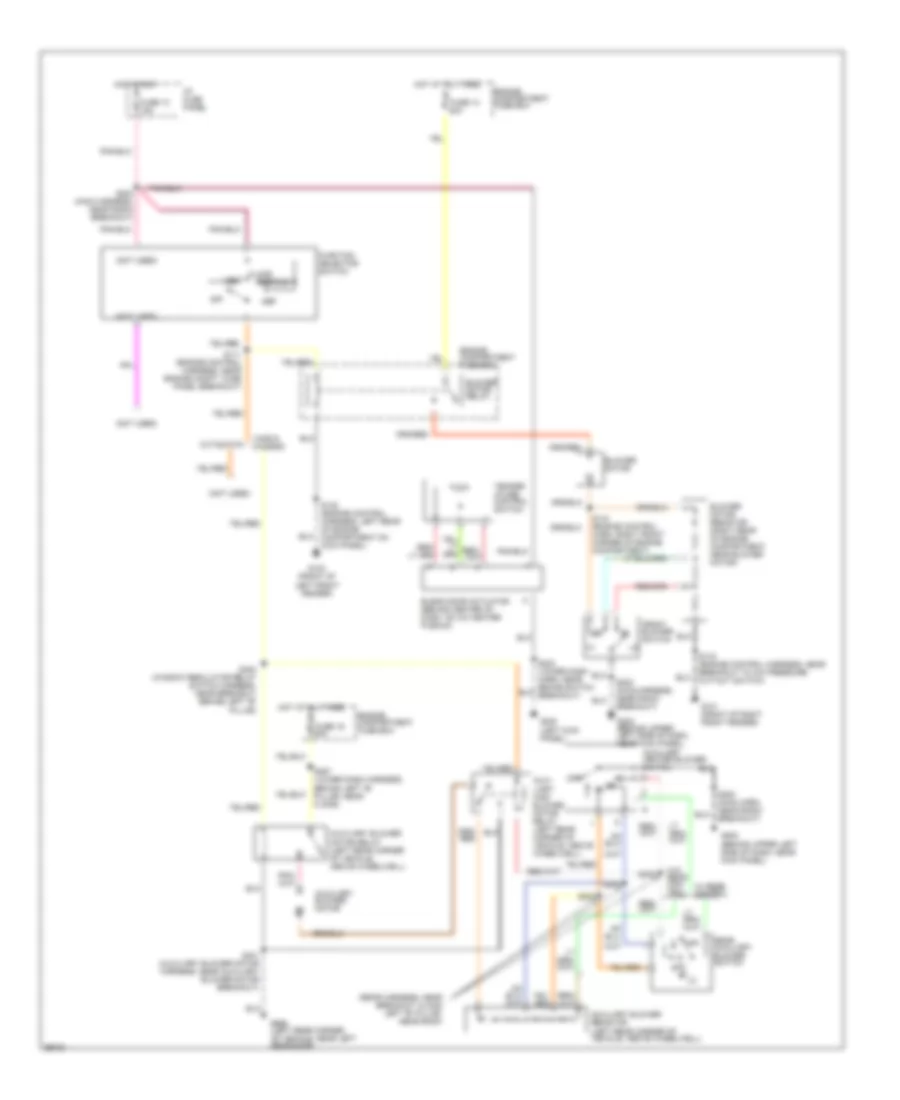
AIR CONDITIONING
A/C Wiring Diagram for Ford RV Cutaway E350 1998

List of elements for A/C Wiring Diagram for Ford RV Cutaway E350 1998:
- (front of right front fender) g101
- (left front of engine compartment, at left upper radiator support) g100
- (not used)
- (rear harness, near breakout along left "b" pillar, near roof)
- A/c clutch cycling pressure switch (right front of engine compartment)
- A/c compressor clutch
- A/c comressor clutch diode
- A/c pressure cut-out switch (right front of engine compartment)
- Auxiliary a/c-heater blower switch
- Auxiliary blower motor
- Auxiliary blower motor relay (left rear corner of vehicle, above wheelwell)
- Auxiliary blower resistor (left rear corner of vehicle, above wheelwell)
- Auxiliary high blower motor relay (left rear corner of vehicle, above wheelwell)
- Blend door actuator (behind right side of dash)
- Blower motor
- Blower motor relay
- Blower motor resistor (right rear of engine compartment, near blower motor)
- Cutaways
- Def/flr
- Defrost
- Diesel
- Engine compartment fuse box
- Floor
- Front blower switch
- Function selector switch
- Fuse 13 15a
- Fuse 13 50a
- Fuse 16 50a
- G200 (left kick panel)
- G202 (left side of dash, near kick panel)
- G999 (left rear corner of vehicle, near left rear door)
- Gasoline
- Hot at all times
- Hot in run
- I/p fuse panel
- Lo/ rear
- Max a/c
- Norm a/c
- Off
- Powertrain control module (pcm) (left rear of engine compartment, near brake master cylinder)
- Rear auxiliary blower switch
- S111 (engine control harness, near engine compartment fuse panel breakout)
- S122 (engine ctrl. harn, near breakout left rear of engine compartment on cowl)
- S141 (eng cntrl harn, near mass air flow sensor breakout)
- S143 (engine control harness, near breakout to a/c pressure cut-out switch)
- S143 (engine ctrl harness, near breakout to a/c pressure cut-out switch)
- S144 (engine ctrl harn, right front corner of eng compt)
- S202 (main harn, near radio breakout)
- S202 (main harness, near radio break- out) g202 (behind upper left side of dash, near kick panel)
- S203 (main harness, near radio breakout)
- S223 (lower i/p harn, near brake switch breakout)
- S257 (lower i/p harness, behind left "b" pillar, near floor)
- S303
- S304
- S305
- S400 (window regulator relay switch harness, near breakout behind left "b" pillar)
- S401 (auxiliary blower motor harness, near auxiliary blower motor breakout)
- Temper- ature control switch
- Vans & wagons
- Vent
- Vent norm a/c
- W/ rear control
- W/o rear con- trol
Heater Wiring Diagram for Ford RV Cutaway E350 1998
List of elements for Heater Wiring Diagram for Ford RV Cutaway E350 1998:
- (not used)
- (rear harness, near breakout along left "b" pillar, near roof)
- Auxi- liary high blower motor relay (left rear corner of vehicle, above wheelwell)
- Auxiliary blower motor
- Auxiliary blower motor relay (left rear corner of vehicle, above wheelwell)
- Auxiliary blower resistor (left rear corner of vehicle, above wheelwell)
- Auxiliary heater blower switch
- Blend door actuator (behind center of dash, on a/c heater plenum)
- Blower motor
- Blower motor relay
- Blower motor resistor (right rear of engine compartment, near blower motor)
- Cutaways
- Def
- Def/flr
- Engine compartment fuse box
- Floor
- Front blower switch
- Function selector switch
- Fuse 13 15a
- Fuse 13 50a
- Fuse 16 50a
- G100 (front of left front fender)
- G101 (front of right front fender)
- G200 (left kick panel)
- G202 (behind upper left side of dash, near kick panel)
- G999 (left rear corner of vehicle, near left rear door)
- Hot at all times
- Hot in run
- I/p fuse panel
- Off
- Rear auxiliary blower switch
- S111 (engine control harness, near engine compt. fuse panel breakout)
- S122 (engine control harness, left rear of engine compartment on kick panel)
- S143 (engine control harness, near breakout to a/c pressure cut-out switch)
- S144 (engine control harn, right front corner of engine compartment)
- S202 (main harn, near radio breakout)
- S202 (main harness, near radio breakout)
- S203 (main harness, near radio breakout)
- S223 (lower dash harn, near brake switch breakout)
- S257 (lower dash harness, behind left "b" pillar, near floor)
- S303
- S304
- S305
- S400 (window regulator relay switch harness, near breakout behind left "b" pillar)
- S401 (auxiliary blower motor harness, near auxiliary blower motor breakout)
- Temper- ature control switch
- Vans & wagons
- Vent
- W/ rear control
- W/o rear con- trol
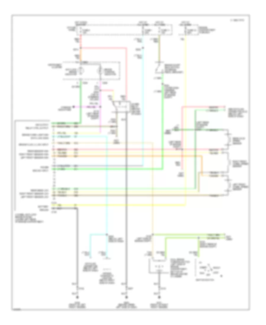
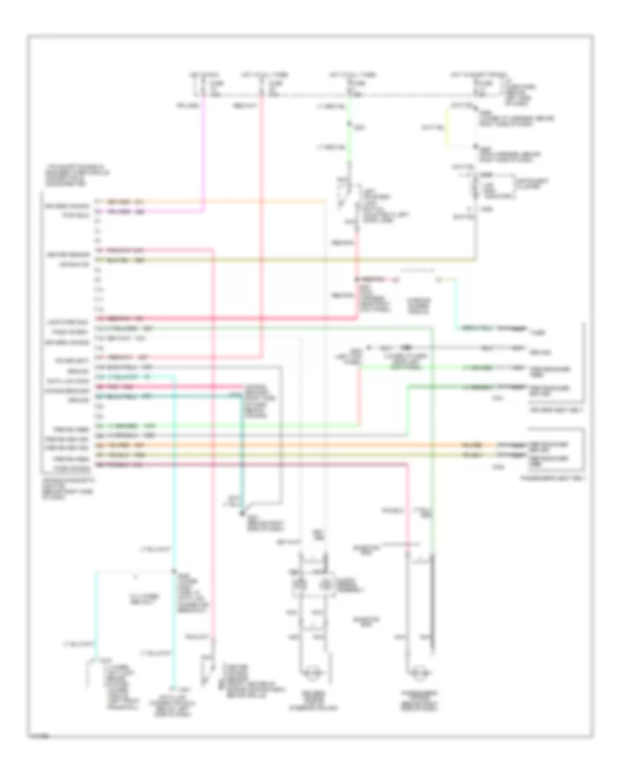
ANTI-LOCK BRAKES
All-Wheel ABS Wiring Diagram for Ford RV Cutaway E350 1998
List of elements for All-Wheel ABS Wiring Diagram for Ford RV Cutaway E350 1998:
- (left rear of engine compt) s117
- (left rear of engine compt) s124
- (not (not used) used)
- (not used)
- 4 wheel anti-lock brake system (lower left rear of engine compartment)
- 4wabs relay (behind center of dash)
- Abs datalink connector (dlc) (below left side of dash)
- Accy
- Air bag diagnostic monitor (below right side of dash)
- Anti-lock brake indicator
- Battery
- Boo sw input
- Brake fluid lvl sw input
- Brake on/off (boo) switch (on brake pedal bracket)
- Brake warn lamp high
- Brake warning indicator
- C 1995 vftc
- C144
- C145
- C225
- C226
- Data link conn
- Datalink connector (below left side of dash)
- Dual brake warning switch (left side of engine compartment, bottom of brake master cylinder)
- Engine compartment fuse box
- Fuse 1 20a
- Fuse 11 15a
- Fuse 19 60a
- Fuse 2 15a
- G100 (front of left front fender)
- G101 (front of right front fender)
- G202 (behind upper left side of dash)
- Ground
- Hot at all times
- Hot in run or start
- I/p fuse panel
- Ignition switch
- Ind output
- Instrument cluster
- Left front sensor high
- Left front sensor low
- Left front wheel speed sensor
- Lock
- Off
- Power
- Rear axle speed sensor
- Rear sens low
- Rear sensor high
- Red/ pnk
- Red/pnk
- Relay ctrl output
- Right front sensor high
- Right front sensor low
- Right front wheel speed sensor
- Run
- S119 (left rear of engine compt)
- S122
- S125 (left side of engine compt)
- S132 (right rear of engine compt)
- S143
- S207
- S213
- S220 (top of steering column)
- S222
- S224 (lower dash harness, left rear of engine compt)
- S228 (below left side of dash)
- S613
- Start
- Warning indicators
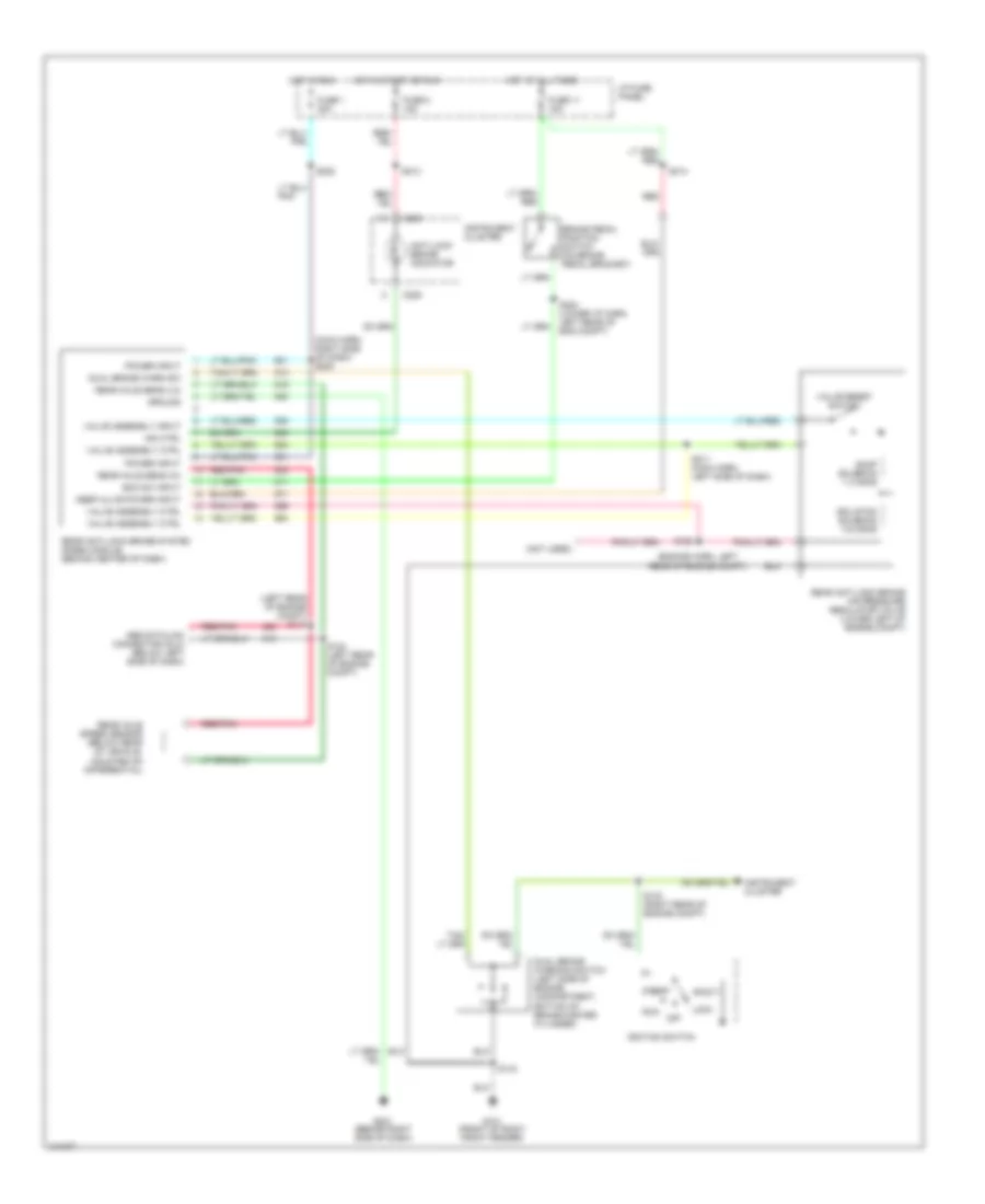
Rear Wheel ABS Wiring Diagram for Ford RV Cutaway E350 1998
List of elements for Rear Wheel ABS Wiring Diagram for Ford RV Cutaway E350 1998:
- (engine harn, left rear of engine compt)
- (left rear of engine compt) s117
- (main harn, right side of dash) s200
- (not used)
- Abs datalink connector (dlc) (below left side of dash)
- Accy
- Anti-lock brake indicator
- Boo sw input
- Brake pedal position switch (on brake pedal bracket)
- C225
- C226
- Dual brake warn sw
- Dual brake warning switch (left side of engine compartment, bottom of brake master cylinder)
- Dump solenoid 1-3 ohms
- Fuse 1 20a
- Fuse 11 15a
- Fuse 2 15a
- G101 (front of right front fender)
- G201 (behind right side of dash)
- Ground
- Hot at all times
- Hot in run
- Hot in start or run
- I/p fuse panel
- Ignition switch
- Ind ctrl
- Instrument cluster
- Isolation solenoid 3-6 ohms
- Keep alive power input
- Lock
- Off
- Pnk
- Power input
- Rear anti-lock brake air pressure regulator valve (lower left of engine compt)
- Rear anti-lock brake system (rabs) module (behind center of dash)
- Rear axle sens (hi)
- Rear axle sens (lo)
- Rear axle speed sensor (below rear of vehicle, mounted on differential)
- Red
- Red/pnk
- Run
- S123
- S124 (left rear of engine compt)
- S132 (right rear of engine compt)
- S143
- S211 (main harn, left side of dash)
- S213
- S214
- S222
- S224 (lower i/p harn, left rear of eng compt)
- Start
- Valve assembly ctrl
- Valve assembly input
- Valve reset switch
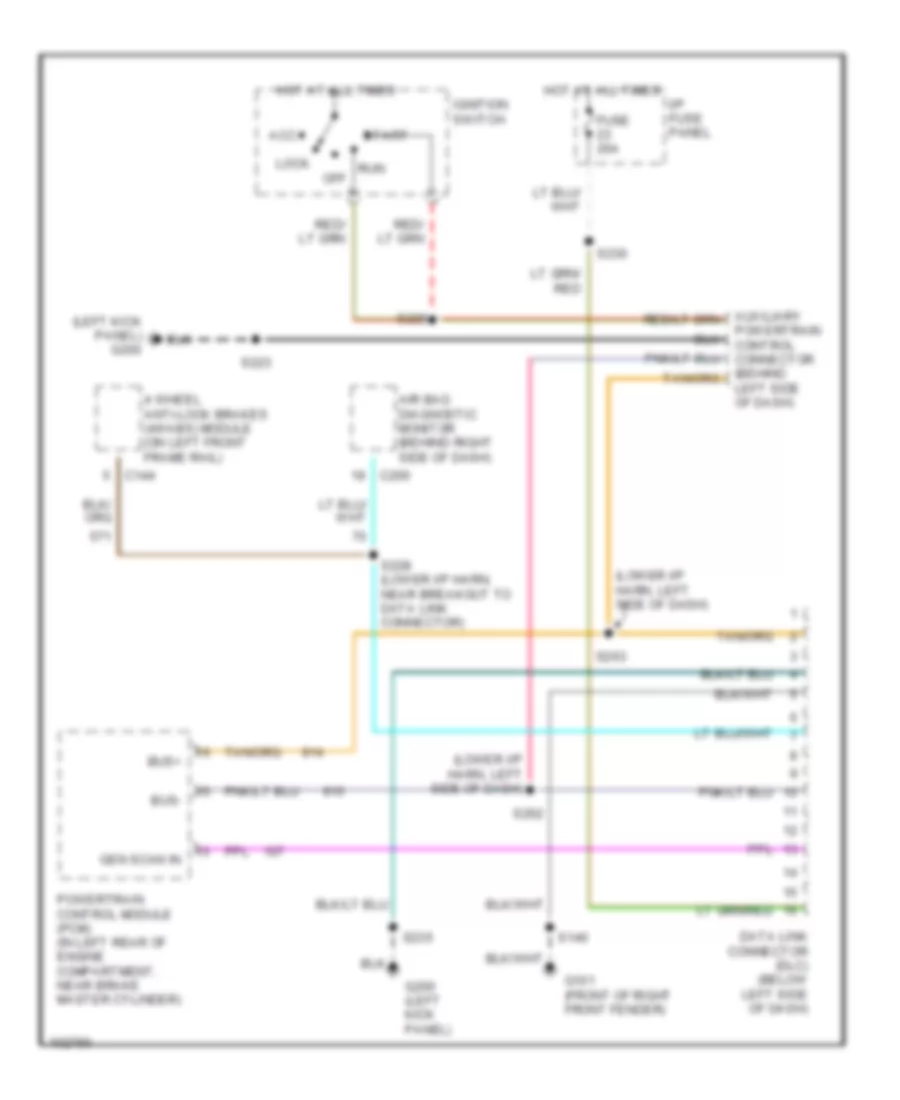
COMPUTER DATA LINES
5.4L
5.4L, Computer Data Lines for Ford RV Cutaway E350 1998
List of elements for 5.4L, Computer Data Lines for Ford RV Cutaway E350 1998:
- 4 wheel anti-lock brakes (4wabs) module (on left front frame rail)
- Air bag diagnostic monitor (behind right side of dash)
- Bus+
- Bus-
- C144
- C200
- Data link connector (dlc) (below left side of dash)
- Fuse 20a
- G101 (front of right front fender)
- G200 (left kick panel)
- Gen scan in
- Hot at all times
- I/p fuse panel
- Powertrain control module (pcm) (in left rear of engine compartment, near brake master cylinder)
- S140
- S228 (lower i/p harn, near breakout to data link connector)
- S230
- S235
6.8L
6.8L, Computer Data Lines for Ford RV Cutaway E350 1998
List of elements for 6.8L, Computer Data Lines for Ford RV Cutaway E350 1998:
- 4 wheel anti-lock brakes (4wabs) module (on left front frame rail)
- Air bag diagnostic monitor (behind right side of dash)
- Bus+
- Bus-
- C144
- C200
- Data link connector (dlc) (below left side of dash)
- Fuse 20a
- G101 (front of right front fender)
- G200 (left kick panel)
- Gen scan in
- Hot at all times
- I/p fuse panel
- Powertrain control module (pcm) (in left rear of engine compartment, near brake master cylinder)
- S140
- S228 (lower i/p harn, near breakout to data link connector)
- S230
- S235
7.3L
7.3L DI Turbo Diesel, Computer Data Lines for Ford RV Cutaway E350 1998
List of elements for 7.3L DI Turbo Diesel, Computer Data Lines for Ford RV Cutaway E350 1998:
- (left kick panel) g200
- (lower i/p harn, left side of dash)
- 4 wheel anti-lock brakes (4wabs) module (on left front frame rail)
- Acc
- Air bag diagnostic monitor (behind right side of dash)
- Auxiliary powertrain control connector (behind left side of dash)
- Bus+
- Bus-
- C144
- C200
- Data link connector (dlc) (below left side of dash)
- Fuse 20a
- G101 (front of right front fender)
- G200 (left kick panel)
- Gen scan in
- Hot at all times
- I/p fuse panel
- Ignition switch
- Lock
- Off
- Powertrain control module (pcm) (in left rear of engine compartment, near brake master cylinder)
- Run
- S140
- S223
- S228 (lower i/p harn, near breakout to data link connector)
- S229
- S230
- S235
- S262
- S263
- Start
CRUISE CONTROL
5.4L
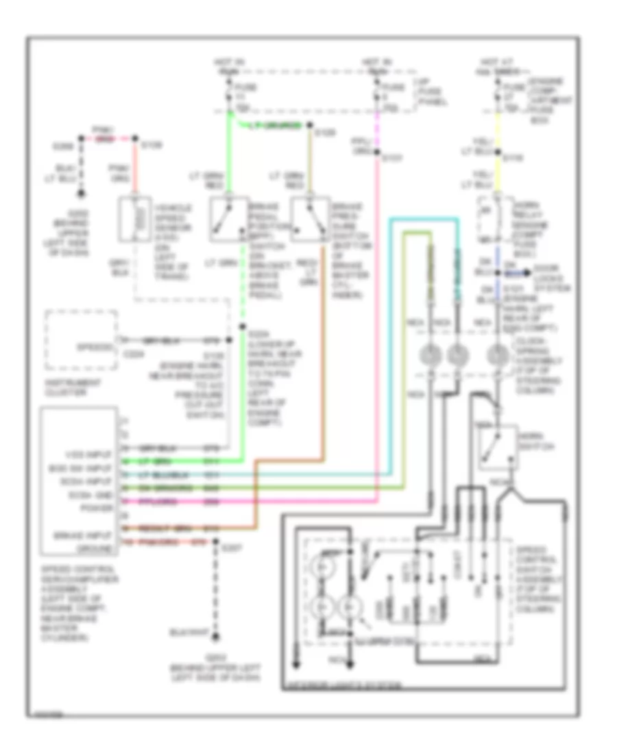
5.4L, Cruise Control Wiring Diagram for Ford RV Cutaway E350 1998
List of elements for 5.4L, Cruise Control Wiring Diagram for Ford RV Cutaway E350 1998:
- (engine harn, left rear of eng compt)
- Accel set/
- Boo sw input
- Brake input
- Brake pedal position (bpp) switch (on bracket, above brake pedal)
- Brake pres- sure switch (bottom of brake master cyl- inder)
- C224
- Clock- spring assembly (top of steering column)
- Coast
- Door locks system
- Engine comp- artment fuse box
- Fuse 10a
- Fuse 15a
- G202 (behind upper left left side of dash)
- G202 (behind upper left side of dash)
- Ground
- Horn relay (engine compt fuse box)
- Horn switch
- Hot at all times
- Hot in run
- I/p fuse panel
- Illumination
- Instrument cluster
- Interior lights system
- Nca
- Off
- Ohms
- Power
- Resume
- S116
- S129
- S131
- S135 (engine harn, near breakout to a/c pressure cut-out switch)
- S139
- S207
- S224 (lower i/p harn, near breakout to 76 pin conn, left rear of engine compt)
- S268
- Scsa gnd
- Scsa input
- Speed control servo/amplifier assembly (left side of engine compt, near brake master cylinder)
- Speed control switch assembly (top of steering column)
- Speedo
- Vehicle speed sensor (vss) (on left side of trans)
- Vss input
6.8L
6.8L, Cruise Control Wiring Diagram for Ford RV Cutaway E350 1998
List of elements for 6.8L, Cruise Control Wiring Diagram for Ford RV Cutaway E350 1998:
- (engine harn, left rear of eng compt)
- Accel set/
- Boo sw input
- Brake input
- Brake pedal position (bpp) switch (on bracket, above brake pedal)
- Brake pres- sure switch (bottom of brake master cyl- inder)
- C224
- Clock- spring assembly (top of steering column)
- Coast
- Door locks system
- Engine comp- artment fuse box
- Fuse 10a
- Fuse 15a
- G202 (behind upper left left side of dash)
- G202 (behind upper left side of dash)
- Ground
- Horn relay (engine compt fuse box)
- Horn switch
- Hot at all times
- Hot in run
- I/p fuse panel
- Illumination
- Instrument cluster
- Interior lights system
- Nca
- Off
- Ohms
- Power
- Resume
- S116
- S129
- S131
- S135 (engine harn, near breakout to a/c pressure cut-out switch)
- S139
- S207
- S224 (lower i/p harn, near breakout to 76 pin conn, left rear of engine compt)
- S268
- Scsa gnd
- Scsa input
- Speed control servo/amplifier assembly (left side of engine compt, near brake master cylinder)
- Speed control switch assembly (top of steering column)
- Speedo
- Vehicle speed sensor (vss) (on left side of trans)
- Vss input
7.3L
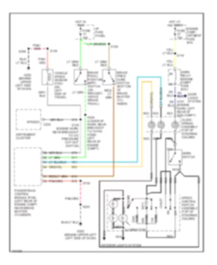
7.3L DI Turbo Diesel, Cruise Control Wiring Diagram for Ford RV Cutaway E350 1998
List of elements for 7.3L DI Turbo Diesel, Cruise Control Wiring Diagram for Ford RV Cutaway E350 1998:
- (engine harn, left rear of eng compt)
- Accel set/
- Brake pedal position (bpp) switch (on bracket, above brake pedal)
- Brake pres- sure switch (bottom of brake master cyl- inder)
- C224
- Clock- spring assembly (top of steering column)
- Coast
- Door locks system
- Engine comp- artment fuse box
- Fuse 15a
- G202 (behind upper left left side of dash)
- G202 (behind upper left side of dash)
- Horn relay (engine compt fuse box)
- Horn switch
- Hot at all times
- Hot in run
- I/p fuse panel
- Illumination
- Instrument cluster
- Interior lights system
- Nca
- Off
- Ohms
- Powertrain control module (pcm) (left rear of engine compt, near brake master cylinder)
- Resume
- S116
- S129
- S135 (engine harn, near breakout to a/c pressure cut-out switch)
- S139
- S205
- S224 (lower i/p harn, near breakout to 76 pin conn, left rear of engine compt)
- S268
- Speed control switch assembly (top of steering column)
- Speedo
- Vehicle speed sensor (vss) (on left side of trans)
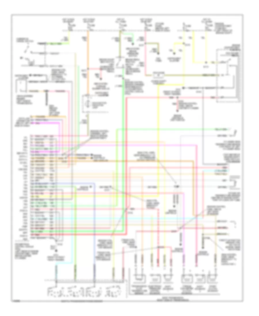
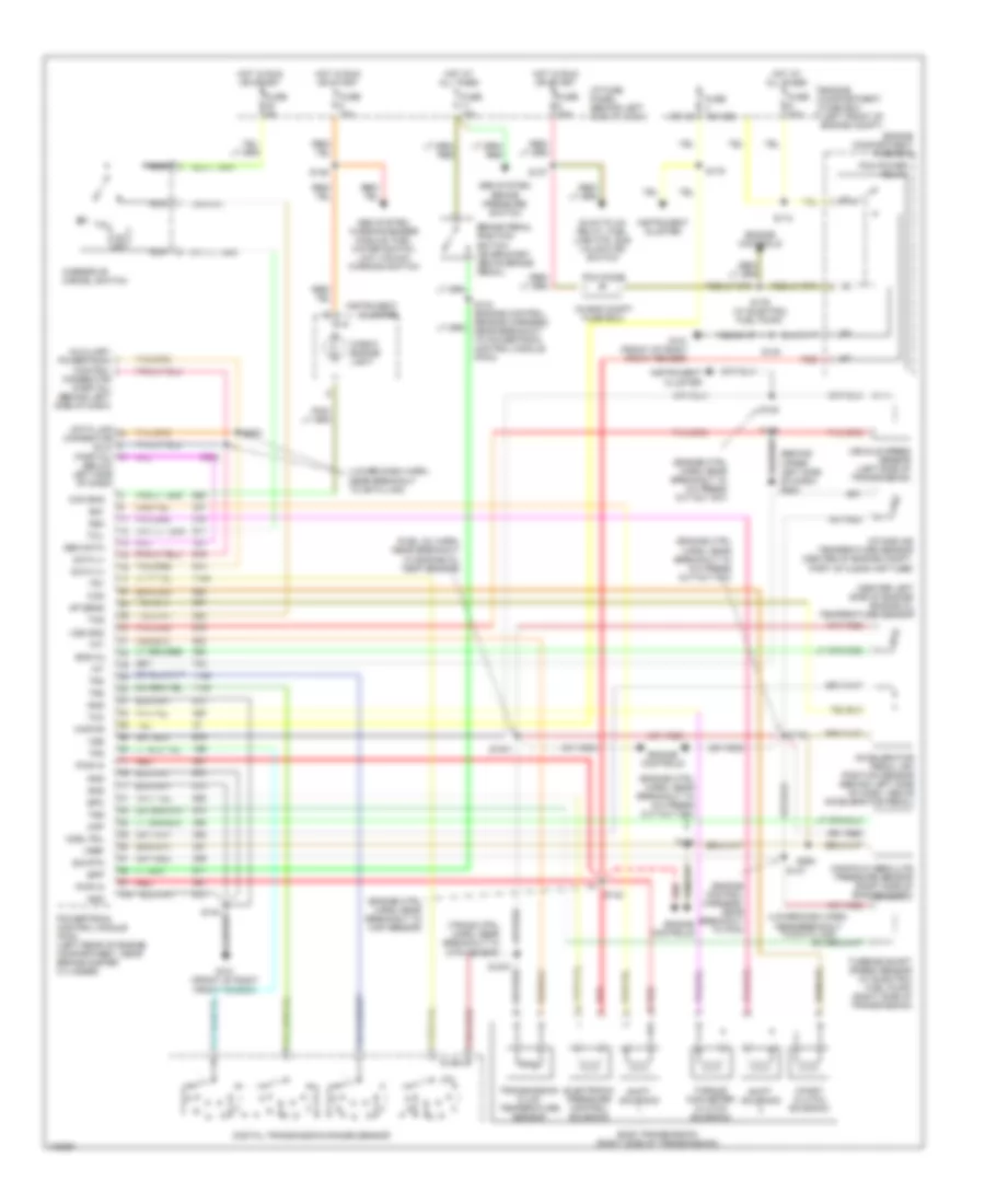
ENGINE PERFORMANCE
5.4L
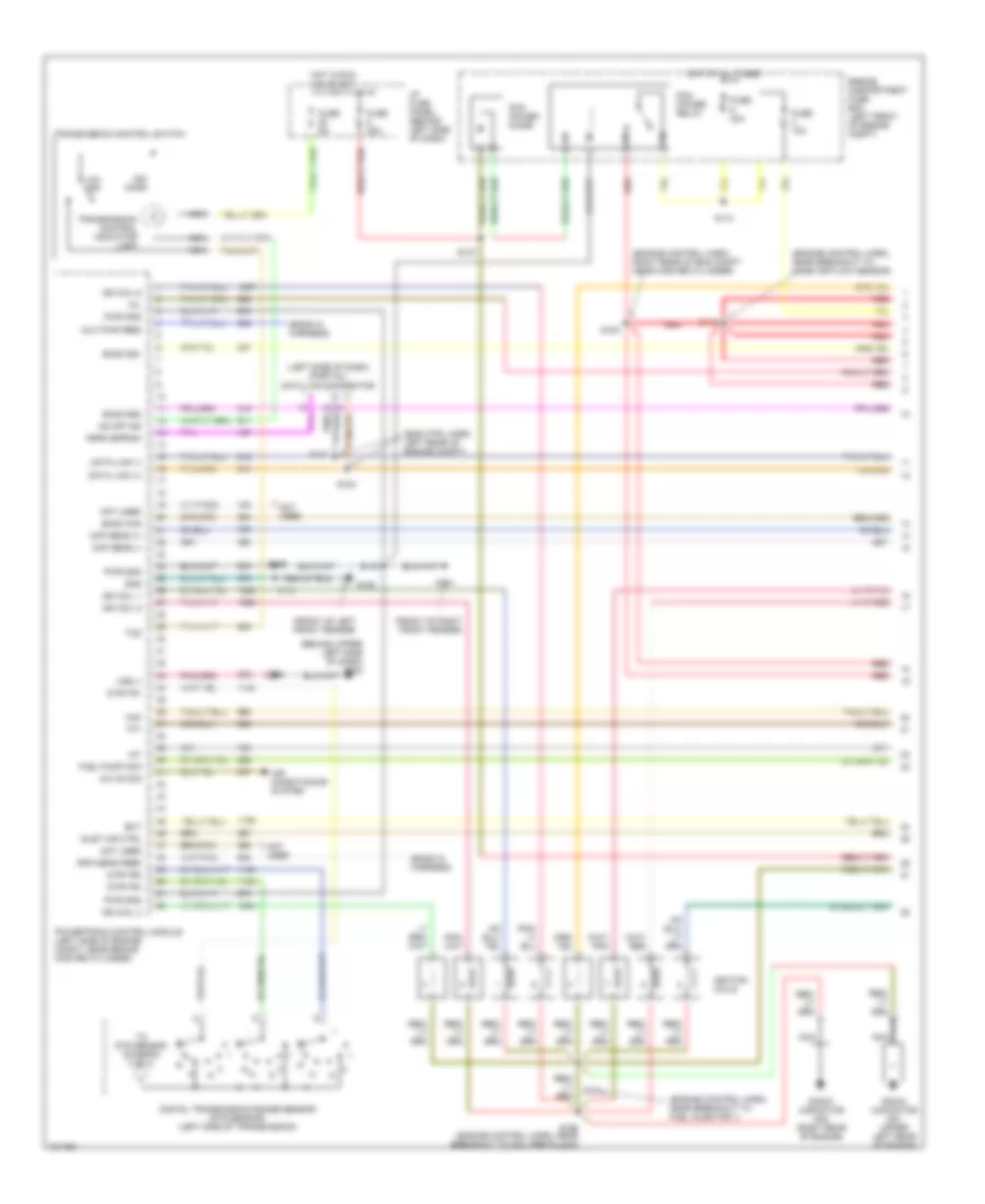
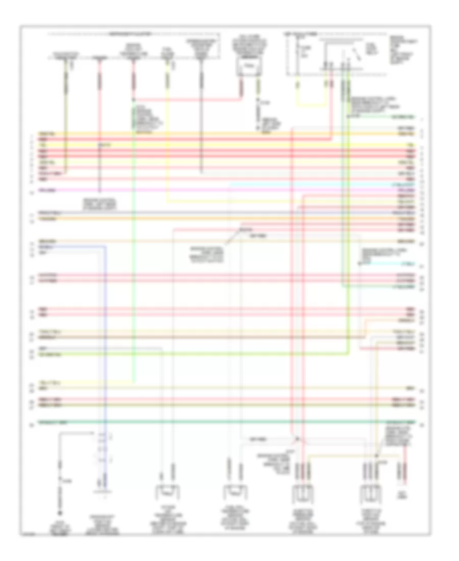
5.4L CNG, Engine Performance Wiring Diagrams (1 of 5) for Ford RV Cutaway E350 1998
List of elements for 5.4L CNG, Engine Performance Wiring Diagrams (1 of 5) for Ford RV Cutaway E350 1998:
- (behind upper left side of dash) g202
- (ends in harness)
- (eng ctrl harn, left rear of engine compt)
- (engine control harn, near breakout to fuel injector 1)
- (engine control harn, near breakout to mass air flow sensor)
- (engine control harn, right rear of eng compt near master cylinder)
- (front of left front fender)
- (front of right front fender)
- (left side of dash) (partial) data link connector
- A/c on sig
- Air conditioning system
- Aux pwr feed
- Ckp sens (+)
- Ckp sens (-)
- Data link (+)
- Data link (-)
- Digital transmission range sensor (dtr sensor) (left side of transmission)
- Dtr-tr1
- Dtr-tr2
- Dtr-tr4
- E4od ccs
- E4od ss1
- E4od ss2
- Ect
- Engine compartment fuse box (left front of engine compt)
- Feps (eprom)
- Fuel pump mon
- Fuse 10a
- Fuse 30a
- Fuse 5a
- G100
- G101
- Gnd
- Hot at all times
- Hot in run or start
- I/p fuse panel (behind left side of dash)
- Iat
- Ign coil 1
- Ign coil 3
- Ign coil 5
- Ign coil 6
- Ignition coils
- Inlet air ctrl
- Maf
- Mil
- Nca
- Not used
- O/d off
- Od off ind
- Ohms
- Pcm power diode
- Pcm power relay
- Powertrain control module (left side of engine compt, near brake master cylinder)
- Pwr gnd
- R n
- Radio capacitor no1 (upper left rear of engine)
- Radio capacitor no2 (right rear of engine)
- Red
- Rpm sens feed
- S110
- S127
- S140
- S142
- S156 (engine control harn, near breakout to coil per plug 6)
- S161
- S169
- S180
- S181
- S182
- S184
- S268
- Tcs
- Tft
- To dtr sensor (diagram 4 of 4)
- Transmission control indicator lamp
- Transmission control switch
- Vss (-)
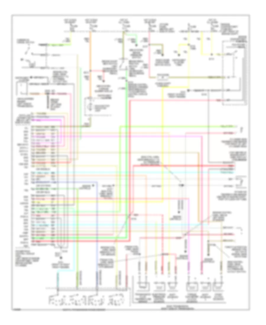
5.4L CNG, Engine Performance Wiring Diagrams (2 of 5) for Ford RV Cutaway E350 1998
List of elements for 5.4L CNG, Engine Performance Wiring Diagrams (2 of 5) for Ford RV Cutaway E350 1998:
- (behind left side of dash) g202
- (engine control harn, left rear of engine compt)
- (engine control harn, near breakout to 76-pin conn in left rear of engine compt) s126
- (engine control harn, near breakout to a/c cutout switch)
- (engine control harn, near breakout to coil per plug 9)
- (engine control harn, near breakout to pcm) s137
- (engine ctrl harn, near breakout to radio noise capacitor 1)
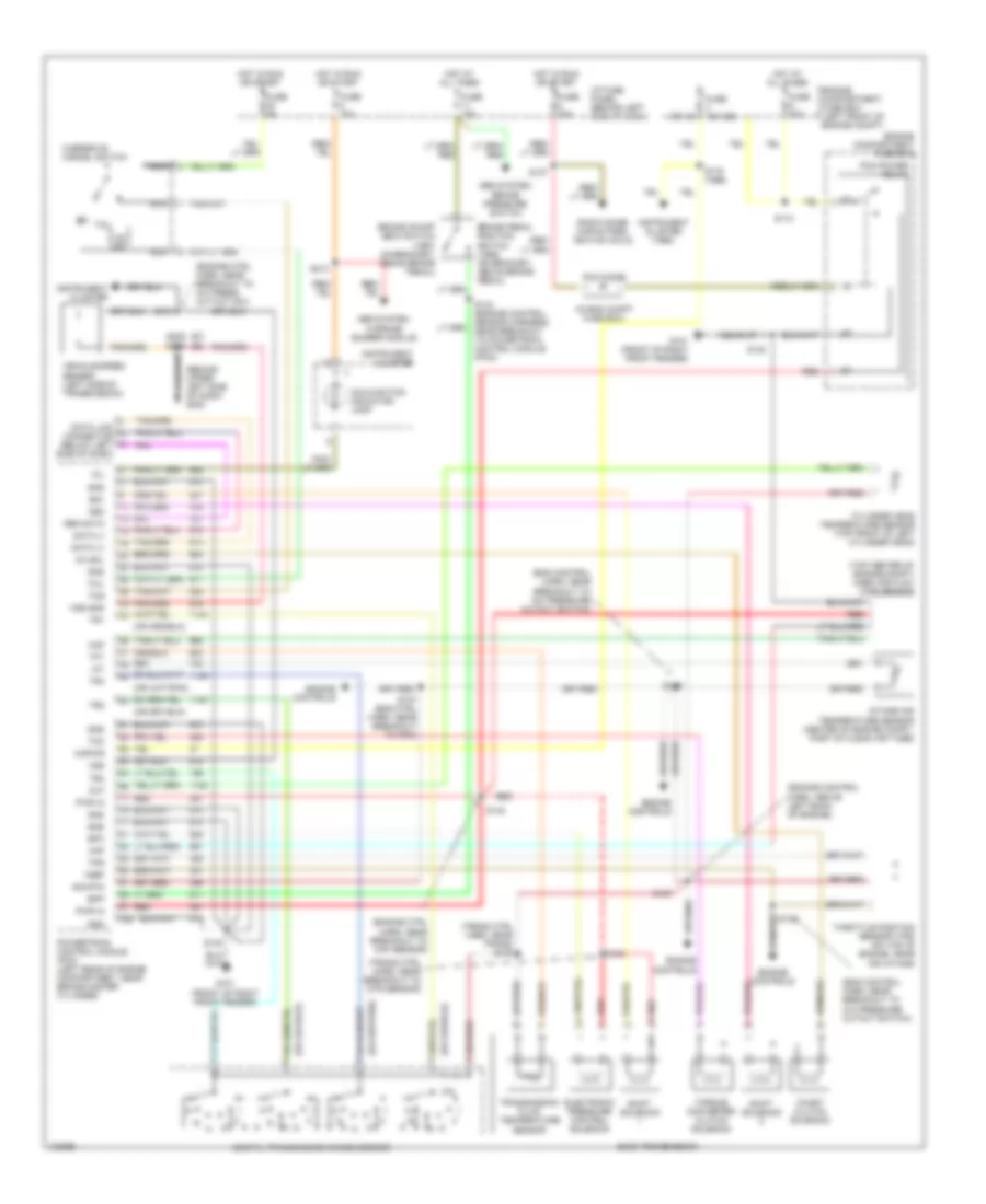
- (on lower intake manifold) instrumentation engine coolant temperature sensor
- (speedometer/ odometer) vehicle speed input
- C224
- C225
- Crankshaft position sensor (lower center front of engine)
- Engine compartment fuse box (left front of engine compt)
- Engine coolant temperature gauge
- Fuel guage input
- Fuel pump relay
- Fuel rail temperature sensor (on fuel rail, on right bank of engine)
- Fuse 30a
- G100 (front of left front fender)
- Hot at all times
- Injection pressure sensor (on fuel rail, on right bank of engine)
- Instrument cluster
- Intake air temperature sensor (center of engine compt, part of clean air tube)
- Malfunction indicator
- Not used
- Power
- Red
- Red/pnk
- S136
- S139
- S157
- S158
- S169
- S175
- Throttle position sensor (top of engine, near air intake)
5.4L CNG, Engine Performance Wiring Diagrams (3 of 5) for Ford RV Cutaway E350 1998
List of elements for 5.4L CNG, Engine Performance Wiring Diagrams (3 of 5) for Ford RV Cutaway E350 1998:
- (behind right kick panel) inertia fuel shut-off switch
- (behind upper left side of dash) g202
- (front of left front fender) g10o
- (front of right front fender) g101
- (fuel tank harn, under left center of vehicle)
- (right side of engine, on fuel rail)
- (transmission control harn, near breakout to dtr sensor)
- (transmission control harn, near breakout to transmission)
- (under left center of vehicle)
- Coast clutch solenoid
- E4od transmission
- Electronic pressure control solenoid
- Engine compartment fuse box (left front of engine compt)
- Forward aft-axle fuel tank
- Fuel rail cut-off valve
- Fuel tank sender
- Fuse 20a
- Hot at all times
- Midship fuel tank valve
- Ngv timer (left rear of engine compt)
- Rear aft-axle fuel tank
- Red
- Red/pnk
- S100
- S102
- S185 (engine ctrl harn, left rear of eng compt)
- S189
- S268
- S317
- S318
- S319
- S320
- Shift solenoid
- Starting/ charging system
- Torque converter clutch solenoid
- Transmission fluid temperature sensor
- Valve (near aft- axle fuel tank assy)
5.4L CNG, Engine Performance Wiring Diagrams (4 of 5) for Ford RV Cutaway E350 1998
List of elements for 5.4L CNG, Engine Performance Wiring Diagrams (4 of 5) for Ford RV Cutaway E350 1998:
- (eng ctrl harn, near breakout to e4od trans)
- (eng ctrl harn, near breakout to iat sensor)
- (engine ctrl harn, near breakout to coil plug 2)
- (front of left front fender)
- (fuel tank harn, near breakout to fuel tank temp sensor)
- (left front of engine)
- Data (+)
- Data (-)
- Fuel gauge
- Fuel injector
- Fuel press
- Fuel tank pressure sensor (under left center of vehicle, near fuel tank)
- Fuel tank temperature sensor (under left center of vehicle)
- Fuel temp
- G100
- Ground
- Ignition
- Inj no1 input
- Inj no1 out
- Inj no2 input
- Inj no2 out
- Inj no3 input
- Inj no3 out
- Inj no4 input
- Inj no4 out
- Inj no5 input
- Inj no5 out
- Inj no6 input
- Inj no6 out
- Inj no7 input
- Inj no7 out
- Inj no8 input
- Inj no8 out
- Inlet air control sensor
- Ngv module (on left rear of engine compt, near brake master cylinder)
- Power
- Red
- Red/pnk
- S155 (engine ctrl harn, near breakout to fuel injector 6)
- S159
- S160
- S181
- S188
- S316
- Sig return
- Tan
- Tan/ red
- Tan/red
- Timer
5.4L CNG, Engine Performance Wiring Diagrams (5 of 5) for Ford RV Cutaway E350 1998
List of elements for 5.4L CNG, Engine Performance Wiring Diagrams (5 of 5) for Ford RV Cutaway E350 1998:
- (behind upper left side of dash)
- (engine control harn, near breakout to a/c cutout switch)
- (front of left cylinder head) cylinder head temperature sensor
- (left side of transmission) vehicle speed sensor
- (near brake master cylinder) speed control servo/amplifier assembly
- 270 ohms
- 5v ref
- Brake on/off
- Brake pedal position switch
- Camshaft position sensor (on front of left cylinder head)
- Camshaft position sensor shield
- Cmp sensor
- Cyl head temp
- Digital transmission range sensor (dtr sensor) (left side of transmission)
- Dtr-tr3a
- Epc sol
- From dtr sensor (diagram 1 of 4)
- Fuel inj 1
- Fuel inj 2
- Fuel inj 3
- Fuel inj 4
- Fuel inj 5
- Fuel inj 6
- Fuel inj 7
- Fuel inj 8
- Fuel pump ctrl
- Fuel temp
- Fuse 15a
- G100 (front of left front fender)
- G101 (front of right front fender)
- G202
- Heated oxygen sensor (ho2s 11) (lower right rear of engine)
- Heated oxygen sensor (ho2s 21) (lower left rear of engine)
- Ho2s (11) htr
- Ho2s (21) htr
- Ho2s sig (11)
- Ho2s sig (21)
- Hot at all times
- I/p fuse panel (behind left side of dash)
- Idle air control valve (top center rear of engine, near air intake)
- Idle air ctrl
- Ign coil 2
- Ign coil 4
- Ign coil 7
- Ign coil 8
- Inj press
- Kap b(+)
- Maf sens in
- Mass air flow sensor (top center of engine)
- Nca
- Not used
- Powertrain control module (left rear of engine compt, near brake master cylinder)
- Pwr gnd
- Red
- Red/pnk
- S135
- S139
- S140
- S169
- S170
- S171
- Sig rtn
- Tan
- Tan/red
- Tcc sol
- Tp sens in
- Vpwr
- Vss (+)
- Vss input
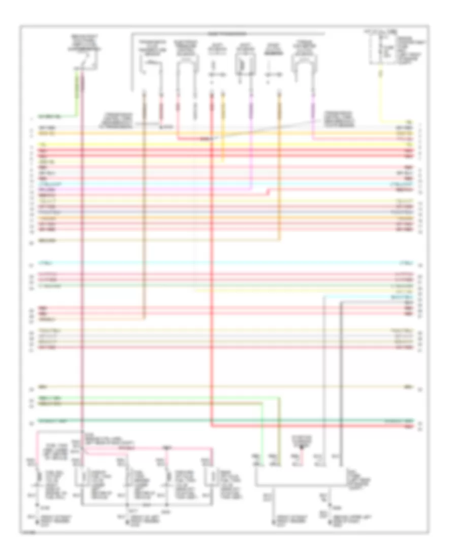
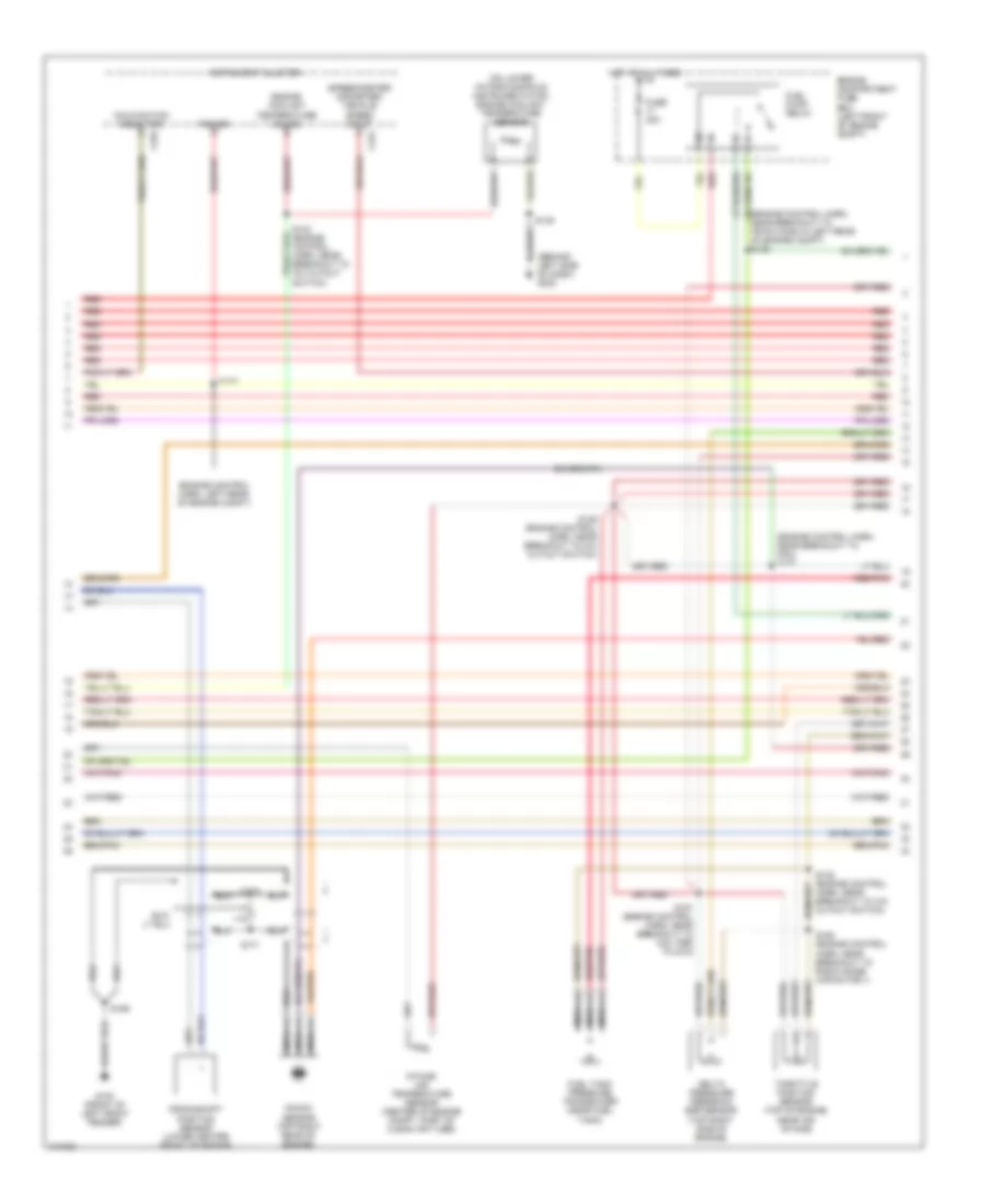
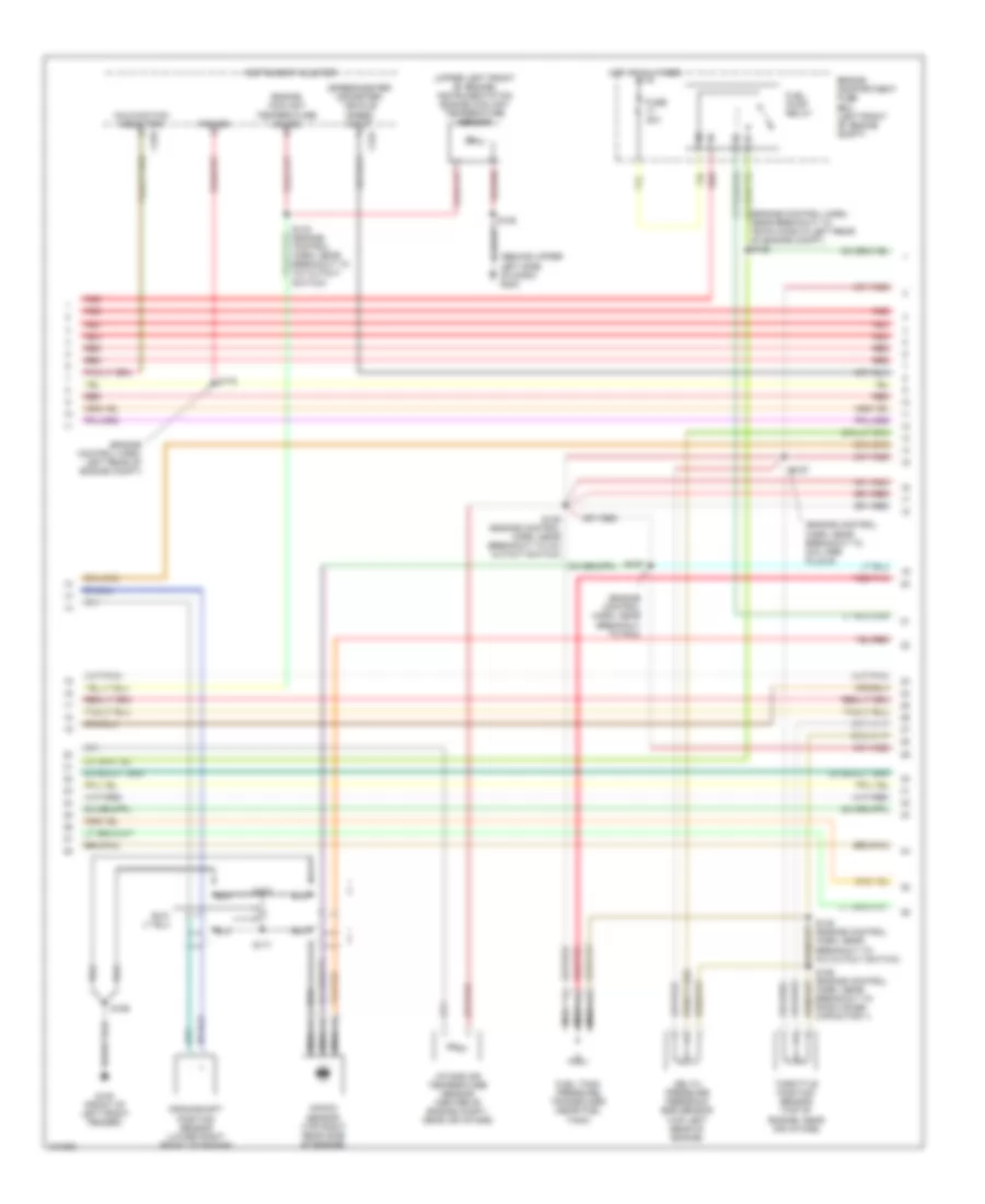
5.4L, Engine Performance Wiring Diagrams (1 of 4) for Ford RV Cutaway E350 1998
List of elements for 5.4L, Engine Performance Wiring Diagrams (1 of 4) for Ford RV Cutaway E350 1998:
- (behind upper left side of dash) g202
- (ends in harness)
- (engine control harn, near breakout to coil per plug 6)
- (engine control harn, near breakout to fuel injector 1)
- (engine control harn, near breakout to mass air flow sensor)
- (front of left front fender)
- (front of right front fender) g101
- A/c on sig
- Air conditioning system
- Data link (+)
- Data link (-)
- Data link connector (partial) (left side of dash)
- Digital transmission range sensor (dtr sensor) (left side of transmission)
- Dtr-tr1
- Dtr-tr2
- Dtr-tr4
- E4od ccs
- E4od ss1
- E4od ss2
- Ect
- Engine compartment fuse box (left front of engine compt)
- Evr sol
- Feps (eprom)
- Fp sending unit
- Fuel pump mon
- Fuse 10a
- Fuse 30a
- Fuse 5a
- G100
- Gnd
- Hot at all times
- Hot in run or start
- I/p fuse panel (behind left side of dash)
- Iat
- Ign coil 1
- Ign coil 3
- Ign coil 5
- Ign coil 6
- Ignition coils
- Inlet air ctrl
- Instrument cluster system
- Maf
- Mil
- Misfire sens (+)
- Misfire sens (-)
- Nca
- Not used
- O/d off
- Od off ind
- Overdrive cancel switch
- Pcm power diode
- Pcm power relay
- Powertrain control module (left side of engine compt, near brake master cylinder)
- Pwr gnd
- R n
- Radio capacitor no 1 (upper left rear of engine
- Radio capacitor no 2 (right rear of engine)
- Rear ho2s (22)
- Red
- S110
- S127
- S140
- S142
- S156
- S161
- S169
- S181
- S268
- Tcs
- Tft
- To dtr sensor (diagram 4 of 4)
- Transmission control indicator lamp
- Vss (-)
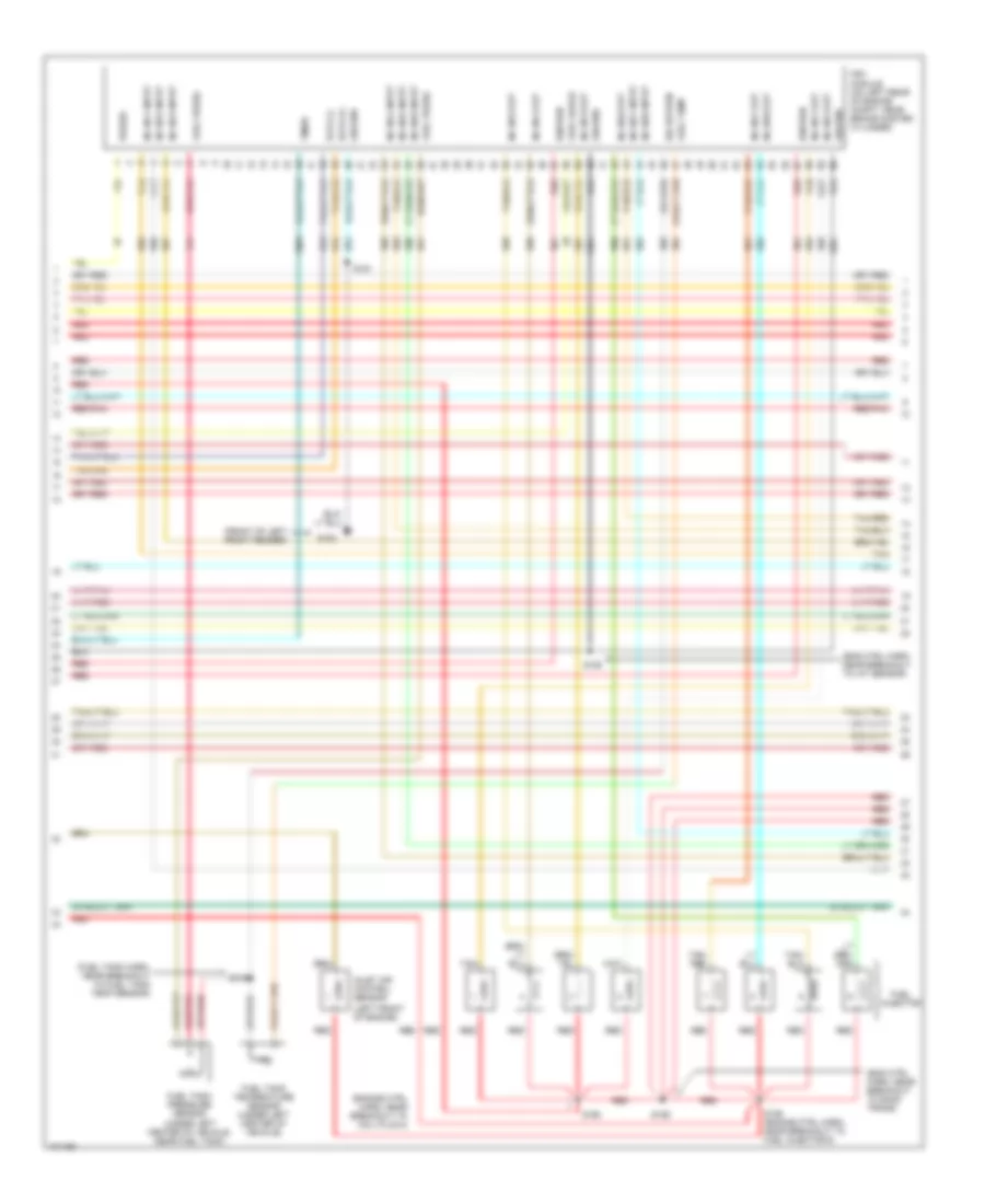
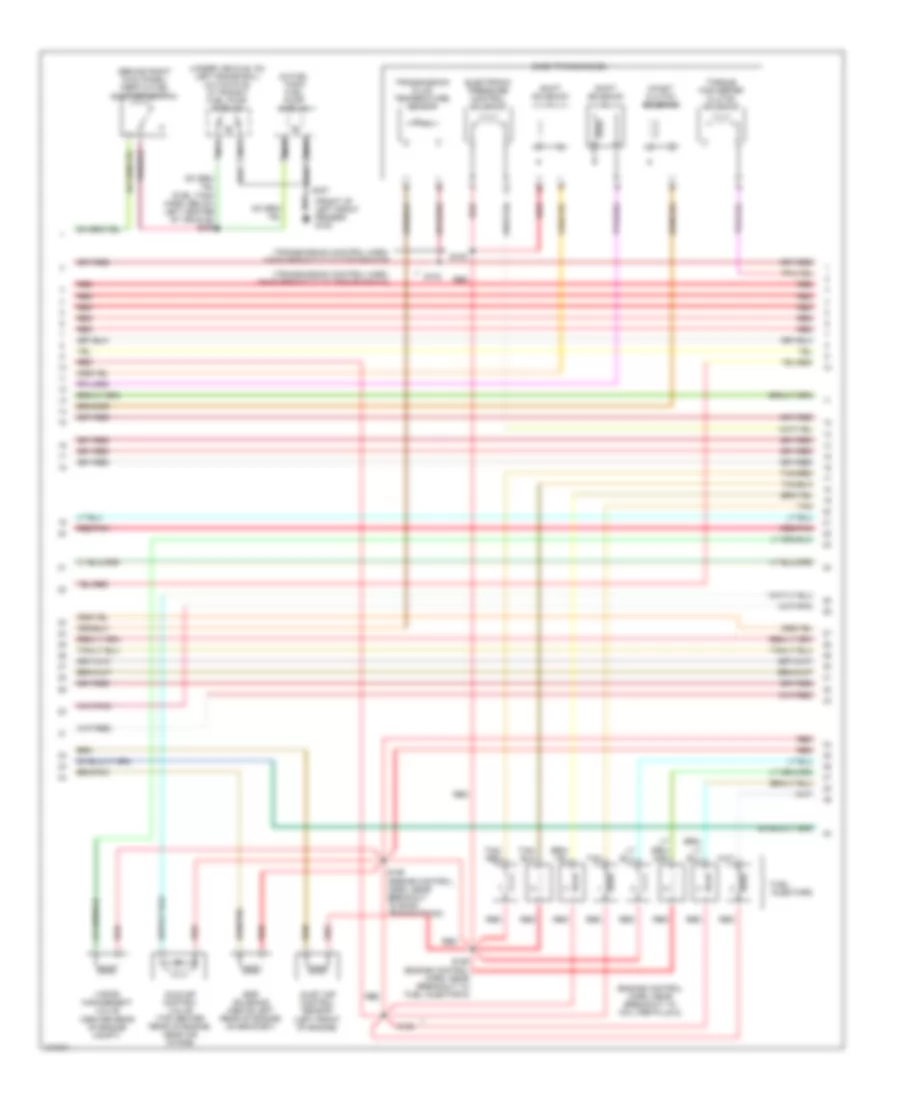
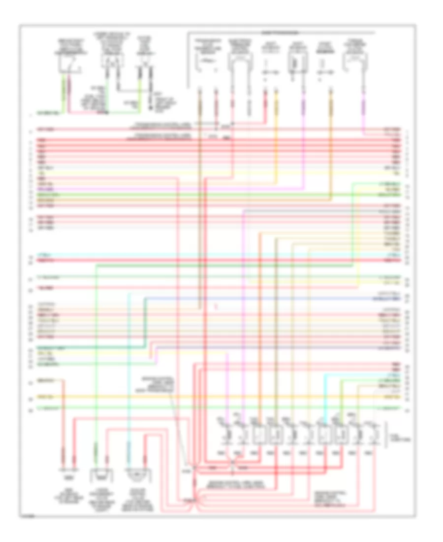
5.4L, Engine Performance Wiring Diagrams (2 of 4) for Ford RV Cutaway E350 1998
List of elements for 5.4L, Engine Performance Wiring Diagrams (2 of 4) for Ford RV Cutaway E350 1998:
- (behind left side of dash) g202
- (engine control harn, left rear of engine compt)
- (engine control harn, near breakout to 76-pin conn in left rear of engine compt) s126
- (engine control harn, near breakout to pcm) s137
- (on lower intake manifold) instrumentation engine coolant temperature sensor
- (speedometer/ odometer) vehicle speed input
- C224
- C225
- Crankshaft position sensor (lower center front of engine)
- Delta pressure feedback egr sensor (top right side of engine)
- Engine compartment fuse box (left front of engine compt)
- Engine coolant temperature gauge
- Fuel pump relay
- Fuel tank pressure transducer (near fuel tank)
- Fuse 30a
- G100 (front of left front fender)
- Hot at all times
- Instrument cluster
- Intake air temperature sensor (center of engine compt, part of clean air tube)
- Knock sensor (top right rear of engine)
- Malfunction indicator
- Nca
- Power
- Red
- Red/pnk
- S136 (engine control harn, near breakout to a/c cutout switch)
- S138 (engine control harn, near breakout to a/c cutout switch)
- S139
- S157 (engine control harn, near breakout to coil per plug 9)
- S158 (engine control harn, near breakout to radio noise capacitor 1)
- S169
- S170
- S171
- S175
- Throttle position sensor (top of engine, near air intake)
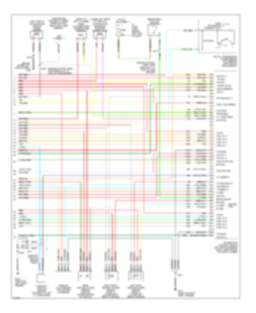
5.4L, Engine Performance Wiring Diagrams (3 of 4) for Ford RV Cutaway E350 1998
List of elements for 5.4L, Engine Performance Wiring Diagrams (3 of 4) for Ford RV Cutaway E350 1998:
- (behind right kick panel) inertia fuel shut-off switch
- (center rear of engine compt)
- (engine control harn, near breakout to coil per plug 2)
- (front of left front fender) g100
- (fuel tank harn, below left center of vehicle) s309
- (in fuel tank) fuel pump module
- (left front of engine)
- (transmission control harn, near breakout to dtr sensor)
- (transmission control harn, near breakout to transmission)
- (under vehicle, on left frame rail) (cutaways) in transit fuel pump module
- Coast clutch solenoid
- E4od transmission
- Egr solenoid (above left rear of engine, on bracket)
- Electronic pressure control solenoid
- Fuel injectors
- Idle air control valve (top center rear of engine, near air intake)
- Inlet air control sensor
- Nca
- Red
- Red/pnk
- S100
- S102
- S155 (engine control harn, near breakout to fuel injector 6)
- S159 (engine control, harn, near breakout to e4od transmission)
- S160
- S307
- Shift solenoid
- Tan
- Tan/ red
- Tan/red
- Torque converter clutch solenoid
- Transmission fluid temperature sensor
- Vapor management valve
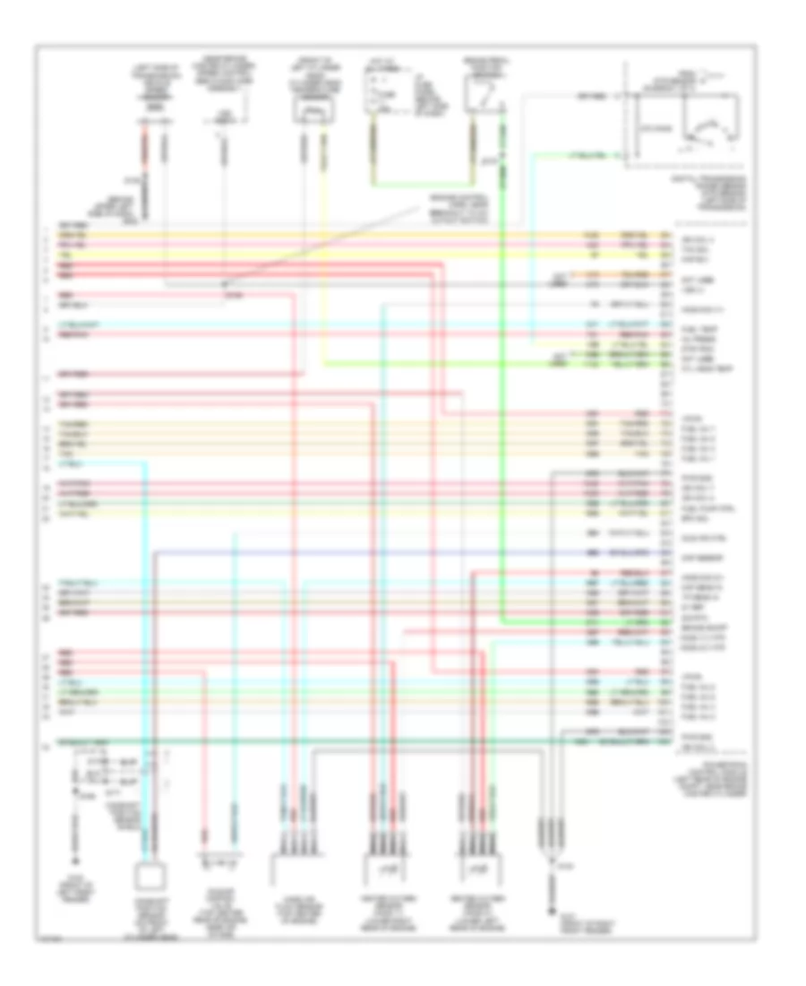
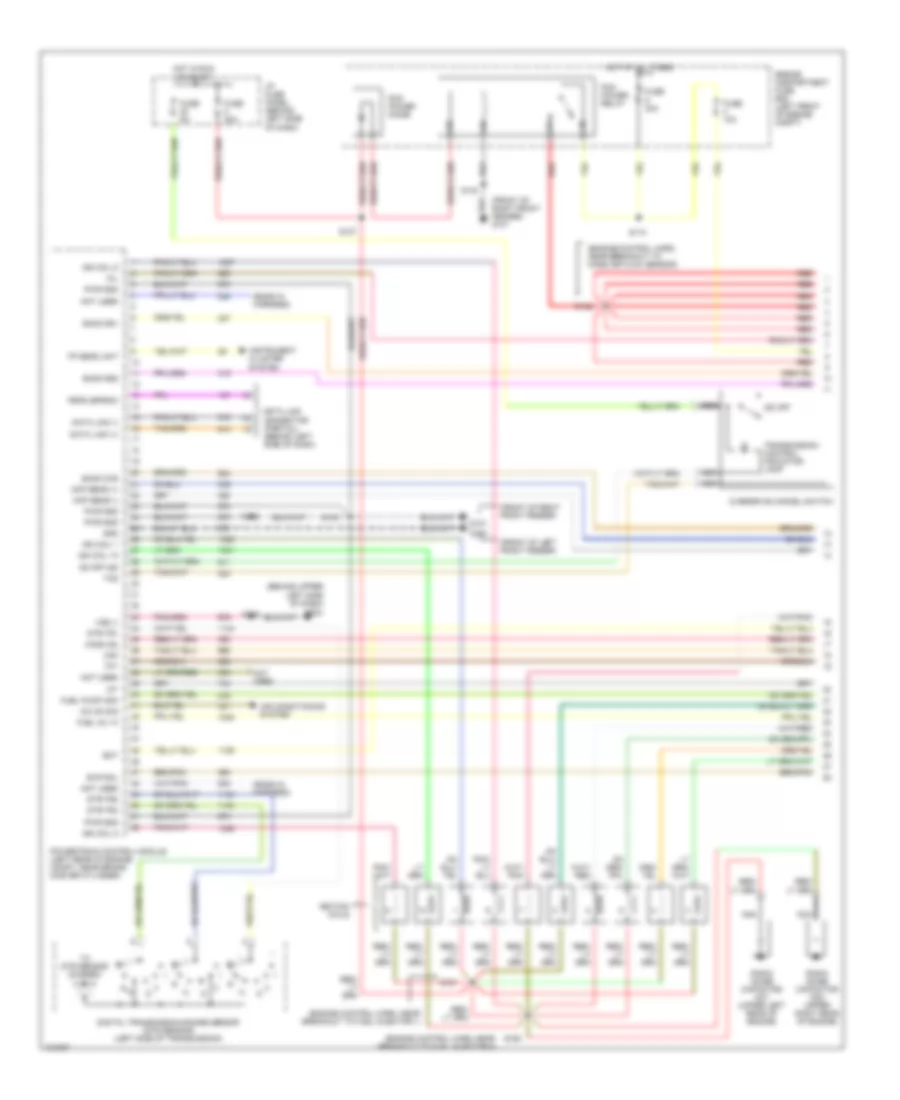
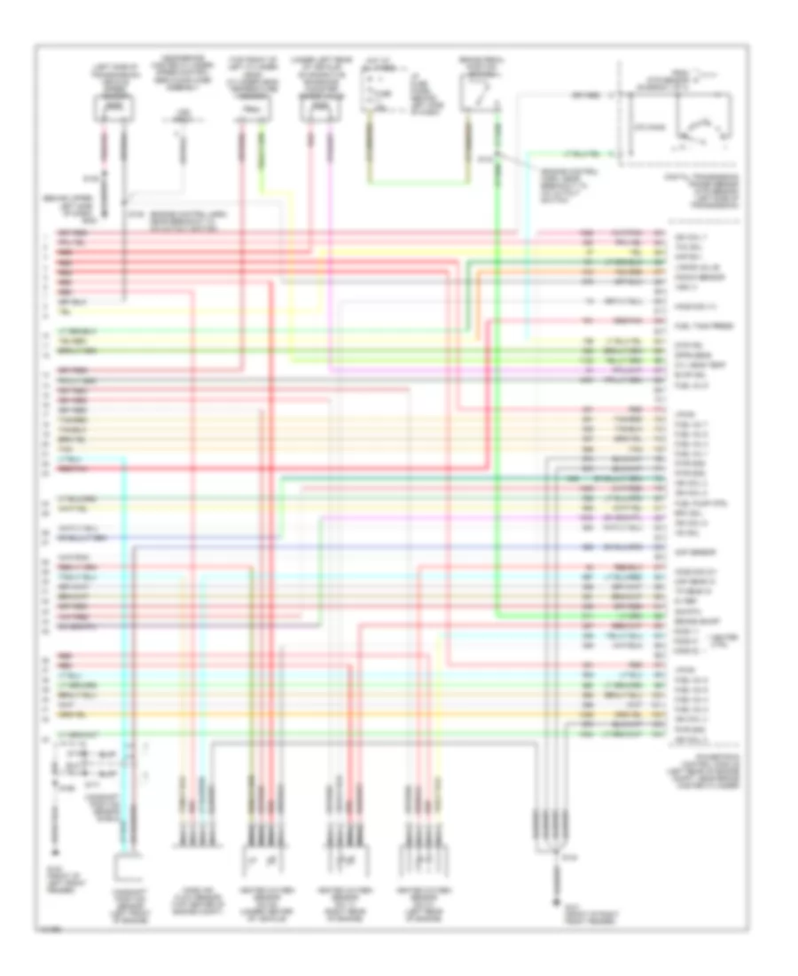
5.4L, Engine Performance Wiring Diagrams (4 of 4) for Ford RV Cutaway E350 1998
List of elements for 5.4L, Engine Performance Wiring Diagrams (4 of 4) for Ford RV Cutaway E350 1998:
- (behind upper left side of dash)
- (engine control harn, near breakout to fuel octane sensor)
- (front of left cylinder head) cylinder head temperature sensor
- (left side of transmission) vehicle speed sensor
- (near brake master cylinder) speed control servo/amplifier assembly
- (under left rear of vehicle) evaporative emissions canister purge valve
- 270 ohms
- 5v ref
- Brake on/off
- Brake pedal position switch
- Camshaft position sensor (on front of left cylinder head)
- Camshaft position sensor shield
- Cyl head temp
- Cylinder id
- Digital transmission range sensor (dtr sensor) (left side of transmission)
- Dpfe sens
- Dtr-tr3a
- Epc sol
- Evap sol
- From dtr sensor (diagram 1 of 4)
- Fuel inj 1
- Fuel inj 2
- Fuel inj 3
- Fuel inj 4
- Fuel inj 5
- Fuel inj 6
- Fuel inj 7
- Fuel inj 8
- Fuel pump ctrl
- Fuel tank press
- Fuse 15a
- G100 (front of left front fender)
- G101 (front of right front fender)
- G202
- Heater ctrl
- Hot at all times
- I/p fuse panel (behind left side of dash)
- Idle air ctrl
- Ign coil 2
- Ign coil 4
- Ign coil 7
- Ign coil 8
- Kap b(+)
- Knock sensor
- Left front heated oxygen sensor (ho2s 21) (lower left rear of engine)
- Lf ho2s
- Lf ho2s sig (21)
- Maf sens in
- Mass air flow sensor (top center of engine)
- Nca
- Powertrain control module (left rear of engine compt, near brake master cylinder)
- Pwr gnd
- R ho2s
- Rear heated oxygen sensor (ho2s 22) (under center of vehicle)
- Red
- Red/pnk
- Rf ho2s
- Rf ho2s sig (11)
- Right front heated oxygen sensor (ho2s 11) (lower right rear of engine)
- S135
- S139
- S140
- S169
- S170
- S171
- Sig rtn
- Tan
- Tan/red
- Tcc sol
- Tp sens in
- Vapor valve
- Vpwr
- Vss (+)
- Vss input
6.8L
6.8L, Engine Performance Wiring Diagrams (1 of 4) for Ford RV Cutaway E350 1998
List of elements for 6.8L, Engine Performance Wiring Diagrams (1 of 4) for Ford RV Cutaway E350 1998:
- (behind upper left side of dash)
- (ends in harness)
- (engine control harn, near breakout to fuel injector 1)
- (engine control harn, near breakout to fuel injector 6)
- (engine control harn, near breakout to mass air flow sensor)
- (front of left front fender)
- (front of right front fender)
- (front of right front fender) g101
- A/c on sig
- Air conditioning system
- Ckp sens (+)
- Ckp sens (-)
- Data link (+)
- Data link (-)
- Data link connector (partial) (behind left side of dash)
- Digital transmission range sensor (dtr sensor) (left side of transmission)
- Dtr-tr1
- Dtr-tr2
- Dtr-tr4
- E4od ccs
- E4od ss1
- E4od ss2
- Ect
- Engine compartment fuse box (left front of engine compt)
- Evr sol
- Feps (eprom)
- Fp send unit
- Fuel inj 10
- Fuel pump mon
- Fuse 10a
- Fuse 30a
- Fuse 5a
- G100
- G101
- G202
- Gnd
- Ho2s (22)
- Hot at all times
- Hot in run or start
- I/p fuse panel (behind left side of dash)
- Iat
- Ign coil 1
- Ign coil 10
- Ign coil 5
- Ign coil 6
- Ignition coils
- Instrument cluster system
- Maf
- Mil
- Nca
- Not used
- O/d off
- Od off ind
- Overdrive cancel switch
- Pcm power diode
- Pcm power relay
- Powertrain control module (left rear of engine compt, near brake master cylinder)
- Pwr gnd
- R n
- Radio noise capacitor no1 (upper left rear of engine)
- Radio noise capacitor no2 (upper right rear of engine)
- Red
- S110
- S127
- S140
- S142
- S161
- S162
- S169
- S268
- Tcs
- Tft
- To dtr sensor (diagram 4 of 4)
- Transmission control indicator lamp
- Vss (-)
6.8L, Engine Performance Wiring Diagrams (2 of 4) for Ford RV Cutaway E350 1998
List of elements for 6.8L, Engine Performance Wiring Diagrams (2 of 4) for Ford RV Cutaway E350 1998:
- (behind upper left side of dash) g202
- (engine control harn, left rear of engine compt)
- (engine control harn, near breakout to 76-pin conn in left rear of engine compt) s126
- (engine control harn, near breakout to coil per plug 9)
- (engine control harn, near breakout to pcm)
- (speedometer/ odometer) vehicle speed input
- (upper left front of engine) instrumentation engine coolant temperature sensor
- C224
- C225
- Crankshaft position sensor (lower right front of engine)
- Delta pressure feedback egr sensor (top left rear of engine)
- Engine compartment fuse box (left front of engine compt)
- Engine coolant temperature gauge
- Fuel pump relay
- Fuel tank pressure transducer (near fuel tank)
- Fuse 30a
- G100 (front of left front fender)
- Hot at all times
- Instrument cluster
- Intake air temperature sensor (center of engine compt, near air intake)
- Knock sensor (top right rear side of engine)
- Malfunction indicator
- Nca
- Power
- Red
- Red/pnk
- S136 (engine control harn, near breakout to a/c cutout switch)
- S137
- S138 (engine control harn, near breakout to a/c cutout switch)
- S157
- S158 (engine control harn, near breakout to radio noise capacitor 1)
- S169
- S170
- S171
- S175
- Throttle position sensor (top of engine, near air intake)
6.8L, Engine Performance Wiring Diagrams (3 of 4) for Ford RV Cutaway E350 1998
List of elements for 6.8L, Engine Performance Wiring Diagrams (3 of 4) for Ford RV Cutaway E350 1998:
- (behind right kick panel) inertia fuel shut-off switch
- (center rear of engine compt)
- (engine control harn, near breakout to coil per plug 2)
- (engine control harn, near breakout to e4od transmission)
- (engine control harn, near breakout to fuel injector 6)
- (front of left front fender) g100
- (fuel tank harn, below left center of vehicle) s309
- (in fuel tank) fuel pump module
- (transmission control harn, near breakout to dtr sensor)
- (transmission control harn, near breakout to transmission)
- (under vehicle, on left frame rail) (cutaways) in transit fuel pump module
- Coast clutch solenoid
- E4od transmission
- Egr solenoid (top left rear of engine)
- Electronic pressure control solenoid
- Fuel injectors
- Idle air control valve (top center rear of engine, near air intake)
- Nca
- Red
- Red/pnk
- S100
- S102
- S155
- S159
- S160
- S307
- Shift solenoid
- Tan
- Tan/ red
- Tan/red
- Torque converter clutch solenoid
- Transmission fluid temperature sensor
- Vapor management valve
6.8L, Engine Performance Wiring Diagrams (4 of 4) for Ford RV Cutaway E350 1998
List of elements for 6.8L, Engine Performance Wiring Diagrams (4 of 4) for Ford RV Cutaway E350 1998:
- (behind upper left side of dash)
- (engine control harn, near breakout to a/c cutout switch)
- (left side of transmission) vehicle speed sensor
- (near brake master cylinder) speed control servo/amplifier assembly
- (top front of left cylinder head) cylinder head temperature sensor
- (under left rear of vehicle) evaporative emissions canister purge valve
- 270 ohms
- 5v ref
- Brake on/off
- Brake pedal position switch
- Camshaft position sensor (left front of engine)
- Camshaft position sensor shield
- Cmp sensor
- Cyl head temp
- Digital transmission range sensor (dtr sensor) (left side of transmission)
- Dpfe sens
- Dtr-tr3
- Epc sol
- Evap sol
- From dtr sensor (diagram 1 of 4)
- Fuel inj 1
- Fuel inj 2
- Fuel inj 3
- Fuel inj 4
- Fuel inj 5
- Fuel inj 6
- Fuel inj 7
- Fuel inj 8
- Fuel inj 9
- Fuel pump ctrl
- Fuel tank press
- Fuse 15a
- G100 (front of left front fender)
- G101 (front of right front fender)
- G202
- Heated oxygen sensor (no 11) (right rear of engine)
- Heated oxygen sensor (no 21) (left rear of engine)
- Heated oxygen sensor (no 22) (under center of vehicle)
- Heater ctrl
- Ho2s 11
- Ho2s 21
- Ho2s 22
- Ho2s sig (11)
- Ho2s sig (21)
- Hot at all times
- I/p fuse panel (behind left side of dash)
- Iac sol
- Ign coil 2
- Ign coil 3
- Ign coil 4
- Ign coil 7
- Ign coil 8
- Ign coil 9
- Kap b(+)
- Knock sensor
- Maf sens in
- Mass air flow sensor (top center of engine compt)
- Nca
- Powertrain control module (left rear of engine compt, near brake master cylinder)
- Pwr gnd
- Red
- Red/pnk
- S135
- S139
- S140
- S169
- S170
- S171
- Sig rtn
- Tan
- Tan/red
- Tcc sol
- Tp sens in
- Vapor valve
- Vpwr
- Vss (+)
- Vss input
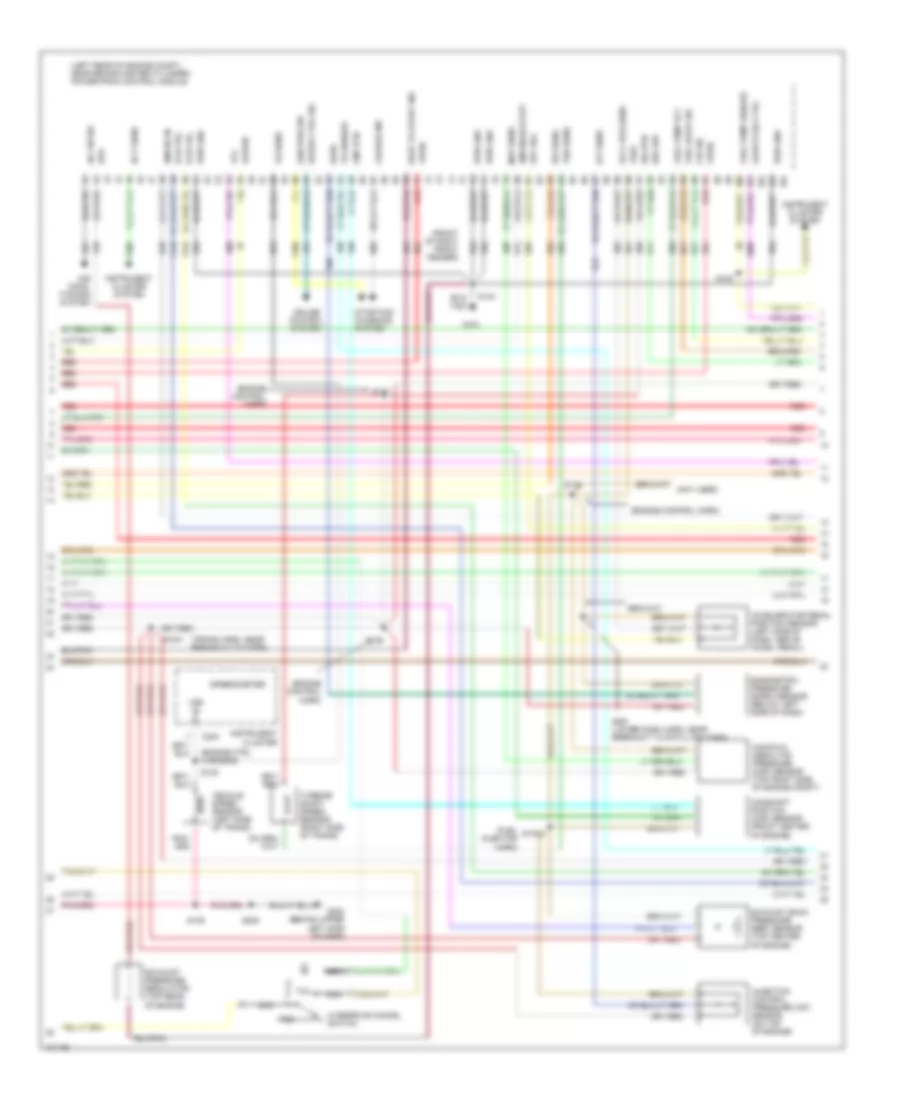
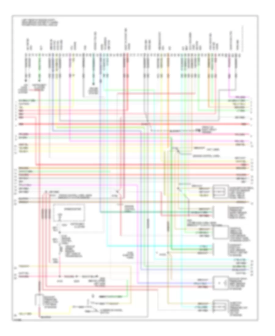
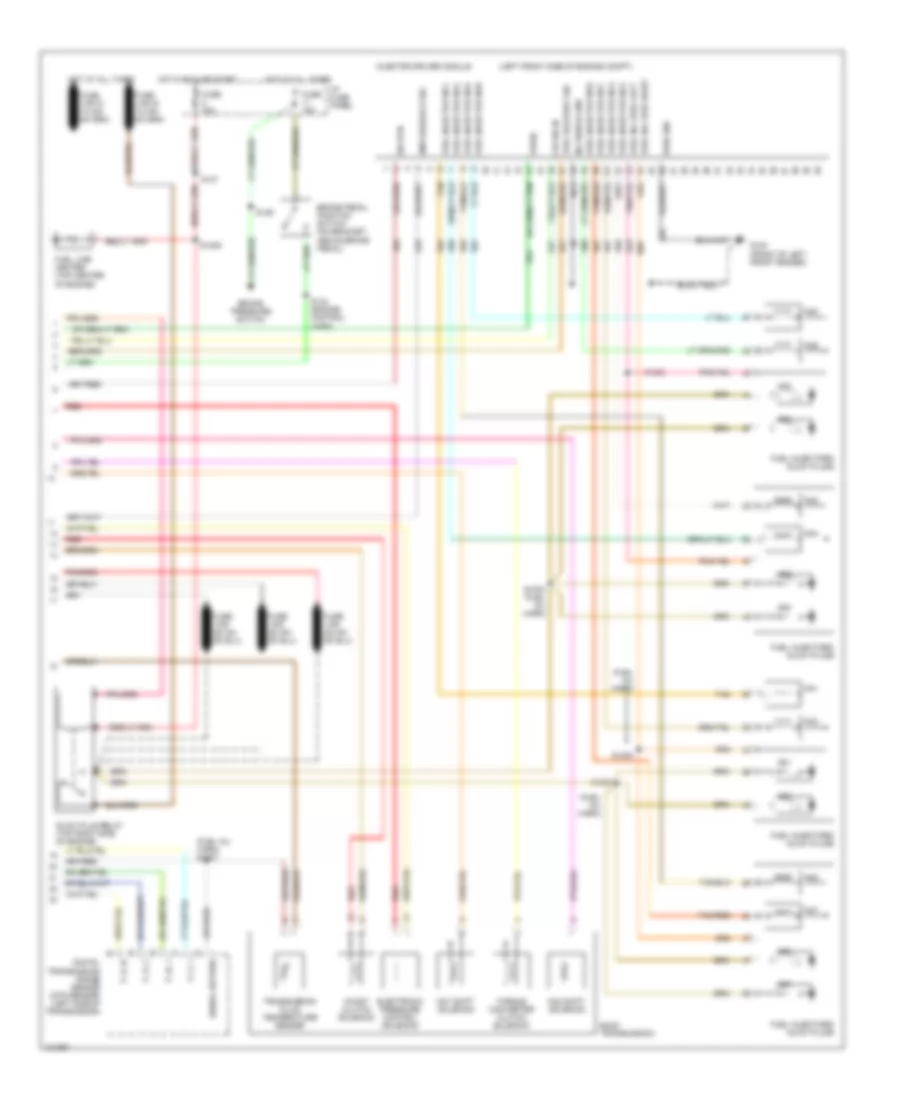
7.3L
7.3L DI Turbo Diesel, Engine Performance Wiring Diagrams, with Electric Fuel Pump (1 of 3) for Ford RV Cutaway E350 1998
List of elements for 7.3L DI Turbo Diesel, Engine Performance Wiring Diagrams, with Electric Fuel Pump (1 of 3) for Ford RV Cutaway E350 1998:
- (below left side of dash) data link connector
- (eng ctrl harn, left rear of engine compt)
- (eng ctrl sensor harness, near breakout to mass air flow sensor)
- (left rear of engine compt, near brake master cylinder) powertrain control module
- (lower dash harn, near breakout to rke data link conn)
- App sens
- Aux tach feed
- Auxiliary powertrain control connector (behind left side of dash)
- Brake on/off switch
- Brake press sw
- Brake pressure switch (left side of engine compt, bottom of master cyl)
- Brake warning ind
- Bus (+)
- Bus (-)
- C225
- C226
- Cam pos sens
- Ccs sol
- Dlc
- Driveline disconn
- Driveline disconnect switch (behind left side of dash)
- Dtr-tr1
- Ebp sens
- Engine compartment fuse box
- Engine oil temperature sensor (center left side of engine)
- Eot
- Fuel line heater (top center of engine)
- Fuel line htr
- Fuel pump (left rear of engine compt)
- Fuel pump relay
- Fuse 10a
- Fuse 15a
- Fuse 30a
- Fuse 5a
- G100 (front of left front fender)
- G101 (front of right front fender)
- Gen pwr sw
- Glow plug relay
- Horn/speed ctrl sw gnd
- Hot at all times
- Hot in run or start
- I/p fuse panel
- Iat
- Idle validation sw
- Idle validation switch (open at idle) (left side of dash)
- Idm relay
- Inertia fuel shutoff switch (behind right kick panel)
- Injection pressure regulator (top of engine)
- Instrument cluster
- Instrument cluster system
- Intake air temperature sensor (center of engine compt, part of clean air tube)
- Mal- function indicator
- Mil dlc
- Not used
- Pcm power diode
- Pcm power relay
- Red
- S110
- S127
- S129
- S140
- S142
- S142 (fuel inj harness)
- S167
- S175
- S176
- S180 (engine ctrl harn, above master cyl)
- S213
- S262
- S263
- Shield gnd
- Ss1
- Starting/ charging system
- Tcil
- Tcs sens
- Tft
- Vss gnd
- Wait to start indicator
- Water in fuel ind
- Water in fuel indicator
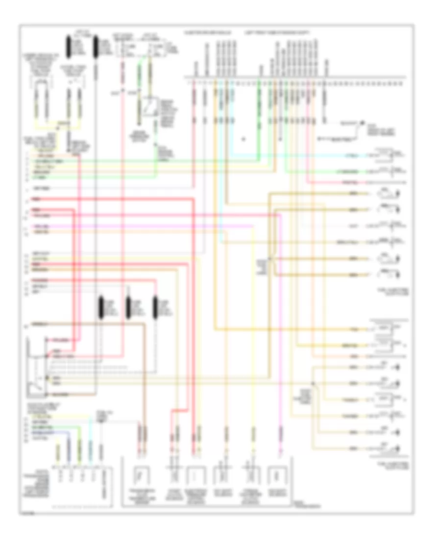
7.3L DI Turbo Diesel, Engine Performance Wiring Diagrams, with Electric Fuel Pump (2 of 3) for Ford RV Cutaway E350 1998
List of elements for 7.3L DI Turbo Diesel, Engine Performance Wiring Diagrams, with Electric Fuel Pump (2 of 3) for Ford RV Cutaway E350 1998:
- (engine control harn)
- (engine ctrl harness)
- (front of right front fender)
- (fuel injector harn)
- (left rear of engine compt, near brake master cylinder) powertrain control module
- (not used)
- (trans harn, near breakout to dtrs)
- A/c on sig
- Accelerator pedal position sensor (left side of dash, above accel pedal)
- Accl pos sens
- Air cond- itioning system
- Baro
- Barometric pressure (baro) sensor (below left side of dash)
- Boo sw
- C224
- Camshaft position (cmp) sensor (front center of engine)
- Charge ind
- Cid sig
- Cmp rtn
- Cruise control system
- Dtr-tr2
- Dtr-tr4
- Ect sens
- Epc sol
- Epr
- Exhaust back pressure (ebp) sensor (top center of engine)
- Exhaust pressure regulator (top rear of engine)
- Fuel deliv sig
- Fuel pump rly
- Fuel pump sender
- G101
- G202 (behind upper left side of dash)
- Gen pwr sw
- Glow plug ctrl
- Icp sens
- Idm enable out
- Idm sig in
- Injection control pressure (icp) sensor (on top of engine)
- Instrument cluster
- Instrument cluster system
- Ipr sens
- Kapwr
- Manifold absolute pressure (map) sensor (top right side of engine compt)
- Map sens
- Nca
- Overdrive cancel switch
- Pwr gnd
- Red
- S1001
- S1002
- S120
- S135
- S136
- S137
- S138
- S139
- S140
- S205
- S261 (lower dash harn, near breakout to data link conn)
- Sig rtn
- Speed ctrl sig
- Speedometer
- Starting/ charging system
- Tcc
- Tcil
- Tcs
- Tr sensor
- Tss sens
- Turbine shaft speed sensor (right side of trans)
- Vehicle speed sensor (left side of trans)
- Vpwr
- Vref
- Vs sens
- Vss in
- Wait to start ind
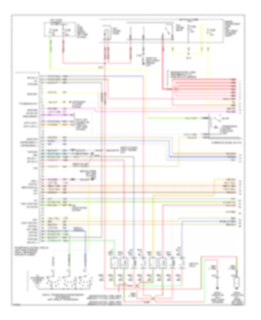
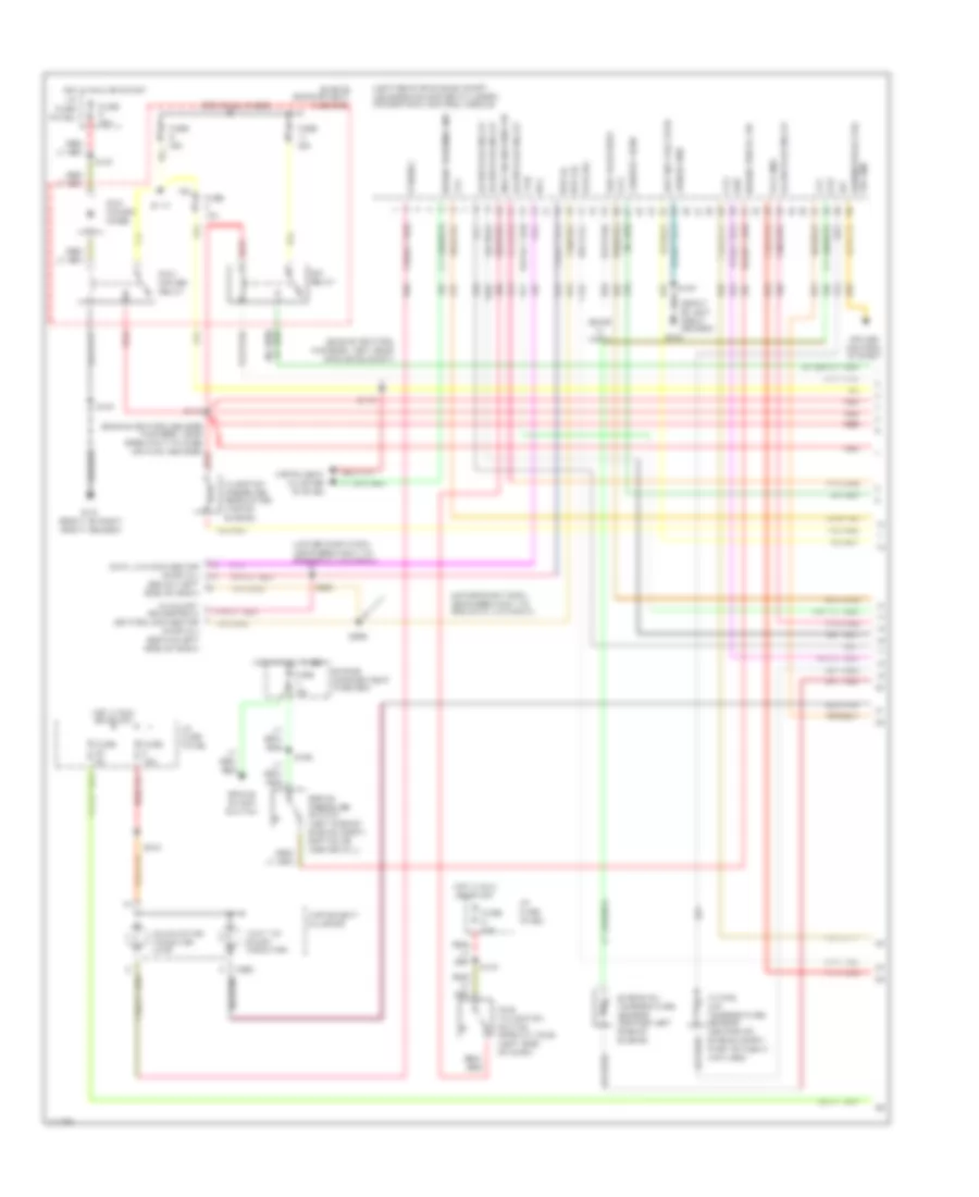
7.3L DI Turbo Diesel, Engine Performance Wiring Diagrams, with Electric Fuel Pump (3 of 3) for Ford RV Cutaway E350 1998
List of elements for 7.3L DI Turbo Diesel, Engine Performance Wiring Diagrams, with Electric Fuel Pump (3 of 3) for Ford RV Cutaway E350 1998:
- (behind left side of dash) g202
- (fuel inj harn) s1007
- (in fuel tank) fuel pump module
- (left front side of engine compt)
- (under vehicle, on left frame rail) (cutaways) in transit fuel pump module
- Brake pedal position switch (above brake pedal)
- Brake pressure switch
- Cid sig in
- Coast clutch solenoid
- Digital transmission range sensor (dtr sensor) (left side of transmission)
- E4od transmission
- Electronic pressure control solenoid
- Fuel delivery sig
- Fuel inj feed left
- Fuel inj feed right
- Fuel injector no1
- Fuel injector no2
- Fuel injector no3
- Fuel injector no4
- Fuel injector no5
- Fuel injector no6
- Fuel injector no7
- Fuel injector no8
- Fuel injectors/ glow plugs
- Fuse 15a
- Fuse 30a
- G100 (front of left front fender)
- Glow plug relay (top right side of engine)
- Hot at all times
- Hot in run or start
- I/p fuse panel
- Idm feedback sig
- Inj shield gnd
- Injector driver module
- Nca
- No1
- No1 shift solenoid
- No2
- No2 shift solenoid
- No3
- No4
- No5
- No6
- No7
- No8
- P, 2, 1
- P, n, 1
- P, r, 2
- P, r, n
- Pwr gnd
- Red
- S1003 (fuel injector harn)
- S1004 (fuel inj harn)
- S127
- S129
- S134 (engine control harn)
- S308
- S310 (fuel tank harn, below left frt of vehicle)
- Sig rtn
- Signal return
- Tan
- Tan/red
- Torque converter clutch solenoid
- Transmission fluid temperature sensor
- Vpwr
7.3L DI Turbo Diesel, Engine Performance Wiring Diagrams, without Electric Fuel Pump (1 of 3) for Ford RV Cutaway E350 1998
List of elements for 7.3L DI Turbo Diesel, Engine Performance Wiring Diagrams, without Electric Fuel Pump (1 of 3) for Ford RV Cutaway E350 1998:
- "wait to start" indicator
- (ends in harn)
- (engine control harness, left rear of engine compt)
- (engine control sensor harness, near breakout to mass air flow sensor)
- (front of left front fender)
- (left rear of engine compt, near brake master cylinder) powertrain control module
- (lower dash harn, near breakout to rke data link conn)
- App ref volt rtn
- Aux tach feed
- Auxiliary powertrain control connector (partial) (behind left side of dash)
- Brake on/off switch
- Brake press sw
- Brake pressure switch (left side of engine compt, bottom of master cyl)
- Brake warning ind
- Bus (+)
- Bus (-)
- C225
- Cam pos sens
- Ccs
- Cruise control system
- Data link connector (partial) (below left side of dash)
- Dlc
- Dtr-tr1
- Ebp
- Engine compartment fuse box
- Engine oil temperature sensor (center left side of engine)
- Eot
- Fuse 10a
- Fuse 15a
- Fuse 30a
- Fuse 5a
- G100
- G101 (front of right front fender)
- Glow plug relay
- Hot at all times
- Hot in run or start
- I/p fuse panel
- Iat
- Idle validation sw
- Idle validation switch (open at idle) (left side of dash)
- Idm relay
- Injection pressure regulator (top of engine)
- Instrument cluster
- Instrument cluster system
- Intake air temperature sensor (center of engine compt, part of clean air tube)
- Malfunction indicator lamp
- Pcm dlc
- Pcm power diode
- Pcm power relay
- Red
- S110
- S127
- S129
- S140
- S142
- S167
- S175
- S213
- S262
- S263
- Shield gnd
- Ss1
- Sw gnd horn/speed ctrl
- Tcil
- Tcs
- Tft
- Vss gnd
7.3L DI Turbo Diesel, Engine Performance Wiring Diagrams, without Electric Fuel Pump (2 of 3) for Ford RV Cutaway E350 1998
List of elements for 7.3L DI Turbo Diesel, Engine Performance Wiring Diagrams, without Electric Fuel Pump (2 of 3) for Ford RV Cutaway E350 1998:
- (engine control harn)
- (front of right front fender)
- (fuel injector harn)
- (left rear of engine compt, near brake master cylinder) powertrain control module
- (not used)
- (trans control harn, near breakout to dtr sensor)
- A/c on sig
- Accelerator pedal position sensor (left side of dash, above accel pedal)
- Accl pos sens
- Air cond- itioning system
- Baro
- Barometric pressure (baro) sensor (below left side of dash)
- Boo
- C224
- Camshaft position (cmp) sensor (front center of engine)
- Cid sig
- Cmp rtn
- Cruise control system
- Dtr-tr2
- Dtr-tr4
- Ect
- Epc
- Epr
- Exhaust back pressure (ebp) sensor (top center of engine)
- Exhaust pressure regulator (top rear of engine)
- Fuel deliv sig
- G101
- G202 (behind upper left side of dash)
- Glow plug ctrl
- Icp
- Idm enable out
- Idm sig in
- Injection control pressure (icp) sensor (on top of engine)
- Instrument cluster
- Instrument cluster system
- Ipr
- Kapwr
- Manifold absolute pressure (map) sensor (top right side of engine compt)
- Map
- Nca
- Overdrive cancel switch
- Pwr gnd
- Red
- S1001
- S1002
- S135 (engine control harn)
- S136
- S138
- S139
- S140
- S205
- S261 (lower dash harn, near breakout to data link conn)
- Sig rtn
- Speed ctrl sig
- Speedometer
- Tcc
- Tcil
- Tcs
- Tr sensor
- Vehicle speed sensor (left side of transmission)
- Vpwr
- Vref
- Vss
- Vss in
- Wait to start ind
7.3L DI Turbo Diesel, Engine Performance Wiring Diagrams, without Electric Fuel Pump (3 of 3) for Ford RV Cutaway E350 1998
List of elements for 7.3L DI Turbo Diesel, Engine Performance Wiring Diagrams, without Electric Fuel Pump (3 of 3) for Ford RV Cutaway E350 1998:
- (fuel inj harn)
- (fuel inj harn) s1007
- (left front side of engine compt)
- Brake pedal position switch (on bracket, above brake pedal)
- Brake pressure switch
- Cid sig in
- Coast clutch solenoid
- Digital transmission range sensor (dtr sensor) (left side of transmission)
- E4od transmission
- Electronic pressure control solenoid
- Fuel delivery sig
- Fuel inj feed left
- Fuel inj feed right
- Fuel injector no1
- Fuel injector no2
- Fuel injector no3
- Fuel injector no4
- Fuel injector no5
- Fuel injector no6
- Fuel injector no7
- Fuel injector no8
- Fuel injectors/ glow plugs
- Fuel line heater (top center of engine)
- Fuse 15a
- Fuse 30a
- G100 (front of left front fender)
- Glow plug relay (top right side of engine)
- Hot at all times
- Hot in run or start
- I/p fuse panel
- Idm feedback sig
- Inj shield gnd
- Injector driver module
- Nca
- No1
- No1 shift solenoid
- No2
- No2 shift solenoid
- No3
- No4
- No5
- No6
- No7
- No8
- P, 2, 1
- P, n, 1
- P, r, 2
- P, r, n
- Pwr gnd
- Red
- S1000
- S1003
- S1004 (fuel inj harn)
- S1005
- S1006
- S127
- S129
- S134 (engine control harn)
- Sig rtn
- Signal return
- Tan
- Tan/red
- Torque converter clutch solenoid
- Transmission fluid temperature sensor
- Vpwr
EXTERIOR LIGHTS
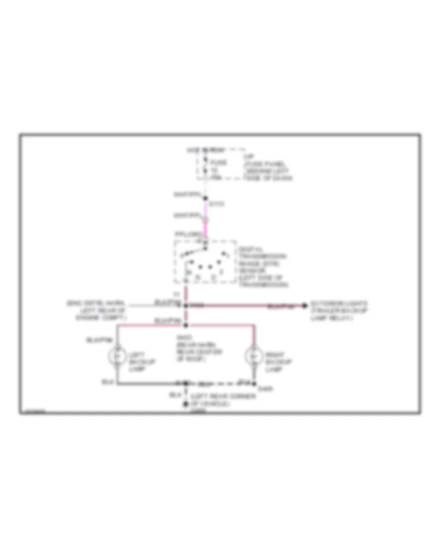
Back-up Lamps Wiring Diagram for Ford RV Cutaway E350 1998
List of elements for Back-up Lamps Wiring Diagram for Ford RV Cutaway E350 1998:
- (eng cntrl harn, left rear of engine compt)
- (left rear corner of vehicle) g999
- Digital transmission range (dtr) sensor (left side of transmission)
- Exterior lights (trailer backup lamp relay)
- Fuse 15a
- Hot in run
- I/p fuse panel (behind left side of dash)
- Left backup lamp
- Right backup lamp
- S113
- S402
- S403 (rear harn, rear center of roof)
- S406
Exterior Lamps Wiring Diagram for Ford RV Cutaway E350 1998
List of elements for Exterior Lamps Wiring Diagram for Ford RV Cutaway E350 1998:
- (dash to headlamp harn, right front corner of eng compt) s165
- (lower dash harn, near left "b" pillar)
- (lower dash harn, near left kick panel) s232
- (not used)
- (rabs) (4wabs)
- All others
- Batt
- Brake pedal position switch (on brake pedal bracket)
- C224
- C250
- Cut- aways
- Electronic flasher (behind left side of dash)
- Eng compt fuse box breakout)
- Fuse 10a
- Fuse 15a
- Fuse 20a
- G107 (behind right front headlamp)
- G200 (left kick panel)
- G202 (behind upper left side of dash)
- G999 (left rear corner of vehicle)
- Hazard
- Hazard switch
- Head
- High mounted stop/ cargo lamp
- Hot at all times
- Hot in run
- I/p fuse panel (behind left side of dash)
- I/p fuse panel (behind left side of dash)
- Ign
- Instrument cluster
- Left front park/ turn lamp
- Left stop/ park/
- Left turn indicator
- License lamp
- Main light switch
- Multi- function switch
- Normal
- Off
- Park r
- Remote keyless entry module
- Right front park/ turn lamp
- Right stop/ park/
- Right turn indicator
- S163
- S207
- S214 s129
- S216 (main harn, behind left side of dash)
- S217 (main harn, behind left side of dash)
- S218
- S226
- S233
- S234 (lower dash harn, near left seat belt retractor)
- S306 (rear harn, left rear of cargo area)
- S402
- S406
- Solid state
- To trailer/ camper adapter circuit (electronic brake)
- To trailer/camper adapter circuit (electronic brake)
- To trailer/camper adapter circuit (engine compartment fuse panel) (fuses 5 & 6)
- To trailer/camper adapter circuit (trailer running lamp relay)
- Turn lamp
- Turn left
- Turn right
Trailer/Camper Adapter Wiring Diagram for Ford RV Cutaway E350 1998
List of elements for Trailer/Camper Adapter Wiring Diagram for Ford RV Cutaway E350 1998:
- (engine control harn, left rear of eng compt) s118
- (left kick panel) g200
- B+ (park or head)
- Battery (b+)
- Brake switch input
- C148 (left rear corner of engine compartment)
- C233 (behind left side of dash)
- C419
- C422 or c419
- Class 1
- Class 2
- Digital transmission range (dtr) sensor (left side of transmission)
- Electronic brake
- Engine compartment fuse box (left front of engine compartment)
- Exterior lights (backup lamps circuit)
- From exterior lamps circuit (brake switch)
- From exterior lamps circuit (main light switch)
- From exterior lights circuit (multi-function switch)
- Fuse 10a
- Fuse 15a
- Fuse 20a
- Fuse 30a
- Fuse 40a
- Fuse 5a
- G100 (front of left front fender)
- G416 (under left rear of vehicle, along frame rail)
- Ground
- Hot at all times
- Hot in acc or run
- Hot in run
- I/p fuse panel (behind left side of dash)
- Modified vehicle power
- Nca
- Not used
- S109
- S112 (eng cntrl harn, near eng compt fuse box breakout)
- S113
- S122
- S130 (eng cntrl harn, left rear of eng compt)
- S223
- S307
- Trailer backup lamp relay (in engine compartment fuse box)
- Trailer battery charge relay (in engine compartment fuse box)
- Trailer connector
- Trailer running lamp relay (in engine compartment fuse box)
- Trailer/camper adapter (below left side of rear bumper)
- Trailer/camper adapter (class 2) (below left side of rear bumper)
- Trailer/camper adapter (class 2) (below left side of rear bumper)
- Wire ends in harness
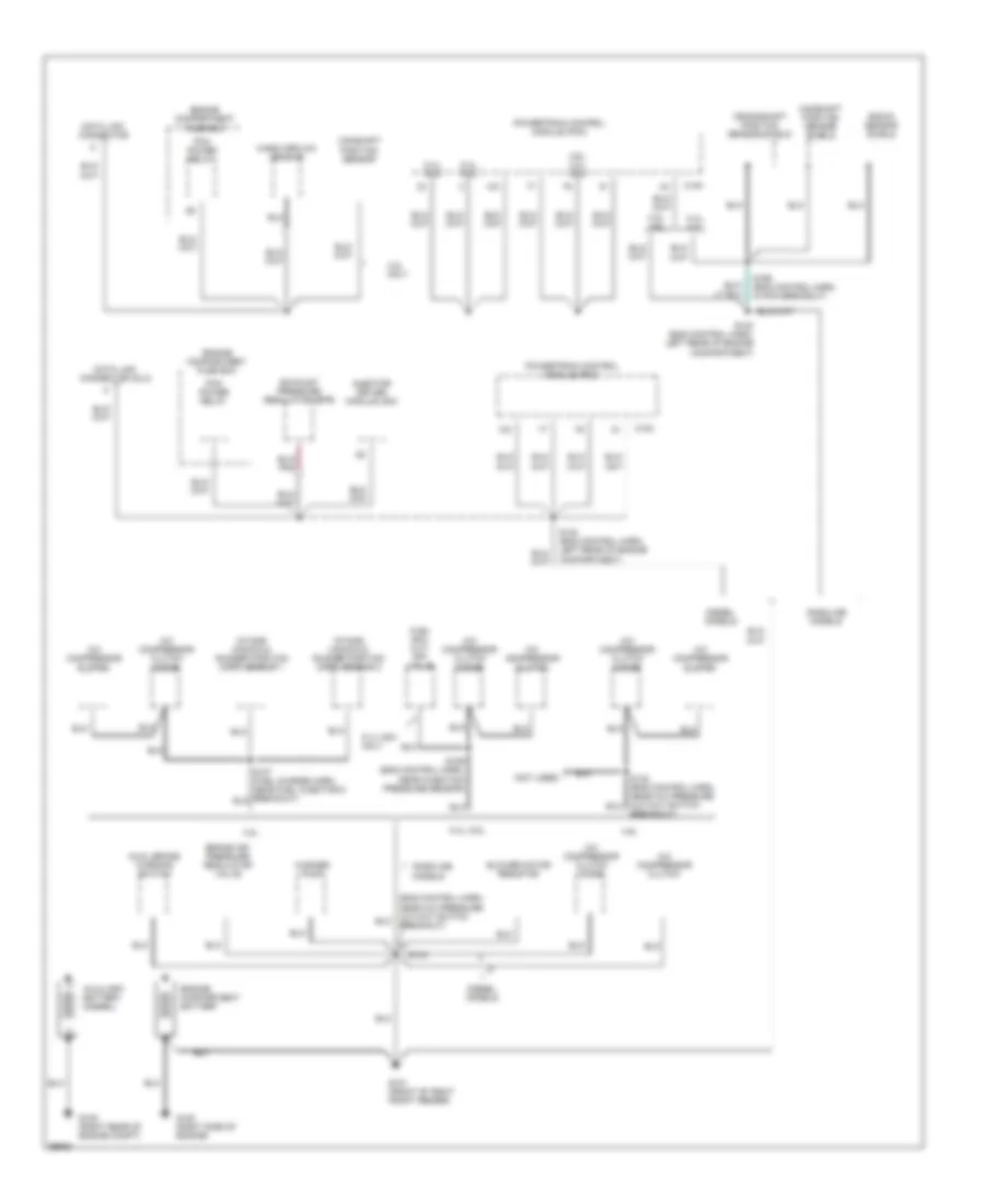
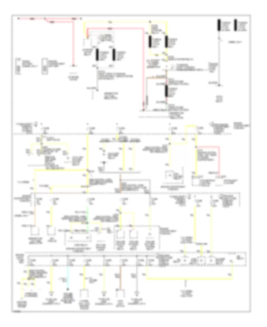
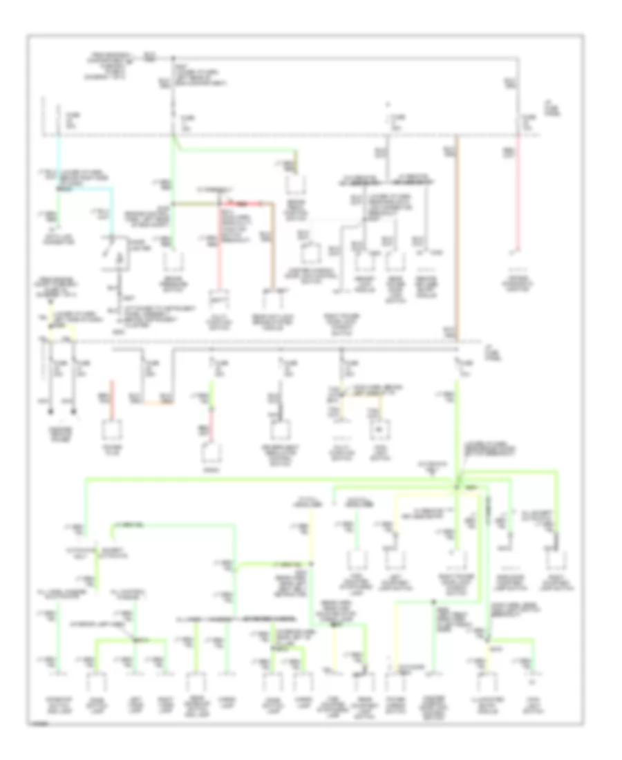
GROUND DISTRIBUTION
Ground Distribution Wiring Diagram (1 of 4) for Ford RV Cutaway E350 1998
List of elements for Ground Distribution Wiring Diagram (1 of 4) for Ford RV Cutaway E350 1998:
- (eng control harn, near a/c pressure cut-out switch breakout)
- (not used)
- 4.2l
- 4.2l only
- 4.2l, 4.6l
- 4.6l
- 4.6l, 4.2l, 6.8l
- 5.4l, 6.8l
- 5.vl ngv only
- A/c compressor clutch
- A/c compressor clutch diode
- Auxiliary battery (diesel)
- Blower motor resistor
- Brake air pressure regulator valve
- Breakout)
- C154
- Camshaft position sensor
- Camshaft position sensor shield
- Crankshaft position sensor shield
- Data link connector
- Data link connector (dlc)
- Diesel models
- Dual brake warning switch
- Engine compartment battery
- Engine compartment fuse box
- Exhaust pressure regulator (epr)
- Fuel rail cut- off valve
- G101 (front of right front fender)
- G105 (right rear of engine compt)
- G120 (right side of engine)
- Gasoline models
- Injector driver module (idm)
- Intake manifold runner position (imrp) sensor 1
- Intake manifold runner position (imrp) sensor 2
- Knock sensor shield
- Mass airflow sensor
- Pcm power relay
- Powertrain control module (pcm)
- S140 (eng control harn, left rear of engine compartment)
- S143
- S169 (eng control harn, in pcm breakout)
- S189 (eng control harn, near injection pressure sensor)
- Washer pump
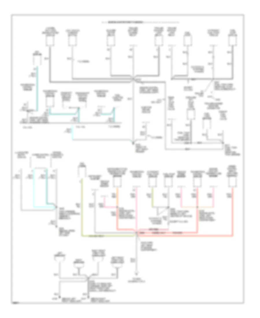
Ground Distribution Wiring Diagram (2 of 4) for Ford RV Cutaway E350 1998
List of elements for Ground Distribution Wiring Diagram (2 of 4) for Ford RV Cutaway E350 1998:
- (behind left front headlamp)
- (behind right front headlamp)
- (engine control harn, left rear of engine compt)
- (fuel tank harn, near fuel tank sender)
- (main harn, left rear of engine compartment)
- (main harness, near clockspring assembly breakout)
- 4 wheel anti-lock brake system module
- 4.2l, 4.6l
- 5.4l ngv only
- 5.4l, 6.8l
- 7.3l diesel
- Air bag diagnostic monitor
- Blower motor relay
- C422
- Camshaft position sensor shield
- Crankshaft position sensor shield
- Cutaway & stripped chassis
- Diesel only
- Engine compartment fuse box
- Engine coolant temperature sender
- Except 5.4l ngv
- Forward aft- axle fuel tank valve
- Fuel injector shield
- Fuel pump
- Fuel pump module
- Fuel tank sender
- G100 (front of left front fender)
- G106
- G107
- G202 (behind upper left side of dash)
- Illuminated entry module
- In-transit fuel pump module
- Injector driver module
- Instrument cluster
- Instrumentation engine coolant temperature sensor
- Left front park/turn signal lamp
- Left headlamp
- Low vacuum warning switch
- Midship fuel tank valve
- Ngv module
- Ngv timer
- Powertrain control module
- Rear aft- axle fuel tank valve
- Right front park/turn signal lamp
- Right headlamp
- S122
- S139 (engine cntrl harn, left rear of eng compartment)
- S163 (dash to headlamp harness, near left front park/turn signal lamp breakout)
- S205
- S268
- S307 (fuel tank harn, near fuel pump module breakout)
- S308 (fuel tank harn, beneath left center of vehicle)
- S317 (fuel tank harn, near fuel tank sender)
- S320
- Speed control servo amplifier assembly
- To g202 (diagram 3 of 4)
- Trailer backup lamp relay
- Trailer battery charge relay
- Trailer running lamp relay
- Trailer/camper adapter connector
- Vehicle speed sensor
- W/ trailer tow
- Wiper control module
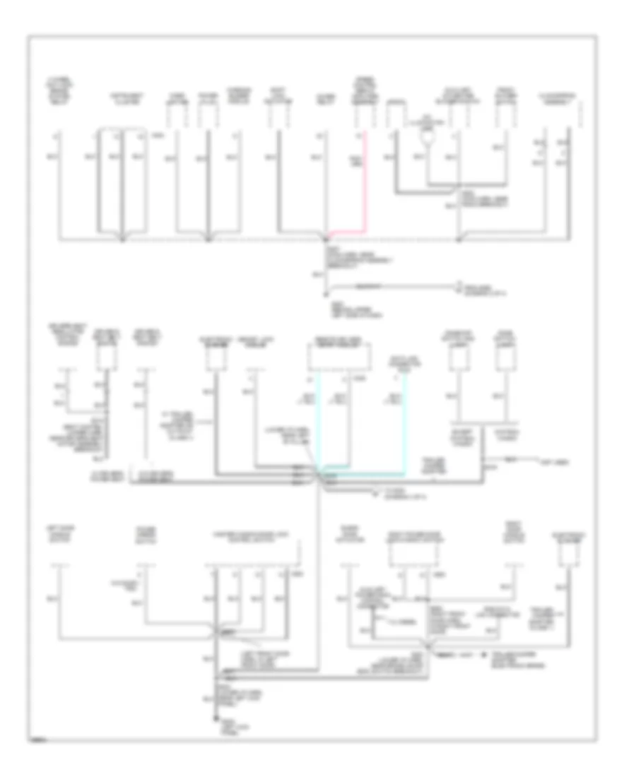
Ground Distribution Wiring Diagram (3 of 4) for Ford RV Cutaway E350 1998
List of elements for Ground Distribution Wiring Diagram (3 of 4) for Ford RV Cutaway E350 1998:
- trim
- (left front door harn, in left front door)
- (lower i/p harn, near left "b" pillar)
- (not used)
- 4 wheel anti-lock brake system relay
- 4wabs relay
- 7.3l diesel
- A/c illumination lamp
- Auxiliary a/c-heater blower switch
- Auxiliary powertrain control connector
- Blend door actuator
- C224
- C335
- C500
- C600
- Chateau wagon
- Cigar lighter
- Clockspring assembly
- Data link connector (dlc)
- Dome switch/ lamp
- Dome/map switch and lamp
- Driver's seat regulator control switch
- Driver,s seat belt switch
- Electronic flasher
- Except chateau wagon
- From s268 (diagram 2 of 4)
- Front blower switch
- G202 (behind upper left side of dash)
- G2oo (left kick panel)
- Instrument cluster
- Left door handle switch
- Master window/door lock control switch
- Memory lock module
- Panel)
- Power mirror switch
- Power plug
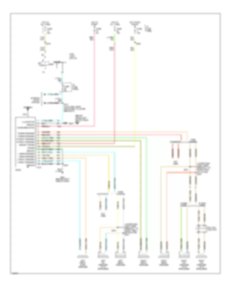
- Radio
- Remote keyless entry module
- Right door handle switch
- Right power door lock/window switch
- Rke data link connector
- S202 (main harn, near radio breakout)
- S207 (main harn, near clockspring assembly breakout)
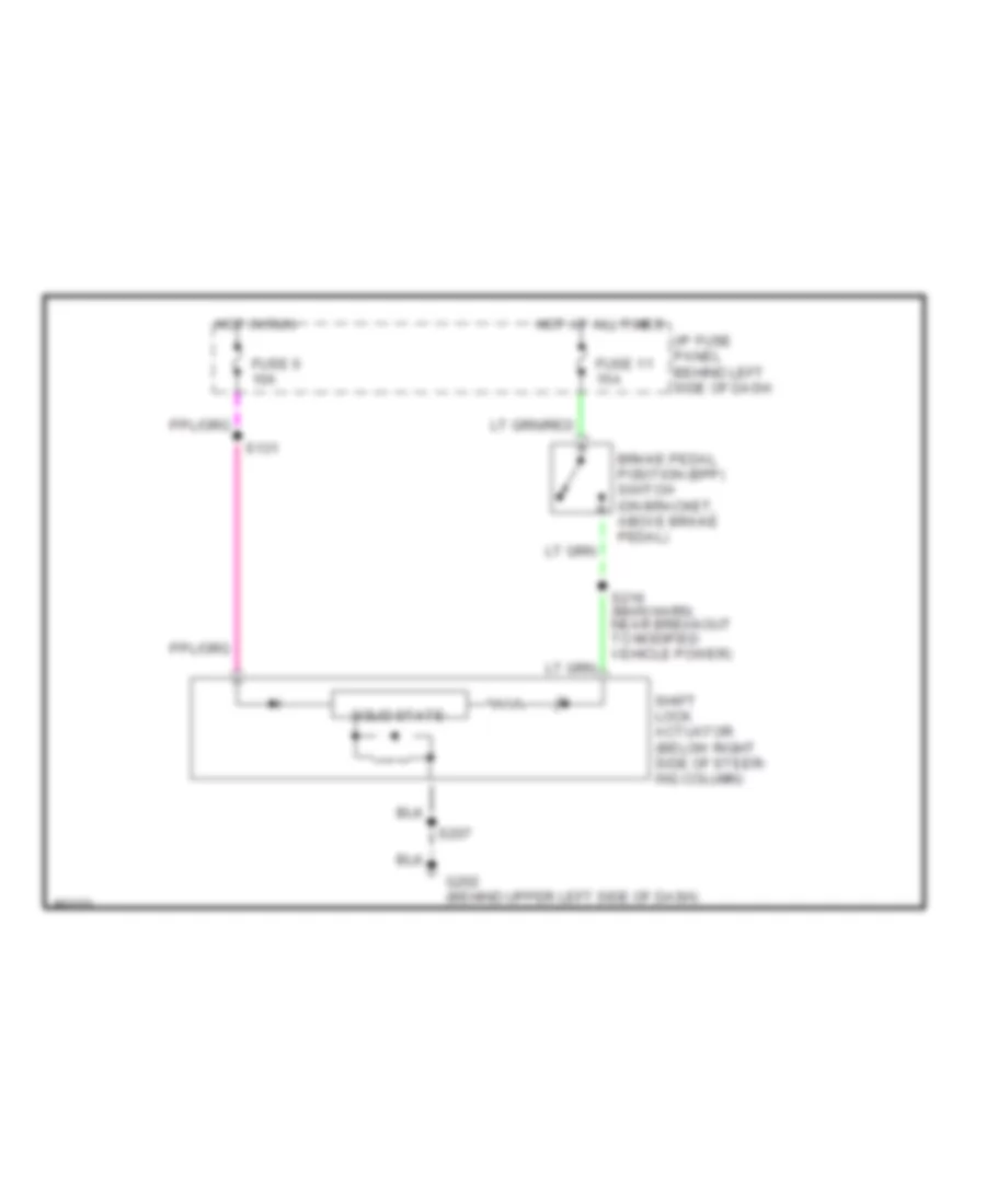
- S223 (lower i/p harn, near brake on/off (boo) switch breakout)
- S235
- S315 (seat control jumper harn, near driver's seat motor assembly breakout)
- S316
- S500
- S600 (right front door harn, in right front door)
- Shift lock actuator
- Speed control servo/ amplifier assembly
- To s300 (diagram 4 of 4)
- Trailer/ camper adapter
- Trailer/ camper adapter (class 1)
- Trailer/camper adapter (electronic brake)
- W/ driver's power seat
- W/ trailer/ camper adapter or cutaway (class ii)
- W/o door
- W/o driver's power seat
- Warning buzzer module
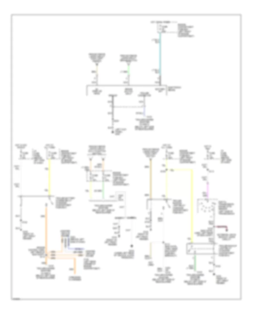
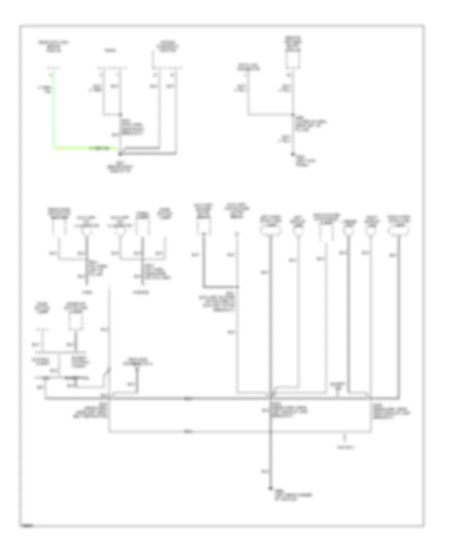
Ground Distribution Wiring Diagram (4 of 4) for Ford RV Cutaway E350 1998
List of elements for Ground Distribution Wiring Diagram (4 of 4) for Ford RV Cutaway E350 1998:
- Air bag diagnostic monitor
- Auxiliary a/c illumination
- Auxiliary blower motor relay
- Auxiliary high blower motor relay
- Cargo lamp
- Chateau wagon
- Data link connector
- Dome switch/ lamp
- Dome/map switch and lamp
- Except chateau wagon
- Except van
- From s235 (diagram 3 of 4)
- G200 (left kick panel)
- G201 (behind right side of i/p)
- G999 (left rear corner of vehicle)
- High mounted stop/cargo lamp
- Left backup lamp
- Left park/ stop/turn lamp
- License lamp
- Radio
- Rear anti-lock brake module
- Rear dome/ map switch and lamp
- Remote keyless entry module
- Right backup lamp
- Right park/ stop/turn lamp
- S260 (lower i/p harn, near left "b" pillar)
- S300 (rear harn, near left seat belt retractor)
- S401 (auxiliary blower motor harn, in auxiliary motor breakout)
- S406 (rear harn, near right backup lamp breakout)
- S913 (int harn, near dome switch lamp)
- S914 (int harn, left "b" pillar)
- Van
- Van only
- Vans
- Wagons
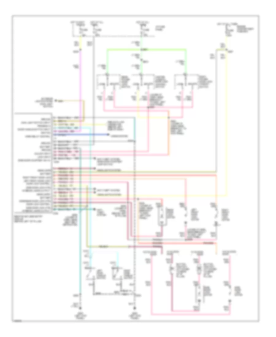
HEADLIGHTS
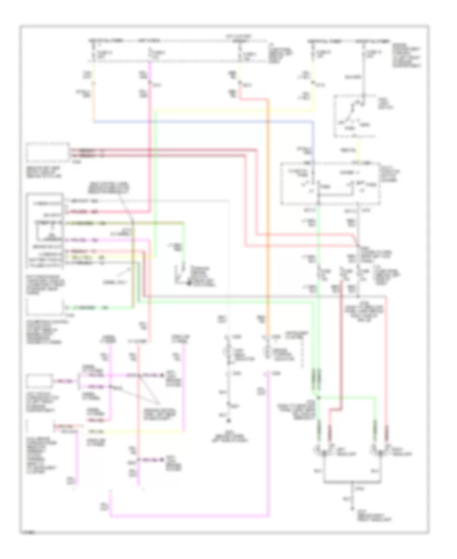
Headlight Wiring Diagram, with DRL for Ford RV Cutaway E350 1998
List of elements for Headlight Wiring Diagram, with DRL for Ford RV Cutaway E350 1998:
- (eng control harn, near blower motor resistor breakout)
- (engine control harn, left rear of eng compt)
- 507/13
- 527/12
- Anti- lock brakes system
- Battery pwr in
- Brake ind out
- Brake warning indicator
- C154
- C218
- C224
- C225
- C226
- C251
- C336
- Daytime running lamps (drl) module (lower right front of engine, near horns)
- Diesel (w/ 4wabs)
- Diesel (w/ rabs)
- Diesel only
- Diesel w/ rabs
- Dimmer
- Drl disable
- Dual brake warning diode/ resistor assembly (in main harness, near t/o to instrument cluster)
- Engine compartment fuse box (in left front of engine compartment)
- Flash-to- pass
- Fuse 10 20a
- Fuse 10a
- Fuse 15 40a
- Fuse 15a
- Fuse 2 15a
- Fuse 27 15a
- Fuse 6 10a
- G107 (behind right front headlamp)
- G202 (behind upper left side of dash)
- Gasoline (w/ rabs)
- Gasoline w/ rabs
- Head
- Hi beam in out
- High beam indicator
- Hot at all times
- Hot in run
- Hot in start
- I/p fuse panel (behind left side of dash)
- Ign input
- Instrument cluster
- Left headlamp
- Lo beams in
- Low vacuum warning switch (in left front of engine compartment)
- Main light switch
- Multi- function switch (dimmer)
- Off
- Or run
- Park
- Park bk on in
- Parking brake switch (near left kick panel)
- Pass
- Powertrain control module (pcm) (in left rear of engine compt, near brake master cylinder)
- Pulsed output
- Remote keyless entry module (behind "b" pillar)
- Right headlamp
- S116
- S119
- S131
- S163
- S164 (dash to headlamp panel harn, near drl module breakout)
- S166 (dash to headlamp panel harn, behind right side of grille)
- S174 (w/ diesel)
- S207
- S213
- S220
- S254 (lower i/p harn, near left kick panel)
- W/ 4wabs
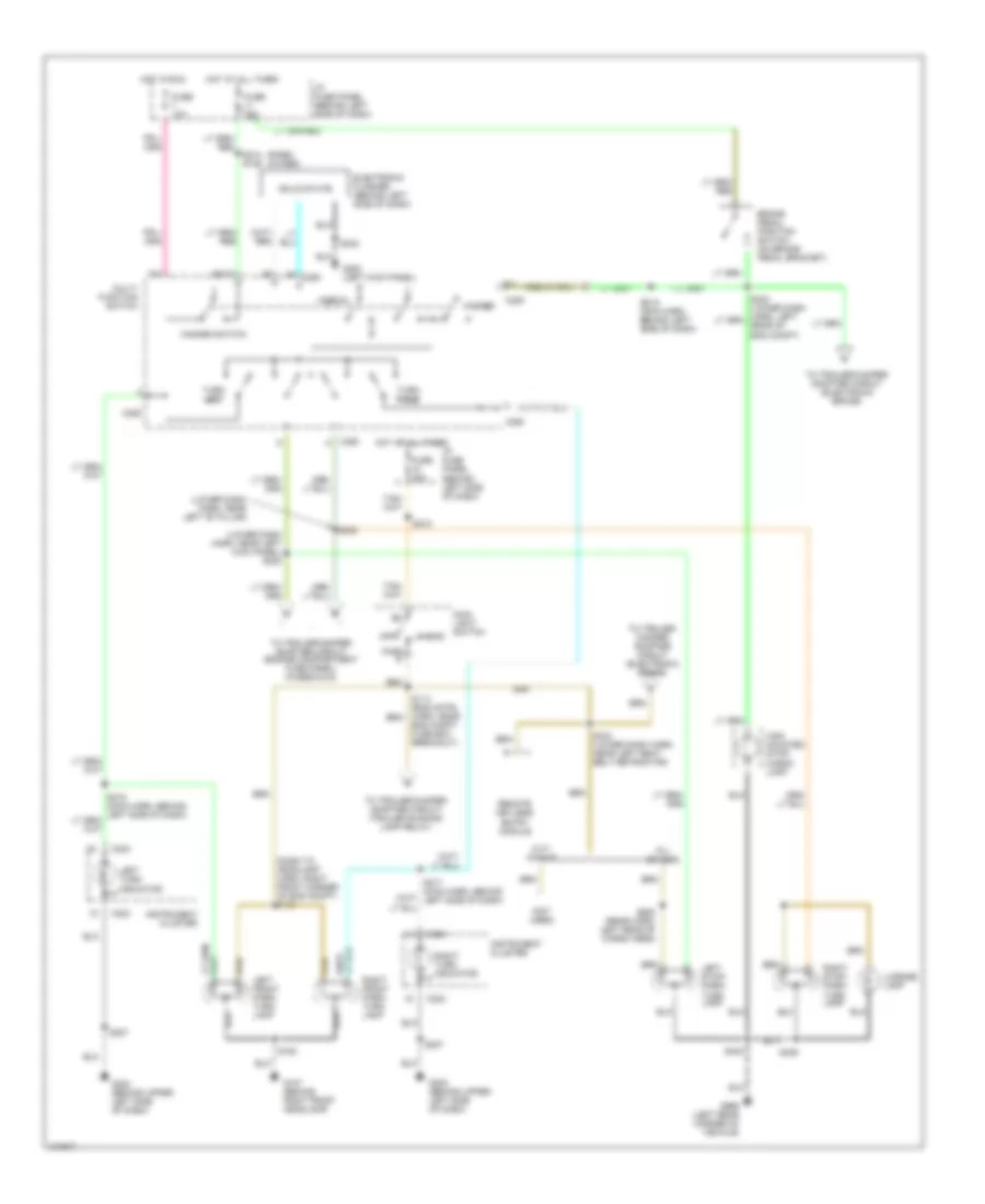
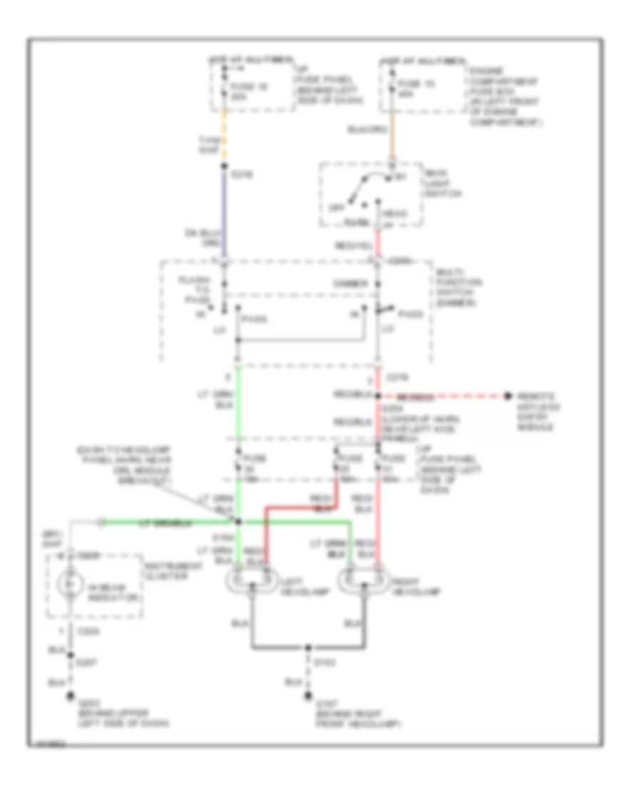
Headlight Wiring Diagram, without DRL for Ford RV Cutaway E350 1998
List of elements for Headlight Wiring Diagram, without DRL for Ford RV Cutaway E350 1998:
- (dash to headlamp panel harn, near drl module breakout)
- C218
- C224
- C225
- Dimmer
- Engine compartment fuse box (in left front of engine compartment)
- Flash- to- pass
- Fuse 10 20a
- Fuse 10a
- Fuse 15 40a
- Fuse 15a
- G107 (behind right front headlamp)
- G202 (behind upper left side of dash)
- Head
- Hi beam indicator
- Hot at all times
- I/p fuse panel (behind left side of dash)
- Instrument cluster
- Left headlamp
- Main light switch
- Multi- function switch (dimmer)
- Off
- Park
- Pass
- Remote keyless entry module
- Right headlamp
- S163
- S164
- S207
- S218
HORN
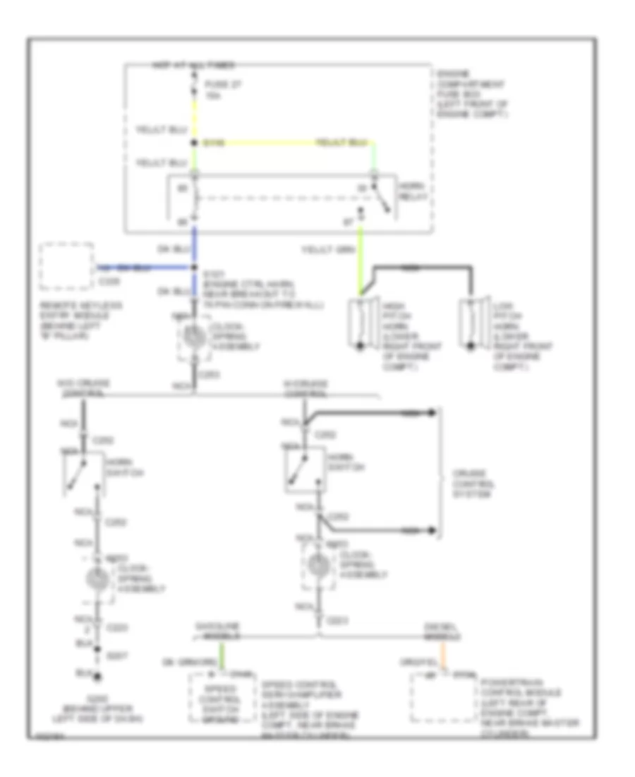
Horn Wiring Diagram for Ford RV Cutaway E350 1998
List of elements for Horn Wiring Diagram for Ford RV Cutaway E350 1998:
- 15a
- C146
- C154
- C223
- C252
- C253
- C335
- Clock- spring assembly
- Cruise control system
- Diesel models
- Engine compartment fuse box (left front of engine compt)
- Fuse 27
- G202 (behind upper left side of dash)
- Gasoline models
- High pitch horn (lower right front of engine compt)
- Horn relay
- Horn switch
- Hot at all times
- Low pitch horn (lower right front of engine compt)
- Nca
- Powertrain control module (left rear of engine compt, near brake master cylinder)
- Remote keyless entry module (behind left "b" pillar)
- S116
- S121 (engine ctrl harn, near breakout to 76 pin conn on firewall)
- S207
- Speed control servo/amplifier assembly (left side of engine compt, near brake master cylinder)
- Speed control switch ground
- W/cruise control
- W/o cruise control
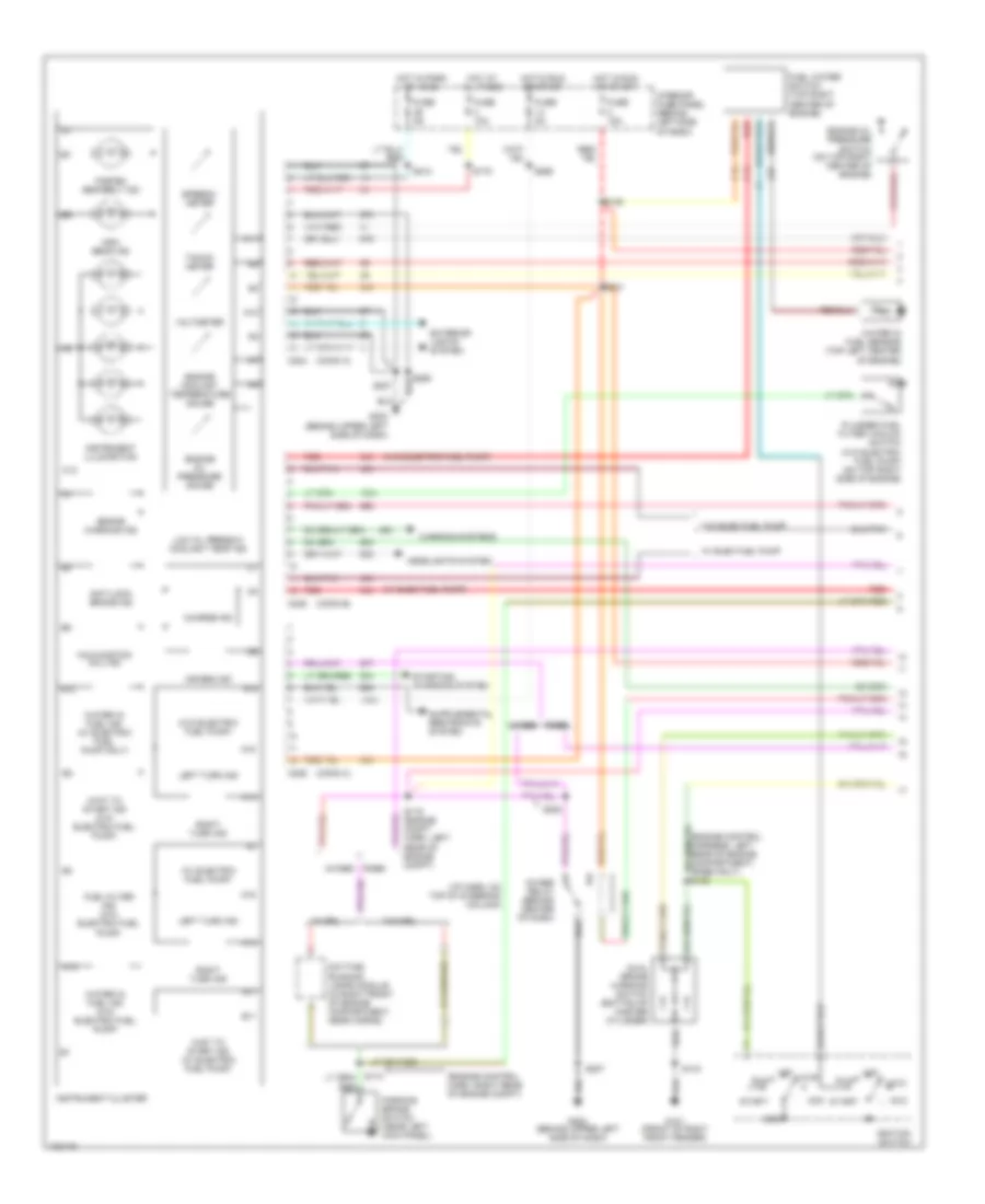
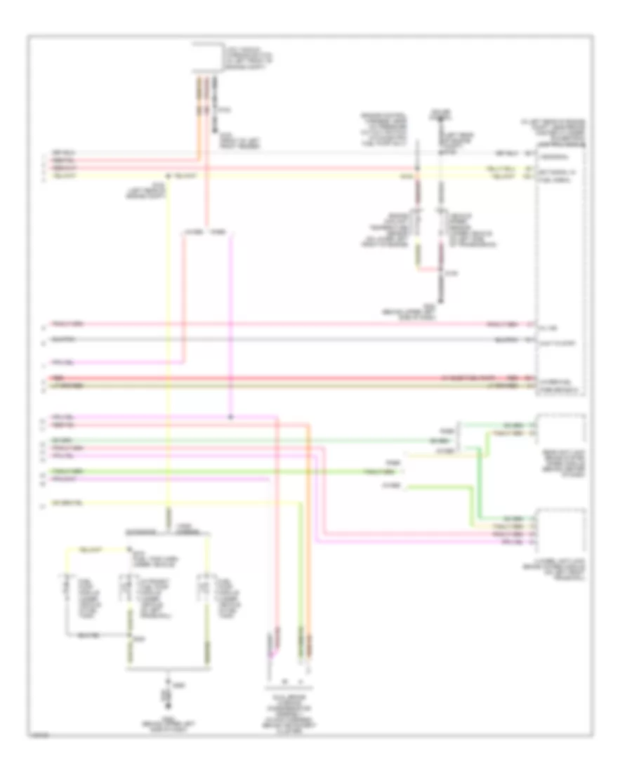
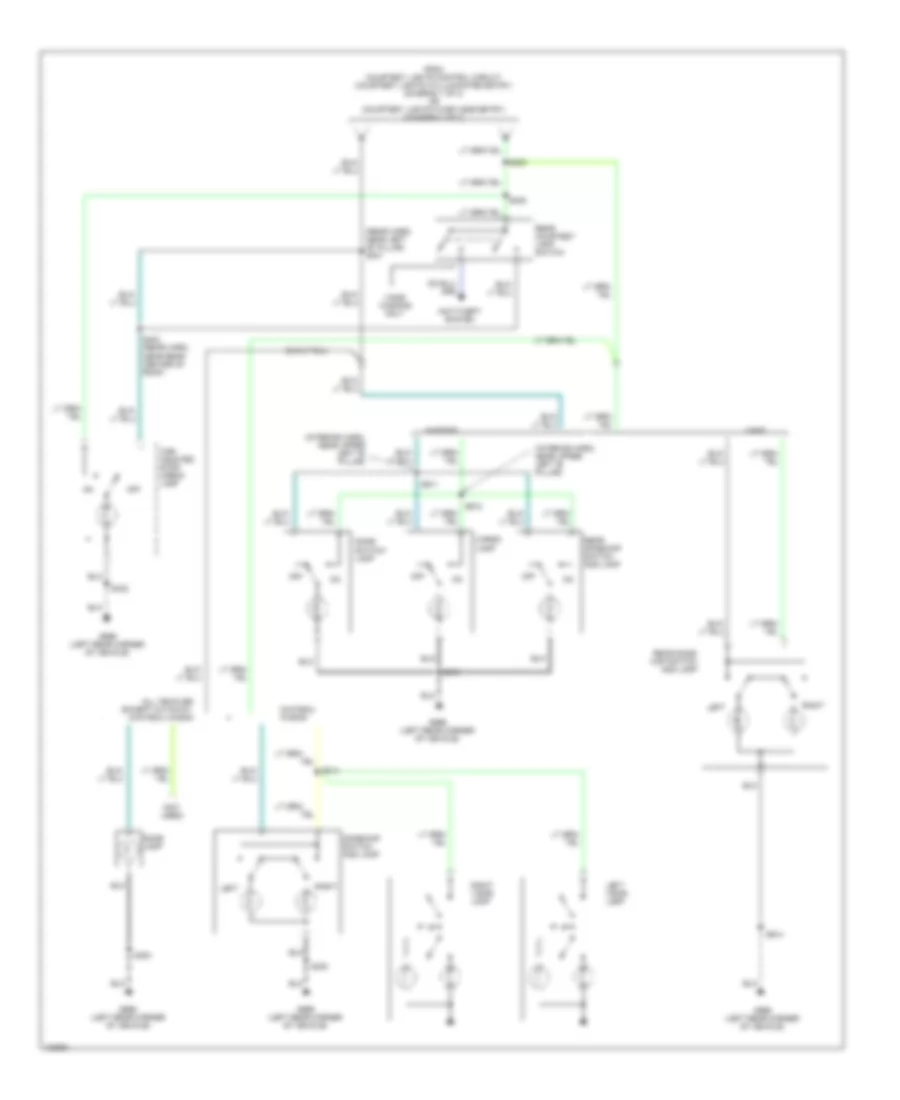
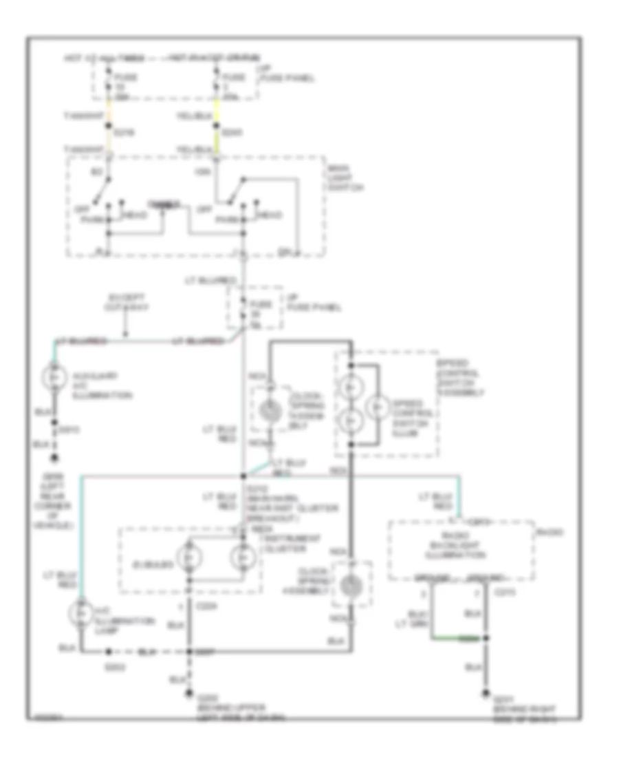
INSTRUMENT CLUSTER
5.4L
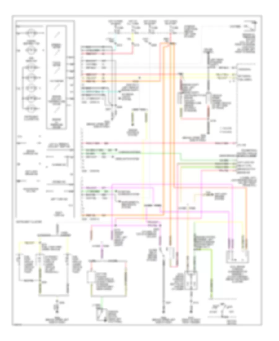
5.4L CNG, Instrument Cluster Wiring Diagram for Ford RV Cutaway E350 1998
List of elements for 5.4L CNG, Instrument Cluster Wiring Diagram for Ford RV Cutaway E350 1998:
- (conn a)
- (conn b)
- (conn c)
- (gas only) (left rear of engine compt)
- (i/p harn, on top of steering column)
- (left rear of engine compt) s135
- 4 wheel anti- lock brakes module (on left front frame rail)
- 4.2l/4.6l
- 4wabs
- 4wabs relay (behind center of dash)
- 5.4l/6.8l
- A10
- A11
- A14
- A15
- A16
- Acc
- Air bag ind
- Anti-lock brake ind
- Anti-lock brakes system
- Anti-lock ind
- Brake ind
- Brake switch
- Brake warning ind
- C12
- C224
- C225
- Charge ind
- Cng
- Cruise control
- Cutaways
- Daytime running lamps module (in right front of engine compartment, near horns)
- Dual brake warning diode/resistor assembly (in main harness, behind instrument cluster)
- Dual brake warning switch (bottom of master cylinder)
- Ect signal
- Engine controls system
- Engine coolant temperature gauge
- Engine oil pressure gauge
- Engine oil pressure switch (4.2l: on left front of engine) (4.6/5.4/6.8l: on lower left front of engine)
- Exterior lights system
- Fasten seatbelt ind
- Fuel pump module (under vehicle, in fuel tank)
- Fuel signal
- Fuse 10a
- Fuse 15a
- Fuse 5a
- G101 (front of right front fender)
- G202 (behind upper left side of dash)
- Gas
- Gnd
- Headlights system
- High beam ind
- Hot at all times
- Hot in park or head
- Hot in run or start
- Ignition switch
- In-transit fuel pump module (under vehicle, on left frame rail)
- Instrument cluster
- Instrument illumination
- Instrumentation engine coolant temperature sensor (on front of engine)
- Interior fuse panel (behind left side of dash)
- Left turn ind
- Lock
- Low oil press/hi coolant temp ind
- Malfunction (mil) ind
- Mil ind
- Off
- Parking brake switch (near left kick panel)
- Powertrain control module (near brake master cylinder)
- Rabs
- Rabs 4wabs
- Relay ctrl
- Right turn ind
- Run
- S119 (engine compt harn, left rear of engine compt)
- S120
- S133
- S139
- S143
- S175
- S207
- S212
- S213
- S220
- S265
- S268
- S308
- S310 (fuel tank harn, under vehicle)
- Speedo- meter
- Start
- Starting/ charging system
- Tacho- meter
- Vans/ wagons
- Vehicle speed sensor (under vehicle, on left side of trans)
- Voltmeter
- Vss signal
- W/ drl
- W/o drl
- Warning systems
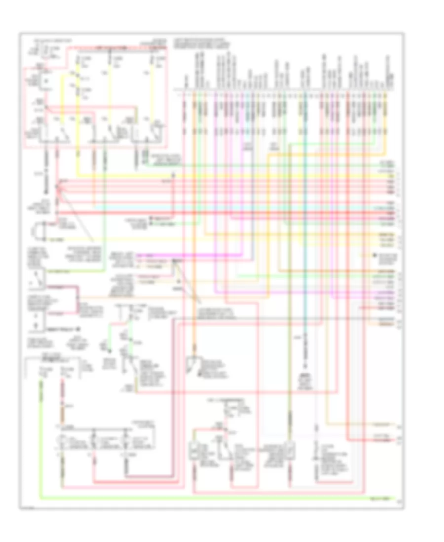
5.4L, Instrument Cluster Wiring Diagram for Ford RV Cutaway E350 1998
List of elements for 5.4L, Instrument Cluster Wiring Diagram for Ford RV Cutaway E350 1998:
- (conn a)
- (conn b)
- (conn c)
- (gas only) (left rear of engine compt)
- (i/p harn, on top of steering column)
- (left rear of engine compt) s135
- 4 wheel anti- lock brakes module (on left front frame rail)
- 4.2l/4.6l
- 4wabs
- 4wabs relay (behind center of dash)
- 5.4l/6.8l
- A10
- A11
- A14
- A15
- A16
- Acc
- Air bag ind
- Anti-lock brake ind
- Anti-lock brakes system
- Anti-lock ind
- Brake ind
- Brake switch
- Brake warning ind
- C12
- C224
- C225
- Charge ind
- Cng
- Cruise control
- Cutaways
- Daytime running lamps module (in right front of engine compartment, near horns)
- Dual brake warning diode/resistor assembly (in main harness, behind instrument cluster)
- Dual brake warning switch (bottom of master cylinder)
- Ect signal
- Engine controls system
- Engine coolant temperature gauge
- Engine oil pressure gauge
- Engine oil pressure switch (4.2l: on left front of engine) (4.6/5.4/6.8l: on lower left front of engine)
- Exterior lights system
- Fasten seatbelt ind
- Fuel pump module (under vehicle, in fuel tank)
- Fuel signal
- Fuse 10a
- Fuse 15a
- Fuse 5a
- G101 (front of right front fender)
- G202 (behind upper left side of dash)
- Gas
- Gnd
- Headlights system
- High beam ind
- Hot at all times
- Hot in park or head
- Hot in run or start
- Ignition switch
- In-transit fuel pump module (under vehicle, on left frame rail)
- Instrument cluster
- Instrument illumination
- Instrumentation engine coolant temperature sensor (on front of engine)
- Interior fuse panel (behind left side of dash)
- Left turn ind
- Lock
- Low oil press/hi coolant temp ind
- Malfunction (mil) ind
- Mil ind
- Off
- Parking brake switch (near left kick panel)
- Powertrain control module (near brake master cylinder)
- Rabs
- Rabs 4wabs
- Relay ctrl
- Right turn ind
- Run
- S119 (engine compt harn, left rear of engine compt)
- S120
- S133
- S139
- S143
- S175
- S207
- S212
- S213
- S220
- S265
- S268
- S308
- S310 (fuel tank harn, under vehicle)
- Speedo- meter
- Start
- Starting/ charging system
- Tacho- meter
- Vans/ wagons
- Vehicle speed sensor (under vehicle, on left side of trans)
- Voltmeter
- Vss signal
- W/ drl
- W/o drl
- Warning systems
6.8L
6.8L, Instrument Cluster Wiring Diagram for Ford RV Cutaway E350 1998
List of elements for 6.8L, Instrument Cluster Wiring Diagram for Ford RV Cutaway E350 1998:
- (conn a)
- (conn b)
- (conn c)
- (gas only) (left rear of engine compt)
- (i/p harn, on top of steering column)
- (left rear of engine compt) s135
- 4 wheel anti- lock brakes module (on left front frame rail)
- 4.2l/4.6l
- 4wabs
- 4wabs relay (behind center of dash)
- 5.4l/6.8l
- A10
- A11
- A14
- A15
- A16
- Acc
- Air bag ind
- Anti-lock brake ind
- Anti-lock brakes system
- Anti-lock ind
- Brake ind
- Brake switch
- Brake warning ind
- C12
- C224
- C225
- Charge ind
- Cng
- Cruise control
- Cutaways
- Daytime running lamps module (in right front of engine compartment, near horns)
- Dual brake warning diode/resistor assembly (in main harness, behind instrument cluster)
- Dual brake warning switch (bottom of master cylinder)
- Ect signal
- Engine controls system
- Engine coolant temperature gauge
- Engine oil pressure gauge
- Engine oil pressure switch (4.2l: on left front of engine) (4.6/5.4/6.8l: on lower left front of engine)
- Exterior lights system
- Fasten seatbelt ind
- Fuel pump module (under vehicle, in fuel tank)
- Fuel signal
- Fuse 10a
- Fuse 15a
- Fuse 5a
- G101 (front of right front fender)
- G202 (behind upper left side of dash)
- Gas
- Gnd
- Headlights system
- High beam ind
- Hot at all times
- Hot in park or head
- Hot in run or start
- Ignition switch
- In-transit fuel pump module (under vehicle, on left frame rail)
- Instrument cluster
- Instrument illumination
- Instrumentation engine coolant temperature sensor (on front of engine)
- Interior fuse panel (behind left side of dash)
- Left turn ind
- Lock
- Low oil press/hi coolant temp ind
- Malfunction (mil) ind
- Mil ind
- Off
- Parking brake switch (near left kick panel)
- Powertrain control module (near brake master cylinder)
- Rabs
- Rabs 4wabs
- Relay ctrl
- Right turn ind
- Run
- S119 (engine compt harn, left rear of engine compt)
- S120
- S133
- S139
- S143
- S175
- S207
- S212
- S213
- S220
- S265
- S268
- S308
- S310 (fuel tank harn, under vehicle)
- Speedo- meter
- Start
- Starting/ charging system
- Tacho- meter
- Vans/ wagons
- Vehicle speed sensor (under vehicle, on left side of trans)
- Voltmeter
- Vss signal
- W/ drl
- W/o drl
- Warning systems
7.3L
7.3L DI Turbo Diesel, Instrument Cluster Wiring Diagram (1 of 2) for Ford RV Cutaway E350 1998
List of elements for 7.3L DI Turbo Diesel, Instrument Cluster Wiring Diagram (1 of 2) for Ford RV Cutaway E350 1998:
- (conn a)
- (conn b)
- (conn c)
- (engine control harn, right rear of engine compt)
- (i/p harn, on top of steering column)
- (w/ elec fuel pump)
- (w/ electric fuel pump)
- (w/o electric fuel pump)
- 4wabs
- 4wabs relay (behind center of dash)
- A10
- A11
- A13
- A14
- A15
- A16
- Acc
- Air bag ind
- Anti-lock brake ind
- B11
- B12
- Brake warning ind
- C12
- C224
- C225
- C226
- Charge ind
- Daytime running lamps module (in right front of engine compartment, near horns)
- Dual brake warning switch (bottom of master cylinder)
- Engine coolant temperature gauge
- Engine oil pressure gauge
- Engine oil pressure switch (on top right center of engine)
- Exterior lights system
- Fasten seatbelt ind
- Fuel filter ind (w/o electric fuel pump)
- Fuel water switch (top right center of engine)
- Fuse 10a
- Fuse 15a
- Fuse 5a
- G101 (front of right front fender)
- G202 (behind upper left side of dash)
- Gnd
- Headlights system
- High beam ind
- Hot at all times
- Hot in park or head
- Hot in run or start
- Ignition switch
- Instrument cluster
- Instrument illumination
- Interior fuse panel (behind left side of dash)
- Left turn ind
- Lock
- Low oil press/hi coolant temp ind
- Malfunction (mil) ind
- Off
- Parking brake switch (near left kick panel)
- Plugged fuel filter vacuum switch (w/o electric fuel pump) (on top right side of engine)
- Rabs
- Red
- Right turn ind
- Run
- S119 (engine compt harn, left rear of engine compt)
- S143
- S146
- S174
- S175
- S207
- S212
- S213
- S220
- S265
- S268
- Speedo- meter
- Start
- Starting/ charging system
- Tacho- meter
- Voltmeter
- W/ drl
- W/ elec fuel pump
- W/o drl
- W/o elec fuel pump
- Wait to start ind (w/ electric fuel pump)
- Wait to start ind (w/o electric fuel pump)
- Warning systems
- Water in fuel ind (w/ electric fuel pump only)
- Water in fuel ind (w/o electric fuel pump)
- Water in fuel sensor (top left center of engine)
7.3L DI Turbo Diesel, Instrument Cluster Wiring Diagram (2 of 2) for Ford RV Cutaway E350 1998
List of elements for 7.3L DI Turbo Diesel, Instrument Cluster Wiring Diagram (2 of 2) for Ford RV Cutaway E350 1998:
- (enginr control harness, near a/c pressure cut-out switch) (w/o electric fuel pump only)
- (in left rear of engine compt, near brake master cylinder) powertrain control module
- (left rear of engine compt)
- (left rear of engine compt) s135
- (w/ elec fuel pump)
- 4 wheel anti-lock brake (4wabs) module (on left front frame rail)
- 4wabs
- Cruise control
- Cutaways
- Dual brake warning diode/resistor assembly (in main harness, behind instrument cluster)
- Ect signal in
- Engine coolant temperature sensor (on lower left front of engine)
- Fuel pump module (under vehicle, in fuel tank)
- Fuel signal
- G100 (front of left front fender)
- G202 (behind upper left side of dash)
- In-transit fuel pump module (under vehicle, on left frame rail)
- Low vaccum warning switch (in left front of engine compt)
- Mil ind
- Park brake in
- Rabs
- Rear anti-lock brake system (rabs) module (behind center of dash)
- Red
- S120
- S122
- S133
- S139
- S268
- S308
- S310 (fuel tank harn, under vehicle)
- Vans/ wagons
- Vehicle speed sensor (under vehicle, on left side of transmission)
- Vss signal
- Wait to strt
- Water-fuel
INTERIOR LIGHTS
Courtesy Lamps Wiring Diagram (1 of 3) for Ford RV Cutaway E350 1998
List of elements for Courtesy Lamps Wiring Diagram (1 of 3) for Ford RV Cutaway E350 1998:
- (left rear corner of vehicle) g999
- (main harn, behind left side of dash) s210
- (not used)
- Battery
- Ctsy lp ctrl
- Cutaway models
- Cutaway only
- Cutaways
- Dome
- Dome/map switch and lamp
- Door sw input
- Exterior lights system (trailer/ camper adapter)
- Fuse 15a
- Fuse 5a
- G200 (left kick panel)
- G202 (behind upper left side of dash)
- Ground
- High mounted stop/ cargo lamp
- High mounted stop/cargo lamp & rear courtesy lamp switch (diagram 3 of 3)
- Hinge door
- Hot at all times
- Hot in run
- I/p fuse panel
- Ignition
- Illuminated entry module (behind center of dash)
- Left
- Left courtesy lamp switch
- Left door handle switch
- Main light switch
- Red/ pnk
- Right
- Right courtesy lamp switch
- Right door handle switch
- S205
- S219
- S221
- S231 (lower i/p harn, near left kick panel)
- S233
- S300
- S316
- S402
- S500
- S600
- Side door courtesy lamp switch
- Sliding door
- Vans/ wagons only
- Vans/wagons &
- Vans/wagons only
- W/ full headliner
- W/illuminated entry
- W/o full headliner
- Warning systems (warning buzzer module)
Courtesy Lamps Wiring Diagram (2 of 3) for Ford RV Cutaway E350 1998
List of elements for Courtesy Lamps Wiring Diagram (2 of 3) for Ford RV Cutaway E350 1998:
- (not used)
- Anti- theft system
- Battery
- C335
- C336
- Dome
- Dome/map switch and lamp
- Door hndle sw
- Fuse 15a
- Fuse 20a
- G200 (left kick panel)
- G999 (left rear corner of vehicle)
- Ground
- High mounted stop/ cargo lamp
- High mounted stop/cargo lamp & rear courtesy lamp switch (diagram 3 of 3)
- Hinge door
- Hot at all times
- I/p fuse panel
- Int lps out
- Left
- Left courtesy lamp switch
- Left door handle switch
- Main light switch
- Red/ pnk
- Remote keyless entry module (behind left "b" pillar)
- Right
- Right courtesy lamp switch
- Right door handle switch
- S219
- S221
- S233
- S235
- S259 (lower i/p harn, behind left "b" pillar)
- S260
- S300
- S402
- S500
- S600
- Side door courtesy lamp switch
- Side door ctsy sw
- Sliding door
- Vans & wagons
- W/ keyless entry
- W/full headliner
- W/o full headliner
- Warning systems (warning buzzer module)
Courtesy Lamps Wiring Diagram (3 of 3) for Ford RV Cutaway E350 1998
List of elements for Courtesy Lamps Wiring Diagram (3 of 3) for Ford RV Cutaway E350 1998:
- (interior harn, near upper left "b' pillar)
- (not used)
- (rear harn, near left "b" pillar) s301
- All vehicles except cutaway, chateau wagon
- Anti-theft system
- Cargo lamp
- Chateau wagon
- Dome lamp
- Dome switch/ lamp
- Dome/map switch and lamp
- From courtesy lights control circuit (courtesy lights w/illuminated entry) (diagram 1 of 3) or (courtesy lights w/keyless entry) (diagram 2 of 3)
- G999 (left rear corner of vehicle)
- High mounted stop/ cargo lamp
- Left
- Left visor lamp
- Off
- Rear courtesy lamp switch
- Rear dome/ map switch and lamp
- Rear dome/map switch and lamp
- Right
- Right visor lamp
- S300
- S302
- S314
- S402
- S404 (rear harn, near rear center of roof)
- S405
- S911
- S912
- S913
- S914
- Vans
- Vans/ wagons only
- Wagons
Instrument Illumination Wiring Diagram for Ford RV Cutaway E350 1998
List of elements for Instrument Illumination Wiring Diagram for Ford RV Cutaway E350 1998:
- (5) bulbs
- A/c illumination lamp
- Auxiliary a/c illumination
- C213
- C224
- Clock- spring assem- bly
- Clock- spring assembly
- Dimmer
- Except cutaway
- Fuse 15a
- Fuse 20a
- Fuse 5a
- G201 (behind right side of dash)
- G202 (behind upper left side of dash)
- G999 (left rear corner of vehicle)
- Ground
- Head
- Hot at all times
- Hot in accy or run
- I/p fuse panel
- Ign
- Instrument cluster
- Main light switch
- Nca
- Off
- Park
- Radio
- Radio backlight illumination
- S202
- S204
- S207
- S212 (main harn, near inst cluster breakout)
- S218
- S245
- S913
- Speed control switch assembly
- Speed control switch illum
POWER DISTRIBUTION
Power Distribution Wiring Diagram (1 of 4) for Ford RV Cutaway E350 1998
List of elements for Power Distribution Wiring Diagram (1 of 4) for Ford RV Cutaway E350 1998:
- (eng control harn, left rear of engine compartment)
- (eng control harn, near eng compt fuse box breakout) s116
- 4 wheel anti-lock brakes module
- 5.4l cng
- 7.3l diesel
- 7.3l diesel w/ elec fuel pump
- 7.3l diesel w/o elec fuel pump
- 7.4l diesel w/ electric fuel pump
- All except 7.3l diesel w/ 215a generator
- Auxiliary battery relay
- Auxiliary blower motor relay
- Blower motor relay
- C143
- C224
- Compartment fuse box (diagram 1 of 4)
- Daytime running lamps
- Diesel only
- Engine compartment battery
- Engine compartment fuse box
- Engine compt fuse box
- Frame battery (diesel only)
- From eng compt fuse fuse box (fuse 16) (diagram 1 0f 4)
- From eng compt fuse fuse box (fuse 17) (diagram 1 0f 4)
- From engine a
- Fuel pump relay
- Fuse 10a
- Fuse 15a
- Fuse 20a
- Fuse 30a
- Fuse 40a
- Fuse 50a
- Fuse 60a
- Gasoline
- Generator/ voltage regulator
- Glow plug relay
- Horn relay
- Idm relay
- Instrument cluster
- Main light switch
- Modified vehicle power
- Ngv module
- Pcm power relay
- Powertrain control module
- Red
- Remote keyless entry module (w/ remote keyless entry)
- S1010 (near power distribution box)
- S1011 (near power distribution box)
- S1012 (right front of engine compartment, near starter motor relay)
- S109 (eng control harn, near eng compt fuse box breakout)
- S110 (eng control harn, near eng compt fuse box breakout)
- S145
- S175 (engine control harn, left rear of engine compartment)
- S183
- Starter motor
- Starter motor relay
- To eng compt fuse box (fuse 13) (diagram 1 of 4)
- To eng compt fuse box (fuse 8) (diagram 1 of 4)
- To engine compt fuse box (fuse 9)(diagram 1 of 4)
- To splice s225 (diagram 3 of 4)
- To splice s227 (diagram 2 of 4)
- To splice s266 (diagram 2 of 4)
- Trailer backup lamp relay
- Trailer battery charge relay
- Trailer running lamp relay
- Trailer/ camper adapter (electronic brake)
- W aux heat or a/c
- W/ 4wabs only
- W/ aux battery
- W/ aux battery jumper
- W/ drl only
- W/o aux battery
- Wires end in harness
Power Distribution Wiring Diagram (2 of 4) for Ford RV Cutaway E350 1998
List of elements for Power Distribution Wiring Diagram (2 of 4) for Ford RV Cutaway E350 1998:
- (attached to instrument panel assembly, behind instrument cluster)
- (interior harn, near left "b" pillar) s912
- (interior lamp harn)
- (lower i/p harn, left side of dash) s266
- (lower i/p harn, near brake on/off switch breakout)
- (lower i/p harn, near rke data link connector breakout) s237
- (main harn, behind left side of i/p)
- (main harn, near main light switch breakout)
- (rear harn, near high mounted stop/ cargo lamp) s405
- (w/o door trim)
- Air bag diagnostic monitor
- All chateau wagons
- All except cutaways
- All vans
- All vans, wagons, & cutaways
- Batt
- Brake pedal position switch
- Brake pressure switch
- C217
- C330
- C335
- Cargo lamp
- Cigar lighter
- Cutaways only
- Data link connector
- Dome switch/ lamp
- Dome/map switch and lamp
- Driver's seat regulator control switch
- Eng compartment)
- Except cutaways
- Extended wagons
- From engine compartment d fuse box (fuse 8) (diagram 1 of 4)
- From engine compt fuse box (fuse 18) (diagram 1 0f 4)
- Fuse 10a
- Fuse 15a
- Fuse 20a
- Fuse 25a
- Fuse 30a
- G202
- High mounted stop/cargo lamp
- I/p fuse panel
- Illuminated entry module
- Left courtesy lamp switch
- Left visor lamp
- Main light switch
- Master window/ door lock control switch
- Memory lock module
- Modified vehicle power
- Multi- function switch
- Nca
- Power mirror switch
- Power plug
- Radio
- Rear anti-lock brake system module
- Rear courtesy lamp switch
- Rear dome/map switch and lamp
- Rear power door lock switch
- Red
- Remote keyless entry module
- Right courtesy lamp switch
- Right power door lock/ window switch
- Right visor lamp
- S129 (engine control harn, left rear of eng compt)
- S207
- S219
- S221
- S302 (rear harn, near left seat belt retractor)
- S314
- S505 (left front door harn, in left front door)
- Side door courtesy lamp switch
- W/ full headliner
- W/ rabs only
- W/ remote/ keyless entry
- W/o full headliner
- W/o remote/ keyless entry
- Wagons
Power Distribution Wiring Diagram (3 of 4) for Ford RV Cutaway E350 1998
List of elements for Power Distribution Wiring Diagram (3 of 4) for Ford RV Cutaway E350 1998:
- (eng cntrl harn, near eng compt fuse box breakout) s113
- (engine contrl harn, left rear of eng compt) s131
- (lower i/p harn, near brake on/off (boo) switch breakout) s222
- (main harn, near instrument cluster breakout) s213
- (main harn, near radio breakout) s203
- 4 wheel anti-lock brake system module
- 4wabs relay
- Accy
- Air bag diagnostic monitor
- Auxiliary battery relay
- Auxiliary powertrain control connector
- Batt
- Blend door actuator
- C193
- C250
- Daytime running lamps module
- Diesel only
- Digital transmission range sensor
- Dual brake warning diode/ resistor assembly
- From engine compartment fuse box (fuse 23) (diagram 1 of 4)
- Fuel water switch
- Function selector switch
- Fuse 10a
- Fuse 15a
- Fuse 20a
- Fuse 30a
- Fuse 5a
- I/p fuse panel
- Ignition switch
- Illuminated entry module
- Instrument cluster
- Lock
- Low vacuum warning switch
- Multi- function switch
- Nca
- Off
- Overdrive cancel switch
- Radio
- Rear anti-lock brakes system module
- Run
- S146 (engine cntrl harn, left rear of eng compt)
- S200 (main harn, near air bag bracket)
- S229 (lower i/p harn, near data link connector breakout)
- S265 (lower i/p harn, behind right side of dash)
- S269 (lower i/p harn, left side of dash)
- Shift lock actuator
- Speed control servo/ apmlifier
- Start
- Tan/ red
- To i/p fuse panel (fuse 3) (diagram 4 of 4)
- To splice s127 (diagram 4 of 4)
- W 4wabs
- W/ 4wabs only
- W/ rabs only
- W/rabs
- Warning buzzer module
Power Distribution Wiring Diagram (4 of 4) for Ford RV Cutaway E350 1998
List of elements for Power Distribution Wiring Diagram (4 of 4) for Ford RV Cutaway E350 1998:
- (eng cntrl harn, left rear of eng compt)
- (eng cntrl harn, near left bank of engine)
- (eng cntrl harn, near right bank of engine)
- (fuel injector harn, near glow plug relay) s1006
- 4.2l engine
- 4.6l engine
- 5.4l cng only
- 5.4l engine
- 6.8l engine
- 7.3l diesel
- 7.3l diesel w/ electric fuel pump
- Digital transmission range sensor
- Eng compt)
- Engine compartment fuse box
- Engine compt fuse box
- Except 5.4l cng
- Except 7.3l diesel w/ electric fuel pump
- From ignition switch (diagram 3 of 4)
- From i/p fuse panel (fuse 8) (diagram 3 of 4)
- Fuel line heater
- Fuel pump relay
- Fuse 15a
- Fuse 30a
- Fuse 5a
- Glow plug relay
- Idle validation switch
- Idm relay
- Ign
- Ignition coil
- Ignition coil 3 & 4
- Ignition coil no 1
- Ignition coil no 10
- Ignition coil no 2
- Ignition coil no 3
- Ignition coil no 4
- Ignition coil no 5
- Ignition coil no 6
- Ignition coil no 7
- Ignition coil no 8
- Ignition coil no 9
- Interior fuse panel
- Main light switch
- Master window/ door lock control switch
- Nca
- Ngv timer
- Pcm power diode
- Pcm power relay
- Radio
- Radio capacitor no 1
- Radio capacitor no 2
- Remote/ keyless entry module
- Right power door lock/ window switch
- S127
- S150 (eng cntrl harn, near right bank of engine)
- S156
- S161
- S208 (main harn, near clock- spring assy breakout)
- S209 (main harn, near clockspring assy breakout)
- S236 (lower i/p harn, behind left side of dash)
- S245 (lower i/p harn, near i/p fuse panel breakout)
- S501 (left front door harn, in left front door)
- Trailer battery charge relay
- Windshield wiper motor
- Wiper control module
POWER DOOR LOCKS
Door Lock Wiring Diagram, with Memory Lock for Ford RV Cutaway E350 1998
List of elements for Door Lock Wiring Diagram, with Memory Lock for Ford RV Cutaway E350 1998:
- (left front door harn, near breakout to left door lock motor) s503
- Battery
- Button contact
- Fuse 20a
- G200 (left kick panel)
- Ground
- Hot at all times
- I/p fuse panel
- Left front door lock motor
- Lk outpt mtr
- Lock
- Lock input
- Master window/ door lock control switch
- Memory lock module (behind left "b" pillar)
- Rear door lock motor (except cutaway)
- Rear power door lock switch
- Red
- Right front door lock motor
- Right power door lock/ window switch
- S233
- S235
- S237
- S238 (lower i/p harn, near breakout to g200)
- S239 (lower i/p harn, near breakout to g200)
- S502 (left front door harn, in breakout to left door lock motor)
- Side door lock motor
- Unlock
- Unlock input
- W/ hinged door
- W/ sliding door
Door Lock Wiring Diagram, without Memory Lock for Ford RV Cutaway E350 1998
List of elements for Door Lock Wiring Diagram, without Memory Lock for Ford RV Cutaway E350 1998:
- (left front door harn, near breakout to left front door lock motor) s502
- Fuse 20a
- G200 (left kick panel)
- Hot at all times
- I/p fuse panel
- Left front door lock motor
- Lock
- Master window/ door lock control switch
- Red
- Right front door lock motor
- Right power door lock/ window switch
- S237
- S503 (left front door harn, in breakout to left front door lock motor)
- S600
- Unlock
Keyless Entry Wiring Diagram for Ford RV Cutaway E350 1998
List of elements for Keyless Entry Wiring Diagram for Ford RV Cutaway E350 1998:
- (lower i/p harn, near breakout to g200, left kick panel) s251
- Anti- theft system
- Anti-theft system
- Anti-theft system (side door courtesy lamp switch)
- Battery
- Button contact (attached to rear of "b" pillar)
- C335
- C336
- Door handle switch input
- Door lock control
- Engine compartment fuse box
- Exterior lights system (main light switch)
- Fuse 15a
- Fuse 20a
- Fuse 50a
- G200 (left kick panel)
- Ground
- Headlamps
- Headlights system
- Horn relay control
- Horns system
- Hot at all times
- Hot in accy or run
- I/p fuse panel
- Ignition
- Interior lamps output
- Left door handle switch
- Left front door lock
- Left front door lock motor
- Lock
- Lock input
- Main light switch input
- Master window/ door lock/ control switch
- Program a
- Rear door lock motor
- Rear power door lock switch
- Remote keyless entry module (behind left "b" pillar)
- Right door handle switch
- Right front door lock
- Right front door lock motor
- Right power door lock/ window switch
- Rke data link connector (behind left side of dash)
- S221
- S233
- S235
- S238 (lower i/p harn, near breakout to g200, left kick panel)
- S245
- S252 (lower i/p harn, near breakout to g200, left kick panel)
- S255 (lower i/p harn, behind left "b" pillar)
- S257
- S258 (lower i/p harn, near seat belt retractor)
- S260
- S500
- S505
- S600
- Side door courtesy sw in
- Side door lock ctrl
- Side door lock motor
- Side/rear door lock ctrl
- Unlock
- Unlock input
- W/ sliding door
- W/o sliding door
POWER MIRRORS
Power Mirror Wiring Diagram for Ford RV Cutaway E350 1998
List of elements for Power Mirror Wiring Diagram for Ford RV Cutaway E350 1998:
- (w/door trim)
- (w/o door trim)
- Direct- ional control switch
- Fuse 4 15a
- G200 (left kick panel)
- Hot at all times
- I/p fuse panel (behind left side of dash)
- L/r motor
- Left power mirror
- Left/ right switch
- Nca
- Power mirror switch
- Red
- Right power mirror
- S500
- S504 (body harness, front of left front door)
- S505
- Up/dn motor
- W/0 door trim
- W/door trim
POWER SEATS
Power Seat Wiring Diagrams for Ford RV Cutaway E350 1998
List of elements for Power Seat Wiring Diagrams for Ford RV Cutaway E350 1998:
- Driver's seat motor assembly
- Driver's seat regulator control switch
- Entire seat
- Front height motor
- Front of seat
- Fuse 16 30a
- Fwd
- Fwd/ rwd motor
- G200 (left kick panel)
- Hot at all times
- I/p fuse panel (below left side of dash)
- Nca
- Rear height motor
- Rear of seat
- Rwd
- S315
POWER WINDOWS
Power Window Wiring Diagram for Ford RV Cutaway E350 1998
List of elements for Power Window Wiring Diagram for Ford RV Cutaway E350 1998:
- Down
- Fuse 21 30a
- G200 (left kick panel)
- Hot in acc or run
- I/p fuse panel (behind left side of dash)
- Left power window motor
- Master window/ door lock control switch
- Right power door lock/ window switch
- Right power window motor
- S236
- S500
- S501
RADIO
Radio Wiring Diagrams for Ford RV Cutaway E350 1998
List of elements for Radio Wiring Diagrams for Ford RV Cutaway E350 1998:
- (behind upper left side of dash) g202
- (lower dash harn, near breakout to blend door actuator) s240
- (lower dash harn, near breakout to safety belt retractor) s244
- Antenna
- Button contact
- C213
- Cutaways
- Dimmer
- Fuse 15a
- Fuse 20a
- Fuse 5a
- G201 (behind right side of dash)
- Ground
- Head
- Hinged door
- Hot at all times
- Hot in run or acc
- Hot in start
- I/p fuse panel
- Illumination
- Interior lights system
- L front speaker
- L rear speaker
- Left front door speaker
- Left mid speaker (w/ 6 speakers)
- Left rear speaker
- Main light switch
- Memory power
- Nca
- Noise reduction
- Not used
- Off
- Park
- Power
- R front speaker
- R rear speaker
- Radio
- Right front speaker
- Right mid speaker (w/ 6 speakers)
- Right rear speaker
- S202
- S204
- S209
- S212 (main harn, near instrument cluster breakout)
- S218
- S241
- S243
- Sliding door
- Vans/ wagons
SHIFT INTERLOCKS
Shift Interlock Wiring Diagram for Ford RV Cutaway E350 1998
List of elements for Shift Interlock Wiring Diagram for Ford RV Cutaway E350 1998:
- Brake pedal position (bpp) switch (on bracket, above brake pedal)
- Fuse 11 15a
- Fuse 6 10a
- G202 (behind upper left side of dash)
- Hot at all times
- Hot in run
- I/p fuse panel behind left side of dash
- S131
- S207
- S216 (main harn, near breakout to modified vehicle power)
- Shift lock actuator (below right side of steer- ing column)
- Solid state
STARTING/CHARGING
5.4L
5.4L CNG, Charging Wiring Diagram for Ford RV Cutaway E350 1998
List of elements for 5.4L CNG, Charging Wiring Diagram for Ford RV Cutaway E350 1998:
- (right front corner of engine compt) starter motor relay
- 0hms
- 6v (normal operation)
- Accy
- C198
- C199
- C226
- Charge indicator
- Engine compart- ment fuse box
- Engine compartment battery
- Fuse 5a
- Fuse 60a
- G120 (right side of engine)
- Generator/ regulator
- Ground distribution system
- I/p fuse panel
- Ignition switch
- Instrument cluster
- Lock
- Off
- Red
- Run
- S1008
- S1009
- S1010
- S1011
- S225
- S229
- Start
- Starting circuit
5.4L CNG, Starting Wiring Diagram for Ford RV Cutaway E350 1998
List of elements for 5.4L CNG, Starting Wiring Diagram for Ford RV Cutaway E350 1998:
- 5.4l cng
- Acc
- Digital transmission range (dtr) sensor (left side of transmission)
- Engine compartment battery
- Engine compartment fuse box
- Engine controls system
- Fuse 10a
- Fuse 60a
- G120 (right side of engine)
- Ground distri- bution system
- I/p fuse panel
- Ignition switch
- Lock
- Off
- Red
- Run
- S1008
- S1009
- S190 (engine ctrl harn, near a/c pressure cut-out switch)
- S225
- Start
- Starter motor (lower right side of engine)
- Starter motor relay (right front corner of engine compartment)
5.4L, Charging Wiring Diagram for Ford RV Cutaway E350 1998
List of elements for 5.4L, Charging Wiring Diagram for Ford RV Cutaway E350 1998:
- (right front corner of engine compt) starter motor relay
- 0hms
- 6v (normal operation)
- Accy
- C198
- C199
- C226
- Charge indicator
- Engine compart- ment fuse box
- Engine compartment battery
- Fuse 5a
- Fuse 60a
- G120 (right side of engine)
- Generator/ regulator
- Ground distribution system
- I/p fuse panel
- Ignition switch
- Instrument cluster
- Lock
- Off
- Red
- Run
- S1008
- S1009
- S1010
- S1011
- S225
- S229
- Start
- Starting circuit
5.4L, Starting Wiring Diagram for Ford RV Cutaway E350 1998
List of elements for 5.4L, Starting Wiring Diagram for Ford RV Cutaway E350 1998:
- 5.4l cng
- Acc
- Digital transmission range (dtr) sensor (left side of transmission)
- Engine compartment battery
- Engine compartment fuse box
- Engine controls system
- Fuse 10a
- Fuse 60a
- G120 (right side of engine)
- Ground distri- bution system
- I/p fuse panel
- Ignition switch
- Lock
- Off
- Red
- Run
- S1008
- S1009
- S190 (engine ctrl harn, near a/c pressure cut-out switch)
- S225
- Start
- Starter motor (lower right side of engine)
- Starter motor relay (right front corner of engine compartment)
6.8L
6.8L, Charging Wiring Diagram for Ford RV Cutaway E350 1998
List of elements for 6.8L, Charging Wiring Diagram for Ford RV Cutaway E350 1998:
- (right front corner of engine compt) starter motor relay
- 0hms
- 6v (normal operation)
- Accy
- C198
- C199
- C226
- Charge indicator
- Engine compart- ment fuse box
- Engine compartment battery
- Fuse 5a
- Fuse 60a
- G120 (right side of engine)
- Generator/ regulator
- Ground distribution system
- I/p fuse panel
- Ignition switch
- Instrument cluster
- Lock
- Off
- Red
- Run
- S1008
- S1009
- S1010
- S1011
- S225
- S229
- Start
- Starting circuit
6.8L, Starting Wiring Diagram for Ford RV Cutaway E350 1998
List of elements for 6.8L, Starting Wiring Diagram for Ford RV Cutaway E350 1998:
- 5.4l cng
- Acc
- Digital transmission range (dtr) sensor (left side of transmission)
- Engine compartment battery
- Engine compartment fuse box
- Engine controls system
- Fuse 10a
- Fuse 60a
- G120 (right side of engine)
- Ground distri- bution system
- I/p fuse panel
- Ignition switch
- Lock
- Off
- Red
- Run
- S1008
- S1009
- S190 (engine ctrl harn, near a/c pressure cut-out switch)
- S225
- Start
- Starter motor (lower right side of engine)
- Starter motor relay (right front corner of engine compartment)
7.3L
7.3L DI Turbo Diesel, Charging Wiring Diagram, 215 AMP for Ford RV Cutaway E350 1998
List of elements for 7.3L DI Turbo Diesel, Charging Wiring Diagram, 215 AMP for Ford RV Cutaway E350 1998:
- (right front corner of engine compt) starter motor relay
- 0hms
- Accy
- C226
- Charge indicator
- Engine compart- ment fuse box
- Engine compartment battery
- Frame battery
- Fuse 10a
- Fuse 5a
- Fuse 60a
- G105 (right rear of engine compt)
- G120 (right side of engine)
- Generator/ regulator
- Ground distribution system
- Hot at all times
- I/p fuse panel
- Ignition switch
- Instrument cluster
- Lock
- Off
- Red
- Run
- S1008
- S1009
- S225
- S229
- Start
- Starting circuit
7.3L DI Turbo Diesel, Charging Wiring Diagram, with Electric Fuel Pump and Dual Generators for Ford RV Cutaway E350 1998
List of elements for 7.3L DI Turbo Diesel, Charging Wiring Diagram, with Electric Fuel Pump and Dual Generators for Ford RV Cutaway E350 1998:
- (right front corner of engine compt) starter motor relay
- 0hms
- Accy
- C226
- Charge indicator
- Engine compart- ment fuse box
- Engine compartment battery
- Frame battery
- Fuse 5a
- Fuse 60a
- G105 (right rear of engine compt)
- G120 (right side of engine)
- Ground distribution system
- I/p fuse panel
- Ignition switch
- Instrument cluster
- Lock
- Off
- Powertrain control module (left rear of engine compt)
- Primary generator/ regulator
- Red
- Run
- S1008
- S1009
- S1010
- S1011
- S178
- S225
- S229
- Secondary generator/ regulator
- Start
- Starting circuit
7.3L DI Turbo Diesel, Charging Wiring Diagram, without Electric Fuel Pump for Ford RV Cutaway E350 1998
List of elements for 7.3L DI Turbo Diesel, Charging Wiring Diagram, without Electric Fuel Pump for Ford RV Cutaway E350 1998:
- (right front corner of engine compt) starter motor relay
- 0hms
- Accy
- C198
- C199
- C226
- Charge indicator
- Engine compart- ment fuse box
- Engine compartment battery
- Frame battery
- Fuse 10a
- Fuse 5a
- Fuse 60a
- G105 (right rear of engine compt)
- G120 (right side of engine)
- Generator/ regulator
- Ground distribution system
- Hot at all times
- I/p fuse panel
- Ignition switch
- Instrument cluster
- Lock
- Off
- Red
- Run
- S1008
- S1009
- S225
- S229
- Start
- Starting circuit
7.3L DI Turbo Diesel, Starting Wiring Diagram for Ford RV Cutaway E350 1998
List of elements for 7.3L DI Turbo Diesel, Starting Wiring Diagram for Ford RV Cutaway E350 1998:
- (w/ electric fuel pump)
- (w/o electric fuel pump)
- Acc
- Digital transmission range (dtr) sensor (left side of transmission)
- Engine compartment battery
- Engine compartment fuse box
- Frame battery
- Fuse 10a
- Fuse 60a
- G105 (right rear engine compt)
- G120 (right side of engine)
- Ground distri- bution system
- I/p fuse panel
- Ignition switch
- Lock
- Off
- Red
- Run
- S1008
- S1009
- S225
- Start
- Starter motor (lower right side of engine)
- Starter motor relay (right front corner of engine compartment)
SUPPLEMENTAL RESTRAINTS
Supplemental Restraint Wiring Diagram for Ford RV Cutaway E350 1998
List of elements for Supplemental Restraint Wiring Diagram for Ford RV Cutaway E350 1998:
- (lower i/p harn, near left kick panel)
- * pin shorting bar is engaged when module connector is disconnected
- 4 wheel anti-lock brake system (4wabs) module (left front frame rail)
- Air bag bracket
- Air bag bracket c210 (right side of dash, behind air bag)
- Air bag diagnostic monitor (behind right side of dash)
- Air bag ind
- Air bag indicator
- C144
- C226
- C241
- C341
- C342
- Center air bag sensor (front center of engine compartment, behind grille)
- Center sensor
- Clock- spring assembly
- Data link conn
- Data link connector (dlc) (below left side of dash)
- Driver's air bag (top of steering column)
- Driver's seat belt
- Drivers air bag
- Fuse 10a
- Fuse 15a
- Fuse 5a
- G200 (left kick panel)
- G201 (behind right side of dash)
- Ground
- Hot at all times
- Hot in run
- Hot in start or run
- I/p fuse panel (behind left side of dash)
- Instrument cluster
- Lamp/warn buz
- Left courtesy lamp switch (mounted in left door jamb)
- Nca
- Pass air bag
- Passenger's air bag (behind right side of dash)
- Passenger's seat belt
- Pnk
- Power (bat)
- Preten feed
- Preten return
- Pretensioner feed
- Pretensioner nca
- Pretensioner return
- Pwr (run)
- Red/pnk
- Return
- S201 (main harness, near right kick panel)
- S221
- S228 (lower dash harn, in data link connector breakout)
- S233
- S265 (lower i/p harness, behind right side of dash)
- S267 (main harness, behind right side of dash)
- Shorting bar
- Timer
- W/ 4 wheel abs only
- Warning buzzer module
TRANSMISSION
5.4L
5.4L CNG, Transmission Wiring Diagram, E4OD for Ford RV Cutaway E350 1998
List of elements for 5.4L CNG, Transmission Wiring Diagram, E4OD for Ford RV Cutaway E350 1998:
- (eng control harn, near breakout to radio capacitor 1)
- (eng ctrl harn, near breakout to a/c pressure cutout switch)
- (eng ctrl harn, near breakout to pcm)
- (engine control harn, above left bank of engine)
- (engine control harness, left rear of engine compartment)
- (engine ctrl harn, near breakout to a/c press cut-out sw)
- (engine ctrl harn, near breakout to maf sensor)
- (in eng compt fuse box)
- (top center of engine compt) mass air flow (maf) sensor
- (trans ctrl harn, near breakout to dtr sensor)
- (trans ctrl harn, near trans) s102
- Abs system, brake pressure switch
- Abs system, warning buzzer module
- Bpp
- Brake on/off (boo) switch (1997) (on bracket, above brake pedal)
- Brake pedal position switch (1998) (on bracket, above brake pedal)
- Cc sol
- Cht
- Coast clutch solenoid
- Cylinder head temperature sensor (top front of left cylinder head)
- Data (+)
- Data (-)
- Data link connector (below left side of dash)
- Digital transmission range sensor
- E40d transmission (right side of transmission)
- Electronic pressure control solenoid
- Engine compartment fuse box
- Engine compartment fuse box (left front of engine compt)
- Engine controls
- Engine controls (ngv module)
- Epc
- Fuse 10a
- Fuse 15a
- Fuse 30a
- Fuse 5a
- G101 (front of right front fender)
- G202 (behind upper left side of dash)
- Gen data
- Gnd
- Harn, above master cylinder)
- Hot at all times
- Hot in run or start
- I/p fuse panel (behind left side of dash)
- Iat
- Instrument cluster
- Intake air temperature sensor (center of engine compt, part of clean air tube)
- Kapwr
- Maf
- Malfunction indicator lamp
- Mil
- Nca
- Ngv timer
- Od off
- Overdrive cancel switch
- Pcm diode
- Pcm power relay
- Powertrain control module (pcm) (left rear of engine compartment, near brake master cylinder)
- Pwr in
- Red
- S100
- S110
- S127
- S134 (engine control sensor harness, near breakout to powertrain control module (pcm))
- S135
- S136
- S137
- S140
- S142
- S157
- S158
- S175
- S180 (engine control red
- S182
- S184
- S213
- S268
- Shift solenoid
- Sig rtn
- Ss1
- Ss2
- Tcc
- Tcil
- Tcs
- Tft
- Throttle position sensor (tps) (on top of engine, near air intake)
- Torque converter clutch solenoid
- Tps
- Tr1
- Tr2
- Tr3
- Tr4
- Transmission fluid temperature sensor
- Vehicle speed sensor (left side of transmission)
- Vref
- Vss
- Vss gnd
5.4L, Transmission Wiring Diagram, E4OD for Ford RV Cutaway E350 1998
List of elements for 5.4L, Transmission Wiring Diagram, E4OD for Ford RV Cutaway E350 1998:
- (97)
- (97) (98)
- (98)
- (behind upper left side of dash) g202
- (eng control harn, near breakout to a/c pressure cutout switch)
- (eng ctrl harn, near breakout to a/c pressure cutout switch)
- (engine control harn, above left bank of engine)
- (engine ctrl harn, near breakout to a/c press cut-out sw)
- (engine ctrl harn, near breakout to maf sensor)
- (in eng compt fuse box)
- (top center of engine compt) mass air flow (maf) sensor
- (trans ctrl harn, near breakout to dtr sensor)
- (trans ctrl harn, near trans) s102
- Abs system, brake pressure switch
- Abs system, warning buzzer module
- Bpp
- Brake on/off (boo) switch (1997) (on bracket, above brake pedal)
- Brake pedal position switch (1998) (on bracket, above brake pedal)
- Cc sol
- Cht
- Coast clutch solenoid
- Cylinder head temperature sensor (top front of left cylinder head)
- Data (+)
- Data (-)
- Data link connector (below left side of dash)
- Digital transmission range sensor
- E40d transmission (right side of transmission)
- Electronic pressure control solenoid
- Engine compartment fuse box
- Engine compartment fuse box (left front of engine compt)
- Engine controls
- Epc
- Fuse 10a
- Fuse 15a
- Fuse 30a
- Fuse 5a
- G101 (front of right front fender)
- Gen data
- Gnd
- Hot at all times
- Hot in run or start
- I/p fuse panel (behind left side of dash)
- Iat
- Instrument cluster
- Instrument cluster (1998)
- Intake air temperature sensor (center of engine compt, part of clean air tube)
- Kapwr
- Maf
- Malfunction indicator lamp
- Mil
- Nca
- Od off
- Overdrive cancel switch
- Pcm diode
- Pcm power relay
- Powertrain control module (pcm) (left rear of engine compartment, near brake master cylinder)
- Pwr in
- Radio noise capacitors, ignition coils
- Red
- S100
- S110
- S127
- S134 (engine control sensor harness, near breakout to powertrain control module (pcm))
- S135
- S136
- S137 (eng ctrl harn, near breakout to pcm)
- S138
- S140
- S142
- S157
- S175 (1998)
- S205 s268
- S213
- Shift solenoid
- Sig rtn
- Ss1
- Ss2
- Tcc
- Tcil
- Tcs
- Tft
- Throttle position sensor (tps) (on top of engine, near air intake)
- Torque converter clutch solenoid
- Tps
- Tr1
- Tr2
- Tr3
- Tr4
- Transmission fluid temperature sensor
- Vehicle speed sensor (left side of transmission)
- Vref
- Vss
- Vss gnd
6.8L
6.8L, Transmission Wiring Diagram, E4OD for Ford RV Cutaway E350 1998
List of elements for 6.8L, Transmission Wiring Diagram, E4OD for Ford RV Cutaway E350 1998:
- (97)
- (97) (98)
- (98)
- (behind upper left side of dash) g202
- (eng control harn, near breakout to a/c pressure cutout switch)
- (engine control harn, above left bank of engine)
- (engine ctrl harn, near breakout to a/c press cut-out sw)
- (engine ctrl harn, near breakout to maf sensor)
- (in eng compt fuse box)
- (top center of engine compt) mass air flow (maf) sensor
- (trans ctrl harn, near breakout to dtr sensor)
- (trans ctrl harn, near trans) s102
- Abs system, brake pressure switch
- Abs system, warning buzzer module
- Bpp
- Brake on/off (boo) switch (1997) (on bracket, above brake pedal)
- Brake pedal position switch (1998) (on bracket, above brake pedal)
- Cc sol
- Cht
- Coast clutch solenoid
- Cylinder head temperature sensor (top front of left cylinder head)
- Data (+)
- Data (-)
- Data link connector (below left side of dash)
- Digital transmission range sensor
- E40d transmission
- Electronic pressure control solenoid
- Engine compartment fuse box
- Engine compartment fuse box (left front of engine compt)
- Engine controls
- Epc
- Fuse 10a
- Fuse 15a
- Fuse 30a
- Fuse 5a
- G101 (front of right front fender)
- Gen data
- Gnd
- Hot at all times
- Hot in run or start
- I/p fuse panel (behind left side of dash)
- Iat
- Instrument cluster
- Instrument cluster (1998)
- Intake air temperature sensor (center of engine compt, part of clean air tube)
- Kapwr
- Maf
- Malfunction indicator lamp
- Mil
- Nca
- Od off
- Overdrive cancel switch
- Pcm diode
- Pcm power relay
- Powertrain control module (pcm) (left rear of engine compartment, near brake master cylinder)
- Pwr in
- Radio noise capacitors, ignition coils
- Red
- S100
- S110
- S127
- S134 (engine control sensor harness, near breakout to powertrain control module (pcm))
- S135
- S136
- S137 (eng ctrl harn, near breakout to pcm)
- S138
- S140
- S142
- S157
- S175 (1998)
- S205 s268
- S213
- Shift solenoid
- Sig rtn
- Ss1
- Ss2
- Tcc
- Tcil
- Tcs
- Tft
- Throttle position sensor (tps) (on top of engine, near air intake)
- Torque converter clutch solenoid
- Tps
- Tr1
- Tr2
- Tr3
- Tr4
- Transmission fluid temperature sensor
- Vehicle speed sensor (left side of transmission)
- Vref
- Vss
- Vss gnd
7.3L
7.3L DI Turbo Diesel, Transmission Wiring Diagram, E4OD for Ford RV Cutaway E350 1998
List of elements for 7.3L DI Turbo Diesel, Transmission Wiring Diagram, E4OD for Ford RV Cutaway E350 1998:
- (97)
- (98)
- (behind upper left side of dash) g202
- (center left side of engine) engine oil temperature sensor
- (engine control harness, near breakout to pcm)
- (engine ctrl harn, near breakout to a/c press cut-out sw)
- (engine ctrl harn, near breakout to map sensor)
- (fuel inj harn, near breakout to engine oil temp sensor)
- (in eng compt fuse box)
- (lower dash harn, near breakout to data link)
- (trans ctrl harn, near breakout to dtr sensor)
- Abs system, brake pressure switch
- Abs system, warning buzzer module, fuel water switch, low vacuum warning switch
- Accelerator pedal (ap) position sensor (behind left side of dash, above accelerator pedal)
- Acel pdl
- Ap sens
- Auxiliary powertrain control connector (partial) (behind left side of dash)
- Bpp
- Brake pedal position switch (on bracket, above brake pedal)
- Ccs
- Check engine light
- Chk eng
- Coast clutch solenoid
- Data (+)
- Data (-)
- Data link connector (dlc) (partial) (below left side of dash)
- Digital transmission range sensor
- E40d transmission (right side of transmission)
- Electronic pressure control solenoid
- Eng oil
- Engine compartment fuse box
- Engine compartment fuse box (left front of engine compt)
- Engine controls
- Epc
- Fuse 10a
- Fuse 15a
- Fuse 30a
- Fuse 5a
- G101 (front of right front fender)
- Gen data
- Glow plug relay, fuel line htr, idle validation switch
- Gnd
- Hot at all times
- Hot in run or start
- I/p fuse panel (behind left side of dash)
- Iat
- Instrument cluster
- Intake air temperature sensor (center of engine compt, part of clean air tube)
- Kapwr
- Manifold absolute pressure sensor (right side of engine compt)
- Map
- Nca
- Od off
- Overdrive cancel switch
- Pcm diode
- Pcm power relay
- Powertrain control module (pcm) (left rear of engine compartment, near brake master cylinder)
- Pwr in
- Red
- S1001
- S1007
- S110
- S127
- S134 (engine control sensor harness, near breakout to powertrain control module (pcm))
- S135
- S136
- S137
- S138
- S139
- S140
- S142
- S146
- S175
- S176 (w/ electric fuel pump)
- S261
- S262
- S263
- Shift solenoid
- Sig rtn
- Ss1
- Ss2
- Tcc
- Tcil
- Tcs
- Tft
- Torque converter clutch solenoid
- Tr1
- Tr2
- Tr3
- Tr4
- Transmission fluid temperature sensor
- Tss
- Turbine shaft speed sensor (w/ electric fuel pump) (right side of transmission)
- Vehicle speed sensor (left side of transmission)
- Vref
- Vss
- Vss gnd
WARNING SYSTEMS
Warning System Wiring Diagrams for Ford RV Cutaway E350 1998
List of elements for Warning System Wiring Diagrams for Ford RV Cutaway E350 1998:
- "fasten belts" indicator
- Assembly)
- C224
- C225
- Clockspring assembly
- Door open
- Driver's seat belt
- Fasten belts
- Fuse 15a
- Fuse 20a
- G200 (left kick panel)
- G202 (behind upper left side of dash)
- Gnd
- Ground
- Head
- Headlamps on
- Hot at all times
- Hot in run or start
- I/p fuse panel (behind left side of dash)
- Instrument cluster
- Interior lights system
- Key in ignition
- Key warning switch
- Left courtesy lamp switch
- Main light switch
- Nca
- Off
- Park
- Power
- Pretensioner
- Red/ pnk
- Red/pnk
- S201 (main harn, behind right kick panel)
- S207
- S213
- S218
- S221
- S233
- Seat belt
- Timer
- Warning buzzer module (behind center of dash)
WIPER/WASHER
Wiper/Washer Wiring Diagram for Ford RV Cutaway E350 1998
List of elements for Wiper/Washer Wiring Diagram for Ford RV Cutaway E350 1998:
- 100k ohms
- 3.3k ohms
- 4.08k
- 7.25k
- Common
- Fuse 30a
- G101 (front of right front fender)
- G202 (behind upper left side of dash)
- Ground
- Hot in acc or run
- I/p fuse panel (behind left side of dash)
- Int max
- Int min
- Intrvl ctl
- Multi- function switch
- Off
- Off 36.27k ohms
- Ohms
- Park
- Park sw
- Power
- Run
- S143
- S205
- S208
- Wash
- Washer pump (on right fender apron)
- Windshield wiper motor (left rear of engine compt)
- Wiper control module (behind center of dash)
- Wiper high
- Wiper low
- Wiper mode
- Wshr pump