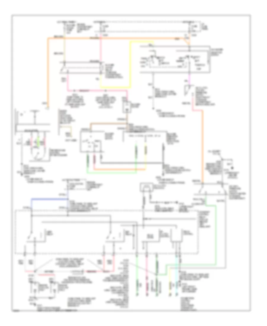
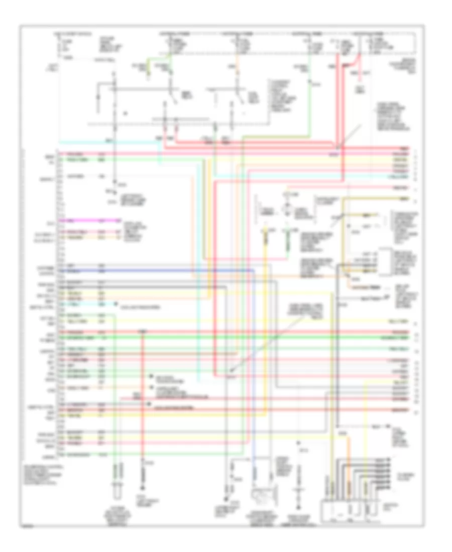
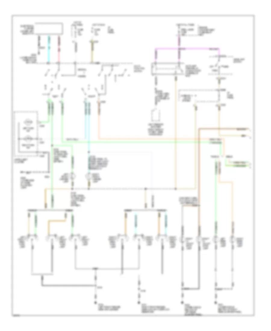
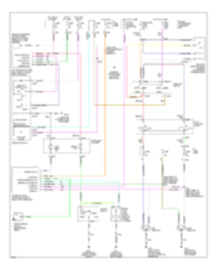
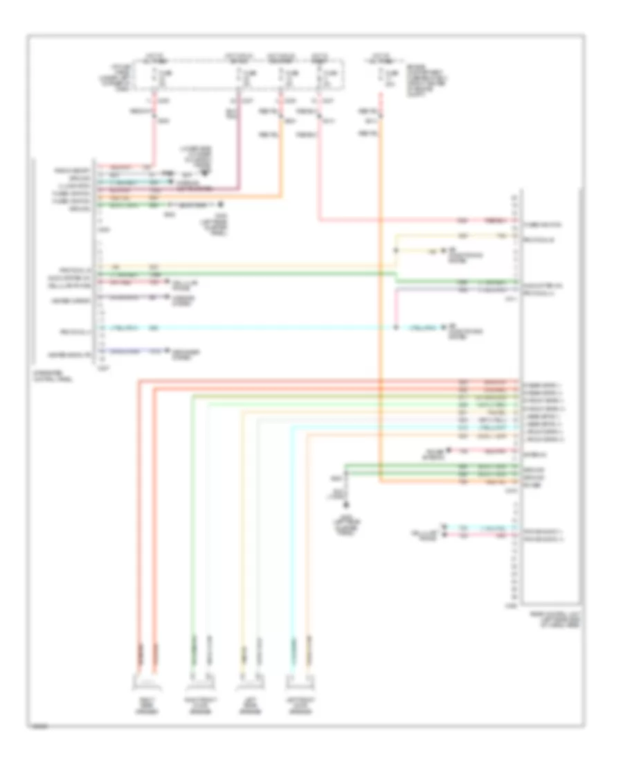
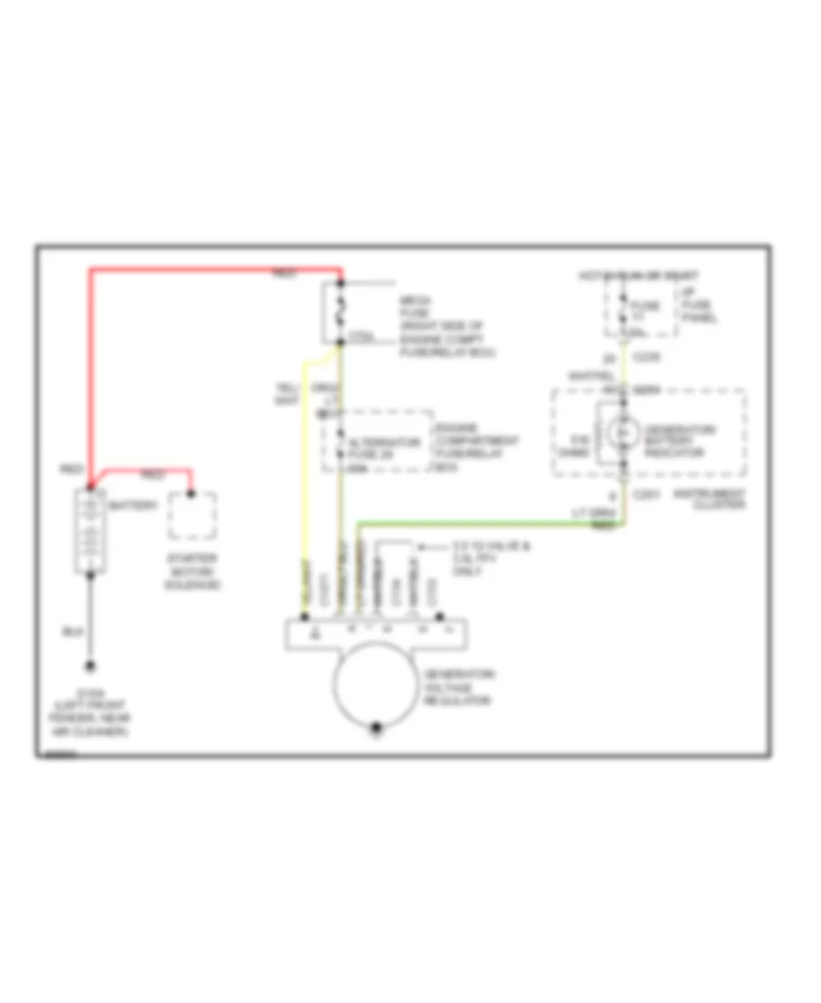
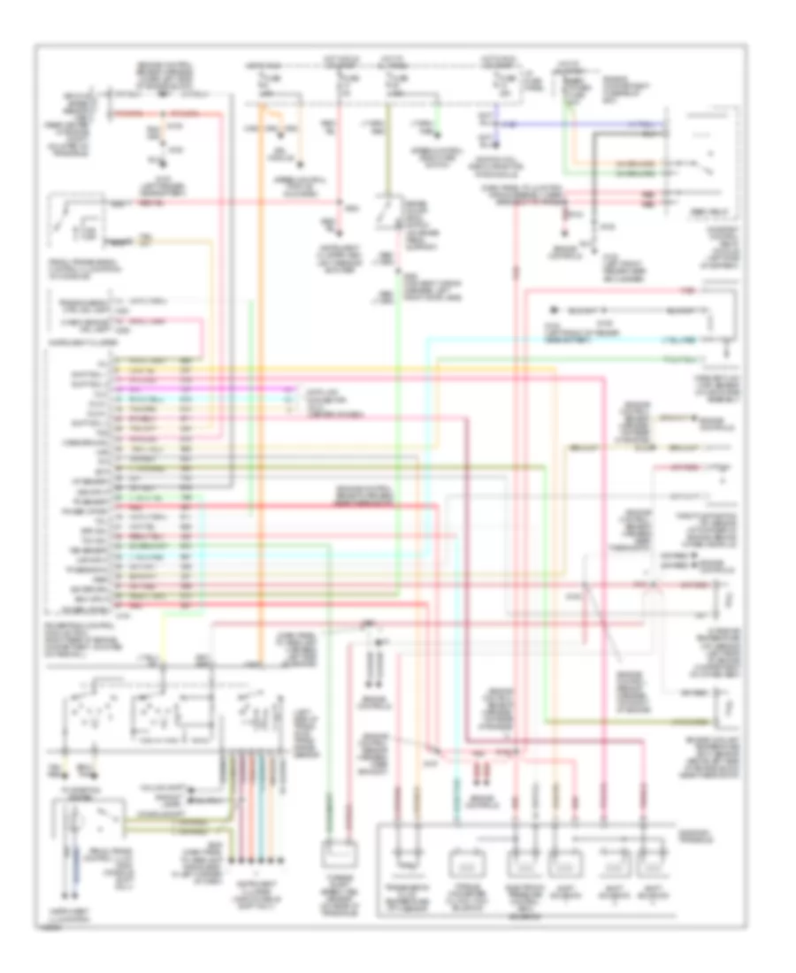
AIR CONDITIONING
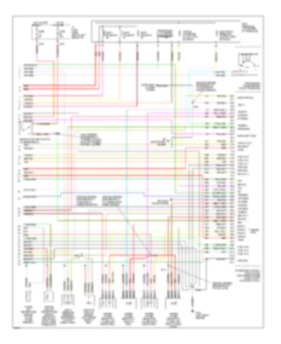
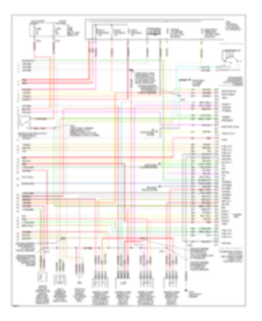
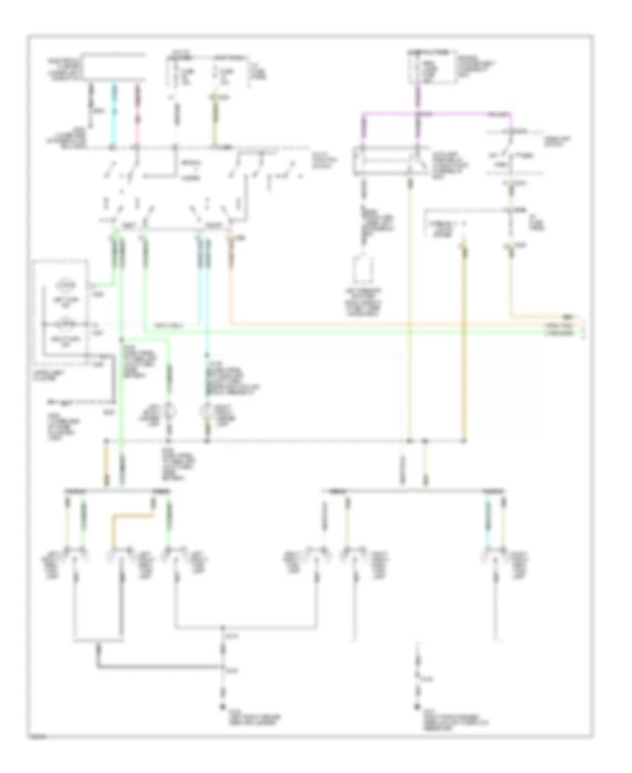
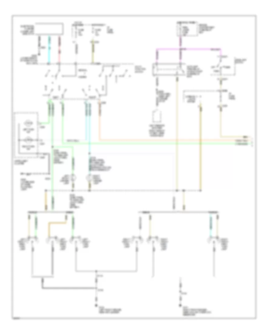
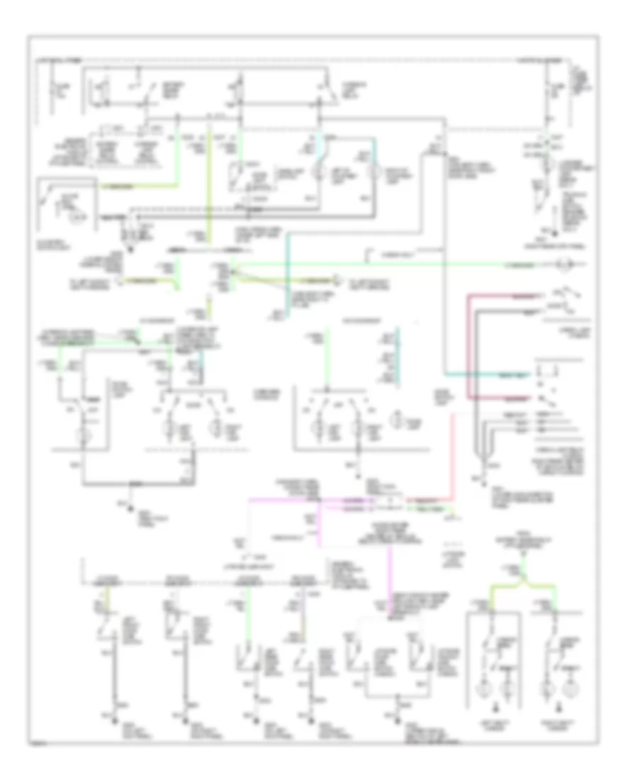
A/C Wiring Diagram, Auto A/C for Ford Taurus G 1997

List of elements for A/C Wiring Diagram, Auto A/C for Ford Taurus G 1997:
- (all except 3.0l 4v)
- (dash panel to headlamp junction harn, near constant control relay module breakout)
- (dash panel to headlamp junction harn, near engine cooling fan 1 breakout)
- (engine cntrl sens harn, near camshaft pos sensor breakout)
- (left front of i/p)
- (main wiring harn, near cigar lighter breakout)
- (main wiring harn, near i/p fuse panel breakout)
- (main wiring harn, near in-car temp sensor breakout)
- (main wiring harn, near pass anti-theft system (pats) breakout)
- (upper right
- (upper right center of cowl)
- 883 or 879
- A/c clutch control
- A/c clutch cycling pressure switch (behind right headlamp)
- A/c clutch field coil
- A/c high pressure switch (front center of engine compartment)
- Ambient temp
- Ambient temperature sensor (center of grille)
- Battery
- Blend door actuator (right side of i/p)
- Blend dr act
- Blower motor
- Blower motor fuse 40a
- Blower motor relay (in engine
- Blower motor speed controller (right side of i/p)
- Blw speed
- C225
- C235
- Center of cowl)
- Compartment fuse/relay box
- Compartment fuse/relay box)
- Constant control relay module (behind left headlamp)
- Cooling fan fuse 40a
- Cycling pres sw
- Data bus
- Data link connector (below steering column)
- Edf relay
- Engine
- Engine compartment fuse/relay box
- Engine cooling fan 1
- Engine cooling fan 2
- Engine cooling fan dropping resistor (inside right front bumper)
- Fuse 15a
- Fuse 5a
- G100 (left front fender)
- G101 (right front fender near coolant overflow reservoir)
- G104 (left front fender, near air cleaner)
- G123
- G206 (lower side of inner glove box frame)
- Ground
- Hedf relay
- Hot at all times
- Hot in run
- I/p fuse panel
- Ign-a/c clutch
- Ignition
- In car temp
- In-car temperature sensor (near climate controls)
- Integrated control panel (center of i/p)
- Nca
- Passive anti-theft system (pats) (center of i/p)
- Pcm input
- Powertrain control module (right rear corner of engine compt)
- Rear control unit (left rear of vehicle)
- Relay control
- Remote climate control module (behind glove box)
- S108 (eng cntrl sens harn, near pcm)
- S109 (3.0l 2v) s160 (3.4l sho) s154 s154 (3.0l 4v) (eng cntrl sens harn, near camshaft pos sensor breakout) (3.0l 4v) s160 (eng cntrl sens harn, near injectors 3 & 4 breakout) (3.4l sho) s109 (eng cntrl sens harn, near injector 3 breakout) (3.0l 2v)
- S131
- S132 (dash panel to headlamp junction harn, near constant control relay module breakout)
- S136
- S145
- S156
- S211
- S213
- S215
- S216 (main wiring harn, near i/p fuse panel breakout)
- S217
- S218
- S219
- S223 (main wiring harn, near electronic flasher breakout)
- Signal return
- Solid state
- Sunload sensor
- Tan
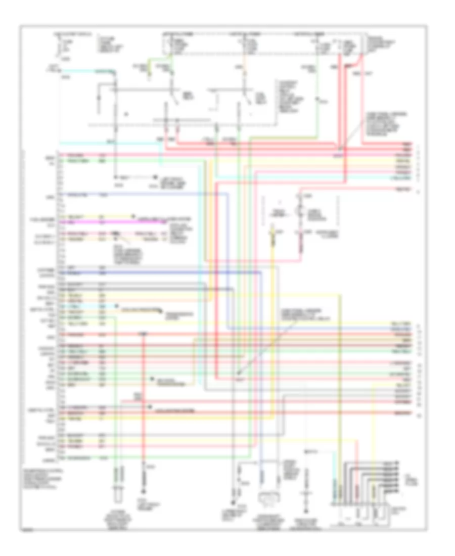
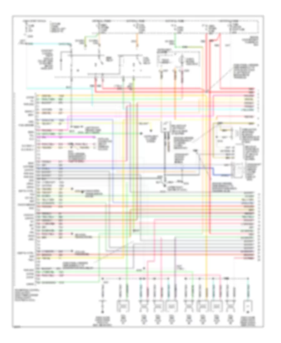
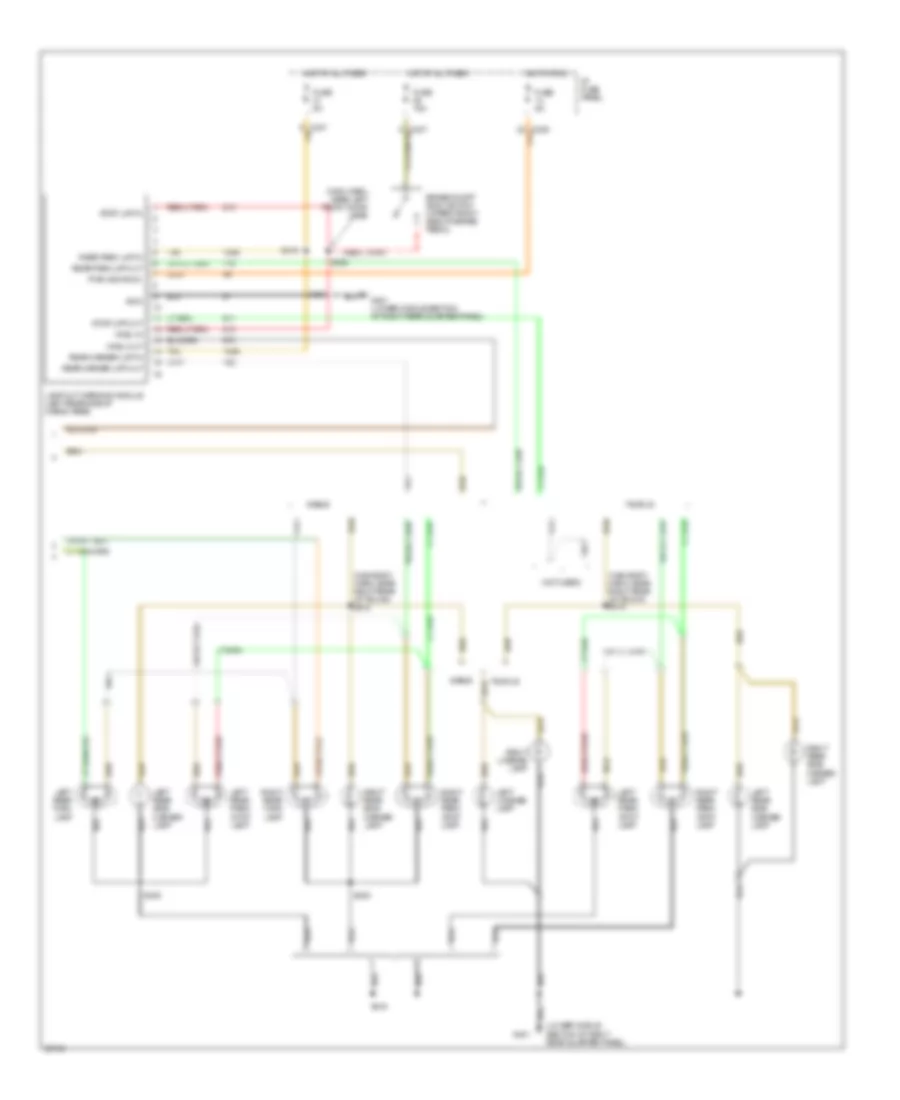
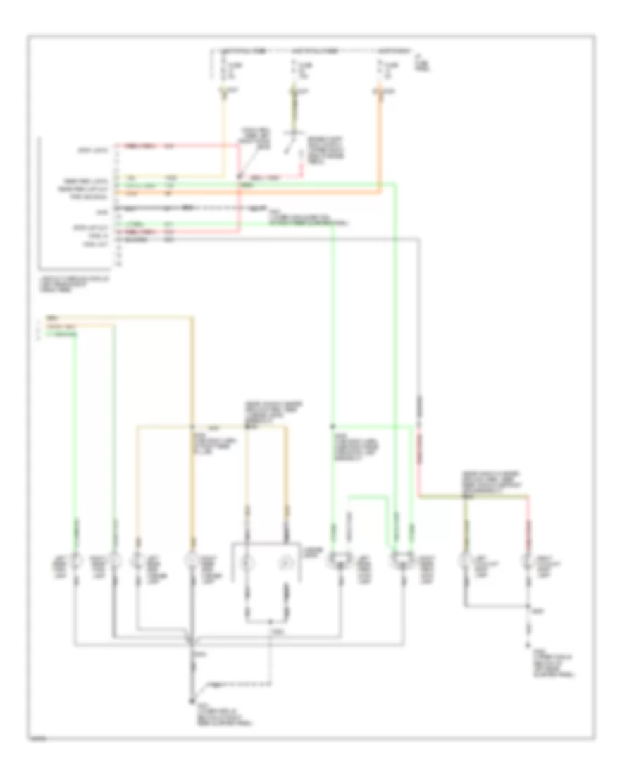
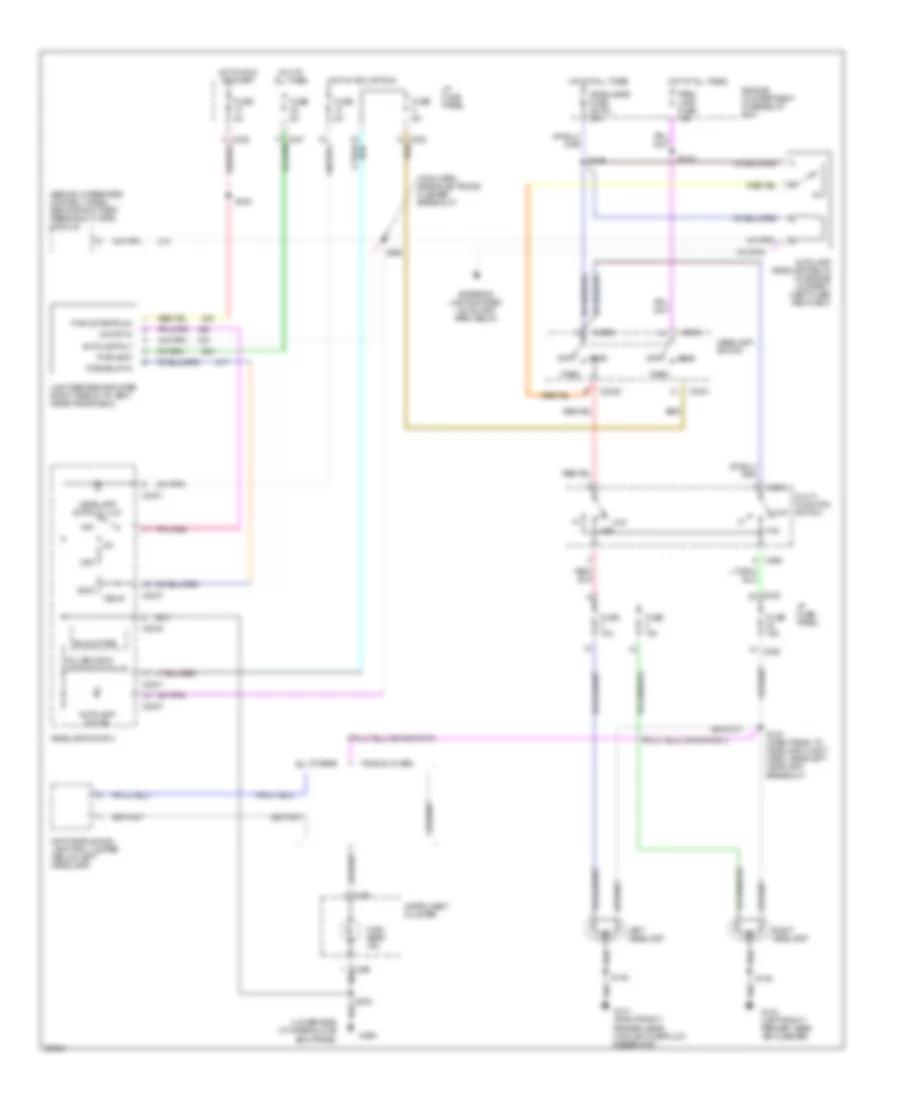
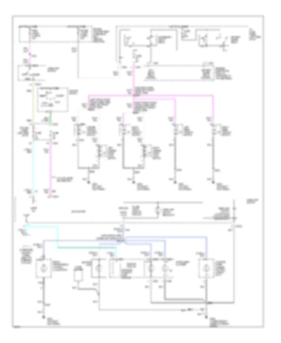
A/C Wiring Diagram, Manual A/C for Ford Taurus G 1997
List of elements for A/C Wiring Diagram, Manual A/C for Ford Taurus G 1997:
- (3.4l sho)
- (all except 3.0l 4v)
- (dash panel to headlamp junction harn, near constant control relay module breakout)
- (dash panel to headlamp junction harn, near engine cooling fan 1 breakout)
- (lower side of
- (main wiring harn, near glove box switch/ lamp breakout)
- (not used)
- (upper right
- (upper right center of cowl)
- 883 or 879
- A/c clutch control
- A/c clutch cycling pressure switch (right front of engine compartment behind headlamp)
- A/c clutch field coil
- A/c high pressure switch (front center of engine compartment)
- A/c-heater
- Blend door actuator (right side of a/c plenum below i/p)
- Blower motor
- Blower motor fuse 40a
- Blower motor relay (in engine compartment fuse/relay box)
- Blower motor switch
- Blower resistor (behind right side of i/p)
- C225
- C235
- Center of cowl)
- Constant control relay module (behind left headlamp)
- Cooling fan fuse 40a
- Def
- Def/flr
- Edf relay
- Engine compartment fuse/relay box
- Engine cooling fan 1
- Engine cooling fan 2
- Engine cooling fan dropping resistor (inside right front bumper)
- Flr
- Flr/vnt
- Fuse 15a
- Fuse 5a
- G101 (right front fender near coolant overflow reservoir)
- G104 (left front fender, near air cleaner)
- G123
- G206
- Hedf relay
- Hot at all times
- Hot in run
- I/p fuse panel
- Inner glove box frame)
- Max
- Norm
- Off
- Pan/flr
- Panel
- Powertrain control module (right rear corner of engine compt)
- Relay control
- S108 (eng cntrl sens harn, near pcm)
- S109 (3.0l 2v)
- S131
- S132 (dash panel to headlamp junction harn, near constant control relay module breakout)
- S136
- S145
- S154 (3.0l 4v) (eng cntrl sens harn, near camshaft pos sensor breakout) (3.0l 4v) s160 (eng cntrl sens harn, near injectors 3 & 4 breakout) (3.4l sho) s109 (eng cntrl sens harn, near injector 3 breakout) (3.0l 2v)
- S156 (engine cntrl sensor harn, near camshaft g123 pos sensor breakout)
- S160
- S210 (dash panel to headlamp harn, left corner of i/p, near headlamp switch)
- S212 (main wiring harn, near cigar lighter breakout)
- S227 (main wiring harn, left corner of i/p, near headlamp switch) (3.0l 4v 0nly)
- S229 (main wiring harn, near glove box switch/ lamp breakout)
- Selector switch
- Solid state
- Temperature control potentiometer
- Vent
ANTI-LOCK BRAKES
Anti-lock Brake Wiring Diagrams for Ford Taurus G 1997
List of elements for Anti-lock Brake Wiring Diagrams for Ford Taurus G 1997:
- (below steering column)
- (left front of engine compartment, near abs module)
- Abs ind ctrl
- Abs module fuse 30a
- Abs module fuse 40a
- Anti-lock brake control module (left front of eng compt, below battery)
- Anti-lock brake indicator
- Boo
- Brake on/off (boo) switch (upper front side of brake pedal)
- C250
- C251
- Computer data lines
- Engine compartment fuse/relay box
- Fuse 10a
- Fuse 15a
- Fuse 5a
- G100 (left front fender)
- G106
- Gnd
- Hot at all times
- Hot in start or run
- Hydraulic pump motor
- I/p fuse panel
- Ign
- Inlet
- Instrument cluster
- Iso link
- Left front
- Left front brake sensor (in left front wheel well, on brake assembly)
- Left rear
- Left rear brake sensor (in left rear wheel well, on brake assembly)
- Lf whl sens hi
- Lf whl sens lo
- Lr whl sens hi
- Lr whl sens lo
- Nca
- Outlet
- Pump motor relay
- Red/pnk
- Rf whl sens hi
- Rf whl sens lo
- Right front
- Right front brake sensor (in right front wheel well, on brake assembly)
- Right rear
- Right rear brake sensor (in right rear wheel well, on brake assembly)
- Rr whl sens hi
- Rr whl sens lo
- S120
- S224
- S225 (main harn, near breakout to datalink connector)
- S308
- Shorting bar (shorts pins 21 & 22 when disconnected)
- Solenoid control valves relay
- Solid state
- Tan/red
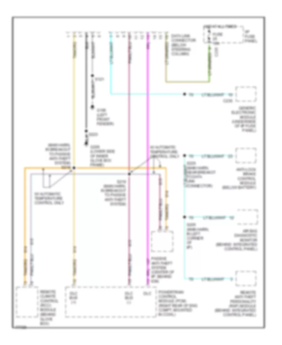
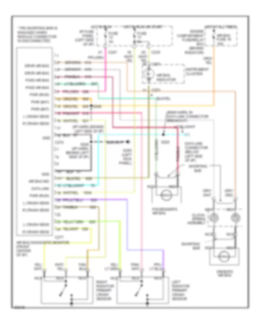
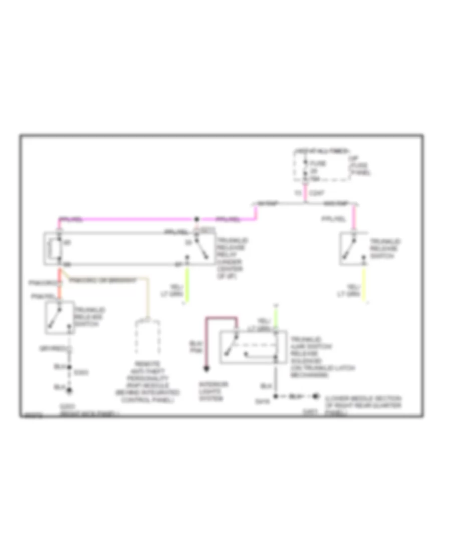
ANTI-THEFT
Anti-theft Wiring Diagram for Ford Taurus G 1997
List of elements for Anti-theft Wiring Diagram for Ford Taurus G 1997:
- (486)
- (behind integrated control panel) remote anti-theft personality module
- (left kick panel) g200
- (main harn, left i/p)
- (main harn, left side of i/p) s222
- (main harn, near pats module) s219
- 1/2
- 3/4
- 5/6
- 7/8
- 9/0
- Air bag diagnostic monitor (behind control panel)
- All door unlock
- Anti-theft indicator
- Anti-theft led
- Autolamp
- B/u lamps (pwr)
- Bus (+)
- Bus (-)
- C225
- C235
- C236
- C247
- C248
- C250
- C253
- C254
- C277
- Data link
- Data link connector (partial) (below steering col)
- Door locks system
- Drv unlock rly
- Exterior lamps system (backup lamps circuit)
- Exterior lamps system (brake on/off switch)
- Fuse 10 20a
- Fuse 20 5a
- Fuse 23 5a
- G100 (left front fender)
- G101 (right front fender, near coolant overflow reservoir)
- G206 (lower side of inner glove box frame)
- G401 (lower middle section of right rear quarter panel)
- Gem in
- Gem input
- Generic electronic module (attached to i/p fuse panel)
- Gnd
- Haz/brake lamps
- Headlamps system (w/ autolamps)
- Hood tamper switch (left front corner of engine compt.)
- Horn rly
- Horns system
- Hot at all times
- Hot in acc or run
- Hot in run or start
- I/p fuse panel (left side of i/p)
- Ign (run)
- Illum entry req
- Instrument cluster
- Iso link
- Keyless entry keypad switch assembly
- Keypad 1/2 sig
- Keypad 3/4 sig
- Keypad 5/6 sg
- Keypad 7/8 sig
- Keypad 9/0 sig
- Keypad comon
- Keypad lamp
- Liftgate release relay (right of steering column)
- Lock input
- Nca
- Passive anti-theft system (behind integrated control panel)
- Passive anti-theft system transceiver (near ignition switch)
- Pats transceiver
- Power/battery
- Powertrain control module (right rear corner of engine compt.)
- Rap input
- Red
- Rke jumper
- S121
- S122
- S145
- S205
- S215
- S218 (main harn, near pats module)
- S223
- S225 (main harn, near datalink connector)
- S416
- S421 (main harn, near boo switch)
- S500
- Sedan
- Trunk lid anti-theft switch (rear of cargo area)
- Trunk lid release relay (right of steering column)
- Trunk lid release switch
- Trunk/hood sw
- Trunk/liftgate
- Unlock input
- W/ keyless entry only
- Wagon
BODY COMPUTER
Body Computer Wiring Diagrams for Ford Taurus G 1997
List of elements for Body Computer Wiring Diagrams for Ford Taurus G 1997:
- 87a
- Accessory delay relay
- All door unlock
- Anti-theft in
- Anti-theft out
- Bat
- Battery saver relay
- Battery saver relay control
- C201
- C2031
- C223
- C225
- C235
- C236
- C247
- C248
- C253
- C254
- Data link
- Data link connector (below steering column)
- Defogger system
- Delay acc relay ctrl
- Door ajar ind ctrl
- Door lock in
- Door locks system
- Door unlock in
- Driver's unlock relay
- Driver's unlock relay ctrl
- Electronic power steering system
- Fuse 5a
- G100 (left front fender)
- G104 (left front fender, near air cleaner)
- G200 (on left kick panel)
- Gem
- Gem chime/ tone logic
- Generic electronic module (attached to i/p fuse panel)
- Gnd (pwr)
- Gnd (sig)
- Head
- Headlamp sw in
- Headlamp switch
- Hot at all times
- Hot in acc or run
- Hot in run or start
- Hot in start
- I/p fuse panel (left side of i/p)
- Ign (run/acc)
- Ign (start)
- Illum entry req
- Instrument cluster system
- Interior lamp relay
- Interior lamp relay ctrl
- Interior lights & warning systems (door ajar switches)
- Intv delay/wash
- Key warning sw in
- Lf door ajar
- Liftgate ajar
- Low coolant
- Low coolant ind ctrl
- Motor low sense
- Motor sense hi
- Motor switch down command
- Off
- One touch window down relay
- Park
- Power (run/start)
- Power windows system
- Rear defrost sw in
- Rear window defrost relay
- Rear window defrost relay ctrl
- Relay ctrl
- Remote anti-theft personality module (behind integrated control panel)
- Rf door ajar
- Rr door ajar
- S120
- S142 (dash to hdlmp harn, near breakout to engine compt fuse box)
- S224
- S225 (main harn, near breakout to datalink connector)
- Seatbelt ind ctrl
- Seatbelt sw
- Shunt resistor
- Tan/red
- Vaps ctrl
- Vehicle speed sensor (rear center of engine compt. on transaxle)
- Vss in
- W/ autolamps
- Warning system
- Washer relay
- Window switch up command
- Wiper hi/lo relay
- Wiper mode select
- Wiper park sense
- Wiper r/p relay
- Wiper/washer sig rtn
- Wiper/washer system
COMPUTER DATA LINES
Computer Data Lines for Ford Taurus G 1997
List of elements for Computer Data Lines for Ford Taurus G 1997:
- (main harn, in breakout to passive anti-theft system) s218
- Air bag diagnostic monitor (behind integrated control panel)
- Anti-lock brake control module (below battery)
- C235
- C236
- Data link connector (below steering column)
- Dlc
- Dlc bus (+)
- Dlc bus (-)
- Fuse 10a
- G100 (left front fender)
- G206 (lower side of inner glove box frame)
- Generic electronic module (underside of i/p fuse panel)
- Hot at all times
- I/p fuse panel
- Passive anti-theft system (center of i/p, behind icm)
- Powertrain control module (pcm) (right rear of eng compt, mounted in cowl)
- Remote anti-theft personality (rap) module (behind integrated control panel)
- Remote climate control (rcc) module (behind glove box)
- S121
- S205 (main harn, in left corner of i/p)
- S219 (main harn, in breakout to passive anti-theft system)
- S223
- S225 (main harn, near breakot to data link connector)
- W/ automatic temperature control only
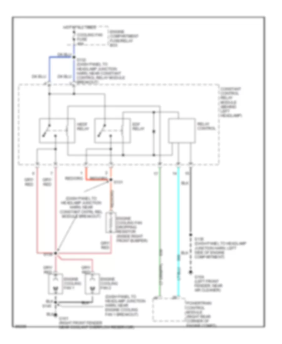
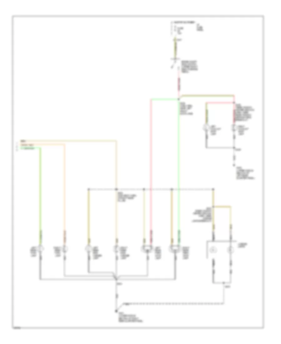
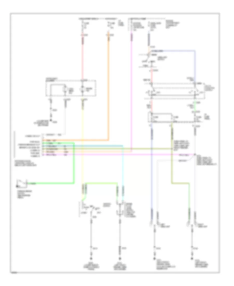
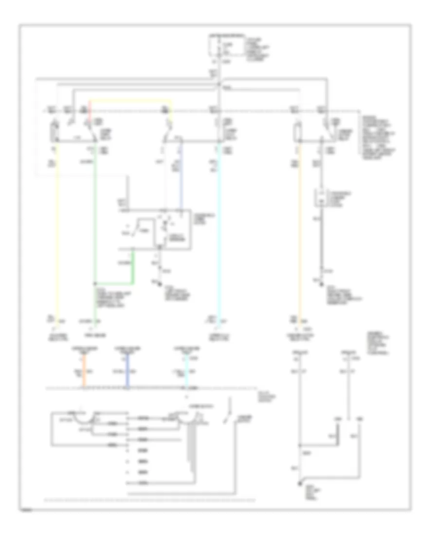
COOLING FAN
Cooling Fan Wiring Diagram for Ford Taurus G 1997
List of elements for Cooling Fan Wiring Diagram for Ford Taurus G 1997:
- (dash panel to headlamp junction harn, near constant cntrl rel module breakout)
- (dash panel to headlamp junction harn, near engine cooling fan 1 breakout)
- Constant control relay module (behind left headlamp)
- Cooling fan fuse 40a
- Edf relay
- Engine compartment fuse/relay box
- Engine cooling fan 1
- Engine cooling fan 2
- Engine cooling fan dropping resistor (inside right front bumper)
- G101 (right front fender near coolant overflow reservoir)
- G104 (left front fender, near air cleaner)
- Hedf relay
- Hot at all times
- Powertrain control module (right rear corner of engine compt)
- Relay control
- S131
- S132 (dash panel to headlamp junction harn, near constant control relay module breakout)
- S135 (dash panel to headlamp junction harn, left side of engine compartment)
- S136
- S145
CRUISE CONTROL
Cruise Control Wiring Diagram for Ford Taurus G 1997
List of elements for Cruise Control Wiring Diagram for Ford Taurus G 1997:
- (back window heater harn, in breakout to defrost- er grid)
- (main body harn, in left door jamb) s308
- (sdn) s416 (wgn) s404
- 15a
- 3.0l 2v or 3.0l 4v
- 3.4l sho
- Accel
- Anti-lock brake control module (below battery)
- Brake on/off (boo) switch (upper front side of brake pedal)
- C225
- C235
- C247
- C250
- C251
- C254
- Clockspring assembly (in steering column, below steering wheel)
- Coast
- Cruise on ind
- Electric cltch pwr
- Engine compart- ment fuse box
- Fuse 15a
- Fuse 19
- Fuse 5a
- G100 (left front fender)
- G104 (left front fender, near air cleaner)
- G400 (upper middle section of left rear quarter panel)
- G401 (lower middle section of right rear quarter panel)
- Gnd
- Horn relay (in engine compt fuse box)
- Horn switches
- Horn/ speed control
- Hot at all times
- Hot in run
- Hot in start or run
- I/p fuse panel
- Ign
- Instrument cluster
- Left hi mount stop lamp
- Left rear park/ stop lamp
- Nca
- Off
- Remote anti-theft personality (rap) module (behind integrated control panel)
- Resume
- Right hi mount stop lamp
- Right rear park/ stop lamp
- S105
- S135
- S142 (dash to headlamp harn, near breakout to speed control module)
- S144
- S224
- S418 (sdn) s429 (wgn)
- S428
- Sedan
- Sedan only
- Set/
- Speed cont sw gnd
- Speed cont sw in
- Speed control deactivate switch (left side of i/p)
- Speed control module (mounted on left front strut)
- Vehicle speed input
- Vehicle speed sensor (vss) (on transaxle)
- W/ rap
- Wagon
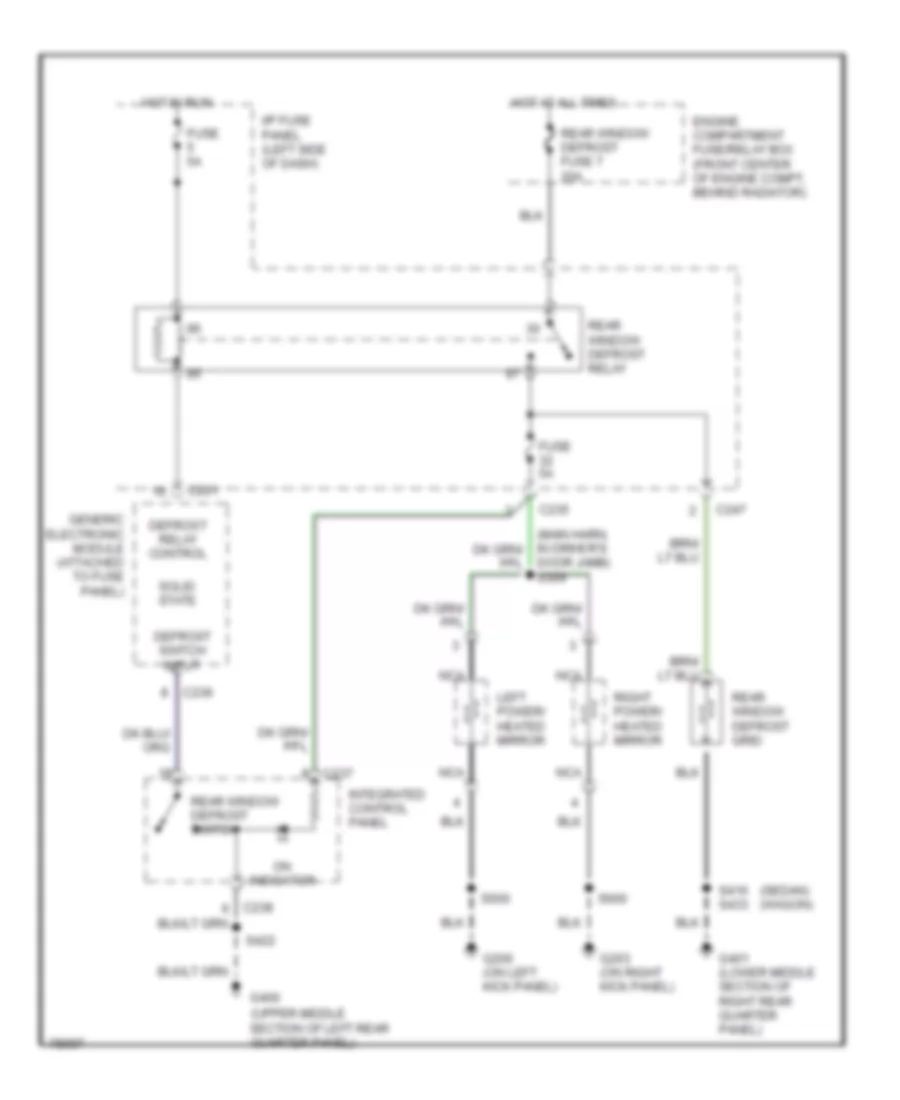
DEFOGGERS
Defogger Wiring Diagram for Ford Taurus G 1997
List of elements for Defogger Wiring Diagram for Ford Taurus G 1997:
- (sedan) (wagon)
- (upper middle section of left rear quarter panel)
- C201
- C235
- C236
- C237
- C247
- Defrost relay control
- Defrost switch input
- Door jamb) s309
- Engine compartment fuse/relay box (front center of engine compt, behind radiator)
- Fuse 5a
- G200 (on left kick panel)
- G203 (on right kick panel)
- G400
- G401 (lower middle section of right rear quarter panel)
- Generic electronic module (attached to fuse panel)
- Hot at all times
- Hot in run
- I/p fuse panel (left side of dash)
- Integrated control panel
- Left power/ heated mirror
- Nca
- On indicator
- Rear window defrost fuse 7 20a
- Rear window defrost grid
- Rear window defrost relay
- Rear window defrost switch
- Right power/ heated mirror
- S416 s433
- S422
- S500
- S600
- Solid state
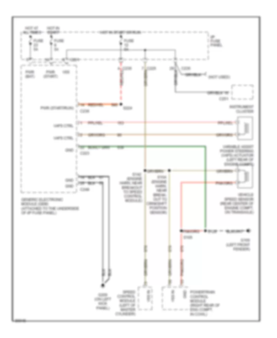
ELECTRONIC POWER STEERING
Electronic Power Steering Wiring Diagram for Ford Taurus G 1997
List of elements for Electronic Power Steering Wiring Diagram for Ford Taurus G 1997:
- (engine harn, near break- out to crnkshft position sensor)
- (engine harn, near breakout to speed control module)
- (not used)
- C201
- C223
- C235
- C236
- C248
- C251
- Fuse 5a
- G100 (left front fender)
- G200 (on left kick panel)
- Generic electronic module (gem) (attached to the underside of i/p fuse panel)
- Gnd
- Hot at all times
- Hot in start
- Hot in start or run
- I/p fuse panel
- Instrument cluster
- Powertrain control module (right rear of eng compt, in cowl)
- Pwr (bat)
- Pwr (start)
- Pwr (start/run)
- S104
- S105
- S120
- S142
- S224
- Speed control module (left of master cylinder)
- Vaps ctrl
- Variable assist power steering (vaps) actuator (left rear of engine compt)
- Vehicle speed sensor (rear center of engine compt, on transaxle)
- Vss
- Vss in
ELECTRONIC SUSPENSION
Electronic Suspension Wiring Diagram for Ford Taurus G 1997
List of elements for Electronic Suspension Wiring Diagram for Ford Taurus G 1997:
- (left front fender)
- (left front fender, near air cleaner)
- (main harn, left side of i/p) s205
- (right front fender, near coolant overflow reservoir)
- Anti-lock brake control module (below battery)
- C225
- C235
- C251
- C450
- C451
- Data link connector (below steering column)
- Dlc
- Electronic power steering system (zf gear solenoid)
- Engine compartment fuse/relay box
- Fuse 5a
- G100
- G101
- G104
- G401 (lower middle section of right rear quarter panel)
- Gnd
- Harn, near drl module) s179
- Hot at all times
- Hot in run
- I/p fuse panel
- Instrument cluster
- Left front height sensor (front of left front wheel)
- Left front shock actuator (front of left wheel well)
- Left rear shock actuator (left rear of vehicle, near wheel well)
- Lf height sensor
- Lf shock actuator
- Lr shock actuator
- Nca
- Pwr (bat)
- Pwr (run)
- Rf height sensor
- Rf shock actuator
- Right front height sensor (front of right front wheel)
- Right front shock actuator (front of right wheel well)
- Right rear shock actuator (right rear of vehicle, near wheel well)
- Rr shock actuator
- S120
- S142 (dash to hdlmp harn, near master cylinder)
- S145
- S158
- S180 (dash to hdlmp harn, near drl module)
- S440
- S442
- S444
- S451
- Semi-active ride control (sarc) module (behind right rear seat)
- Semi-active ride control fuse 20a
- Sensor gnd
- Sensor pwr
- Vss+
- Vss-
- Zf gear sol feed
- Zf gear sol rtn
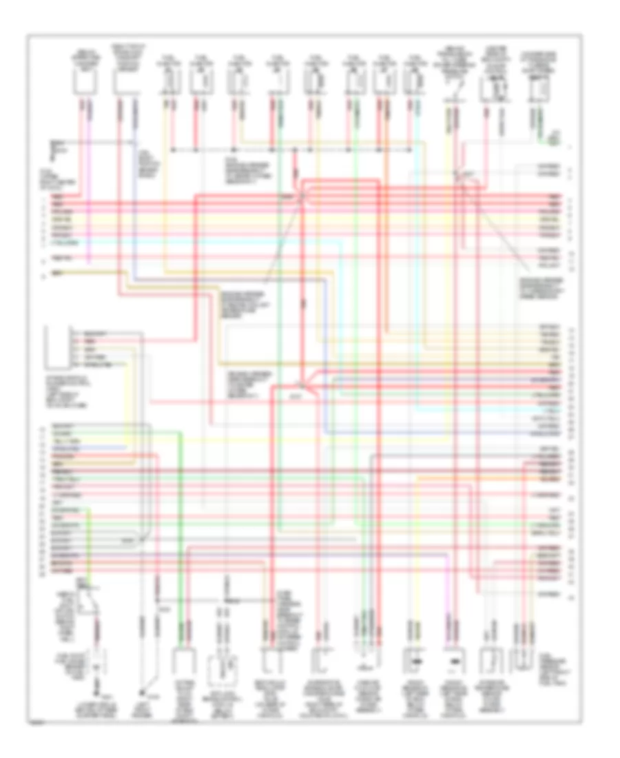
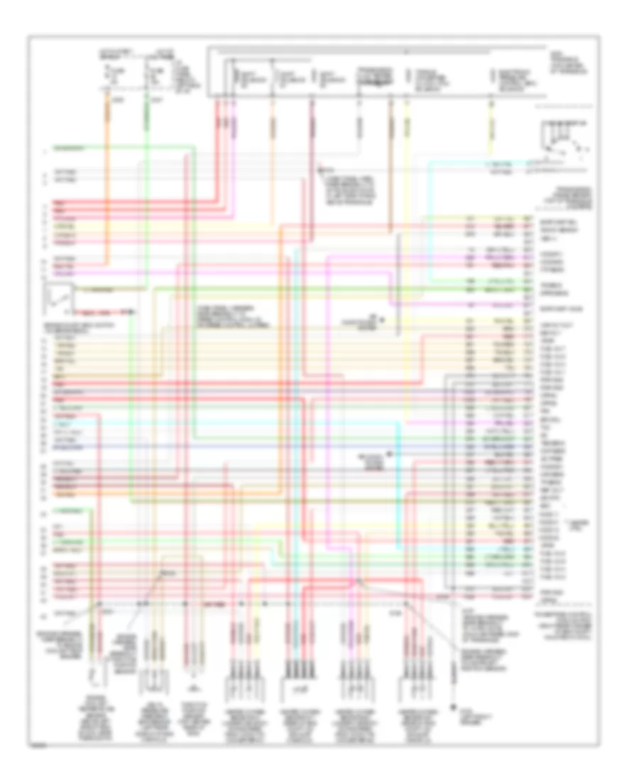
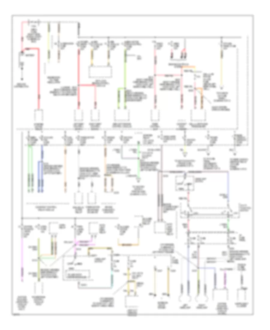
ENGINE PERFORMANCE
3.0L
3.0L 12-Valve, Engine Performance Wiring Diagrams (1 of 3) for Ford Taurus G 1997
List of elements for 3.0L 12-Valve, Engine Performance Wiring Diagrams (1 of 3) for Ford Taurus G 1997:
- (dash panel harn, near breakout to constant control relay)
- (dash panel harness, near breakout to 42-pin black conn in left side of engine above transaxle)
- (engine harness, near breakout to heated oxygen sensor #21)
- (upper right center of cowl)
- Accs
- Air conditioning system (a/c high pressure switch)
- C225
- C250
- C251
- Check engine indicator
- Ckp feed
- Ckp rtn
- Constant control relay module (on left side of battery, behind headlamp)
- Cooling fans system (constant control relay module)
- Cooling fans system (hedf relay)
- Crankshaft position sensor (lower right side of eng)
- Data link connector (below
- Dlc
- Dlc bus (+)
- Dlc bus (-)
- Eam air pump (left front of vehicle, rear of bumper)
- Eam rly
- Eam solid state relay (left front of vehicle, rear of bumper)
- Ect
- Edf rly ctrl
- Eeec power fuse 30a
- Eeec relay
- Engine compartment fuse/relay box
- Evr
- Fpm
- Fuel gauge
- Fuel pump fuse 20a
- Fuel pump relay
- Fuse 20a
- G100 (left front fender)
- G104 (left front fender, near air cleaner)
- G123
- G123 (upper right center of cowl)
- Gnd
- Hedf rly ctrl
- Hego power fuse 10a
- Ho2s #12
- Horn fuse 15a
- Hot at all times
- Hot in start or run
- I/p fuse panel (below left side of i/p)
- Iat
- Ign coil a
- Ign coil b
- Ignition coil
- Instrument cluster
- Instrument cluster system (anti-slosh module)
- Kapwr
- Maf rtn
- Mil
- Nca
- Near breakout to heated oxygen sensor #11)
- Oct adj
- Octane adjust plug (right rear of eng compt, near pcm)
- Powertrain control module (pcm) (right rear corner of eng compt, mounted in cowl)
- Psp
- Pwr gnd
- Radio noise capacitor (on ignition coil)
- Red
- S105
- S108
- S112
- S120
- S133
- S135
- S137
- S144
- S148
- S149
- S155
- S156
- S158
- Ss #1
- Ss #2
- Ss #3
- Steering column)
- Tach
- Tacho- meter
- Tft
- Thermactor air bypass solenoid (above exhaust manifold, rear of eng)
- Thermactor pump fuse 30a
- To spark plugs
3.0L 12-Valve, Engine Performance Wiring Diagrams (2 of 3) for Ford Taurus G 1997
List of elements for 3.0L 12-Valve, Engine Performance Wiring Diagrams (2 of 3) for Ford Taurus G 1997:
- (behind transmission fill tube) power steering pressure switch
- (below spare tire) canister vent
- (center rear of eng compt) idle air control valve
- (dash panel harness, near breakout to 42-pin black conn in left side of engine above transaxle)
- (engine harness, near breakout to crankshaft position sensor)
- (engine harness, near breakout to engine oil pressure switch)
- (engine harness, near breakout to fuel inj #5)
- (left side of eng block) camshaft position sensor
- (lower middle section of rear quarter panel)
- (on rear side of transaxle) turbine shaft speed sensor
- Cam- shaft position sensor shield
- Egr vacuum regulator (evr) valve (on rear of intake manifold)
- Evaporative emission (evap) canister purge valve (right rear of eng compt, mounted on cowl)
- Fuel injector #1
- Fuel injector #2
- Fuel injector #3
- Fuel injector #4
- Fuel injector #5
- Fuel injector #6
- Fuel pressure sensor (left front side of fuel tank)
- Fuel pump/ fuel gauge sender (in fuel tank)
- G123 (upper right center of cowl)
- G401
- Inertia fuel shut- off (ifs) switch (behind right wheel well)
- Mass air flow (maf) sensor (near air intake assembly)
- Red
- S101
- S103
- S107
- S111
- S134
- Tan
- Vehicle speed sensor (vss) (rear center of eng compt, on transaxle)
3.0L 12-Valve, Engine Performance Wiring Diagrams (3 of 3) for Ford Taurus G 1997
List of elements for 3.0L 12-Valve, Engine Performance Wiring Diagrams (3 of 3) for Ford Taurus G 1997:
- heated oxygen sensor #21 (lower left front of eng compt)
- (engine harness, near breakout to crankshaft position sensor)
- (engine harness, near breakout to engine oil pressure switch)
- (engine harness, near breakout to fuel inj #6)
- (engine harness, near breakout to turbine shaft speed sensor)
- (main harness, near breakout to speed control module or speed control jumper)
- A/c pres
- Air condi- tioning system
- Air conditioning system
- Ax4s transaxle (top center of transaxle)
- Boo
- Brake on/off (boo) switch (on brake pedal)
- C235
- C247
- Cmp sens
- Delta pressure feedback egr sensor (top left rear of eng)
- Dpfe sens
- Eam relay
- Electronic pressure control (epc) solenoid
- Engine coolant temperature sensor (above left side of eng block, near thermostat)
- Epc sol
- Evap canp sol
- Evap canp valve
- Fpm
- Ftp sens
- Fuel inj 1
- Fuel inj 2
- Fuel inj 3
- Fuel inj 4
- Fuel inj 5
- Fuel inj 6
- Fuse 15a
- Fuse 5a
- G100 (left front fender)
- Heated oxygen sensor #11 (back of eng)
- Heated oxygen sensor #12 (lower left side of eng)
- Heated oxygen sensor #22 (lower right side of eng)
- Heater ctrl
- Ho2s #11
- Ho2s #21
- Ho2s #22
- Ho2s 11
- Ho2s 12
- Ho2s 21
- Ho2s 22
- Hot at all times
- Hot in start
- I/p fuse panel (below left side of i/p)
- Iac
- Ign coil c
- Instrument cluster system
- Intake air temperature sensor (on air intake assembly)
- Maf sens
- Nca
- Or run
- Powertrain control module (pcm) (right rear corner of eng compt, mounted in cowl)
- Pwr gnd
- Red
- Red/pnk
- Ref volt
- S100
- S102
- S104
- S106
- S110
- S138
- Shift solenoid #1
- Shift solenoid #2
- Shift solenoid #3
- Sig rtn
- Tan
- Tcc
- Throttle position sensor (top center rear of eng)
- Torque converter clutch (tcc) solenoid
- Tp sens
- Tr sens
- Transmission fluid temper- ature sensor
- Transmission range sensor (top of transaxle)
- Tss sens
- Vpwr
- Vss (+)
- Wac rly out
3.0L 24-Valve, Engine Performance Wiring Diagrams (1 of 3) for Ford Taurus G 1997
List of elements for 3.0L 24-Valve, Engine Performance Wiring Diagrams (1 of 3) for Ford Taurus G 1997:
- (dash panel harness, near breakout to 42-pin black conn in left side of engine above transaxle)
- (dash panel harness, near breakout to constant control relay)
- (left front fender, near g104 air cleaner)
- (upper right center of cowl)
- Accs
- Air condi- tioning system
- C225
- C250
- Check engine indicator
- Ckp feed
- Ckp rtn
- Constant control relay module (on left side of battery, behind headlamp)
- Cooling fans system
- Crank- shaft position sensor shield
- Crankshaft position sensor (lower right side of eng)
- Data link connector (below steering column)
- Dlc
- Dlc bus (+)
- Dlc bus (-)
- Ect
- Edf rly ctrl
- Eeec power fuse 30a
- Eeec relay
- Engine compartment fuse/relay box
- Evr
- Fpm
- Fuel pump fuse 20a
- Fuel pump relay
- Fuel sender
- Fuse 20a
- G100 (left front fender)
- G123
- Gnd
- Hedf rly ctrl
- Hego power fuse 15a
- Ho2s #12
- Horn fuse 10a
- Hot at all times
- Hot in start or run
- I/p fuse panel (below left side of i/p)
- Iat
- Ign coil a
- Ign coil b
- Ignition coil
- Imrc
- Instrument cluster
- Instrument cluster system
- Kapwr
- Maf rtn
- Mil
- Nca
- Oct adj
- Octane adjust plug (right rear of eng compt, near pcm)
- Powertrain control module (pcm) (right rear corner of eng compt, mounted in cowl)
- Psp
- Pwr gnd
- Radio noise capacitor (on ignition coil)
- Red
- S105
- S108
- S112
- S120
- S122
- S133
- S135
- S137
- S144
- S218 (main harness, near breakout to passive anti- theft system)
- S219
- Ss #1
- Ss #2
- Ss #3
- Tach
- Tacho- meter
- Tcs
- Tft
- To spark plugs
- Transmissions system
3.0L 24-Valve, Engine Performance Wiring Diagrams (2 of 3) for Ford Taurus G 1997
List of elements for 3.0L 24-Valve, Engine Performance Wiring Diagrams (2 of 3) for Ford Taurus G 1997:
- (behind transmission fill tube) power steering pressure switch
- (below spare tire) canister vent
- (center rear of eng compt) idle air control valve
- (engine harness, near breakout to engine coolant temperature sender)
- (engine harness, near breakout to heated oxygen sensor #11)
- (engine harness, near breakout to turbine shaft speed sensor)
- (left front fender)
- (lower middle section of rear quarter panel)
- (on rear side of transaxle) turbine shaft speed sensor
- (right top of eng block) camshaft position sensor
- Cam- shaft position sensor shield
- Egr vacuum regulator (evr) valve (on rear of intake manifold)
- Evaporative emission (evap) canister purge valve (right rear of eng compt, mounted on cowl)
- Fuel injector #1
- Fuel injector #2
- Fuel injector #3
- Fuel injector #4
- Fuel injector #5
- Fuel injector #6
- Fuel pressure sensor (left front side of fuel tank)
- Fuel pump/ fuel gauge sender (in fuel tank)
- G100
- G123 (upper right center of cowl)
- G401
- Inertia fuel shut- off (ifs) switch (behind right wheel well)
- Intake air temperature sensor (on air intake assembly)
- Intake manifold runner control (imrc) (left side of eng compt, on valve cover)
- Knock sensor (left upper rear of eng, below intake manifold)
- Mass air flow (maf) sensor (in eng air intake assembly)
- Red
- S106
- S107 (engine harness, near breakout to heated oxygen sensor #11)
- S147
- S150
- S152
- Tan
- Vehicle speed sensor (vss) (rear center of eng compt, on transaxle)
3.0L 24-Valve, Engine Performance Wiring Diagrams (3 of 3) for Ford Taurus G 1997
List of elements for 3.0L 24-Valve, Engine Performance Wiring Diagrams (3 of 3) for Ford Taurus G 1997:
- (dash panel harn, near breakout to 42-pin black conn in left side of eng above transaxle)
- (engine harness, near breakout to 10-pin white conn centered atop of transaxle)
- (engine harness, near breakout to campshaft position sensor)
- (engine harness, near breakout to crankshaft position sensor)
- (engine harness, near breakout to engine coolant temperature sender)
- (engine harness, near breakout to throttle position sensor)
- A/c pres
- Air condi- tioning system
- Air conditioning system
- Ax4n transaxle (top center of transaxle)
- Boo
- Brake on/off (boo) switch (on brake pedal)
- C235
- C247
- Cmp sens
- Delta pressure feedback egr sensor (top left rear of eng)
- Dpfe sens
- Electronic pressure control (epc) solenoid
- Engine coolant temperature sensor (above left side of eng block, near thermostat)
- Epc sol
- Evap canp sol
- Evap canp valve
- Fpm
- Ftp sens
- Fuel inj 1
- Fuel inj 2
- Fuel inj 3
- Fuel inj 4
- Fuel inj 5
- Fuel inj 6
- Fuse 15a
- Fuse 5a
- G100 (left front fender)
- Heated oxygen sensor #11 (rear of eng compt, on exhaust manifold)
- Heated oxygen sensor #12 (under car body downstream, from catalytic converter #1)
- Heated oxygen sensor #21 (rear of eng compt, on exhaust manifold)
- Heated oxygen sensor #22 (under car body downstream, from catalytic converter #2)
- Heater ctrl
- Ho2s #11
- Ho2s #21
- Ho2s #22
- Ho2s 11
- Ho2s 12
- Ho2s 21
- Ho2s 22
- Hot at all times i/p fuse panel (below left side of i/p)
- Hot in start
- Iac
- Ign coil c
- Instrument cluster system
- Knock sens
- Maf sens
- Nca
- Or run
- Powertrain control module (pcm) (right rear corner of eng compt, mounted in cowl)
- Pwr gnd
- Red
- Red/pnk
- Ref volt
- S102
- S104
- S106
- S134
- S138 (dash panel harness, near breakout to speed control module or speed control jumper)
- S151
- S153
- S157
- Shift solenoid #1
- Shift solenoid #2
- Shift solenoid #3
- Sig rtn
- Tan
- Tcc
- Tcil
- Throttle position sensor (top center rear of eng)
- Torque converter clutch (tcc) solenoid
- Tp sens
- Tr sens
- Transmission fluid temper- ature sensor
- Transmission range sensor (top of transaxle housing)
- Tss sens
- Vpwr
- Vss (+)
- Wac rly out
3.0L Flex Fuel, Engine Performance Wiring Diagrams (1 of 3) for Ford Taurus G 1997
List of elements for 3.0L Flex Fuel, Engine Performance Wiring Diagrams (1 of 3) for Ford Taurus G 1997:
- (dash panel harn, near breakout to constant control relay)
- (dash panel harness, near breakout to 42-pin black conn in left side of engine above transaxle)
- (engine harness, near breakout to heated oxygen sensor #11)
- (engine harness, near breakout to heated oxygen sensor #21)
- (left front fender, near g104 air cleaner)
- (not used)
- (upper right center of cowl)
- Accs
- Air condi- tioning system
- C225
- C250
- Check engine indicator
- Ckp feed
- Ckp rtn
- Constant control relay module (on left side of battery, behind headlamp)
- Cooling fans system
- Crank- shaft position sensor shield
- Crankshaft position sensor (lower right side of eng)
- Data link connector (below steering column)
- Dlc
- Dlc bus (+)
- Dlc bus (-)
- Dte
- Eam air pump (left front of vehicle, rear of bumper)
- Eam rly
- Eam solid state relay (left front of vehicle, rear of bumper)
- Ect
- Edf rly ctrl
- Eeec power fuse 30a
- Eeec relay
- Engine compartment fuse/relay box
- Evr
- Ff sens
- Fpm
- Fuel pump fuse 20a
- Fuel pump relay
- Fuse 20a
- G100 (left front fender)
- G123
- G123 (upper right center of cowl)
- Gnd
- Hedf rly ctrl
- Hego power fuse 15a
- Horn fuse 15a
- Hot at all times
- Hot in start or run
- I/p fuse panel (below left side of i/p)
- Iat
- Ign coil a
- Ign coil b
- Ignition coil
- Instrument cluster
- Instrument cluster system (distance to empty module)
- Kapwr
- Maf rtn
- Mil
- Nca
- Oct adj
- Octane adjust plug (right rear of eng compt, near pcm)
- Powertrain control module (pcm) (right rear corner of eng compt, mounted in cowl)
- Psp
- Pwr gnd
- Radio noise capacitor (near ignition coil)
- Red
- S105
- S108
- S112
- S120
- S133
- S135
- S137
- S144
- S148
- S149
- S155
- S156
- S158
- Ss #1
- Ss #2
- Ss #3
- Tach
- Tacho- meter
- Tft
- Ther- mactor pump fuse 30a
- Thermactor air bypass solenoid (left front of eng compt, near ignition coil)
- To spark plugs
3.0L Flex Fuel, Engine Performance Wiring Diagrams (2 of 3) for Ford Taurus G 1997
List of elements for 3.0L Flex Fuel, Engine Performance Wiring Diagrams (2 of 3) for Ford Taurus G 1997:
- (behind transmission fill tube) power steering pressure switch
- (center rear of eng compt) idle air control valve
- (engine harness, near breakout to crankshaft position sensor)
- (engine harness, near breakout to engine oil pressure switch)
- (engine harness, near breakout to fuel inj #5)
- (engine harness, near breakout to turbine shaft speed sensor)
- (left front fender)
- (left side of eng block) camshaft position sensor
- (lower middle section of rear quarter panel)
- (on rear side of transaxle) turbine shaft speed sensor
- (right rear of eng compt) flex fuel sensor)
- Cam- shaft position sensor shield
- Egr vacuum regulator (evr) valve (on rear of intake manifold)
- Evaporative emission (evap) canister purge valve (right rear of eng compt, mounted on cowl)
- Fuel injector #1
- Fuel injector #2
- Fuel injector #3
- Fuel injector #4
- Fuel injector #5
- Fuel injector #6
- Fuel pressure sensor (left front side of fuel tank)
- Fuel pump/ fuel gauge sender (in fuel tank)
- G100
- G104 (left front fender, near air cleaner)
- G123 (upper right center of cowl)
- G401
- Inertia fuel shut- off (ifs) switch (behind right wheel well)
- Mass air flow (maf) sensor (in eng air intake assembly)
- Red
- S101
- S103
- S106
- S107
- S108
- S111
- Tan
- Vehicle speed sensor (vss) (rear center of eng compt, on transaxle)
3.0L Flex Fuel, Engine Performance Wiring Diagrams (3 of 3) for Ford Taurus G 1997
List of elements for 3.0L Flex Fuel, Engine Performance Wiring Diagrams (3 of 3) for Ford Taurus G 1997:
- (engine harness, near breakout to crankshaft position sensor)
- (engine harness, near breakout to engine oil pressure switch)
- (engine harness, near breakout to fuel inj #6)
- A/c pres
- Air condi- tioning system
- Air conditioning system
- Ax4s transaxle (top center of transaxle)
- Boo
- Brake on/off (boo) switch (on brake pedal)
- C235
- C247
- Cmp sens
- Delta pressure feedback egr sensor (right rear of intake manifold)
- Dpfe sens
- Eam rly
- Electronic pressure control (epc) solenoid
- Engine coolant temperature sensor (above left side of eng block, near thermostat)
- Epc sol
- Evap canp sol
- Fpm
- Ftp sens
- Fuel inj 1
- Fuel inj 2
- Fuel inj 3
- Fuel inj 4
- Fuel inj 5
- Fuel inj 6
- Fuse 15a
- Fuse 5a
- G100 (left front fender)
- Heated oxygen sensor #11 (rear of eng compt, on exhaust manifold)
- Heated oxygen sensor #21 (front of eng compt, on exhaust manifold)
- Heater ctrl
- Ho2s #11
- Ho2s #21
- Ho2s 11
- Ho2s 21
- Hot at all times i/p fuse panel (below left side of i/p)
- Hot in start or run
- Iac
- Ign coil c
- Instrument cluster system
- Intake air temperature sensor (on air intake assembly)
- Maf sens
- Nca
- Powertrain control module (pcm) (right rear corner of eng compt, mounted in cowl)
- Pwr gnd
- Red
- Red/pnk
- Ref volt
- S100 (engine harness, near breakout to turbine shaft speed sensor)
- S102
- S104
- S106
- S110
- S134 (dash panel harness, near breakout to 42-pin black conn in left side of eng above transaxle)
- S138 (main harness, near breakout to speed control module or speed control jumper)
- Shift solenoid #1
- Shift solenoid #2
- Shift solenoid #3
- Sig rtn
- Tan
- Tcc
- Throttle position sensor (behind inake manifold)
- Torque converter clutch (tcc) solenoid
- Tp sens
- Tr sens
- Transmission fluid temper- ature sensor
- Transmission range sensor (top of transaxle)
- Tss sens
- Vpwr
- Vss (+)
- Wac rly out
3.4L
3.4L SHO, Engine Performance Wiring Diagrams (1 of 3) for Ford Taurus G 1997
List of elements for 3.4L SHO, Engine Performance Wiring Diagrams (1 of 3) for Ford Taurus G 1997:
- (dash panel harness, near breakout to 42-pin black conn in left side of engine above transaxle)
- (dash panel harness, near breakout to constant control relay)
- (engine harness, near breakout to evaporative emission canister valve)
- (engine harness, near breakout to heated oxygen sensor #21)
- (left front fender, near g104 air cleaner)
- (upper right center of cowl)
- Accs
- Air condi- tioning system
- C225
- C250
- Ccp #5
- Ccp #6
- Ccp #7
- Check engine indicator
- Ckp feed
- Ckp rtn
- Coil per plug #1
- Coil per plug #2
- Coil per plug #3
- Coil per plug #4
- Coil per plug #5
- Coil per plug #6
- Coil per plug #7
- Coil per plug #8
- Constant control relay module (on left side of battery, behind headlamp)
- Cooling fans system
- Cpp #1
- Cpp #3
- Crankshaft position sensor (lower right side of eng)
- Crankshaft position sensor shield
- Data link connector (below steering column)
- Dlc
- Dlc bus (+)
- Dlc bus (-)
- Eam air pump (left front vehicle, rear of bumper)
- Eam rly
- Eam solid state relay (left front of vehicle, rear of bumper)
- Ect
- Edf rly ctrl
- Eeec power fuse 30a
- Eeec relay
- Engine compartment fuse/relay box
- Evr
- Fpm
- Fuel pump fuse 20a
- Fuel pump relay
- Fuel sender
- Fuse 20a
- G123
- Gnd
- Hedf rly ctrl
- Hego power fuse 15a
- Ho2s #12
- Horn fuse 15a
- Hot at all times
- Hot in start or run
- I/p fuse panel (below left side of i/p)
- Iat
- Imrc
- Instrument cluster
- Instrument cluster system
- Kapwr
- Knock sens #2
- Maf rtn
- Mil
- Nca
- Oct adj
- Powertrain control module (pcm) (right rear corner of eng compt, mounted in cowl)
- Psp
- Pwr gnd
- Radio noise capacitor #1 (rear of eng, near cpp #4)
- Radio noise capacitor #2 (front of eng, above imrc)
- Red
- S108
- S137
- S144
- S148
- S149
- S156
- S161
- S162
- S163
- S218 (main harness, near breakout to passive anti- theft system)
- S219
- S447
- Ss #1
- Ss #2
- Ss #3
- Tach
- Tacho- meter
- Tcil
- Tcs
- Tft
- Ther- mactor pump fuse 30a
- Thermactor air bypass solenoid (above exhaust manifold, rear of eng)
- Transmissions system
3.4L SHO, Engine Performance Wiring Diagrams (2 of 3) for Ford Taurus G 1997
List of elements for 3.4L SHO, Engine Performance Wiring Diagrams (2 of 3) for Ford Taurus G 1997:
- (behind transmission fill tube) power steering pressure switch
- (below spare tire) canister vent
- (center rear of eng compt) idle air control valve
- (dash panel harness, near breakout to speed control module or speed control jumper)
- (engine harness, near breakout to engine coolant temperature sender)
- (engine harness, near breakout to heated oxygen sensor #11)
- (engine harness, near breakout to turbine shaft speed sensor)
- (left front fender)
- (lower middle section of rear quarter panel)
- (on rear side of transaxle) turbine shaft speed sensor
- (right top of eng block) camshaft position sensor
- Anti-lock brake control module (below battery)
- Cam- shaft position sensor shield
- Egr vacuum regulator (evr) valve (on rear of intake manifold)
- Evaporative emission (evap) canister purge valve (right rear of eng compt, mounted on cowl)
- Fuel injector #1
- Fuel injector #2
- Fuel injector #3
- Fuel injector #4
- Fuel injector #5
- Fuel injector #6
- Fuel injector #7
- Fuel injector #8
- Fuel pressure sensor (left front side of fuel tank)
- Fuel pump/ fuel gauge sender (in fuel tank)
- G100
- G123 (upper right center of cowl)
- G401
- Gnd
- Inertia fuel shut- off (ifs) switch (behind right wheel well)
- Intake air temperature sensor (on air intake assembly)
- Intake manifold runner control (imrc) (left side of eng compt, on valve cover)
- Knock sensor #1 (left rear of eng, below intake manifold)
- Knock sensor #2 (left rear of eng, below intake manifold)
- Mass air flow (maf) sensor (in eng air intake assembly)
- Octane adjust plug (right rear of eng compt, near pcm)
- Red
- S106
- S107
- S120
- S147
- S150
- S152 (engine harness, near breakout to heated oxygen sensor #11)
- Tan
- Tan/red
- Vss out
3.4L SHO, Engine Performance Wiring Diagrams (3 of 3) for Ford Taurus G 1997
List of elements for 3.4L SHO, Engine Performance Wiring Diagrams (3 of 3) for Ford Taurus G 1997:
- (dash panel harn, near breakout to 42-pin black conn in left side of eng above transaxle)
- (dash panel harness, near breakout to speed control module or speed control jumper)
- (engine harness, near breakout to campshaft position sensor)
- (engine harness, near breakout to engine coolant temp sender)
- (engine harness, near breakout to throttle position sensor)
- A/c pres
- Air condi- tioning system
- Air conditioning system
- Ax4n transaxle (top center of transaxle)
- Boo
- Brake on/off (boo) switch (on brake pedal)
- C235
- C247
- Cmp sens
- Cpp #2
- Cpp #4
- Cpp #8
- Delta pressure feedback egr sensor (left rear side of intake manifold)
- Dpfe sens
- Eam rly
- Electronic pressure control (epc) solenoid
- Engine coolant temperature sensor (above left side of eng block, near thermostat)
- Epc sol
- Evap canp sol
- Evap canp valve
- Fpm
- Ftp sens
- Fuel inj 1
- Fuel inj 2
- Fuel inj 3
- Fuel inj 4
- Fuel inj 5
- Fuel inj 6
- Fuel inj 7
- Fuel inj 8
- Fuse 15a
- Fuse 5a
- G100 (left front fender)
- Heated oxygen sensor #11 (rear of eng compt, on exhaust manifold)
- Heated oxygen sensor #12 (under car body, downstream from catalytic converter #1)
- Heated oxygen sensor #21 (rear of eng compt, on exhaust manifold)
- Heated oxygen sensor #22 (under car body, downstream from catalytic converter #2)
- Heater ctrl
- Ho2s #11
- Ho2s #21
- Ho2s #22
- Ho2s 11
- Ho2s 12
- Ho2s 21
- Ho2s 22
- Hot at all times i/p fuse panel (below left side of i/p)
- Hot in start or run
- Iac
- Knock sens #1
- Maf sens
- Nca
- Powertrain control module (pcm) (right rear corner of eng compt, mounted in cowl)
- Pwr gnd
- Red
- Red/pnk
- Ref volt
- S102
- S106
- S134
- S138
- S151
- S153
- S157 (engine harness, near breakout to 10-pin white conn centered atop of transaxle)
- Shift solenoid #1
- Shift solenoid #2
- Shift solenoid #3
- Sig rtn
- Tan
- Tan/red
- Tcc
- Throttle position sensor (top center rear of eng)
- Torque converter clutch (tcc) solenoid
- Tp sens
- Tr sens
- Transmission fluid temper- ature sensor
- Transmission range sensor (top of transaxle housing)
- Tss sens
- Vpwr
- Vss (+)
- Wac rly out
EXTERIOR LIGHTS
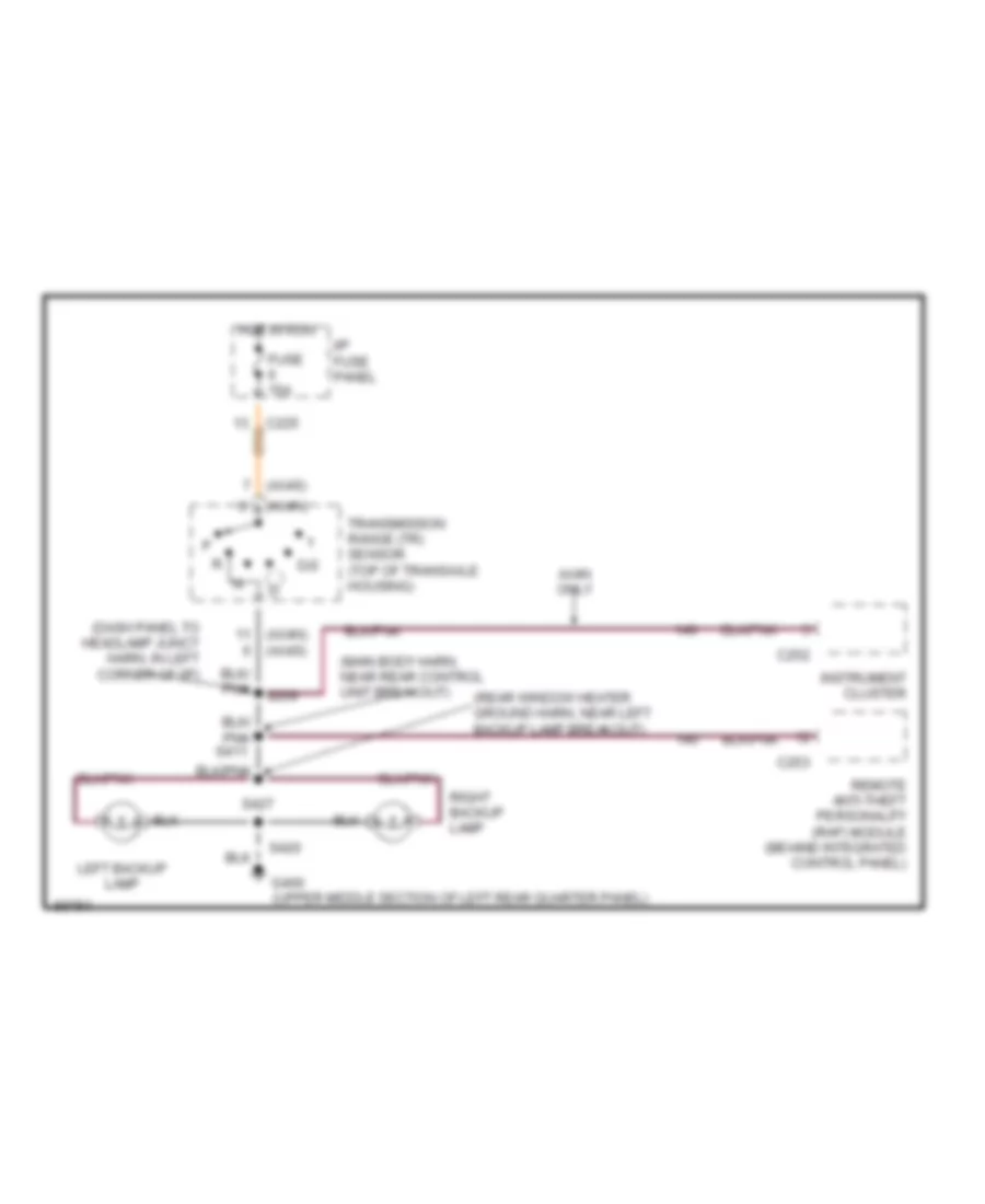
Back-up Lamps Wiring Diagram, Sedan for Ford Taurus G 1997
List of elements for Back-up Lamps Wiring Diagram, Sedan for Ford Taurus G 1997:
- (ax4n)
- (ax4n) (ax4s)
- (ax4s)
- (main body harn, near rear window defrost grid breakout)
- Ax4n only
- C225
- C252
- C253
- D/2
- Fuse 15a
- G401 (lower middle section of right rear quarter panel)
- Hot in run
- I/p fuse panel
- Instrument cluster
- Junct harn, in left corner of i/p)
- Left backup lamp
- Remote anti-theft personality (rap) module (behind integrated control panel)
- Right backup lamp
- S416
- S417
- Transmission range (tr) sensor (top of transaxle housing)
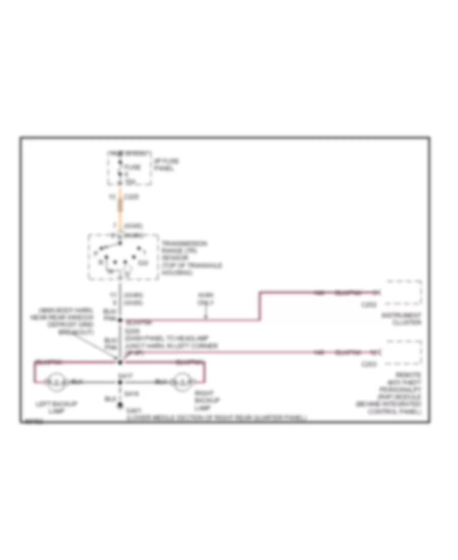
Back-up Lamps Wiring Diagram, Wagon for Ford Taurus G 1997
List of elements for Back-up Lamps Wiring Diagram, Wagon for Ford Taurus G 1997:
- (ax4n)
- (ax4n) (ax4s)
- (ax4s)
- (dash panel to headlamp junct harn, in left corner of i/p)
- (main body harn, near rear control unit breakout)
- (rear window heater ground harn, near left backup lamp breakout)
- Ax4n only
- C225
- C252
- C253
- D/2
- Fuse 15a
- G400 (upper middle section of left rear quarter panel)
- Hot in run
- I/p fuse panel
- Instrument cluster
- Left backup lamp
- Remote anti-theft personality (rap) module (behind integrated control panel)
- Right backup lamp
- S209
- S420
- S427
- Transmission range (tr) sensor (top of transaxle housing)
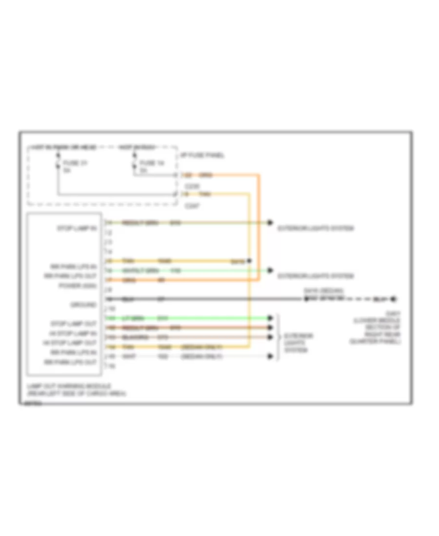
Exterior Lamps Wiring Diagram, Sedan with Lamp Out Warning (1 of 2) for Ford Taurus G 1997
List of elements for Exterior Lamps Wiring Diagram, Sedan with Lamp Out Warning (1 of 2) for Ford Taurus G 1997:
- (lower side of inner glove box lamp)
- (main body harn, in hi mount stop lamp breakout) s420
- (main harn, near left corner of i/p)
- Autolamp park relay (in eng compt fuse/relay box)
- C2031
- C235
- C250
- C251
- C269
- Electronic flasher (under left side of i/p)
- Engine compartment fuse/relay box
- Fuse 10a
- Fuse 15a
- G101 (right front fender, near coolant overflow reservoir)
- G104 (left front fender, near air cleaner)
- G206
- G206 (lower side of inner glove box lamp)
- G400 (upper middle section of left rear quarter panel)
- G401 (lower middle section of right rear quarter panel)
- Hazard
- Head
- Headlamp switch
- Hot at all times
- Hot in run
- I/p fuse panel
- Instrument cluster
- Interior lights system
- Left
- Left front marker lamp
- Left front park/ turn lamp
- Left front turn lamp
- Left rear turn lamp
- Left turn ind
- Light sensor/ amplifier (right side of i/p vent, near windshield)
- Multi- function switch
- Normal
- Off
- Park
- Park lamps fuse 15a
- Right
- Right front marker lamp
- Right front park/ turn lamp
- Right front turn lamp
- Right hi mount stop lamp
- Right rear turn lamp
- Right turn ind
- S119
- S125 (dash panel to headlamp junct harn, near battery)
- S126 (dash panel to headlamp junct harn, near battery)
- S135
- S143
- S145
- S145 (dash panel to headlamp junct harn, near eng cooling fan #1 breakout)
- S223
- S226
- S418
- Sable
- Taurus
Exterior Lamps Wiring Diagram, Sedan with Lamp Out Warning (2 of 2) for Ford Taurus G 1997
List of elements for Exterior Lamps Wiring Diagram, Sedan with Lamp Out Warning (2 of 2) for Ford Taurus G 1997:
- (lower middle section of right rear quarter panel)
- (main body harn, near right rear of trunk) s415
- (main harn, near left front door jamb)
- (not used)
- Brake on/off (boo) switch (upper front side of brake pedal)
- C247 tan
- Fuse 15a
- Fuse 5a
- G401
- G401 (lower middle section of right rear quarter panel)
- Gnd
- Hmsl in
- Hmsl out
- Hot at all times
- Hot in run
- I/p fuse panel
- Lamp out warning module (left rear side of cargo area)
- Left license lamp
- Left rear park/ stop lamp
- Left rear side marker lamp
- Left rear turn lamp
- Pwr (acc/run)
- Rear marker lmp in
- Rear marker lmp out
- Rear park lmp in
- Rear park lmp out
- Right license lamp
- Right rear park/ stop lamp
- Right rear side marker lamp
- Right rear turn lamp
- S308
- S400
- S416
- S419
- S435
- Sable
- Stop lmp in
- Stop lmp out
- Tan
- Taurus
Exterior Lamps Wiring Diagram, Sedan without Lamp Out Warning (1 of 2) for Ford Taurus G 1997
List of elements for Exterior Lamps Wiring Diagram, Sedan without Lamp Out Warning (1 of 2) for Ford Taurus G 1997:
- (lower side of inner glove box lamp)
- Autolamp park relay (in eng compt fuse/relay box)
- C2031
- C235
- C250
- C251
- C269
- Electronic flasher (under left side of i/p)
- Engine compartment fuse/relay box
- Fuse 10a
- Fuse 15a
- G101 (right front fender, near coolant overflow reservoir)
- G104 (left front fender, near air cleaner)
- G206
- G206 (lower side of inner glove box lamp)
- G401 (lower middle section of right rear quarter panel)
- Hazard
- Head
- Headlamp switch
- Hot at all times
- Hot in run
- I/p fuse panel
- Instrument cluster
- Interior lights system
- Left
- Left front marker lamp
- Left front park/ turn lamp
- Left front turn lamp
- Left rear turn lamp
- Left turn ind
- Light sensor/ amplifier (right side of i/p vent, near windshield)
- Multi- function switch
- Normal
- Off
- Park
- Park lamps fuse 15a
- Right
- Right front marker lamp
- Right front park/ turn lamp
- Right front turn lamp
- Right rear turn lamp
- Right turn ind
- S119
- S125 (dash panel to headlamp junct harn, near battery)
- S126 (dash panel to headlamp junct harn, near battery)
- S135
- S143
- S145
- S223
- S416
- Sable
- Taurus
- To headlamp junct harn, eng cooling fan #1 breakout)
Exterior Lamps Wiring Diagram, Sedan without Lamp Out Warning (2 of 2) for Ford Taurus G 1997
List of elements for Exterior Lamps Wiring Diagram, Sedan without Lamp Out Warning (2 of 2) for Ford Taurus G 1997:
- (lower middle section of right rear quarter panel)
- (main body harn, near right rear of trunk) s415
- (not used)
- Brake on/off (boo) switch (upper front side of brake pedal)
- C247
- Fuse 15a
- G400 (upper middle section of left rear quarter panel)
- G401
- Hot at all times
- I/p fuse panel
- Left hi mount stop lamp
- Left license lamp
- Left rear park/ stop lamp
- Left rear side marker lamp
- Left rear turn lamp
- Right hi mount stop lamp
- Right license lamp
- Right rear park/ stop lamp
- Right rear side marker lamp
- Right rear turn lamp
- S308 (main harn, near left front door jamb)
- S400
- S415 (main body harn, near right rear of trunk)
- S416
- S418
- S435
- Sable
- Taurus
Exterior Lamps Wiring Diagram, Wagon with Lamp Out Warning (1 of 2) for Ford Taurus G 1997
List of elements for Exterior Lamps Wiring Diagram, Wagon with Lamp Out Warning (1 of 2) for Ford Taurus G 1997:
- (lower side of inner glove box lamp)
- Autolamp park relay (in eng compt fuse/relay box)
- C2031
- C235
- C250
- C251
- C269
- Electronic flasher (under left side of i/p)
- Engine compartment fuse/relay box
- Fuse 10a
- Fuse 15a
- G101 (right front fender, near coolant overflow reservoir)
- G104 (left front fender, near air cleaner)
- G206
- G206 (lower side of inner glove box lamp)
- Hazard
- Head
- Headlamp switch
- Hot at all times
- Hot in run
- I/p fuse panel
- Instrument cluster
- Interior lights system
- Left
- Left front marker lamp
- Left front park/ turn lamp
- Left front turn lamp
- Left turn ind
- Light sensor/ amplifier (right side of i/p vent, near windshield)
- Multi- function switch
- Normal
- Off
- Park
- Park lamps fuse 15a
- Right
- Right front marker lamp
- Right front park/ turn lamp
- Right front turn lamp
- Right turn ind
- S119
- S125 (dash panel to headlamp junct harn, near battery)
- S126 (dash panel to headlamp junct harn, near battery)
- S135
- S143
- S145
- S223
- Sable
- Taurus
- To headlamp junct harn, near, eng cooling fan #1 breakout)
Exterior Lamps Wiring Diagram, Wagon with Lamp Out Warning (2 of 2) for Ford Taurus G 1997
List of elements for Exterior Lamps Wiring Diagram, Wagon with Lamp Out Warning (2 of 2) for Ford Taurus G 1997:
- (main harn, near left front door jamb)
- (rear window heater ground harn, near license lamps breakout) s432
- (rear window heater ground harn, near rear window defrost grid breakout) s428
- Brake on/off (boo) switch (upper front side of brake pedal)
- C247 tan
- Fuse 15a
- Fuse 5a
- G400 (upper middle section of left rear quarter panel)
- G401 (lower middle section of right rear quarter panel)
- Gnd
- Hmsl in
- Hmsl out
- Hot at all times
- Hot in run
- I/p fuse panel
- Lamp out warning module (left rear side of cargo area)
- Left hi mount stop lamp
- Left rear park/ stop lamp
- Left rear side marker lamp
- Left rear turn lamp
- License lamps
- Nca
- Pwr (acc/run)
- Rear park lmp in
- Rear park lmp out
- Right hi mount stop lamp
- Right rear park/ stop lamp
- Right rear side marker lamp
- Right rear turn lamp
- S308
- S404
- S405 (main body harn, near right rear park/stop lamp breakout)
- S408 (main body harn, at right rear pillar)
- S429
- S433
- Stop lmp in
- Stop lmp out
- Tan
Exterior Lamps Wiring Diagram, Wagon without Lamp Out Warning (1 of 2) for Ford Taurus G 1997
List of elements for Exterior Lamps Wiring Diagram, Wagon without Lamp Out Warning (1 of 2) for Ford Taurus G 1997:
- (lower side of of inner glove box lamp)
- Autolamp park relay (in eng compt fuse/relay box)
- C2031
- C235
- C250
- C251
- C269
- Electronic flasher (under left side of i/p)
- Engine compartment fuse/relay box
- Fuse 10a
- Fuse 15a
- G101 (right front fender, near coolant overflow reservoir)
- G104 (left front fender, near air cleaner)
- G206
- G206 (lower side of inner glove box lamp)
- Hazard
- Head
- Headlamp switch
- Hot at all times
- Hot in run
- I/p fuse panel
- Instrument cluster
- Interior lights system
- Left
- Left front marker lamp
- Left front park/ turn lamp
- Left front turn lamp
- Left turn ind
- Light sensor/ amplifier (right side of i/p vent, near windshield)
- Multi- function switch
- Normal
- Off
- Park
- Park lamps fuse 15a
- Right
- Right front marker lamp
- Right front park/ turn lamp
- Right front turn lamp
- Right turn ind
- S119
- S125 (dash panel to headlamp junct harn, near battery)
- S126 (dash panel to headlamp junct harn, near battery)
- S135
- S143
- S145
- S145 (dash panel to headlamp junct harn, near eng cooling fan #1 breakout)
- S223
- S226 (main harn, near left corner of i/p)
- Sable
- Taurus
Exterior Lamps Wiring Diagram, Wagon without Lamp Out Warning (2 of 2) for Ford Taurus G 1997
List of elements for Exterior Lamps Wiring Diagram, Wagon without Lamp Out Warning (2 of 2) for Ford Taurus G 1997:
- Brake on/off (boo) switch (upper front side of brake pedal)
- C247
- Fuse 15a
- G400 (upper middle section of left rear quarter panel)
- G401 (lower middle section of right rear quarter panel)
- Hot at all times
- I/p fuse panel
- Left hi mount stop lamp
- Left rear park/ stop lamp
- Left rear side marker lamp
- Left rear turn lamp
- License lamps
- Nca
- Right hi mount stop lamp
- Right rear park/ stop lamp
- Right rear side marker lamp
- Right rear turn lamp
- S308 (main harn, near left front door jamb)
- S404
- S408 (main body harn, at right rear pillar)
- S428 (rear window heater ground harn, near rear window defrost grid breakout)
- S429
- S432 (rear window heater ground harn, near license lamps breakout)
- S433
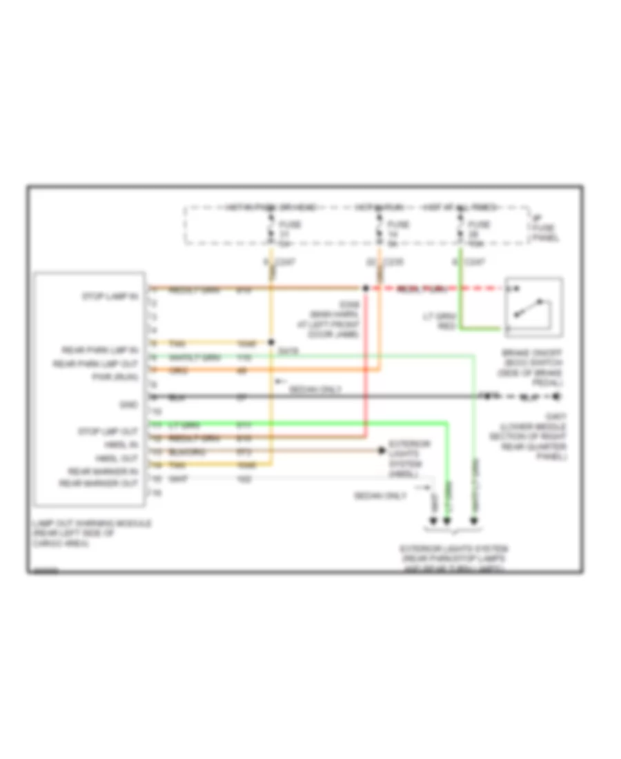
Lamp Outage Module Wiring Diagram for Ford Taurus G 1997
List of elements for Lamp Outage Module Wiring Diagram for Ford Taurus G 1997:
- (sedan only)
- C235
- C247
- Exterior lights system
- Fuse 14 5a
- Fuse 31 5a
- G401 (lower middle section of right rear quarter panel)
- Ground
- Hi stop lamp in
- Hi stop lamp out
- Hot in park or head
- Hot in run
- I/p fuse panel
- Lamp out warning module (rear left side of cargo area)
- Power (ign)
- Rr park lps in
- Rr park lps out
- S416 (sedan) s433 (wagon)
- S419
- Stop lamp in
- Stop lamp out
- Tan
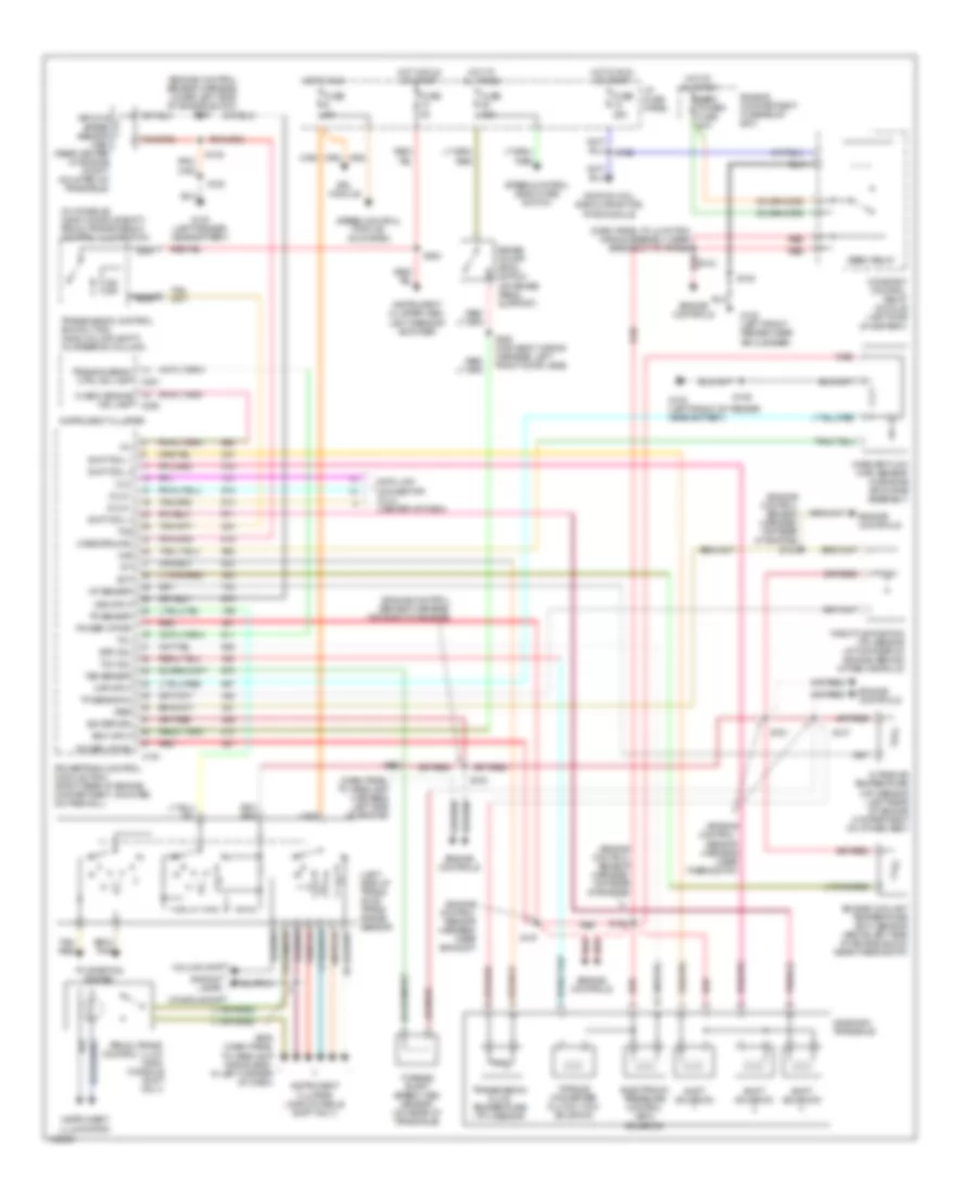
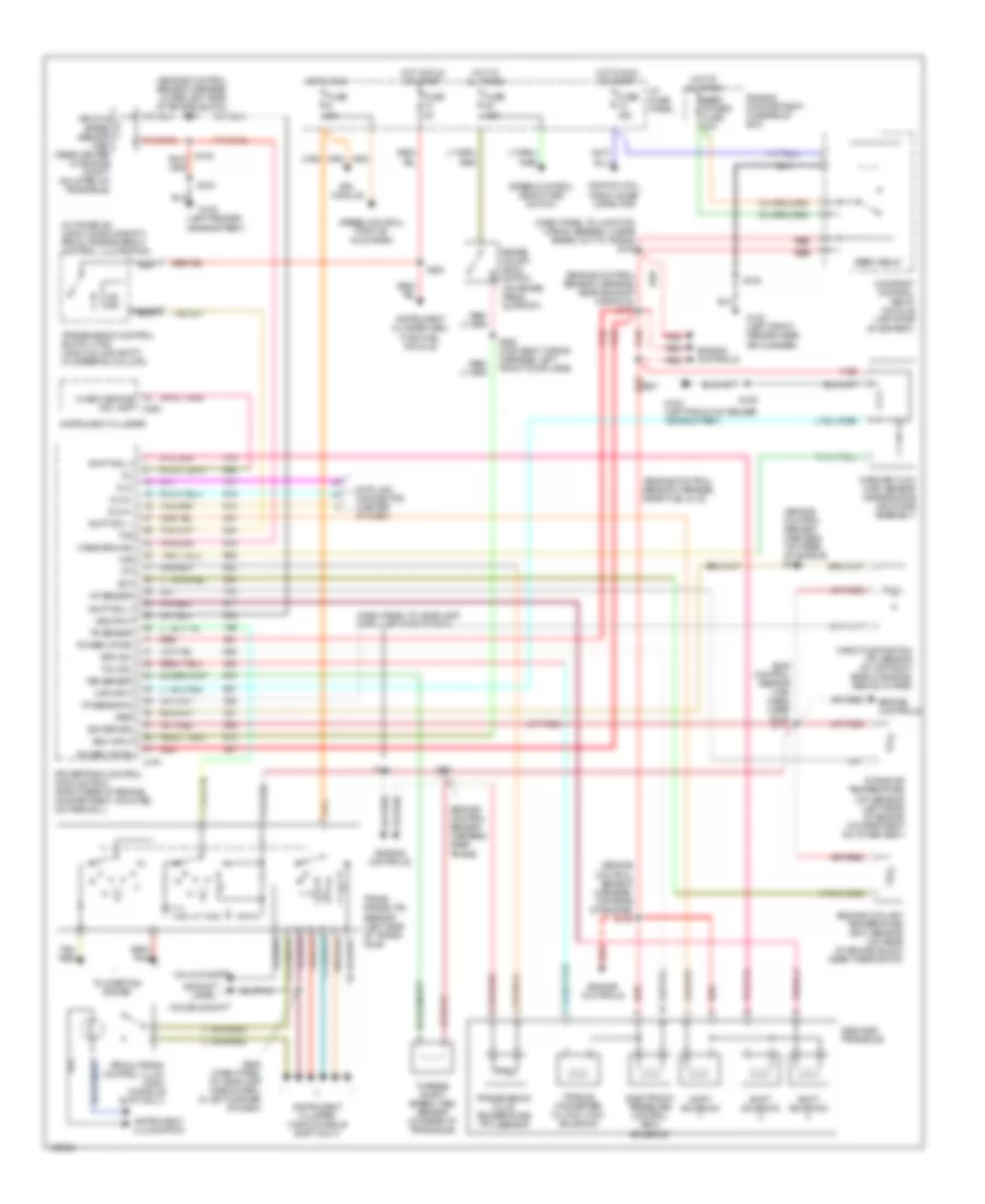
GROUND DISTRIBUTION
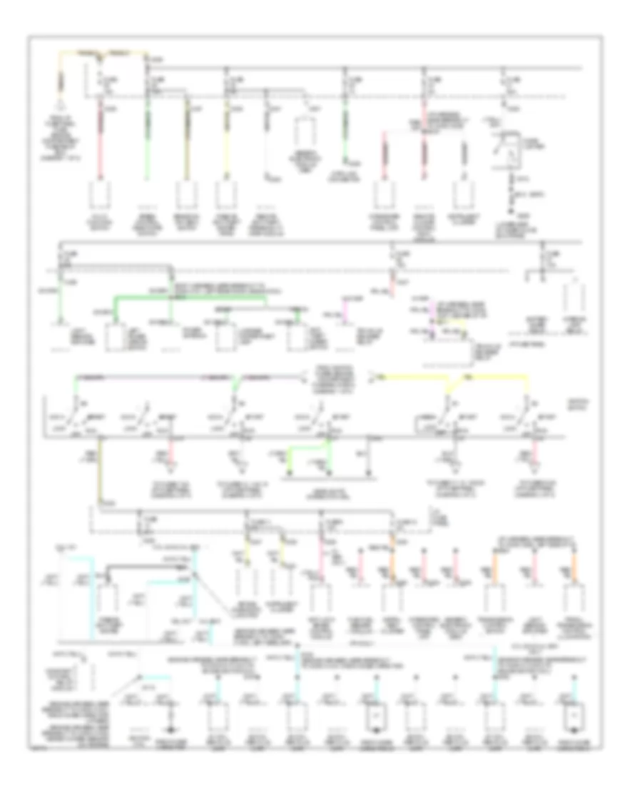
Ground Distribution Wiring Diagram (1 of 3) for Ford Taurus G 1997
List of elements for Ground Distribution Wiring Diagram (1 of 3) for Ford Taurus G 1997:
- (body harness, left front door)
- (body harness, near left rear window motor)
- (engine harness, near air pump)
- (engine harness, near breakout to camshaft position sensor)
- (engine harness, near breakout to crankshaft position sensor; 24v)
- (engine harness, near breakout to left headlamp) s121
- 3.0l 12v ffv
- 3.0l 12v ffv only
- 3.0l 12v only
- 3.0l 24v & 3.4 sho only
- 3.0l 24v only
- 3.4l sho
- 3.4l sho & 3.0l
- 3.4l sho only
- 3.ol
- 87a
- A/c high pressure switch
- Air bag diagnostic monitor
- All door lock relay
- All door unlock relay
- Anti-lock brake control module
- Battery
- Brake fluid level switch
- C248
- C276
- C277
- C501
- C509
- C510
- Camshaft position (cmp) sensor
- Camshaft position (cmp) sensor shield
- Constant control relay module
- Crankshaft position (ckp) sensor shield
- Data link connector
- Eam air pump
- Eam solid state relay
- Engine compartment fuse/relay box
- Engine coolant fan #1
- Engine coolant fan #2
- Flex fuel sensor
- G100 (left front fender)
- G101 (right front fender, near coolant overflow reservoir)
- G104 (left front fender, near air cleaner)
- G106
- G123 (upper right center of cowl)
- G200 (on left kick panel)
- Generic electronic module (gem)
- Hood tamper switch
- Intake manifold runner control (imrc)
- Keyless entry keypad switch assembly
- Left front door ajar switch
- Left front door lock switch
- Left front park/turn lamp
- Left front shock actuator
- Left front turn lamp
- Left head- lamp
- Left master door lock switch
- Left power heated/ mirror
- Left power mirror switch
- Left rear door ajar switch
- Left rear window switch
- Mass air flow (mass) sensor
- Master window control switch assembly
- Nca
- Of eng compt, near abs module)
- Passive anti-theft system (pats)
- Powertrain control module (pcm)
- Remote climate control (rcc) module
- Remote personality (rap) module
- Right front park/ turn lamp
- Right front shock actuator
- Right front turn lamp
- Right head- lamp
- S105 (engine harness, near breakout to crankshaft position sensor; ex. 24v)
- S106 (engine harness, near breakout to pcm)
- S108 (engine harness, near breakout to pcm)
- S120 (engine harness, near breakout to conn c1049, left headlamp)
- S135 (engine harness, left side of engine compt)
- S158
- S158 (engine harness, near air pump)
- S206 (i/p harness, left side of i/p)
- S215 (i/p harness, in breakout to conn c242, behind icp)
- S506
- Speed control module
- Starter relay
- Trunklid release switch
- Vehicle speed sensor (vss)
- W/ eatc only
- W/ taurus sho & ffv only
- Wind- shield wiper motor
- Windshield washer pump motor
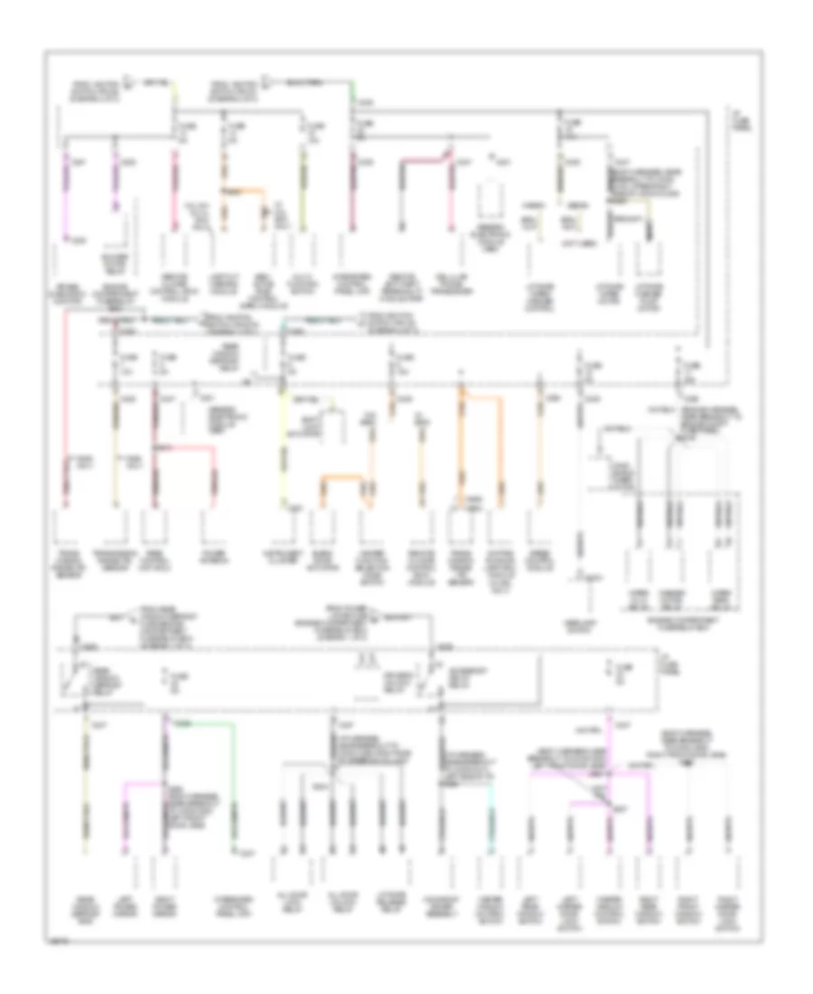
Ground Distribution Wiring Diagram (2 of 3) for Ford Taurus G 1997
List of elements for Ground Distribution Wiring Diagram (2 of 3) for Ford Taurus G 1997:
- (i/p harness, center of i/p)
- (left side of cargo area, near cellular phone transceiver)
- (upper middle section of left rear quarter panel)
- Astray lamp
- Blend door actuator
- Blower motor relay
- Blower motor speed controller
- Blower resistor
- Blower switch
- C250
- C252
- Cellular phone transceiver
- Cigar lighter
- Compact disc changer
- Data link connector
- Dome switch/ lamp
- Electronic flasher
- Engine compartment fuse/relay box
- G203 (right kick panel)
- G206 (lower side of inner glove box frame)
- G400
- G404
- Glove box switch lamp
- Head- lamp switch
- Heater function selector switch
- Ignition switch
- Instrument cluster
- Integrated control panel (icp)
- Left back- up lamp
- Left hi mount stop lamp
- Left i/p courtesy lamp
- Left power lumbar compressor
- Left seat control switch
- Liftgate door ajar switch
- Liftgate window ajar switch
- Liftgate wiper/ washer control
- Moonroof drive assembly
- Nca
- Only
- Overhead console
- Power antenna
- Prndl/ transmission control illumination
- Rear control unit (rcu)
- Rear window defrost grid)
- Right back- up lamp
- Right front door ajar switch
- Right front door lock switch
- Right front window switch
- Right hi mount stop lamp
- Right i/p courtesy lamp
- Right master door lock switch
- Right power mirror
- Right rear door ajar switch
- Right rear window switch
- S212
- S223 (i/p harness, near breakout to electronic flasher unit)
- S303 (body harness)
- S320
- S439 (audio system wiring diagram)
- S600 (body harness, near breakout to right front window motor)
- S800 (body harness, right rear door)
- Seat belt switch
- Sedan
- Sedan w/ rap
- Shift lock actuator
- Subwoofer
- Subwoofer amplifier assembly
- Trunk lid release switch
- W/ eatc
- W/ moon- roof
- W/o eatc
- Wagon
Ground Distribution Wiring Diagram (3 of 3) for Ford Taurus G 1997
List of elements for Ground Distribution Wiring Diagram (3 of 3) for Ford Taurus G 1997:
- 3.4l sho only
- Anti- theft alarm switch
- C451
- Cargo lamp
- Cargo lamp relay
- Except 3.4l sho
- Fuel pump/ fuel gauge sender
- G401 (lower middle section of right rear quarter panel)
- Lamp out warning module
- Left backup lamp
- Left license lamp
- Left rear park/ stop lamp
- Left rear shock actuator
- Left rear side marker lamp
- Left rear turn lamp
- License lamps
- Liftgate wiper motor
- Nca
- Rear window defrost grid
- Right backup lamp
- Right license lamp
- Right rear park/ stop lamp
- Right rear shock actuator
- Right rear side marker lamp
- Right rear turn lamp
- S400 (body harness, left rear of trunk)
- S404 (body harness, right rear cargo area)
- S416 (body harness, near breakout to g401)
- S433 (body harness, near breakout to liftgate wiper motor)
- S435 (body harness, right rear marker light)
- S442 (body harness, near breakout to right rear shock actuator)
- S451 (body harness, near breakout to right rear side of vehicle)
- Sable
- Sedan only
- Semi-active ride control (sarc) module
- Taurus
- Trunklid ajar switch/ release solenoid
- Trunklid anti-theft switch
- W/ rap
- Wagon only
HEADLIGHTS
Autolamps Wiring Diagram, with DRL for Ford Taurus G 1997
List of elements for Autolamps Wiring Diagram, with DRL for Ford Taurus G 1997:
- (behind integrated control panel) remote anti-theft personality (rap) module
- (left front fender, near air cleaner)
- (lower side of inner glove box frame)
- (main harn, near electronic flasher breakout)
- 15a
- 200k
- 3.6k
- Acc
- Autolamp headlamp relay (in engine compartment fuse/relay box)
- Autolamp on ind
- Autolamp rly
- Brake fluid level sw
- Brake fluid level switch (right of master cylinder)
- Brake ind
- C2031
- C2032
- C2037
- C225
- C235
- C247
- C250
- C268
- Daytime running lamps (drl) module (below left headlamp)
- Daytime running lamps fuse 15a
- Delay
- Engine compartment fuse/relay box
- Exterior lights system (autolamp park relay)
- Fuse
- Fuse 10a
- Fuse 15a
- G101 (right front fender, near coolant overflow reservoir)
- G104
- G104 (left front fender, near air cleaner)
- G206
- Gnd
- Head
- Headlamp switch
- Headlamp switch illum
- Headlamps fuse (auto) 30a
- Hi beam in
- Hi beam ind out
- High beam ind
- Hot at all times
- Hot in acc or run
- Hot in run
- Hot in run or start
- I/p fuse panel
- Ignition switch
- Instrument cluster
- Left headlamp
- Light sensor/amplifier (right side of i/p vent, near windshield)
- Lo beam in
- Lock
- Low ftp
- Multi- function switch
- Off
- On/off in
- Park
- Park lamp fuse 15a
- Parking brake sw out
- Parking brake switch (above brake pedal)
- Pulse width dimming module
- Pwr (bat)
- Pwr (run)
- Pwr (start/run)
- Right headlamp
- Run
- S123 (dash panel to headlamp junct harn, near left headlamp breakout)
- S135
- S139
- S143
- S145
- S212
- S223
- S224
- S226
- Solid state
- Start
- Time delay in
Autolamps Wiring Diagram, without DRL for Ford Taurus G 1997
List of elements for Autolamps Wiring Diagram, without DRL for Ford Taurus G 1997:
- (behind integrated control panel) remote anti-theft personality (rap) module
- (lower side of inner glove box frame)
- (main harn, near electronic flasher breakout)
- 200k
- 3.6k
- All others
- Autolamp headlamp relay (in engine compart- ment fuse/ relay box)
- Autolamp on ind
- Autolamp rly
- C2031
- C2032
- C2037
- C225
- C235
- C247
- C250
- C268
- Daytime running lamp (drl) jumper (below left headlamp)
- Delay
- Engine compartment fuse/relay box
- Exterior lights system (autolamp park relay)
- Ftp
- Fuse 10a
- Fuse 15a
- Fuse 5a
- G101 (right front fender, near coolant overflow reservoir)
- G104 (left front fender, near air cleaner)
- G206
- Head
- Headlamp switch
- Headlamp switch illum
- Headlamps fuse (auto) 30a
- High beam ind
- Hot at all times
- Hot in acc or run
- Hot in run or start
- I/p fuse panel
- Instrument cluster
- Left headlamp
- Light sensor/amplifier (right side of i/p vent, near windshield)
- Low
- Multi- function switch
- Off
- On/off in
- Park
- Park lamp fuse 15a
- Pulse width dimming module
- Pwr (bat)
- Pwr (start/run)
- Right headlamp
- S123 (dash panel to headlamp junct harn, near left headlamp breakout)
- S135
- S139
- S143
- S145
- S223
- S224
- S226
- Solid state
- Taurus w/ abs
- Time delay in
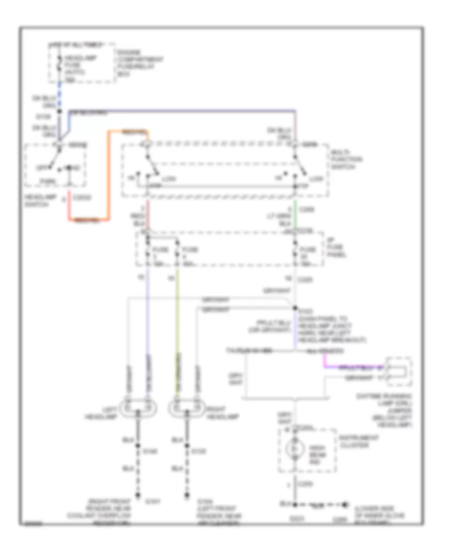
Headlamps Wiring Diagram, with DRL for Ford Taurus G 1997
List of elements for Headlamps Wiring Diagram, with DRL for Ford Taurus G 1997:
- (dash panel to headlamp junct harn, near left front fender) s127
- (left front fender, near air cleaner)
- (lower side of inner glove box frame)
- 15a
- 30a
- Acc
- Brake fluid level sw
- Brake fluid level switch (right of master cylinder)
- Brake ind
- C2032
- C225
- C235
- C250
- C268
- Daytime running lamps (drl) module (below left headlamp)
- Daytime running lamps fuse
- Engine compartment fuse/relay box
- Fuse
- Fuse 10a
- Fuse 15a
- G101 (right front fender, near coolant overflow reservoir)
- G104
- G104 (left front fender, near air cleaner)
- G206
- Gnd
- Head
- Headlamp switch
- Headlamps fuse (auto)
- Hi beam in
- Hi beam ind out
- High beam ind
- Hot at all times
- Hot in run
- Hot in start or run
- I/p fuse panel
- Ignition switch
- Instrument cluster
- Left headlamp
- Lo beam in
- Lock
- Low ftp
- Multi- function switch
- Off
- Park
- Parking brake sw out
- Parking brake switch (above brake pedal)
- Pwr (bat)
- Pwr (run)
- Right headlamp
- Run
- S123 (dash panel to headlamp junct harn, near left headlamp breakout)
- S135
- S139
- S145
- S212
- S223
- Start
Headlamps Wiring Diagram, without DRL for Ford Taurus G 1997
List of elements for Headlamps Wiring Diagram, without DRL for Ford Taurus G 1997:
- (lower side of inner glove box frame)
- (right front fender, near coolant overflow reservoir)
- All others
- C2032
- C225
- C235
- C250
- C268
- Daytime running lamp (drl) jumper (below left headlamp)
- Engine compartment fuse/relay box
- Fuse 10a
- Fuse 15a
- G101
- G104 (left front fender, near air cleaner)
- G206
- Head
- Headlamp fuse (auto) 30a
- Headlamp switch
- High beam ind
- Hot at all times
- I/p fuse panel
- Instrument cluster
- Left headlamp
- Low ftp
- Multi- function switch
- Off
- Park
- Right headlamp
- S123 (dash panel to headlamp junct harn, near left headlamp breakout)
- S135
- S139
- S145
- S223
- Taurus w/ abs
HORN
Horn Wiring Diagram for Ford Taurus G 1997
List of elements for Horn Wiring Diagram for Ford Taurus G 1997:
- C102
- C254
- Clockspring assembly
- Cruise control system
- Engine compartment fuse/relay box
- Fuse 15a
- G104 (left front fender, near air cleaner)
- High pitch horn (front left frame rail)
- Horn
- Horn relay (in engine compartment fuse/ relay box)
- Horn relay control
- Horn/speed control switch
- Hot at all times
- Low pitch horn (front right frame rail)
- Nca
- Remote anti-theft personality module (behind integrated control panel)
- S135
- S144
- Speed control module (on left front strut)
- Speed control module jumper (near left front strut)
- Switches
- W/ anti- theft only
- W/ speed control
- W/o speed control
INSTRUMENT CLUSTER
3.0L
3.0L Flex Fuel, Instrument Cluster Wiring Diagram for Ford Taurus G 1997
List of elements for 3.0L Flex Fuel, Instrument Cluster Wiring Diagram for Ford Taurus G 1997:
- (attached to the underside of i/p fuse panel)
- (conn a)
- (conn b)
- (left front fender)
- (left front fender, near air cleaner)
- (left side of i/p)
- (lower side of inner glove box frame)
- (not
- (on i/p fuse pnl)
- (right rear corner of eng compt, mounted in cowl)
- 0.51k
- A10
- A13
- A14
- A15
- A16
- Acc
- Air bag ind
- Anti-lock brake ind
- Anti-lock brakes system
- Anti-slosh module
- B10
- B11
- B12
- B15
- B16
- Brake fluid level switch (right of master cylinder)
- Brake ind
- C225
- C235
- C236
- C250
- C251
- Check engine ind
- Cruise control system
- Cruise on ind
- Daytime running lamps (drl) jumper (below left headlamp)
- Daytime running lamps (drl) module (below left headlamp)
- Distance to empty (dte) module
- Door ajar ind
- Door ajar ind ctrl
- Dte
- Engine coolant temperature gauge
- Engine coolant temperature sender (near ther- mostat)
- Engine oil pressure switch (left top rear corner of eng block)
- Exterior lights system
- Flex fuel sender module (behind center of i/p)
- Fuel gauge
- Fuel pump/ fuel gauge sender (in fuel tank)
- Fuse
- G101
- G104
- G206
- Generator/ battery ind
- Generic elec- tronic module
- Generic electronic module (gem)
- Gnd
- Headlamp switch
- Headlight system
- High beam ind
- Hot at all times i/p fuse panel
- Hot in run
- Hot in start or run
- I/p fuse panel
- Ignition switch
- Instrument cluster
- Integrated control panel (right of steering column)
- Interior lights system
- Left turn ind
- Lock
- Low coolant ind ctrl
- Low fuel ind
- Mil
- Off
- Oil pressure ind
- Parking brake switch (above brake pedal)
- Power- train control module
- Powertrain control module (right rear of eng compt, mounted in cowl)
- Right turn ind
- Run
- S104 (near crksft pos sensor)
- S120
- S135
- S142
- S209 (dash to hdlmp harn left side of i/p)
- S212
- S216
- S223
- S224
- Seat belt ind
- Seat belt ind ctrl
- Six back light illum ind
- Speed control module (left of master cylinder)
- Speed- ometer
- Start
- Starting/ charging system
- Tach
- Tachometer
- Used)
- Vehicle speed sensor (on trans- axle)
- Vss+
- W/ drl
- W/o drl
3.0L, Instrument Cluster Wiring Diagram for Ford Taurus G 1997
List of elements for 3.0L, Instrument Cluster Wiring Diagram for Ford Taurus G 1997:
- (conn a)
- (conn b)
- (conn c)
- (dash to hdlmp harn left side of i/p)
- (left front fender)
- (left front fender) g101
- (left front fender, near air cleaner)
- (lower side of inner glove box frame)
- (main harn, left side of i/p) s232
- (main harn, left side of i/p) s233
- (right rear corner of eng compt, mounted in cowl)
- 0.51k
- 15a
- A10
- A12
- A13
- A14
- A15
- A16
- Acc
- Air bag ind
- Anti-lock brake ind
- Anti-lock brakes system
- Anti-slosh module
- Anti-theft ind
- Anti-theft system
- B10
- B11
- B12
- B13
- B14
- B16
- Brake fluid level switch (right of master cylinder)
- Brake ind
- C225
- C235
- C236
- C250
- C251
- C252
- C450
- Check engine ind
- Cruise control system
- Cruise on ind
- D/2
- Daytime running lamps (drl) jumper (below left headlamp)
- Daytime running lamps (drl) module (below left headlamp)
- Dimming control
- Door ajar ind
- Door ajar ind ctrl
- Engine coolant temperature gauge
- Engine coolant temperature sender (near thermostat)
- Engine oil pressure switch (left top rear corner of eng block)
- Exterior lights
- Exterior lights system
- Exterior lights system (backup lamps)
- Fuel
- Fuel gauge
- Fuel pump/ fuel gauge sender (in fuel tank)
- Fuse
- G101
- G104
- G206
- Generator/ battery ind
- Generic electronic module (gem) (attached to the underside of i/p fuse panel)
- Generic electronic module (on i/p fuse pnl)
- Gnd
- Headlights system
- High beam ind
- Hot at all times i/p fuse panel
- Hot in run
- Hot in start or run
- I/p fuse panel
- Ignition switch
- Instrument cluster
- Interior lights system
- Interior lights system (pulse width dimming module)
- Left turn ind
- Lock
- Low coolant ind
- Low coolant ind ctrl
- Low fuel ind
- Mil
- Nca
- Off
- Oil pressure ind
- Parking brake switch (above brake pedal)
- Powertrain control module
- Powertrain control module (right rear of eng compt, mounted in cowl)
- Prndl/transmission control illumination (in center console)
- Right turn ind
- Run
- S104 (near crksft pos sensor)
- S105
- S120
- S135
- S142
- S209
- S212
- S216
- S223
- S224
- Seat belt ind
- Seat belt ind ctrl
- Semi-active ride control (sarc) module (behind right rear seat)
- Sho only
- Six back light illum ind
- Speed control module (left of master cylinder)
- Speed- ometer
- Start
- Starting/ charging
- Tach
- Tachometer
- Tcil
- Tcil ind
- Transmission range sensor (top of transaxle housing)
- Vehicle speed sensor (on tras)
- Vss+
- W/ drl
- W/o drl
Lamp Outage Wiring Diagram for Ford Taurus G 1997
List of elements for Lamp Outage Wiring Diagram for Ford Taurus G 1997:
- Brake on/off (boo) switch (side of brake pedal)
- C235
- C247
- Exterior lights system (hmsl)
- Exterior lights system (rear park/stop lamps and rear turn lamps)
- Fuse 15a
- Fuse 5a
- G401 (lower middle section of right rear quarter panel)
- Gnd
- Hmsl in
- Hmsl out
- Hot at all times
- Hot in park or head
- Hot in run
- I/p fuse panel
- Lamp out warning module (rear left side of cargo area)
- Pwr (run)
- Rear marker in
- Rear marker out
- Rear park lmp in
- Rear park lmp out
- S308 (main harn, at left front door jamb)
- S416
- S419
- Sedan only
- Stop lamp in
- Stop lmp out
- Tan
3.4L
3.4L SHO, Instrument Cluster Wiring Diagram for Ford Taurus G 1997
List of elements for 3.4L SHO, Instrument Cluster Wiring Diagram for Ford Taurus G 1997:
- (conn a)
- (conn b)
- (conn c)
- (dash to hdlmp harn left side of i/p)
- (left front fender)
- (left front fender) g101
- (left front fender, near air cleaner)
- (lower side of inner glove box frame)
- (main harn, left side of i/p) s232
- (main harn, left side of i/p) s233
- (right rear corner of eng compt, mounted in cowl)
- 0.51k
- 15a
- A10
- A12
- A13
- A14
- A15
- A16
- Acc
- Air bag ind
- Anti-lock brake ind
- Anti-lock brakes system
- Anti-slosh module
- Anti-theft ind
- Anti-theft system
- B10
- B11
- B12
- B13
- B14
- B16
- Brake fluid level switch (right of master cylinder)
- Brake ind
- C225
- C235
- C236
- C250
- C251
- C252
- C450
- Check engine ind
- Cruise control system
- Cruise on ind
- D/2
- Daytime running lamps (drl) jumper (below left headlamp)
- Daytime running lamps (drl) module (below left headlamp)
- Dimming control
- Door ajar ind
- Door ajar ind ctrl
- Engine coolant temperature gauge
- Engine coolant temperature sender (near thermostat)
- Engine oil pressure switch (left top rear corner of eng block)
- Exterior lights
- Exterior lights system
- Exterior lights system (backup lamps)
- Fuel
- Fuel gauge
- Fuel pump/ fuel gauge sender (in fuel tank)
- Fuse
- G101
- G104
- G206
- Generator/ battery ind
- Generic electronic module (gem) (attached to the underside of i/p fuse panel)
- Generic electronic module (on i/p fuse pnl)
- Gnd
- Headlights system
- High beam ind
- Hot at all times i/p fuse panel
- Hot in run
- Hot in start or run
- I/p fuse panel
- Ignition switch
- Instrument cluster
- Interior lights system
- Interior lights system (pulse width dimming module)
- Left turn ind
- Lock
- Low coolant ind
- Low coolant ind ctrl
- Low fuel ind
- Mil
- Nca
- Off
- Oil pressure ind
- Parking brake switch (above brake pedal)
- Powertrain control module
- Powertrain control module (right rear of eng compt, mounted in cowl)
- Prndl/transmission control illumination (in center console)
- Right turn ind
- Run
- S104 (near crksft pos sensor)
- S105
- S120
- S135
- S142
- S209
- S212
- S216
- S223
- S224
- Seat belt ind
- Seat belt ind ctrl
- Semi-active ride control (sarc) module (behind right rear seat)
- Sho only
- Six back light illum ind
- Speed control module (left of master cylinder)
- Speed- ometer
- Start
- Starting/ charging
- Tach
- Tachometer
- Tcil
- Tcil ind
- Transmission range sensor (top of transaxle housing)
- Vehicle speed sensor (on tras)
- Vss+
- W/ drl
- W/o drl
Lamp Outage Wiring Diagram for Ford Taurus G 1997
List of elements for Lamp Outage Wiring Diagram for Ford Taurus G 1997:
- Brake on/off (boo) switch (side of brake pedal)
- C235
- C247
- Exterior lights system (hmsl)
- Exterior lights system (rear park/stop lamps and rear turn lamps)
- Fuse 15a
- Fuse 5a
- G401 (lower middle section of right rear quarter panel)
- Gnd
- Hmsl in
- Hmsl out
- Hot at all times
- Hot in park or head
- Hot in run
- I/p fuse panel
- Lamp out warning module (rear left side of cargo area)
- Pwr (run)
- Rear marker in
- Rear marker out
- Rear park lmp in
- Rear park lmp out
- S308 (main harn, at left front door jamb)
- S416
- S419
- Sedan only
- Stop lamp in
- Stop lmp out
- Tan
INTERIOR LIGHTS
Courtesy Lamps Wiring Diagram for Ford Taurus G 1997
List of elements for Courtesy Lamps Wiring Diagram for Ford Taurus G 1997:
- door
- (interior lamp feed harn, near overhead console breakout)
- (main body harn, in right rear door jamb) s301
- (main body harn, near right "a" pillar)
- (main wiring harn, under left side of i/p)
- (right rear qtr. panel)
- 87a
- Battery saver relay
- Battery saver relay control
- Bright
- C201
- C2031
- C2032
- C235
- C247
- C248
- Cargo lamp (wagon)
- Cargo lamp relay (wagon) (right rear center of vehicle, below cargo flooring)
- Diode center (right rear center of vehicle, below cargo flooring)
- Dome lamp
- Dome lamp switch
- Dome switch/ lamp
- Dome switch/ lamp breakout) s902
- Door
- From battery saver relay (i/p fuse panel)
- Fuse 10a
- Fuse 5a
- G200 (on left kick panel)
- G203 (on right right panel)
- G203 (right kick panel)
- G206 (lower side of inner glove box frame)
- G400 (upper middle section of left rear quarter panel)
- G401
- G401 (lower middle section of right rear quarter panel)
- Generic electronic module (attached to i/p fuse panel)
- Glove box open
- Glove box switch/lamp
- Headlamp switch
- Hot at all times
- I/p fuse panel (left side of i/p)
- Interior lamp relay
- Interior lamp relay control
- Left backup lamp breakout) s430
- Left front door ajar switch
- Left i/p courtesy lamp
- Left map lamp
- Left rear door ajar switch
- Left vanity mirror
- Lf door ajar input
- Liftgate ajar input
- Liftgate door ajar switch (wagon)
- Liftgate lock switch
- Liftgate window ajar switch (wagon)
- Lr door ajar input
- Luggage compartment lamp (sedan only)
- Mirror open
- Nca
- Off
- Overhead console
- Rf door ajar input
- Right front door ajar switch
- Right i/p courtesy lamp
- Right map lamp
- Right rear door ajar switch
- Right vanity mirror
- Rr door ajar input
- S212
- S212 or s230
- S223
- S304 (main body harn, near right front door jamb)
- S313
- S404
- S429
- S500
- S600
- S700
- S800
- S900
- S901
- Sedan
- To left & right vanity mirrors
- Trunklid ajar switch/ release solenoid (sedan only)
- W/ moonroof
- W/o moonroof
- Wagon
- Wagon only
Instrument Illumination Wiring Diagram for Ford Taurus G 1997
List of elements for Instrument Illumination Wiring Diagram for Ford Taurus G 1997:
- (2)
- (6)
- (8)
- (left front door window reg harn, near left front door jamb) s503
- (main body harn, near left front door jamb) s307
- (main wiring harn, under left side of i/p) s221
- (right front door window reg harn, near right front door jamb) s601
- Acc
- Acc delay relay control
- Accessory delay relay
- Ashtray lamp
- Battery saver relay
- Battery saver relay control
- C201
- C2031
- C2032
- C225
- C235
- C247
- C250
- C251
- C252
- C501
- Cigar lighter
- Dimming module
- Distance to empty (dte) module
- Engine compartment fuse/relay box (behind radiator)
- Fuse 5a
- Fuse 10a
- Fuse 5a
- G200 (on left kick panel)
- G203 (on right kick panel)
- G206 (lower side of inner glove box frame)
- Generic electronic module (attached to i/p fuse panel)
- Ground
- Head
- Headlamp switch
- Headlamp switch backlight
- Headlamp switch illumination (w/ autolamps/ delayed exit)
- Hot at all times
- I/p fuse panel (left side of i/p)
- Ignition switch
- Illum
- Instr illum
- Instrument cluster
- Integrated control panel (right of steering column)
- Lamps on
- Left master door lock switch
- Left rear window switch
- Liftgate/ wiper washer control (wagon only)
- Lock
- Master window control switch
- Nca
- Off
- Park
- Park lamps fuse 20 15a
- Power locks fuse 4 30a
- Prndl/ transmission control illumination
- Pulse width dimming module
- Right front window switch
- Right master door lock switch
- Right rear window switch
- Run
- S143
- S223
- S303
- S506
- S600
- S700
- S800
- Solid state
- Start
- W/ autolamps/ delayed exit
POWER ANTENNA
Power Antenna Wiring Diagram for Ford Taurus G 1997
List of elements for Power Antenna Wiring Diagram for Ford Taurus G 1997:
- (wagon) (sedan)
- Antenna
- C247
- C478
- Fuse 22
- Fuse 8
- G400 (upper middle section of left rear quarter panel)
- Gnd
- Hot at all times
- Hot in start
- I/p fuse panel
- Ign
- Nca
- Power antenna (left rear side of cargo area)
- Radio antenna
- Rear control unit (rcu) (in left rear body of car)
- S313
- S412 s418
- S413
- Solid state
POWER DISTRIBUTION
Power Distribution Wiring Diagram (1 of 3) for Ford Taurus G 1997
List of elements for Power Distribution Wiring Diagram (1 of 3) for Ford Taurus G 1997:
- (3.0l 24v & 3.4l sho) only)
- (audio system wiring harness)
- (body harness, near breakout to conn c420, below driver's seat)
- (engine harness, near breakout to conn c1019, left of battery)
- (engine harness, near breakout to conn c137, near exhaust manifold) s148
- (i/p harness, in breakout to conn c186, left front fender)
- (i/p harness, in breakout to conn c471, left side of cargo area)
- (i/p harness, near breakout to conn c256, right side of steering column) s208
- (lumbar)
- 10a
- 175a
- 3.4l sho
- Abs module fuse 30a
- Abs module fuse 40a
- Air bag diagnostic monitor
- Air bag fuse 10a
- All others
- Alternator fuse 30a
- Anti-lock brake control module
- Auto- lamp head- lamp relay
- Auto- lamp park relay
- Battery
- Blower motor fuse 40a
- Blower motor relay
- C2031
- C225
- C235
- C247
- C250
- C276
- Cellular phone in-line fuse (above left rear wheel well)
- Cellular phone transceiver
- Compact disc changer
- Constant control relay module
- Cooling fan fuse 40a
- Daytime running lamps (drl) module (w/ drl only)
- Daytime running lamps (drl) module (w/ drl)
- Daytime running lamps fuse 15a
- Eam solid state relay
- Eeec power fuse 30a
- Engine compartment fuse/relay box
- Engine controls system
- Exterior lights system
- Fuel pump fuse 20a
- Fuse 10a
- Fuse 15a
- Fuse 5a
- Generator/ voltage regulator
- Ground distribution
- Head
- Headlamp switch
- Headlamps fuse (auto) 30a
- Hego fuse 15a
- Horn fuse 15a
- Horn relay
- I/p fuse panel
- I/p fuse panel fuse 40a
- Ignition fuse 40a
- Instrument cluster
- Lamp out warning module
- Left headlamp
- Left seat control switch
- Low ftp
- Mega fuse (right side of eng compt fuse/relay box)
- Multi- function switch
- Nca
- Near breakout to conn c1049, left headlamp) s123
- Off
- Park
- Park lamps fuse 15a
- Power locks fuse 30a
- Power seats fuse 40a
- Powertrain control module (pcm)
- Pulse width dimming module
- Radio fuse 20a
- Rear control unit
- Rear window defrost fuse 20a
- Red
- Right headlamp
- Right seat control switch
- S127
- S132 (engine harness, near breakout to conn c1019, left of battery)
- S139
- S141 (engine harness, near breakout to conn c1019, left of battery)
- S143
- S144
- S318 (body harness, near breakout to conn c335, below driver's seat)
- S414 (body harness, near breakout to conn c435, left rear wheel well)
- S419
- S423 (body harness, near breakout to conn c435, left rear wheel well)
- S436
- Sedan only
- Semi-active ride control fuse 30a
- Semi-active ride control module
- Starter motor/ relay
- Starter relay (3.0l 24v & 3.4l sho)
- Tan
- Tan/red
- Taurus w/ abs, w/o drl
- Thermactor air bypass solenoid
- Thermactor pump fuse 30a
- To fuse 29 (i/p fuse panel) (diagram 2 of 3)
- To i/p fuse panel (accessory delay relay) (diagram 3 of 3)
- To ignition switch (pins b1 & b3) (diagram 2 of 3)
- To ignition switch (pins b4 & b5) (diagram 2 of 3)
- To rear window defrost relay (i/p fuse panel) (diagram 3 of 3)
Power Distribution Wiring Diagram (2 of 3) for Ford Taurus G 1997
List of elements for Power Distribution Wiring Diagram (2 of 3) for Ford Taurus G 1997:
- #1 coil per plug (cpp)
- #2 coil per plug (cpp)
- #3 coil per plug (cpp)
- #4 coil per plug (cpp)
- #5 coil per plug (cpp)
- #6 coil per plug (cpp)
- #7 coil per plug (cpp)
- #8 coil per plug (cpp)
- (body harness, near breakout to conn c701, left rear door jamb switch) s313
- (eatc)
- (engine harness, near breakout to conn c1031, radio noise capacitor) (others) (engine harness, near breakout to conn c1008, heated oxygen sensor) (24v engine)
- (engine harness, near breakout to conn c1040, left headlamp)
- (engine harness, near breakout to conn c174 & c175, #5 & #6 ignition coil) s161
- (i/p fuse panel) (diagram 3 of 3)
- (i/p harness, near breakout to conn c227, center of i/p) s211
- (i/p harness, near breakout to conn c292, left side of i/p) s224
- (lower side of inner glove box frame)
- 20a
- 3.0l 24v
- 3.0l 24v & 3.4l sho only
- 3.4l sho
- 3.ol 12v
- 3.ol 24v & 3.4l sho
- Acc
- Air bag diagnostic monitor
- Anti- theft disarm switch
- Anti-lock brake control module
- Battery saver relay
- Brake on/ off (boo) switch
- C201
- C211
- C212
- C225
- C229
- C235
- C236
- C238
- C247
- C250
- C251
- C254
- Cigar lighter
- Constant control relay module
- Data link connector
- Ffv only
- Flex fuel sender module
- From i/p fuse panel fuse (engine compartment fuse/relay box) (diagram 1 of 3)
- From ignition fuses (engine compartment
- Fuse
- Fuse 10a
- Fuse 11 5a
- Fuse 12 5a
- Fuse 15a
- Fuse 20a
- Fuse 5a
- Fuse 9 10a
- Fuse/relay box) (diagram 1 of 3)
- G206
- Generic electronic module (gem)
- Gnd
- Headlights system with drl
- I/p fuse panel
- Ignition coil
- Ignition switch
- Instru- ment cluster
- Instrument cluster
- Integrated control panel (icp)
- Interior lamp relay
- Left power mirror switch
- Light sensor/ amplifier
- Lock
- Luggage compartment lamp
- Multi- function switch
- Off
- Passive anti-theft system
- Passive anti-theft system (pats)
- Power antenna
- Prndl/ transmission control illumination
- Radio noise capacitor
- Radio noise capacitor #1
- Radio noise capacitor #2
- Remote anti-theft personality (rap) module
- Remote climate control (rcc) module
- Run
- S112
- S122
- S163 (engine harness, near breakout to conn c1031, radio noise capacitor)
- S212
- Sedan
- Speed control deactivate switch
- Sta
- Start
- To conn c239) s216
- To fuses 13, 14 & 15 (i/p fuse panel) (diagram 3 of 3)
- To fuses 17, 18, 19 & 20 (i/p fuse panel) (diagram 3 of 3)
- To fuses 5 & 6
- To fuses 7 & 8 (i/p fuse panel) (diagram 3 of 3)
- Transmission control switch
- Trunk lid release relay
- W/ abs only
- W/ rap
- W/o rap
- Wagon
Power Distribution Wiring Diagram (3 of 3) for Ford Taurus G 1997
List of elements for Power Distribution Wiring Diagram (3 of 3) for Ford Taurus G 1997:
- (ax4n)
- (ax4s)
- (body harness, near breakout to conn c502 left front door jamb)
- (body harness, near breakout to conn c600, right front door jamb) s203
- (i/p harness, near breakout to conn c256, right side of steering column)
- (not used)
- 3.0l 24v & 3.4l sho only
- Accessory delay relay
- Air bag diagnostic monitor
- All door lock relay
- All door unlock relay
- Ax4n only
- Ax4s only
- Blend door actuator
- Blower motor relay
- C201
- C2031
- C225
- C235
- C237
- C247
- C251
- C276
- Cellular phone transceiver
- Daytime running lamp (drl) module (w/ drl only)
- Driver's unlock relay
- Engine compartment fuse/relay box
- From ignition g
- From ignition h
- From ignition switch (pin a3) (diagram 2 of 3)
- From ignition switch (pin sta) (diagram 2 of 3)
- From power locks fuse (engine compartment fuse/relay box) (diagram 1 of 3)
- From rear window defrost fuse (engine compartment fuse/relay box) (diagram 1 of 3)
- Fuse 10a
- Fuse 15a
- Fuse 30a
- Fuse 5a
- Generic electronic module (gem)
- Headlamp switch
- Heater function selection mode switch
- I/p fuse panel
- Instrument cluster
- Integrated control panel (icp)
- Lamp out warning module
- Left master door lock switch
- Left power mirror
- Left rear window switch
- Liftgate release relay
- Liftgate washer pump motor
- Liftgate wiper motor
- Liftgate wiper/ washer control
- Master window control switch
- Moonroof driver assembly
- Multi- function switch
- Nca
- Near breakout to engine compt fuse panel) s140
- Power antenna
- Rear control unit (rcu)
- Rear window defrost grid
- Rear window defrost relay
- Remote anti-theft personality module (rap)
- Remote climate control (rcc) module
- Right front window switch
- Right master door lock switch
- Right power mirror
- Right rear window switch
- S204
- S309 (body harness, near breakout to conn c502 left front door jamb)
- S413
- S440
- S503
- S507
- Sedan
- Semi- active ride control (sarc) module
- Shift lock actuator
- Speed control module
- Switch (pin a1) (diagram 2 of 3)
- Switch (pin a4) (diagram 2 of 3)
- Trans- mission range (tr) sensor
- Transmission range (tr) sensor
- W/ 3.4l sho only
- W/ eatc
- W/o eatc
- Wagon
- Washer motor relay
- Wind- shield wiper motor
- Wiper hi/lo relay
- Wiper park relay
POWER DOOR LOCKS
Power Door Lock Wiring Diagram for Ford Taurus G 1997
List of elements for Power Door Lock Wiring Diagram for Ford Taurus G 1997:
- (1092)
- (below cargo flooring)
- (body harn, near break out to seat belt switch)
- (body harn, near breakout to 10 pin conn, in right rear door jamb)
- (body harn, near breakout to 38 pin conn, in left corner of i/p)
- (body harn, near breakout to 38 pin conn, in left corner of i/p) s201
- (body harn, near breakout to left front door jamb)
- * w/o rap
- ** w/ rap
- 87a
- All door lock relay
- All door unlock relay
- Anti-theft disarm switch (wagon w/ rap)
- C201
- C225
- C247
- C248
- C253
- C254
- Diode center
- Driver's unlock relay
- Driver's unlock relay control
- Engine compartment fuse/relay box (behind radiator)
- Fuse 5a
- G200 (left kick panel)
- G203 (right kick panel)
- G400 (upper middle section of left rear quarter panel)
- G401 (lower middle sec- tion of right rear quarter panel)
- Generic electronic module (attached to i/p fuse panel)
- Hot at all times
- I/p fuse panel (left side of i/p)
- Interior lights system (instrument illumination)
- Left front door lock motor
- Left front door lock switch
- Left master door lock switch
- Left rear door lock motor
- Liftgate door ajar switch
- Liftgate lock motor (wagon)
- Liftgate lock switch (wagon only)
- Liftgate release relay (wagon w/ rap)
- Liftgate window ajar switch
- Lock
- Power locks fuse 4 30a
- Pulse stretcher module
- Remote anti-theft personality module (behind integrated control panel)
- Right front door lock motor
- Right front door lock switch
- Right master door lock switch
- Right rear door lock motor
- S200 (body harn, near breakout to 38 pin conn, in left corner of i/p)
- S202
- S204
- S206
- S301
- S305
- S306
- S312 (body harn, near break- out to seat belt switch)
- S313
- S429
- S430 (back window harn, near breakout to left backup lamp)
- S433
- S500
- S600
- Sedan
- Trunk lid release relay
- Trunk lid release switch
- Unlock
- W/ keyless entry only
- W/ rap
- W/o rap
- Wagon
- Wagon w/ rap only
POWER MIRRORS
Power Mirror Wiring Diagram for Ford Taurus G 1997
List of elements for Power Mirror Wiring Diagram for Ford Taurus G 1997:
- C247
- Defogger system
- Direct- tional switch
- Fuse 5a
- G200 (on left kick panel)
- Heater
- Hot at all times
- I/p fuse panel
- L/r motor
- Left power mirror
- Left power mirror switch
- Left/ right switch
- Nca
- Red
- Right power mirror
- S313
- S501 (driver's door window regulator harness, near speaker)
- S506
- Up/dn motor
POWER SEATS
Power & Lumbar Seat Wiring Diagram for Ford Taurus G 1997
List of elements for Power & Lumbar Seat Wiring Diagram for Ford Taurus G 1997:
- (w/ lumbar)
- (w/ lumbar) s316
- Deflate
- Engine compartment fuse/relay box (behind radiator)
- Entire seat
- Front of seat
- Fwd
- G203 (right kick panel)
- Hot at all times
- Inflate
- Left lumbar air bladder
- Left lumbar seat switch
- Left power lumbar compressor
- Left seat control switch
- Left seat front height motor
- Left seat horizontal motor
- Left seat rear height motor
- Nca
- Pnk
- Power seats fuse 6 30a
- Rear of seat
- Red
- Rwd
- S303
- S310
- S318 (w/ lumbar)
POWER TOP/SUNROOF
Power Top/Sunroof Wiring Diagrams for Ford Taurus G 1997
List of elements for Power Top/Sunroof Wiring Diagrams for Ford Taurus G 1997:
- Accessory
- Accessory delay relay control
- Battery saver relay
- Battery saver relay control
- C201
- C225
- C247
- Close
- Delay relay
- Down
- Engine compartment fuse/relay box
- Fuse 10a
- G203 (right kick panel)
- Generic electronic module (under i/p fuse panel)
- Gnd
- Hot at all times
- I/p fuse panel
- Moon- roof motor
- Moonroof drive assembly (in center of vehicle's roof)
- Nca
- Open
- Overhead console
- Power locks fuse 30a
- Pwr
- Red
- S203
- S900
- Slid closed feed
- Slid open feed
- Slide
- Slide limit switch
- Solid state
- Tilt
- Tilt down feed
- Tilt limit switch
- Tilt up feed
POWER WINDOWS
Power Window Wiring Diagram for Ford Taurus G 1997
List of elements for Power Window Wiring Diagram for Ford Taurus G 1997:
- (main body harn, near breakout to c313) s302
- 87a
- Accessory delay relay
- Accessory delay relay ctrl
- Battery saver relay
- Battery saver relay ctrl
- C201
- C225
- C247
- C501
- C509
- Engine compartment fuse/relay box
- Fuse 10a
- Fuse 33 5a
- G200 (on left kick panel)
- Generic electronic module (under left side of i/p)
- Hot at all times
- I/p fuse panel
- Interior lights system
- Left front window motor
- Left rear window motor
- Left rear window switch
- Master window control switch
- One touch high sense
- One touch low sense
- One touch window down relay
- One touch window down relay ctrl
- Power locks fuse 4 30a
- Right front window motor
- Right front window switch
- Right rear window motor
- Right rear window switch
- S203
- S500
- S502 (window reg left fr door harn, near breakout to c502, left front door jamb)
- S507
- Shunt resistor
- Switch illum (8) (2 per rocker switch)
- Window lockout switch
- Window switch down in
- Window switch up in
RADIO
Radio Wiring Diagrams, with Cassette Deck for Ford Taurus G 1997
List of elements for Radio Wiring Diagrams, with Cassette Deck for Ford Taurus G 1997:
- (lower side of inner glove box frame) g206
- Air conditioning system
- Antenna
- Audio system on
- Audio sytem on
- C235
- C237
- C238
- C247
- C411
- C478
- C492
- Cassette left (+)
- Cassette left (-)
- Cassette right (+)
- Cassette right (-)
- Cd changer
- Cd left (+)
- Cd left (-)
- Cd right (+)
- Cd right (-)
- Cellular phone
- Defogger system
- Engine compartment fuse/relay box (front center of engine compt)
- Fuse 20a
- Fuse 5a
- Fused ignition
- G400 (left rear quarter panel)
- G404 (left side of cargo area)
- Ground
- Heated backlite
- Heated mirror
- Hot at all times
- Hot in run or acc
- Hot in run or start
- Hot in start
- I/p fuse panel (under left corner of dash)
- Illumination
- Integrated control panel
- Interior lights system
- L front spkr (+)
- L front spkr (-)
- L rear spkr (+)
- L rear spkr (-)
- Left front door sail speaker
- Left front door speaker
- Left rear speaker
- Left sig in
- Left sig out
- Memory seek
- Mirrors system
- Phone audio (+)
- Phone audio (-)
- Pnk
- Power
- Power antenna
- Protocol a
- Protocol b
- Protocol wakeup
- R front spkr (+)
- R front spkr (-)
- R rear spkr (+)
- R rear spkr (-)
- Radio memory
- Rear control unit (left rear side of cargo area)
- Red/pnk
- Right front door sail speaker
- Right front door speaker
- Right rear speaker
- Right sig in
- Right sig out
- S212
- S216
- S224
- S413
- S414
- S422
- S423
- Shield
- Tan
Radio Wiring Diagrams, without Cassette Deck for Ford Taurus G 1997
List of elements for Radio Wiring Diagrams, without Cassette Deck for Ford Taurus G 1997:
- (lower side of inner glove box frame) g206
- Air conditioning system
- Antenna
- Audio system on
- Audio sytem on
- C235
- C237
- C238
- C247
- C411
- C478
- C492
- Cellular phone
- Defogger system
- Engine compartment fuse/relay box (front center of engine compt)
- Fuse 20a
- Fuse 5a
- Fused ignition
- G400 (left rear quarter panel)
- Ground
- Heated backlite
- Heated mirror
- Hot at all times
- Hot in run or acc
- Hot in run or start
- Hot in start
- I/p fuse panel (under left corner of dash)
- Illumination
- Integrated control panel
- Interior lights system
- L front spkr (+)
- L front spkr (-)
- L rear spkr (+)
- L rear spkr (-)
- Left front door speaker
- Left rear speaker
- Mirrors system
- Phone audio (+)
- Phone audio (-)
- Pnk
- Power
- Power antenna
- Protocol a
- Protocol b
- R front spkr (+)
- R front spkr (-)
- R rear spkr (+)
- R rear spkr (-)
- Radio memory
- Rear control unit (left rear side of cargo area)
- Red/pnk
- Right front door speaker
- Right rear speaker
- S212
- S216
- S224
- S413
- S414
- S422
- Tan
SHIFT INTERLOCKS
Shift Interlock Wiring Diagram for Ford Taurus G 1997
List of elements for Shift Interlock Wiring Diagram for Ford Taurus G 1997:
- (1997)
- (1998)
- Brake pedal position (bpp) switch (upper front side
- C235
- C247
- C251
- Fuse 15a
- Fuse 5a
- G206 (lower side of inner glove box frame)
- Hot at all times
- Hot in run
- I/p fuse panel (under left corner of instrument cluster)
- Instrument cluster
- Of brake pedal)
- S212
- S308 (body harn, near breakout to 56 pin conn, in left front door jamb)
- S308 (body harn, near breakout to g200, at left kick panel)
- Shift lock actuator (bottom of steering column)
- Solid state
STARTING/CHARGING
3.0L
3.0L 12-Valve, Starting Wiring Diagram for Ford Taurus G 1997
List of elements for 3.0L 12-Valve, Starting Wiring Diagram for Ford Taurus G 1997:
- Acc
- Battery
- C235
- C247
- Charging circuit
- D/2
- Fuse 5a
- G104 (left front fender, near air cleaner)
- Hold
- Hot at all times
- I/p fuse panel
- Ignition switch
- Lock
- Off
- Power antenna
- Pull-in
- Red
- Run
- S231 (main body harness, near breakout to i/p fuse panel)
- S413
- Sta
- Start
- Starter motor/ solenoid (below oil filter)
- Transmission range (tr) sensor (left rear of eng compt, on top of transmission housing)
3.0L 24-Valve, Starting Wiring Diagram for Ford Taurus G 1997
List of elements for 3.0L 24-Valve, Starting Wiring Diagram for Ford Taurus G 1997:
- (left front fender, near air cleaner)
- Battery
- C225
- Charging system
- D/2
- Engine compartment fuse/ relay box
- Fuse 7 10a
- G104
- Hold
- Hot at all times
- Hot in start
- I/p fuse panel
- Ignition fuse 3 40a
- Pull-in
- Red
- S141
- S158
- Starter motor/ solenoid (below oil filter)
- Starter relay (in engine compartment fuse/ relay box)
- Tan/red
- Transmission range (tr) sensor (left rear of eng compt, on top of transmission housing)
3.0L Flex Fuel, Starting Wiring Diagram for Ford Taurus G 1997
List of elements for 3.0L Flex Fuel, Starting Wiring Diagram for Ford Taurus G 1997:
- Acc
- Battery
- C235
- C247
- Charging circuit
- D/2
- Fuse 5a
- G104 (left front fender, near air cleaner)
- Hold
- Hot at all times
- I/p fuse panel
- Ignition switch
- Lock
- Off
- Power antenna
- Pull-in
- Red
- Run
- S231 (main body harness, near breakout to i/p fuse panel)
- S413
- Sta
- Start
- Starter motor/ solenoid (below oil filter)
- Transmission range (tr) sensor (left rear of eng compt, on top of transmission housing)
Charging Wiring Diagram for Ford Taurus G 1997
List of elements for Charging Wiring Diagram for Ford Taurus G 1997:
- 175a
- 3.0 12-valve & 3.0l ffv only
- Alternator fuse 26 30a
- Battery
- C1071
- C153
- C154
- C235
- C251
- Engine compartment fuse/relay box
- Fuse
- G104 (left front fender, near air cleaner)
- Generator/ battery indicator
- Generator/ voltage regulator
- Hot in run or start
- I/p fuse panel
- Instrument cluster
- Mega fuse (right side of engine compt fuse/relay box)
- Ohms
- Red
- Starter motor/ solenoid
3.4L
3.4L SHO, Starting Wiring Diagram for Ford Taurus G 1997
List of elements for 3.4L SHO, Starting Wiring Diagram for Ford Taurus G 1997:
- (left front fender, near air cleaner)
- Battery
- C225
- Charging system
- D/2
- Engine compartment fuse/ relay box
- Fuse 7 10a
- G104
- Hold
- Hot at all times
- Hot in start
- I/p fuse panel
- Ignition fuse 3 40a
- Pull-in
- Red
- S141
- S158
- Starter motor/ solenoid (below oil filter)
- Starter relay (in engine compartment fuse/ relay box)
- Tan/red
- Transmission range (tr) sensor (left rear of eng compt, on top of transmission housing)
Charging Wiring Diagram for Ford Taurus G 1997
List of elements for Charging Wiring Diagram for Ford Taurus G 1997:
- 175a
- 3.0 12-valve & 3.0l ffv only
- Alternator fuse 26 30a
- Battery
- C1071
- C153
- C154
- C235
- C251
- Engine compartment fuse/relay box
- Fuse
- G104 (left front fender, near air cleaner)
- Generator/ battery indicator
- Generator/ voltage regulator
- Hot in run or start
- I/p fuse panel
- Instrument cluster
- Mega fuse (right side of engine compt fuse/relay box)
- Ohms
- Red
- Starter motor/ solenoid
SUPPLEMENTAL RESTRAINTS
Supplemental Restraint Wiring Diagram for Ford Taurus G 1997
List of elements for Supplemental Restraint Wiring Diagram for Ford Taurus G 1997:
- (i/p harn, behind left side of i/p)
- (main harn, in data link connector breakout)
- * pin shorting bar is engaged when module connector is disconnected
- 10*
- 11*
- Air bag diagnostic monitor (front center of i/p)
- Air bag fuse 16 10a
- Air bag ind
- Air bag indicator
- C235
- C247
- C251
- C276
- C277
- Clock- spring assembly
- Data link
- Data link connector (below left side of i/p)
- Driver's air bag
- Drvr air bag
- Engine compartment fuse/relay box (behind radiator)
- Fuse 5a
- G200 (left kick panel)
- Gnd
- Hot at all times
- Hot in run
- Hot in run or start
- I/p fuse panel (left side of i/p)
- Instrument cluster
- L crash sens
- Left radiator primary crash sensor
- Nca
- Pass air bag
- Passenger's air bag
- Pwr (bat)
- Pwr (run)
- R crash sens
- Right radiator primary crash sensor
- S206 (i/p harn, behind left side of i/p)
- S208
- S225
- Shorting bar
TRANSMISSION
3.0L
3.0L 12-Valve, Transmission Wiring Diagram for Ford Taurus G 1997
List of elements for 3.0L 12-Valve, Transmission Wiring Diagram for Ford Taurus G 1997:
- (dash panel to headlamp harn, left side of eng)
- (dash panel to junction wiring assembly, near break out to trans) s133
- (eng control sensor har- ness, near inj 6) s110
- (engine control sensor harness, lower left side of engine block) s104
- (engine control sensor harness, near exhaust manifold) s107
- (engine control sensor harness, near fuel inj 6)
- (engine control sensor harness, near trans)
- (engine control sensor harness, top rear of engine) s102
- (engine control sensor harness, top rear of engine) s103
- (in console) (ax4n console shift) prndl/transmission control illumination
- (left fender, near battery)
- Ax4s/ax4n transaxle
- Backup lamps
- Boo input
- Brake on/off (boo) switch (on brake pedal support)
- C191
- Case ground
- Check engine ind lamp c250
- Column shift
- Console shift
- Constant control relay module (left side of battery)
- Data link connector (center of dash)
- Dlc
- Dlc(+)
- Dlc(-)
- Drl module
- Ect
- Eeec power fuse 30a
- Eeec relay
- Electronic pressure control (epc) solenoid
- Engine compartment fuse/relay box
- Engine controls
- Engine coolant temperature (ect) sensor (on rear of engine block near thermostat)
- Epc sol
- Fuse 15a
- Fuse 20a
- Fuse 5a
- G100
- G100 (left front fender near air cleaner)
- G100 (left front of fender near battery)
- Hot at all times
- Hot in run
- Hot in run or start
- I/p fuse panel
- Iat sensor
- Ignition coil, radio noise capacitor
- Instrument cluster
- Instrument cluster (ax4n console shift only)
- Instrument cluster, gem, flex fuel module
- Instrument illumination
- Intake air temperature (iat) sensor (left rear of engine compartment on intake assy)
- Maf
- Maf input
- Mass air flow (maf) sensor (near engine air intake assembly)
- Mil
- N d
- Nca
- O/d off
- Power (vpwr)
- Powertrain control module (pcm) (right rear of engine compartment, mounted on firewall)
- Prndl/trans. control illum. (ax4n, console shift only)
- Red
- S101
- S105
- S106
- S111
- S120
- S134
- S135
- S209 (dash panel to headlamp wiring harn, in left corner of dash)
- S224
- S308 (main body wiring harness, left front door jamb)
- Shift sol 1
- Shift sol 2
- Shift sol 3
- Shift solenoid
- Sig return
- Speed control deactivate switch
- Speed control module, a/c system
- Tan/ red
- Tcc sol
- Tcs
- Tft
- Throttle position (tp) sensor (at top right side of engine, behind intake)
- To starting system
- Torque converter clutch (tcc) solenoid
- Tp sensor in
- Tr sensor
- Trans range (tr) sensor (left side of trans- axle)
- Transmission control switch (tcs) (ax4n column shift) (in steering column)
- Transmission fluid temperature (tft) sensor
- Tss sensor
- Turbine shaft speed (tss) sensor (on rear of transaxle)
- Vehicle speed sensor (vss) (rear center of engine compt, mounted on transaxle)
- Vref
- Vss input
3.0L 24-Valve, Transmission Wiring Diagram for Ford Taurus G 1997
List of elements for 3.0L 24-Valve, Transmission Wiring Diagram for Ford Taurus G 1997:
- (dash panel to headlamp harness, left side of engine)
- (dash panel to junction wiring assembly, near breakout to trans)
- (engine control sensor harness, lower left side of engine block) s104
- (engine control sensor harness, near exhaust)
- (engine control sensor harness, top rear of engine)
- (engine control sensor harness, top rear of engine) s102
- (engine control sensor harness, top right of engine)
- (engine control. sensor harness near thermostat)
- (in console) (ax4n console shift) prndl/transmission control illumination
- (left side of trans- axle) trans range sensor
- Ax4s/ax4n transaxle
- Backup lamps
- Boo input
- Brake on/off (boo) switch (on brake pedal support)
- C191
- Case ground
- Check engine ind lamp c250
- Column shift
- Console shift
- Constant control relay module (left side of battery)
- Data link connector (dlc) (center of dash)
- Dlc
- Dlc(+)
- Dlc(-)
- Drl module
- Ect
- Eeec power fuse 30a
- Eeec relay
- Electronic pressure control (epc) solenoid
- Engine compartment fuse/relay box
- Engine controls
- Engine coolant temperature (ect) sensor (above left side of engine block near thermostat)
- Epc sol
- Fuse 15a
- Fuse 20a
- Fuse 5a
- G100 (left fender, near battery)
- G100 (left front fender near air cleaner)
- G100 (left front of fender near battery)
- Hot at all times
- Hot in run
- Hot in run or start
- I/p fuse panel
- Iat sensor
- Ignition coil, radio capacitor, pats module
- Instrument cluster
- Instrument cluster (ax4n console shift only)
- Instrument cluster, gem, light sensor/ amplifier
- Instrument illumination
- Intake air temperature (iat) sensor (left rear of engine compartment on intake assy)
- Maf
- Maf input
- Mass air flow (maf) sensor (in engine air intake assembly)
- Mil
- N d
- Nca
- O/d off
- Power (vpwr)
- Powertrain control module (pcm) (right rear of engine compartment, mounted on firewall)
- Prndl/trans. control illum. (ax4n, console shift only)
- Red
- S105
- S106
- S107
- S120
- S122
- S133
- S135
- S147
- S150
- S151
- S153
- S209 (dash panel to headlamp wiring assy, in left corner of dash)
- S224
- S308 (main body wiring harness, left front door jamb)
- Shift sol 1
- Shift sol 2
- Shift sol 3
- Shift solenoid
- Sig return
- Speed control deactivate switch
- Speed control module, a/c system
- Tan/ red
- Tcc sol
- Tcil
- Tcs
- Tft
- Throttle position (tp) sensor (at top rear of engine, behind intake manifold)
- To starting system
- Torque converter clutch (tcc) solenoid
- Tp sensor in
- Tr sensor
- Transcmission ctrl ind lamp c251
- Transmission control switch (tcs) (ax4n column shift) (in steering column)
- Transmission fluid temperature (tft) sensor
- Tss sensor
- Turbine shaft speed (tss) sensor (on rear of transaxle)
- Vehicle speed sensor (vss) (rear center of engine compt, mounted on transaxle)
- Vref
- Vss input
3.0L Flex Fuel, Transmission Wiring Diagram for Ford Taurus G 1997
List of elements for 3.0L Flex Fuel, Transmission Wiring Diagram for Ford Taurus G 1997:
- (dash panel to headlamp harn, left side of eng)
- (dash panel to junction wiring assembly, near break out to trans) s133
- (eng control sensor har- ness, near inj 6) s110
- (engine control sensor harness, lower left side of engine block) s104
- (engine control sensor harness, near exhaust manifold) s107
- (engine control sensor harness, near fuel inj 6)
- (engine control sensor harness, near trans)
- (engine control sensor harness, top rear of engine) s102
- (engine control sensor harness, top rear of engine) s103
- (in console) (ax4n console shift) prndl/transmission control illumination
- (left fender, near battery)
- Ax4s/ax4n transaxle
- Backup lamps
- Boo input
- Brake on/off (boo) switch (on brake pedal support)
- C191
- Case ground
- Check engine ind lamp c250
- Column shift
- Console shift
- Constant control relay module (left side of battery)
- Data link connector (center of dash)
- Dlc
- Dlc(+)
- Dlc(-)
- Drl module
- Ect
- Eeec power fuse 30a
- Eeec relay
- Electronic pressure control (epc) solenoid
- Engine compartment fuse/relay box
- Engine controls
- Engine coolant temperature (ect) sensor (on rear of engine block near thermostat)
- Epc sol
- Fuse 15a
- Fuse 20a
- Fuse 5a
- G100
- G100 (left front fender near air cleaner)
- G100 (left front of fender near battery)
- Hot at all times
- Hot in run
- Hot in run or start
- I/p fuse panel
- Iat sensor
- Ignition coil, radio noise capacitor
- Instrument cluster
- Instrument cluster (ax4n console shift only)
- Instrument cluster, gem, flex fuel module
- Instrument illumination
- Intake air temperature (iat) sensor (left rear of engine compartment on intake assy)
- Maf
- Maf input
- Mass air flow (maf) sensor (near engine air intake assembly)
- Mil
- N d
- Nca
- O/d off
- Power (vpwr)
- Powertrain control module (pcm) (right rear of engine compartment, mounted on firewall)
- Prndl/trans. control illum. (ax4n, console shift only)
- Red
- S101
- S105
- S106
- S111
- S120
- S134
- S135
- S209 (dash panel to headlamp wiring harn, in left corner of dash)
- S224
- S308 (main body wiring harness, left front door jamb)
- Shift sol 1
- Shift sol 2
- Shift sol 3
- Shift solenoid
- Sig return
- Speed control deactivate switch
- Speed control module, a/c system
- Tan/ red
- Tcc sol
- Tcs
- Tft
- Throttle position (tp) sensor (at top right side of engine, behind intake)
- To starting system
- Torque converter clutch (tcc) solenoid
- Tp sensor in
- Tr sensor
- Trans range (tr) sensor (left side of trans- axle)
- Transmission control switch (tcs) (ax4n column shift) (in steering column)
- Transmission fluid temperature (tft) sensor
- Tss sensor
- Turbine shaft speed (tss) sensor (on rear of transaxle)
- Vehicle speed sensor (vss) (rear center of engine compt, mounted on transaxle)
- Vref
- Vss input
3.4L
3.4L SHO, Transmission Wiring Diagram for Ford Taurus G 1997
List of elements for 3.4L SHO, Transmission Wiring Diagram for Ford Taurus G 1997:
- (dash panel to headlamp harness, left side of engine)
- (dash panel to junction wiring assembly, near breakout to trans)
- (engine control sensor harness, lower left side of engine block) s104
- (engine control sensor harness, near exhaust)
- (engine control sensor harness, top rear of engine)
- (engine control sensor harness, top rear of engine) s102
- (engine control sensor harness, top right of engine)
- (engine control. sensor harness near thermostat)
- (engine control. sensor harness, near thermostat)
- (left side of trans- axle) trans range sensor
- Ax4s/ax4n transaxle
- Backup lamps
- Boo input
- Brake on/off (boo) switch (on brake pedal support)
- C191
- Case ground
- Check engine ind lamp c250
- Column shift
- Console shift
- Constant control relay module (left side of battery)
- Data link connector (dlc) (center of dash)
- Dlc
- Dlc(+)
- Dlc(-)
- Drl module
- Ect
- Eeec power fuse 30a
- Eeec relay
- Electronic pressure control (epc) solenoid
- Engine compartment fuse/relay box
- Engine controls
- Engine coolant temperature (ect) sensor (above left side of engine block near thermostat)
- Epc sol
- Fuse 15a
- Fuse 20a
- Fuse 5a
- G100 (left fender, near battery)
- G100 (left front fender near air cleaner)
- G100 (left front of fender near battery)
- Hot at all times
- Hot in run
- Hot in run or start
- I/p fuse panel
- Iat sensor
- Ignition coil, radio capacitor, pats module
- Instrument cluster
- Instrument cluster (ax4n console shift only)
- Instrument cluster, gem, light sensor/ amplifier
- Instrument illumination
- Intake air temperature (iat) sensor (left rear of engine compartment on intake assy)
- Maf
- Maf input
- Mass air flow (maf) sensor (on air intake assembly)
- Mil
- N d
- Nca
- O/d off
- Power (vpwr)
- Powertrain control module (pcm) (right rear of engine compartment, mounted on firewall)
- Prndl/trans. control illum. (ax4n, console shift only)
- Prndl/transmission control illumination (in console)
- Red
- S105
- S106
- S107
- S120
- S122
- S133
- S135
- S147
- S150
- S151
- S153
- S209 (dash panel to headlamp wiring assy, in left corner of dash)
- S224
- S308 (main body wiring harness, left front door jamb)
- Shift sol 1
- Shift sol 2
- Shift sol 3
- Shift solenoid
- Sig return
- Speed control deactivate switch
- Speed control module, a/c system
- Tan/ red
- Tcc sol
- Tcil
- Tcs
- Tft
- Throttle position (tp) sensor (at top rear of engine, behind intake manifold)
- To starting system
- Torque converter clutch (tcc) solenoid
- Tp sensor in
- Tr sensor
- Transcmission ctrl ind lamp c251
- Transmission fluid temperature (tft) sensor
- Tss sensor
- Turbine shaft speed (tss) sensor (on rear of transaxle)
- Vehicle speed sensor (vss) (rear center of engine compt, mounted on transaxle)
- Vref
- Vss input
TRUNK, TAILGATE, FUEL DOOR
Trunk Release Wiring Diagram for Ford Taurus G 1997
List of elements for Trunk Release Wiring Diagram for Ford Taurus G 1997:
- (lower middle section of right rear quarter panel)
- C247
- Fuse 15a
- G203 (right kick panel)
- G401
- Hot at all times
- I/p fuse panel
- Interior lights system
- Remote anti-theft personality (rap) module (behind integrated control panel)
- S211
- S303
- S416
- Trunklid ajar switch/ release solenoid (on trunklid latch mechanism)
- Trunklid release relay (under center of i/p)
- Trunklid release switch
- W/ rap
- W/o rap
WARNING SYSTEMS
Warning System Wiring Diagrams for Ford Taurus G 1997
List of elements for Warning System Wiring Diagrams for Ford Taurus G 1997:
- (main body harn, near right rear door jamb)
- (wagon only)
- Battery
- C201
- C2031
- C223
- C235
- C236
- C248
- C250
- C251
- C254
- Data link
- Data link connector (below steering column)
- Diode center (wagon) (right rear center of vehicle, below cargo flooring)
- Door ajar ind
- Door ajar indicator
- Engine coolant level switch (on engine coolant reservoir)
- Fuse 5a
- G100 (left front fender)
- G101 (right front fender)
- G200 (on left kick panel)
- G203 (on right kick panel)
- G400 (upper middle section of left rear quarter panel)
- Gem chime/ tone logic
- Generic electronic module (gem) (attached to i/p fuse panel)
- Gnd
- Head
- Headlamp sw in
- Headlamp switch
- Hot at all times
- Hot in acc or run
- Hot in run
- Hot in run or start
- Hot in start
- I/p fuse panel (left side of i/p)
- Ign (run/acc)
- Ign (start)
- Instrument cluster
- Key warn sw in
- Key warning switch
- Left front door ajar switch
- Left rear door ajar switch
- Lf door ajar sw
- Liftgate ajar sws
- Liftgate door ajar switch (wagon)
- Liftgate window ajar switch (wagon)
- Low coolant ind
- Low coolant indicator
- Low coolant sw
- Lr door ajar sw
- Off
- Park
- Rap module in
- Rap sig in
- Remote anti-theft personality module (behind integrated control panel)
- Rf door ajar sw
- Right front door ajar switch
- Right rear door ajar switch
- Rr door ajar sw
- S120
- S145
- S224
- S225
- S301
- S303
- S311 (main body harn, near seatbelt switch breakout)
- S429
- S430 (back window heater ground harn, near left back up lamp breakout)
- S500
- S506
- S600
- S800
- Seat belt ind
- Seat belt indicator
- Seatbelt sw in
- Seatbelt switch
WIPER/WASHER
Front Wiper/Washer Wiring Diagram for Ford Taurus G 1997
List of elements for Front Wiper/Washer Wiring Diagram for Ford Taurus G 1997:
- (1997)
- (1997) (1998)
- (1998)
- (1998) (1997)
- 103.3k
- 11.3k
- 20.3k
- 3.3k
- 36.3k
- 4.08k
- 47.6k
- 51.3k
- 68.3k
- 82.3k
- 87a
- C223
- C225
- C236
- C248
- C268
- Circuit breaker
- Engine compartment fuse/relay box box (front center of engine compt) relay control box 1 (near left side of battery, behind headlamp)
- Fuse 30a
- G101 (right front fender, near coolant overflow reservoir)
- G104 (left front fender, near air cleaner)
- G200 (on left kick panel)
- Generic electronic module (attached to i/p fuse panel)
- Ground
- Hi lo
- Hot in acc or run
- I/p fuse panel (under left rear of instrument cluster)
- Int max
- Int min
- Multi- function switch
- Off
- Off int max
- Park
- Park sense
- Run
- Run/park relay ctrl
- S124 (dash to headlamp harness, near breakout to left headlamp)
- S135
- S140
- S145
- S236
- Tan/ red
- Washer motor relay
- Washer motor relay ctrl
- Washer switch
- Windshield washer pump motor
- Windshield wiper motor
- Wiper hi/lo relay
- Wiper hi/lo relay ctrl
- Wiper park relay
- Wiper switch
- Wiper/washer input
- Wiper/washer return
Rear Wiper/Washer Wiring Diagram for Ford Taurus G 1997
List of elements for Rear Wiper/Washer Wiring Diagram for Ford Taurus G 1997:
- (1997) g401 (1998) g405
- (lower middle section of right rear quarter panel)
- (lower side of inner glove box frame)
- C235
- C247
- Fuse 15a
- G206
- Hot in run or acc
- I/p fuse panel (under left corner of instrument cluster)
- Interior lights system (pulse width dimming module)
- Liftgate washer pump motor (right rear of vehicle, in reservoir)
- Liftgate wiper motor
- Liftgate wiper/washer control
- Nca
- Park switch
- S223
- S409
- S433
- Solid state
- Switch illum
- Washer switch
- Wiper switch