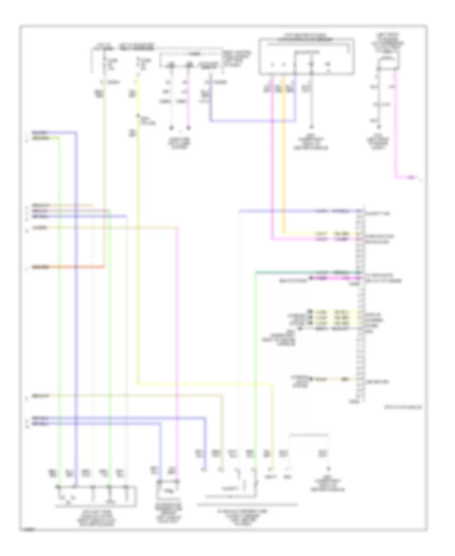
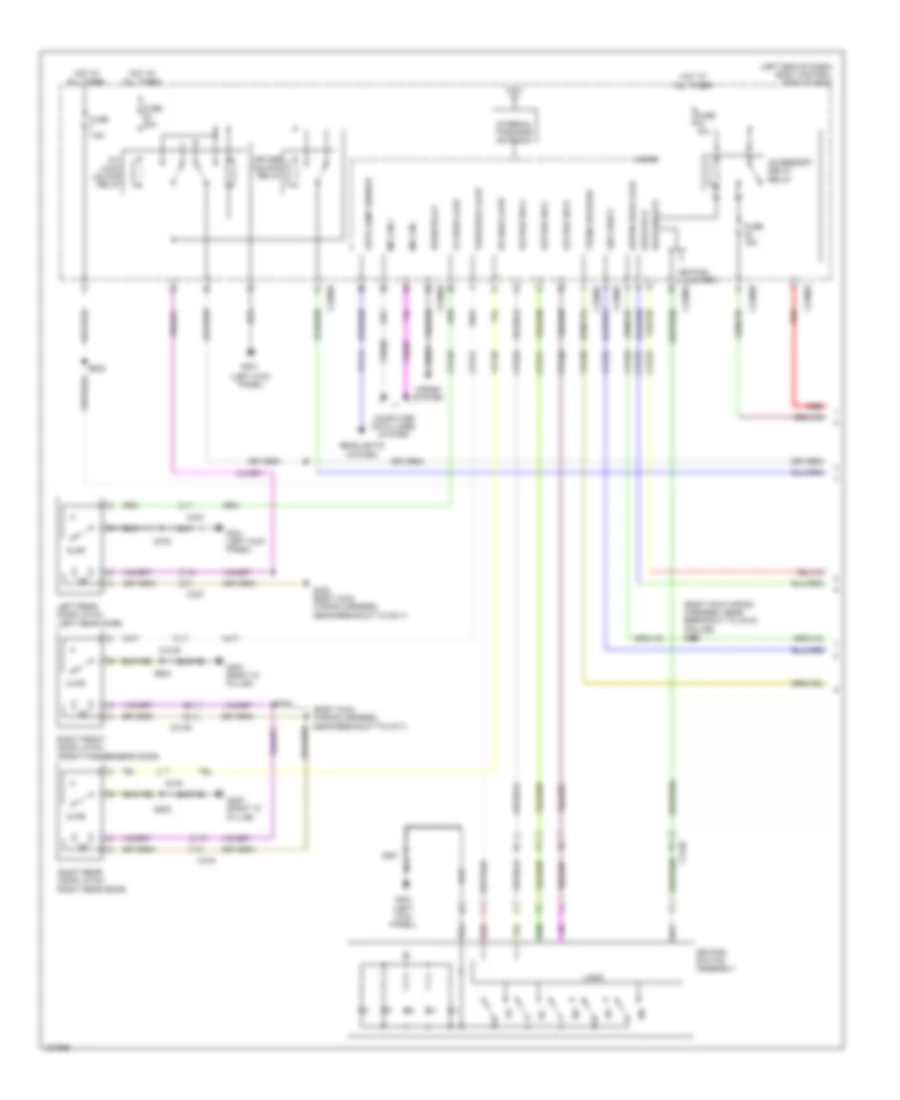
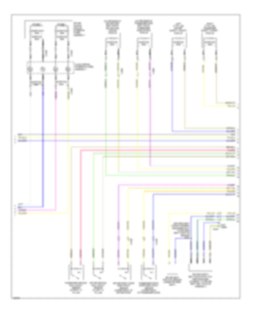
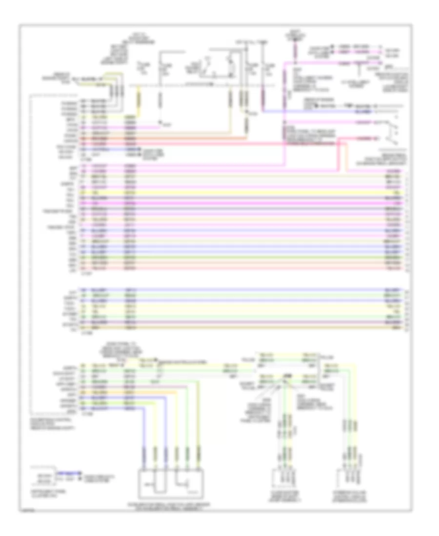
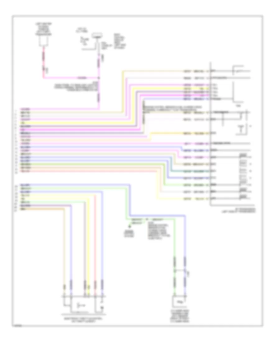
AIR CONDITIONING
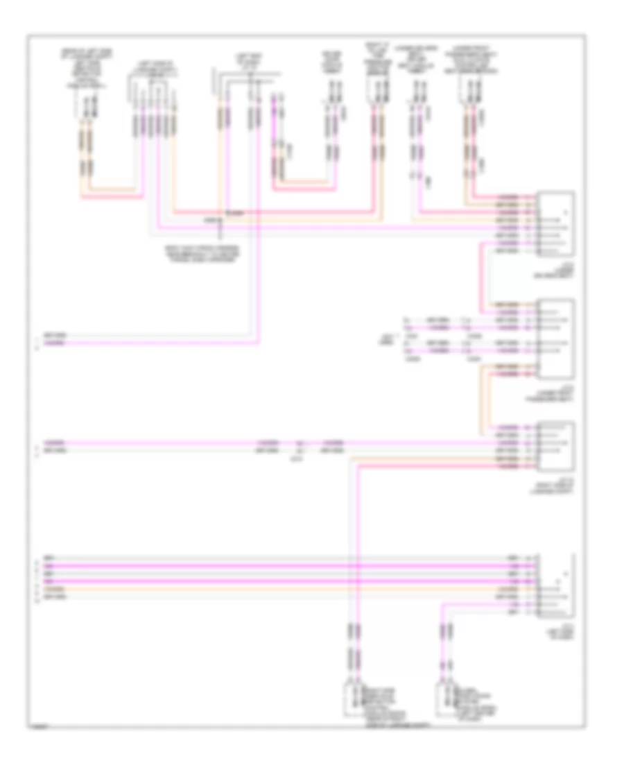
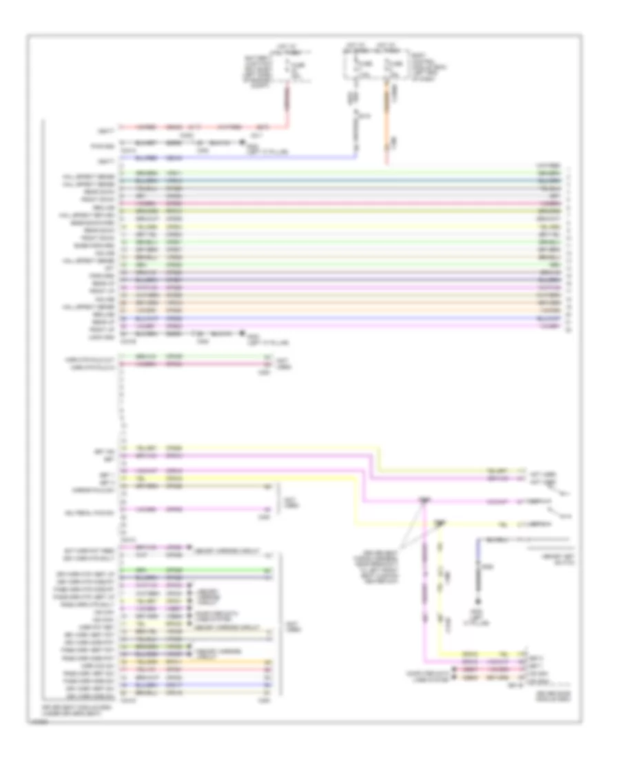
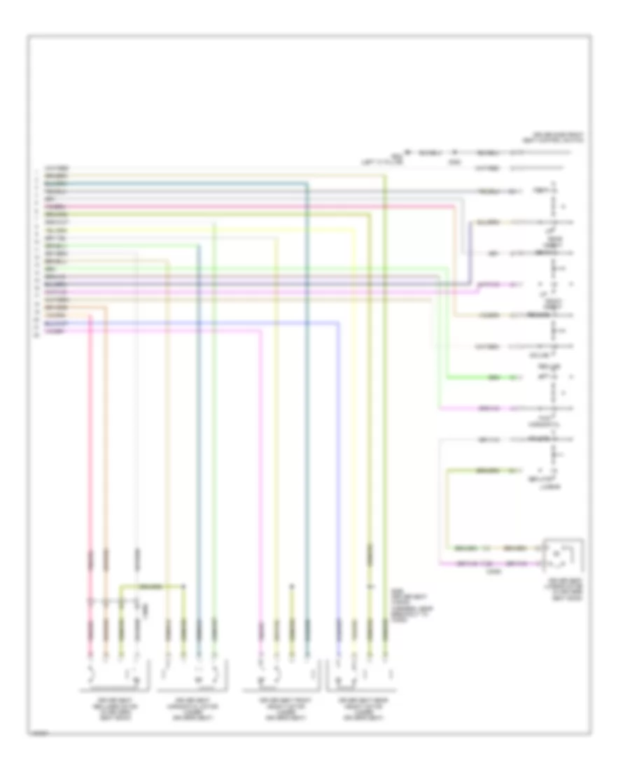
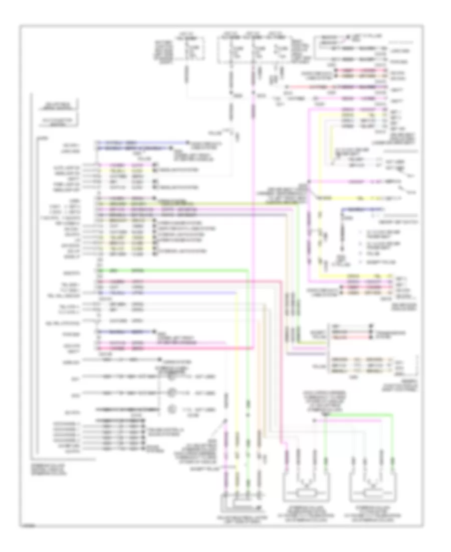
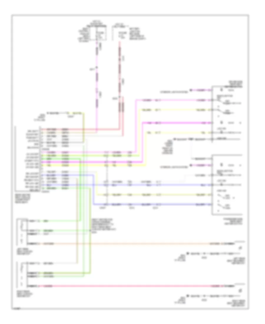
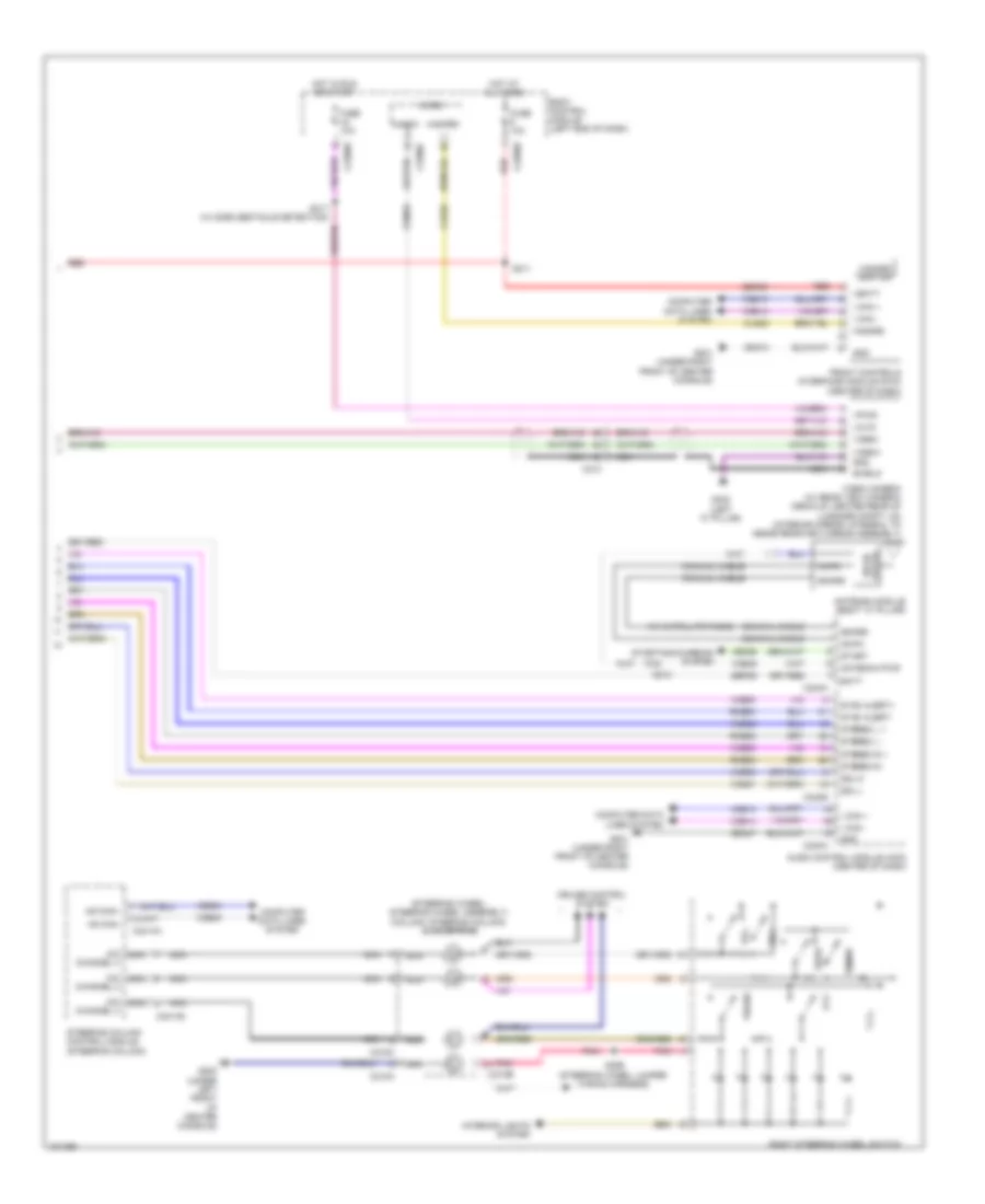
Automatic A/C Wiring Diagram (1 of 3) for Ford Taurus Limited 2014

List of elements for Automatic A/C Wiring Diagram (1 of 3) for Ford Taurus Limited 2014:
- (dash panel to headlamp junction wiring harness, near breakout to blower motor) s202
- (dash panel to headlamp junction wiring harness, near breakout to evaporator temperature sensor)
- (on blower motor) blower motor speed control
- (right side of hvac unit) blower motor
- Battery junction box (bjb) (left side of engine compt)
- Blower motor relay
- Blwr rly
- C210
- C213
- C228a
- C228b
- Ch122
- Ch123
- Ch207
- Ch208
- Ch212
- Ch213
- Ch228
- Ch229
- Ch238
- Ch239
- Chs02
- Chs07
- Computer data lines system
- Datc hvac module
- Defogger system
- Defrost req
- Defrost/panel/ floor mode door actuator (upper left side of hvac unit)
- Drv heater feed
- Evap
- Feedback
- Fuse 28
- Fuse 30a
- Fuse 40a
- Fuse 5a
- G200 (under left front of center console)
- G201 (under right front of center console)
- Gd374
- Gnd
- Hot at all times
- Hot w/ run/start relay energized
- Left side temperature blend door actuator (lower left side of hvac unit)
- Lh111
- Motor +
- Motor -
- Ms can +
- Ms can -
- Pass heater feed
- Pass st ntc sense
- Rh111
- Right side temperature blend door actuator (upper right side of hvac unit)
- S147
- S203
- S209
- S210
- Sbb28
- Sbp46
- Seats system
- Sig return
- Var blwr ctrl
- Vbatt
- Vdb06
- Vdb07
- Vh101
- Vh406
- Vh436
- Vh438
- Vh440
- Vh441
- Vhs27
- Vref
- W/ heated seats
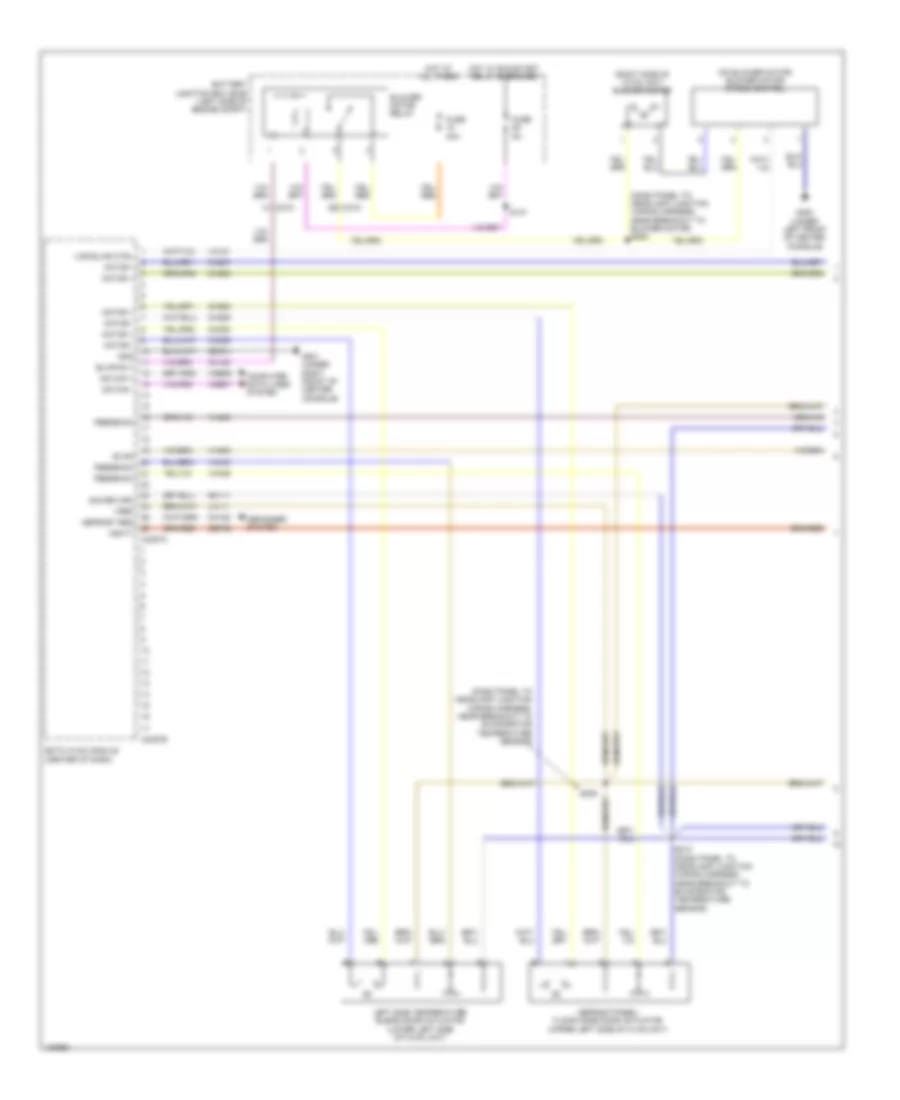
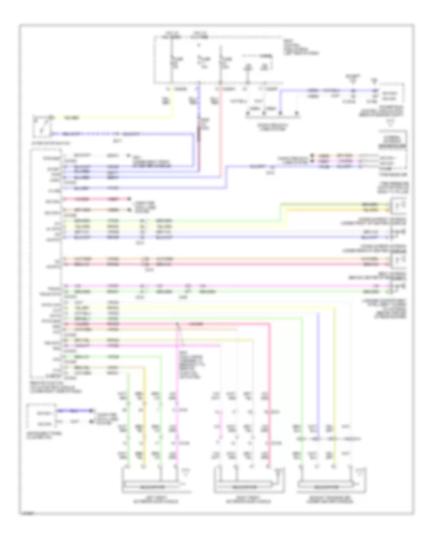
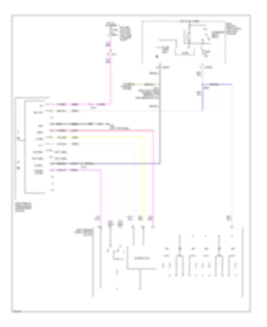
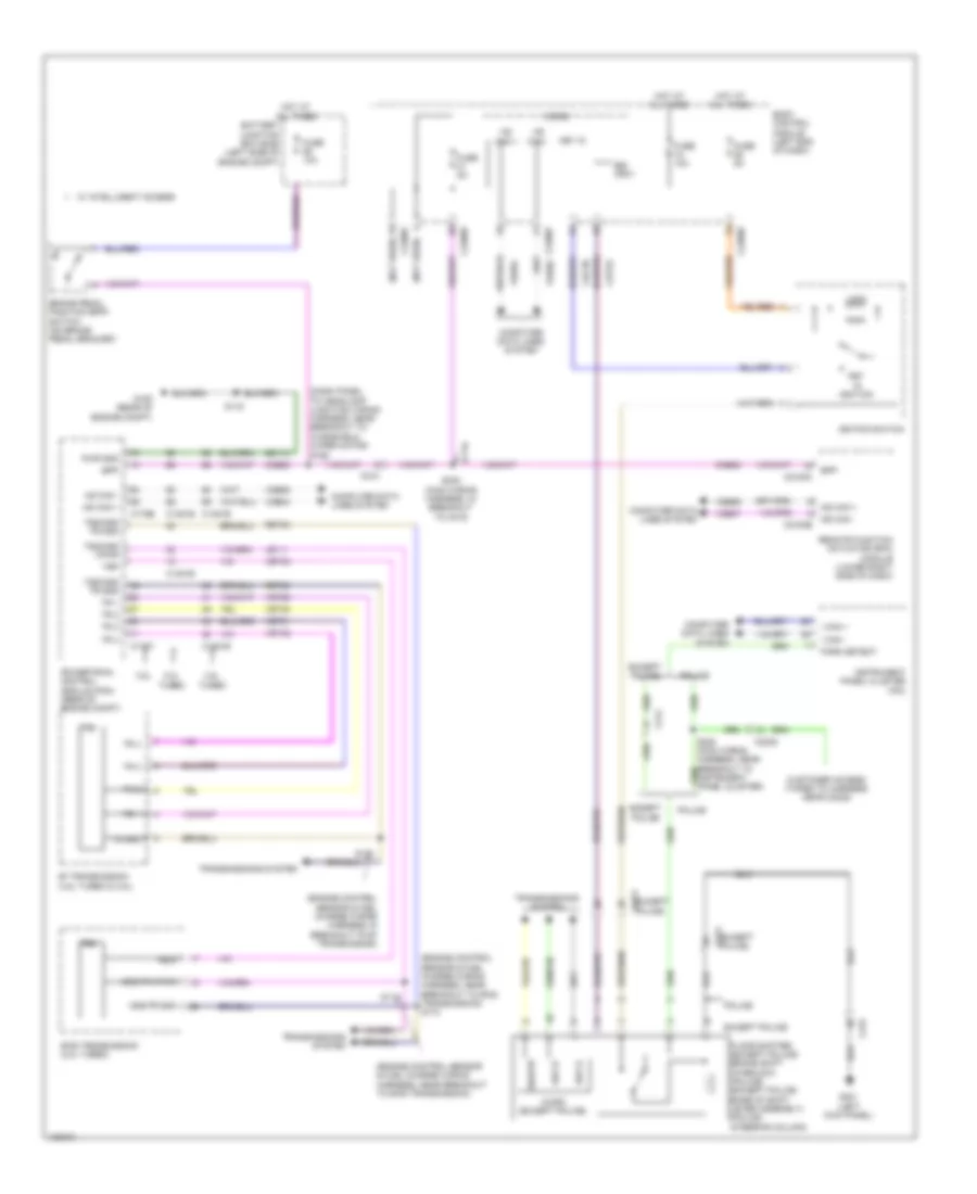
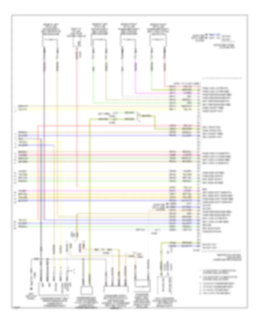
Automatic A/C Wiring Diagram (2 of 3) for Ford Taurus Limited 2014
List of elements for Automatic A/C Wiring Diagram (2 of 3) for Ford Taurus Limited 2014:
- (left front of engine) a/c compressor clutch field coil
- (top center of dash) autolamp/sunload sensor
- Air inlet mode door actuator (right side of hvac blower housing)
- Autolamp sens in
- Body control module (bcm) (left end of dash)
- C144
- C2280a
- C2280b
- C228b
- C228c
- Computer data lines system
- Datc hvac module
- Dr sunload
- Drv st ntc sense
- Evaporator temperature sensor (left side of hvac unit)
- Fuse 10a
- Fuse 5a
- G101 (left front of engine compt)
- G201 (under right front of center console)
- Gd374
- Gnd
- Hot at all times
- Hot w/ run/start relay energized
- Humidity
- Humidity sig
- In vehicle sig
- In-vehicle temperature/ humidity sensor (left center of dash)
- Interior lights system
- Led return
- Micro
- Ms can+
- Ms can-
- Pass sunload
- Rln44
- S204 (police)
- Seats system
- Solid state
- Vbatt
- Vdb06
- Vdb07
- Vh413
- Vh414
- Vh416
- Vh417
- Vhs26
- Vlf14
- Vln48
- Vln49
- Vln50
- Z2-green
- Z2-red
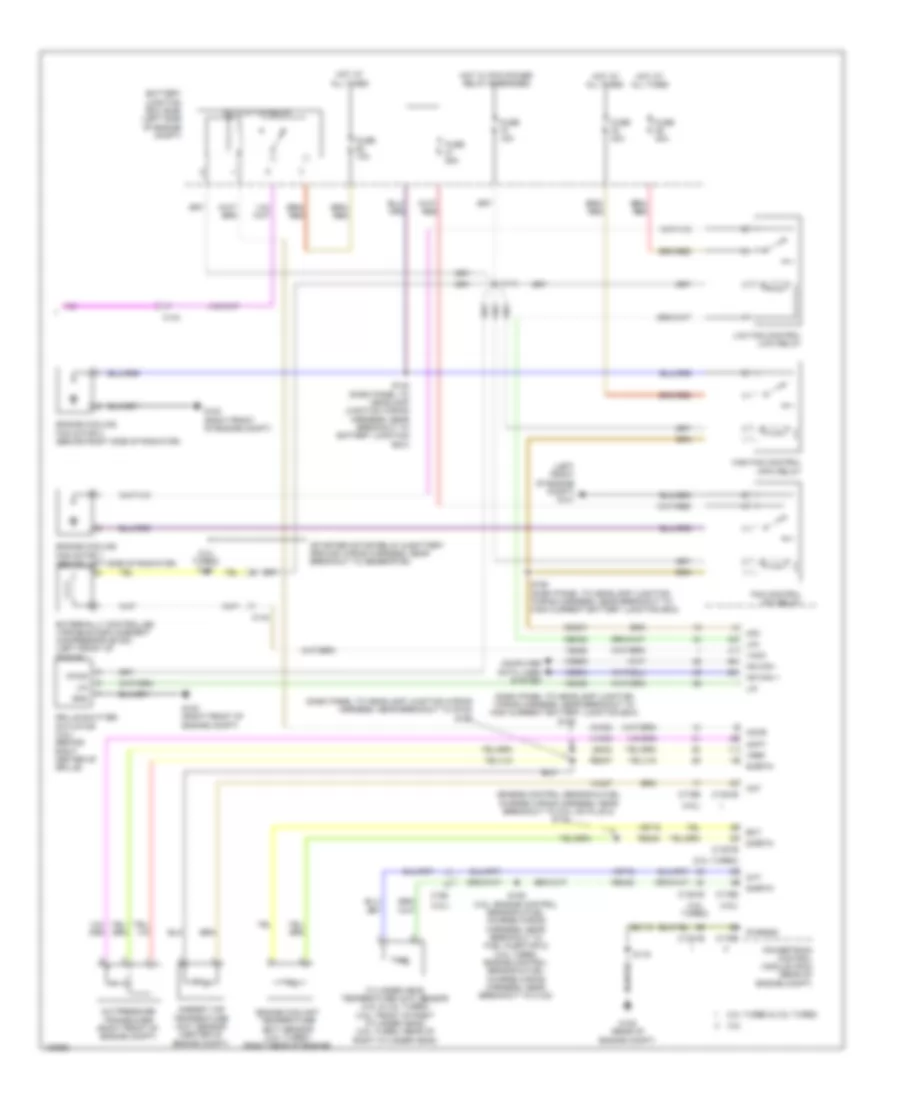
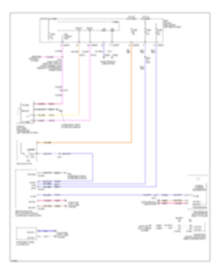
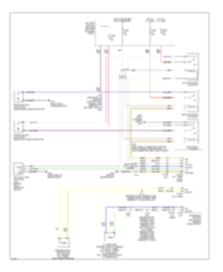
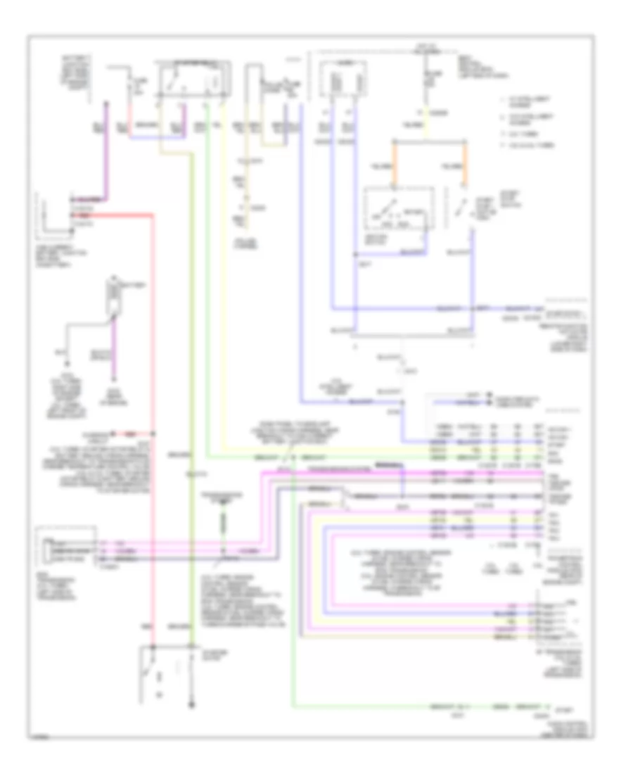
Automatic A/C Wiring Diagram (3 of 3) for Ford Taurus Limited 2014
List of elements for Automatic A/C Wiring Diagram (3 of 3) for Ford Taurus Limited 2014:
- (2.0l turbo)
- (2.0l turbo) s108
- (3.5l turbo)
- (3.5l)
- (dash panel to headlamp junction wiring harness, near breakout to g102) s125
- (dash panel to headlamp junction wiring harness, near breakout to high current battery junction box) s148
- (engine control sensor & fuel charge wiring harness, near breakout to coil on plug 2) s113
- (left front of engine compt) g101
- (starter motor relay & battery ground wiring harness, near breakout to generator)
- 2.0l turbo & 3.5l turbo
- 3.5l
- A/c clutch relay
- A/c pressure transducer (right front of engine compt)
- Aat
- Accr
- Acpt
- Ambient air temperature (aat) sensor (center of engine compt)
- Battery junction box (bjb) (left side of engine compt)
- C1381b
- C1381e
- C144
- C175b
- C175e
- C192
- Cec07
- Cec08
- Ch302
- Cht
- Computer data lines system
- Cylinder head temperature (cht) sensor (3.5l & 3.5l turbo) (3.5l: front of right cylinder head) (3.5l turbo: rear of right cylinder head)
- Ect
- Engine coolant temperature (ect) sensor (2.0l turbo) (right rear of engine)
- Engine cooling fan motor 1 (behind left side of radiator)
- Engine cooling fan motor 2 (behind right side of radiator)
- Externally controlled variable displacement compressor (evdc) (left front of engine)
- Fan control (fc) relay
- Fuse 10a
- Fuse 15a
- Fuse 25a
- Fuse 40a
- G100 (right front of engine compt)
- G100 (right front of of engine compt)
- G105 (rear of engine compt)
- Gd113
- Gnd
- Grille shutter actuator (3.5l) (behind right center of grille)
- Hfc
- High fan control (hfc) relay
- Hot at all times
- Hot w/ pcm power relay energized
- Hs can +
- Hs can -
- Le424
- Lfc
- Lin
- Low fan control (lfc) relay
- Powertrain control module (pcm) (rear of engine compt)
- Pwrgnd
- Re405
- Re407
- Re454
- S109 (3.5l: engine control sensor & fuel charge wiring harness, near breakout to fuel injector 2) (3.5l turbo: engine control sensor & fuel charge wiring harness, near breakout to c123)
- S116
- S119
- S142 (dash panel to headlamp junction wiring harness, near breakout to battery junction box)
- S155 (dash panel to headlamp junction wiring harness, near breakout to high current battery junction box)
- Sig rtn
- Sigrtn
- Vacc
- Vdb04
- Vdb05
- Vdn06
- Ve462
- Ve712
- Ve716
- Vh407
- Vh433
- Vpwr
- Vref
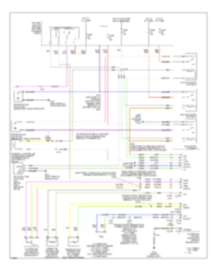
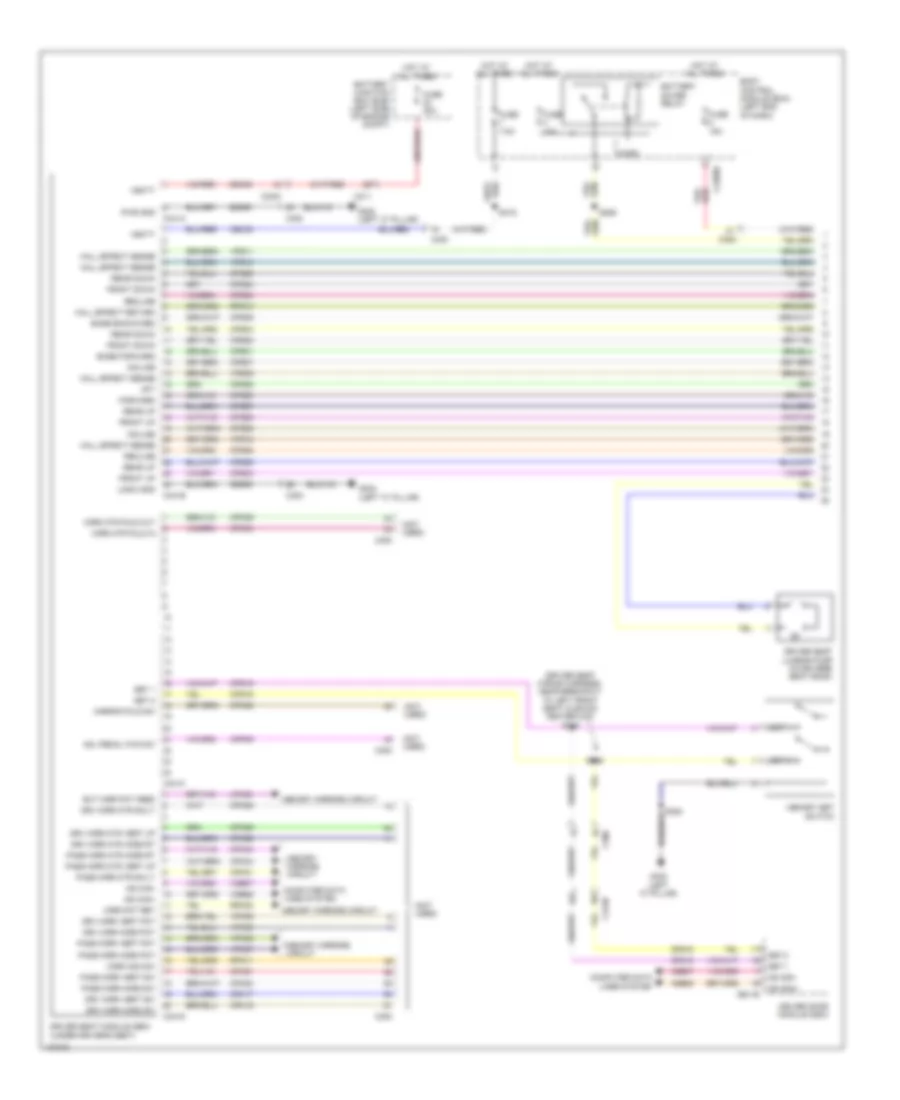
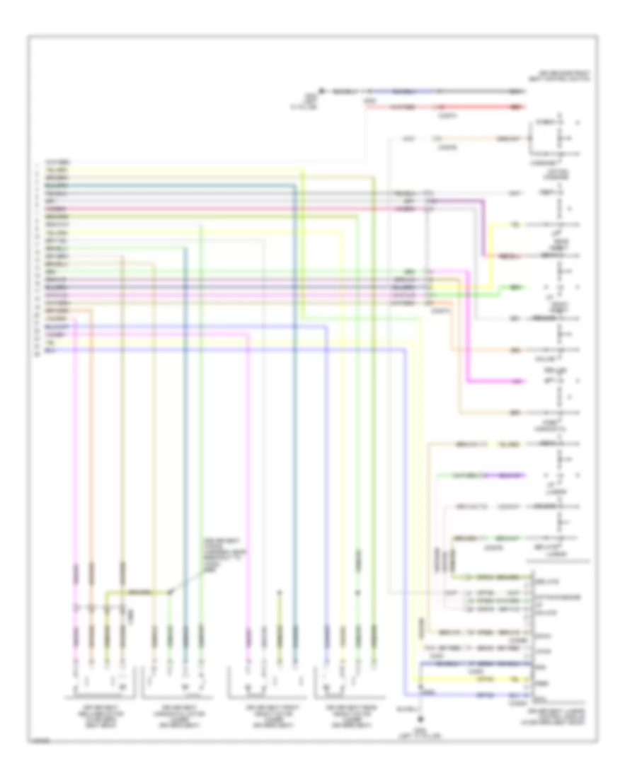
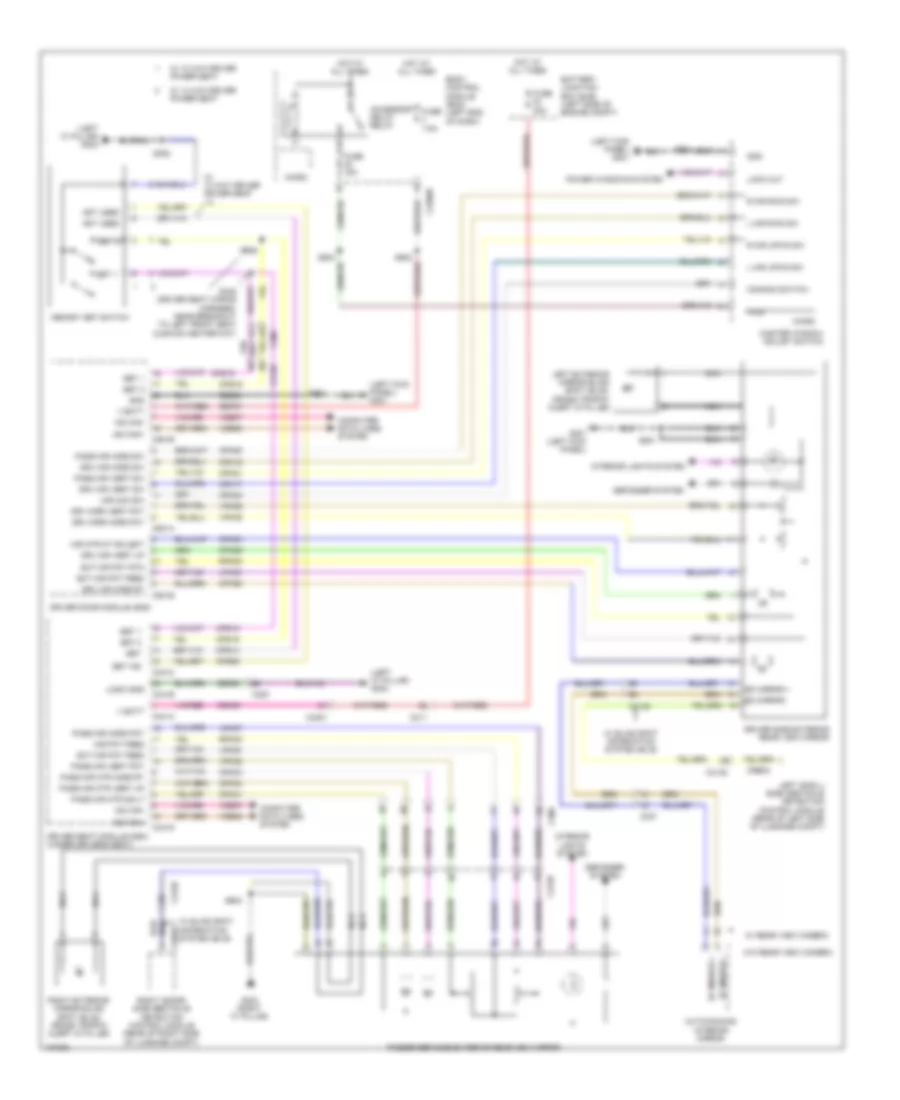
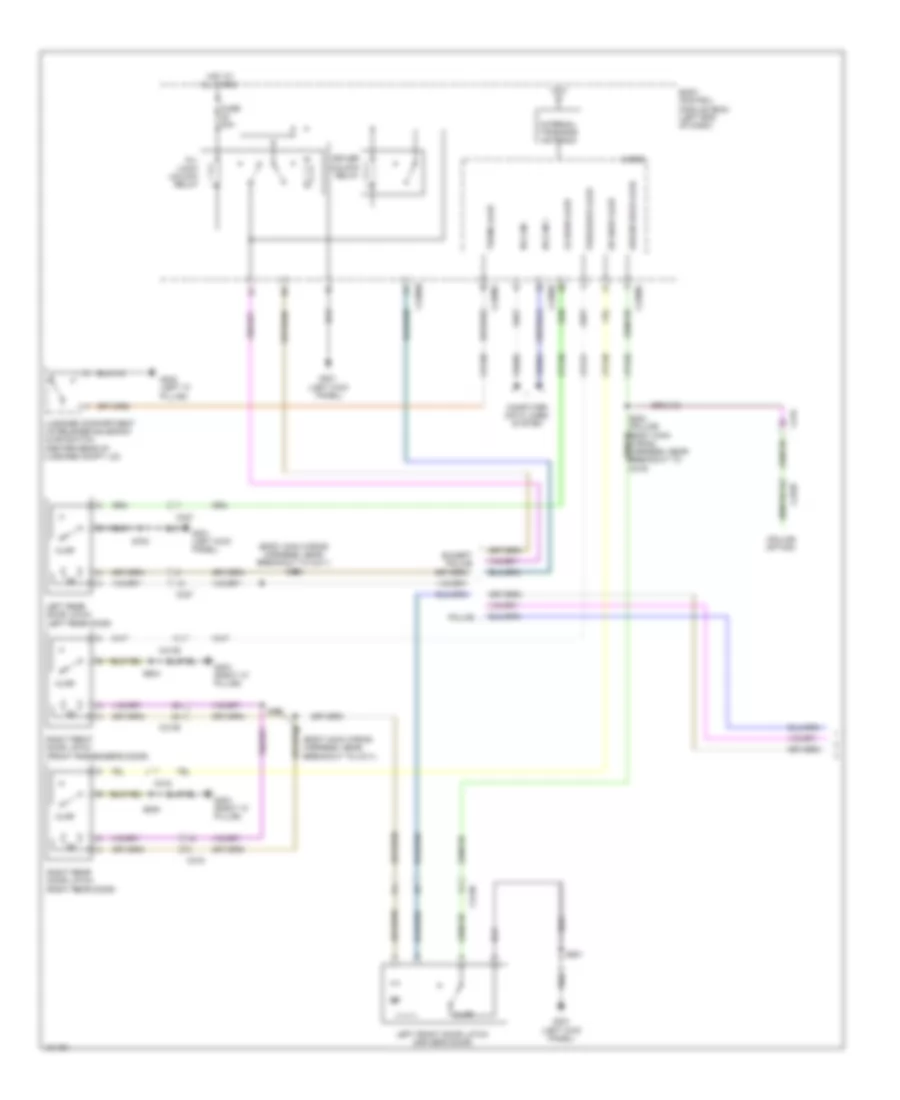
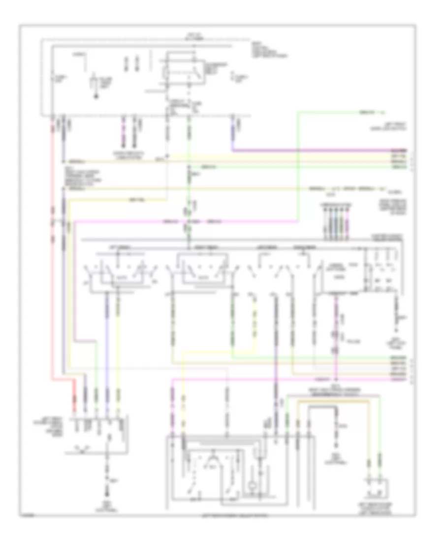
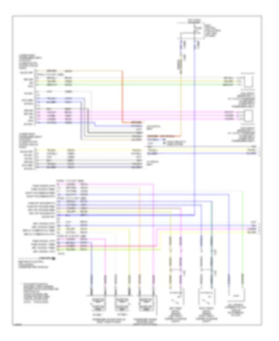
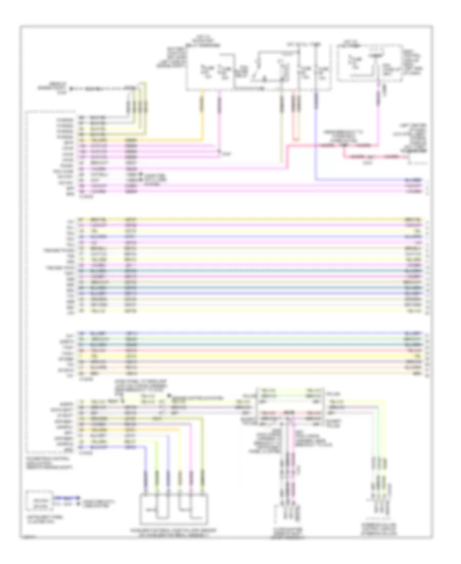
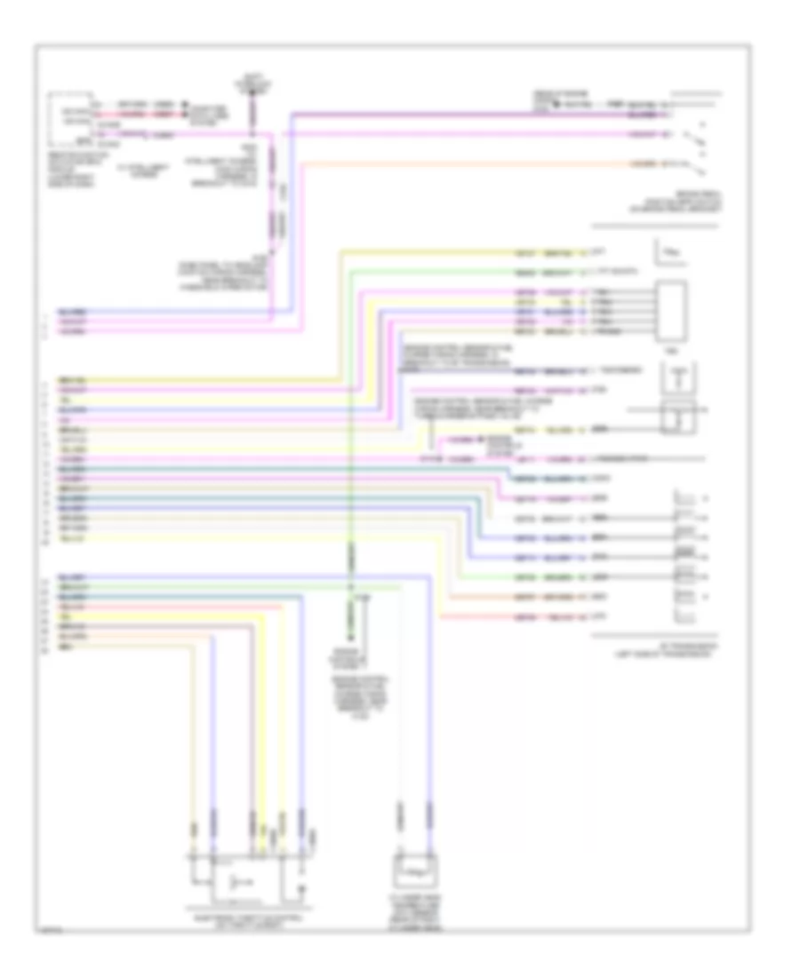
Manual A/C Wiring Diagram (1 of 3) for Ford Taurus Limited 2014
List of elements for Manual A/C Wiring Diagram (1 of 3) for Ford Taurus Limited 2014:
- (dash panel to headlamp junction wiring harness, near breakout to blower motor) s202
- (dash panel to headlamp junction wiring harness, near breakout to evaporator temperature sensor)
- (on blower motor) blower motor speed control
- (right side of hvac unit) blower motor
- Battery junction box (bjb) (left side of engine compt)
- Blower motor relay
- Blwr rly
- C210
- C2357a
- C2357b
- Ch122
- Ch123
- Ch207
- Ch208
- Ch228
- Ch229
- Ch238
- Ch239
- Computer data lines system
- Defogger system
- Defrost req
- Defrost/panel/ floor mode door actuator (upper left side of hvac unit)
- Emtc hvac module (center of dash)
- Evap
- Feedback
- Fuse 40a
- Fuse 5a
- G200 (under left front of center console)
- G201 (under right front of center console)
- Gd374
- Gnd
- Hot at all times
- Hot w/ run/start relay energized
- Left side temperature blend door actuator (lower left side of hvac unit)
- Lh111
- Motor +
- Motor -
- Ms can +
- Ms can -
- Rh111
- S147
- S209
- S210 (dash panel to headlamp junction wiring harness, near breakout to evaporator temperature sensor)
- Sbp46
- Sig return
- Var blwr ctrl
- Vbatt
- Vdb06
- Vdb07
- Vh101
- Vh406
- Vh436
- Vh438
- Vh440
- Vref
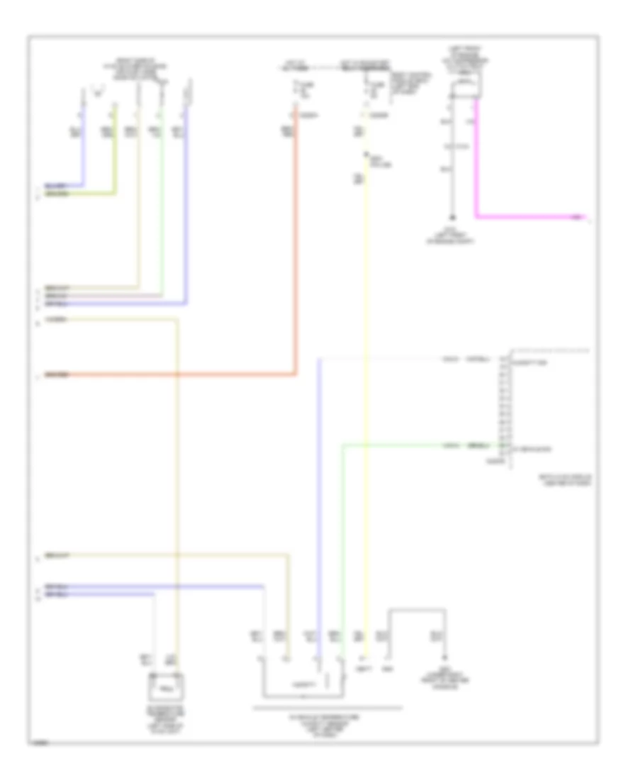
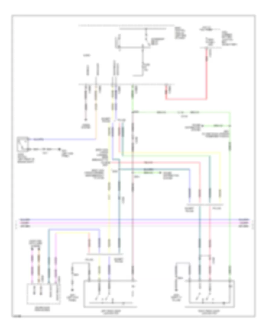
Manual A/C Wiring Diagram (2 of 3) for Ford Taurus Limited 2014
List of elements for Manual A/C Wiring Diagram (2 of 3) for Ford Taurus Limited 2014:
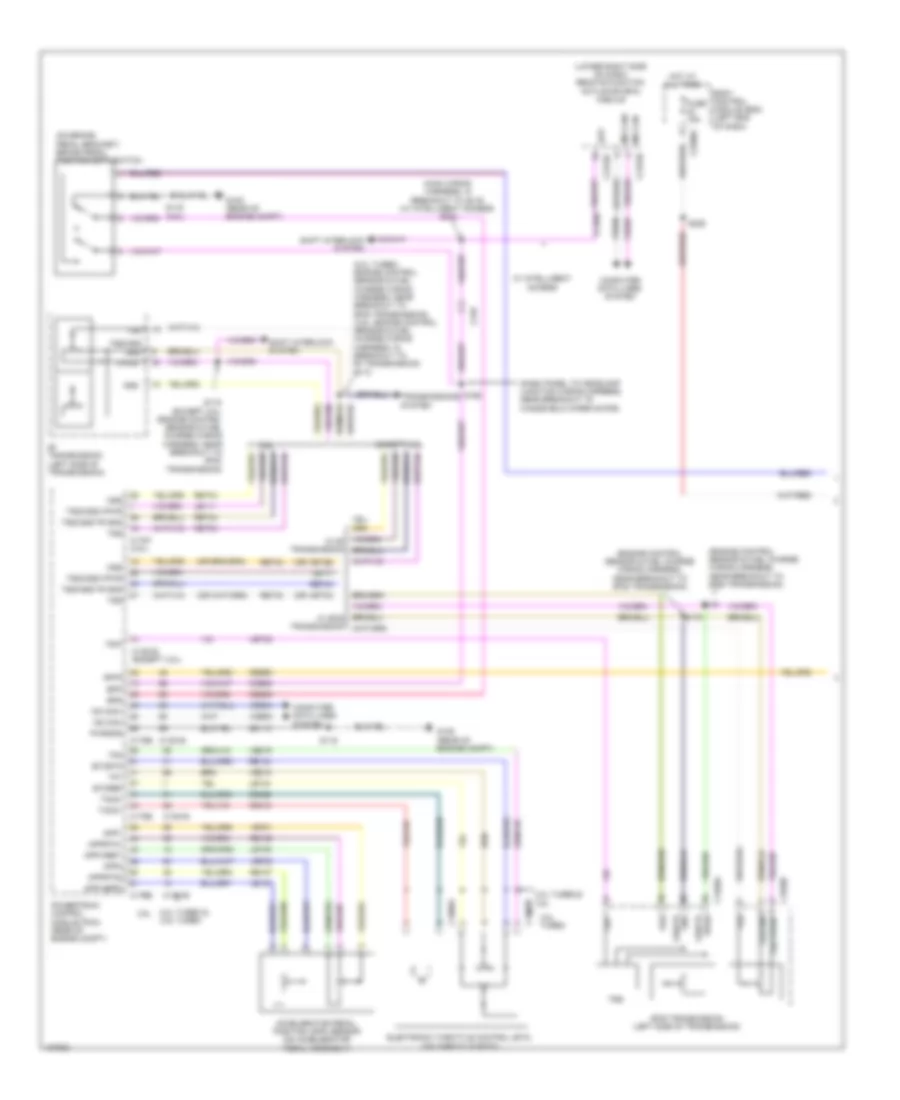
- (left front of engine) a/c compressor clutch field coil
- (right side of hvac blower housing) air inlet mode door actuator
- Body control module (bcm) (left end of dash)
- C144
- C2280a
- C2280b
- C2357b
- Emtc hvac module (center of dash)
- Evaporator temperature sensor (left side of hvac unit)
- Fuse 10a
- Fuse 5a
- G101 (left front of engine compt)
- G201 (under right front of center console)
- Gnd
- Hot at all times
- Hot w/ run/start relay energized
- Humidity
- Humidity sig
- In vehicle sig
- In-vehicle temperature/ humidity sensor (left center of dash)
- S204 (police)
- Vbatt
- Vh413
- Vh414
Manual A/C Wiring Diagram (3 of 3) for Ford Taurus Limited 2014
List of elements for Manual A/C Wiring Diagram (3 of 3) for Ford Taurus Limited 2014:
- (2.0l turbo)
- (2.0l turbo) s108
- (3.5l turbo)
- (3.5l)
- (dash panel to headlamp junction wiring harness, near breakout to g102) s125
- (dash panel to headlamp junction wiring harness, near breakout to high current battery junction box) s148
- (engine control sensor & fuel charge wiring harness, near breakout to coil on plug 2) s113
- (left front of engine compt) g101
- (starter motor relay & battery ground wiring harness, near breakout to generator)
- 2.0l turbo & 3.5l turbo
- 3.5l
- A/c clutch relay
- A/c pressure transducer (right front of engine compt)
- Aat
- Accr
- Acpt
- Ambient air temperature (aat) sensor (center of engine compt)
- Battery junction box (bjb) (left side of engine compt)
- C1381b
- C1381e
- C144
- C175b
- C175e
- C192
- Cec07
- Cec08
- Ch302
- Cht
- Computer data lines system
- Cylinder head temperature (cht) sensor (3.5l & 3.5l turbo) (3.5l: front of right cylinder head) (3.5l turbo: rear of right cylinder head)
- Ect
- Engine coolant temperature (ect) sensor (2.0l turbo) (right rear of engine)
- Engine cooling fan motor 1 (behind left side of radiator)
- Engine cooling fan motor 2 (behind right side of radiator)
- Externally controlled variable displacement compressor (evdc) (left front of engine)
- Fan control (fc) relay
- Fuse 10a
- Fuse 15a
- Fuse 25a
- Fuse 40a
- G100 (right front of engine compt)
- G105 (rear of engine compt)
- Gd113
- Gnd
- Grille shutter actuator (3.5l) (behind right center of grille)
- Hfc
- High fan control (hfc) relay
- Hot at all times
- Hot w/ pcm power relay energized
- Hs can +
- Hs can -
- Le424
- Lfc
- Lin
- Low fan control (lfc) relay
- Powertrain control module (pcm) (rear of engine compt)
- Pwrgnd
- Re405
- Re407
- Re454
- S109 (3.5l: engine control sensor & fuel charge wiring harness, near breakout to fuel injector 2) (3.5l turbo: engine control sensor & fuel charge wiring harness, near breakout to c123)
- S116
- S119
- S142 (dash panel to headlamp junction wiring harness, near breakout to battery junction box)
- S155 (dash panel to headlamp junction wiring harness, near breakout to high current battery junction box)
- Sigrtn
- Vacc
- Vdb04
- Vdb05
- Vdn06
- Ve462
- Ve712
- Ve716
- Vh407
- Vh433
- Vpwr
- Vref
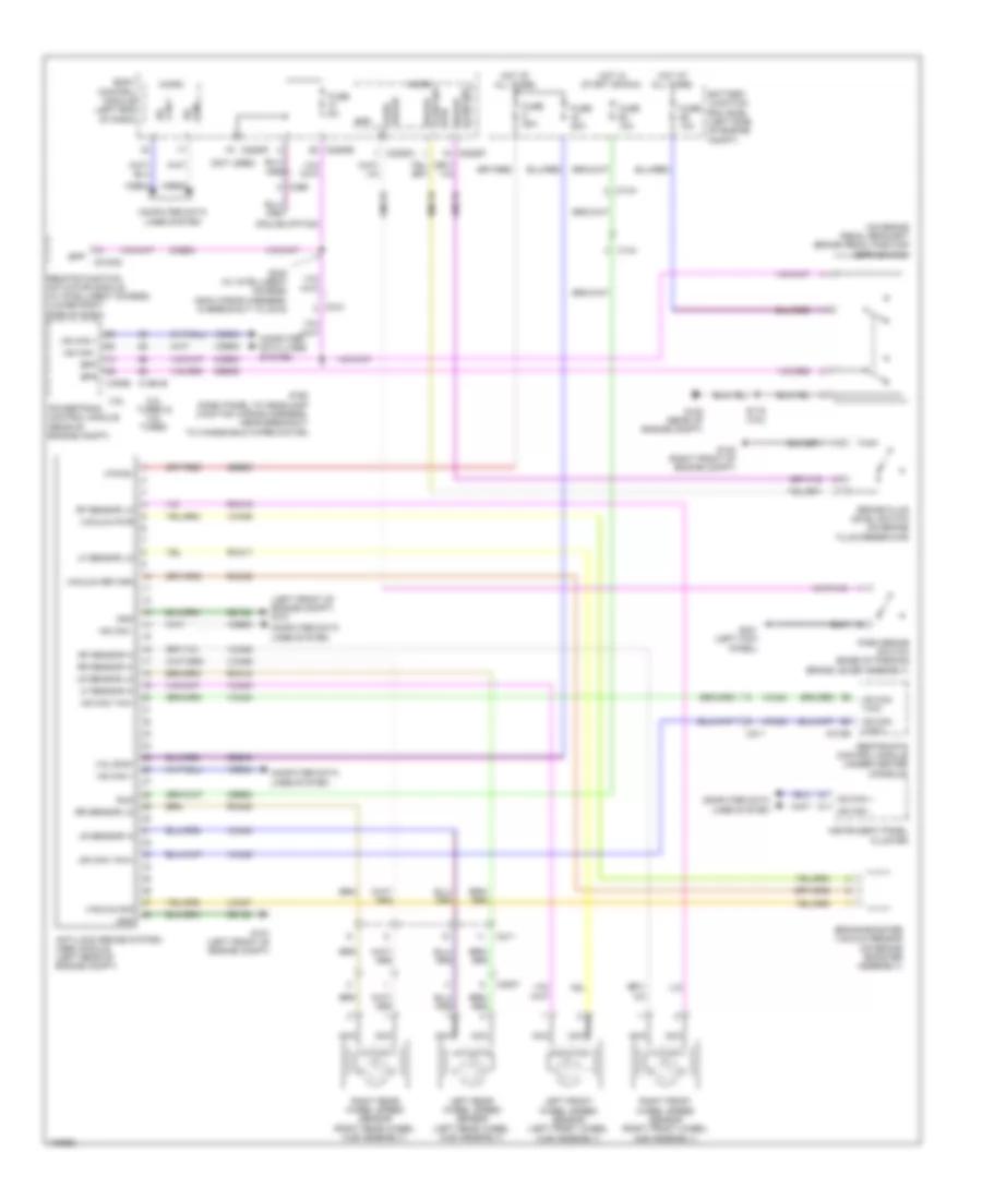
ANTI-LOCK BRAKES
Anti-lock Brakes Wiring Diagram for Ford Taurus Limited 2014
List of elements for Anti-lock Brakes Wiring Diagram for Ford Taurus Limited 2014:
- (left front of engine compt) g101
- (not used)
- (on brake pedal bracket) brake pedal position (bpp) switch
- (police option)
- 2.0l turbo & 3.5l turbo
- 3.5l
- Anti-lock brake system (abs) module (left rear of engine compt)
- Battery junction box (bjb) (left side of engine compt)
- Body control module (left end of dash)
- Bpp
- Bps
- Brake booster vacuum sensor (on brake booster assembly)
- Brake fluid level switch (on brake fluid reservoir)
- Brake fluid sw
- C1381b
- C144
- C175b
- C210
- C211
- C2153c
- C2280b
- C2280c
- C2280f
- C299
- C3007
- C310b
- Can - hs
- Cbb92
- Ccb08
- Ces09
- Cmc19
- Cmc25
- Computer data lines system
- Fuse 10a
- Fuse 20a
- Fuse 50a
- Fuse 5a
- G100 (right front of engine compt)
- G101 (left front of engine compt)
- G105 (rear of engine compt)
- G301 (left kick panel)
- Gd120
- Gnd
- Hot at all times
- Hot in start or run
- Hs can +
- Hs can -
- Hs can yaw+
- Hs can yaw-
- Instrument panel cluster
- Lca37
- Left front wheel speed sensor (left front wheel hub assembly)
- Left rear wheel speed sensor (left rear wheel hub assembly)
- Lf sensor hi
- Lf sensor lo
- Lr sensor hi
- Lr sensor lo
- Micro
- Mtr b+
- Nca
- Park brake
- Park brake switch (base of parking brake lever assembly)
- Powertrain control module (rear of engine compt)
- Rca17
- Rca18
- Rca19
- Rca20
- Rca36
- Remote function actuator module (w/ intelligent access) (lower right side of dash)
- Restraints control module (under center console)
- Rf sensor hi
- Rf sensor lo
- Right front wheel speed sensor (right front wheel hub assembly)
- Right rear wheel speed sensor (right rear wheel hub assembly)
- Rmc19
- Rr sensor hi
- Rr sensor lo
- Rtn
- Run
- S116 (3.5l)
- S168 (dash panel to headlamp junction wiring harness, near breakout to windshield wiper motor)
- S240 (w/ intelligent access) (main wiring harness, in breakout to c215)
- Sbb05
- Sbb43
- Vacuum pwr
- Vacuum return
- Vacuum sig
- Valve b+
- Vca03
- Vca04
- Vca05
- Vca06
- Vca23
- Vca24
- Vca36
- Vdb04
- Vdb05
ANTI-THEFT
Forced Entry Wiring Diagram, with Intelligent Access (1 of 4) for Ford Taurus Limited 2014
List of elements for Forced Entry Wiring Diagram, with Intelligent Access (1 of 4) for Ford Taurus Limited 2014:
- (body main wiring harness, near breakout to c211) s320
- (body main wiring harness, near breakout to c311)
- (front passenger's door)
- (left kick panel)
- (left rear door)
- (police option)
- (right rear door)
- Ajar
- All lock/ unlock relay
- Body control module (bcm) (left end of dash)
- C215
- C2238
- C2280c
- C2280d
- C2280f
- C3138
- C3139
- C316
- C327
- Computer data lines system
- Cpl26
- Cpl31
- Cpl36
- Cpl39
- Cpl58
- Driver door ajar
- Driver unlock relay
- Except police
- Fuse 20a
- G301
- G301 (left kick panel)
- G302 (left "c" pillar)
- G303 (right "c" pillar)
- Hot at all times
- Hs can +
- Hs can -
- Internal tpms/rke antenna
- Left front door latch (driver's door)
- Left rear door latch
- Lr door ajar
- Luggage compartment lid release solenoid/ ajar switch (center rear of luggage compt lid)
- Micro
- Pass door ajar
- Police
- Right front door latch
- Right rear door latch
- Rr door ajar
- S284 (police) (body main wiring harness, near breakout to c219)
- S321
- S501
- S604
- S700
- S800
- Trunk ajar
- Vdb04
- Vdb05
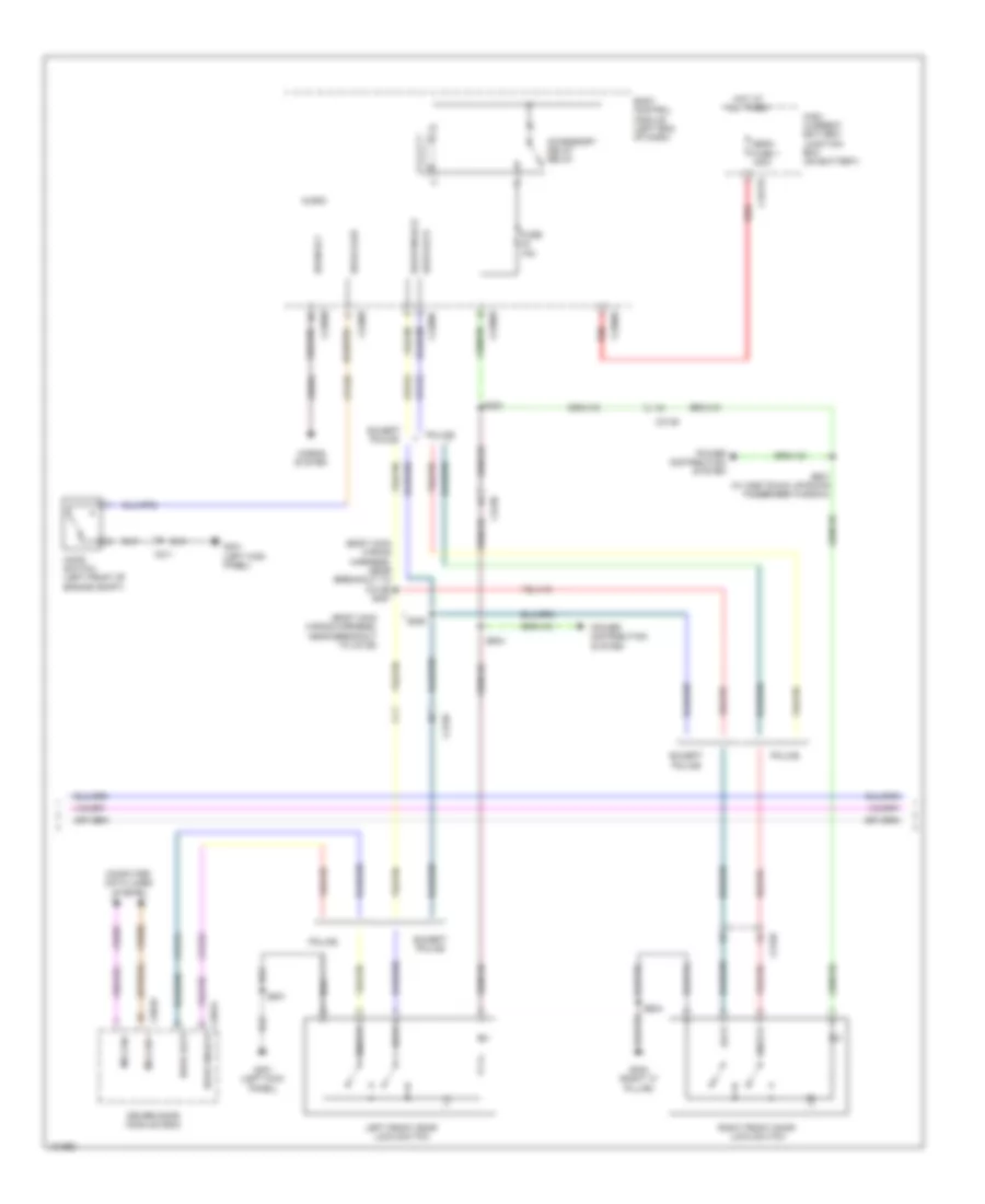
Forced Entry Wiring Diagram, with Intelligent Access (2 of 4) for Ford Taurus Limited 2014
List of elements for Forced Entry Wiring Diagram, with Intelligent Access (2 of 4) for Ford Taurus Limited 2014:
- (body main wiring harness, near breakout to c3139)
- (body main wiring harness, near breakout to c3139) s287
- Accessory delay relay
- Body control module (left end of dash)
- C1617b
- C211
- C2280b
- C2280c
- C2280d
- C2280f
- C2280g
- C3138
- C3139
- C501a
- C501b
- Computer data lines system
- Cpk19
- Cpk23
- Cpl25
- Crh04
- Door lock
- Door unlock
- Driver door module (ddm)
- Except police
- Fuse 15a
- G301 (left kick panel)
- G303 (right "c" pillar)
- High current battery junction box (on battery)
- Hood ajar
- Hood switch (left front of engine compt)
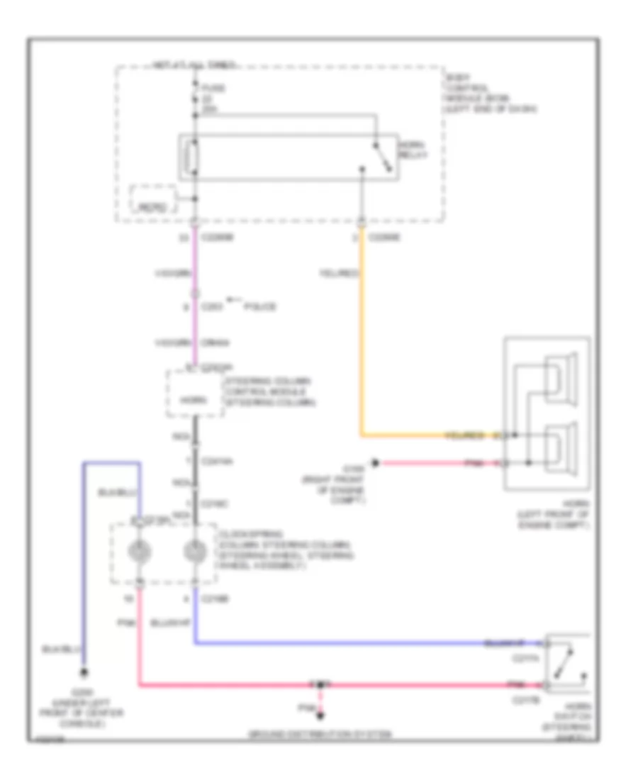
- Horn rly
- Horns system
- Hot at all times
- Left front door lock switch
- Lock
- Mega fuse 1 100a
- Micro
- Ms can +
- Ms can -
- Police
- Power distribution system
- Red
- Right front door lock switch
- S283
- S288
- S501
- S504
- S601 (w/ one touch up/down passenger window)
- S604
- Unlock
- Vdb06
- Vdb07
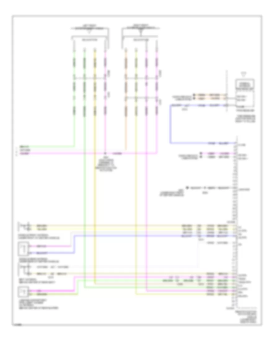
Forced Entry Wiring Diagram, with Intelligent Access (3 of 4) for Ford Taurus Limited 2014
List of elements for Forced Entry Wiring Diagram, with Intelligent Access (3 of 4) for Ford Taurus Limited 2014:
- (under right front of center console)
- 1/2
- 3/4
- 5/6
- 7/8
- 9/0
- Backup transceiver (under center console)
- Body control module (bcm) (left end of dash)
- Bpp
- C212
- C214
- C215
- C2153b
- C2153c
- C2153d
- C2280a
- C2280b
- C2280d
- C3138
- Ccb08
- Cdc35
- Clk
- Cpk28
- Cpk29
- Cpk30
- Cpk31
- Cpl11
- Cpl45
- Cpl51
- Cpl52
- Cpl60
- Cpl84
- Data
- Drv unlock
- Ext trunk
- Exterior lights system
- Fuse 10a
- Fuse 20a
- Fuse 5a
- Fuse 7.5a
- G201
- G201 (under right front of center console)
- G301 (left kick panel)
- Gd374
- Gnd
- Hot at all times
- Keypad a
- Keypad b
- Keypad c
- Keypad illum
- Keypad switch assembly
- Lock
- Logic
- Lpk32
- Pats gnd
- Pats vcc
- Power distribution system
- Pwr gnd
- Red
- Remote function actuator (rfa) module (lower right side of dash)
- Rpk32
- Rpk39
- S205 (w/ acc)
- S217
- S282
- S501
- S502
- Sbp11
- Sbp27
- Solid state
- Start
- Start/stop switch
- Trunk release
- Trunk, tailgate, fuel doors system
- Unlock
- Vbatt
- Vcc
- Vpk32
- Vpk33
- Vpk39
- Vpk40
Forced Entry Wiring Diagram, with Intelligent Access (4 of 4) for Ford Taurus Limited 2014
List of elements for Forced Entry Wiring Diagram, with Intelligent Access (4 of 4) for Ford Taurus Limited 2014:
- C212
- C214
- C215
- C2153a
- C2153e
- C3138
- C3139
- C405
- Computer data lines system
- Console front antenna (under front of center console)
- Console rear antenna (under rear of center console)
- Fla
- Fla rtn
- Fra
- Fra rtn
- G201 (under right front of center console)
- Gd374
- Ia1
- Ia1 rtn
- Ia2
- Ia2 rtn
- Ia3
- Ia3 rtn
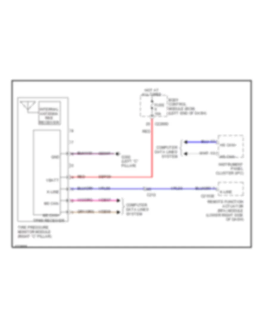
- Internal antenna/ rke receiver
- K-line
- Left front exterior door handle
- Logic gnd
- Luggage compartment intelligent access (ia) antenna (behind center of rear bumper)
- Ms can +
- Ms can -
- Remote function actuator (rfa) module (lower right side of dash)
- Right front exterior door handle
- Rpk01
- Rpk02
- Rpk05
- Rpk06
- Rpk07
- Rpk08
- S201 (main wiring harness, in breakout to remote function actuator)
- S282
- Seat antenna (behind center of rear seat)
- Solid state
- Tire pressure monitor module (right "c" pillar)
- Tpms receiver
- Trunk
- Trunk rtn
- Vdb06
- Vdb07
- Vpk01
- Vpk02
- Vpk05
- Vpk06
- Vpk07
- Vpk08
- Vpl56
Forced Entry Wiring Diagram, without Intelligent Access (1 of 3) for Ford Taurus Limited 2014
List of elements for Forced Entry Wiring Diagram, without Intelligent Access (1 of 3) for Ford Taurus Limited 2014:
- (body main wiring harness, near breakout to c219) (police) s284
- (body main wiring harness, near breakout to c311)
- (front passenger's door)
- (left end of dash) body control module (bcm)
- (left kick panel)
- (left rear door)
- (right rear door)
- 1/2
- 3/4
- 5/6
- 7/8
- 9/0
- Accessory delay relay
- Ajar
- All lock/ unlock relay
- Anti-theft
- Auto lamp sensor
- C2280b
- C2280c
- C2280d
- C2280f
- C2280g
- C3138
- C3139
- C316
- C327
- Computer data lines system
- Cpk19
- Cpk23
- Cpk29
- Cpk30
- Cpk31
- Cpl25
- Cpl26
- Cpl31
- Cpl36
- Cpl39
- Cpl60
- Crh04
- Door lock
- Door unlock
- Driver door ajar
- Driver unlock relay
- Fuse 10a
- Fuse 15a
- Fuse 20a
- Fuse 7.5a
- G301
- G301 (left kick panel)
- G303 (right "c" pillar)
- Headlights system
- Horn relay
- Horns system
- Hot at all times
- Internal tpms/rke antenna
- Keypad illum (fet) c2280c
- Keypad sw a
- Keypad sw b
- Keypad sw c
- Keypad switch assembly
- Left rear door latch
- Logic
- Lr door ajar
- Micro
- Ms can +
- Ms can -
- Pass door ajar
- Red
- Right front door latch
- Right rear door latch
- Rr door ajar
- S320 (body main wiring harness, near breakout to c211)
- S321
- S502
- S604
- S700
- S800
- Trunk release
- Vdb06
- Vdb07
- Vlf14
Forced Entry Wiring Diagram, without Intelligent Access (2 of 3) for Ford Taurus Limited 2014
List of elements for Forced Entry Wiring Diagram, without Intelligent Access (2 of 3) for Ford Taurus Limited 2014:
- (body main wiring harness, near breakout to c3139) s287
- (right front door window regulator wiring harness, in breakout to right front door lock switch) (w/ one touch up/down passenger window) s601
- Acc
- Body control module (bcm) (left end of dash)
- C1617b
- C212
- C2153c
- C2153d
- C2153e
- C2269
- C2280a
- C2280b
- C3139
- Cdc35
- Computer data lines system
- Fuse 10a
- Fuse 20a
- Fuse 5a
- G201 (under right front of center console)
- G303 (right "c" pillar)
- Gd374
- High current battery junction box (on battery)
- Hot at all times
- Ignition switch
- Internal antenna/ rke receiver
- K-line
- Lock
- Logic
- Luggage compartment lid release switch (police)
- Mega fuse 1 100a
- Ms can+
- Ms can-
- Off
- Power distribution system
- Pwr
- Pwr gnd
- Red
- Remote function actuator (rfa) module (lower right side of dash)
- Right front door lock switch
- Run
- S205 (w/ acc)
- S217
- S288 (body main wiring harness, near breakout to c3139)
- S604
- Sbp11
- Sbp27
- Start
- Tire pressure monitor module (right "c" pillar)
- Tpms receiver
- Unlock
- Vdb06
- Vdb07
- Vpl56
- W/ memory
- W/o memory
Forced Entry Wiring Diagram, without Intelligent Access (3 of 3) for Ford Taurus Limited 2014
List of elements for Forced Entry Wiring Diagram, without Intelligent Access (3 of 3) for Ford Taurus Limited 2014:
- Ajar
- C211
- C3138
- C501a
- C501b
- Computer data lines system
- Cpk19
- Cpk23
- Cpl11
- Cpl51
- Door lock
- Door mt lock
- Door mt unlock
- Door unlock
- Driver door module (ddm)
- G301 (left kick panel)
- Hood switch (w/ perimeter alarm) (left front of engine compt)
- Left front door latch (driver's door)
- Left front door lock switch
- Lock
- Ms can +
- Ms can -
- Power distribution system
- S283
- S501
- S504
- Unlock
- Vdb06
- Vdb07
- W/ memory
- W/o memory
Passive Anti-theft Wiring Diagram, with Intelligent Access for Ford Taurus Limited 2014
List of elements for Passive Anti-theft Wiring Diagram, with Intelligent Access for Ford Taurus Limited 2014:
- 3.5l
- Backup transceiver (under center console)
- Body control module (bcm) (left end of dash)
- C1381b
- C175b
- C212
- C214
- C215
- C2153a
- C2153c
- C2153d
- C2153e
- C2280a
- C2280b
- C2280f
- C3138
- C3139
- C405
- Cdc35
- Clk
- Computer data lines system
- Console front antenna (under front of center console)
- Console rear antenna (under rear of center console)
- Data
- Except 3.5l
- Fla
- Flartn
- Fra
- Fra rtn
- Fuse 10a
- Fuse 20a
- Fuse 5a
- G201 (under right front of center console)
- Gd374
- Gnd
- Hot at all times
- Hs can +
- Hs can -
- Hs can+
- Hs can-
- Ia1
- Ia1 rtn
- Ia2
- Ia2 rtn
- Ia3
- Ia3 rtn
- Instrument panel cluster (ipc)
- Internal antenna/ rke receiver
- K-line
- Left front exterior door handle
- Logic
- Lpk32
- Luggage compartment intelligent access (ia) antenna (behind center of rear bumper)
- Micro
- Ms can +
- Ms can -
- Ms can+
- Ms can-
- Pats gnd
- Pats vcc
- Powertrain control module (pcm) (rear of engine compt)
- Pwr
- Pwr gnd
- Remote function actuator (rfa) module (lower right side of dash)
- Right front exterior door handle
- Rpk01
- Rpk02
- Rpk05
- Rpk06
- Rpk07
- Rpk08
- Rpk32
- Rpk39
- S201 (main wiring harness, in breakout to remote function actuator)
- S205 (w/ acc)
- S217
- Sbp11
- Sbp27
- Seat antenna (behind center of rear seat)
- Solid state
- Start
- Start/stop switch
- Tire pressure monitor module (right "c" pillar)
- Tpms receiver
- Trunk
- Trunk rtn
- Vcc
- Vdb04
- Vdb05
- Vdb06
- Vdb07
- Vpk01
- Vpk02
- Vpk04
- Vpk05
- Vpk06
- Vpk07
- Vpk08
- Vpk32
- Vpk33
- Vpk39
- Vpl56
Passive Anti-theft Wiring Diagram, without Intelligent Access for Ford Taurus Limited 2014
List of elements for Passive Anti-theft Wiring Diagram, without Intelligent Access for Ford Taurus Limited 2014:
- (under right front of center console)
- 3.5l
- Acc
- Body control module (bcm) (left end of dash)
- C1381b
- C175b
- C210
- C212
- C2153c
- C2153d
- C2153e
- C2280a
- C2280b
- C2280f
- Cdc35
- Ce436
- Computer data lines system
- Engine controls system
- Epats rx
- Epats tx
- Except 3.5l
- Fuse 10a
- Fuse 20a
- Fuse 5a
- G201
- G201 (under right front of center console)
- Gd374
- Ground
- Hot at all times
- Hs can +
- Hs can -
- Hs can+
- Hs can-
- Ignition switch
- Instrument panel cluster (ipc)
- Internal antenna/ rke receiver
- K-line
- Logic
- Micro
- Ms can +
- Ms can -
- Ms can+
- Ms can-
- Off
- Passive anti-theft transceiver (left center of dash)
- Pcm wakeup (fet)
- Power
- Powertrain control module (pcm) (rear of engine compt)
- Pwr
- Pwr gnd
- Remote function actuator (rfa) module (lower right side of dash)
- Run
- S158 (dash panel to headlamp junction wiring harness, near breakout to windshield wiper motor)
- S205 (w/ acc)
- S217
- Sbp11
- Sbp27
- Start
- Tire pressure monitor module (right "c" pillar)
- Tpms receiver
- Vdb04
- Vdb05
- Vdb06
- Vdb07
- Vpl56
- Vrt23
- Vrt24
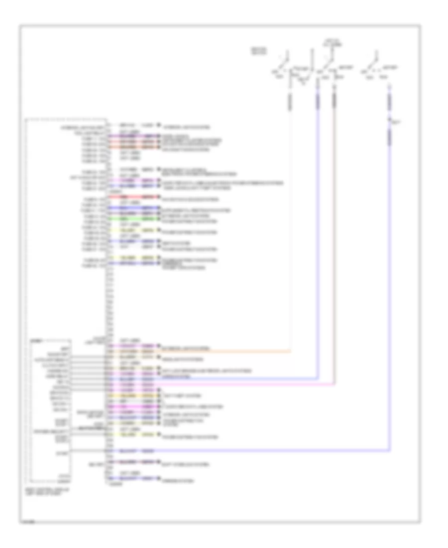
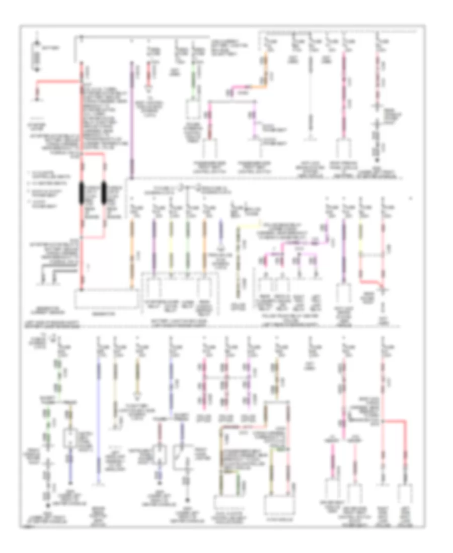
BODY CONTROL MODULES
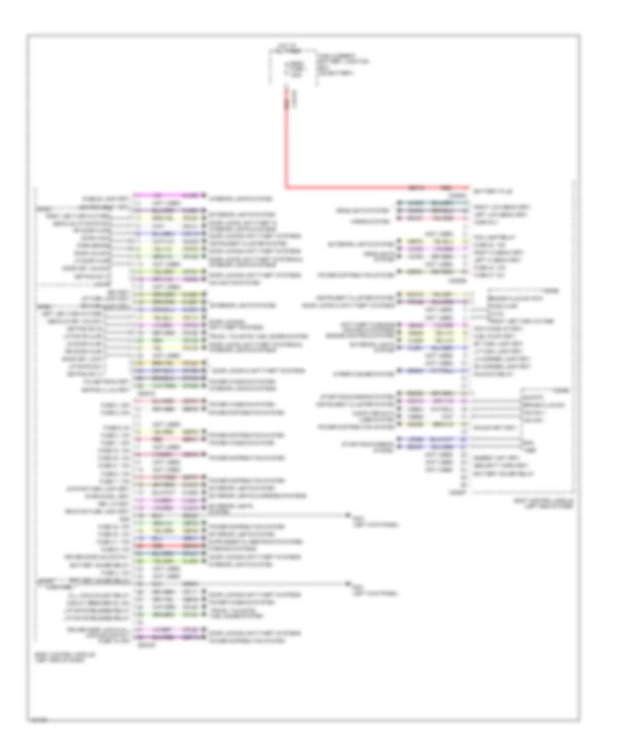
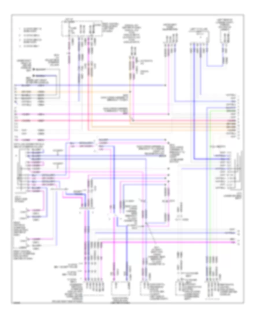
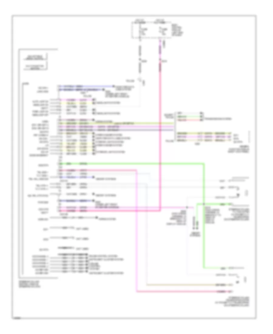
Body Control Module Wiring Diagram (1 of 2) for Ford Taurus Limited 2014
List of elements for Body Control Module Wiring Diagram (1 of 2) for Ford Taurus Limited 2014:
- (not used)
- Acc
- Acc/run
- Air conditioning system
- Anti-lock brakes & exterior lights systems
- Anti-theft system
- Autolamp sens in
- Backlighting led (fet)
- Body control module (left end of dash)
- Bpp
- Bsi (fet)
- C2280a
- C2280b
- Cbp31
- Cbp35
- Cbp36
- Cbp37
- Cbp38
- Cbp41
- Cbp42
- Ccb08
- Cdc30
- Cdc33
- Cdc34
- Cdc35
- Cet53
- Cls32
- Clutch input
- Computer data lines & electronic power steering systems
- Computer data lines system
- Cpk35
- Cpk36
- Crh04
- Door locks & anti-theft systems
- Door locks & instrument cluster systems navigation & sound systems
- Epats rx
- Epats tx
- Exterior lights system
- Fog lamp relay
- Fuse 11, 10a
- Fuse 23, 15a
- Fuse 24, 15a
- Fuse 26, 5a
- Fuse 27, 20a
- Fuse 28, 15a
- Fuse 29, 20a
- Fuse 31, 5a
- Fuse 32, 15a
- Fuse 34, 10a
- Fuse 35, 5a
- Fuse 36, 10a
- Fuse 37, 10a
- Fuse 38, 10a
- Fuse 41, 7.5a
- Fuse 42, 5a
- Fuse 44, 10a
- Fuse 45, 5a
- Fuse 46, 10a
- Fuse 9, 10a
- Hazard sw
- Headlights systems
- Horn relay
- Horns system
- Hot at all times
- Hot in run or acc
- Ignition switch
- Instrument cluster & electronic power steering systems
- Interior lighting (fet)
- Interior lights system
- Key in
- Lin 01
- Lin 04
- Micro
- Mirrors system
- Ms can +
- Ms can -
- Navigation & sound systems
- Off
- Power distribution system
- Power distribution system mirrors & power tops systems
- Red
- Ripcord security
- Run
- Run/start
- S217
- Sbp09
- Sbp11
- Sbp23
- Sbp24
- Sbp26
- Sbp27
- Sbp29
- Sbp46
- Seats system
- Shift interlock system
- Start
- Start/ stop 1
- Start/ stop 2
- Strt button (fet)
- Vdb06
- Vdb07
- Vdn01
- Vlf14
- Vln04
- Vln33
- Vrt23
- Vrt24
- White light (fet)
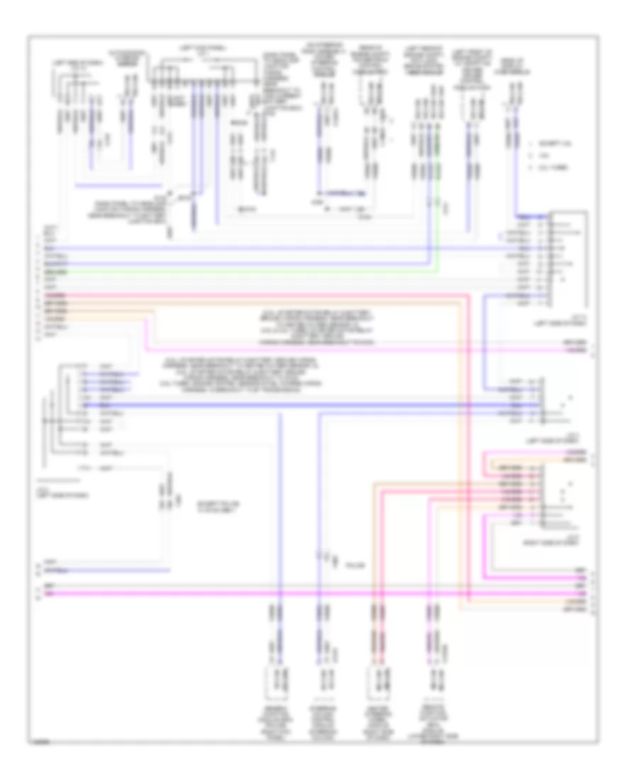
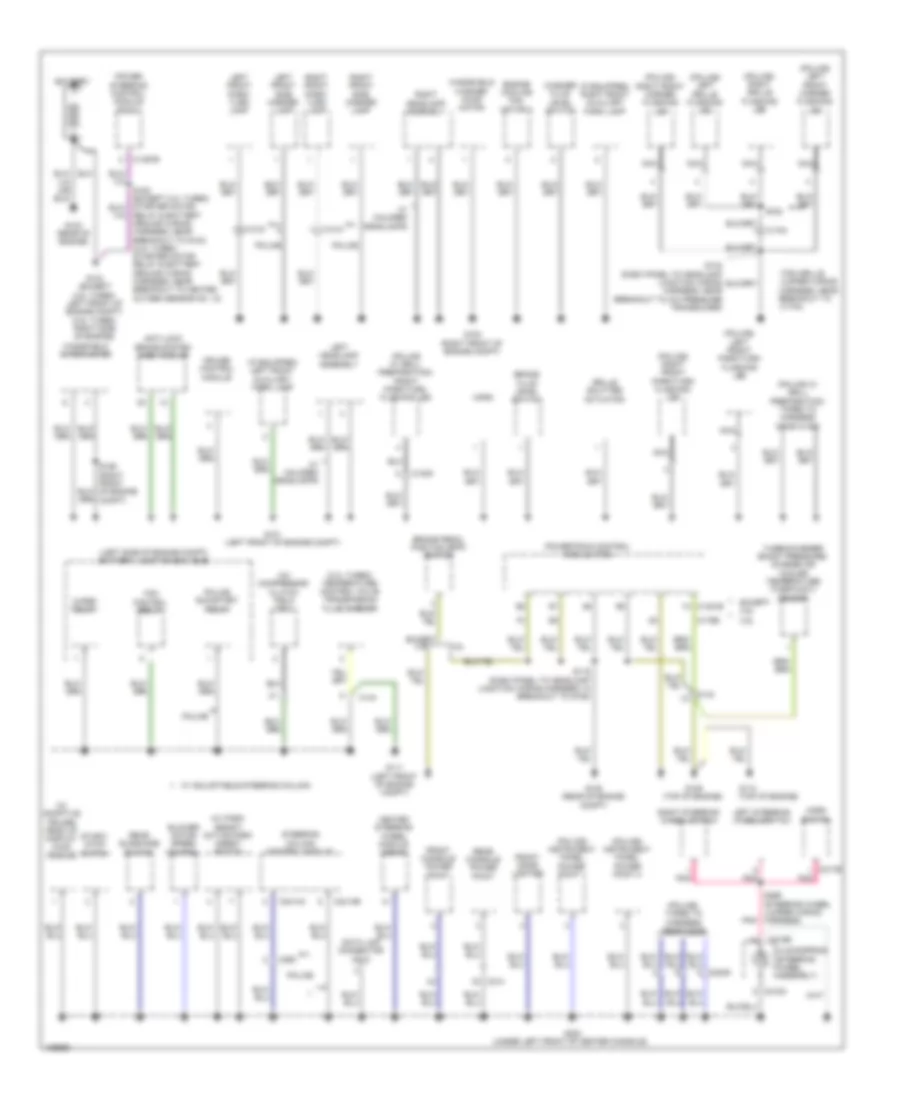
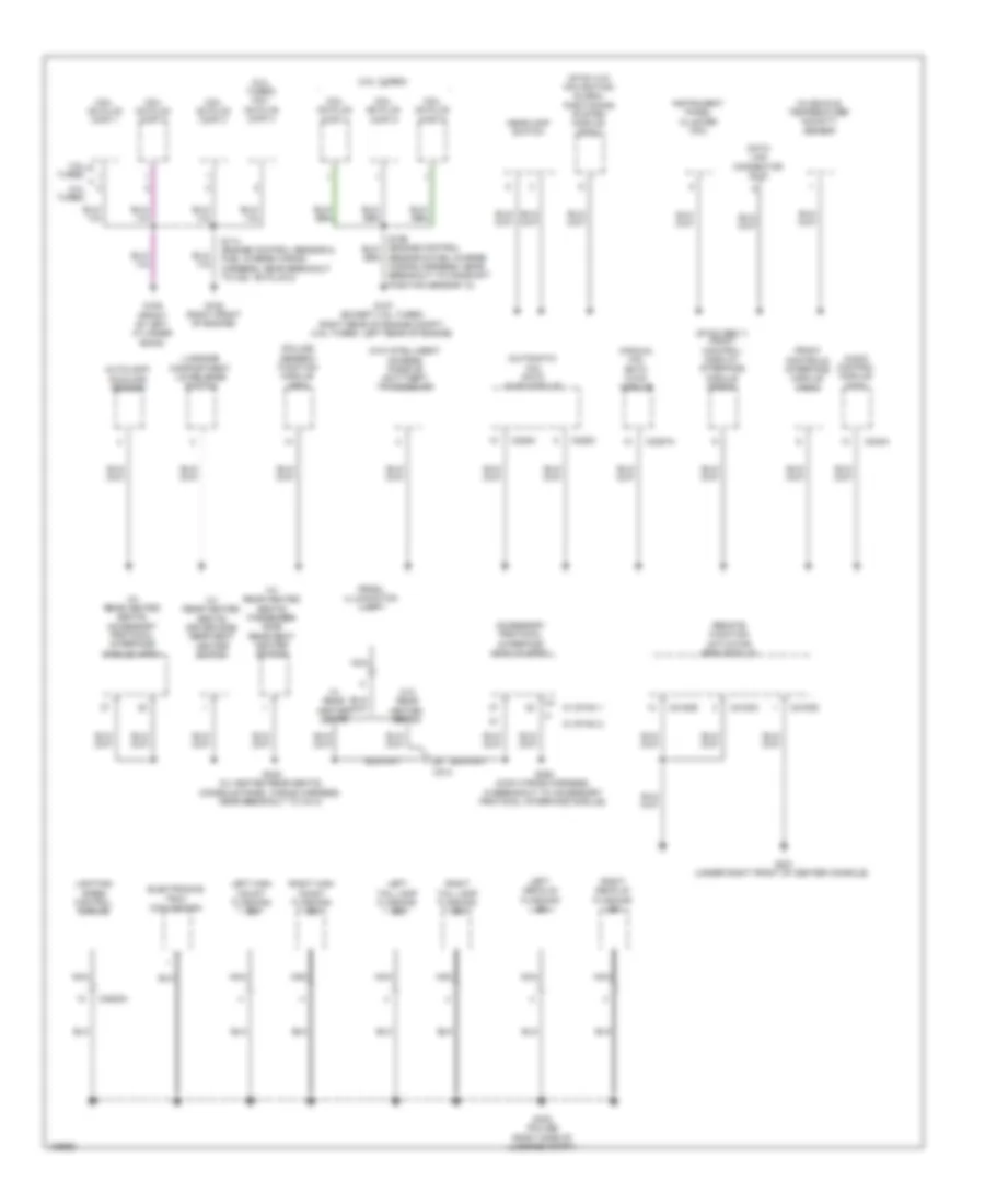
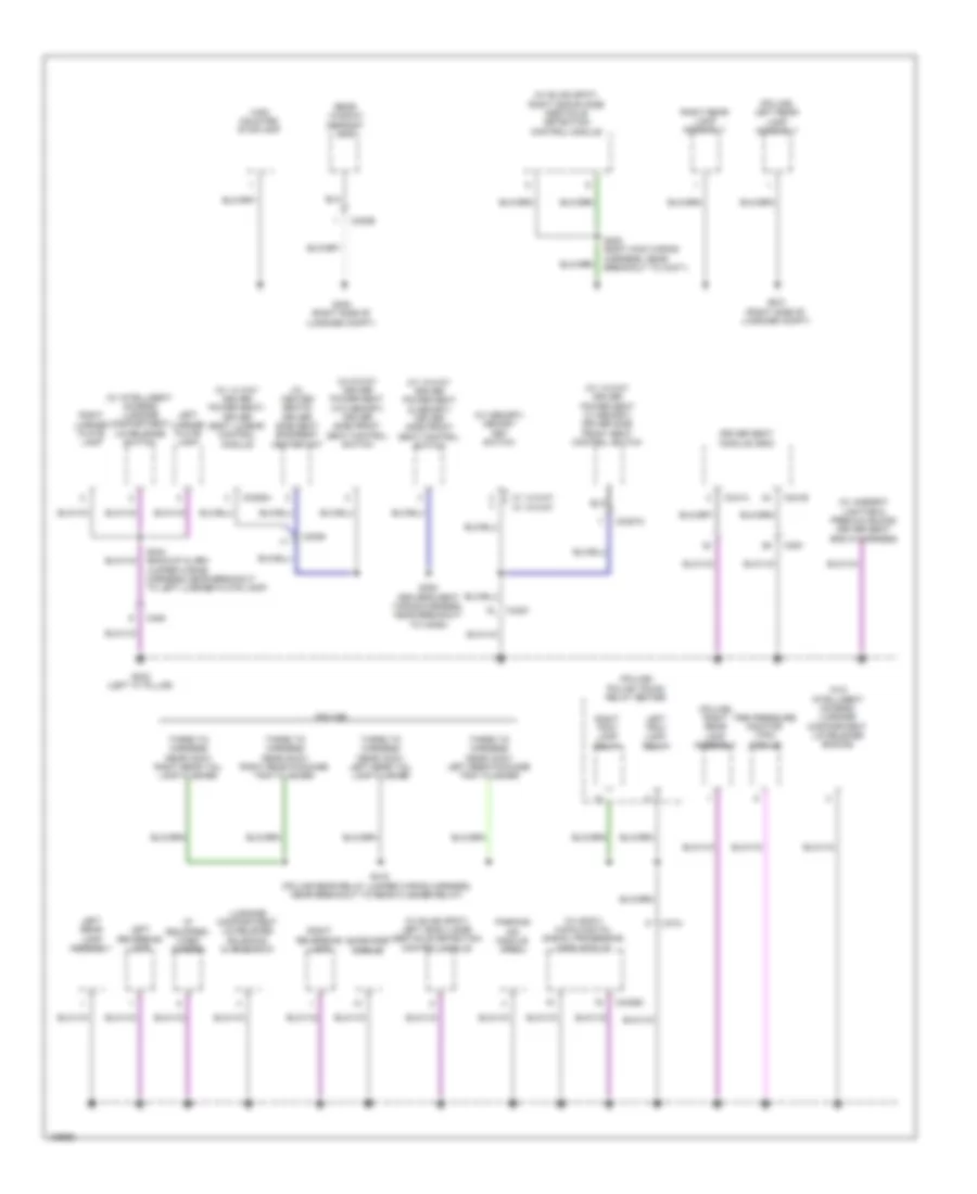
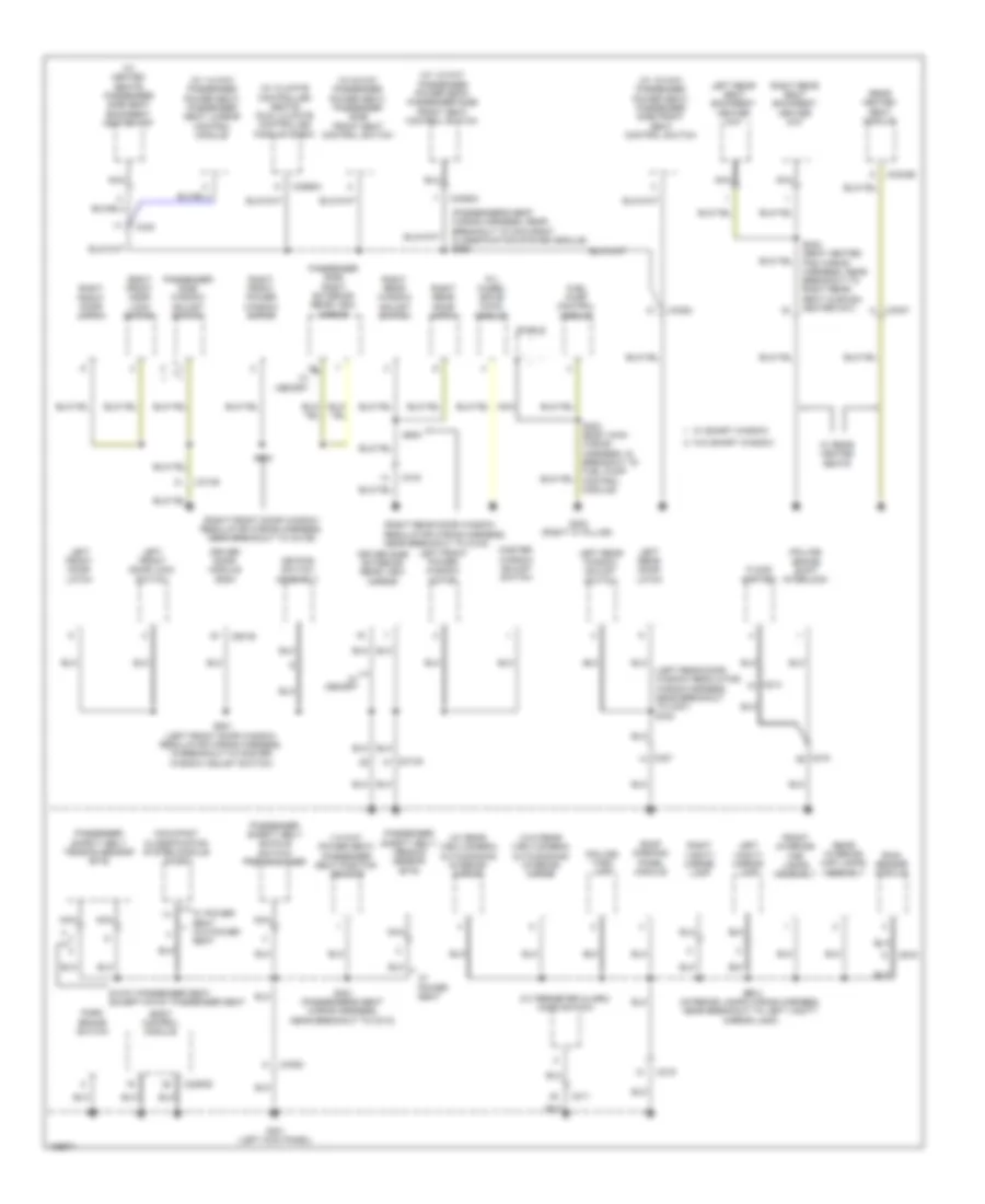
Body Control Module Wiring Diagram (2 of 2) for Ford Taurus Limited 2014
List of elements for Body Control Module Wiring Diagram (2 of 2) for Ford Taurus Limited 2014:
- (not used)
- 2nd row seat (fet)
- All lock/unlock relay
- Anti-theft & engine controls systems engine controls system
- Battery plus
- Battery saver relay
- Bcs
- Body control module (left end of dash)
- Brake fluid sw
- Brake fluid sw rtn
- Bsi (fet) lr turn lamp (fet)
- C1617b
- C2280c
- C2280d
- C2280e
- C2280f
- C2280g
- Cbp30
- Cbp32
- Cbp34
- Cbp40
- Cbp41
- Cbp48
- Cdc21
- Cdc55
- Cdc64
- Ce226
- Ce436
- Circuit breaker 48, 30a
- Clf02
- Clf03
- Clf04
- Clf05
- Cln09
- Cln25
- Cls18
- Cls19
- Cls21
- Cls23
- Cls25
- Cls27
- Cls28
- Cls44
- Cls54
- Cls55
- Cmc19
- Cmc25
- Computer data lines system
- Cpk19
- Cpk23
- Cpk28
- Cpk29
- Cpk30
- Cpk31
- Cpl11
- Cpl25
- Cpl26
- Cpl31
- Cpl36
- Cpl39
- Cpl51
- Cpl52
- Cpl58
- Cpl60
- Cpl74
- Cpl80
- Cpl84
- Cpw01
- Decklid key unlock
- Decklid/liftgate sw
- Door key lock
- Door key unlock
- Door lock
- Door locks & anti-theft systems
- Door locks, anti-theft & interior lights systems
- Door locks, anti-theft systems & interior lights systems
- Door unlock
- Driver door lock & all lock/unlock rly fuse 19, 20a
- Driver door unlock rly
- Energy mgt (fet)
- Exterior lights & mirrors systems
- Exterior lights system
- Fog lamp relay
- Front led turn outage
- Fuel pump (fet)
- Fuse 1, 30a
- Fuse 2, 15a
- Fuse 21, 10a
- Fuse 3, 30a
- Fuse 30, 15a
- Fuse 32, 15a
- Fuse 33, 10a
- Fuse 34, 10a
- Fuse 37 10a
- Fuse 4, 10a
- Fuse 40, 10a
- Fuse 41, 7.5a
- Fuse 43, 10a
- Fuse 5, 20a
- Fuse 6, 5a
- Fuse 7, 7.5a
- Fuse 8, 10a
- Fuse 9, 10a
- G301 (left kick panel)
- Gd233
- Gnd
- Headlights system
- High current battery junction box (on battery)
- Hood ajar
- Horn rly
- Horns system
- Hot at all times
- Hs can +
- Hs can -
- Instrument cluster system
- Interior lights system
- Interior lights systems
- Keypad illum (fet)
- Keypad sw a
- Keypad sw b
- Keypad sw c
- Ldc59
- Left hi beam (fet)
- Left led turn outage
- Left low beam (fet)
- Lf door ajar
- Lf turn lamp (fet)
- Lh corner lamp (fet)
- Liftgate ajar
- Liftgate release relay
- Liftgate sw
- Lin 02
- Lin 03
- Logic gnd
- Lr door ajar
- Lr stop/turn lamp (fet)
- Mega fuse 1 100a
- Micro
- Navigation system
- Park brake
- Pcm wake up (fet)
- Power distribution system
- Power windows system
- Puddle lamp (fet)
- Pulse train (fet)
- Rdc59
- Red
- Rev lp (fet)
- Rf door ajar
- Rf turn lamp (fet)
- Rh corner lamp (fet)
- Right hi beam (fet)
- Right led turn outage
- Right low beam (fet)
- Rmc19
- Rr door ajar
- Rr stop/turn lamp (fet)
- Rr turn lamp (fet)
- Run/acc relay
- Run/start (fet)
- Sbf16
- Sbp01
- Sbp02
- Sbp03
- Sbp05
- Sbp07
- Sbp09
- Sbp19
- Sdc57
- Security horn (fet)
- Sig rtn
- Srh01
- Starting/charging system
- Stop/chmsl (fet)
- Trunk, tailgate, fuel doors system
- Vdb04
- Vdb05
- Vdn03
- Vref
- Warning systems
- Wiper/washer system
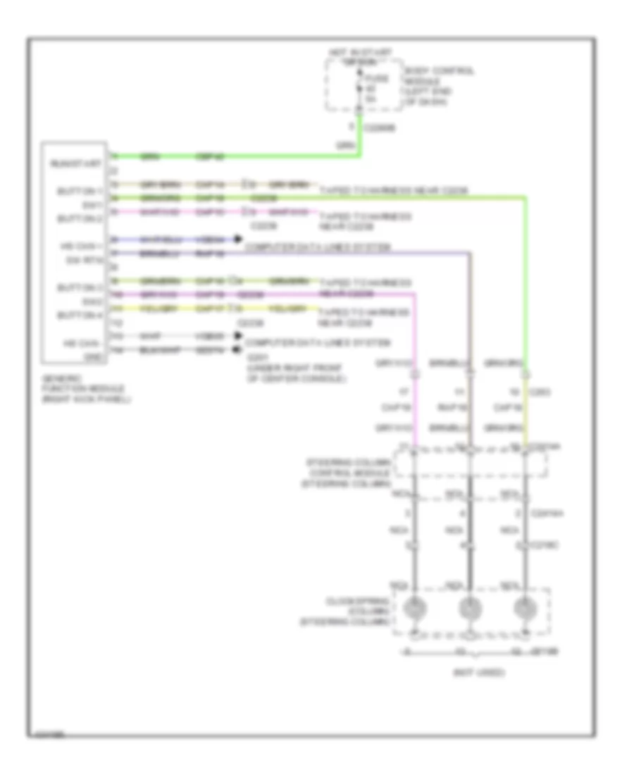
Generic Electronic Module Wiring Diagram for Ford Taurus Limited 2014
List of elements for Generic Electronic Module Wiring Diagram for Ford Taurus Limited 2014:
- (not used)
- Body control module (left end of dash)
- Button 1
- Button 2
- Button 3
- Button 4
- C218b
- C218c
- C2238
- C2280b
- C2414a
- C263
- Cap14
- Cap15
- Cap16
- Cap17
- Cap18
- Cap19
- Cbp42
- Clockspring (column) (steering column)
- Computer data lines system
- Fuse 5a
- G201 (under right front of center console)
- Gd374
- Generic function module (right kick panel)
- Gnd
- Hot in start or run
- Hs can +
- Hs can -
- Nca
- Rap18
- Run/start
- Steering column control module (steering column)
- Sw rtn
- Sw1
- Sw2
- Taped to harness near c2238
- Vdb04
- Vdb05
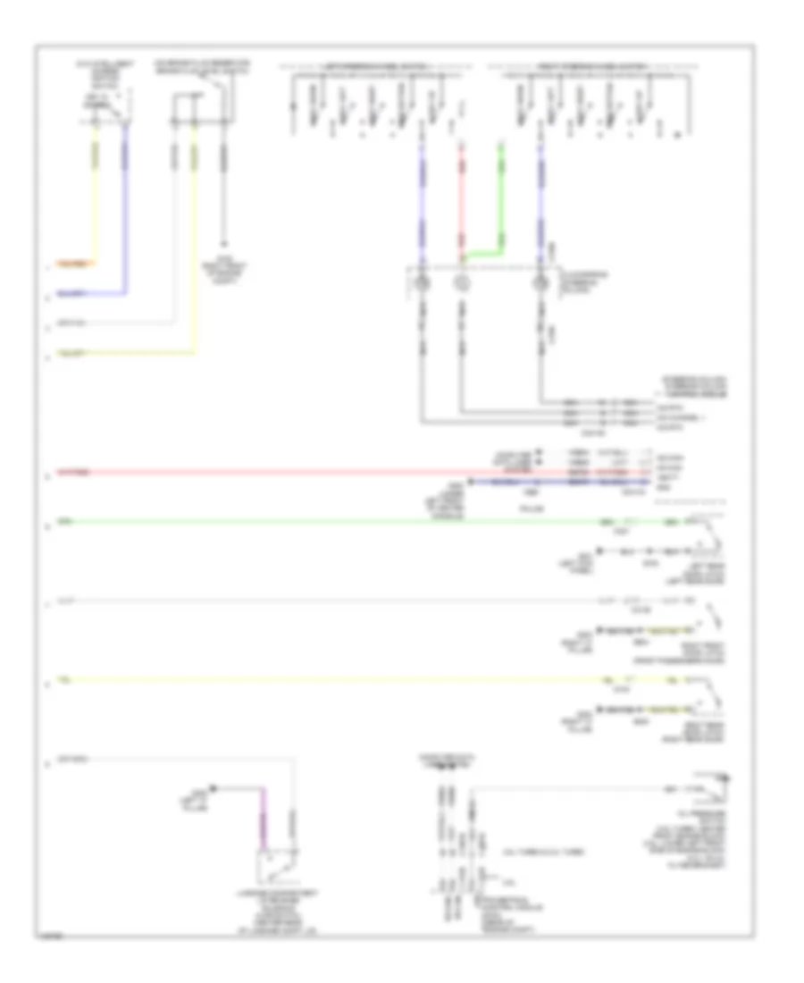
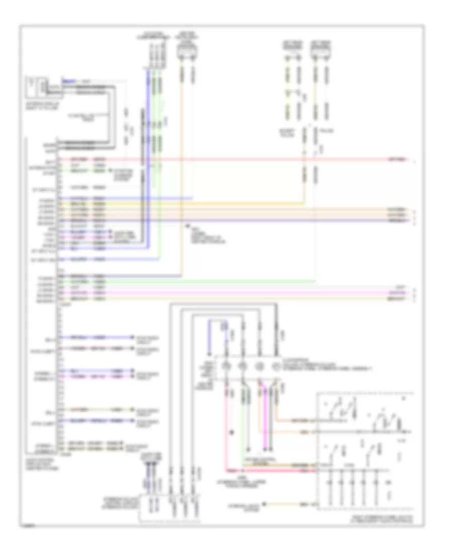
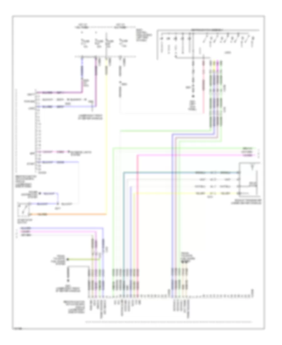
COMPUTER DATA LINES
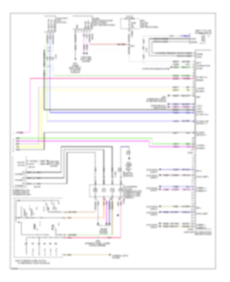
Computer Data Lines Wiring Diagram (1 of 3) for Ford Taurus Limited 2014
List of elements for Computer Data Lines Wiring Diagram (1 of 3) for Ford Taurus Limited 2014:
- (body main wiring harness, near breakout to joint connector 12) (w/ sony) s410
- (left "c" pillar) j/c 7
- (left rear of luggage compt) parking aid module (pam)
- (main wiring harness, in breakout to g201) s207
- (main wiring harness, in breakout to luggage compt lid release switch) s212
- (manual a/c: center of dash) (manual a/c) hvac module (emtc) (automatic a/c) hvac module (datc)
- (under right front of center console) g201
- Accessory protocol interface module (apim) (except police: under center console) (police: right end of dash)
- Audio control module (acm) (center of dash)
- Audio digital processing module (w/ sync gen 2 & sony) (left side of luggage compt)
- Automatic a/c
- Body control module (bcm) (left end of dash)
- C210
- C212
- C214
- C215
- C2280a
- C2280b
- C2280f
- C2357a
- C240a
- C310b
- C3382
- C4326a
- Data link connector (dlc) (below steering column)
- Except police
- Front control/ display interface module (fdim) (center of dash)
- Front controls interface module (fcim) (center of dash)
- Fuse 15a
- G200 (under left front of center console)
- Gd374
- Gd375
- Hot at all times
- Hs can yaw+
- Hs can yaw-
- Hs can+
- Hs can+ occupant classification system module (ocsm) (under front passenger's seat)
- Hs can-
- I can+
- I can-
- Instrument panel cluster (ipc)
- J/c 11 (right side of dash)
- J/c 8 (under driver's seat)
- Manual a/c
- Micro
- Ms can+
- Ms can-
- Ms can- c228a
- Restraints control module (rcm) (under center console)
- S208 (main wiring harness, in breakout to g201)
- S213 (main wiring harness, in breakout to luggage compt lid release switch)
- S218 (w/ adjustable steering column)
- S411 (w/ sony) (body main wiring harness, near breakout to joint connector 12)
- Sbp24
- Vca23
- Vca24
- Vdb04
- Vdb05
- Vdb06
- Vdb07
- Vdb13
- Vdb14
- W/ power seat
- W/ sony
- W/ sync gen 1
- W/ sync gen 1 & base audio
- W/ sync gen 1 except police
- W/ sync gen 1 police
- W/ sync gen 2
- W/ sync gen 2 & base audio
- W/o power seat
- W/o sony
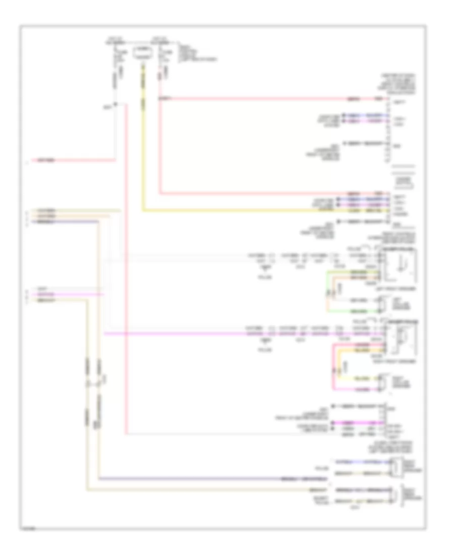
Computer Data Lines Wiring Diagram (2 of 3) for Ford Taurus Limited 2014
List of elements for Computer Data Lines Wiring Diagram (2 of 3) for Ford Taurus Limited 2014:
- (2.ol: starter motor relay & battery ground wiring harness, near breakout to heated oxygen sensor 12) (3.5l & 3.5l turbo: starter motor relay & battery ground wiring harness, near breakout to g103)
- (2.ol: starter motor relay & battery ground wiring harness, near breakout to heated oxygen sensor 12) (3.5l: starter motor relay & battery ground wiring harness, near breakout to g103) (3.5l turbo: engine control sensor & fuel charge wiring harness, in breakout to 6f transmission)
- (dash panel to headlamp junction wiring harness, near breakout to high current battery junction box) s154
- (left end of dash) j/c 13
- (left front of engine compt) (w/ adaptive cruise) cruise- control module (c-cm)
- (left kick panel) j/c 1
- (left rear of engine compt) anti-lock brake system (abs) module
- (not used)
- (on steering rack assembly) power steering control module
- (rear of engine compt) powertrain control module (pcm)
- 2.0l turbo
- 2414a
- 3.5l
- Auto-dimming interior mirror
- C1381b
- C144
- C1467a
- C211
- C214
- C2153e
- C219
- C263
- Except 3.5l
- Except police w/ sync gen 1
- Generic function module (gfm) (police) (right kick panel)
- Head up display (hud) module
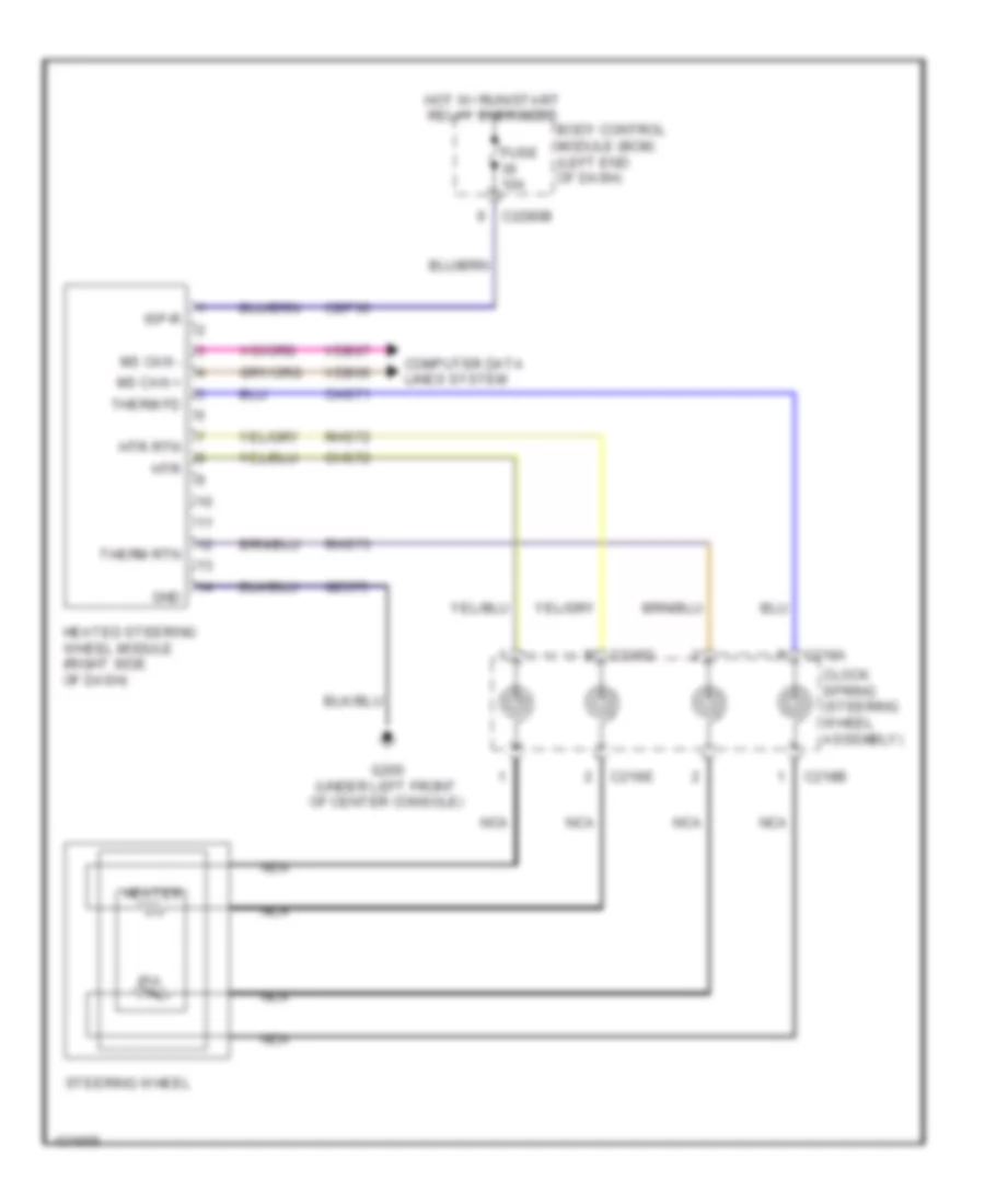
- Heated steering wheel module (right side of dash)
- Hs can yaw+
- Hs can yaw-
- Hs can+
- Hs can-
- Hs can- c175b
- J/c 14 (left side of dash)
- J/c 2 (left side of dash)
- J/c 3 (left side of dash)
- J/c 5 (right side of dash)
- Ms can+
- Ms can-
- Police
- Remote function actuator (rfa) module (lower right side of dash)
- S100
- S101
- S139
- S140 (dash panel to headlamp junction wiring harness, near breakout to battery junction box)
- S155
- Steering column control module (steering column)
- Vca23
- Vca24
- Vdb04
- Vdb05
- Vdb06
- Vdb07
Computer Data Lines Wiring Diagram (3 of 3) for Ford Taurus Limited 2014
List of elements for Computer Data Lines Wiring Diagram (3 of 3) for Ford Taurus Limited 2014:
- (body main wiring harness, near breakout to center parcel shelf speaker)
- (left end of dash) j/c 15
- (left side of luggage compt) j/c 10
- (not used)
- (rear of left side of luggage compt) left side obstacle detection control module (sod-l)
- (right "c" pillar) tire pressure monitor module
- (under driver's seat) driver seat module (dsm)
- (under front passenger's seat) dual climate controlled seat module (dcsm)
- C212
- C300
- C3050
- C3138
- C3265c
- C3381
- C3382
- C340
- Driver door module (ddm)
- Global positioning system module (gpsm) (left center of dash)
- J/c 12 (right side of luggage compt)
- J/c 4 (left side of dash)
- J/c 6 (under front passenger seat)
- J/c 9 (under driver's seat)
- Ms can+
- Ms can-
- Ms can- c341d
- Ms can- c501b
- Right side obstacle detection control module (sod-r) (rear of right side of luggage compt)
- S398
- S399
- Vdb06
- Vdb07
COOLING FAN
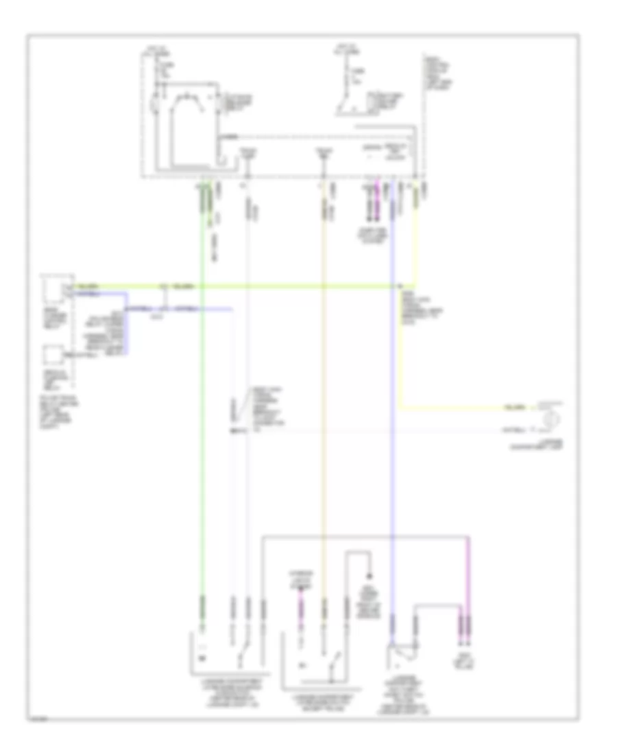
Cooling Fan Wiring Diagram for Ford Taurus Limited 2014
List of elements for Cooling Fan Wiring Diagram for Ford Taurus Limited 2014:
- (2.0l turbo & 3.5l turbo)
- (2.0l turbo)
- (3.5l turbo)
- (3.5l)
- (left front of engine compt) g101
- Battery junction box (bjb) (left side of engine compt)
- C1381b
- C1381e
- C175b
- C175e
- C192
- Cec07
- Cec08
- Cht
- Computer data lines system
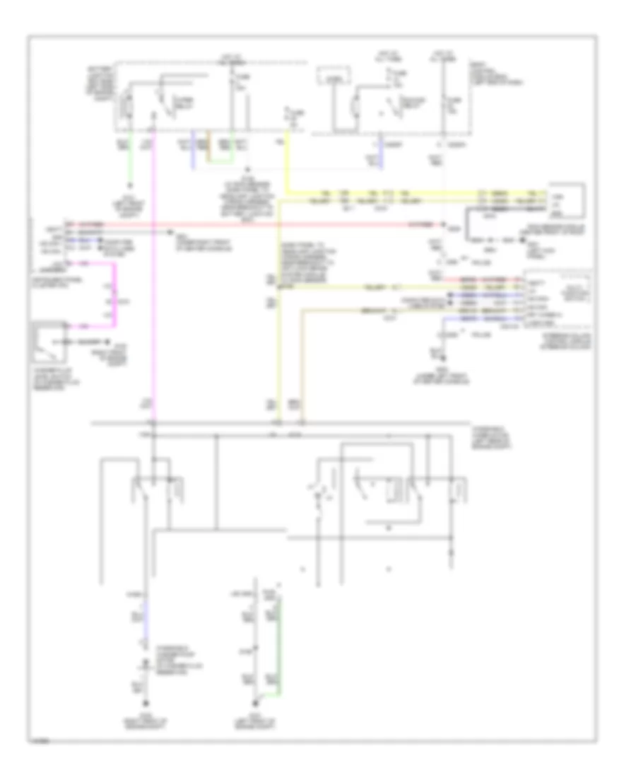
- Cylinder head temperature (cht) sensor (3.5l & 3.5l turbo) (3.5l: front of right cylinder head) (3.5l turbo: rear of right cylinder head)
- Ect
- Engine coolant temperature (ect) sensor (2.0l turbo) (right rear of engine)
- Engine cooling fan motor 1 (behind left side of radiator)
- Engine cooling fan motor 2 (behind right side of radiator)
- Fan control (fc) relay
- Fuse 15a
- Fuse 25a
- Fuse 40a
- G100 (right front of engine compt)
- G105 (rear of engine compt)
- Gd113
- Gnd
- Grille shutter actuator (3.5l) (behind right center of grille)
- Hfc
- High fan control (hfc) relay
- Hot at all times
- Hot w/ pcm power relay energized
- Hs can +
- Hs can -
- Lfc
- Lin
- Low fan control (lfc) relay
- Powertrain control module (pcm) (rear of engine compt)
- Pwr gnd
- Re405
- Re454
- S109 (3.5l: engine control sensor & fuel charge wiring harness, near breakout to fuel injector 2) (3.5l turbo: engine control sensor & fuel charge wiring harness, near breakout to c123)
- S113 (engine control sensor & fuel charge wiring harness, near breakout to coil on plug 2)
- S116
- S119
- S142 (dash panel to headlamp junction wiring harness, near breakout to battery junction box)
- S155 (dash panel to headlamp junction wiring harness, near breakout to high current battery junction box)
- Sig rtn
- Vdb04
- Vdb05
- Vdn06
- Ve712
- Ve716
- Vpwr
CRUISE CONTROL
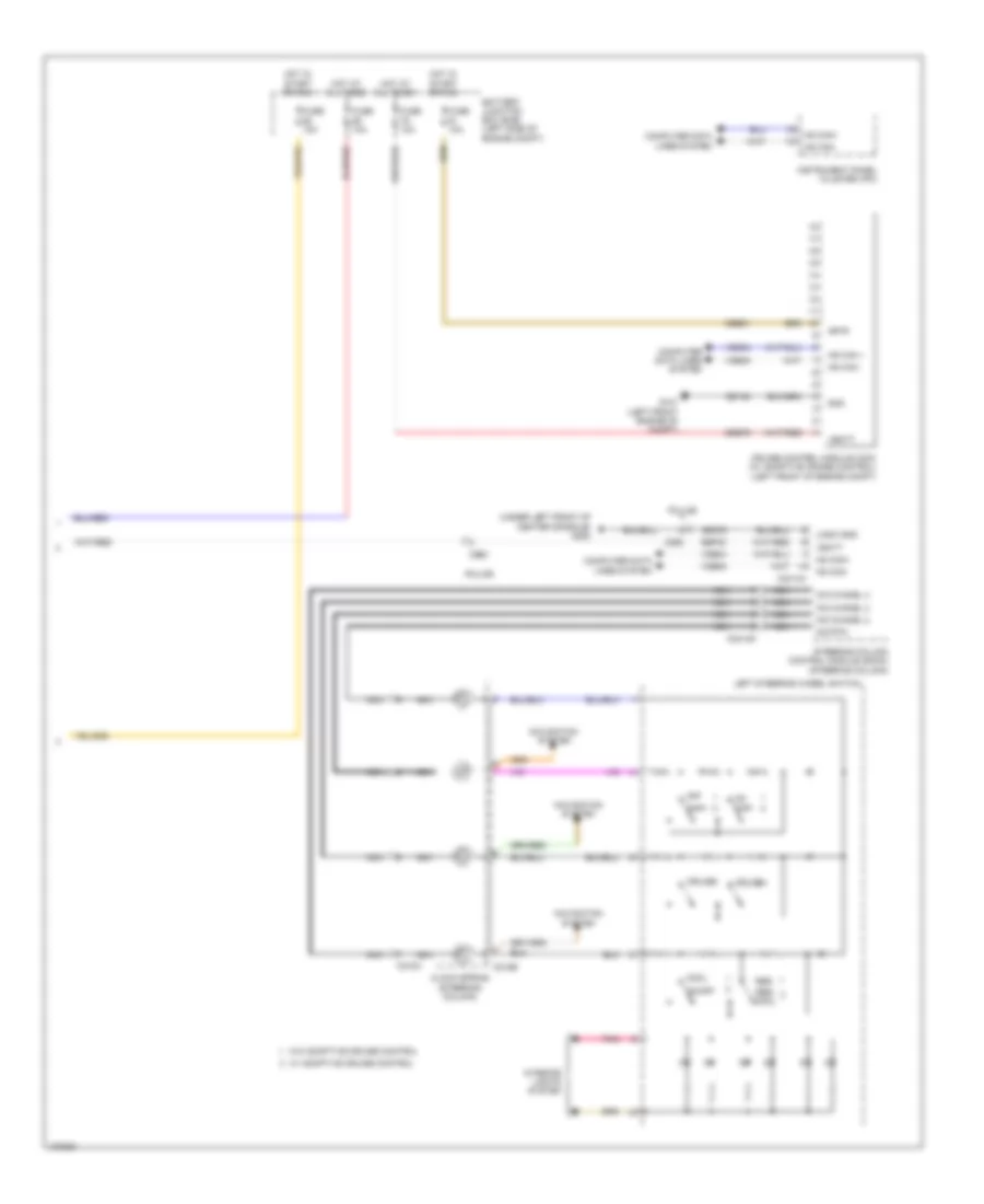
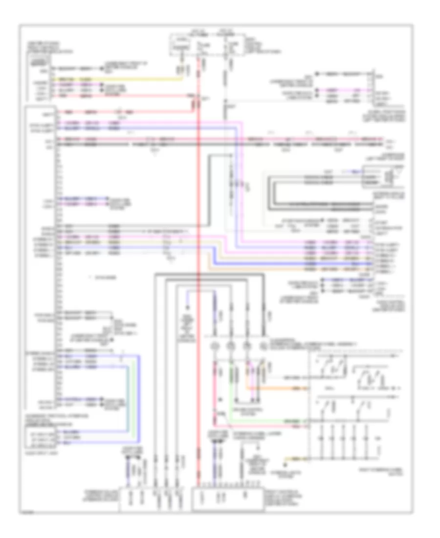
Cruise Control Wiring Diagram (1 of 2) for Ford Taurus Limited 2014
List of elements for Cruise Control Wiring Diagram (1 of 2) for Ford Taurus Limited 2014:
- (2.0l turbo: engine control sensor & fuel charge wiring harness, near breakout to 6f35 transmission) (3.5l: engine control sensor & fuel charge wiring harness, in breakout to 6f transmission) s173
- (dash panel to headlamp junction wiring harness, near breakout to windshield wiper motor)
- (engine control sensor & fuel charge wiring harness, near breakout to 6f35 transmission)
- (lower right side of dash) remote function actuator (rfa) module
- (main wiring harness, in breakout to c215) (w/ intelligent access) s240
- (on brake pedal bracket) brake pedal position (bpp) switch
- (or vet26)
- (or vet33)
- 2.0l turbo & 3.5l
- 2.0l turbo & 3.5l turbo
- 3.5l
- 3.5l turbo
- 6f transmission (left side of transmission)
- 6f35 transmission (left side of transmission)
- Accelerator pedal position (app) sensor (on accelerator pedal assembly)
- App1
- App2
- Apprtn1
- Apprtn2
- Appverf2
- Appvref1
- Body control module (bcm) (left end of dash)
- Bpp
- Bps
- C1381b
- C1381e
- C1381e (except 3.5l)
- C1520a
- C1520b
- C1609a
- C1609b
- C175b
- C175e
- C175t (3.5l)
- C210
- C2153c
- C2153e
- C2280a
- Cbb90
- Ccb08
- Ce412
- Ce426
- Ces09
- Computer data lines system
- Electronic throttle control (etc) (on throttle body)
- Etcref
- Etcrtn
- Except 3.5l
- Fuse 15a
- G105 (rear of engine compt)
- Gd113
- Gnd oss/tr
- Hot at all times
- Hs can+
- Hs can-
- Isp-r
- Le111
- Le134
- Le136
- Le137
- Ms can+
- Ms can-
- Oss
- Powertrain control module (pcm) (rear of engine compt)
- Pwrgnd
- Re134
- Re136
- Re137
- Ret04
- Ret24
- Ret33
- S115
- S115 (except 3.5l) (engine control sensor & fuel charge wiring harness, near breakout to 6f35 transmission)
- S116
- S116 (3.5l)
- S168
- S173
- S229
- Shift interlock system
- Tacm+
- Tacm-
- Tp1
- Tp2
- Tr-p
- Transmissions system
- Trp
- Trs
- Tss
- Tss gnd
- Tss vpwr
- Tss/oss gnd
- Tss/oss/tr gnd
- Tss/oss/vpwr
- Vdb04
- Vdb05
- Vdb06
- Vdb07
- Ve701
- Ve702
- Ve818
- Ve819
- Vet32
- Vpwr
- Vpwr oss/tr
- W/ intelligent access
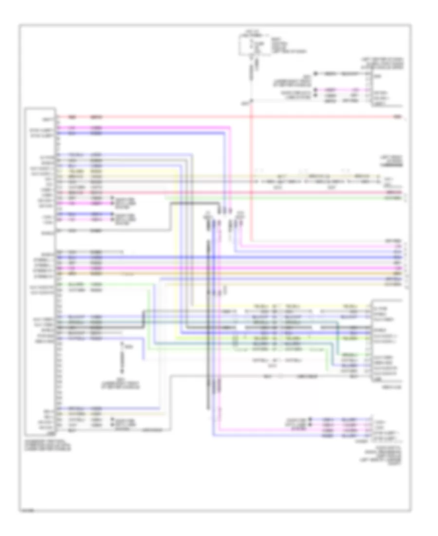
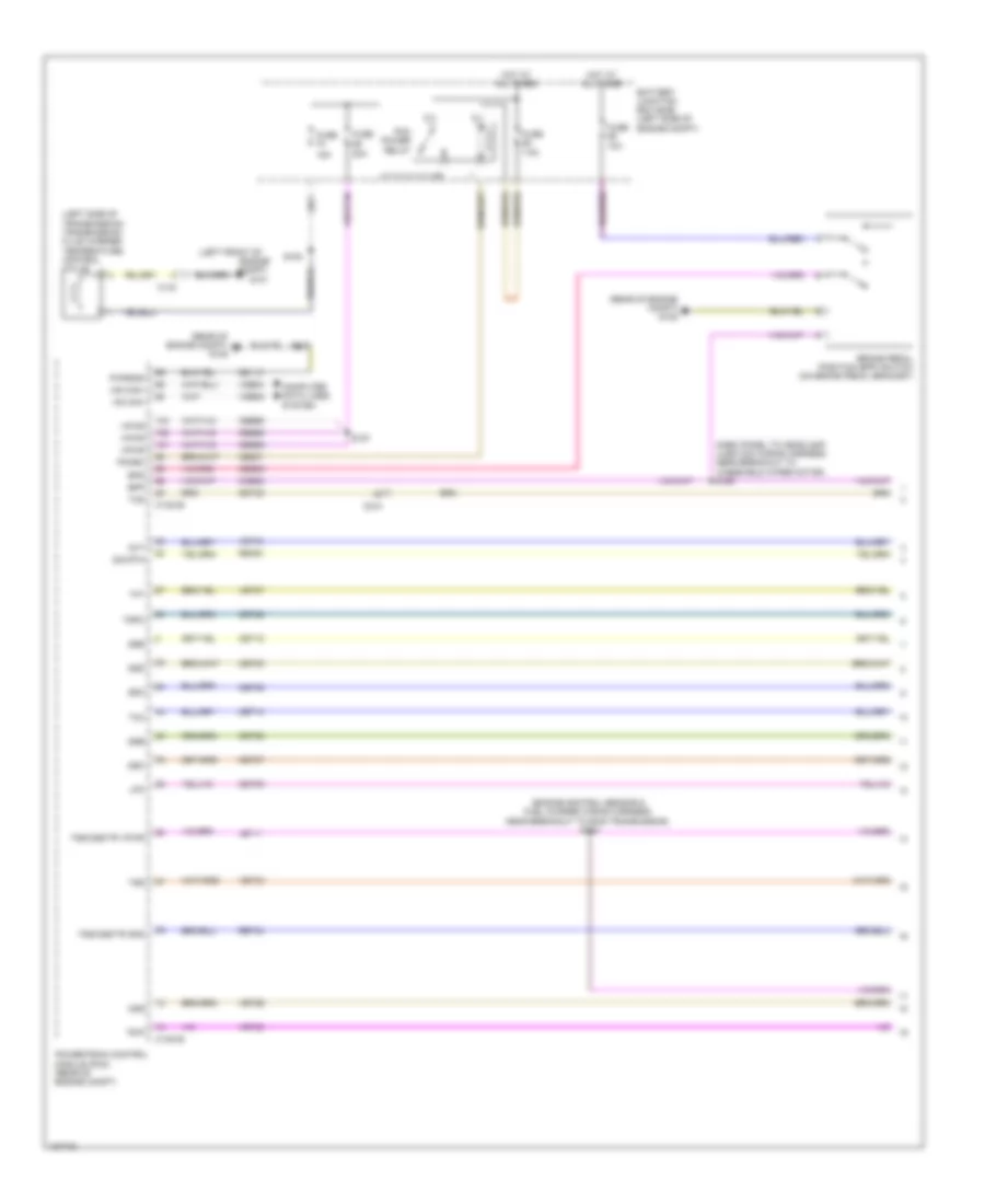
Cruise Control Wiring Diagram (2 of 2) for Ford Taurus Limited 2014
List of elements for Cruise Control Wiring Diagram (2 of 2) for Ford Taurus Limited 2014:
- (under left front of center console) g200
- A/d chanel 2
- A/d chanel 3
- A/d chanel 4
- A/d rtn
- Battery junction box (bjb) (left side of engine compt)
- C218b
- C218c
- C2414a
- C2414d
- C263
- Cbb91
- Clock spring (steering column)
- Cncl
- Computer data lines system
- Cruise control module (ccm) (w/ adaptive cruise control) (left front of engine compt)
- Cruise+
- Cruise-
- Fuse 10a
- G101 (left front engine of compt)
- Gap+
- Gap-
- Gd120
- Gd375
- Gnd
- Hot at all times
- Hot in start or run
- Hs can +
- Hs can -
- Hs can+
- Hs can-
- Instrument panel cluster (ipc)
- Interior lights system
- Isp-r
- Left steering wheel switch
- Logic gnd
- Navigation system
- Nca
- Off
- On/off
- Pnk
- Police
- Res
- Res/ cncl
- Sbb79
- Sbp23
- Steering column control module (sccm) (steering column)
- Vbatt
- Vdb04
- Vdb05
- W/ adaptive cruise control
- W/o adaptive cruise control
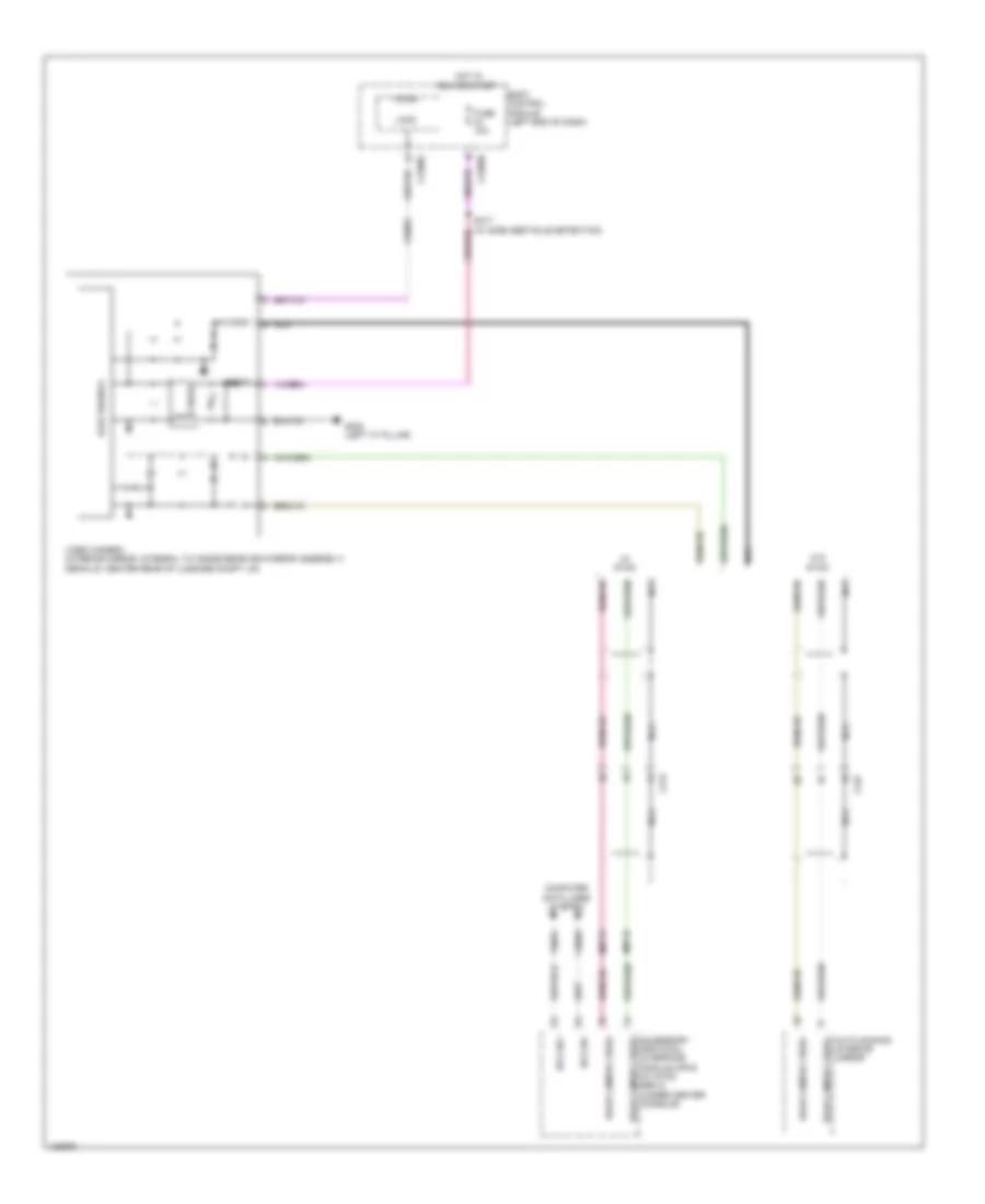
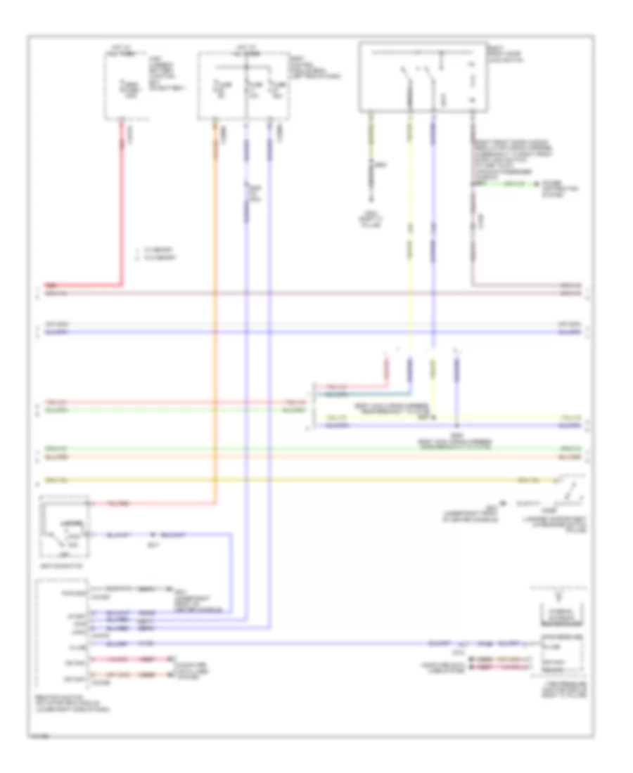
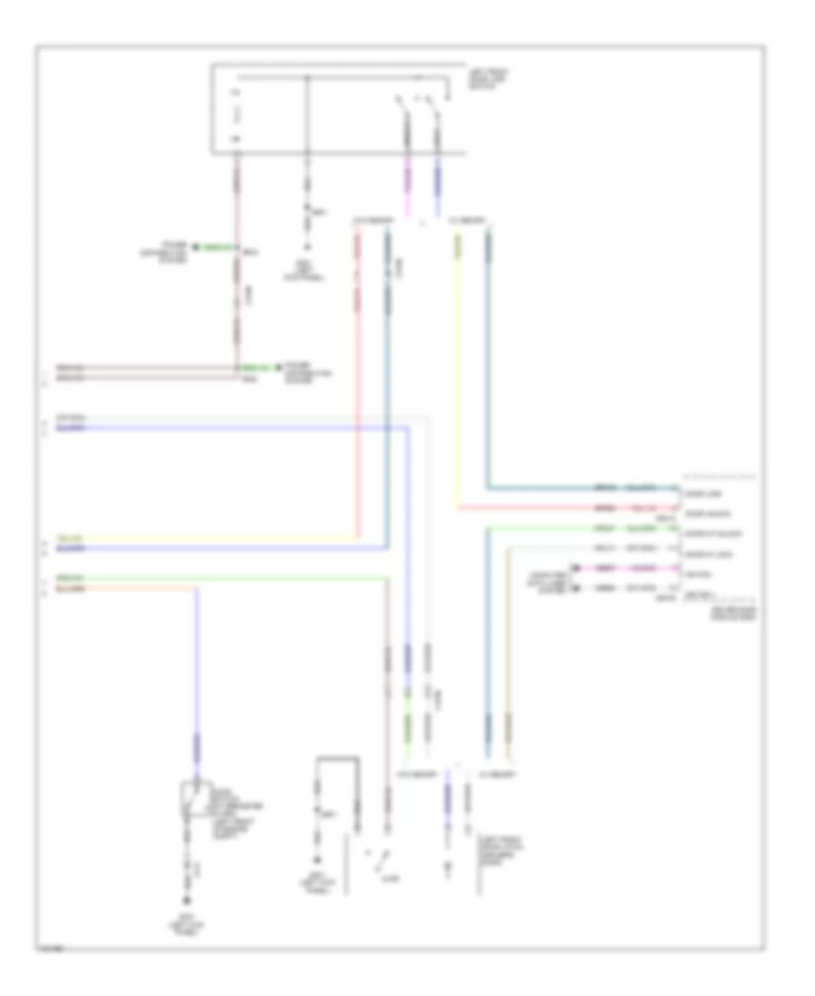
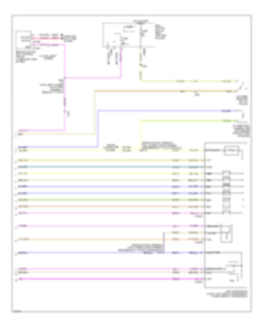
DEFOGGERS
Defoggers Wiring Diagram for Ford Taurus Limited 2014
List of elements for Defoggers Wiring Diagram for Ford Taurus Limited 2014:
- A/c
- Automatic
- Battery junction box (bjb) (left side of engine compt)
- C210
- C211
- C228a
- C2357a
- C3138
- C3139
- C402a
- C402b
- Datc hvac module
- Defrost request
- Driver side exterior rearview mirror
- Emtc hvac module (center of dash)
- Fuse 15a
- Fuse 40a
- Fuse 5a
- G301 (left kick panel)
- G303 (right ``c" pillar)
- G400 (right side luggage compt)
- Hot at all times
- Hot in run or start
- Manual a/c
- Passenger side exterior rearview mirror
- Rear window defrost grid
- Rear window defrost relay
- S107 (dash panel to headlamp junction wiring harness, near breakout to battery junction box)
- S112 (police)
- S285 (body main wiring harness, near breakout to c219)
- S501
- S604
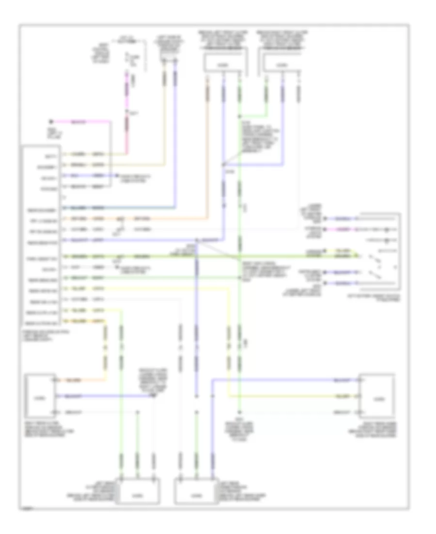
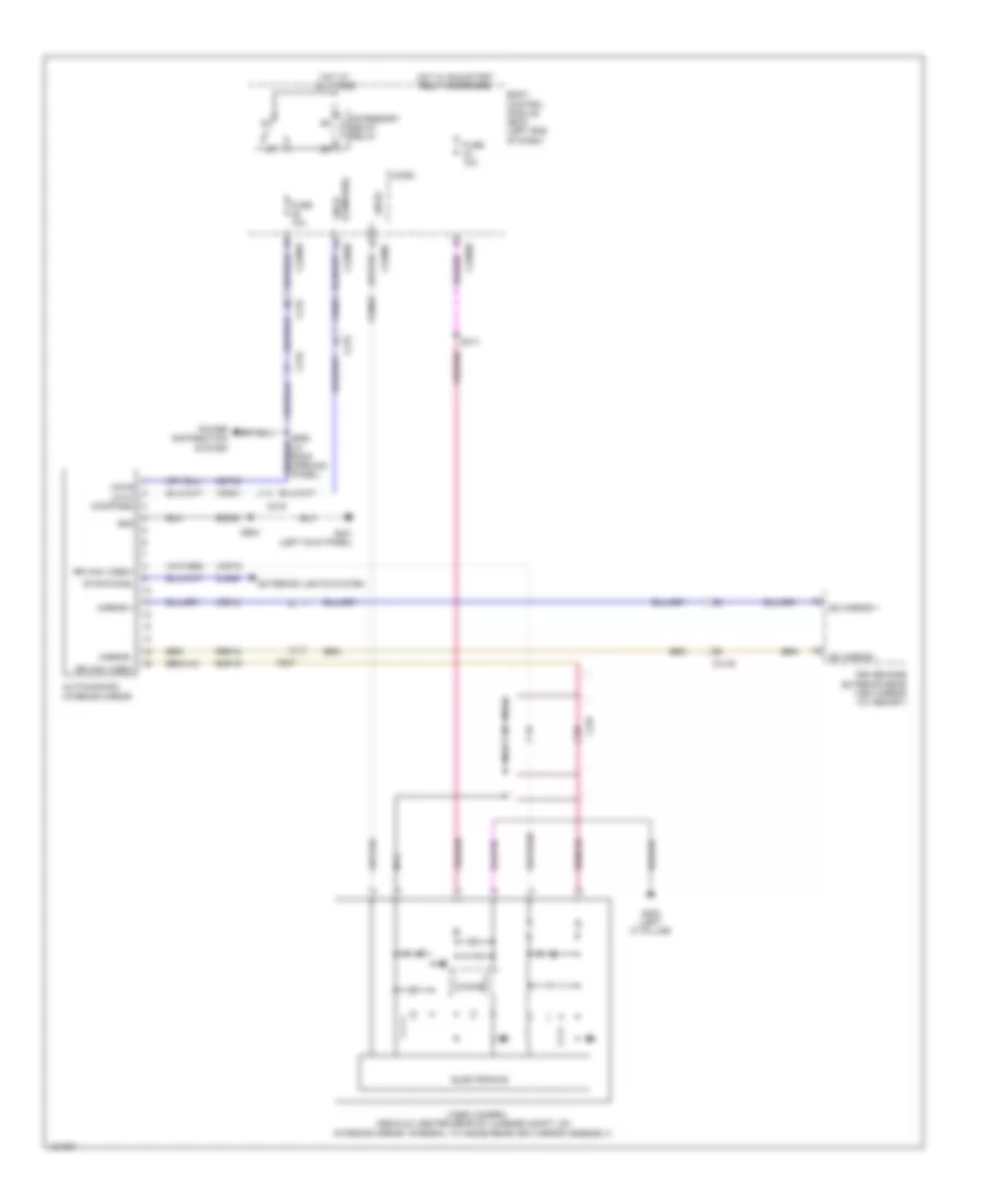
ELECTRONIC POWER STEERING
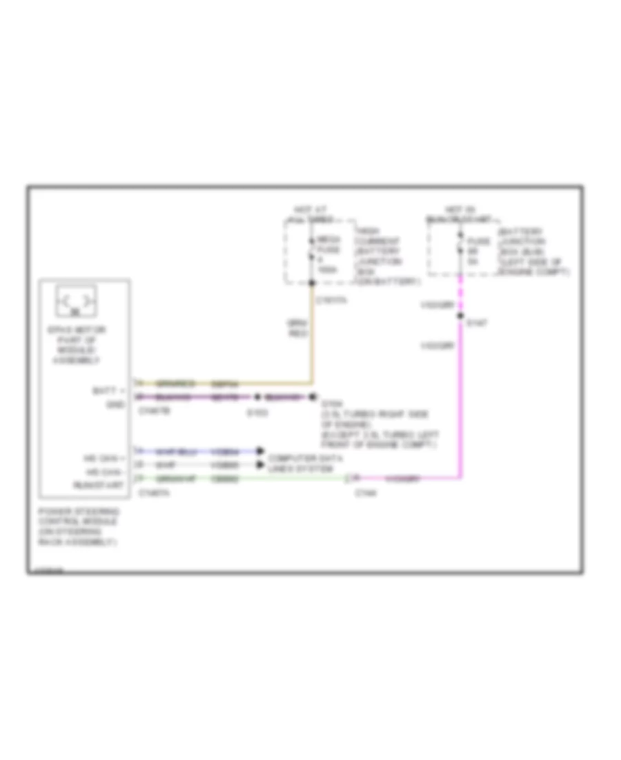
Electronic Power Steering Wiring Diagram for Ford Taurus Limited 2014
List of elements for Electronic Power Steering Wiring Diagram for Ford Taurus Limited 2014:
- Batt +
- Battery junction box (bjb) (left side of engine compt)
- C144
- C1467a
- C1467b
- C1617a
- Cbb92
- Computer data lines system
- Epas motor part of module/ assembly
- Fuse 5a
- G104 (3.5l turbo: right side of engine) (except 3.5l turbo: left front of engine compt)
- Gd178
- Gnd
- High current battery junction box (on battery)
- Hot at all times
- Hot in run or start
- Hs can +
- Hs can -
- Mega fuse 100a
- Power steering control module (on steering rack assembly)
- Run/start
- S147
- S153
- Sbf04
- Vdb04
- Vdb05
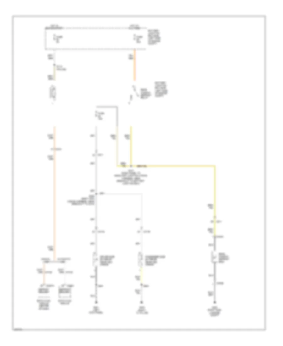
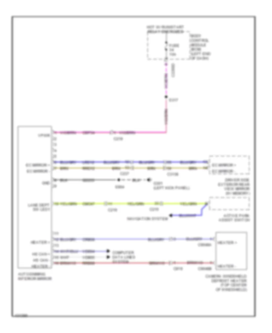
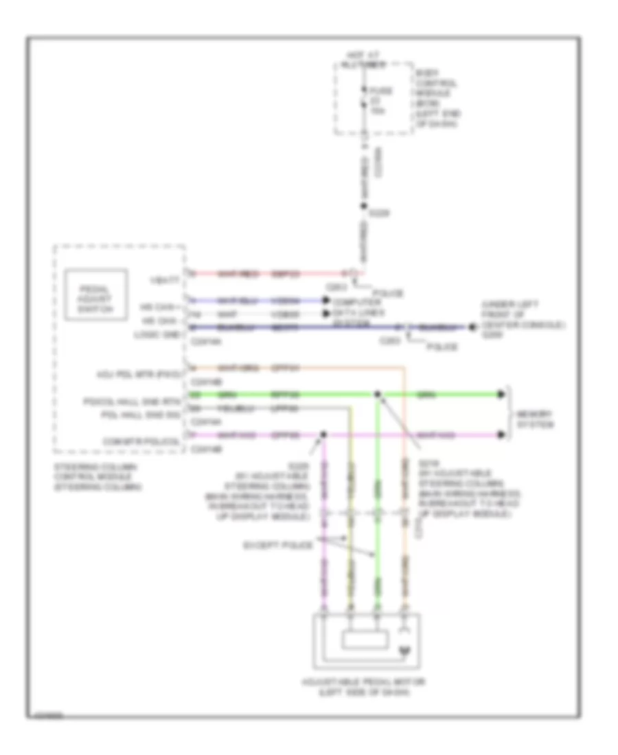
Power Steering Column Wiring Diagram for Ford Taurus Limited 2014
List of elements for Power Steering Column Wiring Diagram for Ford Taurus Limited 2014:
- (not used)
- (or cet42)
- (or cet43)
- (or re407)
- A/d channel 1
- A/d channel 2
- A/d channel 3
- A/d channel 4
- A/d return
- Adj pdl mtr (fwd)
- Adjustable pedal switch
- Auto lamp on
- Body control module (left end of dash)
- C2280a
- C2414a
- C2414b
- C263
- Cap18
- Cap19
- Clf19
- Clf23
- Clf24
- Cln55
- Cln56
- Cls34
- Com mtr
- Computer data lines system
- Cpp01
- Cpp04
- Cpp05
- Cpp22
- Crh04
- Cruise control system
- Crw15
- Dim down
- Dim rtn
- Dim up
- Dome on/defeat
- Except police
- Frt wiper hi
- Fuse 15a
- G200 (under left front of center console)
- Gd375
- Generic function module (right kick panel)
- Headlamp off
- Headlamp on
- Headlights system
- Horn
- Horn sw
- Horns system
- Hot at all times
- Hs can +
- Hs can -
- Instrument cluster system
- Interior lights system
- Lin
- Logic gnd
- Lpp06
- Memory systems
- Micr0
- Multi-function switch
- Nca
- Park lamp on
- Pdl hall sns sig
- Police
- Pwr gnd
- Rap18
- Rln29
- Rpp06
- S218
- S219 (main wiring harness, in breakout to head up display module)
- S225 (main wiring harness, in breakout to head up display module)
- S229
- Sbp23
- Sbp24
- Sig rtn
- Sns rtn
- Steering column control module (steering column)
- Steering column telescoping motor (w/ power tilt/telescoping) (on steering column)
- Steering column tilting motor (w/ power tilt/ telescoping) (on steering column)
- Sw rtn
- Sw1
- Sw1 (or) sst-u
- Sw2
- Sw2 (or) sst-d
- Tel mtr +/-
- Tel sns +
- Tilt mtr +/-
- Tilt sns +
- Transmissions system
- Vbatt
- Vdb04
- Vdb05
- Vdn05
- Vln36
- Vpp08
- Vpp17
- Wiper/washer system
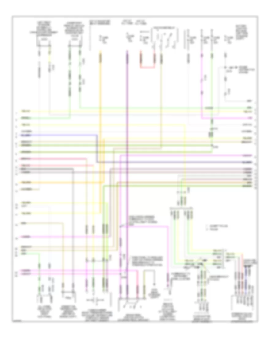
ENGINE PERFORMANCE
2.0L TURBO
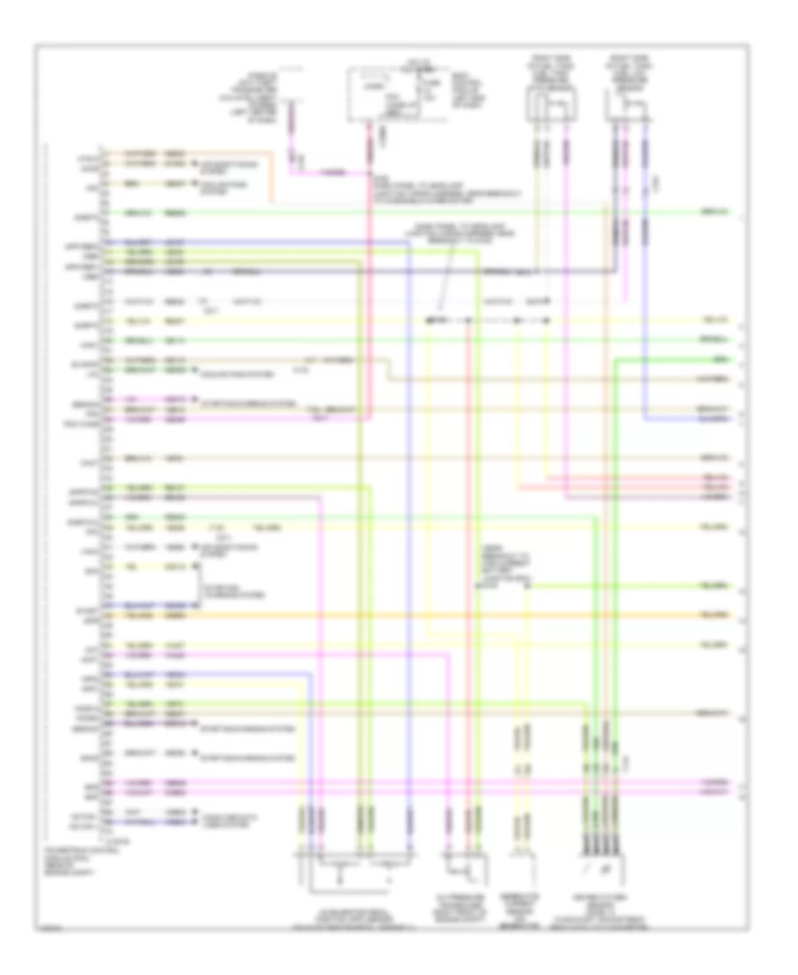
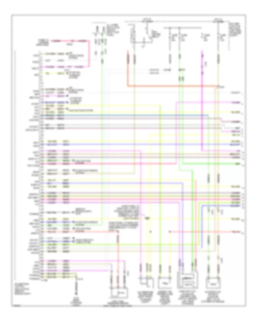
2.0L Turbo, Engine Performance Wiring Diagram (1 of 6) for Ford Taurus Limited 2014
List of elements for 2.0L Turbo, Engine Performance Wiring Diagram (1 of 6) for Ford Taurus Limited 2014:
- (dash panel to headlamp junction wiring harness, near breakout to g102)
- (near breakout to high current battery junction box) s148
- (right side of fuel tank) fuel low pressure sensor
- (right side of fuel tank) fuel tank pressure (ftp) sensor
- A/c pressure transducer (right front of engine compt)
- Aat
- Accelerator pedal position (app) sensor (on accelerator pedal assembly)
- Accr
- Acpt
- Air conditioning system
- App1
- App2
- Apprtn1
- Apprtn2
- Appvref1
- Appvref2
- Body control module (left end of dash)
- Bpp
- Bps
- C134
- C1381b
- C144
- C210
- C211
- C2280f
- C315
- Cact
- Canv
- Cbb90
- Ccb08
- Cdc10
- Cdc12
- Cdc15
- Cdc35
- Ce113
- Ce114
- Ce233
- Ce237
- Ce336
- Ce436
- Cec07
- Cec08
- Ces09
- Ch302
- Computer data lines system
- Cooling fans system
- Evapcp
- Fpc
- Fpm
- Fuse 10a
- Gencom
- Generator current sensor (on generator)
- Genmon
- Heated oxygen sensor (ho2s) 12 (in exhaust, downstream from catalytic converter)
- Hfc
- Ho2s12
- Hot at all times
- Hs can +
- Hs can -
- Htr12
- Ispr
- Le136
- Le137
- Le230
- Le424
- Lfc
- Micro
- Nca
- Passive anti-theft transceiver (w/o intelligent access) (left center of dash)
- Pcm wake
- Pcm wake up (fet)
- Pcmrc
- Powertrain control module (pcm) (rear of engine compt)
- Re136
- Re137
- Re230
- Re242
- Re407
- Res09
- S125
- S158 (dash panel to headlamp junction wiring harness, near breakout to windshield wiper motor)
- S319
- Sigrtn
- Sigrtn12
- Smc
- Smcs
- Start
- Starting/ charging system
- Starting/charging system
- Vacc
- Vdb04
- Vdb05
- Ve225
- Ve462
- Ve518
- Ve701
- Ve702
- Ve731
- Ve751
- Vh407
- Vh433
- Vref
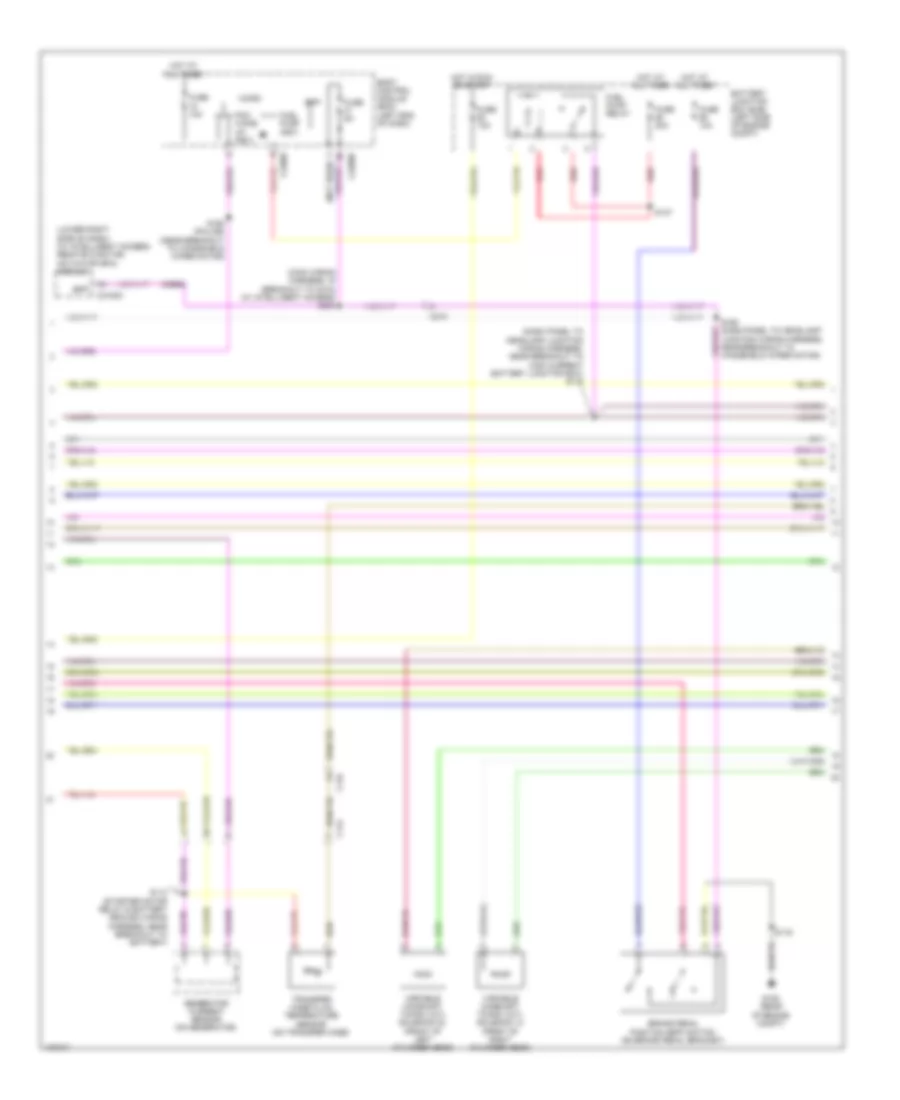
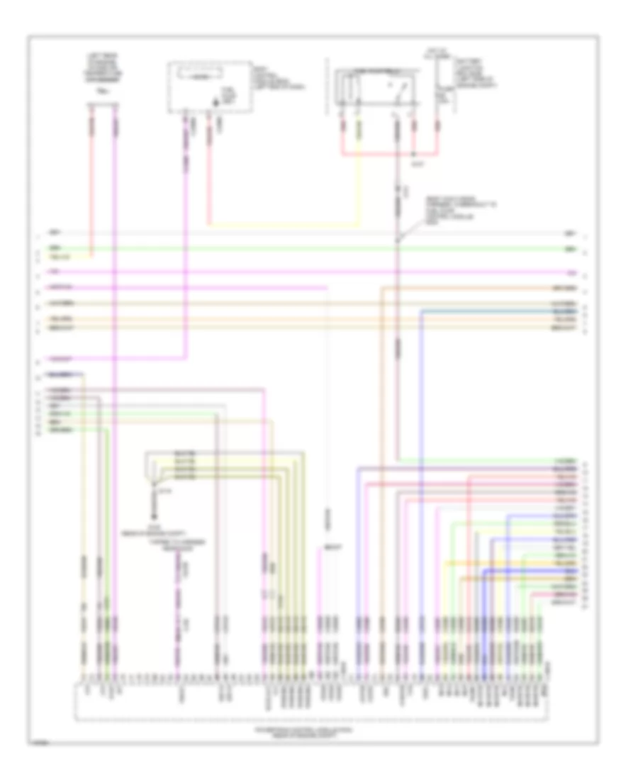
2.0L Turbo, Engine Performance Wiring Diagram (2 of 6) for Ford Taurus Limited 2014
List of elements for 2.0L Turbo, Engine Performance Wiring Diagram (2 of 6) for Ford Taurus Limited 2014:
- (main wiring harness, in breakout to instrument panel cluster) (except police) s226
- (main wiring harness, near breakout to c210) (except police) s281
- (top front of engine) evaporative emission (evap) canister vent valve
- 7.5a
- Ambient air temperature sensor (center of engine compt)
- Battery junction box (bjb) (left side of engine compt)
- Brake pedal position (bpp) switch (on brake pedal bracket)
- C134
- C144
- C210
- C211
- C214
- C2414a
- C263
- C315
- Cet42
- Cet43
- Floor shifter (base of shift lever assembly)
- Fuse
- Fuse 10a
- Fuse 15a
- Fuse 20a
- G105 (rear of engine compt)
- Hot at all times
- Hot in run or start
- Low gear selector switch (police)
- Pcm power relay
- Re407
- S119
- S122
- S168 (near breakout to windshield wiper motor)
- S227 (except police) (main wiring harness, in breakout to instrument panel cluster)
- Steering column control module (steering column)
- Turbocharger boost pressure/ charge air cooler temperature sensor (on throttle body)
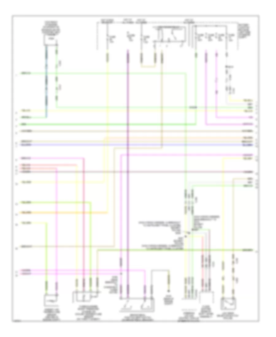
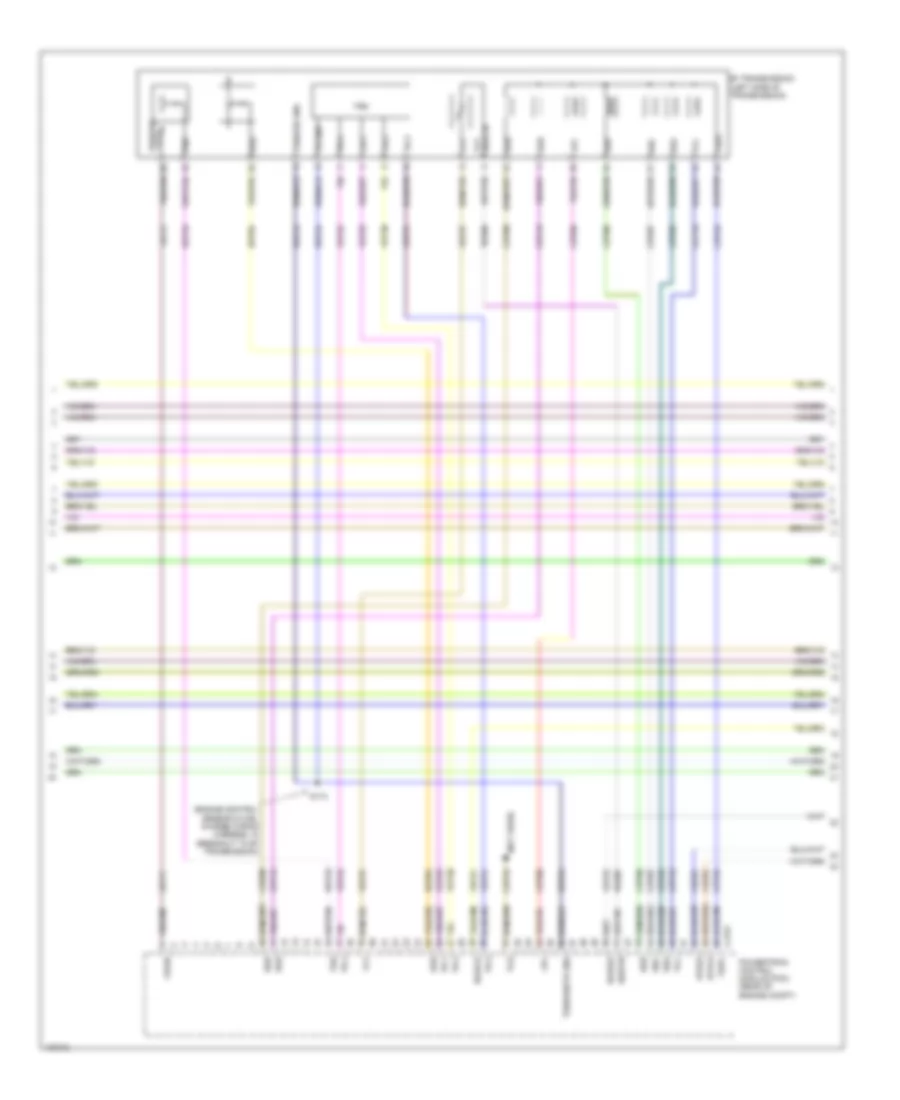
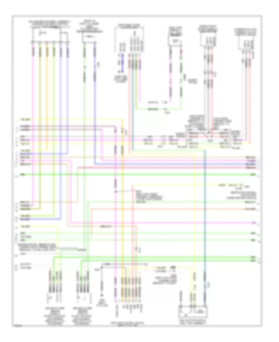
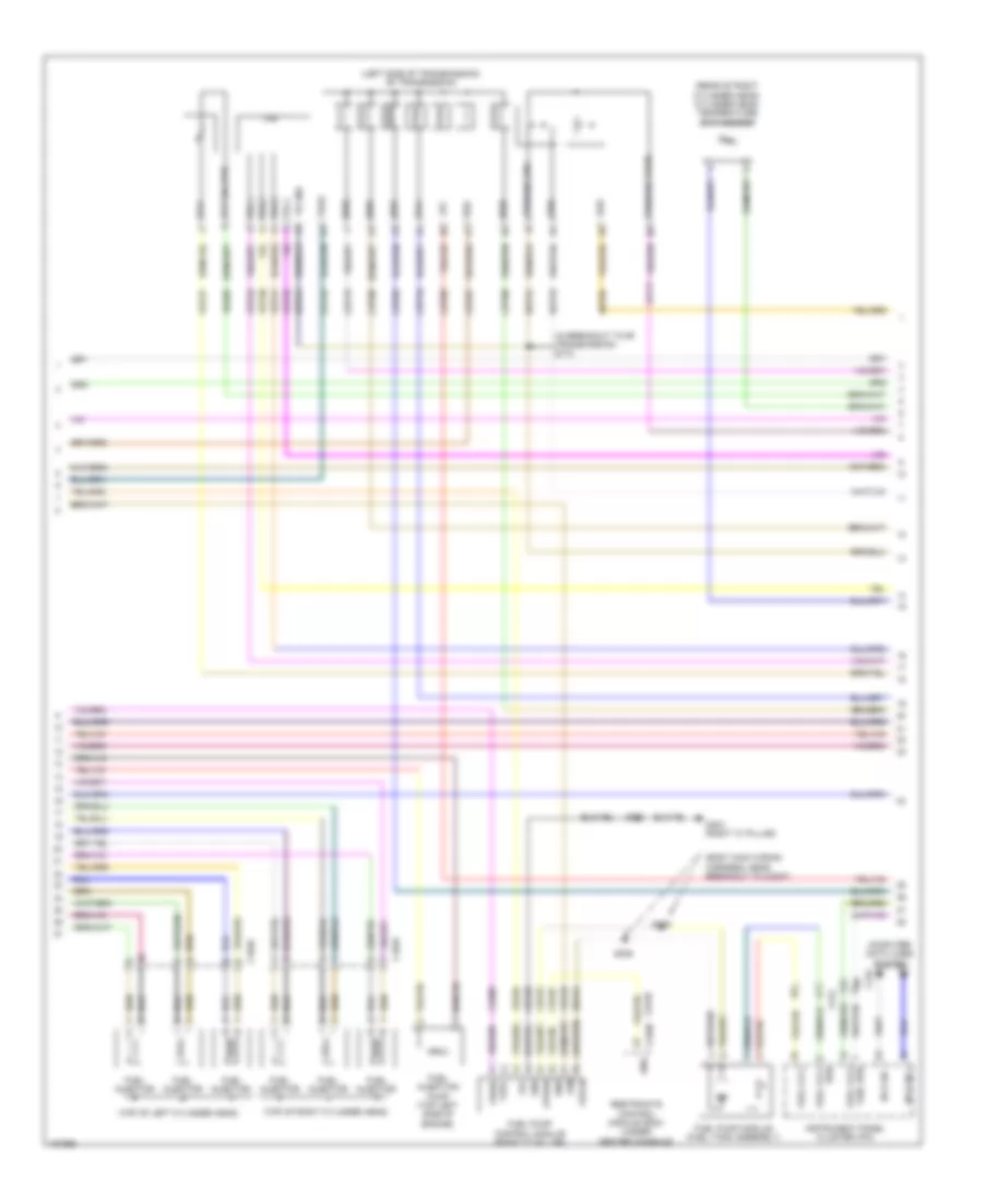
2.0L Turbo, Engine Performance Wiring Diagram (3 of 6) for Ford Taurus Limited 2014
List of elements for 2.0L Turbo, Engine Performance Wiring Diagram (3 of 6) for Ford Taurus Limited 2014:
- (body main wiring harness, in breakout to fuel pump control module) s300
- (left rear of engine) mass air flow/ intake air temperature (maf/iat) sensor
- (left side of transmission) transmission fluid warmer temperature control valve
- (lower right side of dash) (w/ intelligent access) remote function actuator module
- Battery junction box (bjb) (left side of engine compt)
- Bcs2 alt
- Body control module (left end of dash)
- Bpp
- C1381b
- C1381e
- C144
- C210
- C211
- C2153c
- C2280b
- C2280f
- Cbb69
- Ccb08
- Ce205
- Ce206
- Ce207
- Ce208
- Ce226
- Ce305
- Ce412
- Ce426
- Cet07
- Cet25
- Cet35
- Cet42
- Cet43
- Cop3b
- Down shift
- Flp
- Ftp
- Fuel pump (fet)
- Fuel pump relay
- Fuse 30a
- Fuse 5a
- Fvr
- Fvrrtn
- G101 (left front of engine compt)
- G105 (rear of engine compt)
- Gd113
- Hot at all times
- Hot in run or start
- Iat
- Inj1
- Inj1rtn
- Inj2
- Inj2rtn
- Inj3
- Inj3rtn
- Inj4
- Inj4rtn
- Micro
- Power distribution system
- Powertrain control module (pcm) (rear of engine compt)
- Pwrgnd
- Re205
- Re206
- Re207
- Re208
- Re226
- Red
- S108
- S116
- S137
- S157
- S204
- S240 (w/ intelligent access) (main wiring harness, in breakout to c215)
- Ssc
- Starting/ charging system
- Tacm+
- Tacm-
- Tcbp
- Tcs
- Tspc
- Up shift
- Vdc61
- Ve727
- Ve740
- Ve804
- Ve922
- Vpwr
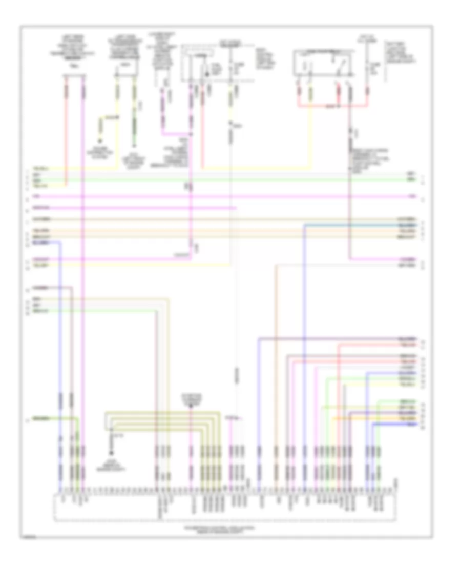
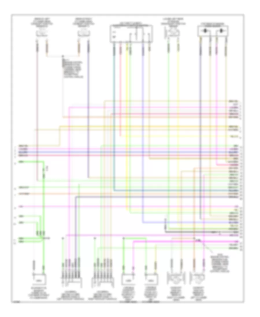
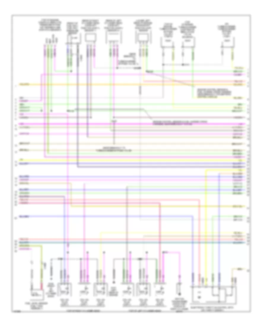
2.0L Turbo, Engine Performance Wiring Diagram (4 of 6) for Ford Taurus Limited 2014
List of elements for 2.0L Turbo, Engine Performance Wiring Diagram (4 of 6) for Ford Taurus Limited 2014:
- (body main wiring harness, near breakout to c3047)
- (body main wiring harness, near breakout to c3047) s305
- (c1520a: left side of transmission) (c1520b: rear of transmission) 6f35 transmission
- (left side of engine)
- (right "c" pillar) g303
- (top right side of engine) cylinder head temperature (cht) sensor
- C110
- C1520a
- C1520b
- C212
- C310b
- Ce515
- Ce608
- Computer data lines system
- Cr167
- Ens
- Fp pwr
- Fp rtn
- Fpc
- Fpm
- Fuel injection pump (top right rear of engine)
- Fuel injector
- Fuel lvl1
- Fuel pump control module (right "c" pillar)
- Fuel pump module (fuel tank assembly)
- Gd348
- Gnd
- Hs can +
- Hs can -
- Instrument panel cluster (ipc)
- Lpc
- Oss
- Re515
- Restraints control module (rcm) (under center console)
- Rtn
- S115 (near breakout to 6f35 transmission)
- S173 (near breakout to 6f35 transmission)
- S306
- S323
- Ssa
- Ssb
- Ssc
- Ssd
- Sse
- Tcc
- Tftin
- Tftout/ sigrtn
- Tr gnd oss
- Tr-p
- Trs
- Tspc
- Tss
- Tss gnd
- Tss vpwr
- Ve225
- Ve518
- Vpwr
- Vpwr oss/tr
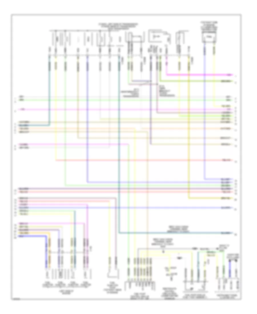
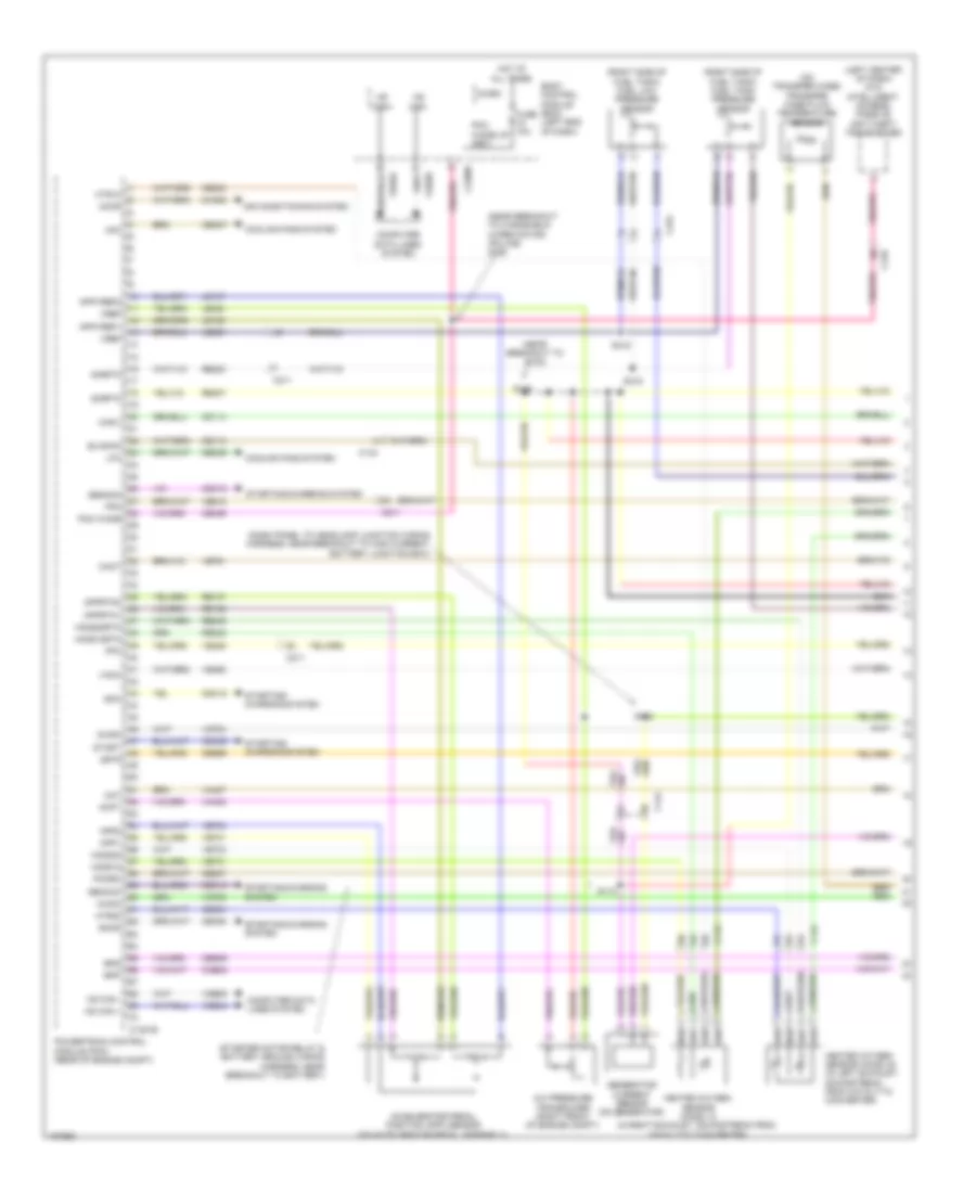
2.0L Turbo, Engine Performance Wiring Diagram (5 of 6) for Ford Taurus Limited 2014
List of elements for 2.0L Turbo, Engine Performance Wiring Diagram (5 of 6) for Ford Taurus Limited 2014:
- (front of fuel rail) fuel rail pressure (frp) sensor
- (lower right front of engine) crankshaft position (ckp) sensor
- (lower right front of engine) turbocharger wastegate regulating valve solenoid
- (near breakout powertrain control module) s192
- (near breakout to coil on plug 2)
- (near breakout to powertrain control module)
- (on intake manifold) manifold absolute pressure sensor
- (on turbocharger) turbocharger bypass valve
- (right rear of engine) engine coolant temperature sensor
- (top of engine)
- (top rear of engine) camshaft position (cmp11) sensor 11
- (top rear of engine) camshaft position (cmp12) sensor 12
- Coil on plug (cop) 1
- Coil on plug (cop) 2
- Coil on plug (cop) 3
- Coil on plug (cop) 4
- Electronic throttle control (etc) position sensor (on throttle body)
- G108 (right front of engine)
- S109
- S111
- S113
- S114
- S131
- S141
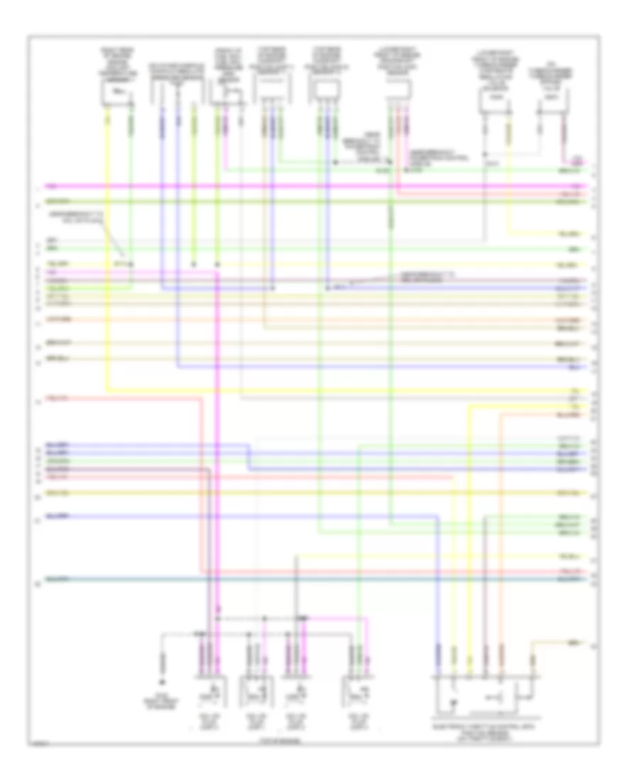
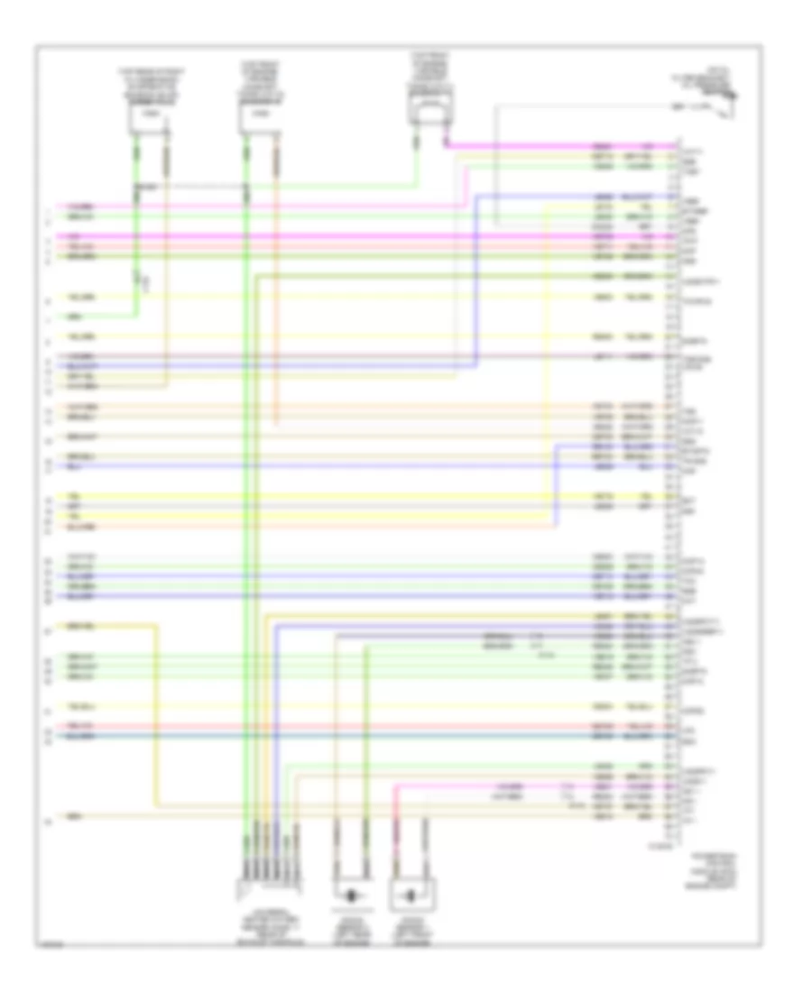
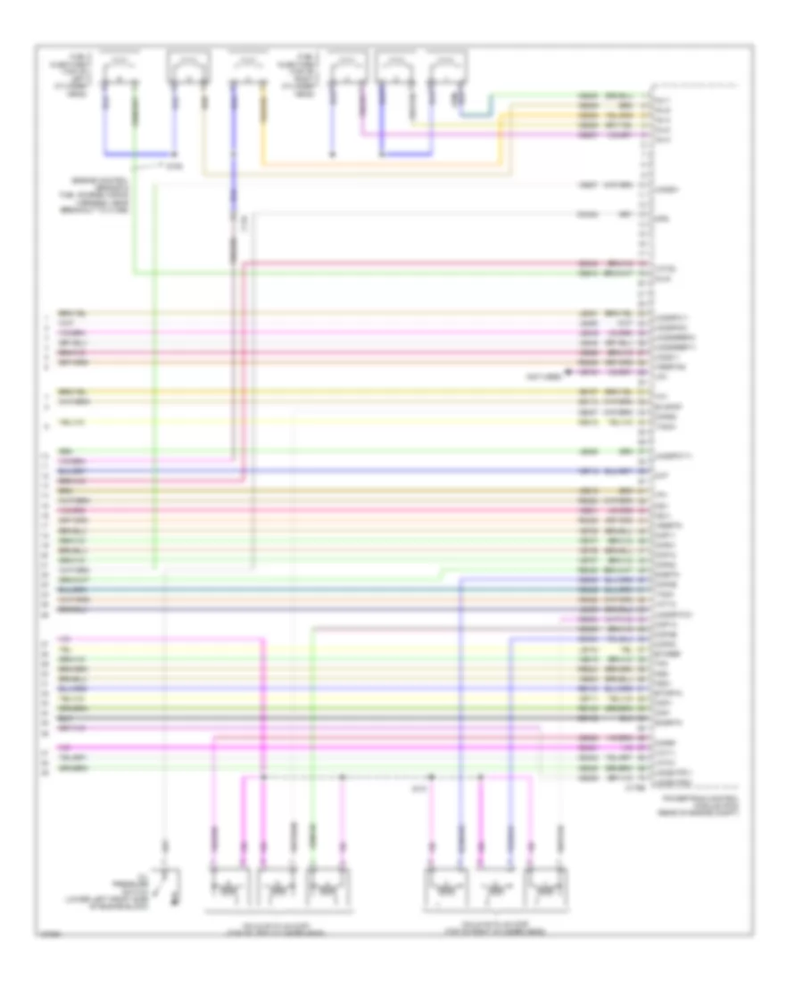
2.0L Turbo, Engine Performance Wiring Diagram (6 of 6) for Ford Taurus Limited 2014
List of elements for 2.0L Turbo, Engine Performance Wiring Diagram (6 of 6) for Ford Taurus Limited 2014:
- (on oil filter bracket) oil pressure switch
- (top front of engine) variable camshaft timing (vct11) solenoid 11
- (top front of engine) variable camshaft timing (vct12) solenoid 12
- (top rear of right cylinder bank) evaporative emission (evap) purge valve
- C110
- C134
- C1381e
- Ce235
- Ce303
- Ce304
- Ce306
- Ce421
- Ce422
- Cet05
- Cet06
- Cet08
- Cet09
- Cet10
- Cet18
- Cht
- Ckp
- Cmc24
- Cmp11
- Cmp12
- Cop1a
- Cop2d
- Cop4c
- Ect
- Etcref
- Etcrtn
- Frp
- Knock sensor 1 (left front of engine)
- Knock sensor 2 (left rear of engine)
- Ks1 +
- Ks1 -
- Ks2 +
- Ks2 -
- Le111
- Le134
- Le238
- Le329
- Le423
- Le448
- Le451
- Le452
- Le458
- Lpc
- Map
- Nca
- Ops
- Oss
- Powertrain control module (pcm) (rear of engine compt)
- Re134
- Re323
- Re324
- Re405
- Re454
- Ret24
- S126
- Sigrtn
- Ssa
- Ssb
- Ssd
- Sse
- Tcby
- Tcc
- Tcwrvs
- Tft
- Tp 1
- Tp 2
- Tr gnd
- Tr p
- Tss
- Tss/oss vpwr
- Universal heated oxygen sensor (ho2s) 11 (rear of exhaust manifold)
- Uo2s11
- Uo2sgref11
- Uo2shtr11
- Uo2spc11
- Uo2spct11
- Vct11
- Vct12
- Ve706
- Ve707
- Ve711
- Ve712
- Ve716
- Ve801
- Ve802
- Ve818
- Ve819
- Ve824
- Ve826
- Ve836
- Vet26
- Vet27
- Vet32
- Vet33
- Vref
3.5L
3.5L, Engine Performance Wiring Diagram (1 of 6) for Ford Taurus Limited 2014
List of elements for 3.5L, Engine Performance Wiring Diagram (1 of 6) for Ford Taurus Limited 2014:
- (dash panel to headlamp junction wiring harness, near breakout to g102) s125
- (dash panel to headlamp junction wiring harness, near breakout to high current battery junction box)
- (rear of engine compt) g105
- 20a
- 7.5a
- A/c pressure transducer (right front of engine compt)
- Aat
- Accr
- Acpt
- Air conditioning system
- All wheel drive (awd) module (right kick panel)
- Ambient air temperature sensor (center of engine compt)
- App1
- App2
- Apprtn1
- Apprtn2
- Appvref1
- Appvref2
- Awdc
- Awdm
- Battery junction box (bjb) (left side of engine compt)
- Bcs2 alt
- Bpp
- Bps
- C134
- C175b
- C210 starting/ charging system
- C211
- C2238
- C315
- Canv
- Cbb69
- Cbb90
- Ccb08
- Cdc10
- Cdc12
- Cdc15
- Cdc35
- Ce114
- Ce237
- Ce336
- Ce436
- Ce608
- Cec07
- Cec08
- Ces09
- Cet42
- Cet43
- Ch302
- Computer data lines system
- Cooling fans system
- Digital
- Down shift
- Evaporative emission canister vent valve (top rear of engine)
- Fpc
- Fpm
- Ftp
- Fuel tank pressure sensor (right side of fuel tank)
- Fuse
- G105 (rear of engine compt)
- Gd113
- Gen com
- Gen mon
- Hfc
- Hot at all times
- Hs can +
- Hs can -
- Iat
- Injpwrm
- Isp-r
- Kapwr
- Le136
- Le137
- Le230
- Le424
- Lfc
- Lin
- Maf
- Mass air flow/ intake air temperature (maf/iat) sensor (left rear of engine)
- Pcm power relay
- Pcm wake
- Pcmrc
- Powertrain control module (pcm) (rear of engine compt)
- Pwrgnd
- Re136
- Re137
- Re320
- Re407
- S116
- S134
- S138
- S148
- S157
- Sbb86
- Sigrtn
- Smc
- Smcs
- Start
- Starting/ charging system
- Starting/charging system
- Taped to harness near c2238
- Up shift
- Vacc
- Vcf34
- Vcf35
- Vdb04
- Vdb05
- Vdc61
- Vdn06
- Ve225
- Ve462
- Ve518
- Ve701
- Ve702
- Ve740
- Ve807
- Ve922
- Vh407
- Vh433
- Vmc05
- Vpwr
- Vref
- Vref 5v
- Vsout
3.5L, Engine Performance Wiring Diagram (2 of 6) for Ford Taurus Limited 2014
List of elements for 3.5L, Engine Performance Wiring Diagram (2 of 6) for Ford Taurus Limited 2014:
- (dash panel to headlamp junction wiring harness, near breakout to high current battery junction box) s110
- (lower right side of dash) (w/ intelligent access) remote function actuator (rfa) module
- (main wiring harness, in breakout to c215) (w/ intelligent access) s240
- (not used)
- Battery junction box (bjb) (left side of engine compt)
- Body control module (bcm) (left end of dash)
- Bpp
- Brake pedal position (bpp) switch (on brake pedal bracket)
- C134
- C144
- C210
- C2153c
- C2280b
- C2280f
- Ccb08
- Fuel pump (fet)
- Fuel pump relay
- Fuse 10a
- Fuse 30a
- Fuse 5a
- G105 (rear of engine compt)
- Generator current sensor (on generator)
- Hot at all times
- Hot in run or start
- Micro
- Pcm wake up (fet)
- Red
- S112 (starter motor relay & battery ground wiring harness, near breakout to battery)
- S116
- S137
- S158 (police) (near breakout to windshield wiper motor)
- S168 (dash panel to headlamp junction wiring harness, near breakout to windshield wiper motor)
- Transfer case fluid temperature sensor (on transfer case)
- Variable camshaft timing (vct) solenoid 12 (front of right cylinder head)
- Variable camshaft timing (vct) solenoid 22 (front of left cylinder head)
3.5L, Engine Performance Wiring Diagram (3 of 6) for Ford Taurus Limited 2014
List of elements for 3.5L, Engine Performance Wiring Diagram (3 of 6) for Ford Taurus Limited 2014:
- (engine control sensor & fuel charge wiring harness, in breakout to 6f transmission)
- (not used)
- 6f transmission (left side of transmission)
- C175t
- Ce233
- Ce234
- Cet05
- Cet06
- Cet07
- Cet08
- Cet09
- Cet10
- Cet19
- Cet25
- Cet34
- Ho2s12
- Ho2s22
- Htr12
- Htr22
- Le111
- Lpc
- Oss
- Powertrain control module (pcm) (rear of engine compt)
- Re406
- Ret04
- Ret24
- Ret33
- S173
- Sigrtn
- Sigrtn tft
- Ssa
- Ssb
- Ssc
- Ssd
- Sse
- Tcc
- Tcs
- Tft
- Tr gnd
- Tr-1
- Tr-2
- Tr-3
- Tr-4
- Trs
- Tspc
- Tss
- Tss/oss gnd
- Tss/oss/tr gnd
- Ve731
- Ve733
- Vet27
- Vet29
- Vet30
- Vet31
- Vet32
- Vpwr
- Vpwr tss/oss
3.5L, Engine Performance Wiring Diagram (4 of 6) for Ford Taurus Limited 2014
List of elements for 3.5L, Engine Performance Wiring Diagram (4 of 6) for Ford Taurus Limited 2014:
- (base of shift lever assembly) floor shifter
- (engine control sensor & fuel charge wiring harness, near breakout to fuel injector 2)
- (front of right cylinder head) cylinder head temperature sensor
- (fuel tank assembly) fuel level sensor
- (in left exhaust, downstream from catalytic converter)
- (main wiring harness, in breakout to instrument panel cluster) s226
- (main wiring harness, near breakout to c210) s281
- (on accelerator pedal assembly) accelerator pedal position (app) sensor
- (steering column) steering column control module
- C192
- C210
- C211
- C212
- C214
- C215
- C2414a
- C310b
- C3309
- Ce515
- Ce608
- Computer data lines system
- Cr167
- Ens
- Except police
- Fp pwr
- Fp rtn
- Fpc
- Fpm
- Fuel level 1
- Fuel level 1 rtn
- Fuel level 2
- Fuel pump (fp) module (fuel tank assembly)
- Fuel pump control module (right "c" pillar)
- Fuel rtn
- G303 (right "c" pillar)
- Gd348
- Gnd
- Heated oxygen sensor (ho2s) 12 (in right exhaust, downstream from catalytic converter)
- Heated oxygen sensor (ho2s) 22
- Hs can +
- Hs can -
- Instrument panel cluster (ipc)
- Nca
- Pnk
- Police
- Re515
- Restraints control module (rcm) (under center console)
- S109
- S227
- S300 (body main wiring harness, in breakout to fuel pump control module)
- S305
- S306 (body main wiring harness, near breakout to c3047)
- S323
- Sigrtn
- Sst-d
- Sst-u
- Ve225
- Ve518
- Vpwr fuel
3.5L, Engine Performance Wiring Diagram (5 of 6) for Ford Taurus Limited 2014
List of elements for 3.5L, Engine Performance Wiring Diagram (5 of 6) for Ford Taurus Limited 2014:
- (lower left rear of engine) crankshaft position sensor
- (on throttle body) electronic throttle control
- (rear of left cylinder head) camshaft position sensor 22
- (rear of right cylinder head) camshaft position sensor 12
- (top rear of engine) knock sensor
- C134
- Camshaft position sensor 11 (rear of right cylinder head)
- Camshaft position sensor 21 (rear of left cylinder head)
- Evaporative emission purge valve (top rear of right cylinder bank)
- Nca
- S102 (engine control sensor & fuel charge wiring harness, near breakout to powertrain control module)
- S105
- S126
- Tan
- Universal heated oxygen sensor (ho2s) 11 (right exhaust manifold)
- Universal heated oxygen sensor (ho2s) 21 (left exhaust manifold)
- Variable camshaft timing (vct) solenoid 11 (front of right cylinder head)
- Variable camshaft timing (vct) solenoid 21 (front of left cylinder head)
3.5L, Engine Performance Wiring Diagram (6 of 6) for Ford Taurus Limited 2014
List of elements for 3.5L, Engine Performance Wiring Diagram (6 of 6) for Ford Taurus Limited 2014:
- (engine control sensor & fuel charge wiring harness, near breakout to c1396)
- (not used)
- C134
- C175e
- Ce113
- Ce205
- Ce206
- Ce207
- Ce208
- Ce209
- Ce210
- Ce235
- Ce236
- Ce303
- Ce304
- Ce305
- Ce306
- Ce307
- Ce308
- Ce412
- Ce421
- Ce422
- Ce426
- Ce442
- Ce443
- Cht
- Ckp+
- Ckp-
- Cmc24
- Cmp11
- Cmp12
- Cmp21
- Cmp22
- Coils on plug (cop) (top of left cylinder head)
- Coils on plug (cop) (top of right cylinder head)
- Cop1a
- Cop2c
- Cop3e
- Cop4b
- Cop5d
- Cop6f
- De135
- Etcref
- Etcrtn
- Evapcp
- Fuel injectors (top of left cylinder head)
- Fuel injectors (top of right cylinder head)
- Inj-1
- Inj-2
- Inj-3
- Inj-4
- Inj-5
- Inj-6
- Ks1+
- Ks1-
- Ks2+
- Ks2-
- Le134
- Le448
- Le449
- Le450
- Le451
- Le452
- Le453
- Lfc
- Oil pressure switch (lower left front side of engine block)
- Ops
- Powertrain control module (pcm) (rear of engine compt)
- Re134
- Re135
- Re323
- Re324
- Re405
- Re429
- S106
- S131
- Shdrtn
- Sigrtn
- Tacm+
- Tacm-
- Tft
- Tp1
- Tp2
- Uo2s11
- Uo2s21
- Uo2sgref11
- Uo2sgref21
- Uo2shtr11
- Uo2shtr21
- Uo2spc11
- Uo2spc21
- Uo2spct11
- Uo2spct21
- Vct11
- Vct12
- Vct21
- Vct22
- Ve706
- Ve707
- Ve711
- Ve712
- Ve740
- Ve801
- Ve802
- Ve818
- Ve819
- Ve826
- Ve827
- Vet27
- Vrsrtn
- Vrsrtn2
3.5L TURBO
3.5L Turbo, Engine Performance Wiring Diagram (1 of 6) for Ford Taurus Limited 2014
List of elements for 3.5L Turbo, Engine Performance Wiring Diagram (1 of 6) for Ford Taurus Limited 2014:
- (dash panel to headlamp junction wiring harness, near breakout to high current battery junction box)
- (left center of dash) (w/o intelligent access) passive anti-theft transceiver
- (near breakout to g102)
- (near breakout to windshield wiper motor) (police) s158
- (on transfer case) transfer case fluid temperature sensor
- (right side of fuel tank) fuel low pressure sensor
- (right side of fuel tank) fuel tank pressure sensor
- (starter motor relay & battery ground wiring harness, near breakout to battery)
- A/c pressure transducer (right front of engine compt)
- Aat
- Accelerator pedal position (app) sensor (on accelerator pedal assembly)
- Accr
- Acpt
- Air conditioning system
- App1
- App2
- Apprtn1
- Apprtn2
- Appvref1
- Appvref2
- Awdc
- Awdm
- Body control module (bcm) (left end of dash)
- Bpp
- Bps
- C134
- C1381b
- C144
- C210
- C211
- C2280f
- C315
- Cact
- Canv
- Cbb90
- Ccb08
- Cd114
- Cdc10
- Cdc12
- Cdc15
- Cdc35
- Ce113
- Ce233
- Ce234
- Ce237
- Ce336
- Ce436
- Cec07
- Cec08
- Ces09
- Ch302
- Computer data lines system
- Cooling fans system
- Evapcp
- Fpc
- Fpm
- Fuse 10a
- Gencom
- Generator current sensor (on generator)
- Genmon
- Heated oxygen sensor (ho2s) 12 (in right exhaust, downstream from catalytic converter)
- Heated oxygen sensor (ho2s) 22 (in left exhaust, downstream from catalytic converter)
- Hfc
- Ho2s12
- Ho2s12rtn
- Ho2s22
- Ho2s22rtn
- Hot at all times
- Hs can +
- Hs can -
- Hs can+
- Hs can-
- Htr12
- Htr22
- Isp-r
- Le136
- Le137
- Le230
- Le424
- Lfc
- Micro
- Pcm wake
- Pcm wake up (fet)
- Pcmrc
- Powertrain control module (pcm) (rear of engine compt)
- Re136
- Re137
- Re230
- Re242
- Re249
- Re407
- S112
- S125
- S148
- S318
- S319
- Sigrtn
- Smc
- Smcs
- Start
- Starting/ charging system
- Starting/charging system
- Vacc
- Vcf34
- Vcf35
- Vdb04
- Vdb05
- Ve225
- Ve462
- Ve518
- Ve701
- Ve702
- Ve731
- Ve733
- Ve751
- Vh407
- Vh433
- Vref
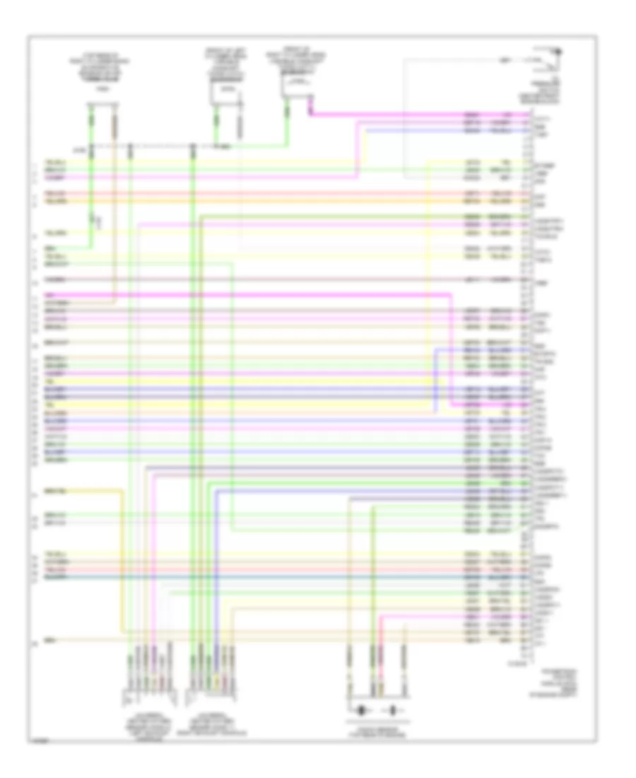
3.5L Turbo, Engine Performance Wiring Diagram (2 of 6) for Ford Taurus Limited 2014
List of elements for 3.5L Turbo, Engine Performance Wiring Diagram (2 of 6) for Ford Taurus Limited 2014:
- (dash panel to headlamp junction wiring harness, near breakout to windshield wiper motor)
- (in breakout to instrument panel cluster)
- (left front of engine) externally controlled variable displacement compressor
- (main wiring harness, in breakout to c215) (w/ intelligent access) s240
- (near breakout
- (under right rear of vehicle) evaporative emission (evap) canister vent valve
- 7.5a
- All wheel drive (awd) module (right kick panel)
- Ambient air temperature sensor (center of engine compt)
- Awdc
- Awdm
- Battery junction box (bjb) (left side of engine compt)
- Bpp
- Brake pedal position switch (on brake pedal bracket)
- C134
- C144
- C210
- C211
- C214
- C2153c
- C2414a
- C315
- Cet42
- Cet43
- Computer data lines system
- Except police
- Floor shifter (base of shift lever assembly)
- Fuse
- Fuse 10a
- Fuse 15a
- Fuse 20a
- G105 (rear of engine compt)
- Hot at all times
- Hot w/ run/start relay energized
- Hs can+
- Hs can-
- Pcm power relay
- Police
- Power distribution system
- Re407
- Remote function actuator (w/ intelligent access) (lower right side of dash)
- S119
- S122
- S168
- S226
- S227
- S281
- Sigrtn
- Sst-d
- Sst-u
- Steering column control module (sccm) (steering column)
- To c210)
- Turbocharger boost pressure/charge air cooler temperature (tcbp/cact) sensor (on throttle body)
- Vcf34
- Vcf35
- Vdb04
- Vdb05
3.5L Turbo, Engine Performance Wiring Diagram (3 of 6) for Ford Taurus Limited 2014
List of elements for 3.5L Turbo, Engine Performance Wiring Diagram (3 of 6) for Ford Taurus Limited 2014:
- (body main wiring harness, in breakout to fuel pump control module) s300
- (left rear of engine) intake air temperature (iat) sensor
- Battery junction box (bjb) (left side of engine compt)
- Bcs2 alt
- Body control module (bcm) (left end of dash)
- C1381b
- C1381e
- C144
- C210
- C211
- C2238
- C2280b
- C2280f
- Cbb69
- Ccb08
- Ce205
- Ce206
- Ce207
- Ce208
- Ce209
- Ce210
- Ce226
- Ce305
- Ce308
- Ce412
- Ce426
- Cet07
- Cet25
- Cet42
- Cet43
- Cop3e
- Cop6f
- Flp
- Ftp
- Fuel pump (fet)
- Fuel pump relay
- Fuse 30a
- Fvr
- Fvrrtn
- G105 (rear of engine compt)
- Gd113
- Hot at all times
- Iat
- Inj1
- Inj1rtn
- Inj2
- Inj2rtn
- Inj3
- Inj3rtn
- Inj4
- Inj4rtn
- Inj5
- Inj5rtn
- Inj6
- Inj6rtn
- Micro
- Powertrain control module (pcm) (rear of engine compt)
- Pwrgnd
- Re205
- Re206
- Re207
- Re208
- Re209
- Re210
- Re226
- Red
- S116
- S137
- S157
- Ssc
- Sst-d
- Sst-u
- Tacm+
- Tacm-
- Tapped to harness near c2238
- Tcbp
- Tft
- Tspc
- Vdc61
- Ve727
- Ve740
- Ve804
- Ve922
- Vet27
- Vmc05
- Vpwr
- Vsout
3.5L Turbo, Engine Performance Wiring Diagram (4 of 6) for Ford Taurus Limited 2014
List of elements for 3.5L Turbo, Engine Performance Wiring Diagram (4 of 6) for Ford Taurus Limited 2014:
- (body main wiring harness, near breakout to c3047)
- (in breakout to 6f transmission) s173
- (left side of transmission) 6f transmission
- (rear of right cylinder head) cylinder head temperature (cht) sensor
- (top of left cylinder head)
- (top of right cylinder head)
- C1045
- C1046
- C212
- C215
- C310b
- Ce515
- Ce608
- Cet05
- Cet06
- Cet07
- Cet08
- Cet09
- Cet10
- Cet19
- Cet25
- Computer data lines system
- Cr167
- Ens
- Fpc
- Fpm
- Fppwr
- Fprtn
- Fuel injection pump (top left side of engine)
- Fuel injector
- Fuel lvl1
- Fuel lvl2
- Fuel pump control module (right "c" pillar)
- Fuel pump module (fuel tank assembly)
- Fuel rtn
- Fuel vpwr
- G303 (right "c" pillar)
- Gd348
- Gnd
- Hs can +
- Hs can -
- Instrument panel cluster (ipc)
- Le111
- Lpc
- Oss
- Re405
- Re515
- Restraints control module (rcm) (under center console)
- Ret04
- Ret24
- Ret33
- Rtn
- S305
- S306
- S323
- Ssa
- Ssb
- Ssc
- Ssd
- Sse
- Tcc
- Tft
- Tft sig rtn
- Tr gnd
- Tr-1
- Tr-2
- Tr-3
- Tr-4
- Trs
- Tspc
- Tss
- Tss/oss gnd
- Tss/oss vpwr
- Ve225
- Ve518
- Vet27
- Vet29
- Vet30
- Vet31
- Vet32
3.5L Turbo, Engine Performance Wiring Diagram (5 of 6) for Ford Taurus Limited 2014
List of elements for 3.5L Turbo, Engine Performance Wiring Diagram (5 of 6) for Ford Taurus Limited 2014:
- (engine control sensor & fuel charge wiring harness, near breakout powertrain control module)
- (engine control sensor & fuel charge wiring harness, near breakout to c123)
- (front of fuel rail) fuel rail pressure sensor
- (lower left rear of engine) crankshaft position (ckp) sensor
- (near breakout to turbocharger bypass valve)
- (on turbocharger) turbocharger bypass valve 1 (tcby)
- (rear of left cylinder head) camshaft position (cmp21) sensor 21
- (rear of right cylinder head) camshaft position (cmp11) sensor 11
- (top of engine) manifold absolute pressure/intake air temperature (map/iat2) sensor 2
- (top of engine) turbocharger bypass valve 2 (tcby2)
- (top of engine) turbocharger wastegate regulating valve solenoid
- (top of left cylinder head)
- (top of right cylinder head)
- C1046
- C1609a
- C1609b
- C3309
- Coil on plug (cop) 1
- Coil on plug (cop) 2
- Coil on plug (cop) 3
- Coil on plug (cop) 4
- Coil on plug (cop) 5
- Coil on plug (cop) 6
- Electronic throttle control (etc) (on throttle body)
- Fuel level sensor (fuel tank assembly)
- G106 (front of left cylinder bank)
- G107 (left rear of engine)
- Iat2
- Ignition transformer capacitor 1 (middle of right cylinder bank)
- Map
- Pnk
- S109
- S114
- S115
- S131
- S141
- S192
- S198
- S199
- Sig rtn
- Vref
3.5L Turbo, Engine Performance Wiring Diagram (6 of 6) for Ford Taurus Limited 2014
List of elements for 3.5L Turbo, Engine Performance Wiring Diagram (6 of 6) for Ford Taurus Limited 2014:
- (front of left cylinder head) variable camshaft timing (vct21) solenoid 21
- (front of right cylinder head) variable camshaft timing (vct11) solenoid 11
- (top rear of right cylinder bank) evaporative emission (evap) purge valve
- C134
- C1381e
- Ce235
- Ce236
- Ce303
- Ce304
- Ce306
- Ce307
- Ce421
- Ce422
- Ce435
- Cet05
- Cet06
- Cet08
- Cet09
- Cet10
- Cet19
- Cht
- Ckp
- Cmc24
- Cmp11
- Cmp21
- Cop1a
- Cop2c
- Cop4b
- Cop5d
- E-sigrtn
- Etcref
- Etcrtn
- Frp
- Iat2
- Knock sensor (top rear of engine)
- Ks1 +
- Ks1 -
- Ks2 +
- Ks2 -
- Le111
- Le134
- Le423
- Le448
- Le449
- Le450
- Le451
- Le452
- Le453
- Lpc
- Map
- Oil pressure switch (center front engine block)
- Ops
- Oss
- Powertrain control module (pcm) (rear of engine compt)
- Re134
- Re323
- Re324
- Re405
- Re406
- Red
- Ret04
- Ret24
- Ret33
- S126
- Ssa
- Ssb
- Ssd
- Sse
- Tan
- Tcby
- Tcby2
- Tcc
- Tcwrvs
- Tft
- Tp 1
- Tp2
- Tr gnd
- Tr-1
- Tr-2
- Tr-3
- Tr-4
- Tss
- Universal heated oxygen sensor (ho2s) 11 (right exhaust manifold)
- Universal heated oxygen sensor (ho2s) 21 (left exhaust manifold)
- Uo2s11
- Uo2s21
- Uo2sgref11
- Uo2sgref21
- Uo2shtr11
- Uo2shtr21
- Uo2spc11
- Uo2spc21
- Uo2spct11
- Uo2spct21
- Vct11
- Vct21
- Ve706
- Ve707
- Ve711
- Ve712
- Ve727
- Ve740
- Ve801
- Ve802
- Ve804
- Ve818
- Ve819
- Ve824
- Ve826
- Ve827
- Vet27
- Vet29
- Vet30
- Vet31
- Vet32
- Vref
EXTERIOR LIGHTS
Backup Lamps Wiring Diagram for Ford Taurus Limited 2014
List of elements for Backup Lamps Wiring Diagram for Ford Taurus Limited 2014:
- (body main wiring harness, near breakout to joint connector 12) s408
- (engine control sensor & fuel charge wiring harness, in breakout to 6f transmission) s173
- (engine control sensor & fuel charge wiring harness, near breakout to 6f35 transmission) s173
- 3.5l
- 3.5l turbo
- 6f transmission (left side of transmission)
- 6f35 transmission (left side of transmission)
- Auto-dimming interior mirror (w/ rearview camera)
- Body control module (bcm) (left end of dash)
- C1381b
- C1381e
- C1520a
- C219
- C2280d
- C2280f
- Cls28
- Computer data lines system
- Except police
- Exterior lamps circuit
- Fuse 15a
- G301 (left kick panel)
- G302 (left "c" pillar)
- Gd347
- Gnd
- Hot at all times
- Hs can +
- Hs can -
- Hs can - c175b
- Le111
- Leds
- Left reversing lamp
- Micro
- Oss/tr gnd
- Oss/tr vpwr
- Police
- Powertrain control module (pcm) (2.0l turbo) (rear of engine compt)
- Powertrain control module (pcm) (rear of engine compt)
- Ret24
- Reverse
- Reverse lamp (fet)
- Right reversing lamp
- S115 (engine control sensor & fuel charge wiring harness, near breakout to 6f35 transmission)
- S904
- Sunshade module (left side of luggage compt)
- Tr 1
- Tr 2
- Tr 3
- Tr 4
- Tr 4 c175t
- Tr gnd
- Tr p
- Transmissions system
- Trs
- Tss/oss vpwr
- Tss/oss/ tr gnd tr 1
- Tss/oss/ tr gnd tr p
- Vbd05
- Vdb04
- Vet29
- Vet30
- Vet31
- Vet32
Exterior Lamps Wiring Diagram (1 of 2) for Ford Taurus Limited 2014
List of elements for Exterior Lamps Wiring Diagram (1 of 2) for Ford Taurus Limited 2014:
- (not used)
- Auto 1
- Body control module (bcm) (left end of dash)
- Bpp
- C2280a
- C2280b
- C2280c
- C2280d
- C2280e
- C2280f
- Cls32
- Cls54
- Cls55
- Computer data lines system
- Fuse 10a
- Fuse 15a
- Fuse 5a
- G100 (right front of engine compt)
- G101 (left front of engine compt)
- G201 (under right front of center console)
- Hazard
- Headlamp switch
- Hot at all times
- Hs can+
- Hs can-
- Leds
- Left front auxiliary park lamp
- Left front park/ turn lamp
- Left front side marker lamp
- Left front turn lamp (fet)
- Left led turn outage
- Left rear turn lamp (fet)
- Low
- Micro
- Off
- Park
- Park lamp
- Park lamp relay
- Red
- Right front auxiliary park lamp
- Right front park/ turn lamp
- Right front side marker lamp
- Right front turn lamp (fet)
- Right led turn outage
- Right rear turn lamp (fet)
- S134 (dash panel to headlamp junction wiring harness, in breakout to turbocharger boost pressure/charge air cooler temperature sensor)
- S211
- S218
- S229
- Side marker lamp
- Stop/ chmsl (fet)
- Turn lamp
- Vdb04
- Vdb05
Exterior Lamps Wiring Diagram (2 of 2) for Ford Taurus Limited 2014
List of elements for Exterior Lamps Wiring Diagram (2 of 2) for Ford Taurus Limited 2014:
- (body main wiring harness, near breakout to joint connector 7) s338
- (center of dash) front controls interface module (fcim)
- (dash panel to headlamp junction wiring harness, near breakout to windshield wiper motor)
- (main wiring harness, in breakout to c215) (w/ intelligent access) s240
- (under right front of center console) g201
- 2.0l turbo & 3.5l turbo
- 3.5l
- Autolamp on
- Battery junction box (bjb) (left side of engine compt)
- Bpp
- Bps
- Brake pedal position (bpp) switch (on brake pedal bracket)
- C1381b
- C175b
- C210
- C2153c
- C2414a
- C2414b
- C405
- C475a
- C475b
- Ccb08
- Ces09
- Clf19
- Clf23
- Clf24
- Cls32
- Cls34
- Computer data lines system
- Fuse 10a
- G105 (rear of engine compt)
- G200 (under left front of center console)
- G302 (left "c" pillar)
- G400 (right side of luggage compt)
- G401 (right side of luggage compt)
- Gd374
- Gd375
- Gnd
- Hazard
- Hazard switch
- Headlamp off
- Headlamp on
- High mounted stoplamp
- High mounted stoplamp capacitor (left side of luggage compt)
- Hot at all times
- Hs can +
- Hs can -
- Hs can+
- Hs can-
- I can +
- I can -
- Leds
- Left license plate lamp
- Left rear lamp assembly
- Left reversing lamp
- Logic gnd
- Micro
- Multi-function switch
- Nca
- Park lamps on
- Powertrain control module (pcm) (rear of engine compt)
- Pwr gnd
- Red
- Remote function actuator (rfa) module (w/ intelligent access) (lower right side of dash)
- Right license plate lamp
- Right rear lamp assembly
- Right reversing lamp
- S116 (3.5l)
- S168
- S405
- S406 (body main wiring harness, near breakout to high mounted stop lamp)
- Sbp09
- Sbp23
- Sbp24
- Steering column control module (sccm) (steering column)
- Stop
- Tail
- Turn
- Vbatt
- Vdb04
- Vdb05
- Vdb13
- Vdb14
- W/ adjustable steering column
GROUND DISTRIBUTION
Ground Distribution Wiring Diagram (1 of 4) for Ford Taurus Limited 2014
List of elements for Ground Distribution Wiring Diagram (1 of 4) for Ford Taurus Limited 2014:
- (2.0l turbo) temperature control valve transmission fluid warmer
- (if equipped) left front auxiliary park lamp
- (if equipped) right front auxiliary park lamp
- (left front of engine compt)
- (left side of engine compt) battery junction box (bjb)
- (police w/ grill preparation) front park/turn flashing led
- (police w/ grill preparation) taped to harness near c1465
- (police) instrument panel power point 1
- (police) instrument panel power point 2
- (police) left front corner flashing led
- (police) left front park/turn flashing led
- (police) left grille flashing led
- (police) right front corner flashing led
- (police) right front park/turn flashing led
- (police) right grille flashing led
- (police) taped to harness near c2239
- (tdm grille jumper wiring harness, near breakout to c1704)
- (w/ adaptive cruise) head up display (hud) module
- (w/ park assist) active park assist switch
- 3.5l
- A/c compressor clutch field coil
- Anti-lock brake system (abs) module
- Battery
- Blower motor speed control
- Brake fluid level switch
- Brake pedal position (bpp) switch
- C1010
- C1019
- C134
- C1381b
- C144
- C1467b
- C1704
- C175b
- C1830
- C214
- C217b pnk
- C218a
- C218b
- C2414a
- C2414b
- C263
- Clockspring (steering wheel assembly)
- Cruise control module
- Data link connector (dlc)
- Engine cooling fan motor 2
- Except 3.5l
- Fan control relay
- Front cigar lighter
- Front console power point
- G100 (right front of engine compt)
- G101
- G103 (rear of engine)
- G104 (except 3.5l turbo: left front of engine compt) (3.5l turbo: right side of engine)
- G105 (rear of engine compt)
- G109 (top of engine)
- G110 (top of engine)
- G111 (left front of engine compt)
- G200 (under left front of center console)
- Grille shutter actuator
- Heated steering wheel module (hswm)
- Horn
- Horn switch
- Left front park/ turn lamp
- Left front side marker lamp
- Left headlamp assembly
- Left steering wheel switch
- Nca
- Pnk
- Police
- Police run/start relay
- Power steering control module (pscm)
- Powertrain control module (pcm)
- Rear console power point
- Rear sunshade switch
- Relay & battery ground wiring harness, near breakout to g103) (2.0l turbo: starter motor relay & battery ground wiring harness, near breakout to heated oxygen sensor no. 12)
- Right front park/ turn lamp
- Right front side marker lamp
- Right headlamp assembly
- Right steering wheel switch
- S116 (dash panel to headlamp junction wiring harness, in breakout to g105)
- S124 (dash panel to headlamp junction wiring harness, near breakout to a/c pressure transducer)
- S159 (right front of engine compt)
- S182
- S299 (steering wheel jumper wiring harness)
- Start/ stop switch
- Steering column control module
- Turbocharger boost pressure/ charge air cooler temperature (tcbp/cact) sensor
- W/ adjustable steering column
- W/ halogen headlamps
- Washer fluid level switch
- Windshield washer pump motor
- Windshield wiper motor
- Wiper relay
Ground Distribution Wiring Diagram (2 of 4) for Ford Taurus Limited 2014
List of elements for Ground Distribution Wiring Diagram (2 of 4) for Ford Taurus Limited 2014:
- (2.0l turbo) coil on plug (cop) 4
- (3.5l turbo)
- (automatic a/c) datc hvac module
- (manual a/c) emtc hvac module
- (police) generic function module (gem)
- (sync gen 1) front control/ display interface module (fcdim)
- (sync w/o navigation) global positioning system module (gpsm)
- (w/ rear heated seats) accessory protocol interface module (apim)
- (w/ rear heated seats) driver side rear seat heater switch
- (w/ rear heated seats) passenger side rear seat heater switch
- (w/o intelligent access) passive anti-theft transceiver
- 2.0l turbo
- 3.5l turbo
- Accessory protocol interface module (apim)
- Audio control module (acm)
- Autolamp/ sunload sensor
- C214
- C2153c
- C2153d
- C2153e
- C228a
- C228c
- C2357a
- C240a
- C4808a
- Coil on plug (cop) 1
- Coil on plug (cop) 2
- Coil on plug (cop) 3
- Coil on plug (cop) 4
- Coil on plug (cop) 5
- Coil on plug (cop) 6
- Data link connector (dlc)
- Electronics tray cooling fan
- Front controls interface module (fcim)
- G106 (front of left cylinder bank)
- G107 (except 3.5l turbo: right rear of engine compt) (3.5l turbo: left rear of engine)
- G108 (right front of engine)
- G201 (under right front of center console)
- G402 (police) (right side of luggage compt)
- Headlamp switch
- In-vehicle temperature/ humidity sensor
- Instrument panel cluster (ipc)
- Left decklid flashing led
- Left high mount flashing led
- Left tail lamp flashing led
- Lighting/ siren control module
- Luggage compartment lid release switch
- Nca
- Prndl illumination lamp
- Remote function actuator (rfa) module
- Right decklid flashing led
- Right high mount flashing led
- Right tail lamp flashing led
- S114 (engine control sensor & fuel charge wiring harness, near breakout to coil on plug 2)
- S282 (main wiring harness, in breakout to accessory protocol interface module)
- S340 (w/ heated rear seats) (console panel wiring harness, near breakout to c314)
- Sensor & fuel charge wiring harness, near breakout to camshaft position sensor 12)
- W/ rear heated seats
- W/ sync 1
- W/ sync 2
- W/o rear heated seats
Ground Distribution Wiring Diagram (3 of 4) for Ford Taurus Limited 2014
List of elements for Ground Distribution Wiring Diagram (3 of 4) for Ford Taurus Limited 2014:
- (if equipped) video camera
- (police)
- (police) left rear lamp assembly
- (police) police trunk relay center
- (police) right rear lamp assembly
- (w/ 10-way driver power seat & memory) driver side front seat control switch
- (w/ 14 way driver power seat) driver seat lumbar control module
- (w/ 14-way driver power seat w/ memory) driver side front seat control switch
- (w/ 6-way driver power seat w/o memory) driver side front seat control switch
- (w/ ambient lighting & premium sound) driver seat end in harness
- (w/ blind spot) left (sod-l) side obstacle detection control module
- (w/ blind spot) right (sod-r) side obstacle detection control module
- (w/ heated seats) driver side seat backrest heater mat
- (w/ intelligent access) luggage compartment lid release switch
- (w/ memory) memory set switch
- (w/ sony) audio digital signal processing (dsp) module
- (w/o intelligent access) luggage compartment lid release switch
- C241b
- C300
- C3050
- C312
- C3381
- C3385a
- C3387a
- C341a
- C402b
- C405
- C4326c
- Driver seat module (dsm)
- G302 (left "c" pillar)
- G400 (right side of luggage compt)
- G401 (right side of luggage compt)
- High mounted stoplamp
- Left license plate lamp
- Left rear lamp assembly
- Left reversing lamp
- Left tray lamp relay
- Luggage compartment lid release solenoid/ ajar switch
- Parking aid module (pam)
- Rear window defrost grid
- Right license plate lamp
- Right rear lamp assembly
- Right reversing lamp
- Right tray lamp relay
- S352 (driver's seat wiring harness, near breakout to c3050)
- S402 (body main wiring harness, near breakout to c4371)
- S404 (backup alarm jumper wiring harness, near breakout to left license plate lamp)
- S415 (police rear relay jumper wiring harness, near breakout to rear flasher relay)
- Sunshade module
- Taped to harness near c4031 left rear package tray flasher
- Taped to harness near c4031 left rear tail lamp flasher
- Taped to harness near c4031 right rear package tray flasher
- Taped to harness near c4031 right rear tail lamp flasher
- Tire pressure monitor (tpm) module
- W/ 10-way
- W/ 14-way
Ground Distribution Wiring Diagram (4 of 4) for Ford Taurus Limited 2014
List of elements for Ground Distribution Wiring Diagram (4 of 4) for Ford Taurus Limited 2014:
- (14-way power seat) passenger seat position sensor
- (left rear door window regulator wiring harness, near breakout to c327) s700
- (passenger's seat wiring harness, near breakout to occupant classification system module) s350
- (police) brake shift interlock
- (police) task lamp
- (right front door window regulator wiring harness, near breakout to c3139)
- (right rear door window regulator wiring harness, near breakout to c316)
- (w/ 10-way passenger power seat) passenger side front seat control switch
- (w/ 14-way passenger power seat) passenger seat lumbar control module
- (w/ 14-way passenger power seat) passenger side front seat control switch
- (w/ 6-way passenger power seat) passenger side front seat control switch
- (w/ climate controlled seats) dual climate controlled module (dcsm)
- (w/ heated seats) passenger side seat backrest heater mat
- (w/ perimeter alarm) hood switch
- (w/ rear view camera) auto-dimming interior mirror
- (w/o rear view camera) auto-dimming interior mirror
- 6-way passenger seat except 6-way passenger seat
- All wheel drive (awd) module
- Body control module
- C211
- C214
- C215
- C219
- C2280d
- C3047
- C3138
- C3139
- C316
- C3265a
- C327
- C3304b
- C3382
- C3388a
- C340
- C501b
- C919
- Driver door module (ddm)
- Driver side exterior rear view mirror
- Flood shifter
- Front interior/ map lamps assembly
- Fuel pump control module
- G301 (left kick panel)
- G303 (right "c" pillar)
- Keypad switch assembly
- Left front door latch
- Left front door lock switch
- Left front power window motor
- Left rear door latch
- Left rear seat backrest heater mat
- Left rear window adjust switch
- Left vanity mirror lamp
- Master window adjust switch
- Nca
- Occupant classification system module (ocsm)
- Park brake switch
- Passenger safety belt buckle switch/ pretensioner
- Passenger safety belt tension sensor (bts)
- Passenger side right exterior rear view mirror
- Passenger side window adjust switch
- Rain sensor module
- Rear heated seat module
- Rear interior/ map lamps assembly
- Right front door latch
- Right front door lock switch
- Right front power window motor
- Right rear door latch
- Right rear seat backrest heater mat
- Right rear window adjust switch
- Right vanity mirror lamp
- Roof opening panel module
- S323 (body main wiring harness, in breakout to fuel pump control module)
- S332 (seat heated pad wiring harness, near breakout to right rear seat cushion heater mat)
- S351 (passenger's seat wiring harness, near breakout to c312)
- S501 (left front door window regulator wiring harness, in breakout to master window adjust switch)
- S604
- S800
- S904 (interior lamps wiring harness, near breakout to left vanity mirror lamp)
- Shield
- W/ memory
- W/ power seat
- W/ power seat w/o power seat
- W/ rear heated seats
- W/ smart window
- W/o smart window
HEADLIGHTS
Headlights Wiring Diagram, with High Intensity Gas Discharge Headlights for Ford Taurus Limited 2014
List of elements for Headlights Wiring Diagram, with High Intensity Gas Discharge Headlights for Ford Taurus Limited 2014:
- Auto 1
- Autolamp on
- Autolamp/ sunload sensor (top center of dash)
- Battery junction box (bjb) (left side of engine compt)
- Body control module (left end of dash)
- C2280b
- C2280c
- C2280e
- C2280f
- C228a
- C2414a
- C263
- Clf19
- Clf23
- Clf24
- Cls34
- Cmc25
- Computer data lines system
- Datc hvac module (automatic a/c)
- Drv sunload c228b
- Fuse 10a
- Fuse 15a
- Fuse 20a
- G100 (right front of engine compt)
- G101 (left front of engine compt)
- G201 (under right front of center console)
- G301 (left kick panel)
- Headlamp
- Headlamp off
- Headlamp on
- Headlamp switch
- Hot at all times
- Hs can+
- Hs can-
- Illum
- Instrument panel cluster (ipc)
- Interior lights system
- Left headlamp assembly
- Left high beam (fet)
- Left low beam (fet)
- Low
- Micro
- Ms can+
- Ms can-
- Off
- Park
- Park brake
- Park brake switch (base of parking brake lever assembly)
- Park lamps on
- Pass sunload
- Police
- Red
- Right headlamp assembly
- Right high beam (fet)
- Right low beam (fet)
- Sensor input autolamp
- Shutter solenoid
- Solid state
- Steering column control module (steering column)
- Vdb04
- Vdb05
- Vdb06
- Vdb07
- Vh416
- Vh417
- Vlf14
Headlights Wiring Diagram, without High Intensity Gas Discharge Headlights for Ford Taurus Limited 2014
List of elements for Headlights Wiring Diagram, without High Intensity Gas Discharge Headlights for Ford Taurus Limited 2014:
- Auto 1
- Autolamp on
- Autolamp/ sunload sensor (top center of dash)
- Body control module (left end of dash)
- C2280b
- C2280c
- C2280e
- C2280f
- C228a
- C2414a
- C263
- Clf19
- Clf23
- Clf24
- Cls34
- Cmc25
- Computer data lines system
- Datc hvac module (automatic a/c)
- Drv sunload c228b
- Fuse 10a
- Fuse 15a
- G100 (right front of engine compt)
- G101 (left front of engine compt)
- G201 (under right front of center console)
- G301 (left kick panel)
- Headlamp
- Headlamp off
- Headlamp on
- Headlamp switch
- Hot at all times
- Hs can+
- Hs can-
- Illum
- Instrument panel cluster (ipc)
- Interior lights system
- Left headlamp assembly
- Left high beam (fet)
- Left low beam (fet)
- Low
- Micro
- Ms can+
- Ms can-
- Off
- Park
- Park brake
- Park brake switch (base of parking brake lever assembly)
- Park lamps on
- Pass sunload
- Police
- Right headlamp assembly
- Right high beam (fet)
- Right low beam (fet)
- Sensor input autolamp
- Shutter solenoid
- Solid state
- Steering column control module (steering column)
- Vdb04
- Vdb05
- Vdb06
- Vdb07
- Vh416
- Vh417
- Vlf14
HORN
Horn Wiring Diagram for Ford Taurus Limited 2014
List of elements for Horn Wiring Diagram for Ford Taurus Limited 2014:
- Body control module (bcm) (left end of dash)
- C217a
- C217b
- C218a
- C218b
- C218c nca
- C2280b
- C2280e
- C2414a
- C263
- Clockspring (column: steering column) (steering wheel: steering wheel assembly)
- Fuse 20a
- G100 (right front of engine compt)
- G200 (under left front of center console)
- Ground distribution system
- Horn
- Horn (left front of engine compt)
- Horn relay
- Horn switch (steering wheel)
- Hot at all times
- Micro
- Nca
- Pnk
- Police
- S299
- Steering column control module (steering column)
INSTRUMENT CLUSTER
Instrument Cluster Wiring Diagram (1 of 2) for Ford Taurus Limited 2014
List of elements for Instrument Cluster Wiring Diagram (1 of 2) for Ford Taurus Limited 2014:
- (under right front of center console) g201
- Active park assist switch
- Ajar lf door
- Auto-dimming interior mirror
- Body control module (bcm) (left end of dash)
- Brk fluid sw
- C212
- C215
- C219
- C2238
- C2280b
- C2280c
- C2280f
- C228oa
- C228ob
- C263
- C3138
- C3309
- Cbp35
- Cca47
- Cdc30
- Cet52
- Cmc19
- Cmc20
- Cmc25
- Computer data lines system
- Cpl26
- Cpl31
- Cpl36
- Cpl39
- Cpl58
- Esc cancel sw
- Fuel level 1
- Fuel level 1 rtn
- Fuel level input 2
- Fuel level sensor (w/ dual sender saddle) (fuel tank assembly)
- Fuel pump (fp) module (fuel tank assembly)
- Fuel return
- Fuse 10a
- Fuse 15a
- Fuse 5a
- G200 (under left front of center console)
- G301 (left kick panel)
- Gd374
- Gd375
- Gnd
- Head up display module (w/ adaptive cruise)
- Hot at all times
- Hot in run or start
- Hs can+
- Hs can-
- I can+
- I can-
- Instrument panel cluster (ipc)
- Isp-r
- Key in
- Left front door latch (driver's door)
- Lin01 (compass)
- Low washer
- Lr door ajar
- Micro
- Park brake sw
- Park brake switch (base of parking brake lever assembly)
- Park detect
- Pnk
- Police
- Rf door ajar
- Rmc19
- Rmc32
- Rmc33
- Rr door ajar
- S204
- S205
- S229
- S284 (police) (body main wiring harness, near breakout to c219)
- S501
- Sbp11
- Sbp23
- Shift interlock system
- Sw rtn brake fluid
- Tapped to harness near c2238
- Trunk ajar
- Vbatt
- Vdb04
- Vdb05
- Vdb13
- Vdb14
- Vdn01
- Vmc11
- Vmc23
- Wiper/washer system
Instrument Cluster Wiring Diagram (2 of 2) for Ford Taurus Limited 2014
List of elements for Instrument Cluster Wiring Diagram (2 of 2) for Ford Taurus Limited 2014:
- (on brake fluid reservoir) brake fluid level switch
- (steering column) steering column control module
- (w/o intelligent access) ignition switch
- 3.5l
- 3.5l turbo & 2.0l turbo
- 4 way down
- 4 way left
- 4 way right
- 4 way up
- A/d channel 1
- A/d rtn
- C1381b
- C1381e
- C175b
- C175e
- C218b
- C218c
- C2414a
- C2414d
- C263
- C3139
- C316
- C327
- Clockspring (steering column)
- Cmc24
- Computer data lines system
- G100 (right front of engine compt)
- G200 (under left front of center console)
- G301 (left kick panel)
- G302 (left "c" pillar)
- G303 (right "c" pillar)
- Gd375
- Gnd
- Hs can+
- Hs can-
- Key in ignition
- Left rear door latch (left rear door)
- Left steering wheel switch
- Luggage compartment lid release solenoid/ ajar switch (center rear of luggage compt lid)
- Nca
- Oil pressure switch (3.5l turbo: center front engine block) (3.5l: lower left front side of engine block) (2.0l: on oil filter bracket)
- Ops
- Police
- Powertrain control module (pcm) (rear of engine compt)
- Push button
- Red
- Right front door latch (front passenger's door)
- Right rear door latch (right rear door)
- Right steering wheel switch
- S604
- S700
- S800
- Sbp23
- Vbatt
- Vdb04
- Vdb05
INTERIOR LIGHTS
Courtesy Lamps Wiring Diagram (1 of 2) for Ford Taurus Limited 2014
List of elements for Courtesy Lamps Wiring Diagram (1 of 2) for Ford Taurus Limited 2014:
- (body main wiring harness, near breakout to c219) s284
- (body main wiring harness, near breakout to c219) s286
- (body main wiring harness, near breakout to joint connector 12)
- (interior lamps wiring harness, near breakout to left vanity mirror lamp) s902
- (interior lamps wiring harness, near breakout to to c9026) (except police) s906
- (not used)
- (under left front of center console) g200
- Ajar
- Battery saver relay
- Body control module (bcm)
- C215
- C219
- C2238
- C2280a
- C2280c
- C2280d
- C2414a
- C2414b
- C263
- C3138
- C3139
- C316
- C327
- Cln55
- Cln56
- Computer data lines system
- Cpl26
- Cpl31
- Cpl36
- Cpl39
- Dim down
- Dim sw gnd
- Dim up
- Dome
- Dome lp
- Driver side exterior rearview mirror
- Drv door ajar
- Front interior/map lamps assembly
- Fuse 10a
- Fuse 15a
- Fuse 2a
- G301 (left kick panel)
- G302 (left "c" pillar)
- G303 (right "c" pillar)
- Gd375
- Glow box lamp
- Gnd
- Homelink module
- Hot at all times
- Hs can+
- Hs can-
- Instrument illumination circuit
- Instrument panel dimmer switch
- Interior lighting (fet)
- Left front door latch (driver's door)
- Left rear door latch (left rear door)
- Left vanity mirror lamp
- Logic gnd
- Lr door ajar
- Luggage compartment lamp
- Luggage compartment lid release solenoid/ ajar switch (center rear of luggage compt lid)
- Micro
- Off
- Pass door ajar
- Passenger side exterior rearview mirror
- Police
- Puddle lamp (fet)
- Pwm input
- Pwr gnd
- Rear interior/map lamps assembly
- Red
- Right front door latch (front passenger's door)
- Right rear door latch (right rear door)
- Right vanity mirror lamp
- Rln29
- Rr door ajar
- S229
- S384 (right "a" pillar)
- S412
- S501
- S604
- S700
- S800
- S904
- Sbp23
- Steering column control module (steering column)
- Taped to harness near c2238
- Task lamp (police)
- Trunk, tailgate, fuel doors system
- Vbatt
- Vdb04
- Vdb05
- Vln36
Courtesy Lamps Wiring Diagram (2 of 2) for Ford Taurus Limited 2014
List of elements for Courtesy Lamps Wiring Diagram (2 of 2) for Ford Taurus Limited 2014:
- (console panel wiring harness, near breakout to c314)
- (dash panel to headlamp junction wiring harness, near breakout to evaporator temperature sensor)
- (main wiring harness, in breakout to c2392) s231
- (not used)
- C212
- C214
- C215
- C228a
- C228c
- C3138
- C3139
- C314
- C3398
- C3399
- C573
- C649
- Computer data lines system
- Cupholder lamp
- Datc hvac module (w/ ambient lighting)
- G201 (under right front of center console)
- Gd374
- Gnd
- Grab handle lamp
- Green
- Interrupt switch (base of shift lever assembly)
- Led return
- Left front door led
- Left front footwell lamp
- Left rear footwell lamp
- Map pocket lamp
- Ms can+
- Ms can-
- Red
- Right front door led
- Right front footwell lamp
- Right rear footwell lamp
- Rln44
- S230
- S232
- S233
- S335
- S336
- S369
- S373
- S374
- S375
- Sbp46
- Storage bin lamp
- Top finish panel lamp
- Vbatt
- Vdb06
- Vdb07
- Vln48
- Vln49
- Vln50
Instrument Illumination Wiring Diagram for Ford Taurus Limited 2014
List of elements for Instrument Illumination Wiring Diagram for Ford Taurus Limited 2014:
- (console panel wiring harness, near breakout to console rear power point) s337
- (not used)
- (steering wheel jumper wiring harness) s215
- (under right front of center console) g201
- Active park assist switch (if equipped)
- Auto1
- Autolamp on
- Backlighting led (fet)
- Body control module (bcm) (left end of dash)
- C214
- C215
- C2153c
- C2153d
- C218a
- C218b
- C2280a
- C2280b
- C2280c
- C2414a
- C2414b
- C263
- C299
- C3138
- C4808a
- Clf19
- Clf23
- Clf24
- Cln55
- Cln56
- Clockspring (steering wheel assembly)
- Cls34
- Computer data lines system
- Cpk28
- Dim down
- Dim sw gnd
- Dim up
- Dome
- Dome lp
- Driver side rear seat heated switch (if equipped)
- Fuse 10a
- Fuse 15a
- G200 (under left front of center console)
- G201 (under right front of center console)
- G301 (left kick panel)
- Gd375
- Gnd
- Ground distribution system
- Headlamp off
- Headlamp on
- Headlamp switch
- Hot at all times
- Hs can+
- Hs can-
- Illum
- Instrument panel dimmer switch
- Keypad illum (fet)
- Keypad illumination
- Keypad switch assembly
- Left steering wheel switch
- Lighting/siren control module (police) (under center of rear shelf)
- Logic gnd
- Low
- Luggage compartment lid release switch
- Micro
- Nca
- Off
- Park
- Park lamps on
- Passenger side rear seat heated switch (if equipped)
- Pnk
- Police
- Prndl illumination lamp
- Pwm input
- Pwr
- Pwr gnd
- Rear sunshade switch
- Remote function actuator (rfa) module (w/ intelligent access) (lower right side of dash)
- Right steering wheel switch
- Rln29
- S205 (w/ acc)
- S221 (main wiring harness, in breakout to luggage compt lid release switch)
- S229
- S282
- S299
- S340
- S501
- Sbp11
- Sbp23
- Start/stop switch
- Steering column control module (steering column)
- Vbatt
- Vdb04
- Vdb05
- Vln04
- Vln36
- W/ intelligent access
- W/ rear heated seats
- W/o intelligent access
- W/o rear heated seats
- White led (fet)
MEMORY SYSTEMS
Driver"s Memory Seat Wiring Diagram, 10-Way Driver Seat (1 of 2) for Ford Taurus Limited 2014
List of elements for Driver"s Memory Seat Wiring Diagram, 10-Way Driver Seat (1 of 2) for Ford Taurus Limited 2014:
- (driver seat wiring harness, near breakout to left front seat cushion heater mat)
- (not used)
- Adj pedal fwd sw
- Aft
- Base backward
- Base forward
- Battery junction box (bjb) (left side of engine compt)
- Body control module (bcm) (left end of dash)
- C211
- C2280d
- C300
- C3138
- C3381
- C341a
- C341b
- C341c
- C341d
- C501b
- Cbx03
- Cbx05
- Computer data lines system
- Cpm04
- Cpm16
- Cpm17
- Cpm20
- Cpm21
- Cpm22
- Cpm26
- Cpm28
- Cpm29
- Cpm31
- Cpm33
- Cpm34
- Cpm39
- Cpp09
- Cps01
- Cps02
- Cps03
- Cps04
- Cps05
- Cps06
- Cps07
- Cps08
- Cps14
- Cps15
- Cps16
- Cps23
- Cps24
- Cps25
- Cps26
- Cps27
- Cps28
- Cps29
- Cps30
- Cps55
- Driver door module (ddm)
- Driver seat module (dsm) (under driver's seat)
- Drv mirr horz pot
- Drv mirr horz sw
- Drv mirr mtr dn/lt
- Drv mirr mtr horz rt
- Drv mirr mtr vert up
- Drv mirr vert pot
- Drv mirr vert sw
- Ext mirr pot feed
- Forward
- Front down
- Front up
- Fuse 15a
- Fuse 30a
- Fuse 7.5a
- G302 (left "c" pillar)
- Gd905
- Gd906
- Hall effect return
- Hall effect sense
- Hot at all times
- Incline
- Logic gnd
- Lpm30
- Memory mirrors circuit
- Memory set switch
- Mirr com sw
- Mirr mtr fold in
- Mirr mtr fold out
- Mirr pot ret
- Mirror fold sw
- Ms can+
- Ms can-
- Not used
- Pass mirr horz pot
- Pass mirr horz sw
- Pass mirr mtr dn/lt
- Pass mirr mtr horz rt
- Pass mirr mtr vert up
- Pass mirr vert pot
- Pass mirr vert sw
- Pwr gnd
- Rear down
- Rear up
- Recline
- Rpm11
- Rpm30
- Rps13
- S315
- S345
- S346
- S352
- Set
- Set 1
- Set 2
- Set ind
- Vbatt
- Vdb06
- Vdb07
- Vpm35
- Vpm36
- Vpm37
- Vpm38
- Vps09
- Vps10
- Vps11
- Vps12
Driver"s Memory Seat Wiring Diagram, 10-Way Driver Seat (2 of 2) for Ford Taurus Limited 2014
List of elements for Driver"s Memory Seat Wiring Diagram, 10-Way Driver Seat (2 of 2) for Ford Taurus Limited 2014:
- Aft
- C3050
- Deflate
- Down
- Driver seat front height motor (under driver's seat)
- Driver seat horizontal motor (under driver's seat)
- Driver seat lumbar motor (in driver's seat back)
- Driver seat rear height motor (under driver's seat)
- Driver seat recliner motor (in driver's seat back)
- Driver side front seat control switch
- Front height
- Fwd
- G302 (left "c" pillar)
- Horizontal
- Incline
- Inflate
- Lumbar
- Rear height
- Recline
- S352
- S368 (driver seat wiring harness, near breakout to c3050)
Driver"s Memory Seat Wiring Diagram, 14-Way Driver Seat (1 of 2) for Ford Taurus Limited 2014
List of elements for Driver"s Memory Seat Wiring Diagram, 14-Way Driver Seat (1 of 2) for Ford Taurus Limited 2014:
- (driver seat wiring harness, near breakout to left front seat cushion heater mat) s345
- (not used)
- Adj pedal fwd sw
- Aft
- Base backward
- Base forward
- Battery junction box (bjb) (left side of engine compt)
- Battery saver relay
- Body control module (bcm) (left end of dash)
- C211
- C2280d
- C300
- C3138
- C3381
- C341a
- C341b
- C341c
- C341d
- C501b
- Cbx03
- Cbx05
- Computer data lines system
- Cpm04
- Cpm16
- Cpm17
- Cpm20
- Cpm21
- Cpm22
- Cpm26
- Cpm28
- Cpm29
- Cpm31
- Cpm33
- Cpm34
- Cpm39
- Cpp09
- Cps01
- Cps02
- Cps03
- Cps04
- Cps05
- Cps06
- Cps07
- Cps08
- Cps15
- Cps16
- Cps23
- Cps24
- Cps25
- Cps26
- Cps27
- Cps28
- Cps29
- Cps30
- Driver door module (ddm)
- Driver seat lumbar pump (in driver's seat back)
- Driver seat module (dsm) (under driver's seat)
- Drv mirr horz pot
- Drv mirr horz sw
- Drv mirr mtr dn/lt
- Drv mirr mtr horz rt
- Drv mirr mtr vert up
- Drv mirr vert pot
- Drv mirr vert sw
- Ext mirr pot feed
- Forward
- Front down
- Front up
- Fuse 10a
- Fuse 15a
- Fuse 30a
- Fuse 7.5a
- G302 (left "c" pillar)
- Gd905
- Gd906
- Hall effect return
- Hall effect sense
- Hot at all times
- Incline
- Logic gnd
- Lpm30
- Memory mirrors circuit
- Memory set switch
- Micro
- Mirr com sw
- Mirr mtr fold in
- Mirr mtr fold out
- Mirr pot ret
- Mirror fold sw
- Ms can+
- Ms can-
- Pass mirr horz pot
- Pass mirr horz sw
- Pass mirr mtr dn/lt
- Pass mirr mtr horz rt
- Pass mirr mtr vert up
- Pass mirr vert pot
- Pass mirr vert sw
- Pwr gnd
- Rear down
- Rear up
- Recline
- Rpm11
- Rpm30
- Rps13
- S286
- S315
- S346
- S352
- Set 1
- Set 2
- Vbatt
- Vdb06
- Vdb07
- Vpm35
- Vpm36
- Vpm37
- Vpm38
- Vps09
- Vps10
- Vps11
- Vps12
Driver"s Memory Seat Wiring Diagram, 14-Way Driver Seat (2 of 2) for Ford Taurus Limited 2014
List of elements for Driver"s Memory Seat Wiring Diagram, 14-Way Driver Seat (2 of 2) for Ford Taurus Limited 2014:
- (driver seat wiring harness, near breakout to c3050) s368
- Aft
- C3050
- C3381
- C3385a
- C3385b
- C3387a
- C3387b
- Cps18
- Cps19
- Cps64
- Cps65
- Cpt05
- Cpt36
- Deflate
- Down
- Driver seat front height motor (under driver's seat)
- Driver seat horizontal motor (under driver's seat)
- Driver seat lumbar control module (in driver's seat back)
- Driver seat rear height motor (under driver's seat)
- Driver seat recliner motor (in driver's seat back)
- Driver side front seat control switch
- Feed
- Fore
- Front height
- G302 (left "c" pillar)
- Gd904
- Gnd
- Horizontal
- Incline
- Inflate
- Lumbar
- Massage
- Motion
- Motion/ massage
- Motion/massage
- Rear height
- Recline
- Red
- Rpt05
- Rtn
- S352
- Sbx06
- Vpwr
Memory Mirrors Wiring Diagram for Ford Taurus Limited 2014
List of elements for Memory Mirrors Wiring Diagram for Ford Taurus Limited 2014:
- (left "c" pillar) g302
- (left kick panel) g301
- Accessory delay relay
- Auto-dimming interior mirror
- Battery junction box (bjb) (left side of engine compt)
- Body control module (bcm) (left end of dash)
- C211
- C2280d
- C237
- C300
- C3138
- C3139
- C3381
- C341a
- C341b
- C341c
- C341d
- C501a
- C501b
- Cbx05
- Common switch
- Computer data lines system
- Cpm03
- Cpm16
- Cpm17
- Cpm20
- Cpm21
- Cpm23
- Cpm28
- Cpm29
- Cpm31
- Cpm33
- Cpm34
- Cps14
- Cps15
- Cps16
- Cps55
- Crb02
- Crb04
- Defogger system
- Driver door module (ddm)
- Driver seat module (dsm) (under driver's seat)
- Driver side exterior rear view mirror
- Drv mir horz rt
- Drv mir horz sw
- Drv mir vert sw
- Drv mir vert up
- Drv mirr horz pot
- Drv mirr vert pot
- Ec mirror +
- Ec mirror -
- Ext mir pot feed
- Ext mir pot rtn
- Fuse 15a
- Fuse 30a
- Fuse 7.5a
- G301 (left kick panel)
- G303 (right "c" pillar)
- Gd233
- Gd905
- Gnd
- Hot at all times
- Interior lights system
- L mir rwd sw
- L mir upwd sw
- Left (sod-l) side obstacle detection control module (rear of left side of luggage compt)
- Left exterior mirror blind spot (blis)/ cross traffic alert (cta) led
- Lock out
- Logic gnd
- Lpm30
- Master window adjust switch
- Memory set switch
- Micro
- Mir com sw
- Mir mtr mt dn/left
- Mir pot feed
- Ms can+
- Ms can-
- Nca
- Not used
- Pass mir horz pot
- Pass mir horz sw
- Pass mir mtr dn/lt
- Pass mir mtr horz rt
- Pass mir mtr vert up
- Pass mir vert pot
- Pass mir vert sw
- Passenger side exterior rearview mirror
- Power windows system
- Pwr
- R mir rwd sw
- R mir upwd sw
- Right (sod-r) side obstacle detection control module (rear of right side of luggage compt)
- Right exterior mirror blind spot (blis)/ cross traffic alert (cta) led
- Rpm30
- S345 (driver seat wiring harness, near breakout to left front seat cushion heater mat)
- S346
- S352
- S501
- S604
- Sbp07
- Set
- Set 1
- Set 2
- Set ind
- V batt
- Vdb06
- Vdb07
- Vpm35
- Vpm36
- Vpm37
- Vpm38
- W/ 10 way driver power seat
- W/ 14 way driver power seat
- W/ blind spot information system (blis)
- W/ rear view camera
- W/o rear view camera
Steering Column Memory Wiring Diagram for Ford Taurus Limited 2014
List of elements for Steering Column Memory Wiring Diagram for Ford Taurus Limited 2014:
- (left "c" pillar) g302
- (main wiring harness, in breakout to head up display module) (w/ adjustable steering column) s219
- (not used)
- (or cet42)
- (or cet43)
- (or re407)
- (steering wheel) clockspring
- A/d channel 1
- A/d channel 2
- A/d channel 3
- A/d channel 4
- A/d return
- A/d rtn
- Adj pdl mtr (fwd)
- Adjustable pedal motor (left side of dash)
- Adjustable pedal switch
- Auto lamp on
- Battery junction box (bjb) (left side of engine compt)
- Body control module (bcm) (left end of dash)
- C210
- C211
- C218b
- C218c
- C2280a
- C2280d
- C2414a
- C2414b
- C263
- C300
- C3138
- C3381
- C341a
- C341b
- C341c
- C341d
- C501b
- Cap18
- Cap19
- Cbx03
- Cbx05
- Clf19
- Clf23
- Clf24
- Cln55
- Cln56
- Cls34
- Com mtr
- Computer data lines system
- Cpp01
- Cpp04
- Cpp05
- Cpp22
- Cps14
- Cps15
- Cps16
- Cps55
- Crh04
- Cruise control & sound systems
- Crw15
- Dim down
- Dim rtn
- Dim up
- Dome lp
- Driver door module (ddm)
- Driver seat module (dsm) (under driver's seat)
- Except police
- Frt wiper hi
- Fuse 15a
- Fuse 30a
- Fuse 7.5a
- G200 (under left front of center console)
- G302 (left "c" pillar)
- Gd375
- Gd905
- Gd906
- Generic function module (right kick panel)
- Headlamp off
- Headlamp on
- Headlights system
- Horn
- Horn sw
- Horns system
- Hot at all times
- Hs can +
- Hs can -
- Interior lights system
- Lin
- Logic gnd
- Lpp06
- Memory set switch
- Micro
- Ms can+
- Ms can-
- Multi-function switch
- Nca
- Not used
- Park lamp on
- Pdl hall sns sig
- Police
- Pwr gnd
- Rap18
- Rln29
- Rpp06
- S218
- S225 (w/ adjustable steering column) (main wiring harness, in breakout to head up display module)
- S229
- S315
- S345 (driver seat wiring harness, near breakout to left front seat cushion heater mat)
- S346
- S352
- Sbp23
- Sbp24
- Set
- Set 1
- Set 2
- Set ind
- Sig rtn
- Sns rtn
- Sound systems
- Sst-d
- Sst-u
- Steering column control module (steering column)
- Steering column telescoping motor (w/ power tilt/telescoping) (on steering column)
- Steering column tilting motor (w/ power tilt/telescoping) (on steering column)
- Sw rtn
- Sw1
- Sw2
- Sw3
- Tel mtr +/-
- Tel sns +
- Tilt mtr +/-
- Tilt sns +
- Transmissions system
- Vbatt
- Vdb04
- Vdb05
- Vdb06
- Vdb07
- Vdn05
- Vln36
- Vpp08
- Vpp17
- W/ 10 way driver power seat
- W/ 14 way driver power seat
- Wiper/washer system
NAVIGATION
Blind Spot Information System Wiring Diagram for Ford Taurus Limited 2014
List of elements for Blind Spot Information System Wiring Diagram for Ford Taurus Limited 2014:
- (right "c" pillar) g302
- Address
- Alert
- Body control module (left end of dash)
- C2280d
- C3138
- C3139
- Cbp34
- Computer data lines system
- Crb02
- Crb04
- Driver side exterior rear view mirror
- Fuse 10a
- G301 (left kick panel)
- G303 (right "c" pillar)
- G401 (right side of luggage compt)
- Gd313
- Gd347
- Gnd
- Hot in run or start
- Left exterior mirror blind spot (blis)/ cross traffic alert (cta) led
- Left side obstacle detection control module (sod-l) (rear of left side of luggage compt)
- Ms can+
- Ms can-
- Nca
- Passenger side exterior rear view mirror
- Right exterior mirror blind spot (blis)/ cross traffic alert (cta) led
- Right side obstacle detection control module (sod-r) (rear of right side of luggage compt)
- Run/start
- S402
- S501
- S604
- Vdb06
- Vdb07
Navigation Wiring Diagram, with Sony (1 of 2) for Ford Taurus Limited 2014
List of elements for Navigation Wiring Diagram, with Sony (1 of 2) for Ford Taurus Limited 2014:
- (center of dash) (w/ sync gen 1) front controls/ display interface module (fcdim)
- (left "c" pillar) g302
- Accessory protocol interface module (apim) (under center console)
- Audio digital signal processing (dsp) module (left side of luggage compt)
- Audio in lf+
- Audio in lf-
- Audio in rh+
- Audio in rh-
- Body control module (left end of dash)
- C212
- C215
- C2280b
- C2280d
- C3138
- C3139
- C316
- C327
- C4326a
- C4326b
- C4326c
- Center instrument panel speaker
- Center parcel shelf speaker
- Cls32
- Computer data lines system
- Dme80
- Enable
- Fc spkr +
- Fc spkr -
- Front controls interface module (fcim) (center of dash)
- Fuse 10a
- Fuse 20a
- G201 (under right front of center console)
- Gd347
- Gd374
- Gnd
- Hazard
- Hazard switch
- Hot at all times
- I can +
- I can -
- Left a-pillar speaker
- Left front speaker
- Left rear speaker
- Left rear subwoofer
- Lf spkr +
- Lf spkr -
- Lr spkr +
- Lr spkr -
- Lr sub+
- Lr sub-
- Micro
- Nca
- Rc spkr +
- Rc spkr -
- Red
- Rf spkr +
- Rf spkr -
- Right a-pillar speaker
- Right front speaker
- Right rear speaker
- Right rear subwoofer
- Rme01
- Rme02
- Rme06
- Rme07
- Rme08
- Rme09
- Rme10
- Rme11
- Rme12
- Rme17
- Rme18
- Rme30
- Rme80
- Rr spkr +
- Rr spkr -
- Rr sub+
- Rr sub-
- S211
- S409
- Sbp05
- Sbp09
- Shield
- Sme23
- Sync alert+
- Sync alert-
- V batt
- Vbatt
- Vdb13
- Vdb14
- Vme01
- Vme02
- Vme06
- Vme07
- Vme08
- Vme09
- Vme10
- Vme11
- Vme12
- Vme17
- Vme18
- Vme30
- Vme80
Navigation Wiring Diagram, with Sony (2 of 2) for Ford Taurus Limited 2014
List of elements for Navigation Wiring Diagram, with Sony (2 of 2) for Ford Taurus Limited 2014:
- (right "c" pillar) antenna module
- (w/ redundant audio controls)
- (w/ satellite radio)
- A/d nca
- Am/fm
- Antenna pwr
- Audio control module (acm) (center of dash)
- Audio input jack (w/o sync)
- Batt
- Body control module (left end of dash)
- C212
- C214
- C218a
- C218c
- C2280a
- C240a
- C240b
- C2414a
- C2414d
- Ce336
- Channel 2
- Channel 3
- Channel 4
- Clockspring (column: steering column) (steering wheel: steering wheel assembly) c218b
- Coaxial cable
- Computer data lines system
- Cruise control system
- Dme17
- Dme45
- Enable
- Fuse 20a
- G200 (under left front of center console)
- G201 (under right front of center console)
- Gd347
- Gd374
- Global positioning system module (gpsm) (left center of dash)
- Gnd
- Hot at all times
- Hs can+
- Hs can-
- I can +
- I can -
- Interior lights system
- Lf spkr +
- Lf spkr -
- Media
- Ms can +
- Ms can -
- Mute
- Nca
- Pnk
- Rf spkr +
- Rf spkr -
- Rf spkr - (or swc1 -)
- Right steering wheel switch
- Rme17
- Rme18
- Rme46
- Rme52
- Rme53
- Rme80
- S237
- S299 (steering wheel jumper wiring harness)
- Sbp29
- Sdars
- Sdl-h
- Sdl-l
- Seek+
- Seek-
- Shield
- Sme23
- Solid state
- St input 2l+
- St input 2l-
- St input 2r+
- St input 2r+ (or swc1 +)
- Start
- Starting/charging system
- Steering column control module (steering column)
- Stereo l +
- Stereo l -
- Stereo r +
- Stereo r -
- Sync alert+
- Sync alert-
- Sync radio circuit
- Vbatt
- Vdb04
- Vdb05
- Vdb06
- Vdb07
- Vdb13
- Vdb14
- Vme17
- Vme18
- Vme45
- Vme46
- Vme49
- Vme52
- Vme53
- Vme80
- Vme90
- Vme91
- Vol+
- Vol-
Navigation Wiring Diagram, without Sony (1 of 2) for Ford Taurus Limited 2014
List of elements for Navigation Wiring Diagram, without Sony (1 of 2) for Ford Taurus Limited 2014:
- (w/o sync) audio input jack
- Am/fm
- Antenna module (right "c" pillar)
- Antenna pwr
- Audio control module (acm) (center of dash)
- Batt
- C212
- C214
- C218a
- C218b
- C218c
- C240a
- C240b
- C2414a
- C2414d
- C327
- Ce336
- Center instrument panel speaker
- Channel 2
- Channel 3
- Channel 4
- Clockspring (column: steering column) (steering wheel: steering wheel assembly)
- Coaxial cable
- Computer data lines system
- Cruise control system
- Dme45
- Except police
- G200 (under left front of center console)
- G201 (under right front of center console)
- Gd347
- Gnd
- Hs can+
- Hs can-
- I can +
- I can -
- Interior lights system
- Ip spkr +
- Ip spkr -
- Left rear speaker
- Lf spkr +
- Lf spkr -
- Lr spkr +
- Lr spkr -
- Media
- Mute
- Nca
- Nca a/d
- Pnk
- Police
- Rf spkr +
- Rf spkr -
- Right steering wheel switch (w/ redundant audio controls)
- Rme07
- Rme09
- Rme10
- Rme12
- Rme46
- Rme51
- Rme52
- Rme53
- Rme80
- Rr spkr +
- Rr spkr -
- S299 (steering wheel jumper wiring harness)
- Sbp29
- Sdars
- Sdl-h
- Sdl-l
- Seek+
- Seek-
- Shield
- Solid state
- St input 2l+
- St input 2l-
- St input 2r+
- Start
- Starting/ charging system
- Steering column control module (steering column)
- Stereo l +
- Stereo l -
- Stereo r +
- Stereo r -
- Sync alert+
- Sync alert-
- Sync radio circuit
- Vdb04
- Vdb05
- Vdb13
- Vdb14
- Vme07
- Vme09
- Vme10
- Vme12
- Vme45
- Vme46
- Vme49
- Vme51
- Vme52
- Vme53
- Vme80
- Vme90
- Vme91
- Vol+
- Vol-
- W/ satellite radio
Navigation Wiring Diagram, without Sony (2 of 2) for Ford Taurus Limited 2014
List of elements for Navigation Wiring Diagram, without Sony (2 of 2) for Ford Taurus Limited 2014:
- (center of dash) (w/ sync gen 1) front controls/ display interface module (fcdim)
- Body control module (left end of dash)
- C2026
- C212
- C214
- C2280a
- C2280b
- C3138
- C3139
- C523a
- C523b
- C612a
- C612b
- Cls32
- Computer data lines system
- Except police
- Front controls interface module (fcim) (center of dash)
- Fuse 10a
- Fuse 20a
- G201 (under right front of center console)
- Gd374
- Global positioning system module (gpsm) (left center of dash)
- Gnd
- Hazard
- Hazard switch
- Hot at all times
- I can +
- I can -
- Left a-pillar speaker
- Left front speaker
- Micro
- Ms can +
- Ms can -
- Police
- Red
- Right a-pillar speaker
- Right front speaker
- Right rear speaker
- S211
- S237
- Sbp09
- Sbp29
- Vbatt
- Vdb06
- Vdb07
- Vdb13
- Vdb14
Parking Assistant Wiring Diagram for Ford Taurus Limited 2014
List of elements for Parking Assistant Wiring Diagram for Ford Taurus Limited 2014:
- (backup alarm jumper wiring harness, near breakout to right license plate lamp) s400
- (behind left front outer end of front bumper) (w/ active park assist) left front outer parking aid sensor
- (behind right front outer end of front bumper) (w/ active park assist) right front outer parking aid sensor
- (body main wiring harness, near breakout to joint connector 7) (w/ active park assist) s328
- (left side of luggage compt) parking aid speaker
- (under left front of center console) g200
- Active park assist switch (if equipped)
- Batt+
- Body control module (left end of dash)
- C211
- C215
- C2280d
- C405
- Cbp34
- Cmp09
- Cmp18
- Computer data lines system
- Frt lf side sn
- Frt rh side sn
- Fuse 10a
- G200 (under left front of center console)
- G302 (left "c" pillar)
- Gd347
- Hot at all times
- Hs can +
- Hs can -
- Instrument cluster system
- Interior lights system
- Left rear inner parking aid sensor (behind left rear inner side of rear bumper)
- Left rear outer parking aid sensor (behind left rear outer side of rear bumper)
- Lmp07
- Micro
- Mirrors system
- Park assist sw
- Parking aid module (pam) (left rear of luggage compt)
- Pwr gnd
- Rear inr lf sn
- Rear inr rh sn
- Rear outr lf sn
- Rear outr rh sn
- Rear sens gnd
- Rear sens pwr
- Rear sounder -
- Right rear inner parking aid sensor (behind right rear inner side of rear bumper)
- Right rear outer parking aid sensor (behind right rear outer side of rear bumper)
- Rmp07
- Rmp09
- S135 (dash panel to headlamp junction wiring harness, near breakout to left front park/ turn/warn led assembly)
- S136
- S317
- S329 (w/ active park assist)
- S401 (backup alarm jumper wiring harness, near breakout to c405)
- Sounder +
- Vdb04
- Vdb05
- Vmp14
- Vmp15
- Vmp16
- Vmp17
- Vmp20
- Vmp21
Rear Camera Wiring Diagram for Ford Taurus Limited 2014
List of elements for Rear Camera Wiring Diagram for Ford Taurus Limited 2014:
- Accessory protocol interface module (apim) (w/ sync gen 2) (under center console)
- Auto dimming interior mirror
- Body control module (left end of dash)
- C212
- C2280c
- C2280d
- C237
- Choke
- Computer data lines system
- Electronics
- Fuse 10a
- G302 (left "c" pillar)
- Hot in run or start
- Hs can +
- Hs can -
- Lin03
- Micro
- Nca
- Rear camera video+
- Rear camera video-
- Rmp19
- S317 (w/ side obstacle detection)
- Un comm
- Vbatt
- Vdb04
- Vdb05
- Vdn03
- Video camera (interior mirror: integral to inside rearview mirror assembly) (decklid: center rear of luggage compt lid)
- Vmp19
- W/ sync
- W/o sync
POWER DISTRIBUTION
Power Distribution Wiring Diagram (1 of 5) for Ford Taurus Limited 2014
List of elements for Power Distribution Wiring Diagram (1 of 5) for Ford Taurus Limited 2014:
- (body main wiring harness, near breakout to park brake switch) s316
- (left side of engine compt) battery junction box (bjb)
- (main wiring harness, in breakout to datc hvac module) s203
- (not used)
- (police option)
- (police rear relay jumper wiring harness, near breakout to rear flasher relay)
- 10-way power seat
- 14-way power seat
- 6-way & 10-way power seat
- 6-way power seat
- Anti-lock brake system (abs) module
- Anti-lock brake system system (abs) module
- Battery
- Battery junction box (bjb) (left side of engine compt)
- Blower motor relay
- Brake pedal position (bpp) switch
- C1021
- C133
- C144
- C1467b
- C1617a
- C1617b
- C1617c
- C1617d
- C210
- C211
- C212
- C214
- C219
- C2238
- C2239
- C228b
- C238
- C312
- C3265a
- C3381
- C3382
- C341a
- Decklid flashing led relay
- Driver seat module (dsm)
- Driver side front seat control switch (6-way power seat)
- Dual climate controlled seat module (dcsm)
- Except police
- From fuse 16 (diagram 5 of 5)
- From splice s149 (diagram 3 of 5)
- Front cigar lighter
- Front console power point
- Fuse 10a
- Fuse 20a
- Fuse 25a
- Fuse 30a
- Fuse 40a
- Fuse 50a
- Fusible link a (10 ga- red) (top rear of engine)
- Fusible link b (10 ga- red) (top rear of engine)
- G200 (under left front of center console)
- Generator
- Generator current sensor
- High current battery junction box (bjb) (on battery)
- Hvac module
- Instru- ment panel power point 2
- Instrument panel power point 1
- Left headlamp assembly (w/ hid headlamp)
- Left side spot lamp (police)
- Left tray lamp relay
- Mega fuse 100a
- Mega fuse 60a
- Nca
- Passenger side front seat control switch
- Police
- Police diode
- Police trunk relay center (police) (left rear of engine compt)
- Power steering control module (pscm)
- Rear console power point
- Rear flasher control relay
- Rear power point
- Rear window defrost relay
- Red
- Right side spot lamp (police)
- Right tray lamp relay
- Roof opening panel module (if equipped)
- S127 (3.5l & 3.5l turbo: starter motor relay & battery ground wiring harness, near breakout to starter motor) (2.0l turbo: starter motor relay & battery ground wiring harness, near breakout to (starter motor relay & battery ground wiring harness, near breakout to fusible link a) s129
- S128 (starter motor relay & battery ground wiring harness, near breakout to fusible link a)
- S341
- S414
- Starter motor
- Starter relay
- To battery junction box (bjb) (diagram 3 of 5)
- To body control module (bcm) (diagram 3 of 5)
- To fuse 13 (diagram 5 of 5)
- To fuse 60 (diagram 2 of 5)
- Transmission fluid warmer temperature control valve)
- W/ climate controlled seats
- W/ heated seats
- W/ memory
- W/o memory
- Wiper relay
Power Distribution Wiring Diagram (2 of 5) for Ford Taurus Limited 2014
List of elements for Power Distribution Wiring Diagram (2 of 5) for Ford Taurus Limited 2014:
- (3.5l turbo: engine control sensor & fuel charge wiring harness, near breakout to c1586) (3.5l: engine control sensor & fuel charge wiring harness, near breakout to fuel injector 3) s126
- (3.5l)
- (3.5l) s134
- (dash panel to headlamp battery junction wiring harness, near breakout to battery junction box)
- (dash panel to headlamp junction wiring harness, in breakout to turbocharger boost pressure/charge air cooler temperature sensor)
- (dash panel to headlamp junction wiring harness, near breakout to battery junction box)
- (left side of engine compt) battery junction box (bjb)
- (not used)
- (police option)
- (seat heated pad wiring harness, in breakout to rear heated seat module)
- 2.0l turbo
- 3.5l
- 3.5l turbo
- A/c clutch relay
- Anti-lock brake system (abs) module
- Battery junction box (bjb) (left side of engine compt)
- Blower motor relay
- Body control module (bcm) (left end of dash)
- C1041
- C1381b
- C144
- C1467a
- C175b
- C1830
- C210
- C211
- C2238
- C2280f
- C3047
- C315
- C3304b
- Cruise control module (ccm) (w/ adaptive cruise)
- Electronics tray cooling fan
- Evap canister vent valve
- Evaporative emission (evap) purge valve
- Evaporative emission canister vent valve (except 3.5l)
- Except 2.0l turbo
- Except 3.5l
- From fuse 20 b (diagram 1 of 5)
- From pcm power d relay (diagram 2 of 5)
- Front park/ turn flashing led module
- Fuel pump (fp) relay
- Fuse 10a
- Fuse 15a
- Fuse 20a
- Fuse 30a
- Fuse 40a
- Fuse 5a
- Fuse 7.5a
- G101 (left front of engine compt)
- Heated oxygen sensor (ho2s) 12 (3.5l turbo)
- Heated oxygen sensor (ho2s) 12 (except 3.5l turbo)
- Heated oxygen sensor (ho2s) 22 (3.5l turbo)
- Heated oxygen sensor (ho2s) 22 (3.5l)
- Lighting/ siren control module
- Mass airflow/ intake air temperature sensor (3.5l)
- Nca
- Pcm power relay
- Police run/ start relay
- Power steering control module (pscm)
- Powertrain control module (pcm)
- Rear heated seats module
- Rear window defrost relay
- Red
- Right headlamp assembly (w/ hid headlamps)
- Run/start (fet)
- Run/start relay
- S112 (police) (starter motor relay & battery ground wiring harness, near breakout to battery)
- S122 (except 3.5l) (dash panel to headlamp junction wiring harness, near breakout c134 to battery junction box)
- S137
- S138
- S143 (dash panel to headlamp junction wiring harness, near breakout to battery junction box)
- S144
- S147 (dash panel to headlamp junction wiring harness, near breakout to battery junction box)
- S157 (dash panel to headlamp junction wiring harness, near breakout to g102)
- S168 (3.5l turbo) (dash panel to headlamp junction wiring harness, near breakout to windshield wiper motor)
- S333
- S425 (police idm main wiring harness, near breakout to g402)
- To battery junction box (bjb) (diagram 3 of 5)
- To body control module (bcm) (diagram 5 of 5)
- To fuse 67 (diagram 2 of 5)
- To fuse 68 (diagram 3 of 5)
- Universal heated oxygen sensor (ho2s) 11
- Universal heated oxygen sensor (ho2s) 21
- Variable camshaft timing 11 (vct11) solenoid (except 3.5l turbo)
- Variable camshaft timing 12 (vct12) solenoid (except 2.0l turbo)
- Variable camshaft timing 21 (vct21) solenoid (3.5l)
- Variable camshaft timing 22 (vct22) solenoid
Power Distribution Wiring Diagram (3 of 5) for Ford Taurus Limited 2014
List of elements for Power Distribution Wiring Diagram (3 of 5) for Ford Taurus Limited 2014:
- (dash panel to headlamp junction wiring harness, near breakout to battery junction box)
- (engine control & fuel charge wiring harness, near breakout to powertrain control module) s141
- (left end of dash) body control module (bcm)
- (main wiring harness, in breakout to luggage compt lid release switch) (w/ adaptive cruise control) s205
- (main wiring harness, near breakout to body control module)
- (main wiring harness, near breakout to c210)
- (near breakout to high current battery junction box) (w/o intelligent access) s149
- (not used)
- (police option)
- (starter motor relay & battery ground wiring harness, near breakout to generator) (2.0l turbo) s108
- 10-way power seat
- 14-way
- A/c clutch relay
- Acc
- Acc/run
- Accessory protocol interface module (apim) (w/ sync)
- All wheel drive (awd) module
- Audio control module (acm)
- Battery junction box (bjb) (left side of engine compt)
- Body control module (bcm) (left end of dash)
- Brake shift interlock
- C134
- C1381b
- C1396) s131
- C144
- C175b
- C210
- C211
- C214
- C215
- C2153c
- C2238
- C2280a
- C2280b
- C2280d
- C2280g
- C240a
- C2414a
- C263
- C300
- C3139
- Coil on plug (cop) 1
- Coil on plug (cop) 2
- Coil on plug (cop) 3
- Coil on plug (cop) 4
- Coil on plug (cop) 5 (except 2.0l turbo)
- Coil on plug (cop) 6 (except 2.0l turbo)
- Driver side front seat control switch
- Except 3.5l 3.5l
- Except police
- Externally controlled variable displacement compressor (evdc)
- Fan control (fc) relay
- Floor shifter
- From 2nd row seat (fet) (diagram 5 of 5)
- From battery junction box (bjb) (diagram 1 of 5)
- From battery junction box (bjb) (diagram 2 of 5)
- From e fuse 69 (diagram 2 of 5)
- From high current battery junction box (bjb) (diagram 1 of 5)
- Front control/ display interface module (fcdim)
- Fuse 10a
- Fuse 15a
- Fuse 20a
- Fuse 30a
- Fuse 5a
- G200 (under left front of center console)
- Global positioning system module (gpsm)
- Grille shutter actuator
- Head up display (hud) module (w/ adaptive cruise)
- High fan control (hfc) relay
- Ignition switch
- Ignition transformer capacitor 1 (3.5l turbo)
- Instrument panel cluster (ipc)
- Interior lights system
- Key in
- Key in ignition switch
- Liftgate release relay
- Lock
- Low fan control (lfc) relay
- Micro
- Off
- Police
- Power seat
- Powertrain control module (pcm)
- Red
- Remote function actuator (raf) module
- Remote function actuator (rfa) module
- Remote function actuator module
- Right front power window motor
- Run
- S119
- S211 (in break- out to luggage compt lid release switch)
- S217 (main wiring harness, in breakout to luggage compt lid release switch)
- S229
- S237
- Start
- Start/ stop 1
- Start/ stop 1 (active high)
- Start/ stop 2
- Start/ stop 2 (active low)
- Start/run
- Start/stop (led) (fet)
- Start/stop switch
- Steering column control module (sccm)
- Tire pressure monitor module
- To battery junction box (diagram 1 of 5)
- To fuse 5 (diagram 4 of 5)
- Transmission fluid warmer temperature control valve
- Turbocharger (tc) wastegate regulating valve solenoid (except 3.5l)
- Turbocharger bypass valve (tcby) (except 3.5l)
- Turbocharger bypass valve 2 (tcby) (3.5l turbo)
- W/ intelligent access
- W/ smart window
- W/ sync base
- W/o intelligent access
Power Distribution Wiring Diagram (4 of 5) for Ford Taurus Limited 2014
List of elements for Power Distribution Wiring Diagram (4 of 5) for Ford Taurus Limited 2014:
- (body main wiring harness, near breakout to c219) s283
- (body main wiring harness, near breakout to c219) s286
- (body main wiring harness, near breakout to joint connector 12) s409
- (interior lamps wiring harness,
- (interior lamps wiring harness, near breakout c219 to left vanity mirror lamp) (w/ roof opening panel) s905
- (left end of dash) body control module (bcm)
- (left front door window regulator wiring harness, in breakout to left front door lock switch) s504
- (left front door window regulator wiring harness, near breakout to left front power window motor) (w/ memory) s502
- (main wiring harness, in breakout to head up display module) (w/ adjustable steering column) s218
- (not used)
- (police option)
- (right front door window regulator wiring harness,
- (tapped to harness near c2238)
- Accessory delay relay
- All lock/ unlock relay
- Audio digital signal processing (dsp) module (sony premium audio)
- Auto- dimming interior mirror (w/ rearview camera)
- Automatic a/c
- Battery saver relay
- C215
- C219
- C2238
- C2280a
- C2280b
- C2280d
- C2280f
- C228a
- C2357a
- C2414b
- C300
- C3050
- C312
- C3138
- C3139
- C316
- C327
- C3381
- C3382
- C3386a
- C340
- C341b
- C4326c
- Data link connector (dlc)
- Datc hvac module
- Driver door module
- Driver door unlock relay
- Driver seat lumbar control module
- Driver seat module (dsm) (w/ memory)
- Emtc hvac module
- From body control module (bcm) (diagram 4 of 5)
- From fuse 26 (diagram 3 of 5)
- Front interior/ map lamp assembly
- Fuse 10a
- Fuse 15a
- Fuse 20a
- Fuse 30a
- Fuse 7.5a
- Glove box lamp
- In breakout to right front door lock switch) (w/ one touch up/ down passenger window) s601
- Keypad switch assembly
- Left front door lock switch
- Left front power window motor
- Left high beam (fet)
- Left rear window adjust switch
- Left vanity mirror lamp
- Luggage compartment lamp
- Manual a/c
- Master window adjust switch
- Micro
- Near breakout to left vanity mirror lamp)
- Park lamp relay
- Passenger seat lumbar control module
- Passenger side window adjust switch
- Police
- Police trunk relay center (left rear of luggage compt)
- Rear flasher control relay
- Rear interior/ map lamp assembly
- Red
- Rev lp (fet)
- Right front door lock switch
- Right front power window motor
- Right high beam (fet)
- Right rear window adjust switch
- Right vanity mirror lamp
- Roof opening panel control switch
- Roof opening panel module
- S314
- S315 (w/ memory) (body main wiring harness, near breakout to park brake switch)
- S902
- Steering column control module (sccm) (w/ adjustable steering column)
- Stop/ chmsl (fet)
- Sunshade module
- Task lamp
- To fuse 18 (diagram 5 of 5)
- To splice s314 (diagram 4 of 5)
- W/ memory
- W/ one touch up/down passenger window
- W/ roof opening panel
- W/o smart window
Power Distribution Wiring Diagram (5 of 5) for Ford Taurus Limited 2014
List of elements for Power Distribution Wiring Diagram (5 of 5) for Ford Taurus Limited 2014:
- (body main wiring harness, near breakout to park brake switch)
- (dash panel to headlamp junction wiring harness, near breakout to battery junction box) (w/ rain sensor) s145
- (left end of dash) body control module (bcm)
- (main wiring harness, in breakout to luggage compt lid release switch) (police) s204
- (not used)
- 2nd row seat (fet)
- Auto-dimming interior mirror
- Back lighting led (fet)
- Battery junction box (bjb) (left side of engine compt)
- Bsi (fet)
- C211
- C215
- C219
- C2280b
- C2280d
- C2280e
- C2280f
- C263
- C3047
- C310a
- C3304b
- C3382
- C919
- Fog lamp relay
- From battery junction box (bjb) (diagram 2 of 5)
- From battery junction box fuse 4 (diagram 1 of 5)
- From fuse 39 k (diagram 4 of 5)
- Fuse 10a
- Fuse 15a
- Fuse 20a
- Fuse 5a
- Fuse 7.5a
- Generic function module (police)
- Head up display (hud) module (w/ adaptive cruise)
- Heated steering wheel module (hswm)
- Horn relay
- In-vehicle temperature/ humidity sensor
- Interior lighting (fet)
- Keypad illum (fet) (w/o intelligent access)
- Left corner lamp (fet)
- Left low beam (fet)
- Left side obstacle detection control module (sod-l) (if equipped)
- Lf turn lamp (fet)
- Low gear selector switch (police)
- Lr stop/ turn lamp (fet)
- Lr turn lamp (fet)
- Micro
- Occupant classification system module (ocsm)
- Parking aid module
- Pcm wake up (fet)
- Puddle lamp (fet)
- Rain sensor module (if equipped)
- Rear heated seat module
- Restraints control module (rcm)
- Rf turn lamp (fet)
- Right corner lamp (fet)
- Right low beam (fet)
- Right side obstacle detection control module (sod-r) (if equipped)
- Rr stop/ turn lamp (fet) (police)
- Rr turn lamp (fet)
- Run/acc relay
- S317
- To battery junction box fuse 4 (diagram 1 of 5)
- To start/stop (led) (fet) (diagram 3 of 5)
- Video camera (w/ side obstacle detection)
- White light (fet)
- Wiper relay 2
POWER DOOR LOCKS
Power Door Locks Wiring Diagram, with Intelligent Access (1 of 4) for Ford Taurus Limited 2014
List of elements for Power Door Locks Wiring Diagram, with Intelligent Access (1 of 4) for Ford Taurus Limited 2014:
- (body main wiring harness, near breakout to c211) s320
- (body main wiring harness, near breakout to c311)
- (front passenger's door)
- (left kick panel)
- (left rear door)
- (police option)
- (right rear door)
- Ajar
- All lock/ unlock relay
- Body control module (bcm) (left end of dash)
- C215
- C2238
- C2280c
- C2280d
- C2280f
- C3138
- C3139
- C316
- C327
- Computer data lines system
- Cpl26
- Cpl31
- Cpl36
- Cpl39
- Cpl58
- Driver door ajar
- Driver unlock relay
- Except police
- Fuse 20a
- G301
- G301 (left kick panel)
- G302 (left "c" pillar)
- G303 (right "c" pillar)
- Hot at all times
- Hs can +
- Hs can -
- Internal tpms/rke antenna
- Left front door latch (driver's door)
- Left rear door latch
- Lr door ajar
- Luggage compartment lid release solenoid/ ajar switch (center rear of luggage compt lid)
- Micro
- Pass door ajar
- Police
- Right front door latch
- Right rear door latch
- Rr door ajar
- S284 (police) (body main wiring harness, near breakout to c219)
- S321
- S501
- S604
- S700
- S800
- Trunk ajar
- Vdb04
- Vdb05
Power Door Locks Wiring Diagram, with Intelligent Access (2 of 4) for Ford Taurus Limited 2014
List of elements for Power Door Locks Wiring Diagram, with Intelligent Access (2 of 4) for Ford Taurus Limited 2014:
- (body main wiring harness, near breakout to c3139)
- (body main wiring harness, near breakout to c3139) s287
- Accessory delay relay
- Body control module (left end of dash)
- C1617b
- C211
- C2280b
- C2280c
- C2280d
- C2280f
- C2280g
- C3138
- C3139
- C501a
- C501b
- Computer data lines system
- Cpk19
- Cpk23
- Cpl25
- Crh04
- Door lock
- Door unlock
- Driver door module (ddm)
- Except police
- Fuse 15a
- G301 (left kick panel)
- G303 (right "c" pillar)
- High current battery junction box (on battery)
- Hood ajar
- Hood switch (left front of engine compt)
- Horn rly
- Horns system
- Hot at all times
- Left front door lock switch
- Lock
- Mega fuse 1 100a
- Micro
- Ms can +
- Ms can -
- Police
- Power distribution system
- Red
- Right front door lock switch
- S283
- S288
- S501
- S504
- S601 (w/ one touch up/down passenger window)
- S604
- Unlock
- Vdb06
- Vdb07
Power Door Locks Wiring Diagram, with Intelligent Access (3 of 4) for Ford Taurus Limited 2014
List of elements for Power Door Locks Wiring Diagram, with Intelligent Access (3 of 4) for Ford Taurus Limited 2014:
- (under right front of center console)
- 1/2
- 3/4
- 5/6
- 7/8
- 9/0
- Backup transceiver (under center console)
- Body control module (bcm) (left end of dash)
- Bpp
- C212
- C214
- C215
- C2153b
- C2153c
- C2153d
- C2280a
- C2280b
- C2280d
- C3138
- Ccb08
- Cdc35
- Clk
- Cpk28
- Cpk29
- Cpk30
- Cpk31
- Cpl11
- Cpl45
- Cpl51
- Cpl52
- Cpl60
- Cpl84
- Data
- Drv unlock
- Ext trunk
- Exterior lights system
- Fuse 10a
- Fuse 20a
- Fuse 5a
- Fuse 7.5a
- G201
- G201 (under right front of center console)
- G301 (left kick panel)
- Gd374
- Gnd
- Hot at all times
- Keypad a
- Keypad b
- Keypad c
- Keypad illum
- Keypad switch assembly
- Lock
- Logic
- Lpk32
- Pats gnd
- Pats vcc
- Power distribution system
- Pwr gnd
- Red
- Remote function actuator (rfa) module (lower right side of dash)
- Rpk32
- Rpk39
- S205 (w/ acc)
- S217
- S282
- S501
- S502
- Sbp11
- Sbp27
- Solid state
- Start
- Start/stop switch
- Trunk release
- Trunk, tailgate, fuel doors system
- Unlock
- Vbatt
- Vcc
- Vpk32
- Vpk33
- Vpk39
- Vpk40
Power Door Locks Wiring Diagram, with Intelligent Access (4 of 4) for Ford Taurus Limited 2014
List of elements for Power Door Locks Wiring Diagram, with Intelligent Access (4 of 4) for Ford Taurus Limited 2014:
- C212
- C214
- C215
- C2153a
- C2153e
- C3138
- C3139
- C405
- Computer data lines system
- Console front antenna (under front of center console)
- Console rear antenna (under rear of center console)
- Fla
- Fla rtn
- Fra
- Fra rtn
- G201 (under right front of center console)
- Gd374
- Ia1
- Ia1 rtn
- Ia2
- Ia2 rtn
- Ia3
- Ia3 rtn
- Internal antenna/ rke receiver
- K-line
- Left front exterior door handle
- Logic gnd
- Luggage compartment intelligent access (ia) antenna (behind center of rear bumper)
- Ms can +
- Ms can -
- Remote function actuator (rfa) module (lower right side of dash)
- Right front exterior door handle
- Rpk01
- Rpk02
- Rpk05
- Rpk06
- Rpk07
- Rpk08
- S201 (main wiring harness, in breakout to remote function actuator)
- S282
- Seat antenna (behind center of rear seat)
- Solid state
- Tire pressure monitor module (right "c" pillar)
- Tpms receiver
- Trunk
- Trunk rtn
- Vdb06
- Vdb07
- Vpk01
- Vpk02
- Vpk05
- Vpk06
- Vpk07
- Vpk08
- Vpl56
Power Door Locks Wiring Diagram, without Intelligent Access (1 of 3) for Ford Taurus Limited 2014
List of elements for Power Door Locks Wiring Diagram, without Intelligent Access (1 of 3) for Ford Taurus Limited 2014:
- (body main wiring harness, near breakout to c219) (police) s284
- (body main wiring harness, near breakout to c311)
- (front passenger's door)
- (left end of dash) body control module (bcm)
- (left kick panel)
- (left rear door)
- (right rear door)
- 1/2
- 3/4
- 5/6
- 7/8
- 9/0
- Accessory delay relay
- Ajar
- All lock/ unlock relay
- Anti-theft
- Auto lamp sensor
- C2280b
- C2280c
- C2280d
- C2280f
- C2280g
- C3138
- C3139
- C316
- C327
- Computer data lines system
- Cpk19
- Cpk23
- Cpk29
- Cpk30
- Cpk31
- Cpl25
- Cpl26
- Cpl31
- Cpl36
- Cpl39
- Cpl60
- Crh04
- Door lock
- Door unlock
- Driver door ajar
- Driver unlock relay
- Fuse 10a
- Fuse 15a
- Fuse 20a
- Fuse 7.5a
- G301
- G301 (left kick panel)
- G303 (right "c" pillar)
- Headlights system
- Horn relay
- Horns system
- Hot at all times
- Internal tpms/rke antenna
- Keypad illum (fet) c2280c
- Keypad sw a
- Keypad sw b
- Keypad sw c
- Keypad switch assembly
- Left rear door latch
- Logic
- Lr door ajar
- Micro
- Ms can +
- Ms can -
- Pass door ajar
- Red
- Right front door latch
- Right rear door latch
- Rr door ajar
- S320 (body main wiring harness, near breakout to c211)
- S321
- S502
- S604
- S700
- S800
- Trunk release
- Vdb06
- Vdb07
- Vlf14
Power Door Locks Wiring Diagram, without Intelligent Access (2 of 3) for Ford Taurus Limited 2014
List of elements for Power Door Locks Wiring Diagram, without Intelligent Access (2 of 3) for Ford Taurus Limited 2014:
- (body main wiring harness, near breakout to c3139) s287
- (right front door window regulator wiring harness, in breakout to right front door lock switch) (w/ one touch up/down passenger window) s601
- Acc
- Body control module (bcm) (left end of dash)
- C1617b
- C212
- C2153c
- C2153d
- C2153e
- C2269
- C2280a
- C2280b
- C3139
- Cdc35
- Computer data lines system
- Fuse 10a
- Fuse 20a
- Fuse 5a
- G201 (under right front of center console)
- G303 (right "c" pillar)
- Gd374
- High current battery junction box (on battery)
- Hot at all times
- Ignition switch
- Internal antenna/ rke receiver
- K-line
- Lock
- Logic
- Luggage compartment lid release switch (police)
- Mega fuse 1 100a
- Ms can+
- Ms can-
- Off
- Power distribution system
- Pwr
- Pwr gnd
- Red
- Remote function actuator (rfa) module (lower right side of dash)
- Right front door lock switch
- Run
- S205 (w/ acc)
- S217
- S288 (body main wiring harness, near breakout to c3139)
- S604
- Sbp11
- Sbp27
- Start
- Tire pressure monitor module (right "c" pillar)
- Tpms receiver
- Unlock
- Vdb06
- Vdb07
- Vpl56
- W/ memory
- W/o memory
Power Door Locks Wiring Diagram, without Intelligent Access (3 of 3) for Ford Taurus Limited 2014
List of elements for Power Door Locks Wiring Diagram, without Intelligent Access (3 of 3) for Ford Taurus Limited 2014:
- Ajar
- C211
- C3138
- C501a
- C501b
- Computer data lines system
- Cpk19
- Cpk23
- Cpl11
- Cpl51
- Door lock
- Door mt lock
- Door mt unlock
- Door unlock
- Driver door module (ddm)
- G301 (left kick panel)
- Hood switch (w/ perimeter alarm) (left front of engine compt)
- Left front door latch (driver's door)
- Left front door lock switch
- Lock
- Ms can +
- Ms can -
- Power distribution system
- S283
- S501
- S504
- Unlock
- Vdb06
- Vdb07
- W/ memory
- W/o memory
POWER MIRRORS
Electrochromic Mirror Wiring Diagram, with Rear View Camera for Ford Taurus Limited 2014
List of elements for Electrochromic Mirror Wiring Diagram, with Rear View Camera for Ford Taurus Limited 2014:
- Accessory delay relay
- Auto-dimming interior mirror
- Body control module (bcm) (left end of dash)
- C215
- C219
- C2280b
- C2280c
- C2280d
- C237
- C3138
- Cbp38
- Choke
- Cls28
- Driver side exterior rear view mirror (w/ memory)
- Ec mirror +
- Ec mirror -
- Electronics
- Exterior lights system
- Fuse 10a
- G301 (left kick panel)
- G302 (left "c" pillar)
- Gd233
- Gnd
- Hot at all times
- Hot w/ run/start relay energized
- Lin 01 (compass)
- Lin 03
- Lrd12
- Micro
- Mirror +
- Mirror -
- Nca
- Power distribution system
- Rmp19
- Rr cam video+
- Rr cam video-
- Rrd12
- S317
- S904
- S905 (w/ roof opening panel)
- Stop/chmsl
- Vdn01
- Vdn03
- Video camera (decklid: center rear of luggage compt lid) (interior mirror: integral to inside rearview mirror assembly)
- Vmp19
- Vpwr
Electrochromic Mirror Wiring Diagram, without Rear View Camera for Ford Taurus Limited 2014
List of elements for Electrochromic Mirror Wiring Diagram, without Rear View Camera for Ford Taurus Limited 2014:
- Active park assist switch
- Auto-dimming interior mirror
- Body control module (bcm) (left end of dash)
- C215
- C219
- C2280d
- C237
- C3138
- C9048a
- C9048b
- C919
- Camera windshield defrost heater (top center of windshield)
- Cbp34
- Cmc47
- Computer data lines system
- Crb08
- Driver side exterior rear view mirror (w/ memory)
- Ec mirror +
- Ec mirror -
- Fuse 10a
- G301 (left kick panel)
- Gd233
- Gnd
- Heater +
- Heater -
- Hot w/ run/start relay energized
- Hs can +
- Hs can -
- Lane dept sw led1
- Lrd12
- Navigation system
- Rrb08
- Rrd12
- S317
- S904
- Vdb04
- Vdb05
- Vpwr
Power Mirrors Wiring Diagram for Ford Taurus Limited 2014
List of elements for Power Mirrors Wiring Diagram for Ford Taurus Limited 2014:
- (left front door window regulator wiring harness, in
- Accessory delay relay
- Body control module (bcm) (left end of dash)
- Breakout to driver's side exterior rear view mirror)
- C2280d
- C3138
- C3139
- Defogger system
- Driver side exterior rear view mirror
- Fuse 15a
- G301 (left kick panel)
- G303 (right "c" pillar)
- Gnd
- Hot at all times
- Interior lights system
- L mir rightward
- L mir upward
- L/r mir sw
- Lockout
- Master window adjust switch
- Micro
- Power windows system
- Pwr
- R mir rightward
- R mir upward
- Right exterior rear view mirror
- S501
- S503
- S504
- S604
POWER SEATS
Adjustable Pedal Wiring Diagram for Ford Taurus Limited 2014
List of elements for Adjustable Pedal Wiring Diagram for Ford Taurus Limited 2014:
- (under left front of center console) g200
- Adj pdl mtr (fwd)
- Adjustable pedal motor (left side of dash)
- Body control module (bcm) (left end of dash)
- C2280a
- C2414a
- C2414b
- C263
- Com mtr pdl/col
- Computer data lines system
- Cpp01
- Cpp05
- Except police
- Fuse 15a
- Gd375
- Hot at all times
- Hs can +
- Hs can -
- Logic gnd
- Lpp06
- Memory system
- Pd/col hall sns rtn
- Pdl hall sns sig
- Pedal adjust switch
- Police
- Rpp06
- S219 (w/ adjustable steering column) (main wiring harness, in breakout to head up display module) c210
- S225 (w/ adjustable steering column) (main wiring harness, in breakout to head up display module)
- S229
- Sbp23
- Steering column control module (steering column)
- Vbatt
- Vdb04
- Vdb05
Climate Control Seats Wiring Diagram for Ford Taurus Limited 2014
List of elements for Climate Control Seats Wiring Diagram for Ford Taurus Limited 2014:
- (driver seat wiring harness, in breakout to c3035) s366
- (passenger seat wiring harness, near breakout to dual climate controlled seat module) s364
- (passenger seat wiring harness, near breakout to dual climate controlled seat module) s365
- Battery junction box (bjb) (left side of engine compt)
- C228a
- C3050
- C3265a
- C3265b
- C3265c
- C3381
- C3382
- C340
- Cbx01
- Chs01
- Chs02
- Chs03
- Chs06
- Chs07
- Chs08
- Chs09
- Chs14
- Chs29
- Computer data lines system
- Dbckblwctl
- Dbksensrt
- Dbkted+
- Dbkted-
- Dblwr+
- Dblwr-
- Dcshcblwctl
- Dcshsens
- Dcshsensrt
- Dcshted+
- Dcshted-
- Driver climate controlled seat switches
- Driver side seat backrest thermo-electric device (ted)
- Driver side seat cushion thermo-electric device (ted)
- Drv batt
- Dual climate controlled seat module (dcsm) (under front passenger's seat)
- Front controls interface module (fcim) (center of dash)
- Fuse 30a
- G303 (right "c" pillar)
- Gd903
- Gnd
- Hot at all times
- Hvac module (datc)
- I can+
- I can-
- Ms can+
- Ms can-
- Nca
- Pass batt
- Passenger climate controlled seat switches
- Passenger side seat backrest thermo-electric device
- Passenger side seat cushion thermo-electric device (ted)
- Pbckblwctl
- Pbksens
- Pbksensrt
- Pbkted+
- Pbkted-
- Pblwr+
- Pblwr-
- Pcshcblwctl
- Pcshsens
- Pcshsensrt
- Pcshted+
- Pcshted-
- Rhs01
- Rhs02
- Rhs03
- Rhs05
- Rhs06
- Rhs07
- Rhs08
- Rhs10
- Rhs20
- S341
- S350
- S367 (driver seat wiring harness, in breakout to c3035)
- Vdb06
- Vdb07
- Vdb13
- Vdb14
- Vhs18
- Vhs21
- Vhs23
- Vhs26
- Vhs27
- Vhs36
Front Heated Seats Wiring Diagram for Ford Taurus Limited 2014
List of elements for Front Heated Seats Wiring Diagram for Ford Taurus Limited 2014:
- Air conditioning system
- Battery junction box (bjb) (left side of engine compt)
- C210
- C212
- C228a
- C228b
- C3050
- C3381
- C3382
- C340
- Chs02
- Chs07
- Computer data lines system
- Datc hvac module
- Driver side seat backrest heater mat
- Drv heater feed
- Drv htd st element
- Drv st ntc sense
- Front controls interface module (fcim) (center of dash)
- Fuse 30a
- G201 (under right front of center console)
- G302 (left "c" pillar)
- G303 (right "c" pillar)
- Gd374
- Gnd
- Hot at all times
- I can+
- I can-
- Left front seat cushion heater mat
- Ms can +
- Ms can -
- Nca
- Pass heater feed
- Pass htd st element
- Pass st ntc sense
- Passenger side seat backrest heater mat
- Return
- Rh111
- Right front seat cushion heater mat
- S203
- S210 (dash panel to headlamp junction wiring harness, near breakout to evaporator temperature sensor)
- S330
- S350
- S352
- Sbb28
- Vdb06
- Vdb07
- Vdb13
- Vdb14
- Vhs26
- Vhs27
Heated Steering Wheel Wiring Diagram for Ford Taurus Limited 2014
List of elements for Heated Steering Wheel Wiring Diagram for Ford Taurus Limited 2014:
- Body control module (bcm) (left end of dash)
- C218a
- C218b
- C218d
- C218e
- C2280b
- Cbp36
- Chs71
- Chs72
- Clock spring (steering wheel assembly)
- Computer data lines system
- Fuse 10a
- G200 (under left front of center console)
- Gd375
- Gnd
- Heated steering wheel module (right side of dash)
- Heater
- Hot w/ run/start relay energized
- Htr
- Htr rtn
- Isp-r
- Ms can +
- Ms can -
- Nca
- Pia
- Rhs72
- Rhs73
- Steering wheel
- Therm fd
- Therm rtn
- Vdb06
- Vdb07
Power Seats Wiring Diagram, 10-Way Driver Seat for Ford Taurus Limited 2014
List of elements for Power Seats Wiring Diagram, 10-Way Driver Seat for Ford Taurus Limited 2014:
- (not used)
- Aft
- Body control module (bcm) (left end of dash)
- C2280d
- C300
- C3050
- Deflate
- Down
- Driver seat front height motor (under driver's seat)
- Driver seat horizontal motor (under driver's seat)
- Driver seat lumbar motor (in driver's seat back)
- Driver seat rear height motor (under driver's seat)
- Driver seat recliner motor (in driver's seat back)
- Driver side front seat control switch
- Front height
- Fuse 15a
- Fwd
- G302 (left "c" pillar)
- Horizontal
- Hot at all times
- Incline
- Inflate
- Lumbar
- Rear height
- Recline
- S352
Power Seats Wiring Diagram, 10-Way Passenger Seat for Ford Taurus Limited 2014
List of elements for Power Seats Wiring Diagram, 10-Way Passenger Seat for Ford Taurus Limited 2014:
- (not used)
- Aft
- Battery junction box (bjb) (left side of engine compt)
- C211
- C3382
- C340
- Deflate
- Down
- Front height
- Fuse 30a
- Fwd
- G303 (right "c" pillar)
- Horizontal
- Hot at all times
- Incline
- Inflate
- Lumbar
- Passenger seat front height motor (under front passenger's seat)
- Passenger seat horizontal motor (under front passenger's seat)
- Passenger seat lumbar motor/pump (in front passenger's seat back)
- Passenger seat rear height motor (under front passenger's seat)
- Passenger seat recliner motor (in front passenger's seat back)
- Passenger side front seat control switch
- Rear height
- Recline
Power Seats Wiring Diagram, 14-Way Driver Seat (1 of 2) for Ford Taurus Limited 2014
List of elements for Power Seats Wiring Diagram, 14-Way Driver Seat (1 of 2) for Ford Taurus Limited 2014:
- (not used)
- Aft
- Body control module (bcm) (left end of dash)
- C2280d
- C300
- C3050
- C3387a
- C3387b
- Deflate
- Down
- Driver seat front height motor (under driver's seat)
- Driver seat horizontal motor (under driver's seat)
- Driver seat rear height motor (under driver's seat)
- Driver seat recliner motor (in driver's seat back)
- Driver side front seat control switch
- Fore
- Front height
- Fuse 15a
- G302 (left "c" pillar)
- Horizontal
- Hot at all times
- Incline
- Inflate
- Lumbar
- Massage
- Motion
- Motion/mass
- Rear height
- Recline
- Red
- S352
Power Seats Wiring Diagram, 14-Way Driver Seat (2 of 2) for Ford Taurus Limited 2014
List of elements for Power Seats Wiring Diagram, 14-Way Driver Seat (2 of 2) for Ford Taurus Limited 2014:
- (left "c" pillar) g302
- Battery saver relay
- Body control module (bcm) (left end of dash)
- C2280d
- C3050
- C3381
- C3385a
- C3385b
- Cps18
- Cps19
- Cps64
- Cps65
- Cpt05
- Cpt36
- Deflate
- Down
- Driver seat lumbar control module (in driver's seat back)
- Driver seat lumbar motor/pump (in driver's seat back)
- Feed
- Fuse 10a
- Gd904
- Gnd
- Hot at all times
- Inflate
- Micro
- Motion/massage
- Rpt05
- Rtn
- S286
- S352
- Sbx06
- Vpwr
Power Seats Wiring Diagram, 14-Way Passenger Seat (1 of 2) for Ford Taurus Limited 2014
List of elements for Power Seats Wiring Diagram, 14-Way Passenger Seat (1 of 2) for Ford Taurus Limited 2014:
- (not used)
- Aft
- Battery junction box (bjb) (left side of engine compt)
- C211
- C3382
- C3388a
- C3388b
- C340
- Deflate
- Down
- Fore
- Front height
- Fuse 30a
- G303 (right "c" pillar)
- Horizontal
- Hot at all times
- Incline
- Inflate
- Lumbar
- Massage
- Motion
- Motion/mass
- Passenger seat front height motor (under front passenger's seat)
- Passenger seat horizontal motor (under front passenger's seat)
- Passenger seat rear height motor (under front passenger's seat)
- Passenger seat recliner motor (in front passenger's seat back)
- Passenger side front seat control switch
- Rear height
- Recline
- Red
- S350
Power Seats Wiring Diagram, 14-Way Passenger Seat (2 of 2) for Ford Taurus Limited 2014
List of elements for Power Seats Wiring Diagram, 14-Way Passenger Seat (2 of 2) for Ford Taurus Limited 2014:
- (right "c" pillar) g303
- Battery saver relay
- Body control module (bcm) (left end of dash)
- C2280d
- C3382
- C3386a
- C3386b
- C340
- Cps18
- Cps19
- Cps64
- Cps65
- Cpt05
- Cpt36
- Deflate
- Down
- Feed
- Fuse 10a
- Gd904
- Gnd
- Hot at all times
- Inflate
- Micro
- Motion/massage
- Passenger seat lumbar control module (in front passenger's seat back)
- Passenger seat lumbar motor/pump (in front passenger's seat back)
- Rpt05
- Rtn
- S286
- S350
- Sbx06
- Vbatt
Power Seats Wiring Diagram, 6-Way Driver Seat for Ford Taurus Limited 2014
List of elements for Power Seats Wiring Diagram, 6-Way Driver Seat for Ford Taurus Limited 2014:
- Aft
- Battery junction box (bjb) (left side of engine compt)
- C211
- C3381
- Down
- Driver seat front height motor (under driver's seat)
- Driver seat horizontal motor (under driver's seat)
- Driver seat rear height motor (under driver's seat)
- Driver side front seat control switch
- Front height
- Fuse 30a
- Fwd
- G302 (left "c" pillar)
- Horizontal
- Hot at all times
- Rear height
- S352
Power Seats Wiring Diagram, 6-Way passenger Seat for Ford Taurus Limited 2014
List of elements for Power Seats Wiring Diagram, 6-Way passenger Seat for Ford Taurus Limited 2014:
- Aft
- Battery junction box (bjb) (left side of engine compt)
- C211
- C3382
- Down
- Front height
- Fuse 30a
- Fwd
- G303 (right "c" pillar)
- Horizontal
- Hot at all times
- Passenger seat front height motor (under front passenger's seat)
- Passenger seat horizontal motor (under front passenger's seat)
- Passenger seat rear height motor (under front passenger's seat)
- Passenger side front seat control switch
- Rear height
- S350
Rear Heated Seats Wiring Diagram for Ford Taurus Limited 2014
List of elements for Rear Heated Seats Wiring Diagram for Ford Taurus Limited 2014:
- (seat heated pad wiring harness, near breakout to right rear seat cushion heater mat)
- Backlighting ind
- Battery junction box (bjb) (left side of engine compt)
- Body control module (bcm) (left end of dash)
- C211
- C212
- C214
- C2280d
- C3047
- C3304a
- C3304b
- Cbp34
- Chs46
- Chs47
- Chs48
- Chs49
- Chs50
- Chs51
- Chs52
- Chs53
- Chs54
- Chs58
- Driver side rear seat heater switch
- Drv batt
- Fuse 10a
- Fuse 20a
- G201 (under right front of center console)
- G303 (right "c" pillar)
- Gd348
- Gnd
- High ind
- Hot at all times
- Hot w/ run/start relay energized
- Interior lights system
- Left rear seat backrest heater mat
- Left rear seat cushion heater mat
- Low ind
- Lr high led
- Lr high/off
- Lr htr fd
- Lr low led
- Lr low/off
- Lr seat ntc
- Nca
- Off/ high
- Off/ low
- Pass batt
- Passenger side rear seat heater switch
- Rear heated seat module (under right rear seat)
- Return
- Rhs41
- Right rear seat backrest heater mat
- Right rear seat cushion heater mat
- Rr high led
- Rr high/off
- Rr htr fd
- Rr low led
- Rr low/off
- Rr seat ntc
- Run/start
- S317
- S332
- S333
- S334
- S340
- Sbb21
- Vhs42
- Vhs45
POWER TOP/SUNROOF
Power Top/Sunroof Wiring Diagram for Ford Taurus Limited 2014
List of elements for Power Top/Sunroof Wiring Diagram for Ford Taurus Limited 2014:
- (not used)
- Accessory delay relay
- Battery junction box (bjb) (left side of engine compt)
- Body control module (bcm) (left end of dash)
- C211
- C219
- C2280b
- C2280c
- Cbp38
- Close
- Common glass
- Cpr31
- Cpr38
- Cpr39
- Cpr40
- Cpw01
- Del acc
- Fuse 10a
- Fuse 20a
- G301 (left kick panel)
- Gd233
- Global
- Gnd
- Hot at all times
- Micro
- Open
- Power windows system
- Pulse train (fet)
- Roof opening panel control switch
- Roof opening panel module (center rear of roof)
- S311 (body main wiring harness, near breakout to park brake switch)
- S904
- S905
- Sbb08
- Slide switch
- Ss close
- Ss open
- Tilt
POWER WINDOWS
Power Windows Wiring Diagram, with Smart Window (1 of 2) for Ford Taurus Limited 2014
List of elements for Power Windows Wiring Diagram, with Smart Window (1 of 2) for Ford Taurus Limited 2014:
- (not used)
- Accessory delay relay
- Auto
- Body control module (bcm) (left end of dash)
- C219
- C2280b
- C2280c
- C2280d
- C311
- C3138
- C327
- Circuit breaker 30a
- Computer data lines system
- Cpw01
- Del acc
- Down
- Fuse 1 30a
- Fuse 15a
- Fuse 3 30a
- G301 (left kick panel)
- Global
- Gnd
- Hot at all times
- Left front
- Left front door lock switch
- Left front power window motor (driver's door)
- Left rear
- Left rear power window motor (left rear door)
- Left rear window adjust switch
- Lock out
- Master window adjust switch
- Micro
- Mirror switches
- Mirrors system
- Ms can +
- Ms can -
- Police
- Pulse train (fet)
- Pwr
- Red
- Right front
- Right rear
- Rly
- Roof opening panel module (center rear of roof)
- S283
- S311 (body main wiring harness, near breakout to park brake switch)
- S313 (body main wiring harness, near breakout to c311)
- S314
- S501
- S504
- S700
- Train pulse
- Vbatt
- Vdb06
- Vdb07
Power Windows Wiring Diagram, with Smart Window (2 of 2) for Ford Taurus Limited 2014
List of elements for Power Windows Wiring Diagram, with Smart Window (2 of 2) for Ford Taurus Limited 2014:
- (right front door window regulator wiring harness, in breakout to passenger side window adjust switch)
- (right front door window regulator wiring harness, near breakout to right front power window motor) s602
- Auto
- C3139
- C316
- Del acc
- Down
- G303 (right "c" pillar)
- Gnd
- Passenger side window adjust switch
- Right front door lock switch
- Right front power window motor (front passenger's door)
- Right rear power window motor (right rear door)
- Right rear window adjust switch
- Rly
- S601
- S603
- S800
- Train pulse
- Used) (not
- Vbatt
Power Windows Wiring Diagram, without Smart Window (1 of 2) for Ford Taurus Limited 2014
List of elements for Power Windows Wiring Diagram, without Smart Window (1 of 2) for Ford Taurus Limited 2014:
- (body main wiring harness, near breakout to park brake switch) s311
- (center rear of roof) roof opening panel module
- (not used)
- Accessory delay relay
- Auto
- Body control module (bcm) (left end of dash)
- C219
- C2280b
- C2280c
- C2280d
- C311
- C3138
- C327
- Circuit breaker 30a
- Computer data lines system
- Cpw01
- Del acc
- Down
- Fuse 1 30a
- Fuse 15a
- G301 (left kick panel)
- Global
- Gnd
- Hot at all times
- Left front
- Left front door lock switch
- Left front power window motor (driver's door)
- Left rear
- Left rear power window motor (left rear door)
- Left rear window adjust switch
- Lock out
- Master window adjust switch
- Micro
- Mirror switches
- Mirrors system
- Ms can +
- Ms can -
- Police
- Pulse train (fet)
- Pwr
- Red
- Right front
- Right rear
- Rly
- S283
- S313 (body main wiring harness, near breakout to c311)
- S314
- S501
- S504
- S700
- Train pulse
- Vbatt
- Vdb06
- Vdb07
Power Windows Wiring Diagram, without Smart Window (2 of 2) for Ford Taurus Limited 2014
List of elements for Power Windows Wiring Diagram, without Smart Window (2 of 2) for Ford Taurus Limited 2014:
- (front passenger's door) right front power window motor
- C3139
- C316
- Down
- G303 (right "c" pillar)
- Passenger side window adjust switch
- Right rear power window motor (right rear door)
- Right rear window adjust switch
- Rly
- S604
- S800
- Used) (not
Rear Window Sun Shade Wiring Diagram for Ford Taurus Limited 2014
List of elements for Rear Window Sun Shade Wiring Diagram for Ford Taurus Limited 2014:
- Accessory delay relay
- Body control module (bcm) (left end of dash)
- C215
- C2280d
- Cbp32
- Cls28
- Cpr88
- Del acc
- Exterior lights system
- Fuse 15a
- G200 (under left front of center console)
- G302 (left "c" pillar)
- Gd347
- Gnd
- Hot at all times
- Interior lights system
- Micro
- Open/close sw
- Rear sunshade switch
- Reverse
- S283
- Sunshade module (left side of luggage compt)
RADIO
Radio Wiring Diagram, with Sony (1 of 2) for Ford Taurus Limited 2014
List of elements for Radio Wiring Diagram, with Sony (1 of 2) for Ford Taurus Limited 2014:
- (center of dash) (w/ sync gen 1) front controls/ display interface module (fcdim)
- (left "c" pillar) g302
- Accessory protocol interface module (apim) (under center console)
- Audio digital signal processing (dsp) module (left side of luggage compt)
- Audio in lf+
- Audio in lf-
- Audio in rh+
- Audio in rh-
- Body control module (left end of dash)
- C212
- C215
- C2280b
- C2280d
- C3138
- C3139
- C316
- C327
- C4326a
- C4326b
- C4326c
- Center instrument panel speaker
- Center parcel shelf speaker
- Cls32
- Computer data lines system
- Dme80
- Enable
- Fc spkr +
- Fc spkr -
- Front controls interface module (fcim) (center of dash)
- Fuse 10a
- Fuse 20a
- G201 (under right front of center console)
- Gd347
- Gd374
- Gnd
- Hazard
- Hazard switch
- Hot at all times
- I can +
- I can -
- Left a-pillar speaker
- Left front speaker
- Left rear speaker
- Left rear subwoofer
- Lf spkr +
- Lf spkr -
- Lr spkr +
- Lr spkr -
- Lr sub+
- Lr sub-
- Micro
- Nca
- Rc spkr +
- Rc spkr -
- Red
- Rf spkr +
- Rf spkr -
- Right a-pillar speaker
- Right front speaker
- Right rear speaker
- Right rear subwoofer
- Rme01
- Rme02
- Rme06
- Rme07
- Rme08
- Rme09
- Rme10
- Rme11
- Rme12
- Rme17
- Rme18
- Rme30
- Rme80
- Rr spkr +
- Rr spkr -
- Rr sub+
- Rr sub-
- S211
- S409
- Sbp05
- Sbp09
- Shield
- Sme23
- Sync alert+
- Sync alert-
- V batt
- Vbatt
- Vdb13
- Vdb14
- Vme01
- Vme02
- Vme06
- Vme07
- Vme08
- Vme09
- Vme10
- Vme11
- Vme12
- Vme17
- Vme18
- Vme30
- Vme80
Radio Wiring Diagram, with Sony (2 of 2) for Ford Taurus Limited 2014
List of elements for Radio Wiring Diagram, with Sony (2 of 2) for Ford Taurus Limited 2014:
- (right "c" pillar) antenna module
- (w/ redundant audio controls)
- (w/ satellite radio)
- A/d nca
- Am/fm
- Antenna pwr
- Audio control module (acm) (center of dash)
- Audio input jack (w/o sync)
- Batt
- Body control module (left end of dash)
- C212
- C214
- C218a
- C218c
- C2280a
- C240a
- C240b
- C2414a
- C2414d
- Ce336
- Channel 2
- Channel 3
- Channel 4
- Clockspring (column: steering column) (steering wheel: steering wheel assembly) c218b
- Coaxial cable
- Computer data lines system
- Cruise control system
- Dme17
- Dme45
- Enable
- Fuse 20a
- G200 (under left front of center console)
- G201 (under right front of center console)
- Gd347
- Gd374
- Global positioning system module (gpsm) (left center of dash)
- Gnd
- Hot at all times
- Hs can+
- Hs can-
- I can +
- I can -
- Interior lights system
- Lf spkr +
- Lf spkr -
- Media
- Ms can +
- Ms can -
- Mute
- Nca
- Pnk
- Rf spkr +
- Rf spkr -
- Rf spkr - (or swc1 -)
- Right steering wheel switch
- Rme17
- Rme18
- Rme46
- Rme52
- Rme53
- Rme80
- S237
- S299 (steering wheel jumper wiring harness)
- Sbp29
- Sdars
- Sdl-h
- Sdl-l
- Seek+
- Seek-
- Shield
- Sme23
- Solid state
- St input 2l+
- St input 2l-
- St input 2r+
- St input 2r+ (or swc1 +)
- Start
- Starting/charging system
- Steering column control module (steering column)
- Stereo l +
- Stereo l -
- Stereo r +
- Stereo r -
- Sync alert+
- Sync alert-
- Sync radio circuit
- Vbatt
- Vdb04
- Vdb05
- Vdb06
- Vdb07
- Vdb13
- Vdb14
- Vme17
- Vme18
- Vme45
- Vme46
- Vme49
- Vme52
- Vme53
- Vme80
- Vme90
- Vme91
- Vol+
- Vol-
Radio Wiring Diagram, without Sony (1 of 2) for Ford Taurus Limited 2014
List of elements for Radio Wiring Diagram, without Sony (1 of 2) for Ford Taurus Limited 2014:
- (w/o sync) audio input jack
- Am/fm
- Antenna module (right "c" pillar)
- Antenna pwr
- Audio control module (acm) (center of dash)
- Batt
- C212
- C214
- C218a
- C218b
- C218c
- C240a
- C240b
- C2414a
- C2414d
- C327
- Ce336
- Center instrument panel speaker
- Channel 2
- Channel 3
- Channel 4
- Clockspring (column: steering column) (steering wheel: steering wheel assembly)
- Coaxial cable
- Computer data lines system
- Cruise control system
- Dme45
- Except police
- G200 (under left front of center console)
- G201 (under right front of center console)
- Gd347
- Gnd
- Hs can+
- Hs can-
- I can +
- I can -
- Interior lights system
- Ip spkr +
- Ip spkr -
- Left rear speaker
- Lf spkr +
- Lf spkr -
- Lr spkr +
- Lr spkr -
- Media
- Mute
- Nca
- Nca a/d
- Pnk
- Police
- Rf spkr +
- Rf spkr -
- Right steering wheel switch (w/ redundant audio controls)
- Rme07
- Rme09
- Rme10
- Rme12
- Rme46
- Rme51
- Rme52
- Rme53
- Rme80
- Rr spkr +
- Rr spkr -
- S299 (steering wheel jumper wiring harness)
- Sbp29
- Sdars
- Sdl-h
- Sdl-l
- Seek+
- Seek-
- Shield
- Solid state
- St input 2l+
- St input 2l-
- St input 2r+
- Start
- Starting/ charging system
- Steering column control module (steering column)
- Stereo l +
- Stereo l -
- Stereo r +
- Stereo r -
- Sync alert+
- Sync alert-
- Sync radio circuit
- Vdb04
- Vdb05
- Vdb13
- Vdb14
- Vme07
- Vme09
- Vme10
- Vme12
- Vme45
- Vme46
- Vme49
- Vme51
- Vme52
- Vme53
- Vme80
- Vme90
- Vme91
- Vol+
- Vol-
- W/ satellite radio
Radio Wiring Diagram, without Sony (2 of 2) for Ford Taurus Limited 2014
List of elements for Radio Wiring Diagram, without Sony (2 of 2) for Ford Taurus Limited 2014:
- (center of dash) (w/ sync gen 1) front controls/ display interface module (fcdim)
- Body control module (left end of dash)
- C2026
- C212
- C214
- C2280a
- C2280b
- C3138
- C3139
- C523a
- C523b
- C612a
- C612b
- Cls32
- Computer data lines system
- Except police
- Front controls interface module (fcim) (center of dash)
- Fuse 10a
- Fuse 20a
- G201 (under right front of center console)
- Gd374
- Global positioning system module (gpsm) (left center of dash)
- Gnd
- Hazard
- Hazard switch
- Hot at all times
- I can +
- I can -
- Left a-pillar speaker
- Left front speaker
- Micro
- Ms can +
- Ms can -
- Police
- Red
- Right a-pillar speaker
- Right front speaker
- Right rear speaker
- S211
- S237
- Sbp09
- Sbp29
- Vbatt
- Vdb06
- Vdb07
- Vdb13
- Vdb14
SYNC Radio Wiring Diagram, with SYNC GEN 1 for Ford Taurus Limited 2014
List of elements for SYNC Radio Wiring Diagram, with SYNC GEN 1 for Ford Taurus Limited 2014:
- (center of dash) front controls interface module (fcim)
- (steering wheel jumper wiring harness)
- (under right front of center console) g201
- (w/ satellite radio)
- Accessory protocol interface module (apim) (under center console)
- Am/fm
- Antenna module (right "c" pillar)
- Antenna pwr
- Audio control module (acm) (center of dash)
- Audio input jack
- Body control module (left end of dash)
- C212
- C214
- C218a
- C218b
- C218c
- C2280a
- C2280b
- C237
- C240a
- C240b
- C2414d
- Ce336
- Channel 2
- Channel 3
- Channel 4
- Clockspring (steering wheel: steering wheel assembly) (column: steering column)
- Cls32
- Coaxial cable
- Computer data lines system
- Cruise control system
- Dme45
- Dme52
- Dme80
- Dmm23
- Front controls/ display interface module (fcdim) (center of dash)
- Fuse 10a
- Fuse 20a
- G200 (under left front of center console)
- G201 (under right front of center console)
- Gd347
- Gd374
- Global positioning system module (gpsm) (left center of dash)
- Gnd
- Hazard
- Hazard switch
- Hot at all times
- Hs can +
- Hs can -
- Hs can+
- Hs can-
- I can +
- I can -
- Interior lights system
- Mic +
- Mic -
- Micro
- Microphone (left front of roof)
- Ms can +
- Ms can -
- Nca
- Nca a/d
- Phone
- Pnk
- Ptt
- Pwr gnd
- Pwr gnd 2
- Red
- Right steering wheel switch
- Rme46
- Rme52
- Rme53
- Rme80
- S211
- S299
- S340 (sync base) s282 (sync gen 1)
- Sbp09
- Sbp29
- Sdars
- Seek+
- Seek-
- Shield
- St input 2l+
- St input 2r+
- St input lr-
- Start
- Starting/charging system
- State solid
- Steering column control module (steering column)
- Stereo 2l+
- Stereo 2r+
- Stereo l +
- Stereo l -
- Stereo lr-
- Stereo r +
- Stereo r -
- Stereo shield
- Sync alert+
- Sync alert-
- Sync base
- V batt
- Vbatt
- Vdb04
- Vdb05
- Vdb05 c2414a
- Vdb06
- Vdb07
- Vdb13
- Vdb14
- Vme45
- Vme46
- Vme49
- Vme52
- Vme53
- Vme80
- Vmm23
- Vol+
- Vol-
SYNC Radio Wiring Diagram, with SYNC GEN 2 (1 of 2) for Ford Taurus Limited 2014
List of elements for SYNC Radio Wiring Diagram, with SYNC GEN 2 (1 of 2) for Ford Taurus Limited 2014:
- (left center of dash) global positioning system module (gpsm)
- (left front of roof) microphone
- 5v pwr
- Accessory protocol interface module (apim) (under center console)
- Audio digital signal processing (dsp) module (left side of luggage compt)
- Aux audio l+
- Aux audio l-
- Aux audio r+
- Aux audio r-
- Aux video+
- Aux video-
- Body control module (left end of dash)
- C212
- C214
- C215
- C2280a
- C237
- C4326a
- Computer data lines system
- Dme45
- Dme52
- Dme80
- Dme88
- Dmm23
- Fuse 20a
- G201 (under right front of center console)
- Gd374
- Gnd
- Hot at all times
- Hs can +
- Hs can -
- I can +
- I can -
- Lme89
- Media gnd
- Media hub
- Mic +
- Mic -
- Ms can +
- Ms can -
- Nca
- Pwr gnd
- Red
- Rme45
- Rme46
- Rme52
- Rme53
- Rme80
- Rme88
- Rme89
- Rmp19
- S237
- S282
- Sbp09
- Sbp29
- Sdl-h
- Sdl-l
- Shield
- Stereo l +
- Stereo l -
- Stereo r +
- Stereo r -
- Sync alert +
- Sync alert -
- Sync alert+
- Sync alert-
- Usb
- Usb cable
- Vbatt
- Vdb04
- Vdb05
- Vdb06
- Vdb07
- Vdb13
- Vdb14
- Video +
- Video -
- Vme45
- Vme46
- Vme52
- Vme53
- Vme80
- Vme88
- Vme90
- Vme91
- Vmm23
- Vmp19
- W/ sony
- W/o sony
SYNC Radio Wiring Diagram, with SYNC GEN 2 (2 of 2) for Ford Taurus Limited 2014
List of elements for SYNC Radio Wiring Diagram, with SYNC GEN 2 (2 of 2) for Ford Taurus Limited 2014:
- (steering wheel: steering wheel assembly) (column: steering column) clockspring
- (w/ satellite radio)
- A/d nca
- Am/fm
- Antenna module (right "c" pillar)
- Antenna pwr
- Audio control module (acm) (center of dash)
- Batt
- Body control module (left end of dash)
- C212
- C218a
- C218b
- C218c
- C2280b
- C2280c
- C2280d
- C240a
- C240b
- C2414a
- C2414d
- Ce336
- Channel 2
- Channel 3
- Channel 4
- Cls32
- Coaxial cable
- Computer data lines system
- Cruise control system
- Front controls interface module (fcim) (center of dash)
- Fuse 10a
- G200 (under left front of center console)
- G201 (under right front of center console)
- G302 (left "c" pillar)
- Gd347
- Gd374
- Gnd
- Hazard
- Hazard switch
- Hot at all times
- Hot in run or start
- Hs can+
- Hs can-
- I can +
- I can -
- Interior lights system
- Lin 03
- Micro
- Nca
- Phone
- Pnk
- Ptt
- Red
- Right steering wheel switch
- Rme52
- Rme53
- Rme80
- S211
- S299 (steering wheel jumper wiring harness)
- S317 (w/ side obstacle detection)
- Sbp09
- Sbp29
- Sdars
- Sdl-h
- Sdl-l
- Seek+
- Seek-
- Shield
- Start
- Starting/charging system
- State solid
- Steering column control module (steering column)
- Stereo l +
- Stereo l -
- Stereo r +
- Stereo r -
- Sync alert+
- Sync alert-
- Vbatt
- Vdb04
- Vdb05
- Vdb13
- Vdb14
- Vdn03
- Video camera (w/ rear view camera) (decklid: center rear of luggage compt lid) (interior mirror: integral to inside rearview mirror assembly)
- Video+
- Video-
- Vme49
- Vme52
- Vme53
- Vme80
- Vme90
- Vme91
- Vol+
- Vol-
- Vpwr
SHIFT INTERLOCK
Shift Interlock Wiring Diagram for Ford Taurus Limited 2014
List of elements for Shift Interlock Wiring Diagram for Ford Taurus Limited 2014:
- (dash panel to headlamp junction wiring harness, near breakout to windshield wiper motor)
- (engine control sensor & fuel charge wiring harness, in breakout to 6f transmission)
- (engine control sensor & fuel charge wiring harness, near breakout to 6f35 transmission)
- (engine control sensor & fuel charge wiring harness, near breakout to 6f35 transmission) s173
- (except police) c214
- (not used)
- 2.0l turbo
- 3.5l
- 3.5l turbo
- 6f transmission (3.5l turbo & 3.5l)
- 6f35 transmission (2.0l turbo)
- Battery junction box (bjb) (left side of engine compt)
- Body control module (left end of dash)
- Bpp
- Brake pedal position (bpp) switch (on brake pedal bracket)
- Bsi (fet)
- C1381b
- C1381e
- C175b
- C175t
- C210
- C214
- C215
- C2153c
- C2153e
- C2238
- C2280b
- C2280f
- Ccb08
- Cdc30
- Cet53
- Computer data lines system
- Customer access (taped to harness near c2238)
- Except police
- Floor shifter (except police) brake shift interlock (police) (except police: base of shift lever assembly) (police: steering column)
- Fuse 10a
- Fuse 5a
- G105 (rear of engine compt)
- G301 (left kick panel)
- Gd113
- Hot at all times
- Hs can +
- Hs can -
- I can +
- I can -
- Ignition switch
- Instrument panel cluster (ipc)
- Key in
- Key in ignition
- Le111
- Lock
- Micro
- Micro (except police)
- Ms can +
- Ms can -
- Oss/tr gnd
- Oss/tr vpwr
- Park detect
- Police
- Powertrain control module (pcm) (rear of engine compt)
- Pwr gnd
- Remote function actuator (rfa) module (lower right side of dash)
- Ret24
- S115
- S116
- S168
- S173
- S240 (main wiring harness, in breakout to c215)
- Sigrtn
- Sst-d
- Sst-u
- Tr 1
- Tr 2
- Tr 3
- Tr 4
- Tr gnd
- Tr p
- Transmissions system
- Trp
- Trs
- Tss/oss tr gnd
- Tss/oss vpwr
- Vdb04
- Vdb05
- Vdb06
- Vdb07
- Vet29
- Vet30
- Vet31
- Vet32
- W/ intelligent access
STARTING/CHARGING
Charging Wiring Diagram for Ford Taurus Limited 2014
List of elements for Charging Wiring Diagram for Ford Taurus Limited 2014:
- (dash panel to headlamp junction wiring harness, near breakout to g102) s125
- (dash panel to headlamp junction wiring harness, near breakout to high current battery junction box)
- 3.5l
- Battery
- Battery current sensor (on battery)
- Battery junction box (bjb) (left side of engine compt)
- Bcs
- Bcs2 alt
- Body control module (bcm) (left end of dash)
- C1381b
- C144
- C1617c
- C1617d
- C175b
- C2280f
- Cdc10
- Cdc15
- Computer data lines system
- Controls system
- Engine
- Except 3.5l
- Fuse 10a
- Fusible link a (10 ga- red)
- Fusible link b (10 ga- red)
- G103 (rear of engine)
- G104 (3.5l turbo: right side of engine) (except 3.5l turbo: left front of engine compt)
- Gencom
- Generator
- Generator current sensor (on generator)
- Genmon
- High current battery junction box (bjb) (on battery)
- Hs can +
- Hs can -
- Instrument panel cluster (ipc)
- Ldc59
- Le424
- Micro
- Nca
- Powertrain control module (pcm) (rear of engine compt)
- Rdc59
- Re407
- Red
- S127
- S128
- S129
- S148
- Sdc57
- Sigrtn
- Starter motor
- Vdb04
- Vdb05
- Vdc61
- Vref
Starting Wiring Diagram for Ford Taurus Limited 2014
List of elements for Starting Wiring Diagram for Ford Taurus Limited 2014:
- (2.0l turbo: engine control sensor & fuel charge wiring harness, near breakout to 6f35 transmission) (3.5l turbo: engine control sensor & fuel charge wiring harness, near breakout to turbocharger bypass valve)
- (2.0l turbo: engine control sensor & fuel charge wiring harness, near breakout to 6f35 transmission) (3.5l: engine control sensor & fuel charge wiring harness, in breakout to 6f transmission)
- (dash panel to headlamp junction wiring harness, near breakout to high current battery junction box)
- (police) (tapped)
- 2.0l turbo
- 3.5l
- 3.5l & 3.5l turbo
- 3.5l turbo
- 6f transmission (3.5l & 3.5l turbo) (left side of transmission)
- 6f35 transmission (2.0l turbo) (left side of transmission)
- Acc
- Audio control module (acm) (center of dash)
- Battery
- Battery junction box (bjb) (left side of engine compt)
- Body control module (bcm) (left end of dash)
- C1381b
- C1381e
- C144
- C1520a
- C1617c
- C1617d
- C175b c1381b
- C175t
- C210
- C2153c
- C2238
- C2280b
- C240a
- Cdc12
- Cdc35
- Ce336
- Charging circuit
- Computer data lines system
- Fuse 20a
- Fuse 30a
- Fuse 5a
- G103 (rear of engine)
- G104 (3.5l turbo: right side of engine) (except 3.5l turbo: left front of engine compt)
- High current battery junction box (bjb) (on battery)
- Hot at all times
- Hs can +
- Hs can -
- Ignition switch
- Le111
- Micro
- Off
- Oss/tr gnd
- Oss/tr vpwr
- Police diode
- Powertrain control module (pcm) (rear of engine compt)
- Red
- Remote function actuator module (lower right side of dash)
- Ret24
- Run
- S115
- S118
- S127 (2.0l turbo: starter motor relay & battery ground wiring harness, near breakout to transmission fluid warmer temperature control valve) (3.5l & 3.5l turbo: starter motor relay & battery ground wiring harness, near breakout to starter motor)
- S149
- S173
- S217
- Smc
- Smcs
- Start
- Start/ stop 1 (active high)
- Start/ stop switch
- Start/stop 1
- Starter motor
- Starter relay
- Stop 1 start/
- Tr gnd
- Tr-1
- Tr-2
- Tr-3
- Tr-4
- Tr-p
- Transmissions system
- Trs
- Tss/oss vpwr
- Tss/oss/ tr gnd
- Vdb04
- Vdb05
- Vet29
- Vet30
- Vet31
- Vet32
- W/ intelligent access
- W/o intelligent access
SUPPLEMENTAL RESTRAINTS
Supplemental Restraints Wiring Diagram (1 of 3) for Ford Taurus Limited 2014
List of elements for Supplemental Restraints Wiring Diagram (1 of 3) for Ford Taurus Limited 2014:
- (pins: 1 to 8 not used)
- (pins: 13 to 14 not used)
- (pins: 2 to 5 not used)
- (pins: 25 to 26 not used)
- (under front passenger's seat) occupant classification system module (ocsm)
- 27-28 & 29-30)
- Adaptive steering feed
- Adaptive steering rtn
- Body control module (bcm) (left end of dash)
- Bts sig
- Bts vref
- C145
- C146
- C210
- C2280b
- C2280d
- C310a
- C3382
- Case ground
- Cbp41
- Cbx02
- Collapsible steering column module (on steering column)
- Computer data lines system
- Cr101
- Cr102
- Cr103
- Cr104
- Cr144
- Cr153
- Cr154
- Cr168
- Deploy steering col feed
- Deploy steering col rtn
- Driv air bag 1 feed
- Driv air bag 1 rtn
- Driv air bag 2 feed
- Driv air bag 2 rtn
- Driv frt cr snsr feed
- Driv frt cr snsr rtn
- Fuse 7.5a
- Gd901
- Ground
- Hot in run or start
- Hs can+
- Hs can-
- Left front impact sensor (left front corner of engine compt)
- Lr142
- Nca
- Ocs weight sensor bolt 3 (w/ 14-way passenger power seat) (under front passenger's seat)
- Ocs weight sensor bolt 4 (w/ 14-way passenger power seat) (under front passenger's seat)
- Pass air bag 1 feed
- Pass air bag 1 rtn
- Pass air bag 2 feed
- Pass air bag 2 rtn
- Pass frt cr snsr feed
- Pass frt cr snsr rtn
- Passenger air bag canister vent (right side of dash)
- Passenger air bag module (right side of dash)
- Pin shorting bar is engaged when harness connector is disconnected from module. (shorting bars are connected between the following pins: c310a:
- Pwr
- Restraints control module (rcm) (under center console)
- Return
- Right front impact sensor (right front corner of engine compt)
- Rr101
- Rr102
- Rr103
- Rr104
- Rr129
- Rr130
- Rr144
- Rr153
- Rr154
- Rr168
- Run/start
- Shorting bar
- Sig
- Stage 1
- Stage 2
- Vdb04
- Vdb05
- Vr210
- Vr213
- Vr214
- Vr226
- Vr227
- W/ manual seat
- W/o manual seat
Supplemental Restraints Wiring Diagram (2 of 3) for Ford Taurus Limited 2014
List of elements for Supplemental Restraints Wiring Diagram (2 of 3) for Ford Taurus Limited 2014:
- (driver's seat wiring harness, near breakout to driver's seat position sensor) s353
- (left "c" pillar) driver safety canopy module
- (not used)
- (outer edge of driver side seat back) driver side air bag module
- (outer edge of passenger side seat back) passenger side air bag module
- (right "c" pillar) passenger safety canopy module
- C216a
- C216b
- C218a
- C3138
- C3139
- C3381
- C3382
- Clock spring (steering wheel assembly)
- Driver air bag module (steering wheel assembly)
- Driver front door side impact sensor (upper front of driver door)
- Driver safety belt buckle switch/ pretensioner (integral to driver seat belt buckle assembly)
- Driver seat position sensor (under driver's seat)
- Driver second row impact sensor (in left "c" pillar)
- Nca
- Passenger front door side impact sensor (upper front of passenger door)
- Passenger second row impact sensor (in right "c" pillar)
- Shorting bar
- Stage 1
- Stage 2
Supplemental Restraints Wiring Diagram (3 of 3) for Ford Taurus Limited 2014
List of elements for Supplemental Restraints Wiring Diagram (3 of 3) for Ford Taurus Limited 2014:
- (base of left "b" pillar) driver safety belt anchor pretensioner
- (base of left "b" pillar) driver safety belt retractor pretensioner
- (base of right "b" pillar) passenger safety belt anchor pretensioner
- (base of right "b" pillar) passenger safety belt load limiting retractor
- (not used)
- (pins 1 to 10 not used)
- (right "c" pillar) fuel pump control module
- Anti-lock brake system (abs) module (left rear of engine compt)
- Bts sig
- Bts vref
- C211
- C310b
- C3382
- Computer data lines system
- Cr105
- Cr106
- Cr109
- Cr111
- Cr120
- Cr122
- Cr147
- Cr167
- Cr170
- Cr171
- Cr201
- Cr203
- Driv 2 row im snsr feed
- Driv 2 row im snsr rtn
- Driv buckle sw
- Driv canopy feed
- Driv canopy rtn
- Driv load limiter feed
- Driv load limiter rtn
- Driv pretensioner feed
- Driv pretensioner rtn
- Driv side air feed
- Driv side air rtn
- Driv side impct snsr feed
- Driv side impct snsr rtn
- Driv track pos
- Ens
- G301 (left kick panel)
- Gnd
- Hs can yaw+
- Hs can yaw-
- Hs can+
- Hs can-
- Instrument panel cluster (ipc)
- Nca
- Nca buckle pass
- Pass 2 row im snsr feed
- Pass 2 row im snsr rtn
- Pass buckle sw
- Pass canopy feed
- Pass canopy rtn
- Pass load limiter feed
- Pass load limiter rtn
- Pass pretensioner feed
- Pass pretensioner rtn
- Pass side air feed
- Pass side air rtn
- Pass side impct snsr feed
- Pass side impct snsr rtn
- Pass track pos
- Passenger safety belt buckle switch/ pretensioner (integral to passenger seat belt buckle assembly)
- Passenger safety belt retractor pretensioner (base of right "b" pillar)
- Passenger safety belt tension sensor (bts) (under front passenger's seat)
- Passenger seat position sensor (14-way power seat) (under front passenger's seat)
- Restraints control module (rcm) (under center console)
- Return
- Rr105
- Rr106
- Rr109
- Rr111
- Rr120
- Rr122
- Rr131
- Rr132
- Rr133
- Rr134
- Rr137
- Rr147
- Rr170
- Rr171
- S351
- Vca23
- Vca24
- Vdb04
- Vdb05
- Vr215
- Vr216
- Vr217
- Vr218
- Vr219
- Vr220
- W/ 14-way power seat
- W/ 6-way passenger seat
- W/ occupant classification system module (ocsm)
- W/o 14-way power seat
- W/o 6-way passenger seat
- W/o occupant classification system module (ocsm)
TRANSMISSION
2.0L TURBO
2.0L Turbo, A/T Wiring Diagram (1 of 2) for Ford Taurus Limited 2014
List of elements for 2.0L Turbo, A/T Wiring Diagram (1 of 2) for Ford Taurus Limited 2014:
- (dash panel to headlamp junction wiring harness, near breakout to windshield wiper motor) s168
- (engine control sensor & fuel charge wiring harness, near breakout to 6f35 transmission) s115
- (left front of
- (left side of transmission) transmission fluid warmer temperature control valve
- (rear of engine compt) g105
- 15a
- 20a
- Battery junction box (bjb) (left side of engine compt)
- Bpp
- Bps
- Brake pedal position (bpp) switch (on brake pedal bracket)
- C1381b
- C1381e
- C144
- C210
- Cbb69
- Ccb08
- Ce237
- Ces09
- Cet05
- Cet06
- Cet07
- Cet08
- Cet09
- Cet10
- Cet18
- Cet25
- Cet35
- Cht
- Computer data lines system
- Engine compt)
- Fuse
- Fuse 10a
- Fuse 7.5a
- G101
- Gd113
- Hot at all times
- Hs can+
- Hs can-
- Le111
- Lpc
- Oss
- Pcm power relay
- Pcmrc
- Powertrain control module (pcm) (rear of engine compt)
- Pwrgnd
- Re454
- Ret24
- S108
- S116
- S157
- Sig rtn
- Ssa
- Ssb
- Ssc
- Ssd
- Sse
- Tcc
- Tcs
- Tft
- Tr-p
- Tspc
- Tss
- Tss/oss/tr gnd
- Tss/oss/tr vpwr
- Vdb04
- Vdb05
- Ve712
- Vet26
- Vet27
- Vet32
- Vet33
- Vpwr
2.0L Turbo, A/T Wiring Diagram (2 of 2) for Ford Taurus Limited 2014
List of elements for 2.0L Turbo, A/T Wiring Diagram (2 of 2) for Ford Taurus Limited 2014:
- (engine control sensor & fuel charge wiring harness, near breakout to 6f35 transmission) s173
- (engine control sensor & fuel charge wiring harness, near breakout to coil on plug 2) s113
- (not used)
- 6f35 transmission (c1520a: left side of transmission) (c1520b: rear of transmission)
- Body control module (bcm) (left end of dash)
- Bpp c2153c
- C1520a
- C1520b
- C210
- C2280b
- C2280f
- C263
- Ccb08
- Cet05
- Cet06
- Cet07
- Cet08
- Cet09
- Cet10
- Cet18
- Cet25
- Computer data lines system
- Cylinder head temperature (cht) sensor (top right side of engine)
- Engine controls system
- Fuse 5a
- Hot in start or run
- Le111
- Low gear selector switch (police)
- Lpc
- Micro
- Ms can+
- Ms can- c2153e
- Oss
- Oss/tr gnd
- Oss/tr vpwr
- Re454
- Remote function actuator (rfa) module (lower right side of dash)
- Ret24
- S204
- S240 (w/ intelligent access) (main wiring harness, in breakout to c215)
- Ssa
- Ssb
- Ssc
- Ssd
- Sse
- Tcc
- Tft
- Tft sig rtn
- Tr-p
- Trs
- Tspc
- Tss
- Tss gnd
- Tss vpwr
- Vdb06
- Vdb07
- Vet26
- Vet27
- Vet32
- Vet33
- W/ intelligent access
3.5L
3.5L, A/T Wiring Diagram (1 of 2) for Ford Taurus Limited 2014
List of elements for 3.5L, A/T Wiring Diagram (1 of 2) for Ford Taurus Limited 2014:
- (dash panel to headlamp junction wiring harness, near breakout to g102) s125
- (main wiring harness, in breakout to instrument panel cluster)
- (rear of engine compt) g105
- 10a
- 20a
- 7.5a
- Accelerator pedal position (app) sensor (on accelerator pedal assembly)
- App1
- App1vref1
- App2
- App2ref
- App2rtn
- Apprtn1
- Battery junction box (bjb) (left side of engine compt)
- Bpp
- Bps
- Brake pedal position (bpp) switch (on brake pedal bracket)
- C175b
- C175e
- C175t
- C210
- C214
- C2153c
- C2153e
- C2414a
- Cbb69
- Cbb90
- Ccb08
- Ce237
- Ce412
- Ce426
- Ce436
- Ces09
- Cet05
- Cet06
- Cet07
- Cet08
- Cet09
- Cet10
- Cet19
- Cet25
- Cet42
- Cet43
- Cht
- Cluster (ipc)
- Computer data
- Computer data lines system
- Down shift
- Engine controls system
- Etcref
- Etcrtn
- Except police
- Floor shifter (base of shift lever assembly)
- Fuse
- Gd113
- Hot at all times
- Hot w/ run/start relay energized
- Hs can+
- Hs can-
- Instrument panel
- Isp-r
- Kapwr
- Le111
- Le134
- Le136
- Le137
- Lines system
- Lpc
- Ms can+
- Ms can-
- Oss
- Pcm power relay
- Pcm wake
- Pcmrc
- Police
- Powertrain control module (pcm) (rear of engine compt)
- Pwrgnd
- Re134
- Re136
- Re137
- Re405
- Re406
- Re407
- Remote function actuator (rfa) module (lower right side of dash)
- Ret04
- Ret24
- Ret33
- S116
- S138
- S157
- S226
- S227
- S240 (w/ intelligent access) (main wiring harness, in breakout to c215)
- S281 (main wiring harness, near breakout to c210)
- Sbb86
- Shift interlock system
- Sigrtn
- Ssa
- Ssb
- Ssc
- Ssd
- Sse
- Sst-d
- Sst-u
- Steering column control module (steering column)
- Tacm+
- Tacm-
- Tcc
- Tft
- Tp1
- Tp2
- Tr-1
- Tr-2
- Tr-3
- Tr-4
- Tspc
- Tss
- Tss/oss vpwr
- Tss/oss/tr gnd
- Up shift
- Vdb04
- Vdb05
- Vdb06
- Vdb07
- Ve701
- Ve702
- Ve712
- Ve818
- Ve819
- Vet27
- Vet29
- Vet30
- Vet31
- Vet32
- Vpwr
- W/ intelligent access
3.5L, A/T Wiring Diagram (2 of 2) for Ford Taurus Limited 2014
List of elements for 3.5L, A/T Wiring Diagram (2 of 2) for Ford Taurus Limited 2014:
- (engine control sensor & fuel charge wiring harness, in breakout to 6f transmission) s173
- (left center of dash) passive anti-theft transceiver
- 6f transmission (left side of transmission)
- Body control module (bcm) (left end of dash)
- C192
- C210
- C2280f
- Cet05
- Cet06
- Cet07
- Cet08
- Cet09
- Cet10
- Cet19
- Cet25
- Cylinder head temperature (cht) sensor (front of right cylinder head)
- Electronic throttle control (on throttle body)
- Engine control
- Fuse 10a
- Hot at all times
- Le111
- Lpc
- Micro
- Oss
- Pcm wake up (fet)
- Re406
- Ret04
- Ret24
- Ret33
- S109 (engine control sensor & fuel charge wiring harness, near breakout to fuel injector 2)
- S158 (dash panel to headlamp junction wiring harness, near breakout to windshield wiper motor)
- Ssa
- Ssb
- Ssc
- Ssd
- Sse
- System
- Tcc
- Tft
- Tft sig rtn
- Tr gnd
- Tr-1
- Tr-2
- Tr-3
- Tr-4
- Trs
- Tspc
- Tss
- Tss/oss gnd
- Tss/oss vpwr
- Vet27
- Vet29
- Vet30
- Vet31
- Vet32
3.5L, AWD Wiring Diagram for Ford Taurus Limited 2014
List of elements for 3.5L, AWD Wiring Diagram for Ford Taurus Limited 2014:
- (dash panel to headlamp junction wiring harness, near breakout to g102) s125
- 3.5l
- 3.5l turbo
- Active torque control coupling (atcc) solenoid (under center rear of vehicle)
- All wheel drive (awd) module (right kick panel)
- Atcc sol +
- Atcc sol -
- Awdc
- Awdm
- B +
- Battery junction box (bjb) (left side of engine compt)
- C134
- C1381b
- C144
- C175b
- C175e
- C211
- C3007
- Cbk03
- Ccf21
- Engine controls system
- Fuse 15a
- G303 (right "c" pillar)
- Gd348
- Gnd
- Hot w/ pcm power relay energized
- Nca
- Powertrain control module (pcm) (rear of engine compt)
- Rcf21
- Re407
- S112 (near breakout to battery)
- S119
- Sigrtn
- Tft
- Transfer case fluid temperature sensor (on transfer case)
- Vcf34
- Vcf35
- Vet27
3.5L TURBO
3.5L Turbo, A/T Wiring Diagram (1 of 2) for Ford Taurus Limited 2014
List of elements for 3.5L Turbo, A/T Wiring Diagram (1 of 2) for Ford Taurus Limited 2014:
- (dash panel to headlamp junction wiring harness, near breakout to g102) s125
- (left center of dash) (w/o intelligent access) passive anti-theft transceiver
- (near breakout to windshield wiper motor) s158
- (rear of engine compt) g105
- 10a
- 20a
- 7.5a
- Accelerator pedal position (app) sensor (on accelerator pedal assembly)
- App1
- App2
- Apprtn1
- Apprtn2
- Appvref1
- Appvref2
- Battery junction box (bjb) (left side of engine compt)
- Body control module (bcm) (left end of dash)
- Bpp
- Bps
- C1381b
- C1381e
- C210
- C214
- C2280f
- C2414a
- Cbb69
- Cbb90
- Ccb08
- Ce237
- Ce412
- Ce426
- Ce436
- Ces09
- Cet05
- Cet06
- Cet07
- Cet08
- Cet09
- Cet10
- Cet19
- Cet25
- Cet42
- Cet43
- Cht
- Cluster (ipc)
- Computer data
- Computer data lines system
- Down shift
- Etcref
- Etcrtn
- Except police
- Floor shifter (base of shift lever assembly)
- Fuse
- Fuse 10a
- Gd113
- Hot at all times
- Hot w/ run/start relay energized
- Hs can+
- Hs can-
- Instrument panel
- Isp-r
- Le111
- Le134
- Le136
- Le137
- Lines system
- Lpc
- Micro
- Oss
- Pcm power relay
- Pcm wake
- Pcm wake up (fet)
- Pcmrc
- Police
- Powertrain control module (pcm) (rear of engine compt)
- Pwrgnd
- Re134
- Re136
- Re137
- Re405
- Re407
- Ret04
- Ret24
- Ret33
- S116
- S157
- S226 (main wiring harness, in breakout to instrument panel cluster)
- S227
- S281 (main wiring harness, near breakout to c210)
- Sigrtn
- Ssa
- Ssb
- Ssc
- Ssd
- Sse
- Sst-d
- Sst-u
- Steering column control module (steering column)
- Tacm+
- Tacm-
- Tcc
- Tft
- Tp1
- Tp2
- Tr-1
- Tr-2
- Tr-3
- Tr-4
- Tspc
- Tss
- Tss/oss vpwr
- Tss/oss/tr gnd
- Up shift
- Vdb04
- Vdb05
- Ve701
- Ve702
- Ve712
- Ve818
- Ve819
- Vet27
- Vet29
- Vet30
- Vet31
- Vet32
- Vpwr
3.5L Turbo, A/T Wiring Diagram (2 of 2) for Ford Taurus Limited 2014
List of elements for 3.5L Turbo, A/T Wiring Diagram (2 of 2) for Ford Taurus Limited 2014:
- (engine control sensor & fuel charge wiring harness, in breakout to 6f transmission) s173
- (engine control sensor & fuel charge wiring harness, near breakout to c123)
- (engine control sensor & fuel charge wiring harness, near breakout to turbocharger bypass valve)
- (left side of transmission)
- (rear of engine compt) g105
- 6f transmission
- Bpp c2153c
- Brake pedal position (bpp) switch (on brake pedal bracket)
- C1609a
- C1609b
- C210
- Ccb08
- Cet05
- Cet06
- Cet07
- Cet08
- Cet09
- Cet10
- Cet19
- Cet25
- Computer data lines system
- Cylinder head temperature (cht) sensor (rear of right cylinder head)
- Electronic throttle control (on throttle body)
- Engine controls system
- Le111
- Lpc
- Ms can+
- Ms can- c2153e
- Oss
- Re405
- Remote function actuator (rfa) module (lower right side of dash)
- Ret04
- Ret24
- Ret33
- S109
- S115
- S116
- S168 (dash panel to headlamp junction wiring harness, near breakout to windshield wiper motor)
- S240 (w/ intelligent access) (main wiring harness, in breakout to c215)
- Shift interlock system
- Ssa
- Ssb
- Ssc
- Ssd
- Sse
- Tcc
- Tft
- Tft sig rtn
- Tr gnd
- Tr-1
- Tr-2
- Tr-3
- Tr-4
- Trs
- Tspc
- Tss
- Tss/oss gnd
- Tss/oss vpwr
- Vdb06
- Vdb07
- Vet27
- Vet29
- Vet30
- Vet31
- Vet32
- W/ intelligent access
3.5L Turbo, AWD Wiring Diagram for Ford Taurus Limited 2014
List of elements for 3.5L Turbo, AWD Wiring Diagram for Ford Taurus Limited 2014:
- (dash panel to headlamp junction wiring harness, near breakout to g102) s125
- 3.5l
- 3.5l turbo
- Active torque control coupling (atcc) solenoid (under center rear of vehicle)
- All wheel drive (awd) module (right kick panel)
- Atcc sol +
- Atcc sol -
- Awdc
- Awdm
- B +
- Battery junction box (bjb) (left side of engine compt)
- C134
- C1381b
- C144
- C175b
- C175e
- C211
- C3007
- Cbk03
- Ccf21
- Engine controls system
- Fuse 15a
- G303 (right "c" pillar)
- Gd348
- Gnd
- Hot w/ pcm power relay energized
- Nca
- Powertrain control module (pcm) (rear of engine compt)
- Rcf21
- Re407
- S112 (near breakout to battery)
- S119
- Sigrtn
- Tft
- Transfer case fluid temperature sensor (on transfer case)
- Vcf34
- Vcf35
- Vet27
TRUNK, TAILGATE, FUEL DOOR
Trunk Release Wiring Diagram, with Intelligent Access for Ford Taurus Limited 2014
List of elements for Trunk Release Wiring Diagram, with Intelligent Access for Ford Taurus Limited 2014:
- Battery saver relay
- Body control module (bcm) (left end of dash)
- C215
- C2153b
- C2153c
- C2153d
- C2153e
- C2269
- C2280a
- C2280b
- C2280c
- C2280d
- C405
- C430
- Computer data lines system
- Cpl45
- Cpl58
- Cpl60
- Cpl84
- Ext trunk trunk release
- Fuse 10a
- Fuse 20a
- G201 (under right front of center console)
- G302 (left "c" pillar)
- Gd374
- Gnd
- Hot at all times
- Interior lights system
- Logic
- Luggage compartment lamp
- Luggage compartment lid release solenoid/ ajar switch (center rear of luggage compt lid)
- Luggage compartment lid release switch
- Micro
- Ms can +
- Ms can -
- Pwr
- Remote function actuator (rfa) module (lower right side of dash)
- S205 (w/ acc)
- S286 (body main wiring harness, near breakout to c219)
- S404
- Sbp11
- Sbp27
- Trunk ajar
- Trunk release
- Vdb06
- Vdb07
Trunk Release Wiring Diagram, without Intelligent Access for Ford Taurus Limited 2014
List of elements for Trunk Release Wiring Diagram, without Intelligent Access for Ford Taurus Limited 2014:
- (body main wiring harness, near breakout to joint connector 12)
- (not used)
- Battery saver relay
- Body control module (bcm) (left end of dash)
- C211
- C2280b
- C2280c
- C2280c cpl74
- C2280d
- C312
- Computer data lines system
- Cpl58
- Cpl60
- Decklid flashing led relay
- Decklid key unlock
- Fuse 10a
- Fuse 15a
- G201 (under right front of center console)
- G302 (left "c" pillar)
- Hot at all times
- Interior
- Liftgate release relay
- Lights
- Luggage compartment anti-theft inhibit switch (police) (center rear of luggage compt lid)
- Luggage compartment lamp
- Luggage compartment lid release solenoid/ ajar switch (center rear of luggage compt lid)
- Luggage compartment lid release switch (except police)
- Micro
- Ms can
- Police trunk relay center (police) (left rear of luggage compt)
- Rear flasher control relay
- S286 (body main wiring harness, near breakout to c219)
- S412
- S413 (police rear relay jumper wiring harness, near breakout to rear flasher relay)
- System
- Trunk ajar
- Trunk rel
WARNING SYSTEMS
Chime Wiring Diagram for Ford Taurus Limited 2014
List of elements for Chime Wiring Diagram for Ford Taurus Limited 2014:
- (body main wiring harness, near breakout to c219) (police) s284
- (driver's seat wiring harness, near breakout to driver's seat position sensor) s353
- Ajar
- Auto
- Auto lamp on
- Body control module (bcm) (left end of dash)
- Brake fluid level switch (on brake fluid reservoir)
- Brk fluid sw
- Brk fluid sw rtn
- C215
- C2238
- C2280b
- C2280c
- C2280d
- C2280f
- C2414a
- C263
- C310b
- C3138
- C3139
- C316
- C327
- C3381
- Cdc30
- Clf19
- Clf23
- Clf24
- Cls34
- Cmc19
- Cmc25
- Computer data lines system
- Cpl26
- Cpl31
- Cpl36
- Cpl39
- Cpl58
- Cr201
- Driver door ajar
- Driver safety belt buckle switch/ pretensioner (integral to driver seat belt buckle assembly)
- Drv buckle sw
- Fuse 5a
- G100 (right front of engine compt)
- G201 (under right front of center console)
- G301 (left kick panel)
- G302 (left "c" pillar)
- G303 (right "c" pillar)
- Gd233
- Headlamp off
- Headlamp on
- Headlamp switch
- Hot at all times
- Hs can +
- Hs can -
- Hs can+
- Hs can-
- Ignition switch (w/o intelligent access)
- Instrument panel cluster (ipc)
- Key in
- Key in ignition
- Left front door latch (driver's door)
- Left rear door latch (left rear door)
- Logic gnd
- Low
- Lr door ajar
- Luggage compartment lid release solenoid/ ajar switch (center rear of luggage compt lid)
- Micro
- Multi-function switch
- Nca
- Off
- Park
- Park brake
- Park brake switch (base of parking brake lever assembly)
- Park lamps on
- Pass door ajar
- Police
- Restraints control module (rcm) (under center console)
- Return
- Right front door latch (front passenger's door)
- Right rear door latch (right rear door)
- Rmc19
- Rr door ajar
- Rr137
- S501
- S604
- S700
- S800
- Steering column control module (steering column)
- Tapped to harness near c2238
- Trunk ajar
- Trunk, tailgate, fuel doors system
- Vdb04
- Vdb05
Tire Pressure Monitoring Wiring Diagram for Ford Taurus Limited 2014
List of elements for Tire Pressure Monitoring Wiring Diagram for Ford Taurus Limited 2014:
- Body control module (bcm) (left end of dash)
- C212
- C2153e
- C2280d
- Computer data lines system
- Fuse 10a
- G302 (left "c" pillar)
- Gd347
- Gnd
- Hot at all times
- Hs can+
- Hs can-
- Instrument panel cluster (ipc)
- Internal antenna rke receiver
- K-line
- Ms can+
- Ms can-
- Red
- Remote function actuator (rfa) module (lower right side of dash)
- Sbp09
- Tire pressure monitor module (right "c" pillar)
- Tpms receiver
- Vbatt
- Vdb06
- Vdb07
- Vpl56
WIPER/WASHER
Wiper/Washer Wiring Diagram for Ford Taurus Limited 2014
List of elements for Wiper/Washer Wiring Diagram for Ford Taurus Limited 2014:
- Battery junction box (bjb) (left side of engine compt)
- Body control module (bcm) (left end of dash)
- C210
- C211
- C219
- C2280a
- C2280f
- C2414a
- C263
- C919
- Cbb45
- Computer data lines system
- Crw15
- Frt wiper hi
- Fuse 10a
- Fuse 15a
- Fuse 30a
- Fuse 5a
- G100 (right front of engine compt)
- G101 (left front of engine compt)
- G200 (under left front of center console)
- G201 (under right front of center console)
- G301 (left kick panel)
- Gd233
- Gd375
- Gnd
- Hi in
- Hot at all times
- Hs can +
- Hs can -
- Hs can+
- Hs can-
- Instrument panel cluster (ipc)
- Lgc gnd
- Lin
- Logic gnd
- Low washer
- Micro
- Multi- function switch
- Police
- Pwr gnd
- Rain sensor module (center front of roof)
- Run/acc relay
- S146 (w/ rain sensor) (dash panel to headlamp junction wiring harness, near breakout to battery junction box)
- S159
- S229
- S904
- Sbp23
- Steering column control module (steering column)
- Vbatt
- Vdb04
- Vdb05
- Vdn05
- Vign
- Wash
- Washer fluid level switch (in washer fluid reservoir)
- Windshield washer pump motor (in washer fluid reservoir)
- Windshield wiper motor (left rear of engine compt)
- Wiper relay