AIR CONDITIONING
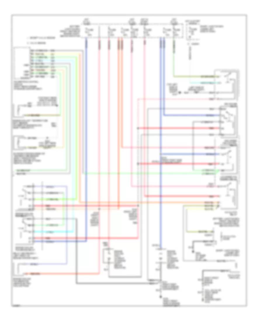
Automatic A/C Wiring Diagram (1 of 2) for Ford Taurus SE 2005

List of elements for Automatic A/C Wiring Diagram (1 of 2) for Ford Taurus SE 2005:
- (behind center of dash) g200
- (behind center of dash) g201
- (right front side of engine) s113
- (right rear side of engine compartment) g102
- (upper left side of dash) s237
- +/-
- Acp+
- Acp-
- Ambient air temperature sensor (behind right side of front bumper)
- Autolamp
- Autolamp/ sunload sensor (in dash, above glove box)
- Blower motor relay
- C2280b
- C2280e
- Computer data
- Dual pressure switch (behind a/c compressor)
- Front blower motor speed controller (behind center of dash, near hvac unit)
- Fuse 31 10a
- Fuse 33 15a
- Fuse 8 40a
- Gnd
- High pressure
- Hot at all times
- Hot in run
- In-vehicle temperature sensor
- Instrument cluster
- Integrated control panel (icp)
- Lines system
- Low charge protection switch
- Low current board
- Microprocessor
- Ms can+
- Ms can-
- Normal pressure
- Remote climate control (rcc) module (behind center of dash, near glove box)
- S205 (top center of dash)
- S237 (upper left side of dash)
- S246 (behind center of dash)
- Sig
- Sig rtn
- Smart junction box (under left side of dash)
- Sound systems
- Sunload
- Sw gnd
- Tan
- Temperature blend door actuator (under right side of dash)
- Vbatt
- Vpwr
- Vref
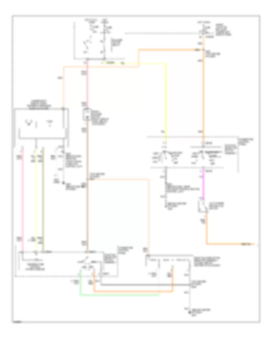
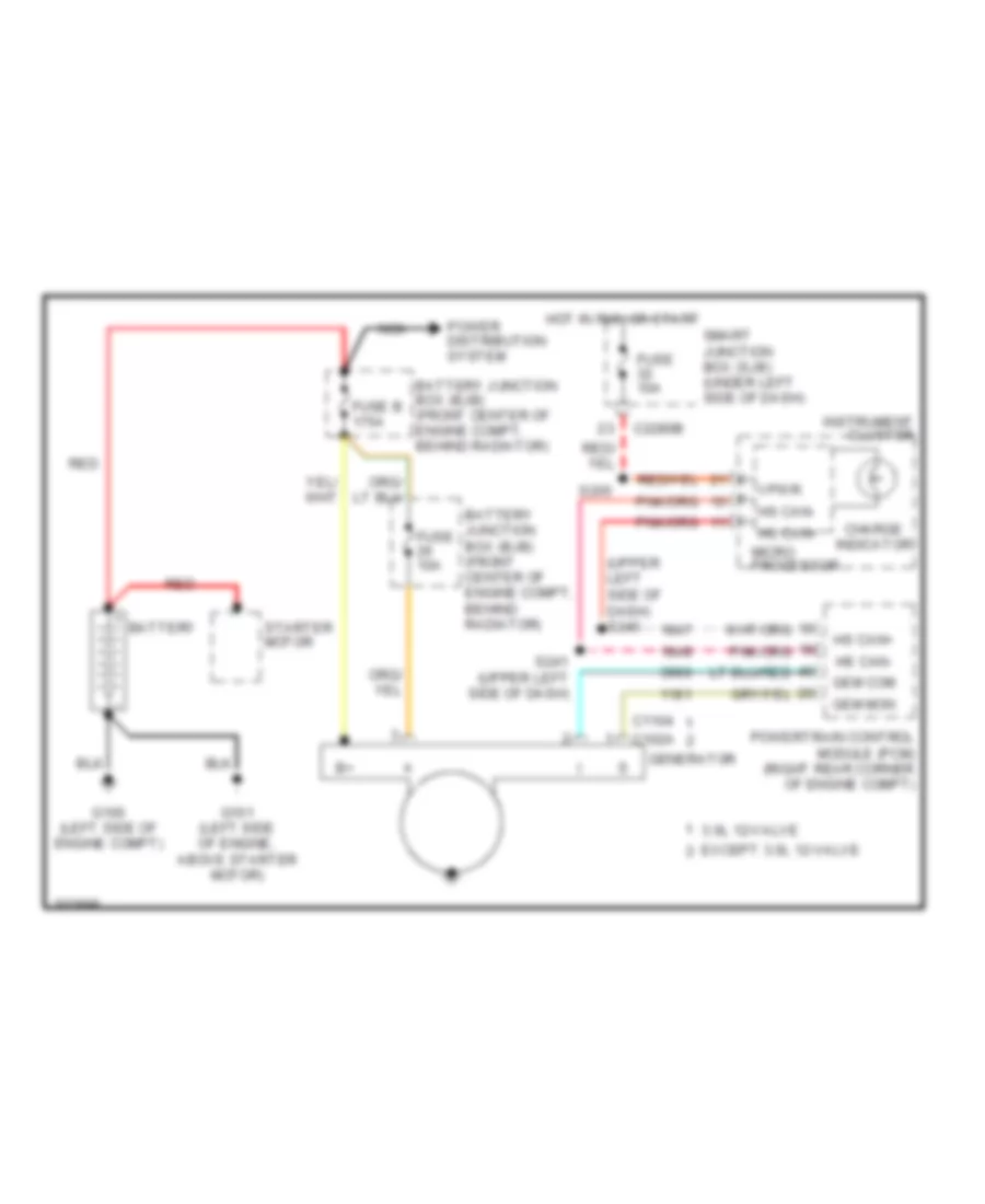
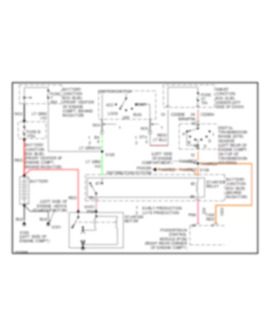
Automatic A/C Wiring Diagram (2 of 2) for Ford Taurus SE 2005
List of elements for Automatic A/C Wiring Diagram (2 of 2) for Ford Taurus SE 2005:
- (3.0l 24-vlv) (3.0l 12-vlv)
- (3.0l, 24-valve: right rear side of engine compartment) g102
- (left side of engine compt) s137
- (right front side of engine) s113
- (top left side of engine compt) g107
- (top right rear side of engine) s104 s116
- 3.0l 2v engine
- 87a
- A/c clutch diode
- A/c clutch field coil
- A/c clutch relay
- Battery junction box (front center of engine compartment, behind radiator)
- Battery junction box (front center of engine compt, behind radiator)
- C2280a
- C2280c
- Engine coolant temperature (ect) sensor (on rear of engine block, near thermostat)
- Engine cooling fan 1 (in front of engine compt, behind radiator)
- Engine cooling fan 2 (in front of engine compt, behind radiator)
- Engine cooling fan brake relay
- Engine cooling fan relay
- Engine cooling fan resistor (near electric cooling fans)
- Evaporator discharge air temperature sensor (early production) (behind center of dash, near glove box)
- Except 3.0l 2v engine
- Fuse 10a
- Fuse 15a
- Fuse 20a
- Fuse 2a
- Fuse 30a
- Fuse 40a
- G105 (right front side of engine compartment)
- G202 (at base of left "a" pillar)
- High speed fan control relay
- Hot at all times
- Hot in start or run
- Low speed fan control relay
- Pcm power relay
- Powertrain control module (right rear corner of engine compartment)
- Red
- Relay center box 1 (left front of engine compartment)
- S133 (top left rear side of engine compt)
- S140 (front left side of engine compt)
- S141 (front right side of engine compartment)
- S142 (front right side of engine compt)
- S144 (front right side of engine compt)
- Sig rtn
- Smart junction box (under left side of dash)
- Vref
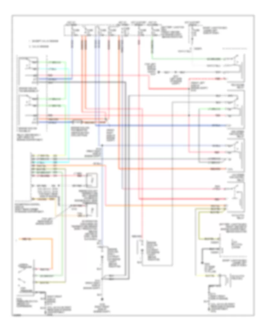
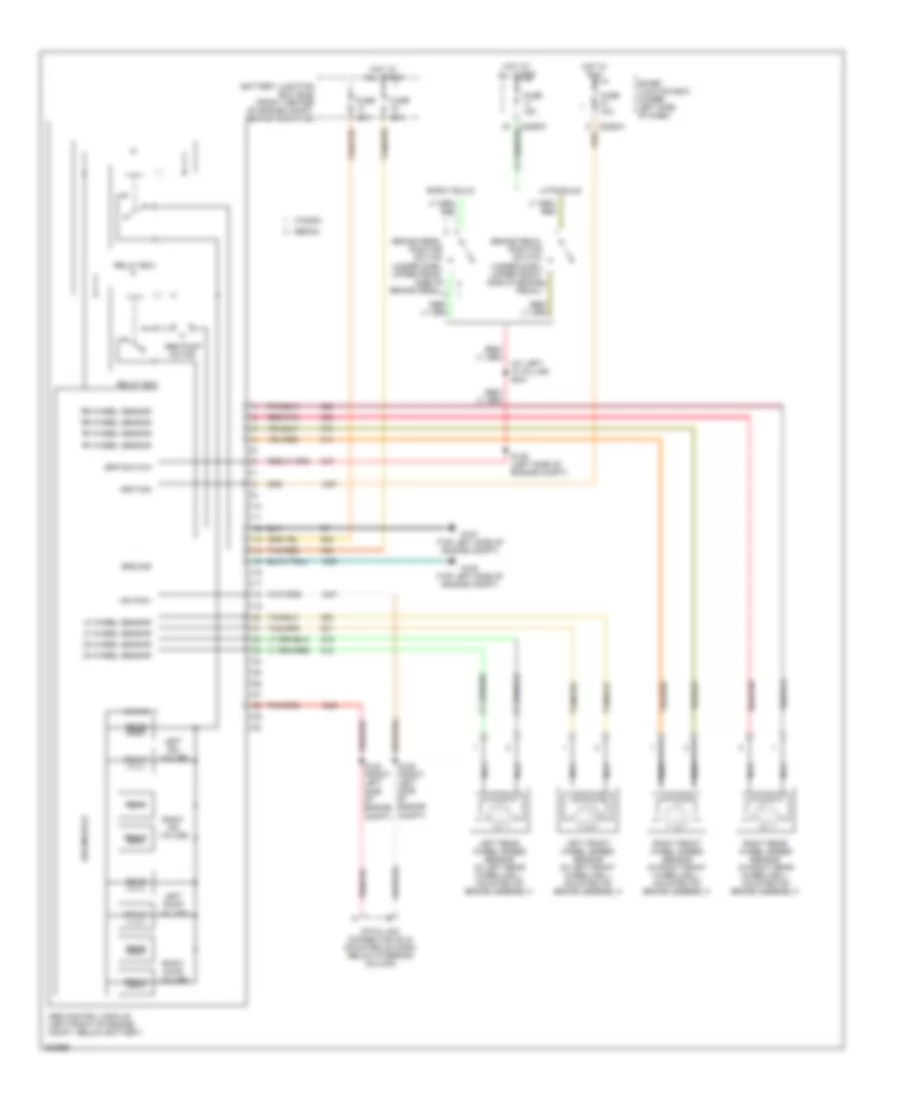
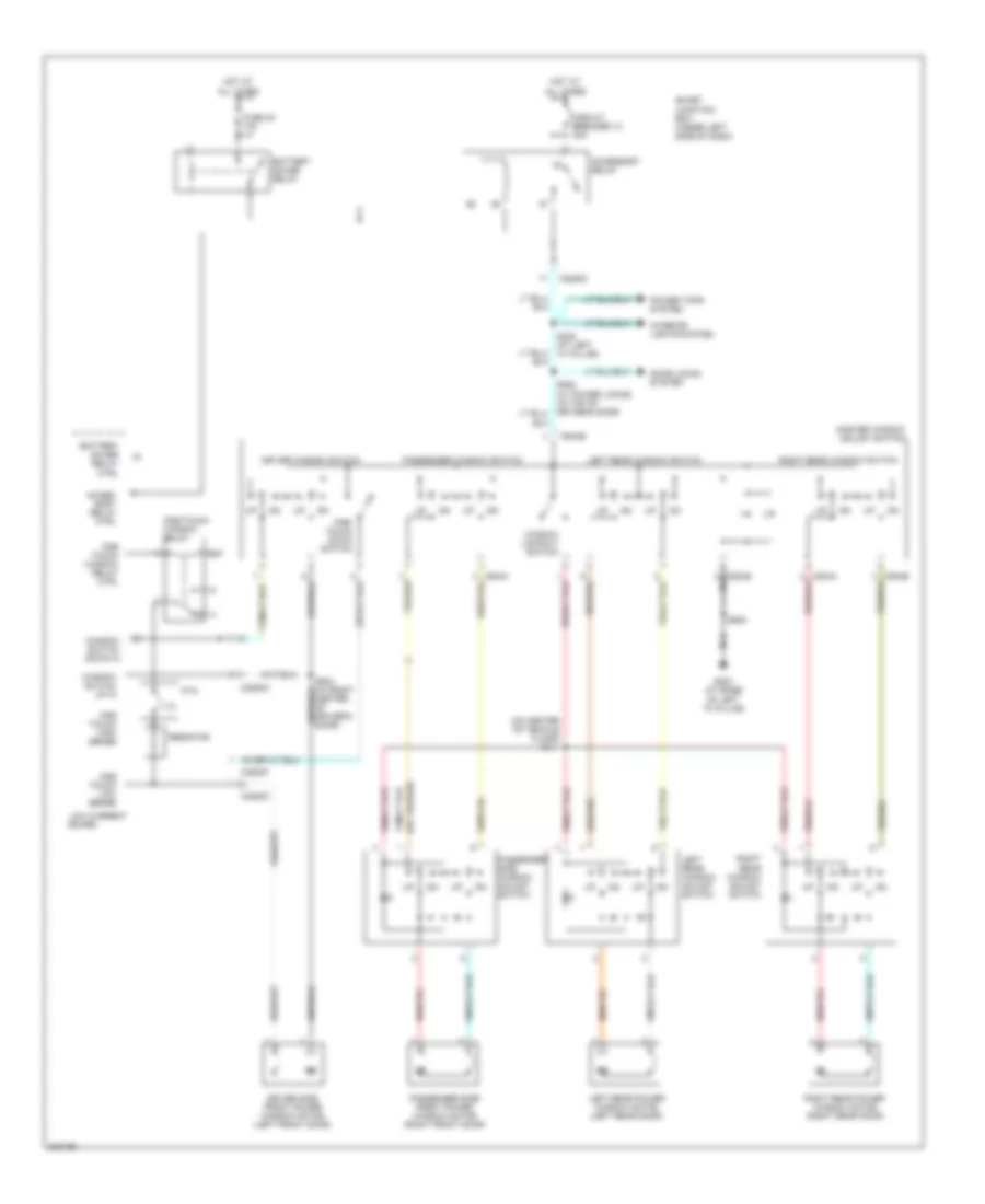
Manual A/C Wiring Diagram (1 of 2) for Ford Taurus SE 2005
List of elements for Manual A/C Wiring Diagram (1 of 2) for Ford Taurus SE 2005:
- (behind center of dash)
- (behind center of dash) g201
- (not used)
- (top center of dash) s201
- (top center of dash) s202
- (under right side of dash) temperature blend door actuator
- Blower motor relay
- C2280b
- C294a
- C294b
- C294c
- Def
- Floor
- Floor/vent
- Front blower motor (right side of dash, below glove box)
- Front blower motor resistor assembly (in dash, below center of glove box)
- Function selector switch assembly
- Fuse 10a
- Fuse 40a
- G201
- G201 (behind center of dash)
- High
- Hot at all times
- Hot in run
- Integrated control panel
- Low
- Low charge protection switch
- Max
- Med med
- Mix
- Norm
- Off
- S203 (behind dash, near air conditioning & heating control unit)
- S207 (top center of dash)
- Smart junction box (sjb) (under left side of dash)
- Temperature control potentiometer
- Vent
Manual A/C Wiring Diagram (2 of 2) for Ford Taurus SE 2005
List of elements for Manual A/C Wiring Diagram (2 of 2) for Ford Taurus SE 2005:
- (3.0l 24-vlv) (3.0l 12-vlv)
- (3.0l, 24-valve: right rear side of engine compartment) g102
- (front left side of engine compt) s140
- (front right
- (right front side of engine) s113
- (top left rear side of engine compt)
- (top left side of engine compt) g107
- (under left side of dash)
- 3.0l 2v engine
- 87a
- A/c clutch diode
- A/c clutch field coil
- A/c clutch relay
- Battery junction box (front center of engine compartment, behind radiator)
- Battery junction box (front center of engine compt, behind radiator)
- C2280a
- C2280c
- Dual pressure switch (behind a/c compressor)
- Engine coolant temperature (ect) sensor (on rear of engine block, near thermostat)
- Engine cooling fan 1 (in front of engine compt, behind radiator)
- Engine cooling fan 2 (in front of engine compt, behind radiator)
- Engine cooling fan brake relay
- Engine cooling fan relay
- Engine cooling fan resistor (near electric cooling fans)
- Evaporator discharge air temperature sensor (early production) (behind center of dash, near glove box)
- Except 3.0l 2v engine
- Fuse 10a
- Fuse 15a
- Fuse 20a
- Fuse 2a
- Fuse 30a
- Fuse 40a
- G105 (right front side of engine compt)
- G202 (at base of left "a" pillar)
- High pressure
- High speed fan control relay
- Hot at all times
- Hot in start or run
- Low speed fan control relay
- Normal pressure
- Pcm power relay
- Powertrain control module (right rear corner of engine compartment)
- Rear side of engine compartment) g102
- Red
- Relay center box 1 (left front of engine compartment)
- S113 (right front side of engine)
- S133
- S137 (left side of engine compt)
- S141 (front right side of engine compt)
- S142
- S144 (front right side of engine compt)
- Side of engine compt)
- Smart junction box
- Smart junction box (under left side of dash)
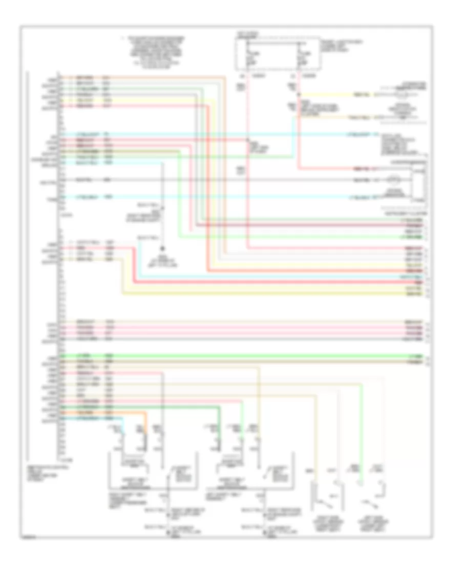
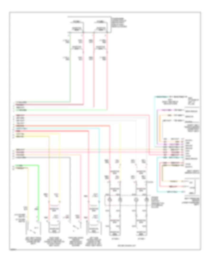
ANTI-LOCK BRAKES
Anti-lock Brakes Wiring Diagram, with Traction Control for Ford Taurus SE 2005
List of elements for Anti-lock Brakes Wiring Diagram, with Traction Control for Ford Taurus SE 2005:
- (at left "a" pillar) s231
- Abs control module (left front of engine compt, below battery)
- Abs module
- Abs pump motor
- Adaptive damping ind
- Battery junction box (front center of engine compt, behind radiator)
- Bpp switch
- Brake assembly)
- Brake pedal position switch (under dash, upper front side of brake pedal)
- C2280a
- C2280b
- C2280c
- Data link connector (dlc) (mounted on dash, below steering column)
- Early build
- Front
- Fuse 10a
- Fuse 15a
- Fuse 20a
- Fuse 40a
- G107 (top left side of engine compt)
- G108 (top left side of engine compt)
- G201 (behind center of dash)
- Ground
- Hot at all times
- Hot in run
- Hot in run or start
- Hs can+
- Hs can-
- Ignition
- Illum
- Instrument cluster
- Interior lights system
- Late build
- Left dump valves
- Left front wheel speed sensor (in left front wheelwell, mounted on brake assembly)
- Left iso valves
- Left rear wheel speed sensor (in left rear wheelwell, mounted on brake assembly)
- Lf wheel sensor
- Lr wheel sensor
- Microprocessor
- Nca
- Rear
- Red/pnk
- Relay box
- Rf wheel sensor
- Right dump valves
- Right front wheel speed sensor (in right front wheelwell, mounted on
- Right iso valves
- Right rear wheel speed sensor (in right rear wheelwell, mounted on
- Rr wheel sensor
- S129 (front left side of engine compt)
- S130 (front left side of engine compt)
- S136 (left side of engine compt)
- S207
- S209
- S212
- Sedan
- Smart junction box (under left side of dash)
- Tan/red
- Traction control off
- Traction control switch
- Volt
- Vpwr
- Wagon
Anti-lock Brakes Wiring Diagram, without Traction Control for Ford Taurus SE 2005
List of elements for Anti-lock Brakes Wiring Diagram, without Traction Control for Ford Taurus SE 2005:
- (at left "a" pillar) s231
- Abs control module (left front of engine compt, below battery)
- Abs module
- Abs pump motor
- Battery junction box (bjb) (front center of engine compt, behind radiator)
- Bpp switch
- Brake pedal position switch (under dash, upper front side of brake pedal)
- C2280a
- C2280c
- Data link connector (dlc) (mounted on dash, below steering column)
- Early build
- Front
- Fuse 10a
- Fuse 15a
- Fuse 20a
- Fuse 40a
- G107 (top left side of engine compt)
- G108 (top left side of engine compt)
- Ground
- Hot at all times
- Hot in run
- Hs can+
- Hs can-
- Ignition
- Late build
- Left dump valves
- Left front wheel speed sensor (in left front wheelwell, mounted on brake assembly)
- Left iso valves
- Left rear wheel speed sensor (in left rear wheelwell, mounted on brake assembly)
- Lf wheel sensor
- Lr wheel sensor
- Nca
- Rear
- Red/pnk
- Relay box
- Rf wheel sensor
- Right dump valves
- Right front wheel speed sensor (in right front wheelwell, mounted on brake assembly)
- Right iso valves
- Right rear wheel speed sensor (in right rear wheelwell, mounted on brake assembly)
- Rr wheel sensor
- S129 (front left side of engine compt)
- S130 (front left side of engine compt)
- S136 (left side of engine compt)
- Sedan
- Smart junction box (under left side of dash)
- Tan/red
- Wagon
ANTI-THEFT
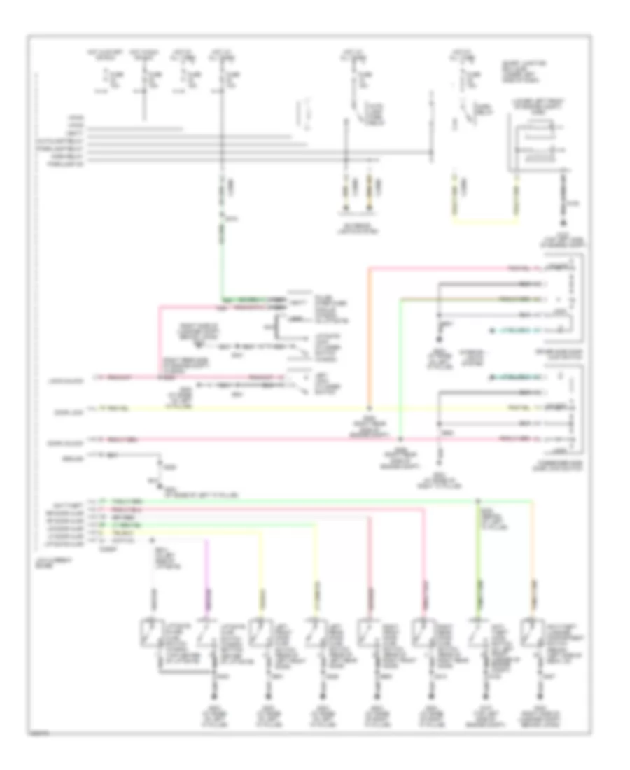
Forced Entry Wiring Diagram for Ford Taurus SE 2005
List of elements for Forced Entry Wiring Diagram for Ford Taurus SE 2005:
- (lower left front of engine compt) horn
- (right rear side of engine compt) (wagon) s230
- (right side of luggage compt, behind lining) g303
- Anti- theft hood switch (at left front corner of engine compt)
- Anti-theft
- Anti-theft luggage compartment switch (sedan) (left side of deck lid)
- Auto- lamp park relay
- Autolamp relay
- C2280a
- C2280c
- C2280f
- Door lock
- Door unlock
- Driver side door lock switch
- Exterior lights system
- Fuse 10a
- Fuse 15a
- G107 (top left side of engine compt)
- G203 (at base of left "a" pillar)
- G204 (at base of right "a" pillar)
- G303 (right side of luggage compt, behind lining)
- Ground
- Horn relay
- Hot at all times
- Hot in run or acc
- Hot in start or run
- Interior lights system
- Left front door ajar switch (rear of left front door)
- Left lock cylinder switch
- Left rear door ajar switch (rear of left rear door)
- Lf door ajar
- Liftgate ajar
- Liftgate ajar switch (wagon) (bottom center of liftgate)
- Liftgate glass ajar switch (wagon) (top center of liftgate)
- Liftgate lock cylinder switch (wagon)
- Lock
- Lock/unlock
- Low current board
- Lr door ajar
- Nca
- Nca vbatt
- Parklamp on
- Parklamp relay
- Passenger side door lock switch
- Pulse stretcher module (wagon) (in liftgate)
- Rf door ajar
- Right front door ajar switch (rear of right front door)
- Right rear door ajar switch (rear of right rear door)
- Rr door ajar
- S135
- S226 (right rear side of engine compt)
- S228 (right rear side of engine compt)
- S229
- S233 (sedan) (at left "a" pillar)
- S313
- S315
- S401
- S403
- S404 (in left side of liftgate)
- S407
- S501
- S600
- Smart junction box (sjb) (under left side of dash)
- Unlock
- Vbatt
- Vpwr
- Vref
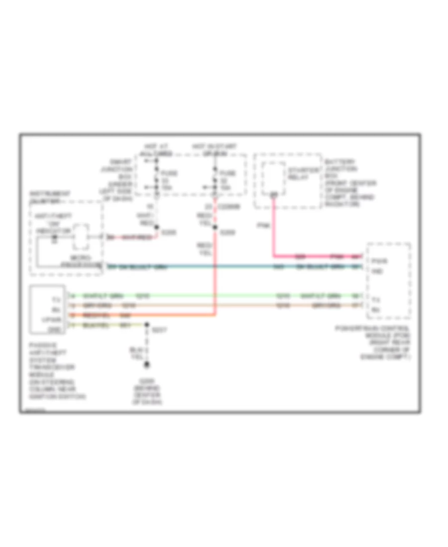
Passive Anti-theft Wiring Diagram for Ford Taurus SE 2005
List of elements for Passive Anti-theft Wiring Diagram for Ford Taurus SE 2005:
- Anti-theft ``on" indicator
- Battery junction box (front center of engine compt, behind radiator)
- C2280b
- Fuse 10a
- Fuse 15a
- G200 (behind center of dash)
- Gnd
- Hot at all times
- Hot in start or run
- Ind
- Instrument cluster
- Micro- processor
- Passive anti-theft system transceiver module (on steering column, near ignition switch)
- Pnk
- Powertrain control module (pcm) (right rear corner of engine compt)
- Pwr
- S205
- S209
- S237
- Smart junction box (under left side of dash)
- Starter relay
- Vpwr
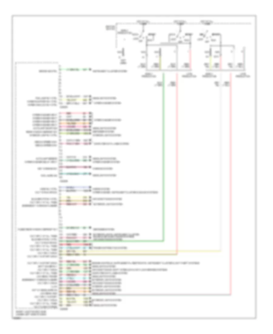
BODY CONTROL MODULES
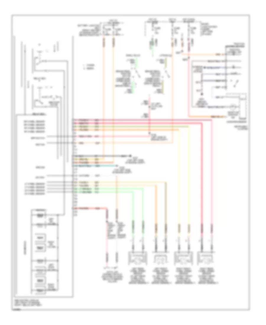
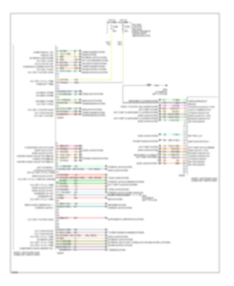
Body Control Modules Wiring Diagram (1 of 2) for Ford Taurus SE 2005
List of elements for Body Control Modules Wiring Diagram (1 of 2) for Ford Taurus SE 2005:
- (or 202)
- (or 84)
- A/c clutch rly,sw
- Accessory rly
- Accessory rly sw
- Air conditioning system
- Anti-lock brakes system
- Anti-theft & instrument cluster systems
- Anti-theft & sound systems
- Anti-theft switch sense
- Anti-theft system
- Batt saver rly
- Battery junction box (bjb) (front center of engine compt, behind radiator)
- C2280a
- C2280c
- C2280f
- Cruise control system
- Defogger system
- Door lock output
- Door lock rly ctrl
- Door locks system
- Door unlock output
- Door unlock rly ctrl
- Engine controls system
- Exterior lamps
- Exterior lamps power
- Exterior lights system
- Exterior lights, shift interlock & cruise control systems
- Fuse 60a
- Fused batt feed
- Fused rear window defrost rly
- G202 (at base of left "a" pillar)
- G203 (at base of left "a" pillar)
- Ground
- Headlights system
- High beam, power
- Horn rly sw
- Horns system
- Hot at all times
- Instrument cluster & anti-theft systems
- Instrument cluster system
- Interior lamp rly
- Interior lights & mirrors systems
- Interior lights system
- Interior lights, power windows & power tops systems
- Key pad common
- Key pad illum
- Lf door ajar switch
- Lf side door lock actuator
- Liftgate ajar sw
- Liftgate unlock rly (or volt sply at all times)
- Liftgate unlock rly ctrl
- Lock cylinder switch
- Low beam, power
- Lr door ajar switch
- Master window adjust sw feed dn
- Master window adjust sw feed up
- Mirrors system
- One-touch down rly
- Parking brake sw
- Power windows system
- Rear window defrost rly 1
- Red
- Rf door ajar switch
- Rr door ajar switch
- S229
- Seats system
- Smart junction box (sjb) (under left side of dash)
- Transmissions system
- Trunk, tailgate, fuel doors system
- Volt in run or acc
- Volt sply at all times
- Volt sply at all times (or luggage)
- Volt sply in run
- Volt sply in start
- Volt sply in start & run
- Window mtr feed dn
- Windshield washer pump mtr
- Wiper park rly, sw
- Wiper/washer & mirrors systems
- Wiper/washer system
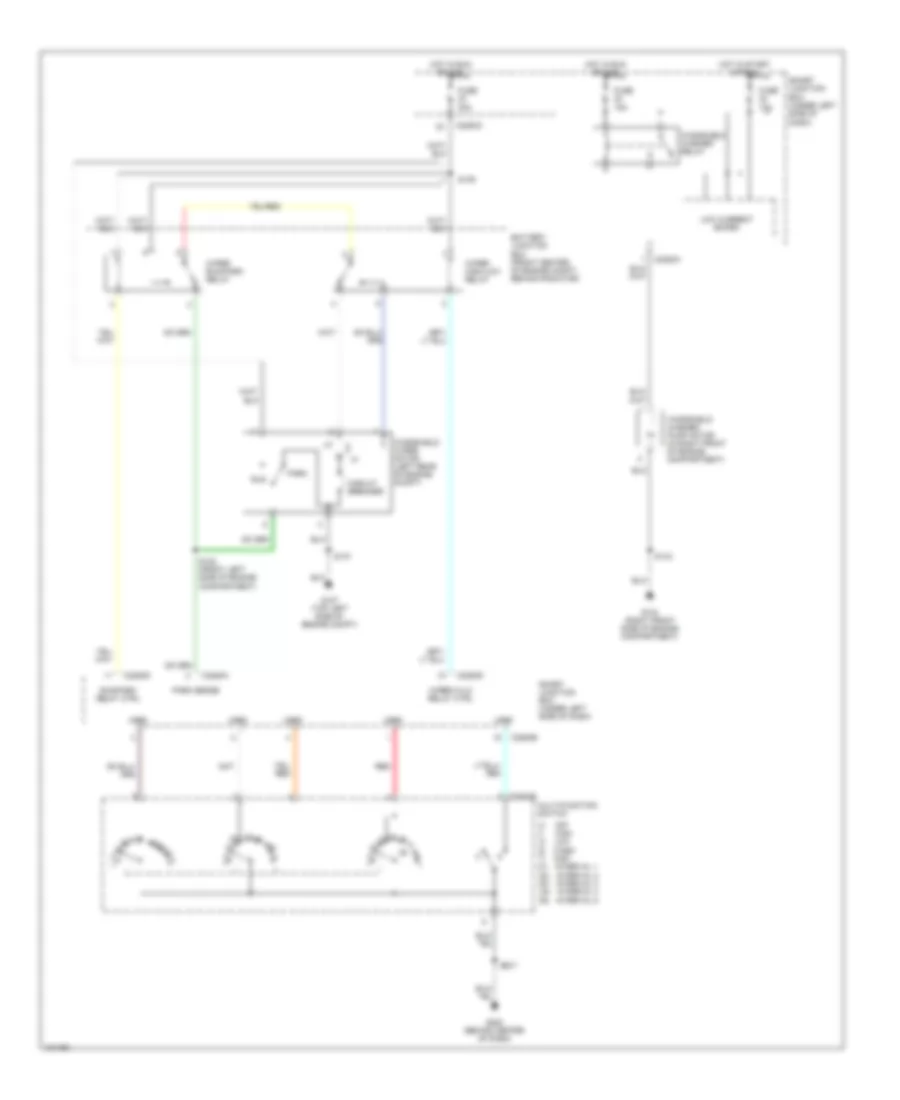
Body Control Modules Wiring Diagram (2 of 2) for Ford Taurus SE 2005
List of elements for Body Control Modules Wiring Diagram (2 of 2) for Ford Taurus SE 2005:
- (not used)
- Acc
- Air conditioning system
- Air conditioning, shift interlock & anti-lock brakes systems
- Autolamp on/off sig
- Autolamp sensor
- Batt saver rly
- Blower mtr rly ctrl
- Brake ind ctrl
- C2280b
- C2280d
- C2280e
- Computer data lines system
- Defogger system
- Early production
- Emergency warning flasher
- Exterior lights system
- Exterior lights, instrument cluster, sound & air conditioning systems
- Fog lamp rly ctrl
- Fog lamps ind
- Fused rear window defrost rly
- Headlights system
- Horn rly ctrl
- Horns system
- Hot at all times
- Hot w/ headlamps on
- Ignition switch
- Illum
- Instrument cluster system
- Interior lamp rly ctrl
- Interior lights system
- Key warning sw
- Late production
- Lock
- Low beam, gnd
- Low beam, power
- Medium speed can+
- Medium speed can-
- Nca
- Off
- Power distribution system
- Rear window defrost sw
- Red
- Run
- Smart junction box (sjb) (under left side of dash)
- Sta
- Start
- Volt flash-to-pass
- Volt in run or acc
- Volt sply at all times
- Volt sply in run
- Volt sply in start
- Volt sply in start & run
- Warning system
- Wiper high/low rly ctrl
- Wiper run/park rly ctrl
- Wiper/washer delay input
- Wiper/washer input
- Wiper/washer system
- Wiper/washer, instrument cluster & sound systems
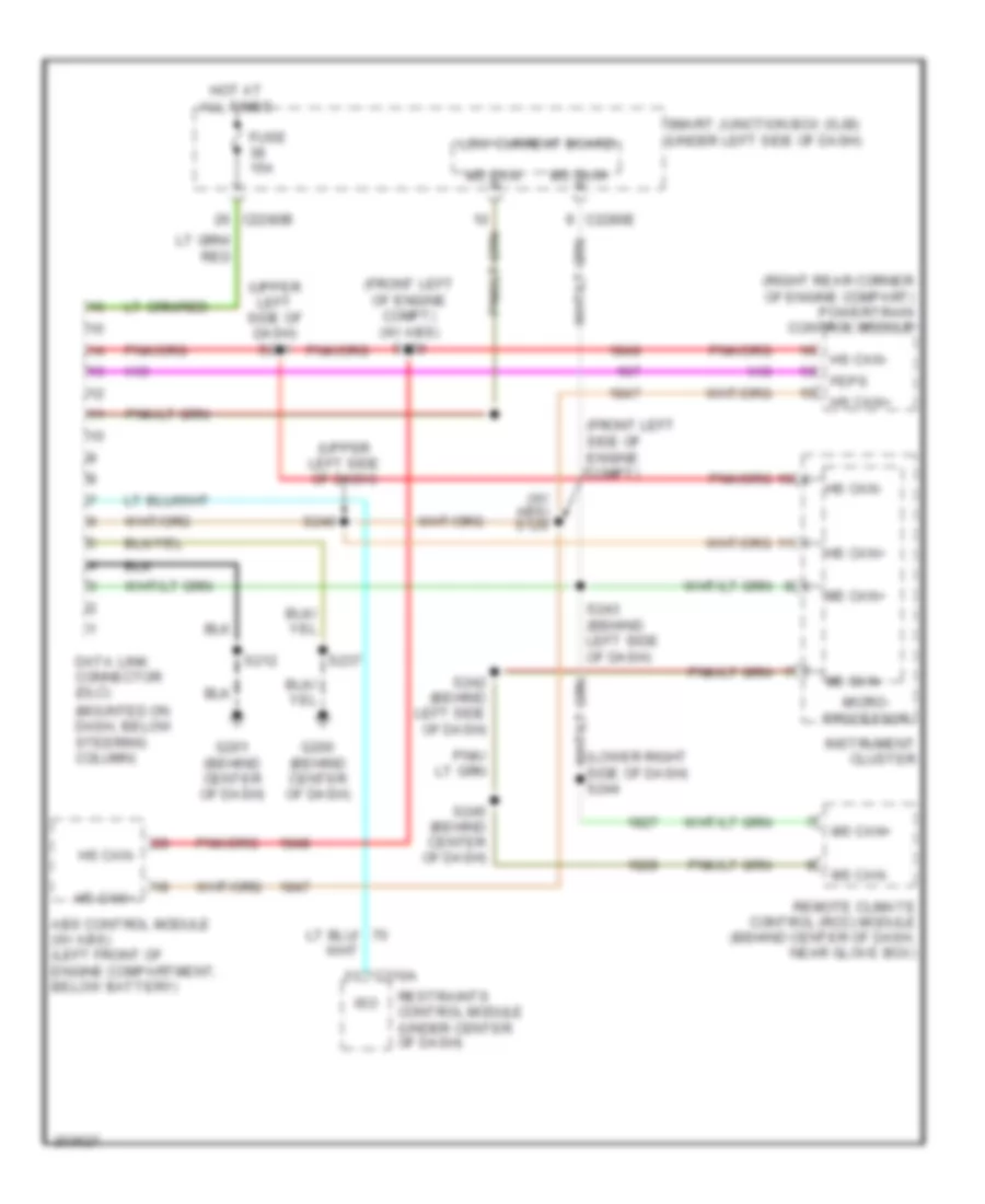
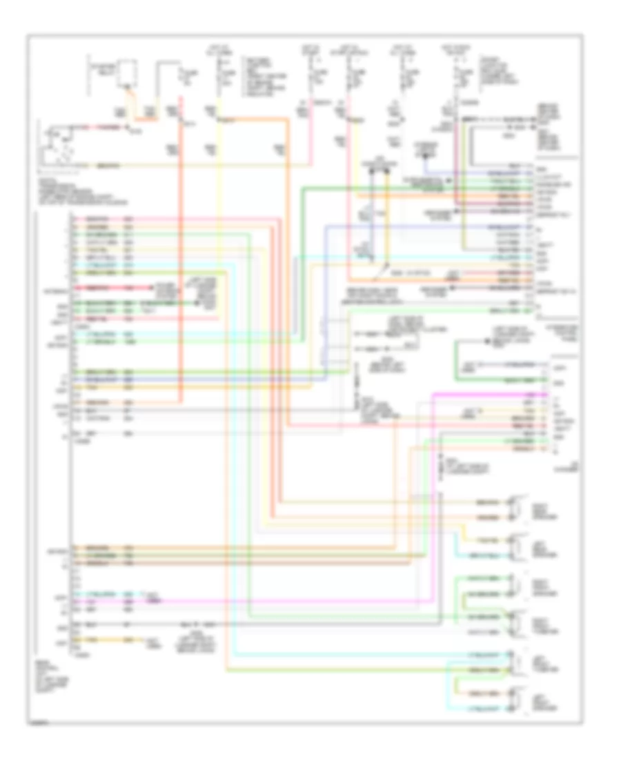
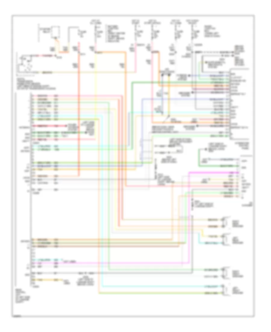
COMPUTER DATA LINES
Computer Data Lines Wiring Diagram for Ford Taurus SE 2005
List of elements for Computer Data Lines Wiring Diagram for Ford Taurus SE 2005:
- (front left of engine compt) (w/ abs) s130
- (front left side of engine compt)
- (lower right side of dash) s244
- (mounted on dash, below steering column)
- (right rear corner of engine compart) powertrain control module
- (upper left side of dash)
- (upper left side of dash) s241
- (w/ abs) s129
- Abs control module (w/ abs) (left front of engine compartment, below battery)
- C2280b
- C2280e
- C310a
- Data link connector (dlc)
- Feps
- Fuse 15a
- G200 (behind center of dash)
- G201 (behind center of dash)
- Hot at all times
- Hs can+
- Hs can-
- Instrument cluster
- Iso
- Low current board
- Micro- processor
- Ms can+
- Ms can-
- Remote climate control (rcc) module (behind center of dash, near glove box)
- Restraints control module (under center of dash)
- S212
- S237
- S240
- S242 (behind left side of dash)
- S243 (behind left side of dash)
- S245 (behind center of dash)
- Smart junction box (sjb) (under left side of dash)
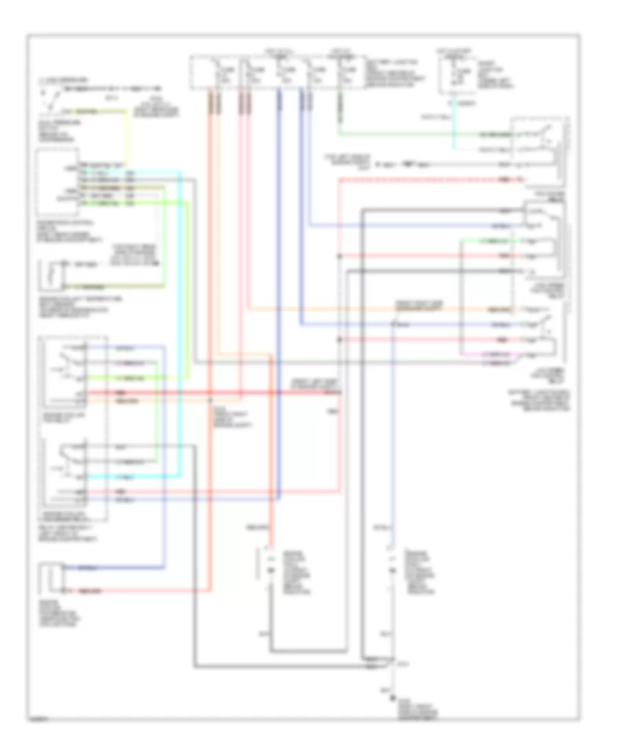
COOLING FAN
Cooling Fan Wiring Diagram for Ford Taurus SE 2005
List of elements for Cooling Fan Wiring Diagram for Ford Taurus SE 2005:
- (1: high pressure)
- (3.0l 24-vlv) (3.0l 12-vlv)
- (behind a/c compressor)
- (front left side of engine compt) s140
- (front right side of engine compt)
- (top left side of engine compt) g107
- (top right rear side of engine) s104 s116
- 87a
- Battery junction box (front center of engine compartment, behind radiator)
- C2280a
- Dual pressure switch
- Engine coolant temperature (ect) sensor (on rear of engine block, near thermostat)
- Engine cooling fan 1 (in front of engine compt, behind radiator)
- Engine cooling fan 2 (in front of engine compt, behind radiator)
- Engine cooling fan brake relay
- Engine cooling fan relay
- Engine cooling fan resistor (near electric cooling fans)
- Fuse 10a
- Fuse 20a
- Fuse 2a
- Fuse 30a
- Fuse 40a
- G102 (3.0l 24-vlv: right rear side of engine compt)
- G105 (right front side of engine compartment)
- High speed fan control relay
- Hot at all times
- Hot in start or run
- Low speed fan control relay
- Pcm power relay
- Powertrain control module (right rear corner of engine compartment)
- Red
- Relay center box 1 (left front of engine compartment)
- S113
- S137
- S141
- S142 (front right side of engine compt)
- S144
- Sig rtn
- Smart junction box (under left side of dash)
- Vref
CRUISE CONTROL
Cruise Control Wiring Diagram for Ford Taurus SE 2005
List of elements for Cruise Control Wiring Diagram for Ford Taurus SE 2005:
- (at left "a" pillar) s231
- (sedan)
- (wagon)
- Accel set/
- Air bag sliding contact (near bottom of steering column)
- Brake pedal position switch (under dash, upper front side of brake pedal)
- C218b
- C2280a
- C2280b
- C2280c
- Coast
- Cruise on ind
- Deactivator switch (behind lower side of brake pedal)
- Early production
- Electric clutch pwr
- Engine compt)
- Fuse 10a
- Fuse 15a
- G107 (top left side of engine compartment)
- Gnd
- Horn
- Horn relay
- Horns system
- Hot at all times
- Hot in run
- Hot in start or run
- Illumination
- Instrument cluster
- Interior lights system
- Late production
- Micro- processor
- Nca
- Off
- Powertrain control module (pcm) (right rear corner of engine compt)
- Rest
- Resume
- S137
- S209
- Shift interlock, engine controls, anti-lock brakes & exterior lights systems
- Sig rtn
- Smart junction box (under left side of dash)
- Speed control ind
- Speed control servo (in left rear of engine compt)
- Steering wheel/ speed control switch
- Vpwr
- Vref
- Vss (+)
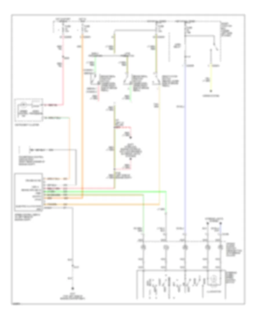
DEFOGGERS
Defoggers Wiring Diagram for Ford Taurus SE 2005
List of elements for Defoggers Wiring Diagram for Ford Taurus SE 2005:
- (2005 wagon)
- (automatic a/c)
- (behind center of dash)
- (manual a/c)
- Automatic a/c
- Battery junction box (front center of engine compartment, behind radiator)
- C2280b
- C2280c
- C2280e
- C402a
- C402b
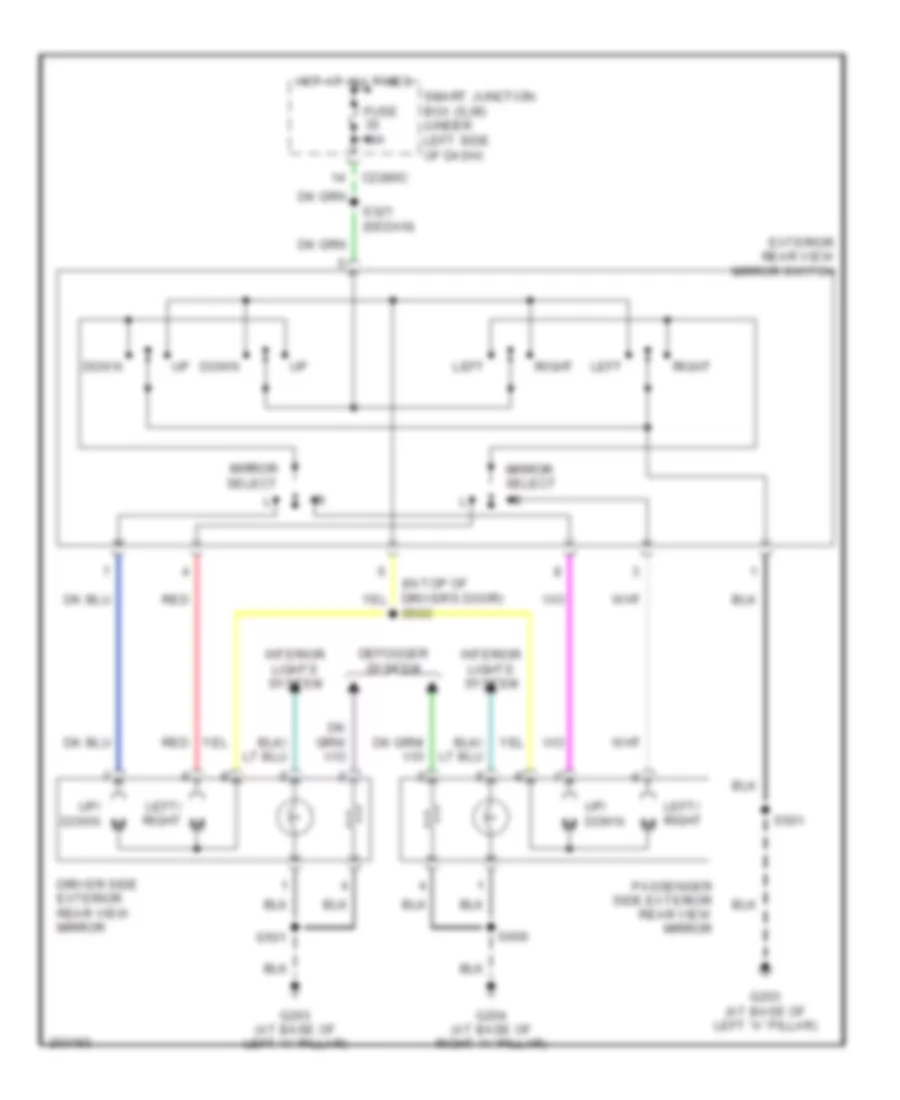
- Driver side exterior rear view mirror
- Fuse 10a
- Fuse 15a
- Fuse 20a
- Fuse 50a
- G107 (top left side of engine compartment)
- G200
- G201
- G203 (at base of left ``a" pillar)
- G204 (at base of right ``a" pillar)
- G303 (right side of luggage compartment, behind lining)
- Hot at all times
- Hot at all times
- Hot in run
- Hot in run or acc
- Hot in start or run
- Integrated control panel
- Low current board
- Manual a/c
- On indicator
- Passenger side exterior rear view mirror
- Rear window defrost grid (rear window)
- Rear window defrost relay 1
- Rear window defrost relay 2
- Rear window defrost switch
- Relay center box 1 (left front of engine compt)
- S135
- S203
- S237
- S402
- S501
- S600
- Smart junction box (under left side of dash)
- Vpwr
- Vref
ENGINE PERFORMANCE
3.0L 12-VALVE
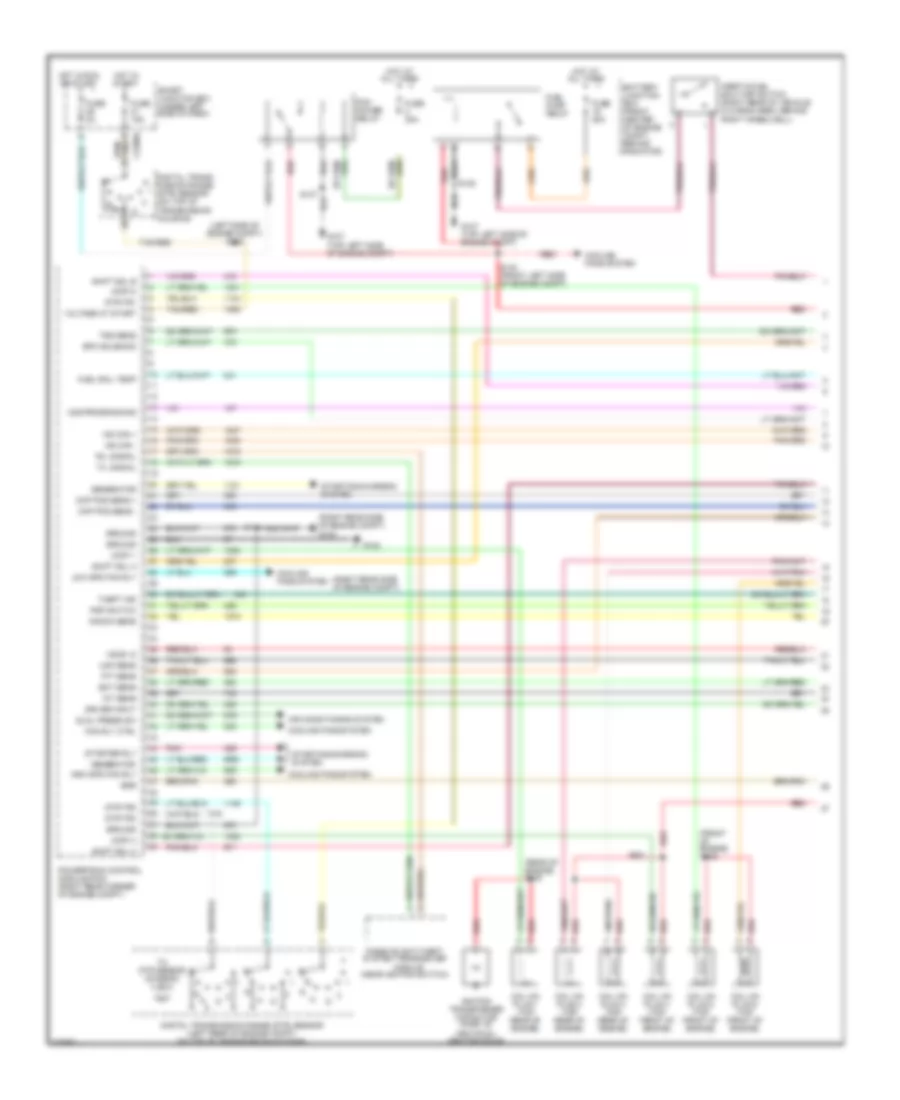
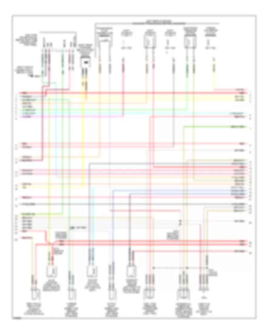
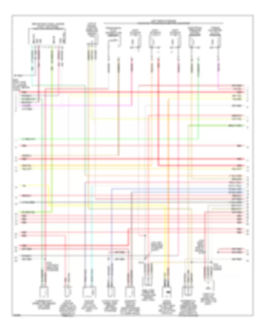
3.0L 12-Valve, Engine Performance Wiring Diagram (1 of 4) for Ford Taurus SE 2005
List of elements for 3.0L 12-Valve, Engine Performance Wiring Diagram (1 of 4) for Ford Taurus SE 2005:
- (left rear of engine compt, on top of transmission housing)
- (left side of engine compt) s138
- (right rear side of engine compt) g102
- (right rear side of engine compt) g103
- (top of engine) s117
- (top right rear side of engine) s115
- Air conditioning system
- Battery junction box (front center of engine compt behind radiator)
- C2280a
- Ckp pos sens +
- Ckp pos sens -
- Cooling fans system
- Digital transmission range (dtr) sensor
- Digital transmission range (dtr) sensor (left rear of engine compt, on top of transmission housing)
- Dtr-tr1
- Dtr-tr2
- Dtr-tr4
- Dual press sw
- Ect sens
- Egr vacuum regulator solenoid (mounted on right side of intake manifold)
- Epc input
- Evr
- Fan rly ctrl
- Fuel pump
- Fuel pump mod
- Fuel pump relay
- Fuel tank unit (on fuel tank)
- Fuse 15a
- Fuse 20a
- Fuse 2a
- Fuse 30a
- Fuse 5a
- G102
- G107 (top left side of engine compt)
- G302 (right side of luggage compt behind lining)
- Generator
- Ground
- H2os 12
- High spd fan rly
- High speed can+
- High speed can-
- Hot at all times
- Hot in run or start
- Hot in start
- Iat sens
- Ign coil a
- Ign coil b
- Ignition coil (top center of engine)
- Ignition transformer capacitor (attached to ignition coil)
- Imrc module
- Inertia fuel shutoff switch (right rear of vehicle, in cargo area, behind right wheelwell)
- Intake manifold runner control (imrc) module (top rear of engine)
- Low spd fan rly
- Maf sens
- Mod programming
- Nca
- Passive anti-theft system transceiver module (on steering column, near ignition switch)
- Pcm power relay
- Pcu htr ctrl
- Pnk
- Positive crankcase ventilation heater
- Powertrain control module (pcm) (right rear corner of engine compt)
- R n
- Red
- Rx, signal
- S114
- S135
- S137
- S140 (front left side of engine compt)
- Shift sol a
- Shift sol b
- Shift sol c
- Signal rtn
- Smart junction box (under left side of dash)
- Starter rly
- Starting/ charging system
- Starting/charging system cooling fans system
- Tan/red
- Tft sens
- Theft ind
- To dtr sensor (diagram 4 of 4)
- To spark plugs
- Tss
- Tx, signal
- Voltage at start
3.0L 12-Valve, Engine Performance Wiring Diagram (2 of 4) for Ford Taurus SE 2005
List of elements for 3.0L 12-Valve, Engine Performance Wiring Diagram (2 of 4) for Ford Taurus SE 2005:
- (behind center of dash) g200
- (behind center of dash, near instrument cluster) flexible fuel sensor module
- (upper left side of dash)
- Anti- slosh module
- Anti-lock brakes system
- Anti-theft "on" indicator
- C2280b
- Check engine indicator
- Crankshaft position sensor (on lower right front of engine)
- Data link connector (dlc) (mounted on dash, below steering column)
- Engine coolant temperature sensor (on rear of engine block, near thermostat)
- Fuel gauge sensor
- Fuel sender (fuel tank)
- Fuel tank unit (on fuel tank)
- Fuse 10a
- Fuse 15a
- G102
- G103 (right rear side of engine compt)
- Hot at all times
- Hot in run or start
- Instrument cluster
- Low fuel indicator
- Mass airflow (maf) sensor (in engine air intake assembly)
- Microprocessor
- Nca
- Red
- S113
- S114
- S129 (front left side of engine compt)
- S130
- S205
- S209
- S237
- S240
- S241
- Smart junction box (under left side of dash)
- W/ flex fuel
- W/o flex fuel
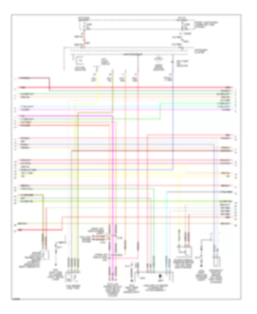
3.0L 12-Valve, Engine Performance Wiring Diagram (3 of 4) for Ford Taurus SE 2005
List of elements for 3.0L 12-Valve, Engine Performance Wiring Diagram (3 of 4) for Ford Taurus SE 2005:
- (behind right side luggage compt trim panel) fuel pump driver module
- (left rear of engine) ax4s/4f50n transmission control solenoids
- (top left rear side of engine compt)
- (top of engine) injector pressure sensor
- (top right rear side of engine) s116
- Camshaft position sensor (rear of engine block, between cylinder heads)
- Differential pressure feedback egr (dpfe) sensor (mounted on right front of intake manifold)
- Electronic pressure control solenoid
- Evap canister purge valve (right rear of engine compt, mounted on firewall)
- Fuel tank pressure transducer sensor (fuel tank)
- G302 (right side of luggage compt, behind lining)
- Gnd
- Idle air control (iac) valve (on throttle body)
- Knock sensor (on left rear of engine, below intake manifold)
- Mod in
- Mod out
- Nca
- Output shaft speed (oss) sensor (left rear of engine)
- Pmp ctrl
- Pwr
- Red
- Red/pnk
- S100 (top right rear side of engine)
- S101 (top of engine)
- S133
- Shift solenoid a
- Shift solenoid b
- Shift solenoid c
- Throttle position sensor (tps) (on throttle body)
- Torque converter clutch solenoid
- Transmission fluid temperature sensor
- Turbine shaft speed (tss) sensor (left rear of engine)
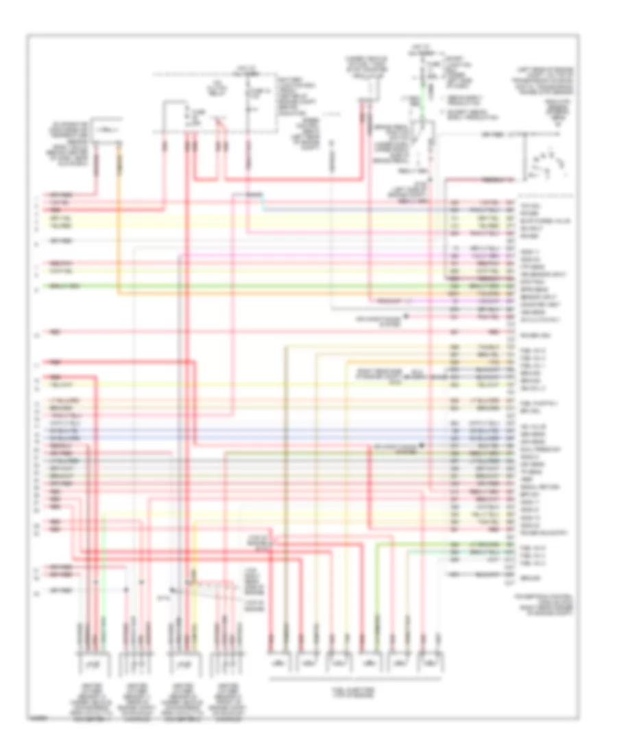
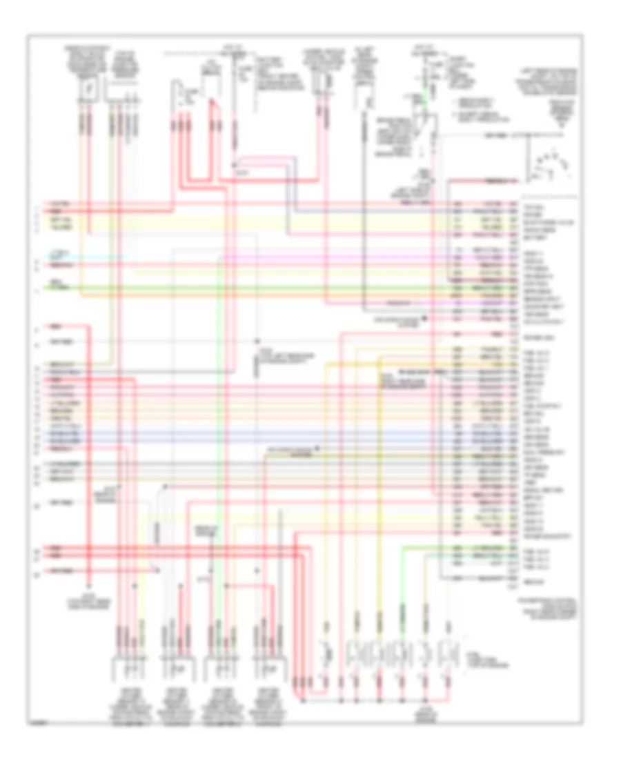
3.0L 12-Valve, Engine Performance Wiring Diagram (4 of 4) for Ford Taurus SE 2005
List of elements for 3.0L 12-Valve, Engine Performance Wiring Diagram (4 of 4) for Ford Taurus SE 2005:
- (left rear of engine compt, on top of transmission housing) digital transmission range (dtr) sensor
- (right rear side of engine compt) g103
- (top of engine)
- (top of engine) s119
- (top right rear side of engine)
- (under vehicle, on fuel tank) evap canister vent valve
- A/c clutch relay
- A/c clutch rly
- Air conditioning system
- Battery junction box (front center of engine compt, behind radiator)
- Bpp sw
- Brake pedal position switch (under dash, upper front side of brake pedal)
- C2280c
- Cam sens
- Canister vent
- Dpfe sens
- Dtr-tr3a
- Dual press sw
- Epc sol
- Evap purge valve
- Evaporator discharge air temperature sensor (early build) (behind center of dash, near glove box)
- Except sedan early production
- From dtr sensor (diagram 1 of 4)
- Ftp sens
- Fuel inj 1
- Fuel inj 2
- Fuel inj 3
- Fuel inj 4
- Fuel inj 5
- Fuel inj 6
- Fuel injectors (top of engine)
- Fuel pump rly
- Fuse 15a
- Fuse 18 10a
- Ground
- H2os 11
- H2os 12
- H2os 21
- H2os 22
- Heated oxygen sensor 11 (rear of engine compt, on exhaust manifold)
- Heated oxygen sensor 12 (under vehicle, downstream from catalytic converter 1)
- Heated oxygen sensor 21 (front of engine compt, on exhaust manifold)
- Heated oxygen sensor 22 (under vehicle, downstream from catalytic converter 2)
- Hot at all times
- Iac valve
- Ign coil c
- Ips sensor input
- Ks input
- Maf sens
- Oss sens
- Power
- Power (ign)
- Power (run/strt)
- Powertrain control module (pcm) (right rear corner of engine compt)
- Red
- Red/pnk
- S105
- S114
- S118
- S136 (left side of engine compt)
- S147
- Sedan early production
- Sensor input
- Signal return
- Smart junction box (under left side of dash)
- Speed control servo (left rear of engine compt)
- Tan
- Tcc sol
- Tp sens
- Vref
- Vss sens
3.0L 24-VALVE
3.0L 24-Valve, Engine Performance Wiring Diagram (1 of 4) for Ford Taurus SE 2005
List of elements for 3.0L 24-Valve, Engine Performance Wiring Diagram (1 of 4) for Ford Taurus SE 2005:
- (cop) 1
- (cop) 4
- (cop) 5
- (front of engine) s149
- (left side of engine compt) s138
- (rear of engine) s148
- (right rear side of engine compt)
- (right rear side of engine compt) g103
- Air conditioning system
- Battery junction box (front center of engine compt, behind radiator)
- Ckp pos sens +
- Ckp pos sens -
- Coil on plug 1 (top rear of engine)
- Coil on plug 2 (top rear of engine)
- Coil on plug 3 (top rear of engine)
- Coil on plug 4 (top front of engine)
- Coil on plug 5 (top front of engine)
- Coil on plug 6 (top front of engine)
- Cooling fans system
- Digital trans- mission range (dtr) sensor (on top of transmission housing)
- Digital transmission range (dtr) sensor (left rear of engine compt, on top of transmission housing)
- Driver input
- Dtr-tr1
- Dtr-tr2
- Dtr-tr4
- Dual press sw
- Ect sens
- Egr
- Epc solenoid
- Fan rly ctrl
- Fuel pump relay
- Fuel rail temp
- Fuse 15a
- Fuse 20a
- Fuse 2a
- Fuse 30a
- G102
- G107 (top left side of engine compt)
- Generator
- Ground
- H2os 12
- High spd fan rly
- Hot at all times
- Hot in run or start
- Hot in start
- Hs can +
- Hs can -
- Iat sens
- Ignition transformer capacitor (part of individual ignition coils)
- Inertia fuel shut-off switch (right rear of vehicle, in cargo area, behind right wheelwell)
- Knock sens
- Low spd fan rly
- Maf sens
- Mod programming
- Module (near ignition switch)
- Passive anti-theft system transceiver
- Pcm power relay
- Pnk
- Powertrain control module (pcm) (right rear corner of engine compt)
- Psp switch
- R n
- Red
- Rx, signal
- S114
- S135
- S137
- S140 (front left side of engine compt)
- Shift sol a
- Shift sol b
- Shift sol c
- Smart junction box (under left side of dash)
- Starter rly
- Starting/charging system
- Tan/red
- Tft sens
- Theft ind
- To dtr sensor (diagram 4 of 4)
- Tss sens
- Tx, signal
- Voltage at start
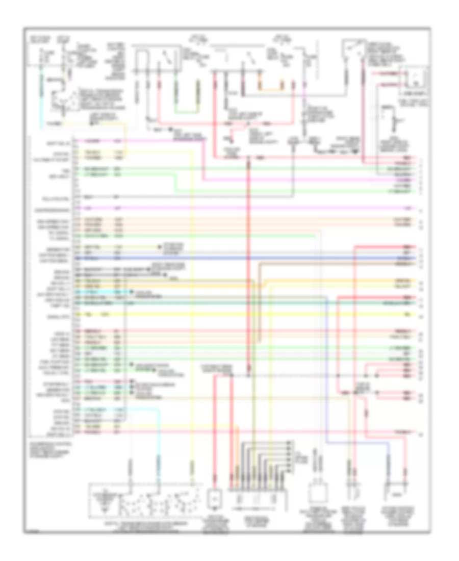
3.0L 24-Valve, Engine Performance Wiring Diagram (2 of 4) for Ford Taurus SE 2005
List of elements for 3.0L 24-Valve, Engine Performance Wiring Diagram (2 of 4) for Ford Taurus SE 2005:
- (front left side of engine compt)
- (right side of luggage compt, behind lining)
- (top left rear side of engine)
- (upper left side of dash)
- Anti- slosh module
- Anti-lock brakes system
- Anti-theft "on" indicator
- C2280b
- Check engine indicator
- Crankshaft position sensor (on lower right front of engine)
- Data link connector (dlc) (mounted on dash, below steering column)
- Engine coolant temperature sensor (on rear of engine block, near thermostat)
- Fuel sender (fuel tank)
- Fuse 10a
- Fuse 15a
- G102 (right rear side of engine compt)
- G103 (right rear side of engine compt)
- G302
- Hot at all times
- Hot in run or start
- Instrument cluster
- Low fuel indicator
- Mass airflow sensor (in engine air intake assembly)
- Microprocessor
- Nca
- Power steering pressure sensor
- Red
- S113
- S114
- S129
- S130
- S205
- S240
- S241
- S417
- Smart junction box (under left side of dash)
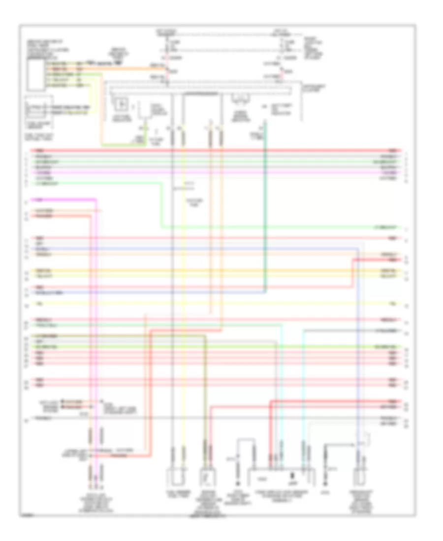
3.0L 24-Valve, Engine Performance Wiring Diagram (3 of 4) for Ford Taurus SE 2005
List of elements for 3.0L 24-Valve, Engine Performance Wiring Diagram (3 of 4) for Ford Taurus SE 2005:
- (left rear of engine) ax4s/4f50n transmission control solenoids
- (right rear of engine, below intake manifold) knock sensor
- (top right rear side of engine)
- Camshaft position sensor (left front of engine, below valve cover)
- Differential pressure feedback egr (dpfe) sensor (on right side of engine)
- Egr vacuum regulator solenoid (on front of intake manifold)
- Electronic pressure control solenoid
- Evap canister purge valve (right rear of engine compt)
- Fuel pump driver module (behind right side luggage compt trim panel)
- Fuel tank pressure transducer sensor (fuel tank)
- Gnd
- Idle air control (iac) valve (on throttle body)
- Mod in
- Mod out
- Nca
- Output shaft speed (oss) sensor (left rear of engine)
- Pmp ctrl
- Pwr
- Red
- Red/pnk
- S100
- S101 (top of engine)
- S104 (top right rear side of engine)
- S110 (rear of engine)
- Shift solenoid a
- Shift solenoid b
- Shift solenoid c
- Throttle position sensor (on throttle body)
- Torque converter clutch solenoid
- Transmission fluid temperature sensor
- Turbine shaft speed (tss) sensor (left rear of engine)
3.0L 24-Valve, Engine Performance Wiring Diagram (4 of 4) for Ford Taurus SE 2005
List of elements for 3.0L 24-Valve, Engine Performance Wiring Diagram (4 of 4) for Ford Taurus SE 2005:
- (cop) 2
- (cop) 3
- (cop) 6
- (in left rear of engine compt) speed control servo
- (left rear of engine compt, on top of transmission housing) digital transmission range (dtr) sensor
- (near glove box) (early build) evaporator discharge air temperature sensor
- (rear of engine)
- (top of engine) injector pressure sensor
- (under vehicle, on fuel tank) evap canister vent valve
- A/c clutch relay
- A/c clutch rly
- Air conditioning system
- Battery
- Battery junction box (front center of engine compt, behind radiator)
- Bpp sw
- Brake pedal position (bpp) switch (upper dash, upper front side of brake pedal)
- C2280c
- Cam sens
- Canister vent
- Dpfe sens
- Dtr-tr3a
- Dual press sw
- Early production
- Epc sol
- Evap purge valve
- Except sedan
- From dtr sensor (diagram 1 of 4)
- Ftp sens
- Fuel inj 1
- Fuel inj 2
- Fuel inj 3
- Fuel inj 4
- Fuel inj 5
- Fuel inj 6
- Fuel injectors (top of engine)
- Fuel pump rly
- Fuse 10a
- Fuse 15a
- G103 (right rear side of engine compt)
- Ground
- H2os 11
- H2os 12
- H2os 21
- H2os 22
- Heated oxygen sensor 11 (rear of engine compt, on exhaust manifold)
- Heated oxygen sensor 12 (under vehicle, downstream from catalytic converter 1)
- Heated oxygen sensor 21 (front of engine compt, on exhaust manifold)
- Heated oxygen sensor 22 (under vehicle, downstream from catalytic converter 2)
- Hot at all times
- Iac valve
- Ips sens in
- Knock sens
- Maf sens
- Oss sens
- Power
- Power (ign)
- Power (run/strt)
- Powertrain control module (pcm) (right rear corner of engine compt)
- Production
- Red
- Red/pnk
- S105 (top right rear side of engine)
- S107 (rear of engine)
- S109 (rear of engine)
- S112
- S114
- S133 (top left rear side of engine compt)
- S136 (left side of engine compt)
- S147
- Sedan early
- Sensor input
- Signal return
- Smart junction box (under left side of dash)
- Tan
- Tcc sol
- Tp sens
- Vref
- Vss
- Vss sens
3.0L FLEX FUEL
3.0L Flex Fuel, Engine Performance Wiring Diagram (1 of 4) for Ford Taurus SE 2005
List of elements for 3.0L Flex Fuel, Engine Performance Wiring Diagram (1 of 4) for Ford Taurus SE 2005:
- (left rear of engine compt, on top of transmission housing)
- (left side of engine compt) s138
- (right rear side of engine compt) g102
- (right rear side of engine compt) g103
- (top of engine) s117
- (top right rear side of engine) s115
- Air conditioning system
- Battery junction box (front center of engine compt behind radiator)
- C2280a
- Ckp pos sens +
- Ckp pos sens -
- Cooling fans system
- Digital transmission range (dtr) sensor
- Digital transmission range (dtr) sensor (left rear of engine compt, on top of transmission housing)
- Dtr-tr1
- Dtr-tr2
- Dtr-tr4
- Dual press sw
- Ect sens
- Egr vacuum regulator solenoid (mounted on right side of intake manifold)
- Epc input
- Evr
- Fan rly ctrl
- Fuel pump
- Fuel pump mod
- Fuel pump relay
- Fuel tank unit (on fuel tank)
- Fuse 15a
- Fuse 20a
- Fuse 2a
- Fuse 30a
- Fuse 5a
- G102
- G107 (top left side of engine compt)
- G302 (right side of luggage compt behind lining)
- Generator
- Ground
- H2os 12
- High spd fan rly
- High speed can+
- High speed can-
- Hot at all times
- Hot in run or start
- Hot in start
- Iat sens
- Ign coil a
- Ign coil b
- Ignition coil (top center of engine)
- Ignition transformer capacitor (attached to ignition coil)
- Imrc module
- Inertia fuel shutoff switch (right rear of vehicle, in cargo area, behind right wheelwell)
- Intake manifold runner control (imrc) module (top rear of engine)
- Low spd fan rly
- Maf sens
- Mod programming
- Nca
- Passive anti-theft system transceiver module (on steering column, near ignition switch)
- Pcm power relay
- Pcu htr ctrl
- Pnk
- Positive crankcase ventilation heater
- Powertrain control module (pcm) (right rear corner of engine compt)
- R n
- Red
- Rx, signal
- S114
- S135
- S137
- S140 (front left side of engine compt)
- Shift sol a
- Shift sol b
- Shift sol c
- Signal rtn
- Smart junction box (under left side of dash)
- Starter rly
- Starting/ charging system
- Starting/charging system cooling fans system
- Tan/red
- Tft sens
- Theft ind
- To dtr sensor (diagram 4 of 4)
- To spark plugs
- Tss
- Tx, signal
- Voltage at start
3.0L Flex Fuel, Engine Performance Wiring Diagram (2 of 4) for Ford Taurus SE 2005
List of elements for 3.0L Flex Fuel, Engine Performance Wiring Diagram (2 of 4) for Ford Taurus SE 2005:
- (behind center of dash) g200
- (behind center of dash, near instrument cluster) flexible fuel sensor module
- (upper left side of dash)
- Anti- slosh module
- Anti-lock brakes system
- Anti-theft "on" indicator
- C2280b
- Check engine indicator
- Crankshaft position sensor (on lower right front of engine)
- Data link connector (dlc) (mounted on dash, below steering column)
- Engine coolant temperature sensor (on rear of engine block, near thermostat)
- Fuel gauge sensor
- Fuel sender (fuel tank)
- Fuel tank unit (on fuel tank)
- Fuse 10a
- Fuse 15a
- G102
- G103 (right rear side of engine compt)
- Hot at all times
- Hot in run or start
- Instrument cluster
- Low fuel indicator
- Mass airflow (maf) sensor (in engine air intake assembly)
- Microprocessor
- Nca
- Red
- S113
- S114
- S129 (front left side of engine compt)
- S130
- S205
- S209
- S237
- S240
- S241
- Smart junction box (under left side of dash)
- W/ flex fuel
- W/o flex fuel
3.0L Flex Fuel, Engine Performance Wiring Diagram (3 of 4) for Ford Taurus SE 2005
List of elements for 3.0L Flex Fuel, Engine Performance Wiring Diagram (3 of 4) for Ford Taurus SE 2005:
- (behind right side luggage compt trim panel) fuel pump driver module
- (left rear of engine) ax4s/4f50n transmission control solenoids
- (top left rear side of engine compt)
- (top of engine) injector pressure sensor
- (top right rear side of engine) s116
- Camshaft position sensor (rear of engine block, between cylinder heads)
- Differential pressure feedback egr (dpfe) sensor (mounted on right front of intake manifold)
- Electronic pressure control solenoid
- Evap canister purge valve (right rear of engine compt, mounted on firewall)
- Fuel tank pressure transducer sensor (fuel tank)
- G302 (right side of luggage compt, behind lining)
- Gnd
- Idle air control (iac) valve (on throttle body)
- Knock sensor (on left rear of engine, below intake manifold)
- Mod in
- Mod out
- Nca
- Output shaft speed (oss) sensor (left rear of engine)
- Pmp ctrl
- Pwr
- Red
- Red/pnk
- S100 (top right rear side of engine)
- S101 (top of engine)
- S133
- Shift solenoid a
- Shift solenoid b
- Shift solenoid c
- Throttle position sensor (tps) (on throttle body)
- Torque converter clutch solenoid
- Transmission fluid temperature sensor
- Turbine shaft speed (tss) sensor (left rear of engine)
3.0L Flex Fuel, Engine Performance Wiring Diagram (4 of 4) for Ford Taurus SE 2005
List of elements for 3.0L Flex Fuel, Engine Performance Wiring Diagram (4 of 4) for Ford Taurus SE 2005:
- (left rear of engine compt, on top of transmission housing) digital transmission range (dtr) sensor
- (right rear side of engine compt) g103
- (top of engine)
- (top of engine) s119
- (top right rear side of engine)
- (under vehicle, on fuel tank) evap canister vent valve
- A/c clutch relay
- A/c clutch rly
- Air conditioning system
- Battery junction box (front center of engine compt, behind radiator)
- Bpp sw
- Brake pedal position switch (under dash, upper front side of brake pedal)
- C2280c
- Cam sens
- Canister vent
- Dpfe sens
- Dtr-tr3a
- Dual press sw
- Epc sol
- Evap purge valve
- Evaporator discharge air temperature sensor (early build) (behind center of dash, near glove box)
- Except sedan early production
- From dtr sensor (diagram 1 of 4)
- Ftp sens
- Fuel inj 1
- Fuel inj 2
- Fuel inj 3
- Fuel inj 4
- Fuel inj 5
- Fuel inj 6
- Fuel injectors (top of engine)
- Fuel pump rly
- Fuse 15a
- Fuse 18 10a
- Ground
- H2os 11
- H2os 12
- H2os 21
- H2os 22
- Heated oxygen sensor 11 (rear of engine compt, on exhaust manifold)
- Heated oxygen sensor 12 (under vehicle, downstream from catalytic converter 1)
- Heated oxygen sensor 21 (front of engine compt, on exhaust manifold)
- Heated oxygen sensor 22 (under vehicle, downstream from catalytic converter 2)
- Hot at all times
- Iac valve
- Ign coil c
- Ips sensor input
- Ks input
- Maf sens
- Oss sens
- Power
- Power (ign)
- Power (run/strt)
- Powertrain control module (pcm) (right rear corner of engine compt)
- Red
- Red/pnk
- S105
- S114
- S118
- S136 (left side of engine compt)
- S147
- Sedan early production
- Sensor input
- Signal return
- Smart junction box (under left side of dash)
- Speed control servo (left rear of engine compt)
- Tan
- Tcc sol
- Tp sens
- Vref
- Vss sens
EXTERIOR LIGHTS
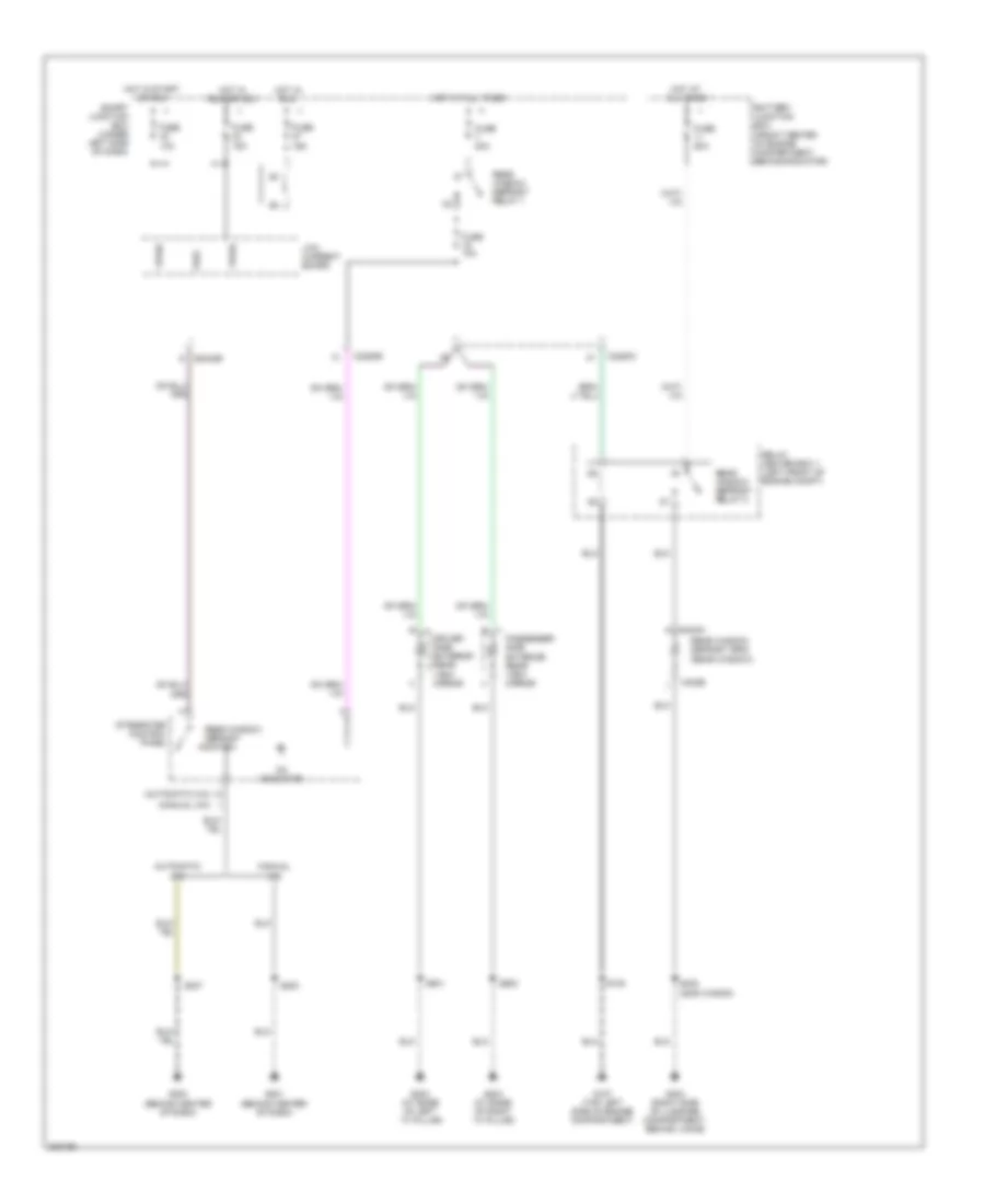
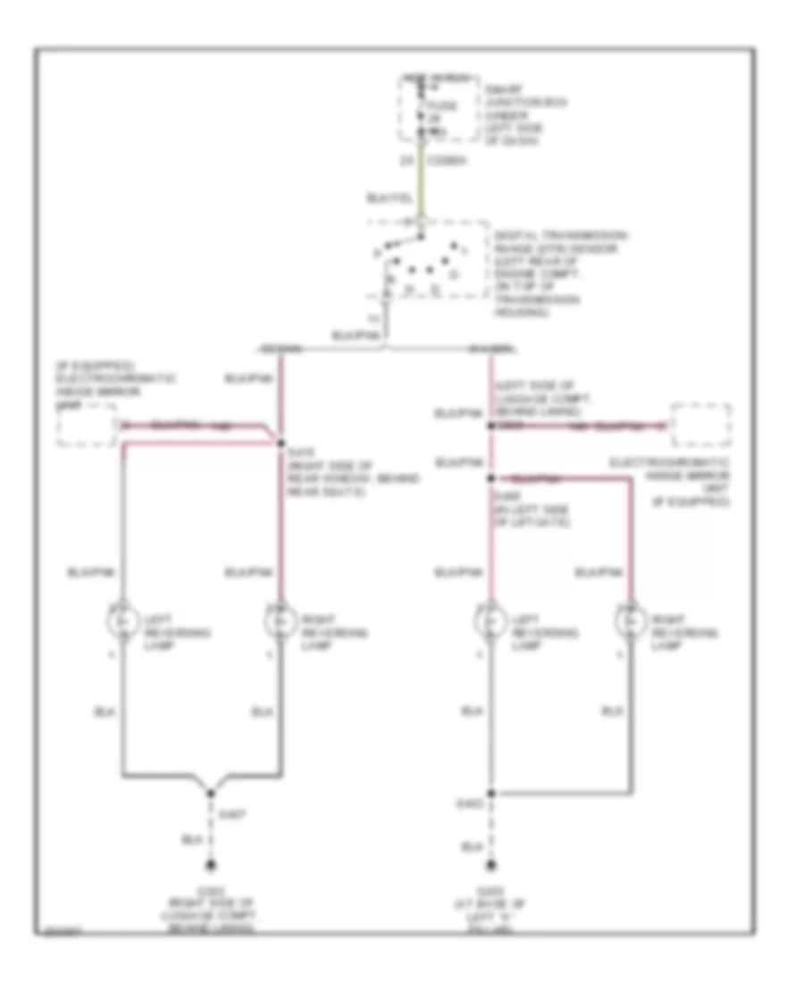
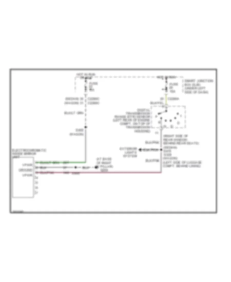
Back-up Lamps Wiring Diagram for Ford Taurus SE 2005
List of elements for Back-up Lamps Wiring Diagram for Ford Taurus SE 2005:
- (if equipped) electrochromatic inside mirror unit
- C2280a
- Digital transmission range (dtr) sensor (left rear of engine compt, on top of transmission housing)
- Electrochromatic inside mirror unit (if equipped)
- Fuse 15a
- G203 (at base of left "a" pillar)
- G303 (right side of luggage compt, behind lining)
- Hot in run
- Left reversing lamp
- Right reversing lamp
- S329
- S403
- S405 (in left side of liftgate)
- S407
- S415 (right side of rear window, behind rear seats)
- Sedan
- Smart junction box (under left side of dash)
- Wagon
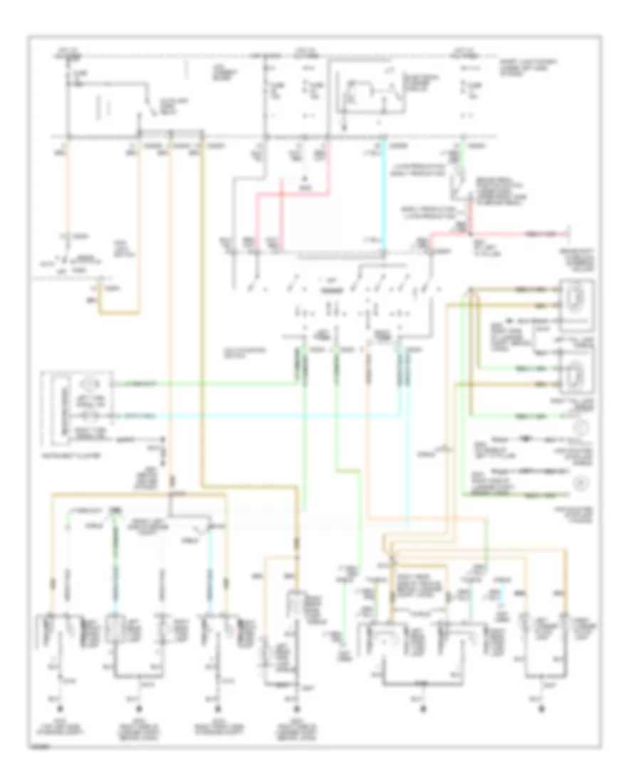
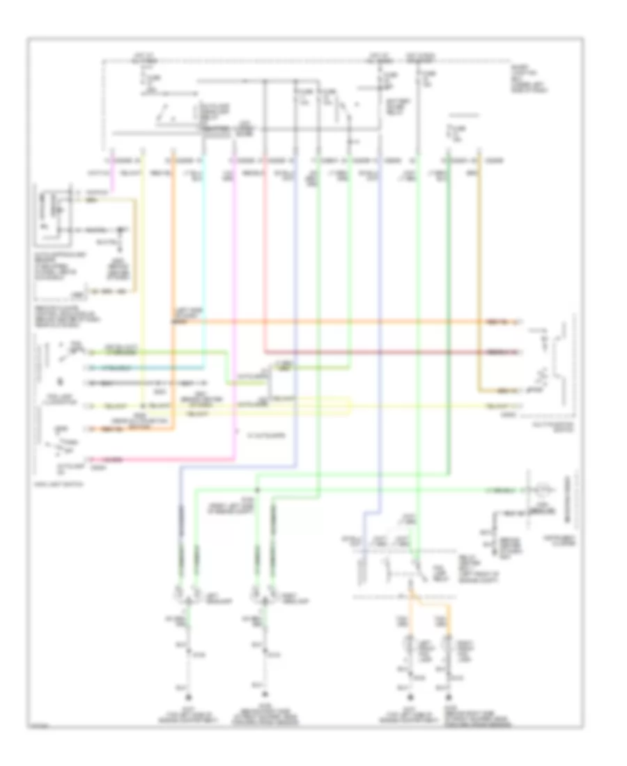
Exterior Lamps Wiring Diagram, Sedan for Ford Taurus SE 2005
List of elements for Exterior Lamps Wiring Diagram, Sedan for Ford Taurus SE 2005:
- (early production)
- (front left side of engine compt)
- (late production)
- (not used)
- (right rear side of vehicle, behind luggage compt lining)
- (right side of luggage compt, behind lining)
- Auto
- Autolamp park relay
- Brake pedal position switch (under dash, upper front side of brake pedal)
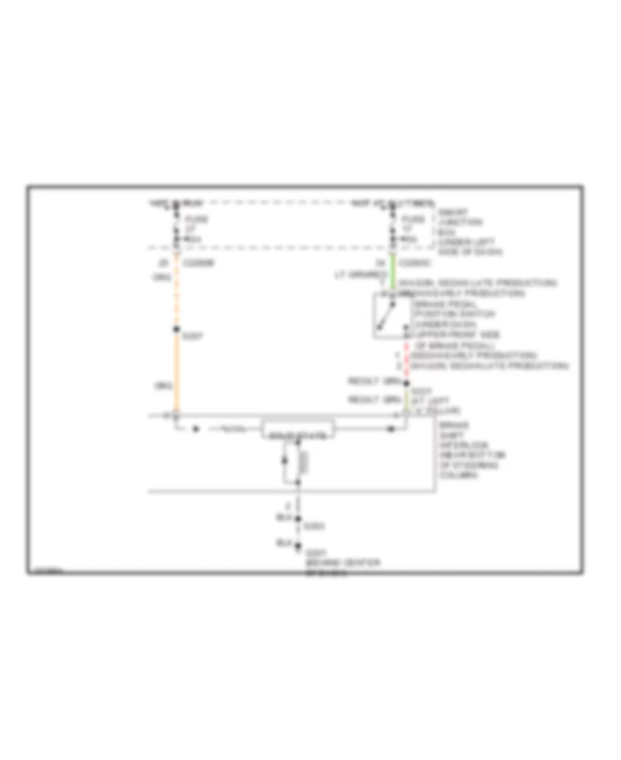
- Brake shift interlock (steering column)
- C202a
- C202c
- C205a
- C2280a
- C2280b
- C2280c
- Electronic flasher module
- Fuse 15a
- G104 (right front side of engine compt)
- G107 (top left side of engine compt)
- G201 (behind center of dash)
- G203 (at base of left "a" pillar)
- G303
- G303 (right side of luggage compt, behind lining)
- Hazard
- Head
- High mounted stoplamp (sable)
- High mounted stoplamp (taurus)
- Hot at all times
- Hot in run
- Instrument cluster
- Left front park/ turn lamp
- Left license plate lamp
- Left rear park/ park lamp
- Left rear side lamp (sable)
- Left rear turn lamp
- Left tail lamp (sable)
- Left turn
- Left turn signal ind
- Low current board
- Main light switch
- Microprocessor
- Multi-function switch
- Off
- Park
- Park lamp
- Right front park/ park lamp turn lamp
- Right license plate lamp
- Right rear park/ turn lamp
- Right rear side lamp (sable)
- Right rear turn lamp
- Right tail lamp (sable)
- Right turn
- Right turn signal ind
- S127
- S135
- S143
- S145
- S146
- S205
- S229
- S231 (at left "a" pillar)
- S407
- S410
- S419
- Sable
- Smart junction box (under left side of dash)
- Taurus
- Turn lamp
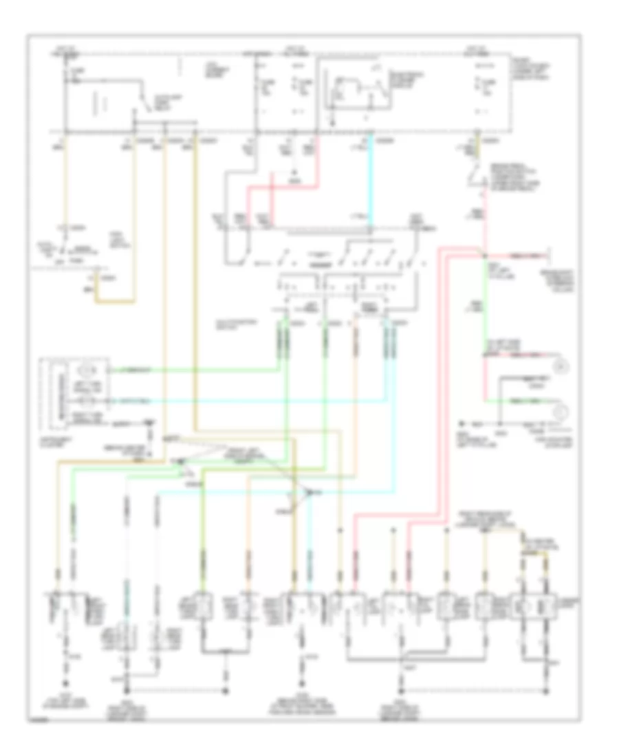
Exterior Lamps Wiring Diagram, Wagon for Ford Taurus SE 2005
List of elements for Exterior Lamps Wiring Diagram, Wagon for Ford Taurus SE 2005:
- (behind center of dash) g201
- (front left side of engine compt)
- (in center of liftgate) s400
- (in left side of liftgate) s406
- (not used)
- (right rear side of vehicle, behind luggage compt lining) s410
- Auto- lamp on
- Autolamp park relay
- Brake pedal position switch (under dash, upper front side of brake pedal)
- Brake shift interlock (steering column)
- C202a
- C202c
- C205a
- C2280a
- C2280b
- C2280c
- C302a
- C302b
- Electronic flasher module
- Fuse 15a
- G106 (behind right side of front bumper, near forward crash sensor)
- G107 (top left side of engine compt)
- G203 (at base of left "a" pillar)
- G303 (right side of luggage compt, behind lining)
- Hazard
- Head
- High mounted stoplamp
- Hot at all times
- Hot in run
- Instrument cluster
- Left
- Left front park/ turn lamp
- Left rear side lamp
- Left rear turn lamp
- Left tail lamp
- Left turn
- Left turn signal ind
- License lamps
- Low current board
- Main light switch
- Microprocessor
- Multi-function switch
- Nca
- Off
- Park
- Park lamp
- Right
- Right front park/ turn lamp
- Right rear side lamp
- Right rear turn lamp
- Right tail lamp
- Right turn
- Right turn signal ind
- S127
- S135
- S143
- S145
- S146
- S205
- S212
- S231 (at left "a" pillar)
- S401
- S403
- S407
- Sable
- Smart junction box (under left side of dash)
- Turn lamp
GROUND DISTRIBUTION
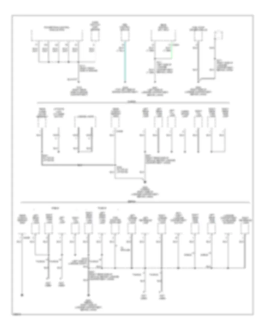
Ground Distribution Wiring Diagram (1 of 3) for Ford Taurus SE 2005
List of elements for Ground Distribution Wiring Diagram (1 of 3) for Ford Taurus SE 2005:
- (3.0l 12-valve, early build)
- (front center of engine compartment, behind radiator) battery junction box (bjb)
- (left front of engine compt)
- (left front of engine compt) relay center box 1
- (under left side of dash) smart junction box
- 87a
- A/c clutch diode
- A/c clutch field coil
- Abs control module
- Anti- theft hood switch
- Battery
- Brake fluid level switch
- C2280c
- C2280f
- C302a
- C302b
- C310a
- C504b
- Cd changer
- Driver side door lock switch
- Driver side exterior rear view mirror
- Dual pressure switch
- Engine compartment)
- Engine cooling fan brake relay
- Engine cooling fan motor 1
- Exterior rear view mirror switch
- Fuel pump relay
- G100 (left side of engine compartment)
- G101 (left side of engine, above starter motor)
- G102 (right rear side of engine compartment)
- G104 (right front side of engine compartment)
- G105 (right front side of engine compartment)
- G106 (behind right side of front bumper, near forward crash sensor)
- G107 (top left side of engine compartment)
- G202 (at base of left "a" pillar)
- G203 (at base of left "a" pillar)
- G300 (left side of luggage compartment, behind lining)
- High mounted stoplamp
- High speed fan control relay
- Horn
- Key pad switch assembly
- Keyless entry w/o anti- theft
- Left front door ajar switch
- Left front fog lamp
- Left front park/ turn lamp
- Left headlamp
- Left lock cylinder switch
- Left rear door ajar switch
- Left reversing lamp
- Left safety belt assembly
- Liftgate ajar switch
- Liftgate glass ajar switch
- Low current board
- Luggage compartment lid release switch
- Master window adjust switch
- Nca
- Of engine compartment)
- Parking brake switch
- Pcm power relay
- Positive crankcase ventilation heater
- Power antenna module
- Powertrain control module
- Rear window defrost relay 2
- Relay center box 1
- Restraints control module
- Right front fog lamp
- Right front park/ turn lamp
- Right head lamp
- Right reversing lamp
- Right safety belt assembly
- S137 (left side of engine compt)
- S229 (right rear side of engine compartment)
- S403 (in left side of liftgate)
- S500 (in top of driver's door)
- S501 (in top of driver's door)
- Sable
- Sable sedan
- Seat weight sensor module
- Sedan w/ keyless entry
- Shield
- Side of engine)
- Speed control servo
- Vehicle floor)
- W/ abs
- W/ anti- theft
- W/ keyless entry
- W/ power locks
- Wagon
- Windshield washer pump motor
- Windshield wiper motor
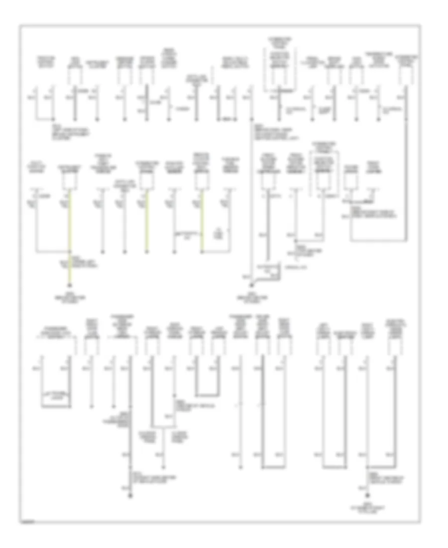
Ground Distribution Wiring Diagram (2 of 3) for Ford Taurus SE 2005
List of elements for Ground Distribution Wiring Diagram (2 of 3) for Ford Taurus SE 2005:
- (early built) adjustable pedal switch
- Air bag sliding contact
- Air conditioning/ heating control unit)
- Automatic a/c
- Brake shift interlock
- C202b
- C205a
- C205b
- C218b
- C271a
- C294a
- C294b
- Data link connector (dlc)
- Driver side front seat adjust switch
- Electro- chromatic inside mirror unit
- Electronic compass
- Flexible fuel sensor module
- Floor shift
- Front blower motor resistor assembly
- Front blower motor speed controller
- Front cigar lighter
- Front interior lamps
- Function selector switch assembly
- G200 (behind center of dash)
- G201 (behind center of dash)
- G204 (at base of right "a" pillar)
- Instrument cluster
- Integrated control panel
- Left vanity mirror lamp
- Main light switch
- Manual a/c
- Map reading lamps
- Message center switch
- Multi- function switch
- Nca
- Passenger side door lock switch
- Passenger side exterior rear view mirror
- Passenger side front seat adjust switch
- Passive anti- theft transceiver module
- Power point
- Prndl illumination lamp
- Rear window wiper/ washer switch
- Remote climate control (rcc) module
- Right front door ajar switch
- Right rear door ajar switch
- Right vanity mirror lamp
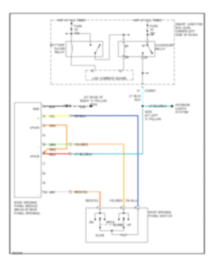
- Roof opening panel module
- S203 (behind dash, near
- S212 (left side of dash, behind instrument cluster)
- S313 (on right side center of vehicle floor)
- S600 (in top of passenger's door)
- S902 (center of vehicle, in roof)
- S905 (front center of vehicle, in roof)
- Side of dash)
- Sunload/ autolamp sensor
- Temperature blend door actuator
- Traction control switch
- W/ flex fuel
- W/ manual a/c
- W/ power locks
- W/ roof opening panel
- W/o roof opening panel
- Wagon
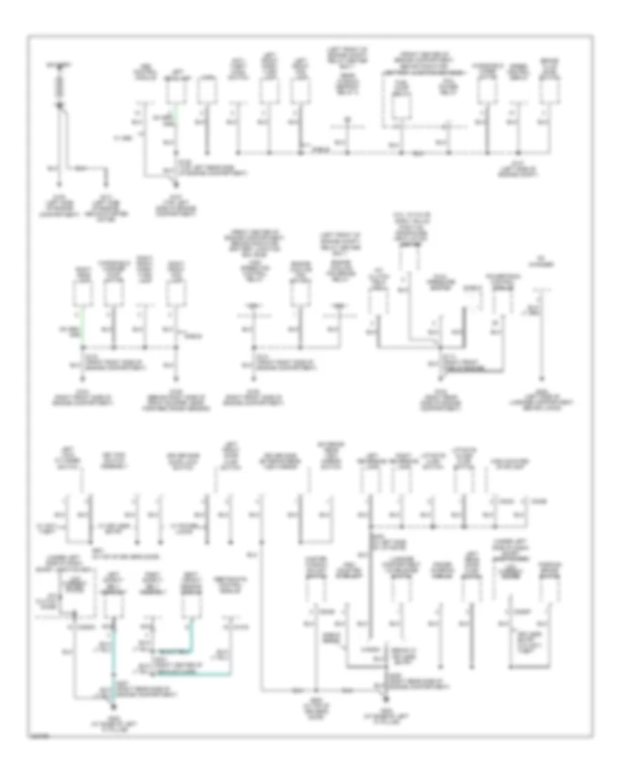
Ground Distribution Wiring Diagram (3 of 3) for Ford Taurus SE 2005
List of elements for Ground Distribution Wiring Diagram (3 of 3) for Ford Taurus SE 2005:
- (not used)
- Abs control module
- Anti- theft luggage compartment switch
- Behind lining)
- C388a
- C402b
- Cargo space lamp
- Fuel pump driver module
- G103 (right rear side of engine compartment)
- G108 (top left side of engine compartment)
- G301 (left side of luggage compartment, behind lining)
- G302 (right side of luggage compartment, behind lining)
- G303 (sedan) (right side of luggage compartment, behind lining)
- G303 (wagon) (right side of luggage compartment, behind lining)
- High mounted stoplamp
- Left license plate lamp
- Left rear park/ turn lamp
- Left rear side lamp
- Left rear turn lamp
- Left reversing lamp
- Left tail lamp
- License lamps
- Liftgate lock cylinder switch
- Luggage compartment lid release solenoid
- Mass air flow (maf) sensor
- Nca
- Powertrain control module (pcm)
- Rear control unit (rcu)
- Rear window defrost grid
- Rear wiper motor assembly
- Right license plate lamp
- Right rear park/ turn lamp
- Right rear side lamp
- Right rear turn lamp
- Right reversing lamp
- Right tail lamp
- S114 (right front side of engine)
- S401 (in top of liftgate)
- S402 (in top of liftgate)
- S407 (right rear side of vehicle, behind luggage compartment lining)
- S417 (right side of luggage compartment, behind lining)
- S419 (left side of luggage compt)
- Sable
- Sedan
- Taurus
- W/ spoiler
- Wagon
HEADLIGHTS
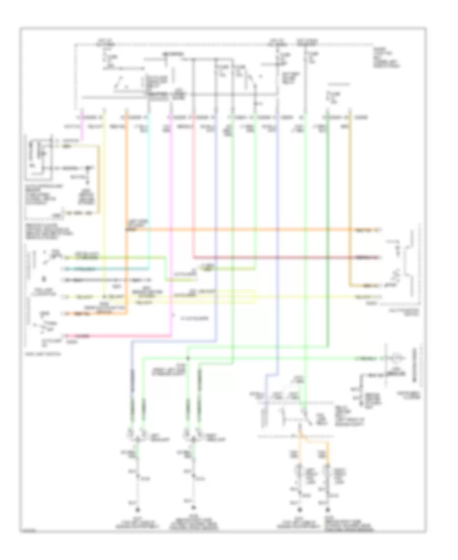
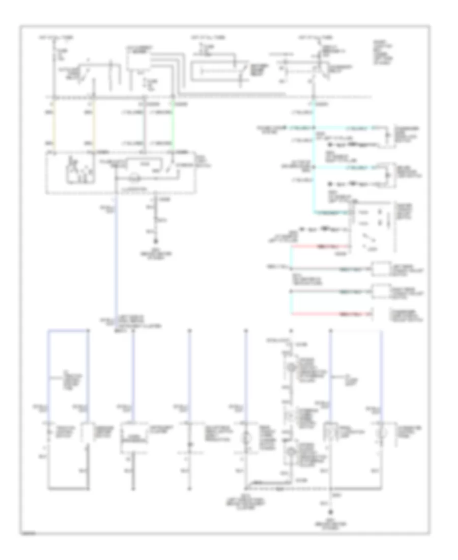
Headlights Wiring Diagram, with DRL for Ford Taurus SE 2005
List of elements for Headlights Wiring Diagram, with DRL for Ford Taurus SE 2005:
- (behind center of dash) g201
- (left side of dash) s223
- Autolamp
- Autolamp headlamp relay (if equipped)
- Autolamp/sunload sensor (if equipped) (in dash, above glove box)
- Battery saver relay
- C202c
- C205a
- C2280a
- C2280b
- C2280d
- C2280e
- Drl driver
- Fog lamp illumination
- Fog lamp relay
- Fog lamps
- Fuse 10a
- Fuse 15a
- Fuse 25a
- G106 (behind right side of front bumper, near forward crash sensor)
- G107 (top left side of engine compartment)
- G200 (behind center of dash)
- G201 (behind center of dash)
- Head
- High beam ind
- Hot at all times
- Hot in run or start
- Instrument cluster
- Left front fog lamp
- Left headlamp
- Low current board
- Main light switch
- Microprocessor
- Multi-function switch
- Off
- Park
- Pass
- Relay center box 1 (left front of engine compt)
- Remote climate control (rcc) module (behind center of dash, near glove box)
- Right front fog lamp
- Right headlamp
- S128 (front left side of engine compt)
- S135
- S143
- S203
- S212
- S237
- S239 (near multifunction switch)
- Smart junction box (under left side of dash)
- Sunload
- Vref
- W/ autolamps
- W/o autolamps
Headlights Wiring Diagram, without DRL for Ford Taurus SE 2005
List of elements for Headlights Wiring Diagram, without DRL for Ford Taurus SE 2005:
- (behind center of dash) g201
- (left side of dash) s223
- Autolamp
- Autolamp headlamp relay (if equipped)
- Autolamp/sunload sensor (if equipped) (in dash, above glove box)
- Battery saver relay
- C202c
- C205a
- C2280a
- C2280b
- C2280d
- C2280e
- Fog lamp illumination
- Fog lamp relay
- Fog lamps
- Fuse 10a
- Fuse 15a
- Fuse 25a
- G106 (behind right side of front bumper, near forward crash sensor)
- G107 (top left side of engine compartment)
- G200 (behind center of dash)
- G201 (behind center of dash)
- Head
- High beam ind
- Hot at all times
- Hot in run or start
- Instrument cluster
- Left front fog lamp
- Left headlamp
- Low current board
- Main light switch
- Microprocessor
- Multi-function switch
- Off
- Park
- Pass
- Relay center box 1 (left front of engine compt)
- Remote climate control (rcc) module (behind center of dash, near glove box)
- Right front fog lamp
- Right headlamp
- S128 (front left side of engine compt)
- S135
- S143
- S203
- S212
- S237
- S239 (near multifunction switch)
- Smart junction box (under left side of dash)
- Sunload
- Vref
- W/ autolamps
- W/o autolamps
HORN
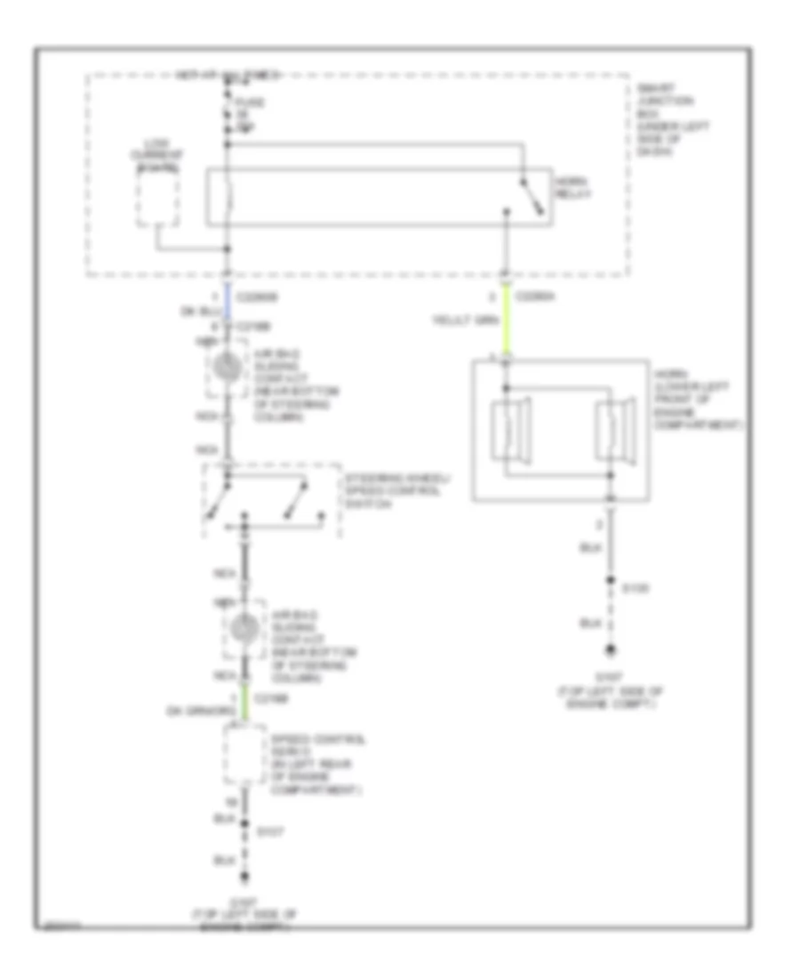
Horn Wiring Diagram for Ford Taurus SE 2005
List of elements for Horn Wiring Diagram for Ford Taurus SE 2005:
- (top left side of engine compt)
- Air bag sliding contact (near bottom of steering column)
- C218b
- C2280a
- C2280b
- Fuse 15a
- G107
- Horn (lower left front of engine compartment)
- Horn relay
- Hot at all times
- Low current board
- Nca
- S135
- S137
- Smart junction box (under left side of dash)
- Speed control servo (in left rear of engine compartment)
- Steering wheel/ speed control switch
INSTRUMENT CLUSTER
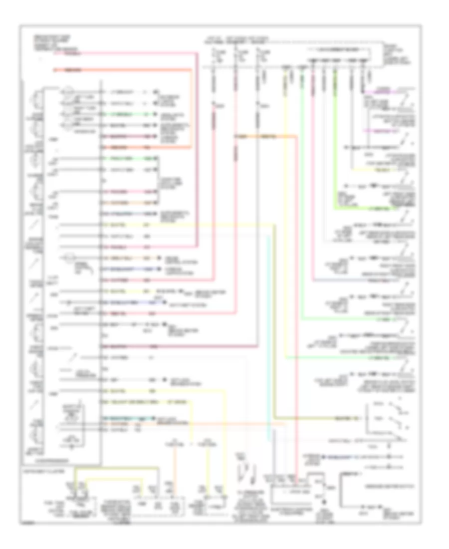
Instrument Cluster Wiring Diagram for Ford Taurus SE 2005
List of elements for Instrument Cluster Wiring Diagram for Ford Taurus SE 2005:
- (behind center of dash)
- (behind right side of front bumper) ambient air temperature sensor
- (or 29)
- Adaptive damping ind
- Air bag ind
- Anti-lock brakes system
- Anti-theft "on" ind
- Anti-theft system
- Brake fluid level ind
- Brake fluid level switch (left rear of engine compt, to right of master cylinder)
- C228ob
- C228od
- C228of
- Charge ind
- Check engine ind
- Check fuel cap ind
- Computer data lines system
- Cruise control system
- Door ajar ind
- Electronic compass (if equipped)
- Engine coolant tempera- ture
- Exterior lights system
- Flexible fuel sensor module (behind center of dash, near instrument cluster)
- Fuel gauge
- Fuel gauge sensor
- Fuel level sig
- Fuel sender (fuel tank)
- Fuel tank unit (on fuel tank)
- Fuse 10a
- Fuse 15a
- G107 (top left side of engine compt)
- G200
- G201 (behind center of dash)
- G203 (at base of left ``a" pillar)
- G204 (at base of right ``a" pillar)
- Gnd
- Headlights system
- High beam ind
- Hot at all times
- Hot in run or acc
- Hot in run or start
- Hs can +
- Hs can -
- Illum
- Instrument cluster
- Interior lights system
- Left front door ajar switch (rear of left front door)
- Left rear door ajar switch (rear of left rear door)
- Left turn ind
- Liftgate ajar switch (bottom center of liftgate)
- Liftgate glass ajar switch (top center of liftgate)
- Low coolant level ind
- Low current board
- Low fuel ind
- Low oil pressure
- Message center switch
- Microprocessor
- Ms can +
- Ms can -
- Nca
- Oil pressure switch (3.0l 2 valve: on right rear of engine block) (3.0l 4 valve: on left front side of engine block)
- Parking brake switch (under left side of dash, mounted above parking brake pedal)
- Right front door ajar switch (rear of right front door)
- Right rear door ajar switch (rear of right rear door)
- Right turn ind
- S137
- S204
- S205
- S209
- S212
- S229
- S237
- S313
- S403
- S404 (in left side of liftgate)
- S501
- S600
- S905
- Safety belt ind
- Sig rtn
- Smart junction box (under left side of dash)
- Speed control ind
- Speedo- meter
- Tacho- meter
- Tone
- Vbatt
- Vpwr
- Vref
- W/ flex fuel
- W/o flex fuel
- Wagon
- Warning system
INTERIOR LIGHTS
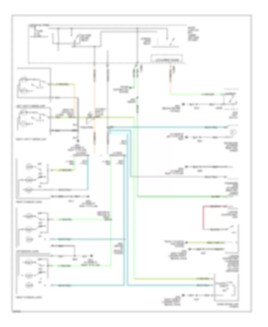
Courtesy Lamps Wiring Diagram for Ford Taurus SE 2005
List of elements for Courtesy Lamps Wiring Diagram for Ford Taurus SE 2005:
- (at base of left "a" pillar) g203
- (at right side "a" pillar) s903
- (center of vehicle, in roof) s900
- (front of vehicle, in roof) s904
- Battery saver relay
- C205b
- C2280c
- C2280e
- Cargo space lamp (wagon)
- Driver side exterior rear view mirror
- Front interior lamps
- Fuse 10a
- G201 (behind center of dash)
- G204 (at base of right "a" pillar)
- G303 (right side of luggage compt, behind lining)
- Hot at all times
- If equipped
- Interior
- Interior lamps relay
- Left vanity mirror lamp
- Low current board
- Luggage compartment lamp
- Luggage compartment lid release solenoid (on trunk lid latch mechanism)
- Main light switch
- Map reading lamps
- Off
- Passenger side exterior rear view mirror
- Power distribution system
- Right vanity mirror lamp
- S212
- S251
- S313
- S321 (sedan)
- S407
- S501
- S600
- S901 (center of vehicle, in roof)
- S902
- S905
- Smart junction box (under left side of dash)
- Tailgate open
- Trunk, tailgate, fuel doors system
- W/ roof opening panel
- W/o roof opening panel
Instrument Illumination Wiring Diagram for Ford Taurus SE 2005
List of elements for Instrument Illumination Wiring Diagram for Ford Taurus SE 2005:
- (in top of driver's door) s502
- (left side of dash, behind
- Accessory relay
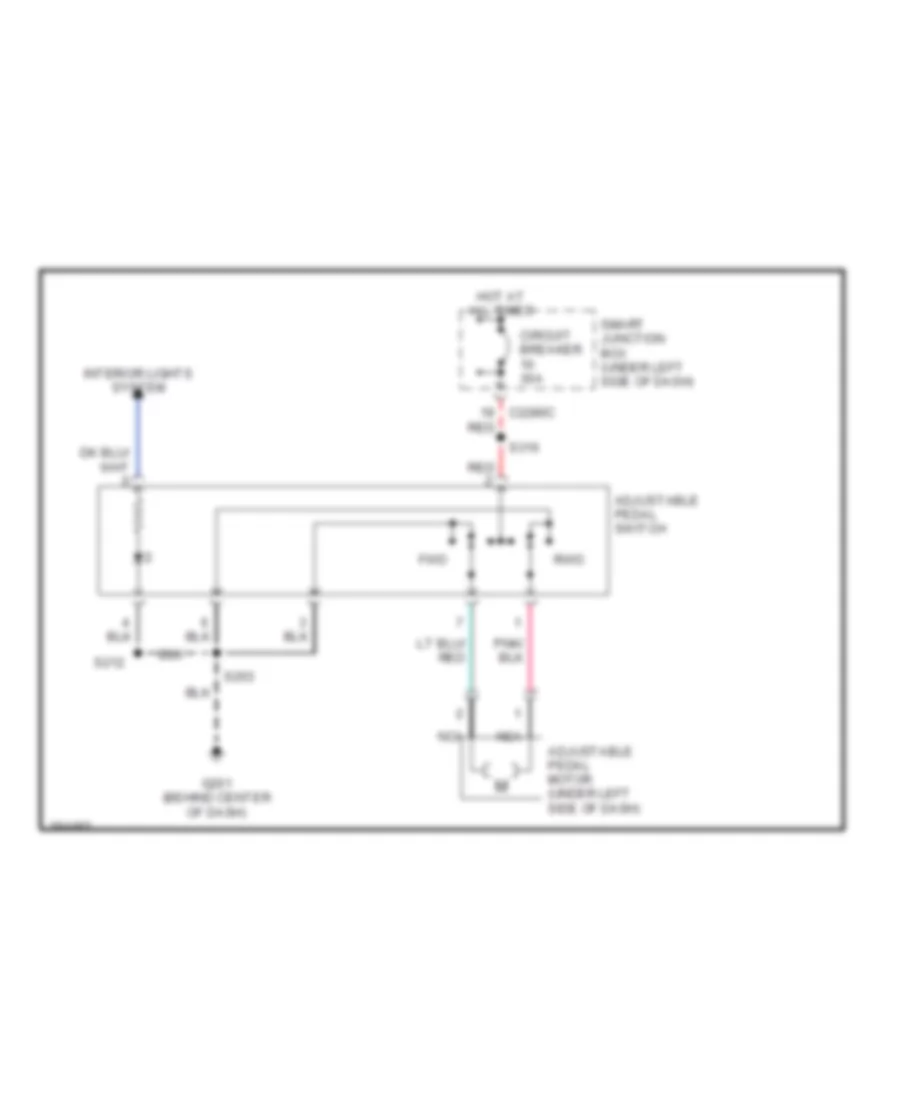
- Adjustable pedal switch (early production)
- Air bag sliding contact (near bottom of steering column)
- Auto
- Autolamp park relay
- Battery battery saver saver relay relay
- C205a
- C205b
- C218b
- C2280b
- C2280c
- C2280e
- C504b
- Circuit breaker 10 30a
- Driver side door lock switch
- Fuse 10a
- Fuse 15a
- G201 (behind center of dash)
- G203 (at base of left "a" pillar)
- G204 (at base of right "a" pillar)
- Gnd
- Head
- Hot at all times
- Illumination
- Instrument cluster
- Integrated control panel
- Interior
- Left rear window adjust switch
- Lock
- Low current board
- Main light switch
- Master window adjust switch
- Message center switch
- Micro- processor
- Nca
- Off
- Park
- Passenger side door lock switch
- Passenger side window adjust switch
- Power tops system
- Prndl illumination lamp
- Pulse width module
- Pwr
- Rear window wiper/ washer switch (wagon)
- Right rear window adjust switch
- S203
- S210
- S212
- S212 (left side of dash, behind instrument cluster)
- S314 (on center of vehicle floor)
- S500
- S501
- S600
- Smart junction box (under left side of dash)
- Steering wheel/ speed control switch
- Traction control switch
- W/ floor shift
- W/ traction control system (tcs)
POWER ANTENNA
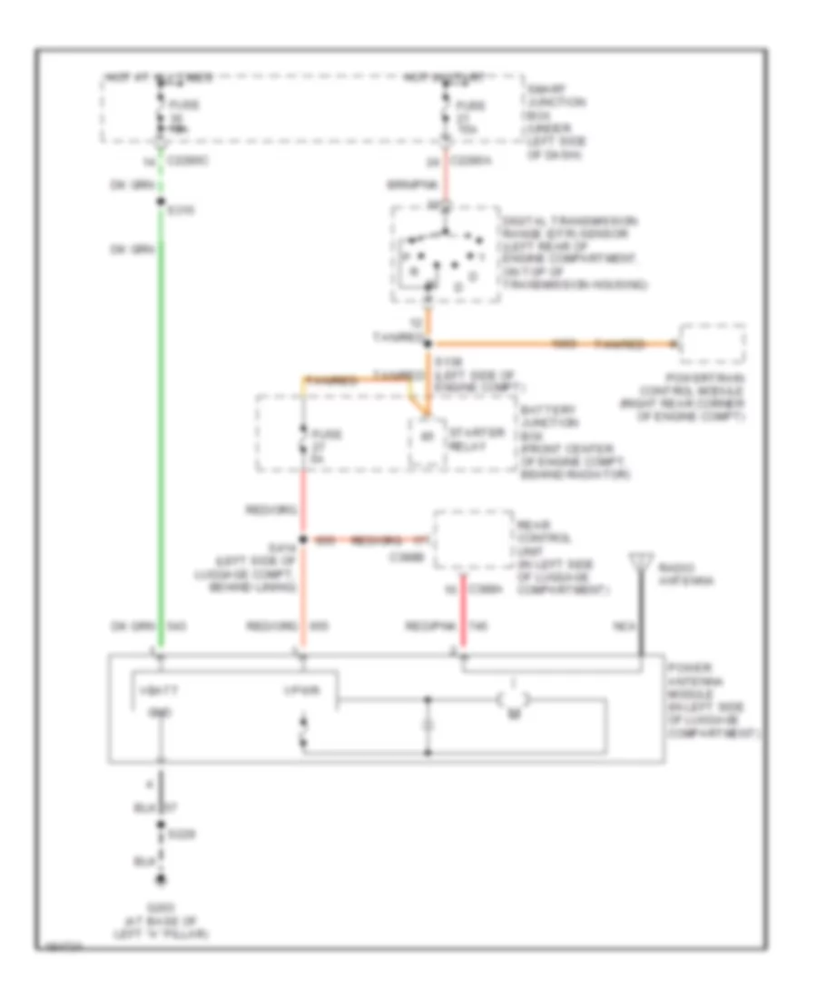
Power Antenna Wiring Diagram for Ford Taurus SE 2005
List of elements for Power Antenna Wiring Diagram for Ford Taurus SE 2005:
- Battery junction box (front center of engine compt, behind radiator)
- C2280a
- C2280c
- C388a
- C388b
- Digital transmission range (dtr) sensor (left rear of engine compartment, on top of transmission housing)
- Engine compt)
- Fuse 10a
- Fuse 15a
- Fuse 5a
- G203 (at base of left "a" pillar)
- Gnd
- Hot at all times
- Hot in start
- Nca
- Power antenna module (in left side of luggage compartment)
- Powertrain control module (right rear corner of engine compt)
- Radio antenna
- Rear control unit (in left side of luggage compartment)
- Red/pnk
- S138 (left side of tan/red
- S229
- S315
- S414 (left side of luggage compt, behind lining)
- Smart junction box (under left side of dash)
- Starter relay
- Tan/red
- Vbatt
- Vpwr
POWER DISTRIBUTION
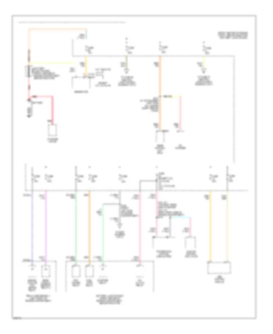
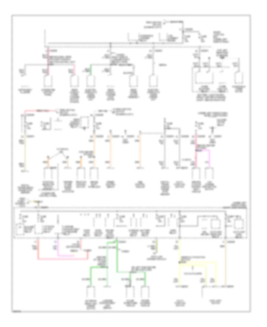
Power Distribution Wiring Diagram (1 of 3) for Ford Taurus SE 2005
List of elements for Power Distribution Wiring Diagram (1 of 3) for Ford Taurus SE 2005:
- (3.0l, 2v: top right rear side of engine) (3.0l, 4v: front right side of engine compartment) s147
- (front center of engine compt, behind radiator) battery junction box
- 3.0l 12-valve
- A/c clutch relay
- Abs control module
- Battery
- Battery junction box (front center of 175a engine compartment, behind radiator)
- Battery junction box (front center of engine compartment, behind radiator)
- C102a
- C1104
- C388a
- Cd changer
- Engine cooling fan brake relay
- Except 3.0l 12-valve
- Fuel pump relay
- Fuse (except 3.0l 12-valve) (3.0l 12-valve) 10a
- Fuse 10a
- Fuse 20a
- Fuse 30a
- Fuse 40a
- Fuse 50a
- Fuse 60a
- Fuse b
- Generator
- Idle air control (iac) valve
- Pcm power relay
- Powertrain control module (pcm)
- Rear control unit (rcu)
- Rear window defrost relay 2
- Red
- Relay center box 1 (left front of engine compartment)
- S125 (front left side of engine compartment)
- S413 (w/ cd changer) (left side of luggage compt, behind lining)
- Starter motor
- Starter relay
- Tan/ red
- To fuse 26 (central junction box) (diagram 3 of 3)
- To fuse 33 (central junction box) (diagram 2 of 3)
- To s208 (diagram 2 of 3)
Power Distribution Wiring Diagram (2 of 3) for Ford Taurus SE 2005
List of elements for Power Distribution Wiring Diagram (2 of 3) for Ford Taurus SE 2005:
- (diagram 1 of 3)
- (front center of engine compt, behind radiator)
- (not used)
- (under left side of dash) smart junction box
- Acc
- Acces- sory relay
- Adjustable pedal switch (early production)
- Battery junction box
- Brake pedal position switch
- C202a
- C2280a
- C2280b
- C2280b c2280b
- C2280c
- C310a
- Deactivator switch
- Driver side front seat adjust switch
- Early production
- Electronic compass
- Flexible fuel sensor module (3.0l flex fuel)
- Fog lamp relay
- From fuse 3 (diagram 1 of 3)
- From s125 c
- Front cigar lighter
- Fuse 15a
- Fuse 16 10a
- Fuse 20 10a
- Fuse 20a
- Fuse 30a
- Fuse 32 10a
- Fuse 36
- Fuse fuse 20a
- G201 (behind center of dash)
- Ignition switch
- Instrument cluster
- Integrated control panel
- Late production
- Lock
- Low current board
- Multi- function switch
- Nca
- Off
- Passenger side front seat adjust switch
- Passive anti-theft transceiver module
- Pcm power relay
- Power point
- Rear window defrost relay 1
- Red
- Red (on center of vehicle floor) s316
- Red/ (left side of dash, behind instrument cluster) s209
- Relay center box 1 (left front of engine compartment)
- Remote climate control (rcc) module
- Restraints control module
- Run
- Seat weight sensor module
- Smart junction box (under left side of dash)
- Sta
- Start
- To fuse 21 (smart junction box) (diagram 3 of 3)
- To fuse 22 (smart junction box) (diagram 3 of 3)
- To fuse 27 (smart junction box) (diagram 3 of 3)
- Vpwr
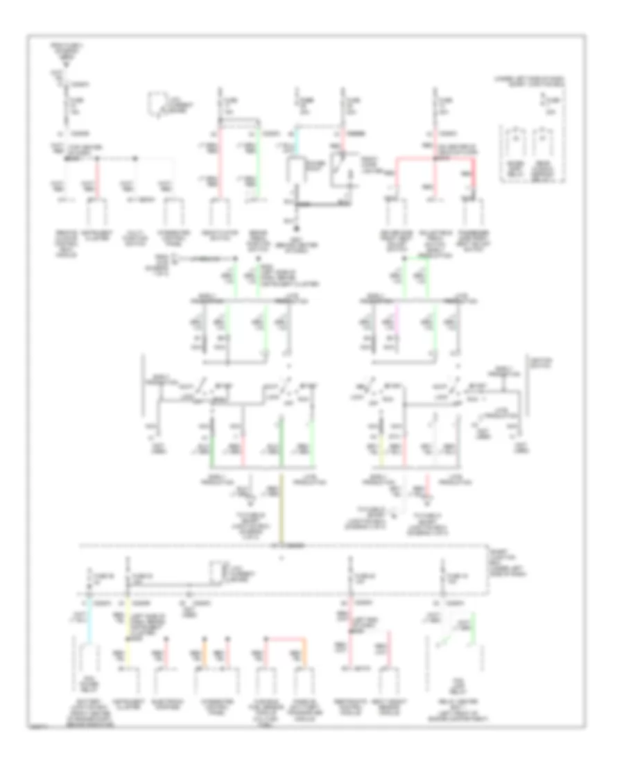
Power Distribution Wiring Diagram (3 of 3) for Ford Taurus SE 2005
List of elements for Power Distribution Wiring Diagram (3 of 3) for Ford Taurus SE 2005:
- (behind center of dash) s246
- (behind dash, near air conditioning & heating control unit) s204
- (center of vehicle floor) (sedan) s321
- (near multifunction switch) s239
- (not used)
- (on left side center of vehicle floor) s315
- (right side of luggage compt, behind lining) s409
- (top center of dash) s207
- (top left rear side of engine) s139
- (under left side of dash) smart junction box
- A/c
- Abs control module
- Autolamp headlamp relay
- Autolamp park relay
- Battery junction box (front center of engine compt, behind radiator)
- Battery saver relay
- Blower motor relay
- Brake shift interlock
- C202a
- C202c
- C205a
- C2280a
- C2280b
- C2280c
- C294b
- Data link connector (dlc)
- Digital trans- mission range (dtr) sensor
- Digital transmission range (dtr) sensor
- Door lock relay
- Door unlock relay
- Driver door unlock relay
- Drl driver
- Electro- chromatic inside mirror unit
- Exterior rear view mirror switch
- From fuse 1 (diagram 1 of 3)
- From ignition d
- From ignition switch (diagram 2 of 3)
- Function selector switch assembly
- Fuse 10a
- Fuse 15a
- Fuse 20a
- Fuse 25a
- Fuse 30a
- Fuse 40a
- Fuse 5a
- Horn relay
- Instrument cluster
- Integrated control panel
- Interior lamps relay
- Liftgate unlock relay
- Low charge protection switch
- Low current board
- Luggage compartment lamp (sedan)
- Luggage compartment lid release relay
- Main light switch
- Multi- function switch
- Nca
- Power antenna module
- Pulse stretcher module
- Rear window defrost relay 1
- Rear window washer pump motor
- Rear window wiper/ washer switch (wagon)
- Rear wiper motor assembly
- Remote climate control (rcc) module
- Sedan
- Smart junction box (under left side of dash)
- Speed control servo
- Switch (diagram 2 of 3)
- Temper- ature blend door actuator
- Traction control switch
- W/ eatc
- W/ manual
- W/o autolamps
- Wagon
- Windshield washer relay
- Windshield wiper motor
- Wiper high/low relay
- Wiper run/park relay
POWER DOOR LOCKS
Power Door Locks Wiring Diagram, with Keyless Entry for Ford Taurus SE 2005
List of elements for Power Door Locks Wiring Diagram, with Keyless Entry for Ford Taurus SE 2005:
- (at base of left "a" pillar) g203
- (on center of vehicle floor) s317
- (right rear side of engine compt) s226
- (right side of luggage compt, behind lining) g303
- 1/2
- 3/4
- 5/6
- 7/8
- 9/0
- C2280c
- C2280f
- Door lock relay
- Door lock rly
- Door lock sw
- Door unlock relay
- Door unlock rly
- Door unlock sw
- Driver door unlock relay
- Driver door unlock rly
- Driver side door lock switch
- Fuse 20a
- G203 (at base of left "a" pillar)
- G204 (at base of right "a" pillar)
- Gnd
- Hot at all times
- Interior lights system
- Key pad illum
- Key pad in
- Key pad switch assembly
- Left front door lock actuator (rear of left front door)
- Left rear door lock actuator (rear of left rear door)
- Liftgate lock actuator (wagon) (in liftgate)
- Liftgate unlock relay (wagon)
- Liftgate unlock rly
- Lock
- Low current board
- Luggage compartment lid release relay
- Luggage compartment lid release relay (sedan)
- Luggage compartment lid release solenoid (sedan) (on trunk lid latch mechanism)
- Passenger side door lock switch
- Red
- Right front door lock actuator (rear of right front door)
- Right rear door lock actuator (right rear door)
- S228 (right rear side of engine compt)
- S229
- S249 (wagon)
- S407
- S501
- S600
- Sedan
- Smart junction box (sjb) (under left side of dash)
- Unlock
- Wagon
Power Door Locks Wiring Diagram, without Keyless Entry for Ford Taurus SE 2005
List of elements for Power Door Locks Wiring Diagram, without Keyless Entry for Ford Taurus SE 2005:
- (on center of vehicle floor) s317
- (right rear side of engine compt) s228
- C2280c
- C2280f
- Door lock relay
- Door lock rly
- Door lock sw
- Door unlock relay
- Door unlock rly
- Door unlock sw
- Driver door unlock relay
- Driver side door lock switch
- Drv dr unlk rly
- Fuse 20a
- G203 (at base of left "a" pillar)
- G204 (at base of right "a" pillar)
- Ground
- Hot at all times
- Interior lights system
- Left front door lock actuator (rear of left front door)
- Left rear door lock actuator (rear of left rear door)
- Lock
- Low current board
- Passenger side door lock switch
- Right front door lock actuator (rear of right front door)
- Right rear door lock actuator (right rear door)
- S226 (right rear side of engine compt)
- S229
- S501
- S600
- Smart junction box (cjb) (under left side of dash)
- Unlock
POWER MIRRORS
Electronic Day/Night Mirror Wiring Diagram for Ford Taurus SE 2005
List of elements for Electronic Day/Night Mirror Wiring Diagram for Ford Taurus SE 2005:
- (at base of right "a" pillar) g204
- (right side of rear window, behind rear seats)
- (sedan)
- (sedan) s415 s329 (wagon) (left side of luggage compt, behind lining)
- (wagon)
- C2280a
- C2280c
- Digital transmission range (dtr) sensor (left rear of engine compt, on top of transmission housing)
- Electrochromatic inside mirror unit
- Exterior lights system
- Fuse 15a
- Ground
- Hot in run
- Hot in run or acc
- S409
- S905
- Smart junction box (sjb) (under left side of dash)
- Vpwr
Power Mirrors Wiring Diagram for Ford Taurus SE 2005
List of elements for Power Mirrors Wiring Diagram for Ford Taurus SE 2005:
- C2280c
- Defogger system
- Down
- Driver side exterior rear view mirror
- Exterior rear view mirror switch
- Fuse 10a
- G203 (at base of left "a" pillar)
- G204 (at base of right "a" pillar)
- Hot at all times
- Interior lights system
- Left
- Left/ right
- Left/ right m
- Mirror select
- Passenger side exterior rear view mirror
- Red
- Right
- S321 (sedan)
- S501
- S503
- S600
- Smart junction box (sjb) (under left side of dash)
- Up/ down
- Up/ down m
POWER SEATS
Adjustable Pedal Wiring Diagram for Ford Taurus SE 2005
List of elements for Adjustable Pedal Wiring Diagram for Ford Taurus SE 2005:
- Adjustable pedal motor (under left side of dash)
- Adjustable pedal switch
- C2280c
- Circuit breaker 30a
- Fwd
- G201 (behind center of dash)
- Hot at all times
- Interior lights system
- Nca
- Red
- Rwd
- S203
- S212
- S316
- Smart junction box (under left side of dash)
Power Seats Wiring Diagram for Ford Taurus SE 2005
List of elements for Power Seats Wiring Diagram for Ford Taurus SE 2005:
- C2280c
- Circuit breaker 30a
- Driver side front seat adjust switch
- Entire seat
- Forward/ rearward motor
- Front of seat
- Front up/down motor
- G204 (at base of right "a" pillar)
- Hot at all times
- Left power seat motor assembly (under driver seat)
- Nca
- Passenger side front seat adjust switch
- Rear of seat
- Rear up/down motor
- Red
- Right power seat motor assembly
- S313
- S316
- Smart junction box (under left side of dash)
POWER TOP/SUNROOF
Power Top/Sunroof Wiring Diagram for Ford Taurus SE 2005
List of elements for Power Top/Sunroof Wiring Diagram for Ford Taurus SE 2005:
- (at base of right "a" pillar) g204
- Accessory relay
- Battery saver relay
- C2280c
- Close
- Fuse 10a
- Fuse 30a
- Gnd
- Hot at all times
- Interior lights system
- Low current board
- Open
- Red
- Roof opening panel module (rear of roof panel opening)
- Roof opening panel switch
- S235 (at left "a" pillar)
- S902
- Slide
- Smart junction box (sjb) (under left side of dash)
- Tilt
- Vpwr
POWER WINDOWS
Power Windows Wiring Diagram for Ford Taurus SE 2005
List of elements for Power Windows Wiring Diagram for Ford Taurus SE 2005:
- (on center of vehicle floor) s314
- 11a
- Acces- sory relay ctrl
- Accessory relay
- Battery saver relay
- Battery saver relay ctrl
- C2280c
- C2280f
- C504a
- C504b
- C5o4b
- Circuit breaker 10 30a
- Door locks system
- Driver side front power window motor (left front door)
- Driver window switch
- Fuse 30 10a
- G203 (at base of left "a" pillar)
- Hot at all times
- Interior lights system
- Left rear power window motor (left rear door)
- Left rear window adjust switch
- Left rear window switch
- Low current board
- Master window adjust switch
- One touch high sense
- One touch low sense
- One touch window relay ctrl
- One- touch down switch
- One-touch window relay
- Passenger side front power window motor (right front door)
- Passenger side window adjust switch
- Passenger window switch
- Power tops system
- Ptc
- Resistor
- Right rear power window motor (right rear door)
- Right rear window adjust switch
- Right rear window switch
- S235 (at left "a" pillar)
- S500
- Smart junction box (under left side of dash)
- Window lockout switch
- Window switch down in
- Window switch up in
RADIO
Radio Wiring Diagram, with Audiophile System for Ford Taurus SE 2005
List of elements for Radio Wiring Diagram, with Audiophile System for Ford Taurus SE 2005:
- (behind center of dash) g200
- (behind dash, near air conditioning &
- (left side of dash, behind instrument cluster) s215
- (left side of luggage compt, behind lining) g300
- (left side of luggage compt, behind lining) g301
- (not used)
- (w/ etac)
- (w/ etac) s219
- Acp+
- Acp-
- Air conditioning system
- Antenna
- Asyson
- Battery junction box (front center of engine compt, behind
- C2280a
- C2280b
- C388a
- C388b
- C388c
- Cd changer
- Defogger system
- Defrost rly
- Defrost sw in
- Digital transmission range (dtr) sensor (left rear of engine compt, on top of transmission housing)
- Disabled ind
- Fuse 10a
- Fuse 15a
- Fuse 20a
- Fuse 5a
- G201 (behind center of dash)
- Gnd
- Heating control unit)
- Hot at all times
- Hot in run or acc
- Hot in start
- Hot in start or run
- Illum out
- Integrated control panel
- Interior lights system
- Left front speaker
- Left front tweeter
- Left rear speaker
- Nca
- Power antenna system
- Radiator)
- Rear control unit (in left side of luggage compt)
- Red/pnk
- Right front speaker
- Right front tweeter
- Right rear speaker
- S138
- S203
- S204 (wagon)
- S205
- S209
- S220
- S232 (behind left side of dash)
- S237
- S304 (at left side of luggage compt)
- S309 (left side of luggage compt, behind lining)
- S411
- S412 (left side of luggage compt, behind lining)
- S413
- S414
- Smart junction box (sjb) (under left side of dash)
- Starter relay
- Tan
- Tan/ red
- Tan/red
- Vbatt
- Vpwr
Radio Wiring Diagram, without Audiophile System for Ford Taurus SE 2005
List of elements for Radio Wiring Diagram, without Audiophile System for Ford Taurus SE 2005:
- (behind center of dash) g200
- (behind dash, near air conditioning & heating control unit)
- (left side of dash, behind instrument cluster) s215
- (left side of luggage compt, behind lining) g300
- (left side of luggage compt, behind lining) g301
- (not used)
- (w/ etac) s219
- Acp+
- Acp-
- Air conditioning system
- Antenna
- Asyson
- Battery junction box (front center of engine compt, behind
- C2280a
- C2280b
- C388a
- C388b
- C388c
- Cd changer
- Defogger system
- Defrost rly
- Defrost sw in
- Digital transmission range (dtr) sensor (left rear of engine compt, on top of transmission housing)
- Disabled ind
- Fuse 10a
- Fuse 15a
- Fuse 20a
- Fuse 5a
- G201 (behind center of dash)
- Gnd
- Hot at all times
- Hot in run or acc
- Hot in start
- Hot in start or run
- Illum out
- Integrated control panel
- Interior lights system
- Left front speaker
- Left rear speaker
- Nca
- Power antenna system
- Radiator)
- Rear control unit (in left side of luggage compt)
- Red/pnk
- Right front speaker
- Right rear speaker
- S138
- S203
- S204 (wagon)
- S205
- S209
- S220 (w/ etac)
- S232 (behind left side of dash)
- S237
- S304 (at left side of luggage compt)
- S309 (left side of luggage compt, behind lining)
- S411
- S412 (left side of luggage compt, behind lining)
- S413
- S414
- Smart junction box (under left side of dash)
- Starter relay
- Tan
- Tan/ red
- Tan/red
- Vbatt
- Vpwr
SHIFT INTERLOCK
Shift Interlock Wiring Diagram for Ford Taurus SE 2005
List of elements for Shift Interlock Wiring Diagram for Ford Taurus SE 2005:
- (wagon, sedan late production) (sedan early production)
- Brake pedal position switch (under dash,
- Brake shift interlock (near bottom of steering column)
- C2280b
- C2280c
- Fuse 10a
- Fuse 15a
- G201 (behind center of dash)
- Hot at all times
- Hot in run
- Of brake pedal) (sedan early production) (wagon, sedan late production)
- S203
- S207
- S231 (at left ``a" pillar)
- Smart junction box (under left side of dash)
- Solid state
- Upper front side
STARTING/CHARGING
Charging Wiring Diagram for Ford Taurus SE 2005
List of elements for Charging Wiring Diagram for Ford Taurus SE 2005:
- (upper left side of dash) s240
- 3.0l 12-valve
- Battery
- Battery junction box (bjb) (front center of engine compt, behind radiator)
- C102a
- C1104
- C2280b
- Charge indicator
- Except 3.0l 12-valve
- Fuse 10a
- Fuse b 175a
- G100 (left side of engine compt)
- G101 (left side of engine, above starter motor)
- Gem com
- Gem mon
- Generator
- Hot in run or start
- Hs can+
- Hs can-
- Instrument cluster
- Micro processor
- Nca
- Power distribution system
- Powertrain control module (pcm) (right rear corner of engine compt)
- Red
- S205
- S241 (upper left side of dash)
- Smart junction box (sjb) (under left side of dash)
- Starter motor
- Vpwr
Starting Wiring Diagram for Ford Taurus SE 2005
List of elements for Starting Wiring Diagram for Ford Taurus SE 2005:
- (left side of engine compartment)
- (left side of engine, above starter motor)
- Acc
- Battery
- Battery junction box (bjb) (behind radiator)
- Battery junction box (bjb) (front center of engine compt, behind radiator)
- Battery junction box (bjb) (front center of red engine compt, behind radiator)
- C2280a
- C2280b
- Digital transmission range (dtr) sensor (left rear of engine compt, on top of transmission housing) tan/red
- Early production late production
- Fuse 15a
- Fuse 40a
- Fuse b 175a
- G100 (left side of engine compt)
- G101
- Ignition switch
- Lock
- Nca
- Off
- Pnk
- Power distribution system
- Powertrain control module (pcm) (right rear corner of engine compt)
- Red
- Run
- S125
- Smart junction box (sjb) (under left side of dash)
- Sta
- Start
- Starter motor
- Starter relay
- Tan/ red
- Tan/red
- Tan/red s138
SUPPLEMENTAL RESTRAINTS
Supplemental Restraints Wiring Diagram (1 of 2) for Ford Taurus SE 2005
List of elements for Supplemental Restraints Wiring Diagram (1 of 2) for Ford Taurus SE 2005:
- (at base of left "a" pillar) g202
- (right center of vehicle floor) s331
- (right rear side of engine compt) s227
- Air bag deactivation warning ind
- Air bag indicator
- C2280b
- C2280c
- C310a
- C310b
- Can+
- Can-
- Data link connector (dlc) (mounted on dash, below steering column)
- Disabled ind
- Fuse 10a
- G202 (at base of left "a" pillar)
- Ground
- Hot in run or start
- Ind ctrl
- Instrument cluster
- Integrated control panel
- Iso
- Left safety belt assembly
- Left side impact sensor (under left front seat)
- Microprocessor
- Nca
- Pin shorting bars engaged when module connector is disconnected from harness. shorting bars are connected between following pins: 1-2, 3-4, 5-6 & 13-14 c310a 3-4 & 5-6 c310b
- Red
- Restraints control module (under center of dash)
- Right safety belt assembly (under passenger seat)
- Right side impact sensor (under right front seat)
- S209 (left side of dash, behind instrument cluster)
- S227 (right rear side of engine compt)
- S250 (left end of dash)
- Safety belt buckle pretensioner
- Safety belt buckle switch
- Shorting bar
- Sig rtn
- Smart junction box (under left side of dash)
- Tone
- Vpwr
- Vref
Supplemental Restraints Wiring Diagram (2 of 2) for Ford Taurus SE 2005
List of elements for Supplemental Restraints Wiring Diagram (2 of 2) for Ford Taurus SE 2005:
- (w/ power seats)
- (w/o power seats)
- Air bag sliding contact (near bottom of steering column)
- C218a
- Can+
- Can-
- Driver air bag unit
- Forward crash sensor (behind right side of front bumper)
- G202 (at base of left "a" pillar)
- Gnd
- Ground
- Left seat track position sensor (under driver seat)
- Left side air bag module (inside outer portion of left front seat back)
- Nca
- Passenger's air bag module (behind right side of dash, near glove box)
- Red
- Right side air bag module (inside outer portion of right front seat back)
- S331 (right center of vehicle floor)
- Safety belt tension sensor (under right front seat)
- Seat pressure sensor (under passenger seat)
- Seat weight sensor module
- Sens ground
- Sens sig
- Shorting bar
- Sig
- Sig rtn
- Stage 1
- Stage 2
- Vpwr
- Vref
TRANSMISSION
3.0L 12-VALVE
3.0L 12-Valve, A/T Wiring Diagram for Ford Taurus SE 2005
List of elements for 3.0L 12-Valve, A/T Wiring Diagram for Ford Taurus SE 2005:
- "a" pillar)
- (front left side of engine compt)
- (front left side of engine compt) s140
- (left rear of engine) output shaft speed sensor
- (top left rear of engine compt) s133
- (top of engine)
- (top right rear of engine)
- (top right rear of engine) s105
- (top right rear side of engine)
- Ax4s/4f50n transmission control solenoids
- Battery junction box (front center of engine compt, behind radiator)
- Bpp
- Brake pedal position switch (under dash, upper front side of brake pedal)
- C2280a
- C2280c
- Can +
- Can -
- Computer data lines system
- Connector (dlc) (mounted on dash, below steering column)
- Data link
- Digital transmission range (dtr) sensor (left rear of engine compartment, on top of transmission housing)
- Early production
- Ect
- Eeprom
- Electronic pressure control (epc) solenoid
- Engine controls system
- Engine coolant temperature (ect) sensor (on rear of engine block, near thermostat)
- Epc
- Except sedan
- Exterior lights system
- Fuse 10a
- Fuse 15a
- Fuse 2a
- Fuse 30a
- G103 (right rear side of engine compt)
- G107 (top left side of engine compt)
- Ground
- Hot at all times
- Hot in run or start
- Nca
- Oss
- Pcm relay
- Powertrain control module (pcm) (right rear corner of engine compartment)
- Production
- Red
- Ref volt
- S100
- S101
- S115
- S116
- S117 (top of engine)
- S129
- S130
- S136 (left side of engine compt)
- S137 (left side of engine compt)
- S147 (top right rear side of engine)
- Sedan early
- Shift solenoids
- Sig return
- Smart junction box (under left side of dash)
- Ss a
- Ss b
- Ss c
- Tcc
- Tft
- Throttle position (tp) sensor (on throttle body)
- Torque converter clutch (tcc) solenoid
- Tps
- Tr1
- Tr2
- Tr3a
- Tr4
- Transmission fluid temperature (tft) sensor
- Tss
- Turbine shaft speed (tss) sensor (left rear of engine)
- Vpwr
- Vref
3.0L 24-VALVE
3.0L 24-Valve, A/T Wiring Diagram for Ford Taurus SE 2005
List of elements for 3.0L 24-Valve, A/T Wiring Diagram for Ford Taurus SE 2005:
- "a" pillar)
- (front left side of engine compt)
- (front left side of engine compt) s140
- (left rear of engine) output shaft speed sensor
- (rear of engine)
- (rear of of engine)
- (top left rear side of engine compt)
- (top of engine)
- (top right rear side of engine)
- Ax4s/4f50n transmission control solenoids
- Battery junction box (front center of engine compt, behind radiator)
- Bpp
- Brake pedal position switch (under dash, upper front side of brake pedal)
- C2280a
- C2280c
- Computer data lines system
- Connector (dlc) (mounted on dash, below steering column)
- Data link
- Digital transmission range (dtr) sensor (left rear of engine compartment, on top of transmission housing)
- Ect
- Eeprom
- Electronic pressure control (epc) solenoid
- Engine controls system
- Engine coolant temperature (ect) sensor (on rear of engine block, near thermostat)
- Epc
- Except sedan early production
- Exterior lights system
- Fuse 10a
- Fuse 15a
- Fuse 2a
- Fuse 30a
- G103 (right rear side of engine compt)
- G107 (top left of engine compt)
- Ground
- Hot at all times
- Hot in run or start
- Nca
- Oss
- Pcm relay
- Powertrain control module (pcm) (right rear corner of engine compartment)
- Red
- Ref volt
- S100
- S101
- S104
- S105
- S107
- S109
- S110
- S112
- S129
- S130
- S133
- S136 (left side of engine compt)
- S137 (left side of engine compt)
- S147 (front right side of engine compt)
- Scp bus+
- Scp bus-
- Sedan early production
- Shift solenoids
- Sig return
- Smart junction box (under left side of dash)
- Ss a
- Ss b
- Ss c
- Tcc
- Tft
- Throttle position (tp) sensor (on throttle body)
- Torque converter clutch (tcc) solenoid
- Tps
- Tr1
- Tr2
- Tr3a
- Tr4
- Transmission fluid temperature (tft) sensor
- Tss
- Turbine shaft speed (tss) sensor (left rear of engine)
- Vpwr
- Vref
3.0L FLEX FUEL
3.0L Flex Fuel, A/T Wiring Diagram for Ford Taurus SE 2005
List of elements for 3.0L Flex Fuel, A/T Wiring Diagram for Ford Taurus SE 2005:
- "a" pillar)
- (front left side of engine compt)
- (front left side of engine compt) s140
- (left rear of engine) output shaft speed sensor
- (top left rear of engine compt) s133
- (top of engine)
- (top right rear of engine)
- (top right rear of engine) s105
- (top right rear side of engine)
- Ax4s/4f50n transmission control solenoids
- Battery junction box (front center of engine compt, behind radiator)
- Bpp
- Brake pedal position switch (under dash, upper front side of brake pedal)
- C2280a
- C2280c
- Can +
- Can -
- Computer data lines system
- Connector (dlc) (mounted on dash, below steering column)
- Data link
- Digital transmission range (dtr) sensor (left rear of engine compartment, on top of transmission housing)
- Early production
- Ect
- Eeprom
- Electronic pressure control (epc) solenoid
- Engine controls system
- Engine coolant temperature (ect) sensor (on rear of engine block, near thermostat)
- Epc
- Except sedan
- Exterior lights system
- Fuse 10a
- Fuse 15a
- Fuse 2a
- Fuse 30a
- G103 (right rear side of engine compt)
- G107 (top left side of engine compt)
- Ground
- Hot at all times
- Hot in run or start
- Nca
- Oss
- Pcm relay
- Powertrain control module (pcm) (right rear corner of engine compartment)
- Production
- Red
- Ref volt
- S100
- S101
- S115
- S116
- S117 (top of engine)
- S129
- S130
- S136 (left side of engine compt)
- S137 (left side of engine compt)
- S147 (top right rear side of engine)
- Sedan early
- Shift solenoids
- Sig return
- Smart junction box (under left side of dash)
- Ss a
- Ss b
- Ss c
- Tcc
- Tft
- Throttle position (tp) sensor (on throttle body)
- Torque converter clutch (tcc) solenoid
- Tps
- Tr1
- Tr2
- Tr3a
- Tr4
- Transmission fluid temperature (tft) sensor
- Tss
- Turbine shaft speed (tss) sensor (left rear of engine)
- Vpwr
- Vref
TRUNK, TAILGATE, FUEL DOOR
Trunk Release Wiring Diagram for Ford Taurus SE 2005
List of elements for Trunk Release Wiring Diagram for Ford Taurus SE 2005:
- C2280f
- Fuse 20a
- G203 (at base of left "a" pillar)
- G303 (right side of luggage compt, behind lining)
- Hot at all times
- Interior lights system
- Low current board
- Luggage compartment lid release relay
- Luggage compartment lid release solenoid (on trunk lid latch mechanism)
- Luggage compartment lid release switch
- S229
- S407
- Smart junction box (under left side of dash)
WARNING SYSTEMS
Warning Systems Wiring Diagram for Ford Taurus SE 2005
List of elements for Warning Systems Wiring Diagram for Ford Taurus SE 2005:
- (at base of left "a" pillar) g202
- (upper left side of dash)
- Air bag sliding contact (near bottom of steering column)
- Auto
- C205a
- C218b
- C2280b
- C2280e
- C2280f
- C310a
- C310b
- Computer data lines system
- Door ajar ind
- Fuse 10a
- Fuse 15a
- G200 (behind center of dash)
- G201 (behind center of dash)
- G203 (at base of left "a" pillar)
- Gnd
- Head
- Hot at all times
- Hot in run or acc
- Hot in start or run
- Instrument cluster
- Key warning switch
- Left front door ajar switch (rear of left front door)
- Left safety belt assembly
- Low current board
- Main light switch
- Microprocessor
- Ms can+
- Ms can-
- Nca
- Off
- Park
- Restraints control module (under center of dash)
- S204
- S205
- S209
- S212
- S227
- S237
- S238
- S501
- Safety belt buckle switch
- Safety belt ind
- Smart junction box (under left side of dash)
- Tone
- Vbatt
- Vpwr
- Vref
WIPER/WASHER
Front Wiper/Washer Wiring Diagram for Ford Taurus SE 2005
List of elements for Front Wiper/Washer Wiring Diagram for Ford Taurus SE 2005:
- 0) 1) 2) 6) 7)
- 21) 22) 23) 24) 25)
- Battery junction box (front center of engine compt, behind radiator)
- C2021b
- C2280a
- C2280d
- C2280e
- Circuit breaker
- Fuse 10a
- Fuse 15a
- Fuse 30a
- G104 (right front side of engine compartment)
- G107 (top left side of engine compt)
- G200 (behind center of dash)
- High low
- Hot in run or acc
- Hot in start or run
- Interval 1 interval 2 interval 3 interval 4 interval 5
- Low current board
- Mist
- Multi-function switch
- Off
- Park
- Park sense
- Red
- Run
- Run/park relay ctrl
- S122 (front left side of engine compartment)
- S137
- S139
- S143
- S237
- Smart junction box (under left side of dash)
- Vref
- Wash
- Windshield washer pump motor (in right front of engine compartment)
- Windshield washer relay
- Windshield wiper motor (left rear of engine compt)
- Wiper hi/lo relay ctrl
- Wiper high/low relay
- Wiper run/park relay
Rear Wiper/Washer Wiring Diagram for Ford Taurus SE 2005
List of elements for Rear Wiper/Washer Wiring Diagram for Ford Taurus SE 2005:
- (right side of luggage compt, behind lining) g303
- C2280b
- C2280c
- Fuse 15a
- G201 (behind center of dash)
- Hot in run or acc
- Interior lights system
- Park
- Rear window washer pump motor (in right side of luggage compt, behind trim panel)
- Rear window wiper/ washer switch
- Rear wiper motor assembly (in liftgate)
- Run
- S204
- S212
- S401
- S409
- Smart junction box (under left side of dash)
- Solid state
- Switch illum
- Washer switch