AIR CONDITIONING
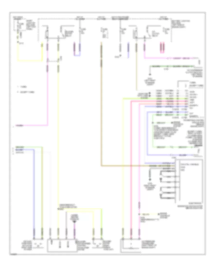
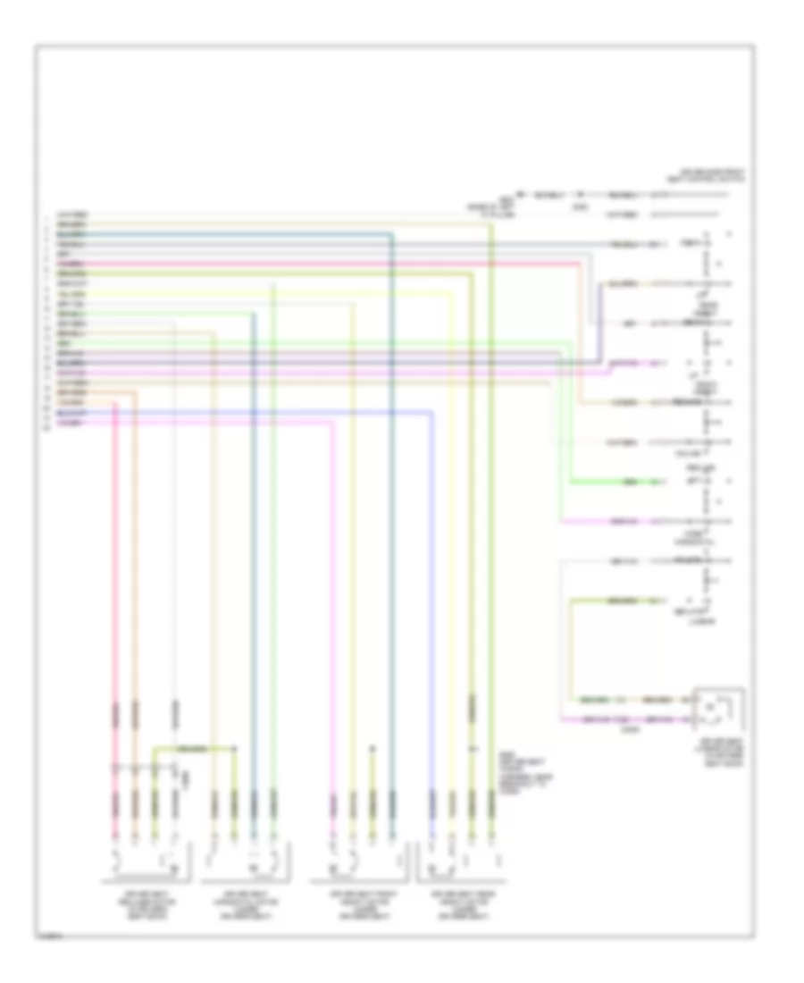
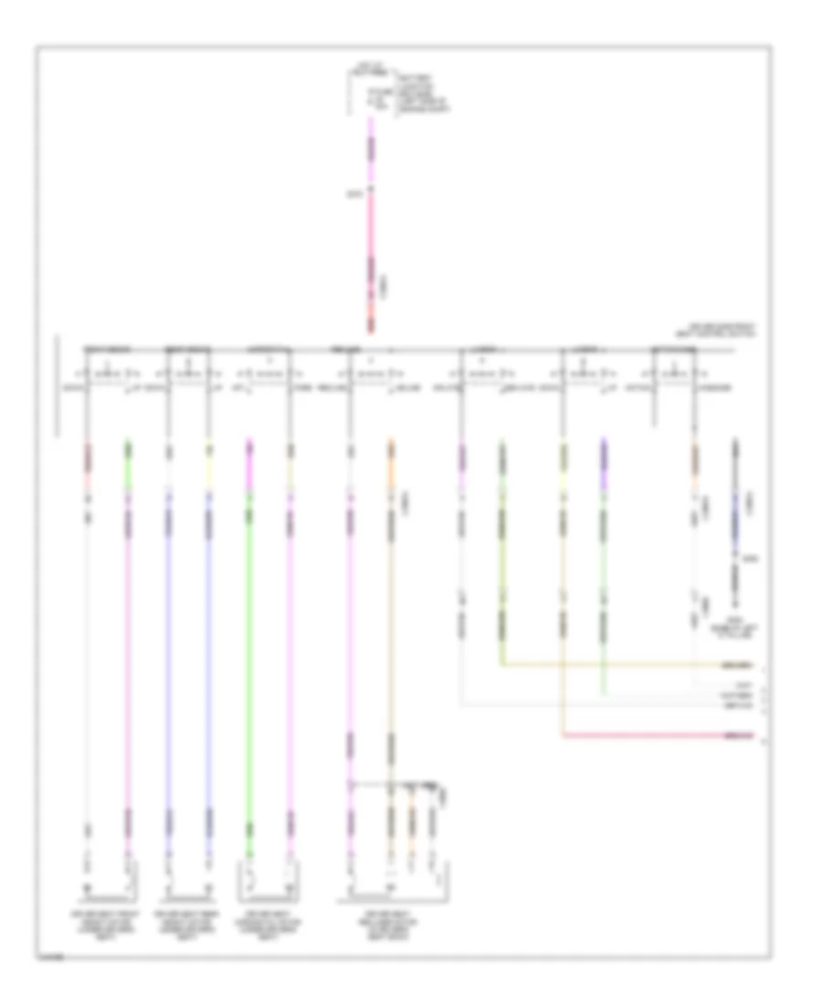
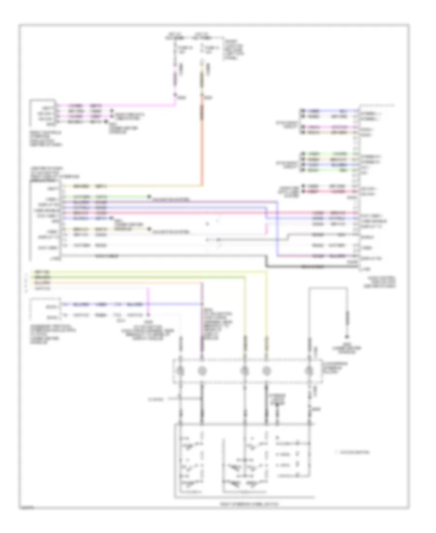
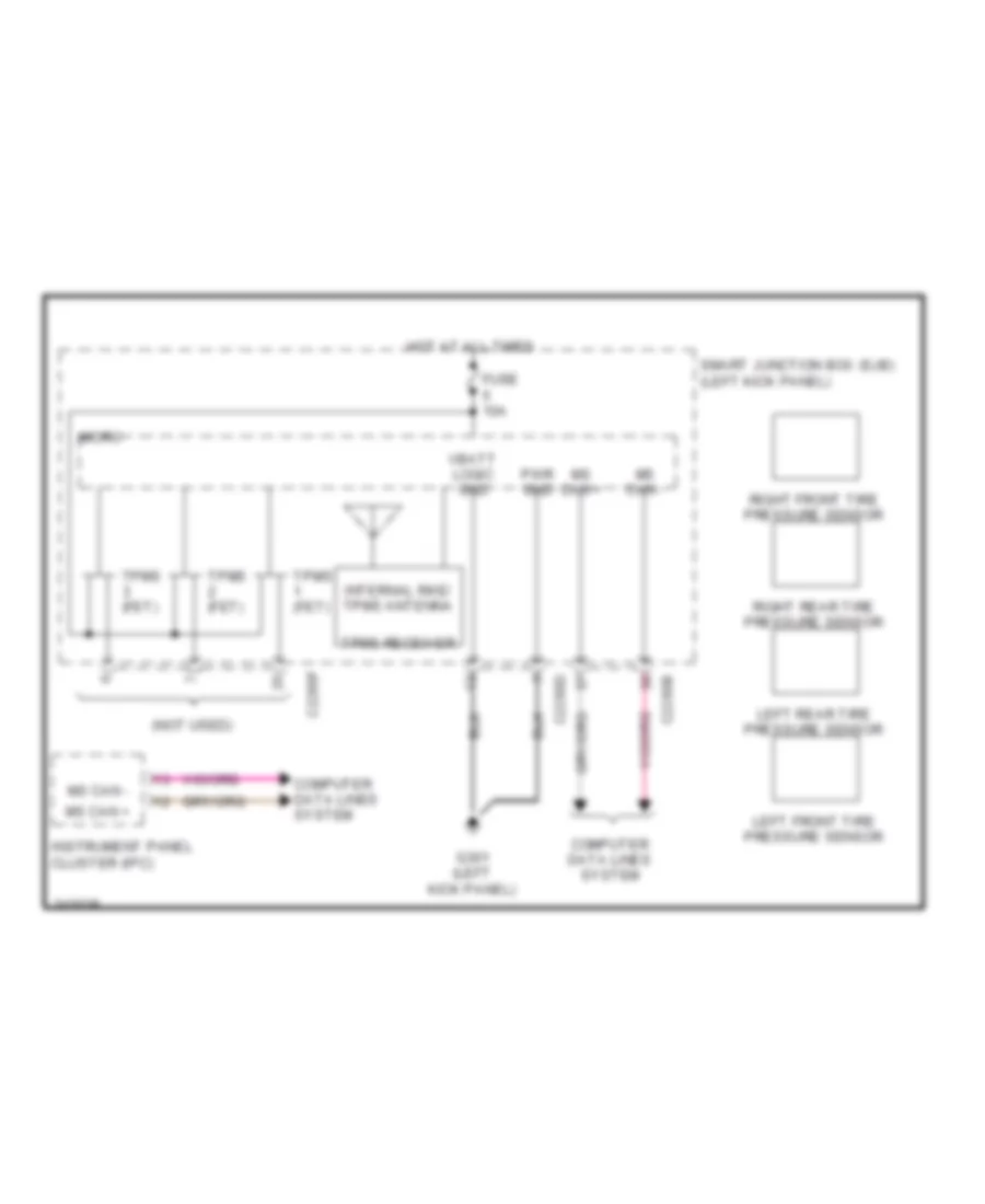
Automatic A/C Wiring Diagram (1 of 2) for Ford Taurus SEL 2011

List of elements for Automatic A/C Wiring Diagram (1 of 2) for Ford Taurus SEL 2011:
- (center front of engine compt) ambient air temperature sensor
- (dash panel to headlamp junction wiring harness, near breakout to evaporative air discharge temperature sensor)
- (left center of dash) in-vehicle temperature sensor
- (main wiring harness, near breakout to heads up display module) s210
- (top center of dash)
- (under center console)
- Ambient temp sensor
- Auto- lamp sens in
- Autolamp/sunload sensor
- C210
- C213
- C2280a
- C2280b
- C228a
- C228b
- Ch122
- Ch123
- Ch207
- Ch208
- Ch212
- Ch213
- Ch228
- Ch229
- Ch238
- Ch239
- Chs04
- Chs09
- Chs13
- Chs14
- Chs29
- Chs30
- Computer data lines system
- Defogger system
- Defrost request
- Defrost/panel/floor mode door actuator (left side of hvac unit)
- Driver sunload
- Driver temp door ccw
- Driver temp door cw
- Drv heated seat hi status
- Drv heated seat lo status
- Drv heated seat request
- Drv temp act fdbk
- Evap temp sensor
- Evaporator discharge air temperature sensor (left side of hvac unit)
- Front blower rly
- Fuse 10a
- G201
- Gd114
- Gnd
- Hot at all times
- Hvac module (datc) (center of dash)
- In car temp sensor
- Lh111
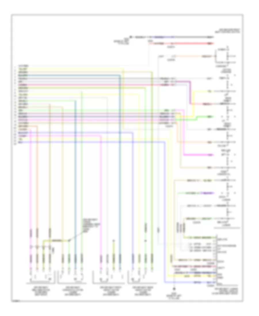
- Lift side temperature blend door actuator (left side of hvac unit)
- Mode 1 act fdbk
- Mode door 1 ccw
- Mode door 1 cw
- Ms can +
- Ms can -
- Pass heated seat hi status
- Pass heated seat lo status
- Pass heated seat request
- Pass temp act fdbk
- Pass temp door ccw
- Pass temp door cw
- Passenger sunload
- Recirc ccw
- Recirc cw
- Return
- Rh107
- Right side temperature blend door actuator (right side of hvac unit)
- S209
- Sbp15
- Seats system
- Smart junction box (sjb) (left kick panel)
- Variable blwr ctrl
- Vbatt
- Vdb06
- Vdb07
- Vh101
- Vh406
- Vh407
- Vh414
- Vh416
- Vh417
- Vh436
- Vh440
- Vh441
- Vref
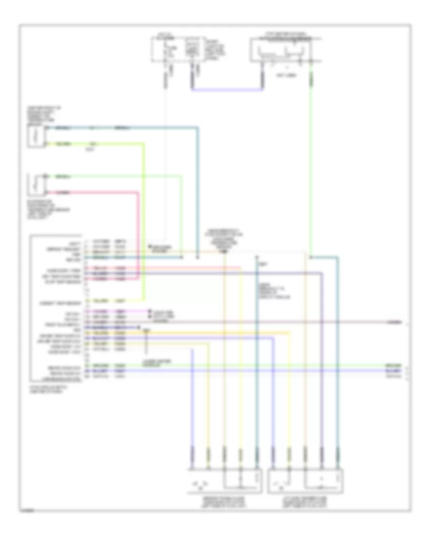
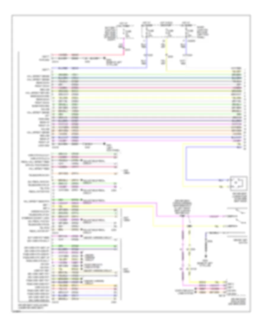
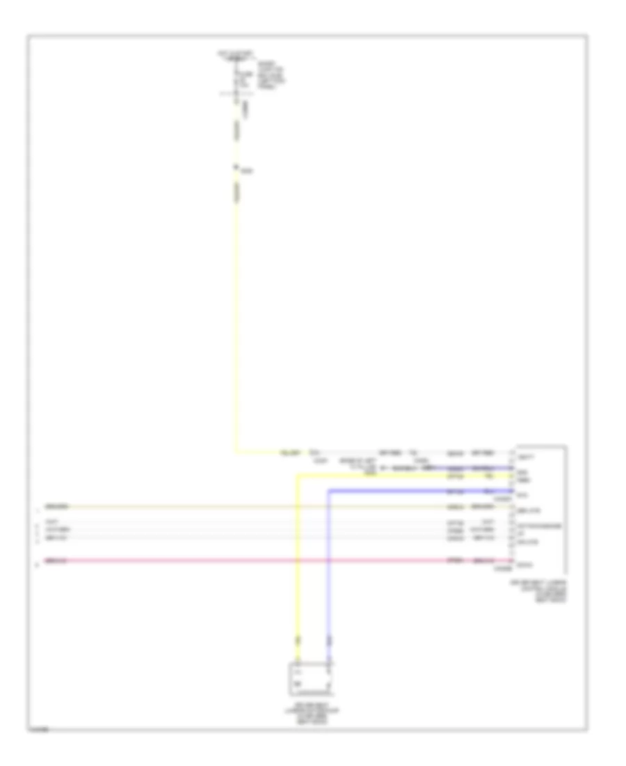
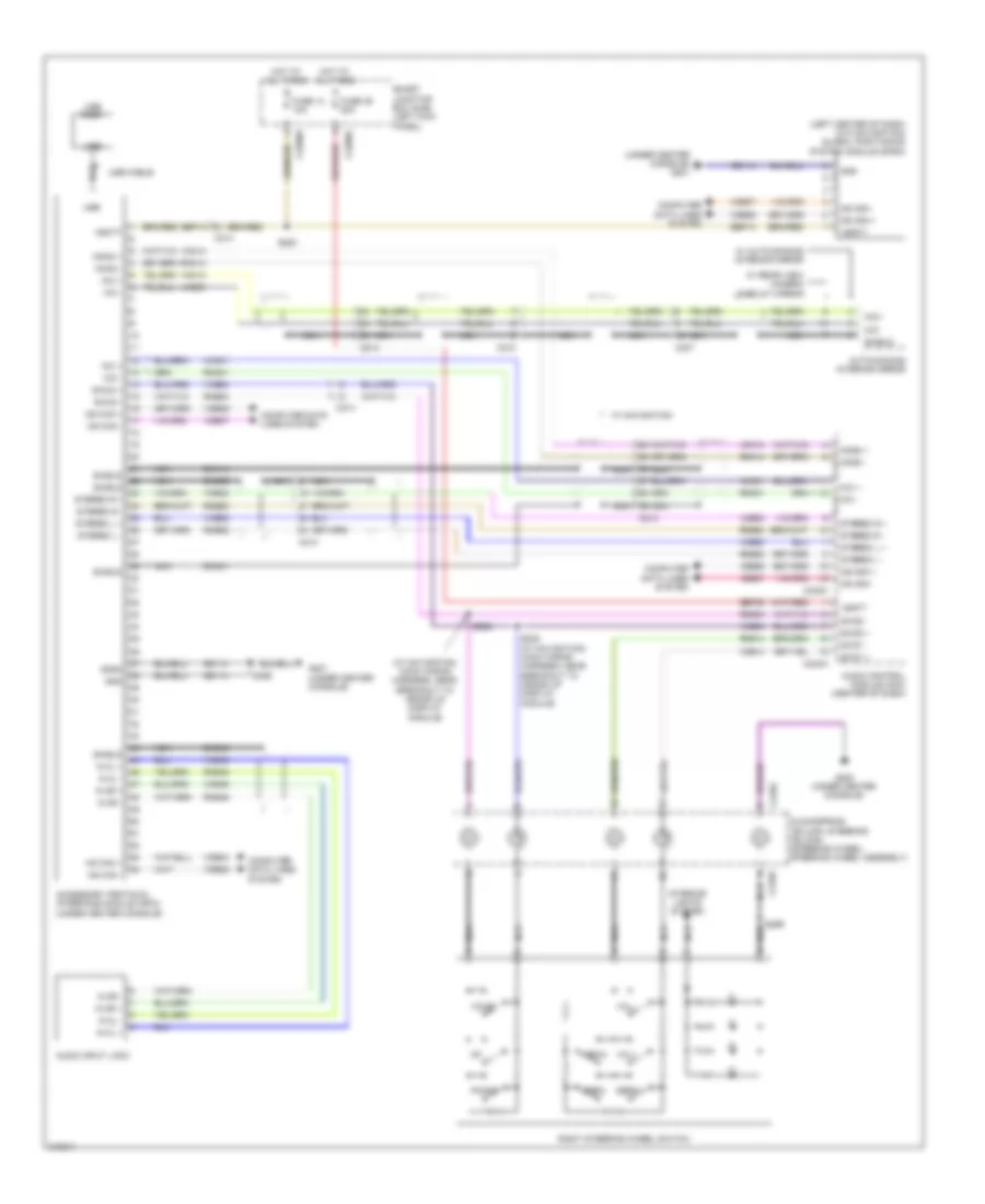
Automatic A/C Wiring Diagram (2 of 2) for Ford Taurus SEL 2011
List of elements for Automatic A/C Wiring Diagram (2 of 2) for Ford Taurus SEL 2011:
- (except turbo: front of right cylinder head) (turbo: top rear of engine) cylinder head temperature sensor
- (near breakout to blower motor) s202
- (under center console) g200
- A/c clutch relay
- A/c compressor clutch field coil (left front of engine)
- A/c pressure transducer (right front of engine compt)
- Accr
- Acpt
- Air inlet mode door actuator (right side of dash)
- B-sigrtn
- Battery junction box (bjb) (left side of engine compt)
- Blower motor (right side of hvac unit)
- Blower motor relay
- Blower motor speed control (on blower motor)
- C1381b
- C1381e
- C139
- C175b
- C175e
- C192
- C210
- C2280e
- Ch302
- Cht
- Computer data lines system
- E-sigrtn
- Electronics
- Engine controls system
- Engine cooling fan motor (behind radiator)
- Except turbo
- Fan ctrl variable
- Fcv
- Fuse 10a
- Fuse 15a
- Fuse 40a
- Fuse 5a
- Fuse 80a 60a
- G100 (right front of engine compt)
- G101 (left front of engine compt)
- Gnd
- Hot at all times
- Hot in run or acc
- Hot w/ pcm power relay energized
- Hs can +
- Hs can -
- Le424
- Motor +
- Motor -
- Nca
- Powertrain control module (pcm) (rear of engine compt)
- Pwm
- Pwr
- Re405
- Re407
- S109 (turbo: near breakout to evaporative emission canister purge valve) (except turbo: near breakout to fuel injector 6)
- S112
- S122
- S125 (near breakout to g102)
- Smart junction box (sjb) (left kick panel)
- Turbo
- Vdb04
- Vdb05
- Ve712
- Vec03
- Vh433
- Vref
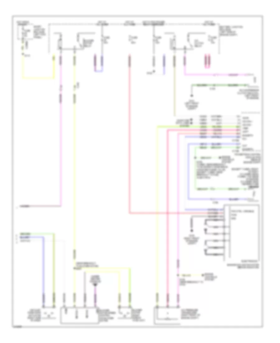
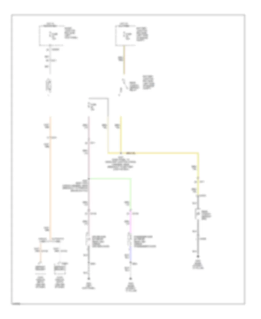
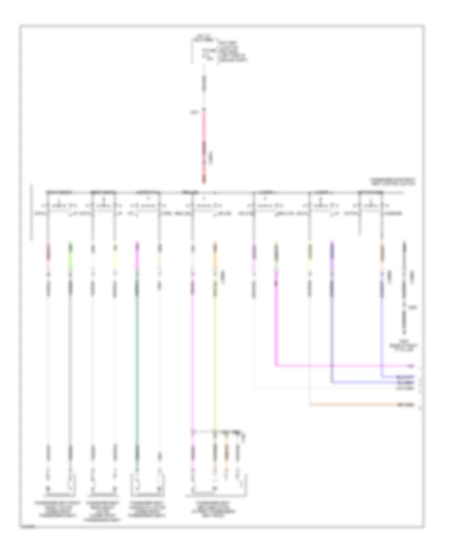
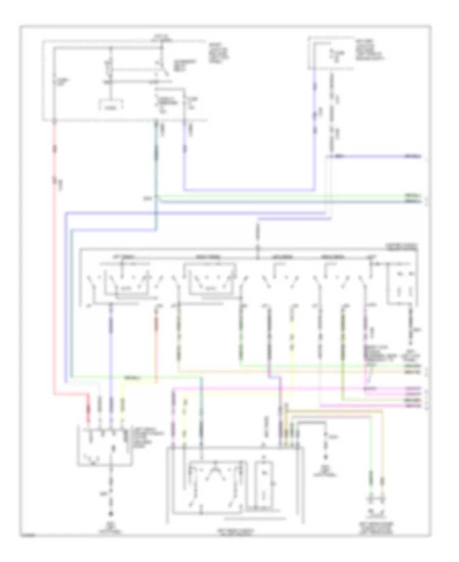
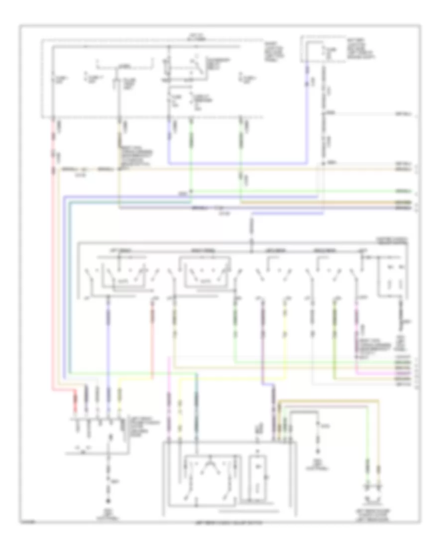
Manual A/C Wiring Diagram (1 of 2) for Ford Taurus SEL 2011
List of elements for Manual A/C Wiring Diagram (1 of 2) for Ford Taurus SEL 2011:
- (center front of engine compt) ambient air temperature sensor
- (near breakout to evaporative air discharge temperature sensor) s209
- (near breakout to heads up display module)
- (not used)
- (top center of dash)
- (under center console)
- Ambient temp sensor
- Auto- lamp sens in
- Autolamp/sunload sensor
- C210
- C2280a
- C2280b
- Ch122
- Ch123
- Ch207
- Ch208
- Ch228
- Ch229
- Ch238
- Ch239
- Computer data lines system
- Defogger system
- Defrost request
- Defrost/panel/floor mode door actuator (left side of hvac unit)
- Driver temp door ccw
- Driver temp door cw
- Drv temp door fdbk
- Evap temp sensor
- Evaporator discharge air temperature sensor (left side of hvac unit)
- Front blower rly
- Fuse 10a
- G201
- Gd114
- Gnd
- Hot at all times
- Hvac module (emtc) (center of dash)
- Lh111
- Lift side temperature blend door actuator (left side of hvac unit)
- Mode door 1 ccw
- Mode door 1 cw
- Mode door 1 fdbk
- Ms can +
- Ms can -
- Recirc door ccw
- Recirc door cw
- Return
- Rh107
- S210
- Sbp15
- Smart junction box (sjb) (left kick panel)
- Variable blwr ctrl
- Vbatt
- Vdb06
- Vdb07
- Vh101
- Vh406
- Vh407
- Vh436
- Vh440
- Vref
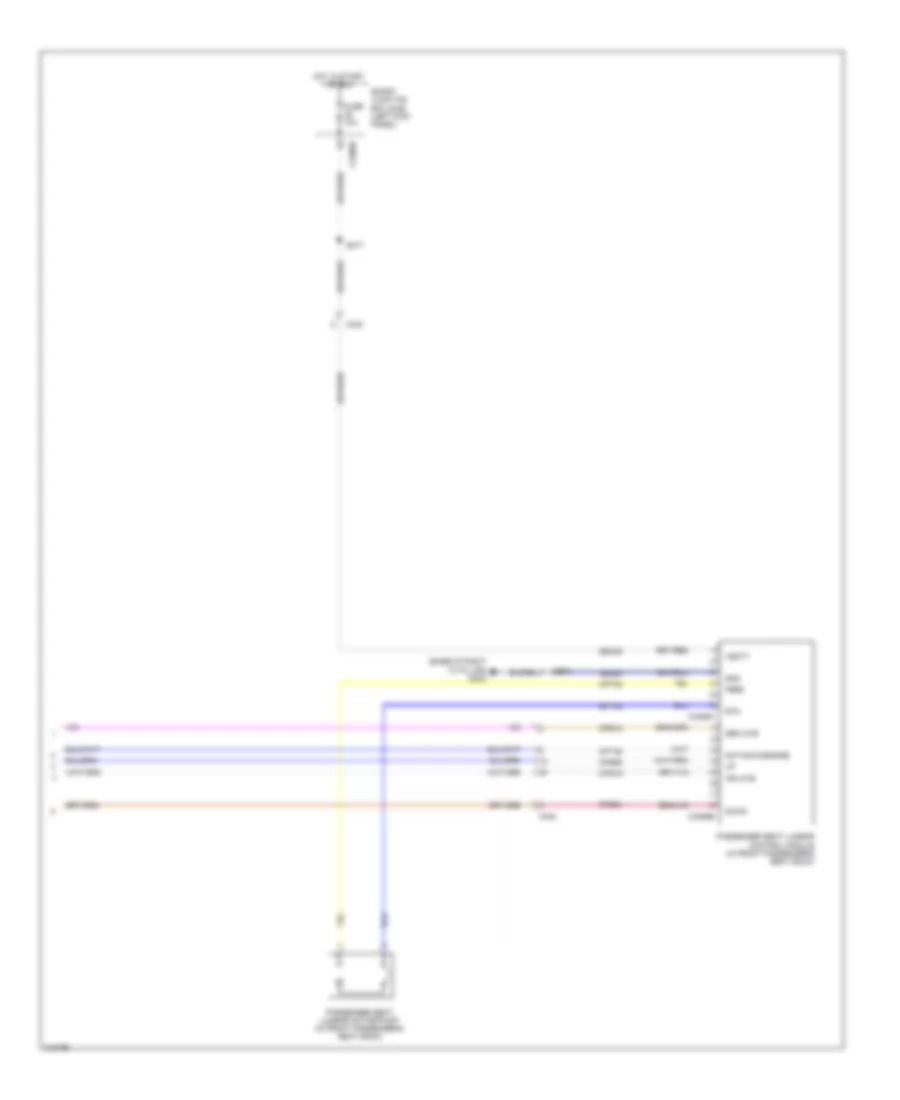
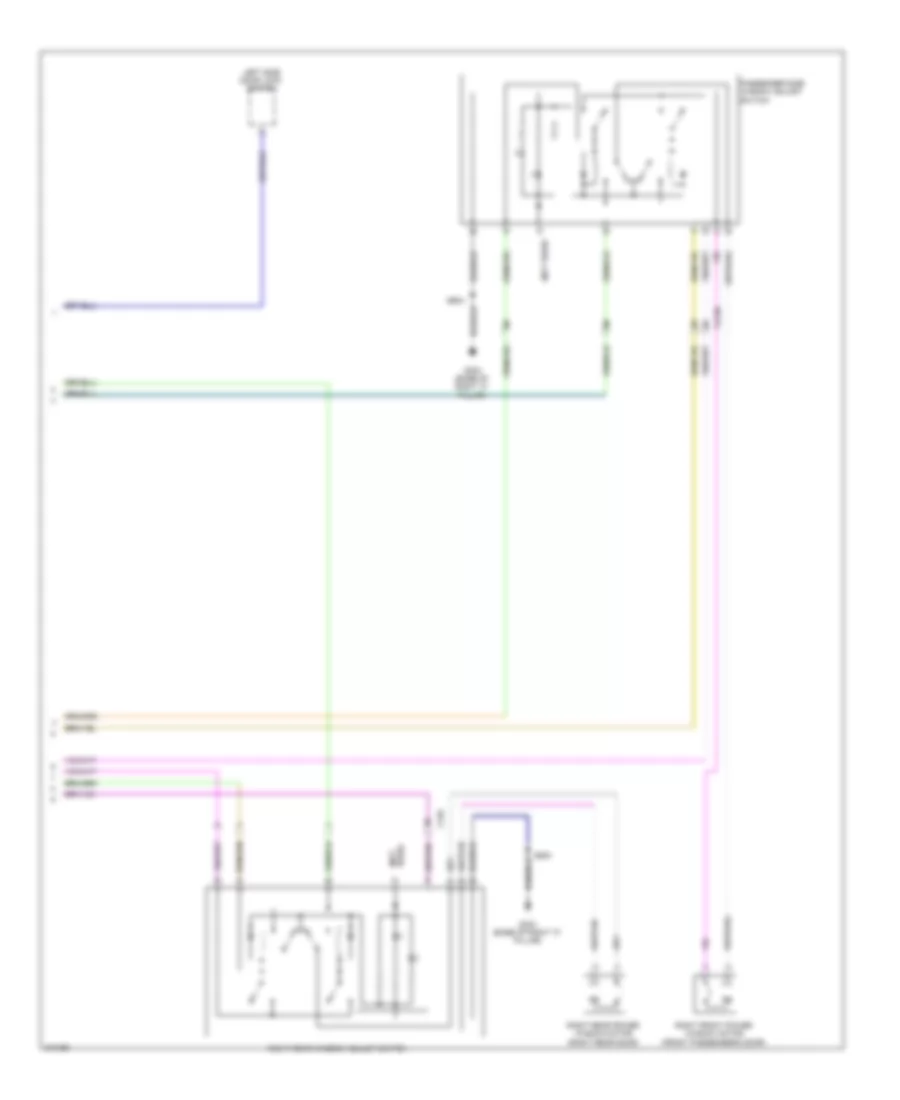
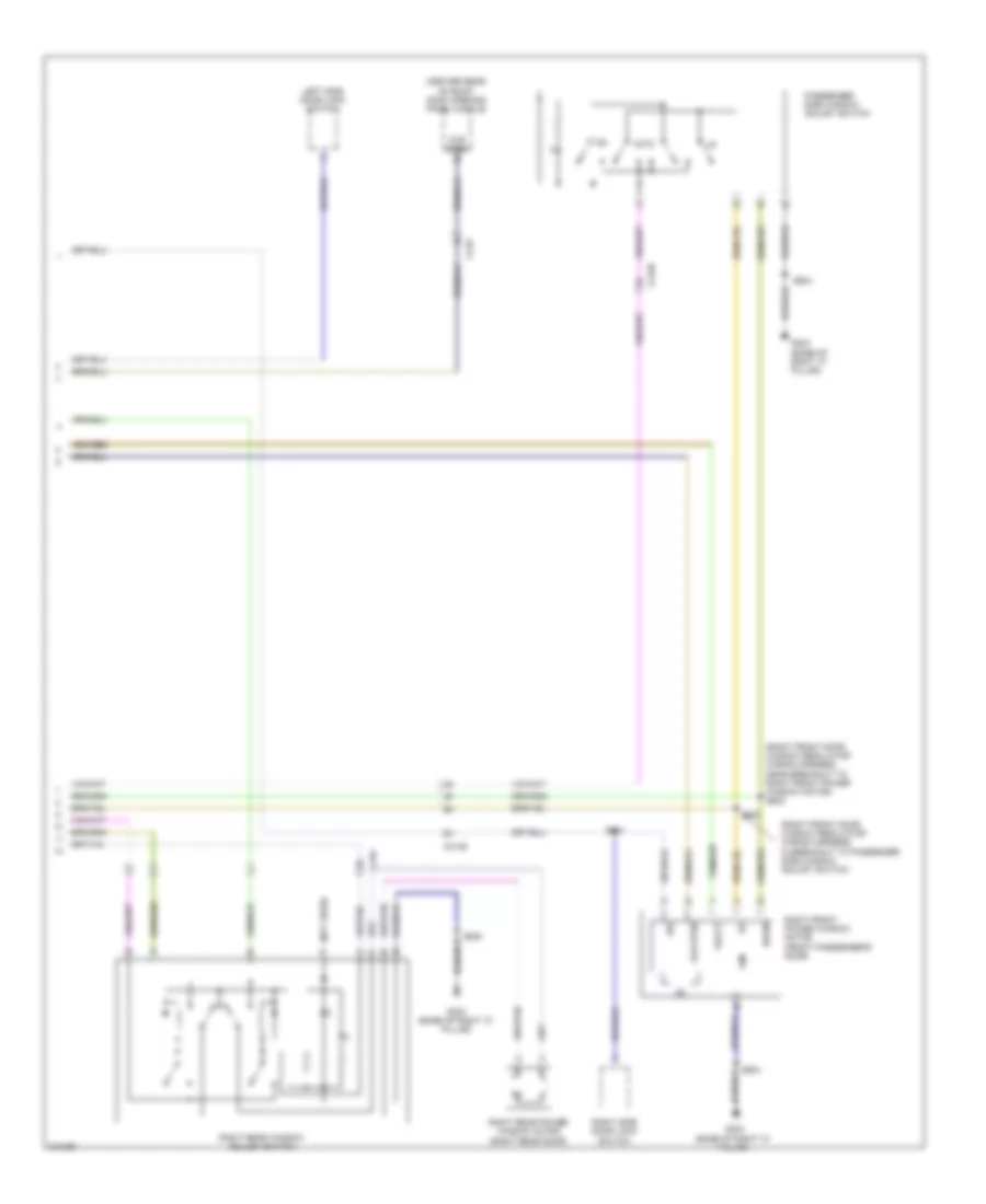
Manual A/C Wiring Diagram (2 of 2) for Ford Taurus SEL 2011
List of elements for Manual A/C Wiring Diagram (2 of 2) for Ford Taurus SEL 2011:
- (except turbo: front of right cylinder head) (turbo: top rear of engine) cylinder head temperature sensor
- (near breakout to blower motor) s202
- (under center console) g200
- A/c clutch relay
- A/c compressor clutch field coil (left front of engine)
- A/c pressure transducer (right front of engine compt)
- Accr
- Acpt
- Air inlet mode door actuator (right side of dash)
- B-sigrtn
- Battery junction box (bjb) (left side of engine compt)
- Blower motor (right side of hvac unit)
- Blower motor relay
- Blower motor speed control (on blower motor)
- C139
- C175b
- C175e
- C192
- C210
- C2280e
- Ch302
- Cht
- Computer data lines system
- E-sigrtn
- Electronics
- Engine controls system
- Engine cooling fan motor (behind radiator)
- Fan ctrl variable
- Fcv
- Fuse 10a
- Fuse 15a
- Fuse 40a
- Fuse 5a
- Fuse 60a
- G100 (right front of engine compt)
- G101 (left front of engine compt)
- Gnd
- Hot at all times
- Hot in run or acc
- Hot w/ pcm power relay energized
- Hs can +
- Hs can -
- Le424
- Motor +
- Motor -
- Nca
- Powertrain control module (pcm) (rear of engine compt)
- Pwm
- Pwr
- Re405
- Re407
- S109 (turbo: near breakout to evaporative emission canister purge valve) (except turbo: near breakout to fuel injector 6)
- S112
- S122
- S125 (near breakout to g102)
- Smart junction box (sjb) (left kick panel)
- Vdb04
- Vdb05
- Ve712
- Vec03
- Vh433
- Vref
ANTI-LOCK BRAKES
Anti-lock Brakes Wiring Diagram (1 of 2) for Ford Taurus SEL 2011
List of elements for Anti-lock Brakes Wiring Diagram (1 of 2) for Ford Taurus SEL 2011:
- Anti-lock brake system (abs) module (left rear of engine compt)
- Battery junction box (bjb) (left side of engine compt)
- C139
- C211
- C2280b
- C3007
- C310b
- Cbp34
- Cca28
- Computer data lines system
- Exterior lights system
- Fuse 15a
- Fuse 20a
- Fuse 40a
- Fuse 5a
- G101 (left front of engine compt)
- Gd120
- Hot at all times
- Hot in start or run
- Hot w/ pcm power relay energized
- Hs can +
- Hs can -
- Hs can yaw +
- Hs can yaw -
- Ivd rtn
- Left front wheel speed sensor (left front wheel hub assembly)
- Left rear wheel speed sensor (left rear wheel hub assembly)
- Lf sens high
- Lf sens low
- Logic gnd
- Lr sens high
- Lr sens low
- Motor gnd
- Mtr b+
- Nca
- Rca17
- Rca18
- Rca19
- Rca20
- Rcs06
- Red
- Restraints control module (rcm) (under center console)
- Rf sens high
- Rf sens low
- Right front wheel speed sensor (right front wheel hub assembly)
- Right rear wheel speed sensor (right rear wheel hub assembly)
- Rr sens high
- Rr sens low
- Run
- S122
- S150
- Sas a
- Sas b
- Sbb09
- Sbb12
- Smart junction box (sjb) (left kick panel)
- Stp lmp rly ctrl
- Valve b+
- Vca03
- Vca04
- Vca05
- Vca06
- Vca23
- Vca24
- Vcs06
- Vcs07
- Vdb04
- Vdb05
Anti-lock Brakes Wiring Diagram (2 of 2) for Ford Taurus SEL 2011
List of elements for Anti-lock Brakes Wiring Diagram (2 of 2) for Ford Taurus SEL 2011:
- (or cls43)
- Bpp
- Bps
- Brake pedal position (bpp) switch (on brake pedal bracket)
- C1381b
- C175b
- C210
- C211
- C2280b
- C2280d
- Ccb08
- Ces09
- Computer data lines system
- Except turbo
- Exterior lights system
- Fuse 10a
- Fuse 15a
- G201 (under center console)
- Hazard (red)
- Hazard pad/ traction switch
- Hot at all times
- Hot in start or run
- Hs can +
- Hs can -
- Instrument panel cluster (ipc)
- Interior lights system
- Micro
- Ms can +
- Ms can -
- Powertrain control module (pcm) (rear of engine compt)
- S164 (w/ adaptive cruise control) (dash panel to headlamp junction wiring harness, near breakout to battery junction box)
- S168 (w/o adaptive cruise control) (dash panel to headlamp junction wiring harness, near breakout to windshield wiper motor)
- Smart junction box (sjb) (left kick panel)
- Solid state
- Steering wheel rotation sensor (top of steering column)
- Tcs
- Tcs (green)
- Traction control on/off
- Turbo
- Vdb04
- Vdb05
ANTI-THEFT
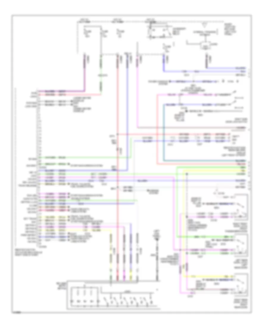
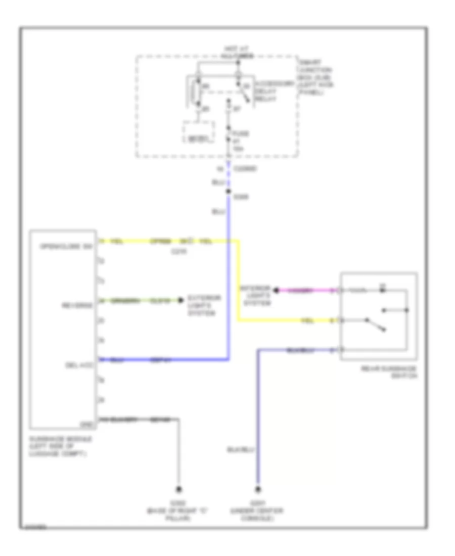
Forced Entry Wiring Diagram, with Intelligent Access (1 of 2) for Ford Taurus SEL 2011
List of elements for Forced Entry Wiring Diagram, with Intelligent Access (1 of 2) for Ford Taurus SEL 2011:
- (base of right "c" pillar) g303
- (left kick panel) g301
- (under center console) g200
- 1/2
- 3/4
- 5/6
- 7/8
- 9/0
- Accessory delay relay
- Anti theft
- Audio mute
- C210
- C212
- C215
- C2153c
- C2153d
- C2280a
- C2280b
- C2280d
- C2280f
- C237
- C3138
- C3139
- C316
- Cbp28
- Cdc30
- Cdc41
- Computer data lines system
- Cpk28
- Cpk29
- Cpk30
- Cpk31
- Cpk34
- Cpk36
- Cpl02
- Cpl44
- Cpl51
- Cpl52
- Cpl59
- Drv unlock
- Ext trunk
- Fuse 15a
- Fuse 20a
- Fuse 5a
- Fuse 7.5a
- G201 (under center console)
- G301 (left kick panel)
- G303 (base of right "c" pillar)
- Gd114
- Gd116
- Gnd
- Hot at all times
- Hs can+
- Hs can-
- Internal tpms/rke antenna
- K-line
- Key in
- Keyless entry keypad
- Keypad a
- Keypad b
- Keypad c
- Keypad illum
- Left rear door latch (left rear door)
- Lin
- Lock
- Logic
- Logic gnd
- Micro
- Mirrors system
- Ms can+
- Ms can-
- Park detect
- Power windows system
- Pwr
- Pwr gnd
- Red
- Remote function actuator (rfa) module (right side of dash)
- Remote functions receiver (rfr) module (left front of roof)
- Rf gnd
- Right front door latch (front passenger's door)
- Right rear door latch (right rear door)
- Right side door lock switch
- Rpk34
- Rpl56
- Run led
- S/s gnd1
- S/s1
- S310
- S390 (body main wiring harness, near breakout to c312)
- S502
- S601 (w/ one touch up/down passenger window)
- S604
- S700
- S800
- Sbp12
- Sbp13
- Sbp27
- Shift interlock system computer data lines system
- Smart junction box (sjb) (left kick panel)
- Sound systems
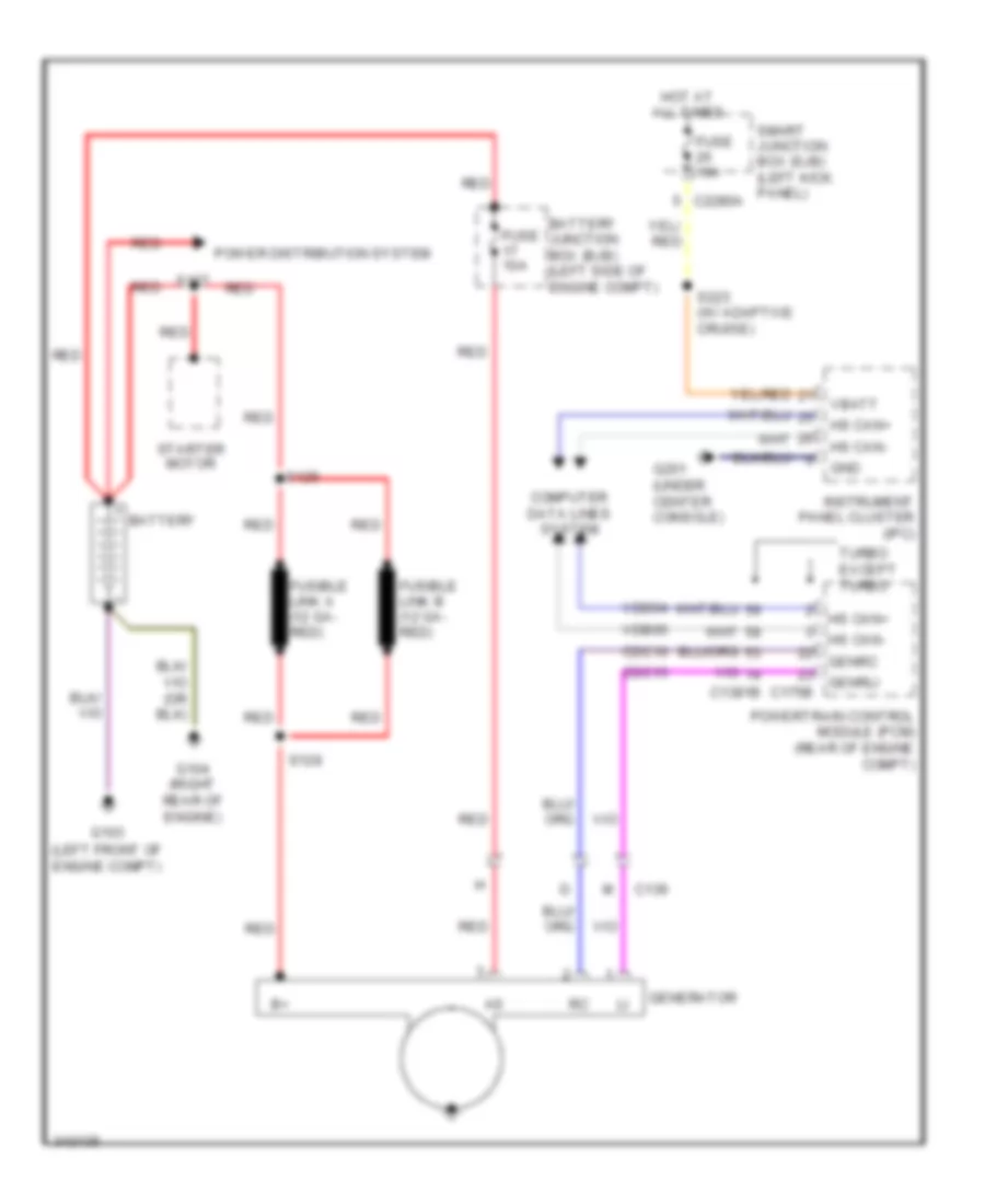
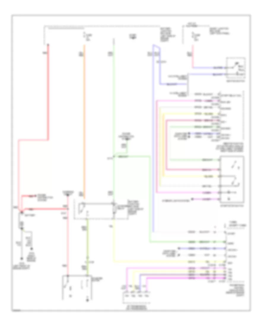
- Starting/charging system
- Trunk release
- Trunk, tailgate, fuel doors system
- Unlock
- Vbatt
- Vdb04
- Vdb05
- Vdb06
- Vdb07
- Vpl56
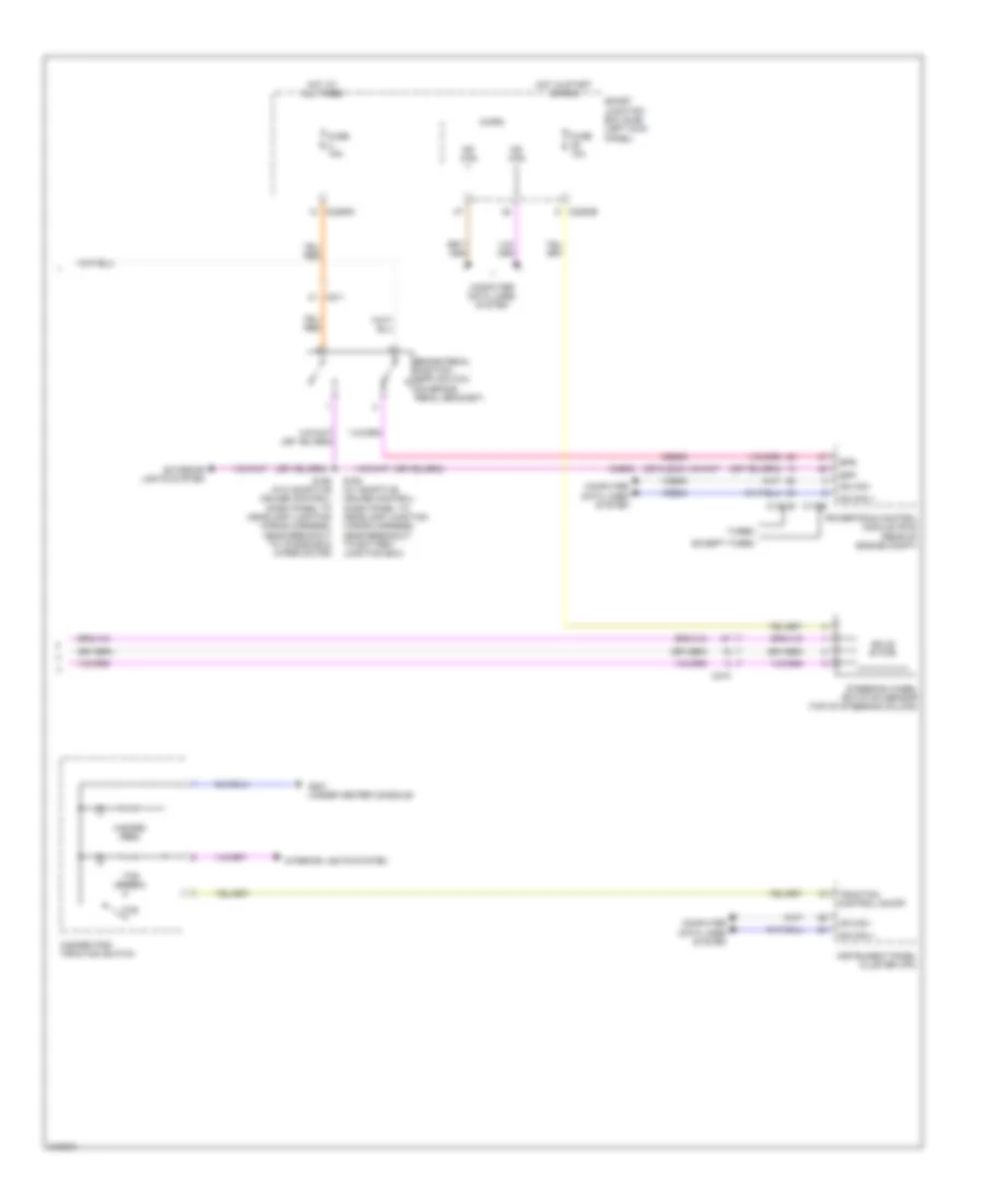
Forced Entry Wiring Diagram, with Intelligent Access (2 of 2) for Ford Taurus SEL 2011
List of elements for Forced Entry Wiring Diagram, with Intelligent Access (2 of 2) for Ford Taurus SEL 2011:
- (dash panel to headlamp junction wiring harness, in breakout to c211) (w/ perimeter alarm) s250
- (left kick panel)
- (under center console) backup transceiver
- Ajar
- Ajar fl
- Ajar fr
- Ajar lr
- Ajar rr
- Alarm reset
- Alarm set
- Battery junction box (bjb) (left side of engine compt)
- Bpp
- C210
- C211
- C212
- C214
- C215
- C2153a
- C2153b
- C2153e
- C3138
- C3139
- C405
- C501a
- C501b
- Ccb08
- Cdc33
- Cdc35
- Cdc55
- Clk
- Computer data lines system
- Console front antenna (under center console)
- Console rear antenna (under center console)
- Cpk19
- Cpk23
- Cpk35
- Cpl25
- Cpl26
- Cpl31
- Cpl36
- Cpl39
- Cpl58
- Cpl60
- Crt19
- Crt21
- Data
- Door lock
- Door unlock
- Driver door module (ddm) (driver's door)
- Exterior lights system
- Fla
- Fla rtn
- Fuse 5a
- G100 (right front of engine compt)
- G301
- G301 (left kick panel)
- G302 (base of left "c" pillar)
- Hood ajar
- Hood switch (left front of engine compt)
- Ia1
- Ia1 rtn
- Ia2
- Ia2 rtn
- Ia3
- Ia3 rtn
- Left front door latch (driver's door)
- Left front exterior door handle
- Left side door lock switch
- Lock
- Lpk32
- Luggage compartment intelligent access antenna (center rear of luggage compt)
- Luggage compartment lamp
- Luggage compartment lid release solenoid/ ajar switch (center rear of luggage compt lid)
- Ms can +
- Ms can -
- Pass lock
- Pass unlock
- Pats gnd
- Pats vcc
- Power windows system
- R/s relay coil
- Remote function actuator (rfa) module (right side of dash)
- Reset
- Ria
- Rpk01
- Rpk05
- Rpk06
- Rpk07
- Rpk08
- Rpk32
- Rpk35
- Run/ start relay
- S/s gnd2
- S/s2
- S326
- S500
- S504
- Sbp13
- Seat antenna (behind right side of rear seat)
- Set
- Solid state
- Start rly coil
- Starting/charging system
- Trunk
- Trunk ajar
- Trunk release
- Trunk rtn
- Trunk, tailgate, fuel doors system
- Unlock
- Vdb06
- Vdb07
- Vpk01
- Vpk05
- Vpk06
- Vpk07
- Vpk08
- Vpk32
- Vpk33
Forced Entry Wiring Diagram, without Intelligent Access (1 of 2) for Ford Taurus SEL 2011
List of elements for Forced Entry Wiring Diagram, without Intelligent Access (1 of 2) for Ford Taurus SEL 2011:
- (body main wiring harness, near breakout to c311)
- (front passenger's door)
- (left kick panel)
- (left kick panel) g301
- (left rear door)
- (right rear door)
- 1/2
- 3/4
- 5/6
- 7/8
- 9/0
- Acce- ssory delay relay
- All lock/ unlock relay
- Anti-theft
- Auto
- C2280a
- C2280b
- C2280c
- C2280d
- C2280f
- C3138
- C3139
- C316
- C327
- Computer data lines system
- Door lock
- Door unlock
- Driver door ajar
- Driver door un- lock relay
- Fuse 10a
- Fuse 15a
- Fuse 20a
- Fuse 5a
- G301
- G301 (left kick panel)
- G302 (base of left "c" pillar)
- G303 (base of right "c" pillar)
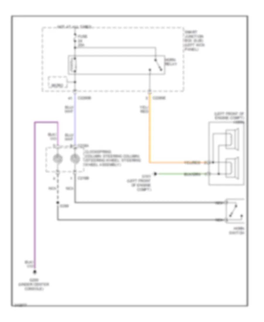
- Headlights system
- Horn sw
- Horns system
- Hot at all times
- Internal tpms/rke antenna
- Keyless entry keypad
- Keypad a
- Keypad b
- Keypad c
- Keypad illum (fet) c2280c
- Left rear door latch
- Logic
- Lr door ajar
- Luggage compartment lamp
- Luggage compartment lid release solenoid/ ajar switch (center rear of luggage compt lid)
- Luggage compt ajar sw
- Micro
- Ms can +
- Ms can -
- Pass door ajar
- Red
- Right front door latch
- Right rear door latch
- Rr door ajar
- S321
- S390 (body main wiring harness, near breakout to c312)
- S502
- S604
- S700
- S800
- Smart junction box (sjb) (left kick panel)
Forced Entry Wiring Diagram, without Intelligent Access (2 of 2) for Ford Taurus SEL 2011
List of elements for Forced Entry Wiring Diagram, without Intelligent Access (2 of 2) for Ford Taurus SEL 2011:
- (base of right "c" pillar)
- (body main wiring harness, in breakout to all wheel drive module) s388
- (body main wiring harness, in breakout to all wheel drive module) s389
- (not used)
- Ajar
- Battery junction box (bjb) (left side of engine compt)
- C210
- C211
- C3138
- C3139
- C501a
- C501b
- Computer data lines system
- Cpk19
- Cpk23
- Cpl02
- Cpl51
- Door lock
- Door mt lock
- Door mt unlock
- Door unlock
- Driver door module (ddm) (driver's door)
- Fuse 5a
- G100 (right front of engine compt)
- G301 (left kick panel)
- G303
- Hood switch (w/ perimeter alarm) (left front of engine compt)
- Left front door latch (driver's door)
- Left side door lock switch
- Lock
- Ms can +
- Ms can -
- Power windows system
- Right side door lock switch
- S250 (dash panel to headlamp junction wiring harness, in breakout to c211)
- S326
- S500
- S504
- S604
- Unlock
- Vdb06
- Vdb07
- W/ memory
- W/o memory
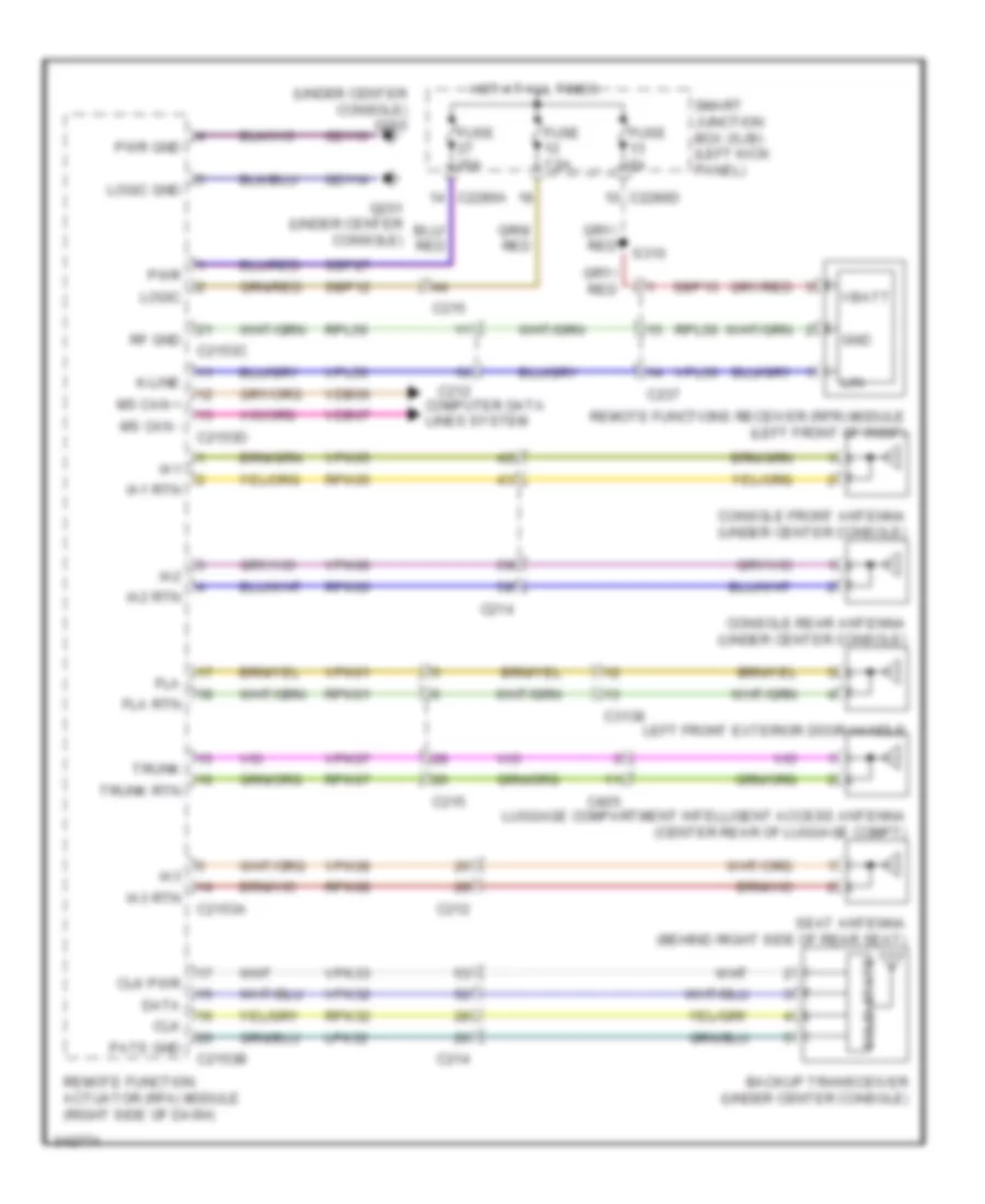
Passive Anti-theft Wiring Diagram, with Intelligent Access for Ford Taurus SEL 2011
List of elements for Passive Anti-theft Wiring Diagram, with Intelligent Access for Ford Taurus SEL 2011:
- (under center console) g200
- Backup transceiver (under center console)
- C212
- C214
- C215
- C2153a
- C2153b
- C2153c
- C2153d
- C2280a
- C2280d
- C237
- C3138
- C405
- Clk
- Clk pwr
- Computer data lines system
- Console front antenna (under center console)
- Console rear antenna (under center console)
- Data
- Fla
- Fla rtn
- Fuse 20a
- Fuse 5a
- Fuse 7.5a
- G201 (under center console)
- Gd114
- Gd116
- Gnd
- Hot at all times
- Ia1
- Ia1 rtn
- Ia2
- Ia2 rtn
- Ia3
- Ia3 rtn
- K-line
- Left front exterior door handle
- Lin
- Logic
- Logic gnd
- Lpk32
- Luggage compartment intelligent access antenna (center rear of luggage compt)
- Ms can +
- Ms can -
- Pats gnd
- Pwr
- Pwr gnd
- Remote function actuator (rfa) module (right side of dash)
- Remote functions receiver (rfr) module (left front of roof)
- Rf gnd
- Rpk01
- Rpk05
- Rpk06
- Rpk07
- Rpk08
- Rpk32
- Rpl56
- S310
- Sbp12
- Sbp13
- Sbp27
- Seat antenna (behind right side of rear seat)
- Smart junction box (sjb) (left kick panel)
- Solid state
- Trunk
- Trunk rtn
- Vbatt
- Vdb06
- Vdb07
- Vpk01
- Vpk05
- Vpk06
- Vpk07
- Vpk08
- Vpk32
- Vpk33
- Vpl56
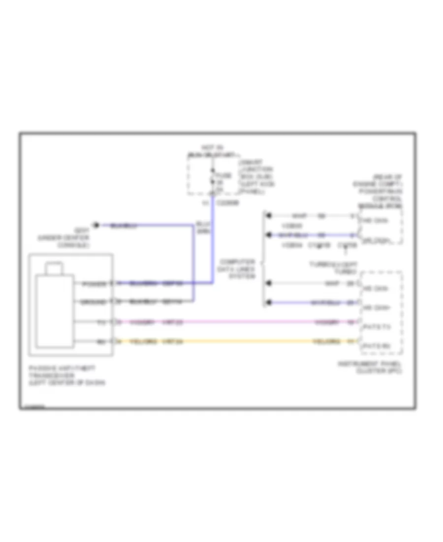
Passive Anti-theft Wiring Diagram, without Intelligent Access for Ford Taurus SEL 2011
List of elements for Passive Anti-theft Wiring Diagram, without Intelligent Access for Ford Taurus SEL 2011:
- (rear of engine compt) powertrain control module (pcm)
- C1381b
- C175b
- C2280b
- Cbp36
- Computer data lines system
- Except turbo
- Fuse 5a
- G201 (under center console)
- Gd114
- Ground
- Hot in run or start
- Hs can+
- Hs can-
- Instrument panel cluster (ipc)
- Passive anti-theft transceiver (left center of dash)
- Pats rx
- Pats tx
- Power
- Smart junction box (sjb) (left kick panel)
- Turbo
- Vdb04
- Vdb05
- Vrt23
- Vrt24
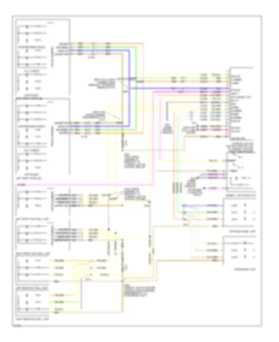
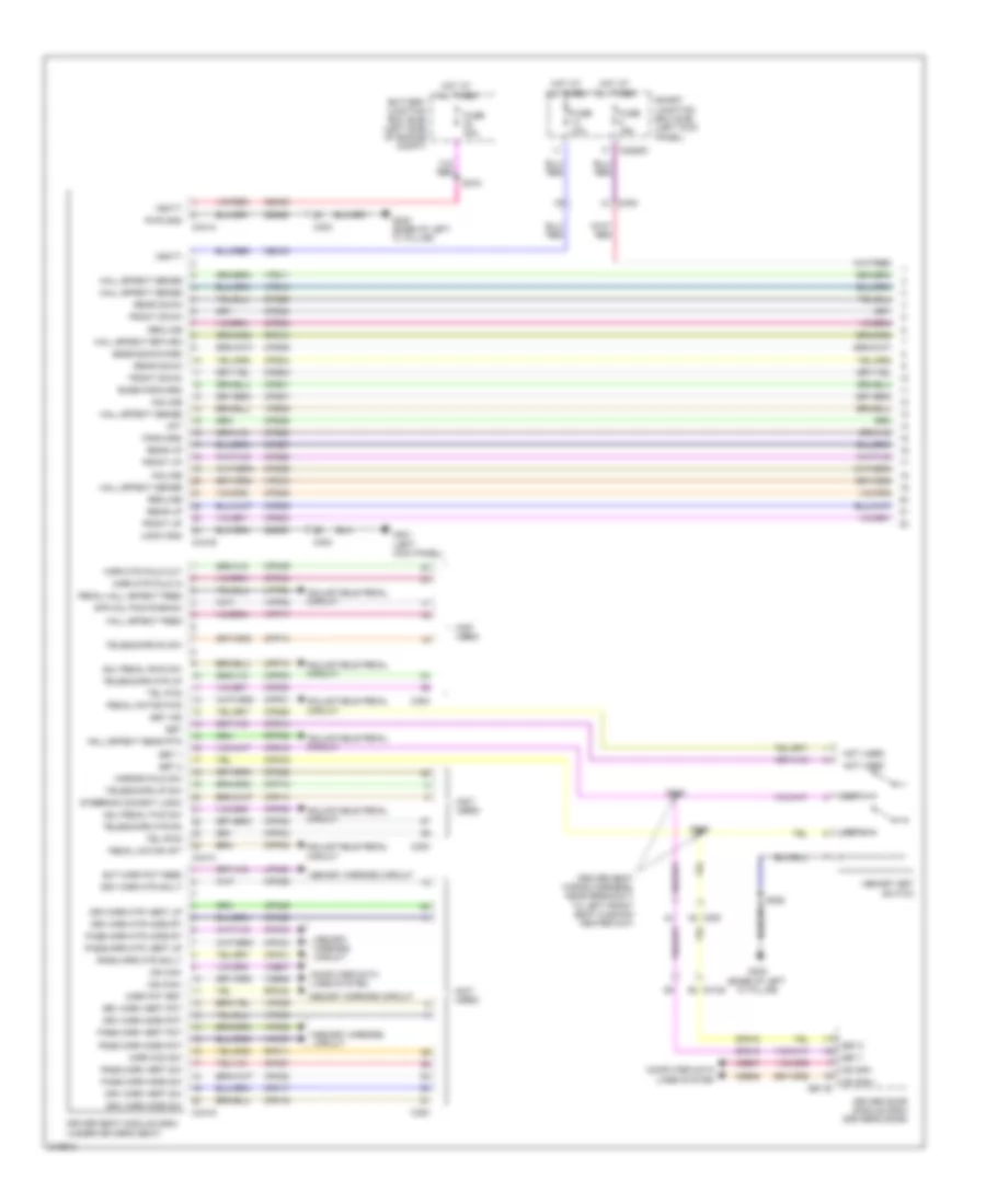
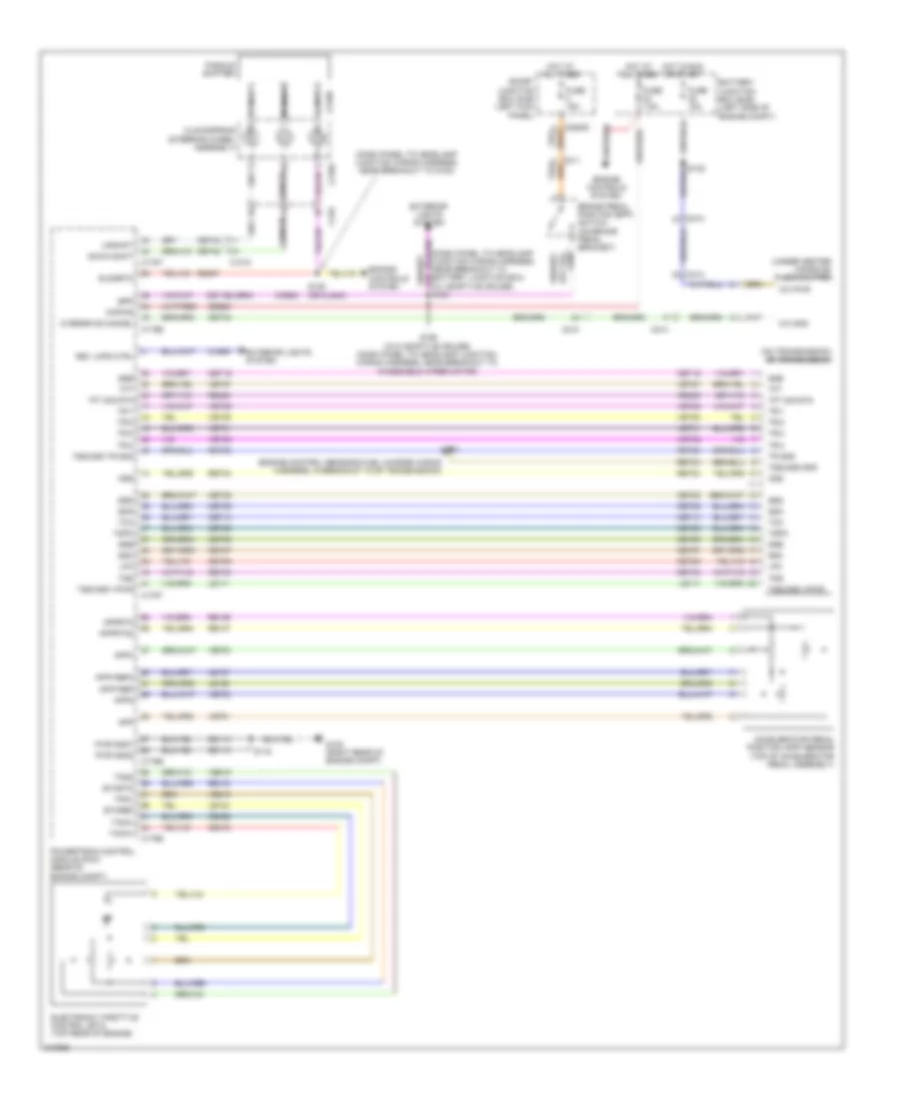
BODY CONTROL MODULES
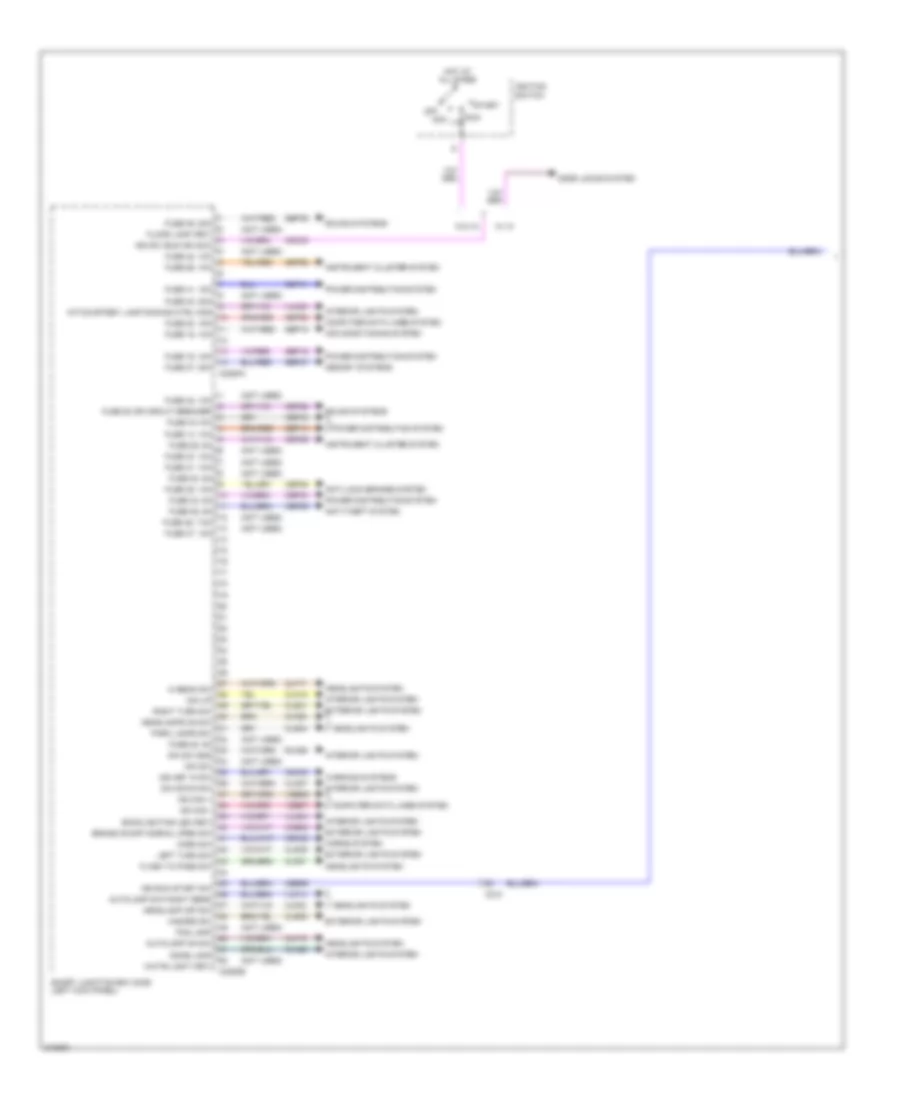
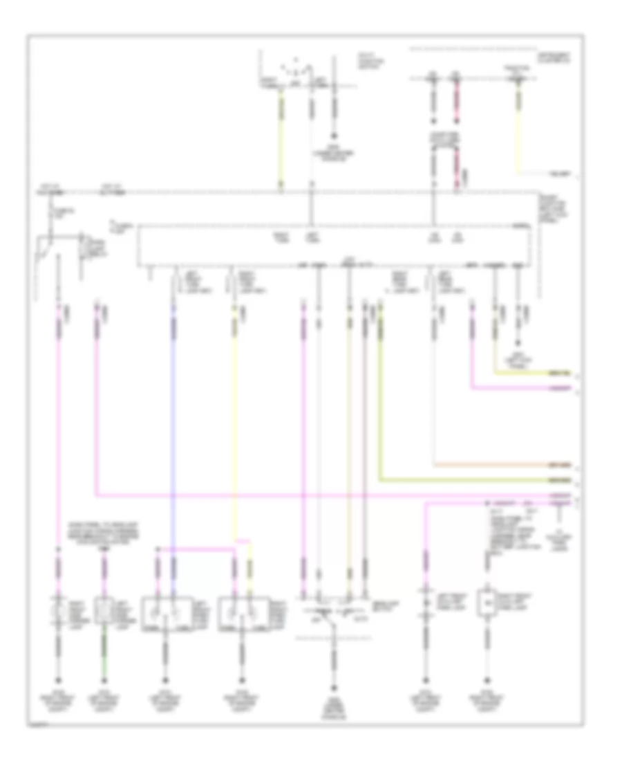
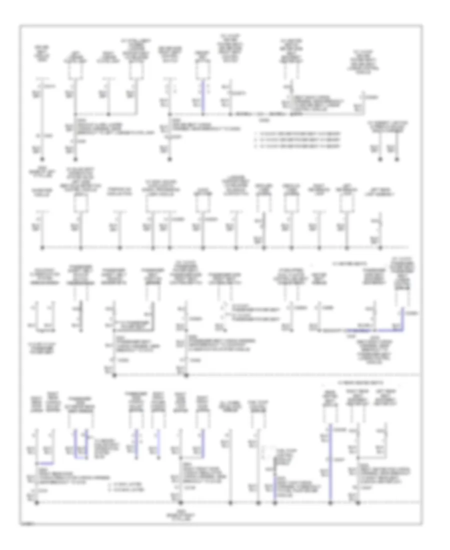
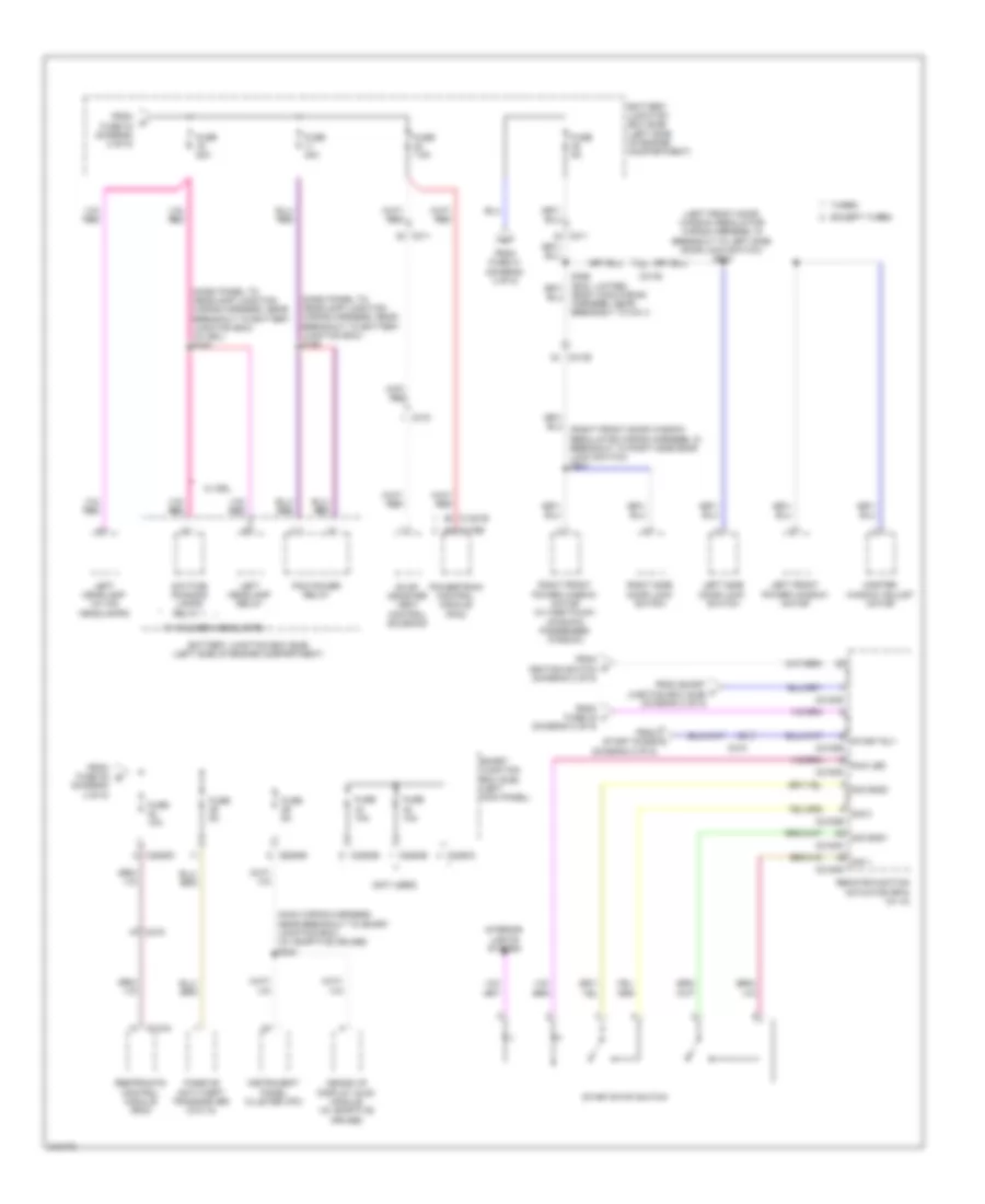
Body Control Modules Wiring Diagram (1 of 2) for Ford Taurus SEL 2011
List of elements for Body Control Modules Wiring Diagram (1 of 2) for Ford Taurus SEL 2011:
- (not used)
- Acc
- Air conditioning system
- Anti-lock brakes system
- Anti-theft system
- Autolamp day/night sens
- Autolamp on sw
- Backlighting led (fet)
- Brake on/off normal open sw
- C210
- C2280a
- C2280b
- Cbb36
- Cbp28
- Cbp29
- Cbp34
- Cbp35
- Cbp36
- Cbp41
- Cbp43
- Ccb08
- Cdc30
- Cdc33
- Clf17
- Clf19
- Clf23
- Clf27
- Clf29
- Cln12
- Cln27
- Cln28
- Cls32
- Cls34
- Cls39
- Cls41
- Computer data lines system
- Crh02
- Dim down sw
- Dim sw
- Dim sw gnd
- Dim up
- Dome lamp
- Door locks system
- Exterior lights system
- Flash to pass sw
- Floor lamp (fet)
- Fog lamp
- Fuse 14, 10a
- Fuse 15, 10a
- Fuse 16, 15a
- Fuse 20, 15a
- Fuse 26, 10a
- Fuse 27, 20a
- Fuse 28 or circuit breaker
- Fuse 28, 5a
- Fuse 29, 5a
- Fuse 30, 5a
- Fuse 31, 10a
- Fuse 33, 10a
- Fuse 34, 5a
- Fuse 35, 10a
- Fuse 36, 5a
- Fuse 37, 10a
- Fuse 39, 20a
- Fuse 40, 20a
- Fuse 41, 15a
- Fuse 42, 10a
- Fuse 43,10a
- Fuse 46, 7.5a
- Hazard sw
- Headlamp off sw
- Headlamps on sw
- Headlights system
- Hi beam sw
- Horn sw
- Horns system
- Hot at all times
- Ign key in sw
- Ign run start sw
- Ign sw (run or acc)
- Ignition switch
- Instrument cluster system
- Int/courtesy lamp dimming ctrl mod
- Interior lights system
- Left turn sw
- Memory systems
- Ms can +
- Ms can -
- Off
- Park lamps sw
- Power distribution system
- Right turn sw
- Rln29
- Run
- Sbp14
- Sbp15
- Sbp16
- Sbp20
- Sbp26
- Sbp27
- Sbp39
- Smart junction box (sjb) (left kick panel)
- Sound systems
- Start
- Vdb06
- Vdb07
- Vlf14
- Vln04
- Vln33
- W/ ia
- W/o ia
- Warning systems
- White light (fet)
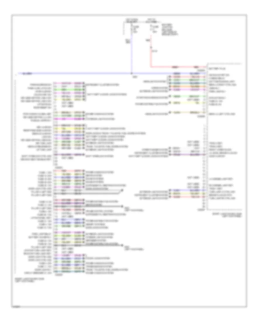
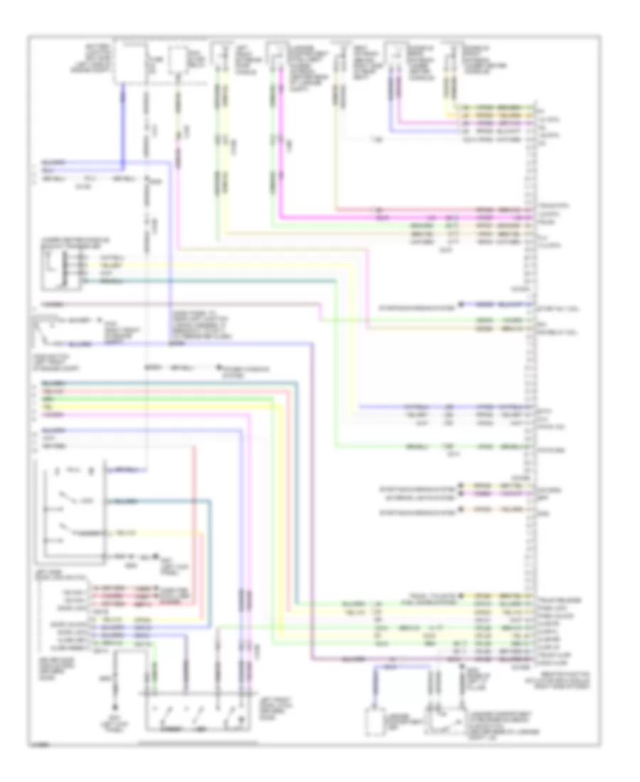
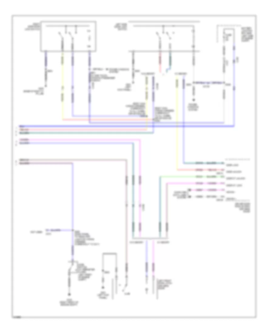
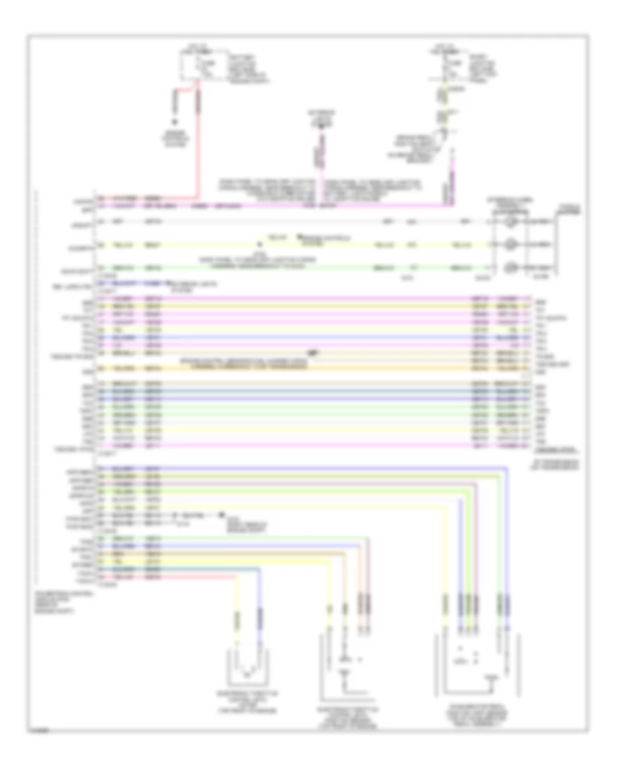
Body Control Modules Wiring Diagram (2 of 2) for Ford Taurus SEL 2011
List of elements for Body Control Modules Wiring Diagram (2 of 2) for Ford Taurus SEL 2011:
- (not used)
- 3rd row seat enable (fet)
- Anti-theft & door locks system
- Anti-theft & door locks systems
- Battery junction box (bjb) (left side of engine compt)
- Battery plus
- Battery saver rly
- Beam lo left ctrl mod
- Beam lo right ctrl mod
- Brake fluid sw rtn
- C2280c
- C2280d
- C2280e
- C2280f
- C2280g
- Cbb36
- Cbp32
- Cbp35
- Cbp41
- Cbp43
- Cbp45
- Cbp46
- Cbp47
- Ce336
- Cet53
- Circuit breaker 47, 30a
- Clf01
- Clf04
- Clf05
- Clf08
- Cln09
- Cln25
- Cls21
- Cls23
- Cls25
- Cls27
- Cls30
- Cmc19
- Cmc25
- Cpk19
- Cpk23
- Cpk28
- Cpk29
- Cpk30
- Cpk31
- Cpl02
- Cpl25
- Cpl26
- Cpl31
- Cpl36
- Cpl39
- Cpl51
- Cpl52
- Cpl58
- Cpl59
- Cpl60
- Cpw01
- Cruise control system
- Crw01
- Daytime running light
- Decklid ajar sw
- Decklid release sw
- Defogger system
- Door lock ctrl mod
- Door lock rly
- Door locks & trunk, tailgate, fuel doors systems
- Door locks system
- Drv ajar sw
- Exterior lights system
- Front wiper on sig
- Fuse 1, 30a
- Fuse 11, 10a
- Fuse 12, 7.5a
- Fuse 13, 5a
- Fuse 14, 10a
- Fuse 18, 20a
- Fuse 19, 25a
- Fuse 2, 15a
- Fuse 20a
- Fuse 3, 15a
- Fuse 32, 10a
- Fuse 35, 10a
- Fuse 38, 20a
- Fuse 4, 30a
- Fuse 41, 15a
- Fuse 43, 10a
- Fuse 44, 10a
- Fuse 45, 5a
- Fuse 46, 7.5a
- Fuse 80a
- G301 (left kick panel)
- Gd133
- Headlights system
- Hi beam relay
- Hood ajar sw
- Horn rly
- Horns system
- Hot at all times
- Hot in run or start
- Ign run start sw
- Instrument cluster system
- Interior lights system
- Keyless keypad illu sw
- Keyless keypad line a sw
- Keyless keypad line b sw
- Keyless keypad line c sw
- Lh corner lamp (fet)
- Liftgate rel (fet)
- Liftgate sw
- Lo level brake fluid sw
- Lock sw
- Lr dr ajar sw
- Lr stop/turn lamp (fet)
- Lr turn lamp
- Memory systems
- Park lamp relay
- Park lamp rly
- Parking brake sw
- Pass ajar latch sw
- Pillar a left gnd
- Power distribution system
- Power windows system
- Puddle lamps rly
- Pwr window global set
- Rear pass side ajar sw
- Red
- Rh corner lamp (fet)
- Rmc19
- Roor reset sw
- Rr stop/turn lamp (fet)
- Rr turn lamp
- S119
- S251
- Sbb01
- Sbp01
- Sbp02
- Sbp03
- Sbp04
- Sbp11
- Sbp12
- Sbp13
- Sbp14
- Sbp18
- Sbp19
- Sbp38
- Seats system
- Shift interlock ctrl mod
- Shift interlock system
- Smart junction box (sjb) (left kick panel)
- Sound systems
- Srh01
- Starting/charging system
- Str motor rly
- Tpms 1 (fet)
- Tpms 2 (fet)
- Tpms 3 (fet)
- Transmissions system
- Trunk, tailgate, fuel doors system
- Turn lamp lf ctrl mod
- Turn lamp rf ctrl mod
- Unlock drv sw
- Wiper/washer system
COMPUTER DATA LINES
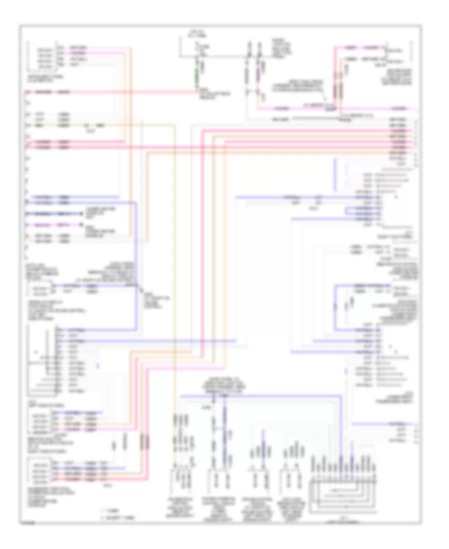
Computer Data Lines Wiring Diagram (1 of 2) for Ford Taurus SEL 2011
List of elements for Computer Data Lines Wiring Diagram (1 of 2) for Ford Taurus SEL 2011:
- (body main wiring harness, near breakout to parking brake switch)
- (dash panel to headlamp junction wiring harness, near breakout to c139) s170
- (main wiring harness, near breakout to heads up display module) (w/ adaptive cruise control) s239
- (under center console) g201
- (w/ memory & ia) s398
- (w/ memory & ia) s399
- Accessory protocol interface module (apim) (w/ sync) (under center console)
- Anti-lock brake system (abs) module (left rear of engine compt)
- C13813b
- C139
- C1463a
- C175b
- C210
- C212
- C214
- C215
- C2153d
- C2280a
- C2280b
- C3138
- C3382
- C501b
- Cdb08
- Cruise control module (w/ adaptive cruise control) (left front of engine compt)
- Data link connector (dlc) (below steering column)
- Driver door module (ddm) (w/ memory & ia) (driver's door)
- Except turbo
- Feps
- Fuse 15a
- G200 (under center console)
- Gd114
- Gd116
- Heads up display (hud) module (w/ adaptive cruise control) (top left side of dash)
- Hot at all times
- Hs can +
- Hs can -
- Hs can - c310b
- Instrument panel cluster (ipc)
- J/c 1 (left kick panel)
- J/c 2 (left side of dash)
- J/c 7 (right kick panel)
- J/c 8 (under front passenger's seat)
- K vdb04
- Ms can +
- Ms can -
- Occupant classification system module (ocsm) (under front passenger's seat)
- Power steering control module (pscm) (turbo) (rear of engine compt)
- Powertrain control module (pcm) (rear of engine compt)
- Remote function actuator (rfa) module (w/ ia) (right side of dash)
- Restraints control module (rcm) (under center console)
- S169
- S222 (w/ adjustable pedals)
- S238 (w/ adaptive cruise control)
- Sbp20
- Smart junction box (sjb) (left kick panel)
- Turbo
- Vdb04
- Vdb05
- Vdb06
- Vdb07
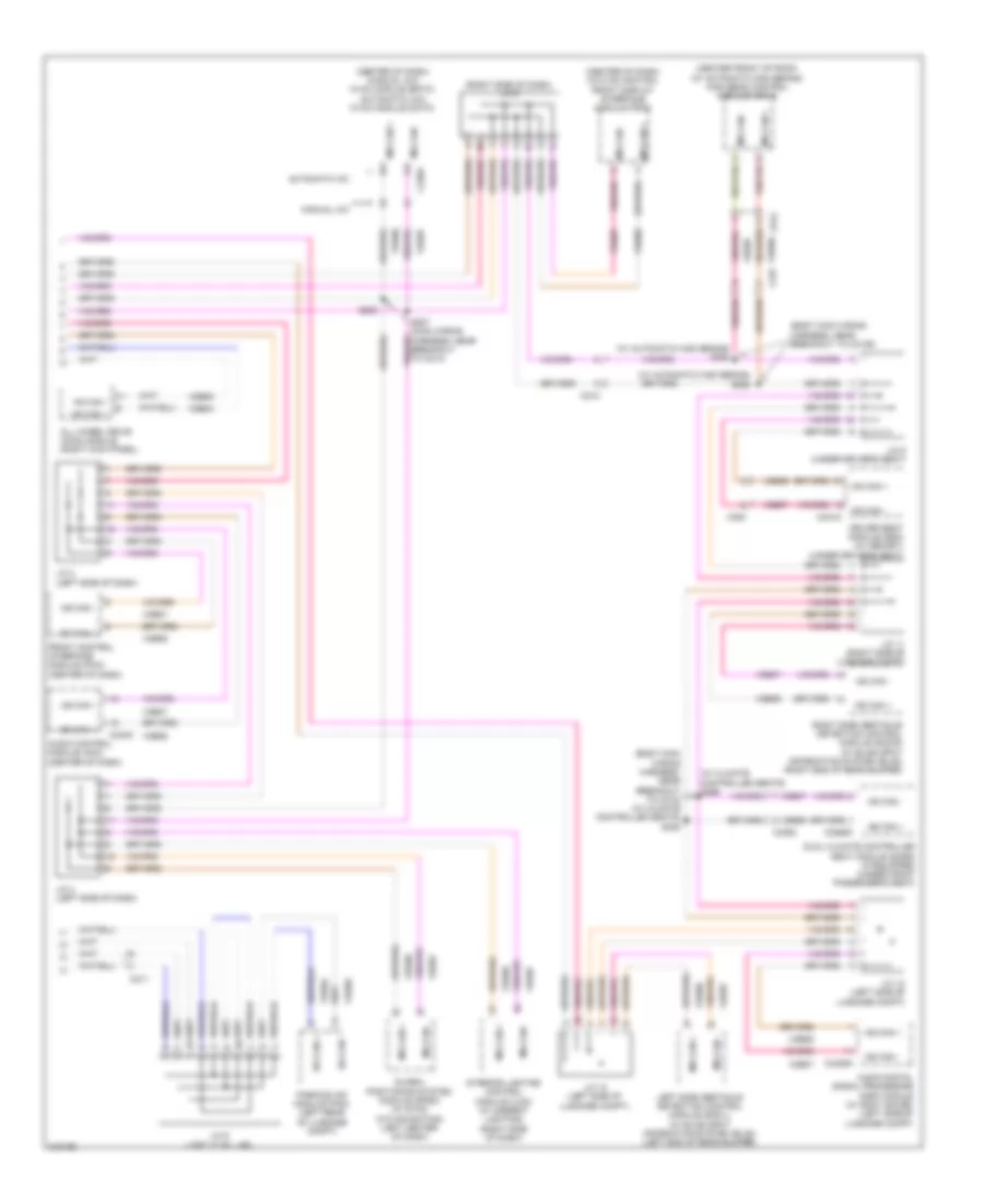
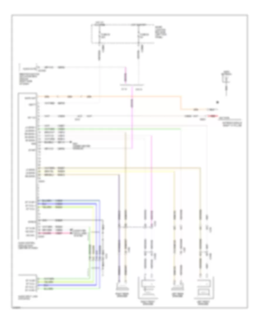
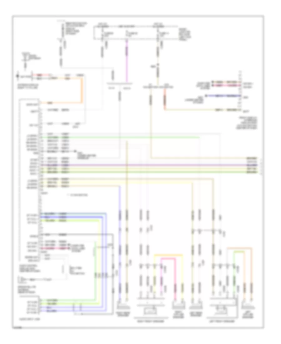
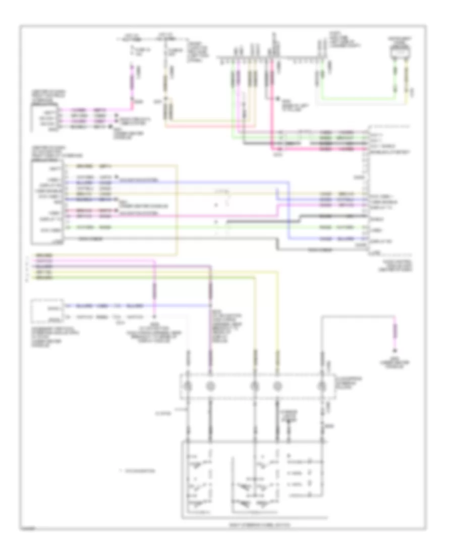
Computer Data Lines Wiring Diagram (2 of 2) for Ford Taurus SEL 2011
List of elements for Computer Data Lines Wiring Diagram (2 of 2) for Ford Taurus SEL 2011:
- (body main wiring harness, near breakout to c312) (w/ climate controlled seats) s325
- (body main wiring harness, near breakout to c3139)
- (center front of roof) (w/ automatic high beams) high beam control module (hcm-2)
- (center of dash) (manual a/c) hvac module (emtc) (automatic a/c) hvac module (datc)
- (center of dash) (w/o navigation) front display interface module (fdim)
- (right side of dash) j/c 5
- (w/ automatic high beams) s392
- (w/ automatic high beams) s393
- (w/ climate controlled seats) s395
- All wheel drive (awd) module (right kick panel)
- Audio control module (acm) (center of dash)
- Audio digital signal processing (dsp) module (w/ sony sound) (left side of luggage compt)
- Automatic a/c
- C211
- C212
- C228a
- C237
- C240c
- C300
- C3265c
- C3382
- C341d
- C4326a
- C913
- Driver seat module (dsm) (w/ memory) (under driver's seat)
- Dual climate controlled seat module (dcsm) (if equipped) (under front passenger's seat)
- Front control interface module (fcim) (center of dash)
- Global positioning system module (gpsm) (w/ sync w/o navigation) (left center of dash)
- Hs can +
- Hs can -
- Interior lighting control module (ilcm) (w/ ambient lighting) (right side of dash)
- J/c 10 (left side of luggage compt)
- J/c 11 (right side of luggage compt)
- J/c 12 (left side of luggage compt)
- J/c 3 (left side of dash)
- J/c 4 (left side of dash)
- J/c 6 (left "c" pillar)
- J/c 9 (under driver's seat)
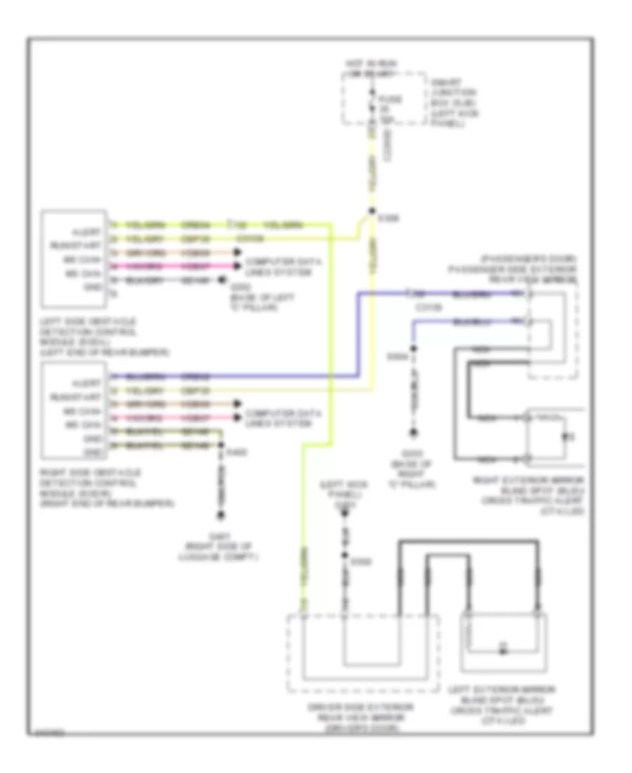
- Left side obstacle detection control module (sod-l) (w/ blind spot information system (blis)) (left end of rear bumper)
- Manual a/c
- Ms can +
- Ms can -
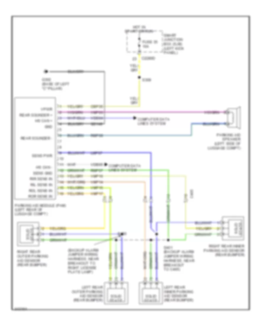
- Parking aid module (pam) (left rear of luggage compt)
- Right side obstacle detection control module (sod-r) (w/ blind spot information system (blis)) (right end of rear bumper)
- S207 (main wiring harness, near breakout to c214)
- S208
- Vdb04
- Vdb05
- Vdb06
- Vdb07
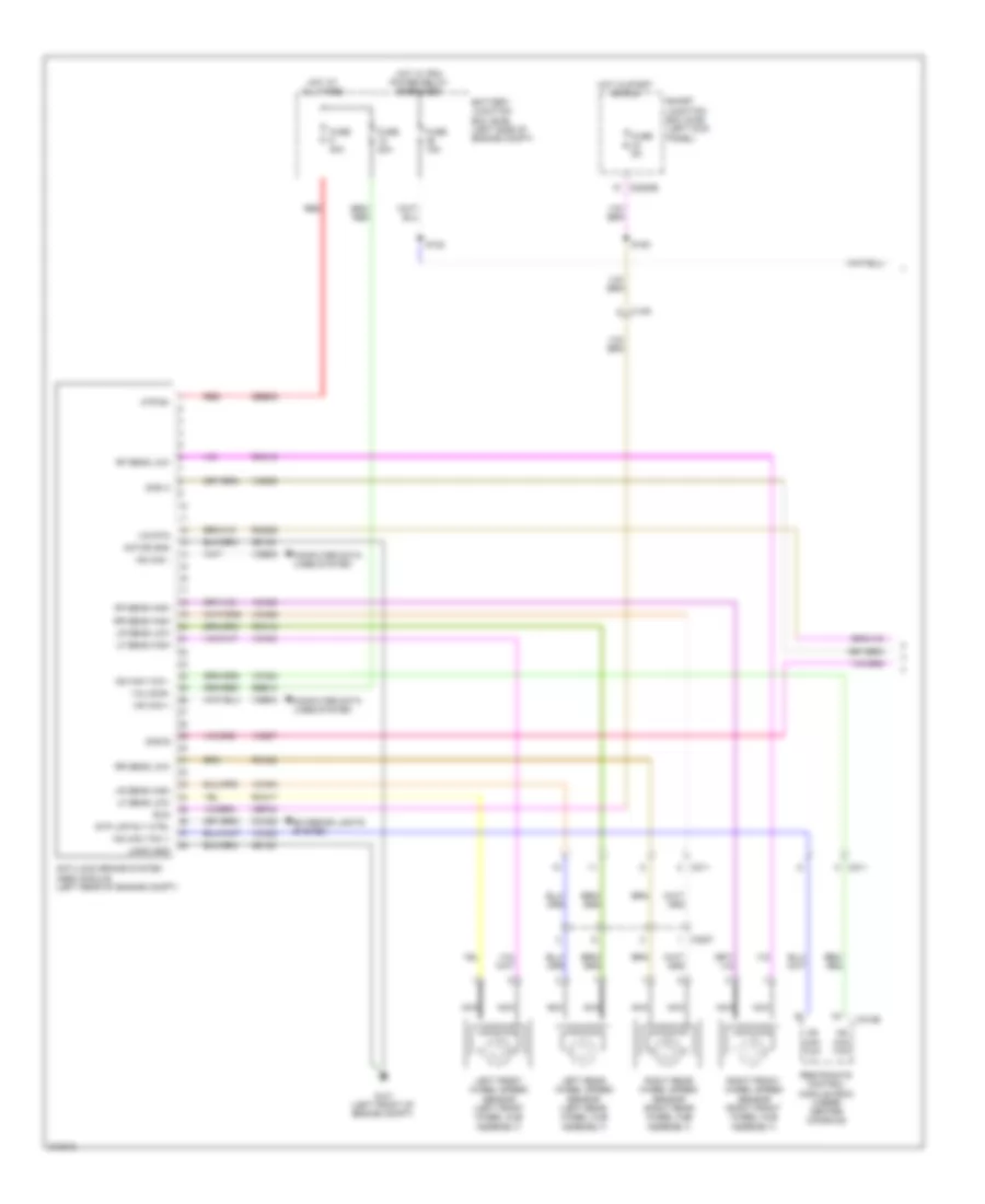
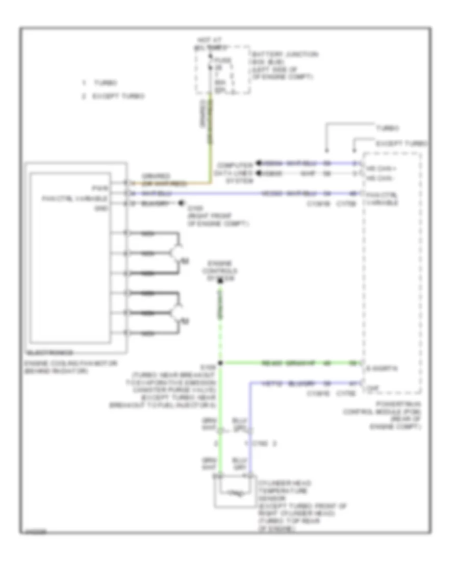
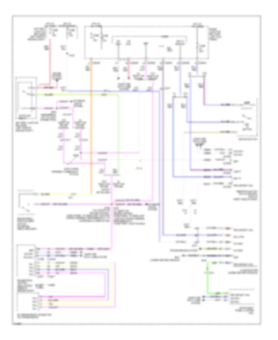
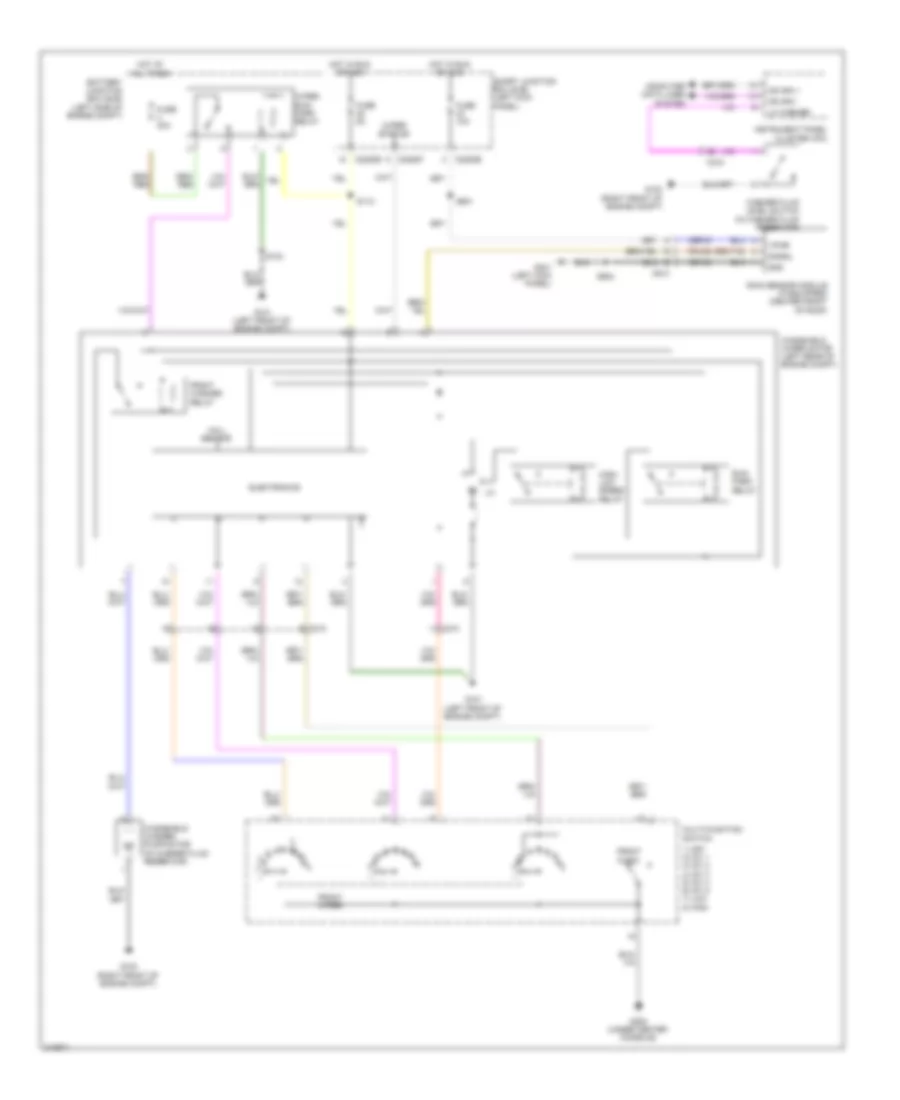
COOLING FAN
Cooling Fan Wiring Diagram for Ford Taurus SEL 2011
List of elements for Cooling Fan Wiring Diagram for Ford Taurus SEL 2011:
- Battery junction box (bjb) (left side of of engine compt)
- C1381b
- C1381e
- C175b
- C175e
- C192
- Cht
- Computer data lines system
- Cylinder head temperature sensor (except turbo: front of right cylinder head) (turbo: top rear of engine)
- E-sigrtn
- Electronics
- Engine controls system
- Engine cooling fan motor (behind radiator)
- Except turbo
- Fan ctrl variable
- Fuse 80a 60a
- G100 (right front of engine compt)
- Gnd
- Hot at all times
- Hs can +
- Hs can -
- Nca
- Powertrain control module (pcm) (rear of engine compt)
- Pwr
- Re405
- S109 (turbo: near breakout to evaporative emission canister purge valve) (except turbo: near breakout to fuel injector 6)
- Turbo
- Vdb04
- Vdb05
- Ve712
- Vec03
CRUISE CONTROL
3.5L
3.5L, Cruise Control Wiring Diagram (1 of 2) for Ford Taurus SEL 2011
List of elements for 3.5L, Cruise Control Wiring Diagram (1 of 2) for Ford Taurus SEL 2011:
- (or cls43)
- 6f transmission (on transmission)
- Anti-lock brake system (abs) module (left rear of engine compt)
- App1
- App1vref
- App1vrtn
- App2
- App2vref
- App2vrtn
- App3
- Battery junction box (bjb) (left side of engine compt)
- Bpp
- Bps
- C175b
- C175e
- C175t
- Cbb36
- Cca28
- Ccb08
- Ce412
- Ce426
- Ces09
- Computer data lines system
- Cruise-control module (c-cm) (w/ adaptive cruise control) (left front of engine compt)
- Electronic throttle control (etc) (top rear of engine)
- Etcref
- Etcrtn
- Fuse 15a
- Fuse 20a
- G101 (left front of engine compt)
- Gd120
- Gnd
- Hot at all times
- Hot in start or run
- Hs can +
- Hs can -
- Hs can+
- Hs can-
- Le111
- Le134
- Le136
- Le137
- Oss
- Powertrain control module (pcm) (rear of engine compt)
- Re134
- Re136
- Re137
- Res08
- Ret04
- Ret24
- Ret33
- Rly
- S164 (dash panel to headlamp junction wiring harness, near breakout to battery junction box)
- S173 (engine control sensor & fuel charge wiring harness, in breakout to 6f transmission)
- S251
- Sbb13
- Sccs
- Sccsrtn
- Stop lamp relay (w/ adaptive cruise control)
- Tacm+
- Tacm-
- Tp1
- Tp2
- Tr gnd
- Tss
- Tss/oss gnd
- Tss/oss vpwr
- Tss/oss/tr gnd
- Vbatt
- Vdb04
- Vdb05
- Ve701
- Ve702
- Ve703
- Ve818
- Ve819
- Ves10
- Vpwr
- W/ adaptive cruise control
- W/o adaptive cruise control
3.5L, Cruise Control Wiring Diagram (2 of 2) for Ford Taurus SEL 2011
List of elements for 3.5L, Cruise Control Wiring Diagram (2 of 2) for Ford Taurus SEL 2011:
- Accelerator pedal position (app) sensor (top of accelerator pedal assembly)
- Battery junction box (bjb) (left side of engine compt)
- Bpp
- Brake pedal position (bpp) switch (on brake pedal bracket)
- C210
- C211
- C215
- C2153e
- C218a
- C218b
- C2280b
- C2280d
- Clockspring (column: steering column) (steering wheel: steering wheel assembly)
- Computer data lines system
- Exterior lights system
- Fuse 15a
- G200 (under center console)
- Harness, near breakout to joint connector 6)
- Hot at all times
- Hot w/ pcm power relay energized
- Hs can+
- Hs can-
- Instrument panel cluster (ipc)
- Interior lights system
- Left steering wheel switch
- Nca
- Off
- Remote function actuator (rfa) module (right side of dash)
- Rsm
- S122
- S168 (dash panel to headlamp junction wiring harness, near breakout to windshield wiper motor)
- S229
- S240 (main wiring harness, in breakout to c215)
- Set+
- Set-
- Smart junction box (sjb) (left kick panel)
- W/ adaptive cruise control
- W/ intelligent access
- W/o adaptive cruise control
3.5L TWIN TURBO
3.5L Twin Turbo, Cruise Control Wiring Diagram (1 of 2) for Ford Taurus SEL 2011
List of elements for 3.5L Twin Turbo, Cruise Control Wiring Diagram (1 of 2) for Ford Taurus SEL 2011:
- (or cls43)
- 6f transmission (on transmission)
- Anti-lock brake system (abs) module (left rear of engine compt)
- App
- App2
- Appref
- Apprtn
- Apprtn2
- Appvref2
- Battery junction box (bjb) (left side of engine compt)
- Bpp
- Bps
- C1381b
- C1381e
- C1381t
- Cbb36
- Cca28
- Ccb08
- Ce412
- Ce426
- Ces09
- Computer data lines system
- Cruise-control module (c-cm) (w/ adaptive cruise control) (left front of engine compt)
- Electronic throttle control (etc) motor (top front of engine)
- Electronic throttle control (etc) position sensor (top front of engine)
- Etcref
- Etcrtn
- Fuse 15a
- Fuse 20a
- G101 (left front of engine compt)
- Gd120
- Gnd
- Hot at all times
- Hot in start or run
- Hs can +
- Hs can -
- Hs can+
- Hs can-
- Le111
- Le134
- Le136
- Le137
- Oss
- Powertrain control module (pcm) (rear of engine compt)
- Re134
- Re136
- Re137
- Res08
- Ret04
- Ret24
- Ret33
- Rly
- S164 (dash panel to headlamp junction wiring harness, near breakout to battery junction box)
- S173 (engine control sensor & fuel charge wiring harness, in breakout to 6f transmission)
- S251
- Sbb13
- Sccs
- Sccsrtn
- Stop lamp relay (w/ adaptive cruise control)
- Tacm+
- Tacm-
- Tp1
- Tp2
- Tr gnd
- Tss
- Tss/oss gnd
- Tss/oss vpwr
- Tss/oss/tr gnd
- Vbatt
- Vdb04
- Vdb05
- Ve701
- Ve702
- Ve818
- Ve819
- Ves10
- Vpwr
- W/ adaptive cruise control
- W/o adaptive cruise control
3.5L Twin Turbo, Cruise Control Wiring Diagram (2 of 2) for Ford Taurus SEL 2011
List of elements for 3.5L Twin Turbo, Cruise Control Wiring Diagram (2 of 2) for Ford Taurus SEL 2011:
- Accelerator pedal position (app) sensor (top of accelerator pedal assembly)
- Battery junction box (bjb) (left side of engine compt)
- Bpp
- Brake pedal position (bpp) switch (on brake pedal bracket)
- C210
- C211
- C215
- C2153e
- C218a
- C218b
- C2280b
- C2280d
- Clock spring (column: steering column) (steering wheel: steering wheel assembly)
- Computer data lines system
- Exterior lights system
- Fuse 15a
- G200 (under center console)
- Hot at all times
- Hot w/ pcm power relay energized
- Hs can+
- Hs can-
- Instrument panel cluster (ipc)
- Interior lights system
- Left steering wheel switch
- Nca
- Off
- Remote function actuator (rfa) module (right side of dash)
- Rsm
- S122
- S168 (dash panel to headlamp junction wiring harness, near breakout to windshield wiper motor)
- S229
- S240 (main wiring harness, in breakout to c215)
- Set+
- Set-
- Smart junction box (sjb) (left kick panel)
- W/ adaptive cruise control
- W/ intelligent access
- W/o adaptive cruise control
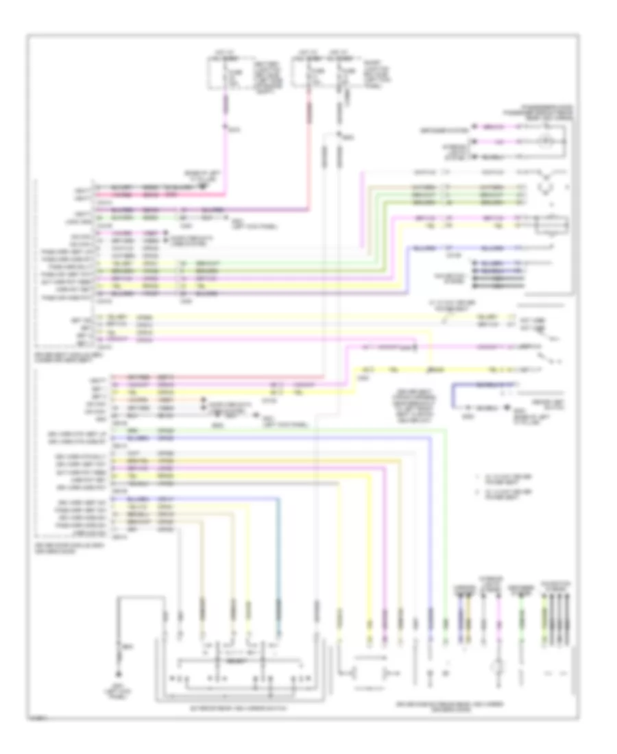
DEFOGGERS
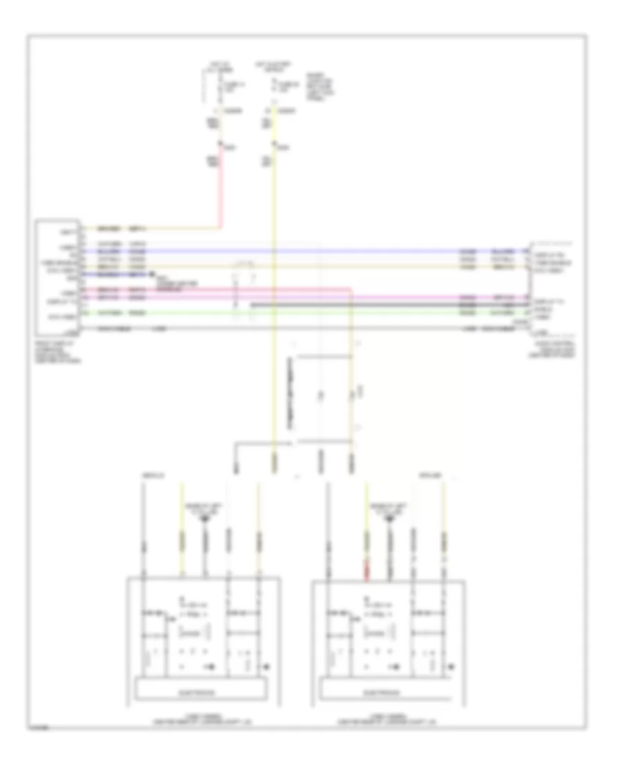
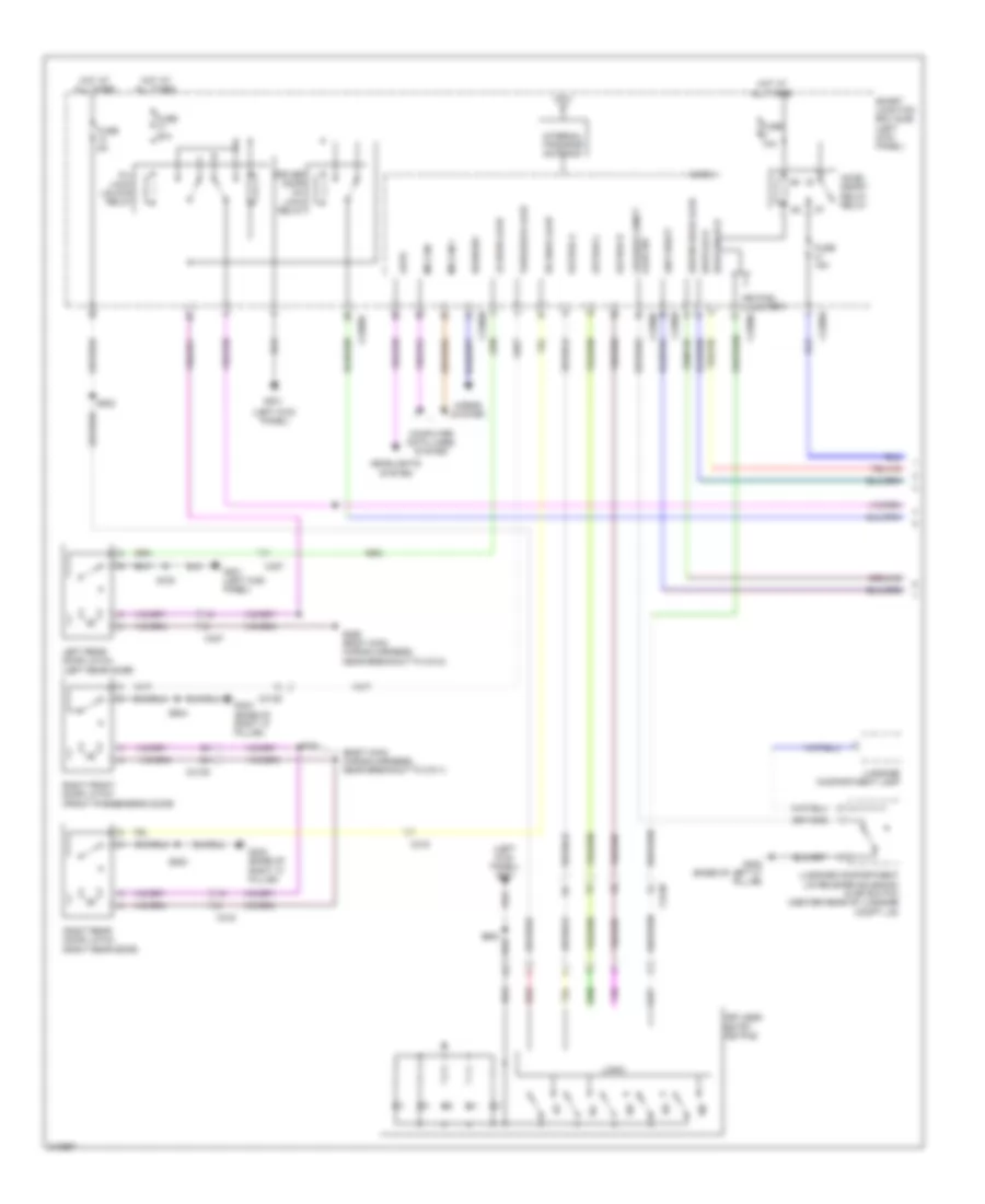
Defoggers Wiring Diagram for Ford Taurus SEL 2011
List of elements for Defoggers Wiring Diagram for Ford Taurus SEL 2011:
- Automatic a/c
- Battery junction box (bjb) (left side of engine compt)
- Brake switch)
- C210
- C211
- C2280d
- C228a
- C3138
- C3139
- C402a
- C402b
- Defrost request
- Driver side exterior rear view mirror (driver's door)
- Fuse 10a
- Fuse 15a
- Fuse 40a
- G301 (left kick panel)
- G303 (base of right ``c" pillar)
- G400 (base of right ``c" pillar)
- Hot at all times
- Hot in run or acc
- Hvac module (datc) (center of dash)
- Hvac module (emtc) (center of dash)
- Manual a/c
- Passenger side exterior rear view mirror (passenger's door)
- Rear window defrost grid
- Rear window defrost relay
- S107 (dash panel to headlamp junction wiring harness, near breakout to battery junction box)
- S391 (body main wiring harness, near breakout to parking
- S500
- S604
- Smart junction box (sjb) (left kick panel)
ELECTRONIC POWER STEERING
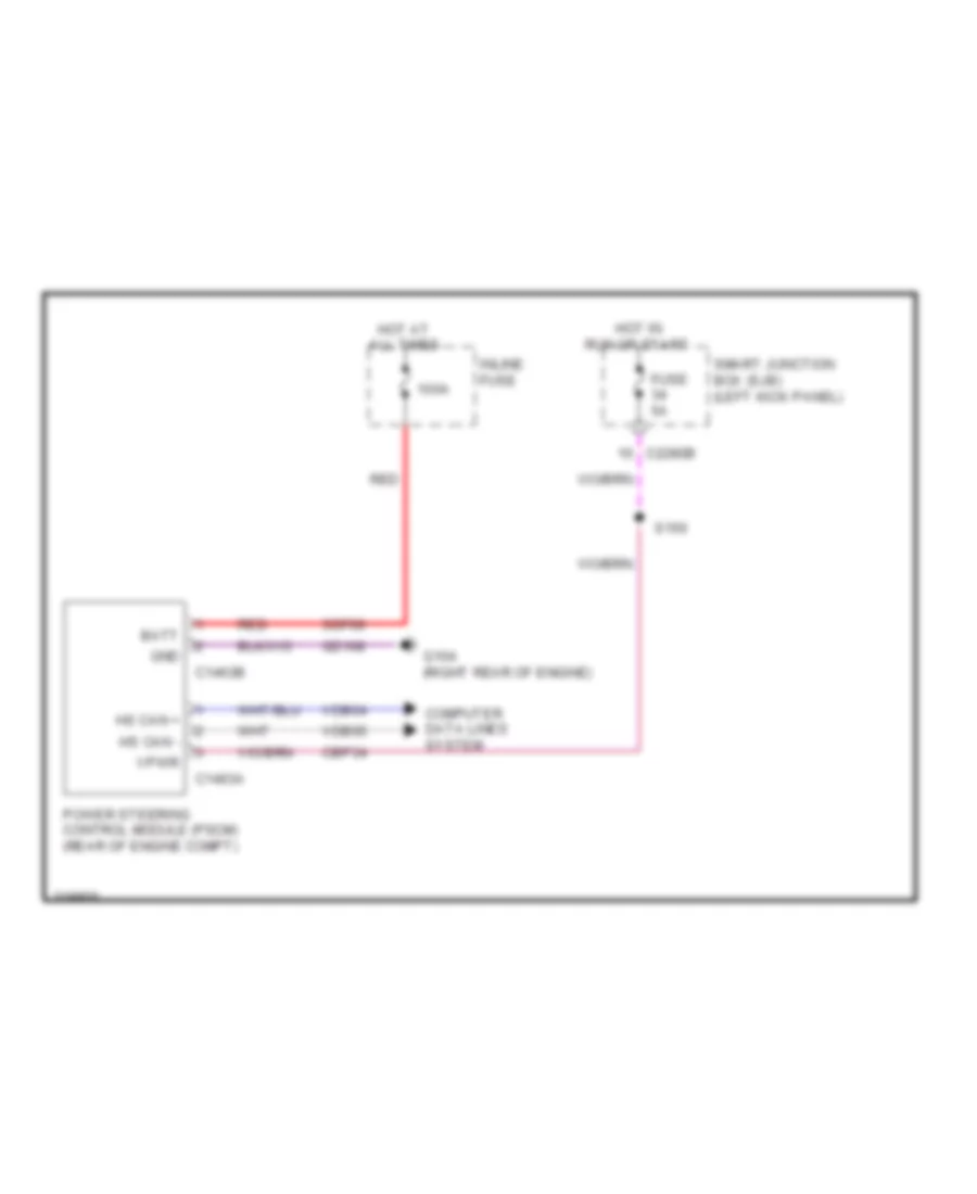
Electronic Power Steering Wiring Diagram for Ford Taurus SEL 2011
List of elements for Electronic Power Steering Wiring Diagram for Ford Taurus SEL 2011:
- 100a
- Batt
- C1463a
- C1463b
- C2280b
- Cbp34
- Computer data lines system
- Fuse 5a
- G104 (right rear of engine)
- Gd108
- Gnd
- Hot at all times
- Hot in run or start
- Hs can +
- Hs can -
- Inline fuse
- Power steering control module (pscm) (rear of engine compt)
- Red
- S150
- Sdf09
- Smart junction box (sjb) (left kick panel)
- Vdb04
- Vdb05
- Vpwr
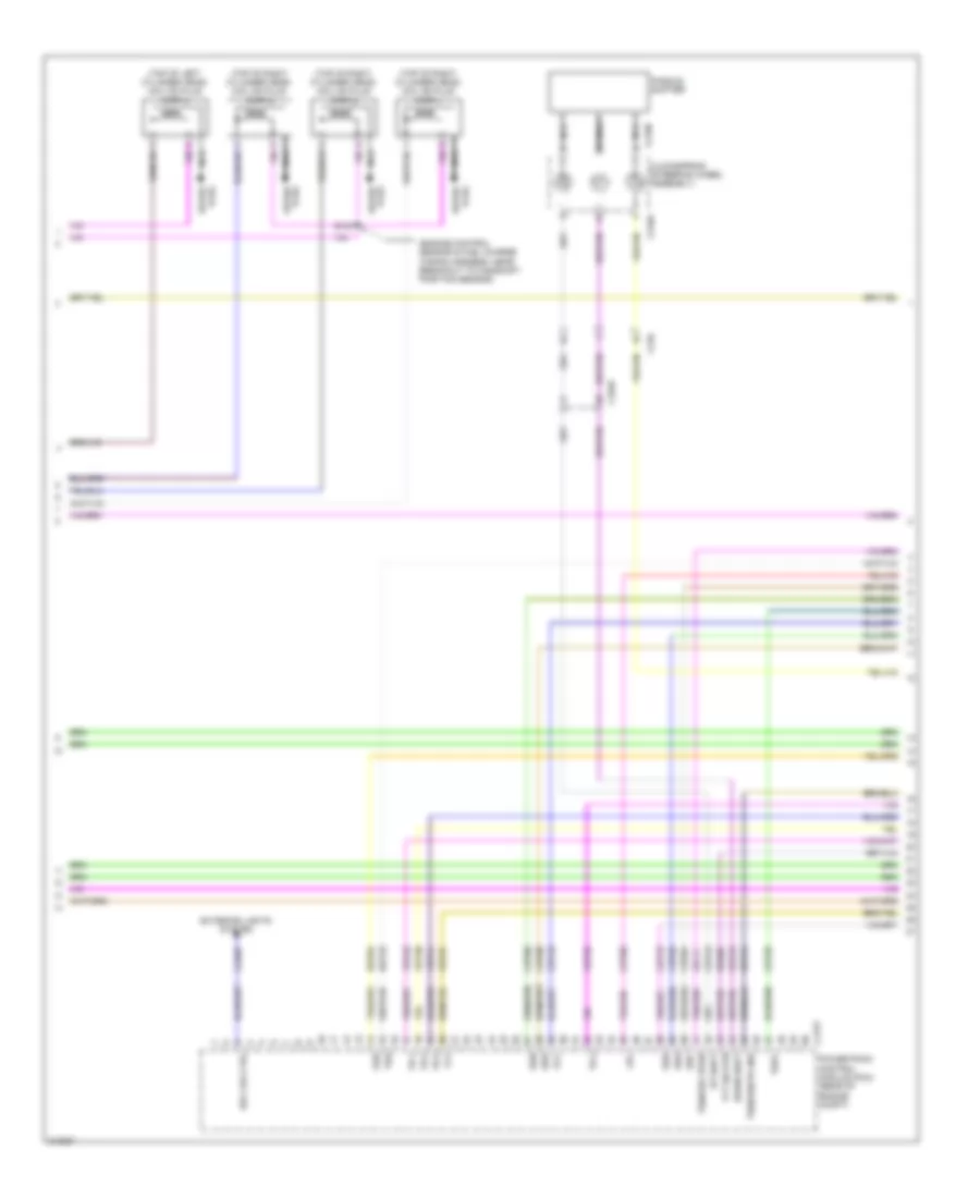
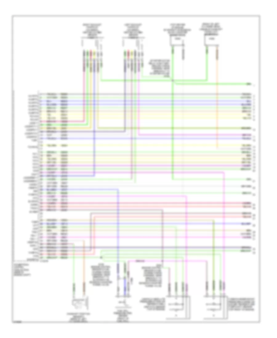
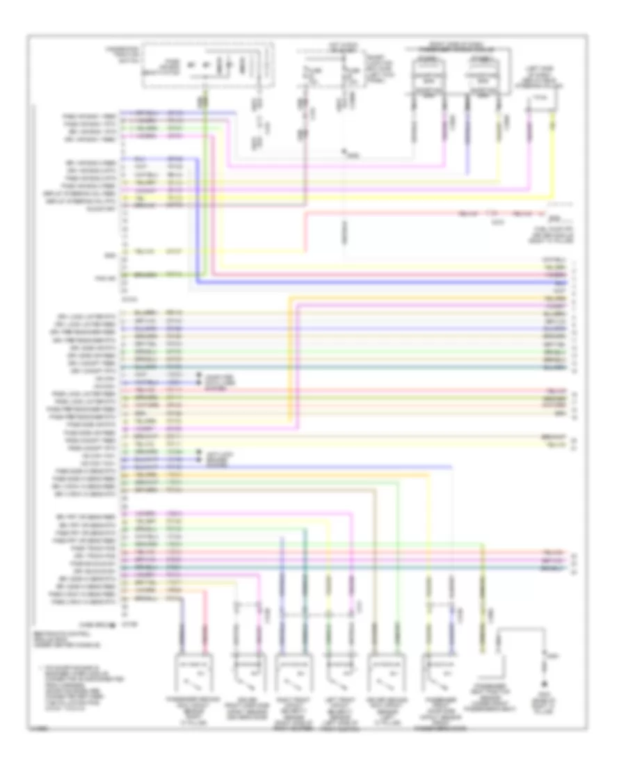
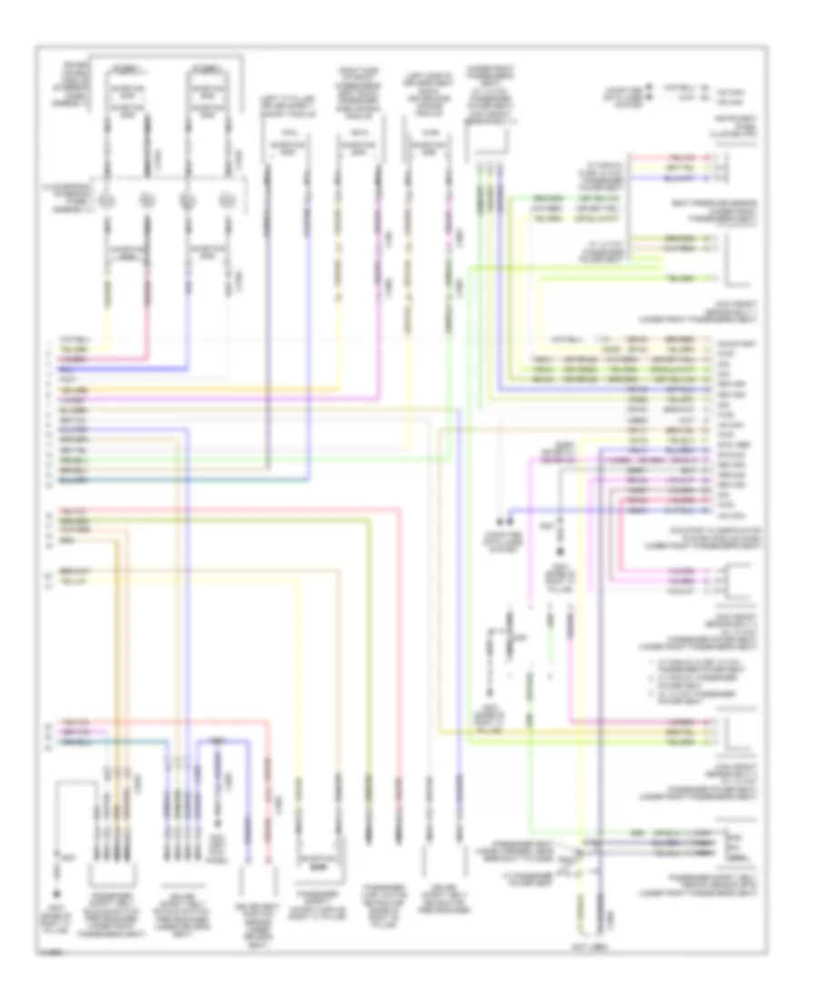
ENGINE PERFORMANCE
3.5L
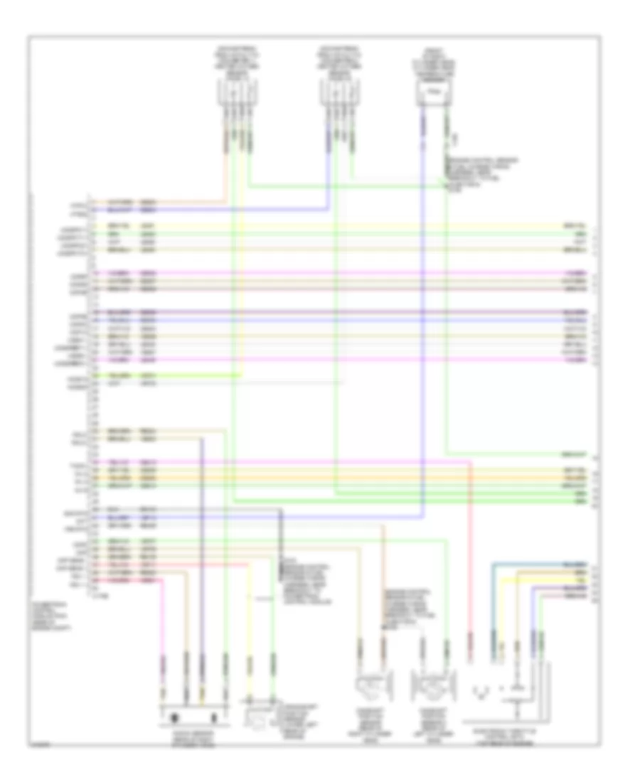
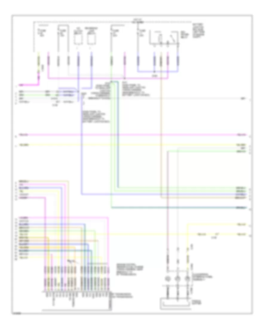
3.5L, Engine Performance Wiring Diagram (1 of 6) for Ford Taurus SEL 2011
List of elements for 3.5L, Engine Performance Wiring Diagram (1 of 6) for Ford Taurus SEL 2011:
- (downstream from catalytic converter 1) heated oxygen sensor (ho2s) 12
- (downstream from catalytic converter 2) heated oxygen sensor (ho2s) 22
- (engine control sensor & fuel charge wiring harness, near breakout to fuel injector 6) s105
- (engine control sensor & fuel charge wiring harness, near breakout to fuel injector 6) s109
- (front of right cylinder head) cylinder head temperature sensor
- C175e
- C192
- Camshaft position sensor (rear of right cylinder head)
- Camshaft position sensor 2 (rear of left cylinder head)
- Ce206
- Ce208
- Ce210
- Ce233
- Ce234
- Ce303
- Ce304
- Ce305
- Ce306
- Ce307
- Ce308
- Ce412
- Cht
- Ckp sens +
- Ckp sens -
- Cmp
- Cmp2
- Cop1a
- Cop2c
- Cop3e
- Cop4b
- Cop5d
- Cop6f
- Crankshaft position sensor (lower left rear of engine)
- De135
- Electronic throttle control (etc) (top rear of engine)
- Ho2s12
- Ho2s22
- Htr12
- Htr22
- Inj 2
- Inj 4
- Inj 6
- Knock sensor (rear of right cylinder head)
- Ksl1 +
- Ksl1 -
- Ksl2+
- Ksl2-
- Le448
- Le449
- Le450
- Le451
- Le452
- Le453
- Powertrain control module (pcm) (rear of engine compt)
- Re135
- Re323
- Re324
- Re429
- S102 (engine control sensor & fuel nca charge wiring harness, near breakout to powertrain control module)
- Shd rtn
- Tacm+
- Tan
- Uo2s11
- Uo2s21
- Uo2sgref11
- Uo2sgref21
- Uo2spc11
- Uo2spc21
- Uo2spct11
- Uo2spct21
- Ve706
- Ve707
- Ve711
- Ve712
- Ve731
- Ve733
- Ve801
- Ve802
- Ve826
- Ve827
- Vrs rtn
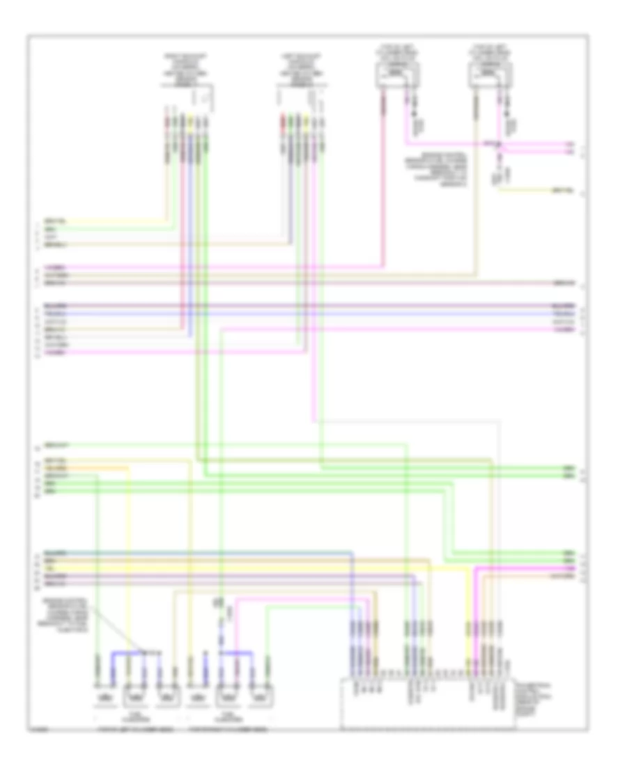
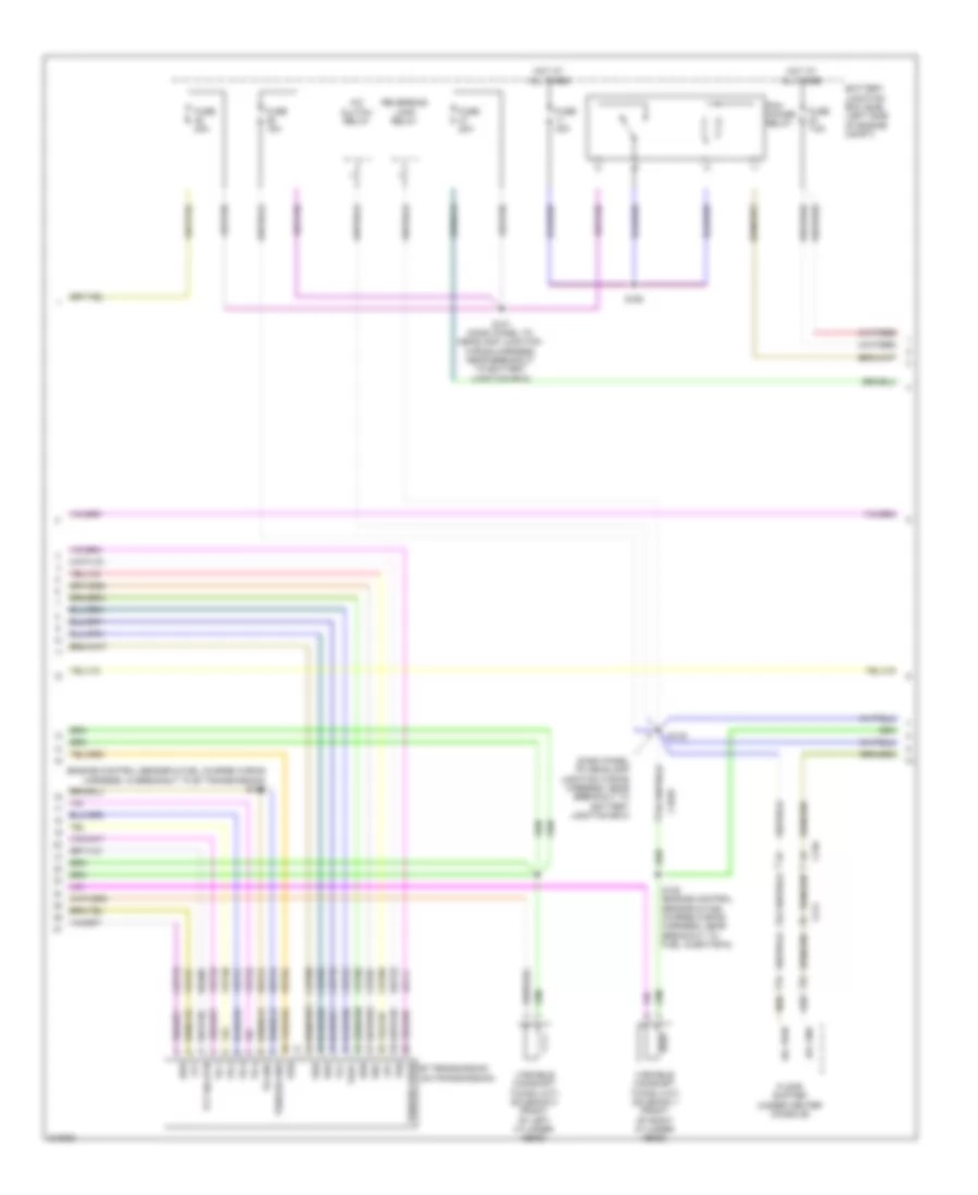
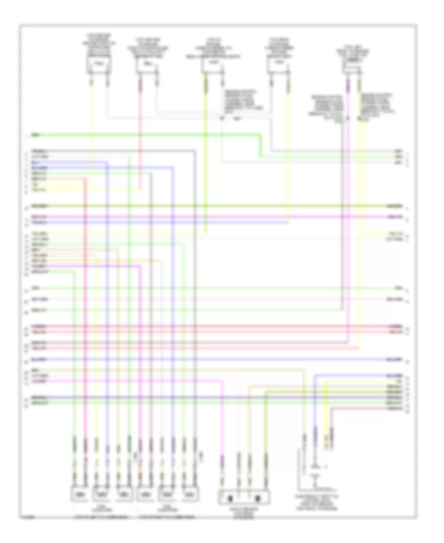
3.5L, Engine Performance Wiring Diagram (2 of 6) for Ford Taurus SEL 2011
List of elements for 3.5L, Engine Performance Wiring Diagram (2 of 6) for Ford Taurus SEL 2011:
- (engine control sensor & fuel charge wiring harness, near breakout to camshaft position sensor 2)
- (engine control sensor & fuel charge wiring harness, near breakout to fuel injector 6)
- (left exhaust manifold) universal heated oxygen sensor (ho2s) 21
- (right exhaust manifold) universal heated oxygen sensor (ho2s) 11
- (top of left cylinder head)
- (top of left cylinder head) coil on plug (cop) 5
- (top of left cylinder head) coil on plug (cop) 6
- (top of right cylinder head)
- C1010
- C175e
- Ce205
- Ce207
- Ce209
- Ce235
- Ce236
- Ce421
- Ce422
- Ce426
- E-sigrtn
- Etc rtn
- Etcref
- Fuel injectors
- Inj 1
- Inj 3
- Inj 5
- Le134
- Nca
- Plug spark
- Powertrain control module (pcm) (rear of engine compt)
- Re134
- Re405
- Red
- S106
- S131
- Spark plug
- Tacm-
- Tp 1
- Tp 2
- Uo2shtr11
- Uo2shtr21
- Vct1
- Vct2
- Ve818
- Ve819
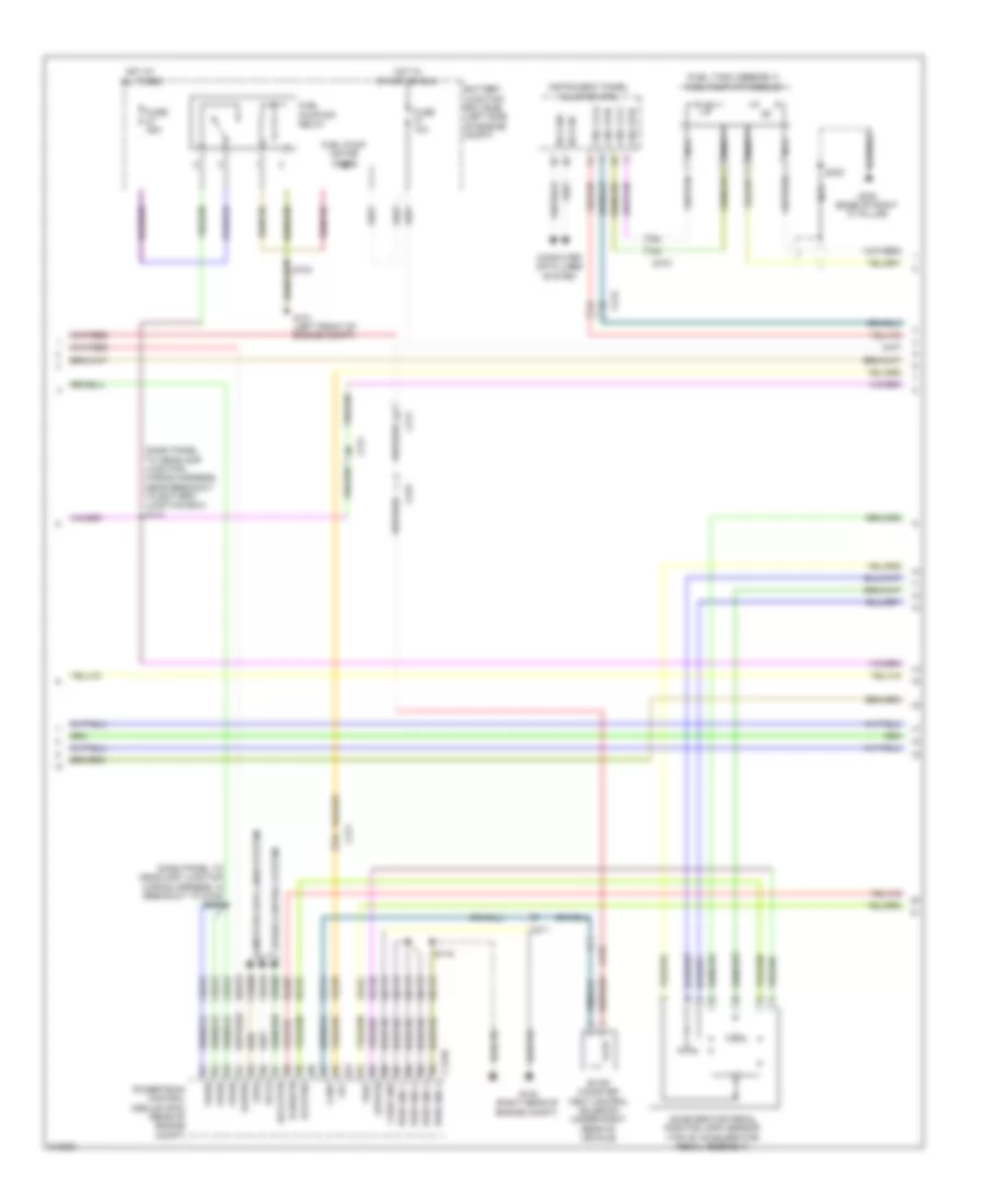
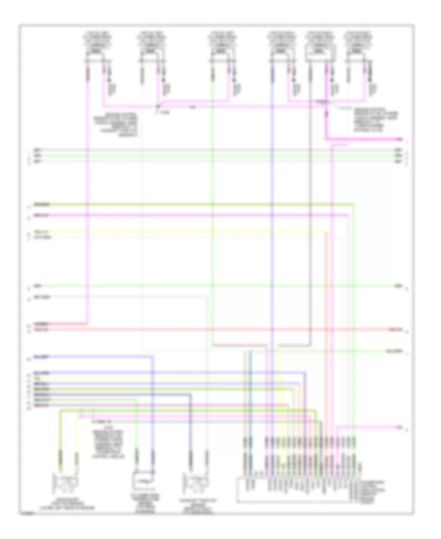
3.5L, Engine Performance Wiring Diagram (3 of 6) for Ford Taurus SEL 2011
List of elements for 3.5L, Engine Performance Wiring Diagram (3 of 6) for Ford Taurus SEL 2011:
- (engine control sensor & fuel charge wiring harness, near breakout to camshaft position sensor)
- (top of left cylinder head) coil on plug (cop) 4
- (top of right cylinder head) coil on plug (cop) 1
- (top of right cylinder head) coil on plug (cop) 2
- (top of right cylinder head) coil on plug (cop) 3
- C1010
- C175t
- C210
- C218a
- C218b
- Cet05
- Cet06
- Cet07
- Cet08
- Cet09
- Cet10
- Cet19
- Cet25
- Cet42
- Cet43
- Clockspring (steering wheel assembly)
- Cls28
- Down shift
- Exterior lights system
- Le111
- Lpc
- Nca
- Oss
- Paddle shifter
- Plug spark
- Powertrain control module (pcm) (rear of engine compt)
- Re406
- Ret04
- Ret24
- Ret33
- Rev lps ctrl
- S103
- Spark plug
- Ssa
- Ssb
- Ssc
- Ssd
- Sse
- Tcc
- Tft
- Tft sig rtn
- Tr-1
- Tr-2
- Tr-3
- Tr-4
- Tspc
- Tss
- Tss/oss vpwr
- Tss/oss/tr gnd
- Up shift
- Vet27
- Vet29
- Vet30
- Vet31
- Vet32
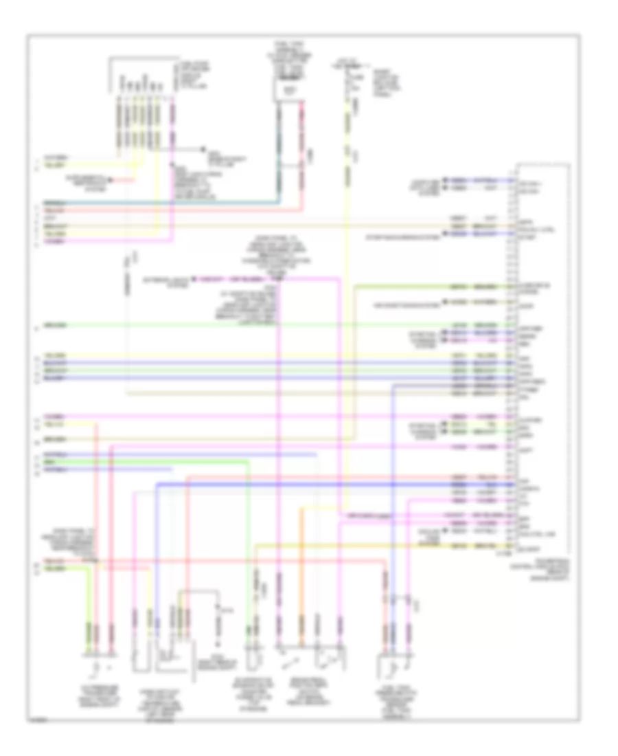
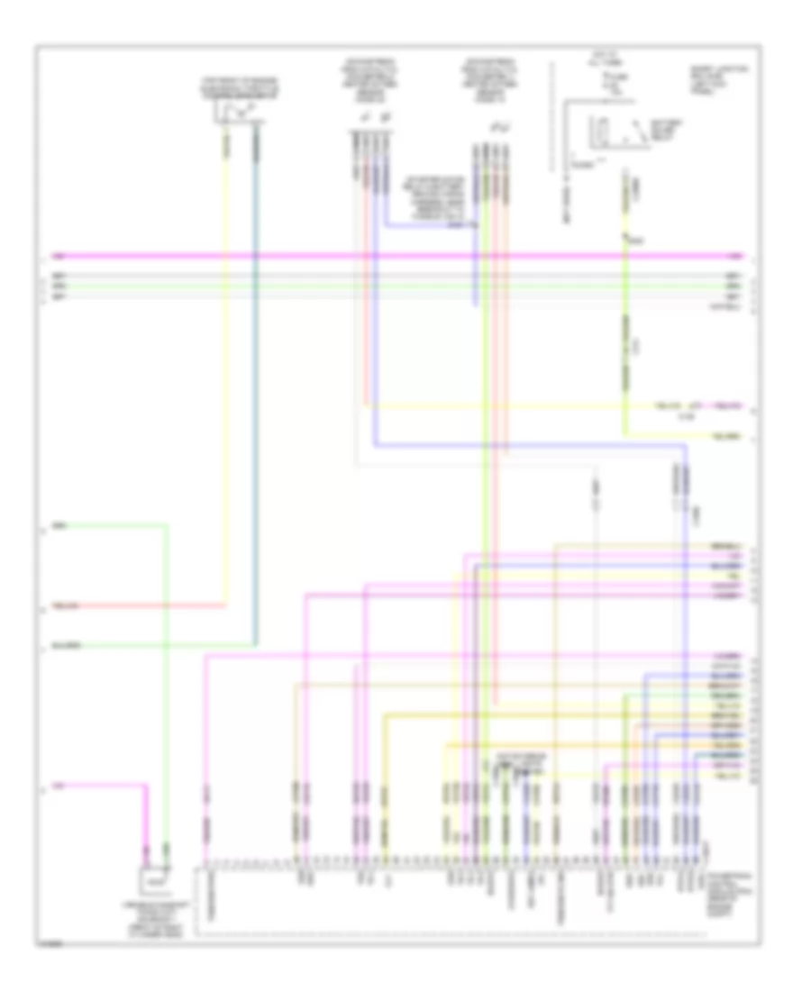
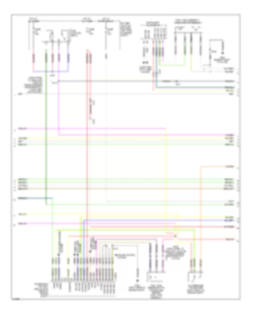
3.5L, Engine Performance Wiring Diagram (4 of 6) for Ford Taurus SEL 2011
List of elements for 3.5L, Engine Performance Wiring Diagram (4 of 6) for Ford Taurus SEL 2011:
- (dash panel to headlamp junction wiring harness, near breakout to battery junction box)
- (engine control sensor & fuel charge wiring harness, in breakout to 6f transmission) s173
- 6f transmission (on transmission)
- A/c clutch relay
- Battery junction box (bjb) (left side of engine compt)
- C1010
- C210
- C214
- Cet05
- Cet06
- Cet07
- Cet08
- Cet09
- Cet10
- Cet19
- Cet25
- Floor shifter (under center console)
- Fuse 15a
- Fuse 20a
- Fuse 30a
- Fuse 7.5a
- Hot at all times
- Le111
- Lpc
- O/c gnd
- O/c pwr
- Oss
- Pcm power relay
- Re406
- Ret04
- Ret24
- Ret33
- Reversing lamp relay
- S101 (dash panel to headlamp junction wiring harness, near breakout to battery junction box)
- S122
- S128 (engine control sensor & fuel charge wiring harness, near breakout to fuel injector 6)
- S160
- Ssa
- Ssb
- Ssc
- Ssd
- Sse
- Tcc
- Tft
- Tft sig rtn
- Tr gnd
- Tr-1
- Tr-2
- Tr-3
- Tr-4
- Tspc
- Tss
- Tss/oss gnd
- Tss/oss vpwr
- Variable camshaft timing (vct) solenoid 1 (front of right cylinder head)
- Variable camshaft timing (vct) solenoid 2 (front of left cylinder head)
- Vet27
- Vet29
- Vet30
- Vet31
- Vet32
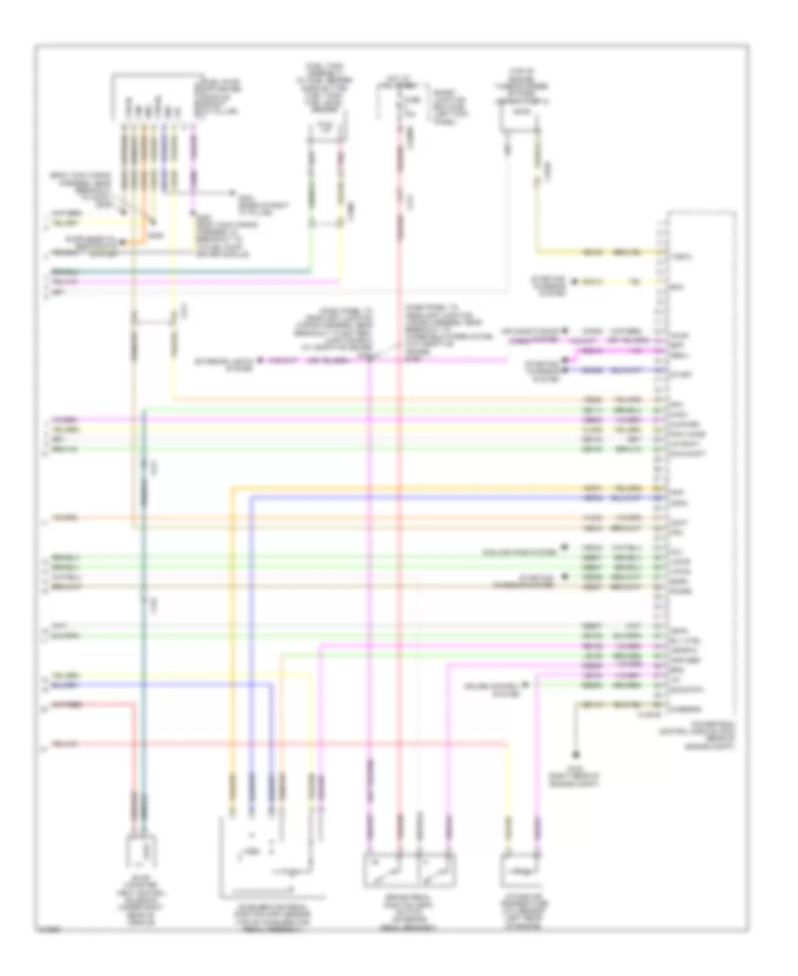
3.5L, Engine Performance Wiring Diagram (5 of 6) for Ford Taurus SEL 2011
List of elements for 3.5L, Engine Performance Wiring Diagram (5 of 6) for Ford Taurus SEL 2011:
- (dash panel to headlamp junction wiring harness, in breakout to g102) s123
- (dash panel to headlamp junction wiring harness, near breakout to battery junction box) s110
- (fuel tank assembly) fuel pump (fp) module
- Accelerator pedal position (app) sensor (top of accelerator pedal assembly)
- Apprtn
- B-sigrtn
- Battery junction box (bjb) (left side of engine compt)
- C175b
- C211
- C212
- C215
- C315
- Canv
- Case gnd
- Cbb47
- Cdb08
- Ce114
- Computer data lines system
- Cruise control system
- Etcrtn2
- Evap canister vent control solenoid (under right rear of vehicle)
- Feps
- Fpc
- Fuel lvl1
- Fuel lvl2
- Fuel pump (fp) relay
- Fuel pump motor diode
- Fuel rtn
- Fuse 10a
- Fuse 25a
- G101 (left front of engine compt)
- G102 (right rear of engine compt)
- G303 (base of right "c" pillar)
- Gd113
- Hot at all times
- Hot in start or run
- Hs can+
- Hs can-
- Instrument panel cluster (ipc)
- Kapwr
- Le424
- Nca
- Powertrain control module (pcm) (rear of engine compt)
- Pwr gnd 1
- Pwr gnd 2
- Pwr gnd 3
- Pwr gnd 4
- Re136
- Re137
- Re407
- Res08
- S104
- S116
- S323
- Sbb23
- Sccs
- Sccs rtn
- Ve225
- Ves10
- Vpwr
- Vref
3.5L, Engine Performance Wiring Diagram (6 of 6) for Ford Taurus SEL 2011
List of elements for 3.5L, Engine Performance Wiring Diagram (6 of 6) for Ford Taurus SEL 2011:
- (dash panel to headlamp junction wiring harness, near breakout to g102) s125
- (dash panel to headlamp junction wiring harness, near breakout to windshield wiper motor) (w/o adaptive cruise) s168
- (fuel tank assembly) (w/ dual sender saddle-type fuel tank) fuel level sender
- (or cls43)
- A/c pressure transducer (right front of engine compt)
- Accr
- Acpt
- Air conditioning system
- App
- App2
- App3
- Appvref
- Appvref2
- Bpp
- Bps
- Brake pedal position (bpp) switch (on brake pedal bracket)
- C1010
- C175b
- C211
- C2280d
- C3309
- Cbb37
- Ccb08
- Cdc10
- Cdc12
- Cdc15
- Cdc35
- Ce132
- Ce237
- Ce336
- Ce515
- Ce608
- Ces09
- Cet34
- Ch302
- Computer data lines system
- Cooling fans system
- Cr167
- Ens
- Evapcp
- Evaporative emission (evap) canister purge valve (top of engine)
- Exterior lights system
- Fan ctrl var
- Fpc
- Fpm
- Fppwr
- Fprtn
- Ftp
- Ftpref
- Fuel pump (fp) driver module (right "c" pillar)
- Fuel tank pressure (ftp) transducer sensor (fuel tank assembly)
- Fuse 15a
- G102 (right rear of engine compt)
- G303 (base of right "c" pillar)
- Gd145
- Gen
- Genrc
- Gnd
- Hot at all times
- Hs can +
- Hs can -
- Iat
- Injpwrm
- Isp-r
- Le136
- Le137
- Le230
- Maf
- Mafrtn
- Mass air flow/ intake air temperature (maf/iat) sensor (left rear of engine)
- Over drive cancel
- Pcm rly ctrl
- Pnk
- Powertrain control module (pcm) (rear of engine compt)
- Re320
- Re515
- S116
- S164 (w/ adaptive cruise) (dash panel to headlamp junction wiring harness, near breakout to battery junction box)
- S300 (body main wiring harness, in breakout to to fuel pump driver module)
- Smart junction box (sjb) (left kick panel)
- Smc
- Smrc
- Start
- Starting/ charging system
- Starting/charging system
- Vdb04
- Vdb05
- Ve225
- Ve518
- Ve701
- Ve702
- Ve703
- Ve740
- Ve807
- Ve922
- Vec03
- Ves18
- Vh433
- Vpwr fuel
3.5L TWIN TURBO
3.5L Twin Turbo, Engine Performance Wiring Diagram (1 of 7) for Ford Taurus SEL 2011
List of elements for 3.5L Twin Turbo, Engine Performance Wiring Diagram (1 of 7) for Ford Taurus SEL 2011:
- (front of left cylinder head) variable camshaft timing (vct) solenoid 2
- (left exhaust manifold) universal heated oxygen sensor (ho2s) 21
- (right exhaust manifold) universal heated oxygen sensor (ho2s) 11
- (starter motor relay & battery ground wiring harness, near breakout to starter motor) s128
- (top center of engine) evaporative emission (evap) canister purge valve
- C1381e
- C1586
- C1587
- Cact
- Camshaft position sensor 2 (rear of left cylinder head)
- Ce113
- Ce205
- Ce206
- Ce207
- Ce208
- Ce209
- Ce210
- Ce226
- Ce308
- Ce321
- Ce328
- Ce412
- Ce435
- Cht
- Cmp
- Cmp2 +
- Cop6f
- E-sigrtn
- E-vref
- Evapcp
- Frp
- Fuel rail pressure (frp) sensor (front of fuel rail)
- Fvr
- Fvrrtn
- Iat2
- Inj1
- Inj1rtn
- Inj2
- Inj2rtn
- Inj3
- Inj3rtn
- Inj4
- Inj4rtn
- Inj5
- Inj5rtn
- Inj6
- Inj6rtn
- Ksl1 +
- Ksl1 -
- Le423
- Le448
- Le449
- Le450
- Le451
- Le452
- Le453
- Manifold absolute pressure/intake air temperature 2 (map/iat2) sensor (top of engine)
- Map
- Pcvhc
- Pcvhf
- Powertrain control module (pcm) (rear of engine compt)
- Re205
- Re206
- Re207
- Re208
- Re209
- Re210
- Re226
- Re266
- Re323
- Re405
- Re429
- Red
- S109 (engine control sensor & fuel charge wiring harness, near breakout to evaporative emission canister purge valve)
- S192 (engine control sensor & fuel charge wiring harness, near breakout to evaporative emission canister purge valve)
- Tacm+
- Tcbp
- Tcby
- Tcwrvs
- Tps1
- Turbocharger boost pressure/charge air cooler temperature (tcbp/cact) sensor (top front of engine)
- Uo2s11
- Uo2s21
- Uo2sgref11
- Uo2sgref21
- Uo2spc11
- Uo2spc21
- Uo2spct11
- Uo2spct21
- Ve706
- Ve707
- Ve712
- Ve727
- Ve740
- Ve801
- Ve804
- Ve818
- Ve824
- Ve826
- Ve827
- Vrsrtn
- Vrsrtn2
3.5L Twin Turbo, Engine Performance Wiring Diagram (2 of 7) for Ford Taurus SEL 2011
List of elements for 3.5L Twin Turbo, Engine Performance Wiring Diagram (2 of 7) for Ford Taurus SEL 2011:
- (engine control sensor & fuel charge wiring harness, near breakout to c1586) s141
- (engine control sensor & fuel charge wiring harness, near breakout to coil on plug 5) s190
- (engine control sensor & fuel charge wiring harness, near breakout to coil on plug 5) s191
- (top center of engine) heated positive crankcase ventilation (pcv) valve
- (top center of engine) positive crankcase ventilation (pcv) heated fitting
- (top left front of engine) fuel injector pump
- (top of engine) turbocharger (tc) wastegate regulating valve solenoid
- (top of left cylinder head)
- (top of right cylinder head)
- (top rear of engine) turbocharger bypass valve (tcby)
- C1586
- C1587
- Electronic throttle control (etc) position sensor (top front of engine)
- Fuel injectors
- Knock sensor (top rear of engine)
- Tan
3.5L Twin Turbo, Engine Performance Wiring Diagram (3 of 7) for Ford Taurus SEL 2011
List of elements for 3.5L Twin Turbo, Engine Performance Wiring Diagram (3 of 7) for Ford Taurus SEL 2011:
- (engine control sensor & fuel charge wiring harness, near breakout to camshaft position sensor 2)
- (engine control sensor & fuel charge wiring harness, near breakout to turbocharger bypass valve)
- (top of left cylinder head) coil on plug (cop) 4
- (top of left cylinder head) coil on plug (cop) 5
- (top of left cylinder head) coil on plug (cop) 6
- (top of right cylinder head) coil on plug (cop) 1
- (top of right cylinder head) coil on plug (cop) 2
- (top of right cylinder head) coil on plug (cop) 3
- C1381e
- Camshaft position sensor (rear of right cylinder head)
- Ce226
- Ce235
- Ce236
- Ce303
- Ce304
- Ce305
- Ce306
- Ce307
- Ce421
- Ce422
- Ce426
- Ckp +
- Ckp-
- Cop1a
- Cop2c
- Cop3e
- Cop4b
- Cop5d
- Crankshaft position sensor (lower left rear of engine)
- Cylinder head temperature sensor (top rear of engine)
- De135
- Etcref
- Etcrtn
- Fvr
- Ksl2 +
- Ksl2 -
- Le134
- Nca
- Plug spark
- Powertrain control module (pcm) (rear of engine compt)
- Re134
- Re135
- Re324
- S102 (engine control sensor & fuel charge wiring harness, near breakout to powertrain control module)
- S198
- S199
- Shdrtn
- Spark plug
- Tacm-
- Tps2
- Uo2shtr11
- Uo2shtr21
- Vct1
- Vct2
- Ve711
- Ve802
- Ve819
3.5L Twin Turbo, Engine Performance Wiring Diagram (4 of 7) for Ford Taurus SEL 2011
List of elements for 3.5L Twin Turbo, Engine Performance Wiring Diagram (4 of 7) for Ford Taurus SEL 2011:
- (downstream from catalytic converter 1) heated oxygen sensor (ho2s) 12
- (downstream from catalytic converter 2) heated oxygen sensor (ho2s) 22
- (not used)
- (starter motor relay & battery ground wiring harness, near breakout to fusible link a) s151
- (top front of engine) electronic throttle control (etc) motor
- Battery saver relay
- C1010
- C1381t
- C139
- C1590
- C211
- C2280d
- Ce233
- Ce234
- Cet05
- Cet06
- Cet07
- Cet08
- Cet09
- Cet10
- Cet19
- Cet25
- Cet34
- Cls28
- Exterior lights system
- Fuse 10a
- Ho2s12
- Ho2s22
- Hot at all times
- Htr12
- Htr22
- Le111
- Lpc
- Micro
- Oss
- Overdrive
- Powertrain control module (pcm) (rear of engine compt)
- Re406
- Ret04
- Ret24
- Ret33
- Rev lamps
- S320
- Smart junction box (sjb) (left kick panel)
- Ssa
- Ssb
- Ssc
- Ssd
- Sse
- Tcc
- Tft
- Tft sig rtn
- Tr-1
- Tr-2
- Tr-3
- Tr-4
- Tspc
- Tss
- Tss/oss/tr gnd
- Tss/oss/vpwr
- Variable camshaft timing (vct) solenoid 1 (front of right cylinder head)
- Ve731
- Ve733
- Vet27
- Vet29
- Vet30
- Vet31
- Vet32
3.5L Twin Turbo, Engine Performance Wiring Diagram (5 of 7) for Ford Taurus SEL 2011
List of elements for 3.5L Twin Turbo, Engine Performance Wiring Diagram (5 of 7) for Ford Taurus SEL 2011:
- (dash panel to headlamp junction wiring harness, near breakout to battery junction box)
- (engine control sensor & fuel charge wiring harness, near breakout to 6f transmission)
- 6f transmission (on transmission)
- A/c clutch relay
- Battery junction box (bjb) (left side of engine compt)
- C1010
- C139
- C210
- C218a
- C218b
- Cet05
- Cet06
- Cet07
- Cet08
- Cet09
- Cet10
- Cet19
- Cet25
- Clockspring (steering wheel assembly)
- Fuse 15a
- Fuse 20a
- Fuse 30a
- Hot at all times
- Le111
- Lpc
- Nca
- Oss
- Paddle shifter
- Pcm power relay
- Re406
- Ret04
- Ret24
- Ret33
- Reversing lamp relay
- S101 (dash panel to headlamp junction wiring harness, near breakout to battery junction box)
- S122
- S123 (dash panel to headlamp junction wiring harness, in breakout breakout to g102)
- S160
- S173
- Ssa
- Ssb
- Ssc
- Ssd
- Sse
- Tcc
- Tft
- Tft sig rtn
- Tr gnd
- Tr-1
- Tr-2
- Tr-3
- Tr-4
- Tspc
- Tss
- Tss/oss gnd
- Tss/oss vpwr
- Vet27
- Vet29
- Vet30
- Vet31
- Vet32
3.5L Twin Turbo, Engine Performance Wiring Diagram (6 of 7) for Ford Taurus SEL 2011
List of elements for 3.5L Twin Turbo, Engine Performance Wiring Diagram (6 of 7) for Ford Taurus SEL 2011:
- (dash panel to headlamp junction wiring harness, near breakout to battery junction box)
- (fuel tank assembly) fuel pump (fp) module
- A/c pressure transducer (right front of engine compt)
- Appref2
- Apprtn2
- B-sigrtn
- Battery junction box (bjb) (left side of engine compt)
- C1381b
- C211
- C212
- C315
- Cbb47
- Cdb08
- Cdc10
- Computer data lines system
- Cruise control system
- Feps
- Ftp
- Ftpref
- Fuel lvl1
- Fuel lvl2
- Fuel pump (fp) relay
- Fuel rtn
- Fuel tank pressure (ftp) transducer sensor (fuel tank assembly)
- Fuse 10a
- Fuse 25a
- Fuse 7.5a
- G102 (right rear of engine compt)
- G303 (base of right "c" pillar)
- Gd113
- Genrc
- Hot at all times
- Hot in start or run
- Hs can+
- Hs can-
- Instrument cluster (ic)
- Kapwr
- Le137
- Le230
- Le424
- Nca
- Powertrain control module (pcm) (rear of engine compt)
- Pwr gnd 1
- Pwr gnd 2
- Pwr gnd 3
- Pwr gnd 4
- Re137
- Re407
- S110
- S116
- S125 (dash panel to headlamp junction wiring harness, near breakout to g102)
- S167
- S323
- Sbb23
- Sccs
- System data lines computer
- System starting/charging
- Vdb04
- Vdb05
- Ve922
- Ves10
- Vpwr
- Vref
3.5L Twin Turbo, Engine Performance Wiring Diagram (7 of 7) for Ford Taurus SEL 2011
List of elements for 3.5L Twin Turbo, Engine Performance Wiring Diagram (7 of 7) for Ford Taurus SEL 2011:
- (body main wiring harness, near breakout to c3047) s306
- (dash panel to headlamp junction wiring harness, near breakout to battery junction box) (w/ adaptive cruise) s164
- (dash panel to headlamp junction wiring harness, near breakout to windshield wiper motor) (w/o adaptive cruise) s168
- (fuel tank assembly) (w/ duel sender saddle-type fuel tank) fuel level sender
- (top of engine) turbocharger bypass valve 2 (tcby 2)
- Accelerator pedal position (app) sensor (top of accelerator pedal assembly)
- Accr
- Acpt
- Air conditioning system
- App
- App2
- Apprtn
- Appvref
- Bpp
- Bps
- Brake pedal position (bpp) switch (on brake pedal bracket)
- C1010
- C1381b
- C211
- C2280d
- C315
- C3309
- Canv
- Casegnd
- Cbb37
- Cbb47
- Ccb08
- Cdc12
- Cdc15
- Cdc35
- Ce114
- Ce132
- Ce237
- Ce336
- Ce515
- Ce608
- Ces09
- Cet42
- Cet43
- Ch302
- Cln09
- Cooling fans system
- Cr167
- Cruise control system
- Dwn shift
- Ens
- Evap canister vent control solenoid (under right rear of vehicle)
- Exterior lights system
- Fcv
- Fpc
- Fpm
- Fppwr
- Fprtn
- Fuel pump (fp) driver module (right "c" pillar)
- Fuse 15a
- G102 (right rear of engine compt)
- G303 (base of right "c" pillar)
- Gd113
- Gd120
- Gd145
- Genli
- Gnd
- Hot at all times
- Iat
- Injpwrm
- Intake air temperature (iat) sensor (left rear of engine)
- Isp-r
- Le136
- Pcm wake
- Pcmrc
- Pnk
- Powertrain control module (pcm) (rear of engine compt)
- Re136
- Re515
- Res08
- Rly ctrl
- S300 (body main wiring harness, in breakout to to fuel pump driver module)
- S305
- Sccs rtn
- Smart junction box (sjb) (left kick panel)
- Smc
- Smrc
- Start
- Starting/ charging system
- Tcby2
- Up shift
- Ve225
- Ve518
- Ve701
- Ve702
- Ve740
- Vec03
- Vh433
- Vpwr
- Vpwr fuel
EXTERIOR LIGHTS
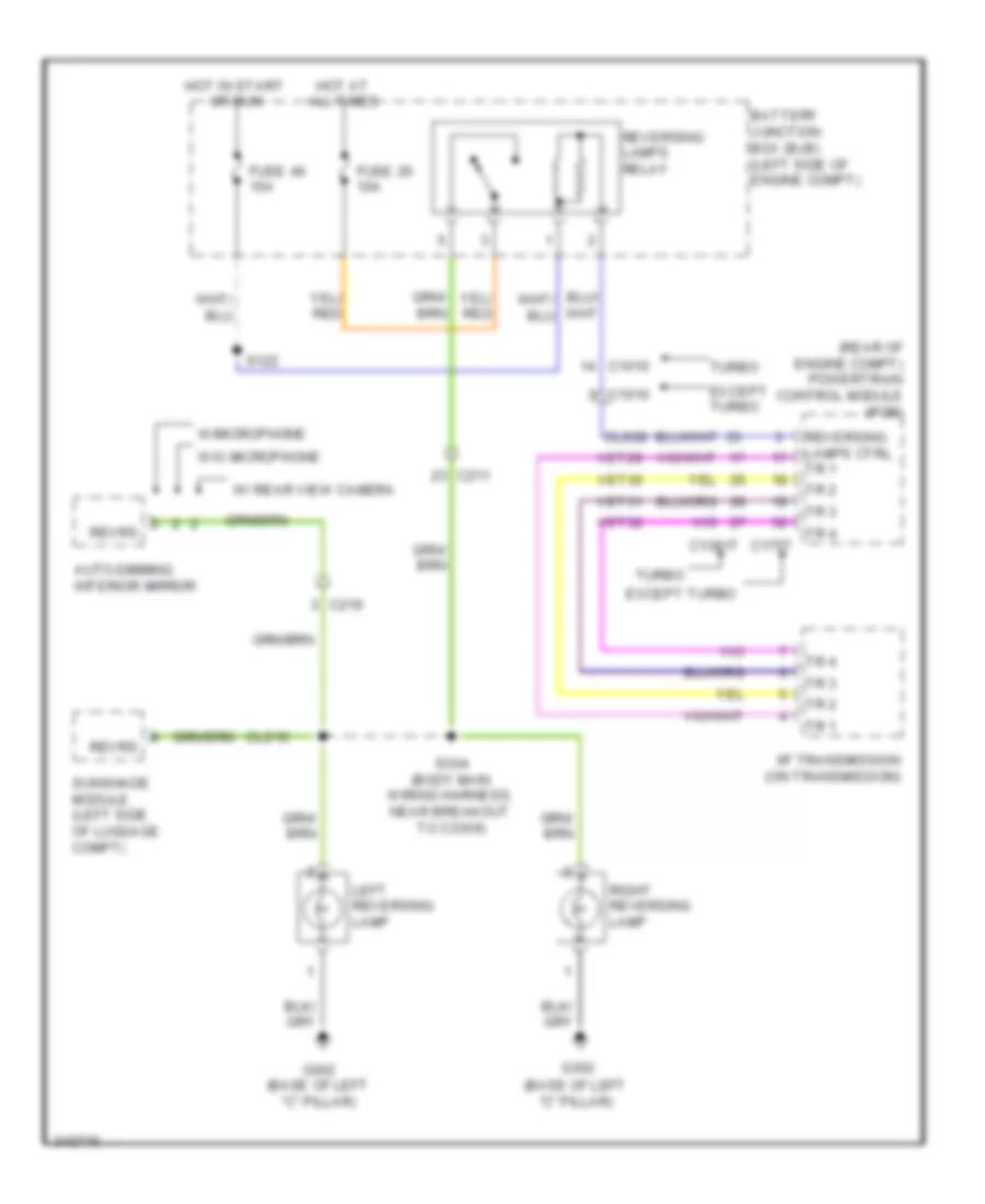
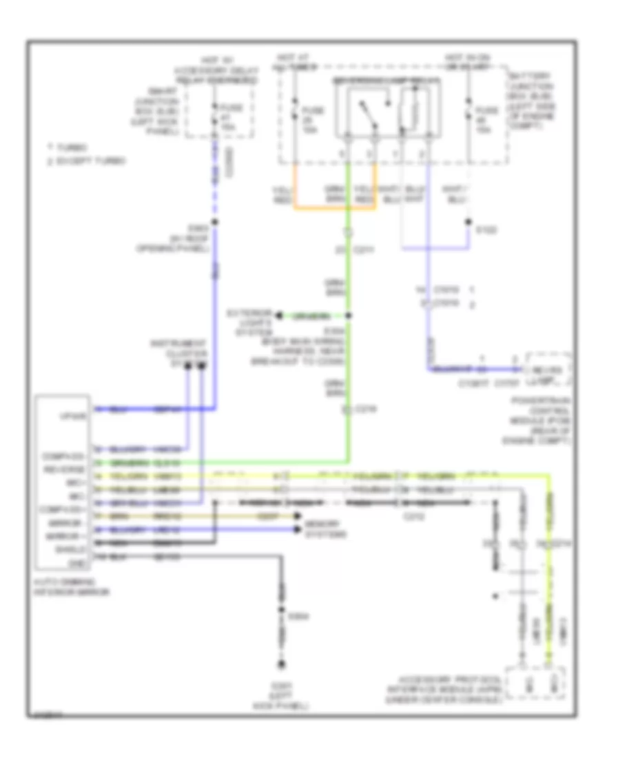
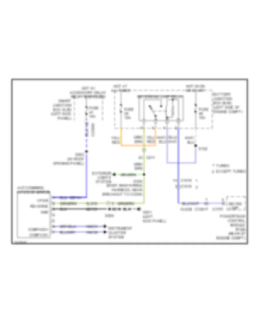
Backup Lamps Wiring Diagram for Ford Taurus SEL 2011
List of elements for Backup Lamps Wiring Diagram for Ford Taurus SEL 2011:
- (base of left "c" pillar)
- (rear of engine compt) powertrain control module (pcm)
- 6f transmission (on transmission)
- Auto-dimming interior mirror
- Battery junction box (bjb) (left side of engine compt)
- C1010
- C1381t
- C175t
- C211
- C219
- Cls10
- Cls28
- Except turbo
- Fuse 26 10a
- Fuse 46 15a
- G302
- G302 (base of left "c" pillar)
- Hot at all times
- Hot in start or run
- Left reversing lamp
- Reversing lamps ctrl tr 1
- Reversing lamps relay
- Revrs
- Right reversing lamp
- S122
- S304 (body main wiring harness, near breakout to c3309)
- Sunshade module (left side of luggage compt)
- Tr 1
- Tr 2
- Tr 3
- Tr 4
- Turbo
- Vet29
- Vet30
- Vet31
- Vet32
- W/ rear view camera
- W/microphone
- W/o microphone
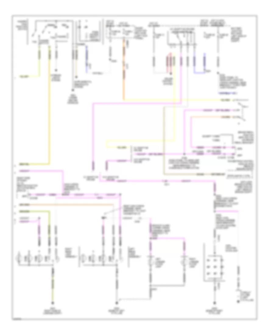
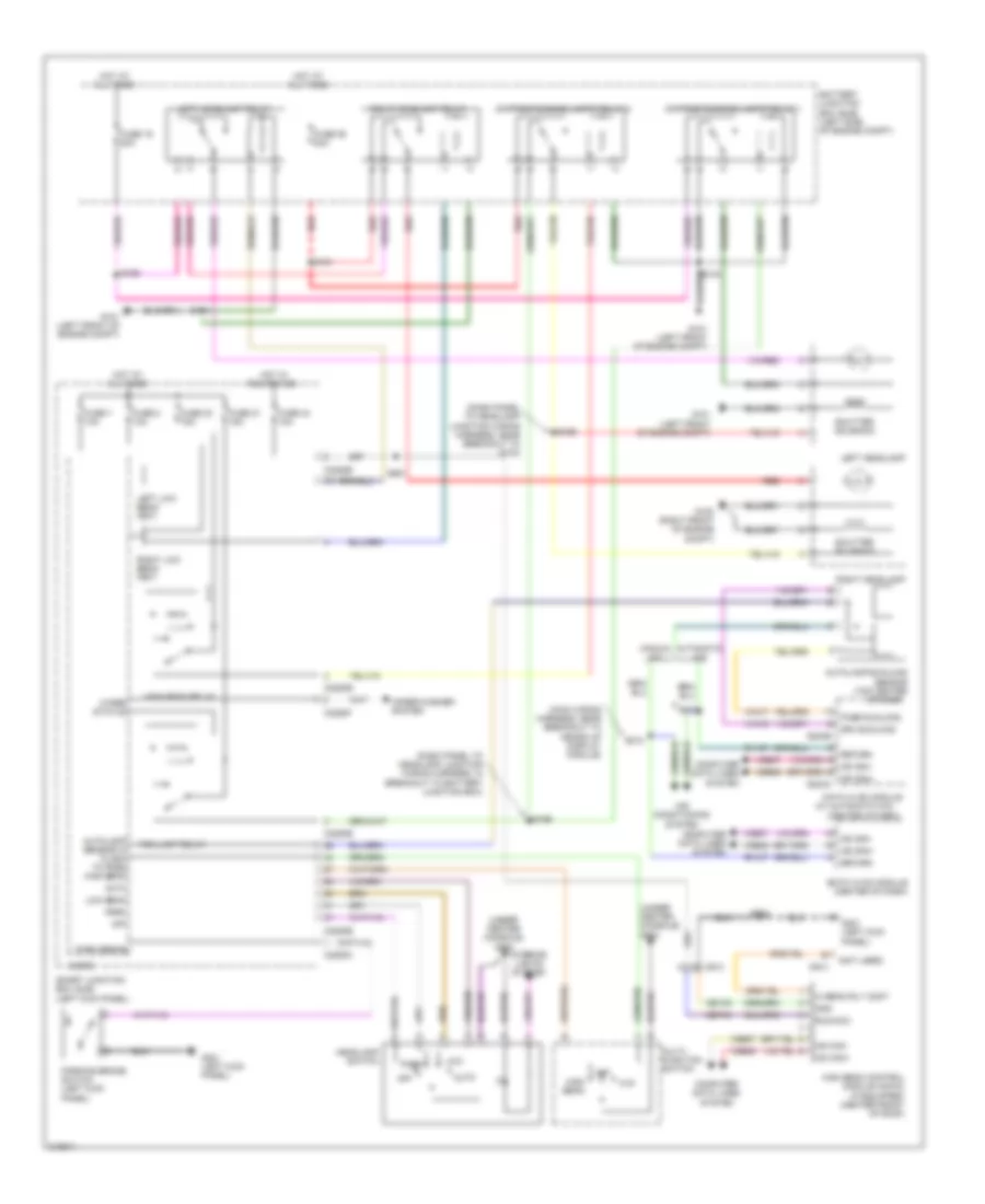
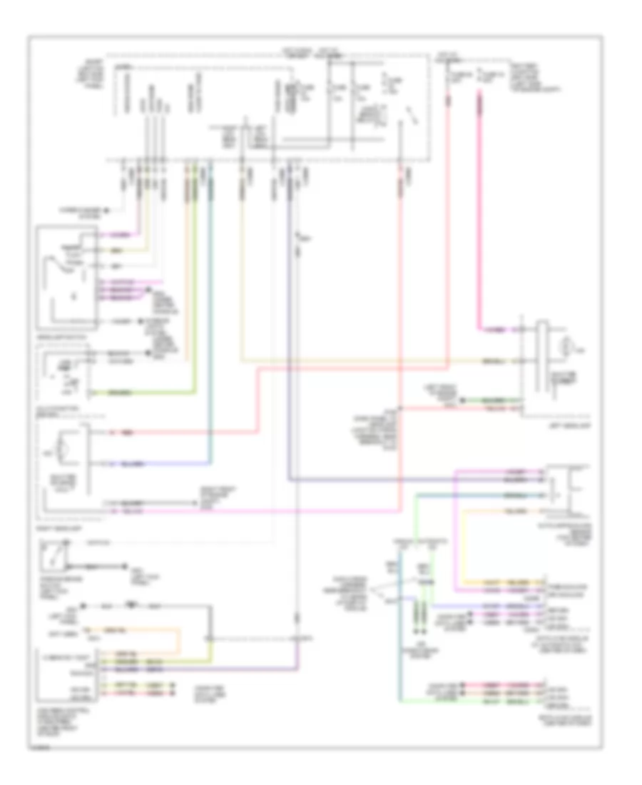
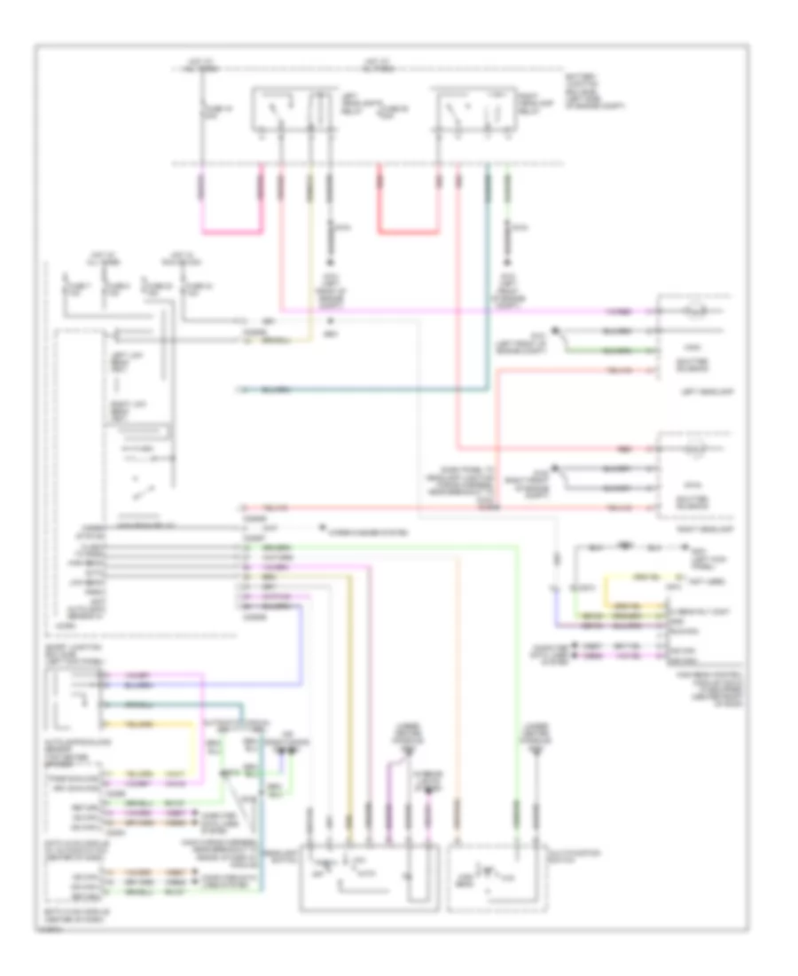
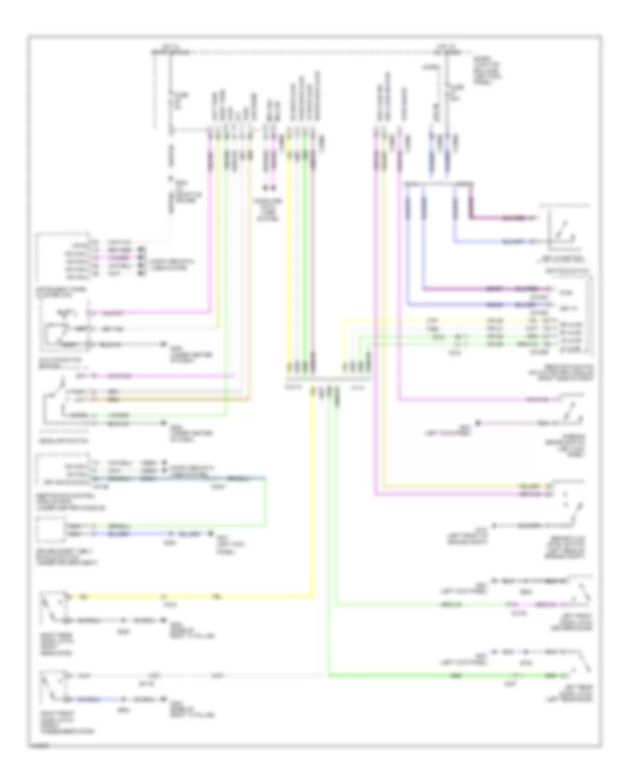
Exterior Lamps Wiring Diagram (1 of 2) for Ford Taurus SEL 2011
List of elements for Exterior Lamps Wiring Diagram (1 of 2) for Ford Taurus SEL 2011:
- (dash panel to headlamp junction wiring harness, near breakout to battery junction box)
- (dash panel to headlamp junction wiring harness, near breakout to engine cooling fan motor) s108
- Auto
- Bpp
- C211
- C2280b
- C2280c
- C2280d
- C2280e
- C2280f
- Computer data lines system
- Fuse 22 15a
- Fuse 6 20a
- G100 (right front of engine compt)
- G101 (left front of engine compt)
- G200 (under center console)
- G301 (left kick panel)
- Gnd
- Hazard
- Headlamp switch
- Hot at all times
- Instrument cluster (ic)
- Left front auxiliary park lamp
- Left front park/ turn lamp
- Left front side marker lamp
- Left front turn lamp (fet)
- Left rear turn lamp (fet)
- Left turn
- Low
- Low beam
- Micro
- Ms can+
- Ms can-
- Multi- function switch
- Off
- Park
- Park lamp relay
- Right front auxiliary park lamp
- Right front park/ turn lamp
- Right front side marker lamp
- Right front turn lamp (fet)
- Right rear turn lamp (fet)
- Right turn
- S117
- Smart junction box (sjb) (left kick panel)
- Traction ctl on/off
- Turn
- W/ auxiliary park lamps
Exterior Lamps Wiring Diagram (2 of 2) for Ford Taurus SEL 2011
List of elements for Exterior Lamps Wiring Diagram (2 of 2) for Ford Taurus SEL 2011:
- (body main wiring harness, near breakout to joint connector 10)
- (main wiring harness, in breakout to c215) s240
- (or cls43) ccb08
- (right side of dash) (w/ ia) remote function actuator (rfa) module
- (w/ adaptive cruise) stoplamp relay
- Amber
- Anti-lock brake system (abs) module (left rear of engine compt)
- Battery junction box (bjb) (left side of engine compt)
- Bpp
- Bps
- Brake pedal position (bpp) switch (on brake pedal bracket)
- C1381b
- C175b
- C211
- C215
- C2153e
- C2280d
- C405
- C405) s405
- C475a
- C475b
- Cca28
- Ccb08
- Ces09
- Circuit filter (left "c" pillar)
- Cruise control system
- Except turbo
- Fuse 13 15a
- Fuse 2 15a
- Fuse 36 20a
- Fuse 46 15a
- Fuse 46 7.5a
- G201 (under center console)
- G302 (base of left "c" pillar)
- G400 (base of right "c" pillar)
- G401 (right side of luggage compt)
- Green
- Hazard
- Hazard switch
- Hazard/ pad/ traction switch
- High mounted stoplamp
- Hot at all times
- Hot in start or run
- Hot w/ pcm power relay energized
- Interior lights system
- Left license plate lamp
- Left rear lamp assembly
- Nca
- Park
- Pass air bag deacti- vation
- Powertrain control module (pcm) (rear of engine compt)
- Red
- Right license plate lamp
- Right rear lamp assembly
- S122 (dash panel to headlamp junction wiring harness, near breakout to battery junction box)
- S168 (dash panel to headlamp junction wiring harness, near breakout to windshield wiper motor)
- S251
- S302 (body main wiring harness, near breakout to joint connector 6)
- S303
- S382
- S406 (body main wiring harness, near breakout to high mounted stoplamp)
- Smart junction box (sjb) (left kick panel)
- Stop
- Stoplamp rly ctrl
- Tcs
- Turbo
- Turn
- W/ adaptive cruise
- W/o adaptive cruise
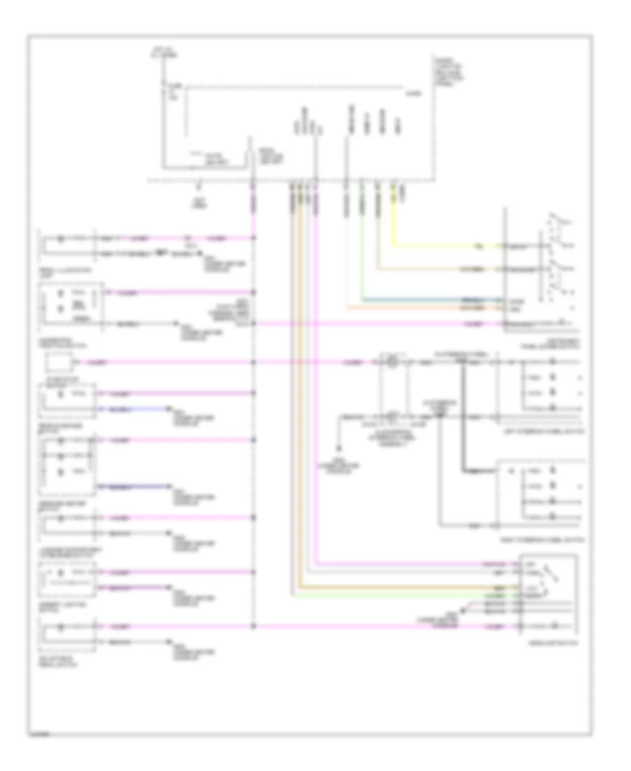
GROUND DISTRIBUTION
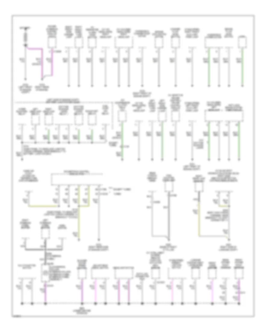
Ground Distribution Wiring Diagram (1 of 3) for Ford Taurus SEL 2011
List of elements for Ground Distribution Wiring Diagram (1 of 3) for Ford Taurus SEL 2011:
- (if equipped) ambient lighting switch
- (if equipped) left front auxiliary park lamp
- (if equipped) right front auxiliary park lamp
- (left side of engine compt) battery junction box (bjb)
- (w/ adaptive cruise control) cruise control module (ccm)
- (w/ blind spot information system (blis)) right side obstacle detection control module (sod-r)
- (w/ halogen headlamps) left headlamp
- (w/ halogen headlamps) right headlamp
- (w/ hid headlamps) left headlamp
- (w/ hid headlamps) right headlamp
- (w/ intelligent access) remote function actuator (rfa) module
- (w/ perimeter alarm) hood switch
- A/c compressor clutch field coil
- Adjustable pedal switch
- Anti-lock brake system (abs) module
- Battery
- Blower motor speed control
- Brake fluid level switch
- C1381b
- C1463b
- C175b
- C214
- C2153c
- C218a
- C218b
- C402b
- C475b
- Clockspring (column: steering column) (steering wheel: steering wheel assembly)
- Data link connector (dlc)
- Daytime running lamps relay 1
- Daytime running lamps relay 2
- Engine cooling fan motor
- Except turbo
- Front cigar lighter
- Front power point console
- Fuel pump (fp) relay
- G c139
- G100 (right front of engine compt)
- G101 (left front of engine compt)
- G102 (right rear side of engine compt)
- G103 (left front of engine compt)
- G104 (right rear of engine)
- G200 (under center console)
- G400 (base of right "c" pillar)
- G401 (right side of luggage compt)
- Headlamp switch
- High mounted stop lamp
- Horn
- Horn switch
- Left front park/ turn lamp
- Left front side marker lamp
- Left headlamp relay
- Left steering wheel switch
- Luggage compartment lid release switch
- Mass air flow/ intake air temperature (maf/iat) sensor
- Multi-function switch
- Nca
- Power steering control module (pscm)
- Powertrain control module (pcm)
- Rear power point console
- Rear window defrost grid
- Right front park/ turn lamp
- Right front side marker lamp
- Right headlamp relay
- Right rear lamp assembly
- Right steering wheel switch
- Run/start relay
- S104 (dash panel to headlamp junction wiring harness, near breakout to battery junction box)
- S116 (dash panel to headlamp junction wiring harness, in breakout to g102)
- S299 (in steering wheel) nca
- S402 (body main wiring harness, near breakout to joint connector 11)
- Turbo
- W/o daytime running lamps
- Washer fluid level switch
- Windshield washer pump motor
- Windshield wiper motor
- Wiper run/park relay
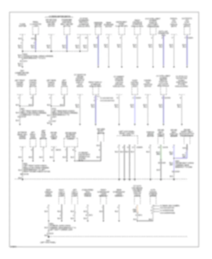
Ground Distribution Wiring Diagram (2 of 3) for Ford Taurus SEL 2011
List of elements for Ground Distribution Wiring Diagram (2 of 3) for Ford Taurus SEL 2011:
- (automatic a/c) hvac module (datc)
- (if equipped) rain sensor module
- (left kick panel) smart junction box (sjb)
- (manual a/c) hvac module (emtc)
- (w/ adaptive cruise control) heads up display (hud) module
- (w/ ambient lighting) interior lighting control module (ilcm)
- (w/ auto high beams) high beam control module (hcm-2)
- (w/ intelligent access) remote function actuator (rfa) module
- (w/ sync w/o navigation) global positioning system module (gpsm)
- (w/ sync) accessory protocol interface module (apim)
- (w/o intelligent access) passive anti-theft transceiver
- Audio control module (acm)
- Auto- dimming interior mirror
- C214
- C2153c
- C2280d
- C228a
- C240a
- C300
- C3138
- C327
- C327)
- C3381
- C341b
- C501b
- C913 d
- C913 e
- Data link connector (dlc)
- Driver door module (ddm)
- Driver safety belt buckle switch/ pretensioner
- Driver seat module (dsm)
- Driver seat position sensor
- Driver side exterior rear view mirror
- Driver side rear seat
- Exterior rear view mirror switch
- Floor shifter
- Front controls interface module (fcim)
- Front display interface module (fdim)
- Front interior/map lamps assembly
- Front power window motor)
- G201 (under center console)
- G301 (left kick panel)
- Hazard/ pad/ traction switch
- Heater switch
- Instrument panel cluster (ipc)
- Keyless entry keypad
- Left front door latch
- Left front power window motor
- Left rear door latch
- Left rear window adjust switch
- Left side door lock switch
- Left vanity mirror lamp
- Master window adjust switch
- Message center switch
- Nca
- Parking brake switch
- Passenger side rear
- Prndl illumination lamp
- Rear interior/map lamps assembly
- Rear sunshade switch
- Right vanity mirror lamp
- Roof opening panel module
- S353 (driver seat wiring harness, near breakout to c356)
- S501 (left front door window regulator wiring harness, in breakout to c504) c3138
- S904 (interior lamps wiring harness, near breakout to left vanity mirror lamp)
- Seat heater switch
- W/ memory & blind spot information system (blis)
- W/ microphone
- W/ navigation
- W/ rear heated seats
- W/ rear view camera w/o navigation
- W/o microphone
- W/o navigation
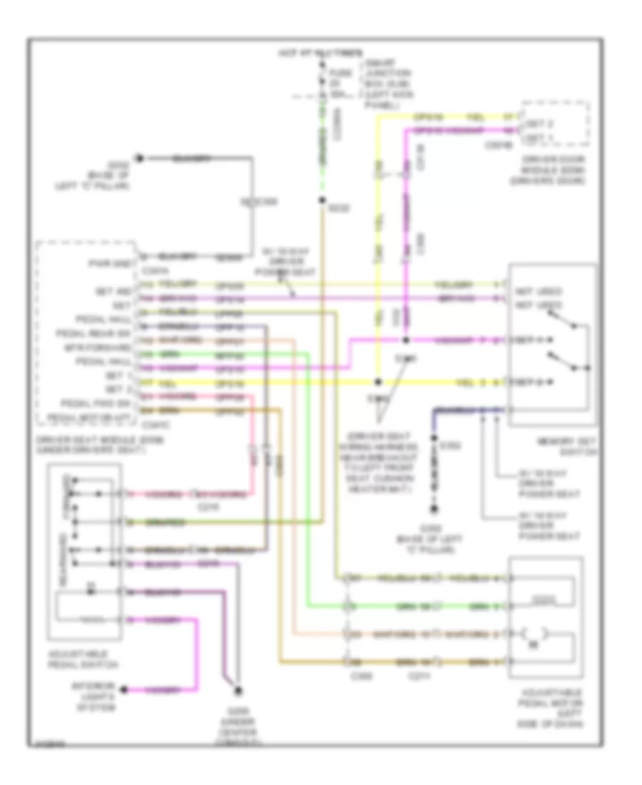
Ground Distribution Wiring Diagram (3 of 3) for Ford Taurus SEL 2011
List of elements for Ground Distribution Wiring Diagram (3 of 3) for Ford Taurus SEL 2011:
- (decklid) video camera
- (if equipped) dual climate controlled seat module (dcsm)
- (spoiler) video camera
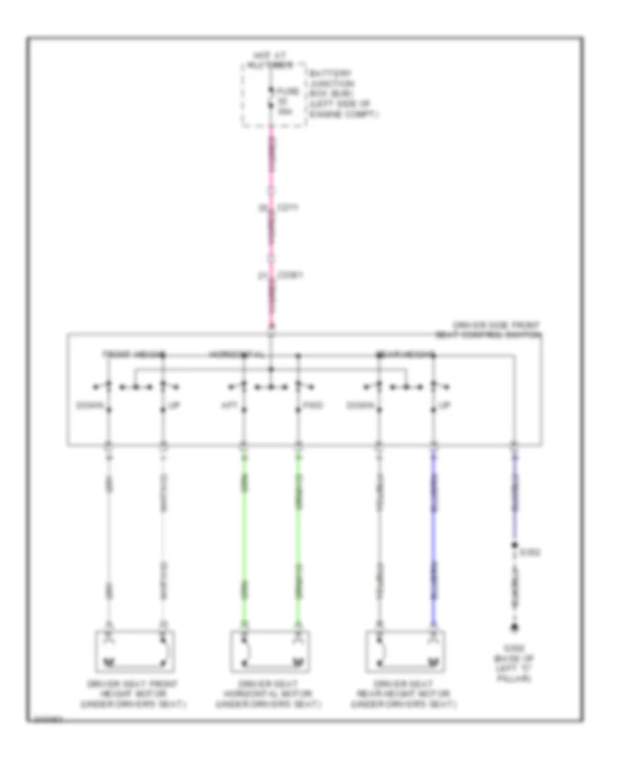
- (w/ 14-way driver power seat) driver seat lumbar control module
- (w/ 14-way driver power seat) driver side front seat control switch
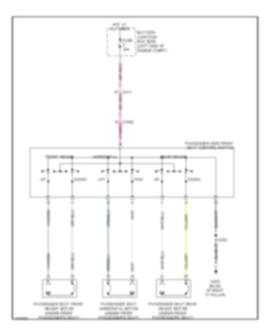
- (w/ 14-way passenger power seat) passenger seat lumbar control module
- (w/ 14-way passenger power seat) passenger side front seat control switch
- (w/ ambient lighting & premium sound) end in harness
- (w/ blind spot information system (blis)) left side obstacle detection control module (sod-l)
- (w/ heated seats) driver side seat backrest heater mat
- (w/ intelligent access) luggage compartment lid release switch
- (w/ sony sound) audio digital signal processing (dsp) module
- All wheel drive (awd) module
- Audio amplifier
- C300
- C3047
- C3050
- C3139
- C316
- C3265a
- C3304b
- C3381
- C3382
- C3385a
- C3386a
- C3387a
- C3388a
- C340
- C341a
- C359b
- C405
- C4208a
- C4326c
- Driver seat module (dsm)
- Driver side front seat control switch
- Fuel pump control module
- Fuel pump control module shield
- G302 (base of left "c" pillar)
- G303 (base of right "c" pillar)
- Harness, near breakout to c3050)
- Heated seat module
- Left license plate lamp
- Left rear lamp assembly
- Left rear seat backrest heater mat
- Left reversing lamp
- Luggage compartment lid release solenoid/ ajar switch
- Memory set switch
- Nca
- Near breakout to occupant classification system module)
- Occupant classification system module (ocsm)
- Parking aid module (pam)
- Passenger safety belt buckle switch/ pretensioner
- Passenger safety belt tension sensor (bts)
- Passenger seat position sensor
- Passenger side exterior rear view mirror
- Passenger side front seat control switch
- Passenger side seat backrest heater mat
- Passenger side window adjust switch
- Rear heated seat module
- Right front door latch
- Right front power window motor
- Right license plate lamp
- Right rear door latch
- Right rear seat backrest heater mat
- Right rear window adjust switch
- Right reversing lamp
- Right side door lock switch
- S323 (body main wiring harness, in breakout to fuel pump driver module)
- S332 (seat heated pad wiring harness, near breakout to right rear seat cushion heater mat)
- S351 (passenger seat wiring harness, near breakout to c312)
- S379 (seat back wiring harness, near breakout to passenger seat lumbar control module)
- S604 (right front door window regulator wiring harness, near breakout to c3139)
- S800 (right rear door window regulator wiring harness, near breakout to c316)
- Sunshade module
- To driver seat lumbar control module) s376
- W/ 10 way passenger power seat
- W/ 10-way driver power seat w/ memory
- W/ 14-way driver power seat w/ memory
- W/ 6 or 10 way passenger power seat
- W/ 6 way passenger power seat
- W/ 6-way driver power seat w/o memory
- W/ heated seats
- W/ memory & blind spot information system (blis)
- W/ passenger power seat
- W/ rear heated seats
- W/ sho limited
- W/o sho limited
- Wiring harness, near breakout to left license plate lamp)
HEADLIGHTS
Headlights Wiring Diagram, with DRL & Halogen Lamps for Ford Taurus SEL 2011
List of elements for Headlights Wiring Diagram, with DRL & Halogen Lamps for Ford Taurus SEL 2011:
- (center of dash)
- (dash panel to headlamp junction wiring harness, in breakout to battery junction box)
- (dash panel to headlamp junction wiring harness, near breakout to g103)
- (main wiring harness, near breakout to heads up display module)
- (not used)
- (under center console) g200
- (w/ automatic a/c)
- Air conditioning system
- Auto
- Autolamp sensor in flash to pass high beam
- Autolamp/sunload sensor (top center
- Automatic a/c
- Battery junction box (bjb) (left side of engine compt)
- C2280b
- C2280c
- C2280e
- C2280f
- C228a
- C228b
- C913
- Cbp43
- Computer data lines system
- D c913
- Datc hvac module
- Daytime running lamps relay 1
- Daytime running lamps relay 2
- Drv sunload
- Emtc hvac module (center of dash)
- Fog lamp relay
- Ftp
- Fuse 16 20a
- Fuse 21 15a
- Fuse 23 15a
- Fuse 25 20a
- Fuse 43 10a
- Fuse 7 10a
- Fuse 8 10a
- G100 (right front of engine compt)
- G101 (left front of engine compt)
- G301 (left kick panel)
- Gd133
- Gnd
- Headlamp switch
- Hi beam rly cont
- High beam
- High beam control module (hcm-2) (if equipped) (center front of roof)
- High beam relay
- Hot at all times
- Hot in run or acc
- Interior lights system
- Left headlamp
- Left headlamp relay
- Left low beam (fet)
- Low
- Low beam
- Manual a/c
- Micro
- Ms can+
- Ms can-
- Multi- function switch
- Of dash)
- Off
- Park
- Park brake
- Parking brake switch (left kick panel)
- Pass sunload
- Red
- Return
- Rh107
- Right headlamp
- Right headlamp relay
- Right low beam (fet)
- Run/acc
- S104
- S126
- S161
- S163
- S166
- S210
- S901
- S904
- Shutter solenoid
- Smart junction box (sjb) (left kick panel)
- Vdb06
- Vdb07
- Vh416
- Vh417
- Wiper status
- Wiper/washer system
Headlights Wiring Diagram, with High Intensity Gas Discharge Headlights for Ford Taurus SEL 2011
List of elements for Headlights Wiring Diagram, with High Intensity Gas Discharge Headlights for Ford Taurus SEL 2011:
- (center of dash)
- (left front of engine compt) g101
- (left kick
- (main wiring harness, near breakout to heads up display module)
- (not used)
- (right front of engine compt) g100
- (under center console) g200
- (w/ automatic a/c)
- Air conditioning system
- Auto
- Auto lamp sensor in
- Autolamp/sunload sensor (top center
- Automatic a/c
- Battery junction box (bjb) (left side of engine compt)
- C2280b
- C2280c
- C2280e
- C2280f
- C228a
- C228b
- C913
- Cbp43
- Computer data lines system
- Datc hvac module
- Drv sunload
- Emtc hvac module (center of dash)
- Flash to pass
- Ftp
- Fuse 10a
- Fuse 15a
- Fuse 16 20a
- Fuse 25 20a
- G200 (under center console)
- G301
- G301 (left kick panel)
- Gd133
- Gnd
- H c913
- Headlamp switch
- Hi beam rly cont
- Hid
- High beam
- High beam control module (hcm-2) (if equipped) (center front of roof)
- High beam relay
- Hot at all times
- Hot in run or acc
- Interior lights system
- Left headlamp
- Left low beam (fet)
- Low
- Low beam
- Manual a/c
- Micro
- Ms can+
- Ms can-
- Multi-function switch
- Of dash)
- Off
- Panel)
- Park
- Park brake
- Parking brake switch (left kick panel)
- Pass sunload
- Red
- Return
- Rh107
- Right headlamp
- Right low beam (fet)
- Run/acc
- S126 (dash panel to headlamp junction wiring harness, near breakout to g103)
- S210
- S901
- S904
- Shutter solenoid
- Smart junction box (sjb) (left kick panel)
- Vdb06
- Vdb07
- Vh416
- Vh417
- Wiper status
- Wiper/washer system
Headlights Wiring Diagram, without DRL, with Halogen Lamps for Ford Taurus SEL 2011
List of elements for Headlights Wiring Diagram, without DRL, with Halogen Lamps for Ford Taurus SEL 2011:
- (dash panel to headlamp junction wiring harness, near breakout to g103) s126
- (main wiring harness, near breakout to heads up display module)
- (not used)
- (under center console) g200
- Air conditioning system
- Auto
- Autolamp/sunload sensor (top center of dash)
- Automatic a/c
- Battery junction box (bjb) (left side of engine compt)
- C2280b
- C2280e
- C2280f
- C228a
- C228b
- C913
- Cbp43
- Computer data lines system
- Datc hvac module (w/ automatic a/c) (center of dash)
- Drv sunload
- Emtc hvac module (center of dash)
- Flash to pass
- Ftp
- Fuse 16 20a
- Fuse 23 15a
- Fuse 25 20a
- Fuse 43 10a
- Fuse 7 10a
- Fuse 8 10a
- G100 (right front of engine compt)
- G101 (left front of engine compt)
- G301 (left kick panel)
- Gd133
- Gnd
- Headlamp switch
- Hi beam rly cont
- High beam
- High beam control module (hcm-2) (if equipped) (center front of roof)
- High beam relay
- Hot at all times
- Hot in run or acc
- Interior lights system
- Left headlamp
- Left headlamp relay
- Left low beam (fet)
- Low
- Low beam
- Manual a/c
- Micro
- Ms can+
- Ms can-
- Multi-function switch
- Off
- Off autolamp sensor in
- Park
- Pass sunload
- Red
- Return
- Rh107
- Right headlamp
- Right headlamp relay
- Right low beam (fet)
- Run/acc
- S104
- S210
- S901
- S904
- Shutter solenoid
- Smart junction box (sjb) (left kick panel)
- Vdb06
- Vdb07
- Vh416
- Vh417
- Wiper status
- Wiper/washer system
HORN
Horn Wiring Diagram for Ford Taurus SEL 2011
List of elements for Horn Wiring Diagram for Ford Taurus SEL 2011:
- (left front of engine compt) horn
- C218a
- C218b
- C2280b
- C2280e
- Clockspring (column: steering column) (steering wheel: steering wheel assembly)
- Fuse 20a
- G101 (left front of engine compt)
- G200 (under center console)
- Horn relay
- Horn switch
- Hot at all times
- Micro
- Nca
- S299
- Smart junction box (sjb) (left kick panel)
INSTRUMENT CLUSTER
Instrument Cluster Wiring Diagram (1 of 2) for Ford Taurus SEL 2011
List of elements for Instrument Cluster Wiring Diagram (1 of 2) for Ford Taurus SEL 2011:
- (under center console) g201
- Anti-lock brakes system
- Anti-theft system
- C1010
- C210
- C212
- C215
- C228oa
- C228ob
- C3309
- Cbp29
- Cca15
- Cet52
- Cmc20
- Cmc24
- Cmc29
- Compass+
- Compass-
- Computer data lines system
- Epats rx
- Epats tx
- Fuel level input 1
- Fuel level input 2
- Fuel level sender (w/ dual sender saddle type fuel tank) (fuel tank assembly)
- Fuel pump (fp) module (fuel tank assembly)
- Fuel return
- Fuse 10a
- Fuse 5a
- Gd114
- Gnd
- Heads up display (hud) module (w/ adaptive cruise) (top left side of dash)
- Hot at all times
- Hot in start or run
- Hs can+
- Hs can-
- Info
- Instrument panel cluster (ipc)
- Interior lights system
- Low washer
- Message center switch
- Message return
- Message signal
- Ms can+
- Ms can-
- Nca
- Oil press
- Oil pressure switch (lower left side of engine block)
- Park detect
- Pnk
- Reset
- Rmc27
- Rmc32
- Rmc33
- Run/start
- Sbp26
- Setup
- Shift interlock system
- Smart junction box (sjb) (left kick panel)
- Traction ctl on/off
- Vbatt
- Vdb04
- Vdb05
- Vdb06
- Vdb07
- Vmc11
- Vmc23
- Vmc30
- Vmc31
- Vpwr
- Vrt23
- Vrt24
- Wiper/washer system
Instrument Cluster Wiring Diagram (2 of 2) for Ford Taurus SEL 2011
List of elements for Instrument Cluster Wiring Diagram (2 of 2) for Ford Taurus SEL 2011:
- (w/ microphone)
- (w/o microphone)
- Ajar sw luggage comp
- Auto-dimming interior mirror
- Brake fluid level switch (left rear of engine compt)
- Brk fl sw
- Brk fluid sw rtn
- C212
- C215
- C2153d
- C2153e
- C2280b
- C2280c
- C2280f
- C237
- C3138
- C3139
- C316
- C327
- Cdc30
- Cdc41
- Compass +
- Compass -
- Computer data lines system
- Cpl26
- Cpl31
- Cpl36
- Cpl39
- Cpl58
- Driver dr ajar
- G101 (left front of engine compt)
- G301 (left kick panel)
- G302 (base of left "c" pillar)
- G303 (base of right "c" pillar)
- Hot at all times
- Hs can+
- Hs can-
- Ignition switch
- Key in
- Key in ign
- Key in ignition
- Left front door latch (driver's door)
- Left rear door latch (left rear door)
- Lf ajar
- Lr ajar
- Lr dr ajar
- Luggage compartment lid release solenoid (center rear of luggage compartment lid)
- Ms can +
- Ms can -
- Park brake sw
- Park detect
- Parking brake switch (left kick panel)
- Pass dr ajar
- Remote function actuator (rfa) module (right side of dash)
- Rf ajar
- Right front door latch (front passenger's door)
- Right rear door latch (right rear door)
- Rr ajar
- Rr dr ajar
- S500
- S604
- S700
- S800
- Shift interlock system
- Smart junction box (sjb) (left kick panel)
- Trunk ajar
- Vdb04
- Vdb05
- W/ auto- dimming interior mirror
- W/ ia
- W/ rear view camera display mirror
- W/o ia
INTERIOR LIGHTS
Courtesy Lamps Wiring Diagram (1 of 2) for Ford Taurus SEL 2011
List of elements for Courtesy Lamps Wiring Diagram (1 of 2) for Ford Taurus SEL 2011:
- (driver's door) driver side exterior rear view mirror
- (interior lamps wiring harness, near breakout to remote functions receiver module) s906
- (not used)
- (right rear door)
- Ajar
- Ajar fl
- Ajar fr
- Ajar lr
- Ajar rr
- Battery saver relay
- C1381b
- C212
- C215
- C2153d
- C2153e
- C219
- C2280a
- C2280b
- C2280c
- C2280d
- C3138
- C3139
- C316
- C327
- Computer data lines system
- Cpl26
- Cpl31
- Cpl36
- Cpl39
- Dim down
- Dim sw gnd
- Dim up
- Dome
- Dome lp
- Drv door ajar
- Front interior/map lamps assembly
- Fuse 10a
- Fuse 15a
- Fuse 2a
- G301 (left kick panel)
- G302 (base of left "c" pillar)
- G303 (base of right "c" pillar)
- Gnd
- Homelink module
- Hot at all times
- Hs can+
- Hs can-
- Instrument illumination circuit
- Instrument panel dimmer switch
- Interior lighting (fet)
- Left front door latch (driver's door)
- Left rear door latch (left rear door)
- Left vanity mirror lamp
- Lr door ajar
- Luggage compartment lamp
- Luggage compartment lid release solenoid ajar switch (center rear of luggage compt lid)
- Micro
- Off
- Pass door ajar
- Passenger side exterior rear view mirror (passenger's door)
- Powertrain control module (pcm) (turbo) (rear of engine compt)
- Puddle led (fet)
- Pwm input
- Rear interior/map lamps assembly
- Red
- Remote function actuator (rfa) module (right side of dash)
- Right front door latch (front passenger's door)
- Right rear door latch
- Right vanity mirror lamp
- Rr door ajar
- S206
- S320
- S384 (body main wiring harness, near breakout to parking brake switch)
- S500
- S604
- S700
- S800
- S902
- S904
- Smart junction box (sjb) (left kick panel)
- Trunk, tailgate, fuel doors system
- Vdb04
- Vdb05
- W/ ia
- W/o ia
Courtesy Lamps Wiring Diagram (2 of 2) for Ford Taurus SEL 2011
List of elements for Courtesy Lamps Wiring Diagram (2 of 2) for Ford Taurus SEL 2011:
- (body main wiring harness, near breakout to c311)
- (body main wiring harness, near breakout to parking brake switch)
- (main wiring harness, in breakout to interior lighting control module)
- Ambient lighting switch
- C212
- C214
- C215
- C3138
- C3139
- C314
- Cln44
- Cln45
- Cln46
- Cln48
- Cln49
- Cln50
- Cln51
- Cln52
- Cln53
- Cln55
- Cln60
- Computer data lines system
- Dim up
- Door release handle
- G200 (under center console)
- G201 (under center console)
- Gd114
- Gnd
- Instrument illumination circuit
- Interior lighting control module (ilcm) (w/ ambient lighting) (right side of dash)
- Led return
- Led-green
- Led-red
- Led-return
- Left front door led
- Left front footwell lamp
- Left rear footwell lamp
- Map pocket
- Ms can+
- Ms can-
- Nca
- Pigtail harness
- Pull handle
- Right front door led
- Right front footwell lamp
- Right rear footwell lamp
- Rln44
- S230
- S231
- S232
- S233 (main wiring harness, in breakout to interior lighting control module)
- S369 (ambient lighting center console wiring harness, near breakout to storage bin light)
- S385
- S386
- S387
- S394
- Sbp16
- Storage bin lamp
- Sw pushbutton
- Sw up
- Toggle
- Top finish panel lamp
- Vbatt
- Vdb06
- Vdb07
- Z1-green
- Z1-red
- Z2-green
- Z2-red
- Z3-green
- Z3-red
Instrument Illumination Wiring Diagram for Ford Taurus SEL 2011
List of elements for Instrument Illumination Wiring Diagram for Ford Taurus SEL 2011:
- (in steering wheel) s215
- (in steering wheel) s299
- (not used)
- Adjustable pedal switch
- Ambient lighting switch
- Auto
- Back- lighting led (fet)
- C214
- C218a
- C218b
- C2280b
- Clockspring (steering wheel assembly)
- Dim down
- Dim sw gnd
- Dim up
- Dome
- Dome lp
- Fuse 15a
- G200 (under center console)
- G201 (under center console)
- Gnd
- Green
- Hazard/pad/ traction switch
- Headlamp switch
- Hot at all times
- Instrument panel dimmer switch
- Left steering wheel switch
- Low
- Low beam
- Luggage compartment lid release switch
- Message center switch
- Micro
- Nca
- Off
- Park
- Prndl illumination lamp
- Pwm input
- Rear sunshade switch
- Red
- Right steering wheel switch
- S221 (main wiring harness, near breakout to c214)
- S340
- Smart junction box (sjb) (left kick panel)
- Start/stop switch
- White led (fet)
MEMORY SYSTEMS
Adjustable Pedal Wiring Diagram for Ford Taurus SEL 2011
List of elements for Adjustable Pedal Wiring Diagram for Ford Taurus SEL 2011:
- (driver seat wiring harness, near breakout to left front seat cushion heater mat)
- Adjustable pedal motor (left side of dash)
- Adjustable pedal switch
- C211
- C215
- C2280a
- C300
- C3138
- C341a
- C341c
- C501b
- Cpp01
- Cpp02
- Cpp09
- Cpp10
- Cps14
- Cps15
- Cps16
- Cps55
- Driver door module (ddm) (driver's door)
- Driver seat module (dsm) (under driver's seat)
- Forward
- Fuse 15a
- G200 (under center console)
- G302 (base of left "c" pillar)
- Gd906
- Hot at all times
- Interior lights system
- Lpp06
- Memory set switch
- Mtr forward
- Not used
- Pedal fwd sw
- Pedal hall
- Pedal motor aft
- Pedal rear sw
- Pwr gnd
- Rearward
- Rpp06
- S222
- S345
- S346
- S352
- Set
- Set 1
- Set 2
- Set ind
- Smart junction box (sjb) (left kick panel)
- W/ 10 way driver power seat
- W/ 14 way driver power seat
Driver"s Memory Seat Wiring Diagram, 10-Way Driver Seat (1 of 2) for Ford Taurus SEL 2011
List of elements for Driver"s Memory Seat Wiring Diagram, 10-Way Driver Seat (1 of 2) for Ford Taurus SEL 2011:
- (driver seat wiring harness, near breakout to left front seat cushion heater mat)
- (not used)
- Adj pedal fwd sw
- Adj pedal rwd sw
- Adjustable pedal circuit
- Aft
- Base backward
- Base forward
- Battery junction box (bjb) (left side of engine compt)
- C2280d
- C300
- C3138
- C341a
- C341b
- C341c
- C341d
- C501b
- Cbx03
- Cbx05
- Computer data lines system
- Cpm04
- Cpm16
- Cpm17
- Cpm20
- Cpm21
- Cpm22
- Cpm26
- Cpm28
- Cpm29
- Cpm31
- Cpm33
- Cpm34
- Cpm39
- Cpp01
- Cpp02
- Cpp03
- Cpp04
- Cpp09
- Cpp10
- Cpp12
- Cpp13
- Cpp14
- Cpp22
- Cpp23
- Cps01
- Cps02
- Cps03
- Cps04
- Cps05
- Cps06
- Cps07
- Cps08
- Cps14
- Cps15
- Cps16
- Cps23
- Cps24
- Cps25
- Cps26
- Cps27
- Cps28
- Cps29
- Cps30
- Cps55
- Driver door module (ddm) (driver's door)
- Driver seat module (dsm) (under driver's seat)
- Drv mirr horz pot
- Drv mirr horz sw
- Drv mirr mtr dn/lt
- Drv mirr mtr horz rt
- Drv mirr mtr vert up
- Drv mirr vert pot
- Drv mirr vert sw
- Ext mirr pot feed
- Forward
- Front down
- Front up
- Fuse 10a
- Fuse 15a
- Fuse 30a
- G301 (left kick panel)
- G302 (base of left "c" pillar)
- Gd905
- Gd906
- Hall effect feed
- Hall effect return
- Hall effect sens rtn
- Hall effect sense
- Hot at all times
- Incline
- Logic gnd
- Lpm30
- Lpp06
- Memory mirrors circuit
- Memory set switch
- Mirr com sw
- Mirr mtr fold in
- Mirr mtr fold out
- Mirr pot ret
- Mirror fold sw
- Ms can+
- Ms can-
- Not used
- Pass mirr horz pot
- Pass mirr horz sw
- Pass mirr mtr dn/lt
- Pass mirr mtr horz rt
- Pass mirr mtr vert up
- Pass mirr vert pot
- Pass mirr vert sw
- Pedal hall effect feed
- Pedal motor aft
- Pedal motor fwd
- Pwr gnd
- Rear down
- Rear up
- Recline
- Rpm11
- Rpm30
- Rpp06
- Rps13
- S345
- S346
- S352
- S372
- Set
- Set 1
- Set 2
- Set ind
- Smart junction box (sjb) (left kick panel)
- Steering com/bat logic
- Str col pos fd/back
- Tel fwd
- Tel rwd
- Telescope dn sw
- Telescope mtr dn
- Telescope mtr up
- Telescope up sw
- Vbatt
- Vdb06
- Vdb07
- Vpm35
- Vpm36
- Vpm37
- Vpm38
- Vpp08
- Vpp17
- Vps09
- Vps10
- Vps11
- Vps12
Driver"s Memory Seat Wiring Diagram, 10-Way Driver Seat (2 of 2) for Ford Taurus SEL 2011
List of elements for Driver"s Memory Seat Wiring Diagram, 10-Way Driver Seat (2 of 2) for Ford Taurus SEL 2011:
- Aft
- C3050
- Deflate
- Down
- Driver seat front height motor (under driver's seat)
- Driver seat horizontal motor (under driver's seat)
- Driver seat lumbar motor (in driver's seat back)
- Driver seat rear height motor (under driver's seat)
- Driver seat recliner motor (in driver's seat back)
- Driver side front seat control switch
- Fore
- Front height
- G302 (base of left "c" pillar)
- Horizontal
- Incline
- Inflate
- Lumbar
- Rear height
- Recline
- S352
- S368 (driver seat wiring harness, near breakout to c3050)
Driver"s Memory Seat Wiring Diagram, 14-Way Driver Seat (1 of 2) for Ford Taurus SEL 2011
List of elements for Driver"s Memory Seat Wiring Diagram, 14-Way Driver Seat (1 of 2) for Ford Taurus SEL 2011:
- (driver seat wiring harness, near breakout to left front seat cushion heater mat) s345
- (not used)
- Adj pedal fwd sw
- Adj pedal rwd sw
- Adjustable pedal circuit
- Aft
- Base backward
- Base forward
- Battery junction box (bjb) (left side of engine compt)
- C2280d
- C300
- C3138
- C341a
- C341b
- C341c
- C341d
- C501b
- Cbx03
- Cbx05
- Computer data lines system
- Cpm04
- Cpm16
- Cpm17
- Cpm20
- Cpm21
- Cpm22
- Cpm26
- Cpm28
- Cpm29
- Cpm31
- Cpm33
- Cpm34
- Cpm39
- Cpp01
- Cpp02
- Cpp03
- Cpp04
- Cpp09
- Cpp10
- Cpp12
- Cpp13
- Cpp14
- Cpp22
- Cpp23
- Cps01
- Cps02
- Cps03
- Cps04
- Cps05
- Cps06
- Cps07
- Cps08
- Cps15
- Cps16
- Cps23
- Cps24
- Cps25
- Cps26
- Cps27
- Cps28
- Cps29
- Cps30
- Driver door module (ddm) (driver's door)
- Driver seat lumbar pump (in driver's seat back)
- Driver seat module (dsm) (under driver's seat)
- Drv mirr horz pot
- Drv mirr horz sw
- Drv mirr mtr dn/lt
- Drv mirr mtr horz rt
- Drv mirr mtr vert up
- Drv mirr vert pot
- Drv mirr vert sw
- Ext mirr pot feed
- Forward
- Front down
- Front up
- Fuse 10a
- Fuse 15a
- Fuse 30a
- G301 (left kick panel)
- G302 (base of left "c" pillar)
- Gd905
- Gd906
- Hall effect feed
- Hall effect return
- Hall effect sens rtn
- Hall effect sense
- Hot at all times
- Hot in run or start
- Incline
- Logic gnd
- Lpm30
- Lpp06
- Memory mirrors circuit
- Memory set switch
- Mirr com sw
- Mirr mtr fold in
- Mirr mtr fold out
- Mirr pot ret
- Mirror fold sw
- Ms can+
- Ms can-
- Pass mirr horz pot
- Pass mirr horz sw
- Pass mirr mtr dn/lt
- Pass mirr mtr horz rt
- Pass mirr mtr vert up
- Pass mirr vert pot
- Pass mirr vert sw
- Pedal hall effect feed
- Pedal motor aft
- Pedal motor fwd
- Pwr gnd
- Rear down
- Rear up
- Recline
- Rpm11
- Rpm30
- Rpp06
- Rps13
- S308
- S346
- S352
- S372
- Set 1
- Set 2
- Smart junction box (sjb) (left kick panel)
- Steering com/bat logic
- Str col pos fd/back
- Tel fwd
- Tel rwd
- Telescope dn sw
- Telescope mtr dn
- Telescope mtr up
- Telescope up sw
- Vbatt
- Vdb06
- Vdb07
- Vpm35
- Vpm36
- Vpm37
- Vpm38
- Vpp08
- Vpp17
- Vps09
- Vps10
- Vps11
- Vps12
Driver"s Memory Seat Wiring Diagram, 14-Way Driver Seat (2 of 2) for Ford Taurus SEL 2011
List of elements for Driver"s Memory Seat Wiring Diagram, 14-Way Driver Seat (2 of 2) for Ford Taurus SEL 2011:
- (driver seat wiring harness, near breakout to c3050) s368
- Aft
- C3050
- C3381
- C3385a
- C3385b
- C3387a
- C3387b
- Cps18
- Cps19
- Cps64
- Cps65
- Cpt05
- Cpt36
- Deflate
- Down
- Driver seat front height motor (under driver's seat)
- Driver seat horizontal motor (under driver's seat)
- Driver seat lumbar control module (in driver's seat back)
- Driver seat rear height motor (under driver's seat)
- Driver seat recliner motor (in driver's seat back)
- Driver side front seat control switch
- Feed
- Fore
- Front height
- G302 (base of left "c" pillar)
- Gd904
- Gnd
- Horizontal
- Incline
- Inflate
- Lumbar
- Massage
- Motion
- Motion/ massage
- Motion/massage
- Rear height
- Recline
- Red
- Rpt05
- Rtn
- S352
- S376
- Sbx06
- Vbatt
Memory Mirrors Wiring Diagram for Ford Taurus SEL 2011
List of elements for Memory Mirrors Wiring Diagram for Ford Taurus SEL 2011:
- (base of left "c" pillar) g302
- (driver seat wiring harness, near breakout to left front seat cushion heater mat)
- (passenger's door) passenger side exterior rear view mirror
- Battery junction box (bjb) (left side of engine compt)
- C2280d
- C300
- C3138
- C3139
- C341a
- C341b
- C341c
- C341d
- C501a
- C501b
- Cbx03
- Cbx05
- Computer data lines system
- Cpm16
- Cpm17
- Cpm20
- Cpm21
- Cpm23
- Cpm26
- Cpm28
- Cpm29
- Cpm31
- Cpm33
- Cpm34
- Cps14
- Cps15
- Cps16
- Cps55
- Defogger system
- Driver door module (ddm) (driver's door)
- Driver seat module (dsm) (under driver's seat)
- Driver side exterior rear view mirror (driver's door)
- Drv mirr horz pot
- Drv mirr horz sw
- Drv mirr mtr dn/lt
- Drv mirr mtr horz rt
- Drv mirr mtr vert up
- Drv mirr vert pot
- Drv mirr vert sw
- Ext mirr pot feed
- Exterior rear view mirror switch
- Fuse 10a
- Fuse 30a
- Fuse 5a
- G301 (left kick panel)
- G302 (base of left "c" pillar)
- Gd133
- Gd905
- Gd906
- Gnd
- Hot at all times
- Interior lights system
- Logic gnd
- Lpm30
- Memory set switch
- Mirr com sw
- Mirr pot ret
- Mirrors system
- Ms can+
- Ms can-
- Navigation system
- Nca
- Not used
- Pass mir horz pot
- Pass mir vert pot
- Pass mirr dn/lt
- Pass mirr horz rt
- Pass mirr horz sw
- Pass mirr vert sw
- Pass mirr vert up
- Rpm30
- S345
- S346
- S352
- S372
- S500
- S502
- Sbp13
- Select
- Set
- Set 1
- Set 2
- Set ind
- Smart junction box (sjb) (left kick panel)
- Vbatt
- Vdb06
- Vdb07
- Vpm35
- Vpm36
- Vpm37
- Vpm38
- W/ 10 way driver power seat
- W/ 14 way driver power seat
NAVIGATION
Blind Spot Information System Wiring Diagram for Ford Taurus SEL 2011
List of elements for Blind Spot Information System Wiring Diagram for Ford Taurus SEL 2011:
- (left kick panel) g301
- (passenger's door) passenger side exterior rear view mirror
- Alert
- C2280d
- C3138
- C3139
- Cbp35
- Computer data lines system
- Crb02
- Crb04
- Driver side exterior rear view mirror (driver's door)
- Fuse 10a
- G302 (base of left "c" pillar)
- G303 (base of right "c" pillar)
- G401 (right side of luggage compt)
- Gd148
- Gd149
- Gnd
- Hot in run or start
- Left exterior mirror blind spot (blis)/ cross traffic alert (cta) led
- Left side obstacle detection control module (sod-l) (left end of rear bumper)
- Ms can+
- Ms can-
- Nca
- Right exterior mirror blind spot (blis)/ cross traffic alert (cta) led
- Right side obstacle detection control module (sod-r) (right end of rear bumper)
- Run/start
- S308
- S402
- S500
- S604
- Smart junction box (sjb) (left kick panel)
- Vdb06
- Vdb07
Navigation Wiring Diagram, with Sony (1 of 3) for Ford Taurus SEL 2011
List of elements for Navigation Wiring Diagram, with Sony (1 of 3) for Ford Taurus SEL 2011:
- Audio amplifier (left side of luggage compt)
- Audio digital signal processing (dsp) module (left side of luggage compt)
- Batt
- C212
- C215
- C2280d
- C3138
- C3139
- C316
- C327
- C4208a
- C4208b
- C4326a
- C4326b
- C4326c
- Center parcel shelf speaker
- Cntr img +
- Cntr img -
- Computer data lines system
- Dme22
- En/cd
- Enable clip
- Fc spkr +
- Fc spkr -
- Fuse 19 25a
- Fuse 38 20a
- G302 (base of left "c" pillar)
- Gd149
- Gnd
- Hot at all times
- Instrument panel speaker
- Left a-pillar speaker
- Left front speaker
- Left rear speaker
- Left rear subwoofer
- Lf spkr +
- Lf spkr -
- Line +
- Line -
- Line out 1+
- Line out 1-
- Lr spkr +
- Lr spkr -
- Lr sub +
- Lr sub -
- Ms can +
- Ms can -
- Nav voice +
- Nav voice -
- Nca
- Rc spkr +
- Rc spkr -
- Rf spkr +
- Rf spkr -
- Right a-pillar speaker
- Right front speaker
- Right rear speaker
- Right rear subwoofer
- Rme06
- Rme07
- Rme08
- Rme09
- Rme10
- Rme11
- Rme12
- Rme22
- Rme30
- Rme51
- Rmn07
- Rr spkr +
- Rr spkr -
- Rr sub +
- S301
- S397
- Sbp19
- Shield
- Smart junction box (sjb) (left kick panel)
- Sme23
- Sub +
- Sub -
- V batt
- Vdb06
- Vdb07
- Vme06
- Vme07
- Vme08
- Vme09
- Vme10
- Vme11
- Vme12
- Vme22
- Vme30
- Vme51
- Vmn07
Navigation Wiring Diagram, with Sony (2 of 3) for Ford Taurus SEL 2011
List of elements for Navigation Wiring Diagram, with Sony (2 of 3) for Ford Taurus SEL 2011:
- Am/fm ant
- Am/fm antenna
- Ant pwr
- Antenna module (right "c" pillar)
- Audio control module (acm) (center of dash)
- Audio mute
- Aux 1
- Aux 1 shield
- Aux 1+
- Aux 1-
- Aux 2 shield
- Aux 2+
- Aux 2-
- Batt
- C212
- C215
- C2153d
- C2280a
- C2280b
- C240a
- C240d
- Cbp28
- Computer data lines system
- Dme07
- Dme09
- Dme22
- Dme51
- Front display interface module (fdim) (w/o navigation) (center of dash)
- Fuse 14 10a
- Fuse 28 5a
- Fuse 39 20a
- G201 (under center console)
- G201 (under center of dash)
- Gd114
- Gnd
- Gps ant
- Gps/ satellite antenna (rear of roof)
- Hot at all times
- Hot in start
- Lf spkr +
- Lf spkr -
- Lr spkr +
- Lr spkr -
- Ms can +
- Ms can -
- Nav voice +
- Nav voice -
- Nca
- Red
- Remote function actuator (rfa) module (left kick panel)
- Rf spkr +
- Rf spkr -
- Rme07
- Rme09
- Rme10
- Rme12
- Rme14
- Rme22
- Rme51
- Rme54
- Rmn07
- Rr spkr +
- Rr spkr -
- S220
- S234 (w/ navigation) (main wiring harness, in breakout to audio control module)
- Sbp14
- Sbp39
- Sdars ant
- Shield
- Smart junction box (sjb) (left kick panel)
- Sme23
- Splitter (w/ navigation)
- Start
- Sw 12v
- Swc1 +
- Swc1 -
- Swc2 +
- Swc2 -
- Vbatt
- Vdb06
- Vdb07
- Vme07
- Vme09
- Vme10
- Vme12
- Vme14
- Vme22
- Vme49
- Vme51
- Vme54
- W/ ia
- W/ navigation
- W/0 ia
- W/o navigation
Navigation Wiring Diagram, with Sony (3 of 3) for Ford Taurus SEL 2011
List of elements for Navigation Wiring Diagram, with Sony (3 of 3) for Ford Taurus SEL 2011:
- (center of dash) (w/ navigation) front display interface module (fdim)
- (w/ navigation) (main wiring harness, near breakout to heads up display module)
- Accessory protocol interface module (apim) (w/ sync) (under center console)
- Audio control module (acm) (center of dash)
- C214
- C218a
- C218b
- C2280a
- C2280b
- C240b
- C240c
- Clockspring (steering column)
- Cmn23
- Cmn24
- Cmn26
- Coax cable
- Computer data lines system
- Display rx
- Display tx
- Dmn20
- Dvd video +
- Dvd video -
- Front controls interface module (fcim) (center of dash)
- Fuse 14 10a
- Fuse 16 15a
- G200 (under center console)
- G201 (under center console)
- Gd114
- Gnd
- Hot at all times
- Interior lights system
- Lvds
- Media
- Mic +
- Mic -
- Mono +
- Mono -
- Ms can +
- Ms can -
- Navigation system
- Nca
- Phone
- Right steering wheel switch
- Rme52
- Rme53
- Rme54
- Rmn01
- Rmn14
- Rmn20
- Rmp19
- S206
- S220
- S235 (w/ navigation) (main wiring harness, near breakout to heads up display module)
- S236
- S299
- Sbp14
- Sbp16
- Seek+
- Seek-
- Shield
- Smart junction box (sjb) (left kick panel)
- Stereo l +
- Stereo l -
- Stereo r +
- Stereo r -
- Swc2 +
- Swc2 -
- Sync radio circuit
- Vbatt
- Vdb06
- Vdb07
- Video +
- Video -
- Video enable
- Video-
- Vme52
- Vme53
- Vme54
- Vmn01
- Vmn14
- Vmn20
- Vmp19
- Voice
- Vol+
- Vol-
- W/ sync
- W/o navigation
Navigation Wiring Diagram, without Sony (1 of 2) for Ford Taurus SEL 2011
List of elements for Navigation Wiring Diagram, without Sony (1 of 2) for Ford Taurus SEL 2011:
- Am/fm ant
- Am/fm antenna
- Ant pwr
- Antenna module (right "c" pillar)
- Audio control module (acm) (center of dash)
- Audio input jack
- Audio mute
- Batt
- C212
- C214
- C215
- C2153d
- C2280a
- C2280b
- C240a
- C240c
- C3138
- C3139
- C316
- C327
- C523a
- C523b
- C612a
- C612b
- C9021
- Cbp28
- Computer data lines system
- Dme45
- Front display interface module (fdim) (w/o navigation) (center of dash)
- Fuse 14 10a
- Fuse 28 5a
- Fuse 39 20a
- G201 (under center console)
- G201 (under center of dash)
- Gd114
- Gnd
- Gps ant
- Gps/satellite antenna (rear of roof)
- Hot at all times
- Hot in start
- Left a-piller speaker
- Left front speaker
- Left rear speaker
- Lf spkr +
- Lf spkr -
- Lr spkr +
- Lr spkr -
- Ms can +
- Ms can -
- Nca
- Red
- Remote function actuator (rfa) module (right side of dash)
- Rf spkr +
- Rf spkr -
- Right a-piller speaker
- Right front speaker
- Right rear speaker
- Rme07
- Rme09
- Rme10
- Rme12
- Rme14
- Rme45
- Rme46
- Rme54
- Rr spkr +
- Rr spkr -
- Sbp14
- Sbp39
- Sdars ant
- Shield
- Smart junction box (sjb) (left kick panel)
- Splitter (w/ navigation)
- St in 2l +
- St in 2l -
- St in 2r +
- St in 2r -
- Start
- Sw 12v
- Swc1 +
- Swc1 -
- Swc2 +
- Swc2 -
- Vbatt
- Vdb06
- Vdb07
- Vme07
- Vme09
- Vme10
- Vme12
- Vme14
- Vme45
- Vme46
- Vme49
- Vme54
- W/ ia
- W/ navigation
- W/0 ia
- W/o navigation
Navigation Wiring Diagram, without Sony (2 of 2) for Ford Taurus SEL 2011
List of elements for Navigation Wiring Diagram, without Sony (2 of 2) for Ford Taurus SEL 2011:
- (center of dash) (w/ navigation) front display interface module (fdim)
- (center of dash) front controls interface module (fcim)
- Accessory protocol interface module (apim) (w/ sync) (under center console)
- Audio amplifier (left side of luggage compt)
- Audio control module (acm) (center of dash)
- Aux 1 shield
- Aux 1+
- Aux 1-
- C214
- C215
- C218a
- C218b
- C2280a
- C2280d
- C240b
- C240d
- C4208a
- C4208b
- Clockspring (steering column)
- Cmn23
- Cmn24
- Cmn26
- Coax cable
- Computer data lines system
- Detect enable/clip
- Display rx
- Display tx
- Dme22
- Dmn20
- Dvd video +
- Dvd video-
- Enable/clip detect
- Fc spkr +
- Fc spkr -
- Fuse 16 15a
- Fuse 38 20a
- G200 (under center console)
- G201 (under center console)
- G302 (base of left "c" pillar)
- Gd114
- Gnd
- Hot at all times
- Instrument panel speaker
- Interior lights system
- Line +
- Line -
- Lvds
- Media
- Ms can +
- Ms can -
- Navigation system
- Nca
- Phone
- Right steering wheel switch
- Rme22
- Rme54
- Rmn20
- Rmp19
- S206
- S235 (w/ navigation) (main wiring harness, near breakout to heads up display module)
- S236 (w/ navigation) (main wiring harness, near breakout to heads up display module)
- S299
- Sbp14
- Sbp16
- Seek+
- Seek-
- Shield
- Smart junction box (sjb) (left kick panel)
- Sme23
- Swc2 +
- Swc2 -
- Vbatt
- Vdb06
- Vdb07
- Video +
- Video -
- Video enable
- Vme22
- Vme54
- Vmn20
- Vmp19
- Voice
- Vol+
- Vol-
- W/ sync
- W/o navigation
Parking Assistant Wiring Diagram for Ford Taurus SEL 2011
List of elements for Parking Assistant Wiring Diagram for Ford Taurus SEL 2011:
- (backup alarm jumper wiring harness, near breakout to right license plate lamp)
- C2280d
- C405
- Cbp35
- Computer data lines system
- Fuse 35 10a
- G302 (base of left "c" pillar)
- Gd149
- Gnd
- Hot in start or run
- Hs can +
- Hs can -
- Left rear inner parking aid sensor (rear bumper)
- Left rear outer parking aid sensor (rear bumper)
- Lmp07
- Parking aid module (pam) (left rear of luggage compt)
- Parking aid speaker (left side of luggage compt)
- Rear sounder +
- Rear sounder -
- Right rear inner parking aid sensor (rear bumper)
- Right rear outer parking aid sensor (rear bumper)
- Ril sens in
- Rir sens in
- Rmp07
- Rmp09
- Rol sens in
- Ror sens in
- S308
- S400
- S401 (backup alarm jumper wiring harness, near breakout to c405)
- Sens gnd
- Sens pwr
- Smart junction box (sjb) (left kick panel)
- Solid state
- State solid
- Vdb04
- Vdb05
- Vmp03
- Vmp14
- Vmp15
- Vmp16
- Vmp17
- Vpwr
Rear Camera Wiring Diagram for Ford Taurus SEL 2011
List of elements for Rear Camera Wiring Diagram for Ford Taurus SEL 2011:
- (base of left "c" pillar) g302
- Audio control module (acm) (center of dash)
- C212
- C2280b
- C2280d
- C240b
- Choke
- Cmn23
- Cmn24
- Cmn26
- Coax cable
- Decklid
- Display rx
- Display tx
- Dmn20
- Dvd video+
- Dvd video-
- Electronics
- Front display interface module (fdim) (center of dash)
- Fuse 14 10a
- Fuse 35 10a
- G201 (under center console)
- Gd114
- Gnd
- Hot at all times
- Hot in start or run
- Lvds
- Nca
- Red
- Rmn20
- Rmp19
- S220
- S308
- Sbp14
- Shield
- Smart junction box (sjb) (left kick panel)
- Spoiler
- Vbatt
- Video camera (center rear of luggage compt lid)
- Video enable
- Video+
- Video-
- Vmn20
- Vmp19
POWER DISTRIBUTION
Power Distribution Wiring Diagram (1 of 5) for Ford Taurus SEL 2011
List of elements for Power Distribution Wiring Diagram (1 of 5) for Ford Taurus SEL 2011:
- (driver seat wiring harness, near breakout to driver seat front height motor) s372
- (left front door window regulator wiring harness, near breakout to left front power window motor) s502
- (left side of engine compartment) battery junction box (bjb)
- (not used)
- (passenger seat wiring harness, near
- (passenger seat wiring harness, near breakout to dual climate controlled seat module) s341
- (starter motor relay & battery ground wiring harness, near breakout to fusible link a) s129
- 100a
- 3rd row seat enable (fet)
- Anti-lock brake system (abs) module
- Battery
- Brake pedal position (bpp) switch
- Breakout to occupant classification system module) s371
- Bsi (fet)
- C102a
- C102b
- C139 h
- C1463b
- C210
- C211
- C214
- C219
- C2280d
- C2280g
- C237
- C300
- C3050
- C3138
- C3139
- C3265a f
- C3381
- C3382
- C3387a
- C3388a
- C340
- C341a
- C359b
- C501b
- Driver door module (ddm)
- Driver seat module (dsm) (w/ memory)
- Driver side front seat control switch
- Driver side front seat control switch (w/ 14 way power seat w/o memory)
- Driver side front seat control switch (w/ 6 way power seat w/o memory)
- Dual climate controlled seat module (dcsm) (if equipped)
- Engine cooling fan motor
- Except turbo
- Exterior rear view mirror switch
- Floor lamp (fet)
- Front cigar lighter
- Front console power point
- Fuse 10a
- Fuse 15a
- Fuse 20a
- Fuse 30a
- Fuse 40a
- Fuse 5a
- Fuse 60a
- Fuse 80a
- Fusible link a (12 ga- red)
- Fusible link b (12 ga- red)
- G200 (under center console)
- Generator
- Heated seat module (if equipped)
- Inline fuse
- Interior lighting (fet)
- Key pad illum (fet)
- Keyless entry keypad
- Left front power window motor
- Micro
- Passenger side front seat control switch
- Passenger side front seat control switch (w/ 14 way passenger power seat)
- Power steering control module (pscm) (turbo)
- Rear console power point
- Red
- Remote functions receiver module (rfr) (w/ ia)
- Right front power window motor
- Roof opening panel module
- S119 (dash panel to headlamp junction wiring harness, near breakout to battery junction box) red
- S127 (starter motor relay & battery ground wiring harness, near breakout to starter motor)
- S128 (non-turbo: near breakout to fuel injector 6) (turbo: near breakout to starter motor)
- S310 (w/ ia) (body main wiring harness, near breakout to c211)
- Smart junction box (sjb) (left kick panel)
- Starter motor
- To fuse 25 (diagram 2 of 5)
- To fuse 6 (diagram 3 of 5)
- Tpms 1 (fet)
- Tpms 2 (fet)
- Tpms 3 (fet)
- Turbo
- W/ 10 way driver power seat & memory
- W/ 10 way passenger power seat
- W/ 14 way driver power seat & memory
- W/ 6 way passenger power seat
Power Distribution Wiring Diagram (2 of 5) for Ford Taurus SEL 2011
List of elements for Power Distribution Wiring Diagram (2 of 5) for Ford Taurus SEL 2011:
- (dash panel to headlamp junction wiring harness, near breakout to battery junction box) (w/ drl) s161
- (dash panel to headlamp junction wiring harness, near breakout to battery junction box) s112
- (interior lamps wiring harness, near breakout to auto-dimming interior mirror) s901
- (not used)
- A/c clutch relay
- Acc
- Acc run
- Audio control module (acm) (w/o ia)
- Battery junction box (bjb) (left side of engine compartment)
- Blower motor relay
- C11
- C1381b
- C175b
- C210
- C214
- C215
- C219
- C2280a
- C2280b
- C2280d
- C2280e
- C240a
- C913 a
- Cruise control module (ccm)
- Daytime running lamps relay 2
- Except turbo
- Floor shifter
- From fuse 27 (diagram 4 of 5)
- From fuse 28 (diagram 1 of 5)
- Fuel pump (fp) relay
- Fuse
- Fuse 10a
- Fuse 15a
- Fuse 20a
- Fuse 25a
- Fuse 30a
- Fuse 40a
- Fuse 5a
- High beam control module (hcm-2)
- Ignition lock solenoid
- Ignition switch
- Key in ignition switch
- Micro
- Off
- Powertrain control module (pcm)
- Rain sensor module
- Rear window defrost relay
- Red
- Reversing lamps relay
- Right headlamp (w/ hid headlamps)
- Right headlamp relay
- Run
- S118 (dash panel to headlamp junction wiring harness, near breakout to battery junction box)
- Smart junction box (sjb) (left kick panel)
- Smrc
- Start
- Start diode
- Starter relay
- Stop lamp relay
- To fuse 16 (diagram 5 of 5)
- To remote function actuator (rfa) (diagram 5 of 5)
- To run/start relay (diagram 4 of 5)
- To s162 (diagram 4 of 5)
- Turbo
- W/ drl
- W/ halogen headlamps
- W/ ia
- W/o ia
- Windshield wiper motor
- Wiper run/park relay
Power Distribution Wiring Diagram (3 of 5) for Ford Taurus SEL 2011
List of elements for Power Distribution Wiring Diagram (3 of 5) for Ford Taurus SEL 2011:
- (body main wiring harness, near breakout to c311) s383
- (body main wiring harness, near breakout to c3309) (w/ power sunshade) s309
- (body main wiring harness, near breakout to joint connector 12) s397
- (console panel wiring harness, near breakout to console rear power point)
- (dash panel to headlamp junction wiring harness, near breakout to c210) (w/ adaptive cruise) s223
- (interior lamps wiring harness, near breakout to left vanity mirror lamp) (w/ roof opening panel) s903
- (main wiring harness, near breakout to heads up display module) (w/ ambient lighting) s206
- (main wiring harness, near breakout to instrument cluster) (w/ adjustable pedals) s222
- (main wiring harness, near breakout to luggage compartment lid release switch) s220
- (not used)
- Accessory delay relay
- Accessory protocol interface module (apim) (w/ sync)
- Adjustable pedal switch (if equipped)
- All lock/ unlock relay
- All wheel drive (awd) module
- Audio digital signal processing (dsp) module (sony sound)
- Auto- dimming interior mirror (w/ micro phone & w/o navigation)
- Automatic a/c
- Back- lighting led (fet)
- C214
- C215
- C2153c
- C219
- C2280a
- C2280b
- C2280d
- C228a
- C300
- C3139
- C316
- C327
- C3304b
- C341b
- C4326c
- Circuit breaker 47 30a
- Data link connector (dlc)
- Datc hvac module
- Driver door unlock relay
- Driver seat module (dsm)
- Emtc hvac module
- Fog lamp relay
- From fuse 13 (diagram 1 of 5)
- From fuse 18 (diagram 3 of 5)
- Front controls interface module (fcim)
- Front display interface module (fdim)
- Fuse 10a
- Fuse 15a
- Fuse 17 20a
- Fuse 20a
- Fuse 21 15a
- Fuse 22 15a
- Fuse 23 15a
- Fuse 24 20a
- Fuse 25a
- Fuse 7.5a
- Global positioning system module (gpsm) (w/ sync w/o navigation)
- Heads up display (hud) module (w/ adaptive cruise)
- High beam relay
- Horn relay
- If equipped
- Instrument panel cluster (ipc)
- Interior lighting control module (ilcm) (w/ ambient lighting)
- Left low beam (fet)
- Left rear window adjust switch
- Lf turn lamp (fet)
- Lh corner lamp (fet)
- Liftgate rel (fet)
- Lr stop/ turn lamp (fet)
- Lr turn lamp (fet)
- Luggage compartment lid release relay
- Manual a/c
- Micro
- Park lamp relay
- Passenger side window adjust switch (sl, sel)
- Puddle lamp (fet)
- Pulse train (fet) (sho, limited)
- Rear driver side seat heater switch
- Rear heated seat module
- Rear passenger side seat heater switch
- Remote function actuator module (rfa)
- Rf turn lamp (fet)
- Rh corner lamp (fet)
- Right low beam (fet)
- Right rear window adjust switch
- Roof opening panel control switch
- Roof opening panel module
- Rr stop/ turn lamp (fet)
- Rr turn lamp (fet)
- S343
- S396 (body main wiring harness, in breakout to all wheel drive module)
- Smart junction box (sjb) (left kick panel)
- Sunshade module (w/ power sunshade)
- To fuse 21 (diagram 3 of 5)
- To fuse 38 (diagram 4 of 5)
- To fuse 38 (diagram 5 of 5)
- W/ navigation
- W/ roof opening panel
- W/o navigation
- White light (fet)
Power Distribution Wiring Diagram (4 of 5) for Ford Taurus SEL 2011
List of elements for Power Distribution Wiring Diagram (4 of 5) for Ford Taurus SEL 2011:
- (body main wiring harness, near breakout to c211) s320
- (body main wiring harness, near breakout to joint connector 8) s308
- (body main wiring harness, near breakout to luggage compartment intelligent access antenna) s301
- (dash panel to headlamp junction wiring harness, near breakout to battery junction box) s162
- (except turbo)
- (in breakout to c215) s382
- (interior lamps wiring harness, near breakout to left vanity mirror lamp) s902
- (left side of engine compt) battery junction box (bjb)
- (not used)
- (starter motor relay & battery ground wiring harness, near breakout to fusible link a)
- (turbo)
- (w/ adaptive cruise) stop lamp relay
- All wheel driver (awd) module
- Anti-lock brake system system module
- Audio amplifier
- Audio control module (acm)
- Battery saver relay
- C1381b
- C139
- C139 b
- C1463a
- C175b
- C210
- C211
- C215
- C2153b
- C2153c
- C219
- C2280a
- C2280b
- C2280b (not used)
- C2280d
- C2280e
- C240a
- C3047
- C3050
- C3304b
- C3381
- C3382
- C3385a
- C3386a
- C340
- C359b
- C4208a
- Cruise control module (ccm) (w/ adaptive cruise)
- Driver seat lumbar control module
- Except turbo
- From fuse 26 (diagram 3 of 5)
- From fuse 33 d (diagram 2 of 5)
- From ignition switch (diagram 2 of 5)
- Front interior/ map lamps assembly
- Fuel pump (fp) relay
- Fuel pump motor diode (except turbo)
- Fuse 10a
- Fuse 20a
- Fuse 25 10a
- Fuse 5a
- Fuse 7.5a
- G101 (left front of engine compt)
- Hazard/ pad/ traction switch
- Heated seat module
- Left side obstacle detection control module
- Left vanity mirror lamp
- Luggage compartment lamp
- Micro
- Occupant classification system module (ocsm)
- Parking aid module (pam)
- Passenger seat lumbar control module
- Power steering control module (pscm)
- Powertrain control module (pcm)
- Powertrain control module (pcm) (turbo)
- Rear heated seat module
- Rear interior/ map lamps assembly
- Red
- Remote function actuator (rfa) module
- Remote function actuator (rfa) module (w/ ia)
- Right side obstacle detection control module
- Right vanity mirror lamp
- Run/ start relay
- S104
- S150
- S251 (dash panel to headlamp junction wiring harness, in breakout to c211)
- S377 (passenger seat wiring harness, near breakout to occupant classification system module)
- Smart junction box (sjb) (left kick panel)
- Steering wheel rotation sensor
- To fuse 32 (diagram 5 of 5)
- To ignition switch (diagram 2 of 5)
- Video camera (w/ decklid)
- Video camera (w/ spoiler)
- W/ blind spot information system
- W/ ia
- W/o ia
Power Distribution Wiring Diagram (5 of 5) for Ford Taurus SEL 2011
List of elements for Power Distribution Wiring Diagram (5 of 5) for Ford Taurus SEL 2011:
- (body main wiring harness, near breakout to c311)
- (dash panel to headlamp junction wiring harness, near breakout to battery junction box) (w/ drl) s163
- (dash panel to headlamp junction wiring harness, near breakout to battery junction box) s160
- (diagram 4 of 5)
- (left front door window regulator wiring harness, in breakout to left side door lock switch) s504
- (main wiring harness, near breakout to smart junction box) (w/ adaptive cruise) s224
- (not used)
- Battery junction box (bjb) (left side of engine compartment)
- C1381b
- C175b
- C210
- C211
- C215
- C2153b
- C2153c
- C2153d
- C2153e
- C2280a
- C2280b
- C2280d
- C2280e
- C310a
- C3138
- C3139
- C315
- Daytime running lamps relay 1
- Evap canister vent control solenoid
- Except turbo
- From fuse 33 (diagram 2 of 5)
- From fuse 35 q
- From fuse 41 (diagram 3 of 5)
- From fuse 43 (diagram 2 of 5)
- From ignition switch (diagram 2 of 5)
- From smart f junction box (sjb) (diagram 2 of 5)
- From start diode (diagram 2 of 5)
- Fuse 10a
- Fuse 20a
- Fuse 30a
- Fuse 5a
- Fuse 7.5a
- Heads up display (hud) module (w/ adaptive cruise)
- Instrument panel cluster (ipc)
- Interior lights system
- Left front power window motor
- Left headlamp (w/ hid headlamps)
- Left headlamp relay
- Left side door lock switch
- Master window adjust motor
- Passive anti-theft transceiver (w/o ia)
- Pcm power relay
- Powertrain control module (pcm)
- Remote function actuator (rfa) (w/ ia)
- Restraints control module (rcm)
- Right front power window motor (w/ one-touch up/down passenger window)
- Right side door lock switch
- Run led
- S/s 1
- S/s 2
- S/s gnd1
- S/s gnd2
- Smart junction box (sjb) (left kick panel)
- Start rly
- Start/stop switch
- Turbo
- W/ drl
- W/ halogen headlamps
POWER DOOR LOCKS
Power Door Locks Wiring Diagram, with Intelligent Access (1 of 2) for Ford Taurus SEL 2011
List of elements for Power Door Locks Wiring Diagram, with Intelligent Access (1 of 2) for Ford Taurus SEL 2011:
- (base of right "c" pillar) g303
- (left kick panel) g301
- (under center console) g200
- 1/2
- 3/4
- 5/6
- 7/8
- 9/0
- Accessory delay relay
- Anti theft
- Audio mute
- C210
- C212
- C215
- C2153c
- C2153d
- C2280a
- C2280b
- C2280d
- C2280f
- C237
- C3138
- C3139
- C316
- Cbp28
- Cdc30
- Cdc41
- Computer data lines system
- Cpk28
- Cpk29
- Cpk30
- Cpk31
- Cpk34
- Cpk36
- Cpl02
- Cpl44
- Cpl51
- Cpl52
- Cpl59
- Drv unlock
- Ext trunk
- Fuse 15a
- Fuse 20a
- Fuse 5a
- Fuse 7.5a
- G201 (under center console)
- G301 (left kick panel)
- G303 (base of right "c" pillar)
- Gd114
- Gd116
- Gnd
- Hot at all times
- Hs can+
- Hs can-
- Internal tpms/rke antenna
- K-line
- Key in
- Keyless entry keypad
- Keypad a
- Keypad b
- Keypad c
- Keypad illum
- Left rear door latch (left rear door)
- Lin
- Lock
- Logic
- Logic gnd
- Micro
- Mirrors system
- Ms can+
- Ms can-
- Park detect
- Power windows system
- Pwr
- Pwr gnd
- Red
- Remote function actuator (rfa) module (right side of dash)
- Remote functions receiver (rfr) module (left front of roof)
- Rf gnd
- Right front door latch (front passenger's door)
- Right rear door latch (right rear door)
- Right side door lock switch
- Rpk34
- Rpl56
- Run led
- S/s gnd1
- S/s1
- S310
- S390 (body main wiring harness, near breakout to c312)
- S502
- S601 (w/ one touch up/down passenger window)
- S604
- S700
- S800
- Sbp12
- Sbp13
- Sbp27
- Shift interlock system computer data lines system
- Smart junction box (sjb) (left kick panel)
- Sound systems
- Starting/charging system
- Trunk release
- Trunk, tailgate, fuel doors system
- Unlock
- Vbatt
- Vdb04
- Vdb05
- Vdb06
- Vdb07
- Vpl56
Power Door Locks Wiring Diagram, with Intelligent Access (2 of 2) for Ford Taurus SEL 2011
List of elements for Power Door Locks Wiring Diagram, with Intelligent Access (2 of 2) for Ford Taurus SEL 2011:
- (dash panel to headlamp junction wiring harness, in breakout to c211) (w/ perimeter alarm) s250
- (left kick panel)
- (under center console) backup transceiver
- Ajar
- Ajar fl
- Ajar fr
- Ajar lr
- Ajar rr
- Alarm reset
- Alarm set
- Battery junction box (bjb) (left side of engine compt)
- Bpp
- C210
- C211
- C212
- C214
- C215
- C2153a
- C2153b
- C2153e
- C3138
- C3139
- C405
- C501a
- C501b
- Ccb08
- Cdc33
- Cdc35
- Cdc55
- Clk
- Computer data lines system
- Console front antenna (under center console)
- Console rear antenna (under center console)
- Cpk19
- Cpk23
- Cpk35
- Cpl25
- Cpl26
- Cpl31
- Cpl36
- Cpl39
- Cpl58
- Cpl60
- Crt19
- Crt21
- Data
- Door lock
- Door unlock
- Driver door module (ddm) (driver's door)
- Exterior lights system
- Fla
- Fla rtn
- Fuse 5a
- G100 (right front of engine compt)
- G301
- G301 (left kick panel)
- G302 (base of left "c" pillar)
- Hood ajar
- Hood switch (left front of engine compt)
- Ia1
- Ia1 rtn
- Ia2
- Ia2 rtn
- Ia3
- Ia3 rtn
- Left front door latch (driver's door)
- Left front exterior door handle
- Left side door lock switch
- Lock
- Lpk32
- Luggage compartment intelligent access antenna (center rear of luggage compt)
- Luggage compartment lamp
- Luggage compartment lid release solenoid/ ajar switch (center rear of luggage compt lid)
- Ms can +
- Ms can -
- Pass lock
- Pass unlock
- Pats gnd
- Pats vcc
- Power windows system
- R/s relay coil
- Remote function actuator (rfa) module (right side of dash)
- Reset
- Ria
- Rpk01
- Rpk05
- Rpk06
- Rpk07
- Rpk08
- Rpk32
- Rpk35
- Run/ start relay
- S/s gnd2
- S/s2
- S326
- S500
- S504
- Sbp13
- Seat antenna (behind right side of rear seat)
- Set
- Solid state
- Start rly coil
- Starting/charging system
- Trunk
- Trunk ajar
- Trunk release
- Trunk rtn
- Trunk, tailgate, fuel doors system
- Unlock
- Vdb06
- Vdb07
- Vpk01
- Vpk05
- Vpk06
- Vpk07
- Vpk08
- Vpk32
- Vpk33
Power Door Locks Wiring Diagram, without Intelligent Access (1 of 2) for Ford Taurus SEL 2011
List of elements for Power Door Locks Wiring Diagram, without Intelligent Access (1 of 2) for Ford Taurus SEL 2011:
- (body main wiring harness, near breakout to c311)
- (front passenger's door)
- (left kick panel)
- (left kick panel) g301
- (left rear door)
- (right rear door)
- 1/2
- 3/4
- 5/6
- 7/8
- 9/0
- Acce- ssory delay relay
- All lock/ unlock relay
- Anti-theft
- Auto
- C2280a
- C2280b
- C2280c
- C2280d
- C2280f
- C3138
- C3139
- C316
- C327
- Computer data lines system
- Door lock
- Door unlock
- Driver door ajar
- Driver door un- lock relay
- Fuse 10a
- Fuse 15a
- Fuse 20a
- Fuse 5a
- G301
- G301 (left kick panel)
- G302 (base of left "c" pillar)
- G303 (base of right "c" pillar)
- Headlights system
- Horn sw
- Horns system
- Hot at all times
- Internal tpms/rke antenna
- Keyless entry keypad
- Keypad a
- Keypad b
- Keypad c
- Keypad illum (fet) c2280c
- Left rear door latch
- Logic
- Lr door ajar
- Luggage compartment lamp
- Luggage compartment lid release solenoid/ ajar switch (center rear of luggage compt lid)
- Luggage compt ajar sw
- Micro
- Ms can +
- Ms can -
- Pass door ajar
- Red
- Right front door latch
- Right rear door latch
- Rr door ajar
- S321
- S390 (body main wiring harness, near breakout to c312)
- S502
- S604
- S700
- S800
- Smart junction box (sjb) (left kick panel)
Power Door Locks Wiring Diagram, without Intelligent Access (2 of 2) for Ford Taurus SEL 2011
List of elements for Power Door Locks Wiring Diagram, without Intelligent Access (2 of 2) for Ford Taurus SEL 2011:
- (base of right "c" pillar)
- (body main wiring harness, in breakout to all wheel drive module) s388
- (body main wiring harness, in breakout to all wheel drive module) s389
- (not used)
- Ajar
- Battery junction box (bjb) (left side of engine compt)
- C210
- C211
- C3138
- C3139
- C501a
- C501b
- Computer data lines system
- Cpk19
- Cpk23
- Cpl02
- Cpl51
- Door lock
- Door mt lock
- Door mt unlock
- Door unlock
- Driver door module (ddm) (driver's door)
- Fuse 5a
- G100 (right front of engine compt)
- G301 (left kick panel)
- G303
- Hood switch (w/ perimeter alarm) (left front of engine compt)
- Left front door latch (driver's door)
- Left side door lock switch
- Lock
- Ms can +
- Ms can -
- Power windows system
- Right side door lock switch
- S250 (dash panel to headlamp junction wiring harness, in breakout to c211)
- S326
- S500
- S504
- S604
- Unlock
- Vdb06
- Vdb07
- W/ memory
- W/o memory
POWER MIRRORS
Electrochromic Mirror Wiring Diagram, with Microphone for Ford Taurus SEL 2011
List of elements for Electrochromic Mirror Wiring Diagram, with Microphone for Ford Taurus SEL 2011:
- Accessory protocol interface module (aipm) (under center console)
- Auto dimming interior mirror
- Battery junction box (bjb) (left side of engine compt)
- C1010
- C1381t
- C175t
- C211
- C212
- C219
- C2280d
- C237
- Cbp41
- Cls10
- Cls28
- Compass+
- Compass-
- Dmm13
- Except turbo
- Exterior lights system
- Fuse 10a
- Fuse 15a
- G301 (left kick panel)
- Gd133
- Gnd
- Hot at all times
- Hot in on or start
- Hot w/ accessory delay relay energized
- Instrument cluster system
- Lme89
- Lrd12
- Memory systems
- Mic+
- Mic-
- Mirror +
- Mirror -
- Nca
- Powertrain control module (pcm) (rear of engine compt)
- Reverse
- Reversing lamp relay
- Revrs lamp
- Rrd12
- S122
- S304 (body main wiring harness, near breakout to c3309)
- S903 (w/ roof opening panel)
- S904
- Shield
- Smart junction box (sjb) (left kick panel)
- Turbo
- Vmc30
- Vmc31
- Vmm13
- Vpwr
Electrochromic Mirror Wiring Diagram, with Rear View Camera for Ford Taurus SEL 2011
List of elements for Electrochromic Mirror Wiring Diagram, with Rear View Camera for Ford Taurus SEL 2011:
- (base of left "c" pillar) g302
- (under center console) accessory protocol interface module (aipm)
- Accessory delay relay
- Auto-dimming interior mirror
- Battery junction box (bjb) (left side of engine compt)
- C1010
- C1381t
- C175t
- C211
- C212
- C214
- C219
- C2280d
- C237
- C3138
- Cbp41
- Choke
- Cls10
- Cls28
- Compass +
- Compass -
- Decklid
- Dmm13
- Driver side exterior rear view mirror (driver's door)
- Electronics
- Except turbo
- Exterior lights system
- Fuse 10a
- Fuse 15a
- Fuse 35 10a
- Fuse 41 15a
- G301 (left kick panel)
- Gd133
- Gnd
- Hot at all times
- Hot in run or start
- Instrument panel cluster (ipc)
- Lme89
- Lrd12
- Mic +
- Mic -
- Mic+
- Mic-
- Micro
- Mirror +
- Mirror -
- Nca
- Powertrain control module (pcm) (rear of engine compt)
- Red
- Reverse
- Reversing lamp relay
- Revrs lamp
- Rmp19
- Rr cam video+
- Rr cam video-
- Rrd12
- S122
- S304 (body main wiring harness, near breakout to c3309)
- S308
- S903
- S904
- Shield
- Smart junction box (sjb) (left kick panel)
- Spoiler
- Turbo
- Video camera (center rear of luggage compt lid)
- Vmc30
- Vmc31
- Vmm13
- Vmp19
- Vpwr
Electrochromic Mirror Wiring Diagram, without Microphone for Ford Taurus SEL 2011
List of elements for Electrochromic Mirror Wiring Diagram, without Microphone for Ford Taurus SEL 2011:
- Auto dimming interior mirror
- Battery junction box (bjb) (left side of engine compt)
- C1010
- C1381t
- C175t
- C211
- C219
- C2280d
- Cbp41
- Cls10
- Cls28
- Compass+
- Compass-
- Except turbo
- Exterior lights system
- Fuse 10a
- Fuse 15a
- G301 (left kick panel)
- Gd133
- Gnd
- Hot at all times
- Hot in on or start
- Hot w/ accessory delay relay energized
- Instrument cluster system
- Powertrain control module (pcm) (rear of engine compt)
- Reverse
- Reversing lamp relay
- Revrs lamp
- S122
- S304 (body main wiring harness, near breakout to c3309)
- S903 (w/ roof opening panel)
- S904
- Smart junction box (sjb) (left kick panel)
- Turbo
- Vmc30
- Vmc31
- Vpwr
Power Mirrors Wiring Diagram for Ford Taurus SEL 2011
List of elements for Power Mirrors Wiring Diagram for Ford Taurus SEL 2011:
- (left front door window regulator wiring harness, in breakout to driver side exterior rear view mirror) s503
- C2280d
- C3138
- C3139
- Defogger system
- Down
- Driver side exterior rear view mirror (driver's door)
- Exterior rear view mirror switch
- Fuse 5a
- G301 (left kick panel)
- Hot at all times
- Interior lights system
- Left
- Passenger side exterior rear view mirror (passenger's door)
- Right
- S502
- Select
- Smart junction box (sjb) (left kick panel)
POWER SEATS
Adjustable Pedal Wiring Diagram for Ford Taurus SEL 2011
List of elements for Adjustable Pedal Wiring Diagram for Ford Taurus SEL 2011:
- (not used)
- Adjustable pedal motor (left side of dash)
- Adjustable pedal switch
- C211
- C215
- C2280a
- Forward
- Fuse 15a
- G200 (under center console)
- Hot at all times
- Illum
- Interior lights system
- Rearward
- S222
- Smart junction box (sjb) (left kick panel)
Climate Control Seats Wiring Diagram for Ford Taurus SEL 2011
List of elements for Climate Control Seats Wiring Diagram for Ford Taurus SEL 2011:
- (center of dash) hvac module (datc)
- (passenger seat wiring harness, near breakout to dual climate controlled seat module) s365
- Battery junction box (bjb) (left side of engine compt)
- C228a
- C3050
- C3265a
- C3265b
- C3265c
- C3381
- C3382
- C340
- Cbx01
- Chs01
- Chs02
- Chs03
- Chs06
- Chs07
- Chs08
- Chs09
- Chs14
- Chs29
- Computer data lines system
- Dbckblwctl
- Dbksensrt
- Dbkted+
- Dbkted-
- Dblwr+
- Dblwr-
- Dcshcblwctl
- Dcshsens
- Dcshsensrt
- Dcshted+
- Dcshted-
- Driver climate controlled seat switches
- Driver seat backrest thermo-electric device (in driver's seat back)
- Driver seat cushion thermo-electric device (ted) (under driver's seat)
- Drv batt
- Dual climate controlled seat module (dcsm) (under front passenger's seat)
- Front controls interface module (fcim) (center of dash)
- Fuse 30a
- G303 (base of right "c" pillar)
- Gd903
- Gnd
- Hot at all times
- Ms can+
- Ms can-
- Nca
- Pass batt
- Passenger climate controlled seat switches
- Passenger seat backrest thermo-electric device (in front passenger's seat back)
- Passenger seat cushion thermo-electric device (ted) (under front passenger's seat)
- Pbckblwctl
- Pbksens
- Pbksensrt
- Pbkted+
- Pbkted-
- Pblwr+
- Pblwr-
- Pcshcblwctl
- Pcshsens
- Pcshsensrt
- Pcshted+
- Pcshted-
- Rhs01
- Rhs02
- Rhs03
- Rhs05
- Rhs06
- Rhs07
- Rhs08
- Rhs10
- Rhs20
- S341
- S350
- S364
- S366 (driver seat wiring harness, in breakout to driver side seat cushion thermo electric device)
- S367
- Vdb06
- Vdb07
- Vhs18
- Vhs21
- Vhs23
- Vhs26
- Vhs27
- Vhs36
Front Heated Seats Wiring Diagram for Ford Taurus SEL 2011
List of elements for Front Heated Seats Wiring Diagram for Ford Taurus SEL 2011:
- (base of right "c" pillar) g303
- (center of dash)
- (passenger seat wiring harness, in breakout to c334) s363
- Battery junction box (bjb) (left side of engine compt)
- C212
- C2280d
- C228a
- C228b
- C3050
- C3381
- C3382
- C340
- C359a
- C359b
- Cbx01
- Chs02
- Chs04
- Chs07
- Chs09
- Chs13
- Chs14
- Chs29
- Chs30
- Computer data lines system
- Dr htd feed
- Dr htd seat hi
- Dr htd seat lo
- Dr htd seat req
- Dr st ntc sense
- Driver heated seat
- Driver side seat backrest heater mat
- Drv batt
- Front controls interface (fcim) module (center of dash)
- Front heated seat module (under front passenger's seat)
- Fuse 10a
- Fuse 30a
- G302 (base of left "c" pillar)
- G303 (base of right "c" pillar)
- Gd903
- Gnd
- Hot at all times
- Hot in start or run
- Hvac module (datc)
- Left front seat cushion heater mat
- Ms can +
- Ms can -
- Ms can+
- Ms can-
- Nca
- Pass batt
- Pass htd feed
- Pass htd seat hi
- Pass htd seat lo
- Pass htd seat req
- Pass st ntc sense
- Passenger heated seat
- Passenger side seat backrest heater mat
- Return
- Rhs05
- Right front seat cushion heater mat
- S341
- S350
- S376
- S377
- S379
- Sbx06
- Smart junction box (sjb) (left kick panel)
- Switch
- Vdb06
- Vdb07
- Vhs26
- Vhs27
- Vpwr
Power Seats Wiring Diagram, 10-Way Passenger Seat for Ford Taurus SEL 2011
List of elements for Power Seats Wiring Diagram, 10-Way Passenger Seat for Ford Taurus SEL 2011:
- (not used)
- Aft
- Battery junction box (bjb) (left side of engine compt)
- C211
- C3382
- C340
- Deflate
- Down
- Front height
- Fuse 30a
- Fwd
- G303 (base of right "c" pillar)
- Horizontal
- Hot at all times
- Incline
- Inflate
- Lumbar
- Passenger lumbar motor/pump (in front passenger's seat back)
- Passenger seat front height motor (under front passenger's seat)
- Passenger seat horizontal motor (under front passenger's seat)
- Passenger seat rear height motor (under front passenger's seat)
- Passenger seat recliner motor (in front passenger's seat back)
- Passenger side front seat control switch
- Rear height
- Recline
- S350
Power Seats Wiring Diagram, 14-Way Driver Seat (1 of 2) for Ford Taurus SEL 2011
List of elements for Power Seats Wiring Diagram, 14-Way Driver Seat (1 of 2) for Ford Taurus SEL 2011:
- (not used)
- Aft
- Battery junction box (bjb) (left side of engine compt)
- C3050
- C3387a
- C3387b
- Deflate
- Down
- Driver seat front height motor (under driver's seat)
- Driver seat horizontal motor (under driver's seat)
- Driver seat rear height motor (under driver's seat)
- Driver seat recliner motor (in driver's seat back)
- Driver side front seat control switch
- Fore
- Front height
- Fuse 30a
- G302 (base of left "c" pillar)
- Horizontal
- Hot at all times
- Incline
- Inflate
- Lumbar
- Massage
- Motion
- Motion/mass
- Rear height
- Recline
- Red
- S352
- S372
Power Seats Wiring Diagram, 14-Way Driver Seat (2 of 2) for Ford Taurus SEL 2011
List of elements for Power Seats Wiring Diagram, 14-Way Driver Seat (2 of 2) for Ford Taurus SEL 2011:
- (base of left "c" pillar) g302
- C2280d
- C3050
- C3381
- C3385a
- C3385b
- Cps18
- Cps19
- Cps64
- Cps65
- Cpt05
- Cpt36
- Deflate
- Down
- Driver seat lumbar control module (in driver's seat back)
- Driver seat lumbar motor/pump (in driver's seat back)
- Feed
- Fuse 10a
- Gd904
- Gnd
- Hot in start or run
- Inflate
- Motion/massage
- Rpt05
- Rtn
- S308
- S376
- Sbx06
- Smart junction box (sjb) (left kick panel)
- Vbatt
Power Seats Wiring Diagram, 14-Way Passenger Seat (1 of 2) for Ford Taurus SEL 2011
List of elements for Power Seats Wiring Diagram, 14-Way Passenger Seat (1 of 2) for Ford Taurus SEL 2011:
- (not used)
- Aft
- Battery junction box (bjb) (left side of engine compt)
- C3387a
- C3388a
- C3388b
- C340
- Deflate
- Down
- Fore
- Front height
- Fuse 30a
- G303 (base of right "c" pillar)
- Horizontal
- Hot at all times
- Incline
- Inflate
- Lumbar
- Massage
- Motion
- Motion/mass
- Passenger seat front height motor (under front passenger's seat)
- Passenger seat horizontal motor (under front passenger's seat)
- Passenger seat rear height motor (under front passenger's seat)
- Passenger seat recliner motor (in front passenger's seat back)
- Passenger side front seat control switch
- Rear height
- Recline
- Red
- S350
- S371
Power Seats Wiring Diagram, 14-Way Passenger Seat (2 of 2) for Ford Taurus SEL 2011
List of elements for Power Seats Wiring Diagram, 14-Way Passenger Seat (2 of 2) for Ford Taurus SEL 2011:
- (base of right "c" pillar) g303
- C2280d
- C3386a
- C3386b
- C340
- Cps18
- Cps19
- Cps64
- Cps65
- Cpt05
- Cpt36
- Deflate
- Down
- Feed
- Fuse 10a
- Gd904
- Gnd
- Hot in start or run
- Inflate
- Motion/massage
- Passenger seat lumbar control module (in front passenger's seat back)
- Passenger seat lumbar motor/pump (in front passenger's seat back)
- Rpt05
- Rtn
- S377
- S379
- Sbx06
- Smart junction box (sjb) (left kick panel)
- Vbatt
Power Seats Wiring Diagram, 6-Way Driver Seat for Ford Taurus SEL 2011
List of elements for Power Seats Wiring Diagram, 6-Way Driver Seat for Ford Taurus SEL 2011:
- Aft
- Battery junction box (bjb) (left side of engine compt)
- C211
- C3381
- Down
- Driver seat front height motor (under driver's seat)
- Driver seat horizontal motor (under driver's seat)
- Driver seat rear height motor (under driver's seat)
- Driver side front seat control switch
- Front height
- Fuse 30a
- Fwd
- G302 (base of left "c" pillar)
- Horizontal
- Hot at all times
- Rear height
- S352
Power Seats Wiring Diagram, 6-Way passenger Seat for Ford Taurus SEL 2011
List of elements for Power Seats Wiring Diagram, 6-Way passenger Seat for Ford Taurus SEL 2011:
- Aft
- Battery junction box (bjb) (left side of engine compt)
- C211
- C3382
- Down
- Front height
- Fuse 30a
- Fwd
- G303 (base of right "c" pillar)
- Horizontal
- Hot at all times
- Passenger seat front height motor (under front passenger's seat)
- Passenger seat horizontal motor (under front passenger's seat)
- Passenger seat rear height motor (under front passenger's seat)
- Passenger side front seat control switch
- Rear height
- S350
Rear Heated Seats Wiring Diagram for Ford Taurus SEL 2011
List of elements for Rear Heated Seats Wiring Diagram for Ford Taurus SEL 2011:
- (seat heated pad wiring harness, near breakout to right rear seat cushion heater mat)
- Backlighting
- C212
- C214
- C2280d
- C3047
- C3304a
- C3304b
- Cbp35
- Chs39
- Chs43
- Chs46
- Chs47
- Chs48
- Chs49
- Chs50
- Chs51
- Chs52
- Chs53
- Driver side rear seat heater switch
- Drv batt
- Fuse 10a
- Fuse 20a
- G201 (under center console)
- G303 (base of right "c" pillar)
- Gd145
- Gnd
- High ind
- Hot at all times
- Hot in start or run
- Interior lights system
- Left rear seat backrest heater mat
- Left rear seat cushion heater mat
- Low ind
- Lr high led
- Lr high/off
- Lr htr fd
- Lr low led
- Lr low/off
- Lr seat ntc
- Nca
- Off/ high
- Off/ low
- Pass batt
- Passenger side rear seat heater switch
- Rear heated seat module (under center of rear seats)
- Return
- Rhs41
- Right rear seat backrest heater mat
- Right rear seat cushion heater mat
- Rr high led
- Rr high/off
- Rr htr fd
- Rr low led
- Rr low/off
- Rr seat ntc
- Run/start
- S308
- S332
- S333
- S334
- S340
- Sbp18
- Smart junction box (sjb) (left kick panel)
- Vhs42
- Vhs45
POWER TOP/SUNROOF
Power Top/Sunroof Wiring Diagram for Ford Taurus SEL 2011
List of elements for Power Top/Sunroof Wiring Diagram for Ford Taurus SEL 2011:
- (not used)
- Accessory delay relay
- Battery junction box (bjb) (left side of engine compt)
- C211
- C219
- C2280c
- C2280d
- Cbp41
- Close
- Common
- Cpr31
- Cpr38
- Cpr39
- Cpr40
- Cpw01
- Del acc
- Fuse 15a
- Fuse 20a
- Fuse 30a
- G301 (left kick panel)
- Gd133
- Glb open
- Gnd
- Hot at all times
- Micro
- Open
- Pulse train (fet)
- Roof opening panel control switch
- Roof opening panel module (center rear of roof)
- S311 (w/ sho limited) (near breakout to parking brake switch)
- S903
- S904
- Sbb08
- Slide switch
- Smart junction box (sjb) (left kick panel)
- Tilt
- Tilt switch
POWER WINDOWS
Power Windows Wiring Diagram, SE, SEL (1 of 2) for Ford Taurus SEL 2011
List of elements for Power Windows Wiring Diagram, SE, SEL (1 of 2) for Ford Taurus SEL 2011:
- (not used)
- Accessory delay relay
- Auto
- Battery junction box (bjb) (left side of engine compt)
- C210
- C211
- C2280a
- C2280d
- C237
- C3138
- Circuit breaker 30a
- Dia
- Down
- Fuse 1 30a
- Fuse 15a
- Fuse 5a
- G301 (left kick panel)
- Gnd
- Hot at all times
- Left front
- Left front power window motor (driver's door)
- Left rear
- Left rear power window motor (left rear door)
- Left rear window adjust switch
- Lock
- Master window adjust switch
- Micro
- Red
- Right front
- Right rear
- S313
- S383
- S501
- S504
- S700
- Smart junction box (sjb) (left kick panel)
- Vbatt
Power Windows Wiring Diagram, SE, SEL (2 of 2) for Ford Taurus SEL 2011
List of elements for Power Windows Wiring Diagram, SE, SEL (2 of 2) for Ford Taurus SEL 2011:
- (not used)
- C3139
- C316
- G303 (base of right "c" pillar)
- Left side door lock switch
- Passenger side window adjust switch
- Right front power window motor (front passenger's door)
- Right rear power window motor (right rear door)
- Right rear window adjust switch
- S604
- S800
- Used) (not
Power Windows Wiring Diagram, SHO, Limited (1 of 2) for Ford Taurus SEL 2011
List of elements for Power Windows Wiring Diagram, SHO, Limited (1 of 2) for Ford Taurus SEL 2011:
- (body main wiring harness, near breakout to parking brake switch) s311
- (not used)
- Accessory delay relay
- Auto
- Battery junction box (bjb) (left side of engine compt)
- C210
- C211
- C2280a
- C2280c
- C2280d
- C3138
- C3138 (body main wiring harness, near breakout to c311) s313
- C3139
- C327
- Circuit breaker 30a
- Dia
- Down
- Fuse 1 30a
- Fuse 15a
- Fuse 17 20a
- Fuse 4 30a
- Fuse 5a
- G301 (left kick panel)
- Glb open
- Gnd
- Hot at all times
- Left front
- Left front power window motor (driver's door)
- Left rear
- Left rear power window motor (left rear door)
- Left rear window adjust switch
- Lock
- Master window adjust switch
- Micro
- Pulse train (fet)
- Red
- Right front
- Right rear
- S326
- S383
- S501
- S504
- S700
- Smart junction box (sjb) (left kick panel)
- Vbatt
Power Windows Wiring Diagram, SHO, Limited (2 of 2) for Ford Taurus SEL 2011
List of elements for Power Windows Wiring Diagram, SHO, Limited (2 of 2) for Ford Taurus SEL 2011:
- (center rear of roof) roof opening panel module
- (not used)
- (right front door window regulator wiring harness, in breakout to passenger side window adjust switch)
- (right front door window regulator wiring harness, near breakout to right front power window motor) s602
- Auto
- C219
- C3139
- C316
- Dia
- Down
- G303 (base of right "c" pillar)
- Glb open
- Gnd
- Left side door lock switch
- Passenger side window adjust switch
- Right front power window motor (front passenger's door)
- Right rear power window motor (right rear door)
- Right rear window adjust switch
- Right side door lock switch
- S601
- S603
- S604
- S800
- Vbatt
Rear Window Sun Shade Wiring Diagram for Ford Taurus SEL 2011
List of elements for Rear Window Sun Shade Wiring Diagram for Ford Taurus SEL 2011:
- Accessory delay relay
- C215
- C2280d
- Cbp41
- Cls10
- Cpr88
- Del acc
- Exterior lights system
- Fuse 15a
- G201 (under center console)
- G302 (base of right "c" pillar)
- Gd149
- Gnd
- Hot at all times
- Interior lights system
- Micro
- Open/close sw
- Rear sunshade switch
- Reverse
- S309
- Smart junction box (sjb) (left kick panel)
- Sunshade module (left side of luggage compt)
RADIO
Base Radio Wiring Diagram for Ford Taurus SEL 2011
List of elements for Base Radio Wiring Diagram for Ford Taurus SEL 2011:
- Am/fm ant
- Am/fm antenna
- Ant pwr
- Antenna module (right "c" pillar)
- Audio control module (acm) (center of dash)
- Audio input jack (w/o sync)
- Audio mute
- C212
- C214
- C215
- C2153d
- C2280a
- C2280b
- C240a
- C240c
- C3138
- C3139
- C316
- C327
- C9021
- Cbp28
- Computer data lines system
- Dme45
- Fuse 28 5a
- Fuse 39 20a
- G201 (under center console)
- Gd114
- Gnd
- Hot at all times
- Hot in start
- Left front speaker
- Left rear speaker
- Lf spkr +
- Lf spkr -
- Lr spkr +
- Lr spkr -
- Ms can +
- Ms can -
- Nca
- Red
- Remote function actuator (rfa) module (right side of dash)
- Rf spkr +
- Rf spkr -
- Right front speaker
- Right rear speaker
- Rme07
- Rme09
- Rme10
- Rme12
- Rme45
- Rme46
- Rr spkr +
- Rr spkr -
- Sbp39
- Shield
- Smart junction box (sjb) (left kick panel)
- St in 2l +
- St in 2l -
- St in 2r +
- St in 2r -
- Start
- Sw 12v
- Vbatt
- Vdb06
- Vdb07
- Vme07
- Vme09
- Vme10
- Vme12
- Vme45
- Vme46
- Vme49
- W/ ia
- W/0 ia
Premium Radio Wiring Diagram (1 of 2) for Ford Taurus SEL 2011
List of elements for Premium Radio Wiring Diagram (1 of 2) for Ford Taurus SEL 2011:
- Am/fm ant
- Am/fm antenna
- Ant pwr
- Antenna module (right "c" pillar)
- Audio control module (acm) (center of dash)
- Audio input jack
- Audio mute
- Batt
- C212
- C214
- C215
- C2153d
- C2280a
- C2280b
- C240a
- C240c
- C3138
- C3139
- C316
- C327
- C523a
- C523b
- C612a
- C612b
- C9021
- Cbp28
- Computer data lines system
- Dme45
- Front display interface module (fdim) (w/o navigation) (center of dash)
- Fuse 14 10a
- Fuse 28 5a
- Fuse 39 20a
- G201 (under center console)
- G201 (under center of dash)
- Gd114
- Gnd
- Gps ant
- Gps/satellite antenna (rear of roof)
- Hot at all times
- Hot in start
- Left a-piller speaker
- Left front speaker
- Left rear speaker
- Lf spkr +
- Lf spkr -
- Lr spkr +
- Lr spkr -
- Ms can +
- Ms can -
- Nca
- Red
- Remote function actuator (rfa) module (right side of dash)
- Rf spkr +
- Rf spkr -
- Right a-piller speaker
- Right front speaker
- Right rear speaker
- Rme07
- Rme09
- Rme10
- Rme12
- Rme14
- Rme45
- Rme46
- Rme54
- Rr spkr +
- Rr spkr -
- Sbp14
- Sbp39
- Sdars ant
- Shield
- Smart junction box (sjb) (left kick panel)
- Splitter (w/ navigation)
- St in 2l +
- St in 2l -
- St in 2r +
- St in 2r -
- Start
- Sw 12v
- Swc1 +
- Swc1 -
- Swc2 +
- Swc2 -
- Vbatt
- Vdb06
- Vdb07
- Vme07
- Vme09
- Vme10
- Vme12
- Vme14
- Vme45
- Vme46
- Vme49
- Vme54
- W/ ia
- W/ navigation
- W/0 ia
- W/o navigation
Premium Radio Wiring Diagram (2 of 2) for Ford Taurus SEL 2011
List of elements for Premium Radio Wiring Diagram (2 of 2) for Ford Taurus SEL 2011:
- (center of dash) (w/ navigation) front display interface module (fdim)
- (center of dash) front controls interface module (fcim)
- Accessory protocol interface module (apim) (w/ sync) (under center console)
- Audio amplifier (left side of luggage compt)
- Audio control module (acm) (center of dash)
- Aux 1 shield
- Aux 1+
- Aux 1-
- C214
- C215
- C218a
- C218b
- C2280a
- C2280d
- C240b
- C240d
- C4208a
- C4208b
- Clockspring (steering column)
- Cmn23
- Cmn24
- Cmn26
- Coax cable
- Computer data lines system
- Detect enable/clip
- Display rx
- Display tx
- Dme22
- Dmn20
- Dvd video +
- Dvd video-
- Enable/clip detect
- Fc spkr +
- Fc spkr -
- Fuse 16 15a
- Fuse 38 20a
- G200 (under center console)
- G201 (under center console)
- G302 (base of left "c" pillar)
- Gd114
- Gnd
- Hot at all times
- Instrument panel speaker
- Interior lights system
- Line +
- Line -
- Lvds
- Media
- Ms can +
- Ms can -
- Navigation system
- Nca
- Phone
- Right steering wheel switch
- Rme22
- Rme54
- Rmn20
- Rmp19
- S206
- S235 (w/ navigation) (main wiring harness, near breakout to heads up display module)
- S236 (w/ navigation) (main wiring harness, near breakout to heads up display module)
- S299
- Sbp14
- Sbp16
- Seek+
- Seek-
- Shield
- Smart junction box (sjb) (left kick panel)
- Sme23
- Swc2 +
- Swc2 -
- Vbatt
- Vdb06
- Vdb07
- Video +
- Video -
- Video enable
- Vme22
- Vme54
- Vmn20
- Vmp19
- Voice
- Vol+
- Vol-
- W/ sync
- W/o navigation
SONY Radio Wiring Diagram (1 of 3) for Ford Taurus SEL 2011
List of elements for SONY Radio Wiring Diagram (1 of 3) for Ford Taurus SEL 2011:
- Audio amplifier (left side of luggage compt)
- Audio digital signal processing (dsp) module (left side of luggage compt)
- Batt
- C212
- C215
- C2280d
- C3138
- C3139
- C316
- C327
- C4208a
- C4208b
- C4326a
- C4326b
- C4326c
- Center parcel shelf speaker
- Cntr img +
- Cntr img -
- Computer data lines system
- Dme22
- En/cd
- Enable clip
- Fc spkr +
- Fc spkr -
- Fuse 19 25a
- Fuse 38 20a
- G302 (base of left "c" pillar)
- Gd149
- Gnd
- Hot at all times
- Instrument panel speaker
- Left a-pillar speaker
- Left front speaker
- Left rear speaker
- Left rear subwoofer
- Lf spkr +
- Lf spkr -
- Line +
- Line -
- Line out 1+
- Line out 1-
- Lr spkr +
- Lr spkr -
- Lr sub +
- Lr sub -
- Ms can +
- Ms can -
- Nav voice +
- Nav voice -
- Nca
- Rc spkr +
- Rc spkr -
- Rf spkr +
- Rf spkr -
- Right a-pillar speaker
- Right front speaker
- Right rear speaker
- Right rear subwoofer
- Rme06
- Rme07
- Rme08
- Rme09
- Rme10
- Rme11
- Rme12
- Rme22
- Rme30
- Rme51
- Rmn07
- Rr spkr +
- Rr spkr -
- Rr sub +
- S301
- S397
- Sbp19
- Shield
- Smart junction box (sjb) (left kick panel)
- Sme23
- Sub +
- Sub -
- V batt
- Vdb06
- Vdb07
- Vme06
- Vme07
- Vme08
- Vme09
- Vme10
- Vme11
- Vme12
- Vme22
- Vme30
- Vme51
- Vmn07
SONY Radio Wiring Diagram (2 of 3) for Ford Taurus SEL 2011
List of elements for SONY Radio Wiring Diagram (2 of 3) for Ford Taurus SEL 2011:
- Am/fm ant
- Am/fm antenna
- Ant pwr
- Antenna module (right "c" pillar)
- Audio control module (acm) (center of dash)
- Audio mute
- Aux 1
- Aux 1 shield
- Aux 1+
- Aux 1-
- Aux 2 shield
- Aux 2+
- Aux 2-
- Batt
- C212
- C215
- C2153d
- C2280a
- C2280b
- C240a
- C240d
- Cbp28
- Computer data lines system
- Dme07
- Dme09
- Dme22
- Dme51
- Front display interface module (fdim) (w/o navigation) (center of dash)
- Fuse 14 10a
- Fuse 28 5a
- Fuse 39 20a
- G201 (under center console)
- G201 (under center of dash)
- Gd114
- Gnd
- Gps ant
- Gps/ satellite antenna (rear of roof)
- Hot at all times
- Hot in start
- Lf spkr +
- Lf spkr -
- Lr spkr +
- Lr spkr -
- Ms can +
- Ms can -
- Nav voice +
- Nav voice -
- Nca
- Red
- Remote function actuator (rfa) module (left kick panel)
- Rf spkr +
- Rf spkr -
- Rme07
- Rme09
- Rme10
- Rme12
- Rme14
- Rme22
- Rme51
- Rme54
- Rmn07
- Rr spkr +
- Rr spkr -
- S220
- S234 (w/ navigation) (main wiring harness, in breakout to audio control module)
- Sbp14
- Sbp39
- Sdars ant
- Shield
- Smart junction box (sjb) (left kick panel)
- Sme23
- Splitter (w/ navigation)
- Start
- Sw 12v
- Swc1 +
- Swc1 -
- Swc2 +
- Swc2 -
- Vbatt
- Vdb06
- Vdb07
- Vme07
- Vme09
- Vme10
- Vme12
- Vme14
- Vme22
- Vme49
- Vme51
- Vme54
- W/ ia
- W/ navigation
- W/0 ia
- W/o navigation
SONY Radio Wiring Diagram (3 of 3) for Ford Taurus SEL 2011
List of elements for SONY Radio Wiring Diagram (3 of 3) for Ford Taurus SEL 2011:
- (center of dash) (w/ navigation) front display interface module (fdim)
- (w/ navigation) (main wiring harness, near breakout to heads up display module)
- Accessory protocol interface module (apim) (w/ sync) (under center console)
- Audio control module (acm) (center of dash)
- C214
- C218a
- C218b
- C2280a
- C2280b
- C240b
- C240c
- Clockspring (steering column)
- Cmn23
- Cmn24
- Cmn26
- Coax cable
- Computer data lines system
- Display rx
- Display tx
- Dmn20
- Dvd video +
- Dvd video -
- Front controls interface module (fcim) (center of dash)
- Fuse 14 10a
- Fuse 16 15a
- G200 (under center console)
- G201 (under center console)
- Gd114
- Gnd
- Hot at all times
- Interior lights system
- Lvds
- Media
- Mic +
- Mic -
- Mono +
- Mono -
- Ms can +
- Ms can -
- Navigation system
- Nca
- Phone
- Right steering wheel switch
- Rme52
- Rme53
- Rme54
- Rmn01
- Rmn14
- Rmn20
- Rmp19
- S206
- S220
- S235 (w/ navigation) (main wiring harness, near breakout to heads up display module)
- S236
- S299
- Sbp14
- Sbp16
- Seek+
- Seek-
- Shield
- Smart junction box (sjb) (left kick panel)
- Stereo l +
- Stereo l -
- Stereo r +
- Stereo r -
- Swc2 +
- Swc2 -
- Sync radio circuit
- Vbatt
- Vdb06
- Vdb07
- Video +
- Video -
- Video enable
- Video-
- Vme52
- Vme53
- Vme54
- Vmn01
- Vmn14
- Vmn20
- Vmp19
- Voice
- Vol+
- Vol-
- W/ sync
- W/o navigation
SYNC Radio Wiring Diagram for Ford Taurus SEL 2011
List of elements for SYNC Radio Wiring Diagram for Ford Taurus SEL 2011:
- (left center of dash) (w/o navigation) global positioning system module (gpsm)
- (under center console) g201
- (w/ navigation) (main wiring harness, near breakout to heads up display module)
- Accessory protocol interface module (apim) (under center console)
- Audio control module (acm) (center of dash)
- Audio input jack
- Auto-dimming interior mirror
- C212
- C214
- C218a
- C218b
- C2280a
- C2280b
- C237
- C240a
- C240c
- Clockspring (column: steering column) (steering wheel: steering wheel assembly)
- Computer data lines
- Computer data lines system
- Dme45
- Dme52
- Dmn01
- Dmn14
- Fuse 14 10a
- Fuse 39 20a
- G200 (under center console)
- G201 (under center console)
- Gd114
- Gnd
- Gnd2
- Hot at all times
- Hs can +
- Hs can -
- In 2l +
- In 2l -
- In 2r +
- In 2r -
- Interior lights system
- Lme89
- Media
- Mic +
- Mic -
- Mic+
- Mic-
- Mono +
- Mono -
- Ms can +
- Ms can -
- Nca
- Phone
- Right steering wheel switch
- Rme14
- Rme45
- Rme46
- Rme52
- Rme53
- Rme54
- Rmn01
- Rmn14
- S220
- S235 (w/ navigation) (main wiring harness, near breakout to heads up display module)
- S236
- S299
- S399
- Sbp14
- Sbp39
- Seek+
- Seek-
- Shield
- Smart junction box (sjb) (left kick panel)
- Stereo l +
- Stereo l -
- Stereo r +
- Stereo r -
- Swc1 +
- Swc1 -
- Swc2 +
- Swc2 -
- System
- Usb
- Usb cable
- Usb port
- Vbatt
- Vdb04
- Vdb05
- Vdb06
- Vdb07
- Vme14
- Vme45
- Vme46
- Vme52
- Vme53
- Vme54
- Vmm13
- Vmn01
- Vmn14
- Voice
- Vol+
- Vol-
- W/ auto-dimming interior mirror
- W/ navigation
- W/ rear view camera display mirror
SHIFT INTERLOCK
Shift Interlock Wiring Diagram for Ford Taurus SEL 2011
List of elements for Shift Interlock Wiring Diagram for Ford Taurus SEL 2011:
- (main wiring harness, in breakout to c215)
- (or cls43)
- 6f transmission connector (on transmission)
- Battery junction box (bjb) (left side of engine compt)
- Bpp
- Brake pedal position (bpp) switch (on brake pedal bracket)
- Bsi (fet)
- C1381b
- C1381t
- C175b
- C175t
- C210
- C211
- C214
- C215
- C2153d
- C2153e
- C2280a
- C2280b
- C2280c
- C2280d
- Ccb08
- Cdc30
- Cdc41
- Computer data lines system
- Cruise control system
- Except turbo
- Exterior lights system
- Floor shifter (under center console)
- Fuse 10a
- Fuse 15a
- Fuse 20a
- G201 (under center console)
- Gnd
- Hot at all times
- Hot in start or run
- Hs can +
- Hs can -
- Ignition switch
- Instrument panel cluster (ipc)
- Key in
- Key in ignition
- Lock
- Micro
- Ms can +
- Ms can -
- O/c gnd
- Powertrain control module (pcm) (rear of engine compt)
- Prk detect (nc)
- Prk detect (nc) c2153d
- Prk detect (no)
- Red
- Remote function actuator (rfa) module (right side of dash)
- S122
- S164 (w/ adaptive cruise control) (dash panel to headlamp junction wiring harness, near breakout to battery junction box)
- S168 (w/o adaptive cruise control) (dash panel to headlamp junction wiring harness, near breakout to windshield wiper motor)
- S240
- S302 (near break- out to joint connector 6)
- S340
- Sbp27
- Smart junction box (sjb) (left kick panel)
- Sol ctrl
- Stoplamp relay
- Tr 1
- Tr 2
- Tr 3
- Tr 4
- Transmissions system
- Turbo
- Vbatt c2153c
- Vdb04
- Vdb05
- Vet29
- Vet30
- Vet31
- Vet32
- W/ adaptive cruise
- W/ adaptive cruise control
- W/ ia
- W/o adaptive cruise
- W/o adaptive cruise control
- W/o ia
STARTING/CHARGING
Charging Wiring Diagram for Ford Taurus SEL 2011
List of elements for Charging Wiring Diagram for Ford Taurus SEL 2011:
- Battery
- Battery junction box (bjb) (left side of engine compt)
- C1381b
- C139
- C175b
- C2280a
- Cdc10
- Cdc15
- Computer data lines system
- Fuse 10a
- Fusible link a (12 ga- red)
- Fusible link b (12 ga- red)
- G103 (left front of engine compt)
- G104 (right rear of engine)
- G201 (under center console)
- Generator
- Genrc
- Genrli
- Gnd
- Hot at all times
- Hs can+
- Hs can-
- Instrument panel cluster (ipc)
- Power distribution system
- Powertrain control module (pcm) (rear of engine compt)
- Red
- S127
- S128
- S129
- S223 (w/ adaptive cruise)
- Smart junction box (sjb) (left kick panel)
- Starter motor
- Turbo except turbo
- Vbatt
- Vdb04
- Vdb05
Starting Wiring Diagram for Ford Taurus SEL 2011
List of elements for Starting Wiring Diagram for Ford Taurus SEL 2011:
- 6f transmission (on transmission)
- Acc
- Battery
- Battery junction box (bjb) (left side of engine compt)
- C1381b
- C1381t
- C139 a
- C175b
- C175t
- C210
- C2153b
- C2153c
- C2153d
- C2153e
- Cdc12
- Cdc35
- Ce336
- Charging circuit
- Computer data lines system
- Cpk34
- Cpk35
- Cpk36
- Except turbo
- Fuse 20a
- Fuse 30a
- G103 (left front of engine compt)
- G104 (right rear of engine)
- Hot at all times
- Hs can +
- Hs can -
- Ignition switch
- Interior lights system
- Off
- Power distribution system
- Powertrain control module (pcm) (rear of engine compt)
- Red
- Remote function actuator (rfa) module (w/ intelligent access) (right side of dash)
- Rpk34
- Rpk35
- Run
- Run led
- S/s 1
- S/s 2
- S/s gnd1
- S/s gnd2
- S118
- S127
- Smart junction box (sjb) (left kick panel)
- Smc
- Smrc
- Start
- Start diode
- Start relay coil
- Start/stop switch
- Starter motor
- Starter relay
- Tr1
- Tr2
- Tr3
- Tr4
- Turbo
- Vdb04
- Vdb05
- Vet29
- Vet30
- Vet31
- Vet32
- W/ intelligent access
- W/o intelligent access
SUPPLEMENTAL RESTRAINTS
Supplemental Restraints Wiring Diagram (1 of 2) for Ford Taurus SEL 2011
List of elements for Supplemental Restraints Wiring Diagram (1 of 2) for Ford Taurus SEL 2011:
- (left side of dash) deployable steering column
- (right side of dash) passenger air bag module
- Amber
- Anti-lock brakes system
- C211
- C215
- C2280d
- C256a
- C256b
- C310a
- C310b case ground
- C3138
- C3139
- C3382
- Cbp32
- Computer data lines system
- Cr101
- Cr102
- Cr103
- Cr104
- Cr105
- Cr106
- Cr109
- Cr111
- Cr120
- Cr122
- Cr139
- Cr146
- Cr147
- Cr167
- Cr201
- Cr203
- Deploy steering col feed
- Deploy steering col rtn
- Driver front door side impact sensor (driver's door)
- Driver second row impact sensor (left "c" pillar)
- Drv 2 row im sens feed
- Drv 2 row im sens rtn
- Drv air bag 1 feed
- Drv air bag 1 rtn
- Drv air bag 2 feed
- Drv air bag 2 rtn
- Drv buckle sw
- Drv canopy feed
- Drv canopy rtn
- Drv frt cr sens feed
- Drv frt cr sens rtn
- Drv load limiter feed
- Drv load limiter rtn
- Drv pretensioner feed
- Drv pretensioner rtn
- Drv side air feed
- Drv side air rtn
- Drv side im sens feed
- Drv side im sens rtn
- Drv track pos
- Ens
- Fuel pump (fp) driver module (right "c" pillar)
- Fuse 10a
- Fuse 7.5a
- G303 (base of right "c" pillar)
- Hazard/pad/ traction switch
- Hot in run or start
- Hs can yaw+
- Hs can yaw-
- Hs can+
- Hs can-
- Left front impact severity sensor (left side of front bumper)
- Nca
- Pad ind
- Pass 2 row im sens feed
- Pass 2 row im sens rtn
- Pass air bag 1 feed
- Pass air bag 1 rtn
- Pass air bag 2 feed
- Pass air bag 2 rtn
- Pass air bag deactivation
- Pass buckle sw
- Pass canopy feed
- Pass canopy rtn
- Pass frt cr sens feed
- Pass frt cr sens rtn
- Pass load limiter feed
- Pass load limiter rtn
- Pass pretensioner feed
- Pass pretensioner rtn
- Pass side air feed
- Pass side air rtn
- Pass side im sens feed
- Pass side im sens rtn
- Pass track pos
- Passenger front door side impact sensor (front passenger's door)
- Passenger seat position sensor (under front passenger's seat)
- Passenger second row impact sensor (right "c" pillar)
- Pin shorting bar is engaged when module connector is disconnected from harness. (shorting bars are connected between the following pins: c310a: 1-2 & 3-4)
- Restraints control module (rcm) (under center console)
- Right front impact severity sensor (right side of front bumper)
- Rr101
- Rr102
- Rr103
- Rr104
- Rr105
- Rr106
- Rr109
- Rr111
- Rr116
- Rr120
- Rr122
- Rr129
- Rr130
- Rr131
- Rr132
- Rr133
- Rr134
- Rr139
- Rr146
- Rr147
- Run/start
- S351
- S382
- Shorting bar
- Smart junction box (sjb) (left kick panel)
- Stage 1
- Stage 2
- Vca23
- Vca24
- Vdb04
- Vdb05
- Vr124
- Vr213
- Vr215
- Vr216
- Vr217
- Vr218
- Vr219
- Vr220
Supplemental Restraints Wiring Diagram (2 of 2) for Ford Taurus SEL 2011
List of elements for Supplemental Restraints Wiring Diagram (2 of 2) for Ford Taurus SEL 2011:
- (left "c" pillar) driver safety canopy module
- (left side of driver's seat back) driver side air bag module
- (not used)
- (or cr152)
- (or rr152)
- (or vr223)
- (passenger seat wiring harness, near breakout to c3285)
- (right side of front passenger's seat back) passenger side air bag module
- (under front passenger's seat) (w/ 14 way passenger power seat) ocs weight sensor bolt 3
- Bts sig
- Bts vref
- C216a
- C216b
- C218a
- C3051
- C3381
- C3382
- C339
- Cbx02
- Clockspring (steering wheel assembly)
- Computer data lines system
- Cr140
- Cr141
- Cr153
- Cr154
- Driver air bag module (steering wheel assembly)
- Driver safety belt buckle switch/ pretensioner (under driver's seat)
- Driver safety belt retractor pretensioner
- Driver seat position sensor (under driver's seat)
- G301 (left kick panel)
- G303 (base of right "c" pillar)
- Gd901
- Gd901 (or rr141) (or rr142)
- Gnd
- Ground
- Hs can+
- Hs can-
- Instrument panel cluster (ipc)
- Lr142
- Nca
- Occupant classification system module (ocsm) (under front passenger's seat)
- Ocs weight sensor bolt 1 (under front passenger's seat)
- Ocs weight sensor bolt 2 (w/ 14 way passenger power seat) (under front passenger's seat)
- Ocs weight sensor bolt 4 (w/ 14 way passenger power seat) (under front passenger's seat)
- Passenger load limiting retractor (base of right "b" pillar)
- Passenger power seat
- Passenger safety belt buckle switch/ pretensioner (under front passenger's seat)
- Passenger safety belt tension sensor (bts) (under front passenger's seat)
- Passenger safety canopy module (right "c" pillar)
- Power seat
- Pwr
- Return
- Rr140
- Rr153
- Rr154
- Run/start
- S351
- S353
- S380
- S381
- Seat pressure sensor (under front passenger's seat)
- Shorting bar
- Sig
- Stage 1
- Stage 2
- Vdb04
- Vdb05
- Vr210
- Vr211
- Vr212
- Vr226
- Vr227
- Vref
- W/ 14 way passenger power seat
- W/ manual 6 (or) 10 way
- W/ manual 6 (or) 10 way passenger power seat
- W/ manual passenger
- W/ passenger power seat
TRANSMISSION
3.5L
3.5L, A/T Wiring Diagram for Ford Taurus SEL 2011
List of elements for 3.5L, A/T Wiring Diagram for Ford Taurus SEL 2011:
- (dash panel to headlamp junction wiring harness, near breakout to g102)
- (engine control sensor & fuel charge wiring harness, in breakout to 6f transmission)
- (on transmission) 6f transmission
- (or cls43)
- (under center console) floor shifter
- Accelerator pedal position (app) sensor (top of accelerator pedal assembly)
- App
- App2
- App3
- Apprtn
- Apprtn2
- Appvref
- Appvref2
- B sigrtn
- Battery junction box (bjb) (left side of engine compt)
- Bpp
- Brake pedal position (bpp) switch (on brake pedal bracket)
- C1010
- C175b
- C175e
- C175t
- C210
- C211 red
- C214
- C218a
- C218b
- Ccb08
- Ce412
- Ce426
- Cet05
- Cet06
- Cet07
- Cet08
- Cet09
- Cet10
- Cet19
- Cet25
- Cet34
- Cet42
- Cet43
- Clockspring (steering wheel assembly)
- Cls28
- Down shift
- Electronic throttle control (etc) (top rear of engine)
- Engine controls system
- Etcref
- Etcrtn
- Exterior lights system
- Fuse 15a
- Fuse 7.5a
- G102 (right rear of engine compt)
- Gd113
- Hot at all times
- Hot in run or start
- Kapwr
- Le111
- Le134
- Le136
- Le137
- Lpc
- Nca
- O/c gnd
- O/c pwr
- Oss
- Overdrive cancel
- Paddle shifter
- Powertrain control module (pcm) (rear of engine compt)
- Pwr gnd1
- Pwr gnd2
- Re134
- Re136
- Re137
- Re406
- Re407
- Ret04
- Ret24
- Ret33
- Rev lmps ctrl
- S116
- S125
- S164
- S168 (w/o adaptive cruise) (dash panel to headlamp junction wiring harness, near breakout to windshield wiper motor)
- S173
- Sbb23
- Smart junction box (sjb) (left kick panel)
- Ssa
- Ssb
- Ssc
- Ssd
- Sse
- Tacm+
- Tacm-
- Tcc
- Tft
- Tft sig rtn
- Tps1
- Tps2
- Tr gnd
- Tr-1
- Tr-2
- Tr-3
- Tr-4
- Tspc
- Tss
- Tss/oss gnd
- Tss/oss tr gnd
- Tss/oss vpwr
- Upshift
- Ve701
- Ve702
- Ve703
- Ve818
- Ve819
- Vet27
- Vet29
- Vet30
- Vet31
- Vet32
3.5L, AWD Wiring Diagram for Ford Taurus SEL 2011
List of elements for 3.5L, AWD Wiring Diagram for Ford Taurus SEL 2011:
- Active torque control coupling (atcc) solenoid (under center rear of vehicle)
- All wheel drive (awd) module (right kick panel)
- Atcc sol +
- Atcc sol -
- C2280d
- C3007
- Cbp35
- Ccf21
- Computer data lines system
- Fuse 10a
- G303 (base of right "c" pillar)
- Gd145
- Gnd
- Hot at all times
- Hot in start or run
- Hs can +
- Hs can -
- Nca
- Rcf21
- Run/start
- S308
- S396
- Sbp11
- Smart junction box (sjb) (left kick panel)
- Vdb04
- Vdb05
3.5L TWIN TURBO
3.5L Twin Turbo, A/T Wiring Diagram for Ford Taurus SEL 2011
List of elements for 3.5L Twin Turbo, A/T Wiring Diagram for Ford Taurus SEL 2011:
- (dash panel to headlamp junction wiring harness, near breakout to battery junction box) (w/ adaptive cruise) s164
- (dash panel to headlamp junction wiring harness, near breakout to windshield wiper motor) (w/o adaptive cruise) s168
- (engine control sensor & fuel charge wiring harness, in breakout to 6f transmission)
- (or cls43)
- (steering wheel assembly) clockspring
- 6f transmission (on transmission)
- Accelerator pedal position (app) sensor (top of accelerator pedal assembly)
- App
- App2
- Apprtn
- Apprtn2
- Appvref
- Appvref2
- B sigrtn
- Battery junction box (bjb) (left side of engine compt)
- Bpp
- Brake pedal position (bpp) switch (on brake pedal bracket)
- C1381b
- C1381e
- C1381t
- C210
- C218a
- C218b
- Ccb08
- Ce412
- Ce426
- Cet05
- Cet06
- Cet07
- Cet08
- Cet09
- Cet10
- Cet19
- Cet25
- Cet42
- Cet43
- Cls28
- Down shift
- Electronic throttle control (etc) motor (top front of engine)
- Electronic throttle control (etc) position sensor (top front of engine)
- Engine controls system
- Etcref
- Etcrtn
- Exterior lights system
- Fuse 15a
- Fuse 7.5a
- G102 (right rear of engine compt)
- Gd113
- Hot at all times
- Kapwr
- Le111
- Le134
- Le136
- Le137
- Lpc
- Nca
- Oss
- Paddle shifter
- Powertrain control module (pcm) (rear of engine compt)
- Pwr gnd1
- Pwr gnd2
- Re134
- Re136
- Re137
- Re406
- Re407
- Ret04
- Ret24
- Ret33
- Rev lmps ctrl
- S116
- S125 (dash panel to headlamp junction wiring harness, near breakout to g102)
- S173
- Sbb23
- Smart junction box (sjb) (left kick panel)
- Ssa
- Ssb
- Ssc
- Ssd
- Sse
- Tacm+
- Tacm-
- Tcc
- Tft
- Tft sig rtn
- Tp2s
- Tps1
- Tr gnd
- Tr-1
- Tr-2
- Tr-3
- Tr-4
- Tspc
- Tss
- Tss/oss gnd
- Tss/oss tr gnd
- Tss/oss vpwr
- Upshift
- Ve701
- Ve702
- Ve818
- Ve819
- Vet27
- Vet29
- Vet30
- Vet31
- Vet32
3.5L Twin Turbo, AWD Wiring Diagram for Ford Taurus SEL 2011
List of elements for 3.5L Twin Turbo, AWD Wiring Diagram for Ford Taurus SEL 2011:
- Active torque control coupling (atcc) solenoid (under center rear of vehicle)
- All wheel drive (awd) module (right kick panel)
- Atcc sol +
- Atcc sol -
- C2280d
- C3007
- Cbp35
- Ccf21
- Computer data lines system
- Fuse 10a
- G303 (base of right "c" pillar)
- Gd145
- Gnd
- Hot at all times
- Hot in start or run
- Hs can +
- Hs can -
- Nca
- Rcf21
- Run/start
- S308
- S396
- Sbp11
- Smart junction box (sjb) (left kick panel)
- Vdb04
- Vdb05
TRUNK, TAILGATE, FUEL DOOR
Trunk Release Wiring Diagram, with Intelligent Access for Ford Taurus SEL 2011
List of elements for Trunk Release Wiring Diagram, with Intelligent Access for Ford Taurus SEL 2011:
- (not used)
- Battery saver relay
- C212
- C215
- C2153c
- C2153e
- C2269
- C2280a
- C2280d
- C405
- C430
- Cpl44
- Cpl58
- Cpl59
- Cpl60
- Ext trunk c2153d
- Fuse 10a
- Fuse 20a
- Fuse 7.5a
- G200 (under center console)
- G302 (base of left "c" pillar)
- Hot at all times
- Interior lights system
- Logic
- Luggage compartment lamp
- Luggage compartment lid release solenoid/ ajar switch (center rear of luggage compt lid)
- Luggage compartment lid release switch
- Micro
- Pwr
- Remote function actuator (rfa) module (right side of dash)
- S320
- S404
- Sbp12
- Sbp27
- Smart junction box (sjb) (left kick panel)
- Trunk ajar
- Trunk release
Trunk Release Wiring Diagram, without Intelligent Access for Ford Taurus SEL 2011
List of elements for Trunk Release Wiring Diagram, without Intelligent Access for Ford Taurus SEL 2011:
- (not used)
- Battery saver relay
- C215
- C2280c
- C2280d
- Fuse 10a
- Fuse 20a
- G200 (under center console)
- G302 (base of left "c" pillar)
- Hot at all times
- Interior lights system
- Luggage compartment lamp
- Luggage compartment lid release relay
- Luggage compartment lid release solenoid/ ajar switch (center rear of luggage compt lid)
- Luggage compartment lid release switch
- Luggage compt ajar sw
- Luggage compt release sw
- Micro
- S320
- Smart junction box (sjb) (left kick panel)
WARNING SYSTEMS
Chime Wiring Diagram for Ford Taurus SEL 2011
List of elements for Chime Wiring Diagram for Ford Taurus SEL 2011:
- Auto
- Brake fluid level switch (left rear of engine compt)
- Brk fluid sw
- Brk fluid sw rtn
- C212
- C215
- C2153c
- C2153d
- C2153e
- C2280a
- C2280b
- C2280c
- C2280f
- C310b
- C3138
- C3139
- C316
- C327
- C3381
- Cdc30
- Computer data lines system
- Cpl26
- Cpl31
- Cpl36
- Cpl39
- Cr201
- Driver door ajar
- Driver safety belt buckle switch (under driver's seat)
- Drv buckle sw
- Fuse 20a
- Fuse 5a
- G101 (left front of engine compt)
- G200 (under center of dash)
- G301 (left kick
- G301 (left kick panel)
- G303 (base of right "c" pillar)
- Headlamp switch
- Hot at all times
- Hot in start or run
- Hs can+
- Hs can-
- Ignition switch
- Instrument panel cluster (ipc)
- Key in
- Key in ignition
- Left
- Left front door latch (driver's door)
- Left rear door latch (left rear door)
- Left turn
- Lf ajar
- Low
- Low beam
- Lr ajar
- Lr door ajar
- Micro
- Ms can +
- Ms can -
- Ms can+
- Ms can-
- Multi-function switch
- Nca
- Off
- Panel)
- Park
- Park brake
- Parking brake switch (left kick panel)
- Pass door ajar
- Pwr
- Remote function actuator (rfa) module (right side of dash)
- Restraints control module (rcm) (under center console)
- Rf ajar
- Right
- Right front door latch (front passenger's door)
- Right rear door latch (right rear door)
- Right turn
- Rr ajar
- Rr door ajar
- S224 (w/ adaptive cruise)
- S353
- S500
- S604
- S700
- S800
- Sbp27
- Smart junction box (sjb) (left kick panel)
- Vdb04
- Vdb05
- Vpwr
- W/ ia
- W/o ia
Tire Pressure Monitoring Wiring Diagram for Ford Taurus SEL 2011
List of elements for Tire Pressure Monitoring Wiring Diagram for Ford Taurus SEL 2011:
- (not used)
- C2280b
- C2280d
- C2280f
- Computer data lines system
- Fuse 10a
- G301 (left kick panel)
- Hot at all times
- Instrument panel cluster (ipc)
- Internal rke/ tpms antenna
- Left front tire pressure sensor
- Left rear tire pressure sensor
- Micro
- Ms can +
- Ms can -
- Pwr gnd
- Right front tire pressure sensor
- Right rear tire pressure sensor
- Smart junction box (sjb) (left kick panel)
- Tpms (fet)
- Tpms receiver
- Vbatt logic gnd
WIPER/WASHER
Wiper/Washer Wiring Diagram for Ford Taurus SEL 2011
List of elements for Wiper/Washer Wiring Diagram for Ford Taurus SEL 2011:
- 1) off 2) int 1 3) int 2 4) int 3 5) int 4 6) int 5 7) low 8) high
- Battery junction box (bjb) (left side of engine compt)
- C210
- C2280b
- C2280e
- C2280f
- C913
- Cbp43
- Computer data lines system
- Electronics
- Front wash
- Front washer relay
- Front wiper
- Fuse 10a
- Fuse 30a
- Fuse 5a
- G100 (right front of engine compt)
- G101 (left front of engine compt)
- G200 (under center console)
- G301 (left kick panel)
- Gd133
- Gnd
- Hall sensor
- High/ low speed relay
- Hot at all times
- Hot in run or acc
- Instrument panel cluster (ipc)
- Lo washer
- Ms can +
- Ms can -
- Multi-function switch
- Rain sensor module (if equipped) (center front of roof)
- Run/ park relay
- S104
- S112
- S901
- S904
- Signal
- Smart junction box (sjb) (left kick panel)
- Vpwr
- Vrw26
- Washer fluid level switch (in washer fluid reservoir)
- Windshield washer pump motor (in washer fluid reservoir)
- Windshield wiper motor (left rear of engine compt)
- Wiper run/ park relay
- Wiper status