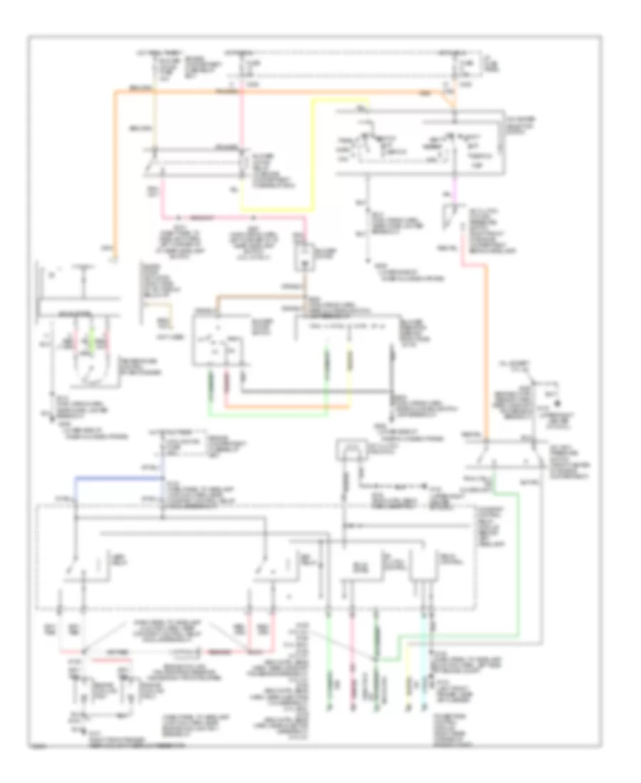
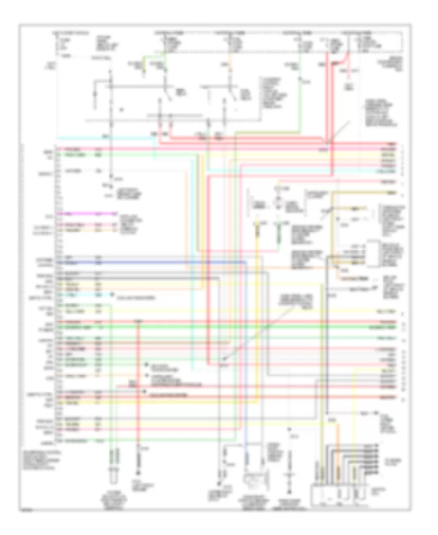
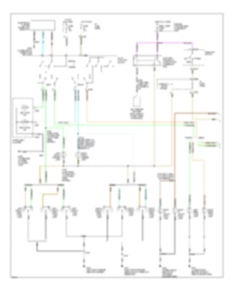
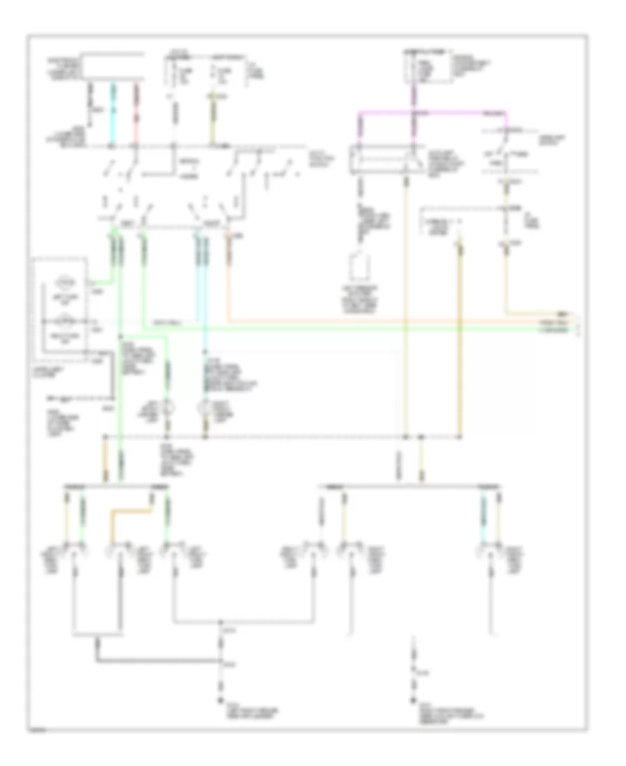
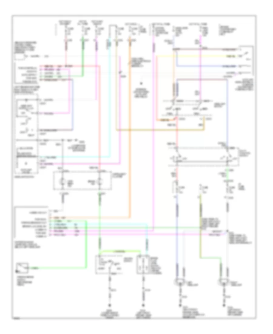
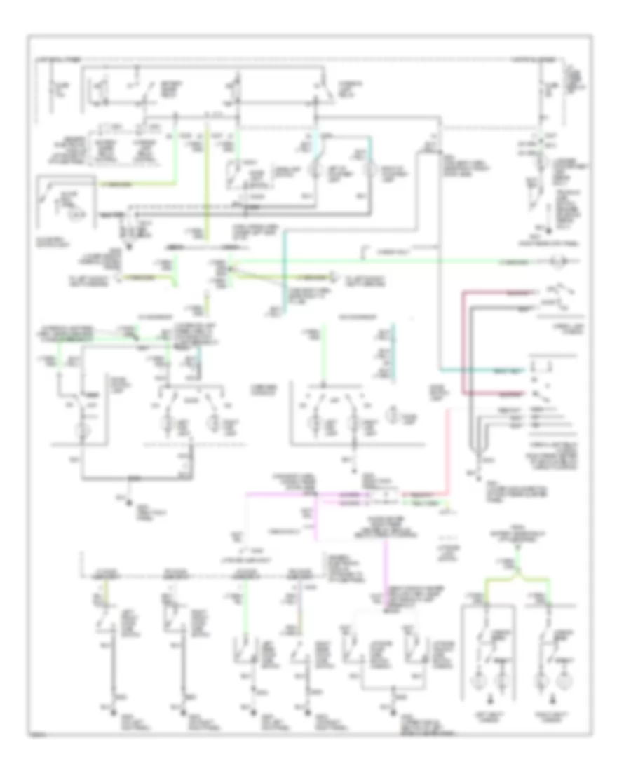
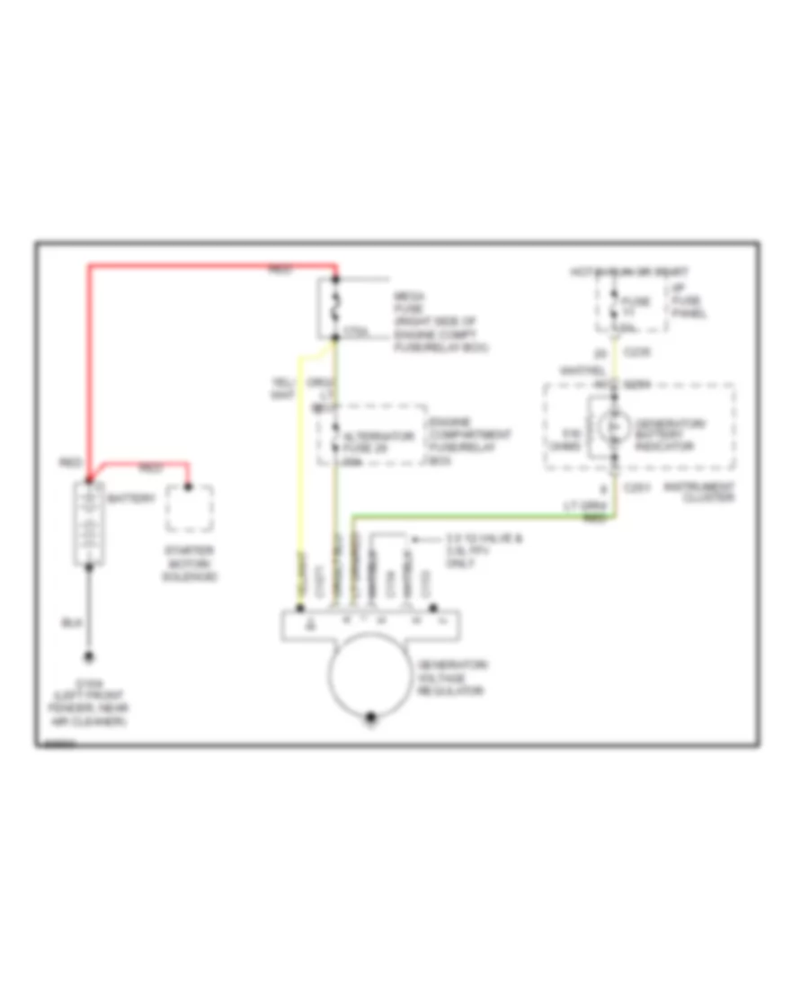
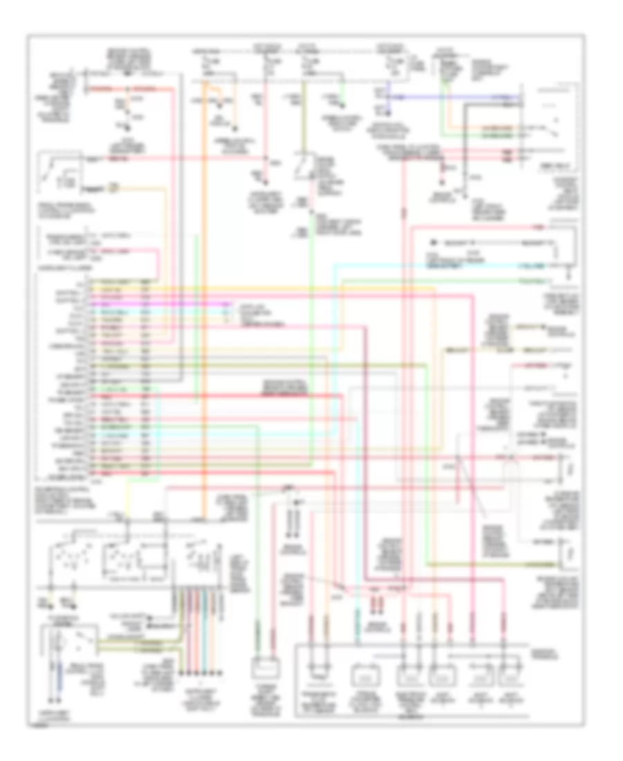
AIR CONDITIONING
A/C Wiring Diagram, Auto A/C for Ford Taurus SHO 1997

List of elements for A/C Wiring Diagram, Auto A/C for Ford Taurus SHO 1997:
- (all except 3.0l 4v)
- (dash panel to headlamp junction harn, near constant control relay module breakout)
- (dash panel to headlamp junction harn, near engine cooling fan 1 breakout)
- (engine cntrl sens harn, near camshaft pos sensor breakout)
- (left front of i/p)
- (main wiring harn, near cigar lighter breakout)
- (main wiring harn, near i/p fuse panel breakout)
- (main wiring harn, near in-car temp sensor breakout)
- (main wiring harn, near pass anti-theft system (pats) breakout)
- (upper right
- (upper right center of cowl)
- 883 or 879
- A/c clutch control
- A/c clutch cycling pressure switch (behind right headlamp)
- A/c clutch field coil
- A/c high pressure switch (front center of engine compartment)
- Ambient temp
- Ambient temperature sensor (center of grille)
- Battery
- Blend door actuator (right side of i/p)
- Blend dr act
- Blower motor
- Blower motor fuse 40a
- Blower motor relay (in engine
- Blower motor speed controller (right side of i/p)
- Blw speed
- C225
- C235
- Center of cowl)
- Compartment fuse/relay box
- Compartment fuse/relay box)
- Constant control relay module (behind left headlamp)
- Cooling fan fuse 40a
- Cycling pres sw
- Data bus
- Data link connector (below steering column)
- Edf relay
- Engine
- Engine compartment fuse/relay box
- Engine cooling fan 1
- Engine cooling fan 2
- Engine cooling fan dropping resistor (inside right front bumper)
- Fuse 15a
- Fuse 5a
- G100 (left front fender)
- G101 (right front fender near coolant overflow reservoir)
- G104 (left front fender, near air cleaner)
- G123
- G206 (lower side of inner glove box frame)
- Ground
- Hedf relay
- Hot at all times
- Hot in run
- I/p fuse panel
- Ign-a/c clutch
- Ignition
- In car temp
- In-car temperature sensor (near climate controls)
- Integrated control panel (center of i/p)
- Nca
- Passive anti-theft system (pats) (center of i/p)
- Pcm input
- Powertrain control module (right rear corner of engine compt)
- Rear control unit (left rear of vehicle)
- Relay control
- Remote climate control module (behind glove box)
- S108 (eng cntrl sens harn, near pcm)
- S109 (3.0l 2v) s160 (3.4l sho) s154 s154 (3.0l 4v) (eng cntrl sens harn, near camshaft pos sensor breakout) (3.0l 4v) s160 (eng cntrl sens harn, near injectors 3 & 4 breakout) (3.4l sho) s109 (eng cntrl sens harn, near injector 3 breakout) (3.0l 2v)
- S131
- S132 (dash panel to headlamp junction harn, near constant control relay module breakout)
- S136
- S145
- S156
- S211
- S213
- S215
- S216 (main wiring harn, near i/p fuse panel breakout)
- S217
- S218
- S219
- S223 (main wiring harn, near electronic flasher breakout)
- Signal return
- Solid state
- Sunload sensor
- Tan
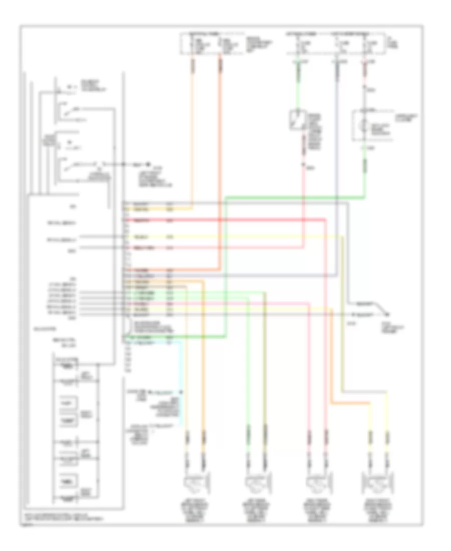
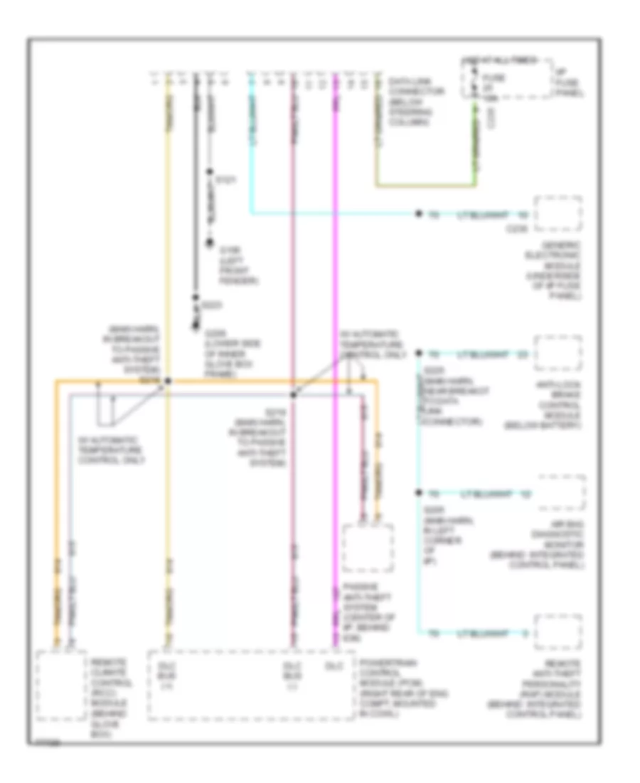
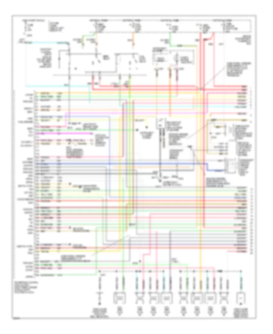
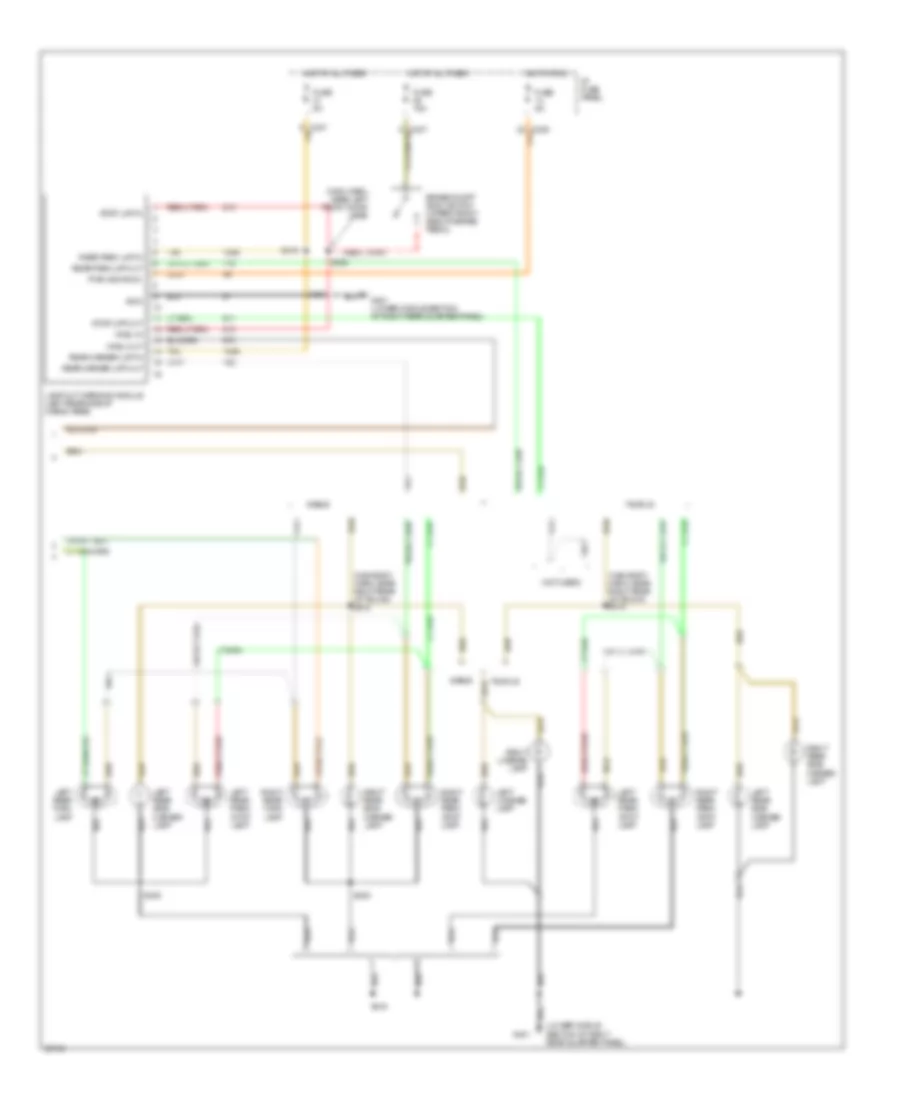
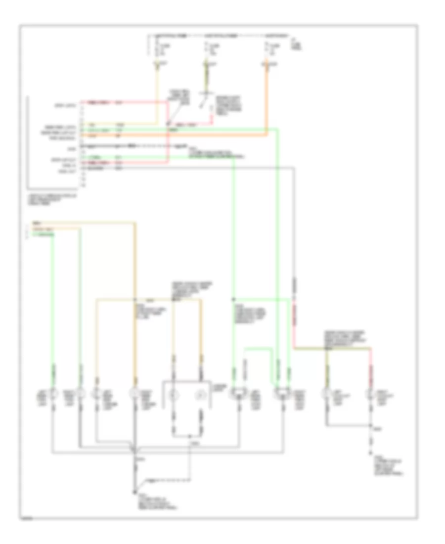
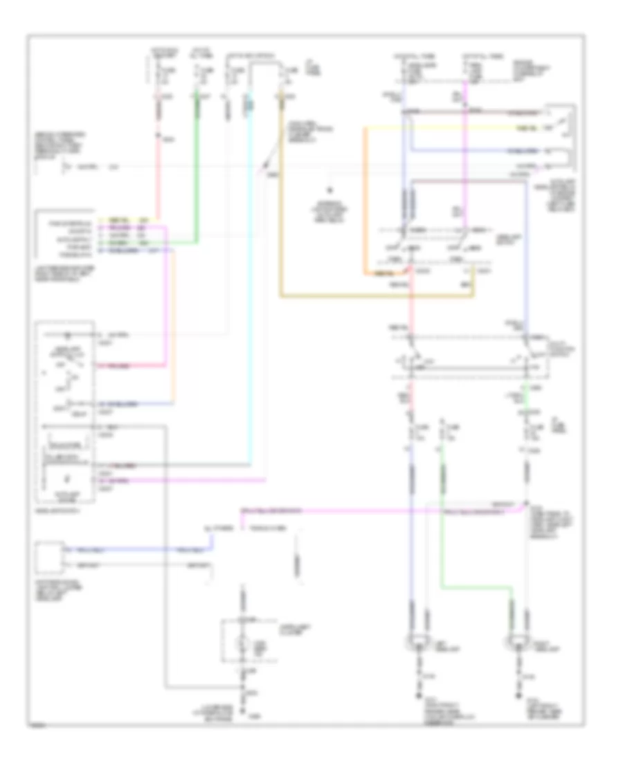
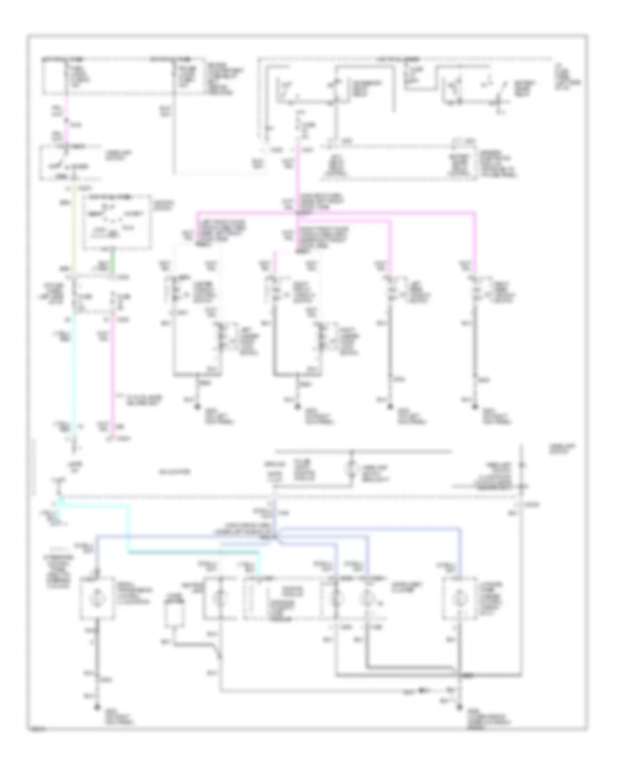
A/C Wiring Diagram, Manual A/C for Ford Taurus SHO 1997
List of elements for A/C Wiring Diagram, Manual A/C for Ford Taurus SHO 1997:
- (3.4l sho)
- (all except 3.0l 4v)
- (dash panel to headlamp junction harn, near constant control relay module breakout)
- (dash panel to headlamp junction harn, near engine cooling fan 1 breakout)
- (lower side of
- (main wiring harn, near glove box switch/ lamp breakout)
- (not used)
- (upper right
- (upper right center of cowl)
- 883 or 879
- A/c clutch control
- A/c clutch cycling pressure switch (right front of engine compartment behind headlamp)
- A/c clutch field coil
- A/c high pressure switch (front center of engine compartment)
- A/c-heater
- Blend door actuator (right side of a/c plenum below i/p)
- Blower motor
- Blower motor fuse 40a
- Blower motor relay (in engine compartment fuse/relay box)
- Blower motor switch
- Blower resistor (behind right side of i/p)
- C225
- C235
- Center of cowl)
- Constant control relay module (behind left headlamp)
- Cooling fan fuse 40a
- Def
- Def/flr
- Edf relay
- Engine compartment fuse/relay box
- Engine cooling fan 1
- Engine cooling fan 2
- Engine cooling fan dropping resistor (inside right front bumper)
- Flr
- Flr/vnt
- Fuse 15a
- Fuse 5a
- G101 (right front fender near coolant overflow reservoir)
- G104 (left front fender, near air cleaner)
- G123
- G206
- Hedf relay
- Hot at all times
- Hot in run
- I/p fuse panel
- Inner glove box frame)
- Max
- Norm
- Off
- Pan/flr
- Panel
- Powertrain control module (right rear corner of engine compt)
- Relay control
- S108 (eng cntrl sens harn, near pcm)
- S109 (3.0l 2v)
- S131
- S132 (dash panel to headlamp junction harn, near constant control relay module breakout)
- S136
- S145
- S154 (3.0l 4v) (eng cntrl sens harn, near camshaft pos sensor breakout) (3.0l 4v) s160 (eng cntrl sens harn, near injectors 3 & 4 breakout) (3.4l sho) s109 (eng cntrl sens harn, near injector 3 breakout) (3.0l 2v)
- S156 (engine cntrl sensor harn, near camshaft g123 pos sensor breakout)
- S160
- S210 (dash panel to headlamp harn, left corner of i/p, near headlamp switch)
- S212 (main wiring harn, near cigar lighter breakout)
- S227 (main wiring harn, left corner of i/p, near headlamp switch) (3.0l 4v 0nly)
- S229 (main wiring harn, near glove box switch/ lamp breakout)
- Selector switch
- Solid state
- Temperature control potentiometer
- Vent
ANTI-LOCK BRAKES
Anti-lock Brake Wiring Diagrams for Ford Taurus SHO 1997
List of elements for Anti-lock Brake Wiring Diagrams for Ford Taurus SHO 1997:
- (below steering column)
- (left front of engine compartment, near abs module)
- Abs ind ctrl
- Abs module fuse 30a
- Abs module fuse 40a
- Anti-lock brake control module (left front of eng compt, below battery)
- Anti-lock brake indicator
- Boo
- Brake on/off (boo) switch (upper front side of brake pedal)
- C250
- C251
- Computer data lines
- Engine compartment fuse/relay box
- Fuse 10a
- Fuse 15a
- Fuse 5a
- G100 (left front fender)
- G106
- Gnd
- Hot at all times
- Hot in start or run
- Hydraulic pump motor
- I/p fuse panel
- Ign
- Inlet
- Instrument cluster
- Iso link
- Left front
- Left front brake sensor (in left front wheel well, on brake assembly)
- Left rear
- Left rear brake sensor (in left rear wheel well, on brake assembly)
- Lf whl sens hi
- Lf whl sens lo
- Lr whl sens hi
- Lr whl sens lo
- Nca
- Outlet
- Pump motor relay
- Red/pnk
- Rf whl sens hi
- Rf whl sens lo
- Right front
- Right front brake sensor (in right front wheel well, on brake assembly)
- Right rear
- Right rear brake sensor (in right rear wheel well, on brake assembly)
- Rr whl sens hi
- Rr whl sens lo
- S120
- S224
- S225 (main harn, near breakout to datalink connector)
- S308
- Shorting bar (shorts pins 21 & 22 when disconnected)
- Solenoid control valves relay
- Solid state
- Tan/red
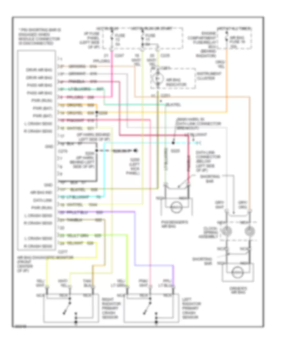
ANTI-THEFT
Anti-theft Wiring Diagram for Ford Taurus SHO 1997
List of elements for Anti-theft Wiring Diagram for Ford Taurus SHO 1997:
- (486)
- (behind integrated control panel) remote anti-theft personality module
- (left kick panel) g200
- (main harn, left i/p)
- (main harn, left side of i/p) s222
- (main harn, near pats module) s219
- 1/2
- 3/4
- 5/6
- 7/8
- 9/0
- Air bag diagnostic monitor (behind control panel)
- All door unlock
- Anti-theft indicator
- Anti-theft led
- Autolamp
- B/u lamps (pwr)
- Bus (+)
- Bus (-)
- C225
- C235
- C236
- C247
- C248
- C250
- C253
- C254
- C277
- Data link
- Data link connector (partial) (below steering col)
- Door locks system
- Drv unlock rly
- Exterior lamps system (backup lamps circuit)
- Exterior lamps system (brake on/off switch)
- Fuse 10 20a
- Fuse 20 5a
- Fuse 23 5a
- G100 (left front fender)
- G101 (right front fender, near coolant overflow reservoir)
- G206 (lower side of inner glove box frame)
- G401 (lower middle section of right rear quarter panel)
- Gem in
- Gem input
- Generic electronic module (attached to i/p fuse panel)
- Gnd
- Haz/brake lamps
- Headlamps system (w/ autolamps)
- Hood tamper switch (left front corner of engine compt.)
- Horn rly
- Horns system
- Hot at all times
- Hot in acc or run
- Hot in run or start
- I/p fuse panel (left side of i/p)
- Ign (run)
- Illum entry req
- Instrument cluster
- Iso link
- Keyless entry keypad switch assembly
- Keypad 1/2 sig
- Keypad 3/4 sig
- Keypad 5/6 sg
- Keypad 7/8 sig
- Keypad 9/0 sig
- Keypad comon
- Keypad lamp
- Liftgate release relay (right of steering column)
- Lock input
- Nca
- Passive anti-theft system (behind integrated control panel)
- Passive anti-theft system transceiver (near ignition switch)
- Pats transceiver
- Power/battery
- Powertrain control module (right rear corner of engine compt.)
- Rap input
- Red
- Rke jumper
- S121
- S122
- S145
- S205
- S215
- S218 (main harn, near pats module)
- S223
- S225 (main harn, near datalink connector)
- S416
- S421 (main harn, near boo switch)
- S500
- Sedan
- Trunk lid anti-theft switch (rear of cargo area)
- Trunk lid release relay (right of steering column)
- Trunk lid release switch
- Trunk/hood sw
- Trunk/liftgate
- Unlock input
- W/ keyless entry only
- Wagon
BODY COMPUTER
Body Computer Wiring Diagrams for Ford Taurus SHO 1997
List of elements for Body Computer Wiring Diagrams for Ford Taurus SHO 1997:
- 87a
- Accessory delay relay
- All door unlock
- Anti-theft in
- Anti-theft out
- Bat
- Battery saver relay
- Battery saver relay control
- C201
- C2031
- C223
- C225
- C235
- C236
- C247
- C248
- C253
- C254
- Data link
- Data link connector (below steering column)
- Defogger system
- Delay acc relay ctrl
- Door ajar ind ctrl
- Door lock in
- Door locks system
- Door unlock in
- Driver's unlock relay
- Driver's unlock relay ctrl
- Electronic power steering system
- Fuse 5a
- G100 (left front fender)
- G104 (left front fender, near air cleaner)
- G200 (on left kick panel)
- Gem
- Gem chime/ tone logic
- Generic electronic module (attached to i/p fuse panel)
- Gnd (pwr)
- Gnd (sig)
- Head
- Headlamp sw in
- Headlamp switch
- Hot at all times
- Hot in acc or run
- Hot in run or start
- Hot in start
- I/p fuse panel (left side of i/p)
- Ign (run/acc)
- Ign (start)
- Illum entry req
- Instrument cluster system
- Interior lamp relay
- Interior lamp relay ctrl
- Interior lights & warning systems (door ajar switches)
- Intv delay/wash
- Key warning sw in
- Lf door ajar
- Liftgate ajar
- Low coolant
- Low coolant ind ctrl
- Motor low sense
- Motor sense hi
- Motor switch down command
- Off
- One touch window down relay
- Park
- Power (run/start)
- Power windows system
- Rear defrost sw in
- Rear window defrost relay
- Rear window defrost relay ctrl
- Relay ctrl
- Remote anti-theft personality module (behind integrated control panel)
- Rf door ajar
- Rr door ajar
- S120
- S142 (dash to hdlmp harn, near breakout to engine compt fuse box)
- S224
- S225 (main harn, near breakout to datalink connector)
- Seatbelt ind ctrl
- Seatbelt sw
- Shunt resistor
- Tan/red
- Vaps ctrl
- Vehicle speed sensor (rear center of engine compt. on transaxle)
- Vss in
- W/ autolamps
- Warning system
- Washer relay
- Window switch up command
- Wiper hi/lo relay
- Wiper mode select
- Wiper park sense
- Wiper r/p relay
- Wiper/washer sig rtn
- Wiper/washer system
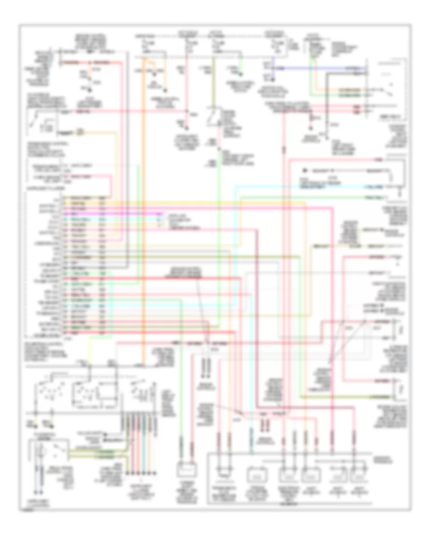
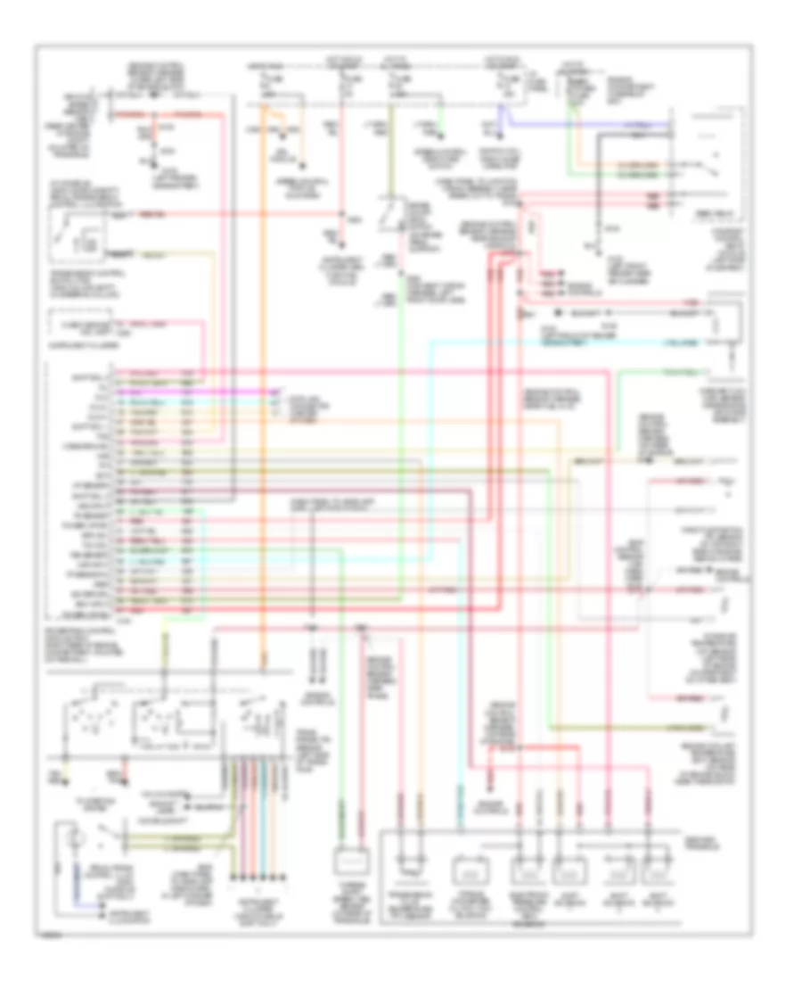
COMPUTER DATA LINES
Computer Data Lines for Ford Taurus SHO 1997
List of elements for Computer Data Lines for Ford Taurus SHO 1997:
- (main harn, in breakout to passive anti-theft system) s218
- Air bag diagnostic monitor (behind integrated control panel)
- Anti-lock brake control module (below battery)
- C235
- C236
- Data link connector (below steering column)
- Dlc
- Dlc bus (+)
- Dlc bus (-)
- Fuse 10a
- G100 (left front fender)
- G206 (lower side of inner glove box frame)
- Generic electronic module (underside of i/p fuse panel)
- Hot at all times
- I/p fuse panel
- Passive anti-theft system (center of i/p, behind icm)
- Powertrain control module (pcm) (right rear of eng compt, mounted in cowl)
- Remote anti-theft personality (rap) module (behind integrated control panel)
- Remote climate control (rcc) module (behind glove box)
- S121
- S205 (main harn, in left corner of i/p)
- S219 (main harn, in breakout to passive anti-theft system)
- S223
- S225 (main harn, near breakot to data link connector)
- W/ automatic temperature control only
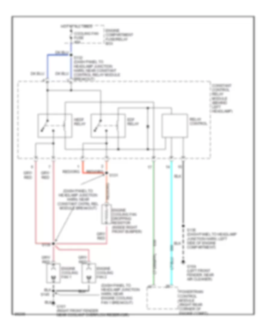
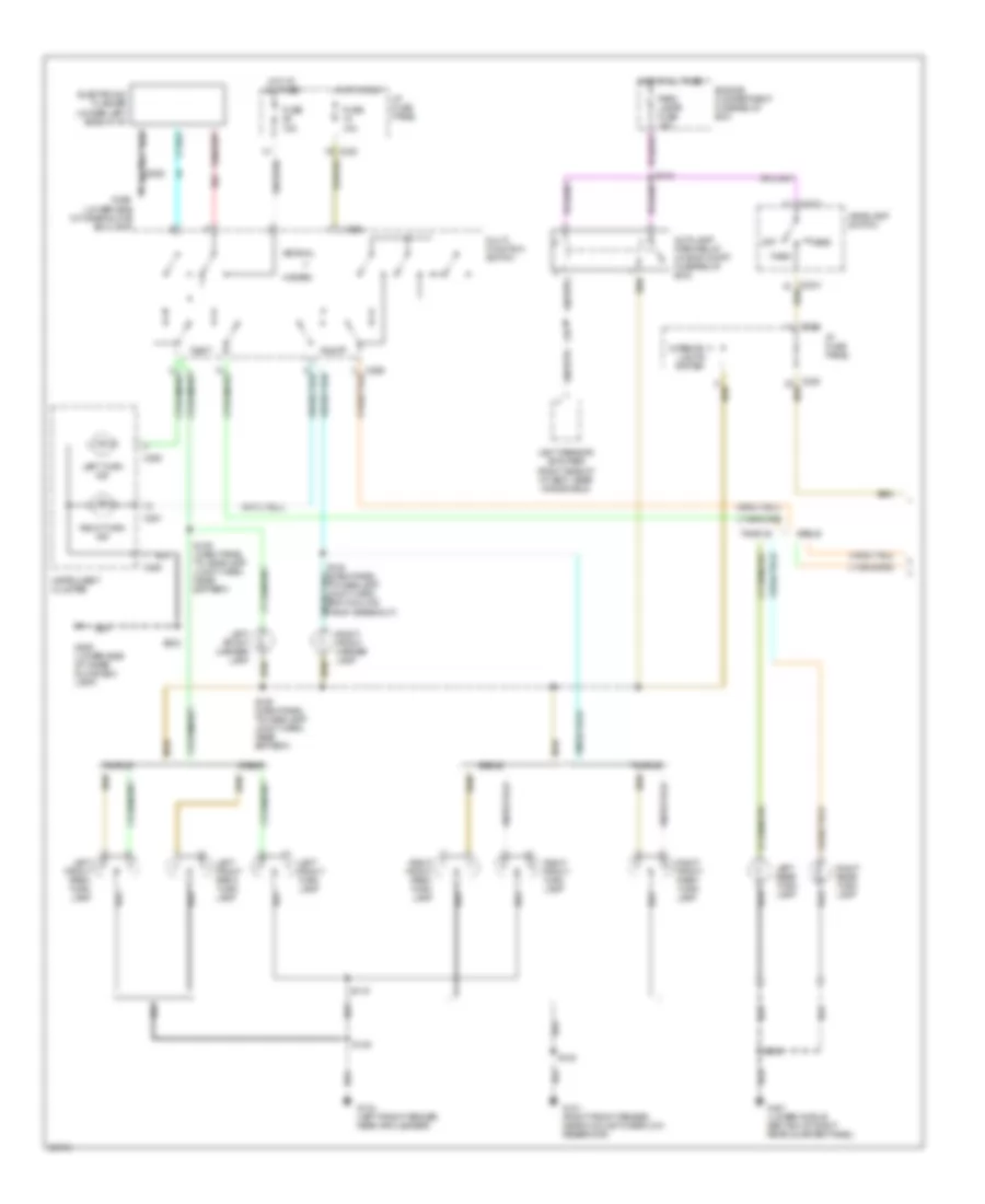
COOLING FAN
Cooling Fan Wiring Diagram for Ford Taurus SHO 1997
List of elements for Cooling Fan Wiring Diagram for Ford Taurus SHO 1997:
- (dash panel to headlamp junction harn, near constant cntrl rel module breakout)
- (dash panel to headlamp junction harn, near engine cooling fan 1 breakout)
- Constant control relay module (behind left headlamp)
- Cooling fan fuse 40a
- Edf relay
- Engine compartment fuse/relay box
- Engine cooling fan 1
- Engine cooling fan 2
- Engine cooling fan dropping resistor (inside right front bumper)
- G101 (right front fender near coolant overflow reservoir)
- G104 (left front fender, near air cleaner)
- Hedf relay
- Hot at all times
- Powertrain control module (right rear corner of engine compt)
- Relay control
- S131
- S132 (dash panel to headlamp junction harn, near constant control relay module breakout)
- S135 (dash panel to headlamp junction harn, left side of engine compartment)
- S136
- S145
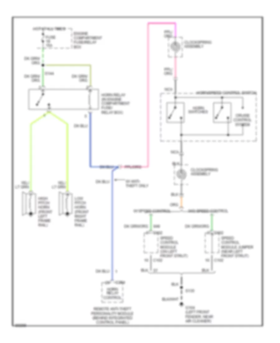
CRUISE CONTROL
Cruise Control Wiring Diagram for Ford Taurus SHO 1997
List of elements for Cruise Control Wiring Diagram for Ford Taurus SHO 1997:
- (back window heater harn, in breakout to defrost- er grid)
- (main body harn, in left door jamb) s308
- (sdn) s416 (wgn) s404
- 15a
- 3.0l 2v or 3.0l 4v
- 3.4l sho
- Accel
- Anti-lock brake control module (below battery)
- Brake on/off (boo) switch (upper front side of brake pedal)
- C225
- C235
- C247
- C250
- C251
- C254
- Clockspring assembly (in steering column, below steering wheel)
- Coast
- Cruise on ind
- Electric cltch pwr
- Engine compart- ment fuse box
- Fuse 15a
- Fuse 19
- Fuse 5a
- G100 (left front fender)
- G104 (left front fender, near air cleaner)
- G400 (upper middle section of left rear quarter panel)
- G401 (lower middle section of right rear quarter panel)
- Gnd
- Horn relay (in engine compt fuse box)
- Horn switches
- Horn/ speed control
- Hot at all times
- Hot in run
- Hot in start or run
- I/p fuse panel
- Ign
- Instrument cluster
- Left hi mount stop lamp
- Left rear park/ stop lamp
- Nca
- Off
- Remote anti-theft personality (rap) module (behind integrated control panel)
- Resume
- Right hi mount stop lamp
- Right rear park/ stop lamp
- S105
- S135
- S142 (dash to headlamp harn, near breakout to speed control module)
- S144
- S224
- S418 (sdn) s429 (wgn)
- S428
- Sedan
- Sedan only
- Set/
- Speed cont sw gnd
- Speed cont sw in
- Speed control deactivate switch (left side of i/p)
- Speed control module (mounted on left front strut)
- Vehicle speed input
- Vehicle speed sensor (vss) (on transaxle)
- W/ rap
- Wagon
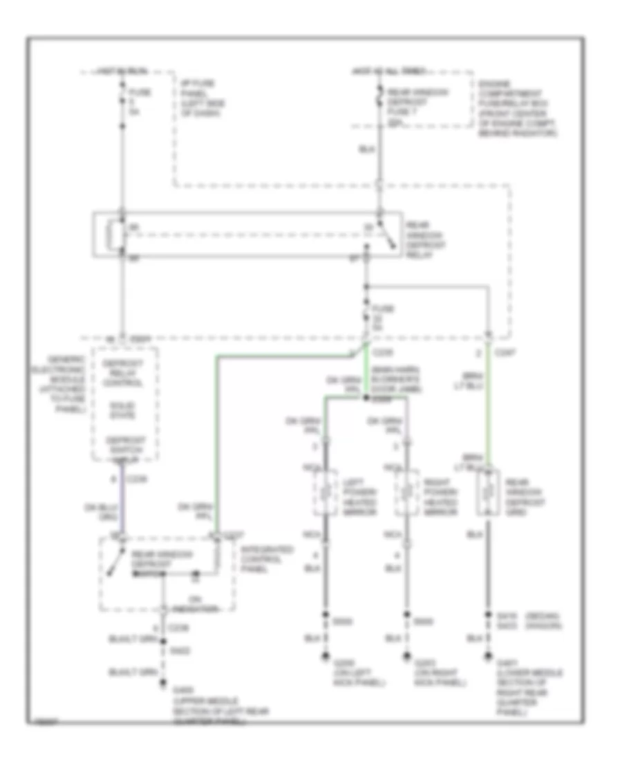
DEFOGGERS
Defogger Wiring Diagram for Ford Taurus SHO 1997
List of elements for Defogger Wiring Diagram for Ford Taurus SHO 1997:
- (sedan) (wagon)
- (upper middle section of left rear quarter panel)
- C201
- C235
- C236
- C237
- C247
- Defrost relay control
- Defrost switch input
- Door jamb) s309
- Engine compartment fuse/relay box (front center of engine compt, behind radiator)
- Fuse 5a
- G200 (on left kick panel)
- G203 (on right kick panel)
- G400
- G401 (lower middle section of right rear quarter panel)
- Generic electronic module (attached to fuse panel)
- Hot at all times
- Hot in run
- I/p fuse panel (left side of dash)
- Integrated control panel
- Left power/ heated mirror
- Nca
- On indicator
- Rear window defrost fuse 7 20a
- Rear window defrost grid
- Rear window defrost relay
- Rear window defrost switch
- Right power/ heated mirror
- S416 s433
- S422
- S500
- S600
- Solid state
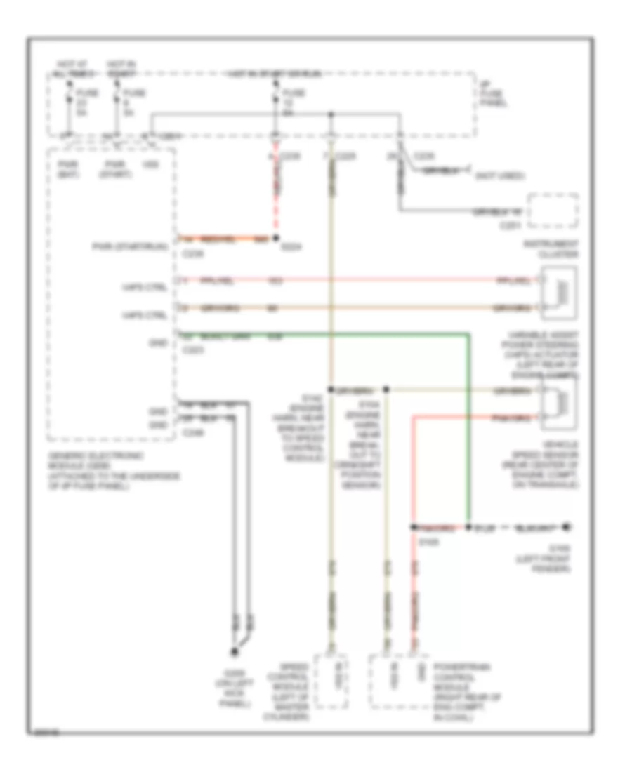
ELECTRONIC POWER STEERING
Electronic Power Steering Wiring Diagram for Ford Taurus SHO 1997
List of elements for Electronic Power Steering Wiring Diagram for Ford Taurus SHO 1997:
- (engine harn, near break- out to crnkshft position sensor)
- (engine harn, near breakout to speed control module)
- (not used)
- C201
- C223
- C235
- C236
- C248
- C251
- Fuse 5a
- G100 (left front fender)
- G200 (on left kick panel)
- Generic electronic module (gem) (attached to the underside of i/p fuse panel)
- Gnd
- Hot at all times
- Hot in start
- Hot in start or run
- I/p fuse panel
- Instrument cluster
- Powertrain control module (right rear of eng compt, in cowl)
- Pwr (bat)
- Pwr (start)
- Pwr (start/run)
- S104
- S105
- S120
- S142
- S224
- Speed control module (left of master cylinder)
- Vaps ctrl
- Variable assist power steering (vaps) actuator (left rear of engine compt)
- Vehicle speed sensor (rear center of engine compt, on transaxle)
- Vss
- Vss in
ELECTRONIC SUSPENSION
Electronic Suspension Wiring Diagram for Ford Taurus SHO 1997
List of elements for Electronic Suspension Wiring Diagram for Ford Taurus SHO 1997:
- (left front fender)
- (left front fender, near air cleaner)
- (main harn, left side of i/p) s205
- (right front fender, near coolant overflow reservoir)
- Anti-lock brake control module (below battery)
- C225
- C235
- C251
- C450
- C451
- Data link connector (below steering column)
- Dlc
- Electronic power steering system (zf gear solenoid)
- Engine compartment fuse/relay box
- Fuse 5a
- G100
- G101
- G104
- G401 (lower middle section of right rear quarter panel)
- Gnd
- Harn, near drl module) s179
- Hot at all times
- Hot in run
- I/p fuse panel
- Instrument cluster
- Left front height sensor (front of left front wheel)
- Left front shock actuator (front of left wheel well)
- Left rear shock actuator (left rear of vehicle, near wheel well)
- Lf height sensor
- Lf shock actuator
- Lr shock actuator
- Nca
- Pwr (bat)
- Pwr (run)
- Rf height sensor
- Rf shock actuator
- Right front height sensor (front of right front wheel)
- Right front shock actuator (front of right wheel well)
- Right rear shock actuator (right rear of vehicle, near wheel well)
- Rr shock actuator
- S120
- S142 (dash to hdlmp harn, near master cylinder)
- S145
- S158
- S180 (dash to hdlmp harn, near drl module)
- S440
- S442
- S444
- S451
- Semi-active ride control (sarc) module (behind right rear seat)
- Semi-active ride control fuse 20a
- Sensor gnd
- Sensor pwr
- Vss+
- Vss-
- Zf gear sol feed
- Zf gear sol rtn
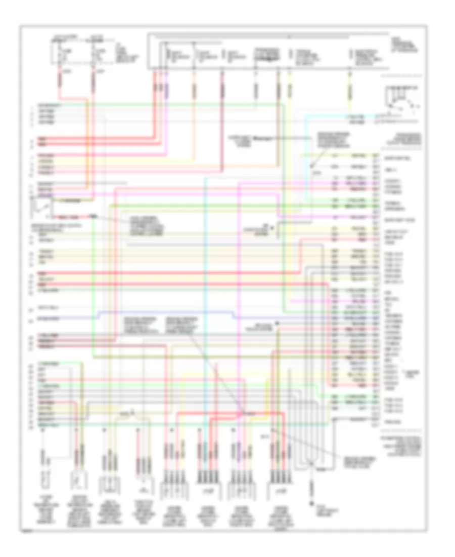
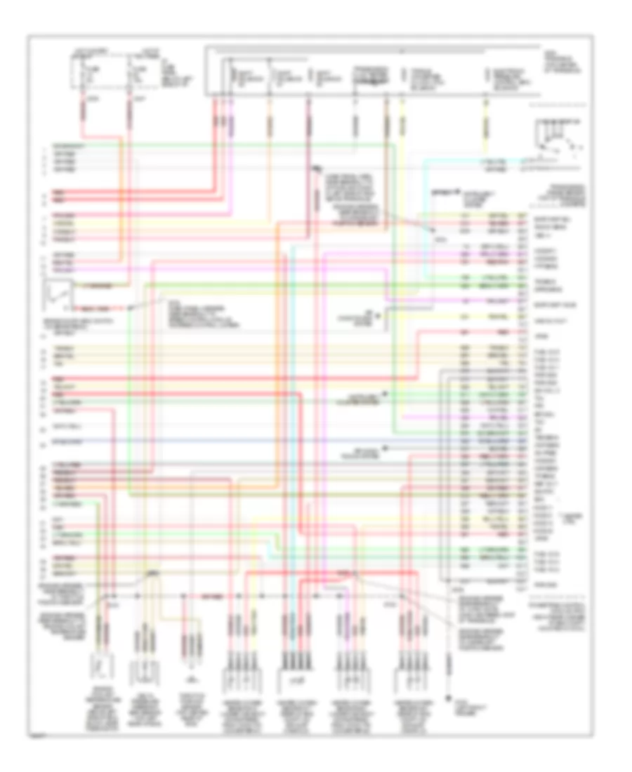
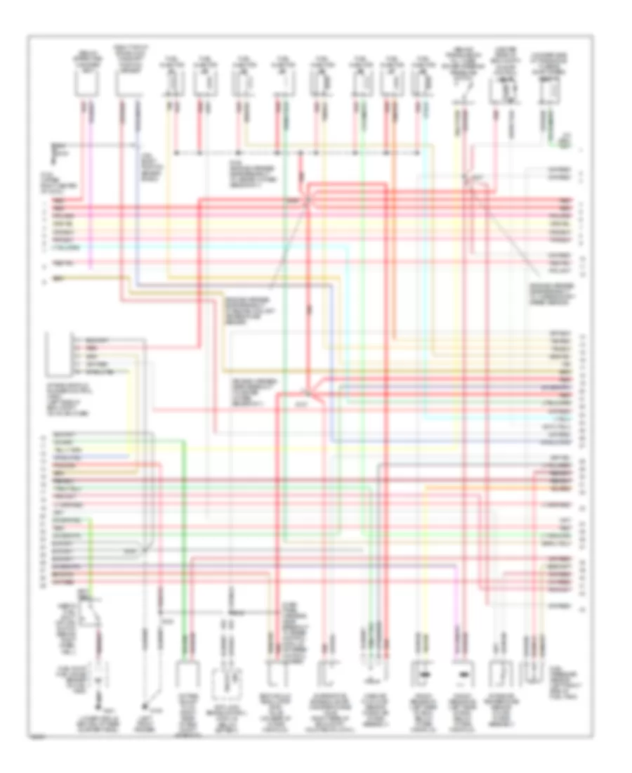
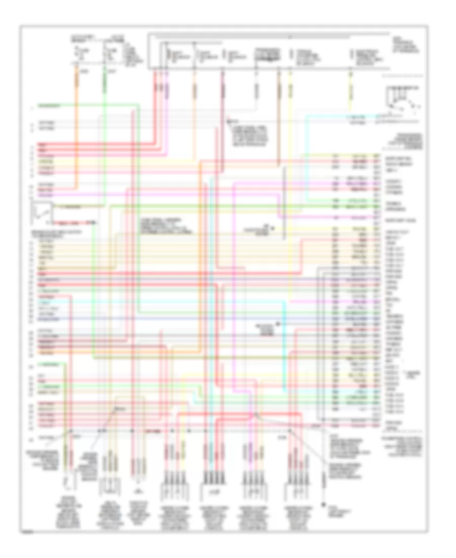
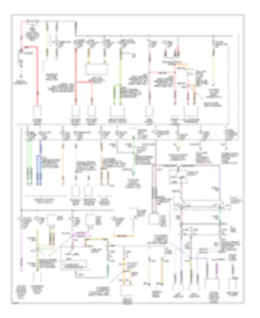
ENGINE PERFORMANCE
3.0L
3.0L 12-Valve, Engine Performance Wiring Diagrams (1 of 3) for Ford Taurus SHO 1997
List of elements for 3.0L 12-Valve, Engine Performance Wiring Diagrams (1 of 3) for Ford Taurus SHO 1997:
- (dash panel harn, near breakout to constant control relay)
- (dash panel harness, near breakout to 42-pin black conn in left side of engine above transaxle)
- (engine harness, near breakout to heated oxygen sensor #21)
- (upper right center of cowl)
- Accs
- Air conditioning system (a/c high pressure switch)
- C225
- C250
- C251
- Check engine indicator
- Ckp feed
- Ckp rtn
- Constant control relay module (on left side of battery, behind headlamp)
- Cooling fans system (constant control relay module)
- Cooling fans system (hedf relay)
- Crankshaft position sensor (lower right side of eng)
- Data link connector (below
- Dlc
- Dlc bus (+)
- Dlc bus (-)
- Eam air pump (left front of vehicle, rear of bumper)
- Eam rly
- Eam solid state relay (left front of vehicle, rear of bumper)
- Ect
- Edf rly ctrl
- Eeec power fuse 30a
- Eeec relay
- Engine compartment fuse/relay box
- Evr
- Fpm
- Fuel gauge
- Fuel pump fuse 20a
- Fuel pump relay
- Fuse 20a
- G100 (left front fender)
- G104 (left front fender, near air cleaner)
- G123
- G123 (upper right center of cowl)
- Gnd
- Hedf rly ctrl
- Hego power fuse 10a
- Ho2s #12
- Horn fuse 15a
- Hot at all times
- Hot in start or run
- I/p fuse panel (below left side of i/p)
- Iat
- Ign coil a
- Ign coil b
- Ignition coil
- Instrument cluster
- Instrument cluster system (anti-slosh module)
- Kapwr
- Maf rtn
- Mil
- Nca
- Near breakout to heated oxygen sensor #11)
- Oct adj
- Octane adjust plug (right rear of eng compt, near pcm)
- Powertrain control module (pcm) (right rear corner of eng compt, mounted in cowl)
- Psp
- Pwr gnd
- Radio noise capacitor (on ignition coil)
- Red
- S105
- S108
- S112
- S120
- S133
- S135
- S137
- S144
- S148
- S149
- S155
- S156
- S158
- Ss #1
- Ss #2
- Ss #3
- Steering column)
- Tach
- Tacho- meter
- Tft
- Thermactor air bypass solenoid (above exhaust manifold, rear of eng)
- Thermactor pump fuse 30a
- To spark plugs
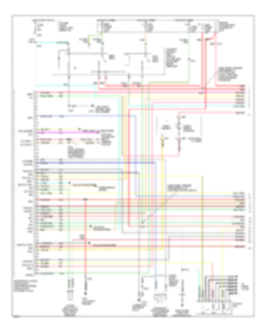
3.0L 12-Valve, Engine Performance Wiring Diagrams (2 of 3) for Ford Taurus SHO 1997
List of elements for 3.0L 12-Valve, Engine Performance Wiring Diagrams (2 of 3) for Ford Taurus SHO 1997:
- (behind transmission fill tube) power steering pressure switch
- (below spare tire) canister vent
- (center rear of eng compt) idle air control valve
- (dash panel harness, near breakout to 42-pin black conn in left side of engine above transaxle)
- (engine harness, near breakout to crankshaft position sensor)
- (engine harness, near breakout to engine oil pressure switch)
- (engine harness, near breakout to fuel inj #5)
- (left side of eng block) camshaft position sensor
- (lower middle section of rear quarter panel)
- (on rear side of transaxle) turbine shaft speed sensor
- Cam- shaft position sensor shield
- Egr vacuum regulator (evr) valve (on rear of intake manifold)
- Evaporative emission (evap) canister purge valve (right rear of eng compt, mounted on cowl)
- Fuel injector #1
- Fuel injector #2
- Fuel injector #3
- Fuel injector #4
- Fuel injector #5
- Fuel injector #6
- Fuel pressure sensor (left front side of fuel tank)
- Fuel pump/ fuel gauge sender (in fuel tank)
- G123 (upper right center of cowl)
- G401
- Inertia fuel shut- off (ifs) switch (behind right wheel well)
- Mass air flow (maf) sensor (near air intake assembly)
- Red
- S101
- S103
- S107
- S111
- S134
- Tan
- Vehicle speed sensor (vss) (rear center of eng compt, on transaxle)
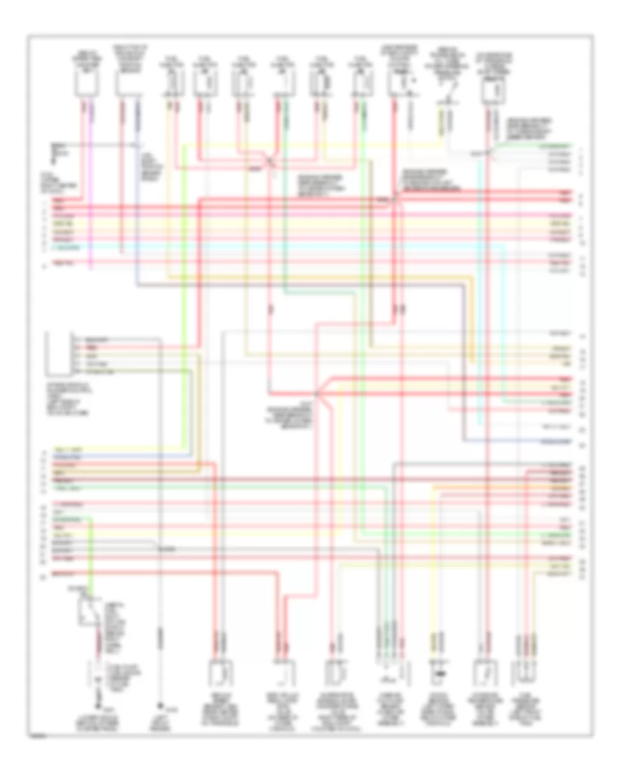
3.0L 12-Valve, Engine Performance Wiring Diagrams (3 of 3) for Ford Taurus SHO 1997
List of elements for 3.0L 12-Valve, Engine Performance Wiring Diagrams (3 of 3) for Ford Taurus SHO 1997:
- heated oxygen sensor #21 (lower left front of eng compt)
- (engine harness, near breakout to crankshaft position sensor)
- (engine harness, near breakout to engine oil pressure switch)
- (engine harness, near breakout to fuel inj #6)
- (engine harness, near breakout to turbine shaft speed sensor)
- (main harness, near breakout to speed control module or speed control jumper)
- A/c pres
- Air condi- tioning system
- Air conditioning system
- Ax4s transaxle (top center of transaxle)
- Boo
- Brake on/off (boo) switch (on brake pedal)
- C235
- C247
- Cmp sens
- Delta pressure feedback egr sensor (top left rear of eng)
- Dpfe sens
- Eam relay
- Electronic pressure control (epc) solenoid
- Engine coolant temperature sensor (above left side of eng block, near thermostat)
- Epc sol
- Evap canp sol
- Evap canp valve
- Fpm
- Ftp sens
- Fuel inj 1
- Fuel inj 2
- Fuel inj 3
- Fuel inj 4
- Fuel inj 5
- Fuel inj 6
- Fuse 15a
- Fuse 5a
- G100 (left front fender)
- Heated oxygen sensor #11 (back of eng)
- Heated oxygen sensor #12 (lower left side of eng)
- Heated oxygen sensor #22 (lower right side of eng)
- Heater ctrl
- Ho2s #11
- Ho2s #21
- Ho2s #22
- Ho2s 11
- Ho2s 12
- Ho2s 21
- Ho2s 22
- Hot at all times
- Hot in start
- I/p fuse panel (below left side of i/p)
- Iac
- Ign coil c
- Instrument cluster system
- Intake air temperature sensor (on air intake assembly)
- Maf sens
- Nca
- Or run
- Powertrain control module (pcm) (right rear corner of eng compt, mounted in cowl)
- Pwr gnd
- Red
- Red/pnk
- Ref volt
- S100
- S102
- S104
- S106
- S110
- S138
- Shift solenoid #1
- Shift solenoid #2
- Shift solenoid #3
- Sig rtn
- Tan
- Tcc
- Throttle position sensor (top center rear of eng)
- Torque converter clutch (tcc) solenoid
- Tp sens
- Tr sens
- Transmission fluid temper- ature sensor
- Transmission range sensor (top of transaxle)
- Tss sens
- Vpwr
- Vss (+)
- Wac rly out
3.0L 24-Valve, Engine Performance Wiring Diagrams (1 of 3) for Ford Taurus SHO 1997
List of elements for 3.0L 24-Valve, Engine Performance Wiring Diagrams (1 of 3) for Ford Taurus SHO 1997:
- (dash panel harness, near breakout to 42-pin black conn in left side of engine above transaxle)
- (dash panel harness, near breakout to constant control relay)
- (left front fender, near g104 air cleaner)
- (upper right center of cowl)
- Accs
- Air condi- tioning system
- C225
- C250
- Check engine indicator
- Ckp feed
- Ckp rtn
- Constant control relay module (on left side of battery, behind headlamp)
- Cooling fans system
- Crank- shaft position sensor shield
- Crankshaft position sensor (lower right side of eng)
- Data link connector (below steering column)
- Dlc
- Dlc bus (+)
- Dlc bus (-)
- Ect
- Edf rly ctrl
- Eeec power fuse 30a
- Eeec relay
- Engine compartment fuse/relay box
- Evr
- Fpm
- Fuel pump fuse 20a
- Fuel pump relay
- Fuel sender
- Fuse 20a
- G100 (left front fender)
- G123
- Gnd
- Hedf rly ctrl
- Hego power fuse 15a
- Ho2s #12
- Horn fuse 10a
- Hot at all times
- Hot in start or run
- I/p fuse panel (below left side of i/p)
- Iat
- Ign coil a
- Ign coil b
- Ignition coil
- Imrc
- Instrument cluster
- Instrument cluster system
- Kapwr
- Maf rtn
- Mil
- Nca
- Oct adj
- Octane adjust plug (right rear of eng compt, near pcm)
- Powertrain control module (pcm) (right rear corner of eng compt, mounted in cowl)
- Psp
- Pwr gnd
- Radio noise capacitor (on ignition coil)
- Red
- S105
- S108
- S112
- S120
- S122
- S133
- S135
- S137
- S144
- S218 (main harness, near breakout to passive anti- theft system)
- S219
- Ss #1
- Ss #2
- Ss #3
- Tach
- Tacho- meter
- Tcs
- Tft
- To spark plugs
- Transmissions system
3.0L 24-Valve, Engine Performance Wiring Diagrams (2 of 3) for Ford Taurus SHO 1997
List of elements for 3.0L 24-Valve, Engine Performance Wiring Diagrams (2 of 3) for Ford Taurus SHO 1997:
- (behind transmission fill tube) power steering pressure switch
- (below spare tire) canister vent
- (center rear of eng compt) idle air control valve
- (engine harness, near breakout to engine coolant temperature sender)
- (engine harness, near breakout to heated oxygen sensor #11)
- (engine harness, near breakout to turbine shaft speed sensor)
- (left front fender)
- (lower middle section of rear quarter panel)
- (on rear side of transaxle) turbine shaft speed sensor
- (right top of eng block) camshaft position sensor
- Cam- shaft position sensor shield
- Egr vacuum regulator (evr) valve (on rear of intake manifold)
- Evaporative emission (evap) canister purge valve (right rear of eng compt, mounted on cowl)
- Fuel injector #1
- Fuel injector #2
- Fuel injector #3
- Fuel injector #4
- Fuel injector #5
- Fuel injector #6
- Fuel pressure sensor (left front side of fuel tank)
- Fuel pump/ fuel gauge sender (in fuel tank)
- G100
- G123 (upper right center of cowl)
- G401
- Inertia fuel shut- off (ifs) switch (behind right wheel well)
- Intake air temperature sensor (on air intake assembly)
- Intake manifold runner control (imrc) (left side of eng compt, on valve cover)
- Knock sensor (left upper rear of eng, below intake manifold)
- Mass air flow (maf) sensor (in eng air intake assembly)
- Red
- S106
- S107 (engine harness, near breakout to heated oxygen sensor #11)
- S147
- S150
- S152
- Tan
- Vehicle speed sensor (vss) (rear center of eng compt, on transaxle)
3.0L 24-Valve, Engine Performance Wiring Diagrams (3 of 3) for Ford Taurus SHO 1997
List of elements for 3.0L 24-Valve, Engine Performance Wiring Diagrams (3 of 3) for Ford Taurus SHO 1997:
- (dash panel harn, near breakout to 42-pin black conn in left side of eng above transaxle)
- (engine harness, near breakout to 10-pin white conn centered atop of transaxle)
- (engine harness, near breakout to campshaft position sensor)
- (engine harness, near breakout to crankshaft position sensor)
- (engine harness, near breakout to engine coolant temperature sender)
- (engine harness, near breakout to throttle position sensor)
- A/c pres
- Air condi- tioning system
- Air conditioning system
- Ax4n transaxle (top center of transaxle)
- Boo
- Brake on/off (boo) switch (on brake pedal)
- C235
- C247
- Cmp sens
- Delta pressure feedback egr sensor (top left rear of eng)
- Dpfe sens
- Electronic pressure control (epc) solenoid
- Engine coolant temperature sensor (above left side of eng block, near thermostat)
- Epc sol
- Evap canp sol
- Evap canp valve
- Fpm
- Ftp sens
- Fuel inj 1
- Fuel inj 2
- Fuel inj 3
- Fuel inj 4
- Fuel inj 5
- Fuel inj 6
- Fuse 15a
- Fuse 5a
- G100 (left front fender)
- Heated oxygen sensor #11 (rear of eng compt, on exhaust manifold)
- Heated oxygen sensor #12 (under car body downstream, from catalytic converter #1)
- Heated oxygen sensor #21 (rear of eng compt, on exhaust manifold)
- Heated oxygen sensor #22 (under car body downstream, from catalytic converter #2)
- Heater ctrl
- Ho2s #11
- Ho2s #21
- Ho2s #22
- Ho2s 11
- Ho2s 12
- Ho2s 21
- Ho2s 22
- Hot at all times i/p fuse panel (below left side of i/p)
- Hot in start
- Iac
- Ign coil c
- Instrument cluster system
- Knock sens
- Maf sens
- Nca
- Or run
- Powertrain control module (pcm) (right rear corner of eng compt, mounted in cowl)
- Pwr gnd
- Red
- Red/pnk
- Ref volt
- S102
- S104
- S106
- S134
- S138 (dash panel harness, near breakout to speed control module or speed control jumper)
- S151
- S153
- S157
- Shift solenoid #1
- Shift solenoid #2
- Shift solenoid #3
- Sig rtn
- Tan
- Tcc
- Tcil
- Throttle position sensor (top center rear of eng)
- Torque converter clutch (tcc) solenoid
- Tp sens
- Tr sens
- Transmission fluid temper- ature sensor
- Transmission range sensor (top of transaxle housing)
- Tss sens
- Vpwr
- Vss (+)
- Wac rly out
3.0L Flex Fuel, Engine Performance Wiring Diagrams (1 of 3) for Ford Taurus SHO 1997
List of elements for 3.0L Flex Fuel, Engine Performance Wiring Diagrams (1 of 3) for Ford Taurus SHO 1997:
- (dash panel harn, near breakout to constant control relay)
- (dash panel harness, near breakout to 42-pin black conn in left side of engine above transaxle)
- (engine harness, near breakout to heated oxygen sensor #11)
- (engine harness, near breakout to heated oxygen sensor #21)
- (left front fender, near g104 air cleaner)
- (not used)
- (upper right center of cowl)
- Accs
- Air condi- tioning system
- C225
- C250
- Check engine indicator
- Ckp feed
- Ckp rtn
- Constant control relay module (on left side of battery, behind headlamp)
- Cooling fans system
- Crank- shaft position sensor shield
- Crankshaft position sensor (lower right side of eng)
- Data link connector (below steering column)
- Dlc
- Dlc bus (+)
- Dlc bus (-)
- Dte
- Eam air pump (left front of vehicle, rear of bumper)
- Eam rly
- Eam solid state relay (left front of vehicle, rear of bumper)
- Ect
- Edf rly ctrl
- Eeec power fuse 30a
- Eeec relay
- Engine compartment fuse/relay box
- Evr
- Ff sens
- Fpm
- Fuel pump fuse 20a
- Fuel pump relay
- Fuse 20a
- G100 (left front fender)
- G123
- G123 (upper right center of cowl)
- Gnd
- Hedf rly ctrl
- Hego power fuse 15a
- Horn fuse 15a
- Hot at all times
- Hot in start or run
- I/p fuse panel (below left side of i/p)
- Iat
- Ign coil a
- Ign coil b
- Ignition coil
- Instrument cluster
- Instrument cluster system (distance to empty module)
- Kapwr
- Maf rtn
- Mil
- Nca
- Oct adj
- Octane adjust plug (right rear of eng compt, near pcm)
- Powertrain control module (pcm) (right rear corner of eng compt, mounted in cowl)
- Psp
- Pwr gnd
- Radio noise capacitor (near ignition coil)
- Red
- S105
- S108
- S112
- S120
- S133
- S135
- S137
- S144
- S148
- S149
- S155
- S156
- S158
- Ss #1
- Ss #2
- Ss #3
- Tach
- Tacho- meter
- Tft
- Ther- mactor pump fuse 30a
- Thermactor air bypass solenoid (left front of eng compt, near ignition coil)
- To spark plugs
3.0L Flex Fuel, Engine Performance Wiring Diagrams (2 of 3) for Ford Taurus SHO 1997
List of elements for 3.0L Flex Fuel, Engine Performance Wiring Diagrams (2 of 3) for Ford Taurus SHO 1997:
- (behind transmission fill tube) power steering pressure switch
- (center rear of eng compt) idle air control valve
- (engine harness, near breakout to crankshaft position sensor)
- (engine harness, near breakout to engine oil pressure switch)
- (engine harness, near breakout to fuel inj #5)
- (engine harness, near breakout to turbine shaft speed sensor)
- (left front fender)
- (left side of eng block) camshaft position sensor
- (lower middle section of rear quarter panel)
- (on rear side of transaxle) turbine shaft speed sensor
- (right rear of eng compt) flex fuel sensor)
- Cam- shaft position sensor shield
- Egr vacuum regulator (evr) valve (on rear of intake manifold)
- Evaporative emission (evap) canister purge valve (right rear of eng compt, mounted on cowl)
- Fuel injector #1
- Fuel injector #2
- Fuel injector #3
- Fuel injector #4
- Fuel injector #5
- Fuel injector #6
- Fuel pressure sensor (left front side of fuel tank)
- Fuel pump/ fuel gauge sender (in fuel tank)
- G100
- G104 (left front fender, near air cleaner)
- G123 (upper right center of cowl)
- G401
- Inertia fuel shut- off (ifs) switch (behind right wheel well)
- Mass air flow (maf) sensor (in eng air intake assembly)
- Red
- S101
- S103
- S106
- S107
- S108
- S111
- Tan
- Vehicle speed sensor (vss) (rear center of eng compt, on transaxle)
3.0L Flex Fuel, Engine Performance Wiring Diagrams (3 of 3) for Ford Taurus SHO 1997
List of elements for 3.0L Flex Fuel, Engine Performance Wiring Diagrams (3 of 3) for Ford Taurus SHO 1997:
- (engine harness, near breakout to crankshaft position sensor)
- (engine harness, near breakout to engine oil pressure switch)
- (engine harness, near breakout to fuel inj #6)
- A/c pres
- Air condi- tioning system
- Air conditioning system
- Ax4s transaxle (top center of transaxle)
- Boo
- Brake on/off (boo) switch (on brake pedal)
- C235
- C247
- Cmp sens
- Delta pressure feedback egr sensor (right rear of intake manifold)
- Dpfe sens
- Eam rly
- Electronic pressure control (epc) solenoid
- Engine coolant temperature sensor (above left side of eng block, near thermostat)
- Epc sol
- Evap canp sol
- Fpm
- Ftp sens
- Fuel inj 1
- Fuel inj 2
- Fuel inj 3
- Fuel inj 4
- Fuel inj 5
- Fuel inj 6
- Fuse 15a
- Fuse 5a
- G100 (left front fender)
- Heated oxygen sensor #11 (rear of eng compt, on exhaust manifold)
- Heated oxygen sensor #21 (front of eng compt, on exhaust manifold)
- Heater ctrl
- Ho2s #11
- Ho2s #21
- Ho2s 11
- Ho2s 21
- Hot at all times i/p fuse panel (below left side of i/p)
- Hot in start or run
- Iac
- Ign coil c
- Instrument cluster system
- Intake air temperature sensor (on air intake assembly)
- Maf sens
- Nca
- Powertrain control module (pcm) (right rear corner of eng compt, mounted in cowl)
- Pwr gnd
- Red
- Red/pnk
- Ref volt
- S100 (engine harness, near breakout to turbine shaft speed sensor)
- S102
- S104
- S106
- S110
- S134 (dash panel harness, near breakout to 42-pin black conn in left side of eng above transaxle)
- S138 (main harness, near breakout to speed control module or speed control jumper)
- Shift solenoid #1
- Shift solenoid #2
- Shift solenoid #3
- Sig rtn
- Tan
- Tcc
- Throttle position sensor (behind inake manifold)
- Torque converter clutch (tcc) solenoid
- Tp sens
- Tr sens
- Transmission fluid temper- ature sensor
- Transmission range sensor (top of transaxle)
- Tss sens
- Vpwr
- Vss (+)
- Wac rly out
3.4L
3.4L SHO, Engine Performance Wiring Diagrams (1 of 3) for Ford Taurus SHO 1997
List of elements for 3.4L SHO, Engine Performance Wiring Diagrams (1 of 3) for Ford Taurus SHO 1997:
- (dash panel harness, near breakout to 42-pin black conn in left side of engine above transaxle)
- (dash panel harness, near breakout to constant control relay)
- (engine harness, near breakout to evaporative emission canister valve)
- (engine harness, near breakout to heated oxygen sensor #21)
- (left front fender, near g104 air cleaner)
- (upper right center of cowl)
- Accs
- Air condi- tioning system
- C225
- C250
- Ccp #5
- Ccp #6
- Ccp #7
- Check engine indicator
- Ckp feed
- Ckp rtn
- Coil per plug #1
- Coil per plug #2
- Coil per plug #3
- Coil per plug #4
- Coil per plug #5
- Coil per plug #6
- Coil per plug #7
- Coil per plug #8
- Constant control relay module (on left side of battery, behind headlamp)
- Cooling fans system
- Cpp #1
- Cpp #3
- Crankshaft position sensor (lower right side of eng)
- Crankshaft position sensor shield
- Data link connector (below steering column)
- Dlc
- Dlc bus (+)
- Dlc bus (-)
- Eam air pump (left front vehicle, rear of bumper)
- Eam rly
- Eam solid state relay (left front of vehicle, rear of bumper)
- Ect
- Edf rly ctrl
- Eeec power fuse 30a
- Eeec relay
- Engine compartment fuse/relay box
- Evr
- Fpm
- Fuel pump fuse 20a
- Fuel pump relay
- Fuel sender
- Fuse 20a
- G123
- Gnd
- Hedf rly ctrl
- Hego power fuse 15a
- Ho2s #12
- Horn fuse 15a
- Hot at all times
- Hot in start or run
- I/p fuse panel (below left side of i/p)
- Iat
- Imrc
- Instrument cluster
- Instrument cluster system
- Kapwr
- Knock sens #2
- Maf rtn
- Mil
- Nca
- Oct adj
- Powertrain control module (pcm) (right rear corner of eng compt, mounted in cowl)
- Psp
- Pwr gnd
- Radio noise capacitor #1 (rear of eng, near cpp #4)
- Radio noise capacitor #2 (front of eng, above imrc)
- Red
- S108
- S137
- S144
- S148
- S149
- S156
- S161
- S162
- S163
- S218 (main harness, near breakout to passive anti- theft system)
- S219
- S447
- Ss #1
- Ss #2
- Ss #3
- Tach
- Tacho- meter
- Tcil
- Tcs
- Tft
- Ther- mactor pump fuse 30a
- Thermactor air bypass solenoid (above exhaust manifold, rear of eng)
- Transmissions system
3.4L SHO, Engine Performance Wiring Diagrams (2 of 3) for Ford Taurus SHO 1997
List of elements for 3.4L SHO, Engine Performance Wiring Diagrams (2 of 3) for Ford Taurus SHO 1997:
- (behind transmission fill tube) power steering pressure switch
- (below spare tire) canister vent
- (center rear of eng compt) idle air control valve
- (dash panel harness, near breakout to speed control module or speed control jumper)
- (engine harness, near breakout to engine coolant temperature sender)
- (engine harness, near breakout to heated oxygen sensor #11)
- (engine harness, near breakout to turbine shaft speed sensor)
- (left front fender)
- (lower middle section of rear quarter panel)
- (on rear side of transaxle) turbine shaft speed sensor
- (right top of eng block) camshaft position sensor
- Anti-lock brake control module (below battery)
- Cam- shaft position sensor shield
- Egr vacuum regulator (evr) valve (on rear of intake manifold)
- Evaporative emission (evap) canister purge valve (right rear of eng compt, mounted on cowl)
- Fuel injector #1
- Fuel injector #2
- Fuel injector #3
- Fuel injector #4
- Fuel injector #5
- Fuel injector #6
- Fuel injector #7
- Fuel injector #8
- Fuel pressure sensor (left front side of fuel tank)
- Fuel pump/ fuel gauge sender (in fuel tank)
- G100
- G123 (upper right center of cowl)
- G401
- Gnd
- Inertia fuel shut- off (ifs) switch (behind right wheel well)
- Intake air temperature sensor (on air intake assembly)
- Intake manifold runner control (imrc) (left side of eng compt, on valve cover)
- Knock sensor #1 (left rear of eng, below intake manifold)
- Knock sensor #2 (left rear of eng, below intake manifold)
- Mass air flow (maf) sensor (in eng air intake assembly)
- Octane adjust plug (right rear of eng compt, near pcm)
- Red
- S106
- S107
- S120
- S147
- S150
- S152 (engine harness, near breakout to heated oxygen sensor #11)
- Tan
- Tan/red
- Vss out
3.4L SHO, Engine Performance Wiring Diagrams (3 of 3) for Ford Taurus SHO 1997
List of elements for 3.4L SHO, Engine Performance Wiring Diagrams (3 of 3) for Ford Taurus SHO 1997:
- (dash panel harn, near breakout to 42-pin black conn in left side of eng above transaxle)
- (dash panel harness, near breakout to speed control module or speed control jumper)
- (engine harness, near breakout to campshaft position sensor)
- (engine harness, near breakout to engine coolant temp sender)
- (engine harness, near breakout to throttle position sensor)
- A/c pres
- Air condi- tioning system
- Air conditioning system
- Ax4n transaxle (top center of transaxle)
- Boo
- Brake on/off (boo) switch (on brake pedal)
- C235
- C247
- Cmp sens
- Cpp #2
- Cpp #4
- Cpp #8
- Delta pressure feedback egr sensor (left rear side of intake manifold)
- Dpfe sens
- Eam rly
- Electronic pressure control (epc) solenoid
- Engine coolant temperature sensor (above left side of eng block, near thermostat)
- Epc sol
- Evap canp sol
- Evap canp valve
- Fpm
- Ftp sens
- Fuel inj 1
- Fuel inj 2
- Fuel inj 3
- Fuel inj 4
- Fuel inj 5
- Fuel inj 6
- Fuel inj 7
- Fuel inj 8
- Fuse 15a
- Fuse 5a
- G100 (left front fender)
- Heated oxygen sensor #11 (rear of eng compt, on exhaust manifold)
- Heated oxygen sensor #12 (under car body, downstream from catalytic converter #1)
- Heated oxygen sensor #21 (rear of eng compt, on exhaust manifold)
- Heated oxygen sensor #22 (under car body, downstream from catalytic converter #2)
- Heater ctrl
- Ho2s #11
- Ho2s #21
- Ho2s #22
- Ho2s 11
- Ho2s 12
- Ho2s 21
- Ho2s 22
- Hot at all times i/p fuse panel (below left side of i/p)
- Hot in start or run
- Iac
- Knock sens #1
- Maf sens
- Nca
- Powertrain control module (pcm) (right rear corner of eng compt, mounted in cowl)
- Pwr gnd
- Red
- Red/pnk
- Ref volt
- S102
- S106
- S134
- S138
- S151
- S153
- S157 (engine harness, near breakout to 10-pin white conn centered atop of transaxle)
- Shift solenoid #1
- Shift solenoid #2
- Shift solenoid #3
- Sig rtn
- Tan
- Tan/red
- Tcc
- Throttle position sensor (top center rear of eng)
- Torque converter clutch (tcc) solenoid
- Tp sens
- Tr sens
- Transmission fluid temper- ature sensor
- Transmission range sensor (top of transaxle housing)
- Tss sens
- Vpwr
- Vss (+)
- Wac rly out
EXTERIOR LIGHTS
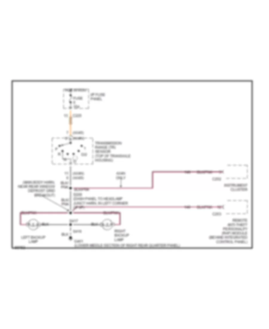
Back-up Lamps Wiring Diagram, Sedan for Ford Taurus SHO 1997
List of elements for Back-up Lamps Wiring Diagram, Sedan for Ford Taurus SHO 1997:
- (ax4n)
- (ax4n) (ax4s)
- (ax4s)
- (main body harn, near rear window defrost grid breakout)
- Ax4n only
- C225
- C252
- C253
- D/2
- Fuse 15a
- G401 (lower middle section of right rear quarter panel)
- Hot in run
- I/p fuse panel
- Instrument cluster
- Junct harn, in left corner of i/p)
- Left backup lamp
- Remote anti-theft personality (rap) module (behind integrated control panel)
- Right backup lamp
- S416
- S417
- Transmission range (tr) sensor (top of transaxle housing)
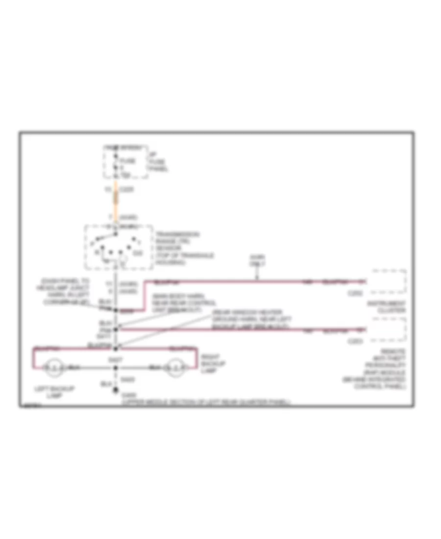
Back-up Lamps Wiring Diagram, Wagon for Ford Taurus SHO 1997
List of elements for Back-up Lamps Wiring Diagram, Wagon for Ford Taurus SHO 1997:
- (ax4n)
- (ax4n) (ax4s)
- (ax4s)
- (dash panel to headlamp junct harn, in left corner of i/p)
- (main body harn, near rear control unit breakout)
- (rear window heater ground harn, near left backup lamp breakout)
- Ax4n only
- C225
- C252
- C253
- D/2
- Fuse 15a
- G400 (upper middle section of left rear quarter panel)
- Hot in run
- I/p fuse panel
- Instrument cluster
- Left backup lamp
- Remote anti-theft personality (rap) module (behind integrated control panel)
- Right backup lamp
- S209
- S420
- S427
- Transmission range (tr) sensor (top of transaxle housing)
Exterior Lamps Wiring Diagram, Sedan with Lamp Out Warning (1 of 2) for Ford Taurus SHO 1997
List of elements for Exterior Lamps Wiring Diagram, Sedan with Lamp Out Warning (1 of 2) for Ford Taurus SHO 1997:
- (lower side of inner glove box lamp)
- (main body harn, in hi mount stop lamp breakout) s420
- (main harn, near left corner of i/p)
- Autolamp park relay (in eng compt fuse/relay box)
- C2031
- C235
- C250
- C251
- C269
- Electronic flasher (under left side of i/p)
- Engine compartment fuse/relay box
- Fuse 10a
- Fuse 15a
- G101 (right front fender, near coolant overflow reservoir)
- G104 (left front fender, near air cleaner)
- G206
- G206 (lower side of inner glove box lamp)
- G400 (upper middle section of left rear quarter panel)
- G401 (lower middle section of right rear quarter panel)
- Hazard
- Head
- Headlamp switch
- Hot at all times
- Hot in run
- I/p fuse panel
- Instrument cluster
- Interior lights system
- Left
- Left front marker lamp
- Left front park/ turn lamp
- Left front turn lamp
- Left rear turn lamp
- Left turn ind
- Light sensor/ amplifier (right side of i/p vent, near windshield)
- Multi- function switch
- Normal
- Off
- Park
- Park lamps fuse 15a
- Right
- Right front marker lamp
- Right front park/ turn lamp
- Right front turn lamp
- Right hi mount stop lamp
- Right rear turn lamp
- Right turn ind
- S119
- S125 (dash panel to headlamp junct harn, near battery)
- S126 (dash panel to headlamp junct harn, near battery)
- S135
- S143
- S145
- S145 (dash panel to headlamp junct harn, near eng cooling fan #1 breakout)
- S223
- S226
- S418
- Sable
- Taurus
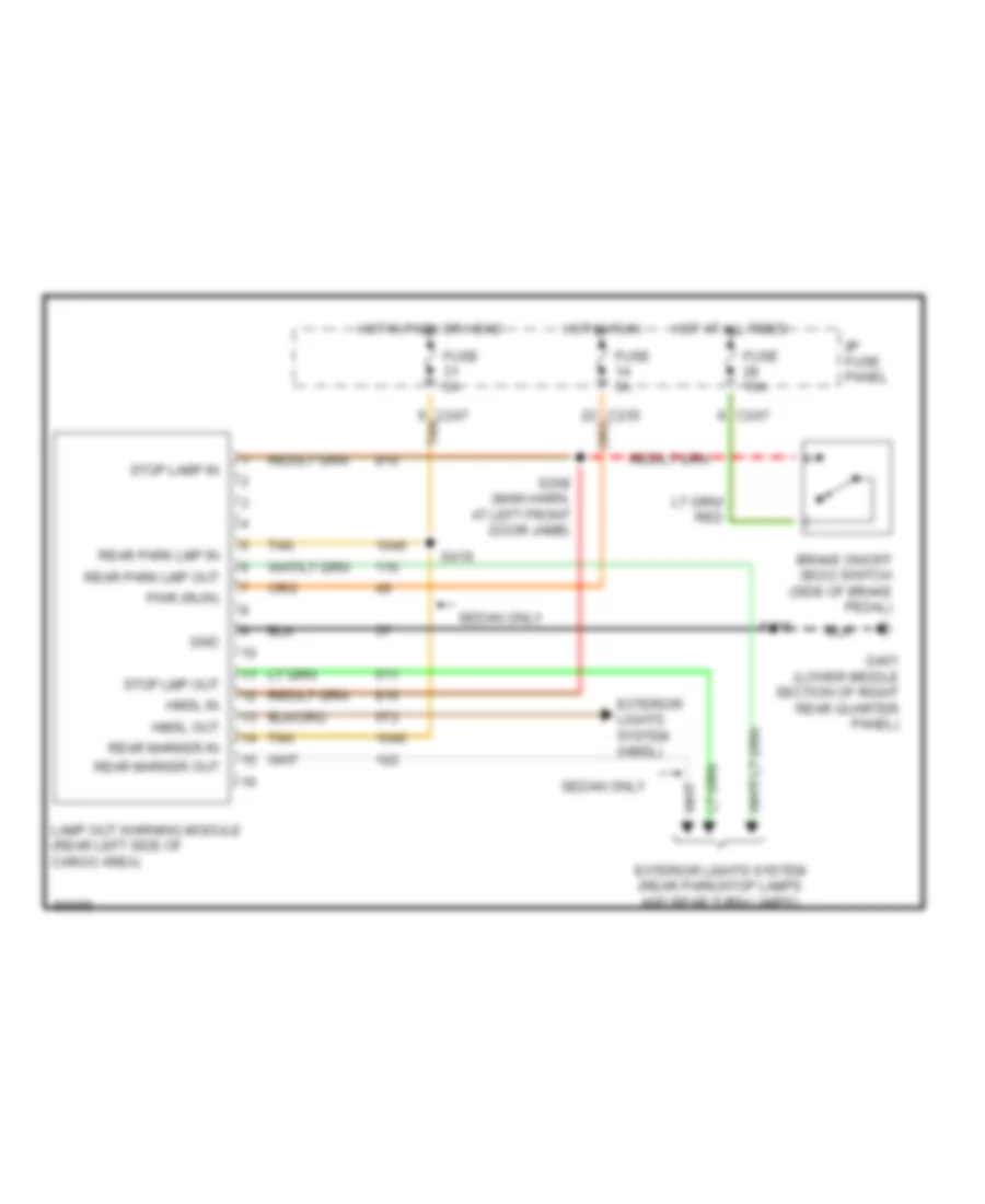
Exterior Lamps Wiring Diagram, Sedan with Lamp Out Warning (2 of 2) for Ford Taurus SHO 1997
List of elements for Exterior Lamps Wiring Diagram, Sedan with Lamp Out Warning (2 of 2) for Ford Taurus SHO 1997:
- (lower middle section of right rear quarter panel)
- (main body harn, near right rear of trunk) s415
- (main harn, near left front door jamb)
- (not used)
- Brake on/off (boo) switch (upper front side of brake pedal)
- C247 tan
- Fuse 15a
- Fuse 5a
- G401
- G401 (lower middle section of right rear quarter panel)
- Gnd
- Hmsl in
- Hmsl out
- Hot at all times
- Hot in run
- I/p fuse panel
- Lamp out warning module (left rear side of cargo area)
- Left license lamp
- Left rear park/ stop lamp
- Left rear side marker lamp
- Left rear turn lamp
- Pwr (acc/run)
- Rear marker lmp in
- Rear marker lmp out
- Rear park lmp in
- Rear park lmp out
- Right license lamp
- Right rear park/ stop lamp
- Right rear side marker lamp
- Right rear turn lamp
- S308
- S400
- S416
- S419
- S435
- Sable
- Stop lmp in
- Stop lmp out
- Tan
- Taurus
Exterior Lamps Wiring Diagram, Sedan without Lamp Out Warning (1 of 2) for Ford Taurus SHO 1997
List of elements for Exterior Lamps Wiring Diagram, Sedan without Lamp Out Warning (1 of 2) for Ford Taurus SHO 1997:
- (lower side of inner glove box lamp)
- Autolamp park relay (in eng compt fuse/relay box)
- C2031
- C235
- C250
- C251
- C269
- Electronic flasher (under left side of i/p)
- Engine compartment fuse/relay box
- Fuse 10a
- Fuse 15a
- G101 (right front fender, near coolant overflow reservoir)
- G104 (left front fender, near air cleaner)
- G206
- G206 (lower side of inner glove box lamp)
- G401 (lower middle section of right rear quarter panel)
- Hazard
- Head
- Headlamp switch
- Hot at all times
- Hot in run
- I/p fuse panel
- Instrument cluster
- Interior lights system
- Left
- Left front marker lamp
- Left front park/ turn lamp
- Left front turn lamp
- Left rear turn lamp
- Left turn ind
- Light sensor/ amplifier (right side of i/p vent, near windshield)
- Multi- function switch
- Normal
- Off
- Park
- Park lamps fuse 15a
- Right
- Right front marker lamp
- Right front park/ turn lamp
- Right front turn lamp
- Right rear turn lamp
- Right turn ind
- S119
- S125 (dash panel to headlamp junct harn, near battery)
- S126 (dash panel to headlamp junct harn, near battery)
- S135
- S143
- S145
- S223
- S416
- Sable
- Taurus
- To headlamp junct harn, eng cooling fan #1 breakout)
Exterior Lamps Wiring Diagram, Sedan without Lamp Out Warning (2 of 2) for Ford Taurus SHO 1997
List of elements for Exterior Lamps Wiring Diagram, Sedan without Lamp Out Warning (2 of 2) for Ford Taurus SHO 1997:
- (lower middle section of right rear quarter panel)
- (main body harn, near right rear of trunk) s415
- (not used)
- Brake on/off (boo) switch (upper front side of brake pedal)
- C247
- Fuse 15a
- G400 (upper middle section of left rear quarter panel)
- G401
- Hot at all times
- I/p fuse panel
- Left hi mount stop lamp
- Left license lamp
- Left rear park/ stop lamp
- Left rear side marker lamp
- Left rear turn lamp
- Right hi mount stop lamp
- Right license lamp
- Right rear park/ stop lamp
- Right rear side marker lamp
- Right rear turn lamp
- S308 (main harn, near left front door jamb)
- S400
- S415 (main body harn, near right rear of trunk)
- S416
- S418
- S435
- Sable
- Taurus
Exterior Lamps Wiring Diagram, Wagon with Lamp Out Warning (1 of 2) for Ford Taurus SHO 1997
List of elements for Exterior Lamps Wiring Diagram, Wagon with Lamp Out Warning (1 of 2) for Ford Taurus SHO 1997:
- (lower side of inner glove box lamp)
- Autolamp park relay (in eng compt fuse/relay box)
- C2031
- C235
- C250
- C251
- C269
- Electronic flasher (under left side of i/p)
- Engine compartment fuse/relay box
- Fuse 10a
- Fuse 15a
- G101 (right front fender, near coolant overflow reservoir)
- G104 (left front fender, near air cleaner)
- G206
- G206 (lower side of inner glove box lamp)
- Hazard
- Head
- Headlamp switch
- Hot at all times
- Hot in run
- I/p fuse panel
- Instrument cluster
- Interior lights system
- Left
- Left front marker lamp
- Left front park/ turn lamp
- Left front turn lamp
- Left turn ind
- Light sensor/ amplifier (right side of i/p vent, near windshield)
- Multi- function switch
- Normal
- Off
- Park
- Park lamps fuse 15a
- Right
- Right front marker lamp
- Right front park/ turn lamp
- Right front turn lamp
- Right turn ind
- S119
- S125 (dash panel to headlamp junct harn, near battery)
- S126 (dash panel to headlamp junct harn, near battery)
- S135
- S143
- S145
- S223
- Sable
- Taurus
- To headlamp junct harn, near, eng cooling fan #1 breakout)
Exterior Lamps Wiring Diagram, Wagon with Lamp Out Warning (2 of 2) for Ford Taurus SHO 1997
List of elements for Exterior Lamps Wiring Diagram, Wagon with Lamp Out Warning (2 of 2) for Ford Taurus SHO 1997:
- (main harn, near left front door jamb)
- (rear window heater ground harn, near license lamps breakout) s432
- (rear window heater ground harn, near rear window defrost grid breakout) s428
- Brake on/off (boo) switch (upper front side of brake pedal)
- C247 tan
- Fuse 15a
- Fuse 5a
- G400 (upper middle section of left rear quarter panel)
- G401 (lower middle section of right rear quarter panel)
- Gnd
- Hmsl in
- Hmsl out
- Hot at all times
- Hot in run
- I/p fuse panel
- Lamp out warning module (left rear side of cargo area)
- Left hi mount stop lamp
- Left rear park/ stop lamp
- Left rear side marker lamp
- Left rear turn lamp
- License lamps
- Nca
- Pwr (acc/run)
- Rear park lmp in
- Rear park lmp out
- Right hi mount stop lamp
- Right rear park/ stop lamp
- Right rear side marker lamp
- Right rear turn lamp
- S308
- S404
- S405 (main body harn, near right rear park/stop lamp breakout)
- S408 (main body harn, at right rear pillar)
- S429
- S433
- Stop lmp in
- Stop lmp out
- Tan
Exterior Lamps Wiring Diagram, Wagon without Lamp Out Warning (1 of 2) for Ford Taurus SHO 1997
List of elements for Exterior Lamps Wiring Diagram, Wagon without Lamp Out Warning (1 of 2) for Ford Taurus SHO 1997:
- (lower side of of inner glove box lamp)
- Autolamp park relay (in eng compt fuse/relay box)
- C2031
- C235
- C250
- C251
- C269
- Electronic flasher (under left side of i/p)
- Engine compartment fuse/relay box
- Fuse 10a
- Fuse 15a
- G101 (right front fender, near coolant overflow reservoir)
- G104 (left front fender, near air cleaner)
- G206
- G206 (lower side of inner glove box lamp)
- Hazard
- Head
- Headlamp switch
- Hot at all times
- Hot in run
- I/p fuse panel
- Instrument cluster
- Interior lights system
- Left
- Left front marker lamp
- Left front park/ turn lamp
- Left front turn lamp
- Left turn ind
- Light sensor/ amplifier (right side of i/p vent, near windshield)
- Multi- function switch
- Normal
- Off
- Park
- Park lamps fuse 15a
- Right
- Right front marker lamp
- Right front park/ turn lamp
- Right front turn lamp
- Right turn ind
- S119
- S125 (dash panel to headlamp junct harn, near battery)
- S126 (dash panel to headlamp junct harn, near battery)
- S135
- S143
- S145
- S145 (dash panel to headlamp junct harn, near eng cooling fan #1 breakout)
- S223
- S226 (main harn, near left corner of i/p)
- Sable
- Taurus
Exterior Lamps Wiring Diagram, Wagon without Lamp Out Warning (2 of 2) for Ford Taurus SHO 1997
List of elements for Exterior Lamps Wiring Diagram, Wagon without Lamp Out Warning (2 of 2) for Ford Taurus SHO 1997:
- Brake on/off (boo) switch (upper front side of brake pedal)
- C247
- Fuse 15a
- G400 (upper middle section of left rear quarter panel)
- G401 (lower middle section of right rear quarter panel)
- Hot at all times
- I/p fuse panel
- Left hi mount stop lamp
- Left rear park/ stop lamp
- Left rear side marker lamp
- Left rear turn lamp
- License lamps
- Nca
- Right hi mount stop lamp
- Right rear park/ stop lamp
- Right rear side marker lamp
- Right rear turn lamp
- S308 (main harn, near left front door jamb)
- S404
- S408 (main body harn, at right rear pillar)
- S428 (rear window heater ground harn, near rear window defrost grid breakout)
- S429
- S432 (rear window heater ground harn, near license lamps breakout)
- S433
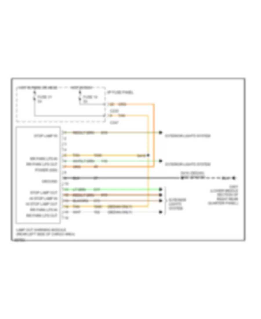
Lamp Outage Module Wiring Diagram for Ford Taurus SHO 1997
List of elements for Lamp Outage Module Wiring Diagram for Ford Taurus SHO 1997:
- (sedan only)
- C235
- C247
- Exterior lights system
- Fuse 14 5a
- Fuse 31 5a
- G401 (lower middle section of right rear quarter panel)
- Ground
- Hi stop lamp in
- Hi stop lamp out
- Hot in park or head
- Hot in run
- I/p fuse panel
- Lamp out warning module (rear left side of cargo area)
- Power (ign)
- Rr park lps in
- Rr park lps out
- S416 (sedan) s433 (wagon)
- S419
- Stop lamp in
- Stop lamp out
- Tan
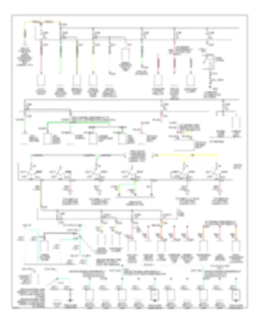
GROUND DISTRIBUTION
Ground Distribution Wiring Diagram (1 of 3) for Ford Taurus SHO 1997
List of elements for Ground Distribution Wiring Diagram (1 of 3) for Ford Taurus SHO 1997:
- (body harness, left front door)
- (body harness, near left rear window motor)
- (engine harness, near air pump)
- (engine harness, near breakout to camshaft position sensor)
- (engine harness, near breakout to crankshaft position sensor; 24v)
- (engine harness, near breakout to left headlamp) s121
- 3.0l 12v ffv
- 3.0l 12v ffv only
- 3.0l 12v only
- 3.0l 24v & 3.4 sho only
- 3.0l 24v only
- 3.4l sho
- 3.4l sho & 3.0l
- 3.4l sho only
- 3.ol
- 87a
- A/c high pressure switch
- Air bag diagnostic monitor
- All door lock relay
- All door unlock relay
- Anti-lock brake control module
- Battery
- Brake fluid level switch
- C248
- C276
- C277
- C501
- C509
- C510
- Camshaft position (cmp) sensor
- Camshaft position (cmp) sensor shield
- Constant control relay module
- Crankshaft position (ckp) sensor shield
- Data link connector
- Eam air pump
- Eam solid state relay
- Engine compartment fuse/relay box
- Engine coolant fan #1
- Engine coolant fan #2
- Flex fuel sensor
- G100 (left front fender)
- G101 (right front fender, near coolant overflow reservoir)
- G104 (left front fender, near air cleaner)
- G106
- G123 (upper right center of cowl)
- G200 (on left kick panel)
- Generic electronic module (gem)
- Hood tamper switch
- Intake manifold runner control (imrc)
- Keyless entry keypad switch assembly
- Left front door ajar switch
- Left front door lock switch
- Left front park/turn lamp
- Left front shock actuator
- Left front turn lamp
- Left head- lamp
- Left master door lock switch
- Left power heated/ mirror
- Left power mirror switch
- Left rear door ajar switch
- Left rear window switch
- Mass air flow (mass) sensor
- Master window control switch assembly
- Nca
- Of eng compt, near abs module)
- Passive anti-theft system (pats)
- Powertrain control module (pcm)
- Remote climate control (rcc) module
- Remote personality (rap) module
- Right front park/ turn lamp
- Right front shock actuator
- Right front turn lamp
- Right head- lamp
- S105 (engine harness, near breakout to crankshaft position sensor; ex. 24v)
- S106 (engine harness, near breakout to pcm)
- S108 (engine harness, near breakout to pcm)
- S120 (engine harness, near breakout to conn c1049, left headlamp)
- S135 (engine harness, left side of engine compt)
- S158
- S158 (engine harness, near air pump)
- S206 (i/p harness, left side of i/p)
- S215 (i/p harness, in breakout to conn c242, behind icp)
- S506
- Speed control module
- Starter relay
- Trunklid release switch
- Vehicle speed sensor (vss)
- W/ eatc only
- W/ taurus sho & ffv only
- Wind- shield wiper motor
- Windshield washer pump motor
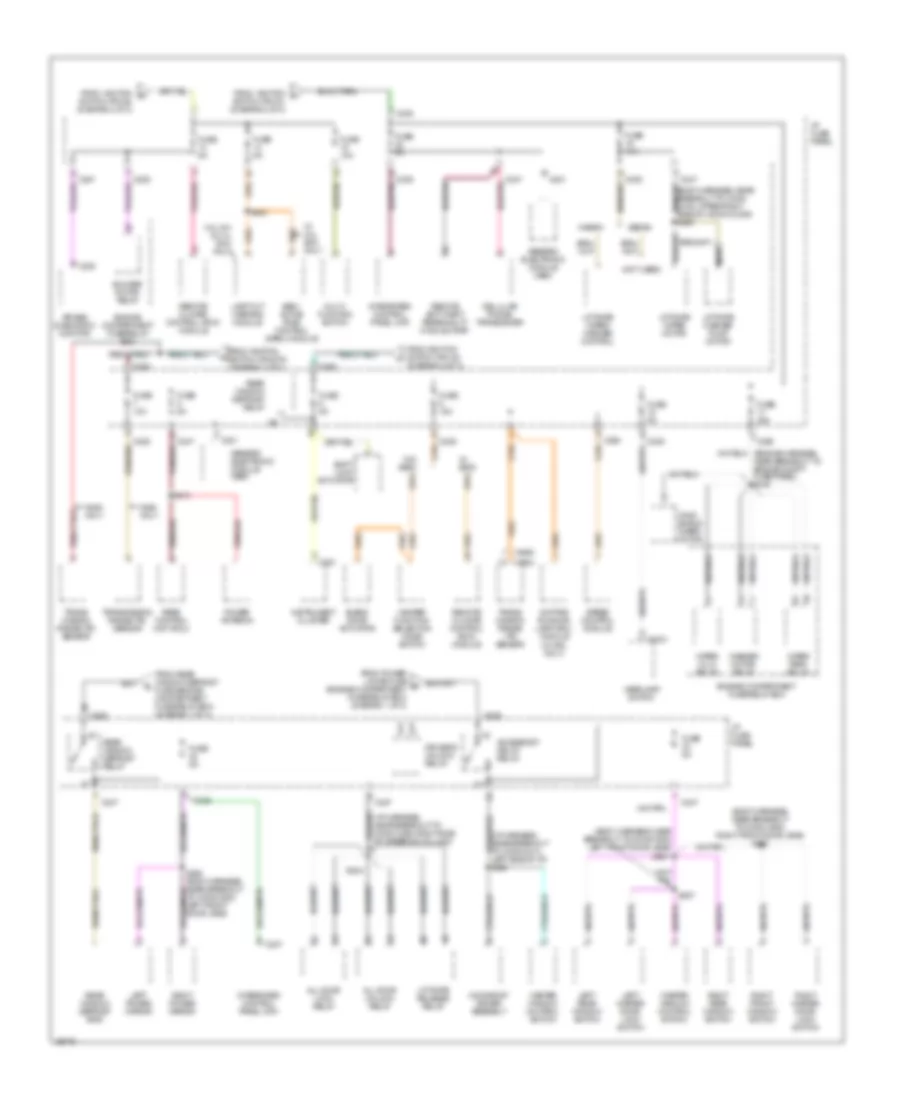
Ground Distribution Wiring Diagram (2 of 3) for Ford Taurus SHO 1997
List of elements for Ground Distribution Wiring Diagram (2 of 3) for Ford Taurus SHO 1997:
- (i/p harness, center of i/p)
- (left side of cargo area, near cellular phone transceiver)
- (upper middle section of left rear quarter panel)
- Astray lamp
- Blend door actuator
- Blower motor relay
- Blower motor speed controller
- Blower resistor
- Blower switch
- C250
- C252
- Cellular phone transceiver
- Cigar lighter
- Compact disc changer
- Data link connector
- Dome switch/ lamp
- Electronic flasher
- Engine compartment fuse/relay box
- G203 (right kick panel)
- G206 (lower side of inner glove box frame)
- G400
- G404
- Glove box switch lamp
- Head- lamp switch
- Heater function selector switch
- Ignition switch
- Instrument cluster
- Integrated control panel (icp)
- Left back- up lamp
- Left hi mount stop lamp
- Left i/p courtesy lamp
- Left power lumbar compressor
- Left seat control switch
- Liftgate door ajar switch
- Liftgate window ajar switch
- Liftgate wiper/ washer control
- Moonroof drive assembly
- Nca
- Only
- Overhead console
- Power antenna
- Prndl/ transmission control illumination
- Rear control unit (rcu)
- Rear window defrost grid)
- Right back- up lamp
- Right front door ajar switch
- Right front door lock switch
- Right front window switch
- Right hi mount stop lamp
- Right i/p courtesy lamp
- Right master door lock switch
- Right power mirror
- Right rear door ajar switch
- Right rear window switch
- S212
- S223 (i/p harness, near breakout to electronic flasher unit)
- S303 (body harness)
- S320
- S439 (audio system wiring diagram)
- S600 (body harness, near breakout to right front window motor)
- S800 (body harness, right rear door)
- Seat belt switch
- Sedan
- Sedan w/ rap
- Shift lock actuator
- Subwoofer
- Subwoofer amplifier assembly
- Trunk lid release switch
- W/ eatc
- W/ moon- roof
- W/o eatc
- Wagon
Ground Distribution Wiring Diagram (3 of 3) for Ford Taurus SHO 1997
List of elements for Ground Distribution Wiring Diagram (3 of 3) for Ford Taurus SHO 1997:
- 3.4l sho only
- Anti- theft alarm switch
- C451
- Cargo lamp
- Cargo lamp relay
- Except 3.4l sho
- Fuel pump/ fuel gauge sender
- G401 (lower middle section of right rear quarter panel)
- Lamp out warning module
- Left backup lamp
- Left license lamp
- Left rear park/ stop lamp
- Left rear shock actuator
- Left rear side marker lamp
- Left rear turn lamp
- License lamps
- Liftgate wiper motor
- Nca
- Rear window defrost grid
- Right backup lamp
- Right license lamp
- Right rear park/ stop lamp
- Right rear shock actuator
- Right rear side marker lamp
- Right rear turn lamp
- S400 (body harness, left rear of trunk)
- S404 (body harness, right rear cargo area)
- S416 (body harness, near breakout to g401)
- S433 (body harness, near breakout to liftgate wiper motor)
- S435 (body harness, right rear marker light)
- S442 (body harness, near breakout to right rear shock actuator)
- S451 (body harness, near breakout to right rear side of vehicle)
- Sable
- Sedan only
- Semi-active ride control (sarc) module
- Taurus
- Trunklid ajar switch/ release solenoid
- Trunklid anti-theft switch
- W/ rap
- Wagon only
HEADLIGHTS
Autolamps Wiring Diagram, with DRL for Ford Taurus SHO 1997
List of elements for Autolamps Wiring Diagram, with DRL for Ford Taurus SHO 1997:
- (behind integrated control panel) remote anti-theft personality (rap) module
- (left front fender, near air cleaner)
- (lower side of inner glove box frame)
- (main harn, near electronic flasher breakout)
- 15a
- 200k
- 3.6k
- Acc
- Autolamp headlamp relay (in engine compartment fuse/relay box)
- Autolamp on ind
- Autolamp rly
- Brake fluid level sw
- Brake fluid level switch (right of master cylinder)
- Brake ind
- C2031
- C2032
- C2037
- C225
- C235
- C247
- C250
- C268
- Daytime running lamps (drl) module (below left headlamp)
- Daytime running lamps fuse 15a
- Delay
- Engine compartment fuse/relay box
- Exterior lights system (autolamp park relay)
- Fuse
- Fuse 10a
- Fuse 15a
- G101 (right front fender, near coolant overflow reservoir)
- G104
- G104 (left front fender, near air cleaner)
- G206
- Gnd
- Head
- Headlamp switch
- Headlamp switch illum
- Headlamps fuse (auto) 30a
- Hi beam in
- Hi beam ind out
- High beam ind
- Hot at all times
- Hot in acc or run
- Hot in run
- Hot in run or start
- I/p fuse panel
- Ignition switch
- Instrument cluster
- Left headlamp
- Light sensor/amplifier (right side of i/p vent, near windshield)
- Lo beam in
- Lock
- Low ftp
- Multi- function switch
- Off
- On/off in
- Park
- Park lamp fuse 15a
- Parking brake sw out
- Parking brake switch (above brake pedal)
- Pulse width dimming module
- Pwr (bat)
- Pwr (run)
- Pwr (start/run)
- Right headlamp
- Run
- S123 (dash panel to headlamp junct harn, near left headlamp breakout)
- S135
- S139
- S143
- S145
- S212
- S223
- S224
- S226
- Solid state
- Start
- Time delay in
Autolamps Wiring Diagram, without DRL for Ford Taurus SHO 1997
List of elements for Autolamps Wiring Diagram, without DRL for Ford Taurus SHO 1997:
- (behind integrated control panel) remote anti-theft personality (rap) module
- (lower side of inner glove box frame)
- (main harn, near electronic flasher breakout)
- 200k
- 3.6k
- All others
- Autolamp headlamp relay (in engine compart- ment fuse/ relay box)
- Autolamp on ind
- Autolamp rly
- C2031
- C2032
- C2037
- C225
- C235
- C247
- C250
- C268
- Daytime running lamp (drl) jumper (below left headlamp)
- Delay
- Engine compartment fuse/relay box
- Exterior lights system (autolamp park relay)
- Ftp
- Fuse 10a
- Fuse 15a
- Fuse 5a
- G101 (right front fender, near coolant overflow reservoir)
- G104 (left front fender, near air cleaner)
- G206
- Head
- Headlamp switch
- Headlamp switch illum
- Headlamps fuse (auto) 30a
- High beam ind
- Hot at all times
- Hot in acc or run
- Hot in run or start
- I/p fuse panel
- Instrument cluster
- Left headlamp
- Light sensor/amplifier (right side of i/p vent, near windshield)
- Low
- Multi- function switch
- Off
- On/off in
- Park
- Park lamp fuse 15a
- Pulse width dimming module
- Pwr (bat)
- Pwr (start/run)
- Right headlamp
- S123 (dash panel to headlamp junct harn, near left headlamp breakout)
- S135
- S139
- S143
- S145
- S223
- S224
- S226
- Solid state
- Taurus w/ abs
- Time delay in
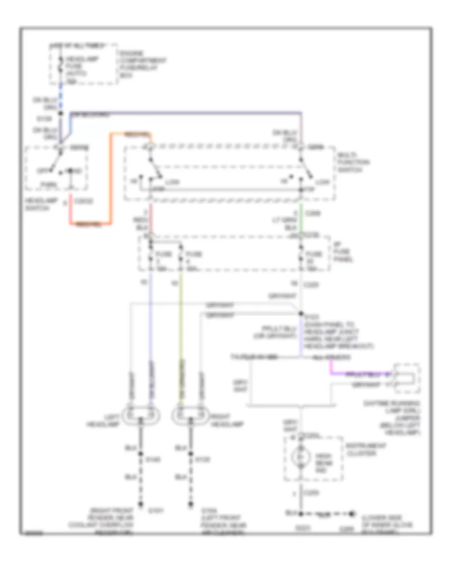
Headlamps Wiring Diagram, with DRL for Ford Taurus SHO 1997
List of elements for Headlamps Wiring Diagram, with DRL for Ford Taurus SHO 1997:
- (dash panel to headlamp junct harn, near left front fender) s127
- (left front fender, near air cleaner)
- (lower side of inner glove box frame)
- 15a
- 30a
- Acc
- Brake fluid level sw
- Brake fluid level switch (right of master cylinder)
- Brake ind
- C2032
- C225
- C235
- C250
- C268
- Daytime running lamps (drl) module (below left headlamp)
- Daytime running lamps fuse
- Engine compartment fuse/relay box
- Fuse
- Fuse 10a
- Fuse 15a
- G101 (right front fender, near coolant overflow reservoir)
- G104
- G104 (left front fender, near air cleaner)
- G206
- Gnd
- Head
- Headlamp switch
- Headlamps fuse (auto)
- Hi beam in
- Hi beam ind out
- High beam ind
- Hot at all times
- Hot in run
- Hot in start or run
- I/p fuse panel
- Ignition switch
- Instrument cluster
- Left headlamp
- Lo beam in
- Lock
- Low ftp
- Multi- function switch
- Off
- Park
- Parking brake sw out
- Parking brake switch (above brake pedal)
- Pwr (bat)
- Pwr (run)
- Right headlamp
- Run
- S123 (dash panel to headlamp junct harn, near left headlamp breakout)
- S135
- S139
- S145
- S212
- S223
- Start
Headlamps Wiring Diagram, without DRL for Ford Taurus SHO 1997
List of elements for Headlamps Wiring Diagram, without DRL for Ford Taurus SHO 1997:
- (lower side of inner glove box frame)
- (right front fender, near coolant overflow reservoir)
- All others
- C2032
- C225
- C235
- C250
- C268
- Daytime running lamp (drl) jumper (below left headlamp)
- Engine compartment fuse/relay box
- Fuse 10a
- Fuse 15a
- G101
- G104 (left front fender, near air cleaner)
- G206
- Head
- Headlamp fuse (auto) 30a
- Headlamp switch
- High beam ind
- Hot at all times
- I/p fuse panel
- Instrument cluster
- Left headlamp
- Low ftp
- Multi- function switch
- Off
- Park
- Right headlamp
- S123 (dash panel to headlamp junct harn, near left headlamp breakout)
- S135
- S139
- S145
- S223
- Taurus w/ abs
HORN
Horn Wiring Diagram for Ford Taurus SHO 1997
List of elements for Horn Wiring Diagram for Ford Taurus SHO 1997:
- C102
- C254
- Clockspring assembly
- Cruise control system
- Engine compartment fuse/relay box
- Fuse 15a
- G104 (left front fender, near air cleaner)
- High pitch horn (front left frame rail)
- Horn
- Horn relay (in engine compartment fuse/ relay box)
- Horn relay control
- Horn/speed control switch
- Hot at all times
- Low pitch horn (front right frame rail)
- Nca
- Remote anti-theft personality module (behind integrated control panel)
- S135
- S144
- Speed control module (on left front strut)
- Speed control module jumper (near left front strut)
- Switches
- W/ anti- theft only
- W/ speed control
- W/o speed control
INSTRUMENT CLUSTER
3.0L
3.0L Flex Fuel, Instrument Cluster Wiring Diagram for Ford Taurus SHO 1997
List of elements for 3.0L Flex Fuel, Instrument Cluster Wiring Diagram for Ford Taurus SHO 1997:
- (attached to the underside of i/p fuse panel)
- (conn a)
- (conn b)
- (left front fender)
- (left front fender, near air cleaner)
- (left side of i/p)
- (lower side of inner glove box frame)
- (not
- (on i/p fuse pnl)
- (right rear corner of eng compt, mounted in cowl)
- 0.51k
- A10
- A13
- A14
- A15
- A16
- Acc
- Air bag ind
- Anti-lock brake ind
- Anti-lock brakes system
- Anti-slosh module
- B10
- B11
- B12
- B15
- B16
- Brake fluid level switch (right of master cylinder)
- Brake ind
- C225
- C235
- C236
- C250
- C251
- Check engine ind
- Cruise control system
- Cruise on ind
- Daytime running lamps (drl) jumper (below left headlamp)
- Daytime running lamps (drl) module (below left headlamp)
- Distance to empty (dte) module
- Door ajar ind
- Door ajar ind ctrl
- Dte
- Engine coolant temperature gauge
- Engine coolant temperature sender (near ther- mostat)
- Engine oil pressure switch (left top rear corner of eng block)
- Exterior lights system
- Flex fuel sender module (behind center of i/p)
- Fuel gauge
- Fuel pump/ fuel gauge sender (in fuel tank)
- Fuse
- G101
- G104
- G206
- Generator/ battery ind
- Generic elec- tronic module
- Generic electronic module (gem)
- Gnd
- Headlamp switch
- Headlight system
- High beam ind
- Hot at all times i/p fuse panel
- Hot in run
- Hot in start or run
- I/p fuse panel
- Ignition switch
- Instrument cluster
- Integrated control panel (right of steering column)
- Interior lights system
- Left turn ind
- Lock
- Low coolant ind ctrl
- Low fuel ind
- Mil
- Off
- Oil pressure ind
- Parking brake switch (above brake pedal)
- Power- train control module
- Powertrain control module (right rear of eng compt, mounted in cowl)
- Right turn ind
- Run
- S104 (near crksft pos sensor)
- S120
- S135
- S142
- S209 (dash to hdlmp harn left side of i/p)
- S212
- S216
- S223
- S224
- Seat belt ind
- Seat belt ind ctrl
- Six back light illum ind
- Speed control module (left of master cylinder)
- Speed- ometer
- Start
- Starting/ charging system
- Tach
- Tachometer
- Used)
- Vehicle speed sensor (on trans- axle)
- Vss+
- W/ drl
- W/o drl
3.0L, Instrument Cluster Wiring Diagram for Ford Taurus SHO 1997
List of elements for 3.0L, Instrument Cluster Wiring Diagram for Ford Taurus SHO 1997:
- (conn a)
- (conn b)
- (conn c)
- (dash to hdlmp harn left side of i/p)
- (left front fender)
- (left front fender) g101
- (left front fender, near air cleaner)
- (lower side of inner glove box frame)
- (main harn, left side of i/p) s232
- (main harn, left side of i/p) s233
- (right rear corner of eng compt, mounted in cowl)
- 0.51k
- 15a
- A10
- A12
- A13
- A14
- A15
- A16
- Acc
- Air bag ind
- Anti-lock brake ind
- Anti-lock brakes system
- Anti-slosh module
- Anti-theft ind
- Anti-theft system
- B10
- B11
- B12
- B13
- B14
- B16
- Brake fluid level switch (right of master cylinder)
- Brake ind
- C225
- C235
- C236
- C250
- C251
- C252
- C450
- Check engine ind
- Cruise control system
- Cruise on ind
- D/2
- Daytime running lamps (drl) jumper (below left headlamp)
- Daytime running lamps (drl) module (below left headlamp)
- Dimming control
- Door ajar ind
- Door ajar ind ctrl
- Engine coolant temperature gauge
- Engine coolant temperature sender (near thermostat)
- Engine oil pressure switch (left top rear corner of eng block)
- Exterior lights
- Exterior lights system
- Exterior lights system (backup lamps)
- Fuel
- Fuel gauge
- Fuel pump/ fuel gauge sender (in fuel tank)
- Fuse
- G101
- G104
- G206
- Generator/ battery ind
- Generic electronic module (gem) (attached to the underside of i/p fuse panel)
- Generic electronic module (on i/p fuse pnl)
- Gnd
- Headlights system
- High beam ind
- Hot at all times i/p fuse panel
- Hot in run
- Hot in start or run
- I/p fuse panel
- Ignition switch
- Instrument cluster
- Interior lights system
- Interior lights system (pulse width dimming module)
- Left turn ind
- Lock
- Low coolant ind
- Low coolant ind ctrl
- Low fuel ind
- Mil
- Nca
- Off
- Oil pressure ind
- Parking brake switch (above brake pedal)
- Powertrain control module
- Powertrain control module (right rear of eng compt, mounted in cowl)
- Prndl/transmission control illumination (in center console)
- Right turn ind
- Run
- S104 (near crksft pos sensor)
- S105
- S120
- S135
- S142
- S209
- S212
- S216
- S223
- S224
- Seat belt ind
- Seat belt ind ctrl
- Semi-active ride control (sarc) module (behind right rear seat)
- Sho only
- Six back light illum ind
- Speed control module (left of master cylinder)
- Speed- ometer
- Start
- Starting/ charging
- Tach
- Tachometer
- Tcil
- Tcil ind
- Transmission range sensor (top of transaxle housing)
- Vehicle speed sensor (on tras)
- Vss+
- W/ drl
- W/o drl
Lamp Outage Wiring Diagram for Ford Taurus SHO 1997
List of elements for Lamp Outage Wiring Diagram for Ford Taurus SHO 1997:
- Brake on/off (boo) switch (side of brake pedal)
- C235
- C247
- Exterior lights system (hmsl)
- Exterior lights system (rear park/stop lamps and rear turn lamps)
- Fuse 15a
- Fuse 5a
- G401 (lower middle section of right rear quarter panel)
- Gnd
- Hmsl in
- Hmsl out
- Hot at all times
- Hot in park or head
- Hot in run
- I/p fuse panel
- Lamp out warning module (rear left side of cargo area)
- Pwr (run)
- Rear marker in
- Rear marker out
- Rear park lmp in
- Rear park lmp out
- S308 (main harn, at left front door jamb)
- S416
- S419
- Sedan only
- Stop lamp in
- Stop lmp out
- Tan
3.4L
3.4L SHO, Instrument Cluster Wiring Diagram for Ford Taurus SHO 1997
List of elements for 3.4L SHO, Instrument Cluster Wiring Diagram for Ford Taurus SHO 1997:
- (conn a)
- (conn b)
- (conn c)
- (dash to hdlmp harn left side of i/p)
- (left front fender)
- (left front fender) g101
- (left front fender, near air cleaner)
- (lower side of inner glove box frame)
- (main harn, left side of i/p) s232
- (main harn, left side of i/p) s233
- (right rear corner of eng compt, mounted in cowl)
- 0.51k
- 15a
- A10
- A12
- A13
- A14
- A15
- A16
- Acc
- Air bag ind
- Anti-lock brake ind
- Anti-lock brakes system
- Anti-slosh module
- Anti-theft ind
- Anti-theft system
- B10
- B11
- B12
- B13
- B14
- B16
- Brake fluid level switch (right of master cylinder)
- Brake ind
- C225
- C235
- C236
- C250
- C251
- C252
- C450
- Check engine ind
- Cruise control system
- Cruise on ind
- D/2
- Daytime running lamps (drl) jumper (below left headlamp)
- Daytime running lamps (drl) module (below left headlamp)
- Dimming control
- Door ajar ind
- Door ajar ind ctrl
- Engine coolant temperature gauge
- Engine coolant temperature sender (near thermostat)
- Engine oil pressure switch (left top rear corner of eng block)
- Exterior lights
- Exterior lights system
- Exterior lights system (backup lamps)
- Fuel
- Fuel gauge
- Fuel pump/ fuel gauge sender (in fuel tank)
- Fuse
- G101
- G104
- G206
- Generator/ battery ind
- Generic electronic module (gem) (attached to the underside of i/p fuse panel)
- Generic electronic module (on i/p fuse pnl)
- Gnd
- Headlights system
- High beam ind
- Hot at all times i/p fuse panel
- Hot in run
- Hot in start or run
- I/p fuse panel
- Ignition switch
- Instrument cluster
- Interior lights system
- Interior lights system (pulse width dimming module)
- Left turn ind
- Lock
- Low coolant ind
- Low coolant ind ctrl
- Low fuel ind
- Mil
- Nca
- Off
- Oil pressure ind
- Parking brake switch (above brake pedal)
- Powertrain control module
- Powertrain control module (right rear of eng compt, mounted in cowl)
- Prndl/transmission control illumination (in center console)
- Right turn ind
- Run
- S104 (near crksft pos sensor)
- S105
- S120
- S135
- S142
- S209
- S212
- S216
- S223
- S224
- Seat belt ind
- Seat belt ind ctrl
- Semi-active ride control (sarc) module (behind right rear seat)
- Sho only
- Six back light illum ind
- Speed control module (left of master cylinder)
- Speed- ometer
- Start
- Starting/ charging
- Tach
- Tachometer
- Tcil
- Tcil ind
- Transmission range sensor (top of transaxle housing)
- Vehicle speed sensor (on tras)
- Vss+
- W/ drl
- W/o drl
Lamp Outage Wiring Diagram for Ford Taurus SHO 1997
List of elements for Lamp Outage Wiring Diagram for Ford Taurus SHO 1997:
- Brake on/off (boo) switch (side of brake pedal)
- C235
- C247
- Exterior lights system (hmsl)
- Exterior lights system (rear park/stop lamps and rear turn lamps)
- Fuse 15a
- Fuse 5a
- G401 (lower middle section of right rear quarter panel)
- Gnd
- Hmsl in
- Hmsl out
- Hot at all times
- Hot in park or head
- Hot in run
- I/p fuse panel
- Lamp out warning module (rear left side of cargo area)
- Pwr (run)
- Rear marker in
- Rear marker out
- Rear park lmp in
- Rear park lmp out
- S308 (main harn, at left front door jamb)
- S416
- S419
- Sedan only
- Stop lamp in
- Stop lmp out
- Tan
INTERIOR LIGHTS
Courtesy Lamps Wiring Diagram for Ford Taurus SHO 1997
List of elements for Courtesy Lamps Wiring Diagram for Ford Taurus SHO 1997:
- door
- (interior lamp feed harn, near overhead console breakout)
- (main body harn, in right rear door jamb) s301
- (main body harn, near right "a" pillar)
- (main wiring harn, under left side of i/p)
- (right rear qtr. panel)
- 87a
- Battery saver relay
- Battery saver relay control
- Bright
- C201
- C2031
- C2032
- C235
- C247
- C248
- Cargo lamp (wagon)
- Cargo lamp relay (wagon) (right rear center of vehicle, below cargo flooring)
- Diode center (right rear center of vehicle, below cargo flooring)
- Dome lamp
- Dome lamp switch
- Dome switch/ lamp
- Dome switch/ lamp breakout) s902
- Door
- From battery saver relay (i/p fuse panel)
- Fuse 10a
- Fuse 5a
- G200 (on left kick panel)
- G203 (on right right panel)
- G203 (right kick panel)
- G206 (lower side of inner glove box frame)
- G400 (upper middle section of left rear quarter panel)
- G401
- G401 (lower middle section of right rear quarter panel)
- Generic electronic module (attached to i/p fuse panel)
- Glove box open
- Glove box switch/lamp
- Headlamp switch
- Hot at all times
- I/p fuse panel (left side of i/p)
- Interior lamp relay
- Interior lamp relay control
- Left backup lamp breakout) s430
- Left front door ajar switch
- Left i/p courtesy lamp
- Left map lamp
- Left rear door ajar switch
- Left vanity mirror
- Lf door ajar input
- Liftgate ajar input
- Liftgate door ajar switch (wagon)
- Liftgate lock switch
- Liftgate window ajar switch (wagon)
- Lr door ajar input
- Luggage compartment lamp (sedan only)
- Mirror open
- Nca
- Off
- Overhead console
- Rf door ajar input
- Right front door ajar switch
- Right i/p courtesy lamp
- Right map lamp
- Right rear door ajar switch
- Right vanity mirror
- Rr door ajar input
- S212
- S212 or s230
- S223
- S304 (main body harn, near right front door jamb)
- S313
- S404
- S429
- S500
- S600
- S700
- S800
- S900
- S901
- Sedan
- To left & right vanity mirrors
- Trunklid ajar switch/ release solenoid (sedan only)
- W/ moonroof
- W/o moonroof
- Wagon
- Wagon only
Instrument Illumination Wiring Diagram for Ford Taurus SHO 1997
List of elements for Instrument Illumination Wiring Diagram for Ford Taurus SHO 1997:
- (2)
- (6)
- (8)
- (left front door window reg harn, near left front door jamb) s503
- (main body harn, near left front door jamb) s307
- (main wiring harn, under left side of i/p) s221
- (right front door window reg harn, near right front door jamb) s601
- Acc
- Acc delay relay control
- Accessory delay relay
- Ashtray lamp
- Battery saver relay
- Battery saver relay control
- C201
- C2031
- C2032
- C225
- C235
- C247
- C250
- C251
- C252
- C501
- Cigar lighter
- Dimming module
- Distance to empty (dte) module
- Engine compartment fuse/relay box (behind radiator)
- Fuse 5a
- Fuse 10a
- Fuse 5a
- G200 (on left kick panel)
- G203 (on right kick panel)
- G206 (lower side of inner glove box frame)
- Generic electronic module (attached to i/p fuse panel)
- Ground
- Head
- Headlamp switch
- Headlamp switch backlight
- Headlamp switch illumination (w/ autolamps/ delayed exit)
- Hot at all times
- I/p fuse panel (left side of i/p)
- Ignition switch
- Illum
- Instr illum
- Instrument cluster
- Integrated control panel (right of steering column)
- Lamps on
- Left master door lock switch
- Left rear window switch
- Liftgate/ wiper washer control (wagon only)
- Lock
- Master window control switch
- Nca
- Off
- Park
- Park lamps fuse 20 15a
- Power locks fuse 4 30a
- Prndl/ transmission control illumination
- Pulse width dimming module
- Right front window switch
- Right master door lock switch
- Right rear window switch
- Run
- S143
- S223
- S303
- S506
- S600
- S700
- S800
- Solid state
- Start
- W/ autolamps/ delayed exit
POWER ANTENNA
Power Antenna Wiring Diagram for Ford Taurus SHO 1997
List of elements for Power Antenna Wiring Diagram for Ford Taurus SHO 1997:
- (wagon) (sedan)
- Antenna
- C247
- C478
- Fuse 22
- Fuse 8
- G400 (upper middle section of left rear quarter panel)
- Gnd
- Hot at all times
- Hot in start
- I/p fuse panel
- Ign
- Nca
- Power antenna (left rear side of cargo area)
- Radio antenna
- Rear control unit (rcu) (in left rear body of car)
- S313
- S412 s418
- S413
- Solid state
POWER DISTRIBUTION
Power Distribution Wiring Diagram (1 of 3) for Ford Taurus SHO 1997
List of elements for Power Distribution Wiring Diagram (1 of 3) for Ford Taurus SHO 1997:
- (3.0l 24v & 3.4l sho) only)
- (audio system wiring harness)
- (body harness, near breakout to conn c420, below driver's seat)
- (engine harness, near breakout to conn c1019, left of battery)
- (engine harness, near breakout to conn c137, near exhaust manifold) s148
- (i/p harness, in breakout to conn c186, left front fender)
- (i/p harness, in breakout to conn c471, left side of cargo area)
- (i/p harness, near breakout to conn c256, right side of steering column) s208
- (lumbar)
- 10a
- 175a
- 3.4l sho
- Abs module fuse 30a
- Abs module fuse 40a
- Air bag diagnostic monitor
- Air bag fuse 10a
- All others
- Alternator fuse 30a
- Anti-lock brake control module
- Auto- lamp head- lamp relay
- Auto- lamp park relay
- Battery
- Blower motor fuse 40a
- Blower motor relay
- C2031
- C225
- C235
- C247
- C250
- C276
- Cellular phone in-line fuse (above left rear wheel well)
- Cellular phone transceiver
- Compact disc changer
- Constant control relay module
- Cooling fan fuse 40a
- Daytime running lamps (drl) module (w/ drl only)
- Daytime running lamps (drl) module (w/ drl)
- Daytime running lamps fuse 15a
- Eam solid state relay
- Eeec power fuse 30a
- Engine compartment fuse/relay box
- Engine controls system
- Exterior lights system
- Fuel pump fuse 20a
- Fuse 10a
- Fuse 15a
- Fuse 5a
- Generator/ voltage regulator
- Ground distribution
- Head
- Headlamp switch
- Headlamps fuse (auto) 30a
- Hego fuse 15a
- Horn fuse 15a
- Horn relay
- I/p fuse panel
- I/p fuse panel fuse 40a
- Ignition fuse 40a
- Instrument cluster
- Lamp out warning module
- Left headlamp
- Left seat control switch
- Low ftp
- Mega fuse (right side of eng compt fuse/relay box)
- Multi- function switch
- Nca
- Near breakout to conn c1049, left headlamp) s123
- Off
- Park
- Park lamps fuse 15a
- Power locks fuse 30a
- Power seats fuse 40a
- Powertrain control module (pcm)
- Pulse width dimming module
- Radio fuse 20a
- Rear control unit
- Rear window defrost fuse 20a
- Red
- Right headlamp
- Right seat control switch
- S127
- S132 (engine harness, near breakout to conn c1019, left of battery)
- S139
- S141 (engine harness, near breakout to conn c1019, left of battery)
- S143
- S144
- S318 (body harness, near breakout to conn c335, below driver's seat)
- S414 (body harness, near breakout to conn c435, left rear wheel well)
- S419
- S423 (body harness, near breakout to conn c435, left rear wheel well)
- S436
- Sedan only
- Semi-active ride control fuse 30a
- Semi-active ride control module
- Starter motor/ relay
- Starter relay (3.0l 24v & 3.4l sho)
- Tan
- Tan/red
- Taurus w/ abs, w/o drl
- Thermactor air bypass solenoid
- Thermactor pump fuse 30a
- To fuse 29 (i/p fuse panel) (diagram 2 of 3)
- To i/p fuse panel (accessory delay relay) (diagram 3 of 3)
- To ignition switch (pins b1 & b3) (diagram 2 of 3)
- To ignition switch (pins b4 & b5) (diagram 2 of 3)
- To rear window defrost relay (i/p fuse panel) (diagram 3 of 3)
Power Distribution Wiring Diagram (2 of 3) for Ford Taurus SHO 1997
List of elements for Power Distribution Wiring Diagram (2 of 3) for Ford Taurus SHO 1997:
- #1 coil per plug (cpp)
- #2 coil per plug (cpp)
- #3 coil per plug (cpp)
- #4 coil per plug (cpp)
- #5 coil per plug (cpp)
- #6 coil per plug (cpp)
- #7 coil per plug (cpp)
- #8 coil per plug (cpp)
- (body harness, near breakout to conn c701, left rear door jamb switch) s313
- (eatc)
- (engine harness, near breakout to conn c1031, radio noise capacitor) (others) (engine harness, near breakout to conn c1008, heated oxygen sensor) (24v engine)
- (engine harness, near breakout to conn c1040, left headlamp)
- (engine harness, near breakout to conn c174 & c175, #5 & #6 ignition coil) s161
- (i/p fuse panel) (diagram 3 of 3)
- (i/p harness, near breakout to conn c227, center of i/p) s211
- (i/p harness, near breakout to conn c292, left side of i/p) s224
- (lower side of inner glove box frame)
- 20a
- 3.0l 24v
- 3.0l 24v & 3.4l sho only
- 3.4l sho
- 3.ol 12v
- 3.ol 24v & 3.4l sho
- Acc
- Air bag diagnostic monitor
- Anti- theft disarm switch
- Anti-lock brake control module
- Battery saver relay
- Brake on/ off (boo) switch
- C201
- C211
- C212
- C225
- C229
- C235
- C236
- C238
- C247
- C250
- C251
- C254
- Cigar lighter
- Constant control relay module
- Data link connector
- Ffv only
- Flex fuel sender module
- From i/p fuse panel fuse (engine compartment fuse/relay box) (diagram 1 of 3)
- From ignition fuses (engine compartment
- Fuse
- Fuse 10a
- Fuse 11 5a
- Fuse 12 5a
- Fuse 15a
- Fuse 20a
- Fuse 5a
- Fuse 9 10a
- Fuse/relay box) (diagram 1 of 3)
- G206
- Generic electronic module (gem)
- Gnd
- Headlights system with drl
- I/p fuse panel
- Ignition coil
- Ignition switch
- Instru- ment cluster
- Instrument cluster
- Integrated control panel (icp)
- Interior lamp relay
- Left power mirror switch
- Light sensor/ amplifier
- Lock
- Luggage compartment lamp
- Multi- function switch
- Off
- Passive anti-theft system
- Passive anti-theft system (pats)
- Power antenna
- Prndl/ transmission control illumination
- Radio noise capacitor
- Radio noise capacitor #1
- Radio noise capacitor #2
- Remote anti-theft personality (rap) module
- Remote climate control (rcc) module
- Run
- S112
- S122
- S163 (engine harness, near breakout to conn c1031, radio noise capacitor)
- S212
- Sedan
- Speed control deactivate switch
- Sta
- Start
- To conn c239) s216
- To fuses 13, 14 & 15 (i/p fuse panel) (diagram 3 of 3)
- To fuses 17, 18, 19 & 20 (i/p fuse panel) (diagram 3 of 3)
- To fuses 5 & 6
- To fuses 7 & 8 (i/p fuse panel) (diagram 3 of 3)
- Transmission control switch
- Trunk lid release relay
- W/ abs only
- W/ rap
- W/o rap
- Wagon
Power Distribution Wiring Diagram (3 of 3) for Ford Taurus SHO 1997
List of elements for Power Distribution Wiring Diagram (3 of 3) for Ford Taurus SHO 1997:
- (ax4n)
- (ax4s)
- (body harness, near breakout to conn c502 left front door jamb)
- (body harness, near breakout to conn c600, right front door jamb) s203
- (i/p harness, near breakout to conn c256, right side of steering column)
- (not used)
- 3.0l 24v & 3.4l sho only
- Accessory delay relay
- Air bag diagnostic monitor
- All door lock relay
- All door unlock relay
- Ax4n only
- Ax4s only
- Blend door actuator
- Blower motor relay
- C201
- C2031
- C225
- C235
- C237
- C247
- C251
- C276
- Cellular phone transceiver
- Daytime running lamp (drl) module (w/ drl only)
- Driver's unlock relay
- Engine compartment fuse/relay box
- From ignition g
- From ignition h
- From ignition switch (pin a3) (diagram 2 of 3)
- From ignition switch (pin sta) (diagram 2 of 3)
- From power locks fuse (engine compartment fuse/relay box) (diagram 1 of 3)
- From rear window defrost fuse (engine compartment fuse/relay box) (diagram 1 of 3)
- Fuse 10a
- Fuse 15a
- Fuse 30a
- Fuse 5a
- Generic electronic module (gem)
- Headlamp switch
- Heater function selection mode switch
- I/p fuse panel
- Instrument cluster
- Integrated control panel (icp)
- Lamp out warning module
- Left master door lock switch
- Left power mirror
- Left rear window switch
- Liftgate release relay
- Liftgate washer pump motor
- Liftgate wiper motor
- Liftgate wiper/ washer control
- Master window control switch
- Moonroof driver assembly
- Multi- function switch
- Nca
- Near breakout to engine compt fuse panel) s140
- Power antenna
- Rear control unit (rcu)
- Rear window defrost grid
- Rear window defrost relay
- Remote anti-theft personality module (rap)
- Remote climate control (rcc) module
- Right front window switch
- Right master door lock switch
- Right power mirror
- Right rear window switch
- S204
- S309 (body harness, near breakout to conn c502 left front door jamb)
- S413
- S440
- S503
- S507
- Sedan
- Semi- active ride control (sarc) module
- Shift lock actuator
- Speed control module
- Switch (pin a1) (diagram 2 of 3)
- Switch (pin a4) (diagram 2 of 3)
- Trans- mission range (tr) sensor
- Transmission range (tr) sensor
- W/ 3.4l sho only
- W/ eatc
- W/o eatc
- Wagon
- Washer motor relay
- Wind- shield wiper motor
- Wiper hi/lo relay
- Wiper park relay
POWER DOOR LOCKS
Power Door Lock Wiring Diagram for Ford Taurus SHO 1997
List of elements for Power Door Lock Wiring Diagram for Ford Taurus SHO 1997:
- (1092)
- (below cargo flooring)
- (body harn, near break out to seat belt switch)
- (body harn, near breakout to 10 pin conn, in right rear door jamb)
- (body harn, near breakout to 38 pin conn, in left corner of i/p)
- (body harn, near breakout to 38 pin conn, in left corner of i/p) s201
- (body harn, near breakout to left front door jamb)
- * w/o rap
- ** w/ rap
- 87a
- All door lock relay
- All door unlock relay
- Anti-theft disarm switch (wagon w/ rap)
- C201
- C225
- C247
- C248
- C253
- C254
- Diode center
- Driver's unlock relay
- Driver's unlock relay control
- Engine compartment fuse/relay box (behind radiator)
- Fuse 5a
- G200 (left kick panel)
- G203 (right kick panel)
- G400 (upper middle section of left rear quarter panel)
- G401 (lower middle sec- tion of right rear quarter panel)
- Generic electronic module (attached to i/p fuse panel)
- Hot at all times
- I/p fuse panel (left side of i/p)
- Interior lights system (instrument illumination)
- Left front door lock motor
- Left front door lock switch
- Left master door lock switch
- Left rear door lock motor
- Liftgate door ajar switch
- Liftgate lock motor (wagon)
- Liftgate lock switch (wagon only)
- Liftgate release relay (wagon w/ rap)
- Liftgate window ajar switch
- Lock
- Power locks fuse 4 30a
- Pulse stretcher module
- Remote anti-theft personality module (behind integrated control panel)
- Right front door lock motor
- Right front door lock switch
- Right master door lock switch
- Right rear door lock motor
- S200 (body harn, near breakout to 38 pin conn, in left corner of i/p)
- S202
- S204
- S206
- S301
- S305
- S306
- S312 (body harn, near break- out to seat belt switch)
- S313
- S429
- S430 (back window harn, near breakout to left backup lamp)
- S433
- S500
- S600
- Sedan
- Trunk lid release relay
- Trunk lid release switch
- Unlock
- W/ keyless entry only
- W/ rap
- W/o rap
- Wagon
- Wagon w/ rap only
POWER MIRRORS
Power Mirror Wiring Diagram for Ford Taurus SHO 1997
List of elements for Power Mirror Wiring Diagram for Ford Taurus SHO 1997:
- C247
- Defogger system
- Direct- tional switch
- Fuse 5a
- G200 (on left kick panel)
- Heater
- Hot at all times
- I/p fuse panel
- L/r motor
- Left power mirror
- Left power mirror switch
- Left/ right switch
- Nca
- Red
- Right power mirror
- S313
- S501 (driver's door window regulator harness, near speaker)
- S506
- Up/dn motor
POWER SEATS
Power & Lumbar Seat Wiring Diagram for Ford Taurus SHO 1997
List of elements for Power & Lumbar Seat Wiring Diagram for Ford Taurus SHO 1997:
- (w/ lumbar)
- (w/ lumbar) s316
- Deflate
- Engine compartment fuse/relay box (behind radiator)
- Entire seat
- Front of seat
- Fwd
- G203 (right kick panel)
- Hot at all times
- Inflate
- Left lumbar air bladder
- Left lumbar seat switch
- Left power lumbar compressor
- Left seat control switch
- Left seat front height motor
- Left seat horizontal motor
- Left seat rear height motor
- Nca
- Pnk
- Power seats fuse 6 30a
- Rear of seat
- Red
- Rwd
- S303
- S310
- S318 (w/ lumbar)
POWER TOP/SUNROOF
Power Top/Sunroof Wiring Diagrams for Ford Taurus SHO 1997
List of elements for Power Top/Sunroof Wiring Diagrams for Ford Taurus SHO 1997:
- Accessory
- Accessory delay relay control
- Battery saver relay
- Battery saver relay control
- C201
- C225
- C247
- Close
- Delay relay
- Down
- Engine compartment fuse/relay box
- Fuse 10a
- G203 (right kick panel)
- Generic electronic module (under i/p fuse panel)
- Gnd
- Hot at all times
- I/p fuse panel
- Moon- roof motor
- Moonroof drive assembly (in center of vehicle's roof)
- Nca
- Open
- Overhead console
- Power locks fuse 30a
- Pwr
- Red
- S203
- S900
- Slid closed feed
- Slid open feed
- Slide
- Slide limit switch
- Solid state
- Tilt
- Tilt down feed
- Tilt limit switch
- Tilt up feed
POWER WINDOWS
Power Window Wiring Diagram for Ford Taurus SHO 1997
List of elements for Power Window Wiring Diagram for Ford Taurus SHO 1997:
- (main body harn, near breakout to c313) s302
- 87a
- Accessory delay relay
- Accessory delay relay ctrl
- Battery saver relay
- Battery saver relay ctrl
- C201
- C225
- C247
- C501
- C509
- Engine compartment fuse/relay box
- Fuse 10a
- Fuse 33 5a
- G200 (on left kick panel)
- Generic electronic module (under left side of i/p)
- Hot at all times
- I/p fuse panel
- Interior lights system
- Left front window motor
- Left rear window motor
- Left rear window switch
- Master window control switch
- One touch high sense
- One touch low sense
- One touch window down relay
- One touch window down relay ctrl
- Power locks fuse 4 30a
- Right front window motor
- Right front window switch
- Right rear window motor
- Right rear window switch
- S203
- S500
- S502 (window reg left fr door harn, near breakout to c502, left front door jamb)
- S507
- Shunt resistor
- Switch illum (8) (2 per rocker switch)
- Window lockout switch
- Window switch down in
- Window switch up in
RADIO
Radio Wiring Diagrams, with Cassette Deck for Ford Taurus SHO 1997
List of elements for Radio Wiring Diagrams, with Cassette Deck for Ford Taurus SHO 1997:
- (lower side of inner glove box frame) g206
- Air conditioning system
- Antenna
- Audio system on
- Audio sytem on
- C235
- C237
- C238
- C247
- C411
- C478
- C492
- Cassette left (+)
- Cassette left (-)
- Cassette right (+)
- Cassette right (-)
- Cd changer
- Cd left (+)
- Cd left (-)
- Cd right (+)
- Cd right (-)
- Cellular phone
- Defogger system
- Engine compartment fuse/relay box (front center of engine compt)
- Fuse 20a
- Fuse 5a
- Fused ignition
- G400 (left rear quarter panel)
- G404 (left side of cargo area)
- Ground
- Heated backlite
- Heated mirror
- Hot at all times
- Hot in run or acc
- Hot in run or start
- Hot in start
- I/p fuse panel (under left corner of dash)
- Illumination
- Integrated control panel
- Interior lights system
- L front spkr (+)
- L front spkr (-)
- L rear spkr (+)
- L rear spkr (-)
- Left front door sail speaker
- Left front door speaker
- Left rear speaker
- Left sig in
- Left sig out
- Memory seek
- Mirrors system
- Phone audio (+)
- Phone audio (-)
- Pnk
- Power
- Power antenna
- Protocol a
- Protocol b
- Protocol wakeup
- R front spkr (+)
- R front spkr (-)
- R rear spkr (+)
- R rear spkr (-)
- Radio memory
- Rear control unit (left rear side of cargo area)
- Red/pnk
- Right front door sail speaker
- Right front door speaker
- Right rear speaker
- Right sig in
- Right sig out
- S212
- S216
- S224
- S413
- S414
- S422
- S423
- Shield
- Tan
Radio Wiring Diagrams, without Cassette Deck for Ford Taurus SHO 1997
List of elements for Radio Wiring Diagrams, without Cassette Deck for Ford Taurus SHO 1997:
- (lower side of inner glove box frame) g206
- Air conditioning system
- Antenna
- Audio system on
- Audio sytem on
- C235
- C237
- C238
- C247
- C411
- C478
- C492
- Cellular phone
- Defogger system
- Engine compartment fuse/relay box (front center of engine compt)
- Fuse 20a
- Fuse 5a
- Fused ignition
- G400 (left rear quarter panel)
- Ground
- Heated backlite
- Heated mirror
- Hot at all times
- Hot in run or acc
- Hot in run or start
- Hot in start
- I/p fuse panel (under left corner of dash)
- Illumination
- Integrated control panel
- Interior lights system
- L front spkr (+)
- L front spkr (-)
- L rear spkr (+)
- L rear spkr (-)
- Left front door speaker
- Left rear speaker
- Mirrors system
- Phone audio (+)
- Phone audio (-)
- Pnk
- Power
- Power antenna
- Protocol a
- Protocol b
- R front spkr (+)
- R front spkr (-)
- R rear spkr (+)
- R rear spkr (-)
- Radio memory
- Rear control unit (left rear side of cargo area)
- Red/pnk
- Right front door speaker
- Right rear speaker
- S212
- S216
- S224
- S413
- S414
- S422
- Tan
SHIFT INTERLOCKS
Shift Interlock Wiring Diagram for Ford Taurus SHO 1997
List of elements for Shift Interlock Wiring Diagram for Ford Taurus SHO 1997:
- (1997)
- (1998)
- Brake pedal position (bpp) switch (upper front side
- C235
- C247
- C251
- Fuse 15a
- Fuse 5a
- G206 (lower side of inner glove box frame)
- Hot at all times
- Hot in run
- I/p fuse panel (under left corner of instrument cluster)
- Instrument cluster
- Of brake pedal)
- S212
- S308 (body harn, near breakout to 56 pin conn, in left front door jamb)
- S308 (body harn, near breakout to g200, at left kick panel)
- Shift lock actuator (bottom of steering column)
- Solid state
STARTING/CHARGING
3.0L
3.0L 12-Valve, Starting Wiring Diagram for Ford Taurus SHO 1997
List of elements for 3.0L 12-Valve, Starting Wiring Diagram for Ford Taurus SHO 1997:
- Acc
- Battery
- C235
- C247
- Charging circuit
- D/2
- Fuse 5a
- G104 (left front fender, near air cleaner)
- Hold
- Hot at all times
- I/p fuse panel
- Ignition switch
- Lock
- Off
- Power antenna
- Pull-in
- Red
- Run
- S231 (main body harness, near breakout to i/p fuse panel)
- S413
- Sta
- Start
- Starter motor/ solenoid (below oil filter)
- Transmission range (tr) sensor (left rear of eng compt, on top of transmission housing)
3.0L 24-Valve, Starting Wiring Diagram for Ford Taurus SHO 1997
List of elements for 3.0L 24-Valve, Starting Wiring Diagram for Ford Taurus SHO 1997:
- (left front fender, near air cleaner)
- Battery
- C225
- Charging system
- D/2
- Engine compartment fuse/ relay box
- Fuse 7 10a
- G104
- Hold
- Hot at all times
- Hot in start
- I/p fuse panel
- Ignition fuse 3 40a
- Pull-in
- Red
- S141
- S158
- Starter motor/ solenoid (below oil filter)
- Starter relay (in engine compartment fuse/ relay box)
- Tan/red
- Transmission range (tr) sensor (left rear of eng compt, on top of transmission housing)
3.0L Flex Fuel, Starting Wiring Diagram for Ford Taurus SHO 1997
List of elements for 3.0L Flex Fuel, Starting Wiring Diagram for Ford Taurus SHO 1997:
- Acc
- Battery
- C235
- C247
- Charging circuit
- D/2
- Fuse 5a
- G104 (left front fender, near air cleaner)
- Hold
- Hot at all times
- I/p fuse panel
- Ignition switch
- Lock
- Off
- Power antenna
- Pull-in
- Red
- Run
- S231 (main body harness, near breakout to i/p fuse panel)
- S413
- Sta
- Start
- Starter motor/ solenoid (below oil filter)
- Transmission range (tr) sensor (left rear of eng compt, on top of transmission housing)
Charging Wiring Diagram for Ford Taurus SHO 1997
List of elements for Charging Wiring Diagram for Ford Taurus SHO 1997:
- 175a
- 3.0 12-valve & 3.0l ffv only
- Alternator fuse 26 30a
- Battery
- C1071
- C153
- C154
- C235
- C251
- Engine compartment fuse/relay box
- Fuse
- G104 (left front fender, near air cleaner)
- Generator/ battery indicator
- Generator/ voltage regulator
- Hot in run or start
- I/p fuse panel
- Instrument cluster
- Mega fuse (right side of engine compt fuse/relay box)
- Ohms
- Red
- Starter motor/ solenoid
3.4L
3.4L SHO, Starting Wiring Diagram for Ford Taurus SHO 1997
List of elements for 3.4L SHO, Starting Wiring Diagram for Ford Taurus SHO 1997:
- (left front fender, near air cleaner)
- Battery
- C225
- Charging system
- D/2
- Engine compartment fuse/ relay box
- Fuse 7 10a
- G104
- Hold
- Hot at all times
- Hot in start
- I/p fuse panel
- Ignition fuse 3 40a
- Pull-in
- Red
- S141
- S158
- Starter motor/ solenoid (below oil filter)
- Starter relay (in engine compartment fuse/ relay box)
- Tan/red
- Transmission range (tr) sensor (left rear of eng compt, on top of transmission housing)
Charging Wiring Diagram for Ford Taurus SHO 1997
List of elements for Charging Wiring Diagram for Ford Taurus SHO 1997:
- 175a
- 3.0 12-valve & 3.0l ffv only
- Alternator fuse 26 30a
- Battery
- C1071
- C153
- C154
- C235
- C251
- Engine compartment fuse/relay box
- Fuse
- G104 (left front fender, near air cleaner)
- Generator/ battery indicator
- Generator/ voltage regulator
- Hot in run or start
- I/p fuse panel
- Instrument cluster
- Mega fuse (right side of engine compt fuse/relay box)
- Ohms
- Red
- Starter motor/ solenoid
SUPPLEMENTAL RESTRAINTS
Supplemental Restraint Wiring Diagram for Ford Taurus SHO 1997
List of elements for Supplemental Restraint Wiring Diagram for Ford Taurus SHO 1997:
- (i/p harn, behind left side of i/p)
- (main harn, in data link connector breakout)
- * pin shorting bar is engaged when module connector is disconnected
- 10*
- 11*
- Air bag diagnostic monitor (front center of i/p)
- Air bag fuse 16 10a
- Air bag ind
- Air bag indicator
- C235
- C247
- C251
- C276
- C277
- Clock- spring assembly
- Data link
- Data link connector (below left side of i/p)
- Driver's air bag
- Drvr air bag
- Engine compartment fuse/relay box (behind radiator)
- Fuse 5a
- G200 (left kick panel)
- Gnd
- Hot at all times
- Hot in run
- Hot in run or start
- I/p fuse panel (left side of i/p)
- Instrument cluster
- L crash sens
- Left radiator primary crash sensor
- Nca
- Pass air bag
- Passenger's air bag
- Pwr (bat)
- Pwr (run)
- R crash sens
- Right radiator primary crash sensor
- S206 (i/p harn, behind left side of i/p)
- S208
- S225
- Shorting bar
TRANSMISSION
3.0L
3.0L 12-Valve, Transmission Wiring Diagram for Ford Taurus SHO 1997
List of elements for 3.0L 12-Valve, Transmission Wiring Diagram for Ford Taurus SHO 1997:
- (dash panel to headlamp harn, left side of eng)
- (dash panel to junction wiring assembly, near break out to trans) s133
- (eng control sensor har- ness, near inj 6) s110
- (engine control sensor harness, lower left side of engine block) s104
- (engine control sensor harness, near exhaust manifold) s107
- (engine control sensor harness, near fuel inj 6)
- (engine control sensor harness, near trans)
- (engine control sensor harness, top rear of engine) s102
- (engine control sensor harness, top rear of engine) s103
- (in console) (ax4n console shift) prndl/transmission control illumination
- (left fender, near battery)
- Ax4s/ax4n transaxle
- Backup lamps
- Boo input
- Brake on/off (boo) switch (on brake pedal support)
- C191
- Case ground
- Check engine ind lamp c250
- Column shift
- Console shift
- Constant control relay module (left side of battery)
- Data link connector (center of dash)
- Dlc
- Dlc(+)
- Dlc(-)
- Drl module
- Ect
- Eeec power fuse 30a
- Eeec relay
- Electronic pressure control (epc) solenoid
- Engine compartment fuse/relay box
- Engine controls
- Engine coolant temperature (ect) sensor (on rear of engine block near thermostat)
- Epc sol
- Fuse 15a
- Fuse 20a
- Fuse 5a
- G100
- G100 (left front fender near air cleaner)
- G100 (left front of fender near battery)
- Hot at all times
- Hot in run
- Hot in run or start
- I/p fuse panel
- Iat sensor
- Ignition coil, radio noise capacitor
- Instrument cluster
- Instrument cluster (ax4n console shift only)
- Instrument cluster, gem, flex fuel module
- Instrument illumination
- Intake air temperature (iat) sensor (left rear of engine compartment on intake assy)
- Maf
- Maf input
- Mass air flow (maf) sensor (near engine air intake assembly)
- Mil
- N d
- Nca
- O/d off
- Power (vpwr)
- Powertrain control module (pcm) (right rear of engine compartment, mounted on firewall)
- Prndl/trans. control illum. (ax4n, console shift only)
- Red
- S101
- S105
- S106
- S111
- S120
- S134
- S135
- S209 (dash panel to headlamp wiring harn, in left corner of dash)
- S224
- S308 (main body wiring harness, left front door jamb)
- Shift sol 1
- Shift sol 2
- Shift sol 3
- Shift solenoid
- Sig return
- Speed control deactivate switch
- Speed control module, a/c system
- Tan/ red
- Tcc sol
- Tcs
- Tft
- Throttle position (tp) sensor (at top right side of engine, behind intake)
- To starting system
- Torque converter clutch (tcc) solenoid
- Tp sensor in
- Tr sensor
- Trans range (tr) sensor (left side of trans- axle)
- Transmission control switch (tcs) (ax4n column shift) (in steering column)
- Transmission fluid temperature (tft) sensor
- Tss sensor
- Turbine shaft speed (tss) sensor (on rear of transaxle)
- Vehicle speed sensor (vss) (rear center of engine compt, mounted on transaxle)
- Vref
- Vss input
3.0L 24-Valve, Transmission Wiring Diagram for Ford Taurus SHO 1997
List of elements for 3.0L 24-Valve, Transmission Wiring Diagram for Ford Taurus SHO 1997:
- (dash panel to headlamp harness, left side of engine)
- (dash panel to junction wiring assembly, near breakout to trans)
- (engine control sensor harness, lower left side of engine block) s104
- (engine control sensor harness, near exhaust)
- (engine control sensor harness, top rear of engine)
- (engine control sensor harness, top rear of engine) s102
- (engine control sensor harness, top right of engine)
- (engine control. sensor harness near thermostat)
- (in console) (ax4n console shift) prndl/transmission control illumination
- (left side of trans- axle) trans range sensor
- Ax4s/ax4n transaxle
- Backup lamps
- Boo input
- Brake on/off (boo) switch (on brake pedal support)
- C191
- Case ground
- Check engine ind lamp c250
- Column shift
- Console shift
- Constant control relay module (left side of battery)
- Data link connector (dlc) (center of dash)
- Dlc
- Dlc(+)
- Dlc(-)
- Drl module
- Ect
- Eeec power fuse 30a
- Eeec relay
- Electronic pressure control (epc) solenoid
- Engine compartment fuse/relay box
- Engine controls
- Engine coolant temperature (ect) sensor (above left side of engine block near thermostat)
- Epc sol
- Fuse 15a
- Fuse 20a
- Fuse 5a
- G100 (left fender, near battery)
- G100 (left front fender near air cleaner)
- G100 (left front of fender near battery)
- Hot at all times
- Hot in run
- Hot in run or start
- I/p fuse panel
- Iat sensor
- Ignition coil, radio capacitor, pats module
- Instrument cluster
- Instrument cluster (ax4n console shift only)
- Instrument cluster, gem, light sensor/ amplifier
- Instrument illumination
- Intake air temperature (iat) sensor (left rear of engine compartment on intake assy)
- Maf
- Maf input
- Mass air flow (maf) sensor (in engine air intake assembly)
- Mil
- N d
- Nca
- O/d off
- Power (vpwr)
- Powertrain control module (pcm) (right rear of engine compartment, mounted on firewall)
- Prndl/trans. control illum. (ax4n, console shift only)
- Red
- S105
- S106
- S107
- S120
- S122
- S133
- S135
- S147
- S150
- S151
- S153
- S209 (dash panel to headlamp wiring assy, in left corner of dash)
- S224
- S308 (main body wiring harness, left front door jamb)
- Shift sol 1
- Shift sol 2
- Shift sol 3
- Shift solenoid
- Sig return
- Speed control deactivate switch
- Speed control module, a/c system
- Tan/ red
- Tcc sol
- Tcil
- Tcs
- Tft
- Throttle position (tp) sensor (at top rear of engine, behind intake manifold)
- To starting system
- Torque converter clutch (tcc) solenoid
- Tp sensor in
- Tr sensor
- Transcmission ctrl ind lamp c251
- Transmission control switch (tcs) (ax4n column shift) (in steering column)
- Transmission fluid temperature (tft) sensor
- Tss sensor
- Turbine shaft speed (tss) sensor (on rear of transaxle)
- Vehicle speed sensor (vss) (rear center of engine compt, mounted on transaxle)
- Vref
- Vss input
3.0L Flex Fuel, Transmission Wiring Diagram for Ford Taurus SHO 1997
List of elements for 3.0L Flex Fuel, Transmission Wiring Diagram for Ford Taurus SHO 1997:
- (dash panel to headlamp harn, left side of eng)
- (dash panel to junction wiring assembly, near break out to trans) s133
- (eng control sensor har- ness, near inj 6) s110
- (engine control sensor harness, lower left side of engine block) s104
- (engine control sensor harness, near exhaust manifold) s107
- (engine control sensor harness, near fuel inj 6)
- (engine control sensor harness, near trans)
- (engine control sensor harness, top rear of engine) s102
- (engine control sensor harness, top rear of engine) s103
- (in console) (ax4n console shift) prndl/transmission control illumination
- (left fender, near battery)
- Ax4s/ax4n transaxle
- Backup lamps
- Boo input
- Brake on/off (boo) switch (on brake pedal support)
- C191
- Case ground
- Check engine ind lamp c250
- Column shift
- Console shift
- Constant control relay module (left side of battery)
- Data link connector (center of dash)
- Dlc
- Dlc(+)
- Dlc(-)
- Drl module
- Ect
- Eeec power fuse 30a
- Eeec relay
- Electronic pressure control (epc) solenoid
- Engine compartment fuse/relay box
- Engine controls
- Engine coolant temperature (ect) sensor (on rear of engine block near thermostat)
- Epc sol
- Fuse 15a
- Fuse 20a
- Fuse 5a
- G100
- G100 (left front fender near air cleaner)
- G100 (left front of fender near battery)
- Hot at all times
- Hot in run
- Hot in run or start
- I/p fuse panel
- Iat sensor
- Ignition coil, radio noise capacitor
- Instrument cluster
- Instrument cluster (ax4n console shift only)
- Instrument cluster, gem, flex fuel module
- Instrument illumination
- Intake air temperature (iat) sensor (left rear of engine compartment on intake assy)
- Maf
- Maf input
- Mass air flow (maf) sensor (near engine air intake assembly)
- Mil
- N d
- Nca
- O/d off
- Power (vpwr)
- Powertrain control module (pcm) (right rear of engine compartment, mounted on firewall)
- Prndl/trans. control illum. (ax4n, console shift only)
- Red
- S101
- S105
- S106
- S111
- S120
- S134
- S135
- S209 (dash panel to headlamp wiring harn, in left corner of dash)
- S224
- S308 (main body wiring harness, left front door jamb)
- Shift sol 1
- Shift sol 2
- Shift sol 3
- Shift solenoid
- Sig return
- Speed control deactivate switch
- Speed control module, a/c system
- Tan/ red
- Tcc sol
- Tcs
- Tft
- Throttle position (tp) sensor (at top right side of engine, behind intake)
- To starting system
- Torque converter clutch (tcc) solenoid
- Tp sensor in
- Tr sensor
- Trans range (tr) sensor (left side of trans- axle)
- Transmission control switch (tcs) (ax4n column shift) (in steering column)
- Transmission fluid temperature (tft) sensor
- Tss sensor
- Turbine shaft speed (tss) sensor (on rear of transaxle)
- Vehicle speed sensor (vss) (rear center of engine compt, mounted on transaxle)
- Vref
- Vss input
3.4L
3.4L SHO, Transmission Wiring Diagram for Ford Taurus SHO 1997
List of elements for 3.4L SHO, Transmission Wiring Diagram for Ford Taurus SHO 1997:
- (dash panel to headlamp harness, left side of engine)
- (dash panel to junction wiring assembly, near breakout to trans)
- (engine control sensor harness, lower left side of engine block) s104
- (engine control sensor harness, near exhaust)
- (engine control sensor harness, top rear of engine)
- (engine control sensor harness, top rear of engine) s102
- (engine control sensor harness, top right of engine)
- (engine control. sensor harness near thermostat)
- (engine control. sensor harness, near thermostat)
- (left side of trans- axle) trans range sensor
- Ax4s/ax4n transaxle
- Backup lamps
- Boo input
- Brake on/off (boo) switch (on brake pedal support)
- C191
- Case ground
- Check engine ind lamp c250
- Column shift
- Console shift
- Constant control relay module (left side of battery)
- Data link connector (dlc) (center of dash)
- Dlc
- Dlc(+)
- Dlc(-)
- Drl module
- Ect
- Eeec power fuse 30a
- Eeec relay
- Electronic pressure control (epc) solenoid
- Engine compartment fuse/relay box
- Engine controls
- Engine coolant temperature (ect) sensor (above left side of engine block near thermostat)
- Epc sol
- Fuse 15a
- Fuse 20a
- Fuse 5a
- G100 (left fender, near battery)
- G100 (left front fender near air cleaner)
- G100 (left front of fender near battery)
- Hot at all times
- Hot in run
- Hot in run or start
- I/p fuse panel
- Iat sensor
- Ignition coil, radio capacitor, pats module
- Instrument cluster
- Instrument cluster (ax4n console shift only)
- Instrument cluster, gem, light sensor/ amplifier
- Instrument illumination
- Intake air temperature (iat) sensor (left rear of engine compartment on intake assy)
- Maf
- Maf input
- Mass air flow (maf) sensor (on air intake assembly)
- Mil
- N d
- Nca
- O/d off
- Power (vpwr)
- Powertrain control module (pcm) (right rear of engine compartment, mounted on firewall)
- Prndl/trans. control illum. (ax4n, console shift only)
- Prndl/transmission control illumination (in console)
- Red
- S105
- S106
- S107
- S120
- S122
- S133
- S135
- S147
- S150
- S151
- S153
- S209 (dash panel to headlamp wiring assy, in left corner of dash)
- S224
- S308 (main body wiring harness, left front door jamb)
- Shift sol 1
- Shift sol 2
- Shift sol 3
- Shift solenoid
- Sig return
- Speed control deactivate switch
- Speed control module, a/c system
- Tan/ red
- Tcc sol
- Tcil
- Tcs
- Tft
- Throttle position (tp) sensor (at top rear of engine, behind intake manifold)
- To starting system
- Torque converter clutch (tcc) solenoid
- Tp sensor in
- Tr sensor
- Transcmission ctrl ind lamp c251
- Transmission fluid temperature (tft) sensor
- Tss sensor
- Turbine shaft speed (tss) sensor (on rear of transaxle)
- Vehicle speed sensor (vss) (rear center of engine compt, mounted on transaxle)
- Vref
- Vss input
TRUNK, TAILGATE, FUEL DOOR
Trunk Release Wiring Diagram for Ford Taurus SHO 1997
List of elements for Trunk Release Wiring Diagram for Ford Taurus SHO 1997:
- (lower middle section of right rear quarter panel)
- C247
- Fuse 15a
- G203 (right kick panel)
- G401
- Hot at all times
- I/p fuse panel
- Interior lights system
- Remote anti-theft personality (rap) module (behind integrated control panel)
- S211
- S303
- S416
- Trunklid ajar switch/ release solenoid (on trunklid latch mechanism)
- Trunklid release relay (under center of i/p)
- Trunklid release switch
- W/ rap
- W/o rap
WARNING SYSTEMS
Warning System Wiring Diagrams for Ford Taurus SHO 1997
List of elements for Warning System Wiring Diagrams for Ford Taurus SHO 1997:
- (main body harn, near right rear door jamb)
- (wagon only)
- Battery
- C201
- C2031
- C223
- C235
- C236
- C248
- C250
- C251
- C254
- Data link
- Data link connector (below steering column)
- Diode center (wagon) (right rear center of vehicle, below cargo flooring)
- Door ajar ind
- Door ajar indicator
- Engine coolant level switch (on engine coolant reservoir)
- Fuse 5a
- G100 (left front fender)
- G101 (right front fender)
- G200 (on left kick panel)
- G203 (on right kick panel)
- G400 (upper middle section of left rear quarter panel)
- Gem chime/ tone logic
- Generic electronic module (gem) (attached to i/p fuse panel)
- Gnd
- Head
- Headlamp sw in
- Headlamp switch
- Hot at all times
- Hot in acc or run
- Hot in run
- Hot in run or start
- Hot in start
- I/p fuse panel (left side of i/p)
- Ign (run/acc)
- Ign (start)
- Instrument cluster
- Key warn sw in
- Key warning switch
- Left front door ajar switch
- Left rear door ajar switch
- Lf door ajar sw
- Liftgate ajar sws
- Liftgate door ajar switch (wagon)
- Liftgate window ajar switch (wagon)
- Low coolant ind
- Low coolant indicator
- Low coolant sw
- Lr door ajar sw
- Off
- Park
- Rap module in
- Rap sig in
- Remote anti-theft personality module (behind integrated control panel)
- Rf door ajar sw
- Right front door ajar switch
- Right rear door ajar switch
- Rr door ajar sw
- S120
- S145
- S224
- S225
- S301
- S303
- S311 (main body harn, near seatbelt switch breakout)
- S429
- S430 (back window heater ground harn, near left back up lamp breakout)
- S500
- S506
- S600
- S800
- Seat belt ind
- Seat belt indicator
- Seatbelt sw in
- Seatbelt switch
WIPER/WASHER
Front Wiper/Washer Wiring Diagram for Ford Taurus SHO 1997
List of elements for Front Wiper/Washer Wiring Diagram for Ford Taurus SHO 1997:
- (1997)
- (1997) (1998)
- (1998)
- (1998) (1997)
- 103.3k
- 11.3k
- 20.3k
- 3.3k
- 36.3k
- 4.08k
- 47.6k
- 51.3k
- 68.3k
- 82.3k
- 87a
- C223
- C225
- C236
- C248
- C268
- Circuit breaker
- Engine compartment fuse/relay box box (front center of engine compt) relay control box 1 (near left side of battery, behind headlamp)
- Fuse 30a
- G101 (right front fender, near coolant overflow reservoir)
- G104 (left front fender, near air cleaner)
- G200 (on left kick panel)
- Generic electronic module (attached to i/p fuse panel)
- Ground
- Hi lo
- Hot in acc or run
- I/p fuse panel (under left rear of instrument cluster)
- Int max
- Int min
- Multi- function switch
- Off
- Off int max
- Park
- Park sense
- Run
- Run/park relay ctrl
- S124 (dash to headlamp harness, near breakout to left headlamp)
- S135
- S140
- S145
- S236
- Tan/ red
- Washer motor relay
- Washer motor relay ctrl
- Washer switch
- Windshield washer pump motor
- Windshield wiper motor
- Wiper hi/lo relay
- Wiper hi/lo relay ctrl
- Wiper park relay
- Wiper switch
- Wiper/washer input
- Wiper/washer return
Rear Wiper/Washer Wiring Diagram for Ford Taurus SHO 1997
List of elements for Rear Wiper/Washer Wiring Diagram for Ford Taurus SHO 1997:
- (1997) g401 (1998) g405
- (lower middle section of right rear quarter panel)
- (lower side of inner glove box frame)
- C235
- C247
- Fuse 15a
- G206
- Hot in run or acc
- I/p fuse panel (under left corner of instrument cluster)
- Interior lights system (pulse width dimming module)
- Liftgate washer pump motor (right rear of vehicle, in reservoir)
- Liftgate wiper motor
- Liftgate wiper/washer control
- Nca
- Park switch
- S223
- S409
- S433
- Solid state
- Switch illum
- Washer switch
- Wiper switch