AIR CONDITIONING
3.8L
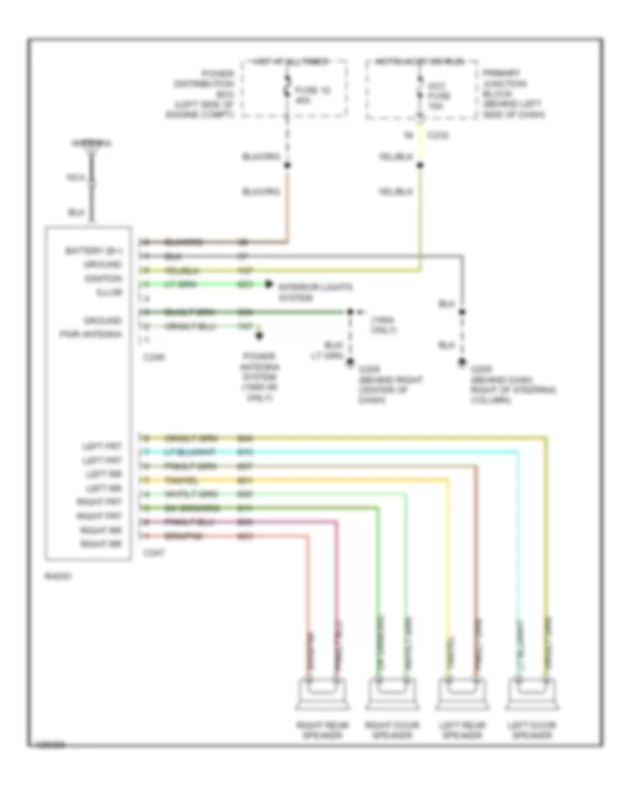
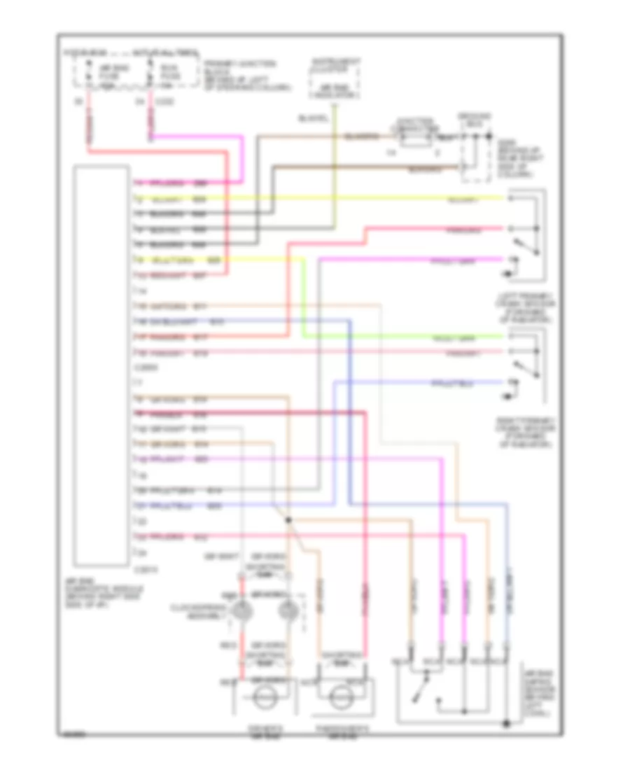
3.8L SC, A/C Wiring Diagram, Auto A/C (1 of 2) for Ford Thunderbird LX 1995

List of elements for 3.8L SC, A/C Wiring Diagram, Auto A/C (1 of 2) for Ford Thunderbird LX 1995:
- 2 std fuse 5a
- 30a
- A/c clutch cycling pressure switch (right rear of engine compartment on accumulator)
- A/c fuse 10a
- Acc
- Atc ambient temperature sensor (right front of vehicle, on lower radiator support)
- Blower in-line fuse holder (behind left side of i/p, taped to harness)
- Blower motor
- Blower motor speed controller (behind right side of i/p)
- C233
- C240
- C298
- Cold engine lockout switch (top right side of engine)
- Def
- Flr
- Flr/def
- G202 (behind i/p, right of steering column)
- G203 (behind right cowl panel)
- Hot at all times
- Hot in run
- Ignition switch
- In-car temperature sensor (behind top left side of i/p)
- Interior lights system
- Joint connec- tor 1
- Joint connector
- Lock
- Max
- Norm
- Off
- Off pan/flr
- Outside/ recirculate solenoid (behind right side of i/p)
- Pan/flr flr
- Panel
- Power distribution box
- Primary junction block
- Run
- Run fuse 5a
- Secondary junction block
- Semi-automatic temperature control module (center of i/p)
- Solid state
- Start
- Sunload sensor (behind right top of i/p)
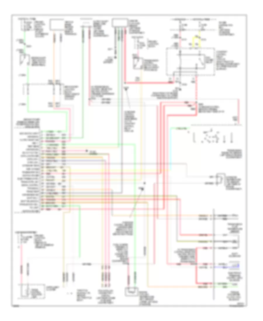
3.8L SC, A/C Wiring Diagram, Auto A/C (2 of 2) for Ford Thunderbird LX 1995
List of elements for 3.8L SC, A/C Wiring Diagram, Auto A/C (2 of 2) for Ford Thunderbird LX 1995:
- (not used)
- A/c clutch coil
- A/c clutch control
- A/c high pressure cutout/fan switch (lower right rear of engine compartment on a/c line)
- Blend door actuator (behind left side of i/p)
- C 1995 vftc
- Edf relay
- Edf relay control
- Electric cooling fan
- Electric cooling pusher fan
- Fl 5 60a
- Fuel pump relay
- G109 (left front of vehicle, on upper radiator support)
- G109 (right front of vehicle, on upper radiator support)
- Hedf 1 relay
- Hedf 2 relay
- Hot at all times
- Integrated relay control module (right front of engine compartment on upper radiator support
- Pcm power relay
- Power distribution box
- Powertrain control module (behind right cowl panel)
- Pusher fan relay (behind left shock tower)
- Red
- Solid state
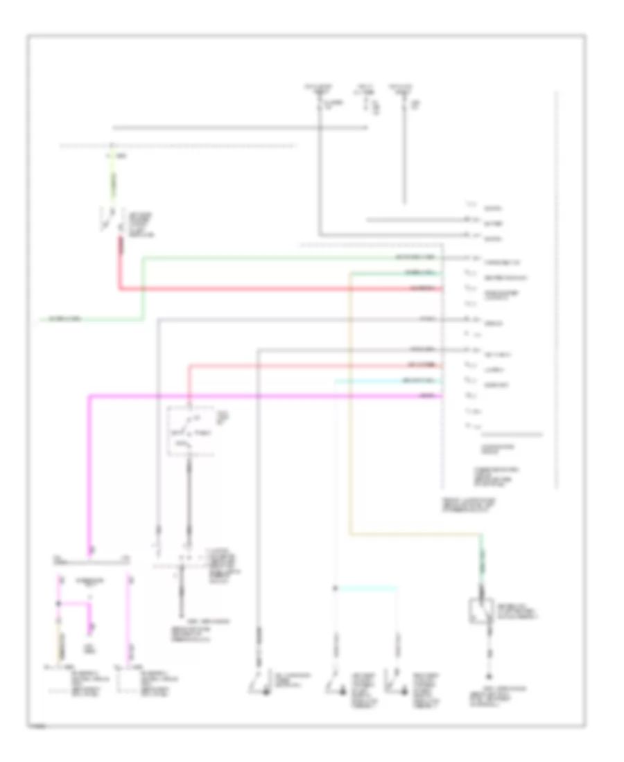
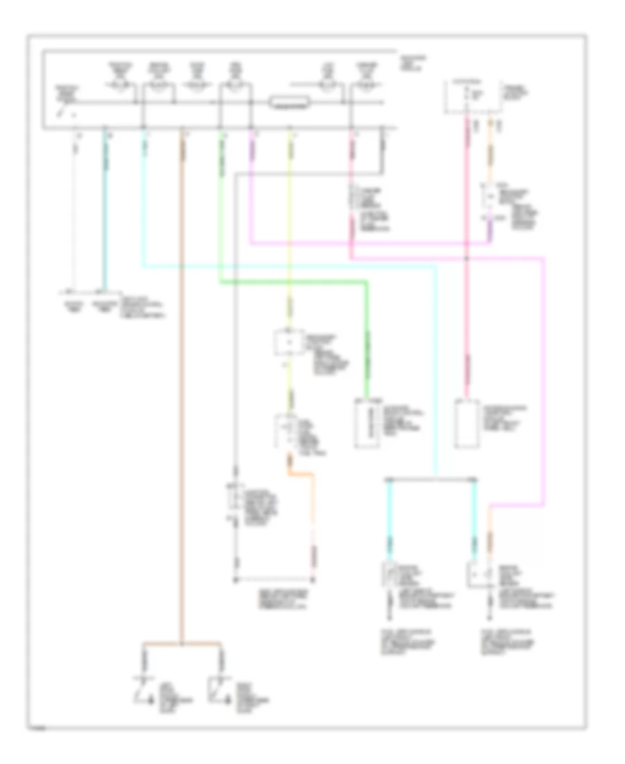
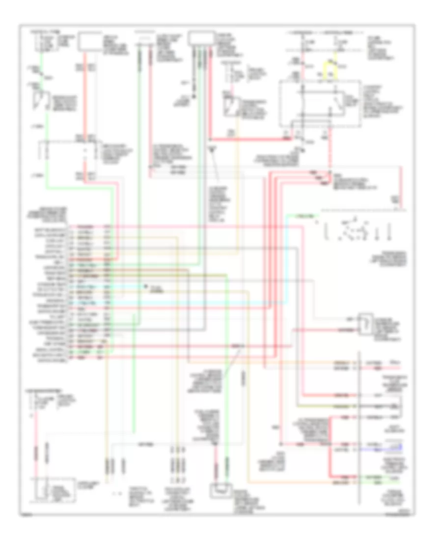
3.8L SC, A/C Wiring Diagram, Manual A/C for Ford Thunderbird LX 1995
List of elements for 3.8L SC, A/C Wiring Diagram, Manual A/C for Ford Thunderbird LX 1995:
- (behind right
- (not used)
- 30a
- A/c clutch coil
- A/c clutch control
- A/c clutch cycling pressure switch (right rear of engine compartment on accumulator)
- A/c fuse 10a
- A/c high pressure cutout/fan switch (lower right rear of engine on a/c line)
- A/c-heater fuction selector switch
- Acc
- Blend door motor control (behind center of i/p, on plenum)
- Blower in-line fuse holder (behind left side of i/p, taped to harness)
- Blower motor
- Blower motor switch
- Blower resistors (behind right side of i/p, in plenum)
- C2001
- C2003
- C211
- C232
- C233
- C263
- Cold
- Cowl panel)
- Def
- Def/flr
- Edf relay
- Edf relay control
- Electric cooling fan
- Electric cooling pusher fan
- Fl 5 60a
- Flr
- Fuel pump relay
- G108 (left front of vehicle, on upper radiator support)
- G109 (right front of vehicle, on upper radiator support)
- G202 (behind i/p, right side of steering column)
- G203
- G203 (behind right cowl panel)
- Hedf 1 relay
- Hedf 2 relay
- Hot at all times
- Hot in run
- Ignition switch
- Illumi- nation
- Integrated relay control module (right front of engine compartment on upper radiator support
- Interior lights system
- Lock
- Max
- Nca
- Norm
- Off
- Pan/flr
- Panel
- Pcm power relay
- Power distribution box
- Power- train control module (behind right cowl)
- Primary junction block
- Pusher fan relay (behind left shock tower)
- Red
- Run
- Run fuse 10a
- Secondary junction block
- Solid state
- Start
- Warm
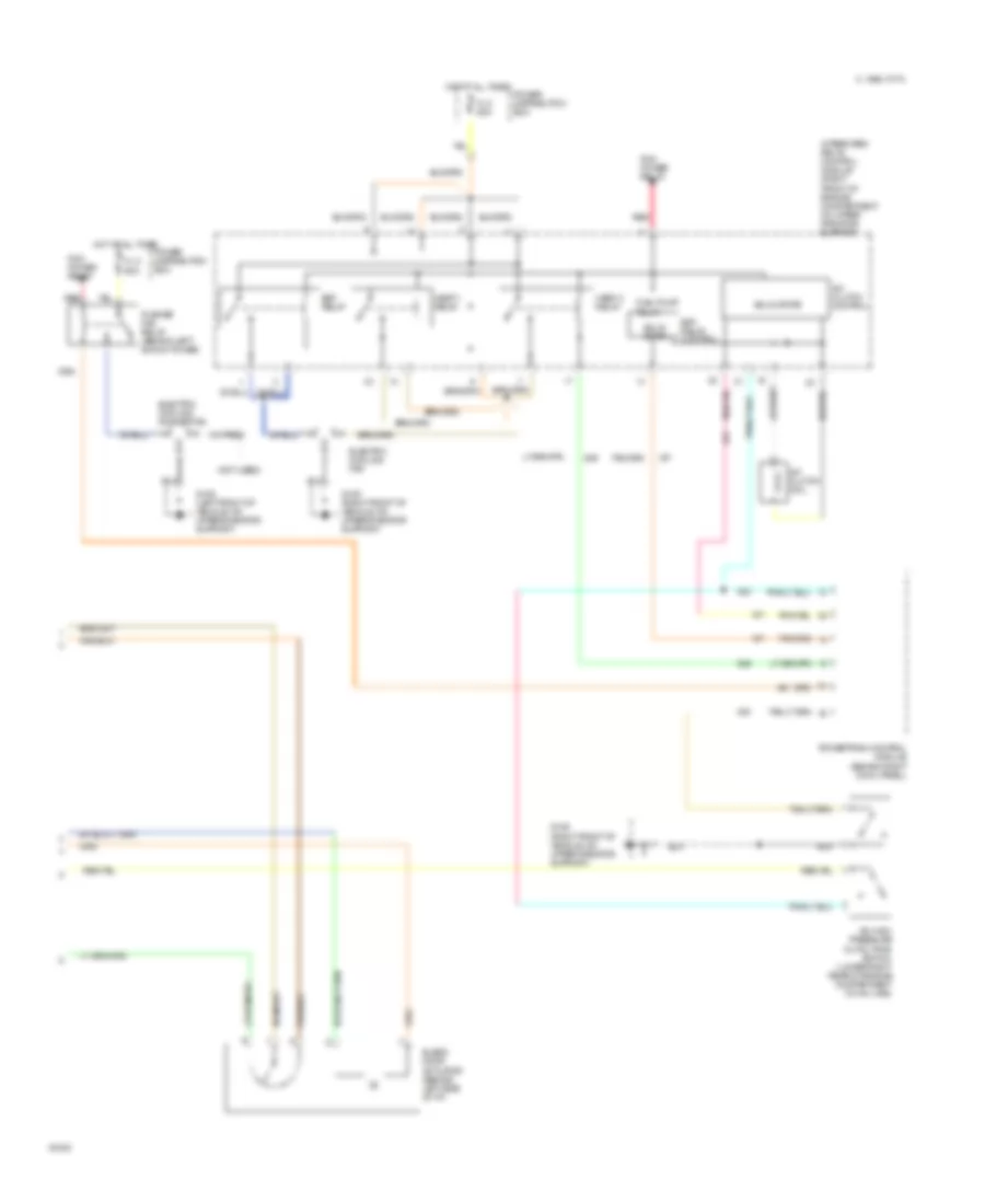
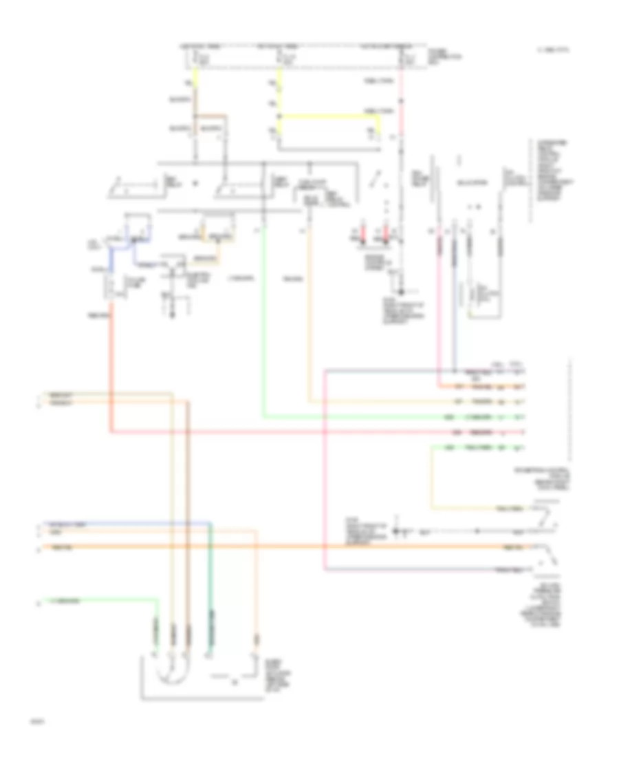
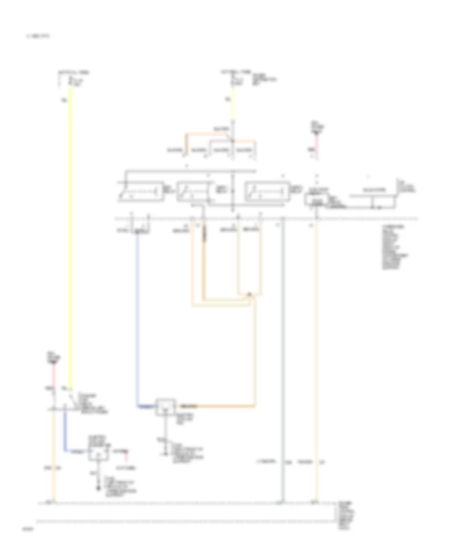
3.8L, A/C Wiring Diagram, Auto A/C (1 of 2) for Ford Thunderbird LX 1995
List of elements for 3.8L, A/C Wiring Diagram, Auto A/C (1 of 2) for Ford Thunderbird LX 1995:
- 2 std fuse 5a
- 30a
- A/c clutch cycling pressure switch (right rear of engine compartment on accumulator)
- A/c fuse 10a
- Acc
- Atc ambient temperature sensor (right front of vehicle, on lower radiator support)
- Blower in-line fuse holder (behind left side of i/p, taped to harness)
- Blower motor
- Blower motor speed controller (behind right side of i/p)
- C232
- C233
- C240
- C298
- Cold engine lockout switch (top right side of engine)
- Def
- Flr
- Flr/def
- G202 (behind i/p, right of steering column)
- G203 (behind right cowl panel)
- Hot at all times
- Hot in run
- Ignition switch
- In-car temperature sensor (behind top left side of i/p)
- Interior lights system
- Joint connec- tor 1
- Joint connector
- Lock
- Max
- Norm
- Off
- Off pan/flr
- Outside/ recirculate solenoid (behind right side of i/p)
- Pan/flr flr
- Panel
- Power distribution box
- Primary junction block
- Run
- Run fuse 5a
- Secondary junction block
- Semi-automatic temperature control module (center of i/p)
- Solid state
- Start
- Sunload sensor (behind right top of i/p)
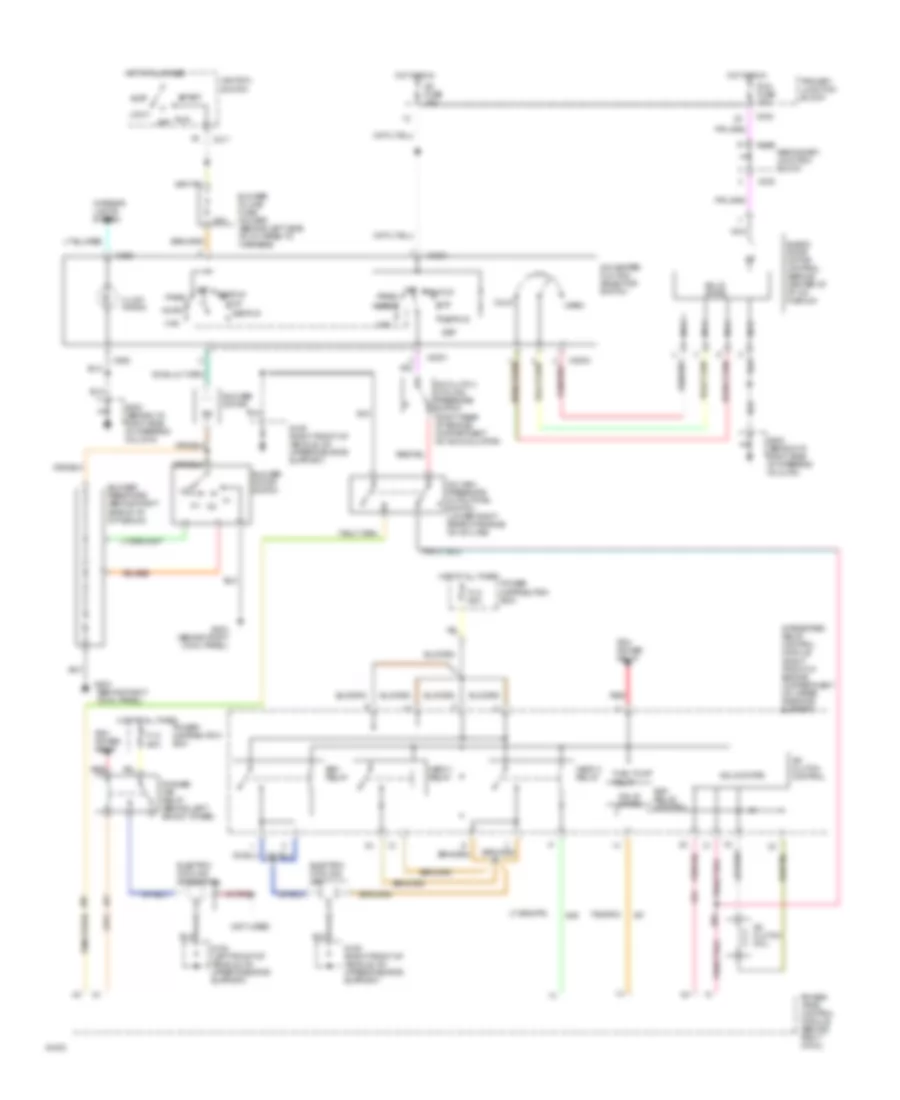
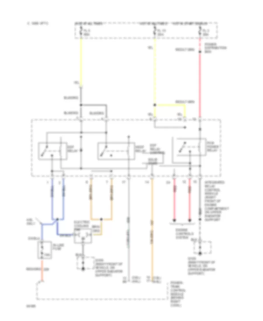
3.8L, A/C Wiring Diagram, Auto A/C (2 of 2) for Ford Thunderbird LX 1995
List of elements for 3.8L, A/C Wiring Diagram, Auto A/C (2 of 2) for Ford Thunderbird LX 1995:
- (3.8l)
- (4.6l)
- 10a
- 4.6l only
- A/c clutch coil
- A/c clutch control
- A/c high pressure cutout/fan switch (lower right rear of engine compartment on a/c line)
- Blend door actuator (behind left side of i/p)
- C 1995 vftc
- Edf relay
- Edf relay control
- Electric cooling fan
- Engine controls system
- Fl 15 20a
- Fl 3 20a
- Fl 5 60a
- Fuel pump relay
- G109 (right front of vehicle, on upper radiator support)
- Hedf relay
- Hot at all times
- Hot in start or run
- In-line fuse
- Integrated relay control module (right front of engine compartment on upper radiator support
- Pcm power relay
- Power distribution box
- Powertrain control module (behind right cowl panel)
- Red
- Solid state
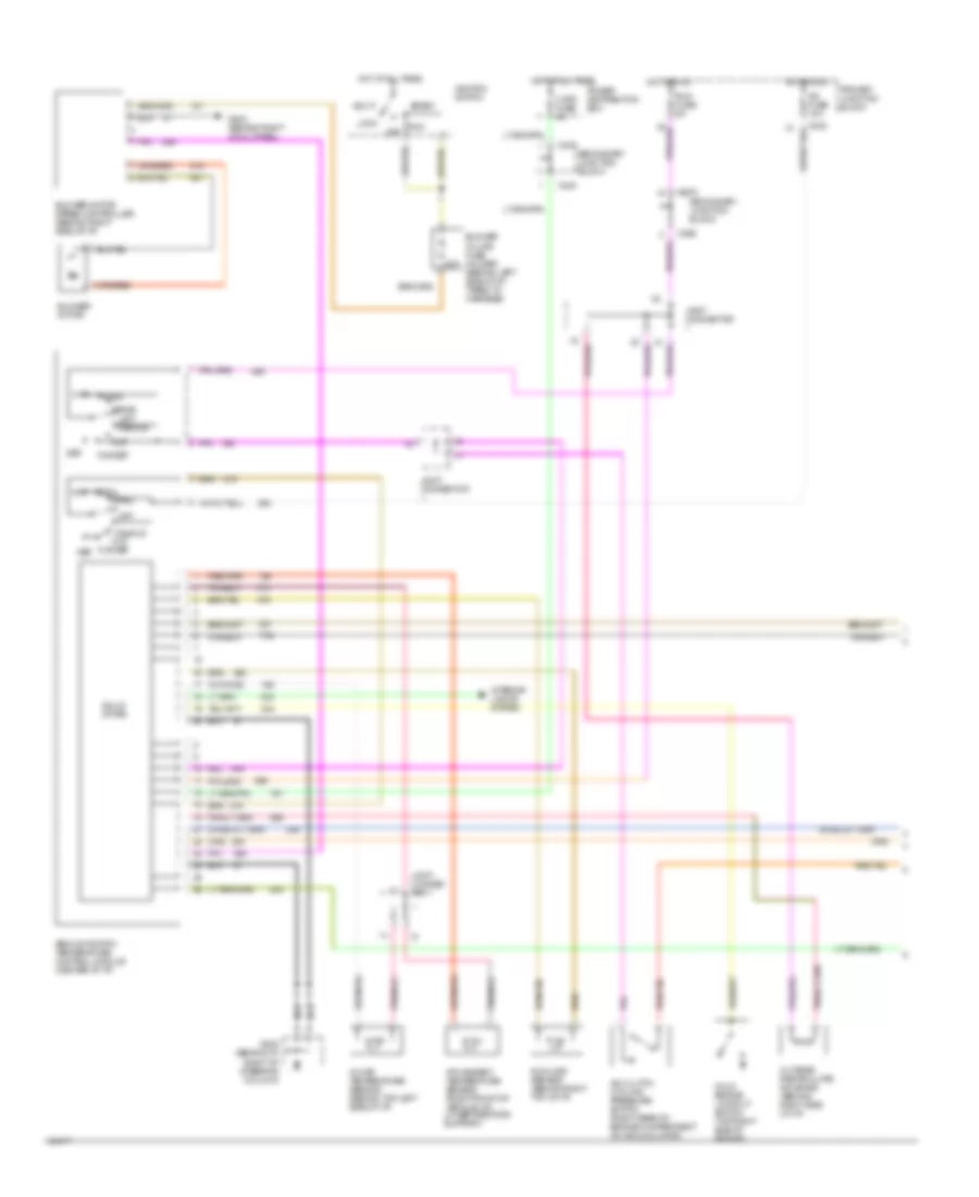
3.8L, A/C Wiring Diagram, Manual A/C for Ford Thunderbird LX 1995
List of elements for 3.8L, A/C Wiring Diagram, Manual A/C for Ford Thunderbird LX 1995:
- (3.8l) (4.6l)
- (behind right
- 10a
- 30a
- 4.6l only
- A/c clutch coil
- A/c clutch control
- A/c clutch cycling pressure switch (right rear of engine compartment on accumulator)
- A/c fuse 10a
- A/c high pressure cutout/fan switch (lower right rear of engine on a/c line)
- A/c-heater fuction selector switch
- Acc
- Blend door motor control (behind center of i/p, on plenum)
- Blower in-line fuse holder (behind left side of i/p, taped to harness)
- Blower motor
- Blower motor switch
- Blower resistors (behind right side of i/p, in plenum)
- C2001
- C2003
- C211
- C232
- C233
- C263
- Cold
- Cowl panel)
- Def
- Def/flr
- Edf relay
- Edf relay control
- Electric cooling fan
- Engine controls system
- Fl 15 20a
- Fl 3 20a
- Fl 5 60a
- Flr
- Fuel pump relay
- G109 (right front of vehicle, on upper radiator support)
- G202 (behind i/p, right side of steering column)
- G203
- G203 (behind right cowl panel)
- Hedf relay
- Hot at all times
- Hot in run
- Hot in start or run
- Ignition switch
- Illumi- nation
- In-line fuse (in engine harness)
- Integrated relay control module (right front of engine compartment on upper radiator support
- Interior lights system
- Lock
- Max
- Nca
- Norm
- Off
- Pan/flr
- Panel
- Pcm power relay
- Power distribution box
- Power- train control module (behind right cowl)
- Primary junction block
- Red
- Run
- Run fuse 10a
- Secondary junction block
- Solid state
- Start
- Warm
4.6L
4.6L, A/C Wiring Diagram, Auto A/C (1 of 2) for Ford Thunderbird LX 1995
List of elements for 4.6L, A/C Wiring Diagram, Auto A/C (1 of 2) for Ford Thunderbird LX 1995:
- 2 std fuse 5a
- 30a
- A/c clutch cycling pressure switch (right rear of engine compartment on accumulator)
- A/c fuse 10a
- Acc
- Atc ambient temperature sensor (right front of vehicle, on lower radiator support)
- Blower in-line fuse holder (behind left side of i/p, taped to harness)
- Blower motor
- Blower motor speed controller (behind right side of i/p)
- C232
- C233
- C240
- C298
- Cold engine lockout switch (top right side of engine)
- Def
- Flr
- Flr/def
- G202 (behind i/p, right of steering column)
- G203 (behind right cowl panel)
- Hot at all times
- Hot in run
- Ignition switch
- In-car temperature sensor (behind top left side of i/p)
- Interior lights system
- Joint connec- tor 1
- Joint connector
- Lock
- Max
- Norm
- Off
- Off pan/flr
- Outside/ recirculate solenoid (behind right side of i/p)
- Pan/flr flr
- Panel
- Power distribution box
- Primary junction block
- Run
- Run fuse 5a
- Secondary junction block
- Semi-automatic temperature control module (center of i/p)
- Solid state
- Start
- Sunload sensor (behind right top of i/p)
4.6L, A/C Wiring Diagram, Auto A/C (2 of 2) for Ford Thunderbird LX 1995
List of elements for 4.6L, A/C Wiring Diagram, Auto A/C (2 of 2) for Ford Thunderbird LX 1995:
- (3.8l)
- (4.6l)
- 10a
- 4.6l only
- A/c clutch coil
- A/c clutch control
- A/c high pressure cutout/fan switch (lower right rear of engine compartment on a/c line)
- Blend door actuator (behind left side of i/p)
- C 1995 vftc
- Edf relay
- Edf relay control
- Electric cooling fan
- Engine controls system
- Fl 15 20a
- Fl 3 20a
- Fl 5 60a
- Fuel pump relay
- G109 (right front of vehicle, on upper radiator support)
- Hedf relay
- Hot at all times
- Hot in start or run
- In-line fuse
- Integrated relay control module (right front of engine compartment on upper radiator support
- Pcm power relay
- Power distribution box
- Powertrain control module (behind right cowl panel)
- Red
- Solid state
4.6L, A/C Wiring Diagram, Manual A/C for Ford Thunderbird LX 1995
List of elements for 4.6L, A/C Wiring Diagram, Manual A/C for Ford Thunderbird LX 1995:
- (3.8l) (4.6l)
- (behind right
- 10a
- 30a
- 4.6l only
- A/c clutch coil
- A/c clutch control
- A/c clutch cycling pressure switch (right rear of engine compartment on accumulator)
- A/c fuse 10a
- A/c high pressure cutout/fan switch (lower right rear of engine on a/c line)
- A/c-heater fuction selector switch
- Acc
- Blend door motor control (behind center of i/p, on plenum)
- Blower in-line fuse holder (behind left side of i/p, taped to harness)
- Blower motor
- Blower motor switch
- Blower resistors (behind right side of i/p, in plenum)
- C2001
- C2003
- C211
- C232
- C233
- C263
- Cold
- Cowl panel)
- Def
- Def/flr
- Edf relay
- Edf relay control
- Electric cooling fan
- Engine controls system
- Fl 15 20a
- Fl 3 20a
- Fl 5 60a
- Flr
- Fuel pump relay
- G109 (right front of vehicle, on upper radiator support)
- G202 (behind i/p, right side of steering column)
- G203
- G203 (behind right cowl panel)
- Hedf relay
- Hot at all times
- Hot in run
- Hot in start or run
- Ignition switch
- Illumi- nation
- In-line fuse (in engine harness)
- Integrated relay control module (right front of engine compartment on upper radiator support
- Interior lights system
- Lock
- Max
- Nca
- Norm
- Off
- Pan/flr
- Panel
- Pcm power relay
- Power distribution box
- Power- train control module (behind right cowl)
- Primary junction block
- Red
- Run
- Run fuse 10a
- Secondary junction block
- Solid state
- Start
- Warm
ANTI-LOCK BRAKES
Anti-lock Brake Wiring Diagrams for Ford Thunderbird LX 1995
List of elements for Anti-lock Brake Wiring Diagrams for Ford Thunderbird LX 1995:
- (ground bus)
- (left front corner of engine compt)
- (left front of
- (left front of
- (left front of eng compt)
- (left front of engine compt)
- (left rear corner of engine compt)
- (left side of
- (left side of i/p)
- (on brake pedal support)
- (power distribution box)
- 10a
- 15a
- 20a
- 40a
- 87a
- Abs diode
- Abs motor relay
- Abs relay
- Abs test conn
- Abs test conn input
- All times
- Anti/lock
- Anti/lock brake control module
- Anti/lock brake fluid level sw
- Anti/lock brake pedal travel sw
- Anti/lock brake power relay
- Anti/lock ind
- Assist
- Block
- Box
- Brake sensor
- Brake sw
- Brake sw input
- Cluster
- Distribution
- Engine compartment)
- Engine compt)
- Fluid level sw input
- Fuse
- G108
- Ground
- Haz
- Hot at
- Hot at all times
- Hot in run
- Indicator
- Inlet
- Instrument
- Junction
- Keep alive power
- L fnt brake sensor
- L fnt valve inlet
- L fnt valve outlet
- L rear brake sensor
- L rear valve inlet
- L rear valve outlet
- Lamp module
- Left front
- Left front of
- Left rear
- Outlet
- Pnk
- Pnk 498
- Power
- Primary
- Pump motor relay
- Pump mtr spd sensor
- Red/pnk
- Red/pnk 523
- Right front
- Right rear
- Rt fnt brake sensor
- Rt fnt valve inlet
- Rt fnt valve outlet
- Rt rear brake sensor
- Rt rear valve inlet
- Rt rear valve outlet
- Run
- Run power
- Solenoid ctrl valve body
- Solid
- State
- Stop lt sw
- Stop/
- Sv #1
- Sv #2
- Sv1
- Sv2
- Sw reference volt
- Switched power
- Tan
- Tan 495
- Tan/red
- Tan/red 510
- Tan/red 533
- Traction
- Traction assist input
- Upper radiator support)
COMPUTER DATA LINES
3.8L
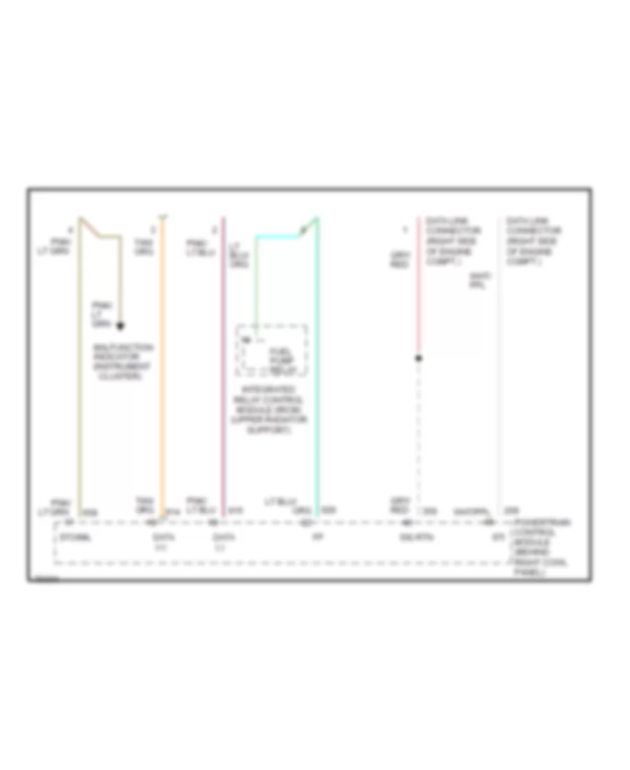
3.8L SC, Computer Data Lines for Ford Thunderbird LX 1995
List of elements for 3.8L SC, Computer Data Lines for Ford Thunderbird LX 1995:
-
- Data (+)
- Data (-)
- Data link connector (right side of engine compt.)
- Fuel pump relay
- Integrated relay control module (ircm) (upper radiator support)
- Malfunction indicator (instrument cluster)
- Pnk/
- Powertrain control module (behind right cowl panel)
- Sig rtn
- Sti
- Sto/mil
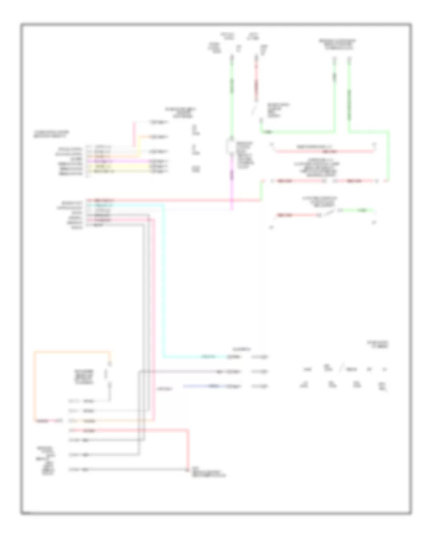
3.8L, Computer Data Lines for Ford Thunderbird LX 1995
List of elements for 3.8L, Computer Data Lines for Ford Thunderbird LX 1995:
-
- Data (+)
- Data (-)
- Data link connector (right side of engine compt.)
- Fuel pump relay
- Integrated relay control module (ircm) (upper radiator support)
- Malfunction indicator (instrument cluster)
- Pnk/
- Powertrain control module (behind right cowl panel)
- Sig rtn
- Sti
- Sto/mil
4.6L
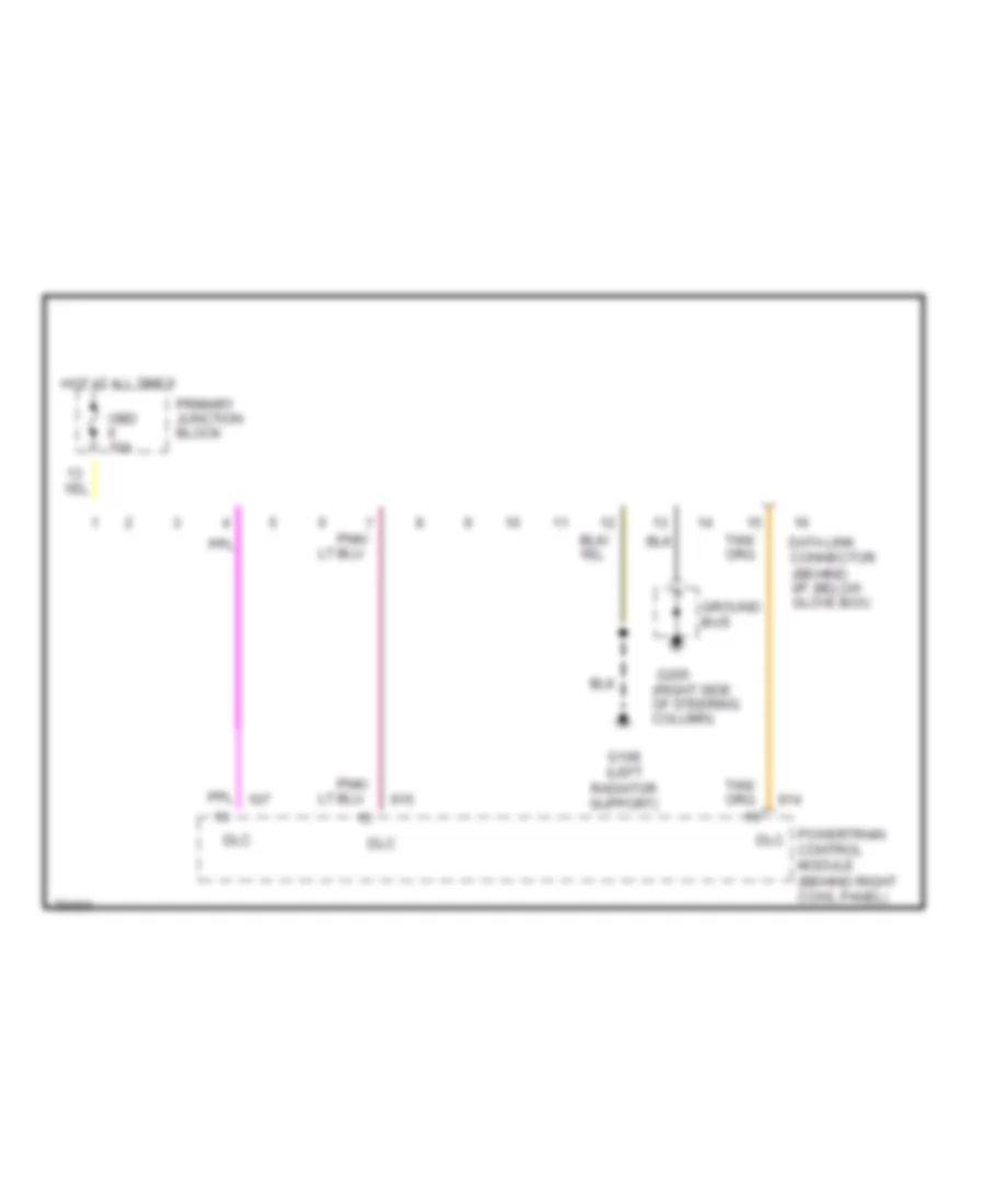
4.6L, Computer Data Lines for Ford Thunderbird LX 1995
List of elements for 4.6L, Computer Data Lines for Ford Thunderbird LX 1995:
- Data link connector (behind i/p, below glove box)
- Dlc
- G108 (left radiator support)
- G205 (right side of steering column)
- Ground bus
- Hot at all times
- Obd ii 10a
- Pnk/
- Powertrain control module (behind right cowl panel)
- Primary junction block
COOLING FAN
3.8L
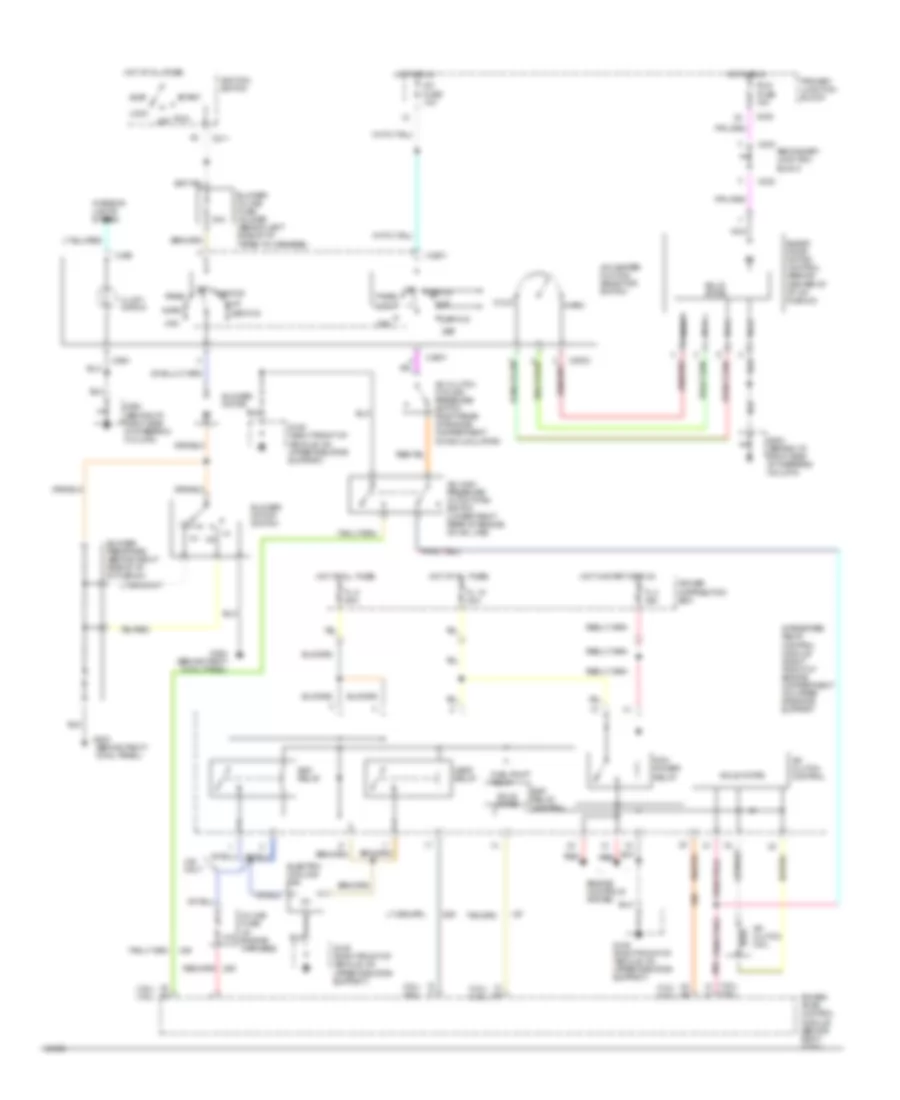
3.8L SC, Cooling Fan Wiring Diagram for Ford Thunderbird LX 1995
List of elements for 3.8L SC, Cooling Fan Wiring Diagram for Ford Thunderbird LX 1995:
- (not used)
- A/c clutch control
- C 1995 vftc
- Edf relay
- Edf relay control
- Electric cooling fan
- Electric cooling pusher fan
- Fl 16 30a
- Fl 5 60a
- Fuel pump relay
- G108 (left front of vehicle, on upper radiator support)
- G109 (right front of vehicle, on upper radiator support)
- Hedf 1 relay
- Hedf 2 relay
- Hot at all times
- Integrated relay control module (right front of engine compartment on upper radiator support
- Pcm power relay
- Power distribution box
- Power- train control module (behind right cowl)
- Pusher fan relay (behind left shock tower)
- Red
- Solid state
3.8L, Cooling Fan Wiring Diagram for Ford Thunderbird LX 1995
List of elements for 3.8L, Cooling Fan Wiring Diagram for Ford Thunderbird LX 1995:
- (3.8l) (4.6l)
- 10a
- 4.6l only
- C 1995 vftc
- Edf relay
- Edf relay control
- Electric cooling fan
- Engine controls system
- Fl 15 20a
- Fl 3 20a
- Fl 5 60a
- G109 (right front of vehicle, on upper radiator support)
- Hedf relay
- Hot at all times
- Hot in start or run
- In-line fuse
- Integrated relay control module (right front of engine compartment on upper radiator support
- Pcm power relay
- Power distribution box
- Power- train control module (behind right cowl)
- Red
- Solid state
4.6L
4.6L, Cooling Fan Wiring Diagram for Ford Thunderbird LX 1995
List of elements for 4.6L, Cooling Fan Wiring Diagram for Ford Thunderbird LX 1995:
- (3.8l) (4.6l)
- 10a
- 4.6l only
- C 1995 vftc
- Edf relay
- Edf relay control
- Electric cooling fan
- Engine controls system
- Fl 15 20a
- Fl 3 20a
- Fl 5 60a
- G109 (right front of vehicle, on upper radiator support)
- Hedf relay
- Hot at all times
- Hot in start or run
- In-line fuse
- Integrated relay control module (right front of engine compartment on upper radiator support
- Pcm power relay
- Power distribution box
- Power- train control module (behind right cowl)
- Red
- Solid state
CRUISE CONTROL
Cruise Control Wiring Diagram for Ford Thunderbird LX 1995
List of elements for Cruise Control Wiring Diagram for Ford Thunderbird LX 1995:
- (behind i/p
- (behind i/p near right
- (behind i/p right side
- (behind left side of i/p
- (behind right side of i/p)
- (inside left
- (left rear of
- (on brake
- (on top of clutch
- 100/
- 10a
- 15a
- 40/
- 50,000
- A/t
- Acc
- Accel
- All times
- Block
- Brake on/off sw
- Brake pedal support)
- Brake sw input
- Clockspring
- Clutch pedal position sw
- Clutch pedal position sw jumper
- Coast
- Column)
- Control sws input
- Cruise control
- Cruise control amplifier
- Cruise control servo
- Except supercoupe w/ a/t
- Feedback pot pos
- Feedback pot sig
- Front fender)
- G205
- Ground
- Haz
- Horn
- Horn relay
- Hot at
- Hot in acc
- Ignition
- Junction
- M/t
- Nca
- Of steering
- Of steering column)
- Off
- Ohms
- Or run
- Pedal
- Pedal support)
- Primary
- Resume
- Right
- Right side
- Secondary
- Secondary junction block
- Sensor (vss)
- Set/
- Side of
- Side of steering column)
- Sol feed
- Steering
- Stop/
- Supercoupe w/ a/t
- Support)
- Sw assembly
- Sws
- Taped to main harness near
- Transmission)
- Vacuum sol control
- Vehicle speed
- Vent sol control
- Vss ground
- Vss signal
DEFOGGERS
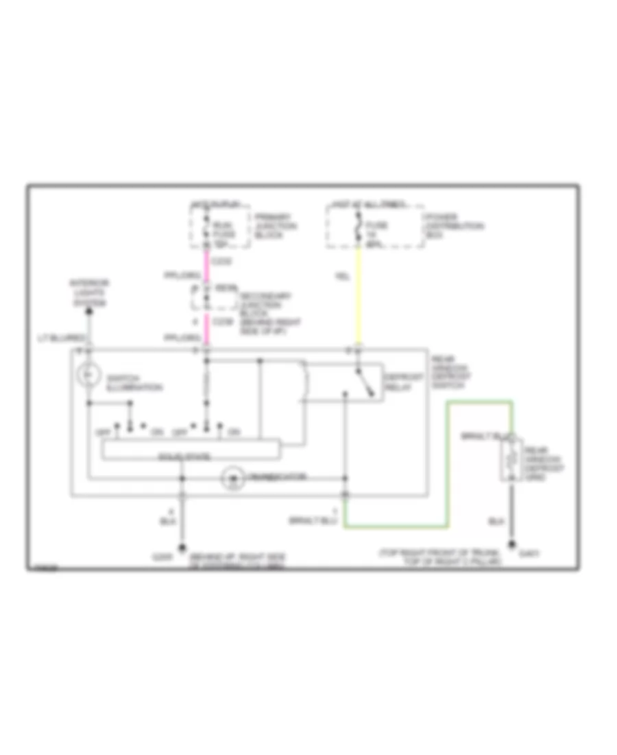
Defogger Wiring Diagram for Ford Thunderbird LX 1995
List of elements for Defogger Wiring Diagram for Ford Thunderbird LX 1995:
- (behind i/p, right side of steering column)
- (top right front of trunk, top of right c pillar)
- C232
- C233
- C238
- Defrost relay
- Fuse 40a
- G205
- G401
- Hot at all times
- Hot in run
- Interior lights system
- Off
- On indicator
- Power distribution box
- Primary junction block
- Rear window defrost grid
- Rear window defrost switch
- Run fuse 15a
- Secondary junction block (behind right side of i/p)
- Solid state
- Switch illumination
ELECTRONIC POWER STEERING
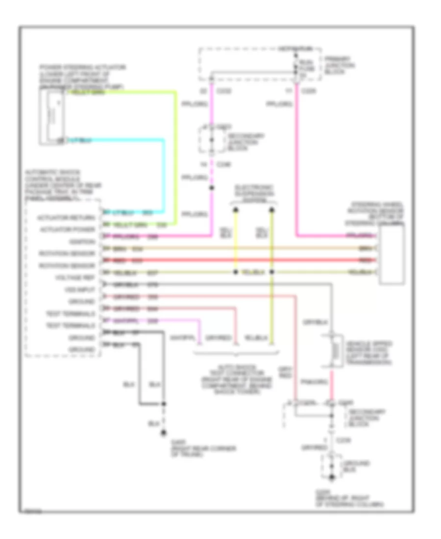
Electronic Power Steering Wiring Diagram, with Programmable Ride Control for Ford Thunderbird LX 1995
List of elements for Electronic Power Steering Wiring Diagram, with Programmable Ride Control for Ford Thunderbird LX 1995:
- Actuator power
- Actuator return
- Auto shock test connector (right rear of engine compartment, behind shock tower)
- Automatic shock control module (under center of rear package tray, in trim panel assembly)
- C226
- C232
- C233
- C236
- C240
- Electronic suspension system
- G205 (behind i/p, right of steering column)
- G405 (right rear corner of trunk)
- Ground
- Ground bus
- Hot in run
- Ignition
- Power steering actuator (lower left front of engine compartment, on power steering pump)
- Primary junction block
- Red
- Rotation sensor
- Run fuse 5a
- Secondary junction block
- Steering wheel rotation sensor (bottom of steering column)
- Test terminals
- Vehicle spped sensor (vss) (left rear of transmission)
- Voltage ref
- Vss input
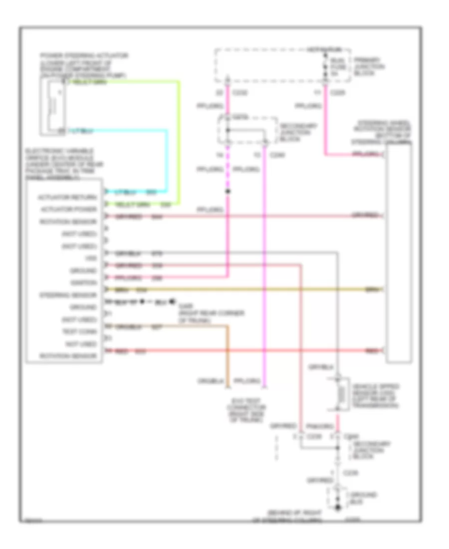
Electronic Power Steering Wiring Diagram, without Programmable Ride Control for Ford Thunderbird LX 1995
List of elements for Electronic Power Steering Wiring Diagram, without Programmable Ride Control for Ford Thunderbird LX 1995:
- (behind i/p, right of steering column)
- (not used)
- Actuator power
- Actuator return
- C226
- C232
- C233
- C236
- C240
- Electronic variable orifice (evo) module (under center of rear package tray, in trim panel assembly)
- Evo test connector (right side of trunk)
- G205
- G405 (right rear corner of trunk)
- Ground
- Ground bus
- Hot in run
- Ignition
- Not used
- Power steering actuator (lower left front of engine compartment, on power steering pump)
- Primary junction block
- Red
- Rotation sensor
- Run fuse 5a
- Secondary junction block
- Steering sensor
- Steering wheel rotation sensor (bottom of steering column)
- Test conn
- Vehicle spped sensor (vss) (left rear of transmission)
- Vss
ELECTRONIC SUSPENSION
3.8L
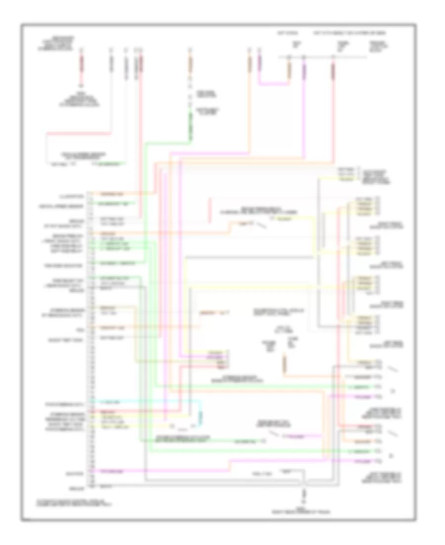
3.8L SC, Electronic Suspension Wiring Diagram for Ford Thunderbird LX 1995
List of elements for 3.8L SC, Electronic Suspension Wiring Diagram for Ford Thunderbird LX 1995:
- (base of steering column)
- (behind right
- (below center of
- (center console)
- (in brake line, below master cylinder)
- (near right side
- (on power steering pump)
- (on transmission)
- (right cowl panel)
- (right rear corner of trunk)
- (right side of
- (under center of rear package tray)
- 20a
- All times
- Auto shock
- Automatic shock control module
- Block
- Box
- Brake pres sw
- Brake pressure sw
- Cluster
- Dist
- Firm ride
- Firm ride indicator
- Fog lt sw
- Fuse
- G205
- G405
- Ground
- Ground bus
- Hard ride relay
- Hot at
- Hot in run
- Hot with headlt sw in park or head
- Illumination
- Indicator
- Instrument
- Junction
- Junction block
- L front shock actu
- L rear shock actu
- Left front
- Left rear
- Lps
- Of steering column)
- Panel
- Pcm
- Power
- Power steering actuator
- Powertrain ctrl module
- Primary
- Pwr steering actu
- Rear package tray)
- Red
- Red 633
- Reference voltage
- Ride select sw
- Right front
- Right rear
- Rt fnt shock actu
- Rt rear shock actu
- Run
- Run pwr
- Secondary
- Shock actuator
- Shock test conn
- Shock tower)
- Soft ride relay
- Steering column)
- Steering sensor
- Tan/red
- Test conn
- Vehical speed sensor
- Vehicle speed sensor
ENGINE PERFORMANCE
3.8L
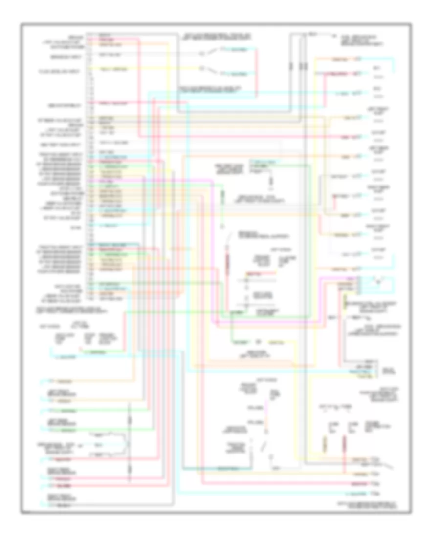
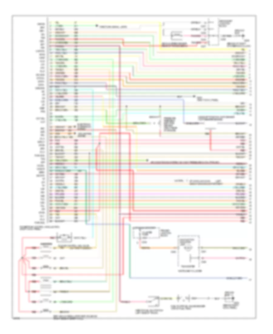
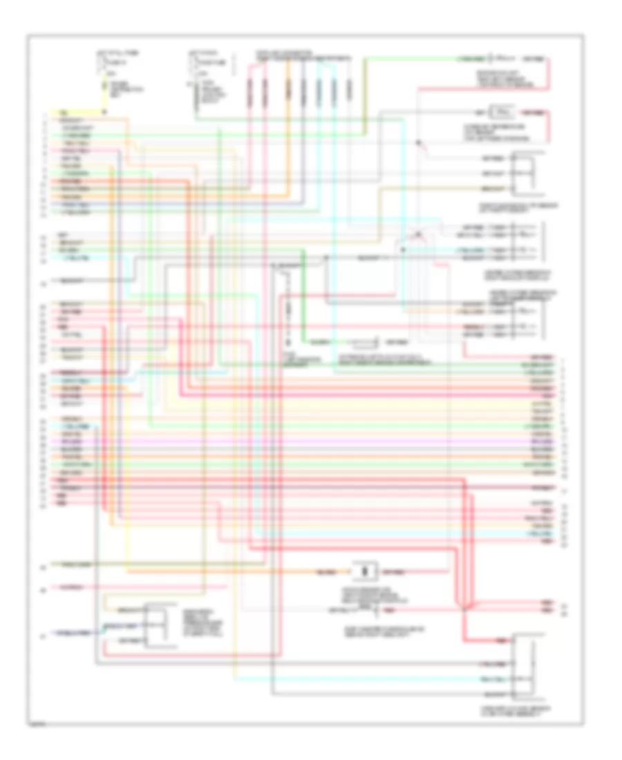
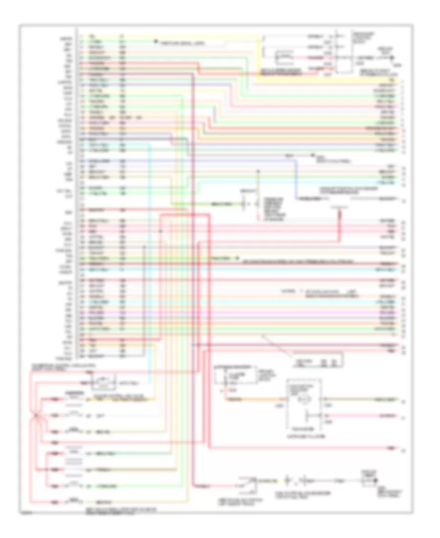
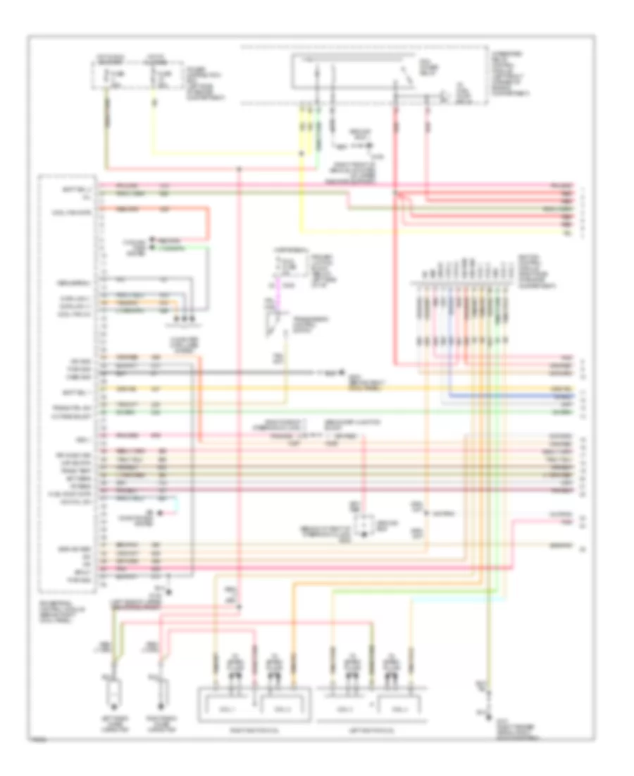
3.8L SC, Engine Performance Wiring Diagrams (1 of 5) for Ford Thunderbird LX 1995
List of elements for 3.8L SC, Engine Performance Wiring Diagrams (1 of 5) for Ford Thunderbird LX 1995:
- (behind i/p, right of steering column)
- (behind right cowl panel)
- (left
- (on throttle body)
- 15a
- Accs
- Acp
- Air conditioning system (a/c hight pressure cutout/fan sw)
- Arc
- Baro
- Boo
- C232
- C236
- C237
- C238
- C240
- C250
- C251
- Camshaft position (cmp) sensor (top front of engine)
- Canp
- Cid
- Cluster fuse
- Cooling fans system
- Cse gnd
- Data +
- Data -
- Ect
- Egr vacuum regulator (evr) solenoid (right side of safety wall)
- Electronic suspension system
- Epc
- Evr
- Fpm
- Fuel pump/fuel gauge sender (top of fuel tank)
- G203
- G203 (right cowl panel)
- G205
- Ground bus
- Hfc
- Ho2s-l
- Hos2-r
- Hot in run or start
- Iac
- Iat
- Idle air control (iac) valve
- Idm
- Ign gnd
- Inertia fuel shutoff sw (left side of trunk)
- Inj 1
- Inj 2
- Inj 3
- Inj 4
- Inj 5
- Inj 6
- Injectors
- Instrument cluster
- Kapwr
- Lfc
- Maf
- Maf rtn
- Malfunction indicator lamp
- Mlp
- Oct adj
- Park/turn signal lamps
- Pfc
- Pfe
- Pip
- Pnk
- Powertrain control module (pcm) (right cowl panel)
- Pressure feedback egr (pfe) sensor (right rear of engine)
- Primary junction block
- Pwr gnd
- Red
- Secondary junction block
- Sig rtn
- Spout
- Ss1
- Ss2
- Sti
- Sti data link conn side of engine compartment)
- Sto/mil
- Tachometer
- Tan
- Tcc
- Tcil
- Tcs
- Tfi
- Tss
- Vehicle speed sensor (rear of transmission)
- Vpwr
- Vref
- Vss +
- Vss -
- Wac
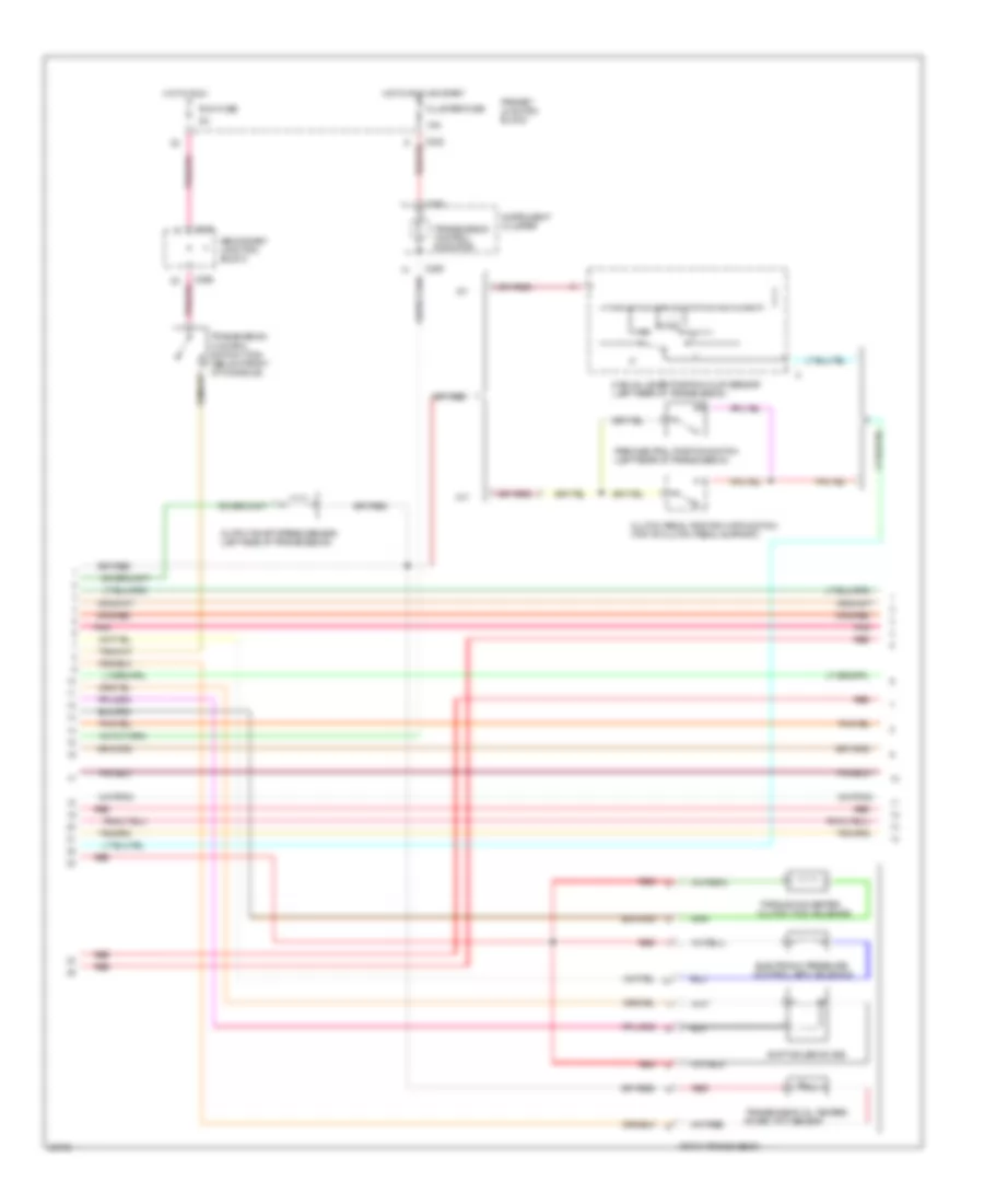
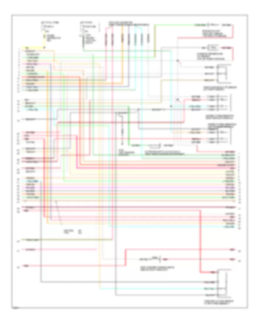
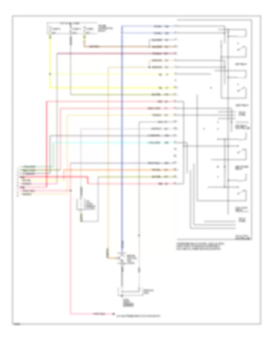
3.8L SC, Engine Performance Wiring Diagrams (2 of 5) for Ford Thunderbird LX 1995
List of elements for 3.8L SC, Engine Performance Wiring Diagrams (2 of 5) for Ford Thunderbird LX 1995:
- 15a
- 20a
- Barometric absolute pressure (bap) (on right side of safety wall)
- C232
- Data link connector (right side of engine compartment)
- Engine coolant temp (ect) sensor (top front of engine)
- Evap canister purge solenoid (behind right headlight)
- Fuse 15
- G108 (left radiator support)
- Heated oxygen sensor #1 (right exhaust manifold)
- Heated oxygen sensor #2 (left exhaust manifold)
- Ho2s fuse
- Hot at all times
- Hot in run
- Intake air temperature (iat) sensor (top left rear of engine)
- Knock sensor (ks) (right side of engine, below exhaust manifold)
- Mass airflow (maf) sensor (in air intake assembly)
- Nca
- Octane adjust plug (calif only) (right side of engine compartment)
- Pnk
- Power distribution box
- Primary junction block
- Red
- Throttle position (tp) sensor (on throttle body)
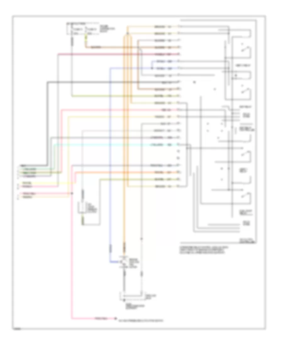
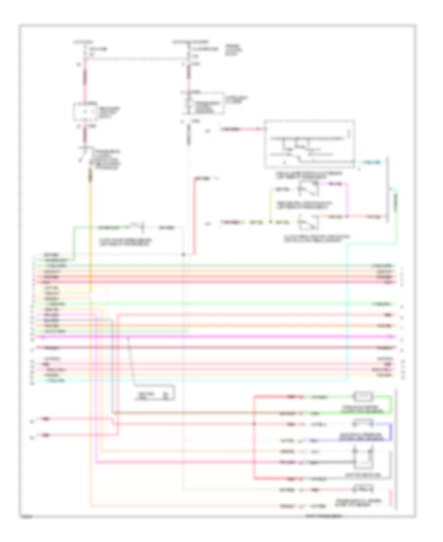
3.8L SC, Engine Performance Wiring Diagrams (3 of 5) for Ford Thunderbird LX 1995
List of elements for 3.8L SC, Engine Performance Wiring Diagrams (3 of 5) for Ford Thunderbird LX 1995:
- 15a
- 4r70w transmission
- A/t
- C232
- C233
- C250
- C298
- Cluster fuse
- Clutch pedal position (cpp) switch (top of clutch pedal support)
- Electronic pressure control (epc) solenoid
- Hot in run
- Hot in run or start
- Instrument cluster
- M/t
- Manual lever position (mlp) sensor (left rear of transmission)
- Output shaft speed sensor (left side of transmission)
- Park/neutral position switch (left rear of transmission)
- Pnk
- Primary junction block
- Red
- Run fuse
- Secondary junction block
- Shift solenoid (ss)
- Torque converter clutch (tcc) solenoid
- Transmission control indicator
- Transmission control switch (tcs) (below front of console)
- Transmission oil temper- ature (tot) sensor
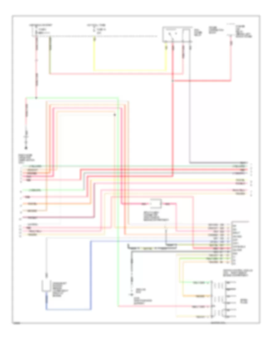
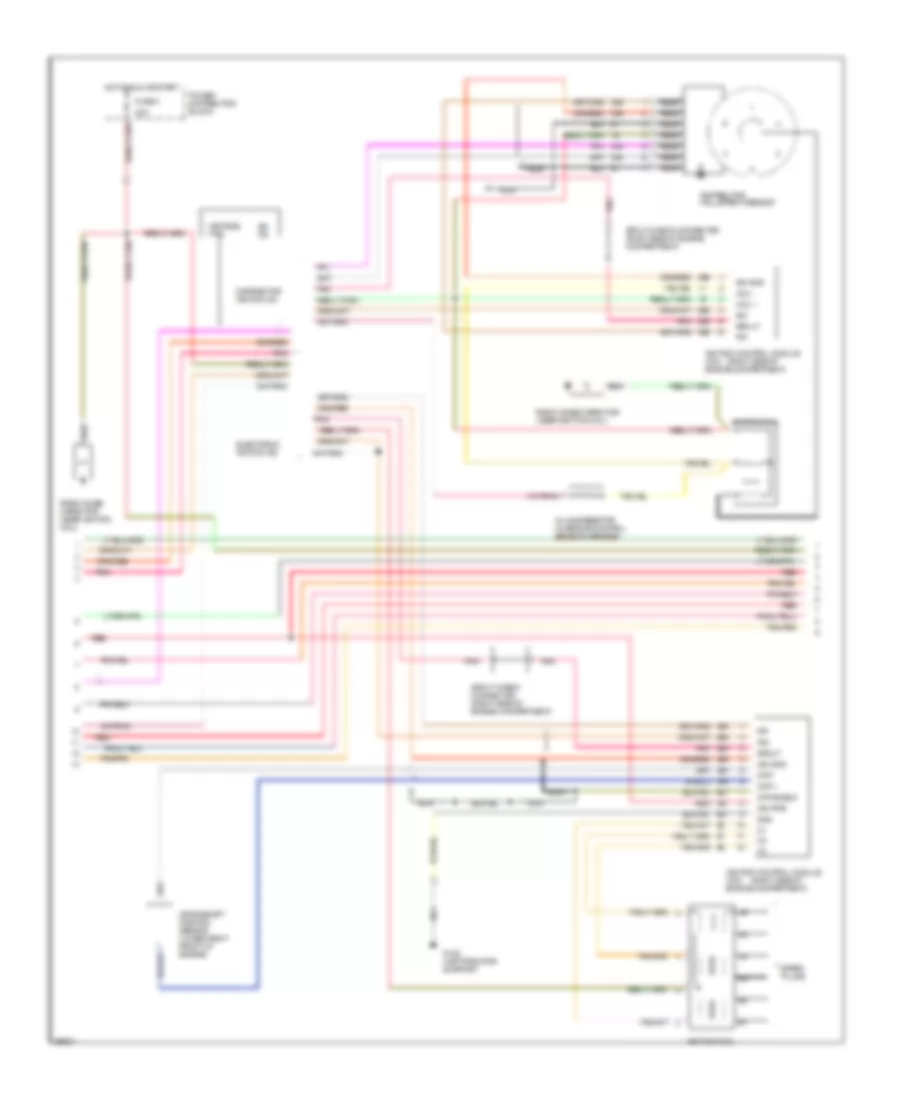
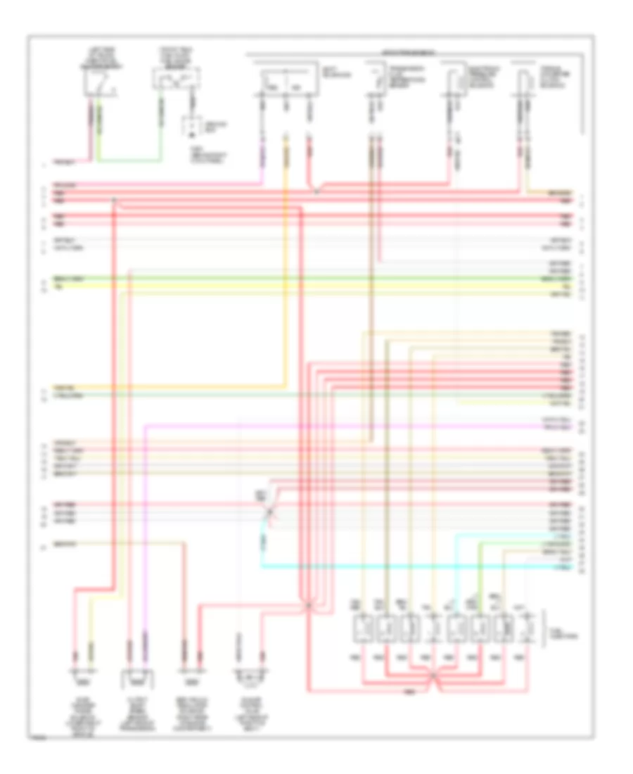
3.8L SC, Engine Performance Wiring Diagrams (4 of 5) for Ford Thunderbird LX 1995
List of elements for 3.8L SC, Engine Performance Wiring Diagrams (4 of 5) for Ford Thunderbird LX 1995:
- (right side of
- 20a
- Ckp +
- Ckp -
- Ckp shield
- Crankshaft position sensor (lower right front of engine)
- Fuse 15
- Fuse 3
- G109 (right radiator support)
- Gnd
- Ground bus
- Hot at all times
- Hot in run or start
- Idm
- Ign gnd
- Ign pwr
- Ignition coil
- Ignition control module (icm) engine compartment)
- Nca
- Pcm power relay
- Pip
- Pnk
- Power distribution block
- Pusher fan relay (behind left shock tower)
- Radio noise capacitor (near ignition coil)
- Red
- Spark plugs
- Spout
- Spout check connector (right side of engine compartment)
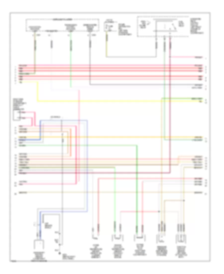
3.8L SC, Engine Performance Wiring Diagrams (5 of 5) for Ford Thunderbird LX 1995
List of elements for 3.8L SC, Engine Performance Wiring Diagrams (5 of 5) for Ford Thunderbird LX 1995:
- 20a
- A/c clutch controller
- A/c comp- ressor clutch
- A/c high pressure cutout/fan switch
- Edf relay
- Edf relay controller
- Engine cooling fan motor
- Fuel pump relay
- Fuse 13
- Fuse 15
- G109 (right radiator support)
- Ground bus
- Hedf 1 relay
- Hedf 2 relay
- Hot at all times
- Integrated relay control module (ircm) (right front of engine compartment, mounted on upper radiator support)
- Power distribution block
- Red
- Solid state
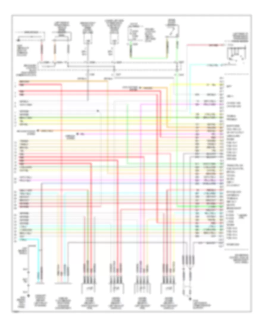
3.8L, Engine Performance Wiring Diagrams (1 of 5) for Ford Thunderbird LX 1995
List of elements for 3.8L, Engine Performance Wiring Diagrams (1 of 5) for Ford Thunderbird LX 1995:
- (behind i/p, right of steering column)
- (ei) (di)
- (left
- (on throttle body)
- * **
- * ** red
- 15a
- Accs
- Acp
- Air conditioning system (a/c hight pressure cutout/fan sw)
- Boo
- C232
- C236
- C237
- C238
- C240
- C250
- C251
- Camshaft position (cmp) sensor (top front of engine)
- Canp
- Cid
- Cluster fuse
- Cse gnd
- Data +
- Data -
- Ect
- Egr vacuum regulator (evr) solenoid (right side of safety wall)
- Epc
- Evr
- Fpm
- Fuel pump/fuel gauge sender (top of fuel tank)
- G203 (behind right cowl panel)
- G203 (right cowl panel)
- G205
- Ground bus
- Hfc
- Ho2s-l
- Hos2-r
- Hot in run or start
- Iac
- Iat
- Idle air control (iac) valve
- Idm
- Ign gnd
- Inertia fuel shutoff sw (left side of trunk)
- Inj 1
- Inj 2
- Inj 3
- Inj 4
- Inj 5
- Inj 6
- Injectors
- Instrument cluster
- Kapwr
- Lfc
- Maf
- Maf rtn
- Malfunction indicator lamp
- Mlp
- Oct. adj.
- Park/turn signal lamps
- Pfe
- Pip
- Pnk
- Powertrain control module (pcm) (right cowl panel)
- Pressure feedback egr (pfe) sensor (right rear of engine)
- Primary junction block
- Pwr gnd
- Red
- Secondary junction block
- Sig rtn
- Spout
- Ss1
- Ss2
- Sti
- Sti data link conn side of engine compartment)
- Sto/mil
- Tachometer
- Tan
- Tcc
- Tcil
- Tcs
- Tfi
- Tss
- Vehicle speed sensor (rear of transmission)
- Vpwr
- Vref
- Vss +
- Vss -
- Wac
3.8L, Engine Performance Wiring Diagrams (2 of 5) for Ford Thunderbird LX 1995
List of elements for 3.8L, Engine Performance Wiring Diagrams (2 of 5) for Ford Thunderbird LX 1995:
- (ei) (di)
- * **
- 15a
- 20a
- C232
- Data link connector (right side of engine compartment)
- Engine coolant temp (ect) sensor (top front of engine)
- Evap canister purge solenoid (behind right headlight)
- Fuse 15
- G108 (left radiator support)
- Heated oxygen sensor #1 (right exhaust manifold)
- Heated oxygen sensor #2 (left exhaust manifold)
- Ho2s fuse
- Hot at all times
- Hot in run
- Intake air temperature (iat) sensor (top left rear of engine)
- Mass airflow (maf) sensor (in air intake assembly)
- Nca
- Octane adjust plug (calif only) (right side of engine compartment)
- Pnk
- Power distribution box
- Primary junction block
- Red
- Throttle position (tp) sensor (on throttle body)
3.8L, Engine Performance Wiring Diagrams (3 of 5) for Ford Thunderbird LX 1995
List of elements for 3.8L, Engine Performance Wiring Diagrams (3 of 5) for Ford Thunderbird LX 1995:
- (ei) (di)
- * **
- 15a
- 4r70w transmission
- A/t
- C232
- C233
- C250
- C298
- Cluster fuse
- Clutch pedal position (cpp) switch (top of clutch pedal support)
- Electronic pressure control (epc) solenoid
- Hot in run
- Hot in run or start
- Instrument cluster
- M/t
- Manual lever position (mlp) sensor (left rear of transmission)
- Output shaft speed sensor (left side of transmission)
- Park/neutral position switch (left rear of transmission)
- Pnk
- Primary junction block
- Red
- Run fuse
- Secondary junction block
- Shift solenoid (ss)
- Torque converter clutch (tcc) solenoid
- Transmission control indicator
- Transmission control switch (tcs) (below front of console)
- Transmission oil temper- ature (tot) sensor
3.8L, Engine Performance Wiring Diagrams (4 of 5) for Ford Thunderbird LX 1995
List of elements for 3.8L, Engine Performance Wiring Diagrams (4 of 5) for Ford Thunderbird LX 1995:
- (ei) (di)
- (right side of
- * **
- 20a
- Ckp +
- Ckp -
- Ckp shield
- Coil +
- Coil -
- Crankshaft position sensor (lower right front of engine)
- Distributor hall effect sensor
- Distributor ignition (di)
- Electornic ignition (ei)
- Fuse 3
- G108 (left radiator support)
- Gnd
- Hot in run or start
- Idm
- Ign gnd
- Ign pwr
- Ignition coil
- Ignition control module (icm) engine compartment)
- Ignition control module (icm) engine compartment)
- In-line resistor (in engine control sensor harness)
- Nca
- Pip
- Pnk
- Power distribution block
- Radio noise capacitor (near ignition coil)
- Red
- Spark plugs
- Spout
- Spout check connector (right side of engine compartment)
- Spout check connector (right side of engine compartment)
3.8L, Engine Performance Wiring Diagrams (5 of 5) for Ford Thunderbird LX 1995
List of elements for 3.8L, Engine Performance Wiring Diagrams (5 of 5) for Ford Thunderbird LX 1995:
- 20a
- 60a
- A/c clutch controller
- A/c comp- ressor clutch
- A/c high pressure cutout/fan switch
- Edf relay
- Edf relay controller
- Eec power relay
- Engine cooling fan motor
- Fuel pump relay
- Fuse 13
- Fuse 15
- Fuse 5
- G109 (right radiator support)
- Ground bus
- Hedf relay
- Hot at all times
- Integrated relay control module (ircm) (right front of engine compartment, mounted on upper radiator support)
- Power distribution block
- Red
- Solid state
4.6L
4.6L, Engine Performance Wiring Diagrams (1 of 4) for Ford Thunderbird LX 1995
List of elements for 4.6L, Engine Performance Wiring Diagrams (1 of 4) for Ford Thunderbird LX 1995:
- (behind i/p, right of steering column) g205
- (right front of vehicle, mounted on upper radiator support)
- (right side of steering column)
- A/c cycl sw
- Air conditioning system
- C232
- C236
- C237
- Case gnd
- Ckp (+)
- Ckp (-)
- Coil 1
- Coil 2
- Coil 3
- Coil 4
- Computer data lines system
- Cool fan (hi)
- Cool fan mntr
- Cooling fans system
- Data link (+)
- Data link (-)
- Ect sens
- Egr vac reg
- Feps (eprom)
- Fuel pump mntr
- Fuse 20a
- G101 (right fender apron, right side of battery)
- G108 (left side of upper radiator support)
- G109
- G203 (behind right cowl panel)
- Gnd
- Ground bus
- Hot at all times
- Hot in run
- Hot in run or start
- Iat sens
- Idm
- Ign gnd
- Ign pwr
- Ignition control module (right side of engine compartment)
- Integrated relay control module (left front corner of engine compartment)
- Left ignition coil
- Left radio noise capacitor
- Maf sig rtn
- Mil
- Octane adjust
- Pcm power relay
- Pip
- Pnk
- Power distribution box (left side of engine compartment)
- Powertrain control module (behind right cowl panel)
- Primary juction block (below left side of i/p)
- Pwr gnd
- Red
- Right ignition coil
- Right radio noise capacitor
- Rr ho2s 3 sig
- Run fuse 5a
- Secondary junction block
- Shift sol 1
- Shift sol 2
- Spout
- To fuel pump relay
- To spark plugs 1 & 6
- To spark plugs 2 & 8
- To spark plugs 3 & 5
- To spark plugs 4 & 7
- Trans ctrl sw
- Trans temp
- Transmission control switch
- Vss (-)
4.6L, Engine Performance Wiring Diagrams (2 of 4) for Ford Thunderbird LX 1995
List of elements for 4.6L, Engine Performance Wiring Diagrams (2 of 4) for Ford Thunderbird LX 1995:
- (right side of engine compartment) spark out check connector
- (speedometer) vehicle speed input
- C250
- C251
- Ckp sensor shield
- Crankshaft position sensor (lower right front of engine)
- Engine coolant temperature sensor (top right rear of engine)
- From pcm a power relay
- Fuel pump relay
- Fuse 20a
- G203 (behind right cowl panel)
- Hot at all times
- Icm shield
- Instrument cluster
- Intake air temperature sensor (rear of air cleaner assembly)
- Integrated relay control module (left front corner of engine compartment)
- Malfunction indicator lamp
- Octane adjust plug (right side of engine compartment)
- Pnk
- Power distribution box (left side of engine compartment)
- Pressure feedback egr sensor (right rear of engine)
- Red
- Tachometer
- Throttle position sensor (left side of throttle body)
- Transmission control indicator lamp
4.6L, Engine Performance Wiring Diagrams (3 of 4) for Ford Thunderbird LX 1995
List of elements for 4.6L, Engine Performance Wiring Diagrams (3 of 4) for Ford Thunderbird LX 1995:
- (left side of trunk) inertia fuel shutoff switch
- (top of tank) fuel pump/ fuel gauge sender
- 4r70w transmission
- Egr vacuum regulator solenoid (right rear of engine compartment)
- Electronic pressure control solenoid
- Evap canister purge solenoid (lower right front of vehicle)
- Fuel injectors
- G203 (behind right cowl panel)
- Ground bus
- Idle air control valve (left side of throttle body)
- Output shaft speed sensor (left side of transmission)
- Red
- Shift solenoids
- Ss1
- Ss2
- Tan
- Tan/ red
- Tan/red
- Torque converter clutch solenoid
- Transmission fluid temperature sensor
4.6L, Engine Performance Wiring Diagrams (4 of 4) for Ford Thunderbird LX 1995
List of elements for 4.6L, Engine Performance Wiring Diagrams (4 of 4) for Ford Thunderbird LX 1995:
- (behind right side of i/p) speed control amplifier
- (left rear of transmission) transmission range sensor
- (left rear of transmission) vehicle speed sensor
- (under left side of rear deck) electronic variable orifice module
- A/c wot cutout
- Air conditioning system
- Batt
- Brake on/off
- Brake on/off switch
- C236
- C237
- C238
- C240
- Camshaft position sensor (left front of engine)
- Cmp sensor shield
- Cool fan (lo)
- Cooling fans system
- Cyl id input
- Epc sol
- Evap purge
- Fuel inj 1
- Fuel inj 2
- Fuel inj 3
- Fuel inj 4
- Fuel inj 5
- Fuel inj 6
- Fuel inj 7
- Fuel inj 8
- Fuel pump ctrl
- G108 (left side of upper radiator support)
- G203 (behind right cowl panel)
- G205 (behind i/p, right of steering column)
- Ground bus
- Heated oxygen sensor 1 (left exhaust manifold)
- Heated oxygen sensor 2 (right exhaust manifold)
- Heated oxygen sensor 3 (right exhaust pipe)
- Heated oxygen sensor 4 (left exhaust pipe)
- Heater ctrl
- Hot at all times
- Iac sol
- L ho2s
- Lf ho2s 1 sig
- Lr ho2s 4 sig
- Maf sens in
- Mass air flow sensor (right side of engine compartment)
- Nca
- Oss (+)
- Pfe sens
- Power
- Power gnd
- Powertrain control module (behind right cowl panel)
- Primary junction block (below left side of i/p)
- Pwr gnd
- R ho2s
- Red
- Ref volt
- Rf ho2s 2 sig
- Secondary junction block (right side of steering column)
- Sig rtn
- Stop/ haz fuse 15a
- Tan
- Tan/red
- Tcc sol
- Tp sens in
- Tr sens
- Trans ctrl ind
- Vss (+)
- Warn/alarm
- Warning system
EXTERIOR LIGHTS
Exterior Light Wiring Diagram for Ford Thunderbird LX 1995
List of elements for Exterior Light Wiring Diagram for Ford Thunderbird LX 1995:
- (behind i/p, right of steering column) g205
- (behind i/p, right side of steering column)
- (behind right cowl panel, near front door sill) g203
- (center rear of trunk) g407
- (ground bus)
- (left front of vehicle, mounted on upper radiator support) g108
- (right front of vehicle, mounted on upper radiator support) g109
- 10a
- A/t
- Autolamp dual coil relay
- Automatic shock control module
- Backup lamp switch (left side trans.)
- Brake 0n/off switch (on top of brake pedal support)
- C250
- C251
- Digital clock
- Door sill) g200
- Electronic flasher
- G205 (behind i/p, right of steering column)
- Hazard
- Hazard switch
- Head
- High mount stop lamps
- Hot at all times
- Hot in run
- Instrument cluster
- Junction connector
- Left backup lamp
- Left front park lamp
- Left front park/ turn lamp
- Left led bar
- Left license lamp
- Left rear stop/ park/ turn lamp
- Left turn indi- cator
- M/t
- Main lamp switch
- Multi- function switch
- Normal
- Off
- Panel dimmer switch
- Panel lps fuse 5a
- Park
- Park lamp in-line fuse holder
- Park lps fuse 10a
- Primary junction block
- Remote keyless entry module
- Right backup lamp
- Right front park lamp
- Right front park/ turn lamp
- Right led bar
- Right license lamp
- Right rear stop/ park/ turn lamp
- Right turn indi- cator
- Secondary junction block
- Solid state
- Stop/haz fuse 15a
- Thunderbird only
- Transmission range (tr) sensor (left rear of transmission)
- Turn left
- Turn right
- Turn sig fuse 10a
- Turn switches
- W/keyless entry
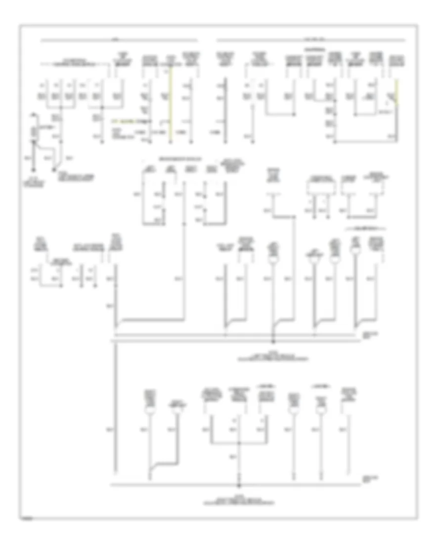
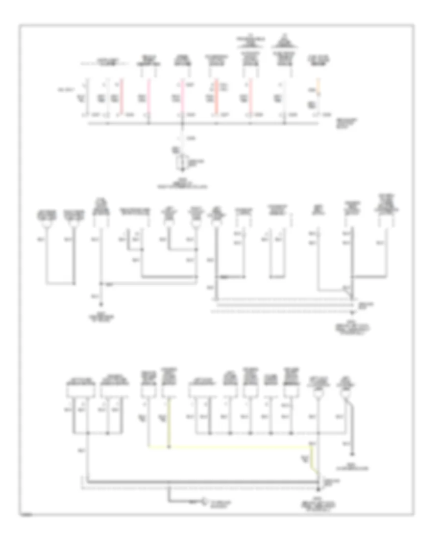
GROUND DISTRIBUTION
Ground Distribution Wiring Diagram (1 of 4) for Ford Thunderbird LX 1995
List of elements for Ground Distribution Wiring Diagram (1 of 4) for Ford Thunderbird LX 1995:
- 3.8l sc
- 3.8l sc only
- 3.8l/3.8l sc
- 4.6l
- 87a
- A/c high pressure cutout/fan switch
- Abs test connector
- Anti- lock power relay
- Anti- lock pump motor relay
- Anti-lock brake control module
- Anti-lock brake motor sensor shield
- Battery
- Brake fluid level switch
- Brake sensor shields
- California
- Camshaft position sensor
- Data link connector
- Ei only
- Engine compartment lamp
- Engine coolant level sensor
- Engine cooling fan motor
- Engine cooling pusher fan
- Fog lamp relay
- G108 (left front of vehicle, mounted on upper radiator support)
- G108 (left side of upper radiator support)
- G109 (right front of vehicle, mounted on upper radiator support)
- G110 (left front of engine)
- Ground bus
- Heated oxygen sensor #1
- Heated oxygen sensor #2
- Ignition control module
- Integrated relay control module
- Left fog lamp
- Left front
- Left front park lamp
- Left front park/ turn lamp
- Left headlamp
- Left rear
- Mass air flow (maf) sensor
- Nca
- Power- train control module
- Powertrain control module (pcm)
- Right fog lamp
- Right front
- Right front park lamp
- Right front park/ turn lamp
- Right headlamp
- Right rear
- Solenoid control valve body
- W/abs
- W/o abs
- Washer motor
- Windshield wiper motor
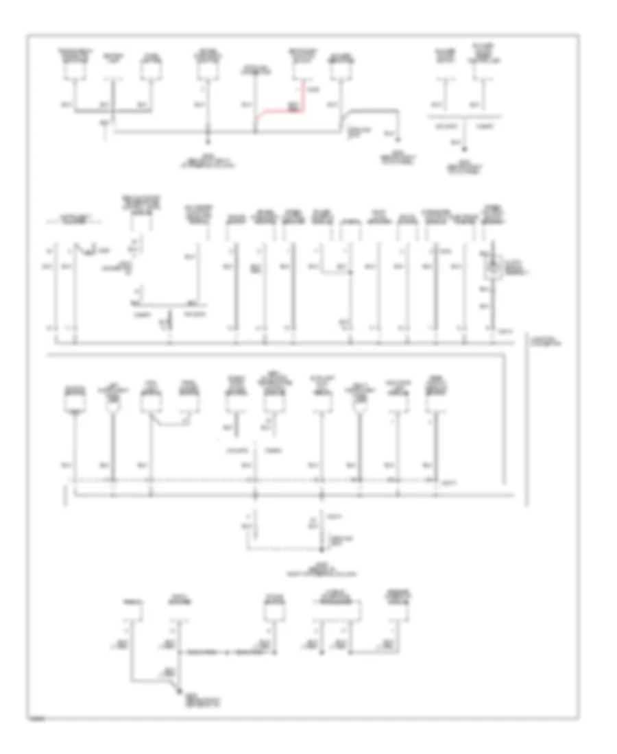
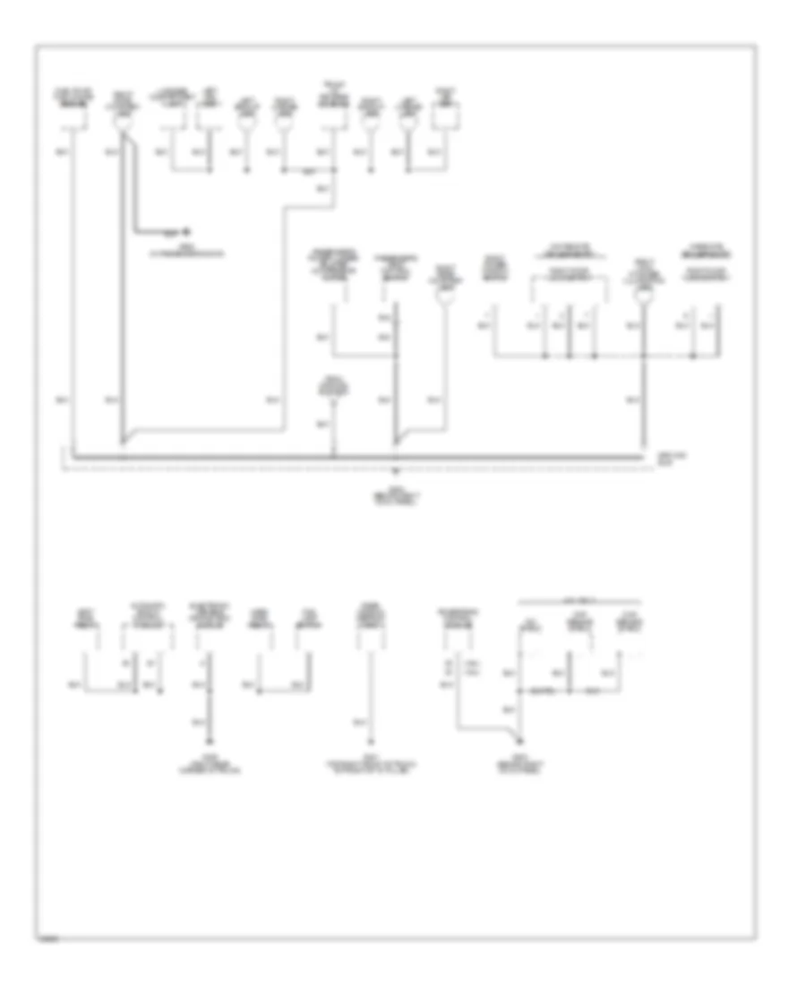
Ground Distribution Wiring Diagram (2 of 4) for Ford Thunderbird LX 1995
List of elements for Ground Distribution Wiring Diagram (2 of 4) for Ford Thunderbird LX 1995:
- A/c-heater function selector switch
- Air bag diagnostic monitor
- Ashtray lamp
- Autolamp dual coil relay
- Blend door motor control
- Blower motor speed controller
- Blower motor switch
- Blower resistors
- C2014
- C236
- C242
- C250
- Cigar lighter
- Clock spring assembly
- Data link connector
- Digital clock
- Electronic flasher
- G203 (behind right cowl panel)
- G205 (behind i/p, right of steering column)
- G206 (behind right center of i/p)
- Gnd
- Ground bus
- Ignition switch
- Indicator lamp module
- Instrument cluster
- Integrated control module
- Joint connector #1
- Junction connector
- Left instrument panel lamp
- Main light switch
- Mobile telephone transceiver
- Panel dimmer switch
- Phone switch
- Power antenna module
- Radio
- Radio amplifier
- Rear window defrost switch
- Right instrument panel light
- Secondary junction block
- Semi- automatic temperature control module
- Semi-automatic temperature control (satc) module
- Shift lock actuator
- Speaker interrupt module
- Speed control amplifier
- Speed control switch assembly
- Transmission range (tr) indicator
- W/o satc
- W/satc
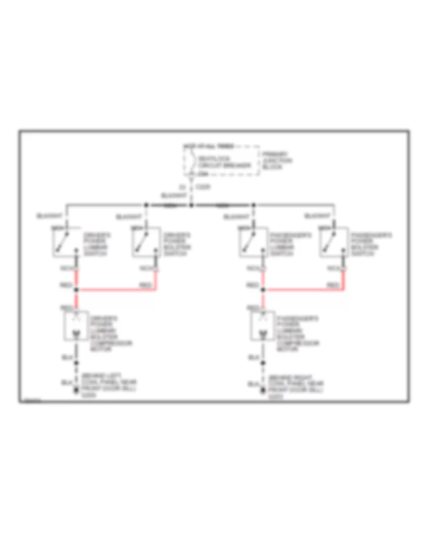
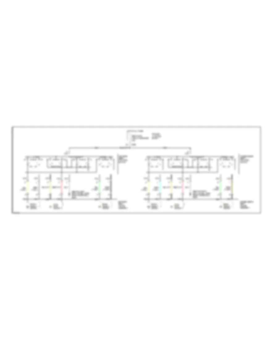
Ground Distribution Wiring Diagram (3 of 4) for Ford Thunderbird LX 1995
List of elements for Ground Distribution Wiring Diagram (3 of 4) for Ford Thunderbird LX 1995:
- (3.8l)
- (4.6l)
- (behind left cowl panel, near front of door sill)
- (in driver's door)
- 4.6l only
- Automatic shock control module
- C236
- C237
- C240
- C245
- C257
- Dome/map lamps
- Driver's power lumbar/ bolster compressor motor
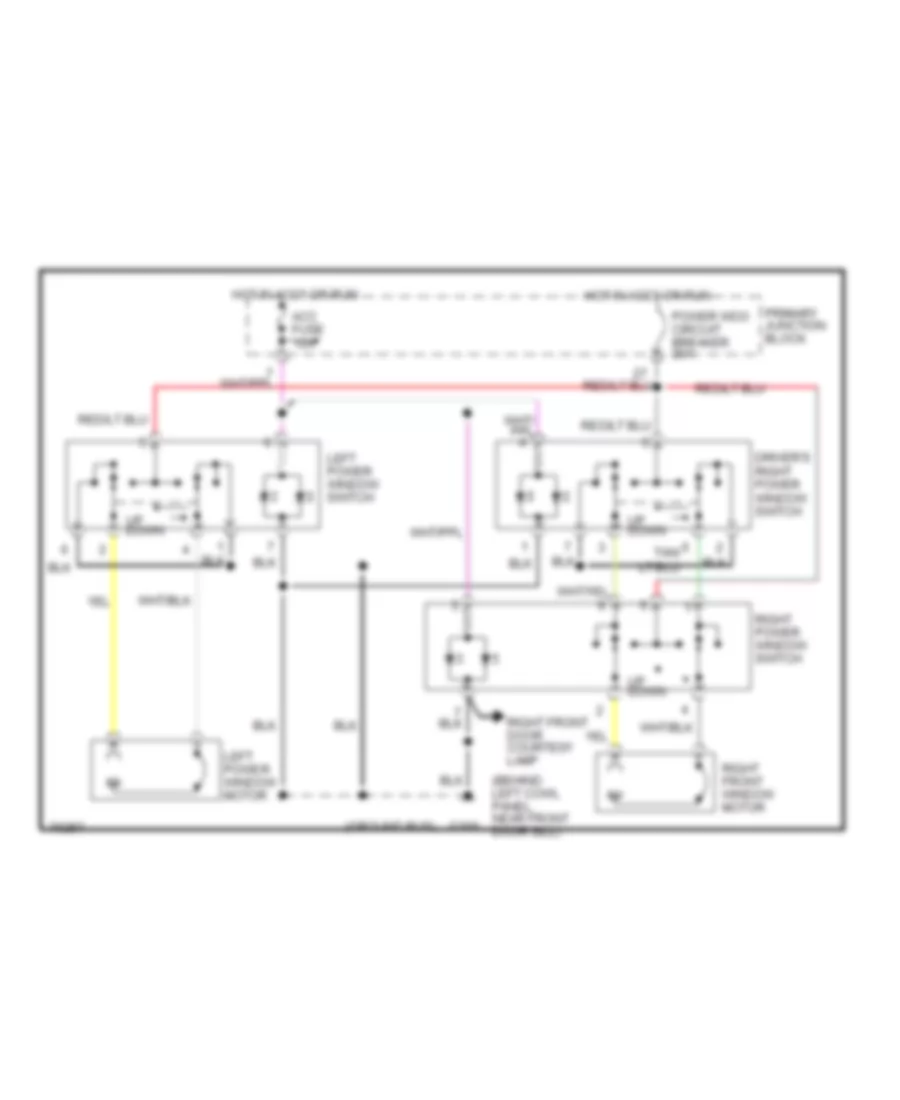
- Driver's right power window switch
- Driver's seat control switch
- Electronic variable orifice module
- Fuel filler door release solenoid
- Fuel pump/ fuel gauge sender
- G200
- G205 (behind i/p, right of steering column)
- G407 (center rear of trunk)
- G500
- Ground bus
- Instrument cluster
- Keyless entry keypad switch assembly
- Left door courtesy lamp
- Left door lock switch
- Left hi mount stop lamp
- Left lock cylinder illumination lamp
- Left power window switch
- Left rear courtesy lamp
- Left rear stop/park/ turn lamp
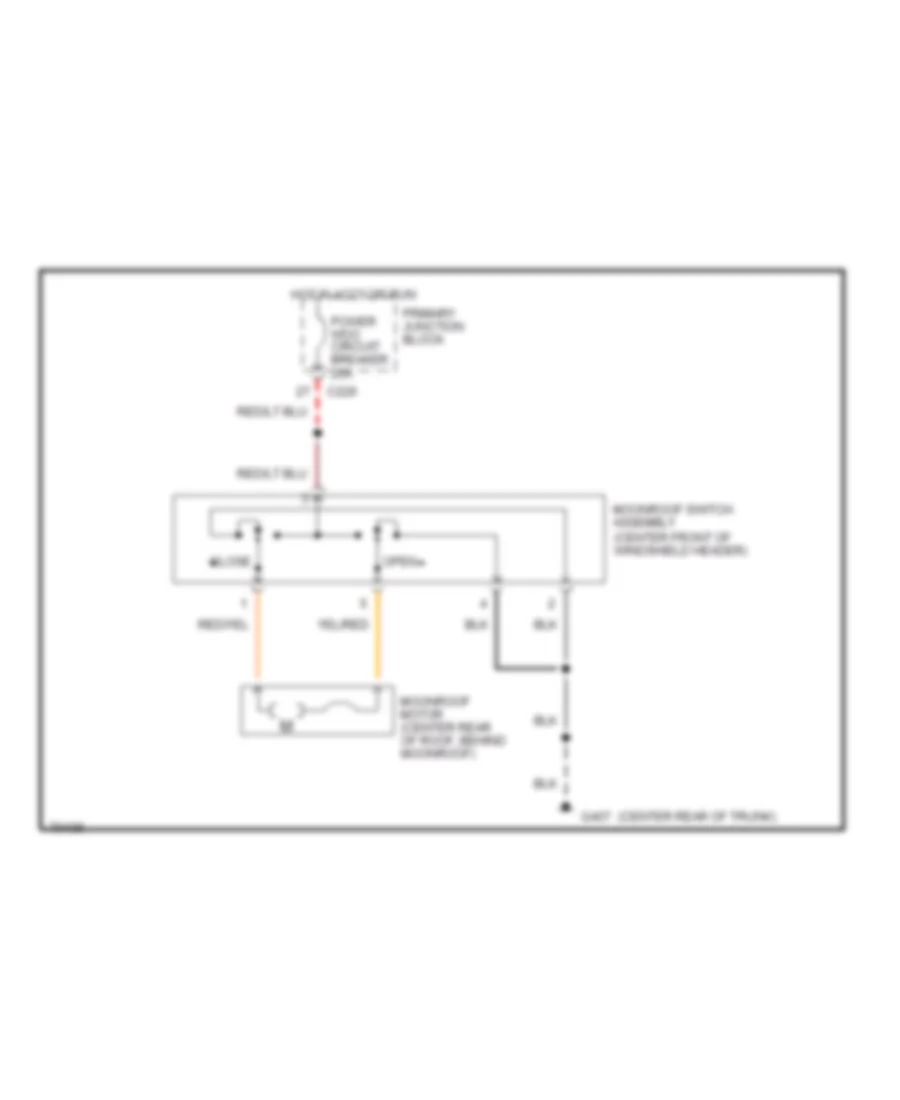
- Moonroof switch assembly
- Power mirror switch
- Powertrain control module
- Remote keyless entry module
- Remote/keyless entry module
- Right hi mount stop lamp
- Right rear stop/park/ turn lamp
- Seat belt switch
- Secondary junction block
- Speed control amplifier
- To ground bus g203
- Vehicle speed sensor (vss)
- W/ evo power steering
- W/ programmable ride control
Ground Distribution Wiring Diagram (4 of 4) for Ford Thunderbird LX 1995
List of elements for Ground Distribution Wiring Diagram (4 of 4) for Ford Thunderbird LX 1995:
- (3.8l)
- (4.6l)
- 4.6l only
- Automatic shock control module
- Ckp sensor shield
- Cmp sensor shield
- Electronic variable orifice (evo) module
- Fog lamp switch
- From ground bus g200
- Fuel pump/ fuel gauge sender
- G203 (behind right cowl panel)
- G401 (top right front of trunk, top right of "d" pillar)
- G405 (right rear corner of trunk)
- G600 (in passenger's door)
- Ground bus
- Hard ride relay
- Icm shield
- Left backup lamp
- Left led bar
- Left license lamp
- Luggage compartment lamp
- Passenger's power lumbar/ bolster compressor motor
- Passenger's seat control switch
- Powertrain control module
- Rear window defrost grid
- Right backup lamp
- Right door courtesy lamp
- Right door lock switch
- Right led bar
- Right license lamp
- Right lock cylinder illumination lamp
- Right power window switch
- Right rear courtesy lamp
- Soft ride relay
- Trunk lid release solenoid
- W/o remote keyless entry
- W/remote keyless entry
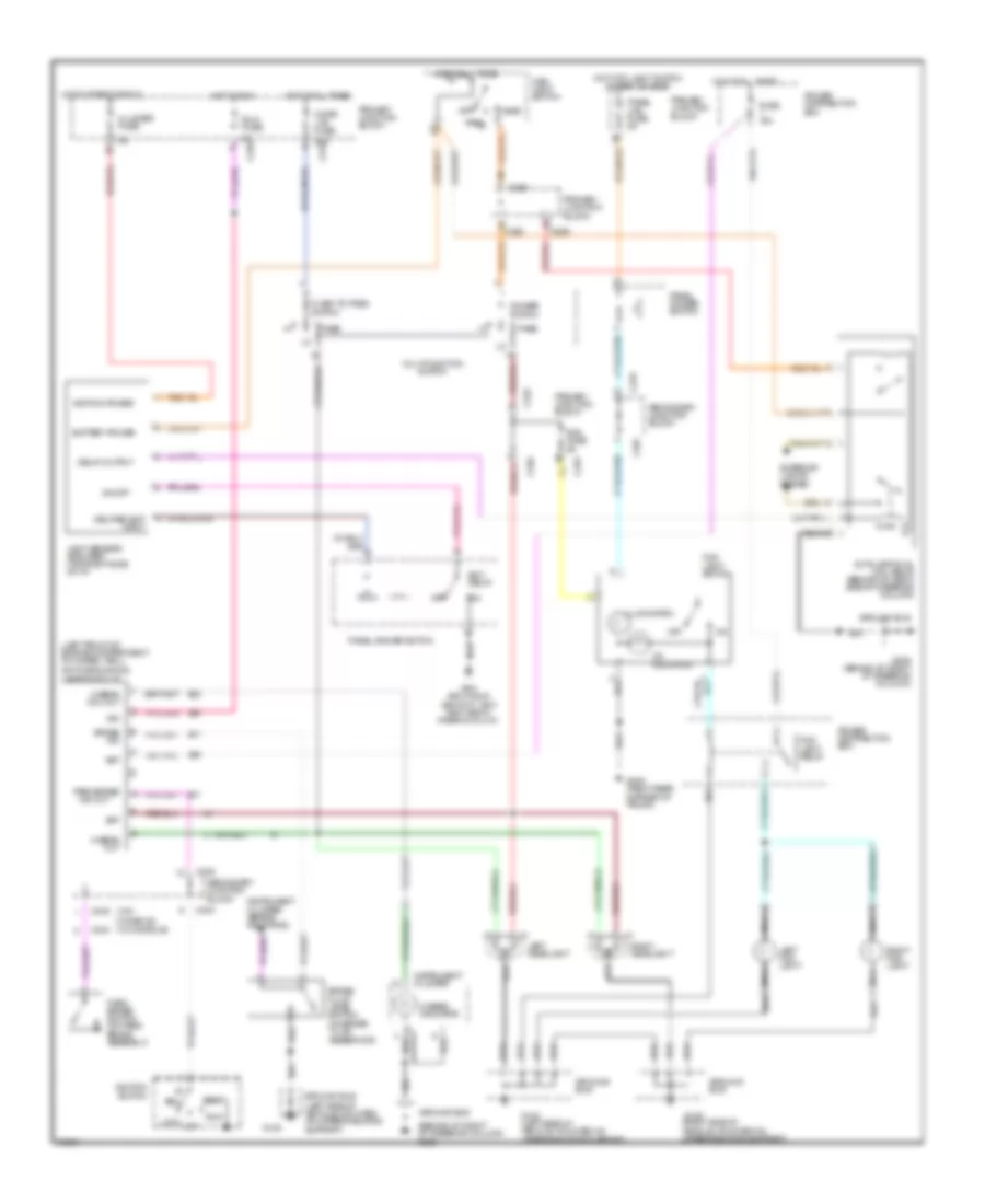
HEADLIGHTS
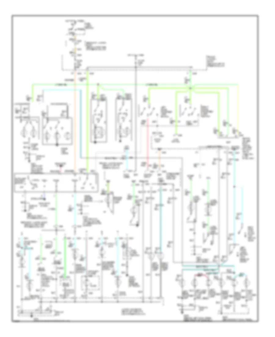
Autolamps/Fog Lamps Wiring Diagram, with DRL for Ford Thunderbird LX 1995
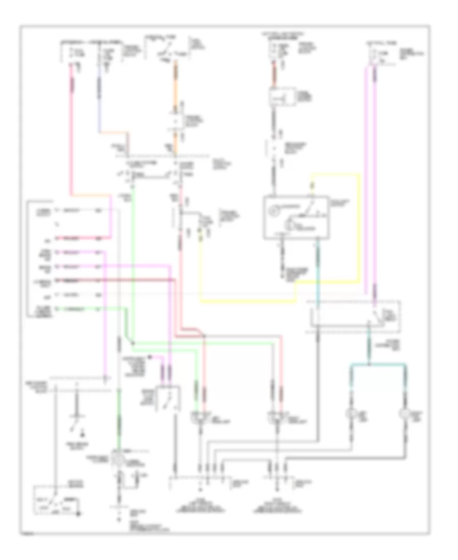
List of elements for Autolamps/Fog Lamps Wiring Diagram, with DRL for Ford Thunderbird LX 1995:
-
-
-
-
-
-
- (behind i/p, right of steering column) g205
- (left front of engine compartment, on wheel well)
- (w/ console)
- (w/o
- 20a c232
- 5a c226
- Acc
- Autolamp dual coil relay (behind i/p, right side of steering column)
- Bat
- Battery power
- Brake fluid level switch (on brake fluid reservoir)
- Brake ind
- C226
- C232
- C233
- C236
- C243
- C245
- Cigar ltr fuse
- Cluster fuse
- Console)
- Daytime running lamps module
- Delay output
- Delayed exit input
- Dimmer switch
- Exit delay
- Exterior lights system
- Flash-to-pass switch
- Fog fuse 5a
- Fog light relay
- Fog light switch
- Fuse 15a
- G108
- G108 (left side of vehicle, mounted on upper radiator support)
- G109 (right side of vehicle, mounted on upper radiator support)
- G205 (behind i/p, right of steering column)
- G205 ground bus (behind i/p, near right side of steering column)
- G405 (right rear corner of trunk)
- Ground bus
- Ground bus (left side of vehicle, mounted on upper radiator support)
- Head
- Hi beam ind. out
- Hi beam out
- Hi-beam indicator
- Hot at all times
- Hot in run
- Hot in start or run
- Hot with light switch in park or head
- Ign
- Ignition power
- Ignition switch
- Illumination
- Ind out
- Instrument cluster
- Instrument cluster (brake indicator)
- Left fog light
- Left headlight
- Light sensor/ amplifier (top right side of i/p)
- Lock
- Main light switch
- Mult-function switch
- Nca
- Off
- On indicator
- On/off
- Panel dimmer switch
- Panel lps fuse 5a
- Park
- Park brake
- Park brake switch (on park brake assembly)
- Pass
- Power distribution box
- Primary junction block
- Right fog light
- Right headlight
- Run
- Run fuse
- Secondary junction block
- Start
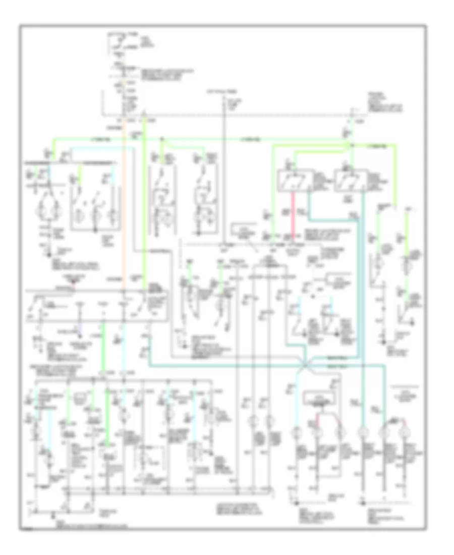
Autolamps/Fog Lamps Wiring Diagram, without DRL for Ford Thunderbird LX 1995
List of elements for Autolamps/Fog Lamps Wiring Diagram, without DRL for Ford Thunderbird LX 1995:
-
-
-
-
-
- 20a c232
- 5a c226
- Autolamp dual coil relay (behind i/p, right side of steering column)
- Battery power
- C226
- C232
- C233
- C245
- C251
- Cigar ltr fuse
- Cluster fuse
- Delay output
- Delayed exit input
- Dimmer switch
- Exit delay
- Exterior lights system
- Flash-to-pass switch
- Fog fuse 5a
- Fog light relay
- Fog light switch
- Fuse 15a
- G108 (left side of vehicle, mounted on upper radiator support)
- G109 (right side of vehicle, mounted on upper radiator support)
- G205 (behind i/p, right of steering column)
- G205 ground bus (behind i/p, near right side of steering column)
- G405 (right rear corner of trunk)
- Ground bus
- Head
- Hi-beam indicator
- Hot at all times
- Hot in run or start
- Hot with light switch in park or head
- Ignition power
- Illumination
- Instrument cluster
- Left fog lamp
- Left headlamp
- Light sensor/ amplifier (top right side of i/p)
- Main light switch
- Multi- function switch
- Nca
- Off
- On indicator
- On/off
- Panel dimmer switch
- Panel lps fuse 5a
- Park
- Pass
- Power distribution box
- Primary junction block
- Right fog lamp
- Right headlamp
- Secondary junction block
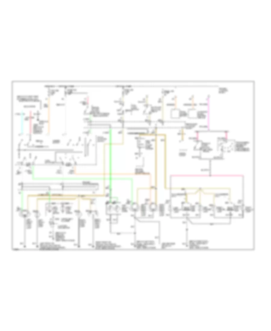
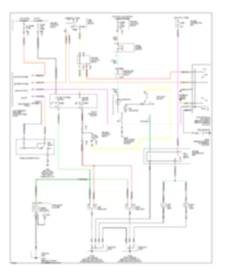
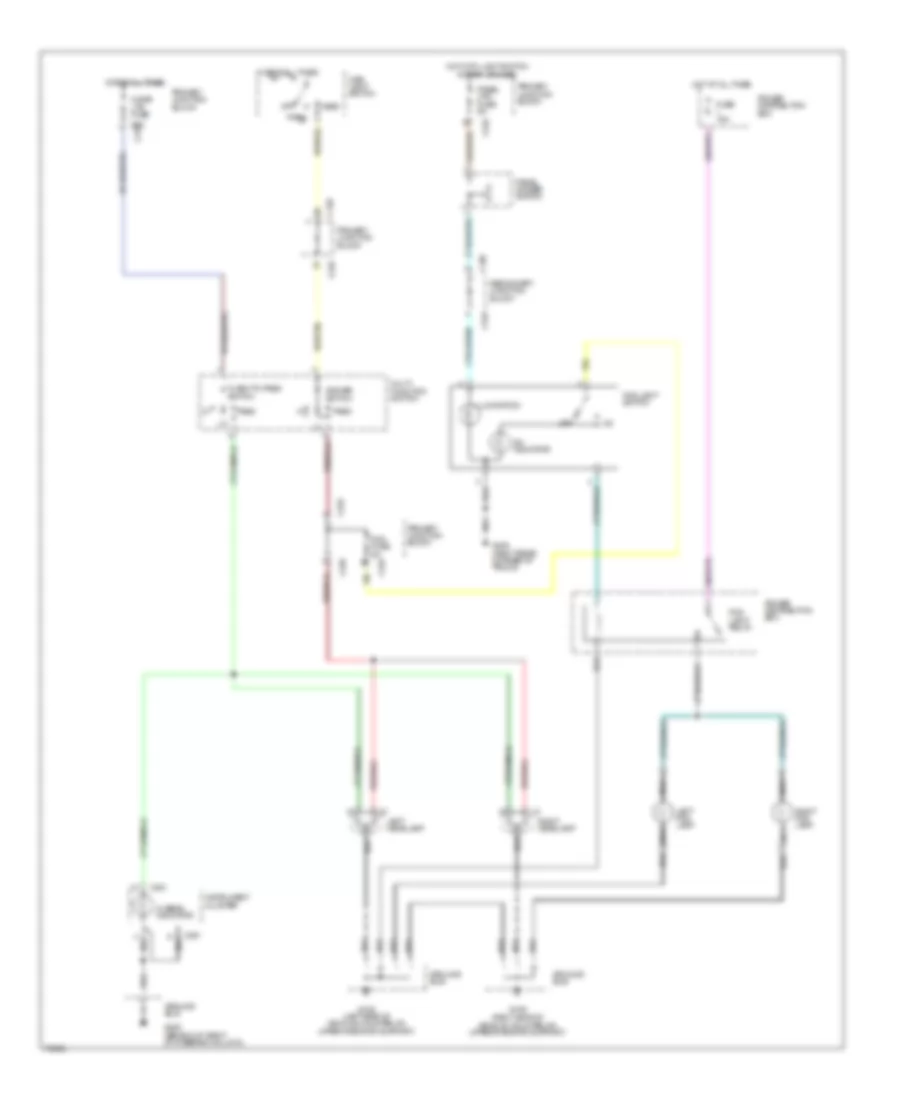
Headlamps/Fog Lamps Wiring Diagram, with DRL for Ford Thunderbird LX 1995
List of elements for Headlamps/Fog Lamps Wiring Diagram, with DRL for Ford Thunderbird LX 1995:
-
-
-
-
- (right rear corner of trunk) g405
- 20a c232
- 5a c226
- Acc
- Bat
- Brake fluid level switch
- Brake ind
- C226
- C232
- C245
- C251
- C265
- Cigar ltr fuse
- Dimmer switch
- Flash-to-pass switch
- Fog fuse 5a
- Fog light relay
- Fog light switch
- Fuse 15a
- G108 (left side of vehicle, mounted on upper radiator support)
- G109 (right side of vehicle, mounted on upper radiator support)
- G205 (behind i/p, right of steering column)
- Ground bus
- Head
- Hi-beam ind out
- Hi-beam indicator
- Hot at all times
- Hot in run
- Hot with light switch in park or head
- Ign
- Ignition switch
- Illumination
- Instrument cluster
- Instrument cluster system (brake indicator)
- Left fog lamp
- Left headlamp
- Lo-beams input
- Lock
- Main light switch
- Multi- function switch
- Nca
- Off
- On indicator
- Panel dimmer switch
- Panel lps fuse 5a
- Park
- Park brake switch
- Park brake ind
- Pass
- Power distribution box
- Primary junction block
- Pulsed hi-beams output
- Right fog lamp
- Right headlamp
- Run
- Run fuse
- Secondary junction block
- Start
Headlamps/Fog Lamps Wiring Diagram, without DRL for Ford Thunderbird LX 1995
List of elements for Headlamps/Fog Lamps Wiring Diagram, without DRL for Ford Thunderbird LX 1995:
-
-
-
-
- c251
- 20a c232
- C226
- C232
- C245
- C251
- C265
- Cigar ltr fuse
- Dimmer switch
- Flash-to-pass switch
- Fog fuse 5a
- Fog light relay
- Fog light switch
- Fuse 15a
- G108 (left side of vehicle, mounted on upper radiator support)
- G109 (right side of vehicle, mounted on upper radiator support)
- G205 (behind i/p, right of steering column)
- G405 (right rear corner of trunk)
- Ground bus
- Head
- Hi-beam indicator
- Hot at all times
- Hot with light switch in park or head
- Illumination
- Instrument cluster
- Left fog lamp
- Left headlamp
- Main light switch
- Multi- function switch
- Nca
- Off
- On indicator
- Panel dimmer switch
- Panel lps fuse 5a
- Park
- Pass
- Power distribution box
- Primary junction block
- Right fog lamp
- Right headlamp
- Secondary junction block
HORN
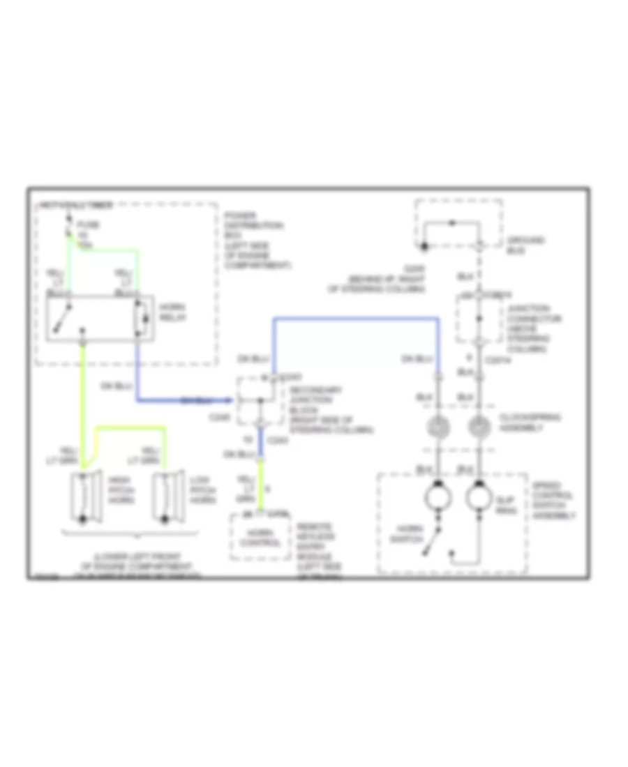
Horn Wiring Diagram for Ford Thunderbird LX 1995
List of elements for Horn Wiring Diagram for Ford Thunderbird LX 1995:
- (lower left front of engine compartment, on bumper reinforcement)
- C2014
- C243
- C245
- C456
- Clockspring assembly
- Fuse 15a
- G205 (behind i/p, right of steering column)
- Ground bus
- High pitch horn
- Horn control
- Horn relay
- Horn switch
- Hot at all times
- Junction connector (above steering column)
- Low pitch horn
- Power distribution box (left side of engine compartment)
- Remote keyless entry module (left side of trunk)
- Secondary junction block (right side of steering column)
- Slip ring
- Speed control switch assembly
INSTRUMENT CLUSTER
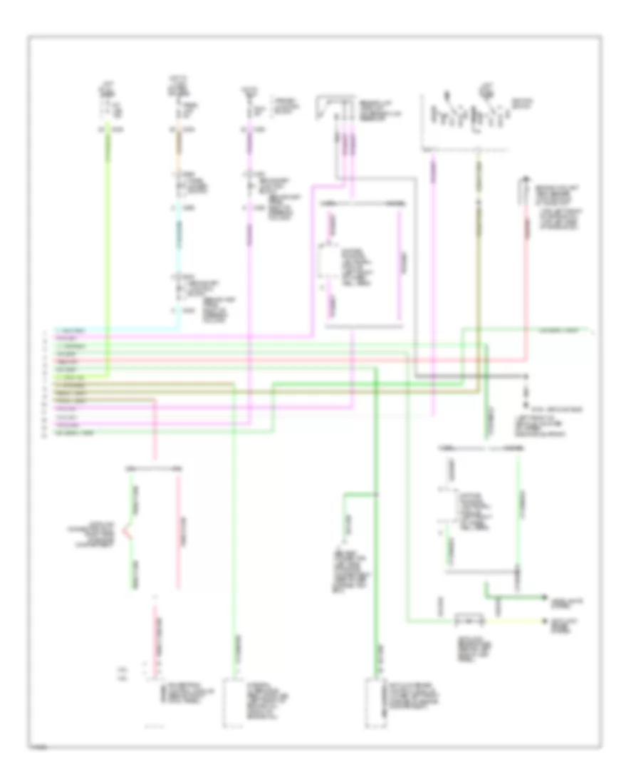
Instrument Cluster Wiring Diagram (1 of 4) for Ford Thunderbird LX 1995
List of elements for Instrument Cluster Wiring Diagram (1 of 4) for Ford Thunderbird LX 1995:
- hot in start or run
- (ground bus)
- (not used)
- 12/
- 3.8l
- 4.6l
- A10
- A11
- A12
- A14
- A15
- A16
- A17
- A18
- Air bag ind
- Airbag diagnostic module (behind right side of inst panel)
- Alternator ind
- Anti/ lock ind
- Anti/slosh module
- B10
- B11
- B12
- B13
- B14
- Brake ind
- C236
- C237
- C238
- C240
- C243
- C245
- Check gauge ind
- Cluster 5a
- Conn a
- Conn b
- Engine oil pres sw (top front of engine 3.8l) (lower left front of engine 4.6l)
- Exterior
- Fasten belts ind
- Fuel gauge
- Fuel pump/ fuel gauge sender (in top of fuel tank)
- G205 (behind inst panel, near right of steering column)
- High beam ind
- Icm
- Idm
- Ignition control module (right side of engine compart)
- Illum (5 used)
- Instrument cluster
- Junction connector (behind left side of inst panel, above steering column)
- Left turn ind
- Lights
- Malfunction/ check eng ind
- Oil pres gauge
- Parking brake sw (on park brake assembly)
- Powertrain control module (pcm) (behind right cowl panel)
- Primary junction block
- Right turn ind
- Secondary junction block (behind inst panel, right of steering column)
- Speed sensor (left rear of transmission)
- Speedometer
- System
- Tachometer
- Temp gauge
- Transmission control ind
- Vehicle
- Voltmeter (sport cluster)
- W/ console
- W/o console
Instrument Cluster Wiring Diagram (2 of 4) for Ford Thunderbird LX 1995
List of elements for Instrument Cluster Wiring Diagram (2 of 4) for Ford Thunderbird LX 1995:
- (behind inst panel right of steering column)
- (ground bus)
- (left front of vehicle, mounted on upper radiator support)
- (top left front of engine 3.8l) (top left side of engine 4.6l)
- 3.8l
- 4.6l
- Abs test connector (left side of engine compartment near power distribution box)
- Acc
- Anti/lock brake control module (lower left front corner of engine compartment)
- Anti/lock brake diode (behind left side of inst panel)
- Anti/lock brake system
- At all times
- Brake fluid level sw (on brake fluid resevoir)
- C232
- C233
- C238
- C245
- C265
- Data link connector (dlc) (right side of engine compartment)
- Daytime running lights(drl) module (left front of wheel well area)
- Engine coolant temp sender 74 ohms cold 9.7 ohms hot
- G108
- Headlights system
- Hot
- Hot in
- Hot w/ lt sw in park or head
- Ignition switch
- Ind control
- Int lps 10a
- Integral alternator regulator (iar) (left front of engine 3.8l) (front of engine 4.6l)
- Lock
- Off
- Panel dimmer switch
- Panel lps 5a
- Powertrain control module (behind right cowl panel)
- Primary junction block
- Run
- Run 5a
- Secondary junction block
- Start
- Sto/mil
- W/ drl
- W/o drl
Instrument Cluster Wiring Diagram (3 of 4) for Ford Thunderbird LX 1995
List of elements for Instrument Cluster Wiring Diagram (3 of 4) for Ford Thunderbird LX 1995:
- only
- cluster 5a
- (behind inst panel near right of steering column)
- (behind left cowl panel, near front of door sill)
- (ground bus)
- (not used)
- 159 red/pnk
- 3.8l (w/mt)
- 4.6l
- Acc 10a
- All times
- Battery
- C226
- C269
- C292
- Door courtesy lamp sw in
- Door input
- Fasten belt ind
- G200
- G205
- Ground
- Head
- Hot at
- Hot in acc
- Hot in start
- Ignition
- Int lps 10a
- Integrated control module (behind left side of inst panel)
- Junction connector (behind left side of inst panel, above steering column)
- Key in ign in
- Key warning sw (inside ignition sw)
- Lamps in
- Left door courtesy lamp sw (in left door jamb)
- Left door latch sw (top rear of left door on door latch assembly)
- Main light sw
- Nca
- Off
- Or run
- Park
- Powertrain control module (pcm) (behind right cowl panel)
- Primary junction block (behind inst panel, left of steering column)
- Red/pnk
- Right door latch sw (top rear of right door on door latch assembly)
- Seatbelt buckle in
- Seatbelt sw (in left seatbelt buckle assembly)
- Supercoupe
- Warning chime module
Instrument Cluster Wiring Diagram (4 of 4) for Ford Thunderbird LX 1995
List of elements for Instrument Cluster Wiring Diagram (4 of 4) for Ford Thunderbird LX 1995:
- (behind inst panel right of side of steering column)
- (behind inst panel right of steering column)
- (ground bus)
- (in bottom of washer fluid reservoir)
- (left side of engine compartment top of engine coolant reservoir)
- 3.8l
- 4.6l
- Anti/lock brake control module (below battery)
- Automatic shock control module (center of rear package tray)
- C226
- C232
- C233
- C240
- C403
- Daytime running lamps (drl) module (in left front wheel well)
- Door ajar ind
- Engine coolant ind
- Engine coolant level sensor
- Firm ride ind
- Fuel pump/ fuel gauge sender (top of fuel tank)
- G108 (left front of vehicle, mounted on upper radiator support)
- G205 (behind inst panel, near right of steering column)
- Hot in run
- Indicator feed
- Indicator lamp module
- Junction connector (behind left side of inst panel above steering column)
- Left door switch (upper rear of left door)
- Low fuel ind
- Primary junction block
- Right door switch (upper rear of right door)
- Run 5a
- Secondary junction block
- Solid state
- Switch feed
- Traction assist ind
- Traction assist switch
- Washer fluid ind
- Washer fluid level sensor
INTERIOR LIGHTS
Interior Light Wiring Diagram, with Remote/Keyless Entry for Ford Thunderbird LX 1995
List of elements for Interior Light Wiring Diagram, with Remote/Keyless Entry for Ford Thunderbird LX 1995:
- (not used)
- 3.5k + 1k - on
- A/c-heater function selector switch
- Autolamp control switch
- Bat
- Bulbs
- C226
- C232
- C233
- C236
- C238
- C240
- C242
- C243
- C245
- C250
- C294
- C295
- C298
- C455
- C456
- C457
- Cylinder illum. lamp
- Digital clock
- Dome/ map lamps
- Engine compt. lamp
- Except rx7
- Fog lamp switch
- G108 (left front of vehicle, mounted on upper radiator support)
- G200 (behind left cowl panel, near front of door sill)
- G203 (behind right cowl panel)
- G205 (behind i/p, right of steering column)
- G405 (right rear corner of trunk)
- Glove box lamp
- Ground
- Ground bus
- Head
- Headlights system
- Hot at all times
- Instrument cluster c251
- Int lps fuse 10a
- Integrated control module
- Junction connector (behind left side of i/p, above steering column)
- Lamp control
- Left door courtesy lamp switch
- Left door latch switch (top rear of door)
- Left instr. panel lamp
- Left vanity lamp
- Lugg. compt lamp switch
- Lugg. compt. lamp
- Main light switch
- Nca
- Off
- Panel dimmer switch
- Panel lps fuse 5a
- Park
- Primary junction block (behind i/p left of steering column)
- Primary junction block (behind i/p, left of steering column)
- Radio
- Red/ pnk
- Remote/ keyless entry module (left side of trunk, above wheelwell, in trim panel assy)
- Right door courtesy lamp
- Right door courtesy lamp switch
- Right door latch switch (top rear of door)
- Right instr. panel lamp
- Right rear courtesy lamp
- Right vanity lamp
- Rx7
- Secondary junction block (behind i/p, right side of steering column)
- Semi- automatic temperature control (satc) module
- Solid state
- Switch input
- Transmission range (tr) indicator
- W/ moonroof
- W/o moonroof
- With satc
- Without eatc
Interior Light Wiring Diagram, without Remote/Keyless Entry for Ford Thunderbird LX 1995
List of elements for Interior Light Wiring Diagram, without Remote/Keyless Entry for Ford Thunderbird LX 1995:
- (not used)
- 3.5k + 1k -
- Ashtray lamp
- Autolamp control switch
- Bat
- Bulbs
- C226
- C232
- C233
- C236
- C238
- C240
- C242
- C243
- C245
- C250
- C251
- C294
- C295
- C298
- Cluster
- Digital clock
- Dome/ map lamps
- Door input
- Engine compt. lamp
- Except xr7
- Fog lamp switch
- G200 (behind left cowl panel, near front of door sill)
- G203 (behind right cowl panel)
- G205 (behind i/p, right of steering column)
- G405 (right rear corner of trunk)
- Glove box lamp
- Ground
- Ground bus
- Ground bus g108 (left front of vehicle, mounted on upper radiator support)
- Ground bus g203 (behind right cowl panel)
- Ground bus g205 (behind i/p, right of steering column)
- Head
- Headlights system
- Hot at all times
- Int lps fuse 10a
- Integrated control module
- Junction connector (behind left side of i/p, above steering column)
- Lamp
- Lamp control
- Left door courtesy lamp
- Left door courtesy lamp switch
- Left door latch switch (top rear of door)
- Left instr. panel lamp
- Left lock cylinder illum. lamp
- Left rear courtesy lamp
- Left vanity lamp
- Lugg. compt lamp switch
- Lugg. compt. lamp
- Main light switch
- Nca
- Off
- Panel dimmer switch
- Panel lps fuse 5a
- Park
- Phone switch
- Primary junction block (behind i/p left of steering column)
- Primary junction block (behind i/p, left of
- Radio
- Rear
- Red
- Red/ pnk
- Right door courtesy lamp switch
- Right door latch switch (top rear of door)
- Right front door courtesy lamp
- Right instr. panel lamp
- Right lock cylinder illum. lamp
- Right rear courtesy lamp
- Secondary junction block (behind i/p, right side of steering column)
- Secondary junction block (behind i/p, right side of steering column)
- Semi- automatic temp. control (satc) module
- Solid state
- Steering column)
- Switch input
- Transmission range (tr) indicator
- W/ moonroof
- W/o moonroof
- With illuminated entry
- With satc
- Without eatc
- Xr7
POWER ANTENNA
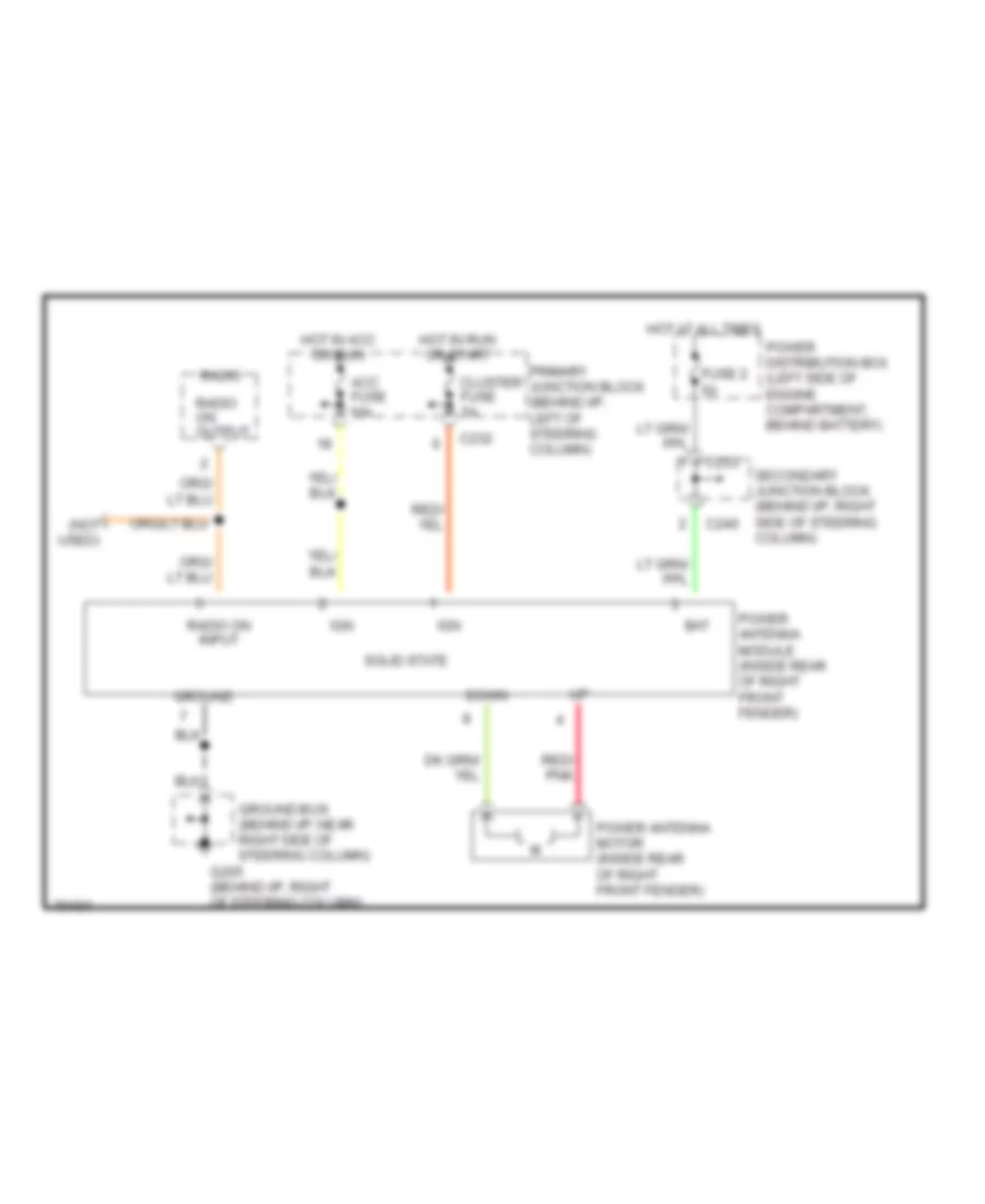
Power Antenna Wiring Diagram for Ford Thunderbird LX 1995
List of elements for Power Antenna Wiring Diagram for Ford Thunderbird LX 1995:
- (not used)
- Acc fuse 10a
- Bat
- C232
- C233
- C240
- Cluster fuse 5a
- Down
- Fuse 2 5a
- G205 (behind i/p, right of steering column)
- Ground
- Ground bus (behind i/p, near right side of steering column)
- Hot at all times
- Hot in acc or run
- Hot in run or start
- Ign
- Power antenna module (inside rear of right front fender)
- Power antenna motor (inside rear of right front fender)
- Power distribution box (left side of engine compartment, behind battery)
- Primary junction block (behind i/p, left of steering column)
- Radio
- Radio on input
- Radio on output
- Red/ pnk
- Secondary junction block (behind i/p, right side of steering column)
- Solid state
POWER DISTRIBUTION
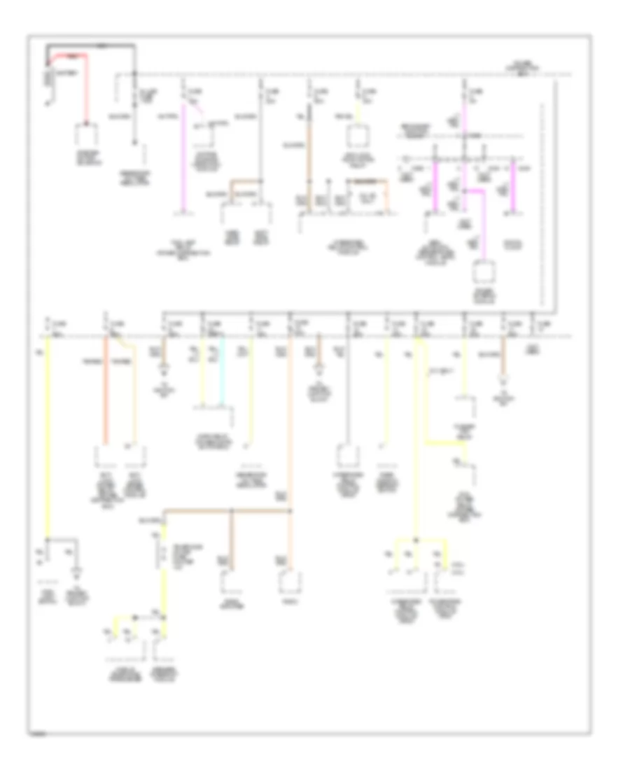
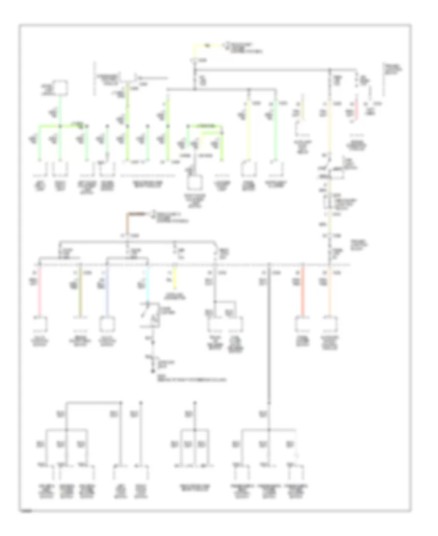
Power Distribution Wiring Diagram (1 of 4) for Ford Thunderbird LX 1995
List of elements for Power Distribution Wiring Diagram (1 of 4) for Ford Thunderbird LX 1995:
- (3.8l)
- (4.6l)
- (not used)
- 3.8l sc only
- Anti- lock brake control module
- Anti- lock power relay (power distribution box)
- Anti-lock pump motor relay
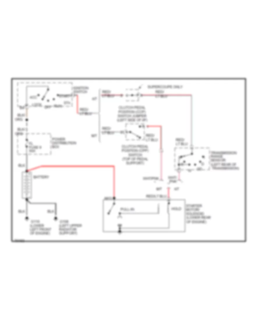
- Battery
- C233
- C240
- C245
- C298
- Daytime running lamps (drl) module
- Digital clock
- Fog lamp relay (power distribution box)
- Fuse
- Fuse 15a
- Fuse 20a
- Fuse 30a
- Fuse 40a
- Fuse 5a
- Fuse 60a
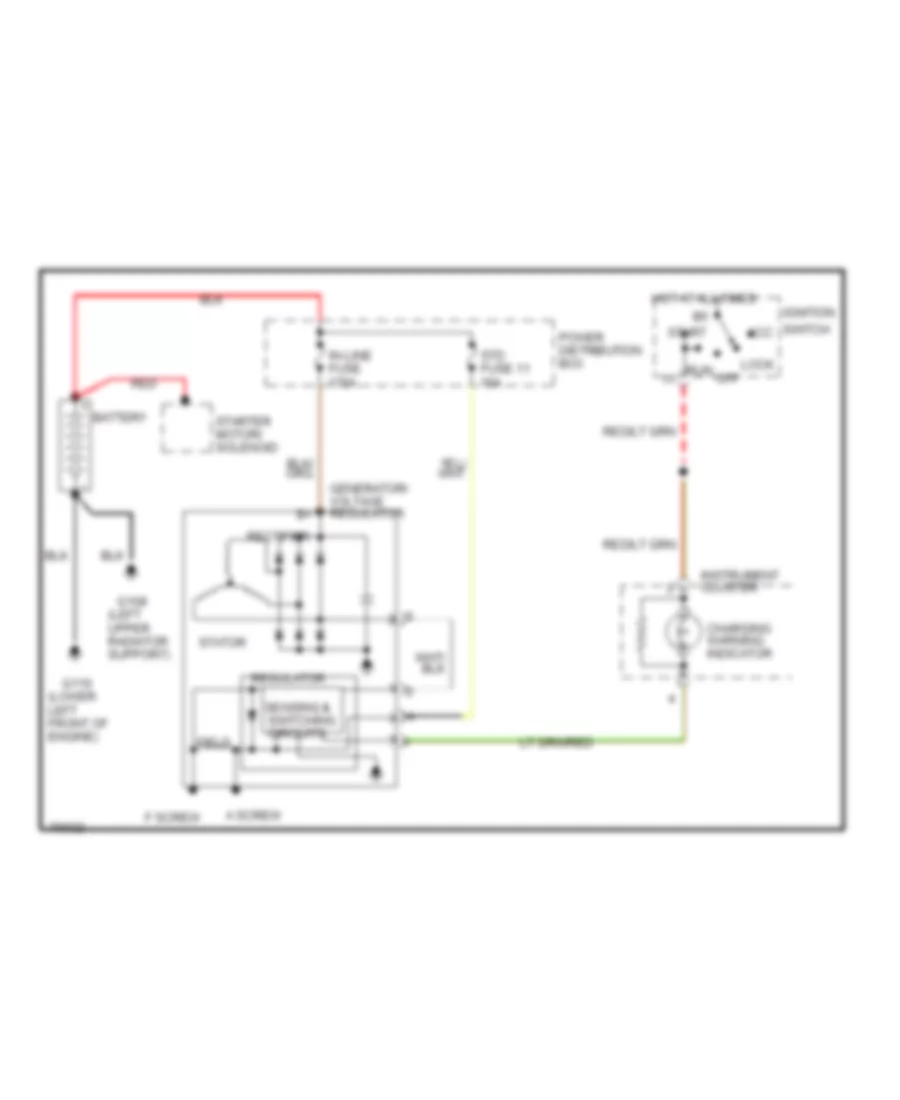
- Generator/ voltage regulator
- Hard ride relay
- Horn relay (power distri- bution box)
- In-line fuse 175a
- Integrated relay control module
- Integrated relay control module (ircm)
- Main light switch
- Mobile telephone transceiver
- Nca
- Pcm power relay (power distribution box)
- Power antenna module
- Power distribution box
- Powertrain control module (pcm)
- Pusher fan relay
- Radio
- Radio amplifier
- Rear window defrost switch
- Red
- S.c. only
- Secondary junction block
- Semi- automatic temperature control (satc) module
- Soft ride relay
- Speaker interrupt module
- Starter motor/ solenoid
- Tan/red
- Telephone in-line fuse holder 10a
- To ignition sw
- To primary junction block
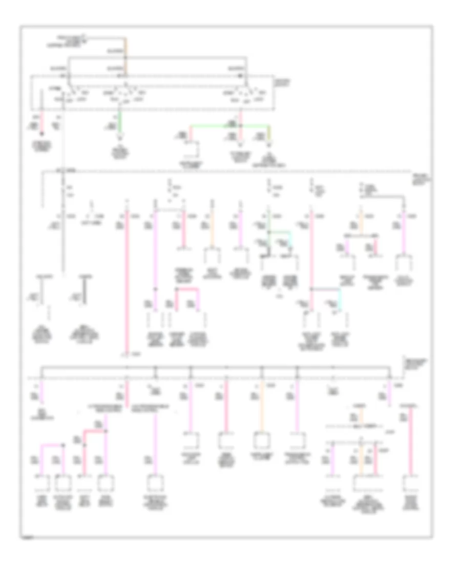
Power Distribution Wiring Diagram (2 of 4) for Ford Thunderbird LX 1995
List of elements for Power Distribution Wiring Diagram (2 of 4) for Ford Thunderbird LX 1995:
- (not used)
- 10a
- 15a
- 3.8l
- A/c
- A/c- heater function selector switch
- A/t
- Acc
- Air bag diagnostic module
- Anti- lock 10a
- Anti-lock brake control module
- Anti-lock power relay (power distri- bution box)
- Automatic shock control module
- Backup lamp switch
- Blend door motor control
- C2007
- C226
- C232
- C233
- C238
- C240
- C298
- Daytime running lamps (drl) module
- Distribution box)
- Electronic variable orifice (evo) module
- Engine coolant level sensor
- Evo test connector
- From fuse 9 (power b
- Hard ride relay
- Heated oxygen sensor #1
- Heated oxygen sensor #2
- Ho2s
- Ignition switch
- Indicator lamp module
- Instrument cluster
- J/c #1
- Lock
- M/t
- Multi- function switch
- Nca
- Off
- Outside/ recirculate solenoid
- Primary junction block
- Rear window defrost switch
- Ride select switch
- Run
- Secondary junction block
- Semi- automatic temperature control (satc) module
- Semi- automatic temperature control (ssatc) module
- Shift lock actuator
- Soft ride relay
- Sta
- Start
- Starting/ charging system
- Steering wheel rotation sensor
- To fuse 3 (power distribution box)
- To primary junction block
- Transmission control switch (tcs)
- Transmission range (tr) sensor
- Turn signal 10a
- W/ programmable ride control
- W/o programmable ride control
- W/o satc
- W/satc
- Washer fluid level sensor
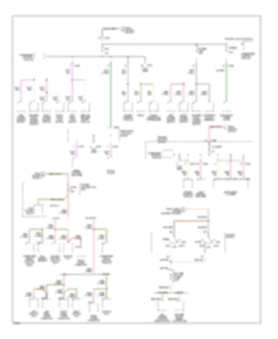
Power Distribution Wiring Diagram (3 of 4) for Ford Thunderbird LX 1995
List of elements for Power Distribution Wiring Diagram (3 of 4) for Ford Thunderbird LX 1995:
- (not used)
- 10a
- 3.8l di
- 3.8l ei
- 3.8l ei/4.6l
- 30a
- 4.6l
- A/c- heater function selector sw
- Acc
- Blower in-line fuse 30a
- Blower motor speed controller
- C226
- C232
- C233
- C237
- C240
- C250
- C251
- C298
- Cluster
- Digital clock
- Distribution box)
- Driver's right power window switch
- From fuse 17 (power c
- From ignition d
- From ignition switch
- Fuse 20a
- Hall effect sensor
- Ignition coil
- Ignition control module (icm)
- Ignition switch
- Instrument cluster
- Integrated control module
- Integrated relay control module
- Integrated relay control module (ircm)
- Left door lock switch
- Left ignition coil
- Left power window switch
- Left radio noise capacitor
- Light sensor/ amplifier
- Lock
- Mobile telephone transceiver
- Moonroof switch assembly
- Nca
- Off
- Pcm power relay
- Power antenna module
- Power distribution box
- Power wdo 20a
- Primary junction block
- Radio
- Radio noise capacitor
- Remote/ keyless entry module
- Right door lock switch
- Right ignition coil
- Right power window switch
- Right radio noise capacitor
- Run
- Sc only
- Secondary junction block
- Speed control amplifier
- Start
- Switch
- W/o satc
- W/satc
- Windshield wiper motor
- Wipers
Power Distribution Wiring Diagram (4 of 4) for Ford Thunderbird LX 1995
List of elements for Power Distribution Wiring Diagram (4 of 4) for Ford Thunderbird LX 1995:
- (not used)
- Air bag diagnostic module
- Air bags 10a
- Autolamp dual coil relay
- Automatic shock control module
- Brake on/off (boo) switch
- C226
- C232
- C236
- C243
- C294
- C295
- C456
- C457
- Cigar lighter
- Cigar ltr 20a
- Data link connector
- Distribution box)
- Dome/ map lamps
- Driver's power bolster switch
- Driver's power lumbar switch
- Driver's seat control switch
- From fuse 12 (power distribution box)
- From fuse 7 (power g
- Fuel filler door release switch
- G205 (behind i/p, right of steering column)
- Ground bus
- Instrument cluster
- Int lps 10a
- Integrated control module
- Left door courtesy lamp switch
- Left door lock switch
- Left vanity lamp
- Luggage compt lamp
- Main light switch head
- Multi- function switch
- Nca
- Obd ii 10a
- Off
- Panel dimmer switch
- Panel lps 5a
- Park
- Park lps 10a
- Passenger's power bolster switch
- Passenger's power lumbar switch
- Passenger's seat control switch
- Power mirror switch
- Primary junction block
- Remote/keyless entry module
- Right door courtesy lamp switch
- Right door lock switch
- Right vanity lamp
- Seat/ lock 20a
- Secondary junction block
- Stop/ haz 15a
- Trunk lid release switch
- W/o rke
- W/rke
POWER DOOR LOCKS
Door Lock Wiring Diagram for Ford Thunderbird LX 1995
List of elements for Door Lock Wiring Diagram for Ford Thunderbird LX 1995:
- (behind left g200 cowl panel, near front of door sill)
- (behind right cowl panel, near front of door sill)
- (ground bus)
- Acc fuse 10a
- C226
- G203
- Hot in accy or run
- Left door lock motor
- Left door lock switch
- Lock
- Primary junction block
- Right door lock motor
- Right door lock switch
- Seat/lock circuit breaker 20a
- Unlock
Keyless Entry Wiring Diagram for Ford Thunderbird LX 1995
List of elements for Keyless Entry Wiring Diagram for Ford Thunderbird LX 1995:
- (behind left cowl panel, near front door sill)
- (behind left cowl panel, near front door sill) g200
- (behind right cowl panel, near front door sill)
- (ground bus)
- (left side of trunk, above wheelwell)
- 1/2
- 1/2 in
- 3/4
- 3/4 in
- 5/6
- 5/6 in
- 7/8
- 7/8 in
- 9/0
- 9/0 in
- A/t
- Acc fuse 10a
- Antenna
- Backup lamp switch (left side of trans.)
- Batt+
- Batt+ save in
- Batt+ save out
- C455
- C456
- C457
- Com
- Ctsy lps out
- Ctsy/dr sw in
- Dr handle in
- Driver st sw in
- Exterior lights system
- G200
- G203
- Gnd
- Horn output
- Horns
- Hot at all times
- Hot in acc or run
- Hot in run
- Ign
- Int lps fuse 10a
- Interior lamps
- Keyless entry keypad switch assembly
- Keypad common
- Keypad lp
- Lamp
- Left door courtesy lamp switch
- Left door latch switch (top rear of left door)
- Left door lock actuator
- Left door lock switch
- Lk drs out
- Lk in
- Lock
- M/t
- Panel dimmer switch
- Park lps out
- Pnk
- Power windows
- Primary junction block
- Program a
- Program b
- Red
- Remote/keyless entry module
- Reverse in
- Right door courtesy lamp switch
- Right door latch switch (top rear of right door)
- Right door lock actuator
- Right door lock switch
- Rke module programmer connector (left side of trunk, above wheelwell)
- Seat switch (under left front seat)
- Seat/lock circuit breaker 20a
- Sig batt+
- Sig gnd
- Trans- mission range (tr) sensor (left rear of trans.)
- Transmitter in
- Trnk lid out
- Trnk lp out
- Trunk lid release solenoid
- Trunk lid release switch
- Turn signal fuse 10a
- Unlk in
- Unlk lt dr out
- Unlk rt dr out
- Unlock
POWER MIRRORS
Power Mirror Wiring Diagram for Ford Thunderbird LX 1995
List of elements for Power Mirror Wiring Diagram for Ford Thunderbird LX 1995:
- (behind left cowl panel near door sill) g200
- (ground bus)
- Direct- tional switch
- Hot at all times
- Int/lps fuse 10a
- L/r motor
- Left power mirror nca
- Left/ right switch
- Nca
- Power mirror switch
- Primary junction block
- Right power mirror nca
- Up/dn motor
POWER SEATS
Power Lumbar Seat Wiring Diagram for Ford Thunderbird LX 1995
List of elements for Power Lumbar Seat Wiring Diagram for Ford Thunderbird LX 1995:
- (behind left, cowl panel near front door sill) g200
- (behind right, cowl panel near front door sill) g203
- 20a
- C226
- Driver's power bolster switch
- Driver's power lumbar switch
- Driver's power lumbar/ bolster compressor motor
- Hot at all times
- Nca
- Passenger's power bolster switch
- Passenger's power lumbar switch
- Passenger's power lumbar/ bolster compressor motor
- Primary junction block
- Red
- Seat/lock circuit breaker
Power Seats Wiring Diagram for Ford Thunderbird LX 1995
List of elements for Power Seats Wiring Diagram for Ford Thunderbird LX 1995:
- (behind left, cowl panel near front door sill) g200
- (behind right, cowl panel near front door sill) g203
- C226
- Driver's seat control switch
- Driver's seat motor assembly
- Entire seat
- Front height motor
- Front of seat
- Fwd
- Fwd/ rwd motor
- Hot at all times
- Nca
- Passenger's seat control switch
- Passenger's seat motor assembly
- Primary junction block
- Rear height motor
- Rear of seat
- Rwd
- Seat/lock circuit breaker 20a
POWER TOP/SUNROOF
Power Top/Sunroof Wiring Diagrams for Ford Thunderbird LX 1995
List of elements for Power Top/Sunroof Wiring Diagrams for Ford Thunderbird LX 1995:
- (center front of windshield header)
- (center rear of trunk)
- C226
- Close
- G407
- Hot in accy or run
- Moonroof motor (center rear of roof, behind moonroof)
- Moonroof switch assembly
- Open
- Power wdo circuit breaker 20a
- Primary junction block
POWER WINDOWS
Power Window Wiring Diagram for Ford Thunderbird LX 1995
List of elements for Power Window Wiring Diagram for Ford Thunderbird LX 1995:
- (behind left cowl panel, near front door sill)
- (ground bus)
- Acc fuse 10a
- Driver's right power window switch
- G200
- Hot in accy or run
- Left power window motor
- Left power window switch
- Power wdo circuit breaker 20a
- Primary junction block
- Right front window motor
- Right front door courtesy lamp
- Right power window switch
- Up down
RADIO
Base Radio for Ford Thunderbird LX 1995
List of elements for Base Radio for Ford Thunderbird LX 1995:
- (1994 only)
- Acc fuse 10a
- Antenna
- Battery (b+)
- C232
- C246
- C247
- Fuse 12 40a
- G205 (behind dash, right of steering column)
- G206 (behind right center of dash)
- Ground
- Hot at all times
- Hot in accy or run
- Ignition
- Illum
- Interior lights system
- Left door speaker
- Left frt
- Left rear speaker
- Left rr
- Nca
- Power antenna system (1995-96 only)
- Power distribution box (left side of engine compt)
- Primary junction block (behind left side of dash)
- Pwr antenna
- Radio
- Right door speaker
- Right frt
- Right rear speaker
- Right rr
Premium Sound Radio Wiring Diagram for Ford Thunderbird LX 1995
List of elements for Premium Sound Radio Wiring Diagram for Ford Thunderbird LX 1995:
- (behind dash, right of steering column) g205
- Acc fuse 10a
- Antenna
- Battery (b+)
- C222
- C232
- C246
- C413
- C414
- Cellular phone
- Fuse 12 40a
- G206 (behind right center of dash)
- Ground
- Hot at all times
- Hot in accy or run
- Ignition
- Illum
- Interior lights system
- Left front door speaker
- Left frt (+)
- Left frt (-)
- Left rear speaker
- Left rr (+)
- Left rr (-)
- Lt frt (+)
- Lt frt (-)
- Lt frt sig (+)
- Lt frt sig (-)
- Lt rr (+)
- Lt rr (-)
- Lt rr sig (+)
- Lt rr sig (-)
- Nca
- Power (b+)
- Power antenna system
- Power distribution box (left side of engine compt)
- Primary junction block (behind left side of dash)
- Pwr antenna
- Radio
- Radio amplifier (under right side of rear)
- Radio on
- Radio on sig
- Right front door speaker
- Right rear speaker
- Rt frt (+)
- Rt frt (-)
- Rt frt sig (+)
- Rt frt sig (-)
- Rt rr (+)
- Rt rr (-)
- Rt rr sig (+)
- Rt rr sig (-)
- Speaker interrupt module (in trunk)
- W/ cellular phone
- W/o cellular phone
SHIFT INTERLOCKS
Shift Interlock Wiring Diagram for Ford Thunderbird LX 1995
List of elements for Shift Interlock Wiring Diagram for Ford Thunderbird LX 1995:
- (behind i/p, right of steering column)
- (ground bus)
- (right side of steering column)
- Brake on/off switch
- C226
- C232
- C238
- G205
- Hot at all times
- Hot in run
- Primary junction block (below left side of i/p)
- Run fuse 15a
- Secondary junction block
- Shift lock actuator (in steering column)
- Stop/haz fuse 15a
STARTING/CHARGING
3.8L
3.8L SC, Charging Wiring Diagram for Ford Thunderbird LX 1995
List of elements for 3.8L SC, Charging Wiring Diagram for Ford Thunderbird LX 1995:
- (left upper radiator support)
- (lower left front of engine)
- (not used)
- Acc
- Battery
- Charging warning indicator
- Diode trio
- Field
- G108
- G110
- Generator/ voltage regulator
- Hot at all times
- Ic regulator
- Ignition switch
- In-line fuse 175a
- Instrument cluster
- Lock
- Off
- Power distribution box
- Rectifier
- Red
- Run
- Start
- Starter motor/ solenoid
- Stator
- Std fuse 11 15a
3.8L, Charging Wiring Diagram for Ford Thunderbird LX 1995
List of elements for 3.8L, Charging Wiring Diagram for Ford Thunderbird LX 1995:
- (left upper radiator support)
- (lower left front of engine)
- A screw
- Acc
- Battery
- Charging warning indicator
- F screw
- Field
- G108
- G110
- Generator/ voltage regulator
- Hot at all times
- Ignition
- In-line fuse 175a
- Instrument cluster
- Lock
- Off
- Power distribution box
- Rectifier
- Red
- Regulator
- Run
- Sensing & switching circuits
- Start
- Starter motor/ solenoid
- Stator
- Std fuse 11 15a
- Switch
Starting Wiring Diagram for Ford Thunderbird LX 1995
List of elements for Starting Wiring Diagram for Ford Thunderbird LX 1995:
- A/t
- Acc
- Battery
- Clutch pedal position (ccp) switch jumper (left side of i/p)
- Clutch pedal position (cpp) switch (top of pedal support)
- Fl fuse 9 60a
- G108 (left upper radiator support)
- G110 (lower left front of engine)
- Hold
- Ignition switch
- Lock
- M/t
- Off
- Power distribution box
- Pull-in
- Red
- Run
- Sta
- Start
- Starter motor/ solenoid (lower rear of engine)
- Supercoupe only
- Transmission range sensor (left rear of transmission)
4.6L
4.6L, Charging Wiring Diagram for Ford Thunderbird LX 1995
List of elements for 4.6L, Charging Wiring Diagram for Ford Thunderbird LX 1995:
- (left upper radiator support)
- (lower left front of engine)
- A screw
- Acc
- Battery
- Charging warning indicator
- F screw
- Field
- G108
- G110
- Generator/ voltage regulator
- Hot at all times
- Ignition
- In-line fuse 175a
- Instrument cluster
- Lock
- Off
- Power distribution box
- Rectifier
- Red
- Regulator
- Run
- Sensing & switching circuits
- Start
- Starter motor/ solenoid
- Stator
- Std fuse 11 15a
- Switch
Starting Wiring Diagram for Ford Thunderbird LX 1995
List of elements for Starting Wiring Diagram for Ford Thunderbird LX 1995:
- A/t
- Acc
- Battery
- Clutch pedal position (ccp) switch jumper (left side of i/p)
- Clutch pedal position (cpp) switch (top of pedal support)
- Fl fuse 9 60a
- G108 (left upper radiator support)
- G110 (lower left front of engine)
- Hold
- Ignition switch
- Lock
- M/t
- Off
- Power distribution box
- Pull-in
- Red
- Run
- Sta
- Start
- Starter motor/ solenoid (lower rear of engine)
- Supercoupe only
- Transmission range sensor (left rear of transmission)
SUPPLEMENTAL RESTRAINTS
Supplemental Restraint Wiring Diagram for Ford Thunderbird LX 1995
List of elements for Supplemental Restraint Wiring Diagram for Ford Thunderbird LX 1995:
- Air bag diagnostic module (behind right side side of i/p)
- Air bag fuse 10a
- Air bag indicator
- Air bag safing sensor (behind left cowl)
- C2000
- C2015
- C232
- Clockspring assembly
- Driver's air bag
- G205 (behind i/p near right side of column)
- Ground bus
- Hot at all times
- Hot in run
- Instrument cluster
- Junction connector
- Left primary crash sensor (forward of radiator)
- Nca
- Passenger's air bag
- Primary junction block (behind i/p, left of steering column)
- Red
- Right primary crash sensor (forward of radiator)
- Run fuse 5a
- Shorting bar
TRANSMISSION
3.8L
3.8L, Transmission Wiring Diagram for Ford Thunderbird LX 1995
List of elements for 3.8L, Transmission Wiring Diagram for Ford Thunderbird LX 1995:
- (behind power steering reservoir) powertrain control module (pcm)
- (fuel charge harness, in break out to in line connector in rear of engine compartment) s167
- (in engine control harness, near break out to constant control relay module)
- (in engine control sensor harness near break out to in line connector behind right side)
- (in transmission control selector neutral switch harness, near break out to transmission) s136
- (in transmission control selector neutral switch harness, near break out to vss) s128
- (right front of engine compartment, on upper radiator support)
- 4r70w transmission
- A/c cut out sw
- Boo switch input
- Brake on/off (boo) switch (near top of brake pedal)
- Cluster fuse 15a
- Constant control relay module
- Data link +
- Data link -
- Data link power
- Elect press cntrl
- Electronic pressure control (epc) solenoid
- Engine coolant temperature (ect) sensor (upper left side of engine)
- Fuse 20a
- G109 (right front of engine compartment, on upper radiator support)
- G111 (under battery)
- Hot at all times
- Hot in run
- Hot in run or start
- Ignition power
- Instrument cluster
- Intake air temp
- Intake air temperature (iat) sensor (left rear of engine compartment)
- Maf return
- Maf sensor sig
- Mass air flow (maf) sensor (left rear of engine compartment)
- Output shaft sig
- Output shaft speed (oss) sensor (lower left rear of engine compartment)
- Pcm data link connector 1 (partial) (left rear coner of engine compartment)
- Pcm power relay
- Power distribution box (left side of engine compartment)
- Primary junction block
- Primary junction block (behind i/p left of steering column)
- Primary junction block (behind i/p, left of steering steering)
- Red
- Red red
- Ref votage
- Run fuse 5a
- S124
- S125
- S170
- S179
- S204
- S211
- S269 (in engine control sensor harness, behind right side of i/p)
- S283
- Seccondary junction block (right side of steering column)
- Shift sol 1
- Shift solenoid 2
- Shift solenoids
- Signal control
- Ss1
- Ss2
- Stop/ haz fuse 15a
- Tci lamp
- Temp sens
- Throttle position (tp) sensor (on throttle body)
- To a/c system
- Torque conv sol
- Torque converter clutch (tcc) solenoid
- Tps signal
- Tr sens/pnp sw
- Trans cntrl sw
- Trans control indicator lamp
- Trans temp
- Transmission control switch (tcs) (below front of console)
- Transmission fluid temperature sensor
- Transmission range (tr) sensor (left side of engine compartment)
- Vehicle speed sensor (lower rear of transaxle)
- Vss (-)
- Vss signal
4.6L
4.6L, Transmission Wiring Diagram for Ford Thunderbird LX 1995
List of elements for 4.6L, Transmission Wiring Diagram for Ford Thunderbird LX 1995:
- (behind power steering reservoir) powertrain control module (pcm)
- (fuel charge harness, in break out to in line connector in rear of engine compartment) s111
- (in engine control harness, near break out to constant control relay module)
- (in engine control sensor harness near break out to in line connector behind right side)
- (in transmission control selector neutral switch harness, near break out to transmission s136
- (in transmission control selector neutral switch harness, near break out to vss) s128
- (right front of engine compartment, on upper radiator support)
- 4r70w transmission
- 91s
- A/c cut out sw
- Boo switch input
- Brake on/off (boo) switch (near top of brake pedal)
- Cluster fuse 15a
- Constant control relay module
- Data link +
- Data link -
- Data link power
- Elect press cntrl
- Electronic pressure control (epc) solenoid
- Engine coolant temperature (ect) sensor (upper left side of engine)
- Fuse 20a
- G109 (right front of engine compartment, on upper radiator support)
- G111 (under battery)
- Hot at all times
- Hot in run
- Hot in run or start
- Ignition power
- Instrument cluster
- Intake air temp
- Intake air temperature (iat) sensor (left rear of engine compartment)
- Interior fuse panel
- Maf return
- Maf sensor sig
- Mass air flow (maf) sensor (left rear of engine compartment)
- Output shaft speed (oss) sensor (lower left rear of engine compartment)
- Pcm data link connector 1 (partial) (left rear coner of engine compartment)
- Pcm power relay
- Power distribution box (left side of engine compartment)
- Primary junction block
- Red
- Red red
- Ref votage
- Run fuse 5a
- S124
- S125
- S170
- S179
- S204
- S211
- S223 (in main harness, near break out to right i/p lamp)
- S269 (in engine control sensor harness, behind right side of i/p)
- S283
- Seccondary junction block (right side of steering column)
- Shift sol 1
- Shift solenoid 2
- Shift solenoids
- Signal control
- Ss1
- Ss2
- Stop/ haz fuse 15a
- Tci lamp
- Temp sens
- Throttle position (tp) sensor (on throttle body)
- To a/c system
- Torque conv sol
- Torque converter clutch (tcc) solenoid
- Tps signal
- Tr sens/pnp sw
- Trans cntrl sw
- Trans control indicator lamp
- Trans temp
- Transmission control switch (tcs) (below front of console)
- Transmission fluid temperature sensor
- Transmission range (tr) sensor (left side of engine compartment)
- Turbine shaft sig
- Vehicle speed sensor (vss) (lower rear of transaxle)
- Vss (-)
- Vss signal
TRUNK, TAILGATE, FUEL DOOR
Trunk & Fuel Door Release Wiring Diagram for Ford Thunderbird LX 1995
List of elements for Trunk & Fuel Door Release Wiring Diagram for Ford Thunderbird LX 1995:
- C232
- Fuel filler door release solenoid (right rear of trunk)
- Fuel filler door release switch (right side of i/p, in left side of glove box)
- G203 (behind right cowl panel)
- G407 (center rear of trunk)
- Ground bus
- Hot at all times
- Primary junction block (behind i/p, left of steering column)
- Remote/keyless entry module (left side of trunk, above wheel well, in trim panel assembly)
- Seat/lock circuit breaker 20a
- Trunk lid release output
- Trunk lid release solenoid (in right rear of trunk lid)
- Trunk lid release switch (right side of i/p, in left side of glove box)
WARNING SYSTEMS
Warning System Wiring Diagrams for Ford Thunderbird LX 1995
List of elements for Warning System Wiring Diagrams for Ford Thunderbird LX 1995:
- lamp switch input
- (behind i/p, right of strg. column) (ground bus)
- (behind i/p, right of strg. column) g205
- (behind left cowl panel, near front of door sill) g200
- (ground bus)
- (left side of i/p)
- (not used)
- Acc fuse 10a
- Bat ign
- C242
- C250
- Cluster fuse 5a
- Door courtesy
- Door input
- Fasten belts indicator
- G205
- Ground
- Head
- Hot at all times
- Hot in accy or run
- Hot in run or start
- Instrument c250 cluster
- Int lps fuse 10a
- Integrated control module
- Integrated control module (primary junction block)
- Key in ignition input
- Key warning switch
- Lamps input
- Left door courtesy lamp switch
- Left door latch switch
- Main light switch
- Nca
- Off
- Park
- Power
- Primary junction block
- Primary junction block (left side of i/p)
- Red
- Red/pnk
- Right door latch switch
- Run/accy
- Seat belt switch
- Seat belt buckled input
- Seat belt lamp output
- Start/run
- Warning chime module
WIPER/WASHER
Wiper/Washer Wiring Diagram for Ford Thunderbird LX 1995
List of elements for Wiper/Washer Wiring Diagram for Ford Thunderbird LX 1995:
- (ground bus: behind i/p near steering column)
- (ground bus: left radiator support)
- 100k ohms
- 4.08k
- 7.25k
- G108
- G205
- Hi/lo speed relay
- Hot in run or start
- Int max
- Int min
- Integrated control module
- Multi- function switch
- Nca
- Off
- Off 36.27k
- Ohms
- Park
- Park relay
- Primary junction block
- Run
- Solid state
- Washer motor relay
- Washer switch
- Windshield washer pump motor
- Windshield wiper motor
- Wiper fuse 30a
- Wiper motor
- Wiper/washer switch