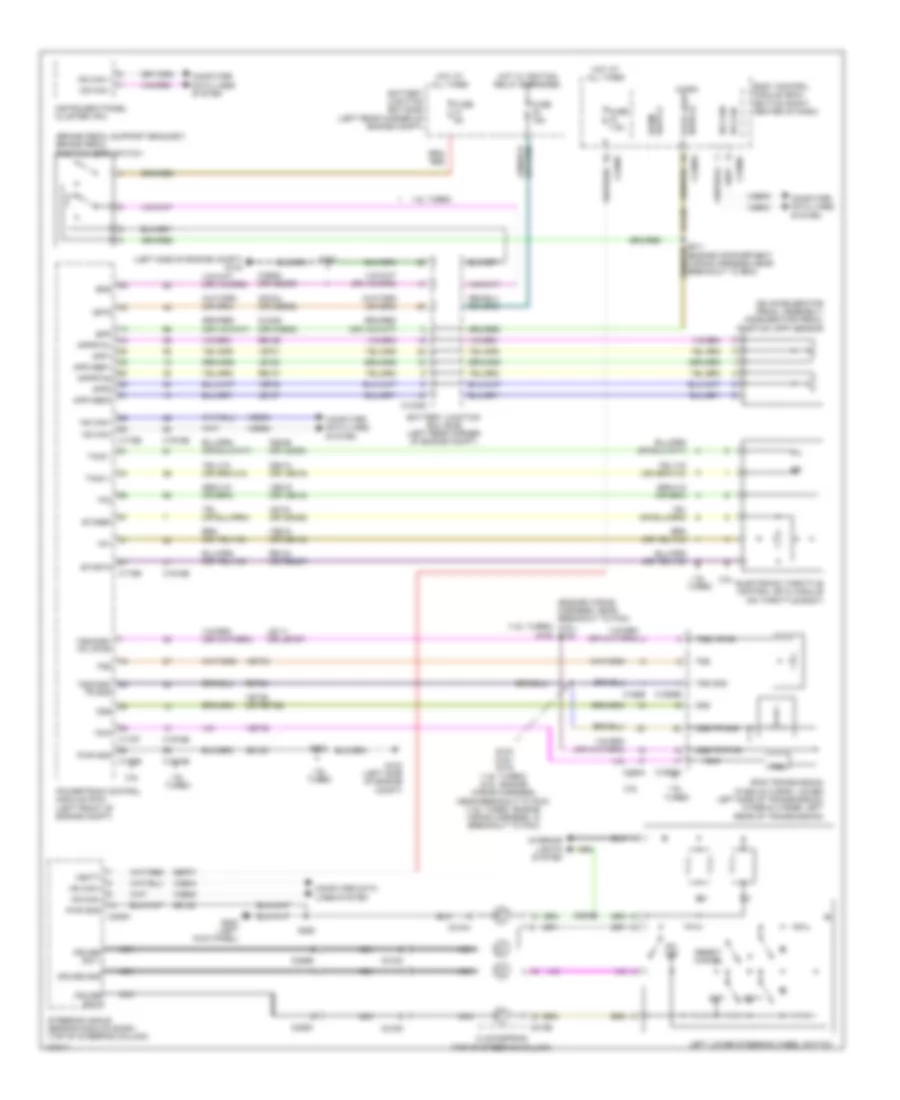
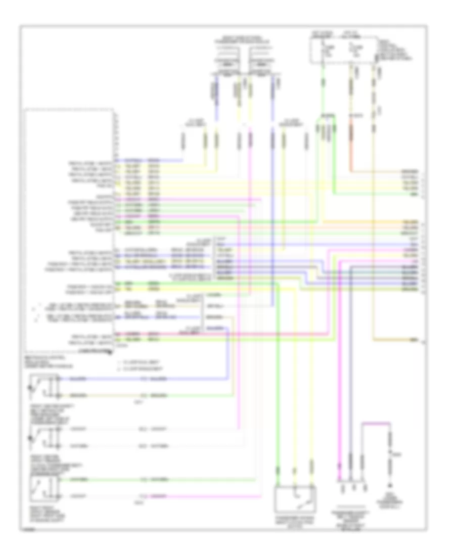
AIR CONDITIONING
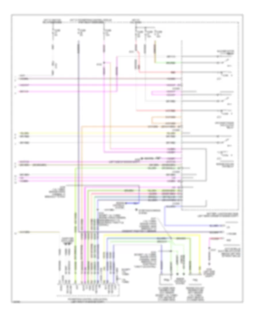
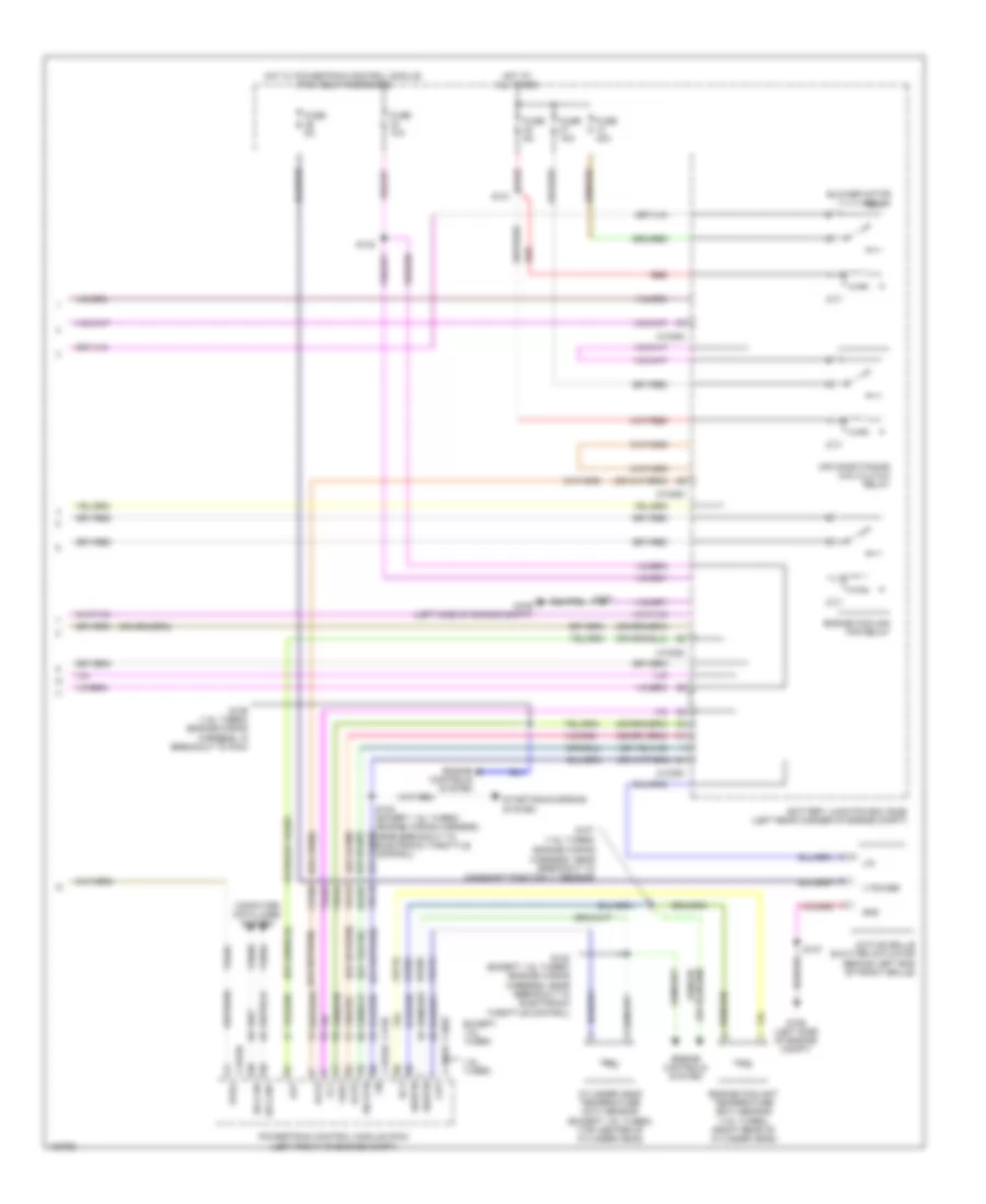
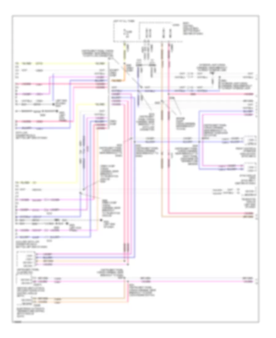
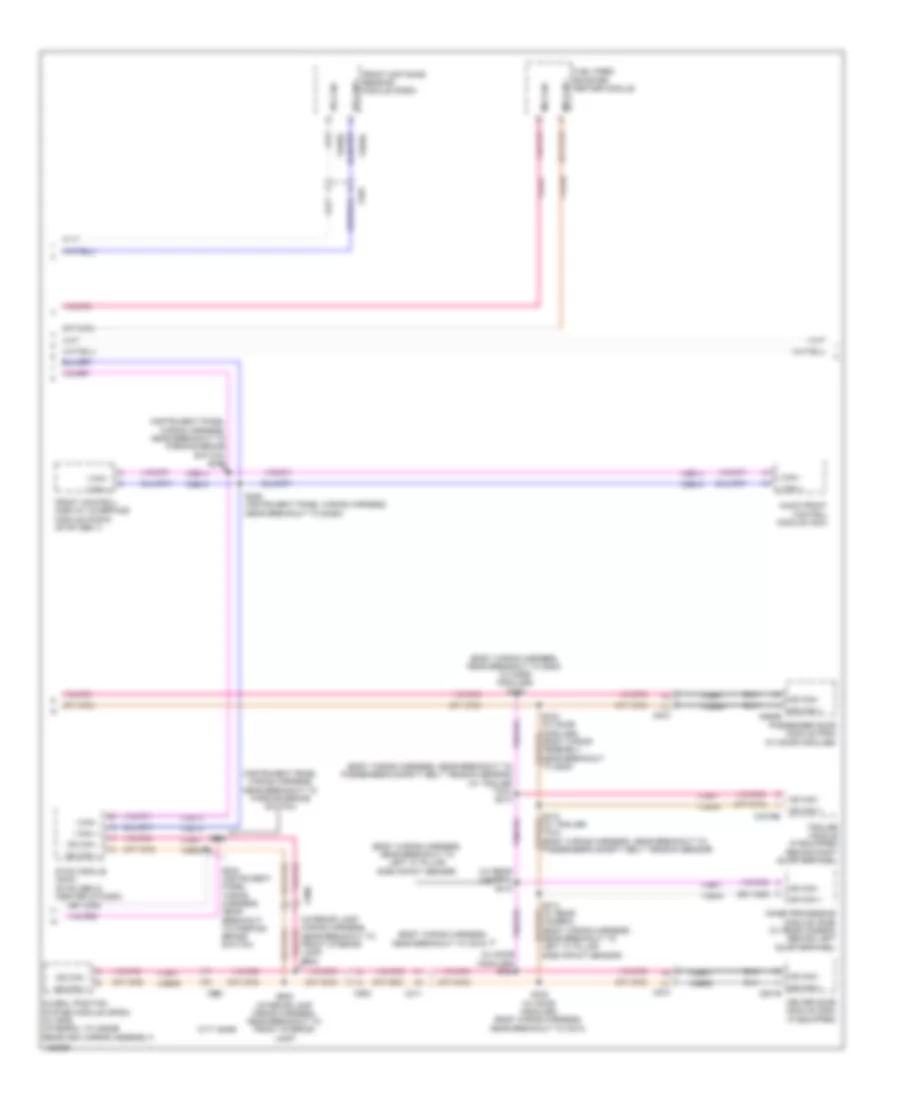
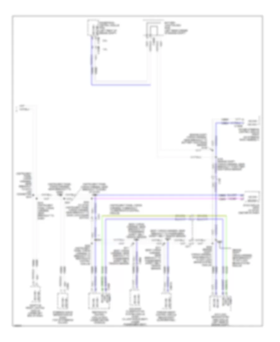
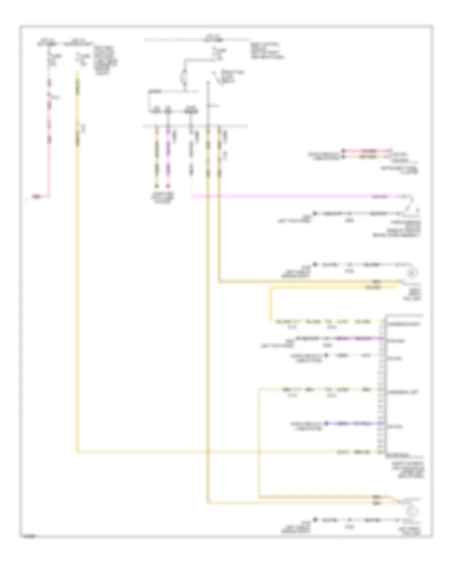
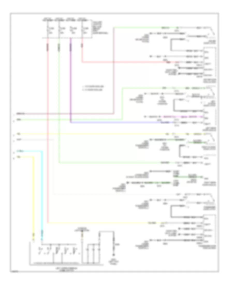
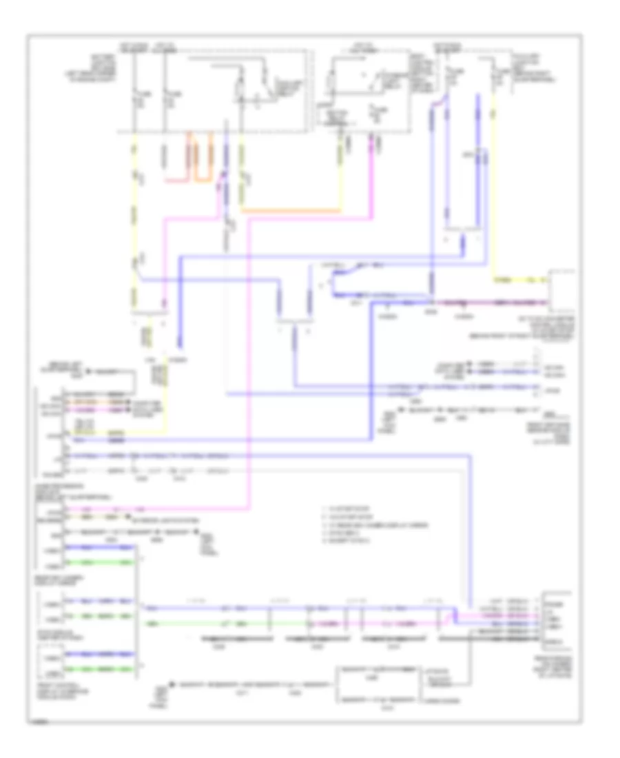
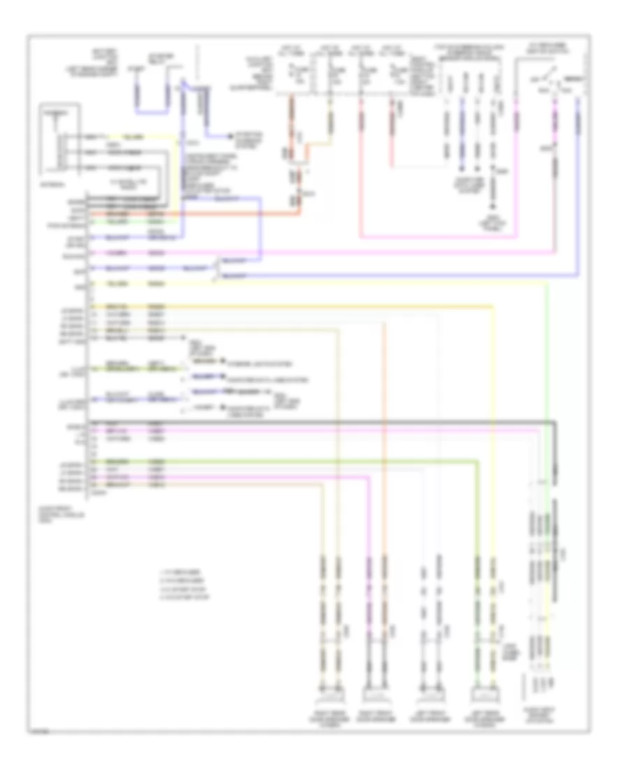
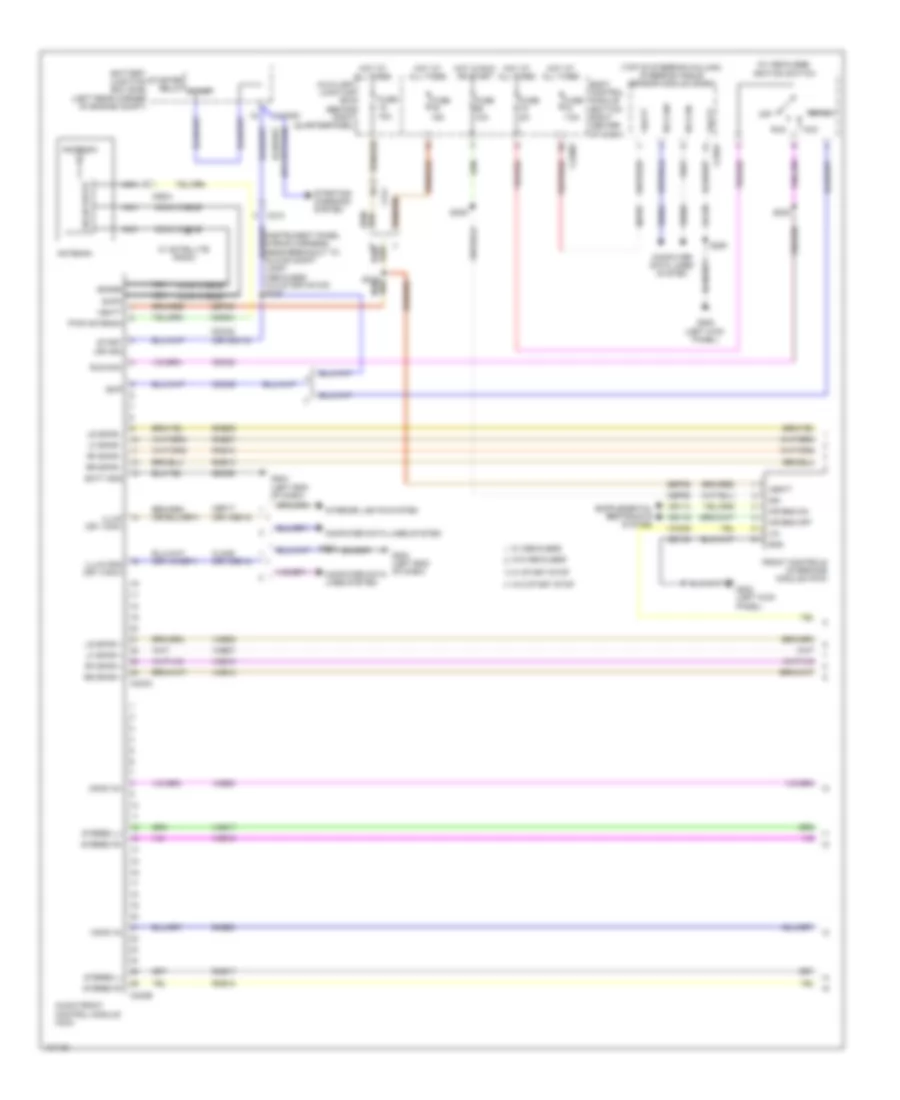
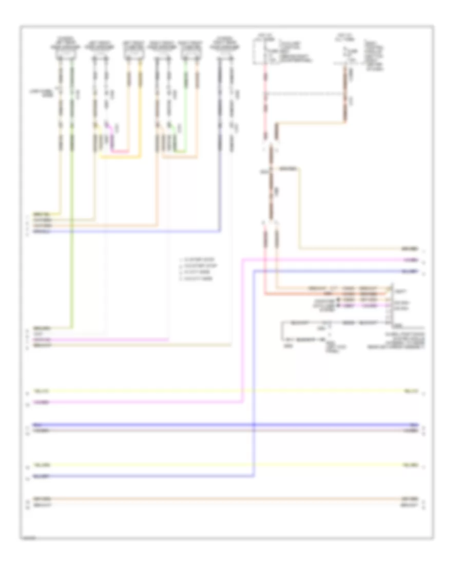
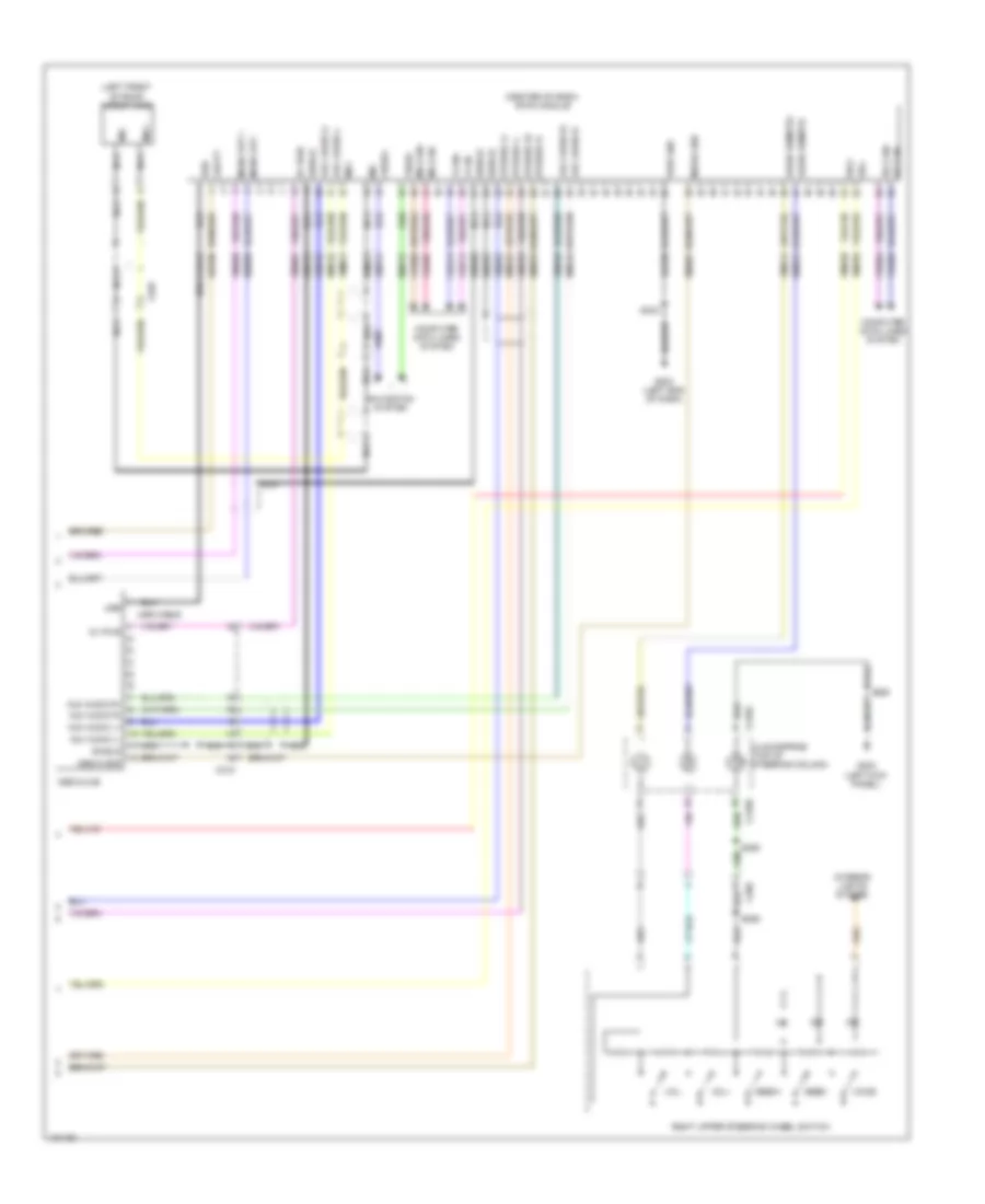
Automatic A/C Wiring Diagram (1 of 3) for Ford Transit Connect Titanium 2014

List of elements for Automatic A/C Wiring Diagram (1 of 3) for Ford Transit Connect Titanium 2014:
- (instrument panel wiring harness, near breakout to sasm) s226
- (left kick panel) g202
- (top center front of dash) sunload sensor
- Aspirator gnd
- Auto lamps sens
- Auxiliary junction box (ajb) (behind right quarterpanel)
- Blower control
- Bmrc
- Body control module (bottom right center of dash)
- C2280a
- C2280c
- C2280f
- C228a
- C228b
- C311
- Ch123
- Ch201
- Ch202
- Ch203
- Ch204
- Ch205
- Ch206
- Ch207
- Ch208
- Ch209
- Ch210
- Ch211
- Ch212
- Ch213
- Ch214
- Ch215
- Ch227
- Ch228
- Ch229
- Ch230
- Ch231
- Ch237
- Ch238
- Ch239
- Ch240
- Ch241
- Chp01
- Computer data lines system
- Defr a
- Defr b
- Defr c
- Defr d
- Defr pwr
- Defrost mode door actuator (upper left side of hvac unit)
- Disc floor l sens
- Disc floor r sens
- Disc panel l sens
- Disc panel r sens
- Electronic automatic temperature (eatc) module
- Evap temp sens
- Evaporator temperature sensor (left side of hvac evaporator assembly)
- Footwell vent/register door actuator (left side of hvac unit)
- Fuse 10a
- Fuse 7.5a
- Gd133
- Gnd
- Hot at all times
- Hot w/ ignition relay energized
- Hs can+
- Hs can-
- Humidity sens
- In-car sens +
- In-car sens -
- In-vehicle temperature/ humidity sensor (left center of dash)
- L sunl sens
- Left floor discharge air temperature sensor (in left floor vent assembly)
- Left panel discharge air temperature sensor (in left panel vent assembly)
- Left temperature door actuator (lower left side of hvac unit)
- Micro
- Mode door a
- Mode door b
- Mode door c
- Mode door d
- Mode door pwr
- Ms can+
- Ms can-
- Ptc heater cntrl
- R sunl sens
- Recirc a
- Recirc b
- Recirc c
- Recirc d
- Recirc power
- Recirculation air inlet door actuator
- Rh103
- Rh104
- Rh105
- Right floor discharge air temperature sensor (in right floor vent assembly)
- Right temperature door actuator (lower right side of hvac unit)
- S213 (instrument panel wiring harness, in breakout to sunload sensor)
- S241
- S248 (instrument panel wiring harness, near breakout to passenger's air bag)
- S250
- Sbp27
- Sens
- Sens gnd
- Sigrtn
- Temp door a
- Temp door b
- Temp door c
- Temp door d
- Temp door power
- Vbatt
- Vdb04
- Vdb05
- Vdb06
- Vdb07
- Vh101
- Vh406
- Vh409
- Vh410
- Vh411
- Vh412
- Vh413
- Vh414
- Vh416
- Vh417
- Vpwr
- W/ start/stop system
- W/o start/stop system
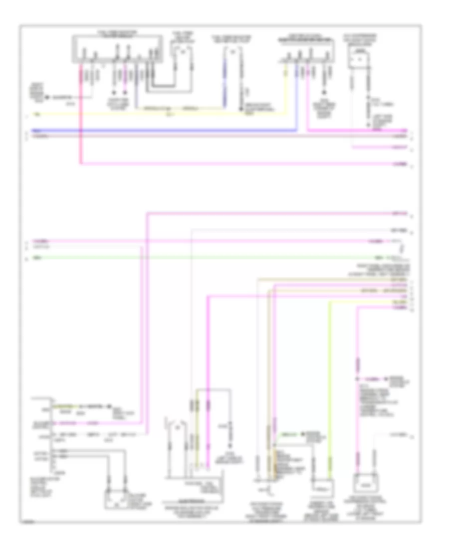
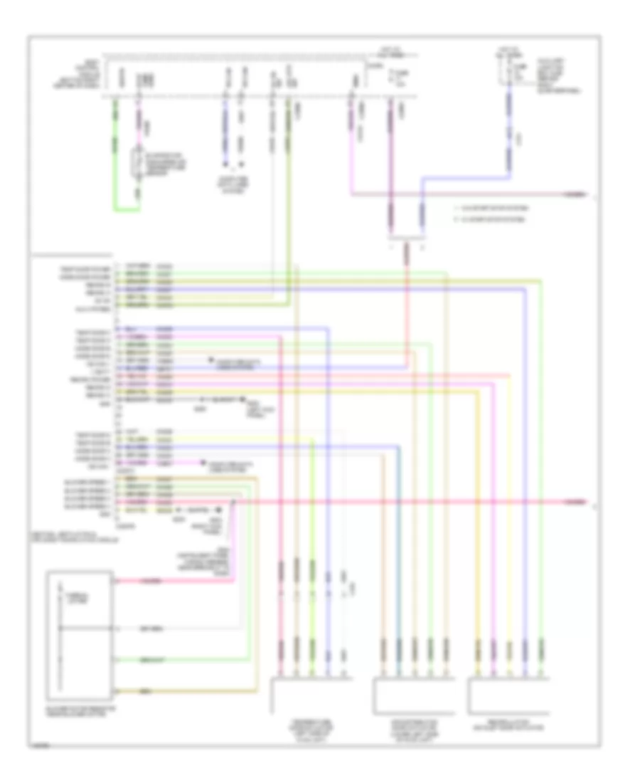
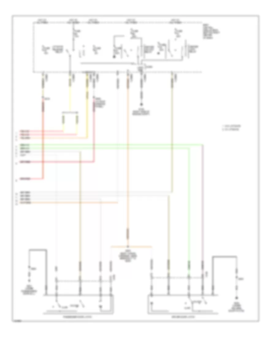
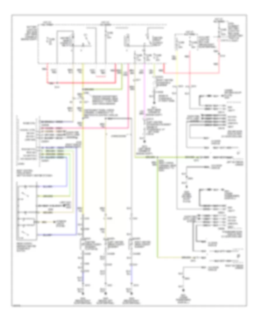
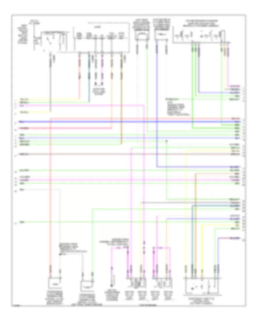
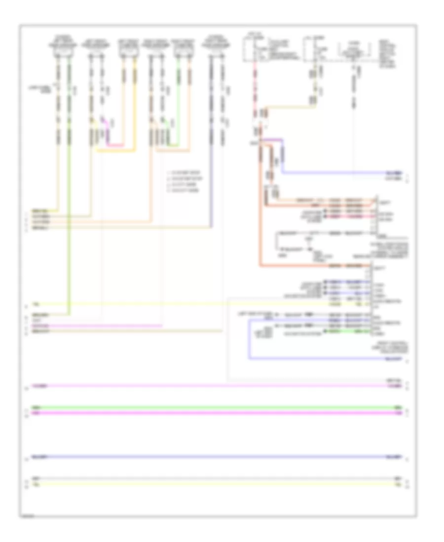
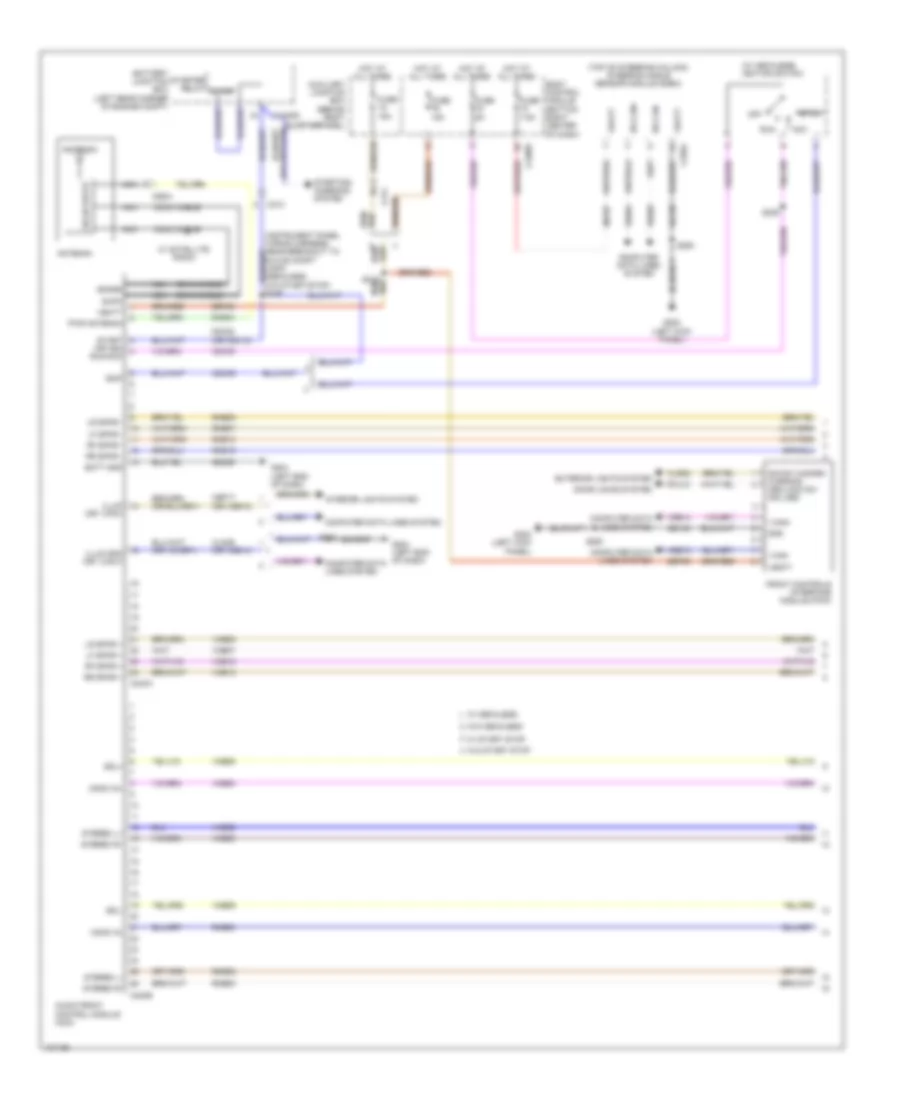
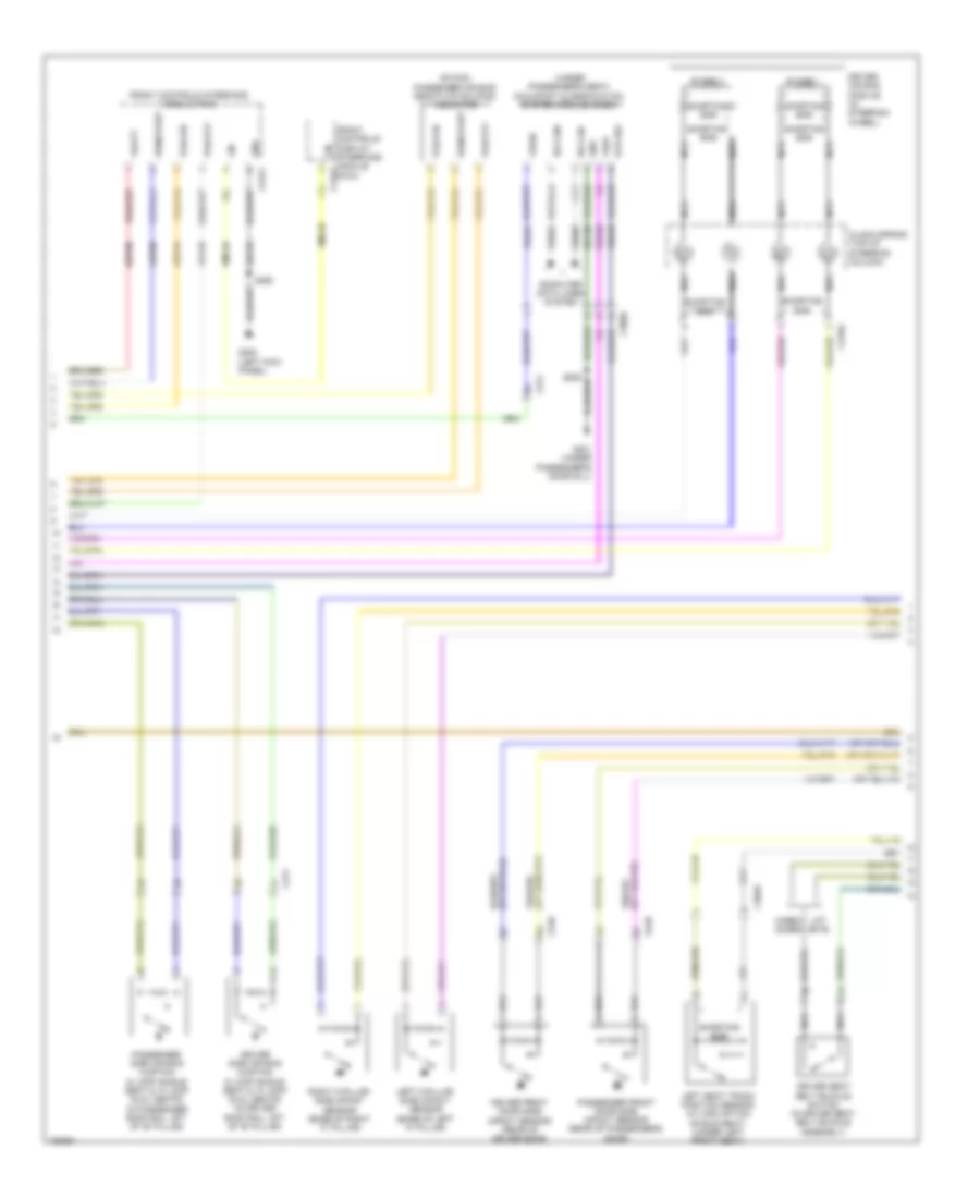
Automatic A/C Wiring Diagram (2 of 3) for Ford Transit Connect Titanium 2014
List of elements for Automatic A/C Wiring Diagram (2 of 3) for Ford Transit Connect Titanium 2014:
- (a/c compressor)
- (behind right quarterpanel) g303
- (center of dash) electric booster heater
- (left side of engine compt) g103
- (right side of engine compt) g109
- Air conditioning (a/c) clutch
- Air conditioning (a/c) pressure transducer (right front corner of engine compt)
- Air conditioning compressor control solenoid (1.6l turbo) (lower left front of engine)
- Ambient air temperature sensor (behind left side of front bumper)
- Blower control
- Blower motor (right side of dash)
- Blower motor control module (bottom of hvac unit)
- C211
- C212
- C2603a
- C2603b
- C2603c
- C297a
- C297b
- C327
- Cbp18
- Chf01
- Computer data lines system
- Electronics
- Engine controls system
- Engine cooling fan module (on engine cooling fan assembly)
- Fan control variable
- Fuel fired booster heater fuel pump
- Fuel fired booster heater module
- Fuel fired heater water pump
- G106 (left side of engine compt)
- G108 (right rear corner of engine compt)
- G203 (right kick panel)
- Gd130
- Gd132
- Gd339
- Gnd
- Ign
- Motor +
- Motor -
- Ms can+
- Ms can-
- Nca
- Pmw
- Pump+
- Pump-
- Pwr
- Right panel discharge air temperature sensor (in right panel vent assembly)
- S102 (1.6l turbo)
- S114 (engine wiring harness, near breakout to transmission fluid warmer temperature control valve 2)
- S126
- S143
- S238
- Sbb05
- Sbb24
- Vdb06
- Vdb07
- Ve203
- Vh101
- Vpwr
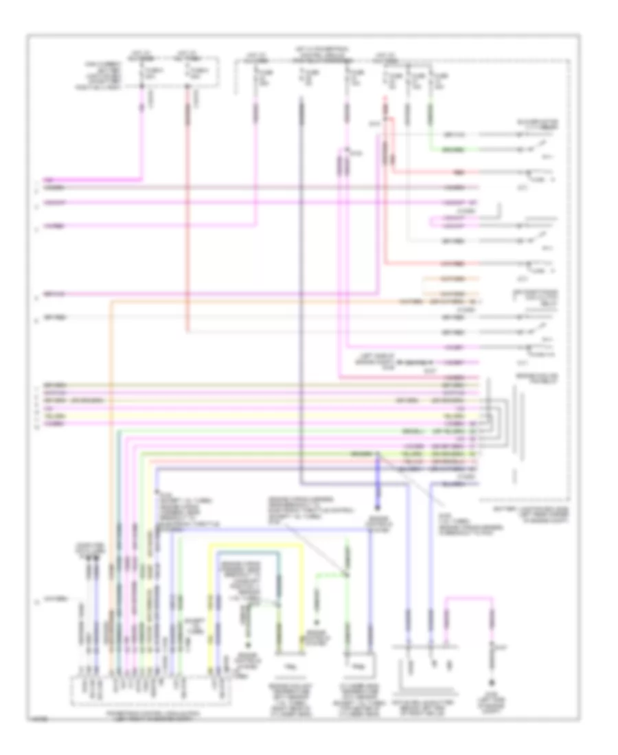
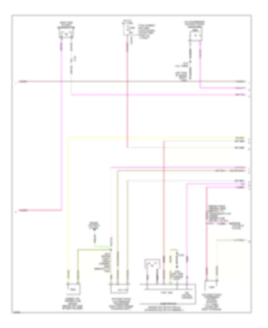
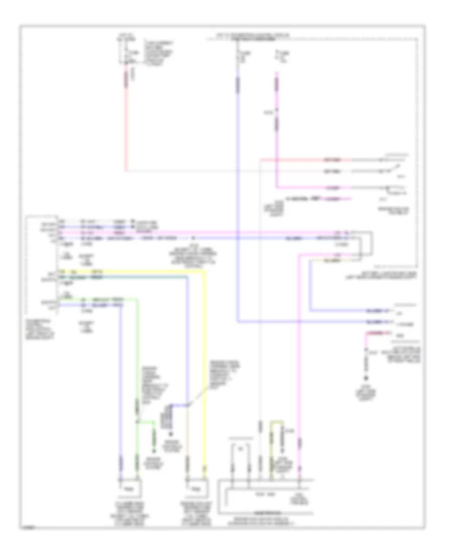
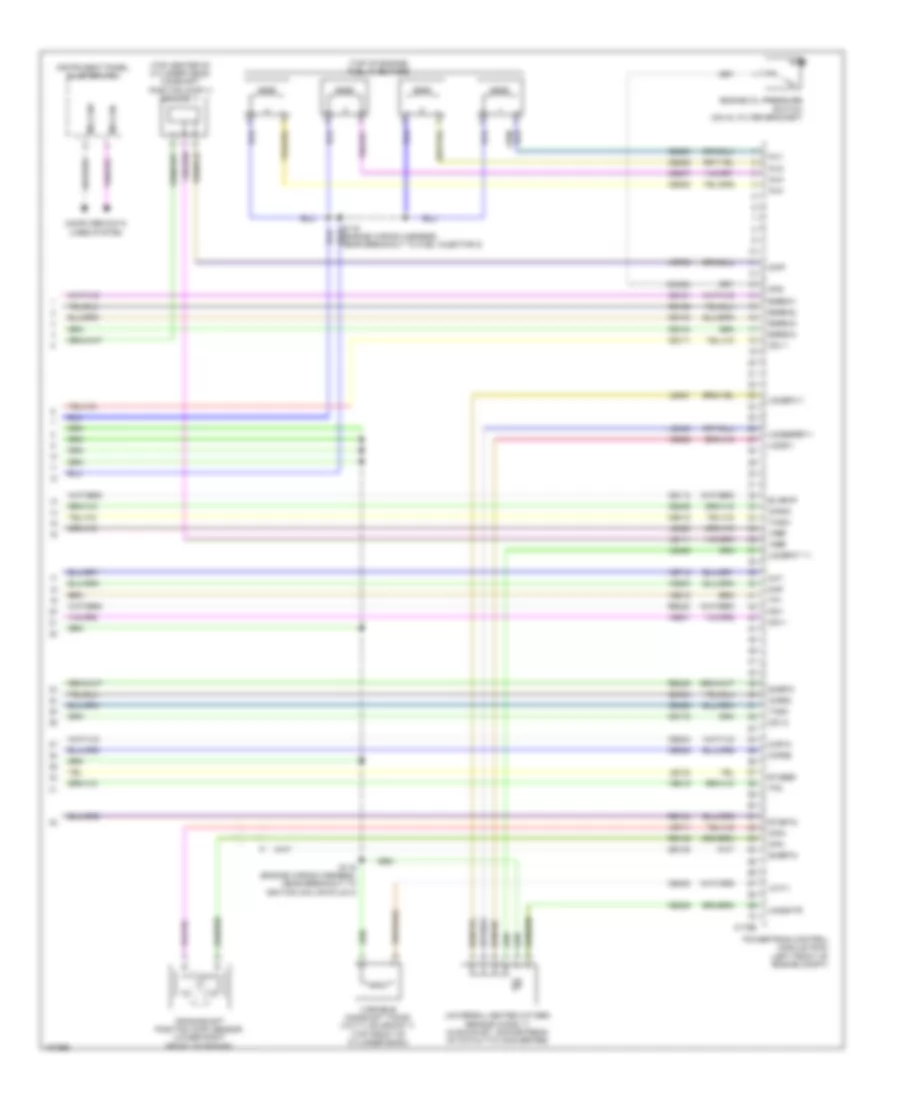
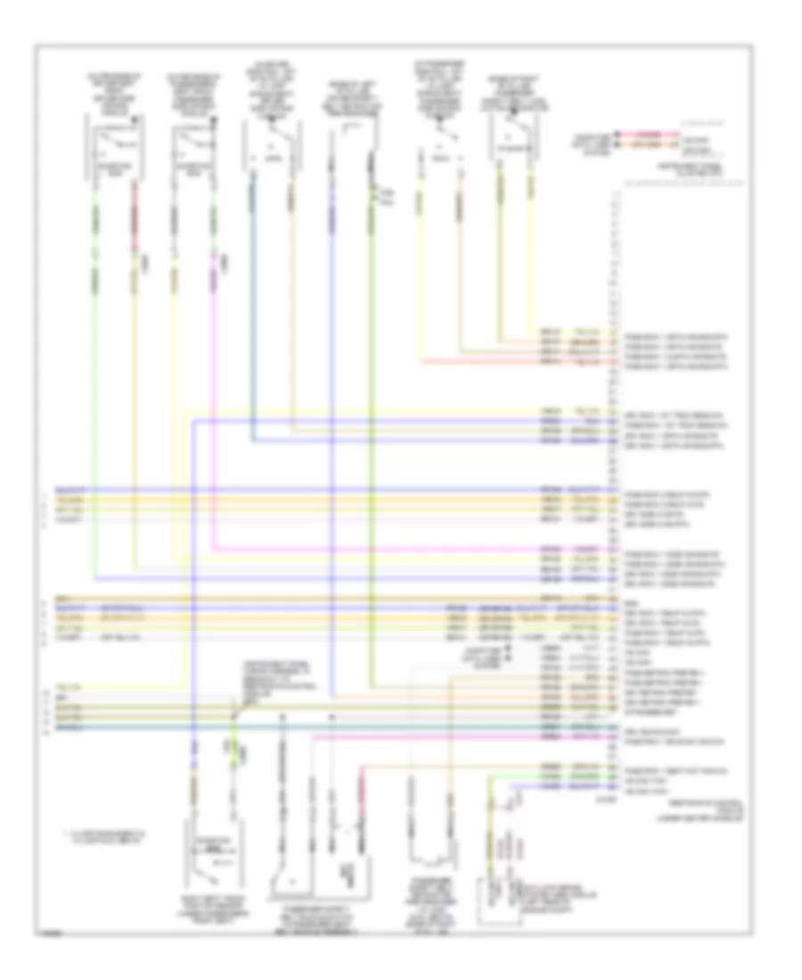
Automatic A/C Wiring Diagram (3 of 3) for Ford Transit Connect Titanium 2014
List of elements for Automatic A/C Wiring Diagram (3 of 3) for Ford Transit Connect Titanium 2014:
- (engine wiring harness, near breakout to camshaft position 11 sensor) (1.6l turbo) s107
- (engine wiring harness, near breakout to electronic throttle control) (except 1.6l turbo) s120
- (left side of engine compt) g106
- (or lh108)
- (or rh107)
- (or vdn06)
- (or vh407)
- 1.6l turbo
- Aat
- Accr
- Acps
- Active grille shutter (behind left end of front grille)
- Air conditioning (a/c) clutch relay
- Battery junction box (bjb) (left rear corner of engine compt)
- Blower motor relay
- C1035c
- C1617e
- C1617h
- C175b
- C175e
- C1915b
- C1915e
- Ch109
- Cht
- Computer data lines system
- Cylinder head temperature (cht) sensor (except 1.6l turbo) (top center of cylinder head)
- Engine controls system
- Engine coolant temperature (ect) sensor (1.6l turbo) (right rear of cylinder head)
- Engine cooling fan relay
- Evdc
- Except 1.6l turbo
- Fcv
- Fuse 10a
- Fuse 15a
- Fuse 25a
- Fuse 40a
- Fuse 5 80a
- Fuse 5a
- Fuse 8 50a
- G106 (left side of engine compt)
- Gnd
- High current battery junction box (on battery positive (+) post)
- Hot at all times
- Hot w/ powertrain control module (pcm) relay energized
- Hs can+
- Hs can-
- Lin
- Powertrain control module (pcm) (left front of engine compt)
- Re329
- Re405
- Re407
- Red
- S109 (1.6l turbo) (engine wiring harness, in breakout to pcm)
- S122 (except 1.6l turbo) (engine wiring harness, near breakout to electronic throttle control)
- S127
- S131
- S132
- Sig rtn
- Sigrtn
- Vdb04
- Vdb05
- Vdc46
- Ve203
- Ve462
- Ve712
- Ve716
- Ve750
- Vh442
- Vh443
- Vpwr
- Vref
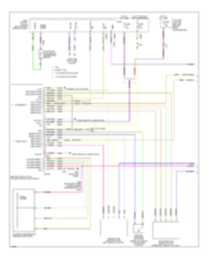
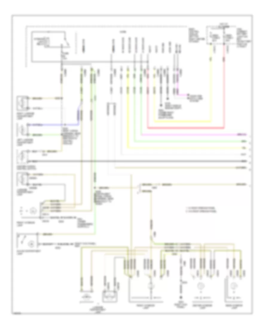
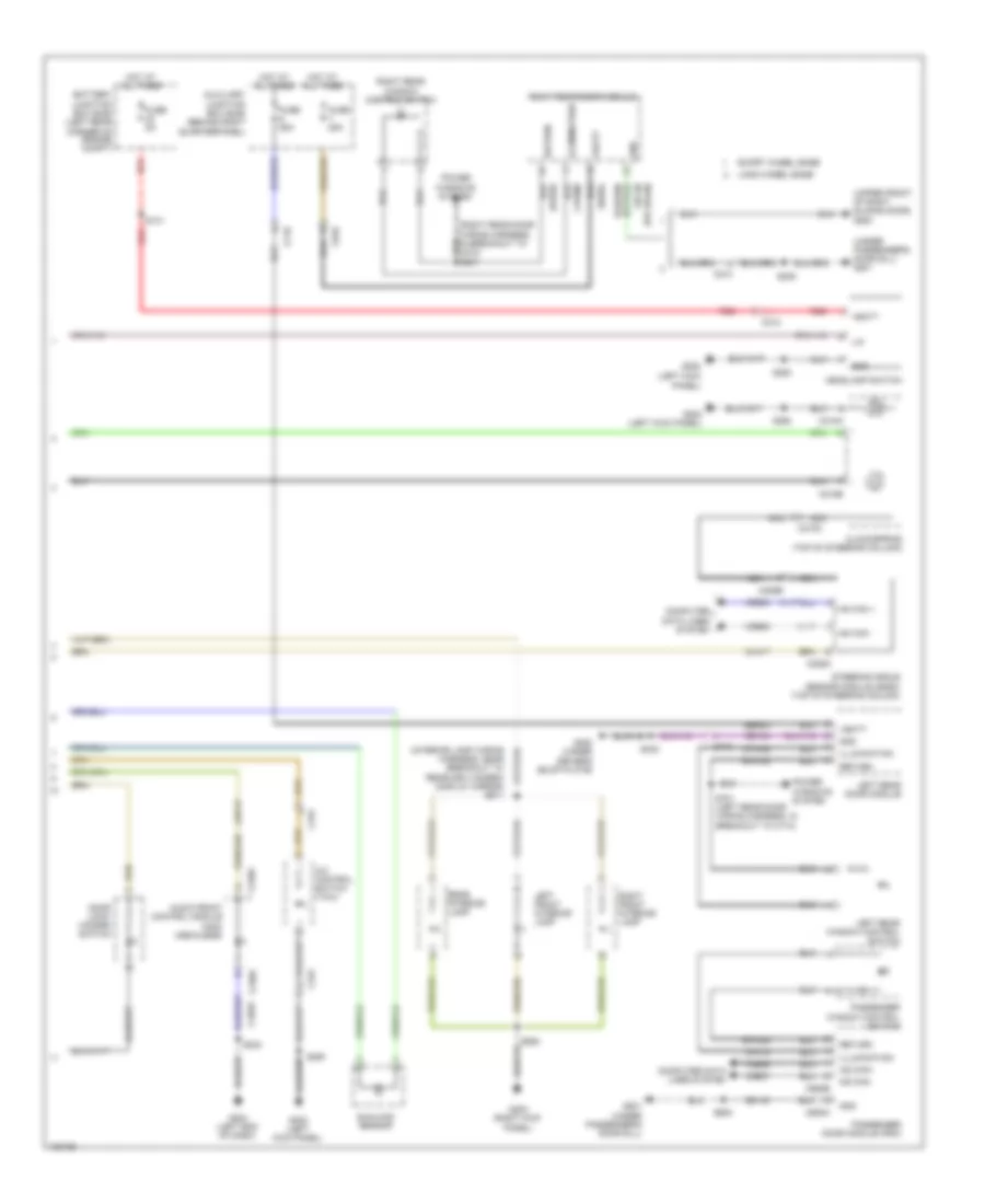
Manual A/C Wiring Diagram (1 of 3) for Ford Transit Connect Titanium 2014
List of elements for Manual A/C Wiring Diagram (1 of 3) for Ford Transit Connect Titanium 2014:
- (left kick panel) g202
- (or ch434)
- (or cln17)
- A/c on
- A/c on sw
- A/c request
- Air distribution door actuator (upper left side of hvac unit)
- Air inlet mode door actuator (upper left side of hvac blower housing)
- Aux htr req
- Aux htr sw
- Auxiliary junction box (ajb) (behind right quarterpanel)
- Blower motor resistor (near blower motor)
- Blower speed 1
- Blower speed 2
- Blower speed 3
- Blower speed 4
- Bmrc
- Body control module (bottom right center of dash)
- C2280a
- C2280c
- C2280f
- C2357a
- C2357b
- C311
- Cbp04
- Ch123
- Ch201
- Ch202
- Ch203
- Ch204
- Ch205
- Ch207
- Ch208
- Ch232
- Ch233
- Ch234
- Ch235
- Ch236
- Ch427
- Ch428
- Ch429
- Ch430
- Ch434
- Chp03
- Cln17
- Computer data lines system
- Evap temp sens
- Evaporator discharge air temperature sensor
- Except taxi
- Fuse 10a
- Fuse 7.5a
- G203 (right kick panel)
- Gd338
- Gd339
- Gnd
- Heating, ventilation & air conditioning (hvac) module
- Hot at all times
- Hot w/ ignition relay energized
- Hs can+
- Hs can-
- Ign
- Illum
- Interior lights system
- Micro
- Mode door a
- Mode door b
- Mode door c
- Mode door d
- Mode door power
- Ms can +
- Ms can-
- Rear acon
- Recirc door a
- Recirc door b
- Rh105
- S224 (instrument panel wiring harness, near breakout to sasm)
- S238
- S240
- S241
- Sbp27
- Sigrtn
- Taxi
- Temp door a
- Temp door b
- Temp door c
- Temp door d
- Temp door power
- Temperature door actuator (left side of hvac unit)
- Thermal limiter
- V batt
- Vdb04
- Vdb05
- Vdb06
- Vdb07
- Vh406
- W/ start/stop system
- W/o start/stop system
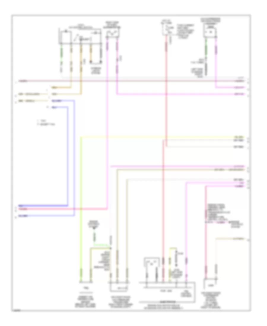
Manual A/C Wiring Diagram (2 of 3) for Ford Transit Connect Titanium 2014
List of elements for Manual A/C Wiring Diagram (2 of 3) for Ford Transit Connect Titanium 2014:
- (a/c compressor) air conditioning clutch
- (engine wiring harness, near breakout to transmission fluid warmer temperature control valve 2) s114
- (left side of engine compt) g103
- (right side of dash) blower motor
- (taxi) a/c control switch
- A/c request
- Air conditioning (a/c) pressure transducer (right front corner of engine compt)
- Air conditioning compressor control solenoid (1.6l turbo) (lower left front of engine)
- Ambient air temperature sensor (behind left side of front bumper)
- C1617h
- C212
- C315
- Electronics
- Engine controls system
- Engine cooling fan module (on engine cooling fan assembly)
- Except taxi
- Fan control variable
- Fuse 50a
- G106 (left side of engine compt)
- Gd130
- Gnd
- High current battery junction box (on battery positive (+) post)
- Hot at all times
- Interior lights system
- Nca
- Pwr
- S102 (1.6l turbo)
- S126
- S212 (engine compt wiring harness, near breakout to bcm)
- Sbb05
- Taxi
- Ve203
Manual A/C Wiring Diagram (3 of 3) for Ford Transit Connect Titanium 2014
List of elements for Manual A/C Wiring Diagram (3 of 3) for Ford Transit Connect Titanium 2014:
- (engine wiring harness, near breakout to camshaft position 11 sensor)
- (or ch302)
- (or lh108)
- (or re407)
- (or vdn06)
- (or vh407)
- 1.6l turbo
- Aat
- Accr
- Acps
- Active grille shutter actuator (behind left end of front grille)
- Air conditioning (a/c) clutch relay
- Battery junction box (bjb) (left rear corner of engine compt)
- Blower motor relay
- C1035c
- C175b
- C175e
- C1915b
- C1915e
- C212
- Ch109
- Cht
- Computer data lines system
- Cylinder head temperature (cht) sensor (except 1.6l turbo) (top center of cylinder head)
- Ect
- Engine controls system
- Engine coolant temperature (ect) sensor (1.6l turbo) (right rear of cylinder head)
- Engine cooling fan relay
- Evdc
- Except 1.6l turbo
- Fcv
- Fuse 10a
- Fuse 15a
- Fuse 40a
- Fuse 5a
- G106 (left side of engine compt)
- Gnd
- Hot at all times
- Hot w/ ignition relay energized
- Hot w/ powertrain control module (pcm) relay energized
- Hs can+
- Hs can-
- Lin
- Powertrain control module (pcm) (left front of engine compt)
- Re329
- Re405
- Red
- Rh107
- S107 (1.6l turbo)
- S109 (1.6l turbo) (engine wiring harness, in breakout to pcm)
- S120 (except 1.6l turbo) (engine wiring harness, near breakout to electronic throttle control)
- S122 (except 1.6l turbo) (engine wiring harness, near breakout to electronic throttle control)
- S127
- S131
- S132
- Sig rtn
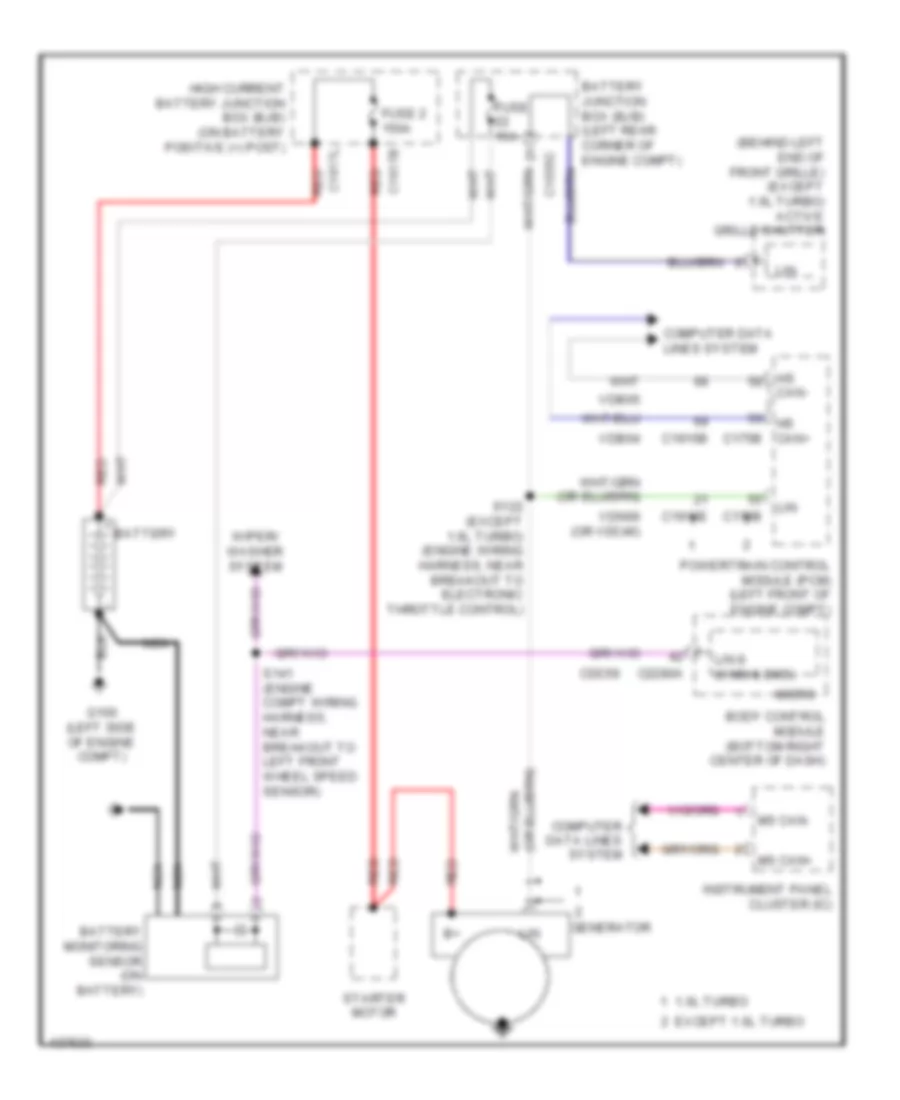
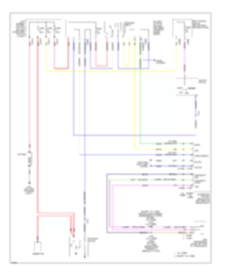
- Starting/charging system
- V power
- Vdb04
- Vdb05
- Vdc46
- Ve203
- Ve462
- Ve712
- Ve716
- Ve750
- Vh442
- Vh443
- Vref
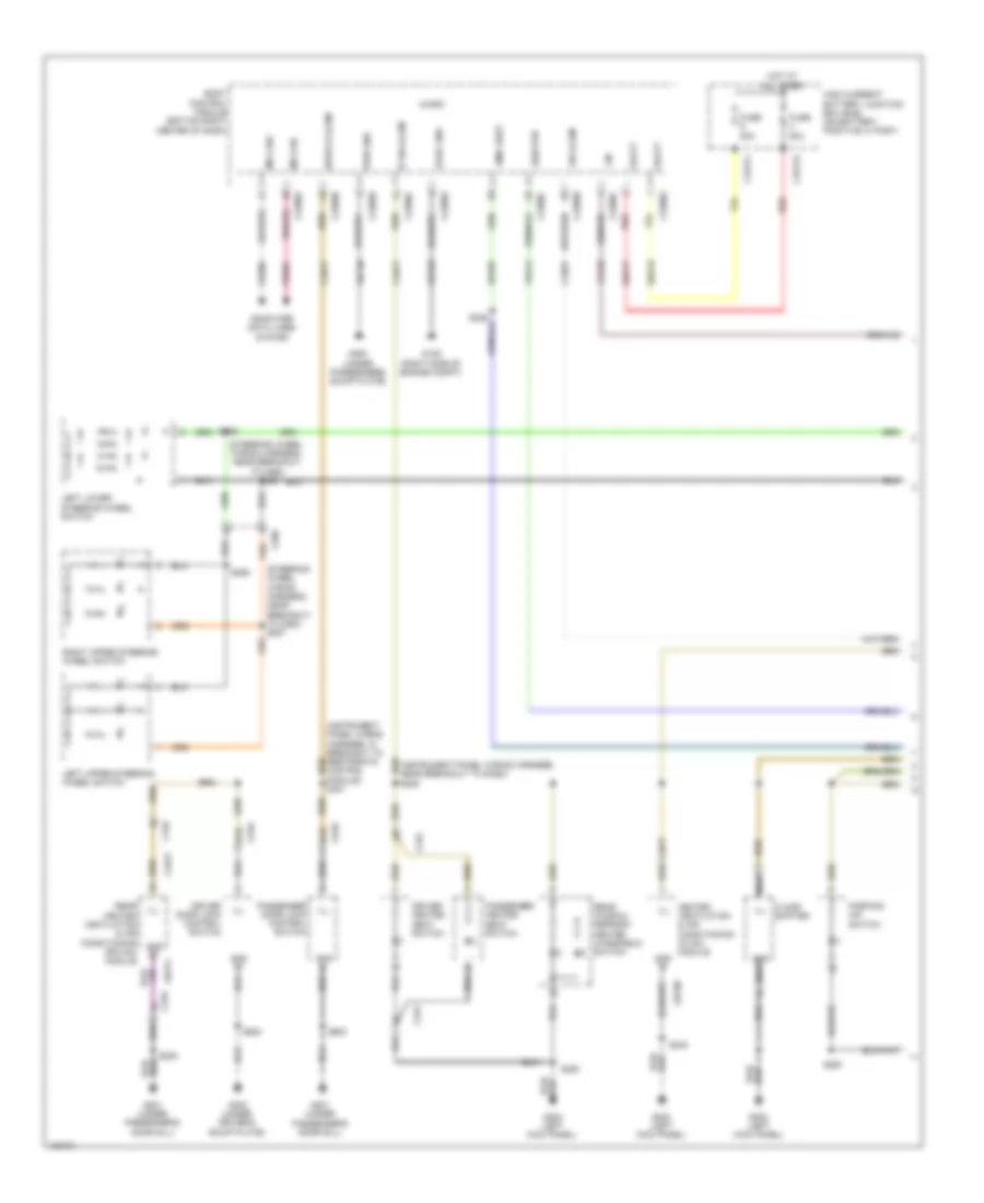
Rear Auxiliary A/C Wiring Diagram for Ford Transit Connect Titanium 2014
List of elements for Rear Auxiliary A/C Wiring Diagram for Ford Transit Connect Titanium 2014:
- (under driver's scuff plate) g300
- A/c control switch (taxi)
- A/c request
- A/c request switch
- Aux htr req
- Aux rear
- Auxiliary junction box (behind right quarterpanel)
- Batt+
- Battery junction box (left rear corner of engine compt)
- Body control module (bottom right center of dash)
- C1617g
- C212
- C213
- C2280b
- C2357a
- C315
- C316
- C3443a
- C3443b
- C3443c
- C3448a
- C3448c
- Cbp18
- Cbp40
- Ch201
- Ch202
- Ch203
- Ch204
- Ch205
- Ch232
- Ch233
- Ch234
- Ch235
- Ch236
- Ch434
- Chp03
- Cln17
- Computer data lines system
- Ctrl
- Evaporator sens
- Evaporator sens gnd
- Expan valve
- Fuse 10a
- Fuse 40a
- Fuse 5a
- Fuse 7 80a
- Fuse 7.5a
- G201 (under passenger's door sill)
- G302 (under driver's door sill)
- G401
- Gd311
- Gd354
- Gnd
- Heater rear ptc
- Heating, ventilation & air conditioning (hvac) module
- High current battery junction box (on battery positive (+) post)
- Hot at all times
- Hot w/ ignition relay energized
- Ign
- Illm
- Interior lights system
- Left rear air distribution door actuator (base of left rear "c" pillar)
- Micro
- Mode door a
- Mode door b
- Mode door c
- Mode door d
- Mode door power
- Ms can+
- Ms can-
- Nca
- Pwm
- Pwm 1
- Pwm1
- Rear a/c on
- Rear blower motor (under driver's seat)
- Rear blower motor control module (under driver's seat)
- Rear blower motor relay
- Rear electric booster heater (behind driver's seat, under floor)
- Rear evaporator temperature sensor (behind driver's seat, under floor)
- Rear heating, ventilation & air conditioning (rhvac) control module
- Rear thermostatic expansion valve (behind driver's seat, under floor)
- Red
- Rh105
- Rha29
- Right rear air distribution door actuator (base of right rear "c" pillar)
- S205
- S324
- S330
- S402
- Sbp17
- Temp door a
- Temp door b
- Temp door c
- Temp door d
- Temp door power
- Txv out ctrl
- Vbatt
- Vdb06
- Vdb07
- Vh101
- Vh406
- Vpwr
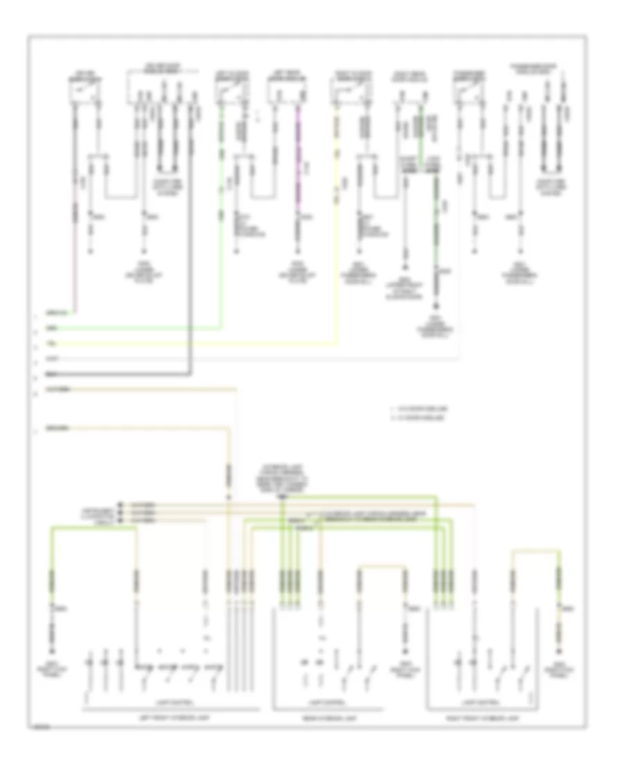
Semi Automatic A/C Wiring Diagram (1 of 3) for Ford Transit Connect Titanium 2014
List of elements for Semi Automatic A/C Wiring Diagram (1 of 3) for Ford Transit Connect Titanium 2014:
- Ac on
- Ac on sw
- Air distribution door actuator (lower left side of hvac unit)
- Aux htr req
- Aux htr sw
- Auxiliary junction box (ajb) (behind right quarterpanel)
- Blower motor resistor (near blower motor)
- Blower speed 1
- Blower speed 2
- Blower speed 3
- Blower speed 4
- Bmrc
- Body control module (bottom right center of dash)
- C2280a
- C2280c
- C2280f
- C2357a
- C2357b
- C311
- C316
- Ch123
- Ch201
- Ch202
- Ch203
- Ch204
- Ch205
- Ch206
- Ch207
- Ch208
- Ch209
- Ch210
- Ch232
- Ch233
- Ch234
- Ch235
- Ch236
- Ch427
- Ch428
- Ch429
- Ch430
- Ch434
- Chp03
- Computer data lines system
- Evap temp sens
- Evaporator discharge air temperature sensor
- Fuse 10a
- G202 (left kick panel)
- G203 (right kick panel)
- Gd338
- Gd339
- Gnd
- Heating, ventilation & air conditioning (hvac) module
- Hot at all times
- Hs can+
- Hs can-
- Micro
- Mode door a
- Mode door b
- Mode door c
- Mode door d
- Mode door power
- Ms can +
- Ms can -
- Recirc a
- Recirc b
- Recirc c
- Recirc d
- Recirc power
- Recirculation air inlet door actuator
- Rh105
- S224 (instrument panel wiring harness, near breakout to sasm)
- S238
- S250
- Sbp27
- Sigrtn
- Temp door a
- Temp door b
- Temp door c
- Temp door d
- Temp door power
- Temperature door actuator (left side of hvac unit)
- Thermal limiter
- V batt
- Vdb04
- Vdb05
- Vdb06
- Vdb07
- Vh406
- W/ start/stop system
- W/o start/stop system
Semi Automatic A/C Wiring Diagram (2 of 3) for Ford Transit Connect Titanium 2014
List of elements for Semi Automatic A/C Wiring Diagram (2 of 3) for Ford Transit Connect Titanium 2014:
- (a/c compressor) air conditioning (a/c) clutch
- (engine wiring harness, near breakout to transmission fluid warmer temperature control valve 2) s114
- (left side of engine compt) g103
- (right side of dash) blower motor
- Air conditioning (a/c) pressure transducer (right front corner of engine compt)
- Air conditioning compressor control solenoid (1.6l turbo) (lower left front of engine)
- Ambient air temperature sensor (behind left side of front bumper)
- C1617h
- C212
- Electronics
- Engine controls system
- Engine cooling fan module (on engine cooling fan assembly)
- Fan control variable
- Fuse 50a
- G106 (left side of engine compt)
- Gd130
- Gnd
- High current battery junction box (on battery positive (+) post)
- Hot at all times
- Nca
- Pwr
- S102 (1.6l turbo)
- S126
- S212 (engine compt wiring harness, near breakout to bcm)
- Sbb05
- Ve203
Semi Automatic A/C Wiring Diagram (3 of 3) for Ford Transit Connect Titanium 2014
List of elements for Semi Automatic A/C Wiring Diagram (3 of 3) for Ford Transit Connect Titanium 2014:
- (engine wiring harness, near breakout to camshaft position 11 sensor)
- (or ch302)
- (or lh108)
- (or re407)
- (or vdn06)
- 1.6l turbo
- Aat
- Accr
- Acps
- Active grille shutter actuator (behind left end of front grille)
- Air conditioning (a/c) clutch relay
- Battery junction box (bjb) (left rear corner of engine compt)
- Blower motor relay
- C1035c
- C175b
- C175e
- C1915b
- C1915e
- Ch109
- Cht
- Computer data lines system
- Cylinder head temperature (cht) sensor (except 1.6l turbo) (top center of cylinder head)
- Ect
- Engine controls system
- Engine coolant temperature (ect) sensor (1.6l turbo) (right rear of cylinder head)
- Engine cooling fan relay
- Evdc
- Except 1.6l turbo
- Fcv
- Fuse 10a
- Fuse 15a
- Fuse 40a
- Fuse 5a
- G106 (left side of engine compt)
- Gnd
- Hot at all times
- Hot w/ powertrain control module (pcm) relay energized
- Hs can+
- Hs can-
- Lin
- Powertrain control module (pcm) (left front of engine compt)
- Re329
- Re405
- Red
- Rh107
- S107 (1.6l turbo)
- S109 (1.6l turbo) (engine wiring harness, in breakout to pcm)
- S120 (except 1.6l turbo) (engine wiring harness, near breakout to electronic throttle control)
- S122 (except 1.6l turbo) (engine wiring harness, near breakout to electronic throttle control)
- S127
- S131
- S132
- Sig rtn
- Sigrtn
- Starting/charging system
- V power
- Vdb04
- Vdb05
- Vdc46
- Ve203
- Ve462
- Ve712
- Ve716
- Ve750 (or vh407)
- Vh442
- Vh443
- Vref
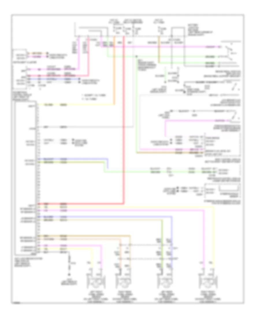
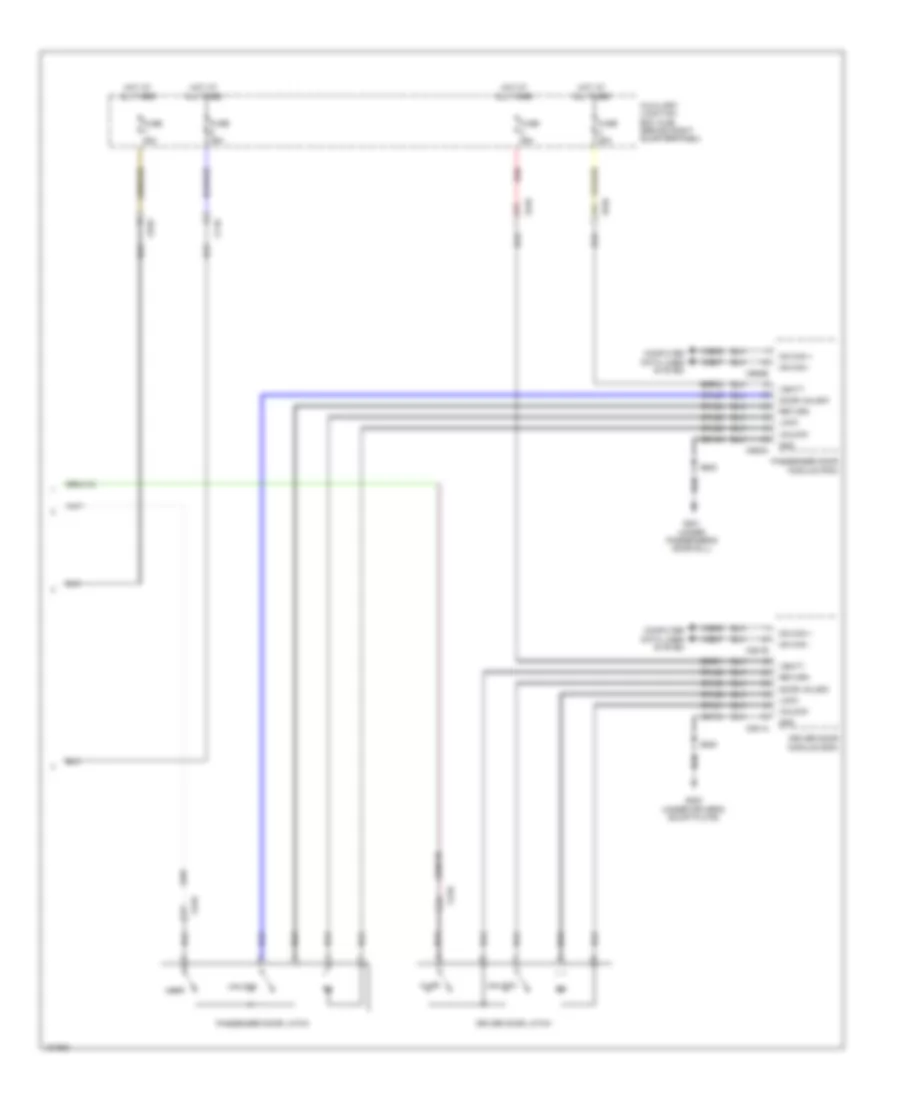
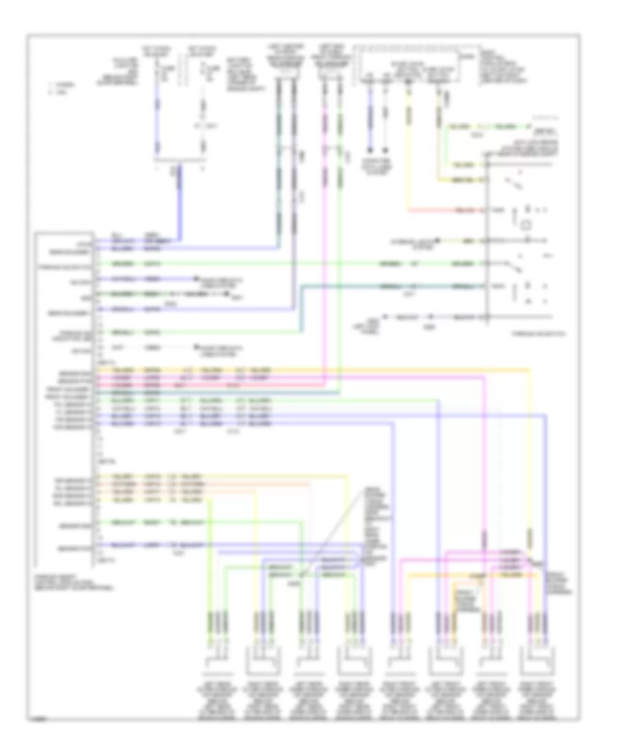
ANTI-LOCK BRAKES
Anti-lock Brakes Wiring Diagram for Ford Transit Connect Titanium 2014
List of elements for Anti-lock Brakes Wiring Diagram for Ford Transit Connect Titanium 2014:
- (right side of engine compt) g109
- 1.6l turbo
- Anti-lock brake system (abs) module (left rear of engine compt)
- Battery junction box (bjb) (left rear corner of engine compt)
- Body control module (bottom right center of dash)
- Bpp
- Bps
- Brake fluid level sw
- Brake pedal position (bpp) switch (brake pedal support bracket)
- C1035c
- C175b
- C1915b
- C211
- C226a
- C2280a
- C2280c
- C310b
- C327
- Cbp03
- Cca29
- Ccb08 (or cca29)
- Ces09 (or ccb08)
- Cmc19
- Cmc25
- Computer data lines system
- Except 1.6l turbo
- Fuse 30a
- Fuse 40a
- Fuse 5a
- G103 (left side of engine compt)
- G107 (left rear of engine compt)
- G202 (left kick panel)
- Gd122
- Gnd
- Hot at all times
- Hot w/ ignition relay energized
- Hs can +
- Hs can -
- Hs can2 +
- Hs can2 -
- Instrument cluster
- Left front wheel speed sensor (on left front wheel hub assembly)
- Left rear wheel speed sensor (on left rear wheel hub assembly)
- Lf sensor hi
- Lf sensor lo
- Low brake fluid indicator switch (in brake fluid reservoir)
- Lr sensor hi
- Lr sensor lo
- Ms can +
- Ms can -
- Nca
- Park brake
- Parking brake switch (base of parking brake lever assembly)
- Powertrain control module (left front of engine compt)
- Rca17
- Rca18
- Rca19
- Rca20
- Red
- Restraints control module (under center console)
- Rf sensor hi
- Rf sensor lo
- Right front wheel speed sensor (on right front wheel hub assembly)
- Right rear wheel speed sensor (on right rear wheel hub assembly)
- Rr sensor hi
- Rr sensor lo
- S102
- S130
- S142 (2.5l)
- S143
- S211 (engine compt wiring harness, near breakout to bcm)
- S250
- Sbb25
- Sbb26
- Steering angle sensor
- Steering angle sensor module (top of steering column)
- Stop light sw
- Vbatt
- Vca03
- Vca04
- Vca05
- Vca06
- Vca23
- Vca24
- Vdb04
- Vdb05
- Vpwr
ANTI-THEFT
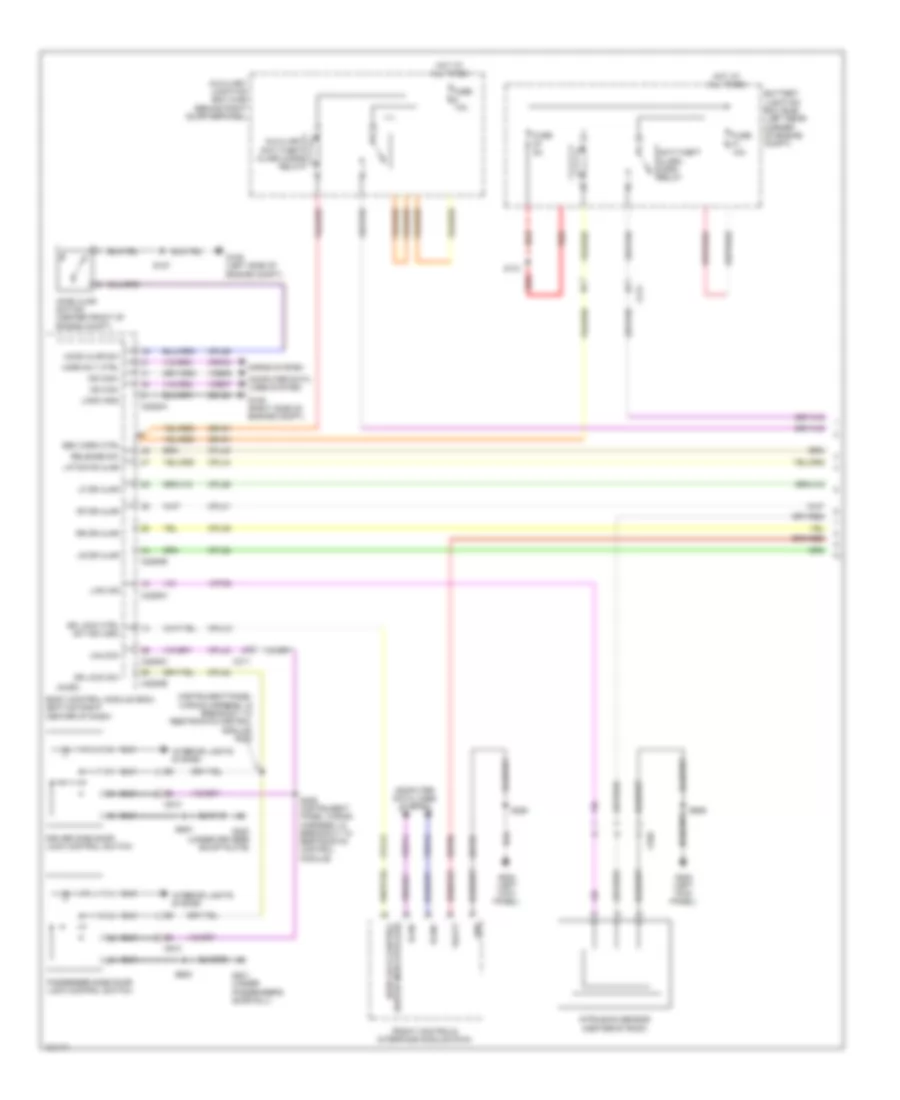
Forced Entry Wiring Diagram, with Door Module (1 of 3) for Ford Transit Connect Titanium 2014
List of elements for Forced Entry Wiring Diagram, with Door Module (1 of 3) for Ford Transit Connect Titanium 2014:
- (instrument panel wiring harness, in breakout to restraints control module) s302
- Anti-theft alarm horn relay
- Auxiliary anti-theft alarm horn relay
- Auxiliary junction box (ajb) (behind right quarterpanel)
- Battery junction box (bjb) (left rear corner of engine compt)
- Body control module (bcm) (bottom right center of dash)
- C211
- C2280a
- C2280b
- C2280c
- C2280h
- C311
- C510
- C610
- C935
- Computer data lines system
- Cpl25
- Cpl26
- Cpl31
- Cpl36
- Cpl39
- Cpl42
- Cpl43
- Cpl44
- Cpl45
- Cplxx
- Crh04
- Door lock control
- Dr lock ctrl sw ind (led)
- Dr lock sw
- Driver side door lock control switch
- Front controls interface module (fcim)
- Fuse 10a
- Fuse 5a
- G106 (left side of engine compt)
- G109 (right side of engine compt)
- G201 (under passenger's door sill)
- G202 (left kick panel)
- G300 (under driver's scuff plate)
- Gd123
- Gd133
- Gnd
- Hood ajar sw
- Hood ajar switch (center front of engine compt)
- Horn rly ctrl
- Horns system
- Hot at all times
- Ican+
- Ican-
- Interior lights system
- Intrusion sensor (center of roof)
- Lf dr ajar
- Liftgate ajar
- Lin2 ims
- Logic gnd
- Lr dr ajar
- Micro
- Ms can+
- Ms can-
- Passenger side door lock control switch
- Red
- Release sw
- Rf dr ajar
- Rr dr ajar
- S127
- S131
- S250
- S306 (instrument panel wiring harness, in breakout to restraints control module)
- S500
- S600
- S906
- Sbp06
- Sec horn ctrl
- Srh01
- Switch indicator (led)
- Unlock
- Vbatt
- Vdb06
- Vdb07
- Vdb13
- Vdb14
- Vrt26
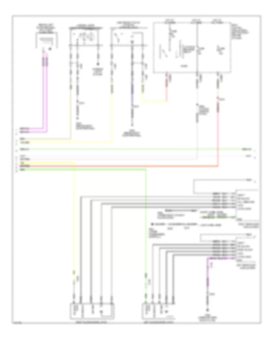
Forced Entry Wiring Diagram, with Door Module (2 of 3) for Ford Transit Connect Titanium 2014
List of elements for Forced Entry Wiring Diagram, with Door Module (2 of 3) for Ford Transit Connect Titanium 2014:
- (behind left quarterpanel) anti-theft alarm horn
- (center bottom of liftgate) liftgate latch
- Ajar
- Body control module (bcm) (bottom right center of dash)
- C2280e
- C2280f
- C2280h
- C438
- C465
- C495
- C710
- C810
- Cpl04
- Cpl11
- Cpl38
- Cpl54
- Door unlock
- Dr unlock
- Fuse 10a
- Fuse 15a
- Fuse 5a
- G201 (under passenger's door sill)
- G300 (under driver's scuff plate)
- G402 (behind right quarterpanel)
- G800 (upper front of right sliding door)
- Gd134
- Gd240 (or gd140)
- Gnd
- Hall sens gnd
- Hot at all times
- Interior lights system
- Latch comm
- Left rear door module (rdm)
- Left sliding door latch
- License lamps/ liftgate release switch
- Liftgate release relay
- Lock
- Long wheel base
- Lr door
- Micro
- Right rear door module (rdm)
- Right sliding door latch
- Rpl53
- Rpw49
- Rpw55
- Rr door
- S205
- S215
- S318
- S330
- S909 (w/ roof opening pavel)
- Sbr03
- Sbr04
- Short wheel base
- Sw gnd
- Vbatt
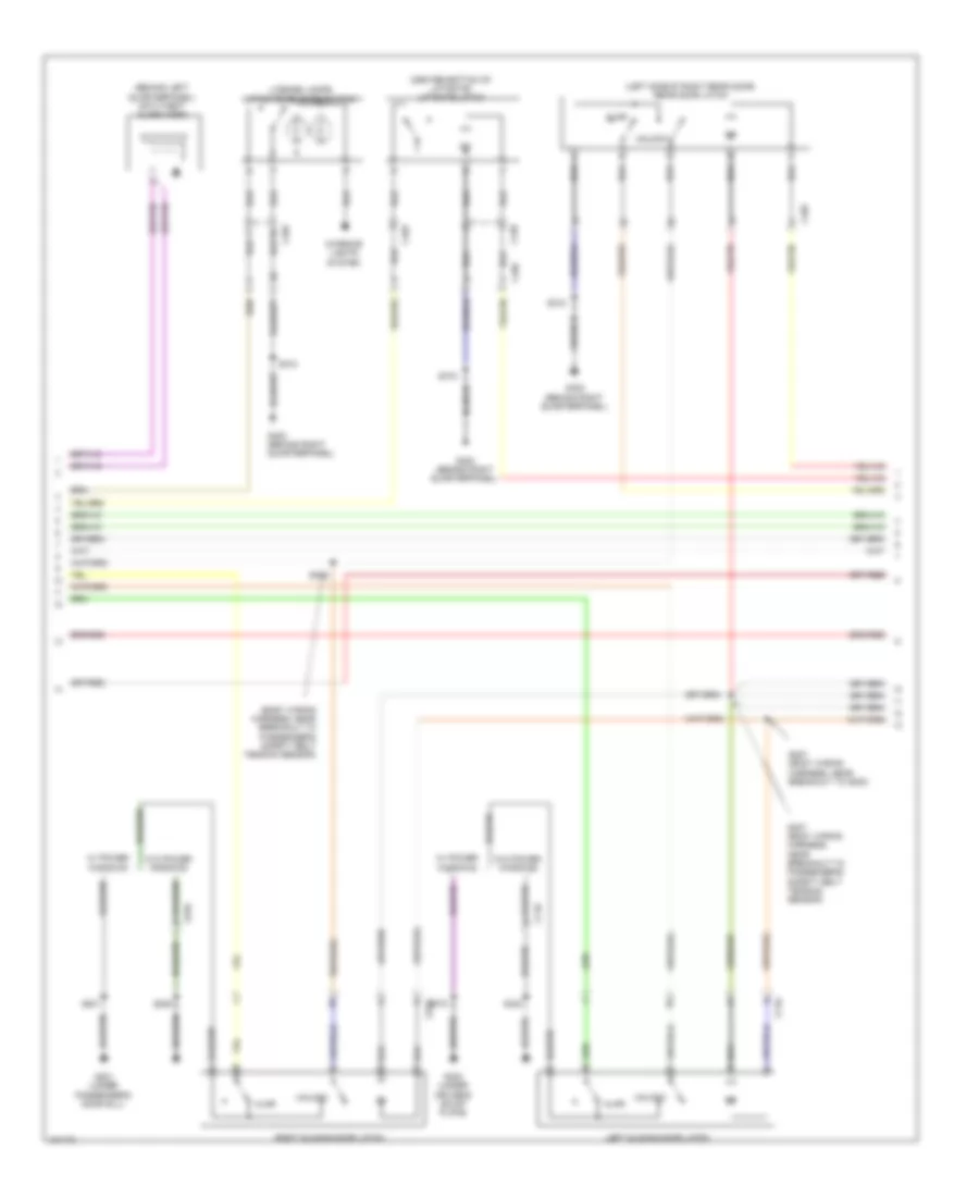
Forced Entry Wiring Diagram, with Door Module (3 of 3) for Ford Transit Connect Titanium 2014
List of elements for Forced Entry Wiring Diagram, with Door Module (3 of 3) for Ford Transit Connect Titanium 2014:
- A14
- Ajar
- Auxiliary junction box (ajb) (behind right quarterpanel)
- C501a
- C501b
- C510
- C610
- C652a
- C652b
- C710
- C810
- Computer data lines system
- Cpl02
- Cpl30
- Cpl35
- Cpl51
- Cpl65
- Cpl66
- Door unlock
- Driver door latch
- Driver door module (ddm)
- Fuse 25a
- G201 (under passenger's door sill)
- G300 (under driver's scuff plate)
- Gd134
- Gd140
- Gnd
- Hot at all times
- Lock
- Ms can +
- Ms can -
- Passenger door latch
- Passenger door module (pdm)
- Red
- Return
- Rpl63
- Rpl64
- S500
- S600
- Sbr01
- Sbr02
- Unlock
- Vbatt
- Vdb06
- Vdb07
Forced Entry Wiring Diagram, without Door Module (1 of 3) for Ford Transit Connect Titanium 2014
List of elements for Forced Entry Wiring Diagram, without Door Module (1 of 3) for Ford Transit Connect Titanium 2014:
- (instrument panel wiring harness, in breakout to restraints control module) s302
- (instrument panel wiring harness, in breakout to restraints control module) s306
- Anti-theft alarm horn relay
- Auxiliary anti-theft alarm horn relay
- Auxiliary junction box (ajb) (behind right quarterpanel)
- Battery junction box (bjb) (left rear corner of engine compt)
- Body control module (bcm) (bottom right center of dash)
- C211
- C2280a
- C2280b
- C2280c
- C2280h
- C311
- C510
- C610
- C935
- Computer data lines system
- Cpl11
- Cpl25
- Cpl26
- Cpl30
- Cpl31
- Cpl36
- Cpl39
- Cpl42
- Cpl43
- Cpl44
- Cpl45
- Cpl53
- Cplxx
- Crh04
- Door lock control
- Dr lock ctrl sw ind (led)
- Dr lock sw
- Dr unlock sw
- Driver side door lock control switch
- Front controls interface module (fcim)
- Fuse 10a
- Fuse 5a
- G106 (left side of engine compt)
- G201 (under passenger's door sill)
- G202 (left kick panel)
- G300 (under driver's scuff plate)
- Gd133
- Gnd
- Hood ajar sw
- Hood ajar switch (center front of engine compt)
- Horn rly ctrl
- Horns system
- Hot at all times
- Ican+
- Ican-
- Interior lights system
- Intrusion sensor (center of roof)
- Lf dr ajar
- Lf dr unlock
- Liftgate ajar
- Lin2 ims
- Lr dr ajar
- Lr dr unlock
- Micro
- Ms can+
- Ms can-
- Passenger side door lock control switch
- Red
- Release sw
- Rf dr ajar
- Rf dr unlock
- Rr dr ajar
- Rr dr unlock
- S127
- S131
- S250
- S500
- S600
- S906
- Sbp06
- Sec hrn ctrl
- Srh01
- Switch indicator (led)
- Vbatt
- Vdb06
- Vdb07
- Vdb13
- Vdb14
- Vrt26
Forced Entry Wiring Diagram, without Door Module (2 of 3) for Ford Transit Connect Titanium 2014
List of elements for Forced Entry Wiring Diagram, without Door Module (2 of 3) for Ford Transit Connect Titanium 2014:
- (behind left quarterpanel) anti-theft alarm horn
- (body wiring harness, near breakout to passenger's safety belt tension sensor)
- (center bottom of liftgate) liftgate latch
- (left side of right rear door) rear door latch
- Ajar
- C438
- C465
- C495
- C710
- C810
- G201 (under passenger's door sill)
- G300 (under driver's scuff plate)
- G402 (behind right quarterpanel)
- Interior lights system
- Left sliding door latch
- License lamps/ liftgate release switch
- Right sliding door latch
- S205
- S207 (body wiring harness, near breakout to g200)
- S307 (body wiring harness, near breakout to passenger's safety belt tension sensor)
- S309
- S318
- S330
- S701
- S801
- Unlock
- W/ power windows
- W/o power windows
Forced Entry Wiring Diagram, without Door Module (3 of 3) for Ford Transit Connect Titanium 2014
List of elements for Forced Entry Wiring Diagram, without Door Module (3 of 3) for Ford Transit Connect Titanium 2014:
- A12
- Ajar
- Ajar sw
- B12
- B14
- Body control module (bcm) (bottom right center of dash)
- C2280a
- C2280b
- C2280e
- C2280f
- C2280h
- C510
- C610
- Center lock relay
- Center unlock relay
- Cpl44
- Driver door latch
- Fuse 10a
- Fuse 15a
- Fuse 20a
- Fuse 5a
- G109 (right side of engine compt)
- G201 (under passenger's door sill)
- G300 (under driver's scuff plate)
- Gd123
- Hot at all times
- Liftgate release relay
- Logic gnd
- Micro
- Passenger door latch
- S203 (body wiring harness, near breakout to g200)
- S215
- S500
- S600
- S909 (w/ roof opening panel)
- Unlock
- W/ liftgate
- W/o liftgate
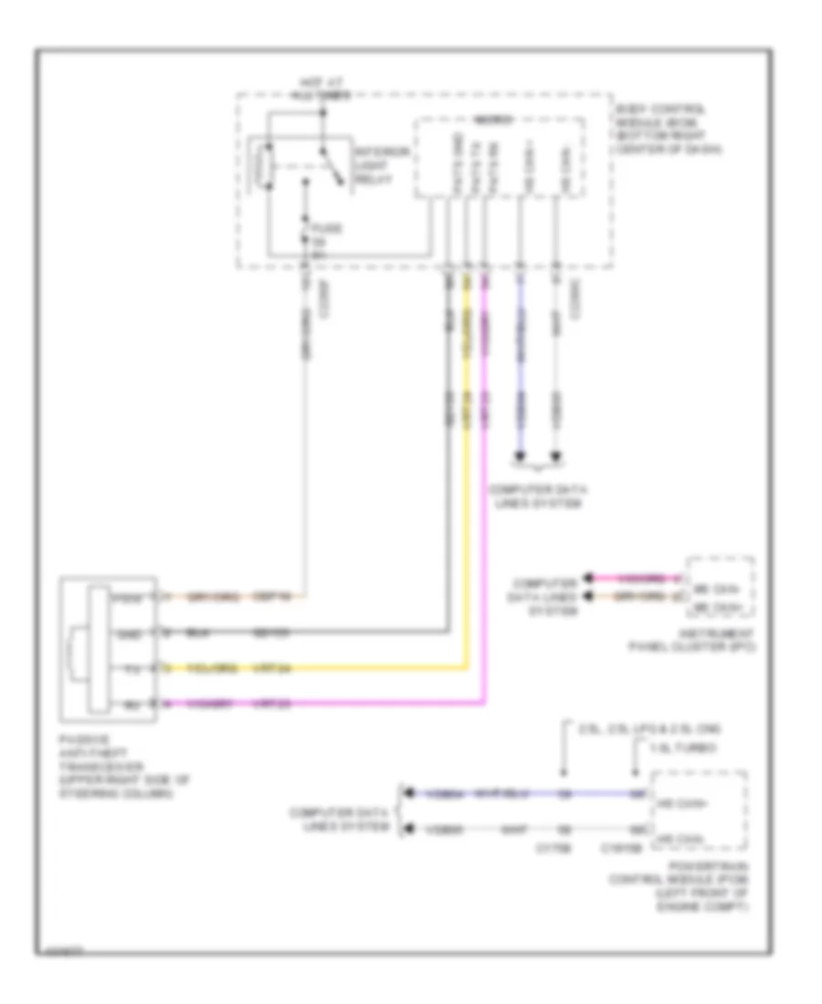
Passive Anti-theft Wiring Diagram for Ford Transit Connect Titanium 2014
List of elements for Passive Anti-theft Wiring Diagram for Ford Transit Connect Titanium 2014:
- 1.6l turbo
- 2.5l, 2.5l lpg & 2.5l cng
- Body control module (bcm) (bottom right center of dash)
- C175b
- C1915b
- C2280c
- C2280f
- Cbp18
- Computer data lines system
- Fuse 5a
- Gd133
- Gnd
- Hot at all times
- Hs can +
- Hs can -
- Hs can+
- Hs can-
- Instrument panel cluster (ipc)
- Interior light relay
- Micro
- Ms can+
- Ms can-
- Passive anti-theft transceiver (upper right side of steering column)
- Pats gnd
- Pats rx
- Pats tx
- Powertrain control module (pcm) (left front of engine compt)
- Pwr
- Vdb04
- Vdb05
- Vrt23
- Vrt24
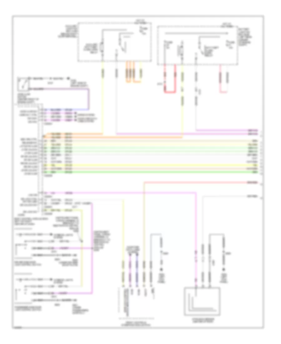
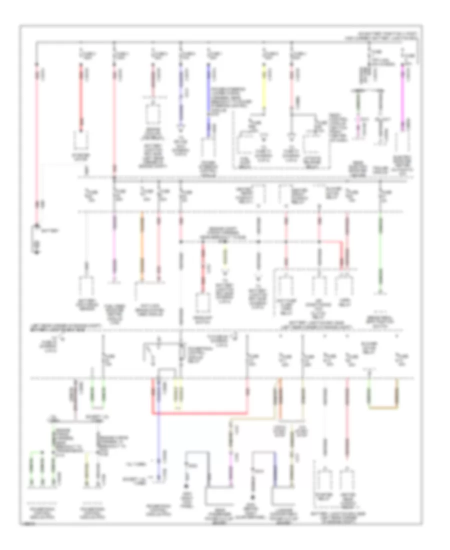
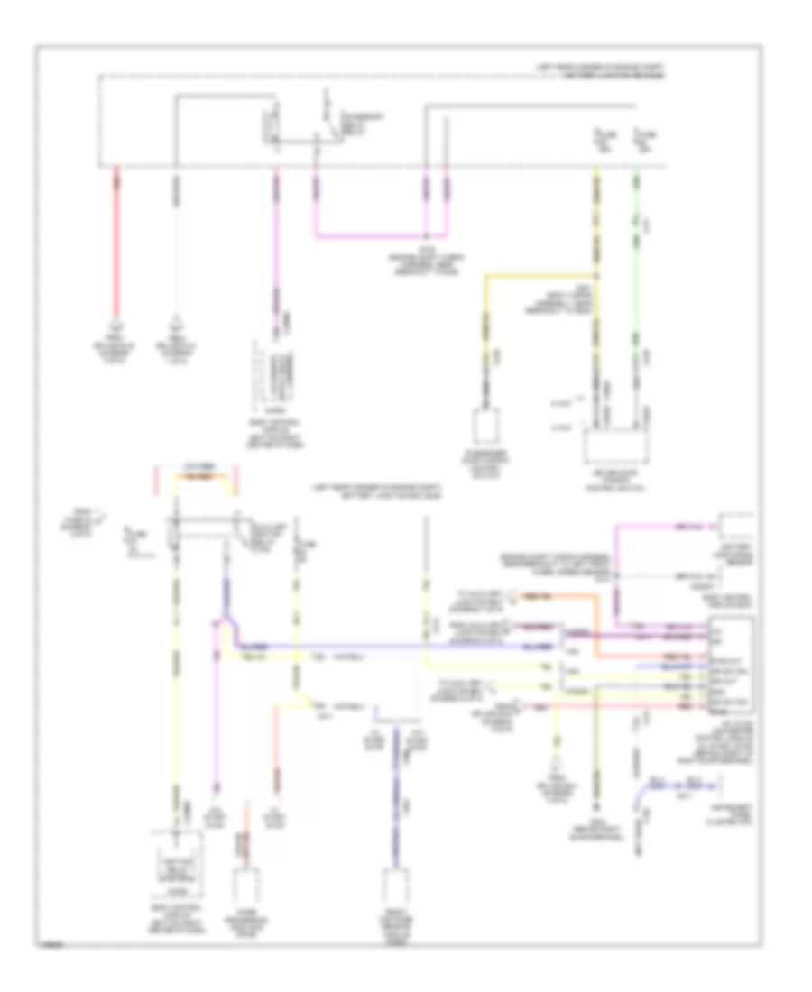
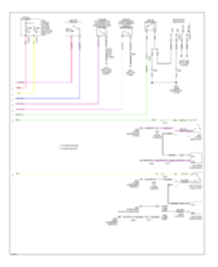
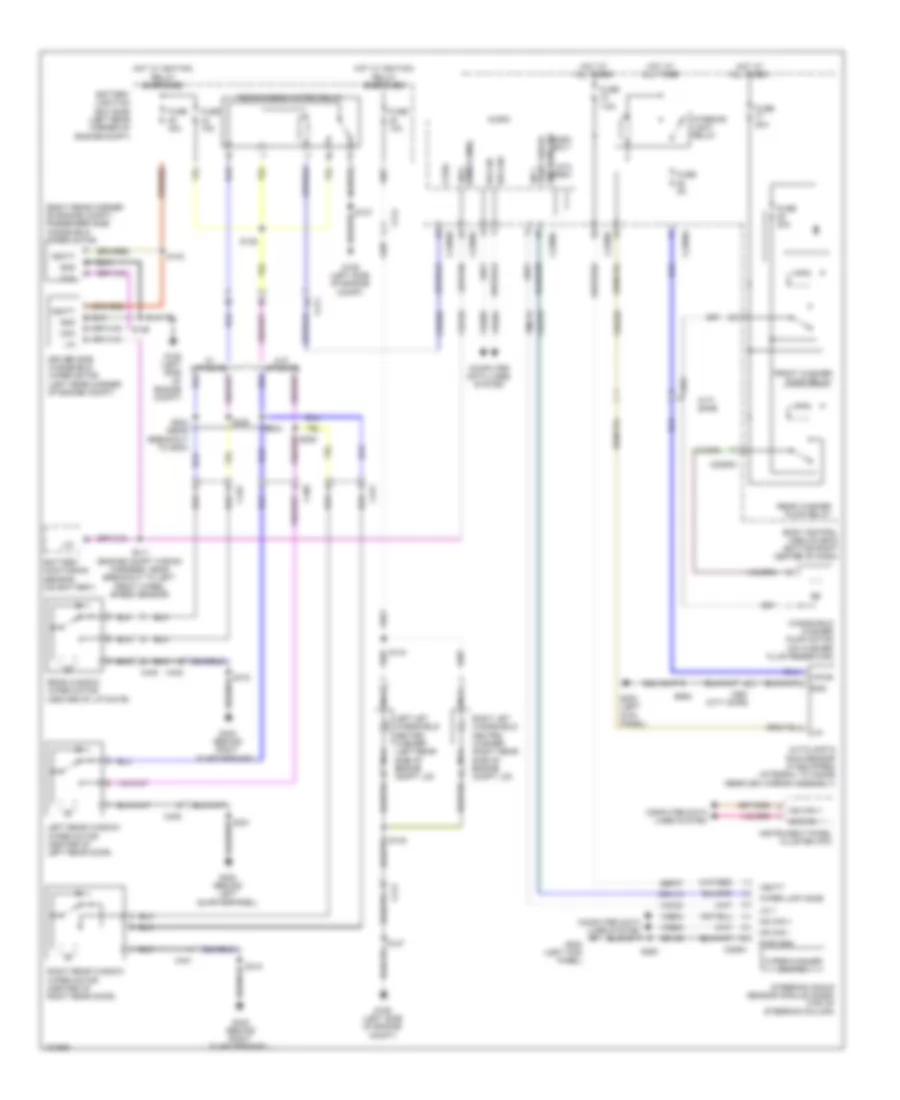
BODY CONTROL MODULES
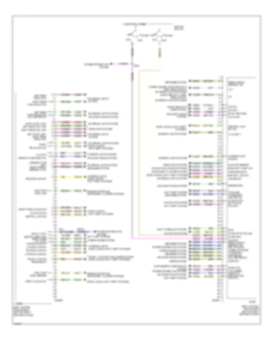
Body Control Modules Wiring Diagram (1 of 2) for Ford Transit Connect Titanium 2014
List of elements for Body Control Modules Wiring Diagram (1 of 2) for Ford Transit Connect Titanium 2014:
- Acc delay relay ctrl
- Air conditioning system
- Anti-theft & door locks systems
- Anti-theft system
- Battery junction box (bjb) (left rear corner of engine compt)
- Blwr mtr rly ctrl
- Body control module (bcm) (bottom right center of dash)
- Brk fluid level sw
- C1617d
- C1617j
- C2280a
- C2280d
- C2280e
- C2280f
- C2280g
- C2280h
- Cbb41
- Cbp01
- Cbp02
- Cbp04
- Cbp17
- Cbp18
- Cca29
- Cdc01
- Cdc56
- Ce436
- Ce903
- Center lock rly
- Center unlock rly
- Ch123
- Clf02
- Clf03
- Clf04
- Clf05
- Clf29
- Clf61
- Clf62
- Cln27
- Cls07
- Cls13
- Cls21
- Cls25
- Cls28
- Clutch pedal pos sw
- Cmc19
- Cmc28
- Computer data lines system
- Cpl11
- Cpl17
- Cpl25
- Cpl51
- Cpl53
- Crd01
- Crh04
- Cruise control & wiper/washer systems
- Crw23
- Crw24
- Defogger system
- Door locks & anti-theft systems
- Door locks system
- Electronic gnd
- Engine controls system
- Exterior lights system
- Fog lamp rly
- Front washer sply
- Fuel pump relay o/p
- Fuse 20a
- Fuse 4 50a
- Fuse 59, 5a
- Fuse 60, 10a
- Fuse 62, 5a
- Fuse 67, 7.5a
- Fuse 69, 5a
- Fuse 71, 10a
- Fuse 72, 7.5a
- Fuse 73, 10a (or) 7.5a
- Fuse 78, 5a
- Fuse 79, 15a
- Fuse 81, 5a
- Fuse 85, 7.5a
- Fuse 86, 10a
- Fuse 88, 25a
- Fuse 9 50a
- G109 (right side of engine compt)
- G200 (under passenger's scuff plate)
- Gd123
- Gd140
- Headlights system
- High beam rly
- High current battery junction box (bjb) (on battery positive (+) post)
- Hood ajar switch
- Horn rly ctrl
- Horns system
- Hot at all times
- Hot w/ ignition relay energized
- Ign rly ctrl
- Ignrs
- Impact status
- Instrument cluster system
- Interior light dimming
- Interior lights system
- Left daytime runng light ctrl
- Left front side marker ctrl
- Left low beam ctrl
- Liftgate release relay
- Lin 8
- Lin 8 (wmm & bms)
- Lin2
- Micro
- Mirrors, power distribution & interior lights systems
- Ms can +
- Ms can -
- Navigation system
- Pcm wake
- Power distribution system
- Pwr gnd
- Rear washer sply
- Red
- Reversing lamp relay
- Right daytime runng light ctrl
- Right front park light
- Right low beam ctrl
- Rrd12
- Sbb17
- Sbb18
- Sbb48 (or syv01)
- Sbp06
- Sbp07
- Sbp08
- Sbp21
- Sbp24
- Sbp26
- Sbp27
- Sound & navigation systems
- Starting/charging & wiper/washer systems
- Stop light switch
- Switch illumination
- Trunk, tailgate, fuel doors, door locks & anti-theft systems
- Vbatt
- Vdb06
- Vdb07
- Ve225
- Ve518
- Vpwr
- Vrt26
- Vrt27
- Vrw26
- Windshield heater ctrl
- Wiper/washer & computer data lines systems
- Wiper/washer system
- Wiper/washer system door locks, anti-theft & power tops systems
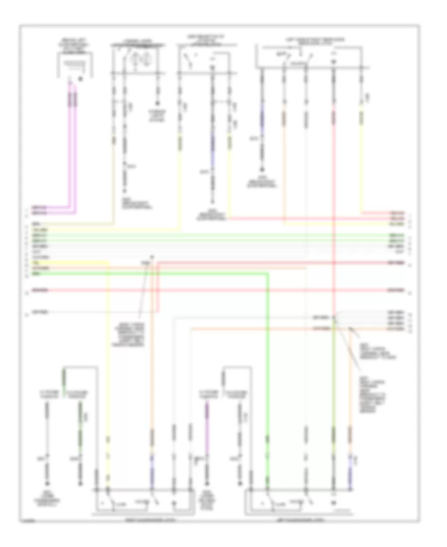
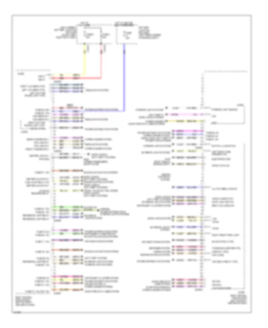
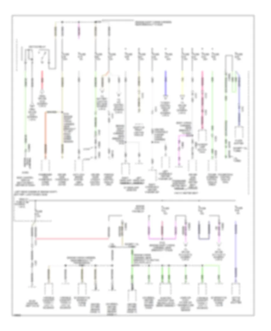
Body Control Modules Wiring Diagram (2 of 2) for Ford Transit Connect Titanium 2014
List of elements for Body Control Modules Wiring Diagram (2 of 2) for Ford Transit Connect Titanium 2014:
- A/c on sw
- Acc
- Acc/run rear window defrost sw key in ign sw
- Air conditioning system
- Anti-theft system
- Body control module (bcm) (bottom right center of dash)
- Btsi
- C2280b
- C2280c
- Cdc03 (or srh01)
- Cdc30
- Cdc32
- Cdc33
- Central lock sw
- Central lock sw ind
- Cet52
- Ch434
- Chmsl
- Chp01
- Chp03
- Cln17
- Cln27
- Cls08
- Cls09
- Cls17
- Cls23
- Cls27
- Cls32
- Cls44
- Cls45
- Cmc25
- Computer data lines system
- Computer data lines, headlights & exterior lights systems
- Cpl11
- Cpl26
- Cpl30
- Cpl31
- Cpl36
- Cpl39
- Cpl42
- Cpl43
- Cpl44
- Cpl45
- Cpl53
- Cplxx
- Cr115
- Crd02
- Crd03
- Crd04
- Crd08
- Crd09
- Crh03
- Crw02
- Crw10
- Cyd03
- Defogger system
- Door locks & anti-theft systems
- Engine controls & instrument cluster systems
- Evap temp sns
- Event sig
- Exterior lights system
- Exterior lights system door locks & anti-theft systems
- Front pass unlock sw
- Front unlock sw
- Fuel pump level gnd
- Fuel pump level sensor
- Gd133
- Hazard sw
- Headlights system
- Horn sw
- Horns system
- Hot at all times
- Hs can +
- Hs can -
- Ign rly ctrl
- Ignition switch
- Illum sply
- Illum sw
- Instrument cluster system
- Interior light dimming
- Interior lights system
- Interior lights, door locks & anti-theft systems
- Left rear park ctrl
- Left rear turn indication aux heater sw
- Left stop light right rear park ctrl
- Lf door ajar sw
- License plate light rear window defrost ctrl
- Liftgate ajar sw
- Lin
- Lin 1
- Lr unlock sw
- Lya03
- Micro
- Navigation & sound systems
- Navigation system
- Off
- Park brake sw
- Pats gnd windshield heater ind
- Power distribution system
- Radio anti-theft sw
- Rear ptc heater ctrl
- Rear window defrost ind
- Rf door ajar sw
- Rh105
- Right rear fog lamp
- Right rear turn indication
- Right stop light left rear fog lamp
- Rmc32
- Rr door ajar sw
- Rr unlock sw
- Run
- S235
- Sectry horn ctrl rear wiper rly ctrl lr door ajar sw
- Sensor gnd
- Shift interlock system
- Srh01
- Start
- Start/run
- Start/stop button sw pats rx
- Start/stop ind led
- Sunload sensor
- Taxi speed rear ptc heater ctrl pats tx
- Trunk liftgate release sw
- Trunk, tailgate, fuel doors system, door locks & anti-theft systems
- Vdb04
- Vdb05
- Vh406
- Vh414
- Vlf25
- Vmc05
- Vmc11
- Vmc34
- Vmp19
- Vrt23
- Vrt24
- Wiper limp home windshield heater sw aux heater sw
- Wiper/washer system
- Wiper/washer, computer data lines, headlights & exterior lights systems
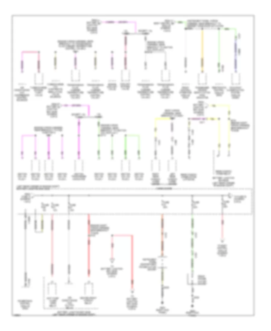
COMPUTER DATA LINES
Computer Data Lines Wiring Diagram (1 of 3) for Ford Transit Connect Titanium 2014
List of elements for Computer Data Lines Wiring Diagram (1 of 3) for Ford Transit Connect Titanium 2014:
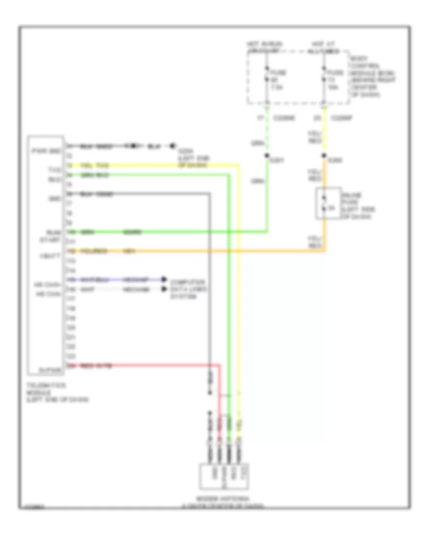
- (crew chief wiring harness, near breakout to telematics module) s264
- (engine compt wiring harness, near breakout to g108)
- (instrument panel wiring harness, near breakout to data link connector) s217
- (instrument panel wiring harness, near breakout to defrost mode door actuator) s242
- (instrument panel wiring harness, near breakout to sasm) s227
- (interior lamp wiring harness, near breakout to front interior lamp) s901
- (left end of dash) g204
- Auxiliary data link connector (adlc) (bottom left end of dash)
- Body control module (bcm) (bottom right center of dash)
- C211
- C215
- C2280a
- C2280c
- C2280f
- C228b
- C2357a
- C900
- Crew chief
- Data link connector (dlc) (bottom left end of dash)
- Electronic automatic temperature control (eatc) module (datc)
- Except crew chief
- Front controls interface module (fcim) (sync gen 2)
- Fuse 5a
- G202 (left kick panel)
- G204 (left end of dash)
- Gd133
- Gd138
- Gnd1
- Heating ventilation & air conditioning (hvac) control module (emtc)
- Hot at all times
- Hs can +
- Hs can -
- Hscanm
- Hscanp
- I can +
- I can -
- Icanm
- Icanp
- Instrument panel cluster (ipc)
- Micro
- Ms can +
- Ms can -
- Ms can+
- Ms can-
- Mscanm
- Mscanp
- S216 (instrument panel wiring harness, near breakout to data link connector)
- S222 (instrument panel wiring harness, near breakout to sasm)
- S223 (instrument panel wiring harness, near breakout to sasm)
- S231 (instrument panel wiring harness, near breakout to door lock/hazard switch)
- S236 (instrument panel wiring harness, near breakout to right panel discharge air temperature sensor)
- S250
- S253
- S254
- S260 (crew chief)
- S262
- S263 (crew chief wiring harness, near breakout to telematics module)
- S900 (interior lamp wiring harness, near breakout to front interior lamp)
- Sbp26
- Sync module (apim) (sync gen 1) (center of dash)
- Telematics module (left end of dash)
- Vb1
- Vdb04
- Vdb05
- Vdb06
- Vdb07
- Vdb13
- Vdb14
- W/ city safe
- W/o city safe
Computer Data Lines Wiring Diagram (2 of 3) for Ford Transit Connect Titanium 2014
List of elements for Computer Data Lines Wiring Diagram (2 of 3) for Ford Transit Connect Titanium 2014:
- (body wiring harness, near breakout to c510)
- (body wiring harness, near breakout to g200) (w/ door modules) s335
- (body wiring harness, near breakout to left "c" pillar side impact sensor)
- (body wiring harness, near breakout to passenger's safety belt tension sensor) (w/ trailer tow) s313
- (instrument panel wiring harness, near breakout to parking brake switch)
- (instrument panel wiring harness, near breakout to parking brake switch) s246
- (interior lamp wiring harness, near breakout to front interior lamp) s903
- (w/ door modules) s333
- (w/ rear camera) s315
- Audio front control module (acm)
- C311
- C4379b
- C501b
- C510
- C610
- C652b
- C900
- C991
- City safe
- Driver door module (ddm) (if equipped)
- Front control/ display interface module (fcdim) (sync gen 1)
- Front distance sensing module (fdsm)
- Fuel fired booster heater module
- Global position system module (gpsm) (w/ gps) (integral to inside rearview mirror assembly)
- Hs can +
- Hs can -
- I can +
- I can -
- Image processing module (ipmb) (w/ rear camera) (behind left quarterpanel)
- Ms can +
- Ms can -
- Passenger door module (pdm) (w/ door modules)
- S228 (instrument panel wiring harness, near breakout to sasm)
- S244 (instrument panel wiring harness, near breakout to parking brake switch)
- S245
- S314 (w/ rear camera) (body wiring harness, near breakout to left "c" pillar side impact sensor)
- S332 (w/ door modules) (body wiring harness, near breakout to c510)
- S902 (interior lamp wiring harness, near breakout to front interior lamp)
- Sync module (apim) (sync gen 2) (center of dash)
- Trailer module (if equipped) (behind right quarterpanel)
- Vdb04
- Vdb05
- Vdb06
- Vdb07
- Vdb13
- Vdb14
Computer Data Lines Wiring Diagram (3 of 3) for Ford Transit Connect Titanium 2014
List of elements for Computer Data Lines Wiring Diagram (3 of 3) for Ford Transit Connect Titanium 2014:
- (body wiring harness, near breakout to passenger's safety belt tension sensor) s310
- (body wiring harness, near breakout to passenger's safety belt tension sensor) s316
- (engine compt wiring harness, near breakout to anti-lock brake system module)
- (engine compt wiring harness, near breakout to battery monitoring sensor) s139
- (instrument panel wiring harness, in breakout to restraints control module)
- (instrument panel wiring harness, near breakout to data link connector) s218
- (instrument panel wiring harness, near breakout to sasm) (w/ sync) s220
- (instrument panel wiring harness, near breakout to sasm) s230
- 1.6l
- 2.5l
- Adaptive front lighting module (upper left end of dash)
- Anti-lock brake system (abs) module (left rear of engine compt)
- Battery junction box (bjb) (left rear corner of engine compt)
- Breakout to battery monitoring sensor)
- C1035c
- C1232b
- C139
- C1463b
- C175b
- C211
- C226a
- C3050
- C310b
- C311
- C9071a
- Hs can +
- Hs can -
- Occupant classification system module (ocsm) (12 loop single seat) (under passenger's seat)
- Parking assist control module (behind right quarterpanel)
- Power steering control module (pscm) (on steering rack assembly)
- Powertrain control module (pcm) (left front of engine compt)
- Restraints control module (rcm) (under center console)
- S208
- S209 (engine compt wiring harness, near breakout to anti-lock brake system module)
- S219 (instrument panel wiring harness, near breakout to sasm)
- S221
- S232 (w/ sync) (instrument panel wiring harness, near breakout to door lock/hazard switch)
- S305 (instrument panel wiring harness, in breakout to restraints control module)
- S311 (body wiring harness, near breakout to passenger's safety belt tension sensor)
- S317 (body wiring harness, near breakout to passenger's safety belt tension sensor)
- Steering angle sensor module (sasm) (top of steering column)
- Sync module (apim) (w/ sync) (center of dash)
- Vca23
- Vca24
- Vdb04
- Vdb05
- Yaw + hs can
- Yaw - hs can
COOLING FAN
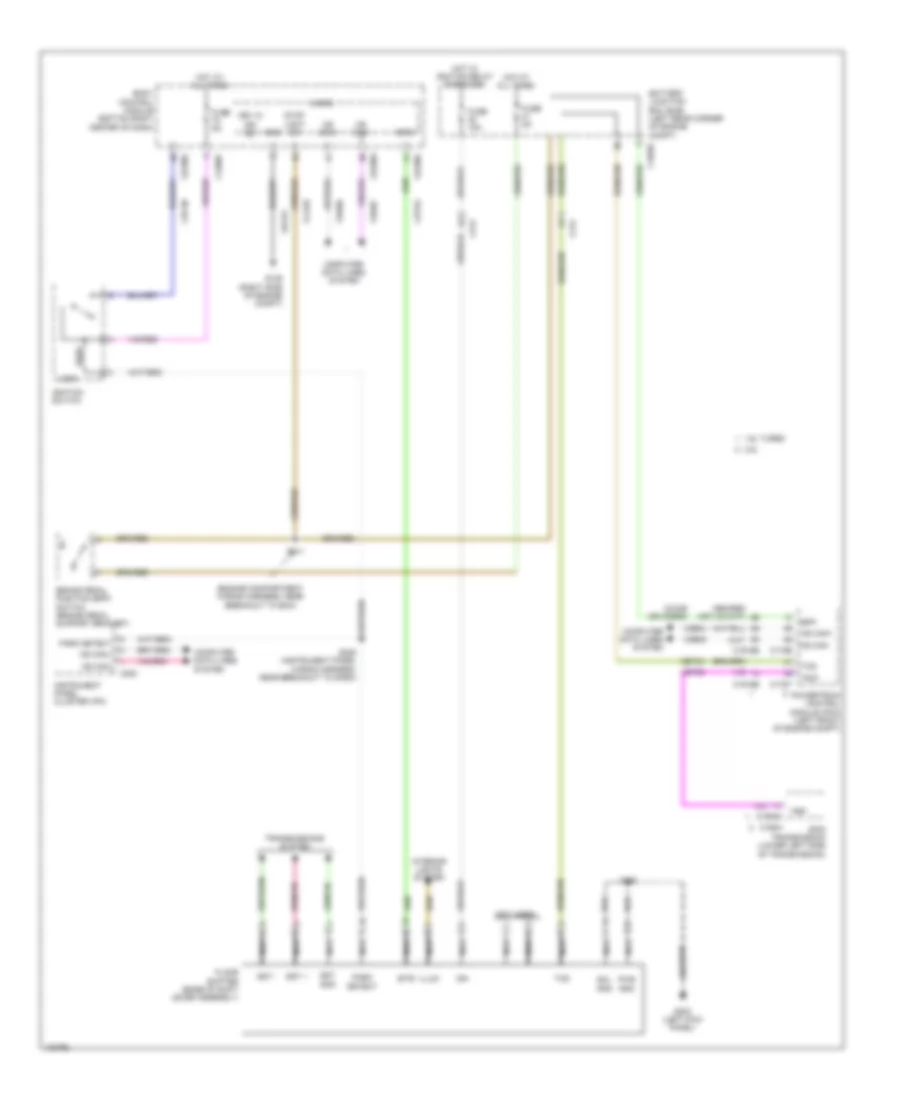
Cooling Fan Wiring Diagram for Ford Transit Connect Titanium 2014
List of elements for Cooling Fan Wiring Diagram for Ford Transit Connect Titanium 2014:
- (engine wiring harness, near breakout to camshaft position 11 sensor) s107
- (engine wiring harness, near breakout to electronic throttle control) s120
- (or vdn06)
- 1.6l turbo
- Active grille shutter actuator (behind left end of front grille)
- Battery junction box (bjb) (left rear corner of engine compt)
- C1035c
- C1617h
- C175b
- C175e
- C1915b
- C1915e
- Cht
- Computer data lines system
- Cylinder head temperature (cht) sensor (except 1.6l turbo) (top center of cylinder head)
- Ect
- Electronics
- Engine controls system
- Engine coolant temperature (ect) sensor (1.6l turbo) (right rear of cylinder head)
- Engine cooling fan module (on engine cooling fan assembly)
- Engine cooling fan relay
- Except 1.6l turbo
- Fan control variable
- Fcv
- Fuse 10a
- Fuse 50a
- Fuse 5a
- G106 (left side of engine compt)
- Gd130
- Gnd
- High current battery junction box (on battery positive (+) post)
- Hot at all times
- Hot w/ powertrain control module (pcm) relay energized
- Hs can+
- Hs can-
- Lin
- Nca
- Powertrain control module (pcm) (left front of engine compt)
- Pwr
- Re329
- Re405
- S122 (except 1.6l turbo) (engine wiring harness, near breakout to electronic throttle control)
- S126
- S127
- S132
- Sbb05
- Sig rtn
- V power
- Vdb04
- Vdb05
- Vdc46
- Ve203
- Ve712
- Ve716
CRUISE CONTROL
Cruise Control Wiring Diagram for Ford Transit Connect Titanium 2014
List of elements for Cruise Control Wiring Diagram for Ford Transit Connect Titanium 2014:
- (1.6l turbo) s100
- (brake pedal support bracket) brake pedal position (bpp) switch
- (engine wiring harness, near breakout to pcm) (2.5l) s123
- (left side of engine compt) g103
- (on accelerator pedal assembly) accelerator pedal position (app) sensor
- 1.6l
- 1.6l turbo
- 2.5l
- 6f35 transmission (c168a & c1909a: lower left side of transmission) (c168b & c1909b: left rear of transmission)
- App1
- App2
- Apprtn1
- Apprtn2
- Appvref1
- Appvref2
- Battery junction box (bjb) (left rear corner of engine compt)
- Body control module (bcm) (bottom right center of dash)
- Bpp
- Bps
- C1035c
- C168a
- C168b
- C175b
- C175e
- C175t
- C1909a
- C1909b
- C1915b
- C1915e
- C218a
- C218b
- C218c
- C218d
- C226a
- C226b
- C226c
- C2280a
- C2280c
- C2280f
- Cca29
- Cca29 (or ccb08)
- Ccb08 (or ces09)
- Cdc34 (or cbb38)
- Ce412 (or ve819)
- Ce426 (or le428)
- Clockspring (top of steering column)
- Computer data lines system
- Cruise gnd
- Cruise sig 1
- Cruise sig 2
- Electronic throttle control (etc) module (on throttle body)
- Etcref
- Etcrtn
- Fuse 15a
- Fuse 5a
- Fuse 7.5a
- G103 (left side of engine compt)
- G202 (left kick panel)
- Gd120
- Gd138
- Hot at all times
- Hot w/ ignition relay energized
- Hs can+
- Hs can-
- Instrument panel cluster (ipc)
- Interior lights system
- Isp-r
- Le111 (or let57)
- Le134 (or ce426)
- Le136
- Le137
- Left lower steering wheel switch
- Micro
- Ms can +
- Ms can -
- Nca
- On/ off
- Oss
- Oss/tr gnd
- Oss/tr pwr
- Powertrain control module (pcm) (left front of engine compt)
- Pwr gnd
- Re134 (or re427)
- Re136
- Re137
- Reset/ cancel
- Ret24
- S102
- S124 (2.5l) s103 (1.6l turbo) (2.5l: engine wiring harness, near breakout to pcm) (1.6l turbo: engine wiring harness, in breakout to pcm)
- S250
- S255
- Sbp07
- Set+
- Set-
- Steering angle sensor module (sasm) (top of steering column)
- Switch stop light
- Tacm +
- Tacm -
- Tp1
- Tp2
- Tr-p
- Trs
- Tss
- Tss gnd
- Tss vpwr
- Tss/oss/ tr gnd
- Tss/oss/ tr vpwr
- Turbo
- Vbatt
- Vdb04
- Vdb05
- Ve701
- Ve702
- Ve818 (or ce412)
- Ve819 (or ve818)
- Vet26 (or ret26)
- Vet32
- Vet33
DEFOGGERS
Defoggers Wiring Diagram for Ford Transit Connect Titanium 2014
List of elements for Defoggers Wiring Diagram for Ford Transit Connect Titanium 2014:
- (base of windshield, at right side)
- (engine compartment wiring harness, near breakout to battery monitoring sensor)
- (instrument panel wiring harness, in breakout to restraints control module) s300
- (left kick panel) g202
- (under driver's scuff plate) g300
- Auxiliary junction box (ajb) (behind right quarterpanel)
- Battery junction box (bjb) (left rear corner of engine compt)
- Body control module (bcm) (bottom right center of dash)
- C1531a
- C1531b
- C1532a
- C1532b
- C211
- C2280a
- C2280b
- C2280c
- C402a
- C402b
- C405
- C421
- C432
- C4425a
- C4425b
- C4426a
- C4426b
- C465
- C501a
- C501b
- C510
- C510 a14
- C610
- C610 a14
- C652a
- C652b
- Cargo doors
- Computer data lines system
- Crd01
- Crd02
- Crd03
- Crd04
- Crd08
- Crd09
- Crd13
- Crd14
- Driver door module (ddm) (w/ door modules)
- Fuse 100a
- Fuse 25a
- Fuse 30a
- Fuse 40a
- Fuse 5a
- Fuse 7.5a
- G109 (right side of engine compt)
- G201 (under passenger's door sill)
- G210 (left rear corner of engine compt)
- G211 (right rear corner of engine compt)
- G300 (under driver's scuff plate)
- G400 (behind left quarterpanel)
- G402 (behind right quarterpanel)
- Gd123
- Gd134
- Gd140
- Gnd
- Heat
- Heated front window relay
- Heated rear window element (liftgate)
- Heated rear window relay
- High current battery junction box (bjb) (on battery positive c1617c (+) post)
- Hot at all times
- Hws rly ctrl
- Interior lights system
- Left exterior mirror
- Left heated rear window element
- Left heated windshield element (base of windshield, at left side)
- Logic gnd
- Micro
- Mirr rtn
- Module
- Ms can +
- Ms can -
- Ms can+
- Ms can-
- Nca
- Passenger door module (pdm) (w/ door modules)
- Rear window defrost/heated windshield switch
- Red
- Right exterior mirror
- Right heated rear window element
- Right heated windshield element
- Rpm05
- Rpm08
- Rwd ind
- Rwd switch
- Rwdr ctrl
- S131
- S133
- S202 (body wiring harness, near breakout to g200)
- S250
- S318
- S321
- S500
- S600
- Sbr01
- Sbr02
- Vbatt
- Vdb06
- Vdb07
- Vdbo6
- Vdbo7
- W/ door module
- W/o door module
- Wd indicator
- Wh switch
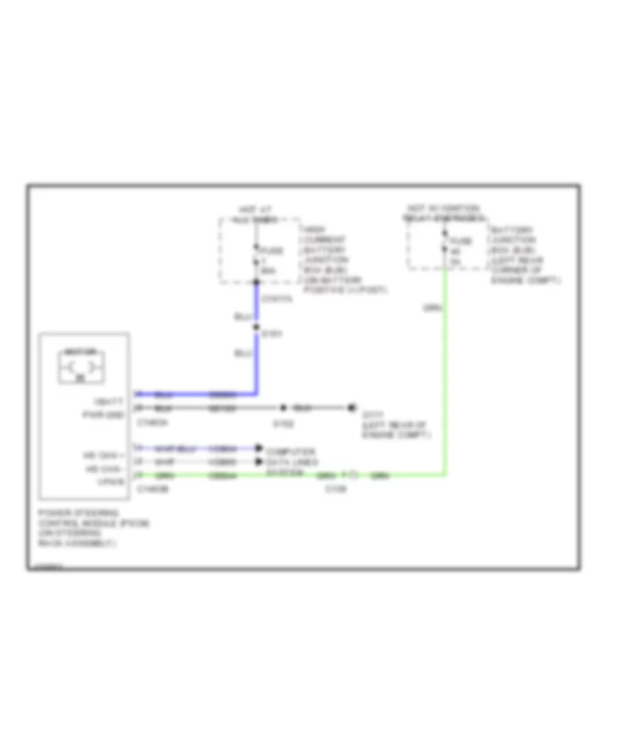
ELECTRONIC POWER STEERING
Electronic Power Steering Wiring Diagram for Ford Transit Connect Titanium 2014
List of elements for Electronic Power Steering Wiring Diagram for Ford Transit Connect Titanium 2014:
- Battery junction box (bjb) (left rear corner of engine compt)
- C139
- C1463a
- C1463b
- C1617a
- Cbb44
- Computer data lines system
- Fuse 5a
- Fuse 80a
- G111 (left rear of engine compt)
- Gd120
- High current battery junction box (bjb) (on battery positive (+) post)
- Hot at all times
- Hot w/ ignition relay energized
- Hs can +
- Hs can -
- Motor
- Power steering control module (pscm) (on steering rack assembly)
- Pwr gnd
- S151
- S152
- Sbb03
- Vbatt
- Vdb04
- Vdb05
- Vpwr
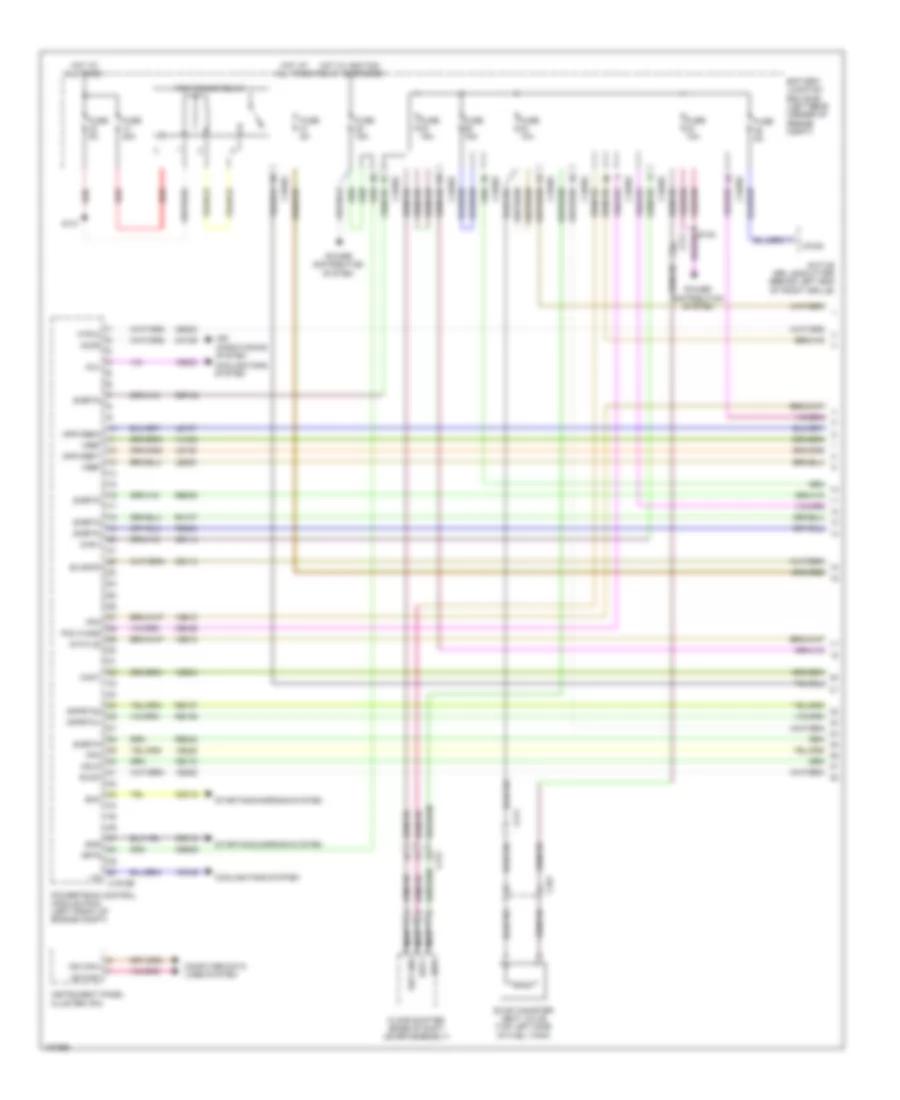
ENGINE PERFORMANCE
1.6L TURBO
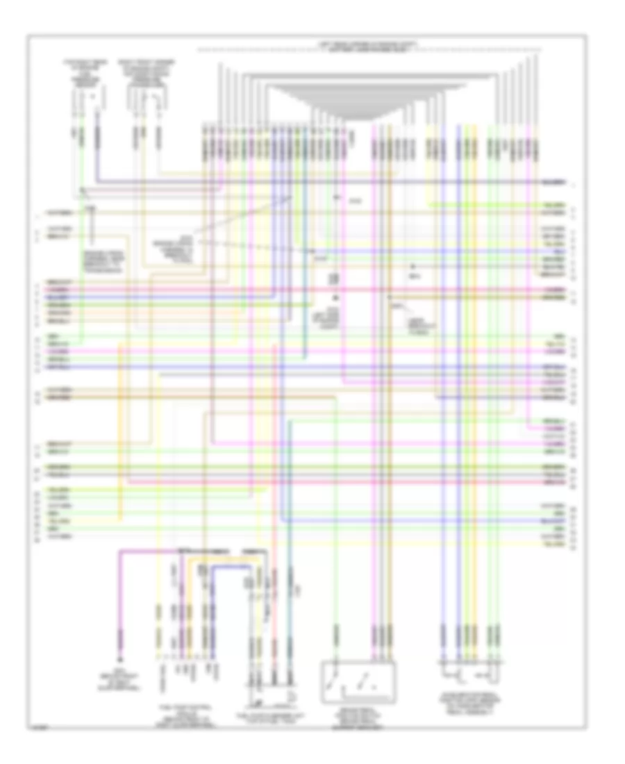
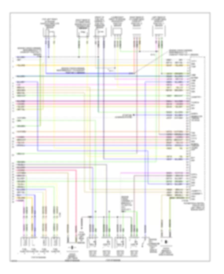
1.6L Turbo, Engine Performance Wiring Diagram (1 of 6) for Ford Transit Connect Titanium 2014
List of elements for 1.6L Turbo, Engine Performance Wiring Diagram (1 of 6) for Ford Transit Connect Titanium 2014:
- Accr
- Active grille shutter (behind left end of front grille)
- Air conditioning system
- Apprtn1
- Apprtn2
- Appvref1
- Appvref2
- Battery junction box (bjb) (left rear corner of engine compt)
- C1035c
- C1915b
- C211
- C212
- C327
- Cact
- Canv
- Cbb38
- Cdc12
- Cdv2
- Ce113
- Ce114
- Ce172
- Ce233
- Ce436
- Ch109
- Computer data lines system
- Cooling fans system
- Evap canister vent valve (top left side of fuel tank)
- Evapcp
- Evdc
- Fcv
- Floor shifter (base of shift lever assembly)
- Fpc
- Fpm
- Fuse 10a
- Fuse 15a
- Fuse 30a
- Fuse 5a
- Hot at all times
- Hot w/ ignition relay energized
- Htr12
- Instrument panel cluster (ipc)
- Isp-r
- Le136
- Le137
- Le230
- Lin
- Ms can+
- Ms can-
- Nca
- Pcm power relay
- Pcm wake
- Power distribution system
- Powertrain control module (pcm) (left front of engine compt)
- Re136
- Re137
- Re238
- Re242
- Re804
- Red
- Ret42
- Rh107
- S131
- Sigrtn
- Smc
- Smr
- Sst gnd
- Sst+
- Sst-
- Starting/charging system
- Status
- Vdc46
- Ve203
- Ve225
- Ve462
- Ve518
- Ve804
- Vh442
- Vpwr
- Vref
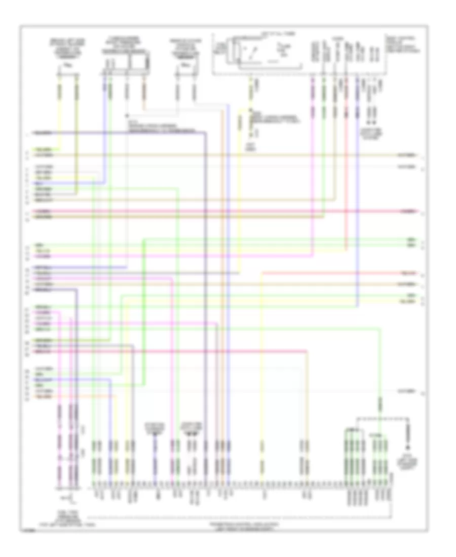
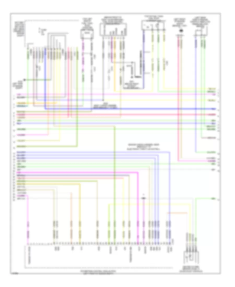
1.6L Turbo, Engine Performance Wiring Diagram (2 of 6) for Ford Transit Connect Titanium 2014
List of elements for 1.6L Turbo, Engine Performance Wiring Diagram (2 of 6) for Ford Transit Connect Titanium 2014:
- (engine wiring harness, near breakout to transmission)
- (left rear corner of engine compt) battery junction box (bjb)
- (near breakout to bcm)
- (right front corner of engine compt) air conditioning pressure transducer
- (top right rear of engine) fuel pressure sensor
- Accelerator pedal position (app) sensor (on accelerator pedal assembly)
- Brake pedal position switch (brake pedal support bracket)
- C1035c
- C211
- C327
- Fpc
- Fpm
- Fppwr
- Fprtn
- Fuel pump & sender unit (top of fuel tank)
- Fuel pump control module (behind front of right quarterpanel)
- G103 (left side of engine compt)
- G301 (behind front of right quarterpanel)
- Gd130
- Gd143
- Gnd
- Nca
- S101
- S102
- S104 (engine wiring harness, in breakout to pcm)
- S109
- S211
- S212
- S319
- Ve208
- Ve225
- Ve518
- Vpwr fuel
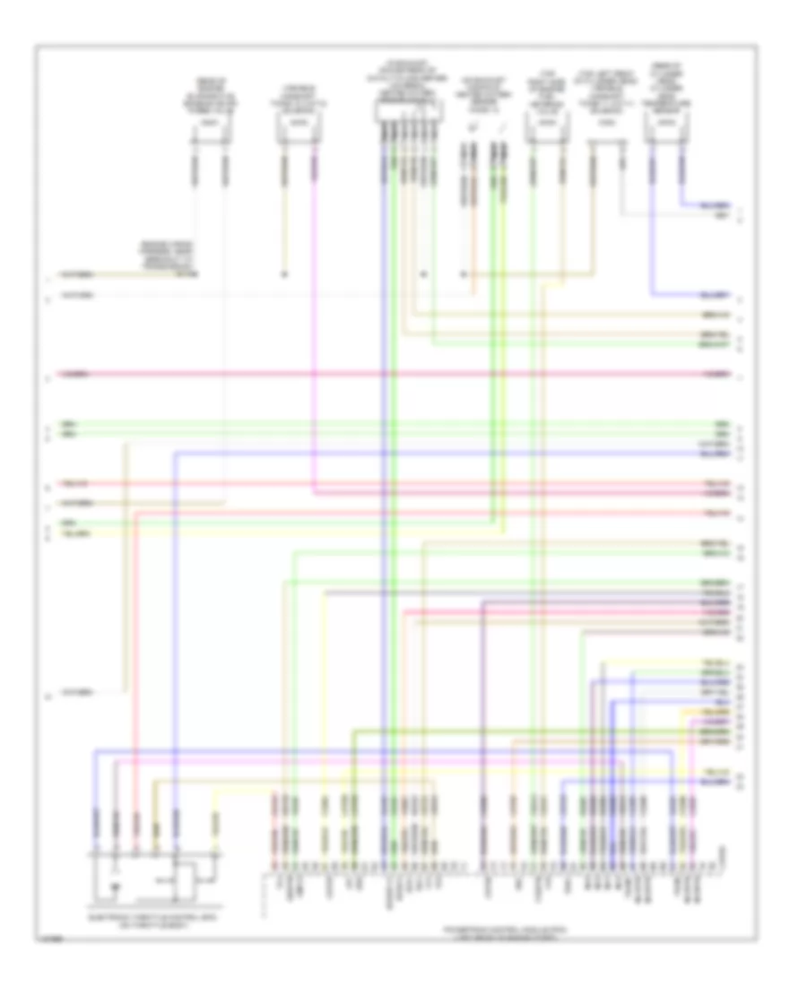
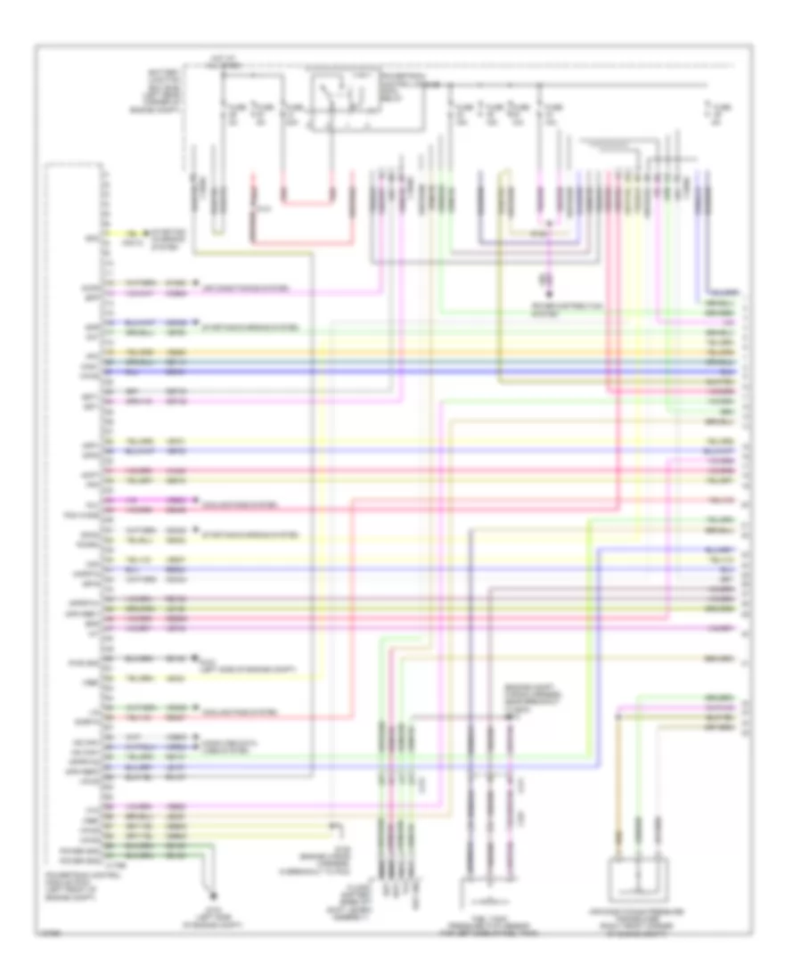
1.6L Turbo, Engine Performance Wiring Diagram (3 of 6) for Ford Transit Connect Titanium 2014
List of elements for 1.6L Turbo, Engine Performance Wiring Diagram (3 of 6) for Ford Transit Connect Titanium 2014:
- (behind left side of front bumper) ambient air temperature sensor
- (not used)
- (rear of intake manifold) intake air temperature sensor
- Aat
- Acpt
- App1
- App2
- Body control module (bottom right center of dash)
- Bpp
- Bps
- C1915b
- C211
- C2280a
- C2280b
- C2280c
- C2280e
- C327
- Cact
- Cbb32
- Cca29
- Ccb08
- Cdc12
- Cdv1
- Ce171
- Ce302
- Ce436
- Cet61
- Cet62
- Computer data lines system
- Event sig
- Flp
- Ftp
- Fuel pump lvl gnd
- Fuel pump relay
- Fuel tank pressure (ftp) sensor (top left side of fuel tank)
- Fuse 20a
- G103 (left side of engine compt)
- Gd120
- Ho2s12
- Hot at all times
- Hs can+
- Hs can-
- Iat
- Lh108
- Lvl sens fuel pump
- Micro
- Pcmrc
- Powertrain control module (pcm) (left front of engine compt)
- Pwrgnd
- Re804
- Rmc32
- S102
- S110 (engine wiring harness, near breakout to transmission)
- S115
- S320 (body wiring harness, near breakout to g301)
- Sigrtn
- Smcs
- Sst+
- Sst-
- Starting/ charging system
- Switch stop light
- Tcbp
- Turbocharger boost pressure/ air cooler temperature sensor
- Vdb04
- Vdb05
- Ve518
- Ve701
- Ve702
- Ve727
- Ve731
- Ve805
- Ve922
- Vh407
- Vmc11
- Vpwr
- Vref
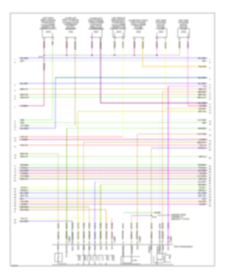
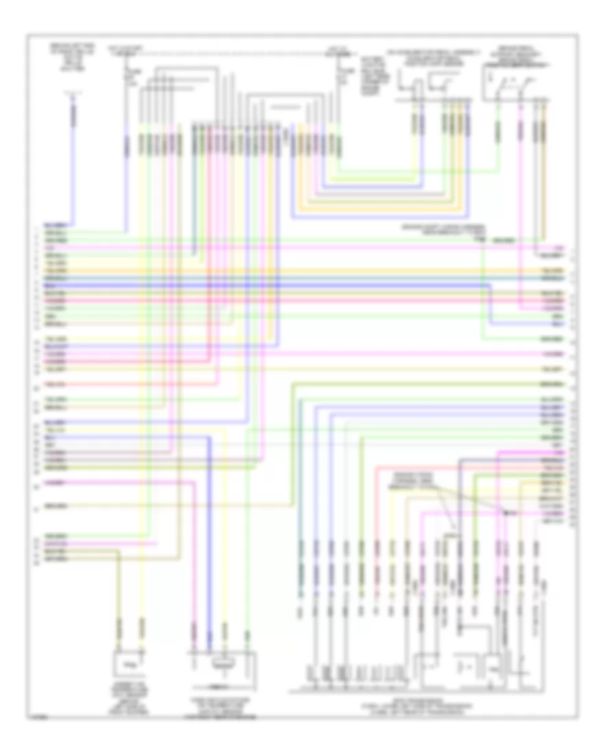
1.6L Turbo, Engine Performance Wiring Diagram (4 of 6) for Ford Transit Connect Titanium 2014
List of elements for 1.6L Turbo, Engine Performance Wiring Diagram (4 of 6) for Ford Transit Connect Titanium 2014:
- (engine wiring harness, near breakout to transmission) s115
- (in exhaust, downstream of catalytic converter) universal heated oxygen sensor (ho2s) 11
- (on exhaust manifold) heated oxygen sensor (ho2s) 12
- (rear of cylinder head) cylinder head temperature sensor
- (rear of engine) evaporative emission (evap) purge valve
- (top left front of cylinder head) variable camshaft timing 11 (vct11) solenoid
- (top right side of engine) fuel metering valve
- C1915e
- Cbb12
- Ce205
- Ce206
- Ce207
- Ce208
- Ce231
- Ce304
- Ce305
- Ce412
- Cet05
- Cet07
- Cet09
- Cet25
- Cmp12
- Cop2d
- Cop3b
- Electronic throttle control (etc) (on throttle body)
- Fvr
- Fvrrtn
- Inj1
- Inj1rtn
- Inj2
- Inj2rtn
- Inj3
- Inj3rtn
- Inj4
- Inj4rtn
- Ks1+
- Ks1-
- Le428
- Le448
- Le452
- Lpc
- Nca
- Powertrain control module (pcm) (left front of engine compt)
- Re205
- Re206
- Re207
- Re208
- Re323
- Ret35
- Sigrtn
- Ssa
- Ssc
- Tacm+
- Tacm-
- Tft
- Tp1
- Tp2
- Tspc
- Uo2s11
- Uo2spc11
- Variable camshaft timing 12 (vct12) solenoid
- Ve707
- Ve801
- Ve818
- Ve819
- Vet27
1.6L Turbo, Engine Performance Wiring Diagram (5 of 6) for Ford Transit Connect Titanium 2014
List of elements for 1.6L Turbo, Engine Performance Wiring Diagram (5 of 6) for Ford Transit Connect Titanium 2014:
- (engine wiring harness, in breakout to pcm)
- (left front side of engine) transmission fluid warmer temperature control valve 2
- (left rear of engine compt) transmission fluid warmer temperature control valve 1
- (left rear of engine) coolant bypass valve
- (left side of engine) engine coolant valve
- (lower left front of engine) air conditioning compressor control solenoid
- (lower right front side of engine) turbocharger bypass valve
- (lower right side of engine) turbocharger wastegate regulating valve solenoid
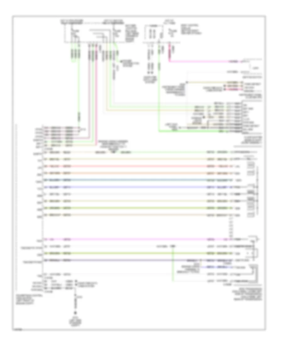
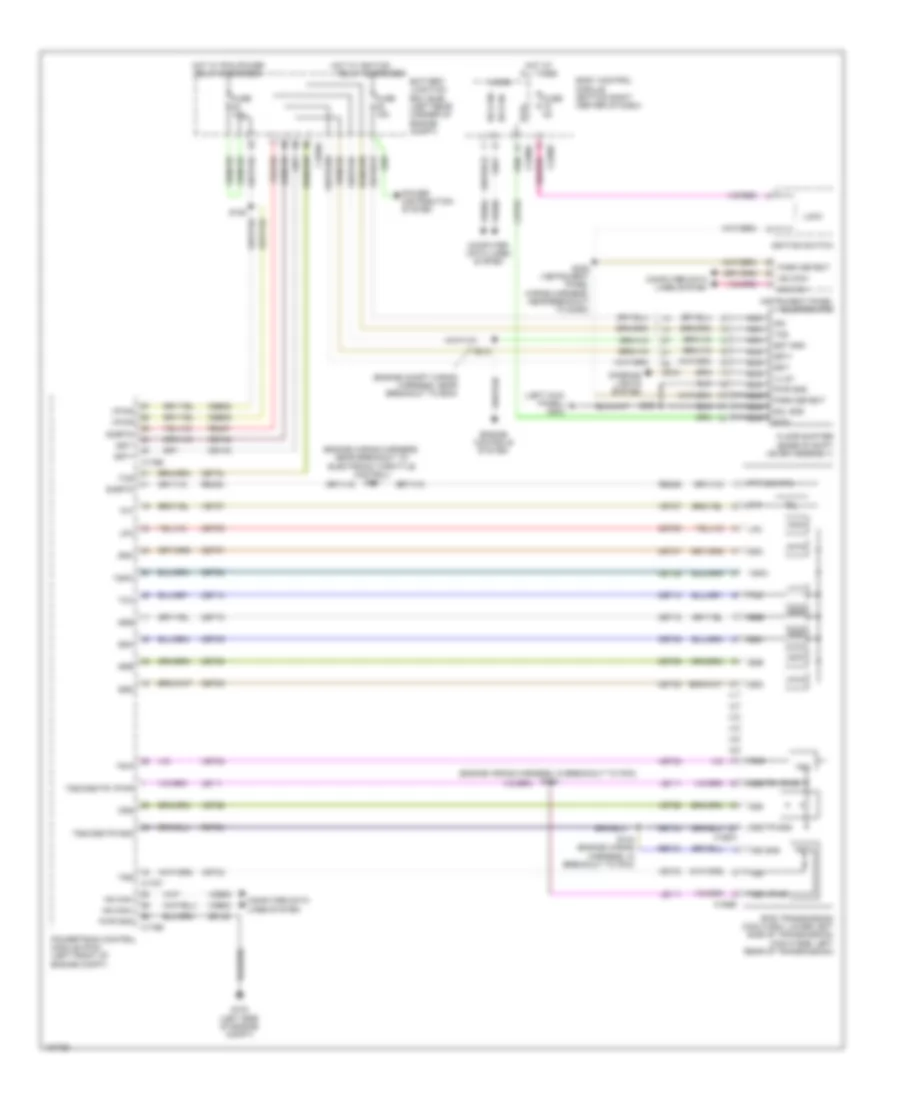
- 6f35 transmission
- C1909a
- C1909b
- Cet05
- Cet06
- Cet07
- Cet08
- Cet09
- Cet10
- Cet18
- Cet25
- Let57
- Lpc
- Oss
- Oss/tr gnd
- Ret24
- Ret26
- Ret35
- S100
- S103
- S114
- Ssa
- Ssb
- Ssc
- Ssd
- Sse
- Tcc
- Tft
- Tft sig rtn
- Tr-p
- Trs
- Tspc
- Tss
- Tss gnd
- Tss vpwr
- Vet27
- Vet32
- Vet33
- Vpwr oss/tr
1.6L Turbo, Engine Performance Wiring Diagram (6 of 6) for Ford Transit Connect Titanium 2014
List of elements for 1.6L Turbo, Engine Performance Wiring Diagram (6 of 6) for Ford Transit Connect Titanium 2014:
- (engine wiring harness, in breakout to ignition coil- on-plug 1) s113
- (engine wiring harness, near breakout to camshaft position 11 sensor)
- (engine wiring harness, near breakout to camshaft position 11 sensor) s107
- (front of fuel rail assembly) fuel rail pressure sensor
- (left rear of cylinder head) camshaft position 11 sensor
- (lower right front of engine) crankshaft position sensor
- (right rear of cylinder head) camshaft position 12 sensor
- (right rear of cylinder head) engine coolant temperature sensor
- (top left front of engine) manifold absolute pressure sensor
- (top of engine)
- C140
- C1915e
- Cbv
- Ce148
- Ce149
- Ce167
- Ce303
- Ce306
- Ce426
- Ce501
- Ce508
- Ce844
- Ce908
- Cet06
- Cet08
- Cet10
- Cet18
- Cht
- Ckp
- Cmp11
- Cop1a
- Cop4c
- Ect
- Ectref
- Ecv
- Engine oil pressure switch (left side of engine)
- Etcrtn tss/oss/ tr gnd map
- Frp
- Fuel injector
- G104 (lower left rear of engine)
- Generator tss/oss/ tr vpwr
- Ignition coil on plug 1
- Ignition coil on plug 2
- Ignition coil on plug 3
- Ignition coil on plug 4
- Knock sensor 1 (left rear side of engine)
- Knock sensor 2 (left front side of engine)
- Ks2+
- Ks2-
- Le135
- Le143
- Le451
- Let57
- Ops
- Oss
- Powertrain control module (pcm) (left front of engine compt)
- Re324
- Re329
- Re427
- Ret24
- Ret26
- S105
- S108
- S111
- S112
- Sigrtn
- Ssb
- Ssd
- Sse
- Starting/ charging system
- Tcby
- Tcc
- Tcwrvs
- Tr-p
- Tss
- Uo2sgref11
- Uo2shtr11
- Uo2spct11
- Vct11
- Vct12
- Vdc46
- Ve706
- Ve711
- Ve712
- Ve716
- Ve727
- Ve802
- Ve803
- Ve826
- Ve827
- Vet32
- Vet33
- Vref
2.5L
2.5L, Engine Performance Wiring Diagram (1 of 5) for Ford Transit Connect Titanium 2014
List of elements for 2.5L, Engine Performance Wiring Diagram (1 of 5) for Ford Transit Connect Titanium 2014:
- (engine compt wiring harness, near breakout to bcm) s212
- 10a
- 15a
- 30a
- Aat
- Accr
- Acpt
- Air conditioning pressure transducer (right front corner of engine compt)
- Air conditioning system
- App1
- App2
- Apprtn1
- Apprtn2
- Appvref1
- Appvref2
- Battery junction box (bjb) (left rear corner of engine compt)
- Bpp
- Bps
- C1035c
- C175b
- C211
- C212
- C327
- Canv
- Cbb08
- Cbk01
- Ccb08
- Cdc12
- Cdc34
- Cdc35
- Cdc54
- Ce114
- Ce302
- Ce436
- Ce515
- Ces09
- Cet42
- Cet43
- Ch302
- Computer data lines system
- Cooling fans system
- Fcv
- Floor shifter (base of shift lever assembly)
- Fpc
- Fpm
- Ftp
- Fuel tank pressure (ftp) sensor (top left side of fuel tank)
- Fuse
- G103 (left side of engine compt)
- Gd120
- Hot at all times
- Hs can+
- Hs can-
- Iat
- Isp-r
- Le136
- Le137
- Le230
- Le424
- Lin
- Maf
- Mafrtn
- Nca sst gnd
- Nca sst+
- Nca sst-
- Nca tcs
- Pcm wake
- Pcmrc
- Power distribution system
- Power gnd
- Powertrain control module (pcm) (left front of engine compt)
- Powertrain control module (pcm) relay
- Pwr gnd
- Re136
- Re137
- Re320
- Re407
- Red
- Rh107
- S125 (engine wiring harness, in breakout to pcm)
- S131
- S132
- Sigrtn
- Smc
- Smcs
- Smr
- Sst+
- Sst-
- Starting/ charging system
- Starting/charging system
- Vdb04
- Vdb05
- Vdn06
- Ve203
- Ve225
- Ve701
- Ve702
- Ve740
- Ve750
- Ve807
- Ve922
- Vh443
- Vpwr
- Vref
2.5L, Engine Performance Wiring Diagram (2 of 5) for Ford Transit Connect Titanium 2014
List of elements for 2.5L, Engine Performance Wiring Diagram (2 of 5) for Ford Transit Connect Titanium 2014:
- (behind left end of front grille) active grille shutter
- (brake pedal support bracket) brake pedal position (bpp) switch
- (engine compt wiring harness, near breakout to bcm) s211
- (engine wiring harness, near
- (on accelerator pedal assembly) accelerator pedal position (app) sensor
- 15a
- 6f35 transmission (c168a: lower left side of transmission) (c168b: left rear of transmission)
- Ambient air temperature (aat) sensor (behind left side of front bumper)
- Battery junction box (bjb) (left rear corner of engine compt)
- Breakout to pcm)
- C1035c
- C168a
- C168b
- Cet05
- Cet06
- Cet07
- Cet08
- Cet09
- Cet10
- Cet18
- Cet25
- Digital
- Fuse
- Hot at all times
- Hot in start or run
- Le111
- Lpc
- Mass air flow/intake air temperature (maf/iat) sensor (top right rear of engine)
- Oss
- Oss/tr gnd
- Oss/tr vpwr
- Re406
- Ret24
- S123
- S124
- Ssa
- Ssb
- Ssc
- Ssd
- Sse
- Tcc
- Tft
- Tft sig rtn
- Trp
- Trs
- Tspc
- Tss
- Tss gnd
- Tss vpwr
- Vet26
- Vet27
- Vet32
- Vet33
- Vref 5v
2.5L, Engine Performance Wiring Diagram (3 of 5) for Ford Transit Connect Titanium 2014
List of elements for 2.5L, Engine Performance Wiring Diagram (3 of 5) for Ford Transit Connect Titanium 2014:
- (behind front of right quarterpanel) fuel pump control module (fpcm)
- (engine wiring harness, near breakout to electronic throttle control)
- (left front of engine) knock sensor 1 (ks1)
- (left rear side of engine) manifold absolute pressure (map) sensor
- (top left side of fuel tank) evap canister vent valve
- (top of fuel tank) fuel pump & sender unit
- 10a
- Battery junction box (bjb) (left rear corner of engine compt)
- C1035c
- C175t
- C211
- C327
- Ce233
- Cet05
- Cet06
- Cet07
- Cet08
- Cet09
- Cet10
- Cet18
- Cet25
- Cet34
- Fpc
- Fpm
- Fppwr
- Fprtn
- Fuse
- G103 (left side of engine compt)
- G301 (behind front of right quarterpanel)
- Gd130
- Gd143
- Gnd
- Heated oxygen sensor (ho2s) 12 (on exhaust manifold)
- Ho2s12
- Htr12
- Le111
- Lpc
- Nca
- Oss
- Powertrain control module (pcm) (left front of engine compt)
- Re406
- Ret24
- S121
- S320 (body wiring harness, near breakout to g301)
- Sigrtn
- Ssa
- Ssb
- Ssc
- Ssd
- Sse
- Tcc
- Tcs
- Tft
- Tr-p
- Tspc
- Tss
- Tss/oss tr vpwr
- Tss/oss/tr gnd
- Ve208
- Ve225
- Ve518
- Ve731
- Vet26
- Vet27
- Vet32
- Vet33
- Vper fuel
2.5L, Engine Performance Wiring Diagram (4 of 5) for Ford Transit Connect Titanium 2014
List of elements for 2.5L, Engine Performance Wiring Diagram (4 of 5) for Ford Transit Connect Titanium 2014:
- (engine wiring harness, near breakout to fuel injector 3) s117
- (left rear side of engine) evaporative emission (evap) purge valve
- (top center of cylinder head) cylinder head temperature (cht) sensor
- (top center rear of engine) electric exhaust gas recirculation (eegr) assembly
- (top of engine)
- 20a
- Body control module (bcm) (bottom right center of dash)
- C2280a
- C2280b
- C2280e
- Cca29
- Ce436
- Coil
- Computer data lines system
- Electronic throttle control (etc) (on throttle body)
- Fuel pump relay
- Fuel sndr rtn
- Fuel sndr sig
- Fuse
- Hot at all times
- Ignition coil on plug (cop) 1
- Ignition coil on plug (cop) 2
- Ignition coil on plug (cop) 3
- Ignition coil on plug (cop) 4
- Ignition transformer capacitor (top rear of engine)
- Micro
- Ms can+
- Ms can-
- Pcm wake up suply
- Rmc32
- S120 (engine wiring harness, near breakout to electronic throttle control)
- Stop light sw
- Transmission fluid warmer temperature control valve 1 (left rear of engine compt)
- Transmission fluid warmer temperature control valve 2 (left front side of engine)
- Vdb06
- Vdb07
- Vmc11
2.5L, Engine Performance Wiring Diagram (5 of 5) for Ford Transit Connect Titanium 2014
List of elements for 2.5L, Engine Performance Wiring Diagram (5 of 5) for Ford Transit Connect Titanium 2014:
- (top center of cylinder head) camshaft position (cmp11) sensor 11
- (top of engine) fuel injectors
- C175e
- Cdv 1
- Cdv 2
- Ce101
- Ce102
- Ce103
- Ce104
- Ce113
- Ce171
- Ce172
- Ce205
- Ce206
- Ce207
- Ce208
- Ce235
- Ce303
- Ce304
- Ce305
- Ce306
- Ce412
- Ce422
- Ce426
- Cht
- Cmc24
- Cmp1
- Computer data lines system
- Cop1a
- Cop2d
- Cop3b
- Cop4c
- Cpk+
- Cpk-
- Crankshaft position (ckp) sensor (lower right front of engine)
- De135
- Egrmc1
- Egrmc2
- Egrmc3
- Egrmc4
- Engine oil pressure switch (on oil filter bracket)
- Etcref
- Etcrtn
- Evapcp
- Inj1
- Inj2
- Inj3
- Inj4
- Instrument panel cluster (ipc)
- Ks1+
- Ks1-
- Le111
- Le134
- Le423
- Le448
- Le451
- Le452
- Map
- Ms can+
- Ms can-
- Ops
- Powertrain control module (pcm) (left front of engine compt)
- Re134
- Re135
- Re323
- Re405
- S119 (engine wiring harness, near breakout to ignition coil-on-plug 4)
- Shdrtn
- Sigrtn
- Tacm+
- Tacm-
- Tp1
- Tp2
- Universal heated oxygen sensor (ho2s) 11 (in exhaust, downstream of catalytic converter)
- Uo2s11
- Uo2sgref11
- Uo2shtr
- Uo2spc11
- Uo2spct 11
- Variable camshaft timing (vct11) solenoid 11 (top front of cylinder bank)
- Vct11
- Ve706
- Ve711
- Ve712
- Ve801
- Ve803
- Ve818
- Ve819
- Ve826
- Vref
2.5L CNG
2.5L CNG, Engine Performance Wiring Diagram (1 of 5) for Ford Transit Connect Titanium 2014
List of elements for 2.5L CNG, Engine Performance Wiring Diagram (1 of 5) for Ford Transit Connect Titanium 2014:
- (engine compt wiring harness, near breakout to bcm) s212
- 10a
- 15a
- 30a
- Aat
- Accr
- Acpt
- Air conditioning pressure transducer (right front corner of engine compt)
- Air conditioning system
- App1
- App2
- Apprtn1
- Apprtn2
- Appvref1
- Appvref2
- Battery junction box (bjb) (left rear corner of engine compt)
- Bpp
- Bps
- C1035c
- C175b
- C211
- C212
- C327
- Canv
- Cbb08
- Cbk01
- Ccb08
- Cdc12
- Cdc34
- Cdc35
- Cdc54
- Ce114
- Ce302
- Ce436
- Ce515
- Ces09
- Cet42
- Cet43
- Ch302
- Computer data lines system
- Cooling fans system
- Fcv
- Floor shifter (base of shift lever assembly)
- Fpc
- Fpm
- Ftp
- Fuel tank pressure (ftp) sensor (top left side of fuel tank)
- Fuse
- G103 (left side of engine compt)
- Gd120
- Hot at all times
- Hs can+
- Hs can-
- Iat
- Isp-r
- Le136
- Le137
- Le230
- Le424
- Lin
- Maf
- Mafrtn
- Nca sst gnd
- Nca sst+
- Nca sst-
- Nca tcs
- Pcm wake
- Pcmrc
- Power distribution system
- Power gnd
- Powertrain control module (pcm) (left front of engine compt)
- Powertrain control module (pcm) relay
- Pwr gnd
- Re136
- Re137
- Re320
- Re407
- Red
- Rh107
- S125 (engine wiring harness, in breakout to pcm)
- S131
- S132
- Sigrtn
- Smc
- Smcs
- Smr
- Sst+
- Sst-
- Starting/ charging system
- Starting/charging system
- Vdb04
- Vdb05
- Vdn06
- Ve203
- Ve225
- Ve701
- Ve702
- Ve740
- Ve750
- Ve807
- Ve922
- Vh443
- Vpwr
- Vref
2.5L CNG, Engine Performance Wiring Diagram (2 of 5) for Ford Transit Connect Titanium 2014
List of elements for 2.5L CNG, Engine Performance Wiring Diagram (2 of 5) for Ford Transit Connect Titanium 2014:
- (behind left end of front grille) active grille shutter
- (brake pedal support bracket) brake pedal position (bpp) switch
- (engine compt wiring harness, near breakout to bcm) s211
- (engine wiring harness, near
- (on accelerator pedal assembly) accelerator pedal position (app) sensor
- 15a
- 6f35 transmission (c168a: lower left side of transmission) (c168b: left rear of transmission)
- Ambient air temperature (aat) sensor (behind left side of front bumper)
- Battery junction box (bjb) (left rear corner of engine compt)
- Breakout to pcm)
- C1035c
- C168a
- C168b
- Cet05
- Cet06
- Cet07
- Cet08
- Cet09
- Cet10
- Cet18
- Cet25
- Digital
- Fuse
- Hot at all times
- Hot in start or run
- Le111
- Lpc
- Mass air flow/intake air temperature (maf/iat) sensor (top right rear of engine)
- Oss
- Oss/tr gnd
- Oss/tr vpwr
- Re406
- Ret24
- S123
- S124
- Ssa
- Ssb
- Ssc
- Ssd
- Sse
- Tcc
- Tft
- Tft sig rtn
- Trp
- Trs
- Tspc
- Tss
- Tss gnd
- Tss vpwr
- Vet26
- Vet27
- Vet32
- Vet33
- Vref 5v
2.5L CNG, Engine Performance Wiring Diagram (3 of 5) for Ford Transit Connect Titanium 2014
List of elements for 2.5L CNG, Engine Performance Wiring Diagram (3 of 5) for Ford Transit Connect Titanium 2014:
- (behind front of right quarterpanel) fuel pump control module (fpcm)
- (engine wiring harness, near breakout to electronic throttle control)
- (left front of engine) knock sensor 1 (ks1)
- (left rear side of engine) manifold absolute pressure (map) sensor
- (top left side of fuel tank) evap canister vent valve
- (top of fuel tank) fuel pump & sender unit
- 10a
- Battery junction box (bjb) (left rear corner of engine compt)
- C1035c
- C175t
- C211
- C327
- Ce233
- Cet05
- Cet06
- Cet07
- Cet08
- Cet09
- Cet10
- Cet18
- Cet25
- Cet34
- Fpc
- Fpm
- Fppwr
- Fprtn
- Fuse
- G103 (left side of engine compt)
- G301 (behind front of right quarterpanel)
- Gd130
- Gd143
- Gnd
- Heated oxygen sensor (ho2s) 12 (on exhaust manifold)
- Ho2s12
- Htr12
- Le111
- Lpc
- Nca
- Oss
- Powertrain control module (pcm) (left front of engine compt)
- Re406
- Ret24
- S121
- S320 (body wiring harness, near breakout to g301)
- Sigrtn
- Ssa
- Ssb
- Ssc
- Ssd
- Sse
- Tcc
- Tcs
- Tft
- Tr-p
- Tspc
- Tss
- Tss/oss tr vpwr
- Tss/oss/tr gnd
- Ve208
- Ve225
- Ve518
- Ve731
- Vet26
- Vet27
- Vet32
- Vet33
- Vper fuel
2.5L CNG, Engine Performance Wiring Diagram (4 of 5) for Ford Transit Connect Titanium 2014
List of elements for 2.5L CNG, Engine Performance Wiring Diagram (4 of 5) for Ford Transit Connect Titanium 2014:
- (engine wiring harness, near breakout to fuel injector 3) s117
- (left rear side of engine) evaporative emission (evap) purge valve
- (top center of cylinder head) cylinder head temperature (cht) sensor
- (top center rear of engine) electric exhaust gas recirculation (eegr) assembly
- (top of engine)
- 20a
- Body control module (bcm) (bottom right center of dash)
- C2280a
- C2280b
- C2280e
- Cca29
- Ce436
- Coil
- Computer data lines system
- Electronic throttle control (etc) (on throttle body)
- Fuel pump relay
- Fuel sndr rtn
- Fuel sndr sig
- Fuse
- Hot at all times
- Ignition coil on plug (cop) 1
- Ignition coil on plug (cop) 2
- Ignition coil on plug (cop) 3
- Ignition coil on plug (cop) 4
- Ignition transformer capacitor (top rear of engine)
- Micro
- Ms can+
- Ms can-
- Pcm wake up suply
- Rmc32
- S120 (engine wiring harness, near breakout to electronic throttle control)
- Stop light sw
- Transmission fluid warmer temperature control valve 1 (left rear of engine compt)
- Transmission fluid warmer temperature control valve 2 (left front side of engine)
- Vdb06
- Vdb07
- Vmc11
2.5L CNG, Engine Performance Wiring Diagram (5 of 5) for Ford Transit Connect Titanium 2014
List of elements for 2.5L CNG, Engine Performance Wiring Diagram (5 of 5) for Ford Transit Connect Titanium 2014:
- (top center of cylinder head) camshaft position (cmp11) sensor 11
- (top of engine) fuel injectors
- C175e
- Cdv 1
- Cdv 2
- Ce101
- Ce102
- Ce103
- Ce104
- Ce113
- Ce171
- Ce172
- Ce205
- Ce206
- Ce207
- Ce208
- Ce235
- Ce303
- Ce304
- Ce305
- Ce306
- Ce412
- Ce422
- Ce426
- Cht
- Cmc24
- Cmp1
- Computer data lines system
- Cop1a
- Cop2d
- Cop3b
- Cop4c
- Cpk+
- Cpk-
- Crankshaft position (ckp) sensor (lower right front of engine)
- De135
- Egrmc1
- Egrmc2
- Egrmc3
- Egrmc4
- Engine oil pressure switch (on oil filter bracket)
- Etcref
- Etcrtn
- Evapcp
- Inj1
- Inj2
- Inj3
- Inj4
- Instrument panel cluster (ipc)
- Ks1+
- Ks1-
- Le111
- Le134
- Le423
- Le448
- Le451
- Le452
- Map
- Ms can+
- Ms can-
- Ops
- Powertrain control module (pcm) (left front of engine compt)
- Re134
- Re135
- Re323
- Re405
- S119 (engine wiring harness, near breakout to ignition coil-on-plug 4)
- Shdrtn
- Sigrtn
- Tacm+
- Tacm-
- Tp1
- Tp2
- Universal heated oxygen sensor (ho2s) 11 (in exhaust, downstream of catalytic converter)
- Uo2s11
- Uo2sgref11
- Uo2shtr
- Uo2spc11
- Uo2spct 11
- Variable camshaft timing (vct11) solenoid 11 (top front of cylinder bank)
- Vct11
- Ve706
- Ve711
- Ve712
- Ve801
- Ve803
- Ve818
- Ve819
- Ve826
- Vref
2.5L LPG
2.5L LPG, Engine Performance Wiring Diagram (1 of 5) for Ford Transit Connect Titanium 2014
List of elements for 2.5L LPG, Engine Performance Wiring Diagram (1 of 5) for Ford Transit Connect Titanium 2014:
- (engine compt wiring harness, near breakout to bcm) s212
- 10a
- 15a
- 30a
- Aat
- Accr
- Acpt
- Air conditioning pressure transducer (right front corner of engine compt)
- Air conditioning system
- App1
- App2
- Apprtn1
- Apprtn2
- Appvref1
- Appvref2
- Battery junction box (bjb) (left rear corner of engine compt)
- Bpp
- Bps
- C1035c
- C175b
- C211
- C212
- C327
- Canv
- Cbb08
- Cbk01
- Ccb08
- Cdc12
- Cdc34
- Cdc35
- Cdc54
- Ce114
- Ce302
- Ce436
- Ce515
- Ces09
- Cet42
- Cet43
- Ch302
- Computer data lines system
- Cooling fans system
- Fcv
- Floor shifter (base of shift lever assembly)
- Fpc
- Fpm
- Ftp
- Fuel tank pressure (ftp) sensor (top left side of fuel tank)
- Fuse
- G103 (left side of engine compt)
- Gd120
- Hot at all times
- Hs can+
- Hs can-
- Iat
- Isp-r
- Le136
- Le137
- Le230
- Le424
- Lin
- Maf
- Mafrtn
- Nca sst gnd
- Nca sst+
- Nca sst-
- Nca tcs
- Pcm wake
- Pcmrc
- Power distribution system
- Power gnd
- Powertrain control module (pcm) (left front of engine compt)
- Powertrain control module (pcm) relay
- Pwr gnd
- Re136
- Re137
- Re320
- Re407
- Red
- Rh107
- S125 (engine wiring harness, in breakout to pcm)
- S131
- S132
- Sigrtn
- Smc
- Smcs
- Smr
- Sst+
- Sst-
- Starting/ charging system
- Starting/charging system
- Vdb04
- Vdb05
- Vdn06
- Ve203
- Ve225
- Ve701
- Ve702
- Ve740
- Ve750
- Ve807
- Ve922
- Vh443
- Vpwr
- Vref
2.5L LPG, Engine Performance Wiring Diagram (2 of 5) for Ford Transit Connect Titanium 2014
List of elements for 2.5L LPG, Engine Performance Wiring Diagram (2 of 5) for Ford Transit Connect Titanium 2014:
- (behind left end of front grille) active grille shutter
- (brake pedal support bracket) brake pedal position (bpp) switch
- (engine compt wiring harness, near breakout to bcm) s211
- (engine wiring harness, near
- (on accelerator pedal assembly) accelerator pedal position (app) sensor
- 15a
- 6f35 transmission (c168a: lower left side of transmission) (c168b: left rear of transmission)
- Ambient air temperature (aat) sensor (behind left side of front bumper)
- Battery junction box (bjb) (left rear corner of engine compt)
- Breakout to pcm)
- C1035c
- C168a
- C168b
- Cet05
- Cet06
- Cet07
- Cet08
- Cet09
- Cet10
- Cet18
- Cet25
- Digital
- Fuse
- Hot at all times
- Hot in start or run
- Le111
- Lpc
- Mass air flow/intake air temperature (maf/iat) sensor (top right rear of engine)
- Oss
- Oss/tr gnd
- Oss/tr vpwr
- Re406
- Ret24
- S123
- S124
- Ssa
- Ssb
- Ssc
- Ssd
- Sse
- Tcc
- Tft
- Tft sig rtn
- Trp
- Trs
- Tspc
- Tss
- Tss gnd
- Tss vpwr
- Vet26
- Vet27
- Vet32
- Vet33
- Vref 5v
2.5L LPG, Engine Performance Wiring Diagram (3 of 5) for Ford Transit Connect Titanium 2014
List of elements for 2.5L LPG, Engine Performance Wiring Diagram (3 of 5) for Ford Transit Connect Titanium 2014:
- (behind front of right quarterpanel) fuel pump control module (fpcm)
- (engine wiring harness, near breakout to electronic throttle control)
- (left front of engine) knock sensor 1 (ks1)
- (left rear side of engine) manifold absolute pressure (map) sensor
- (top left side of fuel tank) evap canister vent valve
- (top of fuel tank) fuel pump & sender unit
- 10a
- Battery junction box (bjb) (left rear corner of engine compt)
- C1035c
- C175t
- C211
- C327
- Ce233
- Cet05
- Cet06
- Cet07
- Cet08
- Cet09
- Cet10
- Cet18
- Cet25
- Cet34
- Fpc
- Fpm
- Fppwr
- Fprtn
- Fuse
- G103 (left side of engine compt)
- G301 (behind front of right quarterpanel)
- Gd130
- Gd143
- Gnd
- Heated oxygen sensor (ho2s) 12 (on exhaust manifold)
- Ho2s12
- Htr12
- Le111
- Lpc
- Nca
- Oss
- Powertrain control module (pcm) (left front of engine compt)
- Re406
- Ret24
- S121
- S320 (body wiring harness, near breakout to g301)
- Sigrtn
- Ssa
- Ssb
- Ssc
- Ssd
- Sse
- Tcc
- Tcs
- Tft
- Tr-p
- Tspc
- Tss
- Tss/oss tr vpwr
- Tss/oss/tr gnd
- Ve208
- Ve225
- Ve518
- Ve731
- Vet26
- Vet27
- Vet32
- Vet33
- Vper fuel
2.5L LPG, Engine Performance Wiring Diagram (4 of 5) for Ford Transit Connect Titanium 2014
List of elements for 2.5L LPG, Engine Performance Wiring Diagram (4 of 5) for Ford Transit Connect Titanium 2014:
- (engine wiring harness, near breakout to fuel injector 3) s117
- (left rear side of engine) evaporative emission (evap) purge valve
- (top center of cylinder head) cylinder head temperature (cht) sensor
- (top center rear of engine) electric exhaust gas recirculation (eegr) assembly
- (top of engine)
- 20a
- Body control module (bcm) (bottom right center of dash)
- C2280a
- C2280b
- C2280e
- Cca29
- Ce436
- Coil
- Computer data lines system
- Electronic throttle control (etc) (on throttle body)
- Fuel pump relay
- Fuel sndr rtn
- Fuel sndr sig
- Fuse
- Hot at all times
- Ignition coil on plug (cop) 1
- Ignition coil on plug (cop) 2
- Ignition coil on plug (cop) 3
- Ignition coil on plug (cop) 4
- Ignition transformer capacitor (top rear of engine)
- Micro
- Ms can+
- Ms can-
- Pcm wake up suply
- Rmc32
- S120 (engine wiring harness, near breakout to electronic throttle control)
- Stop light sw
- Transmission fluid warmer temperature control valve 1 (left rear of engine compt)
- Transmission fluid warmer temperature control valve 2 (left front side of engine)
- Vdb06
- Vdb07
- Vmc11
2.5L LPG, Engine Performance Wiring Diagram (5 of 5) for Ford Transit Connect Titanium 2014
List of elements for 2.5L LPG, Engine Performance Wiring Diagram (5 of 5) for Ford Transit Connect Titanium 2014:
- (top center of cylinder head) camshaft position (cmp11) sensor 11
- (top of engine) fuel injectors
- C175e
- Cdv 1
- Cdv 2
- Ce101
- Ce102
- Ce103
- Ce104
- Ce113
- Ce171
- Ce172
- Ce205
- Ce206
- Ce207
- Ce208
- Ce235
- Ce303
- Ce304
- Ce305
- Ce306
- Ce412
- Ce422
- Ce426
- Cht
- Cmc24
- Cmp1
- Computer data lines system
- Cop1a
- Cop2d
- Cop3b
- Cop4c
- Cpk+
- Cpk-
- Crankshaft position (ckp) sensor (lower right front of engine)
- De135
- Egrmc1
- Egrmc2
- Egrmc3
- Egrmc4
- Engine oil pressure switch (on oil filter bracket)
- Etcref
- Etcrtn
- Evapcp
- Inj1
- Inj2
- Inj3
- Inj4
- Instrument panel cluster (ipc)
- Ks1+
- Ks1-
- Le111
- Le134
- Le423
- Le448
- Le451
- Le452
- Map
- Ms can+
- Ms can-
- Ops
- Powertrain control module (pcm) (left front of engine compt)
- Re134
- Re135
- Re323
- Re405
- S119 (engine wiring harness, near breakout to ignition coil-on-plug 4)
- Shdrtn
- Sigrtn
- Tacm+
- Tacm-
- Tp1
- Tp2
- Universal heated oxygen sensor (ho2s) 11 (in exhaust, downstream of catalytic converter)
- Uo2s11
- Uo2sgref11
- Uo2shtr
- Uo2spc11
- Uo2spct 11
- Variable camshaft timing (vct11) solenoid 11 (top front of cylinder bank)
- Vct11
- Ve706
- Ve711
- Ve712
- Ve801
- Ve803
- Ve818
- Ve819
- Ve826
- Vref
EXTERIOR LIGHTS
Backup Lamps Wiring Diagram for Ford Transit Connect Titanium 2014
List of elements for Backup Lamps Wiring Diagram for Ford Transit Connect Titanium 2014:
- (1.6l turbo) s100
- (engine wiring harness, near breakout to pcm) (1.6l turbo) s103 (except 1.6l turbo) s124
- (or let57)
- 1.6l turbo
- 6f35 transmission (lower left side of transmission)
- Auto dimming interior mirror
- Body control module (bcm) (bottom right center of dash)
- C168a
- C175b
- C175t
- C1909a
- C1915b
- C1915e
- C2280c
- C2280e
- C2280f
- C900
- C934
- Computer data lines system
- Except 1.6l turbo
- Fuse 10a
- G400 (behind left quarterpanel)
- G402 (behind right quarterpanel)
- Hot at all times
- Hs can +
- Hs can -
- Hs can+
- Hs can-
- Left rear lamp assembly
- Micro
- Oss/tr gnd
- Oss/tr vpwr
- Powertrain control module (pcm) (left front of engine compt)
- Rearview camera display mirror
- Relay
- Ret24
- Reverse
- Reversing lamp
- Right rear lamp assembly
- S123 (except 1.6l turbo) (engine wiring harness, near breakout to pcm)
- S318
- S321
- Tr p
- Transmissions system
- Trs
- Tss/oss/tr gnd
- Tss/oss/tr vpwr
- Vbd05
- Vdb04
- Vdb05
- Vet32
Exterior Lamps Wiring Diagram (1 of 2) for Ford Transit Connect Titanium 2014
List of elements for Exterior Lamps Wiring Diagram (1 of 2) for Ford Transit Connect Titanium 2014:
- (body wiring harness, near breakout to g402) s403
- (cm1/cm5) s400
- (engine compt wiring harness, near breakout to anti-lock brake system module) s210
- (engine compt wiring harness, near breakout to bjb) s136
- Backup lamps circuit
- Block connector (bottom right side of dash)
- Body control module (bcm) (bottom right center of dash)
- C1617j
- C226a
- C2280a
- C2280b
- C2280c
- C311
- C405
- C43798
- Cca29
- Chmsl
- Cls07
- Cls08
- Cls09
- Cls13
- Cls17
- Cls21
- Cls23
- Cls25
- Cls27
- Cls32
- Cls44
- Computer data lines system
- Cpl45
- Except cm1/cm5
- Fuse 50a
- G106 (left side of engine compt)
- G109 (right side of engine compt)
- G400 (behind left quarterpanel)
- G402 (behind right quarterpanel)
- Halogen
- Hazard
- High current battery junction box (bjb) (on battery positive (+) post)
- Hot at all times
- Left headlamp assembly
- Left license plate lamp
- Left rear lamp assembly
- Left repeater lamp
- Lf prk lmp
- Lf stop lmp
- Lh turn sig
- Lin
- Lin 1
- Lr prk
- Lr turn
- Micro
- Ms can+
- Ms can-
- Multifunction switch
- Park
- Reverse
- Rf prk lmp
- Rh stop lmp
- Rh turn sig
- Right headlamp assembly
- Right license plate lamp
- Right rear lamp assembly
- Right repeater lamp
- Rr prk
- Rr turn
- S127
- S143
- S308 (w/ liftgate) (body wiring harness, near breakout to passenger's safety belt tension sensor) c408
- S318
- S321
- S401
- S404 (body wiring harness, near breakout to anti-theft alarm horn)
- S405 (w/ trailer tow) (body wiring harness, near breakout to c405)
- S409 (except cm1/cm5)
- S422 (cm1/cm5)
- Sbb18
- Side marker
- Steering angle sensor module (sasm) (top of steering column)
- Stop
- Stop lgt sw
- Trailer module (behind right quarterpanel)
- Turn
- Vbatt
- Vdb06
- Vdb07
- Vlf25
- Vmc34
- Vpwr
- W/ liftgate
Exterior Lamps Wiring Diagram (2 of 2) for Ford Transit Connect Titanium 2014
List of elements for Exterior Lamps Wiring Diagram (2 of 2) for Ford Transit Connect Titanium 2014:
- (left side of engine compt) g106
- (not used)
- (or cca29)
- 1.6l turbo
- A13
- Adaptive front lighting module (upper left end of dash)
- Battery junction box (bjb) (left rear corner of engine compt)
- Bpp
- Bps
- Brake pedal position switch (brake pedal support bracket)
- C1035c
- C110
- C175b
- C1915b
- C212
- C315
- C422
- C465
- C495
- C501b
- C510
- C610
- C625b
- Ccb08
- Ces09 (or ccb08)
- Cl522
- Cl526
- Clf12
- Clf29
- Clf34
- Cls32
- Computer data lines system
- Cornering lh
- Cornering rh
- Driver door module (ddm)
- End in harness taxiroof lamp (blind cut)
- Except 1.6l turbo
- Front controls interface module (fcim) (w/ sync 2)
- Fuse 15a
- Fuse 25a
- Fuse 5a
- G103 (left side of engine compt)
- G202 (left kick
- G202 (left kick panel)
- G402 (behind right quarterpanel)
- Gd133
- Gd134
- Gnd
- Hazard
- Headlamp switch
- High mounted stoplamp
- Hot at all times
- Hot w/ ignition relay energized
- Hs can +
- Hs can -
- Instrument panel cluster (ipc)
- Interior lights system
- Left front fog lamp
- Lh turn sig
- License lamps/ liftgate release switch (w/ liftgate)
- Lin
- Ms can +
- Ms can -
- Panel)
- Passenger door module (pdm)
- Powertrain control module (pcm) (left front of engine compt)
- Pwr gnd
- Red
- Rh turn sig
- Right front fog lamp
- S102 (1.6l turbo)
- S127
- S131
- S150
- S250
- S318
- Start/run
- Taxi roof lamp (taxi)
- Taxiroof lamp switch (taxi)
- V batt
- Vdb04
- Vdb05
- Vdb06
- Vdb07
Trailer Tow Wiring Diagram, 13-Pin for Ford Transit Connect Titanium 2014
List of elements for Trailer Tow Wiring Diagram, 13-Pin for Ford Transit Connect Titanium 2014:
- (bottom right center of dash) body control module (bcm)
- (trailer tow wiring harness, in breakout to trailer socket) s413
- Auxiliary junction box (ajb) (behind right quarterpanel)
- C1617g
- C211
- C2280b
- C2280c
- C4379a
- C4379b
- C4379c
- Can+
- Can-
- Cat03
- Cat06
- Cat07
- Cat09
- Cat10
- Cat11
- Cat23
- Cls44
- Computer data lines system
- Exterior lamps circuit
- Fog lmps
- Fuse 40a
- G401
- G404 (behind center of rear bumper)
- Gd351
- Gnd
- High current battery junction box (bjb) (on battery positive (+) post)
- Hot at all times
- Lh stp lmp
- Lh turn lmp
- Lmp
- Micro
- Ms can +
- Ms can -
- Park
- Red
- Rev lmp
- Rh stp lmp
- Rh turn lmp
- S402
- S405 (body wiring harness, near breakout to c405)
- S411 (trailer tow wiring harness, in breakout to trailer socket)
- S412
- Sbr11 (or sbb07)
- Stop
- Stp lmp i/p
- Trailer module (behind right quarterpanel)
- Trailer socket (under center of rear bumper)
- Van
- Vdb04
- Vdb05
- Vdb06
- Vdb07
- Vpwr
- Wagon
Trailer Tow Wiring Diagram, 4-Pin for Ford Transit Connect Titanium 2014
List of elements for Trailer Tow Wiring Diagram, 4-Pin for Ford Transit Connect Titanium 2014:
- (bottom right center of dash) body control module (bcm)
- Auxiliary junction box (ajb) (behind right quarterpanel)
- C1617g
- C211
- C2280b
- C2280c
- C4379a
- C4379b
- C4379c
- Cat10
- Cat11
- Cls44
- Computer data lines system
- Exterior lamps circuit
- Fuse 40a
- G401
- G404 (behind center of rear bumper)
- Gd351
- Gnd
- High current battery junction box (bjb) (on battery positive (+) post)
- Hot at all times
- Hs can+
- Hs can-
- Left stp lmp
- Micro
- Ms can +
- Ms can -
- Park
- Red
- Right turn
- S402
- S405 (body wiring harness, near breakout to c405)
- Sbr11 (or sbb07)
- Stop lmp
- Stp lmp i/p
- Trailer module (behind right quarterpanel)
- Trailer socket (under center of rear bumper)
- Van
- Vdb04
- Vdb05
- Vdb06
- Vdb07
- Vpwr
- Wagon
GROUND DISTRIBUTION
Ground Distribution Wiring Diagram (1 of 4) for Ford Transit Connect Titanium 2014
List of elements for Ground Distribution Wiring Diagram (1 of 4) for Ford Transit Connect Titanium 2014:
- (1.6l turbo) powertrain control module (pcm)
- (behind right quarterpanel) auxiliary junction box (ajb)
- (except 1.6l turbo) powertrain control module (pcm)
- (left rear corner of engine compt) battery junction box (bjb)
- (taxi) battery saver relay
- 1.6l turbo
- Active grille shutter
- Air conditioning a/c clutch
- Anti-lock brake system (abs) module
- Battery
- Battery junction box (bjb) (left rear corner of engine compt)
- Battery monitoring sensor
- Body control module
- Brake pedal position (bpp) switch
- C1035c
- C110
- C1463a
- C175b
- C1915b
- C214
- C2280a
- C2603b
- C4379b
- C9071a
- Driver side windshield wiper motor
- Electric booster heater
- Engine cooling fan module
- Engine cooling fan relay
- Except 1.6l turbo
- Filling operation
- Fuel fired booster heater module
- G100 (left side of engine compt)
- G101 (lower left rear of engine)
- G102 (left side of engine compt)
- G103 (left side of engine compt)
- G104 (1.6l turbo) (lower left rear of engine)
- G106 (left side of engine compt)
- G107 (left rear of engine compt)
- G108 (right rear corner of engine compt)
- G109 (right side of engine compt)
- G110 (left center rear of engine compt)
- G111 (left rear of engine compt)
- G401
- Halogen
- Hood ajar switch
- Horn
- Ignition coil-on- plug 1
- Ignition coil-on- plug 2
- Ignition coil-on- plug 3
- Ignition coil-on- plug 4
- Left front fog lamp
- Left headlamp assembly
- Left jet windshield heated washer
- Left repeater lamp
- Low brake fluid warning indicator switch
- Nca
- Parking assist control module (pam)
- Passenger side windshield wiper motor
- Power steering control module (pscm)
- Rear blower motor relay
- Rear window wiper relay
- Right front fog lamp
- Right headlamp assembly
- Right jet windshield heated washer
- Right repeater lamp
- S102 (engine wiring harness, near breakout to transmission)
- S143 (engine compt wiring harness, near breakout to right headlamp assembly)
- S152 (power steering jumper wiring harness, near breakout to g111)
- Trailer module
- Wiring harness, near breakout to right headlamp assembly)
Ground Distribution Wiring Diagram (2 of 4) for Ford Transit Connect Titanium 2014
List of elements for Ground Distribution Wiring Diagram (2 of 4) for Ford Transit Connect Titanium 2014:
- (12 loop single seat) occupant classification system module (ocsm)
- (12 loop single seat) passenger safety belt tension sensor (bts)
- (13-pin) trailer socket
- (4-pin) trailer socket
- (4-way) left rear window control switch
- (4-way) right rear window control switch
- (cargo doors) left heated rear window element
- (cargo doors) left rear window wiper motor
- (except cm1/cm5) s409 s400 (cm1/cm5) (left rear cargo door wiring harness, near breakout to left license plate lamp)
- (rear auxiliary a/c)
- (rear auxiliary a/c) rear blower motor control module
- (w/o door module) left exterior mirror
- (w/o door module) right exterior mirror
- 2-way
- 4-way
- B11 c510
- B11 c610
- Breakout to trailer socket)
- C1531b
- C1532b
- C3049
- C3050
- C316
- C3448a
- C352a
- C405
- C408
- C4425b
- C501a
- C504a
- C504b
- C566a
- C652a
- C710
- C810
- C931b
- Cargo doors
- Driver door latch
- Driver door module (pdm)
- Driver door window control switch
- Driver side door lock control switch
- Driver side front heated seat module
- Except cm1/cm5
- Front interior lamp
- G201 (under passenger's door sill)
- G210 (left rear corner of engine compt)
- G211 (right rear corner of engine compt)
- G300 (under driver's scuff plate)
- G400 (behind left quarterpanel)
- G404 (behind center of rear bumper)
- G800 (short wheel base) (upper front of right sliding door)
- Image processing module b (ipmb)
- Left front seat backrest heater
- Left front seat cushion heater
- Left heated windshield element
- Left license plate lamp
- Left power seat switch
- Left rear door module (rdm)
- Left rear lamp assembly
- Left sliding door latch
- Nca
- Passenger door latch
- Passenger door module (pdm)
- Passenger door window control switch
- Passenger side door lock control switch
- Passenger side front heated seat module
- Rear heating ventilation & air conditioning (rhvac) control module
- Right front seat backrest heater
- Right front seat cushion heater
- Right heated windshield element
- Right license plate lamp
- Right rear door module (rdm)
- Right sliding door latch
- S205 (body wiring harness, near breakout to g200)
- S321 (body wiring harness, near breakout to anti-theft alarm horn)
- S330 (body wiring harness, near breakout to c510)
- S500 (driver's door wiring harness, near breakout to left front door speaker)
- S600 (passenger's door wiring harness, near breakout to right front door speaker)
- W/ power windows
- Wiring harness, in breakout to c710)
- Wiring harness, in breakout to c810)
Ground Distribution Wiring Diagram (3 of 4) for Ford Transit Connect Titanium 2014
List of elements for Ground Distribution Wiring Diagram (3 of 4) for Ford Transit Connect Titanium 2014:
- (cargo doors) rear door latch
- (cargo doors) right heated rear window element
- (cargo doors) right rear window wiper motor
- (except crew chief) data link connector
- (liftgate) heated rear window element
- (liftgate) license lamps/ liftgate release switch
- (liftgate) liftgate latch
- (liftgate) rear window wiper motor
- (manual a/c & semi automatic a/c) heating ventilation & air conditioning (hvac) module
- (w/ start stop) dc to dc converter control module
- (w/o mechless & sync 2) front control/ display interface module (fcdim)
- Audio front control module (acm)
- Auxiliary data link connector (adlc)
- Blower motor control module
- C215
- C2357b
- C240a
- C297a
- C315
- C327
- C421
- C422
- C432
- C438
- C4426b
- C465
- C495
- C900
- C929b
- C935
- C936
- C961a
- C963a
- Center interior lamp
- Crew chief
- Front interior lamp
- Front power outlet socket
- Fuel fired booster heater fuel pump
- G203 (right kick panel)
- G204 (left end of dash)
- G303 (behind right quarterpanel)
- G402 (behind right quarterpanel)
- Glass roof panel blind module
- Glass roof panel blind switch
- Glove compartment lamp
- High mounted stop lamp
- Ip compartment power outlet socket
- Left front interior lamp
- Luggage compartment power outlet socket
- Mechless
- Rear interior lamp
- Rear passenger power outlet socket
- Right front interior lamp
- Right rear lamp assembly
- S233 (instrument panel wiring harness, near breakout to right panel discharge air temperature sensor)
- S262 (crew chief wiring harness, near breakout to telematics module)
- S318 (body wiring harness, near breakout to g301)
- S322 (wiring harness center console, near breakout to c315)
- S908 (interior lamp wiring harness, in breakout to rear interior lamp)
- Sync 1
- Sync module (apim)
- Telematics module
- W/ roof opening panel
- W/o roof opening panel
Ground Distribution Wiring Diagram (4 of 4) for Ford Transit Connect Titanium 2014
List of elements for Ground Distribution Wiring Diagram (4 of 4) for Ford Transit Connect Titanium 2014:
- (automatic a/c) electronic automatic temperature (eatc) module
- (crew chief) auxiliary data link connector (adlc)
- (if equipped) autolamp & rain sensor
- (manual a/c & semi automatic a/c) heating ventilation & air conditioning (hvac) module
- (rear auxiliary a/c taxi) a/c control switch
- (rear auxiliary a/c) rear electric booster heater
- (steering wheel wiring harness, near breakout to c260) s255
- (sync 1) door lock/ hazard switch
- (taxi) block connector
- (taxi) taxi roof lamp switch
- (w/ city safe) front distance sensing module (fdsm)
- Adaptive front lighting module
- Auto- dimming interior mirror
- Body control module
- C215
- C217b
- C218a
- C218b
- C226a
- C2280e
- C228b
- C2357a
- C260
- C311
- C315
- C327
- C3443b
- C410
- C423
- C900
- C934
- C935
- C991
- Clockspring (top of steering column)
- Data link connector (dlc)
- Driver heated seat switch
- Floor shifter
- Front controls interface module (fcim)
- Fuel pump control module
- Fuel pump control module shield
- G200 (under passenger's scuff plate)
- G202 (left kick panel)
- G301 (behind front of right quarterpanel)
- G302 (under driver's door sill)
- Global positioning system module (gpsm)
- Headlamp switch
- Horn switch
- Instrument panel cluster (ipc)
- Intrusion sensor
- Left lower steering wheel switch
- Left upper steering wheel switch
- Manual a/c
- Nca
- Parking aid switch
- Parking brake switch
- Passenger heated seat switch
- Rear parking aid camera
- Rear view camera display mirror
- Rear window defrost/ heated windshield switch
- Right upper steering wheel switch
- S256 (steering wheel wiring harness, near breakout to c260)
- S319 (body wiring harness, near breakout to g301)
- S906 (interior lamp wiring harness, near breakout to front interior lamp)
- Semi automatic a/c
- Steering angle sensor module (sacm)
- Sync 1
- Sync 2
- W/ city safe
HEADLIGHTS
Headlights Wiring Diagram (1 of 2) for Ford Transit Connect Titanium 2014
List of elements for Headlights Wiring Diagram (1 of 2) for Ford Transit Connect Titanium 2014:
- (under passenger's scuff plate) g200
- Air conditioning system
- Autolamps sensor
- Body control module (bottom right center of dash)
- C226a
- C2280b
- C2280c
- C2280d
- C2280e
- C228b
- Clf04
- Clf05
- Cls45
- Computer data lines system
- Electronic automatic temperature (eatc) module
- Fog
- Fuse 15a
- G106 (left side of engine compt)
- G109 (right side of engine compt)
- G202 (left kick panel)
- G400 (behind left quarterpanel)
- G402 (behind right quarterpanel)
- Gd140
- Gnd
- Headlamp switch
- High
- High beam relay
- Hot at all times
- In-car sens-
- In-vehicle temperature/ humidity sensor (left center of dash)
- L sunl sens
- Left headlamp assembly
- Left rear lamp assembly
- Lin
- Lin 1
- Low
- Lt hdlp low beam
- Micro
- Ms can+
- Ms can-
- Multi-function switch
- Pwr gnd
- R sunl sens
- Red
- Rh104
- Rh105
- Right headlamp assembly
- Right rear lamp assembly
- Rt hdlp low beam
- S127
- S143
- S213 (instrument panel wiring harness, in breakout to sunload sensor)
- S226 (instrument panel wiring harness, near breakout to sasm)
- S250
- S318
- S321
- Sigrtn
- Steering angle sensor module (sasm) (top of steering column)
- Sunload sensor (top center front of dash)
- Vbatt
- Vdb06
- Vdb07
- Vh414
- Vh416
- Vh417
- Vlf25
- Vmc34
Headlights Wiring Diagram (2 of 2) for Ford Transit Connect Titanium 2014
List of elements for Headlights Wiring Diagram (2 of 2) for Ford Transit Connect Titanium 2014:
- (left kick panel)
- Adaptive front lighting module (upper left end of dash)
- Battery junction box (bjb) (left rear corner of engine compt)
- Body control module (bottom right center of dash)
- C110
- C212
- C2280a
- C2280c
- C2280d
- Clf12
- Clf29
- Clf34
- Cmc25
- Computer data lines system
- Cornering left
- Cornering right
- Front fog lamp relay
- Fuse 15a
- Fuse 5a
- G106 (left side of engine compt)
- G202
- G202 (left kick panel)
- Gd134
- Hot at all times
- Hot in run or start
- Hs can+
- Hs can-
- Instrument panel cluster
- Left front fog lamp
- Micro
- Ms can+
- Ms can-
- Park brake
- Parking brake switch (base of parking brake lever assembly)
- Pwr gnd
- Red
- Right front fog lamp
- S131
- S150
- S250
- Start/run
- Vdb04
- Vdb05
- Vdb06
- Vdb07
HORN
Horn Wiring Diagram for Ford Transit Connect Titanium 2014
List of elements for Horn Wiring Diagram for Ford Transit Connect Titanium 2014:
- (left rear corner of engine compt) battery junction box (bjb)
- Body control module (bcm) (bottom right center of dash)
- C1617d
- C1617j
- C217a
- C217b
- C218a
- C218b
- C2280a
- C2280c
- C2280g
- C260
- Clockspring (top of steering column)
- Crh03
- Crh04
- Fuse 15a
- Fuse 5a
- G109 (right side of engine compt)
- G202 (left kick panel)
- Ground distribution system
- High current battery junction box (bjb) (on battery positive post)
- Horn
- Horn (right front of engine compt)
- Horn rc
- Horn relay
- Horn switch (steering wheel)
- Hot at all times
- Logic gnd
- Mega fuse 4 50a
- Mega fuse 9 50a
- Micro
- Red
- S131
- S143
- S250
- S255
- S256
- Sbb17
- Sbb18
- Vbatt
INSTRUMENT CLUSTER
Instrument Cluster Wiring Diagram (1 of 3) for Ford Transit Connect Titanium 2014
List of elements for Instrument Cluster Wiring Diagram (1 of 3) for Ford Transit Connect Titanium 2014:
- (engine compt wiring harness, near breakout to bcm) s212
- (not used)
- 1.6l turbo
- 2.5l
- Aat
- Ambient air temperature sensor (behind left side of front bumper)
- Auxiliary junction box (ajb) (behind right quarterpanel)
- Battery junction box (bjb) (left rear corner of engine compt)
- Body control module (bcm) (bottom right center of dash)
- C175b
- C175e
- C1915b
- C1915e
- C192
- C211
- C212
- C2280a
- C2280b
- C2280c
- C2280e
- C2280f
- C2280g
- C311
- Cdc30
- Cdc41
- Cmc19
- Cmc24 (or ce908)
- Cmc25
- Cmc29
- Computer data lines system
- Cpl26
- Cpl31
- Cpl36
- Cpl39
- Cpl44
- Cyd05
- Dc to dc converter control module (behind front of right quarterpanel)
- Disp signal
- Disp trip gnd
- Engine controls system
- Engine oil pressure (eop) switch (1.6l turbo: left side of engine) (2.5l: on oil filter bracket)
- Fp lvl gnd
- Fp lvl sens
- Fuse 5a
- Fuse 7.5a
- G200 (under passenger's scuff plate)
- G202 (left kick panel)
- Gd138
- Gd140
- Gnd
- Gnd pwr
- Hot at all times
- Hot w/ ignition relay energized
- Hs can +
- Hs can -
- Hs can+
- Hs can-
- I can +
- I can -
- Ign sw sig
- Instrument panel cluster (ipc)
- Key in ign sw
- Lf dr ajar
- Liftgate ajar
- Lr dr ajar
- Lvl sw brk fluid
- Micro
- Ms can +
- Ms can -
- Ms can+
- Ms can-
- Ops
- Park brake
- Powertrain control module (pcm) (left front of engine compt)
- Prk detect sw
- Re407 (or rh107)
- Red
- Rf dr ajar
- Rmc27
- Rmc32
- Rr dr ajar
- S241
- S250
- Sbb17
- Sbb18
- Sbp08
- Shift interlock system
- Sig rtn
- Trip sig
- V batt
- Vbatt
- Vdb04
- Vdb05
- Vdb06
- Vdb07
- Vdb13
- Vdb14
- Vdbo5
- Vdbo7
- Ve213
- Ve750 (or vh407)
- Vmc11
- Vmc29
- W/ start-stop
- W/o start-stop
Instrument Cluster Wiring Diagram (2 of 3) for Ford Transit Connect Titanium 2014
List of elements for Instrument Cluster Wiring Diagram (2 of 3) for Ford Transit Connect Titanium 2014:
- (2.5l) s142 s143 (1.6l turbo)
- (base of parking brake lever assembly) parking brake switch
- (center bottom of liftgate) liftgate latch
- (in brake fluid reservoir) low brake fluid warning indicator switch
- (top of fuel tank) fuel pump & sender unit
- C1617d
- C1617j
- C218b
- C218c
- C226a
- C226b
- C260
- C327
- C438
- C465
- C495
- Clockspring (top of steering column)
- Cmc29
- Down
- Fuse 50a
- G109 (right side of engine compt)
- G202 (left kick panel)
- G402 (behind right quarterpanel)
- High current battery junction box (bjb) (on battery positive (+) post)
- Hot at all times
- Ignition switch
- Interior lights system
- Key in ignition
- Left
- Nca
- Red
- Right
- Right upper steering wheel switch
- Rmc27
- S250
- S256
- Steering angle sensor module (sasm) (top of steering column)
- Vmc29
Instrument Cluster Wiring Diagram (3 of 3) for Ford Transit Connect Titanium 2014
List of elements for Instrument Cluster Wiring Diagram (3 of 3) for Ford Transit Connect Titanium 2014:
- A14
- Auxiliary junction box (ajb) (behind right quarterpanel)
- C501a
- C501b
- C510
- C610
- C652a
- C652b
- C710
- C810
- Computer data lines system
- Down
- Driver door latch
- Driver door module (ddm)
- Fuse 25a
- G201 (under passenger's door sill)
- G202 (left kick panel)
- G300 (under driver scuff plate)
- G800 (upper front of right sliding door)
- Gd134
- Gd140
- Gd240 (or gd140)
- Gnd
- Hot at all times
- Interior lights system
- Left
- Left rear door module
- Left sliding door latch
- Left upper steering wheel switch
- Long wheel base
- Ms can +
- Ms can -
- Passenger door latch
- Passenger door module (ddm)
- Red
- Right
- Right rear door module
- Right sliding door latch
- Rpl63
- Rpl64
- Rpw49
- Rpw55
- Rtn
- S205
- S256
- S330
- S500
- S600
- S701 (w/ power windows)
- S801 (w/ power windows)
- Sbr01
- Sbr02
- Sbr03
- Sbr04
- Short wheel base
- Vbatt
- Vdb06
- Vdb07
- W/ door modules
- W/o door modules
INTERIOR LIGHTS
Courtesy Lamps Wiring Diagram (1 of 2) for Ford Transit Connect Titanium 2014
List of elements for Courtesy Lamps Wiring Diagram (1 of 2) for Ford Transit Connect Titanium 2014:
- (right kick panel) g203
- Body control module (bottom right center of dash)
- C1617d
- C1617j
- C2280a
- C2280b
- C2280c
- C2280e
- C2280f
- C2280g
- C2280h
- C311
- C510
- C900
- C9056a
- C9056b
- C9075a
- C9075b
- C929a
- C929b
- C931a
- C931b
- C936
- C961a
- C961b
- C963a
- C963b
- Center interior lamp
- Cln27
- Computer data lines system
- Cpl26
- Cpl31
- Cpl36
- Cpl39
- Dimming rtn
- Front interior lamp
- Fuse 10a
- G109 (right side of engine compt)
- G200 (under front passenger scuff plate)
- G201 (under passenger's door sill)
- G203 (right kick panel)
- Gd123
- Gd140
- Glove compartment lamp
- High current battery junction box (on battery positive (+) post)
- Hot at all times
- Interior light relay
- Left luggage compartment lamp
- Lf door ajar
- Logic gnd
- Lr door ajar
- Luggage compartment lamp
- Master window control switch
- Mega fuse 4 50a
- Mega fuse 9 50a
- Micro
- Ms can +
- Ms can -
- Pwr gnd
- Rear interior lamp
- Red
- Rf door ajar
- Right luggage compartment lamp
- Rr door ajar
- S205
- S229 (instrument panel wiring harness, near breakout to sasm)
- S238
- S325
- S340 (body wiring harness, near breakout to restraints control module)
- Sbb17
- Sbb18
- Vbatt
- Vdb06
- Vdb07
- W/ roof opening panel
- W/o roof opening panel
Courtesy Lamps Wiring Diagram (2 of 2) for Ford Transit Connect Titanium 2014
List of elements for Courtesy Lamps Wiring Diagram (2 of 2) for Ford Transit Connect Titanium 2014:
- (interior lamp wiring harness, near breakout to rear interior lamp)
- (interior lamp wiring harness, near breakout to rear view camera display mirror) s910
- (or gd140) gd240
- (w/ power windows)
- C501a
- C501b
- C510
- C610
- C652a
- C652b
- C710
- C810
- Computer data lines system
- Door
- Driver door latch
- Driver door module (ddm)
- G201 (under passenger's door sill)
- G203 (right kick panel)
- G300 (under driver scuff plate)
- G800 (upper front of right sliding door)
- Gd134
- Gd135
- Gd140
- Gnd
- Instrument illumination circuit
- Lamp control
- Left front interior lamp
- Left rear door module
- Left sliding door latch
- Long wheel base
- Map l
- Map r
- Ms can +
- Ms can -
- On/off
- Passenger door latch
- Passenger door module (ddm)
- Rear interior lamp
- Right front interior lamp
- Right rear door module
- Right sliding door latch
- Rpl63
- Rpl64
- Rpw49
- Rpw55
- Rtn
- S205
- S330
- S500
- S600
- S908
- S912
- S913
- Short wheel base
- Vdb06
- Vdb07
- W/ door modules
- W/o door modules
Instrument Illumination Wiring Diagram (1 of 2) for Ford Transit Connect Titanium 2014
List of elements for Instrument Illumination Wiring Diagram (1 of 2) for Ford Transit Connect Titanium 2014:
- (steering wheel wiring harness, near breakout to c260) s257
- (steering wheel wiring harness, near breakout to c260) s258
- Amb light
- B10
- Body control module (bottom right center of dash)
- C1617d
- C1617j
- C2280a
- C2280b
- C2280c
- C2280e
- C2280g
- C2280h
- C260
- C315
- C316
- C510
- C610
- Cln17
- Cln27
- Computer data lines system
- Control module) s301
- Driver door lock control switch
- Driver heated seat switch
- Floor shifter
- Fuse 50a
- G109 (right side of engine compt)
- G200 (under passenger's scuff plate)
- G201 (under passenger's door sill)
- G202 (left kick panel)
- G300 (under driver's scuff plate)
- Gd123
- Gd140
- Gd311 c316
- Gd338
- Gnd
- Heated ventilation & air conditioning (hvac) module
- High current battery junction box (bjb) (on battery positive (+) post)
- Hot at all times
- Ill
- Ip sw illum
- Left lower steering wheel switch
- Left upper steering wheel switch
- Lin
- Logic gnd
- Micro
- Ms can +
- Ms can -
- Nca
- Parking aid switch
- Passenger door lock control switch
- Passenger heated seat switch
- Pwr gnd
- Rear heated ventilation & air conditioning (rhvac) module
- Rear window defrost/ heated windshield switch
- Red
- Rh107
- Right upper steering wheel switch
- S205
- S229
- S240
- S250
- S255
- S256
- S500
- S600
- Sbb17
- Sbb18
- Sen rtn
- Sw illum
- Switch illum
- Vbatt
- Vdb06
- Vdb07
- Vh414
- Vlf25
Instrument Illumination Wiring Diagram (2 of 2) for Ford Transit Connect Titanium 2014
List of elements for Instrument Illumination Wiring Diagram (2 of 2) for Ford Transit Connect Titanium 2014:
- (right rear door wiring harness, in breakout to c810) s801
- (under passenger's door sill) g201
- (upper front of right sliding door) g800
- A/c control switch (taxi)
- Audio front control module (acm) (mechless)
- Auxiliary junction box (bjb) (behind right quarterpanel)
- Battery junction box (bjb) (left rear corner of engine compt)
- C212
- C218a
- C218b
- C218c
- C226a
- C226b
- C240a
- C315
- C652a
- C652b
- C710
- C810
- Cbp17
- Cln17
- Cln29
- Clockspring (top of steering column)
- Computer data lines system
- Cpl78
- Cpw06
- Door lock/ hazard switch
- Fuse 25a
- Fuse 5a
- G201 (under passenger's door sill)
- G202 (left kick
- G202 (left kick panel)
- G203 (right kick panel)
- G204 (left end of dash)
- G300 (under driver's scuff plate)
- Gd134
- Gd140
- Gd140 (or gd240)
- Gnd
- Headlamp switch
- Hot at all times
- Hs can +
- Hs can -
- Illumination
- Left front interior lamp
- Left rear door module
- Left rear window control switch
- Lin
- Long wheel base
- Ms can+
- Ms can-
- Nca
- Panel)
- Passenger door module (pdm)
- Passenger window control switch
- Power windows system
- Rear interior lamp
- Red
- Return
- Right front interior lamp
- Right rear door module
- Right rear window control switch
- Rpw05
- Rpw49
- S131
- S205
- S233
- S250
- S330
- S600
- S701 (left rear door wiring harness, in breakout to c710)
- S908
- S911
- Sbr03
- Sbr04
- Short wheel base
- Steering angle sensor module (sasm) (top of steering column)
- Sunload sensor
- Vbatt
- Vdb04
- Vdb05
- Vdb06
- Vdb07
NAVIGATION
Crew Chief Wiring Diagram for Ford Transit Connect Titanium 2014
List of elements for Crew Chief Wiring Diagram for Ford Transit Connect Titanium 2014:
- 5vpwr
- 5vtb
- Body control module (bcm) (behind right center of dash)
- C2280e
- C2280f
- Cgnd
- Computer data lines system
- Fuse 10a
- Fuse 7.5a
- G204 (left end of dash)
- Gnd
- Gnd2
- Hot at all times
- Hot in run or start
- Hs can+
- Hs can-
- Hscanm
- Hscanp
- Ignrs
- Inline fuse (left side of dash)
- Modem antenna (lower center of dash)
- Nca
- Nca 5vpwr
- Nca gnd
- Nca rxd
- Pwr gnd
- Red
- Run/ start
- Rxd
- S260
- S261
- S262
- Telematics module (left end of dash)
- Txd
- Vb1
- Vbatt
Navigation Wiring Diagram, with SYNC GEN 1 (1 of 3) for Ford Transit Connect Titanium 2014
List of elements for Navigation Wiring Diagram, with SYNC GEN 1 (1 of 3) for Ford Transit Connect Titanium 2014:
- (instrument panel wiring harness, near breakout to glove compt lamp) (mechless w/o start/stop) s249
- (top of steering column) steering angle sensor module (sasm)
- (w/ mechless)
- Acc
- Air bag off
- Air bag on
- Am/fm
- Antenna
- Audio front control module (acm)
- Auxiliary junction box (behind right quarterpanel)
- Batt gnd
- Battery junction box (bjb) (left rear corner of engine compt)
- Body control module (bottom right center of dash)
- C1035c
- C212
- C226a
- C2280f
- C240a
- C240b
- C311
- C9021
- Cbp17 (or vdb13)
- Cbp86
- Cdc33
- Cdc35
- Cdc35 (or cdc12)
- Cln29 (or vdb14)
- Cme44
- Coax cable
- Computer data lines system
- Cr114
- Cr116
- Front controls interface module (fcim)
- Fuse 10a
- Fuse 15a
- Fuse 5a
- Fuse 7.5a
- G202 (left kick panel)
- G204 (left end of dash)
- Gd133
- Gd138
- Gd339
- Gnd
- Hot at all times
- Hot in run or start
- Hs can+
- Hs can-
- Ign
- Ignition switch
- Illum (or i can-)
- Illum gnd (or i can+)
- Interior lights system
- Iscp
- Lf spkr +
- Lf spkr -
- Lin
- Lr spkr +
- Lr spkr -
- Mono in+
- Mono in-
- Nca
- Off
- Pwr antenna
- Red
- Rf spkr +
- Rf spkr -
- Rme07
- Rme09
- Rme10
- Rme12
- Rme17
- Rme18
- Rme80
- Rr spkr +
- Rr spkr -
- Run
- Run/acc
- S223
- S235
- S239
- S250
- Sbp06
- Sbp07
- Sdars
- Solid state
- Start
- Start (or ign)
- Starter relay start
- Starting/ charging system
- Stereo l+
- Stereo l-
- Stereo r+
- Stereo r-
- Vbatt
- Vdb04
- Vdb05
- Vmc29
- Vme07
- Vme09
- Vme10
- Vme12
- Vme17
- Vme18
- Vme80
- W/ mechless
- W/ satellite radio
- W/ start stop
- W/o mechless
- W/o start stop
Navigation Wiring Diagram, with SYNC GEN 1 (2 of 3) for Ford Transit Connect Titanium 2014
List of elements for Navigation Wiring Diagram, with SYNC GEN 1 (2 of 3) for Ford Transit Connect Titanium 2014:
- (left end of dash) g204
- (wagon) left rear door speaker
- (wagon) right rear door speaker
- All times
- Audio anti-theft switch
- Audio remote+
- Audio remote-
- Auxiliary junction box (behind right quarterpanel)
- Body control module (bottom right center of dash)
- C2280c
- C2280e
- C311
- C510
- C610
- C710
- C810
- C900
- C991
- Computer data lines system
- Computer data lines system navigation system
- Front control/ display interface module (fcdim)
- Fuse 7.5a
- G202 (left kick panel)
- G204 (left end of dash)
- Gd138
- Gd338
- Global positioning system module (integral to inside rearview mirror assembly)
- Gnd
- Hot at all times
- I can+
- I can-
- Left front door speaker
- Left front tweeter
- Lin
- Long wheel base
- Micro
- Ms can+
- Ms can-
- Navigation system
- Red
- Right front door speaker
- Right front tweeter
- Rme24
- Rmp31
- S234
- S906
- Sbp06
- Vbatt
- Vdb06
- Vdb07
- Vdb13
- Vdb14
- Video+
- Video-
- Vmc29
- Vme14
- Vmn03
- Vmp19
- Vmp31
- W/ city safe
- W/ start stop
- W/o city safe
- W/o start stop
Navigation Wiring Diagram, with SYNC GEN 1 (3 of 3) for Ford Transit Connect Titanium 2014
List of elements for Navigation Wiring Diagram, with SYNC GEN 1 (3 of 3) for Ford Transit Connect Titanium 2014:
- (center of dash) sync module
- (left front of roof) microphone
- Audio input socket
- C218a
- C218b
- C260
- C900
- C935
- Clockspring (top of steering column)
- Computer data lines system
- Dme17
- Dme37
- Dme80
- Dmm13
- G202 (left kick panel)
- G204 (left end of dash)
- Gd135
- Gnd
- Hs can+
- Hs can-
- I can+
- I can-
- Interior lights system
- L in
- L out
- Mic+
- Mic-
- Mono out +
- Mono out -
- Nca
- Pwr gnd
- R in
- R out
- Right upper steering wheel switch
- Rme17
- Rme18
- Rme45
- Rme80
- S233
- S243 (instrument panel wiring harness, near breakout to defrost mode door actuator)
- S250
- S255
- S256
- Sbp67
- Seek+
- Seek-
- Shield
- Stereo l+
- Stereo l-
- Stereo r+
- Stereo r-
- Usb
- Usb cable
- Usb port
- Vbatt
- Vdb04
- Vdb05
- Vdb13
- Vdb14
- Vme17
- Vme18
- Vme37
- Vme38
- Vme80
- Vmm13
- Voice
- Vol+
- Vol-
Navigation Wiring Diagram, with SYNC GEN 2 (1 of 3) for Ford Transit Connect Titanium 2014
List of elements for Navigation Wiring Diagram, with SYNC GEN 2 (1 of 3) for Ford Transit Connect Titanium 2014:
- (or i can-)
- (top of steering column) steering angle sensor module (sasm)
- (w/ mechless) ignition switch
- Acc
- Am/fm
- Antenna
- Audio front control module (acm)
- Auxiliary junction box (behind right quarterpanel)
- Batt gnd
- Battery junction box (left rear corner of engine compt)
- Body control module (bottom right center of dash)
- C1035c
- C212
- C226a
- C2280f
- C240a
- C240b
- C311
- C9021
- Cbp17 (or vdb13)
- Cdc33
- Cdc35
- Cdc35 (or cdc12)
- Cln29 (or vdb14)
- Cls32
- Cme44
- Coax cable
- Computer data lines system
- Cplxx
- Door locks system
- Exterior lights system
- Front controls interface module (fcim)
- Fuse 15a
- Fuse 5a
- Fuse 7.5a
- G202 (left kick panel)
- G204 (left end of dash)
- Gd133
- Gd138
- Gd339
- Glove compt lamp) (mechless w/o start/stop) s249
- Gnd
- Hot at all times
- Hs can+
- Hs can-
- I can+
- I can-
- Illum
- Illum gnd (or i can+)
- Interior lights system
- Iscp
- Lf spkr +
- Lf spkr -
- Lr spkr +
- Lr spkr -
- Mono in+
- Mono in-
- Nca
- Off
- Pwr antenna
- Red
- Rf spkr +
- Rf spkr -
- Rme07
- Rme09
- Rme10
- Rme12
- Rme52
- Rme53
- Rme80
- Rr spkr +
- Rr spkr -
- Run
- Run/acc
- S215 red
- S223
- S235
- S250
- Sbp06
- Sbp07
- Sdars
- Sdl+
- Sdl-
- Sig sw hazard warning cen lock sw ind (led)
- Solid state
- Start
- Start (or ign)
- Starter relay start
- Starting/ charging system
- Stereo l+
- Stereo l-
- Stereo r+
- Stereo r-
- Vbatt
- Vdb04
- Vdb05
- Vdb13
- Vdb14
- Vme07
- Vme09
- Vme10
- Vme12
- Vme52
- Vme53
- Vme58
- Vme59
- Vme80
- W/ mechless
- W/ satellite radio
- W/ start stop
- W/o mechless
- W/o start stop
Navigation Wiring Diagram, with SYNC GEN 2 (2 of 3) for Ford Transit Connect Titanium 2014
List of elements for Navigation Wiring Diagram, with SYNC GEN 2 (2 of 3) for Ford Transit Connect Titanium 2014:
- (wagon) left rear door speaker
- (wagon) right rear door speaker
- Auxiliary junction box (behind right quarterpanel)
- Body control module (bottom right center of dash)
- C2280e
- C311
- C510
- C610
- C710
- C810
- C900
- C991
- Computer data lines system
- Fuse 7.5a
- G202 (left kick panel)
- Gd338
- Global positioning system module (integral to inside rearview mirror assembly)
- Gnd
- Hot at all times
- Left front door speaker
- Left front tweeter
- Long wheel base
- Ms can+
- Ms can-
- Red
- Right front door speaker
- Right front tweeter
- S906
- Vbatt
- Vdb06
- Vdb07
- Vmn03
- W/ city safe
- W/ start stop
- W/o city safe
- W/o start stop
Navigation Wiring Diagram, with SYNC GEN 2 (3 of 3) for Ford Transit Connect Titanium 2014
List of elements for Navigation Wiring Diagram, with SYNC GEN 2 (3 of 3) for Ford Transit Connect Titanium 2014:
- (center of dash) sync module
- (left front of roof) microphone
- 5v pwr
- Audio remote+
- Audio remote-
- Aux audio l+
- Aux audio l-
- Aux audio r+
- Aux audio r-
- C218a
- C218b
- C260
- C315
- C900
- C935
- Clockspring (top of steering column)
- Computer data lines system
- Dme45
- Dme52
- Dme80
- Dmm13
- G202 (left kick panel)
- G204 (left end of dash)
- Gd338
- Hs can+
- Hs can-
- I can+
- I can-
- Interior lights system
- Media gnd
- Media hub
- Mic+
- Mic-
- Mono out +
- Mono out -
- Ms can+
- Ms can-
- Navigation system
- Nca
- Pwr gnd
- Right upper steering wheel switch
- Rme24
- Rme45
- Rme46
- Rme52
- Rme53
- Rme67
- Rme80
- Rmp31
- S233
- S250
- S255
- S256
- Sbp06
- Sdl+
- Sdl-
- Seek+
- Seek-
- Shield
- Stereo l+
- Stereo l-
- Stereo r+
- Stereo r-
- Usb
- Usb cable
- Vbatt
- Vdb04
- Vdb05
- Vdb06
- Vdb07
- Vdb13
- Vdb14
- Video+
- Video-
- Vme14
- Vme45
- Vme46
- Vme52
- Vme53
- Vme58
- Vme59
- Vme67
- Vme80
- Vmm13
- Vmp31
- Voice
- Vol+
- Vol-
Parking Assistant Wiring Diagram for Ford Transit Connect Titanium 2014
List of elements for Parking Assistant Wiring Diagram for Ford Transit Connect Titanium 2014:
- (front bumper wiring harness)
- (left center of roof) rear parking aid speaker
- (left end of dash) front parking aid speaker
- (rear bumper wiring harness, near breakout to right rear inner parking aid sensor) s407
- Anti-lock brake system (abs) module (left rear of engine compt)
- Auxiliary junction box (behind right quarterpanel)
- Battery junction box (bjb) (left rear corner of engine compt)
- Body control module (bcm) (w/ start stop) (bottom right center of dash)
- C110
- C211
- C212
- C2280c
- C311
- C431
- C900
- C9071a
- C9071b
- C9071c
- Cbr01 (or cbb37)
- Cmp02
- Cmp08
- Cmp09
- Cmp18
- Computer data lines system
- Esp-sw
- Fil sensor in
- Fir sensor in
- Fol sensor in
- For sensor in
- Front sounder +
- Front sounder -
- Fuse 5a
- G202 (left kick panel)
- G401
- Gd351
- Gnd
- Hot in run or start
- Hs can+
- Hs can-
- Interior lights system
- Left front inner parking aid sensor (behind left front inner side of front bumper)
- Left front outer parking aid sensor (behind left front outer end of front bumper)
- Left rear inner parking aid sensor (behind left rear inner side of rear bumper)
- Left rear outer parking aid sensor (behind left rear outer end of rear bumper)
- Lmp06
- Lmp07
- Micro
- Nca
- Parking aid indication led
- Parking aid switch
- Parking assist control module (pam) (behind right quarterpanel)
- Rear sounder +
- Rear sounder -
- Right front inner parking aid sensor (behind right front inner side of front bumper)
- Right front outer parking aid sensor (behind right front outer end of front bumper)
- Right rear inner parking aid sensor (behind right rear inner side of rear bumper)
- Right rear outer parking aid sensor (behind right rear outer end of rear bumper)
- Ril sensor in
- Rir sensor in
- Rmp06
- Rmp07
- Rmp08
- Rmp09
- Rol sensor in
- Ror sensor in
- S195
- S196
- S250
- S402
- S406
- Sensor gnd
- Sensor pwr
- Start stop button indication led
- Start stop button switch
- Van
- Vdb04
- Vdb05
- Vmp10
- Vmp11
- Vmp12
- Vmp13
- Vmp14
- Vmp15
- Vmp16
- Vmp17
- Vpwr
- Wagon
Rear Camera Wiring Diagram for Ford Transit Connect Titanium 2014
List of elements for Rear Camera Wiring Diagram for Ford Transit Connect Titanium 2014:
- (behind left quarterpanel) g400
- Auxiliary ignition relay
- Auxiliary junction box (behind right quarterpanel)
- Battery junction box (bjb) (left rear corner of engine compt)
- Body control module (bottom right center of dash)
- C211
- C2280b
- C2280h
- C311
- C339
- C410
- C423
- C495
- C900
- C934
- C991
- Cargo doors
- Cbr11
- Cbr99
- Cmf01
- Cmp10
- Computer data lines system
- Cyd05
- Dc to dc converter control module (w/ start-stop) (behind front of right quarterpanel)
- Except sync 2
- Exterior lights system
- Front control/ display interface module (fcdim)
- Front distance sensing module (fdsm) (w/ city safe)
- Fuse 5a
- G202 (left kick panel)
- Gd113
- Gd349
- Gnd
- Hot at all times
- Hot in run or start
- Hs can+
- Hs can-
- Ignition relay control
- Image processing module b (behind left quarterpanel)
- Interior light relay
- Liftgate
- Lin
- Micro
- Ms can+
- Ms can-
- Nca
- Power
- Rear parking aid camera (right center of liftgate)
- Rearview camera display mirror
- Reverse
- Rmp31
- S331
- S346
- S906
- Shield
- Smp22
- Sync gen 2
- Sync module (center of dash)
- Van
- Vdb04
- Vdb05
- Vdb06
- Vdb07
- Video+
- Video-
- Vmp31
- Vmp35
- Vpwr
- W/ rearview camera display mirror
- W/ start-stop
- W/o start-stop
- Wagon
POWER DISTRIBUTION
Power Distribution Wiring Diagram (1 of 8) for Ford Transit Connect Titanium 2014
List of elements for Power Distribution Wiring Diagram (1 of 8) for Ford Transit Connect Titanium 2014:
- (diagram 4 of 8)
- (diagram 5 of 8)
- (engine compt wiring harness, near breakout to bjb) s131
- (left rear corner of engine compt) battery junction box (bjb)
- (on battery positive (+) post) high current battery junction box
- (power steering jumper wiring harness, near breakout to power steering control module) s151
- (van) (wagon)
- 1.6l turbo
- Air conditioning (a/c) clutch relay
- Anti-lock brake system (abs) module
- Anti-thief alarm horn relay
- Battery
- Battery junction box (bjb) (left rear corner of engine compt)
- Battery monitoring sensor
- Blower motor relay
- Body control module (bottom right center of dash)
- Brake pedal (bpp) position switch
- C1035c
- C1463a
- C1617a
- C1617b
- C1617c
- C1617d
- C1617e
- C1617f
- C1617g
- C1617h
- C1617j
- C1617l
- C175b
- C1915b
- C211
- C212
- C213
- C2280g
- C2603a
- C315
- C3443a
- C4379a
- Electric booster heater (automatic a/c)
- Engine cooling fan relay
- Except 1.6l turbo
- Fuel fired booster heated module (van)
- Fuel pump relay
- Fuse 1 80a
- Fuse 10a
- Fuse 15a
- Fuse 2 150a
- Fuse 20a
- Fuse 25a
- Fuse 3 100a
- Fuse 30a
- Fuse 4 50a
- Fuse 40a
- Fuse 40a 80a
- Fuse 5a
- Fuse 6 70a
- Fuse 8 50a
- Fuse 80a
- Fuse 9 50a
- G203 (right kick panel)
- G402 (behind right quarterpanel)
- Headlamp switch
- Heated front window relay
- Heated rear window relay
- Horn relay
- Liftgate release relay
- Luggage compartment power outlet socket
- Power steering control module
- Powertrain control module (pcm)
- Powertrain control module relay
- Rear electric booster heater
- Rear passenger power outlet socket
- Red
- S318
- S322
- Starter motor
- Starter relay
- To battery junction box (bjb) (diagram 2 of 8)
- To battery junction box (bjb) (diagram 8 of 8)
- To fuse 26 (diagram 3 of 8)
- To fuse 33 (diagram 2 of 8)
- To fuse 70
- To fuse 74
- To splice s410 (diagram 6 of 8)
- Trailer module
- Transmission) s115
- Van
- Van w/ start stop
- W/0 start stop
- Wagon
Power Distribution Wiring Diagram (2 of 8) for Ford Transit Connect Titanium 2014
List of elements for Power Distribution Wiring Diagram (2 of 8) for Ford Transit Connect Titanium 2014:
- (body wiring harness, near breakout to g200) s343
- (engine compt wiring harness, near breakout to bjb)
- (engine compt wiring harness, near breakout to bjb) s132
- (engine wiring harness, near breakout to ignition coil-on-plug 4) s119
- (engine wiring harness, near breakout to transmission) s115
- (heated windshield washer wiring harness) s144
- (left rear corner of engine compt) battery junction box (bjb)
- 1.6l turbo
- 2 way
- 4 way
- A13
- Active grille shutter
- Adaptive front lighting module
- Anti-lock brake system (abs) module
- Body control module (bottom right center of dash)
- C1035c
- C1463b
- C175b
- C1915b
- C211
- C212
- C214
- C2280d
- C3049
- C3050
- C315
- C319
- C327
- C504c
- C510
- C566b
- C9071a
- Control relay ignition
- Driver door window control switch
- Driver side front heated seat module
- Driver side windshield wiper motor
- Electric exhaust gas recirculation (eegr) assembly
- Engine cooling fan relay
- Evap canister vent valve
- Evaporative emission purge valve
- Except 1.6l turbo
- Floor shifter
- From fuse 32 g (diagram 1 of 8)
- From splice s131 (diagram 1 of 8)
- From splice s133 (diagram 3 of 8)
- Fuse 10a
- Fuse 15a
- Fuse 20a
- Fuse 25a
- Fuse 40a
- Fuse 5a
- Heated oxygen sensor (ho2s) 12
- Ignition relay
- Left headlamp assembly
- Left windshield heated washer jet
- Mass air flow intake air temperature (maf/iat) sensor
- Micro
- Nca
- Parking assist control module (pam)
- Passenger side front heated seat module
- Passenger side windshield wiper motor
- Power steering control module (pscm)
- Powertrain control module (pcm)
- Red
- Right headlamp assembly
- Right windshield heated washer jet
- S129
- S132 (engine compt wiring harness, near breakout to bjb)
- S140 (engine compt wiring harness, near breakout to left front wheel speed sensor)
- Taxiroof lamp switch (taxi)
- To a/c control switch (diagram 5 of 8)
- To battery junction box (bjb) (diagram 4 of 8)
- To body control module (bcm) (diagram 4 of 8)
- To splice s114 & s118 (diagram 3 of 8)
- To splice s117 & s113 (diagram 3 of 8)
- To splice s135 (diagram 3 of 8)
- Universal heated oxygen sensor (ho2s)
- Universal heated oxygen sensor (ho2s) 11
- Van w/ heated seat
- Variable camshaft timing 11 (vct 11) solenoid
- Variable camshaft timing 12 (vct 12) solenoid
- W/ headlamp leveling
Power Distribution Wiring Diagram (3 of 8) for Ford Transit Connect Titanium 2014
List of elements for Power Distribution Wiring Diagram (3 of 8) for Ford Transit Connect Titanium 2014:
- (body wiring harness, near breakout to g200) s206
- (engine compt wiring harness, near breakout to bjb) s133
- (engine wiring harness, near breakout to fuel injector 3) s117
- (engine wiring harness, near breakout to ignition coil-on-plug 1) s113
- (engine wiring harness, near breakout to ignition coil-on-plug 4) s118
- (engine wiring harness, near breakout to transmission fluid warmer temperature control valve 2) s114
- (instrument panel wiring harness, near breakout to defrost mode door actuator) s239
- (left rear corner of engine compt) battery junction box (bjb)
- 1.6l turbo
- Air conditioning (a/c) clutch relay
- Air conditioning (a/c) compressor control solenoid
- Anti-thief alarm horn relay
- Battery junction box (bjb) (left rear corner of engine compt)
- Battery junction box(bjb) (left rear corner of engine compt)
- C1035c
- C175b
- C211
- C212
- C3050
- C310a
- C311
- C315
- C405
- C421
- C432
- C438
- Cargo doors
- Coolant bypass valve
- Engine coolant valve
- Except 1.6l turbo
- From battery junction box (bjb) (diagram 2 of 8)
- From battery k junction box (bjb) (diagram 2 of 8)
- From battery l junction box (bjb) (diagram 2 of 8)
- From body control r module (diagram 4 of 8)
- From fuse 12 f (diagram 1 of 8)
- Front control interface module (fcim)
- Front power outlet socket
- Fuse 10a
- Fuse 15a
- Fuse 20a
- Fuse 25a
- Fuse 5a
- G203 (right kick panel)
- Heated front window relay
- Ignition coil on plug 1
- Ignition coil on plug 2
- Ignition coil on plug 3
- Ignition coil on plug 4
- Ignition tranformer capacitor
- Instrument panel compartment power outlet socket
- Left rear window wiper motor
- Occupant classfication system module (ocsm)
- Passenger air bag deactivation (pad) indicator
- Powertrain control module (pcm)
- Rear window wiper motor (liftgate)
- Rear window wiper relay
- Red
- Restraints control module (rcm)
- Right rear window wiper motor
- S135 (engine compt wiring harness, near breakout to bjb)
- S238
- S322
- To battery junction box (bjb) (diagram 2 of 8)
- To battery junction box (bjb) (diagram 8 of 8)
- To body control module (diagram 7 of 8)
- To fuse 30 (diagram 8 of 8)
- Transimission fluid warmer temperature control valve 1
- Transimission fluid warmer temperature control valve 2
- Turbocharge (tc) wastegate regulating valve solenoid
- Turbocharge bypass (tcby) valve
Power Distribution Wiring Diagram (4 of 8) for Ford Transit Connect Titanium 2014
List of elements for Power Distribution Wiring Diagram (4 of 8) for Ford Transit Connect Titanium 2014:
- (body wiring harness, near breakout to restraints control module) s325
- (bottom right center of dash) body control module
- (instrument panel wiring harness, near breakout to defrost mode door actuator) s241
- (interior lamp wiring harness, in breakout to glass roof panel blind module) (w/ roof opening panel) s909
- (w/o crew chief) (w/ crew chief)
- (wiring harness - center console, near breakout to c315) s323
- Auto-dimming interior mirror (w/o rearview camera) rearview camera display mirror (w/ rearview camera)
- Autolamp & rain sensor
- Auxiliary data link connector (dlc)
- Battery junction box (bjb) (left rear corner of engine compt)
- Battery saver saver relay (taxi)
- C212
- C215
- C2280d
- C2280e
- C2280f
- C2280h
- C2357a
- C2603c
- C311
- C315
- C510
- C9056a
- C931a
- C934
- C935
- C991
- Center lock relay (w/o door modules)
- Center unlock relay (w/o door modules)
- City safe
- Data link connector (dlc)
- Driver heated seat switch
- Electric booster heater
- From battery junction box (bjb) (diagram 2 of 8)
- From fuse 65 c (diagram 1 of 8)
- Front interior lamp
- Fuse 10a
- Fuse 20a
- Fuse 5a
- Fuse 7.5a
- Fuse 7.5a 10a
- Glass roof panel blind module (w/ roof opening panel)
- Glove compartment lamp
- Heating, ventilation & air conditioning (hvac) module
- In-vehicle temperature/ humidity sensor
- Inline fuse (left side of dash)
- Interior light relay
- Intrusion sensor
- Left luggage compartment lamp
- Luggage compartment lamp
- Master window control switch
- Micro
- Passenger heated seat switch
- Passive anti-theft system (pats) transceiver
- Right luggage compartment lamp
- S229 (instrument panel wiring harness, near breakout to sasm)
- S260 (crew chief wiring harness, near breakout to telematics module)
- S261 (crew chief wiring harness, near breakout to telematics module)
- Telematics module
- Telematics module (crew chief)
- To dc to dc converter control module (diagram 8 of 8)
- To splice s239 (diagram 3 of 8)
- To splice s910 (diagram 7 of 8)
- W/ crew chief
- W/o crew chief
Power Distribution Wiring Diagram (5 of 8) for Ford Transit Connect Titanium 2014
List of elements for Power Distribution Wiring Diagram (5 of 8) for Ford Transit Connect Titanium 2014:
- (instrument panel wiring harness, near breakout to right panel discharge air temperature sensor) (mechless) s235
- (instrument panel wiring harness, near breakout to sasm) s225
- 1.6l turbo
- A/c control switch (taxi)
- Acc
- Acc run
- Acc/ run
- Audio front control module
- Battery junction box (bjb) (left rear corner of c1035c engine compt)
- Body control module (bcm) (bottom right center of dash)
- Body control module (bottom right center of dash)
- C175b
- C1915b
- C212
- C226a
- C2280c
- C2280f
- C315
- Except 1.6l turbo
- Floor shifter
- From battery z junction box (bjb) (diagram 2 of 8)
- From fuse 56 b (diagram 1 of 8)
- Front fog lamp relay
- Front washer pump relay
- Fuse 10a
- Fuse 15a
- Fuse 20a
- Fuse 5a
- Fuse 7.5a
- High beam relay
- Ignition switch
- Instrument panel cluster (ipc)
- Key in
- Key in ignition switch
- Lock
- Mechless
- Micro
- Off
- Powertrain control module (pcm)
- Rear washer pump relay
- Reversing lamp relay
- Run
- Run/ start
- Start
- Steering angle sensor module (sasm)
- W/ start stop
- W/o start stop
Power Distribution Wiring Diagram (6 of 8) for Ford Transit Connect Titanium 2014
List of elements for Power Distribution Wiring Diagram (6 of 8) for Ford Transit Connect Titanium 2014:
- (behind right quarterpanel) auxiliary junction box
- (body wiring harness, in breakout to ajb) s410
- (body wiring harness, near breakout to left "c" pillar side impact sensor) s324
- (instrument panel wiring harness, near breakout to sasm)
- (interior lamp wiring harness, in breakout to glass roof panel blind module) s907
- (taxi)
- (w/ start stop)
- A14
- Auxiliary anti-theft alarm horn relay
- Auxiliary ignition relay (wagon)
- Block connector (taxi)
- Body control module (bcm) (bottom right center of dash)
- C211
- C212
- C2280b
- C3049
- C3050
- C311
- C316
- C501a
- C510
- C610
- C652a
- C710
- C810
- C900
- C9071a
- C935
- C991
- Driver door module (ddm)
- Driver side front heated seat module
- From dc to dc converter control module (diagram 8 of 8)
- From high current battery junction box (bjb) (diagram 1 of 8)
- Front distance sensing module (fdsm) (w/ start stop)
- Fuel fired booster heater module (wagon)
- Fuse (wagon) 40a
- Fuse 10a
- Fuse 15a
- Fuse 20a
- Fuse 25a
- Fuse 40a 30a
- Fuse 5a
- Fuse 7.5a
- G402 (behind right quarterpanel)
- Glass roof panel blind module
- Glass roof panel blind switch
- Ignition relay control
- Image processing module b (ipm-b)
- Left power seat switch
- Left rear door module (rdm)
- Luggage compatment power outlet socket (wagon w/ start stop)
- Micro
- Parking assist control module (pam)
- Passenger door module (pdm)
- Passenger side front heated seat module
- Rear blower motor relay
- Rear electric booster heater
- Rear heating, ventilation & air conditioning (rhvac) control module
- Rear heating, ventilation & air conditioning (rhvac) control module assembly
- Rear thermostatic expansion valve
- Red
- Right rear door module (rdm)
- S259
- S318
- S331 (instrument panel wiring harness, in breakout to restraints control module)
- S344 red (body wiring harness, near breakout to g301)
- Taxi
- To body control module (diagram 7 of 8)
- To dc to dc converter control module (diagram 8 of 8)
- Trailer module (wagon)
- W/ start stop
- W/0 start stop
- W/o start stop
Power Distribution Wiring Diagram (7 of 8) for Ford Transit Connect Titanium 2014
List of elements for Power Distribution Wiring Diagram (7 of 8) for Ford Transit Connect Titanium 2014:
- (behind right quarterpanel)
- (bottom right center of dash)
- (instrument panel wiring harness, near breakout to footwell vent/register door actuator) s215
- (interior lamp wiring harness, near breakout to rear view camera display mirror) (w/ roof opening panel) s910
- Audio front control module (acm) (w/o sync)
- Automatic a/c
- Auxiliary junction box
- Body control module
- C2280d
- C2280e
- C2280f
- C228b
- C2357a
- C311
- C900
- C929a
- C936
- C961b
- C963b
- C991
- Center interior lamp
- Electronic automatic temperature control (eatc) module
- From auxiliary junction box (ajb) (diagram 6 of 8)
- From battery junction box (bjb) (diagram 3 of 8)
- From dc to dc converter control module (diagram 8 of 8)
- From splice s299 j (diagram 4 of 8)
- Front control display interface module (fcdim)
- Front control interface module (fcim) (sync 1)
- Front control interface module (fcim) (sync 2)
- Front interior lamp
- Fuse (w/ start stop) 10a
- Fuse (w/ start stop) 15a
- Fuse (w/ start stop) 5a
- Fuse (w/o start stop) 10a
- Fuse (w/o start stop) 15a
- Fuse (w/o start stop) 5a
- Fuse (w/o start stop) 7.5a
- Fuse 25a
- Fuse 7.5a
- Global postioning system module (gpsm)
- Heating, ventilation & air conditioning (hvac) module
- Instrument panel cluster
- Instrument panel cluster (ipc)
- Left front interior lamp
- Manual a/c
- Rear interior lamp
- Red
- Right front interior lamp
- S234 (instrument panel wiring harness, near breakout to right panel discharge air temperature sensor)
- Sync module (apim)
- W/ city safe
- W/ roof opening panel
- W/ start stop
- W/ sync
- W/o roof opening panel
- W/o start stop
- W/o sync
Power Distribution Wiring Diagram (8 of 8) for Ford Transit Connect Titanium 2014
List of elements for Power Distribution Wiring Diagram (8 of 8) for Ford Transit Connect Titanium 2014:
- (diagram 6 of 8)
- (engine compt wiring harness, near breakout to left front wheel speed sensor) s141
- (left rear corner of engine compt) battery junction box (bjb)
- (not used)
- 2 way
- 4 way
- A11
- A14
- Accessory
- Accessory delay relay
- Auxiliary ignition relay (van)
- Battery monitoring sensor
- Body control module (bcm)
- Body control module (bottom right center of dash)
- C192
- C211
- C2280a
- C2280b
- C311
- C504a
- C504b
- C510
- C566a
- C610
- C900
- C991
- Control delay relay
- Dc to dc converter control module (w/ start stop) (behind front of right quarterpanel)
- Driver door window control switch
- From auxiliary x junction box (diagram 6 of 8)
- From fuse 48 m (diagram 3 of 8)
- From splice s131 (diagram 1 of 8)
- From splice s133 (diagram 3 of 8)
- From splice s241 (diagram 4 of 8)
- From u splice s344 (diagram 6 of 8)
- Front distance sensing module (fdsm)
- Fuse 25a
- Fuse 5a
- G303 (behind right quarterpanel)
- Gnd
- Ign
- Ign out
- Ign sw sig
- Ignition relay control
- Image processing module b (ipm-b)
- Instrument panel cluster (ipc)
- Lin
- Micro
- Passenger door window control switch
- Pwr
- Pwr out
- Red
- S128 (engine compt wiring harness, near breakout to bjb)
- S201 (body wiring assembly, near breakout to g200)
- To auxiliary junction box (diagram 7 of 8)
- To auxiliary junction box v
- Van
- W/ start stop
- W/0 start stop
- Wagon
POWER DOOR LOCKS
Power Door Locks Wiring Diagram, with Door Module (1 of 3) for Ford Transit Connect Titanium 2014
List of elements for Power Door Locks Wiring Diagram, with Door Module (1 of 3) for Ford Transit Connect Titanium 2014:
- (instrument panel wiring harness, in breakout to restraints control module) s302
- Anti-theft alarm horn relay
- Auxiliary anti-theft alarm horn relay
- Auxiliary junction box (ajb) (behind right quarterpanel)
- Battery junction box (bjb) (left rear corner of engine compt)
- Body control module (bcm) (bottom right center of dash)
- C211
- C2280a
- C2280b
- C2280c
- C2280h
- C311
- C510
- C610
- C935
- Computer data lines system
- Cpl25
- Cpl26
- Cpl31
- Cpl36
- Cpl39
- Cpl42
- Cpl43
- Cpl44
- Cpl45
- Cplxx
- Crh04
- Door lock control
- Dr lock ctrl sw ind (led)
- Dr lock sw
- Driver side door lock control switch
- Front controls interface module (fcim)
- Fuse 10a
- Fuse 5a
- G106 (left side of engine compt)
- G109 (right side of engine compt)
- G201 (under passenger's door sill)
- G202 (left kick panel)
- G300 (under driver's scuff plate)
- Gd123
- Gd133
- Gnd
- Hood ajar sw
- Hood ajar switch (center front of engine compt)
- Horn rly ctrl
- Horns system
- Hot at all times
- Ican+
- Ican-
- Interior lights system
- Intrusion sensor (center of roof)
- Lf dr ajar
- Liftgate ajar
- Lin2 ims
- Logic gnd
- Lr dr ajar
- Micro
- Ms can+
- Ms can-
- Passenger side door lock control switch
- Red
- Release sw
- Rf dr ajar
- Rr dr ajar
- S127
- S131
- S250
- S306 (instrument panel wiring harness, in breakout to restraints control module)
- S500
- S600
- S906
- Sbp06
- Sec horn ctrl
- Srh01
- Switch indicator (led)
- Unlock
- Vbatt
- Vdb06
- Vdb07
- Vdb13
- Vdb14
- Vrt26
Power Door Locks Wiring Diagram, with Door Module (2 of 3) for Ford Transit Connect Titanium 2014
List of elements for Power Door Locks Wiring Diagram, with Door Module (2 of 3) for Ford Transit Connect Titanium 2014:
- (behind left quarterpanel) anti-theft alarm horn
- (center bottom of liftgate) liftgate latch
- Ajar
- Body control module (bcm) (bottom right center of dash)
- C2280e
- C2280f
- C2280h
- C438
- C465
- C495
- C710
- C810
- Cpl04
- Cpl11
- Cpl38
- Cpl54
- Door unlock
- Dr unlock
- Fuse 10a
- Fuse 15a
- Fuse 5a
- G201 (under passenger's door sill)
- G300 (under driver's scuff plate)
- G402 (behind right quarterpanel)
- G800 (upper front of right sliding door)
- Gd134
- Gd240 (or gd140)
- Gnd
- Hall sens gnd
- Hot at all times
- Interior lights system
- Latch comm
- Left rear door module (rdm)
- Left sliding door latch
- License lamps/ liftgate release switch
- Liftgate release relay
- Lock
- Long wheel base
- Lr door
- Micro
- Right rear door module (rdm)
- Right sliding door latch
- Rpl53
- Rpw49
- Rpw55
- Rr door
- S205
- S215
- S318
- S330
- S909 (w/ roof opening pavel)
- Sbr03
- Sbr04
- Short wheel base
- Sw gnd
- Vbatt
Power Door Locks Wiring Diagram, with Door Module (3 of 3) for Ford Transit Connect Titanium 2014
List of elements for Power Door Locks Wiring Diagram, with Door Module (3 of 3) for Ford Transit Connect Titanium 2014:
- A14
- Ajar
- Auxiliary junction box (ajb) (behind right quarterpanel)
- C501a
- C501b
- C510
- C610
- C652a
- C652b
- C710
- C810
- Computer data lines system
- Cpl02
- Cpl30
- Cpl35
- Cpl51
- Cpl65
- Cpl66
- Door unlock
- Driver door latch
- Driver door module (ddm)
- Fuse 25a
- G201 (under passenger's door sill)
- G300 (under driver's scuff plate)
- Gd134
- Gd140
- Gnd
- Hot at all times
- Lock
- Ms can +
- Ms can -
- Passenger door latch
- Passenger door module (pdm)
- Red
- Return
- Rpl63
- Rpl64
- S500
- S600
- Sbr01
- Sbr02
- Unlock
- Vbatt
- Vdb06
- Vdb07
Power Door Locks Wiring Diagram, without Door Module (1 of 3) for Ford Transit Connect Titanium 2014
List of elements for Power Door Locks Wiring Diagram, without Door Module (1 of 3) for Ford Transit Connect Titanium 2014:
- (instrument panel wiring harness, in breakout to restraints control module) s302
- (instrument panel wiring harness, in breakout to restraints control module) s306
- Anti-theft alarm horn relay
- Auxiliary anti-theft alarm horn relay
- Auxiliary junction box (ajb) (behind right quarterpanel)
- Battery junction box (bjb) (left rear corner of engine compt)
- Body control module (bcm) (bottom right center of dash)
- C211
- C2280a
- C2280b
- C2280c
- C2280h
- C311
- C510
- C610
- C935
- Computer data lines system
- Cpl11
- Cpl25
- Cpl26
- Cpl30
- Cpl31
- Cpl36
- Cpl39
- Cpl42
- Cpl43
- Cpl44
- Cpl45
- Cpl53
- Cplxx
- Crh04
- Door lock control
- Dr lock ctrl sw ind (led)
- Dr lock sw
- Dr unlock sw
- Driver side door lock control switch
- Front controls interface module (fcim)
- Fuse 10a
- Fuse 5a
- G106 (left side of engine compt)
- G201 (under passenger's door sill)
- G202 (left kick panel)
- G300 (under driver's scuff plate)
- Gd133
- Gnd
- Hood ajar sw
- Hood ajar switch (center front of engine compt)
- Horn rly ctrl
- Horns system
- Hot at all times
- Ican+
- Ican-
- Interior lights system
- Intrusion sensor (center of roof)
- Lf dr ajar
- Lf dr unlock
- Liftgate ajar
- Lin2 ims
- Lr dr ajar
- Lr dr unlock
- Micro
- Ms can+
- Ms can-
- Passenger side door lock control switch
- Red
- Release sw
- Rf dr ajar
- Rf dr unlock
- Rr dr ajar
- Rr dr unlock
- S127
- S131
- S250
- S500
- S600
- S906
- Sbp06
- Sec hrn ctrl
- Srh01
- Switch indicator (led)
- Vbatt
- Vdb06
- Vdb07
- Vdb13
- Vdb14
- Vrt26
Power Door Locks Wiring Diagram, without Door Module (2 of 3) for Ford Transit Connect Titanium 2014
List of elements for Power Door Locks Wiring Diagram, without Door Module (2 of 3) for Ford Transit Connect Titanium 2014:
- (behind left quarterpanel) anti-theft alarm horn
- (body wiring harness, near breakout to passenger's safety belt tension sensor)
- (center bottom of liftgate) liftgate latch
- (left side of right rear door) rear door latch
- Ajar
- C438
- C465
- C495
- C710
- C810
- G201 (under passenger's door sill)
- G300 (under driver's scuff plate)
- G402 (behind right quarterpanel)
- Interior lights system
- Left sliding door latch
- License lamps/ liftgate release switch
- Right sliding door latch
- S205
- S207 (body wiring harness, near breakout to g200)
- S307 (body wiring harness, near breakout to passenger's safety belt tension sensor)
- S309
- S318
- S330
- S701
- S801
- Unlock
- W/ power windows
- W/o power windows
Power Door Locks Wiring Diagram, without Door Module (3 of 3) for Ford Transit Connect Titanium 2014
List of elements for Power Door Locks Wiring Diagram, without Door Module (3 of 3) for Ford Transit Connect Titanium 2014:
- A12
- Ajar
- Ajar sw
- B12
- B14
- Body control module (bcm) (bottom right center of dash)
- C2280a
- C2280b
- C2280e
- C2280f
- C2280h
- C510
- C610
- Center lock relay
- Center unlock relay
- Cpl44
- Driver door latch
- Fuse 10a
- Fuse 15a
- Fuse 20a
- Fuse 5a
- G109 (right side of engine compt)
- G201 (under passenger's door sill)
- G300 (under driver's scuff plate)
- Gd123
- Hot at all times
- Liftgate release relay
- Logic gnd
- Micro
- Passenger door latch
- S203 (body wiring harness, near breakout to g200)
- S215
- S500
- S600
- S909 (w/ roof opening panel)
- Unlock
- W/ liftgate
- W/o liftgate
POWER MIRRORS
Power Mirrors Wiring Diagram, with Door Module for Ford Transit Connect Titanium 2014
List of elements for Power Mirrors Wiring Diagram, with Door Module for Ford Transit Connect Titanium 2014:
- A13
- A14
- A16
- Auxiliary junction box (behind right quarterpanel)
- Block connector (bottom right side of dash)
- Body control module (bottom right center of dash)
- C2280a
- C2280e
- C311
- C501a
- C501b
- C510
- C610
- C652a
- C652b
- C710
- C810
- Can + ms
- Can - ms
- Cl522
- Cl526
- Computer data data lines
- Computer data lines system
- Cpm03
- Cpm06
- Cpm28
- Cpm29
- Cpm33
- Cpm34
- Cpmo4
- Crd13
- Crd14
- Driver door module (ddm)
- Fold in
- Fuse 10a
- Fuse 25a
- G201 (under passenger's door sill)
- G300 (under driver's scuff plate)
- Gd134
- Gd135
- Gd140
- Gnd
- Hot at all times
- Htd mirr
- Interior light relay
- Left exterior mirror
- Left front door speaker)
- Left rear door module
- Left turn sig
- Lin
- Master window control switch
- Micro
- Mirr gnd
- Mirr mtr
- Mirr mtr horz
- Mirr mtr vert
- Ms can +
- Ms can -
- Nca
- Passenger door module (pdm)
- Red
- Right exterior rear view mirror
- Right rear door module
- Right turn sig
- Rpm05
- Rpm08
- S325
- S500
- S600
- Sbr01
- Sbr02
- Vbatt
- Vdb06
- Vdb07
- Vpw32
- Vpw33
- Vpwr
Power Mirrors Wiring Diagram, without Door Module for Ford Transit Connect Titanium 2014
List of elements for Power Mirrors Wiring Diagram, without Door Module for Ford Transit Connect Titanium 2014:
- 2-way
- 4-way
- A13
- Battery junction box (bjb) (left rear corner of engine compt)
- C211
- C504a
- C504c
- C510
- C566a
- C566b
- C610
- Defogger system
- Driv l/r
- Driv u/d
- Driver door window control switch
- Exterior rearview mirror switch
- Fuse 10a
- G201 (under passenger's door sill)
- G300 (under driver's scuff plate)
- Gnd
- Hot w/ ignition relay energized
- Left exterior mirror
- Nca
- Pass l/r
- Pass u/d
- Pwr
- Return
- Right exterior mirror
- S500
- S600
POWER SEATS
Heated Seats Wiring Diagram for Ford Transit Connect Titanium 2014
List of elements for Heated Seats Wiring Diagram for Ford Transit Connect Titanium 2014:
- (under driver's scuff plate) g300
- Auxiliary junction box (ajb) (behind right quarterpanel)
- Battery junction box (bjb) (left rear corner of engine compt)
- Body control module (bcm) (bottom right center of dash)
- C211
- C2280f
- C3049
- C3050
- C311
- C315
- Driver heated seat switch
- Driver side front heated seat module (under driver side front seat)
- Drv heater feed
- Drv st ntc sensor
- Fuse 15a
- Fuse 7.5a
- G201 (under passenger's door sill)
- G202 (left kick panel)
- G300 (under driver's scuff plate)
- Gnd
- Hot w/ auxiliary ignition relay energized
- Hot w/ ignition relay energized
- Interior lights system
- Left front seat backrest heater
- Left front seat cushion heater
- Pass heater feed
- Pass st ntc sensor
- Passenger heated seat switch
- Passenger side front heated seat module (under passenger side front seat)
- Red
- Right front seat backrest heater
- Right front seat cushion heater
- S205
- S250
- S323
- S326
- S327
- S330
- S341 (driver's seat cushion wiring harness)
- S342 (passenger's seat cushion wiring harness)
- S343
- Van
- Vpwr
- Wagon
Power Seats Wiring Diagram for Ford Transit Connect Titanium 2014
List of elements for Power Seats Wiring Diagram for Ford Transit Connect Titanium 2014:
- Auxiliary junction box (ajb) (behind right quarterpanel)
- Back
- Backrest
- C3049
- C3053
- C352a
- C352b
- C352c
- C352d
- Down
- Driver seat height motor
- Driver seat horizontal motor
- Driver seat recliner motor
- Forward
- Fuse 25a
- G300 (under driver's scuff plate)
- Height
- Horizontal
- Hot at all times
- Left power seat switch
- S330
POWER TOP/SUNROOF
Power Top/Sunroof Wiring Diagram for Ford Transit Connect Titanium 2014
List of elements for Power Top/Sunroof Wiring Diagram for Ford Transit Connect Titanium 2014:
- Aux rly
- Auxiliary junction box (ajb) (behind right quarterpanel)
- Body control module (bcm) (bottom right center of dash)
- C2280h
- C311
- C900
- C935
- Cbr16
- Close
- Cpr85
- Cpr86
- Fuse 20a
- Fuse 5a
- G203 (right kick panel)
- Gd339
- Glass roof panel blind module (center front of roof)
- Glass roof panel blind switch
- Gnd
- Hot at all times
- Hot w/ auxiliary ignition relay energized
- Open
- S906
- S907
- S909
- Sbp21
POWER WINDOWS
Power Windows Wiring Diagram, with Door Module (1 of 2) for Ford Transit Connect Titanium 2014
List of elements for Power Windows Wiring Diagram, with Door Module (1 of 2) for Ford Transit Connect Titanium 2014:
- (or gd240)
- (under driver's scuff plate) g300
- A14
- A16
- Auxiliary junction box (behind right quarterpanel)
- C501a
- C501b
- C510
- C610
- C652a
- C652b
- C810
- Computer data lines system
- Cpl78
- Cpw08
- Cpw12
- Cpw13
- Cpw17
- Cpw18
- Cpw34
- Cpw35
- Cpw40
- Cpw41
- Cpw52
- Cpw53
- Driver door module (ddm)
- Driver door window regulator motor
- Fuse 25a
- G201 (under passenger's door sill)
- G800 (upper front of right sliding door)
- Gd134
- Gd135
- Gd140
- Gnd
- Hall sensor 1
- Hall sensor 2
- Hall sensor sply
- Hot at all times
- Illumination
- Lin
- Long wheel base
- Lpw36
- Lpw42
- Lpw54
- Ms can+
- Ms can-
- Passenger door module (pdm)
- Passenger door window control switch
- Passenger door window regulator motor
- Red
- Return
- Right rear door module
- Rpw05
- Rpw37
- Rpw43
- Rpw55
- S205
- S500
- S600
- Sbr01
- Sbr02
- Sbr04
- Short wheel base
- Vbatt
- Vdb06
- Vdb07
- Vdbo6
- Vdbo7
- Vpw32
- Vpw33
- Vpw38
- Vpw39
- Vpw44
- Vpw45
- Vpw56
- Vpw57
- Window down
- Window up
Power Windows Wiring Diagram, with Door Module (2 of 2) for Ford Transit Connect Titanium 2014
List of elements for Power Windows Wiring Diagram, with Door Module (2 of 2) for Ford Transit Connect Titanium 2014:
- A16
- Body control module (bcm) (bottom right center of dash)
- C2280e
- C510
- C710
- Cpw06
- Cpw15
- Cpw16
- Cpw47
- Fuse 10a
- G300 (under driver's scuff plate)
- Gd134
- Gnd
- Hall sensor 1
- Hall sensor 2
- Hall sensor sply
- Hot at all times
- Illumination
- Interior light relay
- Left rear door module
- Left rear power window motor
- Left rear window control switch
- Lin
- Lpw48
- Master window control switch
- Micro
- Return
- Right rear power window motor
- Right rear window control switch
- Rpw49
- S325
- S330
- S501 (driver's door wiring harness, near breakout to left front door speaker)
- S701 (left rear door wiring harness, in breakout to c710)
- S801 (right rear door wiring harness, in breakout to c810)
- Sbr03
- Vbatt
- Vpw32
- Vpw46
- Vpw50
- Vpw51
- Vpwr
- Window down
- Window up
Power Windows Wiring Diagram, without Door Module for Ford Transit Connect Titanium 2014
List of elements for Power Windows Wiring Diagram, without Door Module for Ford Transit Connect Titanium 2014:
- (body wiring harness, near breakout to g300)
- 2-way
- 4-way
- A11
- A14
- A15
- A16
- A17
- B14
- B15
- B16
- B17
- Battery junction box (bjb) (left rear corner of engine compt)
- C211
- C504a
- C504b
- C504c
- C510
- C566a
- C566b
- C610
- C710
- C810
- Driver door window control switch
- Driver door window regulator motor
- Fuse 25a
- G201 (under passenger's door sill)
- G300 (under driver's scuff plate)
- Gnd
- Hot w/ accessory delay relay energized
- Left front
- Left rear
- Left rear power window motor (4-way)
- Left rear window control switch (4-way)
- Lock out
- Mirror switches
- Mirrors system
- Passenger door window control switch
- Passenger door window regulator motor
- Pwr
- Right front
- Right front switch
- Right rear
- Right rear power window motor (4-way)
- Right rear window control switch (4-way)
- S201
- S345
- S500
- S600
- S701
- S801
RADIO
Base Radio Wiring Diagram for Ford Transit Connect Titanium 2014
List of elements for Base Radio Wiring Diagram for Ford Transit Connect Titanium 2014:
- (top of steering column) steering angle sensor module (sasm)
- (w/ mechless) ignition switch
- Acc
- Am/fm
- Antenna
- Audio front control module (acm)
- Audio input socket (w/o sync)
- Auxiliary junction box (behind right quarterpanel)
- Batt gnd
- Battery junction box (left rear corner of engine compt)
- Body control module (bottom right center of dash)
- C1035c
- C212
- C226a
- C2280f
- C240a
- C311
- C315
- C510
- C610
- C710
- C810
- C9021
- Cbp17 (or vdb13)
- Cdc33
- Cdc35
- Cdc35 (or cdc12)
- Cln29 (or vdb14)
- Cme44
- Coax cable
- Computer data lines system
- Dme37
- Fuse 15a
- Fuse 5a
- Fuse 7.5a
- G202 (left kick panel)
- G204 (left end of dash)
- Gd138
- Gd339
- Glove compt lamp) (mechless w/o start/stop) s249
- Gnd
- Hot at all times
- Hs can+
- Hs can-
- Illum (or i can-)
- Illum gnd (or i can+)
- Interior lights system
- Iscp
- L in
- L out
- Left front door speaker
- Left rear door speaker (wagon)
- Lf spkr +
- Lf spkr -
- Long wheel base
- Lr spkr +
- Lr spkr -
- Nca
- Off
- Pwr antenna
- R in
- R out
- Rf spkr +
- Rf spkr -
- Right front door speaker
- Right rear door speaker (wagon)
- Rme07
- Rme09
- Rme10
- Rme12
- Rme45
- Rr spkr +
- Rr spkr -
- Run
- Run/acc
- S215
- S223
- S235
- S250
- Sbp06
- Sbp07
- Sdars
- Shield
- Solid state
- Start
- Start (or ign)
- Starter relay
- Starting/ charging system
- Vbatt
- Vdb04
- Vdb05
- Vme07
- Vme09
- Vme10
- Vme12
- Vme37
- Vme38
- W/ mechless
- W/ satellite radio
- W/ start stop
- W/o mechless
- W/o start stop
Premium Radio Wiring Diagram, with SYNC GEN 1 (1 of 3) for Ford Transit Connect Titanium 2014
List of elements for Premium Radio Wiring Diagram, with SYNC GEN 1 (1 of 3) for Ford Transit Connect Titanium 2014:
- (instrument panel wiring harness, near breakout to glove compt lamp) (mechless w/o start/stop) s249
- (top of steering column) steering angle sensor module (sasm)
- (w/ mechless)
- Acc
- Air bag off
- Air bag on
- Am/fm
- Antenna
- Audio front control module (acm)
- Auxiliary junction box (behind right quarterpanel)
- Batt gnd
- Battery junction box (bjb) (left rear corner of engine compt)
- Body control module (bottom right center of dash)
- C1035c
- C212
- C226a
- C2280f
- C240a
- C240b
- C311
- C9021
- Cbp17 (or vdb13)
- Cbp86
- Cdc33
- Cdc35
- Cdc35 (or cdc12)
- Cln29 (or vdb14)
- Cme44
- Coax cable
- Computer data lines system
- Cr114
- Cr116
- Front controls interface module (fcim)
- Fuse 10a
- Fuse 15a
- Fuse 5a
- Fuse 7.5a
- G202 (left kick panel)
- G204 (left end of dash)
- Gd133
- Gd138
- Gd339
- Gnd
- Hot at all times
- Hot in run or start
- Hs can+
- Hs can-
- Ign
- Ignition switch
- Illum (or i can-)
- Illum gnd (or i can+)
- Interior lights system
- Iscp
- Lf spkr +
- Lf spkr -
- Lin
- Lr spkr +
- Lr spkr -
- Mono in+
- Mono in-
- Nca
- Off
- Pwr antenna
- Red
- Rf spkr +
- Rf spkr -
- Rme07
- Rme09
- Rme10
- Rme12
- Rme17
- Rme18
- Rme80
- Rr spkr +
- Rr spkr -
- Run
- Run/acc
- S223
- S235
- S239
- S250
- Sbp06
- Sbp07
- Sdars
- Solid state
- Start
- Start (or ign)
- Starter relay start
- Starting/ charging system
- Stereo l+
- Stereo l-
- Stereo r+
- Stereo r-
- Vbatt
- Vdb04
- Vdb05
- Vmc29
- Vme07
- Vme09
- Vme10
- Vme12
- Vme17
- Vme18
- Vme80
- W/ mechless
- W/ satellite radio
- W/ start stop
- W/o mechless
- W/o start stop
Premium Radio Wiring Diagram, with SYNC GEN 1 (2 of 3) for Ford Transit Connect Titanium 2014
List of elements for Premium Radio Wiring Diagram, with SYNC GEN 1 (2 of 3) for Ford Transit Connect Titanium 2014:
- (left end of dash) g204
- (wagon) left rear door speaker
- (wagon) right rear door speaker
- All times
- Audio anti-theft switch
- Audio remote+
- Audio remote-
- Auxiliary junction box (behind right quarterpanel)
- Body control module (bottom right center of dash)
- C2280c
- C2280e
- C311
- C510
- C610
- C710
- C810
- C900
- C991
- Computer data lines system
- Computer data lines system navigation system
- Front control/ display interface module (fcdim)
- Fuse 7.5a
- G202 (left kick panel)
- G204 (left end of dash)
- Gd138
- Gd338
- Global positioning system module (integral to inside rearview mirror assembly)
- Gnd
- Hot at all times
- I can+
- I can-
- Left front door speaker
- Left front tweeter
- Lin
- Long wheel base
- Micro
- Ms can+
- Ms can-
- Navigation system
- Red
- Right front door speaker
- Right front tweeter
- Rme24
- Rmp31
- S234
- S906
- Sbp06
- Vbatt
- Vdb06
- Vdb07
- Vdb13
- Vdb14
- Video+
- Video-
- Vmc29
- Vme14
- Vmn03
- Vmp19
- Vmp31
- W/ city safe
- W/ start stop
- W/o city safe
- W/o start stop
Premium Radio Wiring Diagram, with SYNC GEN 1 (3 of 3) for Ford Transit Connect Titanium 2014
List of elements for Premium Radio Wiring Diagram, with SYNC GEN 1 (3 of 3) for Ford Transit Connect Titanium 2014:
- (center of dash) sync module
- (left front of roof) microphone
- Audio input socket
- C218a
- C218b
- C260
- C900
- C935
- Clockspring (top of steering column)
- Computer data lines system
- Dme17
- Dme37
- Dme80
- Dmm13
- G202 (left kick panel)
- G204 (left end of dash)
- Gd135
- Gnd
- Hs can+
- Hs can-
- I can+
- I can-
- Interior lights system
- L in
- L out
- Mic+
- Mic-
- Mono out +
- Mono out -
- Nca
- Pwr gnd
- R in
- R out
- Right upper steering wheel switch
- Rme17
- Rme18
- Rme45
- Rme80
- S233
- S243 (instrument panel wiring harness, near breakout to defrost mode door actuator)
- S250
- S255
- S256
- Sbp67
- Seek+
- Seek-
- Shield
- Stereo l+
- Stereo l-
- Stereo r+
- Stereo r-
- Usb
- Usb cable
- Usb port
- Vbatt
- Vdb04
- Vdb05
- Vdb13
- Vdb14
- Vme17
- Vme18
- Vme37
- Vme38
- Vme80
- Vmm13
- Voice
- Vol+
- Vol-
Premium Radio Wiring Diagram, with SYNC GEN 2 (1 of 3) for Ford Transit Connect Titanium 2014
List of elements for Premium Radio Wiring Diagram, with SYNC GEN 2 (1 of 3) for Ford Transit Connect Titanium 2014:
- (or i can-)
- (top of steering column) steering angle sensor module (sasm)
- (w/ mechless) ignition switch
- Acc
- Am/fm
- Antenna
- Audio front control module (acm)
- Auxiliary junction box (behind right quarterpanel)
- Batt gnd
- Battery junction box (left rear corner of engine compt)
- Body control module (bottom right center of dash)
- C1035c
- C212
- C226a
- C2280f
- C240a
- C240b
- C311
- C9021
- Cbp17 (or vdb13)
- Cdc33
- Cdc35
- Cdc35 (or cdc12)
- Cln29 (or vdb14)
- Cls32
- Cme44
- Coax cable
- Computer data lines system
- Cplxx
- Door locks system
- Exterior lights system
- Front controls interface module (fcim)
- Fuse 15a
- Fuse 5a
- Fuse 7.5a
- G202 (left kick panel)
- G204 (left end of dash)
- Gd133
- Gd138
- Gd339
- Glove compt lamp) (mechless w/o start/stop) s249
- Gnd
- Hot at all times
- Hs can+
- Hs can-
- I can+
- I can-
- Illum
- Illum gnd (or i can+)
- Interior lights system
- Iscp
- Lf spkr +
- Lf spkr -
- Lr spkr +
- Lr spkr -
- Mono in+
- Mono in-
- Nca
- Off
- Pwr antenna
- Red
- Rf spkr +
- Rf spkr -
- Rme07
- Rme09
- Rme10
- Rme12
- Rme52
- Rme53
- Rme80
- Rr spkr +
- Rr spkr -
- Run
- Run/acc
- S215 red
- S223
- S235
- S250
- Sbp06
- Sbp07
- Sdars
- Sdl+
- Sdl-
- Sig sw hazard warning cen lock sw ind (led)
- Solid state
- Start
- Start (or ign)
- Starter relay start
- Starting/ charging system
- Stereo l+
- Stereo l-
- Stereo r+
- Stereo r-
- Vbatt
- Vdb04
- Vdb05
- Vdb13
- Vdb14
- Vme07
- Vme09
- Vme10
- Vme12
- Vme52
- Vme53
- Vme58
- Vme59
- Vme80
- W/ mechless
- W/ satellite radio
- W/ start stop
- W/o mechless
- W/o start stop
Premium Radio Wiring Diagram, with SYNC GEN 2 (2 of 3) for Ford Transit Connect Titanium 2014
List of elements for Premium Radio Wiring Diagram, with SYNC GEN 2 (2 of 3) for Ford Transit Connect Titanium 2014:
- (wagon) left rear door speaker
- (wagon) right rear door speaker
- Auxiliary junction box (behind right quarterpanel)
- Body control module (bottom right center of dash)
- C2280e
- C311
- C510
- C610
- C710
- C810
- C900
- C991
- Computer data lines system
- Fuse 7.5a
- G202 (left kick panel)
- Gd338
- Global positioning system module (integral to inside rearview mirror assembly)
- Gnd
- Hot at all times
- Left front door speaker
- Left front tweeter
- Long wheel base
- Ms can+
- Ms can-
- Red
- Right front door speaker
- Right front tweeter
- S906
- Vbatt
- Vdb06
- Vdb07
- Vmn03
- W/ city safe
- W/ start stop
- W/o city safe
- W/o start stop
Premium Radio Wiring Diagram, with SYNC GEN 2 (3 of 3) for Ford Transit Connect Titanium 2014
List of elements for Premium Radio Wiring Diagram, with SYNC GEN 2 (3 of 3) for Ford Transit Connect Titanium 2014:
- (center of dash) sync module
- (left front of roof) microphone
- 5v pwr
- Audio remote+
- Audio remote-
- Aux audio l+
- Aux audio l-
- Aux audio r+
- Aux audio r-
- C218a
- C218b
- C260
- C315
- C900
- C935
- Clockspring (top of steering column)
- Computer data lines system
- Dme45
- Dme52
- Dme80
- Dmm13
- G202 (left kick panel)
- G204 (left end of dash)
- Gd338
- Hs can+
- Hs can-
- I can+
- I can-
- Interior lights system
- Media gnd
- Media hub
- Mic+
- Mic-
- Mono out +
- Mono out -
- Ms can+
- Ms can-
- Navigation system
- Nca
- Pwr gnd
- Right upper steering wheel switch
- Rme24
- Rme45
- Rme46
- Rme52
- Rme53
- Rme67
- Rme80
- Rmp31
- S233
- S250
- S255
- S256
- Sbp06
- Sdl+
- Sdl-
- Seek+
- Seek-
- Shield
- Stereo l+
- Stereo l-
- Stereo r+
- Stereo r-
- Usb
- Usb cable
- Vbatt
- Vdb04
- Vdb05
- Vdb06
- Vdb07
- Vdb13
- Vdb14
- Video+
- Video-
- Vme14
- Vme45
- Vme46
- Vme52
- Vme53
- Vme58
- Vme59
- Vme67
- Vme80
- Vmm13
- Vmp31
- Voice
- Vol+
- Vol-
SHIFT INTERLOCK
Shift Interlock Wiring Diagram for Ford Transit Connect Titanium 2014
List of elements for Shift Interlock Wiring Diagram for Ford Transit Connect Titanium 2014:
- (engine compartment wiring harness, near breakout to bcm)
- (not used)
- 1.6l turbo
- 2.5l
- 6f35 transmission (lower left side of transmission)
- Battery junction box (bjb) (left rear corner of engine compt)
- Body control module (bottom right center of dash)
- Bpp
- Brake pedal position (bpp) switch (brake pedal support bracket)
- Btsi
- C1035c
- C168a
- C175b
- C175t
- C1909a
- C1915b
- C1915e
- C212
- C220
- C2280a
- C2280c
- C2280f
- Cca29
- Cca29 (or ccb08)
- Cdc30
- Cet34
- Cet52
- Computer data lines system
- Floor shifter (base of shift lever assembly)
- Fuse 15a
- Fuse 5a
- G109 (right side of engine compt)
- G202 (left kick panel)
- Gd123
- Gnd
- Hot at all times
- Hot w/ ignition relay energized
- Hs can+
- Hs can-
- Ign
- Ignition switch
- Illum
- Instrument panel cluster (ipc)
- Interior lights system
- Key in ign sw
- Lock
- Micro
- Ms can+
- Ms can-
- Nca
- Park detect
- Powertrain control module (pcm) (left front of engine compt)
- Pwr gnd
- S211
- S225 (instrument panel wiring harness, near breakout to sasm)
- S250
- Sol gnd
- Sst +
- Sst -
- Sst gnd
- Stop light sw
- Tcs
- Tr-p
- Transmissions system
- Vdb04
- Vdb05
- Vdb06
- Vdb07
- Vet32
STARTING/CHARGING
Charging Wiring Diagram for Ford Transit Connect Titanium 2014
List of elements for Charging Wiring Diagram for Ford Transit Connect Titanium 2014:
- (behind left end of front grille) (except 1.6l turbo) active grille shutter
- 1.6l turbo
- Battery
- Battery junction box (bjb) (left rear corner of engine compt)
- Battery monitoring sensor (on battery)
- Body control module (bottom right center of dash)
- C1035c
- C1617b
- C1617l
- C175b
- C1915b
- C1915e
- C2280a
- Cdc56
- Computer data lines system
- Except 1.6l turbo
- Fuse 15a
- Fuse 2 150a
- G100 (left side of engine compt)
- Generator
- High current battery junction box (bjb) (on battery positive (+) post)
- Hs can+ c175b
- Hs can-
- Instrument panel cluster (ic)
- Lin
- Lin 8 (wmm & bms)
- Micro
- Ms can+
- Ms can-
- Nca
- Powertrain control module (pcm) (left front of engine compt)
- Red
- S122 (except 1.6l turbo) (engine wiring harness, near breakout to electronic throttle control)
- S141 (engine compt wiring harness, near breakout to left front wheel speed sensor)
- Starter motor
- Vdb04
- Vdb05
- Vdn06 (or vdc46)
- Wiper/ washer system
Starting Wiring Diagram for Ford Transit Connect Titanium 2014
List of elements for Starting Wiring Diagram for Ford Transit Connect Titanium 2014:
- (except 1.6l turbo: engine wiring harness, near breakout to pcm) (except 1.6l turbo) s123 (1.6l turbo) s100
- (or let57)
- 1.6l turbo
- 6f35 transmission (lower left side of transmission)
- Acc
- Battery
- Battery junction box (bjb) (left rear corner of engine compt)
- Body control module (bottom right center of dash)
- C1035c
- C145
- C1617b
- C1617c
- C1617j
- C1617l
- C168a
- C175b
- C175t
- C1909a
- C1915b
- C1915e
- C212
- C2280f
- C2280g
- Cdc12
- Cdc35
- Cdc54
- Computer data lines system
- Crank detect
- Except 1.6l turbo
- Fuse 100a
- Fuse 150a
- Fuse 30a
- Fuse 50a
- Fuse 5a
- G100 (left side of engine compt)
- Generator
- High current battery junction box (bjb) (on battery positive (+) post)
- Hs can+
- Hs can-
- Ignition switch
- Le111
- Off
- Powertrain control module (pcm) (left front of engine compt)
- Red
- Ret24
- Run
- S103 (1.6l turbo) s124 (except 1.6l turbo) (engine wiring harness, in breakout to pcm)
- Smc
- Smcs
- Sound systems
- Start
- Starter motor
- Starter relay
- Tr-p
- Trs
- Tss/oss/tr gnd
- Tss/oss/tr vpwr
- Vdb04
- Vdb05
- Vet32
SUPPLEMENTAL RESTRAINTS
Supplemental Restraints Wiring Diagram (1 of 3) for Ford Transit Connect Titanium 2014
List of elements for Supplemental Restraints Wiring Diagram (1 of 3) for Ford Transit Connect Titanium 2014:
- (or cr109)
- (or cr112)
- (or rr109)
- (or rr112)
- (right side of dash) passenger air bag module
- 10 loop dual seat
- 12 loop single seat
- 8 loop single seat & 10 loop dual seats
- Acs rtn
- Body control module (bcm) (bottom right center of dash)
- C212
- C2280c
- C2280f
- C256a
- C256b
- C310a
- C311
- Case grounded
- Cbp02
- Cen 1 st belt retra preten fd pass 1 frntal stge 1 air bag rtn
- Cen 1 st belt retra preten rtn pass 1 frntal stge 1 air bag fd
- Cen frt rsug a2 fd
- Cen frt rsug a2 rtn
- Cr101
- Cr102
- Cr103
- Cr104
- Cr114
- Cr115
- Cr116
- Cr120 (or cr 103)
- Cr224
- Cr225
- Ens
- Frntal stge 1 ab fd
- Frntal stge 1 ab rtn
- Frntal stge 2 ab fd
- Frntal stge 2 ab rtn
- Front center impact sensor (w/ dual passenger seat) (center front side of engine compt)
- Front center safety belt retractor pretensioner (under left side of passenger's seat)
- Fuse 10a
- Fuse 15a
- G201 (under passenger's door sill)
- Gnd
- Hot at all times
- Hot in run or start
- Padi off
- Padi on
- Pass frt rsug a2 fd
- Pass frt rsug a2 rtn
- Pass row 1 acs sw off
- Pass row 1 acs sw on
- Pass row 1 frntal stge 2 ab fd
- Pass row 1 frntal stge 2 ab rtn
- Passenger air bag deactivation (pad) switch
- Passenger safety belt tension sensor (base of right "b" pillar)
- Restraints control module (rcm) (under center console)
- Right front impact sensor (right front side of engine compt)
- Rr101
- Rr102
- Rr103
- Rr104
- Rr120 (or rr103)
- Rr129
- Rrp01
- Run/start
- S205
- S215
- S239
- Shorting bar
- Sig
- Vref
- Vrp01
Supplemental Restraints Wiring Diagram (2 of 3) for Ford Transit Connect Titanium 2014
List of elements for Supplemental Restraints Wiring Diagram (2 of 3) for Ford Transit Connect Titanium 2014:
- (sync2) passenger air bag deactivation (pad) indicator
- (under passenger's seat) occupant classification system module (ocsm)
- Bts sig
- C218a
- C2474
- C3049
- C3050
- C311
- C510
- C610
- Cargo doors
- Cbp86
- Clock spring (top of steering column)
- Computer data lines system
- Cr114
- Cr116
- Cr210
- Driver air bag module (in steering wheel)
- Driver front door side impact sensor (rear of driver door)
- Driver seat belt buckle switch (in driver seat belt buckle assembly)
- Driver side air bag curtain (8 loop single seat & 10 loop dual seats) (in driver roof rail, aft of "b" pillar)
- Front controls interface module (fcim)
- Front controls/ display interface module c2123 (fcim)
- G201 (under passenger's door sill)
- G202 (left kick panel)
- Gd133
- Gd140
- Gnd
- Hs can+
- Hs can-
- Left c-pillar side impact sensor (base of left "c" pillar)
- Left seat track position sensor (w/ high option single seat) (under left front seat)
- Lift gate
- Lin
- Nca
- Padi off
- Padi on
- Passenger front door side impact sensor (rear of passenger's door)
- Passenger side air bag curtain (8 loop single seat & 10 loop dual seats) (in passenger roof rail, aft of "b" pillar)
- Right c-pillar side impact sensor (base of right "c" pillar)
- Run/start
- S250
- Sbp06
- Shorting bar
- Stage 1
- Stage 2
- Vbatt
- Vdb04
- Vdb05
- Vmc29
- Vpwr
- Vr210
- Vr223
- Vref
Supplemental Restraints Wiring Diagram (3 of 3) for Ford Transit Connect Titanium 2014
List of elements for Supplemental Restraints Wiring Diagram (3 of 3) for Ford Transit Connect Titanium 2014:
- (base of left "b" pillar) driver safety belt retractor pretensioner
- (base of right "b" pillar) passenger safety belt load limiting retractor
- (in driver roof rail, aft of "b" pillar) (12 loop single seat) driver side air bag curtain
- (in passenger roof rail, aft of "b" pillar) (12 loop single seat) passenger side air bag curtain
- (instrument panel wiring harness, in breakout to restraints control module) s303
- (or cr152)
- (or cr153)
- (or rr152)
- (or rr153)
- (outer edge of driver seat back) driver side air bag module
- (outer edge of passenger's seat back) passenger side air bag module
- 8 loop single seat & 10 loop dual seats
- Anti-lock brake system (abs) module (left rear of engine compt)
- C211
- C3049
- C3050
- C310b
- Computer data lines system
- Cr105
- Cr106
- Cr109
- Cr111
- Cr115
- Cr120
- Cr122
- Cr147
- Cr201
- Cr203
- Cr228
- Cr234
- Driv buckle sw
- Drv retrac preten +
- Drv retrac preten -
- Drv row 1 crtn air bag fd
- Drv row 1 crtn air bag rtn
- Drv row 1 rsup a3 fd
- Drv row 1 rsup a3 rtn
- Drv row 1 side air bag fd
- Drv row 1 side air bag rtn
- Drv row 1 st trck sens dia
- Drv side im sn fd
- Drv side im sn rtn
- Ens
- Fna
- Foe
- Gd902
- Hs can yaw+
- Hs can yaw-
- Hs can+
- Hs can-
- Instrument panel cluster (ipc)
- Minder mat
- Ms can+
- Ms can-
- Nca
- Pass retrac preten +
- Pass retrac preten -
- Pass row 1 bkle sw non dia
- Pass row 1 crtn air bag fd
- Pass row 1 crtn air bag rtn
- Pass row 1 curtn air bag fd
- Pass row 1 rsup a3 fd
- Pass row 1 rsup a3 rtn
- Pass row 1 seat mat non dia
- Pass row 1 side air bag fd
- Pass row 1 side air bag rtn
- Pass row 1 st trck sens dia
- Pass row 2 rsup a3 fd
- Pass row 2 rsup a3 rtn
- Passenger safety belt buckle switch (in passenger seat belt buckle assembly)
- Passenger safety belt retractor pretensioner (10 loop dual seats) (base of right "b" pillar)
- Restraints control module (under center console)
- Right seat track position sensor (under passenger's front seat)
- Rr105
- Rr106
- Rr109
- Rr111
- Rr120
- Rr122
- Rr131
- Rr132
- Rr147
- Rr155
- Shorting bar
- Stps/sbbs ret
- Vca23
- Vca24
- Vdb04
- Vdb05
- Vr215
- Vr217
- Vr218
- Yaw+ hs can
- Yaw- hs can
TRANSMISSION
1.6L TURBO
1.6L Turbo, Transmission Wiring Diagram for Ford Transit Connect Titanium 2014
List of elements for 1.6L Turbo, Transmission Wiring Diagram for Ford Transit Connect Titanium 2014:
- (engine wiring harness, near breakout to camshaft position 11 sensor) s107
- (left kick panel) g202
- 6f35 transmission (con c1909a: lower left side of transmission) (con c1909b: left rear of transmission)
- Battery junction box (bjb) (left rear corner of engine compt)
- Body control module (bottom right center of dash)
- Btsi
- C1035c
- C1909a
- C1909b
- C1915b
- C1915e
- C212
- C2280c
- C2280f
- Cbb32
- Cet05
- Cet06
- Cet07
- Cet08
- Cet09
- Cet10
- Cet18
- Cet25
- Cet52
- Cet61
- Cet62
- Computer data lines system
- Floor shifter (base of shift lever assembly)
- Fuse 15a
- Fuse 5a
- G103 (left side of engine compt)
- Gd120
- Hot at all times
- Hot w/ ignition relay energized
- Hot w/ pcm power relay energized
- Hs can+
- Hs can-
- Ign
- Ignition switch
- Illum
- Instrument panel cluster (ipc)
- Interior lights system
- Let57
- Lock
- Lpc
- Micro
- Ms can+
- Ms can-
- Nca
- Oss
- Oss/tr gnd
- Oss/tr vpwr
- Park detect
- Power distribution system
- Powertrain control module (pcm) (left front of engine compt)
- Pwr gnd
- Re329
- Ret24
- Ret26
- Ret35
- Ret42
- S100
- S102
- S103 (engine wiring harness, in breakout to pcm)
- S115
- S225 (instrument panel wiring harness, near breakout to sasm)
- S250
- Sigrtn
- Sol gnd
- Ssa
- Ssb
- Ssc
- Ssd
- Sse
- Sst gnd
- Sst+
- Sst-
- Tcc
- Tft
- Tft sig rtn
- Tr-p
- Trs
- Tspc
- Tss
- Tss gnd
- Tss vpwr
- Tss/oss/tr gnd
- Tss/oss/tr vpwr
- Vdb04
- Vdb05
- Vet27
- Vet32
- Vet33
- Vpwr
2.5L
2.5L, Transmission Wiring Diagram for Ford Transit Connect Titanium 2014
List of elements for 2.5L, Transmission Wiring Diagram for Ford Transit Connect Titanium 2014:
- (engine compt wiring harness, near breakout to bcm)
- (engine wiring harness, in breakout to pcm) s123
- (engine wiring harness, near breakout to electronic throttle control) s121
- (left kick panel) g202
- 6f35 transmission (con c168a: lower left side of transmission) (con c168b: left rear of transmission)
- Battery junction box (bjb) (left rear corner of engine compt)
- Body control module (bottom right center of dash)
- Btsi
- C1035c
- C168a
- C168b
- C175b
- C175t
- C212
- C2280c
- C2280f
- Cbb08
- Cet05
- Cet06
- Cet07
- Cet08
- Cet09
- Cet10
- Cet18
- Cet25
- Cet34
- Cet42
- Cet43
- Cet52
- Computer data lines system
- Engine controls system
- Floor shifter (base of shift lever assembly)
- Fuse 15a
- Fuse 5a
- G103 (left side of engine compt)
- Gd120
- Hot at all times
- Hot w/ ignition
- Hot w/ pcm power relay energized
- Hs can+
- Hs can-
- Ign
- Ignition switch
- Illum
- Instrument panel cluster (ipc)
- Interior lights system
- Le111
- Lock
- Lpc
- Micro
- Ms can+
- Ms can-
- Nca
- Oss
- Oss/tr gnd
- Oss/tr vpwr
- Park detect
- Power distribution system
- Powertrain control module (pcm) (left front of engine compt)
- Pwr gnd
- Re406
- Re407
- Relay energized
- Ret24
- S124 (engine wiring harness, in breakout to pcm)
- S125
- S212
- S225 (instrument panel wiring harness, near breakout to sasm)
- S250
- Sigrtn
- Sol gnd
- Ssa
- Ssb
- Ssc
- Ssd
- Sse
- Sst gnd
- Sst+
- Sst-
- Tcc
- Tcs
- Tft
- Tft sig rtn
- Tr-p
- Trs
- Tspc
- Tss
- Tss gnd
- Tss vpwr
- Tss/oss/tr gnd
- Tss/oss/tr vpwr
- Vdb04
- Vdb05
- Vet26
- Vet27
- Vet32
- Vet33
- Vpwr
2.5L CNG
2.5L CNG, Transmission Wiring Diagram for Ford Transit Connect Titanium 2014
List of elements for 2.5L CNG, Transmission Wiring Diagram for Ford Transit Connect Titanium 2014:
- (engine compt wiring harness, near breakout to bcm)
- (engine wiring harness, in breakout to pcm) s123
- (engine wiring harness, near breakout to electronic throttle control) s121
- (left kick panel) g202
- 6f35 transmission (con c168a: lower left side of transmission) (con c168b: left rear of transmission)
- Battery junction box (bjb) (left rear corner of engine compt)
- Body control module (bottom right center of dash)
- Btsi
- C1035c
- C168a
- C168b
- C175b
- C175t
- C212
- C2280c
- C2280f
- Cbb08
- Cet05
- Cet06
- Cet07
- Cet08
- Cet09
- Cet10
- Cet18
- Cet25
- Cet34
- Cet42
- Cet43
- Cet52
- Computer data lines system
- Engine controls system
- Floor shifter (base of shift lever assembly)
- Fuse 15a
- Fuse 5a
- G103 (left side of engine compt)
- Gd120
- Hot at all times
- Hot w/ ignition
- Hot w/ pcm power relay energized
- Hs can+
- Hs can-
- Ign
- Ignition switch
- Illum
- Instrument panel cluster (ipc)
- Interior lights system
- Le111
- Lock
- Lpc
- Micro
- Ms can+
- Ms can-
- Nca
- Oss
- Oss/tr gnd
- Oss/tr vpwr
- Park detect
- Power distribution system
- Powertrain control module (pcm) (left front of engine compt)
- Pwr gnd
- Re406
- Re407
- Relay energized
- Ret24
- S124 (engine wiring harness, in breakout to pcm)
- S125
- S212
- S225 (instrument panel wiring harness, near breakout to sasm)
- S250
- Sigrtn
- Sol gnd
- Ssa
- Ssb
- Ssc
- Ssd
- Sse
- Sst gnd
- Sst+
- Sst-
- Tcc
- Tcs
- Tft
- Tft sig rtn
- Tr-p
- Trs
- Tspc
- Tss
- Tss gnd
- Tss vpwr
- Tss/oss/tr gnd
- Tss/oss/tr vpwr
- Vdb04
- Vdb05
- Vet26
- Vet27
- Vet32
- Vet33
- Vpwr
2.5L LPG
2.5L LPG, Transmission Wiring Diagram for Ford Transit Connect Titanium 2014
List of elements for 2.5L LPG, Transmission Wiring Diagram for Ford Transit Connect Titanium 2014:
- (engine compt wiring harness, near breakout to bcm)
- (engine wiring harness, in breakout to pcm) s123
- (engine wiring harness, near breakout to electronic throttle control) s121
- (left kick panel) g202
- 6f35 transmission (con c168a: lower left side of transmission) (con c168b: left rear of transmission)
- Battery junction box (bjb) (left rear corner of engine compt)
- Body control module (bottom right center of dash)
- Btsi
- C1035c
- C168a
- C168b
- C175b
- C175t
- C212
- C2280c
- C2280f
- Cbb08
- Cet05
- Cet06
- Cet07
- Cet08
- Cet09
- Cet10
- Cet18
- Cet25
- Cet34
- Cet42
- Cet43
- Cet52
- Computer data lines system
- Engine controls system
- Floor shifter (base of shift lever assembly)
- Fuse 15a
- Fuse 5a
- G103 (left side of engine compt)
- Gd120
- Hot at all times
- Hot w/ ignition
- Hot w/ pcm power relay energized
- Hs can+
- Hs can-
- Ign
- Ignition switch
- Illum
- Instrument panel cluster (ipc)
- Interior lights system
- Le111
- Lock
- Lpc
- Micro
- Ms can+
- Ms can-
- Nca
- Oss
- Oss/tr gnd
- Oss/tr vpwr
- Park detect
- Power distribution system
- Powertrain control module (pcm) (left front of engine compt)
- Pwr gnd
- Re406
- Re407
- Relay energized
- Ret24
- S124 (engine wiring harness, in breakout to pcm)
- S125
- S212
- S225 (instrument panel wiring harness, near breakout to sasm)
- S250
- Sigrtn
- Sol gnd
- Ssa
- Ssb
- Ssc
- Ssd
- Sse
- Sst gnd
- Sst+
- Sst-
- Tcc
- Tcs
- Tft
- Tft sig rtn
- Tr-p
- Trs
- Tspc
- Tss
- Tss gnd
- Tss vpwr
- Tss/oss/tr gnd
- Tss/oss/tr vpwr
- Vdb04
- Vdb05
- Vet26
- Vet27
- Vet32
- Vet33
- Vpwr
TRUNK, TAILGATE, FUEL DOOR
Liftgate Release Wiring Diagram for Ford Transit Connect Titanium 2014
List of elements for Liftgate Release Wiring Diagram for Ford Transit Connect Titanium 2014:
- Body control module (bcm) (bottom right center of dash)
- C2280a
- C2280b
- C2280e
- C438
- C465
- C495
- Computer data lines system
- Cpl44
- Cpl45
- Exterior lights system
- Fuse 10a
- G402 (behind right quarterpanel)
- Hot at all times
- License lamps/ liftgate release switch
- Liftgate ajar
- Liftgate latch (center bottom of liftgate)
- Liftgate rel sw
- Liftgate release relay
- Micro
- Ms can+
- Ms can-
- S318
- Vdb06
- Vdb07
WARNING SYSTEMS
Warning Systems Wiring Diagram (1 of 2) for Ford Transit Connect Titanium 2014
List of elements for Warning Systems Wiring Diagram (1 of 2) for Ford Transit Connect Titanium 2014:
- Auxiliary junction box (ajb) (behind right quarterpanel)
- Battery junction box (bjb) (left rear corner of engine compt)
- Body control module (bcm) (bottom right center of dash)
- C212
- C226a
- C2280a
- C2280b
- C2280c
- C2280e
- C2280f
- C2280g
- C310b
- C311
- C610
- C652a
- C652b
- Cargo doors
- Cdc30
- Cmc19
- Cmc25
- Computer data lines system
- Cpl26
- Cpl31
- Cpl36
- Cpl39
- Cr201
- Driv buckle sw
- Driver seat belt buckle switch (in driver seat belt buckle assembly)
- Fuse 5a
- G200 (under passenger's scuff plate)
- G201 (under passenger's door sill)
- G202 (left kick panel)
- Gd140
- Gd902
- Gnd
- Gnd pwr
- Headlamp switch
- Hot at all times
- Hs can +
- Hs can -
- Hs can+
- Hs can-
- Instrument panel cluster (ipc)
- Key in ign sw
- Lf dr ajar
- Lift gate
- Lin
- Lin 1
- Lr dr ajar
- Lvl sw brk fluid
- Micro
- Ms can +
- Ms can -
- Ms can+
- Ms can-
- Multi-function switch
- Nca
- Park brake
- Passenger door latch
- Passenger door module (ddm)
- Red
- Restraints control module (under center console)
- Rf dr ajar
- Rpl64
- Rr dr ajar
- Rr155
- Rtn
- S131
- S250
- S303 (instrument panel wiring harness, in breakout to restraints control module)
- S600
- Sbb17
- Sbb18
- Steering angle sensor module (sasm) (top of steering column)
- Stps/sbbs ret
- V batt
- Vbatt
- Vdb04
- Vdb05
- Vdb06
- Vdb07
- Vdbo7
- Vlf25
- Vmc34
- W/ door modules
- W/ start-stop
- W/o door modules
- W/o start-stop
Warning Systems Wiring Diagram (2 of 2) for Ford Transit Connect Titanium 2014
List of elements for Warning Systems Wiring Diagram (2 of 2) for Ford Transit Connect Titanium 2014:
- (2.5l) s142 s143 (1.6l turbo)
- (base of parking brake lever assembly) parking brake switch
- (in brake fluid reservoir) low brake fluid warning indicator switch
- C1617d
- C1617j
- C501a
- C501b
- C510
- C710
- C810
- Computer data lines system
- Driver door latch
- Driver door module (ddm)
- Fuse 50a
- G109 (right side of engine compt)
- G201 (under passenger's door sill)
- G202 (left kick panel)
- G300 (under driver scuff plate)
- G800 (upper front of right sliding door)
- Gd134
- Gd240 (or gd140)
- Gnd
- High current battery junction box (bjb) (on battery positive (+) post)
- Hot at all times
- Ignition switch
- Key in ignition
- Left rear door module
- Left sliding door latch
- Long wheel base
- Ms can +
- Ms can -
- Red
- Right rear door module
- Right sliding door latch
- Rpl63
- Rpw49
- Rpw55
- Rtn
- S205
- S250
- S330
- S500
- S701 (w/ power windows)
- S801 (w/ power windows)
- Short wheel base
- Vdb06
- Vdb07
- W/ door modules
- W/o door modules
WIPER/WASHER
Wiper/Washer Wiring Diagram for Ford Transit Connect Titanium 2014
List of elements for Wiper/Washer Wiring Diagram for Ford Transit Connect Titanium 2014:
- (right rear corner of engine compt) passenger side windshield wiper motor
- Autolamp & rain sensor (if equipped) (integral to inside rearview mirror assembly)
- Battery junction box (bjb) (left rear corner of engine compt)
- Battery monitoring sensor (on battery)
- Body control module (bcm) (bottom right center of dash)
- C211
- C214
- C226a
- C2280a
- C2280b
- C2280c
- C2280d
- C2280f
- C2280h
- C405
- C421
- C432
- C438
- C991
- C991 (city safe)
- Cdc56
- Cfeac
- City safe
- Com
- Computer data lines system
- Crw02
- Crw10
- Driver side windshield wiper motor (left rear corner of engine compt)
- Front washer pump relay
- Front wiper limp home sw
- Fuse 10a
- Fuse 15a
- Fuse 20a
- Fuse 40a
- Fuse 5a
- Fuse 7.5a
- G106 (left side of engine compt)
- G202 (left kick panel)
- G400 (behind left quarterpanel)
- G402 (behind right quarterpanel)
- Gd138
- Gnd
- Hot at all times
- Hot w/ ignition relay energized
- Hs can +
- Hs can -
- Hs can+
- Hs can-
- Instrument panel cluster (ipc)
- Interior light relay
- Left jet windshield heated washer (left rear side of engine compt lid)
- Left rear window wiper motor (center of left rear door)
- Lin
- Lin 1
- Lin 8 (rsm)
- Lin 8 (wmm & bms)
- Micro
- Ms can +
- Ms can -
- Nca
- Pwr gnd
- Rear washer pump relay
- Rear window wiper motor (center of liftgate)
- Rear window wiper relay
- Right jet windshield heated washer (right rear side of engine compt lid)
- Right rear window wiper motor (center of right rear door)
- S126
- S127
- S135
- S140
- S141 (engine compt wiring harness, near breakout to left front wheel speed sensor)
- S144
- S145
- S204
- S204 (near breakout to g200)
- S206
- S250
- S318
- S906
- Sasm sply
- Sbp07
- Steering angle sensor module (sasm) (top of steering column)
- Vbatt
- Vdb04
- Vdb05
- Vmc34
- Vpwr
- Vrw26
- W/ liftgate
- W/o liftgate
- Windshield washer pump motor (on washer fluid reservoir)
- Wiper limp home
- Wiper/washer switch