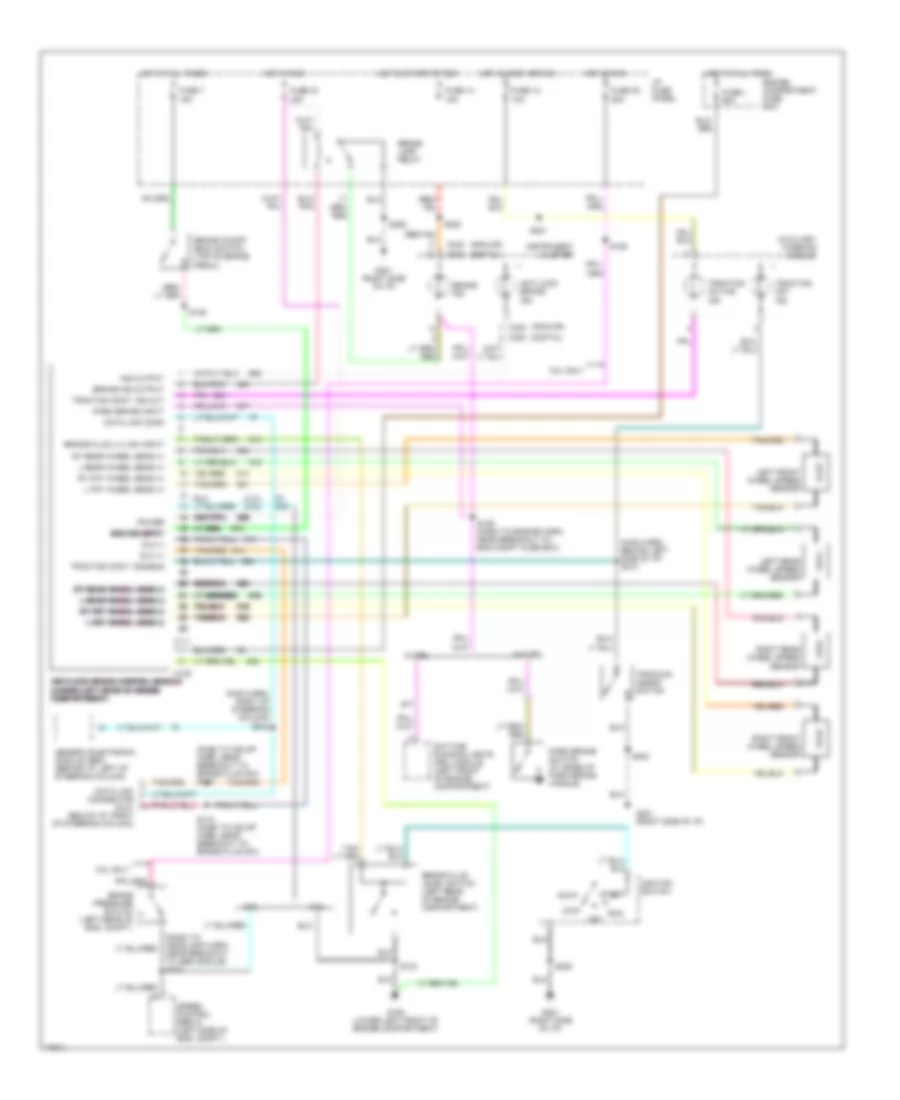
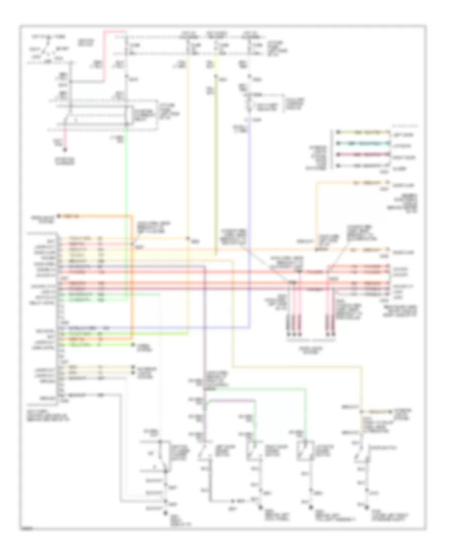
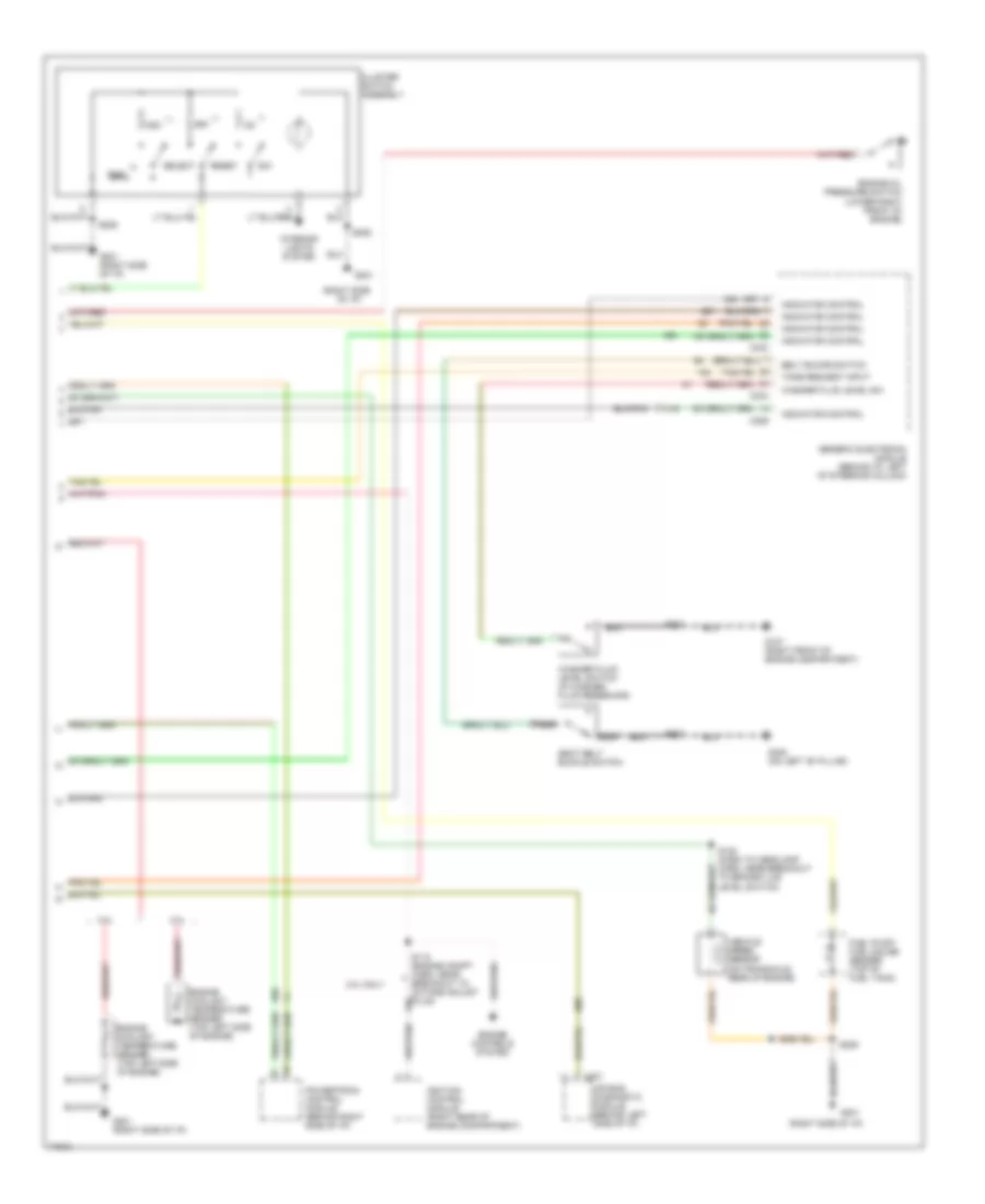
AIR CONDITIONING
Air Conditioning Wiring Diagrams for Ford Windstar GL 1997

List of elements for Air Conditioning Wiring Diagrams for Ford Windstar GL 1997:
- (a/c blower motor harn, in aux blwr motor breakout)
- (a/c blwr mtr harn, in left "b" pillar)
- (a/c blwr mtr harn, near aux mtr blwr res ass'y breakout)
- (behind left
- (behind left cowl panel)
- (behind right side of i/p)
- (behind right side of i/p) g201
- (dash panel to headlamp junction harn, near left elect cooling fan motor breakout)
- (dash panel to headlamp junction harn, near left headlamp breakout) s105
- (dash panel to headlamp junction harn, near left headlamp breakout) s135
- (eng control sens harn, in a/c clutch coil breakout)
- (engine harn, left rear of eng compt (3.8l) (engine harn, right rear of eng compt) (3.0l)
- (front of transaxle on stud) g130
- (main harn, near inst cluster breakout)
- (window regulator jumper harn, near blower motor breakout)
- 3.0l
- 3.8l
- A/c clutch coil
- A/c clutch control
- A/c clutch cycling pressure switch (right rear of engine compartment on accumulator)
- A/c high pressure cutout/ fan switch (lower right rear of engine compartment)
- A/c-heater
- Aux ctrl
- Auxiliary a/c relay (left of rear seat)
- Auxiliary blower motor
- Auxiliary blower motor relay (in i/p fuse panel)
- Auxiliary blower motor resistor assembly (behind panel, left of rear seat)
- B 60a
- Blend door actuator (behind right side of i/p)
- Blower motor
- Blower motor resistor (behind right side of i/p)
- Blower motor switch
- Clutch switch
- Constant control relay module (left front of engine compartment)
- Cooling fan dropping resistor (lower right front of engine compartment)
- Cowl panel)
- Def
- Def/flr
- Edf relay
- Edf relay control
- Engine compartment fuse box
- Fan switch
- Flr
- Front auxiliary blower motor switch
- Front blower motor relay (in i/p fuse panel)
- Fuel pump relay
- Fuse
- Fuse 10a
- Fuse 30a
- G100 (lower left front of engine)
- G200
- G201
- G201 (behind right side of i/p)
- G308 (on left "b" pillar)
- H 40a
- Hedf 1 relay
- Hedf 2 relay
- Hot at all times
- Hot in acc or run
- I/p fuse panel
- Left electric cooling fan motor
- Max
- Nca
- Norm
- Off
- Pan/flr
- Panel
- Pcm power relay
- Power- train control module (behind right side of i/p)
- Rear auxiliary blower motor switch
- Red
- Red/pnk
- Right electric cooling fan motor
- S102
- S112 (3.8l) s113 (3.0l)
- S134 (dash panel to headlamp junction harn, near left elect cooling fan motor breakout)
- S137
- S202 (main harn, behind right side of i/p)
- S205
- S205 (main harn, near inst cluster breakout)
- S212
- S218 (main harn, behind left side of i/p)
- S267 (window regulator jumper harn, in blower motor resistor breakout)
- S302
- S314
- S315
- S316
- S317
- Selector switch
- Solid state
- Temperature control potentiometer
ANTI-LOCK BRAKES
Anti-lock Brake Wiring Diagrams for Ford Windstar GL 1997
List of elements for Anti-lock Brake Wiring Diagrams for Ford Windstar GL 1997:
-
- (3.0l) (3.8l)
- (analog)
- (dash to hdlmp harn, near breakout to brake fluid sw) s143
- (dash to headlamp harn, near breakout to abs module) s142
- (digital)
- (main harn, behind left side of i/p) s210
- (main harn, right of steering column) s242
- 3.0l
- 3.8l
- 3.8l only
- Acc
- Anti-lock brake control module anti-lock brake control module anti-lock brake control module anti-lock brake control module anti-lock brake control module (lower left rear of engine (lower left rear of engine (lower left rear of engine (lower left rear of engine (lower left rear of engine compartment) compartment) compartment) compartment) compartment)
- Anti-lock brake ind
- Auxiliary warning module
- Boo sw input boo sw input boo sw input boo sw input boo sw input
- Brake fluid level switch (left rear of engine compartment)
- Brake fluid lvl sw input
- Brake ind
- Brake ind output
- Brake lamp relay
- Brake on/off (boo) switch (top of brake pedal)
- Brake pressure switch (left rear of eng. compt.)
- C105
- C111
- C202
- C240
- Data link conn
- Data link connector (dlc) (below i/p, right of steering column)
- Daytime running lights (drl) module (left front of engine compartment)
- Dlc (+)
- Dlc (-)
- Engine compartment fuse box
- Fuse 12 10a
- Fuse 14 15a
- Fuse 30 25a
- Fuse 33 15a
- Fuse 7 15a
- Fuse l 60a
- G106 (lower left front of engine compartment)
- G201 (right side of i/p)
- Generic electronic module (gem) (behind i/p, left of steering column)
- Hot at all times
- Hot in accy or run
- Hot in run
- Hot in start or run
- I/p fuse panel
- Ignition switch
- Ind output
- Instrument cluster
- L fnt wheel sens (+)
- L fnt wheel sens (-) l fnt wheel sens (-) l fnt wheel sens (-) l fnt wheel sens (-) l fnt wheel sens (-)
- L rear wheel sens (+)
- L rear wheel sens (-) l rear wheel sens (-) l rear wheel sens (-) l rear wheel sens (-) l rear wheel sens (-)
- Left front wheel speed sensor
- Left rear wheel speed sensor
- Lock
- Off
- Park brake input
- Park brake switch (at base of park brake handle)
- Power
- Right front wheel speed sensor
- Right rear wheel speed sensor
- Rt fnt wheel sens (+)
- Rt fnt wheel sens (-) rt fnt wheel sens (-) rt fnt wheel sens (-) rt fnt wheel sens (-) rt fnt wheel sens (-)
- Rt rear wheel sens (+)
- Rt rear wheel sens (-) rt rear wheel sens (-) rt rear wheel sens (-) rt rear wheel sens (-) rt rear wheel sens (-)
- Run
- S103
- S106
- S128
- S129 (dash to engine harn, near breakout to eng compt fuse box)
- S144 (dash to hdlmp harn, near breakout to brake fluid sw)
- S203
- S205
- S220
- S221
- Speed control servo (left side of eng. compt.)
- Start
- Traction active ind
- Traction assist switch
- Traction cont. disable
- Traction cont. ind out
- Traction off ind
- W/ drl
- W/o drl
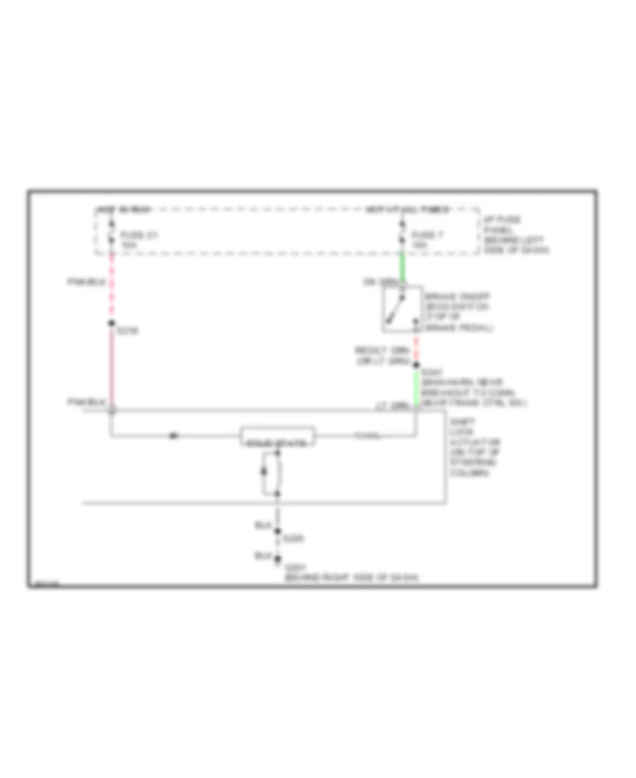
ANTI-THEFT
Anti-theft Wiring Diagram for Ford Windstar GL 1997
List of elements for Anti-theft Wiring Diagram for Ford Windstar GL 1997:
- (main harn, left side of i/p) s246
- (main harn, near breakout to glove box lamp) s251
- (main harn, near breakout to inst cluster)
- (window reg harn, near breakout to blower motor)
- (window reg harn, near breakout to boo switch)
- Acc
- Anti-theft controller module (behind center of i/p)
- Anti-theft indicator
- Auxiliary warning module
- Bat
- C206
- C207
- C233
- C234
- C235
- C245
- C249
- Disarm in
- Door ajar
- Door locks system
- Exterior lights system
- Fuse 10a
- Fuse 15a
- Fuse 5a
- G106 (lower left front of engine compt)
- G201 right side of i/p)
- G202 (behind left cowl panel)
- G404 (behind left taillight assembly)
- Generic electronic module (behind center of i/p)
- Glove box) s245
- Ground
- Headlights system
- Hood open
- Hood switch
- Horn cntrl
- Horns system
- Hot at all times
- Hot in run or accy
- I/p fuse panel (left side of i/p)
- Ignition cylinder tamper switch
- Ignition switch
- Ind cntrl
- Interior lights system
- Interior lights system (door ajar switches)
- Lamps out
- Left door
- Left door disarm switch
- Liftgate
- Liftgate disarm switch
- Lock
- Lock in
- Off
- Power
- Relay cntrl
- Remote/keyless entry module (right side of i/p)
- Right door
- Right door disarm switch
- Run
- S103
- S200
- S207
- S215
- S216
- S221
- S222
- S228
- S244 (main harn, left side of i/p)
- S247
- S248 (window reg harn, near breakout to rke module)
- S249
- S250
- S501
- S601
- S900
- Slider
- Start
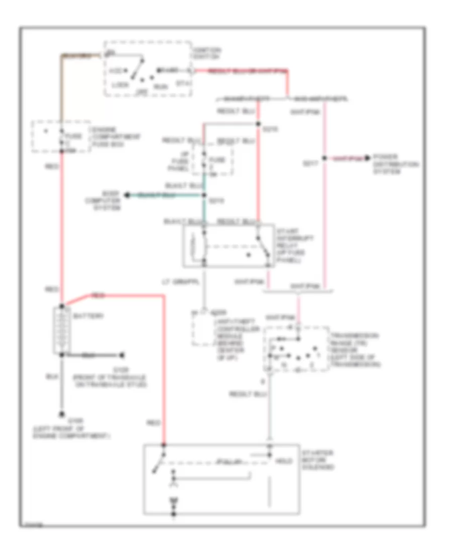
- Starter interrupt relay
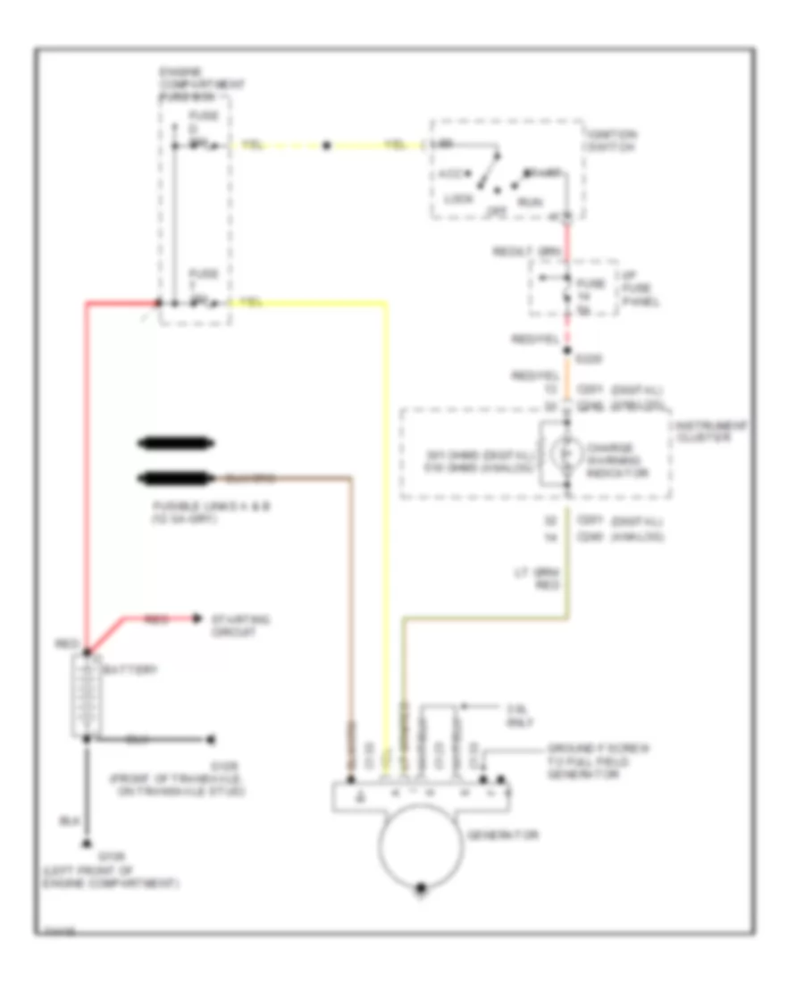
- Starting/ charging
- Switch in
- Unlock
- Unlock in
- Unlock lf
- Unlock lf in
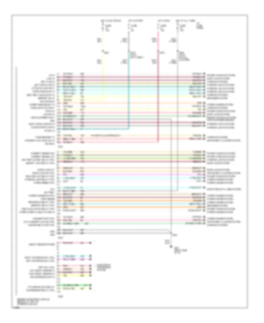
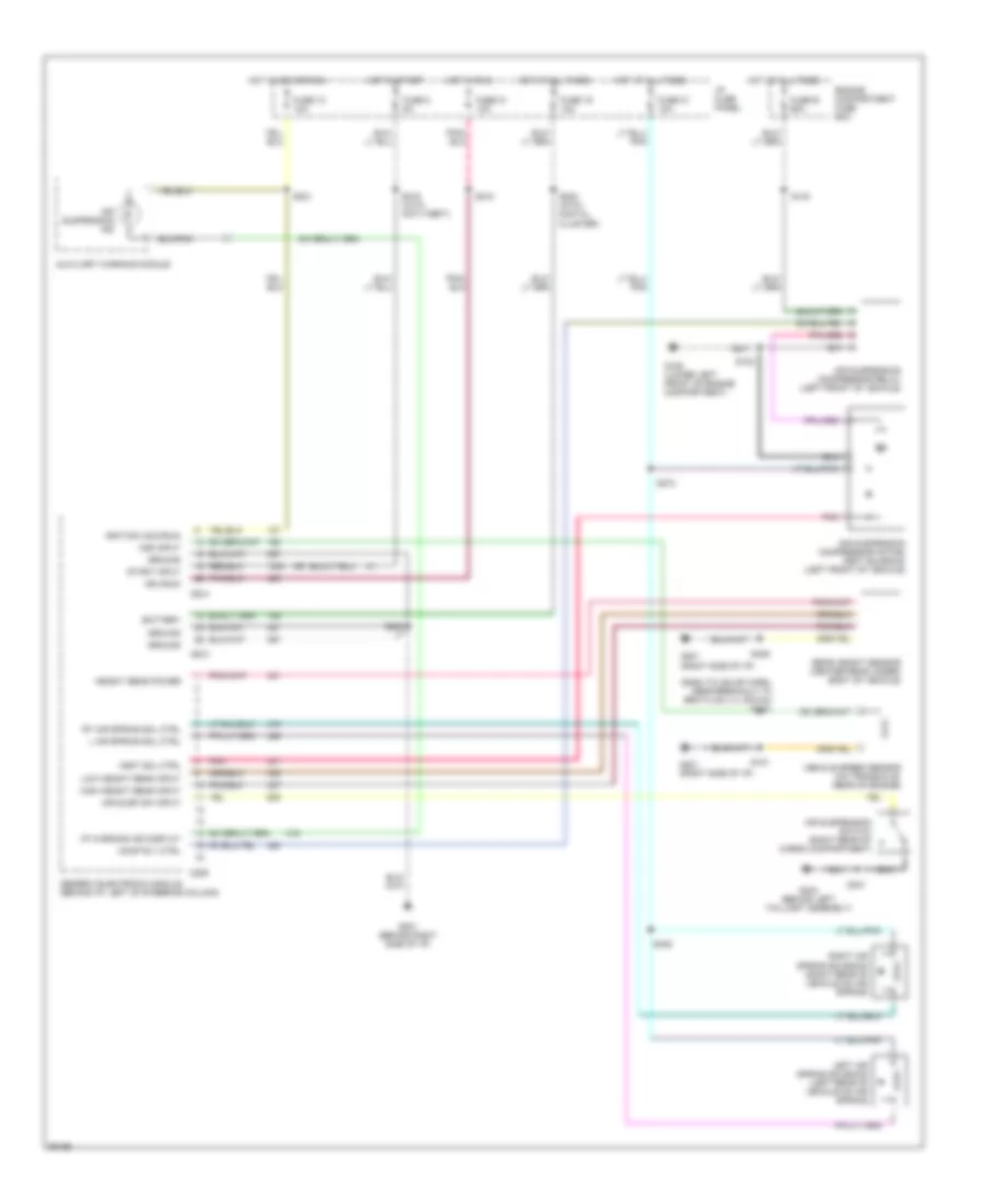
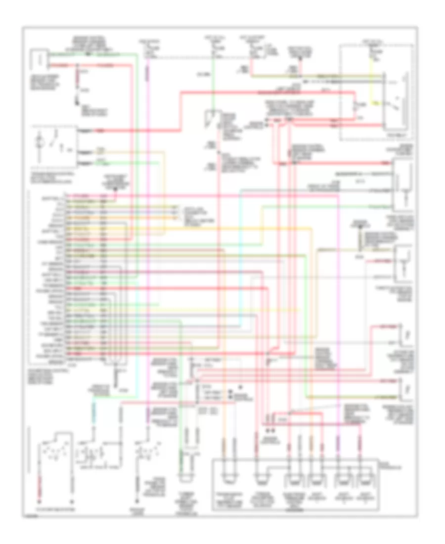
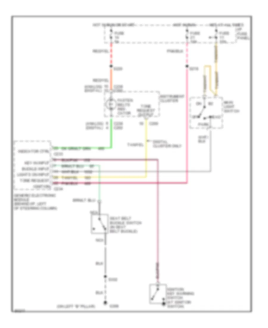
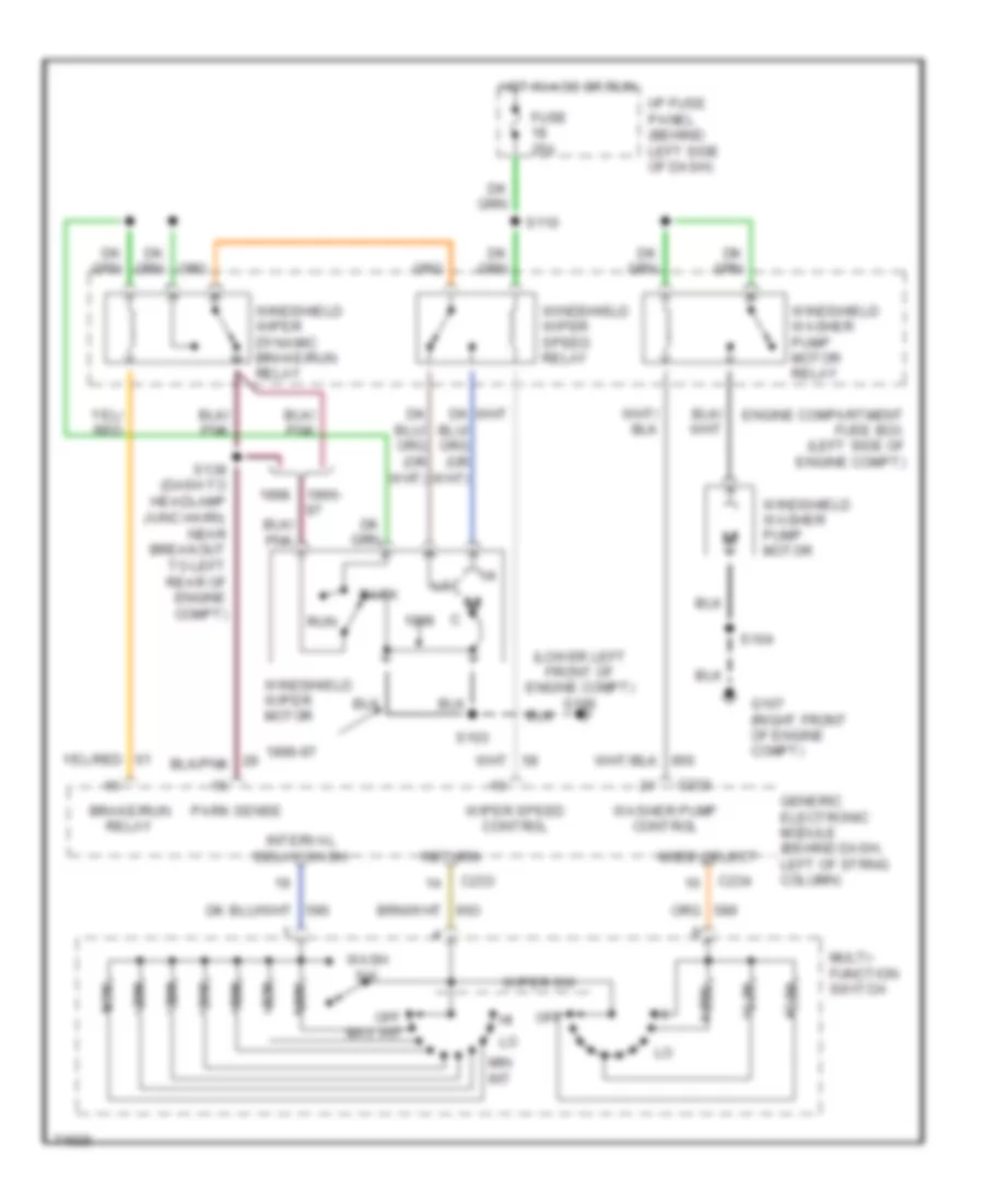
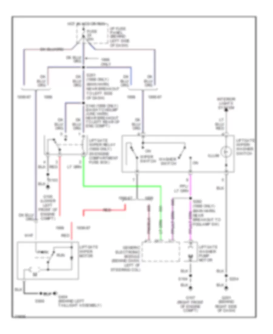
BODY COMPUTER
Body Computer Wiring Diagrams for Ford Windstar GL 1997
List of elements for Body Computer Wiring Diagrams for Ford Windstar GL 1997:
- (w/ digital cluster only)
- Air suspension sw in
- Battery
- Battery saver relay ctrl
- Brake/run relay ctrl
- C233
- C234
- C289
- Compressor relay ctrl
- Computer data lines system
- Current sense high
- Current sense low
- Defogger system
- Defrost relay ctrl
- Defrost sw in
- Delayed acc relay ctrl
- Dlc
- Door ajar ind ctrl
- Door ajar out
- Door handle sw in
- Door locks system
- Down in
- Electronic suspension system
- Engine controls system (vehicle speed sensor)
- Fasten belts ind ctrl
- Fuse 10a
- Fuse 5a
- G201 (right side of i/p)
- Generic electronic module (behind i/p, left of steering column)
- Gnd
- Height sensor power
- High height sensor in
- Hot at all times
- Hot in acc or run
- Hot in run
- Hot in start
- I/p fuse panel
- I/p warning ind display
- Ign (acc/run)
- Ign (run)
- Instrument cluster system
- Interior lamp relay ctrl
- Interior lights system
- Key in ign in
- Left air spring sol ctrl
- Left door ajar in
- Liftgate ajar input
- Lock in
- Low height sensor in
- Low washer fluid ind ctrl
- Memory lock relay ctrl
- One-touch down relay ctrl
- Park sense
- Parklights on input
- Pnk
- Power windows system
- Right air spring sol ctrl
- Right door ajar sw in
- S207
- S216 (with anti-theft)
- S218
- S221
- S223 (with digital cluster)
- Seat belt buckle sw in
- Sliding door ajar in
- Start in
- Tan/red
- Tone request in
- Unlock in
- Up in
- Vehicle speed input
- Vent sol ctrl
- Warning systems
- Washer fluid level sw in
- Washer pump ctrl
- Wiper interval delay/wash in
- Wiper mode select in
- Wiper speed ctrl
- Wiper/washer sw rtn
- Wiper/washer system
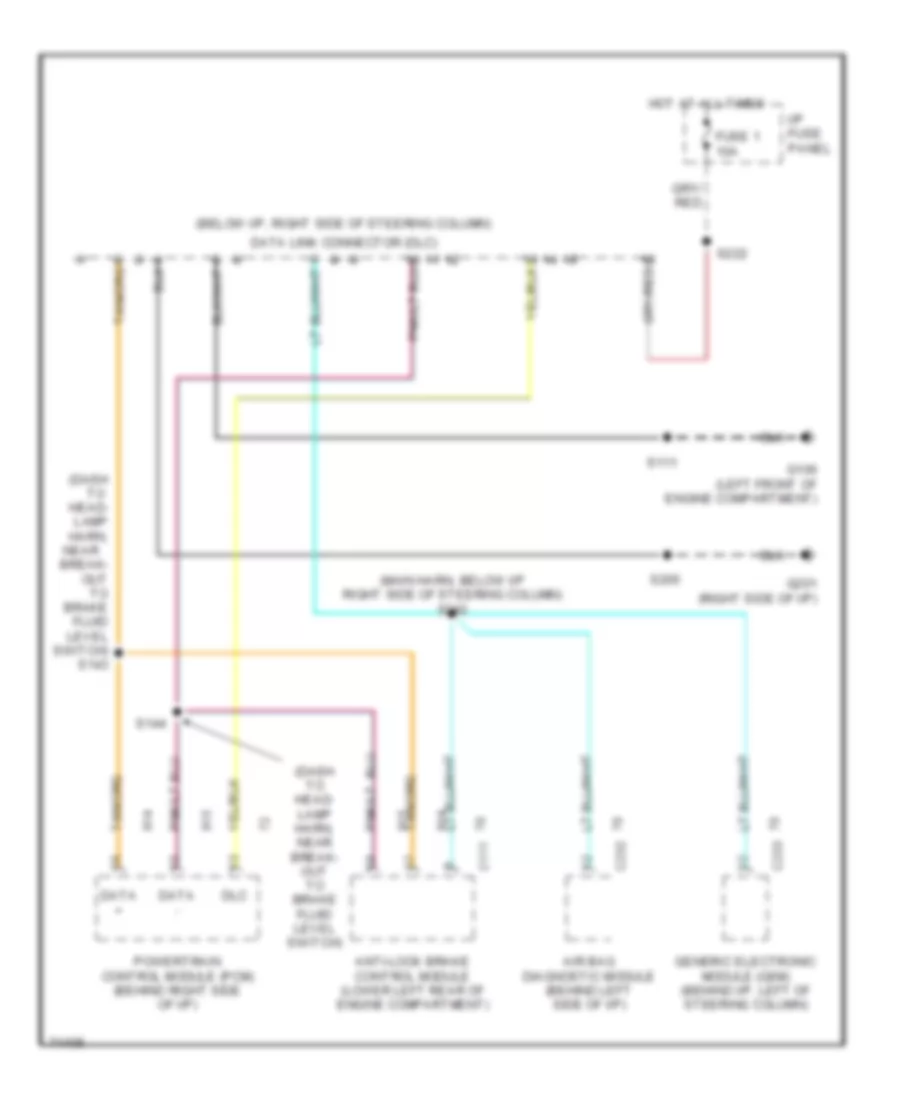
COMPUTER DATA LINES
Computer Data Lines for Ford Windstar GL 1997
List of elements for Computer Data Lines for Ford Windstar GL 1997:
- (below i/p, right side of steering column)
- (dash to head- lamp harn,
- (dash to head- lamp harn, near break- out to brake fluid level switch)
- (main harn, below i/p right side of steering column) s242
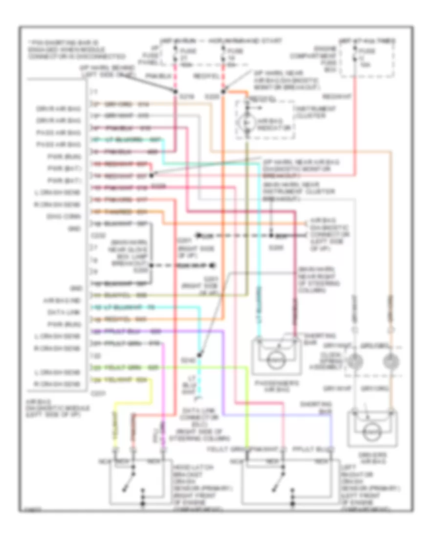
- Air bag diagnostic module (behind left side of i/p)
- Anti-lock brake control module (lower left rear of engine compartment)
- Break- out to brake fluid level switch) s143
- C111
- C232
- C233
- Data +
- Data -
- Data link connector (dlc)
- Dlc
- Fuse 1 10a
- G106 (left front of engine compartment)
- G201 (right side of i/p)
- Generic electronic module (gem) (behind i/p, left of steering column)
- Hot at all times
- I/p fuse panel
- Near
- Powertrain control module (pcm) (behind right side of i/p)
- S111
- S144
- S205
- S222
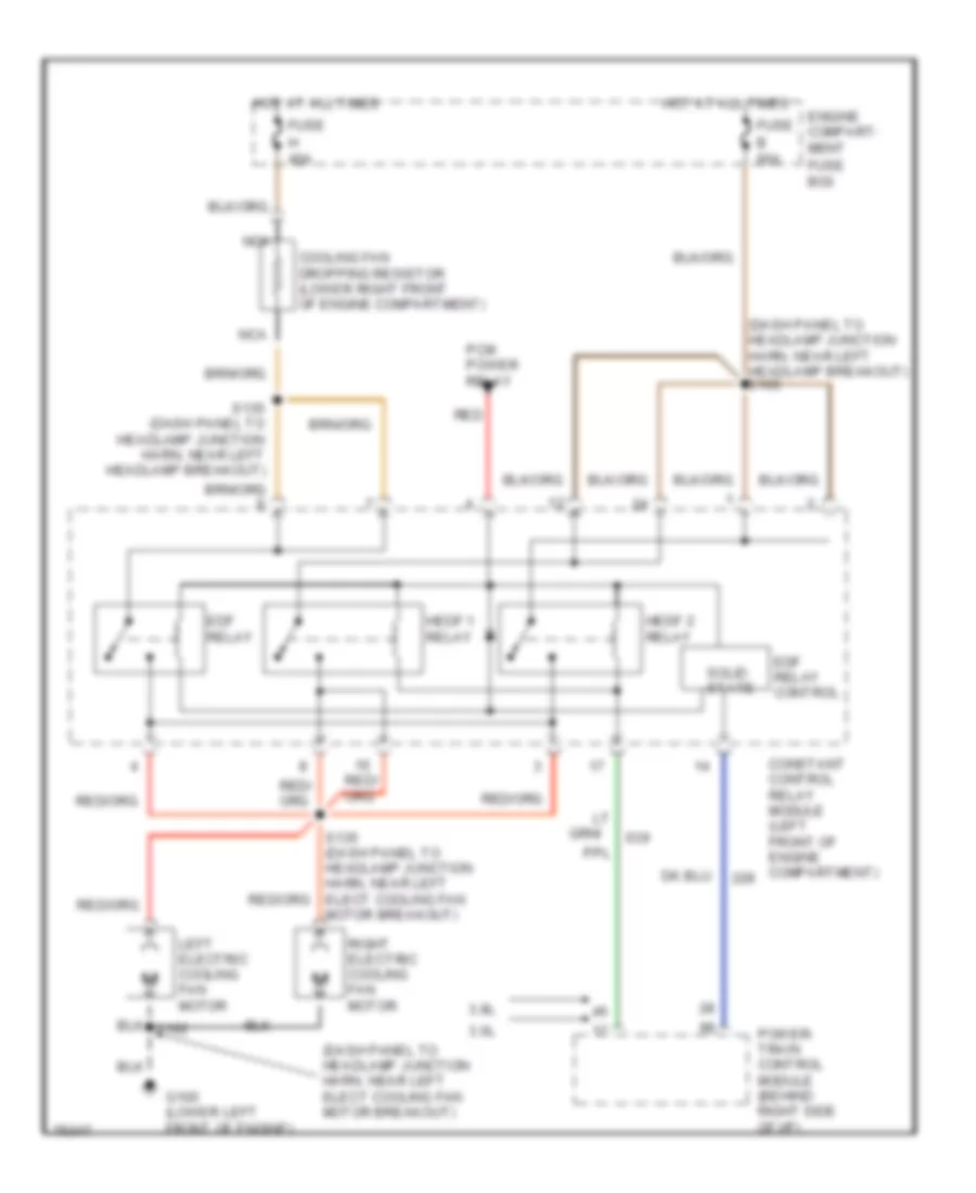
COOLING FAN
Cooling Fan Wiring Diagram for Ford Windstar GL 1997
List of elements for Cooling Fan Wiring Diagram for Ford Windstar GL 1997:
- (dash panel to headlamp junction harn, near left elect cooling fan motor breakout)
- (dash panel to headlamp junction harn, near left headlamp breakout) s105
- 3.0l
- 3.8l
- B 60a
- Constant control relay module (left front of engine compartment)
- Cooling fan dropping resistor (lower right front of engine compartment)
- Edf relay
- Edf relay control
- Engine compart- ment
- Fuse
- Fuse box
- G100 (lower left front of engine)
- H 40a
- Hedf 1 relay
- Hedf 2 relay
- Hot at all times
- Left electric cooling fan motor
- Nca
- Pcm power relay
- Power- train control module (behind right side of i/p)
- Red
- Right electric cooling fan motor
- S102
- S135 (dash panel to headlamp junction harn, near left elect cooling fan motor breakout)
- S135 (dash panel to headlamp junction harn, near left headlamp breakout)
- Solid state
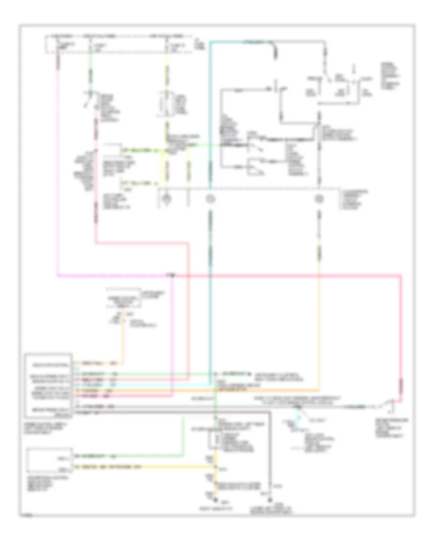
CRUISE CONTROL
Cruise Control Wiring Diagram for Ford Windstar GL 1997
List of elements for Cruise Control Wiring Diagram for Ford Windstar GL 1997:
- (dash to headlamp harness, near breakout to anti-lock brake control module) s142
- (in horn switch/ speed nca
- (lower left front of engine compartment)
- (main harn,near breakout to instrument cluster) s223
- (right side of i/p)
- 15a
- 3.8l only
- Accel
- Anti-lock brake control module (left rear of eng compt)
- Anti-theft controller module (center of i/p)
- Brake on/off (boo) switch (on brake pedal support)
- Brake on/off sw in
- Brake press input
- Brake pressure switch (left rear of engine compartment)
- C111
- C201
- C207
- C254
- Clockspring assembly (top of
- Coast
- Control switch assembly) s276
- Digital cluster only
- Fuse 16
- Fuse 30 25a
- Fuse 7
- G106
- G201
- Ground
- Horn relay (in i/p fuse panel)
- Horn switches
- Hot at all times
- Hot in run
- I/p fuse panel
- Indicator control
- Instrument cluster
- Instrument cluster & body computer systems
- Nca
- Off
- Ohms
- Power (hot in run)
- Powertrain control module (pcm) (behind right side of i/p)
- Remote/keyless entry module (right side of i/p)
- Resume
- S101
- S103
- S106
- S128 (dash to headlamp harn, near breakout to engine compt fuse box)
- S209 (analog cluster) s206 (digital cluster)
- S237 (main harness, behind leftside of i/p)
- S275 (in horn switch/ speed control switch assembly)
- S277 (in horn switch/ speed control switch assembly)
- Set/
- Speed cont sw gnd
- Speed cont sw in
- Speed control indicator input
- Speed control servo (left side of engine compartment)
- Speed control switch assembly (in steering wheel)
- Steering column)
- Vehicle speed input
- Vehicle speed sensor (vss) (on transaxle, rear of engine)
- Vss (+)
- Vss (-)
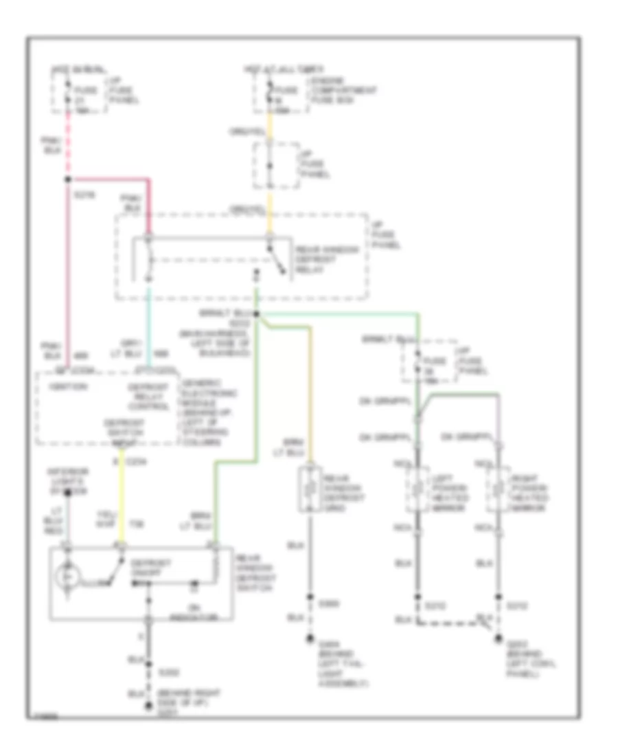
DEFOGGERS
Defogger Wiring Diagram for Ford Windstar GL 1997
List of elements for Defogger Wiring Diagram for Ford Windstar GL 1997:
- (behind right side of i/p) g201
- C233
- C234
- Defrost on/off sw
- Defrost relay control
- Defrost switch input
- Engine compartment fuse box
- Fuse 10a
- Fuse 15a
- Fuse m 60a
- G202 (behind left cowl panel)
- G404 (behind left tail- light assembly)
- Generic electronic module (behind i/p, left of steering column)
- Hot at all times
- Hot in run
- I/p fuse panel
- Ignition
- Illum
- Interior lights system
- Left power/ heated mirror
- Nca
- On indicator
- Rear window defrost grid
- Rear window defrost relay
- Rear window defrost switch
- Right power/ heated mirror
- S202
- S212
- S218
- S232 (main harness, left side of bulkhead)
- S900
ELECTRONIC SUSPENSION
Electronic Suspension Wiring Diagram for Ford Windstar GL 1997
List of elements for Electronic Suspension Wiring Diagram for Ford Windstar GL 1997:
- (dash to hdlmp harn, near breakout to brk fluid lvl swich) s122
- Air susp sw input
- Air suspension compressor motor/ vent solenoid (left front of vehicle)
- Air suspension compressor relay (left front of vehicle)
- Air suspension ind
- Air suspension switch (right rear of cargo compartment)
- Auxiliary warning module
- Battery
- C233
- C234
- C289
- Comp rly ctrl
- Engine compartment fuse box
- Fuse 12 10a
- Fuse 19 10a
- Fuse 2 5a
- Fuse 21 10a
- Fuse 31 10a
- Fuse e 60a
- G106 (lower left front of engine compartment)
- G201 (behind right side of i/p)
- G201 (right side of i/p)
- G404 (behind left taillight assembly)
- Generic electronic module (behind i/p, left of steering column)
- Ground
- Height sens power
- High height sens input
- Hot at all times
- Hot in acc or run
- Hot in run
- Hot in start
- I/p fuse panel
- I/p warning ind display
- Ign (run)
- Ignition (acc/run)
- L air spring sol ctrl
- Left air spring solenoid (left rear of vehicle on air spring)
- Low height sens input
- Pnk
- Rear height sensor (center rear under- body of vehicle)
- Right air spring solenoid (right rear of vehicle on air spring)
- Rt air spring sol ctrl
- S101
- S102
- S140
- S207
- S216 (with anti-theft)
- S218
- S221
- S223 (with digital cluster)
- S273
- S301
- S406
- S408
- Start input
- Vehicle speed sensor (on transaxle, rear of engine)
- Vent sol ctrl
- Vss input
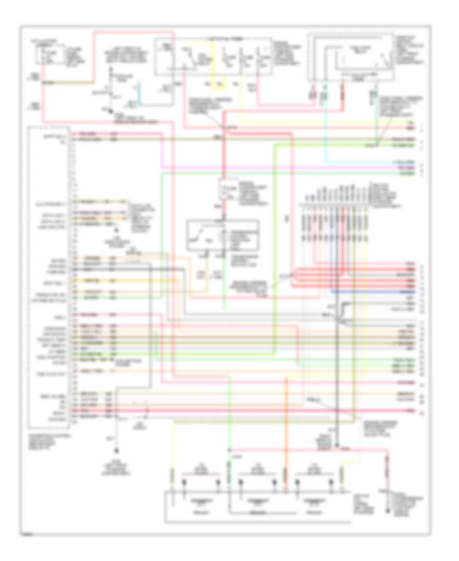
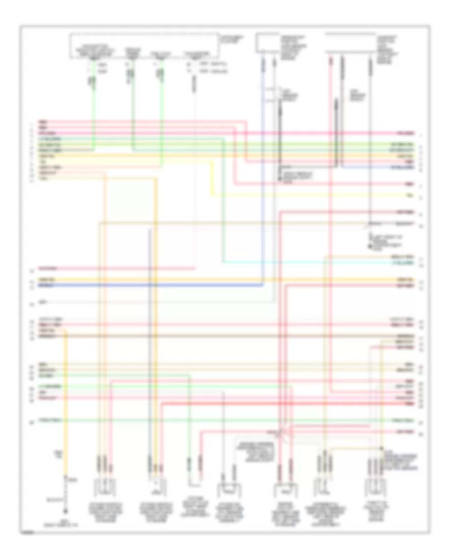
ENGINE PERFORMANCE
3.0L
3.0L, Engine Performance Wiring Diagrams (1 of 4) for Ford Windstar GL 1997
List of elements for 3.0L, Engine Performance Wiring Diagrams (1 of 4) for Ford Windstar GL 1997:
- (dash panel harness, near breakout to engine compt fuse box)
- (dash panel harness, near breakout to g106 ground at left front of engine compt)
- (engine harness, near breakout to octane adjust plug)
- (left front of engine compartment) constant control relay module (ccrm)
- (right rear of engine compt)
- A/c sig
- Air conditioning system
- Case gnd
- Ckp (+)
- Ckp (-)
- Coil c1
- Coil c2
- Coil c3
- Constant control relay module (ccrm) (left front of engine compartment)
- Cooling fans
- Cooling fans system
- Data link (+)
- Data link (-)
- Data link connector (dlc) (below i/p, right of steering column)
- Dlc (pwr sply)
- Ect sens in
- Egr vac reg
- Engine compartment fuse box (left side of engine comartment)
- Engine compartment fuse box (left side of engine compartment)
- Fuel flow out
- Fuel pump mon
- Fuel pump relay
- Fuse 25a
- Fuse n 20a
- Fuse r 15a
- Fuse s 30a
- Fuse v 10a
- G105
- G106 (left front of engine compartment)
- High fan ctrl
- Ho2s sig #3
- Hot at all times
- Hot in start or run
- I/p fuse panel (behind left side of i/p)
- Iat sens
- Icm shield
- Idm
- Ign gnd
- Ign pwr
- Ignition coil (upper left rear of engine)
- Ignition control module (icm) (right rear of engine compartment)
- Maf sig rtn
- Mil
- Nca
- Octane adj plug
- Off
- Pcm power relay
- Pip
- Pnk
- Powertrain control module (pcm) (behind right side of i/p)
- Primary
- Pwr gnd
- Radio interference capacitor (top right side of engine)
- Red
- S108
- S109
- S111
- S114
- S116
- S117
- S118
- S119
- S136
- Secondary
- Shd gnd
- Shift sol 1
- Shift sol 2
- Spout
- To spark plugs
- Trans ctrl sw
- Trans fl temp
- Transmission control indicator lamp (tcil)
- Transmission control switch (tcs)
- Vss (-)
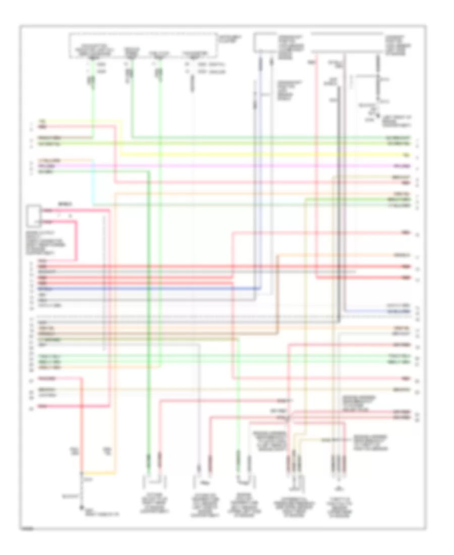
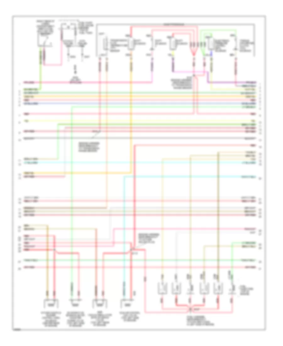
3.0L, Engine Performance Wiring Diagrams (2 of 4) for Ford Windstar GL 1997
List of elements for 3.0L, Engine Performance Wiring Diagrams (2 of 4) for Ford Windstar GL 1997:
- (analog)
- (digital)
- (engine harness, near breakout to 42-pin conn in left rear of engine compt)
- (engine harness, near breakout to octane adjust plug)
- (engine harness, near breakout to throttle position sensor)
- (left front of engine compartment)
- C200
- C202
- C239
- C240
- Camshaft position (cmp) sensor (left side of engine)
- Cmp shield
- Crankshaft position (ckp) sensor (lower right side of engine)
- Crankshaft position (ckp) sensor shield
- Differential pressure feedback egr (dpfe) sensor (right rear of engine)
- Engine coolant temperature (ect) sensor (upper left side of engine)
- Fuel flow input
- G106
- G201 (right side of i/p)
- Instrument cluster
- Intake air temperature (iat) sensor (left side of engine compartment)
- Malfunction indicator lamp (mil) (service engine soon)
- Nca
- Octane adjust plug (right rear of engine compartment)
- Pnk
- Red
- S101
- S113
- S124
- S125
- S138
- Shield
- Spark output (spout) check connector (right rear corner of engine compartment)
- Tachometer input
- Throttle position (tp) sensor (upper rear of engine)
- Vehicle speed input
3.0L, Engine Performance Wiring Diagrams (3 of 4) for Ford Windstar GL 1997
List of elements for 3.0L, Engine Performance Wiring Diagrams (3 of 4) for Ford Windstar GL 1997:
- (engine harness, near breakout to octane adjust plug)
- (engine harness, near breakout to transmission range sensor)
- (fuel harness, near breakout to 8-pin gray conn in left side of engine)
- (left side of engine compartment) ax4s transaxle
- (on left "b" pillar)
- (right rear of cargo compartment) inertia fuel shut-off (ifs) switch
- Egr vacuum regulator (evr) solenoid valve (left rear of engine)
- Electronic pressure control (epc) solenoid
- Evaporative emission (evap) canister purge valve (center rear of engine compartment)
- Fuel injectors (top of engine)
- Fuel pump/ fuel gauge sender (top of fuel tank)
- G308
- Idle air control (iac) valve (upper left rear of engine)
- Pnk
- Red
- S115
- S120
- S127
- S302
- S407
- Shift solenoid
- Tan
- Torque converter clutch (tcc) solenoid
- Transmission fluid temperature (tft) sensor
- With trailer tow
- Without trailer tow
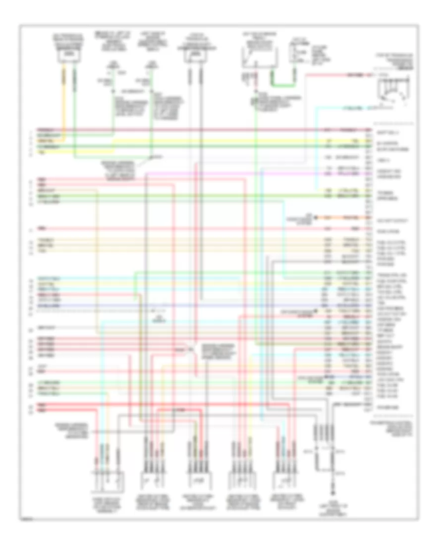
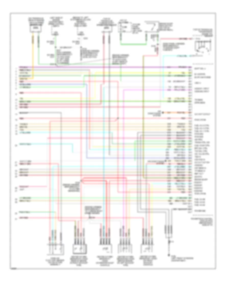
3.0L, Engine Performance Wiring Diagrams (4 of 4) for Ford Windstar GL 1997
List of elements for 3.0L, Engine Performance Wiring Diagrams (4 of 4) for Ford Windstar GL 1997:
- (behind i/p, left of steering column)
- (engine harness, near breakout to 42-pin conn in left rear of engine compt)
- (engine harness, near breakout to oxygen sensor #22)
- (engine harness, near breakout to turbine shaft speed sensor)
- (left side of engine compartment) speed control servo
- (on top of brake pedal)
- (on transaxle, rear of engine)
- (top of transaxle)
- A/c cut out sw
- A/c wot cutout
- Air conditioning system
- B+ (kapwr)
- Brake on/off
- Brake on/off (boo) switch
- C234
- Cam pos sens
- Cooling fans system
- Dpfe sens
- Epc sol ctrl
- Evap can purge
- Fuel inj #2
- Fuel inj #4
- Fuel inj #6
- Fuel inj 1 ctrl
- Fuel inj 3 ctrl
- Fuel inj 5 ctrl
- Fuel pump ctrl
- Fuse 15a
- G106 (left front of engine compartment)
- Generic electronic module (gem)
- Heated oxygen sensor #11 (ho2s) (on front exhaust)
- Heated oxygen sensor #12 (ho2s) (on rear exhaust)
- Heated oxygen sensor #21 (ho2s) (rear of engine on exhaust pipe)
- Heated oxygen sensor #22 (ho2s) (rear of engine, on exhaust pipe)
- Ho2s #11
- Ho2s #11 sig
- Ho2s #12
- Ho2s #21
- Ho2s #21 sig
- Ho2s #22
- Ho2s #22 sig
- Hot at all times
- I/p fuse panel (behind left side of i/p)
- Iac valve ctrl
- Icm shield
- Low cool fan
- Maf sens
- Mass air flow (maf) sensor (on air intake assembly)
- Nca
- Near breakout to engine compt fuse box)
- Power gnd
- Powertrain control module (pcm) (behind right side of i/p)
- Pwr (vpwr)
- Pwr gnd
- Red
- Red/
- Ref volt
- S112
- S113
- S114
- S121
- S122 (engine harness, near breakout to brake fluid level switch)
- S123
- S126
- S237 (main harness, near breakout to 3-pin conn at left side of i/p, taped to harness)
- Shift sol 3
- Sig rtn
- Tan
- Tcc sol ctrl
- Tp sens
- Tr sens
- Trans ctrl ind
- Transmission range (tr) sensor
- Tss
- Turbine shaft speed (tss) sensor
- Vehicle speed sensor (vss)
- Vss (+)
- Vss input
3.8L
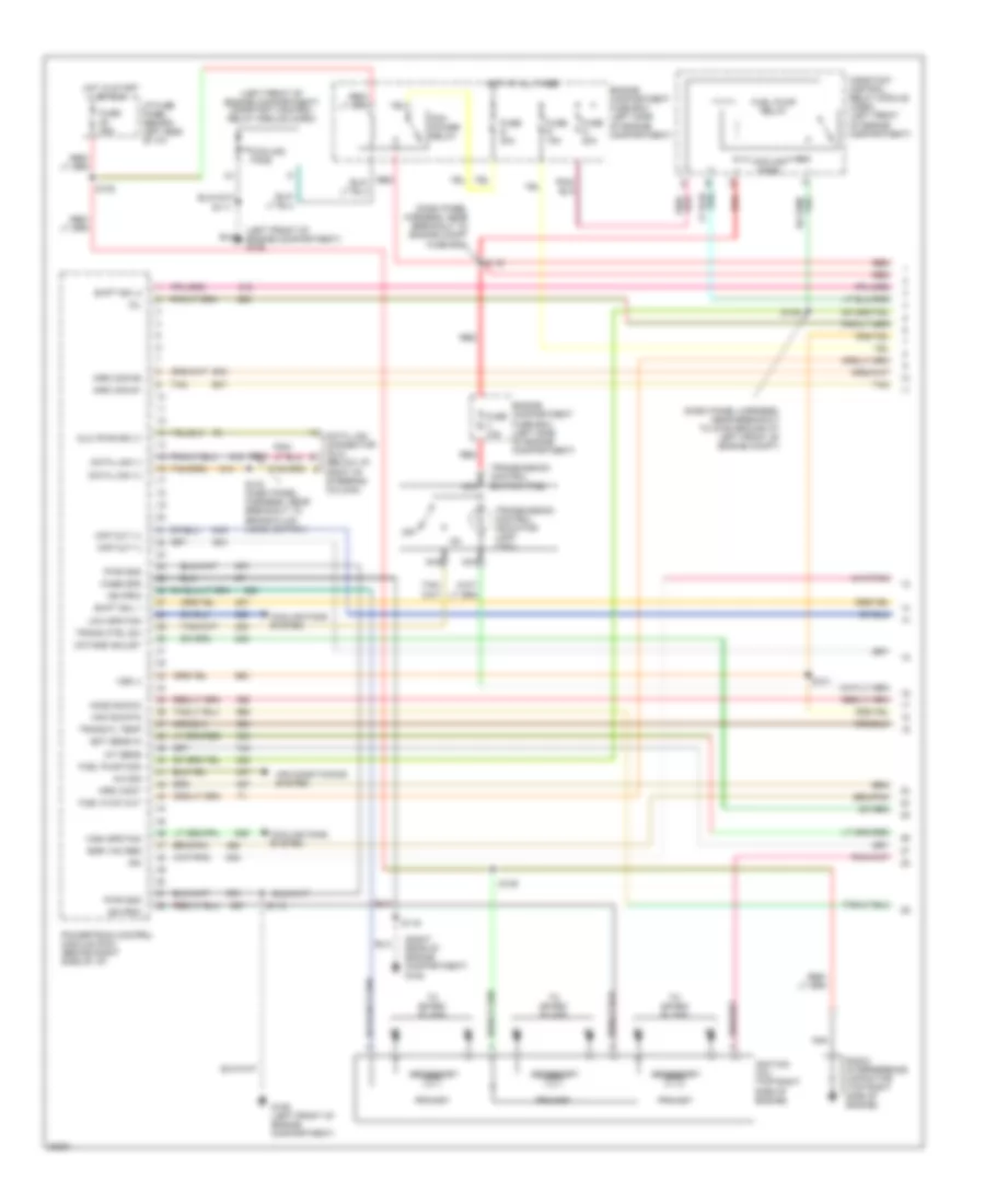
3.8L, Engine Performance Wiring Diagrams (1 of 4) for Ford Windstar GL 1997
List of elements for 3.8L, Engine Performance Wiring Diagrams (1 of 4) for Ford Windstar GL 1997:
- (dash panel harness, near breakout to engine compt fuse box)
- (dash panel harness, near breakout to g106 ground at left front of engine compt)
- (left front of engine compartment) constant control relay module (ccrm)
- (left front of engine compartment) g106
- (right rear of engine compartment) g105
- A/c sig
- Air conditioning system
- Case gnd
- Ckp out (+)
- Ckp out (-)
- Constant control relay module (ccrm) (left front of engine compartment)
- Cooling fans
- Cooling fans system
- Data link (+)
- Data link (-)
- Data link connector (dlc) (below i/p, right of steering column)
- Dlc (pwr sply)
- Ect sens in
- Egr vac reg
- Engine compartment fuse box (left side of engine compartment)
- Fuel flow out
- Fuel pump mon
- Fuel pump relay
- Fuse 25a
- Fuse n 20a
- Fuse r 15a
- Fuse s 30a
- Fuse v 10a
- G106 (left front of engine compartment)
- High spd fan
- Ho2s sig #12
- Hot at all times
- Hot in start or run
- I/p fuse panel (behind left side of i/p)
- Iat sens
- Idm
- Ign prim
- Ignition coil (top right side of engine)
- Imrc cont
- Imrc mon #1
- Imrc mon #2
- Low spd fan
- Maf sig rtn
- Mil
- Nca
- Octane adjust
- Off
- Pcm power relay
- Powertrain control module (pcm) (behind right side of i/p)
- Primary
- Pwr gnd
- Radio interference capacitor (top right side of engine)
- Red
- S101
- S108
- S109
- S111
- S112
- S116
- S119
- S136
- S143 (dash panel harness, near breakout to brake fluid level switch)
- S144
- Secondary
- Shift sol 1
- Shift sol 2
- Tan
- To spark plugs
- Trans ctrl sw
- Trans fl temp
- Transmission control indicator lamp (tcil)
- Transmission control switch (tcs)
- Vss (-)
3.8L, Engine Performance Wiring Diagrams (2 of 4) for Ford Windstar GL 1997
List of elements for 3.8L, Engine Performance Wiring Diagrams (2 of 4) for Ford Windstar GL 1997:
- (analog)
- (digital)
- (engine harness, near breakout to 42-pin conn, in left rear of engine compt)
- (left front of engine compartment) g106
- (right rear of engine compt.) g105
- (right side of i/p)
- C200
- C202
- C239
- C240
- Camshaft position (cmp) sensor (top right side of engine)
- Ckp sensor shield
- Cmp sensor shield
- Crankshaft position (ckp) sensor (top right front of engine)
- Differential pressure feedback egr (dpfe) sensor (left rear of engine compartment)
- Engine coolant temperature (ect) sensor (top left side of engine)
- Fuel flow input
- G201
- Instrument cluster
- Intake air temperature (iat) sensor (on air intake assembly)
- Intake manifold runner control (imrc) monitor #1 (right side of engine)
- Intake manifold runner control (imrc) monitor #2 (right side of engine)
- Malfunction indicator lamp (mil) (service engine soon)
- Nca
- Octane adjust plug (right rear of engine compartment)
- Red
- S112
- S119
- S124
- S138 (engine harness, near breakout to throttle position sensor)
- S206
- Tachometer input
- Tan
- Throttle position (tp) sensor (top of engine)
- Vehicle speed input
3.8L, Engine Performance Wiring Diagrams (3 of 4) for Ford Windstar GL 1997
List of elements for 3.8L, Engine Performance Wiring Diagrams (3 of 4) for Ford Windstar GL 1997:
- (engine harness, near breakout to octane adjust plug)
- (engine harness, near breakout to transmission range sensor)
- (fuel harness, near breakout to 8-pin gray conn, in left side of engine)
- (right rear of cargo compartment) inertia fuel shut-off (ifs) switch
- Ax4s transaxle
- Egr vacuum regulator (evr) solenoid valve (top left rear of engine)
- Electronic pressure control (epc) solenoid
- Evaporative emission (evap) canister purge valve (top left side of engine)
- Fuel injectors (top of engine)
- Fuel pump/ fuel gauge sender (top of fuel tank)
- G308 (on left "b" pillar)
- Idle air control (iac) valve (top left side of engine)
- Intake manifold runner control (imrc) solenoid (center rear of engine)
- Pnk
- Red
- S115
- S120 (engine harness, near breakout to transmission range sensor)
- S127
- S141
- S302
- S407
- Shift solenoid
- Tan
- Torque converter clutch (tcc) solenoid
- Transmission fluid temperature (tft) sensor
- With trailer tow
- Without trailer tow
3.8L, Engine Performance Wiring Diagrams (4 of 4) for Ford Windstar GL 1997
List of elements for 3.8L, Engine Performance Wiring Diagrams (4 of 4) for Ford Windstar GL 1997:
- (behind i/p, left of steering column) generic electronic module (gem)
- (dash panel harness, near breakout to engine compt fuse box)
- (engine harness, near breakout to 42-pin conn in left rear of engine compt)
- (engine harness, near breakout to turbine shaft speed sensor)
- (left side of engine compartment) speed control servo
- (on transaxle, rear of engine)
- (top of transaxle) transmission range (tr) sensor
- (top of transaxle) turbine shaft speed (tss) sensor
- A/c cut out sw
- A/c wot cutout
- Air conditioning system
- B+ (kapwr)
- Brake on/off
- Brake on/off (boo) switch (on top of brake pedal)
- C234
- Cam pos in
- Dpfe sens
- Epc sol ctrl
- Evap can purge
- Fuel inj #2
- Fuel inj #4
- Fuel inj #6
- Fuel inj 1 ctrl
- Fuel inj 3 ctrl
- Fuel inj 5 ctrl
- Fuel pump ctrl
- Fuse 15a
- G106 (left front of engine compartment)
- Heated oxygen sensor #11 (ho2s) (on rear exhaust manifold)
- Heated oxygen sensor #12 (ho2s) (rear of engine, on right exhaust pipe)
- Heated oxygen sensor #21 (ho2s) (on front exhaust manifold)
- Heated oxygen sensor #22 (ho2s) (behind engine, on left exhaust pipe)
- Ho2s #11
- Ho2s #11 input
- Ho2s #12
- Ho2s #21
- Ho2s #22
- Ho2s #22 input
- Hot at all times
- I/p fuse panel (behind left side of i/p)
- Iac valve ctrl
- Ign prim
- Maf sens in
- Mass air flow (maf) sensor (on air intake assembly)
- Nca
- Power gnd
- Powertrain control module (pcm) (behind right side of i/p)
- Pwr (vpwr)
- Pwr gnd
- Red
- Ref volt
- S121
- S122 (engine harness, near breakout to brake fluid level switch)
- S123
- S126 (engine harness, near breakout to oxygen sensor #22)
- S128
- Shift sol 3
- Sig rtn
- Tan
- Tcc sol ctrl
- To 3-pin conn at left side of i/p, taped to harness)
- Tp sens in
- Tr sens
- Trans ctrl ind
- Tss in
- Vehicle speed sensor (vss)
- Vss (+)
- Vss input
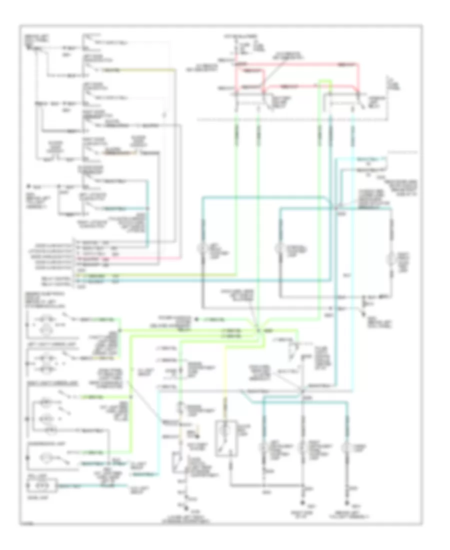
EXTERIOR LIGHTS
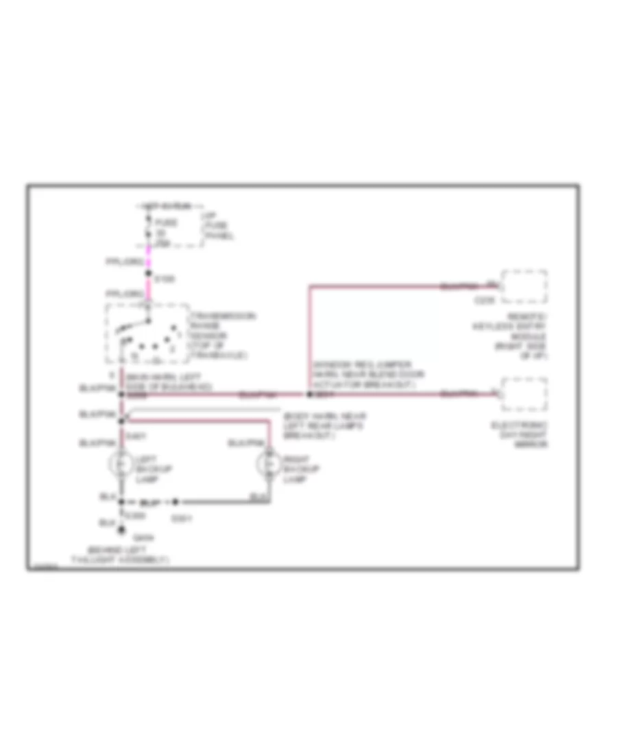
Back-up Lamps Wiring Diagram for Ford Windstar GL 1997
List of elements for Back-up Lamps Wiring Diagram for Ford Windstar GL 1997:
- (behind left
- (body harn, near left rear lamps breakout)
- (window reg jumper harn, near blend door actuator breakout) s231
- C235
- Electronic day/night mirror
- Fuse 25a
- G404
- Hot in run
- I/p fuse panel
- Left backup lamp
- Remote/ keyless entry module (right side of i/p)
- Right backup lamp
- S106
- S269
- S300
- S301
- S401
- Taillight assembly)
- Transmission range sensor (top of transaxle)
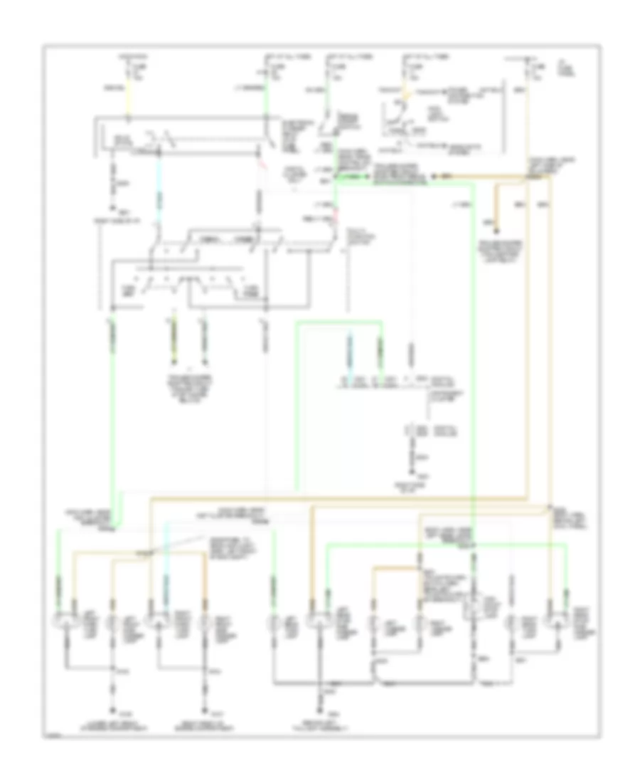
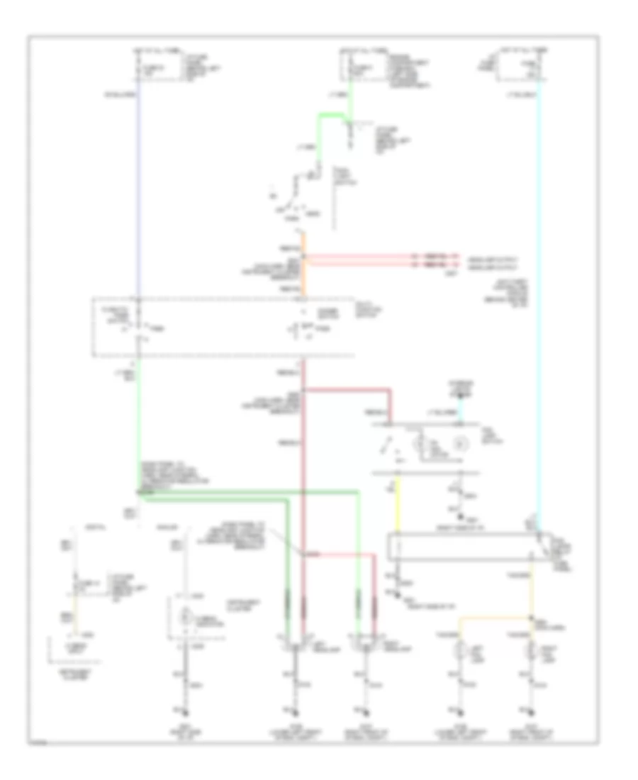
Exterior Lamps Wiring Diagram for Ford Windstar GL 1997
List of elements for Exterior Lamps Wiring Diagram for Ford Windstar GL 1997:
- (behind left
- (body harn, near left rear lamps breakout)
- (dashpanel to headlamp junct harn, left front of eng compt)
- (digital) (analog)
- (lower left front
- (main harn, near inst cluster breakout) s265
- (main harn, near inst cluster breakout) s266
- (main harn, near left side of bulkhead) s243
- (right front of
- (right side
- (right side of i/p)
- Brake on/off switch
- C201
- C202
- C239
- C240
- Digital cluster only
- Electronic flasher relay (in i/p fuse panel)
- Engine compartment)
- Fuse 10a
- Fuse 15a
- G106
- G107
- G201
- G404
- Hazard
- Head
- Headlights system
- High mount stop lamp
- Hot at all times
- Hot in run
- I/p fuse panel
- Instrument cluster
- Left front park/ turn lamp
- Left front side marker lamp
- Left license lamp
- Left rear stop/ side marker lamp
- Left rear turn lamp
- Main light switch
- Multi- function switch
- Nca
- Normal
- Of engine compartment)
- Of i/p)
- Off
- Park
- Power distribution system
- Right front park/ turn lamp
- Right front side marker lamp
- Right license lamp
- Right rear stop/ side marker lamp
- Right rear turn lamp
- S102
- S104
- S130
- S241
- S300
- S301
- S308
- S309 (body harn, behind left cowl panel)
- S900
- Solid state
- Taillight assembly)
- Trailer/camper adapter circuit (electronic brake switch connector)
- Trailer/camper adapter circuit (trailer park lamp relay)
- Trailer/camper adapter circuit (trailer turn/ stop hazard relays)
- Turn left
- Turn right
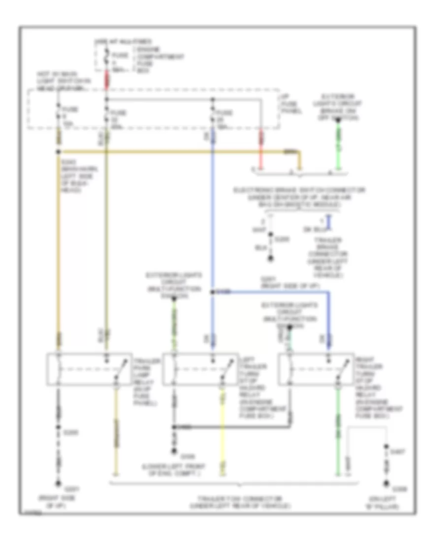
Trailer/Camper Adapter Wiring Diagram for Ford Windstar GL 1997
List of elements for Trailer/Camper Adapter Wiring Diagram for Ford Windstar GL 1997:
- "b" pillar)
- (lower left front of eng. compt.)
- (on left
- (right side
- Electronic brake switch connector (under center of i/p, near air bag diagnostic module)
- Engine compartment fuse box
- Exterior lights circuit (brake on/ off switch)
- Exterior lights circuit (multi-function switch)
- Fuse 10a
- Fuse 15a
- Fuse a 50a
- G106
- G201
- G201 (right side of i/p)
- G308
- Hot at all times
- Hot w/ main light switch in head or park
- I/p fuse panel
- Left trailer turn/ stop hazard relay (in engine compartment fuse box)
- Of i/p)
- Red
- Right trailer turn/ stop hazard relay (in engine compartment fuse box)
- S103
- S139
- S205
- S243 (main harn, left side of bulk- head)
- S407
- Trailer brake connector (under left rear of vehicle)
- Trailer park lamp relay (in i/p fuse panel)
- Trailer tow connector (under left rear of vehicle)
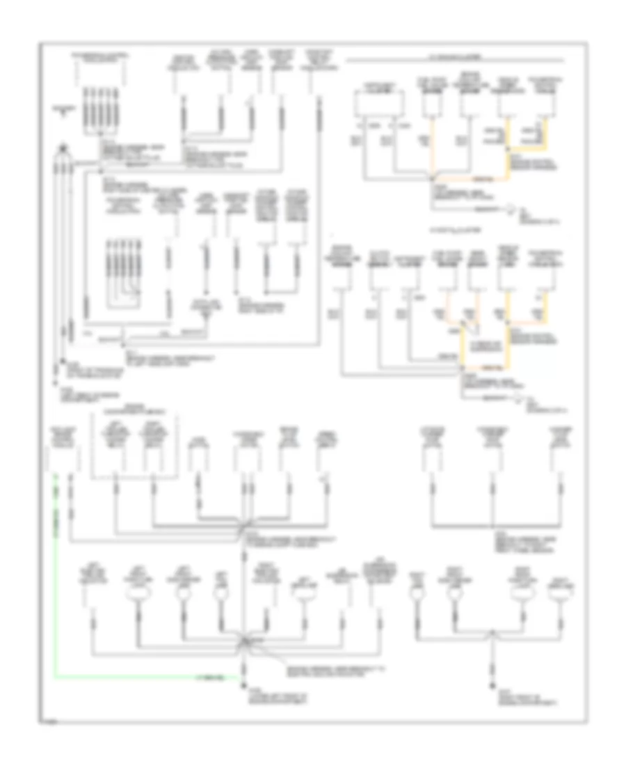
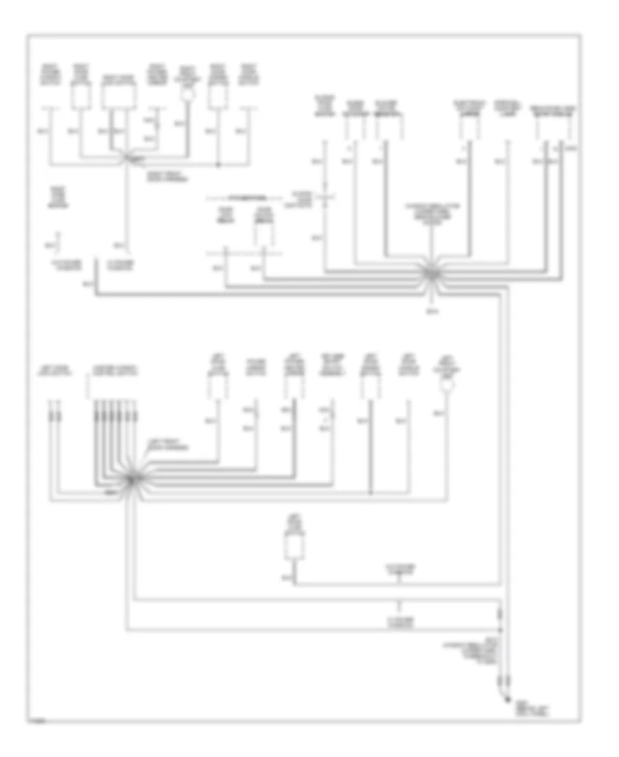
GROUND DISTRIBUTION
Ground Distribution Wiring Diagram (1 of 4) for Ford Windstar GL 1997
List of elements for Ground Distribution Wiring Diagram (1 of 4) for Ford Windstar GL 1997:
- (engine harness, near breakout to electric cooling fan motor)
- 3.0l
- 3.8l
- A/c high pressure cutout/fan switch
- Air suspension compressor motor/vent solenoid
- Air suspension relay
- Anti-lock brake control module
- Battery
- Brake fluid level switch
- C105
- C111
- C200
- C239
- C240
- Camshaft position (cmp) sensor
- Clutch switch assembly
- Constant control relay module (ccrm)
- Data link connector (dlc)
- Engine compartmentfuse box
- Engine coolant temperature sender
- Fuel pump/ fuel gauge sender
- G106 (left front of engine compartment)
- G106 (lower left front of engine compartment)
- G107 (right front of engine compartment)
- G129 (front of transaxle, on transaxle stud)
- Hood switch
- Ignition control module (icm)
- Instrument cluster
- Intake manifold runner control monitor (imrc) #1
- Intake manifold runner control monitor (imrc) #2
- Left electric cooling fan motor
- Left fog lamp
- Left front park/turn lamp
- Left front side marker lamp
- Left headlamp
- Left trailer turn/stop/ hazard relay
- Liftgate washer pump motor
- Mass air flow (maf) sensor
- Nca
- Powertrain control module
- Powertrain control module (pcm)
- Rear height sensor
- Right electric cooling fan motor
- Right fog lamp
- Right front park/turn lamp
- Right front side marker lamp
- Right headlamp
- Right trailer turn/stop/ hazard relay
- S101 (engine control sensor harness)
- S102
- S103 (engine harness, near breakout to engine compt fuse box)
- S104 (engine harness, near breakout to right front wheel sensor)
- S111 (engine harness, near breakout to left headlamp conn)
- S112 (engine harness, right side of i/p)
- S112 (engine harness, right side of master cylinder)
- S113 (engine harness, near breakout for octane adjust plug)
- S114 (engine harness, near breakout for octane adjust plug)
- S206 (i/p harness, near breakout to i/p conn)
- S209 (i/p harness, near breakout to i/p conn)
- S406
- Speed control servo
- To s207 (diagram 2 of 4)
- Vehicle speed sensor (vss)
- W/ analog cluster
- W/ digital cluster
- W/ rear air suspension
- Washer fluid level switch
- Windshield washer pump motor
- Windshield wiper motor
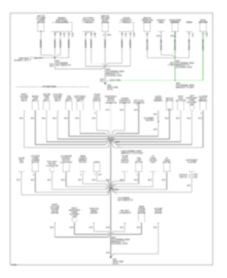
Ground Distribution Wiring Diagram (2 of 4) for Ford Windstar GL 1997
List of elements for Ground Distribution Wiring Diagram (2 of 4) for Ford Windstar GL 1997:
- (analog)
- (digital)
- (i/p harness, left side of i/p)
- (main harness, near breakout to i/p conn)
- A/c heater control switch illumination
- Air bag diagnostic connector
- Air bag diagnostic module
- Anti-theft controller module
- Ash tray illumination
- Auxiliary blower motor relay
- Blower motor switch
- Brake lamp relay
- C202
- C206
- C211
- C231
- C232
- C233
- C234
- C235
- C236
- C239
- Clock- spring assembly
- Cluster switch assembly
- Compact disc
- Data link connector
- Electronic brake switch connector
- Electronic flasher relay
- Fog lamp switch
- Fog lamps relay
- From s209 a (diagram 1 of 4)
- Front auxiliary blower motor switch
- Front blower motor relay
- G201 (right side of i/p)
- Generic electronic module (gem)
- Glove box lamp
- Gnd
- I/p cigar lighter
- I/p cigar lighter lamp
- I/p fuse panel
- Ignition cylinder tamper switch
- Ignition switch
- Instrument cluster
- Left instrument panel courtesy lamp
- Liftgate wiper/ washer switch
- Main light switch illumination
- Nca
- Pulse width dimming module
- Radio
- Radio amplifier
- Rear power window switch
- Rear window defrost switch
- Remote headphone module
- Remote/ keyless entry module
- Right instrument panel courtesy lamp
- S200 (i/p harness, near breakout to glove box lamp)
- S201 (i/p harness, near breakout to glove box lamp)
- S203 (i/p harness, near breakout to glove box lamp)
- S204
- S205
- S208 (i/p harness, near breakout to g201)
- Shift lock actuator
- Subwoofer assembly
- Traction assist switch
- Trailer park lamp relay
- W/o speed control
Ground Distribution Wiring Diagram (3 of 4) for Ford Windstar GL 1997
List of elements for Ground Distribution Wiring Diagram (3 of 4) for Ford Windstar GL 1997:
- (left front door harness)
- (right front door harness)
- (window regulator jumper harn, near blower motor)
- Blend door actuator
- Blower motor resistor
- C245
- Door lock relay
- Door unlock relay
- Electronic day/night mirror
- G200 (behind left cowl panel)
- I/p fuse panel
- Keyless entry switch assembly
- Left door ajar switch
- Left door disarm switch
- Left door handle switch
- Left door lock switch
- Left front courtesy lamp
- Left power/ heated mirror
- Master window control switch
- Nca
- Power mirror switch
- Remote/keyless entry module
- Right door ajar switch
- Right door disarm switch
- Right door handle switch
- Right door lock switch
- Right front courtesy lamp
- Right power window switch
- Right power/ heated mirror
- S212
- S213 (window regulator jumper harn, in breakout to g200)
- S500
- S600
- Sliding door ajar switch
- Sliding door contacts
- Stepwell courtesy lamp
- W/ power windows
- W/o power windows
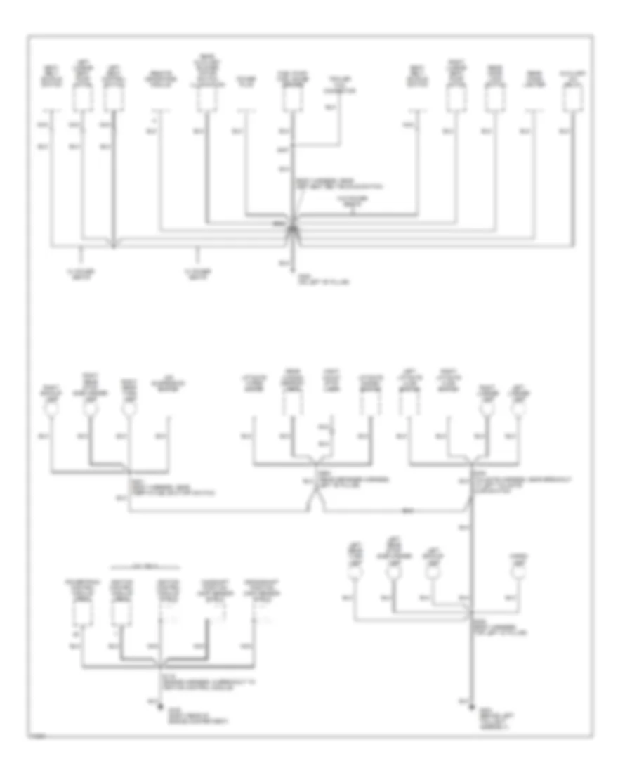
Ground Distribution Wiring Diagram (4 of 4) for Ford Windstar GL 1997
List of elements for Ground Distribution Wiring Diagram (4 of 4) for Ford Windstar GL 1997:
- (body harness, near left seat belt buckle switch)
- 3.0l only
- Air suspension switch
- Auxiliary a/c relay
- Camshaft position (cmp) sensor shield
- Cargo lamp
- Crankshaft position (ckp) sensor shield
- Fuel pump/ fuel gauge sender
- G105 (right rear of engine compartment)
- G308 (on left "b" pillar)
- G404 (behind left taillight assembly)
- Hight mount stop lamp
- Ignition control module (pcm)
- Ignition control module shield
- Left "b" pillar)
- Left backup lamp
- Left license lamp
- Left liftgate ajar switch
- Left lumbar seat pump motor
- Left rear stop/ side marker lamp
- Left rear turn lamp
- Left seat control switch
- Liftgate disarm switch
- Liftgate wiper motor
- Nca
- Power plug
- Powertrain control module (pcm)
- Rear auxiliary blower motor switch illumination
- Rear cigar lighter
- Rear door lock switch
- Rear window defrost grid
- Remote headphone module
- Right backup lamp
- Right license lamp
- Right liftgate ajar switch
- Right lumbar seat pump motor
- Right rear stop/ side marker lamp
- Right rear turn lamp
- S119 (engine harness, in breakout to ignition control module)
- S300 (body harness, top left "d" pillar)
- S301 (body harness, near inertia fuel shut-off switch)
- S302
- S407
- Seat belt buckle switch
- To left tailgate ajar switch)
- Trailer tow connector
- W/ power seats
- W/o power seats
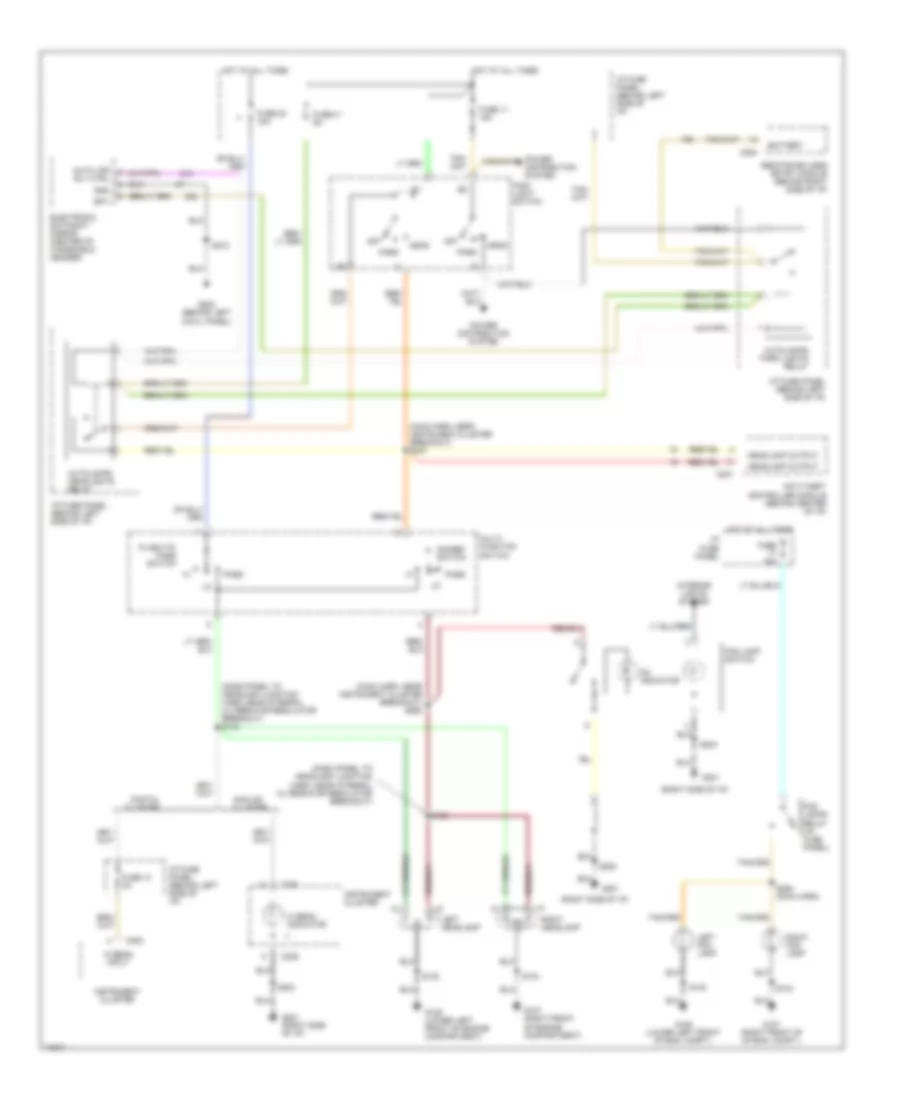
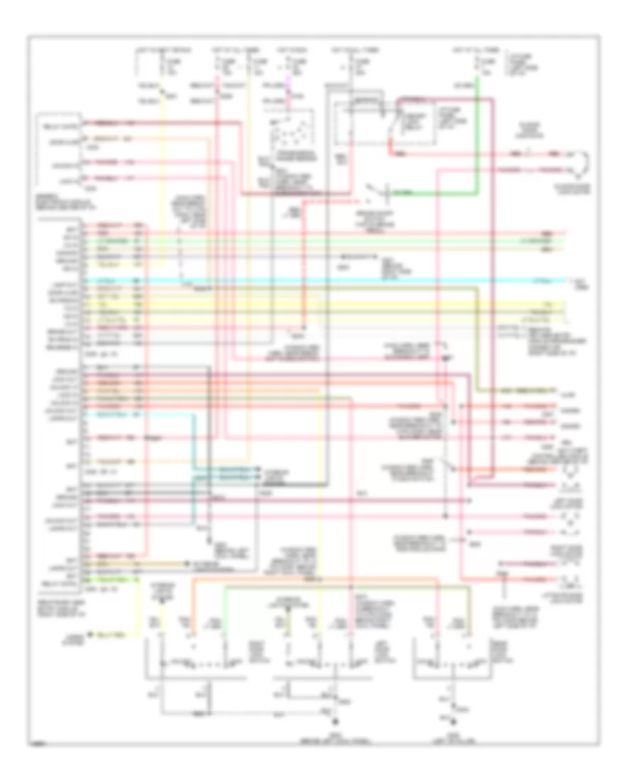
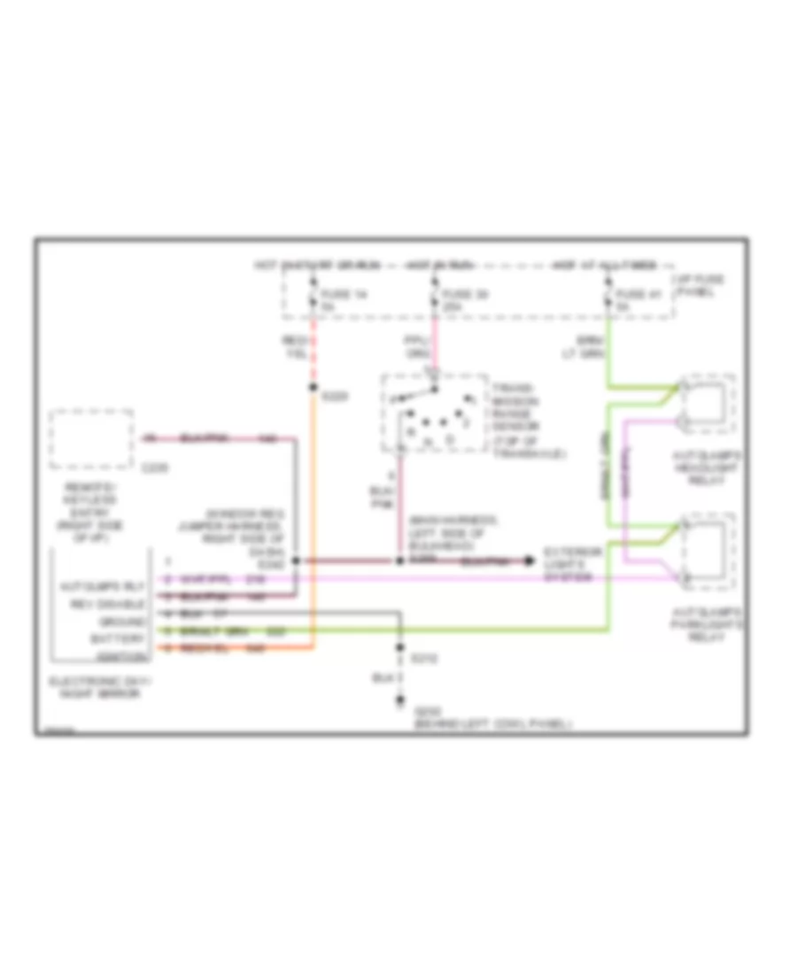
HEADLIGHTS
Headlight Wiring Diagram, with Autolamps for Ford Windstar GL 1997
List of elements for Headlight Wiring Diagram, with Autolamps for Ford Windstar GL 1997:
- (dash panel to headlamp junction harn, near integral alternator regulator breakout) s132
- (dash panel to headlamp junction harn, near integral alternator regulator breakout)
- (main harn, near instrument cluster breakout) s247
- (main harn, near instrument cluster breakout) s263
- (right side of i/p)
- Analog cluster
- Anti-theft controller module (behind center of i/p)
- Auto lps rly ctrl
- Autolamps headlights relay
- Autolamps park lights relay
- Bat
- Battery
- C200
- C207
- C239
- C240
- C254
- Digital cluster
- Dimmer switch
- Electronic day/night mirror (center of windshield header)
- Flash-to- pass switch
- Fog lamp switch
- Fog lamps relay (i/p fuse panel)
- Fuse 10 2a
- Fuse 11 15a
- Fuse 15a
- Fuse 23 15a
- Fuse 41 5a
- G106 (lower left front of eng. compt.)
- G106 (lower left front of engine compartment)
- G107 (right front of engine compartment)
- G107 (right front of of eng. compt.)
- G201
- G201 (right side of i/p)
- G202 (behind left cowl panel)
- Gnd
- Head
- Headlamp output
- Hi beam indicator
- Hi beam input
- Hot at all times
- I/p fuse panel
- I/p fuse panel (behind left side of i/p)
- Instrument cluster
- Interior lights system
- Left fog lamp
- Left headlamp
- Main light switch
- Multi- function switch
- Off
- On indicator
- Park
- Pass
- Power distribution system
- Remote/keyless entry module (behind right side of i/p)
- Right fog lamp
- Right headlamp
- S102
- S104
- S133
- S204
- S205
- S212
- S264 (main harn)
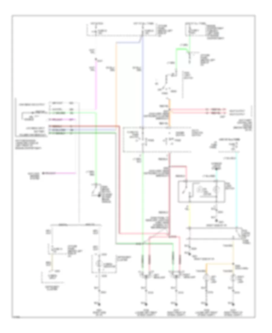
Headlight Wiring Diagram, with DRL for Ford Windstar GL 1997
List of elements for Headlight Wiring Diagram, with DRL for Ford Windstar GL 1997:
- (dash panel to headlamp junction harn, near integral alt reg breakout)
- (right side of i/p)
- Analog
- Anti-lock brakes system
- Anti-theft controller module (behind center of i/p)
- Battery
- C200
- C207
- C239
- C240
- Daytime running lamps (drl) module (left front of engine compartment)
- Digital
- Dimmer switch
- Drl disable
- Engine compartment fuse box (left side of engine compartment)
- Flash-to- pass switch
- Fog lamp switch
- Fog lamps relay (i/p fuse panel)
- Fuse 10 2a
- Fuse 15a
- Fuse 23 15a
- Fuse 33 15a
- Fuse k 60a
- G106 (lower left front of eng. compt.)
- G107 (right front of of eng. compt.)
- G201
- G201 (right side of i/p)
- Hdlp output
- Head
- Hi beam indicator
- Hi beam input
- High beam ind output
- Hot at all times
- Hot in run
- I/p fuse panel
- I/p fuse panel (behind left side of i/p)
- Ignition
- Instrument cluster
- Interior lights system
- Left fog lamp
- Left headlamp
- Low beam input
- Main light switch
- Multi- function switch
- Off
- On indi- cator
- Park
- Park brake switch (at base of park brake handle)
- Pass
- Pulsed high beam out
- Right fog lamp
- Right headlamp
- S102
- S104
- S107
- S132
- S133
- S204
- S205
- S247 (main harn, near instrument cluster breakout)
- S263 (main harn, near instrument cluster breakout)
- S264 (main harn)
Headlight Wiring Diagram, without DRL for Ford Windstar GL 1997
List of elements for Headlight Wiring Diagram, without DRL for Ford Windstar GL 1997:
- (dash panel to headlamp junction harn, near integral alternator regulator breakout) s132
- (dash panel to headlamp junction harn, near integral alternator regulator breakout)
- (right side of i/p)
- Analog
- Anti-theft controller module (behind center of i/p)
- C200
- C207
- C239
- C240
- Digital
- Dimmer switch
- Engine compartment fuse box (left side of engine compartment)
- Flash-to- pass switch
- Fog lamp switch
- Fog lamps relay (i/p fuse panel)
- Fuse 10 2a
- Fuse 15a
- Fuse 23 15a
- Fuse k 60a
- G106 (lower left front of eng. compt.)
- G107 (right front of of eng. compt.)
- G201
- G201 (right side of i/p)
- Head
- Headlamp output
- Hi beam indicator
- Hi beam input
- Hot at all times
- I/p fuse panel
- I/p fuse panel (behind left side of i/p)
- Instrument cluster
- Interior lights system
- Left fog lamp
- Left headlamp
- Main light switch
- Multi- function switch
- Off
- On indi- cator
- Park
- Pass
- Right fog lamp
- Right headlamp
- S102
- S104
- S133
- S204
- S205
- S247 (main harn, near instrument cluster breakout)
- S263 (main harn, near instrument cluster breakout)
- S264 (main harn)
HORN
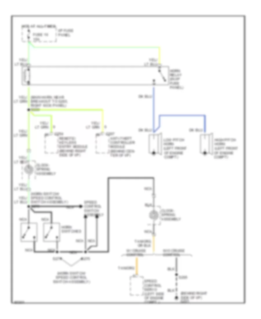
Horn Wiring Diagram for Ford Windstar GL 1997
List of elements for Horn Wiring Diagram for Ford Windstar GL 1997:
- (behind right side of i/p)
- (horn switch/ speed control switch assembly)
- (horn switch/ speed control switch assembly) s276
- 15a
- Anti-theft controller module (behind cen- ter of i/p)
- Breakout to g203, right kick panel) s233
- C207
- C254
- Clock- spring assembly
- Fuse 16
- G201
- High pitch horn (left front
- Horn relay (in i/p fuse panel)
- Horn switches
- Hot at all times
- I/p fuse panel
- Low pitch horn (left front
- Nca
- Of engine compt)
- Remote/ keyless entry module (behind right side of i/p)
- S205
- S275
- S277
- Speed control servo (left side of engine compt.)
- Speed control switch assembly
- W/ cruise control
- W/o cruise control
INSTRUMENT CLUSTER
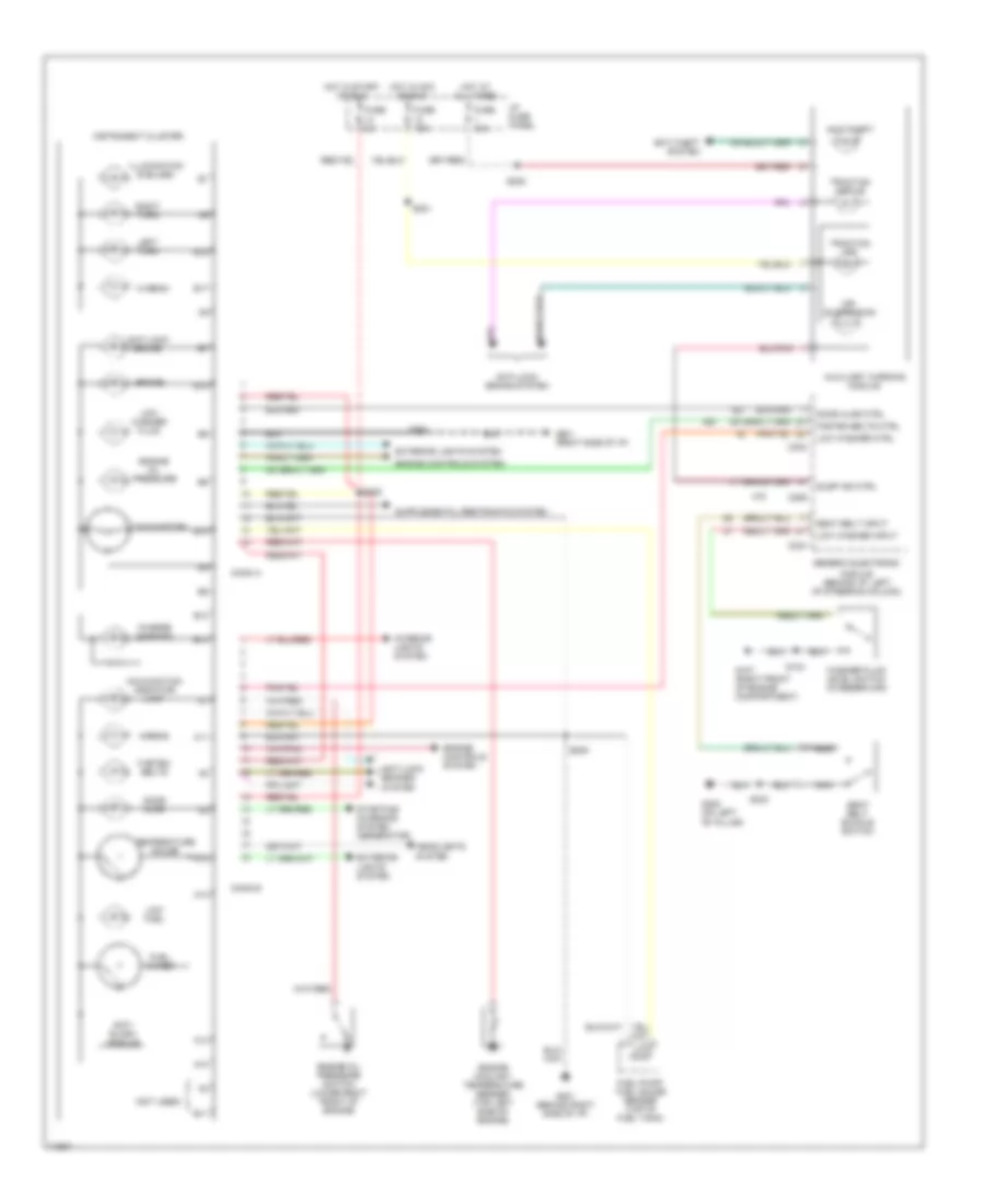
Instrument Cluster Wiring Diagram, Analog Cluster for Ford Windstar GL 1997
List of elements for Instrument Cluster Wiring Diagram, Analog Cluster for Ford Windstar GL 1997:
- (not used)
- A10
- A11
- A12
- A13
- A14
- Air suspension
- Airbag
- Anti- slosh module
- Anti-lock brake
- Anti-lock brake system
- Anti-lock brakes system
- Anti-theft
- Anti-theft system
- Auxiliary warning module
- B10
- B11
- B12
- B13
- B14
- B17
- B18
- Brake
- C233
- C234
- C289
- Charge warning
- Conn a
- Conn b
- Door ajar
- Door ajar ctrl
- Engine controls system
- Engine coolant temperature sender (top left side of engine)
- Engine oil pressure
- Engine oil pressure switch (lower right front of engine)
- Exterior lights system
- Fasten belts
- Fasten belts ctrl
- Fuel gauge
- Fuel pump/ fuel gauge sender (top of fuel tank)
- Fuse 10a
- Fuse 5a
- G107 (right front of engine compartment)
- G201 (behind right side of i/p)
- G201 (right side of i/p)
- G308 (on left "b" pillar)
- Generic electronic
- Headlights system
- Hi beam
- Hot at all times
- Hot in acc or run
- Hot in start or run
- I/p fuse panel
- Illumination (6 bulbs)
- Instrument cluster
- Interior lights system
- Left turn
- Low fuel
- Low washer ctrl
- Low washer fluid
- Low washer input
- Malfunction indicator lamp
- Module (behind i/p, left of steering column)
- Nca
- Right turn
- S104
- S204
- S209
- S220
- S221
- S222
- S303
- Seat belt buckle switch
- Seat belt input
- Starting/ charging system (generator)
- Susp ind ctrl
- Tachometer
- Temperature gauge
- Traction active
- Traction off
- Washer fluid level switch (in reservoir)
Instrument Cluster Wiring Diagram, Digital Cluster (1 of 2) for Ford Windstar GL 1997
List of elements for Instrument Cluster Wiring Diagram, Digital Cluster (1 of 2) for Ford Windstar GL 1997:
- "brake" indicator
- Air bag indicator
- Air suspension indicator
- Alternator warning lamp
- Anti-lock brake indicator
- Anti-lock brake system
- Anti-lock brakes system
- Anti-theft controller module (behind center of i/p)
- Anti-theft indicator
- Auxiliary warning module
- Battery
- C200
- C201
- C202
- Charging system
- Cluster switch input
- Coolant temp sensor
- Cruise control system
- Digital display
- Door ajar indicator
- Exterior lights system
- Fasten belts indicator
- Fuel flow input
- Fuel level
- Fuse 10a
- Fuse 25a
- Fuse 5a
- G201 (right side of i/p)
- Ground
- Hazard indicator
- Headlamps system
- Hi beam input
- Hot at all times
- Hot in acc or run
- Hot in run
- Hot in run or start
- I/p fuse panel
- Ignition
- Illumination
- Indicator control
- Instrument cluster
- Interior lights system
- Left turn input
- Low washer fluid indicator
- Malfunction indicator lamp
- Oil pressure switch
- Prndl illumination
- Right turn input
- S204
- S206
- S218
- S220
- S221
- S222
- S223
- Speed control input
- Tachometer input
- Tone request
- Traction active
- Traction off
- Vehicle speed
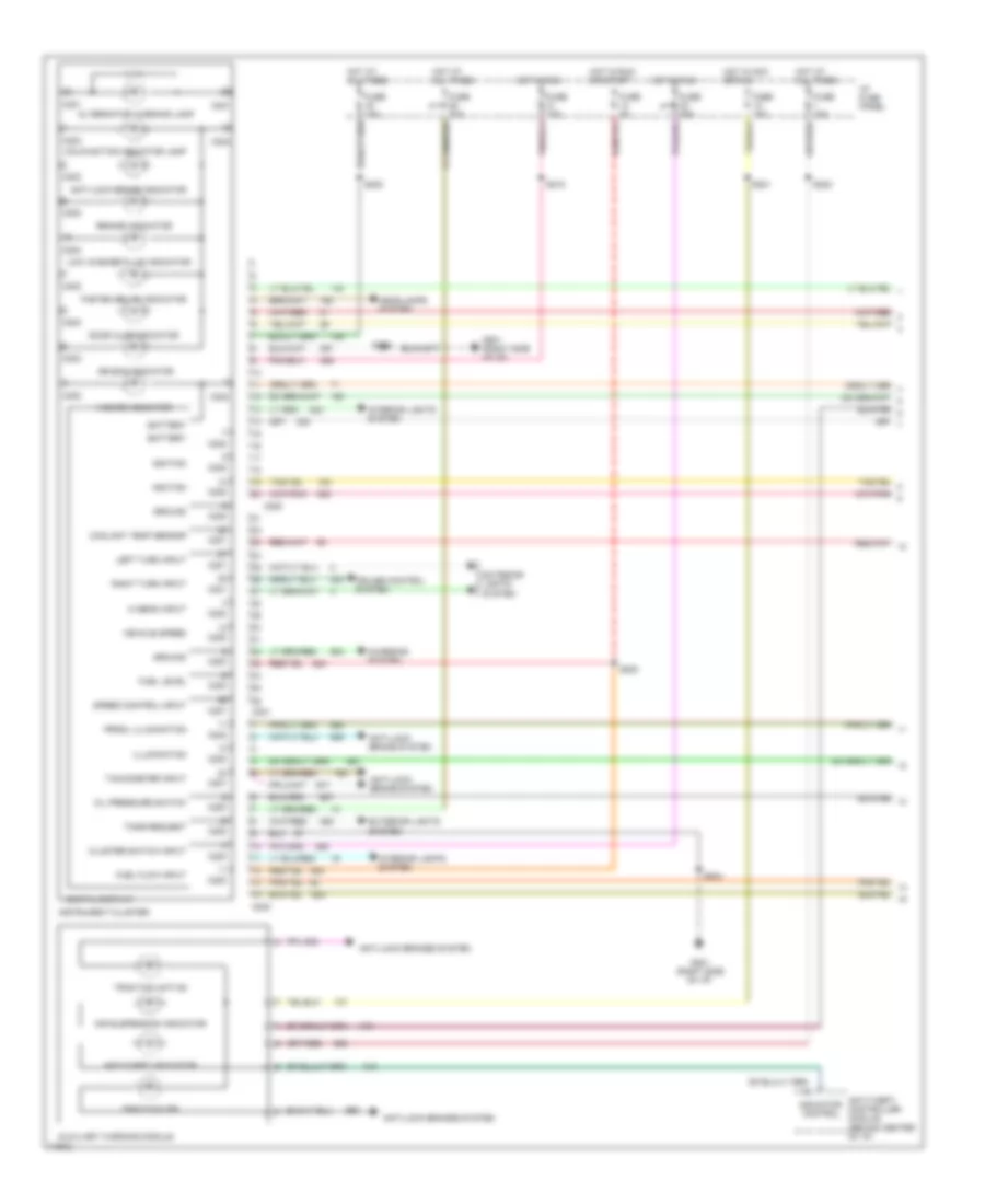
Instrument Cluster Wiring Diagram, Digital Cluster (2 of 2) for Ford Windstar GL 1997
List of elements for Instrument Cluster Wiring Diagram, Digital Cluster (2 of 2) for Ford Windstar GL 1997:
- (right side
- (right side of i/p)
- 3.0l
- 3.0l only
- 3.8l
- Air bag diagnostic module (behind left side of i/p)
- Belt bucke switch
- C231
- C233
- C234
- C289
- Cluster switch assembly
- E/m
- Engine controls system
- Engine coolant temperature sender (top left side of engine)
- Engine oil pressure switch (lower right front of engine)
- Fuel pump/ fuel gauge sender (top of fuel tank)
- G107 (right front of engine compartment)
- G201
- G201 (right side of i/p)
- G308 (on left "b" pillar)
- Generic electronic module (behind i/p, left of steering column)
- Ignition control module (right rear of engine compartment)
- Indicator control
- Interior lights system
- Nca
- Of i/p)
- Powertrain control module (behind right side of i/p)
- Reset
- S104
- S118 (engine compt harn, near breakout to octane adjust plug)
- S122 (dash to headlamp harn, near breakout to brake fluid level switch)
- S205
- S206
- S303
- Seat belt buckle switch
- Select
- Tone request input
- Vehicle speed sensor (on transaxle, rear of engine)
- Washer fluid level sw
- Washer fluid level switch (in washer fluid reservoir)
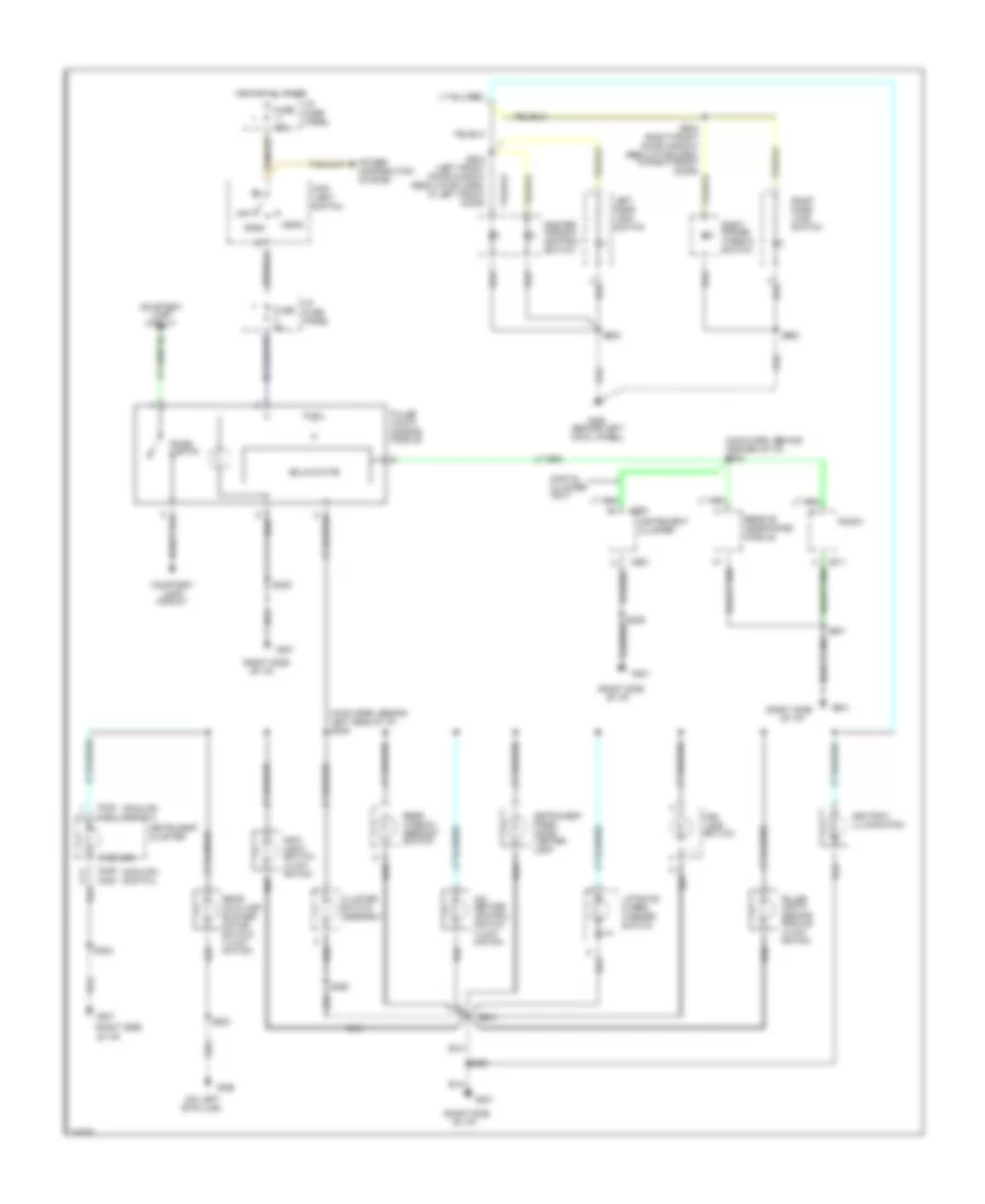
INTERIOR LIGHTS
Courtesy Lamps Wiring Diagram for Ford Windstar GL 1997
List of elements for Courtesy Lamps Wiring Diagram for Ford Windstar GL 1997:
- (behind left
- (behind left cowl panel) g202
- (dash panel to headlamp junct harn, near windshield wiper motor)
- (lower left front
- (main harn, near inst cluster breakout)
- (main harn, near left side of bulkhead)
- (right side
- (w/ remote keyless entry)
- (w/o remote keyless entry)
- (window reg jumper harn, near blend door actuator breakout)
- Anti-theft system
- Battery saver relay
- C233
- C234
- C245
- Cargo lamp
- Diode d1
- Dome
- Dome lamp
- Dome/reading lamp
- Door ajar switch
- Door handle switch
- Engine compartment fuse box
- Engine compartment lamp
- Fuse 15a
- G106
- G201
- G202 (behind left cowl panel)
- G404
- G404 (behind left taillight assembly)
- Generic electronic module (behind i/p, left of steering column)
- Glove box lamp
- Hood switch (left rear of engine compartment)
- Hot at all times
- I/p fuse panel
- Interior lamp relay
- Left door ajar switch
- Left door handle switch
- Left front courtesy lamp
- Left instrument panel courtesy lamp
- Left liftgate ajar switch
- Left vanity mirror lamp
- Liftgate ajar switch
- Nca
- Of engine compartment)
- Of i/p)
- Power windows system (delayed accessory relay)
- Pulse width dimming module (center of i/p)
- Rail lamp
- Relay control
- Remote/keyless entry module (behind right side of i/p)
- Right door ajar switch
- Right door handle switch
- Right front cour- tesy lamp
- Right instrument panel courtesy lamp
- Right liftgate ajar switch
- Right vanity mirror lamp
- S103
- S131
- S203
- S204
- S205
- S212
- S226
- S253
- S255
- S260
- S300
- S400
- S405 (tailgate warning switch harn, left side of liftgate)
- S500
- S501
- S600
- S601
- S901 (int lamp feed harn, near left "b" pillar)
- S902 (vanity mirror lamp feed harn, near left vanity mirror lamp)
- S903 (int lamp feed harn, near left "b" pillar)
- Sliding door ajar switch
- Sliding door contact
- Stepwell courtesy lamp
- Taillight assembly)
- W/ light group
- W/o light group
Instrument Illumination Wiring Diagram for Ford Windstar GL 1997
List of elements for Instrument Illumination Wiring Diagram for Ford Windstar GL 1997:
- "b" pillar)
- (6 bulbs)
- (analog) (digital)
- (behind left cowl panel)
- (main harn, behind center of i/p) s240
- (main harn, behind left side of i/p) s239
- (on left
- (right side
- (right side of i/p)
- A/c- heater control switch illumi- nation
- Ashtray illumination
- C200
- C202
- C211
- C239
- C240
- Cluster switch assembly
- Courtesy lamp circuit
- Digital cluster only
- Dome lights
- Fog lamp switch
- Fuse 15a
- Fuse 5a
- G201
- G202
- G308
- Head
- Hot at all times
- I/p fuse panel
- Instrument cluster
- Instrument panel cigar lighter lamp
- Left door lock switch
- Liftgate wiper/ washer switch
- Main light switch
- Main light switch illumi- nation
- Master window control switch
- Of i/p)
- Off
- Park
- Power distribution system
- Pulse width dimming module
- Pulse width dimming module illumi- nation
- Radio
- Rear auxiliary blower motor switch illumi- nation
- Rear window defrost switch
- Remote headphone module
- Right door lock switch
- Right power window switch
- S201
- S203
- S204
- S205
- S302
- S500
- S504 (left front door window regulator harn, in left front door)
- S600
- S602 (right front door window regulator harn, in right front door)
- Solid state
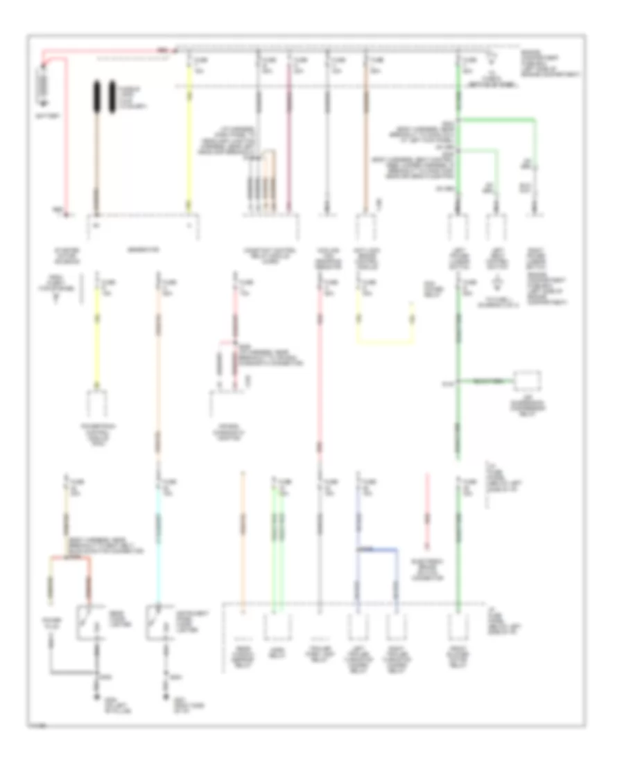
POWER DISTRIBUTION
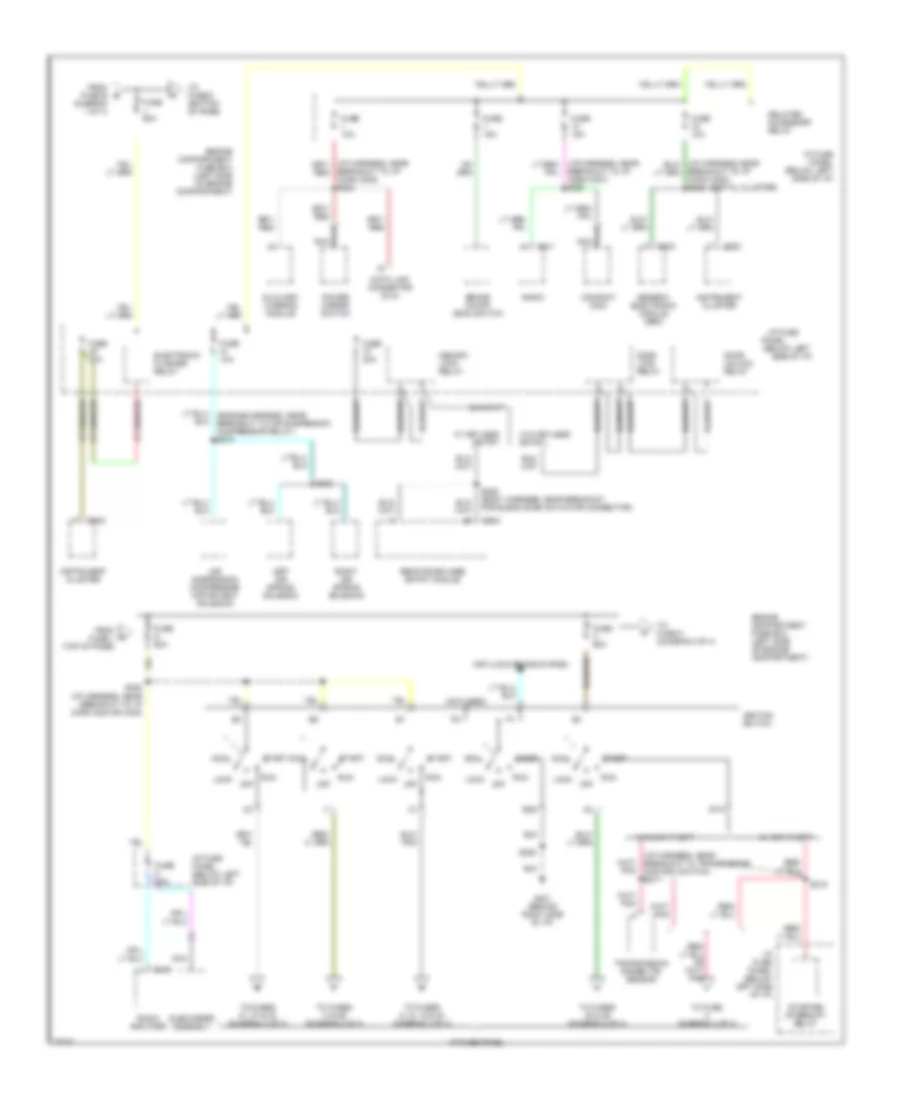
Power Distribution Wiring Diagram (1 of 4) for Ford Windstar GL 1997
List of elements for Power Distribution Wiring Diagram (1 of 4) for Ford Windstar GL 1997:
- (body harness, near breakout to seat belt buckle switch connector) s306
- (diagram 2 of 4)
- (i/p harness, dash panel to headlamp junction harness, near left headlamp breakout) s105
- Air bag diagnostic monitor
- Air suspension compressor relay
- Anti-lock brake control module
- Battery
- C105
- C232
- Constant control relay module (ccrm)
- Cooling fan dropping resistor
- Electronic brake switch connector
- Engine compartment fuse box (left side of engine compartment)
- From fuse f (top of page)
- Front blower motor relay
- Fuse 15a
- Fuse 20a
- Fuse 30a
- Fuse a 50a
- Fuse b 60a
- Fuse e 60a
- Fuse f 60a
- Fuse h 40a
- Fuse l 60a
- Fuse m 60a
- Fuse n 20a
- Fuse r 15a
- Fuse s 30a
- Fuse t 15a
- Fuse u 10a
- G201 (right side of i/p)
- G308 (on left "b" pillar)
- Generator
- Horn relay
- I/p fuse panel (below left side of i/p)
- Instrument panel cigar lighter
- Left power lumbar switch
- Left seat control switch
- Left trailer turn/stop hazard relay
- Nca
- Pcm power relay
- Power plug
- Powertrain control module (pcm)
- Rear cigar lighter
- Rear window defrost relay
- Red
- Right power lumbar switch
- Right trailer turn/stop hazard relay
- S139
- S140
- S204
- S229 (i/p harness, near breakout to air bag diagnostic connector)
- S302
- S304 (body harness, near breakout to conn c214 at left kick panel)
- S305 (body harness, seat control feed jumper harness, in breakout to conn c309, near driver's floor pan)
- Starter motor/ solenoid
- To fuse j
- To fuse r (bottom of page)
- Trailer park lamp relay
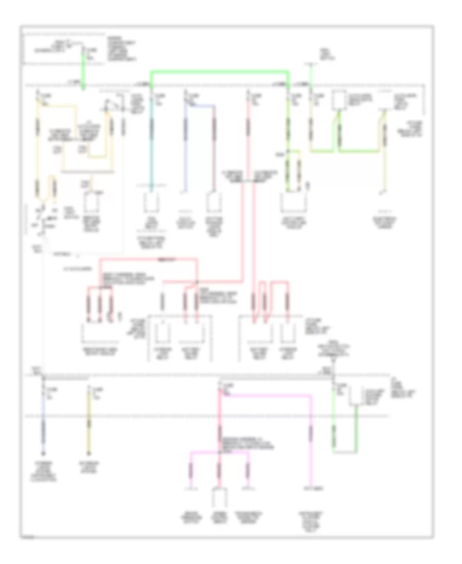
Power Distribution Wiring Diagram (2 of 4) for Ford Windstar GL 1997
List of elements for Power Distribution Wiring Diagram (2 of 4) for Ford Windstar GL 1997:
- (below left side of i/p)
- (digital cluster)
- (i/p harness, near breakout to i/p conn c202 or c240)
- (i/p harness, near breakout to transmission control switch) s217
- (not used)
- Acc
- Air suspension compressor motor/vent solenoid
- Anti-lock brake system
- Auxiliary warning module
- Brake on/off (boo) switch
- Breakout to i/p conn c237) s230
- Breakout to i/p conn c202) s222
- Breakout to i/p conn c202) s223
- C200
- C202
- C211
- C233
- C236
- C254
- Compact disc
- Data link connector (dlc)
- Delayed accessory relay
- Door lock relay
- Door unlock relay
- Electronic flasher relay
- Engine compartment fuse box (left side of engine compartment)
- From fuse e (diagram 1 of 4)
- From fuse j (top of page)
- Fuse 10a
- Fuse 15a
- Fuse 20a
- Fuse 25a
- Fuse c 60a
- Fuse d 60a
- Fuse j 60a
- G201 (behind right side of i/p)
- Generic electronic module (gem)
- Gnd
- I/p fuse
- I/p fuse panel
- I/p fuse panel (below left side of i/p)
- Ignition switch
- Instrument cluster
- Left air spring solenoid
- Lock
- Memory lock relay
- Nca
- Off
- Panel
- Power mirror switch
- Radio
- Radio amplifier
- Remote/keyless entry module
- Right air spring solenoid
- Run
- S205
- S215
- S222
- S225 (body harness, near breakout for blend door actuator connector)
- S408
- Sta
- Start
- Starter interrupt relay
- Subwoofer assembly
- To fuse (diagram 4 of 4)
- To fuse d (bottom of page)
- To fuse k (diagram 3 of 4)
- To fuses 14 & 20 (diagram 4 of 4)
- To fuses 21, 27 & 33 (diagram 4 of 4)
- To fuses 30 & 36 (diagram 2 of 4)
- To fuses 6, 12, 18 & 24 (diagram 4 of 4)
- Transmission range (tr) sensor
- W/ anti-theft
- W/ keyless entry
- W/o anti-theft
- W/o keyless entry
Power Distribution Wiring Diagram (3 of 4) for Ford Windstar GL 1997
List of elements for Power Distribution Wiring Diagram (3 of 4) for Ford Windstar GL 1997:
- (body harness, near breakout to blend door actuator conn c242) s226
- (engine harness, in breakout to conn c100, behind center of engine) s106
- Anti-theft controller module
- Auto- lamps park lights relay
- Autolamps headlights relay
- Autolamps park lights relay
- Auxiliary blower motor relay
- Battery saver relay
- Brake pressure switch
- C202
- C207
- C235
- C254
- Daytime running lamps module (drl)
- Electronic day/night mirror
- Engine compartment fuse box (left side of engine compartment)
- Exterior lights system
- Fog lamps relay
- From fuse c (diagram 2 of 4)
- From ignition switch (hot in run) (diagram 2 of 4)
- Fuse 10a
- Fuse 15a
- Fuse 25a
- Fuse 30a
- Fuse 5a
- Fuse k 60a
- Head
- I/p fuse panel (below left side of i/p)
- Instrument cluster (digital cluster only)
- Interior lamp relay
- Interior lights system (instrument illumination)
- Main light switch
- Multi- function switch
- Off
- Park
- Remote/ keyless entry module
- Remote/keyless entry module
- S226 (i/p harness, near breakout to i/p conn c202 or c240)
- S228
- Speed control servo
- Transmission range (tr) sensor
- W/ autolamps
- W/ autolamps & remote keyless entry
- W/ remote keyless entry
- W/ remote keyless entry only
- W/o remote keyless entry
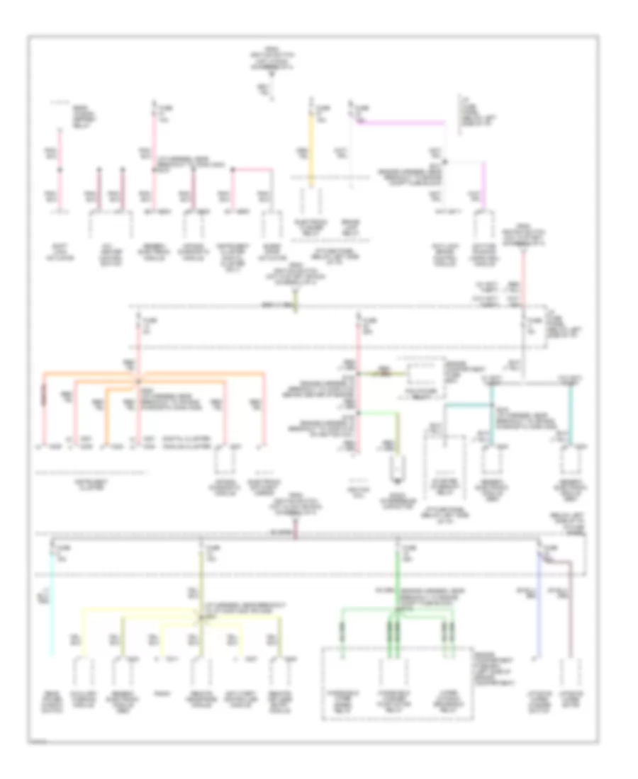
Power Distribution Wiring Diagram (4 of 4) for Ford Windstar GL 1997
List of elements for Power Distribution Wiring Diagram (4 of 4) for Ford Windstar GL 1997:
- (analog cluster)
- (below left side of i/p)
- (digital cluster)
- (i/p harness, near breakout to conn c203) s218
- (i/p harness, near breakout to i/p conn c200 or c239) s221
- (w/ anti- theft)
- (w/o anti- theft)
- A/c-
- Air bag diagnostic module
- Anti-lock brake control module
- Anti-theft controller module
- Auxiliary warning module
- Blend door actuator
- Brake lamp relay
- C111
- C200
- C201
- C207
- C211
- C231
- C232
- C234
- C235
- C239
- C240
- Daytime running lamps (drl) module
- Electronic day/night mirror
- Electronic flasher relay
- Engine compartment fuse box
- Engine compartment fuse box (left side of engine compartment)
- From ignition switch (hot in acc or run) (diagram 2 of 4)
- From ignition switch (hot in run) (diagram 2 of 4)
- From ignition switch (hot in start or run) (diagram 2 of 4)
- From ignition switch (hot in start) (diagram 2 of 4)
- Fuse 10a
- Fuse 15a
- Fuse 20a
- Fuse 25a
- Fuse 5a
- Generic electronic module
- Generic electronic module (gem)
- Heater control switch
- I/p fuse panel
- I/p fuse panel (below left side of i/p)
- Ignition coil
- Instrument cluster
- Instrument cluster (digital cluster only)
- Liftgate wiper motor
- Liftgate wiper/ washer switch
- Pcm power relay
- Radio
- Radio inteference capacitor
- Rear power window switch
- Rear window defrost relay
- Remote headphone module
- Remote/ keyless entry module
- S107 (engine harness, near breakout to engine compt fuse block)
- S109 (engine harness, in breakout to conn c130 on ignition coil)
- S216 (i/p harness, near breakout to air bag diagnostic conn c225)
- S220 (i/p harness, near breakout to air bag diagnostic conn c225)
- Shift lock actuator
- Starter interrupt relay
- W/ anti- theft
- W/o anti- theft
- Windshield washer pump motor relay
- Windshield wiper speed relay
- Wiper dynamic brake/run relay
POWER DOOR LOCKS
Door Lock Wiring Diagram for Ford Windstar GL 1997
List of elements for Door Lock Wiring Diagram for Ford Windstar GL 1997:
- (window reg harn, near breakout to 14 pin conn, behind right cowl panel) s252
- (window reg harn, near breakout to 2 pin conn, near blower motor) s249
- C233
- C234
- Door lock relay
- Door unlock relay
- Fuse 37 20a
- G202 (behind left cowl panel)
- G308 (left "b" pillar)
- Generic electronic module (behind i/p, left of steering column)
- Hot at all times
- I/p fuse panel (left side of i/p)
- Interior lights system
- Left door lock motor
- Left door lock switch
- Liftgate lock motor
- Lock
- Lock input
- Memory lock relay
- Memory lock relay control
- Rear door lock switch
- Red
- Right door lock motor
- Right door lock switch
- S212
- S244 (main harn, near breakout to 10 pin conn, behind left side of i/p)
- S251 (main harn, near breakout to glove box lamp)
- S274 (window reg harn, near breakout to 14 pin conn, behind right cowl panel)
- S302
- S500
- S600
- Sliding door contacts
- Sliding door lock motor
- Unlock
- Unlock input
Keyless Entry Wiring Diagram for Ford Windstar GL 1997
List of elements for Keyless Entry Wiring Diagram for Ford Windstar GL 1997:
- (main harn, near break- out to 3 pin conn, near left side of i/p)
- (main harn, near breakout to 10 pin conn behind left side of i/p)
- (main harn, near breakout to glove box lamp)
- (window reg harn, near break- out to boo switch)
- (window reg harn, near breakout to 14 pin conn, behind right cowl panel) s252
- (window reg harn, near breakout to rke module conn)
- 1/2 in
- 3/4 in
- 5/6 in
- 7/8 in
- 9/0 in
- Ajar
- Anti-theft controller module (behind center of i/p)
- Arm
- Bat
- Brake on/off switch (top of brake pedal)
- Brake out
- C206
- C207
- C233
- C234
- C235
- C245
- C254
- Common
- Disarm
- Door ajar
- Exterior lights system
- Fuse 10a
- Fuse 15a
- Fuse 20a
- Fuse 25a
- G201 (behind right side of i/p)
- G202 (behind left cowl panel)
- G308 (left "b" pillar)
- Generic electronic module (behind center of i/p)
- Ground
- Horns system
- Hot at all times
- Hot in accy or run
- Hot in run
- I/p fuse panel (left side of i/p)
- Ign in
- Interior lights system
- Lamp out
- Lamps out
- Left door lock motor
- Left door lock switch
- Liftgate door lock motor
- Lock
- Lock in
- Lock out
- Memory lock relay
- Not used
- Rear door lock switch
- Red
- Relay cntrl
- Remote/ keyless entry module programmer connector (right side of i/p)
- Remote/keyless entry module (right side of i/p)
- Reverse in
- Right door lock motor
- Right door lock switch
- Rk prog b
- Rk prog in
- S106
- S200
- S212
- S221
- S225
- S226
- S227
- S231 (window reg harn, near breakout to blend door act)
- S244
- S246
- S248
- S249 (window reg harn, near breakout to 2 pin conn, near blower motor)
- S250 (window reg harn, near breakout to boo switch)
- S251
- S274 (window harn, in breakout to 8 pin conn behind right cowl panel)
- S278
- S302
- S500
- S600
- Sliding door contacts
- Sliding door lock motor
- Transmission range sensor
- Unlck
- Unlock
- Unlock in
- Unlock lf
- Unlock out
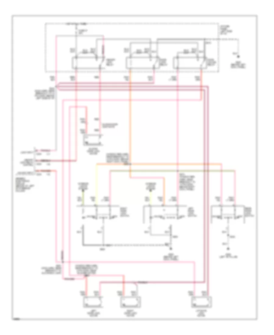
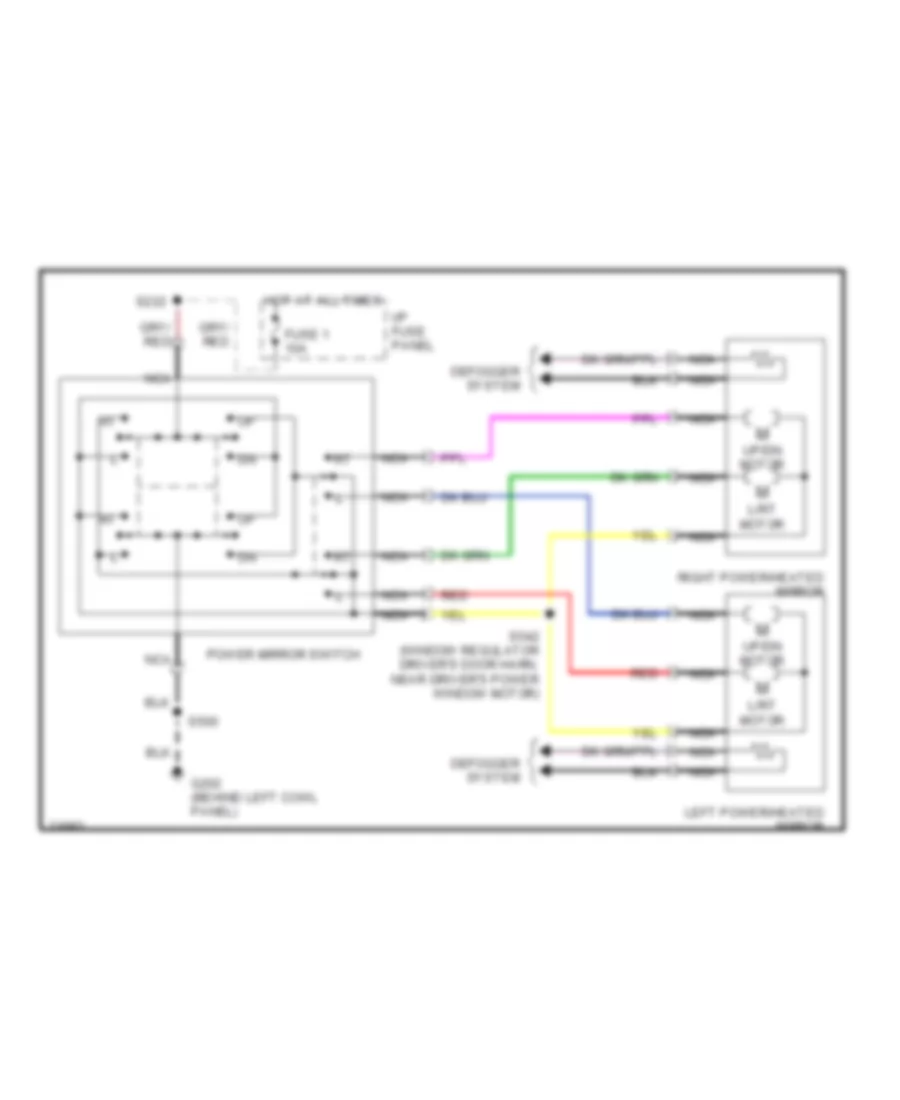
POWER MIRRORS
Photochromic Mirror Wiring Diagram for Ford Windstar GL 1997
List of elements for Photochromic Mirror Wiring Diagram for Ford Windstar GL 1997:
- (main harness, left side of bulkhead) s269
- (top of transaxle)
- (window reg jumper harness, right side of dash) s242
- Autolamps headlight relay
- Autolamps parklights relay
- Autolmps rly
- Battery
- C235
- Electronic day/ night mirror
- Exterior lights system
- Fuse 14 5a
- Fuse 30 25a
- Fuse 41 5a
- G202 (behind left cowl panel)
- Ground
- Hot at all times
- Hot in run
- Hot in start or run
- I/p fuse panel
- Ignition
- Remote/ keyless entry (right side of i/p)
- Rev disable
- S212
- S220
- Trans- mission range sensor
Power Mirror Wiring Diagram for Ford Windstar GL 1997
List of elements for Power Mirror Wiring Diagram for Ford Windstar GL 1997:
- Defogger system
- Fuse 1 10a
- G202 (behind left cowl panel)
- Hot at all times
- I/p fuse panel
- L/rt motor
- Left power/heated mirror
- Nca
- Power mirror switch
- Red
- Right power/heated mirror
- S222
- S500
- S542 (window regulator driver's door harn, near driver's power window motor)
- Up/dn motor
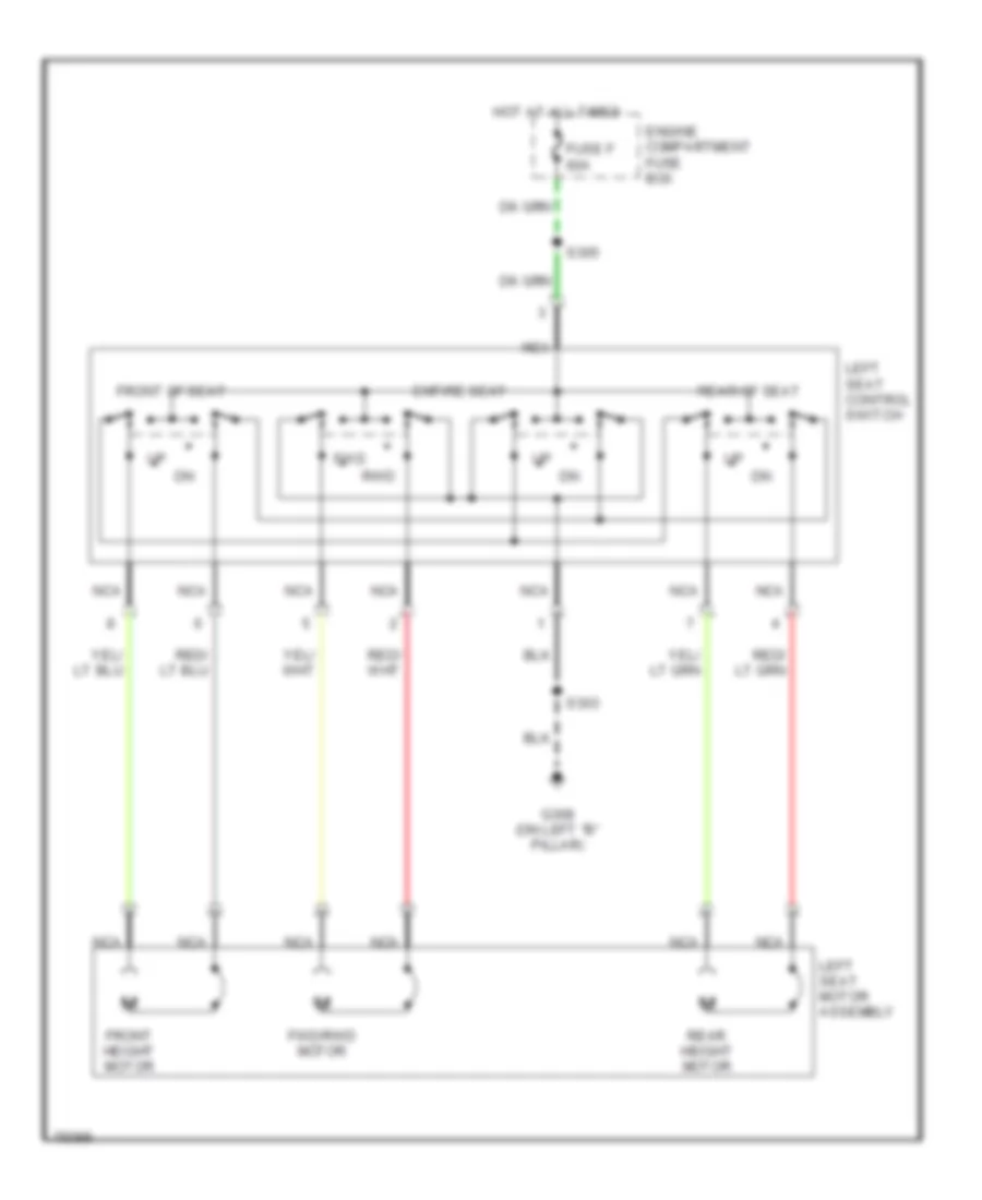
POWER SEATS
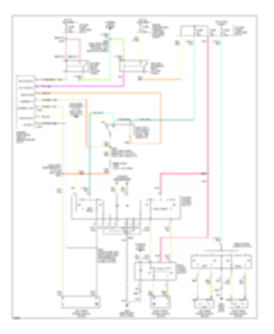
Driver Power Seat Wiring Diagram for Ford Windstar GL 1997
List of elements for Driver Power Seat Wiring Diagram for Ford Windstar GL 1997:
- Engine compartment fuse box
- Entire seat
- Front height motor
- Front of seat
- Fuse f 60a
- Fwd
- Fwd/rwd motor
- G308 (on left "b" pillar)
- Hot at all times
- Left seat control switch
- Left seat motor assembly
- Nca
- Rear height motor
- Rear of seat
- Rwd
- S303
- S305
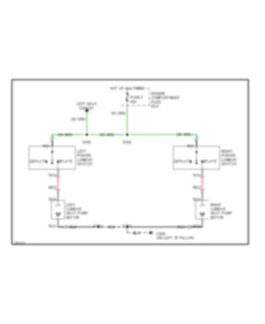
Lumbar Wiring Diagram for Ford Windstar GL 1997
List of elements for Lumbar Wiring Diagram for Ford Windstar GL 1997:
- Deflate
- Engine compartment fuse box
- Fuse f 60a
- G308 (on left "b" pillar)
- Hot at all times
- Inflate
- Left lumbar seat pump motor
- Left power lumbar switch
- Left seat circuit
- Nca
- Red
- Right lumbar seat pump motor
- Right power lumbar switch
- S302
- S303
- S304
- S305
POWER WINDOWS
Power Window Wiring Diagram for Ford Windstar GL 1997
List of elements for Power Window Wiring Diagram for Ford Windstar GL 1997:
- (main harn, near break- out to g201, right side of i/p) s258
- (main harn, near breakout to glove box lamp) s257
- Bat svr rly
- Battery saver relay (i/p fuse panel)
- C233
- C234
- Current hi
- Current low
- Delayed accessory relay (i/p fuse panel)
- Dly acc rly
- Down input
- Engine compartment fuse box (left side of engine compt)
- Fuse 15a
- Fuse 30a
- Fuse j 60a
- G201 (right side of i/p)
- G202 (behind left cowl panel)
- Generic electronic module (behind center of i/p)
- Hot at all times
- Hot in acc or run
- I/p fuse panel (left side of i/p)
- Interior lights system
- Left
- Left front
- Left front power window motor
- Left rear power window motor
- M m
- Master window control switch
- Nca
- One touch
- One touch down relay (in i/p fuse panel, left side of i/p)
- Pnk
- Rear power window switch
- Resistance wire (.015 +/- .001 ohms)
- Right
- Right front
- Right front power window motor
- Right power window switch
- Right rear power window motor
- S203
- S226
- S256 (main harn, near breakout to 10 pin conn, left side of i/p)
- S259
- S260 (main harn, near breakout to 76 pin conn, left side of bulkhead)
- S500
- S506 (window reg left front door harn, near breakout to left power window motor)
- S600
- Tan/ red
- Tan/red
- Up input
RADIO
Radio Wiring Diagrams, Base Radio for Ford Windstar GL 1997
List of elements for Radio Wiring Diagrams, Base Radio for Ford Windstar GL 1997:
- Battery power
- C211
- C212
- C275
- C301
- Common (-)
- Data
- Fuse 10a
- Fuse 15a
- G201 (right side of dash)
- G308 (left "b" pillar)
- Ground
- Hot at all times
- Hot in run or acc
- I/p fuse panel (behind dash, left of steering column)
- Illumination power
- Illumination pwr
- Interior lights system
- Left front door speaker
- Left rear in
- Left rear out
- Left rear speaker
- Lf door spkr (+)
- Lf door spkr (-)
- Lr spkr (+)
- Nca
- Power
- Radio
- Remote headphone module (behind panel, left of rear seat)
- Rf door spkr (+)
- Rf door spkr (-)
- Right front door speaker
- Right rear in
- Right rear out
- Right rear speaker
- Rr spkr (+)
- S201
- S204
- S221
- S302
- S313 (body harn, near remote headphone module)
- Tan
Radio Wiring Diagrams, Premium Radio for Ford Windstar GL 1997
List of elements for Radio Wiring Diagrams, Premium Radio for Ford Windstar GL 1997:
- Auxiliary control
- Battery power
- Battery pwr
- C211
- C236
- C237
- C275
- C277
- C278
- C280
- C281
- C282
- C301
- C313
- C328
- C329
- Cd player
- Cd/radio shield
- Control
- Data
- Fuse 10a
- Fuse 15a
- Fuse 25a
- G201 (right side of dash)
- G308 (left "b" pillar)
- Ground
- Hot at all times
- Hot in run or acc
- I/p fuse panel (behind dash, left of steering column)
- Ignition
- Illum pwr
- Illumination power
- Interior lights system
- Left front door speaker
- Left rear speaker
- Lf spkr (+)
- Lf spkr (-)
- Lr spkr (+)
- Lr spkr (-)
- Mute input
- Mute output
- Nca
- Power
- Radio
- Radio amplifier
- Radio/ amplifier shield
- Rear control amp shield
- Red
- Remote headphone module
- Rf spkr (+)
- Rf spkr (-)
- Right front door speaker
- Right rear speaker
- Rr spkr (+)
- Rr spkr (-)
- S201
- S204
- S208
- S221
- S230
- S271 (main harn, center of dash)
- S272 (main harn, center of dash)
- S302
- Sub speaker (+)
- Sub speaker (-)
- Subwoofer
- Subwoofer amplifier
- Subwoofer shield
- Tan
SHIFT INTERLOCKS
Shift Interlock Wiring Diagram for Ford Windstar GL 1997
List of elements for Shift Interlock Wiring Diagram for Ford Windstar GL 1997:
- Brake on/off (boo) switch (top of
- Brake pedal)
- Fuse 21 10a
- Fuse 7 15a
- G201 (behind right side of dash)
- Hot at all times
- Hot in run
- I/p fuse panel (behind left side of dash)
- S205
- S218
- S241 (main harn, near breakout to conn, near trans ctrl sw)
- Shift lock actuator (on top of steering column)
- Solid state
STARTING/CHARGING
Charging Wiring Diagram for Ford Windstar GL 1997
List of elements for Charging Wiring Diagram for Ford Windstar GL 1997:
- (analog)
- (digital)
- (digital) (analog)
- (front of transaxle, on transaxle stud)
- (left front of engine compartment)
- 3.0l 0nly
- 301 ohms (digital) 510 ohms (analog)
- Acc
- Battery
- C123
- C133
- C201
- C240
- Charge warning indicator
- Engine compartment fuse box
- Fuse 5a
- Fuse d 60a
- Fuse t 15a
- Fusible links a & b
- G106
- G129
- Generator
- Ground f screw to full field generator
- I/p fuse panel
- Ignition switch
- Instrument cluster
- Lock
- Off
- Red
- Run
- S220
- Start
- Starting circuit
Starting Wiring Diagram for Ford Windstar GL 1997
List of elements for Starting Wiring Diagram for Ford Windstar GL 1997:
- (front of transaxle on transaxle stud)
- (left front of engine compartment)
- Acc
- Anti-theft controller module (behind center of i/p)
- Battery
- Body computer system
- C206
- Engine compartment fuse box
- Fuse 5a
- Fuse c 60a
- G106
- G129
- Hold
- I/p fuse panel
- Ignition switch
- Lock
- Off
- Power distribution system
- Pull-in
- Red
- Run
- S215
- S216
- S217
- Sta
- Start
- Start interrupt relay (i/p fuse panel)
- Starter motor/ solenoid
- Transmission range (tr) sensor (left side of transmission)
- W/anti-theft
- W/o anti-theft
SUPPLEMENTAL RESTRAINTS
Supplemental Restraint Wiring Diagram for Ford Windstar GL 1997
List of elements for Supplemental Restraint Wiring Diagram for Ford Windstar GL 1997:
- (i/p harn, behind left side of i/p)
- (i/p harn, near air bag diagnostic monitor breakout)
- (main harn, near glove box lamp breakout) s200
- (main harn, near instrument cluster breakout)
- (main harn, near right of steering column)
- (right side of i/p)
- * pin shorting bar is engaged when module connector is disconnected
- Air bag diagnostic connector (left side of i/p)
- Air bag diagnostic module (left side of i/p)
- Air bag ind
- Air bag indicator
- C231
- C232
- Clock- spring assembly
- Data link
- Data link connector (dlc) (right side of steering column)
- Diag conn
- Driver's air bag
- Drvr air bag
- Engine compartment fuse box
- Fuse 10a
- Fuse 5a
- Fuse u 10a
- G201
- G201 (right side of i/p)
- Gnd
- Hood latch bracket crash sensor (primary) (right front of engine compartment)
- Hot at all times
- Hot in run and start
- Hot in run i/p fuse panel
- Instrument cluster
- L crash sens
- Left radiator crash sensor (primary) (left front of engine compartment)
- Nca
- Pass air bag
- Passenger's air bag
- Pwr (bat)
- Pwr (run)
- R crash sens
- S205
- S218
- S220
- S229
- S242
- Shorting bar
- Tan/red
TRANSMISSION
Transmission Wiring Diagram for Ford Windstar GL 1997
List of elements for Transmission Wiring Diagram for Ford Windstar GL 1997:
- (3.0l)
- (3.0l) (3.8l)
- (dash panel to headlamp junction harness, near breakout to engine compartment fuse box)
- (engine control sensor harness, right rear of engine)
- (engine control sensor harness, left rear of engine) red
- (engine control sensor harness, near breakout to tps)
- (engine control sensor harness, lower left rear of engine compartment) s121
- (engine ctrl sensor harn, left side of engine)
- (engine ctrl sensor harn, near breakout to pcm)
- (engine ctrl sensor harn, near breakout to tr sensor)
- 10a
- 3.0l
- 3.8l
- Ax4s transaxle
- Backup lamps
- Boo input
- Brake on/off (boo) switch (on brake pedal support)
- C103
- Case ground
- Data link connector (dlc) (below center of dash)
- Dlc
- Dlc(+)
- Dlc(-)
- Ect
- Electronic pressure control (epc) solenoid
- Engine compartment fuse box
- Engine controls
- Engine coolant temperature (ect) sensor (top left side of engine)
- Epc sol
- Fuse 15a
- Fuse 25a
- Fuse s 30a
- Fuse v
- G100 (left side of engine compartment)
- G129
- G129 (front of trans, on trans stud)
- G201 (behind right side of dash)
- Ground
- Hot at all times
- Hot in run
- Hot in start or run
- I/p fuse panel
- Iat sensor
- Ignition coil, radio noise capacitor
- Instrument cluster (check engine indicator)
- Intake air temperature (iat) sensor (on air intake assembly)
- Maf
- Maf input
- Mass air flow (maf) sensor (on air intake assembly)
- Mil
- N d
- Nca
- Pcm relay
- Power (vpwr)
- Powertrain control module (pcm) (behind right side of dash)
- Red
- S101
- S108
- S111
- S112
- S113
- S114
- S116
- S117
- S120
- S123 s141
- S124
- S125
- S138
- S278 (window regulator jumper harness, near breakout to boo switch)
- Shift sol 1
- Shift sol 2
- Shift sol3
- Shift solenoid
- Sig return
- Tcc sol
- Tcil
- Tcs
- Tft
- Throttle position (tp) sensor (top of engine)
- To starting system
- Torque converter clutch (tcc) solenoid
- Tp sensor in
- Tr sensor
- Trans range (tr) sensor (on top of transaxle)
- Transmission control switch (tcs) (on steering column)
- Transmission fluid temperature (tft) sensor
- Tss sensor
- Turbine shaft speed (tss) sensor (top of transaxle)
- Vehicle speed sensor (vss) (on transaxle, near engine)
- Vref
- Vss input
WARNING SYSTEMS
Warning System Wiring Diagrams for Ford Windstar GL 1997
List of elements for Warning System Wiring Diagrams for Ford Windstar GL 1997:
- (analog) (digital)
- (on left "b" pillar)
- Buckle input
- C200
- C233
- C234
- C239 c202
- Digital cluster only
- Fasten belts indi- cator
- Fuse 10a
- Fuse 15a
- Fuse 5a
- G308
- Generic electronic module (behind i/p, left of steering column)
- Head
- Hot at all times
- Hot in run
- Hot in run or start
- I/p fuse panel
- Ignition
- Ignition key warning switch (at ignition switch)
- Indicator ctrl
- Instrument cluster
- Key in input
- Lights on input
- Main light switch
- Nca
- Off
- Park
- S218
- S220
- S302
- Seat belt buckle switch (in seat belt buckle)
- Tone request
- Tone request output
WIPER/WASHER
Front Washer/Wiper Wiring Diagram for Ford Windstar GL 1997
List of elements for Front Washer/Wiper Wiring Diagram for Ford Windstar GL 1997:
- (lower left front of engine compt) g106
- 100k
- 11.2k
- 1996-
- 1996-97
- 20k
- 3.3k
- 36k
- 4.08k
- 47.5k
- 51k
- 68k
- 82k
- Brake/run relay
- C233
- C234
- Engine compartment fuse box (left side of engine compt)
- Fuse 25a
- G107 (right front of engine compt)
- Generic electronic module (behind dash, left of strng column)
- Hot in acc or run
- I/p fuse panel (behind left side of dash)
- Interval delay/wash
- Min int
- Mode select
- Multi- function switch
- Off
- Off max int
- Park
- Park sense
- Return
- Run
- S103
- S104
- S110
- S138 (dash to headlamp junc harn, near breakout to left rear of engine compt)
- Wash sw
- Washer pump control
- Windshield washer pump motor
- Windshield washer pump motor relay
- Windshield wiper dynamic brake/run relay
- Windshield wiper motor
- Windshield wiper speed relay
- Wiper speed control
- Wiper sw
Rear Washer/Wiper Wiring Diagram for Ford Windstar GL 1997
List of elements for Rear Washer/Wiper Wiring Diagram for Ford Windstar GL 1997:
- (main harn, near breakout to foglamp sw)
- (main harn, near breakout to left side of dash)
- 1996-97
- Fuse 20a
- G106 (lower left front of engine compt)
- G107 (right front of engine compt)
- G201 (behind right side of dash)
- G404 (behind left taillight assembly)
- Generic electronic module (behind dash, left of steering col)
- Hot in acc or run
- I/p fuse panel (behind left side of dash)
- Illum
- Interior lights system
- Liftgate washer pump motor
- Liftgate wiper motor
- Liftgate wiper relay (1998 only) (in engine compartment fuse box)
- Liftgate wiper/ washer switch
- Only
- Park
- Red
- Run
- S104
- S140 (1998 only) (dash to hdlmp junc harn, near breakout to left rear of eng compt)
- S204
- S261 (1998 only)
- S282 (1998 only)
- S900
- Washer switch
- Wiper switch