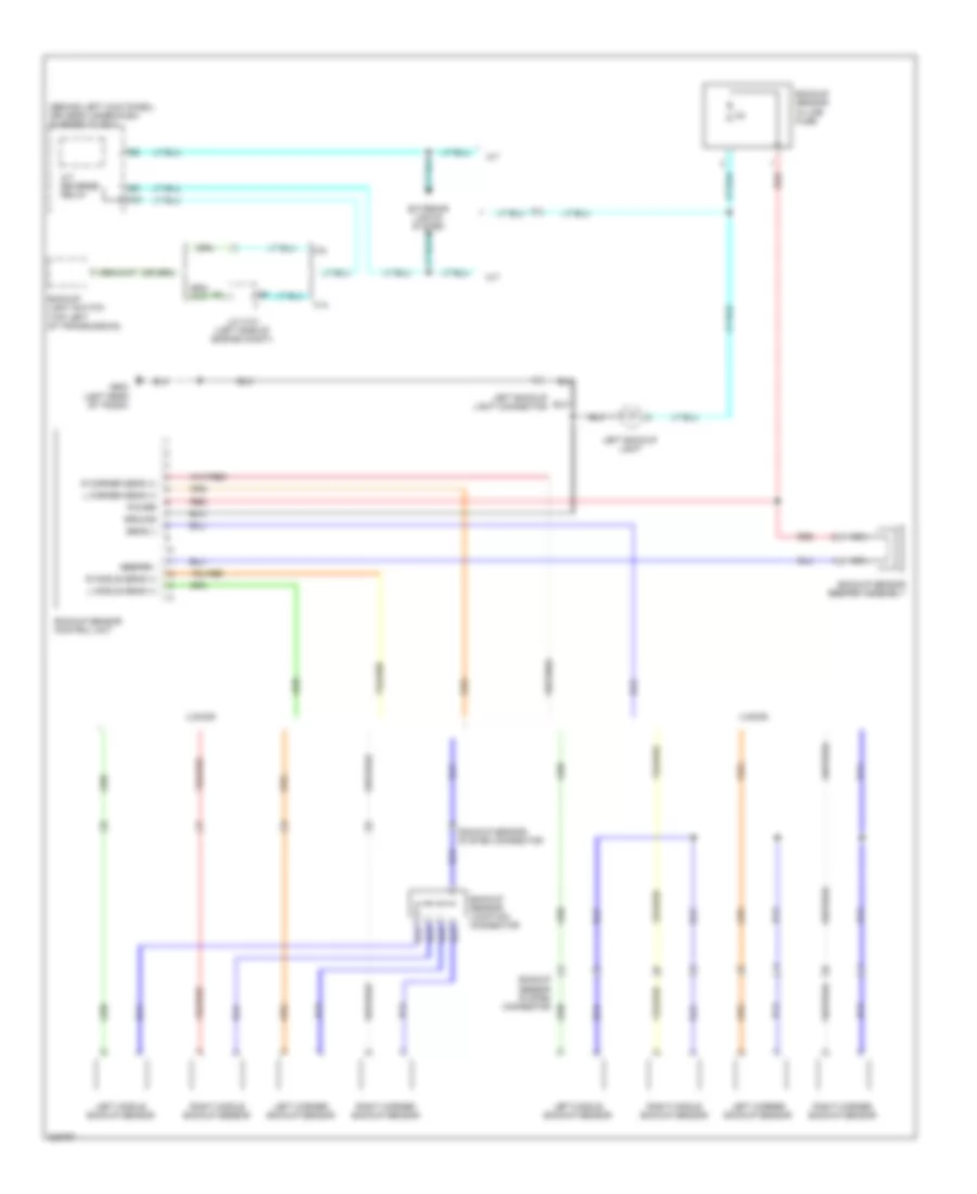
AIR CONDITIONING
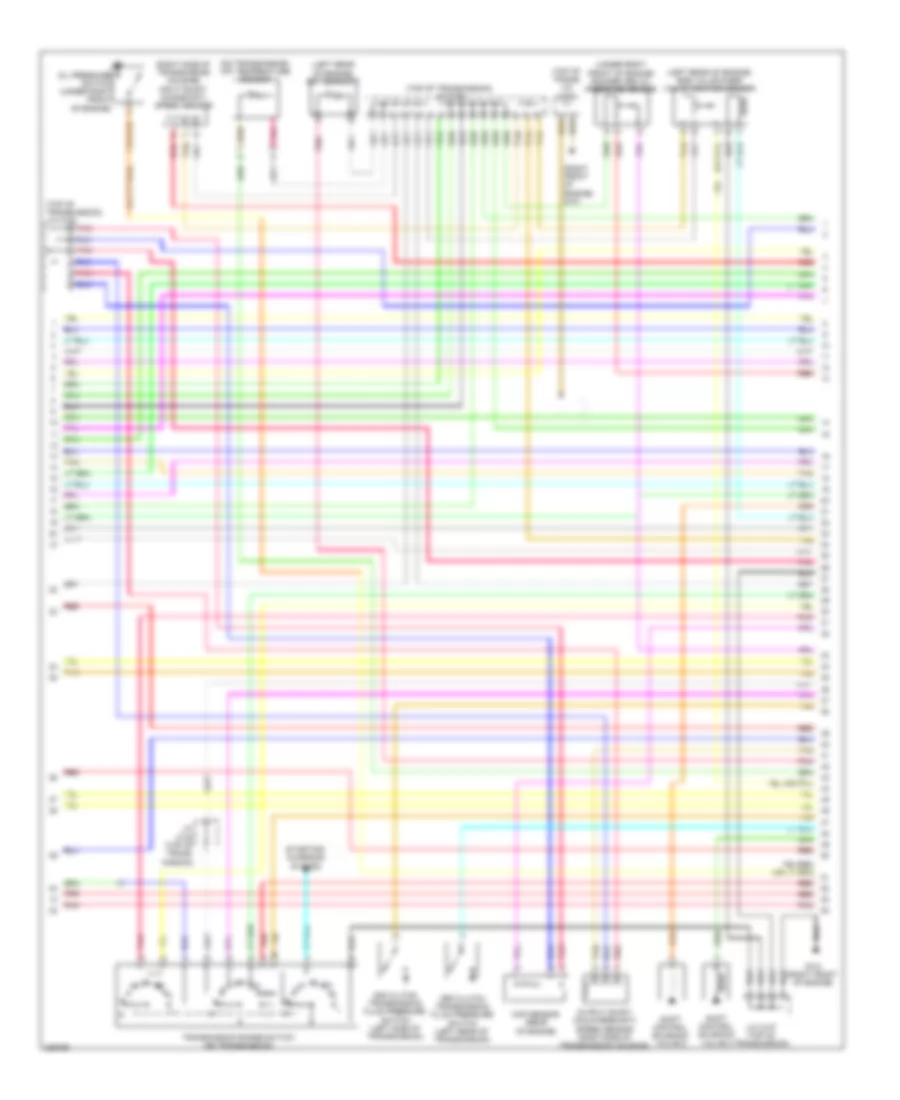
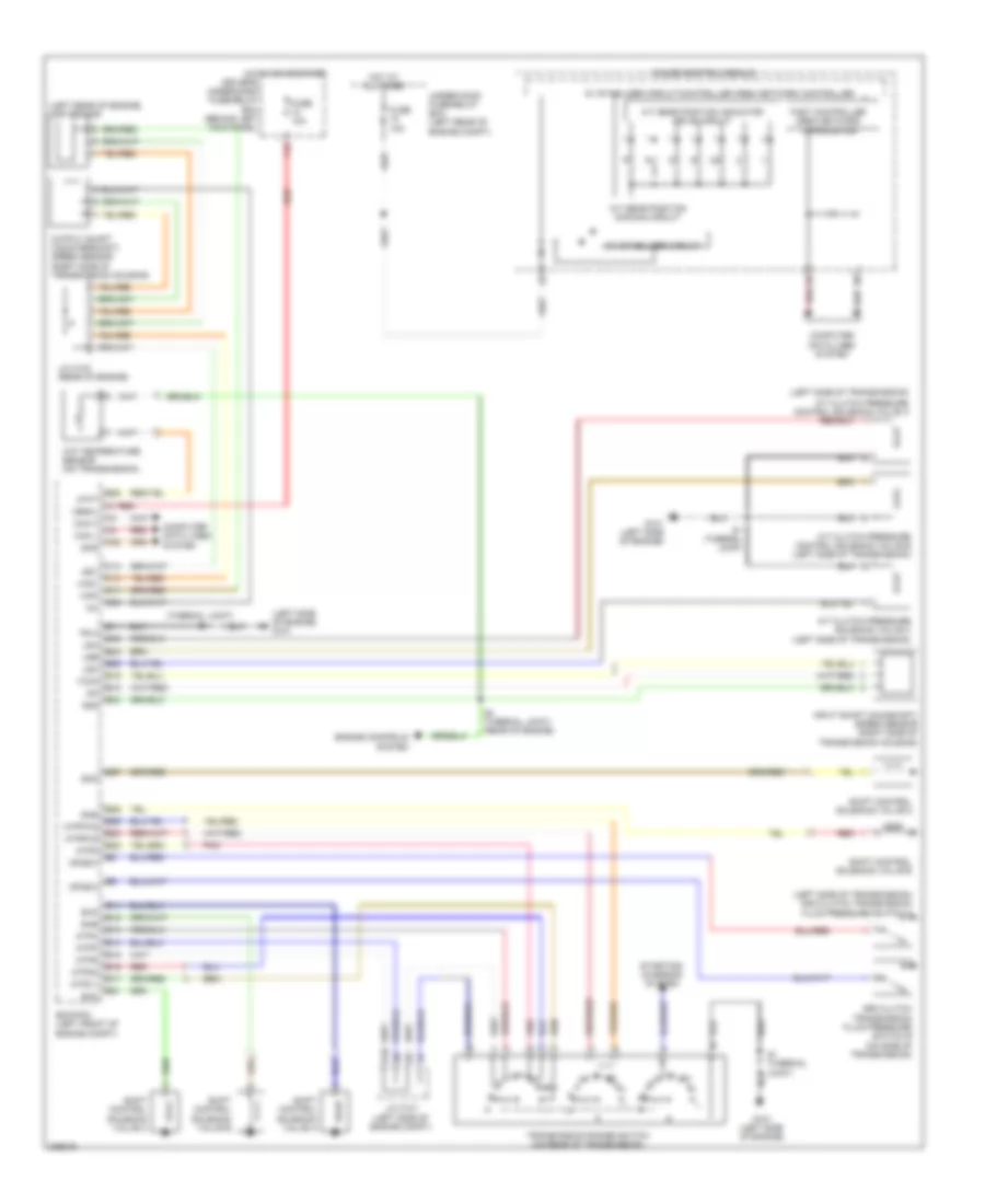
2.4L
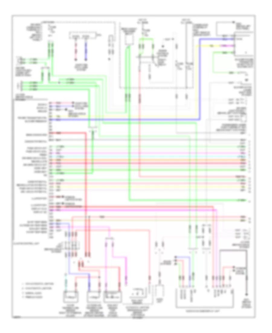
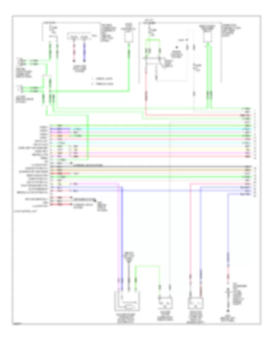
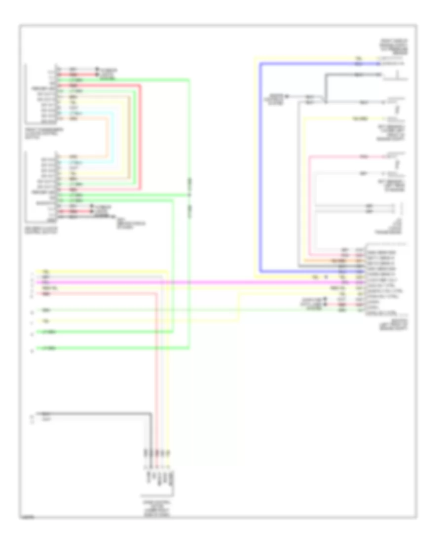
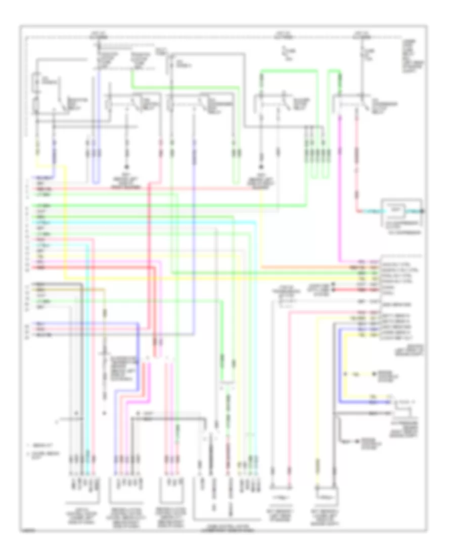
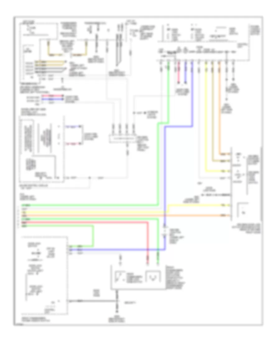
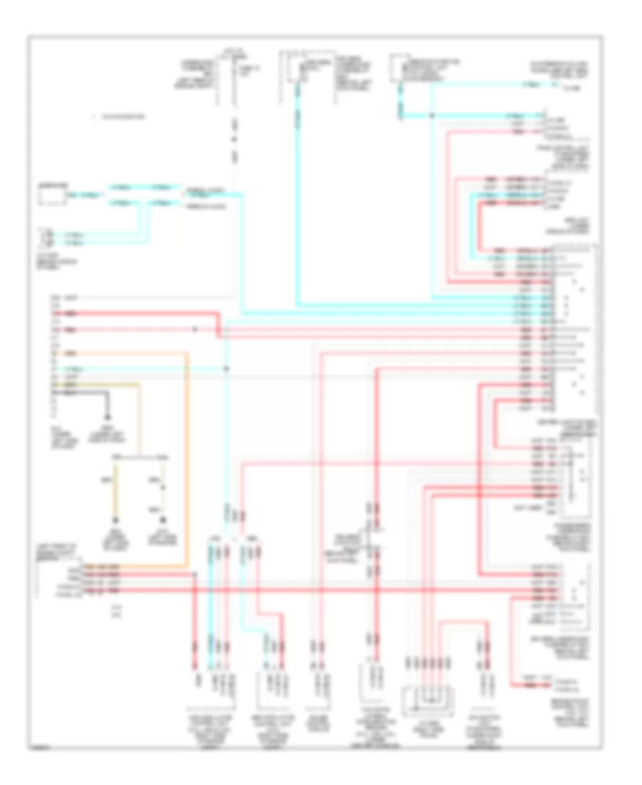
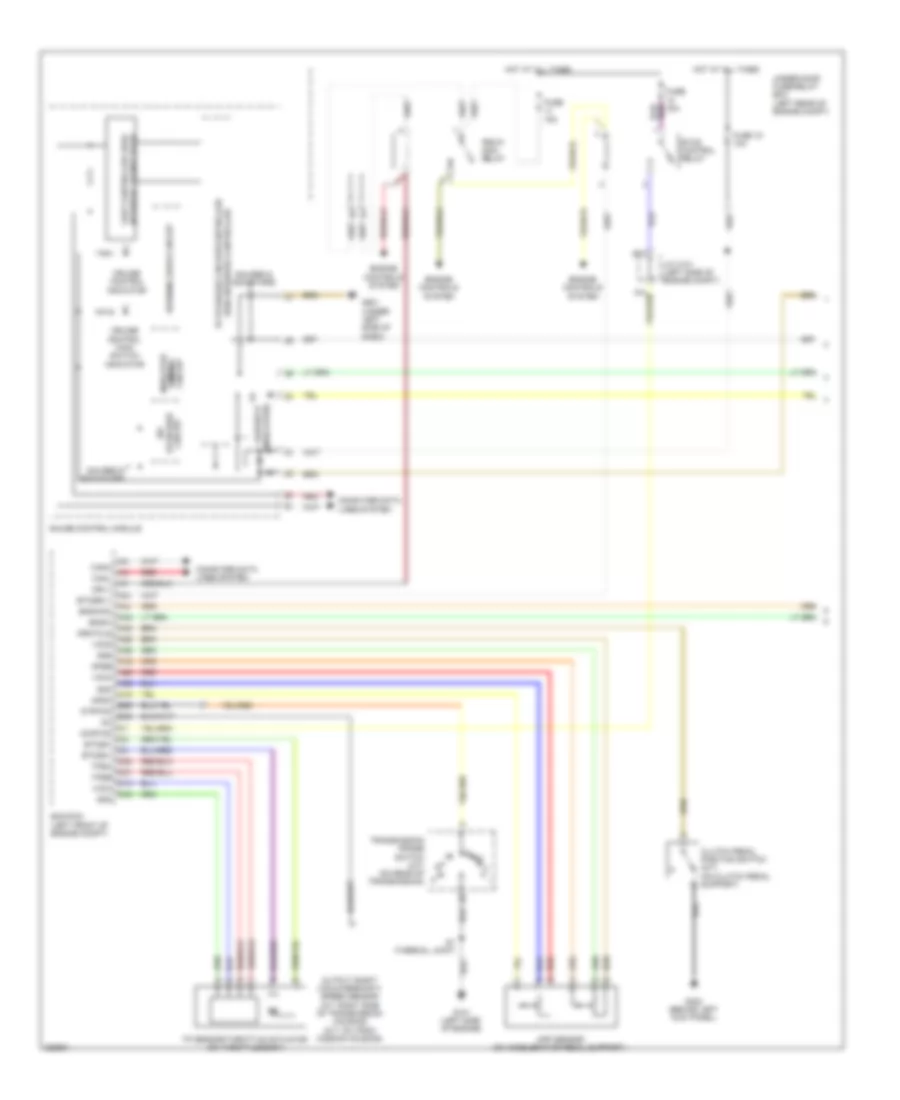
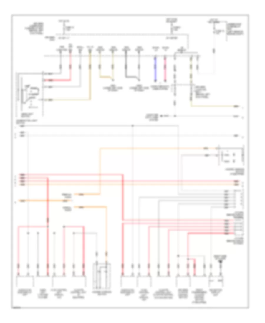
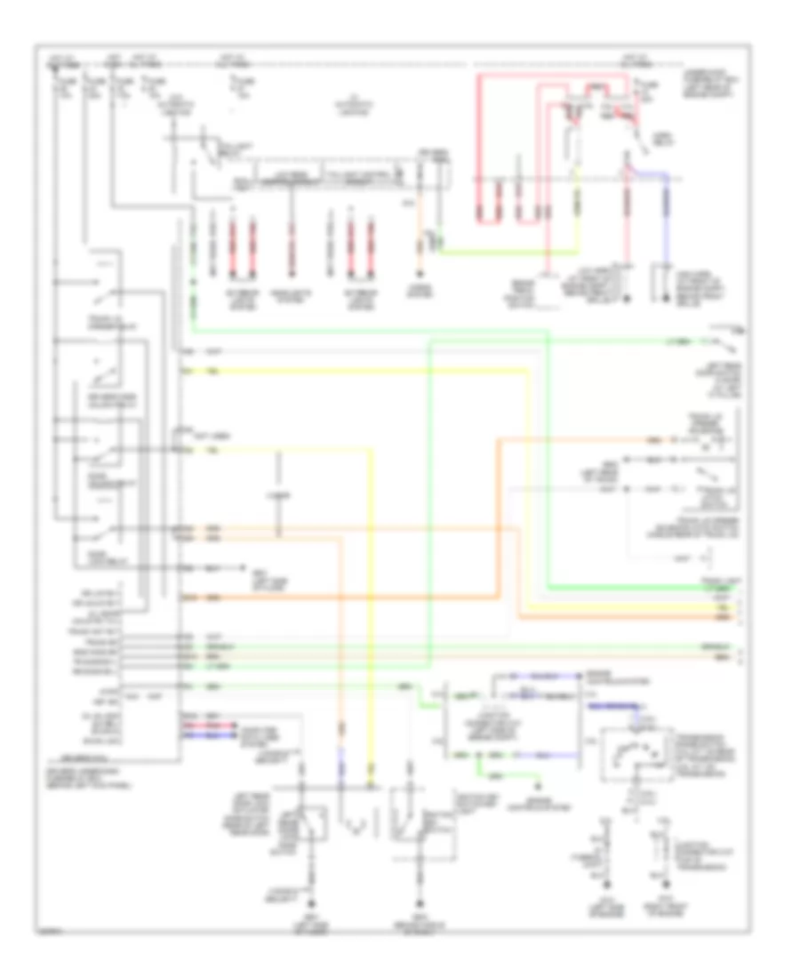
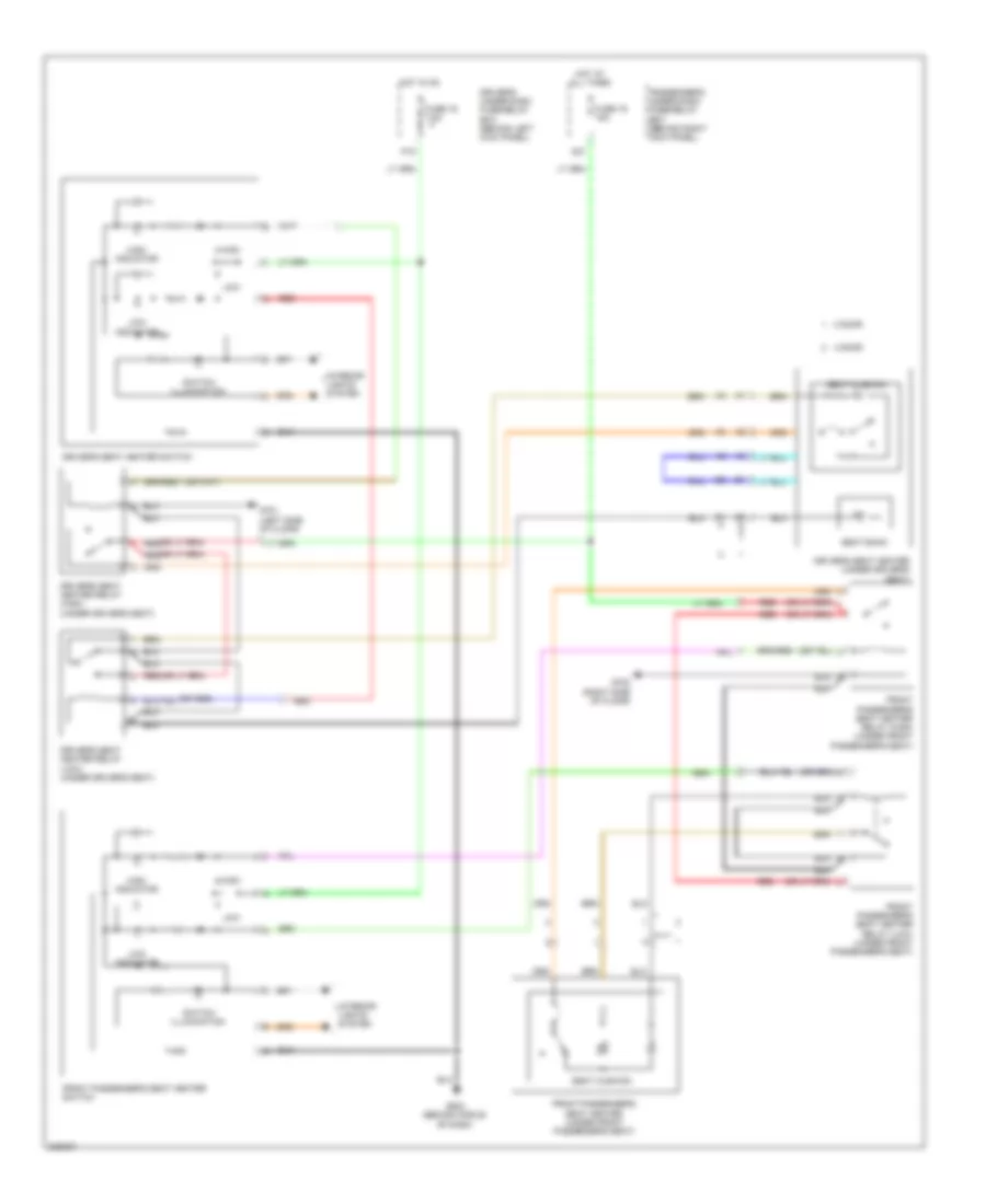
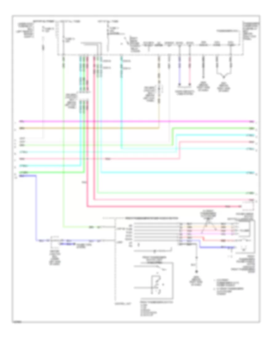
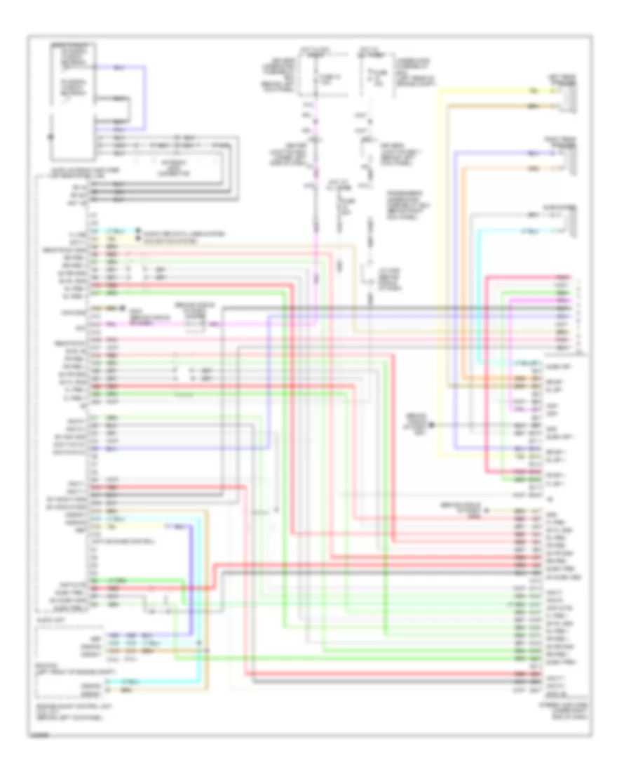
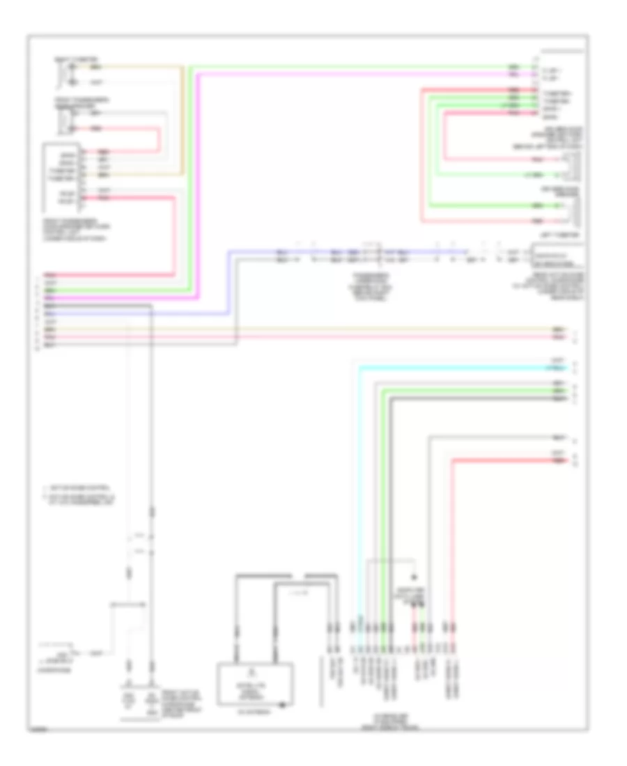
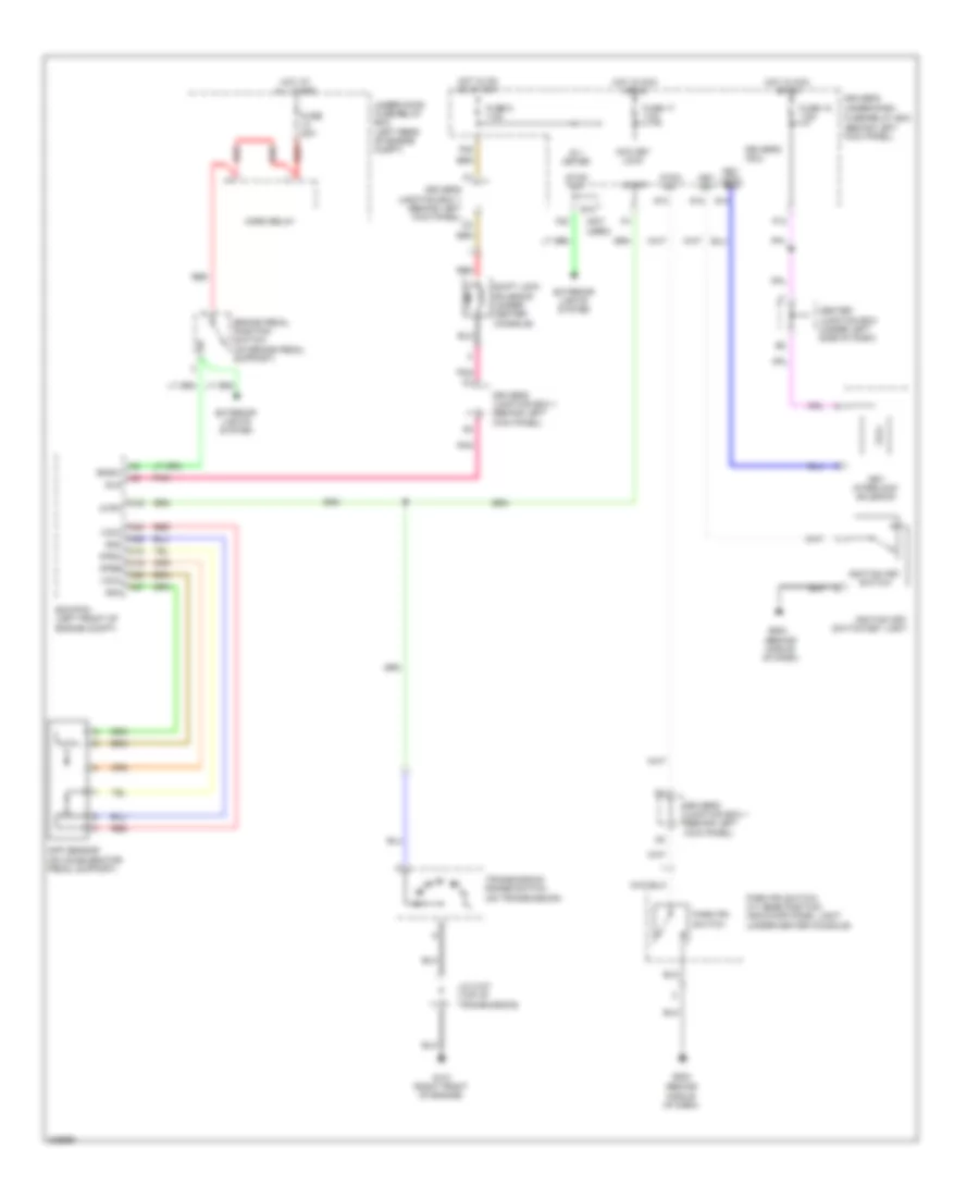
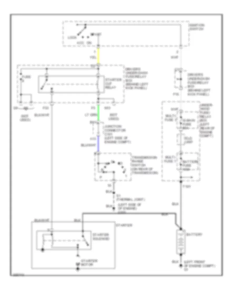
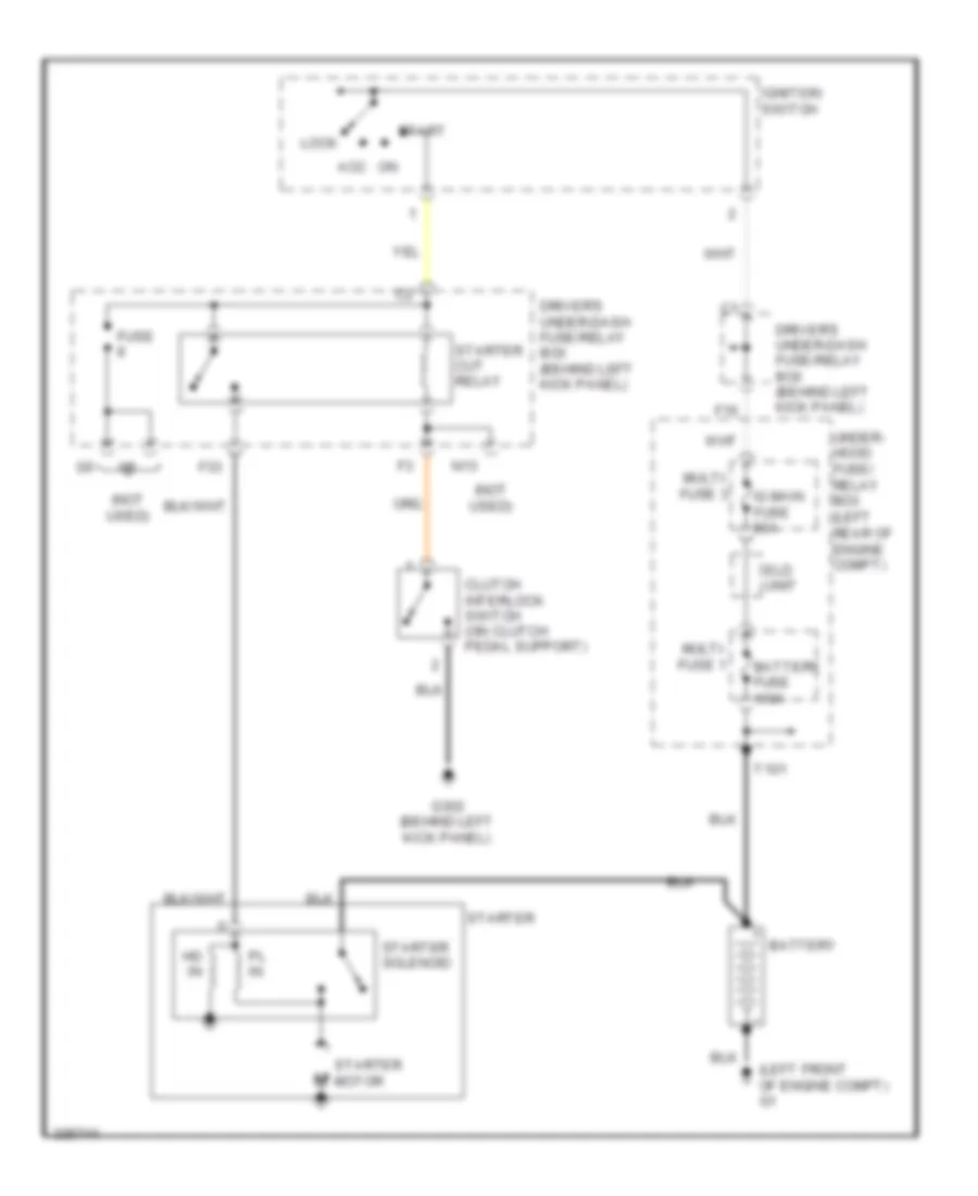
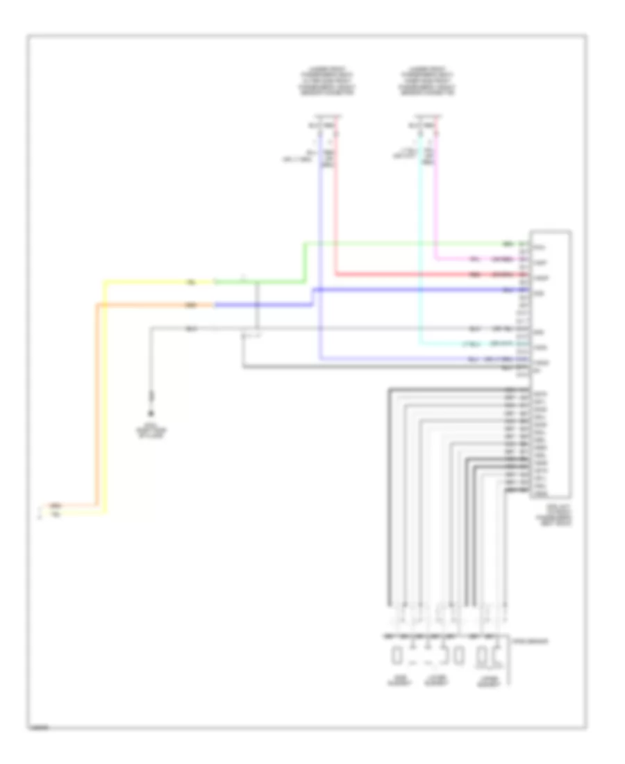
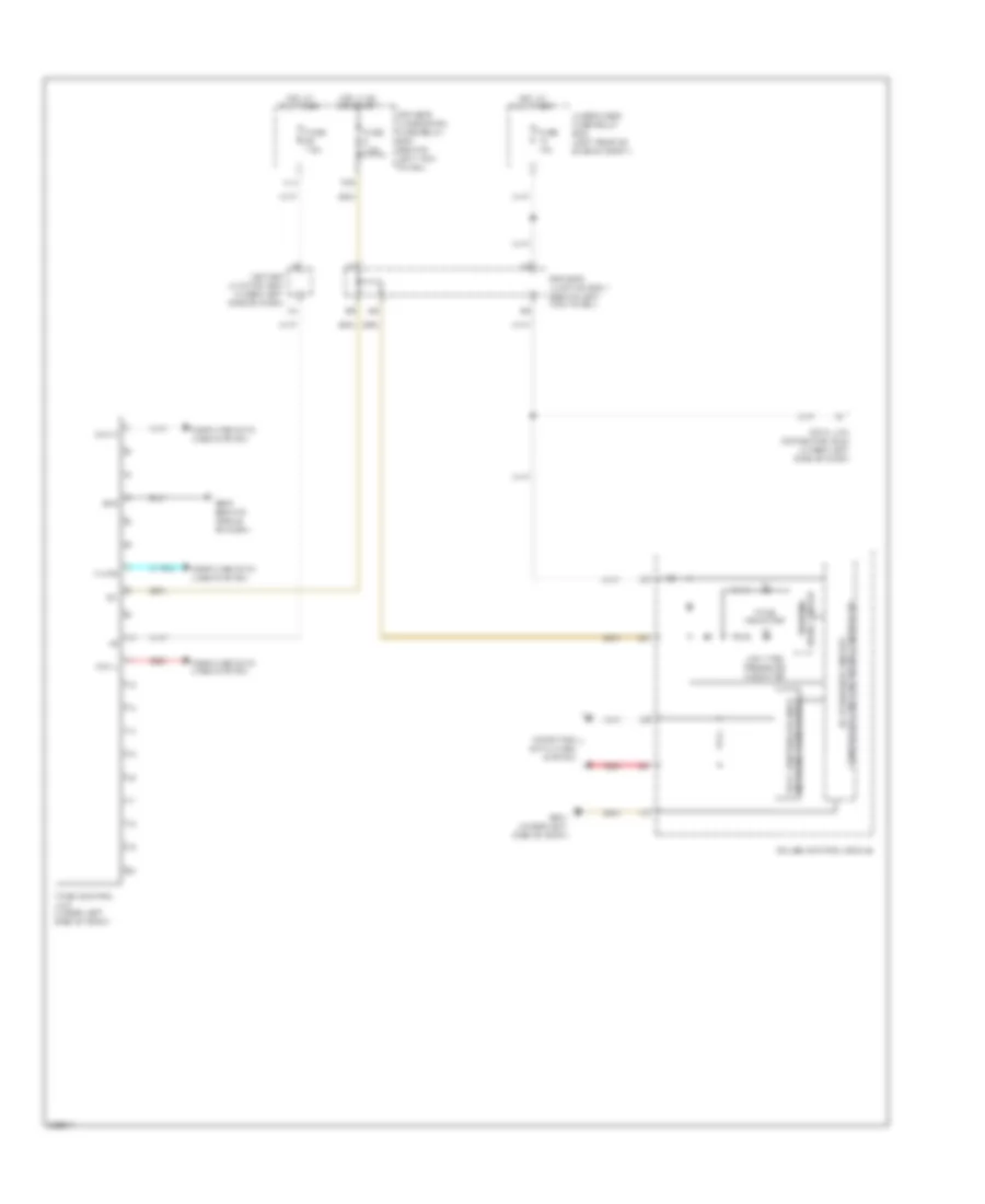
2.4L, Automatic A/C Wiring Diagram, with Navigation (1 of 3) for Honda Accord EX 2010

List of elements for 2.4L, Automatic A/C Wiring Diagram, with Navigation (1 of 3) for Honda Accord EX 2010:
- A10
- A11
- A12
- A13
- A14
- A15
- A16
- A17
- A18
- A19
- A20
- A21
- A22
- A23
- A24
- A25
- A26
- A27
- A28
- Ac-clk
- Audio unit
- Audio-hvac sub-display unit
- Automatic lighting sensor/sunlight sensor (top middle of dash)
- B can hi
- B can lo
- B-can hi
- B-can lo
- B10
- B11
- B12
- Blower feedback
- Blower motor (under right side of dash)
- Blower power transistor (on bottom of blower unit)
- Center junction box (under left side of dash)
- Climate control unit
- Climate ctrl sw
- Common potential
- Computer data lines system
- D16
- Display (clk)
- Display (si)
- Driver's air mix cool
- Driver's air mix hot
- Driver's junction box 1 (behind left kick panel)
- Driver's under-dash fuse/relay box (behind left kick panel)
- Drv air mix potential
- Duet cont
- Dute rx
- Dute tx
- Engine controls system
- Evap temp sens
- F11
- F26
- Fresh
- Fuse 10a
- Fuse 15a
- Fuse 7.5a
- G302 (behind left kick panel)
- G401 (behind middle of dash)
- Gnd
- Ground
- Hot at all times
- Hot in on
- Ig2
- Ill+
- Ill-
- In-car temp sens
- In-car temperature sensor (right of steering column)
- Interior lights system
- J/c c406 (behind middle of dash)
- J/c c408 (behind middle of dash)
- Micu
- Mode potential
- Mode vent
- Mode-heat
- Navigation system
- Navigation unit (clk)
- Navigation unit (si)
- Navigation unit (so)
- Normal audio
- Outside air temp sens
- Outside air temperature sensor (behind center of front bumper)
- P18
- Pass air mix cool
- Pass air mix hot
- Pass air mix potential
- Passenger's under- dash fuse/relay box (behind right kick panel)
- Pgm-fi sub- relay
- Pnk
- Power transistor ctrl
- Premium audio
- Rear window defogger relay
- Recirculate
- Recirculation potential
- Red
- Sc-so
- Sens common gnd
- Sound systems
- Sun light sensor
- Sunlight sens
- Under-hood fuse/relay box (left rear of engine compt)
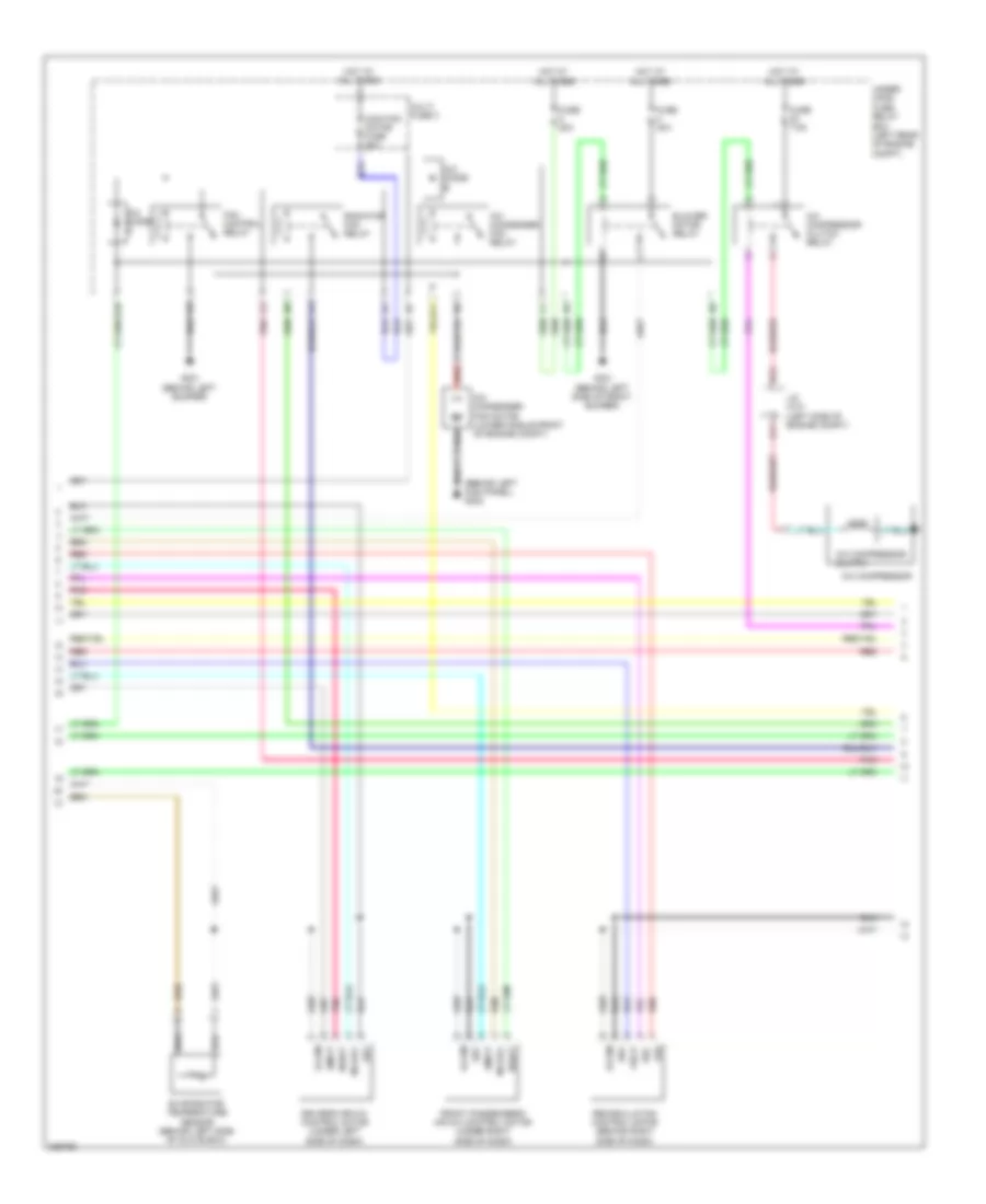
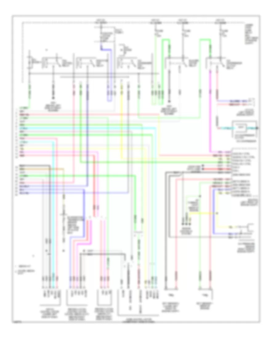
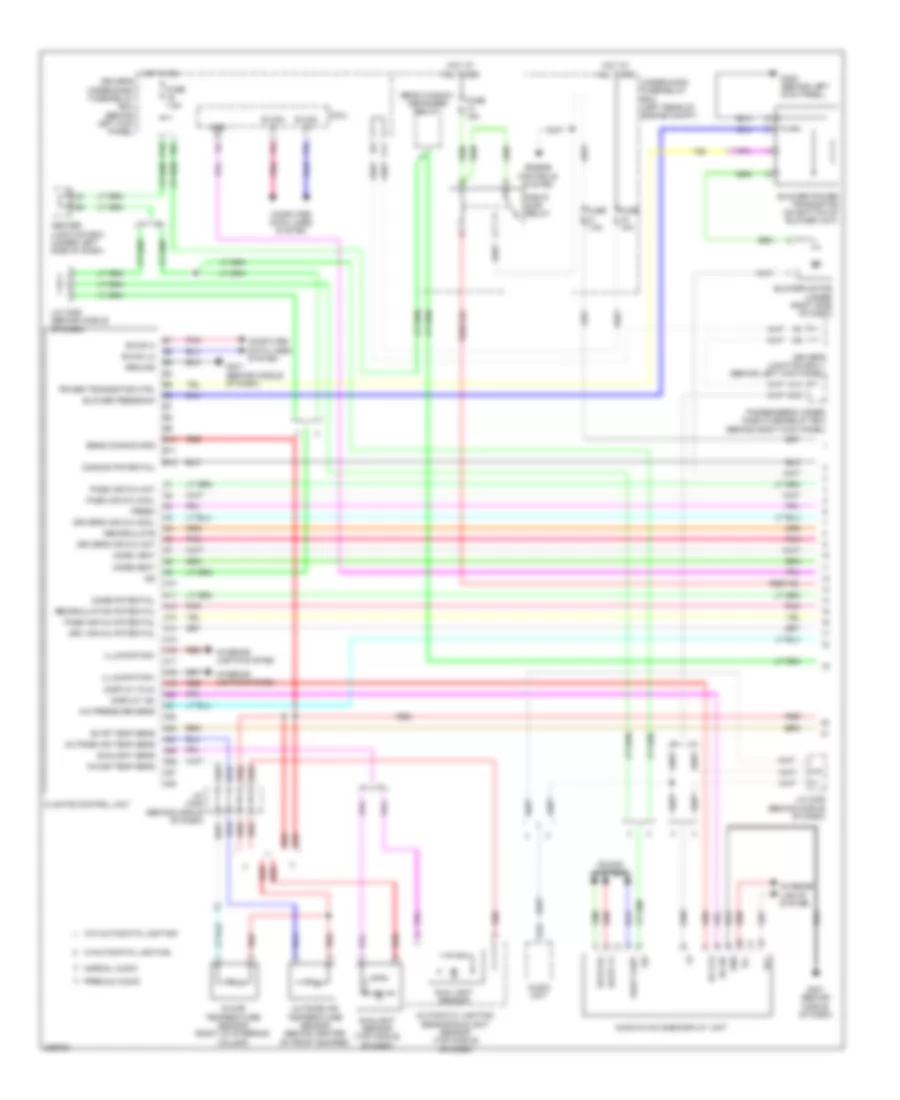
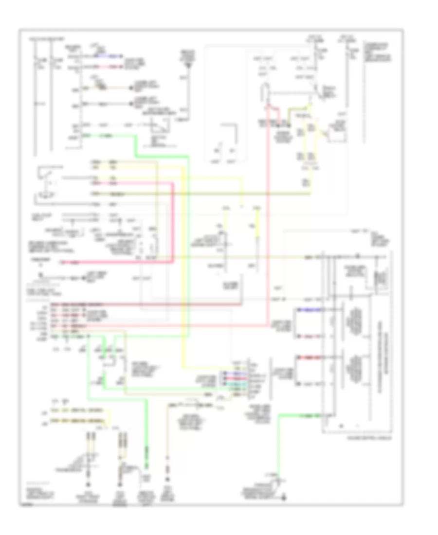
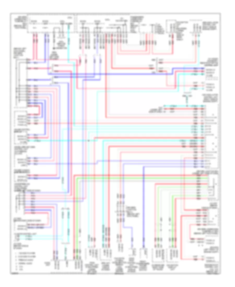
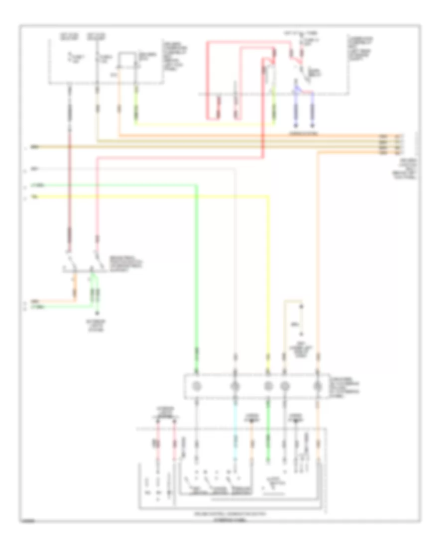
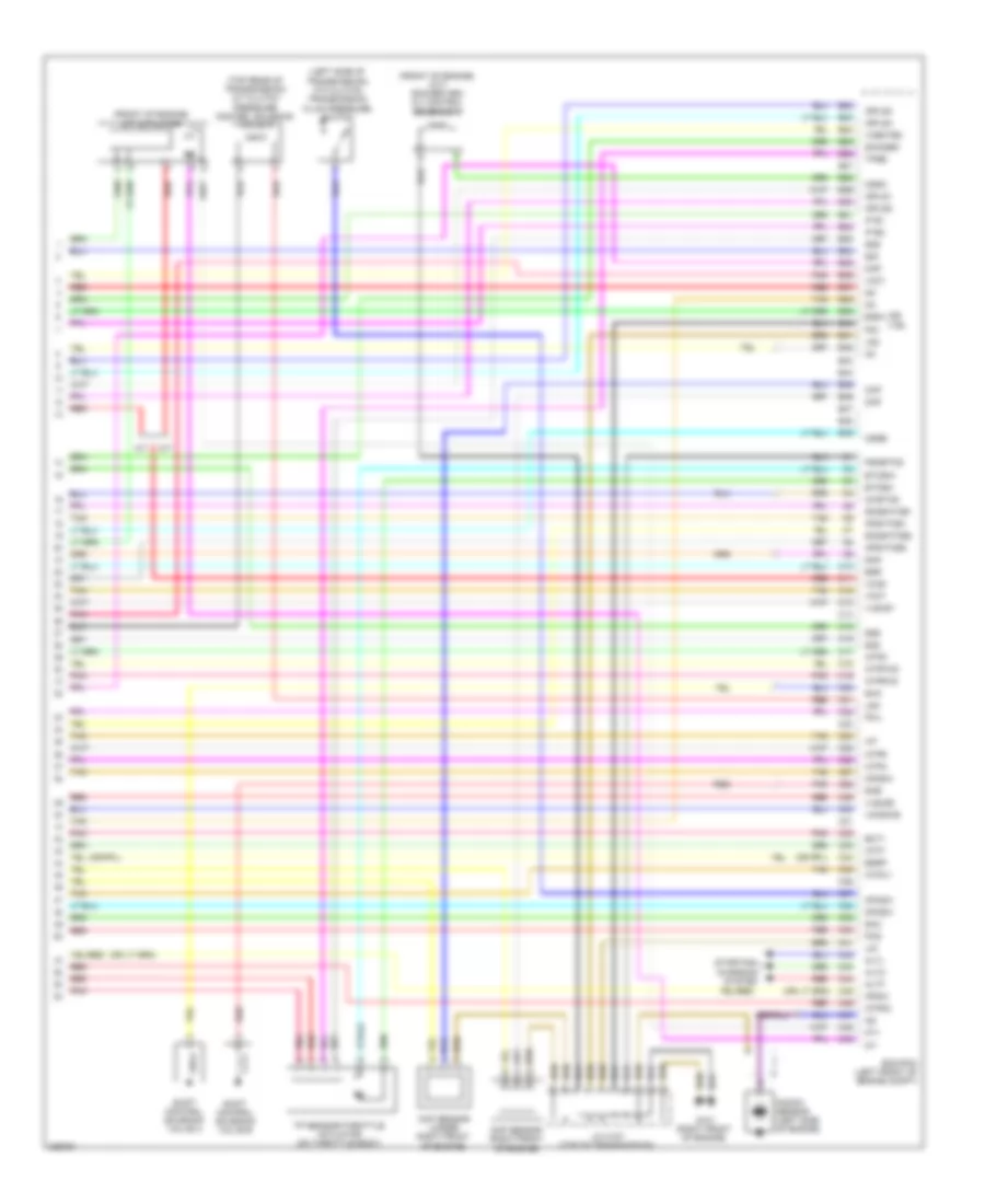
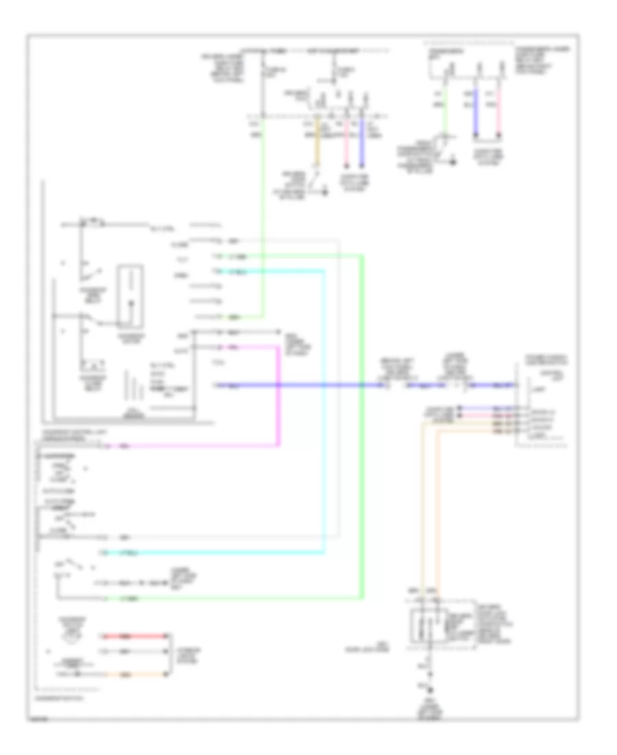
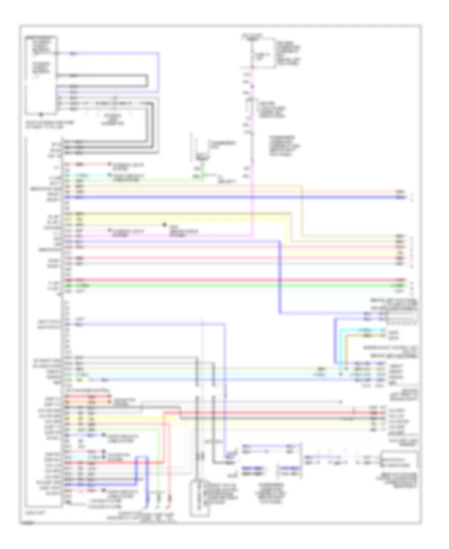
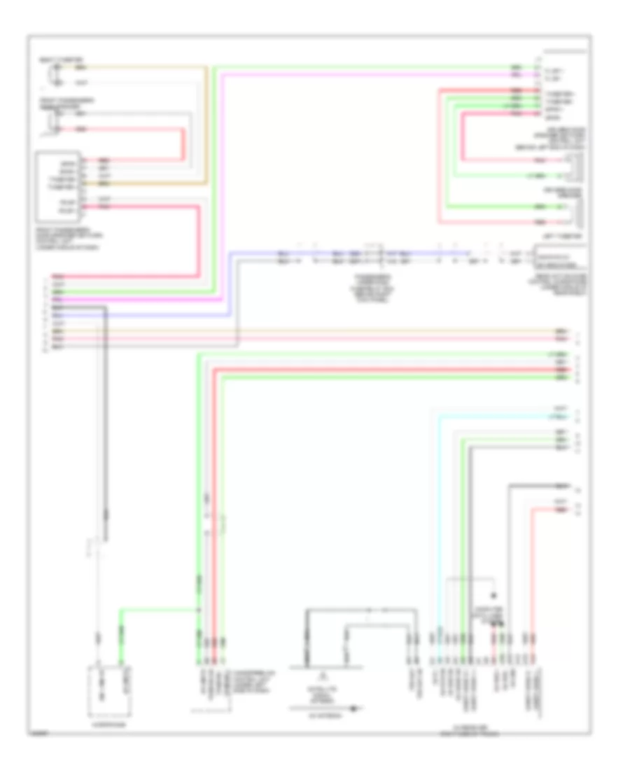
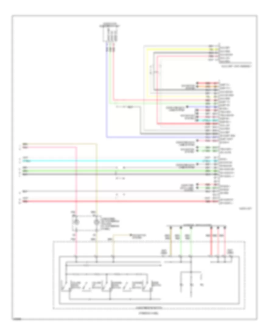
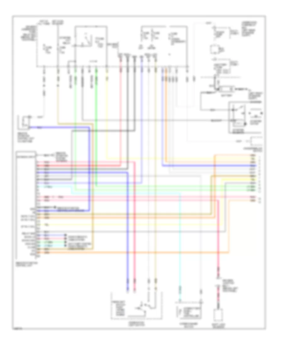
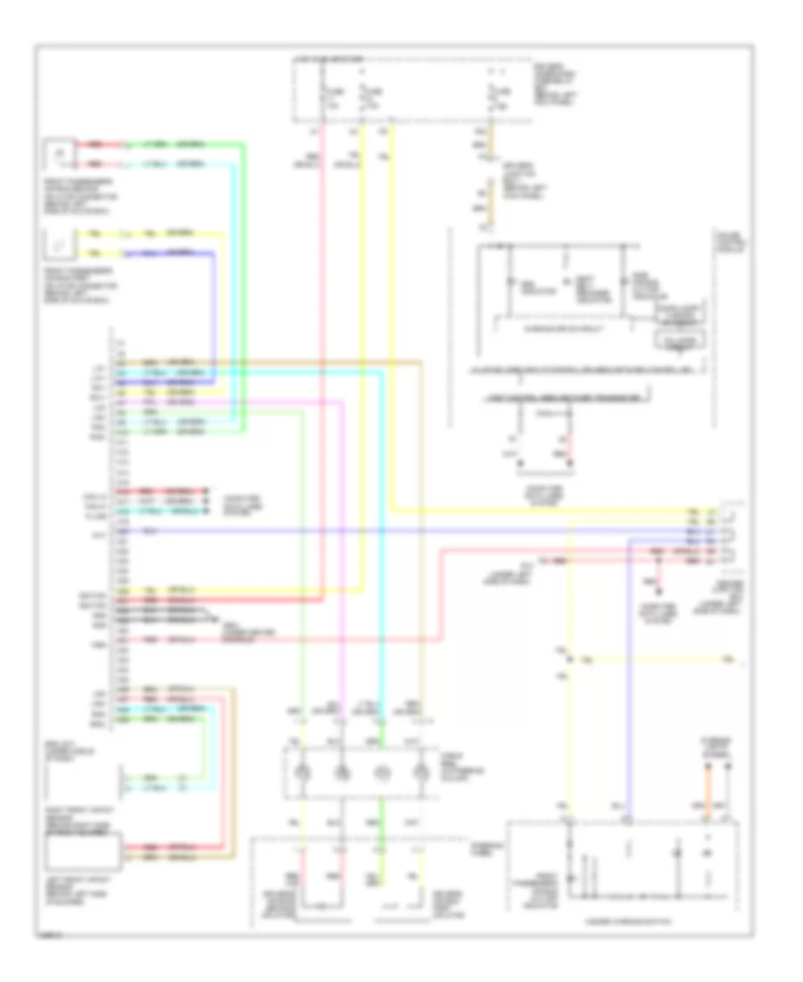
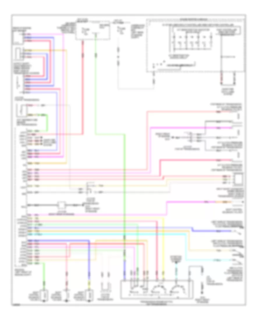
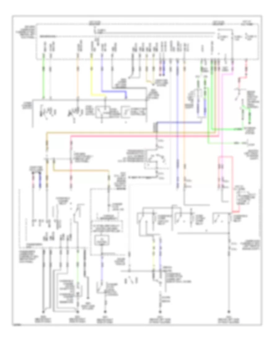
2.4L, Automatic A/C Wiring Diagram, with Navigation (2 of 3) for Honda Accord EX 2010
List of elements for 2.4L, Automatic A/C Wiring Diagram, with Navigation (2 of 3) for Honda Accord EX 2010:
- (behind left kick panel) g302
- A/c compressor
- A/c compressor clutch
- A/c compressor clutch relay
- A/c condenser fan motor (lower middle front of engine compt)
- A/c condenser fan relay
- A/c diode a
- A/c diode b
- A11
- Amd-p
- B10
- B11
- B13
- Blower motor relay
- Driver's air mix control motor (under left side of dash)
- Evaporator temperature sensor (behind left side of glove box)
- Fan control relay
- Frd-p
- Front passenger's air mix control motor (under right side of dash)
- Frs
- Fuse 20a
- Fuse 40a
- Fuse 7.5a
- G301 (behind left bumper)
- G301 (behind left side of front bumper)
- Hot at all times
- J/c c101 (left side of engine compt)
- M-cool
- M-hot
- Main fan motor fuse 30a
- Multi fuse 3
- Pnk
- Radiator fan relay
- Rec
- Recirculation control motor (behind right side of dash)
- Red
- S-com
- S5v
- Under- hood fuse/ relay box (left rear of engine compt)
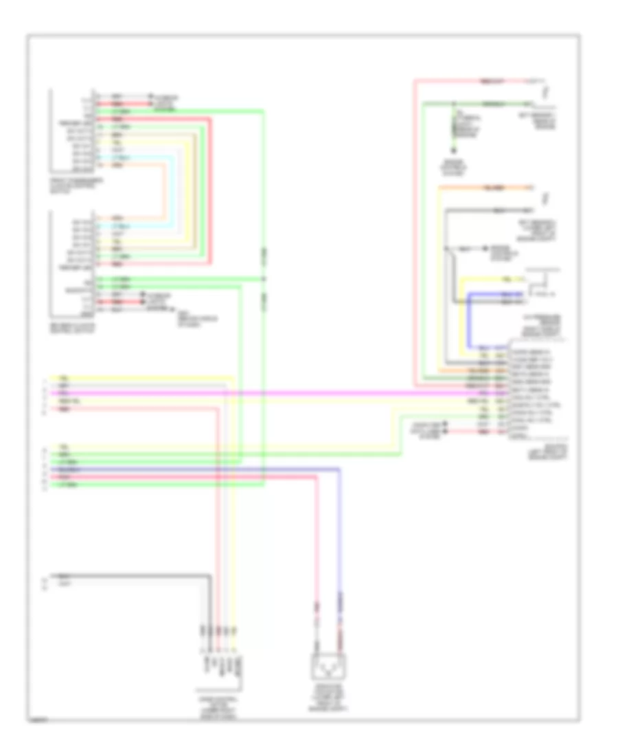
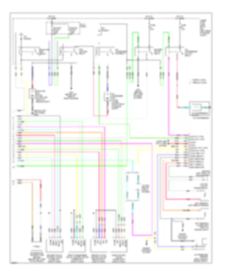
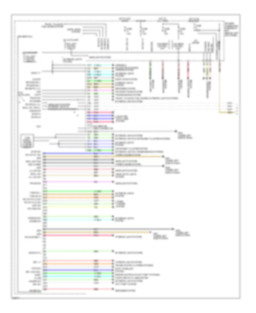
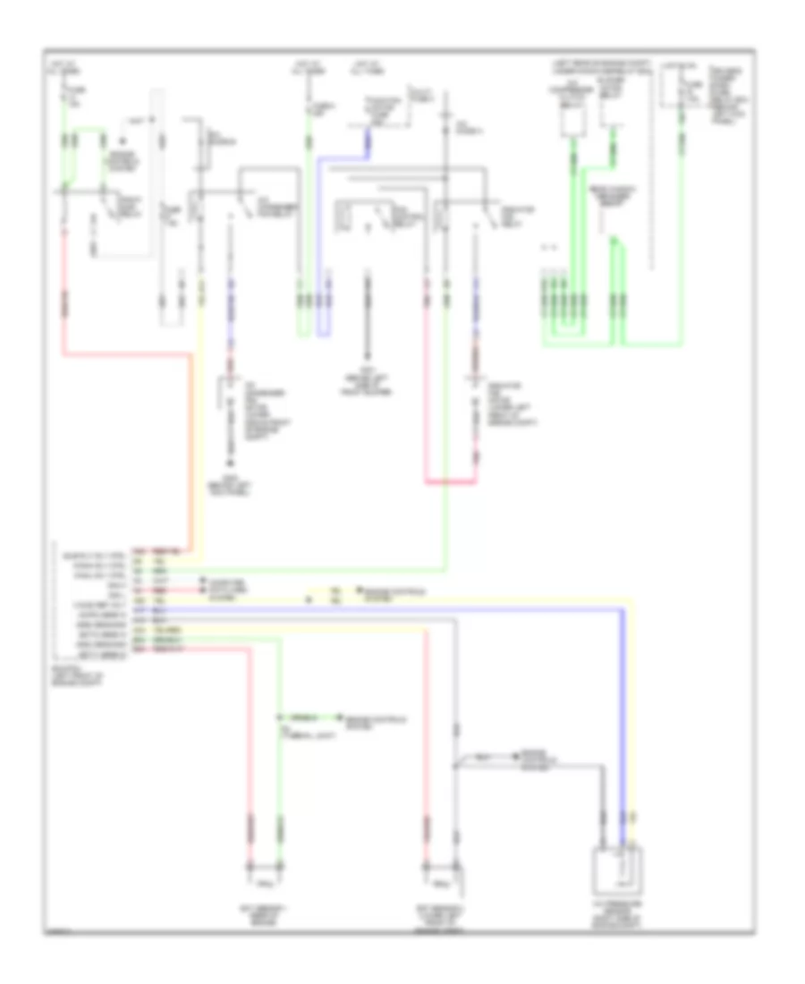
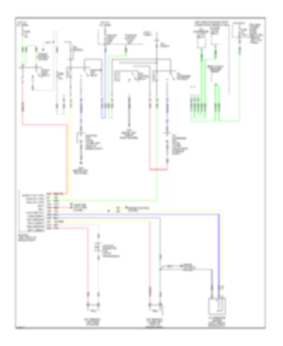
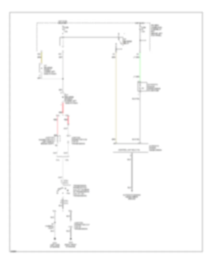
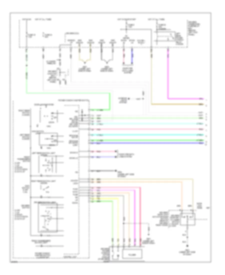
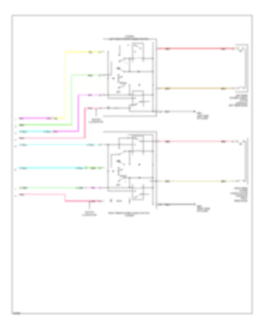
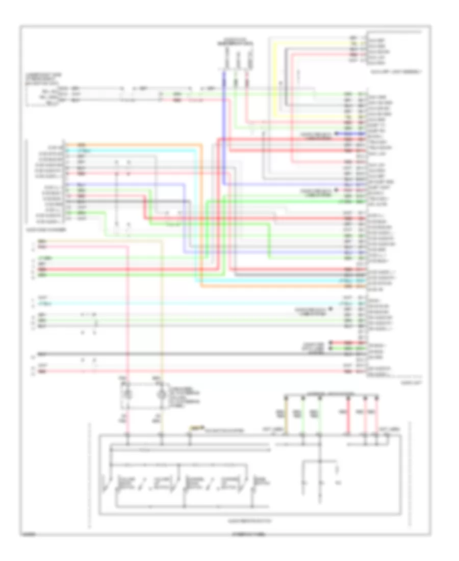
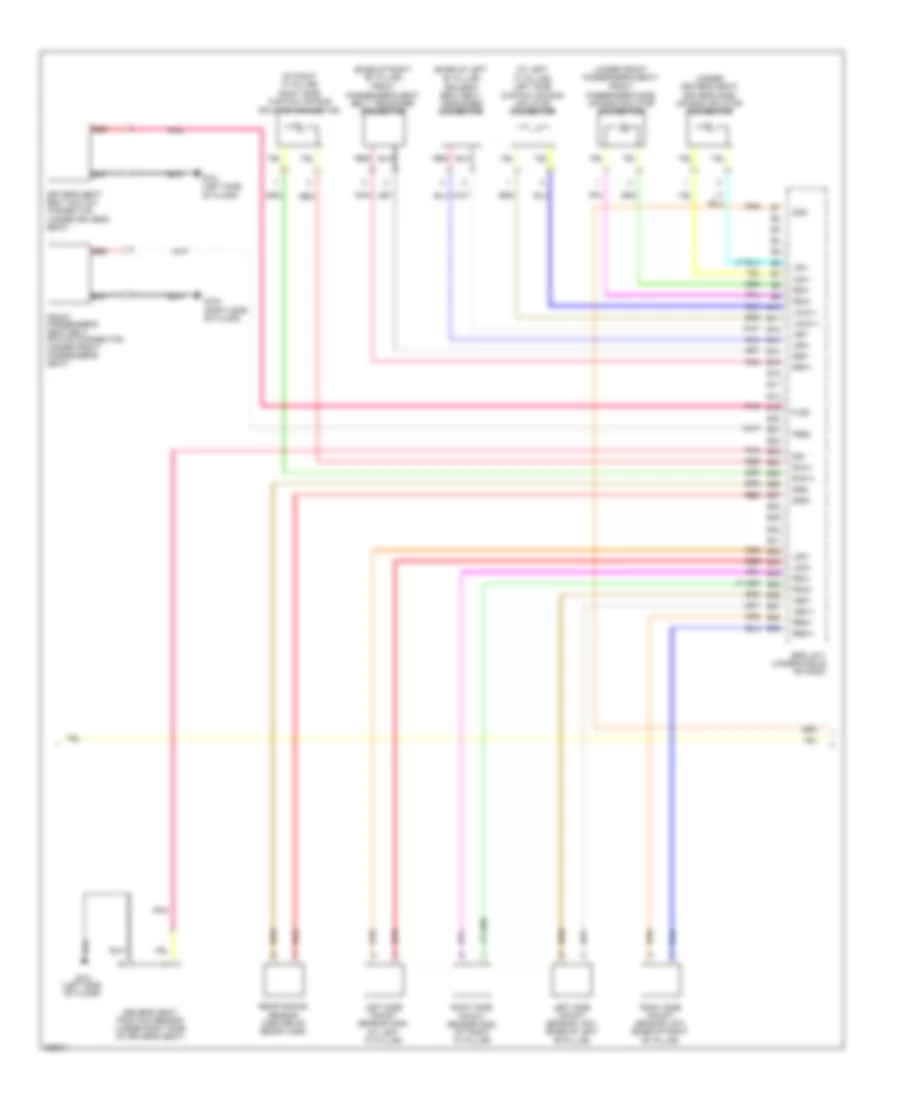
2.4L, Automatic A/C Wiring Diagram, with Navigation (3 of 3) for Honda Accord EX 2010
List of elements for 2.4L, Automatic A/C Wiring Diagram, with Navigation (3 of 3) for Honda Accord EX 2010:
- (acc) rly ctrl
- (acpd) sens in
- (canh)
- (canl)
- (ect1) sens in
- (ect2) sens in
- (fanc) rly ctrl
- (fanl) rly ctrl
- (sg2) sens gnd
- (sg7) sens gnd
- (sub rly) rly ctrl
- (vcc6) ref volt
- A/c pressure sensor (right side of engine compt)
- A10
- A15
- A17
- A20
- A22
- A34
- B24
- B34
- Bus-data
- Computer data lines system
- Driver's climate control switch
- Ecm/pcm (left front of engine compt)
- Ect sensor 1 (rear of engine)
- Ect sensor 2 (lower left front of engine compt)
- Engine controls system
- Front passenger's climate control switch
- G401 (behind middle of dash)
- Gnd
- Ig2
- Ill+
- Ill-
- Interior lights system
- Joint) (rear of engine)
- M-def
- M-vent
- Mode control motor (under right side of dash)
- Mode-p
- Per-def-led
- Pnk
- Radiator fan motor (lower left front of engine compt)
- Red
- S-com
- S5v
- Sw in-1
- Sw in-2
- Sw in-3
- Sw in-4
- Sw out-3
- Sw out-4
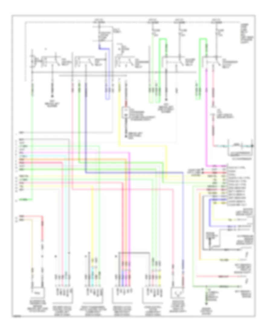
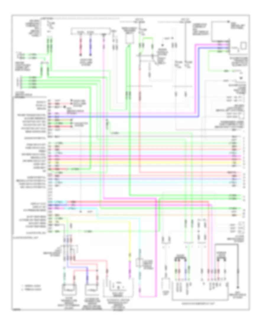
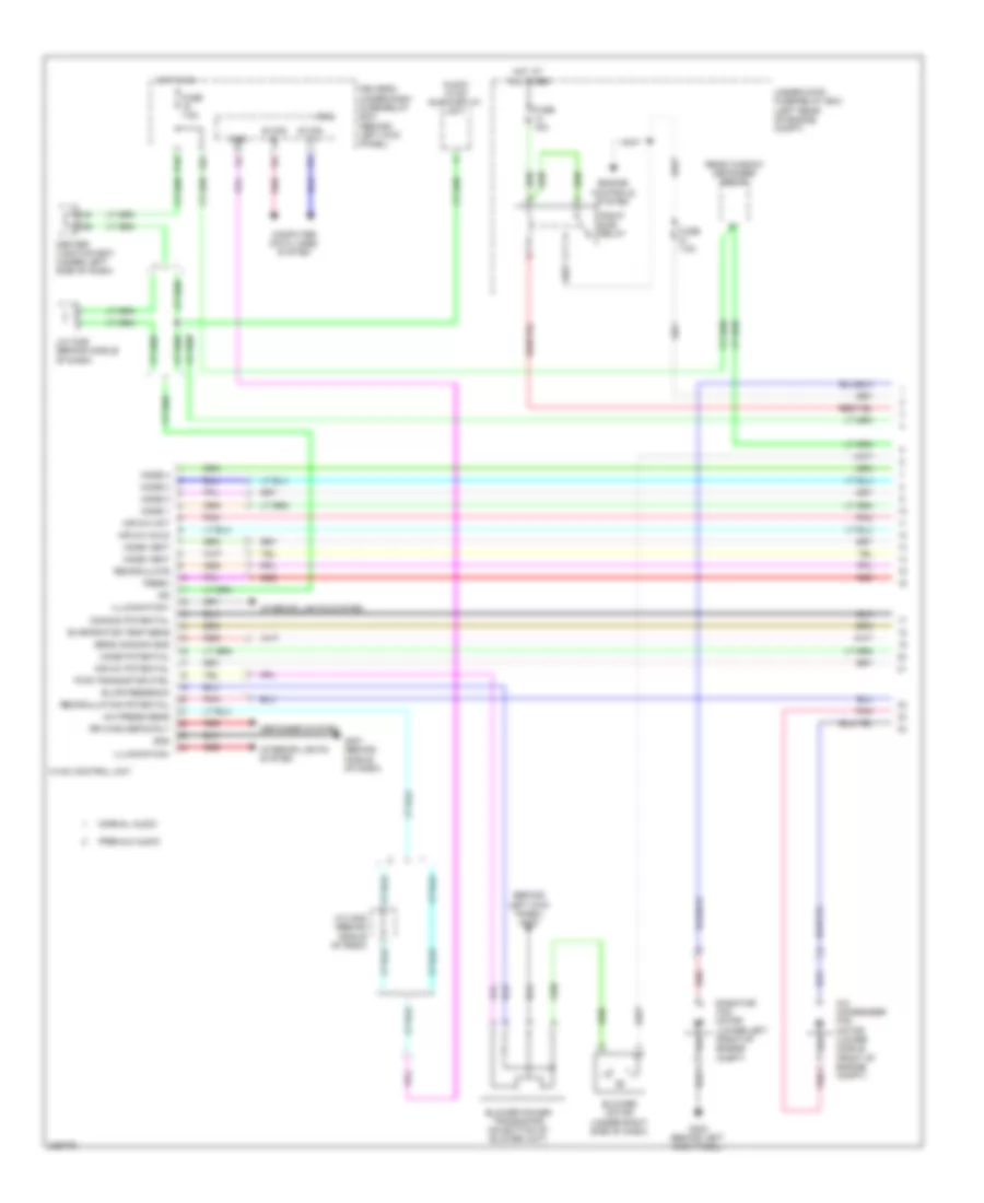
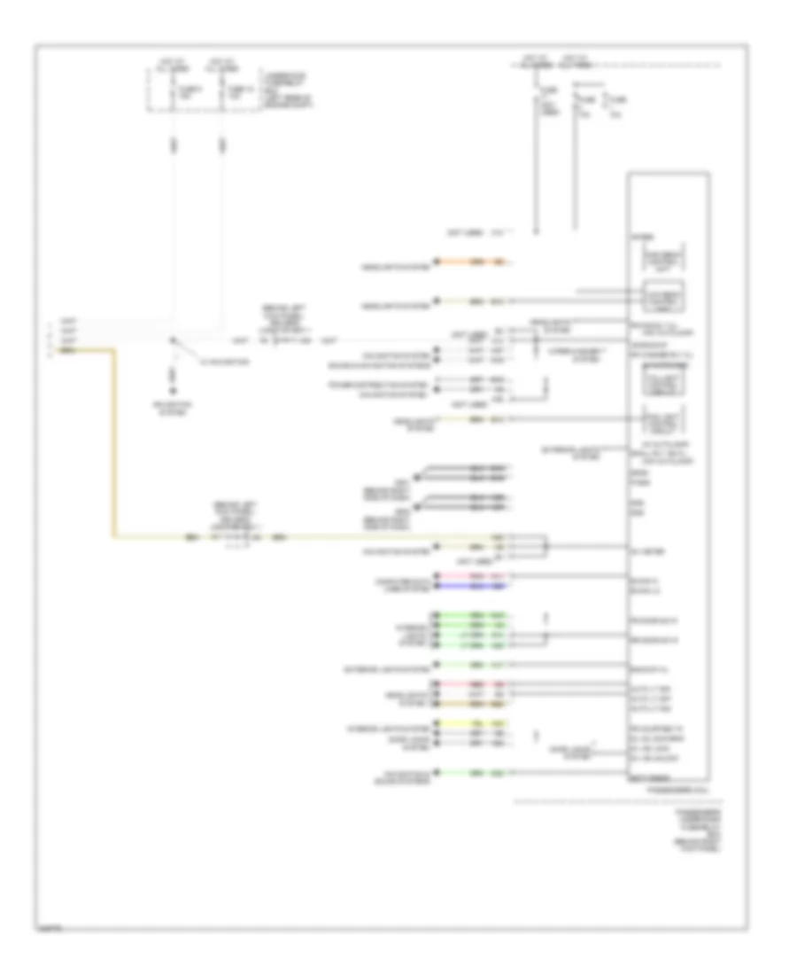
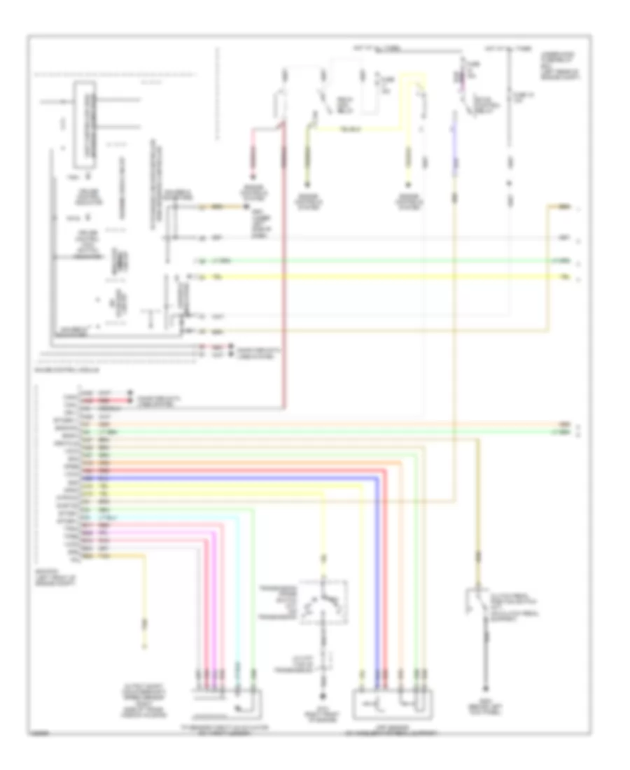
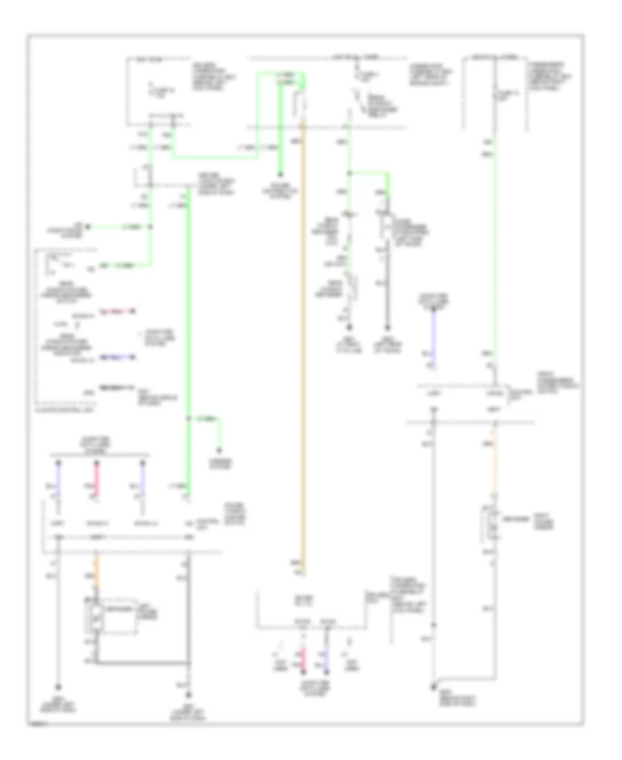
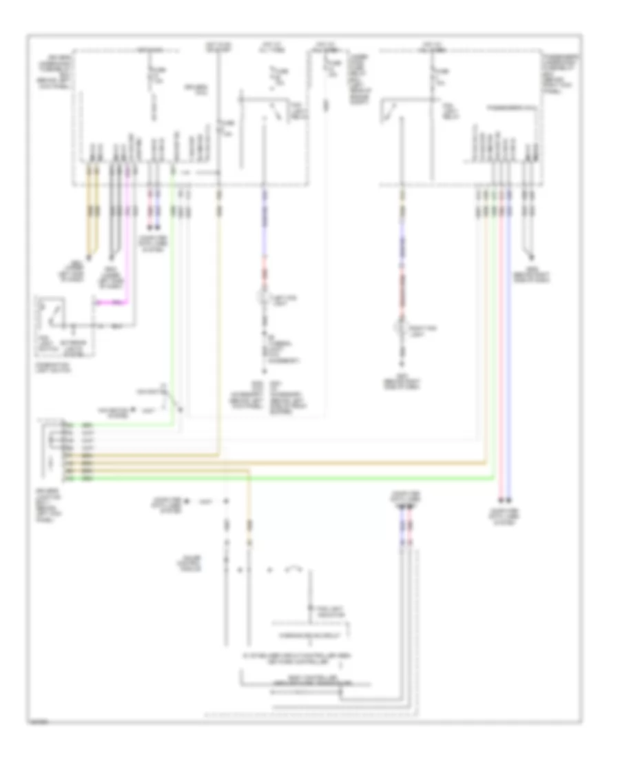
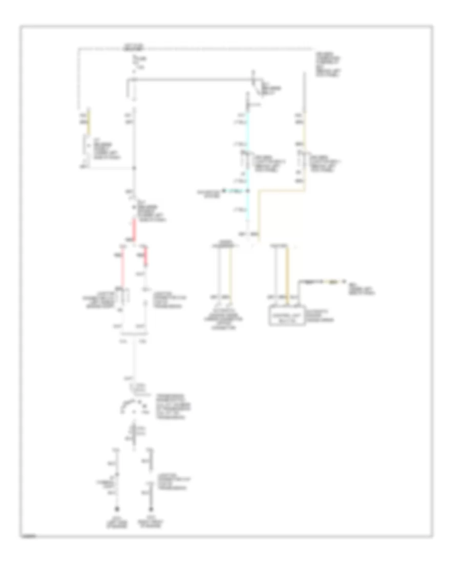
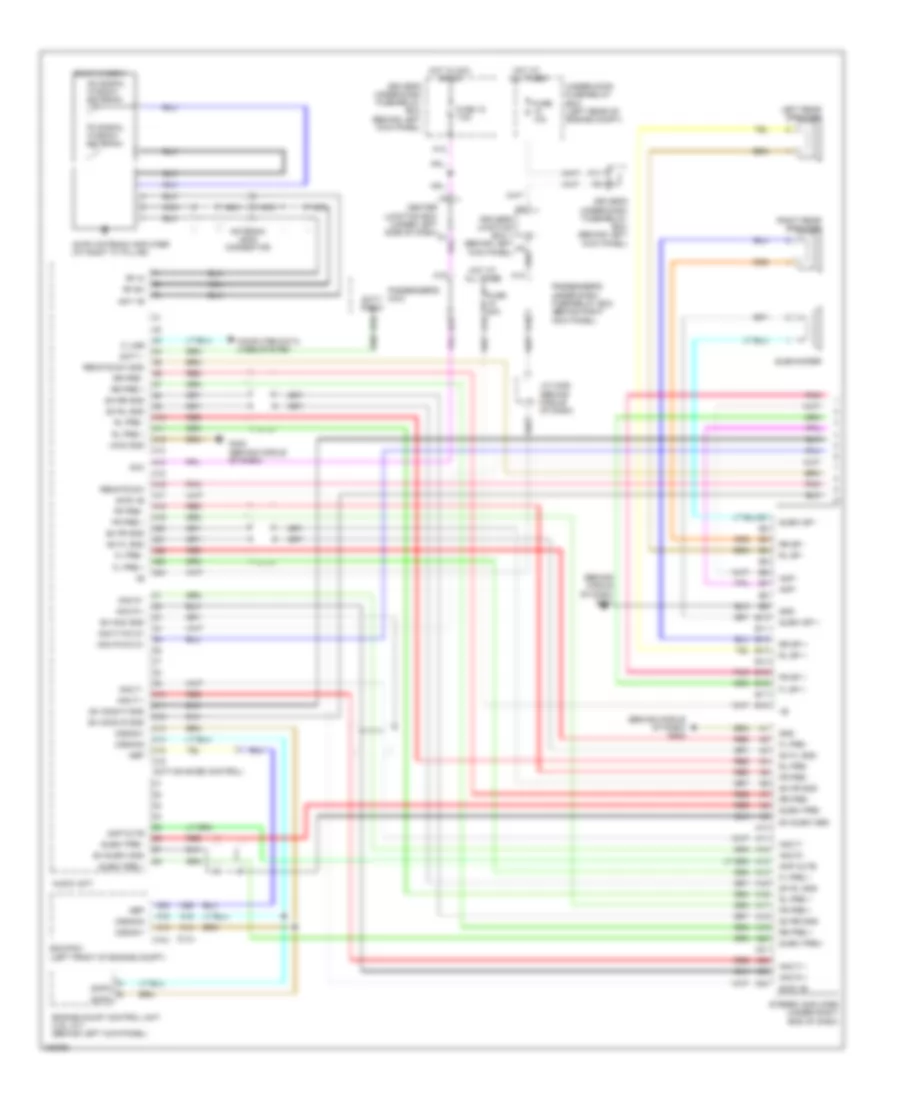
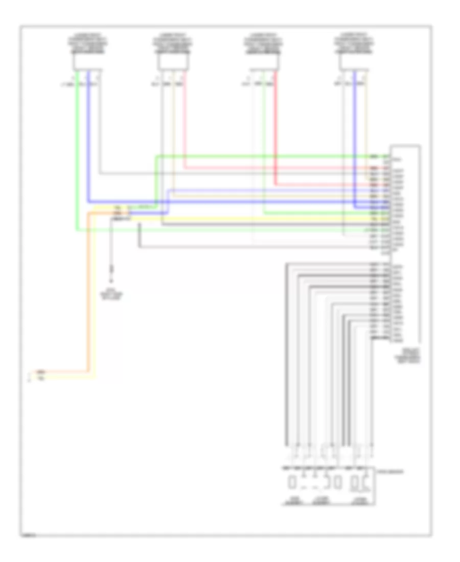
2.4L, Automatic A/C Wiring Diagram, without Navigation (1 of 2) for Honda Accord EX 2010
List of elements for 2.4L, Automatic A/C Wiring Diagram, without Navigation (1 of 2) for Honda Accord EX 2010:
- A10
- A11
- A12
- A13
- A14
- A15
- A16
- A17
- A18
- A19
- A20
- A21
- A22
- A23
- A24
- A25
- A26
- A27
- A28
- Ac-clk
- Audio unit
- Audio-hvac sub-display unit
- Automatic lighting sensor/sunlight sensor (top middle of dash)
- B can hi
- B can lo
- B-can h
- B-can lo
- B10
- B11
- B12
- Blower feedback
- Blower motor (under right side of dash)
- Blower power transistor (on bottom of blower unit)
- Center junction box (under left side of dash)
- Climate control unit
- Common potential
- Computer data lines system
- D16
- Display (clk)
- Display (si)
- Driver's air mix cool
- Driver's air mix hot
- Driver's junction box 1 (behind left kick panel)
- Driver's under-dash fuse/relay box (behind left kick panel)
- Drv air mix potential
- Duet cont
- Dute rx
- Dute tx
- Engine controls system
- Evap temp sens
- F11
- F26
- Fresh
- Fuse 10a
- Fuse 15a
- Fuse 7.5a
- G302 (behind left kick panel)
- G401 (behind middle of dash)
- Gnd
- Ground
- Hot at all times
- Hot in on
- Ig2
- Ill+
- Ill-
- Illumination+
- Illumination-
- In-car temp sens
- In-car temperature sensor (right of steering column)
- Interior lights system
- J/c c406 (behind middle of dash)
- J/c c408 (behind middle of dash)
- Micu
- Mode potential
- Mode vent
- Mode-heat
- Normal audio
- Outside air temp sens
- Outside air temperature sensor (behind center of front bumper)
- P18
- Pass air mix cool
- Pass air mix hot
- Pass air mix potential
- Passenger's under- dash fuse/relay box (behind right kick panel)
- Pgm-fi sub- relay
- Pnk
- Power transistor ctrl
- Premium audio
- Rear window defogger relay
- Recirculate
- Recirculation potential
- Red
- Sc-so
- Sens common gnd
- Sound systems
- Sun light sensor
- Sunlight sens
- Sunlight sensor (top middle of dash)
- Under-hood fuse/relay box (left rear of engine compt)
- W/automatic lighting
- W/o automatic lighting
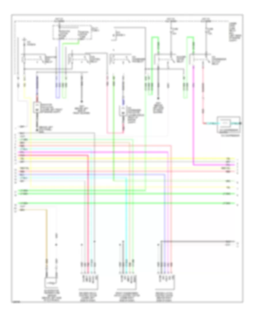
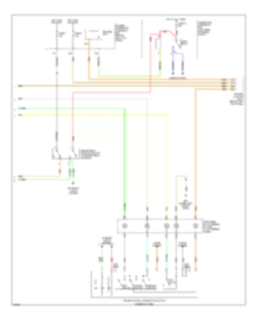
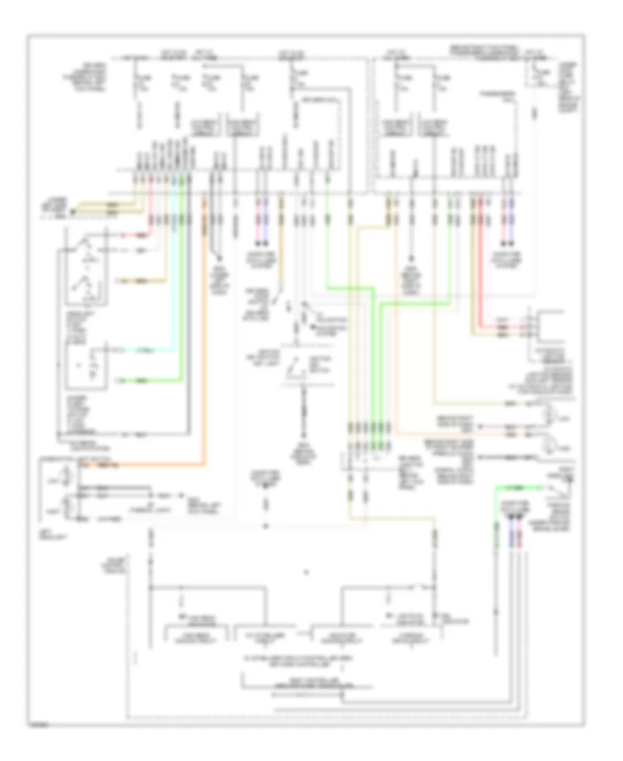
2.4L, Automatic A/C Wiring Diagram, without Navigation (2 of 2) for Honda Accord EX 2010
List of elements for 2.4L, Automatic A/C Wiring Diagram, without Navigation (2 of 2) for Honda Accord EX 2010:
- (acc) rly ctrl
- (acpd) sens in
- (behind left kick panel) g302
- (canh)
- (canl)
- (ect1) sens in
- (ect2) sens in
- (fanh) rly ctrl
- (fanl) rly ctrl
- (sg2) sens gnd
- (sg7) sens gnd
- (sub rly) rly ctrl
- (vcc6) ref volt
- A/c compressor
- A/c compressor clutch
- A/c compressor clutch relay
- A/c condenser fan motor (lower middle front of engine compt)
- A/c condenser fan relay
- A/c diode a
- A/c diode b
- A/c pressure sensor (right side of engine compt)
- A10
- A11
- A15
- A17
- A20
- A22
- A34
- Amd-p
- B10
- B11
- B13
- B24
- B34
- Blower motor relay
- Computer data lines system
- Driver's air mix control motor (under left side of dash)
- Ecm/pcm (left front of engine compt)
- Ect sensor 1 (rear of engine)
- Ect sensor 2 (lower left front of engine compt)
- Engine controls system
- Evaporator temperature sensor (behind left side of glove box)
- Fan control relay
- Frd-p
- Front passenger's air mix control motor (under right side of dash)
- Frs
- Fuse 20a
- Fuse 40a
- Fuse 7.5a
- G301 (behind left bumper)
- G301 (behind left side of front bumper)
- Hot at all times
- J/c c101 (left side of engine compt)
- Joint) (rear of engine)
- M-cool
- M-def
- M-hot
- M-vent
- Main fan motor fuse 30a
- Mode control motor (under right side of dash)
- Mode-p
- Multi fuse 3
- Pnk
- Radiator fan motor (lower left front of engine compt)
- Radiator fan relay
- Rec
- Recirculation control motor (behind right side of dash)
- Red
- S-com
- S5v
- Under- hood fuse/ relay box (left rear of engine compt)
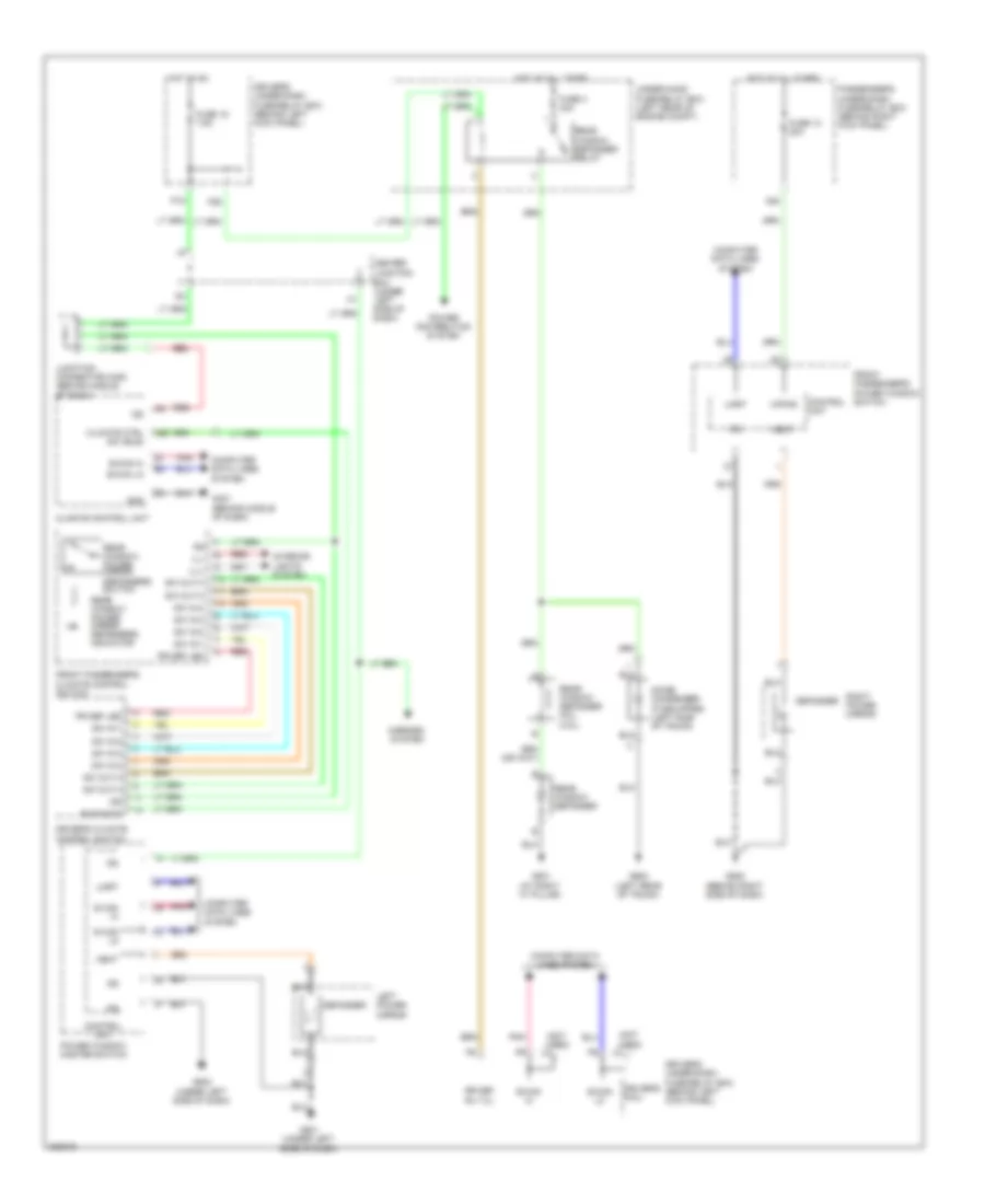
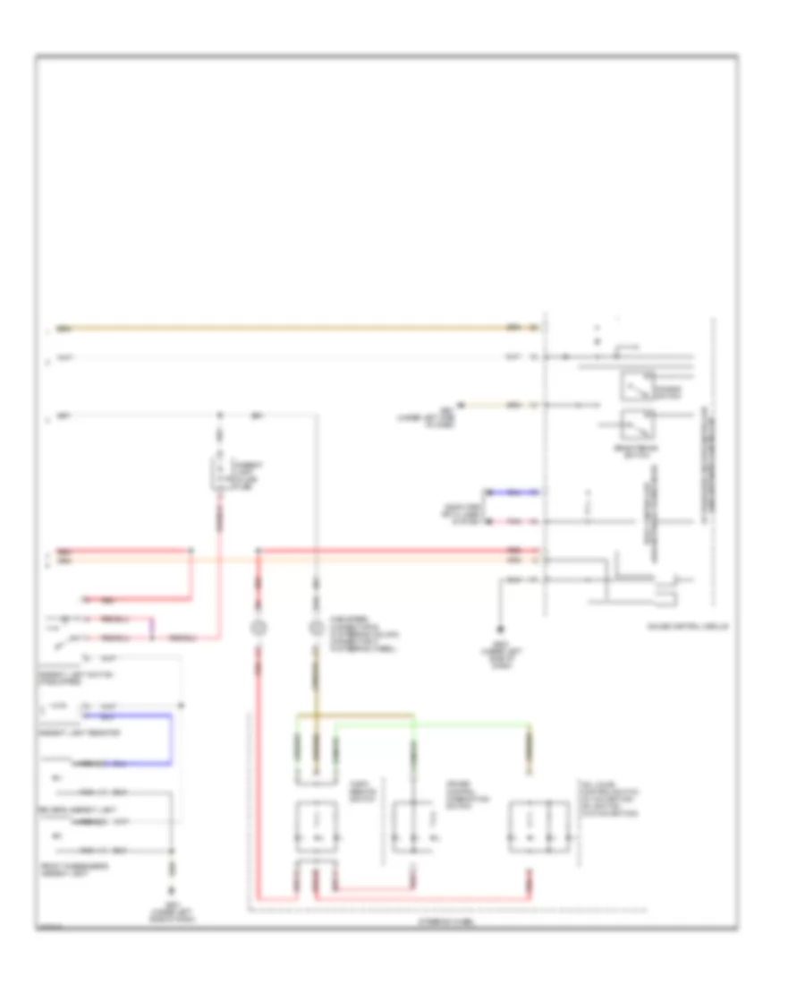
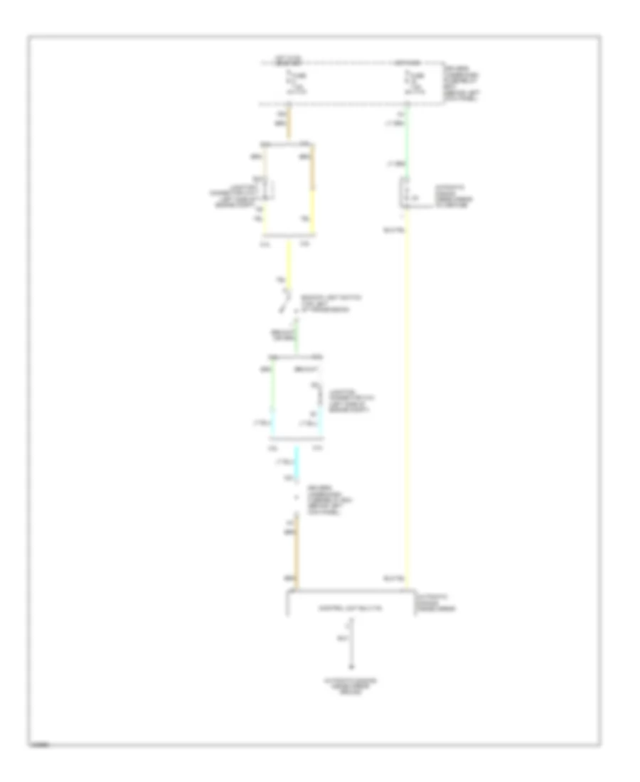
2.4L, Manual A/C Wiring Diagram (1 of 2) for Honda Accord EX 2010
List of elements for 2.4L, Manual A/C Wiring Diagram (1 of 2) for Honda Accord EX 2010:
- (behind left kick panel) g302
- A/c condenser fan motor (lower middle front of engine compt)
- Air mix cold
- Air mix hot
- Air mix potential
- Audio- hvac sub-display unit
- B can hi
- B can lo
- Blower motor (under right side of dash)
- Blower power transistor (on bottom of blower unit)
- Blwr feedback
- Center junction box (under left side of dash)
- Common potential
- Computer data lines system
- Defogger system
- Driver's under-dash fuse/relay box (behind left kick panel)
- Engine controls system
- Evaporator temp sens
- F26
- Fresh
- Fuse 15a
- Fuse 7.5a
- G302 (behind left kick panel)
- G401 (behind middle of dash)
- Gnd
- Hot at all times
- Hot in on
- Hvac control unit
- Ig2
- Illumination+
- Illumination-
- Interior lights system
- J/c c406 (behind middle of dash)
- Micu
- Mode 1
- Mode 2
- Mode 3
- Mode 4
- Mode potential
- Mode vent
- Mode vent (or mode def)
- Normal audio
- P18
- Pgm-fi sub- relay
- Pnk
- Premium audio
- Pwr transister ctrl
- Radiator fan motor (lower left front of engine compt)
- Rear window defogger relay
- Recirculate
- Recirculation potential
- Red
- Rr wind defog rly
- Sens common gnd
- Under-hood fuse/relay box (left rear of engine compt)
2.4L, Manual A/C Wiring Diagram (2 of 2) for Honda Accord EX 2010
List of elements for 2.4L, Manual A/C Wiring Diagram (2 of 2) for Honda Accord EX 2010:
- & m/t
- (acc) rly ctrl
- (acpd) sens in
- (ect1) sens in
- (ect2) sens in
- (fanh) rly ctrl
- (fanl) rly ctrl
- (or mode2)
- (or mode4)
- (sg2) sens gnd
- (sg6) sens gnd
- (sub rly) rly ctrl
- (vcc6) ref volt
- A/c compressor
- A/c compressor clutch
- A/c compressor clutch relay
- A/c condenser fan relay
- A/c diode a
- A/c diode b
- A/c pressure sensor (right side of engine compt)
- A10
- A11
- A15
- A17
- A20
- A22
- A34
- Air mix control motor (under left side of dash)
- Amd-p
- B10
- B11
- B13
- B24
- B34
- Blower motor relay
- Can h
- Can l
- Computer data lines system
- Coupe, sedan
- Ecm/pcm (left front of engine compt)
- Ect sensor 1 (rear of engine)
- Ect sensor 2 (lower left front of engine compt)
- Engine controls system
- Evaporator temperature sensor (behind left side of glove box)
- Fan control relay
- Frd-p
- Frs
- Fuse 20a
- Fuse 40a
- Fuse 7.5a
- G301 (behind left side of front bumper)
- Hot at all times
- Ig2
- J/c c101 (left side of engine compt)
- M-cool
- M-def
- M-hot
- M-vent
- Main fan motor fuse 30a
- Mode 1
- Mode 3
- Mode control motor (under right side of dash)
- Mode-p
- Multi fuse 3
- Pnk
- Radiator fan relay
- Rec
- Recirculation control motor (coupe, sedan & m/t) (behind right side of dash)
- Recirculation control motor (sedan a/t) (behind right side of dash)
- Red
- S-com
- S4 (thermal joint) (rear of engine)
- S5v
- Sedan a/t
- Under- hood fuse/ relay box (left rear of engine compt)
3.5L
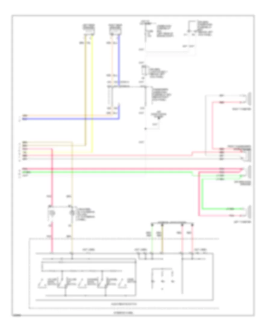
3.5L, Automatic A/C Wiring Diagram, with Navigation (1 of 3) for Honda Accord EX 2010
List of elements for 3.5L, Automatic A/C Wiring Diagram, with Navigation (1 of 3) for Honda Accord EX 2010:
- A/c pressure sens
- A10 a11
- A12
- A13
- A14
- A15
- A16
- A17
- A18
- A19
- A20
- A21
- A22
- A23
- A24
- A25
- A26
- A27
- A28
- Ac-clk
- Acs
- Audio unit
- Audio-hvac sub-display unit
- Automatic lighting sensor/sunlight sensor (top middle of dash)
- B can hi
- B can lo
- B-can hi
- B-can lo
- B10
- B11
- B12
- Blower feedback
- Blower motor (under right side of dash)
- Blower power transistor (on bottom of blower unit)
- Center junction box (under left side of dash)
- Climate control unit
- Climate ctrl sw
- Common potential
- Computer data lines system
- D16
- Display (clk)
- Display (si)
- Driver's air mix cool
- Driver's air mix hot
- Driver's junction box 1 (behind left kick panel)
- Driver's under-dash fuse/relay box (behind left kick panel)
- Drv air mix potential
- Duet cont
- Dute rx
- Dute tx
- Engine controls system
- Evap temp sens
- F11
- F26
- Fresh
- Fuse 10a
- Fuse 15a
- Fuse 7.5a
- G302 (behind left kick panel)
- G401 (behind middle of dash)
- Gnd
- Ground
- Hot at all times
- Hot in on
- Ig2
- Ill+
- Ill-
- In-car temp sens
- In-car temperature sensor (right of steering column)
- Interior lights system
- J/c c406 (behind middle of dash)
- J/c c408 (behind middle of dash)
- Micu
- Mode potential
- Mode vent
- Mode-heat
- Navigation system
- Navigation unit (clk)
- Navigation unit (si)
- Navigation unit (so)
- Normal audio
- Outside air temp sens
- Outside air temperature sensor (behind center of front bumper)
- P18
- Pass air mix cool
- Pass air mix hot
- Pass air mix potential
- Passenger's under- dash fuse/relay box (behind right kick panel)
- Pgm-fi sub- relay
- Pnk
- Power transistor ctrl
- Premium audio
- Rear window defogger relay
- Recirculate
- Recirculation potential
- Red
- Sc-so
- Sens common gnd
- Sound systems
- Sun light sensor
- Sunlight sens
- Under-hood fuse/relay box (left rear of engine compt)
3.5L, Automatic A/C Wiring Diagram, with Navigation (2 of 3) for Honda Accord EX 2010
List of elements for 3.5L, Automatic A/C Wiring Diagram, with Navigation (2 of 3) for Honda Accord EX 2010:
- (behind left kick panel) g302
- A/c compressor
- A/c compressor clutch
- A/c compressor clutch relay
- A/c condenser fan motor (lower middle front of engine compt)
- A/c condenser fan relay
- A/c diode a
- A/c diode b
- Amd-p
- B10
- B11
- Blower motor relay
- Driver's air mix control motor (under left side of dash)
- Evaporator temperature sensor (behind left side of glove box)
- Fan control relay
- Frd-p
- Front passenger's air mix control motor (under right side of dash)
- Frs
- Fuse 40a
- Fuse 7.5a
- G301 (behind left side of front bumper)
- Hot at all times
- M-cool
- M-hot
- Main fan motor fuse 30a
- Multi fuse 3
- Pnk
- Radiator fan motor (lower left front of engine compt)
- Radiator fan relay
- Rec
- Recirculation control motor (behind right side of dash)
- Red
- S-com
- S5v
- Sub fan motor fuse 30a
- Under- hood fuse/ relay box (left rear of engine compt)
3.5L, Automatic A/C Wiring Diagram, with Navigation (3 of 3) for Honda Accord EX 2010
List of elements for 3.5L, Automatic A/C Wiring Diagram, with Navigation (3 of 3) for Honda Accord EX 2010:
- (acc) rly ctrl
- (acrd) sens in
- (canh)
- (canl)
- (ect1) sens in
- (ect2) sens in
- (fanh) rly ctrl]
- (fanl) rly ctrl
- (right side of engine compt) a/c pressure sensor
- (sg2) sens gnd
- (sg7) sens gnd
- (sub rly) rly ctrl
- (vcc7) ref volt
- A13
- A21
- A36
- A37
- A40
- A45
- A48
- A49
- Bus-data
- C16
- C32
- Computer data lines system
- Driver's climate control switch
- Ecm/pcm (left front of engine compt)
- Ect sensor 1 (left rear of engine)
- Ect sensor 2 (lower left front of engine compt)
- Engine controls system
- Front passenger's climate control switch
- G401 (behind middle of dash)
- Gnd
- Ig2
- Ill+
- Ill-
- Interior lights system
- J/c c108 (top of transmission)
- M-def
- M-vent
- Mode control motor (under right side of dash)
- Mode-p
- Per-def-led
- Pnk
- Red
- S-com
- S5v
- Sw in-1
- Sw in-2
- Sw in-3
- Sw in-4
- Sw out-3
- Sw out-4
3.5L, Automatic A/C Wiring Diagram, without Navigation (1 of 2) for Honda Accord EX 2010
List of elements for 3.5L, Automatic A/C Wiring Diagram, without Navigation (1 of 2) for Honda Accord EX 2010:
- A/c pressure sens
- A10
- A11
- A12
- A13
- A14
- A15
- A16
- A17
- A18
- A19
- A20
- A21
- A22
- A23
- A24
- A25
- A26
- A27
- A28
- Ac-clk
- Acs
- Audio unit
- Audio-hvac sub-display unit
- Automatic lighting sensor/sunlight sensor (top middle of dash)
- B can hi
- B can lo
- B-can h
- B-can lo
- B10
- B11
- B12
- Blower feedback
- Blower motor (under right side of dash)
- Blower power transistor (on bottom of blower unit)
- Center junction box (under left side of dash)
- Climate control unit
- Common potential
- Computer data lines system
- D16
- Display (clk)
- Display (si)
- Driver's air mix cool
- Driver's air mix hot
- Driver's junction box 1 (behind left kick panel)
- Driver's under-dash fuse/relay box (behind left kick panel)
- Drv air mix potential
- Duet cont
- Dute rx
- Dute tx
- Engine controls system
- Evap temp sens
- F11
- F26
- Fresh
- Fuse 10a
- Fuse 15a
- Fuse 7.5a
- G302 (behind left kick panel)
- G401 (behind middle of dash)
- Gnd
- Ground
- Hot at all times
- Hot in on
- Ig2
- Ill+
- Ill-
- Illumination+
- Illumination-
- In-car temp sens
- In-car temperature sensor (right of steering column)
- Interior lights system
- J/c c406 (behind middle of dash)
- J/c c408 (behind middle of dash)
- Micu
- Mode potential
- Mode vent
- Mode-heat
- Normal audio
- Outside air temp sens
- Outside air temperature sensor (behind center of front bumper)
- P18
- Pass air mix cool
- Pass air mix hot
- Pass air mix potential
- Passenger's under- dash fuse/relay box (behind right kick panel)
- Pgm-fi sub- relay
- Pnk
- Power transistor ctrl
- Premium audio
- Rear window defogger relay
- Recirculate
- Recirculation potential
- Red
- Sc-so
- Sens common gnd
- Sound systems
- Sun light sensor
- Sunlight sens
- Sunlight sensor (top middle of dash)
- Under-hood fuse/relay box (left rear of engine compt)
- W/automatic lighting
- W/o automatic lighting
3.5L, Automatic A/C Wiring Diagram, without Navigation (2 of 2) for Honda Accord EX 2010
List of elements for 3.5L, Automatic A/C Wiring Diagram, without Navigation (2 of 2) for Honda Accord EX 2010:
- (acc) rly ctrl
- (acrd) sens in
- (behind left kick panel) g302
- (canh)
- (canl)
- (ect1) sens in
- (ect2) sens in
- (fanh) rly ctrl
- (fanl) rly ctrl
- (sg2) sens gnd
- (sg7) sens gnd
- (sub rly) rly ctrl
- (vcc7) ref volt
- A/c compressor
- A/c compressor clutch
- A/c compressor clutch relay
- A/c condenser fan motor (lower middle front of engine compt)
- A/c condenser fan relay
- A/c diode a
- A/c diode b
- A/c pressure sensor (right side of engine compt)
- A13
- A21
- A36
- A37
- A40
- A45
- A48
- A49
- Amd-p
- B10
- B11
- Blower motor relay
- C16
- C32
- Computer data lines system
- Driver's air mix control motor (under left side of dash)
- Ecm/pcm (left front of engine compt)
- Ect sensor 1 (left rear of engine)
- Ect sensor 2 (lower left front of engine compt)
- Engine controls system
- Evaporator temperature sensor (behind left side of glove box)
- Fan control relay
- Frd-p
- Front passenger's air mix control motor (under right side of dash)
- Frs
- Fuse 40a
- Fuse 7.5a
- G301 (behind left side of front bumper)
- Hot at all times
- J/c c108 (top of transmission)
- J/c c408 (behind middle of dash)
- M-cool
- M-def
- M-hot
- M-vent
- Main fan motor fuse 30a
- Mode control motor (under right side of dash)
- Mode-p
- Multi fuse 3
- Normal audio
- Pnk
- Premium audio
- Radiator fan motor (lower left front of engine compt)
- Radiator fan relay
- Rec
- Recirculation control motor (behind right side of dash)
- Red
- S-com
- S5v
- Sub fan motor fuse 30a
- Under- hood fuse/ relay box (left rear of engine compt)
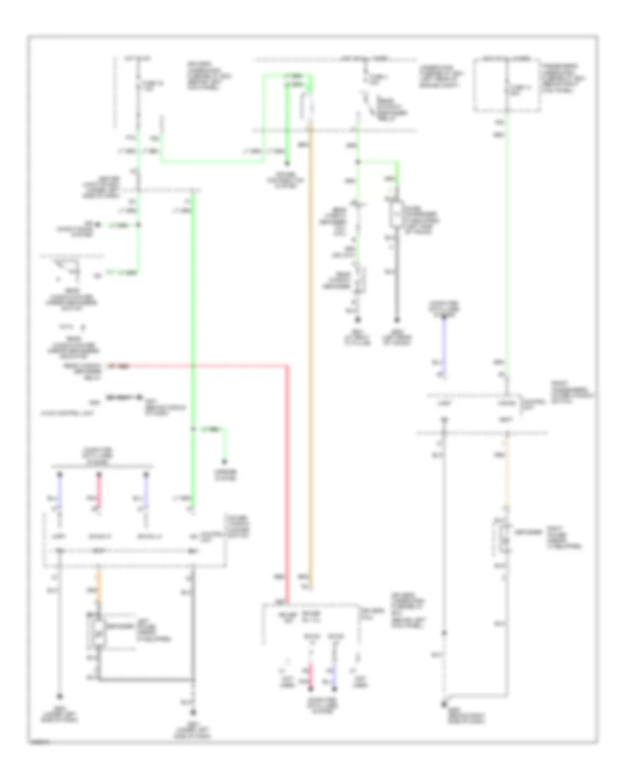
3.5L, Manual A/C Wiring Diagram (1 of 2) for Honda Accord EX 2010
List of elements for 3.5L, Manual A/C Wiring Diagram (1 of 2) for Honda Accord EX 2010:
- (behind left kick panel) g302
- A/c condenser fan motor (lower middle front of engine compt)
- A/c press sens
- Acs
- Air mix cold
- Air mix hot
- Air mix potential
- Audio- hvac sub-display unit
- B can hi
- B can lo
- Blower motor (under right side of dash)
- Blower power transistor (on bottom of blower unit)
- Blwr feedback
- Center junction box (under left side of dash)
- Common potential
- Computer data lines system
- Defogger system
- Driver's under-dash fuse/relay box (behind left kick panel)
- Engine controls system
- Evaporator temp sens
- F26
- Fresh
- Fuse 15a
- Fuse 7.5a
- G302 (behind left kick panel)
- G401 (behind middle of dash)
- Gnd
- Hot at all times
- Hot in on
- Hvac control unit
- Ig2
- Illumination+
- Illumination-
- Interior lights system
- J/c c406 (behind middle of dash)
- J/c c408 (behind middle of dash)
- Micu
- Mode 1
- Mode 2
- Mode 3
- Mode 4
- Mode potential
- Mode vent
- Normal audio
- P18
- Pgm-fi sub- relay
- Pnk
- Premium audio
- Pwr transistor ctrl
- Radiator fan motor (lower left front of engine compt)
- Rear window defogger relay
- Recirculate
- Recirculation potential
- Red
- Rr wind defog rly
- Sens common gnd
- Under-hood fuse/relay box (left rear of engine compt)
3.5L, Manual A/C Wiring Diagram (2 of 2) for Honda Accord EX 2010
List of elements for 3.5L, Manual A/C Wiring Diagram (2 of 2) for Honda Accord EX 2010:
- & m/t
- (acc) rly ctrl
- (acrd) sens in
- (canh)
- (canl)
- (ect1) sens in
- (ect2) sens in
- (fanh) rly ctrl
- (fanl) rly ctrl
- (or mode2)
- (or mode4)
- (sg2) sens gnd
- (sg7) sens gnd
- (sub rly) rly ctrl
- (top of transmission) j/c c108
- (vcc7) ref volt
- A/c compressor
- A/c compressor clutch
- A/c compressor clutch relay
- A/c condenser fan relay
- A/c diode a
- A/c diode b
- A/c pressure sensor (right side of engine compt)
- A13
- A21
- A36
- A37
- A40
- A45
- A48
- A49
- Air mix control motor (under left side of dash)
- Amd-p
- B10
- B11
- Blower motor relay
- C16
- C32
- Computer data lines system
- Coupe, sedan
- Ecm/pcm (left front of engine compt)
- Ect sensor 1 (left rear of engine)
- Ect sensor 2 (lower left front of engine compt)
- Engine controls system
- Evaporator temperature sensor (behind left side of glove box)
- Fan control relay
- Frd-p
- Frs
- Fuse 40a
- Fuse 7.5a
- G301 (behind left side of front bumper)
- Hot at all times
- Ig2
- M-cool
- M-def
- M-hot
- M-vent
- Main fan motor fuse 30a
- Mode 1
- Mode 3
- Mode control motor (under right side of dash)
- Mode-p
- Multi fuse 3
- Pnk
- Radiator fan relay
- Rec
- Recirculation control motor (coupe, sedan & m/t) (behind right side of dash)
- Recirculation control motor (sedan a/t) (behind right side of dash)
- Red
- S-com
- S5v
- Sedan a/t
- Sub fan motor fuse 30a
- Under- hood fuse/ relay box (left rear of engine compt)
ANTI-LOCK BRAKES
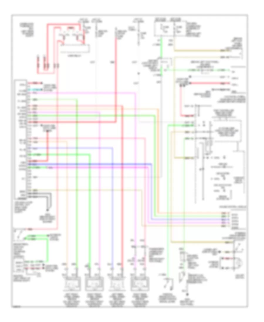
Anti-lock Brakes Wiring Diagram, with VSA for Honda Accord EX 2010
List of elements for Anti-lock Brakes Wiring Diagram, with VSA for Honda Accord EX 2010:
- (behind left kick panel) driver's junction box 1
- (behind left kick panel) driver's junction box 2
- (under left side of dash) g501
- 2.4l
- 3.5l
- 3.5l 2.4l
- 5v stabilizer circuit/controller area network controller
- A42
- A48
- A49
- Abs ind
- Abs/vsa fuse 40a
- Abs/vsa motor fuse 30a
- B13
- B14
- Bksw
- Brake fluid level switch (on brake fluid reservoir)
- Brake pedal position switch (on brake pedal support)
- Brake system ind
- Can h
- Can l
- Can-l
- Center junction box (under left side of dash)
- Computer data lines system
- Driver's junction box 1 (behind left kick panel)
- Driver's under-dash fuse/relay box (behind left kick panel)
- Ecm/pcm (left front of engine compt)
- Exterior lights system
- Fast controller area network transceiver
- Fl +b
- Fl -gnd
- Fr +b
- Fr -gnd
- Fsr +b
- Fuse 10a
- Fuse 20a
- Fuse 7.5a
- G202 (behind right side of front bumper)
- G302 (behind left kick panel)
- G4 (or h4)
- G5 (or h5)
- G503 (behind middle of dash)
- Gauge control module
- Gnd
- Horn relay
- Hot at all times
- Hot in on or start
- Ig 1
- Ig1
- Interior lights system
- K-line
- Left front wheel speed sensor (on left front suspension knuckle)
- Left rear wheel speed sensor (on left rear suspension knuckle)
- Mr +b
- Mr-gnd
- Multi fuse 2
- P20
- Parking brake switch (under parking brake lever)
- Passenger's under-dash fuse/relay box (behind right kick panel)
- Pnk
- Red
- Right front wheel speed sensor (on right front suspension knuckle)
- Right rear wheel speed sensor (on right rear suspension knuckle)
- Rl +b
- Rl -gnd
- Rr +b
- Rr -gnd
- S-gnd
- Sgnd
- Steering angle sensor (in steering column)
- Str-a
- Str-b
- Str-d
- Svcc
- Under-hood fuse/relay box (left rear of engine compt)
- Vsa activation ind
- Vsa modulator control unit (right side of engine compt)
- Vsa off switch
- Vsa system ind
- Warning drive circuit
- Wen
- Yaw rate-lateral acceleration sensor (under center console)
Anti-lock Brakes Wiring Diagram, without VSA for Honda Accord EX 2010
List of elements for Anti-lock Brakes Wiring Diagram, without VSA for Honda Accord EX 2010:
- (or h4)
- (or h5)
- 2.4l
- 3.5l
- 3.5l 2.4l
- 5v stabilizer circuit/controller area network controller
- A42
- A48
- A49
- Abs ind
- Abs modulator control unit (right side of engine compt)
- B13
- B14
- Bksw
- Brake fluid level switch (on brake fluid reservoir)
- Brake pedal position switch (on brake pedal support)
- Brake system ind
- Can h
- Can l
- Center junction box (under left side of dash)
- Computer data lines system
- Driver's junction box 1 (behind left kick panel)
- Driver's under-dash fuse/relay box (behind left kick panel)
- Ecm/pcm (left front of engine compt)
- Exterior lights system
- Fast controller area network transceiver
- Fl +b
- Fl-gnd
- Fr +b
- Fr-gnd
- Fsr +b
- Fuse 10a
- Fuse 20 30a
- Fuse 20a
- Fuse 21 30a
- Fuse 7.5a
- G202 (behind right side of front bumper)
- G302 (behind left kick panel)
- Gauge control module
- Gnd
- Horn relay
- Hot at all times
- Hot in on or start
- Ig1
- K-line
- Left front wheel speed sensor (on left front suspension knuckle)
- Left rear wheel speed sensor (on left rear suspension knuckle)
- Mr +b
- Mr-gnd
- P20
- Parking brake switch (under parking brake lever)
- Passenger's under-dash fuse/relay box (behind right kick panel)
- Pnk
- Red
- Right front wheel speed sensor (on right front suspension knuckle)
- Right rear wheel speed sensor (on right rear suspension knuckle)
- Rl +b
- Rl-gnd
- Rr +b
- Rr-gnd
- Under-hood fuse/relay box (left rear of engine compt)
- Warning drive circuit
ANTI-THEFT
Forced Entry Wiring Diagram (1 of 3) for Honda Accord EX 2010
List of elements for Forced Entry Wiring Diagram (1 of 3) for Honda Accord EX 2010:
- (2.4l)
- (3.5l)
- (not used)
- 2.4l
- 2.4l red
- 3.5l
- 4 door
- 4 door & security
- Atp-p
- B-can low
- B13
- B14
- Brake pedal position switch
- Computer data lines system
- Controls system
- D/l dr fr unlck rly cl-
- D/l sil-con sw rr-l b-can hi
- D11
- D12
- D15
- D16
- Door lock relay
- Door unlock relay
- Dr lck rly
- Dr unlck rly
- Driver's door unlock relay
- Driver's micu
- Driver's under-dash fuse/relay box (behind left kick panel)
- Eng hood sw
- Engine
- Engine controls system
- Exterior lights system
- F10
- F21
- Fr door sw l
- Fuse 10a
- Fuse 20a
- Fuse 7.5a
- G101 (left side of engine)
- G101 (right front of engine)
- G503 (behind middle of dash)
- G601 (left side of floor)
- G602 (left rear of trunk)
- H10
- Headlights system
- High horn (at front of engine compt, behind front grille)
- Horn relay
- Horns system
- Hot at all times
- Hot in on
- Ignition key switch
- Ignition key switch/key light
- Junction connector c101 (left side of engine compt)
- Junction connector c107 (top of transmission)
- Key sw
- Left rear door lock actuator/ knob switch (rear of left rear door)
- Left rear door lock knob switch
- Left rear door switch (4 door) (at left "c" pillar)
- Low beam control circuit
- Low horn (at front of engine compt, behind front grille)
- P18
- Pnk
- Q12
- Q18
- Red
- Rr door sw l
- S1 (thermal joint)
- Small rly
- Taillight control circuit
- Taillight relay
- Transmission range switch (2.4l a/t: on rear of transmission) (3.5l a/t: on transmission)
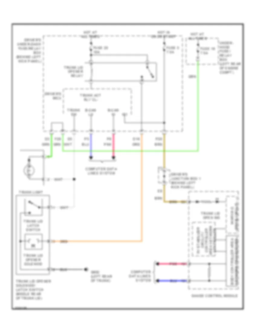
- Trunk act rly
- Trunk lid latch switch
- Trunk lid opener relay
- Trunk lid opener solenoid
- Trunk lid opener solenoid/latch switch (middle rear of trunk lid)
- Trunk light
- Trunk sw
- Under-hood fuse/relay box (left rear of engine compt)
- W/ automatic lighting
- W/o automatic lighting
Forced Entry Wiring Diagram (2 of 3) for Honda Accord EX 2010
List of elements for Forced Entry Wiring Diagram (2 of 3) for Honda Accord EX 2010:
- (not used)
- 4 door
- 4 door & security
- A11
- A20
- A28
- A29
- A38
- A4 security -
- Audio unit
- B- can hi
- B- can lo
- Computer data lines system
- Connector g
- Connector h
- D/l as lck rly cl-
- D/l as unlck rly cl-
- D/l sil-con rr-r
- D22
- Door lock relay
- Door un lock relay
- Driver's door switch (at driver's "b" pillar)
- E10
- E12
- Exterior lights system
- Fr door sw r
- Front passenger's door switch (at front passenger's "b" pillar)
- Fuse 10 10a
- Fuse 10a
- Fuse 20a
- Fuse/relay box
- G302 (behind left kick panel)
- G651 (right side of floor)
- H1 g9
- H22 g6
- H25 g14
- H27
- H3 g15
- H36
- H7 g8
- Headlights system
- Hot at all times
- Low beam control circuit
- Navigation unit (under right side of rear shelf)
- Passenger's micu
- Passenger's under-dash
- Passenger's under-dash fuse/relay box (behind right kick panel)
- Pnk
- Red
- Right rear door lock actuator/ knob switch (rear of right rear door)
- Right rear door lock knob switch
- Right rear door switch (4 door) (at right rear "c" pillar)
- Rr door sw r
- Scty radio
- Security +
- Security -
- Security hood switch (security) (at front of engine compt, on hood lock/latch assembly)
- Small rly
- Taillight control circuit
- Taillight relay
- W/ automatic lighting
- W/ navigation
- W/o automatic lighting
- W/o navigation
Forced Entry Wiring Diagram (3 of 3) for Honda Accord EX 2010
List of elements for Forced Entry Wiring Diagram (3 of 3) for Honda Accord EX 2010:
- (behind left kick panel) driver's junction box 1
- (left rear
- (under left
- 5v stabilize circuit/
- A14
- A35
- A37
- B can high
- B can low
- B- can hi
- B- can lo
- Body
- Box
- Center junction box (under left side of dash)
- Circuit
- Compt)
- Computer data lines
- Computer data lines system
- Control unit
- Controller area network controller
- Dlc (under left side of dash)
- Door lock knob
- Door lock switch
- Door lock switch lock light
- Door lock switch unlock light
- Driver's door key cylinder switch
- Driver's door lock actuator/knob switch (rear of driver's front door)
- Driver's door lock knob switch
- Driver's junction box 1 (behind left kick panel)
- Driver's micu
- Driver's under-dash fuse/relay box (behind left kick panel)
- E15
- E16
- F11
- Front passenger's door lock actuator/ knob switch (security) (rear of front passenger's front door)
- Front passenger's door lock knob switch
- Front passenger's power window switch
- Fuse 10a
- Fuse 7.5a
- Fuse/relay
- G201 (behind right side of dash)
- G501
- G501 (under left side of dash)
- G502 (under left side of dash)
- G505 (behind right side of dash)
- Gauge control module
- Hot at all times
- Hot in on or start
- Ig1
- Ig2
- Immobilizer keyless control unit (in steering column)
- Indicator blinking
- Interior lights system
- Key
- Knob lock
- Knob un lck
- Knob un lock
- Lock
- Meter
- Micu-s
- Of engine
- P-gnd
- P20
- Passenger's micu
- Passenger's under-dash fuse/relay box (behind right kick panel)
- Pnk
- Power window master switch
- Q1 micu-p
- Q2 micu-s
- R5 micu-p
- Red
- S-gnd
- Security
- Security indicator
- Side of dash)
- System
- Transceiver area network controller
- Uart
- Un lock
- Under-hood
- Unlock
- Vbu
- Vmp as uart
- Vmp dr
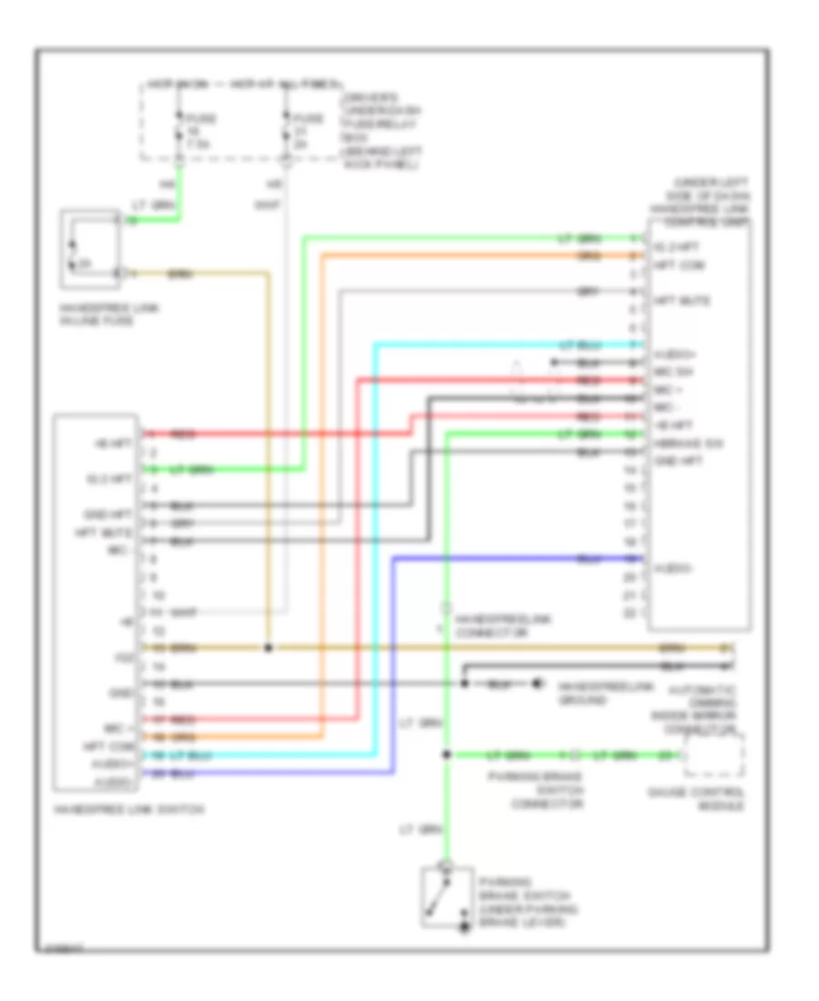
- W/ handsfreelink
Immobilizer Wiring Diagram for Honda Accord EX 2010
List of elements for Immobilizer Wiring Diagram for Honda Accord EX 2010:
- (behind
- (left rear of floor) g603
- (not used)
- (under left side of dash) g501
- (under left side of dash) g502
- 2.4l
- 3.5l
- 5v stabilize circuit/controller area
- A11
- A15
- A16
- A41
- A46
- A48
- A49
- B-can
- B-can hi
- B-can lo
- B41
- B42
- C10
- C41
- C44
- C48
- Can-h
- Can-l
- Circuit drive warning
- Computer data lines system
- D10
- Dlc (under left side of dash)
- Driver's
- Driver's +b back
- Driver's junction box 1 (behind left kick panel)
- Driver's under-dash fuse/relay box (behind left kick panel)
- E14
- Ecm/pcm (left front of engine compt)
- Engine controls system
- Etcs control relay
- F11
- F22
- F31
- Fuel pump
- Fuel pump relay
- Fuel tank unit (top of fuel tank)
- Fuse 10a
- Fuse 15a
- Fuse 20a
- Fuse 7.5a
- G101 (left side of engine)
- G101 (right front of engine)
- G503
- Gauge control module
- Gnd
- Hot at all times
- Hot in on or start
- Ig1
- Ignition key
- Ignition key switch
- Immo sig
- Immobilizer keyless control unit (in steering column)
- Immobilizer system indicator
- J/c c101 (left side of engine compt)
- J/c c107 (top of transmission)
- K-line
- Key
- Lg1
- Lg2
- Micu
- Middle
- Network controller
- Of dash)
- P20
- Parking brake switch (under parking brake lever)
- Pgm-fi main relay
- Pnk
- Q15
- Q18
- Red
- Remote starting control unit
- Rly ctrl
- S-net
- S3 (thermal joint)
- Switch/key light
- Transceiver area network controller body
- Transceiver area network controller fast
- Under-hood fuse/relay box (left rear of engine compt)
- Vbu
- W/ handsfreelink
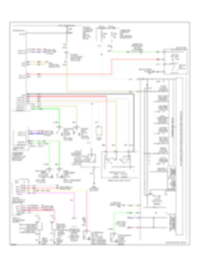
BODY CONTROL MODULES
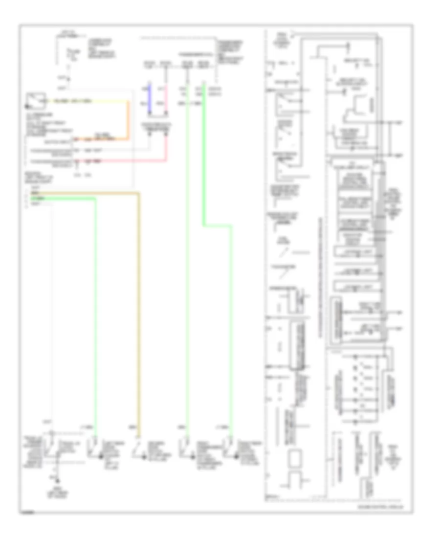
Body Control Modules Wiring Diagram (1 of 2) for Honda Accord EX 2010
List of elements for Body Control Modules Wiring Diagram (1 of 2) for Honda Accord EX 2010:
- (w/ autolamp)
- (w/o autolamp)
- +b backup
- +b hazard
- Acc key lk
- Acs
- Air conditioning system
- Anti-theft system
- Atp-p
- B-can hi
- B-can-lo
- Back lt-
- Backup h/l
- Chk
- Computer data lines system
- Cruise control & horns systems
- D12
- D13
- D15
- Defogger system
- Dimmer sw
- Door locks system
- Dr lock
- Dr unlock
- Driver's micu
- Driver's under-dash fuse/relay box (behind left kick panel)
- Engine controls & anti-theft systems
- Exterior lights & instrument cluster systems
- Exterior lights & transmissions systems
- Exterior lights system
- F11
- F13
- F20
- F21
- F27
- F32
- Fog light control circuit
- Fr courtesy l
- Fr door sw l
- Fr fog rly cl-
- Fr fog sw
- Fr unlock
- Fr wash sw
- Fr wip hi/lo sw
- Fr wip int vr+
- Fr wip int/lo sw
- Fr wiper
- Fuse 10a
- Fuse 7.5a
- G501 (under left side of dash)
- G502 (under left side of dash)
- Gnd
- Gnd (lighting)
- Gnd (wiper)
- H/l low sw
- H/l off sw
- Hazard sw
- Headlights lights system
- Headlights system
- Headlights system exterior lights & interior lights systems
- High beam control unit
- Hood sw
- Hot at all times
- Hot in acc or on
- Hot in on
- Hot in on or start
- Ig1 day lt
- Ig1 meter
- Instrument cluster system
- Interior lights system
- Intr lt-
- K-line
- Key lock sol-
- Key lt-
- Key sw
- Low beam control unit
- Micu service check connector
- Mirrors & navigation systems mirrors system
- Mist sw
- N12
- P-pin sw
- P14
- P17
- P20
- Passing sw
- Pnk
- Q10
- Q11
- Q12
- Q13
- Q14
- Q15
- Q16
- Q17
- Q18
- Q19
- Q20
- R10
- R11
- R12
- R13
- R14
- R15
- R16
- R17
- R18
- R19
- R20
- R21
- R22
- R23
- R24
- Red
- Rr def rly cl-
- Rr def sw
- Rr door sw l
- S-net
- Shift interlock system
- Small rly dr cl-
- Small sw
- Stop sw
- Taillight control circuit
- Transmissions system
- Trunk act
- Trunk sw
- Trunk, tailgate, fuel doors & interior lights systems
- Trunk, tailgate, fuel doors system
- Turn signal/ hazard flasher circuit
- Turn sw l
- Turn sw r
- Unlock
- Wip hi/lo
- Wip int
- Wiper/ washer system
- Wiper/washer system
Body Control Modules Wiring Diagram (2 of 2) for Honda Accord EX 2010
List of elements for Body Control Modules Wiring Diagram (2 of 2) for Honda Accord EX 2010:
- (behind left kick panel) driver's junction box 1
- (not used)
- (w/ autolamp)
- (w/o autolamp)
- +b backup
- +b res
- A11
- A14
- A17
- A29
- A33
- A35
- A36
- A37
- Auto lt sid
- Auto lt sig
- Auto lt sip
- B-can hi
- B-can lo
- Backup h/l
- Computer data lines system
- D/l as lock
- D/l as unlock
- D/l sil-con rr-r
- D16
- D20
- D22
- Door locks system
- E10
- E12
- E13
- E15
- E16
- Exterior lights system
- Fog light control circuit
- Fr courtesy r
- Fr door sw r
- Fr fog rly cl-
- Fr washer rly cl-
- Fuse (not used)
- Fuse 10a
- Fuse 15 10a
- Fuse 9 15a
- G14
- G15
- G201 (behind right side of dash)
- G505 (behind right side of dash)
- Gnd
- H10
- H22
- H25
- H36
- H37
- Headlights system
- High beam control unit
- Hot at all times
- Ig1 meter
- Interior lights system
- Low beam control unit
- Navigation & sound systems
- Navigation system
- P-gnd
- Passenger's micu
- Passenger's under-dash fuse/relay box (behind right kick panel)
- Pnk
- Power distribution system
- Red
- Rr door sw r
- Scty radio
- Sgnd
- Small rly as cl-
- Sound & navigation systems
- Taillight control circuit
- Under-hood fuse/relay box (left rear of engine compt)
- W/ navigation
- Wiper/washer system
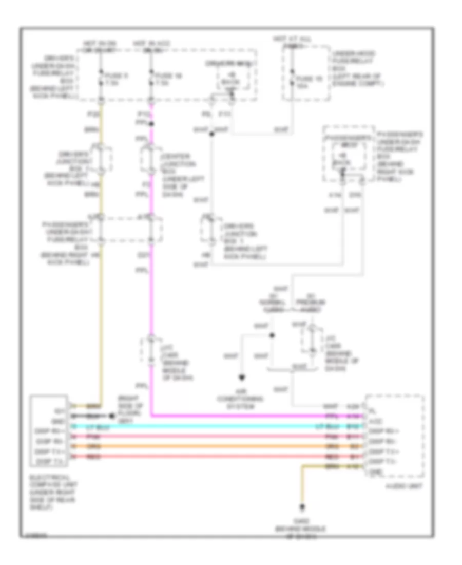
COMPUTER DATA LINES
Data Link Connector Wiring Diagram for Honda Accord EX 2010
List of elements for Data Link Connector Wiring Diagram for Honda Accord EX 2010:
- (if equipped)
- (in steering column) immobilizer keyless control unit
- (left front of engine compt) ecm/pcm
- (not
- (not used)
- (under right side of rear shelf)
- 2.4l
- 3.5l
- A16
- A17
- A18
- A19
- A31
- A32
- A44
- A48
- A49
- Abs
- Abs modulator control unit (2.4l) (right side of engine compt)
- Audio unit
- B24
- Center junction box (under left side of dash)
- D25
- D26
- Dlc (under left side of dash)
- Driver's junction box 2 (behind left
- Driver's micu
- Driver's under-dash fuse/relay box (behind left kick panel)
- E18
- E19
- Engine mount control unit (3.5l: a/t) (behind left kick panel)
- F-can hi
- F-can lo
- F24
- F25
- Fuse 15 10a
- G10
- G101 (left side of engine)
- G501 (under left side of dash)
- G502 (under left side of dash)
- Gauge control module
- H11
- H13
- H14
- H29
- Hot at all times
- J/c c405 (behind middle of dash)
- J/c c652 (right side trunk)
- K-line
- Kick panel)
- Navigation unit
- Normal audio
- P15
- P16
- Passenger's under-dash fuse/relay box (behind right kick panel)
- Premium audio
- Q16
- Red
- Remote starting control unit (w/ honda accessory)
- Scs
- Srs unit (under middle of dash)
- Tpms control unit (if equipped) (under left side of dash)
- Under-hood fuse/relay box (left rear of engine compt)
- Used)
- Vsa
- Vsa modulator control unit (2.4l: vsa & 3.5l) (right side of engine compt)
- W/o navigation
- Wen
- Yaw rate- lateral acceleration sensor (2.4l: vsa; 3.5l) (under center console)
F-CAN High/Low & B-CAN High/Low Wiring Diagram for Honda Accord EX 2010
List of elements for F-CAN High/Low & B-CAN High/Low Wiring Diagram for Honda Accord EX 2010:
- (behind left kick panel) driver's junction box 1
- (not used)
- (or red)
- (w/ honda accssory) remote starting control unit
- (w/ navigation)
- 2.4l
- 3.5l
- 6 cd disc player
- A10
- A11
- A16
- A17
- A18
- A19
- A29
- A48
- A49
- Abs
- Abs modulator control unit (right side of engine compt)
- Audio unit
- B-can hi
- B-can lo
- B-can low
- B18
- B24
- Center junction box (under left side of dash)
- Climate control unit
- D10
- D11
- D13
- D14
- Dlc (under left side of dash)
- Driver's junction box 2 (behind left kick panel)
- Driver's under-dash fuse/relay box (behind left kick panel)
- E10
- Ecm/pcm (left front of engine compt)
- Engine mount control unit (3.5l: a/t) (behind left kick panel)
- F-can hi
- F-can lo
- F24
- F25
- Front passenger's power window switch
- G10
- G502 (under left side of dash)
- Ga-bus sh
- Ga-bus+
- Ga-bus-
- Gauge control module
- H11
- H13
- H14
- H29
- Handsfreelink control unit (if equipped) (under left side of dash)
- I cd disc player
- Immobilizer keyless control unit (in steering column)
- J/c c405 (behind middle of dash)
- J/c c407 (behind middle of dash)
- J/c c503 (behind right side of dash)
- J/c c652 (right side of trunk)
- K-line
- Micu
- Micu chk
- Micu service check connector
- Moon roof control unit (if equipped) (middle of roof)
- N12
- Navigation display unit
- Navigation unit (if equipped) (under right side of rear shelf)
- Normal audio
- P15
- P16
- Passenger's under-dash fuse/relay box (behind right kick panel)
- Pnk
- Power window master switch
- Premium audio
- Q16
- Red
- Srs unit (under middle of dash)
- Tpms control unit (if equipped) (under left side of dash)
- Uart
- Vsa
- Vsa modulator control unit (right side of engine compt)
- Xm receiver (right side of trunk)
- Yaw rate- lateral acceleration sensor (vsa) (under center console)
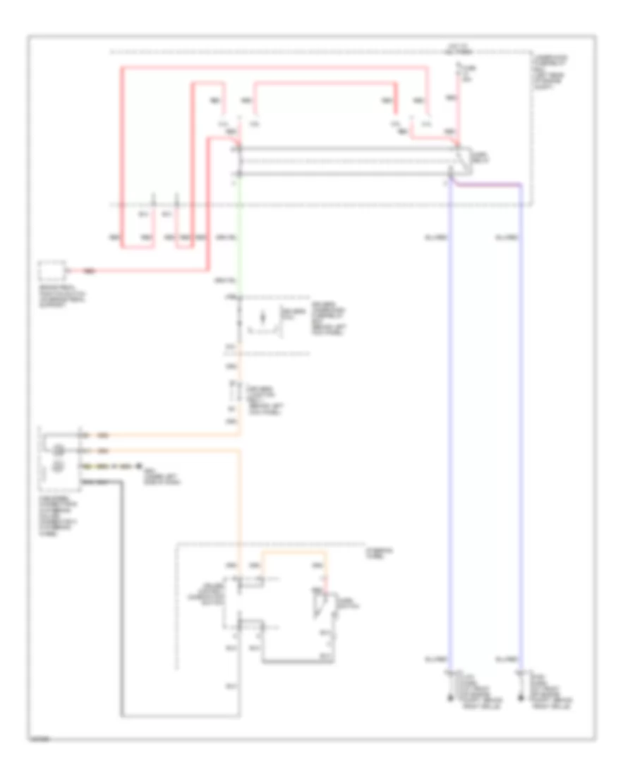
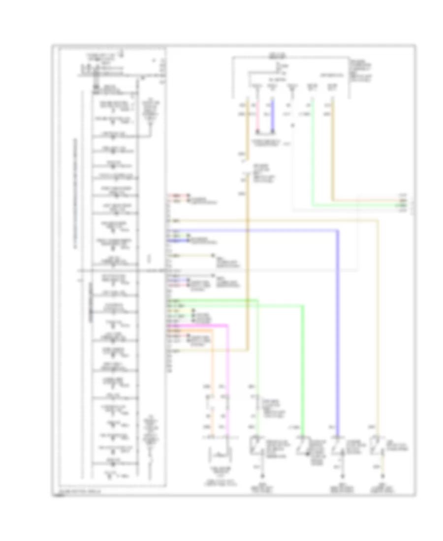
COOLING FAN
2.4L
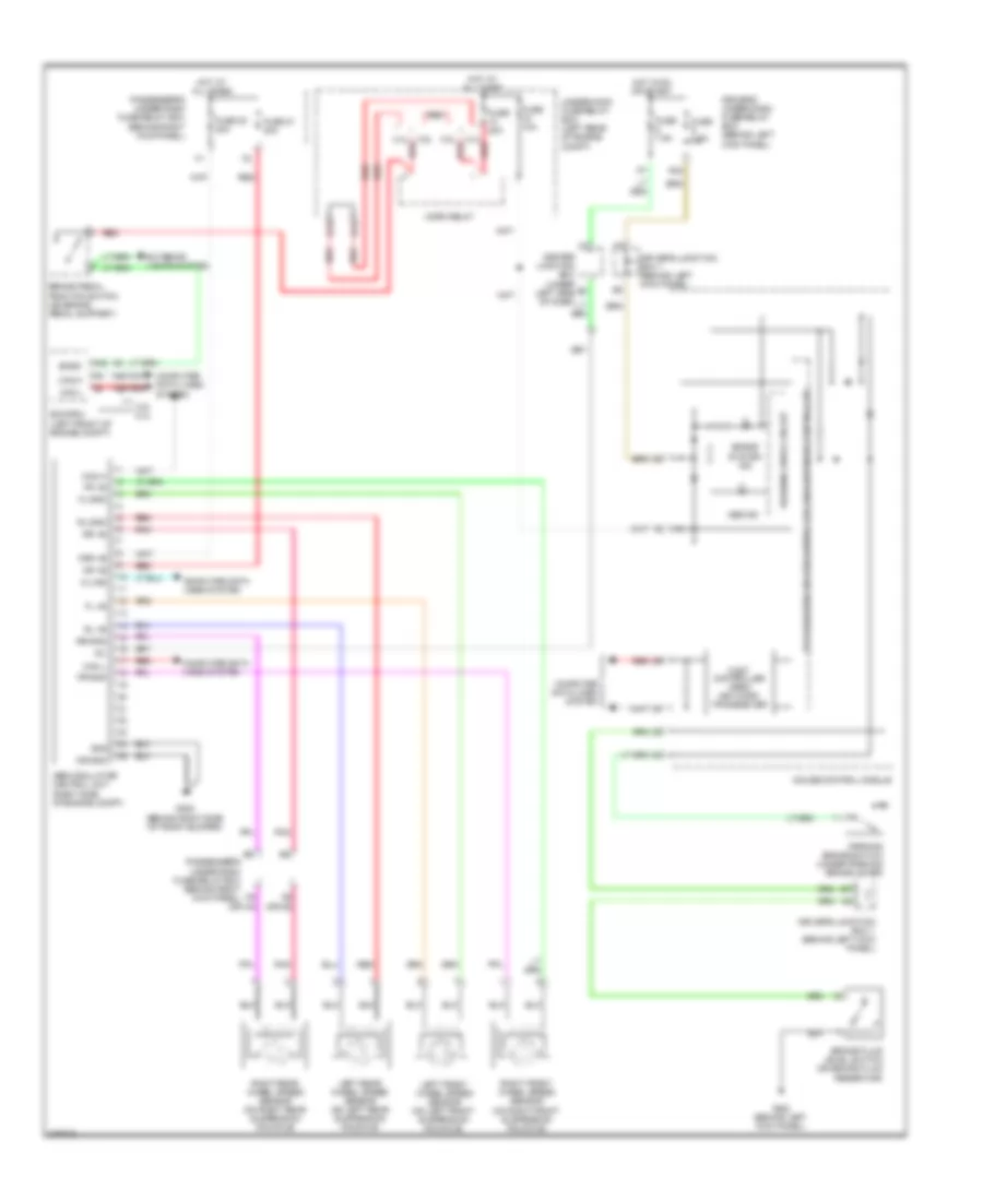
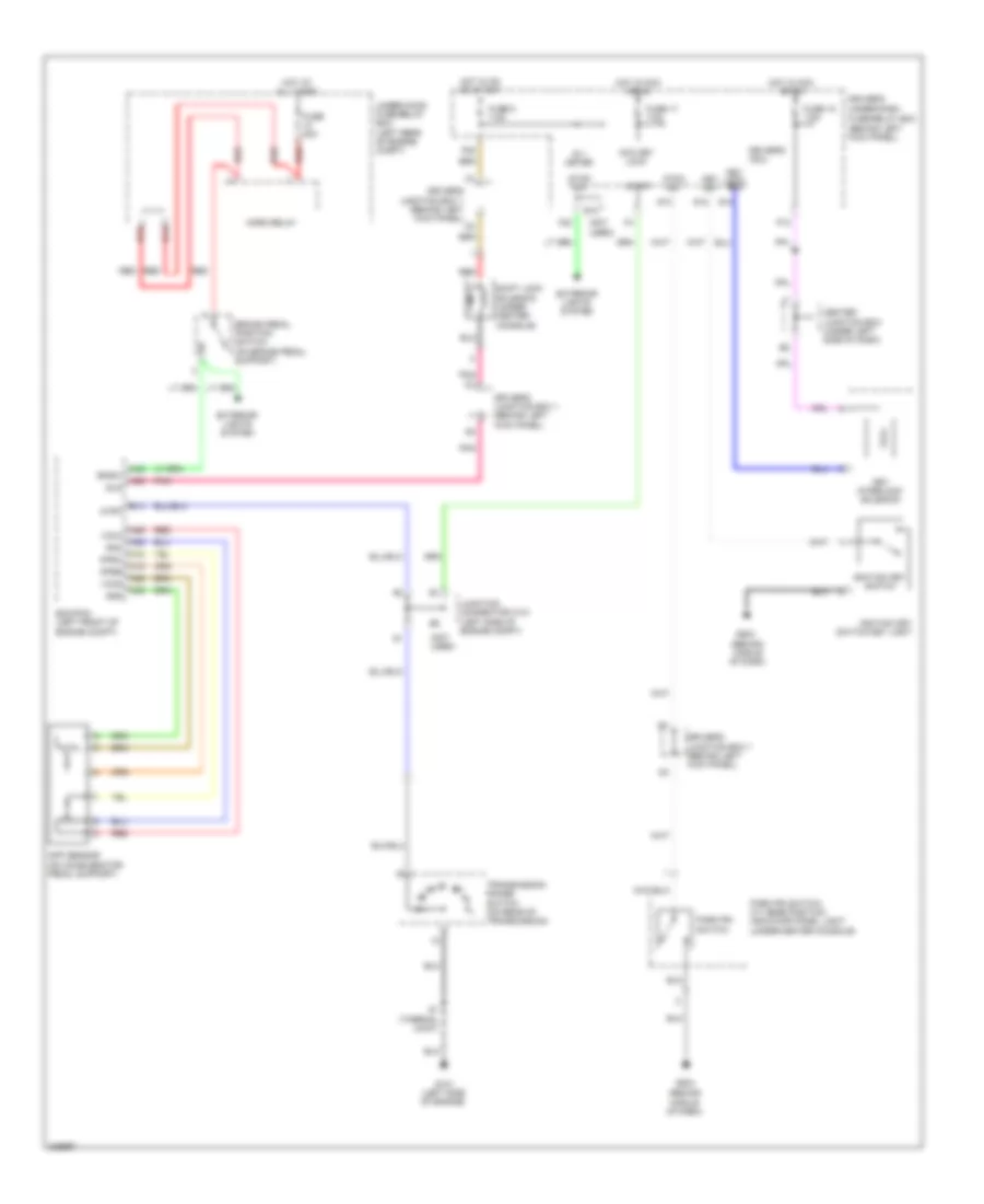
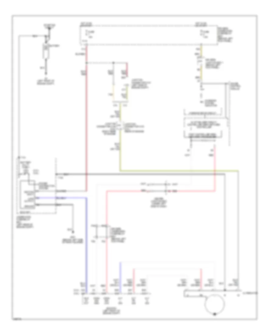
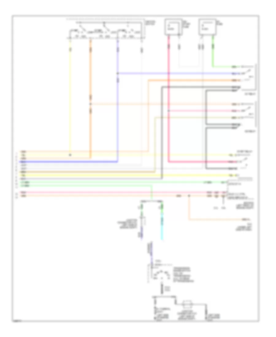
2.4L, Cooling Fan Wiring Diagram for Honda Accord EX 2010
List of elements for 2.4L, Cooling Fan Wiring Diagram for Honda Accord EX 2010:
- (acpd) sens in
- (ect1) sens in
- (ect2) sens in
- (fanh) rly ctrl
- (fanl) rly ctrl
- (left rear of engine compt) under-hood fuse/relay box
- (sg2) sens gnd
- (sg6) sens gnd
- (sub rly) rly ctrl
- (vcc6) ref volt
- A/c compressor clutch relay
- A/c condenser fan motor (lower middle front of engine compt)
- A/c condenser fan relay
- A/c diode a
- A/c diode b
- A/c pressure sensor (right side of engine compt)
- A10
- A17
- A20
- A22
- A34
- B10
- B11
- B24
- B34
- Blower motor relay
- Can h
- Can l
- Computer data lines system
- Driver's under- dash fuse/ relay box (behind left kick panel)
- Ecm/pcm (left front of engine compt)
- Ect sensor 1 (rear of engine)
- Ect sensor 2 (lower left front of engine compt)
- Engine controls system
- F26
- Fan control relay
- Fuse 15a
- Fuse 5 20a
- Fuse 7.5a
- G301 (behind left side of front bumper)
- G302 (behind left kick panel)
- Hot at all times
- Hot in on
- Main fan motor fuse 30a
- Multi- fuse 3
- Pgm-fi sub- relay
- Pnk
- Radiator fan motor (lower left front of engine compt)
- Radiator fan relay
- Rear window defogger relay
- Red
- S4 (thermal joint)
3.5L
3.5L, Cooling Fan Wiring Diagram for Honda Accord EX 2010
List of elements for 3.5L, Cooling Fan Wiring Diagram for Honda Accord EX 2010:
- (acrd) sens in
- (ect1) sens in
- (ect2) sens in
- (fanh) rly ctrl
- (fanl) rly ctrl
- (left rear of engine compt) under-hood fuse/relay box
- (sg2) sens gnd
- (sg7) sens gnd
- (sub rly) rly ctrl
- (vcc7) ref volt
- A/c compressor clutch relay
- A/c condenser fan motor (lower middle front of engine compt)
- A/c condenser fan relay
- A/c diode a
- A/c diode b
- A/c pressure sensor (right side of engine compt)
- A21
- A36
- A37
- A40
- A45
- A48
- A49
- B10
- B11
- Blower motor relay
- C16
- C32
- Can h
- Can l
- Computer data lines system
- Driver's under- dash fuse/ relay box (behind left kick panel)
- Ecm/pcm (left front of engine compt)
- Ect sensor 1 (left rear of engine)
- Ect sensor 2 (lower left front of engine compt)
- Engine controls system
- F26
- Fan control relay
- Fuse 15a
- Fuse 7.5a
- G301 (behind left side of front bumper)
- G302 (behind left kick panel)
- Hot at all times
- Hot in on
- Junction connector c108 (top of transmission)
- Main fan motor fuse 30a
- Multi- fuse 3
- Pgm-fi sub- relay
- Pnk
- Radiator fan motor (lower left front of engine compt)
- Radiator fan relay
- Rear window defogger relay
- Red
- Sub fan motor fuse 30a
CRUISE CONTROL
2.4L
2.4L, Cruise Control Wiring Diagram (1 of 2) for Honda Accord EX 2010
List of elements for 2.4L, Cruise Control Wiring Diagram (1 of 2) for Honda Accord EX 2010:
- A18
- A19
- A21
- A25
- A26
- A35
- A36
- A41
- A42
- A43
- App sensor (on accelerator pedal support)
- Apsa
- Apsb
- Area network controller 5v stabilize circuit/controller
- Atpfwd
- B10
- B29
- B38
- Bksw
- Bkswnc
- C12
- C20
- C21
- C43
- Canh
- Canl
- Circuit dimming
- Circuit stablizer 10v
- Clutch pedal position switch (m/t) (on clutch pedal support)
- Computer data lines system
- Crmtcls
- Cruise control indicator
- Cruise control main switch indicator
- Ecm/pcm (left front of engine compt)
- Engine controls system
- Etcs control relay
- Etcsm+
- Etcsm-
- Etcsrly
- Fuse 15 10a
- Fuse 15a
- G101 (left side of engine)
- G302 (behind left kick panel)
- G501 (under left side of dash)
- Gauge control module
- Gauges & indicators
- Hot at all times
- Ig1etcs
- Indicator
- J/c c101 (left side of engine compt)
- Mrly
- Network transceiver fast controller area
- Output shaft (countershaft) speed sensor (a/t: right side of transmission housing) (m/t: on tran- mission housing)
- Pgm-fi main relay
- Red
- S1 (thermal joint)
- Sg3
- Sg4
- Sg5
- Tp sensor/throttle actuator (on throttle body)
- Tpsa
- Tpsb
- Transmission range switch (a/t) (on rear of transmission)
- Under-hood fuse/relay box (left rear of engine compt)
- Vcc3
- Vcc4
- Vcc5
- Warning drive circuit
2.4L, Cruise Control Wiring Diagram (2 of 2) for Honda Accord EX 2010
List of elements for 2.4L, Cruise Control Wiring Diagram (2 of 2) for Honda Accord EX 2010:
- (not used)
- B13
- B14
- Brake pedal position switch (on brake pedal support)
- C10
- C11
- C12
- Cable reel (b: in steering column) (c: in steering wheel)
- Cancel switch
- Cruise control combination switch
- Driver's junction box 1 (behind left kick panel)
- Driver's micu
- Driver's under-dash fuse/relay box (behind left kick panel)
- Exterior lights system
- F14
- F23
- Fuse 10 20a
- Fuse 5 7.5a
- Fuse 7 15a
- G501 (under left side of dash)
- Horn relay
- Horns system
- Hot at all times
- Hot in on or start
- Interior lights system
- Main switch
- P20
- Q12
- Red
- Resume switch
- Set switch
- Steering wheel
- Under-hood fuse/relay box (left rear of engine compt)
3.5L
3.5L, Cruise Control Wiring Diagram (1 of 2) for Honda Accord EX 2010
List of elements for 3.5L, Cruise Control Wiring Diagram (1 of 2) for Honda Accord EX 2010:
- A18
- A19
- A24
- A25
- A26
- A27
- A29
- A47
- A48
- A49
- App sensor (on accelerator pedal support)
- Apsa
- Apsb
- Area network controller 5v stabilize circuit/controller
- Atpfwd
- B17
- B18
- B26
- B33
- B38
- Bksw
- Bkswnc
- C18
- Canh
- Canl
- Circuit dimming
- Circuit stablizer 10v
- Clutch pedal position switch (m/t) (on clutch pedal support)
- Computer data lines system
- Crmtcls
- Cruise control indicator
- Cruise control main switch indicator
- Ecm/pcm (left front of engine compt)
- Engine controls system
- Etcs control relay
- Etcsm+
- Etcsm-
- Etcsrly
- Fuse 15 10a
- Fuse 15a
- G101 (right front of engine)
- G302 (behind left kick panel)
- G501 (under left side of dash)
- Gauge control module
- Gauges & indicators
- Hot at all times
- Ig1etcs
- Indicator
- Indicators gauges &
- J/c c107 (top of transmission)
- Mrly
- Network transceiver fast controller area
- Output shaft (countershaft) speed sensor (right side of trans- mission housing)
- Pgm-fi main relay
- Pnk
- Red
- Sg3
- Sg4
- Sg5
- Tan
- Tp sensor/throttle actuator (on throttle body)
- Tpsa
- Tpsb
- Transmission range switch (a/t) (on transmission)
- Under-hood fuse/relay box (left rear of engine compt)
- Vcc3
- Vcc4
- Vcc5
- Warning drive circuit
3.5L, Cruise Control Wiring Diagram (2 of 2) for Honda Accord EX 2010
List of elements for 3.5L, Cruise Control Wiring Diagram (2 of 2) for Honda Accord EX 2010:
- (not used)
- Brake pedal position switch (on brake pedal support)
- C10
- C11
- C12
- Cable reel (b: in steering column) (c: in steering wheel)
- Cancel switch
- Cruise control combination switch
- Driver's junction box 1 (behind left kick panel)
- Driver's micu
- Driver's under-dash fuse/relay box (behind left kick panel)
- Exterior lights system
- F14
- F23
- Fuse 10 20a
- Fuse 5 7.5a
- Fuse 7 15a
- G501 (under left side of dash)
- Horn relay
- Horns system
- Hot at all times
- Hot in on or start
- Interior lights system
- Main switch
- P20
- Q12
- Red
- Resume switch
- Set switch
- Steering wheel
- Under-hood fuse/relay box (left rear of engine compt)
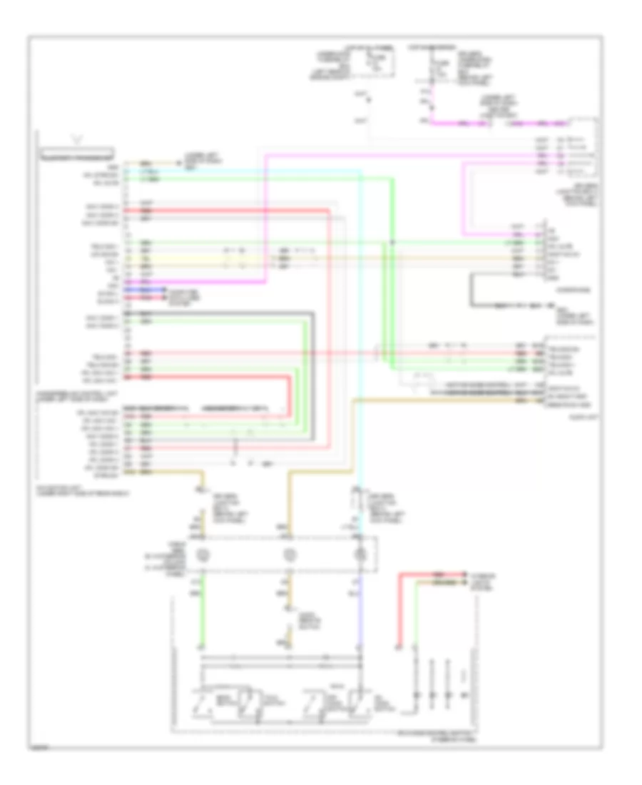
DEFOGGERS
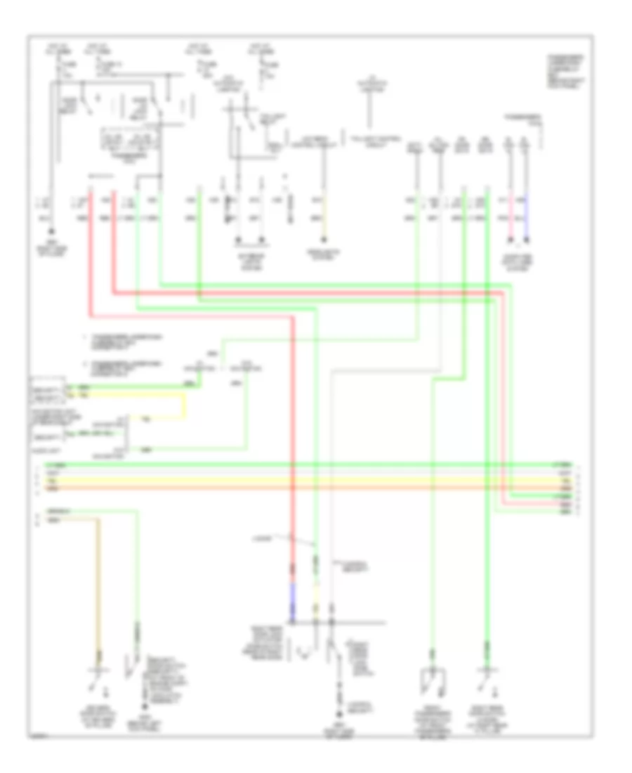
Defoggers Wiring Diagram, Automatic A/C with Navigation for Honda Accord EX 2010
List of elements for Defoggers Wiring Diagram, Automatic A/C with Navigation for Honda Accord EX 2010:
- (not used)
- (not used) h1
- A28
- B can hi
- B can lo
- B-can hi
- B-can lo
- Box (under left side of dash)
- Bus-data
- Center junction
- Climate control unit
- Climate ctrl sw (bus)
- Computer data lines system
- Control unit
- Defogger
- Driver's climate control switch
- Driver's micu
- Driver's under-dash fuse/relay box (behind left kick panel)
- F26
- Front passenger's climate control switch
- Front passenger's power window switch
- Fuse 13 20a
- Fuse 16 7.5a
- Fuse 4 40a
- G401 (behind middle of dash)
- G501 (under left side of dash)
- G502 (under left side of dash)
- G505 (behind right side of dash)
- G602 (left rear of trunk)
- G801 (at right "c" pillar)
- Gnd
- Heat
- Hot at all times
- Hot in on
- Ig2
- Ill+
- Ill-
- Interior lights system
- Junction connector c406 (behind middle of dash)
- Left power mirror
- Mirrors system
- Noise condenser (if equipped) (left side of trunk)
- P18
- Passenger's under-dash fuse/relay box (behind right kick panel)
- Pnk
- Power distribution system
- Power window master switch
- Pr def led
- Rear window defogger
- Rear window defogger coil (3.5l)
- Rear window defogger relay
- Rear window/ power mirror defoggers indicator
- Rear window/ power mirror defoggers switch
- Red
- Right power mirror
- Rr def rly cl-
- Sw in-1
- Sw in-2
- Sw in-3
- Sw in-4
- Sw out-3
- Sw out-4
- Uart
- Under-hood fuse/relay box (left rear of engine compt)
- Vmpas
Defoggers Wiring Diagram, Automatic A/C without Navigation for Honda Accord EX 2010
List of elements for Defoggers Wiring Diagram, Automatic A/C without Navigation for Honda Accord EX 2010:
- (behind left kick panel)
- (not used)
- A28
- Air conditioning system
- B-can hi
- B-can lo
- Box
- Center junction box (under left side of dash)
- Climate control unit
- Computer data lines system
- Control ig2 unit
- Control unit
- Defogger
- Driver's micu
- Driver's under-dash fuse/relay
- Driver's under-dash fuse/relay box (behind left kick panel)
- F26
- Front passenger's power window switch
- Fuse 13 20a
- Fuse 16 7.5a
- Fuse 4 40a
- G401 (behind middle of dash)
- G501 (under left side of dash)
- G502 (under left side of dash)
- G505 (behind right side of dash)
- G602 (left rear of trunk)
- G801 (at right "c" pillar)
- Gnd
- Heat
- Hot at all times
- Hot in on
- Ig2
- Left power mirror
- Mirrors system
- Noise condenser (if equipped) (left side of trunk)
- P18
- Passenger's under-dash fuse/relay box (behind right kick panel)
- Pnk
- Power distribution system
- Power window master switch
- Rear window defogger
- Rear window defogger coil (3.5l)
- Rear window defogger relay
- Rear window/power mirror defoggers indicator
- Rear window/power mirror defoggers switch
- Right power mirror
- Rr def rly cl-
- Uart
- Under-hood fuse/relay box (left rear of engine compt)
- Vmpas
Defoggers Wiring Diagram, Manual A/C for Honda Accord EX 2010
List of elements for Defoggers Wiring Diagram, Manual A/C for Honda Accord EX 2010:
- (behind left kick panel)
- (not used)
- A28
- Air conditioning system
- B-can hi
- B-can lo
- Box
- Center junction box (under left side of dash)
- Computer data lines system
- Control ig2 unit
- Control unit
- Defogger
- Driver's micu
- Driver's under-dash fuse/relay
- Driver's under-dash fuse/relay box (behind left kick panel)
- F26
- Front passenger's power window switch
- Fuse 13 20a
- Fuse 16 7.5a
- Fuse 4 40a
- G401 (behind middle of dash)
- G501 (under left side of dash)
- G502 (under left side of dash)
- G505 (behind right side of dash)
- G602 (left rear of trunk)
- G801 (at right "c" pillar)
- Gnd
- Heat
- Hot at all times
- Hot in on
- Hvac control unit
- Ig2
- Left power mirror (if equipped)
- Mirrors system
- Noise condenser (if equipped) (left side of trunk)
- P18
- Passenger's under-dash fuse/relay box (behind right kick panel)
- Pnk
- Power distribution system
- Power window master switch
- Q20
- Rear window defogger
- Rear window defogger coil (3.5l)
- Rear window defogger relay
- Rear window/power mirror defoggers indicator
- Rear window/power mirror defoggers switch
- Red
- Right power mirror (if equipped)
- Rr def rly cl-
- Rr def sw
- Uart
- Under-hood fuse/relay box (left rear of engine compt)
- Vmpas
ENGINE PERFORMANCE
2.4L
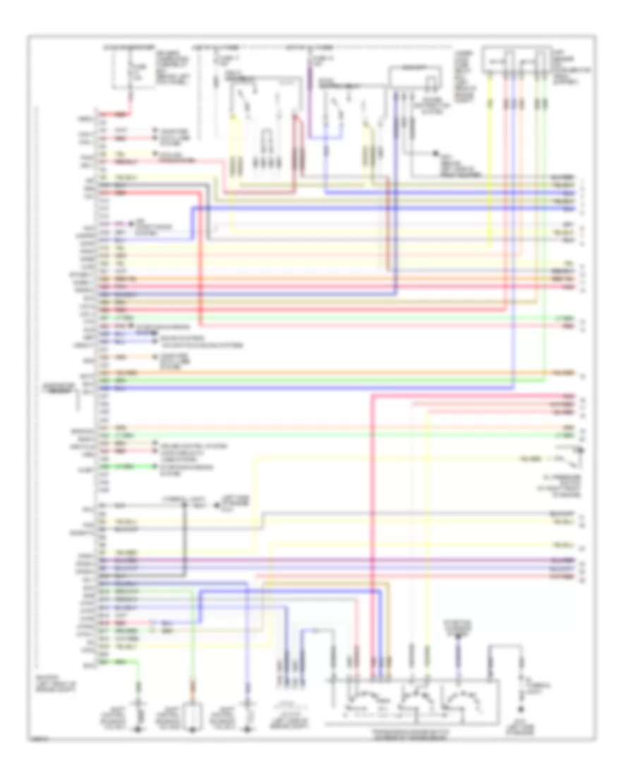
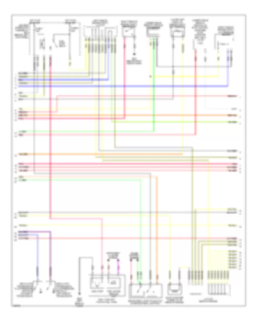
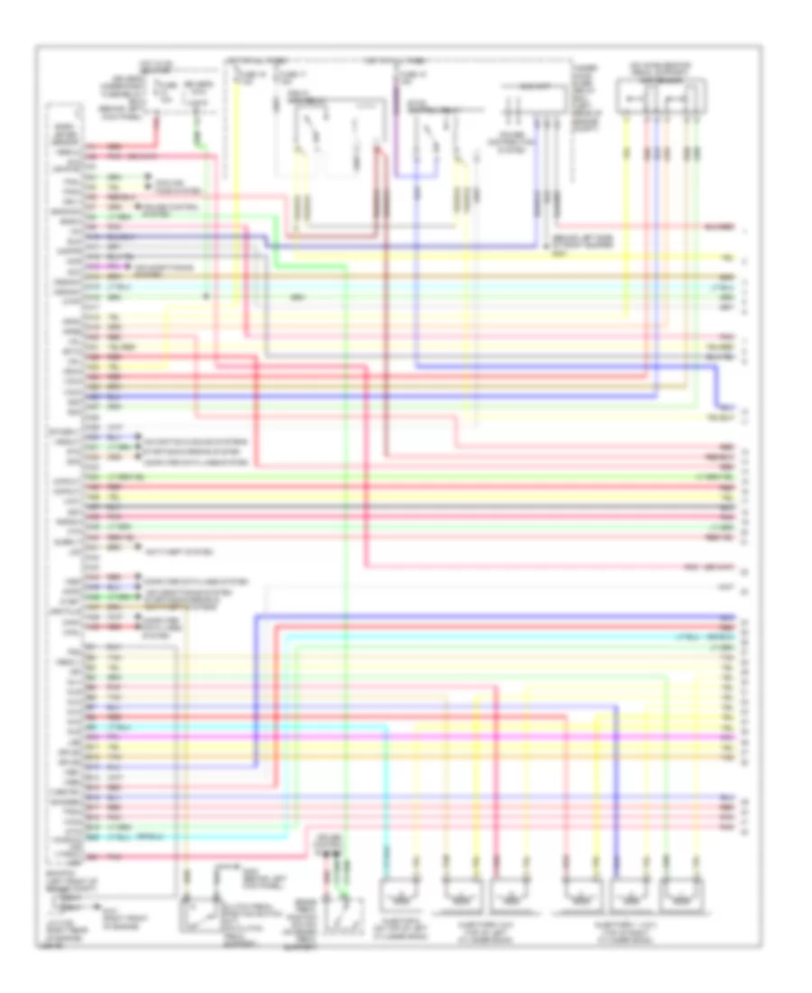
2.4L, Engine Performance Wiring Diagram (1 of 5) for Honda Accord EX 2010
List of elements for 2.4L, Engine Performance Wiring Diagram (1 of 5) for Honda Accord EX 2010:
- (left side of engine) g101
- (thermal joint) s1
- A10
- A11
- A12
- A13
- A14
- A15
- A16
- A17
- A18
- A19
- A20
- A21
- A22
- A23
- A24
- A25
- A26
- A27
- A28
- A29
- A30
- A31
- A32
- A33
- A34
- A35
- A36
- A37
- A38
- A39
- A40
- A41
- A42
- A43
- A44
- A45
- A46
- A47
- A48
- A49
- Acc
- Acpd
- Air conditioning system
- App sensor (on accelerator pedal support)
- Apsa
- Apsb
- Atp2-1
- Atpd3
- Atpn
- Atpp
- Atpr
- B10
- B11
- B12
- B13
- B14
- B15
- B16
- B17
- B18
- B19
- B20
- B21
- Barometer sensor
- Bksw
- Bkswnc
- Can h
- Can l
- Computer data lines system
- Cooling fans system
- Crmtcls
- Cruise control system
- Driver's under-dash fuse/relay box (behind left kick panel)
- Ecm/pcm (left front of engine compt)
- Ect2
- Eld
- Eld unit
- Etcs control relay
- Etcsrly
- F12
- Fanc
- Ftp
- Fuse 10a
- Fuse 17 15a
- Fuse 18 15a
- G101 (left side of engine)
- G301 (behind left side of front bumper)
- Hot at all times
- Hot in on or start
- Igp
- Imofpr
- J/c c101 (left side of engine compt)
- Mrly
- Navigation & sound systems
- Nep
- Oil pressure switch (at right front of engine)
- Op2sw
- Op3sw
- Opsw
- Pcs
- Pg 1
- Pg 2
- Pgm fi main relay
- Pnk
- Power distribution system
- Pspsw
- Red
- S net
- S1 (thermal joint)
- Scs
- Sg 4
- Sg 5
- Sg6
- Sha
- Shb
- Shc
- Shift control solenoid valve a
- Shift control solenoid valve b
- Shift control solenoid valve c
- Sls
- So2shtc
- Sound systems
- Starting/ charging system
- Starting/charging system
- Subrly
- Transmission range switch (on rear of transmission)
- Under- hood fuse/ relay box (left rear of engine compt)
- Vbsol
- Vcc 4
- Vcc 5
- Vcc2
- Vcc6
- Vssout
- Vsv
- Wen
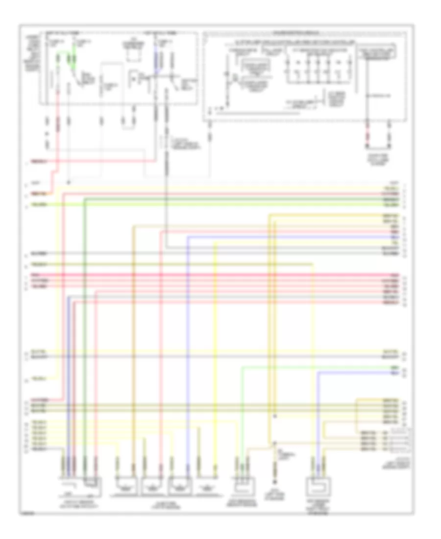
2.4L, Engine Performance Wiring Diagram (2 of 5) for Honda Accord EX 2010
List of elements for 2.4L, Engine Performance Wiring Diagram (2 of 5) for Honda Accord EX 2010:
- (left side of engine compt) j/c c101
- (lower left front of engine compt) ect sensor 2
- (right rear of engine compt) psp switch
- (right side of engine compt) a/c pressure sensor
- (under middle rear of vehicle) ftp sensor
- (under middle rear of vehicle, on evap control canister) evap canister vent shut valve
- 2nd clutch transmission fluid pressure switch a (left side of transmission)
- 3rd clutch transmission fluid pressure switch b (on side of transmission)
- A14
- A15
- A17
- B10
- B22
- Brake pedal position switch (on brake pedal support)
- Cruise control system
- D10
- Driver's under-dash fuse/relay box (behind left kick panel)
- Evap canister purge valve (rear of engine)
- F14
- F22
- F31
- Fuel gauge sending unit
- Fuel pump
- Fuel pump relay
- Fuel tank unit (top of fuel tank)
- Fuse 7 15a
- Fuse 9 20a
- G201 (behind right side of dash)
- G603 (left rear of floor)
- Hot in on or start
- Instrument cluster system
- J/c c103 (rear of engine)
- Pnk
- Red
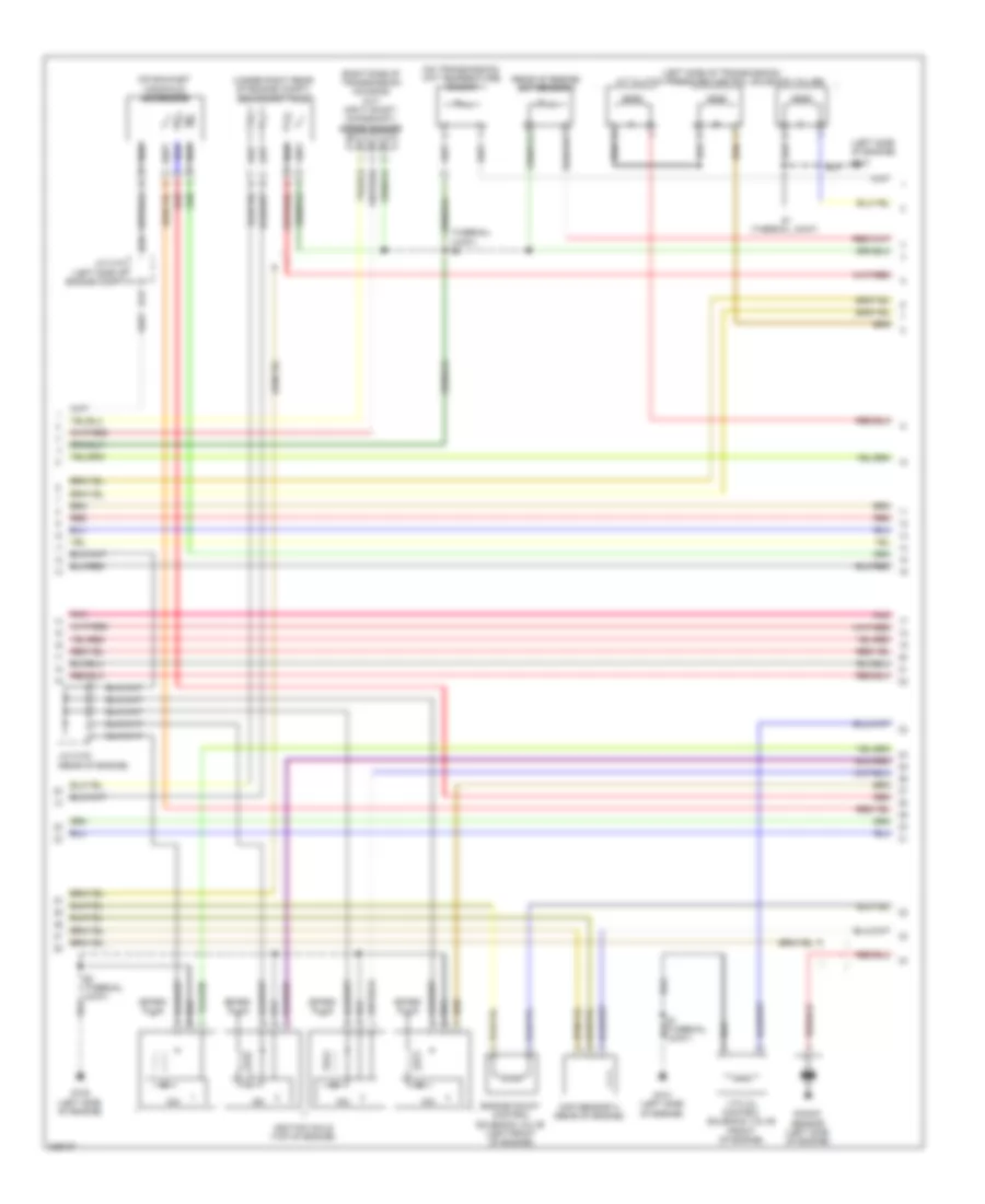
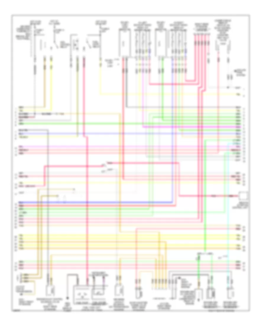
2.4L, Engine Performance Wiring Diagram (3 of 5) for Honda Accord EX 2010
List of elements for 2.4L, Engine Performance Wiring Diagram (3 of 5) for Honda Accord EX 2010:
- 10v stabilizer circuit
- 5v stabilizer circuit/controller area network controller
- A/c condenser fan relay
- A/c diode b
- A/t gear position dimming circuit
- A/t gear position indicator drive circuit
- A16
- B23
- Ckp sensor (under right front of engine)
- Cmp sensor b (rear of engine)
- Compulsory turning off circuit
- Compulsory turning on circuit
- Computer data lines system
- Fall safe circuit
- Fast controller area network transceiver
- Fuse 13 15a
- Fuse 14 15a
- Fuse 15 10a
- Fuse 21 7.5a
- G101 (left side of engine)
- Gauge control module
- Hot at all times
- Iat
- Ignition coil relay
- Injectors (top of engine)
- J/c c101 (left side of engine compt)
- Maf
- Maf/iat sensor (on intake air duct)
- Mil ind
- Pgm fi sub relay
- Pnk
- Red
- S3 (thermal joint)
- Under- hood fuse/ relay box (left rear of engine compt)
- Warning drive circuit
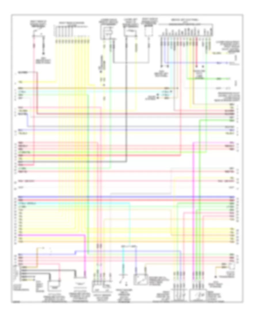
2.4L, Engine Performance Wiring Diagram (4 of 5) for Honda Accord EX 2010
List of elements for 2.4L, Engine Performance Wiring Diagram (4 of 5) for Honda Accord EX 2010:
- (left side of engine)
- (left side of transmission) a/t clutch pressure control solenoid valves
- (on exhaust manifold) a/f sensor
- (on transmission) atf temperature sensor
- (rear of engine) ect sensor 1
- (right side of transmission housing) (a/t) input shaft (mainshaft) speed sensor
- (thermal joint) s4
- (under right rear of engine compt) secondary ho2s
- A12
- B12
- Cmp sensor a (rear of engine)
- Engine mount control solenoid valve (left front of engine)
- G101
- G101 (left side of engine)
- G102 (left side of engine)
- Icm
- Ignition coils (top of engine)
- J/c c101 (left side of engine compt)
- J/c c103 (rear of engine)
- Knock sensor (left side of engine)
- Pnk
- Red
- S1 (thermal joint)
- S2 (thermal joint)
- Spark plug
- Vtc oil control solenoid valve (front of engine)
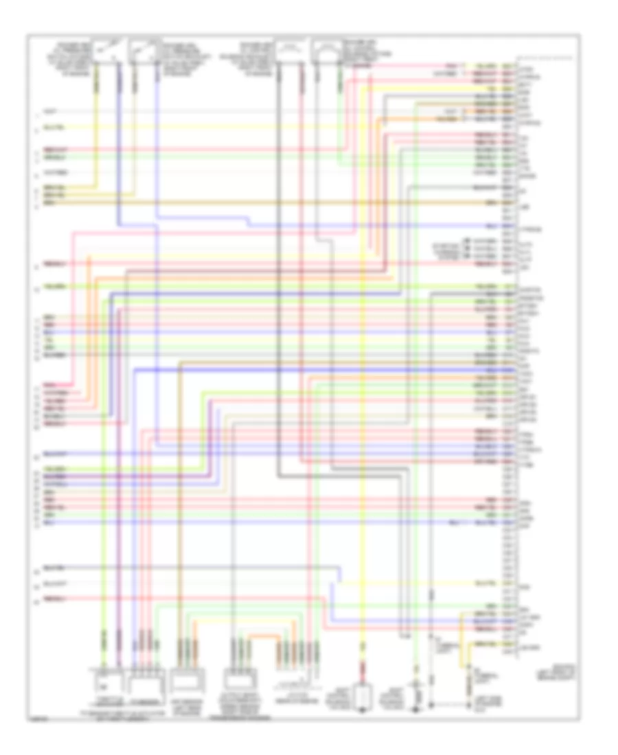
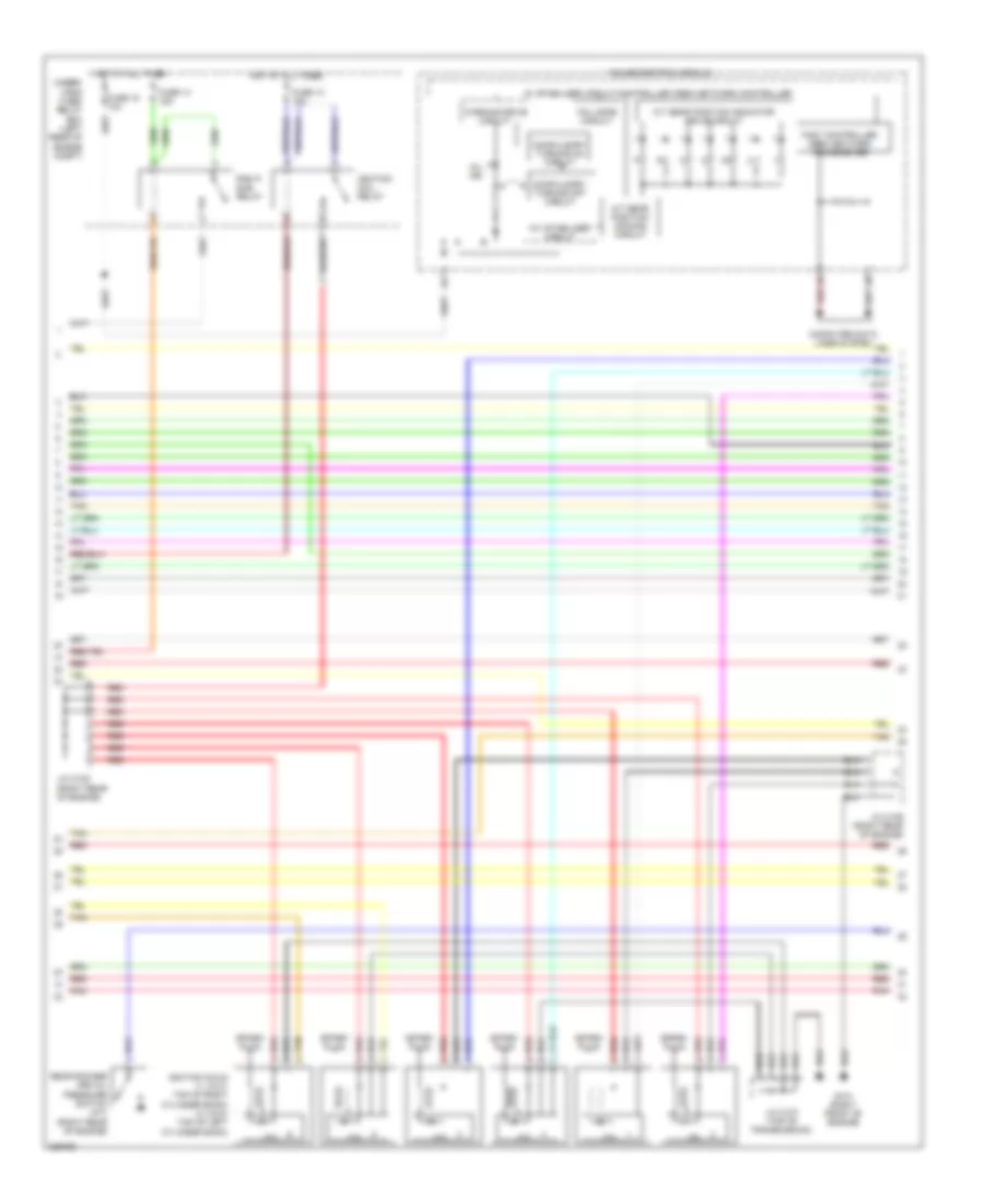
2.4L, Engine Performance Wiring Diagram (5 of 5) for Honda Accord EX 2010
List of elements for 2.4L, Engine Performance Wiring Diagram (5 of 5) for Honda Accord EX 2010:
- (left side of engine) g101
- Afs+
- Afs-
- Afshtc
- Altc
- Altf
- Altl
- Atft
- Atpd
- Atpfwd
- Atprvs
- B22
- B23
- B24
- B25
- B26
- B27
- B28
- B29
- B30
- B31
- B32
- B33
- B34
- B35
- B36
- B37
- B38
- B39
- B40
- B41
- B42
- B43
- B44
- B45
- B46
- B47
- B48
- B49
- C10
- C11
- C12
- C13
- C14
- C15
- C16
- C17
- C18
- C19
- C20
- C21
- C22
- C23
- C24
- C25
- C26
- C27
- C28
- C29
- C30
- C31
- C32
- C33
- C34
- C35
- C36
- C37
- C38
- C39
- C40
- C41
- C42
- C43
- C44
- C45
- C46
- C47
- C48
- C49
- Ckp
- Cmpa
- Cmpb
- Ecm/pcm (left front of engine compt)
- Ect1
- Etcsm+
- Etcsm-
- Iat
- Ig1
- Ig1etcs
- Igpls1
- Igpls2
- Igpls3
- Igpls4
- Inj1
- Inj2
- Inj3
- Inj4
- J/c c103 (rear of engine)
- Lg1 gnd
- Lg2 gnd
- Lsa
- Lsb
- Lsc
- Map
- Map sensor (left rear of engine)
- Mcs
- Output shaft (countershaft) speed sensor (right side of transmission housing)
- Pgmetcs
- Pnk
- Red
- Rocker arm oil control solenoid (intake) (right front of engine)
- Rocker arm oil pressure switch (exhaust) (w/ sulev/pzev) (right front of engine)
- S1 (thermal joint)
- S3 (thermal joint)
- Sg1
- Sg2
- Sg3
- Shd
- She
- Shift control solenoid valve d
- Shift control solenoid valve e
- Sho2s
- Starting/ charging system
- Throttle actuator
- Tp sensor
- Tp sensor/throttle actuator (on throttle body)
- Tpsa
- Tpsb
- Vcc1
- Vcc3
- Vg+
- Vg-
- Vtc
- Vtpswa
- Vtpswb
- Vts
- Vtsb
3.5L
3.5L, Engine Performance Wiring Diagram (1 of 6) for Honda Accord EX 2010
List of elements for 3.5L, Engine Performance Wiring Diagram (1 of 6) for Honda Accord EX 2010:
- (behind left side of front bumper) g301
- (on accelerator pedal support) app sensor
- A10
- A11
- A12
- A13
- A14
- A15
- A16
- A17
- A18
- A19
- A20
- A21
- A22
- A23
- A24
- A25
- A26
- A27
- A28
- A29
- A30
- A31
- A32
- A33
- A34
- A35
- A36
- A37
- A38
- A39
- A40
- A41
- A42
- A43
- A44
- A45
- A46
- A47
- A48
- A49
- Acc
- Acpd
- Air conditioning system
- Air conditioning system starting/charging & anti-theft systems
- Anti-theft system
- Apsa
- Apsb
- Atp-p
- Atpp
- B10
- B11
- B12
- B13
- B14
- B15
- B16
- B17
- B18
- B19
- B20
- B21
- Baro- meter sensor
- Bksw
- Bkswnc
- Brake pedal position switch (on brake pedal support)
- Canh
- Canl
- Ckpout
- Clutch pedal position switch (m/t) (on clutch pedal support)
- Cmpout
- Computer data lines system
- Cooling fans system
- Crmtcls
- Cruise control system
- Cssama
- Cssamc
- Driver's micu
- Driver's under-dash fuse/relay box (behind left kick panel)
- Ecm/pcm (left front of engine compt)
- Ect2
- Eld
- Eld unit
- Etcs control relay
- Etcsrly
- F12
- Fanh
- Fanl
- Ftp
- Fuse 10a
- Fuse 17 15a
- Fuse 18 15a
- Fuse 19 7.5a
- G101 (right front of engine)
- G302 (behind left kick panel)
- Hot at all times
- Hot in on or start
- Igp
- Igpls5
- Igpls6
- Imofpr
- Imtm vcmswc (or vtpsw) lsc
- Inj1
- Inj2
- Inj3
- Inj4
- Inj5
- Inj6
- Injector 6 (on top of left cylinder bank)
- Injectors 1, 2 & 3 (top of right cylinder bank)
- Injectors 4 & 5 (top of left cylinder bank)
- J/c c106 (right rear of engine)
- Lg3
- Lsb
- Mcs
- Mrly
- Navigation & sound systems
- Pg2
- Pgm fi main relay
- Pnk
- Power distribution system
- Pspsw
- Red
- S net
- Scs
- Sg3
- Sg4
- Sg7
- Sho2sb2
- Sls (or rvs)
- Starting/charging system
- Sts
- Subrly
- Tan
- Tpsa
- Under- hood fuse/ relay box (left rear of engine compt)
- Vbsol1
- Vbsol2
- Vbum
- Vcc3
- Vcc4
- Vcc5
- Vcc7
- Vcentb1
- Vg+
- Vg-
- Vsb1
- Vsb2
- Vssout
- Vsv
- Wen
3.5L, Engine Performance Wiring Diagram (2 of 6) for Honda Accord EX 2010
List of elements for 3.5L, Engine Performance Wiring Diagram (2 of 6) for Honda Accord EX 2010:
- (behind left kick panel) (a/t) engine mount control unit
- (lower left front of engine compt) ect sensor 2
- (lower middle front of engine compt) front engine mount control actuator
- (right rear of engine compt) psp switch
- (right rear of engine) j/c c105
- (right side of engine compt) a/c pressure sensor
- (under middle rear of vehicle) ftp sensor
- A/t
- A/t clutch pressure control solenoid valve b (top rear of transmission)
- A/t clutch pressure control solenoid valve c (top of transmission)
- Can h
- Can l
- Ckp
- Cmp
- Computer data lines system
- Front rocker arm oil pressure switch (left front of engine)
- Front secondary ho2s (b2, s2) (in left exhaust bank)
- G101 (right front of engine)
- G201 (behind right side of dash)
- G302 (behind left kick panel)
- Iat
- Ig1
- Igsol
- J/c c107 (top of transmission)
- M/t
- Maf
- Maf/iat sensor (on intake air duct)
- Pnk
- Rear engine mount control actuator (lower middle rear of engine compt)
- Rear secondary ho2s (b1, s2) (in right exhaust bank)
- Red
- Rocker arm oil pressure switch (right rear of engine)
- Scpa
- Scpc
- Solfm
- Solfp
- Solrly
- Solrm
- Solrp
- Sound systems
- System conditioning air
- Tan
3.5L, Engine Performance Wiring Diagram (3 of 6) for Honda Accord EX 2010
List of elements for 3.5L, Engine Performance Wiring Diagram (3 of 6) for Honda Accord EX 2010:
- (in left exhaust bank) front a/f sensor (b2, s1)
- (in right exhaust bank) rear a/f sensor (b1, s1)
- (right rear of engine)
- (right rear of engine) j/c c105
- (sulev/ ulev) chip resistor
- (under middle rear of vehicle, on evap control canister) evap canister vent shut valve
- A/t
- Acm control relay
- Cooling fans system
- D10
- Driver's under-dash fuse/relay box (behind left kick panel)
- Engine mount control solenoid valve (m/t) (right rear of engine)
- Evap canister purge valve (right rear of engine)
- F14
- F22
- F31
- Fuel gauge sending unit
- Fuel pump
- Fuel pump relay
- Fuel tank unit (top of fuel tank)
- Fuse 14 10a
- Fuse 7 15a
- Fuse 9 20a
- G101 (right front of engine)
- G603 (left rear of floor)
- Hot at all times
- Hot in on or start
- Instrument cluster system
- J/c c106 (right rear of engine)
- J/c c107 (top of transmission)
- M/t
- Pnk
- Red
- Remote starting control unit
- Reverse lockout solenoid (on transmission housing)
- Rocker arm oil control solenoid (under right front of engine)
- Rocker arm oil control solenoid a
- Rocker arm oil control solenoid b
- Sulev/ ulev
- Tan
- Ulev
3.5L, Engine Performance Wiring Diagram (4 of 6) for Honda Accord EX 2010
List of elements for 3.5L, Engine Performance Wiring Diagram (4 of 6) for Honda Accord EX 2010:
- 10v stabilizer circuit
- 5v stabilizer circuit/controller area network controller
- A/t gear position dimming circuit
- A/t gear position indicator drive circuit
- Compulsory turning off circuit
- Compulsory turning on circuit
- Computer data lines system
- Fail safe circuit
- Fast controller area network transceiver
- Fuse 13 15a
- Fuse 14 15a
- Fuse 15 10a
- G101 (right front of engine)
- Gauge control module
- Hot at all times
- Icm
- Ignition coil relay
- Ignition coils (1, 2 & 3: top of right cylinder bank) (4, 5 & 6: top of left cylinder bank)
- J/c c105 (right rear of engine)
- J/c c106 (right rear of engine)
- J/c c107 (top of transmission)
- Mil ind
- Pgm fi sub relay
- Pnk
- Rear rocker arm oil pressure switch (a/t) (right rear of engine)
- Red
- Spark plug
- Tan
- Under- hood fuse/ relay box (left rear of engine compt)
- Warning drive circuit
3.5L, Engine Performance Wiring Diagram (5 of 6) for Honda Accord EX 2010
List of elements for 3.5L, Engine Performance Wiring Diagram (5 of 6) for Honda Accord EX 2010:
- (left rear of engine) ect sensor 1
- (left rear of engine) egr valve & egr valve position sensor
- (on transmission) atf temperature sensor
- (right front of engine) g101
- (right side of transmission housing) input shaft (mainshaft) speed sensor
- (top of trans) j/c c107
- (top of transmission) j/c c108
- (under right front of engine) rocker arm oil pressure sensor
- 2nd clutch transmission fluid pressure switch (left side of transmission)
- 3rd clutch transmission fluid pressure switch (left rear of transmission)
- G101 (right front of engine)
- J/c c107 (top of transmission)
- J/c c108 (top of trans- mission)
- Map sensor (rear of engine)
- Oil pressure switch (under right front of engine)
- Output shaft (countershaft) speed sensor (right side of transmission housing)
- Pnk
- Red
- Shift control solenoid valve c
- Shift control solenoid valve d
- Starting/ charging system
- Tan
- Transmission range switch (on transmission)
3.5L, Engine Performance Wiring Diagram (6 of 6) for Honda Accord EX 2010
List of elements for 3.5L, Engine Performance Wiring Diagram (6 of 6) for Honda Accord EX 2010:
- (front of engine) (a/t) rocker arm oil control solenoid c
- (front of engine) imt actuator
- (left side of transmission) 4th clutch transmission fluid pressure switch
- (or vts)
- (top rear of transmission) a/t clutch pressure control solenoid valve a
- A/t
- Afshtcb1
- Afshtcb2
- Altc
- Altf
- Altl
- Atft
- Atp2-1
- Atpd
- Atpd3
- Atpfwd
- Atpn
- Atpr
- Atprvs
- B22
- B23
- B24
- B25
- B26
- B27
- B28
- B29
- B30
- B31
- B32
- B33
- B34
- B35
- B36
- B37
- B38
- B39
- B40
- B41
- B42
- B43
- B44
- B45
- B46
- B47
- B48
- B49
- C10
- C11
- C12
- C13
- C14
- C15
- C16
- C17
- C18
- C19
- C20
- C21
- C22
- C23
- C24
- C25
- C26
- C27
- C28
- C29
- C30
- C31
- C32
- C33
- C34
- C35
- C36
- C37
- C38
- C39
- C40
- C41
- C42
- C43
- C44
- C45
- C46
- C47
- C48
- C49
- Ckp
- Ckp sensor (under right front of engine)
- Cmp
- Cmp sensor (right front of engine)
- Cssa
- Cssb
- Cssc
- Ecm/pcm (left front of engine compt)
- Ect1
- Egr
- Egrp
- Etcsm+
- Etcsm-
- G101 (right front of engine)
- Iat
- Ig1
- Ig1etcs
- Igpls1
- Igpls2
- Igpls3
- Igpls4
- Ip b1
- Ip b2
- J/c c107 (top of transmission)
- Knock sensor (left side of engine)
- Lg1
- Lg2
- Lsa
- M/t
- Map
- Mt+
- Mt-
- Op2sw
- Op3sw
- Op4sw
- Opsw
- Pcs
- Pg1
- Pgmetcs
- Pnk
- Poil
- Red
- Sg1
- Sg2
- Sg5
- Sg6
- Sha
- Shb
- Shc
- Shd
- Shift control solenoid valve a
- Shift control solenoid valve b
- Sho2sb1
- So2shtcb1
- So2shtcb2
- Starting/ charging system
- Tan
- Tp sensor/throttle actuator (on throttle body)
- Tpsb
- Vcc1
- Vcc6
- Vcc7
- Vcentb2
- Vcmswb
- Vlblb1
- Vlblb2
EXTERIOR LIGHTS
2.4L
2.4L, Backup Lamps Wiring Diagram, A/T for Honda Accord EX 2010
List of elements for 2.4L, Backup Lamps Wiring Diagram, A/T for Honda Accord EX 2010:
- A/t reverse diode a (under left side of dash)
- A/t reverse diode b (under left side of dash)
- A/t reverse relay
- B15
- Drive input (atpr)
- Driver's under-dash fuse/relay box (behind left kick panel)
- Ecm/pcm (left front of engine compt)
- F27
- F28
- Fuse 5 7.5a
- G101 (left side of engine)
- G602 (left rear of trunk)
- Hot in on or start
- J/c c101 (left side of engine compt)
- Left backup light
- Red
- Right backup light
- S1 (thermal joint)
- Transmission range switch (on rear of transmission)
2.4L, Backup Lamps Wiring Diagram, M/T for Honda Accord EX 2010
List of elements for 2.4L, Backup Lamps Wiring Diagram, M/T for Honda Accord EX 2010:
- 2.4l
- 3.5l
- B15
- Backup light switch (on top left of transmission)
- Backup light switch (top left of transmission)
- Driver's under-dash fuse/relay box (behind left kick panel)
- F27
- F28
- Fuse 5 7.5a
- G602 (left rear of trunk)
- Hot in on or start
- J/c c101 (left side of engine compt)
- Left backup light
- Right backup light
2.4L, Exterior Lamps Wiring Diagram (1 of 2) for Honda Accord EX 2010
List of elements for 2.4L, Exterior Lamps Wiring Diagram (1 of 2) for Honda Accord EX 2010:
- (not used)
- +b back up
- A11
- A14
- A29
- A35
- A37
- Accessory
- Auto lt sid
- Auto lt sig
- Auto lt sip
- Automatic lighting sensor
- Automatic lighting sensor/sunlight sensor (top middle of dash)
- B- can hi
- B- can lo
- Computer data lines system
- D11
- D13
- D20
- Driver's junction box 1 (behind left kick panel)
- Driver's micu
- Driver's under- dash fuse/ relay box (behind left kick panel)
- E10
- E12
- F10
- Fuse 10a
- Fuse 7.5a
- G201 (behind right side of dash)
- G302 (behind left kick panel)
- G501 (under left side of dash)
- G502 (under left side of dash)
- G505 (behind right side of dash)
- G601 (left side of floor)
- G602 (left rear of trunk)
- Gnd (micu -s)
- Gnd (micu-p)
- Gnd (micu-s)
- H10
- H18
- H36
- High mount brake light
- High mount brake light (trunk spoiler) (honda accessory)
- High mount brake light connector
- Hot at all times
- Hot in on
- Hot in on or start
- Ig1 day lt
- Ig1 meter
- Left brake light/ taillight
- Left front side marker light
- Left front turn signal/ parking light
- Left license plate light (4-door)
- License plate light (2-door)
- Lighting
- Navigation unit (if equipped) (under right side of rear shelf)
- Nca
- P14
- P20
- Passenger's micu
- Passenger's under-dash fuse/relay box (behind right kick panel)
- Pnk
- Red
- Right brake light/ taillight
- Right front side marker light
- Right front turn signal/ parking light
- Right license plate light (4-door)
- S5 (thermal joint)
- Small rly as cl-
- Small rly dr cl-
- Taillight ctrl circuit
- Taillight relay
- Trailer lighting connector (option connector) (if equipped) (left rear of trunk)
- Turn signal/ hazard flasher circuit
- W/ automatic
- W/o automatic
- W/o honda w/ honda accessory
2.4L, Exterior Lamps Wiring Diagram (2 of 2) for Honda Accord EX 2010
List of elements for 2.4L, Exterior Lamps Wiring Diagram (2 of 2) for Honda Accord EX 2010:
- (not used)
- (under left side of dash) g501
- +b back up
- +b hazard
- 0) off 1) park 2) auto
- 2.4l
- 3) head
- 3.5l
- 5v stabilizer circuit/ controller area network controller
- A20
- A42
- B-can hi
- B-can lo
- B13
- B14
- Body controller area network transceiver
- Brake pedal position switch (on brake pedal support)
- Center junction box (under left side of dash)
- Combination light switch
- Driver's micu
- Driver's under-dash fuse/relay box (behind left kick panel)
- E12
- Ecm/pcm (left front of engine compt)
- F11
- F20
- F32
- Front passenger's airbag cut-off indicator
- Fuse 10a
- Fuse 15a
- Fuse 20a
- Fuse 7.5a
- G602 (left rear of trunk)
- Gauge control module
- Gnd (light)
- H/l low sw
- H/l off sw
- Hazard sw
- Hazard warning switch
- Head
- Headlight switch
- Horn relay
- Hot at all times
- Hot in on or start
- Interior lights system
- Left rear turn signal light
- Left turn signal ind
- Lighting
- Lights on ind
- Pnk
- Ptt
- Q17
- R14
- Red
- Right rear turn signal light
- Right turn signal ind
- Small sw
- Srs unit (under middle of dash)
- Stop sw
- Swin
- Turn signal switch
- Turn signal/hazard relay 2 (sounder)
- Turn sw l r13
- Turn sw r
- Under-hood fuse/relay box (left rear of engine compt)
- W/ automatic
- W/o automatic
- Warning drive circuit
3.5L
3.5L, Backup Lamps Wiring Diagram, A/T for Honda Accord EX 2010
List of elements for 3.5L, Backup Lamps Wiring Diagram, A/T for Honda Accord EX 2010:
- A/t reverse diode a (under left side of dash)
- A/t reverse diode b (under left side of dash)
- A/t reverse relay
- C25
- Drive input (atpr)
- Driver's under-dash fuse/relay box (behind left kick panel)
- Ecm/pcm (left front of engine compt)
- F27
- F28
- Fuse 5 7.5a
- G101 (right front of engine)
- G602 (left rear of trunk)
- Hot in on or start
- J/c c107 (top of transmission)
- J/c c108 (top of transmission)
- Left backup light
- Red
- Right backup light
- Transmission range switch (on transmission)
3.5L, Backup Lamps Wiring Diagram, M/T for Honda Accord EX 2010
List of elements for 3.5L, Backup Lamps Wiring Diagram, M/T for Honda Accord EX 2010:
- 2.4l
- 3.5l
- B15
- Backup light switch (on top left of transmission)
- Backup light switch (top left of transmission)
- Driver's under-dash fuse/relay box (behind left kick panel)
- F27
- F28
- Fuse 5 7.5a
- G602 (left rear of trunk)
- Hot in on or start
- J/c c101 (left side of engine compt)
- Left backup light
- Right backup light
3.5L, Exterior Lamps Wiring Diagram (1 of 2) for Honda Accord EX 2010
List of elements for 3.5L, Exterior Lamps Wiring Diagram (1 of 2) for Honda Accord EX 2010:
- (not used)
- +b back up
- A11
- A14
- A29
- A35
- A37
- Accessory
- Auto lt sid
- Auto lt sig
- Auto lt sip
- Automatic lighting sensor
- Automatic lighting sensor/sunlight sensor (top middle of dash)
- B- can hi
- B- can lo
- Computer data lines system
- D11
- D13
- D20
- Driver's junction box 1 (behind left kick panel)
- Driver's micu
- Driver's under- dash fuse/ relay box (behind left kick panel)
- E10
- E12
- F10
- Fuse 10a
- Fuse 7.5a
- G201 (behind right side of dash)
- G302 (behind left kick panel)
- G501 (under left side of dash)
- G502 (under left side of dash)
- G505 (behind right side of dash)
- G601 (left side of floor)
- G602 (left rear of trunk)
- Gnd (micu -s)
- Gnd (micu-p)
- Gnd (micu-s)
- H10
- H18
- H36
- High mount brake light
- High mount brake light (trunk spoiler) (honda accessory)
- High mount brake light connector
- Hot at all times
- Hot in on
- Hot in on or start
- Ig1 day lt
- Ig1 meter
- Left brake light/ taillight
- Left front side marker light
- Left front turn signal/ parking light
- Left license plate light (4-door)
- License plate light (2-door)
- Lighting
- Navigation unit (if equipped) (under right side of rear shelf)
- Nca
- P14
- P20
- Passenger's micu
- Passenger's under-dash fuse/relay box (behind right kick panel)
- Pnk
- Red
- Right brake light/ taillight
- Right front side marker light
- Right front turn signal/ parking light
- Right license plate light (4-door)
- S5 (thermal joint)
- Small rly as cl-
- Small rly dr cl-
- Taillight ctrl circuit
- Taillight relay
- Trailer lighting connector (option connector) (if equipped) (left rear of trunk)
- Turn signal/ hazard flasher circuit
- W/ automatic
- W/o automatic
- W/o honda w/ honda accessory
3.5L, Exterior Lamps Wiring Diagram (2 of 2) for Honda Accord EX 2010
List of elements for 3.5L, Exterior Lamps Wiring Diagram (2 of 2) for Honda Accord EX 2010:
- (not used)
- (under left side of dash) g501
- +b back up
- +b hazard
- 0) off 1) park 2) auto
- 2.4l
- 3) head
- 3.5l
- 5v stabilizer circuit/ controller area network controller
- A20
- A42
- B-can hi
- B-can lo
- B13
- B14
- Body controller area network transceiver
- Brake pedal position switch (on brake pedal support)
- Center junction box (under left side of dash)
- Combination light switch
- Driver's micu
- Driver's under-dash fuse/relay box (behind left kick panel)
- E12
- Ecm/pcm (left front of engine compt)
- F11
- F20
- F32
- Front passenger's airbag cut-off indicator
- Fuse 10a
- Fuse 15a
- Fuse 20a
- Fuse 7.5a
- G602 (left rear of trunk)
- Gauge control module
- Gnd (light)
- H/l low sw
- H/l off sw
- Hazard sw
- Hazard warning switch
- Head
- Headlight switch
- Horn relay
- Hot at all times
- Hot in on or start
- Interior lights system
- Left rear turn signal light
- Left turn signal ind
- Lighting
- Lights on ind
- Pnk
- Ptt
- Q17
- R14
- Red
- Right rear turn signal light
- Right turn signal ind
- Small sw
- Srs unit (under middle of dash)
- Stop sw
- Swin
- Turn signal switch
- Turn signal/hazard relay 2 (sounder)
- Turn sw l r13
- Turn sw r
- Under-hood fuse/relay box (left rear of engine compt)
- W/ automatic
- W/o automatic
- Warning drive circuit
GROUND DISTRIBUTION
Ground Distribution Wiring Diagram (1 of 5) for Honda Accord EX 2010
List of elements for Ground Distribution Wiring Diagram (1 of 5) for Honda Accord EX 2010:
- (a/t) a/t clutch pressure control solenoid valve a
- (a/t) a/t clutch pressure control solenoid valve b
- (a/t) a/t clutch pressure control solenoid valve c
- (a/t) rocker arm oil control solenoid a
- (a/t) rocker arm oil control solenoid b
- (a/t) rocker arm oil control solenoid c
- (a/t) trans- mission range switch
- (except sulev & pzev) rocker arm oil control solenoid (intake)
- (lg1)
- (lg2)
- (m/t)
- (not used)
- (pg1)
- (pg2)
- (pgmetcs)
- (sulev & pzev) rocker arm oil control solenoid (exhaust)
- (sulev & pzev) rocker arm oil pressure switch (exhaust)
- (ulev, sulev & pzev) rocker arm oil pressure switch (intake)
- B10
- B40
- B41
- Battery
- C41
- C44
- C48
- Ckp sensor
- Cmp sensor
- Cmp sensor a
- Cmp sensor b
- Dlc
- Driver's junction box 1 (behind left kick panel)
- Ecm/pcm
- Egr valve & egr valve position sensor
- Engine
- Front a/f sensor shield
- Front secondary ho2s shield
- G1 (left front of engine compt)
- G101 (2.4l) (left side of engine)
- G101 (3.5l) (right front of engine)
- G102 (2.4l) (left side of engine)
- G2 (right side of engine compt)
- G203 (behind right side of front bumper)
- G3 (lower left front of engine compt)
- Gnd
- Gnd (lg1)
- Gnd (lg2)
- Gnd (pg1)
- Gnd (pg2)
- Gnd (pgmetcs)
- High
- Ignition coil 1
- Ignition coil 2
- Ignition coil 3
- Ignition coil 4
- Ignition coil 5
- Ignition coil 6
- Immobilizer- keyless control unit
- J/c c101 (left side of engine compt)
- J/c c106 (right rear of engine)
- J/c c107 (top of transmission)
- Knock sensor shield
- Rear a/f sensor & rear secondary ho2s shield
- Right headlight (premium audio)
- Rocker arm oil pressure switch
- S1 (thermal joint) (rear of engine)
- S2 (thermal joint) (rear of engine)
- S3 (thermal joint) (rear of engine)
- Secondary ho2s shield
- Trans- mission
- Vtc oil control solenoid valve
Ground Distribution Wiring Diagram (2 of 5) for Honda Accord EX 2010
List of elements for Ground Distribution Wiring Diagram (2 of 5) for Honda Accord EX 2010:
- (3.5l: a/t) engine mount control unit
- (canada) washer fluid level switch
- (if equipped) left fog light
- (if equipped) right fog light
- (w/ vsa) vsa modulator control unit
- (w/o vsa) abs modulator control unit
- 2.4l
- 3.5l
- 4 door
- A/c condenser fan motor (2.4l)
- Blower motor relay
- Blower power transistor
- Brake fluid level switch
- Clutch interlock switch (m/t)
- Clutch pedal position switch (m/t)
- E15
- E16
- Eld unit
- Except 4 door
- Fan control relay
- G201 (behind right side of dash)
- G202 (behind right side of front bumper)
- G301 (behind left side of front bumper)
- G302 (behind left kick panel)
- High
- Intermittent wiper relay
- Left front side marker light
- Left front turn signal/ parking light
- Left headlight
- Low
- Micu p-gnd
- Micu s-gnd
- Normal audio
- Passenger's micu
- Passenger's under-dash fuse/relay box (behind right kick panel)
- Psp switch
- Radiator fan motor
- Right front side marker light
- Right front turn signal/ parking light
- Right headlight
- S5 (thermal joint) (under left side of dash)
- Security hood switch (if equipped)
- Under-hood fuse/relay box (left rear of engine compt)
- Windshield washer motor
- Windshield wiper motor
- Windshield wiper relay
Ground Distribution Wiring Diagram (3 of 5) for Honda Accord EX 2010
List of elements for Ground Distribution Wiring Diagram (3 of 5) for Honda Accord EX 2010:
- (3.5l) dlc
- (a/t) park pin switch/a/t gear position indicator panel light
- (automatic a/c w/0 navigation) climate control unit
- (behind left kick panel) driver's under-dash fuse/relay box
- (if equipped)
- (if equipped) automatic dimming inside mirror
- (if equipped) automatic dimming inside mirror connector (option connector)
- (if equipped) handsfreelink control unit
- (if equipped) homelink unit
- (if equipped) moonroof control unit
- (if equipped) moonroof switch
- (if equipped) tpms control unit
- (if equipped) vsa off switch
- (manual a/c) hvac control unit
- (power mirror defoggers) left power mirror
- (premium audio) stereo amplifier
- (under left side of dash)
- (w/ handsfree link) microphone
- (w/ navigation) climate control unit
- (w/ navigation) driver's climate control switch
- (w/ navigation) interface dial
- (w/ vsa) yaw rate lateral acceleration sensor
- A12
- A28
- A29
- Audio unit
- Audio-hvac sub-display unit
- C12
- Cable
- Check connector
- Console accessory power socket
- Console accessory power socket relay
- Cruise control combination switch
- Dlc
- Driver's door lock actuator/ knob switch
- Driver's micu
- Driver's power window motor
- Driver's seat heater switch
- Driver's under-dash fuse/relay box (behind left kick panel)
- Driver's vanity mirror light
- Factory
- Front accessory power socket
- Front individual map lights
- Front passenger's seat heater switch
- Front passenger's vanity mirror light
- G401 (behind middle of dash)
- G402 (behind middle of dash)
- G501
- G502 (under left side of dash)
- G503 (behind middle of dash)
- G504 (under center console)
- Gauge control module
- Gnd (micu-p)
- Gnd (micu-s)
- Honda accessory 1
- Horn switch
- Ignition key switch/key light
- Micu service
- N12
- Park pin switch
- Power mirror switch
- Power window master switch
- Red
- Reel
- Srs unit
- Steering wheel
- Switch illumination
Ground Distribution Wiring Diagram (4 of 5) for Honda Accord EX 2010
List of elements for Ground Distribution Wiring Diagram (4 of 5) for Honda Accord EX 2010:
- (2-door) license plate light
- (4-door & security) left rear door lock actuator/knob switch
- (4-door & security) right rear door lock actuator/knob switch
- (4-door) left license plate light
- (4-door) left rear power window switch
- (4-door) right license plate light
- (4-door) right rear power window switch
- (behind right kick panel) passenger's under-dash fuse/relay box
- (if equipped) driver's power lumbar support switch
- (if equipped) driver's power lumber support switch
- (if equipped) driver's power seat adjustment switch
- (if equipped) driver's seat heater
- (if equipped) driver's seat heater relay (high)
- (if equipped) driver's seat heater relay (low)
- (if equipped) electrical compass unit
- (if equipped) navigation display unit
- (if equipped) navigation unit
- (if equipped) noise condenser
- (power mirror defoggers) right power mirror
- (security) front passenger's door lock actuator/ knob switch
- A37
- D14
- Door lock relay
- Door unlock relay
- Driver's door unlock relay
- Driver's seat belt buckle switch
- Driver's seat position sensor
- Driver's under-dash fuse/relay box (behind left kick panel)
- Front accessory power socket relay
- Front passenger's power window switch
- Fuse/relay box connector g
- Fuse/relay box connector h
- G16 h21
- G505 (behind right side of dash)
- G601 (left side of floor)
- G602 (left rear of trunk)
- G651 (right side of floor)
- G701 (2-door) (left side of floor)
- G701 (4-door) (left side of floor)
- G8 h7
- Gnd (micu-s)
- High mount brake light
- Left backup light
- Left brake light/taillight
- Left rear turn signal light
- Passenger's micu
- Passenger's under-dash
- Passenger's under-dash fuse/relay box (behind right kick panel)
- Right backup light
- Right brake light/taillight
- Right rear turn signal light
- Security
- Trunk lid opener solenoid/latch switch
- Windshield washer relay
Ground Distribution Wiring Diagram (5 of 5) for Honda Accord EX 2010
List of elements for Ground Distribution Wiring Diagram (5 of 5) for Honda Accord EX 2010:
- (if equipped)
- (if equipped) front passenger's power seat adjustment switch
- (if equipped) front passenger's seat heater
- (right side of floor)
- D12
- Front passenger's seat belt buckle switch
- Front passenger's seat heater relay (high)
- Front passenger's seat heater relay (low)
- Fuel tank unit
- G603 (left rear of floor)
- G702 (2-door)
- G702 (4-door)
- G801 (at right "c" pillar)
- Ods unit
- Rear window defogger
HEADLIGHTS
Fog Lamp Wiring Diagram, with Autolamps for Honda Accord EX 2010
List of elements for Fog Lamp Wiring Diagram, with Autolamps for Honda Accord EX 2010:
- (or red)
- (under
- + backup
- +b backup
- 5v stabilizer circuit/controller area network controller
- A11
- A14
- A17
- A29
- A35
- A37
- Auto lt sid
- Auto lt sig
- Auto lt sip
- Automatic lighting sensor
- Automatic lighting sensor/ sunlight sensor (top middle of dash)
- B-can hi
- B-can lo
- Backup h/l
- Body controller area network transceiver
- Combination light switch
- Computer data lines system
- D20
- Driver's junction box 1 (behind left kick panel)
- Driver's micu
- Driver's under-dash fuse/relay box (behind left kick panel)
- E13
- Exterior lights system
- F11
- Fog light control circuit
- Fog light indicator
- Fog light switch
- Fr fog sw
- Fuse 10a
- Fuse 7.5a
- G12
- G201 (behind right side of dash)
- G302 (behind left kick panel)
- G501
- G502 (under left side of dash)
- G505 (behind right side of dash)
- Gauge control module
- Hot at all times
- Hot in on
- Hot in on or start
- Ig1 day lt
- Ig1 meter
- Left fog light
- Left side of dash)
- Lighting
- Micu-p
- Micu-s
- Navigation system
- P20
- Passenger's micu
- Passenger's under-dash fuse/relay box (behind right kick panel)
- Pnk
- R10
- Red
- Right fog light
- S5 (thermal joint)
- Under- hood fuse/ relay box (left rear of engine compt)
- W/ navigation
- Warning drive circuit
Fog Lamp Wiring Diagram, without Autolamps for Honda Accord EX 2010
List of elements for Fog Lamp Wiring Diagram, without Autolamps for Honda Accord EX 2010:
- (under left side of dash)
- + backup
- +b backup
- 5v stabilizer circuit/controller area network controller
- A11
- A14
- A17
- A29
- A35
- A36
- A37
- B-can hi
- B-can lo
- Backup h/l
- Body controller area network transceiver
- Combination light switch
- Computer data lines system
- Driver's junction box 1 (behind left kick panel)
- Driver's micu
- Driver's under-dash fuse/relay box (behind left
- E13
- Exterior lights system
- F11
- Fog light indicator
- Fog light relay
- Fog light switch
- Fr fog rly cl-
- Fr fog sw
- Fuse 10a
- Fuse 7.5a
- G12
- G201 (behind right side of dash)
- G301 (w/ accessory) (behind left side of front bumper)
- G302 (w/o accessory) (behind left kick panel)
- G501
- G502 (under left side of dash)
- G505 (behind right side of dash)
- Gauge control module
- Hot at all times
- Hot in on
- Hot in on or start
- Ig1 day lt
- Ig1 meter
- Kick panel)
- Left fog light
- Lighting
- Micu-p
- Micu-s
- Navigation system
- P20
- Passenger's micu
- Passenger's under-dash fuse/relay box (behind right kick panel)
- Pnk
- R10
- Red
- Right fog light
- S5 (thermal joint) (w/o accessory)
- Under- hood fuse/ relay box (left rear of engine compt)
- W/ navigation
- Warning drive circuit
Headlamps Wiring Diagram for Honda Accord EX 2010
List of elements for Headlamps Wiring Diagram for Honda Accord EX 2010:
- (behind right kick panel) passenger's under-dash fuse/relay box
- (behind right side of dash) g201
- (behind right side of front bumper) (premium audio) g203 g201 (normal audio) (behind right side of dash)
- (under
- +b backup
- 10v stabilizer circuit
- 5v stabilizer circuit/controller area network controller
- A11
- A14
- A17
- A29
- A35
- A37
- Auto lt sid
- Auto lt sig
- Auto lt sip
- Automatic lighting sensor
- Automatic lighting sensor/ sunlight sensor (w/ automatic lighting) (top middle of dash)
- B-can hi
- B-can lo
- Backup h/l
- Body controller area network transceiver
- Combination light switch
- Computer data lines system
- D12
- D20
- Dimmer sw
- Dimmer/ flash- to-pass switch 0) low 1) high 2) passing
- Driver's door switch (at driver's "b" pillar)
- Driver's junction box 1 (behind left kick panel)
- Driver's micu
- Driver's under-dash fuse/relay box (behind left kick panel)
- Drl indicator
- E10
- Exterior lights system
- F11
- F13
- F21
- Fr door sw l
- Fuse 10a
- Fuse 7.5a
- G302 (behind left kick panel)
- G501
- G502 (under left side of dash)
- G503 (behind middle of dash)
- G505 (behind right side of dash)
- Gauge control module
- H/l low sw
- H/l off sw
- Headlight switch 0) off 1) park 2) auto 3) head
- High
- High beam control circuit
- High beam dimming circuit
- High beam indicator
- Hot at all times
- Hot in on
- Hot in on or start
- Ig1 day lt
- Ig1 meter
- Ignition key switch
- Ignition key switch/ key light
- Indicator dimming circuit
- Key sw
- Left headlight
- Left side of dash)
- Lighting
- Lights on indicator
- Low
- Low beam control circuit
- Micu s
- Micu-p
- Micu-s
- Navigation system
- P20
- Parking brake switch (under parking brake lever)
- Passenger's micu
- Passing sw
- Pnk
- Q18
- R21
- R22
- Red
- Right headlight
- S5 (thermal joint)
- Small sw
- Under- hood fuse/ relay box (left rear of engine compt)
- W/ navigation
- Warning drive circuit
HORN
Horn Wiring Diagram for Honda Accord EX 2010
List of elements for Horn Wiring Diagram for Honda Accord EX 2010:
- 2.4l
- 3.5l
- B13
- B14
- Brake pedal position switch (on brake pedal support)
- C11
- C12
- Cable reel (connector b: in steering column) (connector c: in steering wheel)
- Cruise control combination switch
- Driver's junction box 1 (behind left kick panel)
- Driver's micu
- Driver's under-dash fuse/relay box (behind left kick panel)
- F23
- Fuse 20a
- G501 (under left side of dash)
- High horn (at front of engine compt, behind front grille)
- Horn relay
- Horn switch
- Hot at all times
- Low horn (at front of engine compt, behind front grille)
- Q12
- Red
- Steering wheel
- Under-hood fuse/relay box (left rear of engine compt)
INSTRUMENT CLUSTER
Instrument Cluster Wiring Diagram (1 of 2) for Honda Accord EX 2010
List of elements for Instrument Cluster Wiring Diagram (1 of 2) for Honda Accord EX 2010:
- 5v stabilizer circuit/controller area network controller
- Abs ind
- B-can hi
- B-can lo
- Brake fluid level switch (on brake fluid reservoir)
- Brake system ind
- Charging system ind
- Computer data lines system
- Cruise control ind
- Cruise control main switch ind
- Cruise control system
- D12
- Driver's door open ind
- Driver's junction box 1 (behind left kick panel)
- Driver's micu
- Driver's under-dash fuse/relay box (behind left kick panel)
- Drl ind
- Eco ind
- Exterior lights system
- Fog light ind
- Fr dr sw l
- Front passenger's door open ind
- Fuel gauge sending unit
- Fuel tank unit (top of fuel tank)
- Fuse 7.5a
- G201 (behind right side of dash)
- G302 (behind left kick panel)
- G501 (under left side of dash)
- G502 (under left side of dash)
- Gauge control module
- Hot in on or start
- Ig1 meter
- Immobilizer system ind
- Interior lights system
- Left rear door open ind
- Lights on ind
- Low fuel ind
- Low oil pressure ind
- Low tire pressure ind
- Maintenance required ind
- Mil ind
- P20
- Parking brake switch (under parking brake lever)
- Pnk
- Red
- Right rear door open ind
- Rr dr sw l
- Seat belt reminder ind
- Side airbag cut-off ind
- Srs ind
- To compul- sory turning off circuit (diagram 2 of 2)
- To indicator dimming circuit (diagram 2 of 2)
- To security ind (diagram 2 of 2)
- Tpms ind
- Trunk lid open ind
- Trunk sw
- Vsa activation ind
- Vsa off switch (if equipped)
- Vsa system ind
- Warning drive circuit
- Washer fluid level ind
- Washer fluid level switch (canada)
Instrument Cluster Wiring Diagram (2 of 2) for Honda Accord EX 2010
List of elements for Instrument Cluster Wiring Diagram (2 of 2) for Honda Accord EX 2010:
- (con g)
- (con h)
- -off circuit compulsory turning
- 10v stabilizer circuit
- 2.4l
- 3.5l
- 5v stabilizer circuit/controller area network controller
- A/t gear position dimming circuit
- A/t gear position indicator drive circuit
- A11
- A29
- A3 f-can communication sig (canh)
- A4 f-can communication sig (canl)
- A48
- A49
- B-can hi
- B-can lo
- Beeper
- Body controller area network transceiver
- Brightening switch
- C45
- Compulsory turning -on circuit
- Computer data lines system
- Dial brightness control and dimming circuit
- Dimming switch
- Display (mid) unit multi-information
- Driver's door switch (at driver's "b" pillar)
- Ecm/pcm (left front of engine compt)
- Engine coolant temperature gauge
- Fail-safe circuit
- Fr dr sw r
- From 16 pin (diagram 1 of 2)
- From control cruse control ind (diagram 1 of 2)
- From mil ind (diagram 1 of 2)
- Front passenger's door switch (at front passenger's "b" pillar)
- Fuel gauge
- Fuse 10a
- G14
- G15
- G602 (left rear of trunk)
- Gauge control module
- H25
- High beam dimming circuit
- High beam ind
- Hot at all times
- Indicator dimming circuit
- Lcd back light
- Lcd brightness control and dimming circuit
- Left rear door switch (4-door) (at left "c" pillar)
- Left turn signal ind
- Network transceiver fast controller area
- Odometer/trip meter/select/ reset switch
- Oil pressure switch (2.4l: at right front of engine) (3.5l: under right front of engine)
- Passenger's micu
- Passenger's under-dash fuse/relay box (behind right kick panel)
- Pnk
- Pointer brightness control and dimming circuit
- Red
- Relay 2 (sounder) turn signal/hazard
- Right rear door switch (4-door) (at right "c" pillar)
- Right turn signal ind
- Rr dr sw r
- Security ind
- Security ind blinking circuit
- Speedometer
- Switch input
- Tachometer
- Trunk lid latch switch
- Trunk lid opener solenoid/ latch switch (middle rear of trunk lid)
- Under-hood fuse/relay box (left rear of engine compt)
- Unit 5v control
- Warning drive circuit
INTERIOR LIGHTS
Courtesy Lamps Wiring Diagram for Honda Accord EX 2010
List of elements for Courtesy Lamps Wiring Diagram for Honda Accord EX 2010:
- (con g)
- (con h)
- +b backup
- A11
- A13
- A14
- A29
- A33
- Ambient light in line fuse
- Ambient light resistor
- Ambient light switch (if equipped)
- B-can hi
- B-can lo
- Ceiling light
- Center junction box (under left side of dash)
- Computer data lines system
- D12
- Door
- Driver's ambient light
- Driver's door courtesy light (4 door)
- Driver's door switch (at driver's "b" pillar)
- Driver's junction box 1 (behind left kick panel)
- Driver's micu
- Driver's under-dash fuse/relay box (behind left kick panel)
- Driver's vanity mirror light
- F11
- F29
- Fr courtesy l
- Fr courtesy r
- Fr door sw l
- Fr door sw r
- Front individual map lights
- Front passenger's ambient light
- Front passenger's door courtesy light (4 door)
- Front passenger's door switch (at front passenger's "b" pillar)
- Front passenger's vanity mirror light
- Fuse 10a
- Fuse 2 10a
- Fuse 6 7.5a
- Fuse 7.5a
- G14
- G15
- G501 (under left side of dash)
- G602 (left rear of trunk)
- H25
- Hot at all times
- Ignition key light
- Ignition key switch/key light
- Instrument illumination circuit
- Interior light switch
- Intr lt-
- Key lt-
- Left
- Left rear door switch (4 door) (at left "c" pillar)
- Moonroof switch (if equipped)
- Nca
- Off
- P19
- Passenger's micu
- Passenger's under-dash fuse/relay box (behind right kick panel)
- Pnk
- Pnk b4
- Power windows system
- Q11
- Red
- Right
- Right rear door switch (4 door) (at right "c" pillar)
- Rr door sw l
- Rr door sw r
- Small rly dr cl-
- Taillight control circuit
- Taillight relay
- Trunk lid latch switch
- Trunk lid opener solenoid/ latch switch (middle rear of trunk lid)
- Trunk light
- Trunk sw
- Under-hood fuse/relay box (left rear of engine compt)
- W/ automatic lighting
- W/ moonroof
- W/o automatic lighting
Entry Light Timer Wiring Diagram for Honda Accord EX 2010
List of elements for Entry Light Timer Wiring Diagram for Honda Accord EX 2010:
- (behind left kick panel) driver's under-dash fuse/relay box
- (con g)
- (con h)
- (in steering column) immobilizer keyless control unit
- +b backup
- A11
- A14
- A29
- A35
- A37
- B-can hi
- B-can lo
- Ceiling light
- Center junction box (under left side of dash)
- Computer data lines system
- Control unit
- D12
- Door
- Door lock knob
- Driver's door key cylinder switch
- Driver's door lock actuator/knob switch (rear of driver's front door)
- Driver's door switch (at driver's "b" pillar)
- Driver's junction box 1 (behind left kick panel)
- Driver's micu
- Driver's under-dash fuse/relay box (behind left kick panel)
- E15
- E16
- F11
- F29
- Fr door sw l
- Fr door sw r
- Front individual map lights
- Front passenger's door switch (at front passenger's "b" pillar)
- Fuse 15 10a
- Fuse 16 7.5a
- Fuse 5 7.5a
- G14
- G15
- G201 (behind right side of dash)
- G501 (under left side of dash)
- G501 (under left side of dash) g502 (under left side of dash)
- G502 (under left side of dash)
- G503 (behind middle of dash)
- G505 (behind right side of dash)
- G602 (left rear of trunk)
- Gnd (micu-p)
- Gnd (micu-s)
- H25
- Hot at all times
- Hot in on or start
- Ig1 meter
- Ignition key light
- Ignition key switch
- Ignition key switch/ key light
- Interior light switch
- Intr lt-
- Key
- Key lt-
- Key sw
- Left
- Left rear door switch (4 door) (at left "c" pillar)
- Lock
- Micu p-gnd
- Micu s-gnd
- Moonroof switch (if equipped)
- Off
- P19
- P20
- Passenger's micu
- Passenger's under-dash fuse/relay box (behind right kick panel)
- Pnk
- Power window master switch
- Q11
- Q18
- Red
- Right
- Right rear door switch (4 door) (at right "c" pillar)
- Rr door sw l
- Rr door sw r
- Trunk lid latch switch
- Trunk lid opener solenoid/ latch switch (middle rear of trunk lid)
- Trunk light
- Trunk sw
- Under-hood fuse/relay box (left rear of engine compt)
- Unlock
- Vbu
- W/ moonroof
Instrument Illumination Wiring Diagram (1 of 3) for Honda Accord EX 2010
List of elements for Instrument Illumination Wiring Diagram (1 of 3) for Honda Accord EX 2010:
- A/t gear position indicator panel light
- A11
- A13
- A29
- A30
- A37
- Ambient light
- B-can hi
- B-can lo
- Center junction box (under left side of dash)
- Computer data lines system
- D12 red
- Driver's junction box 2 (behind left kick panel)
- Driver's micu
- Driver's seat heater switch (if equipped)
- Front passenger's seat heater switch (if equipped)
- Fuse 2 10a
- Fuse 6 7.5a
- G505 (behind right side of dash)
- G651 (right side of floor)
- Gnd (micu-s)
- Gnd a4
- H18
- Homelink unit (if equipped)
- Hot at all times
- Ill+
- Moonroof switch (if equipped)
- Navigation unit (if equipped) (under right side of rear shelf)
- Normal audio
- Park pin switch/ a/t gear position indicator light (a/t) (under center console)
- Passenger's micu
- Passenger's under-dash fuse/relay box (behind right kick panel)
- Pnk
- Premium audio
- Red
- Small rly dr cl-
- Taillight control circuit
- Taillight relay
- Vsa junction box, moonroof
- Vsa off switch
- Vsa w/o junction box
- W/ automatic lighting
- W/o automatic lighting
Instrument Illumination Wiring Diagram (2 of 3) for Honda Accord EX 2010
List of elements for Instrument Illumination Wiring Diagram (2 of 3) for Honda Accord EX 2010:
- (lighting)
- (right side of floor) g651
- +b backup
- A13
- A16
- A18
- Audio unit (1 cd disc player)
- Audio-hvac sub display unit
- Auto
- B-can hi
- B-can lo
- Climate control unit (climate control
- Climate control unit (if equipped)
- Combination light switch
- Computer data lines system
- Driver's climate control switch
- Driver's junction box 1 (behind left kick panel)
- Driver's micu
- Driver's under-dash fuse/relay box (behind left kick panel)
- F11
- Front passenger's climate control switch (if equipped)
- Fuse 15 10a
- Fuse 15 7.5a
- Fuse 5 7.5a
- G501 (under left side of dash)
- G502 (under left side of dash)
- Gnd
- Gnd (micu-p)
- Gnd (micu-s)
- H/l lo
- H/l off
- Hazard warning switch
- Hazard warning switch (if equipped)
- Head
- Headlight switch
- Hot at all times
- Hot in on
- Hot in on or start
- Hvac control unit (manual a/c)
- Ig1 day lt
- Ig1 meter
- Ill+
- J/c c405 (behind middle of dash)
- J/c c406 (behind middle of dash)
- Navigation display unit
- Normal audio
- Off
- P20
- Park
- Pnk
- Premium audio
- Red
- Small sw r7
- Sw r6
- Sw r8
- Under-hood fuse/relay box (left rear of engine compt)
- W/o navigation)
Instrument Illumination Wiring Diagram (3 of 3) for Honda Accord EX 2010
List of elements for Instrument Illumination Wiring Diagram (3 of 3) for Honda Accord EX 2010:
- Ambient light in-line fuse
- Ambient light resistor
- Ambient light switch (if equipped)
- Area network controller 5v stabilizer circuit/controller
- Area network transceiver body controller
- Audio remote switch
- B10
- Brightening switch
- Cable reel (connector b: in steering column) (connector c: in steering wheel)
- Computer data lines system
- Cruise control combination switch
- Dimming switch
- Driver's ambient light
- Front passenger's ambient light
- G501 (under left side of dash)
- G502 (under left side of dash)
- Gauge control module
- Hfl-voice control switch (w/ navigation) hfl-switch (w/o navigation)
- Nca
- Pnk
- Red
- Steering wheel
NAVIGATION
Compass Wiring Diagram for Honda Accord EX 2010
List of elements for Compass Wiring Diagram for Honda Accord EX 2010:
- (right side of floor) g651
- +b back up
- A12
- A14
- A15
- A24
- A35
- Acc
- Air conditioning system
- Audio unit
- B11
- B12
- Center junction box (under left side of dash)
- D16
- D21
- Disp rx+
- Disp rx-
- Disp tx+
- Disp tx-
- Driver's junction box 1 (behind left kick panel)
- Driver's micu
- Driver's under-dash fuse/relay box (behind left kick panel)
- Electrical compass unit (under right side of rear shelf)
- F11
- Fuse 15 10a
- Fuse 18 7.5a
- Fuse 5 7.5a
- G402 (behind middle of dash)
- Gnd
- Hot at all times
- Hot in acc or on
- Hot in on or start
- Ig1
- J/c c405 (behind middle of dash)
- J/c c406 (behind middle of dash)
- P13
- P20
- Passenger's micu
- Passenger's under-dash fuse/relay box (behind right kick panel)
- Pnk
- Red
- Under-hood fuse/relay box (left rear of engine compt)
- W/ normal audio
- W/ premium audio
Hands Free Module Wiring Diagram, Except Honda Accessory for Honda Accord EX 2010
List of elements for Hands Free Module Wiring Diagram, Except Honda Accessory for Honda Accord EX 2010:
- (active noise control)
- (under left side of dash) center junction box
- (under left side of dash) g501
- Acc
- Amc f nic 8v
- Audio remote switch
- Audio unit
- B can h
- B can l
- B10
- B13
- B19
- B20
- Back switch
- C11
- C12
- C13
- C15
- C16
- Cable reel (b: in steering column) (c: in steering wheel)
- Computer data lines system
- Driver's junction box 2 (behind left kick panel)
- Driver's under-dash fuse/relay box (behind left kick panel)
- Fuse 10a
- Fuse 7.5a
- G501 (under left side of dash)
- Gnd
- Handsfreelink control unit (under left side of dash)
- Hfl comm 1
- Hfl comm 3
- Hfl comm 4
- Hfl comm sh
- Hfl mute
- Hfl navi mic +
- Hfl navi mic -
- Hfl navi mic sh
- Hfl strg sw
- Hfl-voice control switch
- Hot at all times
- Hot in acc or on
- Interior lights system
- K10
- Mc +
- Mc -
- Mic +
- Mic -
- Mic sig sh
- Microphone
- Navi comm 1
- Navi comm 2
- Navi comm 3
- Navi comm 4
- Navi comm sh
- Navigation unit (under right side of rear shelf)
- Off hook switch
- On hook switch
- P13
- Pnk
- Red
- Remote sw gnd
- Sh ancm f gnd
- Steering wheel
- Strg sw
- Talk switch
- Telm sig +
- Telm sig -
- Telm sig sh
- Under-hood fuse/relay box (left rear of engine compt)
Hands Free Module Wiring Diagram, Honda Accessory for Honda Accord EX 2010
List of elements for Hands Free Module Wiring Diagram, Honda Accessory for Honda Accord EX 2010:
- (under left side of dash) handsfree link control unit
- +b hft
- Audio+
- Audio-
- Automatic dimming inside mirror connector
- Driver's under-dash fuse/relay box (behind left kick panel)
- Fuse 2a
- Fuse 7.5a
- Gauge control module
- Gnd
- Gnd hft
- Handsfree link in line fuse
- Handsfree link switch
- Handsfreelink connector
- Handsfreelink ground
- Hbrake sw
- Hft com
- Hft mute
- Hot at all times
- Hot in on
- Ig 2 hft
- Ig2
- Mic +
- Mic -
- Mic sh
- Parking brake switch (under parking brake lever)
- Parking brake switch connector
- Red
Home Link Remote Control Wiring Diagram for Honda Accord EX 2010
List of elements for Home Link Remote Control Wiring Diagram for Honda Accord EX 2010:
- Fuse 10a
- G501 (under left side of dash)
- Home link unit (center front of roof)
- Homelink unit
- Hot at all times
- Interior lights system
- Sw 1
- Sw 2
- Sw 3
- Under-hood fuse/relay box (left rear of engine compt)
Navigation Wiring Diagram (1 of 2) for Honda Accord EX 2010
List of elements for Navigation Wiring Diagram (1 of 2) for Honda Accord EX 2010:
- (behind middle of dash) g401
- (right side of floor) g651
- (under left side of dash) center junction box
- (under right side of rear shelf) gps antenna
- A14
- A15
- A30
- Ac clk
- Ac si
- Ac so
- Acc
- Amplifier
- B sig 1
- B10
- B11
- B12
- B13
- B14
- B15
- B16
- B17
- B18
- B19
- B20
- B21
- B22
- B23
- B24
- B25
- B26
- B27
- B28
- B29
- B30
- B31
- B32
- Back lt
- C sig 1
- C10
- C11
- C12
- C13
- C14
- C15
- C16
- Can h
- Can l
- Climate control unit
- Computer data lines system
- D16
- D21
- Diag +
- Diag -
- Driver's junction box 1 (behind left kick panel)
- Driver's junction box 2 (behind left kick panel)
- Driver's under-dash fuse/relay box (behind left kick panel)
- Ecm/pcm (left front of engine compt)
- Ecu bus +
- Ecu bus -
- Exterior lights system
- Fuse 10a
- Fuse 7.5a
- G sig 1
- Gnd
- Gnd sig 1
- Gps sh
- Gps sig
- H15
- H37
- Hfl comm 1
- Hfl comm 2
- Hfl comm 3
- Hfl comm 4
- Hfl comm sh
- Hfl navi mic +
- Hfl navi mic sh
- Hfl navi out -
- Hot at all times
- Hot in acc or on
- Ill +
- Interface dial
- Interior lights system
- J/c c405 (behind middle of dash)
- J/c c406 (behind middle of dash)
- Jog
- Navigation service check connector (under right side of rear shelf)
- Navigation unit (under right side of rear shelf)
- Nca
- P13
- Passenger's under-dash fuse/relay box (behind right kick panel)
- R sig 1
- Red
- Rg l +
- Rg l gnd
- Rg l sh
- Sh ecu bus
- Sh jog
- Sh sig 1
- Sound systems
- Strg sw
- Under-hood fuse/relay box (left rear of engine compt)
- Vsp
- W/ premium audio
Navigation Wiring Diagram (2 of 2) for Honda Accord EX 2010
List of elements for Navigation Wiring Diagram (2 of 2) for Honda Accord EX 2010:
- Acc
- Audio remote switch
- Audio unit
- B sig 1
- B13
- Back switch
- C sig 1
- C13
- Cable reel (b: in steering column) (c: in steering wheel)
- Camera
- Camera adpt
- Camera gnd
- Camera sh
- Computer data lines system
- D22
- Driver's junction box 2 (behind left kick panel)
- E10
- Ecu bus +
- Ecu bus -
- G sig 1
- G651 (right side of floor)
- Ga bus +
- Ga bus -
- Ga bus sh
- Gnd
- Gnd sig 1
- Handsfreelink control unit (under left side of dash)
- Hfl navi mic +
- Hfl navi mic -
- Hfl strg sw
- Hfl-voice control switch
- Ill +
- Interior lights system
- Navi comm 1
- Navi comm 2
- Navi comm 3
- Navi comm 4
- Navi comm sh
- Navigation display unit
- Off hook switch
- On hook switch
- Passenger's micu
- Passenger's under-dash fuse/relay box (behind right kick panel)
- R sig 1
- Rc gnd
- Rc vcc
- Rear camera circuit
- Red
- Remote sw gnd
- Scty radio
- Security +
- Security -
- Sh ecu bus
- Sh sig 1
- Steering wheel
- Talk switch
Parking Assistant Wiring Diagram for Honda Accord EX 2010
List of elements for Parking Assistant Wiring Diagram for Honda Accord EX 2010:
- (behind left kick panel) driver's under-dash fuse/relay box
- 2 door
- 2.4l
- 3.5l
- 4 door
- A/t
- A/t reverse relay
- Backup light switch (top left of transmission)
- Backup sensor beeper assembly
- Backup sensor control unit
- Backup sensor in line fuse
- Backup sensor junction connector
- Backup sensor system connector
- Beefer -
- Exterior lights system
- F27
- G602 (left rear of trunk)
- Ground
- J/c c101 (left side of engine compt)
- L corner sens (+)
- L middle sens (+)
- Left backup light
- Left backup light connector
- Left corner backup sensor
- Left middle backup sensor
- M/t
- Nca
- Power
- R corner sens (+)
- R middle sens (+)
- Red
- Right corner backup sensor
- Right middle backup sensor
- Sens (-)
Rear Camera Wiring Diagram for Honda Accord EX 2010
List of elements for Rear Camera Wiring Diagram for Honda Accord EX 2010:
- A14
- Camera
- Camera adpt
- Camera gnd
- Camera sh
- D16
- Driver's junction box 1 (behind left kick panel)
- Fuse 10a
- G651 (right side of floor)
- Gnd
- Hot at all times
- J/c c406 (behind middle of dash)
- Navigation display unit
- Passenger's under-dash fuse/relay box (behind right kick panel)
- Rc gnd
- Rc vcc
- Rearview camera
- Rearview camera connector (option connector) (behind left side of glove box)
- Red
- Under-hood fuse/relay box (left rear of engine compt)
- W/ premium radio
POWER DISTRIBUTION
Power Distribution Wiring Diagram (1 of 7) for Honda Accord EX 2010
List of elements for Power Distribution Wiring Diagram (1 of 7) for Honda Accord EX 2010:
- (2.4l)
- (2.4l) (3.5l)
- (3.5l)
- (left rear of engine compt) under-hood fuse/relay box
- (not used)
- (right rear of engine) j/c c105
- (vsa)
- (vsa) (abs)
- +b haz
- 2.4l
- 3.5l
- 30a
- 70a
- A/c diode b
- A/f sensor
- A12
- A22 (2.4l)
- A40 (3.5l)
- Abs/vsa fuse 40a
- Abs/vsa motor fuse 30a
- Alternator
- As fuse box fuse 40a
- As fuse box fuse 40a 60a
- B12
- B13
- B14
- Battery
- Battery fuse 100a 120a
- Brake pedal position switch
- Driver's micu
- Driver's under-dash fuse/relay box (behind left kick panel)
- E13 (not used)
- Ecm/pcm
- Electrical load detector (eld) unit
- Evap canister vent shut valve
- F15
- F32
- Front a/f sensor (b2, s1)
- Front secondary ho2s (b2, s2)
- Fuse 10 20a
- Fuse 11
- Fuse 12
- Fuse 13 15a
- Fuse 14 15a
- Fuse 7.5a
- Fuse 9 15a
- G1 (left front of engine compt)
- Hazard warning switch
- Horn relay
- Ignition coil relay
- J/c c101 (left side of engine compt)
- Multi fuse 1
- Multi fuse 2
- Option package
- Pgm fi sub relay
- Pnk
- Radiator fan relay (3.5l) a/c condenser fan relay (2.4l)
- Rear a/f sensor (b1, s1)
- Rear secondary ho2s (b1, s2)
- Red
- Rly ctrl
- Starter
- Starter solenoid
- T101
- T102
- To passenger's under-dash fuse/relay box (diagram 2 of 7)
- To under hood fuse/relay box (diagram 3 of 7)
- To under hood fuse/relay box (diagram 4 of 7)
- Under hood fuse/relay box (left rear of engine compt)
- Vsa modulator control unit (vsa)
Power Distribution Wiring Diagram (2 of 7) for Honda Accord EX 2010
List of elements for Power Distribution Wiring Diagram (2 of 7) for Honda Accord EX 2010:
- (4 door)
- (abs)
- (behind right kick panel) passenger's under dash fuse/relay box
- (not used)
- +b res
- A10
- A14
- A15
- A21
- A26
- A27
- A28
- Abs modulator control unit (w/ abs)
- Acc key lock
- Audio unit
- B18
- Center junction box (under left side of dash)
- Console accessory power socket
- Console accessory power socket relay (under left side of dash)
- D14
- D15
- D21
- Door lock relay
- Door unlock relay
- Driver's junction box 2 (behind left kick panel)
- Driver's micu
- Driver's power lumbar support switch (w/ driver's power lumbar support)
- Driver's seat heater relay (high)
- Driver's seat heater relay (low)
- Driver's under dash fuse/relay box (behind left kick panel)
- E1 (not used)
- From under hood fuse/relay box (diagram 1 of 7)
- Front accessory power socket
- Front accessory power socket relay
- Front passenger's power seat adjustment switch (if equipped)
- Front passenger's power window switch
- Front passenger's seat heater relay (high)
- Front passenger's seat heater relay (low)
- Fuse 10a
- Fuse 10a (driver's power lumbar support)
- Fuse 14 (not used)
- Fuse 15a
- Fuse 16 (not used)
- Fuse 17 (not used)
- Fuse 19 15a (seat heater)
- Fuse 20a
- Fuse 20a (front passenger's power seat
- Fuse 20a (premium audio)
- Fuse 22 (not used)
- Fuse 30a
- Fuse 7
- Fuse 7.5a
- G503 (behind middle of dash)
- G601 (left side of floor)
- H10 (not used)
- H15
- H20 (not used)
- H28
- H38 (not used)
- H8 (not used)
- H9 (not used)
- Handsfree- link control unit (w/ handsfree- link)
- Ignition key switch/ key light (a/t)
- Interface dial
- J/c c405 (behind middle of dash)
- K10
- Microphone (w/ hands- freelink)
- Navigation display unit
- Navigation unit (w/ navigation)
- P13
- Passenger's micu
- Pnk
- Red
- Right rear power window relay (4 door)
- Stereo amplifier (w/ premium audio)
- To fuse (diagram 4 of 7)
- To ignition switch (diagram 3 of 7)
- W/ navigation
- W/o navigation
Power Distribution Wiring Diagram (3 of 7) for Honda Accord EX 2010
List of elements for Power Distribution Wiring Diagram (3 of 7) for Honda Accord EX 2010:
- (behind left kick panel) driver's junction box 1
- (behind left kick panel) driver's junction box 2
- (behind middle of dash) j/c c406
- (behind right kick panel) passenger's under-dash fuse/relay box
- (left rear of engine compt) under-hood fuse/relay box
- (not used)
- +b back
- 2.4l
- 3.5l
- A/c compressor clutch relay
- A/c condenser relay
- A14
- A16
- A23
- A24
- Acc
- Audio unit
- Audio- hvac sub display unit
- Audio-hvac sub display unit
- Back
- Blower motor relay
- D14
- D16
- Dlc
- Driver's door courtesy light (4 door)
- Driver's micu
- Driver's under dash fuse/relay box (behind left kick panel)
- E10
- E12
- E13
- E14 (not used)
- E3 (not used)
- Ecm/pcm
- Etcs control relay
- F11
- Factory: canada
- Factory: usa
- Fog light
- Fog light connector a (option connector)
- Fog light control circuit
- Fog light relay
- Fr fog rly cl-
- From driver's under-dash fuse/relay box (diagram 2 of 7)
- From under hood fuse/relay box (diagram 1 of 7)
- Front passenger's door courtesy light (4 door)
- Fuse (not used)
- Fuse 10a
- Fuse 15a
- Fuse 2 10a
- Fuse 20a (2.4l)
- Fuse 3 (fog lights) 10a
- Fuse 40a
- Fuse 6 7.5a
- Fuse 7.5a
- Fuse 7.5a (3.5l)
- Gauge control module
- H18
- H36 (not used)
- H37
- Handsfree- link control unit
- High
- High beam control circuit
- Honda accessory
- Ignition switch
- Immobilizer keyless control unit
- Lighting
- Lock
- Low
- Low beam control circuit
- Micro- phone
- Navigation display unit (if equipped)
- Navigation unit (if equipped)
- Navigation unit (w/ navigation)
- Normal audio
- Passenger's micu
- Pgm-fi main relay
- Power window master switch
- Premium audio
- Rear window defogger relay
- Red
- Right fog light
- Right front side marker light
- Right front turn signal/ parking light
- Right headlight
- Small rly as cl-
- Start
- Tail light control circuit
- Tail light relay
- To driver's under-dash fuse/relay box (diagram 4 of 7)
- To driver's under-dash fuse/relay box (diagram 5 of 7)
- To driver's under-dash fuse/relay box (diagram 6 of 7)
- To driver's under-dash fuse/relay box (diagram 7 of 7)
- To passenger's under- dash fuse/ relay box diagram 5 of 7)
- Vbum
- W/ automatic
- W/ handsfreelink
- W/o automatic
Power Distribution Wiring Diagram (4 of 7) for Honda Accord EX 2010
List of elements for Power Distribution Wiring Diagram (4 of 7) for Honda Accord EX 2010:
- (2.4l) c4 c2
- (3.5l)
- (3.5l) a/c condenser fan relay
- (4 door)
- (behind left kick panel) driver's under-dash fuse/relay box
- (left rear of engine compt) under-hood fuse/relay box
- (moon roof)
- (not used)
- (us type) (eu type)
- 2.4l
- 3.5l
- 40a
- 40a 60a
- Acm control relay (3.5l: a/t)
- Adjustment switch
- As light main fuse 30a 50a
- Center junction box (under left side of dash)
- D11
- Door lock relay
- Door unlock relay
- Dr fuse box
- Dr light main fuse 30a
- Driver's door unlock relay
- Driver's micu
- Driver's power seat
- E11 (not used)
- E2 (not used)
- F10
- F13
- F16
- F17
- F18
- F19
- F21
- Factory
- Fog light connector b (option connector)
- Fog light control circuit
- Fog light relay
- Fog lights
- Fr fog rly cl-
- From front accessory power socket relay (diagram 2 of 7)
- From ignition switch (diagram 3 of 7)
- From passenger's under-dash fuse/relay box (diagram 3 of 7)
- From under hood fuse/relay box (diagram 1 of 7)
- Fuse 10a
- Fuse 10a (3.5l: a/t)
- Fuse 15a
- Fuse 20a
- Fuse 26 (fog light) 10a
- Fuse 27 10a
- Fuse 28 10a
- Fuse 29 7.5a (tpms)
- Fuse 2a (honda accessory)
- Fuse 30 10a
- G12
- H10
- Handsfree- link switch
- High
- High beam control circuit
- Honda accessory
- Ig main fuse 50a
- Left brake light/ tail- light
- Left fog light
- Left front side marker light
- Left front turn signal/ parking light
- Left headlight
- Left license plate light (4 door)
- Left rear power window relay (4 door)
- License plate light (2 door)
- Low
- Low beam control circuit
- Main fan motor fuse 30a
- Moonroof control unit (if equipped)
- Multi fuse 3
- N10
- N14
- P11
- P12
- Pnk
- Power window master switch
- Radiator fan relay
- Red
- Right brake light/ tail- light
- Right license plate light (4 door)
- Small rly dr cl-
- Sub fan motor fuse 30a
- Tail light control circuit
- Tail light relay
- Tpms control unit (if equipped)
- Trunk lid opener relay
- W/ automatic lighting
- W/o automatic lighting
- W/o driver's power seat w/ driver's power seat
- Windshield wiper relay
- Wiper motor fuse 30a
Power Distribution Wiring Diagram (5 of 7) for Honda Accord EX 2010
List of elements for Power Distribution Wiring Diagram (5 of 7) for Honda Accord EX 2010:
- (behind left kick panel) driver's under-dash fuse/relay box
- (behind middle of dash) j/c c405
- (behind right kick panel) passenger's under-dash fuse/relay box
- (under left side of dash) center junction box
- (w/ navigation)
- A/t gear position indicator panel light
- A13
- A18
- Audio remote switch
- Audio unit (1 cd disc player)
- Audio-hvac sub display unit
- B10
- Cable reel (in steering column)
- Ceiling light
- Center junction box (under left side of dash)
- Climate control unit (climate control w/o navigation)
- Climate control unit (w/ climate control)
- Cruise control combination switch
- Driver's climate control switch (w/ navigation)
- Driver's junction box 2 (behind left kick panel)
- Driver's seat heater switch
- Driver's vanity mirror light
- F29
- From passenger's under-dash m fuse/relay box (diagram 5 of 7)
- From under-hood fuse/relay box (diagram 3 of 7)
- Front individual map lights
- Front passenger's climate control switch (w/ navigation)
- Front passenger's seat heater switch
- Front passenger's vanity mirror light
- Hazard warning switch
- Hfl-voice control switch (w/ navigation) hfl-switch (w/o navigation)
- Homelink unit (homelink)
- Hvac control unit (manual a/c)
- Ignition key switch/key light
- Moonroof
- Moonroof switch (2-door w/ ambient lights)
- Navigation display unit
- Normal audio
- P19
- Park pin switch/ a/t gear position indicator panel light (a/t)
- Premium audio
- Red
- Seat heaters
- Steering wheel
- Trunk light
- Vsa off switch
- Vsa w/ junction box & moonroof
- Vsa w/o junction box
- W/ hands- freelink
Power Distribution Wiring Diagram (6 of 7) for Honda Accord EX 2010
List of elements for Power Distribution Wiring Diagram (6 of 7) for Honda Accord EX 2010:
- (3.5l)
- (a/t)
- (behind left kick panel) driver's junction box 1
- (behind left kick panel) driver's under-dash fuse/relay box
- (left side of engine compt) j/c c101
- (not used)
- (option connector)
- (rear of engine) j/c c103
- (vsa) (abs)
- 2.4l
- 2.4l: m/t
- 3.5l
- 3.5l: m/t
- A/t reverse diode a (a/t)
- A/t reverse relay (a/t)
- A10
- A17
- A26
- A27
- A31
- A35
- Abs modulator control unit (abs) vsa modulator control unit (vsa)
- Acm control relay (3.5l: a/t)
- Alternator
- Automatic dimming
- Automatic dimming inside mirror
- Automatic dimming inside mirror connector
- B12 (3.5l) 2.4l)
- B14
- B22
- Backup light switch
- Brake pedal position switch
- Center junction box (under left side of dash)
- Cmp sensor a
- Driver's junction box 1 (behind left kick panel)
- Driver's junction box 2 (vsa junction box) (behind left kick panel)
- Driver's micu
- E20 (not used)
- Ecm/pcm
- Eld unit
- Electrical compass unit (if equipped)
- Engine mount control solenoid valve
- Engine mount control solenoid valve (m/t)
- Engine mount control unit (3.5l: a/t)
- Evap canister purge valve
- F12
- F14
- F28
- F30
- Factory
- From ignition switch (diagram 3 of 7)
- Fuse (not used)
- Fuse 10 10a (a/t)
- Fuse 11 10a
- Fuse 12 7.5a
- Fuse 3 15a
- Fuse 4 7.5a
- Fuse 5 7.5a
- Fuse 6 7.5a
- Fuse 7 15a
- Fuse 7.5a (3.5l)
- G11
- G13
- Gauge control module
- Hazard warning switch
- Honda accessory
- Ig1 meter
- Inside mirror
- J/c c101 (left side of engine compt)
- J/c c106 (right rear of engine)
- Micu
- N11
- N15
- Ods unit
- P10
- P20
- Passenger's
- Passenger's under-dash fuse/relay box (behind right kick panel)
- Pnk
- Red
- Reverse lockout solenoid (m/t)
- Secondary ho2s
- Shift lock solenoid (a/t)
- Srs unit
- Starter cut relay
- Sts
- Tan
- To fuse 9 (diagram 7 of 7)
- Tpms control unit (if equipped)
- Under-hood fuse/relay box (left rear of engine compt)
- Vb sol 1
- Windshield washer relay
- Windshield wiper relay
- Yaw rate lateral acceleration sensor (vsa)
Power Distribution Wiring Diagram (7 of 7) for Honda Accord EX 2010
List of elements for Power Distribution Wiring Diagram (7 of 7) for Honda Accord EX 2010:
- (3.5l) (2.4l)
- (behind left kick panel) driver's under-dash fuse/relay box
- (not
- (not used)
- (under left side of dash) center junction box
- 2.4l
- 3.5l
- A/c compressor clutch relay
- A/c condenser fan relay (3.5l)
- A/c diode a
- A15
- Audio-hvac sub display unit
- Automatic dimming inside mirror
- Automatic dimming inside mirror inline fuse (honda accessory)
- B10
- B42 c10
- Blower motor relay
- Climate control
- Climate control unit
- Climate control unit (w/ navigation)
- Climate control w/ navigation
- Climate control w/o navigation
- Driver's climate control switch
- Driver's junction box 2 (behind left kick panel)
- Driver's micu
- Driver's seat heater switch (seat heaters)
- E10
- Ecm/pcm
- F26
- Fan control relay
- From fuse 12 p (diagram 6 of 7)
- From ignition switch (diagram 3 of 7)
- Front passenger's climate control switch
- Front passenger's seat heater switch (seat heaters)
- Fuel pump relay
- Fuse 15 7.5a
- Fuse 16 7.5a
- Fuse 9 20a
- Hvac control unit
- Ig1 day lt
- Immobilizer keyless control unit
- J/c c101 (left side of engine compt)
- J/c c406 (behind middle of dash)
- Manual a/c
- N16
- Normal audio
- P18
- Power mirror switch
- Power window master switch
- Premium audio
- Radiator fan relay (2.4l)
- Rear window defogger relay
- Recirculation control motor (manual a/c: 4 door a/t)
- Red
- Under-hood fuse/relay box (left rear of engine compt)
- Used)
POWER DOOR LOCKS
Power Door Locks Wiring Diagram (1 of 3) for Honda Accord EX 2010
List of elements for Power Door Locks Wiring Diagram (1 of 3) for Honda Accord EX 2010:
- (2.4l)
- (3.5l)
- (not used)
- 2.4l
- 2.4l red
- 3.5l
- 4 door
- 4 door & security
- Atp-p
- B-can low
- B13
- B14
- Brake pedal position switch
- Computer data lines system
- Controls system
- D/l dr fr unlck rly cl-
- D/l sil-con sw rr-l b-can hi
- D11
- D12
- D15
- D16
- Door lock relay
- Door unlock relay
- Dr lck rly
- Dr unlck rly
- Driver's door unlock relay
- Driver's micu
- Driver's under-dash fuse/relay box (behind left kick panel)
- Eng hood sw
- Engine
- Engine controls system
- Exterior lights system
- F10
- F21
- Fr door sw l
- Fuse 10a
- Fuse 20a
- Fuse 7.5a
- G101 (left side of engine)
- G101 (right front of engine)
- G503 (behind middle of dash)
- G601 (left side of floor)
- G602 (left rear of trunk)
- H10
- Headlights system
- High horn (at front of engine compt, behind front grille)
- Horn relay
- Horns system
- Hot at all times
- Hot in on
- Ignition key switch
- Ignition key switch/key light
- Junction connector c101 (left side of engine compt)
- Junction connector c107 (top of transmission)
- Key sw
- Left rear door lock actuator/ knob switch (rear of left rear door)
- Left rear door lock knob switch
- Left rear door switch (4 door) (at left "c" pillar)
- Low beam control circuit
- Low horn (at front of engine compt, behind front grille)
- P18
- Pnk
- Q12
- Q18
- Red
- Rr door sw l
- S1 (thermal joint)
- Small rly
- Taillight control circuit
- Taillight relay
- Transmission range switch (2.4l a/t: on rear of transmission) (3.5l a/t: on transmission)
- Trunk act rly
- Trunk lid latch switch
- Trunk lid opener relay
- Trunk lid opener solenoid
- Trunk lid opener solenoid/latch switch (middle rear of trunk lid)
- Trunk light
- Trunk sw
- Under-hood fuse/relay box (left rear of engine compt)
- W/ automatic lighting
- W/o automatic lighting
Power Door Locks Wiring Diagram (2 of 3) for Honda Accord EX 2010
List of elements for Power Door Locks Wiring Diagram (2 of 3) for Honda Accord EX 2010:
- (not used)
- 4 door
- 4 door & security
- A11
- A20
- A28
- A29
- A38
- A4 security -
- Audio unit
- B- can hi
- B- can lo
- Computer data lines system
- Connector g
- Connector h
- D/l as lck rly cl-
- D/l as unlck rly cl-
- D/l sil-con rr-r
- D22
- Door lock relay
- Door un lock relay
- Driver's door switch (at driver's "b" pillar)
- E10
- E12
- Exterior lights system
- Fr door sw r
- Front passenger's door switch (at front passenger's "b" pillar)
- Fuse 10 10a
- Fuse 10a
- Fuse 20a
- Fuse/relay box
- G302 (behind left kick panel)
- G651 (right side of floor)
- H1 g9
- H22 g6
- H25 g14
- H27
- H3 g15
- H36
- H7 g8
- Headlights system
- Hot at all times
- Low beam control circuit
- Navigation unit (under right side of rear shelf)
- Passenger's micu
- Passenger's under-dash
- Passenger's under-dash fuse/relay box (behind right kick panel)
- Pnk
- Red
- Right rear door lock actuator/ knob switch (rear of right rear door)
- Right rear door lock knob switch
- Right rear door switch (4 door) (at right rear "c" pillar)
- Rr door sw r
- Scty radio
- Security +
- Security -
- Security hood switch (security) (at front of engine compt, on hood lock/latch assembly)
- Small rly
- Taillight control circuit
- Taillight relay
- W/ automatic lighting
- W/ navigation
- W/o automatic lighting
- W/o navigation
Power Door Locks Wiring Diagram (3 of 3) for Honda Accord EX 2010
List of elements for Power Door Locks Wiring Diagram (3 of 3) for Honda Accord EX 2010:
- (behind left kick panel) driver's junction box 1
- (left rear
- (under left
- 5v stabilize circuit/
- A14
- A35
- A37
- B can high
- B can low
- B- can hi
- B- can lo
- Body
- Box
- Center junction box (under left side of dash)
- Circuit
- Compt)
- Computer data lines
- Computer data lines system
- Control unit
- Controller area network controller
- Dlc (under left side of dash)
- Door lock knob
- Door lock switch
- Door lock switch lock light
- Door lock switch unlock light
- Driver's door key cylinder switch
- Driver's door lock actuator/knob switch (rear of driver's front door)
- Driver's door lock knob switch
- Driver's junction box 1 (behind left kick panel)
- Driver's micu
- Driver's under-dash fuse/relay box (behind left kick panel)
- E15
- E16
- F11
- Front passenger's door lock actuator/ knob switch (security) (rear of front passenger's front door)
- Front passenger's door lock knob switch
- Front passenger's power window switch
- Fuse 10a
- Fuse 7.5a
- Fuse/relay
- G201 (behind right side of dash)
- G501
- G501 (under left side of dash)
- G502 (under left side of dash)
- G505 (behind right side of dash)
- Gauge control module
- Hot at all times
- Hot in on or start
- Ig1
- Ig2
- Immobilizer keyless control unit (in steering column)
- Indicator blinking
- Interior lights system
- Key
- Knob lock
- Knob un lck
- Knob un lock
- Lock
- Meter
- Micu-s
- Of engine
- P-gnd
- P20
- Passenger's micu
- Passenger's under-dash fuse/relay box (behind right kick panel)
- Pnk
- Power window master switch
- Q1 micu-p
- Q2 micu-s
- R5 micu-p
- Red
- S-gnd
- Security
- Security indicator
- Side of dash)
- System
- Transceiver area network controller
- Uart
- Un lock
- Under-hood
- Unlock
- Vbu
- Vmp as uart
- Vmp dr
- W/ handsfreelink
POWER MIRRORS
Automatic Day/Night Mirror Wiring Diagram, A/T Accessory 2 for Honda Accord EX 2010
List of elements for Automatic Day/Night Mirror Wiring Diagram, A/T Accessory 2 for Honda Accord EX 2010:
- (2.4l)
- (3.5l)
- (control unit built-in)
- 2.4l
- 3.5l
- A/t reverse diode a (under left side of dash)
- A/t reverse diode b (under left side of dash)
- A/t reverse relay
- Automatic dimming inside mirror
- Automatic dimming inside mirror ground
- Automatic dimming inside mirror in-line fuse
- B15
- Driver's under-dash fuse/relay box (behind left kick panel)
- F27
- F28
- Fuse 7.5a
- G101 (left side of engine)
- G101 (right front of engine)
- Hot in on
- Hot in on or start
- Junction connector c101 (left side of engine compt)
- Junction connector c107 (top of transmission)
- Junction connector c108 (top of transmission)
- Red
- S1 (thermal joint)
- Transmission range switch (2.4l a/t: on rear of transmission) (3.5l a/t: on transmission)
Automatic Day/Night Mirror Wiring Diagram, A/T Factory & Accessory 1 for Honda Accord EX 2010
List of elements for Automatic Day/Night Mirror Wiring Diagram, A/T Factory & Accessory 1 for Honda Accord EX 2010:
- (2.4l)
- (3.5l)
- (control unit
- 2.4l
- 3.5l
- A/t reverse diode a (under left side of dash)
- A/t reverse diode b (under left side of dash)
- A/t reverse relay
- Automatic dimming inside mirror
- Automatic dimming inside mirror connector (option connector)
- B15
- Built-in)
- Driver's junction box 1 (behind left kick panel)
- Driver's junction box 2 (behind left kick panel)
- Driver's under-dash fuse/relay box (behind left kick panel)
- F27
- F28
- Factory
- Fuse 7.5a
- G101 (left side of engine)
- G101 (right front of engine)
- G501 (under left side of dash)
- Honda accessory 1
- Hot in on or start
- Junction connector c101 (left side of engine compt)
- Junction connector c107 (top of transmission)
- Junction connector c108 (top of transmission)
- Navigation system
- P17
- P20
- Red
- S1 (thermal joint)
- Transmission range switch (2.4l a/t: on rear of transmission) (3.5l a/t: on transmission)
Automatic Day/Night Mirror Wiring Diagram, M/T Accessory 2 for Honda Accord EX 2010
List of elements for Automatic Day/Night Mirror Wiring Diagram, M/T Accessory 2 for Honda Accord EX 2010:
- (control unit built-in)
- 2.4l
- 3.5l
- Automatic dimming inside mirror
- Automatic dimming inside mirror ground
- Automatic dimming inside mirror in-line fuse
- B15
- Backup light switch (top left of transmission)
- Driver's under-dash fuse/relay box (behind left kick panel)
- F27
- F28
- Fuse 7.5a
- Hot in on
- Hot in on or start
- Junction connector c101 (left side of engine compt)
Automatic Day/Night Mirror Wiring Diagram, M/T Factory & Accessory 1 for Honda Accord EX 2010
List of elements for Automatic Day/Night Mirror Wiring Diagram, M/T Factory & Accessory 1 for Honda Accord EX 2010:
- (control unit built-in)
- 2.4l
- 3.5l
- Automatic dimming inside mirror
- Automatic dimming inside mirror (option connector)
- B15
- Backup light switch (top left of transmission)
- Driver's junction box 1 (behind left kick panel)
- Driver's junction box 2 (behind left kick panel)
- Driver's under-dash fuse/relay box (behind left kick panel)
- F27
- F28
- Factory
- Fuse 7.5a
- G501 (under left side of dash)
- Honda accessory 1
- Hot in on or start
- Junction connector c101 (left side of engine compt)
- Navigation system
- P17
- P20
Power Mirrors Wiring Diagram for Honda Accord EX 2010
List of elements for Power Mirrors Wiring Diagram for Honda Accord EX 2010:
- A28
- B-canhi
- Center junction box (under left side of dash)
- Com
- Computer data lines system
- Control unit
- Defogger
- Down
- Driver's under-dash fuse/relay box (behind left kick panel)
- Front passenger's power window switch
- Fuse 13 20a
- Fuse 16 7.5a
- G501 (under left side of dash)
- G502 (under left side of dash)
- G505 (behind right side of dash)
- Heat
- Hot at all times
- Hot in on
- Ig2
- Illumi
- Internal switch positions
- Left
- Left power mirror
- Left/right motor
- Mirror direction selected
- P18
- Passenger's under-dash fuse/relay box (behind right kick panel)
- Pnk
- Power mirror switch
- Power window master switch
- Power windows system
- Red
- Right
- Right power mirror
- Switch 1
- Switch 2
- Switch 3
- Uart
- Up/down motor
- Vmp as
POWER SEATS
Driver Power Seat Wiring Diagram for Honda Accord EX 2010
List of elements for Driver Power Seat Wiring Diagram for Honda Accord EX 2010:
- (left side of floor) g701
- (or pnk)
- Back- ward
- Down
- Driver's power seat adjustment switch
- Driver's power seat front up-down motor (under driver's seat)
- Driver's power seat rear up-down motor (under driver's seat)
- Driver's power seat recline motor (under driver's seat)
- Driver's power seat slide motor (under driver's seat)
- Driver's under-dash fuse/relay box (behind left kick panel)
- For- ward
- Fuse 19 20a
- Fuse 21 20a
- Hot at all times
- P11
- P12
- Pnk
- Red
Driver"s Lumbar Wiring Diagram for Honda Accord EX 2010
List of elements for Driver"s Lumbar Wiring Diagram for Honda Accord EX 2010:
- Back
- Driver's power lumbar support motor (in driver's seat back)
- Driver's power lumbar support switch
- Forward
- Fuse 18 10a
- G701 (left side of floor)
- Hot at all times
- Passenger's under-dash fuse/relay box (behind right kick panel)
- Pnk
Heated Seats Wiring Diagram for Honda Accord EX 2010
List of elements for Heated Seats Wiring Diagram for Honda Accord EX 2010:
- (or red)
- 2 door
- 4 door
- A27
- Driver's seat heater (under driver's seat)
- Driver's seat heater relay (high) (under driver's seat)
- Driver's seat heater relay (low) (under driver's seat)
- Driver's seat heater switch
- Driver's under-dash fuse/relay box (behind left kick panel)
- Front passenger's seat heater (under front passenger's seat)
- Front passenger's seat heater relay (high) (under front passenger's seat)
- Front passenger's seat heater relay (low) (under front passenger's seat)
- Front passenger's seat heater switch
- Fuse 16 7.5a
- Fuse 19 15a
- G503 (behind middle of dash)
- G701 (left side of floor)
- G702 (right side of floor)
- High
- High indicator
- Hot at all times
- Hot in on
- Interior lights system
- Low
- Low indicator
- P18
- Passenger's under-dash fuse/relay box (behind right kick panel)
- Red
- Seat back
- Seat cushion
- Switch illumination
Passenger Power Seat Wiring Diagram for Honda Accord EX 2010
List of elements for Passenger Power Seat Wiring Diagram for Honda Accord EX 2010:
- A21
- A26
- Back- ward
- For- ward
- Front passenger's power seat adjustment switch
- Front passenger's power seat recline motor (in front passenger's seat back)
- Front passenger's power seat slide motor (under front passenger's seat)
- Fuse 8 20a
- Fuse 9 20a
- G702 (right side of floor)
- Hot at all times
- Passenger's under-dash fuse/relay box (behind right kick panel)
- Recline switch
- Red
- Slide switch
POWER TOP/SUNROOF
Power Top/Sunroof Wiring Diagram for Honda Accord EX 2010
List of elements for Power Top/Sunroof Wiring Diagram for Honda Accord EX 2010:
- (at driver's "b" pillar)
- (behind left kick panel) driver's junction box 2
- (not used)
- (under left side of dash) center junction box
- (under left side of dash) g501
- A11
- A29
- Ambient light
- Auto
- Auto close
- Auto open
- B-can hi
- B-can lo
- Can h
- Can l
- Close
- Computer
- Computer data lines system
- Control unit
- Cpu
- D12
- Data lines
- Door fr
- Driver's door key cylinder lock switch
- Driver's door lock actuator/ knob switch (rear of driver's front door)
- Driver's door switch
- Driver's micu
- Driver's under- dash fuse/ relay box (behind left kick panel)
- Fr door
- Front passenger's door switch (at front passenger's "b" pillar)
- Fuse 20 20a
- Fuse 5 7.5a
- G501 (under left side of dash)
- G502 (under left side of dash)
- Gnd
- Hall sensor
- Hot at all times
- Hot in on or start
- Ig1
- Interior lights system
- Key/ door lock knob
- Lock
- Moonroof close relay
- Moonroof control unit (middle of roof)
- Moonroof motor
- Moonroof open relay
- Moonroof switch
- Moonroof switch light
- N10
- Off
- Open
- Passenger's micu
- Passenger's under- dash fuse/ relay box (behind right kick panel)
- Plsa
- Plsb
- Pnk
- Power window master switch
- Red
- Rly ctrl
- Svcc
- System
- Tilt
- Uart
- Unlock
POWER WINDOWS
Power Windows Wiring Diagram (1 of 3) for Honda Accord EX 2010
List of elements for Power Windows Wiring Diagram (1 of 3) for Honda Accord EX 2010:
- (middle of driver's door)
- +b back up
- 0) off 1) on
- 0) off 1) up 2) down 3) auto down 5) auto up
- B-can hi
- B-can lo
- Computer data lines system
- Control unit
- Door lock knob
- Door locks system
- Down
- Driver's door key cylinder switch
- Driver's door lock actuator/knob switch (rear of driver's 1) unlock front door) 2) lock
- Driver's junction box 1 (behind left kick panel)
- Driver's micu
- Driver's power window motor
- Driver's switch
- Driver's switch light
- Driver's under-dash fuse/relay box (behind left kick panel)
- F11
- Front passenger's switch
- Front passenger's switch light
- Fuse 16 7.5a
- Fuse 22 20a (4 door)
- Fuse 24 20a
- Fuse 5 7.5a
- G501 (under left side of dash)
- G502 (under left side of dash)
- Gnd (micu-p)
- Gnd (micu-s)
- Hot at all times
- Hot in on
- Hot in on or start
- Ig1 meter
- Ig2
- Illumi
- Interior lights system
- Key
- Left rear power window relay (4 door)
- Left rear switch (4 door)
- Left rear switch light (4door)
- Lock
- Main switch
- Main switch light
- Off
- P/w rr l rly cl-
- P18
- Plsa
- Plsb
- Pnk
- Power window master switch
- Power window master switch illumination
- Pulser
- Right rear switch (4 door)
- Right rear switch light (4door)
- Rr r sub sw down uart
- Rr r sub sw up
- Svcc
- Unlock
- Vbu rr l sub sw up vmp dr rr l sub sw down
- W/ hands- freelink
Power Windows Wiring Diagram (2 of 3) for Honda Accord EX 2010
List of elements for Power Windows Wiring Diagram (2 of 3) for Honda Accord EX 2010:
- (con g)
- (con h)
- +b back up
- 0) off 1) up 2) down 3) auto down 5) auto up
- A11
- A12
- A14
- A28
- A29
- A32
- A34
- A35
- A37
- Auto power window
- B-can hi
- B-can lo
- Center junction box (under left side of dash)
- Computer data lines system
- Control unit
- Down
- Driver's junction box 1 (behind left kick panel)
- E15
- E16
- Front passenger's power window motor (middle of front passenger's door)
- Front passenger's power window switch
- Front passenger's switch
- Front passenger's switch light (if equipped)
- Fuse 11 20a (4 door)
- Fuse 13 20a
- Fuse 15 10a
- G13
- G201 (behind right side of dash)
- G505 (behind right side of dash)
- Gnd (micu-s)
- H12
- H26
- H31
- Hot at all times
- Ig1 meter
- Micu p-gnd
- Micu s-gnd
- P/w rr r rly cl-
- Passenger's auto power window
- Passenger's micu
- Passenger's under-dash fuse/relay box (behind right kick panel)
- Plsa
- Plsb
- Pnk
- Power mirror switch (switch illumination)
- Power tops system
- Pulser
- Red
- Right rear power window relay (4 door)
- Svcc
- Uart
- Under-hood fuse/relay box (left rear of engine compt)
- Vmp as
- W/ front passenger's
- W/ front passenger's auto power window
- W/o front
Power Windows Wiring Diagram (3 of 3) for Honda Accord EX 2010
List of elements for Power Windows Wiring Diagram (3 of 3) for Honda Accord EX 2010:
- (4 door) left rear power window switch
- Down
- G601 (left side of floor)
- G651 (right side of floor)
- Left rear power window motor (middle of left rear door)
- Off
- Pnk
- Red
- Right rear power window motor (middle of right rear door)
- Right rear power window switch (4 door)
- Switch illumination
RADIO
Base Radio Wiring Diagram (1 of 2) for Honda Accord EX 2010
List of elements for Base Radio Wiring Diagram (1 of 2) for Honda Accord EX 2010:
- (2.4l)
- (3.5l)
- (active noise control)
- (behind left kick panel) (1 cd disc player) driver's junction box 1
- 1 cd disc player
- 6 cd disc player
- A10
- A11
- A12
- A13
- A14
- A15
- A16
- A17
- A18
- A19
- A20
- A21
- A22
- A23
- A24
- A29
- A30
- A33
- Acc
- Am signal window antenna
- Am/fm antenna amplifier (at right "c" pillar)
- Amc f mic 8v
- Amc r mic 8v
- Anc f mic sv
- Ant +b
- Antenna lead connector
- Audio unit
- Audio-hvac sub display unit
- Aux det
- Aux gnd
- Aux lch
- Aux rch
- Aux sh gnd
- Aux sig gnd
- Aux sig sh
- Auxiliary jack assembly
- B can h
- B can l
- B10
- B11
- B12
- B13
- B14
- B15
- B16
- B17
- B18
- B19
- B20
- C10
- C11
- C12
- C13
- C14
- C15
- C16
- Center junction box (under left side of dash)
- Computer data lines system
- Cssam1
- Cssam2
- D21
- D22
- D27
- D28
- Disp rx+
- Disp rx-
- Disp tx+
- Disp tx-
- Door
- Driver's under-dash fuse/relay box (behind left kick panel)
- Duet cont
- Duet rx
- Duet tx
- Ecm/pcm (left front of engine compt)
- Engine mount control unit (3.5l a/t) (behind left kick panel)
- Fl sp +
- Fl sp -
- Fm signal window antenna
- Fr sp +
- Fr sp -
- Front active noise control microphone (center front of roof)
- Fuse 18 7.5a
- G402 (behind middle of dash)
- H16
- H17
- Hot in acc or on
- Ill +
- Ill -
- Interior lights system
- K line
- Main gnd
- Navigation system
- Nca
- Nep
- P13
- Passenger's micu
- Passenger's under-dash fuse/relay box (behind right kick panel)
- Pnk
- Rear active noise control microphone (under middle of rear shelf)
- Rear window
- Red
- Remote sw
- Remote sw gnd
- Rf in
- Rf sh
- Rl sp +
- Rl sp -
- Rr sp +
- Rr sp -
- Scpa
- Scpc
- Scty radio
- Scty-
- Sh ancm f gnd
- Sh ancm r gnd
- Sh duet gnd
- Vsp
- Vssout
- W/ security
Base Radio Wiring Diagram (2 of 2) for Honda Accord EX 2010
List of elements for Base Radio Wiring Diagram (2 of 2) for Honda Accord EX 2010:
- (not used)
- A14
- Air conditioning system
- Audio remote switch
- Cable reel (b: in steering column) (c: in steering wheel)
- Channel down switch
- Channel up switch
- D16
- D23
- D24
- Driver's door speaker
- Driver's junction box 1 (behind left kick panel)
- Driver's under-dash fuse/relay box (behind left kick panel)
- F11
- Front passenger's door speaker
- Fuse 10a
- G11 (conn g)
- G12
- H23 (conn h)
- H24
- Hot at all times
- Interior lights system
- Left rear speaker
- Left tweeter
- Mode switch
- Passenger's under-dash fuse/relay box (behind right kick panel)
- Pnk
- Red
- Right rear speaker
- Right tweeter
- Steering wheel
- Under-hood fuse/relay box (left rear of engine compt)
- Volume down switch
- Volume up switch
Premium Radio Wiring Diagram, with Navigation (1 of 3) for Honda Accord EX 2010
List of elements for Premium Radio Wiring Diagram, with Navigation (1 of 3) for Honda Accord EX 2010:
- (2.4l)
- (3.5l)
- (active noise control)
- (behind middle of dash) g401
- (behind middle of dash) g402
- (behind middle of dash) j/c c405
- A10
- A11
- A12
- A13
- A14
- A15
- A16
- A17
- A18
- A19
- A20
- A21
- A22
- A23
- A24
- A29
- A33
- Acc
- Am signal window antenna
- Am/fm antenna amplifier (at right "c" pillar)
- Amc f mic 8v
- Amc r mic 8v
- Amp -
- Amp mute
- Anc f +
- Anc f -
- Anc r +
- Anc r -
- Ant +b
- Antenna lead connector
- Audio unit
- B10
- B11
- B12
- B13
- B14
- B15
- B16
- B17
- B18
- C10
- C11
- C12
- C13
- C14
- C15
- C16
- Center junction box (under left side of dash)
- Computer data lines system
- Cssam1
- Cssam2
- D15
- D16
- D21
- Driver's junction box 1 (behind left kick panel)
- Driver's under-dash fuse/relay box (behind left kick panel)
- Ecm/pcm (left front of engine compt)
- Engine mount control unit (3.5l a/t) (behind left kick panel)
- Fl pre +
- Fl pre -
- Fl sp +
- Fm signal window antenna
- Fr pre +
- Fr pre -
- Fr sp +
- Fuse 10a
- Fuse 18 7.5a
- Fuse 20a
- G402 (behind middle of dash)
- Gnd
- Hot at all times
- Hot in acc or on
- J/c c406 (behind middle of dash)
- K line
- Left rear speaker
- Main gnd
- Navigation system
- Nca
- Nep
- P13
- Passenger's under-dash fuse/relay box (behind right kick panel)
- Pnk
- Rear window
- Red
- Remote sw
- Remote sw gnd
- Rf in
- Rf sh
- Right rear speaker
- Rl pre +
- Rl pre -
- Rl sp +
- Rl sp -
- Rr pre +
- Rr pre -
- Rr sp +
- Rr sp -
- Scty-
- Sh anc gnd
- Sh ancm f gnd
- Sh ancm r gnd
- Sh fl gnd
- Sh fr gnd
- Sh rl gnd
- Sh rr gnd
- Sh subw gnd
- Stereo amplifier (under right end of dash)
- Subw pre +
- Subw pre -
- Subw sp +
- Subw sp -
- Subwoofer
- Swd +b
- Under-hood fuse/relay box (left rear of engine compt)
Premium Radio Wiring Diagram, with Navigation (2 of 3) for Honda Accord EX 2010
List of elements for Premium Radio Wiring Diagram, with Navigation (2 of 3) for Honda Accord EX 2010:
- A1 ga b +
- A10 ga bus -
- A11 ga gnd
- A12
- A13 ganet audio r -
- A14 ganet audio l -
- A2 ga sys on
- A3 ga bus sh
- A4 ga audio sh
- A5 ganet audio r +
- A6 ganet audio l +
- A9 ga bus +
- Anc f mic 8v
- Anc r mic 8v
- B1 ter sat
- B2 ter sat sh
- Computer data lines system
- D27
- D28
- Driver's door speaker
- Driver's door speaker network control unit (behind left end of dash)
- Fl sp +
- Fl sp -
- Fr sp +
- Fr sp -
- Front passenger's door speaker
- Front passenger's door speaker network control unit (under middle of dash)
- H16
- H17
- Handsfreelink control unit (under left side of dash)
- Hfl mute
- Left tweeter
- Microphone
- Nca
- Passenger's under-dash fuse/relay box (behind right kick panel)
- Pnk
- Rear active noise control microphone (under middle of rear shelf)
- Red
- Right tweeter
- Satellite signal antenna
- Sh ancm r gnd
- Spkr +
- Spkr -
- Telm sig +
- Telm sig -
- Telm sig sh
- Tweeter +
- Tweeter -
- Xm antenna
- Xm receiver (right side of trunk)
Premium Radio Wiring Diagram, with Navigation (3 of 3) for Honda Accord EX 2010
List of elements for Premium Radio Wiring Diagram, with Navigation (3 of 3) for Honda Accord EX 2010:
- (not used)
- (under right side of rear shelf) navigation unit
- 6 cd +b
- 6 cd audio l +
- 6 cd audio l -
- 6 cd audio r +
- 6 cd audio r -
- 6 cd audio sh
- 6 cd bus +
- 6 cd bus -
- 6 cd bus sh
- 6 cd gnd
- 6 cd ill +
- 6 cd ill -
- 6 cd sys on
- Audio disc changer
- Audio remote switch
- Audio unit
- Audio-hvac sub display unit
- Aux det
- Aux gnd
- Aux lch
- Aux rch
- Aux sh gnd
- Aux sig sh
- Auxiliary jack assembly
- B can h
- B can l
- B10
- B11
- B12
- B13
- B14
- B15
- B16
- B17
- B18
- B19
- B20
- C13
- C14
- Cable reel (b: in steering column) (c: in steering wheel)
- Channel down switch
- Channel up switch
- Computer data lines system
- Duet cont
- Duet rx
- Duet tx
- E10
- E11
- E12
- E13
- E14
- G10
- G11
- G12
- G13
- G14
- Ga audio l +
- Ga audio l -
- Ga audio r +
- Ga audio r -
- Ga audio sh
- Ga b +
- Ga bus +
- Ga bus -
- Ga bus sh
- Ga gnd
- Ga sys on
- Hfl mute
- Interior lights system
- Mode switch
- Navi gnd
- Navi lch
- Navi sh gnd
- Navigation system
- Pnk
- Red
- Rg l gnd
- Rg l sh
- Rg l+
- Sh duet gnd
- Steering wheel
- Telm sig +
- Telm sig -
- Telm sig sh
- Volume down switch
- Volume up switch
Premium Radio Wiring Diagram, without Navigation (1 of 3) for Honda Accord EX 2010
List of elements for Premium Radio Wiring Diagram, without Navigation (1 of 3) for Honda Accord EX 2010:
- (2.4l)
- (3.5l)
- (active noise control)
- (behind middle of dash) g401
- (behind middle of dash) g402
- A10
- A11
- A12
- A13
- A14
- A15
- A16
- A17
- A18
- A19
- A20
- A21
- A22
- A23
- A24
- A29
- A33
- Acc
- Am signal window antenna
- Am/fm antenna amplifier (at right "c" pillar)
- Amc f mic 8v
- Amc r mic 8v
- Amp -
- Amp mute
- Anc f +
- Anc f -
- Anc r +
- Anc r -
- Ant +b
- Antenna lead connector
- Audio unit
- B10
- B11
- B12
- B13
- B14
- B15
- B16
- B17
- B18
- C10
- C11
- C12
- C13
- C14
- C15
- C16
- Center junction box (under left side of dash)
- Computer data lines system
- Cssam1
- Cssam2
- D15
- D16
- D21
- D22
- Driver's junction box 1 (behind left kick panel)
- Driver's under-dash fuse/relay box (behind left kick panel)
- Ecm/pcm (left front of engine compt)
- Engine mount control unit (3.5l a/t) (behind left kick panel)
- F11
- Fl pre +
- Fl pre -
- Fl sp +
- Fm signal window antenna
- Fr pre +
- Fr pre -
- Fr sp +
- Fuse 10a
- Fuse 18 7.5a
- Fuse 20a
- G402 (behind middle of dash)
- Gnd
- Hot at all times
- Hot in acc or on
- J/c c406 (behind middle of dash)
- K line
- Left rear speaker
- Main gnd
- Nca
- Nep
- P13
- Passenger's micu
- Passenger's under-dash fuse/relay box (behind right kick panel)
- Pnk
- Rear window
- Red
- Remote sw
- Remote sw gnd
- Rf in
- Rf sh
- Right rear speaker
- Rl pre +
- Rl pre -
- Rl sp +
- Rl sp -
- Rr pre +
- Rr pre -
- Rr sp +
- Rr sp -
- Scpa
- Scpc
- Scty -
- Scty radio
- Sh anc gnd
- Sh ancm f gnd
- Sh ancm r gnd
- Sh fl gnd
- Sh fr gnd
- Sh rl gnd
- Sh rr gnd
- Sh subw gnd
- Stereo amplifier (under right end of dash)
- Subw pre +
- Subw pre -
- Subw sp +
- Subw sp -
- Subwoofer
- Swd +b
- Under-hood fuse/relay box (left rear of engine compt)
Premium Radio Wiring Diagram, without Navigation (2 of 3) for Honda Accord EX 2010
List of elements for Premium Radio Wiring Diagram, without Navigation (2 of 3) for Honda Accord EX 2010:
- A1 ga + b
- A10 ga bus -
- A11 ga gnd
- A12
- A13 ganet audio r -
- A14 ganet audio l -
- A2 ga sys on
- A3 ga bus sh
- A4 ga audio sh
- A5 ganet audio r +
- A6 ganet audio l +
- A9 ga bus +
- Active noise control
- Active noise control & a/t w/o handsfree link
- Anc f mic 8v
- Anc r mic 8v
- B1 ter sat
- B2 ter sat sh
- Computer data lines system
- D27
- D28
- Driver's door speaker
- Driver's door speaker network control unit (behind left end of dash)
- Fl sp +
- Fl sp -
- Fr sp +
- Fr sp -
- Front active noise control microphone (center front of roof)
- Front passenger's door speaker
- Front passenger's door speaker network control unit (under middle of dash)
- H16
- H17
- Left tweeter
- Microphone
- Nca
- Passenger's under-dash fuse/relay box (behind right kick panel)
- Pnk
- Rear active noise control microphone (w/ active noise control) (under middle of rear shelf)
- Red
- Right tweeter
- Satellite signal antenna
- Sh ancm f gnd
- Sh ancm r gnd
- Spkr +
- Spkr -
- Tweeter +
- Tweeter -
- Xm antenna
- Xm receiver (if equipped) (right side of trunk)
Premium Radio Wiring Diagram, without Navigation (3 of 3) for Honda Accord EX 2010
List of elements for Premium Radio Wiring Diagram, without Navigation (3 of 3) for Honda Accord EX 2010:
- (not used)
- Audio remote switch
- Audio unit
- Audio-hvac sub display unit
- Aux det
- Aux gnd
- Aux lch
- Aux rch
- Aux sh gnd
- Aux sig sh
- Auxiliary jack assembly
- B can h
- B can l
- B10
- B11
- B12
- B13
- B14
- B15
- B16
- B17
- B18
- B19
- B20
- Cable reel (b: in steering column) (c: in steering wheel)
- Channel down switch
- Channel up switch
- Computer data lines system
- Disp rx +
- Disp rx -
- Disp tx +
- Disp tx -
- Duet cont
- Duet rx
- Duet tx
- E10
- E11
- E12
- E13
- E14
- Ga audio l +
- Ga audio l -
- Ga audio r +
- Ga audio r -
- Ga audio sh
- Ga b +
- Ga bus +
- Ga bus -
- Ga bus sh
- Ga gnd
- Ga sys on
- Hfl mute
- Interior lights system
- Mode switch
- Navigation system
- Pnk
- Red
- Sh duet gnd
- Steering wheel
- Telm sig +
- Telm sig -
- Telm sig sh
- Volume down switch
- Volume up switch
SHIFT INTERLOCK
2.4L
2.4L, Shift Interlock Wiring Diagram, A/T for Honda Accord EX 2010
List of elements for 2.4L, Shift Interlock Wiring Diagram, A/T for Honda Accord EX 2010:
- (behind middle of dash)
- (not used)
- A18
- A19
- A25
- A26
- A28
- A35
- A36
- A42
- Acc key lock
- App sensor (on accelerator pedal support)
- Apsa
- Apsb
- Atp-p
- Atpp
- B13
- B14
- Bksw
- Brake pedal position switch (on brake pedal support)
- Center junction box (under left side of dash)
- Driver's junction box 1 (behind left kick panel)
- Driver's micu
- Driver's under-dash
- E12
- Ecm/pcm (left front of engine compt)
- Exterior lights system
- F20
- Fuse 17 7.5a
- Fuse 18 7.5a
- Fuse 20a
- Fuse 5 7.5a
- Fuse/relay box (behind left kick panel)
- G101 (left side of engine)
- G503
- Horn relay
- Hot at all times
- Hot in acc or on
- Hot in on or start
- Ig 1 meter
- Ignition key switch
- Ignition key switch/key light
- Junction connector c101 (left side of engine compt)
- Key interlock solenoid
- Key lock sol
- Key sw
- P-pin sw
- P13
- P20
- Park pin switch
- Park pin switch/ a/t gear position indicator panel light (under center console)
- Pnk
- Q13
- Q14
- Q18
- Red
- S1 (thermal joint)
- Sg4
- Sg5
- Shift lock solenoid (under center console)
- Sls
- Stop sw
- Transmission range switch (on rear of transmission)
- Under-hood fuse/relay box (left rear of engine compt)
- Vcc4
- Vcc5
3.5L
3.5L, Reverse Lockout Wiring Diagram, M/T for Honda Accord EX 2010
List of elements for 3.5L, Reverse Lockout Wiring Diagram, M/T for Honda Accord EX 2010:
- (right rear of engine)
- Driver's under-dash fuse/relay box (behind left kick panel)
- Ecm/pcm (left front of engine compt)
- F14
- Fuse 15a
- Hot in on or start
- J/c c106
- Reverse lockout solenoid (on transmission housing)
- Rvs
- Tan
3.5L, Shift Interlock Wiring Diagram, A/T for Honda Accord EX 2010
List of elements for 3.5L, Shift Interlock Wiring Diagram, A/T for Honda Accord EX 2010:
- (behind middle of dash)
- (not used)
- A16
- A18
- A19
- A24
- A25
- A26
- A27
- Acc key lock
- App sensor (on accelerator pedal support)
- Apsa
- Apsb
- Atp-p
- Atpp
- Bksw
- Brake pedal position switch (on brake pedal support)
- Center junction box (under left side of dash)
- Driver's junction box 1 (behind left kick panel)
- Driver's micu
- Driver's under-dash
- E12
- Ecm/pcm (left front of engine compt)
- Exterior lights system
- F20
- Fuse 17 7.5a
- Fuse 18 7.5a
- Fuse 20a
- Fuse 5 7.5a
- Fuse/relay box (behind left kick panel)
- G101 (right front of engine)
- G503
- Horn relay
- Hot at all times
- Hot in acc or on
- Hot in on or start
- Ig 1 meter
- Ignition key switch
- Ignition key switch/key light
- J/c c107 (top of transmission)
- Key interlock solenoid
- Key lock sol
- Key sw
- P-pin sw
- P13
- P20
- Park pin switch
- Park pin switch/ a/t gear position indicator panel light (under center console)
- Pnk
- Q13
- Q14
- Q18
- Red
- Sg3
- Sg4
- Shift lock solenoid (under center console)
- Sls
- Stop sw
- Transmission range switch (on transmission)
- Under-hood fuse/relay box (left rear of engine compt)
- Vcc3
- Vcc4
STARTING/CHARGING
2.4L
2.4L, Charging Wiring Diagram for Honda Accord EX 2010
List of elements for 2.4L, Charging Wiring Diagram for Honda Accord EX 2010:
- (2.4l)
- (3.5l)
- 100a 120a
- 2.4l
- 3.5l
- 5v stabilizer circuit/ controller area network controller
- A10
- A17
- A24
- A48
- A49
- Alt c sig
- Alt fr sig
- Alt l sig
- Alternator
- B22
- B45
- B46
- B47
- Battery
- Battery multi- fuse 1
- C42
- C43
- C44
- Center junction box (under left side of dash)
- Charging system indicator
- Comm sig high
- Comm sig low
- Driver's junction box 1 (behind left kick panel)
- Driver's under-dash fuse/relay box (behind left kick panel)
- Ecm/pcm (left front of engine compt)
- Eld in- put
- Eld unit
- F14
- F24
- F25
- Fast controller area network transceiver
- Fuse 15a
- Fuse 7.5a
- G1 (left front of engine compt)
- G301 (behind left side of front bumper)
- Gauge control module
- Ground
- Hot in on or start
- Ignition input
- Junction connector c101 (left side of engine compt)
- Junction connector c103 (2.4l) (rear of engine)
- Junction connector c106 (3.5l) (right rear of engine)
- Load output
- P15
- P16
- P20
- Power distribution system
- Red
- Starting circuit
- T101
- T102
- Tan
- Under-hood fuse/relay box (left rear of engine compt)
- Warning drive circuit
2.4L, Remote Starting Wiring Diagram (1 of 2) for Honda Accord EX 2010
List of elements for 2.4L, Remote Starting Wiring Diagram (1 of 2) for Honda Accord EX 2010:
- (2.4l) (3.5l)
- (not used)
- 0=off 1=park 2=auto 3=head
- Antenna input
- Anti-theft system computer data lines system
- B-can high
- B-can lo
- Battery
- Battery fuse 100a 120a
- Combination light switch
- Computer data lines system
- Day
- Driver's junction box 1 (behind left kick panel)
- Driver's micu
- Driver's under-dash fuse/ relay box (behind left kick panel)
- Eld unit
- F16
- F33
- Fuse (3.5l) 7.5a
- Fuse (honda accessory) 2a
- Fuse 7.5a
- G1 (left front of engine compt)
- Gnd
- Handsfreelink switch
- Headlight switch
- Hot at all times
- Hot in on or start
- Ig main fuse 50a
- Ig1
- Ig1 meter
- Ig1 rly coil
- Ig2 rly coil
- Immo sig
- Intermittent dwell time controller
- K-line
- Low sw
- Multi- fuse 1
- Multi- fuse 3
- N13
- N14
- Off sw
- P20
- Pnk
- Red
- Relay gnd
- Remote starting control unit
- Remote starting control unit ground
- Remote starting control unit in-line fuse
- Remote starting system antenna
- Scs
- Shift lock solenoid
- Small sw
- St rly coil
- Starter
- Starter cut relay
- Starter motor
- Starter solenoid
- T101
- Under-hood fuse/relay box (left rear of engine compt)
- Vr+
- Wiper/washer switch
2.4L, Remote Starting Wiring Diagram (2 of 2) for Honda Accord EX 2010
List of elements for 2.4L, Remote Starting Wiring Diagram (2 of 2) for Honda Accord EX 2010:
- (2.4l)
- (2.4l: on rear of transmission)
- (3.5l)
- (left side of engine) g101
- (scs) ser chk in
- (sls) vlv ctrl
- (sts) st in
- (under left side of dash)
- 2.4l
- 3.5l
- 40a
- A13
- A28
- A31
- A32
- Acc
- B11
- Dlc
- Ecm/pcm (left front of engine compt)
- Ig1 fuse
- Ig1 relay
- Ig2 relay
- Ig2/ start fuse
- Ignition switch
- Junction connector c101 (left side of engine compt)
- Lock
- Pnk
- Start
- Start relay
- Transmission range switch (3.5l: on transmission)
2.4L, Starting Wiring Diagram, A/T for Honda Accord EX 2010
List of elements for 2.4L, Starting Wiring Diagram, A/T for Honda Accord EX 2010:
- (left front of engine compt) g1
- (left side of of engine) g101
- (not used)
- A13
- Acc
- B11
- Battery
- Battery fuse 100a
- Driver's under-dash fuse/relay box (behind left kick panel)
- Eld unit
- F16
- F33
- Fuse
- Ig main fuse 50a
- Ignition switch
- Junction connector c101 (left side of engine compt)
- Lock
- Multi- fuse 1
- Multi- fuse 3
- N13
- S1 (thermal joint)
- Start
- Starter
- Starter cut relay
- Starter motor
- Starter solenoid
- T101
- Transmission range switch (on rear of transmission)
- Under- hood fuse/ relay box (left rear of engine compt)
2.4L, Starting Wiring Diagram, M/T for Honda Accord EX 2010
List of elements for 2.4L, Starting Wiring Diagram, M/T for Honda Accord EX 2010:
- (left front of engine compt) g1
- (not used)
- Acc
- Battery
- Battery fuse 100a
- Clutch interlock switch (on clutch pedal support)
- Driver's under-dash fuse/relay box (behind left kick panel)
- Eld unit
- F16
- F33
- Fuse
- G302 (behind left kick panel)
- Hd in
- Ig main fuse 50a
- Ignition switch
- Lock
- Multi- fuse 1
- Multi- fuse 3
- N13
- Pl in
- Start
- Starter
- Starter cut relay
- Starter motor
- Starter solenoid
- T101
- Under- hood fuse/ relay box (left rear of engine compt)
3.5L
3.5L, Charging Wiring Diagram for Honda Accord EX 2010
List of elements for 3.5L, Charging Wiring Diagram for Honda Accord EX 2010:
- (2.4l)
- (3.5l)
- 100a 120a
- 2.4l
- 3.5l
- 5v stabilizer circuit/ controller area network controller
- A10
- A17
- A24
- A48
- A49
- Alt c sig
- Alt fr sig
- Alt l sig
- Alternator
- B22
- B45
- B46
- B47
- Battery
- Battery multi- fuse 1
- C42
- C43
- C44
- Center junction box (under left side of dash)
- Charging system indicator
- Comm sig high
- Comm sig low
- Driver's junction box 1 (behind left kick panel)
- Driver's under-dash fuse/relay box (behind left kick panel)
- Ecm/pcm (left front of engine compt)
- Eld in- put
- Eld unit
- F14
- F24
- F25
- Fast controller area network transceiver
- Fuse 15a
- Fuse 7.5a
- G1 (left front of engine compt)
- G301 (behind left side of front bumper)
- Gauge control module
- Ground
- Hot in on or start
- Ignition input
- Junction connector c101 (left side of engine compt)
- Junction connector c103 (2.4l) (rear of engine)
- Junction connector c106 (3.5l) (right rear of engine)
- Load output
- P15
- P16
- P20
- Power distribution system
- Red
- Starting circuit
- T101
- T102
- Tan
- Under-hood fuse/relay box (left rear of engine compt)
- Warning drive circuit
3.5L, Remote Starting Wiring Diagram (1 of 2) for Honda Accord EX 2010
List of elements for 3.5L, Remote Starting Wiring Diagram (1 of 2) for Honda Accord EX 2010:
- (2.4l) (3.5l)
- (not used)
- 0=off 1=park 2=auto 3=head
- Antenna input
- Anti-theft system computer data lines system
- B-can high
- B-can lo
- Battery
- Battery fuse 100a 120a
- Combination light switch
- Computer data lines system
- Day
- Driver's junction box 1 (behind left kick panel)
- Driver's micu
- Driver's under-dash fuse/ relay box (behind left kick panel)
- Eld unit
- F16
- F33
- Fuse (3.5l) 7.5a
- Fuse (honda accessory) 2a
- Fuse 7.5a
- G1 (left front of engine compt)
- Gnd
- Handsfreelink switch
- Headlight switch
- Hot at all times
- Hot in on or start
- Ig main fuse 50a
- Ig1
- Ig1 meter
- Ig1 rly coil
- Ig2 rly coil
- Immo sig
- Intermittent dwell time controller
- K-line
- Low sw
- Multi- fuse 1
- Multi- fuse 3
- N13
- N14
- Off sw
- P20
- Pnk
- Red
- Relay gnd
- Remote starting control unit
- Remote starting control unit ground
- Remote starting control unit in-line fuse
- Remote starting system antenna
- Scs
- Shift lock solenoid
- Small sw
- St rly coil
- Starter
- Starter cut relay
- Starter motor
- Starter solenoid
- T101
- Under-hood fuse/relay box (left rear of engine compt)
- Vr+
- Wiper/washer switch
3.5L, Remote Starting Wiring Diagram (2 of 2) for Honda Accord EX 2010
List of elements for 3.5L, Remote Starting Wiring Diagram (2 of 2) for Honda Accord EX 2010:
- (2.4l)
- (2.4l: on rear of transmission)
- (3.5l)
- (left side of engine) g101
- (scs) ser chk in
- (sls) vlv ctrl
- (sts) st in
- (under left side of dash)
- 2.4l
- 3.5l
- 40a
- A13
- A28
- A31
- A32
- Acc
- B11
- Dlc
- Ecm/pcm (left front of engine compt)
- Ig1 fuse
- Ig1 relay
- Ig2 relay
- Ig2/ start fuse
- Ignition switch
- Junction connector c101 (left side of engine compt)
- Lock
- Pnk
- Start
- Start relay
- Transmission range switch (3.5l: on transmission)
3.5L, Starting Wiring Diagram for Honda Accord EX 2010
List of elements for 3.5L, Starting Wiring Diagram for Honda Accord EX 2010:
- (left front of engine compt) g1
- (not used)
- (right front of engine) g101
- A/t
- A31
- Acc
- Battery
- Battery fuse 100a
- Clutch interlock switch (on clutch pedal support)
- Driver's under-dash fuse/relay box (behind left kick panel)
- Ecm/pcm (left front of engine compt)
- Eld unit
- F16
- F33
- Fuse 7.5a
- G302 (behind left kick panel)
- Hd in
- Ig main fuse 50a
- Ignition switch
- J/c c107 (top of transmission)
- Lock
- M/t
- Multi- fuse 1
- Multi- fuse 3
- N13
- Pl in
- Start
- Starter
- Starter cut relay
- Starter motor
- Starter solenoid
- T101
- Transmission range switch (on transmission)
- Under- hood fuse/ relay box (left rear of engine compt)
SUPPLEMENTAL RESTRAINTS
Supplemental Restraints Wiring Diagram, 2 Door (1 of 3) for Honda Accord EX 2010
List of elements for Supplemental Restraints Wiring Diagram, 2 Door (1 of 3) for Honda Accord EX 2010:
- (under left
- 5v stabilizer circuit/controller area network controller
- A10
- A11
- A12
- A13
- A14
- A15
- A16
- A17
- A18
- A19
- A20
- A21
- A22
- A23
- A24
- A25
- A26
- A27
- A28
- A29
- A30
- A31
- A32
- A33
- A34
- A35
- A36
- A37
- A38
- A39
- Cable reel (in steering column)
- Can hi
- Can lo
- Center junction box
- Compulsory turning- on circuit
- Computer data lines system
- Dlc
- Driver's air bag first inflator
- Driver's air bag second inflator
- Driver's junction box 1 (behind left kick panel)
- Driver's under-dash fuse/relay box (behind left kick panel)
- Fail-safe circuit
- Fast control area network transceiver
- Front passenger's air bag cut-off indicator
- Front passenger's air bag first inflator connector (behind left side of glove box)
- Front passenger's air bag second inflator connector (behind left side of glove box)
- Fuse 10a
- Fuse 7.5a
- G504 (under center console)
- Gauge control module
- Gnd
- Hazard warning switch
- Hot in on or start
- Ignition
- Interior lights system
- K-line
- La1+
- La1-
- La2+
- La2-
- Left front impact sensor (behind left side of bumper)
- Lfs+
- Lfs-
- P20
- Ptt
- Ra1+
- Ra1-
- Ra2+
- Ra2-
- Red
- Rfs+
- Rfs-
- Right front impact sensor (behind right side of front bumper)
- Seat belt reminder indicator
- Side air bag cut-off indicator
- Side of dash)
- Srs indicator
- Srs unit (under middle of dash)
- Steering wheel
- Warning drive circuit
- Wen
Supplemental Restraints Wiring Diagram, 2 Door (2 of 3) for Honda Accord EX 2010
List of elements for Supplemental Restraints Wiring Diagram, 2 Door (2 of 3) for Honda Accord EX 2010:
- (at left "b" pillar)
- (at left "c" pillar) left side curtain air bag inflator connector
- (at right "b" pillar)
- (at right "b" pillar) front passenger's seat belt tensioner connector
- (at right "c" pillar) right side curtain air bag inflator connector
- (center of rear floor)
- (on floor, at outer side of left front seat)
- (right side of floor)
- (under driver's seat)
- (under front passenger's seat) front passenger's side air bag inflator connector
- B10
- B11
- B12
- B13
- B14
- B15
- B16
- B17
- B18
- B19
- B20
- B21
- B22
- B23
- B24
- B25
- B26
- B27
- B28
- B29
- B30
- B31
- B32
- B33
- B34
- B35
- B36
- B37
- B38
- B39
- Driver's seat belt switch connector (under driver's seat)
- Driver's seat belt tensioner connector
- Driver's seat position sensor (under right side of driver's seat)
- Driver's side air bag inflator connector
- Flbc
- Frbc
- Front passenger's seat belt switch connector (under front passenger's seat)
- G701 (left side of floor)
- G702
- Impact sensor (1st) (on floor, at outer side of right front seat)
- Laca1+
- Laca1-
- Lbs1+
- Lbs1-
- Left side impact sensor (1st)
- Left side impact sensor (2nd) (at left "b" pillar)
- Lrp+
- Lrp-
- Lsa+
- Lsa-
- Ods
- Pnk
- Rbs1+
- Rbs1-
- Rca1+
- Rca1-
- Rear safing sensor
- Red
- Right side
- Right side impact sensor (2nd)
- Rrp+
- Rrp-
- Rsa+
- Rsa-
- Srs unit (under middle of dash)
- Ss+
Supplemental Restraints Wiring Diagram, 2 Door (3 of 3) for Honda Accord EX 2010
List of elements for Supplemental Restraints Wiring Diagram, 2 Door (3 of 3) for Honda Accord EX 2010:
- (in front passenger's seat back)
- (or
- (or red)
- (under front passenger's seat) inner side front passenger's weight sensor connector
- (under front passenger's seat) outer side front passenger's weight sensor connector
- D10
- D11
- D12
- D13
- D14
- D15
- D16
- D17
- D18
- G702 (right side of floor)
- Gnd
- Lower element
- Nca
- Ods
- Ods unit
- Opds sensor
- Os1l
- Os1s
- Os2l
- Os2s
- Os3l
- Os3s
- Os4l
- Os4s
- Os5l
- Os5s
- Os6l
- Os6s
- Os7l
- Os7s
- Pow
- Red
- Red)
- Side element
- Upper element
- Wsig
- Wsip
- Wsog
- Wsop
Supplemental Restraints Wiring Diagram, 4 Door (1 of 3) for Honda Accord EX 2010
List of elements for Supplemental Restraints Wiring Diagram, 4 Door (1 of 3) for Honda Accord EX 2010:
- (under left
- 5v stabilizer circuit/controller area network controller
- A10
- A11
- A12
- A13
- A14
- A15
- A16
- A17
- A18
- A19
- A20
- A21
- A22
- A23
- A24
- A25
- A26
- A27
- A28
- A29
- A30
- A31
- A32
- A33
- A34
- A35
- A36
- A37
- A38
- A39
- Cable reel (in steering column)
- Can hi
- Can lo
- Center junction box
- Compulsory turning- on circuit
- Computer data lines system
- Dlc
- Driver's air bag first inflator
- Driver's air bag second inflator
- Driver's junction box 1 (behind left kick panel)
- Driver's under-dash fuse/relay box (behind left kick panel)
- Fail-safe circuit
- Fast control area network transceiver
- Front passenger's air bag cut-off indicator
- Front passenger's air bag first inflator connector (behind left side of glove box)
- Front passenger's air bag second inflator connector (behind left side of glove box)
- Fuse 10a
- Fuse 7.5a
- G504 (under center console)
- Gauge control module
- Gnd
- Hazard warning switch
- Hot in on or start
- Ignition
- Interior lights system
- K-line
- La1+
- La1-
- La2+
- La2-
- Left front impact sensor (behind left side of bumper)
- Lfs+
- Lfs-
- P20
- Ptt
- Ra1+
- Ra1-
- Ra2+
- Ra2-
- Red
- Rfs+
- Rfs-
- Right front impact sensor (behind right side of front bumper)
- Seat belt reminder indicator
- Side air bag cut-off indicator
- Side of dash)
- Srs indicator
- Srs unit (under middle of dash)
- Steering wheel
- Warning drive circuit
- Wen
Supplemental Restraints Wiring Diagram, 4 Door (2 of 3) for Honda Accord EX 2010
List of elements for Supplemental Restraints Wiring Diagram, 4 Door (2 of 3) for Honda Accord EX 2010:
- (at left "c" pillar) left side curtain air bag inflator connector
- (at right "c" pillar) right side curtain air bag inflator connector
- (base of left "b" pillar)
- (base of right "b" pillar) front passenger's seat belt tensioner connector
- (right side of floor)
- (under driver's seat)
- (under front passenger's seat) front passenger's side air bag inflator connector
- (under middle of dash)
- B10
- B11
- B12
- B13
- B14
- B15
- B16
- B17
- B18
- B19
- B20
- B21
- B22
- B23
- B24
- B25
- B26
- B27
- B28
- B29
- B30
- B31
- B32
- B33
- B34
- B35
- B36
- B37
- B38
- B39
- Driver's seat belt switch connector (under driver's seat)
- Driver's seat belt tensioner connector
- Driver's seat position sensor (under right side of driver's seat)
- Driver's side air bag inflator connector
- Flbc
- Frbc
- Front passenger's seat belt switch connector (under front passenger's seat)
- G701 (left side of floor)
- G702
- Laca1+
- Laca1-
- Lbs1+
- Lbs1-
- Left side impact sensor (1st) (base of left "b" pillar)
- Left side impact sensor (2nd) (at left "c" pillar)
- Lrp+
- Lrp-
- Lsa+
- Lsa-
- Lsi2+
- Lsi2-
- Ods
- Pnk
- Rbs1+
- Rbs1-
- Rca1+
- Rca1-
- Rear safing sensor (center of rear floor)
- Red
- Right side impact sensor (1st) (base of right "b" pillar)
- Right side impact sensor (2nd) (at right "c" pillar)
- Rrp+
- Rrp-
- Rsa+
- Rsa-
- Rsi2+
- Rsi2-
- Srs unit
- Ss+
- Sss+
- Sss-
Supplemental Restraints Wiring Diagram, 4 Door (3 of 3) for Honda Accord EX 2010
List of elements for Supplemental Restraints Wiring Diagram, 4 Door (3 of 3) for Honda Accord EX 2010:
- (in front passenger's seat back)
- (under front passenger's seat)
- D10
- D11
- D12
- D13
- D14
- D15
- D16
- D17
- D18
- Front passenger's weight sensor (front inner side)
- Front passenger's weight sensor (front outer side)
- Front passenger's weight sensor (rear inner side)
- Front passenger's weight sensor (rear outer side)
- G702 (right side of floor)
- Gnd
- Lower element
- Nca
- Ods
- Ods unit
- Opds sensor
- Os1l
- Os1s
- Os2l
- Os2s
- Os3l
- Os3s
- Os4l
- Os4s
- Os5l
- Os5s
- Os6l
- Os6s
- Os7l
- Os7s
- Pow
- Red
- Side element
- Upper element
- Ws1d
- Ws1g
- Ws1p
- Ws2d
- Ws2g
- Ws2p
- Ws3d
- Ws3g
- Ws3p
- Ws4d
- Ws4g
- Ws4p
TRANSMISSION
2.4L
2.4L, Transmission Wiring Diagram for Honda Accord EX 2010
List of elements for 2.4L, Transmission Wiring Diagram for Honda Accord EX 2010:
- (left rear of engine) map sensor
- (left side of engine) g101
- (left side of transmission)
- (left side of transmission) 2nd clutch transmission fluid pressure switch a
- (thermal joint) s1
- 10v stabilizer circuit
- 3rd clutch transmission fluid pressure switch b (on side of transmission)
- 5v stabilizer circuit/controller area network controller
- A/t clutch pressure control solenoid valve a
- A/t clutch pressure control solenoid valve b (left side of transmission)
- A/t clutch pressure solenoid valve c (left side of transmission)
- A/t gear position dimming circuit
- A/t gear position indicator drive circuit
- A10
- A32
- Atf temperature sensor (on transmission)
- Atft
- Atp2-1
- Atpd
- Atpd3
- Atpfwd
- Atpn
- Atpp
- Atpr
- Atprvs
- B11
- B12
- B13
- B14
- B15
- B16
- B17
- B18
- B19
- B21
- B22
- B23
- B25
- B26
- B27
- B28
- B29
- B34
- B38
- B40
- B48
- C11
- C13
- C14
- Can h
- Can l
- Computer data lines system
- Driver's under-dash fuse/relay box (behind left kick panel)
- Ecm/pcm (left front of engine compt)
- Engine controls system
- F12
- Fast controller area network transceiver
- Fuse 10a
- G101 (left side of engine)
- Gauge control module
- Hot at all times
- Hot in on or start
- Input shaft (mainshaft) speed sensor (right side of transmission housing)
- J/c c101 (left side of engine compt)
- J/c c103 (rear of engine)
- Lsa
- Lsb
- Lsc
- Map
- Op2sw
- Op3sw
- Output shaft (countershaft) speed sensor (right side of transmission housing)
- Pg 2
- Pnk
- Red
- S1 (thermal joint)
- S4 (thermal joint) (rear of engine)
- Scs
- Sg1
- Sg2
- Sha
- Shb
- Shc
- Shd
- She
- Shift control solenoid valve a
- Shift control solenoid valve b
- Shift control solenoid valve c
- Shift control solenoid valve d
- Shift control solenoid valve e
- Starting/ charging system
- Transmission range switch (on rear of transmission)
- Under-hood fuse/relay box (left rear of engine compt)
- Vbsol
- Vcc2
- Vcg1
3.5L
3.5L, Transmission Wiring Diagram for Honda Accord EX 2010
List of elements for 3.5L, Transmission Wiring Diagram for Honda Accord EX 2010:
- (left side of transmission) 2nd clutch transmission fluid pressure switch a
- (left side of transmission) 4th clutch transmission fluid pressure switch
- (rear of engine) map sensor
- (right front of engine)
- (top rear of transmission)
- 10v stabilizer circuit
- 3rd clutch transmission fluid pressure switch b (left rear of transmission)
- 5v stabilizer circuit/controller area network controller
- A/t clutch pressure solenoid valve a
- A/t clutch pressure solenoid valve b (top rear of transmission)
- A/t clutch pressure solenoid valve c (top rear of transmission)
- A/t gear position dimming circuit
- A/t gear position indicator drive circuit
- A16
- A32
- A48
- A49
- Atf temperature sensor (on transmission)
- Atft
- Atp2-1
- Atpd
- Atpd3
- Atpfwd
- Atpn
- Atpp
- Atpr
- Atprvs
- B10
- B21
- B34
- B35
- B36
- B37
- B38
- C12
- C16
- C17
- C18
- C19
- C20
- C21
- C25
- C26
- C27
- C28
- C33
- C35
- C37
- C38
- C39
- C46
- Can h
- Can l
- Computer data lines system
- Driver's micu
- Driver's under-dash fuse/relay box (behind left kick panel)
- Ecm/pcm (left front of engine compt)
- F12
- Fast controller area network transceiver
- Fuse 10a
- G101
- G101 (right front of engine)
- Gauge control module
- Hot at all times
- Hot in on or start
- Input shaft (mainshaft) speed sensor (right side of transmission housing)
- J/c c106 (right rear of engine)
- J/c c107 (top of transmission)
- J/c c108 (top of transmission)
- Lsa
- Lsb
- Lsc
- Map
- Op2sw
- Op3sw
- Op4sw
- Output shaft (countershaft) speed sensor (right side of transmission housing)
- Pg 2
- Pnk
- Red
- Scs
- Sg1
- Sg2
- Sha
- Shb
- Shc
- Shd
- Shift control solenoid valve a
- Shift control solenoid valve b
- Shift control solenoid valve c
- Shift control solenoid valve d
- Starting/ charging system
- Tan
- Transmission range switch (on transmission)
- Under-hood fuse/relay box (left rear of engine compt)
- Vbsol
- Vcc7
- Vcg1
TRUNK, TAILGATE, FUEL DOOR
Trunk Release Wiring Diagram for Honda Accord EX 2010
List of elements for Trunk Release Wiring Diagram for Honda Accord EX 2010:
- B-can hi
- B-can lo
- Computer data lines system
- Controller area network controller circuit/ 5v stabilizer
- D16
- Drive circuit warning
- Driver's junction box 1 (behind left kick panel)
- Driver's micu
- Driver's under-dash fuse/relay box (behind left kick panel)
- F29
- Fuse 16 7.5a
- Fuse 25 10a
- Fuse 5 7.5a
- G602 (left rear of trunk)
- Gauge control module
- Hot at all times
- Hot in on or start
- Ig1
- Network transceiver body controller area
- P20
- Pnk
- Trunk act rly cl-
- Trunk lid latch switch
- Trunk lid open ind
- Trunk lid opener relay
- Trunk lid opener solenoid
- Trunk lid opener solenoid/ latch switch (middle rear of trunk lid)
- Trunk light
- Trunk sw
- Under- hood fuse/ relay box (left rear of engine compt)
WARNING SYSTEMS
Chime Wiring Diagram for Honda Accord EX 2010
List of elements for Chime Wiring Diagram for Honda Accord EX 2010:
- (behind middle of dash) g503
- (con g)
- (con h)
- (left side of floor) g701
- (right side of floor) g702
- (under left side of dash) center junction box
- (under left side of dash) g501
- 0) off
- 1) park
- 2) auto
- 2.4l
- 3) head
- 3.5l
- 5v stabilizer circuit/ controller area network controller
- A11
- A16
- A17
- A29
- A48
- A49
- B can hi
- B can lo
- B-can hi
- B-can lo
- B19
- B21
- Beeper
- Body controller area network transceiver
- Brake system indicator
- C22
- C45
- Can h
- Can l
- Circuit
- Circuit stabilizer 10v
- Combination light switch
- Computer data lines system
- D12
- Driver's door open indicator
- Driver's door switch (at driver's "b" pillar)
- Driver's junction box 1 (behind left kick panel)
- Driver's micu
- Driver's seat belt switch connector (under driver's seat)
- Driver's under-dash fuse/relay box (behind left kick panel)
- Ecm/pcm (left front of engine compt)
- Flbc
- Fr dr sw
- Fr dr sw l
- Frbc
- Front passenger's door open indicator
- Front passenger's door switch (at front passenger's "b" pillar)
- Front passenger's seat belt switch connector (under front passenger's seat)
- Fuse 10a
- Fuse 7.5a
- G14
- G15
- G501 (under left side of dash)
- G602 (left rear of trunk)
- Gauge control module
- Gnd
- H/l low sw
- H/l off sw
- H25
- Headlight switch
- Hot at all times
- Hot in on or start
- Ig1 mtr
- Ignition key light
- Ignition key switch
- Ignition key switch/key light
- Indicator dimming
- Key lt-
- Key sw
- Left rear door open indicator
- Left rear door switch (4 door) (at left rear "c" pillar)
- Lights on indicator
- Low oil pressure indicator
- Oil pressure switch (2.4l; 3.5l: m/t) (2.4l: at right front of engine) (3.5l: under right front of engine)
- Opsw
- P20
- Parking brake switch (under parking brake lever)
- Passenger's micu
- Passenger's under-dash fuse/relay box (behind right kick panel)
- Pnk
- Poil
- Q11
- Q18
- Red
- Right rear door open indicator
- Right rear door switch (4 door) (at right rear "c" pillar)
- Rocker arm oil pressure sensor (3.5l: a/t) (under right front of engine)
- Rr dr sw
- Rr dr sw l
- Seat belt reminder indicator
- Small sw
- Srs unit (under middle of dash)
- Trunk lid latch switch
- Trunk lid open indicator
- Trunk lid opener solenoid/ latch switch (middle rear of trunk lid)
- Trunk light
- Trunk sw
- Under-hood fuse/relay box (left rear of engine compt)
- Warning drive circuit
Tire Pressure Monitoring Wiring Diagram for Honda Accord EX 2010
List of elements for Tire Pressure Monitoring Wiring Diagram for Honda Accord EX 2010:
- Can h
- Can l
- Center junction box (under left side of dash)
- Computer data lines system
- Controller area network controller 5v stabilizer circuit/
- Data link connector (dlc) (under left side of dash)
- Drive circuit warning
- Driver's junction box 1 (behind left kick panel)
- Driver's under-dash fuse/relay box (behind left kick panel)
- Fast controller area network transceiver
- Fuse 10a
- Fuse 7.5a
- G501 (under left side of dash)
- G503 (behind middle of dash)
- Gauge control module
- Gnd
- Hot at all times
- Hot in on or start
- Ig1
- K-line
- Low tire pressure indicator
- N14
- P20
- Red
- Tpms control unit (under left side of dash)
- Tpms indicator
- Under-hood fuse/relay box (left rear of engine compt)
WIPER/WASHER
Wiper/Washer Wiring Diagram for Honda Accord EX 2010
List of elements for Wiper/Washer Wiring Diagram for Honda Accord EX 2010:
- (2.4l)
- (2.4l) b9
- (3.5l)
- (3.5l) b12
- (3.5l) b13
- (as) fr wiper
- (coupe)
- (micu-p) gnd
- (micu-p) gnd q1
- (micu-p) gnd r5
- (micu-s) gnd
- (micu-s) gnd q2
- (micu-s) gnd r2
- (not used)
- (or h21)
- (sedan)
- 2.4l
- 3.5l
- 5v control unit
- 5v stabilizer circuit/ controller area network controller
- A11
- A16
- A29
- A31
- A35
- A36
- A37
- Atp-p
- Atpp
- B-can hi
- B-can lo
- B10
- B12
- B14
- Brake pedal position switch (on brake pedal support)
- Computer data lines system
- Driver's junction box 1 (behind left kick panel)
- Driver's micu
- Driver's under-dash fuse/relay box (behind left kick panel)
- E12
- E15
- E16
- Ecm/pcm (left front of engine compt)
- Exterior lights system
- F20
- F30
- Fr wip hi/lo sw
- Fuse 10 20a
- Fuse 3 15a
- Fuse 4 7.5a
- Fuse 5 7.5a
- G101 (2.4l: left side of engine) (3.5: right front of engine)
- G16
- G201 (behind right side of dash)
- G301 (behind left side of front bumper)
- G501 (under left side of dash)
- G502 (under left side of dash)
- G505 (behind right side of dash)
- G651 (right side of floor)
- Gauge control module
- Gnd (wiper)
- Hi b-can
- High
- Hot at all times
- Hot in on or start
- Int low
- Int vr+ fr wip r1
- Int/lo sw fr wip r15
- Inter- mittent wiper relay
- Intermittent dwell time controller
- J/c c101 (left side of engine compt)
- Lo b-can
- Low
- Meter ig1
- Mist
- Mist sw r17
- Multi- fuse
- Off
- P-gnd micu
- P10
- P20
- Park
- Passenger's micu
- Passenger's under-dash fuse/relay box (behind right kick panel)
- Pnk
- R16
- Red
- Rly cl- washer fr
- Rly cl- wip hi/lo
- Rly cl- wip int
- Run
- S-gnd micu
- Stop sw
- Sw fr wash r18
- Transmission range switch (2.4l: on rear of transmission) (3.5: on transmission)
- Under-hood fuse/relay box (left rear of engine compt)
- Warning drive circuit
- Wash
- Washer fluid level ind
- Washer fluid level switch (canada)
- Wind- shield washer switch
- Wind- shield wiper switch
- Windshield washer fluid reservoir)
- Windshield washer motor (on bottom of
- Windshield washer relay
- Windshield wiper high/low relay
- Windshield wiper motor (under left side of cowl cover)
- Windshield wiper relay
- Wiper motor fuse 30a
- Wiper/ washer switch