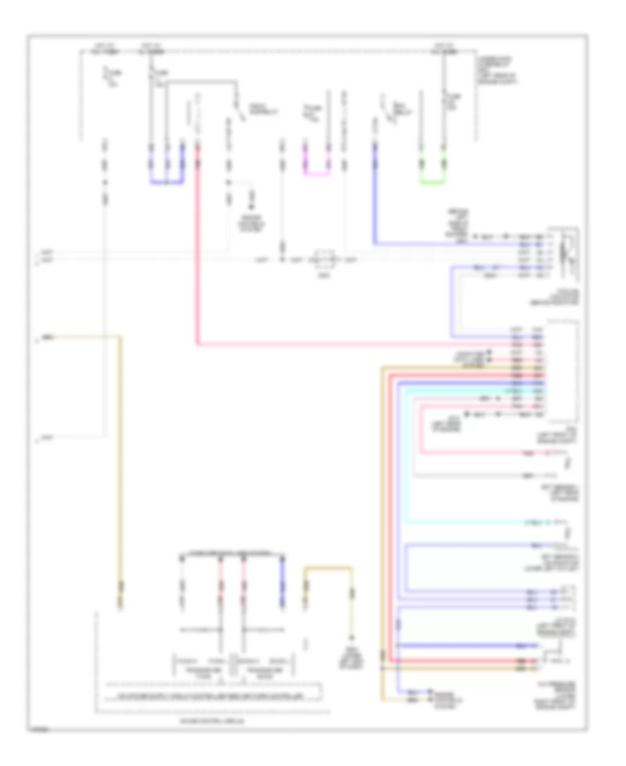
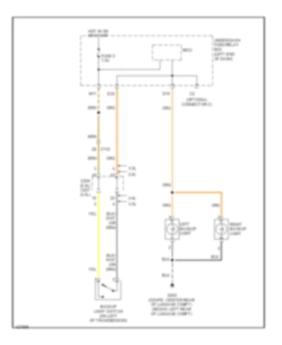
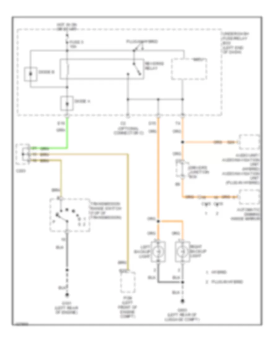
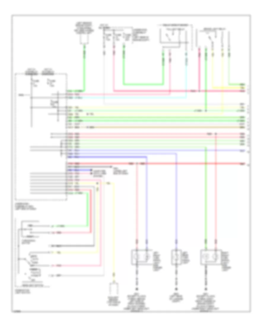
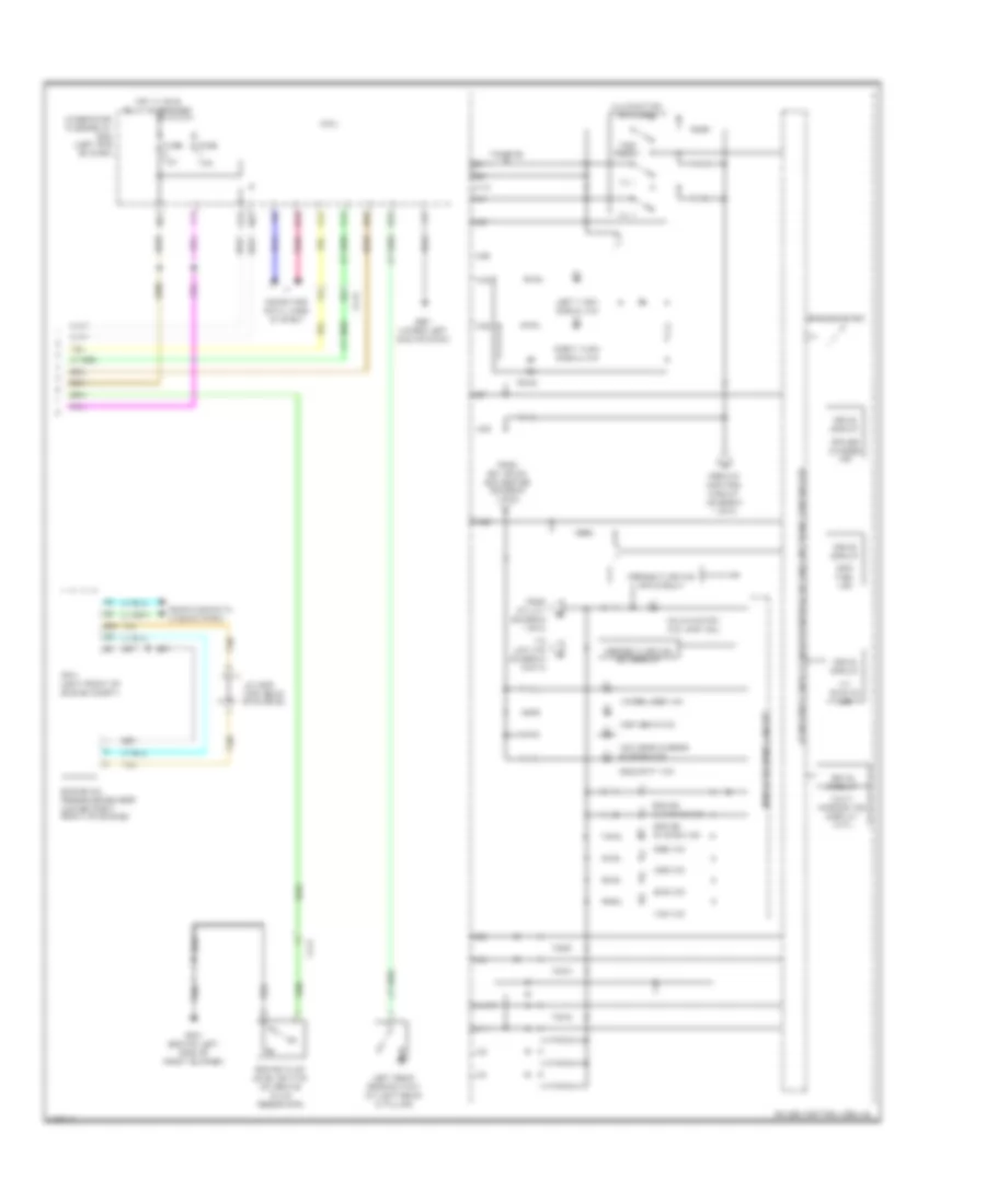
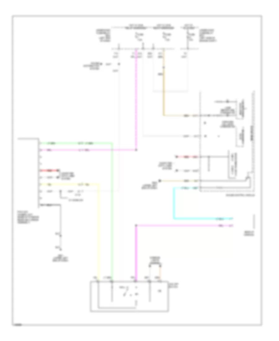
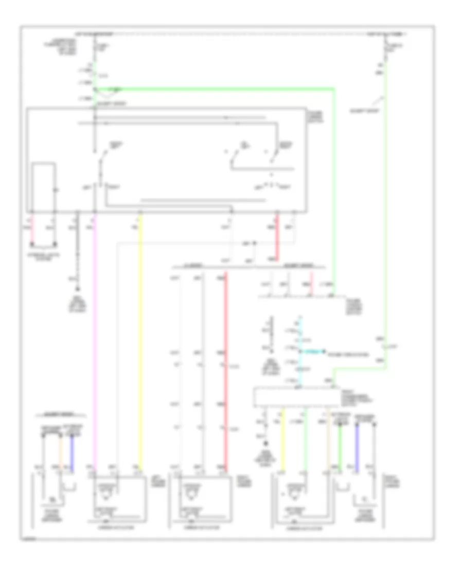
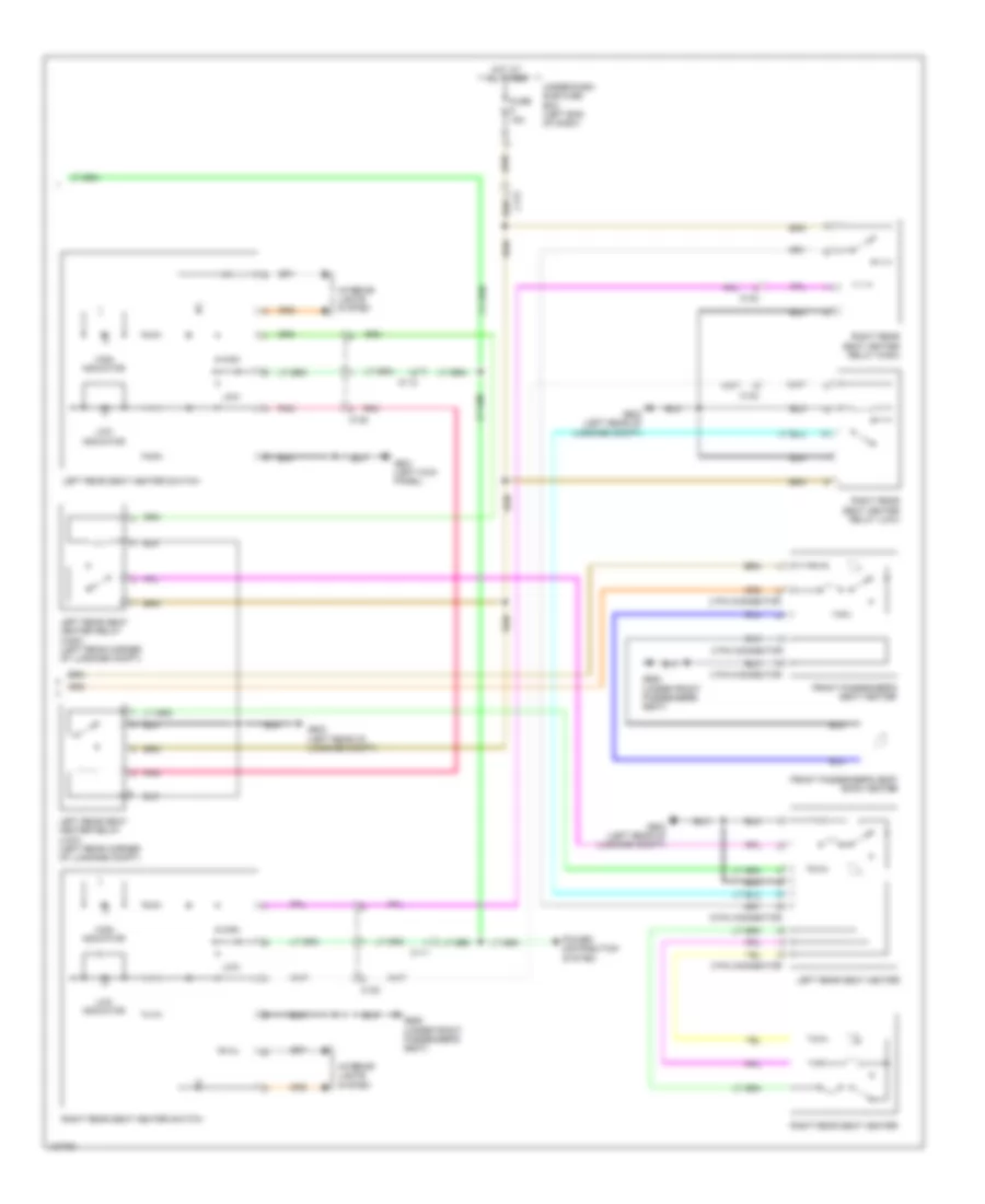
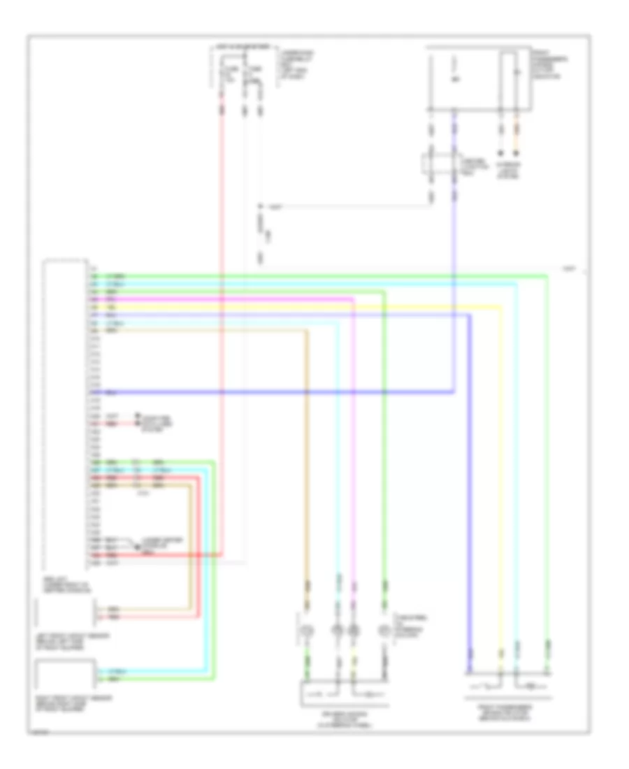
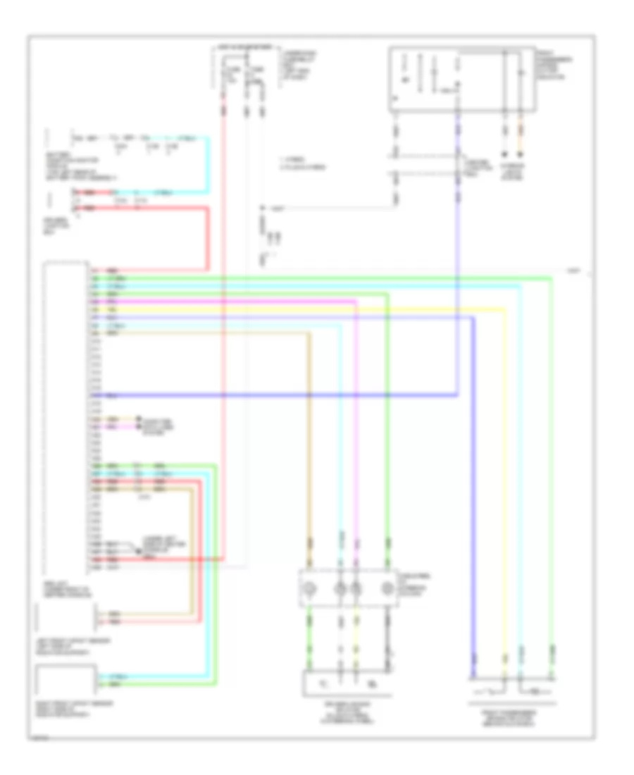
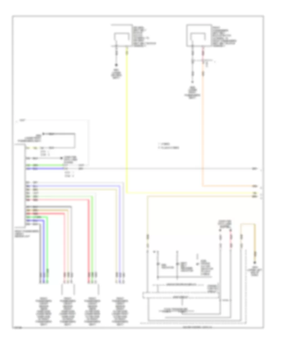
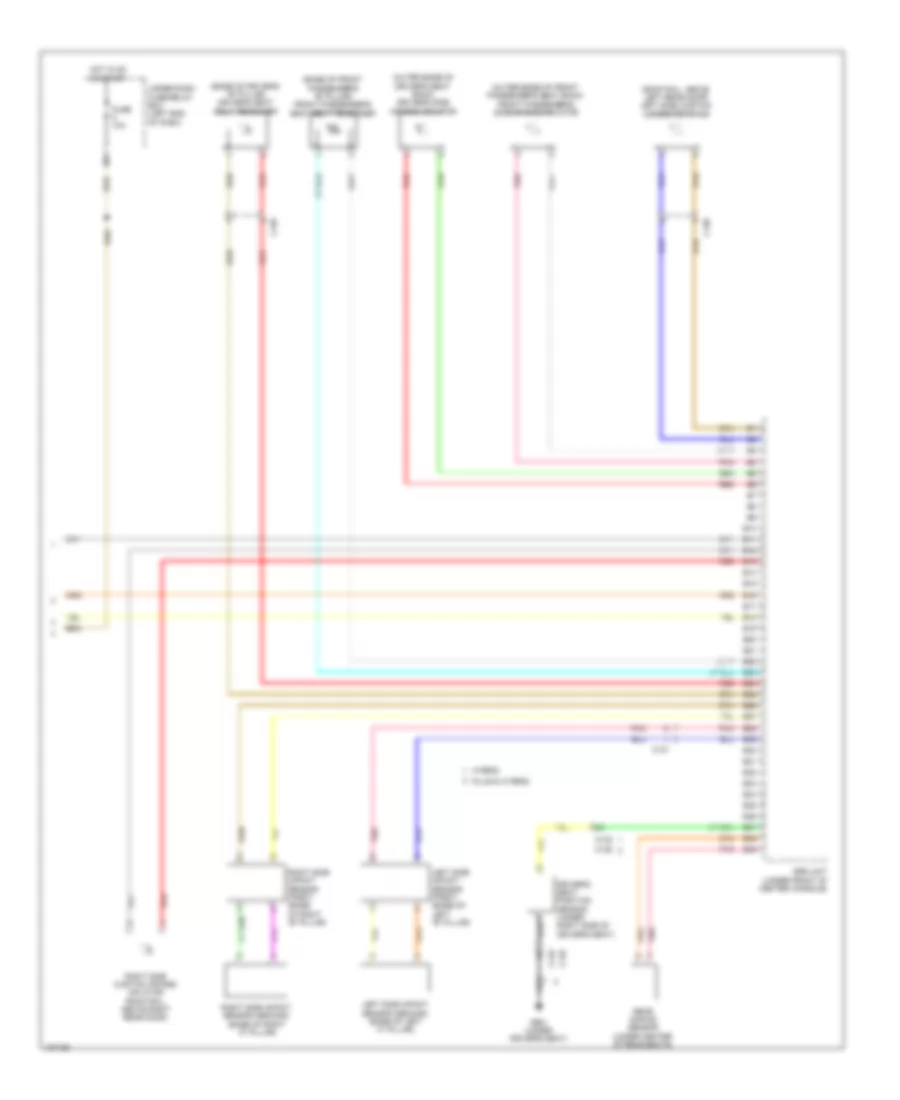
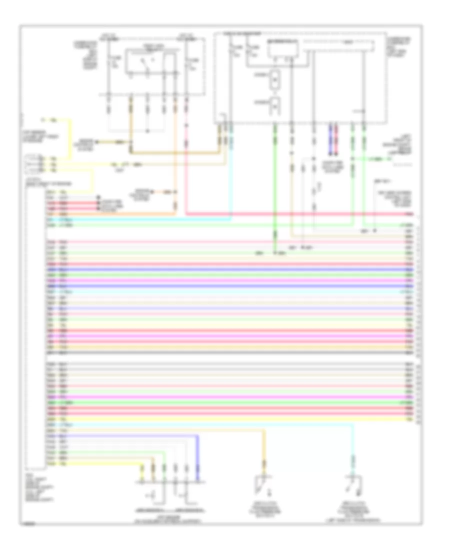
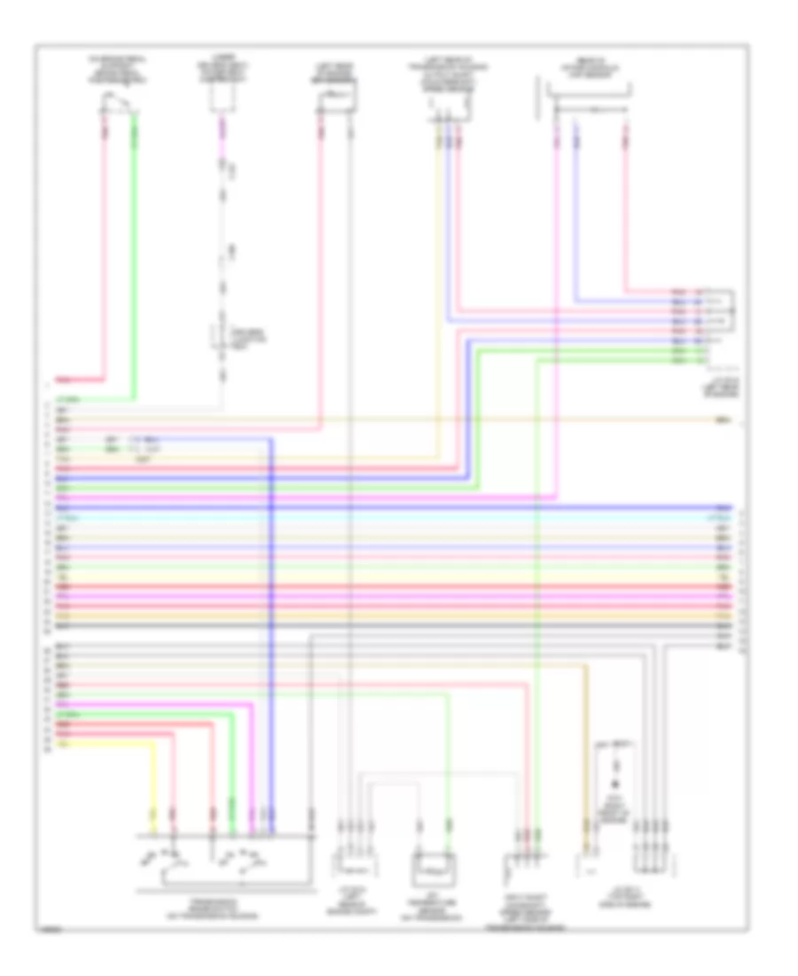
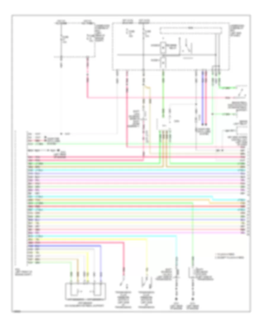
AIR CONDITIONING
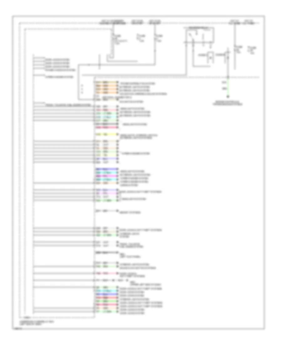
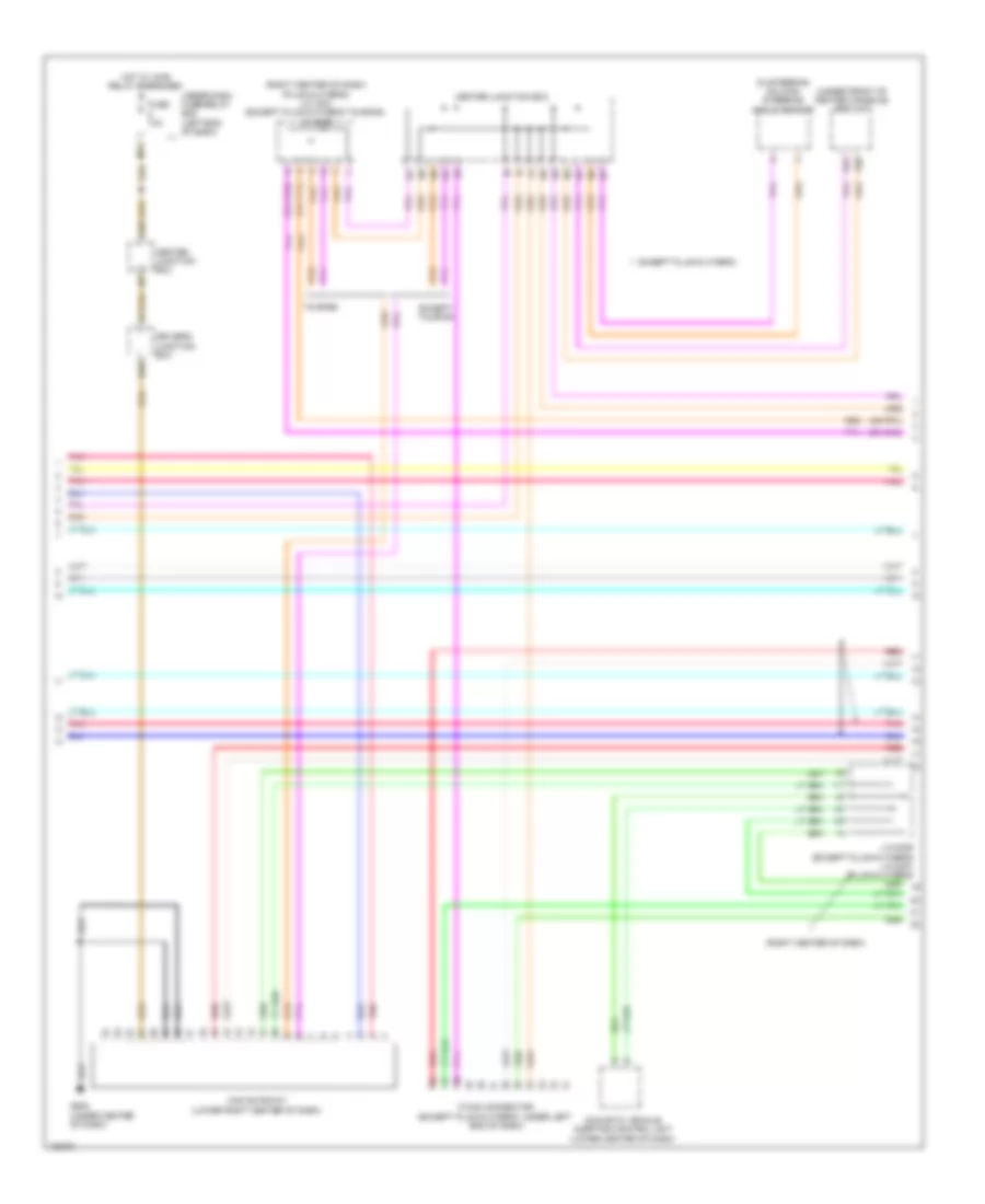
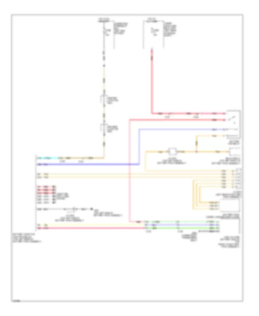
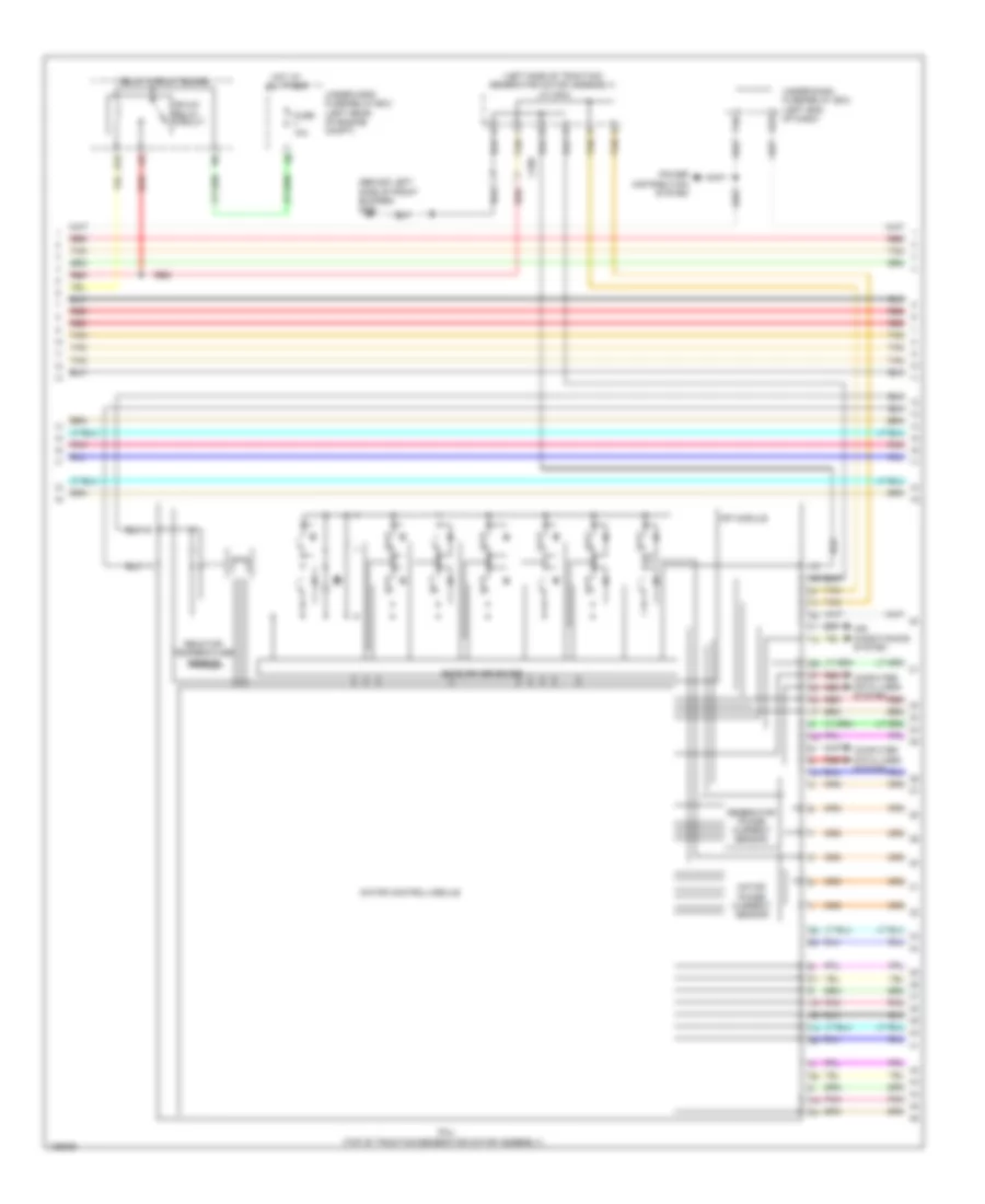
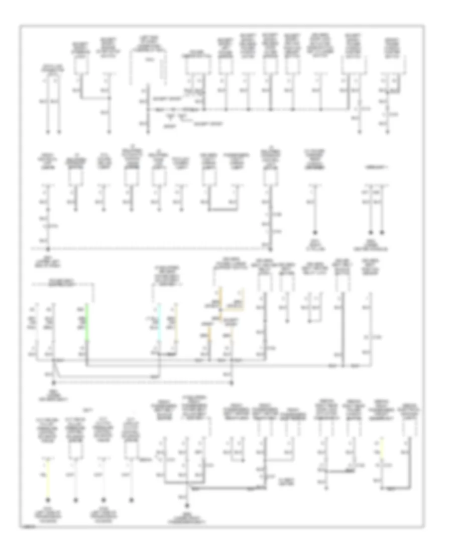
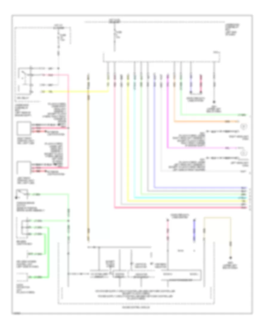
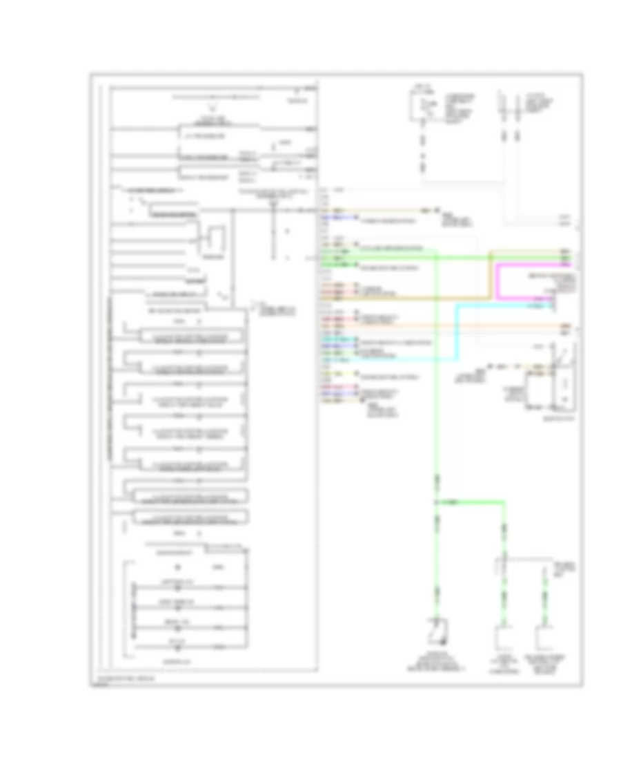
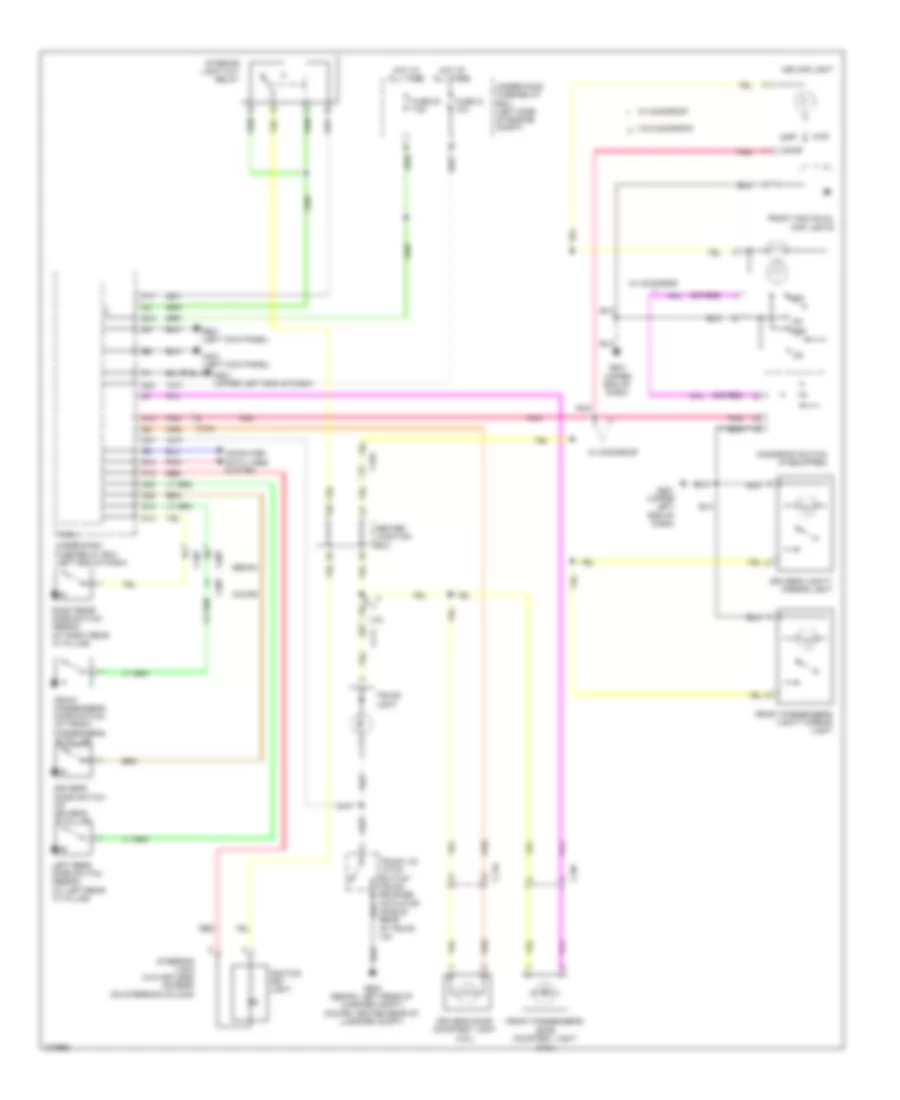
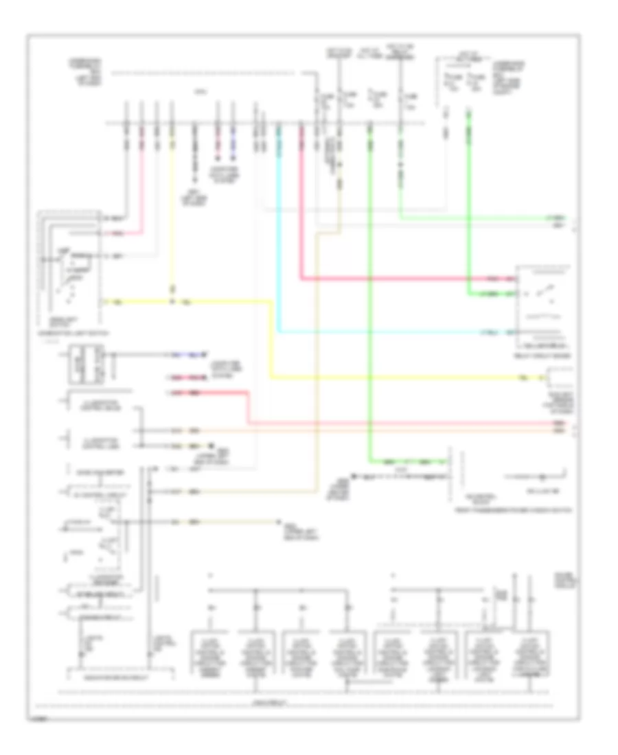
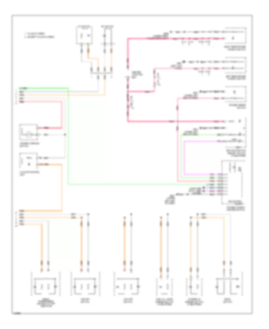
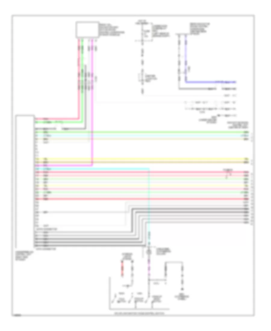
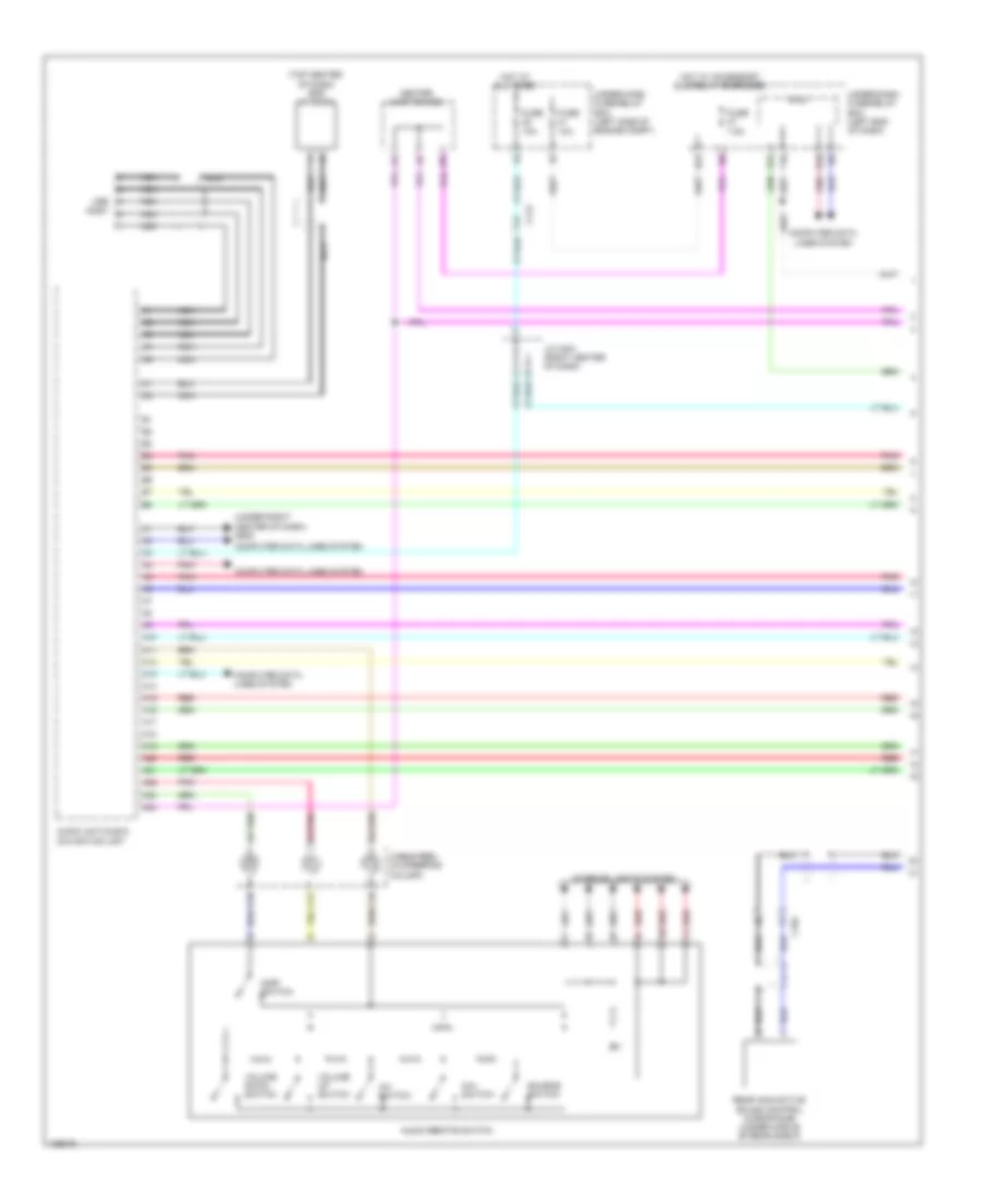
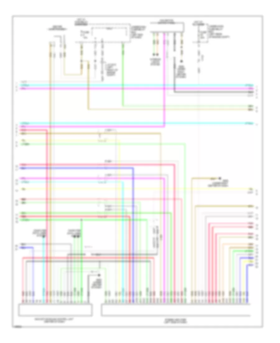
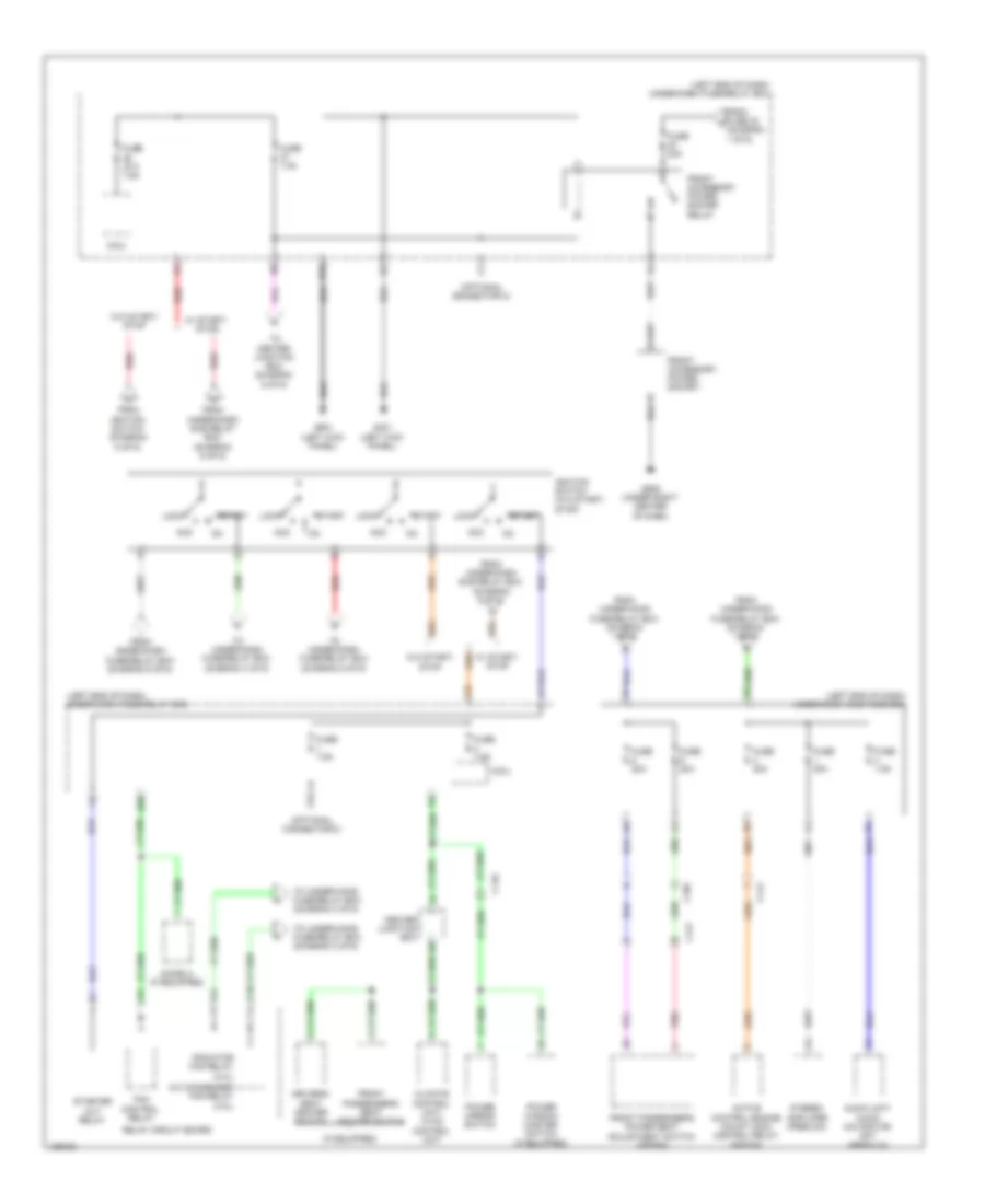
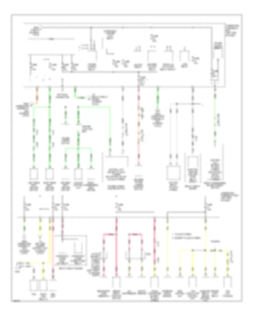
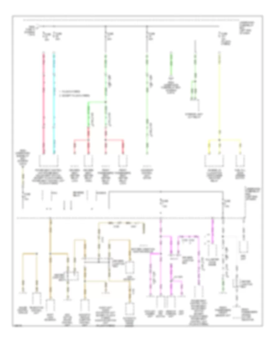
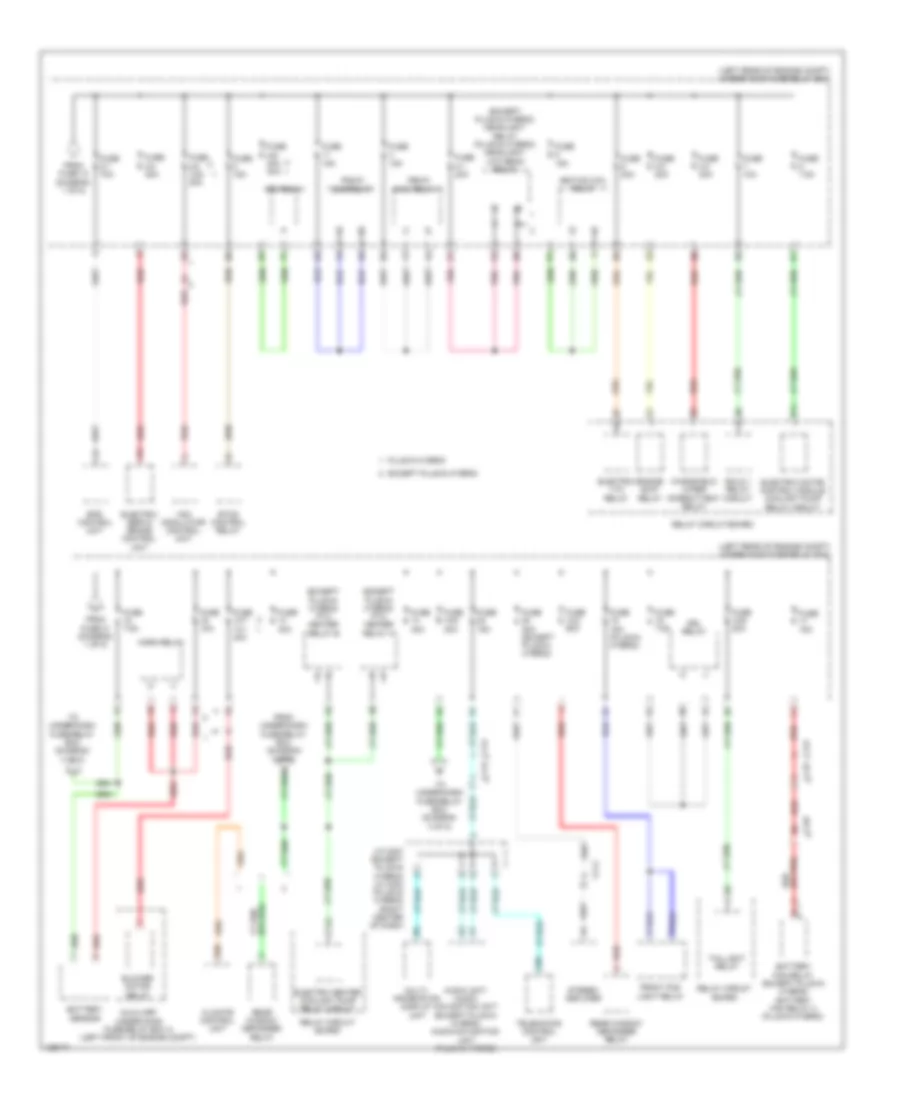
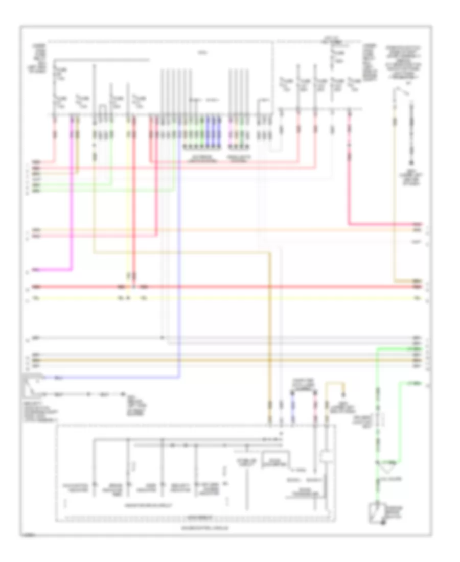
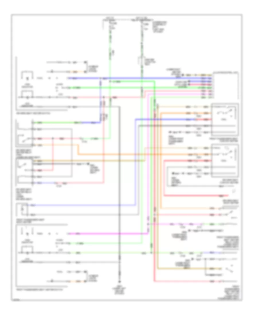
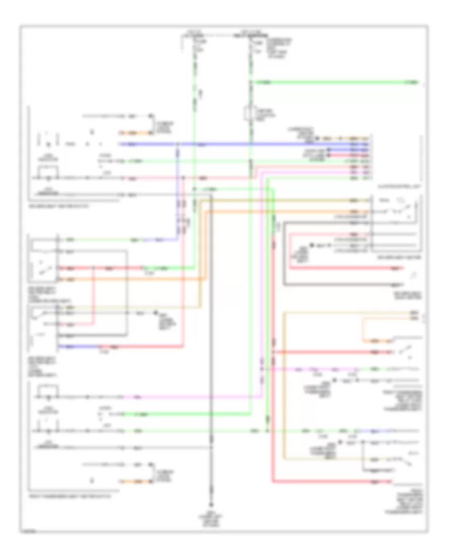
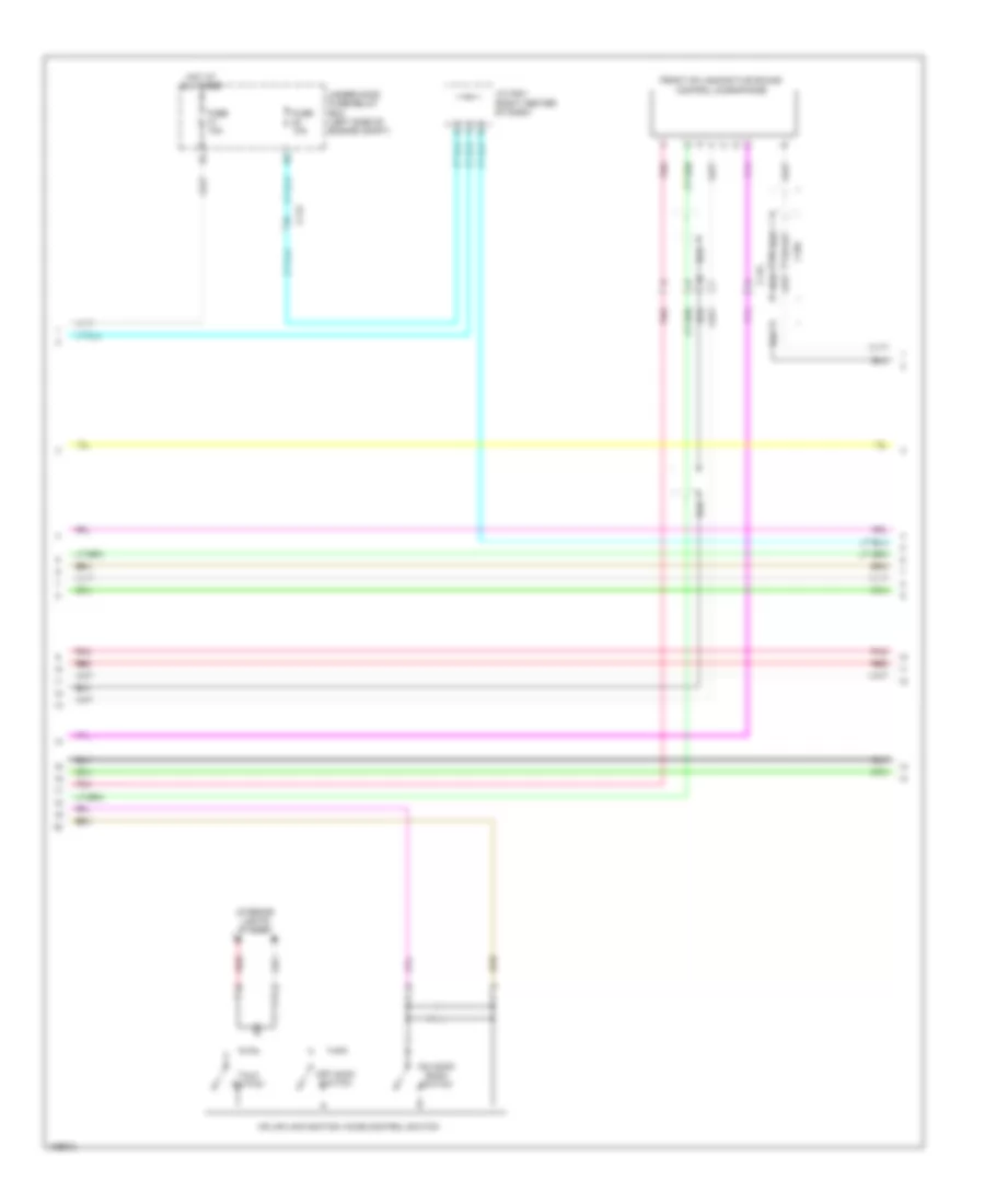
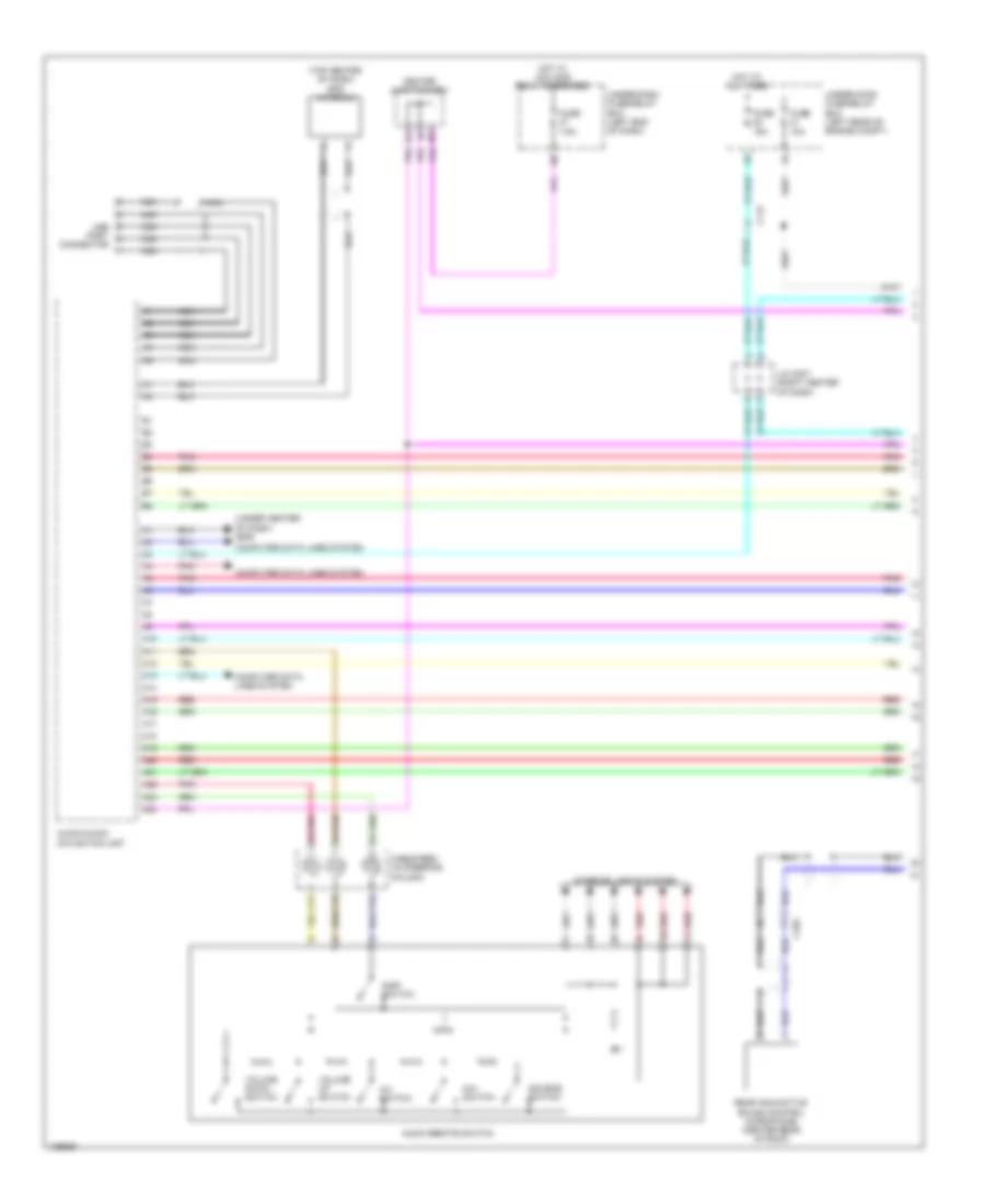
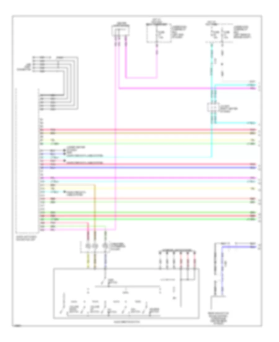
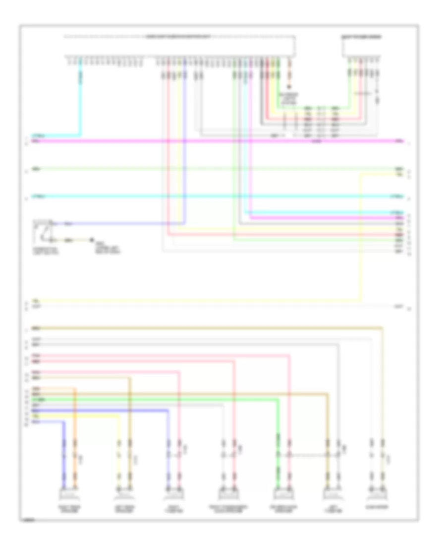
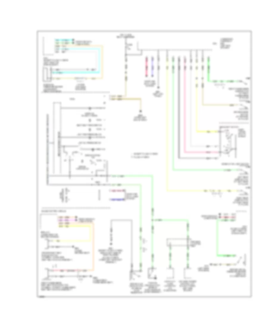
Automatic A/C Wiring Diagram, Except Hybrid (1 of 3) for Honda Accord Plug-In 2014

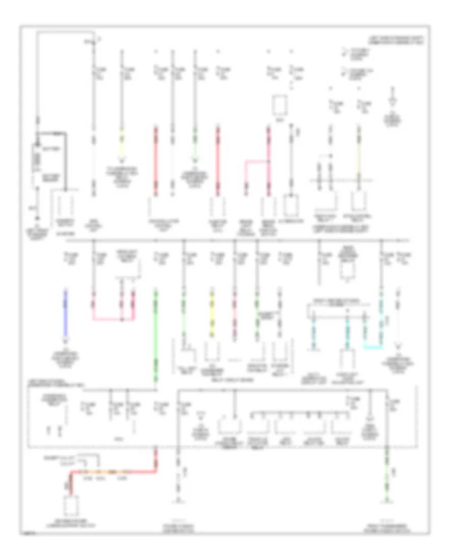
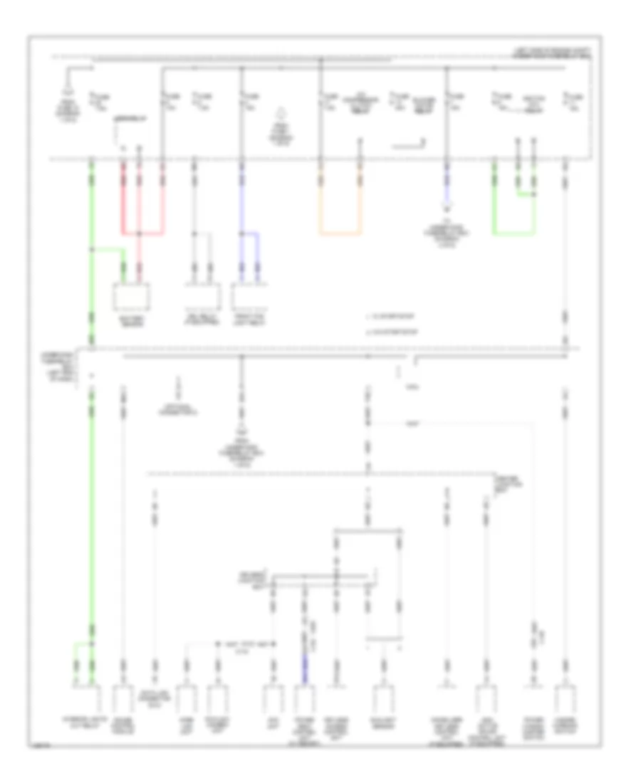
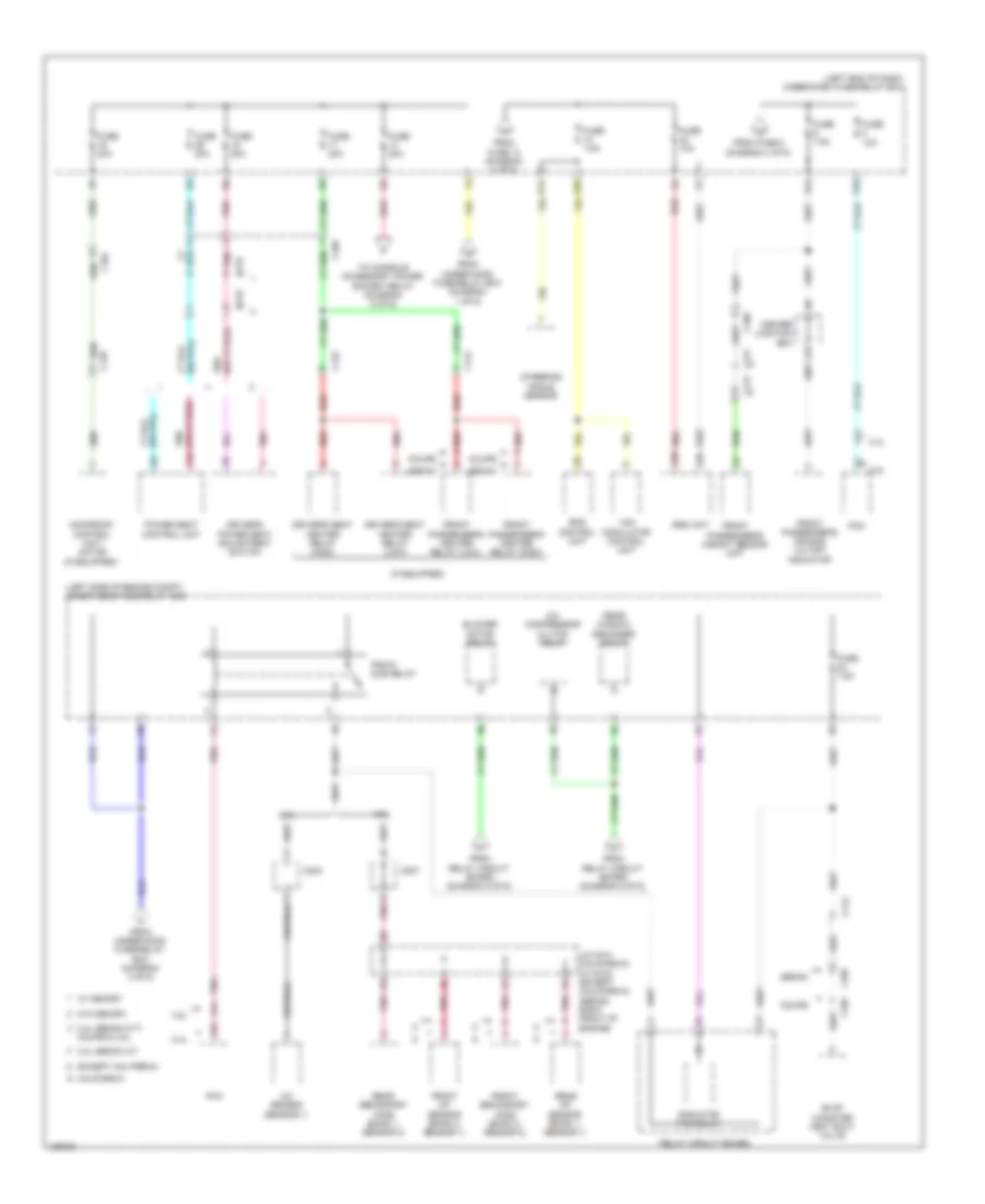
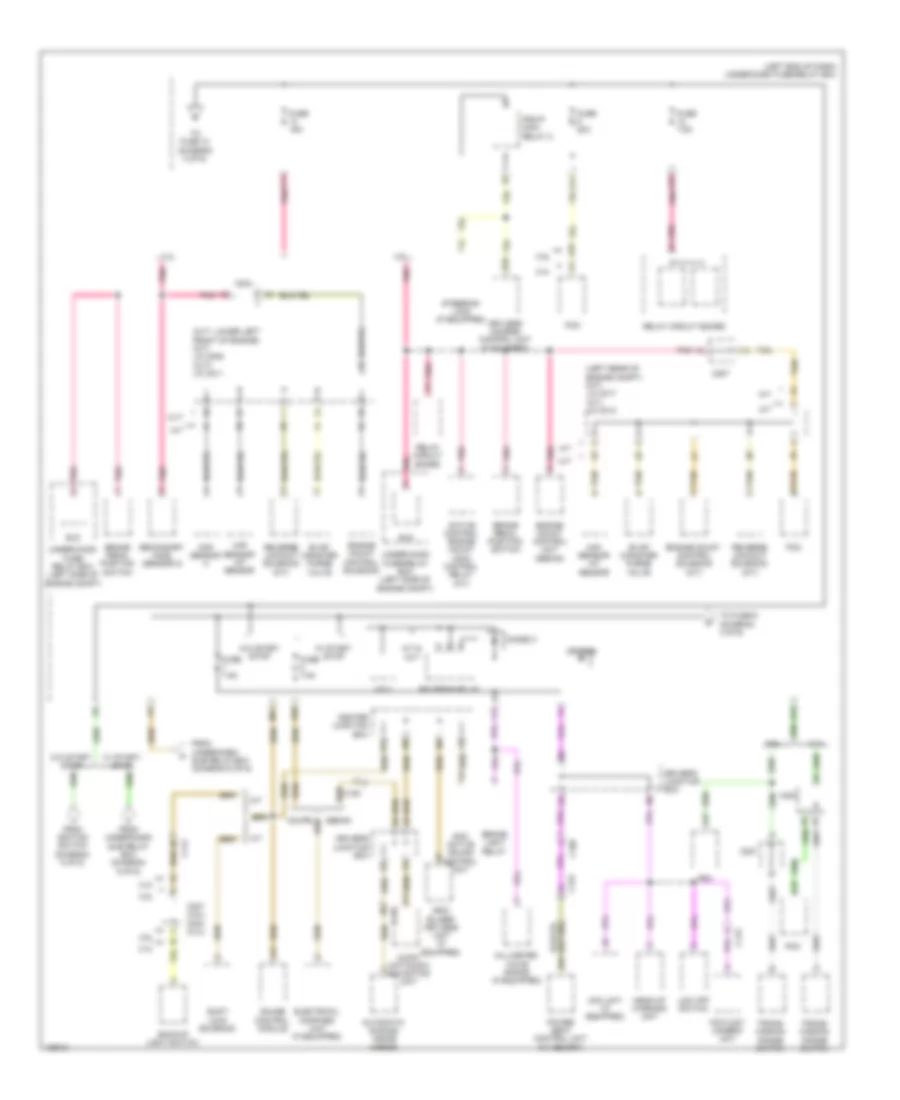
List of elements for Automatic A/C Wiring Diagram, Except Hybrid (1 of 3) for Honda Accord Plug-In 2014:
- C112
- Center junction box
- Computer data lines system
- E20
- E23
- Engine controls system
- Except 2.4l m/t sport
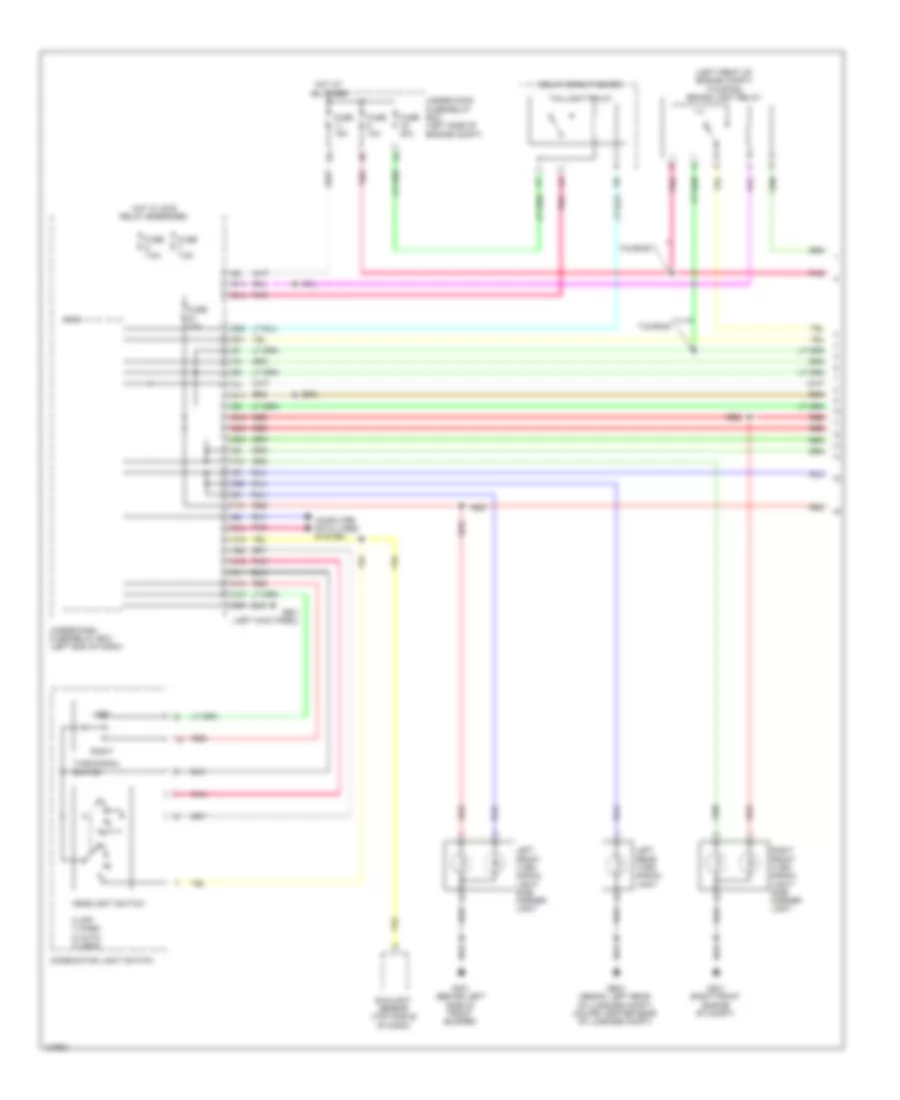
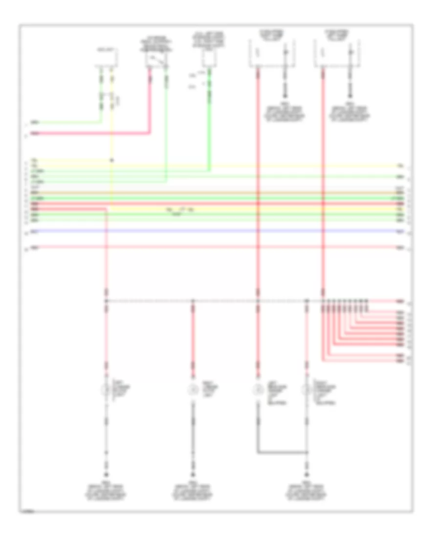
- Exterior lights system
- Fuse 10a
- Fuse 15a
- Fuse 7.5a
- G301 (behind left side of front bumper)
- G506 (under center of dash)
- Hot at all times
- Hot w/ ig1b relay energized
- Hot w/ ig2 relay energized
- Hvac control unit/ climate control unit
- In-car temperature sensor (right of steering column)
- J/c c001 (right center of dash)
- M11
- M12
- Micu
- Outside air temperature sensor (behind center of front bumper)
- Pgm-fi sub- relay
- Pnk
- Radiator fan motor (3.5l) a/c condenser fan motor (2.4l) (2.4l: left front of engine compt)
- Rear window defogger switch
- Rear window defogger switch ind
- Red
- Seats system
- Sunlight sensor (top middle of dash)
- Under-dash fuse/relay box (left end of dash)
- Under-hood fuse/relay box (left side of engine compt)
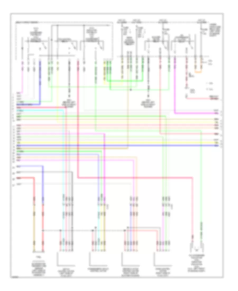
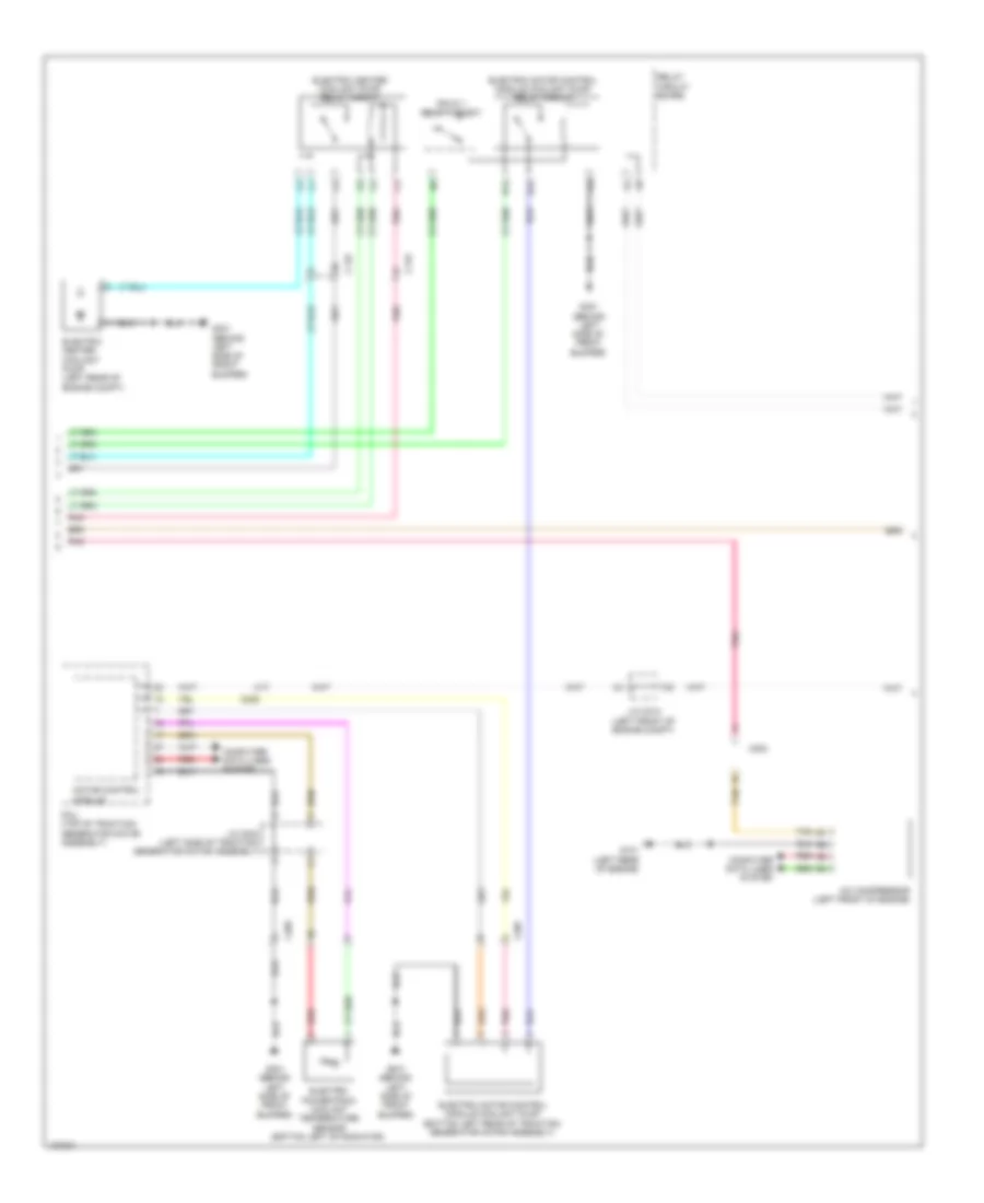
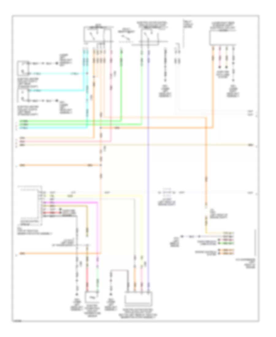
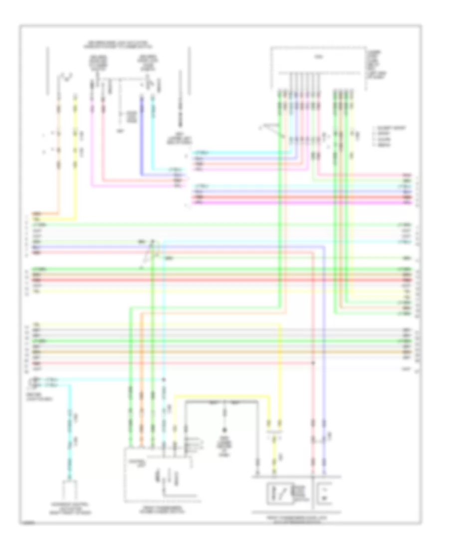
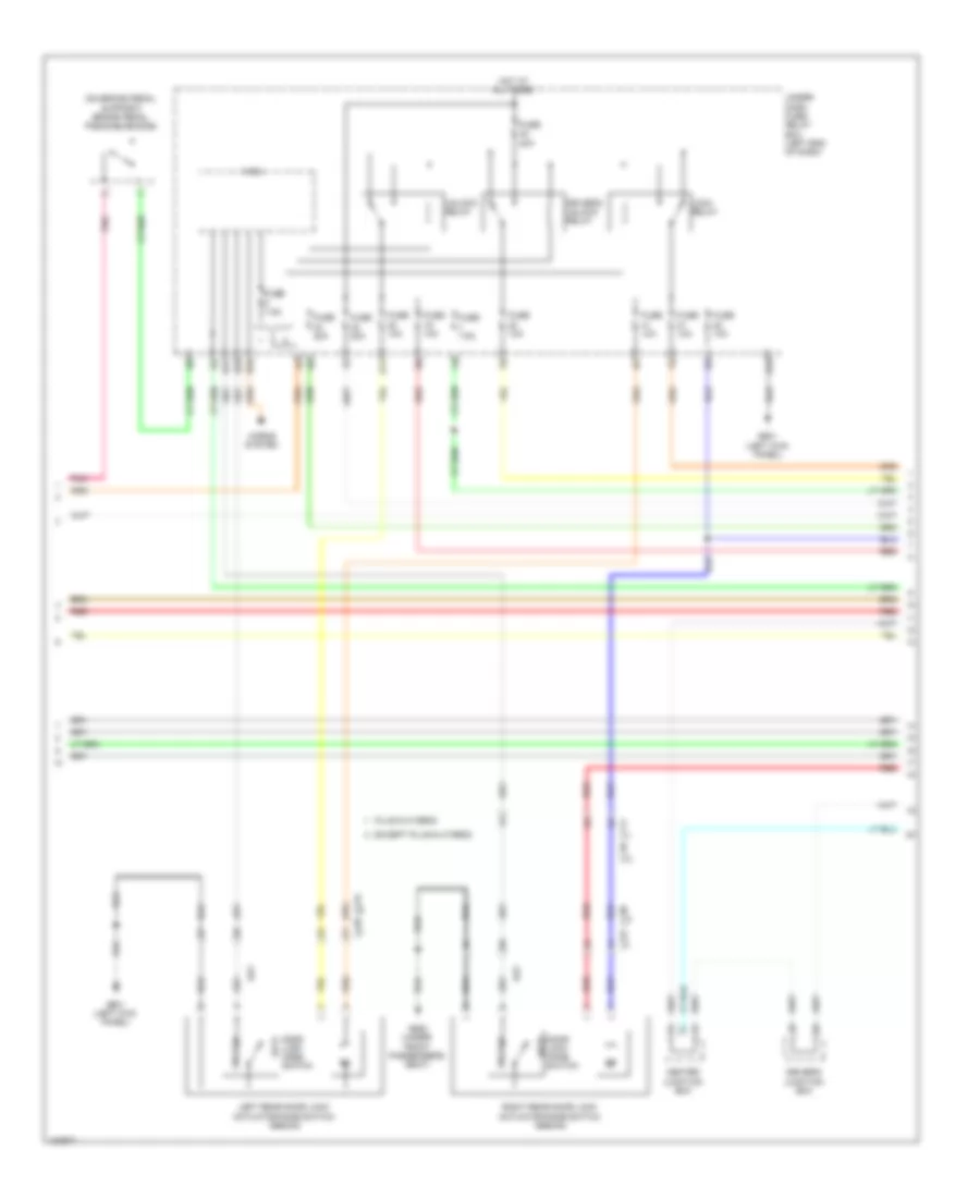
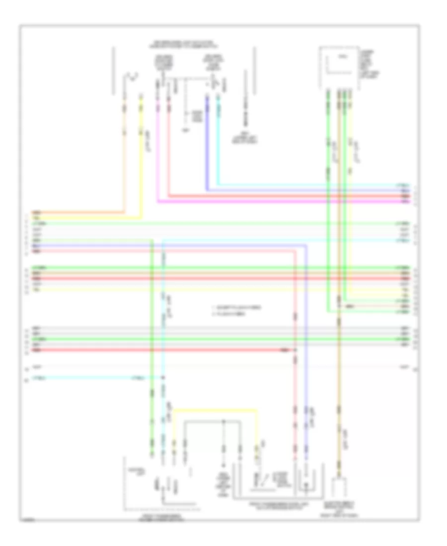
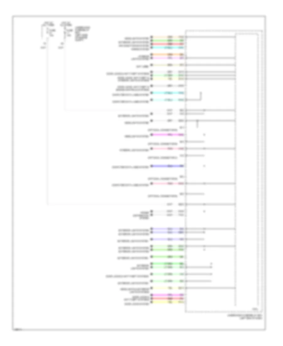
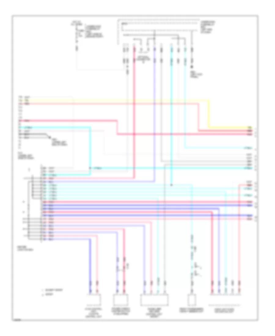
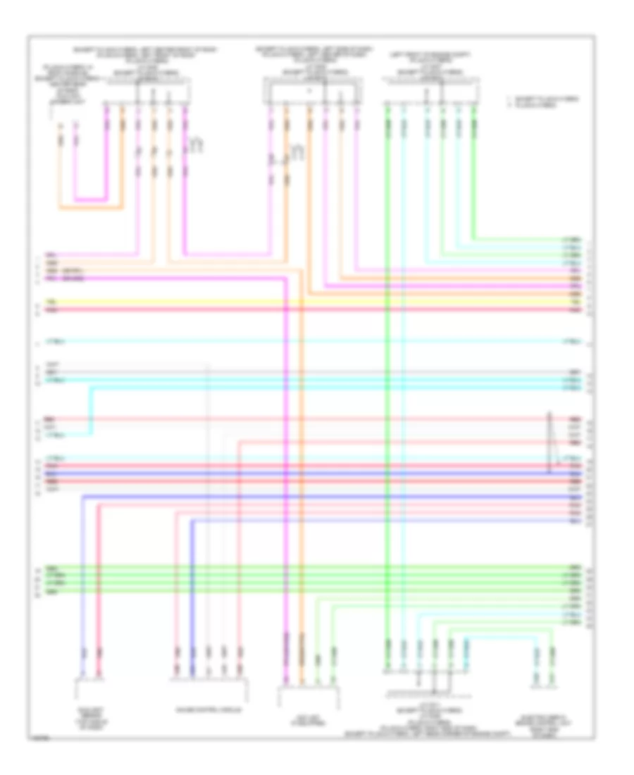
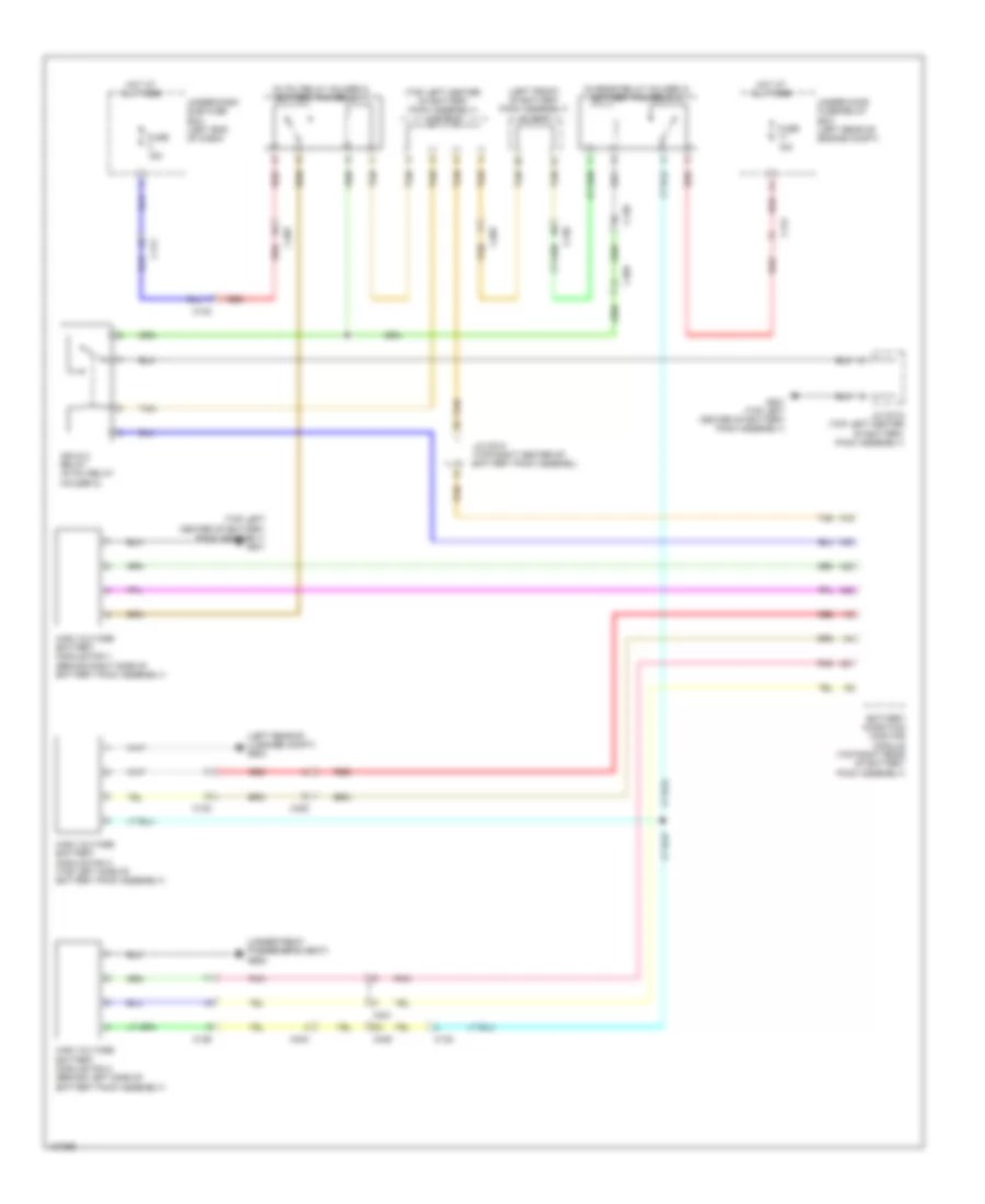
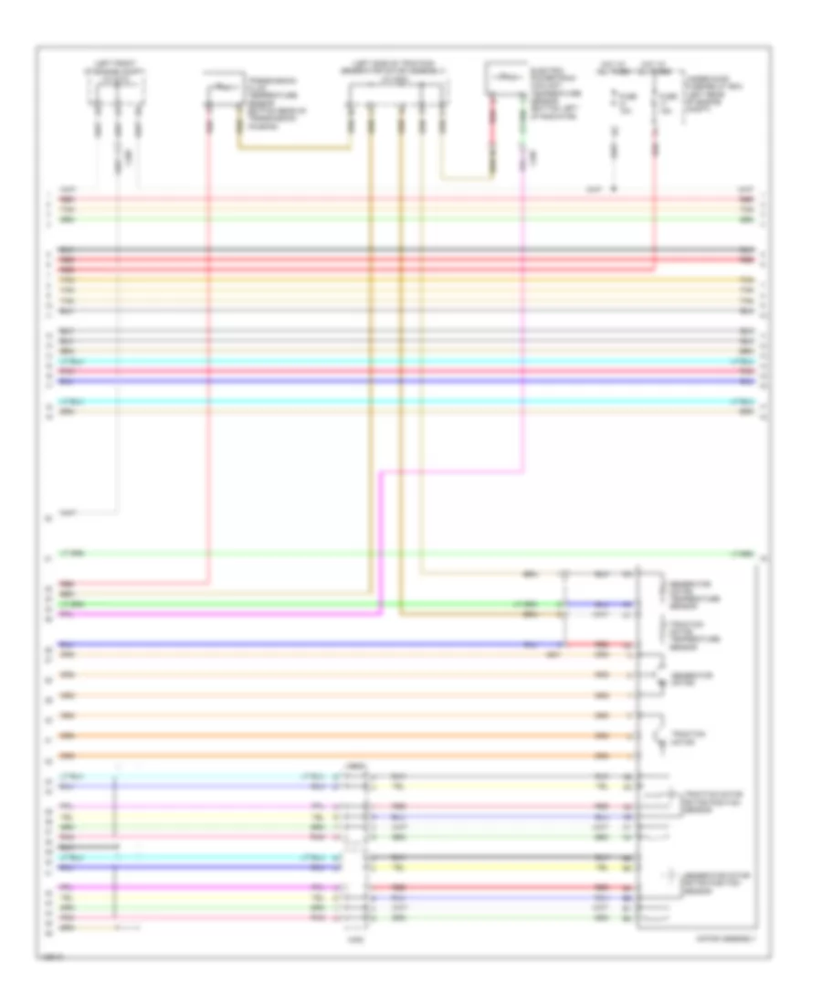
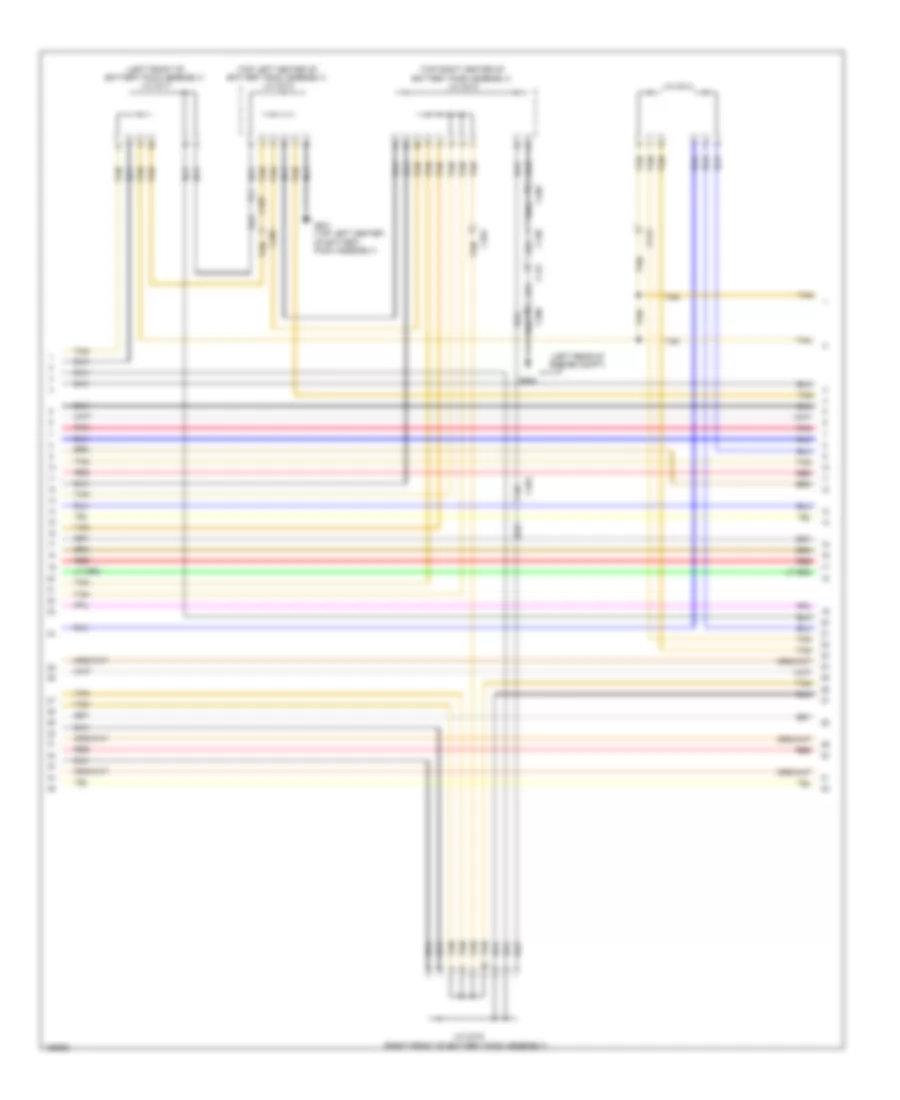
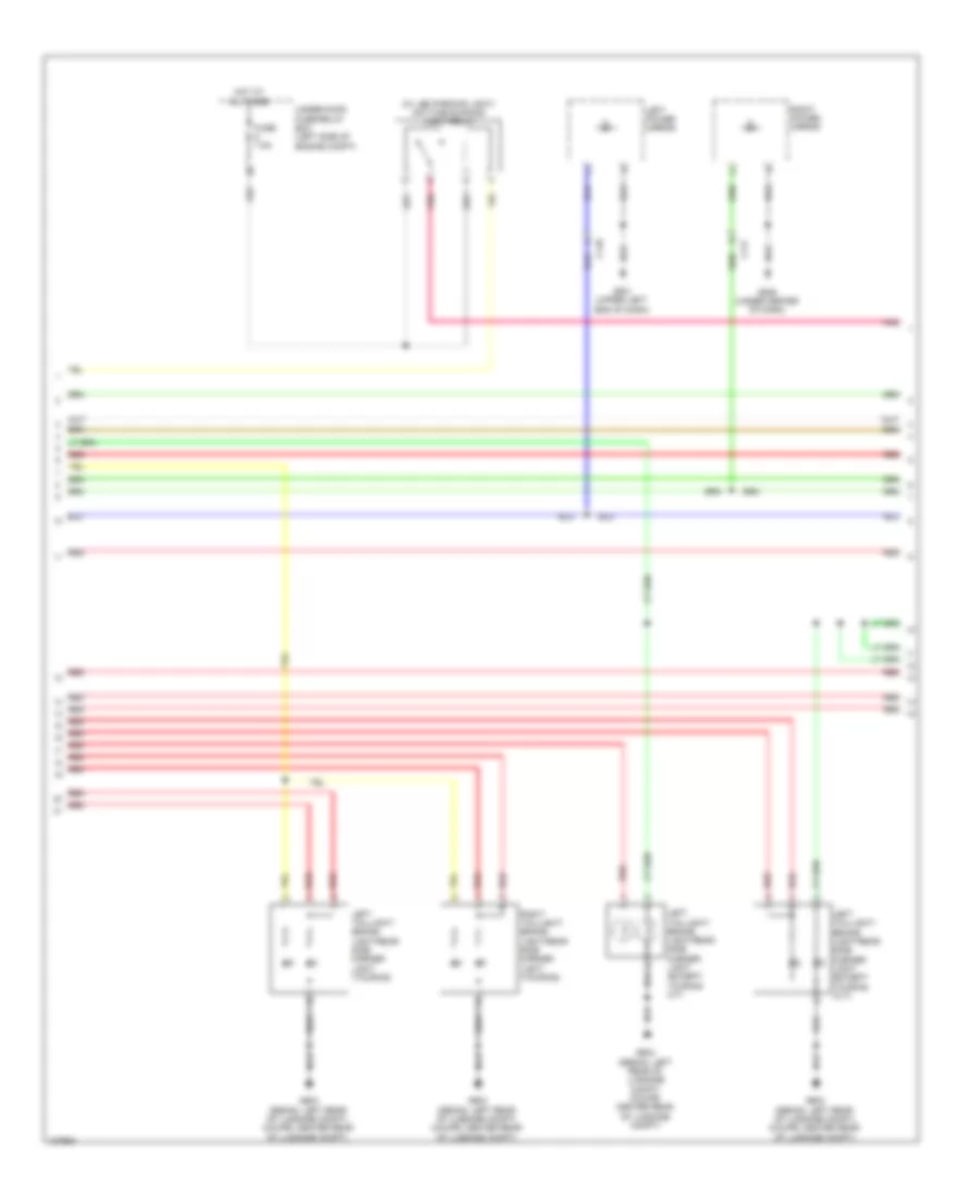
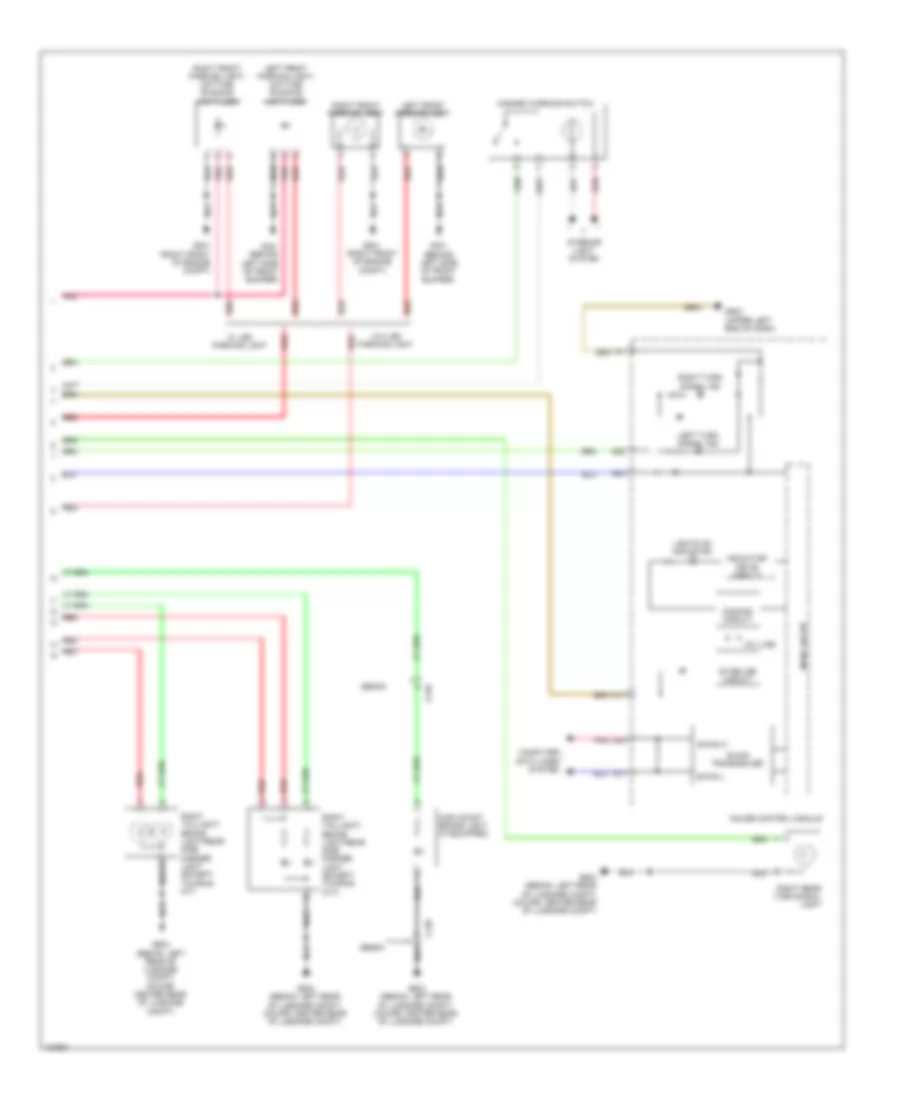
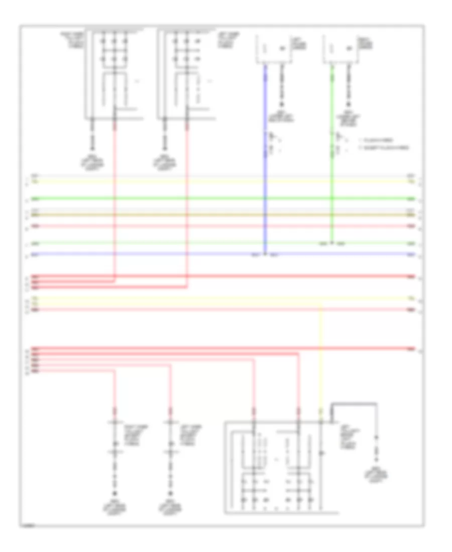
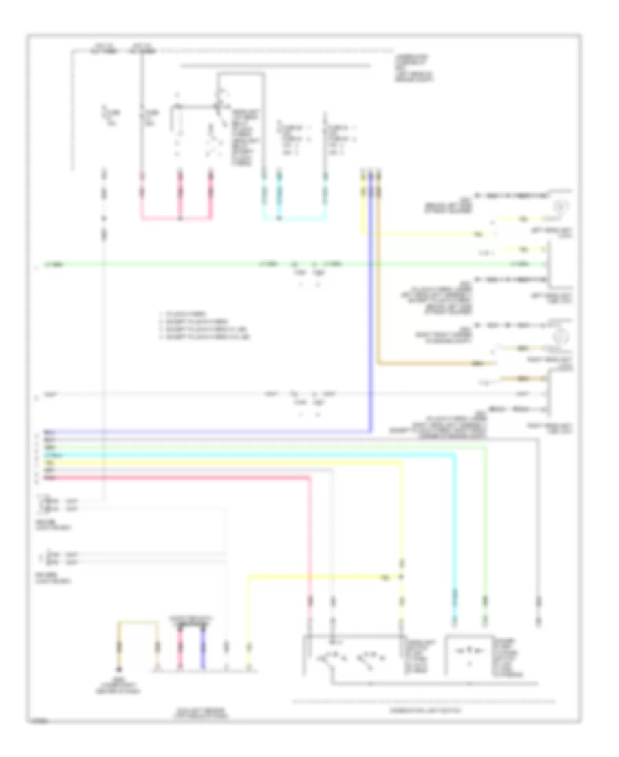
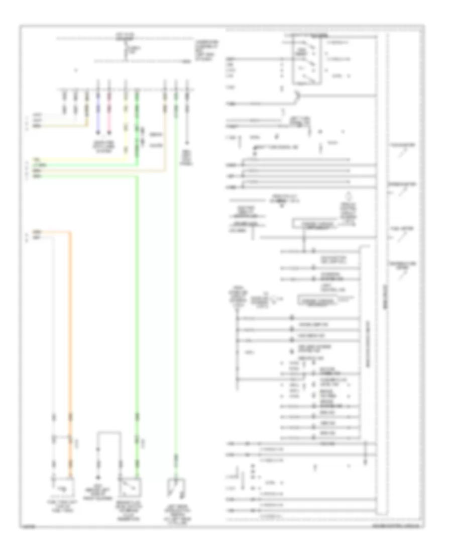
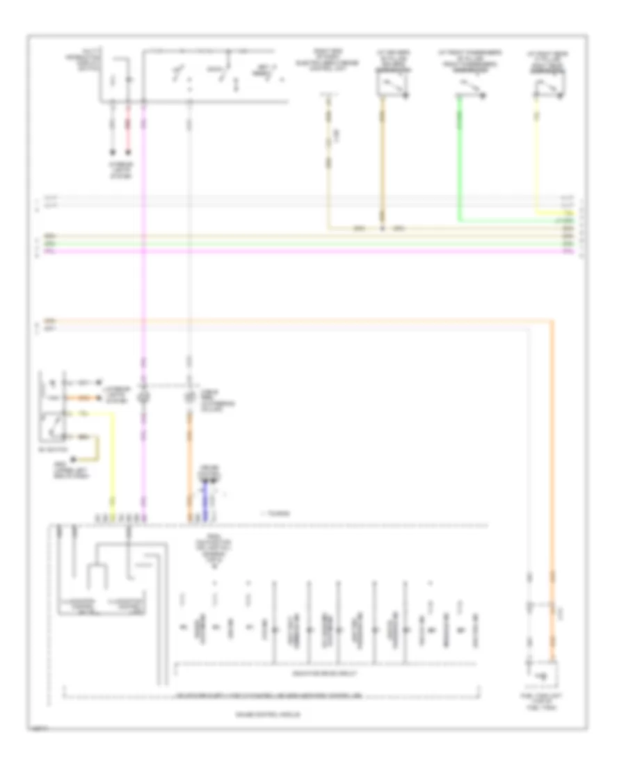
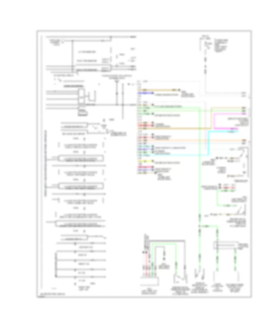
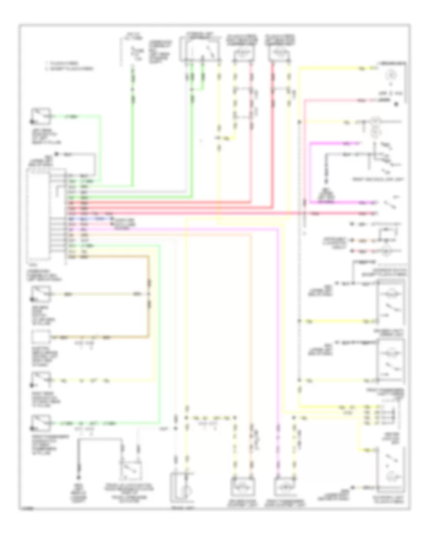
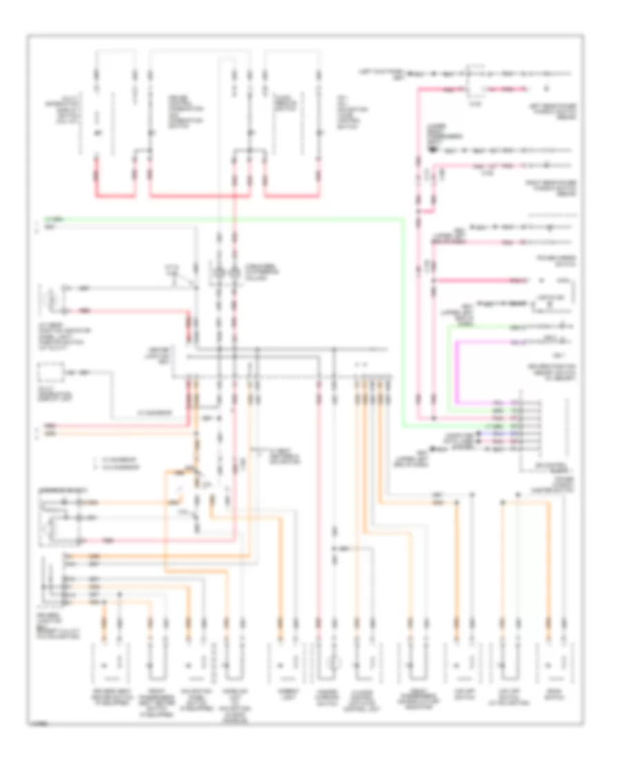
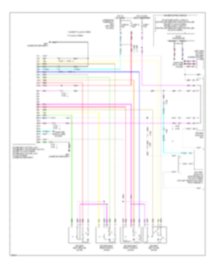
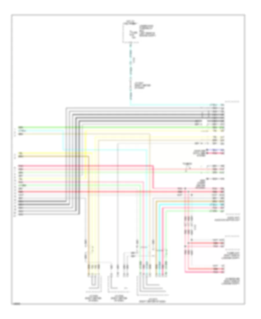
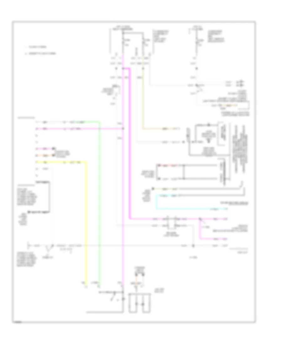
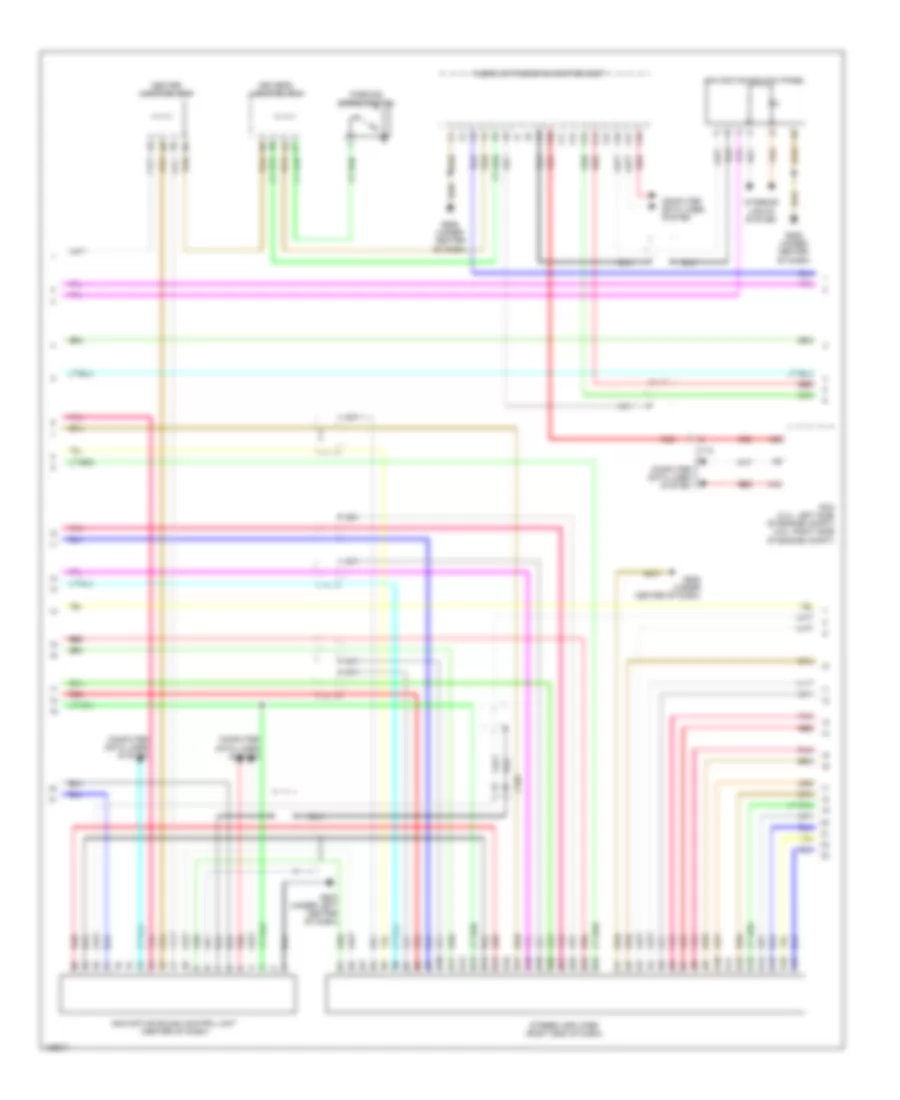
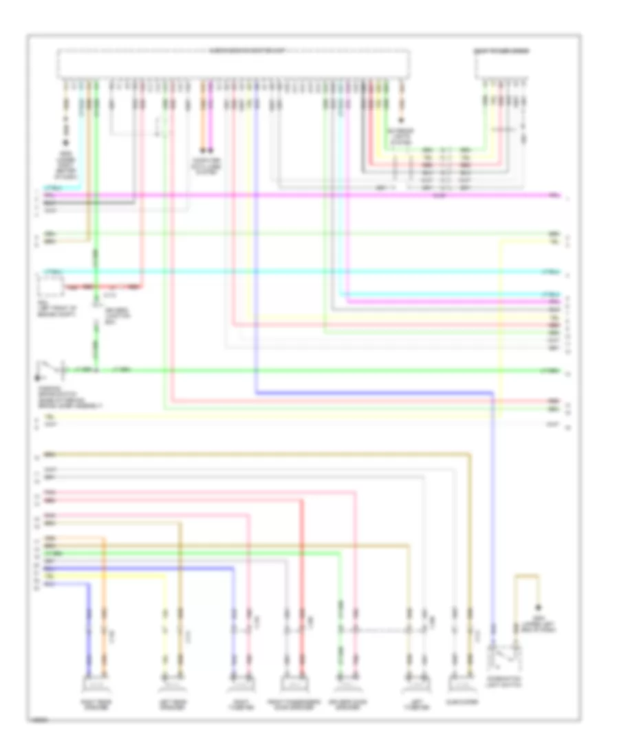
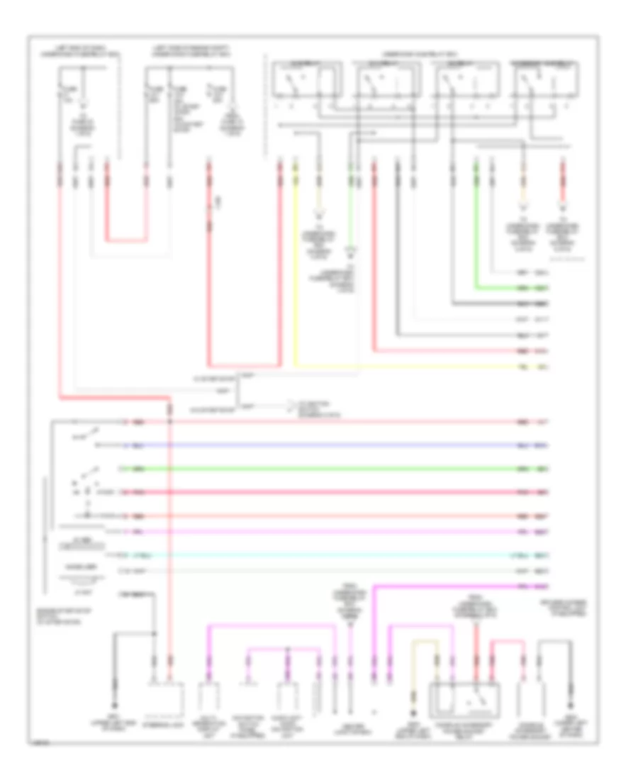
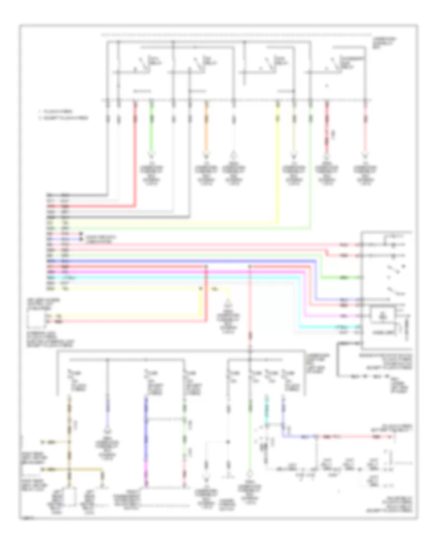
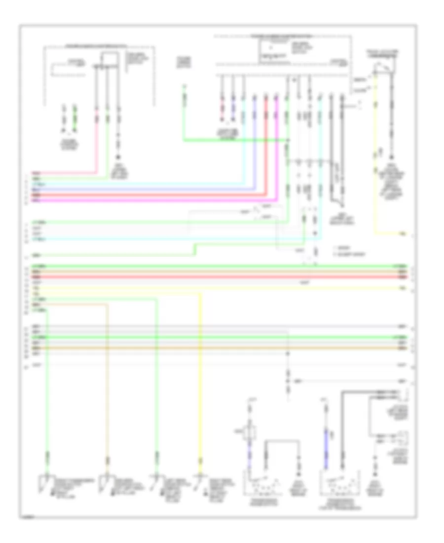
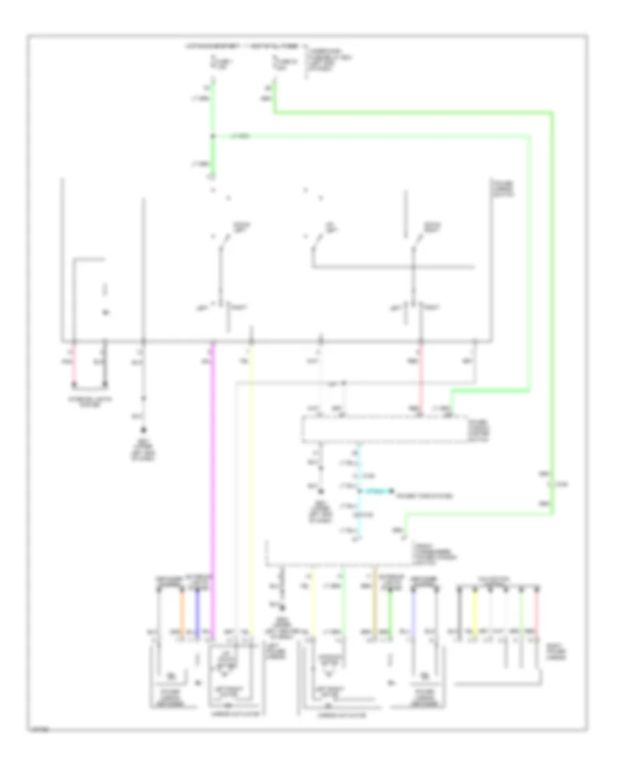
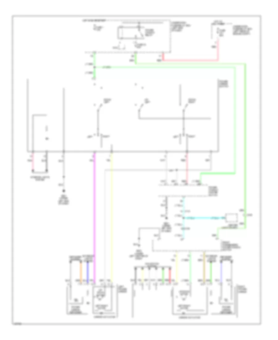
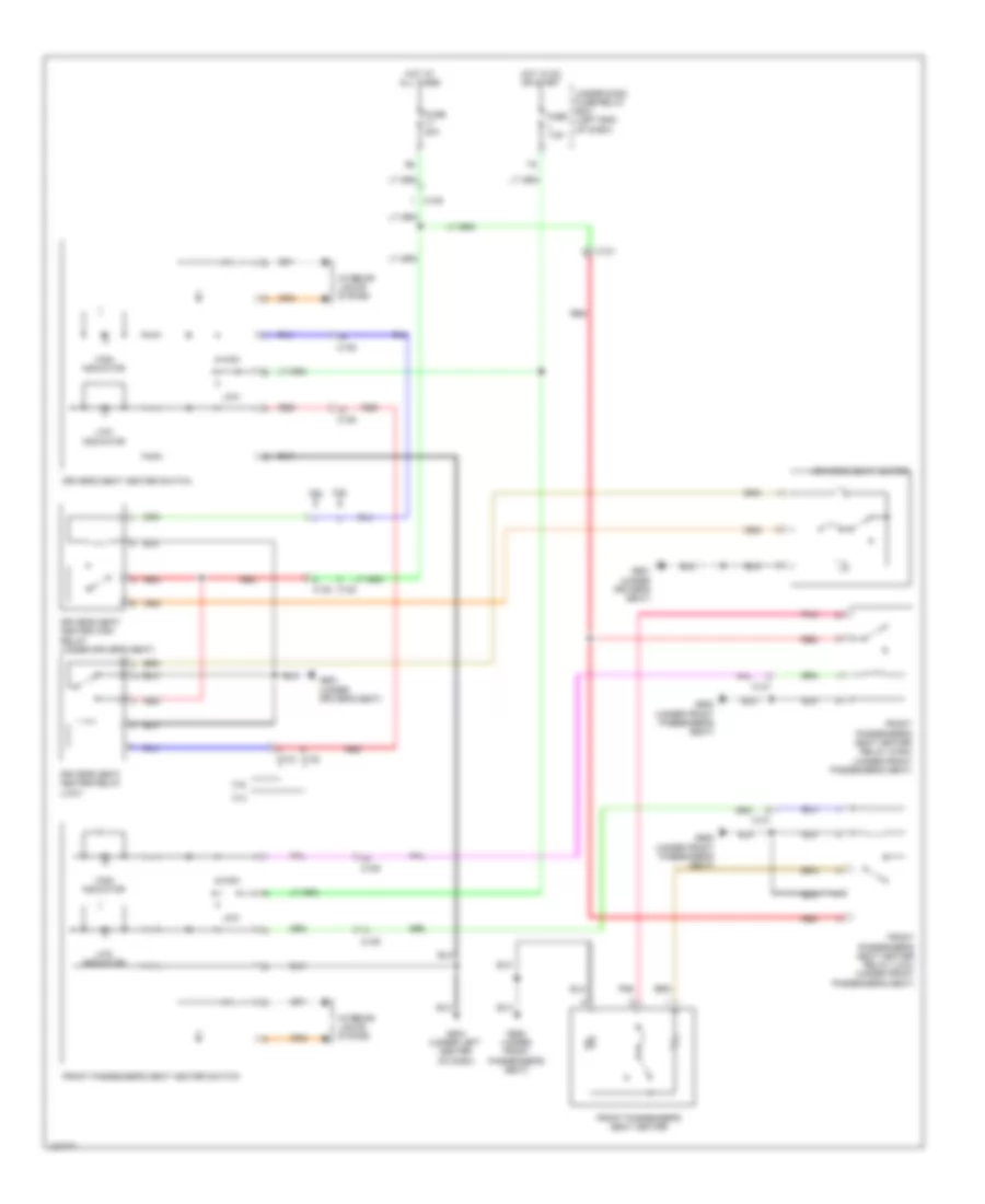
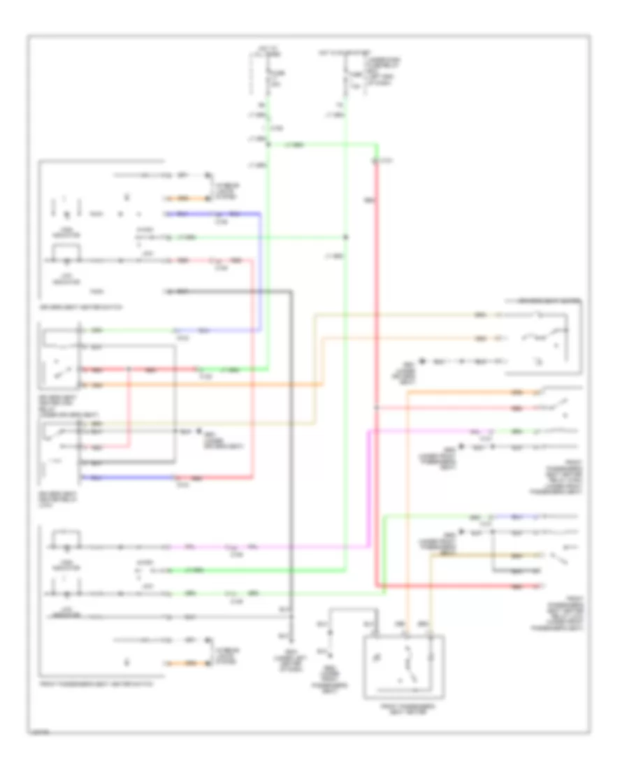
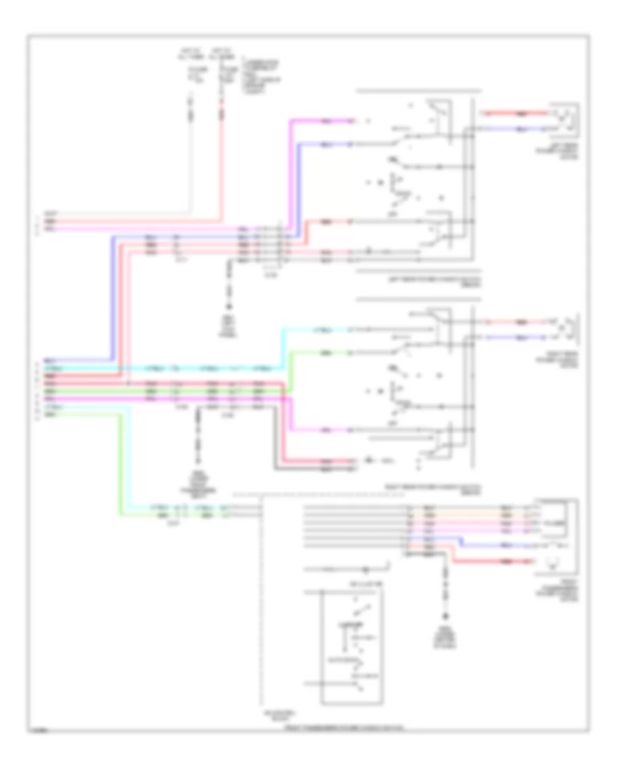
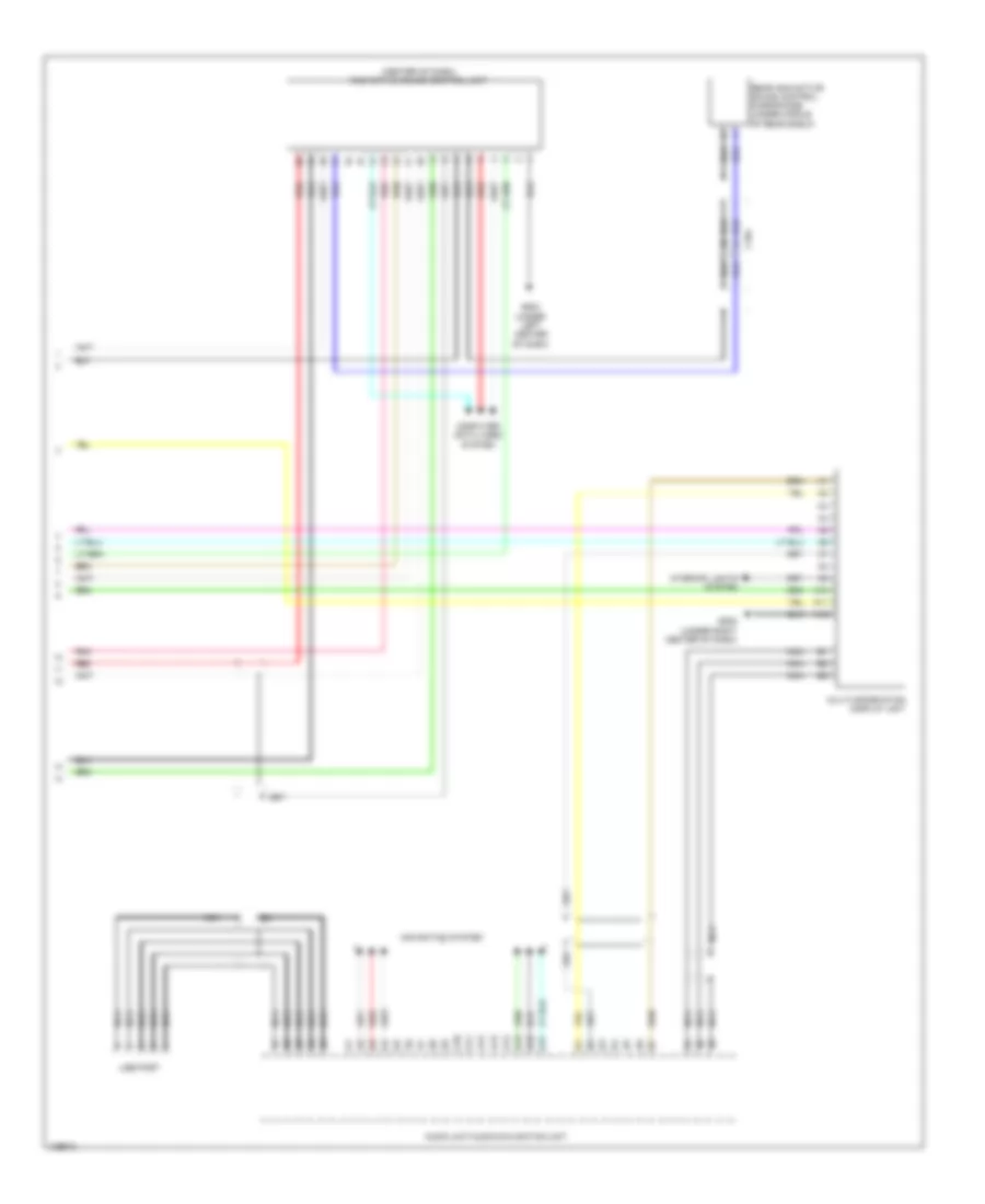
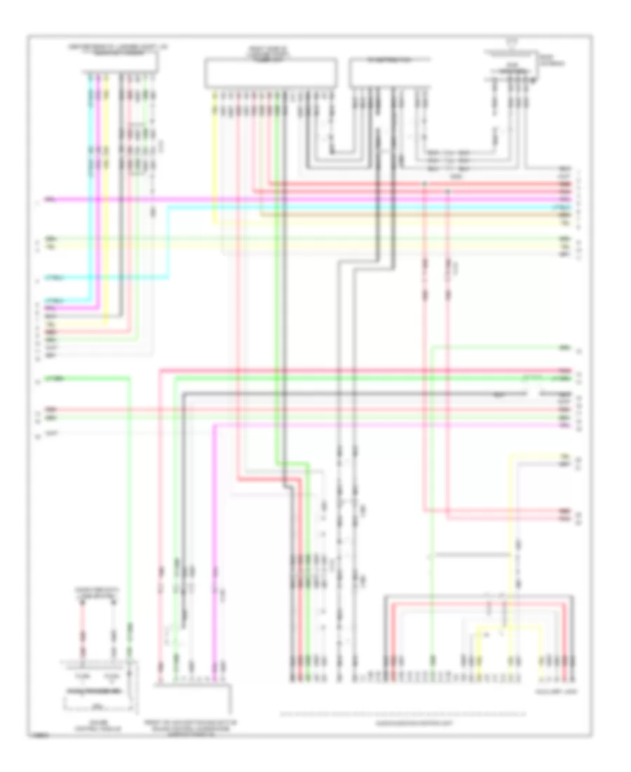
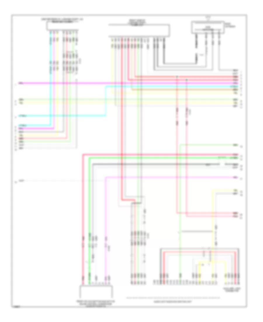
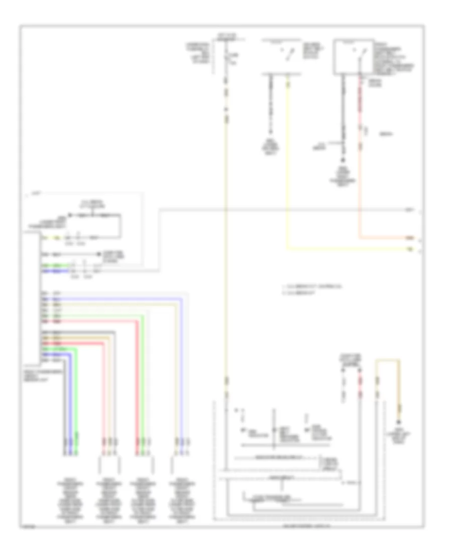
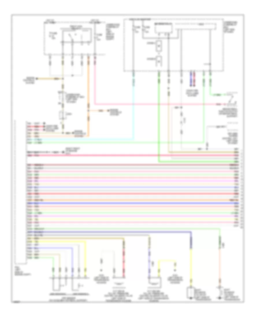
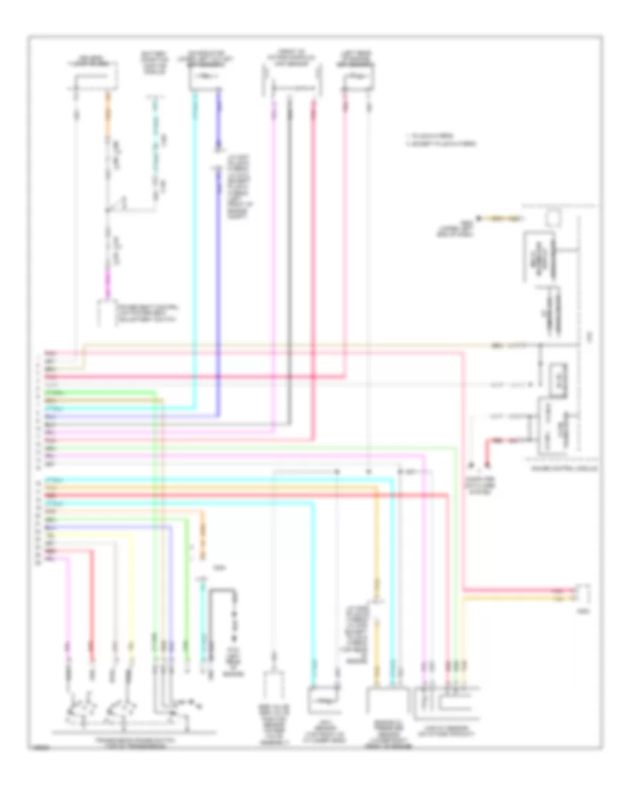
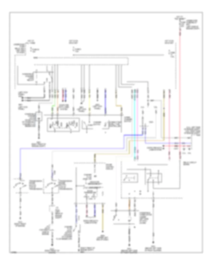
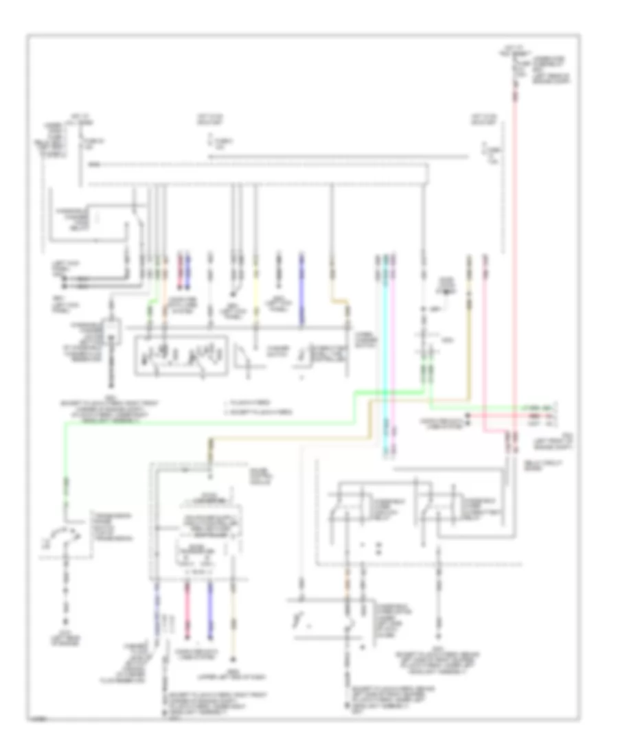
Automatic A/C Wiring Diagram, Except Hybrid (2 of 3) for Honda Accord Plug-In 2014
List of elements for Automatic A/C Wiring Diagram, Except Hybrid (2 of 3) for Honda Accord Plug-In 2014:
- (2.4l) a/c condenser fan relay (3.5l) radiator fan relay
- (2.4l) radiator fan relay (3.5l) a/c condenser fan relay
- (3.5l)
- (or red)
- 2.4l
- 3.5l
- A/c compressor clutch relay
- A/c condenser fan motor (3.5l) radiator fan motor (2.4l) (2.4l: left front of engine compt)
- Air mix control motor (left side of hvac unit)
- B13
- B14
- Blower motor relay
- C10
- C113
- C204 (2.4l)
- C207
- Evaporator temperature sensor (left side of evaporator assembly)
- Fan control relay
- Fuse 12-5 12-9 30a
- Fuse 12-9 12-5 30a 20a
- Fuse 40a
- Fuse 7.5a
- G301 (behind left side of front bumper)
- Hot at all times
- Mode control motor (right side of hvac unit)
- Passenger's air mix control motor
- Pnk
- Rear window defogger relay
- Recirculation control motor (right side of blower housing)
- Red
- Relay circuit board
- Under- hood fuse/ relay box (left side of engine compt)
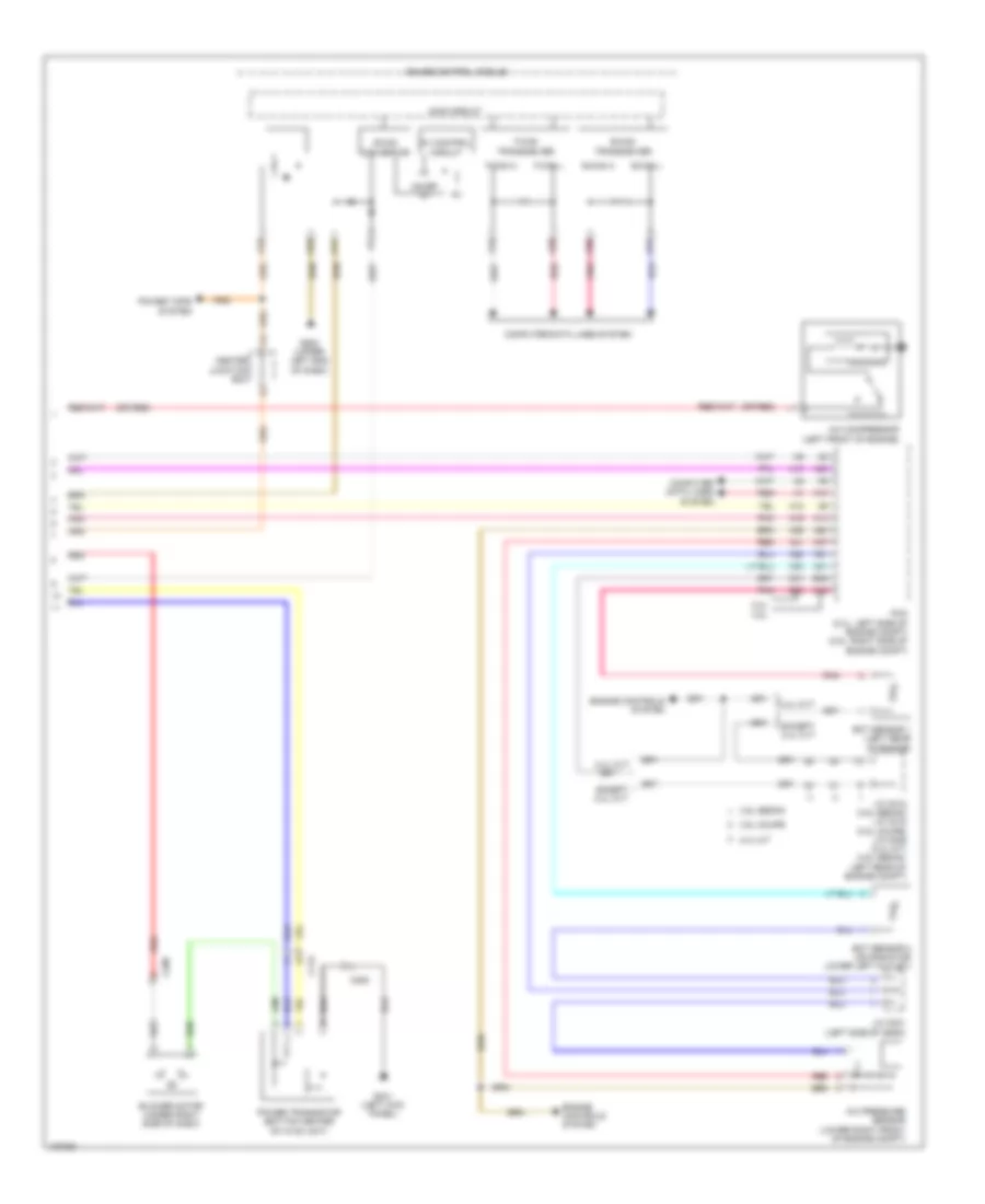
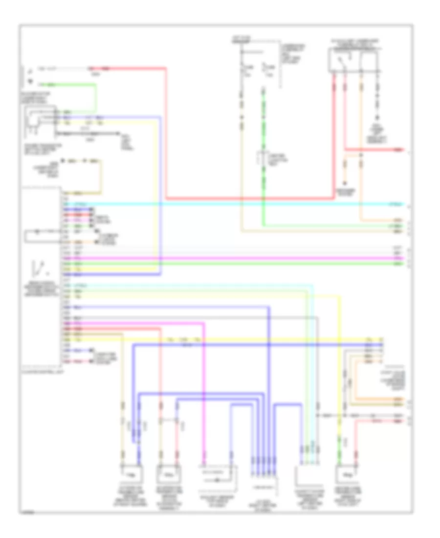
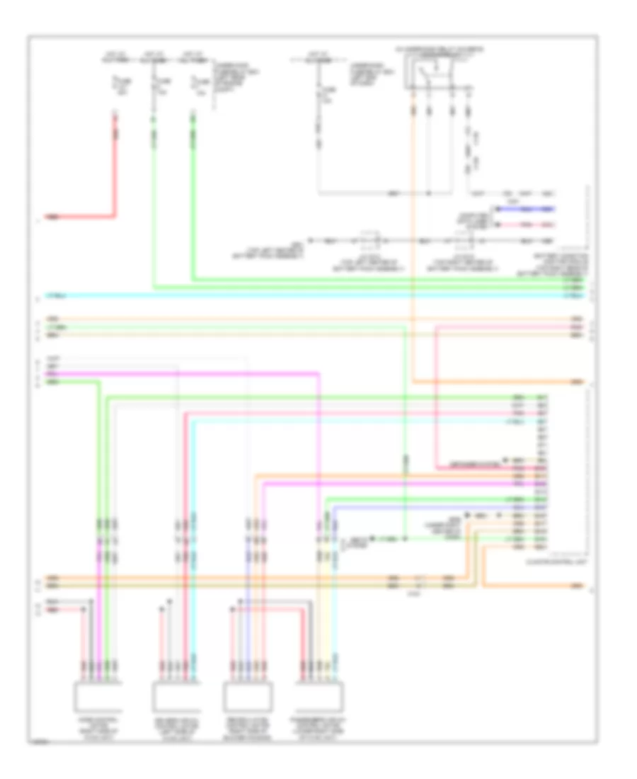
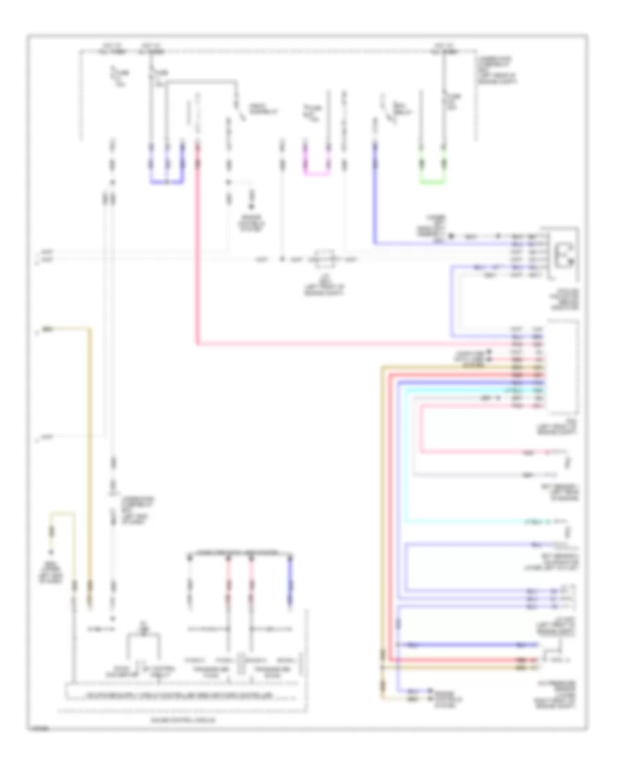
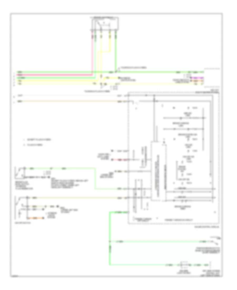
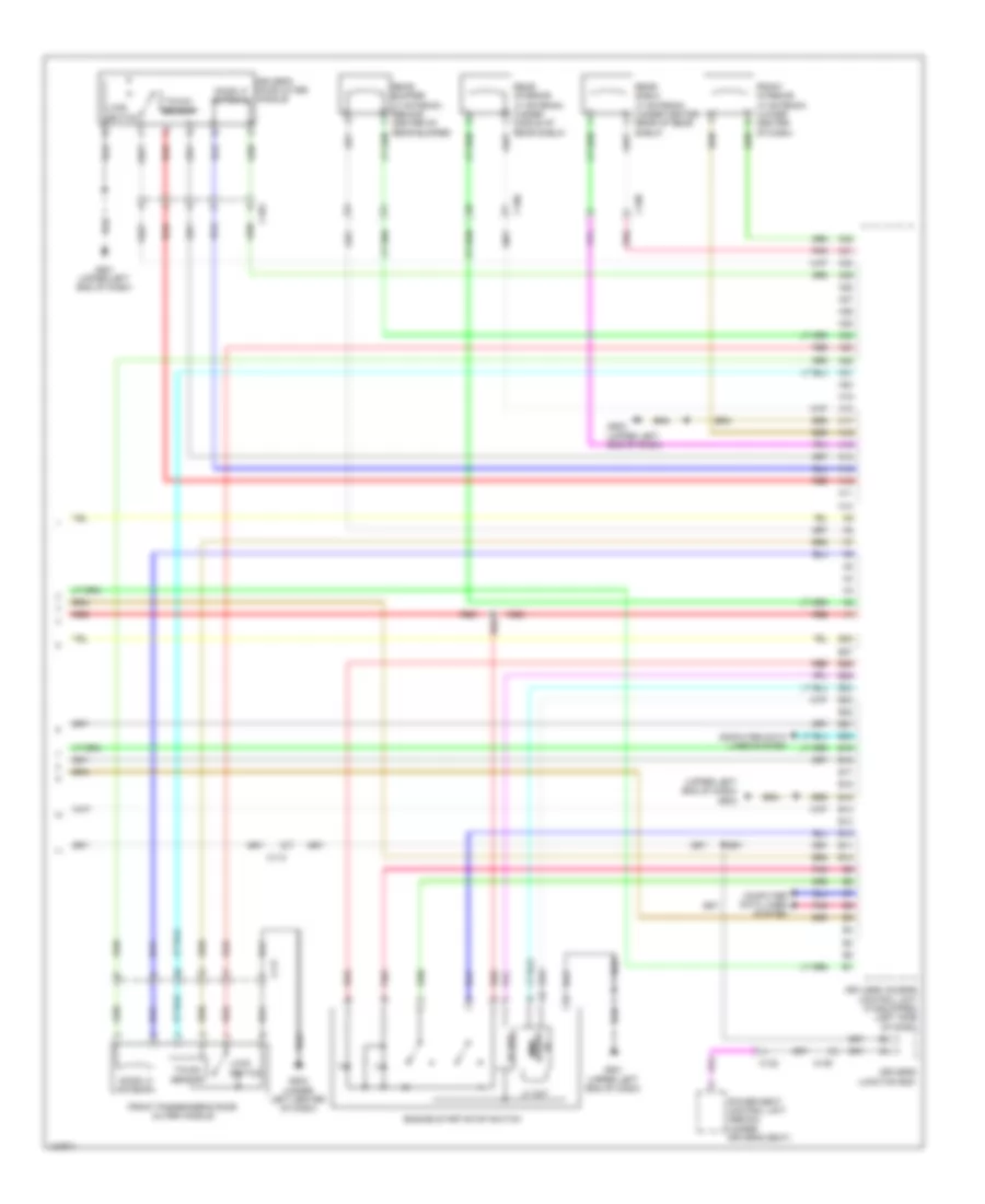
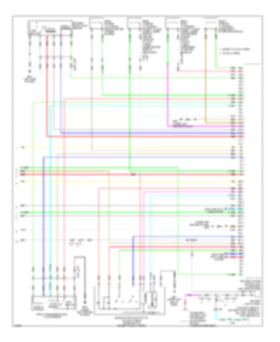
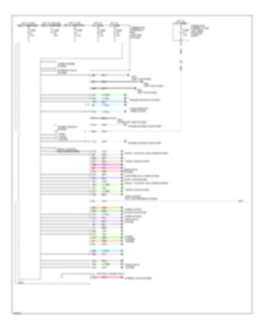
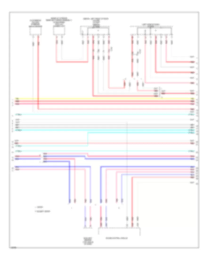
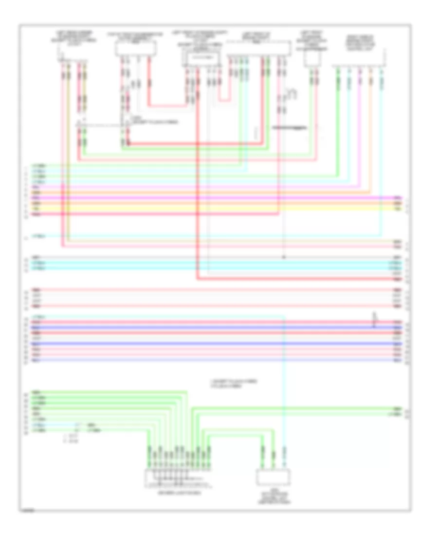
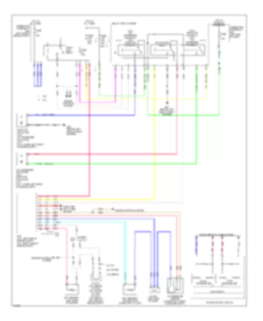
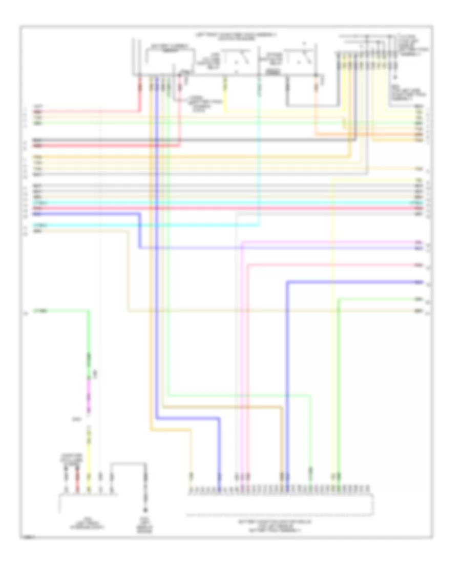
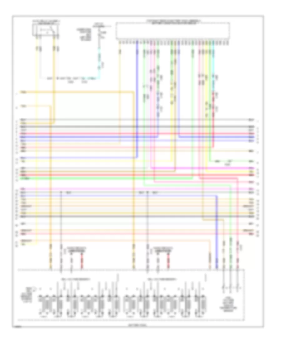
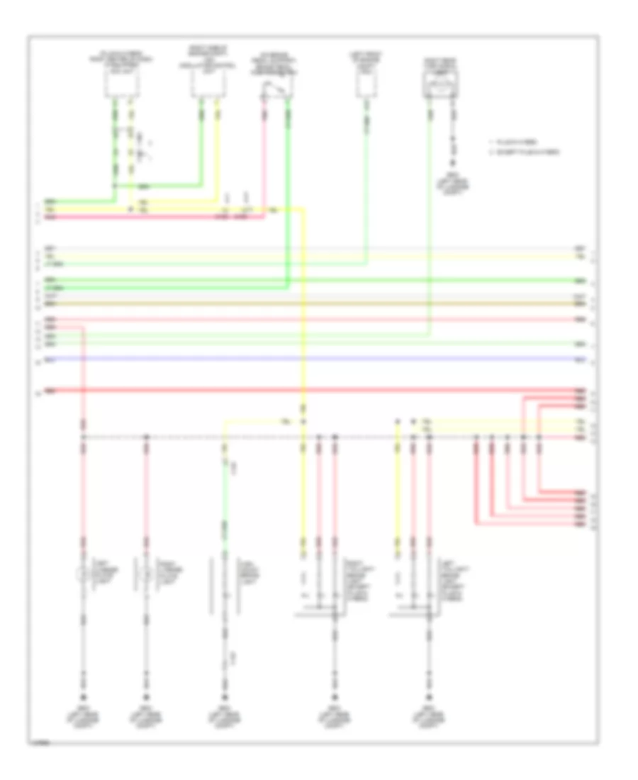
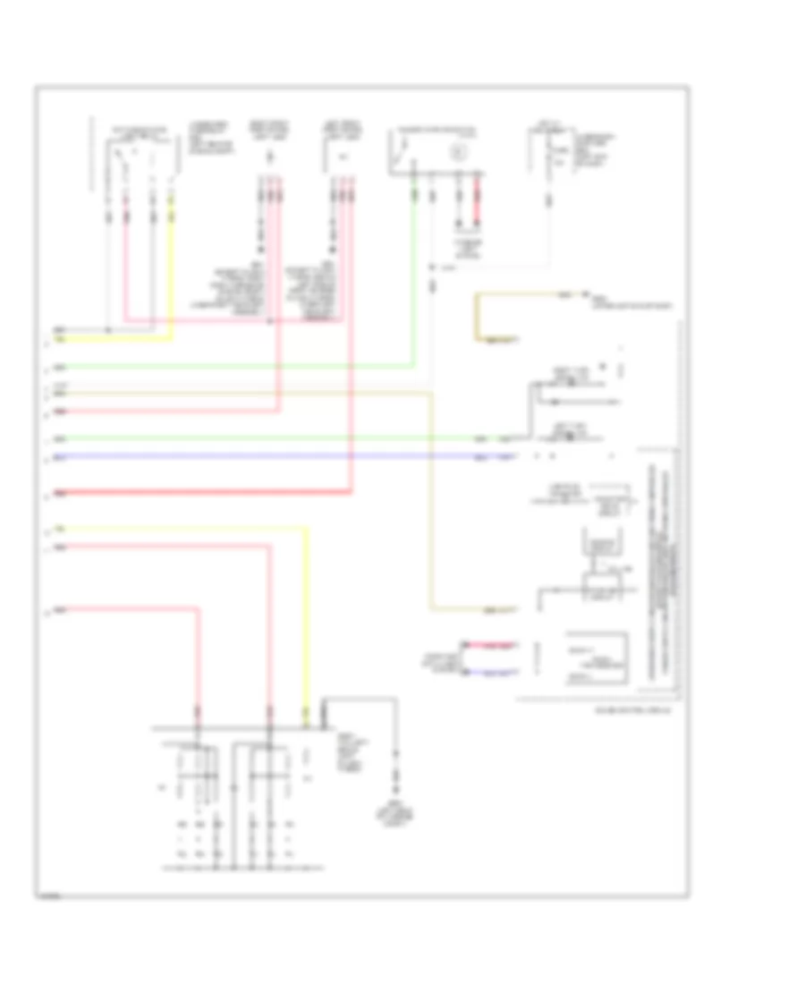
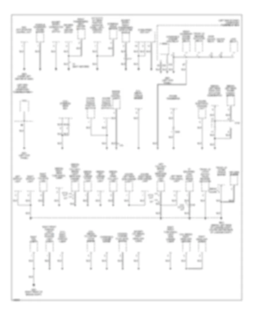
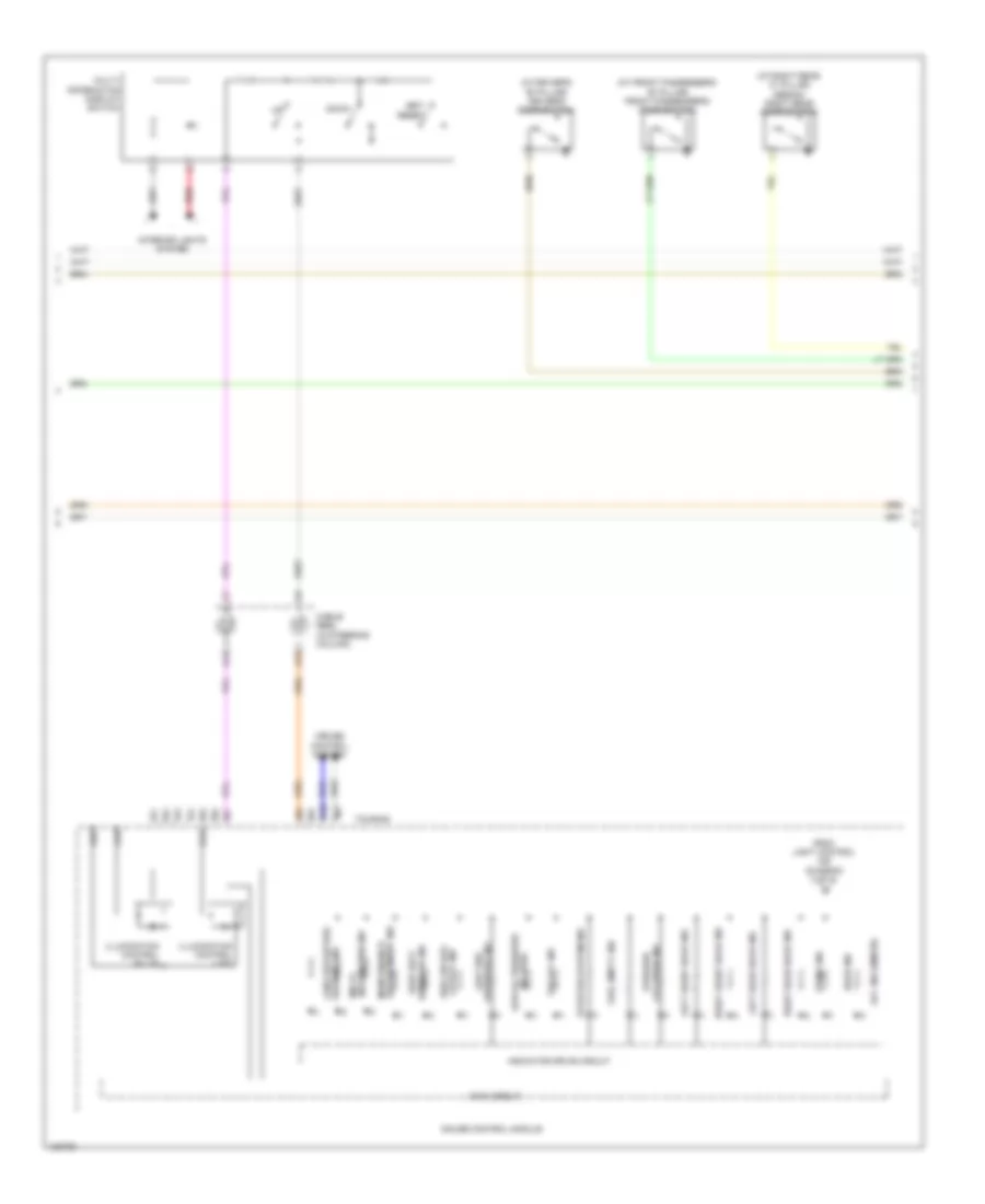
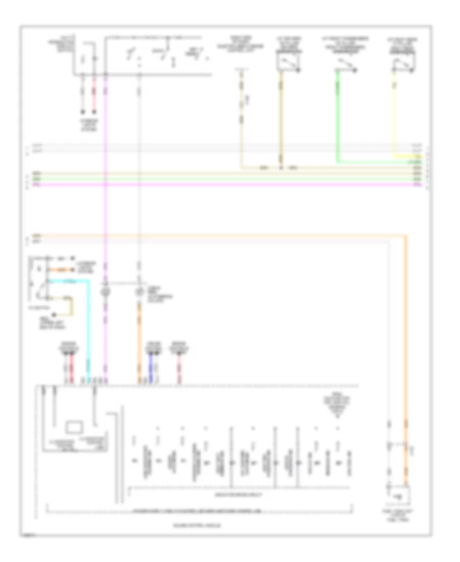
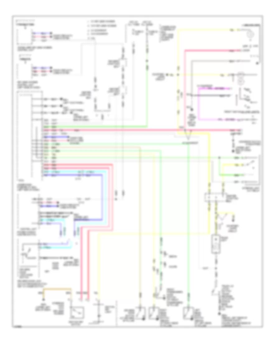
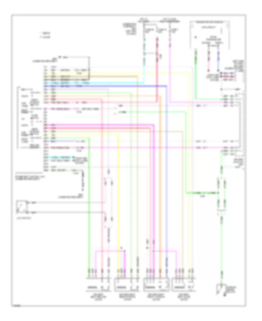
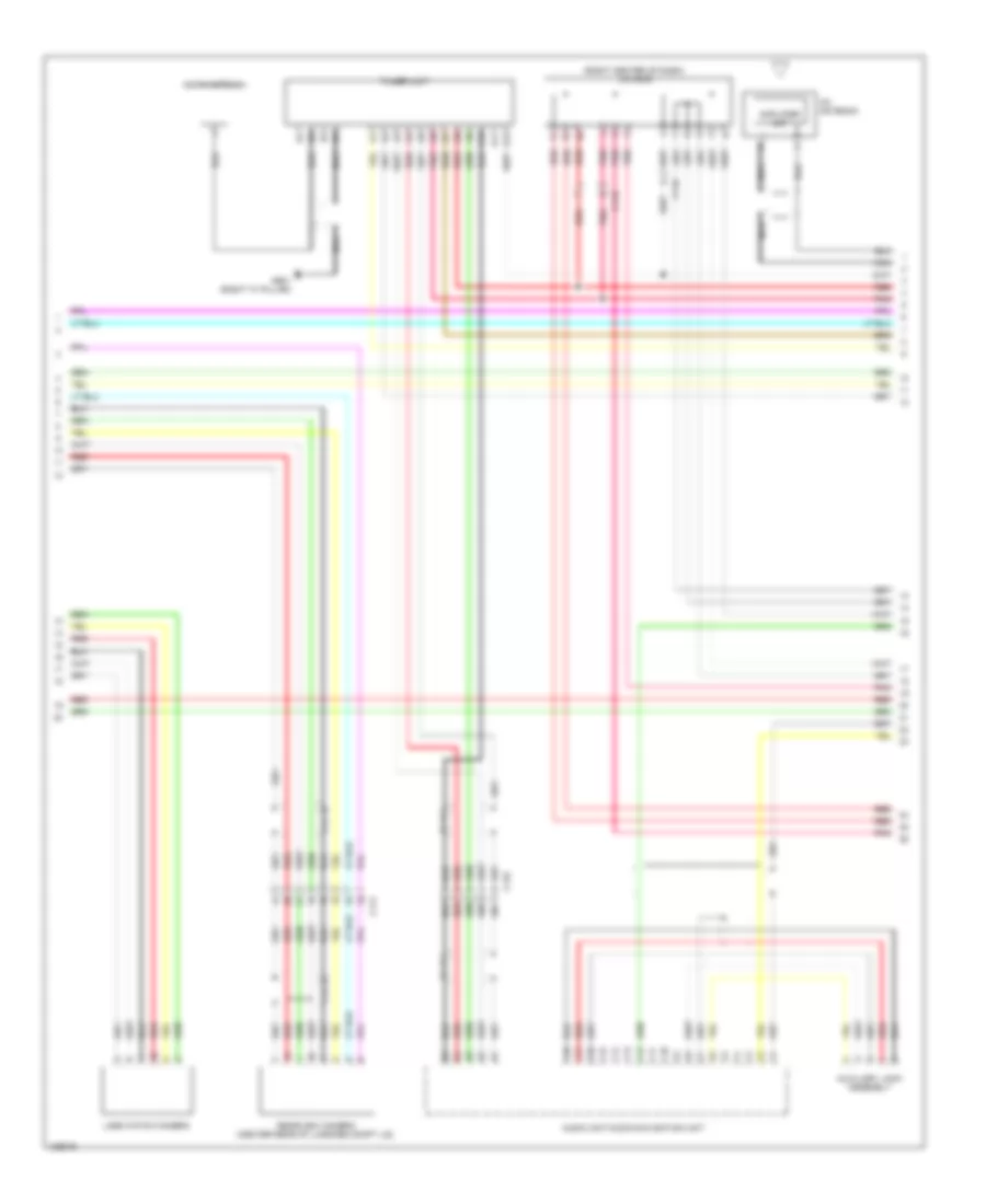
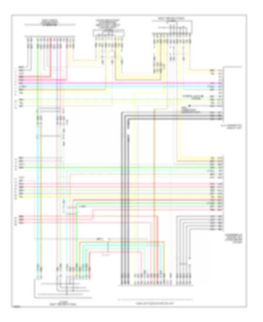
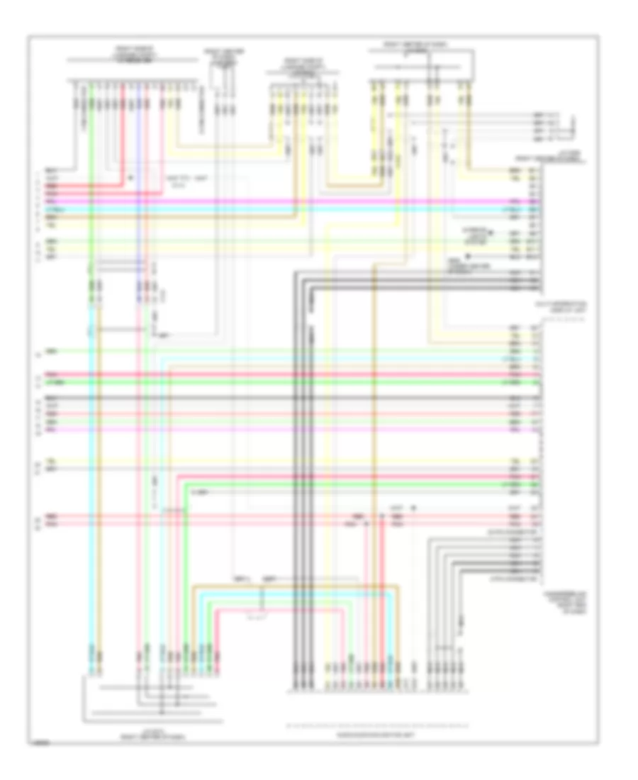
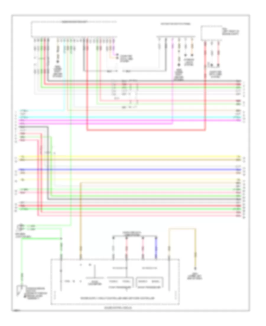
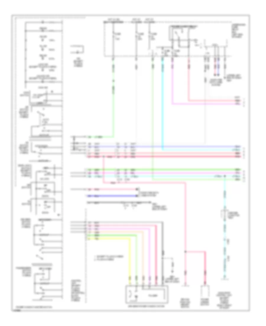
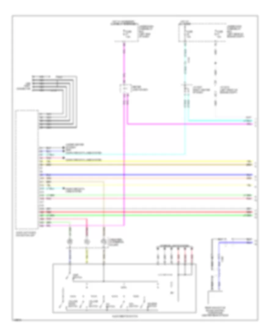
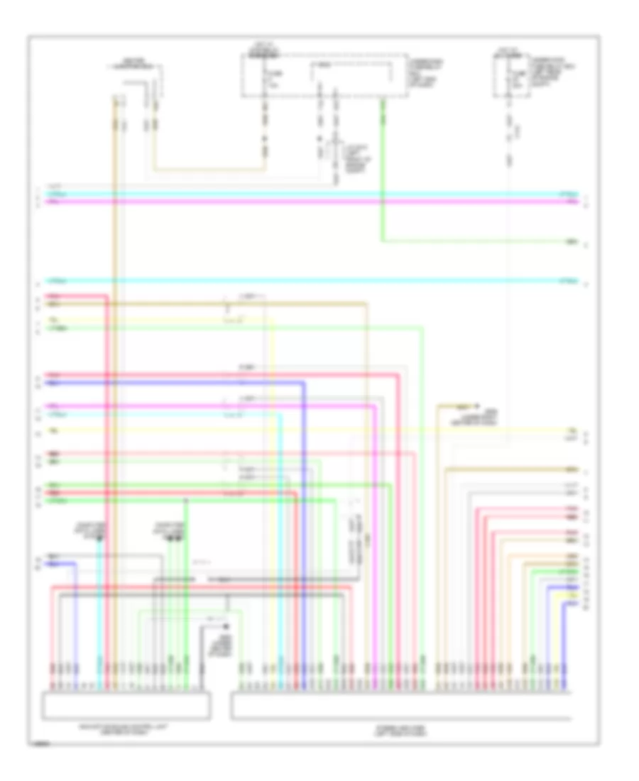
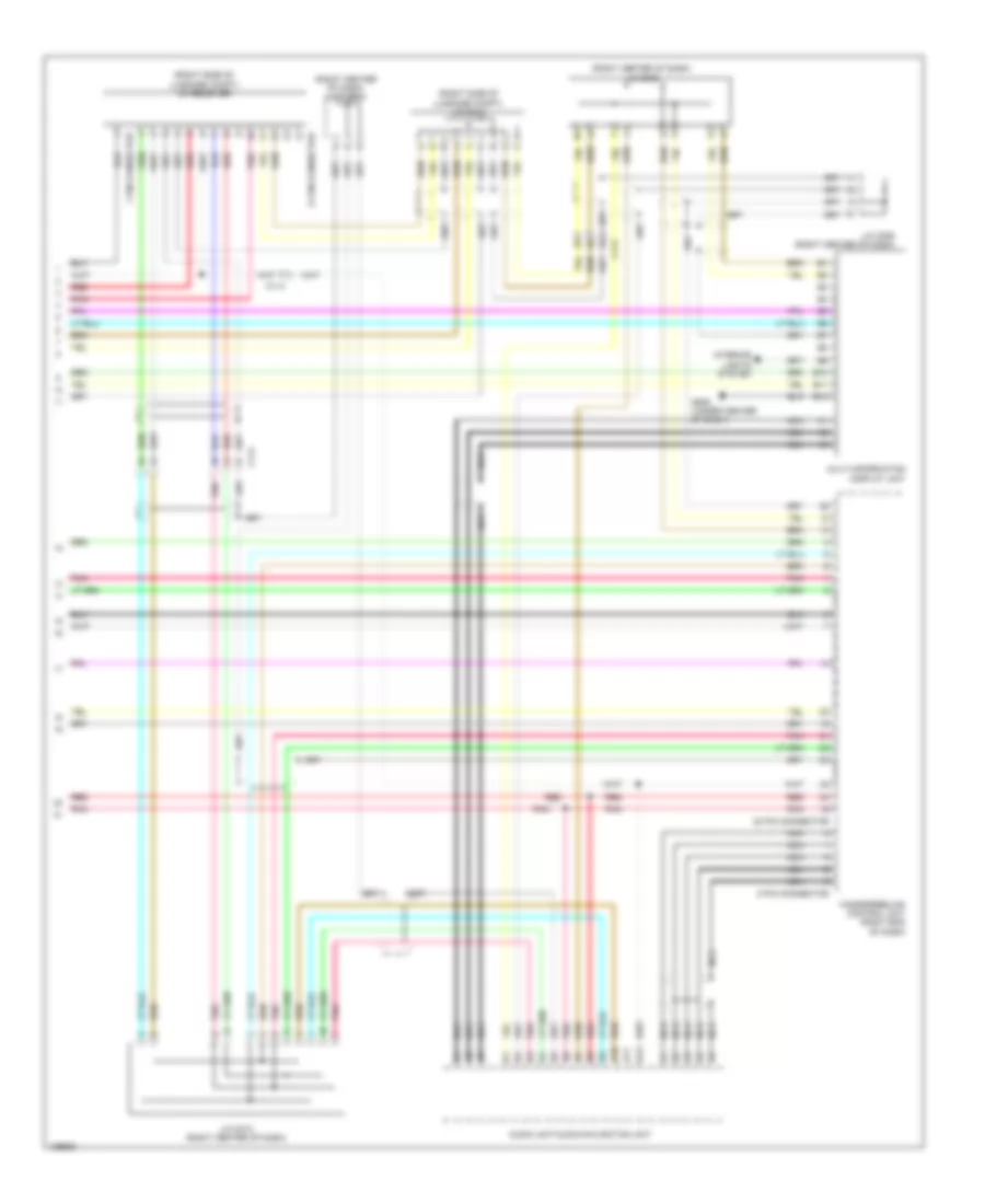
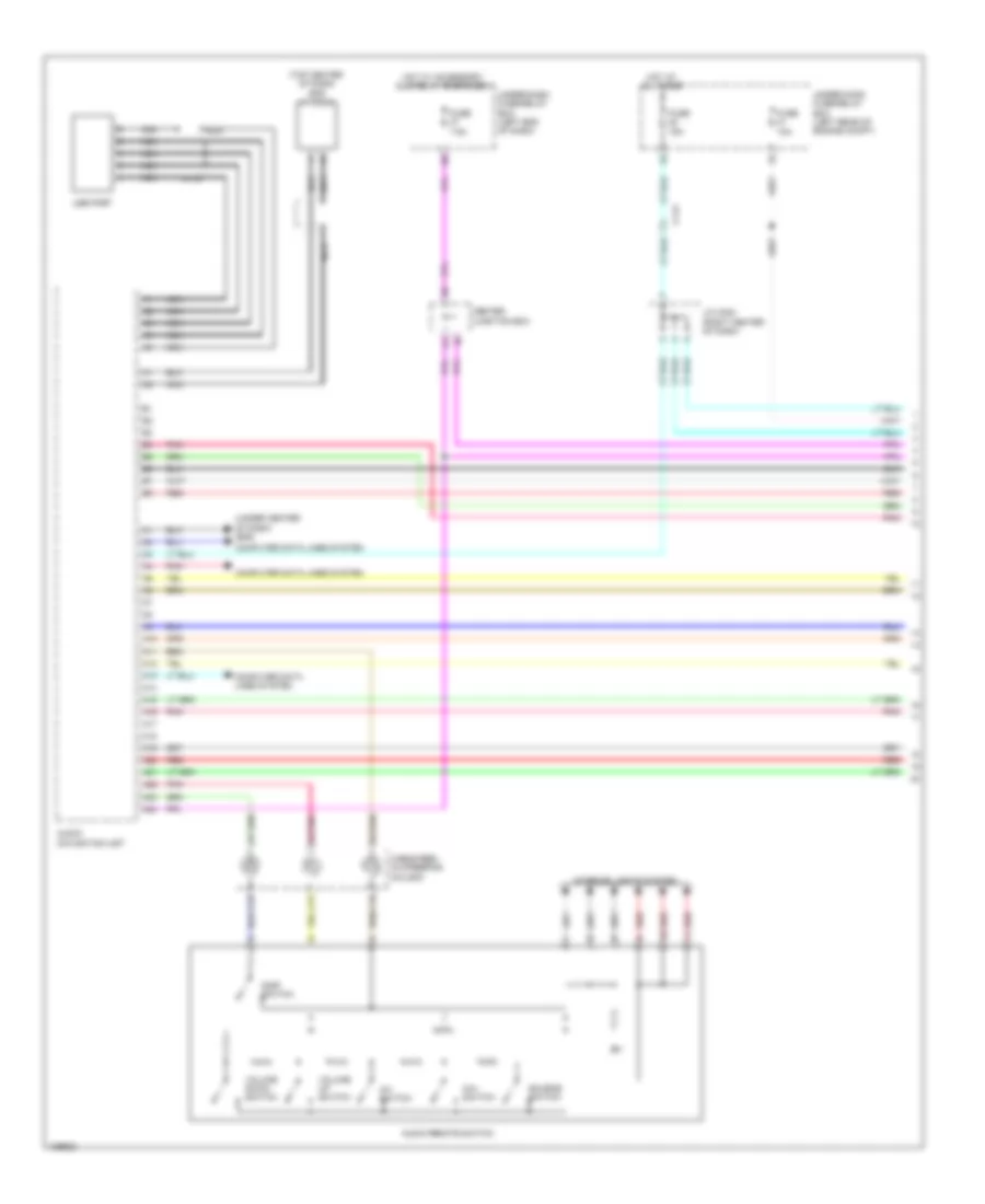
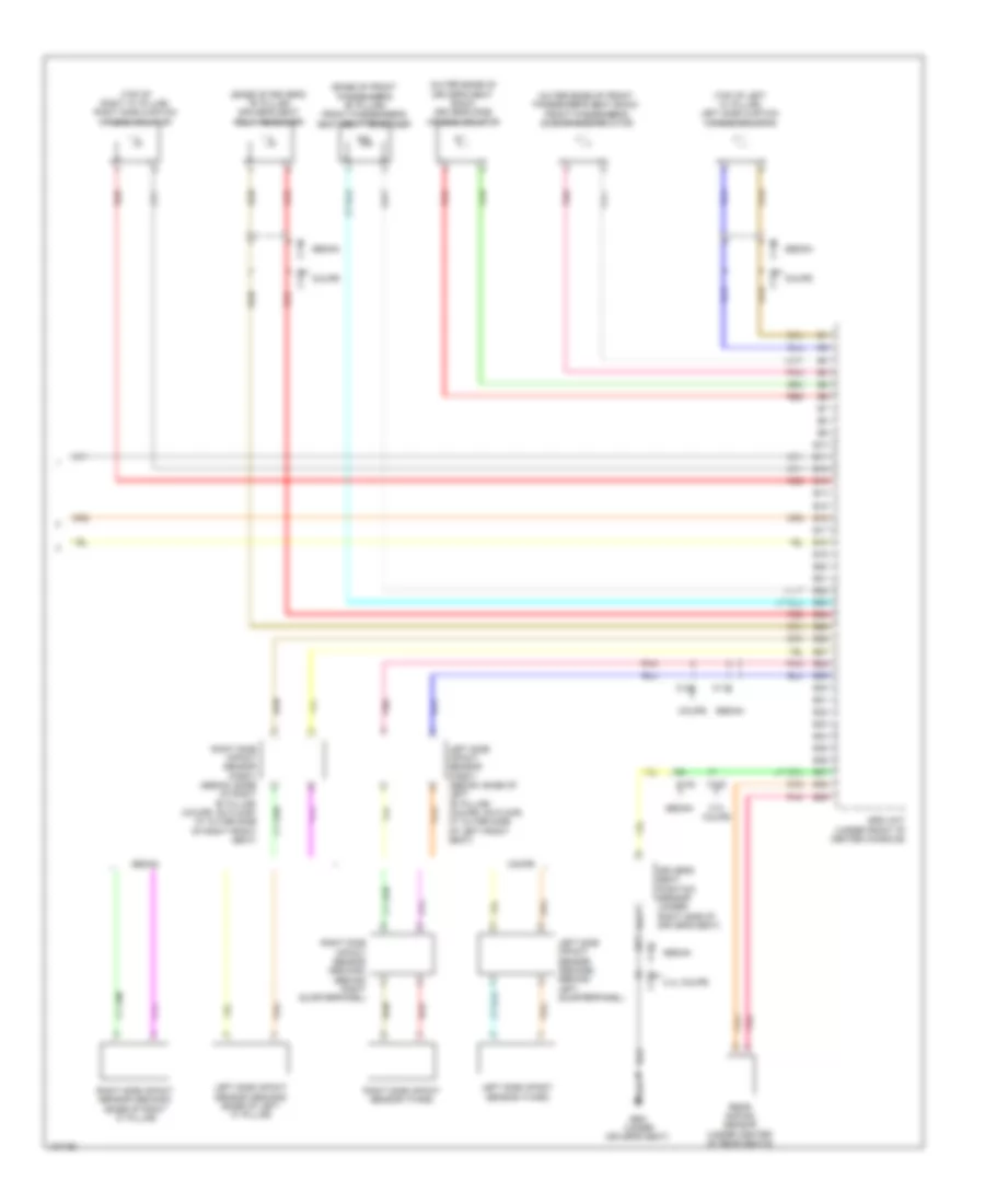
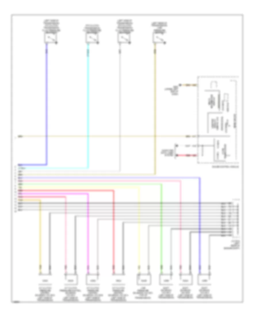
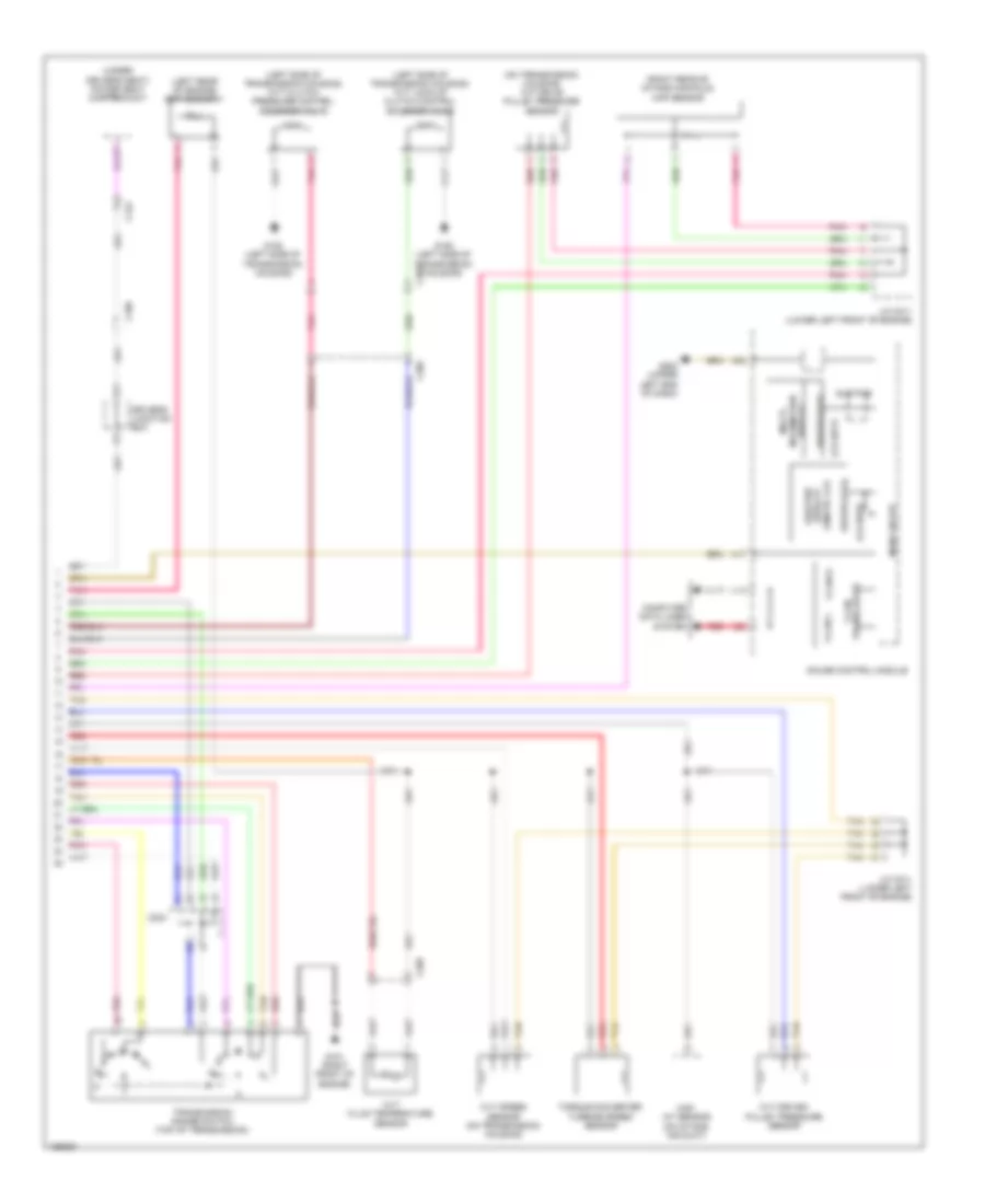
Automatic A/C Wiring Diagram, Except Hybrid (3 of 3) for Honda Accord Plug-In 2014
List of elements for Automatic A/C Wiring Diagram, Except Hybrid (3 of 3) for Honda Accord Plug-In 2014:
- (or red)
- 2.4l
- 2.4l cvt
- 2.4l m/t
- 3.5l
- 3.5l coupe
- 3.5l sedan
- 5v control circuit
- A/c compressor (left front of engine)
- A/c pressure sensor (lower right front of engine compt)
- A10
- A13
- A14
- A15
- A16
- A17
- A19
- A20
- A21
- A23
- A28
- A29
- A30
- A31
- A32
- A33
- A37
- A41
- A50
- A51
- B-can h
- B-can l
- B-can transceiver
- B45
- B50
- Blower motor (under right side of dash)
- C113
- C208
- C31
- C48
- Center junction box
- Computer data lines system
- Dc-dc convertor
- Ect sensor 1 (left rear of engine)
- Ect sensor 2 (on radiator lower left outlet)
- Engine controls system
- Except 2.4l cvt
- F-can h
- F-can l
- F-can transceiver
- G401 (left kick panel)
- G502 (upper left end of dash)
- Gauge control module
- J/c c012 (3.5l sedan) j/c c019 (3.5l coupe) j/c c009 (2.4l m/t) (3.5l sedan: left rear of engine compt)
- J/c c021 (left side of dash)
- Main circuit
- On/off 5v
- Pcm (2.4l: left side of engine compt) (3.5l: right side of engine compt)
- Pnk
- Power tops system
- Power transistor (bottom center of hvac unit)
- Red
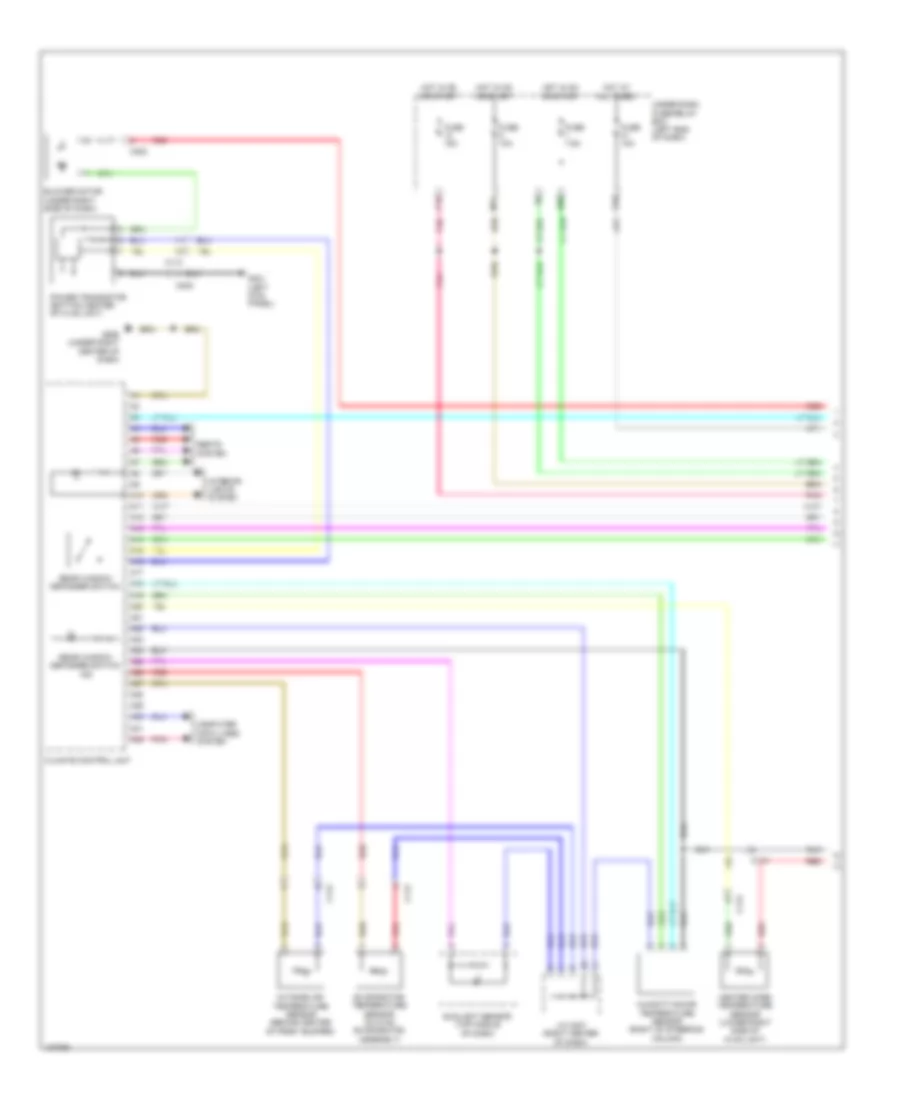
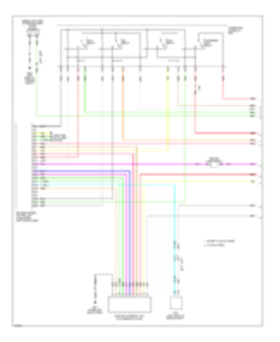
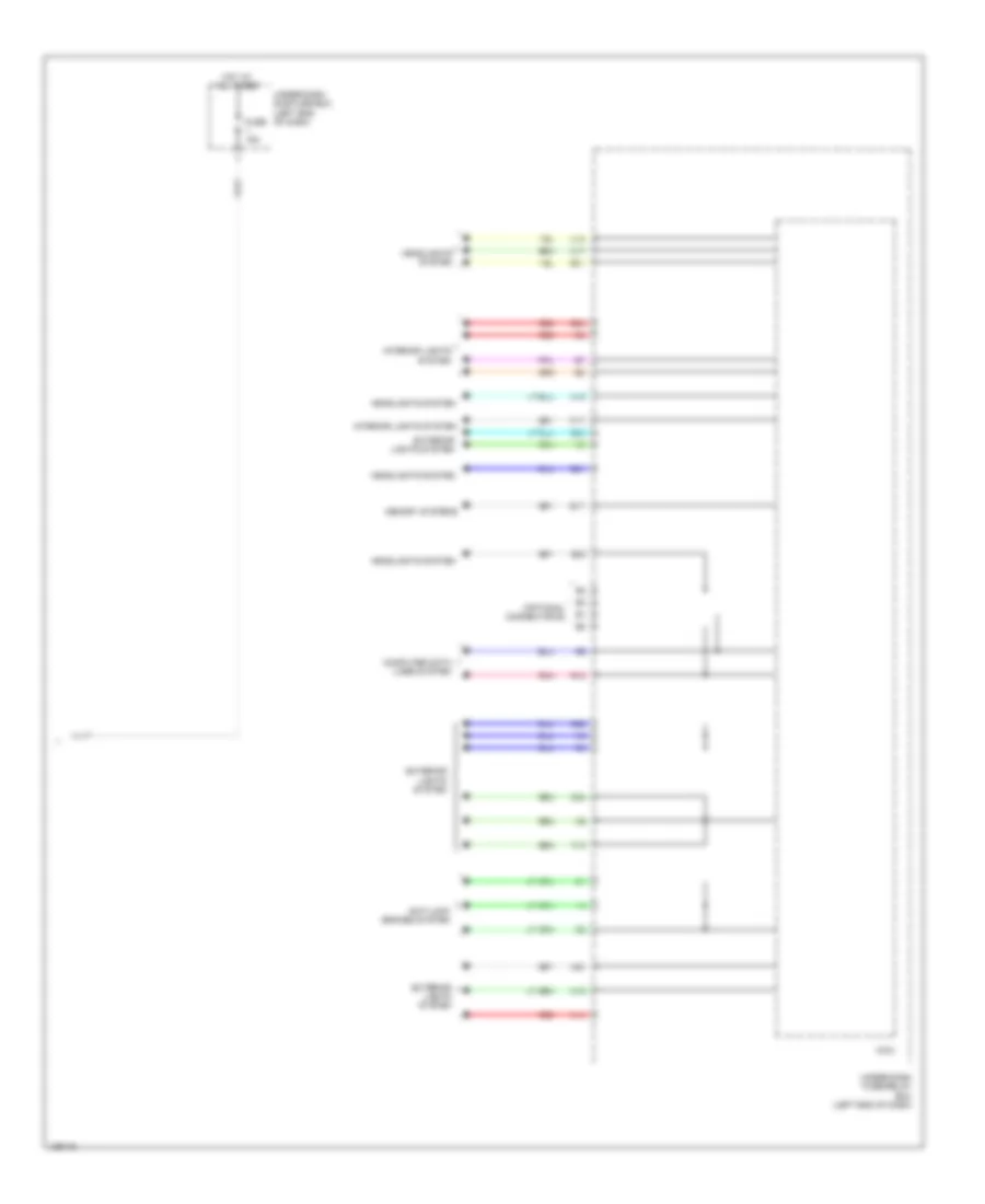
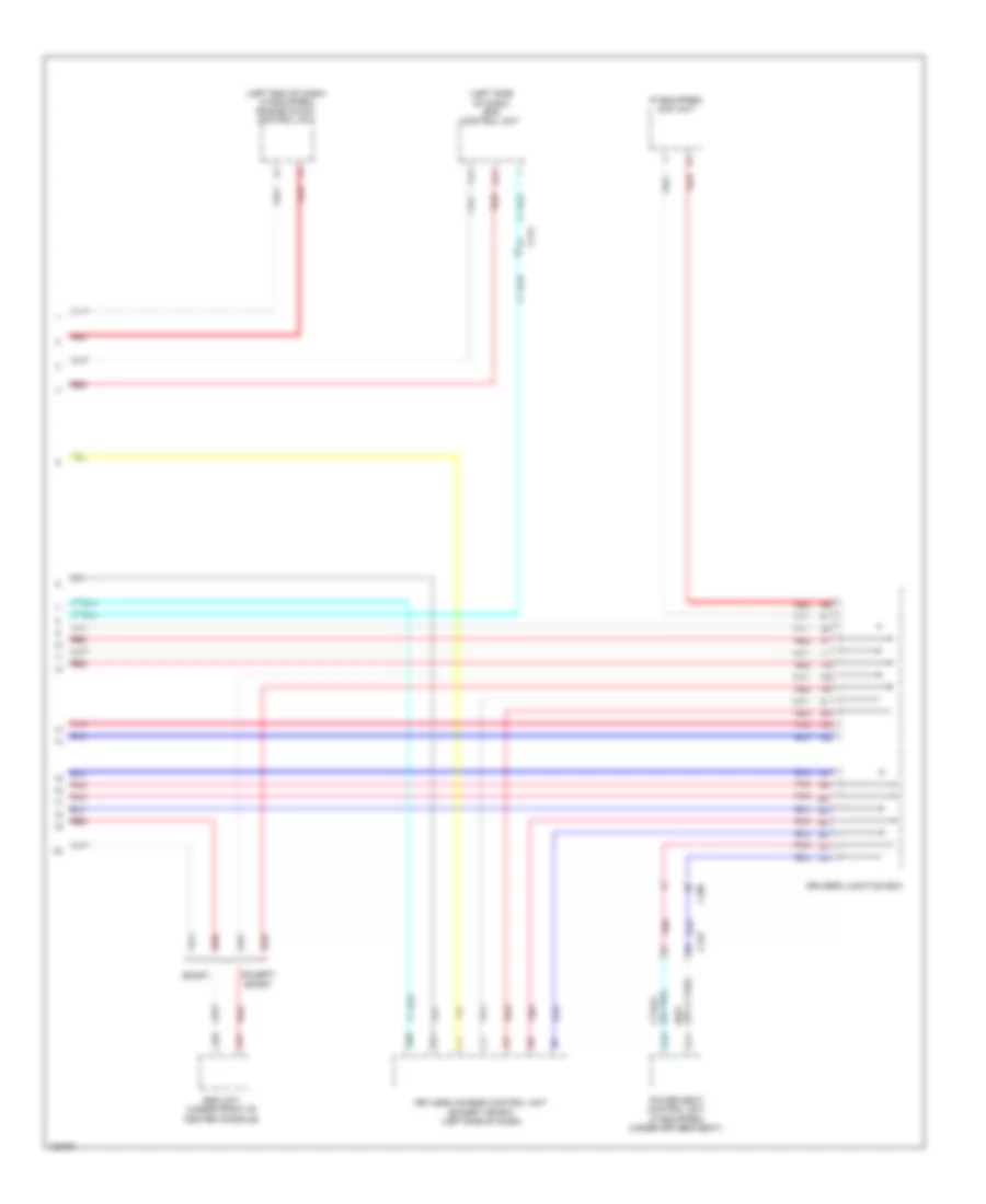
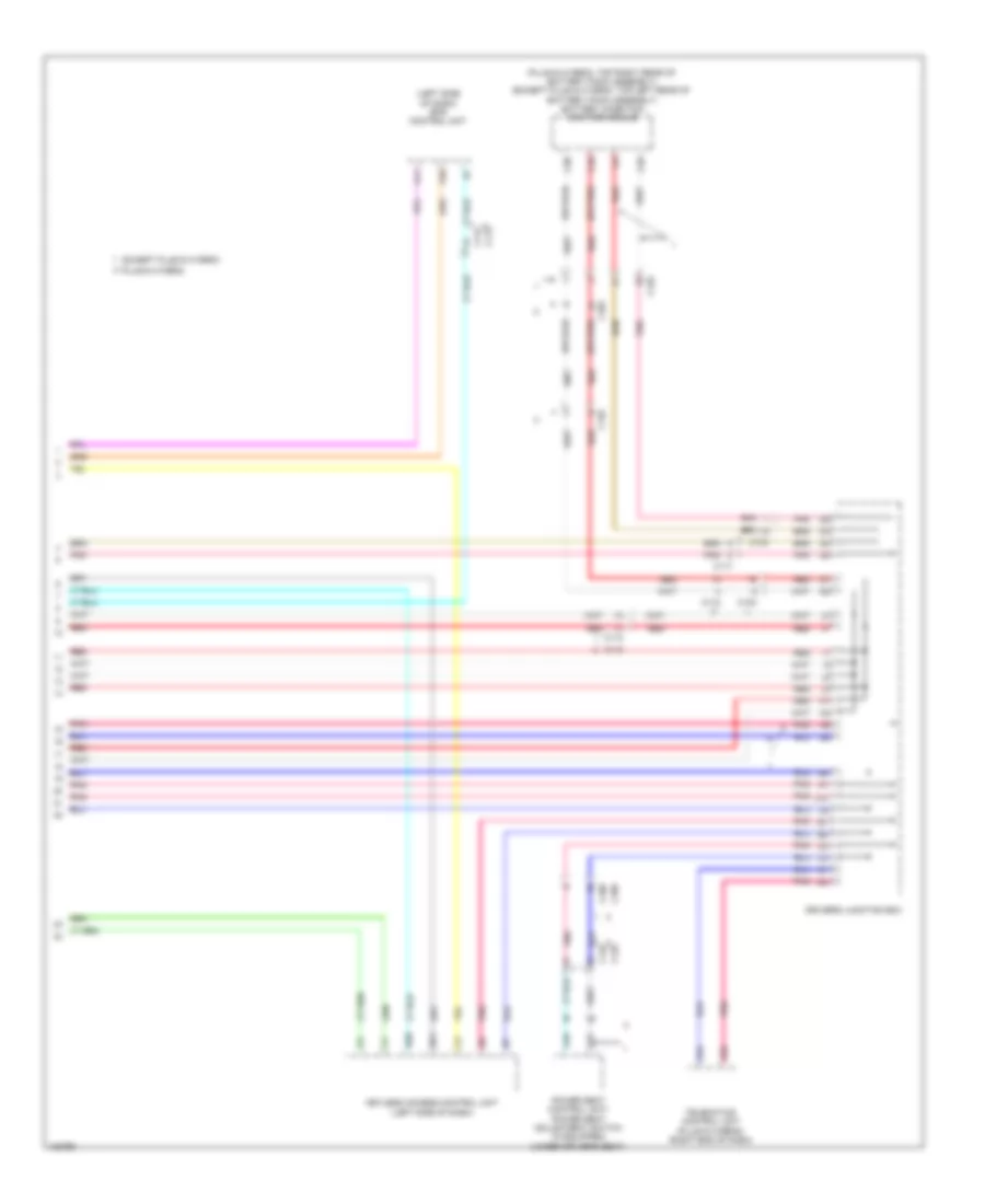
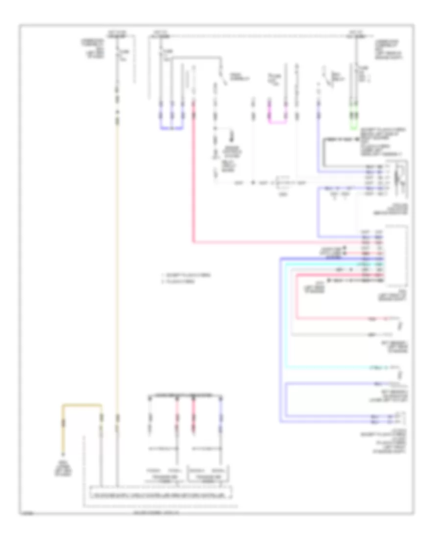
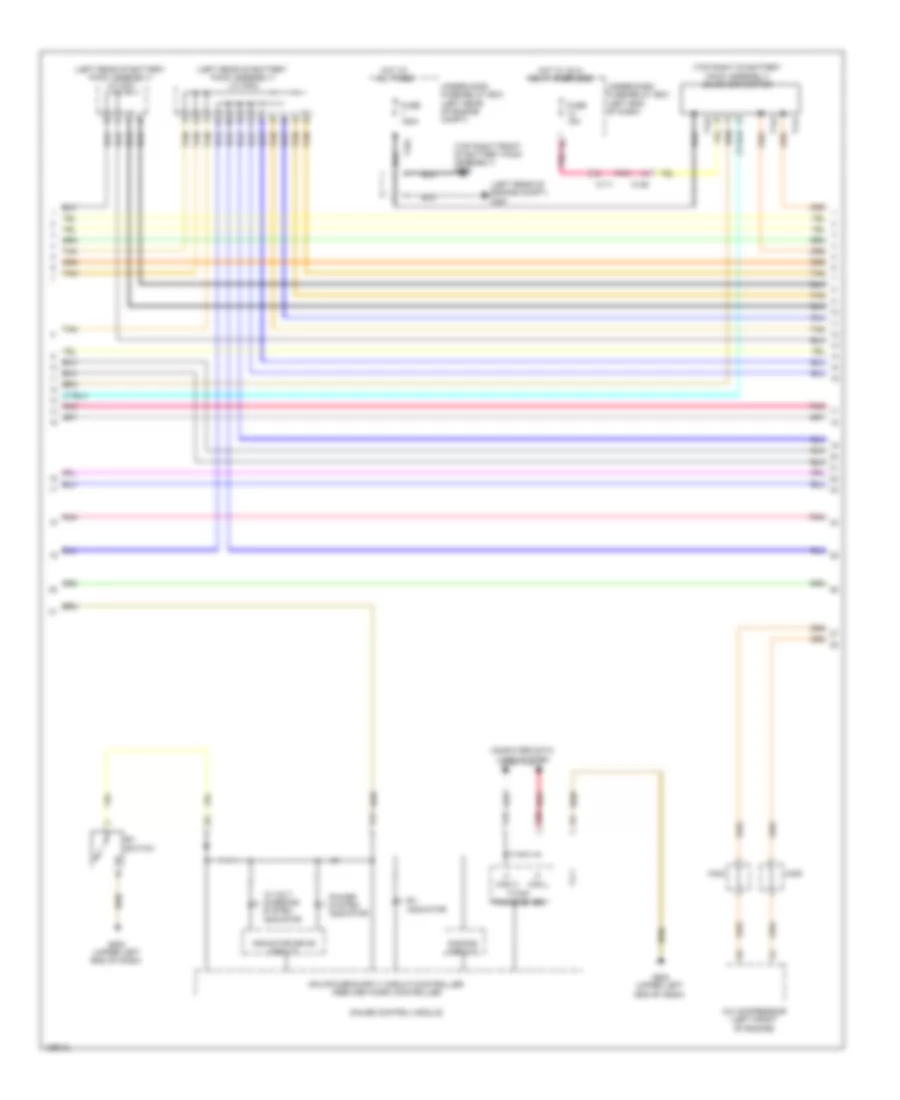
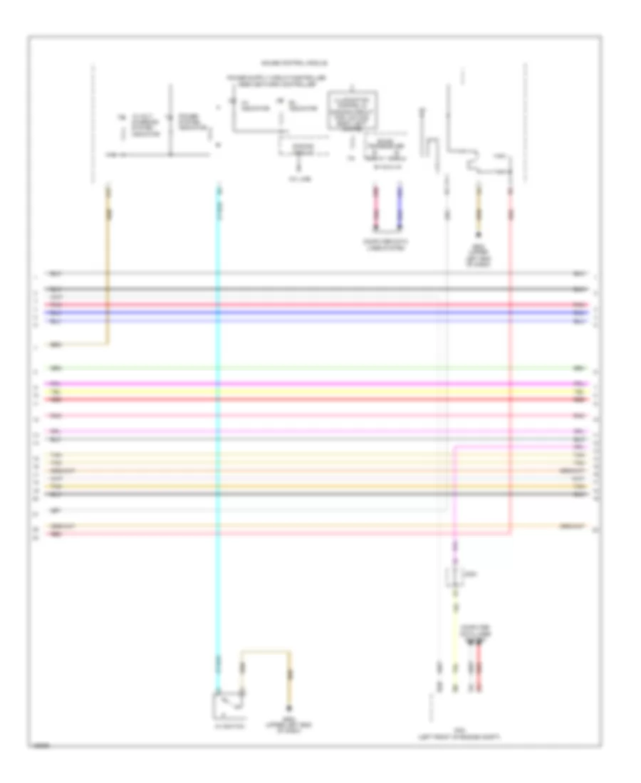
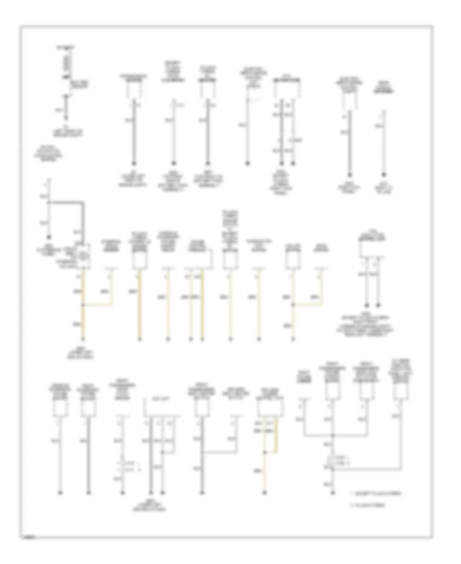
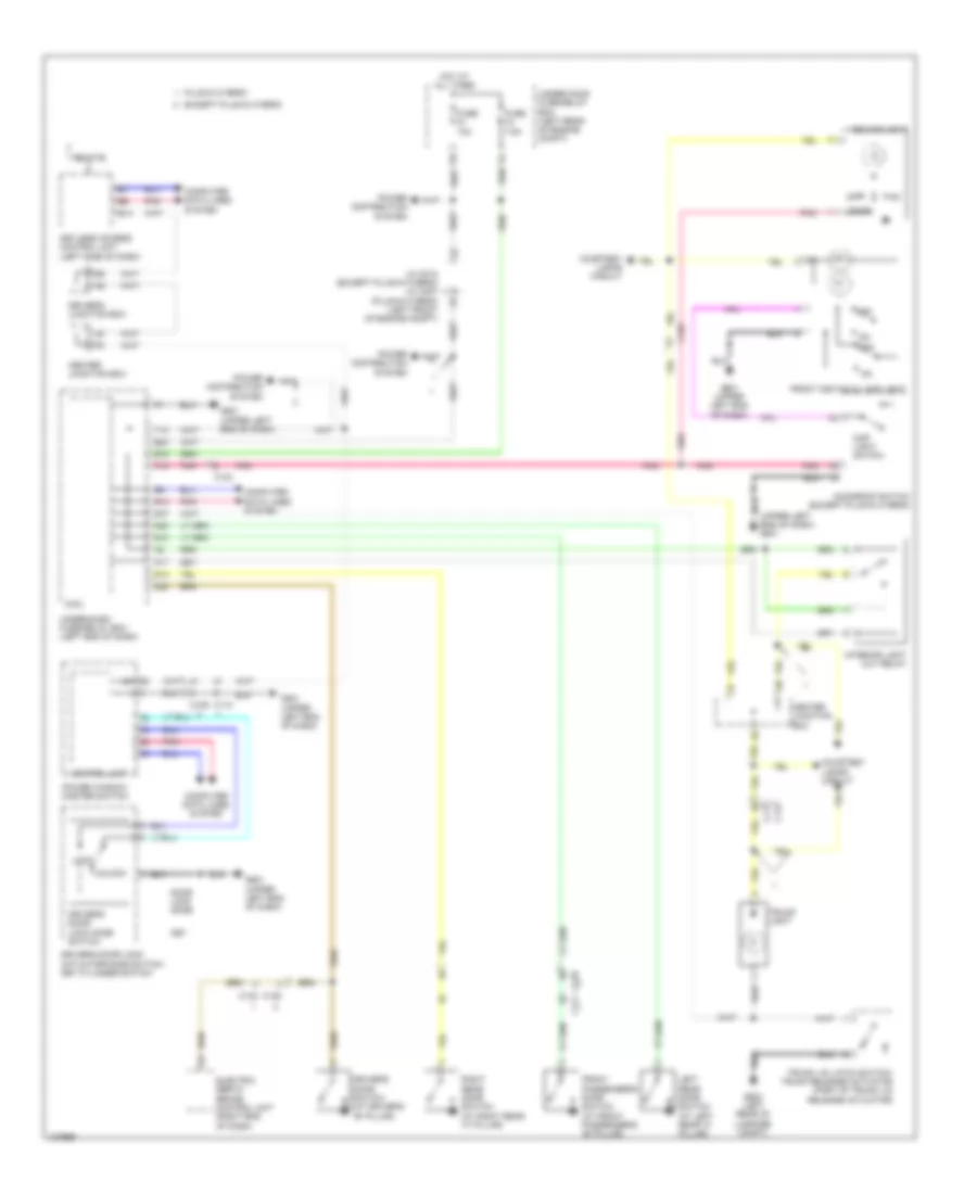
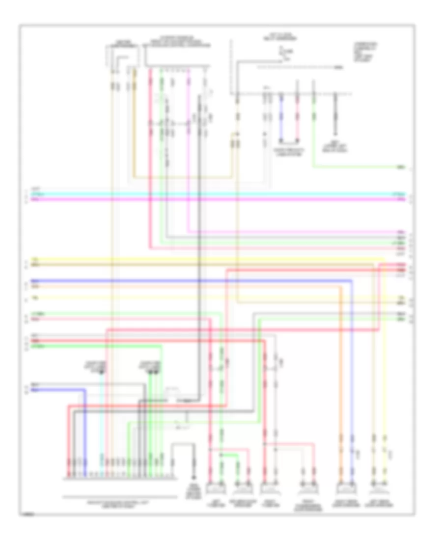
Automatic A/C Wiring Diagram, Hybrid (1 of 4) for Honda Accord Plug-In 2014
List of elements for Automatic A/C Wiring Diagram, Hybrid (1 of 4) for Honda Accord Plug-In 2014:
- A10
- A11
- A12
- A13
- A14
- A15
- A16
- A17
- A18
- A19
- A20
- A21
- A22
- A23
- A24
- A25
- A26
- A27
- A28
- A29
- A30
- A31
- A32
- Blower motor (under right side of dash)
- C112
- C113
- C202
- Climate control unit
- Computer data lines system
- E20
- Evaporator temperature sensor (in hvac evaporator assembly)
- F11
- Fuse 10a
- Fuse 15a
- Fuse 7.5a
- G401 (left kick panel)
- G506 (under right center of dash)
- Heater core temperature sensor (lower right side of hvac unit)
- Hot at all times
- Hot in on or start
- Humidity/in-car temperature sensor (right of steering column)
- Interior lights system
- J/c c007 (right center of dash)
- M11
- Outside air temperature sensor (behind center of front bumper)
- Pnk
- Power transistor (bottom center of hvac unit)
- Rear window defogger switch
- Rear window defogger switch ind
- Red
- S10
- Seats system
- Sunlight sensor (top middle of dash)
- Under-dash fuse/relay box (left end of dash)
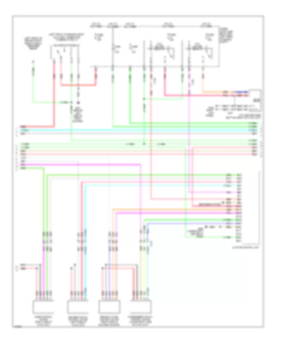
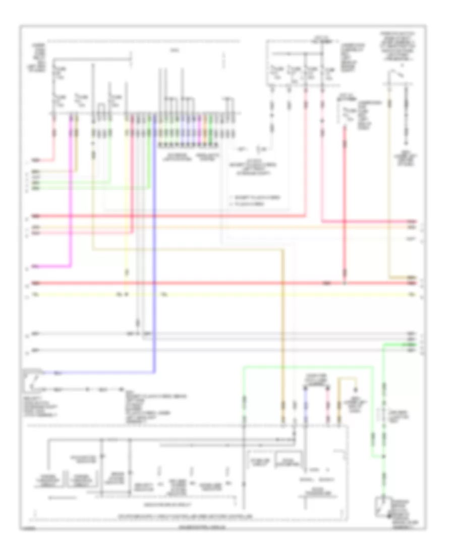
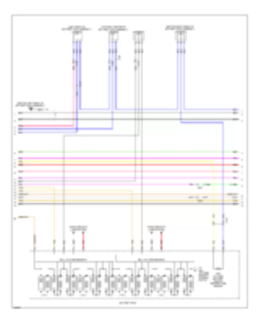
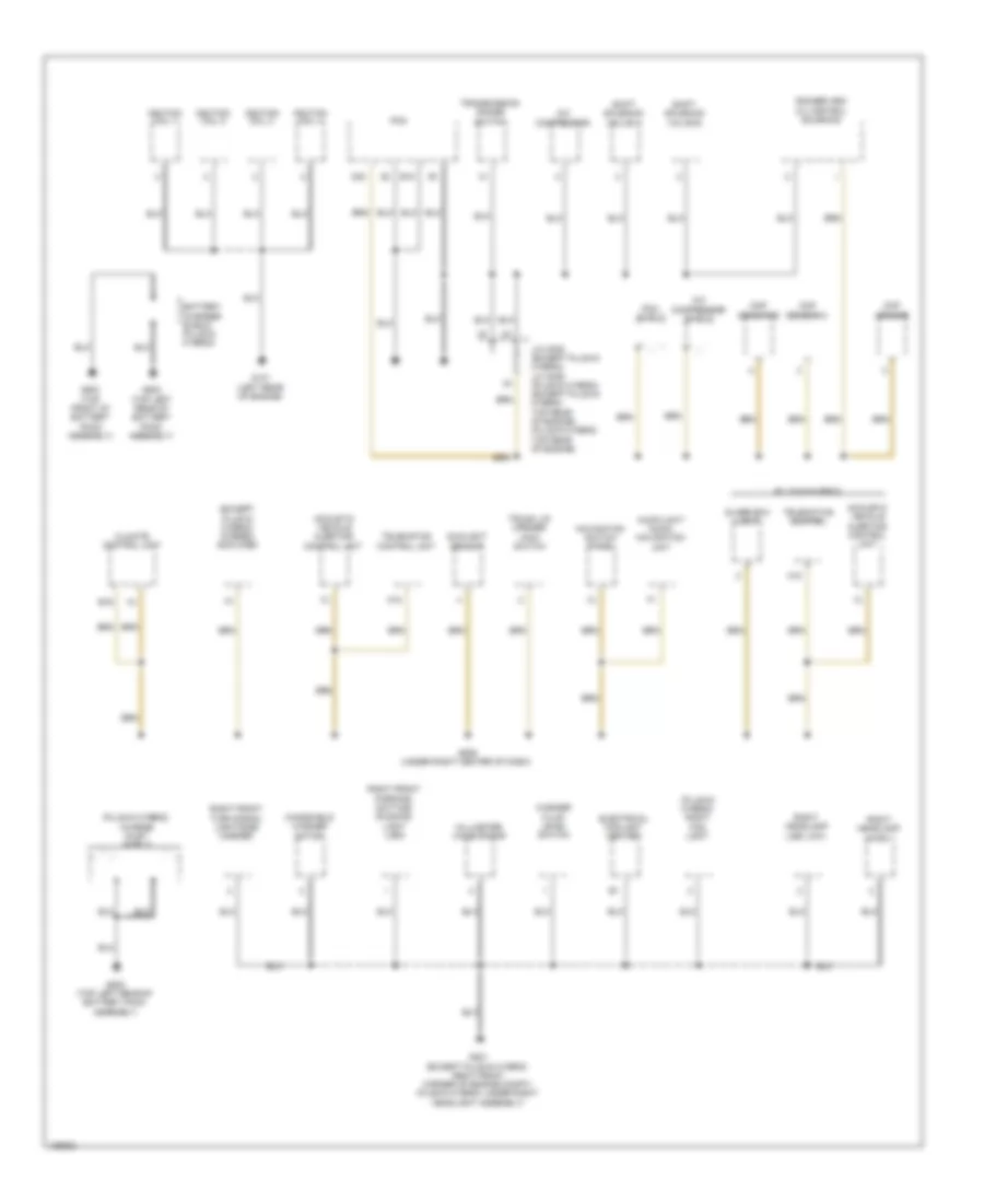
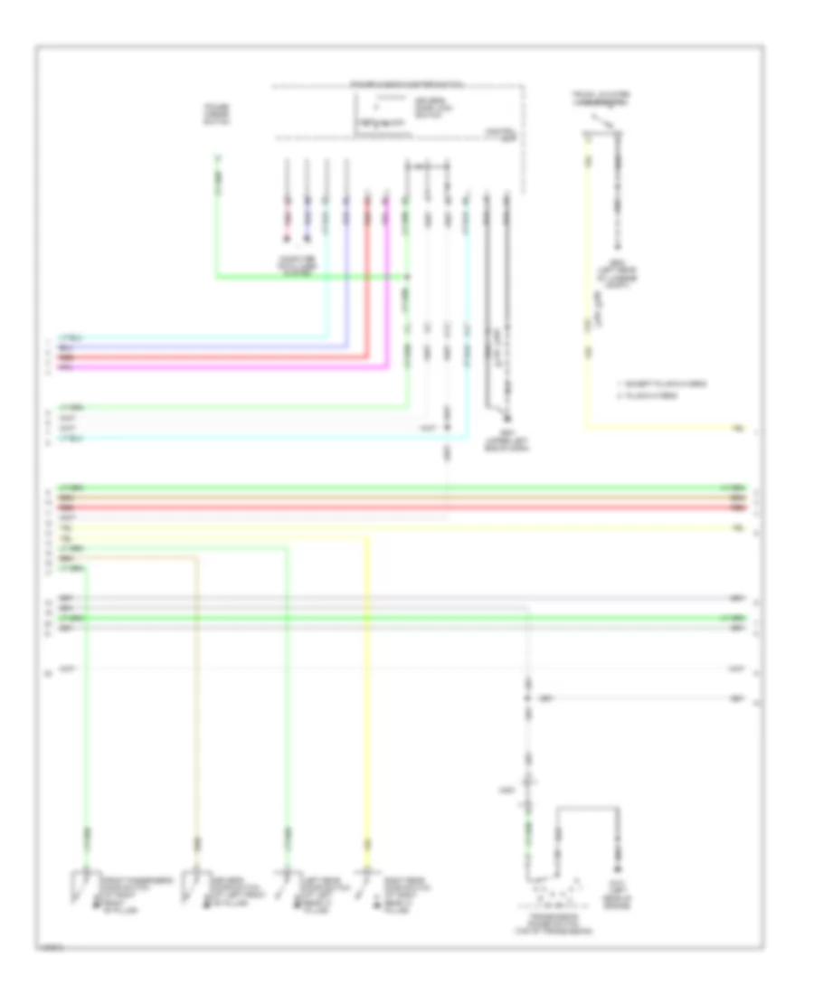
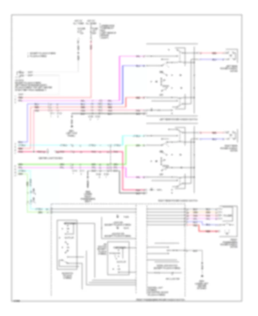
Automatic A/C Wiring Diagram, Hybrid (2 of 4) for Honda Accord Plug-In 2014
List of elements for Automatic A/C Wiring Diagram, Hybrid (2 of 4) for Honda Accord Plug-In 2014:
- (left front of engine compt) auxiliary under-hood fuse/relay box a
- (left front of engine compt) rear window defogger relay
- B10
- B11
- B12
- B13
- B14
- B15
- B16
- B17
- B18
- B19
- B20
- Blower motor relay
- C113
- C118
- C201
- Climate control unit
- Defogger system
- Driver's air mix control motor (left side of hvac unit)
- Fuse 10a
- Fuse 12-7 40a
- Fuse 40a
- Fuse 7.5a
- G301 (behind left side of front bumper)
- G404 (right kick panel)
- G506 (under right center of dash)
- Hot at all times
- Mode control motor (right side of hvac unit)
- Passenger's air mix control motor (lower right side of hvac unit)
- Pnk
- Ptc heater core (bottom front of hvac unit)
- Ptc heater relay a
- Ptc heater relay b
- Recirculation control motor (right side of blower housing)
- Red
- Under- hood fuse/ relay box (left rear of engine compt)
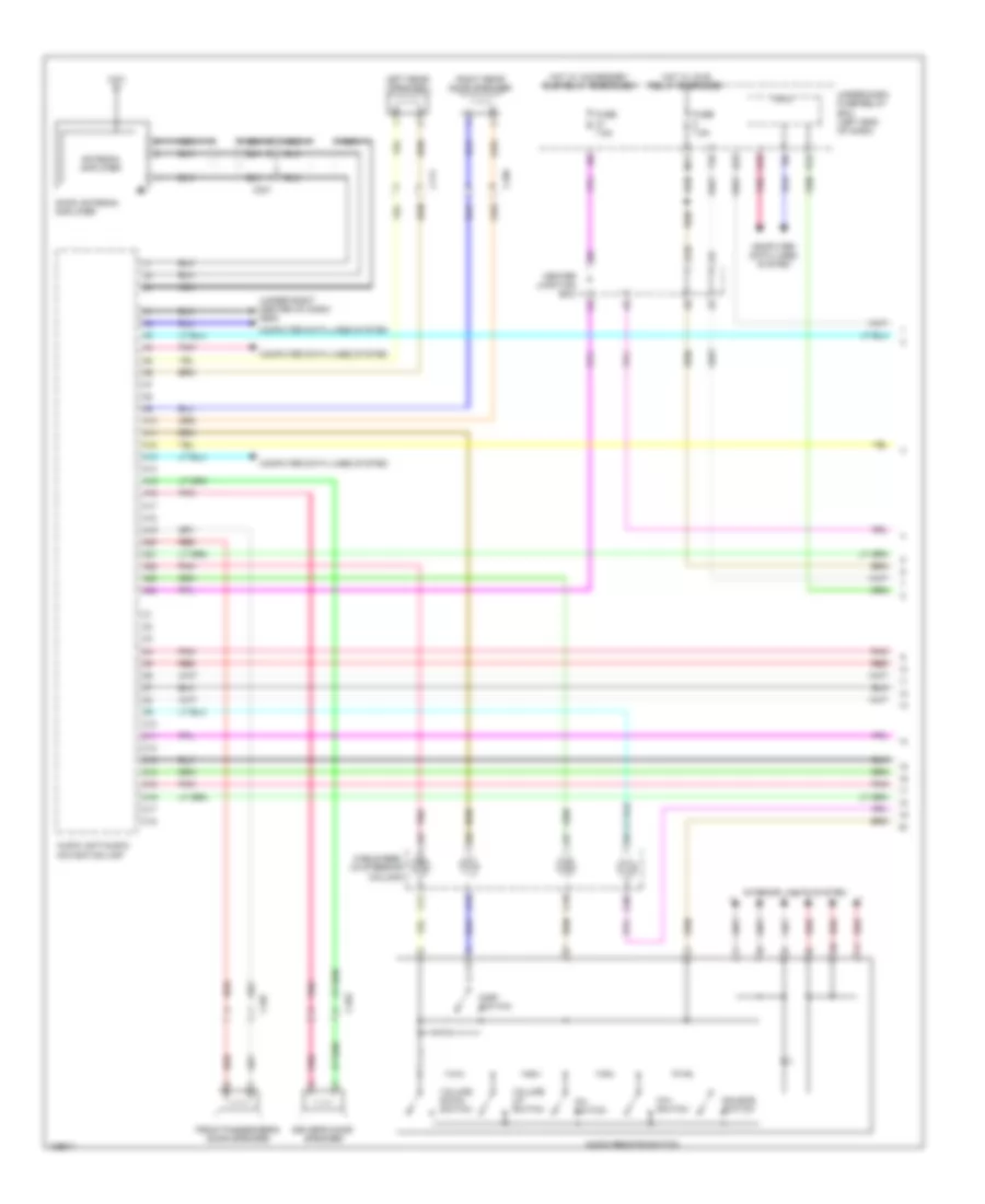
Automatic A/C Wiring Diagram, Hybrid (3 of 4) for Honda Accord Plug-In 2014
List of elements for Automatic A/C Wiring Diagram, Hybrid (3 of 4) for Honda Accord Plug-In 2014:
- A/c compressor (left front of engine)
- B13
- B14
- C118
- C203
- C205
- C207
- Computer data lines system
- Electric heater coolant pump (left rear of engine compt)
- Electric heater coolant pump relay circuit
- Electric motor control module coolant pump (bottom left rear of traction/ generator motor assembly)
- Electric motor control module coolant pump relay circuit
- Electric powertrain coolant temperature sensor (bottom left of radiator)
- G101 (left rear of engine)
- G301 (behind left side of front bumper)
- Ighld 1 relay circuit
- J/c c004 (left side of traction/ generator motor assembly)
- J/c c012 (left front of engine compt)
- Motor control module
- Pcu (top of traction/ generator motor assembly)
- Pnk
- Red
- Relay circuit board
- Tan
Automatic A/C Wiring Diagram, Hybrid (4 of 4) for Honda Accord Plug-In 2014
List of elements for Automatic A/C Wiring Diagram, Hybrid (4 of 4) for Honda Accord Plug-In 2014:
- (behind left side of front bumper) g301
- A/c pressure sensor (lower right front of engine compt)
- A10
- A15
- A17
- A20
- A27
- A30
- A31
- A46
- B-can h
- B-can l
- B32
- C203
- C204
- C41
- Computer data lines system
- Cooling fan motor (behind radiator)
- Cpu/ipd
- Ect sensor 1 (left rear of engine)
- Ect sensor 2 (on radiator lower left outlet)
- Engine controls system
- F-can h
- F-can l
- Fuse 10a
- Fuse 15a
- Fuse 2-6 40a
- Fuse 7.5a
- G101 (left rear of engine)
- G502 (upper left end of dash)
- Gauge control module
- Hot at all times
- J/c c012 (left front of engine compt)
- Pcm (left front of engine compt)
- Pgm-fi sub-relay
- Pnk
- Pnk a30
- Red
- Red a20
- Rfc relay
- Transceiver b-can
- Transceiver f-can
- Under-hood fuse/relay box (left rear of engine compt)
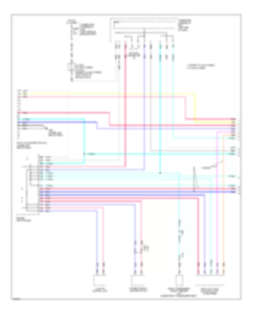
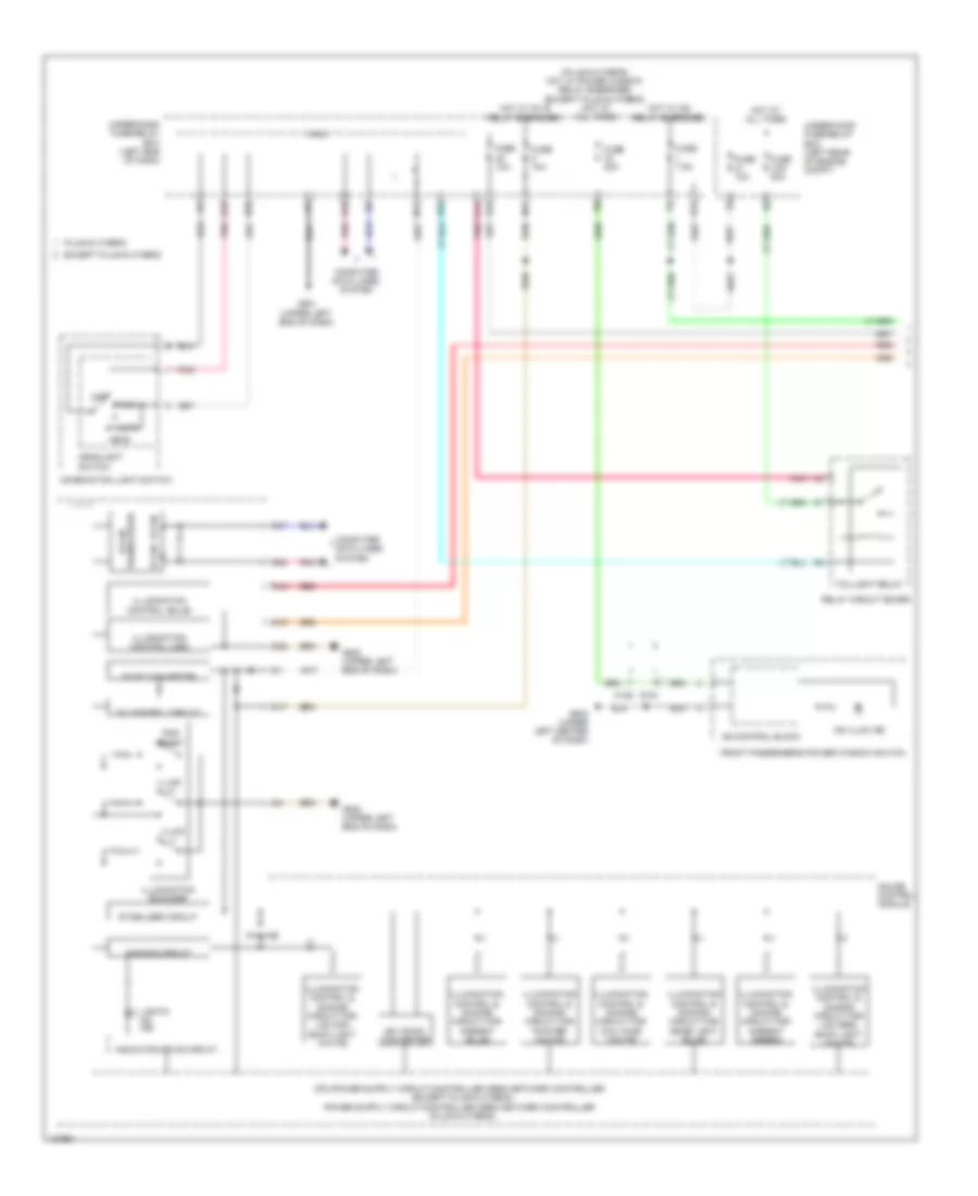
Automatic A/C Wiring Diagram, Plug-In Hybrid (1 of 4) for Honda Accord Plug-In 2014
List of elements for Automatic A/C Wiring Diagram, Plug-In Hybrid (1 of 4) for Honda Accord Plug-In 2014:
- (in auxiliary under-hood fuse/relay box a) blower motor relay
- 3-way valve motor (lower rear of engine compt)
- A10
- A11
- A12
- A13
- A14
- A15
- A16
- A17
- A18
- A19
- A20
- A21
- A22
- A23
- A24
- A25
- A26
- A27
- A28
- A29
- A30
- A31
- A32
- Blower motor (under right side of dash)
- C104
- C113
- C114
- C204
- Center
- Climate control unit
- Computer data lines system
- Defogger system
- Evaporator temperature sensor (in hvac evaporator assembly)
- Fuse 10a
- Fuse 7.5a
- G301 (under left headlight assembly)
- G401 (left kick panel)
- G506 (under right center of dash)
- Heater core temperature sensor (right side of hvac unit)
- Hot in on or start
- Humidity/in-car temperature sensor (left center of dash)
- Interior lights system
- J/c c003 (right center of dash)
- Junction box
- M11
- Outside air temperature sensor (behind center of front bumper)
- Pnk
- Power transistor (bottom center of hvac unit)
- Rear window defogger switch/ power mirror defogger switch
- Red
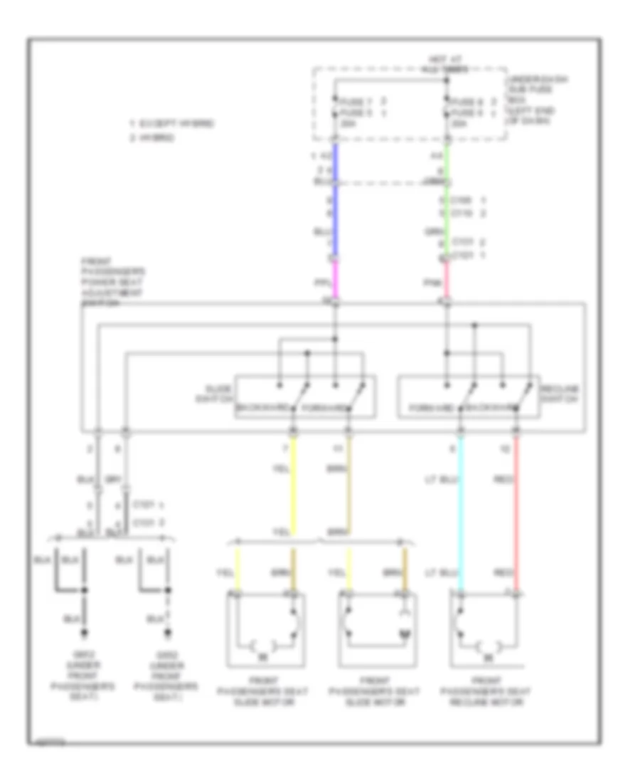
- Seats system
- Sunlight sensor (top middle of dash)
- Under-dash fuse/relay box (left end of dash)
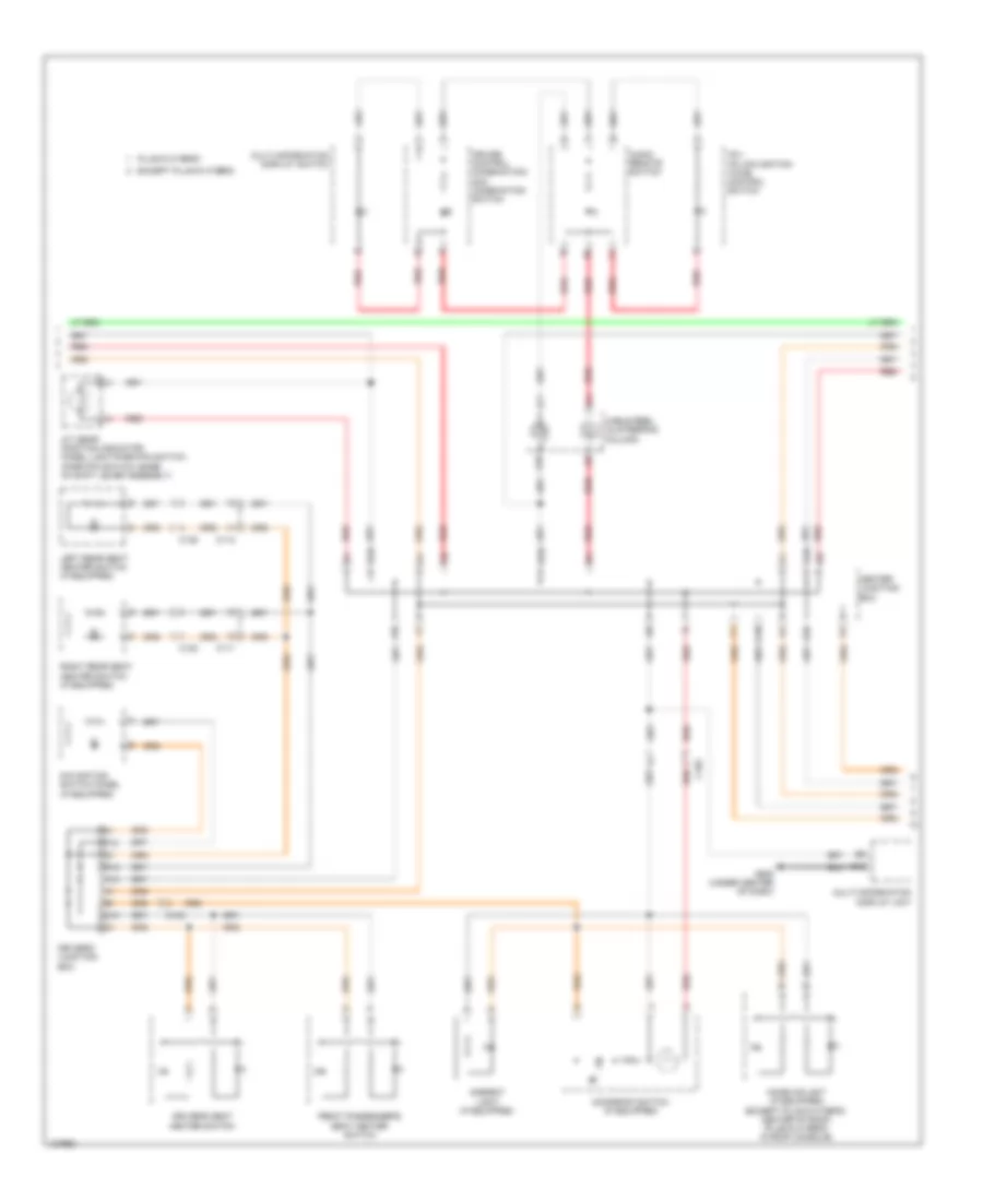
Automatic A/C Wiring Diagram, Plug-In Hybrid (2 of 4) for Honda Accord Plug-In 2014
List of elements for Automatic A/C Wiring Diagram, Plug-In Hybrid (2 of 4) for Honda Accord Plug-In 2014:
- (in under-dash relay holder b) a/c main relay
- A32
- A36
- B10
- B11
- B12
- B13
- B14
- B15
- B16
- B17
- B18
- B19
- B20
- Battery condition monitor module (top right rear of battery pack assembly)
- C10
- C104
- C114
- C118
- C126
- C30
- C401
- Climate control unit
- Computer data lines system
- Defogger system
- Driver's air mix control motor (left side of hvac unit)
- Fuse 10a
- Fuse 14-1 40a
- G506 (under right center of dash)
- G801 (top left center of battery pack assembly)
- Hot at all times
- J/c c010 (top right center of battery pack assembly)
- J/c c012 (top left center of battery pack assembly)
- Mode control motor (right side of hvac unit)
- Passenger's air mix control motor (lower right side of hvac unit)
- Pnk
- Recirculation control motor (right side of blower housing)
- Red
- S10
- Seats system
- Under-dash fuse/relay box (left end of dash)
- Under-hood fuse/relay box (left rear of engine compt)
Automatic A/C Wiring Diagram, Plug-In Hybrid (3 of 4) for Honda Accord Plug-In 2014
List of elements for Automatic A/C Wiring Diagram, Plug-In Hybrid (3 of 4) for Honda Accord Plug-In 2014:
- (lower right rear of engine compt) electrical coolant heater
- (under left headlight assembly) g301
- A/c compressor (left front of engine)
- B13
- B14
- B19
- C104
- C205
- C207
- Computer data lines system
- Electric heater coolant pump a (left rear of engine compt)
- Electric heater coolant pump b (left rear of engine compt)
- Electric motor control module coolant pump (bottom left rear of traction/ generator motor assembly)
- Electric motor control module coolant pump relay circuit
- Electric powertrain coolant temperature sensor
- Engine controls system
- Ewp heater relay
- G101 (left rear of engine)
- G201 (under right headlight assembly)
- G301 (under left headlight assembly)
- Ighld 1 relay circuit
- J/c c007 (left front of engine compt)
- J/c c013 (left side of transmission)
- J/c c203 (left front of engine compt)
- Motor control module
- Pcu (top of traction/ generator motor assembly)
- Pnk
- Red
- Relay circuit board
- Tan
Automatic A/C Wiring Diagram, Plug-In Hybrid (4 of 4) for Honda Accord Plug-In 2014
List of elements for Automatic A/C Wiring Diagram, Plug-In Hybrid (4 of 4) for Honda Accord Plug-In 2014:
- (under left headlight assembly) g301
- 5v control circuit
- 5v line
- A/c pressure sensor (lower right front of engine compt)
- A10
- A15
- A17
- A19
- A20
- A27
- A30
- A31
- A46
- B-can h
- B-can l
- B32
- C201
- C41
- Computer data lines system
- Cooling fan motor (behind radiator)
- Cpu/ipd
- Dc-dc convertor
- E23
- Ect sensor 1 (left rear of engine)
- Ect sensor 2 (on radiator lower left outlet)
- Engine controls system
- F-can h
- F-can l
- Fuse 10a
- Fuse 15a
- Fuse 2-6 30a
- Fuse 7.5a
- G502 (upper left end of dash)
- Gauge control module
- Hot at all times
- J/c c007 (left front of engine compt)
- J/c c203 (left front of engine compt)
- M12
- Pcm (left front of engine compt)
- Pgm-fi sub-relay
- Pnk
- Red
- Rfc relay
- Transceiver b-can
- Transceiver f-can
- Under-dash fuse/relay box (left end of dash)
- Under-hood fuse/relay box (left rear of engine compt)
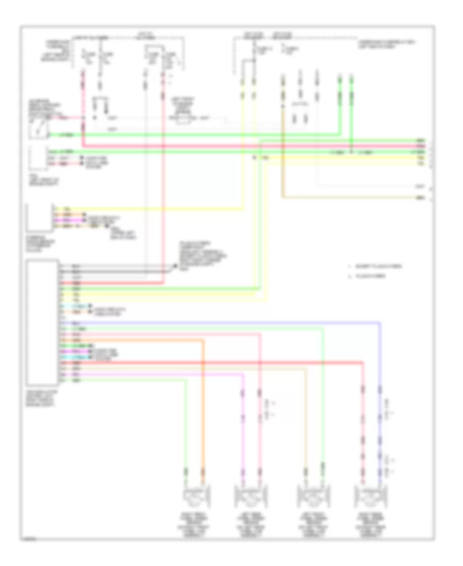
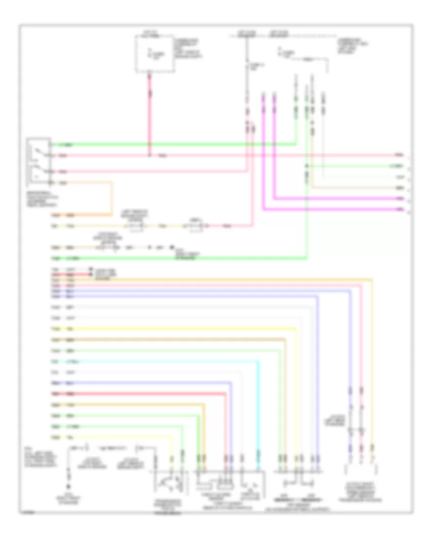
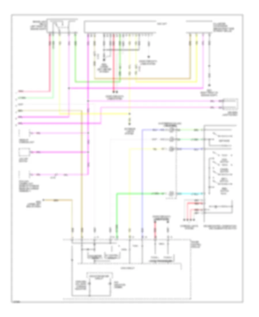
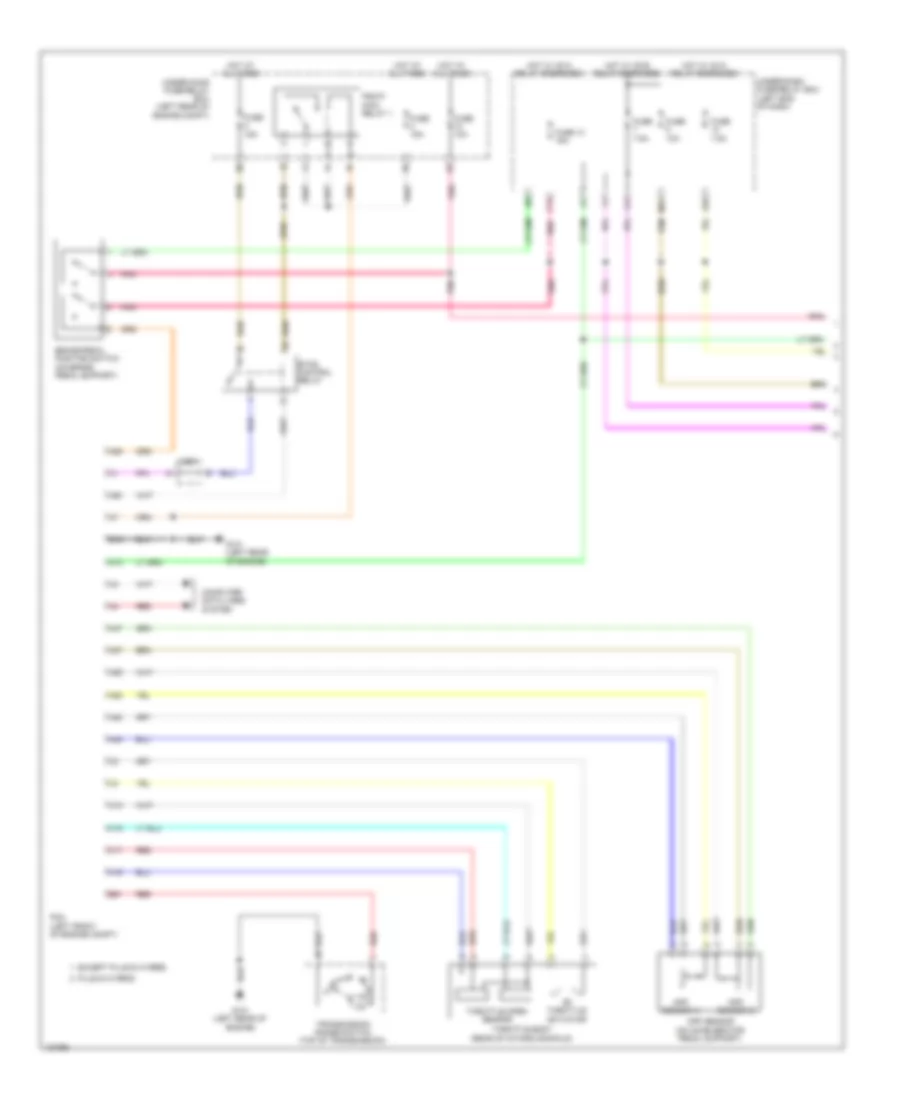
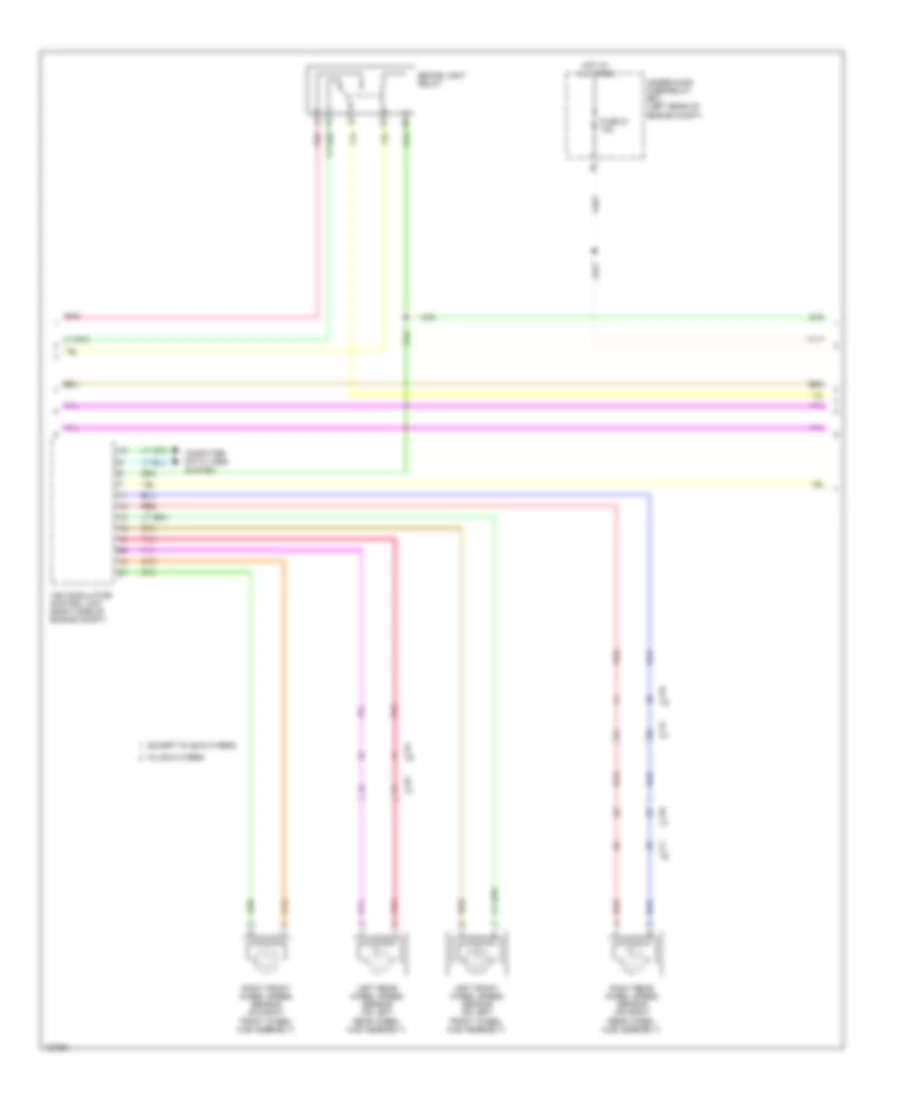
ANTI-LOCK BRAKES
Anti-Lock Brakes Wiring Diagram, Except Hybrid for Honda Accord Plug-In 2014
List of elements for Anti-Lock Brakes Wiring Diagram, Except Hybrid for Honda Accord Plug-In 2014:
- (on brake pedal support) brake pedal position switch
- (right front of engine compt) g202
- 3.5l 2.4l
- A10
- A11
- A17
- A19
- A20
- A25
- A37
- Abs ind
- Brake fluid level switch (on brake fluid reservoir)
- Brake ind (red)
- Brake system ind
- C105
- C109
- C112
- C122
- C129
- Computer data lines system
- Coupe
- Driver's junction box
- E23
- E26
- Exterior lights system
- F-can h
- F-can l
- F-can transceiver
- Forced turning off circuit
- Forced turning on circuit
- Fuse 10 7.5a
- Fuse 10a
- Fuse 2-6 40a
- Fuse 2-7 30a
- Fuse 5 7.5a
- G301 (behind left side of front bumper)
- G502 (upper left end of dash)
- G503 (under left center of dash)
- Gauge control module
- Hot at all times
- Hot in on or start
- Indicator drive circuit
- Interior lights system
- Left front wheel speed sensor (on left front wheel hub assembly)
- Left rear wheel speed sensor (on left rear wheel hub assembly)
- M11
- M12
- Main circuit
- Micu
- Parking brake switch
- Pcm (3.5l: right side of engine compt) (2.4l: left side of engine compt)
- Pnk
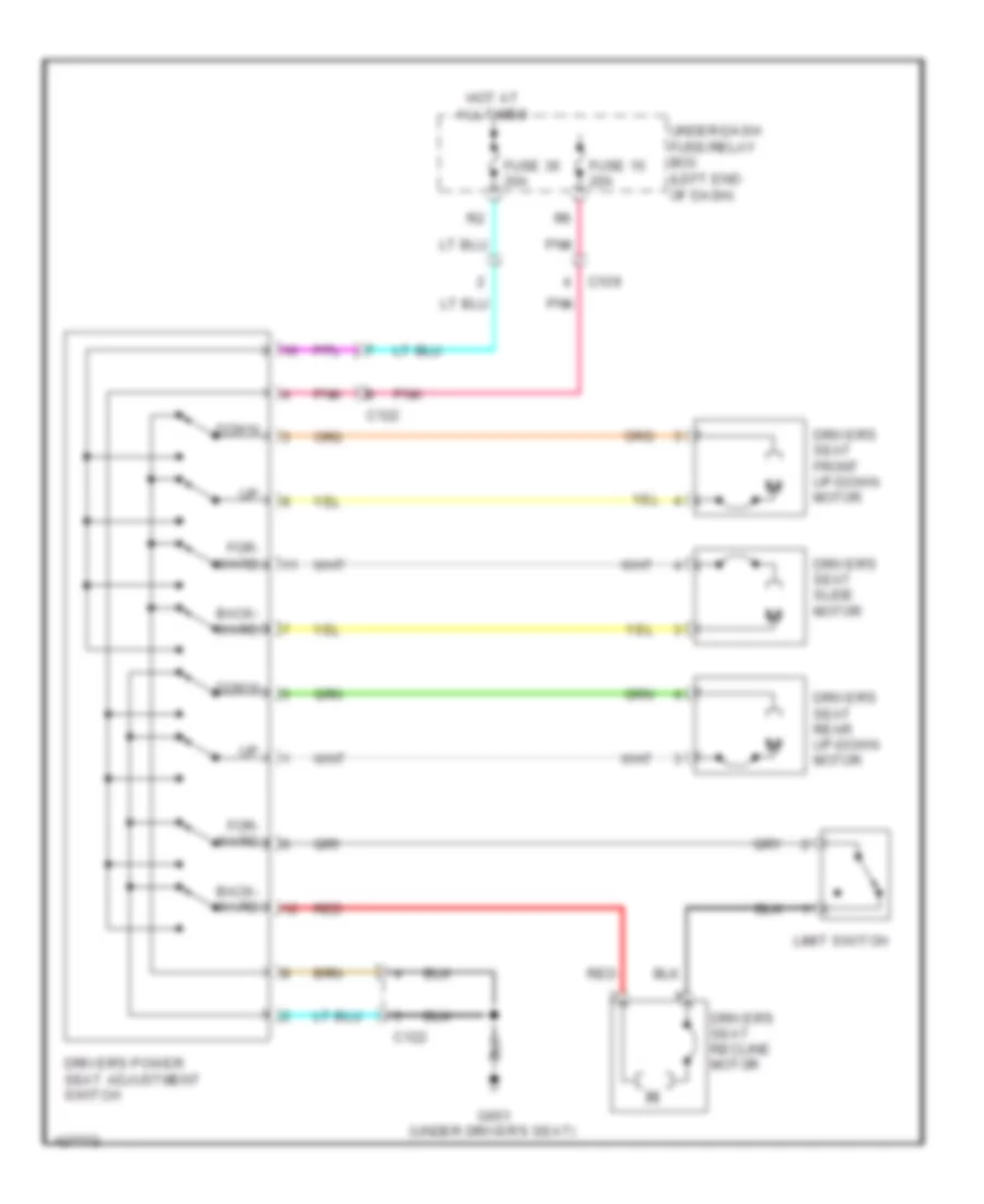
- Power seat control unit (under driver's seat)
- R14
- Red
- Right front wheel speed sensor (on right front wheel hub assembly)
- Right rear wheel speed sensor (on right rear wheel hub assembly)
- Sedan
- Steering angle sensor (in steering column)
- Touring
- Under-dash fuse/relay box (left end of dash)
- Under-hood fuse/relay box (left side of engine compt)
- Vsa ind
- Vsa modulator control unit (right side of engine compt)
- Vsa off ind
- Vsa off switch
- W/ memory
Anti-Lock Brakes Wiring Diagram, Hybrid (1 of 2) for Honda Accord Plug-In 2014
List of elements for Anti-Lock Brakes Wiring Diagram, Hybrid (1 of 2) for Honda Accord Plug-In 2014:
- (left front of engine compt) j/c c012
- (on brake pedal support) brake pedal position switch
- (plug-in hybrid: under right headlight assembly) (except plug-in hybrid: right front corner of engine compt) g202
- A13
- C110
- C111
- C117
- C119
- C127
- C131
- Computer data lines system
- E23
- E26
- Except plug-in hybrid
- Fuse 10 7.5a
- Fuse 10a
- Fuse 12-4 40a
- Fuse 2-5 12-6 30a
- Fuse 5 10a
- G502 (upper left end of dash)
- Hot at all times
- Hot in on or start
- Left front wheel speed sensor (on left front wheel hub assembly)
- Left rear wheel speed sensor (on left rear wheel hub assembly)
- M11
- M12
- Pcm (left front of engine compt)
- Plug-in hybrid
- Pnk
- R14
- Red
- Right front wheel speed sensor (on right front wheel hub assembly)
- Right rear wheel speed sensor (on right rear wheel hub assembly)
- Steering angle sensor (in steering column)
- Under-dash fuse/relay box (left end of dash)
- Under-hood fuse/relay box (left rear of engine compt)
- Vsa modulator control unit (right side of engine compt)
Anti-Lock Brakes Wiring Diagram, Hybrid (2 of 2) for Honda Accord Plug-In 2014
List of elements for Anti-Lock Brakes Wiring Diagram, Hybrid (2 of 2) for Honda Accord Plug-In 2014:
- (on brake
- (upper left end
- A10
- A11
- A17
- A19
- A20
- Abs ind
- Abs ind (led)
- Acc unit (right center of dash)
- B19
- Brake fluid
- Brake light relay
- Brake system ind
- Brake system ind (led)
- Brake warning (led)
- Brake warning (red)
- C112
- C113
- C113 c112
- Computer data lines system
- Driver's junction box
- Except plug-in hybrid
- Exterior lights system
- F-can h
- F-can l
- F-can transceiver
- Fluid reservoir)
- Forced turning off circuit
- Forced turning on circuit
- G301 (except plug-in hybrid: behind left side of front bumper) (plug-in hybrid: under left headlight assembly)
- G502
- G502 (upper left end of dash)
- Gauge control module
- Indicator drive circuit
- Interior
- Keyless access control unit (left side of dash)
- Level switch
- Lights system
- Of dash)
- Parking brake switch (base of parking brake lever assembly)
- Plug-in hybrid
- Pnk
- Red
- Touring & plug-in hybrid
- Vsa ind
- Vsa ind (led)
- Vsa off ind
- Vsa off ind (led)
- Vsa off switch
Electric Servo Brake System Wiring Diagram, Hybrid for Honda Accord Plug-In 2014
List of elements for Electric Servo Brake System Wiring Diagram, Hybrid for Honda Accord Plug-In 2014:
- (left kick panel)
- (right kick panel) g403
- 10a
- 40a
- 7.5a
- A10
- A11
- A17
- A19
- A20
- B10
- B11
- B12
- B13
- B14
- B15
- B16
- Brake pedal stroke sensor (on brake pedal support)
- Brake system indicator (led)
- Brake warning indicator (led)
- C128
- C132
- C208
- Circuit turning-on forced
- Computer data lines system
- Converter dc-dc
- D22
- Driver's door switch (at left "b" pillar)
- E23
- E26
- Electric servo brake control unit (right end of dash)
- Except plug-in hybrid
- F-can h
- F-can l
- Fuse
- Fuse 2-2
- Fuse 7.5a
- G401
- G502 (upper left end of dash)
- Gauge control module
- Hot at all times
- Hot w/ accessory sub relay energized
- Hot w/ ig1a relay energized
- Hot w/ ig1b relay energized
- Indicator driver circuit
- J/c c010 (except plug-in hybrid) j/c c008 (plug-in hybrid) (except plug-in hybrid: left side of dash) (plug-in hybrid: left center of dash)
- J/c c012 (left front of engine compt)
- Lower hydraulic pressure sensor
- M11
- M12
- Master cut valve
- Micu
- Motor
- Motor angle sensor
- Pcm (left front of engine compt)
- Pedal feel simulator (left rear of engine compt)
- Pedal force simulator valve
- Plug-in hybrid
- Pnk
- Red
- Tandem motor cylinder (right rear of engine compt)
- Transceiver f-can
- Under-dash fuse/ relay box (left end of dash)
- Under-hood fuse/relay box (left rear of engine compt)
- Upper hydraulic pressure sensor
ANTI-THEFT
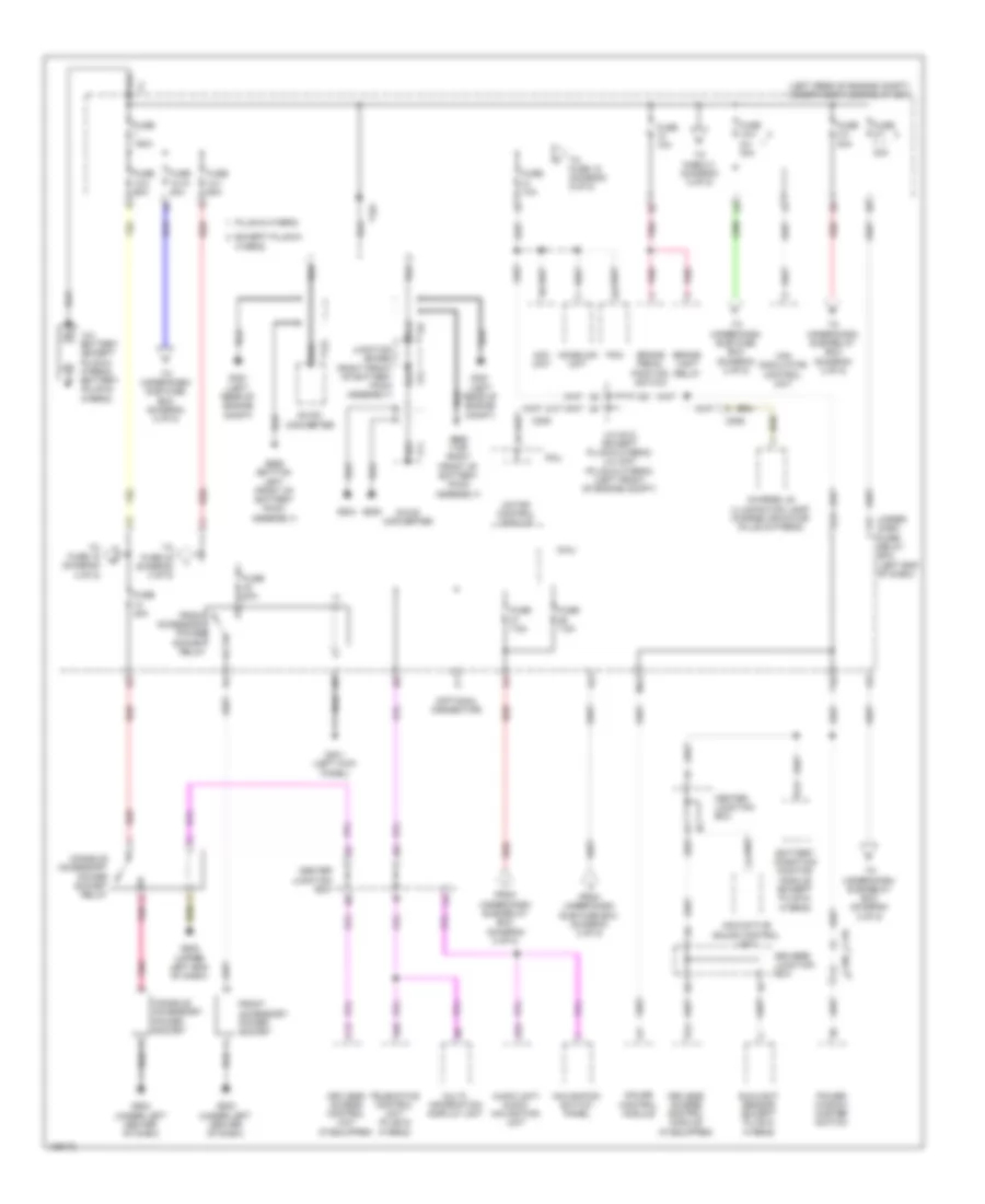
Forced Entry Wiring Diagram, Except Hybrid (1 of 6) for Honda Accord Plug-In 2014
List of elements for Forced Entry Wiring Diagram, Except Hybrid (1 of 6) for Honda Accord Plug-In 2014:
- 2.4l
- 2.4l coupe & 3.5l coupe
- 3.5l
- 3.5l sedan
- A17
- A21
- A27
- A33
- A38
- A49
- A50
- A51
- Accessory sub relay
- C10
- C102
- C106
- C11
- C112
- C12
- C13
- C14
- C15
- C16
- C17
- C18
- C19
- C20
- C21
- C22
- C23
- C24
- Center junction box
- Clutch pedal position switch a (m/t)
- Clutch pedal position switch b (m/t)
- Computer data lines system
- G401 (left kick panel)
- G501 (upper left end of dash)
- G603 (coupe: center rear of luggage compt) (sedan: left rear of luggage compt)
- Ig1a relay
- Ig1b relay
- Ig2 relay
- Keyless access control unit (if equipped) (left side of dash)
- Pcm (2.4l: left side of engine compt) (3.5l: right side of engine compt)
- Pnk
- Red
- Smart buzzer
- Steering lock (on steering column)
- Under-dash sub-relay box
Forced Entry Wiring Diagram, Except Hybrid (2 of 6) for Honda Accord Plug-In 2014
List of elements for Forced Entry Wiring Diagram, Except Hybrid (2 of 6) for Honda Accord Plug-In 2014:
- (park-pin switch: base of shift lever assembly) (sedan) a/t gear position indicator panel light/park- pin switch
- 3.5l coupe
- A17
- A30
- A31
- A32
- B-can h
- B-can l
- B-can transceiver
- Brake indicator (red)
- Computer data lines system
- D20
- D34
- Dc-dc converter
- Door indicator
- Driver's junction box
- E15
- E17
- E23
- E24
- Exterior lights system
- F10
- F12
- Fuse 10a
- Fuse 12-1 60a
- Fuse 12-3 30a
- Fuse 12-4 20a
- Fuse 125a
- Fuse 20a
- Fuse 7.5a
- G301 (behind left side
- G502 (upper left end of dash)
- G503 (under left center of dash)
- Gauge control module
- Headlights system
- Hot at all times
- Indicator drive circuit
- Keyless access indicator
- M10
- M11
- M12
- Main circuit
- Malfunction indicator
- Micu
- Of front bumper)
- P12
- P22
- P24
- Parking brake switch
- Pnk
- Red
- S10
- Security hood switch (on engine compt hood lock/ latch assembly)
- Security indicator
- Stabilize circuit
- T10
- Under- dash fuse/ relay box (left end of dash)
- Under- hood fuse/ relay box (left side of engine compt)
Forced Entry Wiring Diagram, Except Hybrid (3 of 6) for Honda Accord Plug-In 2014
List of elements for Forced Entry Wiring Diagram, Except Hybrid (3 of 6) for Honda Accord Plug-In 2014:
- (on brake pedal support) brake pedal position switch
- (sedan)
- C105
- C109
- C120
- C122
- C130
- Center junction box
- D11
- D16
- D29
- Door lock knob switch
- Door unlock relay
- Driver's junction box
- E34
- Fuse 10a
- Fuse 20a
- Fuse 7.5a
- G601 (left kick panel)
- G652 (under front passenger's seat)
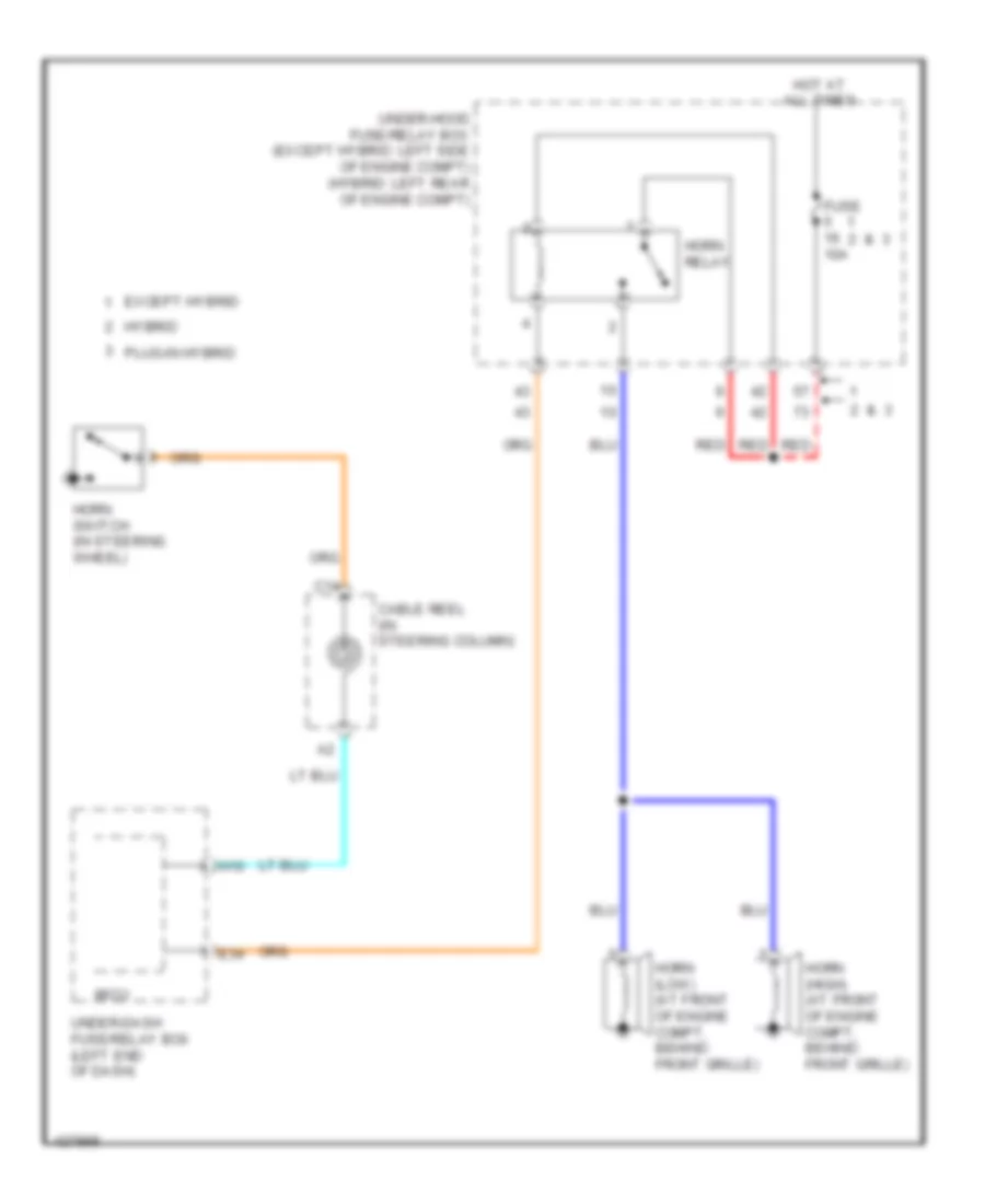
- Horns system
- Hot at all times
- Key
- Left rear door lock actuator/knob switch
- Lock
- Lock relay
- Micu
- P11
- Pnk
- Power seat control unit (3.5l coupe) (under driver's seat)
- Red
- Right rear door lock actuator/knob switch (sedan)
- S17
- Under- dash fuse/ relay box (left end of dash)
- Unlock
- Unlock relay
Forced Entry Wiring Diagram, Except Hybrid (4 of 6) for Honda Accord Plug-In 2014
List of elements for Forced Entry Wiring Diagram, Except Hybrid (4 of 6) for Honda Accord Plug-In 2014:
- C104
- C105
- C107
- C110
- C126
- Center junction box
- Control unit
- Coupe
- D22
- D23
- Door lock knob
- Door lock knob switch
- Driver's door key cylinder switch
- Driver's door lock actuator/ knob switch/key cylinder switch
- Driver's door lock knob switch
- Except sport
- Front passenger's door lock actuator/knob switch
- Front passenger's power window switch
- G501 (upper left end of dash)
- G506 (under center of dash)
- Key
- Lock
- Micu
- Moonroof control unit/motor (right front of roof)
- P10
- Pnk
- Red
- S13
- S14
- Sedan
- Sport
- Under- dash fuse/ relay box (left end of dash)
- Unlock
Forced Entry Wiring Diagram, Except Hybrid (5 of 6) for Honda Accord Plug-In 2014
List of elements for Forced Entry Wiring Diagram, Except Hybrid (5 of 6) for Honda Accord Plug-In 2014:
- A/t
- C106
- C110
- C204
- C207
- Computer data lines system
- Control unit
- Coupe
- Cvt
- Driver's door lock switch
- Driver's door switch (at left front "b" pillar)
- Except sport
- Front passenger's door switch (at right front "b" pillar)
- G101 (right front of engine)
- G501 (upper left end of dash)
- G603 (coupe: center rear of luggage compt) (sedan: left rear of luggage compt)
- J/c c012 (left rear of engine compt)
- J/c c013 (top right side of engine)
- Left rear door switch (sedan) (at left rear "c" pillar)
- Lock
- Pnk
- Power mirror switch
- Power window master switch
- Power windows system
- Red
- Right rear door switch (sedan) (at right rear "c" pillar)
- Sedan
- Sport
- Transmission range switch
- Transmission range switch (top of transmission)
- Trunk lid outer handle switch
- Unlock
Forced Entry Wiring Diagram, Except Hybrid (6 of 6) for Honda Accord Plug-In 2014
List of elements for Forced Entry Wiring Diagram, Except Hybrid (6 of 6) for Honda Accord Plug-In 2014:
- (upper left end of dash) g502
- 5v reg
- A10
- A11
- A12
- A13
- A14
- A15
- A16
- A17
- A18
- A19
- A20
- A21
- A22
- A23
- A24
- A25
- A26
- A27
- A28
- A29
- A30
- A31
- A32
- B10
- B11
- B12
- B13
- B14
- B15
- B16
- B17
- B18
- B19
- B20
- B21
- B22
- B23
- B24
- B25
- B26
- B27
- B28
- C103
- C106
- C108
- C109
- C112
- C117
- C122
- Computer data lines system
- Door lf antenna
- Driver's door outer handle
- Driver's junction box
- Engine start/stop switch
- Front interior lf antenna (lower center of dash)
- Front passenger's door outer handle
- G501 (upper left end of dash)
- G502 (upper left end of dash)
- G503 (under left center of dash)
- I/f bilizer immo-
- Keyless access control unit (if equipped) (left side of dash)
- Lf ant
- Lock switch
- Pnk
- Power seat control unit (sedan) (under driver's seat)
- Rear bumper lf antenna (behind center of rear bumper)
- Rear interior lf antenna (under middle of rear shelf)
- Rear shelf lf antenna (under center rear of rear shelf)
- Red
- Touch sensor
Forced Entry Wiring Diagram, Hybrid (1 of 6) for Honda Accord Plug-In 2014
List of elements for Forced Entry Wiring Diagram, Hybrid (1 of 6) for Honda Accord Plug-In 2014:
- (behind left side of rear bumper) smart buzzer
- A17
- Accessory sub relay
- C10
- C102
- C104
- C105
- C11
- C112
- C113
- C12
- C13
- C14
- C15
- C16
- C17
- C18
- C19
- C20
- C21
- C22
- C23
- C24
- Center junction box
- Computer data lines system
- Electric steering lock (on steering column)
- Except plug-in hybrid
- G501 (upper left end of dash)
- G603 (left rear of luggage compt)
- Ig1a relay
- Ig1b relay
- Ig2 relay
- Keyless access control unit (if equipped) (left side of dash)
- Pcm (left front of engine compt)
- Plug-in hybrid
- Pnk
- Red
- Under-dash sub-relay box
Forced Entry Wiring Diagram, Hybrid (2 of 6) for Honda Accord Plug-In 2014
List of elements for Forced Entry Wiring Diagram, Hybrid (2 of 6) for Honda Accord Plug-In 2014:
- (park-pin switch: base of shift lever assembly) a/t gear position indicator panel light/park- pin switch
- A10
- A17
- A30
- A31
- A32
- B-can h
- B-can l
- B-can transceiver
- Brake system indicator
- Computer data lines system
- D20
- D34
- Dc-dc converter
- Driver's junction box
- E15
- E17
- E23
- E24
- Except plug-in hybrid
- Exterior lights system
- F10
- F12
- Forced turning-off circuit
- Forced turning-on circuit
- Fuse 10a
- Fuse 2-7 30a
- Fuse 20a
- Fuse 3-3 30a
- Fuse 7.5a
- G301 (except plug-in hybrid: behind left side of front bumper) (plug-in hybrid: under left headlight assembly)
- G502 (upper left end of dash)
- G503 (under left center of dash)
- Gauge control module
- Headlights system
- Hot at all times
- Immobilizer indicator
- Indicator drive circuit
- J/c c012 (except plug-in hybrid) (left front of engine compt)
- Keyless access system indicator
- M10
- M11
- M12
- Malfunction indicator
- Micu
- P12
- P22
- P24
- Parking brake switch (base of parking brake lever assembly)
- Plug-in hybrid
- Pnk
- Red
- Security hood switch (on engine compt hood lock/ latch assembly)
- Security indicator
- Stabilize circuit
- T10
- Under- dash fuse/ relay box (left end of dash)
- Under-dash sub fuse box (left end of dash)
- Under-hood fuse/relay box (left rear of engine compt)
Forced Entry Wiring Diagram, Hybrid (3 of 6) for Honda Accord Plug-In 2014
List of elements for Forced Entry Wiring Diagram, Hybrid (3 of 6) for Honda Accord Plug-In 2014:
- (on brake pedal support) brake pedal position switch
- C110
- C111
- C122
- C124
- C128
- C130
- Center junction box
- D11
- D16
- D29
- Door lock knob switch
- Driver's junction box
- Driver's unlock relay
- E34
- Except plug-in hybrid
- Fuse 10a
- Fuse 20a
- Fuse 7.5a
- G601 (left kick panel)
- G652 (under front passenger's seat)
- Horns system
- Hot at all times
- Key
- Left rear door lock actuator/knob switch (sedan)
- Lock
- Lock relay
- Micu
- Plug-in hybrid
- Pnk
- Red
- Right rear door lock actuator/knob switch (sedan)
- S17
- Under- dash fuse/ relay box (left end of dash)
- Unlock
- Unlock relay
Forced Entry Wiring Diagram, Hybrid (4 of 6) for Honda Accord Plug-In 2014
List of elements for Forced Entry Wiring Diagram, Hybrid (4 of 6) for Honda Accord Plug-In 2014:
- C105
- C106
- C109
- C110
- C111
- C128
- C132
- Control unit
- D22
- D23
- Door lock knob
- Door lock knob switch
- Driver's door key cylinder switch
- Driver's door lock actuator/ knob switch/key cylinder switch
- Driver's door lock knob switch
- Electro servo brake control unit (right end of dash)
- Except plug-in hybrid
- Front passenger's door lock actuator/knob switch
- Front passenger's power window switch
- G501 (upper left end of dash)
- G503 (under left center of dash)
- Key
- Lock
- Micu
- Plug-in hybrid
- Red
- S13
- S14
- Under- dash fuse/ relay box (left end of dash)
- Unlock
Forced Entry Wiring Diagram, Hybrid (5 of 6) for Honda Accord Plug-In 2014
List of elements for Forced Entry Wiring Diagram, Hybrid (5 of 6) for Honda Accord Plug-In 2014:
- C104
- C105
- C109
- C110
- C203
- Computer data lines system
- Control unit
- Driver's door lock switch
- Driver's door switch (at left front "b" pillar)
- Except plug-in hybrid
- Front passenger's door switch (at right front "b" pillar)
- G101 (left rear of engine)
- G501 (upper left end of dash)
- G603 (left rear of luggage compt)
- Left rear door switch (at left rear "c" pillar)
- Lock
- Plug-in hybrid
- Pnk
- Power mirror switch
- Power window master switch
- Red
- Right rear door switch (at right rear "c" pillar)
- Transmission range switch (top of transmission)
- Trunk lid outer handle switch
- Unlock
Forced Entry Wiring Diagram, Hybrid (6 of 6) for Honda Accord Plug-In 2014
List of elements for Forced Entry Wiring Diagram, Hybrid (6 of 6) for Honda Accord Plug-In 2014:
- (top right rear of battery pack assembly) battery condition monitor module
- (under left center of dash) g503
- 5v reg
- A10
- A11
- A12
- A13
- A14
- A15
- A16
- A17
- A18
- A19
- A20
- A21
- A22
- A23
- A24
- A25
- A26
- A27
- A28
- A29
- A30
- A31
- A32
- B10
- B11
- B12
- B13
- B14
- B15
- B16
- B17
- B18
- B19
- B20
- B21
- B22
- B23
- B24
- B25
- B26
- B27
- B28
- C104
- C105
- C106
- C107
- C108
- C109
- C112
- C113
- C116
- C117
- C125
- C126
- C132
- C401
- Computer data lines system
- Door lf antenna
- Driver's door touch sensor
- Driver's junction box
- Engine start/stop switch (plug-in hybrid) power switch (except plug-in hybrid)
- Except plug-in hybrid
- Front interior lf antenna (under front of center console)
- Front passenger's door touch sensor
- G501 (left side of dash)
- G501 (upper left end of dash)
- G503 (under left center of dash)
- I/f
- Immobilizer
- Keyless access control unit (if equipped) (left side of dash)
- Lf ant
- Lock switch
- Plug-in hybrid
- Pnk
- Power seat control unit/ power seat adjustement switch (under driver's seat)
- Rear bumper lf antenna (behind center of rear bumper)
- Rear interior lf antenna (except plug-in hybrid: under rear of center console) (plug-in hybrid: under center rear of rear shelf)
- Rear shelf lf antenna (except plug-in hybrid: under center rear of rear shelf) (plug-in hybrid: under rear of center console)
- Red
- Touch sensor
Immobilizer Wiring Diagram, Except Hybrid for Honda Accord Plug-In 2014
List of elements for Immobilizer Wiring Diagram, Except Hybrid for Honda Accord Plug-In 2014:
- (left kick panel) g601
- (under center rear of vehicle)
- A10
- A14
- A17
- A19
- A20
- A21
- A30
- A31
- A32
- B-can h
- B-can l
- B12
- C112
- C204
- Center junction box
- Circuit
- Circuit stabilize
- Computer data lines system
- Converter dc-dc
- E11
- E13
- Engine controls system
- F-can h
- F-can l
- F18
- Fuel tank unit (top of fuel tank)
- Fuse 15a
- Fuse 20a
- Fuse 7.5a
- G101 (right front of engine)
- G502 (upper left end of dash)
- G602
- Gauge control module
- Hot at all times
- Hot in on or start
- Immobilizer keyless control unit
- Immobilizer system indicator
- Indicator drive
- M10
- M11
- M12
- Main circuit
- Micu
- Parking brake switch
- Pcm (2.4l: left side of of engine compt) (3.5l: right side of of engine compt)
- Pgm-fi main relay 1
- Pgm-fi main relay 2
- Pnk
- R10
- Red
- T10
- Transceiver b-can
- Transceiver f-can
- Under-dash fuse/relay box (left end of dash)
- Under-hood fuse/relay box (left side of engine compt)
BODY CONTROL MODULES
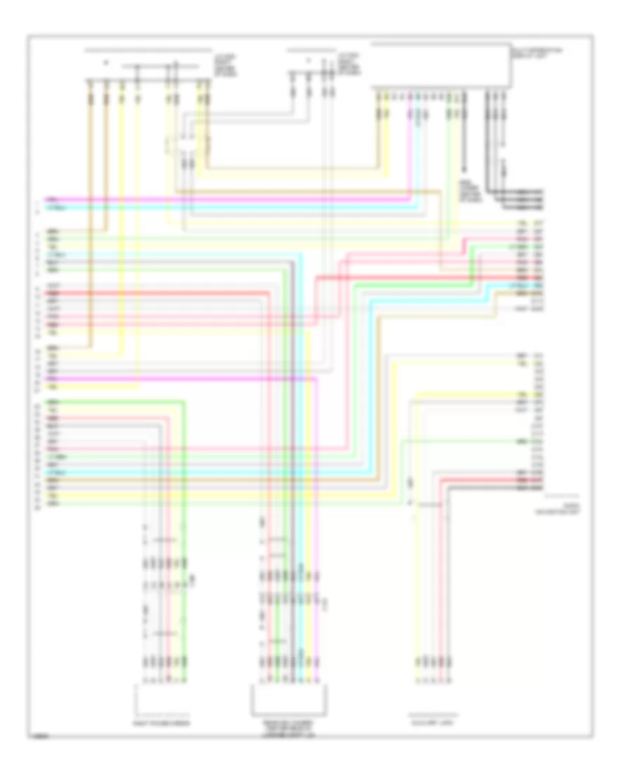
Body Control Modules Wiring Diagram, Except Hybrid (1 of 2) for Honda Accord Plug-In 2014
List of elements for Body Control Modules Wiring Diagram, Except Hybrid (1 of 2) for Honda Accord Plug-In 2014:
- D15
- D22
- D23
- D26
- D29
- D30
- D37
- Diode b
- Diode c
- Door locks & anti-theft systems
- Door locks system
- E15
- E16
- E17
- E21
- E22
- E24
- E25
- E28
- E29
- E34
- Engine controls & transmissions systems
- Exterior lights system
- Fuse (a/t & cvt) 7.5a
- Fuse 10a
- Fuse 7.5a
- G501 (upper left end of dash)
- G601 (left kick panel)
- Headlights system
- Headlights, interior lights & exterior lights systems
- Horns system
- Hot at all times
- Hot in on or start
- Hot w/ accessory sub relay energized
- Interior lights system
- M11
- Memory systems
- Micu
- N11
- N12
- N13
- N14
- N15
- N16
- N17
- N18
- N19
- N20
- Navigation system
- Navigation, mirrors & sound systems
- P10
- P12
- P13
- P17
- P19
- P22
- P23
- P24
- Pnk
- Power distribution system
- Power windows system
- Red
- Reverse relay
- Sound & navigation systems
- Trunk, tailgate, fuel doors system
- Under-dash fuse/relay box (left end of dash)
- Wiper/washer system
Body Control Modules Wiring Diagram, Except Hybrid (2 of 2) for Honda Accord Plug-In 2014
List of elements for Body Control Modules Wiring Diagram, Except Hybrid (2 of 2) for Honda Accord Plug-In 2014:
- (not used)
- (optional connector b)
- (optional connector c)
- Air conditioning system
- Computer data lines system
- D20
- D34
- Door locks & anti-theft systems
- Door locks system
- Door locks, anti-theft & engine controls systems
- Door locks, anti-theft & interior lights systems
- E23
- E31
- E33
- Exterior lights system
- F10
- F12
- F15
- Fuse 10a
- Fuse 15a
- H10
- H12
- Headlights & exterior lights systems
- Headlights system
- Horns system
- Hot at all times
- Interior lights system
- M10
- M12
- Micu
- N10
- P11
- Pnk
- Power distribution system
- R10
- R12
- Red
- S13
- S14
- S17
- T10
- Under-dash fuse/relay box (left end of dash)
- Under-hood fuse/relay box (left side of engine compt)
Body Control Modules Wiring Diagram, Hybrid (1 of 2) for Honda Accord Plug-In 2014
List of elements for Body Control Modules Wiring Diagram, Hybrid (1 of 2) for Honda Accord Plug-In 2014:
- (optional connector c)
- Computer data lines system
- D22
- D23
- D29
- D30
- D37
- Door locks & anti-lock brakes systems
- Door locks system
- E15
- E22
- E23
- E28
- E29
- E34
- Engine controls system
- Exterior lights system
- F12
- Fuse 10a
- Fuse 7.5a
- G401 (left kick panel)
- G501 (upper left end of dash)
- G601 (left kick panel)
- H10
- H12
- Headlights system
- Horns system
- Hot at all times
- Hot w/ acc sub relay energized
- Hot w/ ig1b relay energized
- Hot w/ ig2 relay energized
- Interior lights system
- M10
- M12
- Micu
- N10
- N11
- N12
- N13
- N18
- Navigation system
- P12
- P16
- P19
- P20
- P21
- P22
- P23
- P24
- Pnk
- Power distribution system
- Power windows system
- R12
- S13
- S14
- S17
- T10
- Trunk, tailgate, fuel doors system
- Under-dash fuse/relay box (left end of dash)
- Under-hood fuse/relay box (left rear of engine compt)
- Wiper/ washer system
- Wiper/washer system
Body Control Modules Wiring Diagram, Hybrid (2 of 2) for Honda Accord Plug-In 2014
List of elements for Body Control Modules Wiring Diagram, Hybrid (2 of 2) for Honda Accord Plug-In 2014:
- (optional connector b)
- Anti-lock brakes system
- Computer data lines system
- D20
- D24
- D34
- E17
- E21
- E25
- E31
- E33
- Exterior lights system
- F10
- Fuse 15a
- Headlights system
- Hot at all times
- Interior lights system
- Memory systems
- Micu
- N14
- N15
- N16
- N17
- N19
- N20
- P17
- Pnk
- R10
- Red
- Under-dash fuse/relay box (left end of dash)
- Under-dash sub fuse box (left end of dash)
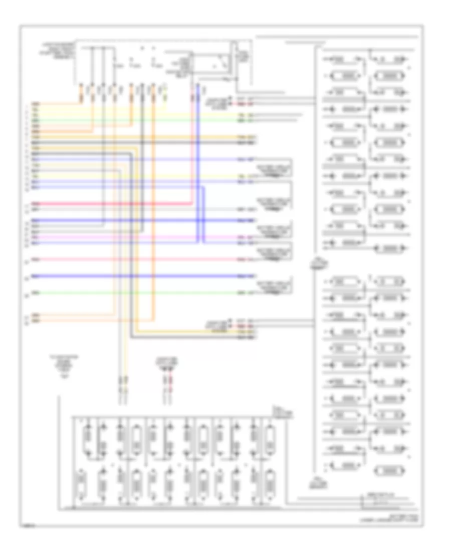
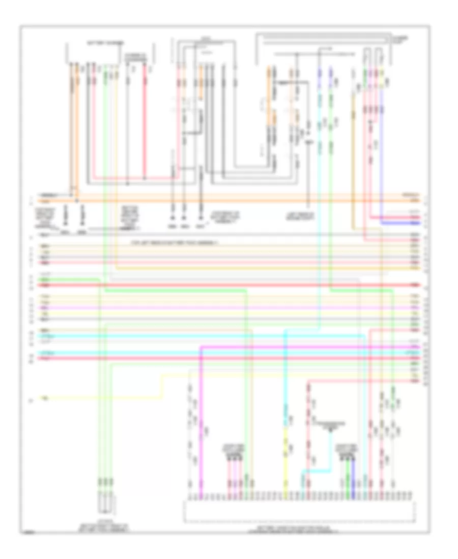
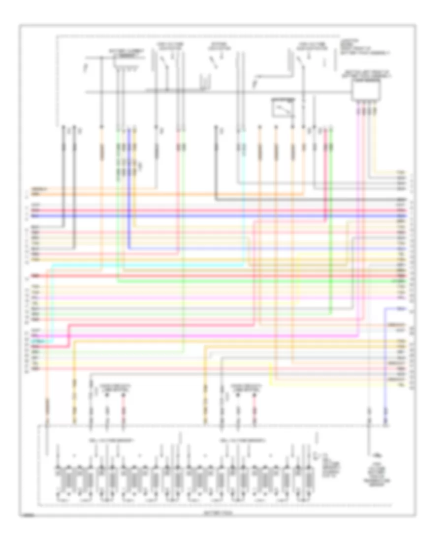
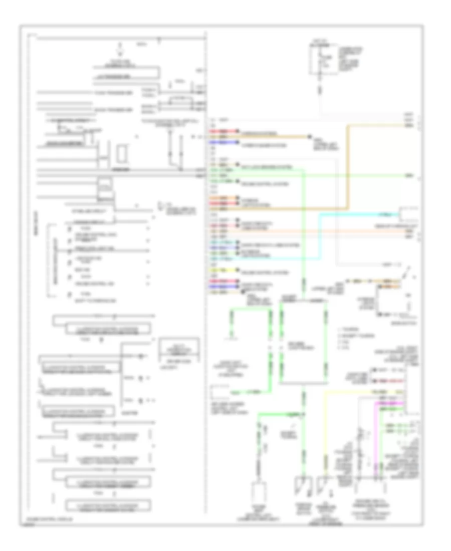
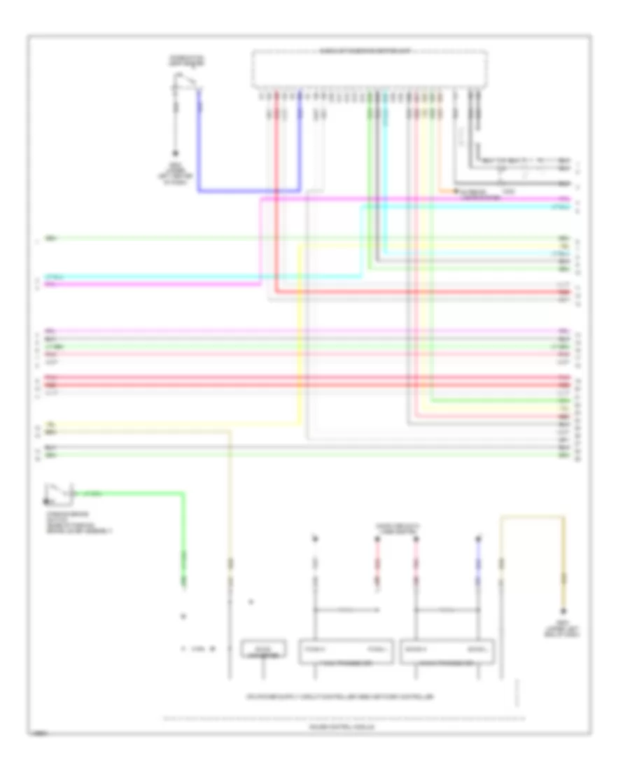
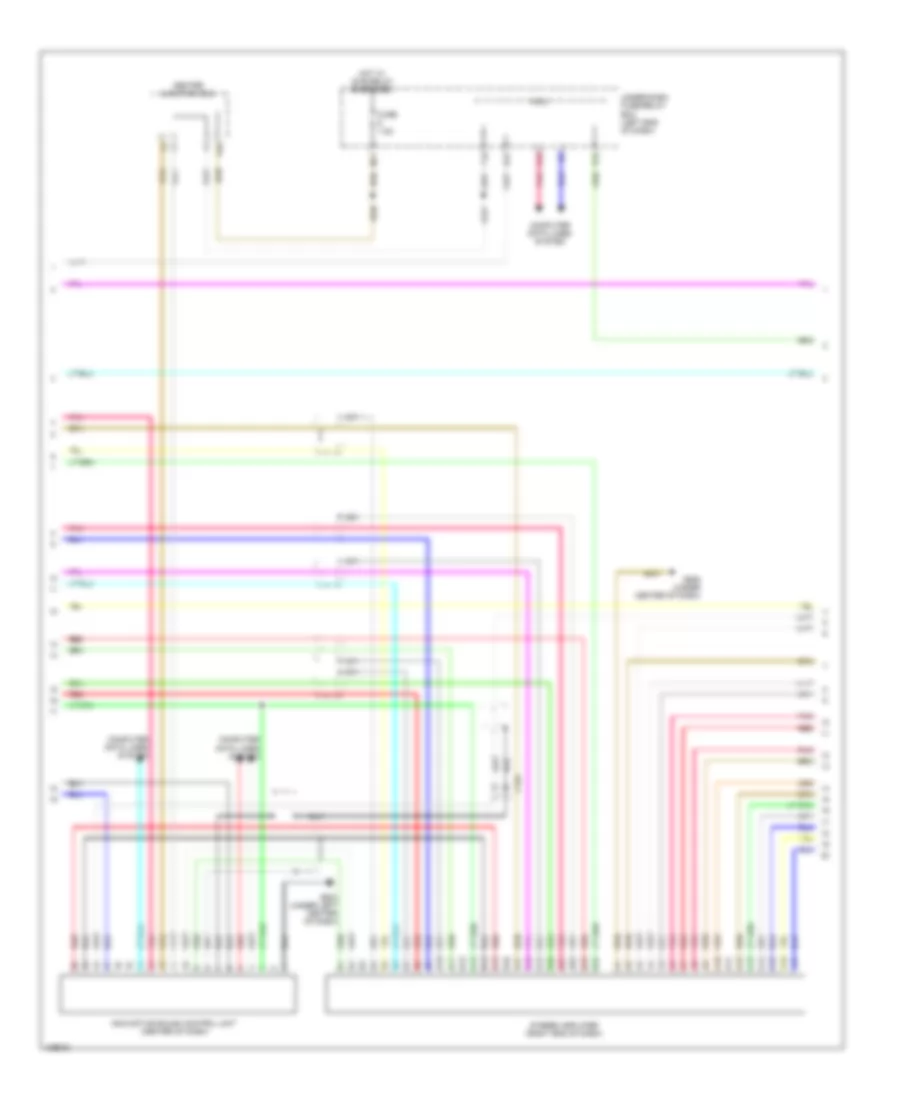
COMPUTER DATA LINES
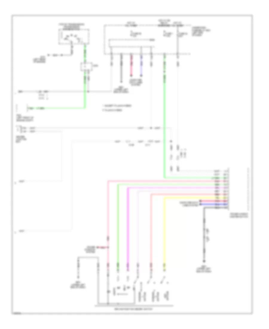
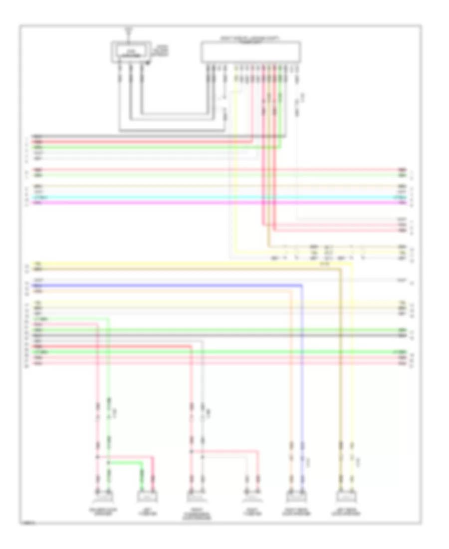
Computer Data Lines Wiring Diagram, Except Hybrid (1 of 4) for Honda Accord Plug-In 2014
List of elements for Computer Data Lines Wiring Diagram, Except Hybrid (1 of 4) for Honda Accord Plug-In 2014:
- A13
- Audio unit/audio navigation unit
- C109
- C110
- C121
- Center junction box
- D30
- Dlc (under left side of dash)
- E23
- Except sport
- F15
- F17
- F18
- Front passenger's weight sensor unit
- Fuse 10a
- G501 (upper left end of dash)
- G601 (left kick panel)
- Hot at all times
- Hvac control unit/ climate control unit
- Immobilizer keyless control unit (sport)
- M10
- M12
- Micu
- Optional connector b
- Pnk
- Power window master switch (if equipped)
- R10
- R12
- Red
- Sport
- T10
- Under-dash fuse/relay box (left end of dash)
- Under-hood fuse/relay box (left side of engine compt)
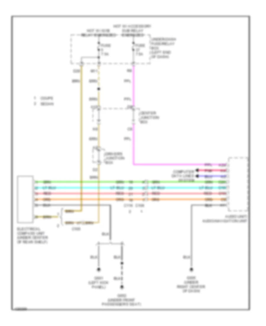
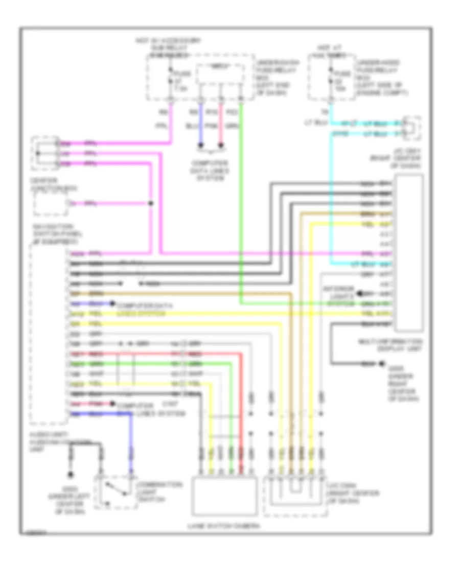
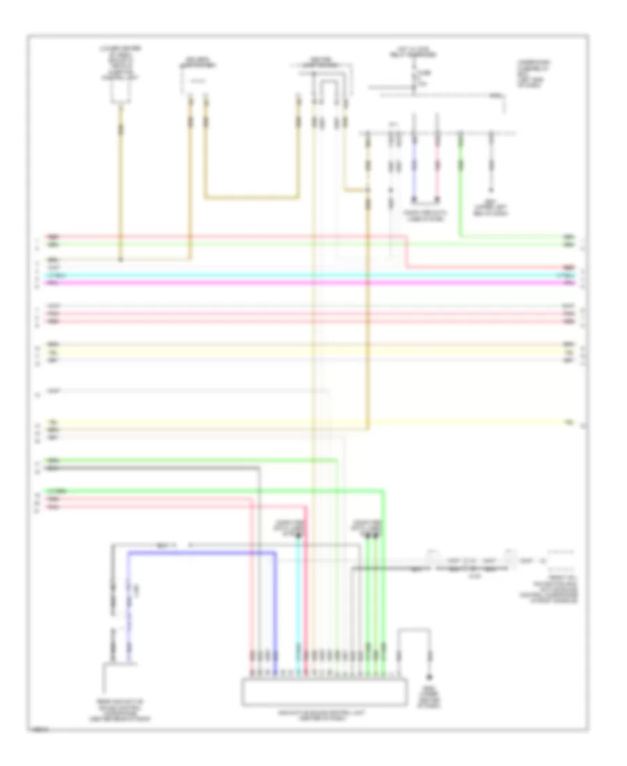
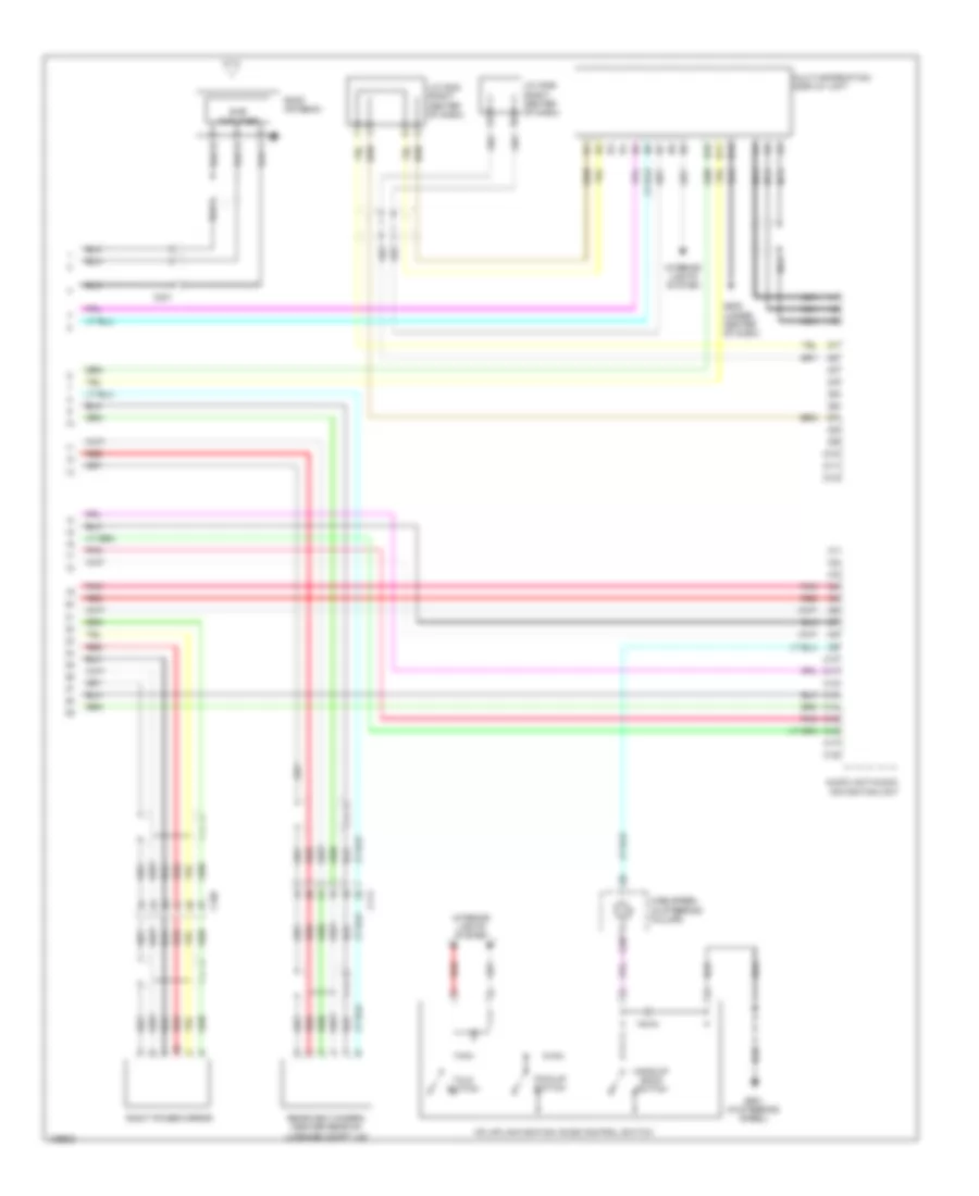
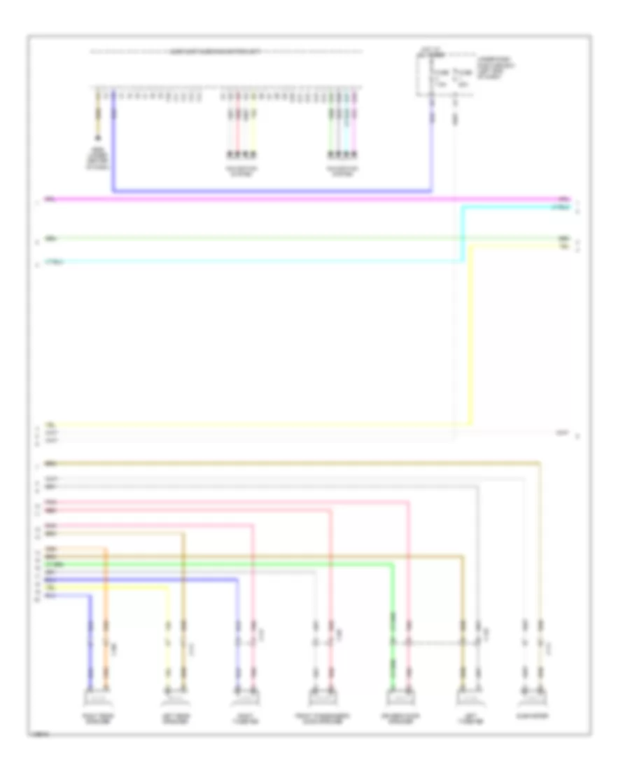
Computer Data Lines Wiring Diagram, Except Hybrid (2 of 4) for Honda Accord Plug-In 2014
List of elements for Computer Data Lines Wiring Diagram, Except Hybrid (2 of 4) for Honda Accord Plug-In 2014:
- (base of interior rearview mirror assembly) (if equipped) fcw/ldw camera unit
- (in steering column) steering angle sensor
- (left side of dash) j/c c021
- (sedan: left front of roof) (coupe) j/c c007 (sedan) j/c c023
- A19
- A20
- A30
- A31
- C112
- C115
- Except sport
- Gauge control module
- Pnk
- Red
- Sport
- Sunlight sensor (top middle of dash)
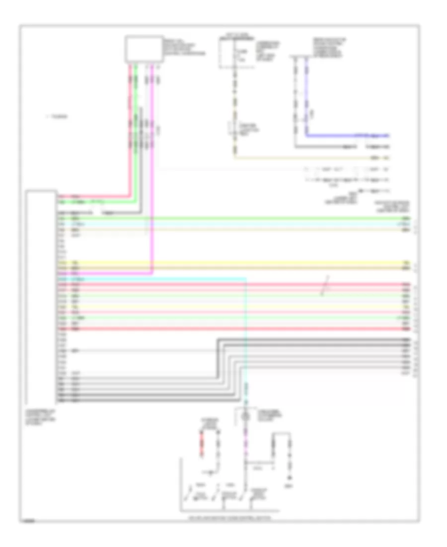
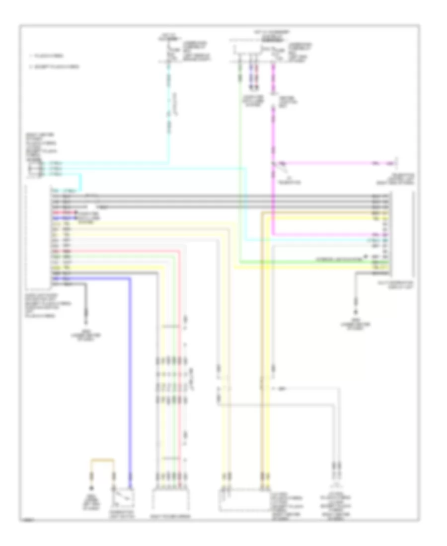
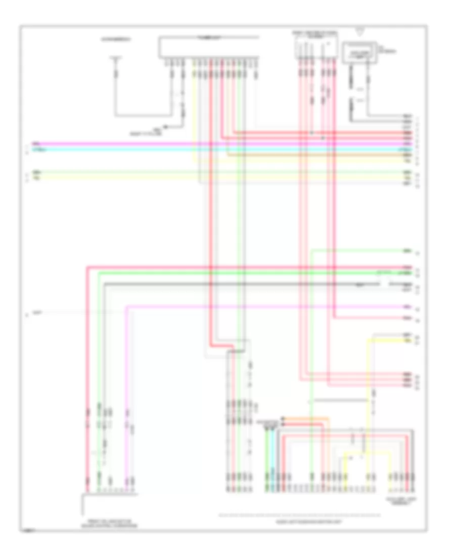
Computer Data Lines Wiring Diagram, Except Hybrid (3 of 4) for Honda Accord Plug-In 2014
List of elements for Computer Data Lines Wiring Diagram, Except Hybrid (3 of 4) for Honda Accord Plug-In 2014:
- (3.5l: right side of engine compt) (2.4l: left side of engine compt) pcm
- (left rear of engine compt) (2.4l) j/c c022 (3.5l) j/c c020
- (right side of engine compt) vsa modulator control unit
- 2.4l
- 3.5l
- A10
- A21
- A29
- A38
- A48
- Anc/ active sound control unit (center of dash)
- C112
- Center junction box
- Pnk
- Red
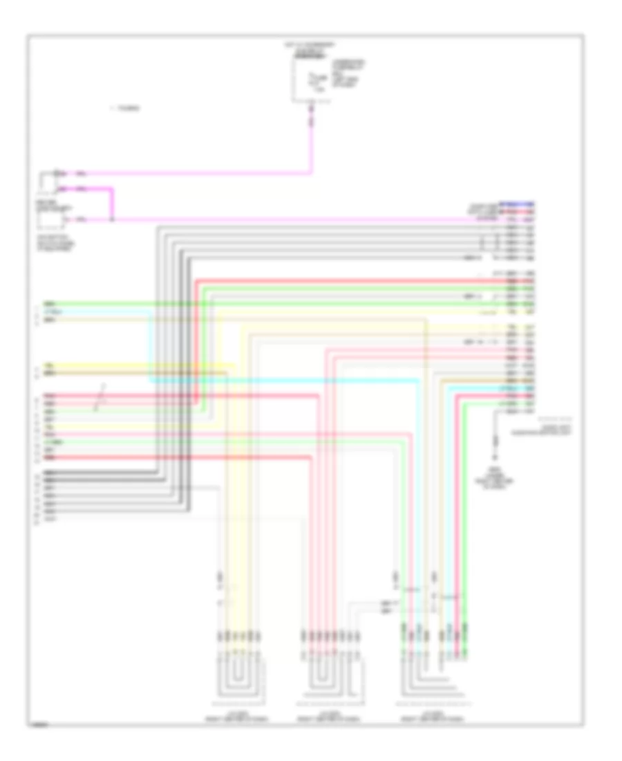
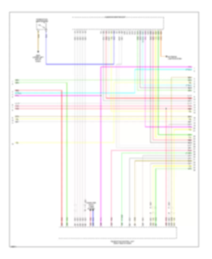
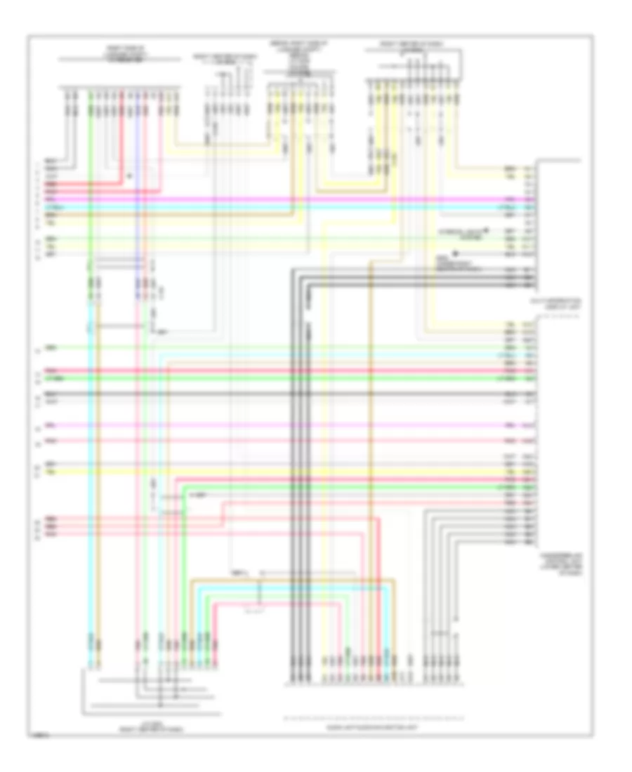
Computer Data Lines Wiring Diagram, Except Hybrid (4 of 4) for Honda Accord Plug-In 2014
List of elements for Computer Data Lines Wiring Diagram, Except Hybrid (4 of 4) for Honda Accord Plug-In 2014:
- (if equipped) acc unit
- (left end of dash) (if equipped) engine mount control unit
- (left side of dash) eps control unit
- A10
- A11
- A20
- A21
- B16
- B17
- B20
- B21
- C109
- C112
- C122
- Driver's junction box
- Except sport
- Keyless access control unit (except sport) (left side of dash)
- Pnk
- Power seat control unit (if equipped) (under driver's seat)
- Red
- Sport
- Srs unit (under front of center console)
Computer Data Lines Wiring Diagram, Hybrid (1 of 5) for Honda Accord Plug-In 2014
List of elements for Computer Data Lines Wiring Diagram, Hybrid (1 of 5) for Honda Accord Plug-In 2014:
- A13
- A30
- A32
- Audio unit/audio navigation unit (if equipped)
- C108
- C109
- C110
- C131
- Center junction box
- Climate control unit
- Data link connector (dlc) (under left end of dash)
- E23
- Except plug-in hybrid
- F17
- F18
- Front passenger's weight sensor unit (under front passenger's seat)
- Fuse 10a
- G501 (upper left end of dash)
- Hot at all times
- J/c c007 (plug-in hybrid) j/c c012 (except plug-in hybrid) (left front of engine compt)
- M10
- M12
- Micu
- Optional connector b
- Plug-in hybrid
- Pnk
- Power window master switch
- R10
- R12
- T10
- Touring
- Under-dash fuse/relay box (left end of dash)
- Under-hood fuse/relay box (left rear of engine compt)
Computer Data Lines Wiring Diagram, Hybrid (2 of 5) for Honda Accord Plug-In 2014
List of elements for Computer Data Lines Wiring Diagram, Hybrid (2 of 5) for Honda Accord Plug-In 2014:
- (in steering column) steering angle sensor
- (right center of dash)
- (right center of dash) (plug-in hybrid) j/c c001 (except plug-in hybrid touring) j/c c009
- (under front of center console) srs unit
- A10
- A20
- A21
- Acoustic vehicle alerting control unit (lower center of dash)
- Can gateway (lower right center of dash)
- Center junction box
- Driver's junction box
- Except plug-in hybrid
- Except touring
- F-can connector (except plug-in hybrid: under left end of dash)
- Fuse 10a
- G505 (under center of dash)
- H10
- Hot w/ ig1b relay energized
- J/c c009 (except plug-in hybrid) j/c c001 (plug-in hybrid)
- M11
- Pnk
- Red
- Touring
- Under-dash fuse/relay box (left end of dash)
Computer Data Lines Wiring Diagram, Hybrid (3 of 5) for Honda Accord Plug-In 2014
List of elements for Computer Data Lines Wiring Diagram, Hybrid (3 of 5) for Honda Accord Plug-In 2014:
- (except plug-in hybrid: left center front of roof) (plug-in hybrid: left front of roof) (plug-in hybrid) j/c c005 (except plug-in hybrid) j/c c015
- (except plug-in hybrid: left side of dash) (plug-in hybrid: left center of dash) (plug-in hybrid) j/c c008 (except plug-in hybrid) j/c c010
- (left front of engine compt) (plug-in hybrid) j/c c007 (except plug-in hybrid) j/c c012
- (plug-in hybrid: in roof console) (except plug-in hybrid: center rear of roof) fcw/ldw camera unit
- A10
- A11
- A19
- A20
- A30
- A31
- Acc unit (if equipped)
- C112
- C113
- C115
- C116
- Electric servo brake control unit (right end of dash)
- Except plug-in hybrid
- Gauge control module
- J/c c011 (except plug-in hybrid) j/c c009 (plug-in hybrid) (plug-in hybrid: right end of dash) (except plug-in hybrid: left rear corner of engine compt)
- Plug-in hybrid
- Pnk
- Red
- Sunlight sensor (top middle of dash)
Computer Data Lines Wiring Diagram, Hybrid (4 of 5) for Honda Accord Plug-In 2014
List of elements for Computer Data Lines Wiring Diagram, Hybrid (4 of 5) for Honda Accord Plug-In 2014:
- (left front of engine compt) (plug-in hybrid) j/c c007 (except plug-in hybrid) j/c c012
- (left front of engine compt) pcm
- (left front of engine) (except plug-in hybrid) a/c compressor
- (left rear corner of engine compt) (except plug-in hybrid) j/c c011
- (right side of engine compt) vsa modulator control unit
- (top of traction/generator motor assembly) pcu
- A17
- A44
- Anc/ active sound control unit (center of dash)
- C112
- C113
- C117
- C119
- C203 (except plug-in hybrid)
- C207
- C32
- C33
- Driver's junction box
- Except plug-in hybrid
- I10
- Nca
- Plug-in hybrid
- Pnk
- Red
Computer Data Lines Wiring Diagram, Hybrid (5 of 5) for Honda Accord Plug-In 2014
List of elements for Computer Data Lines Wiring Diagram, Hybrid (5 of 5) for Honda Accord Plug-In 2014:
- (left side of dash) eps control unit
- (or pnk)
- (plug-in hybrid: top right rear of battery pack assembly) (except plug-in hybrid: top left rear of battery pack assembly) battery condition monitor module
- A10
- A11
- A16
- A17
- A33
- A34
- B20
- B21
- C10
- C104
- C108
- C109
- C112
- C113
- C117
- C118
- C125
- C126
- C129
- C132
- C29
- C30
- C404
- Driver's junction box
- Except plug-in hybrid
- J10
- Keyless access control unit (left side of dash)
- Plug-in hybrid
- Pnk
- Power seat control unit/ power seat adjustment switch (if equipped) (under driver's seat)
- Red
- Telematics control unit (plug-in hybrid) (right end of dash)
COOLING FAN
Battery Cooling Fan Wiring Diagram, Hybrid for Honda Accord Plug-In 2014
List of elements for Battery Cooling Fan Wiring Diagram, Hybrid for Honda Accord Plug-In 2014:
- A10
- A16
- A18
- A21
- A33
- A36
- Battery condition monitor module (top left rear of battery pack assembly)
- Battery fan relay
- Battery pack (under luggage compt floor)
- C10
- C104
- C126
- C127
- C129
- C28
- C29
- C30
- Center junction box
- Computer data lines system
- Driver's junction box
- Fuse 10a
- Fuse 15a
- G652 (under front passenger's seat)
- G801 (top left side of battery pack assembly)
- High voltage battery module fan (front of battery pack assembly)
- Hot at all times
- Hot in on or start
- Ighld 2 relay (top left front of battery pack assembly)
- J/c c002 (left rear of battery pack assembly)
- J/c c003 (top left side of battery pack assembly)
- M11
- Pnk
- Red
- Tan
- Under- hood fuse/ relay box (left rear of engine compt)
- Under-dash fuse/relay box (left end of dash)
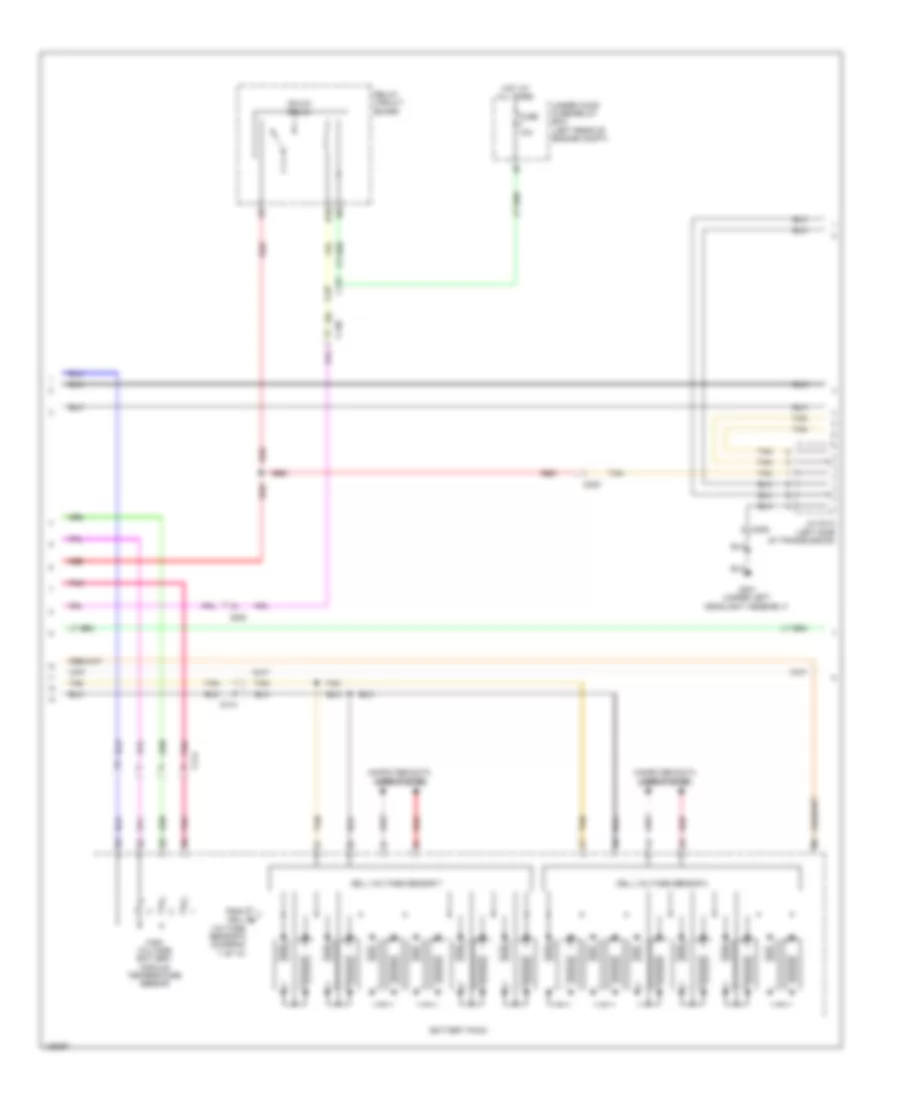
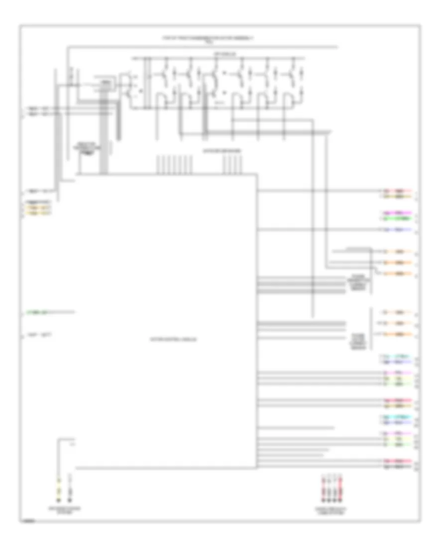
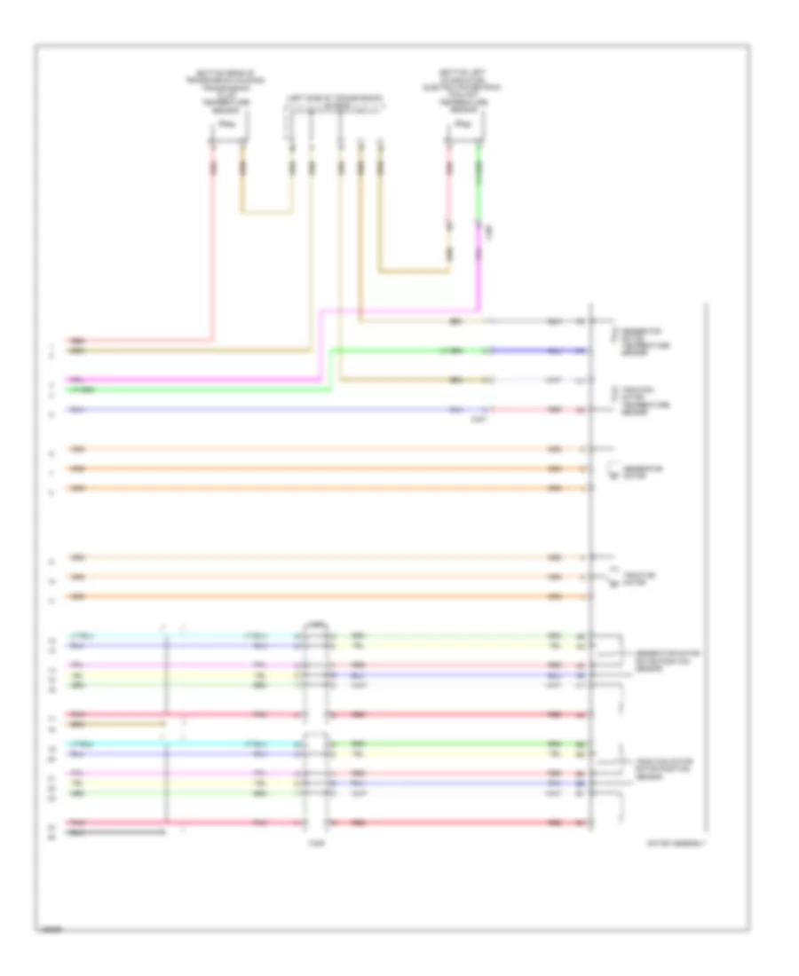
Battery Cooling Fan Wiring Diagram, Plug-In Hybrid for Honda Accord Plug-In 2014
List of elements for Battery Cooling Fan Wiring Diagram, Plug-In Hybrid for Honda Accord Plug-In 2014:
- (in ipu relay holder 2) battery fan relay 1
- (in rear relay holder c) battery fan relay 2
- (left front of battery pack assembly) j/c c017
- (left rear of luggage compt) g603
- (top left center of battery pack assembly) g801
- (top left center of battery pack assembly) j/c c012
- (under front passenger's seat) g652
- A18
- A21
- A22
- A23
- A33
- Battery condition monitor module (top right rear of battery pack assembly)
- C112
- C126
- C130
- C131
- C401
- C404
- C405
- Fuse 15a
- G801 (top left center of battery pack assembly)
- High voltage battery module fan 1 (behind right side of battery pack assembly)
- High voltage battery module fan 2 (behind left side of battery pack assembly)
- High voltage battery module fan 3 (top left side of battery pack assembly)
- Hot at all times
- Ighld 2 relay (in ipu relay holder 2)
- J/c c010 (top right center of battery pack assembl)
- J/c c012 (top left center of battery pack assembly)
- Pnk
- Red
- Tan
- Under-dash sub fuse box (left end of dash)
- Under-hood fuse/relay box (left rear of engine compt)
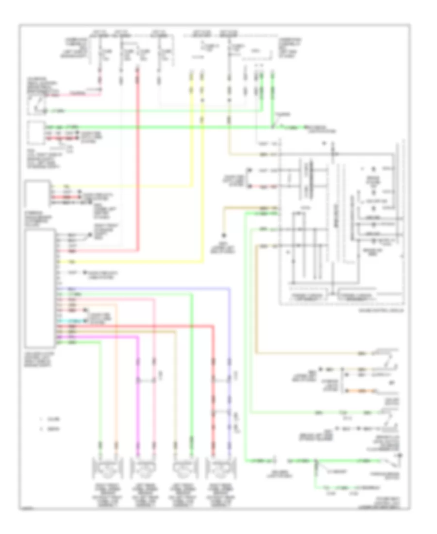
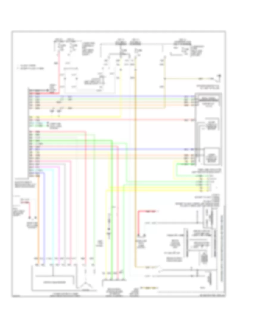
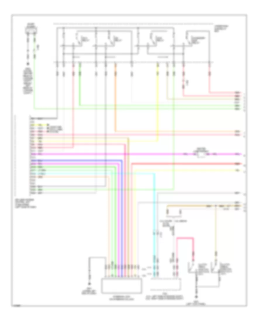
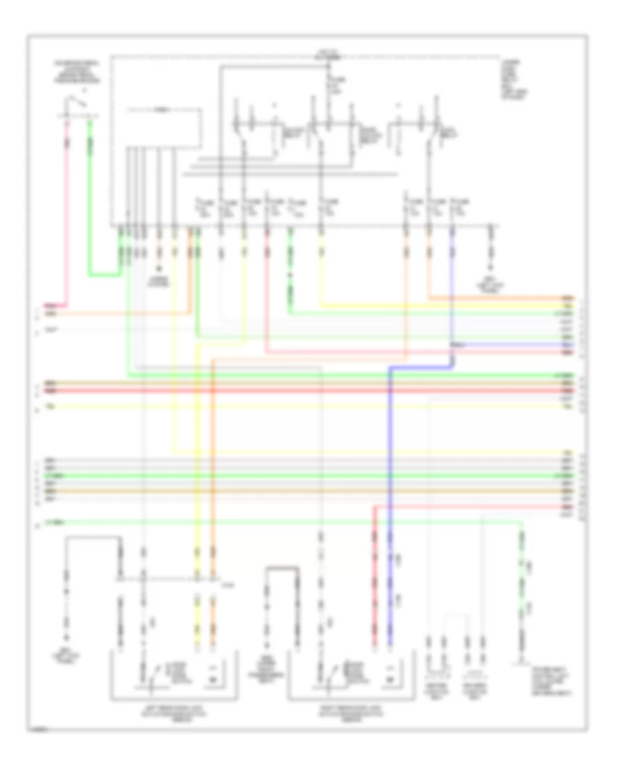
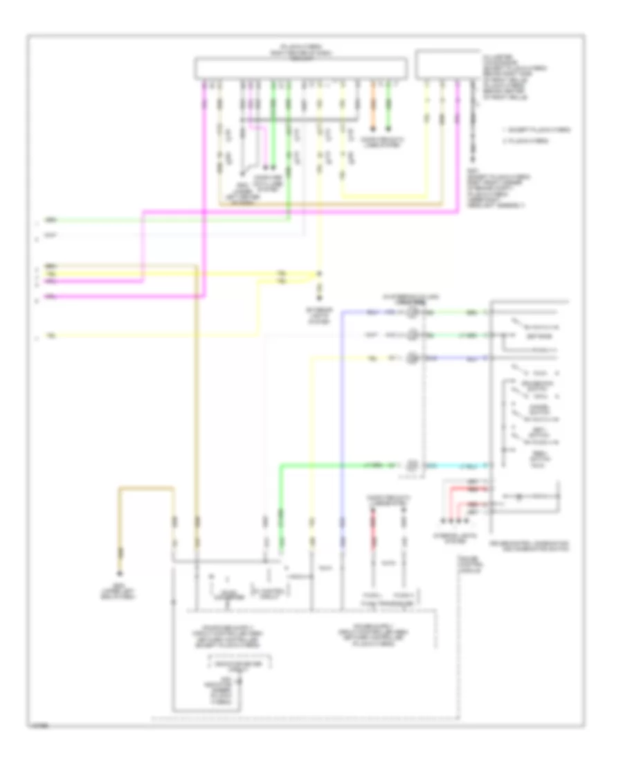
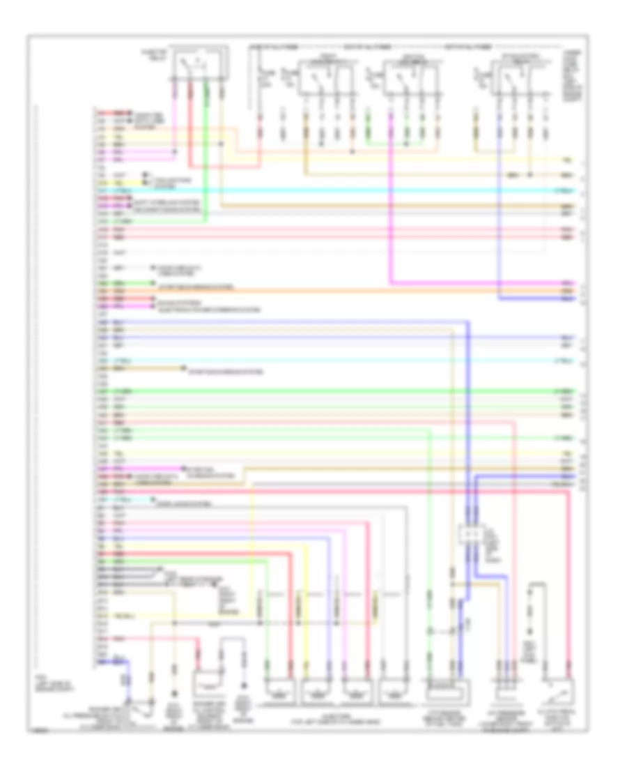
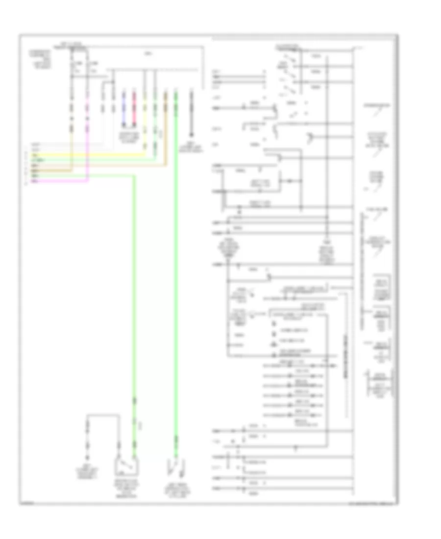
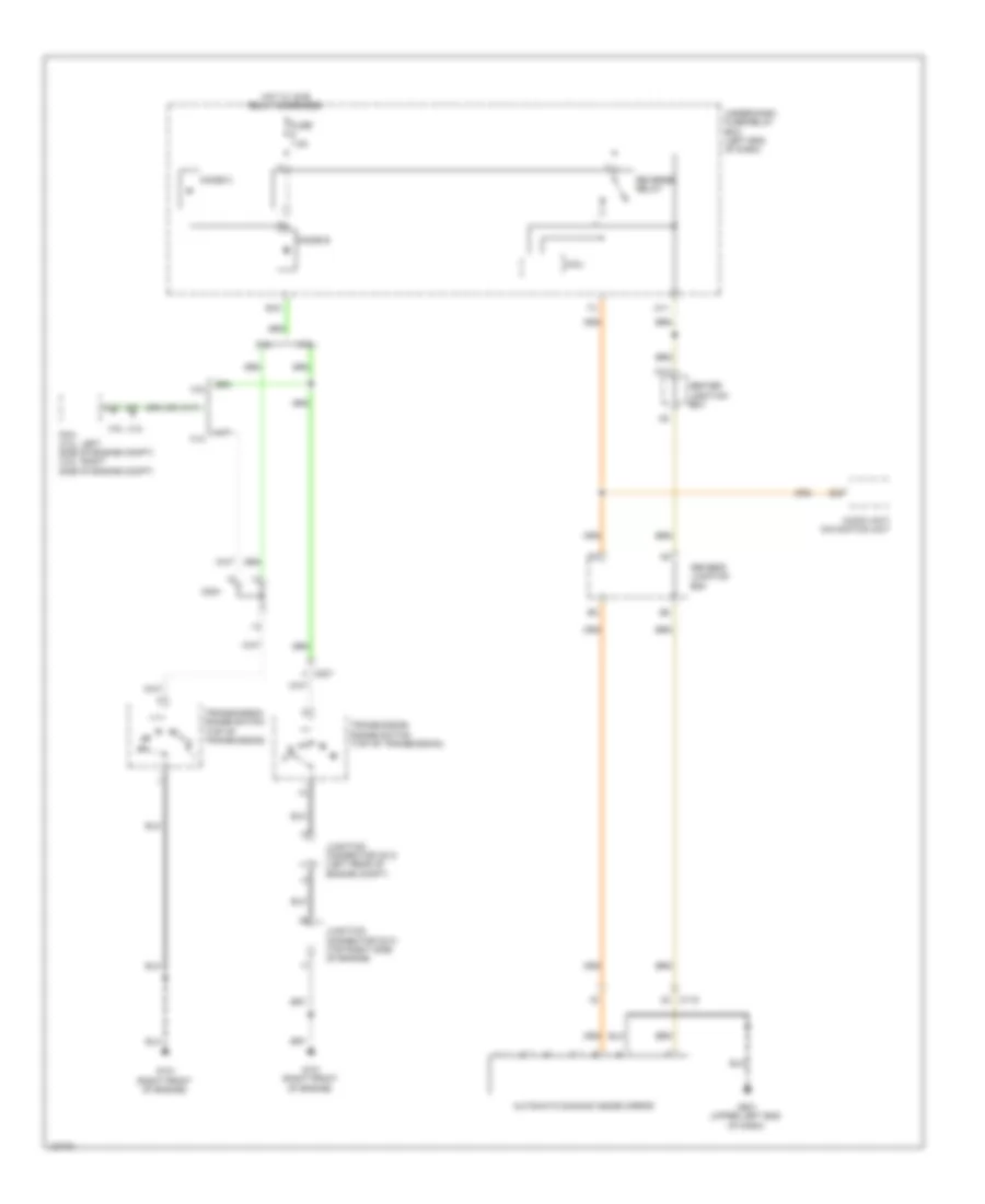
Cooling Fan Wiring Diagram, Except Hybrid for Honda Accord Plug-In 2014
List of elements for Cooling Fan Wiring Diagram, Except Hybrid for Honda Accord Plug-In 2014:
- (2.4l) a/c condenser fan relay (3.5l) radiator fan relay
- (2.4l) radiator fan relay (3.5l) a/c condenser fan relay
- 2.4l
- 2.4l 3.5l
- 2.4l cvt
- 2.4l m/t
- 20a
- 3.5l
- 3.5l coupe
- 3.5l sedan
- 30a
- A/c condenser fan motor (3.5l) radiator fan motor (2.4l) (2.4l: lower left front of engine compt)
- A/c pressure sensor (lower right front of engine compt)
- A10
- A14
- A16
- A19
- A20
- A21
- A28
- A29
- A30
- A31
- A33
- A37
- A41
- A50
- A51
- B-can h
- B-can l
- B-can transceiver
- B13
- B14
- B45
- B50
- C31
- C48
- Computer data lines system
- E20
- Ect sensor 1 (left rear of engine)
- Ect sensor 2 (on radiator lower left outlet)
- Engine controls system
- Except 2.4l cvt
- F-can h
- F-can l
- F-can transceiver
- Fan control relay
- Fuse 12-5 12-9 30a
- Fuse 12-9 12-5
- Fuse 15a
- Fuse 7.5a
- G301 (behind left side of front bumper)
- Gauge control module
- Hot at all times
- Hot w/ ig2 relay energized
- J/c c012 (3.5l sedan) j/c c019 (3.5l coupe) j/c c009 (2.4l m/t) (3.5l sedan: left rear of engine compt)
- J/c c021 (left side of dash)
- Main circuit
- Pcm (2.4l: left side of engine compt) (3.5l: right side of engine compt)
- Pgm-fi sub- relay
- Pnk
- Radiator fan motor (3.5l) a/c condenser fan motor (2.4l) (2.4l: lower left front of engine compt)
- Red
- Relay circuit board
- Under-dash fuse/relay box (left end of dash)
- Under-hood fuse/relay box (left side of engine compt)
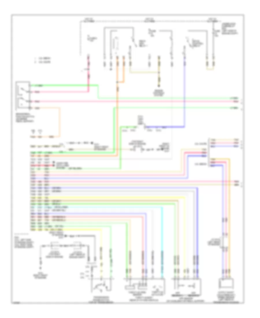
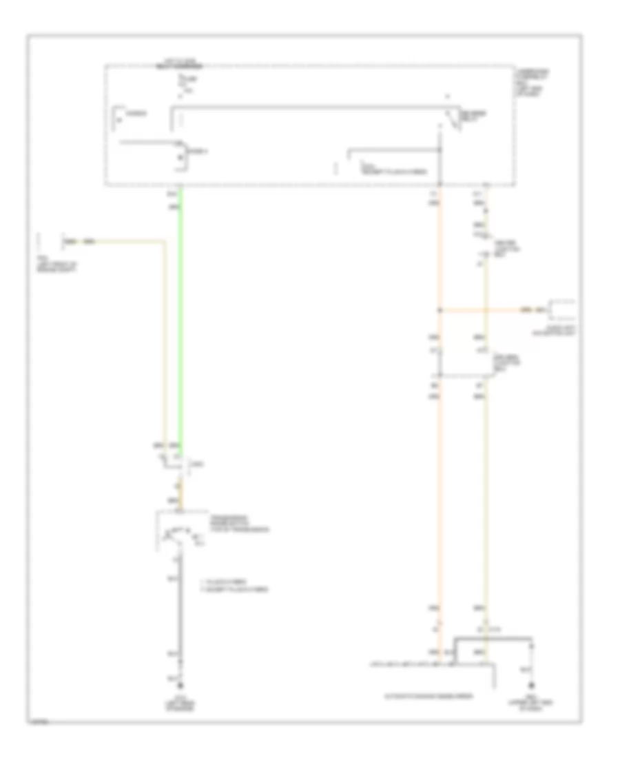
Cooling Fan Wiring Diagram, Hybrid for Honda Accord Plug-In 2014
List of elements for Cooling Fan Wiring Diagram, Hybrid for Honda Accord Plug-In 2014:
- (except plug-in hybrid: behind left side of front bumper) g301 (plug-in hybrid: under left headlight assembly)
- (left front of engine compt)
- A10
- A15
- A17
- A20
- A31
- A46
- B-can h
- B-can l
- B32
- C201
- C203
- C204
- C41
- Computer data lines system
- Cooling fan motor (behind radiator)
- Cpu/ipd
- Ect sensor 1 (left rear of engine)
- Ect sensor 2 (on radiator lower left outlet)
- Engine controls system
- Except plug-in hybrid:
- F-can h
- F-can l
- Fuse 10a
- Fuse 15a
- Fuse 2-6 40a 30a
- Fuse 7.5a
- G101 (left rear of engine)
- G502 (upper left end of dash)
- Gauge control module
- Hot at all times
- Hot in on or start
- J/c c012 (except plug-in hybrid) j/c c007 (plug-in hybrid)
- M11
- Pcm (left front of engine compt)
- Pgm-fi sub-relay
- Plug-in hybrid
- Pnk
- Pnk a30
- Red
- Red a20
- Relay circuit board
- Rfc relay
- Transceiver b-can
- Transceiver f-can
- Under-dash fuse/relay box (left end of dash)
- Under-hood fuse/relay box (left rear of engine compt)
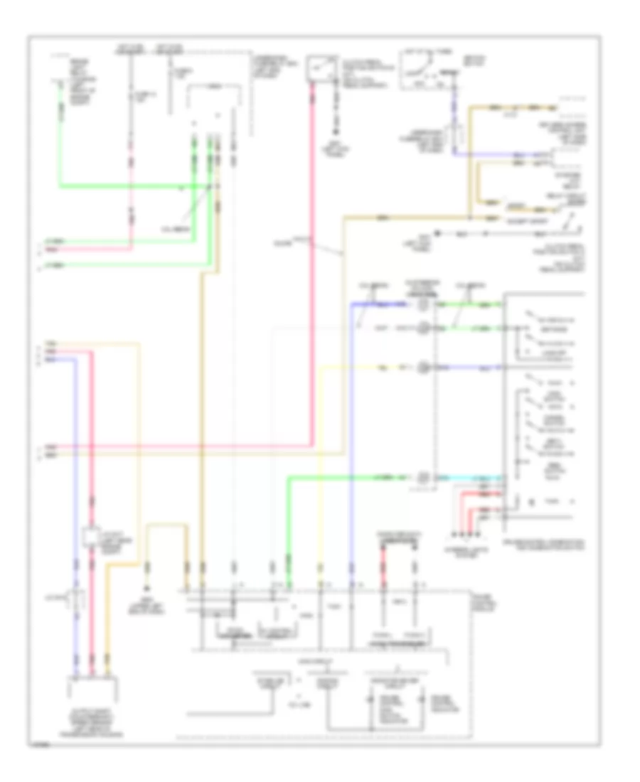
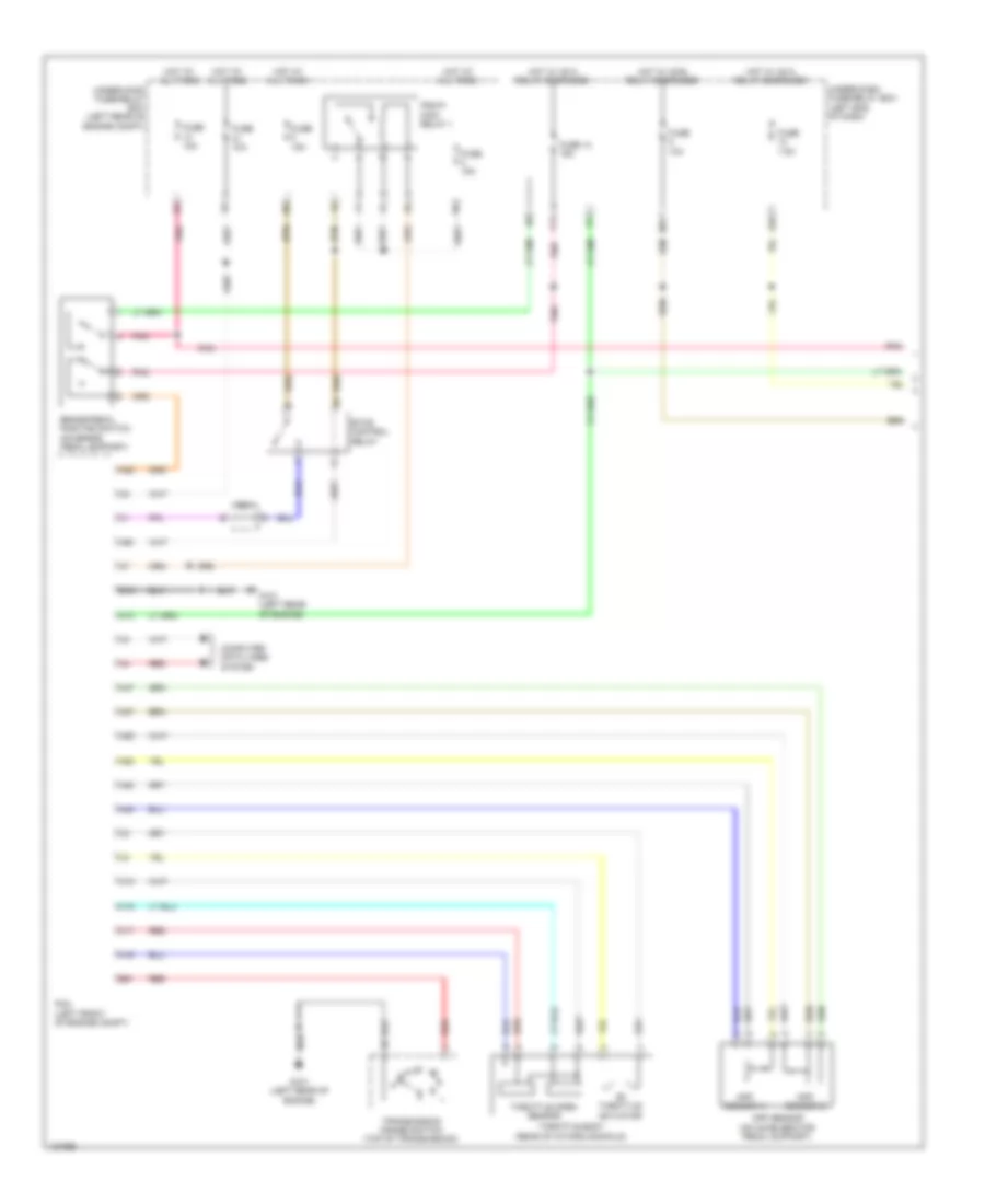
Cooling Fan Wiring Diagram, Plug-In Hybrid for Honda Accord Plug-In 2014
List of elements for Cooling Fan Wiring Diagram, Plug-In Hybrid for Honda Accord Plug-In 2014:
- (except plug-in hybrid: behind left side of front bumper) g301 (plug-in hybrid: under left headlight assembly)
- (left front of engine compt)
- A10
- A15
- A17
- A20
- A31
- A46
- B-can h
- B-can l
- B32
- C201
- C203
- C204
- C41
- Computer data lines system
- Cooling fan motor (behind radiator)
- Cpu/ipd
- Ect sensor 1 (left rear of engine)
- Ect sensor 2 (on radiator lower left outlet)
- Engine controls system
- Except plug-in hybrid:
- F-can h
- F-can l
- Fuse 10a
- Fuse 15a
- Fuse 2-6 40a 30a
- Fuse 7.5a
- G101 (left rear of engine)
- G502 (upper left end of dash)
- Gauge control module
- Hot at all times
- Hot in on or start
- J/c c012 (except plug-in hybrid) j/c c007 (plug-in hybrid)
- M11
- Pcm (left front of engine compt)
- Pgm-fi sub-relay
- Plug-in hybrid
- Pnk
- Pnk a30
- Red
- Red a20
- Relay circuit board
- Rfc relay
- Transceiver b-can
- Transceiver f-can
- Under-dash fuse/relay box (left end of dash)
- Under-hood fuse/relay box (left rear of engine compt)
CRUISE CONTROL
Adaptive Cruise Control Wiring Diagram, Except Hybrid (1 of 2) for Honda Accord Plug-In 2014
List of elements for Adaptive Cruise Control Wiring Diagram, Except Hybrid (1 of 2) for Honda Accord Plug-In 2014:
- (left rear of engine compt) j/c c012
- (top right side of engine) j/c c013
- A10
- A24
- A25
- A31
- A42
- A43
- A44
- A45
- A46
- App sensor (on accelerator pedal support)
- App sensor a
- App sensor b
- B20
- B23
- B29
- B31
- B40
- B44
- B46
- Brake pedal position switch (on brake pedal support)
- C207
- C21
- C32
- C33
- Computer data lines system
- F11
- F17
- Fuse 13 15a
- Fuse 5 7.5a
- Fuse 6 10a
- G101 (right front of engine)
- Hot at all times
- Hot in on or start
- J/c c012 (left rear of engine compt)
- J/c c013 (top right side of engine)
- J/c c015 (left rear of engine)
- M11
- M12
- Micu
- N r
- Output shaft (countershaft) speed sensor (left rear of transmission housing)
- Pcm (2.4l: left side of engine compt) (3.5l: right side of engine compt)
- Pnk
- Red
- Tan
- Throttle actuator
- Throttle body (rear of intake manifold)
- Throttle open sensor
- Transmission range switch (top of transmission)
- Under-dash fuse/relay box (left end of dash)
- Under-hood fuse/relay box (left side of engine compt)
Adaptive Cruise Control Wiring Diagram, Except Hybrid (2 of 2) for Honda Accord Plug-In 2014
List of elements for Adaptive Cruise Control Wiring Diagram, Except Hybrid (2 of 2) for Honda Accord Plug-In 2014:
- (in steering column) cable reel
- 5v control circuit
- A15
- A16
- Acc indicator (amber)
- Acc unit
- Brake light relay (left front of engine compt)
- C114
- C115
- C15
- C16
- Cancel switch
- Computer data lines system
- Converter dc-dc
- Cruise control combination/ acc combination switch
- Distance
- Driver's junction box
- Exterior lights system
- F-can h
- F-can l
- F-can transceiver
- Fcw/ldw camera unit (base of interior rearview mirror assembly)
- Forward collision warning indicator
- G201 (right front of engine compt)
- G502 (upper left end of dash)
- G503 (under left center of dash)
- Gauge control module
- Head-up warning unit
- Indicator driver circuit
- Interior lights system
- Ldw off switch
- Main circuit
- Main switch
- Millimeter wave radar (behind right side of front grille)
- Pnk
- Red
- Res/- switch
- Set/+ switch
Adaptive Cruise Control Wiring Diagram, Hybrid (1 of 3) for Honda Accord Plug-In 2014
List of elements for Adaptive Cruise Control Wiring Diagram, Hybrid (1 of 3) for Honda Accord Plug-In 2014:
- A13
- A25
- A28
- A29
- A37
- A38
- A47
- A48
- A50
- App sensor (on accelerator pedal support)
- App sensor a
- App sensor b
- B18
- B51
- Brake pedal position switch (on brake pedal support)
- C16
- C17
- C18
- C19
- C203
- Computer data lines system
- E26
- Etcs control relay
- Except plug-in hybrid
- F11
- F17
- Fuse 10a
- Fuse 13 15a
- Fuse 15a
- Fuse 7.5a
- G101 (left rear of engine)
- Hot at all times
- Hot w/ ig1a relay energized
- Hot w/ ig1b relay energized
- M11
- N r
- Pcm (left front of engine compt)
- Pgm-fi main relay 1
- Plug-in hybrid
- Pnk
- Red
- Throttle actuator
- Throttle body (rear of intake manifold)
- Throttle open sensor
- Transmission range switch (top of transmission)
- Under-dash fuse/relay box (left end of dash)
- Under-hood fuse/relay box (left rear of engine compt)
Adaptive Cruise Control Wiring Diagram, Hybrid (2 of 3) for Honda Accord Plug-In 2014
List of elements for Adaptive Cruise Control Wiring Diagram, Hybrid (2 of 3) for Honda Accord Plug-In 2014:
- Brake light relay
- C110
- C111
- C117
- C119
- C127
- C131
- Computer data lines system
- Except plug-in hybrid
- Fuse 21 10a
- Hot at all times
- Left front wheel speed sensor (on left front wheel hub assembly)
- Left rear wheel speed sensor (on left rear wheel hub assembly)
- Plug-in hybrid
- Pnk
- Red
- Right front wheel speed sensor (on right front wheel hub assembly)
- Right rear wheel speed sensor (on right rear wheel hub assembly)
- Under-hood fuse/relay box (left rear of engine compt)
- Vsa modulator- control unit (right side of engine compt)
Adaptive Cruise Control Wiring Diagram, Hybrid (3 of 3) for Honda Accord Plug-In 2014
List of elements for Adaptive Cruise Control Wiring Diagram, Hybrid (3 of 3) for Honda Accord Plug-In 2014:
- (in steering column) cable reel
- (plug-in hybrid: right center of dash) acc unit
- 5v control circuit
- A12
- A15
- A16
- A17
- A19
- A20
- A28
- Acc indicator (amber) (plug-in hybrid)
- B10
- B11
- C104
- C112
- C113
- C118
- C15
- C16
- Cancel switch
- Computer data lines system
- Cruise control combination/ acc combination switch
- Cruise/main switch
- Dc-dc converter
- Distance
- Except plug-in hybrid
- Exterior lights system
- F-can h
- F-can l
- F-can transceiver
- G201 (except plug-in hybrid: right front corner of engine compt) (plug-in hybrid: under right headlight assembly)
- G502 (upper left end of dash)
- G503 (under left center of dash)
- Gauge control module
- Indicator driver circuit
- Interior lights system
- Millimeter wave radar (except plug-in hybrid: behind right side of front grille) (plug-in hybrid: behind center of front grille)
- Plug-in hybrid
- Red
- Res/+ switch
- Set/- switch
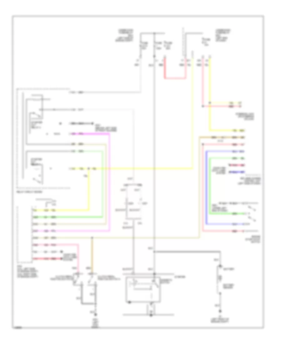
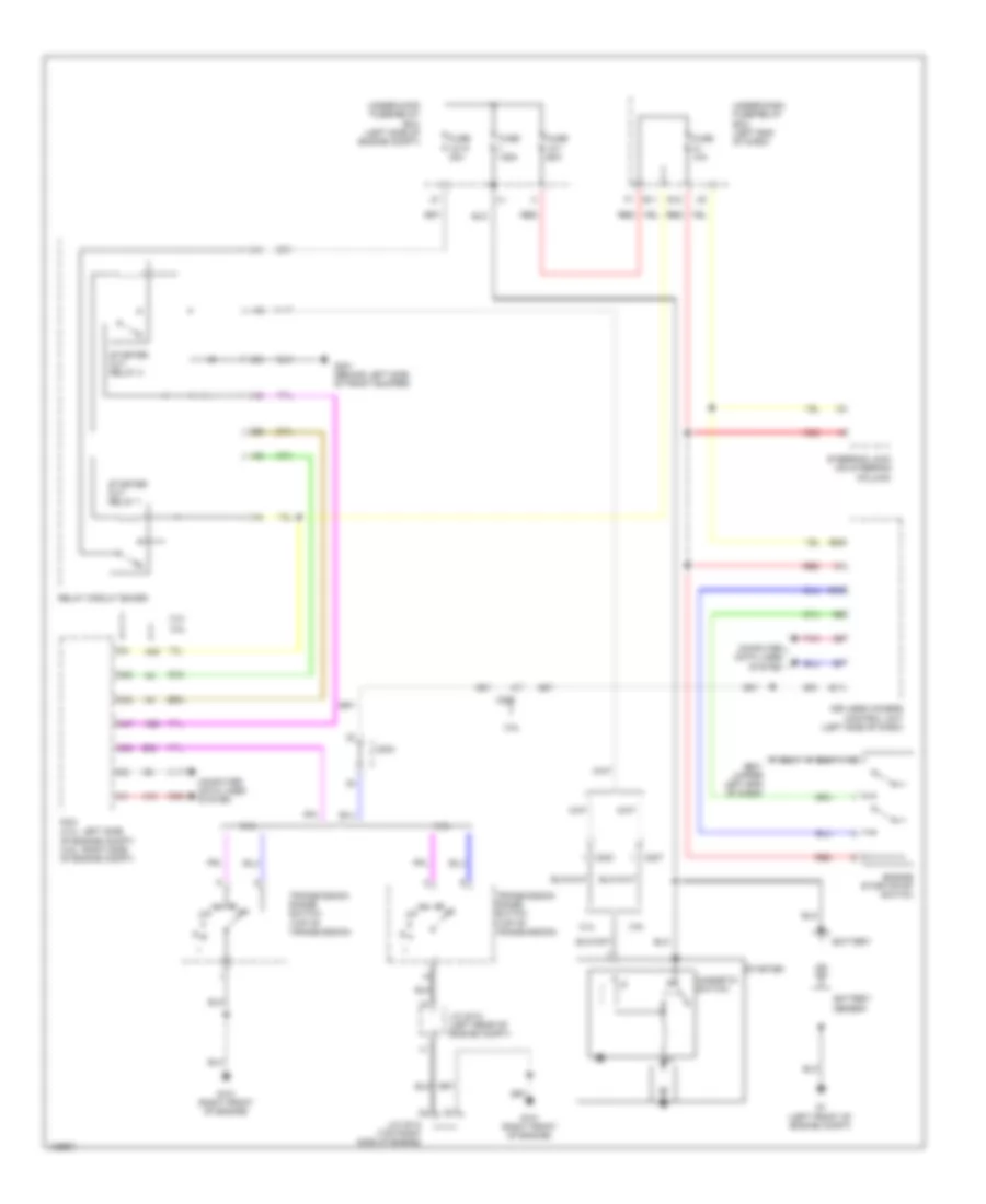
Cruise Control Wiring Diagram, Except Hybrid (1 of 2) for Honda Accord Plug-In 2014
List of elements for Cruise Control Wiring Diagram, Except Hybrid (1 of 2) for Honda Accord Plug-In 2014:
- (2.4l)
- (2.4l) c204 (3.5l) c207
- (3.5l)
- (right front of engine) g101
- (top right side of engine) j/c c013
- 2.4l
- 3.5l
- 3.5l coupe
- 3.5l sedan
- A10
- A13
- A19
- A24
- A25
- A27
- A30
- A31
- A33
- A37
- A38
- A39
- A40
- A42
- A43
- A44
- A45
- A46
- A49
- A50
- App sensor (on accelerator pedal support)
- App sensor a
- App sensor b
- B11
- B20
- B23
- B29
- B31
- B40
- B44
- B46
- B47
- B48
- B49
- Brake pedal position switch (on brake pedal support)
- C11
- C12
- C21
- C25
- C26
- C32
- C33
- Computer data lines system
- Engine controls system
- Etcs control relay
- Fuse 15a
- Fuse 6 10a
- G101 (right front of engine)
- Hot at all times
- J/c c012 (left rear of engine compt)
- J/c c013 (top right side of engine)
- J/c c015 (left rear of engine)
- Output shaft (countershaft) speed sensor (left rear of transmission housing)
- Pcm (2.4l: left side of engine compt) (3.5l: right side of engine compt)
- Pgm-fi main relay 1
- Pnk
- Red
- Tan
- Throttle actuator
- Throttle body (rear of intake manifold)
- Throttle open sensor
- Transmission range switch (top of transmission)
- Under-hood fuse/relay box (left side of engine compt)
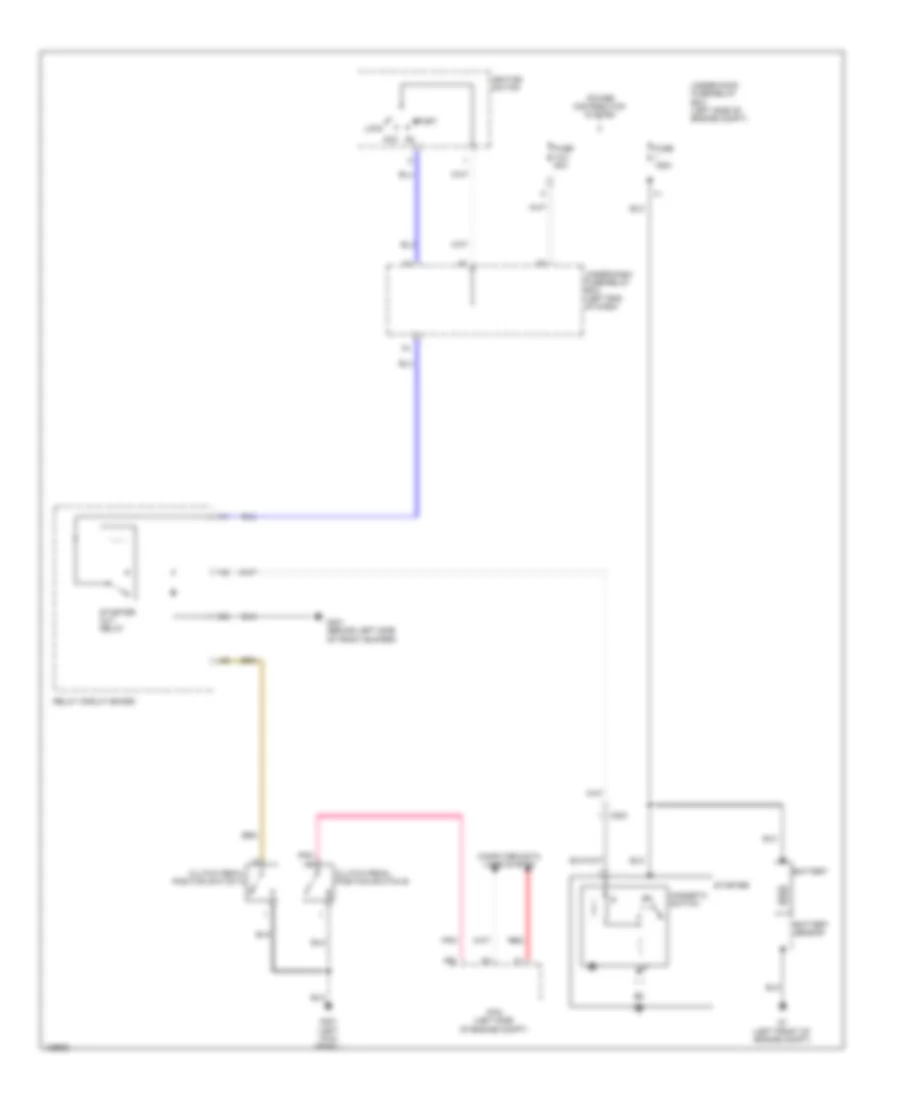
Cruise Control Wiring Diagram, Except Hybrid (2 of 2) for Honda Accord Plug-In 2014
List of elements for Cruise Control Wiring Diagram, Except Hybrid (2 of 2) for Honda Accord Plug-In 2014:
- (in steering column) cable reel
- 10v line
- 3.5l sedan
- 5v control circuit
- A15
- A16
- Acc
- Brake light relay (touring) (left front of engine compt)
- C112
- C15
- C16
- Cancel switch
- Clutch pedal position switch a (m/t) (on clutch pedal support)
- Clutch pedal position switch b (m/t) (on clutch pedal support)
- Computer data lines system
- Coupe
- Cruise control combination/ acc combination switch
- Cruise control indicator
- Cruise control main switch indicator
- Dc-dc converter
- Dimming circuit
- Distance
- Except sport
- F-can h
- F-can l
- F-can transceiver
- F11
- Fuse 13 15a
- Fuse 5 7.5a
- G401 (left kick panel)
- G502 (upper left end of dash)
- Gauge control module
- Hot at all times
- Hot in on or start
- Ignition switch
- Indicator driver circuit
- Interior lights system
- J/c c017 (left rear engine compt)
- J/c c019
- Keyless access control unit (left side of dash)
- Lkas off
- Lock
- M11
- M12
- Main circuit
- Main switch
- Micu
- Output shaft (countershaft) speed sensor (left rear of transmission housing)
- Pnk
- Red
- Relay circuit board
- Res/- switch
- Set/+ switch
- Sport
- Stabilize circuit
- Start
- Starter cut relay
- Tan
- Under-dash fuse/relay box (left end of dash)
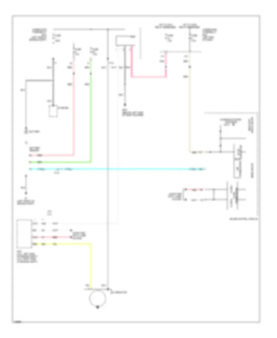
Cruise Control Wiring Diagram, Hybrid (1 of 2) for Honda Accord Plug-In 2014
List of elements for Cruise Control Wiring Diagram, Hybrid (1 of 2) for Honda Accord Plug-In 2014:
- A13
- A25
- A28
- A29
- A37
- A38
- A47
- A48
- A50
- App sensor (on accelerator pedal support)
- App sensor a
- App sensor b
- B18
- B51
- Brake pedal position switch (on brake pedal support)
- C16
- C17
- C18
- C19
- C203
- Computer data lines system
- E26
- Etcs control relay
- F11
- Fuse 10a
- Fuse 13 15a
- Fuse 15a
- Fuse 7.5a
- G101 (left rear of engine)
- Hot at all times
- Hot w/ ig1a relay energized
- Hot w/ ig1b relay energized
- M11
- N r
- Pcm (left front of engine compt)
- Pgm-fi main relay 1
- Pnk
- Red
- Throttle actuator
- Throttle body (rear of intake manifold)
- Throttle open sensor
- Transmission range switch (top of transmission)
- Under-dash fuse/relay box (left end of dash)
- Under-hood fuse/relay box (left rear of engine compt)
Cruise Control Wiring Diagram, Hybrid (2 of 2) for Honda Accord Plug-In 2014
List of elements for Cruise Control Wiring Diagram, Hybrid (2 of 2) for Honda Accord Plug-In 2014:
- (in steering column) cable reel
- (on left front wheel hub assembly) left front wheel speed sensor
- (on right rear wheel hub assembly) right rear wheel speed sensor
- 5v control circuit
- A12
- A17
- A19
- A20
- A28
- Brake light relay
- C110
- C117
- C127
- C15
- C16
- Cancel switch
- Computer data lines system
- Cruise control combination/ acc combination switch
- Cruise/main switch
- Dc-dc converter
- Except plug-in hybrid
- Exterior lights system
- F-can h
- F-can l
- F-can transceiver
- G502 (upper left end of dash)
- Gauge control module
- Interior lights system
- Left rear wheel speed sensor (on left rear wheel hub assembly)
- Plug-in hybrid
- Pnk
- Red
- Res/+ switch
- Right front wheel speed sensor (on right front wheel hub assembly)
- Set/- switch
- Vsa modulator- control unit (right side of engine compt)
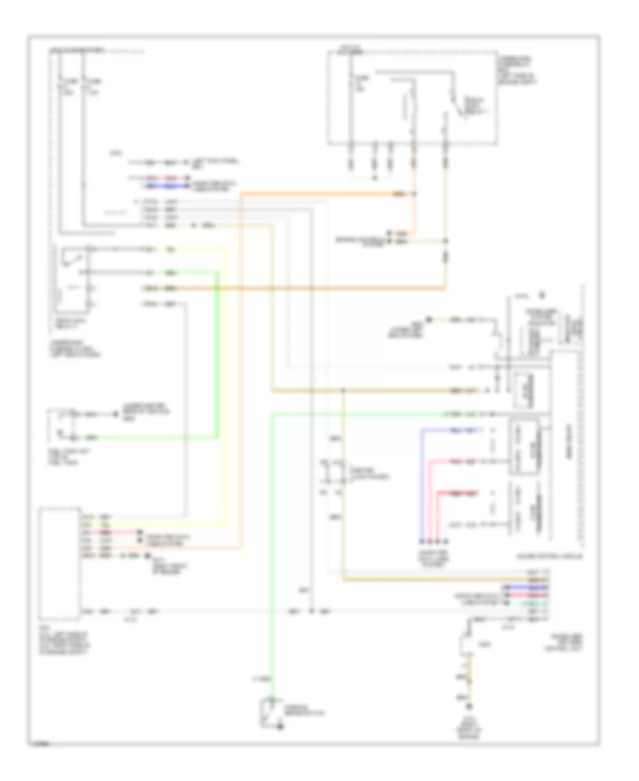
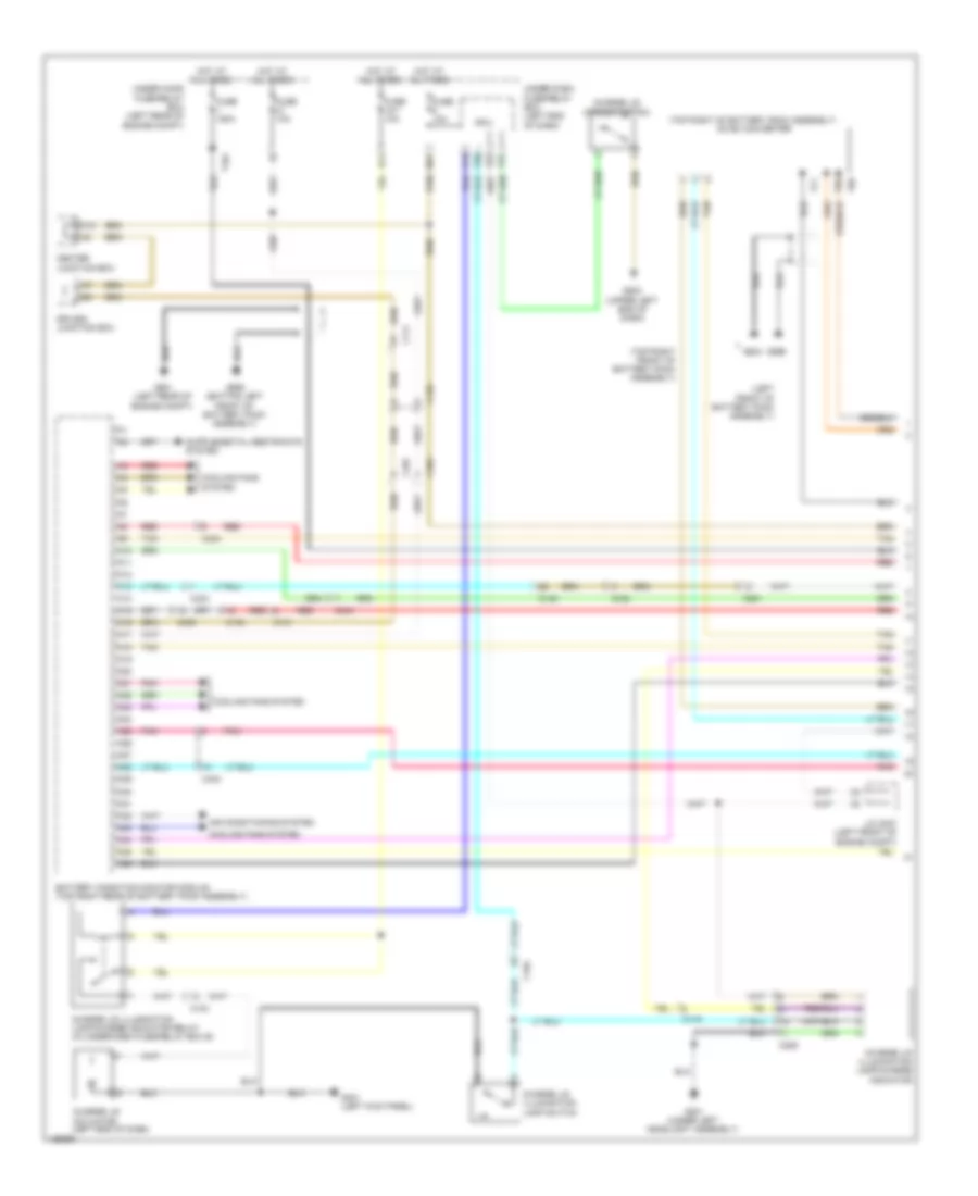
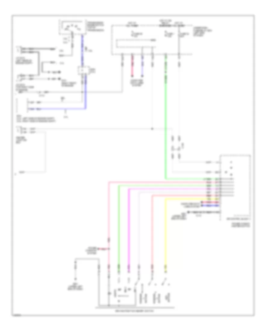
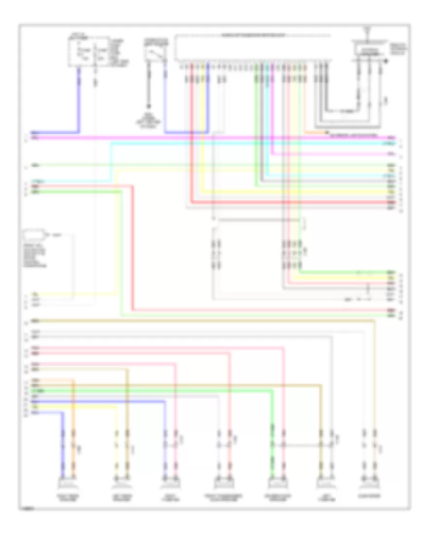
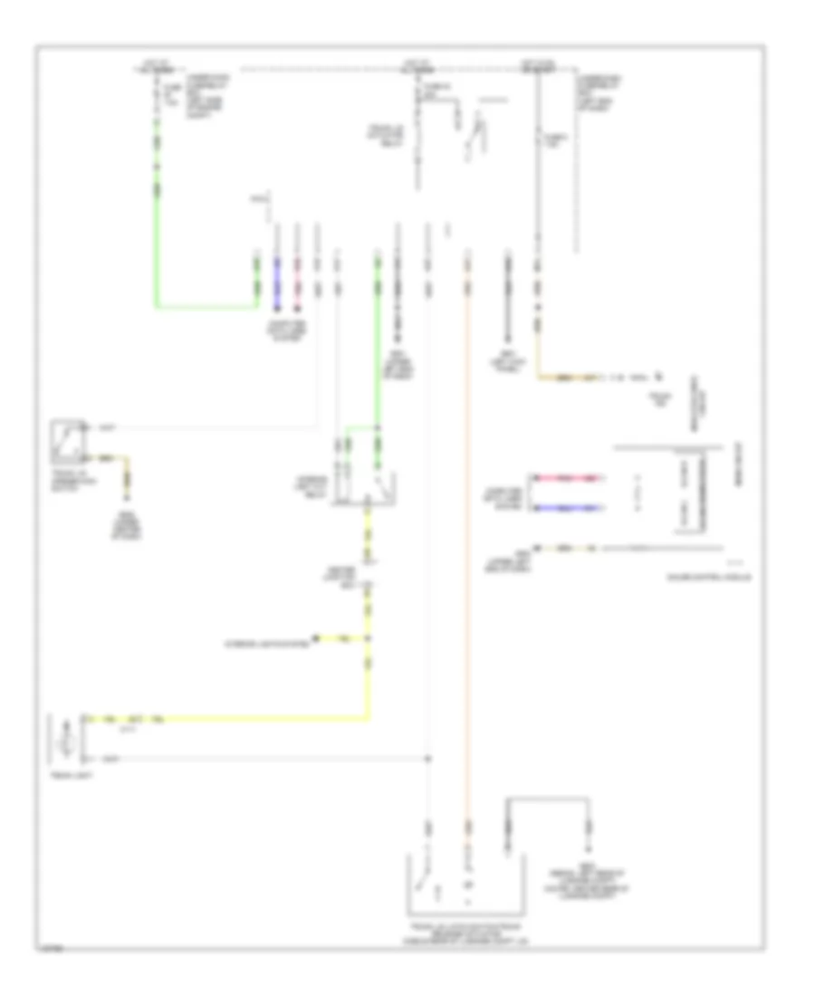
DEFOGGERS
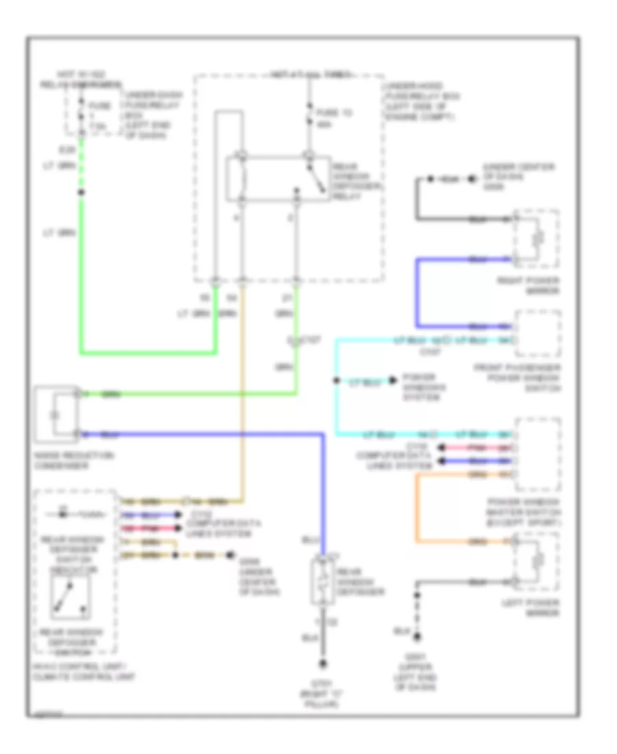
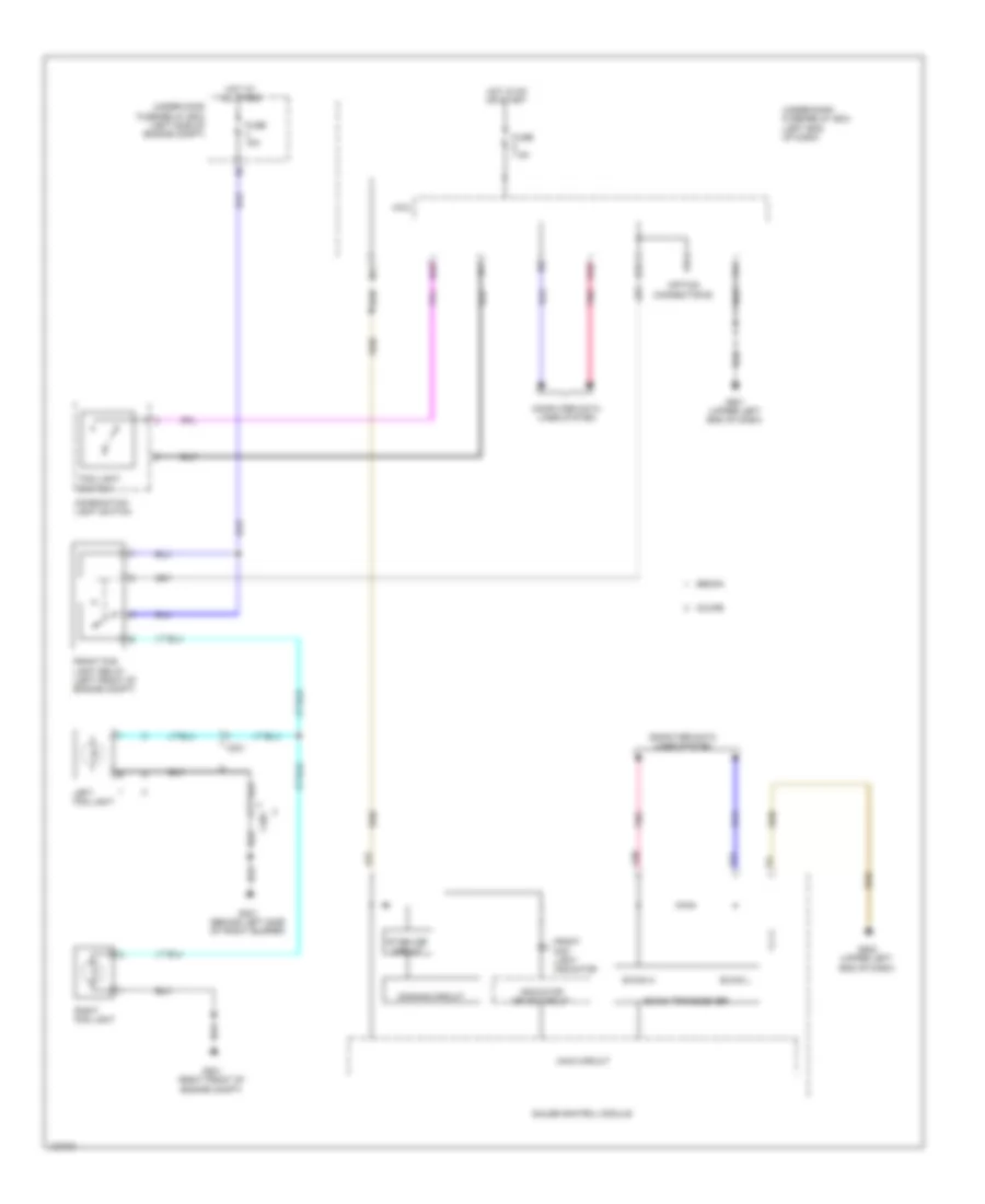
Defoggers Wiring Diagram, Except Hybrid for Honda Accord Plug-In 2014
List of elements for Defoggers Wiring Diagram, Except Hybrid for Honda Accord Plug-In 2014:
- (under center of dash) g506
- 40a
- C107
- C110 computer data lines system
- C112 computer data lines system
- C127
- E20
- Front passenger power window switch
- Fuse 13
- Fuse 7.5a
- G501 (upper left end of dash)
- G506 (under center of dash)
- G701 (right "c" pillar)
- Hot at all times
- Hot w/ ig2 relay energized
- Hvac control unit/ climate control unit
- Left power mirror
- Noise reduction condenser
- Pnk
- Power window master switch (except sport)
- Power windows system
- Rear window defogger
- Rear window defogger relay
- Rear window defogger switch
- Rear window defogger switch indicator
- Right power mirror
- Under-dash fuse/relay box (left end of dash)
- Under-hood fuse/relay box (left side of engine compt)
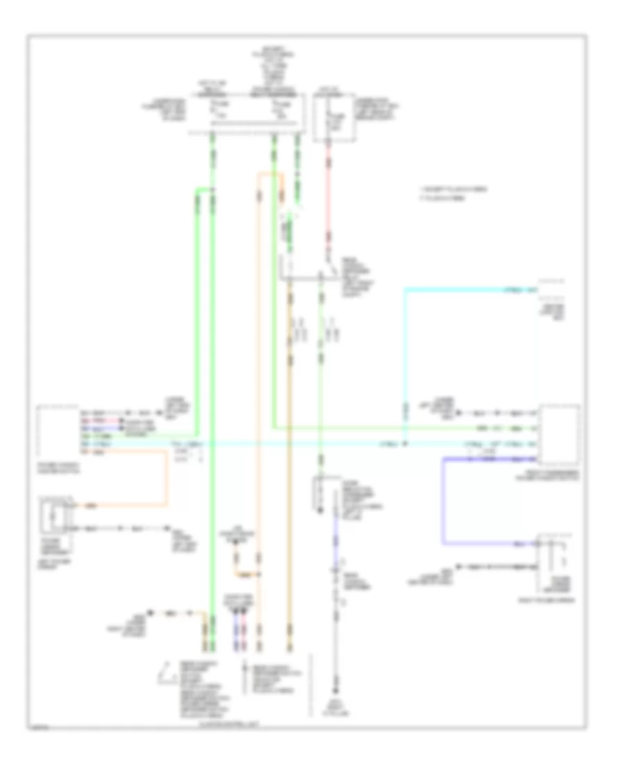
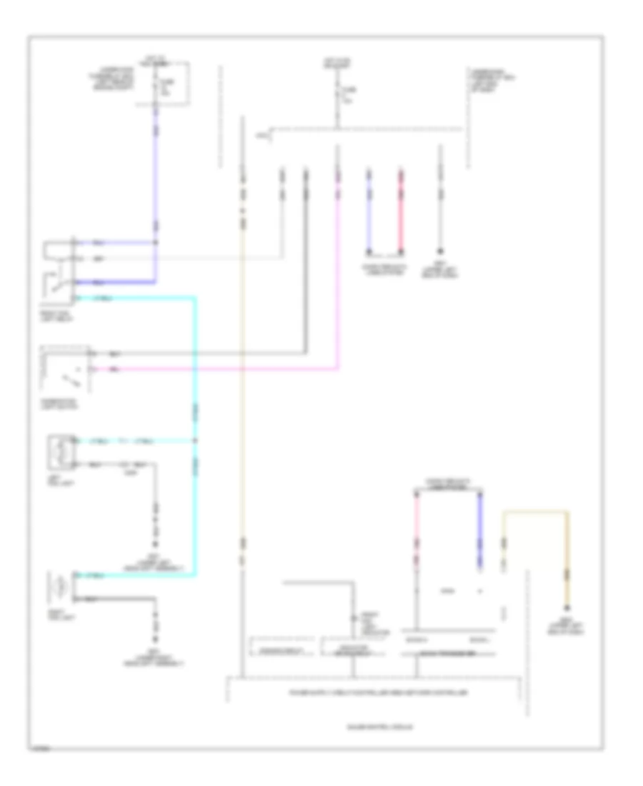
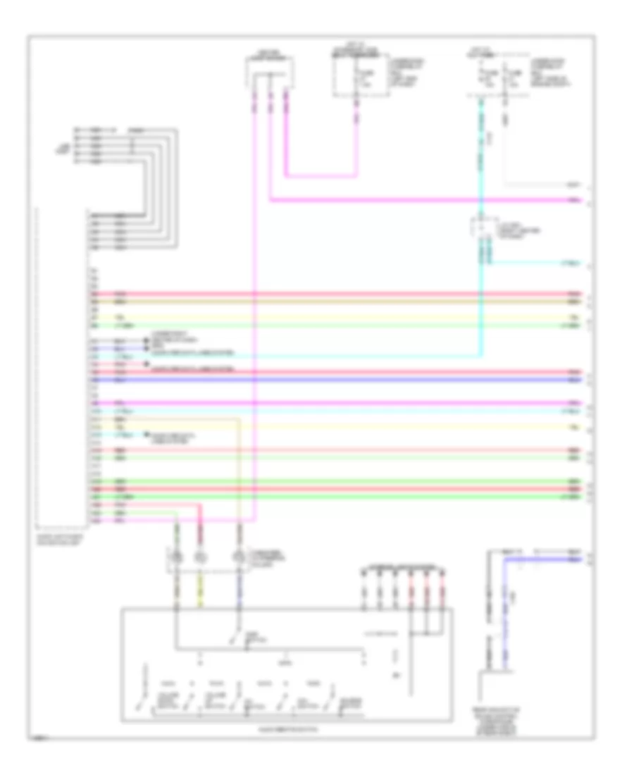
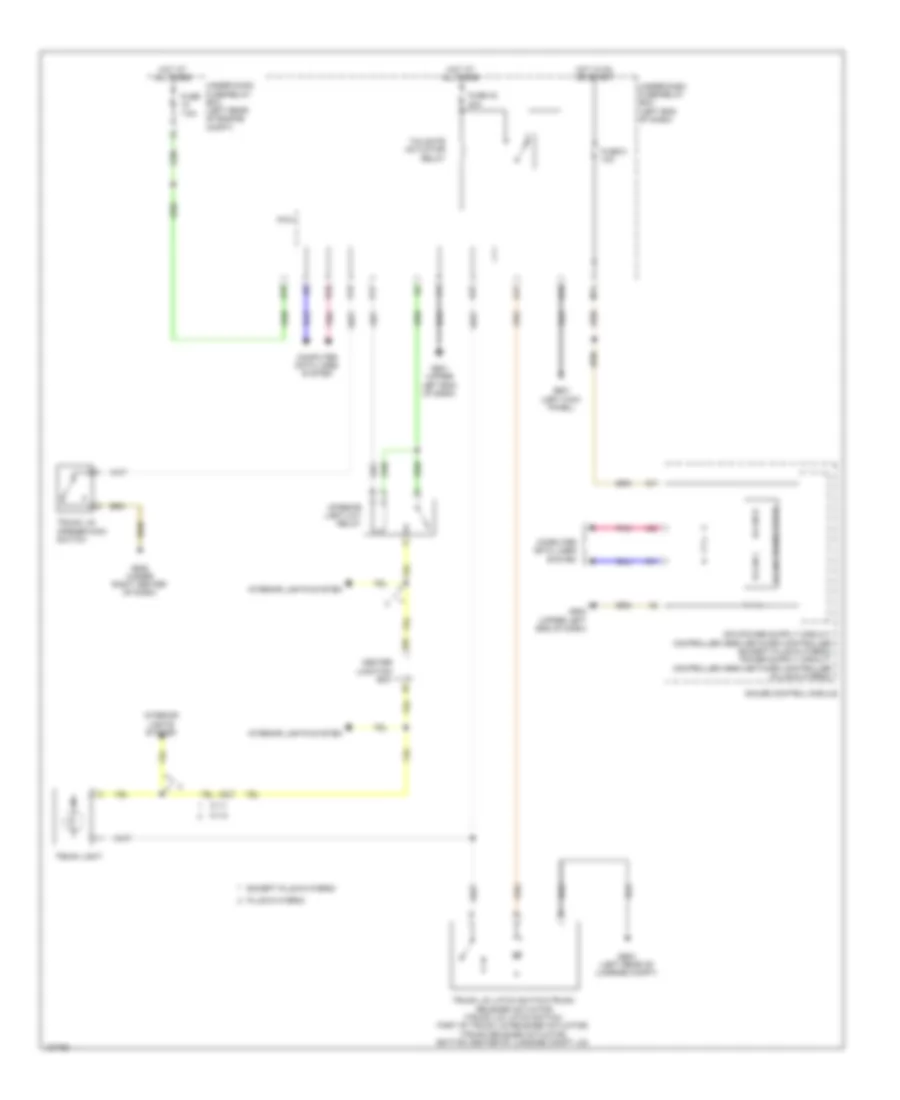
Defoggers Wiring Diagram, Hybrid for Honda Accord Plug-In 2014
List of elements for Defoggers Wiring Diagram, Hybrid for Honda Accord Plug-In 2014:
- (except plug-in hybrid) hot at all times (plug-in hybrid) hot w/ power window relay energized
- (under left center of dash) g503
- (upper left end of dash) g501
- A30
- A32
- Air conditioning system
- B16
- B19
- B20
- C105
- C106
- C109
- C110
- C112
- C113
- C125
- C129
- Center junction box
- Climate control unit
- Computer data lines system
- Except plug-in hybrid
- Front passenger's power window switch
- Fuse 12-2 50a
- Fuse 20a
- Fuse 7.5a
- G501 (upper left end of dash)
- G503 (under left center of dash)
- G506 (under right center of dash)
- G701 (right "c" pillar)
- Hot at all times
- Hot w/ ig2 relay energized
- Left power mirror
- Noise reduction condenser (except plug-in hybrid: left "c" pillar)
- Plug-in hybrid
- Pnk
- Power mirror defogger
- Power window master switch
- Rear window defogger
- Rear window defogger relay (left front of engine compt)
- Rear window defogger switch (except plug-in hybrid) rear window defogger switch/ power mirror defogger switch (plug-in hybrid)
- Rear window defogger switch indicator (except plug-in hybrid)
- Red
- Right power mirror
- Under-dash fuse/relay box (left end of dash)
- Under-hood fuse/relay box (left rear of engine compt)
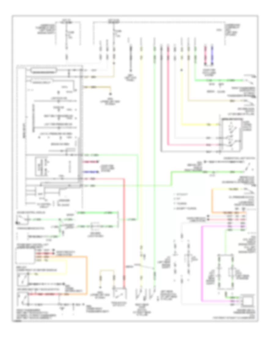
ELECTRONIC POWER STEERING
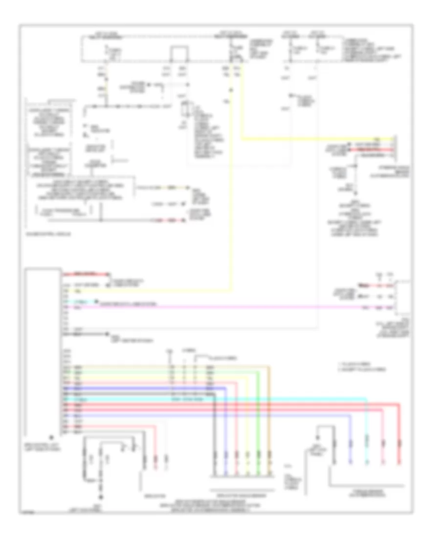
Electronic Power Steering Wiring Diagram for Honda Accord Plug-In 2014
List of elements for Electronic Power Steering Wiring Diagram for Honda Accord Plug-In 2014:
- 2.4l
- 3.5l
- 3.5l, hybrid & plug-in hybrid
- A10
- A11
- A17
- A19
- A20
- A26
- A30
- B10
- B11
- B12
- B13
- B14
- B15
- B16
- C119
- C131
- C133
- Compulsory turning -off circuit (plug-in hybrid) forced turning-off circuit (except (plug-in hybrid)
- Compulsory turning on circuit (plug-in hybrid) forced turning- on circuit (except (plug-in hybrid)
- Computer data lines system
- Dc-dc converter
- E23
- E26
- Eps control unit (left side of dash)
- Eps indicator
- Eps motor
- Eps motor angle sensor
- Eps motor/eps motor angle sensor (eps motor angle sensor: on steering rack motor) (eps motor: on steering rack assembly)
- Except plug-in hybrid
- F-can h
- F-can l
- F-can transceiver
- Fuse 2-1 70a
- Fuse 21 10a
- Fuse 5 7.5a 10a
- Fuse 7.5a
- G401 (left kick panel)
- G402 (left center of dash)
- G502 (upper left end of dash)
- G503 (except hybrid) g502 (hybrid & plug-in hybrid) (except hybrid: under left center of dash) (hybrid & plug-in hybrid: under left end of dash)
- Gauge control module
- Hot at all times
- Hot w/ ig1a relay energized
- Hot w/ ig1b relay energized
- Hybrid
- Hybrid & plug-in hybrid
- Indicator drive unit
- J/c c012 (hybrid & plug-in hybrid) (hybrid: left front of engine compt) (plug-in hybrid: top left center of battery pack assembly)
- M11
- M12
- Pcm (2.4l: left side of engine compt) (3.5l: right side of engine compt)
- Plug-in hybrid
- Plug-in hybrid & hybrid
- Pnk
- Power distribution system
- R14
- Red
- Steering angle sensor (in steering column)
- Torque sensor (on steering rack)
- Under-dash fuse/relay box (left end of dash)
- Under-hood fuse/relay box (except hybrid: left side of engine compt) (hybrid & plug-in hybrid: left rear of engine compt)
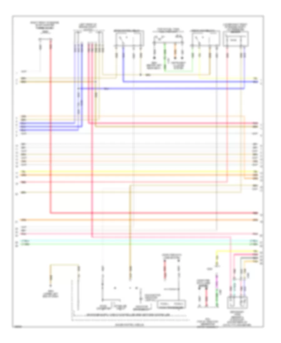
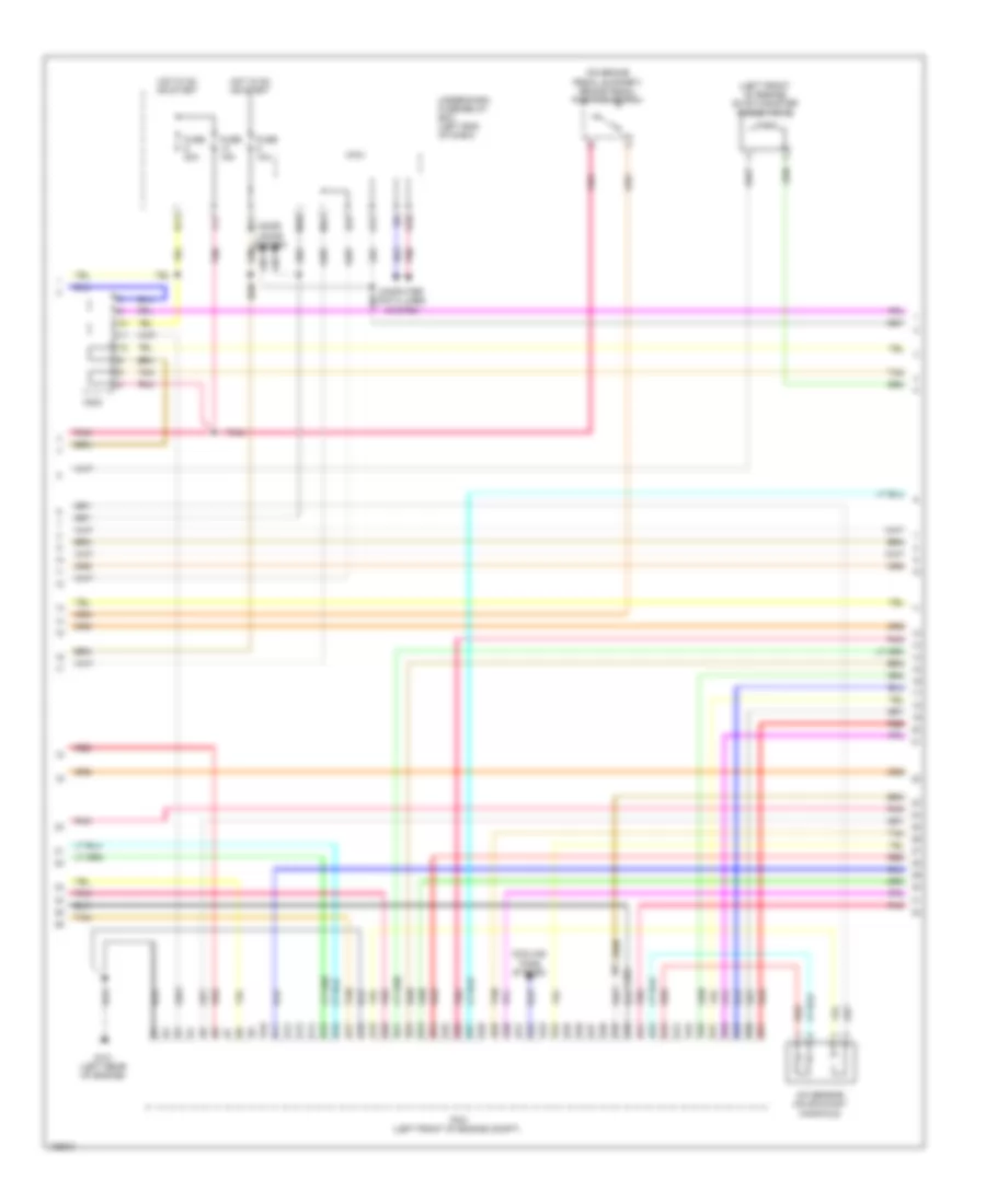
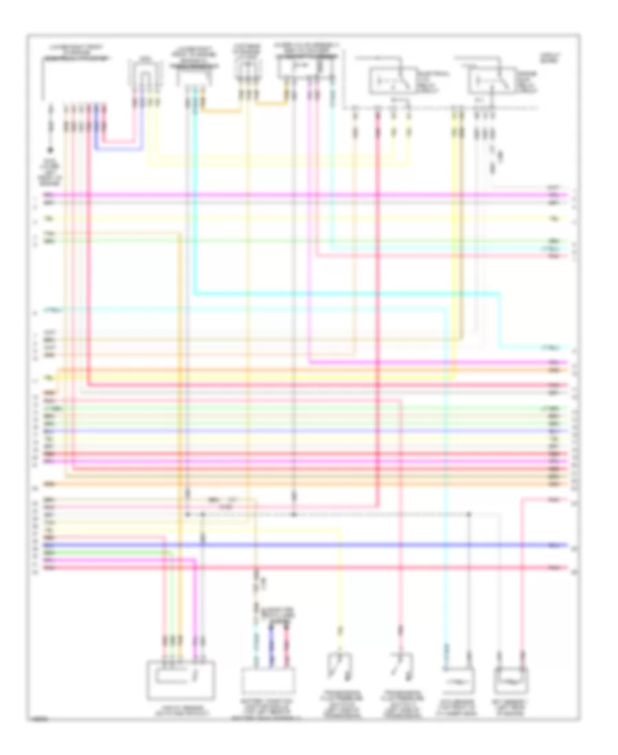
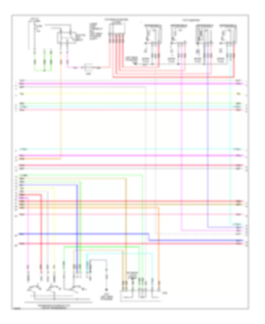
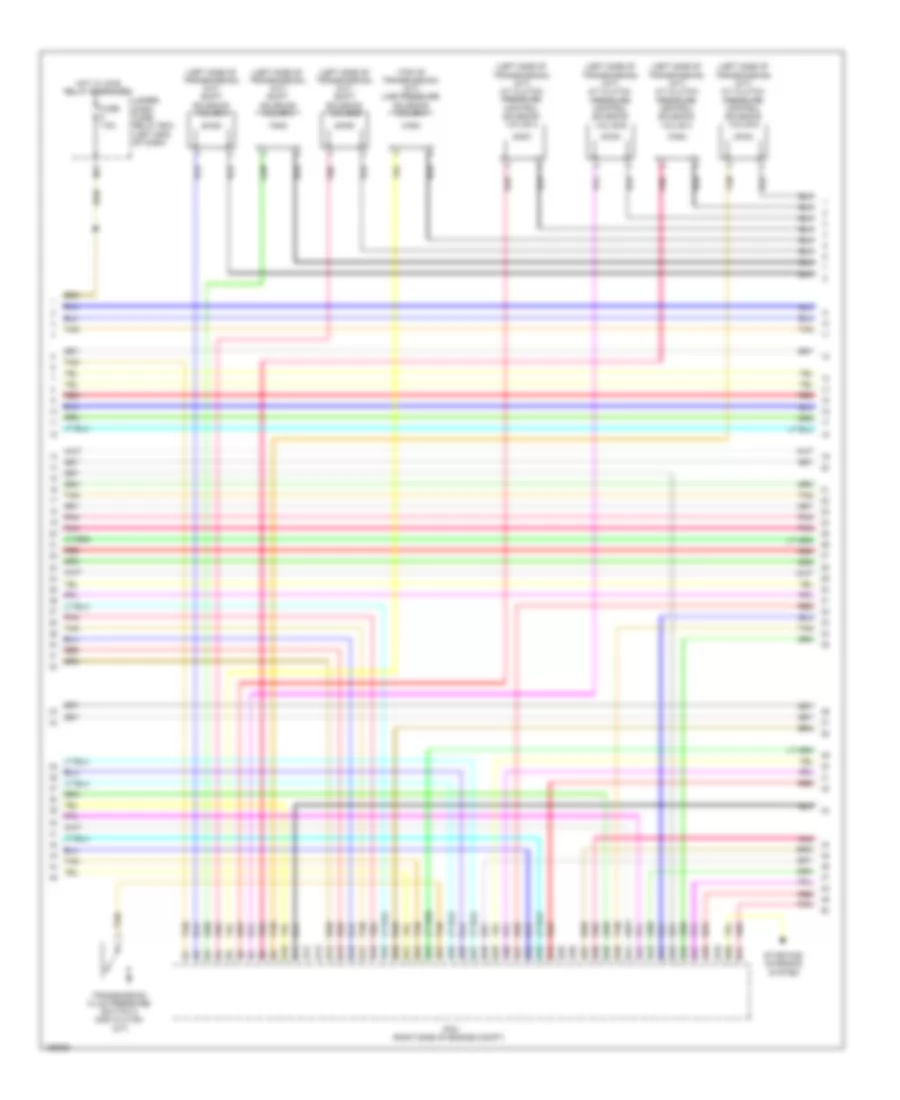
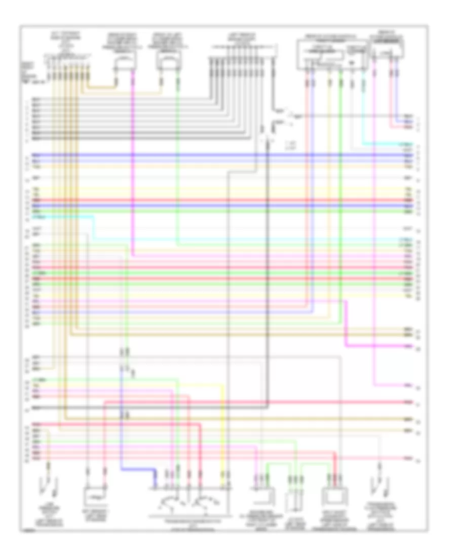
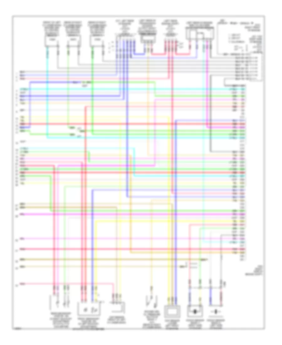
ENGINE PERFORMANCE
2.0L HYBRID
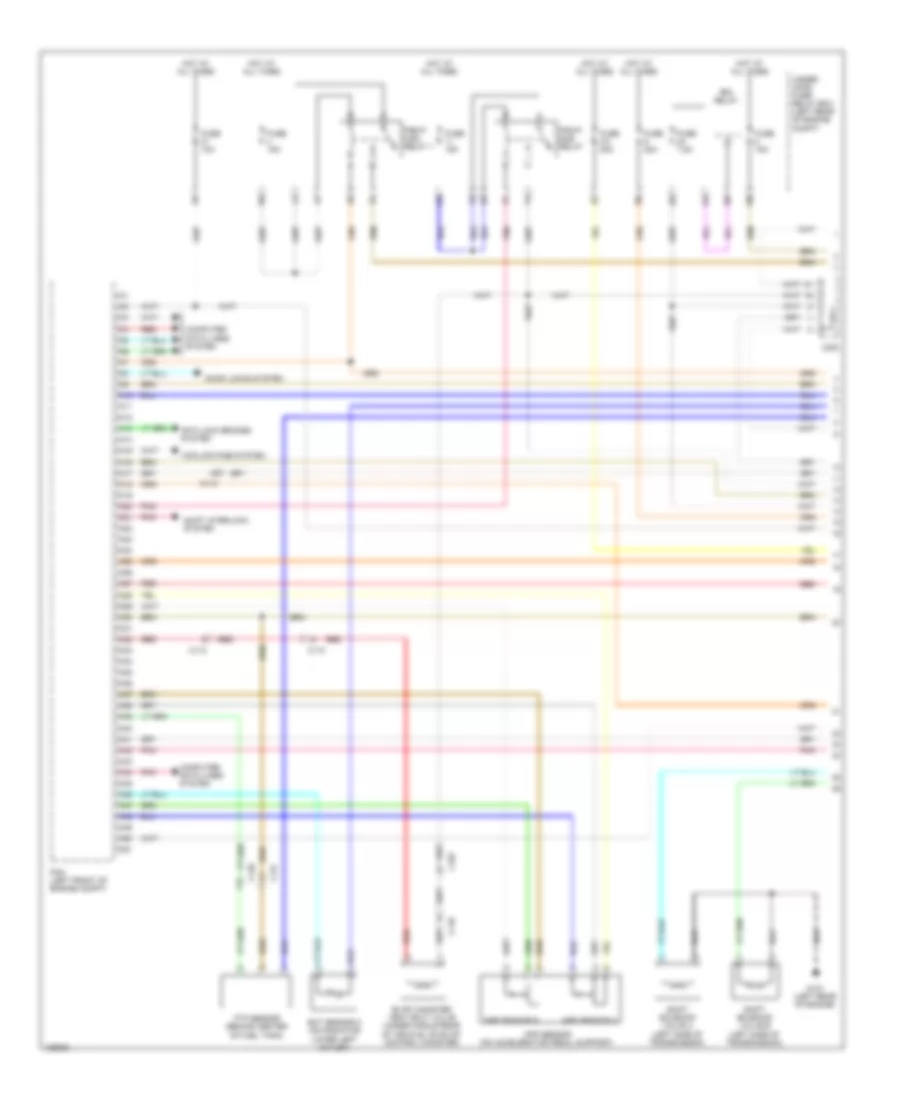
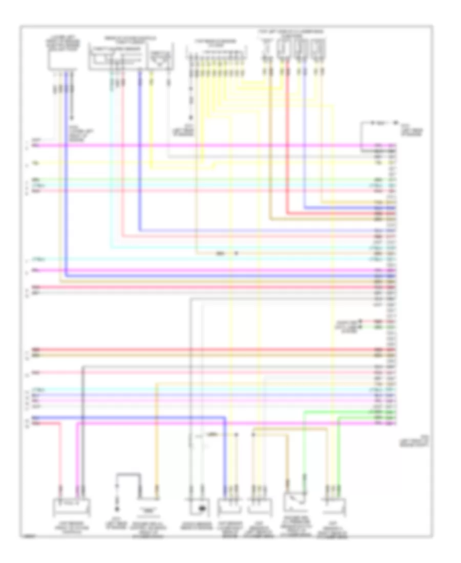
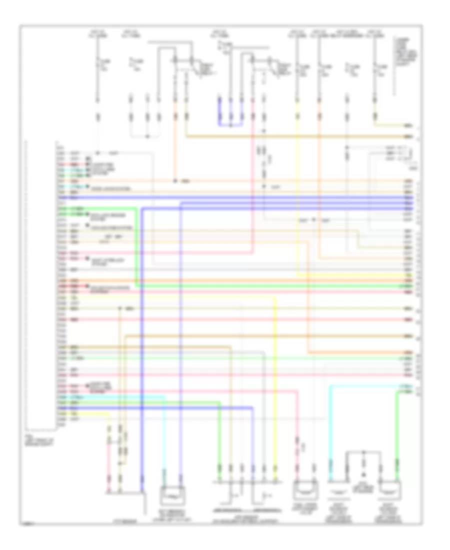
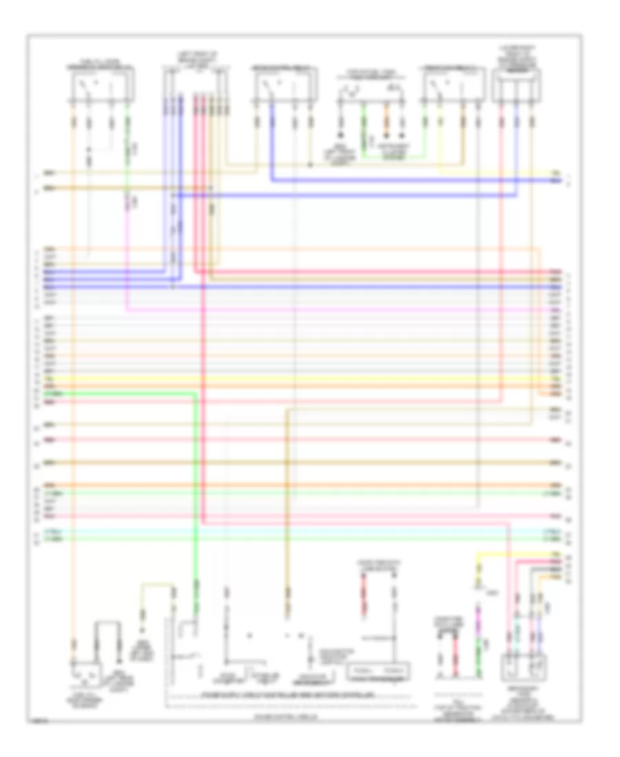
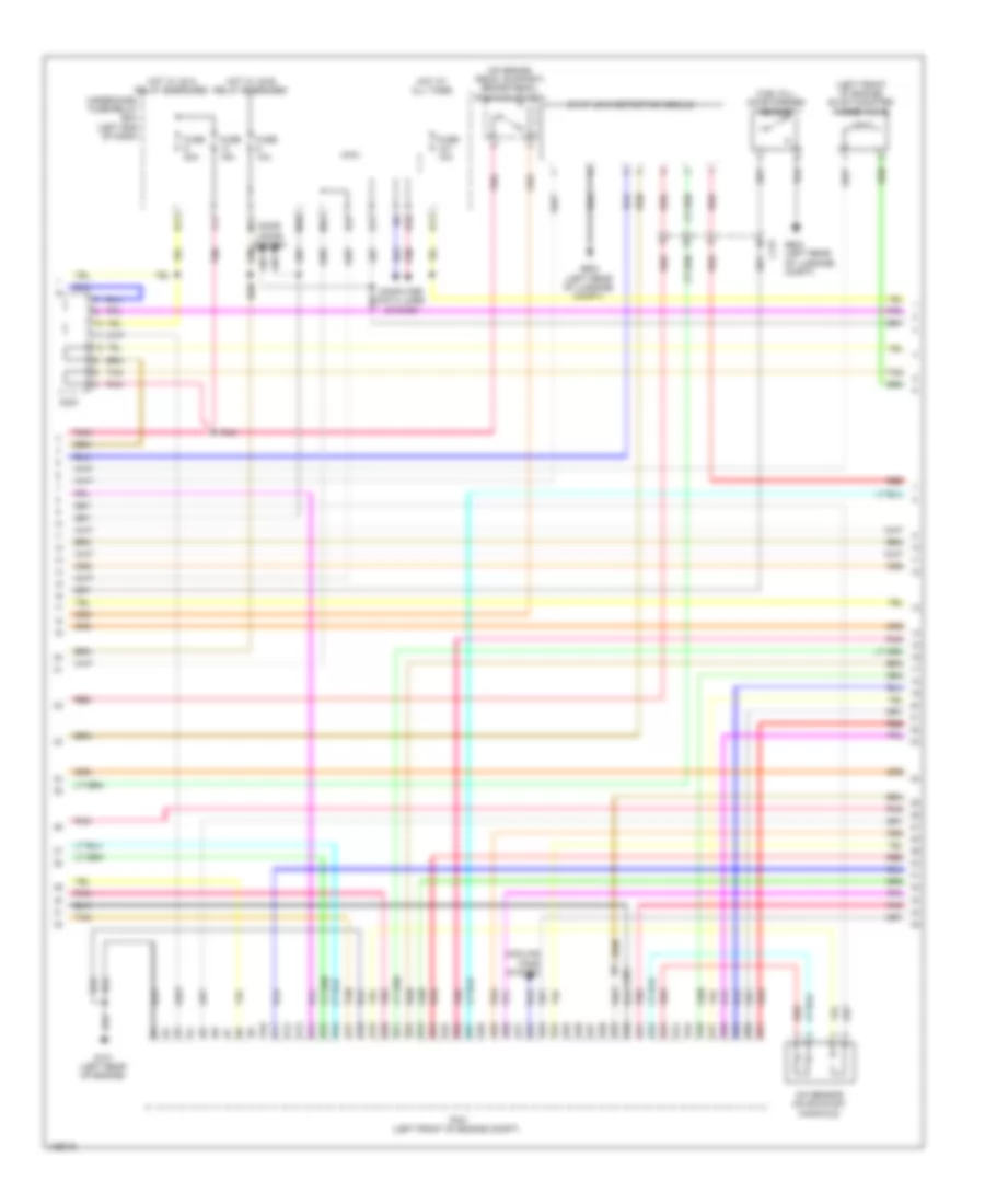
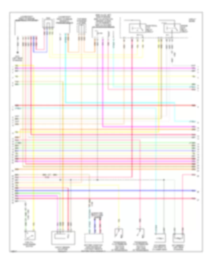
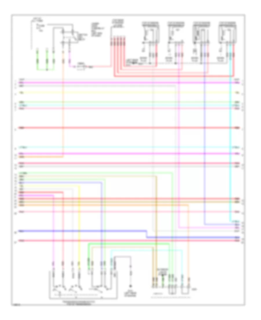
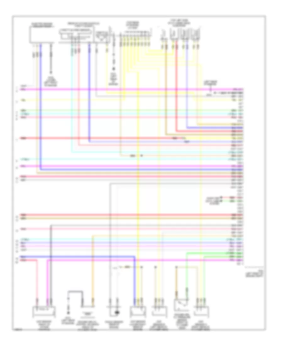
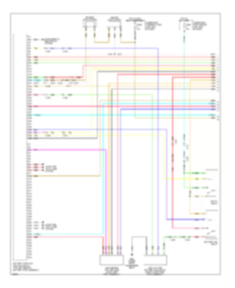
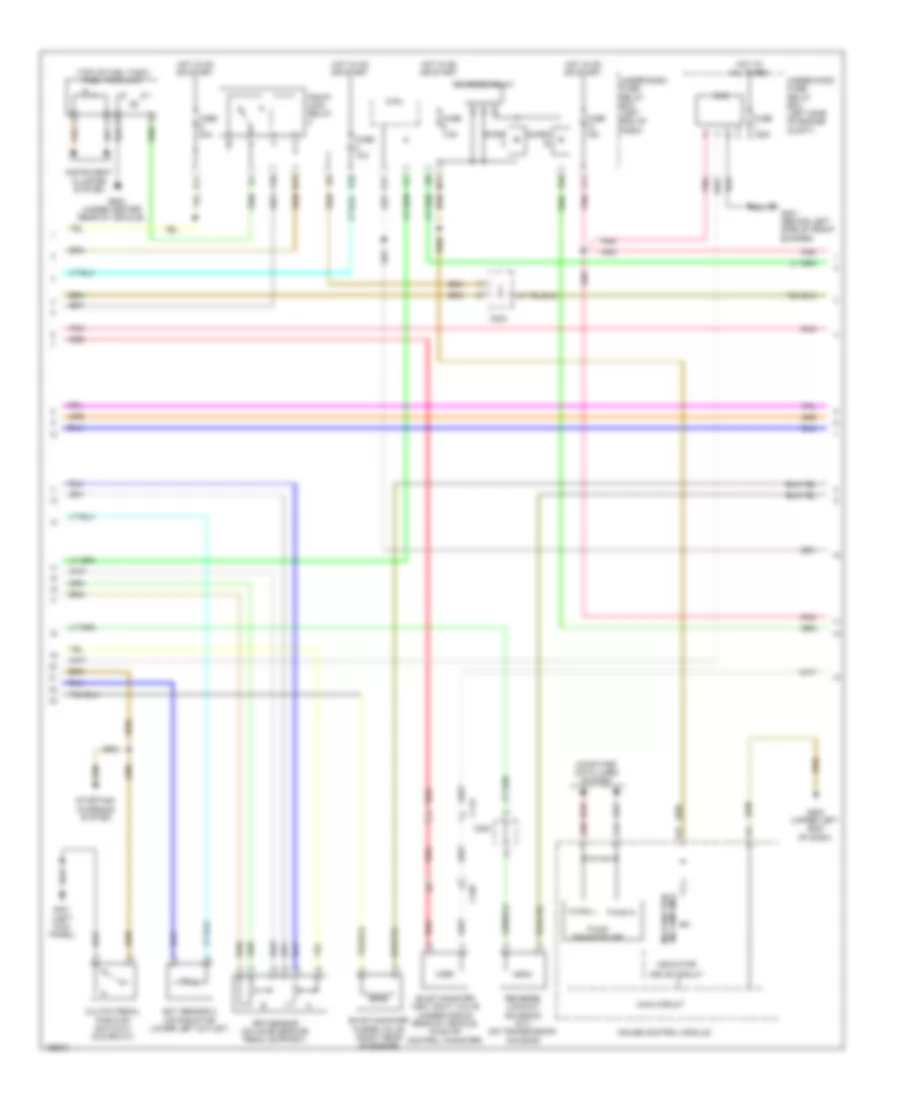
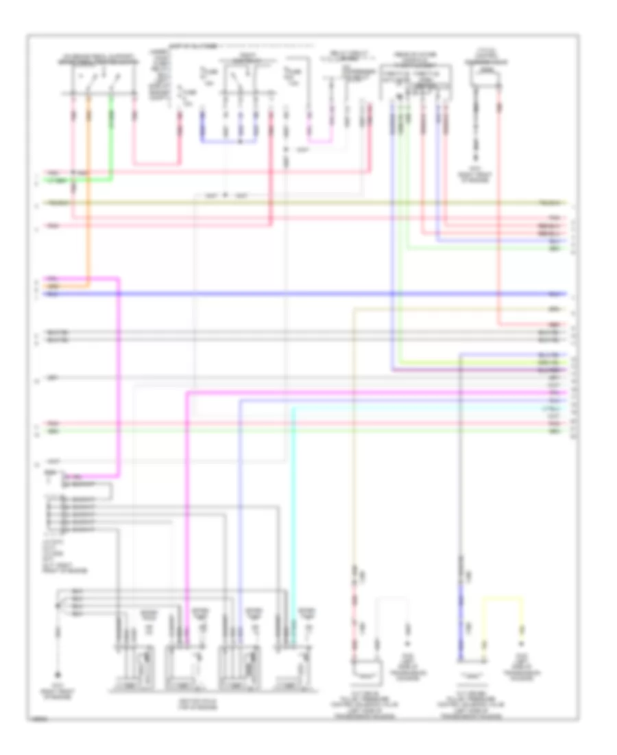
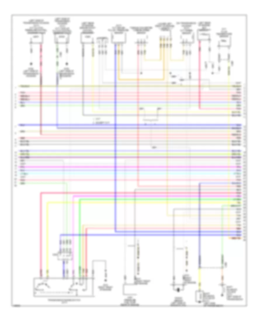
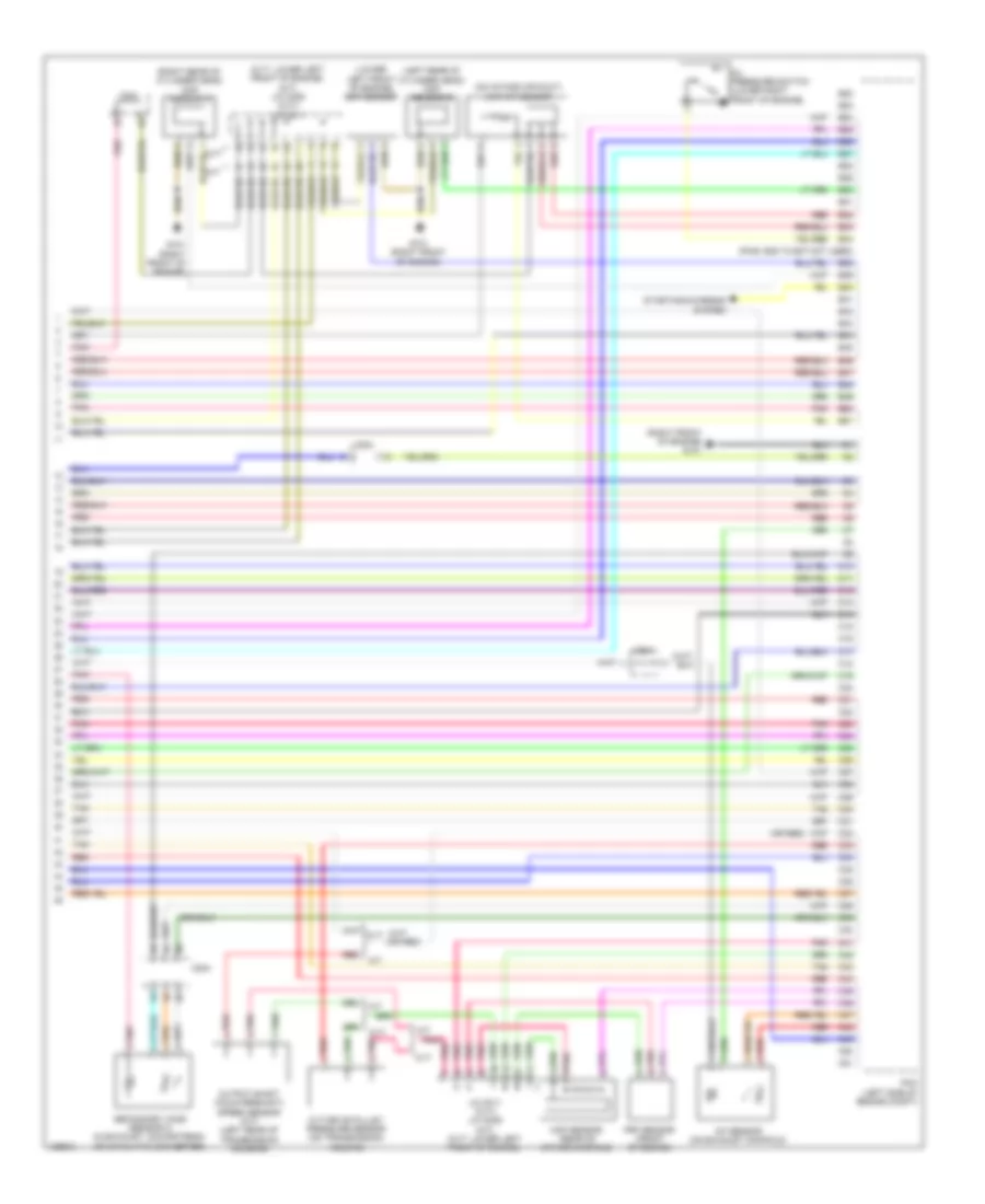
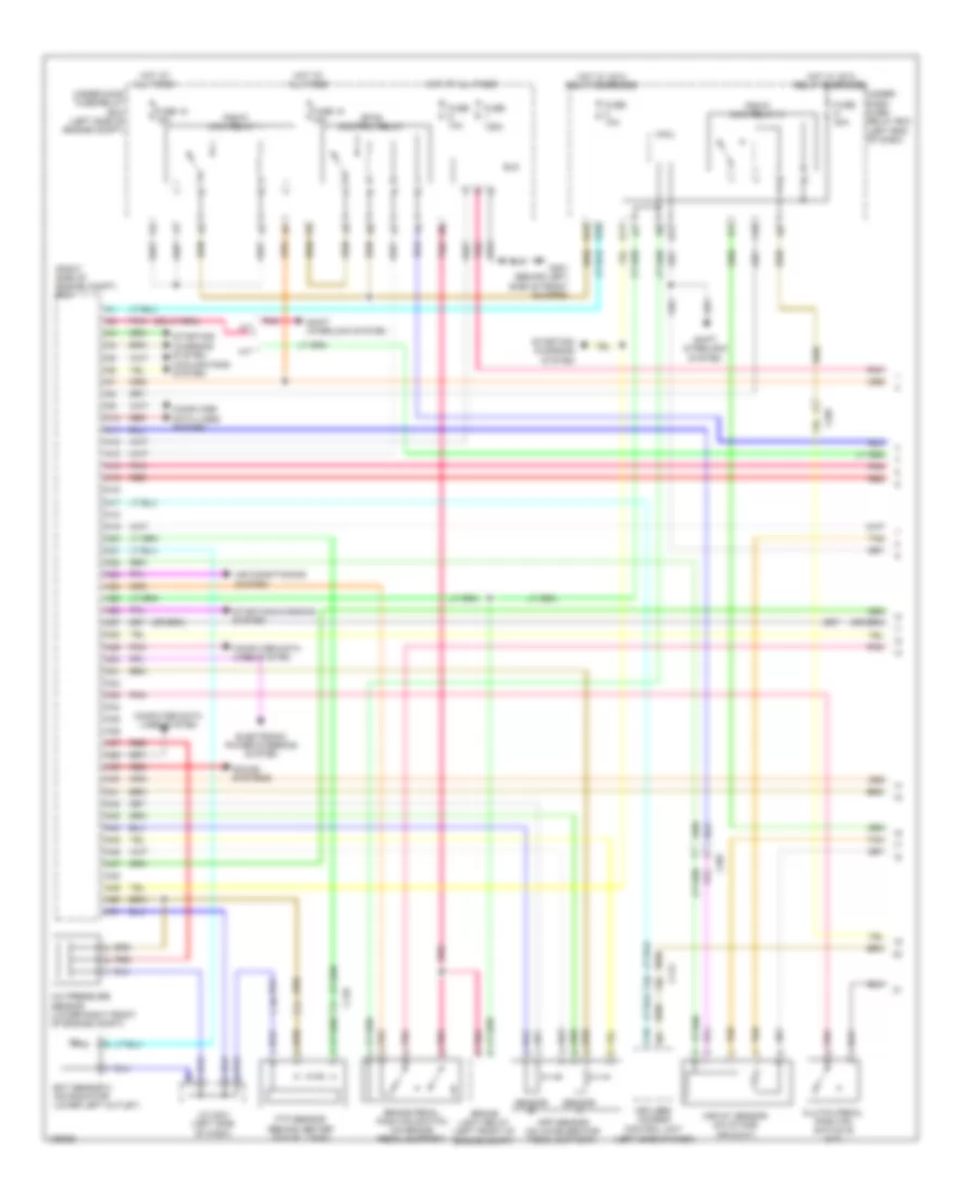
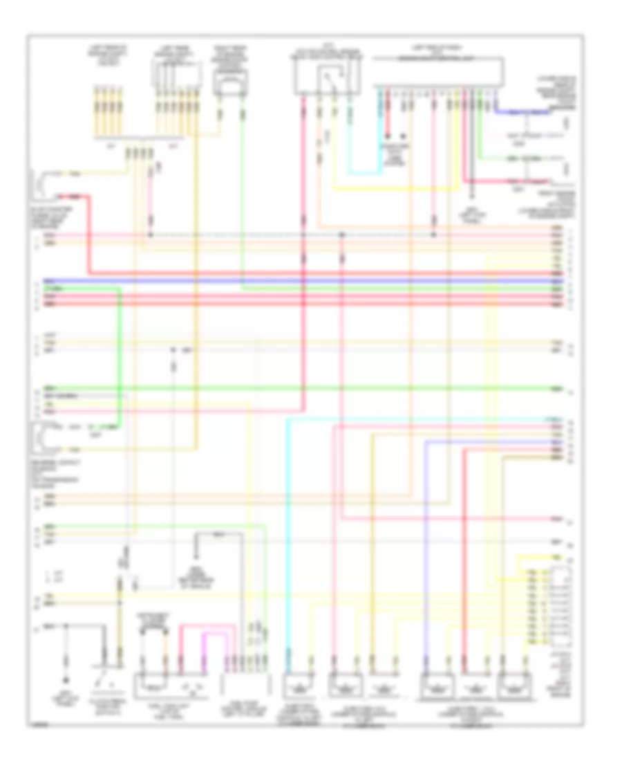
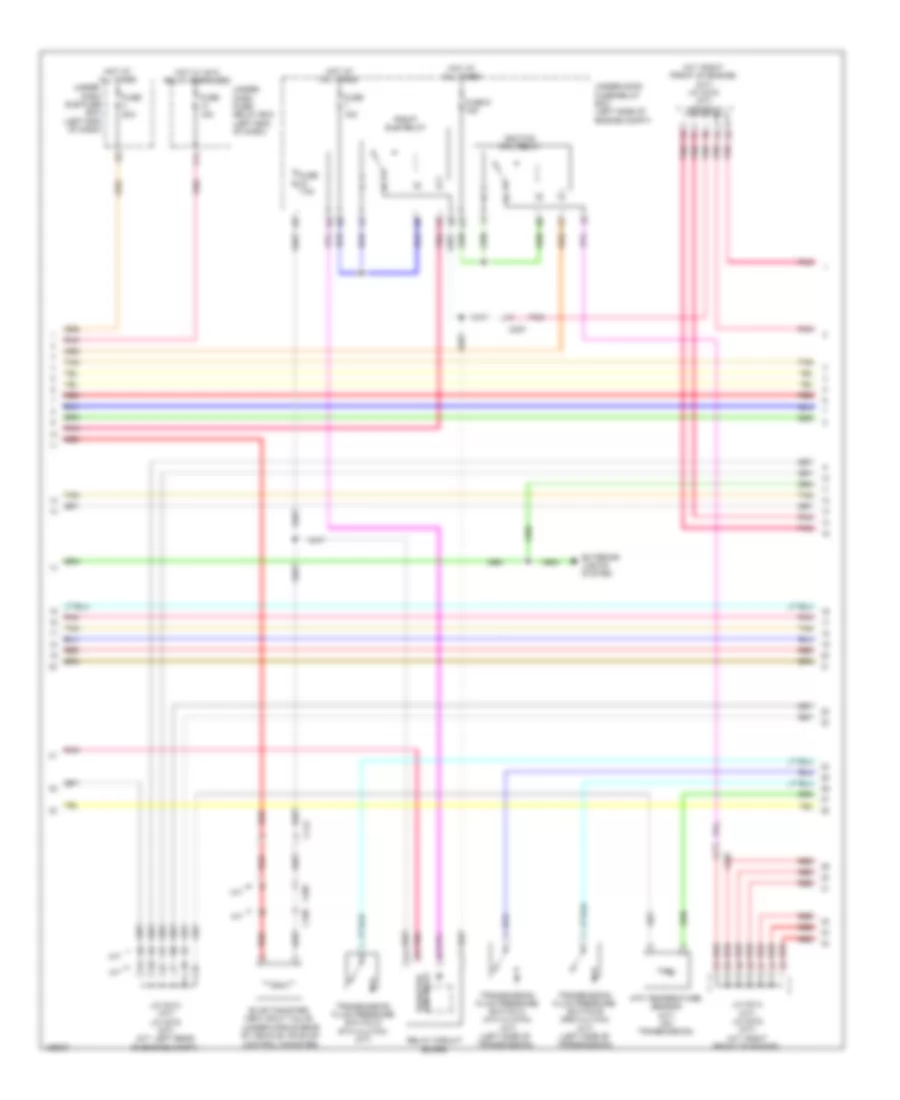
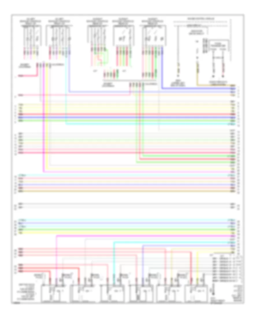
2.0L Hybrid, Engine Controls Wiring Diagram, Except Plug-In Hybrid (1 of 6) for Honda Accord Plug-In 2014
List of elements for 2.0L Hybrid, Engine Controls Wiring Diagram, Except Plug-In Hybrid (1 of 6) for Honda Accord Plug-In 2014:
- A10
- A11
- A12
- A13
- A14
- A15
- A16
- A17
- A18
- A19
- A20
- A21
- A22
- A23
- A24
- A25
- A26
- A27
- A28
- A29
- A30
- A31
- A32
- A33
- A34
- A35
- A36
- A37
- A38
- A39
- A40
- A41
- A42
- A43
- A44
- A45
- A46
- A47
- A48
- A49
- A50
- A51
- Anti-lock brakes system
- App sensor (on accelerator pedal support)
- App sensor a
- App sensor b
- C102
- C110
- C112
- C127
- C128
- C203
- Computer data lines system
- Cooling fans system
- Door locks system
- Ect sensor 2 (on radiator lower left outlet)
- Evap canister vent shut valve (under middle rear of vehicle, on evap control canister)
- Ftp sensor (behind center of fuel tank)
- Fuse 10a
- Fuse 15a
- Fuse 2-3 20a
- Fuse 20a
- Fuse 7.5a
- G101 (left rear of engine)
- Hot at all times
- Pcm (left front of engine compt)
- Pgm-fi main relay 1
- Pgm-fi sub relay
- Pnk
- Red
- Rfc relay
- Shift interlock system
- Shift solenoid valve a (left side of transmission)
- Shift solenoid valve b (left side of transmission)
- Under- hood fuse/ relay box (left rear of engine compt)
2.0L Hybrid, Engine Controls Wiring Diagram, Except Plug-In Hybrid (2 of 6) for Honda Accord Plug-In 2014
List of elements for 2.0L Hybrid, Engine Controls Wiring Diagram, Except Plug-In Hybrid (2 of 6) for Honda Accord Plug-In 2014:
- (left front of engine compt) j/c c012
- (lower right front of engine compt) a/c pressure sensor
- (right front of engine) evap canister purge valve 2
- (top of fuel tank) fuel tank unit
- A17
- A19
- A20
- C127
- C203
- C204
- C207
- Computer data lines system
- Dc-dc converter
- Etcs control relay
- F-can h
- F-can l
- F-can transceiver
- G502 (upper left end of dash)
- G602 (behind left rear seat)
- Gauge control module
- Indicator drive circuit
- Instrument cluster system
- Malfunction indicator lamp (mil)
- Pcu (top of traction/ generator motor assembly)
- Pgm-fi main relay 2
- Pnk
- Red
- Secondary ho2s (sensor 2) (in exhaust, downstream of catalytic converter)
- Stabilize circuit
- Tan
2.0L Hybrid, Engine Controls Wiring Diagram, Except Plug-In Hybrid (3 of 6) for Honda Accord Plug-In 2014
List of elements for 2.0L Hybrid, Engine Controls Wiring Diagram, Except Plug-In Hybrid (3 of 6) for Honda Accord Plug-In 2014:
- (left front of engine) evap canister purge valve
- (on brake pedal support) brake pedal position switch
- A/f sensor (on exhaust manifold)
- B10
- B11
- B12
- B13
- B14
- B15
- B16
- B17
- B18
- B19
- B20
- B21
- B22
- B23
- B24
- B25
- B26
- B27
- B28
- B29
- B30
- B31
- B32
- B33
- B34
- B35
- B36
- B37
- B38
- B39
- B40
- B41
- B42
- B43
- B44
- B45
- B46
- B47
- B48
- B49
- B50
- B51
- C201
- C203
- Computer data lines system
- Cooling fans system
- Door locks system
- E11
- E17
- E23
- F11
- Fuse 10a
- Fuse 15a
- Fuse 20a
- G101 (left rear of engine)
- Hot in on or start
- M10
- M11
- M12
- Micu
- Pcm (left front of engine compt)
- Pnk
- R10
- Red
- Tan
- Under-dash fuse/relay box (left end of dash)
2.0L Hybrid, Engine Controls Wiring Diagram, Except Plug-In Hybrid (4 of 6) for Honda Accord Plug-In 2014
List of elements for 2.0L Hybrid, Engine Controls Wiring Diagram, Except Plug-In Hybrid (4 of 6) for Honda Accord Plug-In 2014:
- (in egr valve assembly) egr valve & egr valve position sensor
- (lower right front of engine) electrical vtc motor
- (lower right front of engine) engine oil pressure sensor
- (top rear of engine) j/c c005
- A13
- Battery condition monitor module (top left rear of battery pack assembly)
- C10
- C130
- C132
- C203
- C206
- C30
- C403
- Circuit board
- Computer data lines system
- Ect sensor 1 (left rear of engine)
- Electrical vtc relay circuit
- Engine ewp relay circuit
- G102 (lower left front of engine)
- Inta sensor (top front of cylinder head)
- Maf/iat sensor (on intake air duct)
- Pnk
- Red
- Tan
- Transmission fluid pressure switch a (left side of transmission)
- Transmission fluid pressure switch b (left side of transmission)
2.0L Hybrid, Engine Controls Wiring Diagram, Except Plug-In Hybrid (5 of 6) for Honda Accord Plug-In 2014
List of elements for 2.0L Hybrid, Engine Controls Wiring Diagram, Except Plug-In Hybrid (5 of 6) for Honda Accord Plug-In 2014:
- (left rear of engine) g101
- (top of engine)
- (top rear of engine) j/c c005
- C203
- Exterior lights system
- Fuse 15a
- Fwd
- Fwd2
- G101 (left rear of engine)
- Gnd
- Hot at all times
- Icm
- Ignition coil 1
- Ignition coil 2
- Ignition coil 3
- Ignition coil 4
- Ignition coil relay
- Pnk
- Red
- Rvs
- Rvs2
- Spark plug
- Transmission range switch (top of transmission)
- Under- hood fuse/relay box (left rear of engine compt)
2.0L Hybrid, Engine Controls Wiring Diagram, Except Plug-In Hybrid (6 of 6) for Honda Accord Plug-In 2014
List of elements for 2.0L Hybrid, Engine Controls Wiring Diagram, Except Plug-In Hybrid (6 of 6) for Honda Accord Plug-In 2014:
- (lower left front of engine) electric engine coolant pump
- (rear of intake manifold) throttle body
- (right rear of cylinder head)
- (top left side of cylinder head) injectors
- (top rear of engine) j/c c005
- C10
- C11
- C12
- C13
- C14
- C15
- C16
- C17
- C18
- C19
- C20
- C21
- C22
- C23
- C24
- C25
- C26
- C27
- C28
- C29
- C30
- C31
- C32
- C33
- C34
- C35
- C36
- C37
- C38
- C39
- C40
- C41
- C42
- C43
- C44
- C45
- C46
- C47
- C48
- C49
- C50
- Ckp sensor (lower right rear of engine)
- Cmp
- Cmp sensor b (left rear of cylinder head)
- Computer data lines system
- G101 (left rear of engine)
- G102 (lower left front of engine)
- Knock sensor (rear of engine)
- Map sensor (front of intake manifold)
- Pcm (left front of engine compt)
- Pnk
- Red
- Rocker arm oil control solenoid (front of cylinder bank)
- Rocker arm oil pressure sensor switch (front of cylinder bank)
- Sensor a
- Tan
- Throttle actuator
- Throttle open sensor
2.0L Hybrid, Engine Controls Wiring Diagram, Plug-In Hybrid (1 of 6) for Honda Accord Plug-In 2014
List of elements for 2.0L Hybrid, Engine Controls Wiring Diagram, Plug-In Hybrid (1 of 6) for Honda Accord Plug-In 2014:
- A10
- A11
- A12
- A13
- A14
- A15
- A16
- A17
- A18
- A19
- A20
- A21
- A22
- A23
- A24
- A25
- A26
- A27
- A28
- A29
- A30
- A31
- A32
- A33
- A34
- A35
- A36
- A37
- A38
- A39
- A40
- A41
- A42
- A43
- A44
- A45
- A46
- A47
- A48
- A49
- A50
- A51
- Anti-lock brakes system
- App sensor (on accelerator pedal support)
- App sensor a
- App sensor b
- C113
- C131
- C203
- Computer data lines system
- Cooling fans system
- Door locks system
- Ect sensor 2 (on radiator lower left outlet)
- Ftp sensor
- Fuel vapor containment valve
- Fuse 10a
- Fuse 15a
- Fuse 2-3 20a
- Fuse 20a
- Fuse 7.5a
- G101 (left rear of engine)
- Hot at all times
- Hot w/ rfc relay energized
- Navigation & sound systems
- Pcm (left front of engine compt)
- Pgm-fi main relay 1
- Pgm-fi sub relay
- Pnk
- Red
- Shift interlock system
- Shift solenoid valve a (left side of transmission)
- Shift solenoid valve b (left side of transmission)
- Under- hood fuse/ relay box (left rear of engine compt)
2.0L Hybrid, Engine Controls Wiring Diagram, Plug-In Hybrid (2 of 6) for Honda Accord Plug-In 2014
List of elements for 2.0L Hybrid, Engine Controls Wiring Diagram, Plug-In Hybrid (2 of 6) for Honda Accord Plug-In 2014:
- (left front of engine compt) j/c c007
- (lower right front of engine compt) a/c pressure sensor
- (top of fuel tank) fuel tank unit
- (upper left end of dash)
- A17
- A19
- A20
- B12
- C131
- C132
- C201
- C203
- C207
- Computer data lines system
- Dc-dc converter
- Etcs control relay
- F-can h
- F-can l
- F-can transceiver
- Fuel fill door opener solenoid
- Fuel fill door opener solenoid relay
- G502
- G602 (left front of luggage compt)
- G603 (left rear of luggage compt)
- Gauge control module
- Indicator drive circuit
- Instrument cluster system
- Malfunction indicator lamp (mil)
- Pcu (top of traction/ generator motor assembly)
- Pgm-fi main relay 2
- Pnk
- Red
- Secondary ho2s (sensor 2) (in exhaust, downstream of catalytic converter)
- Stabilize circuit
- Tan
2.0L Hybrid, Engine Controls Wiring Diagram, Plug-In Hybrid (3 of 6) for Honda Accord Plug-In 2014
List of elements for 2.0L Hybrid, Engine Controls Wiring Diagram, Plug-In Hybrid (3 of 6) for Honda Accord Plug-In 2014:
- (left front of engine) evap canister purge valve
- (on brake pedal support) brake pedal position switch
- A/f sensor (on exhaust manifold)
- B10
- B11
- B12
- B13
- B14
- B15
- B16
- B17
- B18
- B19
- B20
- B21
- B22
- B23
- B24
- B25
- B26
- B27
- B28
- B29
- B30
- B31
- B32
- B33
- B34
- B35
- B36
- B37
- B38
- B39
- B40
- B41
- B42
- B43
- B44
- B45
- B46
- B47
- B48
- B49
- B50
- B51
- C131
- C201
- C203
- Computer data lines system
- Cooling fans system
- Door locks system
- E11
- E17
- E23
- Evap leak detection module
- F11
- Fuel fill door opener sensor
- Fuse 10a
- Fuse 15a
- Fuse 18-1 10a
- Fuse 20a
- G101 (left rear of engine)
- G603 (left rear of luggage compt)
- Hot at all times
- Hot w/ ig1a relay energized
- Hot w/ ig1b relay energized
- M10
- M11
- M12
- Micu
- Pcm (left front of engine compt)
- Pnk
- R10
- R11
- Red
- Tan
- Under-dash fuse/relay box (left end of dash)
2.0L Hybrid, Engine Controls Wiring Diagram, Plug-In Hybrid (4 of 6) for Honda Accord Plug-In 2014
List of elements for 2.0L Hybrid, Engine Controls Wiring Diagram, Plug-In Hybrid (4 of 6) for Honda Accord Plug-In 2014:
- (egr valve: left side of engine) (egr valve position sensor: on egr valve assembly) egr valve & egr valve position sensor
- (lower right front of engine) electrical vtc motor
- (lower right front of engine) engine oil pressure sensor
- (top rear of engine) j/c c006
- A13
- Battery condition monitor module (top right rear of battery pack assembly)
- C10
- C104
- C130
- C132
- C201
- C202
- C203
- C30
- C403
- Circuit board
- Computer data lines system
- Ect sensor 1 (left rear of engine)
- Electrical vtc relay circuit
- Engine ewp relay circuit
- Fuel fill door opener switch
- G101 (left rear of engine)
- Inta sensor (top front of cylinder head)
- Maf/iat sensor (on intake air duct)
- Pnk
- Red
- Tan
- Transmission fluid pressure switch a (left side of transmission)
- Transmission fluid pressure switch b (left side of transmission)
2.0L Hybrid, Engine Controls Wiring Diagram, Plug-In Hybrid (5 of 6) for Honda Accord Plug-In 2014
List of elements for 2.0L Hybrid, Engine Controls Wiring Diagram, Plug-In Hybrid (5 of 6) for Honda Accord Plug-In 2014:
- (left rear of engine) g101
- (top of engine) ignition coil 1
- (top of engine) ignition coil 2
- (top of engine) ignition coil 3
- (top of engine) ignition coil 4
- (top rear of engine) j/c c006
- C203
- Exterior lights system
- Fuse 15a
- Fwd
- Fwd2
- G101 (left rear of engine)
- Gnd
- Hot at all times
- Icm
- Ignition coil relay
- Pnk
- Red
- Rvs
- Rvs2
- Spark plug
- Transmission range switch (top of transmission)
- Under- hood fuse/relay box (left end of dash)
2.0L Hybrid, Engine Controls Wiring Diagram, Plug-In Hybrid (6 of 6) for Honda Accord Plug-In 2014
List of elements for 2.0L Hybrid, Engine Controls Wiring Diagram, Plug-In Hybrid (6 of 6) for Honda Accord Plug-In 2014:
- (left rear of engine)
- (rear of intake manifold) throttle body
- (top left side of cylinder head) injectors
- (top rear of engine) j/c c006
- C10
- C11
- C12
- C13
- C14
- C15
- C16
- C17
- C18
- C19
- C20
- C201
- C21
- C22
- C23
- C24
- C25
- C26
- C27
- C28
- C29
- C30
- C31
- C32
- C33
- C34
- C35
- C36
- C37
- C38
- C39
- C40
- C41
- C42
- C43
- C44
- C45
- C46
- C47
- C48
- C49
- C50
- C51
- Ckp sensor (lower right rear of engine)
- Cmp sensor a (right rear of cylinder head)
- Cmp sensor b (left rear of cylinder head)
- Computer data lines system
- Electric engine coolant pump
- G101
- G101 (left rear of engine)
- G102 (lower left front of engine)
- Knock sensor (rear of engine)
- Map sensor (front of intake manifold)
- Pcm (left front of engine compt)
- Pnk
- Red
- Rocker arm oil control solenoid (front of cylinder head)
- Rocker arm oil pressure sensor (front of cylinder head)
- Tan
- Throttle actuator
- Throttle open sensor
2.0L Hybrid, Hybrid System Wiring Diagram, Except Plug-In Hybrid (1 of 6) for Honda Accord Plug-In 2014
List of elements for 2.0L Hybrid, Hybrid System Wiring Diagram, Except Plug-In Hybrid (1 of 6) for Honda Accord Plug-In 2014:
- A10
- A11
- A12
- A13
- A14
- A15
- A16
- A17
- A18
- A19
- A20
- A21
- A22
- A23
- A24
- A25
- A26
- A27
- A28
- A29
- A30
- A31
- A32
- A33
- A34
- A35
- A36
- Battery condition monitor module (top left rear of battery pack assembly)
- Battery fan relay
- C10
- C104
- C11
- C111
- C12
- C126
- C127
- C129
- C13
- C14
- C15
- C16
- C17
- C18
- C19
- C20
- C21
- C22
- C23
- C24
- C25
- C26
- C27
- C28
- C29
- C30
- C31
- C32
- C33
- C34
- C35
- C36
- C37
- C38
- C39
- C40
- Center junction box
- Computer data lines system
- Driver's junction box
- Fuse 10a
- G652 (under front passenger's seat)
- High voltage battery module fan (front of battery pack assembly)
- Hot at all times
- Hot w/ ig1b relay energized
- Ighld 2 relay
- Leak sensor (top left side of battery pack assembly)
- M11
- Pnk
- Red
- Tan
- Under-dash fuse/relay box (left end of dash)
- Under-dash sub fuse box (left end of dash)
2.0L Hybrid, Hybrid System Wiring Diagram, Except Plug-In Hybrid (2 of 6) for Honda Accord Plug-In 2014
List of elements for 2.0L Hybrid, Hybrid System Wiring Diagram, Except Plug-In Hybrid (2 of 6) for Honda Accord Plug-In 2014:
- (behind left side of front bumper) g301
- (left side of traction/ generator motor assembly) j/c c004
- Air conditioning system
- B10
- C205
- Computer data lines system
- E23
- Fuse 10a
- Gate driver board
- Generator phase current sensor
- Hot at all times
- Ighld1 relay circuit
- Ipin
- Motor control module
- Motor phase current sensor
- Mpi module
- Pcu (top of traction/generator motor assembly)
- Pnk
- Power distribution system
- Reactor temperature sensor
- Red
- Relay circuit board
- T10
- Tan
- Under-dash fuse/relay box (left end of dash)
- Under-hood fuse/relay box (left rear of engine compt)
2.0L Hybrid, Hybrid System Wiring Diagram, Except Plug-In Hybrid (3 of 6) for Honda Accord Plug-In 2014
List of elements for 2.0L Hybrid, Hybrid System Wiring Diagram, Except Plug-In Hybrid (3 of 6) for Honda Accord Plug-In 2014:
- (left front of engine compt) j/c c012
- (left side of traction/ generator motor assembly) j/c c004
- C205
- C207
- C401
- C402
- C403
- Electric powertrain coolant temperature sensor (bottom left of radiator)
- Fuse 10a
- Fuse 15a
- Generator motor
- Generator motor rotor position sensor
- Generator motor temperature sensor
- Hot at all times
- Motor assembly
- Pnk
- Red
- Tan
- Traction motor
- Traction motor rotor position sensor
- Traction motor temperature sensor
- Transmission fluid temperature sensor (bottom rear of transmission housing)
- Under-hood fuse/relay box (left rear of engine compt)
2.0L Hybrid, Hybrid System Wiring Diagram, Except Plug-In Hybrid (4 of 6) for Honda Accord Plug-In 2014
List of elements for 2.0L Hybrid, Hybrid System Wiring Diagram, Except Plug-In Hybrid (4 of 6) for Honda Accord Plug-In 2014:
- (diagram 6 of 6)
- (left front of battery pack assembly) contactor board
- B10
- B11
- B12
- B13
- B14
- B15
- B16
- B17
- B18
- B19
- B20
- B21
- B22
- B23
- B24
- B25
- B26
- B27
- B28
- B29
- B30
- B31
- B32
- Battery condition monitor module (top left rear of battery pack assembly)
- Battery current sensor
- Bypass contactor relay
- C203
- C207
- Computer data lines system
- From battery pack a
- G101 (left rear of engine)
- G801 (top left side of battery pack assembly)
- High voltage contactor relay
- J/c c003 (top left side of battery pack assembly)
- Pcm (left front of engine compt)
- Pnk
- Red
- T131
- T152
- Tan
2.0L Hybrid, Hybrid System Wiring Diagram, Except Plug-In Hybrid (5 of 6) for Honda Accord Plug-In 2014
List of elements for 2.0L Hybrid, Hybrid System Wiring Diagram, Except Plug-In Hybrid (5 of 6) for Honda Accord Plug-In 2014:
- (left rear of battery pack assembly) j/c c001
- (left rear of battery pack assembly) j/c c002
- (left rear of engine compt) g351
- (top right front of battery pack assembly) g655
- (top right of battery pack assembly) dc-dc converter
- 12 volt charging system indicator
- A/c compressor (left front of engine)
- A17
- A19
- A20
- C111
- C129
- C404
- C405
- Computer data lines system
- Dimming circuit
- Ev indicator
- Ev switch
- F- can h
- F- can l
- F-can transceiver
- Fuse 150a
- Fuse 15a
- G502 (upper left end of dash)
- Gauge control module
- Hot at all times
- Hot w/ ig1a relay energized
- Indicator drive circuit
- Pnk
- Power system indicator
- Red
- T101
- T122
- T141
- T142
- Tan
- Under-dash fuse/relay box (left end of dash)
- Under-hood fuse/relay box (left rear of engine compt)
2.0L Hybrid, Hybrid System Wiring Diagram, Except Plug-In Hybrid (6 of 6) for Honda Accord Plug-In 2014
List of elements for 2.0L Hybrid, Hybrid System Wiring Diagram, Except Plug-In Hybrid (6 of 6) for Honda Accord Plug-In 2014:
- 30a
- Battery module temperature sensor 1
- Battery module temperature sensor 2
- Battery module temperature sensor 3
- Battery module temperature sensor 4
- Battery module temperature sensor 5
- Battery pack (under luggage compt floor)
- Cell voltage sensor 1
- Cell voltage sensor 2
- Cell voltage sensor 3
- Computer data lines system
- High voltage sub contactor relay
- Junction board (right front of battery pack assembly)
- Main fuse 200a
- Pnk
- Red
- Service plug
- T123
- T124
- T132
- T143
- T144
- T151
- T181
- T182
- Tan
- To contactor board (diagram 4 of 6)
2.0L Hybrid, Hybrid System Wiring Diagram, Plug-In Hybrid (1 of 10) for Honda Accord Plug-In 2014
List of elements for 2.0L Hybrid, Hybrid System Wiring Diagram, Plug-In Hybrid (1 of 10) for Honda Accord Plug-In 2014:
- (left front of battery pack assembly)
- (top right front of battery pack assembly)
- (top right of battery pack assembly) dc-dc converter
- A10
- A11
- A12
- A13
- A14
- A15
- A16
- A17
- A18
- A19
- A20
- A21
- A22
- A23
- A24
- A25
- A26
- A27
- A28
- A29
- A30
- A31
- A32
- A33
- A34
- A35
- A36
- Air conditioning system
- Battery condition monitor module (top right rear of battery pack assembly)
- C104
- C111
- C119
- C126
- C130
- C131
- C132
- C201
- C206
- C401
- C403
- C404
- C405
- Center junction box
- Charge lid actuator (left end of dash)
- Charge lid illumination lamp switch
- Charge lid illumination lamp/charge indicator
- Charge lid illumination lamp/charge indicator relay (in under-dash fuse/relay box b)
- Charge lid opener switch
- Cooling fans system
- Drive's junction box
- E23
- Fuse 10a
- Fuse 150a
- Fuse 18-1 10a
- G301 (under left headlight assembly)
- G351 (left rear of engine compt)
- G401 (left kick panel)
- G502 (upper left end of dash)
- G655 (bottom left front of battery pack assembly)
- G804
- G805
- Hot at all times
- J/c c007 (left front of engine compt)
- M11
- Micu
- P16
- P20
- P21
- Pnk
- R11
- Red
- T101
- T65
- T66
- T71
- Tan
- Under dash fuse/relay box (left end of dash)
- Under hood fuse/relay box (left rear of engine compt)
2.0L Hybrid, Hybrid System Wiring Diagram, Plug-In Hybrid (2 of 10) for Honda Accord Plug-In 2014
List of elements for 2.0L Hybrid, Hybrid System Wiring Diagram, Plug-In Hybrid (2 of 10) for Honda Accord Plug-In 2014:
- (bottom center front of battery pack assembly)
- (left rear of engine compt)
- (top front of battery pack assembly)
- (top left rear of battery pack assembly)
- (top right front of battery pack assembly)
- Battery charger
- Battery condition monitor module (top right rear of battery pack assembly)
- C10
- C11
- C118
- C12
- C126
- C13
- C130
- C131
- C132
- C14
- C15
- C16
- C17
- C18
- C19
- C20
- C206
- C21
- C22
- C23
- C24
- C25
- C26
- C27
- C28
- C29
- C30
- C31
- C32
- C33
- C34
- C35
- C36
- C37
- C38
- C39
- C40
- C401
- C403
- C405
- C406
- C410
- Charge ac condenser
- Charge inlet
- Computer data lines system
- G532
- G656
- G802
- G803
- G804
- J/c c015 (bottom right front of battery pack assembly)
- Pnk
- Red
- T11
- T12
- T13
- T14
- T61
- T63
- Tan
- Transmissions system
2.0L Hybrid, Hybrid System Wiring Diagram, Plug-In Hybrid (3 of 10) for Honda Accord Plug-In 2014
List of elements for 2.0L Hybrid, Hybrid System Wiring Diagram, Plug-In Hybrid (3 of 10) for Honda Accord Plug-In 2014:
- (bottom left front of battery pack assembly) leak sensor
- Battery current sensor
- Battery pack
- Bypass contactor
- C401
- C411
- Cell voltage sensor 1
- Cell voltage sensor 2
- Computer data lines system
- High voltage battery module temperature sensor
- High voltage contactor
- High voltage sub contactor
- Junction board (right front of battery pack assembly)
- Main switch
- Pnk
- Red
- T51
- T52
- T57
- T62
- T64
- T72
- Tan
- To cell voltage sensor 3 (diagram 5 of 10)
2.0L Hybrid, Hybrid System Wiring Diagram, Plug-In Hybrid (4 of 10) for Honda Accord Plug-In 2014
List of elements for 2.0L Hybrid, Hybrid System Wiring Diagram, Plug-In Hybrid (4 of 10) for Honda Accord Plug-In 2014:
- (left front of battery pack assembly) j/c c017
- (left rear of engine compt)
- (top left center of battery pack assembly) j/c c012
- (top right center of battery pack assembly) j/c c010
- C130
- C131
- C206
- C401
- C403
- C404
- C405
- C413
- G532
- G801 (top left center of battery pack assembly)
- J/c c014
- J/c c016 (right front of battery pack assembly)
- Pnk
- Red
- Tan
2.0L Hybrid, Hybrid System Wiring Diagram, Plug-In Hybrid (5 of 10) for Honda Accord Plug-In 2014
List of elements for 2.0L Hybrid, Hybrid System Wiring Diagram, Plug-In Hybrid (5 of 10) for Honda Accord Plug-In 2014:
- (in ipu relay holder 1) ighldb relay
- (top right rear of battery pack assembly) battery condition monitor module
- B10
- B11
- B12
- B13
- B14
- B15
- B16
- B17
- B18
- B19
- B20
- B21
- B22
- B23
- B24
- B25
- B26
- B27
- B28
- B29
- B30
- B31
- B32
- Battery pack
- C112
- C118
- C126
- C130
- C131
- C401
- C402
- C403
- C405
- C412
- C413
- Cell voltage sensor 3
- Cell voltage sensor 4
- Computer data lines system
- From a cell voltage sensor 2 (diagram 3 of 10)
- Fuse 10a
- High voltage battery module temperature sensor
- Hot at all times
- Pnk
- Red
- Tan
- Under dash sub fuse box (left end of dash)
2.0L Hybrid, Hybrid System Wiring Diagram, Plug-In Hybrid (6 of 10) for Honda Accord Plug-In 2014
List of elements for 2.0L Hybrid, Hybrid System Wiring Diagram, Plug-In Hybrid (6 of 10) for Honda Accord Plug-In 2014:
- 10v line
- 12 volt charging system indicator
- A17
- A30
- A31
- B- can h
- B- can l
- B-can transceiver
- B39
- C203
- Computer data lines system
- Dimming circuit
- Ev indicator
- G502 (upper left end of dash)
- Gauge control module
- Hv indicator
- Hv switch
- Illumination control & dimming circuit for lcd (mid) back light (white)
- Pcm (left front of engine compt)
- Pnk
- Power system indicator
- Red
- Tan
2.0L Hybrid, Hybrid System Wiring Diagram, Plug-In Hybrid (7 of 10) for Honda Accord Plug-In 2014
List of elements for 2.0L Hybrid, Hybrid System Wiring Diagram, Plug-In Hybrid (7 of 10) for Honda Accord Plug-In 2014:
- (bottom left front of battery pack assembly) g655
- (bottom right front of battery pack assembly) j/c c015
- (left front of battery pack assembly) j/c c017
- (top right center of battery pack assembly) j/c c010
- Battery pack
- C130
- C205
- C207
- C401
- C403
- C413
- C414
- Cell voltage sensor 5
- Cell voltage sensor 6
- Computer data lines system
- High voltage battery module temperature sensor
- J/c c014
- Pnk
- Red
- Tan
- To cell voltage sensor 7 (diagram 8 of 10)
2.0L Hybrid, Hybrid System Wiring Diagram, Plug-In Hybrid (8 of 10) for Honda Accord Plug-In 2014
List of elements for 2.0L Hybrid, Hybrid System Wiring Diagram, Plug-In Hybrid (8 of 10) for Honda Accord Plug-In 2014:
- B10
- Battery pack
- C130
- C131
- C205
- C405
- C414
- Cell voltage sensor 7
- Cell voltage sensor 8
- Computer data lines system
- From cell b
- Fuse 10a
- G301 (under left headlight assembly)
- High voltage battery module temperature sensor
- Hot at all times
- Ighld1 relay
- J/c c013 (left side of transmission)
- Pnk
- Red
- Relay circuit board
- Tan
- Under hood fuse/relay box (left rear of engine compt)
- Voltage sensor 6 (diagram 7 of 10)
2.0L Hybrid, Hybrid System Wiring Diagram, Plug-In Hybrid (9 of 10) for Honda Accord Plug-In 2014
List of elements for 2.0L Hybrid, Hybrid System Wiring Diagram, Plug-In Hybrid (9 of 10) for Honda Accord Plug-In 2014:
- (top of traction/generator motor assembly) pcu
- Air conditioning system
- Computer data lines system
- Gate driver board
- Ipin
- Motor control module
- Mpi module
- Phase generator current sensor
- Phase motor current sensor
- Pnk
- Reactor temperature sensor
- Red
- Tan
2.0L Hybrid, Hybrid System Wiring Diagram, Plug-In Hybrid (10 of 10) for Honda Accord Plug-In 2014
List of elements for 2.0L Hybrid, Hybrid System Wiring Diagram, Plug-In Hybrid (10 of 10) for Honda Accord Plug-In 2014:
- (bottom left of radiator) electric powertrain coolant temperature sensor
- (bottom rear of transmission housing) transmission fluid temperature sensor
- (left side of transmission) j/c c013
- C207
- C407
- C408
- C409
- Generator motor
- Generator motor rotor position sensor
- Generator motor temperature sensor
- Motor assembly
- Pnk
- Red
- Traction motor
- Traction motor rotor position sensor
- Traction motor temperature sensor
2.4L
2.4L, Engine Performance Wiring Diagram (1 of 5) for Honda Accord Plug-In 2014
List of elements for 2.4L, Engine Performance Wiring Diagram (1 of 5) for Honda Accord Plug-In 2014:
- A/c pressure sensor (lower right front of engine compt)
- A10
- A11
- A12
- A13
- A14
- A15
- A16
- A17
- A18
- A19
- A20
- A21
- A22
- A23
- A24
- A25
- A26
- A27
- A28
- A29
- A30
- A31
- A32
- A33
- A34
- A35
- A36
- A37
- A38
- A39
- A40
- A41
- A42
- A43
- A44
- A45
- A46
- A47
- A48
- A49
- A50
- A51
- Air conditioning system
- B10
- B11
- B12
- B13
- B14
- B15
- B16
- B17
- B18
- B19
- B20
- B21
- C129
- Clutch pedal position switch b (m/t)
- Computer data lines system
- Cooling fans system
- Door locks system
- Electronic power steering system
- Etcs control relay
- Ftp sensor (behind center of fuel tank)
- Fuse 15a
- Fuse 20a
- G101 (right front of engine)
- G102 (left rear of engine)
- G401 (left kick panel)
- Hot at all times
- Ignition coil relay
- Injector relay
- Injectors (top left side of cylinder head)
- J/c c021 (left side of dash)
- Nca
- Pcm (left side of engine compt)
- Pgm-fi main relay 1
- Pnk
- Red
- Rocker arm oil control solenoid (front of cylinder bank)
- Rocker arm oil pressure switch (front of cylinder bank)
- Shift interlock system
- Sound systems
- Starting/ charging system
- Starting/charging system
- Under- hood fuse/ relay box (left side of engine compt)
2.4L, Engine Performance Wiring Diagram (2 of 5) for Honda Accord Plug-In 2014
List of elements for 2.4L, Engine Performance Wiring Diagram (2 of 5) for Honda Accord Plug-In 2014:
- (top of fuel tank) fuel tank unit
- (under center rear of vehicle)
- A17
- A19
- A20
- App sensor (on accelerator pedal support)
- C105
- C112
- C204
- Clutch pedal position switch a (coupe m/t)
- Computer data lines system
- Diode b
- Diode c
- Drive circuit
- E10
- E11
- E13
- E16
- E17
- Ect sensor 2 (on radiator lower left outlet)
- Eld
- Evap canister purge valve (right rear of engine)
- Evap canister vent shut valve (under middle rear of vehicle, on evap control canister)
- F-can h
- F-can l
- F-can transceiver
- F11
- F18
- Fuse 10a
- Fuse 125a
- Fuse 15a
- Fuse 20a
- Fuse 7.5a
- G301 (behind left side of front bumper)
- G401 (left kick panel)
- G502 (upper left end of dash)
- G602
- Gauge control module
- Hot at all times
- Hot in on or start
- Ind lamp (mil) malfunction
- Indicator
- Instrument cluster system
- M11
- Main circuit
- Micu
- Pgm-fi main relay
- Pnk
- Red
- Reverse lockout solenoid (m/t) (on transmission housing)
- Reverse relay
- Starting/ charging system
- Under-dash fuse/ relay box (left end of dash)
- Under-hood fuse/ relay box (left side of engine compt)
2.4L, Engine Performance Wiring Diagram (3 of 5) for Honda Accord Plug-In 2014
List of elements for 2.4L, Engine Performance Wiring Diagram (3 of 5) for Honda Accord Plug-In 2014:
- (on brake pedal support) brake pedal position switch
- (rear of intake manifold) throttle body
- A/c compressor fan relay
- C204
- C205
- C302
- Cvt drive pulley pressure control solenoid valve (left side of transmission housing)
- Cvt driven pulley pressure control solenoid valve (left side of transmission housing)
- Fuse 10a
- Fuse 15a
- Fuse 7.5a
- G101 (right front of engine)
- G151 (left side of transmission housing)
- Hot at all times
- Icm
- Ignition coils (top of engine)
- J/c c010 (cvt) j/c c008 (m/t) (cvt: right front of engine)
- Pgm-fi sub relay
- Pnk
- Red
- Relay circuit board
- Spark plug
- Throttle actuator
- Throttle open sensor
- Under- hood fuse/ relay box (left side of engine compt)
- Vtc oil control solenoid valve
2.4L, Engine Performance Wiring Diagram (4 of 5) for Honda Accord Plug-In 2014
List of elements for 2.4L, Engine Performance Wiring Diagram (4 of 5) for Honda Accord Plug-In 2014:
- (cvt) cvt driven pulley pressure sensor
- (left rear of engine) ect sensor 1
- (left rear of engine) engine mount control solenoid
- (left side of transmission housing) (cvt) cvt clutch pressure control solenoid valve
- (left side of transmission housing) (cvt) cvt lock-up clutch control solenoid valve
- (lower left front of engine) j/c c011
- (on transmission housing) (cvt) cvt speed sensor
- C204
- C205
- C302
- Cvt
- Cvt fluid temperature sensor
- Except cvt
- G101 (right front of engine)
- G152 (left side of transmission housing)
- High pressure fuel pump (rear of engine)
- J/c c009
- Knock sensor (left side of engine block)
- Pnk
- Red
- Shift solenoid valve b (cvt) (left side of transmission)
- Shift solenoid valve o/p (cvt) (left side of transmission)
- Tan
- Torque converter turbine speed sensor
- Transmission range switch (cvt)
2.4L, Engine Performance Wiring Diagram (5 of 5) for Honda Accord Plug-In 2014
List of elements for 2.4L, Engine Performance Wiring Diagram (5 of 5) for Honda Accord Plug-In 2014:
- (cvt: lower left front of engine) (m/t) j/c c009 (cvt) j/c c011
- (left rear of cylinder head) cmp sensor b
- (lower left front of engine) ckp sensor
- (on intake air duct) maf/iat sensor
- (or red)
- (pins: b35 to b37 not used)
- (right front of engine) g101
- (right rear of cylinder head) cmp sensor a
- A/f sensor (on exhaust manifold)
- B22
- B23
- B24
- B25
- B26
- B27
- B28
- B29
- B30
- B31
- B32
- B33
- B34
- B38
- B39
- B40
- B41
- B42
- B43
- B44
- B45
- B46
- B47
- B48
- B49
- B50
- B51
- C10
- C11
- C12
- C13
- C14
- C15
- C16
- C17
- C18
- C19
- C20
- C204
- C21
- C22
- C23
- C24
- C25
- C26
- C27
- C28
- C29
- C30
- C31
- C32
- C33
- C34
- C35
- C36
- C37
- C38
- C39
- C40
- C41
- C42
- C43
- C44
- C45
- C46
- C47
- C48
- C49
- C50
- C51
- Cvt
- Cvt drive pulley pressure sensor (on transmission housing)
- Frp sensor (front of engine)
- G101 (right front of engine)
- J/c c011 (cvt) j/c c009 (m/t) (cvt: lower left front of engine)
- M/t
- M/t pnk
- Map sensor (rear of intake manifold)
- Oil pressure switch (lower right front of engine)
- Output shaft (countershaft) speed sensor (m/t) (left rear of transmission housing)
- Pcm (left side of engine compt)
- Pnk
- Red
- Secondary ho2s (sensor 2) (in exhaust, downstream of catalytic converter)
- Starting/charging
- System
- Tan
3.5L
3.5L, Engine Performance Wiring Diagram (1 of 7) for Honda Accord Plug-In 2014
List of elements for 3.5L, Engine Performance Wiring Diagram (1 of 7) for Honda Accord Plug-In 2014:
- (left side of dash)
- (right side of engine compt) pcm
- A/c pressure sensor (lower right front of engine compt)
- A/t
- A10
- A11
- A12
- A13
- A14
- A15
- A16
- A17
- A18
- A19
- A20
- A21
- A22
- A23
- A24
- A25
- A26
- A27
- A28
- A29
- A30
- A31
- A32
- A33
- A34
- A35
- A36
- A37
- A38
- A39
- A40
- A41
- A42
- A43
- A44
- A45
- A46
- A47
- A48
- A49
- A50
- A51
- Air conditioning system
- App sensor (on accelerator pedal support)
- Brake light relay (left front of engine compt)
- Brake pedal position switch (on brake pedal support)
- C112
- C129
- C18
- C207
- Clutch pedal position switch b (m/t)
- Computer data lines system
- Cooling fans system
- E10
- E11
- E13
- E17
- Ect sensor 2 (on radiator lower left outlet)
- Eld
- Electronic power steering system
- Etcs control relay
- F18
- Ftp sensor (behind center of fuel tank)
- Fuse 10a
- Fuse 125a
- Fuse 15 15a
- Fuse 18 15a
- Fuse 20a
- G301 (behind left side of front bumper)
- Hot at all times
- Hot w/ ig1a relay energized
- J/c c021 (left side of dash)
- Keyless access control unit
- M/t
- Maf/iat sensor (on intake air duct)
- Micu
- Pgm-fi main relay 1
- Pgm-fi main relay 2
- Pnk
- Red
- Sensor a
- Sensor b
- Shift interlock system
- Sound systems
- Starting/ charging system
- Starting/charging system
- Tan
- Under- dash fuse/ relay box (left end of dash)
- Under-hood fuse/relay box (left side of engine compt)
3.5L, Engine Performance Wiring Diagram (2 of 7) for Honda Accord Plug-In 2014
List of elements for 3.5L, Engine Performance Wiring Diagram (2 of 7) for Honda Accord Plug-In 2014:
- (a/t) active control engine mount (acm) control relay
- (left end of dash) (a/t) engine mount control unit
- (left rear engine compt) j/c c017
- (left rear of engine compt) j/c c012
- (lower middle rear of engine compt) rear engine mount actuator
- (right rear of engine) engine mount control solenoid
- A/t
- C112
- C129
- C201
- C202
- C207
- Clutch pedal position switch a
- Computer data lines system
- Evap canister purge valve (right rear of engine)
- Front engine mount actuator (lower middle front of engine compt)
- Fuel pump control module (left "c" pillar)
- Fuel tank unit (top of fuel tank)
- G401 (left kick panel)
- G602 (under center rear of vehicle)
- Injector 6 (under intake manifold, in left cylinder bank)
- Injectors 1, 2 & 3 (under intake manifold, in right cylinder bank)
- Injectors 4 & 5 (under intake manifold, in left cylinder bank)
- Instrument cluster system
- J/c c014 (a/t) j/c c016 (m/t) (a/t: right front of engine)
- M/t
- Pnk
- Red
- Reverse lockout solenoid (m/t) (on transmission housing)
- Tan
3.5L, Engine Performance Wiring Diagram (3 of 7) for Honda Accord Plug-In 2014
List of elements for 3.5L, Engine Performance Wiring Diagram (3 of 7) for Honda Accord Plug-In 2014:
- (a/t: right front of engine) (m/t) j/c c016 (a/t) j/c c014
- (under middle rear of vehicle, on evap control canister)
- A/t
- Atf temperature sensor (a/t) (on transmission)
- C105
- C112
- C207
- Evap canister vent shut valve
- Exterior lights system
- F11
- Fan relay radiator
- Fuse 15a
- Fuse 20a
- Fuse 7.5a
- Fuse 9 15a
- Hot at all times
- Hot w/ ig1a relay energized
- Ignition coil relay
- J/c c012 (a/t) j/c c019 (m/t) (a/t: left rear of engine compt)
- J/c c014 (a/t) j/c c016 (m/t) (a/t: right front of engine)
- M/t
- Pgm-fi sub relay
- Pnk
- Red
- Relay circuit board
- Tan
- Transmission fluid pressure switch b (3rd clutch) (a/t) (left side of transmission)
- Transmission fluid pressure switch c (4th clutch) (a/t) (left side of transmission)
- Transmission fluid pressure switch d (5th clutch) (a/t)
- Under- dash fuse/ relay box (left end of dash)
- Under- dash sub fuse box (left end of dash)
- Under-hood fuse/relay box (left side of engine compt)
3.5L, Engine Performance Wiring Diagram (4 of 7) for Honda Accord Plug-In 2014
List of elements for 3.5L, Engine Performance Wiring Diagram (4 of 7) for Honda Accord Plug-In 2014:
- (in left exhaust manifold) front a/f sensor (b2, s1)
- (in right exhaust manifold) rear a/f sensor (b1, s1)
- A/t
- A17
- A19
- A20
- California
- Computer data lines system
- Drive circuit
- Except california
- F-can h
- F-can l
- F-can transceiver
- G101 (right front of engine)
- G502 (upper left end of dash)
- Gauge control module
- Icm
- Ignition coils (1, 2 & 3: top of right cylinder bank) (4, 5 & 6: top of left cylinder bank)
- Ind lamp (mil) malfunction
- Indicator
- J/c c015 (a/t) j/c c019 (m/t) (a/t: left rear of engine)
- M/t
- Main circuit
- Pnk
- Red
- Spark plug
- Tan
3.5L, Engine Performance Wiring Diagram (5 of 7) for Honda Accord Plug-In 2014
List of elements for 3.5L, Engine Performance Wiring Diagram (5 of 7) for Honda Accord Plug-In 2014:
- (left side of transmission) (a/t) a/t clutch pressure control solenoid valve a
- (left side of transmission) (a/t) a/t clutch pressure control solenoid valve b
- (left side of transmission) (a/t) a/t clutch pressure control solenoid valve c
- (left side of transmission) (a/t) a/t clutch pressure control solenoid valve d
- (left side of transmission) (a/t) shift solenoid valve a
- (left side of transmission) (a/t) shift solenoid valve b
- (left side of transmission) (a/t) shift solenoid valve c
- (top of transmission) (a/t) line pressure solenoid valve a
- B10
- B11
- B12
- B13
- B14
- B15
- B16
- B17
- B18
- B19
- B20
- B21
- B22
- B23
- B24
- B25
- B26
- B27
- B28
- B29
- B30
- B31
- B32
- B33
- B34
- B35
- B36
- B37
- B38
- B39
- B40
- B41
- B42
- B43
- B44
- B45
- B46
- B47
- B48
- B49
- B50
- B51
- Fuse 7.5a
- Hot w/ ig1b relay energized
- M11
- Pcm (right side of engine compt)
- Pnk
- Red
- Starting/ charging system
- Tan
- Transmission fluid pressure switch a (2nd clutch) (a/t)
- Under- dash fuse/ relay box (left end of dash)
3.5L, Engine Performance Wiring Diagram (6 of 7) for Honda Accord Plug-In 2014
List of elements for 3.5L, Engine Performance Wiring Diagram (6 of 7) for Honda Accord Plug-In 2014:
- (a/t: top right side of engine) (m/t) j/c c018 (a/t) j/c c013
- (front of left cylinder bank) rocker arm oil pressure switch a (bank 2)
- (left rear of engine compt) j/c c012
- (rear of intake manifold) map sensor
- (rear of intake manifold) throttle body
- (rear of right cylinder bank) rocker arm oil pressure switch a (bank 1)
- (right front of engine) g101
- A/t
- C207
- Ect sensor 1 (left rear of engine)
- Input shaft (mainshaft) speed sensor (left side of transmission housing)
- J/c c015 (left rear of engine)
- Line pressure switch (a/t) (left rear of transmission)
- M/t
- Pnk
- Red
- Rocker arm oil pressure sensor (top front of right cylinder bank)
- Tan
- Throttle actuator
- Throttle open sensor
- Transmission fluid pressure switch e (6th clutch) (a/t) (left side of transmission)
- Transmission range switch (a/t) (top of transmission)
3.5L, Engine Performance Wiring Diagram (7 of 7) for Honda Accord Plug-In 2014
List of elements for 3.5L, Engine Performance Wiring Diagram (7 of 7) for Honda Accord Plug-In 2014:
- (a/t: left rear of engine) (m/t) j/c c019 (a/t) j/c c015
- (a/t: top right side of engine) (m/t) j/c c018 (a/t) j/c c013
- (front of left cylinder bank) rocker arm oil control solenoid a (bank 2)
- (left rear engine compt) (m/t) j/c c017 (a/t) j/c c015
- (left rear of engine) egr valve & egr valve position sensor
- (left rear of transmission housing) output shaft (countershaft) speed sensor
- (rear of right cylinder bank) rocker arm oil control solenoid a (bank 1)
- (rear of right cylinder bank) rocker arm oil control solenoid b (bank 1)
- A/t
- C10
- C11
- C12
- C13
- C14
- C15
- C16
- C17
- C18
- C19
- C20
- C206
- C207
- C21
- C22
- C23
- C24
- C25
- C26
- C27
- C28
- C29
- C30
- C31
- C32
- C33
- C34
- C35
- C36
- C37
- C38
- C39
- C40
- C41
- C42
- C43
- C44
- C45
- C46
- C47
- C48
- C49
- C50
- C51
- California
- Ckp sensor (lower left front of engine)
- Cmp sensor (front of left cylinder bank)
- Front secondary ho2s (b2, s2) (in left exhaust, downstream of catalytic converter)
- G101 (right front of engine)
- Knock sensor (bank 1) (right side of engine)
- Knock sensor (bank 2) (left side of engine)
- M/t
- Pcm (right side of engine compt)
- Pnk
- Rear secondary ho2s (b1, s2) (in right exhaust, downstream of catalytic converter)
- Red
- Rocker arm oil pressure switch b (bank 1) (a/t) (rear of right cylinder bank)
- Tan
- Usa a/t
- Usa m/t
EXTERIOR LIGHTS
Backup Lamps Wiring Diagram, Except Hybrid with A/T for Honda Accord Plug-In 2014
List of elements for Backup Lamps Wiring Diagram, Except Hybrid with A/T for Honda Accord Plug-In 2014:
- (left rear of engine compt) j/c c012
- (optional connector c)
- A/t
- A47
- Audio unit/ audio navigation
- Automatic dimming inside mirror
- C115
- C207 (a/t) c204 (cvt)
- Cvt
- D15
- Diode b
- Diode c
- Driver's junction box
- E16
- Fuse 5 7.5a
- G101 (right front of engine)
- G24
- G603 (coupe: center rear of luggage compt) (sedan: left rear of luggage compt)
- Hot in on or start
- J/c c013 (top right side of engine)
- Left backup light
- Micu
- Pcm (3.5l: right side of engine compt) (2.4l: left side of engine compt)
- Reverse relay
- Right backup light
- Transmission range switch (a/t: top of transmission)
- Under-dash fuse/relay box (left end of dash)
Backup Lamps Wiring Diagram, Except Hybrid with CVT for Honda Accord Plug-In 2014
List of elements for Backup Lamps Wiring Diagram, Except Hybrid with CVT for Honda Accord Plug-In 2014:
- (left rear of engine compt) j/c c012
- (optional connector c)
- A/t
- A47
- Audio unit/ audio navigation
- Automatic dimming inside mirror
- C115
- C207 (a/t) c204 (cvt)
- Cvt
- D15
- Diode b
- Diode c
- Driver's junction box
- E16
- Fuse 5 7.5a
- G101 (right front of engine)
- G24
- G603 (coupe: center rear of luggage compt) (sedan: left rear of luggage compt)
- Hot in on or start
- J/c c013 (top right side of engine)
- Left backup light
- Micu
- Pcm (3.5l: right side of engine compt) (2.4l: left side of engine compt)
- Reverse relay
- Right backup light
- Transmission range switch (a/t: top of transmission)
- Under-dash fuse/relay box (left end of dash)
Backup Lamps Wiring Diagram, Except Hybrid with M/T for Honda Accord Plug-In 2014
List of elements for Backup Lamps Wiring Diagram, Except Hybrid with M/T for Honda Accord Plug-In 2014:
- (optional connector c)
- 2.4l
- 3.5l
- Backup light switch (on left of transmission)
- C112
- C204 (2.4l) c207 (3.5l)
- D15
- E24
- Fuse 5 7.5a
- G603 (coupe: center rear of luggage compt) (sedan: left rear of luggage compt)
- Hot in on or start
- Left backup light
- M11
- Micu
- Right backup light
- Under-dash fuse/relay box (left end of dash)
Backup Lamps Wiring Diagram, Hybrid for Honda Accord Plug-In 2014
List of elements for Backup Lamps Wiring Diagram, Hybrid for Honda Accord Plug-In 2014:
- (optional connector c)
- Audio unit/ audio-navigation unit (hybrid) audio-navigation unit (plug-in hybrid)
- Automatic dimming inside mirror
- B22
- C115
- C116
- C203
- D15
- Diode a
- Diode b
- Driver's junction box
- E16
- Fuse 5 10a
- G101 (left rear of engine)
- G24
- G603 (left rear of luggage compt)
- Hot in on or start
- Hybrid
- Left backup light
- Micu
- Pcm (left front of engine compt)
- Plug-in hybrid
- Reverse relay
- Right backup light
- Transmission range switch (top of transmission)
- Under-dash fuse/relay box (left end of dash)
Exterior Lamps Wiring Diagram, Except Hybrid (1 of 4) for Honda Accord Plug-In 2014
List of elements for Exterior Lamps Wiring Diagram, Except Hybrid (1 of 4) for Honda Accord Plug-In 2014:
- (left front of engine compt) (touring) brake light relay
- 0) off 1) park 2) auto 3) head
- Combination light switch
- Computer data lines system
- D20
- D30
- D34
- D38
- E12
- E14
- E25
- E31
- F10
- F13
- F17
- Fuse 10a
- Fuse 15a
- Fuse 20a
- Fuse 7.5a
- G201 (right front engine of compt)
- G301 (behind left side of front bumper)
- G601 (left kick panel)
- G603 (sedan: left rear of luggage compt) (coupe: center rear of luggage compt)
- Headlight switch
- Hot at all times
- Hot w/ ig1b relay energized
- Left
- Left front turn signal light/ side marker light
- Left rear turn signal light
- M11
- Micu
- N14
- N15
- N18
- N19
- N20
- Pnk
- R10
- Red
- Relay circuit board
- Right
- Right front turn signal light/ side marker light
- Sunlight sensor (top middle of dash)
- Taillight relay
- Touring
- Turn signal switch
- Under-dash fuse/relay box (left end of dash)
- Under-hood fuse/relay box (left side of engine compt)
Exterior Lamps Wiring Diagram, Except Hybrid (2 of 4) for Honda Accord Plug-In 2014
List of elements for Exterior Lamps Wiring Diagram, Except Hybrid (2 of 4) for Honda Accord Plug-In 2014:
- (2.4l: left side of engine compt) (3.5l: right side of engine compt) pcm
- (if equipped) left inner taillight
- (if equipped) right inner taillight
- (on brake pedal support) brake pedal position switch
- 2.4l
- 3.5l
- A25
- A37
- Acc unit
- C114
- C127
- G603 (sedan: left rear of luggage compt) (coupe: center rear of luggage compt)
- Left license plate light
- Left rear side marker light (if equipped)
- Pnk
- Red
- Right license plate light
- Right rear side marker light (if equipped)
Exterior Lamps Wiring Diagram, Except Hybrid (3 of 4) for Honda Accord Plug-In 2014
List of elements for Exterior Lamps Wiring Diagram, Except Hybrid (3 of 4) for Honda Accord Plug-In 2014:
- (w/ led parking light) daytime running light relay
- C110
- C117
- Fuse 7.5a
- G501 (upper left end of dash)
- G506 (under center of dash)
- G603 (sedan: left rear of luggage compt) (coupe: center rear of luggage compt)
- Hot at all times
- Left power mirror
- Left taillight/ brake light/rear side marker light (except touring cvt)
- Left taillight/ brake light/rear side marker light (except touring m/t)
- Left taillight/ brake light/rear side marker light (touring)
- Pnk
- Red
- Right power mirror
- Right taillight/ brake light/rear side marker light (touring)
- Under-hood fuse/relay box (left side of engine compt)
Exterior Lamps Wiring Diagram, Except Hybrid (4 of 4) for Honda Accord Plug-In 2014
List of elements for Exterior Lamps Wiring Diagram, Except Hybrid (4 of 4) for Honda Accord Plug-In 2014:
- (right front of engine compt)
- 10v line
- A17
- A24
- A25
- A30
- A31
- B-can h
- B-can l
- B-can transceiver
- C128
- C218
- Computer data lines system
- Dimming circuit
- G201
- G201 (right front of engine compt)
- G301 (behind left side of front bumper)
- G502 (upper left end of dash)
- G603 (sedan: left rear of luggage compt) (coupe: center rear of luggage compt)
- Gauge control module
- Hazard warning switch
- High mount brake light (if equipped)
- Indicator drive circuit
- Interior light system
- Left front parking light
- Left front parking light/ daytime running light (led)
- Left turn signal ind
- Lights on indicator
- Main circuit
- Pnk
- Red
- Right front parking light
- Right front parking light/ daytime running light (led)
- Right rear turn signal light
- Right taillight/ brake light/rear side marker light (except touring cvt)
- Right taillight/ brake light/rear side marker light (except touring m/t)
- Right turn signal ind
- Sedan
- Stabilize circuit
- W/ led parking light
- W/o led parking light
Exterior Lamps Wiring Diagram, Hybrid (1 of 4) for Honda Accord Plug-In 2014
List of elements for Exterior Lamps Wiring Diagram, Hybrid (1 of 4) for Honda Accord Plug-In 2014:
- (left rear of engine compt) (if equipped) keyless access control unit
- Auto
- Brake light relay
- Combination light switch
- Computer data lines system
- D20
- D34
- D38
- E12
- E14
- E25
- E26
- E31
- F10
- F13
- Fuse 10a
- Fuse 12-9 20a
- Fuse 7.5a
- G201 (except plug-in hybrid: right front corner of engine compt) (plug-in hybrid: under right headlight assembly)
- G301 (except plug-in hybrid: behind left side of front bumper) (plug-in hybrid: under left headlight assembly)
- G501 (upper left end of dash)
- G603 (left rear of luggage compt)
- Head
- Headlight switch
- Hot at all times
- Hot w/ ig1a relay energized
- Hot w/ ig1b relay energized
- Left
- Left front turn signal light/ side marker light
- Left rear turn signal light
- M11
- Micu
- N14
- N15
- N18
- N19
- N20
- Off
- Park
- Pnk
- R10
- Red
- Relay circuit board
- Right
- Right front turn signal light/ side marker light
- Sunlight sensor (top middle of dash)
- Taillight relay
- Turn signal switch
- Under-dash fuse/relay box (left end of dash)
- Under-hood fuse/relay box (left rear of engine compt)
Exterior Lamps Wiring Diagram, Hybrid (2 of 4) for Honda Accord Plug-In 2014
List of elements for Exterior Lamps Wiring Diagram, Hybrid (2 of 4) for Honda Accord Plug-In 2014:
- (left front of engine compt) pcm
- (on brake pedal support) brake pedal position switch
- (plug-in hybrid: right center of dash) (if equipped) acc unit
- (right side of engine compt) vsa modulator-control unit
- A13
- C112
- C113
- C122
- C128
- C132
- Except plug-in hybrid
- G603 (left rear of luggage compt)
- High mount brake light
- Left license plate light
- Left taillight/ brake light (except plug-in hybrid)
- Plug-in hybrid
- Pnk
- Red
- Right license plate light
- Right rear turn signal light
- Right taillight/ brake light (except plug-in hybrid)
Exterior Lamps Wiring Diagram, Hybrid (3 of 4) for Honda Accord Plug-In 2014
List of elements for Exterior Lamps Wiring Diagram, Hybrid (3 of 4) for Honda Accord Plug-In 2014:
- C109
- C110
- C116
- C117
- Except plug-in hybrid
- G501 (upper left end of dash)
- G503 (under left center of dash)
- G603 (left rear of luggage compt)
- Left inner taillight (except plug-in hybrid)
- Left inner taillight (plug-in hybrid)
- Left power mirror
- Left taillight/ brake light (plug-in hybrid)
- Plug-in hybrid
- Red
- Right inner taillight (except plug-in hybrid)
- Right inner taillight (plug-in hybrid)
- Right power mirror
Exterior Lamps Wiring Diagram, Hybrid (4 of 4) for Honda Accord Plug-In 2014
List of elements for Exterior Lamps Wiring Diagram, Hybrid (4 of 4) for Honda Accord Plug-In 2014:
- (plug-in hybrid)
- 10v line
- A17
- A24
- A25
- A30
- A31
- B-can h
- B-can l
- B-can transceiver
- Computer data lines system
- Daytime running light relay
- Dimming circuit
- Fuse 15a
- G201 (except plug-in hybrid: right front corner of engine compt) (plug-in hybrid: under right headlight assembly)
- G301 (except plug-in hybrid: behind left side of front bumper) (plug-in hybrid: under left headlight assembly)
- G502 (upper left end of dash)
- G603 (left rear of luggage compt)
- Gauge control module
- Hazard warning switch
- Hot at all times
- Indicator drive circuit
- Interior light system
- Left front position/drl light (led)
- Left turn signal ind
- Lights on indicator
- Pnk
- Red
- Right front position/drl light (led)
- Right taillight/ brake light (plug-in hybrid)
- Right turn signal ind
- Stabilize circuit
- Under-dash sub fuse box (left end of dash)
- Under-hood fuse/relay box (left rear of engine compt)
GROUND DISTRIBUTION
Ground Distribution Wiring Diagram, Except Hybrid (1 of 4) for Honda Accord Plug-In 2014
List of elements for Ground Distribution Wiring Diagram, Except Hybrid (1 of 4) for Honda Accord Plug-In 2014:
- (2.4l) a/c condenser fan motor
- (2.4l) fuel trunk unit
- (2.4l) left front parking light
- (2.4l) pcm
- (3.5l coupe & 2.4l) left headlamp (low)
- (3.5l sedan) left headlamp (led low)
- (3.5l sedan) navigation switch panel
- (3.5l) fuel pump control module
- (3.5l) radiator fan motor
- (except sport) audio unit/ audio navigation unit
- (except sport) hfl/hfl- navigation voice control switch
- (if equipped) keyless access control unit
- (if equipped) tpms switch
- (left front of engine compt)
- (left side of engine compt) under-hood fuse/relay box
- A12
- A17
- A32
- Am/fm antenna shield
- Audio unit/ audio navigation unit
- B10
- B15
- Battery
- Battery sensor
- Blower motor relay
- Brake fluid level switch
- C107
- C13
- C301
- Cable reel (in steering column)
- Console accessory power socket relay
- Coupe
- Econ switch
- Eld
- Engine
- Eps control unit
- Except sport
- Front accessory power socket
- Front passenger's door lock actuator/ knob switch
- Front passenger's power window switch
- G102 (left rear of engine)
- G2 (front of engine)
- G202 (right front of engine compt)
- G3 (lower left front of engine compt)
- G301 (behind left side of front bumper)
- G402 (left center of dash)
- G502 (upper left end of dash)
- G505 (under right center of dash)
- G506 (under center of dash)
- G551
- G602 (under center rear of vehicle)
- G901 (right "c" pillar)
- Gauge control module
- Hvac control unit/ climate control unit
- Ignition key switch
- Left fog lamp
- Left front parking light/ daytime running light (led)
- Left front turn signal light/ side marker light
- Left headlamp (high)
- Multi information display unit
- Nca
- Relay circuit board
- Right power mirror
- Security hood switch
- Sedan
- Stereo amplifier
- Sunlight sensor
- Transmission housing
- Trunk lid opener main switch
- Vsa modulator control unit
- Vsa off switch
- Windshield wiper motor
Ground Distribution Wiring Diagram, Except Hybrid (2 of 4) for Honda Accord Plug-In 2014
List of elements for Ground Distribution Wiring Diagram, Except Hybrid (2 of 4) for Honda Accord Plug-In 2014:
- (2.4l) pcm
- (3.5l) pcm
- (a/t) transmission range switch
- (cvt) transmission range switch
- (if equipped) immobilizer keyless control unit
- (sedan) knock sensor (bank 1) shield (coupe) knock sensor (bank 2) shield
- (sedan) knock sensor (bank 2) shield (coupe) knock sensor (bank 1) shield
- 2.4l
- 3.5l
- 3.5l coupe
- 3.5l sedan
- A/t clutch pressure control solenoid valve a
- A/t clutch pressure control solenoid valve b
- A/t clutch pressure control solenoid valve c
- A/t clutch pressure control solenoid valve d
- B11
- B12
- B20
- C112
- C20
- C204
- Ckp sensor
- Cmp sensor
- Cmp sensor a
- Cmp sensor b
- Coupe
- Egr valve/ egr valve position sensor
- G101 (right front of engine)
- High pressure fuel pump shield
- Ignition coil 1
- Ignition coil 2
- Ignition coil 3
- Ignition coil 4
- Ignition coil 5
- Ignition coil 6
- Injector 1 shield
- Injector 2 shield
- Injector 3 shield
- Injector 4 shield
- J/c c012 (3.5l) (left rear of engine compt)
- J/c c013 (3.5l sedan) j/c c018 (3.5l coupe) (3.5l sedan: top right side of engine)
- J/c c015 (3.5l sedan) j/c c019 (3.5l coupe) (3.5l sedan: left rear of engine)
- Knock sensor shield
- Line pressure solenoid valve a
- Nca
- Rocker arm oil control solenoid
- Rocker arm oil control solenoid a (bank 1)
- Rocker arm oil control solenoid a (bank 2)
- Rocker arm oil control solenoid b (bank 1)
- Rocker arm oil pressure switch
- Rocker arm oil pressure switch a (bank 1)
- Rocker arm oil pressure switch a (bank 2)
- Sedan
- Shift solenoid valve a
- Shift solenoid valve b
- Shift solenoid valve c
- Vtc oil control solenoid valve
Ground Distribution Wiring Diagram, Except Hybrid (3 of 4) for Honda Accord Plug-In 2014
List of elements for Ground Distribution Wiring Diagram, Except Hybrid (3 of 4) for Honda Accord Plug-In 2014:
- (2.4l coupe) ceiling light
- (cvt)
- (except sport) driver's door outer handle
- (except sport) driver's power window motor
- (except sport) driving position memory switch
- (except sport) engine start/stop switch
- (except sport) left power mirror
- (except sport) power window master switch
- (except sport) steering lock
- (if equipped) automatic dimming inside mirror
- (if equipped) driver's power seat adjustment switch
- (if equipped) front passenger's power seat adjustment switch
- (if equipped) home link unit
- (if equipped) moonroof control unit/ motor
- (if equipped) moonroof switch
- (left end of dash) under-dash fuse/relay box
- (sedan) electrical compass unit
- (sedan) front passenger's weight sensor unit
- (sedan) right rear door lock actuator/ knob switch
- (sedan) right rear power window switch
- (sport) power window master switch
- (w/ power mirrors) rear window defogger
- A36
- A37
- B20
- C103
- C104
- C110
- C120
- C121
- C122
- C126
- Cvt clutch pressure control solenoid valve
- Cvt drive pulley pressure control solenoid valve
- Cvt driven pulley pressure control solenoid valve
- Cvt lock-up clutch control solenoid valve
- Data link connector (dlc)
- Driver seat belt buckle switch
- Driver's door lock actuator/ knob switch/ key cylinder switch
- Driver's power lumbar support switch
- Driver's seat heater
- Driver's seat heater relay (high)
- Driver's seat heater relay (low)
- Driver's seat position sensor
- Driver's vanity mirror light
- Except sport
- Fcw/ldw camera unit
- Front individual map lights
- Front passenger's seat belt buckle switch
- Front passenger's seat heater
- Front passenger's seat heater relay (high)
- Front passenger's seat heater relay (low)
- G151 (left side of transmission housing)
- G152 (left side of transmission housing)
- G501 (upper left end of dash)
- G504 (under center console)
- G651 (under driver's seat)
- G652 (under front passenger's seat)
- G701 (right "c" pillar)
- Micu
- Passenger's vanity mirror light
- Pnk)
- Power mirror switch
- Power seat control unit
- Sedan
- Sport
- Srs unit
- W/ seat heater
Ground Distribution Wiring Diagram, Except Hybrid (4 of 4) for Honda Accord Plug-In 2014
List of elements for Ground Distribution Wiring Diagram, Except Hybrid (4 of 4) for Honda Accord Plug-In 2014:
- (2.4l sedan) torque sensor
- (2.4l) right front parking light
- (3.5l sedan) millimeter wave radar
- (3.5l sedan) right headlamp (led low)
- (3.5l) steering gear box
- (a/t & cvt) a/t gear position indicator panel light/ park-pin switch
- (canada) washer fluid level switch
- (coupe) clutch paddle position switch a
- (coupe) clutch paddle position switch b
- (coupe) electrical compass unit
- (coupe) left rear side marker light
- (coupe) right rear side marker lamp
- (except 3.5l sedan) right headlamp (low)
- (except sport) combination light switch
- (except sport) front passenger's door outer handle
- (if equipped) acc unit
- (if equipped) high mount brake lamp
- (left end of dash) under-dash fuse/relay box
- (sedan) left inner taillight (led)
- (sedan) left license plate light
- (sedan) left rear door lock actuator/ knob switch
- (sedan) left rear power window switch
- (sedan) right license plate lamp
- (sedan) right rear turn signal lamp
- (sedan) right taillight/ brake light/ rear side marker light
- 2.4l cvt & m/t
- 3.5l
- A/t & cvt
- Anc/ active sound control unit
- C117
- C128
- C130
- C208
- Console accessory power socket
- Coupe
- D16
- D30
- Door unlock relay
- Driver's seat heater switch
- Engine mount control unit
- Front accessory power socket relay
- Front passenger's seat heater switch
- G201 (right front of engine compt)
- G401 (left kick panel)
- G503 (under left center of dash)
- G601 (left kick panel)
- G603 (sedan: left rear of luggage compt) (coupe: center rear of luggage compt)
- Keyless buzzer
- Left backup light
- Left rear turn signal light
- Left taillight/ brake light/ rear side marker light (led)
- Lock relay
- M/t
- Micu
- Power transistor
- Right backup light
- Right fog light
- Right front parking light/ daytime running light (led)
- Right front turn signal light/ side marker light
- Right headlamp (high)
- Right inner tailgate (led)
- Sedan
- Steering angle sensor
- Trunk lid latch switch/ trunk release actuator
- Trunk lid outer handle switch
- Trunk lid release actuator relay
- Unlock relay
- W/ seat heaters
- Windshield washer main relay
- Windshield washer motor
Ground Distribution Wiring Diagram, Hybrid (1 of 6) for Honda Accord Plug-In 2014
List of elements for Ground Distribution Wiring Diagram, Hybrid (1 of 6) for Honda Accord Plug-In 2014:
- (except plug-in hybrid) dc-dc converter
- (left front of engine compt)
- (plug-in hybrid) charge lid opener switch
- (plug-in hybrid) engine switch hv (except plug-in hybrid) ev switch
- (plug-in hybrid) ipu bracket
- (top front of battery pack assembly)
- A/t gear position indicator panel light/ park-pin switch
- A17
- A32
- Acc unit
- B15
- Battery
- Battery sensor
- C105
- C106
- C116
- C117
- C13
- C201
- Cable reel (in steering column)
- Combination light switch
- Console accessory power socket
- Console accessory power socket relay
- Driver's seat heater switch
- Econ switch
- Electric servo brake control unit
- Electric servo brake control unit shield
- Except plug-in hybrid
- Front accessory power socket
- Front passenger's door lock actuator/ knob switch
- Front passenger's door touch sensor
- Front passenger's power window switch
- Front passenger's seat heater switch
- G202 (except plug-in hybrid: right front corner of engine compt) (plug-in hybrid: under right headlight assembly)
- G3 (lower left front of engine compt)
- G403 (right kick panel)
- G404 (except plug-in hybrid) (right kick panel)
- G502 (upper left end of dash)
- G503 (under left center of dash)
- G551 (in steering wheel)
- G657
- G701 (right "c" pillar)
- G803 (top right side of battery pack assembly)
- Gauge control module
- Hfl/hfl- navigation voice control switch
- Keyless access control unit
- Plug-in hybrid
- Ptc heater core
- Rear window defogger
- Right power mirror
- Steering angle sensor
- T171
- T81
- Transmission housing
- Vsa modulator control unit
- Vsa off switch
Ground Distribution Wiring Diagram, Hybrid (2 of 6) for Honda Accord Plug-In 2014
List of elements for Ground Distribution Wiring Diagram, Hybrid (2 of 6) for Honda Accord Plug-In 2014:
- (except plug-in hybrid) stereo amplifier
- (plug-in hybrid)
- (plug-in hybrid) charge inlet shield
- (plug-in hybrid) right fog light
- A/c compressor
- A/c compressor shield
- A18
- Acoustic vehicle alerting
- Acoustic vehicle alerting control unit
- Audio unit/ audio navigation unit
- B16
- B18
- Battery charger shield (plug-in hybrid)
- C20
- Ckp sensor
- Climate control unit
- Cmp sensor a
- Cmp sensor b
- Control unit
- Electrical coolant heater
- G101 (left rear of engine)
- G201 (except plug-in hybrid: right front corner of engine compt) (plug-in hybrid: under right headlight assembly)
- G506 (under right center of dash)
- G802 (top left rear of battery pack assembly)
- G803 (top front of battery pack assembly)
- Globe box light
- Ignition coil 1
- Ignition coil 2
- Ignition coil 3
- Ignition coil 4
- J/c c005 (except plug-in hybrid) j/c c006 (plug-in hybrid) (except plug-in hybrid: top rear of engine) (plug-in hybrid: top rear of engine)
- Millimeter wave radar
- Navigation switch panel
- Pcm
- Pcm shield
- Right front parking/ daytime running light (led)
- Right front turn signal light/side marker
- Right headlamp (high)
- Right headlamp (led low)
- Rocker arm oil control solenoid
- Shift solenoid valve a
- Shift solenoid valve b
- Sunlight sensor
- Telematics
- Telematics control
- Transmission range switch
- Trunk lid opener main switch
- Washer fluid level switch
- Windshield washer motor
Ground Distribution Wiring Diagram, Hybrid (3 of 6) for Honda Accord Plug-In 2014
List of elements for Ground Distribution Wiring Diagram, Hybrid (3 of 6) for Honda Accord Plug-In 2014:
- (except plug-in hybrid) driver seat cushion heater
- (plug-in hybrid)
- (plug-in hybrid) driver's seat heater
- C125
- C127
- C132
- C501
- Driver power lumbar support switch
- Driver seat heater relay (high)
- Driver seat heater relay (low)
- Driver's seat belt buckle switch
- Driver's seat position sensor
- Evap leak detection module
- Except plug-in hybrid
- Fuel filler door opener sensor
- Fuel filler door opener solenoid
- Fuel tank unit
- G602 (except plug-in hybrid: behind left rear seat) (plug-in hybrid: left front of luggage compt)
- G603 (left rear of luggage compt)
- G651 (under driver's seat)
- High mount brake lamp
- High voltage battery module fan 3
- Left backup light
- Left inner taillight
- Left license plate light
- Left rear seat heater
- Left rear seat heater relay (high)
- Left rear seat heater relay (low)
- Left rear turn signal light
- Left taillight/ brake light
- Plug-in hybrid
- Power seat control unit
- Right backup light
- Right inner taillight
- Right license plate light
- Right rear seat heater relay (high)
- Right rear seat heater relay (low)
- Right rear turn signal lamp
- Right taillight/ brake light
- Smart buzzer
- Trunk lid latch switch/ trunk release actuator
- Trunk lid outer handle switch
Ground Distribution Wiring Diagram, Hybrid (4 of 6) for Honda Accord Plug-In 2014
List of elements for Ground Distribution Wiring Diagram, Hybrid (4 of 6) for Honda Accord Plug-In 2014:
- (except plug-in hybrid) front passenger's power seat adjustment switch
- (except plug-in hybrid) front passenger's seat cushion heater
- (except plug-in hybrid) high voltage battery module
- (plug-in hybrid)
- (plug-in hybrid) charge lid illumination lamp/charge indicator
- (plug-in hybrid) front passenger's seat heater
- (plug-in hybrid) high voltage battery module fan 2
- A36
- A37
- Anc/ active sound control unit
- Audio unit/ audio navigation unit
- B12
- Battery condition monitor module
- Battery pack
- Blower motor relay
- Brake fluid level switch
- C123
- C130
- C131
- C205
- C206
- C209
- C504
- Can gateway
- Cell voltage sensor 1
- Cell voltage sensor 2
- Cell voltage sensor 3
- Contactor board
- Cooling fan motor
- Electric heater coolant pump
- Electric heater coolant pump a
- Electric heater coolant pump b
- Electric motor control module coolant pump
- Eps control unit
- Except plug-in hybrid
- Front passenger's seat belt buckle switch
- Front passenger's seat heater relay (high)
- Front passenger's seat heater relay (low)
- Front passenger's weight sensor unit
- G301 (except plug-in hybrid: behind left side of front bumper) (plug-in hybrid: under left headlight assembly)
- G402 (left center of dash)
- G504 (under left side of center console)
- G505 (under center of dash)
- G652 (under front passenger's seat)
- G801 (except plug-in hybrid) (top left side of battery pack assembly)
- J/c c001 (left rear of battery pack assembly)
- J/c c003 (top left side of battery pack assembly)
- J/c c004 (left side of traction/ generator motor assembly) j/c c013 (left side of transmission)
- Leak sensor
- Left fog light
- Left front parking/ daytime running light (led)
- Left front turn signal light/side marker
- Left headlamp (high)
- Left headlamp (led low)
- Multi- information display unit
- Pcu
- Plug-in hybrid
- Power window switch
- Relay circuit board
- Right rear
- Right rear door lock actuator/ knob switch
- Right rear seat heater switch
- Security hood switch
- Srs unit
- Windshield wiper motor
Ground Distribution Wiring Diagram, Hybrid (5 of 6) for Honda Accord Plug-In 2014
List of elements for Ground Distribution Wiring Diagram, Hybrid (5 of 6) for Honda Accord Plug-In 2014:
- (except plug-in hybrid & touring) homelink unit
- (except plug-in hybrid)
- (except plug-in hybrid) moonroof switch
- (except plug-in hybrid) steering gear box
- (except plug-in hybrid) steering lock (plug-in hybrid) steering lock
- (except plug-in hybrid) windshield washer main relay
- (left end of dash) under-dash fuse/relay box
- (plug-in hybrid) engine start/stop switch (except plug-in hybrid) power switch
- (plug-in hybrid) left rear seat heater switch
- Automatic dimming inside mirror
- Brake pedal stroke sensor shield
- C103
- C109
- C110
- C119
- C124
- C128
- C133
- C202
- C204
- Change lid actuator (plug-in hybrid)
- Change lid illumination lamp switch (plug-in hybrid)
- D16
- D30
- Data link connector (dlc)
- Door unlock relay
- Driver's door lock actuator/ knob switch/ key cylinder switch
- Driver's door touch sensor
- Driver's power window motor
- Driver's vanity mirror light
- Driving position memory switch
- Eps motor
- Except plug-in hybrid
- Fcw/ldw camera unit
- Front accessory power socket relay
- Front individual map light
- G401 (left kick panel)
- G501 (upper left end of dash)
- G601 (left kick panel)
- Left power mirror
- Left rear
- Left rear door lock actuator/ knob switch
- Lock relay
- Micu
- Moonroof control unit/ motor
- Passenger's vanity mirror light
- Plug-in hybrid
- Power mirror switch
- Power transistor
- Power window master switch
- Power window switch
- Trunk lid actuator relay
- Unlock relay
Ground Distribution Wiring Diagram, Hybrid (6 of 6) for Honda Accord Plug-In 2014
List of elements for Ground Distribution Wiring Diagram, Hybrid (6 of 6) for Honda Accord Plug-In 2014:
- (bottom center front of battery pack assembly)
- (right front of battery pack assembly) j/c c016
- (top right center of battery pack assembly) j/c c010
- A36
- Battery charger shield
- Battery condition monitor module
- Battery pack (plug-in hybrid)
- C130
- C131
- C206
- C401
- C403
- C405
- C411
- C412
- C413
- C414
- Cell voltage sensor 1
- Cell voltage sensor 2
- Cell voltage sensor 3
- Cell voltage sensor 4
- Cell voltage sensor 5
- Cell voltage sensor 6
- Cell voltage sensor 7
- Cell voltage sensor 8
- Charge inlet
- Dc-dc converter shield
- Electric engine coolant pump
- Electric engine pump unit
- Electrical vtc motor
- G102 (lower left front of engine)
- G351 (except plug-in hybrid) (left rear of engine compt)
- G351 (plug-in hybrid) (left rear of engine compt)
- G532 (plug-in hybrid) (left rear of engine compt)
- G655 (except plug-in hybrid) (top right front of battery pack assembly)
- G655 (plug-in hybrid) (bottom left front of battery pack assembly)
- G656 (plug-in hybrid)
- G801 (plug-in hybrid) (top left center of battery pack assembly)
- G804 (plug-in hybrid) (top right front of battery pack assembly)
- High voltage battery module fan 1
- Ighld 2 relay
- J/c c012 (top left center of battery pack assembly)
- J/c c014
- J/c c017 (left front of battery pack assembly)
- Junction board
- Leak sensor
- Pcu shield
- Under-dash fuse/relay box shield
HEADLIGHTS
Fog Lamp Wiring Diagram, Except Hybrid for Honda Accord Plug-In 2014
List of elements for Fog Lamp Wiring Diagram, Except Hybrid for Honda Accord Plug-In 2014:
- (option connector b)
- A17
- A30
- A31
- B-can h
- B-can l
- B-can transceiver
- C301
- Combination light switch
- Computer data lines system
- Coupe
- Dimming circuit
- E33
- Fog light switch
- Front fog light indicator
- Front fog light relay (left front of engine compt)
- Fuse 15a
- Fuse 7.5a
- G201 (right front of engine compt)
- G301 (behind left side of front bumper)
- G501 (upper left end of dash)
- G502 (upper left end of dash)
- Gauge control module
- Hot at all times
- Hot in on or start
- Indicator drive circuit
- Left fog light
- M11
- Main circuit
- Micu
- N10
- Pnk
- R10
- Right fog light
- Sedan
- Stabilize circuit
- Under-dash fuse/relay box (left end of dash)
- Under-hood fuse/relay box (left side of engine compt)
Fog Lamp Wiring Diagram, Plug-In Hybrid for Honda Accord Plug-In 2014
List of elements for Fog Lamp Wiring Diagram, Plug-In Hybrid for Honda Accord Plug-In 2014:
- A17
- A30
- A31
- B-can h
- B-can l
- B-can transceiver
- C209
- Combination light switch
- Computer data lines system
- Dimming circuit
- E33
- Front fog light indicator
- Front fog light relay
- Fuse 10a
- Fuse 15a
- G201 (under right headlight assembly)
- G301 (under left headlight assembly)
- G501 (upper left end of dash)
- G502 (upper left end of dash)
- Gauge control module
- Hot at all times
- Hot in on or start
- Indicator drive circuit
- Left fog light
- M11
- Micu
- N10
- Pnk
- R10
- Right fog light
- Under-dash fuse/relay box (left end of dash)
- Under-hood fuse/relay box (left rear of engine compt)
Headlamps Wiring Diagram, Except Hybrid (1 of 2) for Honda Accord Plug-In 2014
List of elements for Headlamps Wiring Diagram, Except Hybrid (1 of 2) for Honda Accord Plug-In 2014:
- (behind left side of front bumper) g301
- (if equipped)
- (right front of engine compt) g201
- 3.5l m/t
- A10
- A17
- A30
- A31
- B-can h
- B-can l
- B-can transceiver
- C109
- C122
- Computer data lines system
- Dimming circuit
- Driver's junction box
- Drl relay
- E21
- E31
- Except sport
- Exterior lights system
- F12
- Fuse 7.5a
- G201 (right front of engine compt)
- G301 (behind left side of front bumper)
- G501 (upper left end of dash)
- G502 (upper left end of dash)
- Gauge control module
- High beam indicator
- Hot at all times
- Hot in on or start
- Indicator drive circuit
- Left front
- Left headlight (high)
- Lights on indicator
- M11
- Main circuit
- Micu
- N16
- N17
- N18
- N19
- N20
- P12
- P24
- Parking brake switch
- Parking light/ drl light (led)
- Pnk
- Power seat control unit (under driver's seat)
- R10
- Red
- Right front parking light/ drl light (led)
- Right headlight (high)
- Sport
- Stabilize circuit
- Under-dash fuse/relay box (left end of dash)
- Under-hood fuse/relay box (left side of engine compt)
Headlamps Wiring Diagram, Except Hybrid (2 of 2) for Honda Accord Plug-In 2014
List of elements for Headlamps Wiring Diagram, Except Hybrid (2 of 2) for Honda Accord Plug-In 2014:
- 3.5l a/t
- C114
- Center junction box
- Combination light switch
- Computer data lines system
- Dimmer/ flash- to-pass switch 0) low 1) high 2) passing
- Driver's junction box
- Except 3.5l a/t
- Except sport
- Fuse 10a
- Fuse 12-6 30a
- Fuse 24 15a 10a
- Fuse 25 15a 10a
- G201 (right front of engine compt)
- G301 (behind left side of front bumper)
- G506 (under center of dash)
- Headlight low beam relay
- Headlight switch 0) off 1) park 2) auto 3) head
- Headlight switch 0) off 1) park 2) head
- Hot at all times
- Left headlight (led low)
- Left headlight (low)
- Pnk
- Right headlight (led low)
- Right headlight (low)
- Sport
- Sunlight sensor (top middle of dash)
- Under-hood fuse/relay box (left side of engine compt)
- W/ automatic lighting
- W/o automatic lighting
Headlamps Wiring Diagram, Hybrid (1 of 2) for Honda Accord Plug-In 2014
List of elements for Headlamps Wiring Diagram, Hybrid (1 of 2) for Honda Accord Plug-In 2014:
- (plug-in hybrid: under left headlight assembly) (except plug-in hybrid: behind left side of front bumper) g301
- (plug-in hybrid: under right headlight assembly) (except plug-in hybrid: right front corner of engine compt) g201
- 10v stabilizer circuit
- A10
- A17
- A30
- A31
- Audio navigation unit (plug-in hybrid)
- B-can h
- B-can l
- B-can transceiver
- B19
- Computer data lines system
- Dimming circuit
- Driver's junction box
- Drl relay
- E21
- E31
- Except plug-in hybrid
- Exterior lights system
- F12
- Fuse 10a
- Fuse 7.5a
- G201 (plug-in hybrid: under right headlight assembly) (except plug-in hybrid: right front corner of engine compt)
- G301 (plug-in hybrid: under left headlight assembly) (except plug-in hybrid: behind left side of front bumper)
- G501 (upper left end of dash)
- G502 (upper left end of dash)
- Gauge control module
- High beam indicator
- Hot at all times
- Hot in on or start
- Indicator drive circuit
- Keyless access control unit (left side of dash)
- Left front parking light/ drl light (led)
- Left headlight (high)
- Lights on indicator
- M11
- Micu
- N16
- N17
- N18
- N19
- N20
- P12
- P24
- Parking brake switch (base of parking brake lever assembly)
- Pnk
- R10
- Red
- Right front parking light/ drl light (led)
- Right headlight (high)
- Under-dash fuse/relay box (left end of dash)
- Under-hood fuse/relay box (left rear of engine compt)
Headlamps Wiring Diagram, Hybrid (2 of 2) for Honda Accord Plug-In 2014
List of elements for Headlamps Wiring Diagram, Hybrid (2 of 2) for Honda Accord Plug-In 2014:
- 15a
- C112
- C113
- C117
- C119
- Center junction box
- Combination light switch
- Computer data lines system
- Dimmer/ flash- to-pass switch 0) low 1) high 2) passing
- Driver's junction box
- Except plug-in hybrid
- Except plug-in hybrid w/ led
- Except plug-in hybrid w/o led
- Fuse 10a
- Fuse 24 15a fuse 25 10a
- Fuse 25 15a fuse 24 10a
- Fuse 3-1 30a
- G201 (plug-in hybrid: under right headlight assembly) (except plug-in hybrid: right front corner of engine compt)
- G201 (right front corner of engine compt)
- G301 (behind left side of front bumper)
- G301 (plug-in hybrid: under left headlight assembly) (except plug-in hybrid: behind left side of front bumper)
- G506 (under right center of dash)
- Headlight low beam relay (plug-in hybrid) headlight relay (except plug-in hybrid)
- Headlight switch 0) off 1) park 2) auto 3) head
- Hot at all times
- Left headlight (led low)
- Left headlight (low)
- Plug-in hybrid
- Pnk
- Right headlight (led low)
- Right headlight (low)
- Sunlight sensor (top middle of dash)
- Under-hood fuse/relay box (left rear of engine compt)
HORN
Horn Wiring Diagram for Honda Accord Plug-In 2014
List of elements for Horn Wiring Diagram for Honda Accord Plug-In 2014:
- C14
- Cable reel (in steering column)
- E34
- Except hybrid
- Fuse 10a
- H10
- Horn (high) (at front of engine compt, behind front grille)
- Horn (low) (at front of engine compt, behind front grille)
- Horn relay
- Horn switch (in steering wheel)
- Hot at all times
- Hybrid
- Micu
- Plug-in hybrid
- Red
- Under-dash fuse/relay box (left end of dash)
- Under-hood fuse/relay box (except hybrid: left side of engine compt) (hybrid: left rear of engine compt)
INSTRUMENT CLUSTER
Instrument Cluster Wiring Diagram, Except Hybrid (1 of 3) for Honda Accord Plug-In 2014
List of elements for Instrument Cluster Wiring Diagram, Except Hybrid (1 of 3) for Honda Accord Plug-In 2014:
- (3.5l: right side of engine compt) (2.4l: left side of engine compt) pcm
- 2.4l
- 3.5l
- 5v control circuit
- 5v on/off
- A10
- A11
- A12
- A13
- A14
- A15
- A16
- A17
- A18
- A19
- A20
- A21
- A22
- A23
- A24
- A25
- A26
- A27
- A28
- A29
- A30
- A31
- A32
- Amp
- Anti-lock brakes system
- Audio unit/ audio navigation unit (if equipped)
- B-can h
- B-can l
- B-can transceiver
- B19
- B34
- B43
- B45
- B47
- C109
- C122
- Computer data lines system
- Cruise control ind
- Cruise control main switch ind
- Cruise control system
- Dc-dc converter
- Dimming circuit
- Driver (cog)
- Driver's junction box
- Eco ind
- Econ switch
- Eeprom
- Except sport
- Except touring
- Exterior lights system
- F-can h
- F-can l
- F-can transceiver
- Front fog light ind
- Fuse 10a
- G502 (upper left end of dash)
- Gauge control module
- Head-up warning unit
- Hot at all times
- Illumination control & dimming circuit for ambient (green)
- Illumination control & dimming circuit for ambient (white)
- Illumination control & dimming circuit for car outline (white)
- Illumination control & dimming circuit for dial face (white)
- Illumination control & dimming circuit for lcd back light (amber)
- Illumination control & dimming circuit for lcd back light (white)
- Illumination control & dimming circuit for pointer (white)
- Illumination control & dimming circuit for sub scale (white)
- Indicator drive circuit
- Interior lights system
- J/c c012 (touring) c019 (except touring) (touring: left rear of engine compt)
- J/c c015 (touring) j/c c017 (except touring) (touring: left rear of engine) (except touring: (left rear engine compt)
- Keyless access control unit (left side of dash)
- Lcd (dot)
- Lights-on ind
- Lin transceiver
- Main circuit
- Multi- information display
- Oil pressure switch (2.4l) (lower right front of engine)
- Parking brake switch
- Pnk
- Power seat control unit (under driver's seat)
- Red
- Rocker arm oil pressure sensor (3.5l) (top front of right cylinder bank)
- Shift to parking ind
- Speaker
- Sport
- Stabilize circuit
- Sub pcb
- To immobilizer ind (diagram 3 of 3)
- To malfunction ind lamp (mil) (diagram 3 of 3)
- To pin a28 (diagram 3 of 3)
- Touring
- Under-hood fuse/relay box (left side of engine compt)
- Warning systems
- Wiper/washer system
- X'tal
Instrument Cluster Wiring Diagram, Except Hybrid (2 of 3) for Honda Accord Plug-In 2014
List of elements for Instrument Cluster Wiring Diagram, Except Hybrid (2 of 3) for Honda Accord Plug-In 2014:
- (at driver's "b" pillar) driver's door switch
- (at front passenger's "b" pillar) front passenger's door switch
- (at right rear "c" pillar) (sedan) right rear door switch
- A13
- A14
- A15
- A16
- A32
- Acc ind (amber)
- B10
- B11
- Cable reel (in steering column)
- Collision ind forward
- Cruise control system
- Cutoff ind side air bag
- Door ind
- Down
- From light control ind (diagram 3 of 3)
- Fuel empty ind
- Gauge control module
- Illumination control (bulb)
- Illumination control (led)
- Ind (red)
- Indicator drive circuit
- Information ind multi-
- Interior lights system
- Left front door ind
- Left rear door ind
- Low oil pressure
- Main circuit
- Multi- information display switch
- Pressure ind low tire
- Red
- Reminder ind seat belt
- Requirement ind maintenance
- Right front door ind
- Right rear door ind
- Set/ reset
- Starter system ind
- Touring
- Trunk ind
- Vsa off ind
- Warning ind lane departure
Instrument Cluster Wiring Diagram, Except Hybrid (3 of 3) for Honda Accord Plug-In 2014
List of elements for Instrument Cluster Wiring Diagram, Except Hybrid (3 of 3) for Honda Accord Plug-In 2014:
- A10
- A11
- A12
- A21
- A24
- A25
- A26
- A28
- Abs ind
- B10
- B11
- Brake fluid level switch (on brake fluid reservoir)
- Brake ind (red)
- Brake system ind
- C105
- C111
- C112
- Charging system ind
- Computer data lines system
- Coupe
- D22
- D23
- D30
- Driver (cog)
- E23
- Eps ind
- Forced turning- off circuit
- Forced turning- on circuit
- From 5v control circuit (diagram 1 of 3)
- From pin a17 (diagram 1 of 3)
- From stabilize circuit (diagram 1 of 3)
- Fuel meter
- Fuel tank unit (top of fuel tank)
- Fuse 5 7.5a
- G301 (behind left side of front bumper)
- G601 (left kick panel)
- Gauge control module
- High beam ind
- Hot in on or start
- Ill +
- Ill -
- Illumination encoder
- Immobilizer ind
- Indicator drive circuit
- Keyless access system ind
- Lcd (seg)
- Left rear door switch (sedan) (at left rear "c" pillar)
- Left turn signal ind
- Light control ind
- M11
- M12
- Main circuit
- Malfunction ind lamp (mil)
- Micu
- Odo/trip (seg) at s-matic lcd
- Pnk
- R10
- Right turn signal ind
- Rotate wheel ind
- S13
- S14
- Security ind
- Sedan
- Speedometer
- Srs ind
- Tachometer
- Temperature meter
- To door ind (diagram 2 of 3)
- Trip reset
- Under-dash fuse/relay box (left end of dash)
- Vsa ind
- Washer fluid level ind
Instrument Cluster Wiring Diagram, Hybrid (1 of 3) for Honda Accord Plug-In 2014
List of elements for Instrument Cluster Wiring Diagram, Hybrid (1 of 3) for Honda Accord Plug-In 2014:
- (behind instrument cluster) head-up warning unit
- 10v
- 26v dc-dc converter
- 5v control circuit
- A10
- A11
- A12
- A13
- A14
- A15
- A16
- A17
- A18
- A19
- A20
- A21
- A22
- A23
- A24
- A25
- A26
- A27
- A28
- A29
- A30
- A31
- A32
- Amp
- Anti-lock brakes system
- Audio/ navigation unit (if equipped)
- B-can h
- B-can l
- B-can transceiver
- B10
- B19
- Computer data lines system
- Cruise control system
- Dc-dc converter
- Dimming circuit
- Driver's junction box
- E-drive ind
- Econ mode ind
- Econ switch
- Eeprom
- Ev ind
- Exterior lights system
- F-can h
- F-can l
- F-can transceiver
- Fuse 10a
- G502 (upper left end of dash)
- Gauge control module
- Hot at all times
- Illumination control & dimming circuit for ambient (green)
- Illumination control & dimming circuit for dial face (white)
- Illumination control & dimming circuit for lcd (mid) back light (white)
- Illumination control & dimming circuit for lcd (seg) back light (white)
- Illumination control & dimming circuit for pointer (white)
- Indicator drive circuit
- Interior lights system
- J/c c012 (left front of engine compt)
- Keyless access control unit (left side of dash)
- Lights-on ind
- Lin transceiver
- Parking brake switch (base of parking brake lever assembly)
- Pnk
- Ready ind
- Red
- Speaker
- Stabilize circuit
- To immobilizer ind (diagram 3 of 3)
- To malfunction ind lamp (mil) (diagram 3 of 3)
- To pin a28 (diagram 3 of 3)
- Touring
- Under-hood fuse/relay box (left rear of engine compt)
- Wiper/washer system
- X'tal
Instrument Cluster Wiring Diagram, Hybrid (2 of 3) for Honda Accord Plug-In 2014
List of elements for Instrument Cluster Wiring Diagram, Hybrid (2 of 3) for Honda Accord Plug-In 2014:
- (at driver's "b" pillar) driver's door switch
- (at front passenger's "b" pillar) front passenger's door switch
- (at right rear "c" pillar) right rear door switch
- (right end of dash) electric servo brake control unit
- 12v charging system ind
- A13
- A14
- A15
- A16
- A32
- B10
- B11
- C111
- C128
- Cable reel (in steering column)
- Cruise control system
- Down
- Ev switch
- Fcw ind
- From malfunction ind lamp (mil) (diagram 3 of 3)
- Fuel tank unit (top of fuel tank)
- G502 (upper left end of dash)
- Gauge control module
- Illumination control (bulb)
- Illumination control (led)
- Indicator drive circuit
- Interior lights system
- Ldw ind
- Low fuel ind
- Low oil pressure ind
- Message ind
- Multi- information display switch
- Power system ind
- Pressure ind low tire
- Red
- Seat belt reminder ind
- Set/ reset
- Touring
- Vsa off ind
Instrument Cluster Wiring Diagram, Hybrid (3 of 3) for Honda Accord Plug-In 2014
List of elements for Instrument Cluster Wiring Diagram, Hybrid (3 of 3) for Honda Accord Plug-In 2014:
- A10
- A11
- A12
- A21
- A22
- A24
- A25
- A26
- A28
- Abs ind
- At s-matic lcd
- B11
- B29
- Brake fluid level switch (on brake fluid reservoir)
- Brake system ind
- Brake warning ind
- C110
- C112
- C21
- Computer data lines system
- D22
- D23
- Drive circuit
- E23
- Engine oil pressure sensor (lower right front of engine)
- Eps ind
- Forced turning- off circuit
- Forced turning- on circuit
- From 26v dc-dc converter (diagram 1 of 3)
- From 5v control circuit (diagram 1 of 3)
- From pin a17 (diagram 1 of 3)
- Fuse 10a
- Fuse 7.5a
- G301 (behind left side of front bumper)
- G501 (upper left end of dash)
- Gauge control module
- High beam ind
- Hot w/ ig1b relay energized
- Ill +
- Ill -
- Illumination encoder
- Immobilizer ind
- Indicator drive circuit
- J/c c005 (top rear of engine)
- Keyless access system ind
- Left rear door switch (at left rear "c" pillar)
- Left turn signal ind
- M11
- M12
- Malfunction ind lamp (mil)
- Micu
- Multi information display (tft)
- Pcm (left front of engine compt)
- Pnk
- Power charge lcd
- R10
- Right turn signal ind
- S13
- S14
- Security ind
- Soc fuel lcd
- Speedometer
- Srs ind
- Tan
- To ldw ind (diagram 2 of 3)
- Touring
- Trip reset
- Under-dash fuse/relay box (left end of dash)
- Vsa ind
Instrument Cluster Wiring Diagram, Plug-In Hybrid (1 of 3) for Honda Accord Plug-In 2014
List of elements for Instrument Cluster Wiring Diagram, Plug-In Hybrid (1 of 3) for Honda Accord Plug-In 2014:
- (behind instrument cluster) head-up warning unit
- 10v
- 26v dc-dc converter
- 5v control circuit
- A10
- A11
- A12
- A13
- A14
- A15
- A16
- A17
- A18
- A19
- A20
- A21
- A22
- A23
- A24
- A25
- A26
- A27
- A28
- A29
- A30
- A31
- A32
- Amp
- Anti-lock brakes system
- Audio/ navigation unit (touring)
- B-can h
- B-can l
- B-can transceiver
- B10
- B19
- C48
- Computer data lines system
- Cruise control system
- Dc-dc converter
- Dimming circuit
- Door ind
- Driver's junction box
- Eco ind
- Econ switch
- Eeprom
- Ev ind
- Exterior lights system
- F-can h
- F-can l
- F-can transceiver
- Front fog light ind
- Fuse 10a
- G101
- G101 (left rear of engine)
- G502 (upper left end of dash)
- Gauge control module
- Hot at all times
- Hv ind
- Illumination control & dimming circuit for ambient (green)
- Illumination control & dimming circuit for dial face (white)
- Illumination control & dimming circuit for lcd (mid) back light (white)
- Illumination control & dimming circuit for lcd (seg) back light (white)
- Illumination control & dimming circuit for pointer (white)
- Indicator drive circuit
- Interior lights system
- Keyless access control unit (left side of dash)
- Lights-on ind
- Lin transceiver
- Parking brake switch (base of parking brake lever assembly)
- Pcm (left front of engine compt)
- Pnk
- Ready ind
- Red
- Rocker arm oil pressure sensor (front of cylinder head)
- Speaker
- Stabilize circuit
- To immobilizer ind (diagram 3 of 3)
- To malfunction ind lamp (mil) (diagram 3 of 3)
- To pin a28 (diagram 3 of 3)
- Under-hood fuse/relay box (left rear of engine compt)
- Wiper/washer system
- X'tal
Instrument Cluster Wiring Diagram, Plug-In Hybrid (2 of 3) for Honda Accord Plug-In 2014
List of elements for Instrument Cluster Wiring Diagram, Plug-In Hybrid (2 of 3) for Honda Accord Plug-In 2014:
- (at driver's "b" pillar) driver's door switch
- (at front passenger's "b" pillar) front passenger's door switch
- (at right rear "c" pillar) right rear door switch
- (right end of dash) electric servo brake control unit
- 12v charging system ind
- A13
- A14
- A15
- A16
- A32
- B10
- B11
- B12
- C112
- C132
- Cable reel (in steering column)
- Cruise control system
- Down
- Engine controls system
- Forward collision warning ind
- From malfunction ind lamp (mil) (diagram 3 of 3)
- Fuel tank unit (top of fuel tank)
- G502 (upper left end of dash)
- Gauge control module
- Hv switch
- Illumination control (bulb)
- Illumination control (led)
- Indicator drive circuit
- Interior lights system
- Low fuel ind
- Low oil pressure ind
- Message ind
- Multi- information display switch
- Power system ind
- Pressure ind low tire
- Red
- Seat belt reminder ind
- Set/ reset
- Vsa off ind
- Warning ind lane departure
Instrument Cluster Wiring Diagram, Plug-In Hybrid (3 of 3) for Honda Accord Plug-In 2014
List of elements for Instrument Cluster Wiring Diagram, Plug-In Hybrid (3 of 3) for Honda Accord Plug-In 2014:
- A10
- A11
- A12
- A21
- A22
- A24
- A25
- A26
- A28
- Abs ind
- At s-matic lcd
- B11
- B12
- Brake fluid level switch (on brake fluid reservoir)
- Brake system ind
- Brake warning ind
- C111
- C113
- Compulsory turning- off circuit
- Compulsory turning- on circuit
- Computer data lines system
- Coolant temperature gauge
- D22
- D23
- Drive circuit
- E23
- Eps ind
- From 26v dc-dc converter (diagram 1 of 3)
- From 5v control circuit (diagram 1 of 3)
- From pin a17 (diagram 1 of 3)
- Fuel gauge
- Fuse 10a
- Fuse 7.5a
- G301 (under left headlight assembly)
- G501 (upper left end of dash)
- Gauge control module
- High beam ind
- Hot w/ ig1b relay energized
- Ill +
- Ill -
- Illumination encoder
- Immobilizer ind
- Indicator drive circuit
- Keyless access system ind
- Left rear door switch (at left rear "c" pillar)
- Left turn signal ind
- Lithium ion battery charge level gauge
- M11
- M12
- Malfunction ind lamp (mil)
- Micu
- Multi information display (mid)
- Pnk
- Power charge gauge
- Power charge lcd
- R10
- Right turn signal ind
- S13
- S14
- Security ind
- Soc fuel lcd
- Speedometer
- Srs ind
- To low fuel ind (diagram 2 of 3)
- Trip reset
- Under-dash fuse/relay box (left end of dash)
- Vsa ind
INTERIOR LIGHTS
Courtesy Lamps Wiring Diagram, Except Hybrid for Honda Accord Plug-In 2014
List of elements for Courtesy Lamps Wiring Diagram, Except Hybrid for Honda Accord Plug-In 2014:
- (or red)
- 3.5l
- C104
- C105
- C107
- C110
- C111
- Ceiling light
- Center junction box
- Computer data lines system
- Coupe
- D22
- D23
- D37
- Door
- Door courtesy light (3.5l)
- Driver's door courtesy light (3.5l)
- Driver's door switch (at driver's "b" pillar)
- Driver's vanity mirror light
- E18
- E23
- Front individual map lights
- Front passenger's
- Front passenger's door switch (at front passenger's "b" pillar)
- Front passenger's vanity mirror light
- Fuse 20 7.5a
- Fuse 21 10a
- G401 (left kick panel)
- G501 (upper end of dash)
- G501 (upper left end of dash)
- G601 (left kick panel)
- G603 (sedan: left rear of luggage compt) (coupe: center rear of luggage compt)
- H12
- Hot at all times
- Ignition key light
- Interior light cut relay
- Left rear door switch (sedan) (at left rear "c" pillar)
- Micu
- Moonroof switch (if equipped)
- Off
- P13
- P17
- Pnk
- R10
- Red
- Right rear door switch (sedan) (at right rear "c" pillar)
- S13
- S14
- Sedan
- Steering lock (w/o keyless access) (on steering column)
- Trunk lid latch switch/ trunk release actuator (middle rear of trunk lid)
- Trunk light
- Under-dash fuse/relay box (left end of dash)
- Under-hood fuse/relay box (left side of engine compt)
- W/ moonroof
- W/o moonroof
Courtesy Lamps Wiring Diagram, Hybrid for Honda Accord Plug-In 2014
List of elements for Courtesy Lamps Wiring Diagram, Hybrid for Honda Accord Plug-In 2014:
- (plug-in hybrid) left rear door courtesy light
- (plug-in hybrid) right rear door courtesy light
- C103
- C105
- C106
- C109
- C110
- C111
- C112
- C122
- C128
- C132
- Ceiling light
- Center junction box
- Computer data lines system
- D22
- D23
- D24
- D37
- Door
- Driver's door courtesy light
- Driver's door switch (at driver's "b" pillar)
- Driver's vanity mirror light
- E18
- Electric servo brake control unit (right end of dash)
- Except plug-in hybrid
- Front individual map light
- Front passenger's door courtesy light
- Front passenger's door switch (at front passenger's "b" pillar)
- Front passenger's vanity mirror light
- Fuse 7.5a
- G501 (upper left end of dash)
- G506 (under right center of dash)
- G603 (left rear of luggage compt)
- Glove box light (plug-in hybrid)
- H12
- Hot at all times
- Instrument illumination circuit
- Interior light cut relay
- Left rear door switch (at left rear "c" pillar)
- Micu
- Moonroof switch (except plug-in hybrid)
- Off
- P17
- Plug-in hybrid
- Pnk
- R10
- Red
- Right rear door switch (at right rear "c" pillar)
- S13
- S14
- Trunk lid latch switch/ trunk release actuator (part of trunk lid release actuator)
- Trunk light
- Under-dash fuse/relay box (left end of dash)
- Under-hood fuse/relay box (left rear of engine compt)
Entry Light Timer Wiring Diagram, Except Hybrid for Honda Accord Plug-In 2014
List of elements for Entry Light Timer Wiring Diagram, Except Hybrid for Honda Accord Plug-In 2014:
- (or red)
- (upper left end of dash) g501
- 3.5l
- B14
- C104
- C105
- C110
- C111
- Ceiling light
- Center junction box
- Computer data lines system
- Control unit
- Coupe
- Courtesy lamps circuit
- D22
- D23
- D37
- Door
- Door lock knob
- Driver's door lock actuator/knob switch/ key cylinder switch
- Driver's door lock knob switch
- Driver's door switch (at driver's "b" pillar)
- Driver's junction box
- E18
- E23
- Front individual map lights
- Front passenger's door switch (at front passenger's "b" pillar)
- Fuse 20 7.5a
- Fuse 21 10a
- G401 (left kick panel)
- G501 (upper left end of dash)
- G502 (upper left end of dash)
- G601 (left kick panel)
- G603 (sedan: left rear of luggage compt) (coupe: center rear of luggage compt)
- H12
- Hot at all times
- Ignition key light
- Ignition key switch
- Immobilizer keyless access control unit
- Interior light cut relay
- Key
- Keyless access control unit (left side of dash)
- Left rear door switch (sedan) (at left rear "c" pillar)
- Lid)
- Lock
- Micu
- Moonroof switch (if equipped)
- Off
- P10
- P13
- P17
- P22
- Pnk
- Power window master switch
- R10
- Red
- Remote
- Right rear door switch (sedan) (at right rear "c" pillar)
- S13
- S14
- Sedan
- Steering lock (w/o keyless access)
- T10
- Transmitter
- Trunk light
- Under-dash fuse/relay box (left end of dash)
- Under-hood fuse/relay box (left side of engine compt)
- Unlock
- W/ keyless access
- W/ moonroof
- W/o keyless access
- W/o moonroof
Entry Light Timer Wiring Diagram, Hybrid for Honda Accord Plug-In 2014
List of elements for Entry Light Timer Wiring Diagram, Hybrid for Honda Accord Plug-In 2014:
- B14
- C103
- C109
- C110
- C111
- C112
- C128
- C132
- Ceiling light
- Center junction box
- Computer data lines system
- Control unit
- Courtesy lamps circuit
- D22
- D23
- D37
- Door
- Door lock knob
- Driver's door lock actuator/knob switch/ key cylinder switch
- Driver's door lock knob switch
- Driver's door switch (at driver's "b" pillar)
- Driver's junction box
- E18
- E23
- Electric servo brake control unit (right end of dash)
- End of dash) g501
- Except plug-in hybrid
- Front individual map light
- Front passenger's door switch (at front passenger's "b" pillar)
- Fuse 10a
- Fuse 7.5a
- G501 (upper left end of dash)
- G603 (left rear of luggage compt)
- H12
- Hot at all times
- Interior light cut relay
- J/c c012 (except plug-in hybrid) j/c c007 (plug-in hybrid) (left front of engine compt)
- Key
- Keyless access control unit (left side of dash)
- Left rear door switch (at left rear "c" pillar)
- Lock
- Map light switch
- Micu
- Moonroof switch (except plug-in hybrid)
- Off
- P17
- Plug-in hybrid
- Pnk
- Power distribution system
- Power window master switch
- R10
- Remote
- Right rear door switch (at right rear "c" pillar)
- S13
- S14
- T10
- Trunk lid latch switch/ trunk release actuator (part of trunk lid release actuator)
- Trunk light
- Under-dash fuse/relay box (left end of dash)
- Under-hood fuse/relay box (left rear of engine compt)
- Unlock
Instrument Illumination Wiring Diagram, Except Hybrid (1 of 2) for Honda Accord Plug-In 2014
List of elements for Instrument Illumination Wiring Diagram, Except Hybrid (1 of 2) for Honda Accord Plug-In 2014:
- 5v control circuit
- A15
- A16
- A17
- A30
- A31
- A32
- As control block
- As illumi ind
- Auto
- C107
- Combination light switch
- Computer data lines
- Computer data lines system
- Connector c) (optional
- Dc/dc converter
- Dimming circuit
- E14
- E23
- E25
- Front passenger's power window switch
- Fuse 10a
- Fuse 20a
- Fuse 7.5a
- G501 (left side of dash)
- G502 (upper left end of dash)
- G506 (under center of dash)
- Gauge control module
- H b-can
- Head
- Headlight switch
- Hot at all times
- Hot in on or start
- Hot w/ ig2 relay energized
- Illumi (+)
- Illumi (-)
- Illumi- nation control & dimming circuit for ambient (green)
- Illumi- nation control & dimming circuit for ambient (white)
- Illumi- nation control & dimming circuit for car outline (white)
- Illumi- nation control & dimming circuit for dial face (white)
- Illumi- nation control & dimming circuit for lcd back light (amber)
- Illumi- nation control & dimming circuit for lcd back light (white)
- Illumi- nation control & dimming circuit for pointer (white)
- Illumi- nation control & dimming circuit for sub scale (white)
- Illumination control (bulb)
- Illumination control (led)
- Illumination encoder
- Indicator drive circuit
- Iov
- L b-can
- Lights control ind
- Lights on ind
- M11
- M12
- Main circuit
- Micu
- N18
- N19
- N20
- Off
- Park
- Pnk
- R10
- R16
- Red
- Relay circuit board
- Stabilize circuit
- Sub pcb
- Sunlight sensor (top middle of dash)
- System
- Taillight relay
- Transceiver b-can
- Under-dash fuse/relay box (left end of dash)
- Under-hood fuse/relay box (left side of engine compt)
Instrument Illumination Wiring Diagram, Except Hybrid (2 of 2) for Honda Accord Plug-In 2014
List of elements for Instrument Illumination Wiring Diagram, Except Hybrid (2 of 2) for Honda Accord Plug-In 2014:
- (left kick panel) g601
- (under front passenger's seat) g652
- 3.5l
- A/t & cvt
- A/t gear position indicator panel light/ park-pin switch (a/t & cvt)
- A10
- Ambient light
- Audio remote switch
- C10
- C104
- C105
- C110
- C111
- C120
- C130
- Cable reel (in steering column)
- Center junction box
- Climate control unit/hvac control unit
- Computer data lines system
- Cruise control combination/ acc combination switch
- D10
- Dr control block
- Driver's junction box (except 2.4l m/t w/o navigation)
- Driver's position memory switch (w/ memory)
- Driver's seat heater switch (if equipped)
- E10
- Econ switch
- F10
- Front passenger's air bag cut-off indicator
- Front passenger's seat heater switch (if equipped)
- G10
- G501 (upper left end of dash)
- H10
- Hazard warning switch
- Hfl/ hfl- navigation voice control switch
- Homelink unit (w/ navigation) (in roof console)
- Ind 1
- Ind 2
- J10
- K10
- Ldw off switch (w/ navigation)
- Left rear power window switch (sedan)
- Lights ind
- Moonroof switch
- Multi- information display switch (3.5l a/t)
- Multi- information display unit
- Navigation panel switch (if equipped)
- Pnk
- Power mirror switch
- Power window master switch
- Red
- Right rear power window switch (sedan)
- Vsa off switch
- W/ moonroof
- W/ seat heaters & navigation
- W/o moonroof
Instrument Illumination Wiring Diagram, Hybrid (1 of 3) for Honda Accord Plug-In 2014
List of elements for Instrument Illumination Wiring Diagram, Hybrid (1 of 3) for Honda Accord Plug-In 2014:
- (plug-in hybrid) hot w/ power window relay energized (except plug-in hybrid) hot at all times
- 10v line
- 26v dc/dc converter
- 5v control circuit
- A15
- A16
- A17
- A30
- A31
- A32
- As control block
- As illumi ind
- Auto
- C105
- C106
- Combination light switch
- Computer data lines system
- Dc/dc converter
- Dimming circuit
- E14
- E23
- E25
- Except plug-in hybrid
- Front passenger's power window switch
- Fuse 10a
- Fuse 12-9 20a
- Fuse 20a
- Fuse 7.5a
- G501 (upper left end of dash)
- G502 (upper left end of dash)
- G503 (under left center of dash)
- Gauge control module
- H b-can
- Head
- Headlight switch
- Hot at all times
- Hot w/ ig1 b relay energized
- Hot w/ ig2 relay energized
- Illumi (+)
- Illumi (-)
- Illumination control & dimming circuit for ambient (green)
- Illumination control & dimming circuit for dial face (white)
- Illumination control & dimming circuit for lcd (mid) back light (white)
- Illumination control & dimming circuit for lcd (seg) back light (white)
- Illumination control & dimming circuit for pointer (white)
- Illumination control (bulb)
- Illumination control (led)
- Illumination encoder
- Indicator drive circuit
- L b-can
- Lights on ind
- M11
- M12
- Micu
- N18
- N20
- Off
- Park
- Plug-in hybrid
- Pnk
- R10
- R16
- Red
- Relay circuit board
- Stabilizer circuit
- Taillight relay
- Transceiver b-can
- Trip reset
- Under-dash fuse/relay box (left end of dash)
- Under-hood fuse/relay box (left rear of engine compt)
Instrument Illumination Wiring Diagram, Hybrid (2 of 3) for Honda Accord Plug-In 2014
List of elements for Instrument Illumination Wiring Diagram, Hybrid (2 of 3) for Honda Accord Plug-In 2014:
- A/t gear position indicator panel light/park-pin switch (park-pin switch: base of shift lever assembly)
- A10
- Ambient light (if equipped)
- Audio remote switch
- B12
- C10
- C103
- C111
- C112
- C122
- C128
- Cable reel (in steering column)
- Center junction box
- Cruise control combination/ acc combination switch
- D10
- Driver's junction box
- Driver's seat heater switch
- E10
- Except plug-in hybrid
- F10
- Front passenger's seat heater switch
- G10
- G505 (under center of dash)
- H10
- Hfl/ hfl-navigation voice control switch
- Homelink unit (if equipped) (except plug-in hybrid: center of roof) (plug-in hybrid: in roof console)
- I10
- J10
- Left rear seat heater switch (if equipped)
- Moonroof switch (if equipped)
- Multi-information display switch
- Multi-information display unit
- Navigation switch panel (if equipped)
- Plug-in hybrid
- Red
- Right rear seat heater switch (if equipped)
Instrument Illumination Wiring Diagram, Hybrid (3 of 3) for Honda Accord Plug-In 2014
List of elements for Instrument Illumination Wiring Diagram, Hybrid (3 of 3) for Honda Accord Plug-In 2014:
- A10
- As ind
- C109
- C110
- C111
- C112
- C122
- C124
- C128
- C130
- Center junction box
- Charge lid opener switch (if equipped)
- Climate control unit
- Computer data lines system
- Dr control block
- Driving position memory switch (if equipped)
- Econ switch
- Ev switch
- Except plug-in hybrid
- Front passenger's air bag cut-off indicator
- Fuel fill door opener switch (if equipped)
- G501 (upper left end of dash)
- G601 (left kick panel)
- G652 (under front passenger's seat)
- Hazard warning switch
- Hv switch
- Ind 1
- Ind 2
- Ldw off switch
- Left rear power window switch
- Plug-in hybrid
- Pnk
- Power mirror switch
- Power window master switch
- Red
- Right rear power window switch
- Vsa off switch
MEMORY SYSTEMS
Memory Systems Wiring Diagram, Except Hybrid (1 of 2) for Honda Accord Plug-In 2014
List of elements for Memory Systems Wiring Diagram, Except Hybrid (1 of 2) for Honda Accord Plug-In 2014:
- (left side of dash) keyless access control unit
- (or pnk)
- A10
- A11
- A12
- A30
- A31
- B-can h
- B-can l
- B-can transceiver
- B10
- B11
- B12
- B13
- B14
- B15
- B16
- B17
- B18
- B19
- B20
- Back- ward
- C109
- C122
- Computer data lines system
- Coupe
- Down
- Driver's junction box
- Driver's seat front up-down motor
- Driver's seat rear up-down motor
- Driver's seat recline motor
- Driver's seat slide motor
- For- ward
- Front up-down switch
- Fuse 15 20a
- Fuse 36 20a
- Fuse 7 7.5a
- G651 (under driver's seat)
- Gauge control module
- Hot at all times
- Hot w/ ig1b relay energized
- Limit switch
- Main circuit
- Parking brake switch
- Pnk
- Power seat control unit (under driver's seat)
- Rear up-down switch
- Recline switch
- Red
- Sedan
- Sensor
- Slide switch
- Under-dash fuse/relay box (left end of dash)
Memory Systems Wiring Diagram, Except Hybrid (2 of 2) for Honda Accord Plug-In 2014
List of elements for Memory Systems Wiring Diagram, Except Hybrid (2 of 2) for Honda Accord Plug-In 2014:
- 2.4l
- 3.5l
- A27
- Button position
- Button set
- C110
- C112
- C204 (2.4l)
- C207
- C34
- Center junction box
- Computer data lines system
- Dr control block
- Driving position memory switch
- E17
- Fuse 1 7.5a
- Fuse 32 20a
- Fuse 39 10a
- G101 (right front of engine)
- G501 (upper left end of dash)
- Hot at all times
- Hot w/ ig2 relay energized
- Ind 1
- Ind 2
- J/c c012 (left rear of engine compt)
- J/c c013 (top right side of engine)
- Lights
- Micu
- Pcm (2.4l: left side of engine compt) (3.5l: right side of engine compt)
- Pnk
- Power window master switch
- Power windows system
- R10
- Red
- T10
- Transmission range switch (top of transmission)
- Under-dash fuse/relay box (left end of dash)
Memory Systems Wiring Diagram, Hybrid (1 of 2) for Honda Accord Plug-In 2014
List of elements for Memory Systems Wiring Diagram, Hybrid (1 of 2) for Honda Accord Plug-In 2014:
- (left side of dash) keyless access control unit
- A10
- A11
- A12
- A17
- A30
- A31
- B-can h
- B-can l
- B-can transceiver
- B10
- B11
- B12
- B13
- B14
- B15
- B16
- B17
- B18
- B19
- B20
- Battery condition monitor module (plug-in hybrid) (top left rear of battery pack assembly)
- C108
- C109
- C125
- C126
- C132
- C21
- C401
- C404
- Computer data lines system
- Driver's junction box
- Driver's seat front up-down motor
- Driver's seat rear up-down motor
- Driver's seat recline motor
- Driver's seat slide motor
- Except plug-in hybrid
- Fuse 15 20a
- Fuse 36 20a
- Fuse 7 7.5a
- G651 (under driver's seat)
- Gauge control module
- Hot at all times
- Hot w/ ig1b relay energized
- Plug-in hybrid
- Pnk
- Power seat control unit/ power seat adjustment switch (except plug-in hybrid) power seat control unit (plug-in hybrid) (under driver's seat)
- Red
- Under-dash fuse/relay box (left end of dash)
Memory Systems Wiring Diagram, Hybrid (2 of 2) for Honda Accord Plug-In 2014
List of elements for Memory Systems Wiring Diagram, Hybrid (2 of 2) for Honda Accord Plug-In 2014:
- (top of transmission) transmission range switch
- B s
- B21
- Button position
- Button set
- C109
- C110
- C111
- C112
- C113
- C129
- C203
- Center junction box
- Computer data lines system
- Driving position memory switch
- E17
- Except plug-in hybrid
- Fuse 1 7.5a
- Fuse 32 20a
- Fuse 39 10a
- G101 (left rear of engine)
- G501 (upper left end of dash)
- Hot at all times
- Hot w/ ig2 relay energized
- Ind 1
- Ind 2
- Lights
- Micu
- Pcm (left front of engine compt)
- Plug-in hybrid
- Pnk
- Power window master switch
- Power windows system
- R10
- Red
- T10
- Under-dash fuse/relay box (left end of dash)
NAVIGATION
Compass Wiring Diagram for Honda Accord Plug-In 2014
List of elements for Compass Wiring Diagram for Honda Accord Plug-In 2014:
- A10
- A24
- Audio unit/ audio-navigation unit
- C10
- C105
- C106
- C116
- C19
- C20
- Center junction box
- Computer data lines system
- Coupe
- D26
- Driver's junction box
- Electrical compass unit (under center of rear shelf)
- Fuse 7.5a
- G505 (under right center of dash)
- G601 (left kick panel)
- G652 (under front passenger's seat)
- Hot w/ accessory sub relay energized
- Hot w/ ig1b relay energized
- M11
- Pnk
- Red
- Sedan
- Under-dash fuse/relay box (left end of dash)
Hands Free Module Wiring Diagram, Except Hybrid (1 of 2) for Honda Accord Plug-In 2014
List of elements for Hands Free Module Wiring Diagram, Except Hybrid (1 of 2) for Honda Accord Plug-In 2014:
- A10
- A11
- A12
- A13
- A14
- A15
- A16
- A17
- A18
- A19
- A20
- A21
- A22
- A23
- A24
- A25
- A26
- A27
- A28
- A29
- A30
- A31
- A32
- Anc/active sound control unit (center of dash)
- C104
- C115
- C20
- Cable reel (in steering column)
- Center junction box
- Front hfl- navigation-anc/ active sound control microphone
- Fuse 7.5a
- G503 (under left center of dash)
- G551
- Handsfreelink control unit (lower center of dash)
- Hang-up back switch
- Hfl/hfl-navigation voice control switch
- Hot w/ ig1b relay energized
- Interior lights system
- M11
- Nca
- Pick-up switch
- Pnk
- Rear anc/active sound control microphone (under middle of rear shelf)
- Red
- Talk switch
- Touring
- Under-dash fuse/relay box (left end of dash)
Hands Free Module Wiring Diagram, Except Hybrid (2 of 2) for Honda Accord Plug-In 2014
List of elements for Hands Free Module Wiring Diagram, Except Hybrid (2 of 2) for Honda Accord Plug-In 2014:
- A24
- Audio unit/ audio-navigation unit
- C12
- Center junction box
- Computer data lines system
- D10
- D12
- F13
- F14
- Fuse 7.5a
- G505 (under right center of dash)
- Hot w/ accessory sub relay energized
- J/c c002 (right center of dash)
- J/c c003 (right center of dash)
- J/c c004 (right center of dash)
- Navigation switch panel (if equipped)
- Nca
- Pnk
- Red
- Touring
- Under-dash fuse/relay box (left end of dash)
Hands Free Module Wiring Diagram, Hybrid (1 of 2) for Honda Accord Plug-In 2014
List of elements for Hands Free Module Wiring Diagram, Hybrid (1 of 2) for Honda Accord Plug-In 2014:
- 32-pin connector
- 5-pin connector
- Anc/active sound control unit (center of dash)
- C103
- C115
- C20
- Cable reel (in steering column)
- Center junction box
- Front hfl- navigation-anc/ active sound control microphone (in roof console)
- Fuse 10a
- G505 (under center of dash)
- G551 (in steering wheel)
- Handsfreelink control unit (right end of dash)
- Hang-up back switch
- Hfl/hfl-navigation voice control switch
- Hot at all times
- Interior lights system
- Nca
- Pick-up switch
- Pnk
- Rear anc/active sound control microphone (center rear of roof)
- Red
- Talk switch
- Touring
- Under-hood fuse/relay box (left rear of engine compt)
Hands Free Module Wiring Diagram, Hybrid (2 of 2) for Honda Accord Plug-In 2014
List of elements for Hands Free Module Wiring Diagram, Hybrid (2 of 2) for Honda Accord Plug-In 2014:
- A12
- Audio unit/ audio-navigation unit
- C112
- C114
- C12
- Computer data lines system
- D10
- D12
- F13
- F14
- Fuse 15a
- G505 (under center of dash)
- Hot at all times
- J/c c006 (right center of dash)
- J/c c007 (right center of dash)
- J/c c008 (right center of dash)
- J/c c013 (right center of dash)
- Nca
- Pnk
- Red
- Touring
- Tuner unit (right side of luggage compt)
- Under-hood fuse/relay box (left rear of engine compt)
- Xm receiver (right side of luggage compt)
Home Link Remote Control Wiring Diagram, Except Hybrid for Honda Accord Plug-In 2014
List of elements for Home Link Remote Control Wiring Diagram, Except Hybrid for Honda Accord Plug-In 2014:
- Cpu
- Fuse 10a
- G501 (left side of dash)
- Homelink unit
- Hot at all times
- Interior lights system
- Sw 1
- Sw 2
- Sw 3
- Under-hood fuse/relay box (left side of engine compt)
Home Link Remote Control Wiring Diagram, Hybrid for Honda Accord Plug-In 2014
List of elements for Home Link Remote Control Wiring Diagram, Hybrid for Honda Accord Plug-In 2014:
- Cpu
- Except plug-in hybrid
- Fuse 10a
- G501 (upper left end of dash)
- Homelink unit (plug-in hybrid: in roof console) (except plug-in hybrid: center of roof)
- Hot at all times
- Ind
- Interior lights system
- Plug-in hybrid
- Sw 1
- Sw 2
- Sw 3
- Under-hood fuse/relay box (left rear of engine compt)
Lane Departure Warning Wiring Diagram, Except Hybrid for Honda Accord Plug-In 2014
List of elements for Lane Departure Warning Wiring Diagram, Except Hybrid for Honda Accord Plug-In 2014:
- A17
- A19
- A20
- A26
- C115
- Computer data lines system
- Converter dc-dc
- Drive circuit indicator
- E23
- F-can h
- F-can l
- F-can transceiver
- Fcw/ldw camera unit (base of interior rearview mirror assembly)
- Forward collision warning ind
- Fuse 10a
- Fuse 7.5a
- G501 (upper left end of dash)
- G502 (upper left end of dash)
- Gauge control module
- Head-up warning
- Hot at all times
- Hot w/ ig1b relay energized
- Interior lights system
- Lane departure warning ind
- Ldw off switch
- M11
- M12
- Main circuit
- Power distribution system
- Red
- T10
- Under-dash fuse/relay box (left end of dash)
- Under-hood fuse/relay box (left side of engine compt)
- W/ homelink
Lane Departure Warning Wiring Diagram, Hybrid for Honda Accord Plug-In 2014
List of elements for Lane Departure Warning Wiring Diagram, Hybrid for Honda Accord Plug-In 2014:
- (except plug-in hybrid)
- A19
- A20
- A26
- Acc unit
- C115
- C116
- C206
- Center junction box
- Charge lid illumination lamp/charge indicator
- Computer data lines system
- Drive circuit indicator
- Driver's junction box
- E23
- Except plug-in hybrid
- F-can h
- F-can l
- F-can transceiver
- Fcw/ldw camera unit (plug-in hybrid: in roof console) (except plug-in hybrid: center rear of roof)
- Forward collision warning ind (fcw)
- Fuse 10a
- Fuse 7.5a
- G501 (upper left end of dash)
- G502 (upper left end of dash)
- Gauge control module
- Head-up warning unit (behind instrument cluster)
- Homelink unit (plug-in hybrid: in roof console) (except plug-in hybrid: center rear of roof)
- Hot at all times
- Hot w/ ig1b relay energized
- Interior lights system
- J/c c007 (plug-in hybrid) j/c c012 (except plug-in hybrid) (left front of engine compartment)
- Lane departure warning ind (ldw)
- Ldw off switch
- M11
- M12
- Plug-in hybrid
- Red
- T10
- Under-dash fuse/relay box (left end of dash)
- Under-hood fuse/relay box (left rear of engine compt)
- W/ acc
- W/ homelink
Lane Watch Camera Wiring Diagram, Except Hybrid for Honda Accord Plug-In 2014
List of elements for Lane Watch Camera Wiring Diagram, Except Hybrid for Honda Accord Plug-In 2014:
- A10
- A11
- A12
- A24
- Audio unit/ audio-navigation unit
- C107
- C112
- Center junction box
- Combination light switch
- Computer data lines system
- Fuse 10a
- Fuse 7.5a
- G20
- G21
- G22
- G23
- G503 (under left center of dash)
- G505 (under right center of dash)
- Hot at all times
- Hot w/ accessory sub relay energized
- Interior lights system
- J/c c001 (right center of dash)
- J/c c004 (right center of dash)
- Lane watch camera
- Micu
- Multi-information display unit
- Navigation switch panel (if equipped)
- Nca
- P23
- Pnk
- R10
- Red
- Under-dash fuse/relay box (left end of dash)
- Under-hood fuse/relay box (left side of engine compt)
Lane Watch Camera Wiring Diagram, Hybrid for Honda Accord Plug-In 2014
List of elements for Lane Watch Camera Wiring Diagram, Hybrid for Honda Accord Plug-In 2014:
- (right center of dash) (plug-in hybrid) j/c c003 (except plug-in hybrid) j/c c007
- A12
- A35
- Audio unit/audio- navigation unit (except plug-in hybrid) audio-navigation unit (plug-in hybrid)
- B10
- B11
- B12
- C105
- C106
- C112
- C113
- Center junction box
- Combination light switch
- Computer data lines system
- Except plug-in hybrid
- Fuse 15a
- Fuse 7.5a
- G20
- G21
- G22
- G23
- G502 (upper left end of dash)
- G505 (under center of dash)
- Hot at all times
- Hot w/ accessory sub relay energized
- Interior lights system
- J/c c002 (plug-in hybrid) j/c c008 (except plug-in hybrid) (right center of dash)
- J/c c004 (plug-in hybrid) j/c c006 (except plug-in hybrid) (right center of dash)
- Micu
- Multi-information display unit
- P23
- Plug-in hybrid
- Pnk
- R10
- Red
- Right power mirror
- Telematics control unit (right end of dash)
- Under-dash fuse/relay box (left end of dash)
- Under-hood fuse/relay box (left rear of engine compt)
- W/ telematics
Navigation Wiring Diagram, Except Hybrid (1 of 5) for Honda Accord Plug-In 2014
List of elements for Navigation Wiring Diagram, Except Hybrid (1 of 5) for Honda Accord Plug-In 2014:
- (top center of dash) gps antenna
- (under right center of dash) g505
- A10
- A11
- A12
- A13
- A14
- A15
- A16
- A17
- A18
- A19
- A20
- A21
- A22
- A23
- A24
- Audio remote switch
- Audio unit/audio- navigation unit
- C104
- C112
- C17
- C18
- C19
- Cable reel (in steering column)
- Center junction box
- Ch+ switch
- Ch- switch
- Computer data lines system
- Disp switch
- E23
- Fuse 10a
- Fuse 7.5a
- Hot at all times
- Hot w/ accessory sub relay energized
- Interior lights system
- J/c c001 (right center of dash)
- Micu
- Nca
- P23
- Pnk
- R10
- Rear anc/active sound control microphone (under middle of rear shelf)
- Red
- Source switch
- T10
- Under-dash fuse/relay box (left end of dash)
- Under-hood fuse/relay box (left side of engine compt)
- Usb port
- Volume down switch
- Volume up switch
Navigation Wiring Diagram, Except Hybrid (2 of 5) for Honda Accord Plug-In 2014
List of elements for Navigation Wiring Diagram, Except Hybrid (2 of 5) for Honda Accord Plug-In 2014:
- A10
- A11
- A12
- A13
- A14
- A15
- A16
- A17
- A39
- Anc/active sound control unit (center of dash)
- Audio unit/audio-navigation unit
- B10
- B11
- B12
- B13
- B14
- B15
- B16
- B17
- B18
- B19
- B20
- B21
- B22
- B23
- B24
- C104
- C112
- Center junction box
- Computer data lines system
- Driver's junction box
- F10
- F11
- F12
- F13
- F14
- F15
- F16
- F17
- F18
- G503 (under left center of dash)
- G506 (under center of dash)
- Interior lights system
- Navigation switch panel
- Parking brake switch
- Pcm (2.4l: left side of engine compt) (3.5l: right side of engine compt)
- Pnk
- Red
- Stereo amplifier (right end of dash)
Navigation Wiring Diagram, Except Hybrid (3 of 5) for Honda Accord Plug-In 2014
List of elements for Navigation Wiring Diagram, Except Hybrid (3 of 5) for Honda Accord Plug-In 2014:
- Antenna amplifier
- Audio unit/audio-navigation unit
- C105
- C107
- C110
- C111
- C117
- C301
- Combination light switch
- Driver's door speaker
- Exterior lights system
- Front hfl- navigation- anc/active sound control microphone
- Front passenger's door speaker
- Fuse 20a
- Fuse 7.5a
- G10
- G11
- G12
- G13
- G14
- G15
- G16
- G17
- G18
- G19
- G20
- G21
- G22
- G23
- G24
- G503 (under left center of dash)
- Hot at all times
- Left rear speaker
- Left tweeter
- Nca
- Pnk
- Rds/tmc antenna module
- Red
- Right rear speaker
- Right tweeter
- Subwoofer
- Under- dash sub fuse box (left end of dash)
Navigation Wiring Diagram, Except Hybrid (4 of 5) for Honda Accord Plug-In 2014
List of elements for Navigation Wiring Diagram, Except Hybrid (4 of 5) for Honda Accord Plug-In 2014:
- (right center of dash) j/c c003
- A10
- A11
- A12
- Am/fm antenna
- Amplifier amp
- Audio unit/audio-navigation unit
- Auxiliary jack assembly
- C10
- C11
- C111
- C116
- C12
- C13
- C14
- C15
- C16
- C17
- C18
- G901 (right "c" pillar)
- Lane watch camera
- Nca
- Pnk
- Rearview camera (center rear of luggage compt lid)
- Red
- Tuner unit
- Xm antenna
Navigation Wiring Diagram, Except Hybrid (5 of 5) for Honda Accord Plug-In 2014
List of elements for Navigation Wiring Diagram, Except Hybrid (5 of 5) for Honda Accord Plug-In 2014:
- (coupe: behind right quarterpanel) (sedan: right side of luggage compt) j/c c005
- (right center of dash) j/c c004
- (right side of luggage compt) xm receiver
- A10
- A11
- A12
- A13
- A16
- A17
- A18
- A19
- A20
- A21
- A22
- A23
- A24
- A28
- A32
- Audio unit/audio-navigation unit
- C116
- D10
- D11
- D12
- G505 (under right center of dash)
- Handsfreelink control unit (lower center of dash)
- Interior lights system
- J/c c002 (right center of dash)
- Multi-information display unit
- Nca
- Pnk
- Red
Navigation Wiring Diagram, Hybrid (1 of 5) for Honda Accord Plug-In 2014
List of elements for Navigation Wiring Diagram, Hybrid (1 of 5) for Honda Accord Plug-In 2014:
- (top center of dash) gps antenna
- (under center of dash) g505
- A10
- A11
- A12
- A13
- A14
- A15
- A16
- A17
- A18
- A19
- A20
- A21
- A22
- A23
- A24
- Audio remote switch
- Audio/audio- navigation unit
- C103
- C112
- C17
- C18
- C19
- Cable reel (in steering column)
- Center junction box
- Ch+ switch
- Ch- switch
- Computer data lines system
- Disp switch
- Fuse 10a
- Fuse 15a
- Fuse 7.5a
- Hot at all times
- Hot w/ acc sub relay energized
- Interior lights system
- J/c c007 (right center of dash)
- Nca
- Pnk
- Rear anc/active sound control microphone (center rear of roof)
- Red
- Source switch
- Under-dash fuse/relay box (left end of dash)
- Under-hood fuse/relay box (left rear of engine compt)
- Usb port connector
- Volume down switch
- Volume up switch
Navigation Wiring Diagram, Hybrid (2 of 5) for Honda Accord Plug-In 2014
List of elements for Navigation Wiring Diagram, Hybrid (2 of 5) for Honda Accord Plug-In 2014:
- A10
- A11
- A12
- A13
- A14
- A15
- A16
- A17
- Anc/active sound control unit (center of dash)
- B10
- B11
- B12
- B13
- B14
- B15
- B16
- B17
- B18
- B19
- B20
- B21
- B22
- B23
- B24
- C103
- C112
- Center junction box
- Computer data lines system
- E23
- Fuse 10a
- Fuse 20a
- G505 (under center of dash)
- G506 (under right center of dash)
- Hot at all times
- Hot w/ ig1b relay energized
- Interior lights system
- J/c c012 (left front of engine compt)
- M11
- Micu
- Navigation switch panel
- P23
- Pnk
- Red
- Stereo amplifier (left side of dash)
- T10
- Under-dash fuse/relay box (left end of dash)
- Under-hood fuse relay box (left rear of engine compt)
Navigation Wiring Diagram, Hybrid (3 of 5) for Honda Accord Plug-In 2014
List of elements for Navigation Wiring Diagram, Hybrid (3 of 5) for Honda Accord Plug-In 2014:
- A26
- Audio/audio-navigation unit
- C105
- C109
- C110
- C111
- C112
- C116
- Combination light switch
- Computer data lines system
- Driver's door speaker
- Driver's junction box
- Exterior lights system
- F10
- F11
- F12
- F13
- F14
- F15
- F16
- F17
- F18
- Front passenger's door speaker
- G10
- G11
- G12
- G13
- G14
- G15
- G16
- G17
- G18
- G19
- G20
- G21
- G22
- G23
- G24
- G502 (upper left end of dash)
- G506 (under right center of dash)
- Left rear speaker
- Left tweeter
- Parking brake switch (base of parking brake lever assembly)
- Pcm (left front of engine compt)
- Pnk
- Red
- Right power mirror
- Right rear speaker
- Right tweeter
- Subwoofer
Navigation Wiring Diagram, Hybrid (4 of 5) for Honda Accord Plug-In 2014
List of elements for Navigation Wiring Diagram, Hybrid (4 of 5) for Honda Accord Plug-In 2014:
- (center rear of luggage compt lid) rearview camera
- (right side of luggage compt) tuner unit
- A10
- A11
- A12
- A19
- A20
- Audio/audio-navigation unit
- Auxiliary jack
- C10
- C11
- C111
- C114
- C115
- C12
- C13
- C14
- C15
- C16
- C17
- C18
- C19
- C20
- C301
- C302
- C303
- Computer data lines system
- Cpu
- F-can h
- F-can l
- F-can transceiver
- Fm distribution
- Front hfl-navigation-anc/active sound control microphone (in roof console)
- Gauge control module
- Nca
- Pnk
- Red
- Roof antenna
- Sub amplifier
Navigation Wiring Diagram, Hybrid (5 of 5) for Honda Accord Plug-In 2014
List of elements for Navigation Wiring Diagram, Hybrid (5 of 5) for Honda Accord Plug-In 2014:
- (right center of dash) j/c c006
- (right center of dash) j/c c008
- (right side of luggage compt) j/c c014
- (right side of luggage compt) xm receiver
- 1 pin connector
- 14 pin connector
- 32 pin connector
- 5 pin connector
- Audio/audio-navigation unit
- B10
- B11
- B12
- C114
- D10
- D11
- D12
- G505 (under center of dash)
- Handsfreelink control unit (right end of dash)
- Interior lights system
- J/c c006 (right center of dash)
- J/c c013 (right center of dash)
- Multi-information display unit
- Nca
- Pnk
- Red
Navigation Wiring Diagram, Plug-In Hybrid (1 of 6) for Honda Accord Plug-In 2014
List of elements for Navigation Wiring Diagram, Plug-In Hybrid (1 of 6) for Honda Accord Plug-In 2014:
- (top center of dash) gps antenna
- (under center of dash) g505
- A10
- A11
- A12
- A13
- A14
- A15
- A16
- A17
- A18
- A19
- A20
- A21
- A22
- A23
- A24
- Audio remote switch
- Audio- navigation unit
- C113
- C17
- C18
- C19
- Cable reel (in steering column)
- Center junction box
- Ch+ switch
- Ch- switch
- Computer data lines system
- Disp switch
- Fuse 10a
- Fuse 15a
- Fuse 7.5a
- Hot at all times
- Hot w/ accessory sub relay energized
- Interior lights system
- J/c c003 (right center of dash)
- Nca
- Pnk
- Red
- Source switch
- Under-dash fuse/relay box (left end of dash)
- Under-hood fuse/relay box (left rear of engine compt)
- Usb port
- Volume down switch
- Volume up switch
Navigation Wiring Diagram, Plug-In Hybrid (2 of 6) for Honda Accord Plug-In 2014
List of elements for Navigation Wiring Diagram, Plug-In Hybrid (2 of 6) for Honda Accord Plug-In 2014:
- A10
- A17
- A19
- A20
- A26
- A30
- A31
- Audio-navigation unit
- B-can h
- B-can l
- B-can transceiver
- C111
- C113
- Computer data lines system
- Dc-dc converter
- Driver's junction box
- F-can h
- F-can l
- F-can transceiver
- F10
- F11
- F12
- F13
- F14
- F15
- F16
- F17
- F18
- G502 (upper left end of dash)
- G506 (under right center of dash)
- Gauge control module
- Interior lights system
- Navigation switch panel
- Parking brake switch (base of parking brake lever assembly)
- Pcm (left front of engine compt)
- Pnk
- Red
Navigation Wiring Diagram, Plug-In Hybrid (3 of 6) for Honda Accord Plug-In 2014
List of elements for Navigation Wiring Diagram, Plug-In Hybrid (3 of 6) for Honda Accord Plug-In 2014:
- (right side of luggage compt) tuner unit
- A10
- A11
- A12
- Am/fm/ tel/gps antenna
- C106
- C110
- C111
- C112
- C115
- Driver's door speaker
- Front passenger's door speaker
- Left rear door speaker
- Left tweeter
- Pnk
- Red
- Right rear door speaker
- Right tweeter
- Sub amplifier
Navigation Wiring Diagram, Plug-In Hybrid (4 of 6) for Honda Accord Plug-In 2014
List of elements for Navigation Wiring Diagram, Plug-In Hybrid (4 of 6) for Honda Accord Plug-In 2014:
- (lower center of dash) acoustic vehicle alerting control unit
- A10
- Anc/active sound control unit (center of dash)
- C103
- Center junction box
- Computer data lines system
- Driver's junction box
- E23
- Front hfl- navigation-anc/ active sound control microphone (in roof console)
- Fuse 10a
- G501 (upper left end of dash)
- G505 (under center of dash)
- Hot w/ ig1b relay energized
- M11
- Micu
- P23
- Pnk
- R10
- Rear anc/active sound control microphone (center rear of roof)
- Red
- T10
- Under-dash fuse/relay box (left end of dash)
Navigation Wiring Diagram, Plug-In Hybrid (5 of 6) for Honda Accord Plug-In 2014
List of elements for Navigation Wiring Diagram, Plug-In Hybrid (5 of 6) for Honda Accord Plug-In 2014:
- A14
- A15
- A21
- A22
- A23
- A24
- A25
- A26
- A27
- A28
- A32
- A33
- A34
- A35
- Audio-navigation unit
- Combination light switch
- Computer data lines system
- Exterior lights system
- G10
- G11
- G12
- G13
- G14
- G15
- G16
- G17
- G18
- G19
- G20
- G21
- G22
- G23
- G24
- G502 (upper left end of dash)
- Pnk
- Red
- Telematics control unit (right end of dash)
Navigation Wiring Diagram, Plug-In Hybrid (6 of 6) for Honda Accord Plug-In 2014
List of elements for Navigation Wiring Diagram, Plug-In Hybrid (6 of 6) for Honda Accord Plug-In 2014:
- Audio- navigation unit
- Auxiliary jack
- B10
- B11
- B12
- C10
- C106
- C11
- C112
- C12
- C13
- C14
- C15
- C16
- C17
- C18
- D10
- D11
- D12
- G505 (under center of dash)
- J/c c002 (right center of dash)
- J/c c004 (right center of dash)
- Multi-information display unit
- Nca
- Pnk
- Rearview camera (center rear of luggage compt lid)
- Red
- Right power mirror
Rear Camera Wiring Diagram, Except Hybrid Coupe for Honda Accord Plug-In 2014
List of elements for Rear Camera Wiring Diagram, Except Hybrid Coupe for Honda Accord Plug-In 2014:
- Audio unit/audio- navigation unit
- C111
- C112
- Computer data lines system
- Fuse 10a
- G15
- G16
- G17
- G18
- G505 (under right center of dash)
- Hot at all times
- J/c c001 (right center of dash)
- Pnk
- Rearview camera (center rear of luggage compt lid)
- Red
- Under-hood fuse/relay box (left side of engine compt)
Rear Camera Wiring Diagram, Except Hybrid Sedan for Honda Accord Plug-In 2014
List of elements for Rear Camera Wiring Diagram, Except Hybrid Sedan for Honda Accord Plug-In 2014:
- Audio unit/audio- navigation unit
- C111
- C112
- Computer data lines system
- Except sport
- Fuse 10a
- G15
- G16
- G17
- G18
- G505 (under right center of dash)
- Hot at all times
- J/c c001 (right center of dash)
- Pnk
- Rearview camera
- Rearview camera (center rear of luggage compt lid)
- Red
- Sport
- Under-hood fuse/relay box (left side of engine compt)
Rear Camera Wiring Diagram, Hybrid for Honda Accord Plug-In 2014
List of elements for Rear Camera Wiring Diagram, Hybrid for Honda Accord Plug-In 2014:
- (right center of dash) (plug-in hybrid) j/c c003 (except plug-in hybrid) j/c c007
- Audio unit/audio- navigation unit (except plug-in hybrid) audio-navigation unit (plug-in hybrid)
- Base
- C111
- C112
- C113
- Computer data lines system
- Except plug-in hybrid
- Fuse 15a
- G15
- G16
- G17
- G18
- G505 (under center of dash)
- Hot at all times
- Plug-in hybrid
- Pnk
- Premium
- Rearview camera (center rear of luggage compt lid)
- Red
- Under-hood fuse/relay box (left rear of engine compt)
Telematics Wiring Diagram (1 of 2) for Honda Accord Plug-In 2014
List of elements for Telematics Wiring Diagram (1 of 2) for Honda Accord Plug-In 2014:
- (center of dash) anc/active sound control unit
- A10
- A11
- A12
- A13
- A14
- A15
- A16
- A17
- A18
- A19
- A20
- A21
- A22
- A23
- A24
- A25
- A26
- A27
- A28
- A29
- A30
- A31
- A32
- A33
- A34
- A35
- A36
- C103
- C113
- C116
- C20
- Cable reel (in steering column)
- Center junction box
- Computer data lines system
- Front hfl- navigation-anc/ active sound control microphone (in roof console)
- Fuse 10a
- Fuse 15a
- G503 (under left center of dash)
- G506 (under right center of dash)
- G551 (in steering wheel)
- Hang-up back switch
- Hfl/hfl-navigation voice control switch
- Hot at all times
- Hot w/ ig1b relay energized
- Interior lights system
- J/c c003 (right center of dash)
- M11
- Pick-up switch
- Pnk
- Red
- Talk switch
- Telematics control unit (right end of dash)
- Under-dash fuse/relay box (left end of dash)
- Under-hood fuse/relay box (left rear of engine compt)
Telematics Wiring Diagram (2 of 2) for Honda Accord Plug-In 2014
List of elements for Telematics Wiring Diagram (2 of 2) for Honda Accord Plug-In 2014:
- (right end of dash) telematics control unit
- A24
- Am/fm/tel/ gps antenna (gps antenna: top center of dash)
- Audio-navigation unit
- C115
- C12
- C301
- C302
- Computer data lines system
- D10
- F13
- F14
- Fuse 7.5a
- G505 (under center of dash)
- Hot w/ accessory sub relay energized
- J/c c002 (right center of dash)
- J/c c004 (right center of dash)
- Pnk
- Red
- Tuner unit (right side of luggage compt)
- Under-dash fuse/relay box (left end of dash)
POWER DISTRIBUTION
Power Distribution Wiring Diagram, Except Hybrid (1 of 6) for Honda Accord Plug-In 2014
List of elements for Power Distribution Wiring Diagram, Except Hybrid (1 of 6) for Honda Accord Plug-In 2014:
- (left end of dash) under-dash fuse/relay box
- (left side of engine compt) under-hood fuse/relay box
- (right center of dash) j/c c001
- 2.4l m/t
- A/c condenser fan relay
- Alternator
- Audio unit/ audio navigation unit
- B10
- Battery
- Battery sensor
- Brake light relay (touring)
- Brake pedal position switch
- C107
- C109
- C110
- C112
- C122
- Driver's power lumbar support switch
- Eld
- Eps control unit
- Etcs control relay
- Except 2.4l m/t
- Except sport
- From fuse 31 (diagram 6 of 6)
- Front passenger's power window switch
- Fuse 10a
- Fuse 12-10 30a
- Fuse 12-2 40a
- Fuse 12-5 30a
- Fuse 12-6 30a
- Fuse 12-7 30a
- Fuse 12-8 30a
- Fuse 12-9 30a
- Fuse 125a
- Fuse 15a
- Fuse 2-1 70a
- Fuse 2-2 60a
- Fuse 2-3 40a
- Fuse 2-6 40a
- Fuse 2-7 30a
- Fuse 20a
- Fuse 40a
- G1 (left front of engine compt)
- Headlight low beam relay
- Injector relay (2.4l)
- Lock relay
- Magnetic switch
- Micu
- Multi- information display unit
- Pgm-fi main relay 1
- Pnk
- Power window master switch
- Power window relay (sedan)
- Radiator fan relay
- Rear window defogger relay
- Red
- Relay circuit board
- Starter
- Starter cut relay 1
- T101
- Tail light relay
- To fuse 12-4 (diagram 6 of 6)
- To fuse 20 (diagram 2 of 6)
- To fuse 4 (diagram 2 of 6)
- To fuse 40 (diagram 5 of 6)
- To under-dash fuse/relay box (diagram 2 of 6)
- To under-dash fuse/relay box relay (diagram 3 of 6)
- To under-dash sub fuse box (diagram 5 of 6)
- Trunk lid actuator relay
- Under-hood fuse/relay box (left side of engine compt)
- Unlock relay
- Unlock relay (dr)
- Vsa modulator control unit
- Windshield washer main relay
Power Distribution Wiring Diagram, Except Hybrid (2 of 6) for Honda Accord Plug-In 2014
List of elements for Power Distribution Wiring Diagram, Except Hybrid (2 of 6) for Honda Accord Plug-In 2014:
- (left side of engine compt) under-hood fuse/relay box
- (optional connector c)
- A/c compressor clutch relay
- Acc unit
- Anc/ active sound control unit (if equipped)
- B11
- B14
- Battery sensor
- Blower motor relay
- C109
- C110
- C115
- C122
- Center junction box
- Data link connector (dlc)
- Driver's junction box
- Drl relay (if equipped)
- E18
- E23
- Fcw/ldw camera unit
- From fuse 1 (diagram 1 of 6)
- From fuse 18 (diagram 1 of 6)
- From under-h00d fuse/relay box (diagram 1 of 6)
- Front fog light relay
- Fuse 10a
- Fuse 15a
- Fuse 40a
- Fuse 7.5a
- Gauge control module
- Hazard warning switch
- Home link unit
- Horn relay
- Ignition coil relay
- Immobilizer keyless control unit (if equipped)
- Interior lights cut relay
- Keyless access control unit
- M12
- Micu
- Power seat control unit (w/ memory)
- Power window master switch
- Red
- Sunlight sensor
- T10
- To under-hood fuse/relay box (diagram 3 of 6)
- Under-dash fuse/relay box (left end of dash)
- W/ start/stop
- W/o start/stop
Power Distribution Wiring Diagram, Except Hybrid (3 of 6) for Honda Accord Plug-In 2014
List of elements for Power Distribution Wiring Diagram, Except Hybrid (3 of 6) for Honda Accord Plug-In 2014:
- (if equipped)
- (left end of dash) under-dash fuse/relay box
- (left side of engine compt) under-hood fuse/relay box
- 2.4l
- 2.4l sedan a/t
- 2.4l sedan cvt,
- 3.5l
- A/c compressor clutch relay
- A/f sensor (sensor 1)
- A11
- A12
- A14
- A16
- A38
- A39
- Blower motor relay
- C104
- C105
- C109
- C112
- C121
- C122
- C126
- C204
- C207
- California
- Center junction box
- Coupe
- Coupe & 3.5l
- Driver's power seat adjustment switch
- Driver's seat heater relay (high)
- Driver's seat heater relay (low)
- E10
- E26
- Eps control unit
- Evap canister vent shut valve
- Except california
- From fuse 13 (diagram 4 of 6)
- From fuse 5 (diagram 4 of 6)
- From relay circuit board (diagram 5 of 6)
- From under-hood fuse/relay box (diagram 1 of 6)
- From under-hood fuse/relay box (diagram 2 of 6)
- Front a/f sensor (bank 2, sensor 1)
- Front passenger's air bag cutoff indicator
- Front passenger's heater relay (high)
- Front passenger's heater relay (low)
- Front passenger's weight sensor unit
- Front secondary ho2s (bank 2, sensor 2)
- Fuse 10a
- Fuse 20a
- Fuse 7.5a
- J/c c014 (california) j/c c016 (except (california) (sedan: right front of engine)
- Moonroof control unit/ motor
- Pcm
- Pgm-fi sub relay
- Pnk
- Power seat control unit
- R13
- R14
- Radiator fan relay
- Rear a/f sensor (bank 1, sensor 1)
- Rear secondary ho2s (bank 1, sensor 2)
- Rear window defogger relay
- Red
- Relay circuit board
- Sedan
- Srs unit
- Steering angle sensor
- To console accessory power socket relay (diagram 6 of 6)
- Vsa modulator control unit
- W/ memory
- W/o memory
Power Distribution Wiring Diagram, Except Hybrid (4 of 6) for Honda Accord Plug-In 2014
List of elements for Power Distribution Wiring Diagram, Except Hybrid (4 of 6) for Honda Accord Plug-In 2014:
- (cvt: lower left front of engine) (m/t) j/c c009 (cvt) j/c c011
- (left end of dash) under-dash fuse/relay box
- (left rear of engine compt) (m/t) j/c c017 (a/t) j/c c012
- 2.4l
- 3.5l
- A/t
- A/t & cvt
- A10
- A17
- A47
- A49
- Acc unit (if equipped)
- Active control engine mount (acm) control relay (a/t)
- Anc/ active sound control unit
- Audio unit/audio navigation unit
- Automatic dimming inside mirror
- B13
- B28
- Backup light switch
- Brake light relay
- Brake pedal position switch
- C105
- C109
- C112
- C115
- C122
- C204
- C207
- C207 (3.5l) c204 (2.4l)
- C27
- Center junction box
- Cmp sensor a
- Coupe
- Cvt
- D26
- Diode b
- Diode c
- Driver's junction box
- E11
- E16
- E19
- Eld
- Electrical compass unit (if equipped)
- Engine mount control solenoid
- Engine mount control solenoid (m/t)
- Engine mount control unit (sedan)
- Evap canister purge valve
- F11
- F17
- Fcw/ldw camera unit
- From ignition switch (diagram 5 of 6)
- From under-dash sub relay box (diagram 6 of 6)
- Fuse 15a
- Fuse 20a
- Fuse 7.5a
- Gauge control module
- Head-up warning unit
- Immo- bilizer keyless unit (if equipped)
- Keyless access control unit (if equipped)
- Ldw off switch
- M/t
- M11
- Maf sensor/ iat sensor
- Micu
- Millimeter wave radar (if equipped)
- Pcm
- Pgm-fi main relay 2
- Pnk
- Power seat control unit (w/ memory)
- Relay circuit board
- Reverse lockout solenoid (m/t)
- Reverse relay
- Secondary ho2s (sensor 2)
- Sedan
- Shift lock solenoid
- Steering lock (if equipped)
- Tan
- To fuse 10 (diagram 3 of 6)
- To fuse 6 (diagram 3 of 6)
- Trans- mission range switch
- Under-hood fuse/ relay box (left side of engine compt)
- Under-hood fuse/relay box (left side of engine compt)
- W/ start /stop
- W/ start/ stop
- W/o start /stop
Power Distribution Wiring Diagram, Except Hybrid (5 of 6) for Honda Accord Plug-In 2014
List of elements for Power Distribution Wiring Diagram, Except Hybrid (5 of 6) for Honda Accord Plug-In 2014:
- (if equipped)
- (left end of dash) under-dash fuse/relay box
- (left end of dash) under-dash sub fuse box
- (optional connector c)
- A/c condenser fan relay (3.5l)
- Acc
- Active control engine mount (acm) control relay (sedan)
- Audio unit/ audio navigation unit (premium)
- C10
- C105
- C110
- C112
- C121
- Center junction box
- Climate control unit/ hvac control unit
- D16
- Diode a (if equipped)
- Driver's seat heater switch
- E20
- Fan control relay
- From fuse 32 (diagram 1 of 6)
- From ignition switch (diagram 5 of 6)
- From under-dash fuse/relay box (diagram 6 of 6)
- From under-dash sub relay box (diagram 6 of 6)
- From under-hood fuse/relay box (diagram 1 of 6)
- Front accessory power socket
- Front accessory power socket relay
- Front passenger's power seat adjustment switch (sedan)
- Front passenger's seat heater switch
- Fuse (a/t) 7.5a
- Fuse 20a
- Fuse 7.5a
- G401 (left kick panel)
- G505 (under right center of dash)
- G601 (left kick panel)
- Ignition switch (w/o start/ stop)
- Lock
- Micu
- Pnk
- Power mirror switch
- Power window master switch (if equipped)
- Radiator fan relay (2.4l)
- Red
- Relay circuit board
- Start
- Starter cut relay
- Stereo amplifier (premium)
- To center junction box (diagram 6 of 6)
- To under-dash fuse/relay box (diagram 4 of 6)
- To under-dash fuse/relay box (diagram 5 of 6)
- To under-hood fuse/relay box (diagram 3 of 6)
- W/ start/ stop
- W/o start/ stop
Power Distribution Wiring Diagram, Except Hybrid (6 of 6) for Honda Accord Plug-In 2014
List of elements for Power Distribution Wiring Diagram, Except Hybrid (6 of 6) for Honda Accord Plug-In 2014:
- (left end of dash) under-dash fuse/relay box
- (left side of engine compt) under-hood fuse/relay box
- 5v ref
- A24
- Accessory sub relay
- Audio unit/ audio navigation unit
- B12
- B23
- B24
- B25
- B26
- C10
- C102
- C11
- C12
- C22
- C23
- C24
- Center junction box
- Console accessory power socket
- Console accessory power socket relay
- Engine start/stop switch (w/ start/stop)
- From fuse 15 (diagram 1 of 6)
- From under-dash fuse/relay box (diagram 3 of 6)
- From under-dash fuse/relay box (diagram 5 of 6)
- Fuse 10a
- Fuse 12-1 60a
- Fuse 12-3 30a (w/ start /stop) 50a (w/o start /stop)
- Fuse 12-4 30a
- G501 (upper left end of dash)
- G502 (upper left end of dash)
- G503 (under left center of dash)
- Ig1a relay
- Ig1b relay
- Ig2 relay
- Immobilizer
- Keyless access control unit (if equipped)
- Lf ant
- Multi- information display unit
- Navigation switch panel (if equipped)
- Pnk
- Red
- S10
- Steering lock
- To fuse 42 (diagram 1 of 6)
- To ignition switch (diagram 5 of 6)
- To under-dash fuse/relay box (diagram 4 of 6)
- To under-dash fuse/relay box (diagram 5 of 6)
- Under-dash sub relay box
- W/ start/stop
- W/o start/stop
Power Distribution Wiring Diagram, Hybrid (1 of 5) for Honda Accord Plug-In 2014
List of elements for Power Distribution Wiring Diagram, Hybrid (1 of 5) for Honda Accord Plug-In 2014:
- (left rear of engine compt) under-hood fuse/relay box
- (optional connector)
- 12v battery (except plug-in hybrid) battery (plug-in hybrid)
- A17
- A24
- A35
- Acc unit
- Anc/active sound control unit
- Audio unit/ audio- navigation unit
- B14
- Battery condition monitor module (except plug-in hybrid)
- Brake light relay
- Brake pedal position switch
- C109
- C110
- C12
- C205
- C206
- Center junction box
- Charge lid illumination lamp/ charge indicator (plug-in hybrid)
- Console accessory power socket
- Console accessory power socket relay
- Dc-dc converter
- Driver's junction box
- E23
- Except plug-in hybrid
- From under-dash sub fuse box (diagram 2 of 5)
- From under-dash sub-relay box (diagram 2 of 5)
- Front accessory power socket
- Front accessory power socket relay
- Fuse 10a
- Fuse 12-1 60a
- Fuse 12-10 40a
- Fuse 12-3 60a
- Fuse 12-4 2-4 30a
- Fuse 150a
- Fuse 2-7 30a
- Fuse 20a
- Fuse 3-3 30a
- Fuse 7.5a
- G351 (left rear of engine compt)
- G401 (left kick panel)
- G502 (upper left end of dash)
- G503 (under left center of dash)
- G655 (bottom left front of battery pack assembly)
- G655 (top right front of battery pack assembly)
- G804
- G805
- Gauge control module
- Homelink unit
- J/c c012 (except plug-in hybrid) j/c c007 (plug-in hybrid) (left front of engine compt)
- Junction board (right front of battery pack assembly)
- Keyless access control module (if equipped)
- Keyless access control unit (if equipped)
- M12
- Micu
- Motor control module
- Multi- information display unit
- Navigation switch panel
- Pcm
- Pcu
- Plug-in hybrid
- Pnk
- Power window master switch
- Red
- Sunlight sensor (except plug-in hybrid)
- T10
- T101
- T122
- T57
- T71
- T72
- Telematics control unit (plug-in hybrid)
- To fuse 15 (diagram 4 of 5)
- To fuse 18 (diagram 5 of 5)
- To fuse 2-1 (diagram 5 of 5)
- To fuse 42 (diagram 3 of 5)
- To under-dash sub fuse box (diagram 2 of 5)
- To under-dash sub-relay box (diagram 2 of 5)
- Under- dash fuse/ relay box (left end of dash)
- Vsa modulator control unit
Power Distribution Wiring Diagram, Hybrid (2 of 5) for Honda Accord Plug-In 2014
List of elements for Power Distribution Wiring Diagram, Hybrid (2 of 5) for Honda Accord Plug-In 2014:
- (plug-in hybrid) battery fan relay 1
- 5v reg
- Accessory sub relay
- B12
- B23
- B24
- B25
- B26
- B28
- C10
- C102
- C11
- C110
- C111
- C112
- C129
- C130
- C131
- C22
- C23
- C24
- C405
- Computer data lines system
- Engine start/stop switch (plug-in hybrid) power switch (except plug-in hybrid)
- Except plug-in hybrid
- From under-dash fuse/relay box (diagram 1 of 5)
- From under-dash fuse/relay box (diagram 3 of 5)
- From under-hood fuse/relay box (diagram 1 of 5)
- Front passenger's power seat adjustment switch
- Fuse 10a
- Fuse 15a
- Fuse 15a (plug-in hybrid)
- Fuse 20a (except plug-in hybrid)
- G501 (upper left end of dash)
- Hazard warning switch
- Ig1a relay
- Ig1b relay
- Ig2 relay
- Ighldb relay (plug-in hybrid) ighld 2 relay (except plug-in hybrid)
- Immobilizer
- Keyless access control unit (if equipped)
- Left rear seat heater relay (high)
- Left rear seat heater relay (low)
- Lf antenna
- Plug-in hybrid
- Pnk
- Red
- Right rear seat heater relay (high)
- Right rear seat heater relay (low)
- Steering lock (plug-in hybrid) electric steering lock (except plug-in hybrid)
- To under-dash fuse/relay box (diagram 1 of 5)
- To under-dash fuse/relay box (diagram 3 of 5)
- To under-dash fuse/relay box (diagram 4 of 5)
- Under-dash sub fuse box (left end of dash)
- Under-dash sub-relay box
Power Distribution Wiring Diagram, Hybrid (3 of 5) for Honda Accord Plug-In 2014
List of elements for Power Distribution Wiring Diagram, Hybrid (3 of 5) for Honda Accord Plug-In 2014:
- (optional connector)
- A/c compressor
- A/c main relay (plug-in hybrid)
- A38
- Acc unit (touring)
- B19
- Brake light relay
- Brake pedal position switch
- C10
- C105
- C106
- C108
- C109
- C110
- C111
- C112
- C113
- C118
- C122
- C125
- C128
- C129
- C132
- C203
- Center junction box
- Climate control unit
- Control unit (except plug-in hybrid) dr control block (plug-in hybrid)
- Dc-dc converter (except plug-in hybrid)
- Driver's power lumbar support switch
- Driver's seat heater switch
- Driver's unlock relay
- E11
- E19
- E20
- E26
- Electric heater coolant pump relay circuit
- Electric servo brake control unit
- Eps control unit
- Except plug-in hybrid
- F11
- From e under-dash sub-relay box (diagram 2 of 5)
- From j fuse 40 (diagram 1 of 5)
- From under-dash sub-relay box (diagram 2 of 5)
- From under-hood fuse/relay box (diagram 5 of 5)
- Front passenger's power window switch
- Front passenger's seat heater
- Fuse 10a
- Fuse 15a
- Fuse 20a
- Fuse 28-2 10a
- Fuse 7.5a
- J/c c012 (except plug-in hybrid) j/c c007 (plug-in hybrid) (left front of engine compt)
- Left rear seat heater switch
- Lock relay
- Maf/iat sensor
- Micu
- Pcm
- Pgm-fi main relay 2
- Plug-in hybrid
- Pnk
- Power mirror switch
- Power window master switch
- Power window relay
- R14
- Red
- Relay circuit board
- Right rear seat heater switch
- S10
- Secondary ho2s (sensor 2)
- Srs unit
- Steering angle sensor
- Tan
- To keyless access control unit (diagram 2 of 5)
- To relay circuit board (diagram 5 of 5)
- Touring
- Trunk lid actuator relay circuit
- Under-dash fuse/relay box (left end of dash)
- Unlock relay
- Vsa modulator control unit
- Windshield washer main relay
- Windshield wiper high/ low relay
- Windshield wiper intermittent relay
Power Distribution Wiring Diagram, Hybrid (4 of 5) for Honda Accord Plug-In 2014
List of elements for Power Distribution Wiring Diagram, Hybrid (4 of 5) for Honda Accord Plug-In 2014:
- A10
- A12
- A16
- A17
- A30
- A39
- Acc unit
- Acoustic vehicle alerting control unit
- Anc/ active sound control unit
- Audio unit/ audio- navigation unit (except plug-in hybrid) audio-navigation unit (plug-in hybrid)
- Automatic dimming inside mirror
- B13
- Battery condition monitor module
- C103
- C104
- C108
- C109
- C111
- C115
- C116
- C123
- C125
- C126
- C131
- C132
- C133
- C401
- Can gateway
- Center junction box
- Charge lid illumination lamp/charge indicator relay
- Diode b
- Driver's junction box
- Driver's seat heater relay (high)
- Driver's seat heater relay (low)
- E18
- Except plug-in hybrid
- F17
- Fcw/ldw camera unit
- From m fuse 14 (diagram 1 of 5)
- From under-dash sub-relay box (diagram 2 of 5)
- From under-hood fuse/relay box (diagram 5 of 5)
- Front passenger's air bag cut off indicator
- Front passenger's seat heater relay (high)
- Front passenger's seat heater relay (low)
- Front passenger's weight sensor unit
- Fuel fill door opener switch
- Fuse 10a
- Fuse 18-1 10a (plug-in hybrid)
- Fuse 20a
- Fuse 7.5a
- Gauge control module
- H10
- Head-up warning unit
- Interior light cut relay
- Ldw off switch
- M11
- Micu
- Millimeter wave radar
- Moonroof control unit/ motor
- Plug-in hybrid
- Pnk
- Power seat control unit/ power seat adjustment switch (except plug-in hybrid) power seat control unit (plug-in hybrid)
- Power seat control unit/power seat adjustment switch (except plug-in hybrid) power seat control unit (plug-in hybrid)
- R11
- R13
- Red
- Reverse relay
- Shift lock solenoid
- Srs unit
- Telematics control unit
- Under-dash fuse/relay box (left end of dash)
- W/ acc
Power Distribution Wiring Diagram, Hybrid (5 of 5) for Honda Accord Plug-In 2014
List of elements for Power Distribution Wiring Diagram, Hybrid (5 of 5) for Honda Accord Plug-In 2014:
- (except plug-in hybrid) headlight relay (plug-in hybrid) headlight low beam relay
- (except plug-in hybrid) ptc heater relay a
- (except plug-in hybrid) ptc heater relay b
- (left rear of engine compt) under-hood fuse/relay box
- (or pnk) red
- A36
- Audio unit/ audio- navigation unit (except plug-in hybrid) audio-navigation unit (plug-in hybrid)
- Auxiliary under-hood fuse/relay box a (left front of engine compt)
- B14
- B20
- Battery fan relay (except plug-in hybrid) battery fan relay 2 (plug-in hybrid)
- Battery sensor
- Blower motor relay
- C112
- C113
- C127
- C129
- C131
- Climate control unit
- Drl relay
- Electric heater coolant pump relay circuit
- Electric motor control module coolant pump relay circuit
- Electric servo brake control unit
- Electric vtc relay
- Engine ewp relay
- Eps control unit
- Etcs control relay
- Except plug-in hybrid
- From fuse 10 (diagram 1 of 5)
- From fuse 21 (diagram 1 of 5)
- From under-dash fuse/relay box (diagram 3 of 5)
- Front fog light relay
- Fuse 10a
- Fuse 12-2 50a
- Fuse 12-5 30a
- Fuse 12-7 14-1 40a
- Fuse 12-9 20a
- Fuse 15a
- Fuse 15a (plug-in hybrid)
- Fuse 2-1 70a
- Fuse 2-2 40a
- Fuse 2-3 20a
- Fuse 2-5 12-6 30a
- Fuse 2-6 40a 30a
- Fuse 20a
- Fuse 20a (except plug-in hybrid)
- Fuse 3-1 30a
- Fuse 3-4 30a
- Fuse 40a
- Fuse 7.5a
- Horn relay
- Ighld 1 relay circuit
- Ignition coil relay
- J/c c007 (except plug-in hybrid) j/c c003 (plug-in hybrid) (right center of dash)
- Multi- information display unit
- Pgm-fi main relay 1
- Pgm-fi sub-relay
- Plug-in hybrid
- Pnk
- Rear window defogger relay
- Red
- Relay circuit board
- Rfc relay
- Stereo amplifier
- Taillight relay
- Telematics control unit
- To under-dash fuse/relay box (diagram 3 of 5)
- To under-dash fuse/relay box (diagram 4 of 5)
- Vsa modulator control unit
- Windshield wiper intermittent relay
POWER DOOR LOCKS
Power Door Locks Wiring Diagram, Except Hybrid (1 of 6) for Honda Accord Plug-In 2014
List of elements for Power Door Locks Wiring Diagram, Except Hybrid (1 of 6) for Honda Accord Plug-In 2014:
- 2.4l
- 2.4l coupe & 3.5l coupe
- 3.5l
- 3.5l sedan
- A17
- A21
- A27
- A33
- A38
- A49
- A50
- A51
- Accessory sub relay
- C10
- C102
- C106
- C11
- C112
- C12
- C13
- C14
- C15
- C16
- C17
- C18
- C19
- C20
- C21
- C22
- C23
- C24
- Center junction box
- Clutch pedal position switch a (m/t)
- Clutch pedal position switch b (m/t)
- Computer data lines system
- G401 (left kick panel)
- G501 (upper left end of dash)
- G603 (coupe: center rear of luggage compt) (sedan: left rear of luggage compt)
- Ig1a relay
- Ig1b relay
- Ig2 relay
- Keyless access control unit (if equipped) (left side of dash)
- Pcm (2.4l: left side of engine compt) (3.5l: right side of engine compt)
- Pnk
- Red
- Smart buzzer
- Steering lock (on steering column)
- Under-dash sub-relay box
Power Door Locks Wiring Diagram, Except Hybrid (2 of 6) for Honda Accord Plug-In 2014
List of elements for Power Door Locks Wiring Diagram, Except Hybrid (2 of 6) for Honda Accord Plug-In 2014:
- (park-pin switch: base of shift lever assembly) (sedan) a/t gear position indicator panel light/park- pin switch
- 3.5l coupe
- A17
- A30
- A31
- A32
- B-can h
- B-can l
- B-can transceiver
- Brake indicator (red)
- Computer data lines system
- D20
- D34
- Dc-dc converter
- Door indicator
- Driver's junction box
- E15
- E17
- E23
- E24
- Exterior lights system
- F10
- F12
- Fuse 10a
- Fuse 12-1 60a
- Fuse 12-3 30a
- Fuse 12-4 20a
- Fuse 125a
- Fuse 20a
- Fuse 7.5a
- G301 (behind left side
- G502 (upper left end of dash)
- G503 (under left center of dash)
- Gauge control module
- Headlights system
- Hot at all times
- Indicator drive circuit
- Keyless access indicator
- M10
- M11
- M12
- Main circuit
- Malfunction indicator
- Micu
- Of front bumper)
- P12
- P22
- P24
- Parking brake switch
- Pnk
- Red
- S10
- Security hood switch (on engine compt hood lock/ latch assembly)
- Security indicator
- Stabilize circuit
- T10
- Under- dash fuse/ relay box (left end of dash)
- Under- hood fuse/ relay box (left side of engine compt)
Power Door Locks Wiring Diagram, Except Hybrid (3 of 6) for Honda Accord Plug-In 2014
List of elements for Power Door Locks Wiring Diagram, Except Hybrid (3 of 6) for Honda Accord Plug-In 2014:
- (on brake pedal support) brake pedal position switch
- (sedan)
- C105
- C109
- C120
- C122
- C130
- Center junction box
- D11
- D16
- D29
- Door lock knob switch
- Door unlock relay
- Driver's junction box
- E34
- Fuse 10a
- Fuse 20a
- Fuse 7.5a
- G601 (left kick panel)
- G652 (under front passenger's seat)
- Horns system
- Hot at all times
- Key
- Left rear door lock actuator/knob switch
- Lock
- Lock relay
- Micu
- P11
- Pnk
- Power seat control unit (3.5l coupe) (under driver's seat)
- Red
- Right rear door lock actuator/knob switch (sedan)
- S17
- Under- dash fuse/ relay box (left end of dash)
- Unlock
- Unlock relay
Power Door Locks Wiring Diagram, Except Hybrid (4 of 6) for Honda Accord Plug-In 2014
List of elements for Power Door Locks Wiring Diagram, Except Hybrid (4 of 6) for Honda Accord Plug-In 2014:
- C104
- C105
- C107
- C110
- C126
- Center junction box
- Control unit
- Coupe
- D22
- D23
- Door lock knob
- Door lock knob switch
- Driver's door key cylinder switch
- Driver's door lock actuator/ knob switch/key cylinder switch
- Driver's door lock knob switch
- Except sport
- Front passenger's door lock actuator/knob switch
- Front passenger's power window switch
- G501 (upper left end of dash)
- G506 (under center of dash)
- Key
- Lock
- Micu
- Moonroof control unit/motor (right front of roof)
- P10
- Pnk
- Red
- S13
- S14
- Sedan
- Sport
- Under- dash fuse/ relay box (left end of dash)
- Unlock
Power Door Locks Wiring Diagram, Except Hybrid (5 of 6) for Honda Accord Plug-In 2014
List of elements for Power Door Locks Wiring Diagram, Except Hybrid (5 of 6) for Honda Accord Plug-In 2014:
- A/t
- C106
- C110
- C204
- C207
- Computer data lines system
- Control unit
- Coupe
- Cvt
- Driver's door lock switch
- Driver's door switch (at left front "b" pillar)
- Except sport
- Front passenger's door switch (at right front "b" pillar)
- G101 (right front of engine)
- G501 (upper left end of dash)
- G603 (coupe: center rear of luggage compt) (sedan: left rear of luggage compt)
- J/c c012 (left rear of engine compt)
- J/c c013 (top right side of engine)
- Left rear door switch (sedan) (at left rear "c" pillar)
- Lock
- Pnk
- Power mirror switch
- Power window master switch
- Power windows system
- Red
- Right rear door switch (sedan) (at right rear "c" pillar)
- Sedan
- Sport
- Transmission range switch
- Transmission range switch (top of transmission)
- Trunk lid outer handle switch
- Unlock
Power Door Locks Wiring Diagram, Except Hybrid (6 of 6) for Honda Accord Plug-In 2014
List of elements for Power Door Locks Wiring Diagram, Except Hybrid (6 of 6) for Honda Accord Plug-In 2014:
- (upper left end of dash) g502
- 5v reg
- A10
- A11
- A12
- A13
- A14
- A15
- A16
- A17
- A18
- A19
- A20
- A21
- A22
- A23
- A24
- A25
- A26
- A27
- A28
- A29
- A30
- A31
- A32
- B10
- B11
- B12
- B13
- B14
- B15
- B16
- B17
- B18
- B19
- B20
- B21
- B22
- B23
- B24
- B25
- B26
- B27
- B28
- C103
- C106
- C108
- C109
- C112
- C117
- C122
- Computer data lines system
- Door lf antenna
- Driver's door outer handle
- Driver's junction box
- Engine start/stop switch
- Front interior lf antenna (lower center of dash)
- Front passenger's door outer handle
- G501 (upper left end of dash)
- G502 (upper left end of dash)
- G503 (under left center of dash)
- I/f bilizer immo-
- Keyless access control unit (if equipped) (left side of dash)
- Lf ant
- Lock switch
- Pnk
- Power seat control unit (sedan) (under driver's seat)
- Rear bumper lf antenna (behind center of rear bumper)
- Rear interior lf antenna (under middle of rear shelf)
- Rear shelf lf antenna (under center rear of rear shelf)
- Red
- Touch sensor
Power Door Locks Wiring Diagram, Hybrid (1 of 6) for Honda Accord Plug-In 2014
List of elements for Power Door Locks Wiring Diagram, Hybrid (1 of 6) for Honda Accord Plug-In 2014:
- (behind left side of rear bumper) smart buzzer
- A17
- Accessory sub relay
- C10
- C102
- C104
- C105
- C11
- C112
- C113
- C12
- C13
- C14
- C15
- C16
- C17
- C18
- C19
- C20
- C21
- C22
- C23
- C24
- Center junction box
- Computer data lines system
- Electric steering lock (on steering column)
- Except plug-in hybrid
- G501 (upper left end of dash)
- G603 (left rear of luggage compt)
- Ig1a relay
- Ig1b relay
- Ig2 relay
- Keyless access control unit (if equipped) (left side of dash)
- Pcm (left front of engine compt)
- Plug-in hybrid
- Pnk
- Red
- Under-dash sub-relay box
Power Door Locks Wiring Diagram, Hybrid (2 of 6) for Honda Accord Plug-In 2014
List of elements for Power Door Locks Wiring Diagram, Hybrid (2 of 6) for Honda Accord Plug-In 2014:
- (park-pin switch: base of shift lever assembly) a/t gear position indicator panel light/park- pin switch
- A10
- A17
- A30
- A31
- A32
- B-can h
- B-can l
- B-can transceiver
- Brake system indicator
- Computer data lines system
- D20
- D34
- Dc-dc converter
- Driver's junction box
- E15
- E17
- E23
- E24
- Except plug-in hybrid
- Exterior lights system
- F10
- F12
- Forced turning-off circuit
- Forced turning-on circuit
- Fuse 10a
- Fuse 2-7 30a
- Fuse 20a
- Fuse 3-3 30a
- Fuse 7.5a
- G301 (except plug-in hybrid: behind left side of front bumper) (plug-in hybrid: under left headlight assembly)
- G502 (upper left end of dash)
- G503 (under left center of dash)
- Gauge control module
- Headlights system
- Hot at all times
- Immobilizer indicator
- Indicator drive circuit
- J/c c012 (except plug-in hybrid) (left front of engine compt)
- Keyless access system indicator
- M10
- M11
- M12
- Malfunction indicator
- Micu
- P12
- P22
- P24
- Parking brake switch (base of parking brake lever assembly)
- Plug-in hybrid
- Pnk
- Red
- Security hood switch (on engine compt hood lock/ latch assembly)
- Security indicator
- Stabilize circuit
- T10
- Under- dash fuse/ relay box (left end of dash)
- Under-dash sub fuse box (left end of dash)
- Under-hood fuse/relay box (left rear of engine compt)
Power Door Locks Wiring Diagram, Hybrid (3 of 6) for Honda Accord Plug-In 2014
List of elements for Power Door Locks Wiring Diagram, Hybrid (3 of 6) for Honda Accord Plug-In 2014:
- (on brake pedal support) brake pedal position switch
- C110
- C111
- C122
- C124
- C128
- C130
- Center junction box
- D11
- D16
- D29
- Door lock knob switch
- Driver's junction box
- Driver's unlock relay
- E34
- Except plug-in hybrid
- Fuse 10a
- Fuse 20a
- Fuse 7.5a
- G601 (left kick panel)
- G652 (under front passenger's seat)
- Horns system
- Hot at all times
- Key
- Left rear door lock actuator/knob switch (sedan)
- Lock
- Lock relay
- Micu
- Plug-in hybrid
- Pnk
- Red
- Right rear door lock actuator/knob switch (sedan)
- S17
- Under- dash fuse/ relay box (left end of dash)
- Unlock
- Unlock relay
Power Door Locks Wiring Diagram, Hybrid (4 of 6) for Honda Accord Plug-In 2014
List of elements for Power Door Locks Wiring Diagram, Hybrid (4 of 6) for Honda Accord Plug-In 2014:
- C105
- C106
- C109
- C110
- C111
- C128
- C132
- Control unit
- D22
- D23
- Door lock knob
- Door lock knob switch
- Driver's door key cylinder switch
- Driver's door lock actuator/ knob switch/key cylinder switch
- Driver's door lock knob switch
- Electro servo brake control unit (right end of dash)
- Except plug-in hybrid
- Front passenger's door lock actuator/knob switch
- Front passenger's power window switch
- G501 (upper left end of dash)
- G503 (under left center of dash)
- Key
- Lock
- Micu
- Plug-in hybrid
- Red
- S13
- S14
- Under- dash fuse/ relay box (left end of dash)
- Unlock
Power Door Locks Wiring Diagram, Hybrid (5 of 6) for Honda Accord Plug-In 2014
List of elements for Power Door Locks Wiring Diagram, Hybrid (5 of 6) for Honda Accord Plug-In 2014:
- C104
- C105
- C109
- C110
- C203
- Computer data lines system
- Control unit
- Driver's door lock switch
- Driver's door switch (at left front "b" pillar)
- Except plug-in hybrid
- Front passenger's door switch (at right front "b" pillar)
- G101 (left rear of engine)
- G501 (upper left end of dash)
- G603 (left rear of luggage compt)
- Left rear door switch (at left rear "c" pillar)
- Lock
- Plug-in hybrid
- Pnk
- Power mirror switch
- Power window master switch
- Red
- Right rear door switch (at right rear "c" pillar)
- Transmission range switch (top of transmission)
- Trunk lid outer handle switch
- Unlock
Power Door Locks Wiring Diagram, Hybrid (6 of 6) for Honda Accord Plug-In 2014
List of elements for Power Door Locks Wiring Diagram, Hybrid (6 of 6) for Honda Accord Plug-In 2014:
- (top right rear of battery pack assembly) battery condition monitor module
- (under left center of dash) g503
- 5v reg
- A10
- A11
- A12
- A13
- A14
- A15
- A16
- A17
- A18
- A19
- A20
- A21
- A22
- A23
- A24
- A25
- A26
- A27
- A28
- A29
- A30
- A31
- A32
- B10
- B11
- B12
- B13
- B14
- B15
- B16
- B17
- B18
- B19
- B20
- B21
- B22
- B23
- B24
- B25
- B26
- B27
- B28
- C104
- C105
- C106
- C107
- C108
- C109
- C112
- C113
- C116
- C117
- C125
- C126
- C132
- C401
- Computer data lines system
- Door lf antenna
- Driver's door touch sensor
- Driver's junction box
- Engine start/stop switch (plug-in hybrid) power switch (except plug-in hybrid)
- Except plug-in hybrid
- Front interior lf antenna (under front of center console)
- Front passenger's door touch sensor
- G501 (left side of dash)
- G501 (upper left end of dash)
- G503 (under left center of dash)
- I/f
- Immobilizer
- Keyless access control unit (if equipped) (left side of dash)
- Lf ant
- Lock switch
- Plug-in hybrid
- Pnk
- Power seat control unit/ power seat adjustement switch (under driver's seat)
- Rear bumper lf antenna (behind center of rear bumper)
- Rear interior lf antenna (except plug-in hybrid: under rear of center console) (plug-in hybrid: under center rear of rear shelf)
- Rear shelf lf antenna (except plug-in hybrid: under center rear of rear shelf) (plug-in hybrid: under rear of center console)
- Red
- Touch sensor
POWER MIRRORS
Automatic Day/Night Mirror Wiring Diagram, Except Hybrid for Honda Accord Plug-In 2014
List of elements for Automatic Day/Night Mirror Wiring Diagram, Except Hybrid for Honda Accord Plug-In 2014:
- 2.4l
- 3.5l
- A10
- A47
- Audio unit/ navigation unit
- Automatic dimming inside mirror
- C115
- C204
- C207
- C27
- Center junction box
- Diode b
- Diode c
- Driver's junction box
- E16
- Fuse 7.5a
- G101 (right front of engine)
- G24
- G501 (upper left end of dash)
- Hot w/ ig1b relay energized
- Junction connector c012 (left rear of engine compt)
- Junction connector c013 (top right side of engine)
- M11
- Micu
- Pcm (2.4l: left side of engine compt) (3.5l: right side of engine compt)
- Reverse relay
- Transmission range switch (top of transmission)
- Under-dash fuse/relay box (left end of dash)
Automatic Day/Night Mirror Wiring Diagram, Hybrid for Honda Accord Plug-In 2014
List of elements for Automatic Day/Night Mirror Wiring Diagram, Hybrid for Honda Accord Plug-In 2014:
- A10
- Audio unit/ navigation unit
- Automatic dimming inside mirror
- B22
- C115
- C203
- Center junction box
- Diode a
- Diode b
- Driver's junction box
- E16
- Except plug-in hybrid
- Fuse 10a
- G101 (left rear of engine)
- G24
- G501 (upper left end of dash)
- Hot w/ ig1b relay energized
- M11
- Micu (except plug-in hybrid)
- Pcm (left front of engine compt)
- Plug-in hybrid
- Reverse relay
- Transmission range switch (top of transmission)
- Under-dash fuse/relay box (left end of dash)
Power Mirrors Wiring Diagram, Except Hybrid for Honda Accord Plug-In 2014
List of elements for Power Mirrors Wiring Diagram, Except Hybrid for Honda Accord Plug-In 2014:
- C107
- C110
- Defogger system
- Down/ left
- Down/ right
- Except sport
- Exterior lights system
- Front passenger's power window switch
- Fuse 1 7.5a
- Fuse 33 20a
- G501 (upper left end of dash)
- G506 (under center of dash)
- Hot at all times
- Hot in on or start
- Interior lights system
- Left
- Left power mirror
- Left/right motor
- Mirror actuator
- Pnk
- Power mirror defogger
- Power mirror switch
- Power tops system
- Power window master switch
- Red
- Right
- Right power mirror
- Under-dash fuse/relay box (left end of dash)
- Up/ left
- Up/down motor
- W/ sport
Power Mirrors Wiring Diagram, Hybrid for Honda Accord Plug-In 2014
List of elements for Power Mirrors Wiring Diagram, Hybrid for Honda Accord Plug-In 2014:
- C105
- C109
- Defogger system
- Down/ left
- Down/ right
- Exterior lights system
- Front passenger's power window switch
- Fuse 1 7.5a
- Fuse 33 20a
- G501 (upper left end of dash)
- G503 (under left center of dash)
- Hot at all times
- Hot in on or start
- Interior lights system
- Left
- Left power mirror
- Left/right motor
- Mirror actuator
- Navigation system
- Pnk
- Power mirror defogger
- Power mirror switch
- Power tops system
- Power window master switch
- Red
- Right
- Right power mirror
- Under-dash fuse/relay box (left end of dash)
- Up/ down motor
- Up/ left
- Up/down motor
Power Mirrors Wiring Diagram, Plug-In Hybrid for Honda Accord Plug-In 2014
List of elements for Power Mirrors Wiring Diagram, Plug-In Hybrid for Honda Accord Plug-In 2014:
- C106
- C110
- Center junction box
- Defogger system
- Down/ left
- Down/ right
- Exterior lights system
- Front passenger's power window switch
- Fuse 1 7.5a
- Fuse 12-1 60a
- Fuse 33 20a
- G501 (upper left end of dash)
- G503 (under left center of dash)
- Hot at all times
- Hot in on or start
- Interior lights system
- Left
- Left power mirror
- Left/right motor
- Micu
- Mirror actuator
- Navigation system
- Pnk
- Power mirror defogger
- Power mirror switch
- Power window master switch
- Power window relay
- Red
- Right
- Right power mirror
- Under-dash fuse/relay box (left end of dash)
- Under-hood fuse/relay box (left rear of engine compt)
- Up/ down motor
- Up/ left
- Up/down motor
POWER SEATS
Driver Power Seat Wiring Diagram, Coupe for Honda Accord Plug-In 2014
List of elements for Driver Power Seat Wiring Diagram, Coupe for Honda Accord Plug-In 2014:
- Back- ward
- C109
- C122
- Down
- Driver's power seat adjustment switch
- Driver's seat front up-down motor
- Driver's seat rear up-down motor
- Driver's seat recline motor
- Driver's seat slide motor
- For- ward
- Fuse 15 20a
- Fuse 36 20a
- G651 (under driver's seat)
- Hot at all times
- Limit switch
- Pnk
- Red
- Under-dash fuse/relay box (left end of dash)
Driver Power Seat Wiring Diagram, Sedan for Honda Accord Plug-In 2014
List of elements for Driver Power Seat Wiring Diagram, Sedan for Honda Accord Plug-In 2014:
- Back- ward
- C109
- C122
- Down
- Driver's power seat adjustment switch
- Driver's seat front up-down motor
- Driver's seat rear up-down motor
- Driver's seat recline motor
- Driver's seat slide motor
- For- ward
- Fuse 15 20a
- Fuse 36 20a
- G651 (under driver's seat)
- Hot at all times
- Pnk
- Red
- Under-dash fuse/relay box (left end of dash)
Driver"s Lumbar Wiring Diagram, Except Hybrid Coupe for Honda Accord Plug-In 2014
List of elements for Driver"s Lumbar Wiring Diagram, Except Hybrid Coupe for Honda Accord Plug-In 2014:
- 2.4l
- 3.5l
- Backward
- C109
- C122
- Driver's power lumbar support motor
- Driver's power lumbar support switch
- Forward
- Fuse 10a
- G651 (under driver's seat)
- Hot at all times
- Pnk
- Red
- Under-dash fuse/relay box (left end of dash)
Driver"s Lumbar Wiring Diagram, Except Hybrid Sedan for Honda Accord Plug-In 2014
List of elements for Driver"s Lumbar Wiring Diagram, Except Hybrid Sedan for Honda Accord Plug-In 2014:
- Backward
- C109
- C122
- Driver's power lumbar support motor
- Driver's power lumbar support switch
- Except sport
- Forward
- Fuse 10a
- G651 (under driver's seat)
- Hot at all times
- Pnk
- Red
- Sport
- Under-dash fuse/relay box (left end of dash)
Driver"s Lumbar Wiring Diagram, Hybrid for Honda Accord Plug-In 2014
List of elements for Driver"s Lumbar Wiring Diagram, Hybrid for Honda Accord Plug-In 2014:
- Backward
- C108
- C109
- C125
- C132
- Driver's power lumbar support motor
- Driver's power lumbar support switch
- Except plug-in hybrid
- Forward
- Fuse 28-2 10a
- G651 (under driver's seat)
- Hot at all times
- Plug-in hybrid
- Pnk
- Red
- Under-dash fuse/relay box (left end of dash)
Heated Seats Wiring Diagram, Except Hybrid Coupe for Honda Accord Plug-In 2014
List of elements for Heated Seats Wiring Diagram, Except Hybrid Coupe for Honda Accord Plug-In 2014:
- 2.4l
- 3.5l
- C109
- C121
- C122
- Driver's seat heater
- Driver's seat heater high relay (under driver's seat)
- Driver's seat heater relay (low)
- Driver's seat heater switch
- Front passenger's seat heater
- Front passenger's seat heater relay (high) (under front passenger's seat)
- Front passenger's seat heater relay (low) (under front passenger's seat)
- Front passenger's seat heater switch
- Fuse 20a
- Fuse 7.5a
- G503 (under left center of dash)
- G651 (under driver's seat)
- G652 (under front passenger's seat)
- High
- High indicator
- Hot at all times
- Hot in on or start
- Interior lights system
- Low
- Low indicator
- Pnk
- Red
- Under-dash fuse/relay box (left end of dash)
Heated Seats Wiring Diagram, Except Hybrid Sedan for Honda Accord Plug-In 2014
List of elements for Heated Seats Wiring Diagram, Except Hybrid Sedan for Honda Accord Plug-In 2014:
- C109
- C121
- C122
- Driver's seat heater
- Driver's seat heater high relay (under driver's seat)
- Driver's seat heater relay (low)
- Driver's seat heater switch
- Front passenger's seat heater
- Front passenger's seat heater relay (high) (under front passenger's seat)
- Front passenger's seat heater relay (low) (under front passenger's seat)
- Front passenger's seat heater switch
- Fuse 20a
- Fuse 7.5a
- G503 (under left center of dash)
- G651 (under driver's seat)
- G652 (under front passenger's seat)
- High
- High indicator
- Hot at all times
- Hot in on or start
- Interior lights system
- Low
- Low indicator
- Red
- Under-dash fuse/relay box (left end of dash)
Heated Seats Wiring Diagram, Hybrid for Honda Accord Plug-In 2014
List of elements for Heated Seats Wiring Diagram, Hybrid for Honda Accord Plug-In 2014:
- (under right center of dash) g506
- A30
- A32
- B19
- C108
- C131
- C132
- C501
- C504
- C601
- C603
- Center junction box
- Climate control unit
- Computer data lines system
- Driver's seat back heater
- Driver's seat cushion heater
- Driver's seat heater relay (high) (under driver's seat)
- Driver's seat heater relay (low) (under driver's seat)
- Driver's seat heater switch
- Front passenger's seat back heater
- Front passenger's seat cushion heater
- Front passenger's seat heater relay (high) (under front passenger's seat)
- Front passenger's seat heater relay (low) (under front passenger's seat)
- Front passenger's seat heater switch
- Fuse 20a
- Fuse 7.5a
- G503 (under left center of dash)
- G651 (under driver's seat)
- G652 (under front passenger's seat)
- High
- High indicator
- Hot at all times
- Hot w/ ig2 relay energized
- Interior lights system
- Low
- Low indicator
- Pnk
- Red
- Under-dash fuse/relay box (left end of dash)
Heated Seats Wiring Diagram, Plug-In Hybrid (1 of 2) for Honda Accord Plug-In 2014
List of elements for Heated Seats Wiring Diagram, Plug-In Hybrid (1 of 2) for Honda Accord Plug-In 2014:
- (under right center of dash) g506
- 2 pin connector
- 3 pin connector
- A30
- A32
- B19
- C109
- C123
- C125
- Center junction box
- Climate control unit
- Computer data lines system
- Driver's seat back heater
- Driver's seat heater
- Driver's seat heater relay (high) (under driver's seat)
- Driver's seat heater relay (low) (under driver's seat)
- Driver's seat heater switch
- Front passenger's seat heater relay (high) (under front passenger's seat)
- Front passenger's seat heater relay (low) (under front passenger's seat)
- Front passenger's seat heater switch
- Fuse 20a
- Fuse 7.5a
- G503 (under left center of dash)
- G651 (under driver's seat)
- G652 (under front passenger's seat)
- High
- High indicator
- Hot at all times
- Hot w/ ig2 relay energized
- Interior lights system
- Low
- Low indicator
- Pnk
- Red
- Under-dash fuse/relay box (left end of dash)
Heated Seats Wiring Diagram, Plug-In Hybrid (2 of 2) for Honda Accord Plug-In 2014
List of elements for Heated Seats Wiring Diagram, Plug-In Hybrid (2 of 2) for Honda Accord Plug-In 2014:
- 2 pin connector
- 3 pin connector
- 6 pin connector
- C111
- C112
- C122
- C124
- C128
- Front passenger's seat back heater
- Front passenger's seat heater
- Fuse 15a
- G601 (left kick panel)
- G603 (left rear of luggage compt)
- G652 (under front passenger's seat)
- High
- High indicator
- Hot at all times
- Interior lights system
- Left rear seat heater
- Left rear seat heater relay (high) (left rear corner of luggage compt)
- Left rear seat heater relay (low) (left rear corner of luggage compt)
- Left rear seat heater switch
- Low
- Low indicator
- Pnk
- Power distribution system
- Right rear seat heater
- Right rear seat heater relay (high)
- Right rear seat heater relay (low)
- Right rear seat heater switch
- Under-dash sub fuse box (left end of dash)
Passenger Power Seat Wiring Diagram for Honda Accord Plug-In 2014
List of elements for Passenger Power Seat Wiring Diagram for Honda Accord Plug-In 2014:
- Backward
- C105
- C110
- C121
- C131
- Except hybrid
- Forward
- Front passenger's power seat adjustment switch
- Front passenger's seat recline motor
- Front passenger's seat slide motor
- Fuse 7 fuse 5 20a
- Fuse 8 fuse 6 20a
- G652 (under front passenger's seat)
- Hot at all times
- Hybrid
- Pnk
- Recline switch
- Red
- Slide switch
- Under-dash sub fuse box (left end of dash)
POWER TOP/SUNROOF
Power Top/Sunroof Wiring Diagram for Honda Accord Plug-In 2014
List of elements for Power Top/Sunroof Wiring Diagram for Honda Accord Plug-In 2014:
- (at driver's "b" pillar)
- 2.4l coupe & 3.5l coupe
- Auto close
- Auto open
- C103
- C104
- C104 c103
- C105
- C107
- C109
- C110
- C126 c133
- C128
- Center junction box
- Close
- Close relay
- Computer data lines system
- Control unit
- Cpu
- D22
- Driver's door key cylinder lock switch
- Driver's door lock actuator/ knob switch/ key cylinder switch
- Driver's door switch
- Electric servo brake control unit (hybrid) (right end of dash)
- Except 2.4l coupe & 3.5l coupe
- Except hybrid
- Except sport
- Front passenger's door switch (at front passenger's "b" pillar)
- Front passenger's power window switch
- Fuse 16 20a
- G501 (upper left end of dash)
- Hall sensor
- Hot at all times
- Hybrid
- Interior lights system
- J3 i3
- Key/door lock knob
- M/t except touring
- Micu
- Moonroof control unit/motor (except plug-in hybrid: right front of roof)
- Moonroof switch
- Motor
- Off
- Open
- Open relay
- Pnk
- Power window master switch
- R10
- Red
- S13
- Sport
- Tilt switch
- Under-dash fuse/relay box (left end of dash)
- Unlock
POWER WINDOWS
Power Windows Wiring Diagram, Except Hybrid (1 of 2) for Honda Accord Plug-In 2014
List of elements for Power Windows Wiring Diagram, Except Hybrid (1 of 2) for Honda Accord Plug-In 2014:
- (sedan) power window relay
- (upper left end of dash) g501
- As ind
- Auto down
- Auto up
- C104
- C110
- C126
- Center junction box
- Computer data lines system
- D10
- Down
- Dr control block
- Dr ind
- Driver's power window motor
- Driver's switch
- Driving position memory switch (w/ memory)
- E23
- F1 red
- Front passenger's switch
- Fuse 20a
- Fuse 7.5a
- G501 (upper left end of dash)
- Hot at all times
- Hot w/ ig2
- Left rear switch
- Lr ind
- Main ind
- Main switch
- Micu
- Moon roof control unit (right front of roof)
- Off
- Pnk
- Power mirror switch
- Power window master switch
- Pulser
- R10
- Red
- Relay energized
- Right rear switch
- Rr ind
- T10
- Under- dash fuse/ relay box (left end of dash)
Power Windows Wiring Diagram, Except Hybrid (2 of 2) for Honda Accord Plug-In 2014
List of elements for Power Windows Wiring Diagram, Except Hybrid (2 of 2) for Honda Accord Plug-In 2014:
- As control block
- As illumi ind
- Auto down
- Auto up
- C105
- C107
- C111
- C120
- C130
- Down
- Front passenger's power window motor
- Front passenger's power window switch
- Fuse 10a
- Fuse 12-1 60a
- G506 (under center of dash)
- G601 (left kick panel)
- G652 (under front passenger's seat)
- Hot at all times
- Left rear power window motor
- Left rear power window switch (sedan)
- Off
- Pnk
- Pulser
- Red
- Right rear power window motor
- Right rear power window switch (sedan)
- Under-hood fuse/relay box (left side of engine compt)
Power Windows Wiring Diagram, Hybrid (1 of 2) for Honda Accord Plug-In 2014
List of elements for Power Windows Wiring Diagram, Hybrid (1 of 2) for Honda Accord Plug-In 2014:
- (upper left end of dash) g501
- As ind
- As switch (except plug-in hybrid)
- Auto dn
- Auto down
- Auto up
- C103
- C109
- C110
- C133
- Center junction box
- Computer data lines system
- Control unit (except plug-in hybrid) dr control block (plug-in hybrid)
- D10
- Door lock switch (except plug-in hybrid)
- Down
- Dr ind
- Dr switch (except plug-in hybrid)
- Driver's power window motor
- Driver's switch (plug-in hybrid)
- Driving position memory switch
- E23
- Except plug-in hybrid
- F1 red
- Fuse 20a
- Fuse 7.5a
- G501 (upper left end of dash)
- Hot at all times
- Hot w/ ig2
- Ind (except plug-in hybrid)
- Lock
- Lock ind (except plug-in hybrid)
- Main ind
- Main switch
- Micu
- Moon roof control unit (except plug-in hybrid) (right front of roof)
- Off
- Passenger's switch (plug-in hybrid)
- Plug-in hybrid
- Pnk
- Power mirror switch
- Power window master switch
- Power window relay
- Pulser
- R10
- Red
- Relay energized
- Rl ind
- Rl switch
- Rr ind
- Rr switch
- T10
- Un lock
- Under-dash fuse/ relay box (left end of dash)
- Unlock ind (except plug-in hybrid)
Power Windows Wiring Diagram, Hybrid (2 of 2) for Honda Accord Plug-In 2014
List of elements for Power Windows Wiring Diagram, Hybrid (2 of 2) for Honda Accord Plug-In 2014:
- As illumi ind
- As switch (except plug-in hybrid)
- As switch (plug-in hybrid)
- Auto down
- Auto up
- C105
- C106
- C110
- C111
- C112
- C122
- C124
- C128
- C130
- Center junction box
- Control unit (hybrid) as control block (plug-in hybrid)
- Door lock switch (except plug-in hybrid)
- Down
- Except plug-in hybrid
- Front passenger's power window motor
- Front passenger's power window switch
- Fuse 10a
- Fuse 12-1 60a
- G503 (under left center of dash)
- G601 (left kick panel)
- G652 (under front passenger's seat)
- Hot at all times
- J/c c012 (except plug-in hybrid: left front of engine compt) (plug-in hybrid: top left center of battery pack assembly)
- Left rear power window motor
- Left rear power window switch
- Lock ind (except plug-in hybrid)
- Off
- Plug-in hybrid
- Pnk
- Pulser
- Red
- Right rear power window motor
- Right rear power window switch
- Under-hood fuse/relay box (left rear of engine compt)
- Unlock ind (except plug-in hybrid)
RADIO
Base Radio Wiring Diagram, Except Hybrid (1 of 3) for Honda Accord Plug-In 2014
List of elements for Base Radio Wiring Diagram, Except Hybrid (1 of 3) for Honda Accord Plug-In 2014:
- (under right center of dash) g505
- A10
- A11
- A12
- A13
- A14
- A15
- A16
- A17
- A18
- A19
- A20
- A21
- A22
- A23
- A24
- Am/fm antenna amplifier
- Antenna amplifier
- Audio remote switch
- Audio unit/audio- navigation unit
- C10
- C103
- C105
- C107
- C11
- C111
- C12
- C13
- C14
- C15
- C16
- C17
- C18
- C19
- C20
- C301
- Cable reel (in steering column)
- Center junction box
- Ch+ switch
- Ch- switch
- Computer data lines system
- Disp switch
- Driver's door speaker
- E23
- Front passenger's door speaker
- Fuse 7.5a
- Hot w/ accessory sub relay energized
- Hot w/ ig1b relay energized
- Interior lights system
- Left rear speaker
- M11
- Micu
- Nca
- P23
- Pnk
- R10
- Red
- Right rear door speaker
- Source switch
- T10
- Under-dash fuse/relay box (left end of dash)
- Volume down switch
- Volume up switch
Base Radio Wiring Diagram, Except Hybrid (2 of 3) for Honda Accord Plug-In 2014
List of elements for Base Radio Wiring Diagram, Except Hybrid (2 of 3) for Honda Accord Plug-In 2014:
- C104
- C112
- C115
- Front hfl-anc/active sound control microphone
- Fuse 10a
- Hfl/hfl-navigation voice control switch
- Hot at all times
- Interior lights system
- J/c c001 (right center of dash)
- Off hook switch
- On hook/ back switch
- Pnk
- Red
- Talk switch
- Under-hood fuse/relay box (left side of engine compt)
Base Radio Wiring Diagram, Except Hybrid (3 of 3) for Honda Accord Plug-In 2014
List of elements for Base Radio Wiring Diagram, Except Hybrid (3 of 3) for Honda Accord Plug-In 2014:
- (center of dash) anc/active sound control unit
- A10
- A11
- A12
- Audio unit/audio-navigation unit
- C104
- Computer data lines system
- G10
- G11
- G12
- G13
- G14
- G15
- G16
- G17
- G503 (under left center of dash)
- G505 (under right center of dash)
- Interior lights system
- Multi-information display unit
- Navigation system
- Nca
- Pnk
- Rear anc/active sound control microphone (under middle of rear shelf)
- Red
- Usb port
Base Radio Wiring Diagram, Hybrid (1 of 4) for Honda Accord Plug-In 2014
List of elements for Base Radio Wiring Diagram, Hybrid (1 of 4) for Honda Accord Plug-In 2014:
- (under center of dash) g505
- A10
- A11
- A12
- A13
- A14
- A15
- A16
- A17
- A18
- A19
- A20
- A21
- A22
- A23
- A24
- Audio remote switch
- Audio unit/audio- navigation unit
- C103
- C112
- C17
- C18
- C19
- Cable reel (in steering column)
- Center junction box
- Ch+ switch
- Ch- switch
- Computer data lines system
- Disp switch
- Fuse 10a
- Fuse 7.5a
- Hot at all times
- Hot w/ accessory sub relay energized
- Interior lights system
- J/c c007 (right center of dash)
- J/c c012 (left front of engine compt)
- Nca
- Pnk
- Rear anc/active sound control microphone (center rear of roof)
- Red
- Source switch
- Under-dash fuse/relay box (left end of dash)
- Under-hood fuse/relay box (left rear of engine compt)
- Usb port connector
- Volume down switch
- Volume up switch
Base Radio Wiring Diagram, Hybrid (2 of 4) for Honda Accord Plug-In 2014
List of elements for Base Radio Wiring Diagram, Hybrid (2 of 4) for Honda Accord Plug-In 2014:
- (in roof console) front hfl-navigation-anc/ active sound control microphone
- A10
- Anc/active sound control unit (center of dash)
- C103
- C105
- C109
- C110
- C111
- C115
- Center junction box
- Computer data lines system
- Driver's door speaker
- E23
- Front passenger's door speaker
- Fuse 10a
- G501 (upper left end of dash)
- G505 (under center of dash)
- Hot w/ ig1b relay energized
- Left rear door speaker
- Left tweeter
- M11
- Micu
- P23
- Pnk
- R10
- Red
- Right rear door speaker
- Right tweeter
- T10
- Under-dash fuse/relay box (left end of dash)
Base Radio Wiring Diagram, Hybrid (3 of 4) for Honda Accord Plug-In 2014
List of elements for Base Radio Wiring Diagram, Hybrid (3 of 4) for Honda Accord Plug-In 2014:
- A10
- A17
- A19
- A20
- A30
- A31
- Audio unit/audio-navigation unit
- B-can h
- B-can l
- B-can transceiver
- C302
- Combination light switch
- Computer data lines system
- Dc-dc converter
- Exterior lights system
- F-can h
- F-can l
- F-can transceiver
- G10
- G11
- G12
- G13
- G14
- G15
- G16
- G17
- G18
- G19
- G20
- G21
- G22
- G23
- G24
- G502 (upper left end of dash)
- G503 (under left center of dash)
- Gauge control module
- Parking brake switch (base of parking brake lever assembly)
- Pnk
- Red
Base Radio Wiring Diagram, Hybrid (4 of 4) for Honda Accord Plug-In 2014
List of elements for Base Radio Wiring Diagram, Hybrid (4 of 4) for Honda Accord Plug-In 2014:
- Audio unit/audio- navigation unit
- B10
- B11
- B12
- C10
- C105
- C11
- C111
- C12
- C13
- C14
- C15
- C16
- C17
- C18
- C20
- C301
- Cable reel (in steering column)
- D10
- D11
- D12
- G505 (under center of dash)
- G551 (in steering wheel)
- Hang-up back switch
- Hfl/hfl-navigation voice control switch
- Interior lights system
- J/c c006 (right center of dash)
- J/c c008 (right center of dash)
- Multi-information display unit
- Nca
- Pick-up switch
- Pnk
- Rearview camera (center rear of luggage compt lid)
- Red
- Right power mirror
- Roof antenna
- Sub amplifier
- Talk switch
Premium Radio Wiring Diagram, Except Hybrid with Navigation (1 of 5) for Honda Accord Plug-In 2014
List of elements for Premium Radio Wiring Diagram, Except Hybrid with Navigation (1 of 5) for Honda Accord Plug-In 2014:
- (top center of dash) gps antenna
- (under right center of dash) g505
- A10
- A11
- A12
- A13
- A14
- A15
- A16
- A17
- A18
- A19
- A20
- A21
- A22
- A23
- A24
- Audio remote switch
- Audio unit/audio- navigation unit
- C104
- C112
- C17
- C18
- C19
- Cable reel (in steering column)
- Center junction box
- Ch+ switch
- Ch- switch
- Computer data lines system
- Disp switch
- E23
- Fuse 10a
- Fuse 7.5a
- Hot at all times
- Hot w/ accessory sub relay energized
- Interior lights system
- J/c c001 (right center of dash)
- Micu
- Nca
- P23
- Pnk
- R10
- Rear anc/active sound control microphone (under middle of rear shelf)
- Red
- Source switch
- T10
- Under-dash fuse/relay box (left end of dash)
- Under-hood fuse/relay box (left side of engine compt)
- Usb port
- Volume down switch
- Volume up switch
Premium Radio Wiring Diagram, Except Hybrid with Navigation (2 of 5) for Honda Accord Plug-In 2014
List of elements for Premium Radio Wiring Diagram, Except Hybrid with Navigation (2 of 5) for Honda Accord Plug-In 2014:
- A10
- A11
- A12
- A13
- A14
- A15
- A16
- A17
- A39
- Anc/active sound control unit (center of dash)
- Audio unit/audio-navigation unit
- B10
- B11
- B12
- B13
- B14
- B15
- B16
- B17
- B18
- B19
- B20
- B21
- B22
- B23
- B24
- C104
- C112
- Center junction box
- Computer data lines system
- Driver's junction box
- F10
- F11
- F12
- F13
- F14
- F15
- F16
- F17
- F18
- G503 (under left center of dash)
- G506 (under center of dash)
- Interior lights system
- Navigation switch panel
- Parking brake switch
- Pcm (2.4l: left side of engine compt) (3.5l: right side of engine compt)
- Pnk
- Red
- Stereo amplifier (right end of dash)
Premium Radio Wiring Diagram, Except Hybrid with Navigation (3 of 5) for Honda Accord Plug-In 2014
List of elements for Premium Radio Wiring Diagram, Except Hybrid with Navigation (3 of 5) for Honda Accord Plug-In 2014:
- Antenna amplifier
- Audio unit/audio-navigation unit
- C105
- C107
- C110
- C111
- C117
- C301
- Combination light switch
- Driver's door speaker
- Exterior lights system
- Front hfl- navigation- anc/active sound control microphone
- Front passenger's door speaker
- Fuse 20a
- Fuse 7.5a
- G10
- G11
- G12
- G13
- G14
- G15
- G16
- G17
- G18
- G19
- G20
- G21
- G22
- G23
- G24
- G503 (under left center of dash)
- Hot at all times
- Left rear speaker
- Left tweeter
- Nca
- Pnk
- Rds/tmc antenna module
- Red
- Right rear speaker
- Right tweeter
- Subwoofer
- Under- dash sub fuse box (left end of dash)
Premium Radio Wiring Diagram, Except Hybrid with Navigation (4 of 5) for Honda Accord Plug-In 2014
List of elements for Premium Radio Wiring Diagram, Except Hybrid with Navigation (4 of 5) for Honda Accord Plug-In 2014:
- (right center of dash) j/c c003
- A10
- A11
- A12
- Am/fm antenna
- Amplifier amp
- Audio unit/audio-navigation unit
- Auxiliary jack assembly
- C10
- C11
- C111
- C116
- C12
- C13
- C14
- C15
- C16
- C17
- C18
- G901 (right "c" pillar)
- Lane watch camera
- Nca
- Pnk
- Rearview camera (center rear of luggage compt lid)
- Red
- Tuner unit
- Xm antenna
Premium Radio Wiring Diagram, Except Hybrid with Navigation (5 of 5) for Honda Accord Plug-In 2014
List of elements for Premium Radio Wiring Diagram, Except Hybrid with Navigation (5 of 5) for Honda Accord Plug-In 2014:
- (coupe: behind right quarterpanel) (sedan: right side of luggage compt) j/c c005
- (right center of dash) j/c c004
- (right side of luggage compt) xm receiver
- A10
- A11
- A12
- A13
- A16
- A17
- A18
- A19
- A20
- A21
- A22
- A23
- A24
- A28
- A32
- Audio unit/audio-navigation unit
- C116
- D10
- D11
- D12
- G505 (under right center of dash)
- Handsfreelink control unit (lower center of dash)
- Interior lights system
- J/c c002 (right center of dash)
- Multi-information display unit
- Nca
- Pnk
- Red
Premium Radio Wiring Diagram, Except Hybrid without Navigation (1 of 5) for Honda Accord Plug-In 2014
List of elements for Premium Radio Wiring Diagram, Except Hybrid without Navigation (1 of 5) for Honda Accord Plug-In 2014:
- (under right center of dash) g505
- A10
- A11
- A12
- A13
- A14
- A15
- A16
- A17
- A18
- A19
- A20
- A21
- A22
- A23
- A24
- Audio remote switch
- Audio unit/audio- navigation unit
- C104
- C112
- C17
- C18
- C19
- Cable reel (in steering column)
- Center junction box
- Ch+ switch
- Ch- switch
- Computer data lines system
- Disp switch
- Fuse 10a
- Fuse 7.5a
- Hot at all times
- Hot w/ accessory sub relay energized
- Interior lights system
- J/c c001 (right center of dash)
- Nca
- Pnk
- Rear anc/active sound control microphone (under middle of rear shelf)
- Red
- Source switch
- Under-dash fuse/relay box (left end of dash)
- Under-hood fuse/relay box (left side of engine compt)
- Usb port
- Volume down switch
- Volume up switch
Premium Radio Wiring Diagram, Except Hybrid without Navigation (2 of 5) for Honda Accord Plug-In 2014
List of elements for Premium Radio Wiring Diagram, Except Hybrid without Navigation (2 of 5) for Honda Accord Plug-In 2014:
- A10
- A11
- A12
- A13
- A14
- A15
- A16
- A17
- Anc/active sound control unit (center of dash)
- B10
- B11
- B12
- B13
- B14
- B15
- B16
- B17
- B18
- B19
- B20
- B21
- B22
- B23
- B24
- C104
- Center junction box
- Computer data lines system
- E23
- Fuse 7.5a
- G503 (under left center of dash)
- G506 (under center of dash)
- Hot w/ ig1b relay energized
- M11
- Micu
- P23
- Pnk
- R10
- Red
- Stereo amplifier (right end of dash)
- T10
- Under-dash fuse/relay box (left end of dash)
Premium Radio Wiring Diagram, Except Hybrid without Navigation (3 of 5) for Honda Accord Plug-In 2014
List of elements for Premium Radio Wiring Diagram, Except Hybrid without Navigation (3 of 5) for Honda Accord Plug-In 2014:
- Audio unit/audio-navigation unit
- C105
- C107
- C110
- C111
- C117
- Driver's door speaker
- F10
- F11
- F12
- F13
- F14
- Front passenger's door speaker
- Fuse 20a
- Fuse 7.5a
- G10
- G11
- G12
- G13
- G14
- G15
- G16
- G17
- G18
- G506 (under center of dash)
- Hot at all times
- Left rear speaker
- Left tweeter
- Navigation system
- Pnk
- Red
- Right rear speaker
- Right tweeter
- Subwoofer
- Under-dash sub fuse box (left end of dash)
Premium Radio Wiring Diagram, Except Hybrid without Navigation (4 of 5) for Honda Accord Plug-In 2014
List of elements for Premium Radio Wiring Diagram, Except Hybrid without Navigation (4 of 5) for Honda Accord Plug-In 2014:
- (right center of dash) j/c c003
- A10
- A11
- A12
- Am/fm antenna
- Amplifier amp
- Audio unit/audio-navigation unit
- Auxiliary jack assembly
- C10
- C11
- C115
- C116
- C12
- C13
- C14
- C15
- C16
- C17
- C18
- C19
- C20
- Front hfl-anc/active sound control microphone
- G901 (right "c" pillar)
- Navigation system
- Nca
- Pnk
- Red
- Tuner unit
- Xm antenna
Premium Radio Wiring Diagram, Except Hybrid without Navigation (5 of 5) for Honda Accord Plug-In 2014
List of elements for Premium Radio Wiring Diagram, Except Hybrid without Navigation (5 of 5) for Honda Accord Plug-In 2014:
- (right center of dash) j/c c003
- (right center of dash) j/c c004
- (right side of luggage compt) xm receiver
- (sedan: right side of luggage compt) (sedan) j/c c005 (coupe) j/c c006
- A10
- A11
- A12
- A13
- A14
- A16
- A19
- A20
- A21
- A22
- A23
- A24
- A28
- A32
- Audio unit/audio-navigation unit
- C116
- D10
- D11
- D12
- G505 (under right center of dash)
- Handsfreelink control unit (lower center of dash)
- Interior lights system
- J/c c002 (right center of dash)
- Multi-information display unit
- Nca
- Pnk
- Red
Premium Radio Wiring Diagram, Hybrid with Navigation (1 of 5) for Honda Accord Plug-In 2014
List of elements for Premium Radio Wiring Diagram, Hybrid with Navigation (1 of 5) for Honda Accord Plug-In 2014:
- (top center of dash) gps antenna
- (under center of dash) g505
- A10
- A11
- A12
- A13
- A14
- A15
- A16
- A17
- A18
- A19
- A20
- A21
- A22
- A23
- A24
- Audio remote switch
- Audio/audio- navigation unit
- C103
- C112
- C17
- C18
- C19
- Cable reel (in steering column)
- Center junction box
- Ch+ switch
- Ch- switch
- Computer data lines system
- Disp switch
- Fuse 10a
- Fuse 15a
- Fuse 7.5a
- Hot at all times
- Hot w/ acc sub relay energized
- Interior lights system
- J/c c007 (right center of dash)
- Nca
- Pnk
- Rear anc/active sound control microphone (center rear of roof)
- Red
- Source switch
- Under-dash fuse/relay box (left end of dash)
- Under-hood fuse/relay box (left rear of engine compt)
- Usb port connector
- Volume down switch
- Volume up switch
Premium Radio Wiring Diagram, Hybrid with Navigation (2 of 5) for Honda Accord Plug-In 2014
List of elements for Premium Radio Wiring Diagram, Hybrid with Navigation (2 of 5) for Honda Accord Plug-In 2014:
- A10
- A11
- A12
- A13
- A14
- A15
- A16
- A17
- Anc/active sound control unit (center of dash)
- B10
- B11
- B12
- B13
- B14
- B15
- B16
- B17
- B18
- B19
- B20
- B21
- B22
- B23
- B24
- C103
- C112
- Center junction box
- Computer data lines system
- E23
- Fuse 10a
- Fuse 20a
- G505 (under center of dash)
- G506 (under right center of dash)
- Hot at all times
- Hot w/ ig1b relay energized
- Interior lights system
- J/c c012 (left front of engine compt)
- M11
- Micu
- Navigation switch panel
- P23
- Pnk
- Red
- Stereo amplifier (left side of dash)
- T10
- Under-dash fuse/relay box (left end of dash)
- Under-hood fuse relay box (left rear of engine compt)
Premium Radio Wiring Diagram, Hybrid with Navigation (3 of 5) for Honda Accord Plug-In 2014
List of elements for Premium Radio Wiring Diagram, Hybrid with Navigation (3 of 5) for Honda Accord Plug-In 2014:
- A26
- Audio/audio-navigation unit
- C105
- C109
- C110
- C111
- C112
- C116
- Combination light switch
- Computer data lines system
- Driver's door speaker
- Driver's junction box
- Exterior lights system
- F10
- F11
- F12
- F13
- F14
- F15
- F16
- F17
- F18
- Front passenger's door speaker
- G10
- G11
- G12
- G13
- G14
- G15
- G16
- G17
- G18
- G19
- G20
- G21
- G22
- G23
- G24
- G502 (upper left end of dash)
- G506 (under right center of dash)
- Left rear speaker
- Left tweeter
- Parking brake switch (base of parking brake lever assembly)
- Pcm (left front of engine compt)
- Pnk
- Red
- Right power mirror
- Right rear speaker
- Right tweeter
- Subwoofer
Premium Radio Wiring Diagram, Hybrid with Navigation (4 of 5) for Honda Accord Plug-In 2014
List of elements for Premium Radio Wiring Diagram, Hybrid with Navigation (4 of 5) for Honda Accord Plug-In 2014:
- (center rear of luggage compt lid) rearview camera
- (right side of luggage compt) tuner unit
- A10
- A11
- A12
- A19
- A20
- Audio/audio-navigation unit
- Auxiliary jack
- C10
- C11
- C111
- C114
- C115
- C12
- C13
- C14
- C15
- C16
- C17
- C18
- C19
- C20
- C301
- C302
- C303
- Computer data lines system
- Cpu
- F-can h
- F-can l
- F-can transceiver
- Fm distribution
- Front hfl-navigation-anc/active sound control microphone (in roof console)
- Gauge control module
- Nca
- Pnk
- Red
- Roof antenna
- Sub amplifier
Premium Radio Wiring Diagram, Hybrid with Navigation (5 of 5) for Honda Accord Plug-In 2014
List of elements for Premium Radio Wiring Diagram, Hybrid with Navigation (5 of 5) for Honda Accord Plug-In 2014:
- (right center of dash) j/c c006
- (right center of dash) j/c c008
- (right side of luggage compt) j/c c014
- (right side of luggage compt) xm receiver
- 1 pin connector
- 14 pin connector
- 32 pin connector
- 5 pin connector
- Audio/audio-navigation unit
- B10
- B11
- B12
- C114
- D10
- D11
- D12
- G505 (under center of dash)
- Handsfreelink control unit (right end of dash)
- Interior lights system
- J/c c006 (right center of dash)
- J/c c013 (right center of dash)
- Multi-information display unit
- Nca
- Pnk
- Red
Premium Radio Wiring Diagram, Hybrid without Navigation (1 of 5) for Honda Accord Plug-In 2014
List of elements for Premium Radio Wiring Diagram, Hybrid without Navigation (1 of 5) for Honda Accord Plug-In 2014:
- (under center of dash) g505
- A10
- A11
- A12
- A13
- A14
- A15
- A16
- A17
- A18
- A19
- A20
- A21
- A22
- A23
- A24
- Audio remote switch
- Audio unit/audio- navigation unit
- C103
- C112
- C17
- C18
- C19
- Cable reel (in steering column)
- Center junction box
- Ch+ switch
- Ch- switch
- Computer data lines system
- Disp switch
- Fuse 10a
- Fuse 15a
- Fuse 7.5a
- Hot at all times
- Hot w/ acc main relay energized
- Interior lights system
- J/c c007 (right center of dash)
- Nca
- Pnk
- Rear anc/active sound control microphone (center rear of roof)
- Red
- Source switch
- Under-dash fuse/relay box (left end of dash)
- Under-hood fuse/relay box (left rear of engine compt)
- Usb port connector
- Volume down switch
- Volume up switch
Premium Radio Wiring Diagram, Hybrid without Navigation (2 of 5) for Honda Accord Plug-In 2014
List of elements for Premium Radio Wiring Diagram, Hybrid without Navigation (2 of 5) for Honda Accord Plug-In 2014:
- A10
- A11
- A12
- A13
- A14
- A15
- A16
- A17
- Anc/active sound control unit (center of dash)
- B10
- B11
- B12
- B13
- B14
- B15
- B16
- B17
- B18
- B19
- B20
- B21
- B22
- B23
- B24
- C103
- C112
- Center junction box
- Computer data lines system
- E23
- Fuse 10a
- Fuse 20a
- G505 (under center of dash)
- G506 (under right center of dash)
- Hot at all times
- Hot w/ ig1b relay energized
- J/c c012 (left front of engine compt)
- M11
- Micu
- P23
- Pnk
- Red
- Stereo amplifier (left side of dash)
- T10
- Under-dash fuse/relay box (left end of dash)
- Under-hood fuse relay box (left rear of engine compt)
Premium Radio Wiring Diagram, Hybrid without Navigation (3 of 5) for Honda Accord Plug-In 2014
List of elements for Premium Radio Wiring Diagram, Hybrid without Navigation (3 of 5) for Honda Accord Plug-In 2014:
- Audio unit/audio-navigation unit
- C105
- C109
- C110
- C111
- C116
- Combination light switch
- Driver's door speaker
- Exterior lights system
- F10
- F11
- F12
- F13
- F14
- Front passenger's door speaker
- G10
- G11
- G12
- G13
- G14
- G15
- G16
- G17
- G18
- G19
- G20
- G21
- G22
- G23
- G24
- G502 (upper left end of dash)
- Left rear speaker
- Left tweeter
- Pnk
- Red
- Right power mirror
- Right rear speaker
- Right tweeter
- Subwoofer
Premium Radio Wiring Diagram, Hybrid without Navigation (4 of 5) for Honda Accord Plug-In 2014
List of elements for Premium Radio Wiring Diagram, Hybrid without Navigation (4 of 5) for Honda Accord Plug-In 2014:
- (center rear of luggage compt lid) rearview camera
- (right side of luggage compt) tuner unit
- A10
- A11
- A12
- Audio unit/audio-navigation unit
- Auxiliary jack connector
- C10
- C11
- C111
- C114
- C115
- C12
- C13
- C14
- C15
- C16
- C17
- C18
- C19
- C20
- Front hfl-navigation-anc/active sound control microphone (in roof console)
- Nca
- Pnk
- Red
- Roof antenna
- Sub amplifier
Premium Radio Wiring Diagram, Hybrid without Navigation (5 of 5) for Honda Accord Plug-In 2014
List of elements for Premium Radio Wiring Diagram, Hybrid without Navigation (5 of 5) for Honda Accord Plug-In 2014:
- (right center of dash) j/c c006
- (right center of dash) j/c c008
- (right side of luggage compt) j/c c014
- (right side of luggage compt) xm receiver
- 1 pin connector
- 14 pin connector
- 32 pin connector
- 5 pin connector
- Audio unit/audio-navigation unit
- B10
- B11
- B12
- C114
- D10
- D11
- D12
- G505 (under center of dash)
- Handsfreelink control unit (right end of dash)
- Interior lights system
- J/c c006 (right center of dash)
- J/c c013 (right center of dash)
- Multi-information display unit
- Nca
- Pnk
- Red
Radio Wiring Diagram, Plug-In Hybrid (1 of 6) for Honda Accord Plug-In 2014
List of elements for Radio Wiring Diagram, Plug-In Hybrid (1 of 6) for Honda Accord Plug-In 2014:
- (top center of dash) gps antenna
- (under center of dash) g505
- A10
- A11
- A12
- A13
- A14
- A15
- A16
- A17
- A18
- A19
- A20
- A21
- A22
- A23
- A24
- Audio remote switch
- Audio- navigation unit
- C113
- C17
- C18
- C19
- Cable reel (in steering column)
- Center junction box
- Ch+ switch
- Ch- switch
- Computer data lines system
- Disp switch
- Fuse 10a
- Fuse 15a
- Fuse 7.5a
- Hot at all times
- Hot w/ accessory sub relay energized
- Interior lights system
- J/c c003 (right center of dash)
- Nca
- Pnk
- Red
- Source switch
- Under-dash fuse/relay box (left end of dash)
- Under-hood fuse/relay box (left rear of engine compt)
- Usb port
- Volume down switch
- Volume up switch
Radio Wiring Diagram, Plug-In Hybrid (2 of 6) for Honda Accord Plug-In 2014
List of elements for Radio Wiring Diagram, Plug-In Hybrid (2 of 6) for Honda Accord Plug-In 2014:
- A10
- A17
- A19
- A20
- A26
- A30
- A31
- Audio-navigation unit
- B-can h
- B-can l
- B-can transceiver
- C111
- C113
- Computer data lines system
- Dc-dc converter
- Driver's junction box
- F-can h
- F-can l
- F-can transceiver
- F10
- F11
- F12
- F13
- F14
- F15
- F16
- F17
- F18
- G502 (upper left end of dash)
- G506 (under right center of dash)
- Gauge control module
- Interior lights system
- Navigation switch panel
- Parking brake switch (base of parking brake lever assembly)
- Pcm (left front of engine compt)
- Pnk
- Red
Radio Wiring Diagram, Plug-In Hybrid (3 of 6) for Honda Accord Plug-In 2014
List of elements for Radio Wiring Diagram, Plug-In Hybrid (3 of 6) for Honda Accord Plug-In 2014:
- (right side of luggage compt) tuner unit
- A10
- A11
- A12
- Am/fm/ tel/gps antenna
- C106
- C110
- C111
- C112
- C115
- Driver's door speaker
- Front passenger's door speaker
- Left rear door speaker
- Left tweeter
- Pnk
- Red
- Right rear door speaker
- Right tweeter
- Sub amplifier
Radio Wiring Diagram, Plug-In Hybrid (4 of 6) for Honda Accord Plug-In 2014
List of elements for Radio Wiring Diagram, Plug-In Hybrid (4 of 6) for Honda Accord Plug-In 2014:
- (lower center of dash) acoustic vehicle alerting control unit
- A10
- Anc/active sound control unit (center of dash)
- C103
- Center junction box
- Computer data lines system
- Driver's junction box
- E23
- Front hfl- navigation-anc/ active sound control microphone (in roof console)
- Fuse 10a
- G501 (upper left end of dash)
- G505 (under center of dash)
- Hot w/ ig1b relay energized
- M11
- Micu
- P23
- Pnk
- R10
- Rear anc/active sound control microphone (center rear of roof)
- Red
- T10
- Under-dash fuse/relay box (left end of dash)
Radio Wiring Diagram, Plug-In Hybrid (5 of 6) for Honda Accord Plug-In 2014
List of elements for Radio Wiring Diagram, Plug-In Hybrid (5 of 6) for Honda Accord Plug-In 2014:
- A14
- A15
- A21
- A22
- A23
- A24
- A25
- A26
- A27
- A28
- A32
- A33
- A34
- A35
- Audio-navigation unit
- Combination light switch
- Computer data lines system
- Exterior lights system
- G10
- G11
- G12
- G13
- G14
- G15
- G16
- G17
- G18
- G19
- G20
- G21
- G22
- G23
- G24
- G502 (upper left end of dash)
- Pnk
- Red
- Telematics control unit (right end of dash)
Radio Wiring Diagram, Plug-In Hybrid (6 of 6) for Honda Accord Plug-In 2014
List of elements for Radio Wiring Diagram, Plug-In Hybrid (6 of 6) for Honda Accord Plug-In 2014:
- Audio- navigation unit
- Auxiliary jack
- B10
- B11
- B12
- C10
- C106
- C11
- C112
- C12
- C13
- C14
- C15
- C16
- C17
- C18
- D10
- D11
- D12
- G505 (under center of dash)
- J/c c002 (right center of dash)
- J/c c004 (right center of dash)
- Multi-information display unit
- Nca
- Pnk
- Rearview camera (center rear of luggage compt lid)
- Red
- Right power mirror
SHIFT INTERLOCK
Reverse Lockout Wiring Diagram for Honda Accord Plug-In 2014
List of elements for Reverse Lockout Wiring Diagram for Honda Accord Plug-In 2014:
- (or tan)
- 2.4l
- 3.5l
- A43
- B12
- B20
- C204 (2.4l) c207 (3.5l)
- F11
- Fuse 15a
- G101 (right front of engine)
- Hot w/ ig1a relay energized
- J/c c009 (2.4l) j/c c017 (3.5l) (3.5l: left rear of engine)
- J/c c018
- N/a
- Pcm (3.5l: right side of engine compt) (sedan 2.4l: left side of engine compt)
- Pnk
- Reverse lockout solenoid (on transmission housing)
- Under-dash fuse/relay box (left end of dash)
Shift Interlock Wiring Diagram, Except Hybrid for Honda Accord Plug-In 2014
List of elements for Shift Interlock Wiring Diagram, Except Hybrid for Honda Accord Plug-In 2014:
- 2.4l
- 3.5l
- A/t gear position indicator panel light/ park pin switch (park-pin switch: base of shift lever assembly)
- A10
- A12
- A25
- A27
- A30
- A31
- A37
- A38
- A39
- A40
- A42
- A43
- A44
- A45
- A46
- App sensor (on accelerator pedal support)
- B10
- B11
- B20
- Brake pedal position switch (on brake pedal support)
- C109
- C112
- C122
- C204 (2.4l)
- C207
- Computer data lines system
- Driver's junction box
- E17
- Fuse 10a
- Fuse 5 7.5a
- Fuse/relay box (left end of dash)
- G101 (right front of engine)
- G503 (under left center of dash)
- Hot at all times
- Hot w/ ig1b relay energized
- Interior lights system
- J/c c012 (left rear of engine compt)
- J/c c013 (top right side of engine)
- Keyless access control unit (left side of dash)
- M11
- Micu
- N/a
- Pcm (2.4l: left side of engine compt) (3.5l: right side of engine compt)
- Pnk
- Power seat control unit (sedan) (under driver's seat)
- R10
- Red
- S10
- Shift lock solenoid (base of shift lever assembly)
- Transmission range switch (top of transmission)
- Under-dash
- Under-hood fuse/relay box (left side of engine compt)
Shift Interlock Wiring Diagram, Hybrid for Honda Accord Plug-In 2014
List of elements for Shift Interlock Wiring Diagram, Hybrid for Honda Accord Plug-In 2014:
- A/t gear position indicator panel light/ park pin switch (park-pin switch: base of shift lever assembly)
- A13
- A21
- A28
- A29
- A37
- A38
- A47
- A48
- App sensor (on accelerator pedal support)
- B10
- B11
- B18
- B21
- Battery condition monitor module (except plug-in hybrid: top left rear of battery pack assembly) (plug-in hybrid: top right rear of battery pack assembly)
- Brake light relay
- Brake pedal position switch (on brake pedal support)
- C108
- C112
- C113
- C12
- C125
- C126
- C132
- C203
- C21
- C401
- Center junction box
- Computer data lines system
- Driver's junction box
- E17
- Except plug-in hybrid
- Fuse 10a
- Fuse 5 10a
- Fuse 7.5a
- Fuse/relay box (left end of dash)
- G101 (left rear of engine)
- G503 (under left center of dash)
- Hot at all times
- Hot w/ accessory sub relay energized
- Hot w/ ig1b relay energized
- Interior lights system
- Keyless access control unit (left side of dash)
- M11
- Micu
- Pcm (left front of engine compt)
- Plug-in hybrid
- Pnk
- Power seat control unit/power seat adjustment switch (except plug-in hybrid) power seat control unit (plug-in hybrid) (under driver's seat)
- R10
- Red
- Shift lock solenoid (base of shift lever assembly)
- Transmission range switch (top of transmission)
- Under-dash
- Under-hood fuse/relay box (left rear of engine compt)
STARTING/CHARGING
2.4L
2.4L, Charging Wiring Diagram for Honda Accord Plug-In 2014
List of elements for 2.4L, Charging Wiring Diagram for Honda Accord Plug-In 2014:
- 2.4l
- 3.5l
- A10
- A12
- A17
- A23
- A46
- Alternator
- B40
- B50
- Battery
- Battery sensor
- C112
- Charging system indicator
- Computer data lines system
- Converter dc-dc
- Drive circuit indicator
- Eld
- F-can h
- F-can l
- F11
- Fuse 10a
- Fuse 125a
- Fuse 7.5a
- G1 (left front of engine compt)
- G301 (behind left side of front bumper)
- Gauge control module
- Hot w/ ig1a relay energized
- Hot w/ ig1b relay energized
- Lin transceiver
- M11
- Main circuit
- Pcm (2.4l: left side of engine compt) (3.5l: right side of engine compt)
- Pnk
- Red
- Starter
- T101
- Transceiver f-can
- Under-dash fuse/relay box (left end of dash)
- Under-hood fuse/relay box (left side of engine compt)
2.4L, Starting Wiring Diagram, CVT for Honda Accord Plug-In 2014
List of elements for 2.4L, Starting Wiring Diagram, CVT for Honda Accord Plug-In 2014:
- 2.4l
- 3.5l
- A10
- A23
- A26
- A34
- A47
- A49
- B11
- B12
- B28
- B30
- Battery
- Battery sensor
- C203
- C204
- C207
- C24
- Computer data lines system
- E11
- Engine start/stop switch
- Fuse 10a
- Fuse 12-1 60a
- Fuse 12-10 30a
- Fuse 125a
- G1 (left front of engine compt)
- G101 (right front of engine)
- G301 (behind left side of front bumper)
- G501 (upper left end of dash)
- J/c c012 (left rear of engine compt)
- J/c c013 (top right side of engine)
- Keyless access control unit (left side of dash)
- Magnetic switch
- Pcm (2.4l: left side of engine compt) (3.5l: right side of engine compt)
- Pnk
- Red
- Relay circuit board
- S10
- Starter
- Starter cut relay 1
- Starter cut relay 2
- Steering lock (on steering column)
- Transmission range switch (top of transmission)
- Under-dash fuse/relay box (left end of dash)
- Under-hood fuse/relay box (left side of engine compt)
2.4L, Starting Wiring Diagram, Coupe M/T for Honda Accord Plug-In 2014
List of elements for 2.4L, Starting Wiring Diagram, Coupe M/T for Honda Accord Plug-In 2014:
- 2.4l
- 3.5l
- A10
- A23
- A26
- A27
- A33
- A34
- A47
- A49
- A50
- B12
- B28
- Battery
- Battery sensor
- C112
- C203
- C207
- Clutch pedal position switch a
- Clutch pedal position switch b
- Computer data lines system
- E11
- Engine start/stop switch
- Fuse 10a
- Fuse 12-1 60a
- Fuse 12-10 30a
- Fuse 125a
- G1 (left front of engine compt)
- G301 (behind left side of front bumper)
- G401 (left kick panel)
- G501 (upper left end of dash)
- Keyless access control unit (left side of dash)
- Magnetic switch
- Pcm (2.4l: left side of engine compt) (3.5l: right side of engine compt)
- Pnk
- Red
- Relay circuit board
- S10
- Starter
- Starter cut relay 1
- Starter cut relay 2
- Steering lock (on steering column)
- Under-dash fuse/relay box (left end of dash)
- Under-hood fuse/relay box (left side of engine compt)
2.4L, Starting Wiring Diagram, Sedan M/T for Honda Accord Plug-In 2014
List of elements for 2.4L, Starting Wiring Diagram, Sedan M/T for Honda Accord Plug-In 2014:
- A50
- Acc
- Battery
- Battery sensor
- C203
- Clutch pedal position switch a
- Clutch pedal position switch b
- Computer data lines system
- Fuse 12-3 50a
- Fuse 125a
- G1 (left front of engine compt)
- G301 (behind left side of front bumper)
- G401 (left kick panel)
- Ignition switch
- Lock
- Magnetic switch
- Pcm (left side of engine compt)
- Pnk
- Power distribution system
- Red
- Relay circuit board
- Start
- Starter
- Starter cut relay
- Under-dash fuse/relay box (left end of dash)
- Under-hood fuse/relay box (left side of engine compt)
3.5L
3.5L, Charging Wiring Diagram for Honda Accord Plug-In 2014
List of elements for 3.5L, Charging Wiring Diagram for Honda Accord Plug-In 2014:
- 2.4l
- 3.5l
- A10
- A12
- A17
- A23
- A46
- Alternator
- B40
- B50
- Battery
- Battery sensor
- C112
- Charging system indicator
- Computer data lines system
- Converter dc-dc
- Drive circuit indicator
- Eld
- F-can h
- F-can l
- F11
- Fuse 10a
- Fuse 125a
- Fuse 7.5a
- G1 (left front of engine compt)
- G301 (behind left side of front bumper)
- Gauge control module
- Hot w/ ig1a relay energized
- Hot w/ ig1b relay energized
- Lin transceiver
- M11
- Main circuit
- Pcm (2.4l: left side of engine compt) (3.5l: right side of engine compt)
- Pnk
- Red
- Starter
- T101
- Transceiver f-can
- Under-dash fuse/relay box (left end of dash)
- Under-hood fuse/relay box (left side of engine compt)
3.5L, Starting Wiring Diagram, A/T for Honda Accord Plug-In 2014
List of elements for 3.5L, Starting Wiring Diagram, A/T for Honda Accord Plug-In 2014:
- 2.4l
- 3.5l
- A10
- A23
- A26
- A34
- A47
- A49
- B11
- B12
- B28
- B30
- Battery
- Battery sensor
- C203
- C204
- C207
- C24
- Computer data lines system
- E11
- Engine start/stop switch
- Fuse 10a
- Fuse 12-1 60a
- Fuse 12-10 30a
- Fuse 125a
- G1 (left front of engine compt)
- G101 (right front of engine)
- G301 (behind left side of front bumper)
- G501 (upper left end of dash)
- J/c c012 (left rear of engine compt)
- J/c c013 (top right side of engine)
- Keyless access control unit (left side of dash)
- Magnetic switch
- Pcm (2.4l: left side of engine compt) (3.5l: right side of engine compt)
- Pnk
- Red
- Relay circuit board
- S10
- Starter
- Starter cut relay 1
- Starter cut relay 2
- Steering lock (on steering column)
- Transmission range switch (top of transmission)
- Under-dash fuse/relay box (left end of dash)
- Under-hood fuse/relay box (left side of engine compt)
3.5L, Starting Wiring Diagram, M/T for Honda Accord Plug-In 2014
List of elements for 3.5L, Starting Wiring Diagram, M/T for Honda Accord Plug-In 2014:
- 2.4l
- 3.5l
- A10
- A23
- A26
- A27
- A33
- A34
- A47
- A49
- A50
- B12
- B28
- Battery
- Battery sensor
- C112
- C203
- C207
- Clutch pedal position switch a
- Clutch pedal position switch b
- Computer data lines system
- E11
- Engine start/stop switch
- Fuse 10a
- Fuse 12-1 60a
- Fuse 12-10 30a
- Fuse 125a
- G1 (left front of engine compt)
- G301 (behind left side of front bumper)
- G401 (left kick panel)
- G501 (upper left end of dash)
- Keyless access control unit (left side of dash)
- Magnetic switch
- Pcm (2.4l: left side of engine compt) (3.5l: right side of engine compt)
- Pnk
- Red
- Relay circuit board
- S10
- Starter
- Starter cut relay 1
- Starter cut relay 2
- Steering lock (on steering column)
- Under-dash fuse/relay box (left end of dash)
- Under-hood fuse/relay box (left side of engine compt)
SUPPLEMENTAL RESTRAINTS
Supplemental Restraints Wiring Diagram, Except Hybrid (1 of 3) for Honda Accord Plug-In 2014
List of elements for Supplemental Restraints Wiring Diagram, Except Hybrid (1 of 3) for Honda Accord Plug-In 2014:
- (under center console) g504
- A10
- A11
- A12
- A13
- A14
- A15
- A16
- A17
- A18
- A19
- A20
- A21
- A22
- A23
- A24
- A25
- A26
- A27
- A28
- A29
- A30
- A31
- A32
- A33
- A34
- A35
- A36
- A37
- A38
- A39
- C101
- C109
- Cable reel (in steering column)
- Center junction box
- Computer data lines system
- Driver's air bag inflator (in steering wheel)
- Front passenger's air bag cut-off indicator
- Front passenger's air bag inflator (behind glove box)
- Fuse 10a
- Fuse 7.5a
- Hot in on or start
- Interior lights system
- Left front impact sensor (behind left side of front bumper)
- R13
- Red
- Right front impact sensor (behind right side of front bumper)
- Srs unit (under front of center console)
- Under-dash fuse/relay box (left end of dash)
Supplemental Restraints Wiring Diagram, Except Hybrid (2 of 3) for Honda Accord Plug-In 2014
List of elements for Supplemental Restraints Wiring Diagram, Except Hybrid (2 of 3) for Honda Accord Plug-In 2014:
- 2.4l sedan
- 2.4l sedan cvt & coupe
- 2.4l sedan cvt, coupe & 3.5l
- 2.4l sedan m/t
- A17
- A19
- A20
- A32
- C121
- Computer data lines system
- Coupe
- Driver's seat belt buckle switch
- F-can h
- F-can l
- F-can transceiver
- Forced turn on circuit
- Front passenger's seat belt buckle switch (integral to front passenger's seat belt buckle assembly)
- Front passenger's weight sensor (front inner side) (under front inner side of front passenger's seat)
- Front passenger's weight sensor (front outer side) (under front outer side of front passenger's seat)
- Front passenger's weight sensor (rear inner side) (under rear inner side of front passenger's seat)
- Front passenger's weight sensor (rear outer side) (under rear outer side of front passenger's seat)
- Front passenger's weight sensor unit
- Fuse 7.5a
- G502 (upper left end of dash)
- G651 (under driver's seat)
- G652 (under front passenger's seat)
- Gauge control module
- Hot in on or start
- Indicator drive circuit
- M11
- Main circuit
- Red
- Seat belt reminder indicator
- Sedan
- Side air bag cut-off indicator
- Srs indicator
- Under-dash fuse/relay box (left end of dash)
Supplemental Restraints Wiring Diagram, Except Hybrid (3 of 3) for Honda Accord Plug-In 2014
List of elements for Supplemental Restraints Wiring Diagram, Except Hybrid (3 of 3) for Honda Accord Plug-In 2014:
- (base of driver's "b" pillar) driver's seat belt tensioner
- (base of front passenger's "b" pillar) front passenger's seat belt tensioner
- (outer edge of driver's seat back) driver's side air bag inflator
- (outer edge of front passenger's seat back) front passenger's side air bag inflator
- (top of left "c" pillar) left side curtain air bag inflator
- (top of right "c" pillar) right side curtain air bag inflator
- 2.4l coupe
- B10
- B11
- B12
- B13
- B14
- B15
- B16
- B17
- B18
- B19
- B20
- B21
- B22
- B23
- B24
- B25
- B26
- B27
- B28
- B29
- B30
- B31
- B32
- B33
- B34
- B35
- B36
- B37
- B38
- B39
- C118
- C119
- C122
- C124
- C125
- Coupe
- Driver's seat position sensor (under right side of driver's seat)
- G651 (under driver's seat)
- Left side impact sensor (first) (sedan: base of left "b" pillar) (coupe: on floor, at outer side of left front seat)
- Left side impact sensor (second) (base of left "c" pillar)
- Left side impact sensor (second) (behind left quarterpanel)
- Left side impact sensor (third)
- Pnk
- Rear safing sensor (under center of rear seats)
- Red
- Right side impact sensor (first) (sedan: base of right "b" pillar) (coupe: on floor, at outer side of right front seat)
- Right side impact sensor (second) (base of right "c" pillar)
- Right side impact sensor (second) (behind right quarterpanel)
- Right side impact sensor (third)
- Sedan
- Srs unit (under front of center console)
Supplemental Restraints Wiring Diagram, Hybrid (1 of 3) for Honda Accord Plug-In 2014
List of elements for Supplemental Restraints Wiring Diagram, Hybrid (1 of 3) for Honda Accord Plug-In 2014:
- (under left side of center console) g504
- A10
- A11
- A12
- A13
- A14
- A15
- A16
- A17
- A18
- A19
- A20
- A21
- A22
- A23
- A24
- A25
- A26
- A27
- A28
- A29
- A30
- A31
- A32
- A33
- A34
- A35
- A36
- A37
- A38
- A39
- Battery condition monitor module (top left rear of battery pack assembly)
- C101
- C104
- C108
- C109
- C118
- C126
- C129
- C404
- Cable reel (in steering column)
- Center junction box
- Computer data lines system
- Driver's air bag inflator (plug-in hybrid: in steering wheel)
- Driver's junction box
- Front passenger's air bag cut-off indicator
- Front passenger's air bag inflator (behind glove box)
- Fuse 10a
- Fuse 7.5a
- Hot in on or start
- Hybrid
- Interior lights system
- Left front impact sensor (left side of radiator support)
- Plug-in hybrid
- R13
- Red
- Right front impact sensor (right side of radiator support)
- Srs unit (under front of center console)
- Under-dash fuse/relay box (left end of dash)
Supplemental Restraints Wiring Diagram, Hybrid (2 of 3) for Honda Accord Plug-In 2014
List of elements for Supplemental Restraints Wiring Diagram, Hybrid (2 of 3) for Honda Accord Plug-In 2014:
- A17
- A19
- A20
- A32
- C123
- C131
- Computer data lines system
- Driver's seat belt buckle switch (integral to driver's seat belt buckle assembly)
- F-can h
- F-can l
- F-can transceiver
- Forced turn on circuit
- Front passenger's seat belt buckle switch (integral to front passenger's seat belt buckle assembly)
- Front passenger's weight sensor (front inner side) (under front inner side of front passenger's seat)
- Front passenger's weight sensor (front outer side) (under front outer side of front passenger's seat)
- Front passenger's weight sensor (rear inner side) (under rear inner side of front passenger's seat)
- Front passenger's weight sensor (rear outer side) (under rear outer side of front passenger's seat)
- Front passenger's weight sensor unit
- G502 (upper left end of dash)
- G651 (under driver's seat)
- G652 (under front passenger's seat)
- Gauge control module
- Hybrid
- Indicator drive circuit
- Main circuit
- Plug-in hybrid
- Red
- Seat belt reminder indicator
- Side air bag cut-off indicator (plug-in hybrid)
- Srs indicator
Supplemental Restraints Wiring Diagram, Hybrid (3 of 3) for Honda Accord Plug-In 2014
List of elements for Supplemental Restraints Wiring Diagram, Hybrid (3 of 3) for Honda Accord Plug-In 2014:
- (base of driver's "b" pillar) driver's seat belt tensioner
- (base of front passenger's "b" pillar) front passenger's seat belt tensioner
- (outer edge of driver's seat back) driver's side air bag inflator
- (outer edge of front passenger's seat back) front passenger's side air bag inflator
- (roof rail, above left rear door) left side curtain air bag inflator
- B10
- B11
- B12
- B13
- B14
- B15
- B16
- B17
- B18
- B19
- B20
- B21
- B22
- B23
- B24
- B25
- B26
- B27
- B28
- B29
- B30
- B31
- B32
- B33
- B34
- B35
- B36
- B37
- B38
- B39
- C120
- C121
- C125
- C132
- Driver's seat position sensor (under right side of driver's seat)
- Fuse 10a
- G651 (under driver's seat)
- Hot in on or start
- Hybrid
- Left side impact sensor (first) (base of left "b" pillar)
- Left side impact sensor (second) (base of left "c" pillar)
- M11
- Plug-in hybrid
- Pnk
- Rear safing sensor (under center of rear seats)
- Red
- Right side curtain air bag inflator (roof rail, above right rear door)
- Right side impact sensor (first) (base of right "b" pillar)
- Right side impact sensor (second) (base of right "c" pillar)
- Srs unit (under front of center console)
- Under-dash fuse/relay box (left end of dash)
TRANSMISSION
Transmission Wiring Diagram, A/T (1 of 3) for Honda Accord Plug-In 2014
List of elements for Transmission Wiring Diagram, A/T (1 of 3) for Honda Accord Plug-In 2014:
- (left front of engine compt) brake light relay
- 2nd clutch transmission fluid pressure switch a
- 3rd clutch transmission fluid pressure switch b (left side of transmission)
- A10
- A25
- A27
- A29
- A31
- A42
- A43
- A44
- A45
- A46
- A47
- App sensor (on accelerator pedal support)
- App sensor a
- App sensor b
- B10
- B11
- B20
- B23
- B24
- B25
- B26
- B27
- B28
- B29
- B30
- B34
- B37
- B38
- B39
- B43
- B45
- B48
- C112
- C20
- C207
- C21
- C32
- C33
- C45
- C48
- Ckp sensor (lower left front of engine)
- Computer data lines system
- Diode b
- Diode c
- E10
- E13
- E16
- E17
- Engine controls system
- Fuse 10a
- Fuse 15a
- Fuse 7.5a
- Hot at all times
- Hot in on or start
- J/c c014 (right front of engine)
- Keyless access control unit (left side of dash)
- M11
- Micu
- Pcm (3.5l: right side of engine compt) (2.4l: left side of engine compt)
- Pgm-fi main relay 1
- Pnk
- R10
- Red
- Reverse relay
- Tan
- Under-dash fuse/relay box (left end of dash)
- Under-hood fuse/relay box (left side of engine compt)
Transmission Wiring Diagram, A/T (2 of 3) for Honda Accord Plug-In 2014
List of elements for Transmission Wiring Diagram, A/T (2 of 3) for Honda Accord Plug-In 2014:
- (left rear of engine) ect sensor 1
- (left rear of transmission housing) output shaft (countershaft) speed sensor
- (on brake pedal support) brake pedal position switch
- (rear of intake manifold) map sensor
- (under driver's seat) power seat control unit
- Atf temperature sensor (on transmission)
- C109
- C122
- C207
- Driver's junction box
- G101 (right front of engine)
- Input shaft (mainshaft) speed sensor (left side of transmission housing)
- J/c c012 (left rear of engine compt)
- J/c c013 (top right side of engine)
- J/c c015 (left rear of engine)
- Pnk
- Red
- Tan
- Transmission range switch (on transmission housing)
Transmission Wiring Diagram, A/T (3 of 3) for Honda Accord Plug-In 2014
List of elements for Transmission Wiring Diagram, A/T (3 of 3) for Honda Accord Plug-In 2014:
- (left rear of transmission) line pressure switch
- (left side of transmission) 4th clutch transmission fluid pressure switch c
- (left side of transmission) 6th clutch transmission fluid pressure switch e
- 5th clutch transmission fluid pressure switch d
- A/t clutch pressure control solenoid valve a (left side of transmission)
- A/t clutch pressure control solenoid valve b (left side of transmission)
- A/t clutch pressure control solenoid valve c (left side of transmission)
- A/t clutch pressure control solenoid valve d (left side of transmission)
- A17
- A19
- A20
- A32
- Computer data lines system
- Driver (cog)
- F-can h
- F-can l
- G502 (upper left end of dash)
- Gauge control module
- Information display
- J/c c012 (left rear of engine compt)
- Lcd (dot)
- Lcd (seg)
- Line pressure solenoid valve a (top of transmission)
- Main circuit
- Multi-
- Odo/trip
- Pnk
- Red
- S-matic lcd (seg) at
- Shift solenoid valve a (left side of transmission)
- Shift solenoid valve b (left side of transmission)
- Shift solenoid valve c (left side of transmission)
- Sub pcb
- Tan
- Transceiver f-can
Transmission Wiring Diagram, CVT (1 of 2) for Honda Accord Plug-In 2014
List of elements for Transmission Wiring Diagram, CVT (1 of 2) for Honda Accord Plug-In 2014:
- (right front of engine) g101
- A11
- A30
- A31
- A37
- A38
- A39
- A40
- A45
- A48
- App sensor (on accelerator pedal support)
- App sensor a
- App sensor b
- B11
- B50
- Brake pedal position switch (on brake pedal support)
- C10
- C112
- C17
- C19
- C204
- C205
- C21
- C23
- C24
- C25
- C26
- C27
- C30
- C302
- C31
- C32
- C33
- C34
- C37
- C41
- C42
- C43
- C44
- C45
- C49
- Computer data lines system
- Cvt drive pulley pressure control solenoid valve (left side of transmission housing)
- Cvt driven pulley pressure control solenoid valve (left side of transmission housing)
- Diode b
- Diode c
- E10
- E13
- E16
- E17
- Engine controls system
- Fuse 10a
- Fuse 15a
- Fuse 7.5a
- G151 (left side of transmission housing)
- Hot at all times
- Hot in on or start
- Keyless access control unit (left side of dash)
- M11
- Micu
- Pcm (left side of engine compt)
- Pgm-fi main relay 1
- Pnk
- R10
- Red
- Reverse relay
- Shift solenoid valve b (left side of transmission)
- Shift solenoid valve o/p (left side of transmission)
- Tan
- Under-dash fuse/relay box (left end of dash)
- Under-hood fuse/relay box (left side of engine compt)
Transmission Wiring Diagram, CVT (2 of 2) for Honda Accord Plug-In 2014
List of elements for Transmission Wiring Diagram, CVT (2 of 2) for Honda Accord Plug-In 2014:
- (left rear of engine) ect sensor 1
- (left side of transmission housing) cvt clutch pressure control solenoid valve
- (left side of transmission housing) cvt lock-up clutch control solenoid valve
- (on transmission housing) cvt drive pulley pressure sensor
- (right rear of intake manifold) map sensor
- (under driver's seat) power seat control unit
- A17
- A19
- A20
- A32
- C109
- C122
- C204
- C205
- C302
- Computer data lines system
- Cvt driven pulley pressure sensor
- Cvt fluid temperature sensor
- Cvt speed sensor (on transmission housing)
- Driver (cog)
- Driver's junction box
- F-can h
- F-can l
- G101 (right front of engine)
- G152 (left side of transmission housing)
- G502 (upper left end of dash)
- Gauge control module
- Information display
- J/c c011 (lower left front of engine)
- Lcd (dot)
- Lcd (seg)
- Maf/ iat sensor (on intake air duct)
- Main circuit
- Multi-
- Odo/trip
- Pnk
- Red
- S-matic lcd (seg) at
- Sub pcb
- Tan
- Torque converter turbine speed sensor
- Transceiver f-can
- Transmission range switch (top of transmission)
Transmission Wiring Diagram, Hybrid (1 of 2) for Honda Accord Plug-In 2014
List of elements for Transmission Wiring Diagram, Hybrid (1 of 2) for Honda Accord Plug-In 2014:
- A10
- A13
- A18
- A21
- A28
- A29
- A37
- A38
- A46
- A47
- A48
- App sensor (on accelerator pedal support)
- App sensor a
- App sensor b
- B11
- B15
- B16
- B18
- B21
- B22
- B23
- B24
- B26
- B27
- B29
- B30
- B34
- B41
- B46
- B47
- B48
- B49
- B50
- B51
- Brake light relay
- Brake pedal position switch (on brake pedal support)
- C112
- C113
- C203
- C21
- C40
- C41
- C50
- Computer data lines system
- Diode a
- Diode b
- E16
- E17
- E23
- Except plug-in hybrid
- F11
- Fuse 10a
- Fuse 15a
- G101 (left rear of engine)
- Hot at all times
- Hot in on or start
- Keyless access control unit (left side of dash)
- M11
- M12
- Micu
- Pcm (left front of engine compt)
- Plug-in hybrid
- Pnk
- R10
- Red
- Reverse relay
- Shift lock solenoid (base of shift lever assembly)
- Shift solenoid valve a (left side of transmission)
- Shift solenoid valve b (left side of transmission)
- Tan
- Transmission fluid pressure switch a (left side of transmission)
- Transmission fluid pressure switch b (left side of transmission)
- Under-dash fuse/relay box (left end of dash)
- Under-hood fuse/relay box (left rear of engine compt)
Transmission Wiring Diagram, Hybrid (2 of 2) for Honda Accord Plug-In 2014
List of elements for Transmission Wiring Diagram, Hybrid (2 of 2) for Honda Accord Plug-In 2014:
- (front of intake manifold) map sensor
- (left rear of engine) ect sensor 1
- (on radiator lower left outlet) ect sensor 2
- A17
- A19
- A20
- A32
- Battery condition monitor module
- C108
- C109
- C125
- C126
- C132
- C203
- C21
- C401
- Computer data lines
- Converter dc-dc
- Cpu
- Drive circuit
- Driver's junction box
- Egr valve/ egr valve position sensor (on egr valve assembly)
- Engine oil pressure sensor (lower right front of engine)
- Except plug-in hybrid
- F-can h
- F-can l
- Fwd
- Fwd2
- G101 (left rear of engine)
- G502 (upper left end of dash)
- Gauge control module
- Gnd
- Information display
- Inta sensor (top front of cylinder head)
- J/c c006 (plug-in hybrid) j/c c005 (except plug-in hybrid) (top rear of engine)
- J/c c007 (plug-in hybrid) j/c c012 (except plug-in hybrid) (left front of engine compt)
- Maf/iat sensor (on intake air duct)
- Multi-
- Plug-in hybrid
- Pnk
- Power seat control unit/power seat adjustment switch
- Red
- Rvs
- Rvs2
- S-matic lcd at
- System
- Tan
- Transceiver f-can
- Transmission range switch (top of transmission)
TRUNK, TAILGATE, FUEL DOOR
Trunk Release Wiring Diagram, Except Hybrid for Honda Accord Plug-In 2014
List of elements for Trunk Release Wiring Diagram, Except Hybrid for Honda Accord Plug-In 2014:
- A17
- A30
- A31
- B-can h
- B-can l
- B-can transceiver
- C111
- Center junction box
- Circuit
- Computer data lines system
- D16
- D17
- D37
- E18
- Fuse 42 20a
- Fuse 5 7.5a
- Fuse 7.5a
- G501 (upper left end of dash)
- G502 (upper left end of dash)
- G506 (under center of dash)
- G601 (left kick panel)
- G603 (sedan: left rear of luggage compt) (coupe: center rear of luggage compt)
- Gauge control module
- Hot at all times
- Hot in on or start
- Indicator drive
- Interior light cut relay
- Interior lights system
- M11
- Main circuit
- Micu
- P17
- P19
- Pnk
- R10
- Trunk ind
- Trunk lid actuator relay
- Trunk lid latch switch/trunk release actuator (middle rear of luggage compt lid)
- Trunk lid opener main switch
- Trunk light
- Under-dash fuse/relay box (left end of dash)
- Under-hood fuse/relay box (left side of engine compt)
Trunk Release Wiring Diagram, Hybrid for Honda Accord Plug-In 2014
List of elements for Trunk Release Wiring Diagram, Hybrid for Honda Accord Plug-In 2014:
- A17
- A30
- A31
- B-can h
- B-can l
- B-can transceiver
- C111
- C112
- Center junction box
- Computer data lines system
- D16
- D17
- D37
- E18
- Except plug-in hybrid
- Fuse 42 20a
- Fuse 5 10a
- Fuse 7.5a
- G501 (upper left end of dash)
- G502 (upper left end of dash)
- G506 (under right center of dash)
- G601 (left kick panel)
- G603 (left rear of luggage compt)
- Gauge control module
- Hot at all times
- Hot in on or start
- Interior light cut relay
- Interior lights system
- M11
- Micu
- P17
- P19
- Plug-in hybrid
- Pnk
- R10
- Tailgate actuator relay
- Trunk lid latch switch/trunk release actuator (trunk lid latch switch: part of trunk lid release actuator) (trunk release actuator: bottom center of luggage compt lid)
- Trunk lid opener main switch
- Trunk light
- Under-dash fuse/relay box (left end of dash)
- Under-hood fuse/relay box (left rear of engine compt)
WARNING SYSTEMS
Warning Systems Wiring Diagram, Except Hybrid for Honda Accord Plug-In 2014
List of elements for Warning Systems Wiring Diagram, Except Hybrid for Honda Accord Plug-In 2014:
- 0=off 1=park 2=auto 3=head
- 2.4l
- 3.5l
- 5v control circuit
- 5v on/off
- A/t & cvt
- A10
- A11
- A17
- A20
- A21
- A30
- A31
- Amp
- B-can
- B16
- B18
- B34
- B43
- B45
- B47
- Brake fluid level switch (on brake fluid reservoir)
- Brake ind (red)
- C105
- C109
- C112
- C121
- C122
- Combination light switch
- Computer data
- Computer data lines system
- Coupe
- D22
- D23
- D30
- Dc-dc converter
- Dimming circuit
- Door ind
- Driver's door switch (at driver's "b" pillar)
- Driver's junction box
- Driver's seat belt buckle switch
- E23
- Except sport
- Except touring
- Front passenger's door switch (at front passenger's "b" pillar)
- Front passenger's seat belt buckle switch (integral to front passenger's seat belt buckle assembly)
- Fuse 10a
- Fuse 7.5a
- G301 (behind left side of front bumper)
- G502 (upper left end of dash)
- G601 (left kick panel)
- G651 (under driver's seat)
- G652 (under front passenger's seat)
- Gauge control module
- Headlight switch
- Hot at all times
- Hot in on or start
- Indicator drive circuit
- J/c c012 (left rear engine compt)
- J/c c015 (left rear of engine)
- J/c c017 (left rear engine compt)
- J/c c019
- Left rear door switch (at left rear "c" pillar)
- Lights-on ind
- Lines system
- Low oil pressure ind (red)
- Low tire pressure ind
- M/t
- M11
- M12
- Main circuit
- Micu
- N18
- N19
- N20
- Oil pressure switch (2.4l) (lower right front of engine)
- Parking brake switch
- Pcm (3.5l: right side of engine compt) (2.4l: left side of engine compt)
- Pnk
- Power seat control unit (under driver's seat)
- R10
- Red
- Right rear door switch (at right rear "c" pillar)
- Rocker arm oil pressure sensor (3.5l) (top front of right cylinder bank)
- S13
- S14
- Seat belt reminder ind
- Sedan
- Speaker
- Sport
- Srs unit (under front of center console)
- Touring
- Tpms switch (m/t & cvt)
- Transceiver b-can
- Under-dash fuse/relay box (left end of dash)
- Under-hood fuse/relay box (left side of engine compt)
Warning Systems Wiring Diagram, Hybrid for Honda Accord Plug-In 2014
List of elements for Warning Systems Wiring Diagram, Hybrid for Honda Accord Plug-In 2014:
- (plug-in hybrid: under left headlight assembly)
- 0=off 1=park 2=auto 3=head
- A10
- A11
- A17
- A20
- A21
- A30
- A31
- Audio unit/ audio navigation unit (if equipped)
- B-can
- B16
- B18
- B19
- B29
- Brake fluid level switch (on brake fluid reservoir)
- Brake system ind
- Brake warning ind
- C110
- C111
- C112
- C113
- C131
- C21
- C48
- Combination light switch
- Computer data
- Computer data lines system
- D22
- D23
- Door ind (plug-in hybrid)
- Driver's door switch (at driver's "b" pillar)
- Driver's junction box
- Driver's seat belt buckle switch (integral to driver's seat belt buckle assembly)
- Engine oil pressure sensor (lower right front of engine)
- Except plug-in hybrid
- Front passenger's door switch (at front passenger's "b" pillar)
- Front passenger's seat belt buckle switch (integral to front passenger's seat belt buckle assembly)
- Fuse 10a
- G101 (left rear of engine)
- G301 (except plug-in hybrid: behind left side of front bumper)
- G502 (upper left end of dash)
- G601 (left kick panel)
- G651 (under driver's seat)
- G652 (under front passenger's seat)
- Gauge control module
- Headlight switch
- Hot w/ ig1b relay energized
- Indicator drive circuit
- J/c c005 (top rear of engine)
- Keyless access control unit (plug-in hybrid: left side of dash)
- Left rear door switch (at left rear "c" pillar)
- Lines system
- Low oil pressure ind
- Low tire pressure ind
- M11
- Micu
- N18
- N19
- N20
- Parking brake switch (base of parking brake lever assembly)
- Pcm (except plug-in hybrid) (left front of engine compt)
- Pcm (plug-in hybrid) (left front of engine compt)
- Plug-in hybrid
- Pnk
- R10
- Red
- Right rear door switch (at right rear "c" pillar)
- Rocker arm oil pressure sensor (front of cylinder head)
- S13
- S14
- Seat belt reminder ind
- Srs unit (under front of center console)
- Tan
- Transceiver b-can
- Under-dash fuse/relay box (left end of dash)
WIPER/WASHER
Wiper/Washer Wiring Diagram, Except Hybrid for Honda Accord Plug-In 2014
List of elements for Wiper/Washer Wiring Diagram, Except Hybrid for Honda Accord Plug-In 2014:
- (2.4l: left side of engine compt) (3.5l: right side of engine compt) pcm
- (left kick panel)
- 2.4l
- 3.5l
- A10
- A17
- A27
- A30
- A31
- B- can h
- B- can l
- B-can transceiver
- B10
- B11
- B12
- C012 (left rear of engine compt)
- C114
- C204
- C207
- C34
- Computer data lines system
- D16
- D30
- E17
- E19
- E22
- E28
- E29
- Engine compt) g201
- Fuse 12-8 30a
- Fuse 30 15a
- Fuse 5 7.5a
- Fuse 7.5a
- G101 (right front of engine)
- G201 (right front of engine compt)
- G301 (behind left side of front bumper)
- G401
- G401 (left kick panel)
- G502 (upper left end of dash)
- G601
- G601 (left kick panel)
- Gauge control module
- High
- Hot at all times
- Hot in on or start
- Indicator drive circuit
- Int low
- Intermittent dwell time controller
- J/c
- J/c c013 (top right side of engine)
- Low
- M11
- Main circuit
- Micu
- Mist
- N11
- N12
- N13
- Off
- Pnk
- R10
- Red
- Relay circuit board
- Transmission range switch (top of transmission)
- Transmission range switch p (top of transmission)
- Under-dash fuse/ relay box (left end of dash)
- Under-hood fuse/relay box (left side of engine compt)
- Wash
- Washer fluid level ind
- Washer fluid level switch (canada) (in washer fluid reservoir)
- Washer switch
- Windshield washer main relay
- Windshield washer motor (on bottom of windshield washer fluid reservoir)
- Windshield wiper motor (under left side of cowl cover)
- Wiper/ washer switch
Wiper/Washer Wiring Diagram, Hybrid for Honda Accord Plug-In 2014
List of elements for Wiper/Washer Wiring Diagram, Hybrid for Honda Accord Plug-In 2014:
- (except plug-in hybrid: behind left side of front bumper) (plug-in hybrid: under left headlight assembly) g301
- (left kick panel)
- A17
- A30
- A31
- A32
- B- can h
- B- can l
- B-can transceiver
- B11
- B21
- C10
- C117
- C119
- C203
- Computer data lines system
- D16
- D30
- Dc-dc converter
- Door locks system
- E17
- E19
- E22
- E28
- E29
- Except plug-in hybrid
- Fuse 3-4 30a
- Fuse 30 15a
- Fuse 5 10a
- Fuse 7.5a
- G101 (left rear of engine)
- G201 (except plug-in hybrid: right front corner of engine compt) (plug-in hybrid: under right headlight assembly)
- G301 (except plug-in hybrid: behind left side of front bumper) (plug-in hybrid: under left headlight assembly)
- G401
- G401 (left kick panel)
- G502 (upper left end of dash)
- G601
- G601 (left kick panel)
- Gauge control module
- Headlight assembly) g201
- High
- Hot at all times
- Hot in on or start
- Int low
- Intermittent dwell time controller
- Low
- M11
- Micu
- Mist
- N11
- N12
- N13
- Off
- Pcm (left front of engine compt)
- Plug-in hybrid
- Pnk
- R10
- Red
- Relay circuit board
- S b
- Transmission range switch (top of transmission)
- Under- dash fuse/ relay box (left end of dash)
- Under-hood fuse/relay box (left rear of engine compt)
- Washer fluid level switch (canada) (in washer fluid reservoir)
- Washer switch
- Windshield washer main relay
- Windshield washer motor (bottom of windshield washer fluid reservoir)
- Windshield wiper high/low relay
- Windshield wiper intermittent relay
- Windshield wiper motor (under left side of cowl cover)
- Wiper/ washer switch