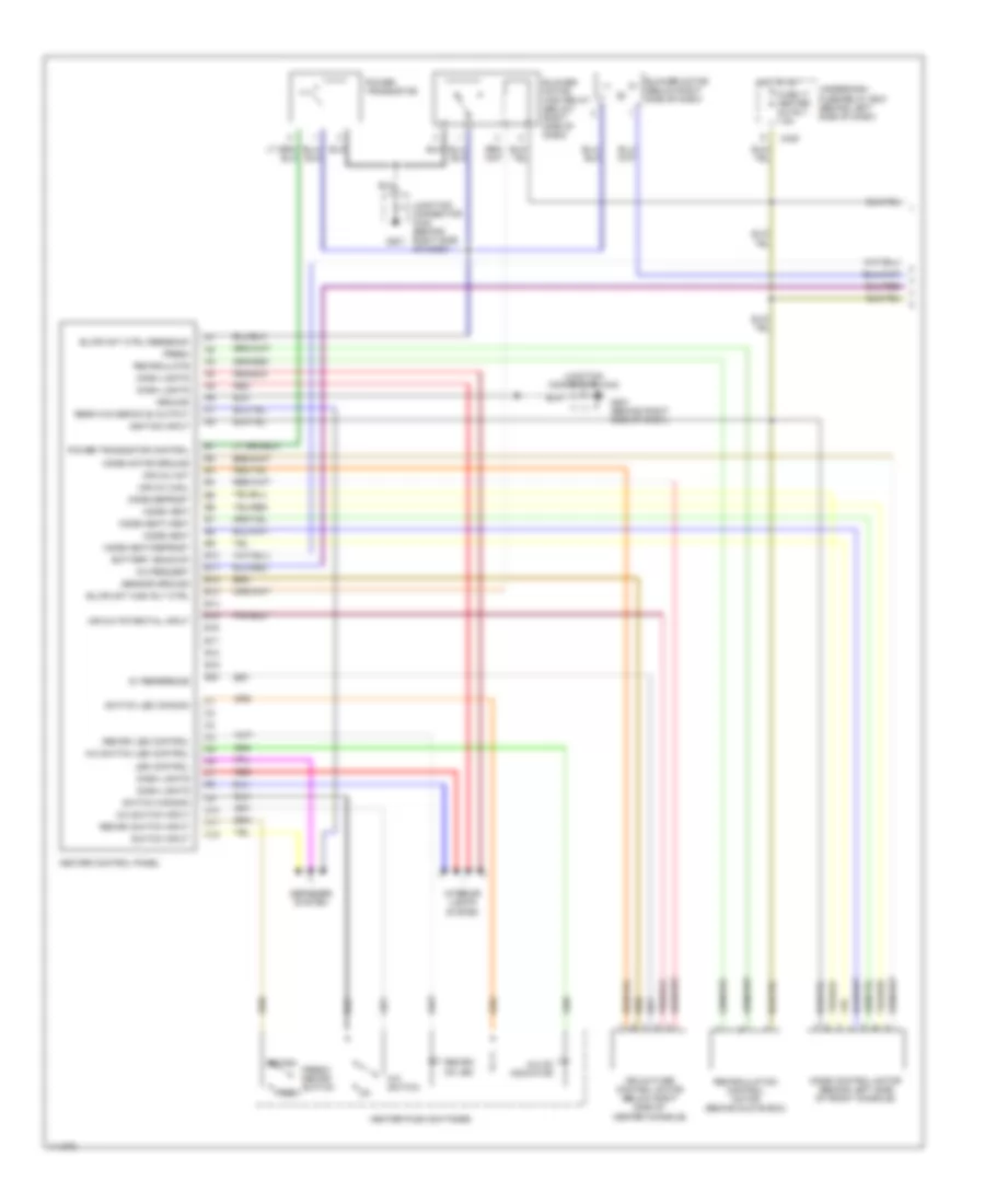
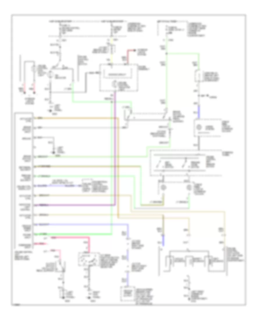
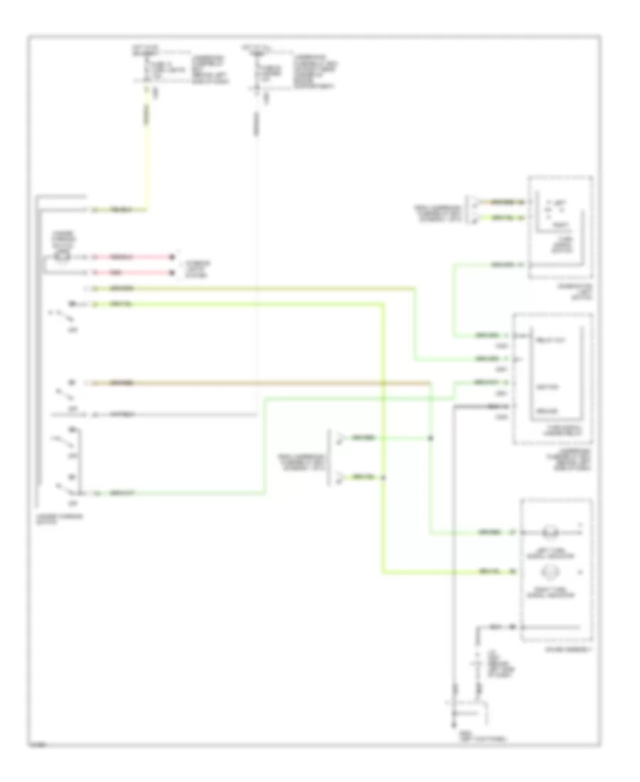
AIR CONDITIONING
Heater Wiring Diagram for Honda Civic CX 1999

List of elements for Heater Wiring Diagram for Honda Civic CX 1999:
- 5v reference
- Air mix cool
- Air mix hot
- Air mix potential input
- Air mixture control motor (below right side of center console)
- B10
- B11
- B12
- B13
- B14
- B15
- B16
- B17
- B18
- B19
- B20
- Battery (backup)
- Blower motor (below right side of dash)
- Blower motor high relay (below right side of dash)
- Blower motor relay
- Blwr mot ctrl feedback
- Blwr mot high rly ctrl
- C10
- C11
- C12
- C351
- C352
- C420
- Dash lights
- Defogger system
- Fresh
- Fresh/ recirc switch
- Fuse 17 heater a/c rly 7.5a
- Fuse 47 back up 7.5a
- Fuse 55 heater motor 40a
- G201
- Ground
- Heater control panel
- Heater push switches
- Hot at all times
- Hot in on
- Ignition input
- Interior lights system
- Junction connector c442 (behind right side of dash)
- Led control
- Mode control motor (behind left side of front console)
- Mode defrost
- Mode heat
- Mode heat/defrost
- Mode heat/vent
- Mode motor ground
- Mode vent
- Power transistor (behind glove box)
- Power transistor control
- Rear win defog on output
- Recirc
- Recirc led control
- Recirc on led
- Recirc switch input
- Recirculate
- Recirculation control motor (behind glove box)
- Red
- Sensor ground
- Switch common
- Switch input
- Switch led common
- Underdash fuse/relay box (behind left side of dash)
- Underhood fuse/relay box (right rear corner of engine compartment)
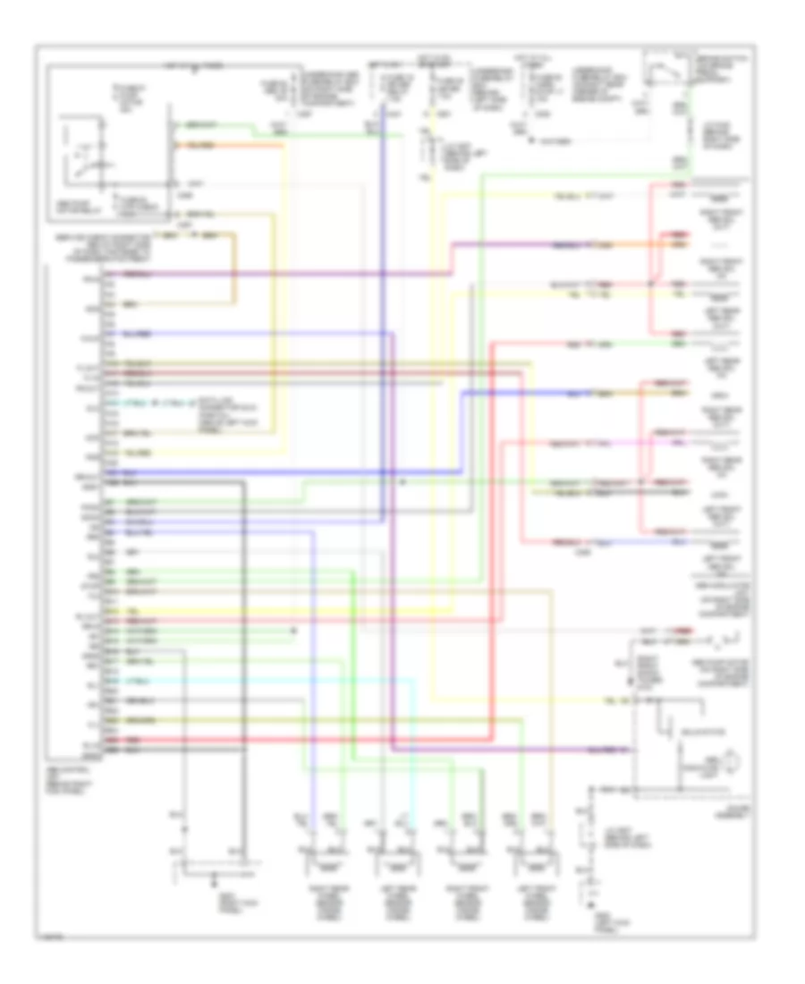
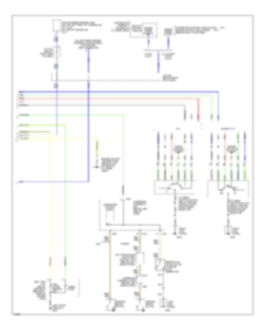
Manual A/C Wiring Diagram (1 of 2) for Honda Civic CX 1999
List of elements for Manual A/C Wiring Diagram (1 of 2) for Honda Civic CX 1999:
- 5v reference
- A/c on indicator
- A/c request
- A/c switch
- A/c switch input
- A/c switch led control
- Air mix cool
- Air mix hot
- Air mix potential input
- Air mixture control motor (below right side of center console)
- B10
- B11
- B12
- B13
- B14
- B15
- B16
- B17
- B18
- B19
- B20
- Battery (backup)
- Blower motor (below right side of dash)
- Blower motor high relay (below right side of dash)
- Blwr mot ctrl feedback
- Blwr mot high rly ctrl
- C10
- C11
- C12
- C420
- Dash lights
- Defogger system
- Fresh
- Fresh/ recirc switch
- Fuse 17 heater a/c rly 7.5a
- G201
- G201 (behind right side of dash)
- Ground
- Heater control panel
- Heater push switches
- Hot in on
- Ignition input
- Interior lights system
- Junction connector c442
- Junction connector c442 (behind right side of dash)
- Led control
- Mode control motor (behind left side of front console)
- Mode defrost
- Mode heat
- Mode heat/defrost
- Mode heat/vent
- Mode motor ground
- Mode vent
- Power transistor
- Power transistor control
- Rear win defog on output
- Recirc
- Recirc led control
- Recirc on led
- Recirc switch input
- Recirculate
- Recirculation control motor (behind glove box)
- Red
- Sensor ground
- Switch common
- Switch input
- Switch led common
- Underdash fuse/relay box (behind left side of dash)
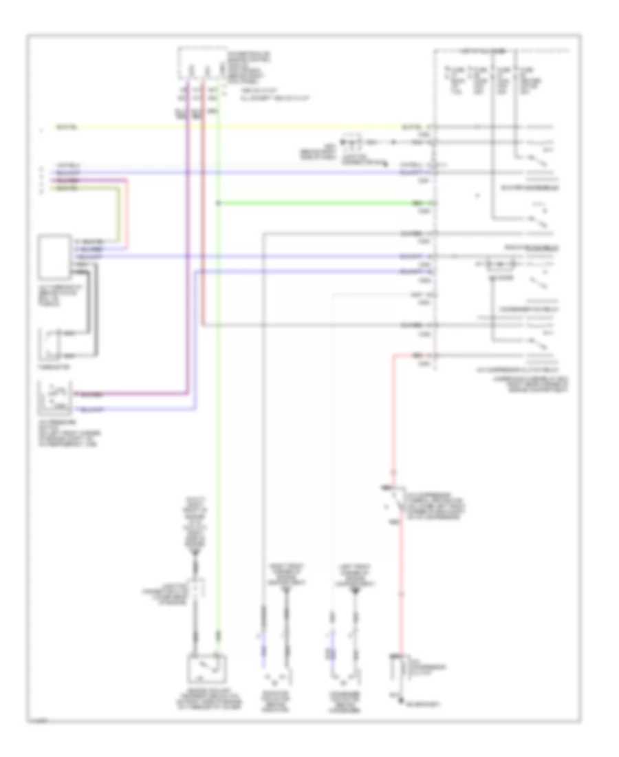
Manual A/C Wiring Diagram (2 of 2) for Honda Civic CX 1999
List of elements for Manual A/C Wiring Diagram (2 of 2) for Honda Civic CX 1999:
- (left front corner of engine compartment) g100
- (on bracket)
- (right front corner of engine compartment) g101
- (w/cvt) (right front of engine) g119 (w/o cvt) (right side of engine) g120
- 1600 cc w/ m/t
- A/c compressor clutch
- A/c compressor clutch relay
- A/c compressor thermal protector (on lower left front corner of eng compt, on a/c compressor)
- A/c diode
- A/c pressure switch (on left front corner of engine compt, on a/c refrigerant line)
- A/c thermostat (behind glove box, on plenum)
- A17
- A20
- A27
- Acc
- Acs
- All except 1600 cc w/ m/t
- Blower motor relay
- C351
- C352
- C353
- Condenser fan motor (behind condenser)
- Condenser fan relay
- Engine coolant temperature switch (on right side of engine, on thermostat cover)
- Fan c
- Fuse back up 7.5a
- Fuse cond fan 20a
- Fuse cool fan 20a
- Fuse heater motor 40a
- G201 (behind right side of dash)
- High
- Hot at all times
- Junction connector c116 (lower rear of engine)
- Junction connector c442
- Low
- Nca
- Powertrain or engine control module (pcm or ecm) (behind right kick panel)
- Radiator fan motor (behind radiator)
- Radiator fan relay
- Red
- Thermistor
- Underhood fuse/relay box (right rear corner of engine compartment)
ANTI-LOCK BRAKES
Anti-lock Brake Wiring Diagrams for Honda Civic CX 1999
List of elements for Anti-lock Brake Wiring Diagrams for Honda Civic CX 1999:
- (right front shock tower) g103
- +b1
- +b2
- A10
- A11
- A12
- A13
- A14
- A15
- A16
- A17
- A18
- A19
- A20
- A21
- A22
- Abs control unit (behind right kick panel)
- Abs indicator light
- Abs modulator unit (on right side of engine compartment)
- Abs pump motor (on right side of engine compartment)
- Abs pump motor relay
- B10
- B11
- B12
- B13
- B14
- B15
- B16
- B17
- B18
- B19
- B20
- B21
- B22
- B23
- B24
- B25
- B26
- Brake switch (on brake pedal support)
- C352
- C356
- C357
- C359
- C421
- C501
- Data link connector (dlc) (partial) (above left kick panel)
- Dlc
- Fl-in
- Fl-out
- Fl0
- Fl1
- Fr-in
- Fr-out
- Fr0
- Fr1
- Fuse 16 rr def relay 7.5a
- Fuse 25 meter 7.5a
- Fuse 52 horn, stop lt 15a
- Fuse 61 pump motor 40a
- Fuse 62 abs +b 20a
- Fuse 63 mtr check 7.5a
- G200 (left kick panel)
- G203 (right kick panel)
- Gauge assembly
- Gnd1
- Gnd2
- Gnd3
- Hot at all times
- Hot in on
- Hot in on or start
- Ig2
- J/c c442 (behind right side of dash)
- J/c c507 (behind left side of dash)
- Left front abs sol (in)
- Left front abs sol (out)
- Left front wheel sensor (inside wheel)
- Left rear abs sol (in)
- Left rear abs sol (out)
- Left rear wheel sensor (inside wheel)
- Mck
- Pcom
- Pmr
- Red
- Right front abs sol (in)
- Right front abs sol (out)
- Right front wheel sensor (inside wheel)
- Right rear abs sol (in)
- Right rear abs sol (out)
- Right rear wheel sensor (inside wheel)
- Rl-in
- Rl-out
- Rl0
- Rl1
- Rr-in
- Rr-out
- Rr0
- Rr1
- Scom
- Scs
- Service check connector (below right side of dash, fastened to passenger's footrest)
- Solid state
- Stop
- Underdash fuse/relay box (behind left side of dash)
- Underhood abs fuse/relay box (on right side of engine compartment)
- Underhood fuse/relay box (on right rear corner of engine compt)
- Walp
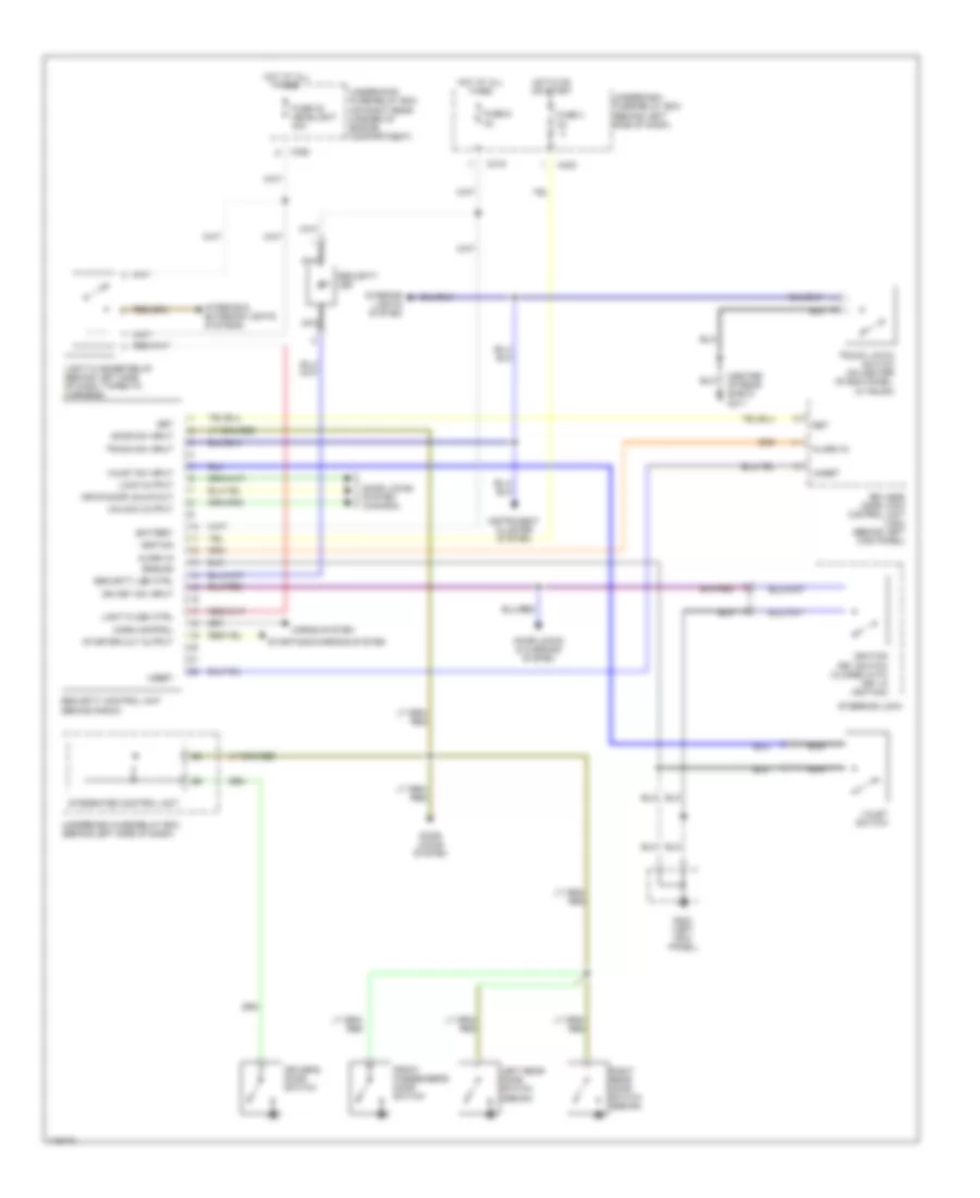
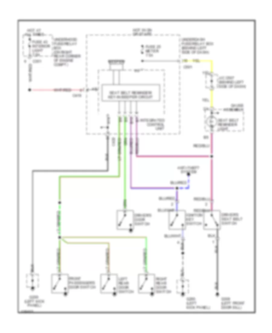
ANTI-THEFT
Anti-theft Wiring Diagram, with Keyless Entry for Honda Civic CX 1999
List of elements for Anti-theft Wiring Diagram, with Keyless Entry for Honda Civic CX 1999:
- (center of rear shelf) g311
- Alarm in
- Battery
- C352
- C419
- C423
- Door locks & warning system
- Door locks system
- Door locks system (canada)
- Door sw input
- Driver's door switch
- Drvr door unlck out
- Front passenger's door switch
- Fuse 3
- Fuse 48 headlight 30a
- Fuse 6
- G200 (left kick panel)
- Ground
- Horn control
- Horns system
- Hot at all times
- Hot in on or start
- Ign key sw input
- Ignition
- Ignition key switch (closed with key in ignition)
- Instrument cluster system
- Integrated control unit
- Interior & exterior lights systems
- Interior lights system
- Keyless door lock control unit (usa) (behind left kick panel)
- Left rear door switch (sedan)
- Light flash ctrl
- Light flasher relay (behind left side of dash, taped to harness)
- Lock output
- Nca
- Right rear door switch (sedan)
- Security control unit (behind radio)
- Security led
- Security led ctrl
- Set
- Starter cut output
- Starting/charging system
- Steering lock
- Trunk latch switch (on center of end panel, in trunk)
- Trunk sw input
- Underdash fuse/relay box (behind left side of dash)
- Underhood fuse/relay box (on right rear corner of engine compartment)
- Unlock output
- Unset
- Valet sw input
- Valet switch
Anti-theft Wiring Diagram, without Keyless Entry for Honda Civic CX 1999
List of elements for Anti-theft Wiring Diagram, without Keyless Entry for Honda Civic CX 1999:
- (1998)
- (1999, 2000)
- (center of rear shelf) g311
- (on hatch lid) g412
- 1999-00
- Acc
- Battery
- C351
- C352
- C419
- C926 (option connector)
- Coupe & sedan
- Door open input
- Driver's door switch
- Front passenger's door switch
- Fuse 48 headlight 30a
- Fuse 54 option 40a
- G200 (left kick panel)
- Ground
- Hatch latch switch (on bottom inside of hatch)
- Hatchback
- Headlights & exterior lights systems
- Horn ctrl
- Horns system
- Hot at all times
- Ign key sw input
- Ignition
- Ignition key switch
- Ignition switch
- Instrument cluster system
- Integrated control unit
- Interior lights system
- Left rear door switch (sedan)
- Light flash ctrl
- Light flasher relay (behind left side of dash, taped to harness)
- Lock
- Nca
- Red
- Right rear door switch (sedan)
- Security control unit (behind radio)
- Security in-line fuse holder (behind left side of dash, taped to harness)
- Security ind ctrl
- Security led
- Start
- Starter cut output
- Starting/charging system
- Steering lock
- Trunk latch switch (on center of end panel in trunk)
- Trunk sw input
- Underdash fuse/relay box (behind left side of dash)
- Underhood fuse/relay box (on right rear corner of engine compartment)
- Valet sw
- Valet switch (1999-00)
- Warning systems
BODY COMPUTER
Integrated Control Unit Wiring Diagram for Honda Civic CX 1999
List of elements for Integrated Control Unit Wiring Diagram for Honda Civic CX 1999:
- A10
- A11
- A12
- A13
- A14
- Alternator sp sensor fuse 15 7.5a
- B10
- Battery input
- Brake bulb check output
- C351
- C419
- C420
- C551
- Door open input
- Driver's door switch input
- Driver's seat belt sw in
- Fr wiper fr washer fuse 26 20a
- Front wiper/ washer
- G200 (left kick panel)
- Ground
- Hot at all times
- Hot in on or start
- Hot with engine cranking
- Hot with headlight switch in park or head
- Ignition input
- Instrument cluster system (brake indicator light)
- Instrument lights fuse 30 7.5a
- Integrated control unit (rear of underdash fuse/relay box
- Interior light fuse 43 7.5a
- Interior lights system
- Key in ignition input
- Lights on in
- Meter fuse 25 7.5a
- Start input
- Starter signal fuse 31 7.5a
- Underdash fuse/relay box (behind left side of dash)
- Underhood fuse/relay box (right rear corner of engine compt)
- Warning systems
- Wiper/washer system
COMPUTER DATA LINES
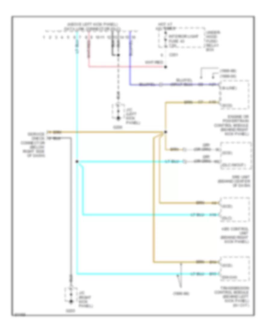
Computer Data Lines for Honda Civic CX 1999
List of elements for Computer Data Lines for Honda Civic CX 1999:
- (1996-98)
- (1999-00)
- (above left kick panel) data link connector (dlc)
- (diag-h)
- (dlc in/out)
- (dlc)
- (k-line)
- (scs)
- A10
- A14
- A21
- Abs control unit (behind right kick panel)
- B13
- B14
- C351
- Engine or powertrain control module (behind right kick panel)
- Fuse 43 7.5a
- G200
- G203
- Hot at all times
- Interior light
- J/c (left kick panel)
- J/c (right kick panel)
- Service check connector (below right side of dash)
- Srs unit (behind center of dash)
- Transmission control module (behind left kick panel) (w/ cvt)
- Under- hood fuse/ relay box
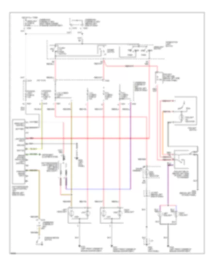
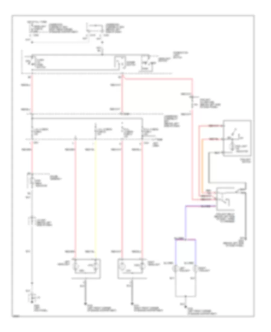
COOLING FAN
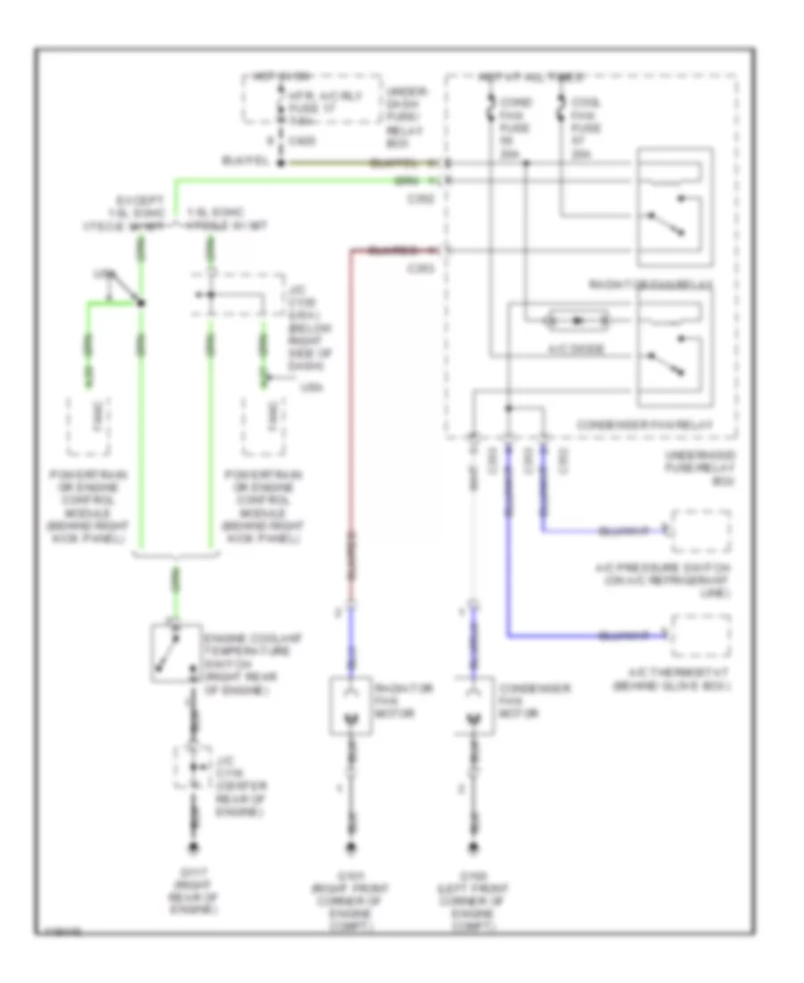
Cooling Fan Wiring Diagram for Honda Civic CX 1999
List of elements for Cooling Fan Wiring Diagram for Honda Civic CX 1999:
- 1.6l sohc vtec-e w/ m/t
- A/c diode
- A/c pressure switch (on a/c refrigerant line)
- A/c thermostat (behind glove box)
- A20
- A27
- C352
- C353
- C420
- Cond fan fuse 20a
- Condenser fan motor
- Condenser fan relay
- Cool fan fuse 20a
- Engine coolant temperature switch (right rear of engine)
- Except 1.6l sohc vtec-e w/ m/t
- Fanc
- G100 (left front corner of engine compt)
- G101 (right front corner of engine compt)
- G117 (right rear of engine)
- Hot at all times
- Hot in on
- Htr, a/c rly fuse 17 7.5a
- J/c c116 (center rear of engine)
- J/c c130 (usa) (below right side of dash)
- Powertrain or engine control module (behind right kick panel)
- Radiator fan motor
- Radiator fan relay
- Under- dash fuse/ relay box
- Underhood fuse/relay box
- Usa
CRUISE CONTROL
Cruise Control Wiring Diagram for Honda Civic CX 1999
List of elements for Cruise Control Wiring Diagram for Honda Civic CX 1999:
- "on" indicator
- (left front corner of engine compartment) g100
- (left kick panel)
- (right kick panel)
- 1.6l sohc, 1.6l sohc vetec w/ a/t
- A/t
- A/t gear position switch (below center console, right side of gear selector)
- Actuator ctrl
- Brake switch (on brake pedal support)
- Brake switch input
- C352
- C501
- Cable reel (top of steering column)
- Clutch switch (on clutch pedal support)
- Cruise control actuator (on left side of engine compartment)
- Cruise control indicator light
- Cruise control main switch
- Cruise control main switch light
- Cruise control set/ resume switch
- Cruise control unit (behind left side of dash)
- Cruise ctrl signal input
- Cruise ctrl signal out
- Dimming circuit
- Disengage input
- Fuse 14 cruise control (keyless) 7.5a
- Fuse 25 meter 7.5a
- Fuse 52 horn, stop lt 15a
- G200
- G203
- Gauge assembly
- Ground
- Horn relay (behind left side of dash, on bracket)
- Horns
- Horns system
- Hot at all times
- Hot in on or start
- Indicator light control
- Interior lights system
- J/c c130 (below right right side of dash)
- J/c c422 (behind right side of dash)
- J/c c442 (behind right kick panel)
- J/c c507 (behind left side of dash)
- M/t
- Off
- Pnk
- Power input
- Powertrain control module (pcm) (behind right kick panel)
- Red
- Resume/ accel sig input
- Resume/ accel switch
- Safety solenoid
- Set/ decel switch
- Set/decel sig input
- Steering wheel
- Underdash fuse/relay box (behind left side of dash)
- Underhood fuse/relay box (on right rear corner of engine compartment)
- Vacuum solenoid
- Vehicle speed input
- Vehicle speed output
- Vehicle speed sensor (vss) (a/t & m/t: on top left front of transaxle) (cvt: on top of transaxle)
- Vent solenoid
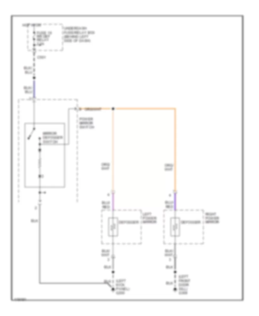
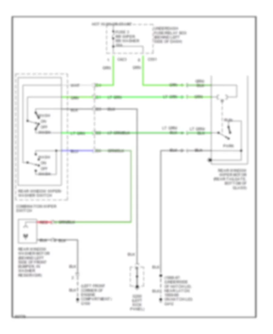
DEFOGGERS
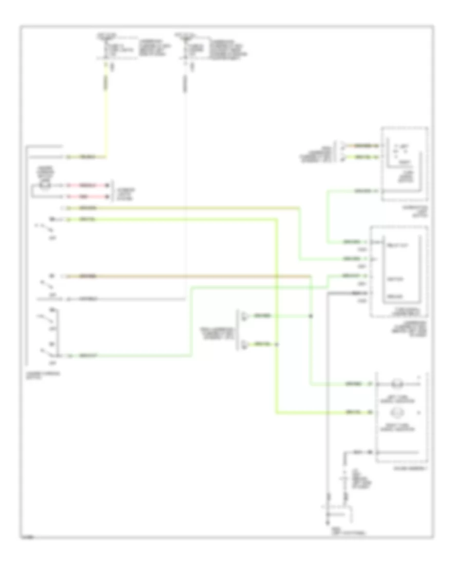
Heated Mirrors Wiring Diagram for Honda Civic CX 1999
List of elements for Heated Mirrors Wiring Diagram for Honda Civic CX 1999:
- (left front door sill) g309
- (left kick panel) g200
- C501
- Defogger
- Fuse 16 rr def relay 7.5a
- Hot in on
- Left power mirror
- Mirror defogger switch
- Power mirror switch
- Right power mirror
- Underdash fuse/relay box (behind left side of dash)
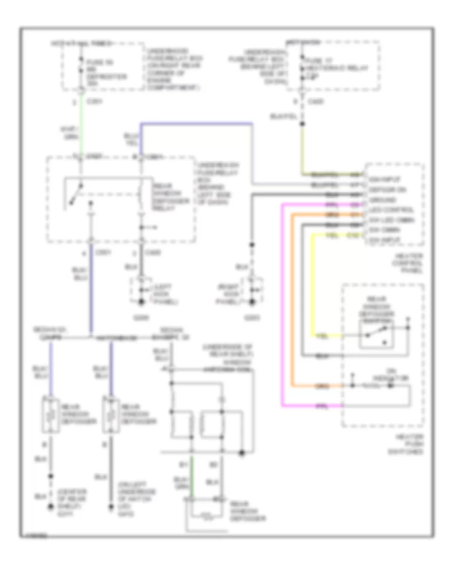
Rear Defogger Wiring Diagram for Honda Civic CX 1999
List of elements for Rear Defogger Wiring Diagram for Honda Civic CX 1999:
- (center of rear shelf) g311
- (left kick panel)
- (on left underside of hatch lid) g412
- (right kick panel)
- (underside of rear shelf)
- C12
- C351
- C420
- C501
- C551
- Defggr on
- Fuse 17 heater/a/c relay 7.5a
- Fuse 50 rr defroster 30a
- G200
- G203
- Ground
- Hatchback
- Heater control panel
- Heater push switches
- Hot at all times
- Hot in on
- Ign input
- Led control
- On indicator
- Rear window defogger
- Rear window defogger relay
- Rear window defogger switch
- Sedan except gx
- Sedan gx, coupe
- Sw cmmn
- Sw input
- Sw led cmmn
- Underdash fuse/relay box (behind left side of dash)
- Underhood fuse/relay box (on right rear corner of engine compartment)
- Window antenna coil
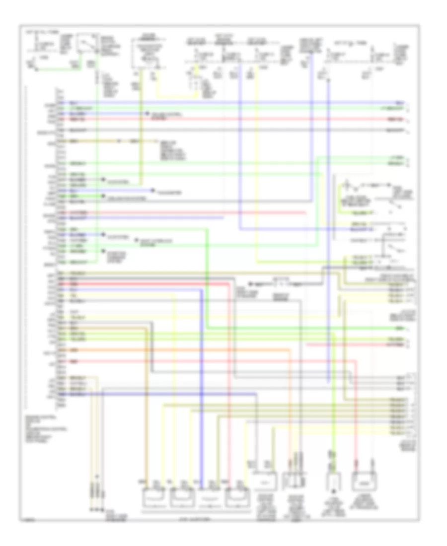
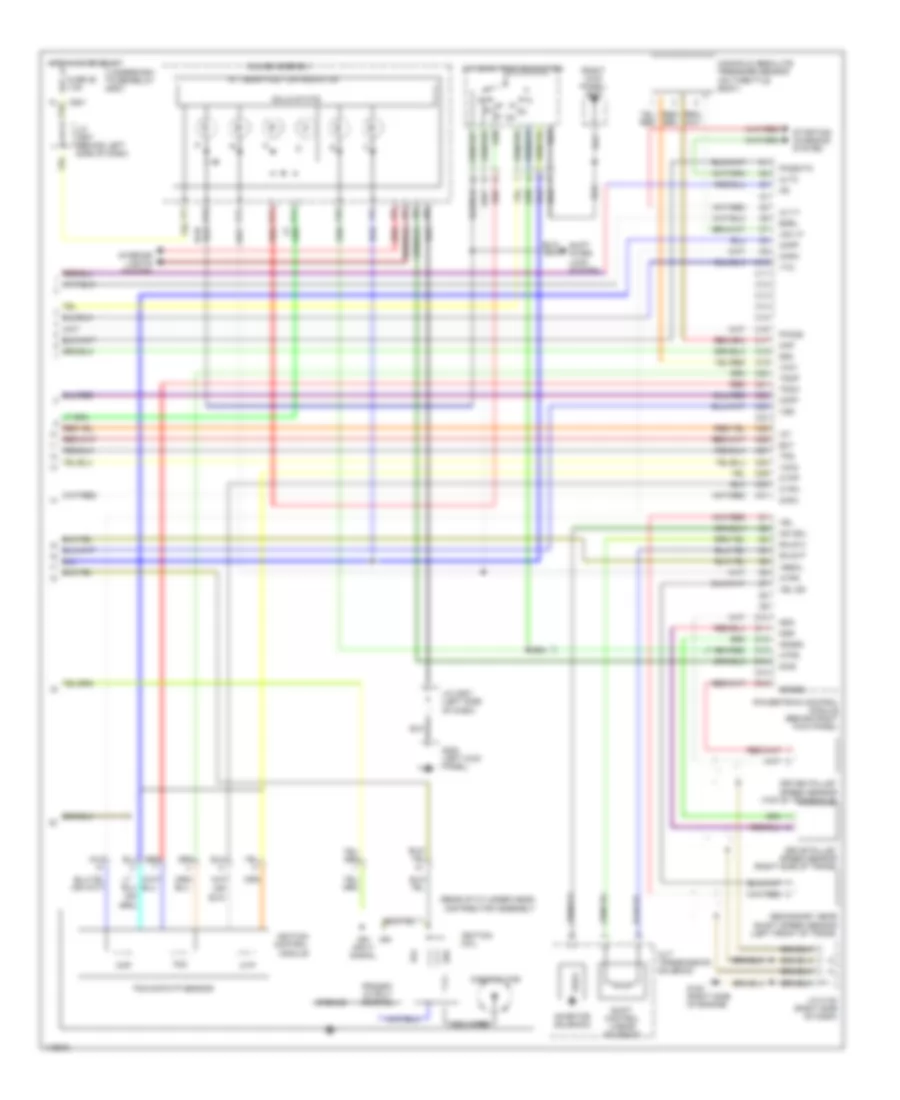
ENGINE PERFORMANCE
1.6L
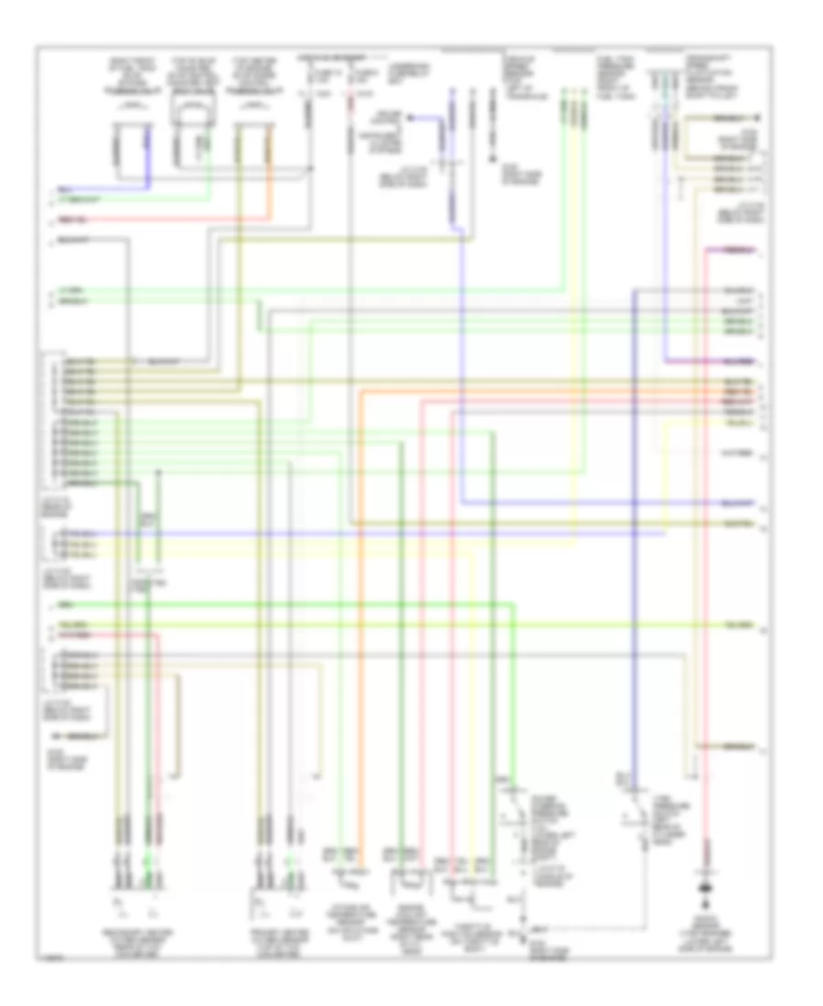
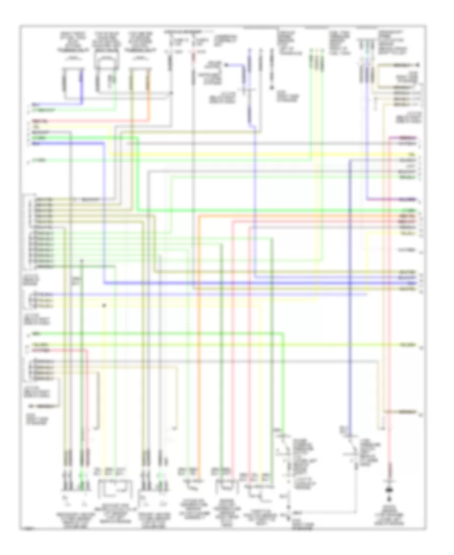
1.6L, Engine Performance Wiring Diagrams, Except HX (1 of 3) for Honda Civic CX 1999
List of elements for 1.6L, Engine Performance Wiring Diagrams, Except HX (1 of 3) for Honda Civic CX 1999:
- (above left kick panel) data link connector
- (rear of engine)
- 2wbs
- A/c system
- A10
- A11
- A12
- A13
- A14
- A15
- A16
- A17
- A18
- A19
- A20
- A21
- A22
- A23
- A24
- A25
- A26
- A27
- A28
- A29
- A30
- A31
- A32
- Acc
- Acs
- B10
- B11
- B12
- B13
- B14
- B15
- B16
- B17
- B18
- B19
- B20
- B21
- B22
- B23
- B24
- B25
- Bksw
- Box
- Brake switch (on brake pedal support)
- C351
- C352
- C420
- C501
- Cooling fan system
- Crs
- Cruise control system
- D4ind
- Engine control module or powertrain control module (behind right kick panel)
- Fanc
- Flr
- Ftank
- Fuel injectors
- Fuel pump (below center of rear seat)
- Fuse 13 15a
- Fuse 25 7.5a
- Fuse 31 7.5a
- Fuse 44 15a
- Fuse 47 7.5a
- Fuse 52 15a
- G120 (right side of engine)
- G309 (left side of floor)
- Gauge assembly
- Hot at all times
- Hot in on or start
- Hot with engine cranking
- Iacv
- Iacv n
- Iacvp
- Icm
- Idle air control valve (except vtec-m/t) (on throttle body)
- Idle air control valve (vtec-m/t) (left side of intake manifold)
- Igp1
- Igp2
- Inj1
- Inj2
- Inj3
- Inj4
- J/c (c116)
- J/c c116 (rear of engine)
- J/c c130 (below right side of dash)
- J/c c442 (behind right side of dash)
- J/c c507 (left side of dash)
- K-line
- Lg1
- Lg2
- Linear solenoid (right side of transaxle)
- Ls+
- Ls-
- Malfunction indicator light
- Mil
- Nep
- Pcs
- Pg1
- Pg2
- Pgm-fi main relay (right side of glove box)
- Pspw
- Red
- Scs
- Service check connector (below right side of dash)
- Shift interlock system
- Sho2s
- Slu
- So2s htc
- Starting/ charging system
- Sts
- Tachometer
- Under- dash fuse/ relay box
- Under- hood fuse/ relay
- Vbu
- Vsv
- Vtec solenoid valve (left rear of cyl head)
- Vts
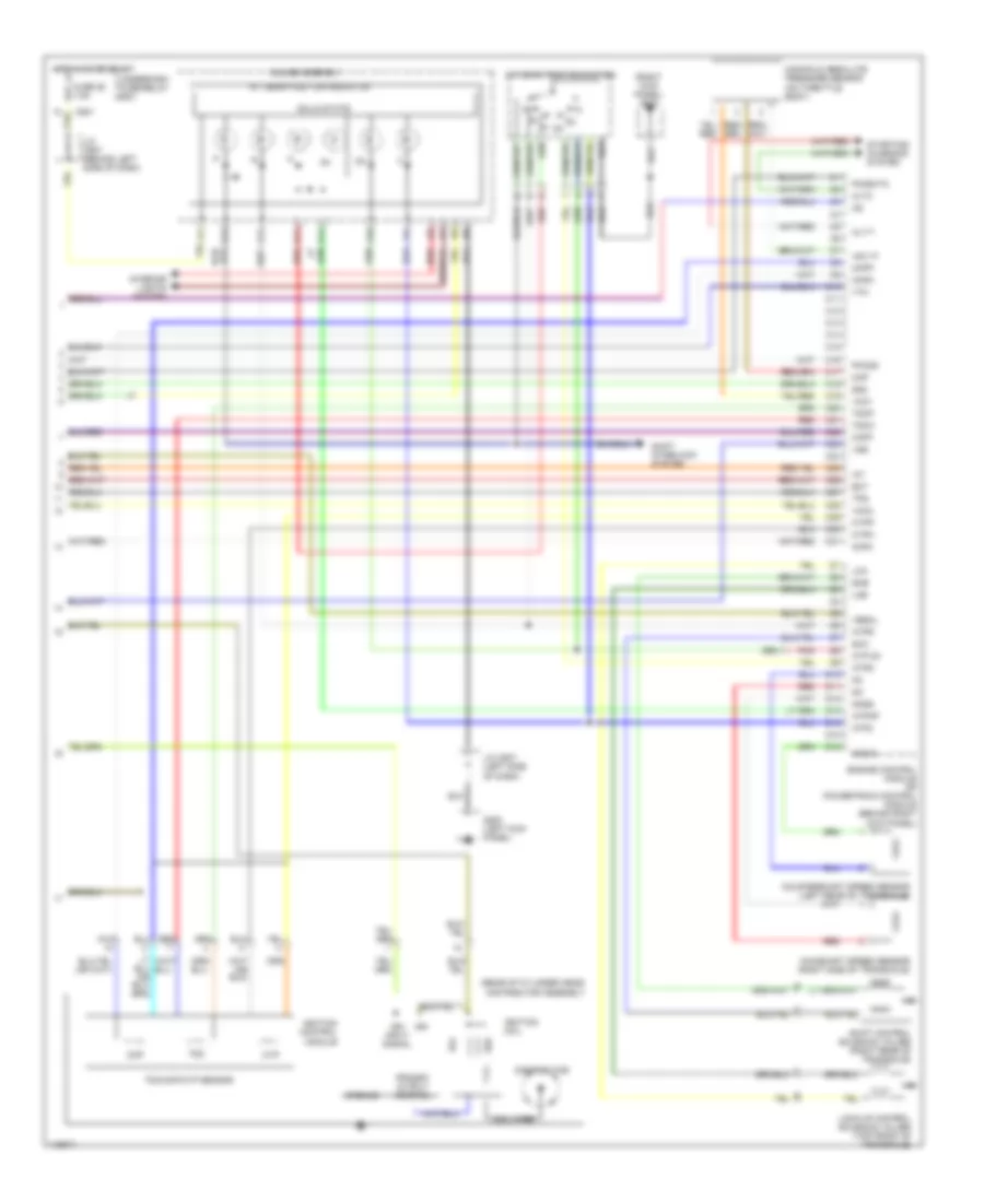
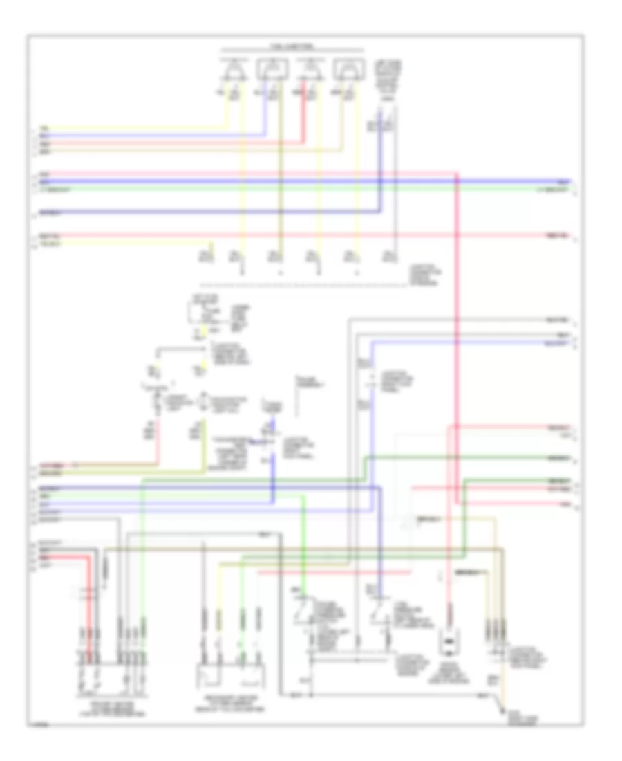
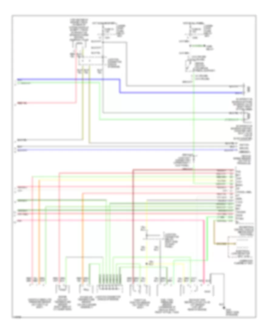
1.6L, Engine Performance Wiring Diagrams, Except HX (2 of 3) for Honda Civic CX 1999
List of elements for 1.6L, Engine Performance Wiring Diagrams, Except HX (2 of 3) for Honda Civic CX 1999:
- (behind crank- shaft pulley)
- (middle of engine)
- (right front of fuel tank) evap bypass solenoid valve
- (top center of engine) evap purge control solenoid valve
- (top of evap canister) evap control canister vent shut valve
- C419
- C421
- Crankshaft speed fluctuation sensor
- Cruise control & instrument cluster systems
- Engine coolant temperature sensor (right rear of cyl head)
- Fuel tank pressure sensor (right front of fuel tank)
- Fuse 15 7.5a
- Fuse 9 15a
- G120 (right side of engine)
- Hot in on or start
- Intake air temperature sensor (on air intake duct)
- J/c c115 (rear of engine)
- J/c c116
- J/c c130 (below right side of dash)
- Knock sensor (vtec engines) (lower left side of engine)
- Non- vtec
- Power steering pressure switch (u.s.) (lower left rear of engine compt)
- Primary heated oxygen sensor (top of twc converter)
- Red
- Secondary heated oxygen sensor (rear of twc converter)
- Throttle position sensor (on throttle body)
- Underdash fuse/relay box
- Vehicle speed sensor (top left of transaxle)
- Vtec
- Vtec pressure switch (left rear of cylinder head)
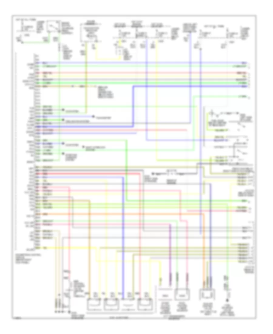
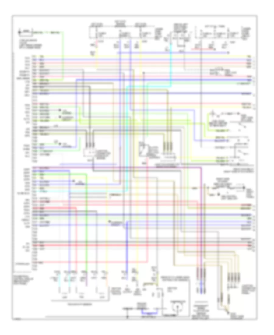
1.6L, Engine Performance Wiring Diagrams, Except HX (3 of 3) for Honda Civic CX 1999
List of elements for 1.6L, Engine Performance Wiring Diagrams, Except HX (3 of 3) for Honda Civic CX 1999:
- (rear of cylinder head)
- (right kick panel) g203
- A/t gear position indicator
- A/t gear position switch
- A10
- A11
- A12
- A13
- A14
- Alt f
- Altc
- Atp d3
- Atp2
- Atpd
- Atpnp
- Atpr
- C10
- C11
- C12
- C13
- C14
- C15
- C16
- C17
- C18
- C19
- C20
- C21
- C22
- C23
- C24
- C25
- C26
- C27
- C28
- C29
- C30
- C31
- C501
- Ckfm
- Ckfp
- Ckp
- Ckpm
- Ckpp
- Coil wire
- Countershaft speed sensor (left rear of transaxle)
- Cyp
- Cypm
- Cypp
- D10
- D11
- D12
- D13
- D14
- D15
- D16
- Distributor
- Distributor assembly
- Ect
- Engine control module or powertrain control module (behind right kick panel)
- Fuse 25 7.5a
- G200 (left kick panel)
- Gauge assembly
- Ground
- Hot in on or start
- Iacv p
- Iat
- Ign
- Ign input signal
- Ignition coil
- Ignition control module
- Interior lights system
- J/c c507 (behind left side of dash)
- J/c c507 (left side of dash)
- Lca
- Lcb
- Lock-up control solenoid valves (top front of transaxle)
- Mainshaft speed sensor (right side of transaxle)
- Manifold absolute pressure sensor (on throttle body)
- Map
- Ncs g
- Nmsg
- Pho2s
- Pnk
- Po2shtc
- Pri
- Primary output control
- Red
- Sec
- Sg2
- Sha
- Shb
- Shift control solenoid valves (right rear of transaxle)
- Shift interlock system
- Solid state
- Starting/ charging system
- Tdc
- Tdc/ckp/cyp sensor
- Tdcm
- Tdcp
- Tps
- Underdash fuse/relay box
- Vbsol
- Vcc1
- Vcc2
- Vss
- Vtm
1.6L, Engine Performance Wiring Diagrams, HX A/T (1 of 3) for Honda Civic CX 1999
List of elements for 1.6L, Engine Performance Wiring Diagrams, HX A/T (1 of 3) for Honda Civic CX 1999:
- (above left kick panel) data link connector
- (on throttle body)
- (rear of engine)
- 2wbs
- A/c system
- A10
- A11
- A12
- A13
- A14
- A15
- A16
- A17
- A18
- A19
- A20
- A21
- A22
- A23
- A24
- A25
- A26
- A27
- A28
- A29
- A30
- A31
- A32
- Acc
- Acs
- Atp l
- Atp n d
- Atpd
- B10
- B11
- B12
- B13
- B14
- B15
- B16
- B17
- B18
- B19
- B20
- B21
- B22
- B23
- B24
- B25
- Bksw
- Box
- Brake switch (on brake pedal support)
- C351
- C352
- C420
- C501
- Cooling fan system
- Cvt transmission solenoid
- Egr control solenoid valve (center of firewall)
- Esol
- Fanc
- Flr
- Ftank
- Fuel injectors
- Fuel pump (below center of rear seat)
- Fuse 13 15a
- Fuse 25 7.5a
- Fuse 31 7.5a
- Fuse 44 15a
- Fuse 47 7.5a
- Fuse 52 15a
- G120 (right side of engine)
- G309 (left side of floor)
- Gauge assembly
- Hlc lsm
- Hlc lsp
- Hot at all times
- Hot in on or start
- Hot with engine cranking
- Iacv n
- Iacvp
- Icm
- Idle air control valve
- Igp1
- Igp2
- Inj1
- Inj2
- Inj3
- Inj4
- J/c (c116)
- J/c c116 (rear of engine)
- J/c c130 (below right side of dash)
- J/c c442 (behind right side of dash)
- J/c c507 (left side of dash)
- K-line
- Lg1
- Lg2
- Malfunction indicator light
- Mil
- Nep
- Pcs
- Pg1
- Pg2
- Pgm-fi main relay (right side of glove box)
- Ph-pl control linear solenoid
- Powertrain control module (behind right kick panel)
- Pspw
- Red
- Sc lsm
- Sclsp
- Scs
- Service check connector (below right side of dash)
- Shift interlock system
- Sho2s
- Slu
- So2s htc
- Start clutch control linear solenoid
- Starting/ charging system
- Sts
- Tachometer
- Under- dash fuse/ relay box
- Under- hood fuse/ relay
- Vbu
- Vsv
- Vtec solenoid valve (left rear of cyl head)
- Vts
1.6L, Engine Performance Wiring Diagrams, HX A/T (2 of 3) for Honda Civic CX 1999
List of elements for 1.6L, Engine Performance Wiring Diagrams, HX A/T (2 of 3) for Honda Civic CX 1999:
- (behind crank- shaft pulley)
- (middle of engine)
- (right front of fuel tank) evap bypass solenoid valve
- (top center of engine) evap purge control solenoid valve
- (top of evap canister) evap control canister vent shut valve
- C419
- C421
- Crankshaft speed fluctuation sensor
- Cruise control & instrument cluster systems
- Engine coolant temperature sensor (right rear of cyl head)
- Exhaust gas recirculation valve lift sensor (top left rear of engine)
- Fuel tank pressure sensor (right front of fuel tank)
- Fuse 15 7.5a
- Fuse 9 15a
- G120 (right side of engine)
- Hot in on or start
- Intake air temperature sensor (on air cleaner assembly)
- J/c c115 (rear of engine)
- J/c c116
- J/c c130 (below right side of dash)
- Knock sensor (vtec engines) (lower left side of engine)
- Power steering pressure switch (u.s.) (lower left rear of engine compt)
- Primary heated oxygen sensor (top of twc converter)
- Red
- Secondary heated oxygen sensor (rear of twc converter)
- Throttle position sensor (on throttle body)
- Underdash fuse/relay box
- Vehicle speed sensor (top left of transaxle)
- Vtec pressure switch (left rear of cylinder head)
1.6L, Engine Performance Wiring Diagrams, HX A/T (3 of 3) for Honda Civic CX 1999
List of elements for 1.6L, Engine Performance Wiring Diagrams, HX A/T (3 of 3) for Honda Civic CX 1999:
- (or
- (rear of cylinder head)
- (right kick panel) g203
- A/t gear position indicator
- A/t gear position switch
- A10
- A11
- A12
- A13
- A14
- Alt f
- Altc
- Atpr
- Atps
- C10
- C11
- C12
- C13
- C14
- C15
- C16
- C17
- C18
- C19
- C20
- C21
- C22
- C23
- C24
- C25
- C26
- C27
- C28
- C29
- C30
- C31
- C501
- Ckfm
- Ckfp
- Ckp
- Ckpm
- Ckpp
- Coil wire
- Cvt transmission solenoid
- Cyp
- Cypm
- Cypp
- D10
- D11
- D12
- D13
- D14
- D15
- D16
- Dind
- Distributor
- Distributor assembly
- Drive pulley speed sensor (right side of trans)
- Driven pulley speed sensor (top of transaxle)
- Ect
- Egrl
- Fuse 25 7.5a
- G120 (right side of engine)
- G200 (left kick panel)
- Gauge assembly
- Ground
- Hot in on or start
- Iacv p
- Iat
- Ign
- Ign input signal
- Ignition coil
- Ignition control module
- Inh sol
- Inhibitor solenoid
- Interior lights system
- J/c c130 (right side of dash)
- J/c c507 (behind left side of dash)
- J/c c507 (left side of dash)
- Manifold absolute pressure sensor (on throttle body)
- Map
- Nd2sg
- Ndn
- Ndnsg
- Ndr
- Pho2s
- Po2shtc
- Powertrain control module (behind right kick panel)
- Pri
- Primary output control
- Red
- Sec
- Secondary gear shaft speed sensor (left front of trans.
- Sg2
- Shift control linear solenoid
- Shift inter- lock system
- Shls m
- Shls p
- Solid state
- Starting/ charging system
- Tdc
- Tdc/ckp/cyp sensor
- Tdcm
- Tdcp
- Tps
- Underdash fuse/relay box
- Vbsol
- Vcc1
- Vcc2
- Vel
- Vel sg
- Vss
- Vtm
1.6L, Engine Performance Wiring Diagrams, HX M/T (1 of 3) for Honda Civic CX 1999
List of elements for 1.6L, Engine Performance Wiring Diagrams, HX M/T (1 of 3) for Honda Civic CX 1999:
- (above left kick panel) data link connector
- (rear of cylinder head)
- (right side of dash) service check connector
- 2wbs
- A/c
- A/c system
- A10
- A11
- A12
- A13
- A14
- A15
- A16
- A17
- A18
- A19
- A20
- A21
- A22
- A23
- A24
- A25
- A26
- A27
- A28
- A29
- A30
- A31
- A32
- Abs control unit, srs unit
- Acc
- Acs
- Altc
- Altf
- Atpnp/clsw
- Box
- C10
- C11
- C12
- C13
- C14
- C15
- C16
- C17
- C18
- C19
- C20
- C21
- C22
- C23
- C24
- C25
- C26
- C27
- C28
- C29
- C30
- C31
- C351
- C419
- C420
- Charging
- Circuit
- Ckfm
- Ckfp
- Ckp
- Ckpm
- Ckpp
- Clutch switch (clutch pedal support)
- Coil wire
- Crankshaft speed fluctuation sensor (behind crank- shaft pulley)
- Cyp
- Cypm
- Cypp
- Distributor
- Distributor assembly
- Esol/e-egr
- Fanc
- Flr
- Fuel pump (below center of rear seat)
- Fuse 13 15a
- Fuse 31 7.5a
- Fuse 43 7.5a
- Fuse 44 15a
- Fuse 47 7.5a
- Fuse 9 15a
- G120 (right side of engine)
- G200 (left kick panel)
- G203 (right kick panel)
- G309 (left side of floor)
- Ground
- Hot at all times
- Hot in on or start
- Hot with engine cranking
- Iacv
- Icm
- Ign
- Ign input signal
- Ignition coil
- Ignition control module
- Igp1
- Igp2
- Inj1
- Inj2
- Inj3
- Inj4
- Ip+
- Ip-,vs-
- Junction connector (middle of engine)
- Junction connector (right kick panel)
- Kline (dlc)
- Lg1
- Lg2
- Mil
- Pcs
- Pg1
- Pg2
- Pgm-fi main relay (right side of glove box)
- Pnk
- Po2shtc
- Powertrain control module (behind right kick panel)
- Pri
- Primary output control
- Pspsw
- Red
- Rpm output
- Scs
- Sec
- Slu
- So2shtc
- Sts
- System
- Tdc
- Tdc/ckp/cyp sensor
- Tdcm
- Tdcp
- U.s.
- Under- dash fuse/ relay box
- Under- hood fuse/ relay
- Vbu
- Vs+
- Vss
- Vsv
- Vtec solenoid valve (left rear corner of cylinder head)
- Vtm
- Vts
1.6L, Engine Performance Wiring Diagrams, HX M/T (2 of 3) for Honda Civic CX 1999
List of elements for 1.6L, Engine Performance Wiring Diagrams, HX M/T (2 of 3) for Honda Civic CX 1999:
- (left side of intake manifold) idle air control valve
- (rear of twc converter)
- C501
- Dim ctrl
- Fuel injectors
- Fuse 7.5a
- G120 (right side of engine)
- Gauge assembly
- Hot in on or start
- Junction connector (behind left side of dash)
- Junction connector (behind right kick panel)
- Junction connector (middle of engine)
- Junction connector (right kick panel)
- Knock sensor (lower left side of engine)
- Malfunction indicator light (mil)
- Pnk
- Power steering pressure switch (u.s.) (lower left rear of engine compt)
- Primary heated oxygen sensor (top of twc converter)
- Red
- Secondary heated oxygen sensor
- Tacho- meter
- Under- dash fuse/ relay box
- Upshift indicator light
- Vtec pressure switch (left rear of cylinder head)
1.6L, Engine Performance Wiring Diagrams, HX M/T (3 of 3) for Honda Civic CX 1999
List of elements for 1.6L, Engine Performance Wiring Diagrams, HX M/T (3 of 3) for Honda Civic CX 1999:
- (top center of engine-vtec's, on rear of intake manifold- except vtec's) evaporative emission purge control solenoid valve
- (w/ cruise)
- (w/o cruise)
- Bksw
- Brake switch (on brake pedal support)
- C241
- C352
- D10
- D11
- D12
- D14
- D15
- D16
- Ect
- Egrl
- Electrical load detector (u.s.)
- Engine coolant temperature sensor (right rear of cylinder head)
- Evaporative emission bypass solenoid valve (right front of fuel tank)
- Evaporative emission control canister vent shut valve (top of evap canister)
- Exhaust gas recirculation valve lift sensor (top left rear of engine)
- Fuel tank pressure sensor (underside of vehicle, right front of fuel tank)
- Fuse 15 7.5a
- Fuse 52 15a
- G120 (right side of engine)
- Ground
- Horn relay
- Hot at all times
- Hot in on or start
- Iat
- Ignition
- Intake air temperature sensor (on air cleaner assembly)
- Jucntion connector (below right side of dash panel)
- Junction connector (middle of engine)
- Junction connector (upper right kick panel)
- Manifold absolute pressure sensor (on throttle body)
- Map
- Pho2s,label
- Pnk
- Powertrain control module (behind right kick panel)
- Ptank
- Sg1
- Sg2
- Sh02sg
- So2s
- Throttle position sensor (on throttle body)
- Tps
- Under- dash fuse/ relay box
- Under- hood fuse/ relay box
- Underhood fuse/relay box
- Unit
- Vcc1
- Vcc2
- Vehicle speed sensor (on top of transaxle)
- Vss out
EXTERIOR LIGHTS
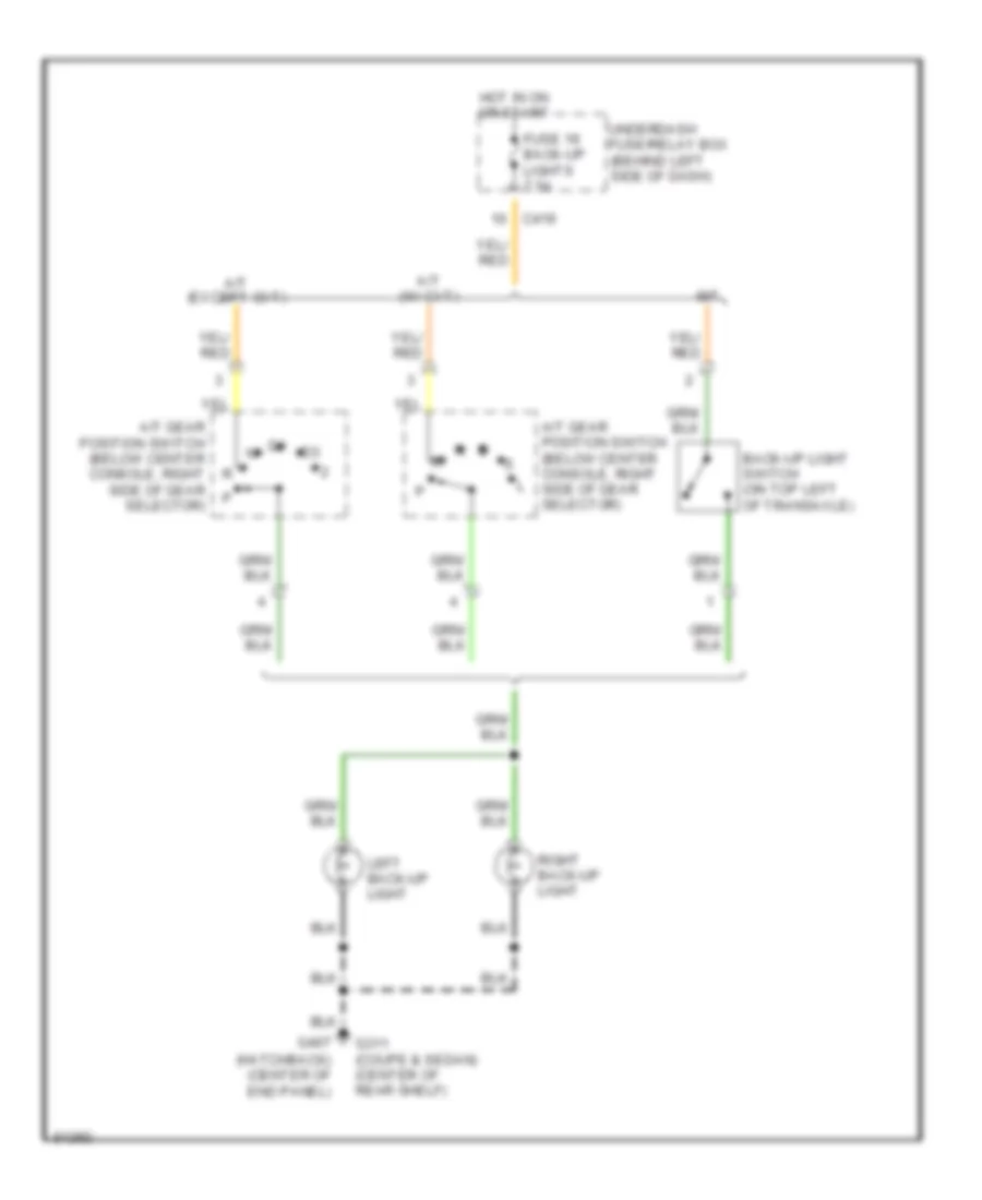
Backup Lamps Wiring Diagram for Honda Civic CX 1999
List of elements for Backup Lamps Wiring Diagram for Honda Civic CX 1999:
- A/t (except cvt)
- A/t (w/ cvt)
- A/t gear position switch (below center console, right side of gear selector)
- Back-up light switch (on top left of transaxle)
- C419
- Fuse 19 back-up lights 7.5a
- G311 (coupe & sedan) (center of rear shelf)
- G407 (hatchback) (center of end panel)
- Hot in on or start
- Left back-up light
- M/t
- Right back-up light
- Underdash fuse/relay box (behind left side of dash)
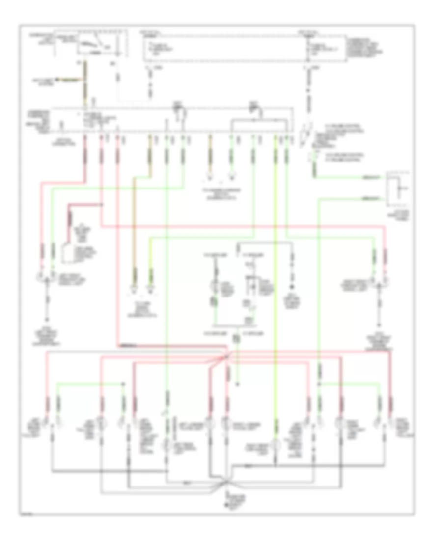
Exterior Light Wiring Diagram, Coupe & Sedan (1 of 2) for Honda Civic CX 1999
List of elements for Exterior Light Wiring Diagram, Coupe & Sedan (1 of 2) for Honda Civic CX 1999:
- (center of rear shelf) g311
- (not used)
- (option connector)
- 2000)
- Anti-theft system
- Brake switch (on brake pedal support)
- C352
- C421
- C422
- C423
- C501
- C551
- C927
- Combination light switch
- Fuse 32 license lights tail lights 7.5a
- Fuse 48 headlight 30a
- Fuse 52 horn, stop lt 15a
- G100 (left front corner of engine compartment)
- G101 (right front corner of engine compartment)
- G311 (center of rear shelf)
- Head
- Headlight switch
- High mount brake light
- Hot at all times
- J/c c442 (right kick panel)
- Keyless door lock control unit
- Left front parking/turn signal light
- Left inner brake light/ taillight (1996-98 sedan) (all coupe)
- Left inner taillight (1999,
- Left license plate light
- Left outer brake light/ taillight
- Off
- Park
- Right front parking/turn signal light
- Right inner taillight (1999, 2000)
- Right license plate light
- Right outer brake light/ taillight
- Right rear turn signal light
- To hazard warning switch (diagram 2 of 2)
- To turn signal switch (diagram 2 of 2)
- Underdash fuse/relay box (behind left side of dash)
- Underhood fuse/relay box (on right rear corner of engine compartment)
- W/ cruise control
- W/ keyless entry (1999, 2000)
- W/ spoiler
- W/o cruise control
- W/o spoiler
Exterior Light Wiring Diagram, Coupe & Sedan (2 of 2) for Honda Civic CX 1999
List of elements for Exterior Light Wiring Diagram, Coupe & Sedan (2 of 2) for Honda Civic CX 1999:
- C352
- C420
- C423
- C501
- Combination light switch
- From underdash fuse/relay box (diagram 1 of 2)
- Fuse 12 turn lights 7.5a
- Fuse 53 hazard 10a
- G200 (left kick panel)
- Gauge assembly
- Ground
- Hazard warning switch
- Hazard warning switch lamp
- Hot at all times
- Hot in on start
- Ignition
- Interior lights system
- J/c c507 (behind left side of dash)
- Left
- Left turn signal indicator
- Off
- Red
- Relay out
- Right
- Right turn signal indicator
- Turn signal switch
- Turn signal/ hazard relay
- Underdash fuse/relay box (behind left side of dash)
- Underhood fuse/relay box (on right rear corner of engine compartment)
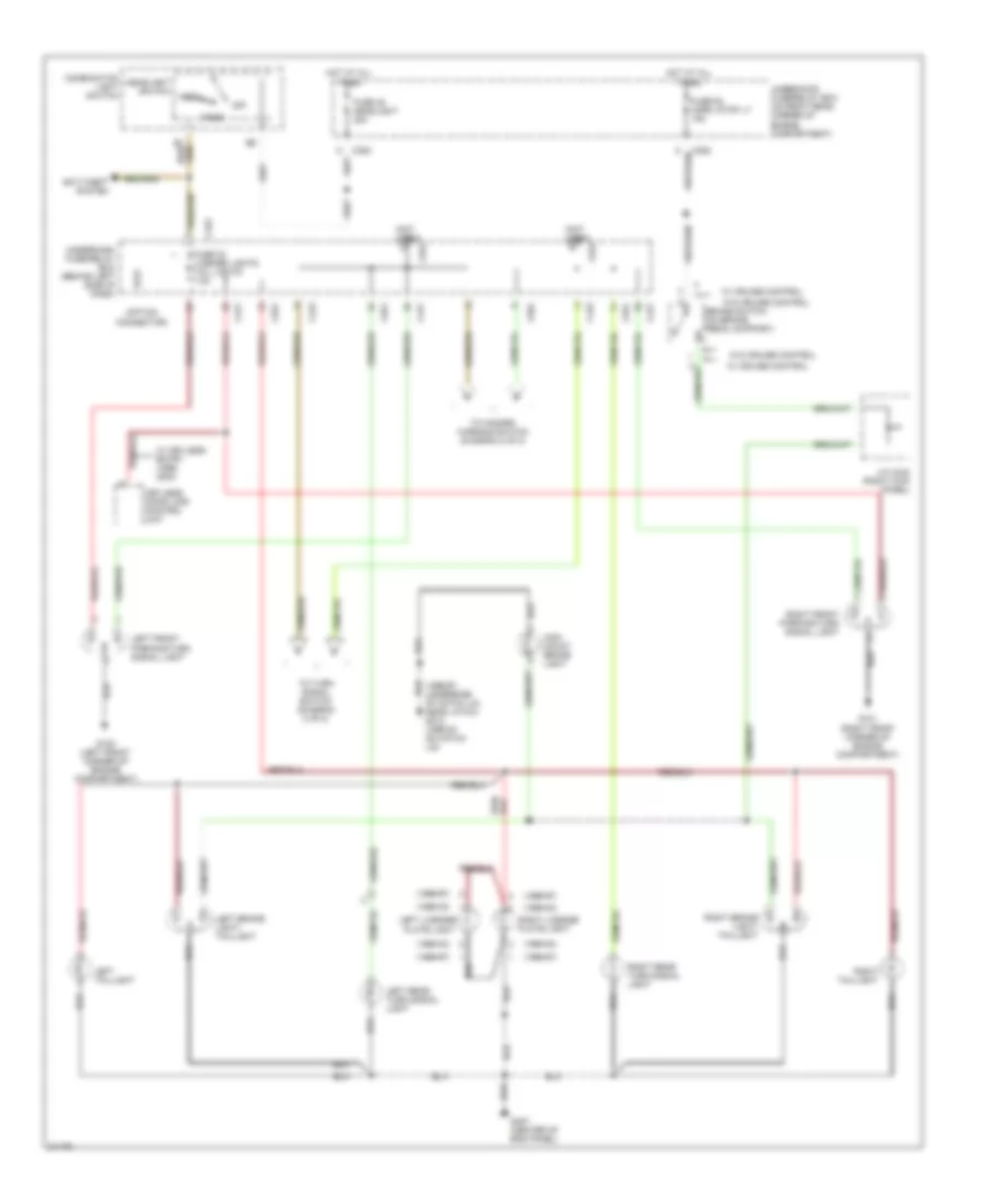
Exterior Light Wiring Diagram, Hatchback (1 of 2) for Honda Civic CX 1999
List of elements for Exterior Light Wiring Diagram, Hatchback (1 of 2) for Honda Civic CX 1999:
- (1996-97)
- (1996-97: underside of hatch lid, near latch) g412 (1998-00: on hatch lid)
- (1998-00)
- (not used)
- (option connector)
- Anti-theft system
- Brake switch (on brake pedal support)
- C352
- C421
- C422
- C423
- C501
- C551
- C927
- Combination light switch
- Fuse 32 license lights tail lights 7.5a
- Fuse 48 headlight 30a
- Fuse 52 horn, stop lt 15a
- G100 (left front corner of engine compartment)
- G101 (right front corner of engine compartment)
- G407 (center of end panel)
- Head
- Headlight switch
- High mount brake light
- Hot at all times
- J/c c442 (right kick panel)
- Keyless door lock control unit
- Left brake light/ taillight
- Left front parking/turn signal light
- Left license plate light
- Left rear turn signal light
- Left taillight
- Off
- Park
- Right brake light/ taillight
- Right front parking/turn signal light
- Right license plate light
- Right rear turn signal light
- Right taillight
- To hazard warning switch (diagram 2 of 2)
- To turn signal switch (diagram 2 of 2)
- Underdash fuse/relay box (behind left side of dash)
- Underhood fuse/relay box (on right rear corner of engine compartment)
- W/ cruise control
- W/ keyless entry (1999, 2000)
- W/o cruise control
Exterior Light Wiring Diagram, Hatchback (2 of 2) for Honda Civic CX 1999
List of elements for Exterior Light Wiring Diagram, Hatchback (2 of 2) for Honda Civic CX 1999:
- C352
- C420
- C423
- C501
- Combination light switch
- From underdash fuse/relay box (diagram 1 of 2)
- Fuse 12 turn lights 7.5a
- Fuse 53 hazard 10a
- G200 (left kick panel)
- Gauge assembly
- Ground
- Hazard warning switch
- Hazard warning switch light
- Hot at all times
- Hot in on or start
- Ignition
- Interior lights system
- J/c c507 (behind left side of dash)
- Left
- Left turn signal indicator
- Off
- Red
- Relay out
- Right
- Right turn signal indicator
- Turn signal switch
- Turn signal/ hazard relay
- Underdash fuse/relay box (behind left side of dash)
- Underdash fuse/relay box (behind left side of dash)
- Underhood fuse/relay box (on right rear corner of engine compartment)
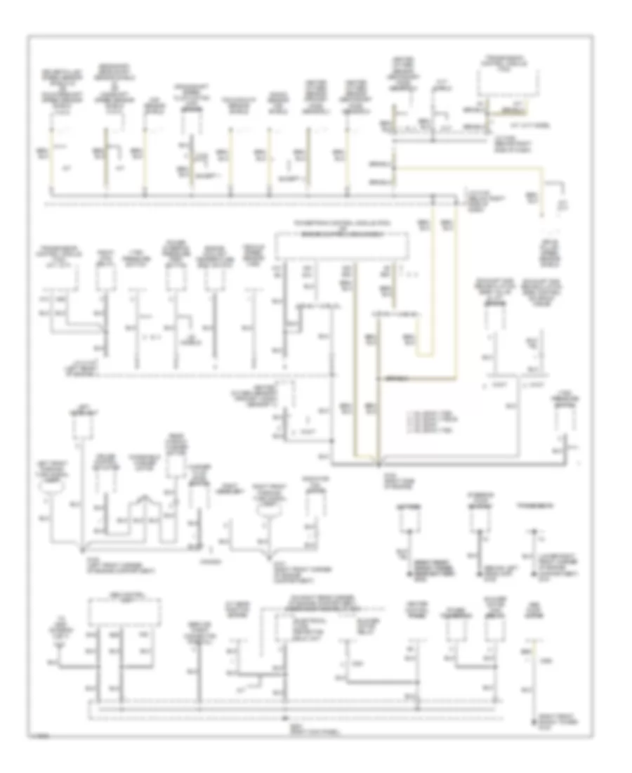
GROUND DISTRIBUTION
Ground Distribution Wiring Diagram (1 of 3) for Honda Civic CX 1999
List of elements for Ground Distribution Wiring Diagram (1 of 3) for Honda Civic CX 1999:
- (behind left headlamp) g106
- (lower right front corner of engine compartment) g101
- (on right rear corner of engine compartment) underhood fuse/relay box
- (right front (right front shock tower, shock tower, near battery) near battery) g103 g103
- (right front shock tower) g103
- 1.6l dohc vtec 1.6l sohc vtec-e 1.6l sohc
- 1.6l sohc vtec
- A/t
- A/t gear position switch
- A/t: cvt
- A/t: cvt model
- A10
- A13
- A17
- A22
- A22 b22
- A23
- A26
- A9 b20
- Abs control unit
- Abs pump motor
- B10
- B16
- B26
- Battery
- Blower motor high relay
- Blower motor relay
- C102
- C351
- C360
- Canada
- Ckf sensor shield
- Crankshaft speed fluctuation (ckf) sensor
- Cruise control actuator
- Cvt
- Cvt shield
- Drive pulley speed sensor shield
- Driver pulley speed sensor shield (2) or countershaft speed sensor shield (3 & 4)
- Electrical load detector (eld) unit
- Engine coolant temperature (ect) switch
- Except
- Exhaust gas recirculation (egr) control solenoid valve
- Exhaust gas recirculation (egr) valve & lift sensor
- G100 (left front corner of engine compartment)
- G101 (right front corner of engine compartment)
- G120 (right side of engine)
- G203 (right kick panel)
- Heated oxygen sensor (primary ho2s) (sensor 1)
- Heated oxygen sensor (secondary ho2s) (sensor 2)
- Heater control panel
- J/c c116 (left rear of engine)
- J/c c130 (below right side of dash)
- J/c c422 (behind right side of dash)
- Knock sensor (ks) shield
- Left front parking/ turn signal light
- Left headlight
- Pgm-fi main relay
- Power steering pressure (psp) switch
- Power transistor
- Powertrain control module (pcm) or engine control module (ecm)
- Radiator fan motor
- Rear window washer motor
- Right front parking/ turn signal light
- Right headlight
- Secondary gear shaft sensor shield (2) or mainshaft speed sensor shield (3 & 4)
- Service check connector (partial)
- Steering pump bracket
- Tdc/ckp/cyp sensor shield
- To g200 (diagram 2 of 3)
- Transmission
- Transmission control module (tcm)
- Transmission control module (tcm) (a/t: cvt)
- Us models
- Vehicle speed sensor (vss)
- Vtec pressure switch
- W/a/t
- W/m/t
- Washer fluid level switch
- Windshield washer motor
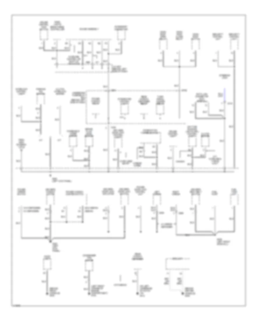
Ground Distribution Wiring Diagram (2 of 3) for Honda Civic CX 1999
List of elements for Ground Distribution Wiring Diagram (2 of 3) for Honda Civic CX 1999:
- (behind center console) g302
- (behind front console) g302
- (exc sedan)
- (left front corner of engine compartment) g100
- (on left underside of hatch lid) g412
- (sedan)
- (w/ defogger)
- (w/o defogger)
- A/t
- A14
- Abs
- Accessory connector
- Audio unit
- Brake fluid level switch
- C415
- C420
- C501
- C639
- C656
- C712
- Canada
- Clutch interlock switch
- Clutch switch
- Combination wiper switch
- Condenser fan motor
- Cruise control main switch
- Cruise control unit
- Dash lights brightness controller
- Data link connector (dlc) (partial)
- Daytime running lights (drl) control unit
- Driver's door lock actuator
- Driver's door lock switch
- Driver's seat belt switch
- Driver's window motor
- From g203 (diagram 1 of 3)
- Fuel pump
- Fuel tank unit
- G200 (left kick panel)
- G309 (left front door sill)
- Gauge assembly
- Hatchback
- Integrated control unit
- Interlock control unit
- J/c c507 (behind left side of dash)
- Keyless door lock control unit
- Left mirror
- M/t
- M/t: w/cruise & vtec-e w/m/t
- Moon roof close relay
- Moon roof open relay
- Moon roof switch
- Parking pin switch
- Power door lock control unit
- Power mirror switch
- Power window master switch
- Power window relay
- Rear window defogger
- Rear window defogger relay
- Right mirror
- Security control unit
- Srs unit
- Steering lock
- Turn/ signal hazard relay
- Underdash fuse/relay box (behind left side of dash)
- W/ mirror defogger
- W/cruise control or shift-up indicator
- W/keyless entry
- W/rear wiper
- Windshield wiper motor
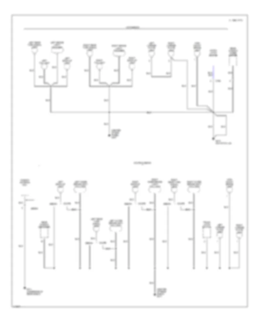
Ground Distribution Wiring Diagram (3 of 3) for Honda Civic CX 1999
List of elements for Ground Distribution Wiring Diagram (3 of 3) for Honda Civic CX 1999:
- (center of end panel) g407
- (center of rear shelf) g311
- C 1995 vftc
- C768
- Coupe
- Coupe & sedan
- G311 (underside of rear shelf)
- G412 (on hatch lid)
- Hatch latch switch
- Hatchback
- High mount brake light
- Left back-up light
- Left brake light/ taillight
- Left inner brakelight/ taillight
- Left license plate light
- Left outer brakelight/ taillight
- Left rear turn signal light
- Left taillight
- Rear window defogger
- Rear window wiper motor
- Right back-up light
- Right brake light/ taillight
- Right inner brake- light/ taillight
- Right license plate light
- Right outer brakelight/ taillight
- Right rear turn signal light
- Right taillight
- Sedan
- Trunk latch switch
- Window antenna coil
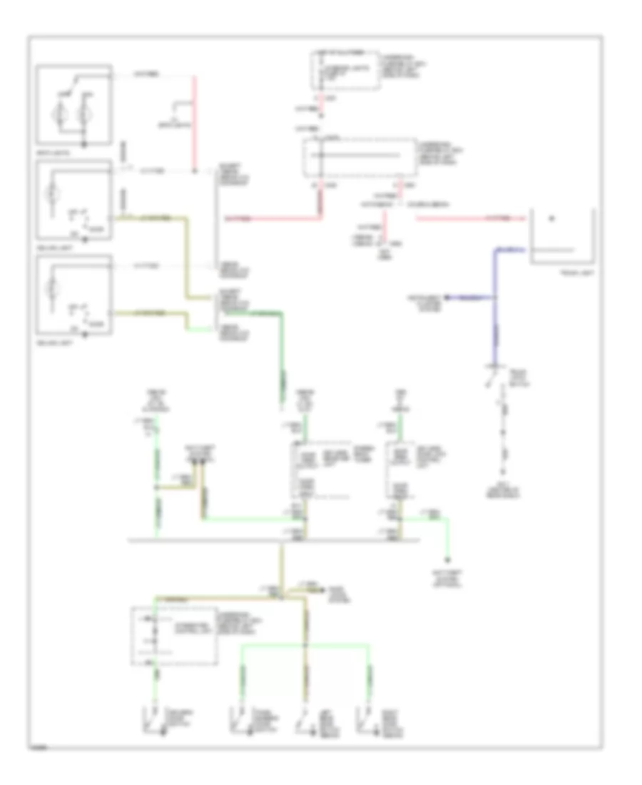
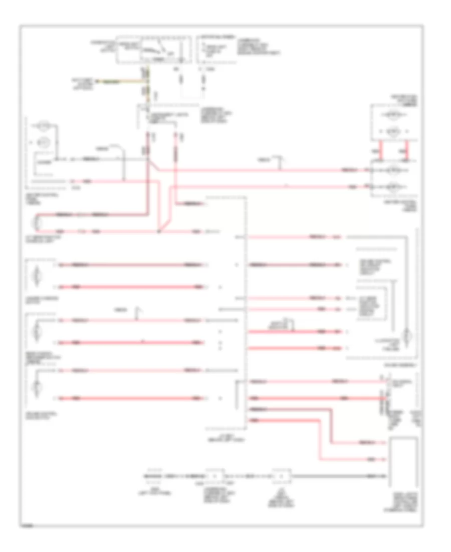
HEADLIGHTS
Headlight Wiring Diagram, with DRL for Honda Civic CX 1999
List of elements for Headlight Wiring Diagram, with DRL for Honda Civic CX 1999:
- 15a
- A1 headlight control
- A4 lights-on input
- B6 parking brake input b7
- Battery
- Brake system indicator b4
- C352
- C419
- C420
- C421
- C422
- C501
- C551
- Combination light switch
- Daytime running lights control unit (behind left side of dash)
- Daytime running lights resistor (left rear corner of eng compt)
- Dimmer switch
- Flash- to- pass switch
- Foglight in-line fuse (behind left side of dash panel)
- Foglight on indicator
- Foglight relay (behind left side of dash, taped to harness)
- Foglight switch
- G100 (left front corner of engine compartment)
- G101 (right front corner of engine compartment)
- G200 (left kick panel)
- G202 (behind left side of dash panel)
- Gauge assembly
- Ground
- Head
- Headlight fuse 48 30a
- Headlight switch
- High
- High beam indicator
- Hot at all times
- Hot in on
- Ignition
- Instrument cluster system
- J/c
- J/c c507 (behind left side of dash)
- L h/l hi beam fuse 5 10a
- L h/l lo beam fuse 22 10a
- Left foglight
- Left headlight
- Light control
- Low
- Nca
- Off
- Park
- Parking brake switch
- R h/l hi beam fuse 4 10a
- R h/l lo beam fuse 21 10a
- Red
- Right foglight
- Right headlight
- Running light fuse 20 7.5a
- Running light relay fuse 18 7.5a
- Underdash fuse/relay box
- Underdash fuse/relay box (behind left side of dash)
- Underhood fuse/relay box (right rear corner of engine compartment)
Headlight Wiring Diagram, without DRL for Honda Civic CX 1999
List of elements for Headlight Wiring Diagram, without DRL for Honda Civic CX 1999:
- (not used)
- 15a
- C352
- C419
- C420
- C421
- C422
- C501
- Combination light switch
- Dimmer switch
- Flash- to- pass switch
- Fog light on indicator
- Foglight in-line fuse (behind left side of dash panel)
- Foglight relay (behind left side of dash, taped to harness)
- Foglight switch
- G100 (left front corner of engine compartment)
- G101 (right front corner of engine compartment)
- G200 (left kick panel)
- G202 (behind left side of dash panel)
- Gauge assembly
- Head
- Headlight fuse 48 30a
- Headlight switch
- High
- High beam indicator
- Hot at all times
- J/c
- J/c c507 (behind left side of dash)
- L h/l hi beam fuse 5 10a
- L h/l lo beam fuse 22 10a
- Left foglight
- Left headlight
- Low
- Off
- Park
- R h/l hi beam fuse 4 10a
- R h/l lo beam fuse 21 10a
- Right foglight
- Right headlight
- Underdash fuse/relay box (behind left side of dash)
- Underhood fuse/relay box (right rear corner of engine compartment)
HORN
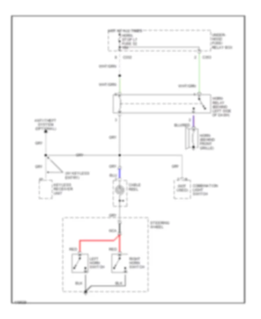
Horn Wiring Diagram for Honda Civic CX 1999
List of elements for Horn Wiring Diagram for Honda Civic CX 1999:
- (not used)
- (w/ keyless entry)
- Anti-theft system (optional)
- C352
- C353
- Cable reel
- Combination light switch
- Horn (behind front grille)
- Horn relay (behind left side of dash)
- Horn, stop lt fuse 52 15a
- Hot at all times
- Keyless receiver unit
- Left horn switch
- Nca
- Red
- Right horn switch
- Steering wheel
- Under- hood fuse/ relay box
INSTRUMENT CLUSTER
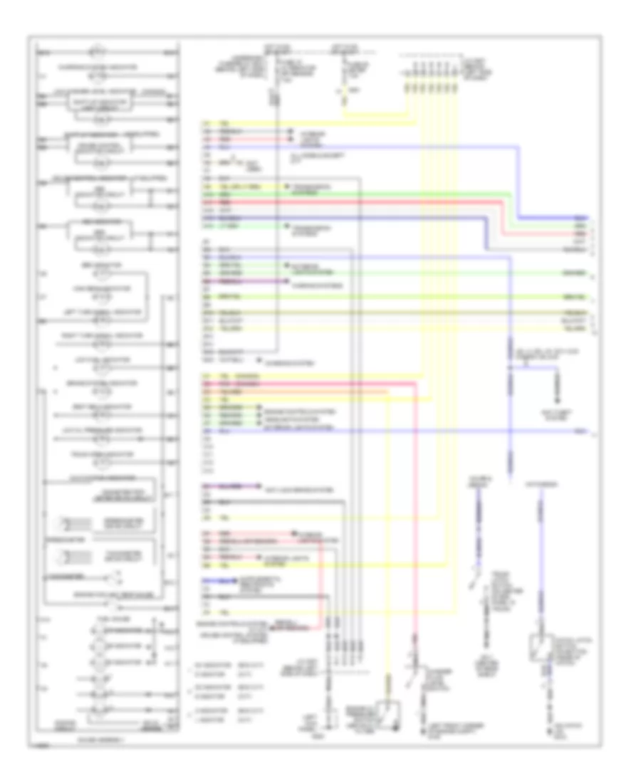
Instrument Cluster Wiring Diagram (1 of 2) for Honda Civic CX 1999
List of elements for Instrument Cluster Wiring Diagram (1 of 2) for Honda Civic CX 1999:
- (canada)
- (cvt)
- (exc cvt)
- (if equipped)
- (left front corner of engine compt) g100
- (left kick panel)
- (not used)
- (on hatch lid) g412
- 2 indicator
- A10
- A11
- A12
- A13
- A14
- Abs indicator
- Abs indicator circuit
- All models except cvt
- Anti-lock brake system
- Anti-theft system
- B10
- B11
- B12
- B13
- B14
- B15
- B16
- Brake system indicator
- C10
- C11
- C12
- C13
- C501
- Charging system
- Charging system indicator
- Coupe &
- Cruise control indicator
- Cruise control indicator circuit
- D indictor
- D3 indicator
- D4 indicator
- Dimming circuit
- Engine controls system
- Engine controls system (w: m/t) cruise control system (if equipped)
- Engine coolant temp gauge
- Engine oil pressure switch (above oil filter)
- Exterior lights system
- Fuel gauge
- Fuse 15 alternator (sp sensor) 7.5a
- Fuse 25 meter 7.5a
- G200
- G311 (center of rear shelf)
- Gauge assembly
- Hatch latch switch (on bottom inside of hatch)
- Hatchback
- Headlights system
- High beam indicator
- Hot in on or start
- Interior lights system
- J/c c507 (behind (left side of dash)
- J/c c507 (behind left side of dash)
- L indictor
- Left turn signal indicator
- Low fuel indicator
- Low oil pressure indicator
- Low washer level indicator
- Malfunction indicator
- N indicator
- Nca
- Odometer/trip- meter drive circuit
- P indicator
- Pnk
- R indicator
- Red
- Right turn signal indicator
- S indictor
- Seat belt indicator
- Sedan
- Shift-up indicator
- Shift-up indicator light circuit
- Solid state
- Speedometer
- Speedometer drive circuit
- Srs indicator
- Srs indicator circuit
- Tachometer
- Tachometer drive circuit
- Transmission systems
- Trunk latch switch (on center of end panel in trunk)
- Trunk open indicator
- Underdash fuse/relay box (behind left side of dash)
- Us: lx, ex, hx, dx-v & si canada: ex & si
- Warning systems
- Washer fluid level switch
Instrument Cluster Wiring Diagram (2 of 2) for Honda Civic CX 1999
List of elements for Instrument Cluster Wiring Diagram (2 of 2) for Honda Civic CX 1999:
- (a/t)
- (left front door sill) g309
- (left kick panel)
- (m/t)
- (on left rear corner of engine compartment) tachometer test connector
- (right kick panel)
- A/t gear position switch (below center console, right side of gear selector)
- All except d16y5 w/ m/t
- Brake fluid level switch (in brake fluid reservoir)
- C419
- C421
- C551
- Canada
- Cvt
- D16y5 w/ m/t
- Daytime running lights (drl) control unit (behind left side of dash)
- Distributor assembly (on rear of cylinder head)
- Engine controls system
- Engine coolant temperature sending unit (on rear of cylinder head)
- Engine speed output
- Except cvt
- Fuel gauge sending unit
- Fuel tank unit (below center of rear seat, through access hole)
- G200
- G203
- Ignition control module
- Integrated control unit
- J/c c130 (below right side of dash)
- J/c c442 (behind right kick panel)
- Parking brake switch
- Powertrain control module (pcm) engine control module (ecm) (behind right kick panel)
- Red
- Side of gear selector)
- Therm- istor
- Trans- missions system
- Underdash fuse/relay box (behind left side of dash)
- Usa
- Vehicle speed sensor (vss) (on top left front of transaxle) (a/t & m/t) (on top of transaxle) (cvt)
INTERIOR LIGHTS
Courtesy Lamps Wiring Diagram for Honda Civic CX 1999
List of elements for Courtesy Lamps Wiring Diagram for Honda Civic CX 1999:
- (1996-98) (1999-00)
- (sedan)
- 1996-98 sedan w/o moonroof
- 1996-98 usa: cx, dx & canada
- 1996-98 usa: lx, ex, & hx
- Anti-theft system (optional)
- B14
- C351
- C419
- C420
- C551
- C562
- Ceiling light
- Coupe & sedan
- Door
- Door locks system
- Door open input
- Door open output
- Driver's door switch
- Except 1996-98 sedan w/o moonroof
- G311 (center of rear shelf)
- Gx & 1999-00
- Hatchback
- Hot at all times
- Instrument cluster system
- Integrated control unit
- Interior lights fuse 43 7.5a
- Keyless door lock control unit
- Keyless receiver unit
- Left rear door switch (sedan)
- Not used
- Off
- Pass- enger's door switch
- Right rear door switch (sedan)
- Spotlights
- Stereo radio tuner
- Trunk latch switch
- Trunk light
- Underdash fuse/relay box (behind left side of dash)
- W/ spotlights
Instrument Illumination Wiring Diagram for Honda Civic CX 1999
List of elements for Instrument Illumination Wiring Diagram for Honda Civic CX 1999:
- (1996-98)
- (1999-00)
- 1996-98
- 1999-00
- A/t gear position console light
- A/t gear position indicator dimming circuit
- A12
- Anti-theft system (optional)
- Audio unit (1999- 00)
- C12
- C13
- C352
- C419
- C420
- C442
- C501
- C743
- Combination light switch
- Cruise control main switch
- Cruise control or upshift indicator circuit
- Dash lights brightness controller (left side of steering wheel)
- Dim signal input
- Dimmer
- G200 (left kick panel)
- Gauge assembly
- Hazard warning switch
- Head
- Headlight fuse 48 30a
- Headlight switch
- Heater control panel (1996-98)
- Heater control panel (1999-00)
- Heater push switches (1999-00)
- Hot at all times
- Illumination light (7-bulbs)
- Instrument lights fuse 30 7.5a
- J/c c507 (1999-00) (behind left side of dash)
- J/c c507 (behind left dash)
- Off
- Park
- Rear window defogger switch (1996-98)
- Red
- Stereo radio tuner (1996- 98)
- Underdash fuse/relay box (behind left side of dash)
- Underhood fuse/relay box (right rear of engine compartment)
- W/ shift-up indicator
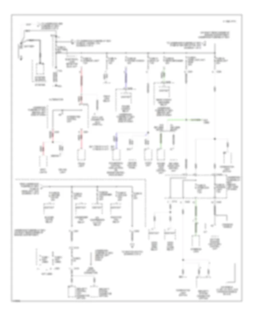
POWER DISTRIBUTION
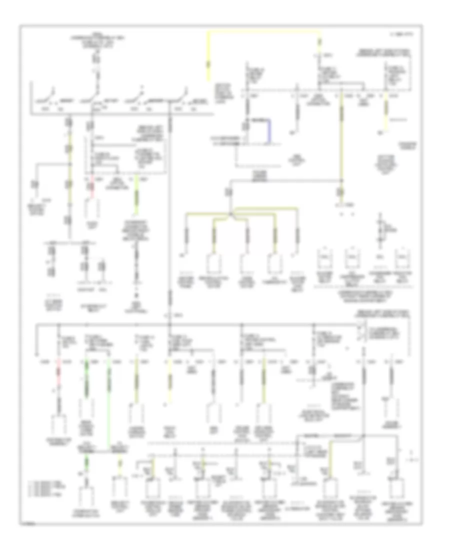
Power Distribution Wiring Diagram (1 of 3) for Honda Civic CX 1999
List of elements for Power Distribution Wiring Diagram (1 of 3) for Honda Civic CX 1999:
- (ex vtec-e w/ m/t)
- (on right rear corner of engine compartment) underhood fuse/relay box
- (sedan) 1
- (vtec-e w/ m/t)
- A/c compressor clutch relay
- A/t
- Alternator
- Audio unit
- B10
- B21
- Battery
- Blower motor relay
- C 1995 vftc
- C10
- C351
- C352
- C419
- C420
- C422
- C551
- C712
- C926 (option connector)
- Canadian models
- Ceiling light
- Combination light switch
- Condenser fan relay
- Contact
- Data link connector (dlc) (partial)
- Daytime running lights (drl) control unit
- Electrical load detector (eld) unit
- From underhood fuse/relay box (fuse 48 headlight, 30a) (diagram 1 of 3)
- Fuse 1 (not used)
- Fuse 2 (not used)
- Fuse 20 running light 7.5a
- Fuse 33 interlock unit 7.5a
- Fuse 41 battery 80a
- Fuse 42 ig1 40a
- Fuse 43 interior light 7.5a
- Fuse 44 fi e/m 15a
- Fuse 46 power window 40a
- Fuse 47 back up 7.5a
- Fuse 48 headlight 30a
- Fuse 50 rear defogger 30a
- Fuse 51 door lock unit, roof 20a
- Fuse 54 option 40a
- Fuse 55 heater motor 40a
- Fuse 56 condenser fan 20a
- Fuse 57 cooling fan 20a
- Fuse 6 3a
- Heater control panel
- Integrated control unit
- Keyless door lock control unit
- Moon roof close relay
- Moon roof open relay
- Not used
- Pgm-fi main relay
- Power door lock control unit
- Power window relay
- Powertrain control module (pcm) or engine control module (ecm)
- Radiator fan relay
- Rear window defogger relay
- Security control unit connector (option)
- Security system connector (option)
- Spot lights
- Starter
- Starter solenoid
- Steering lock
- T101
- T102
- To ignition switch (diagram 2 of 3)
- To underhood abs fuse/relay box (diagram 3 of 3)
- To underhood fuse/relay box (fuse 53 hazard, 10a) (diagram 3 of 3)
- To underhood fuse/relay box (fuse 55 heater motor, 40a) (diagram 1 of 3)
- Trunk light
- Underdash fuse/relay box (behind left side of dash)
- Underdash fuse/relay box (behind left side of dash)
- Underhood fuse/relay box (on right rear corner of engine compartment)
- Us models: lx, ex, hx, dx-v, & si canadian models: ex & si
- W/ keyless entry
- W/o keyless entry
Power Distribution Wiring Diagram (2 of 3) for Honda Civic CX 1999
List of elements for Power Distribution Wiring Diagram (2 of 3) for Honda Civic CX 1999:
- (behind left side of dash) underdash fuse/relay box
- (canada)
- (not used)
- (us)
- (w/ defogger)
- (w/o defogger)
- 1.6l dohc vtec 1.6l sohc vtec-e
- 1.6l sohc 1.6l sohc vtec
- A/c compressor clutch relay
- A/c diode
- A/c thermostat
- A/t
- A/t gear position switch
- Abs control unit
- Acc
- Accessory connector (behind front console, below radio)
- Alternator
- Audio unit
- B15
- Blower motor high relay
- Blower motor relay
- C 1995 vftc
- C352
- C416
- C419
- C420
- C421
- C423
- C439
- C501
- C551
- C801
- C913
- C928 (option connector)
- C929 (option connector)
- Canadian models
- Coil
- Combination wiper switch
- Condenser fan relay
- Contact
- Cruise control main switch
- Daytime running lights (drl) control unit
- Distributor assembly
- Electrical load detector (eld) unit
- Evaporative emission (evap) bypass solenoid valve
- Evaporative emission (evap) control canister vent shut valve
- Evaporative emission (evap) purge control solenoid valve
- Except vtec-e m/t
- From underhood fuse/relay box (fuse 42 ig1, 40a) (diagram 1 of 3)
- Fuse 12 turn lights 7.5a
- Fuse 13 fuel pump (srs unit) 15a
- Fuse 14 cruise control (keyless) 7.5a
- Fuse 15 alternator (sp sensor) 7.5a
- Fuse 16 rr def relay 7.5a
- Fuse 17 heater a/c relay 7.5a
- Fuse 18 (running light relay) 7.5a
- Fuse 27 cigarette lighter acc socket 10a
- Fuse 28 radio clock 10a
- Fuse 3 rr wiper (rr washer) 10a
- Fuse 9 ign coil 15a
- G200 (left kick panel)
- Gauge assembly
- Hazard warning switch
- Heated oxygen sensor (primary h02s) (sensor 1)
- Heated oxygen sensor (secondary h02s) (sensor 2)
- Heater control panel
- Ignition switch (part of steering lock)
- J/c c115 (left rear of engine)
- Keyless doorlock control unit
- Lock
- M/t
- Mode control motor
- Pgm-fi main relay
- Power mirror switch
- Powertrain control module (a/t)
- Radiator fan relay
- Rear window wiper motor
- Recirculation control motor
- Red
- Security control unit
- Security system option
- Srs unit
- Start
- Starter cut relay
- To underdash fuse/relay box (diagram 3 of 3)
- Underhood fuse/relay box (on right rear corner of engine compartment)
- Us models
- Vehicle speed sensor (vss)
- W/ security system
- W/o security system
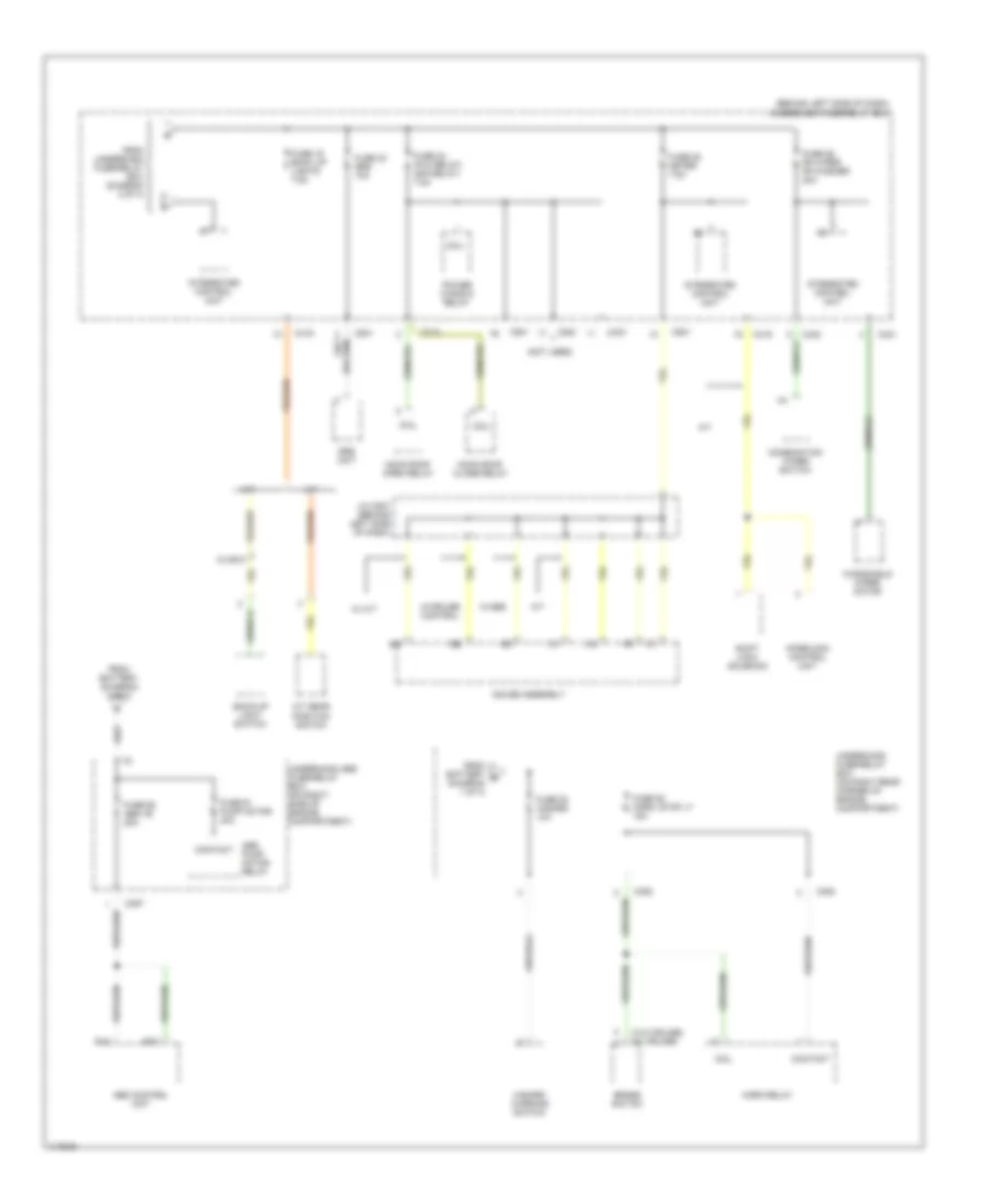
Power Distribution Wiring Diagram (3 of 3) for Honda Civic CX 1999
List of elements for Power Distribution Wiring Diagram (3 of 3) for Honda Civic CX 1999:
- (behind left side of dash) underdash fuse/relay box
- (not used)
- (w/o cruise) (w/ cruise)
- 15 or 6
- A/t
- A/t gear position switch
- Abs control unit
- Abs pump motor relay
- B14
- B15
- Back-up light switch
- Brake switch
- C352
- C353
- C357
- C419
- C420
- C421
- C423
- C501
- C712
- C801
- Coil
- Combination wiper switch
- Contact
- From battery (diagram 1 of 3)
- From battery b (diagram 1 of 3)
- From underdash fuse/relay box (diagram 2 of 3)
- Fuse 19 back up lights 7.5a
- Fuse 23 srs 10a
- Fuse 24 (p/w relay) (s/r relay) 7.5a
- Fuse 25 meter 7.5a
- Fuse 26 fr wiper fr washer 20a
- Fuse 52 horn, stop lt 15a
- Fuse 53 hazard 10a
- Fuse 61 pump motor 40a
- Fuse 62 abs +b 20a
- Gauge assembly
- Hazard warning switch
- Horn relay
- Integrated control unit
- Interlock control unit
- J/c c507 (behind left side of dash)
- M/t
- Moon roof close relay
- Moon roof open relay
- Power window relay
- Shift lock solenoid
- Srs unit
- Underhood abs fuse/relay box (on right side of engine compartment)
- Underhood fuse/relay box (on right rear corner of engine compartment)
- W/ m/t
- W/abs
- W/cruise control
- Windshield wiper motor
POWER DOOR LOCKS
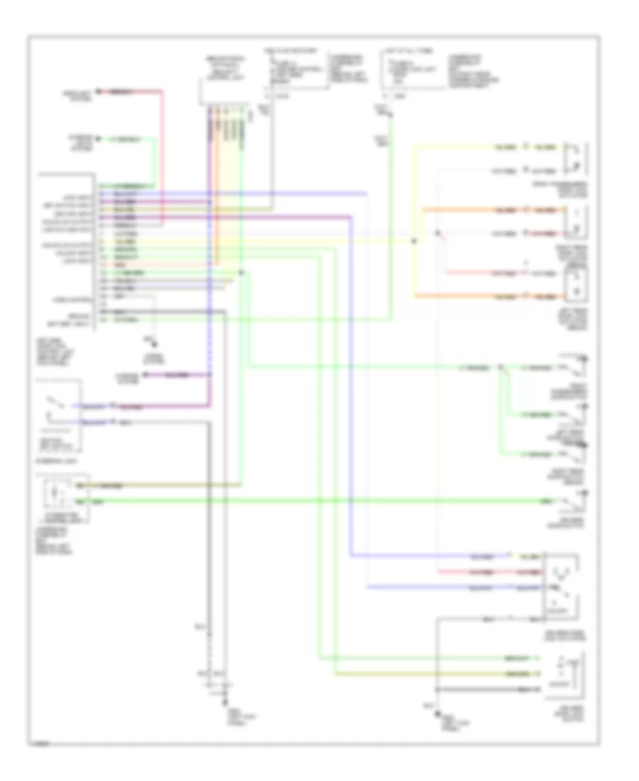
Power Door Lock Wiring Diagram, with Keyless Entry for Honda Civic CX 1999
List of elements for Power Door Lock Wiring Diagram, with Keyless Entry for Honda Civic CX 1999:
- (behind radio)
- (optional)
- 20a
- 7.5a
- Battery input
- C351
- C419
- C447
- Driver's door lock actuator
- Driver's door lock switch
- Driver's door switch
- Front passenger's door lock actuator
- Front passenger's door switch
- Fuse 14 (cruise control) (keyless)
- Fuse 51 door lock unit, roof
- G200 (left kick panel)
- Ground
- Headlight system
- Horn control
- Horns system
- Hot at all times
- Hot in on or start
- Ignition input
- Ignition key switch
- Integrated control unit
- Interior lights system
- Key switch input
- Keyless door lock control unit (behind left kick panel)
- Left rear door lock actuator (sedan)
- Left rear door switch (sedan)
- Lights flash cntl
- Lock
- Lock input
- Right rear door lock actuator (sedan)
- Right rear door switch (sedan)
- Security control unit
- Steering lock
- Underdash fuse/relay box (behind left side of dash)
- Underhood fuse/relay box (on right rear corner of engine compartment)
- Unlck/lck output
- Unlock
- Unlock input
- Warning system
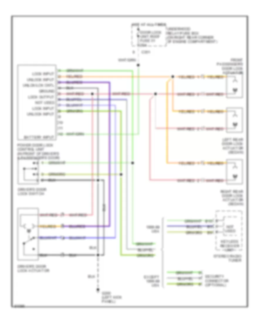
Power Door Lock Wiring Diagram, without Keyless Entry for Honda Civic CX 1999
List of elements for Power Door Lock Wiring Diagram, without Keyless Entry for Honda Civic CX 1999:
- 1996-98 usa
- B10
- Battery input
- C351
- Door lock unit,roof fuse 51 20a
- Driver's door lock actuator
- Driver's door lock switch
- Except 1996-98 usa
- Front passenger's door lock actuator
- G200 (left kick panel)
- Ground
- Hot at all times
- Keyless receiver unit
- Left rear door lock actuator (sedan)
- Lock input
- Lock output
- Not used
- Power door lock control unit (in front of driver's & passenger's door)
- Right rear door lock actuator (sedan)
- Security connector (optional)
- Stereo radio tuner
- Underhood relay/fuse box (on right rear corner of engine compartment)
- Unlck/lck cntl
- Unlock input
POWER MIRRORS
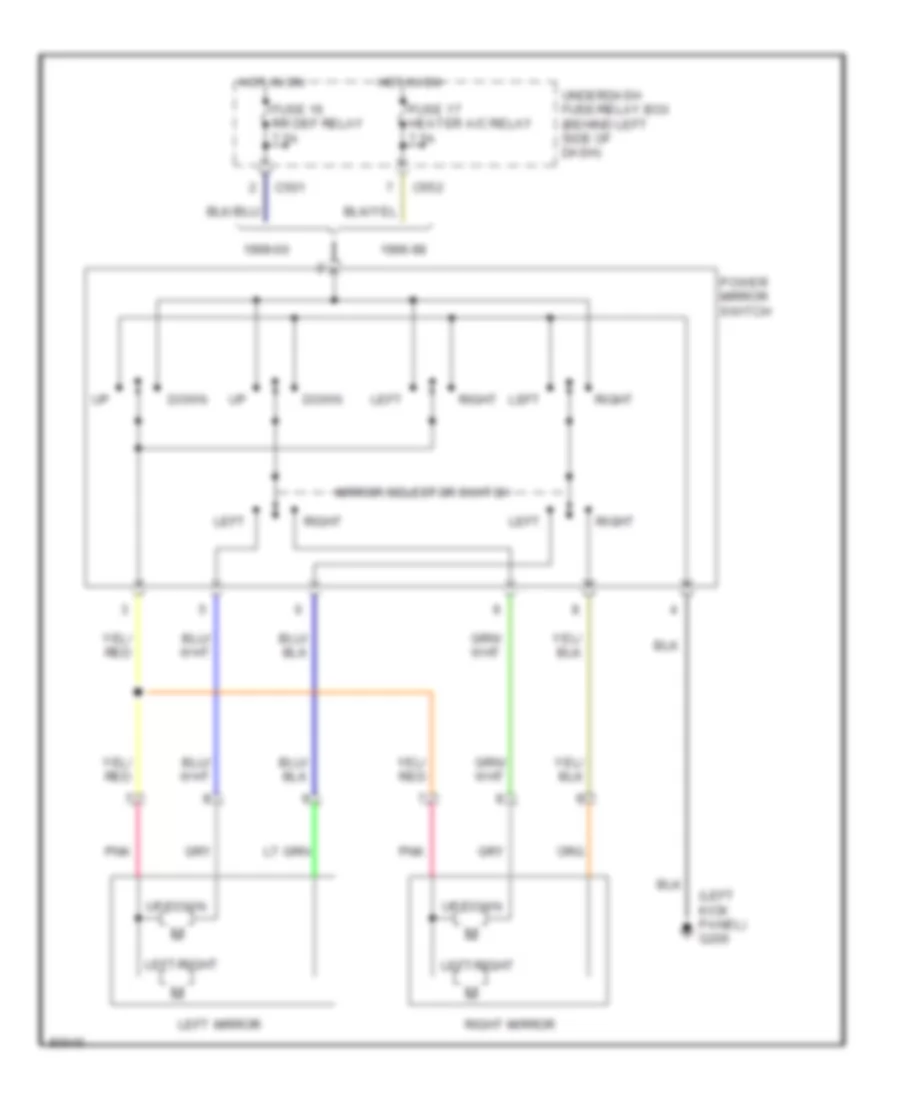
Power Mirror Wiring Diagram for Honda Civic CX 1999
List of elements for Power Mirror Wiring Diagram for Honda Civic CX 1999:
- (left kick panel) g200
- 1996-98
- 1999-00
- C501
- C552
- Down
- Fuse 16 rr def relay 7.5a
- Fuse 17 heater a/c relay 7.5a
- Hot in on
- Left
- Left mirror
- Left/right
- Mirror selector switch
- Pnk
- Power mirror switch
- Right
- Right mirror
- Underdash fuse/relay box (behind left side of dash)
- Up/down
POWER TOP/SUNROOF
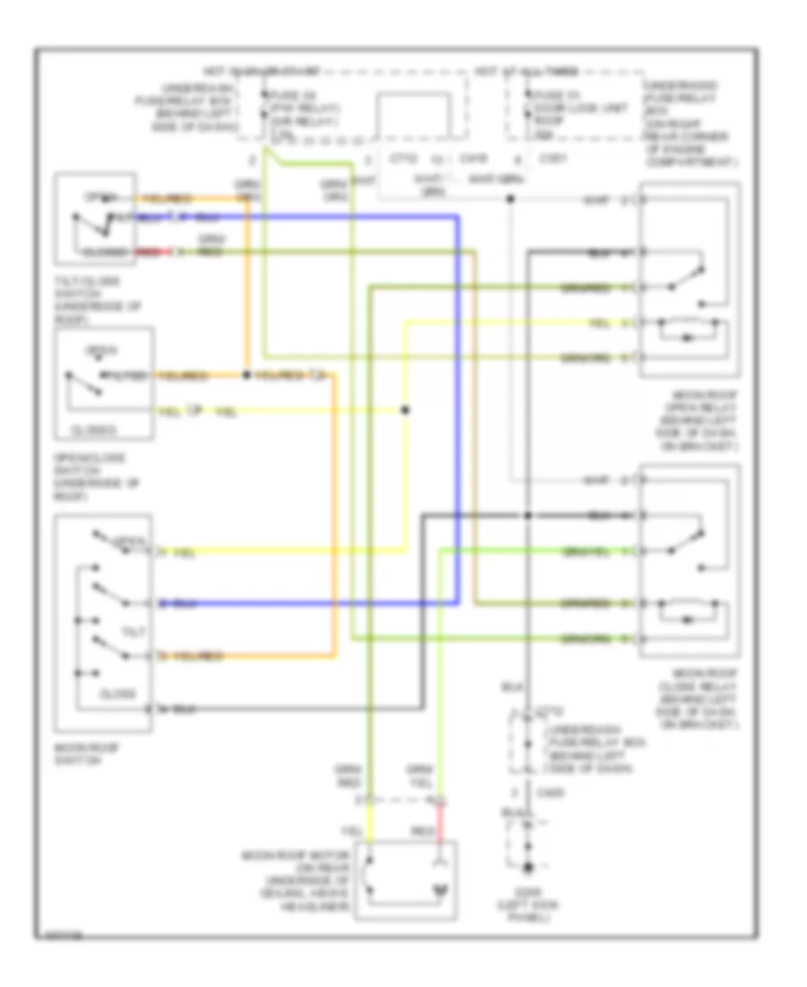
Power Top/Sunroof Wiring Diagrams for Honda Civic CX 1999
List of elements for Power Top/Sunroof Wiring Diagrams for Honda Civic CX 1999:
- C351
- C419
- C420
- C712
- Close
- Closed
- Fuse 24 (p/w relay) (s/r relay) 7.5a
- Fuse 51 door lock unit roof 20a
- G200 (left kick panel)
- Hot at all times
- Hot in on or start
- Moon roof close relay (behind left side of dash, on bracket)
- Moon roof motor (on rear underside of ceiling, above headliner)
- Moon roof open relay (behind left side of dash, on bracket)
- Moon roof switch
- Open
- Open/close switch (underside of roof)
- Red
- Tilt
- Tilt/close switch (underside of roof)
- Tilted
- Underdash fuse/relay box (behind left side of dash)
- Underhood fuse/relay box (on right rear corner of engine compartment)
POWER WINDOWS
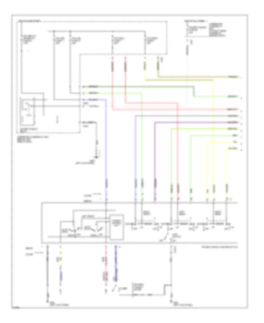
Power Window Wiring Diagram (1 of 2) for Honda Civic CX 1999
List of elements for Power Window Wiring Diagram (1 of 2) for Honda Civic CX 1999:
- (p/w as) fuse 10 20a
- (p/w dr) fuse 11 20a
- (p/w relay) (sr relay) fuse 24 7.5a
- (p/w rr-l) fuse 7 20a
- (p/w rr-r) fuse 8 20a
- 40a
- A or b
- Auto down
- C351
- C420
- C552
- Coupe
- Down
- Driver's window motor
- G200 (left kick panel)
- Hot at all times
- Hot in on or start
- Left front
- Left rear
- Main switch
- Off
- Power window fuse 46
- Power window master switch
- Power window relay
- Pulser
- Red/
- Right front
- Right rear
- Sedan
- Underdash fuse/relay box (behind left side of dash)
- Underhood fuse/relay box (on right rear corner of engine compt)
- Window control unit
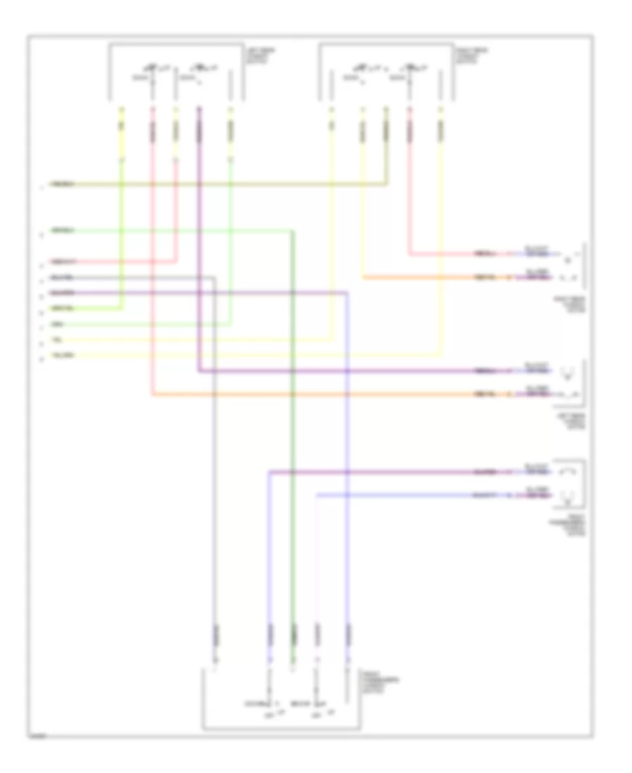
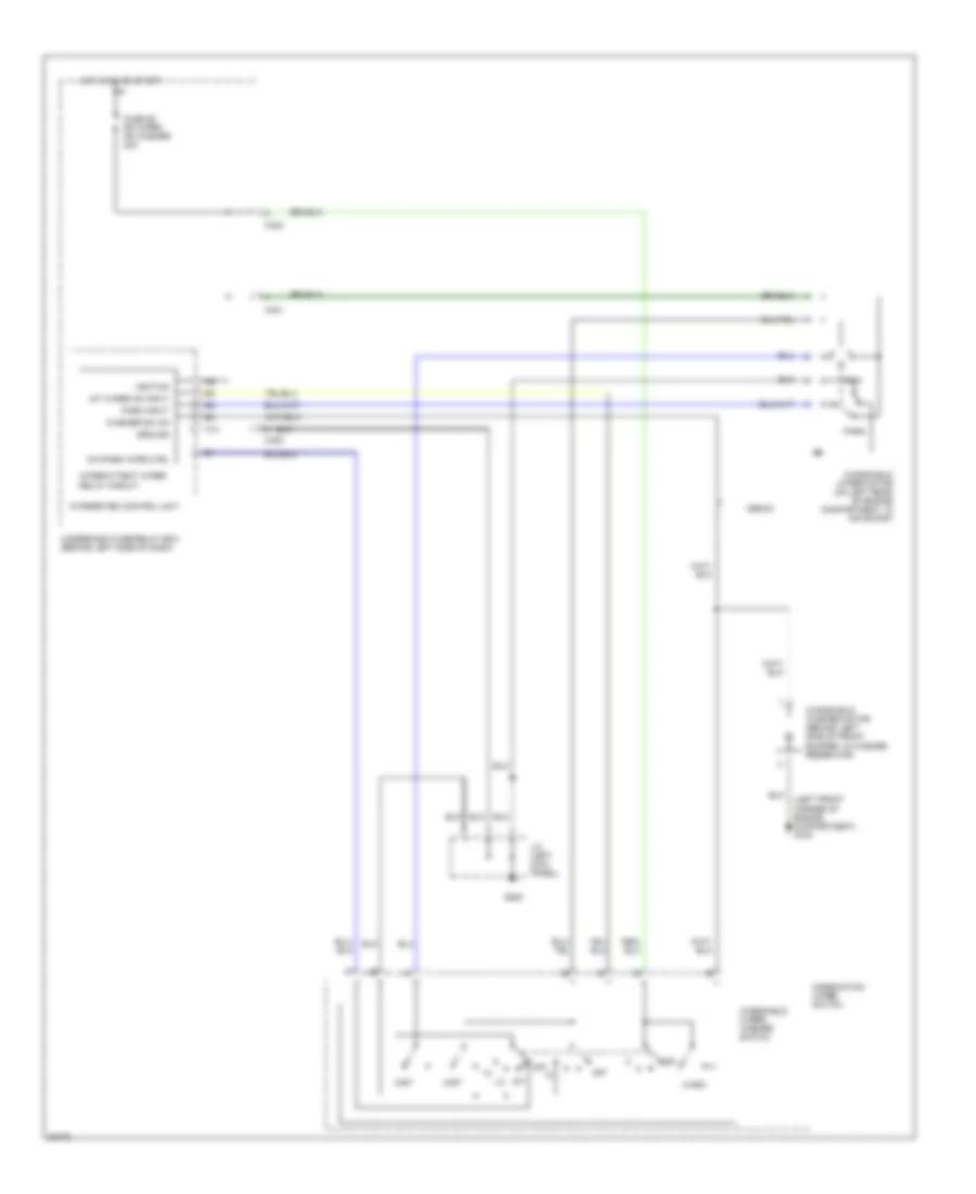
Power Window Wiring Diagram (2 of 2) for Honda Civic CX 1999
List of elements for Power Window Wiring Diagram (2 of 2) for Honda Civic CX 1999:
- Down
- Front passenger's window motor
- Front passenger's window switch
- Left rear window motor
- Left rear window switch
- Off
- Right rear window motor
- Right rear window switch
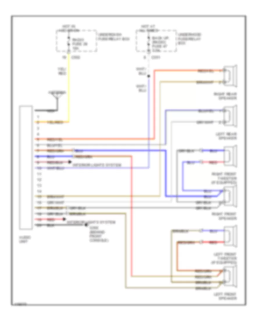
RADIO
Radio Wiring Diagrams for Honda Civic CX 1999
List of elements for Radio Wiring Diagrams for Honda Civic CX 1999:
- Antenna
- Audio unit
- Back up, (radio) fuse 47 7.5a
- C351
- C502
- G302 (behind front console)
- Hot at all times
- Hot in acc or on
- Interior lights system
- Left front speaker
- Left front tweeter (if equipped)
- Left rear speaker
- Nca
- Radio fuse 28 10a
- Red
- Right front speaker
- Right front tweeter (if equipped)
- Right rear speaker
- Underdash fuse/relay box
- Underhood fuse/relay box
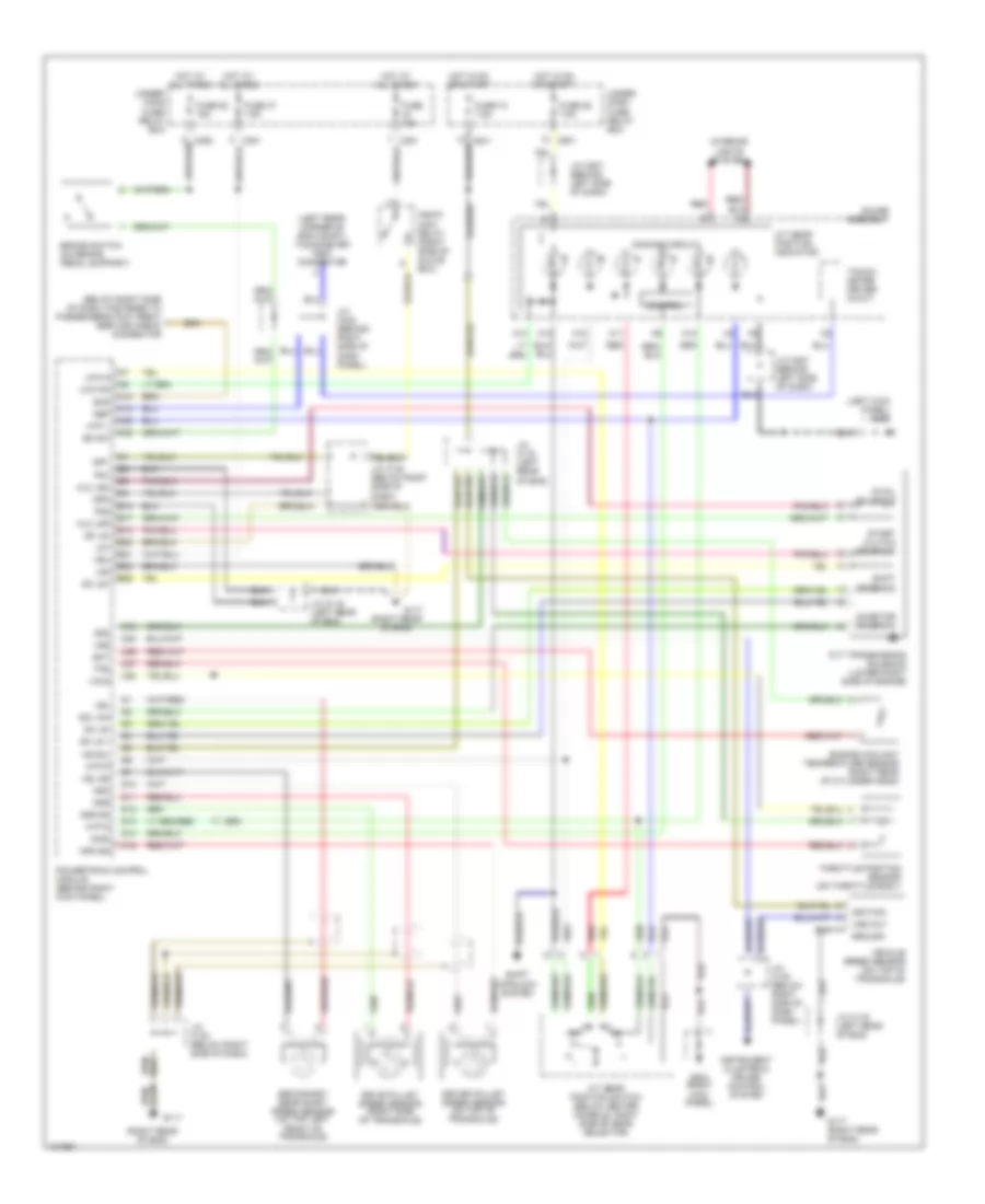
SHIFT INTERLOCKS
Shift Interlock Wiring Diagram, with CVT for Honda Civic CX 1999
List of elements for Shift Interlock Wiring Diagram, with CVT for Honda Civic CX 1999:
- (behind left kick panel)
- A/t gear position switch (below center
- A30
- B12
- Brake sw in
- Brake switch (on brake pedal support)
- C30
- C352
- C415
- C419
- C420
- Console)
- Data output
- Engine control module (behind right kick data input panel)
- Engine controls system
- G200
- G203
- Horn stop light fuse 52 15a
- Hot at all times
- Hot in on or start
- Instrument cluster system
- Interlock control unit (behind dash,
- Interlock unit fuse 33 7.5a
- J/c (left kick panel)
- J/c (right kick panel)
- J/c c442 (behind right side of dash)
- Key interlock solenoid
- Key interlock switch
- Meter fuse 25 7.5a
- N d
- Parking pin switch (below center console)
- Pnk
- Right of steering column)
- Sensor output
- Shft lk cir ctrl
- Shift lock solenoid (below center console)
- Steering lock
- Throttle position sensor (on throttle body)
- Trans- mission control module tps in
- Underdash fuse/relay box
- Underhood fuse/relay box
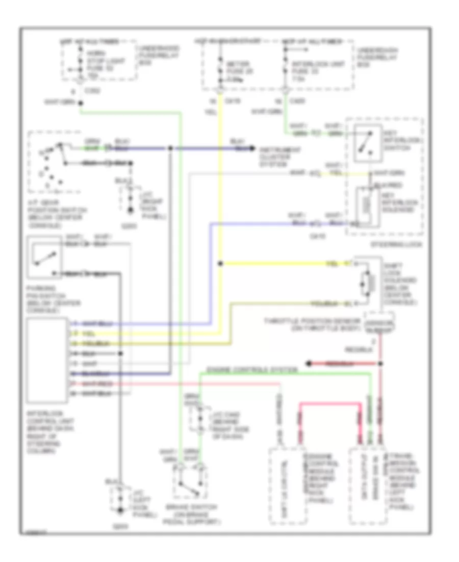
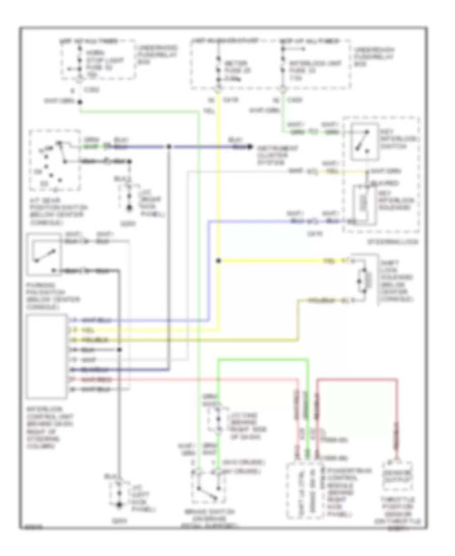
Shift Interlock Wiring Diagram, without CVT for Honda Civic CX 1999
List of elements for Shift Interlock Wiring Diagram, without CVT for Honda Civic CX 1999:
- (1996-98)
- (1999-00)
- (w/ cruise)
- (w/o cruise)
- A/t gear position switch (below center
- A28 b12
- A32
- Brake sw in
- Brake switch (on brake pedal support)
- C27
- C352
- C415
- C419
- C420
- Console)
- G200
- G203
- Horn stop light fuse 52 15a
- Hot at all times
- Hot in on or start
- Instrument cluster system
- Interlock control unit (behind dash,
- Interlock unit fuse 33 7.5a
- J/c (left kick panel)
- J/c (right kick panel)
- J/c c442 (behind right side of dash)
- Key interlock solenoid
- Key interlock switch
- Meter fuse 25 7.5a
- Parking pin switch (below center console)
- Powertrain control module (behind right kick panel)
- Right of steering column)
- Sensor output
- Shft lk ctrl
- Shift lock solenoid (below center console)
- Steering lock
- Throttle position sensor (on throttle body)
- Tps in
- Underdash fuse/relay box
- Underhood fuse/relay box
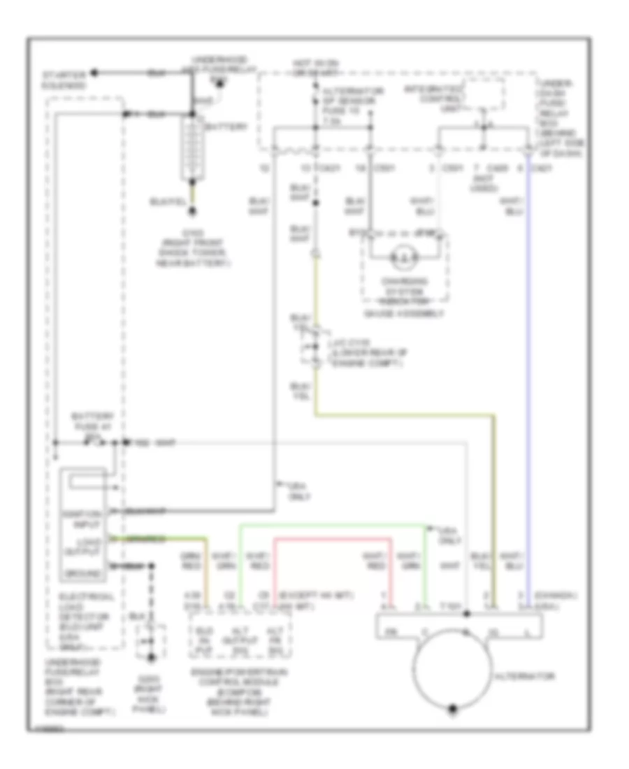
STARTING/CHARGING
Charging Wiring Diagram for Honda Civic CX 1999
List of elements for Charging Wiring Diagram for Honda Civic CX 1999:
- (canada)
- (except hx m/t) c5
- (hx m/t) c17
- (usa)
- A19
- A30
- Alt fr sig
- Alt output sig
- Alternator
- Alternator sp sensor fuse 15 7.5a
- B15
- B16
- Battery
- Battery fuse 41 80a
- C420 (not used)
- C421
- C501
- Charging system indicator
- D16
- Eld in- put
- Electrical load detector (eld) unit (usa only)
- Engine/powertrain control module (ecm/pcm) (behind right kick panel)
- G103 (right front shock tower, near battery)
- G203 (right kick panel)
- Gauge assembly
- Ground
- Hot in on or start
- Ignition input
- Integrated control unit
- J/c c115 (lower rear of engine compt)
- Load output
- Starter solenoid
- T101
- T102
- Under- dash fuse/ relay box (behind left side of dash)
- Underhood abs fuse/relay box
- Underhood fuse/relay box (right rear corner of engine compt)
- Usa only
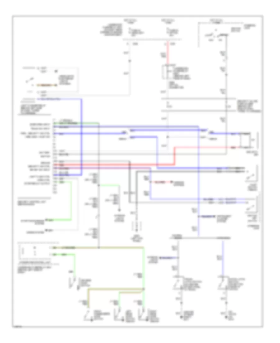
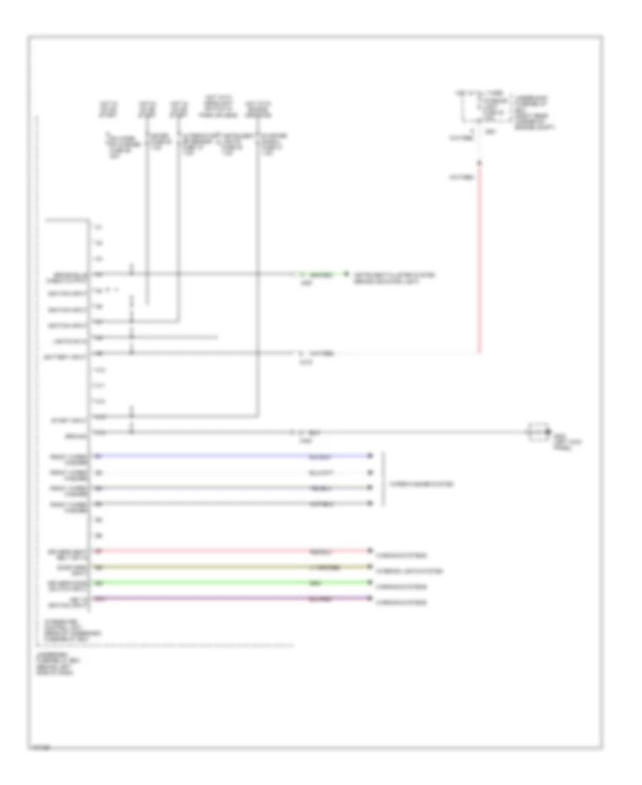
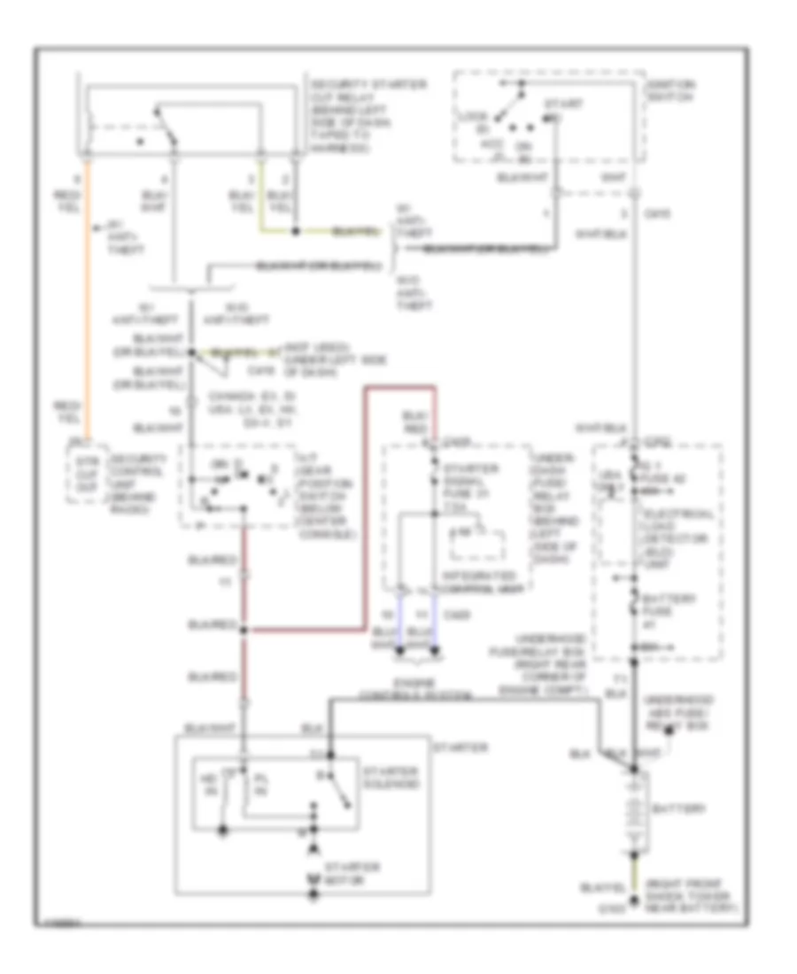
Starting Wiring Diagram, with A/T for Honda Civic CX 1999
List of elements for Starting Wiring Diagram, with A/T for Honda Civic CX 1999:
- (not used) (under left side of dash)
- (right front shock tower near battery)
- 80a
- A/t gear position switch (below center console)
- A13
- Acc (i)
- Battery
- Battery fuse
- C352
- C415
- C416
- C419
- C420
- Canada: ex, si usa: lx, ex, hx,
- D d4
- Dx-v, s1
- Electrical load detector (eld) unit
- Engine controls system
- G103
- Hd in
- Ig 1 fuse 42 40a
- Ignition switch
- Integrated control unit
- Lock (0)
- On (ii)
- Or/
- Pl in
- Security control unit (behind radio)
- Security starter cut relay (behind left side of dash, taped to harness)
- Start (iii)
- Starter
- Starter motor
- Starter signal fuse 31 7.5a
- Starter solenoid
- Str cut out
- Under- dash fuse/ relay box (behind left side of dash)
- Underhood abs fuse/ relay box
- Underhood fuse/relay box (right rear corner of engine compt)
- Usa only
- W/ anti- theft
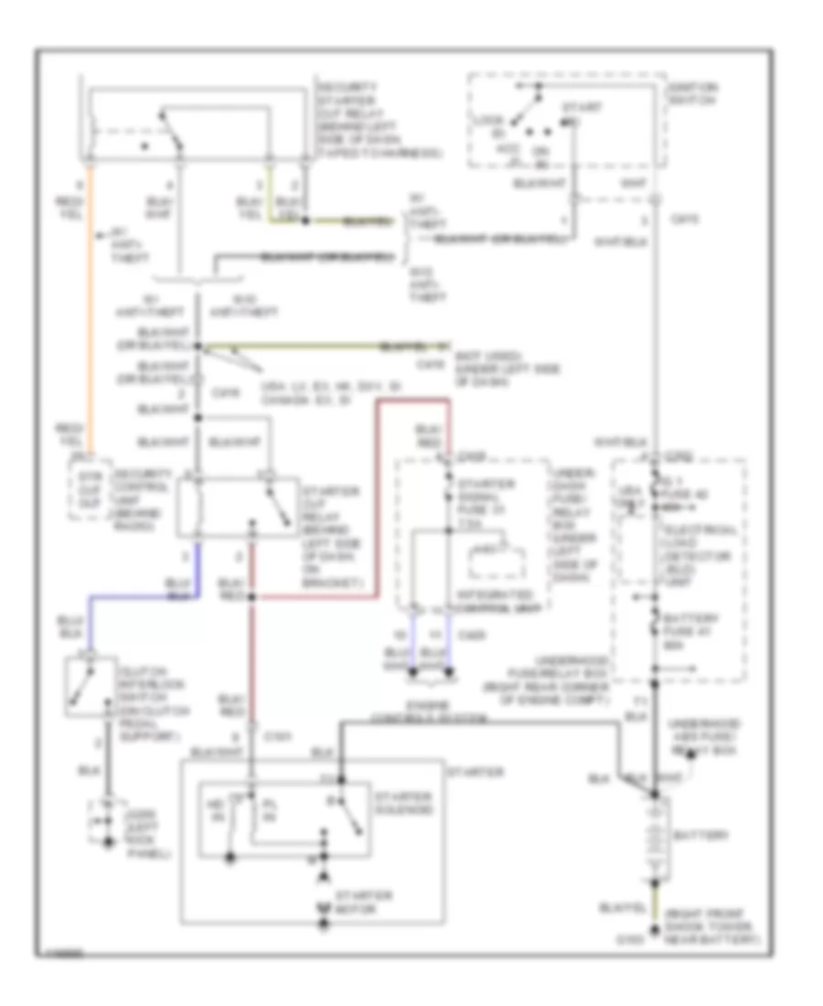
- W/ anti-theft
- W/o anti- theft
- W/o anti-theft
Starting Wiring Diagram, with M/T for Honda Civic CX 1999
List of elements for Starting Wiring Diagram, with M/T for Honda Civic CX 1999:
- (not used) c416 (under left side of dash)
- (right front shock tower, near battery)
- A13
- Acc (i)
- Battery
- Battery fuse 41 80a
- C101
- C352
- C415
- C416
- C419
- C420
- Clutch interlock switch (on clutch pedal support)
- Electrical load detector (eld) unit
- Engine controls system
- G103
- G200 (left kick panel)
- Hd in
- Ig 1 fuse 42 40a
- Ignition switch
- Integrated control unit
- Lock (0)
- On (ii)
- Pl in
- Security control unit (behind radio)
- Security starter cut relay (behind left side of dash, taped to harness)
- Start (iii)
- Starter
- Starter cut relay (behind left side of dash, on bracket)
- Starter motor
- Starter signal fuse 31 7.5a
- Starter solenoid
- Str cut out
- Under- dash fuse/ relay box (under left side of dash)
- Underhood abs fuse/ relay box
- Underhood fuse/relay box (right rear corner of engine compt)
- Usa only
- Usa: lx, ex, hx, dxv, si canada: ex, si
- W/ anti- theft
- W/ anti-theft
- W/o anti- theft
- W/o anti-theft
SUPPLEMENTAL RESTRAINTS
Supplemental Restraint Wiring Diagram for Honda Civic CX 1999
List of elements for Supplemental Restraint Wiring Diagram for Honda Civic CX 1999:
- (behind left side of front console) g206
- Airbag
- C501
- C801
- Cable reel
- Canada
- Circuit
- Connector (dlc) (partial) (above left kick panel, near engine hood release lever)
- Data link
- Dlc
- Driver's air bag
- Dummy resistor
- Front passenger's air bag
- Fuse 13 15a
- Fuse 23 10a
- Fuse 25 7.5a
- G200 (left kick panel)
- Gauge assembly
- Gnd
- Hot in on or start
- Ign
- Ind
- J/c c507 (behind left side of dash)
- Mes in
- Nca
- Red
- Service check connector (partial) (below right side of dash, fastened to passenger's footrest)
- Srs indicator
- Srs unit (behind center of dash, below radio)
- Steering wheel
- Underdash fuse/relay box (behind left side of dash)
- Usa
TRANSMISSION
A/T Wiring Diagram, Except HX for Honda Civic CX 1999
List of elements for A/T Wiring Diagram, Except HX for Honda Civic CX 1999:
- (below right side of dash, fastened to passenger's foot rest) service check connector
- (left kick panel) g200
- (left rear corner of eng compt) tachometer test connector
- (right rear of eng)
- A/t gear position indicator
- A/t gear position switch (below center console, right side of gear selector)
- A10
- A11
- A12
- A13
- A14
- A19
- A32
- Atp d3
- Atp d4
- Atp np
- Atp r
- Atpp 2
- B10
- B17
- B20
- B21
- B22
- Bksw
- Brake switch (on brake pedal support)
- C18
- C23
- C26
- C27
- C28
- C351
- C501
- Control
- Counter- shaft sensor speed (on left rear of transaxle)
- Cruise control & instrument cluster system
- D10
- D11
- D12
- D13
- D14
- D16
- D4ind
- Dimming circuit
- Ect
- Engine coolant temperature sensor (right rear of cylinder head)
- Fuel tank pressure sensor
- Fuse 15 7.5a
- Fuse 15a
- Fuse 25 7.5a
- Fuse 7.5a
- G117
- G117 (right rear of eng)
- G203 (right kick panel)
- Gauge assembly
- Ground
- Hot at all times
- Hot in on or start
- Ignition
- Igp1
- Igp2
- Interior lights system
- J/c c115 (left rear of eng)
- J/c c116 (left rear of eng)
- J/c c130 (below right side of dash panel)
- J/c c442 (behind right side of dash panel)
- J/c c507 (behind left side of dash)
- Lca
- Lcb
- Lg1
- Lg2
- Linear solenoid (on right side of transaxle)
- Lock-up control solenoid valves (on top front of transaxle)
- Ls+
- Ls-
- Mainshaft sensor speed (on right side of transaxle)
- Ncsg
- Nep
- Nmsg
- Pg1
- Pg2
- Pgm-fi main relay (right side of glove box)
- Pnk
- Powertrain control module (behind right kick panel)
- Red
- Scs
- Sg2
- Sha
- Shb
- Shift control solenoid valves (on right rear of transaxle)
- Shift intrlock system
- Tacho- meter driver cicuit
- Throttle position sensor (on throttle body)
- Tps
- Under- dash fuse/ relay box
- Under- hood fuse/ relay box
- Vbsol
- Vbu
- Vcc2
- Vehicle speed sensor (top left front of transaxle)
- Vss
- Vss out
- W/ cruise
- W/o cruise
A/T Wiring Diagram, HX for Honda Civic CX 1999
List of elements for A/T Wiring Diagram, HX for Honda Civic CX 1999:
- (below right side of dash, fastened to passenger's foot rest) service check connector
- (left kick panel) g200
- (left rear corner of eng compt) tachometer test connector
- (right rear of eng)
- A/t gear position indicator
- A/t gear position switch (below center console, right side of gear selector)
- A10
- A11
- A12
- A13
- A14
- A22
- A32
- Atp d
- Atp l
- Atp pn
- Atp r
- Atp s
- B10
- B17
- B18
- B20
- B21
- B22
- B25
- Bk sw
- Brake switch (on brake pedal support)
- C18
- C23
- C26
- C27
- C28
- C351
- C501
- Control
- Cvt transmission solenoid (lower right side of engine)
- D10
- D11
- D12
- D13
- D14
- D16
- Dimming circuit
- Dind
- Drive pulley speed sensor (right side of transaxle)
- Driven pulley speed sensor (on top of transaxle)
- Ect
- Engine coolant temperature sensor (right rear of cylinder head)
- Fuse 15 7.5a
- Fuse 15a
- Fuse 25 7.5a
- Fuse 47 7.5a
- Fuse 52 15a
- G117
- G117 (right rear of eng)
- G203 (right kick panel)
- Gauge assembly
- Ground
- Hlc lsm
- Hlc lsp
- Hot at all times
- Hot in on or start
- Ignition
- Igp1
- Igp2
- Inhibitor solenoid
- Instrument cluster & cruise control system
- Interior lights system
- J/c c115 (left rear of eng)
- J/c c116 (left rear of eng)
- J/c c130 (below right side of dash panel)
- J/c c130 (below right side of dash)
- J/c c442 (behind right side of dash panel)
- J/c c507 (behind left side of dash)
- Lg1
- Lg2
- Ndn
- Ndn sg
- Ndr
- Ndr sg
- Nep
- Pg1
- Pg2
- Pgm-fi main relay (right side of glove box)
- Ph-pl solenoid
- Powertrain control module (behind right kick panel)
- Red
- Sc ls+
- Sc ls-
- Scs
- Secondary gear shaft speed sensor (on top left front of transaxle)
- Sg2
- Sh ls +
- Sh ls-
- Shift intrlock system
- Shift solenoid
- Sol inh
- Start clutch solenoid
- Tacho- meter driver cicuit
- Throttle position sensor (on throttle body)
- Tps
- Under- dash fuse/ relay box
- Under- hood fuse/ relay box
- Vb sol
- Vbu
- Vcc2
- Vehicle speed sensor (on top of transaxle)
- Vel
- Vel sg
- Vss
- Vss out
WARNING SYSTEMS
Warning System Wiring Diagrams for Honda Civic CX 1999
List of elements for Warning System Wiring Diagrams for Honda Civic CX 1999:
- (left kick
- A14
- Anti-theft system
- B10
- Beeper
- C351
- C419
- C420
- C501
- Driver's door switch
- Driver's seat belt switch
- Front passenger's door switch
- Fuse 25 meter 7.5a
- Fuse 43 interior light 7.5a
- G200
- G200 (left kick panel)
- G309 (left front door sill)
- Gauge assembly
- Hot at all times
- Hot in on or start
- Ignition key switch
- Integrated control unit
- J/c c507 (behind left side of dash)
- Left rear door switch
- Panel)
- Right rear door switch
- Seat belt reminder light
- Seat belt reminder/ key-in beeper circuit
- Underdash fuse/relay box (behind left side of dash)
- Underhood fuse/relay box (on right rear corner of engine compt)
WIPER/WASHER
Front Wiper/Washer Wiring Diagram for Honda Civic CX 1999
List of elements for Front Wiper/Washer Wiring Diagram for Honda Civic CX 1999:
- (left front corner of engine compartment) g100
- 1998-00
- A14
- C420
- C421
- C423
- Combination wiper switch
- Fuse 26 fr wiper fr washer 20a
- G200
- Ground
- Hot in on or start
- Ignition
- Int
- Int wiper on input
- Int/park wipe ctrl
- Integrated control unit
- Intermittent wiper relay circuit
- J/c (left kick panel)
- Mist
- Off
- Park
- Park input
- Run
- Underdash fuse/relay box (behind left side of dash)
- Wash
- Washer sw on
- Windshield washer motor (behind left side of front bumper, in washer reservoir)
- Windshield wiper motor (on left rear of engine compartment, in air scoop)
- Windshield wiper/ washer switch
Rear Wiper/Washer Wiring Diagram for Honda Civic CX 1999
List of elements for Rear Wiper/Washer Wiring Diagram for Honda Civic CX 1999:
- (1996-97: (underside of hatch lid, near latch; 1998-99: on hatch lid) g412
- (left front corner of engine compartment) g100
- C423
- C551
- Combination wiper switch
- Fuse 3 rr wiper rr washer 10a
- G200 (left kick panel)
- Hot in on or start
- Off
- Park
- Rear window washer motor (behind left side of front bumper, in washer reservoir)
- Rear window wiper motor (rear tailgate, bottom of glass)
- Rear window wiper/ washer switch
- Red
- Run
- Underdash fuse/relay box (behind left side of dash)
- Wash