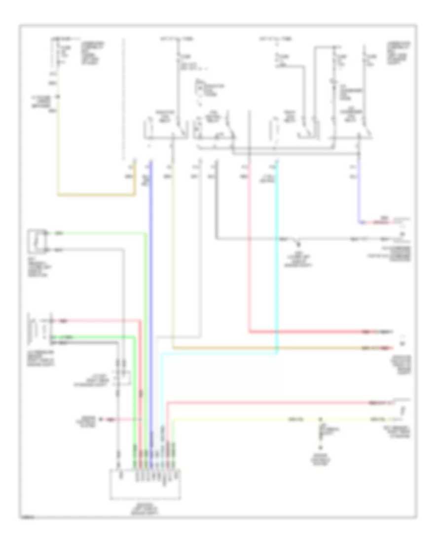
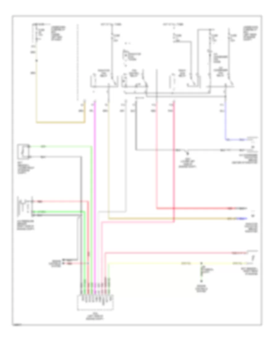
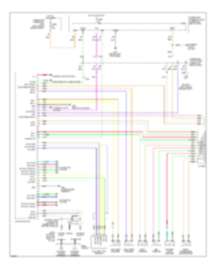
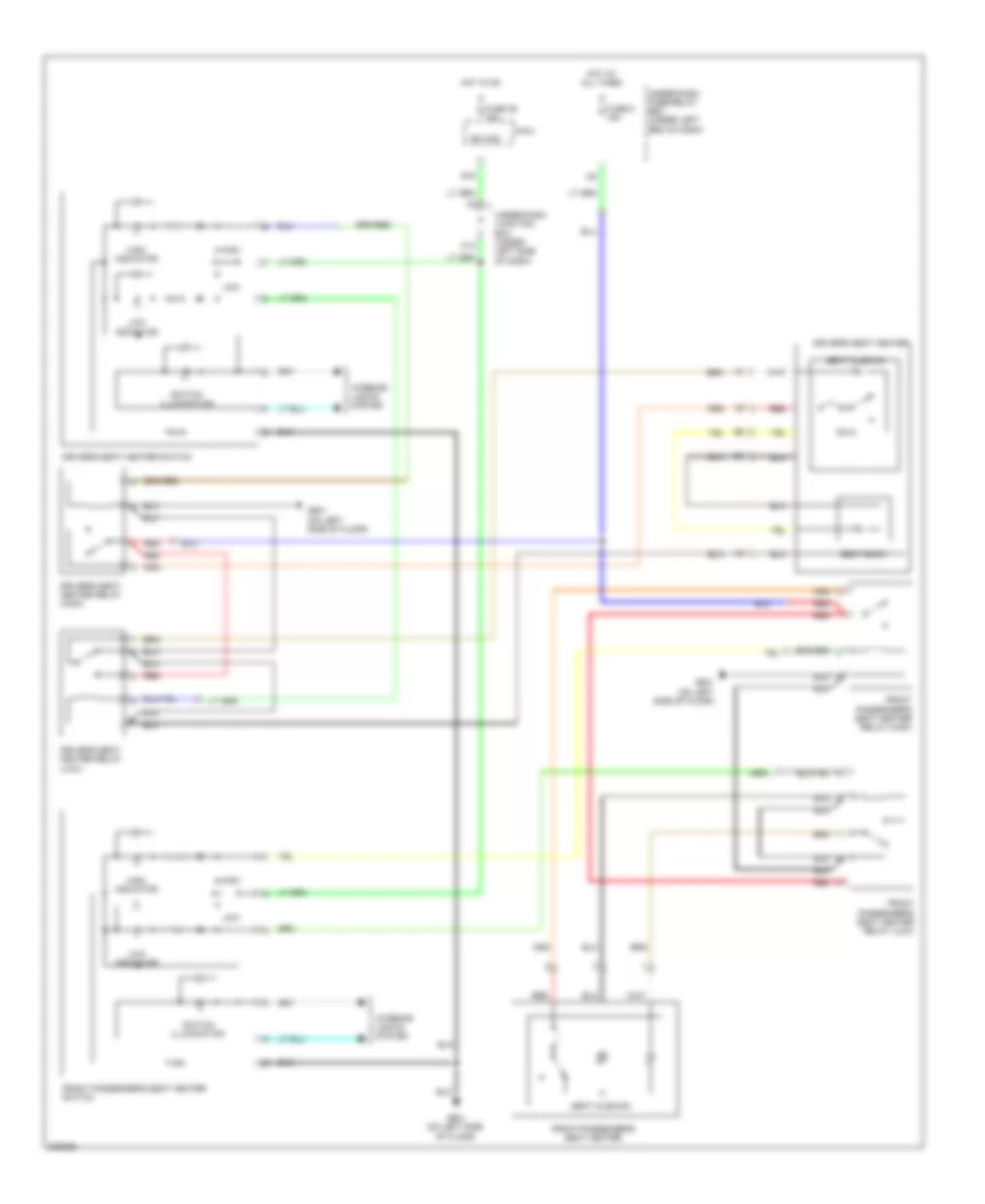
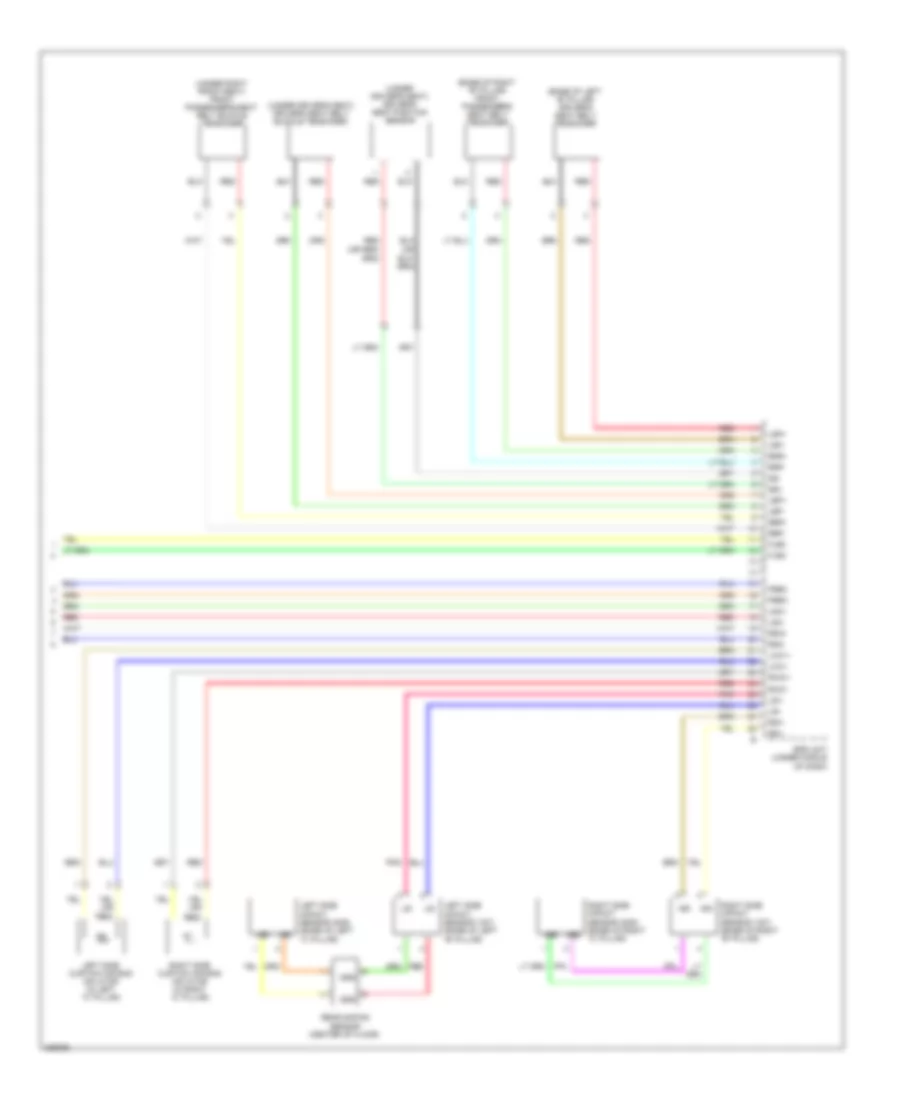
AIR CONDITIONING
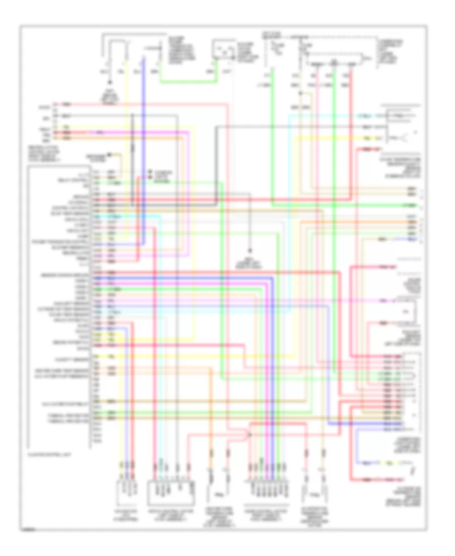
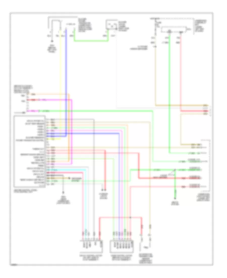
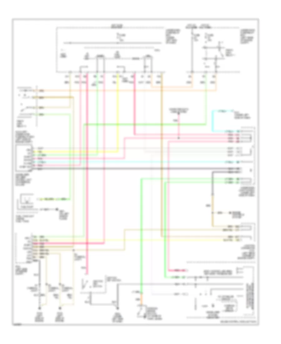
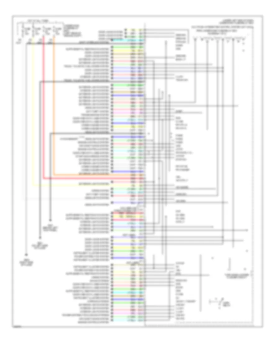
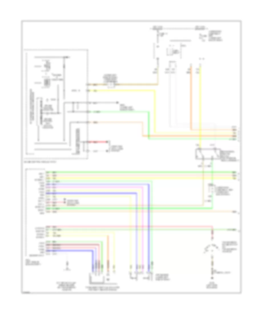
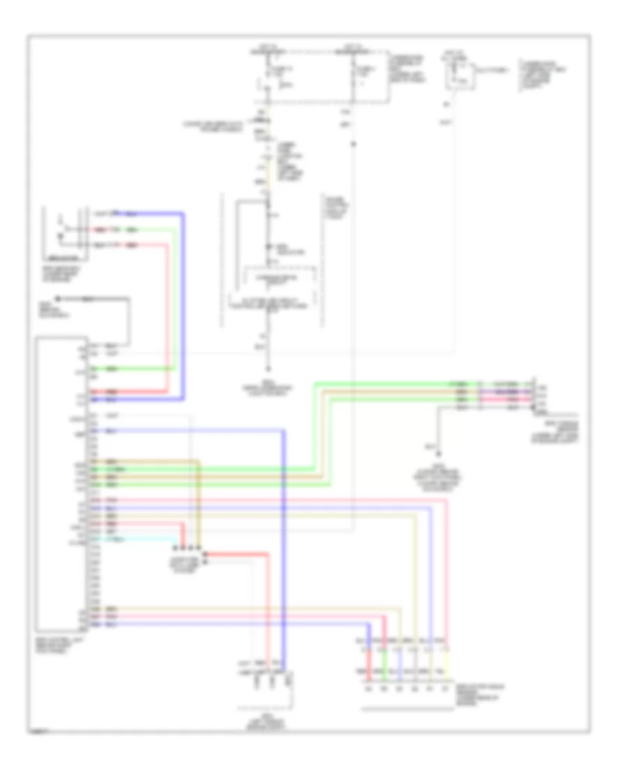
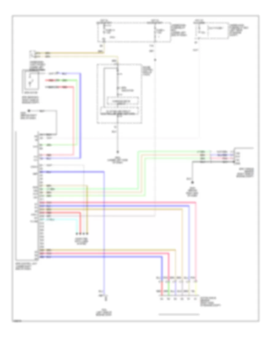
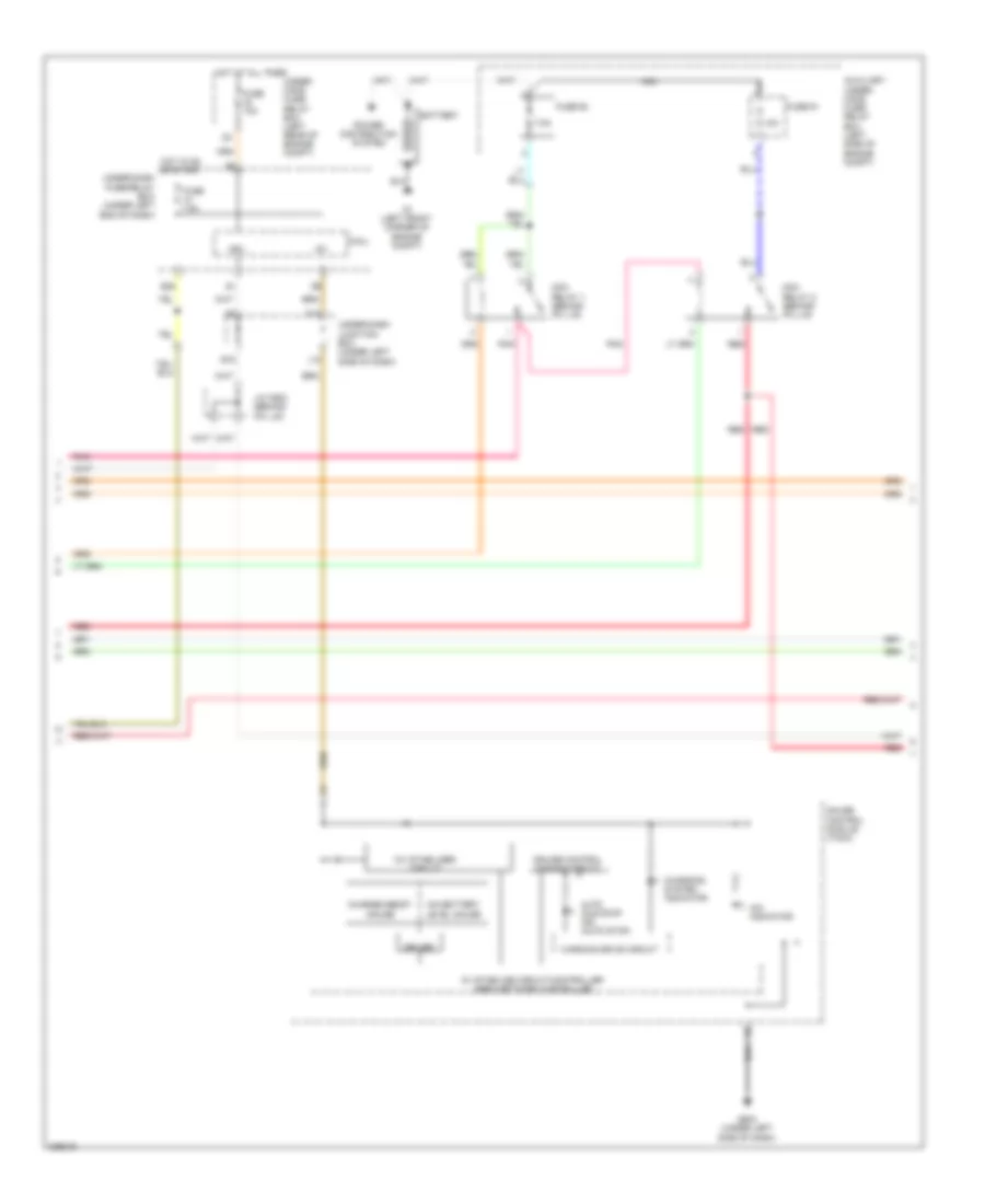
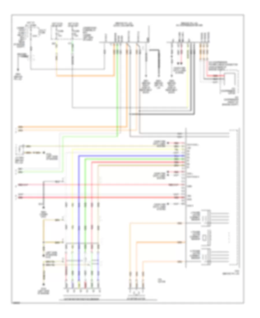
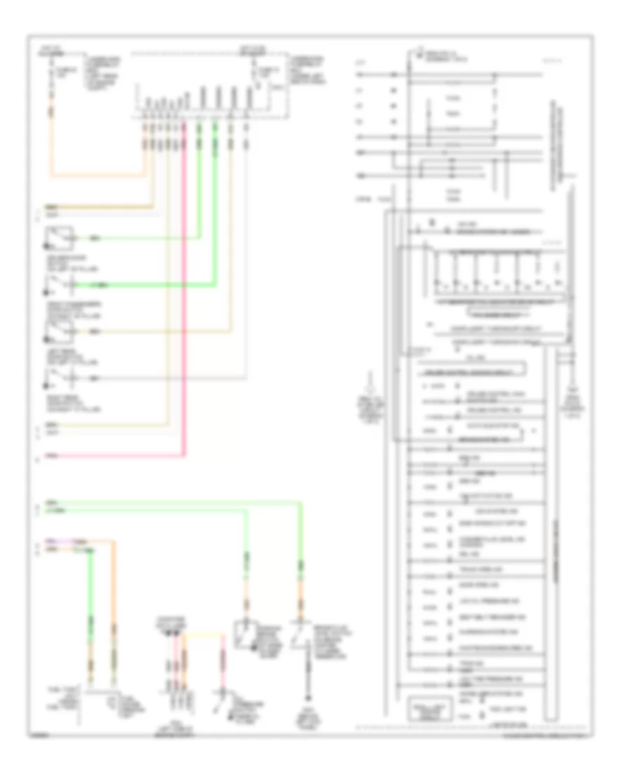
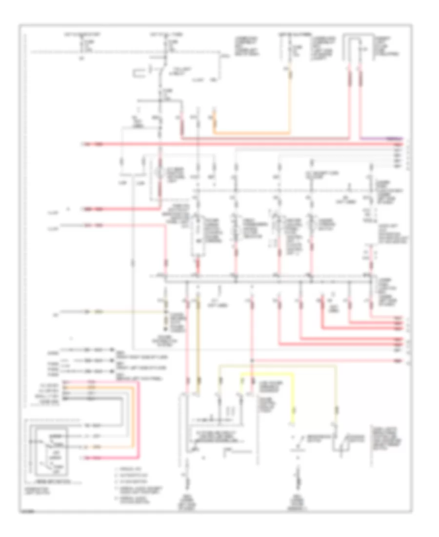
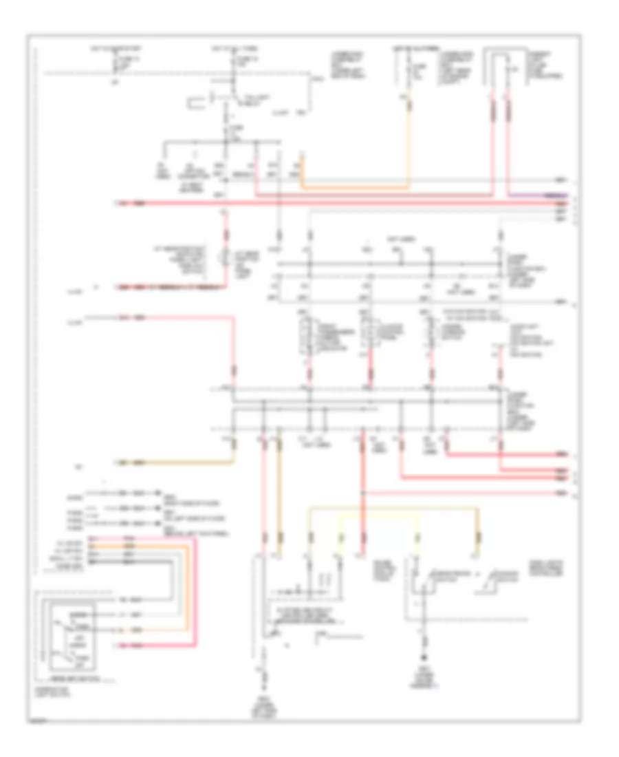
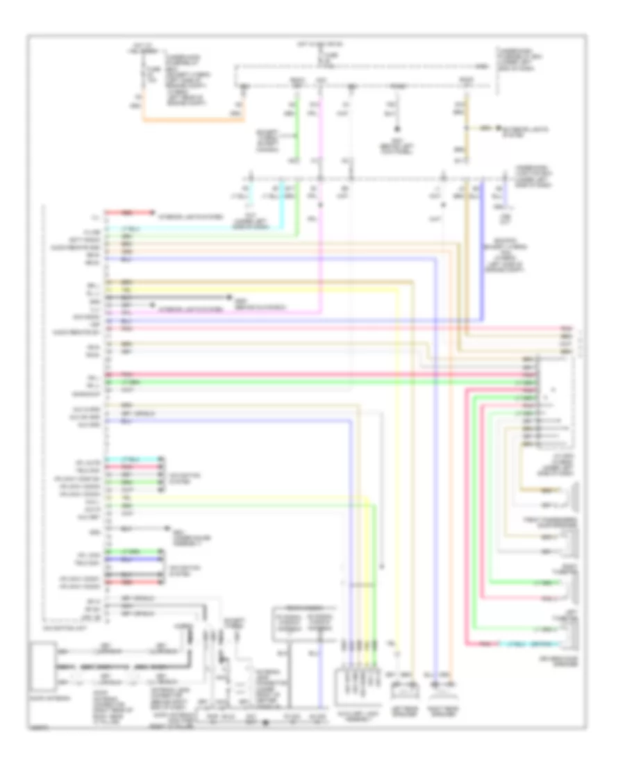
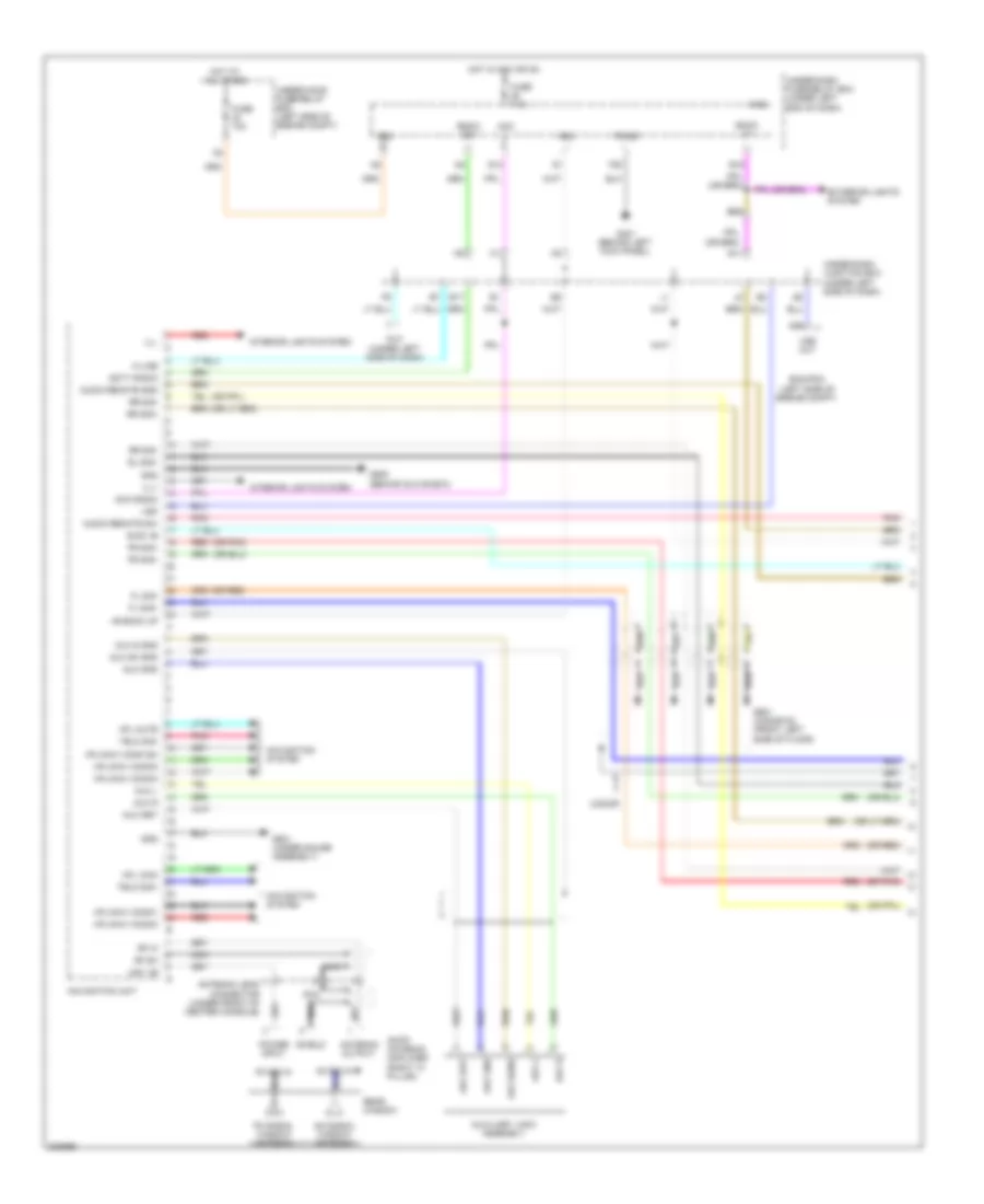
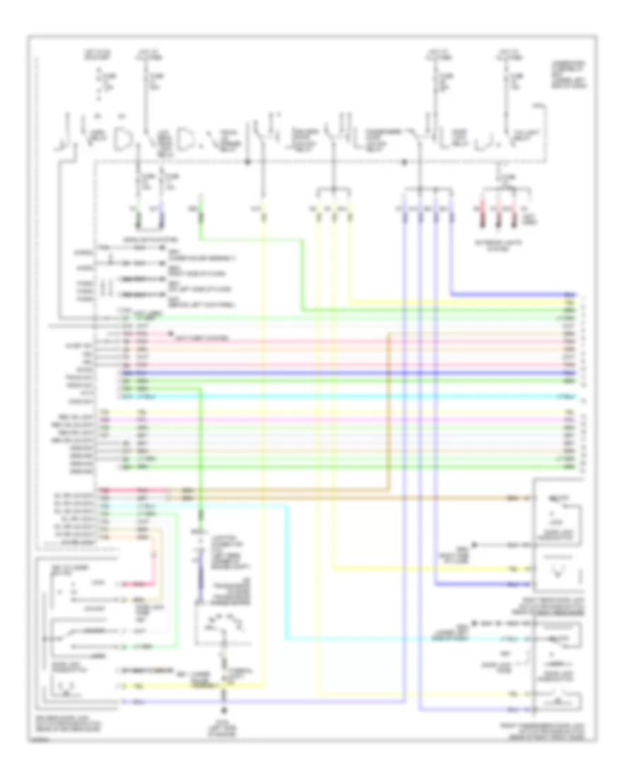
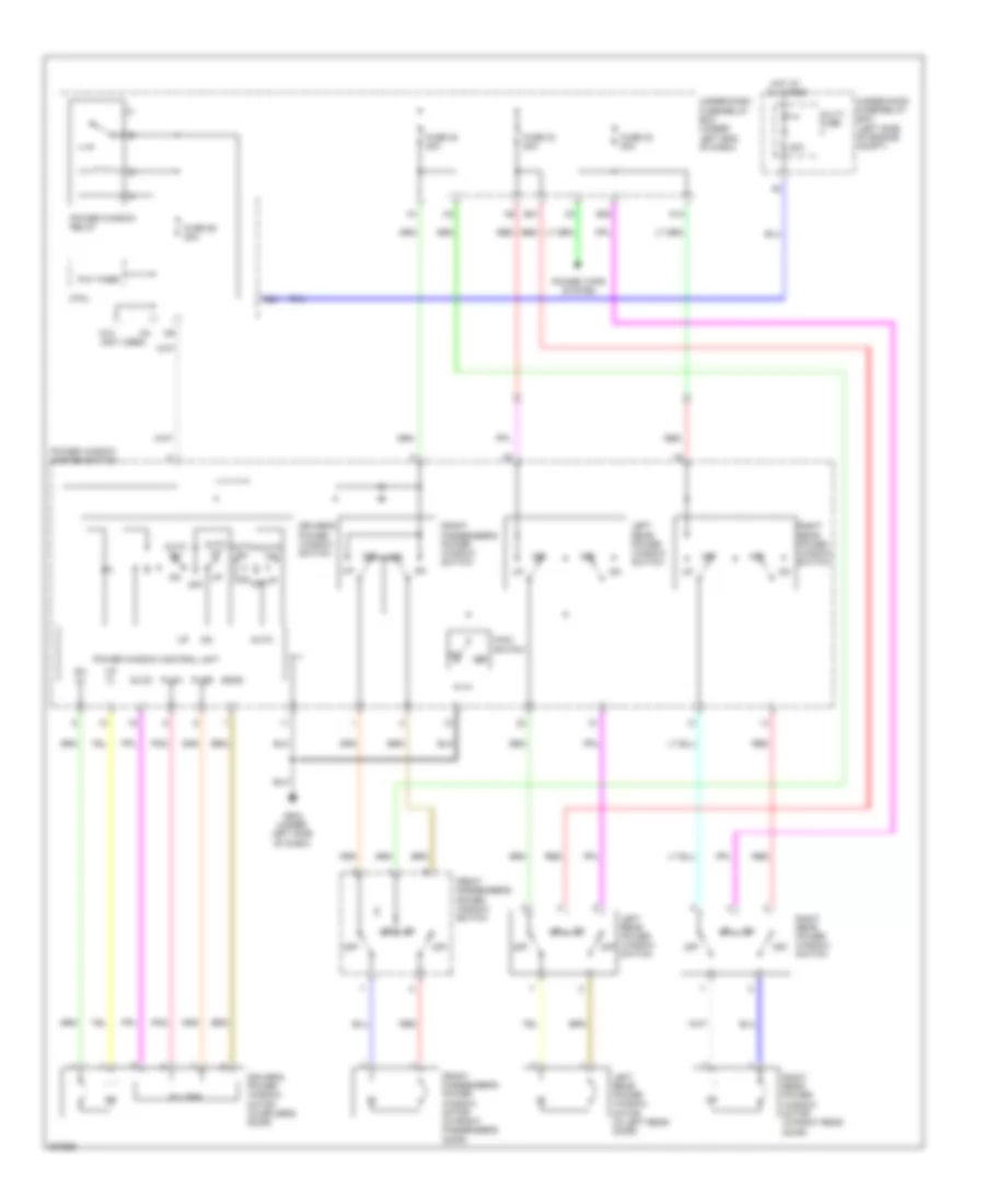
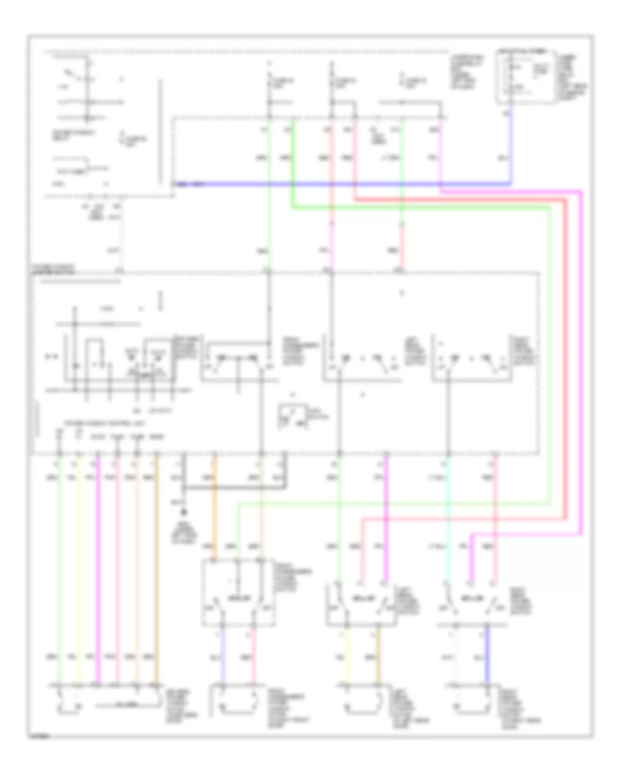
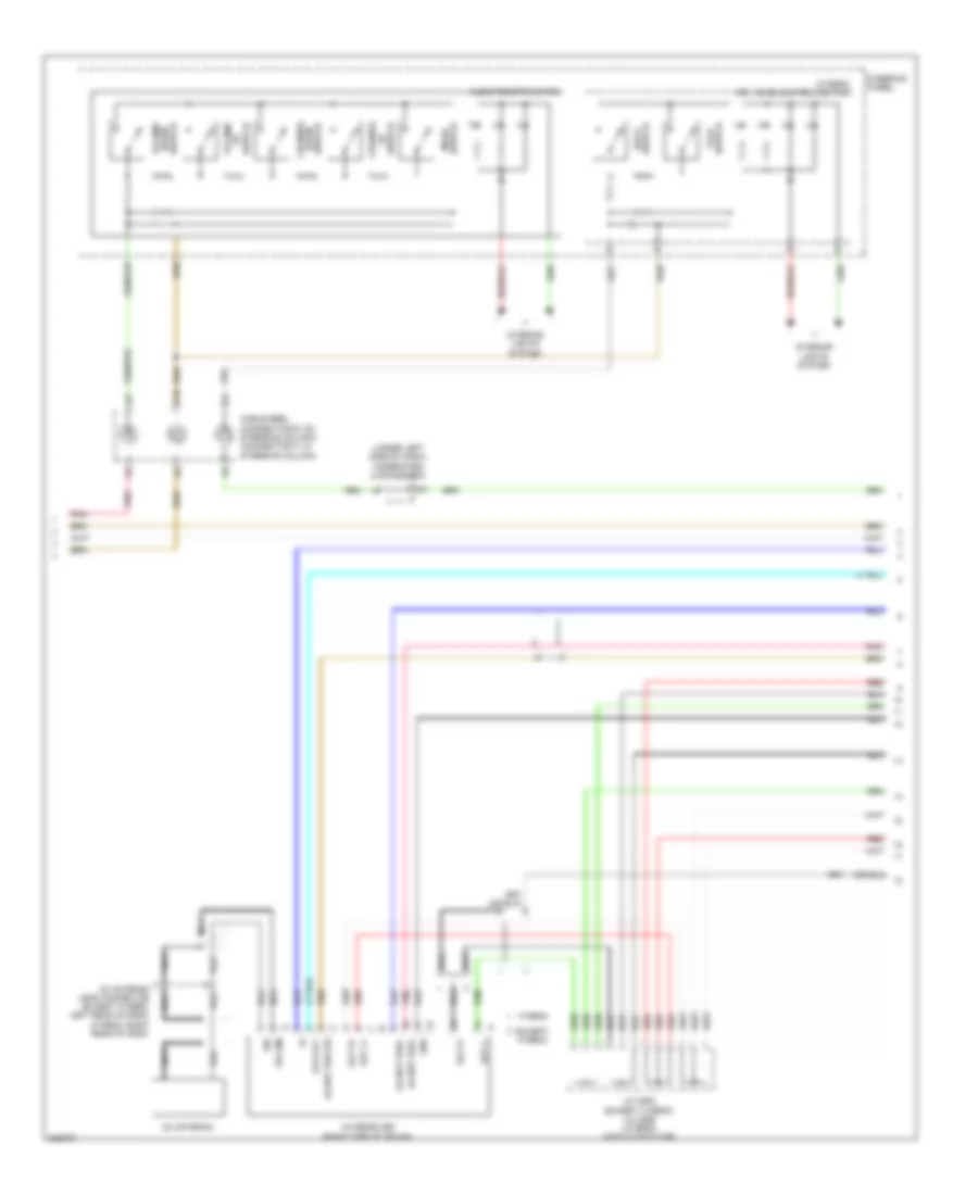
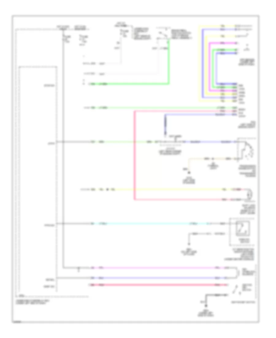
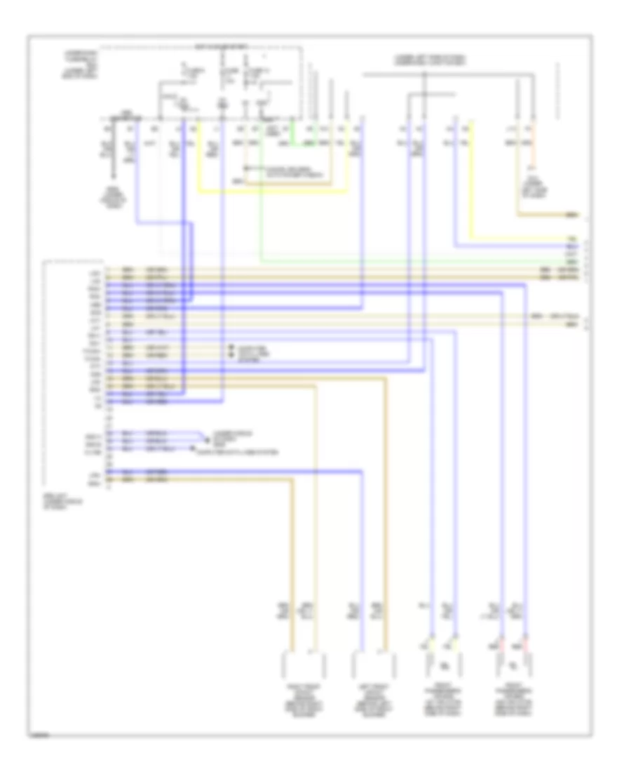
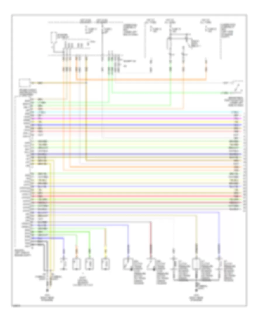
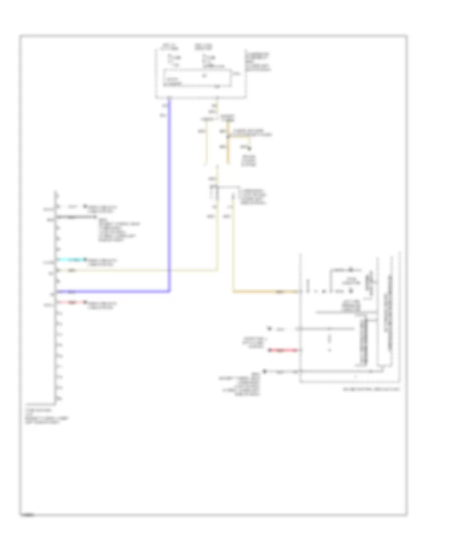
Automatic A/C Wiring Diagram, Except Hybrid (1 of 2) for Honda Civic EX 2011

List of elements for Automatic A/C Wiring Diagram, Except Hybrid (1 of 2) for Honda Civic EX 2011:
- A/c signal
- Acs
- Air mix control motor (on left side of hvac assembly)
- Air mix cool
- Air mix hot
- Air mix potential
- Amd-p
- B-can
- Blower feedback
- Blower motor (under right side of dash)
- Blower power transistor (under right side of dash, near blower motor)
- C10
- C12
- C14
- Climate control unit
- Control motor 5v
- Defogger system
- Evap temp sensor
- Evaporator temperature sensor (under right side of dash)
- F26
- Frd-p
- Fresh
- Frs
- Fuse 10a
- G12
- G13
- G401 (behind left kick panel)
- G504 (near under-dash junction box)
- Gauge control module
- Ground
- Hot in on
- Ig2
- Ig2 hac
- Ill (+)
- Ill (-)
- In-car temp sensor
- In-car temperature sensor
- Interior lights system
- J16
- J22
- K13
- M-cool
- M-def
- M-hot
- M-vent
- Micu
- Mode 1
- Mode 2
- Mode 3
- Mode 4
- Mode control motor (behind glove box, on hvac assembly)
- Mode-def
- Mode-vent
- Outside air temp sensor
- Outside air temperature sensor (behind left side of front bumper)
- Pnk
- Power transistor control
- Q16
- Rec
- Recirc potential
- Recirculate
- Recirculation control motor (behind glove box, on hvac assembly)
- Red
- Rly ctrl
- S-com
- S5v
- Sensor common ground
- Sunlight sensor
- Under-dash fuse/relay box (under left end of dash)
- Under-dash junction box (under left side of dash)
- W/ power mirror defogger
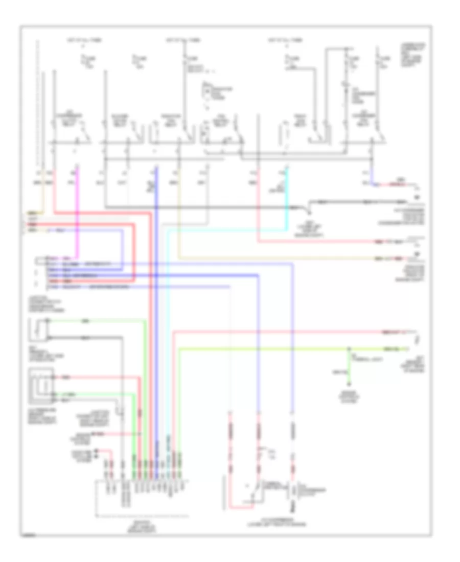
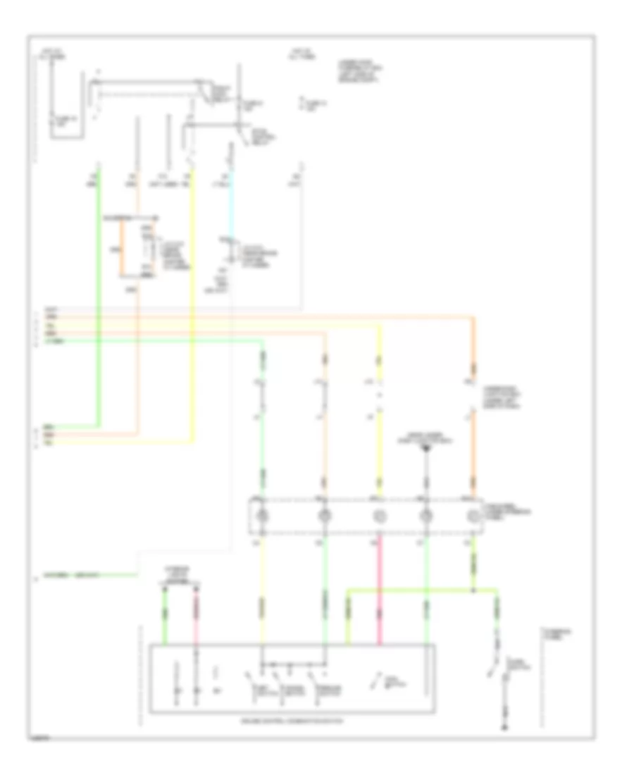
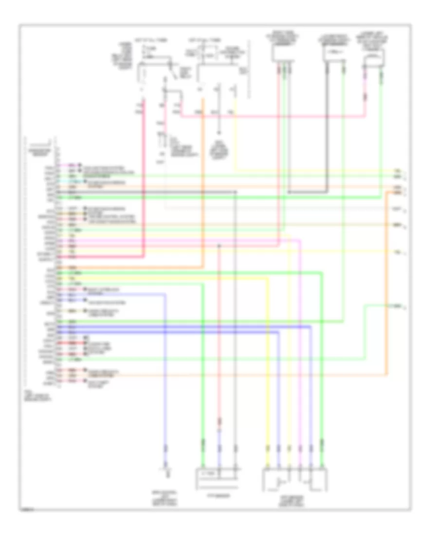
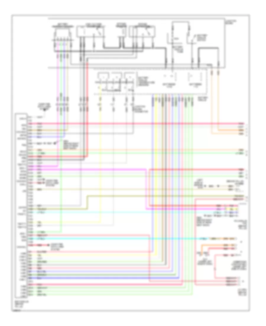
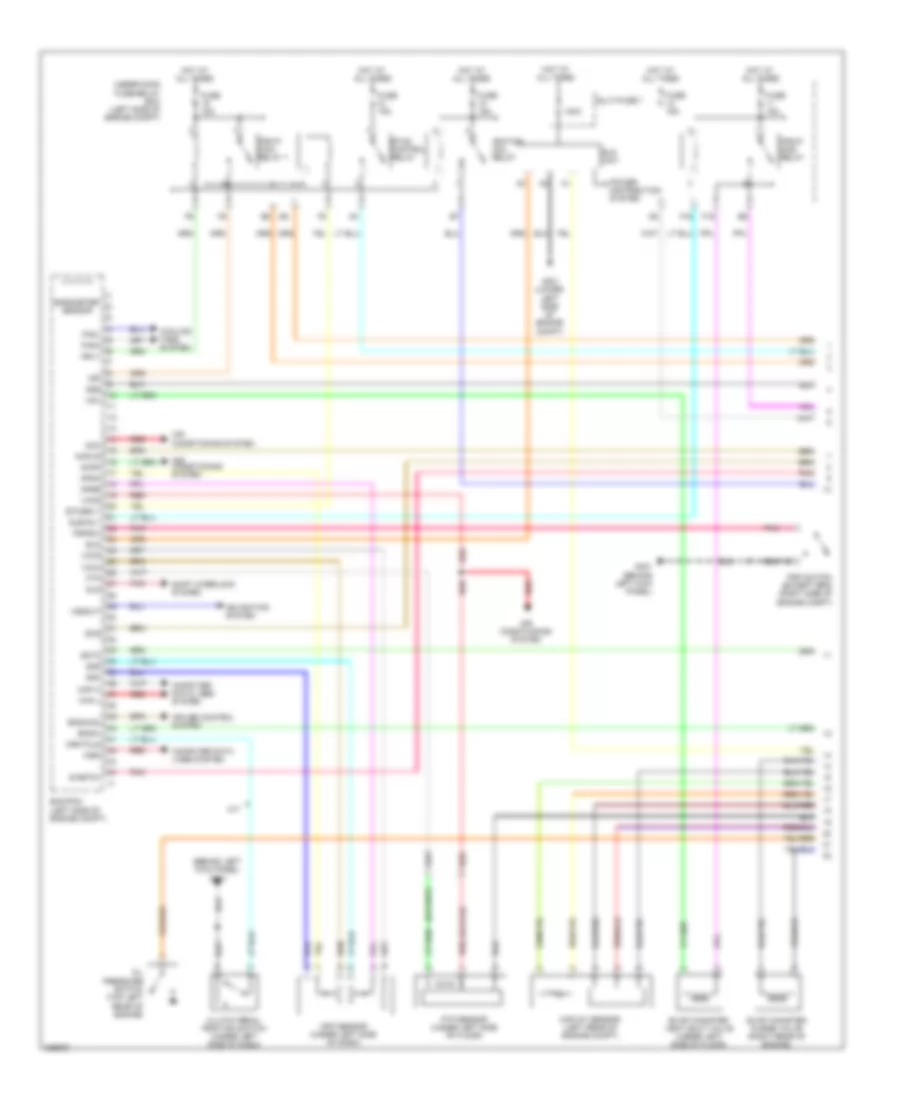
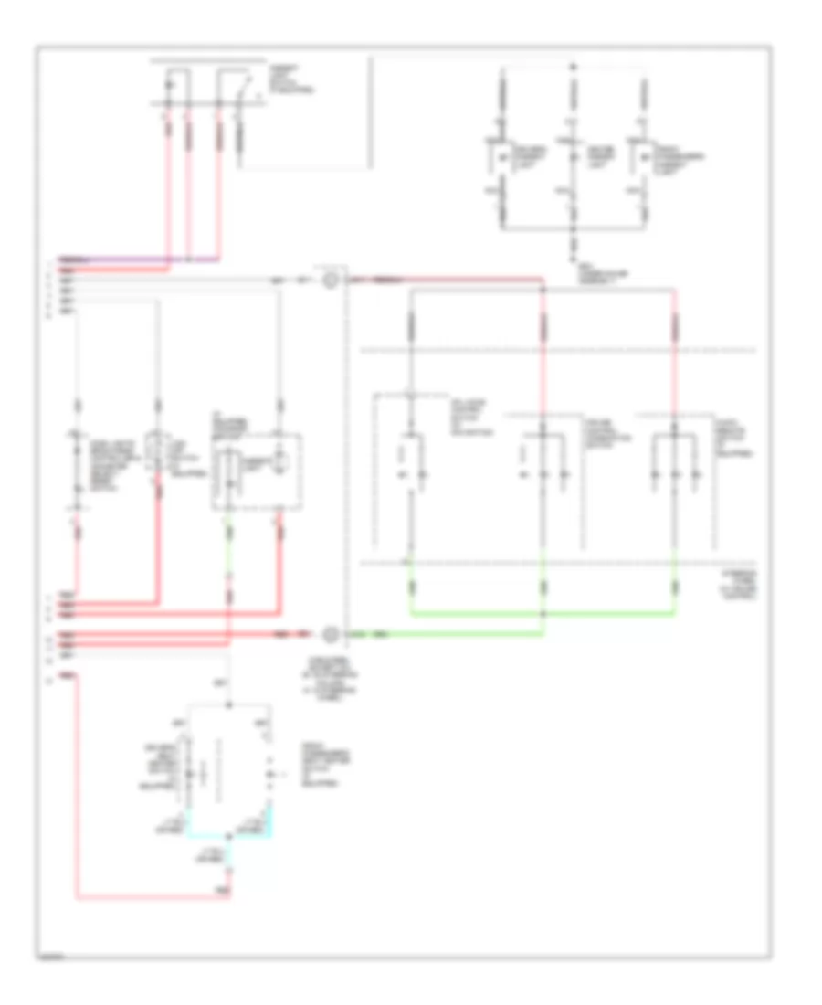
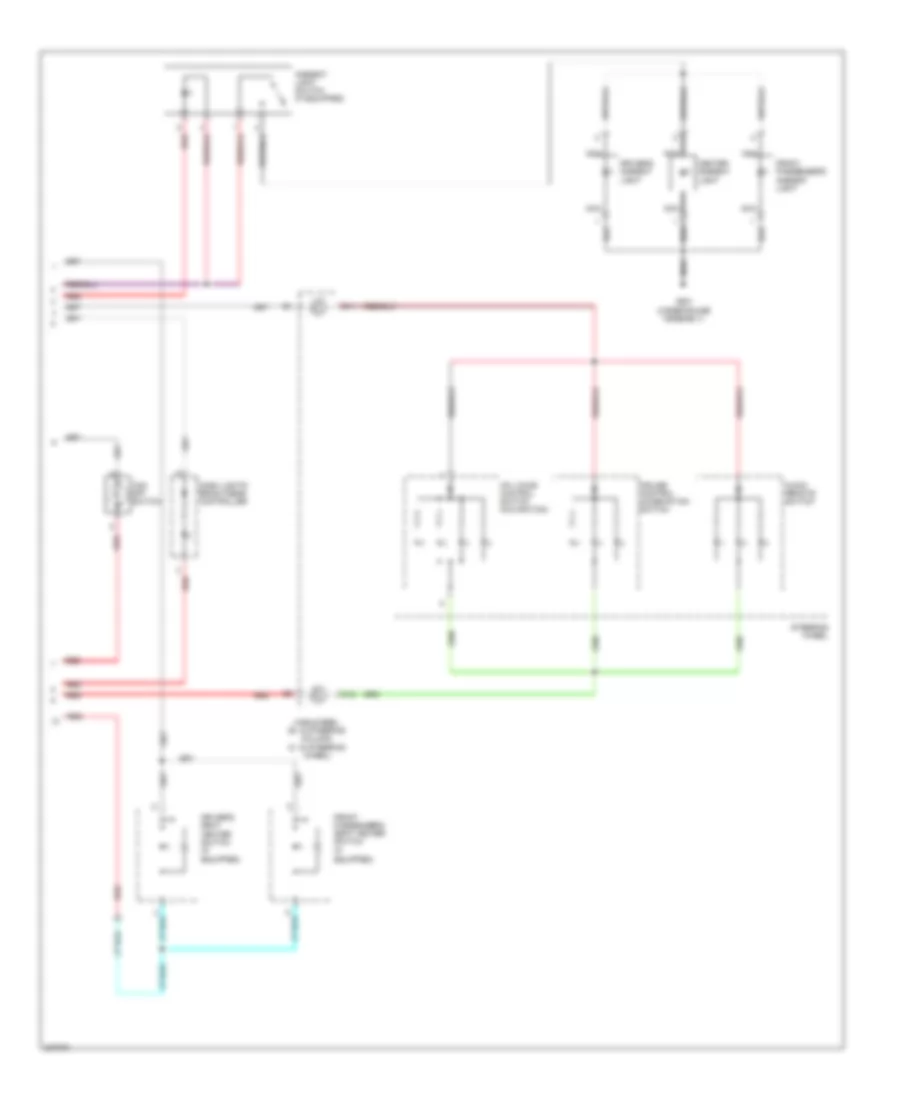
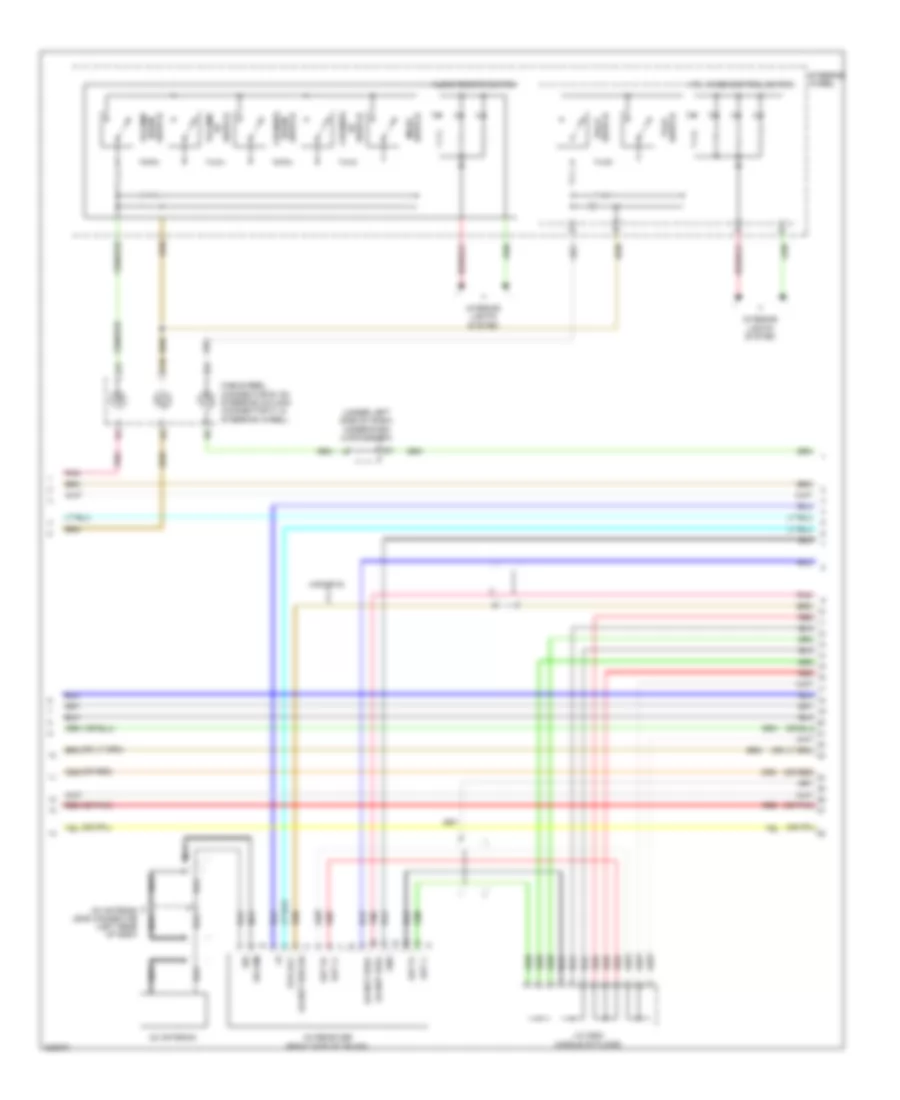
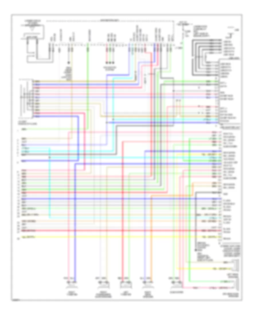
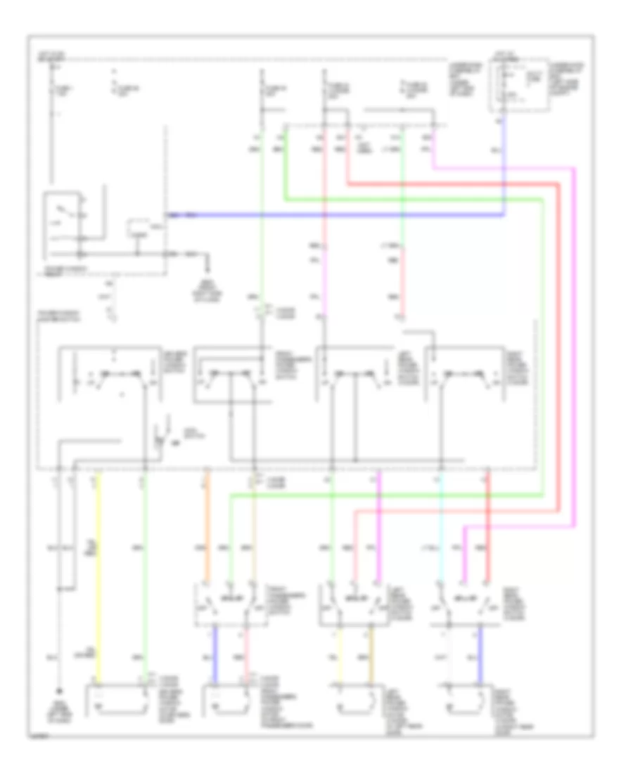
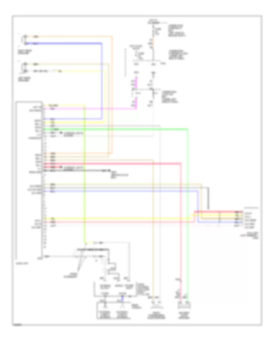
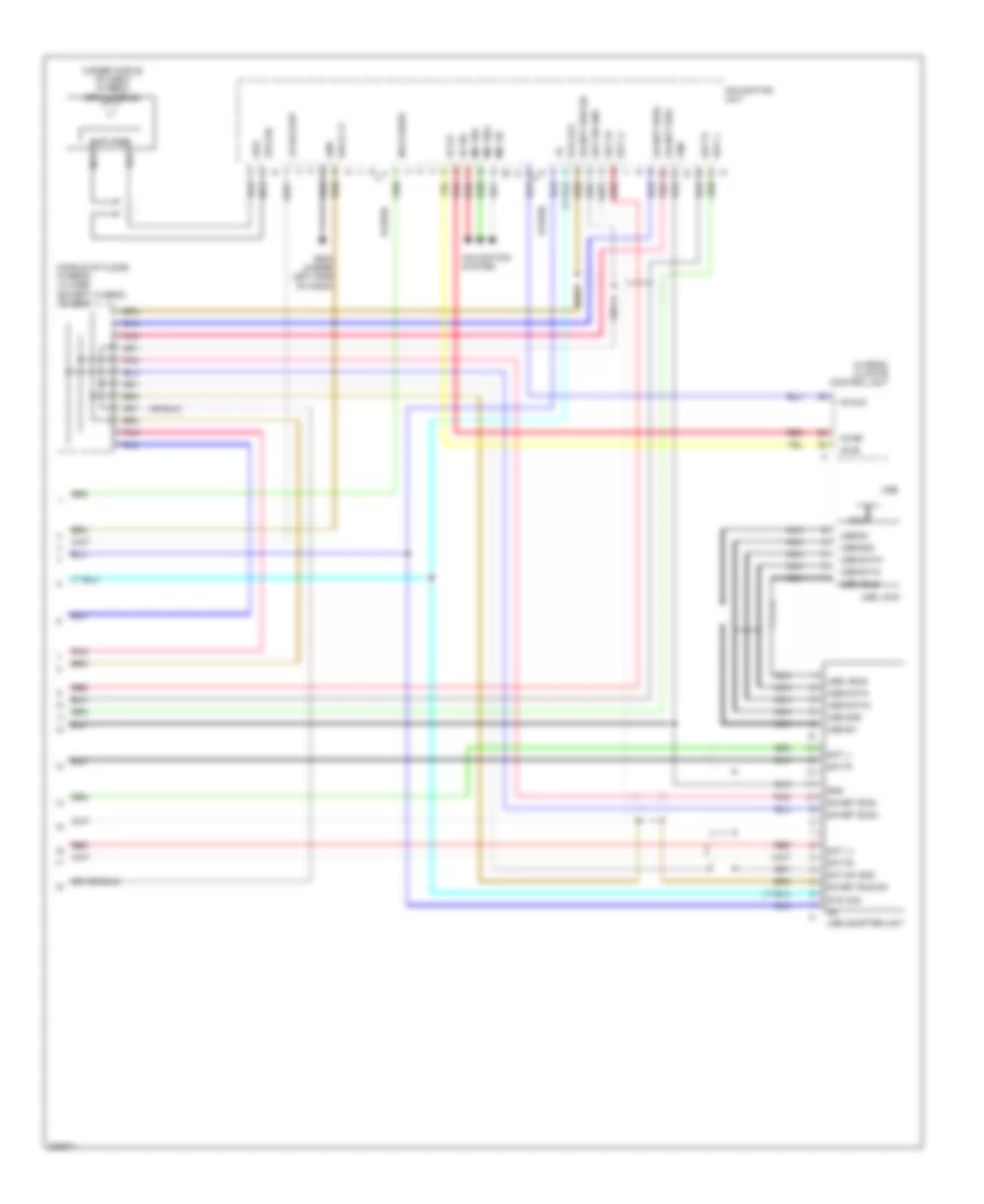
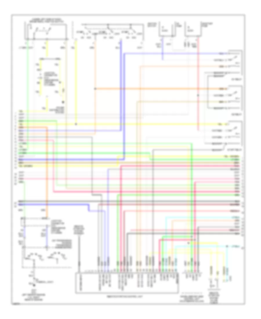
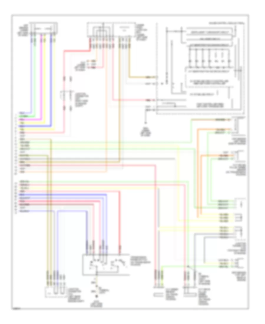
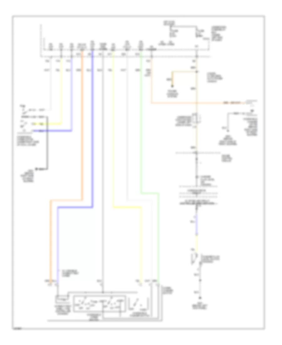
Automatic A/C Wiring Diagram, Except Hybrid (2 of 2) for Honda Civic EX 2011
List of elements for Automatic A/C Wiring Diagram, Except Hybrid (2 of 2) for Honda Civic EX 2011:
- (m/t) (a/t)
- A/c compressor (lower left front of engine)
- A/c compressor clutch
- A/c compressor clutch relay
- A/c condenser fan diode
- A/c condenser fan motor (top of a/c condenser fan motor)
- A/c condenser fan relay
- A/c pressure sensor (right side of engine compt)
- A11
- A14
- A16
- A19
- A21
- A33
- A36
- A37
- Acc
- Acpd
- B13
- B23
- B33
- Blower motor relay
- Can h
- Can l
- Computer data line system
- Ecm/pcm (left side of engine compt)
- Ect sensor 1 (right rear of engine)
- Ect sensor 2 (lower left side of radiator)
- Ect1
- Ect2
- Engine controls system
- F11
- F12
- F14
- F16
- F20
- Fan control relay
- Fanh
- Fanl
- Fuse 15a
- Fuse 20a
- Fuse 20a 30a
- Fuse 40a
- Fuse 7.5a
- G301 (lower left side of engine compt)
- Hot at all times
- Junction connector c101 (near brake master cylinder)
- Junction connector c207 (right rear of engine compt)
- Pgm-fi sub relay
- Pnk
- Radiator fan diode
- Radiator fan motor (front of engine compt)
- Radiator fan relay
- Red
- S4 (thermal joint)
- Sg2
- Sg3
- Subrly
- Under-hood fuse/relay box (left side of engine compt)
- Vcc6
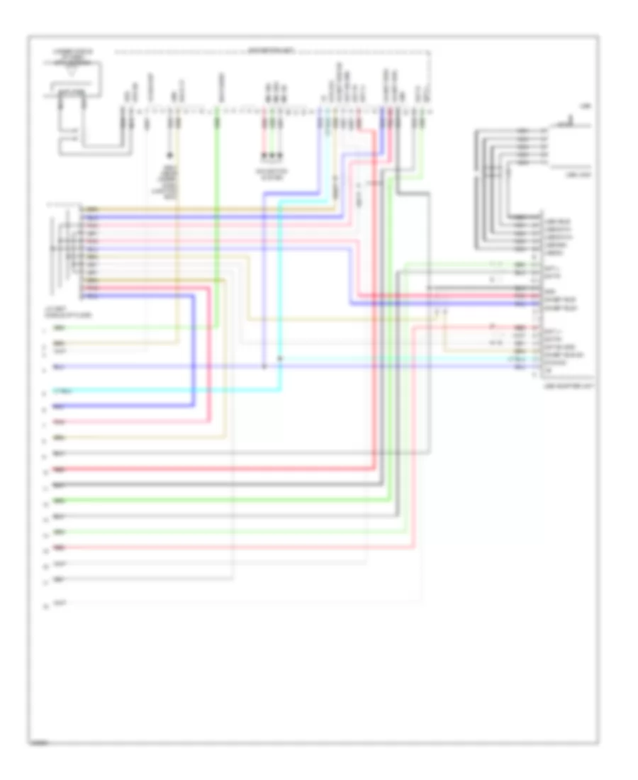
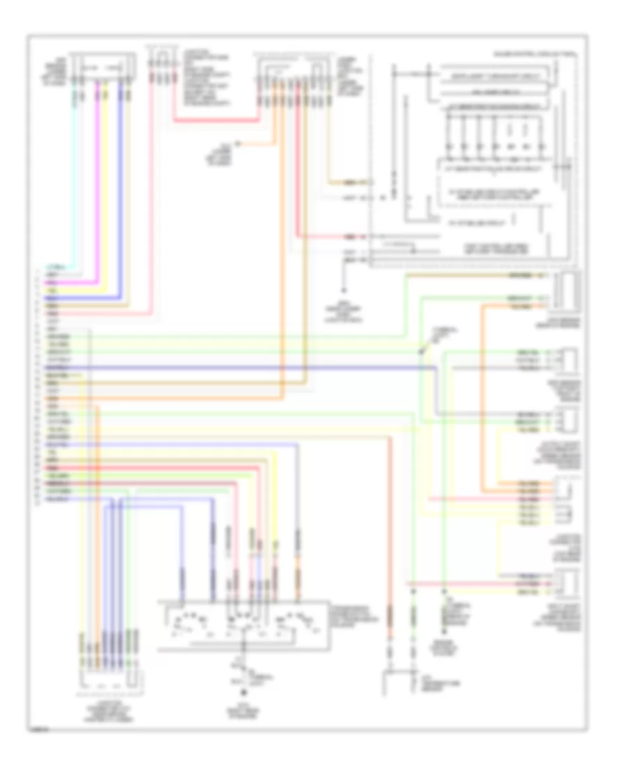
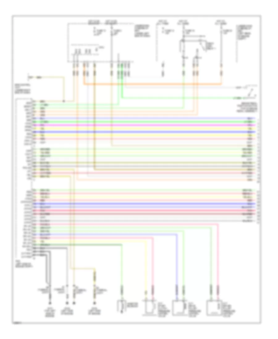
Automatic A/C Wiring Diagram, Hybrid (1 of 2) for Honda Civic EX 2011
List of elements for Automatic A/C Wiring Diagram, Hybrid (1 of 2) for Honda Civic EX 2011:
- A/c signal
- A10
- A11
- A12
- A13
- A14
- A15
- A16
- A17
- A18
- A19
- A20
- A21
- A22
- A23
- A24
- A25
- A26
- A27
- A28
- A29
- A30
- A31
- A32
- Ac-clk
- Ac-si
- Ac-so
- Acs
- Air mix control motor (left side of hvac assembly)
- Air mix cool
- Air mix hot
- Air mix potential
- Amd-p
- Aux water pump feedback
- Aux water pump relay
- B-can
- B10
- B11
- B12
- B13
- B14
- B15
- B16
- Blower feedback
- Blower motor (under right side of dash)
- Blower power transistor (under right side of dash, near blower motor)
- C10
- C12
- C14
- Climate control unit
- Control motor 5v
- D12
- Defogger system
- Evap temp sensor
- Evaporator
- F17
- F26
- Frd-p
- Fresh
- Frs
- Fuse 10a
- Fuse 7.5a
- G12
- G13
- G401 (behind left kick panel)
- G504 (under left side of dash)
- Gauge control module (tach)
- Ground
- Heater core
- Heater core temp sensor
- Hot in on
- Hot in on or start
- Humidity sensor
- Ig2
- Ig2 hac
- Ill (+)
- Ill (-)
- In-car temp sensor
- In-car temperature sensor/humidity sensor (right of steering column)
- Interior lights system
- J16
- J22
- K13
- M-cool
- M-def
- M-hot
- M-vent
- Micu
- Mode 1
- Mode 2
- Mode 3
- Mode 4
- Mode control motor (right side of hvac assembly)
- Navigation unit (if equipped)
- Outside air temp sensor
- Outside air temperature sensor (behind left side of front bumper)
- Pnk
- Power transistor control
- Q16
- Rec
- Recirc potential
- Recirculate
- Recirculation control motor (right side of hvac assembly)
- Red
- Relay control
- S-com
- S5v
- Sensor common ground
- Sunlight sensor
- Sunlight sensor (under top left side of dash)
- Temperature sensor (left side of hvac assembly)
- Temperature sensor (near blower motor)
- Thermal protector
- Under-dash fuse/relay box (under left end of dash)
- Under-dash junction box (under left side of dash)
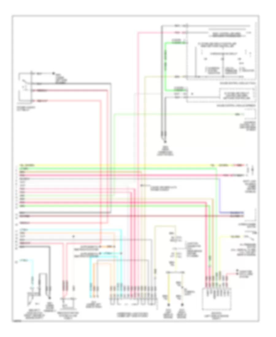
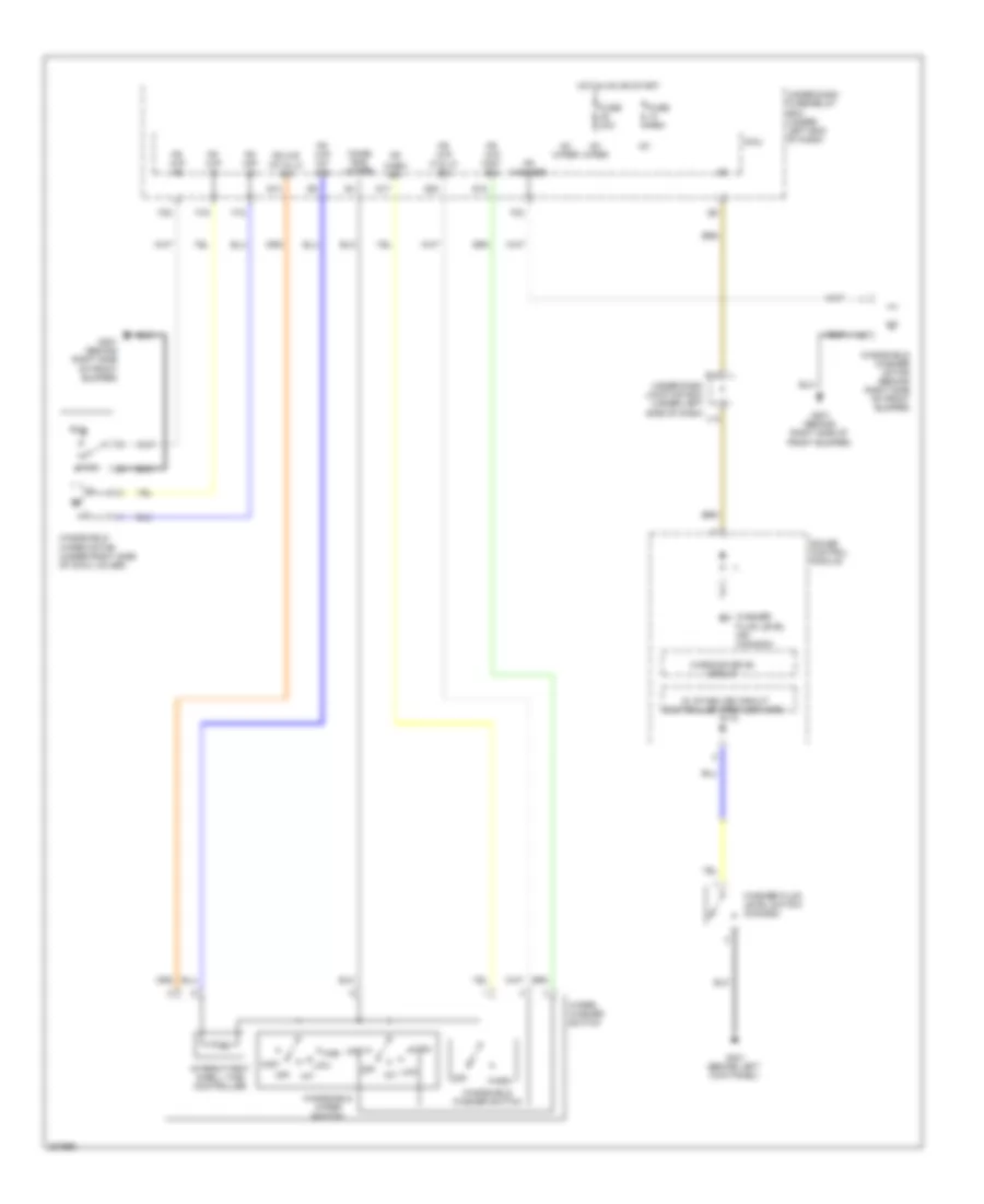
Automatic A/C Wiring Diagram, Hybrid (2 of 2) for Honda Civic EX 2011
List of elements for Automatic A/C Wiring Diagram, Hybrid (2 of 2) for Honda Civic EX 2011:
- A/c compressor (front of engine compt)
- A/c compressor clutch relay
- A/c compressor driver (behind ipu lid)
- A/c condenser fan diode
- A/c condenser fan motor (behind center of radiator)
- A/c condenser fan relay
- A/c pressure sensor (right side of engine compt)
- A11
- A12
- A13
- A14
- A16
- A19
- A20
- A21
- A33
- A36
- A37
- A38
- A39
- A40
- Acc
- Acpd
- Auxiliary electric water pump (in auxiliary under-hood fuse/relay box)
- Auxiliary electric water pump relay
- Auxiliary under-hood fuse/relay box (left side of engine compt)
- B11
- B12
- B13
- B23
- B33
- Bcm module (behind ipu lid)
- Blower motor relay
- Can h
- Can l
- Clutch compressor a/c
- Computer data line system
- Ect sensor 1 (right rear of engine)
- Ect sensor 2 (lower front of engine compt)
- Ect1
- Ect2
- Engine controls system
- F11
- F12
- F14
- F16
- F20
- Fan control relay
- Fanh
- Fanl
- Fuse 15a
- Fuse 20a
- Fuse 40a
- Fuse 7.5a
- G301 (lower left side of engine compt)
- G902 (behind right side of rear seat back)
- Hot at all times
- Ig1
- Imacanh
- Imacanl
- Junction connector c101 (left rear corner of engine compt)
- Junction connector c903 (behind ipu lid)
- Mcm (behind ipu lid)
- Motor
- Nca
- Pcm (left side of engine compt)
- Pgm-fi sub relay
- Pnk
- Radiator fan diode
- Radiator fan motor (behind radiator)
- Radiator fan relay
- Red
- S5 (thermal joint)
- Sg2
- Sg3
- Subrly
- Thermal protector
- U phase
- Under-hood fuse/relay box (left rear of engine compt)
- V phase
- Vcc6
- W phase
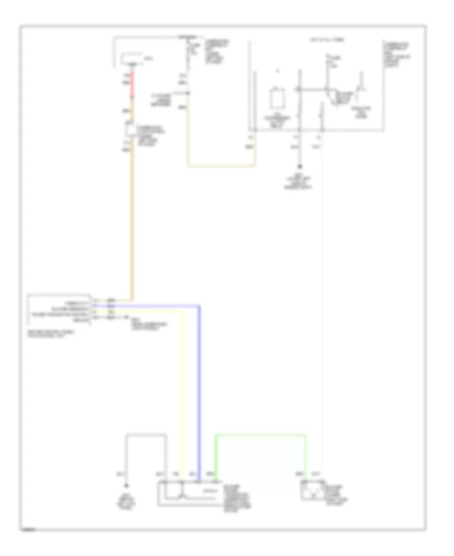
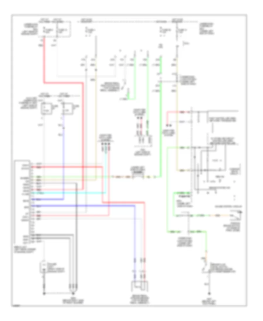
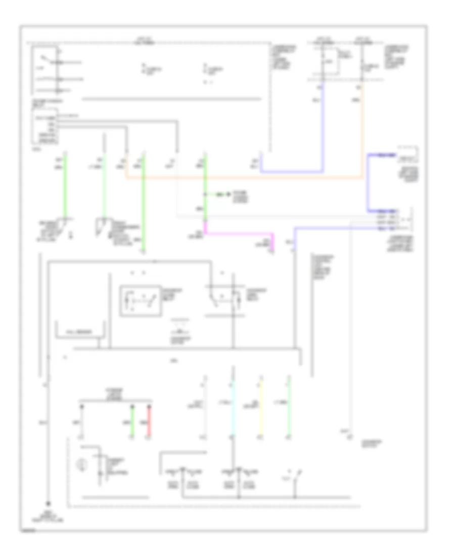
Heater Wiring Diagram for Honda Civic EX 2011
List of elements for Heater Wiring Diagram for Honda Civic EX 2011:
- A/c compressor clutch relay
- Acs
- Blower feedback
- Blower motor (under right side of dash)
- Blower motor relay
- Blower power transistor (under right side of dash, near blower motor)
- C14
- F26
- Fuse 10a
- Fuse 40a
- G12
- G301 (lower left side of engine compt)
- G401 (behind left kick panel)
- G504 (near under-dash junction box)
- Ground
- Heater control panel/ hvac control unit
- Hot at all times
- Hot in on
- Micu
- Power transistor control
- Radiator fan diode
- Red
- Thermo out
- Under-dash fuse/relay box (under left end of dash)
- Under-dash junction box (under left side of dash)
- Under-hood fuse/relay box (left side of engine compt)
- W/ power mirror defogger
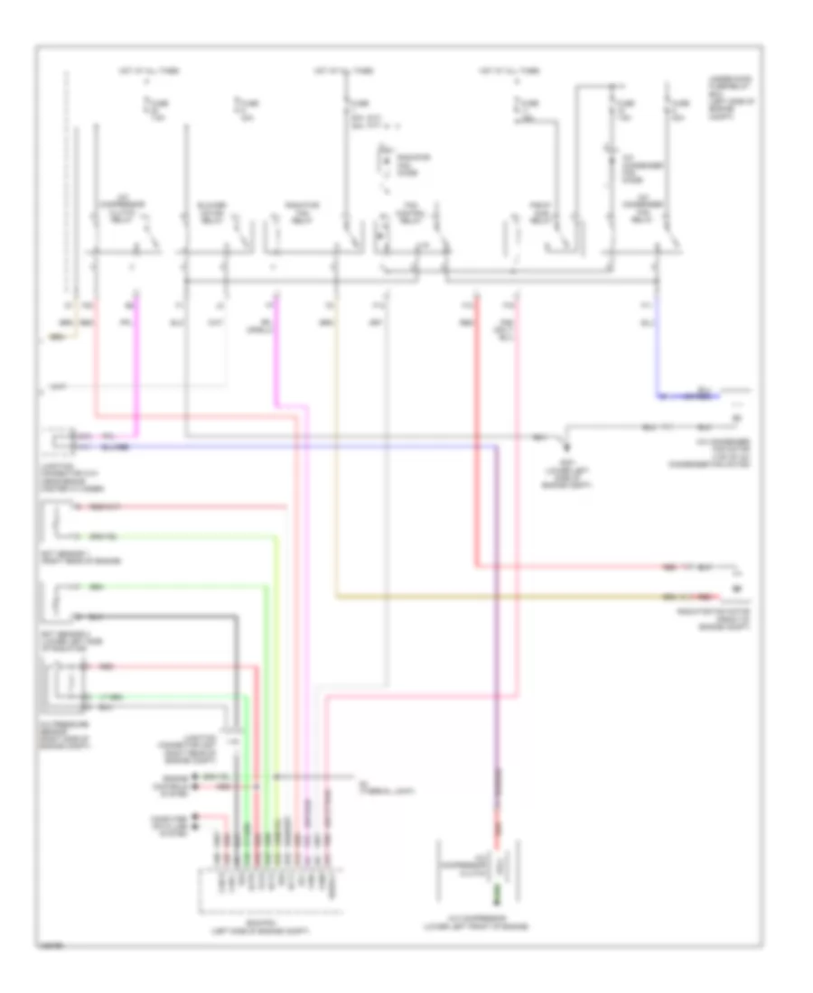
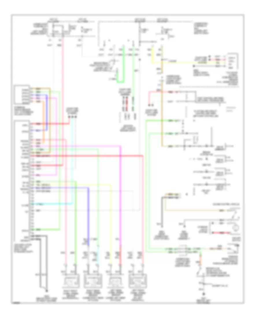
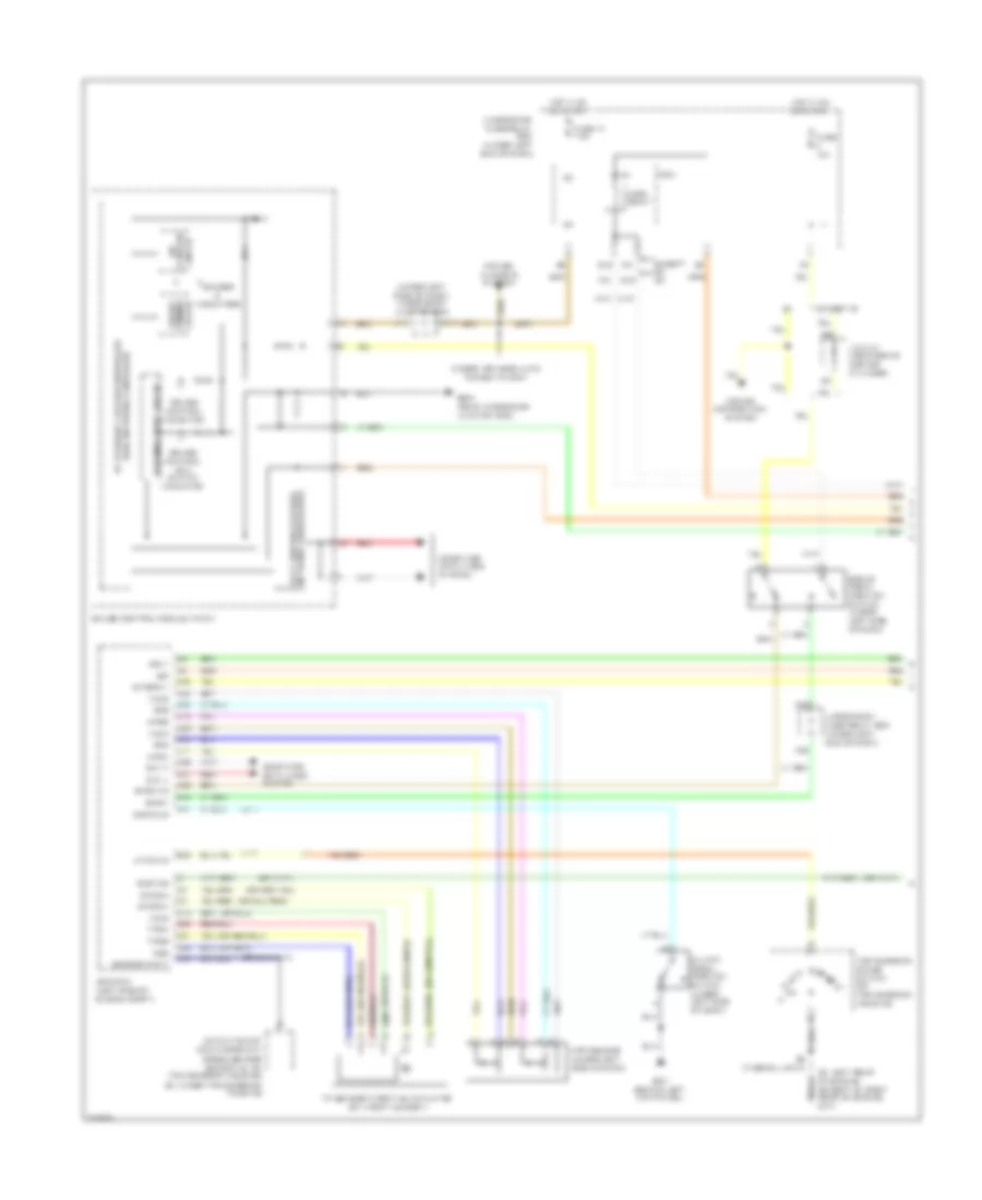
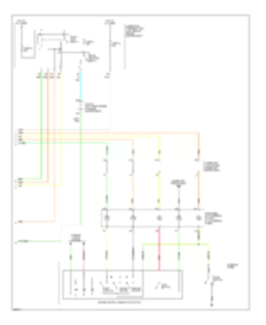
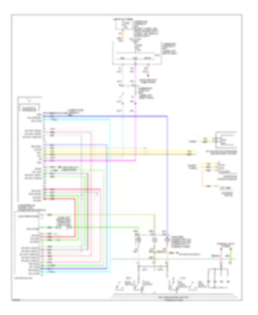
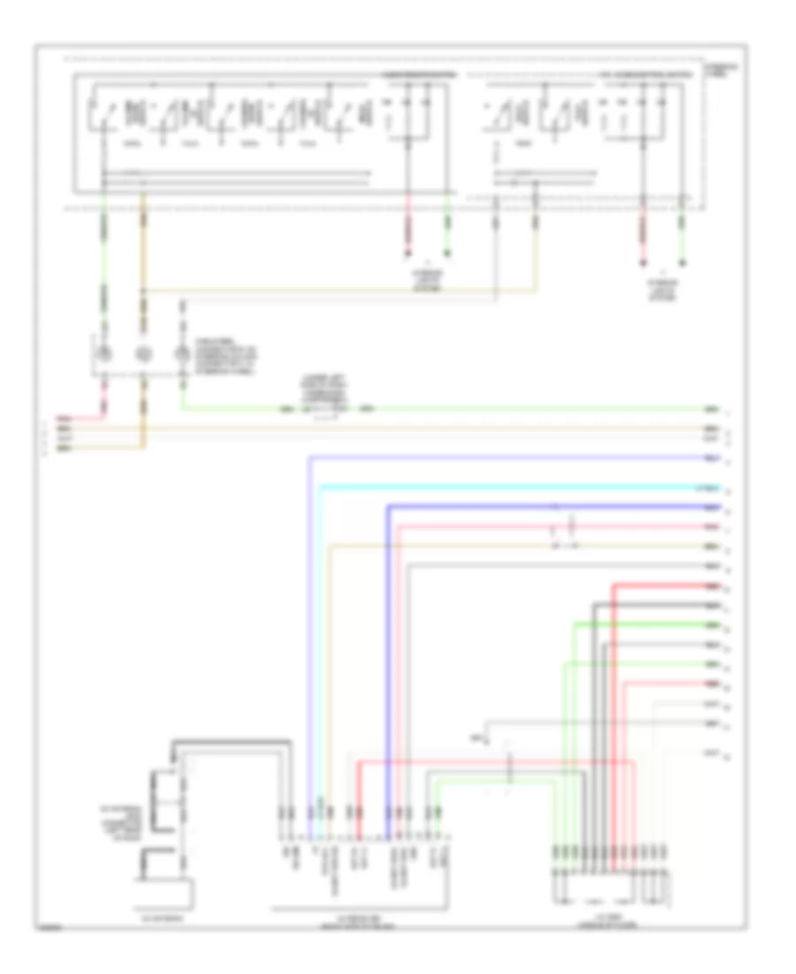
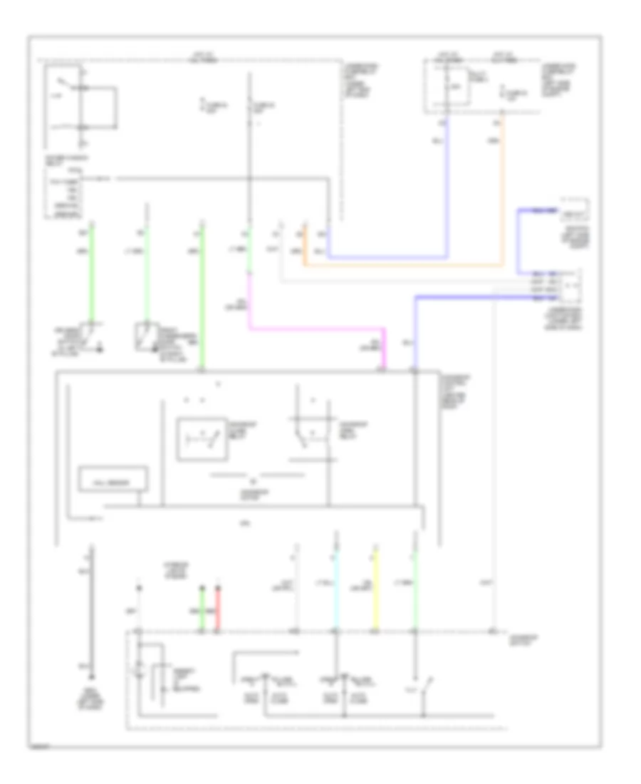
Manual A/C Wiring Diagram (1 of 2) for Honda Civic EX 2011
List of elements for Manual A/C Wiring Diagram (1 of 2) for Honda Civic EX 2011:
- (2 door)
- (2 door) (4 door)
- (4 door)
- (behind glove box, on hvac assembly) recirculation control motor
- 4 door: seat heaters
- Acs
- Air mix control motor (on left side of hvac assembly)
- Air mix cool
- Air mix hot
- Air mix potential
- Amd-p
- Blower feedback
- Blower motor (under right side of dash)
- Blower power transistor (under right side of dash, near blower motor)
- C10 c3
- C14
- C3 c10
- C4 c6
- C6 c4
- Defogger system
- Evap temp sensor
- Evaporator temperature sensor (under right side of dash)
- F26
- Fresh
- Frs
- Fuse 10a
- G12
- G401 (behind left kick panel)
- G504 (near under-dash junction box)
- Ground
- Heater control panel/ hvac control unit
- Hot in on
- Ig2
- Ig2 ihac
- Ig2 power
- Ill (+)
- Ill (-)
- Interior lights system
- M-cool
- M-def
- M-hot
- M-vent
- Micu
- Mode 1
- Mode 2
- Mode 3
- Mode 4
- Mode control motor (behind glove box, on hvac assembly)
- Mode def
- Mode vent
- Pnk
- Power transistor control
- Q16
- Rear window def relay
- Rec
- Recirculate
- Red
- S-com
- S5v
- Seats system
- Sensor common ground
- Thermo out
- Under-dash fuse/relay box (under left end of dash)
- Under-dash junction box (under left side of dash)
- W/ power mirror defogger
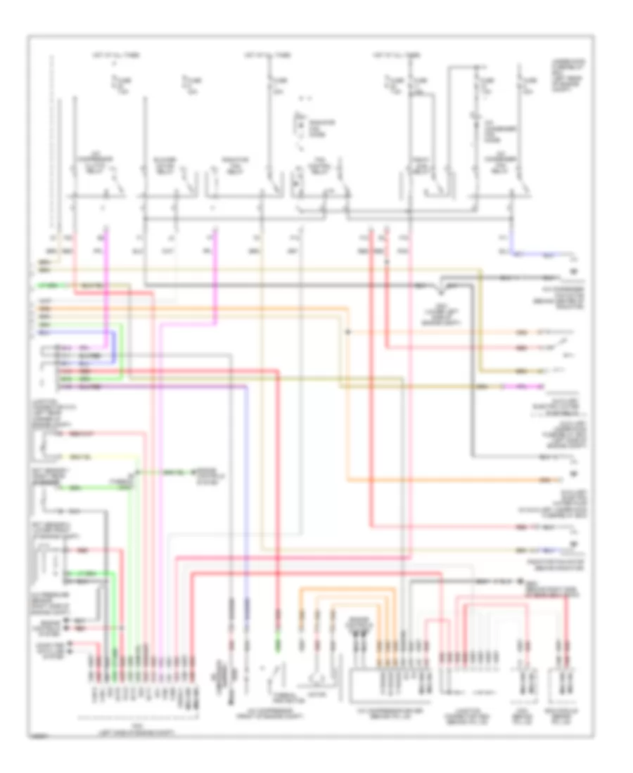
Manual A/C Wiring Diagram (2 of 2) for Honda Civic EX 2011
List of elements for Manual A/C Wiring Diagram (2 of 2) for Honda Civic EX 2011:
- (2 door)
- (4 door)
- (m/t) (a/t)
- (or pnk)
- 1.8l
- 2.0l
- A/c compressor (lower left front of engine)
- A/c compressor clutch
- A/c compressor clutch relay
- A/c condenser fan diode
- A/c condenser fan motor (top of a/c condenser fan motor)
- A/c condenser fan relay
- A/c pressure sensor (right side of engine compt)
- A11
- A12
- A13
- A14
- A16
- A19
- A21
- A33
- A36
- A37
- A9 sg6
- Acc
- Acpd
- B11
- B12
- B13
- B23
- B33
- Blower motor relay
- Can h
- Can l
- Computer data line system
- Ecm/pcm (left side of engine compt)
- Ect sensor 1 (right rear of engine)
- Ect sensor 2 (lower left side of radiator)
- Ect1
- Ect2
- Engine controls system
- F11
- F12
- F14
- F16
- F20
- Fan control relay
- Fanh
- Fanl
- Fuse 15a
- Fuse 20a
- Fuse 20a 30a
- Fuse 40a
- Fuse 7.5a
- G301 (lower left side of engine compt)
- Hot at all times
- Junction connector c101 (near brake master cylinder)
- Junction connector c207 (right rear of engine compt)
- Nca
- Pgm-fi sub relay
- Radiator fan diode
- Radiator fan motor (front of engine compt)
- Radiator fan relay
- Red
- S4 (thermal joint)
- Sg2
- Sg3
- Subrly
- Thermal protector
- Under-hood fuse/relay box (left side of engine compt)
- Vcc6
ANTI-LOCK BRAKES
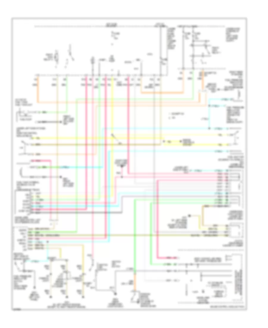
Advanced Hydraulic Booster Wiring Diagram for Honda Civic EX 2011
List of elements for Advanced Hydraulic Booster Wiring Diagram for Honda Civic EX 2011:
- (under left
- (under left side of dash) buzzer
- 10a
- 15a
- 5v stabilize circuit/ controller area network controller
- A36
- A37
- A40
- Auxiliary under-hood fuse/relay box (left side of engine compt)
- Bksw
- Bps
- Brake fluid level switch (on brake master cylinder reservoir)
- Brake pedal position switch (top of brake pedal assembly)
- Brake pedal stroke sensor (top of brake pedal assembly)
- Brake system ind
- Bs+b
- Buzzer
- Can-h
- Can-l
- Computer data lines system
- E10
- F16
- F25
- F30
- F31
- Fast controller area network transceiver
- Fuse
- Fuse 10 7.5a
- Fuse 12 15a
- Fuse 36 10a
- Fuse 4 7.5a
- Fuse 5 40a
- G12
- G16
- G202 (behind right side of front bumper)
- G401 (behind left kick panel)
- G504
- Gauge control module
- Gnd1
- Gnd2
- Gnd3
- Hot at all times
- Hot in on
- Hot in on or start
- Ig1
- Ig2
- Ig2 hac
- J14
- J21
- K-line
- K14
- Micu
- Mot+
- Mr+b
- Ms+b
- Parking brake switch (at base of park lever)
- Pcm (left side of engine compt)
- Power unit (right side of engine compt)
- Q16
- Rbs ind
- Red
- Servo unit (left rear corner of engine compt)
- Sgnda
- Side of dash)
- Svcca
- Under-dash fuse/relay box (under left end of dash)
- Under-dash junction box (under left side of dash)
- Under-hood fuse/relay box (left rear of engine compt)
- Warning drive circuit
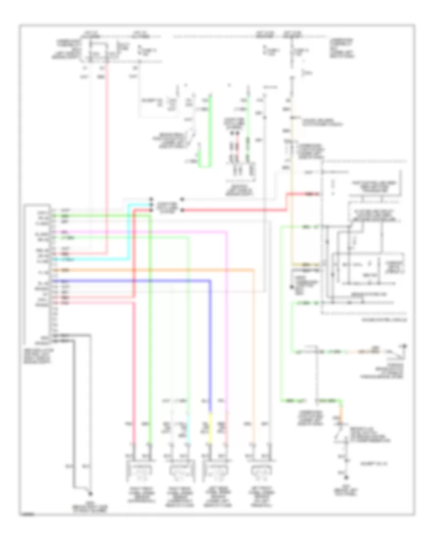
Anti-Lock Brakes Wiring Diagram, Except Hybrid with VSA for Honda Civic EX 2011
List of elements for Anti-Lock Brakes Wiring Diagram, Except Hybrid with VSA for Honda Civic EX 2011:
- (under left rear of floor)
- 2 door
- 30a
- 40a
- 5v stabilize circuit/ controller area network controller
- A36
- A37
- A40
- Abs ind
- Bksw
- Brake fluid level switch (on brake master cylinder reservoir)
- Brake pedal position switch (under left side of dash)
- Brake system ind
- Can h
- Can l
- Can-h
- Can-l
- Computer data lines system
- Drive circuit
- E24
- Ecm/pcm (left side of engine compt)
- Except gx, si
- F16
- F25
- F30
- F31
- Fast controller area network transceiver
- Fl +b
- Fl-gnd
- Fr +b
- Fr-gnd
- Fsr +b
- Fuse 10 7.5a
- Fuse 12 15a
- Fuse 4 7.5a
- G12
- G16
- G202 (behind right side of front bumper)
- G401 (behind left kick panel)
- G501 (under gauge assembly)
- G504 (near under-dash junction box)
- G602 (front right side of floor)
- Gauge control module
- Gnd
- Hot at all times
- Hot in on or start
- Ig1
- Interior lights system
- J14
- J21
- K-line
- K14
- Left front wheel speed sensor (on left frame rail)
- Left rear wheel speed sensor
- Micu
- Mr +b
- Mr-gnd
- Multi- fuse
- Parking brake switch (at base of parking brake lever)
- Pnk
- Red
- Right front wheel speed sensor (on frame rail)
- Right rear wheel speed sensor (under right rear of floor)
- Rl +b
- Rl-gnd
- Rr +b
- Rr-gnd
- S-gnd
- Steering angle sensor (2.0l: in steering column cover)
- Str-a
- Str-b
- Str-d
- Svcc
- Under-dash fuse/relay box (under left end of dash)
- Under-dash junction box (under left side of dash)
- Under-hood fuse/relay box (left side of engine compt)
- Vsa act ind
- Vsa ind
- Vsa modulator control unit (right side of engine compt)
- Vsa off switch
- Warning drive circuit
- Yaw rate- lateral acceleration sensor (2.0l: under middle of dash)
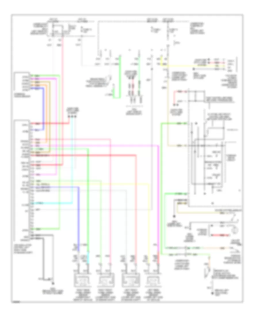
Anti-Lock Brakes Wiring Diagram, Except Hybrid without VSA for Honda Civic EX 2011
List of elements for Anti-Lock Brakes Wiring Diagram, Except Hybrid without VSA for Honda Civic EX 2011:
- (near
- (on left frame rail)
- (under left rear of floor)
- 2-door: driver's auto power window
- 30a
- 5v stabilize circuit/ controller area network controller
- A36
- A37
- A40
- Abs ind
- Abs modulator control unit (right side of engine compt)
- Bksw
- Box) g504
- Brake fluid level switch (on brake master cylinder reservoir)
- Brake pedal position switch (under left side of dash)
- Brake system ind
- Can h
- Can l
- Computer data lines system
- Ecm/pcm (left side of engine compt)
- Except gx gx
- Except gx, si
- F16
- F25
- F30
- F31 g16
- Fast controller area area network transceiver
- Fl +b
- Fl-gnd
- Fr +b
- Fr-gnd
- Frs +b
- Fuse 10 7.5a
- Fuse 12 15a
- Fuse 4 7.5a
- G12
- G16
- G202 (behind right side of front bumper)
- G401 (behind left kick panel)
- Gauge control module
- Gnd
- Hot at all times
- Hot in on or start
- Ig1
- J14
- J21
- Junction
- K-line
- K14
- Left front wheel speed sensor
- Left rear wheel speed sensor
- Micu
- Mr +b
- Mr-gnd
- Multi- fuse
- Parking brake switch (at base of parking brake lever)
- Pnk
- Red
- Right front wheel speed sensor (on frame rail)
- Right rear wheel speed sensor (under right rear of floor)
- Rl +b
- Rl-gnd
- Rr +b
- Rr-gnd
- Under-dash
- Under-dash fuse/relay box (under left end of dash)
- Under-dash junction box (under left side of dash)
- Under-hood fuse/relay box (left side of engine compt)
- Warning drive circuit
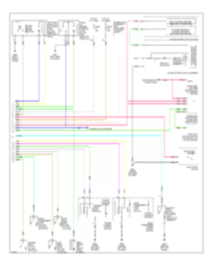
Anti-Lock Brakes Wiring Diagram, Hybrid for Honda Civic EX 2011
List of elements for Anti-Lock Brakes Wiring Diagram, Hybrid for Honda Civic EX 2011:
- (behind left
- (red)
- 30a
- 40a
- 5v stabilize circuit/ controller area network controller
- A36
- A37
- A40
- Abs ind
- Bksw
- Brake fluid level switch (on brake master cylinder reservoir)
- Brake pedal position switch (top of brake pedal assembly)
- Brake system
- Can h
- Can l
- Can-h
- Can-l
- Computer data lines system
- E24
- F16
- F25
- F30
- F31
- Fast controller area network transceiver
- Fl +b
- Fl-gnd
- Fr +b
- Fr-gnd
- Fsr +b
- Fuse 10 7.5a
- Fuse 12 15a
- Fuse 4 7.5a
- G12
- G16
- G202 (behind right side of front bumper)
- G401
- G501 (under gauge assembly)
- G504 (under left side of dash)
- G602 (right side of floor)
- Gauge control module
- Gnd
- Hot at all times
- Hot in on or start
- Ig1
- Ind
- Interior lights system
- J14
- J21
- Junction box (under left
- K-line
- K14
- Kick panel)
- Left front wheel speed sensor (lower left side of engine compt)
- Left rear wheel speed sensor (under left side of vehicle)
- Micu
- Mr +b
- Mr-gnd
- Multi- fuse
- Of engine compt)
- Parking brake switch (at base of parking lever)
- Pcm (left side of engine compt)
- Pnk
- Red
- Right front wheel speed sensor (lower right side of engine compt)
- Right rear wheel speed sensor (under right rear of vehicle)
- Rl +b
- Rl-gnd
- Rr +b
- Rr-gnd
- S-gnd
- Side of dash)
- Steering angle sensor
- Stra
- Strb
- Strd
- Svcc
- Under-dash
- Under-dash fuse/relay box (under left end of dash)
- Under-dash junction box (under left side of dash)
- Under-hood fuse/relay box (left rear of engine compt)
- Vsa act ind
- Vsa ind
- Vsa modulator control unit (right side
- Vsa off switch
- Warning drive circuit
- Yaw rate- lateral acceleration sensor (under middle of dash)
ANTI-THEFT
Forced Entry Wiring Diagram, Except Hybrid (1 of 2) for Honda Civic EX 2011
List of elements for Forced Entry Wiring Diagram, Except Hybrid (1 of 2) for Honda Civic EX 2011:
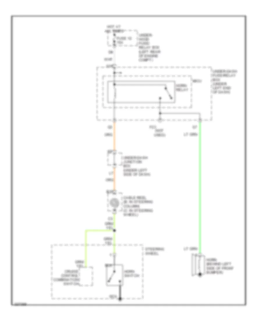
- (behind right side of front bumper) (usa: si) high horn
- (not used)
- (on transmission housing) (a/t) transmission range switch
- (usa: w/ security)
- 2-1
- Anti-theft system
- At-p
- B-can
- Door lock knob
- Door lock knob switch
- Door lock relay
- Driver's door lock actuator/knob switch (rear of driver's front door)
- Driver's door unlock relay
- Drswas
- Drswdr
- Drswra
- Drswrd
- E14
- E17
- E19
- E20
- E21
- E31
- E33
- E36
- E37
- Except gx
- Exterior lights system
- F20
- F23
- F27
- F31
- Front passenger's door lock actuator/knob switch (rear of front passenger's front door)
- Fuel fill door switch (gx) (left side of trunk)
- Fuel sw
- Fuse 10a
- Fuse 15a
- Fuse 20a
- Fuse 7.5a
- G101 (si: left rear of engine) (except si: right rear of engine)
- G13
- G16
- G17
- G401 (2 door) (behind left kick panel)
- G401 (behind left kick panel)
- G501 (4 door) (under gauge assembly)
- G501 (under gauge assembly)
- G502 (2 door) (behind glove box)
- G504 (4 door) (near under-dash junction box)
- G601 (front left side of floor)
- G602 (front right side of floor)
- G701 (2 door: left side of trunk) (4 door: left rear of trunk)
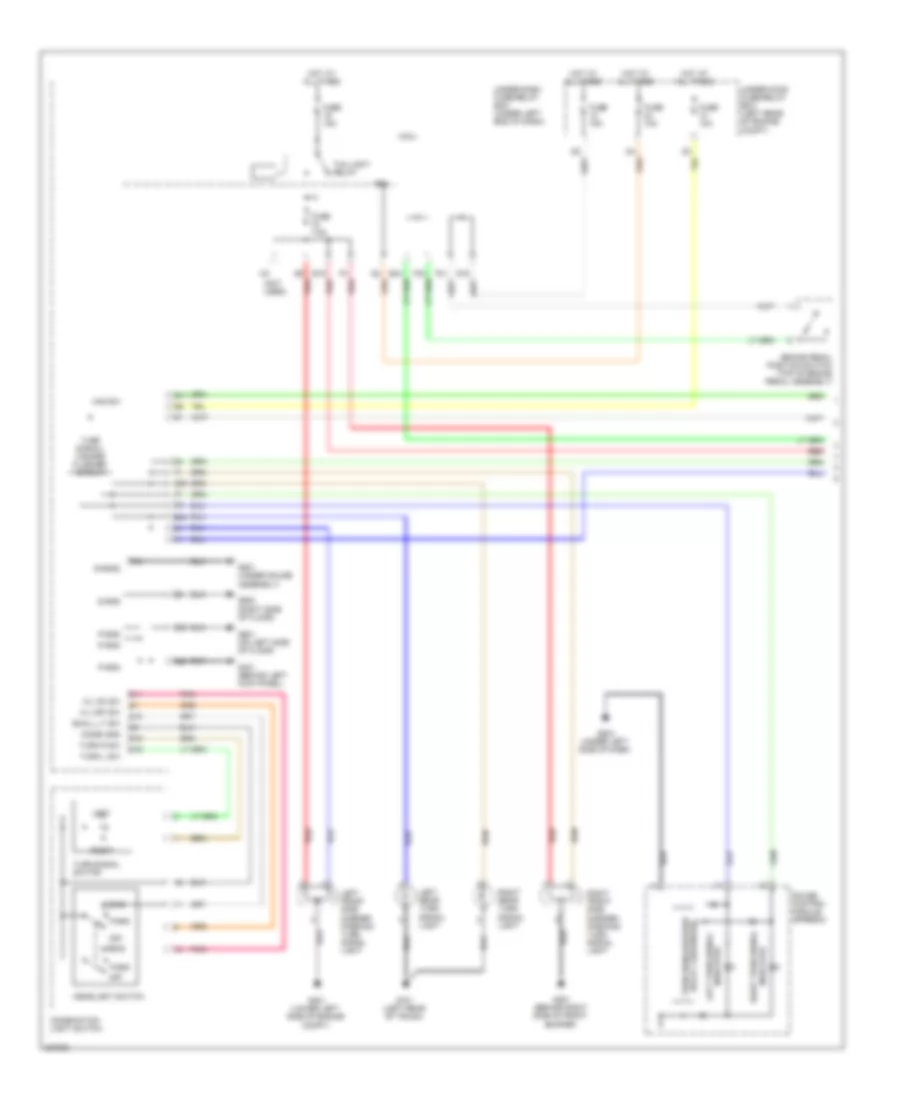
- Headlights system
- Hood sw
- Horn relay
- Hot at all times
- Hot in on or start
- Ig key sw
- Ig1
- Junction connector c101 (near brake master cylinder)
- Kc dr lock
- Kc dr unlock
- Key
- Key cylinder switch
- Lock
- Low beam head- light relay
- M10
- Micu
- N13
- P-gnd
- Passenger's door unlock relay
- Pnk
- R16
- Radio sw
- Red
- Rem as lock
- Rem as unlock
- Rem dr lock
- Rem dr unlock
- Right rear door lock actuator/knob switch (4 door) (rear of right rear door)
- S-gnd
- S-gnd2
- S2 (thermal joint)
- Sil as unlock
- Sil dr lock
- Sil dr unlock
- Sil ra unlock
- Sil rd unlock
- T11
- T22
- T23
- T24
- T25
- T26
- T27
- T28
- T29
- T30
- T31
- T32
- T34
- Taillight relay
- Trunk lid opener solenoid relay (security: w/ remote trunk release)
- Trunk sw
- Trunk unlock
- Under-dash fuse/relay box (under left end of dash)
- Unlock
- Usa: w/ security
- Vbu
- W/ security
Forced Entry Wiring Diagram, Except Hybrid (2 of 2) for Honda Civic EX 2011
List of elements for Forced Entry Wiring Diagram, Except Hybrid (2 of 2) for Honda Civic EX 2011:
- (2 door) (4 door)
- (4 door) (2 door)
- 2 door: w/o security
- 5v stabilize circuit/ controller area network controller
- Audio unit (w/o navigation) navigation unit (w/navigation)
- B-can
- Body controller area network transceiver
- Denso type
- Door unlock
- Driver's door lock switch lock
- Driver's door switch (in left "b" pillar)
- E17
- Except denso type
- Front passenger's door lock lock switch
- Front passenger's door switch (in right "b" pillar)
- Front passenger's power window switch
- Fuse 10a
- Fuse 15a
- G401 (behind left kick panel)
- G502 (2 door) (behind glove box)
- G503 (under left side of dash)
- G504 (4 door) (near under-dash junction box)
- G504 (near under-dash junction box)
- G602 (front right side of floor)
- G701 (2 door: left side of trunk) (4 door: left rear of trunk)
- Gauge control module (speedo) (w/ security)
- Gauge control module (tach) (w/ security)
- Horn (low) (usa: si) (behind left side of front bumper) horn (w/o security & except)
- Hot at all times
- Ignition key switch
- Immobilizer- keyless control unit (on steering column)
- Interior lights system
- J22
- K13
- Left rear door lock actuator/ knob switch (4 door) (rear of left rear door)
- Left rear door switch (4 door) (in left "c" pillar)
- Lock
- Lock knob switch
- Pnk
- Power window master switch
- Right rear door switch (4 door) (in right "c" pillar)
- Security hood switch (w/ security) (front center of engine compt)
- Security indicator (usa)
- Security indicator blinking circuit
- Security: except remote trunk release
- Trunk key cylinder switch (security: lock except remote trunk release) (2 door: right side of trunk lid, on key cylinder assembly) (4 door: right side of trunk lid)
- Trunk latch switch (middle of trunk lid)
- Trunk lid opener solenoid/ latch switch (security: w/ remote trunk release) (middle of trunk lid)
- Under- hood fuse/ relay box (left side of engine compt)
- Under-dash junction box (under left side of dash)
- Unlock
- W/ security
- W/o security: except remote trunk release
Forced Entry Wiring Diagram, Hybrid (1 of 2) for Honda Civic EX 2011
List of elements for Forced Entry Wiring Diagram, Hybrid (1 of 2) for Honda Civic EX 2011:
- (not used)
- (on transmission housing) transmission range switch
- (thermal joint) s2
- (under gauge assembly)
- Anti-theft system
- At-p
- B-can
- Door lock knob
- Door lock knob switch
- Door lock relay
- Driver's door lock actuator/knob switch (rear of driver's door)
- Driver's door unlock relay
- Drswas
- Drswdr
- Drswra
- Drswrd
- E14
- E17
- E19
- E20
- E21
- E31
- E33
- E36
- E37
- Exterior lights
- F20
- F23
- F27
- Front passenger's door lock actuator/knob switch (rear of right front door)
- Fuse 10a
- Fuse 15a
- Fuse 20a
- Fuse 7.5a
- G102 (left side of engine)
- G13
- G16
- G17
- G401 (behind left kick panel)
- G501
- G501 (under gauge assembly)
- G504 (under left side of dash)
- G601 (on left side of floor)
- G602 (right side of floor)
- Headlights system
- Hood sw
- Horn relay
- Hot at all times
- Hot in on or start
- Ig key sw
- Ig1
- Junction connector c101 (left rear corner of engine compt)
- Kc dr lock
- Kc dr unlock
- Key
- Key cylinder switch
- Lock
- Low beam head- light relay
- M10
- Micu
- N13
- P-gnd
- Passenger's door unlock relay
- Pnk
- R16
- Radio sw
- Red
- Rem as lock
- Rem as unlock
- Rem dr lock
- Rem dr unlock
- Right rear door lock actuator/knob switch (rear of right rear door)
- S-gnd
- S-gnd2
- Sil as unlock
- Sil dr lock
- Sil dr unlock
- Sil ra unlock
- Sil rd unlock
- System
- T22
- T23
- T24
- T25
- T26
- T27
- T28
- T29
- T30
- T31
- T32
- T34
- Taillight relay
- Trunk lid opener relay
- Trunk sw
- Under-dash fuse/relay box (under left end of dash)
- Unlock
- Vbu
Forced Entry Wiring Diagram, Hybrid (2 of 2) for Honda Civic EX 2011
List of elements for Forced Entry Wiring Diagram, Hybrid (2 of 2) for Honda Civic EX 2011:
- 5v stabilize circuit/ controller area network controller
- Audio unit (w/o navigation) navigation unit (w/ navigation)
- B-can
- Body controller area network transceiver
- Computer data lines system
- Door unlock
- Driver's door lock switch lock
- Driver's door switch (on left "b" pillar)
- E17
- Front passenger's door lock switch
- Front passenger's door switch (on right "b" pillar)
- Front passenger's power window switch
- Fuse 10a
- Fuse 15a
- G401 (behind left kick panel)
- G503 (under left side of dash)
- G504 (under left side of dash)
- G602 (right side of floor)
- G701 (left rear of trunk)
- Gauge control module (speedo)
- Gauge control module (tach)
- Horn (behind left side of front bumper)
- Hot at all times
- Ignition key switch
- Immobilizer- keyless control unit (in steering column)
- Interior lights system
- J22
- K13
- Left rear door lock actuator/ knob switch (rear of left rear door)
- Left rear door switch (on left "c" pillar)
- Lock
- Lock knob switch
- Pnk
- Power window master switch
- Power windows system
- Right rear door switch (on right "c" pillar)
- Security hood switch (on engine compt hood latch assembly)
- Security indicator
- Security indicator blinking circuit
- Trunk lid opener solenoid/ latch switch (usa) (middle of trunk lid)
- Under-dash junction box (under left side of dash)
- Under-hood fuse/relay box (left rear of engine compt)
- Unlock
Immobilizer Wiring Diagram, Except Hybrid for Honda Civic EX 2011
List of elements for Immobilizer Wiring Diagram, Except Hybrid for Honda Civic EX 2011:
- (behind left kick panel) g401
- (front left side of floor) g601
- (gx)
- (in top of fuel tank) fuel tank unit
- (not used)
- (or pnk)
- (right rear of engine)
- (under left side of dash) (gx) injector control module relay
- (under left side of dash) dlc
- 10v stabilize circuit
- A15
- A22
- A41
- A44
- B-can
- B17
- Body controller area network transceiver
- C36
- C40
- C44 lg2
- Computer data lines system
- Controller area 5v stabilize circuit/
- D6 (except si) (si)
- Ecm/pcm (left side of engine compt)
- Engine controls system
- Except gx
- F10
- F24
- Fuel pressure regulator leak check connector (gx) (front of engine compt)
- Fuel pressure regulator shut-off solenoid valve
- Fuel pressure regulator switch (gx) (right rear of engine)
- Fuel pump
- Fuel shut-off solenoid valve relay (gx) (under left side of dash)
- Fuel tank internal solenoid valve (gx) (left side of trunk)
- Fuse 10a
- Fuse 15a
- G101 (si: left rear of engine) (except si: right rear of engine)
- G11
- G401 (behind left kick panel)
- G504 (near under-dash junction box)
- G601 (front left side of floor)
- Gauge control module (tach)
- Hot at all times
- Hot in on or start
- Ig key sw
- Ig1
- Ig1 fuel pump
- Ignition key switch
- Immobilizer system indicator
- Immobilizer- keyless control unit (on steering column)
- Imofpr
- J/c c101 (near brake master cylinder)
- J11
- J21
- J22
- K-line
- K13
- Lg1
- Micu
- Mrly
- Network controller
- Parking brake switch (at base of parking brake lever)
- Pf2sw
- Pgm-fi main relay 1
- Pgm-fi main relay 2
- Pnk
- R11
- R12
- R16
- S-net
- S-net5v
- S3 (thermal joint)
- Under- dash fuse/ relay box (under left end of dash)
- Under-dash junction box (under left side of dash)
- Under-hood fuse/relay box (left side of engine compt)
- Vbu
- Warning drive circuit
Immobilizer Wiring Diagram, Hybrid for Honda Civic EX 2011
List of elements for Immobilizer Wiring Diagram, Hybrid for Honda Civic EX 2011:
- (not used)
- 10v stabilize circuit
- A15
- A17
- A22
- A44
- Auxiliary under-hood fuse/relay box (left side of engine compt)
- B-can
- B17
- B22
- B36
- Body controller area network transceiver
- C36
- C40
- C44
- Computer data
- Controller area 5v stabilize circuit/
- Dlc (under left side of dash)
- Engine controls system
- F24
- Fuel pump
- Fuel tank unit (inside fuel tank)
- Fuse 10a
- Fuse 15a
- G102 (left side of engine)
- G11
- G504 (under left side of dash)
- G601 (on left side of floor)
- Gauge control module (tach)
- Hot at all times
- Hot in on or start
- Ig key sw
- Ig1
- Ig1 fuel pump
- Ignition key switch
- Immobilizer system indicator
- Immobilizer- keyless control unit (in steering column)
- Imoflr
- J11
- J21
- J22
- Junction connector c101 (left rear corner of engine compt)
- K-line
- K13
- Lg1
- Lg2
- Lines system
- Micu
- Mrly
- Network controller
- Parking brake switch (at base of park lever)
- Pcm (left side of engine compt)
- Pg1
- Pg2
- Pgm-fi main relay 1
- Pgm-fi main relay 2
- Pnk
- R11 (not used)
- R12
- R16
- S-net
- S1 (thermal joint)
- S2 (thermal joint)
- S3 (thermal joint)
- S4 (thermal joint)
- Under-dash fuse/relay box (under left end of dash)
- Under-dash junction box (under left side of dash)
- Under-hood fuse/relay box (left rear of engine compt)
- Vbu
- Warning drive circuit
BODY CONTROL MODULES
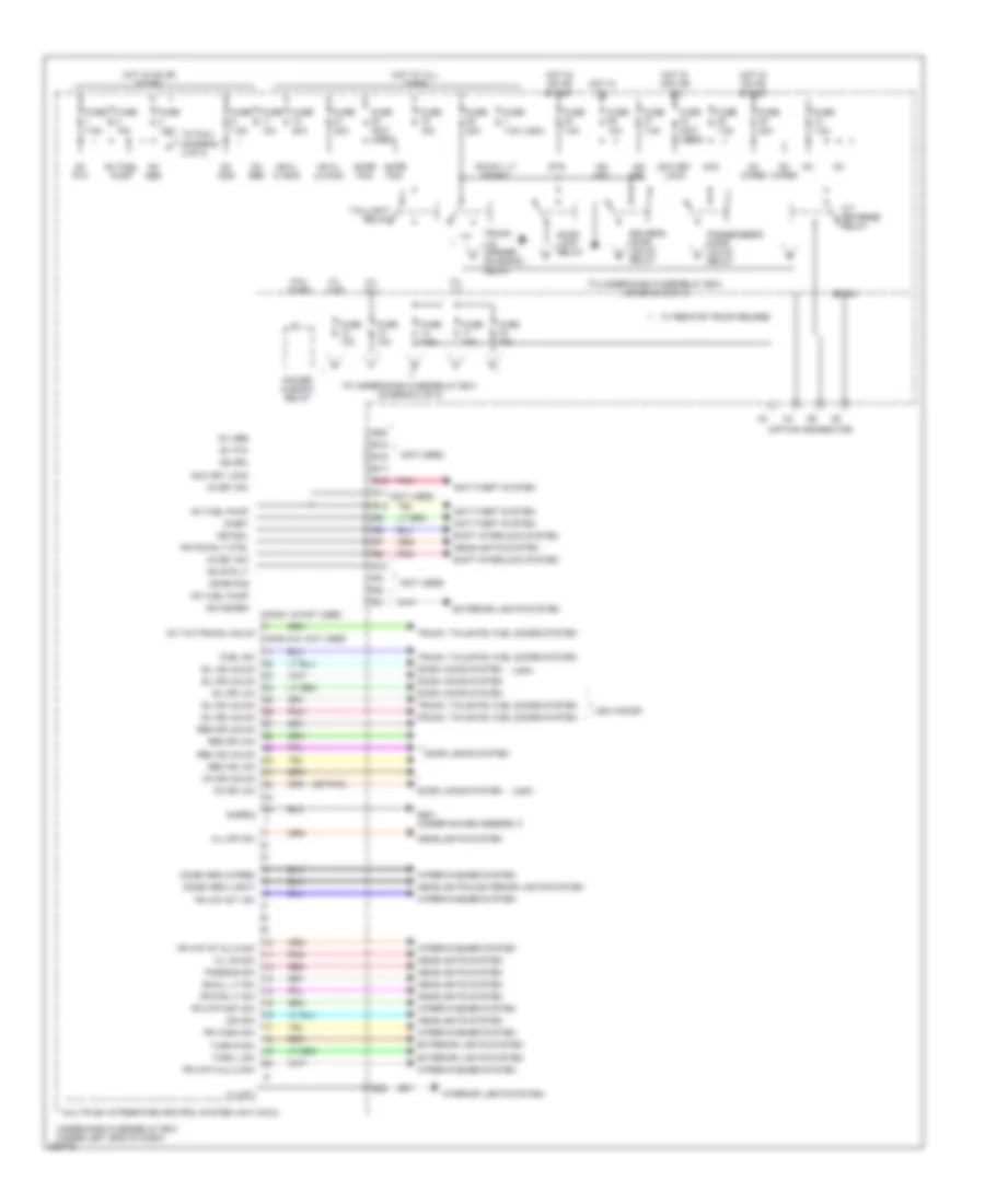
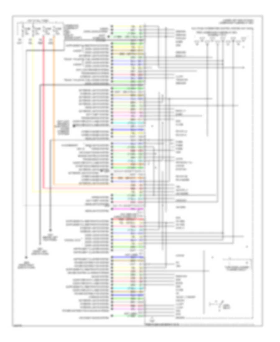
Body Control Modules Wiring Diagram, Except Hybrid (1 of 2) for Honda Civic EX 2011
List of elements for Body Control Modules Wiring Diagram, Except Hybrid (1 of 2) for Honda Civic EX 2011:
- (not used)
- (option connector)
- (or pnk)
- (usa)
- +b day lt/ smart
- +b h/l hi main
- +b h/l lo main
- +b hazard
- +b intr lt
- +b rr fog
- A/t reverse relay
- Acc
- Acc key lock
- Anti-theft system
- B-can
- Combi grd (light)
- Combi grd (wiper)
- Conn 1-6 not used
- Conn 8-21 not used
- Dim sw
- Door lock relay
- Door locks system
- Driver's door unlck relay
- E25
- Exterior lights system
- Fr fog lt sw
- Fr fog rly ctrl
- Fr wash sw
- Fr wip hi & lo sw
- Fr wip int & lo sw
- Fr wip int vr+
- Fr wip mist sw
- Fuel sw
- Fuse (not used)
- Fuse 10a
- Fuse 15a
- Fuse 20a
- Fuse 30a
- Fuse 7.5a
- G501 (under gauge assembly)
- H/l hi-l
- H/l hi-r
- H/l lo
- H/l off sw
- H/l on sw
- Headlights & exterior lights system
- Headlights system
- Hot at all times
- Hot in acc or on
- Hot in on
- Hot in on or start
- Ig key sw
- Ig1
- Ig1 abs
- Ig1 fuel pump
- Ig1 ods
- Ig1 p/w
- Ig1 srs
- Ig1 wiper
- Ig2 drl
- Ig2 hac
- Illumi+
- Interior lights system
- Kc dr lck
- Kc dr unlck
- Kc t/g (trunk) unlck
- Keysol
- Multiplex integrated control system unit (micu)
- P/w timer
- Passenger's door unlck relay
- Passing sw
- Pnk
- Power window relay
- R10
- R11
- R12
- R16
- R17
- R18
- R19
- R20
- Red
- Rem as lck
- Rem as unlck
- Rem dr lck
- Rem dr unlck
- S-grd2
- S-net
- Shift interlock system
- Sil as unlck
- Sil dr lck
- Sil dr unlck
- Sil ra unlck
- Sil rd unlck
- Small lt sw
- Sts
- Taillight relay
- To micu (diagram 2 of 2)
- To under-dash fuse/relay box (diagram 2 of 2)
- Trunk lid opener solenoid relay
- Trunk, tailgate, fuel doors system
- Turn l sw
- Turn r sw
- Under-dash fuse/relay box (under left end of dash)
- Usa 4-door
- W/ remote trunk relese
- Wiper/washer system
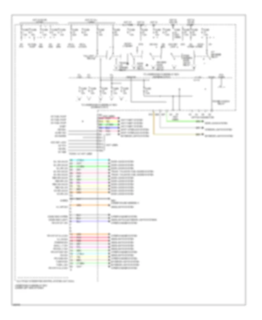
Body Control Modules Wiring Diagram, Except Hybrid (2 of 2) for Honda Civic EX 2011
List of elements for Body Control Modules Wiring Diagram, Except Hybrid (2 of 2) for Honda Civic EX 2011:
- (except gx)
- (gx)
- (not used)
- (under left end of dash) under-dash fuse/relay box
- +b day lt/smart
- +b hazard
- +b horn
- +b intr lt
- 4-door
- Acc
- Acs
- Air conditioning system
- Anti-lock brakes & electronic power steering systems
- Anti-lock brakes systems
- Anti-theft system
- Atp-np
- Atp-p
- B-can
- Back lt-
- Canada: dx-g
- Chk
- Computer data lines system
- Cruise control & horns systems
- Door locks system
- Drswas
- Drswdr
- Drswra
- Drswrd
- E14
- E15
- E17
- E20
- E21
- E24
- E25
- E26
- E31
- E33
- E34
- E36
- E37
- E38
- E39
- E40
- Engine controls system
- Exterior lights system
- F11
- F14
- F16
- F18
- F19
- F20
- F21
- F22
- F23
- F25
- F26
- F27
- F28
- F29
- F30
- F31
- F32
- F33
- Fr fog rly cl -
- Fr washer
- Fr wip as
- Fr wip hi
- Fr wip lo
- From fuse 4 (diagram 1 of 2)
- From under-dash fuse/relay box (diagram 1 of 2)
- Fuse 10a
- Fuse 15a
- Fuse 7.5a
- G13
- G15
- G16
- G17
- G401 (behind left kick panel)
- G601 (front left side of floor)
- G602 (front right side of floor)
- Haz sw
- Headlights system
- Hood sw
- Horn relay
- Horns system
- Hot at all times
- Ig1
- Ig1 ods
- Ig1 srs
- Ig2 hac
- Illumi+
- Illumi-
- Instrument cluster system
- Interior lights system
- Intr lt
- K-line
- M10
- Micu service check connector
- Multiplex integrated control system unit (micu)
- N13
- Ods
- P-grd
- P-pin sw
- P10
- Pnk
- Power distribution & sound systems
- Power distribution system
- Q10
- Q11
- Q12
- Q13
- Q14
- Q15
- Q16
- Radio sw
- Red
- S-grd
- S-net
- Scs
- Shift interlock system
- Sound system
- Starting/charging system
- Stop sw
- Sts
- Transmission system
- Transmission systems
- Transmissions system
- Trunk sw
- Trunk, tailgate, fuel doors system
- Turn signal/hazard flasher circuit
- Underhood fuse/relay box (left side of engine compt)
- Usa: si
- Vbu
- W/accessory
- Warning system
- Wiper/washer system
Body Control Modules Wiring Diagram, Hybrid (1 of 2) for Honda Civic EX 2011
List of elements for Body Control Modules Wiring Diagram, Hybrid (1 of 2) for Honda Civic EX 2011:
- (not used)
- (option connector)
- +b day lt/smart
- +b h/l hi main
- +b h/l lo main
- +b hazard
- A/t reverse relay
- Acc
- Acc key lock
- Anti-theft system
- B-can
- Combi gnd (light)
- Combi gnd (wiper)
- Conn 1-21 not used
- Dim sw
- Door lock relay
- Door locks system
- Driver's door unlck relay
- Drswdr
- E15
- E25
- E37
- Exterior lights system
- Fr fog lt sw
- Fr wash sw
- Fr wip hi & lo sw
- Fr wip int & lo sw
- Fr wip int vr+
- Fr wip mist sw
- Fuse (not used)
- Fuse 10a
- Fuse 15a
- Fuse 20a
- Fuse 30a
- Fuse 7.5a
- G501 (under gauge assembly)
- H/l hi-l
- H/l hi-r
- H/l lo
- H/l off sw
- H/l on sw
- Headlights & exterior lights systems
- Headlights system
- Hot at all times
- Hot in acc or on
- Hot in on
- Hot in on or start
- Hot in start
- Ig key sw
- Ig1
- Ig1 abs
- Ig1 fuel pump
- Ig1 ods
- Ig1 p/w
- Ig1 srs
- Ig1 wiper
- Ig2 drl
- Ig2 hac
- Illum -
- Interior lights system
- Kc dr lck
- Kc dr unlck
- Keysol
- Multiplex integrated control system unit (micu)
- N2 (not
- P/w timer
- Pass- enger's door unlck relay
- Passing sw
- Pnk
- Power window relay
- R11
- R12
- R16
- R17
- R18
- R19
- R20
- Red
- Rem as lck
- Rem as unlck
- Rem dr lck
- Rem dr unlck
- S-grd2
- S-net
- Shift interlock system
- Sil as unlck
- Sil dr lck
- Sil dr unlck
- Sil ra unlck
- Sil rd unlck
- Small lt sw
- Sts
- Taillight relay
- To under-dash fuse/relay box (diagram 2 of 2)
- Trunk lid opener relay
- Trunk, tailgate, fuel doors system
- Turn l sw
- Turn r sw
- Under-dash fuse/relay box (under left end of dash)
- Used)
- Wiper/washer system
Body Control Modules Wiring Diagram, Hybrid (2 of 2) for Honda Civic EX 2011
List of elements for Body Control Modules Wiring Diagram, Hybrid (2 of 2) for Honda Civic EX 2011:
- (not used)
- (under left end of dash) under-dash fuse/relay box
- +b day lt/smart
- +b hazard
- +b horn
- +b intr lt
- Acs
- Air conditioning system
- Anti-theft system
- Atp-np
- Atp-p
- B-can
- Back lt-
- Chk
- Computer data lines system
- Door locks system
- Drswas
- Drswra
- Drswrd
- E14
- E15
- E17
- E19
- E20
- E21
- E26
- E31
- E33
- E34
- E36
- E38
- E39
- E40
- Engine controls system
- Exterior lights system
- F11
- F14
- F18
- F19
- F20
- F21
- F22
- F25
- F26
- F27
- F28
- F29
- F30
- F31
- F32
- F33
- Fr fog rly cl -
- Fr washer
- Fr wip as
- Fr wip hi
- Fr wip lo
- From under-dash fuse/relay box (diagram 1 of 2)
- Fuse 10a
- Fuse 15a
- Fuse 7.5a
- G13
- G15
- G16
- G17
- G401 (behind left kick panel)
- G601 (on left side of floor)
- G602 (right side of floor)
- Haz sw
- Headlights system
- Hood sw
- Horn relay
- Horns system
- Hot at all times
- Ig1
- Ig1 ods
- Ig1 srs
- Ig2 hac
- Illumi+
- Illumi-
- Instrument cluster system
- Interior lights system
- Intr lt
- K-line
- M10
- Micu service check connector
- Multiplex integrated control system unit (micu)
- N13
- Ods
- P-gnd
- P-pin sw
- P10
- Pnk
- Power distribution & sound systems
- Power distribution system
- Q10
- Q11
- Q12
- Q13
- Q14
- Q15
- Q16
- Radio sw
- Red
- S-gnd
- S-net
- Scs
- Shift interlock system
- Sound systems
- Starting/charging system
- Stop sw
- Sts
- Transmissions system
- Trunk sw
- Trunk, tailgate, fuel doors system
- Turn signal/hazard flasher circuit
- Under-hood fuse/relay box (left rear of engine compt)
- Vbu
- W/acccessory
- Warning systems
- Wiper/washer system
COMPUTER DATA LINES
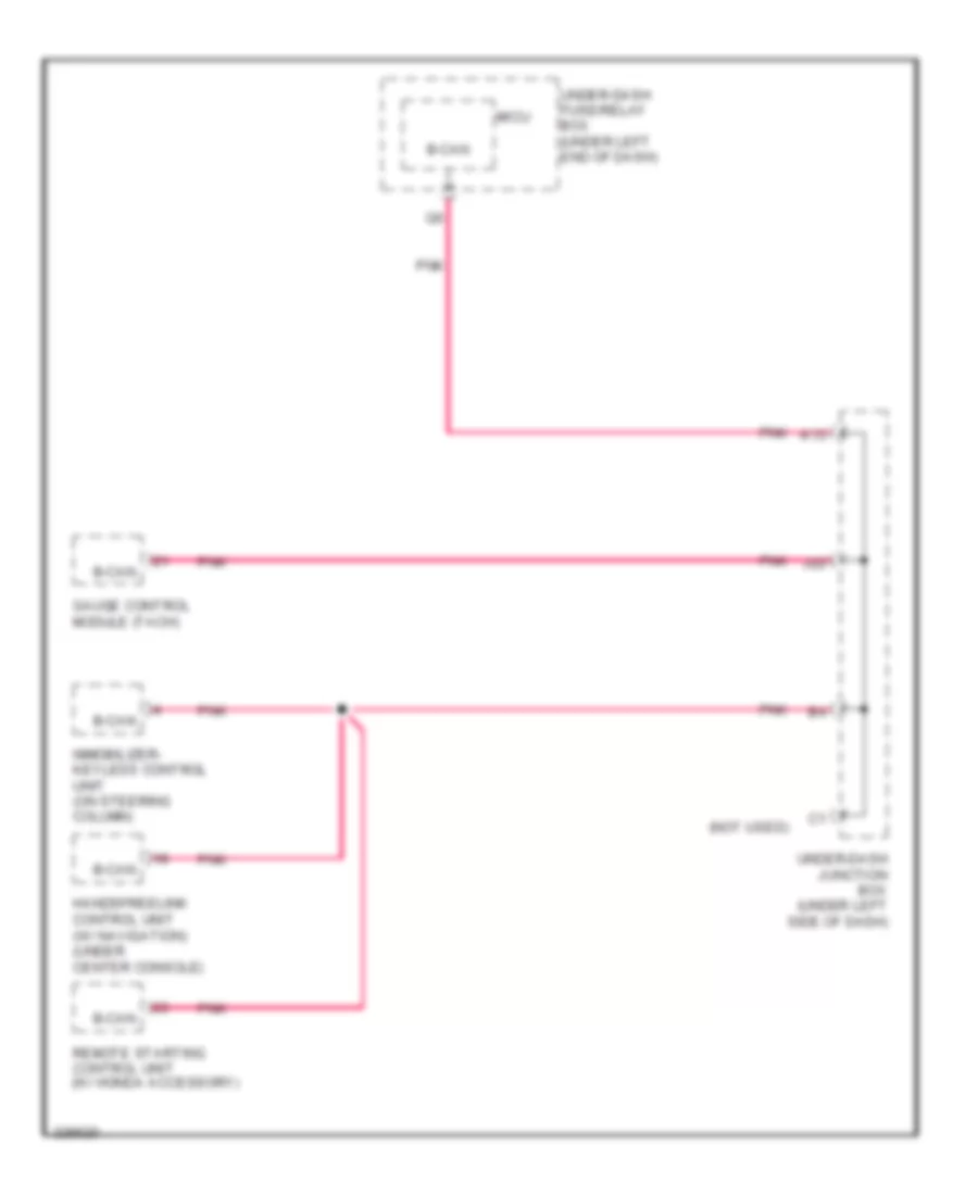
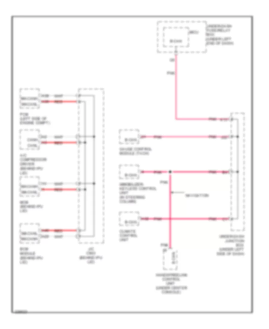
B-CAN Wiring Diagram, Except Hybrid for Honda Civic EX 2011
List of elements for B-CAN Wiring Diagram, Except Hybrid for Honda Civic EX 2011:
- (not used)
- B-can
- Gauge control module (tach)
- Handsfreelink control unit (w/ navigation) (under center console)
- Immobilizer- keyless control unit (on steering column)
- J22
- K13
- Micu
- Pnk
- Remote starting control unit (w/ honda accessory)
- Under-dash fuse/relay box (under left end of dash)
- Under-dash junction box (under left side of dash)
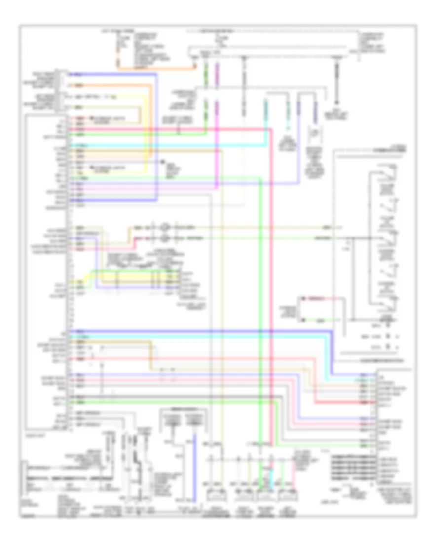
Data Link Connector Wiring Diagram, Except Hybrid for Honda Civic EX 2011
List of elements for Data Link Connector Wiring Diagram, Except Hybrid for Honda Civic EX 2011:
- (behind right kick panel) (if equipped) eps control unit
- (c206: right side of engine compt) (c207: right rear of engine compt) j/c c206 (gx) j/c c207 (except gx)
- (if equipped) moonroof switch
- (left side of engine compt) ecm/pcm
- (left side of engne compt) ecm/pcm
- (not used)
- (on steering column) immobilizer- keyless control unit
- (right side of engine compt)
- (right side of engine compt) abs modulator control unit
- (right side of engine compt) vsa modulator control unit
- (si: under middle of dash) (w/ vsa) yaw rate-lateral acceleration sensor
- (under center console) handsfreelink control unit
- (under left side of dash) (if equipped) tpms control unit
- (under middle of dash) srs unit
- (w/o navigation) audio unit (w/ navigation) navigation unit
- A10
- A11
- A12
- A17
- A24
- A31
- A36
- A37
- A42
- Abs modulator control unit
- Audio unit (factory)
- Audio unit (w/o navigation) navigation unit (w/ navigation)
- D15
- D17
- Dlc (under left side of dash)
- E14
- E15
- E16 (not used)
- E18
- E8 (not used)
- Ecm/pcm (left side of engine compt)
- Eps control unit (if equipped) (behind right kick panel)
- Except si
- F11
- F14
- F28
- Fuse 10a
- G10
- G101 (left rear of engine)
- G101 (right rear of engine)
- G14
- G502 (behind glove box)
- Gauge control module (speedo)
- Gauge control module (tach)
- H10
- Hot at all times
- Immobilizer- keyless control unit (on steering column)
- J/c c101 (near brake master cylinder)
- J/c c206 (gx) j/c c207 (except gx) (c206: right side of engine compt) (c207: right rear of engine compt)
- J10
- J11
- K-line
- Micu
- Navigation
- Navigation unit
- Normal audio: except audio unit w/ factory
- Red
- Remote starting control unit (w/ honda accessory)
- Scs
- Srs unit (under middle of dash)
- Tpms control unit (if equipped) (under left side of dash)
- Under-dash fuse/relay box (under left end of dash)
- Under-dash junction box (under left side of dash)
- Under-hood fuse/relay box (left side of engine compt)
- Vbu
- Vsa modulator control unit (right side of engine compt)
- W/ eps
- W/ navigation
- W/ vsa
- W/o navigation
- W/o vsa
- Wen
- Yaw rate-lateral acceleration sensor (w/ vsa) (si: under middle of dash)
Data Link Connector Wiring Diagram, Hybrid for Honda Civic EX 2011
List of elements for Data Link Connector Wiring Diagram, Hybrid for Honda Civic EX 2011:
- (behind ipu lid) bcm module
- (behind ipu lid) j/c c902
- (behind ipu lid) mcm
- (left rear corner of engine compt) servo unit
- (left side of engine compt) pcm
- (right side of engine compt) vsa modulator control unit
- (under middle of dash) srs unit
- (under middle of dash) yaw rate-lateral acceleration sensor
- (under right end of dash) eps control unit
- (usa) tpms control unit
- A11
- A12
- A21
- A24
- A31
- A37
- A38
- A42
- Audio unit (w/o navigation) navigation unit) (w/ navigation)
- Bcm module (behind ipu lid)
- D15
- D17
- Dlc (under left side of dash)
- E14
- E15
- E16
- Eps control unit (under right end of dash)
- F10
- F11
- F14
- F28
- Fuse 10a
- G10
- G102 (left side of engine)
- G11
- G14
- G502 (behind right end of dash)
- Gauge control module (tach)
- H10
- Hot at all times
- Immobilizer keyless control unit (in steering column)
- J/c c207 (right side of engine compt)
- J/c c902 (behind ipu lid)
- J10
- K-line
- Mcm (behind ipu lid)
- Micu
- Pcm (left side of engine compt)
- Red
- Scs
- Servo unit (left rear corner of engine compt)
- Srs unit (under middle of dash)
- Tpms control unit (usa)
- Under-dash fuse/relay box (under left end of dash)
- Under-dash junction box (under left side of dash)
- Under-hood fuse/relay box (left rear of eng compt)
- Vbu
- Vsa modulator control unit (right side of engine compt)
- W/ navigation
- W/o navigation
- Yaw rate-lateral acceleration sensor (under middle of dash)
IMA F-CAN High/Low & B-CAN Wiring Diagrams, Hybrid for Honda Civic EX 2011
List of elements for IMA F-CAN High/Low & B-CAN Wiring Diagrams, Hybrid for Honda Civic EX 2011:
- (under center
- A/c compressor driver (behind ipu lid)
- A20
- A32
- A38
- A39
- A40
- B-can
- Bcm module (behind ipu lid)
- Canh
- Canl
- Climate control unit
- Console)
- Control
- Gauge control module (tach)
- Handsfreelink
- Imacanh
- Imacanl
- Immobilizer- keyless control unit (in steering column)
- J/c c903 (behind ipu lid)
- J22
- K13
- Mcm (behind ipu lid)
- Micu
- Navigation
- Pcm (left side of engine compt)
- Pnk
- Red
- Under-dash fuse/relay box (under left end of dash)
- Under-dash junction box (under left side of dash)
- Unit
COOLING FAN
Cooling Fan Wiring Diagram, Except Hybrid for Honda Civic EX 2011
List of elements for Cooling Fan Wiring Diagram, Except Hybrid for Honda Civic EX 2011:
- (m/t) (a/t)
- (or pnk)
- (right rear
- A/c condenser fan diode
- A/c condenser fan motor (top of a/c condenser fan motor)
- A/c condenser fan relay
- A/c pressure sensor (right side of engine compt)
- A16
- A19
- A21
- A33
- Acpd
- B23
- B33
- Ecm/pcm (left side of engine compt)
- Ect sensor 1 (right rear of engine)
- Ect sensor 2 (lower left side of radiator)
- Ect1
- Ect2
- Engine controls system
- F11
- F12
- F14
- F16
- Fan control relay
- Fanh
- Fanl
- Fuse 10a
- Fuse 15a
- Fuse 20a
- Fuse 20a 30a
- Fuse 7.5a
- G12
- G301 (lower left side of engine compt)
- Hot at all times
- Hot in on
- J/c c207
- Of engine compt)
- Pgm-fi sub relay
- Radiator fan diode
- Radiator fan motor (front of engine compt)
- Radiator fan relay
- Red
- Sg2
- Sg6
- Subrly
- Under-dash fuse/relay box (under left end of dash)
- Under-hood fuse/relay box (left side of engine compt)
- Vcc6
- W/ power mirror defogger
Cooling Fan Wiring Diagram, Hybrid for Honda Civic EX 2011
List of elements for Cooling Fan Wiring Diagram, Hybrid for Honda Civic EX 2011:
- A/c condenser fan diode
- A/c condenser fan motor (behind center of radiator)
- A/c condenser fan relay
- A/c pressure sensor (right side of engine compt)
- A16
- A19
- A21
- A33
- Acpd
- B23
- B33
- Ect sensor 1 (right rear of engine)
- Ect sensor 2 (lower front of engine compt)
- Ect1
- Ect2
- Engine controls system
- F11
- F12
- F14
- F16
- Fan control relay
- Fanh
- Fanl
- Fuse 10a
- Fuse 15a
- Fuse 20a
- Fuse 7.5a
- G12
- G301 (lower left side of engine compt)
- Hot at all times
- Hot in on
- Pcm (left side of engine compt)
- Pgm-fi sub relay
- Pnk
- Radiator fan diode
- Radiator fan motor (behind radiator)
- Radiator fan relay
- Red
- Sg2
- Sg3
- Subrly
- Under-dash fuse/relay box (under left end of dash)
- Under-hood fuse/relay box (left rear of engine compt)
- Vcc6
CRUISE CONTROL
Cruise Control Wiring Diagram, Except Hybrid (1 of 2) for Honda Civic EX 2011
List of elements for Cruise Control Wiring Diagram, Except Hybrid (1 of 2) for Honda Civic EX 2011:
- (a/t)
- (m/t)
- (si: left rear of engine) (except si: right rear of engine) g101
- (under left side of dash) under-dash junction box
- 10v stabilize circuit
- 2 door: driver's auto power window
- 2-1
- A17
- A18
- A20
- A24
- A25
- A34
- A35
- A36
- A37
- A39
- A40
- A41
- App sensor (under left side of dash)
- Apsa
- Apsb
- Area network controler 5v stabilize circuit/controller
- Atp-fwd
- B28
- Bksw
- Bkswnc
- Brake pedal position switch (under left side of dash)
- C12
- C20
- C21
- C39
- C43
- Can h
- Can l
- Clutch pedal position switch (under left side of dash)
- Computer data lines system
- Crmtcls
- Cruise control indicator
- Cruise control main switch indicator
- Cruise dimming circuit
- Ecm/pcm (left side of engine compt)
- Etcsm+
- Etcsm-
- Etcsrly
- Except gx gx
- Except si
- F25
- F30
- F31
- Fuse 10 7.5a
- Fuse 10a
- G16
- G401 (behind left kick panel)
- G504 (near under-dash junction box)
- Gauge control module (tach)
- Gauges & indicators
- Horn relay
- Hot in on or start
- Ig1
- Ig1etcs
- Igp
- J/c c101 (near brake master cylinder)
- J14
- Micu
- Mrly
- Network transceiver fast controller area
- Output shaft (countershaft) speed sensor (except si: on transmission housing) (si: under transmission housing)
- Power distribution system
- Power windows system
- Red
- S2 (thermal joint)
- Sensor input
- Sg3
- Sg4
- Sg5
- Tp sensor/throttle actuator (on throttle body)
- Tpsa
- Tpsb
- Transmission range switch (on transmission housing)
- Under-dash fuse/relay box (under left end of dash)
- Vcc3
- Vcc4
- Vcc5
- Warning drive circuit
Cruise Control Wiring Diagram, Except Hybrid (2 of 2) for Honda Civic EX 2011
List of elements for Cruise Control Wiring Diagram, Except Hybrid (2 of 2) for Honda Civic EX 2011:
- (near under- dash junction box) g504
- (not used)
- A21
- B10
- B14
- B15
- B18
- Cable reel (under steering wheel)
- Cancel switch
- Cruise control combination switch
- Etcs control relay
- Except si
- F10
- Fuse 12 15a
- Fuse 19 15a
- Fuse 21 15a
- Horn switch
- Hot at all times
- Interior lights system
- J/c c101 (near brake master cylinder)
- J13
- J18
- Main switch
- Nca
- Pgm-fi main relay 1
- Pnk
- Resume switch
- Set switch
- Steering wheel
- Under hood fuse/relay box (left side of engine compt)
- Under-dash junction box (under left side of dash)
Cruise Control Wiring Diagram, Hybrid (1 of 2) for Honda Civic EX 2011
List of elements for Cruise Control Wiring Diagram, Hybrid (1 of 2) for Honda Civic EX 2011:
- (under left side of dash) under dash junction box
- 10v stabilize circuit
- A13
- A17
- A18
- A20
- A24
- A25
- A34
- A35
- A36
- A37
- A40
- A43
- App sensor (under left side of dash)
- Apsa
- Apsb
- Area network controler 5v stabilize circuit/controller
- Atp-fwd
- B28
- Bksw
- Bkswnc
- Brake pedal position switch (top of brake pedal assembly)
- C10
- C12
- C20
- C21
- C39
- Can h
- Can l
- Computer data lines system
- Cruise control indicator
- Cruise control main switch indicator
- Cruise dimming circuit
- Cvt driven pulley speed sensor (on transmission housing)
- Etcsm+
- Etcsm-
- Etcsrly
- F15
- F25
- F30
- F31
- Fuse 10 7.5a
- Fuse 10a
- G102 (left side of engine)
- G16
- G504 (under left side of dash)
- Gauge control module (tach)
- Gauges & indicators
- Horn relay
- Hot in on or start
- Ig1
- Ig1etcs
- Igp1
- Igp2
- J14
- K14
- Micu
- Mrly
- Network transceiver fast controller area
- Pcm (left side of engine compt)
- Red
- S2 (thermal joint)
- Sensor input
- Sg3
- Sg4
- Sg5
- Tp sensor/throttle actuator (top right rear of engine)
- Tpsa
- Tpsb
- Transmission range switch (on transmission housing)
- Under dash fuse/relay box (under left end of dash)
- Under-dash fuse/relay box (under left end of dash)
- Vcc3
- Vcc4
- Vcc5
- Warning drive circuit
Cruise Control Wiring Diagram, Hybrid (2 of 2) for Honda Civic EX 2011
List of elements for Cruise Control Wiring Diagram, Hybrid (2 of 2) for Honda Civic EX 2011:
- (under left side of dash) g504
- A21
- B10
- B18
- Cable reel (b: in steering column) (c: in steering wheel)
- Cancel switch
- Cruise control combination switch
- Etcs control relay
- F10
- Fuse 12 15a
- Fuse 19 15a
- Fuse 21 15a
- Horn switch
- Hot at all times
- Interior lights system
- J/c c101 (left rear corner of engine compartment)
- J13
- J18
- Main switch
- Nca
- Pgm-fi main relay 1
- Pnk
- Resume switch
- Set switch
- Steering wheel
- Under hood fuse/relay box (left rear of engine compartment)
- Under-dash junction box (under left side of dash)
DEFOGGERS
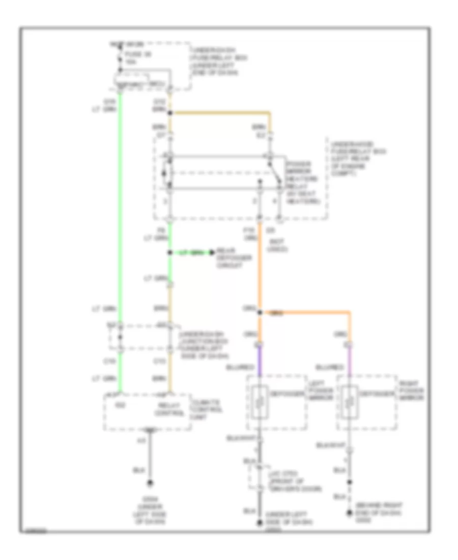
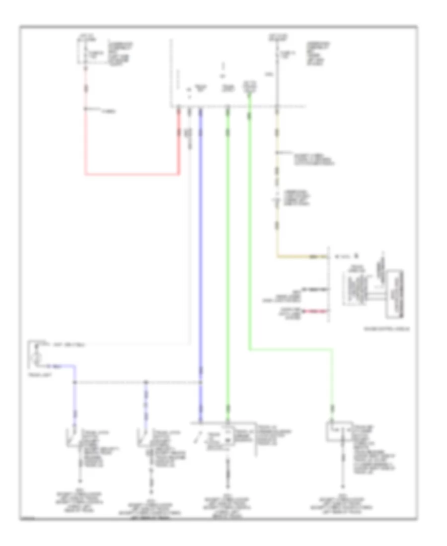
Heated Mirrors Wiring Diagram, Coupe for Honda Civic EX 2011
List of elements for Heated Mirrors Wiring Diagram, Coupe for Honda Civic EX 2011:
- (not used)
- C13
- Defogger
- F15
- Fuse 36 10a
- G501 (under gauge assembly)
- G502 (behind glove box)
- G504 (near under-dash junction box)
- Gnd
- Heater control panel/ hvac control unit
- Hot in on
- Ig2 hac
- Left power mirror (front of driver's door)
- Micu
- Power
- Power mirror defogger relay (if equipped)
- Rear defogger circuit
- Relay control
- Right power mirror (front of front passenger's door)
- Under-dash fuse/relay box (under left end of dash)
- Under-dash junction box (under left side of dash)
- Under-hood fuse/relay box (left side of engine compt)
Heated Mirrors Wiring Diagram, Hybrid for Honda Civic EX 2011
List of elements for Heated Mirrors Wiring Diagram, Hybrid for Honda Civic EX 2011:
- (behind right end of dash) g502
- (not used)
- (under left side of dash) g503
- C10
- C13
- Climate control unit
- Defogger
- F15
- Fuse 36 10a
- G504 (under left side of dash)
- Gnd
- Hot in on
- Ig2
- Ig2 hac
- J/c c753 (front of driver's door)
- Left power mirror
- Micu
- Power mirror heaters relay (w/ seat heaters)
- Rear defogger circuit
- Relay control
- Right power mirror
- Under-dash fuse/relay box (under left end of dash)
- Under-dash junction box (under left side of dash)
- Under-hood fuse/relay box (left rear of engine compt)
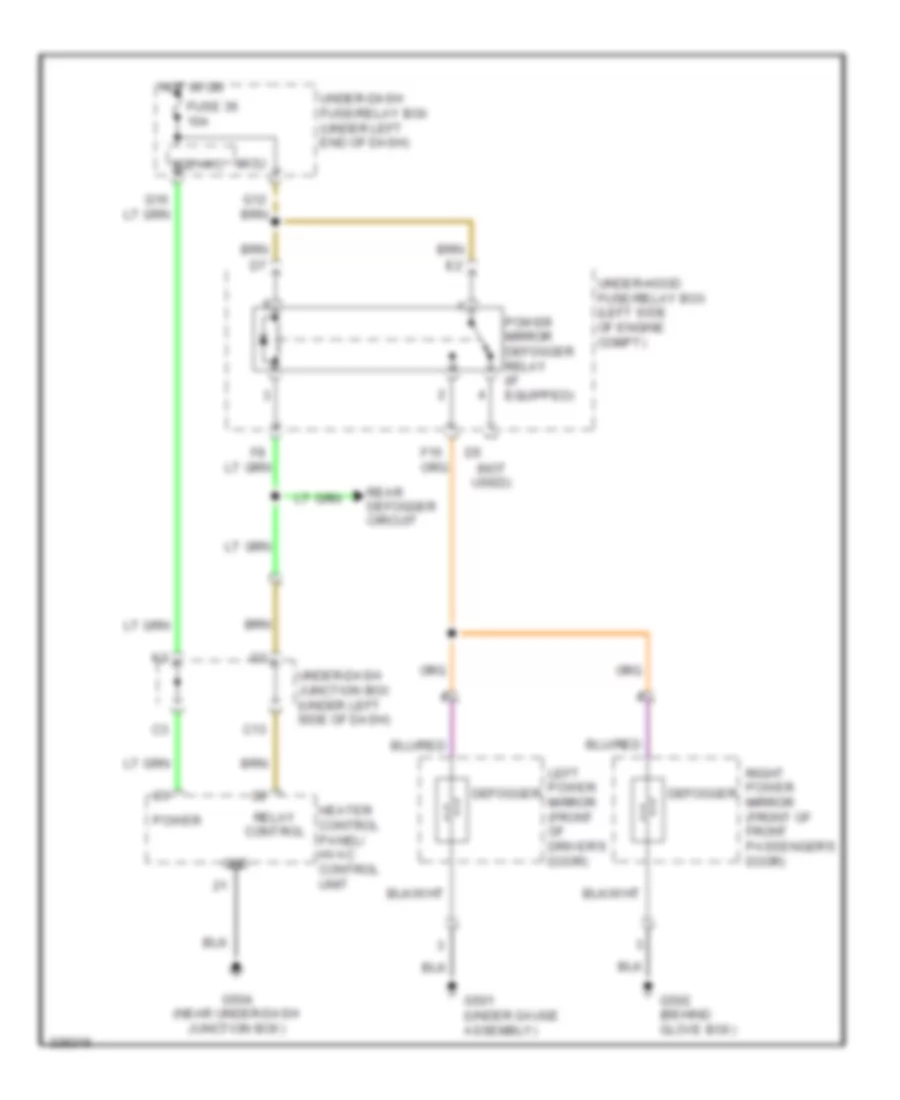
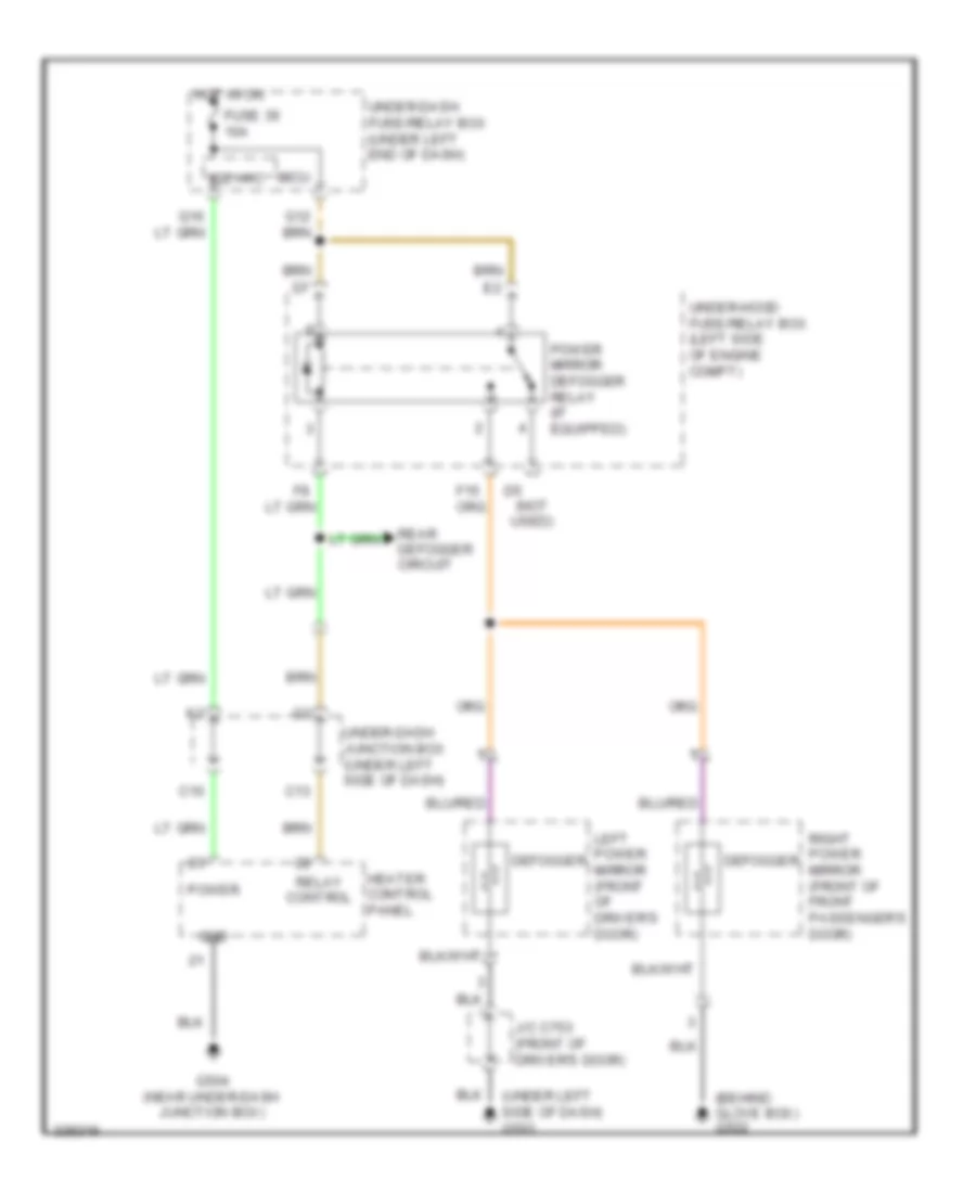
Heated Mirrors Wiring Diagram, Sedan Except Hybrid for Honda Civic EX 2011
List of elements for Heated Mirrors Wiring Diagram, Sedan Except Hybrid for Honda Civic EX 2011:
- (behind glove box) g502
- (not used)
- (under left side of dash) g503
- C10
- C13
- Defogger
- F15
- Fuse 36 10a
- G504 (near under-dash junction box)
- Gnd
- Heater control panel
- Hot in on
- Ig2 hac
- J/c c753 (front of driver's door)
- Left power mirror (front of driver's door)
- Micu
- Power
- Power mirror defogger relay (if equipped)
- Rear defogger circuit
- Relay control
- Right power mirror (front of front passenger's door)
- Under-dash fuse/relay box (under left end of dash)
- Under-dash junction box (under left side of dash)
- Under-hood fuse/relay box (left side of engine compt)
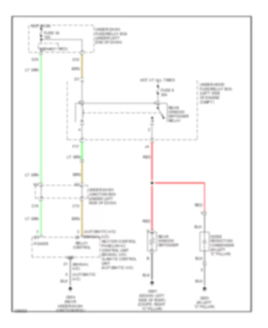
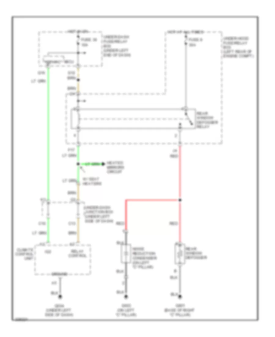
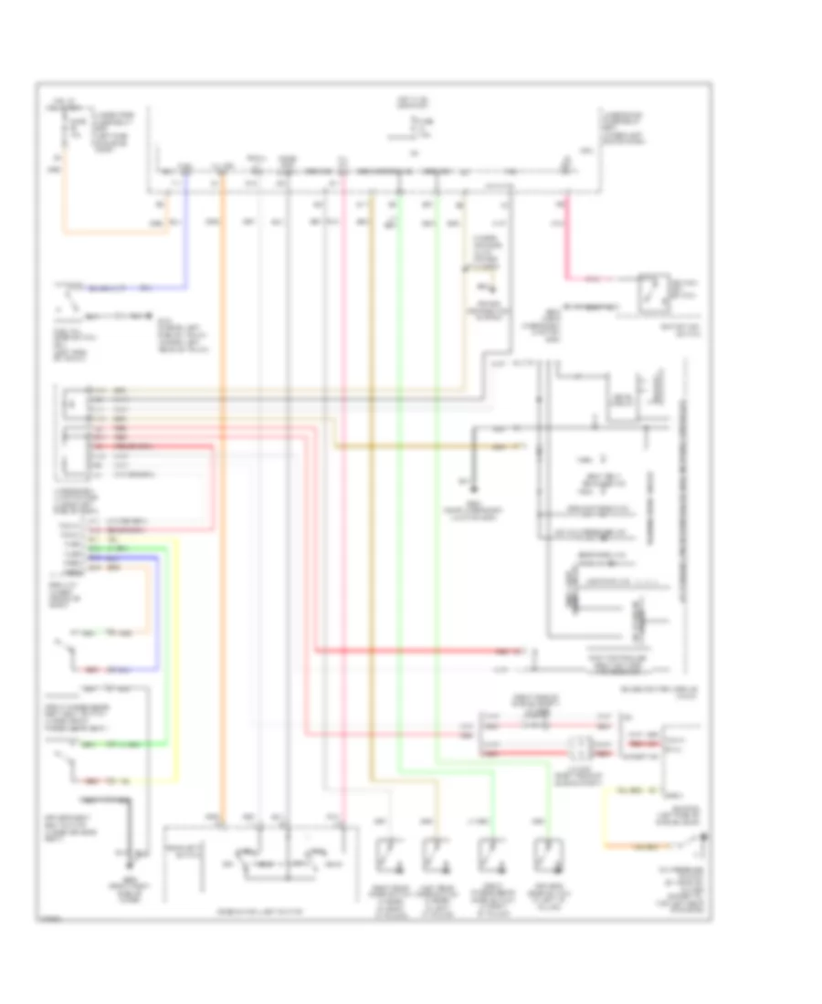
Rear Defogger Wiring Diagram, Except Hybrid Except Power Mirror Defogger for Honda Civic EX 2011
List of elements for Rear Defogger Wiring Diagram, Except Hybrid Except Power Mirror Defogger for Honda Civic EX 2011:
- (automatic a/c)
- (manual a/c)
- C10
- C13
- F17
- Fuse 36 10a
- Fuse 8 30a
- G12
- G504 (near under-dash junction box)
- G603 (in left "c" pillar)
- G801 (sedan: left side of roof) (coupe: right "c" pillar)
- Gnd
- Heater control panel/hvac control unit (manual a/c) climate control unit (automatic a/c)
- Hot at all times
- Hot in on
- Ig2 hac
- Micu
- Noise reduction condenser (in left "c" pillar)
- Power
- Q16
- Rear window defogger
- Rear window defogger relay
- Red
- Relay control
- Under-dash fuse/relay box (under left end of dash)
- Under-dash junction box (under left side of dash)
- Under-hood fuse/relay box (left side of engine compt)
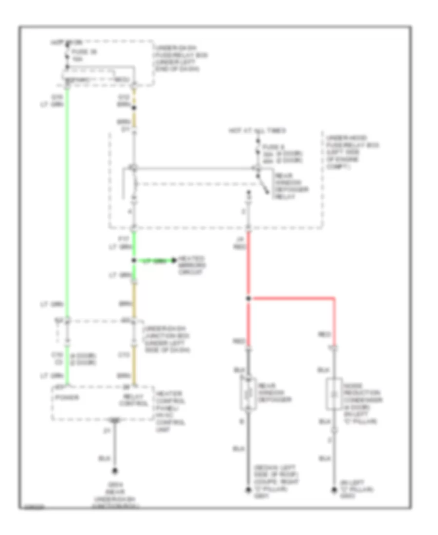
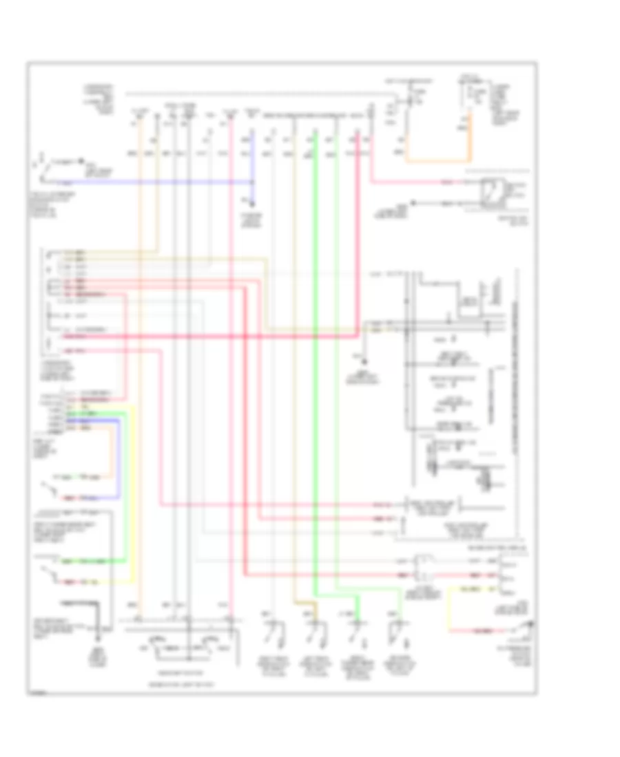
Rear Defogger Wiring Diagram, Except Hybrid for Honda Civic EX 2011
List of elements for Rear Defogger Wiring Diagram, Except Hybrid for Honda Civic EX 2011:
- (4 door) (2 door)
- (in left "c" pillar) g603
- (sedan: left side of roof) (coupe: right "c" pillar) g801
- C10 (4 door) (2 door)
- C13
- F17
- Fuse 36 10a
- Fuse 8 30a 40a
- G504 (near under-dash junction box)
- Gnd
- Heated mirrors circuit
- Heater control panel/ hvac control unit
- Hot at all times
- Hot in on
- Ig2 hac
- Micu
- Noise reduction condenser (4 door) (in left "c" pillar)
- Power
- Rear window defogger
- Rear window defogger relay
- Red
- Relay control
- Under-dash fuse/relay box (under left end of dash)
- Under-dash junction box (under left side of dash)
- Under-hood fuse/relay box (left side of engine compt)
Rear Defogger Wiring Diagram, Hybrid for Honda Civic EX 2011
List of elements for Rear Defogger Wiring Diagram, Hybrid for Honda Civic EX 2011:
- 10a
- 30a
- C10
- C13
- Climate control unit
- F17
- Fuse 36
- Fuse 8
- G12
- G504 (under left side of dash)
- G603 (on left "c" pillar)
- G801 (base of right "c" pillar)
- Ground
- Heated mirrors circuit
- Hot at all times
- Hot in on
- Ig2
- Ig2 hac
- Micu
- Noise reduction condenser (on left "c" pillar)
- Q16
- Rear window defogger
- Rear window defogger relay
- Red
- Relay control
- Under-dash fuse/relay box (under left end of dash)
- Under-dash junction box (under left side of dash)
- Under-hood fuse/relay box (left rear of engine compt)
- W/ seat heaters
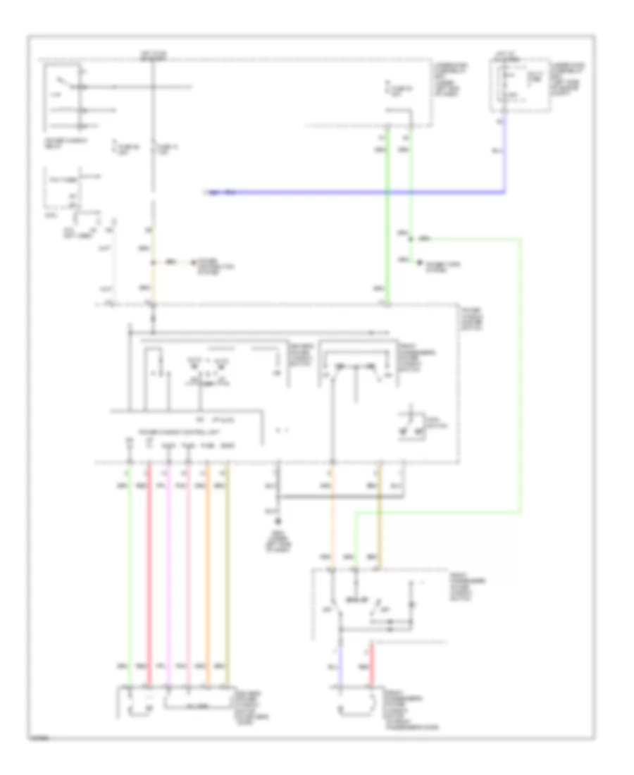
ELECTRONIC POWER STEERING
Electronic Power Steering Wiring Diagram, Except Hybrid for Honda Civic EX 2011
List of elements for Electronic Power Steering Wiring Diagram, Except Hybrid for Honda Civic EX 2011:
- 2 door: driver's auto power window
- 5v stabilize circuit controller area network
- 70a
- A28
- A36
- A37
- Can-h
- Can-l
- Canh
- Canl
- Computer data lines system
- D10
- D11
- D12
- D13
- D14
- D15
- D16
- D17
- D18
- D19
- D20
- D21
- D22
- D23
- D24
- D25
- D26
- D27
- D28
- Ecm (left side of engine compt)
- Eps control unit (behind right kick panel)
- Eps gear box (under rear of engine)
- Eps indicator
- Eps motor
- Eps motor angle sensor (under rear of engine)
- Eps torque sensor (under left side of engine compt)
- F16
- Fuse 10 7.5a
- Fuse 4 7.5a
- G402 (behind glove box)
- G403 (2 door: behind right kick panel) (4 door: behind glove box)
- G504 (near under-dash junction box)
- Gauge control module (tach)
- Gnd
- H-u
- H-v
- H-w
- Hot at all times
- Hot in on or start
- Ig1
- J14
- K-line
- K14
- Micu
- Multi-fuse 1
- Nep
- Pnk
- Pvf
- Red
- Scs
- Under- dash junction box (under left side of dash)
- Under-dash fuse/relay box (under left end of dash)
- Under-hood fuse/relay box (left side of engine compt)
- Vs1
- Vs2
- Warning drive circuit
Electronic Power Steering Wiring Diagram, Hybrid for Honda Civic EX 2011
List of elements for Electronic Power Steering Wiring Diagram, Hybrid for Honda Civic EX 2011:
- 5v stabilize circuit controller area network
- 70a
- A28
- Can-h
- Can-l
- Computer data lines system
- D10
- D11
- D12
- D13
- D14
- D15
- D16
- D17
- D18
- D19
- D20
- D21
- D22
- D23
- D24
- D25
- D26
- D27
- D28
- Eps control unit (under right end of dash)
- Eps gear box (right side of engine compt)
- Eps indicator
- Eps motor
- Eps torque sensor (right side of engine compt)
- F16
- Fuse 10 7.5a
- Fuse 4 7.5a
- G402 (behind right end of dash)
- G403 (behind right end of dash)
- G504 (under left side of dash)
- Gauge control module (tach)
- Gnd
- H-u
- H-v
- H-w
- Hot at all times
- Hot in on or start
- Ig1
- J14
- K-line
- K14
- Micu
- Motor angle sensor (right side of engine compt)
- Multi-fuse 1
- Nep
- Pcm (left side of engine comp)
- Pnk
- Pvf
- Red
- Scs
- Under-dash fuse/relay box (under left end of dash)
- Under-dash junction box (under left side of dash)
- Under-hood fuse/relay box (left rear of engine compt)
- Vs1
- Vs2
- Warning drive circuit
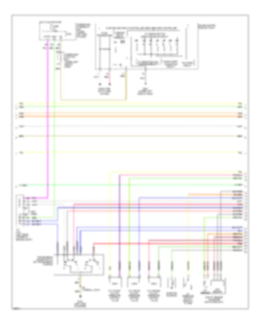
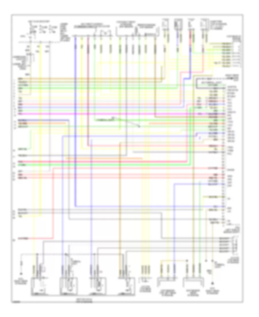
ENGINE PERFORMANCE
1.3L HYBRID
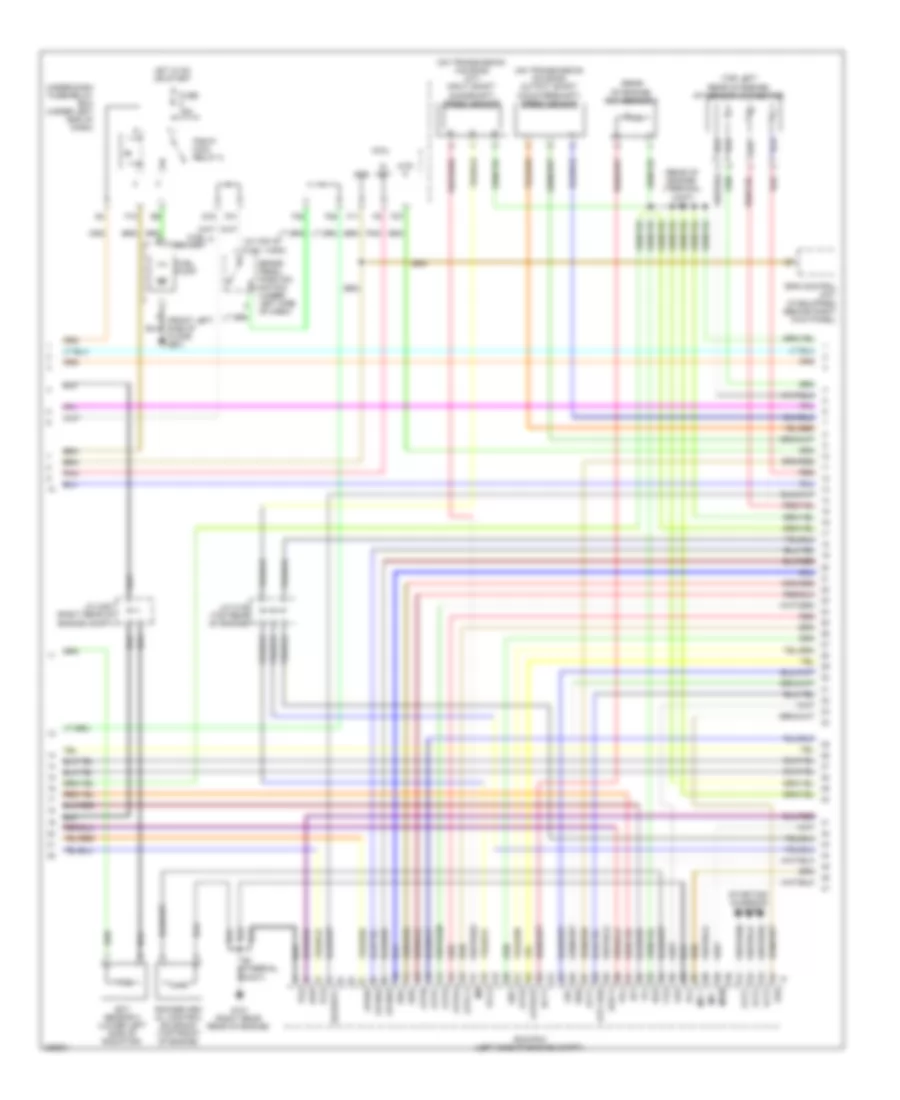
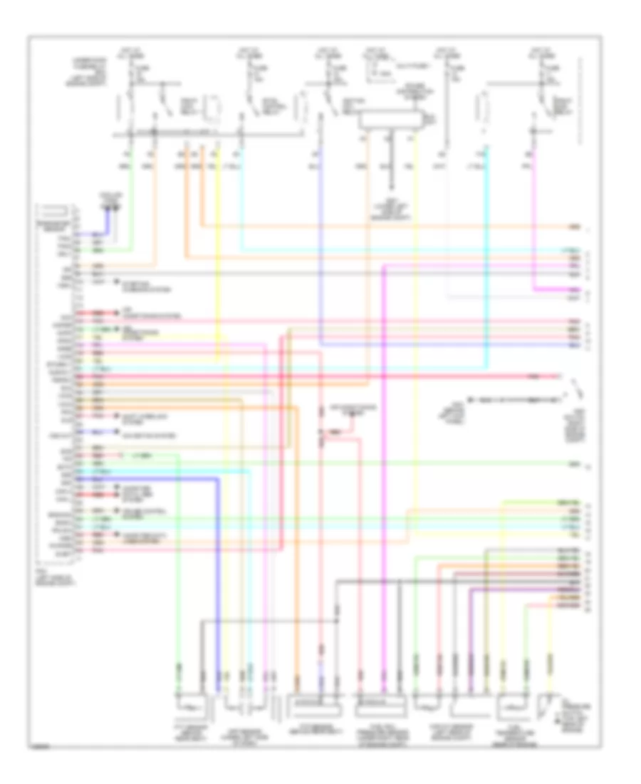
1.3L Hybrid, Engine Controls Wiring Diagram (1 of 5) for Honda Civic EX 2011
List of elements for 1.3L Hybrid, Engine Controls Wiring Diagram (1 of 5) for Honda Civic EX 2011:
- (lower front of engine compt) ect sensor 2
- (right side of engine compt) a/c pressure sensor
- (under left rear of vehicle) evap canister vent shut valve
- 100a
- Acc
- Acpd
- Air conditioning & cooling fans systems
- Air conditioning system
- Anti-theft system
- App sensor (under left side of dash)
- Apsa
- Apsb
- B15
- Barometer sensor
- Bksw
- Bkswnc
- Can-h
- Can-l
- Computer data lines system
- Cooling fans system
- Ect2
- Eld
- Eld unit
- Eps control unit (under right end of dash)
- Etcsrly
- F16
- F19
- Fanh
- Fanl
- Ftp
- Ftp sensor
- Fuse 15a
- G301 (lower left side of engine compt)
- Hot at all times
- Igp1
- Igp2
- Imacanh
- Imacanl
- Imoflr
- J/c c101 (left rear corner of engine compt)
- Mrly
- Multi- fuse 1
- Navigation system
- Nep
- Pcm (left side of engine compt)
- Pgm-fi sub- relay
- Pnk
- Power distribution system
- Red
- S-net
- Scs
- Sg3
- Sg4
- Sg5
- Shift interlock system
- Sls
- Starting/charging system
- Starting/charging system cruise control system
- Stc
- Sts
- Sub rly
- Under- hood fuse/ relay box (left rear of engine compt)
- Vcc4
- Vcc5
- Vcc6
- Vssout
- Vsv
- Wen
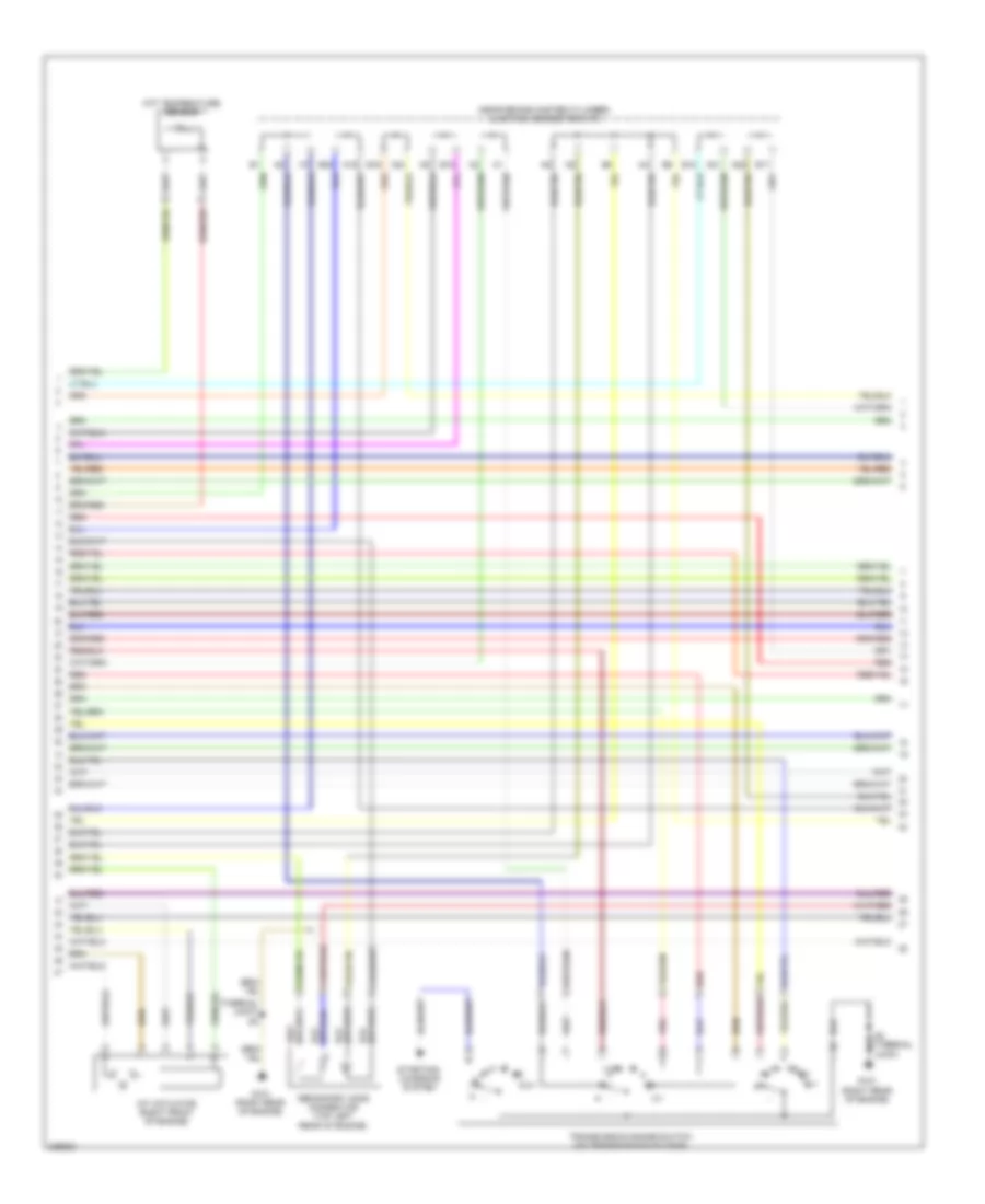
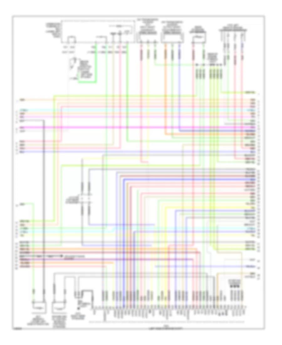
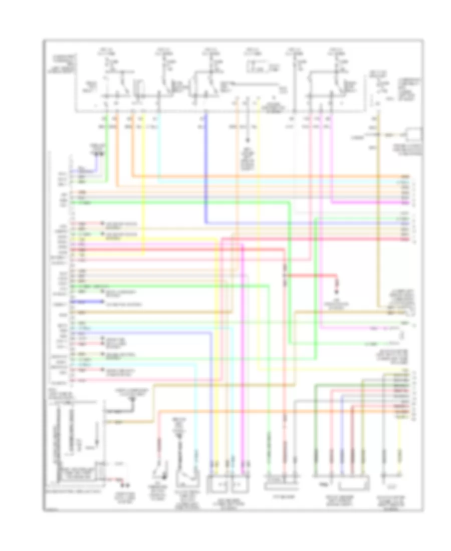
1.3L Hybrid, Engine Controls Wiring Diagram (2 of 5) for Honda Civic EX 2011
List of elements for 1.3L Hybrid, Engine Controls Wiring Diagram (2 of 5) for Honda Civic EX 2011:
- (not used)
- 5v stabilize circuit/controller area network controller
- A/t gear position dimming circuit
- A/t gear position indicator drive circuit
- At-p
- Atp-r
- Compulsory turninf-off circuit
- Computer data lines system
- Cvt drive pulley pressure control valve
- Cvt driven pulley pressure control valve
- Cvt start clutch pressure control valve
- F-can transceiver
- F27
- Fail-safe circuit
- Fuse 7.5a
- G102 (left side of engine)
- G504 (under left side of dash)
- Gauge control module (tach)
- Hot in on or start
- Iat sensor
- Ig1
- Ind mil
- Inhibitor solenoid
- J/c c101 (left rear corner of engine compt)
- J14
- K14
- Maf sensor
- Maf/iat sensor (on engine air intake duct)
- Micu
- Oil pressure switch (near oil filter)
- Pnk
- Red
- S2 (thermal joint)
- Transmission range switch (on transmission housing)
- Under-dash fuse/relay box (under left end of dash)
- Under-dash junction box (under left side of dash)
- Warning drive circuit
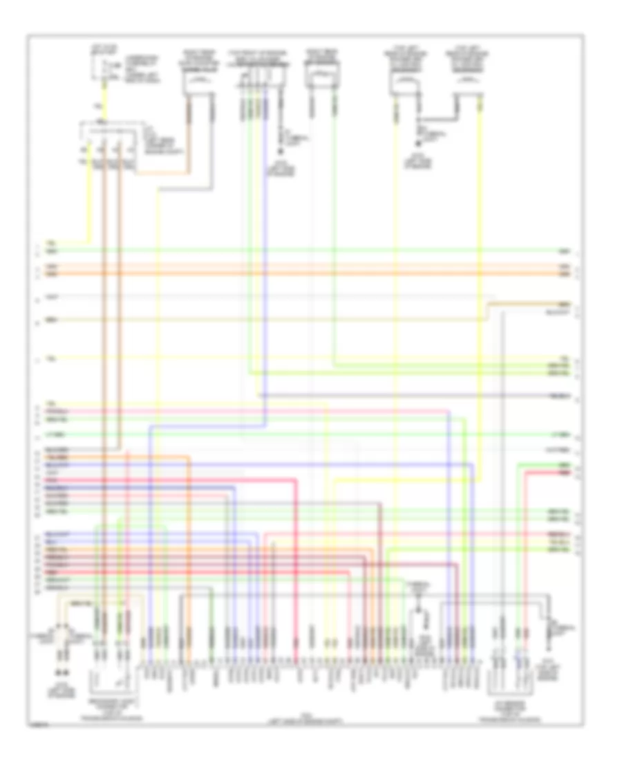
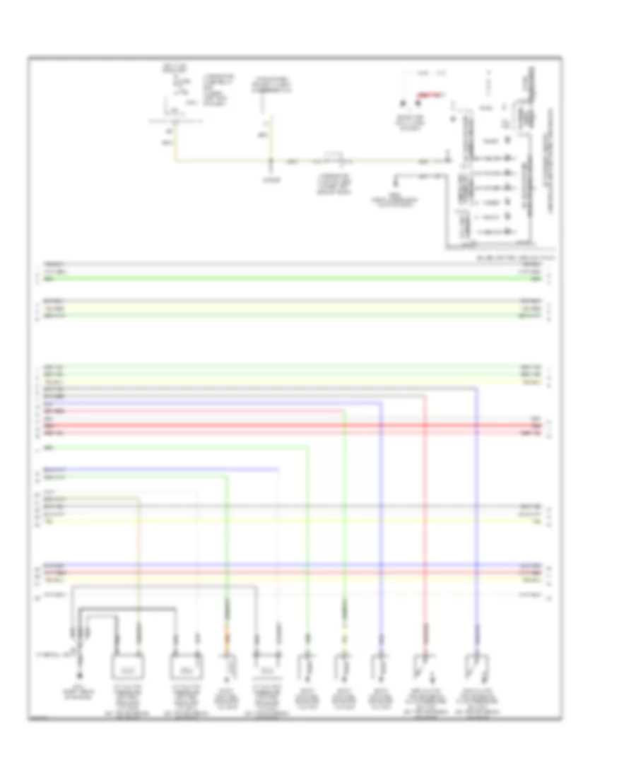
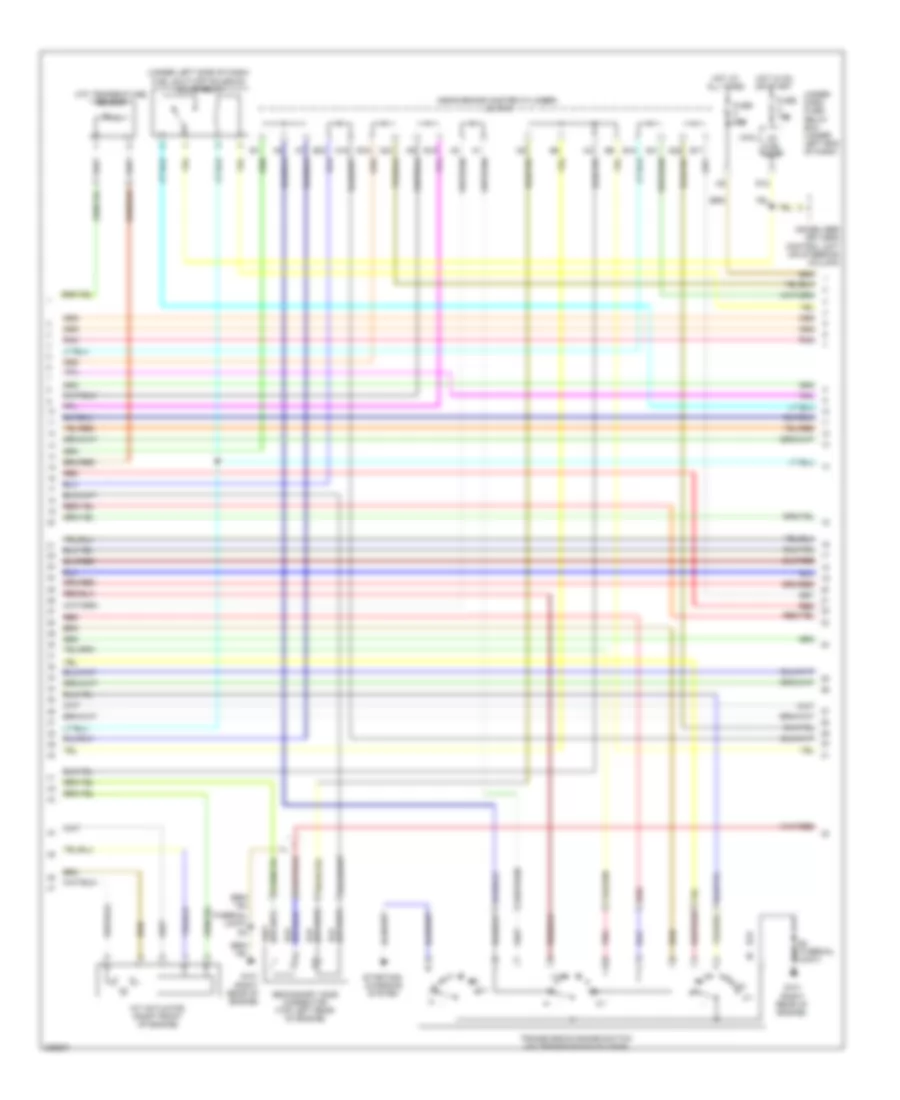
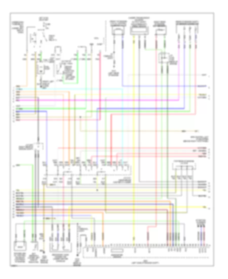
1.3L Hybrid, Engine Controls Wiring Diagram (3 of 5) for Honda Civic EX 2011
List of elements for 1.3L Hybrid, Engine Controls Wiring Diagram (3 of 5) for Honda Civic EX 2011:
- (right rear of engine) ect sensor 1
- (right rear of engine) evap canister purge valve
- (thermal joint) s1
- (top front of engine) egr valve & egr valve position sensor
- (top left rear of engine) rocker arm oil control solenoid 1
- (top left rear of engine) rocker arm oil control solenoid 2
- A/f sensor connector (top of transmission housing)
- Atp fwd
- Atpd
- Atpl
- Atpn
- Atpp
- Atpr
- Atps
- Cvt pg1
- Cvt pg2
- Dnls (+)
- Dnls (-)
- Drls (+)
- Drls (-)
- Ect1
- Egr p
- Erg
- Fuse 10a
- G101 (top left side of engine)
- G102 (left side of engine)
- Hot in on or start
- Iat
- Inhsol
- J/c c101 (left rear corner of engine compt)
- Ndr
- Opsw
- Pcm (left side of engine compt)
- Pcs
- Pg1
- Pg2
- Pnk
- Red
- S1 (thermal joint)
- S2 (thermal joint)
- S4 (thermal joint)
- S6 (thermal joint
- Scls (+)
- Scls (-)
- Secondary ho2s connector (top of transmission housing)
- Sg2
- So2shtc
- Under-dash fuse/relay box (under left end of dash)
- Vcc2
- Vg (+)
- Vg (-)
- Vts1
- Vts2
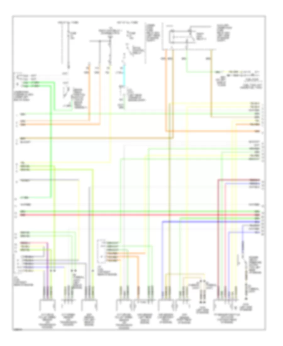
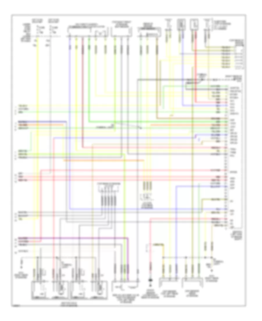
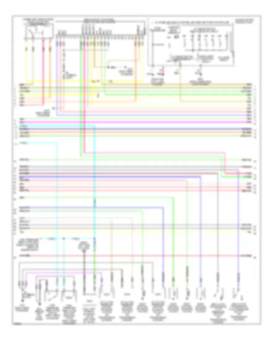
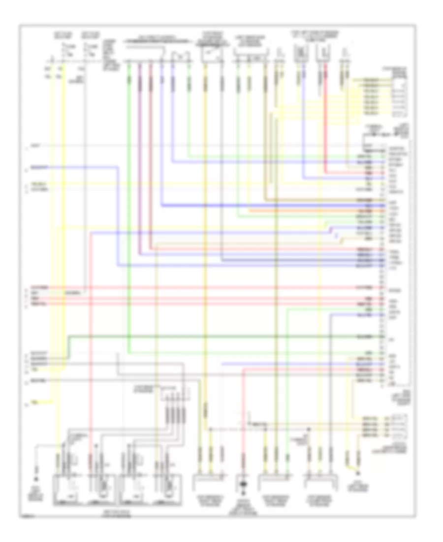
1.3L Hybrid, Engine Controls Wiring Diagram (4 of 5) for Honda Civic EX 2011
List of elements for 1.3L Hybrid, Engine Controls Wiring Diagram (4 of 5) for Honda Civic EX 2011:
- A21
- Auxiliary under-hood fuse/ relay box (left side of engine compt)
- B18
- Brake pedal position switch (top of brake pedal assembly)
- Ckp sensor (lower right front of engine)
- Cmp sensor (right rear of engine)
- Cvt drive pulley speed sensor (on transmission housing)
- Cvt driven pulley speed sensor (on transmission housing)
- Cvt speed sensor (on transmission housing)
- Eop sensor (top left rear of engine)
- Etcs control relay
- F10
- F25
- F30
- F31
- Fuel pump
- Fuel tank unit (inside fuel tank)
- Fuse 15a
- G102 (left side of engine)
- G16
- G601 (on left side of floor)
- Hot at all times
- J/c c101 (left rear corner of engine compt)
- J/c c105 (top right rear of engine)
- Map sensor (left rear side of engine)
- Pgm-fi main relay 2
- Red
- Rocker arm oil pressure switch (top left rear of engine)
- S3 (thermal joint)
- S4 (thermal joint)
- S5 (thermal joint) (left side of engine)
- To pgm-fi main relay 1 (diagram 5 of 5)
- Tp sensor/throttle actuator (top right rear of engine)
- Under- hood fuse/ relay box (left rear of engine compt)
- Under-dash fuse/relay box (under left end of dash)
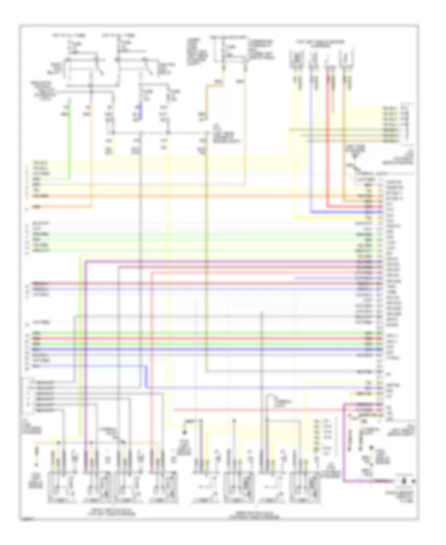
1.3L Hybrid, Engine Controls Wiring Diagram (5 of 5) for Honda Civic EX 2011
List of elements for 1.3L Hybrid, Engine Controls Wiring Diagram (5 of 5) for Honda Civic EX 2011:
- (left side of engine) g102
- (thermal joint) s2
- (top left side of engine) injectors
- A16
- A18
- A22
- A23
- Afs (+)
- Afs (-)
- Afshtc
- B16
- B17
- B21
- B23
- Ckp
- Cmp
- E10
- Etcsm (+)
- Etcsm (-)
- F24
- From etcs control relay a (diagram 4 of 5)
- Front ignition coils (top left side of engine)
- Fuse 15a
- Fuse 20a
- G102 (left side of engine)
- G11
- Hot at all times
- Hot in on or start
- Icm
- Ig1
- Ig1etcs
- Ignition coil relay
- Igpls1
- Igpls1e
- Igpls2e
- Igpls2i
- Igpls31
- Igpls3e
- Igpls4e
- Igpls4i
- Igrtne
- Igrtni
- Inj1
- Inj2
- Inj3
- Inj4
- J/c c101 (left rear corner of engine compt)
- J/c c105 (top right rear of engine)
- J/c c106 (top rear of engine)
- Knock sensor (near oil filter)
- Lg1
- Lg2
- Map
- Ndn
- Pcm (left side of engine compt)
- Pgm-fi main relay 1
- Pgmetcs
- Poilcs
- Rear ignition coils (top right side of engine)
- Red
- S1 (thermal joint)
- S2 (thermal joint)
- Sg1
- Sg3
- Sho2s
- Tpsa
- Tpsb
- Under- hood fuse/ relay box (left rear of engine compt)
- Under-dash fuse/relay box (under left end of dash)
- Vcc1
- Vcc3
- Vel
- Vtpsw
1.3L Hybrid, IMA Wiring Diagram (1 of 3) for Honda Civic EX 2011
List of elements for 1.3L Hybrid, IMA Wiring Diagram (1 of 3) for Honda Civic EX 2011:
- (+)
- (-)
- (behind ipu lid) j/c c902
- (left side of engine) g102
- 100a
- A10
- A11
- A12
- A13
- A14
- A15
- A16
- A17
- A18
- A19
- A20
- A21
- A22
- A23
- A24
- A25
- A26
- A27
- A28
- A29
- A30
- A31
- A32
- A33
- A34
- A35
- A36
- A37
- A38
- A39
- A40
- B10
- B11
- B12
- B13
- B14
- Batteries 1-12
- Batteries 13-22
- Battery current sensor
- Battery module
- Battery module fuse
- Battery module switch
- Battery module temperature sensors
- Bcm module (behind ipu lid)
- Bypass contractor
- Bypass resistor
- Can h
- Can-l
- Cnt
- Cntpg
- Computer data lines system
- Dlc (under left side of dash)
- E16
- Fanctl
- G902 (behind right side of rear seat back)
- High voltage connector
- Ig1
- Iga2
- Ighld
- Ighld2
- Imacanh
- Imacanl
- Ipu module fan (behind ipu lid)
- Isoc +
- Isoc -
- J/c c902 (behind ipu lid)
- Junction board
- Lg2
- Nca
- Nfan
- Pg2
- Pnk
- Pre
- Red
- Scibd
- Scidb
- Scs
- Sg1soc
- Sgtb
- Tbatt1
- Tbatt2
- Tbatt3
- Under-dash junction box (under left side of dash)
- Vbu
- Vcc1soc
- Vhb0
- Vhb1
- Vhb10
- Vhb11
- Vhb12
- Vhb2
- Vhb3
- Vhb4
- Vhb5
- Vhb6
- Vhb7
- Vhb8
- Vhb9
- Wen
1.3L Hybrid, IMA Wiring Diagram (2 of 3) for Honda Civic EX 2011
List of elements for 1.3L Hybrid, IMA Wiring Diagram (2 of 3) for Honda Civic EX 2011:
- 10a
- 10v stabilizer circuit
- 5v stabilize circuit/controller area network controller
- 7.5a
- Auto idle stop ind (auto stop)
- Auxiliary under- hood fuse/ relay box (left side of engine compt)
- Battery
- Charge/assist gauge
- Charging system indicator
- Cruise control dimming circuit
- Driver
- E18
- E28
- Fuse 10a
- Fuse 61
- Fuse 62
- Fuse 7.5a
- G1 (left front corner of engine compt)
- G504 (under left side of dash)
- Gauge control module (tach)
- Hot at all times
- Hot in on or start
- Ig1
- Ima battery level gauge
- Ima indicator
- J/c c903 (behind ipu lid)
- J14
- K14
- Mcm relay 1 (behind ipu lid)
- Mcm relay 2 (behind ipu lid)
- Micu
- Nca
- Pnk
- Power distribution system
- Red
- Under- hood fuse/ relay box (left rear of engine compt)
- Under-dash fuse/relay box (under left end of dash)
- Under-dash junction box (under left side of dash)
- Vbu
- Warning drive circuit
1.3L Hybrid, IMA Wiring Diagram (3 of 3) for Honda Civic EX 2011
List of elements for 1.3L Hybrid, IMA Wiring Diagram (3 of 3) for Honda Civic EX 2011:
- (behind ipu lid) a/c compressor driver
- (behind ipu lid) dc-dc converter
- (left side of engine) g102
- 100a
- 12 volt
- A/c compressor (front of engine compt)
- A/c compressor motor
- A/c compressor power cable connector (middle rear of engine compt)
- Braided wire
- Can h
- Can l
- Computer data lines system
- Fuse 10a
- Fuse 7.5a
- G102 (left side of engine)
- G901 (behind right side of rear seat back)
- G902 (behind right side of rear seat back)
- G903 (under mcm)
- G904 (behind ipu lid)
- G904 (behind left ipu lid)
- Gnd
- Hi volt (+)
- Hi volt (-)
- Hot at all times
- Hot in on or start
- Ig1
- Iga2
- Ignition
- Ima can l
- Ima canh
- Ima f-can h
- Ima f-can l
- Ima motor
- J/c c902 (behind ipu lid)
- Lg2
- Mcm (behind ipu lid)
- Motor rotor position sensor
- Multi- fuse
- Nca
- Red
- Scidb
- Starter motor
- U phase
- U phase motor current sensor
- Under- hood fuse/ relay box (left rear of engine compt)
- Under-dash fuse/relay box (under left end of dash)
- V phase
- V phase motor current sensor
- Vbu
- W phase
- W phase motor current sensor
- Wen
1.8L
1.8L, Engine Controls Wiring Diagram, Except GX (1 of 5) for Honda Civic EX 2011
List of elements for 1.8L, Engine Controls Wiring Diagram, Except GX (1 of 5) for Honda Civic EX 2011:
- (behind left kick panel) g401
- 100a
- Acc
- Acpd
- Air conditioning system
- App sensor (under left side of dash)
- Apsa
- Apsb
- Barometer sensor
- Bksw
- Bkswnc
- Can h
- Can l
- Clutch pedal position switch (under left side of dash)
- Computer data lines system
- Cooling fans system
- Crmtcls
- Cruise control system
- Ecm/pcm (left side of engine compt)
- Ect2
- Eld
- Eld unit
- Etcs control relay
- Etcsrly
- Evap canister purge valve (right rear of engine)
- Evap canister vent shut valve (under left side of floor)
- F16
- F19
- Fanh
- Fanl
- Ftp
- Ftp sensor (under left side of floor)
- Fuse 15a
- G301 (lower left side of engine compt)
- G401 (behind left kick panel)
- Hot at all times
- Ignition coil relay
- Igp
- Imoflr
- M/t
- Maf/iat sensor (left rear of engine compt)
- Mrly
- Multi-fuse 1
- Navigation system
- Oil pressure switch (top left rear of engine)
- Pgm-fi main relay 1
- Pgm-fi sub- relay
- Pnk
- Power distribution system
- Psp switch (except eps) (right side of engine compt)
- Pspsw
- Red
- S-net5v
- Scs
- Sg4
- Sg5
- Sg6
- Shift interlock system
- Sls
- Sub rly
- Under-hood fuse/relay box (left side of engine compt)
- Vcc4
- Vcc5
- Vcc6
- Vssout
- Vsv
- Wen
1.8L, Engine Controls Wiring Diagram, Except GX (2 of 5) for Honda Civic EX 2011
List of elements for 1.8L, Engine Controls Wiring Diagram, Except GX (2 of 5) for Honda Civic EX 2011:
- (front left side of floor) g601
- (in top of fuel tank)
- (on transmission housing) (a/t) input shaft (mainshaft) speed sensor
- (on transmission housing) output shaft (countershaft) speed sensor
- (rear of engine) (terminal joint) s4
- (rear of engine) ect sensor 1
- (top left rear of engine) a/f sensor connector
- Altc
- Altf
- Altl
- Atft
- Atp fwd
- Atp- p
- Atp2-1
- Atpd
- Atpd3
- Atpn
- Atpp
- Atpr
- Atprvs
- Brake pedal position switch (under left side of dash)
- Ecm/pcm (left side of engine compt)
- Ect sensor 2 (lower left side of radiator)
- Ect1
- Egr
- Egr p
- Eps control unit (if equipped) (behind right kick panel)
- F10
- F11
- F25
- F27
- F30
- F31
- Fuel pump
- Fuel tank unit
- Fuse 15a
- G101 (right rear rear of engine)
- G16
- Hot in on or start
- Iat
- Imt +
- Imt -
- Imtm
- J/c c105 (top rear of engine)
- J/c c207 (right rear of engine compt)
- Lsa
- Lsb
- Lsc
- Micu
- Op2sw
- Op3sw
- Opsw
- Pcs
- Pg1
- Pg2
- Pgm-fi main relay 2
- Pnk
- Red
- Rocker arm oil control solenoid (top front of engine)
- S- net
- Scs
- Sg2
- Sha
- Shb
- Shc
- Shd
- So2shtc
- Starting/ charging system
- Under-dash fuse/relay box (under left end of dash)
- Vcc2
- Vg+
- Vg-
- Vts
1.8L, Engine Controls Wiring Diagram, Except GX (3 of 5) for Honda Civic EX 2011
List of elements for 1.8L, Engine Controls Wiring Diagram, Except GX (3 of 5) for Honda Civic EX 2011:
- (near brake master cylinder) junction connector c101
- (thermal joint) s3
- 2-1
- A16
- A21
- A22
- A23
- Atf temperature sensor
- B15
- B16
- B17
- B18
- B23
- G101 (right rear of engine)
- Imt actuator (right front of engine)
- Pnk
- Red
- Secondary ho2s connector (top left rear of engine)
- Starting/ charging system
- Transmission range switch (on transmission housing)
1.8L, Engine Controls Wiring Diagram, Except GX (4 of 5) for Honda Civic EX 2011
List of elements for 1.8L, Engine Controls Wiring Diagram, Except GX (4 of 5) for Honda Civic EX 2011:
- (if equipped) power window master switch
- 2 door
- 2nd clutch transmission fluid pressure switch (on transmission housing)
- 3rd clutch transmission fluid pressure switch (on transmission housing)
- 5v stabilize circuit/ controller area network controller
- A/t clutch pressure control solenoid valve a (on transmission housing)
- A/t clutch pressure control solenoid valve b (on transmission housing)
- A/t clutch pressure control solenoid valve c (on transmission housing)
- A/t gear position dimming circuit
- Circuit drive
- Compulsory turninf-off circuit
- Computer data lines system
- Fail-safe circuit
- Fuse 7.5a
- G101 (right rear of engine)
- G504 (near under-dash junction box)
- Gauge control module (tach)
- Hot in on or start
- Ig1
- Indicator drive circuit a/t gear position
- J14
- K14
- Micu
- Mil ind
- Red
- S2 (thermal joint)
- Shift control solenoid valve a
- Shift control solenoid valve b
- Shift control solenoid valve c
- Shift control solenoid valve d
- Transceiver f-can
- Under-dash fuse/relay box (under left end of dash)
- Under-dash junction box (under left side of dash)
- Warning
1.8L, Engine Controls Wiring Diagram, Except GX (5 of 5) for Honda Civic EX 2011
List of elements for 1.8L, Engine Controls Wiring Diagram, Except GX (5 of 5) for Honda Civic EX 2011:
- (on throttle body) tp sensor/throttle actuator
- (rear of engine) map sensor
- (right rear of engine) g101
- (thermal joint) s2
- (top rear of engine) j/c c105
- (top right front of engine) eop sensor
- Afs+
- Afs-
- Afshtc
- Ckp
- Ckp sensor (top left rear of engine)
- Cmp
- Cmp sensor (rear of engine)
- Ecm/pcm (left side of engine compt)
- Egr valve & egr valve position sensor (top left rear of engine)
- Etcsm+
- Etcsm-
- F24
- Fuse 10a
- Fuse 15a
- G101 (right rear of engine)
- Hot in on or start
- Icm
- Ig1
- Ig1etcs
- Ignition coils (top of engine)
- Igpls1
- Igpls2
- Igpls3
- Igpls4
- Inj1
- Inj2
- Inj3
- Inj4
- Injectors (top of engine, at 1, 2, 3 & 4 cylinders)
- J/c c105 (top rear of engine)
- Knock sensor (lower right rear of engine)
- Lg1
- Lg2
- Map
- Pgm etcs
- Poil
- Red
- S1 (thermal joint)
- S5 (thermal joint)
- Sg1
- Sg3
- Sho2s
- Tpsa
- Tpsb
- Under- dash fuse/ relay box (under left end of dash)
- Vcc1
- Vcc3
1.8L, Engine Controls Wiring Diagram, GX (1 of 5) for Honda Civic EX 2011
List of elements for 1.8L, Engine Controls Wiring Diagram, GX (1 of 5) for Honda Civic EX 2011:
- 100a
- Acc
- Acpd
- Air conditioning system
- App sensor (under left side of dash)
- Apsa
- Apsb
- Barometer sensor
- Bksw
- Bkswnc
- Can h
- Can l
- Computer data lines system
- Cooling fans system
- Cruise control system
- Ect2
- Eld
- Eld unit
- Etcs control relay
- Etcsrly
- F16
- Fanh
- Fanl
- Ftp sensor (behind rear seat)
- Ftt sensor (behind rear seat)
- Fuel rail pressure sensor (under right rear of engine compt)
- Fuel temperature sensor (rear of engine)
- Fuse 15a
- G301 (lower left side of engine compt)
- G401 (behind left kick panel)
- Hot at all times
- Ignition coil relay
- Igp
- Imofsr
- Injmode
- Maf/iat sensor (left rear of engine compt)
- Mrly
- Multi-fuse 1
- Navigation system
- Oil pressure switch (top left rear of engine)
- Pcm (left side of engine compt)
- Pf2 sw
- Pfo
- Pgm-fi main relay 1
- Pgm-fi sub- relay
- Pnk
- Power distribution system
- Psp switch (right side of engine compt)
- Pspsw
- Red
- S-net
- Scs
- Sg4
- Sg5
- Sg6
- Shift interlock system
- Sls
- Starting/ charging system
- Sub rly
- Tf0
- Under-hood fuse/relay box (left side of engine compt)
- Vcc4
- Vcc5
- Vcc6
- Vss out
- Vssv
- Wen
1.8L, Engine Controls Wiring Diagram, GX (2 of 5) for Honda Civic EX 2011
List of elements for 1.8L, Engine Controls Wiring Diagram, GX (2 of 5) for Honda Civic EX 2011:
- (on transmission housing) (a/t) input shaft (mainshaft) speed sensor
- (on transmission housing) output shaft (countershaft) speed sensor
- (rear of engine) (thermal joint) s4
- (rear of engine) ect sensor 1
- (top left rear of engine) a/f sensor connector
- Air conditioning system
- Altc
- Altf
- Altl
- Atft
- Atp- p
- Atp2-1
- Atpd
- Atpd3
- Atpfwd
- Atpn
- Atpp
- Atpr
- Atprvs
- Brake pedal position switch (under left side of dash)
- Ect sensor 2 (lower left side of radiator)
- Ect1
- F11
- F25
- F27
- F30
- F31
- G101 (right rear of engine)
- G16
- Iat
- Imt +
- Imt -
- Imtm
- J/c c105 (top rear of engine)
- Lsa
- Lsb
- Lsc
- Micu
- Op2sw
- Op3sw
- Opsw
- Pcm (left side of engine compt)
- Pg1
- Pg2
- Pnk
- Red
- Rocker arm oil control solenoid (top front of engine)
- S- net
- Scs
- Sg2
- Sha
- Shb
- Shc
- Shd
- So2shtc
- Starting/ charging system
- Tf2
- Under-dash fuse/relay box (under left end of dash)
- Vcc2
- Vg+
- Vg-
- Vts
1.8L, Engine Controls Wiring Diagram, GX (3 of 5) for Honda Civic EX 2011
List of elements for 1.8L, Engine Controls Wiring Diagram, GX (3 of 5) for Honda Civic EX 2011:
- (near brake master cylinder) j/c c101
- (thermal joint) s3
- (under left side of dash) fuel shut-off solenoid valve relay
- 2-1
- A16
- A21
- A22
- A23
- Atf temperature sensor
- B15
- B16
- B17
- B18
- B23
- Fuse 15a
- G101 (right rear of engine)
- Hot at all times
- Hot in on or start
- Ig1 fuel pump
- Immobilizer keyless control unit (on steering column)
- Imt actuator (right front of engine)
- Micu
- Pnk
- R12
- Red
- S2 (thermal joint)
- Secondary ho2s connector (top left rear of engine)
- Starting/ charging system
- Transmission range switch (on transmission housing)
- Under- dash fuse/ relay box (under left end of dash)
1.8L, Engine Controls Wiring Diagram, GX (4 of 5) for Honda Civic EX 2011
List of elements for 1.8L, Engine Controls Wiring Diagram, GX (4 of 5) for Honda Civic EX 2011:
- (behind right kick panel) injector control module
- (front left side of floor) g601
- (on transmission housing)
- (under left side of dash) injector control module relay
- 2nd clutch transmission fluid pressure switch (on transmission housing)
- 3rd clutch transmission fluid pressure switch (on transmission housing)
- 5v stabilize circuit/controller area network controller
- A/t clutch pressure control solenoid valve a
- A/t clutch pressure control solenoid valve b
- A/t clutch pressure control solenoid valve c (on transmission housing)
- A/t gear position dimming circuit
- A/t gear position indicator drive circuit
- Compulsory turninf-off circuit
- Computer data lines system
- F-can transceiver
- Fail-safe circuit
- Fuel pressure regulator leak check connector (front of engine compt)
- Fuel pressure regulator shut-off solenoid valve (right rear of engine)
- Fuel pressure regulator switch (right rear of engine)
- Fuel tank internal solenoid valve (left side of trunk)
- G101 (right rear of engine)
- G401 (behind left kick panel)
- G504 (near under-dash junction box)
- Gauge control module (tach)
- Inj1
- Inj2
- Inj3
- Inj4
- Injcntl1
- Injcntl2
- Injcntl3
- Injcntl4
- Injigp
- Injmode
- Lg1
- Lg2
- Mil ind
- Pg1
- Pg3
- Pnk
- Red
- S2 (thermal joint)
- Shift control solenoid valve a
- Shift control solenoid valve b
- Shift control solenoid valve c
- Shift control solenoid valve d
- Warning drive circuit
1.8L, Engine Controls Wiring Diagram, GX (5 of 5) for Honda Civic EX 2011
List of elements for 1.8L, Engine Controls Wiring Diagram, GX (5 of 5) for Honda Civic EX 2011:
- (on throttle body) tp sensor/throttle actuator
- (rear of engine) map sensor
- (right rear of engine) g101
- (thermal joint)
- (top rear of engine) j/c c105
- (top right front of engine) eop sensor
- Afs+
- Afs-
- Afshtc
- Ckp
- Ckp sensor (top left rear of engine)
- Cmp
- Cmp sensor (rear of engine)
- Etcsm+
- Etcsm-
- F24
- Fuse 10a
- Fuse 15a
- Fuse 7.5a
- G101 (right rear of engine)
- Hot in on or start
- Icm
- Ig1
- Ig1etcs
- Ignition coils (top of engine)
- Igpls1
- Igpls2
- Igpls3
- Igpls4
- Inj1
- Inj2
- Inj3
- Inj4
- Injectors (top of engine, at 1, 2, 3 & 4 cylinders)
- J/c c105 (top rear of engine)
- K14
- Lg1
- Lg2
- Map
- Micu
- Pcm (left side of engine compt)
- Pf2
- Pgm etcs
- Pnk
- Poil
- Red
- S1 (thermal joint)
- S3 (thermal joint)
- S5 (thermal joint)
- Sg1
- Sg3
- Sho2s
- Tpsa
- Tpsb
- Under- dash fuse/ relay box (under left end of dash)
- Under-dash junction box (under left j14 side of dash)
- Vcc1
- Vcc3
2.0L
2.0L, Engine Controls Wiring Diagram (1 of 3) for Honda Civic EX 2011
List of elements for 2.0L, Engine Controls Wiring Diagram (1 of 3) for Honda Civic EX 2011:
- (behind left kick panel) g401
- (near under-dash junction box) g504
- (under left side of dash) under-dash junction box
- 100a
- 2 door
- Acc
- Acpd
- Air conditioning system
- App sensor (under left side of dash)
- Aps2
- Apsa
- Bksw
- Bkswnc
- Can h
- Can l
- Clutch pedal position switch (under left side of dash)
- Computer data lines system
- Controller area network controller 5v stabilize circuit/
- Cooling fans system
- Crmtcls
- Cruise control system
- Ecm (left side of engine compt)
- Ect2
- Eld
- Eld unit
- Etcs control relay
- Etcsrly
- Evap canister purge valve (right rear of engine)
- Evap canister vent shut valve (under left side of floor)
- F16
- F19
- Fanh
- Fanl
- Fast controller area network transceiver
- Ftp
- Ftp sensor
- Fuse 15a
- Fuse 7.5a
- G301 (lower left side of engine compt)
- Gauge control module (tach)
- Hot at all times
- Hot in on or start
- Ig1
- Ignition coil relay
- Igp
- Imofpr
- J14
- K14
- Maf/iat sensor (left side of engine compt)
- Micu
- Mil ind
- Mrly
- Multi- fuse 1
- Navigation system
- Oil pressure switch (near oil filter)
- Pgm-fi main relay 1
- Pgm-fi sub- relay
- Pnk
- Power distribution system
- Power window master switch (if equipped)
- Red
- Rvslck
- S-net5v
- Scs
- Sg4
- Sg5
- Sg6
- Shift interlock system
- Sub rly
- Under-dash fuse/relay box (under left end of dash)
- Under-hood fuse/relay box (left side of engine compt)
- Vcc4
- Vcc5
- Vcc6
- Vssout
- Vsv
- Warning drive circuit
- Wen
2.0L, Engine Controls Wiring Diagram (2 of 3) for Honda Civic EX 2011
List of elements for 2.0L, Engine Controls Wiring Diagram (2 of 3) for Honda Civic EX 2011:
- (front of engine) vtc oil control solenoid valve
- (in top of fuel tank)
- (rear of engine compt) a/f sensor connector
- (right rear of engine) ect sensor 1
- (top rear of engine) j/c c105
- (under transmission housing) output shaft (countershaft) speed sensor
- A14
- A15
- A16
- A17
- A18
- A19
- A21
- A22
- A23
- Altc
- Altf
- Altl
- B10
- B14
- B15
- B16
- B17
- B18
- B20
- B21
- B22
- B23
- Barometer sensor
- Brake pedal position switch (under left side of dash)
- Ecm (left side of engine compt)
- Ect sensor 2 (lower left side of radiator)
- Ect1
- Eps control unit (if equipped) (behind right kick panel)
- F10
- F11
- F25
- F30
- F31
- Floor) g601
- Fuel pump
- Fuse 15a
- G101 (left rear of engine)
- G16
- Hot in on or start
- Iat
- J/c c101 (near brake master cylinder)
- J/c c105 (top rear of engine)
- J/c c207 (right rear of engine compt)
- Micu
- Opsw
- Pcs
- Pg1
- Pg2
- Pgm-fi main relay 2
- Pnk
- Red
- Rocker arm oil control solenoid (top front of engine)
- S-net
- S1 (terminal joint)
- Scs
- Secondary ho2s connector (under center console)
- Sg2
- So2shtc
- Starting/ charging system
- Under-dash fuse/relay box (under left end of dash)
- Vcc2
- Vg+
- Vg-
- Vts
2.0L, Engine Controls Wiring Diagram (3 of 3) for Honda Civic EX 2011
List of elements for 2.0L, Engine Controls Wiring Diagram (3 of 3) for Honda Civic EX 2011:
- (left rear of engine) g101
- (left rear side of engine) map sensor
- (on throttle body) tp sensor/throttle actuator
- (thermal joint) s1
- (top front of engine) rocker arm oil pressure switch
- (top left side of engine, at 1, 2, 3 & 4 cylinders) injectors
- (top rear of engine)
- (top rear of engine) j/c c105
- Afs+
- Afs-
- Afshtc
- Ckp
- Ckp sensor (lower front of engine)
- Cmp a
- Cmp b
- Cmp sensor a (right rear of engine)
- Cmp sensor b (right rear of engine)
- E27
- Ecm (left side of engine compt)
- Etcsm+
- Etcsm-
- F24
- Fuse 10a
- Fuse 15a
- G101 (left rear of engine)
- Hot in on or start
- Icm
- Ig1
- Ig1etcs
- Ignition coils (top of engine)
- Igpls1
- Igpls2
- Igpls3
- Igpls4
- Inj1
- Inj2
- Inj3
- Inj4
- J/c c101 (near brake master cylinder)
- J/c c105
- Knock sensor (left front side of engine)
- Lg1
- Lg2
- Map
- Pgm etcs
- Red
- S2 (thermal joint)
- Sg1
- Sg3
- Sho2s
- Tpsa
- Tpsb
- Under- dash fuse/ relay box (under left end of dash)
- Vcc1
- Vcc3
- Vtc
- Vtpsw
EXTERIOR LIGHTS
Backup Lamps Wiring Diagram, A/T for Honda Civic EX 2011
List of elements for Backup Lamps Wiring Diagram, A/T for Honda Civic EX 2011:
- (2-door &
- (2-door & except hybrid)
- (except 2-door)
- (except hybrid) (hybrid)
- (not used)
- 2-1
- A/t reverse relay
- A1 a2
- A6 (option connector) (hybrid) (used for automatic dimming inside mirror) (except hybrid)
- E15
- Except hybrid
- Except hybrid)
- Fuse 10 7.5a
- G101 (si: left rear of engine) (except si: right rear of engine)
- G102 (hybrid: left side of engine)
- G701 (2-door except hybrid: left side of trunk) (4-door except hybrid & hybrid: left rear of trunk)
- Hot in on or start
- Hybrid
- J/c c101 (hybrid: left rear corner of engine compt) (except hybrid: near brake master cylinder)
- Left backup light
- Micu
- Navigation system
- Right backup light
- S2 (thermal joint)
- Trans- mission range switch (on trans- mission housing)
- Under-dash fuse/relay box (under left end of dash)
Backup Lamps Wiring Diagram, M/T for Honda Civic EX 2011
List of elements for Backup Lamps Wiring Diagram, M/T for Honda Civic EX 2011:
- (2-door)
- (except 2-door)
- (except 2-door) (2-door)
- (used for automatic dimming inside mirror)
- Back lt-
- Backup light switch (on transaxle housing)
- E15
- Fuse 10 7.5a
- G701 (2-door: left side of trunk) (4-door: left rear of trunk)
- Hot in on or start
- J/c c101 (near brake master cylinder)
- Left backup light
- Micu
- Navigation system
- Right backup light
- Under-dash fuse/relay box (under left end of dash)
Exterior Lamps Wiring Diagram, Except Hybrid (1 of 2) for Honda Civic EX 2011
List of elements for Exterior Lamps Wiring Diagram, Except Hybrid (1 of 2) for Honda Civic EX 2011:
- (2-door)
- (except 2-door)
- (not used)
- Brake pedal position switch (under left side of dash)
- Combi gnd
- Combination light switch
- E19
- E33
- E34
- E39
- E40
- Except gx
- F20
- F30
- F31
- Fuse 10a
- Fuse 15a
- Fuse 7.5a
- G16
- G201 (behind right side of front bumper)
- G301 (lower left side of engine compt)
- G401 (behind left kick panel)
- G501 (under gauge assembly)
- G504 (near under-dash junction box)
- G601 (front left side of floor)
- G602 (front right side of floor)
- G701 (2-door: left side of trunk) (4-door: left rear of trunk)
- Gauge control module (speedo)
- H/l off sw
- H/l on sw
- Haz sw
- Head
- Headlight switch
- Hot at all times
- Left
- Left front side marker/ parking/ turn signal light
- Left rear turn signal light
- Left turn signal indicator
- Micu
- Off
- P-gnd
- Park
- Pnk
- Q11
- Red
- Relay 2 (sounder) turn signal/hazard
- Right
- Right front side marker/ parking/ turn signal light
- Right rear turn signal light
- Right turn signal indicator
- S-gnd
- S-gnd2
- S11
- S13
- S18
- S19
- Small lt sw
- T34
- Taillight relay
- Turn l sw
- Turn r sw
- Turn signal switch
- Turn signal/ hazard flasher circuit
- Under-dash fuse/relay box (under left end of dash)
- Under-hood fuse/relay box (left side of engine compt)
- Vbu
Exterior Lamps Wiring Diagram, Except Hybrid (2 of 2) for Honda Civic EX 2011
List of elements for Exterior Lamps Wiring Diagram, Except Hybrid (2 of 2) for Honda Civic EX 2011:
- (2-door)
- (except 2-door)
- 4-door: high mount brake light (trunk spoiler)
- Except 4-door
- G701 (2-dr: left side of trunk) 4-dr: left rear of trunk)
- Hazard warning switch
- High mount brake light (2-door: high mount brake light (trunk spoiler))
- High mount brake light (high mount brake light (led) & 4-door: high mount brake light (trunk spoiler))
- High mount brake light (if equipped)
- Interior light system
- Left brake light/ taillight
- Left inner taillight (4 door)
- Left license plate light
- Left rear side marker light
- Red
- Red (2-door) (except 2-door)
- Right brake light/ taillight
- Right inner taillight (4 door)
- Right license plate light
- Right rear side marker light
Exterior Lamps Wiring Diagram, Hybrid (1 of 2) for Honda Civic EX 2011
List of elements for Exterior Lamps Wiring Diagram, Hybrid (1 of 2) for Honda Civic EX 2011:
- (not used)
- Brake pedal position switch (top of brake pedal assembly)
- Combi gnd
- Combination light switch
- E19
- E33
- E34
- E39
- E40
- F20
- F30
- F31
- Fuse 10a
- Fuse 15a
- Fuse 7.5a
- G16
- G201 (behind right side of front bumper)
- G301 (lower left side of engine compt)
- G401 (behind left kick panel)
- G501 (under gauge assembly)
- G504 (under left side of dash)
- G601 (on left side of floor)
- G602 (right side of floor)
- G701 (left rear of trunk)
- Gauge control module (speedo)
- H/l off sw
- H/l on sw
- Haz sw
- Head
- Headlight switch
- Hot at all times
- Left
- Left front side marker/ parking/ turn signal light
- Left rear turn signal light
- Left turn signal indicator
- Micu
- Off
- P-gnd
- Park
- Pnk
- Q11
- Red
- Relay 2 (sounder) turn signal/hazard
- Right
- Right front side marker/ parking/ turn signal light
- Right rear turn signal light
- Right turn signal indicator
- S-gnd
- S-gnd2
- S11
- S13
- S18
- S19
- Small lt sw
- T34
- Taillight relay
- Turn l sw
- Turn r sw
- Turn signal switch
- Turn signal/ hazard flasher circuit
- Under-dash fuse/relay box (under left end of dash)
- Under-hood fuse/relay box (left rear of engine compt)
- Vbu
Exterior Lamps Wiring Diagram, Hybrid (2 of 2) for Honda Civic EX 2011
List of elements for Exterior Lamps Wiring Diagram, Hybrid (2 of 2) for Honda Civic EX 2011:
- G502 (behind right end of dash)
- G503 (under left side of dash)
- G701 (left rear of trunk)
- Hazard warning switch
- High mount brake light
- Interior light system
- Junction connector c753 (front of driver's door)
- Left brake light/ taillight
- Left inner taillight
- Left license plate light
- Left power mirror
- Left rear side marker light
- Left side turn signal light
- Pnk
- Red
- Right brake light/ taillight
- Right inner taillight
- Right license plate light
- Right power mirror
- Right rear side marker light
- Right side turn signal light
- W/ seat heaters
- W/o seat heaters
GROUND DISTRIBUTION
Ground Distribution Wiring Diagram, Except Hybrid (1 of 4) for Honda Civic EX 2011
List of elements for Ground Distribution Wiring Diagram, Except Hybrid (1 of 4) for Honda Civic EX 2011:
- (a/t) a/t clutch pressure control solenoid valve a
- (a/t) a/t clutch pressure control solenoid valve b
- (a/t) a/t clutch pressure control solenoid valve c
- (a/t) transmission range switch
- (except gx) egr valve & egr valve position sensor
- (except gx) knock sensor shield
- (gx) injector control module
- (not used)
- (w/ vsa)
- (w/o vsa)
- A17
- Abs modulator- control unit
- B22
- B36
- Battery
- Braided wire
- C40
- C44
- Ckp sensor
- Cmp sensor
- Cmp sensor a
- Cmp sensor b
- Data link connector
- Ecm
- Ecm/pcm
- Eps control unit
- Eps torque sensor
- F10
- G1 (left side of engine compt)
- G101 (except si) (right rear of engine)
- G101 (si) (left rear of engine)
- G11
- G2 (at top right front of engine)
- G202 (behind right side of front bumper)
- G3 (left side of engine compt)
- G402 (behind glove box)
- G403 (4door: behind glove box, 2door: behind right kick panel)
- Ignition coil 1
- Ignition coil 2
- Ignition coil 3
- Ignition coil 4
- Immobilizer- keyless control unit
- J/c c101 (near brake master cylinder)
- Knock sensor shield
- Lg1
- Lg2
- Pg1
- Pg2
- Pgme- tcs
- Right side engine mount
- Rocker arm oil control solenoid
- Rocker arm oil pressure switch
- S1 (thermal joint) (rear of engine)
- S2 (thermal joint) (rear of engine)
- S3 (thermal joint) (rear of engine)
- Secondary ho2s shield
- Transmission housing
- Under-dash junction box (under left side of dash)
- Vsa modulator- control unit
- Vtc oil control solenoid valve
Ground Distribution Wiring Diagram, Except Hybrid (2 of 4) for Honda Civic EX 2011
List of elements for Ground Distribution Wiring Diagram, Except Hybrid (2 of 4) for Honda Civic EX 2011:
- (2-door: canada) washer fluid level switch
- (2-door: console accessory power socket) console accessory power socket
- (2-door: except eps) psp switch
- (2-door: power door locks & security: except canada) front passenger's door lock actuator/ knob switch
- (2-door: power door locks) driver's door lock actuator/ knob switch
- (2-door: power door locks) front passenger's power window switch
- (2-door: power mirror defoggers) left power mirror
- (2-door: power mirrors) power mirror switch
- (4-door: canada) washer fluid level switch
- (4-door: except si)
- (4-door: except si, gx) brake fluid level switch
- (4-door: power door locks) driver's door lock actuator/knob switch
- (except
- (gx) fuel pressure regulator shut-off solenoid valve
- (gx) fuel pressure regulator switch
- (if equipped)
- (if equipped) console accessory power socket relay
- (if equipped) moonroof control unit
- (if equipped) navigation unit
- (if equipped) security hood switch
- (if equipped) vsa off switch
- (left side of engine compt) under-hood fuse/relay box
- (m/t) clutch interlock switch
- (m/t: cruise
- (si)
- (si, gx)
- (under left end of dash) under-dash fuse/ relay box
- (under left end of dash) under-dash fuse/relay box
- (w/ power mirror defogger) right power mirror
- 2-door
- 2-door) (2-
- 4-door
- 4-door: power mirrors
- A/c condenser fan motor
- B17
- Blower motor relay
- Blower power transistor
- Brake fluid level switch
- Control) clutch pedal position switch
- Dash lights brightness controller & odometer select/reset switch
- Data link connector
- Door)
- E33
- Eld unit (if equipped)
- F20
- Fan control relay
- Front accessory power socket
- G201 (behind right side of front bumper)
- G301 (lower left side of engine compartment)
- G401 (behind left kick panel)
- G501 (under gauge assembly)
- G502 (behind glove box)
- G503 (under left side of dash)
- G506 (under middle of dash)
- Gauge control module (tach)
- High beam
- J/c c753 (front of driver's door)
- Left fog light
- Left front side marker/ parking/turn signal light
- Left headlight
- Left power mirror
- Low beam
- Mes connector
- Micu
- P-gnd
- Power mirror switch
- Power window master switch
- Psp switch
- Right fog light
- Right front side marker/ parking/turn signal lights
- Right headlight
- S-gnd2
- Srs unit
- T34
- To g601 (diagram 3 of 4)
- W/ power mirror defoggers
- W/o power mirror defoggers
- Windshield washer motor
- Windshield wiper motor
Ground Distribution Wiring Diagram, Except Hybrid (3 of 4) for Honda Civic EX 2011
List of elements for Ground Distribution Wiring Diagram, Except Hybrid (3 of 4) for Honda Civic EX 2011:
- (2- door) srs shield
- (2-door)
- (2-door: high mount brakelight trunk spoiler) high mount brake light
- (4-door console accessory power socket) console accessory power socket
- (4-door seat heaters) driver's seat heater switch
- (4-door seat heaters) front passenger's seat heater switch
- (4-door)
- (4-door: si) audio shields
- (4-door: si) stereo amplifier
- (a/t) park pin switch/ a/t gear position indicator panel light
- (except
- (except 2-door)
- (except gx) fuel tank unit
- (gx) fuel filler door switch
- (gx) fuel tank internal solenoid valve
- (seat heaters) driver's seat cushion heater
- (seat heaters) driver's seat heater relay (high)
- (seat heaters) front passenger's seat cushion heater
- (seat heaters) front passenger's seat heater relay (high)
- (security: except remote trunk release) trunk key cylinder switch
- (trunk spoiler)
- (w/ side air bag side curtain air bag) srs shields
- 2-door)
- 4-door: high mount brake light
- A20
- Driver's seat heater relay (low)
- Driver's seat heater relay box
- Except 4-door
- Except remote trunk release
- Except security
- From under-dash fuse/relay box (diagram 2 of 4)
- Front passenger's seat heater relay (low)
- Front passenger's seat heater relay box
- G601 (front left side of floor)
- G701 (2-door: left side of trunk 4-door: left rear of trunk)
- High mount brake light
- High mount brake light & 4-door:
- High mount brake light (trunk spoiler)
- Left backup light
- Left brake light/ taillight
- Left inner taillight
- Left license plate light
- Left rear side marker light
- Left rear turn signal light
- Park pin switch
- Remote trunk release
- Right backup light
- Right brake light/ taillight
- Right inner taillight
- Right license plate light
- Right rear side marker light
- Right rear turn signal light
- Security
- Trunk latch switch
- Trunk lid opener solenoid/ latch switch
Ground Distribution Wiring Diagram, Except Hybrid (4 of 4) for Honda Civic EX 2011
List of elements for Ground Distribution Wiring Diagram, Except Hybrid (4 of 4) for Honda Civic EX 2011:
- (2-door premium audio) stereo amplifier
- (2-door: moonroof) moonroof control unit
- (4-door power door locks: security)
- (4-door)
- (if equipped) navigation unit
- (if equipped) tpms control unit
- (normal audio: except audio unit w/ factory)
- (not used)
- (security: except canada) front passenger's door lock actuator/ knob switch
- (under left end of dash) under-dash fuse/relay box
- (vsa) yaw-rate lateral acceleration sensor
- (w/ cruise control) steering wheel
- (w/ navigation)
- (w/ navigation) navigation unit (w/o navigation) audio unit
- (w/ side air bag & side curtain air bag) srs shields
- (w/o driver auto power window) power window relay
- (w/o navigation)
- 4-door: power door locks
- A12
- A20
- Automatic a/c
- Cable reel (on steering column)
- Climate control unit
- Cruise control combination switch
- Driver's seat belt buckle switch
- Front passenger's power window switch
- Front passenger's seat belt buckle switch
- G504 (near under-dash junction box)
- G505 (behind glove box)
- G602 (front right side of floor)
- G603 (in left "c" pillar)
- G801 (4-door: left side of roof) (2-door: right "c" pillar)
- G851 (base of right "c" pillar)
- Gauge control module (speedo)
- Gauge control module (tach)
- Heater control panel/ hvac control unit
- Ignition key switch
- Left rear door lock actuator/ knob switch
- Manual a/c
- Micu
- Micu service check connector
- Noise reduction condenser
- Ods unit
- Rear window defogger
- Right rear door lock actuator/ knob switch
- S-gnd
- Srs shield
Ground Distribution Wiring Diagram, Hybrid (1 of 3) for Honda Civic EX 2011
List of elements for Ground Distribution Wiring Diagram, Hybrid (1 of 3) for Honda Civic EX 2011:
- A/c compressor driver
- A17
- A23
- B22
- B36
- B40
- Battery
- Bcm module
- Braided wire
- C40
- C44
- Ckp sensor
- Cmp sensor
- Data link connector
- Dc-dc converter
- Dc-dc converter terminal(-)
- Egr valve & egr valve position sensor
- Engine
- Eps control unit
- Eps torque sensor
- F10
- Front ignition coil 1
- Front ignition coil 2
- Front ignition coil 3
- Front ignition coil 4
- G1 (left front corner of engine compt)
- G101 (top left side of engine)
- G102 (left side of engine)
- G11
- G2 (right side of engine compt)
- G202 (behind right side of front bumper)
- G3 (left side of engine compt, near battery)
- G402 (behind right end of dash)
- G403 (behind right end of dash)
- G901 (behind right side of rear seat back)
- G902 (behind right side of rear seat back)
- G903 (under mcm)
- G904 (behind ipu lid)
- Ima system shield
- Immobilizer- keyless control unit
- Ipu module fan
- J/c c101 (left rear corner of engine compt)
- J/c c105 (top right rear of engine)
- J/c c902 (behind ipu lid)
- Knock sensor shield
- Mcm
- Pcm
- Power unit
- Rear ignition coil 1
- Rear ignition coil 2
- Rear ignition coil 3
- Rear ignition coil 4
- Rocker arm oil control solenoid 1
- Rocker arm oil control solenoid 2
- Rocker arm oil pressure switch
- S1 (thermal joint) (top of engine)
- S2 (thermal joint) (top of engine)
- S3 (thermal joint) (left side of engine)
- S4 (thermal joint) (left side of engine)
- S6 (thermal joint) (left rear corner of engine compt)
- Secondary ho2s shield
- Servo unit
- Transmission
- Transmission range switch
- Under-dash junction box (under left side of dash)
- Vsa modulator- control unit
Ground Distribution Wiring Diagram, Hybrid (2 of 3) for Honda Civic EX 2011
List of elements for Ground Distribution Wiring Diagram, Hybrid (2 of 3) for Honda Civic EX 2011:
- (canada) washer fluid level switch
- (left rear of engine compt) under-hood fuse/relay box
- (under left end of dash) under-dash fuse/ relay box
- (under left end of dash) under-dash fuse/relay box
- (w/ navigation)
- (w/ navigation) handsfreelink control unit
- (w/ navigation) navigation unit (w/o navigation) audio unit
- (w/ seat heaters)
- (w/o navigation)
- (w/o navigation) console accessory power socket relay
- (w/o seat heaters)
- A/c condenser fan motor
- A12
- Auxiliary electric water pump
- Blower motor relay
- Blower power transistor
- Brake fluid level switch
- Connector
- Dash lights brightness controller
- Data link connector
- Driver's door lock actuator/knob switch
- E33
- Eld unit
- F20
- Fan control relay
- Front accessory power socket
- Front accessory power socket relay
- G201 (behind right side of front bumper)
- G301 (lower left side of engine compt)
- G401 (behind left kick panel)
- G501 (under gauge assembly)
- G502 (behind right end of dash)
- G503 (under left side of dash)
- G505 (behind glove box)
- G506 (under middle of dash)
- Gauge control module (tach)
- High beam
- J/c c753 (front of driver's door)
- Left front side marker/ parking/turn signal light
- Left headlight
- Left power mirror
- Low beam
- Mes
- Micu
- P-gnd
- Power mirror switch
- Power window master switch
- Right front side marker/ parking/turn signal light
- Right headlight
- Right power mirror
- S-gnd2
- Security hood switch
- Srs unit
- T34
- To g601 (diagram 3 0f 3)
- Vsa off switch
- W/ seat heaters
- Windshield washer motor
- Windshield wiper motor
Ground Distribution Wiring Diagram, Hybrid (3 of 3) for Honda Civic EX 2011
List of elements for Ground Distribution Wiring Diagram, Hybrid (3 of 3) for Honda Civic EX 2011:
- (if
- (if equipped) driver's seat heater switch
- (if equipped) front passenger's seat heater switch
- (if equipped) navigation unit
- (seat
- (under left end of dash) under-dash fuse/relay box
- (usa) tpms control unit
- (w/o
- A/t gear position indicator panel light/park pin switch
- Cable reel (in steering column)
- Climate control unit
- Cruise control combination switch
- Driver's
- Driver's seat belt buckle switch
- Driver's seat heater relay(high)
- Equipped)
- From under-dash fuse/relay box (diagram 2 of 3)
- Front passenger's door lock actuator/knob switch
- Front passenger's power window switch
- Front passenger's seat belt buckle switch
- Front passenger's seat heater (if equipped)
- Front passenger's seat heater relay(high)
- Front passenger's seat heater relay(low) (if equipped)
- Fuel tank unit
- G504 (under left side of dash)
- G601 (on left side of floor)
- G602 (right side of floor)
- G603 (on left "c" pillar)
- G701 (left rear of trunk)
- G801 (base of right "c" pillar)
- Gauge control module (speedo)
- Gauge control module (tach)
- Heaters)
- High mount brake light
- Ignition key switch
- Left backup light
- Left brake light/ taillight
- Left inner taillight
- Left license plate light
- Left rear door lock actuator/ knob switch
- Left rear side marker light
- Left rear turn signal light
- Micu
- Micu service check connector
- Navigation) console accessory power socket
- Noise reduction condenser
- Ods unit
- Park pin switch
- Rear window defogger
- Right backup light
- Right brake light/ taillight
- Right inner taillight
- Right license plate light
- Right rear door lock actuator/ knob switch
- Right rear side marker light
- Right rear turn signal light
- S-gnd
- Seat heater
- Seat heater relay(low)
- Steering wheel
- Trunk lid opener solenoid/ latch switch
- Yaw rate-lateral acceleration sensor
HEADLIGHTS
Headlights Wiring Diagram, Except Hybrid for Honda Civic EX 2011
List of elements for Headlights Wiring Diagram, Except Hybrid for Honda Civic EX 2011:
- (at base of parking brake lever) parking brake switch
- (behind right side of front bumper)
- (lower
- (or red)
- (or red) pnk
- (under gauge assembly) g501
- (under left side of dash) under-dash junction box
- 10v stabilize circuit
- 2-door: driver's auto power window
- 2-door: except si
- 4 door: except gx, si & si
- 4-door: except gx, si
- 5v stabilize circuit/controller area network controller
- B-can
- Body controller area network transceiver
- Combi gnd
- Combination light switch
- Dim sw
- Dimmer/flash- to-pass switch
- Drl indicator
- E33
- Except si
- F20
- F21
- Fog light ind
- Fog light relay (under left side of dash)
- Fog light switch
- Fog lt sw
- Fr fog rly cl-
- Fuse 10a
- Fuse 20a
- Fuse 7.5a
- G15
- G17
- G20
- G201
- G201 (behind right side of front bumper)
- G301
- G301 (lower left side of engine compt)
- G401 (behind left kick panel)
- G504 (near under-dash junction box)
- G601 (front left side of floor)
- G602 (front right side of floor)
- Gauge control module (tach)
- H/l off sw
- H/l on sw
- Head
- Headlight switch
- High
- High beam control circuit
- High beam dimming circuit
- High beam indicator
- Honda accessory
- Hot at all times
- Hot in on
- Hot in on or start
- Ig1
- Ig2 drl
- Interior lights system
- J11
- J14
- J21
- J22
- K13
- K14
- Left
- Left fog light
- Left headlight
- Lights on ind
- Low
- Low beam headlight relay
- Micu
- Not used
- Off
- P-gnd
- Park
- Passing
- Passing sw
- Pnk
- Power windows system
- Red
- Right fog light
- Right headlight
- S-gnd
- S11
- S12
- S13
- S14
- S16
- Side of engine compt)
- Small light dimming circuit
- Small lt sw
- Under-dash fuse/relay box (under left end of dash)
- Under-hood fuse/relay box (left side of engine compt)
- Vbu
- Warning drive circuit
Headlights Wiring Diagram, Hybrid for Honda Civic EX 2011
List of elements for Headlights Wiring Diagram, Hybrid for Honda Civic EX 2011:
- (under left side of dash) under-dash junction box
- 10v stabilize circuit
- 5v stabilize circuit/controller area network controller
- B-can
- Body controller area network transceiver
- Combi gnd
- Combination light switch
- Dim sw
- Dimmer/flash- to-pass switch
- Drl indicator
- E33
- F20
- F21
- F22
- Fog light ind
- Fog light relay
- Fog light switch
- Fr fog on
- Fr fog rly cl-
- Fuse 10a
- Fuse 20a
- Fuse 7.5a
- G15
- G17
- G20
- G201 (behind right side of front bumper)
- G301 (lower left side of engine compt)
- G401 (behind left kick panel)
- G504 (under left side of dash)
- G601 (on left side of floor)
- G602 (right side of floor)
- Gauge control module (tach)
- H/l off sw
- H/l on sw
- Head
- Headlight switch
- High
- High beam control circuit
- High beam dimming circuit
- High beam indicator
- Hot at all times
- Hot in on
- Hot in on or start
- Ig1
- Ig2 drl
- J11
- J14
- J21
- J22
- K13
- K14
- Left fog light
- Left headlight
- Lights on ind
- Low
- Low beam headlight relay
- Micu
- Off
- P-gnd
- Park
- Parking brake switch (at base of park lever)
- Passing
- Passing sw
- Pnk
- Red
- Right fog light
- Right headlight
- S-gnd
- S11
- S12
- S13
- S14
- S16
- Small light dimming circuit
- Small lt sw
- Under-dash fuse/relay box (under left end of dash)
- Under-hood fuse/relay box (left rear of engine compt)
- Vbu
- Warning drive circuit
HORN
Horn Wiring Diagram, Except Hybrid for Honda Civic EX 2011
List of elements for Horn Wiring Diagram, Except Hybrid for Honda Civic EX 2011:
- (behind right side of front bumper)
- (except gx)
- (gx)
- B10
- Cable reel (b: on steering column) (c: in steering wheel)
- Cruise control combination switch
- Except usa: si
- F23
- F31
- Fuse 12 15a
- G16
- High horn (usa: si)
- Horn
- Horn relay
- Horn switch
- Hot at all times
- Low horn (behind left side of front bumper)
- Micu
- Nca
- Steering wheel
- Under-dash fuse/relay box (under left end of dash)
- Under-dash junction box (under left side of dash)
- Under-hood fuse/relay box (left side of engine compt)
- Usa: si
- W/ cruise control
- W/o cruise control
Horn Wiring Diagram, Hybrid for Honda Civic EX 2011
List of elements for Horn Wiring Diagram, Hybrid for Honda Civic EX 2011:
- (not used)
- B10
- Cable reel (b: in steering column) (c: in steering wheel)
- Cruise control combination switch
- F23
- Fuse 12 15a
- G16
- Horn (behind left side of front bumper)
- Horn relay
- Horn switch
- Hot at all times
- Micu
- Nca
- Steering wheel
- Under- hood fuse/ relay box (left rear of engine compt)
- Under-dash fuse/relay box (under left end of dash)
- Under-dash junction box (under left side of dash)
INSTRUMENT CLUSTER
Instrument Cluster Wiring Diagram, Except Hybrid (1 of 2) for Honda Civic EX 2011
List of elements for Instrument Cluster Wiring Diagram, Except Hybrid (1 of 2) for Honda Civic EX 2011:
- (si)
- 10v stabilize circuit
- 5v control circuit
- 5v stabilize circuit/controller area network controller
- Beeper
- Body controller area network transceiver
- Brightening switch
- Computer data lines system
- Cruise control system
- Dash lights brightness controller & odometer select/ reset switch
- Dial brightness control & dimming circuit
- Dimming circuit
- Dimming switch
- Drive circuit
- Driver
- Engine coolant temp. gauge (lcd)
- Engine coolant temp. gauge brightness control & dimming circuit
- Exterior lights system
- Fast controller area network transceiver
- Fuel gauge (lcd)
- Fuel gauge brightness control & dimming circuit
- G12
- G13
- G501 (under gauge assembly)
- G503 (under left side of dash)
- G504 (near under- dash junction box)
- Gauge control module (speedo)
- Gauge control module (tach)
- High beam dimming circuit
- High beam ind
- Interior lights
- Interior lights system
- J11
- J14
- J16
- J19
- J20
- J21
- J22
- K13
- K14
- Lcd
- Lcd (mid) brightness control & dimming circuit
- Lcd back light
- Lcd driver
- Left turn signal ind
- Low fuel ind
- Mph/ km/h switch
- Multi-informational display (mid) unit
- Pnk
- Pointer brightness control & dimming circuit
- Red
- Rev limit ind
- Right turn signal ind
- Security ind (usa)
- Security indicator blinking circuit
- Select/ reset switch
- Speedo
- Speedometer (lcd)
- Speedometer brightness control & dimming circuit
- System
- Tach
- To cruise control dimming circuit (diagram 2 of 2)
- To pin 17 (diagram 2 of 2)
- To warning drive circuit (diagram 2 of 2)
- Turn signal/ hazard relay 2
- Under-dash junction box (under left side of dash)
- Vsa off switch (if equipped)
- W/ cruise control
- W/ denso type
- W/o denso type
- Warning drive circuit
- Wiper/washer system
Instrument Cluster Wiring Diagram, Except Hybrid (2 of 2) for Honda Civic EX 2011
List of elements for Instrument Cluster Wiring Diagram, Except Hybrid (2 of 2) for Honda Civic EX 2011:
- (si: near oil filter) (except si: top left rear of engine) oil pressure switch
- (speedo)
- (w/ cruise control)
- 2 door: driver's auto power window
- 4door except si & gx
- 5v stabilize circuit/controller
- A/t gear position dimming circuit
- A/t gear position indicator drive circuit
- A36
- A37
- Abs ind
- Area network controller
- B-can
- Brake fluid level switch (on brake master cylinder reservoir)
- Brake system ind
- Can-h
- Can-l
- Charging system ind
- Compulsory turning-off circuit
- Compulsory turning-on circuit
- Computer data lines system
- Cruise control dimming circuit
- Cruise control ind
- Cruise control main switch ind (if equipped)
- Dhswra
- Door open ind
- Driver's door switch (in left "b" pillar)
- Drl ind
- Drswas
- Drswdr
- Drswrd
- E17
- E37
- Ecm/pcm (left side of engine compt)
- Eps ind (if equipped)
- Fail-safe circuit
- Fog light ind
- From 10v stabilize circuit (diagram 1 of 2)
- From pin 18 b (diagram 1 of 2)
- From pin 33 (diagram 1 of 2)
- Front passenger's door switch (in right "b" pillar)
- Fuel gauge sending unit
- Fuel tank unit (except gx) (in top of fuel tank)
- Fuse 10 7.5a
- Fuse 23 10a
- G401 (behind left kick panel)
- Gauge control module (tach)
- Hot at all times
- Hot in on or start
- Ig1
- Immobilizer system ind
- Left rear door switch (4-door) (in left "c" pillar)
- Lights on ind
- Low oil pressure ind
- Low tire pressure ind (if equipped)
- Maintenance required ind
- Micu
- Mil ind
- Opsw
- Outside air temperature sensor (if equipped) (behind left side of front bumper)
- P10
- Parking brake switch (at base of parking brake lever)
- Pnk
- Red
- Right rear door switch (4-door) (in right "c" pillar)
- Seat belt reminder ind
- Side air bag cut-off ind (w/ side air bag & side curtain air bag)
- Small light dimming circuit
- Srs ind
- Tacho- meter
- Tpms ind (if equipped)
- Trunk open ind
- Under-dash fuse/relay box (under left end of dash)
- Under-hood fuse/relay box (left side of engine compt)
- Vbu
- Vsa activation indicator (usa)
- Vsa system indicator (usa)
- Warning drive circuit
- Washer fluid level ind (canada)
Instrument Cluster Wiring Diagram, Hybrid (1 of 2) for Honda Civic EX 2011
List of elements for Instrument Cluster Wiring Diagram, Hybrid (1 of 2) for Honda Civic EX 2011:
- (asst/chrg) lcd brightness control & dimming circuit
- (lcd)
- (odo/trip) lcd brightness control & dimming circuit
- 10v stabilize circuit
- 5v control circuit
- 5v stabilize circuit/controller area network controller
- Beeper
- Body controller network transceiver
- Brightening switch
- Charge/assist gauge
- Computer data lines system
- Cruise control system
- Dash lights brightness controller
- Dial brightness control & dimming circuit
- Dimming switch
- Drive circuit
- Driver
- Engine coolant temp. gauge (lcd)
- Engine coolant temp. gauge brightness control & dimming circuit
- Exterior lights
- Fast controller network transceiver
- Fuel gauge (lcd)
- Fuel gauge brightness control & dimming circuit
- G12
- G501 (under gauge assembly)
- G503 (under left side of dash)
- G504 (under left side of dash)
- Gauge control module (speedo)
- Gauge control module (tach)
- High beam dimming circuit
- High beam ind
- Ima battery level gauge
- Interior lights
- Interior lights system
- J11
- J14
- J19
- J20
- J21
- J22
- K13
- K14
- Lcd
- Lcd back light
- Lcd driver
- Left turn signal ind
- Low fuel ind
- Mph/ km/h switch
- Multi-informational display (mid) unit
- Pnk
- Pointer brightness control & dimming circuit
- Red
- Right turn signal ind
- Security ind
- Security indicator blinking circuit
- Select/ reset switch
- Speedo
- Speedometer
- Speedometer brightness control & dimming circuit
- System
- Tach
- Tachometer
- To cruise control dimming circuit (diagram 2 of 2)
- To pin 17 (diagram 2 of 2)
- To warning drive circuit (diagram 2 of 2)
- Turn signal/ hazard relay 2 (sounder)
- Under-dash junction box (under left side of dash)
- Vsa off switch
- Warning drive circuit
- Wiper/washer system
Instrument Cluster Wiring Diagram, Hybrid (2 of 2) for Honda Civic EX 2011
List of elements for Instrument Cluster Wiring Diagram, Hybrid (2 of 2) for Honda Civic EX 2011:
- (amber)
- (usa)
- 1 of 2)
- 5v stabilize circuit/controller
- A/t gear position dimming circuit
- A/t gear position indicator drive circuit
- A36
- A37 can-h
- Abs ind
- Area network controller
- Auto idle stop ind
- B-can
- B7 can-l
- Brake fluid level switch (on brake master cylinder reservoir)
- Brake system ind
- Charging system ind
- Compulsory turning-off circuit
- Compulsory turning-on circuit
- Computer data lines system
- Cruise control dimming circuit
- Cruise control ind
- Cruise control main switch ind
- Dhswra
- Door open ind
- Driver's door switch (on left "b" pillar)
- Drl ind
- Drswas
- Drswdr
- Drswrd
- E17
- E37
- Eps ind
- Fail-safe circuit
- Fog light ind
- From 10v stabilize circuit (diagram 1 of 2)
- From pin 18 (diagram 1 of 2)
- From pin 33 (diagram
- Front passenger's door switch (on right "b" pillar)
- Fuel gauge sending unit
- Fuel tank unit (inside fuel tank)
- Fuse 10 7.5a
- Fuse 23 10a
- G401 (behind left kick panel)
- Gauge control module (tach)
- Hot at all times
- Hot in on or start
- Ig1
- Ima ind
- Immobilizer system ind
- Left rear door switch (on left "c" pillar)
- Lights on ind
- Low oil pressure ind
- Low tire pressure ind (usa)
- Maintenance required ind
- Micu
- Mil ind
- Oil pressure switch (near oil filter)
- Opsw
- P10
- Parking brake switch (at base of park lever)
- Pcm (left side of engine compt)
- Pnk
- Red
- Right rear door switch (on right "c" pillar)
- Seat belt reminder ind
- Side air bag cut-off ind
- Small light dimming circuit
- Srs ind
- Tpms ind
- Trunk open ind
- Under-dash fuse/relay box (under left end of dash)
- Under-hood fuse/relay box (left rear of engine compt)
- Vbu
- Vsa activation ind
- Vsa system ind
- Warning drive circuit
- Washer fluid level ind (canada)
INTERIOR LIGHTS
Courtesy Lamps Wiring Diagram, Except Hybrid with Sunroof for Honda Civic EX 2011
List of elements for Courtesy Lamps Wiring Diagram, Except Hybrid with Sunroof for Honda Civic EX 2011:
- (2 door) (left side of trunk) (4 door) (left rear of trunk)
- (rear of driver's front door) driver's door lock actuator/knob switch
- 2 door
- 4 door
- B-can
- Ceiling light
- Computer data lines system
- Door
- Door lock knob
- Driver's door lock knob switch
- Driver's door switch (in left "b" pillar)
- Drswas
- Drswdr
- Drswra
- Drswrd
- E17
- E36
- E37
- E38
- Front individual map lights
- Front passenger's door switch (in right "b" pillar)
- Fuse 7.5a
- G401 (behind left kick panel)
- G501 (under gauge assembly)
- G504 (near under-dash junction box)
- G701
- G701 (2 door) (left side of trunk) (4 door) (left rear of trunk)
- Hot at all times
- Ig key sw
- Ignition key switch
- Interior light switch
- Intr lt
- Key
- Left rear door switch (4 door) (in left "c" pillar)
- Lock
- Micu
- Moonroof switch
- Off
- Pnk
- Red
- Right rear door switch (4 door) (in right "c" pillar)
- S-gnd2
- Sil dr lock
- Sil dr unlock
- T23
- T24
- T34
- Trunk latch switch (except security: w/ remote trunk release) (middle of trunk lid)
- Trunk latch switch (security: w/o remote trunk release) (middle of trunk lid)
- Trunk lid latch switch
- Trunk lid opener solenoid/ latch switch (w/ remote trunk release) (middle of trunk lid)
- Trunk light
- Trunk sw
- Under-dash fuse/relay box (under left end of dash)
- Under-hood fuse/relay box (left side of engine compt)
- Unlock
Courtesy Lamps Wiring Diagram, Except Hybrid without Sunroof for Honda Civic EX 2011
List of elements for Courtesy Lamps Wiring Diagram, Except Hybrid without Sunroof for Honda Civic EX 2011:
- (rear of driver's front door) driver's door lock actuator/knob switch
- 2 door
- 4 door
- B-can
- Ceiling light
- Computer data lines system
- Door
- Door lock knob
- Driver's door lock knob switch
- Driver's door switch (in left "b" pillar)
- Drswas
- Drswdr
- Drswra
- Drswrd
- E17
- E36
- E37
- E38
- Front individual map lights (if equipped)
- Front passenger's door switch (in right "b" pillar)
- Fuse 7.5a
- G401 (behind left kick panel)
- G501 (under gauge assembly)
- G504 (near under-dash junction box)
- G701 (2 door) (left side of trunk) (4 door) (left rear of trunk)
- Hot at all times
- Ig key sw
- Ignition key switch
- Intr lt
- Key
- Left rear door switch (4 door) (in left "c" pillar)
- Lock
- Micu
- Off
- Pnk
- Red
- Right rear door switch (4 door) (in right "c" pillar)
- S-gnd2
- Sil dr lock
- Sil dr unlock
- T23
- T24
- T34
- Trunk latch switch (except security: w/ remote trunk release) (middle of trunk lid)
- Trunk latch switch (security: w/o remote trunk release) (middle of trunk lid)
- Trunk lid latch switch
- Trunk lid opener solenoid latch switch (w/ remote trunk release) (middle of trunk lid)
- Trunk light
- Trunk sw
- Under-dash fuse/relay box (under left end of dash)
- Under-hood fuse/relay box (left side of engine compt)
- Unlock
Courtesy Lamps Wiring Diagram, Hybrid for Honda Civic EX 2011
List of elements for Courtesy Lamps Wiring Diagram, Hybrid for Honda Civic EX 2011:
- (rear of driver's door) driver's door lock actuator/knob switch
- B-can
- Ceiling light
- Computer data lines system
- Door
- Door lock knob
- Driver's door lock knob switch
- Driver's door switch (on left "b" pillar)
- Drswas
- Drswdr
- Drswra
- Drswrd
- E17
- E36
- E37
- E38
- Front individual map lights
- Front passenger's door switch (on right "b" pillar)
- Fuse 7.5a
- G501 (under gauge assembly)
- G504 (under left side of dash)
- G701 (left rear of trunk)
- Hot at all times
- Ig key sw
- Ignition key switch
- Intr lt
- Key
- Left rear door switch (on left "c" pillar)
- Lock
- Micu
- Off
- Pnk
- Red
- Right rear door switch (on right "c" pillar)
- Sil dr lock
- Sil dr unlock
- T23
- T24
- Trunk lid latch switch
- Trunk lid opener solenoid/ latch switch (middle of trunk lid)
- Trunk light
- Trunk sw
- Under-dash fuse/relay box (under left end of dash)
- Under-hood fuse/relay box (left rear of engine compt)
- Unlock
Instrument Illumination Wiring Diagram, Except Hybrid (1 of 2) for Honda Civic EX 2011
List of elements for Instrument Illumination Wiring Diagram, Except Hybrid (1 of 2) for Honda Civic EX 2011:
- (2-dr)
- (except 2-dr) h3 h8
- (not used)
- 2 door, driver's auto power window
- 2 dr
- 2 dr: power mirrors & moonroof
- 4 dr
- 5v stabilize circuit/ controller area network controller
- A/t gear position ind panel light
- A10
- A13
- A19
- Ambient light in-line fuse (if equipped)
- Audio unit (w/o navigation) navigation unit (w/ navigation)
- Automatic a/c
- Brightening switch
- C11
- Combi gnd
- Combination light switch
- Dash lights brightness controller and odometer select/reset switch
- Dimming switch
- E12
- E13
- E26
- E33
- F20
- Front passenger's air bag cut-off indicator
- Fuse 10a
- Fuse 15a
- Fuse 7.5a
- G401 (behind left kick panel)
- G501 (under gauge assembly)
- G503 (under left side of dash)
- G601 (front left side of floor)
- G602 (front right side of floor)
- Gauge control module (tach)
- H/l off sw
- H/l on sw
- Hazard warning switch
- Head
- Headlight switch
- Heater control panel/ hvac control unit climate control unit
- Hot at all times
- Hot in on or start
- Ig1
- Illum+
- Illum-
- J12
- J14
- J17
- K10
- K11
- K14
- L10
- Manual a/c
- Micu
- Normal audio:
- Normal audio: except audio unit (factory)
- Off
- P-gnd
- Park
- Park pin switch/a/t gear position indicator panel light (a/t)
- Pnk
- Power distribution system
- Power mirror switch (2 door & power mirrors)
- Q12
- Q13
- Red
- S-gnd
- S11
- S13
- Small lt sw
- Taillight relay
- Under- dash junction box (under left side of dash)
- Under-dash fuse/relay box (under left end of dash)
- Under-hood fuse/relay box (left side of engine compt)
- Vbu
- W/ navigation
- W/o navigation
Instrument Illumination Wiring Diagram, Except Hybrid (2 of 2) for Honda Civic EX 2011
List of elements for Instrument Illumination Wiring Diagram, Except Hybrid (2 of 2) for Honda Civic EX 2011:
- (if equipped) moonroof switch
- (or red)
- Ambient light
- Ambient light switch (if equipped)
- Audio remote switch (if equipped)
- C11
- C12
- Cable reel (except dx) (b: on steering column) (c: in steering wheel)
- Center ambient light
- Cruise control combination switch
- Dash lights brightness controller & odometer select/ reset switch
- Driver's ambient light
- Driver's seat heater switch (if equipped)
- Front passenger's ambient light
- Front passenger's seat heater switch (if equipped)
- G501 (under gauge assembly)
- Hfl-voice control switch (w/ navigation)
- Nca
- Red
- Steering wheel (w/ cruise control)
- Vsa off switch (if equipped)
Instrument Illumination Wiring Diagram, Hybrid (1 of 2) for Honda Civic EX 2011
List of elements for Instrument Illumination Wiring Diagram, Hybrid (1 of 2) for Honda Civic EX 2011:
- (not
- (not used)
- (option connector)
- (w/ navigation)
- (w/o navigation)
- 5v stabilize circuit/ controller area network controller
- 7.5a
- A/t gear position ind panel light
- A/t gear position indicator panel/light park pin switch
- A10 a13
- A17
- Ambient light in-line fuse (if equipped)
- Audio unit (w/o navigation) navigation unit (w/ navigation)
- Brightening switch
- C11
- Climate control panel
- Combi gdn
- Combination light switch
- Dash lights brightness controller
- Dimming switch
- E12
- E13
- E25
- E26
- E33
- F20
- Front passenger's airbag cut-off indicator
- Fuse 10
- Fuse 10a
- Fuse 19 15a
- Fuse 7.5a
- G401 (behind left kick panel)
- G501 (under gauge assembly)
- G503 (under left side of dash)
- G601 (on left side of floor)
- G602 (right side of floor)
- Gauge control module (tach)
- H/l off sw
- H/l on sw
- Hazard warning switch
- Head
- Headlight switch
- Hot at all times
- Hot in on or start
- Ig1
- Illum+
- Illum-
- J12 red
- J14
- J17
- K10
- K11
- K14
- L10
- Micu
- N2 (not used)
- Off
- P-gnd
- Park
- Pnk
- Q12
- Q13
- Red
- S-gnd
- S11
- S13
- Small lt sw
- Taillight relay
- Under- dash junction box (under left side of dash)
- Under-dash fuse/relay box (under left end of dash)
- Under-hood fuse/relay box (left rear of engine compt)
- Used)
- Vbu
- W/ seat heaters
Instrument Illumination Wiring Diagram, Hybrid (2 of 2) for Honda Civic EX 2011
List of elements for Instrument Illumination Wiring Diagram, Hybrid (2 of 2) for Honda Civic EX 2011:
- (if equipped)
- Ambient light switch (if equipped)
- Audio remote switch
- C11
- C12
- Cable reel (b: in steering column) (c: in steering wheel)
- Center ambient light
- Cruise control combination switch
- Dash lights brightness controller
- Driver's ambient light
- Driver's seat heater switch (if equipped)
- Front passenger's ambient light
- Front passenger's seat heater switch
- G501 (under gauge assembly)
- Hfl-voice control switch (navigation)
- Nca
- Red
- Steering wheel
- Vsa off switch
NAVIGATION
Hands Free Module Wiring Diagram for Honda Civic EX 2011
List of elements for Hands Free Module Wiring Diagram for Honda Civic EX 2011:
- (under gauge assembly) g501
- (under left side of dash) under-dash junction box
- Acc
- Audio remote gnd
- B-can
- B20
- Back switch
- C10
- C20
- Cable reel (connector b: on steering column) (connector c: in steering wheel)
- Computer data lines system
- Except hybrid
- Fuse 10a
- Fuse 7.5a
- Gnd
- Handsfreelink control unit (under center console)
- Hfl icon
- Hfl mute
- Hfl navi comm sh
- Hfl strg sw
- Hfl voice control switch
- Hfl-navigation microphone (center front of roof)
- Hfl/navi comm 1
- Hfl/navi comm 2
- Hfl/navi comm 3
- Hfl/navi comm 4
- Hfl/navi comm sh
- Hfl/navi comm1
- Hfl/navi comm2
- Hfl/navi comm3
- Hfl/navi comm4
- Hot at all times
- Hot in acc or on
- Hybrid
- Interior lights system
- Mic adpt
- Mic sh
- Mic sig+
- Mic sig-
- Mic+
- Mic-
- Microphone (in roof console)
- Micu
- Moonroof switch
- Navi guide
- Navigation circuit
- Navigation unit
- Not used
- Off hook switch
- On hook switch
- Pnk
- Q14
- Red
- Steering wheel
- Talk switch
- Telm sig sh
- Telm sig+
- Telm sig-
- Under-dash fuse/relay box (under left end of dash)
- Under-dash junction box (under left side of dash)
- Under-hood fuse/relay box (except hybrid: left side of engine compt) (hybrid: left rear of engine compt)
- Vbu
Navigation Wiring Diagram, Base (1 of 3) for Honda Civic EX 2011
List of elements for Navigation Wiring Diagram, Base (1 of 3) for Honda Civic EX 2011:
- (except hybrid: except canada)
- (or pnk)
- +b backup
- A29
- Acc
- Acc radio
- Am sig in
- Am signal window antenna
- Am/fm antenna
- Am/fm antenna amplifier (right "c" pillar)
- Am/fm antenna connector (right rear of roof, near "c" pillar)
- Ant +b
- Ant out
- Antenna lead connector (behind right end of dash)
- Antenna lead connector (under front of center console)
- Audio remote gnd
- Audio remote sw
- Aux det
- Aux gnd
- Aux l
- Aux r
- Aux s gnd
- Aux sgnd
- Aux sh gnd
- Auxiliary jack assembly
- Back lt-
- Dlc (under left side of dash)
- Driver's door speaker
- E11
- E15
- E17
- Ecm/pcm (except hybrid) pcm (hybrid) (left side of engine compt)
- Except hybrid
- Exterior lights system
- F20
- Fm sig in
- Fm signal window antenna
- Fr l+
- Fr l-
- Fr r+
- Fr r-
- Front passenger's door speaker
- Fuse 10a
- Fuse 7.5a
- G401 (behind left kick panel)
- G501 (under gauge assembly)
- G505 (behind glove box)
- Gnd
- Hfl icon
- Hfl mute
- Hfl/navi comm sh
- Hfl/navi comm1
- Hfl/navi comm2
- Hfl/navi comm3
- Hfl/navi comm4
- Hot at all times
- Hot in acc or on
- Hybrid
- Ill+
- Ill-
- Interior lights system
- J/c c503 (hybrid: under left side of dash)
- K-line
- Left rear speaker
- Left tweeter
- Micu
- Navigation system
- Navigation unit
- Nca
- P-gnd
- Pnk
- Pwr in
- Q14
- Radio sw
- Rear window
- Red
- Rf in
- Rf sh
- Right rear speaker
- Right tweeter
- Rl l+
- Rr l-
- Rr r+
- Rr r-
- Scty radio
- Shld
- Telm sig+
- Telm sig-
- Under-dash fuse/relay box (under left end of dash)
- Under-dash junction box (under left side of dash)
- Under-hood fuse/relay box (except hybrid: left side of engine compt) (hybrid: left rear of engine compt)
- Vbu
- Vsp
- Vss out
Navigation Wiring Diagram, Base (2 of 3) for Honda Civic EX 2011
List of elements for Navigation Wiring Diagram, Base (2 of 3) for Honda Civic EX 2011:
- (hybrid) hfl voice control switch
- (under left side of dash) under-dash junction box
- Audio remote switch
- C10
- Cable reel (connector b: on steering column) (connector c: in steering column)
- Channel
- Down switch
- Down volume
- Except hybrid
- Ga-net bus sh
- Ga-net bus+
- Ga-net bus-
- Gnd
- Hybrid
- Interior lights system
- J/c c608 (except hybrid) j/c c699 (hybrid) (middle of floor)
- Mode switch
- Nca
- Pnk
- Red
- Sat l+
- Sat l-
- Sat r+
- Sat r-
- Sh (xm)
- Sig
- Steering wheel
- Switch
- Switch back
- Sys acc
- Talk switch
- Up channel
- Volume up
- Xm antenna
- Xm antenna lead connector (except hybrid: left rear of roof) (hybrid: right rear of roof)
- Xm receiver (right side of trunk)
Navigation Wiring Diagram, Base (3 of 3) for Honda Civic EX 2011
List of elements for Navigation Wiring Diagram, Base (3 of 3) for Honda Civic EX 2011:
- (hybrid) climate control unit
- (middle of floor) (hybrid) j/c c698 (except hybrid) j/c c607
- (under middle of dash) (hybrid) gps antenna
- +b backup
- Ac-clk
- Ac-s1
- Ac-si
- Ac-so
- Amplifier
- Back lt-
- G504 (under left side of dash)
- Ga-net bus sh
- Ga-net bus+
- Ga-net bus-
- Gnd
- Gps
- Gps sh
- Hybrid
- Mic sh
- Mic sig+
- Mic sig-
- Navi guide
- Navigation system
- Navigation unit
- Nca
- Pnk
- Red
- Sat l+
- Sat l-
- Sat r+
- Sat r-
- Sat sh gnd
- Sys acc
- Usb
- Usb adapter unit
- Usb data+
- Usb data-
- Usb gnd
- Usb jack
- Usb sh
- Usb vbus
Navigation Wiring Diagram, with Amplifier (1 of 3) for Honda Civic EX 2011
List of elements for Navigation Wiring Diagram, with Amplifier (1 of 3) for Honda Civic EX 2011:
- (or pnk)
- (or red)
- (right "c" pillar)
- +b back up
- 2-door
- A29
- Acc
- Acc radio
- Am signal window antenna
- Am/fm antenna amplifier
- Ant +b
- Antenna lead connector (under front of center console)
- Antenna output
- Audio remote gnd
- Audio remote sw
- Aux det
- Aux gnd
- Aux l
- Aux r
- Aux s gnd
- Aux sgnd
- Aux sh gnd
- Auxiliary jack assembly
- Back lt-
- Dlc (under left side of dash)
- E11
- E15
- E17
- Ecm/pcm (left side of engine compt)
- Exterior lights system
- F20
- Fl sig+
- Fl sig-
- Fm signal window antenna
- Fr sig+
- Fuse 10a
- Fuse 7.5a
- G401 (behind left kick panel)
- G501 (under gauge assembly)
- G505 (behind glove box)
- G601 (4-door si) (front left side of floor)
- Gnd
- Hfl icon
- Hfl mute
- Hfl/navi comm sh
- Hfl/navi comm1
- Hfl/navi comm2
- Hfl/navi comm3
- Hfl/navi comm4
- Hot at all times
- Hot in acc or on
- Ill+
- Ill-
- Interior lights system
- K-line
- Micu
- Navigation system
- Navigation unit
- Nca
- P-gnd
- Pnk
- Power input
- Q14
- Radio sw
- Rear window
- Red
- Rf in
- Rf sh
- Rl sig+
- Rr sig+
- Rr sig-
- Scty radio
- Shield
- Swd +b
- Telm sig+
- Telm sig-
- Under-dash fuse/relay box (under left end of dash)
- Under-dash junction box (under left side of dash)
- Under-hood fuse/relay box (left side of engine compt)
- Vbu
- Vsp
- Vss out
Navigation Wiring Diagram, with Amplifier (2 of 3) for Honda Civic EX 2011
List of elements for Navigation Wiring Diagram, with Amplifier (2 of 3) for Honda Civic EX 2011:
- (or pnk)
- (or red)
- (under left side of dash) under-dash junction box
- 4-door si
- Audio remote switch
- C10
- Cable reel (connector b: on steering column) (connector c: in steering wheel)
- Channel
- Channel up
- Down switch
- Down volume
- Ga-net bus sh
- Ga-net bus+
- Ga-net bus-
- Gnd
- Hfl voice control switch
- Interior lights system
- J/c c608 (middle of floor)
- Mode switch
- Nca
- Pnk
- Red
- Sat l+
- Sat l-
- Sat r+
- Sat r-
- Sh (xm)
- Sig
- Steering wheel
- Switch
- Switch back
- Sys acc
- Talk switch
- Volume up
- Xm antenna
- Xm antenna lead connector (left rear of roof)
- Xm receiver (right side of trunk)
Navigation Wiring Diagram, with Amplifier (3 of 3) for Honda Civic EX 2011
List of elements for Navigation Wiring Diagram, with Amplifier (3 of 3) for Honda Civic EX 2011:
- (4-door: under driver's seat)
- (behind glove box) (2-door) g505
- (or pnk)
- (or red)
- (under middle of dash) gps antenna
- +b audio amp
- +b back up
- Acc radio
- Amp on
- Amplifier
- Back lt-
- Driver's door speaker
- Fl sig+
- Fl sig-
- Fr l spkr+
- Fr l spkr-
- Fr l tw+
- Fr l tw-
- Fr r spkr+
- Fr r spkr-
- Fr r tw+
- Fr r tw-
- Fr sig+
- Fr sig-
- Front passenger's door speaker
- Fuse 15a
- G504 (near under- dash junction box)
- G601 (4-door si) (front left side of floor)
- Ga-net bus sh
- Ga-net bus+
- Ga-net bus-
- Gnd
- Gps
- Gps sh
- Hot at all times
- J/c c607 (middle of floor)
- Left rear speaker
- Left tweeter
- Mic sh
- Mic sig+
- Mic sig-
- Navi guide
- Navigation system
- Navigation unit
- Nca
- Pnk
- Red
- Right rear speaker
- Right tweeter
- Rl sig+
- Rl sig-
- Rr l spkr+
- Rr l spkr-
- Rr r spkr+
- Rr r spkr-
- Rr sig+
- Rr sig-
- Sat l+
- Sat l-
- Sat r+
- Sat r-
- Sat sh gnd
- Sig shield
- Stereo amplifier (2-door: under middle of dash)
- Subwoofer
- Subwoofer+
- Subwoofer-
- Sys acc
- Under-hood fuse/relay box (left side of engine compt)
- Usb
- Usb adapter unit
- Usb data+
- Usb data-
- Usb gnd
- Usb jack
- Usb sh
- Usb vbus
Navigation Wiring Diagram, without Amplifier (1 of 3) for Honda Civic EX 2011
List of elements for Navigation Wiring Diagram, without Amplifier (1 of 3) for Honda Civic EX 2011:
- +b back up
- A29
- Acc
- Acc radio
- Am signal window antenna
- Am/fm antenna amplifier (right "c" pillar)
- Ant +b
- Antenna lead connector (under front of center console)
- Antenna output
- Audio remote gnd
- Audio remote sw
- Aux det
- Aux gnd
- Aux l
- Aux r
- Aux s gnd
- Aux sgnd
- Aux sh gnd
- Auxiliary jack assembly
- Back lt-
- Computer data lines system
- Driver's door speaker
- E11
- E15
- E17
- Ecm/pcm (left side of engine compt)
- Exterior lights system
- F20
- Fm signal window antenna
- Fr l+
- Fr l-
- Fr r+
- Fr r-
- Front passenger's door speaker
- Fuse 10a
- Fuse 7.5a
- G401 (behind left kick panel)
- G501 (under gauge assembly)
- G505 (behind glove box)
- Gnd
- Hfl icon
- Hfl mute
- Hfl/navi comm sh
- Hfl/navi comm1
- Hfl/navi comm2
- Hfl/navi comm3
- Hfl/navi comm4
- Hot at all times
- Hot in acc or on
- Ill+
- Ill-
- Interior lights system
- J/c c503
- K-line
- Left rear speaker
- Left tweeter
- Micu
- Navigation system
- Navigation unit
- Nca
- P-gnd
- Pnk
- Power input
- Q14
- Radio sw
- Rear window
- Red
- Rf in
- Rf sh
- Right rear speaker
- Right tweeter
- Rr l+
- Rr l-
- Rr r+
- Rr r-
- Scty radio
- Shield
- Telm sig+
- Telm sig-
- Under-dash fuse/relay box (under left end of dash)
- Under-dash junction box (under left side of dash)
- Under-hood fuse/relay box (left side of engine compt)
- Usa
- Vbu
- Vsp
- Vss out
Navigation Wiring Diagram, without Amplifier (2 of 3) for Honda Civic EX 2011
List of elements for Navigation Wiring Diagram, without Amplifier (2 of 3) for Honda Civic EX 2011:
- (under left side of dash) under-dash junction box
- Audio remote switch
- C10
- Cable reel (connector b: on steering column) (connector c: in steering wheel)
- Channel down switch
- Channel up
- Down volume
- Ga-net bus sh
- Ga-net bus+
- Ga-net bus-
- Gnd
- Hfl voice control switch
- Interior lights system
- J/c c608 (middle of floor)
- Mode switch
- Nca
- Pnk
- Red
- Sat l+
- Sat l-
- Sat r+
- Sat r-
- Sh (xm)
- Sig
- Steering wheel
- Switch
- Switch back
- Sys acc
- Talk switch
- Volume up
- Xm antenna
- Xm antenna lead connector (left rear of roof)
- Xm receiver (right side of trunk)
Navigation Wiring Diagram, without Amplifier (3 of 3) for Honda Civic EX 2011
List of elements for Navigation Wiring Diagram, without Amplifier (3 of 3) for Honda Civic EX 2011:
- (under middle of dash) gps antenna
- +b backup
- Amplifier
- Back lt-
- G504 (near under- dash junction box)
- Ga-net bus sh
- Ga-net bus+
- Ga-net bus-
- Gnd
- Gps
- Gps sh
- J/c c607 (middle of floor)
- Mic sh
- Mic sig+
- Mic sig-
- Navi guide
- Navigation system
- Navigation unit
- Nca
- Pnk
- Red
- Sat l+
- Sat l-
- Sat r+
- Sat r-
- Sat sh gnd
- Sys acc
- Usb
- Usb adapter unit
- Usb data+
- Usb data-
- Usb gnd
- Usb jack
- Usb sh
- Usb vbus
POWER DISTRIBUTION
Power Distribution Wiring Diagram, Except Hybrid (1 of 5) for Honda Civic EX 2011
List of elements for Power Distribution Wiring Diagram, Except Hybrid (1 of 5) for Honda Civic EX 2011:
- (4 door) (2 door)
- (except gx)
- (gx)
- (gx) (except gx)
- (left side of engine compt) under-hood fuse/relay box
- (m/t) (a/t)
- (not used)
- (option connector)
- (w/ vsa)
- (w/o vsa)
- +b d/l
- +b day lt/smart
- +b h/l hi main
- +b h/l lo main
- +b haz
- +b horn
- +b intr lt
- +b rr fog
- 100a
- 30a
- 30a (w/o vsa) 40a (w/ vsa)
- 40a
- 50a
- 60a
- 70a
- A/c compressor clutch relay
- A/c condenser fan relay
- A10
- Abs modulator control unit (w/o vsa) vsa modulator control unit (w/ vsa)
- Alternator
- Battery
- Blower motor relay
- Brake pedal position switch
- Ceiling light
- E10
- E22
- E38
- Eld unit (if equipped)
- Eps control unit (if equipped)
- Etcs control relay
- F13
- F31
- F31 g16
- Fog light relay (honda accessory)
- Fog light relay (si)
- From multi-fuse 1 (diagram 1 of 5)
- From under-hood fuse/relay box multi-fuse 1 a (diagram 1 of 5)
- Front individual map lights (if equipped)
- Fuse (not used)
- Fuse 10a
- Fuse 15a
- Fuse 20a
- Fuse 20a (si & honda accessory)
- Fuse 20a 30a
- Fuse 30a 40a
- Fuse 40a
- Fuse 7.5a
- Fuse 7.5a (usa)
- G16
- G18
- G19
- G20
- G21
- Hazard warning switch
- Ignition coil relay
- Micu
- Moonroof control unit (if equipped)
- Multi- fuse 1
- Multi- fuse 2
- Multi- fuse 3
- Multi- fuse 4
- Pgm-fi main relay 1
- R10
- Radiator fan relay
- Rear window defogger relay
- Red
- Starter
- Starter solenoid
- Stereo amplifier (premium audio)
- T101
- Taillight relay
- To fuse 14 (diagram 5 of 5)
- To ignition switch (diagram 2 of 5)
- To pgm-fi sub-relay (diagram 4 of 5)
- To under-dash fuse/relay box (diagram 4 of 5)
- To under-dash fuse/relay box, fuse 28 & 29 (diagram 2 of 5)
- To under-dash fuse/relay box, fuse 5 (diagram 3 of 5)
- To under-hood fuse/relay box, fuse 23 (diagram 4 of 5)
- To under-hood fuse/relay box, multi-fuse 3 (diagram 1 of 5)
- To under-hood fuse/relay box, multi-fuse 4 (diagram 1 of 5)
- Tpms control unit (if equipped)
- Trunk light
- Under- dash fuse/ relay box (under left end of dash)
- Under-dash fuse/relay box (under left end of dash)
- Usa
Power Distribution Wiring Diagram, Except Hybrid (2 of 5) for Honda Civic EX 2011
List of elements for Power Distribution Wiring Diagram, Except Hybrid (2 of 5) for Honda Civic EX 2011:
- (not used)
- (under left end of dash) under-dash fuse/relay box
- (under left side of dash) g503
- (w/ vsa)
- (w/o vsa)
- 2 door
- 4 door
- 4 of 5)
- A14
- A22
- Abs modulator- control unit (w/o vsa) vsa modulator- control unit (w/ vsa)
- Acc
- Acc key lock
- Audio unit (w/o navigation) navigation unit (w/ navigation)
- B17
- Backup light switch (m/t)
- C36
- Console accessory power socket
- Console accessory power socket relay (if equipped) (near under-dash junction box)
- D16
- E24
- E28
- E30 (not used)
- E32
- E35
- Ecm
- Ecm/pcm
- Eps control unit (if equipped)
- Except audio unit w/ factory
- Except si
- F16
- F17
- F24
- From under-dash fuse/relay box (diagram 1 of 5)
- From under-dash fuse/relay box b (diagram 1 of 5)
- Front accessory power socket
- Front accessory power socket relay (near under-dash junction box)
- Front passenger's air bag cut-off indicator (2 door)
- Fuel pump
- Fuel shut-off solenoid valve relay (gx)
- Fuse
- Fuse (not used)
- Fuse 15a
- Fuse 30a
- Fuse 7.5a
- Fuse 7.5a (4 door)
- G11
- G502 (behind glove box)
- G503 (under left side of dash)
- G601 (front left side of floor)
- Handsfreelink control unit (w/ navigation)
- Ig1
- Ig1 abs
- Ig1 fuel pump
- Ig1 ods
- Ig1 wiper
- Ignition key switch (a/t)
- Ignition switch
- Immobilizer- keyless control unit
- J/c c101 (near brake master cylinder)
- Lock
- Micu
- Normal audio:
- Normal audio: except audio unit w/o factory
- Ods unit (w/ side air bag & side curtain air bag)
- On acc
- P/w
- Pgm-fi main relay (except gx)
- Power mirror switch (4-door)
- Power window relay (w/o driver's auto power window)
- R11
- R12
- R17
- R18 (not used)
- R20
- Red
- Shift lock solenoid (a/t)
- Srs unit
- Start
- Stereo amplifier (2 door w/ premium audio)
- Stereo amplifier (4 door w/ premium audio)
- To fuse 11 (diagram 4 of 5)
- To micu (diagram 4 of 5)
- To starter cut relay (diagram
- To under-dash fuse/ relay box, fuse 3 (diagram 3 of 5)
- To under-dash fuse/relay box, fuse 36 & 37 (diagram 3 of 5)
- Under-dash fuse/relay box (under left end of dash)
- Under-dash junction box (under left side of dash)
- Yaw-rate lateral acceleration sensor (w/ vsa)
Power Distribution Wiring Diagram, Except Hybrid (3 of 5) for Honda Civic EX 2011
List of elements for Power Distribution Wiring Diagram, Except Hybrid (3 of 5) for Honda Civic EX 2011:
- (4 door) (2 door)
- (not used)
- (si)
- (under left side of dash) under-dash junction box
- 4 door 2 door
- A/c compressor clutch relay
- A17
- Alternator
- Automatic a/c
- Automatic dimming inside mirror
- Automatic dimming inside mirror in-line fuse (honda accessory)
- B22
- Blower motor relay
- Brake pedal position switch
- Brake pedal position switch (w/ cruise control)
- C10
- Climate control unit (4 door & w/ seat heaters)
- Cmp sensor a
- Driver's seat heater relay (high)
- Driver's seat heater relay (low)
- Driver's seat heater relay box (gx w/ seat heaters)
- Driver's seat heater switch (w/ seat heaters)
- E10
- E27
- Eld unit
- Eld unit (if equipped)
- Evap canister purge valve
- Evap canister purge valve (except gx)
- Ex-l
- Except gx
- Except si
- F15
- Fan control relay
- From ignition switch (diagram 2 of 5)
- From under- dash fuse/ relay box (diagram 1 of 5)
- From under- dash fuse/ relay box (diagram 2 of 5)
- Front passenger's seat heater relay (high)
- Front passenger's seat heater relay (low)
- Front passenger's seat heater relay box (gx w/ seat heaters)
- Front passenger's seat heater switch (w/ seat heaters)
- Fuse 10a
- Fuse 15a (gx, w/ seat heaters)
- Fuse 7.5a
- G12
- Heater control panel/ havc control unit (except seat heaters)
- Heater control panel/ hvac control unit (4 door & w/ seat heaters)
- Ig2 drl
- Ig2 hac
- Injector control module relay
- J/c c101 (near brake master cylinder)
- J/c c105 (top rear of engine)
- Maf/iat sensor
- Manual a/c
- Micu
- N11
- Power mirror defogger relay (if equipped)
- Power mirror switch (if equipped)
- Q16
- Radiator fan diode
- Radiator fan relay
- Rear window defogger relay
- Recir- culation control motor
- Red
- Reverse lockout solenoid
- Secondary ho2s
- Under-dash fuse/relay box (under left end of dash)
- Under-dash fuse/relay box connector a (honda accessory)
- Under-hood fuse/relay box (left side of engine compt)
- Under-hood fuse/relay box (left side of of engine compt)
Power Distribution Wiring Diagram, Except Hybrid (4 of 5) for Honda Civic EX 2011
List of elements for Power Distribution Wiring Diagram, Except Hybrid (4 of 5) for Honda Civic EX 2011:
- (2 door)
- (4 door)
- (diagram 1 of 5)
- (diagram 2 of 5)
- (not used)
- (under left side of dash) under-dash junction box
- +b rr
- 2 door w/ moon roof
- 2-door w/ driver's auto power window
- 4 door w/ moon roof
- A/c condenser fan diode
- A/c condenser fan relay
- A/f sensor
- A10
- A17
- A18
- A21
- A24
- Audio unit (w/o navigation) navigation unit (w/ navigation)
- Auto power window
- B15
- Dlc
- E18
- E41 red
- Ecm/pcm
- Evap canister vent shut valve (usa: except gx)
- Except si
- F16
- F18
- F19
- Fog
- From fuse 10 (diagram 2 of 5)
- From fuse 11 (diagram 1 of 5)
- From fuse 22 (diagram 1 of 5)
- From fuse 25 c
- From fuse 38 l
- From under dash fuse/relay box (diagram 2 of 5)
- Front passenger's power window switch
- Fuse 10a
- Fuse 20a
- Fuse 7.5a
- G15 pnk
- Gauge control module (speedo)
- Gauge control module (tach)
- H/l
- H/l hi-l
- H/l hi-r
- Handsfreelink control unit (w/ navigation)
- Ig1
- Immobilizer- keyless control unit
- J/c c101 (near brake master cylinder)
- J11
- J14
- K14
- Left headlight
- Left rear power window switch (4 door)
- Micu
- Moonroof control unit
- Moonroof switch (if equipped)
- N10
- N8 red
- Navigation unit (w/ navigation)
- Normal audio: except audio unit w/ factory
- P/w
- Pgm-fi sub- relay
- Pnk
- Power window master switch
- Power window relay
- Power window relay (w/ driver's auto power window)
- Q15
- Red
- Right headlight
- Right rear power window switch
- Srs
- Srs unit
- Starter cut relay
- Sts
- Timer
- Tpms control unit (if equipped)
- Under-dash fuse/relay box (under left end of dash)
- Under-dash junction box (under left side of dash)
- Under-hood fuse/relay box (left side of engine compt)
- Vbu
- W/ driver's
- W/ navigation
- W/o driver's
- W/o navigation
Power Distribution Wiring Diagram, Except Hybrid (5 of 5) for Honda Civic EX 2011
List of elements for Power Distribution Wiring Diagram, Except Hybrid (5 of 5) for Honda Civic EX 2011:
- (2 door)
- (2 door) h8
- (4 door)
- (4-door)
- (navigation)
- (not used)
- 2-door
- 4-door
- A/t gear position indicator panel light
- A10
- A13
- Ambient light in-line fuse (honda accessory)
- Ambient light switch
- Audio remote switch (if equipped)
- Audio unit (w/o
- Automatic a/c
- C11
- Cable reel
- Climate control unit
- Cruise control combination switch
- Dash lights brightness controller & odometer select/reset switch
- Driver's seat heater switch (if equipped)
- E13
- E19
- E25
- Except audio unit w/ factory
- From taillight relay (diagram 1 of 5)
- Front passenger's air bag cut-off indicator (2 door)
- Front passenger's seat heater switch (if equipped)
- Fuse 7.5a
- H3 (4 door)
- Hazard warning switch
- Heater control panel/ hvac control unit
- Hfl-voice control switch
- Illumi+
- K10
- Left brake light/taillight
- Left front side marker/parking/ turn signal lights
- Left inner taillight
- Left license plate light
- Left rear side marker light
- Manual a/c
- Micu
- Moonroof switch (w/ moon roof & ambient lights)
- Navigation unit (w/ navigation)
- Navigation)
- Normal audio:
- Park pin switch/ a/t gear position indicator panel light (a/t)
- Power mirror switch (2 door w/ power mirrors)
- Q12
- Red
- Right brake light/taillight
- Right front side marker/parking/ turn signal lights
- Right inner taillight
- Right license plate light
- Right rear side marker light
- Steering wheel (w/ cruise control)
- Under-dash fuse/relay box (under left end of dash)
- Under-dash junction box (under left side of dash)
- Vsa off switch (if equipped)
- W/ navigation
- W/o navigation
Power Distribution Wiring Diagram, Hybrid (1 of 5) for Honda Civic EX 2011
List of elements for Power Distribution Wiring Diagram, Hybrid (1 of 5) for Honda Civic EX 2011:
- (left rear of engine compt) under-hood fuse/relay box
- (not used)
- (option connector)
- (under left end of dash) under-dash fuse/ relay box
- +b d/l
- +b day lt/smart
- +b h/l hi main
- +b h/l lo main
- +b horn
- +b intr lt
- +b rr fog
- 100a
- 30a
- 40a
- 50a
- 60a
- 70a
- A/c compressor clutch relay
- A/c condenser fan relay
- Auxiliary electric water pump relay
- Auxiliary under-hood fuse/relay box (left side of of engine compt)
- Battery
- Blower motor relay
- Braided
- Brake pedal position switch
- Ceiling light
- D2 red
- Dc-dc converter
- Driver's seat heater relay (high)
- Driver's seat heater relay (low)
- E22
- Eld unit
- Eps control unit
- Etcs control relay
- F13
- F31
- Fog light relay
- From under- hood fuse/ relay box, b fuse 20 (diagram 1 of 5)
- From under-hood fuse/relay box a
- Front individual map lights
- Front passenger's seat heater relay (high)
- Front passenger's seat heater relay (low)
- Fuse
- Fuse (not used)
- Fuse 10a
- Fuse 15a
- Fuse 15a (seat heaters)
- Fuse 20a
- Fuse 20a (honda accessory)
- Fuse 20a (not used)
- Fuse 30a
- Fuse 40a
- Fuse 7.5a
- Fuse 7.5a (usa)
- G1 red
- G16
- G18
- G19
- G20
- G21
- G904 (behind ipu lid)
- Hazard
- Hazard warning switch
- Micu
- Multi- fuse 2
- Multi- fuse 3
- Multi- fuse 4
- Multi-fuse 1
- Multi-fuse 1 (diagram 1 of 5)
- Pgm-fi main relay 1
- R10
- Radiator fan relay
- Rear window defogger relay
- Red
- Seat heaters
- Servo unit
- Starter
- Starter solenoid
- T101
- Taillight relay
- To auxiliary under-hood fuse/relay box, fuse 62 (diagram 3 of 5)
- To auxiliary under-hood fuse/relay box, fuse 63 (diagram 3 of 5)
- To fuse 14 (diagram 5 of 5)
- To ignition coil relay (diagram 4 of 5)
- To ignition switch (diagram 2 of 5)
- To pgm-fi sub-relay (diagram 4 of 5)
- To under- dash fuse/ relay box, fuse 29 (diagram 2 of 5)
- To under-dash fuse/relay box (diagram 4 of 5)
- To under-hood fuse/relay box multi-fuse 3 & 4 (diagram 1 of 5)
- To under-hood fuse/relay box, fuse 23 (diagram 3 of 5)
- Tpms control unit (usa)
- Trunk light
- Under-dash fuse/relay box (under left end of dash)
- Vsa modulator control unit
Power Distribution Wiring Diagram, Hybrid (2 of 5) for Honda Civic EX 2011
List of elements for Power Distribution Wiring Diagram, Hybrid (2 of 5) for Honda Civic EX 2011:
- (not
- (not used)
- (on under-dash junction box)
- (under left end of dash) under-dash fuse/relay box
- A/c compressor driver
- A14
- A22
- A29
- Acc
- Acc key lock
- Atp-np
- Audio unit (w/o navigation) navigation unit (w/ navigation)
- Auxiliary under-hood fuse/relay box (left side of of engine compt)
- B17
- Bcm module
- C36
- Cigar lighter
- Console accessory power socket
- Console accessory power socket relay (w/o navigation) (on under-dash junction box)
- D16
- E30
- E32
- E35
- Eps control unit
- Except honda accessory
- F16
- F29
- From under-dash c
- From under-dash f fuse/relay box fuse 5 (diagram 1 of 5)
- Front accessory power socket
- Front accessory power socket relay
- Front passenger's air bag cut-off indicator
- Fuse (not used)
- Fuse 15a
- Fuse 15a (except navigation)
- Fuse 30a
- Fuse 7.5a
- Fuse/relay box (diagram 1 of 5)
- Fuse/relay box (under left end of dash)
- G502 (behind right end of dash)
- G503 (under left side of dash)
- G601 (on left side of floor)
- Handsfreelink control unit (w/ navigation)
- Honda accessory
- Ig1 fuel pump
- Ig1 ods
- Ig1 p/w
- Ig1 vsa
- Ig1 wiper
- Ignition key switch
- Ignition switch
- Immobilizer keyless control unit
- J/c c101 (left rear corner of engine compt)
- Lock
- Micu
- Ods unit
- On acc
- Pcm
- Pgm-fi main relay 2
- Power mirror switch
- Q15
- R11
- R17
- R18
- R20
- Red
- Servo unit
- Shift lock solenoid
- Srs unit
- Start
- Starter
- Starter cut relay
- Starter solenoid
- Sts
- To fuse 11 (diagram 4 of 5)
- To micu (diagram 4 of 5)
- To under-dash fuse/relay box, fuse 3 (diagram 3 of 5)
- To under-dash fuse/relay box, fuse 36 (diagram 3 of 5)
- Under- dash junction box (under left side of dash)
- Under-dash
- Under-dash junction box (under left side of dash)
- Used)
- Vsa modulator- control unit
- Yaw rate- lateral acceleration sensor
Power Distribution Wiring Diagram, Hybrid (3 of 5) for Honda Civic EX 2011
List of elements for Power Distribution Wiring Diagram, Hybrid (3 of 5) for Honda Civic EX 2011:
- (left rear corner of engine compt) j/c c101
- (not used)
- (under left end of dash) under-dash fuse/relay box
- (under left side of dash) under-dash junction box
- 10a
- 15a
- 7.5a
- A/c compressor clutch relay
- A17
- A24
- Audio unit (w/o navigation) navigation unit (w/ (navigation)
- Auto dimming inside mirror
- Auto dimming inside mirror in-line fuse (honda accessory)
- Auxiliary electric water pump relay
- Auxiliary under-hood fuse/relay box (left side of engine compt)
- Auxiliary under-hood fuse/relay box (left side of of engine compt)
- Bcm module
- Blower motor relay
- Brake pedal position switch
- Buzzer
- C10
- C3 (not used)
- Climate control unit
- Dc-dc converter
- Dlc
- Driver's seat heater switch
- E10
- E18
- E27
- Eld unit
- Evap canister purge valve
- F15
- Fan control relay
- From battery g (diagram 1 of 5)
- From battery h (diagram 1 of 5)
- From ignition k switch (diagram 2 of 5)
- From under- hood fuse/ relay box (diagram 1 of 5)
- From under-dash fuse/relay box fuse 10 (diagram 2 of 5)
- Front passenger's seat heater switch
- Fuse
- Fuse 10a
- Fuse 7.5a
- G12
- Gauge control module (speedo)
- Gauge control module (tach)
- Hands- freelink control unit
- Ig2 drl
- Ig2 hac
- Immobilizer- keyless control unit
- J/c c903 (behind ipu lid)
- J11
- Maf/iat sensor
- Mcm
- Mcm relay 1
- Mcm relay 2
- Micu
- N11
- Navigation
- Navigation unit
- Power mirror defoggers relay
- Power mirror switch
- Q16
- R19 (not used)
- Radiator fan diode
- Radiator fan relay
- Rear window defogger relay
- Seat heaters
- Secondary ho2s
- Servo unit
- Under-dash fuse/relay box (under left end of dash)
- Under-dash fuse/relay box connector a
- Under-dash junction box (under left side of dash)
- Under-hood fuse/relay box (left rear of engine compt)
- Vbu
- W/ navigation
- W/o navigation
Power Distribution Wiring Diagram, Hybrid (4 of 5) for Honda Civic EX 2011
List of elements for Power Distribution Wiring Diagram, Hybrid (4 of 5) for Honda Civic EX 2011:
- (diagram 2 of 5)
- (not used)
- (under left end of dash) under-dash fuse/relay box
- +b rr
- A/c condenser fan diode
- A/c condenser fan relay
- A/f sensor
- A10
- A18
- A21
- B14
- B15
- Evap canister vent shut valve
- F16
- F18
- F19
- Fog
- From fuse 10 p (diagram 2 of 5)
- From fuse 11 m (diagram 1 of 5)
- From fuse 18 l (diagram 1 of 5)
- From fuse 25 e (diagram 1 of 5)
- From fuse 38 o
- Fuse 10a
- Fuse 20a
- Fuse 7.5a
- G15 red
- Gauge control module (speedo)
- Gauge control module (tach)
- H/l
- H/l hi-l
- H/l hi-r
- Ig1
- Ig1 srs
- Ignition coil relay
- J/c c101 (left rear corner of engine compt)
- J14
- K14
- Left headlight
- Micu
- Pcm
- Pgm-fi sub- relay
- Pnk
- Power window master switch
- Power window relay
- Red
- Right headlight
- Srs unit
- Tpms control unit (usa)
- Under-dash junction box (under left side of dash)
- Under-hood fuse/relay box (left rear of engine compt)
Power Distribution Wiring Diagram, Hybrid (5 of 5) for Honda Civic EX 2011
List of elements for Power Distribution Wiring Diagram, Hybrid (5 of 5) for Honda Civic EX 2011:
- (not used)
- A/t gear position indicator panel light
- A/t gear position indicator panel light/ park pin switch
- A10
- A13
- Ambient light in-line fuse (honda accessory)
- Ambient light switch
- Audio remote switch
- Audio unit (w/o
- C11
- Cable reel
- Climate control unit
- Cruise control combination switch
- Dash lights brightness controller
- Driver's seat heater switch
- E19
- From taillight relay (diagram 1 of 5)
- Front passenger's air bag cut-off indicator
- Front passenger's seat heater switch
- Fuse 7.5a
- Hazard warning switch
- Hfl-voice control switch (w/ navigation)
- Illumi+
- K10
- Left brake light/taillight
- Left front side marker/parking/ turn signal light
- Left inner taillight
- Left license plate light
- Left rear side marker light
- Micu
- Navigation unit (w/ navigation)
- Navigation)
- Red
- Right brake light/taillight
- Right front side marker/parking/ turn signal light
- Right inner taillight
- Right license plate light
- Right rear side marker light
- Seat heaters
- Steering wheel
- Under-dash fuse/relay box (under left end of dash)
- Under-dash junction box (under left side of dash)
- Vsa off switch
- W/ navigation
- W/o navigation
POWER DOOR LOCKS
Power Door Locks Wiring Diagram, Except Hybrid (1 of 2) for Honda Civic EX 2011
List of elements for Power Door Locks Wiring Diagram, Except Hybrid (1 of 2) for Honda Civic EX 2011:
- (behind right side of front bumper) (usa: si) high horn
- (not used)
- (on transmission housing) (a/t) transmission range switch
- (usa: w/ security)
- 2-1
- Anti-theft system
- At-p
- B-can
- Door lock knob
- Door lock knob switch
- Door lock relay
- Driver's door lock actuator/knob switch (rear of driver's front door)
- Driver's door unlock relay
- Drswas
- Drswdr
- Drswra
- Drswrd
- E14
- E17
- E19
- E20
- E21
- E31
- E33
- E36
- E37
- Except gx
- Exterior lights system
- F20
- F23
- F27
- F31
- Front passenger's door lock actuator/knob switch (rear of front passenger's front door)
- Fuel fill door switch (gx) (left side of trunk)
- Fuel sw
- Fuse 10a
- Fuse 15a
- Fuse 20a
- Fuse 7.5a
- G101 (si: left rear of engine) (except si: right rear of engine)
- G13
- G16
- G17
- G401 (2 door) (behind left kick panel)
- G401 (behind left kick panel)
- G501 (4 door) (under gauge assembly)
- G501 (under gauge assembly)
- G502 (2 door) (behind glove box)
- G504 (4 door) (near under-dash junction box)
- G601 (front left side of floor)
- G602 (front right side of floor)
- G701 (2 door: left side of trunk) (4 door: left rear of trunk)
- Headlights system
- Hood sw
- Horn relay
- Hot at all times
- Hot in on or start
- Ig key sw
- Ig1
- Junction connector c101 (near brake master cylinder)
- Kc dr lock
- Kc dr unlock
- Key
- Key cylinder switch
- Lock
- Low beam head- light relay
- M10
- Micu
- N13
- P-gnd
- Passenger's door unlock relay
- Pnk
- R16
- Radio sw
- Red
- Rem as lock
- Rem as unlock
- Rem dr lock
- Rem dr unlock
- Right rear door lock actuator/knob switch (4 door) (rear of right rear door)
- S-gnd
- S-gnd2
- S2 (thermal joint)
- Sil as unlock
- Sil dr lock
- Sil dr unlock
- Sil ra unlock
- Sil rd unlock
- T11
- T22
- T23
- T24
- T25
- T26
- T27
- T28
- T29
- T30
- T31
- T32
- T34
- Taillight relay
- Trunk lid opener solenoid relay (security: w/ remote trunk release)
- Trunk sw
- Trunk unlock
- Under-dash fuse/relay box (under left end of dash)
- Unlock
- Usa: w/ security
- Vbu
- W/ security
Power Door Locks Wiring Diagram, Except Hybrid (2 of 2) for Honda Civic EX 2011
List of elements for Power Door Locks Wiring Diagram, Except Hybrid (2 of 2) for Honda Civic EX 2011:
- (2 door) (4 door)
- (4 door) (2 door)
- 2 door: w/o security
- 5v stabilize circuit/ controller area network controller
- Audio unit (w/o navigation) navigation unit (w/navigation)
- B-can
- Body controller area network transceiver
- Denso type
- Door unlock
- Driver's door lock switch lock
- Driver's door switch (in left "b" pillar)
- E17
- Except denso type
- Front passenger's door lock lock switch
- Front passenger's door switch (in right "b" pillar)
- Front passenger's power window switch
- Fuse 10a
- Fuse 15a
- G401 (behind left kick panel)
- G502 (2 door) (behind glove box)
- G503 (under left side of dash)
- G504 (4 door) (near under-dash junction box)
- G504 (near under-dash junction box)
- G602 (front right side of floor)
- G701 (2 door: left side of trunk) (4 door: left rear of trunk)
- Gauge control module (speedo) (w/ security)
- Gauge control module (tach) (w/ security)
- Horn (low) (usa: si) (behind left side of front bumper) horn (w/o security & except)
- Hot at all times
- Ignition key switch
- Immobilizer- keyless control unit (on steering column)
- Interior lights system
- J22
- K13
- Left rear door lock actuator/ knob switch (4 door) (rear of left rear door)
- Left rear door switch (4 door) (in left "c" pillar)
- Lock
- Lock knob switch
- Pnk
- Power window master switch
- Right rear door switch (4 door) (in right "c" pillar)
- Security hood switch (w/ security) (front center of engine compt)
- Security indicator (usa)
- Security indicator blinking circuit
- Security: except remote trunk release
- Trunk key cylinder switch (security: lock except remote trunk release) (2 door: right side of trunk lid, on key cylinder assembly) (4 door: right side of trunk lid)
- Trunk latch switch (middle of trunk lid)
- Trunk lid opener solenoid/ latch switch (security: w/ remote trunk release) (middle of trunk lid)
- Under- hood fuse/ relay box (left side of engine compt)
- Under-dash junction box (under left side of dash)
- Unlock
- W/ security
- W/o security: except remote trunk release
Power Door Locks Wiring Diagram, Hybrid (1 of 2) for Honda Civic EX 2011
List of elements for Power Door Locks Wiring Diagram, Hybrid (1 of 2) for Honda Civic EX 2011:
- (not used)
- (on transmission housing) transmission range switch
- (thermal joint) s2
- (under gauge assembly)
- Anti-theft system
- At-p
- B-can
- Door lock knob
- Door lock knob switch
- Door lock relay
- Driver's door lock actuator/knob switch (rear of driver's door)
- Driver's door unlock relay
- Drswas
- Drswdr
- Drswra
- Drswrd
- E14
- E17
- E19
- E20
- E21
- E31
- E33
- E36
- E37
- Exterior lights
- F20
- F23
- F27
- Front passenger's door lock actuator/knob switch (rear of right front door)
- Fuse 10a
- Fuse 15a
- Fuse 20a
- Fuse 7.5a
- G102 (left side of engine)
- G13
- G16
- G17
- G401 (behind left kick panel)
- G501
- G501 (under gauge assembly)
- G504 (under left side of dash)
- G601 (on left side of floor)
- G602 (right side of floor)
- Headlights system
- Hood sw
- Horn relay
- Hot at all times
- Hot in on or start
- Ig key sw
- Ig1
- Junction connector c101 (left rear corner of engine compt)
- Kc dr lock
- Kc dr unlock
- Key
- Key cylinder switch
- Lock
- Low beam head- light relay
- M10
- Micu
- N13
- P-gnd
- Passenger's door unlock relay
- Pnk
- R16
- Radio sw
- Red
- Rem as lock
- Rem as unlock
- Rem dr lock
- Rem dr unlock
- Right rear door lock actuator/knob switch (rear of right rear door)
- S-gnd
- S-gnd2
- Sil as unlock
- Sil dr lock
- Sil dr unlock
- Sil ra unlock
- Sil rd unlock
- System
- T22
- T23
- T24
- T25
- T26
- T27
- T28
- T29
- T30
- T31
- T32
- T34
- Taillight relay
- Trunk lid opener relay
- Trunk sw
- Under-dash fuse/relay box (under left end of dash)
- Unlock
- Vbu
Power Door Locks Wiring Diagram, Hybrid (2 of 2) for Honda Civic EX 2011
List of elements for Power Door Locks Wiring Diagram, Hybrid (2 of 2) for Honda Civic EX 2011:
- 5v stabilize circuit/ controller area network controller
- Audio unit (w/o navigation) navigation unit (w/ navigation)
- B-can
- Body controller area network transceiver
- Computer data lines system
- Door unlock
- Driver's door lock switch lock
- Driver's door switch (on left "b" pillar)
- E17
- Front passenger's door lock switch
- Front passenger's door switch (on right "b" pillar)
- Front passenger's power window switch
- Fuse 10a
- Fuse 15a
- G401 (behind left kick panel)
- G503 (under left side of dash)
- G504 (under left side of dash)
- G602 (right side of floor)
- G701 (left rear of trunk)
- Gauge control module (speedo)
- Gauge control module (tach)
- Horn (behind left side of front bumper)
- Hot at all times
- Ignition key switch
- Immobilizer- keyless control unit (in steering column)
- Interior lights system
- J22
- K13
- Left rear door lock actuator/ knob switch (rear of left rear door)
- Left rear door switch (on left "c" pillar)
- Lock
- Lock knob switch
- Pnk
- Power window master switch
- Power windows system
- Right rear door switch (on right "c" pillar)
- Security hood switch (on engine compt hood latch assembly)
- Security indicator
- Security indicator blinking circuit
- Trunk lid opener solenoid/ latch switch (usa) (middle of trunk lid)
- Under-dash junction box (under left side of dash)
- Under-hood fuse/relay box (left rear of engine compt)
- Unlock
POWER MIRRORS
Automatic Day/Night Mirror Wiring Diagram, A/T Except Hybrid for Honda Civic EX 2011
List of elements for Automatic Day/Night Mirror Wiring Diagram, A/T Except Hybrid for Honda Civic EX 2011:
- (has built-in control unit)
- 2-1
- A/t reverse relay
- Automatic dimming inside mirror
- Automatic dimming inside mirror in-line fuse
- Fuse 10 7.5a
- Fuse 36 10a
- G101 (si: left rear of engine) (except si: right rear of engine)
- G501 (under gauge assembly)
- Hot in on
- Hot in on or start
- J/c c101 (near brake master cylinder)
- Micu
- S2 (thermal joint)
- Transmission range switch (on transmission housing)
- Under-dash fuse/relay box (under left end of dash)
- Under-dash fuse/relay box connector a (under left end of dash)
Automatic Day/Night Mirror Wiring Diagram, Hybrid for Honda Civic EX 2011
List of elements for Automatic Day/Night Mirror Wiring Diagram, Hybrid for Honda Civic EX 2011:
- (has built-in control unit)
- A/t reverse relay
- Automatic dimming inside mirror
- Automatic dimming inside mirror in-line fuse
- Fuse 10 7.5a
- Fuse 36 10a
- G102 (left side of engine)
- G501 (under gauge assembly)
- Hot in on
- Hot in on or start
- J/c c101 (left rear corner of engine compartment)
- Micu
- S2 (thermal joint)
- Transmission range switch (on transmission housing)
- Under-dash fuse/relay box (under left end of dash)
- Under-dash fuse/relay box connector a (under left end of dash)
Automatic Day/Night Mirror Wiring Diagram, M/T Except Hybrid for Honda Civic EX 2011
List of elements for Automatic Day/Night Mirror Wiring Diagram, M/T Except Hybrid for Honda Civic EX 2011:
- (has built-in control unit)
- Automatic dimming inside mirror
- Automatic dimming inside mirror in-line fuse
- Backup light switch (on transaxle housing)
- Fuse 10 7.5a
- Fuse 36 10a
- G501 (under gauge assembly)
- Hot in on
- Hot in on or start
- J/c c101 (near brake master cylinder)
- Under-dash fuse/relay box (under left end of dash)
- Under-dash fuse/relay box connector a (under left end of dash)
Power Mirrors Wiring Diagram, Coupe for Honda Civic EX 2011
List of elements for Power Mirrors Wiring Diagram, Coupe for Honda Civic EX 2011:
- 10a
- Down
- Fuse 36
- G501 (under gauge assembly)
- Hot in on
- Interior lights system
- Internal switch positions
- Left
- Left power mirror (front of driver's door)
- Left/ right motor
- Mirror direction selected
- N11
- Pnk
- Power mirror switch
- Red
- Right
- Right power mirror (front of front passenger's door)
- Switch 1
- Switch 2
- Switch 3
- Under-dash fuse/relay box (under left end of dash)
- Up/ down motor
Power Mirrors Wiring Diagram, Hybrid for Honda Civic EX 2011
List of elements for Power Mirrors Wiring Diagram, Hybrid for Honda Civic EX 2011:
- 10a
- Down
- Fuse 36
- G503 (under left side of dash)
- Hot in on
- Interior lights system
- Internal switch positions
- J/c c753 (front of driver's door)
- Left
- Left power mirror (front of driver's door)
- Left/ right motor
- Mirror direction selected
- N11
- Pnk
- Power mirror switch
- Right
- Right power mirror (front of right front door)
- Switch 1
- Switch 2
- Switch 3
- Under-dash fuse/relay box (under left end of dash)
- Up/ down motor
- W/ seat heaters
- W/o seat heaters
Power Mirrors Wiring Diagram, Sedan without Hybrid for Honda Civic EX 2011
List of elements for Power Mirrors Wiring Diagram, Sedan without Hybrid for Honda Civic EX 2011:
- 10a
- Down
- Fuse 36
- G503 (under left left of dash)
- Hot in on
- Interior lights system
- Internal switch positions
- J/c c753 (front of driver's door)
- Left
- Left power mirror (front of driver's door)
- Left/ right motor
- Mirror direction selected
- N11
- Pnk
- Power mirror switch
- Right
- Right power mirror (front of front passenger's door)
- Switch 1
- Switch 2
- Switch 3
- Under-dash fuse/relay box (under left end of dash)
- Up/ down motor
- W/ power mirror defoggers
- W/o power mirror defoggers
POWER SEATS
Heated Seats Wiring Diagram, Except Hybrid for Honda Civic EX 2011
List of elements for Heated Seats Wiring Diagram, Except Hybrid for Honda Civic EX 2011:
- (or red)
- 2-door
- 4-door
- Automatic a/c
- C10
- Climate control unit
- Driver's seat heater
- Driver's seat heater relay (high)
- Driver's seat heater relay (low)
- Driver's seat heater relay box
- Driver's seat heater switch
- E10
- Front passenger's seat heater
- Front passenger's seat heater relay (high)
- Front passenger's seat heater relay (low)
- Front passenger's seat heater relay box
- Front passenger's seat heater switch
- Fuse 36 10a
- Fuse 5 15a
- G501 (2-door) (under gauge assembly)
- G601 (4-door) (front left side of floor)
- G601 (front left side of floor)
- Heater control panel/hvac control unit
- High
- High indicator
- Hot at all times
- Hot in on
- Ig2 hac
- Interior lights system
- Low
- Low indicator
- Manual a/c
- Micu
- Q16
- Red
- Seat back
- Seat cushion
- Switch illumination
- Under-dash fuse/relay box (under left end of dash)
- Under-dash junction box (under left side of dash)
Heated Seats Wiring Diagram, Hybrid for Honda Civic EX 2011
List of elements for Heated Seats Wiring Diagram, Hybrid for Honda Civic EX 2011:
- C10
- Driver's seat heater
- Driver's seat heater relay (high)
- Driver's seat heater relay (low)
- Driver's seat heater switch
- Front passenger's seat heater
- Front passenger's seat heater relay (high)
- Front passenger's seat heater relay (low)
- Front passenger's seat heater switch
- Fuse 36 10a
- Fuse 5 15a
- G601 (on left side of floor)
- High
- High indicator
- Hot at all times
- Hot in on
- Ig2 hac
- Interior lights system
- Low
- Low indicator
- Micu
- Q16
- Red
- Seat back
- Seat cushion
- Switch illumination
- Under-dash fuse/relay box (under left end of dash)
- Under-dash junction box (under left side of dash)
POWER TOP/SUNROOF
Power Top/Sunroof Wiring Diagram, Coupe for Honda Civic EX 2011
List of elements for Power Top/Sunroof Wiring Diagram, Coupe for Honda Civic EX 2011:
- 40a
- A29
- Ambient light (if equipped)
- Auto close
- Auto open
- Close
- Cpu
- Driver's door switch (in left "b" pillar)
- Drswas
- Drswdr
- E18
- E37
- Ecm/pcm (left side of engine compt)
- Front passenger's door switch (in right "b" pillar)
- Fuse 23 10a
- Fuse 24 20a
- Fuse 30 20a
- G21
- G851 (base of right "c" pillar)
- Hall sensor
- Hot at all times
- Interior lights system
- Micu
- Moonroof close relay
- Moonroof control unit (center rear of roof)
- Moonroof motor
- Moonroof open relay
- Moonroof switch
- Multi- fuse 4
- Off
- Open
- P/w timer
- Power window relay
- Power window system
- Red
- Tilt
- Under-dash fuse/relay box (under left end of dash)
- Under-dash junction box (under left side of dash)
- Under-hood fuse/relay box (left side of engine compt)
- Vbu
- Vss out
Power Top/Sunroof Wiring Diagram, Sedan Except Hybrid for Honda Civic EX 2011
List of elements for Power Top/Sunroof Wiring Diagram, Sedan Except Hybrid for Honda Civic EX 2011:
- 40a
- A29
- Ambient light (if equipped)
- Auto close
- Auto open
- Close
- Cpu
- Driver's door switch (in left "b" pillar)
- Drswas
- Drswdr
- E18
- E37
- Ecm/pcm (left side of engine compt)
- Front passenger's door switch (in right "b" pillar)
- Fuse 23 10a
- Fuse 24 20a
- Fuse 32 20a
- G21
- G503 (under left side of dash)
- Hall sensor
- Hot at all times
- Interior lights system
- Micu
- Moonroof close relay
- Moonroof control unit (center rear of roof)
- Moonroof motor
- Moonroof open relay
- Moonroof switch
- Multi- fuse 4
- Off
- Open
- P/w timer
- Power window relay
- Red
- Tilt
- Under-dash fuse/relay box (under left end of dash)
- Under-dash junction box (under left side of dash)
- Under-hood fuse/relay box (left side of engine compt)
- Vbu
- Vss out
POWER WINDOWS
Power Windows Wiring Diagram, 2 Door Except DX for Honda Civic EX 2011
List of elements for Power Windows Wiring Diagram, 2 Door Except DX for Honda Civic EX 2011:
- (not used)
- 40a
- Auto
- Auto dn
- Auto up
- Dn (+)
- Driver's power window motor (in driver's door)
- Driver's power window switch
- Front passenger's power window motor (in front passenger's door)
- Front passenger's power window switch
- Fuse 10 7.5a
- Fuse 26 20a
- Fuse 30 20a
- G21
- G503 (under left side of dash)
- Hot at all times
- Hot in on or start
- Ig1
- Main switch off
- Micu
- Multi- fuse
- N10
- Off
- P/w timer
- Plsa
- Plsb
- Pnk
- Power distribution system
- Power tops system
- Power window control unit
- Power window master switch
- Power window relay
- Pulser
- Red
- Sgnd
- Svcc
- Under-dash fuse/relay box (under left end of dash)
- Under-hood fuse/relay box (left side of engine compt)
- Up (+)
Power Windows Wiring Diagram, 4 Door Except DX for Honda Civic EX 2011
List of elements for Power Windows Wiring Diagram, 4 Door Except DX for Honda Civic EX 2011:
- (not used)
- 40a
- Auto
- Auto dn
- Auto up
- Dn (+)
- Driver's power window motor (in driver's door)
- Driver's power window switch
- E23
- E41
- Front passenger's power window motor (in front passenger's door)
- Front passenger's power window switch
- Fuse 26 20a
- Fuse 30 20a
- Fuse 32 20a
- Fuse 33 20a
- G21
- G503 (under left side of dash)
- Hot at all times
- Left rear power window motor (in left rear door)
- Left rear power window switch
- Main switch
- Micu
- Multi- fuse
- N10
- N14
- Off
- P/w timer
- Plsa
- Plsb
- Pnk
- Power tops system
- Power window control unit
- Power window master switch
- Power window relay
- Pulser
- Red
- Right rear power window motor (in right rear door)
- Right rear power window switch
- Sgnd
- Svcc
- Under-dash fuse/relay box (under left end of dash)
- Under-hood fuse/relay box (left side of engine compt)
- Up (+)
Power Windows Wiring Diagram, DX for Honda Civic EX 2011
List of elements for Power Windows Wiring Diagram, DX for Honda Civic EX 2011:
- (not used)
- 2 door 4 door
- 2 door 4 door front passenger's power window motor (in front passenger's door)
- 4 door 2 door
- 40a
- Driver's power window motor (in driver's door)
- Driver's power window switch
- E23
- E41
- Front passenger's power window switch
- Fuse 1 7.5a
- Fuse 26 20a
- Fuse 30 20a
- Fuse 32 (4 door) 20a
- Fuse 33 (4 door) 20a
- G21
- G503 (under left side of dash)
- G602 (front right side of floor)
- Hot at all times
- Hot in on or start
- Left rear power window motor (4 door) (in left rear door)
- Left rear power window switch (4 door)
- Main switch
- Micu
- Multi- fuse
- N14
- Off
- Power window master switch
- Power window relay
- Red
- Right rear power window motor (4 door) (in right rear door)
- Right rear power window switch (4 door)
- S-gnd
- Under-dash fuse/relay box (under left end of dash)
- Under-hood fuse/relay box (left side of engine compt)
Power Windows Wiring Diagram, Hybrid for Honda Civic EX 2011
List of elements for Power Windows Wiring Diagram, Hybrid for Honda Civic EX 2011:
- (not used)
- 40a
- Auto
- Auto dn
- Auto up
- Dn (+)
- Driver's power window motor (in driver's door)
- Driver's power window switch
- E23
- E41
- Front passenger's power window motor (in right front door)
- Front passenger's power window switch
- Fuse 26 20a
- Fuse 30 20a
- Fuse 32 20a
- Fuse 33 20a
- G21
- G503 (under left side of dash)
- Hot at all times
- Left rear power window motor (in left rear door)
- Left rear power window switch
- Main switch
- Micu
- Multi- fuse
- N10
- N14
- Off
- P/w timer
- Plsa
- Plsb
- Pnk
- Power window control unit
- Power window master switch
- Power window relay
- Pulser
- Red
- Right rear power window motor (in right rear door)
- Right rear power window switch
- Sgnd
- Svcc
- Under- hood fuse/ relay box (left rear of engine compt)
- Under-dash fuse/relay box (under left end of dash)
- Up (+)
RADIO
Base Radio Wiring Diagram, Honda Accessory for Honda Civic EX 2011
List of elements for Base Radio Wiring Diagram, Honda Accessory for Honda Civic EX 2011:
- + b backup
- Acc
- Acc radio
- Am sig in
- Am signal window antenna
- Am/fm antenna amplifier (right "c" pillar)
- Ant +b
- Antenna output
- Audio unit
- Aux det
- Aux gnd
- Aux l
- Aux r
- Aux sgnd
- Aux sh gnd
- Auxiliary jack assembly (usa)
- Driver's door speaker
- Fm sig in
- Fm signal window antenna
- Fr l+
- Fr l-
- Fr r+
- Fr r-
- Front passenger's door speaker
- Fuse 10a
- Fuse 7.5a
- G505 (behind glove box)
- Honda accessory
- Hot at all times
- Hot in acc or on
- Ill+
- Ill-
- Interior lights system
- Left rear speaker
- Micu
- Nca
- Pnk
- Power input
- Q14
- Radio gnd
- Rear window
- Red
- Right rear speaker
- Rr l+
- Rr l-
- Rr r+
- Rr r-
- Shield
- Sig
- Under-dash fuse/relay box (under left end of dash)
- Under-dash junction box (under left side of dash)
- Under-hood fuse/relay box (left side of engine compt)
- Vbu
Base Radio Wiring Diagram, with Navigation (1 of 3) for Honda Civic EX 2011
List of elements for Base Radio Wiring Diagram, with Navigation (1 of 3) for Honda Civic EX 2011:
- (except hybrid: except canada)
- (or pnk)
- +b backup
- A29
- Acc
- Acc radio
- Am sig in
- Am signal window antenna
- Am/fm antenna
- Am/fm antenna amplifier (right "c" pillar)
- Am/fm antenna connector (right rear of roof, near "c" pillar)
- Ant +b
- Ant out
- Antenna lead connector (behind right end of dash)
- Antenna lead connector (under front of center console)
- Audio remote gnd
- Audio remote sw
- Aux det
- Aux gnd
- Aux l
- Aux r
- Aux s gnd
- Aux sgnd
- Aux sh gnd
- Auxiliary jack assembly
- Back lt-
- Dlc (under left side of dash)
- Driver's door speaker
- E11
- E15
- E17
- Ecm/pcm (except hybrid) pcm (hybrid) (left side of engine compt)
- Except hybrid
- Exterior lights system
- F20
- Fm sig in
- Fm signal window antenna
- Fr l+
- Fr l-
- Fr r+
- Fr r-
- Front passenger's door speaker
- Fuse 10a
- Fuse 7.5a
- G401 (behind left kick panel)
- G501 (under gauge assembly)
- G505 (behind glove box)
- Gnd
- Hfl icon
- Hfl mute
- Hfl/navi comm sh
- Hfl/navi comm1
- Hfl/navi comm2
- Hfl/navi comm3
- Hfl/navi comm4
- Hot at all times
- Hot in acc or on
- Hybrid
- Ill+
- Ill-
- Interior lights system
- J/c c503 (hybrid: under left side of dash)
- K-line
- Left rear speaker
- Left tweeter
- Micu
- Navigation system
- Navigation unit
- Nca
- P-gnd
- Pnk
- Pwr in
- Q14
- Radio sw
- Rear window
- Red
- Rf in
- Rf sh
- Right rear speaker
- Right tweeter
- Rl l+
- Rr l-
- Rr r+
- Rr r-
- Scty radio
- Shld
- Telm sig+
- Telm sig-
- Under-dash fuse/relay box (under left end of dash)
- Under-dash junction box (under left side of dash)
- Under-hood fuse/relay box (except hybrid: left side of engine compt) (hybrid: left rear of engine compt)
- Vbu
- Vsp
- Vss out
Base Radio Wiring Diagram, with Navigation (2 of 3) for Honda Civic EX 2011
List of elements for Base Radio Wiring Diagram, with Navigation (2 of 3) for Honda Civic EX 2011:
- (hybrid) hfl voice control switch
- (under left side of dash) under-dash junction box
- Audio remote switch
- C10
- Cable reel (connector b: on steering column) (connector c: in steering column)
- Channel
- Down switch
- Down volume
- Except hybrid
- Ga-net bus sh
- Ga-net bus+
- Ga-net bus-
- Gnd
- Hybrid
- Interior lights system
- J/c c608 (except hybrid) j/c c699 (hybrid) (middle of floor)
- Mode switch
- Nca
- Pnk
- Red
- Sat l+
- Sat l-
- Sat r+
- Sat r-
- Sh (xm)
- Sig
- Steering wheel
- Switch
- Switch back
- Sys acc
- Talk switch
- Up channel
- Volume up
- Xm antenna
- Xm antenna lead connector (except hybrid: left rear of roof) (hybrid: right rear of roof)
- Xm receiver (right side of trunk)
Base Radio Wiring Diagram, with Navigation (3 of 3) for Honda Civic EX 2011
List of elements for Base Radio Wiring Diagram, with Navigation (3 of 3) for Honda Civic EX 2011:
- (hybrid) climate control unit
- (middle of floor) (hybrid) j/c c698 (except hybrid) j/c c607
- (under middle of dash) (hybrid) gps antenna
- +b backup
- Ac-clk
- Ac-s1
- Ac-si
- Ac-so
- Amplifier
- Back lt-
- G504 (under left side of dash)
- Ga-net bus sh
- Ga-net bus+
- Ga-net bus-
- Gnd
- Gps
- Gps sh
- Hybrid
- Mic sh
- Mic sig+
- Mic sig-
- Navi guide
- Navigation system
- Navigation unit
- Nca
- Pnk
- Red
- Sat l+
- Sat l-
- Sat r+
- Sat r-
- Sat sh gnd
- Sys acc
- Usb
- Usb adapter unit
- Usb data+
- Usb data-
- Usb gnd
- Usb jack
- Usb sh
- Usb vbus
Base Radio Wiring Diagram, without Navigation for Honda Civic EX 2011
List of elements for Base Radio Wiring Diagram, without Navigation for Honda Civic EX 2011:
- (behind right end of dash) antenna lead connector
- (hybrid) steering wheel
- +b backup
- A29
- Acc
- Acc radio
- Am sig in
- Am signal window antenna
- Am/fm antenna
- Am/fm antenna amplifier (right "c" pillar)
- Am/fm antenna connector (right rear of roof, near "c" pillar)
- Ant +b
- Ant out
- Antenna lead connector (under front of center console)
- Audio remote gnd
- Audio remote sw
- Audio remote switch
- Audio unit
- Aux det
- Aux gnd
- Aux l
- Aux r
- Aux sgnd
- Aux sh gnd
- Auxiliary jack assembly
- C10
- Cable reel (con b: on steering column) (con c: in steering wheel)
- Channel down switch
- Channel up switch
- Dlc (under left side of dash)
- Driver's door speaker
- E17
- Ecm/pcm (except hybrid) pcm (hybrid) (left side of engine compt)
- Except hybrid
- Except hybrid: except canada
- Except hybrid: honda accessory canada
- F20
- Fm sig in
- Fm signal window antenna
- Fr l+
- Fr l-
- Fr r+
- Fr r-
- Front passenger's door speaker
- Fuse 10a
- Fuse 7.5a
- G401 (behind left kick panel)
- G505 (behind glove box)
- Ga-net bus sh
- Ga-net bus+
- Ga-net bus-
- Gnd
- Hot at all times
- Hot in acc or on
- Hybrid
- Ill+
- Ill-
- Interior lights system
- J/c c503 (hybrid) (under left side of dash)
- K-line
- Left rear speaker (except hybrid: except gx)
- Left tweeter (hybrid)
- Micu
- Mode switch
- Nca
- P-gnd
- Pnk
- Pwr in
- Q14
- Radio sw
- Rear window
- Red
- Rf in
- Rf sh
- Right rear speaker (except hybrid: except gx)
- Right tweeter (hybrid)
- Rr l+
- Rr l-
- Rr r+
- Rr r-
- Sat l+
- Sat l-
- Sat r+
- Sat r-
- Sat sh gnd
- Scty radio
- Shld
- Sys acc
- Under-dash fuse/relay box (under left end of dash)
- Under-dash junction box (under left side of dash)
- Under-hood fuse/relay box (except hybrid: left side of engine compt) (hybrid: left rear of engine compt)
- Usb (except hybrid)
- Usb adapter unit (except hybrid: canada 2 door usb adapter)
- Usb data+
- Usb data-
- Usb gnd
- Usb jack
- Usb sh
- Usb vbus
- Vbu
- Volume down switch
- Volume up switch
- Vsp
- Vss out
Bass Speaker Wiring Diagram, Except Hybrid for Honda Civic EX 2011
List of elements for Bass Speaker Wiring Diagram, Except Hybrid for Honda Civic EX 2011:
- +b intr lt
- Audio unit
- Bass unit
- Bass unit in-line fuse
- Boost sw
- E38
- Except usa: dx
- Fuse 7.5a
- G701 (4-dr: left rear of trunk, 2-dr: left side of trunk)
- Gnd
- Hot at all times
- Interior lights system
- Left rear speaker
- Red
- Right rear speaker
- Rr bass l+
- Rr bass l-
- Rr bass r+
- Rr bass r-
- Rr l+
- Rr l-
- Rr r+
- Rr r-
- Under-dash fuse/relay box (under left end of dash)
- Under-hood fuse/relay box (left side of engine compt)
- Usa: dx
Bass Speaker Wiring Diagram, Hybrid for Honda Civic EX 2011
List of elements for Bass Speaker Wiring Diagram, Hybrid for Honda Civic EX 2011:
- +b intr lt
- Audio unit
- Bass unit
- Bass unit in-line fuse
- Boost sw
- E38
- Fuse 7.5a
- G701 (left rear of trunk)
- Gnd
- Hot at all times
- Interior lights system
- Left rear speaker
- Pnk
- Red
- Right rear speaker
- Rr bass l+
- Rr bass l-
- Rr bass r+
- Rr bass r-
- Rr l+
- Rr l-
- Rr r+
- Rr r-
- Under-dash fuse/relay box (under left end of dash)
- Under-hood fuse/relay box (left rear of engine compt)
CD Player Wiring Diagram, Dash Mounted for Honda Civic EX 2011
List of elements for CD Player Wiring Diagram, Dash Mounted for Honda Civic EX 2011:
- (behind glove box) g505
- (under left end of dash) under-dash fuse/relay box
- +b backup
- Acc
- Acc radio
- Audio unit
- Base except base
- F20
- Fuse 10a
- Fuse 7.5a
- G401 (behind left kick panel)
- Ga +b
- Ga +b sub
- Ga audio l+
- Ga audio l-
- Ga audio r+
- Ga audio r-
- Ga audio sh
- Ga bus sh
- Ga bus+
- Ga bus-
- Ga gnd
- Ga ill+
- Ga sys on
- Hot at all times
- Hot in acc or on
- In-dash cd changer/ cassette player/multimedia player
- Micu
- P-gnd
- Pnk
- Q14
- Radio gnd
- Red
- Under- dash junction box (under left side of dash)
- Under-hood fuse/relay box (left side of engine compt)
- Vbu
CD Player Wiring Diagram, Trunk Mounted for Honda Civic EX 2011
List of elements for CD Player Wiring Diagram, Trunk Mounted for Honda Civic EX 2011:
- (behind glove box) g505
- (under left end of dash) under-dash fuse/relay box
- +b backup
- Acc
- Acc radio
- Audio unit (w/o navigation) navigation unit (w/ navigation)
- Cd changer
- F20
- Fuse 10a
- Fuse 7.5a
- G401 (behind left kick panel)
- Ga +b
- Ga +b sub
- Ga audio l+
- Ga audio l-
- Ga audio r+
- Ga audio r-
- Ga audio sh
- Ga bus sh
- Ga bus+
- Ga bus-
- Ga gnd
- Ga ill+
- Ga sys on
- Hot at all times
- Hot in acc or on
- Micu
- Nca
- Nca ga +b
- Nca ga +b sub
- Nca ga audio l+
- Nca ga audio r+
- Nca ga audio sh
- Nca ga bus sh
- Nca ga bus+
- Nca ga bus-
- Nca ga gnd
- Nca ga ill+
- Nca ga sys on
- P-gnd
- Pnk
- Q14
- Radio gnd
- Red
- Under- dash junction box (under left side of dash)
- Under-hood fuse/relay box (except hybrid: left side of engine compt) (hybrid: left rear of engine compt)
- Vbu
- W/ navigation w/o navigation
Premium Radio Wiring Diagram, with Navigation, with Amplifier (1 of 3) for Honda Civic EX 2011
List of elements for Premium Radio Wiring Diagram, with Navigation, with Amplifier (1 of 3) for Honda Civic EX 2011:
- (or pnk)
- (or red)
- (right "c" pillar)
- +b back up
- 2-door
- A29
- Acc
- Acc radio
- Am signal window antenna
- Am/fm antenna amplifier
- Ant +b
- Antenna lead connector (under front of center console)
- Antenna output
- Audio remote gnd
- Audio remote sw
- Aux det
- Aux gnd
- Aux l
- Aux r
- Aux s gnd
- Aux sgnd
- Aux sh gnd
- Auxiliary jack assembly
- Back lt-
- Dlc (under left side of dash)
- E11
- E15
- E17
- Ecm/pcm (left side of engine compt)
- Exterior lights system
- F20
- Fl sig+
- Fl sig-
- Fm signal window antenna
- Fr sig+
- Fuse 10a
- Fuse 7.5a
- G401 (behind left kick panel)
- G501 (under gauge assembly)
- G505 (behind glove box)
- G601 (4-door si) (front left side of floor)
- Gnd
- Hfl icon
- Hfl mute
- Hfl/navi comm sh
- Hfl/navi comm1
- Hfl/navi comm2
- Hfl/navi comm3
- Hfl/navi comm4
- Hot at all times
- Hot in acc or on
- Ill+
- Ill-
- Interior lights system
- K-line
- Micu
- Navigation system
- Navigation unit
- Nca
- P-gnd
- Pnk
- Power input
- Q14
- Radio sw
- Rear window
- Red
- Rf in
- Rf sh
- Rl sig+
- Rr sig+
- Rr sig-
- Scty radio
- Shield
- Swd +b
- Telm sig+
- Telm sig-
- Under-dash fuse/relay box (under left end of dash)
- Under-dash junction box (under left side of dash)
- Under-hood fuse/relay box (left side of engine compt)
- Vbu
- Vsp
- Vss out
Premium Radio Wiring Diagram, with Navigation, with Amplifier (2 of 3) for Honda Civic EX 2011
List of elements for Premium Radio Wiring Diagram, with Navigation, with Amplifier (2 of 3) for Honda Civic EX 2011:
- (or pnk)
- (or red)
- (under left side of dash) under-dash junction box
- 4-door si
- Audio remote switch
- C10
- Cable reel (connector b: on steering column) (connector c: in steering wheel)
- Channel
- Channel up
- Down switch
- Down volume
- Ga-net bus sh
- Ga-net bus+
- Ga-net bus-
- Gnd
- Hfl voice control switch
- Interior lights system
- J/c c608 (middle of floor)
- Mode switch
- Nca
- Pnk
- Red
- Sat l+
- Sat l-
- Sat r+
- Sat r-
- Sh (xm)
- Sig
- Steering wheel
- Switch
- Switch back
- Sys acc
- Talk switch
- Volume up
- Xm antenna
- Xm antenna lead connector (left rear of roof)
- Xm receiver (right side of trunk)
Premium Radio Wiring Diagram, with Navigation, with Amplifier (3 of 3) for Honda Civic EX 2011
List of elements for Premium Radio Wiring Diagram, with Navigation, with Amplifier (3 of 3) for Honda Civic EX 2011:
- (4-door: under driver's seat)
- (behind glove box) (2-door) g505
- (or pnk)
- (or red)
- (under middle of dash) gps antenna
- +b audio amp
- +b back up
- Acc radio
- Amp on
- Amplifier
- Back lt-
- Driver's door speaker
- Fl sig+
- Fl sig-
- Fr l spkr+
- Fr l spkr-
- Fr l tw+
- Fr l tw-
- Fr r spkr+
- Fr r spkr-
- Fr r tw+
- Fr r tw-
- Fr sig+
- Fr sig-
- Front passenger's door speaker
- Fuse 15a
- G504 (near under- dash junction box)
- G601 (4-door si) (front left side of floor)
- Ga-net bus sh
- Ga-net bus+
- Ga-net bus-
- Gnd
- Gps
- Gps sh
- Hot at all times
- J/c c607 (middle of floor)
- Left rear speaker
- Left tweeter
- Mic sh
- Mic sig+
- Mic sig-
- Navi guide
- Navigation system
- Navigation unit
- Nca
- Pnk
- Red
- Right rear speaker
- Right tweeter
- Rl sig+
- Rl sig-
- Rr l spkr+
- Rr l spkr-
- Rr r spkr+
- Rr r spkr-
- Rr sig+
- Rr sig-
- Sat l+
- Sat l-
- Sat r+
- Sat r-
- Sat sh gnd
- Sig shield
- Stereo amplifier (2-door: under middle of dash)
- Subwoofer
- Subwoofer+
- Subwoofer-
- Sys acc
- Under-hood fuse/relay box (left side of engine compt)
- Usb
- Usb adapter unit
- Usb data+
- Usb data-
- Usb gnd
- Usb jack
- Usb sh
- Usb vbus
Premium Radio Wiring Diagram, with Navigation, without Amplifier (1 of 3) for Honda Civic EX 2011
List of elements for Premium Radio Wiring Diagram, with Navigation, without Amplifier (1 of 3) for Honda Civic EX 2011:
- +b back up
- A29
- Acc
- Acc radio
- Am signal window antenna
- Am/fm antenna amplifier (right "c" pillar)
- Ant +b
- Antenna lead connector (under front of center console)
- Antenna output
- Audio remote gnd
- Audio remote sw
- Aux det
- Aux gnd
- Aux l
- Aux r
- Aux s gnd
- Aux sgnd
- Aux sh gnd
- Auxiliary jack assembly
- Back lt-
- Computer data lines system
- Driver's door speaker
- E11
- E15
- E17
- Ecm/pcm (left side of engine compt)
- Exterior lights system
- F20
- Fm signal window antenna
- Fr l+
- Fr l-
- Fr r+
- Fr r-
- Front passenger's door speaker
- Fuse 10a
- Fuse 7.5a
- G401 (behind left kick panel)
- G501 (under gauge assembly)
- G505 (behind glove box)
- Gnd
- Hfl icon
- Hfl mute
- Hfl/navi comm sh
- Hfl/navi comm1
- Hfl/navi comm2
- Hfl/navi comm3
- Hfl/navi comm4
- Hot at all times
- Hot in acc or on
- Ill+
- Ill-
- Interior lights system
- J/c c503
- K-line
- Left rear speaker
- Left tweeter
- Micu
- Navigation system
- Navigation unit
- Nca
- P-gnd
- Pnk
- Power input
- Q14
- Radio sw
- Rear window
- Red
- Rf in
- Rf sh
- Right rear speaker
- Right tweeter
- Rr l+
- Rr l-
- Rr r+
- Rr r-
- Scty radio
- Shield
- Telm sig+
- Telm sig-
- Under-dash fuse/relay box (under left end of dash)
- Under-dash junction box (under left side of dash)
- Under-hood fuse/relay box (left side of engine compt)
- Usa
- Vbu
- Vsp
- Vss out
Premium Radio Wiring Diagram, with Navigation, without Amplifier (2 of 3) for Honda Civic EX 2011
List of elements for Premium Radio Wiring Diagram, with Navigation, without Amplifier (2 of 3) for Honda Civic EX 2011:
- (under left side of dash) under-dash junction box
- Audio remote switch
- C10
- Cable reel (connector b: on steering column) (connector c: in steering wheel)
- Channel down switch
- Channel up
- Down volume
- Ga-net bus sh
- Ga-net bus+
- Ga-net bus-
- Gnd
- Hfl voice control switch
- Interior lights system
- J/c c608 (middle of floor)
- Mode switch
- Nca
- Pnk
- Red
- Sat l+
- Sat l-
- Sat r+
- Sat r-
- Sh (xm)
- Sig
- Steering wheel
- Switch
- Switch back
- Sys acc
- Talk switch
- Volume up
- Xm antenna
- Xm antenna lead connector (left rear of roof)
- Xm receiver (right side of trunk)
Premium Radio Wiring Diagram, with Navigation, without Amplifier (3 of 3) for Honda Civic EX 2011
List of elements for Premium Radio Wiring Diagram, with Navigation, without Amplifier (3 of 3) for Honda Civic EX 2011:
- (under middle of dash) gps antenna
- +b backup
- Amplifier
- Back lt-
- G504 (near under- dash junction box)
- Ga-net bus sh
- Ga-net bus+
- Ga-net bus-
- Gnd
- Gps
- Gps sh
- J/c c607 (middle of floor)
- Mic sh
- Mic sig+
- Mic sig-
- Navi guide
- Navigation system
- Navigation unit
- Nca
- Pnk
- Red
- Sat l+
- Sat l-
- Sat r+
- Sat r-
- Sat sh gnd
- Sys acc
- Usb
- Usb adapter unit
- Usb data+
- Usb data-
- Usb gnd
- Usb jack
- Usb sh
- Usb vbus
Premium Radio Wiring Diagram, without Navigation (1 of 2) for Honda Civic EX 2011
List of elements for Premium Radio Wiring Diagram, without Navigation (1 of 2) for Honda Civic EX 2011:
- (or red)
- (right "c" pillar)
- +b backup
- 2-door
- 4-door
- A29
- Acc
- Acc radio
- Am sig in
- Am signal window antenna
- Am/fm antenna amplifier
- Amp on
- Ant +b
- Antenna lead connector (under front of center console)
- Antenna output
- Audio remote gnd
- Audio remote sw
- Audio unit
- Aux det
- Aux gnd
- Aux l
- Aux r
- Aux sgnd
- Aux sh gnd
- Auxiliary jack assembly
- Dlc (under left side of dash)
- E17
- Ecm/pcm (left side of engine compt)
- Except canada
- F20
- Fl sig+
- Fl sig-
- Fm sig in
- Fm signal window antenna
- Fr sig+
- Fr sig-
- Fuse 10a
- Fuse 15a
- Fuse 7.5a
- G401 (behind left kick panel)
- G505 (behind glove box)
- G601 (4-door) (front left side of floor)
- Gnd
- Hot at all times
- Hot in acc or on
- Ill+
- Ill-
- Interior lights system
- K-line
- Micu
- Nca
- P-gnd
- Pnk
- Power input
- Q14
- Radio sw
- Rear window
- Red
- Rf in
- Rf sh
- Rl sig+
- Rl sig-
- Rr sig+
- Rr sig-
- Scty radio
- Shield
- Under-dash fuse/relay box (under left end of dash)
- Under-dash junction box (under left side of dash)
- Under-hood fuse/relay box (left side of engine compt)
- Vbu
- Vsp
Premium Radio Wiring Diagram, without Navigation (2 of 2) for Honda Civic EX 2011
List of elements for Premium Radio Wiring Diagram, without Navigation (2 of 2) for Honda Civic EX 2011:
- (or red)
- +b audio amp
- 2-door
- Acc radio
- Amp on
- Audio unit
- Bus sh gnd
- C10
- Cable reel (connector b: on steering column) (connector c: in steering wheel)
- Channel down switch
- Channel up
- Driver's door speaker
- Fl sig+
- Fl sig-
- Fr l spkr+
- Fr l spkr-
- Fr l tw+
- Fr l tw-
- Fr r spkr+
- Fr r spkr-
- Fr r tw+
- Fr r tw-
- Fr sig+
- Fr sig-
- Front passenger's door speaker
- G505 (2-door) (behind glove box)
- G601 (4-door) (front left side of floor)
- Ga-net bus+
- Ga-net bus-
- Gnd
- Interior lights system
- Left rear speaker
- Left tweeter
- Mode switch
- Nca
- Pnk
- Radio remote switch
- Red
- Right rear speaker
- Right tweeter
- Rl sig+
- Rl sig-
- Rr l spkr+
- Rr l spkr-
- Rr r spkr+
- Rr r spkr-
- Rr sig+
- Rr sig-
- Sat l+
- Sat l-
- Sat r+
- Sat r-
- Sat sh gnd
- Sig shield
- Steering wheel
- Stereo amplifier (2-door: under middle of dash) (4-door: under driver's seat)
- Subwoofer
- Subwoofer+
- Subwoofer-
- Switch
- Switch down volume
- Switch up
- Sys acc
- Usb
- Usb adapter unit
- Usb data+
- Usb data-
- Usb gnd
- Usb jack
- Usb sh
- Usb vbus
- Volume
XM Receiver Wiring Diagram for Honda Civic EX 2011
List of elements for XM Receiver Wiring Diagram for Honda Civic EX 2011:
- +b 1
- +b backup
- +b2
- Acc
- Acc radio
- Audio lch+
- Audio lch-
- Audio rch+
- Audio rch-
- Audio unit
- Bus+
- Bus-
- Except hybrid
- Fuse 10a
- Fuse 7.5a
- G505 (behind glove box)
- Gnd 1
- Gnd 2
- Hot at all times
- Hot in acc or on
- Hybrid
- Illumi+
- Micu
- Nca
- Parking gnd
- Pnk
- Q14
- Radio gnd
- Red
- Shd (xm)
- Shield
- Sig
- Sys acc
- Under-dash fuse/relay box (under left end of dash)
- Under-dash junction box (under left side of dash)
- Under-hood fuse/relay box (except hybrid: left side of engine compt) (hybrid: left rear of engine compt)
- Vbu
- Xm antenna
- Xm receiver (right side of trunk)
SHIFT INTERLOCK
Reverse Lockout Wiring Diagram, Except Hybrid for Honda Civic EX 2011
List of elements for Reverse Lockout Wiring Diagram, Except Hybrid for Honda Civic EX 2011:
- (under left end of dash)
- A17
- A20
- A27
- B19
- B22
- Ecm (left side of engine compt)
- Fuse 3 10a
- Hot in on or start
- J/c c101 (near brake master cylinder)
- J/c c105 (top rear of engine)
- Reverse lockout solenoid (top of transmission housing)
- Rvs
- Under-dash fuse/relay box
Shift Interlock Wiring Diagram, Except Hybrid for Honda Civic EX 2011
List of elements for Shift Interlock Wiring Diagram, Except Hybrid for Honda Civic EX 2011:
- (not used)
- 2-1
- A17
- A18
- A24
- A25
- A27
- A34
- A35
- A40
- App sensor (under left side of dash)
- Apsa
- Apsb
- Atp-p
- Atpp
- B13
- Bksw
- Brake pedal position switch (under left side of dash)
- E28
- F25
- F27
- F30
- F31
- Fuse 15a
- Fuse 7.5a
- G101 (si: left rear of engine) (except si: right rear of engine)
- G16
- G504 (near under-dash junction box)
- G601 (front left side of floor)
- Hot at all times
- Hot in acc or on
- Hot in on or start
- Igkey sw
- Ignition key switch
- J/c c101 (near brake master cylinder)
- Key interlock solenoid
- Keysol
- Micu
- P-pin sw
- Park pin switch
- Park pin switch/a/t gear position indicator pane light (under center console)
- Pcm (left side of engine compt)
- Pnk
- Red
- S2 (thermal joint)
- Sg4
- Sg5
- Shift lock solenoid (under center console)
- Sls
- Stop sw
- Transmission range switch (on transmission housing)
- Under-dash fuse/relay box (under left end of dash)
- Under-hood fuse/relay box (left side of engine compt)
- Vcc4
- Vcc5
- W/ gx
- W/o gx
Shift Interlock Wiring Diagram, Hybrid for Honda Civic EX 2011
List of elements for Shift Interlock Wiring Diagram, Hybrid for Honda Civic EX 2011:
- (not used)
- A/t gear position indicator panel light/park pin switch (under center console)
- A17
- A18
- A24
- A25
- A27
- A34
- A35
- A40
- App sensor (under left side of dash)
- Apsa
- Apsb
- Atp-p
- B13
- Bksw
- Brake pedal position switch (top of brake pedal assembly)
- E28
- F25
- F27
- F30
- F31
- Fuse 15a
- Fuse 7.5a
- G102 (left side of engine)
- G16
- G504 (under left side of dash)
- G601 (on left side of floor)
- Hot at all times
- Hot in acc or on
- Hot in on or start
- Igkey sw
- Ignition key switch
- J/c c101 (left rear corner of engine compt)
- Key interlock solenoid
- Keysol
- Micu
- P-pin sw
- Park pin switch
- Pcm (left side of engine compt)
- Pnk
- Red
- S2 (thermal joint)
- Sg4
- Sg5
- Shift lock solenoid (base of a/t shift lever)
- Sls
- Stop sw
- Transmission range switch (on transmission housing)
- Under-dash fuse/relay box (under left end of dash)
- Under-hood fuse/relay box (left rear of engine compt)
- Vcc4
- Vcc5
STARTING/CHARGING
1.3L HYBRID
1.3L Hybrid, Starting Wiring Diagram for Honda Civic EX 2011
List of elements for 1.3L Hybrid, Starting Wiring Diagram for Honda Civic EX 2011:
- 100a
- 50a
- A12
- Acc
- B12
- B13
- Battery
- Drive input
- Eld unit
- F29
- Fuse 23 7.5a
- G1 (left front corner of engine compt)
- G102 (left side of engine)
- G20
- Ignition switch
- Junction connector c101 (left rear corner of engine compt)
- Lock
- Micu
- Multi- fuse 1
- Multi- fuse 2
- Pcm (left side of engine compt)
- Q15
- Red
- Relay control
- S2 (thermal joint)
- Start
- Start input
- Starter
- Starter cut relay
- Starter motor
- Starter solenoid
- Sts
- Transmission range switch (on tranmission housing)
- Under-dash fuse/relay box (under left end of dash)
- Underhood fuse/relay box (left rear of engine compt)
1.8L
1.8L, Charging Wiring Diagram for Honda Civic EX 2011
List of elements for 1.8L, Charging Wiring Diagram for Honda Civic EX 2011:
- 100a
- 2 door: driver's auto power window
- 5v stabilize circuit/
- A23
- A36
- A37
- Alternator
- Alternator cntrl sig
- Alternator fr signal
- Alternator l signal
- B41
- B42
- B43
- Battery
- Can h
- Can l
- Charging system ind
- Computer data lines system
- Controller area network controller
- Ecm/pcm (left side of engine compt)
- Eld unit
- Eld unit input
- Fast controller area network transceiver
- Fuse 10a
- Fuse 7.5a
- G1 (left side of engine compt)
- G301 (lower left side of engine compt)
- G504 (near under dash junction box)
- Gauge control module (tach)
- Hot in on or start
- Ig1
- J14
- Junction connector c101 (near brake master cylinder)
- Junction connector c105 (except gx) (top rear of engine)
- K14
- Micu
- Multi- fuse 1
- Power distribution system
- Power windows system
- Red
- Starting circuit
- T101
- T102
- Under- hood fuse/ relay box (left side of engine compt)
- Under-dash fuse/relay box (under left end of dash)
- Warning drive circuit
1.8L, Remote Starting Wiring Diagram (1 of 3) for Honda Civic EX 2011
List of elements for 1.8L, Remote Starting Wiring Diagram (1 of 3) for Honda Civic EX 2011:
- (2 door) (4 door)
- +b horn
- 100a
- 2 door
- 4 door
- 50a
- At-p
- B-can
- Battery
- Combi gnd
- Door lock knob switch
- Door locks system
- Driver's door lock actuator/knob switch (rear of driver's front door)
- Driver's door lock switch lock
- Driver's door switch (in left "b" pillar)
- Drswas
- Drswdr
- Drswra
- Drswrd
- E17
- E28
- E36
- E37
- F25
- F27
- F29
- F30
- F31
- Fr wip int
- Front passenger's door lock lock
- Front passenger's door switch (in right "b" pillar)
- Front passenger's power window switch
- Fuse 10a
- Fuse 15a
- Fuse 20a
- Fuse 7.5a
- G1 (left side of engine compt)
- G16
- G20
- G401 (2 door) (behind left kick panel) g501 (4 door) (under gauge assembly)
- G502 (behind glove box)
- G504 (near under-dash junction box)
- G701 (2 door: left side of trunk) (4 door: left rear of trunk)
- Hot at all times
- Hot in on or start
- Ig1
- Ig1 fuel pump
- Ig2 hac
- Interior lights system
- Kc dr unlock
- Key cylinder switch
- Left rear door switch (4 door) (in left "c" pillar)
- Lock
- Micu
- Multi- fuse 1
- Multi- fuse 2
- Pnk
- Power window master switch
- R12
- Red
- Rem as lock
- Rem as unlock
- Rem dr lock
- Rem dr unlock
- Right rear door switch (4 door) (in right "c" pillar)
- S-net
- Sil dr lock
- Sil dr unlock
- Starter
- Starter cut relay
- Starter motor
- Starter solenoid
- Stop sw
- Switch
- T23
- T24
- T27
- T28
- T29
- T30
- T31
- Trunk latch switch (if equipped) (middle of trunk lid)
- Trunk sw
- Under-dash fuse/relay box (under left end of dash)
- Under-hood fuse/relay box (left side of engine compt)
- Unlock
- Vbu
1.8L, Remote Starting Wiring Diagram (2 of 3) for Honda Civic EX 2011
List of elements for 1.8L, Remote Starting Wiring Diagram (2 of 3) for Honda Civic EX 2011:
- (on transmission housing) transmission range switch
- (under left side of dash) brake pedal position switch
- 1.8l
- 2-1
- 2.0l
- 40a
- A20
- Acc
- Antenna input
- B-can
- B19
- C515
- Eng st sig
- Eng st sig 1
- G101 (2.0l: left rear of engine) (1.8l: right rear of engine)
- Gnd
- Hood sw
- Ig1
- Ig1 fuse
- Ig1 relay
- Ig1 rly coil
- Ig2 relay
- Ig2 rly coil
- Ig2/start fuse
- Ignition switch
- Immobilizer-keyless control unit (on steering column)
- Int vol cut
- Int vol+
- Junction connector c101 (near brake master cylinder)
- K-line
- Lock
- Lock sol cut
- Pnk
- Power distribution system
- Remote starting control unit
- Remote starting system antenna
- Remote starting system in-line fuse b
- Rly gnd
- S-net
- S2 (thermal joint)
- Scs
- Shift lock sol
- St rly coil
- Start
- Start relay
- Vbu
- Wiper cut out
- Wiper gnd
1.8L, Remote Starting Wiring Diagram (3 of 3) for Honda Civic EX 2011
List of elements for 1.8L, Remote Starting Wiring Diagram (3 of 3) for Honda Civic EX 2011:
- (2 door)
- (2 door) (4 door)
- (2.0l) a3
- (2.0l) b3
- (4 door)
- 1.8l
- 2 door: driver's auto power window
- 2.0l
- 5v stabilize circuit/ controller area network controller
- 5v stabilize circuit/contrller area network controller
- A17 (1.8l)
- A27
- A36
- A37
- A39
- A40
- A44
- B22 (1.8l)
- Bksw
- Bkswnc
- Body controller area network transceiver
- Can h
- Can l
- Charging system indicator
- Computer data lines system
- Dlc (under left side of dash)
- Ecm/pcm (left side of engine compt)
- F10
- G101 (left rear of engine)
- G101 (right rear of engine)
- G11
- G501 (under gauge assembly)
- G503 (under left side of dash)
- G504 (near under-dash junction box)
- Gauge control module (speedo)
- Gauge control module (tach)
- J14
- J22
- Junction connector c101 (near brake master cylinder)
- K13
- K14
- Low oil pressure indicator
- Mil indicator
- Moonroof control unit (center rear of roof)
- Nca
- Oil pressure switch (2.0l: near oil filter) (1.8l: top left rear of engine)
- Opsw
- Pnk
- Power window cut relay
- Red
- Remote starting system in-line fuse a
- S-net
- S3 (thermal joint)
- Security hood switch (front center of engine compt)
- Shift lock solenoid (under center console)
- Sls
- Under-dash junction box (under left side of dash)
- Warning drive circuit
- Wiper/washer switch
1.8L, Starting Wiring Diagram, A/T for Honda Civic EX 2011
List of elements for 1.8L, Starting Wiring Diagram, A/T for Honda Civic EX 2011:
- 100a
- 2-1
- 50a
- A10
- A20
- Acc
- B19
- Battery
- Ecm/pcm (left side of engine compt)
- Eld unit
- Except gx
- F29
- G1 (left side of engine compt)
- G101 (2.0l: left rear of engine) (1.8l: right rear of engine)
- G20
- Ignition switch
- Junction connector c101 (near brake master cylinder)
- Lock
- Multi- fuse 1
- Multi- fuse 2
- Red
- Rly ctrl
- S2 (thermal joint)
- Start
- Starter
- Starter control relay (under left side of dash)
- Starter cut relay
- Starter motor
- Starter solenoid
- Transmission range switch (on transmission housing)
- Under-dash fuse/relay box (under left end of dash)
- Underhood fuse/relay box (left side of engine compt)
1.8L, Starting Wiring Diagram, M/T for Honda Civic EX 2011
List of elements for 1.8L, Starting Wiring Diagram, M/T for Honda Civic EX 2011:
- 100a
- 50a
- Acc
- Battery
- Clutch interlock switch (under left side of dash)
- Eld unit
- F29
- G1 (left side of engine compt)
- G20
- G401 (behind left kick panel)
- Ignition switch
- Lock
- Multi- fuse 1
- Multi- fuse 2
- Red
- Start
- Starter
- Starter cut relay
- Starter motor
- Starter solenoid
- Under-dash fuse/relay box (under left end of dash)
- Underhood fuse/relay box (left side of engine compt)
2.0L
2.0L, Charging Wiring Diagram for Honda Civic EX 2011
List of elements for 2.0L, Charging Wiring Diagram for Honda Civic EX 2011:
- 100a
- 5v stabilize circuit/
- A17
- A23
- A36
- A37
- Alternator
- Alternator cntrl sig
- Alternator fr signal
- Alternator l signal
- B22
- B41
- B42
- B43
- Battery
- Can h
- Can l
- Charging system ind
- Computer data lines system
- Controller area network controller
- Ecm/pcm (left side of engine compt)
- Eld unit
- Eld unit input
- Fast controller area network transceiver
- Fuse 10a
- Fuse 7.5a
- G1 (left side of engine compt)
- G301 (lower left side of engine compt)
- G504 (near under dash junction box)
- Gauge control module (tach)
- Hot in on or start
- Ig1
- J14
- Junction connector c101 (near brake master cylinder)
- Junction connector c105 (top rear of engine)
- K14
- Micu
- Multi- fuse 1
- Power distribution system
- Power windows system
- Red
- Starting circuit
- T101
- T102
- Under- hood fuse/ relay box (left side of engine compt)
- Under-dash fuse/relay box (under left end of dash)
- Warning drive circuit
2.0L, Starting Wiring Diagram, M/T for Honda Civic EX 2011
List of elements for 2.0L, Starting Wiring Diagram, M/T for Honda Civic EX 2011:
- 100a
- 50a
- Acc
- Battery
- Clutch interlock switch (under left side of dash)
- Eld unit
- F29
- G1 (left side of engine compt)
- G20
- G401 (behind left kick panel)
- Ignition switch
- Lock
- Multi- fuse 1
- Multi- fuse 2
- Red
- Start
- Starter
- Starter cut relay
- Starter motor
- Starter solenoid
- Under-dash fuse/relay box (under left end of dash)
- Underhood fuse/relay box (left side of engine compt)
SUPPLEMENTAL RESTRAINTS
Supplemental Restraints Wiring Diagram, Except Hybrid (1 of 4) for Honda Civic EX 2011
List of elements for Supplemental Restraints Wiring Diagram, Except Hybrid (1 of 4) for Honda Civic EX 2011:
- (not used)
- (or red)
- (under left side of dash) under-dash junction box
- (under middle of dash)
- (under middle of dash) g506
- 2-door: driver's auto power window
- Computer data lines
- Computer data lines system
- Dlc (under left side of dash)
- E29
- F-can+
- F-can-
- Front passenger's air bag 1st inflator (behind right side of dash)
- Front passenger's air bag 2nd inflator (behind right side of dash)
- Fuse 10 7.5a
- Fuse 10a
- Fuse 9 7.5a
- G506
- Gnd a
- Gnd b
- Hot in on or start
- Ig1
- Ig1 ods
- Ig1 srs
- J14
- K-line
- K14
- La1+
- La1-
- La2+
- La2-
- Left front impact sensor (behind left side of front bumper)
- Lfs+
- Lfs-
- Mes
- Mes connector
- Micu
- Ods
- Ptt
- Ra1+
- Ra1-
- Ra2+
- Ra2-
- Red
- Rfs+
- Rfs-
- Right front impact sensor (behind right side of front bumper)
- Scs
- Srs unit (under middle of dash)
- System
- Under-dash fuse/relay box (under left end of dash)
Supplemental Restraints Wiring Diagram, Except Hybrid (2 of 4) for Honda Civic EX 2011
List of elements for Supplemental Restraints Wiring Diagram, Except Hybrid (2 of 4) for Honda Civic EX 2011:
- 4 door seat heaters
- 5v stabilize circuit/controller area network controller
- Cable reel (on steering column)
- Computer data lines system
- Driver's air bag 1st inflator
- Driver's air bag 2nd inflator
- Driver's seat belt switch 1) unbuckled 2) buckled (under driver's seat)
- Driver's side air bag inflator (w/ side air bag & side curtain air bag) (under driver's seat)
- Fast controller area network transceiver
- Front passenger's air bag cut-off indicator
- Front passenger's seat belt switch 1) unbuckled 2) buckled (under front passenger's seat)
- Front passenger's side air bag inflator (w/ side air bag & side curtain air bag) (under front passenger's seat)
- G504 (near under-dash junction box)
- G602 (front right side of floor)
- Gauge control module (tach)
- Interior lights system
- Red
- Side air bag cut-off ind
- Srs ind
- Steering wheel
- Warning drive circuit
Supplemental Restraints Wiring Diagram, Except Hybrid (3 of 4) for Honda Civic EX 2011
List of elements for Supplemental Restraints Wiring Diagram, Except Hybrid (3 of 4) for Honda Civic EX 2011:
- (in front passenger's seat back) ods unit
- (lower four sensors in seatback) lower element
- (or wsig)
- (or wsip)
- (or wsog)
- (or wsop)
- (right side of seat back) side element
- (under front passenger's seat)
- (under left side of front passenger's seat)
- (under right side of front passenger's seat)
- (upper two sensors in seatback) upper element
- (w/ side air bag & side curtain air bag) opds sensor
- 2-door
- 4-door
- Front passenger's weight sensor (front inner side) (4-door)
- Front passenger's weight sensor (front outer side) (4-door)
- Front passenger's weight sensor (inner side) (2-door)
- Front passenger's weight sensor (outer side) (2-door)
- Front passenger's weight sensor (rear inner side) (4-door) (under left side of front passenger's seat)
- Front passenger's weight sensor (rear outer side) (4-door)
- G602 (front right side of floor)
- Gnd
- Nca
- Ods
- Os1l
- Os1s
- Os2l
- Os2s
- Os3l
- Os3s
- Os4l
- Os4s
- Os5l
- Os5s
- Os6l
- Os6s
- Os7l
- Os7s
- Pow
- Red
- Shield gnd
- Ws1d
- Ws1g
- Ws1p
- Ws2d
- Ws2g
- Ws2p
- Ws3d
- Ws3g
- Ws3p
- Ws4d
- Ws4g
- Ws4p
Supplemental Restraints Wiring Diagram, Except Hybrid (4 of 4) for Honda Civic EX 2011
List of elements for Supplemental Restraints Wiring Diagram, Except Hybrid (4 of 4) for Honda Civic EX 2011:
- (2-door: at left "b" pillar) (4-door: base of left "b" pillar) driver's seat belt tensioner
- (2-door: at right "b" pillar) (4-door: base of right "b" pillar) front passenger's seat belt tensioner
- (under driver's seat) driver's seat belt buckle tensioner
- (under driver's seat) driver's seat position sensor
- (under front passenger's seat) (w/ air bag & side curtain air bag) front passenger's seat belt buckle tensioner
- 2-door
- 4-door
- Flbc
- Flbo
- Frbc
- Frbo
- G601 (front left side of floor)
- G602 (front right side of floor)
- G603 (4-door) (in left "c" pillar) g601 (2-door) (front left side of floor)
- Lbp+
- Lbp-
- Lca1+
- Lca1-
- Left side curtain air bag inflator (w/ air bag & side curtain air bag) (in left "c" pillar)
- Left side impact sensor (1st) (w/ air bag & side curtain air bag) (2-door: at left outer side of floor) (4-door: base of left "b" pillar)
- Left side impact sensor (2nd) (2-door : in left "b" pillar) (4-door : in left "c" pillar)
- Lrp+
- Lrp-
- Ls1
- Ls1+
- Ls1-
- Ls2
- Lsa+
- Lsa-
- Pnk
- Rbp+
- Rbp-
- Rca1+
- Rca1-
- Rear safing sensor (middle of floor)
- Red
- Right side curtain air bag inflator (w/ air bag & side curtain air bag) (in right "c" pillar)
- Right side impact sensor (1st) (w/ air bag & side curtain air bag) (2-door: at right outer side of floor) (4-door: base of right "b" pillar)
- Right side impact sensor (2nd) (w/ air bag & side curtain air bag) (2-door: in right "b" pillar) (4-door: in right "c" pillar)
- Rrp+
- Rrp-
- Rs1
- Rs1+
- Rs1-
- Rs2
- Rsa+
- Rsa-
- Seat heaters
- Srs unit (under middle of dash)
- Ss+
- Ss-
- Sss
Supplemental Restraints Wiring Diagram, Hybrid (1 of 4) for Honda Civic EX 2011
List of elements for Supplemental Restraints Wiring Diagram, Hybrid (1 of 4) for Honda Civic EX 2011:
- (not used)
- (or red)
- (under left side of dash) under-dash junction box
- (under middle of dash)
- (under middle of dash) g506
- Computer data lines
- Computer data lines system
- Dlc (under left side of dash)
- E29
- F-can-hi
- F-can-lo
- Front passenger's air bag 1st inflator (behind right side of dash)
- Front passenger's air bag 2nd inflator (behind right side of dash)
- Fuse 10 7.5a
- Fuse 10a
- Fuse 9 7.5a
- G506
- Gnd a
- Gnd b
- Hot in on or start
- Ig1
- Ig1 ods
- Ig1 srs
- J14
- K-line
- K14
- La1+
- La1-
- La2+
- La2-
- Left front impact sensor (behind left side of front bumper)
- Lfs+
- Lfs-
- Mes
- Mes connector
- Micu
- Ods
- Ptt
- Ra1+
- Ra1-
- Ra2+
- Ra2-
- Red
- Rfs+
- Rfs-
- Right front impact sensor (behind right side of front bumper)
- Scs
- Srs unit (under middle of dash)
- System
- Under-dash fuse/relay box (under left end of dash)
Supplemental Restraints Wiring Diagram, Hybrid (2 of 4) for Honda Civic EX 2011
List of elements for Supplemental Restraints Wiring Diagram, Hybrid (2 of 4) for Honda Civic EX 2011:
- 5v stabilize circuit/controller area network controller
- Cable reel (on steering column)
- Computer data lines system
- Driver's air bag 1st inflator
- Driver's air bag 2nd inflator
- Driver's seat belt switch 1) unbuckled 2) buckled (under driver's seat)
- Driver's side air bag inflator (under driver's seat)
- Fast controller area network transceiver
- Front passenger's air bag cut-off indicator
- Front passenger's seat belt switch 1) unbuckled 2) buckled (under right front seat)
- Front passenger's side air bag inflator (under front passenger's seat)
- G504 (near under-dash junction box)
- G602 (front right side of floor)
- Gauge control module (tach)
- Interior lights system
- Red
- Side air bag cut-off ind
- Srs ind
- Steering wheel
- Warning drive circuit
Supplemental Restraints Wiring Diagram, Hybrid (3 of 4) for Honda Civic EX 2011
List of elements for Supplemental Restraints Wiring Diagram, Hybrid (3 of 4) for Honda Civic EX 2011:
- (left side of right front seat back) ods unit
- (lower four
- (right side of seat back) side element
- (upper two sensors in seatback) upper element
- (w/ side air bag & side curtain air bag) opds sensor
- Front passenger's weight sensor (front inner side) (under left side of right front seat)
- Front passenger's weight sensor (front outer side) (under left side of right front seat)
- Front passenger's weight sensor (rear inner side) (under left side of right front seat)
- Front passenger's weight sensor (rear outer side) (under left side of right front seat)
- G602 (right side of floor)
- Gnd
- Nca
- Ods
- Os1l
- Os1s
- Os2l
- Os2s
- Os3l
- Os3s
- Os4l
- Os4s
- Os5l
- Os5s
- Os6l
- Os6s
- Os7l
- Os7s
- Pow
- Red
- Seatback) lower element
- Sensors in
- Shield gnd
- Ws1d
- Ws1g
- Ws1p
- Ws2d
- Ws2g
- Ws2p
- Ws3d
- Ws3g
- Ws3p
- Ws4d
- Ws4g
- Ws4p
Supplemental Restraints Wiring Diagram, Hybrid (4 of 4) for Honda Civic EX 2011
List of elements for Supplemental Restraints Wiring Diagram, Hybrid (4 of 4) for Honda Civic EX 2011:
- (base of left "b" pillar) driver's seat belt tensioner
- (base of right "b" pillar) front passenger's seat belt tensioner
- (under driver's seat) driver's seat belt buckle tensioner
- (under driver's seat) driver's seat position sensor
- (under right front seat) front passenger's seat belt buckle tensioner
- As1
- As2
- Flbc
- Flbo
- Frbc
- Frbo
- Lbp+
- Lbp-
- Lca1+
- Lca1-
- Left side curtain air bag inflator (in left "c" pillar)
- Left side impact sensor (1st) (base of left "b" pillar)
- Left side impact sensor (2nd) (base of left "c" pillar)
- Lrp+
- Lrp-
- Ls2
- Lsa+
- Lsa-
- Lsi
- Lsi+
- Lsi-
- Pnk
- Rbp+
- Rbp-
- Rca1+
- Rca1-
- Rear safing sensor (center of floor)
- Red
- Red (or red/
- Red)
- Right side curtain air bag inflator (in right "c" pillar)
- Right side impact sensor (1st) (base of right "b" pillar)
- Right side impact sensor (2nd) (base of right "c" pillar)
- Rrp+
- Rrp-
- Rs1-
- Rsa+
- Rsa-
- Rsi+
- Srs unit (under middle of dash)
- Ss+
- Ss-
- Sss
TRANSMISSION
Transmission Wiring Diagram, Except Hybrid (1 of 2) for Honda Civic EX 2011
List of elements for Transmission Wiring Diagram, Except Hybrid (1 of 2) for Honda Civic EX 2011:
- 2nd clutch trans- mission fluid pressure switch (on trans- mission housing)
- 3rd clutch trans- mission fluid pressure switch (on trans- mission housing)
- A/t clutch pressure control solenoid valve a (on trans- mission housing)
- A/t clutch pressure control solenoid valve b (on trans- mission housing)
- A/t clutch pressure control solenoid valve c (on trans- mission housing)
- Apsa
- Apsb
- Atft
- Atp-d
- Atp-d3
- Atp-fwd
- Atp-n
- Atp-p
- Atp-r
- Atp-rvs
- Atp2-1
- Bksw
- Brake pedal position switch (under left side of dash)
- Can h
- Can l
- Ecm/pcm (left side of engine compt)
- Except gx
- F11
- F24
- F25
- F29
- F30
- F31
- Fuse 10 7.5a
- Fuse 12 15a
- Fuse 19 15a
- Fuse 2 15a
- Fuse 23 10a
- G101 (right rear of engine)
- G16
- Hot at all times
- Hot in on or start
- Ig1
- Igp
- Lg1
- Lg2
- Lsa
- Lsb
- Lsc
- Map
- Micu
- Mrly
- Op2sw
- Op3sw
- Pg1
- Pg2
- Pgm-fi main relay 1
- Poil
- Power window master switch (if equipped)
- Red
- S2 (thermal joint)
- S3 (thermal joint)
- Scs
- Sg1
- Sg2
- Sg4
- Sg5
- Sha
- Shb
- Shc
- Shd
- Shift control solenoid valves a, b, c & d
- Starter cut relay
- Under-dash fuse/relay box (under left end of dash)
- Under-hood fuse/relay box (left side of engine compt)
- Vbu
- Vcc1
- Vcc2
- Vcc4
- Vcc5
Transmission Wiring Diagram, Except Hybrid (2 of 2) for Honda Civic EX 2011
List of elements for Transmission Wiring Diagram, Except Hybrid (2 of 2) for Honda Civic EX 2011:
- (thermal joint) s5
- 10v stabilize circuit
- 2-1
- 5v stabilize circuit/controller area network controller
- A/t gear position dimming circuit
- A/t gear position ind drive circuit
- A20
- A22
- App sensor (under left side of dash)
- Atf temperature sensor
- B17
- B19
- Compulsory turning-off circuit
- Dlc (under left side of dash)
- Engine controls system
- Eop sensor (top right front of engine)
- Fail-safe circuit
- Fast controller area network transceiver
- G101 (right rear of engine)
- G14
- G504 (near under- dash junction box)
- Gauge control module (tach)
- Input shaft (mainshaft) speed sensor (on transmission housing)
- J10
- J11
- J14
- Junction connector c101 (near brake master cylinder)
- Junction connector c105 (top rear of engine)
- Junction connector c206 (gx) (right side of engine compt) junction connector c207 (except gx) (right rear of engine compt)
- K14
- Map sensor (rear of engine)
- Output shaft (countershaft) speed sensor (on transmission housing)
- Pnk
- Red
- S2 (thermal joint)
- S4 (thermal joint) (rear of engine)
- Transmission range switch (on transmission housing)
- Under- dash junction box (under left side of dash)
Transmission Wiring Diagram, Hybrid (1 of 2) for Honda Civic EX 2011
List of elements for Transmission Wiring Diagram, Hybrid (1 of 2) for Honda Civic EX 2011:
- Apsa
- Apsb
- Atp-d
- Atp-fwd
- Atp-l
- Atp-n
- Atp-p
- Atp-r
- Atp-s
- Bksw
- Brake pedal position switch (top of brake pedal assembly)
- Can h
- Can l
- Cvt drive pulley pressure control valve
- Cvt driven pulley pressure control valve
- Cvt start clutch pressure control valve
- Cvt-pg1
- Cvt-pg2
- Dn ls+
- Dn ls-
- Dr ls+
- Dr ls-
- Eps control unit (under right end of dash)
- F10
- F11
- F24
- F25
- F30
- F31
- Fuse 10 7.5a
- Fuse 12 15a
- Fuse 19 15a
- Fuse 2 15a
- Fuse 23 10a
- G101 (top left side of engine)
- G102 (left side of engine)
- G16
- Hot at all times
- Hot in on or start
- Ig1
- Igp1
- Igp2
- Inh sol
- Inhibitor solenoid
- Lg1
- Lg2
- Map
- Micu
- Mrly
- Ndn
- Ndr
- Pcm (left side of engine compt)
- Pg1
- Pgm-fi main relay 1
- Pnk
- Poilcs
- Red
- S1 (thermal joint)
- S3 (thermal joint)
- S4 (thermal joint)
- S6 (thermal joint)
- Sc ls+
- Sc ls-
- Scs
- Sg1
- Sg2
- Sg4
- Sg5
- Under-dash fuse/relay box (under left end of dash)
- Under-hood fuse/relay box (left rear of engine compt)
- Vbu
- Vcc1
- Vcc2
- Vcc4
- Vcc5
- Vel
Transmission Wiring Diagram, Hybrid (2 of 2) for Honda Civic EX 2011
List of elements for Transmission Wiring Diagram, Hybrid (2 of 2) for Honda Civic EX 2011:
- 10v stabilize circuit
- 5v stabilize circuit/controller area network controller
- A/t gear position dimming circuit
- A/t gear position ind drive circuit
- A22
- App sensor (under left side of dash)
- B17
- Compulsory turning-off circuit
- Cvt drive pulley speed sensor (on trans- mission housing)
- Cvt driven pulley speed sensor (on transmission housing)
- Cvt speed sensor (on trans- mission housing)
- Dlc (under left side
- Eop sensor (top left rear of engine)
- Fail-safe circuit
- Fast controller area network transceiver
- G102 (left side of engine)
- G14
- G504 (under left side of dash)
- Gauge control module (tach)
- J10
- J11
- J14
- Junction connector c101 (left rear corner of engine compt)
- Junction connector c105 (top right rear of engine)
- Junction connector c207 (right side of engine compt)
- K14
- Map sensor (left rear side of engine)
- Of dash)
- Pnk
- Red
- S2 (thermal joint)
- S5 (thermal joint) (left side of engine)
- Transmission range switch (on transmission housing)
- Under- dash junction box (under left side of dash)
TRUNK, TAILGATE, FUEL DOOR
Trunk Release Wiring Diagram for Honda Civic EX 2011
List of elements for Trunk Release Wiring Diagram for Honda Civic EX 2011:
- Computer data lines system
- Controller area network controller circuit/ 5v stabilize
- Drive circuit warning
- E20
- E36
- E38
- Except hybrid 2 door: w/ driver's auto power window
- Fuse 10 7.5a
- Fuse 22 7.5a
- G504 (near under- dash junction box)
- G701 (except hybrid 2-door: left side of trunk) (except hybrid 4-door & hybrid: left rear of trunk)
- Gauge control module
- Hot at all times
- Hot in on or start
- Hybrid
- Ig1
- J14
- K14
- Kc t/g (trunk) (un lk)
- Micu
- Network transceiver controller area body
- Pnk
- Red
- Trunk key cylinder switch (except hybrid w/o remote trunk release) (2-door: right side of trunk lid, on key cylinder assembly) (4-door: right side of trunk lid)
- Trunk latch switch (except hybrid) (except security: remote trunk release) (middle of trunk lid)
- Trunk latch switch (except hybrid) (security: except remote trunk release) (middle of trunk lid)
- Trunk lid latch switch
- Trunk lid opener solenoid
- Trunk lid opener solenoid/ latch switch (middle of trunk lid)
- Trunk lid rly
- Trunk light
- Trunk open ind
- Trunk sw
- Under-dash fuse/relay box (under left end of dash)
- Under-dash junction box (under left side of dash)
- Under-hood fuse/relay box (left side of engine compt)
WARNING SYSTEMS
Chime Wiring Diagram, Except Hybrid for Honda Civic EX 2011
List of elements for Chime Wiring Diagram, Except Hybrid for Honda Civic EX 2011:
- (right side of engine compt) j/c c206
- (tach)
- 10v stabilize circuit
- 2 door: driver's auto power window
- 5v stabilize circuit/controller area network controller
- A11
- A12
- A36
- A37
- B11
- B12
- B15
- B16
- Beeper
- Brake system ind
- Can-h
- Can-l
- Combi gnd (light)
- Combination light switch
- Door open ind
- Drive circuit
- Driver's door switch (in left "b" pillar)
- Driver's seat belt switch (under driver's seat)
- Drswas
- Drswdr
- Drswra
- Drswrd
- E17
- E37
- Ecm/pcm (left side of engine comp)
- Except gx
- F-can+
- F-can-
- Fast controller area network transceiver
- Flbc
- Flbo
- Frbc
- Frbo
- Front passenger's door switch (in right "b" pillar)
- Front passenger's seat belt switch (under front passenger's seat)
- Fuel fill door switch (gx) (left side of trunk)
- Fuel sw
- Fuse 10a
- Fuse 7.5a
- G14
- G504 (near under-dash junction box)
- G602 (front right side of floor)
- G701 (2-door: left side of trunk) (4-door: left rear of trunk)
- Gauge control module
- H/l off sw
- H/l on sw
- Head
- Headlight switch
- Hot at all times
- Hot in on or start
- Ig key sw
- Ig1
- Ignition key switch
- J/c c207 (right rear of engine compt)
- J10
- J11
- J14
- K14
- Left rear door switch (4 door) (in left "c" pillar)
- Lights on ind
- Low oil pressure ind
- Micu
- Off
- Oil pressure switch (si: near oil filter) (except si: top left rear of engine)
- Opsw
- Park
- Pnk
- Power distribution system
- Red
- Right rear door switch (4 door) (in right "c" pillar)
- S11
- S13
- Seat belt reminder ind
- Small light dimming circuit
- Small lt sw
- Srs unit (under middle of dash)
- T11
- Under-dash fuse/relay box (under left end of dash)
- Under-dash junction box (under left side of dash)
- Under-hood fuse/relay box (left side of engine comp)
- Vbu
- Warning drive circuit
Chime Wiring Diagram, Hybrid for Honda Civic EX 2011
List of elements for Chime Wiring Diagram, Hybrid for Honda Civic EX 2011:
- 10v stabilize circuit
- 5v stabilize circuit/controller area network controller
- A11
- A12
- A36
- A37
- B-can
- B11
- B12
- B15
- B16
- Beeper
- Body controller area network controller
- Brake system ind
- Can-h
- Can-l
- Combi gnd (light)
- Combination light switch
- Door open ind
- Drive circuit
- Driver's door switch (on left "b" pillar)
- Driver's seat belt buckle switch (under driver's seat)
- Drswas
- Drswdr
- Drswra
- Drswrd
- E17
- E36
- E37
- F-can-hi
- F-can-lo
- Fast controller area network transceiver
- Flbc
- Flbo
- Frbc
- Frbo
- Front passenger's door switch (on right "b" pillar)
- Front passenger's seat belt buckle switch (under right front seat)
- Fuse 10a
- Fuse 7.5a
- G14
- G504 (under left side of dash)
- G602 (right side of floor)
- G701 (left rear of trunk)
- Gauge control module
- H/l off sw
- H/l on sw
- Head
- Headlight switch
- Hot at all times
- Hot in on or start
- Ig key sw
- Ig1
- Ignition key switch
- Interior lights system
- J/c c207 (right side of engine compt)
- J10
- J11
- J14
- J22
- K13
- K14
- Left rear door switch (on left "c" pillar)
- Lights on ind
- Low oil pressure ind
- Micu
- Off
- Oil pressure switch (near oil filter)
- Opsw
- Park
- Pcm (left side of engine comp)
- Pnk
- Red
- Right rear door switch (on right "c" pillar)
- S11
- S13
- Seat belt reminder ind
- Small light dimming circuit
- Small lt sw
- Srs unit (under middle of dash)
- Trunk lid opener solenoid/latch switch (middle of trunk lid)
- Trunk open ind
- Trunk sw
- Under- hood fuse/ relay box (left rear of engine comp)
- Under-dash fuse/relay box (under left end of dash)
- Under-dash junction box (under left side of dash)
- Vbu
- Warning drive circuit
Tire Pressure Monitoring Wiring Diagram for Honda Civic EX 2011
List of elements for Tire Pressure Monitoring Wiring Diagram for Honda Civic EX 2011:
- +b day
- 2 door: driver's auto power window
- Can-h
- Can-l
- Computer data lines system
- Controller area network controller 5v stabilize circuit/
- Drive circuit warning
- Except hybrid
- Fast controller area network transceiver
- Fuse 7.5a
- G504 (except hybrid: near under-dash junction box) (hybrid: under left side of dash)
- Gauge control module (tach)
- Gnd
- Hot at all times
- Hot in on or start
- Hybrid
- Ig1
- J14
- K-line
- K14
- Low tire pressure indicator
- Lt/smart
- Micu
- Power window system
- Q10
- Red
- Tpms control unit (except hybrid: under left side of dash)
- Tpms indicator
- Under-dash fuse/relay box (under left end of dash)
- Under-dash junction box (under left side of dash)
WIPER/WASHER
Front Wiper/Washer Wiring Diagram, Except Hybrid for Honda Civic EX 2011
List of elements for Front Wiper/Washer Wiring Diagram, Except Hybrid for Honda Civic EX 2011:
- (canada)
- 2 door: w/ driver's auto power window
- 5v stabilize circuit controller area network
- Combi gnd (wiper)
- F18
- F19
- F32
- F33
- Fr washer
- Fr wip as
- Fr wip hi
- Fr wip hi & lo sw
- Fr wip int & lo sw
- Fr wip int vr+
- Fr wip lo
- Fr wip mist sw
- Fr wip sw
- Fuse 30a
- Fuse 7.5a
- G201 (behind right side of front bumper)
- G401 (behind left kick panel)
- Gauge control module
- High
- Ig1
- Ig1 wiper
- Int
- Intermittent dwell time controller
- J14
- K14
- Low
- Micu
- Mist
- Off
- Or start
- Park
- Power windows system
- Run
- S10
- S15
- S17
- S20
- Under-dash fuse/relay box (under left end of dash)
- Under-dash junction box (under left side of dash)
- W/ variable intermittent wiper
- Warning drive circuit
- Wash
- Washer fluid level ind (canada)
- Washer fluid level switch (canada)
- Windshield washer motor (behind right side of front bumper)
- Windshield washer switch
- Windshield wiper motor (under right side of cowl cover)
- Windshield wiper switch
- Wiper/ washer switch
Front Wiper/Washer Wiring Diagram, Hybrid for Honda Civic EX 2011
List of elements for Front Wiper/Washer Wiring Diagram, Hybrid for Honda Civic EX 2011:
- 5v stabilize circuit controller area network
- Combi gnd (wiper)
- F18
- F19
- F32
- F33
- Fr wash sw
- Fr washer
- Fr wip as
- Fr wip hi
- Fr wip hi & lo sw
- Fr wip int & lo sw
- Fr wip int vr+
- Fr wip lo
- Fr wip mist sw
- Fuse 30a
- Fuse 7.5a
- G201 (behind right side of front bumper)
- G401 (behind left kick panel)
- Gauge control module
- High
- Hot in on or start
- Ig1
- Ig1 wiper
- Int
- Intermittent dwell time controller
- J14
- K14
- Low
- Micu
- Mist
- Off
- Park
- Run
- S10
- S15
- S17
- S20
- Under-dash fuse/relay box (under left end of dash)
- Under-dash junction box (under left side of dash)
- Warning drive circuit
- Wash
- Washer fluid level ind (canada)
- Washer fluid level switch (canada)
- Windshield washer motor (behind right side of front bumper)
- Windshield washer switch
- Windshield wiper motor (under right side of cowl cover)
- Windshield wiper switch
- Wiper/ washer switch