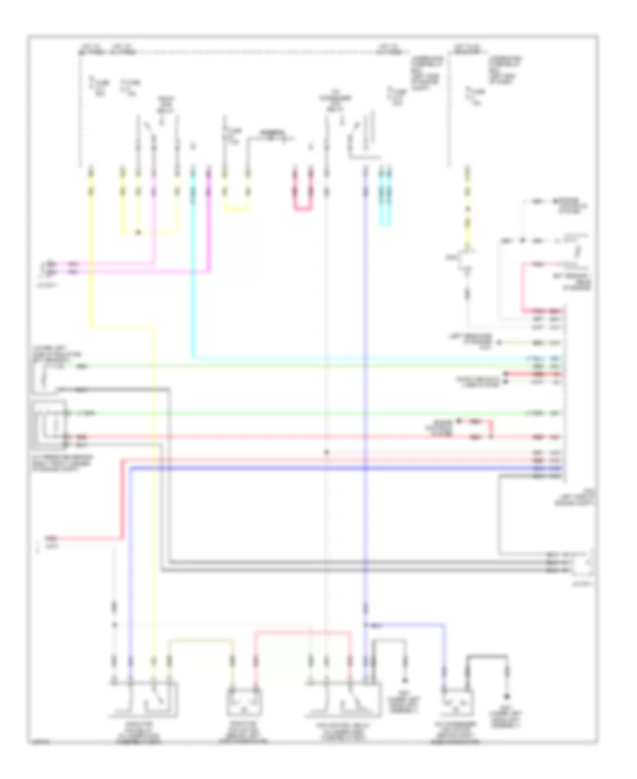
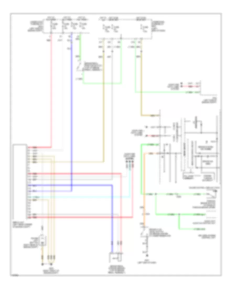
AIR CONDITIONING
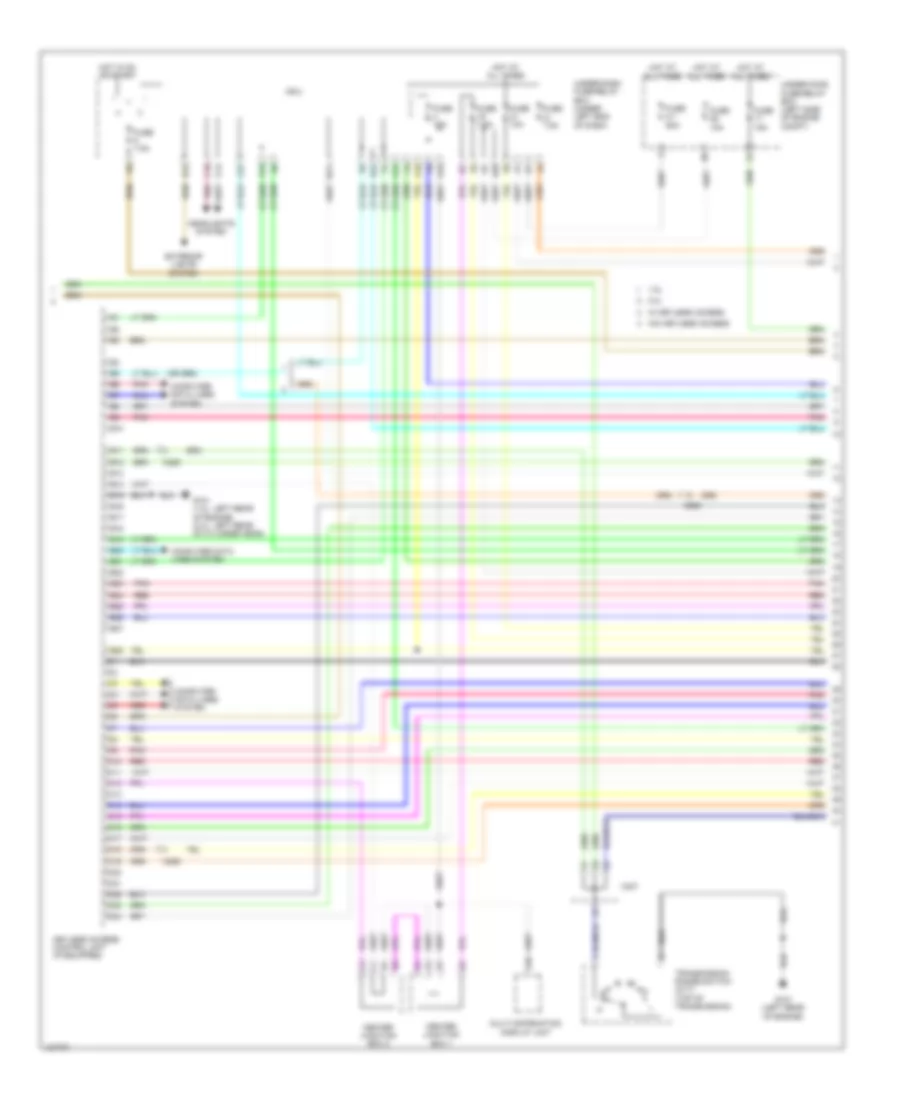
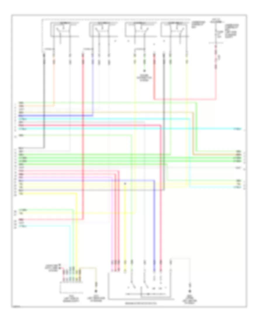
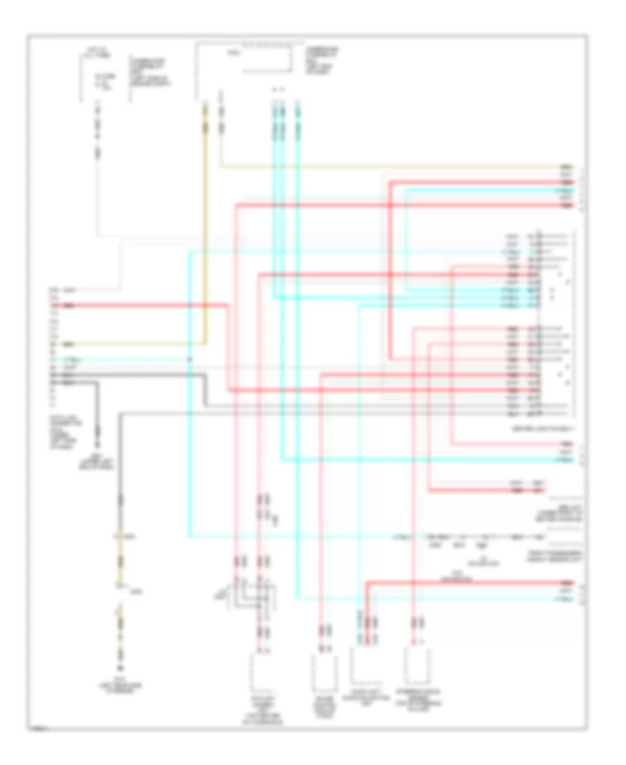
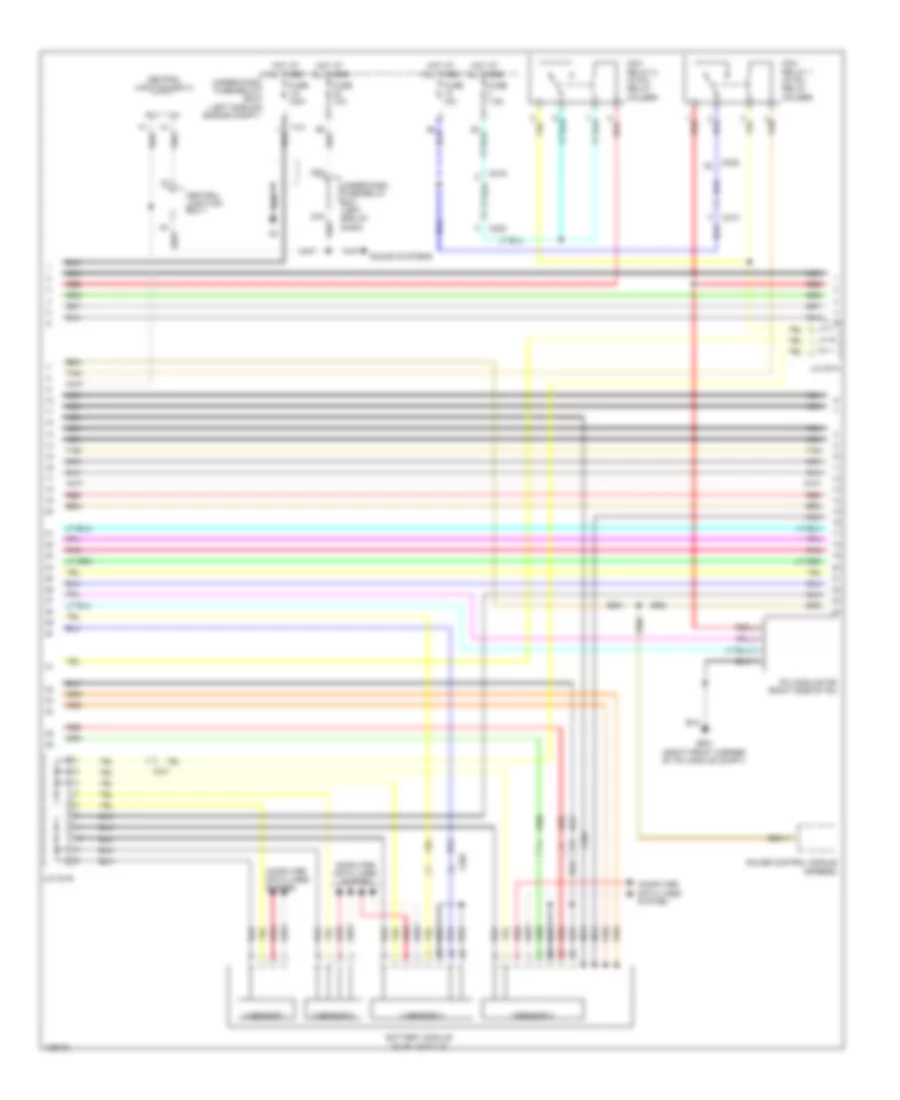
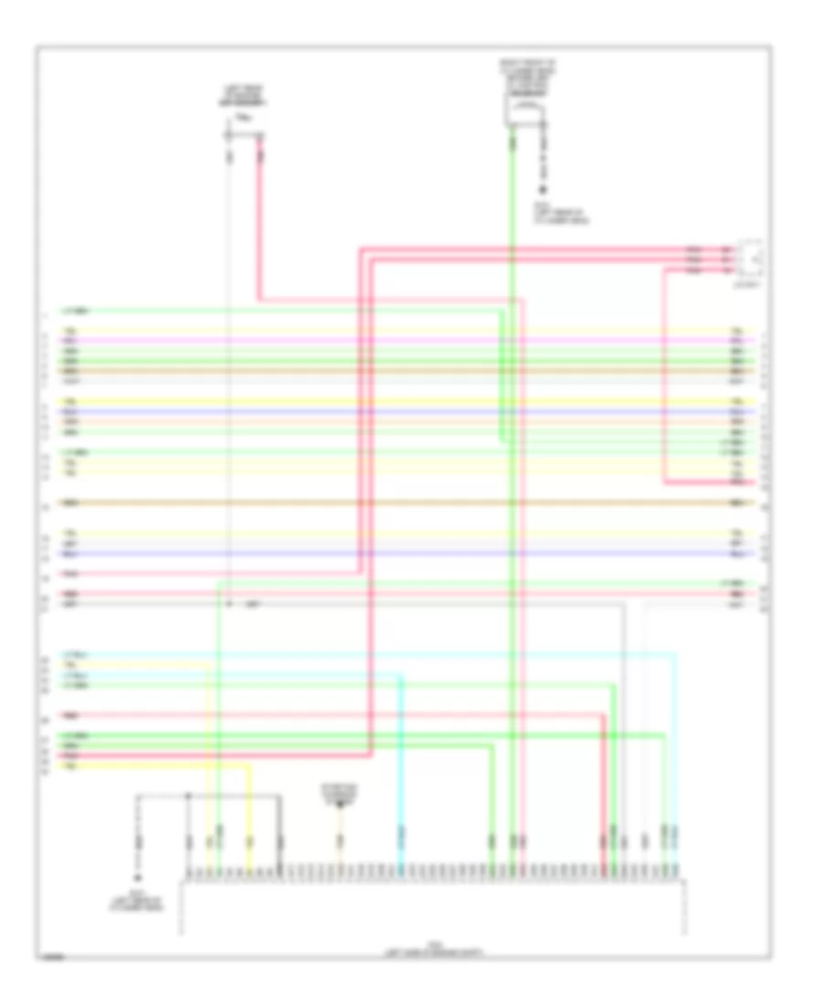
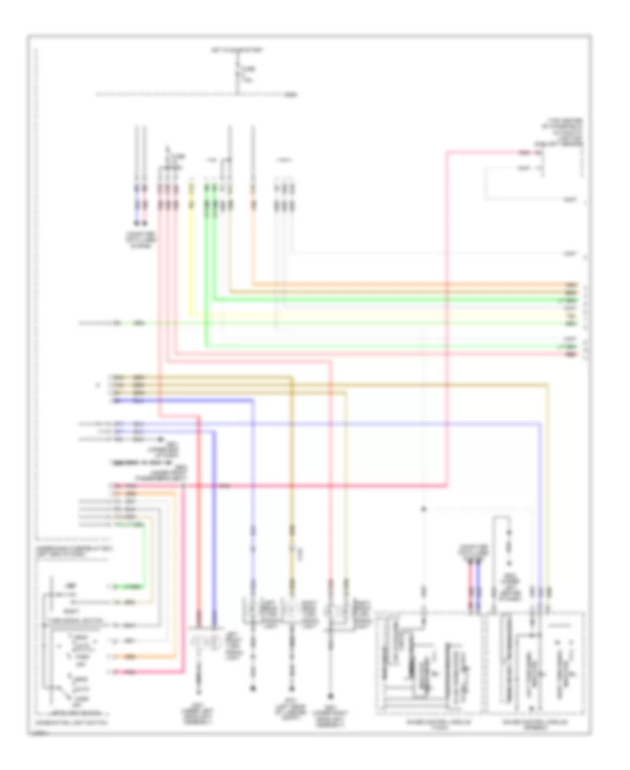
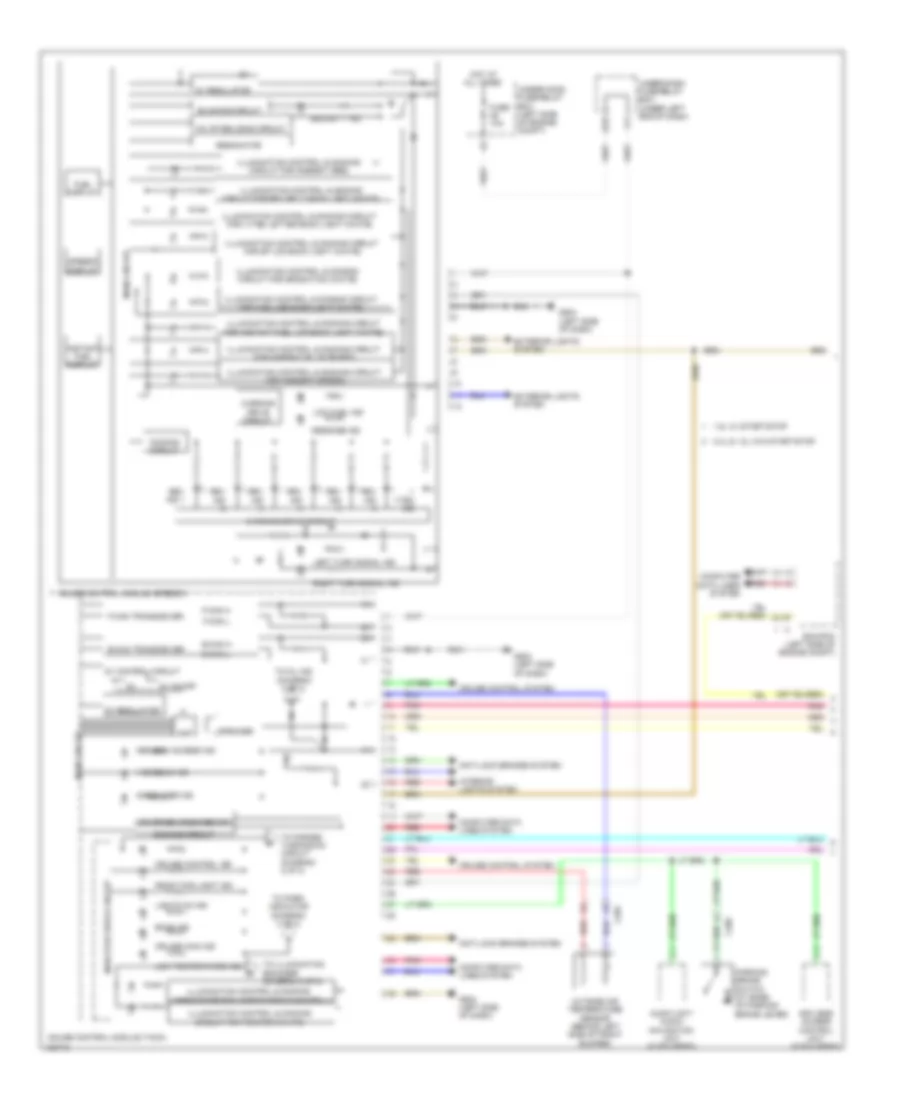
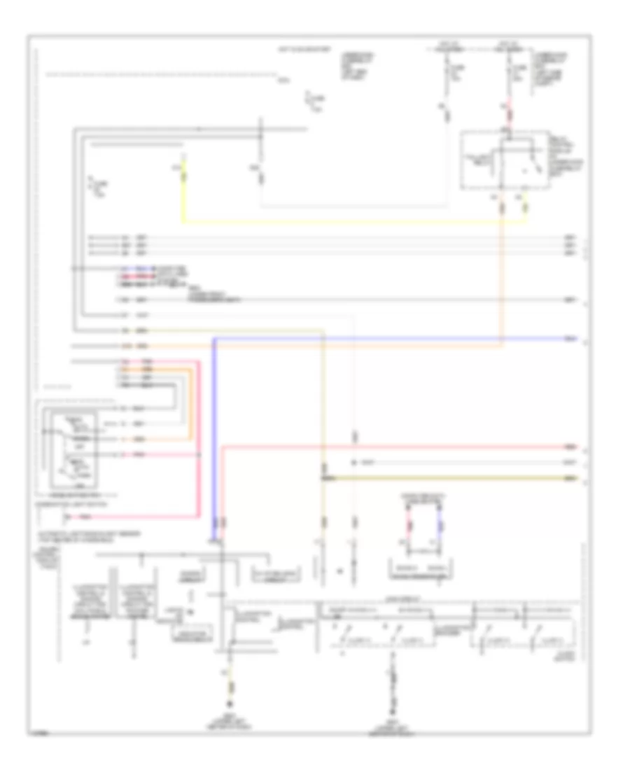
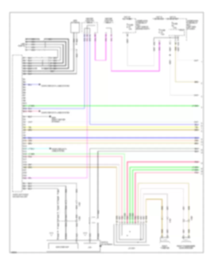
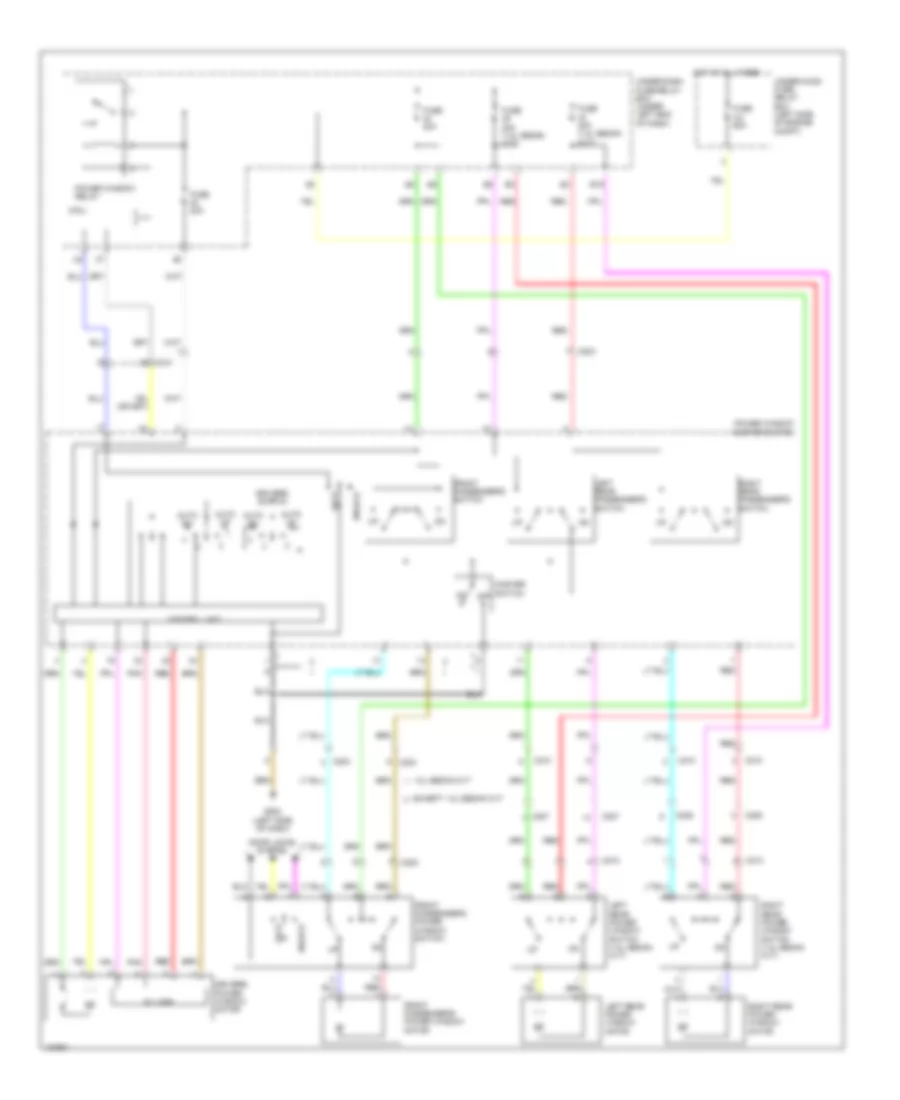
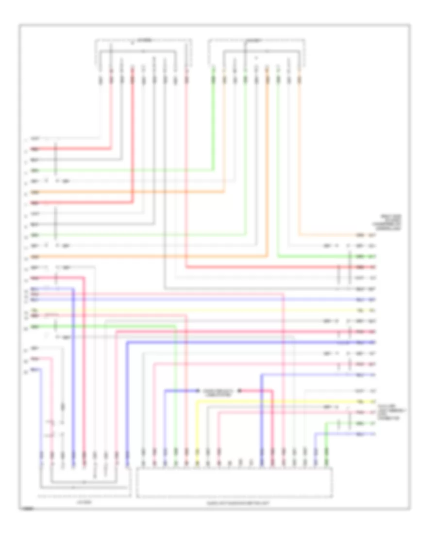
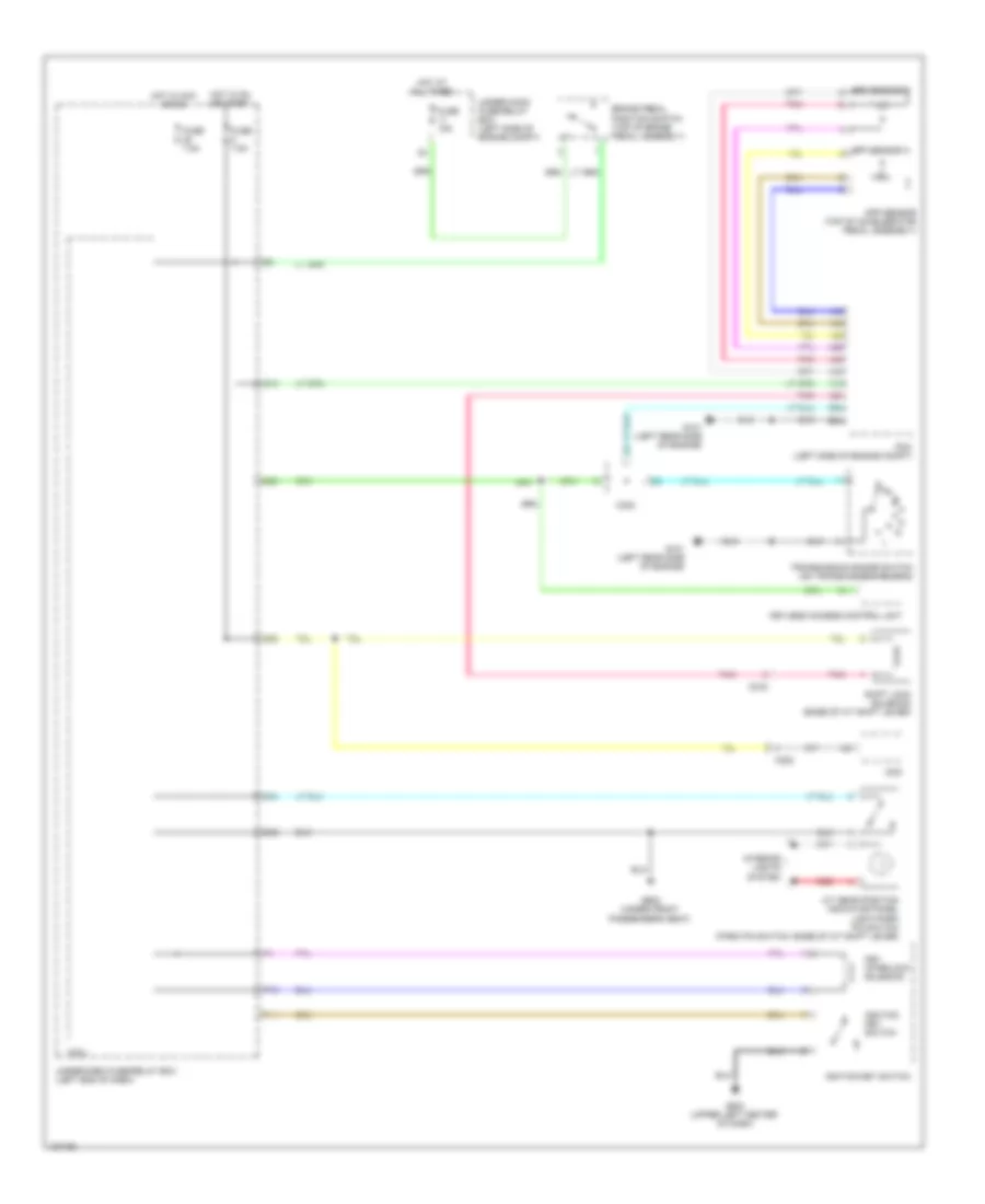
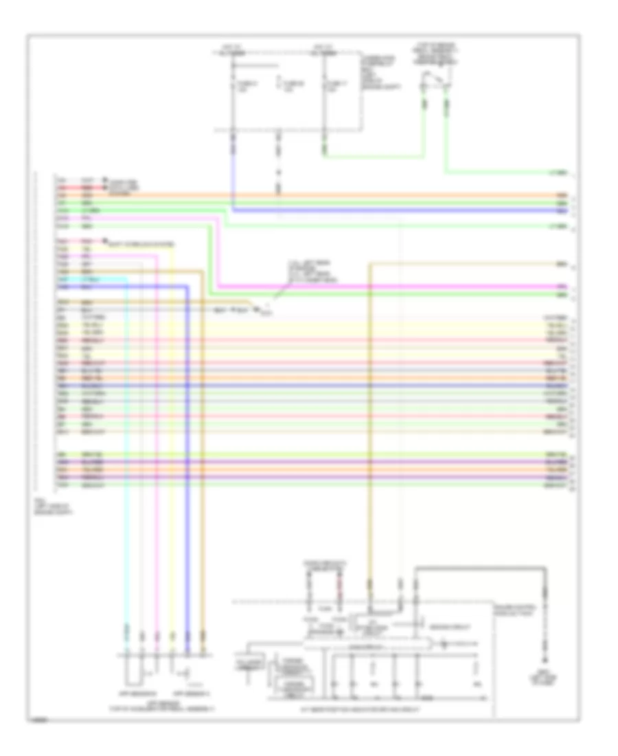
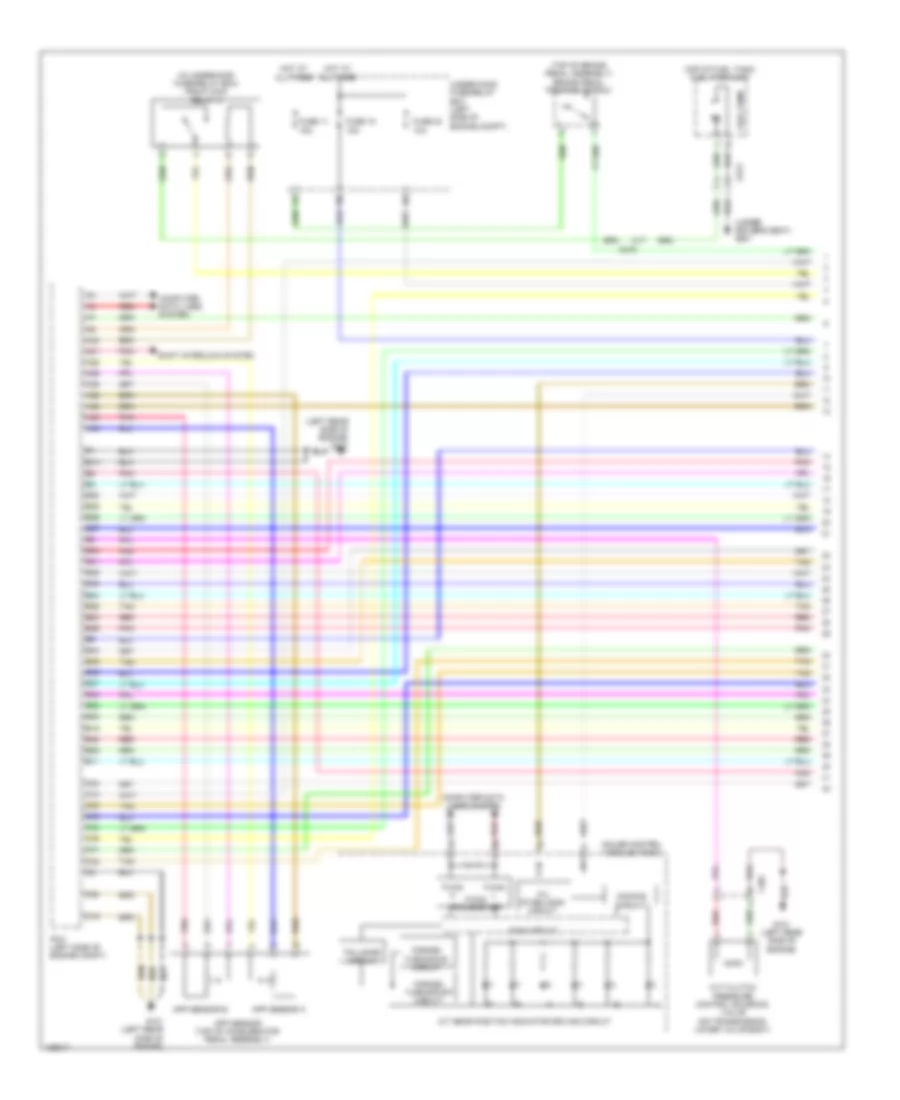
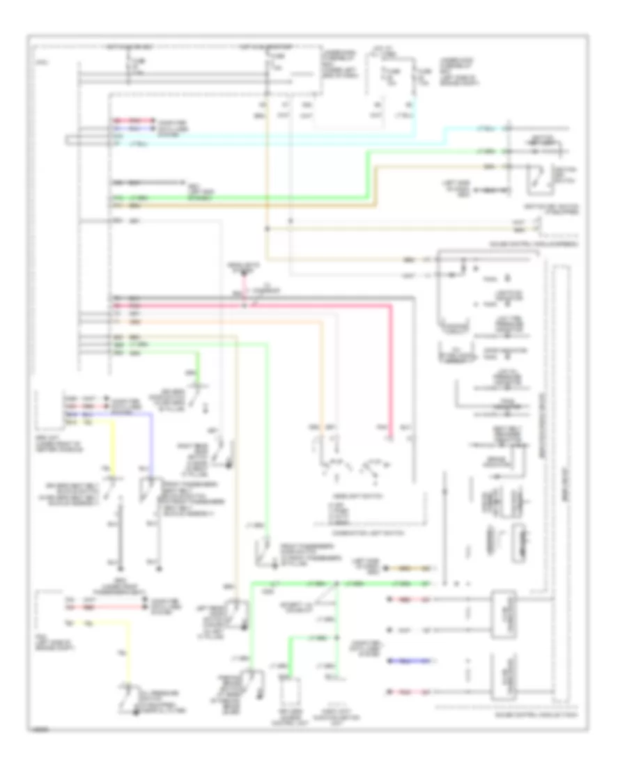
Automatic A/C Wiring Diagram, Except Hybrid (1 of 3) for Honda Civic HF 2014

List of elements for Automatic A/C Wiring Diagram, Except Hybrid (1 of 3) for Honda Civic HF 2014:
- (right side of hvac unit) mode control motor
- Air mix control motor (on left side of hvac assembly)
- Automatic lighting/ sunlight sensor (top center of dash)
- Blower motor (bottom of blower unit)
- Blower motor relay
- C204
- C208
- C413
- Computer data lines system
- Coupe
- Defogger system
- Evaporator temperature sensor (left side of hvac evaporator assembly)
- Fuse 2-8 40a
- G401 (left kick panel)
- G504 (right end of dash)
- Hot at all times
- Humidity sensor
- Humidity/in-car temperature sensor (left center of dash)
- Hvac control unit/ climate control unit
- In-car temperature sensor
- Interior lights system
- J/c c006
- Outside air temperature sensor (behind left side of front bumper)
- Pnk
- Power transistor (bottom of blower unit)
- Recirculation control motor (left side of blower unit)
- Red
- Sedan
- Under-hood fuse/relay box (left side of engine compt)
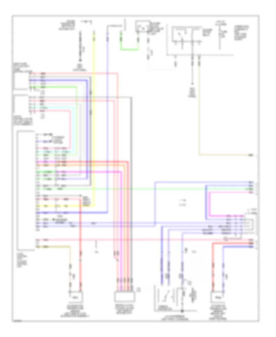
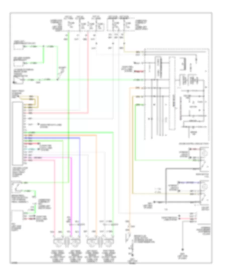
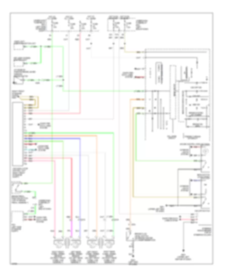
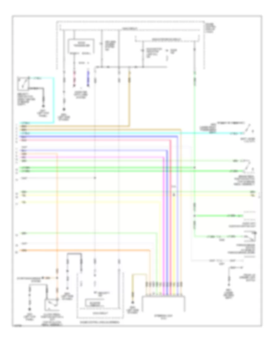
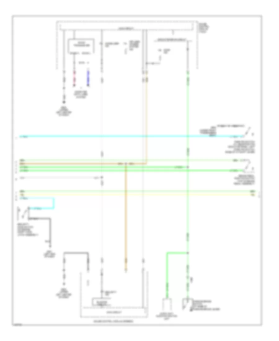
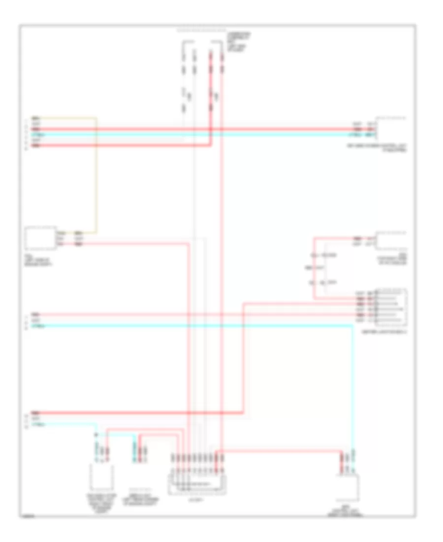
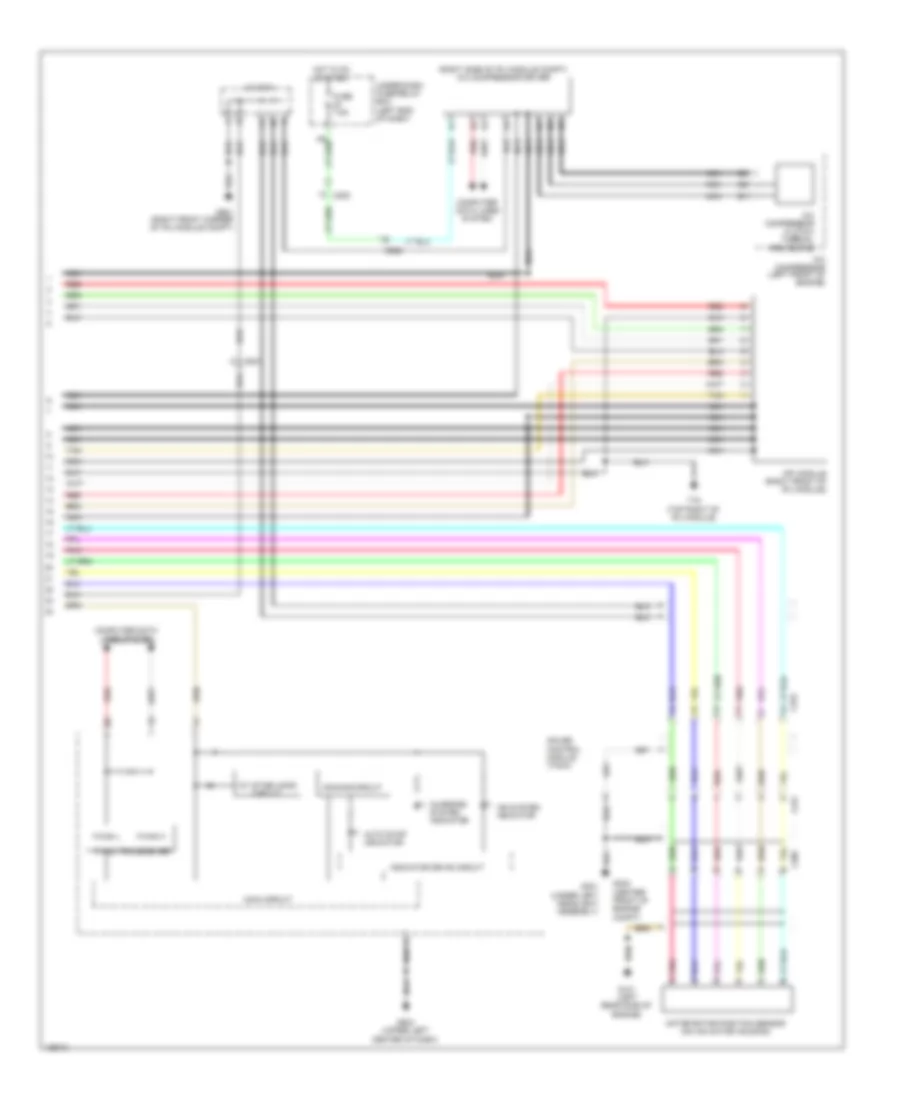
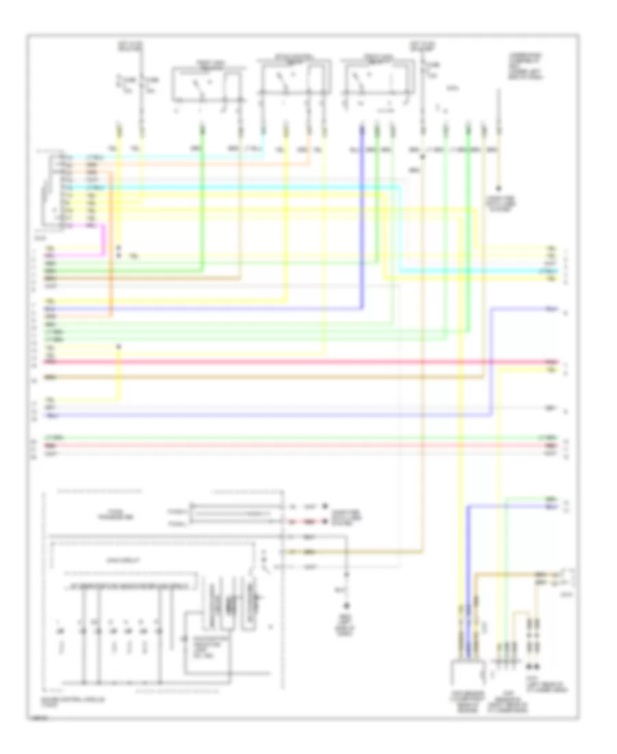
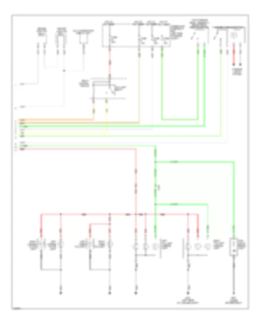
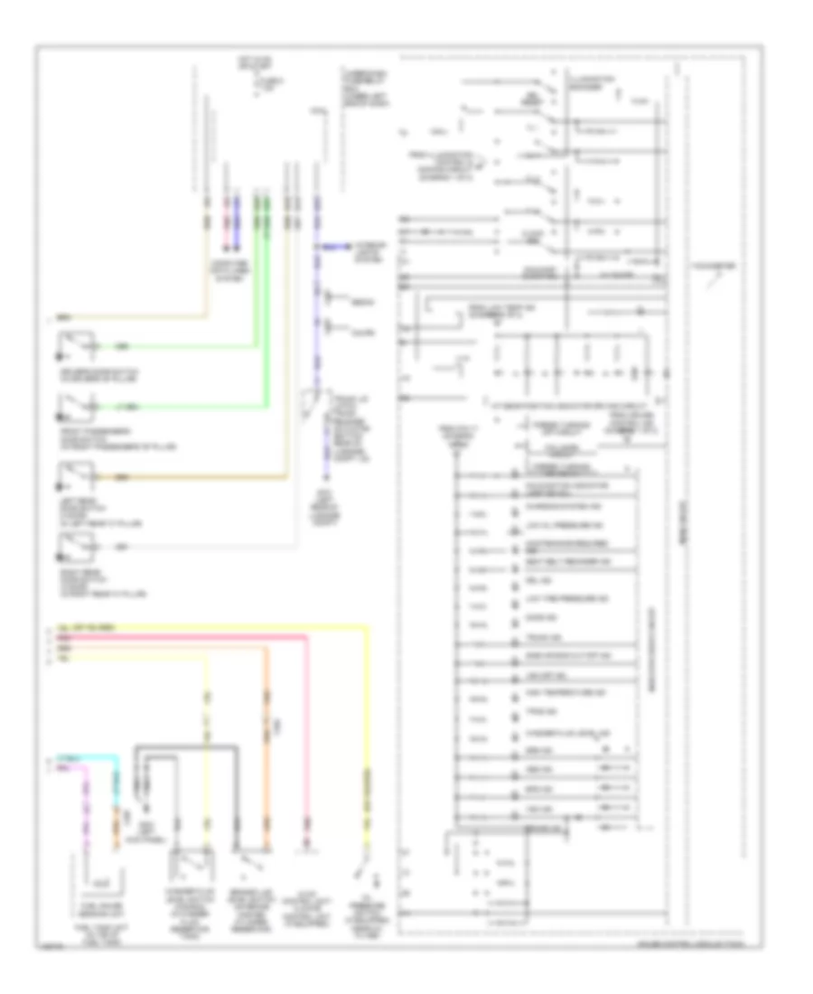
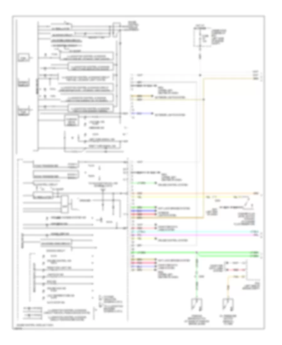
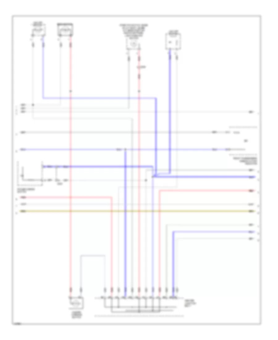
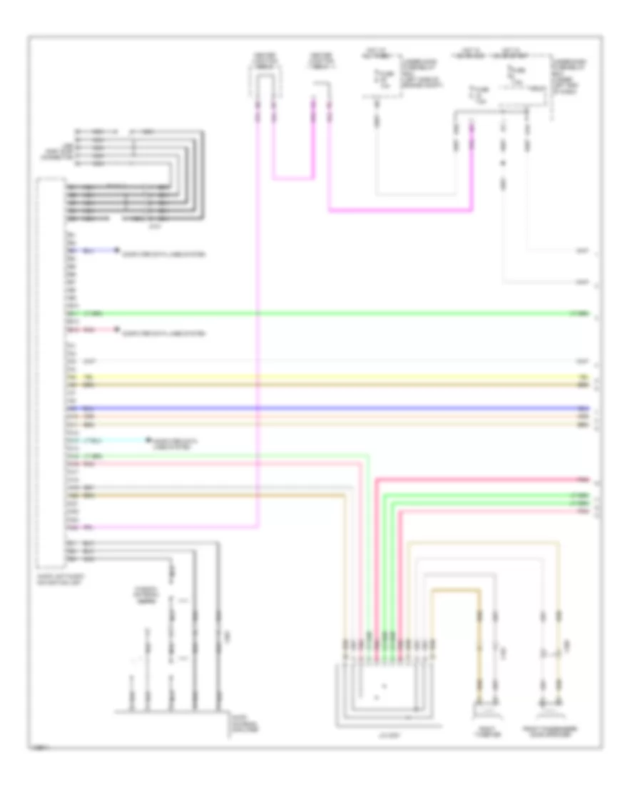
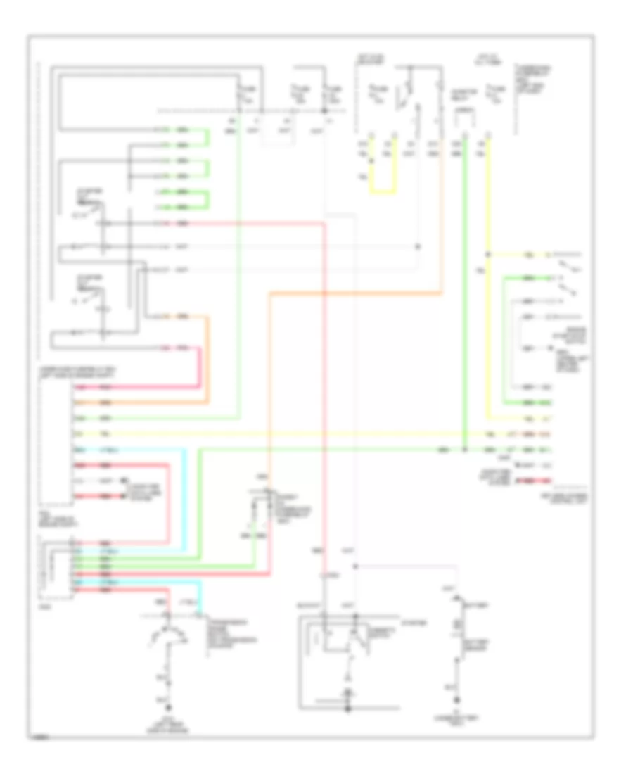
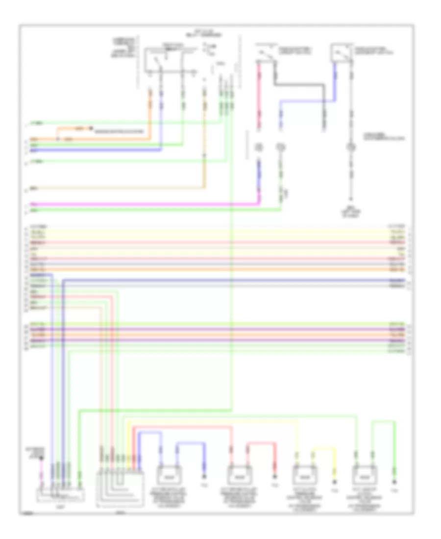
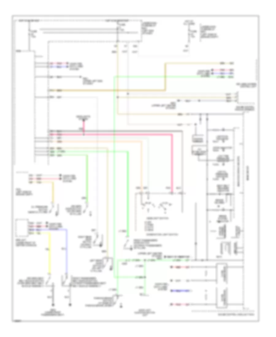
Automatic A/C Wiring Diagram, Except Hybrid (2 of 3) for Honda Civic HF 2014
List of elements for Automatic A/C Wiring Diagram, Except Hybrid (2 of 3) for Honda Civic HF 2014:
- 10v stabilizing circuit
- 5v control circuit
- 5v regulator
- A/c compressor (left front of engine)
- A10
- A11
- B-can h
- B-can l
- B-can transceiver
- C13
- C17
- C407
- Center junction box 1
- Center junction box 2
- Clutch compressor a/c
- Computer data lines system
- Coupe
- D14
- Dimming circuit
- Econ ind (led)
- Econ switch
- Fuse 15a
- Fuse 7.5a
- G501 (left end of dash)
- G502 (left side of dash)
- Gauge control module (tach)
- H10
- Hot in on
- Hot in on or start
- Indicator drive circuit
- Interior lights system
- Main circuit
- Micu
- On/off 5v
- Pnk
- Red
- Relay control module
- Sedan
- Thermal protector
- Under-dash fuse/relay box (under left end of dash)
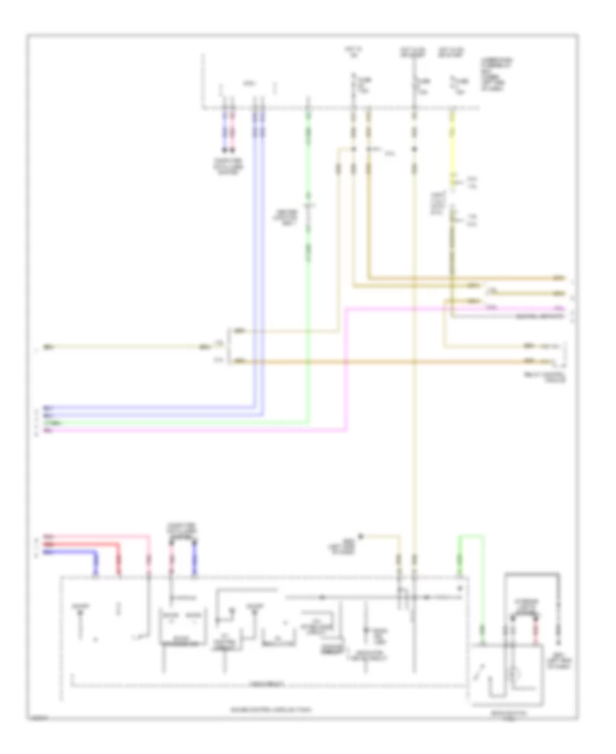
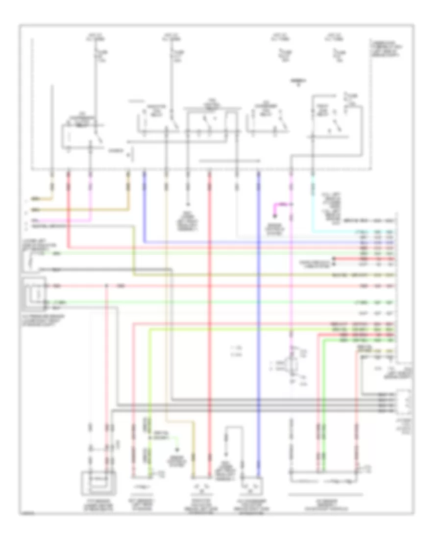
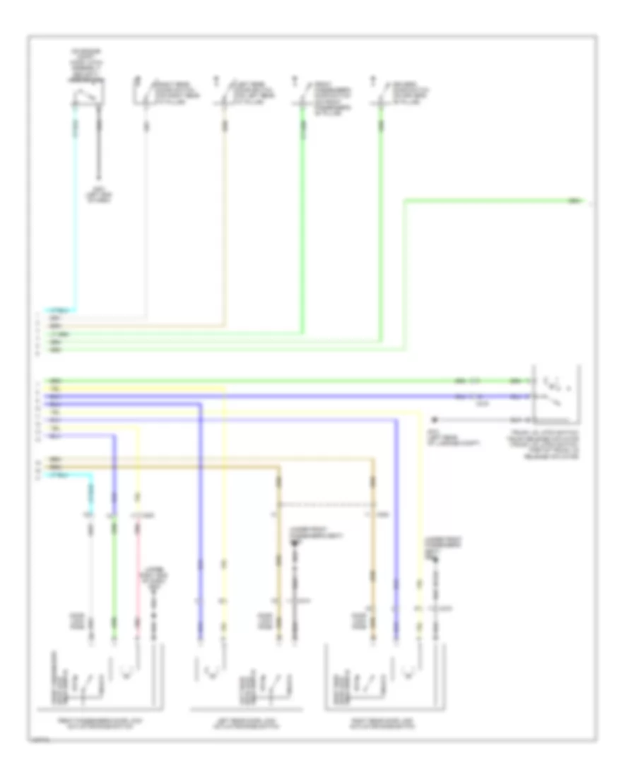
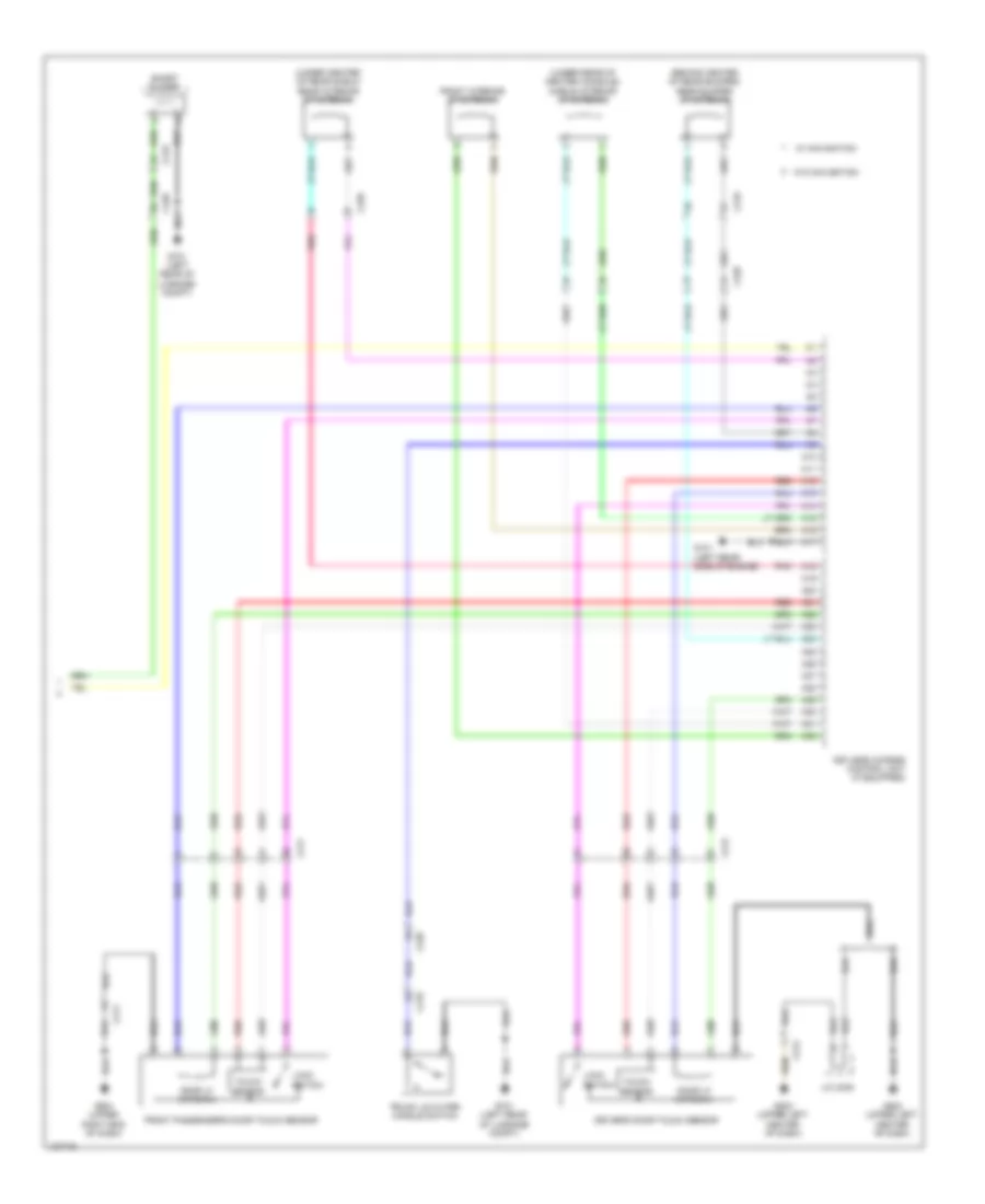
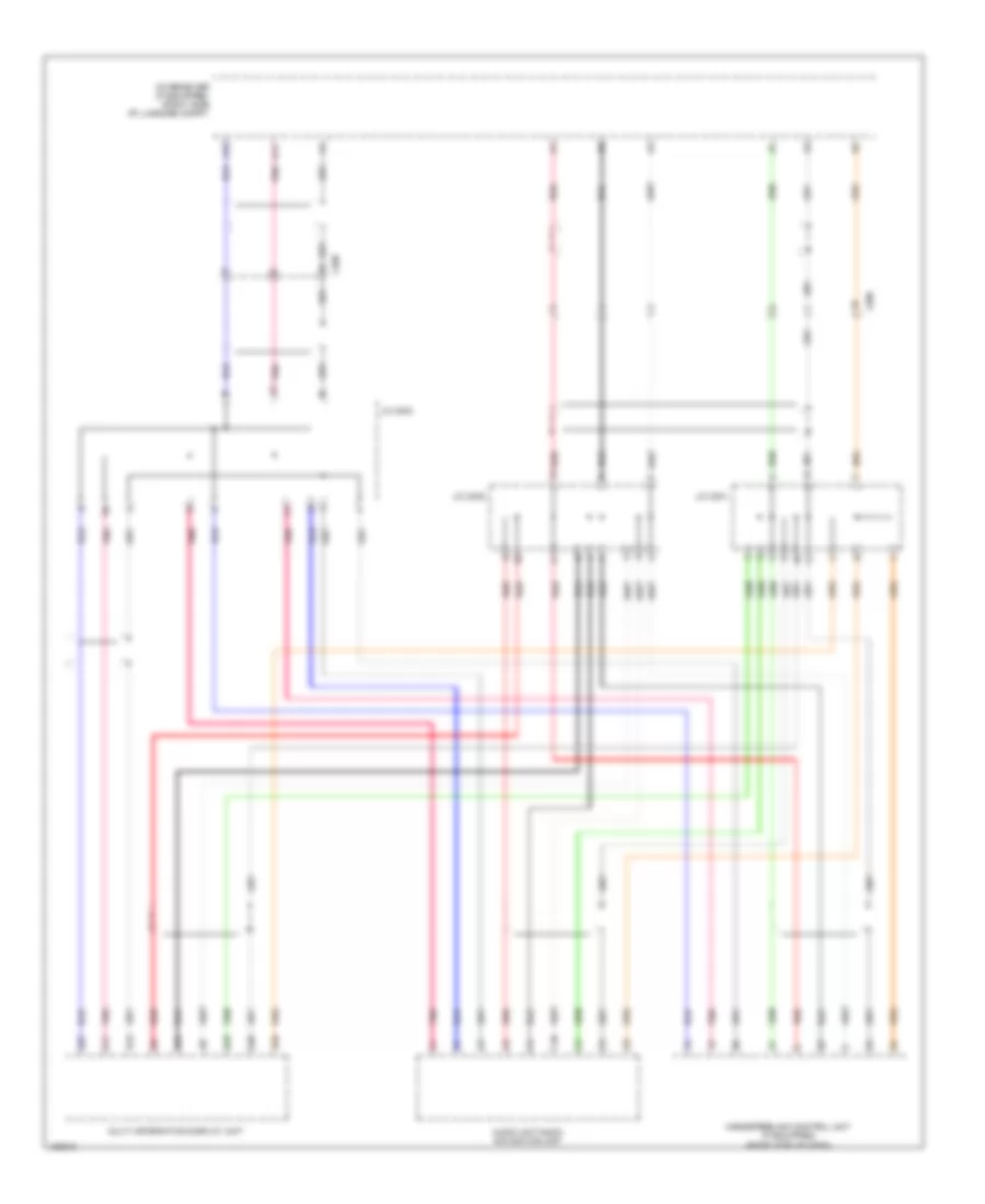
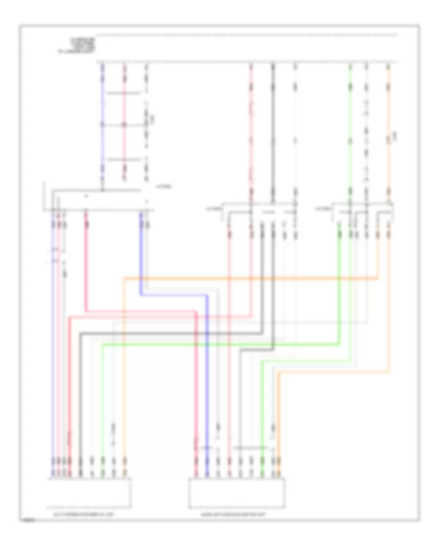
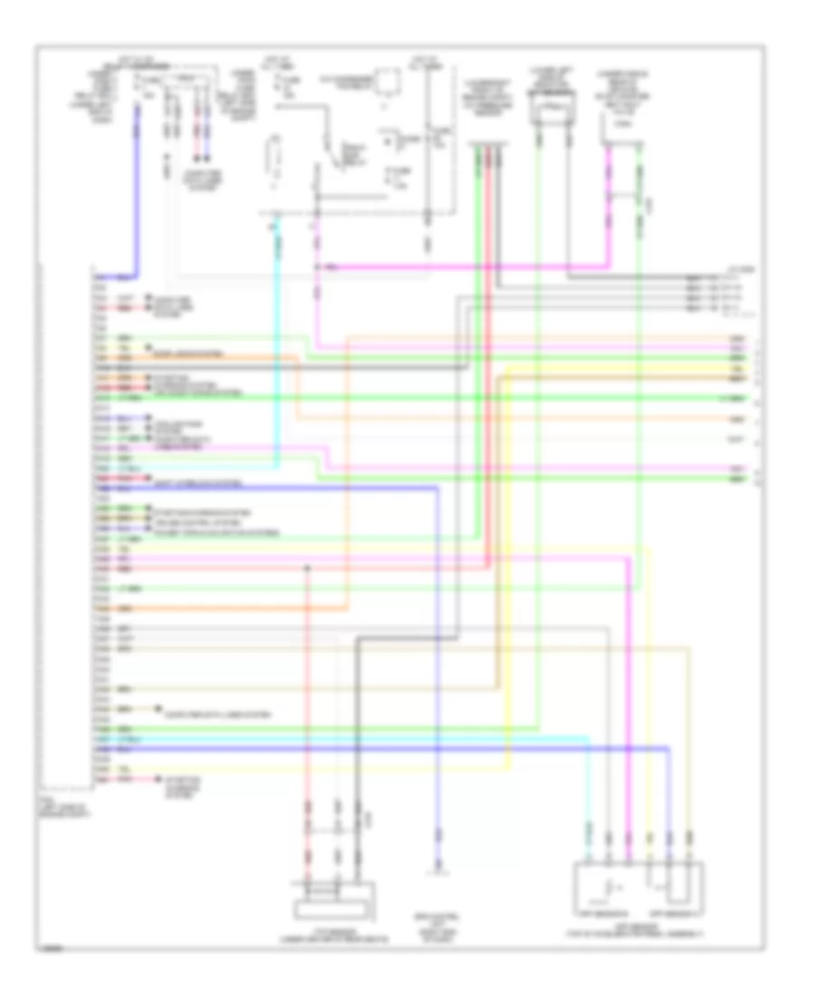
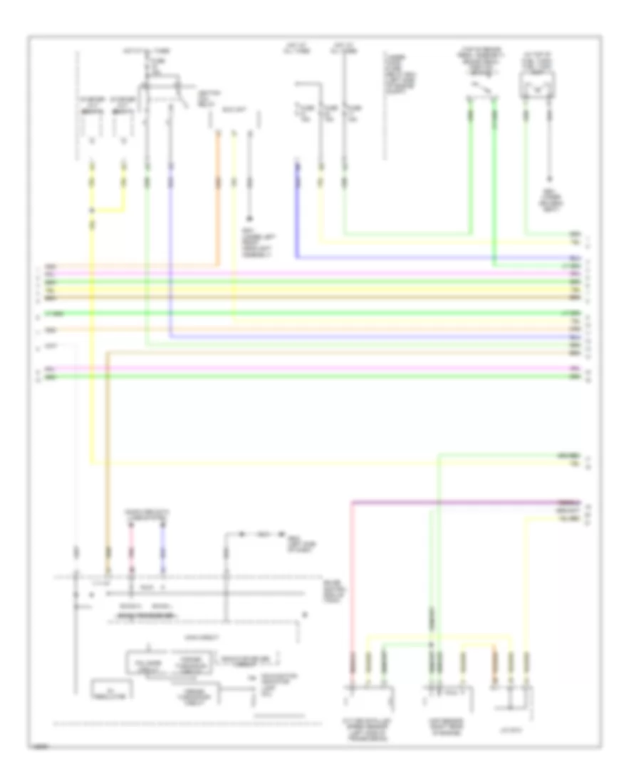
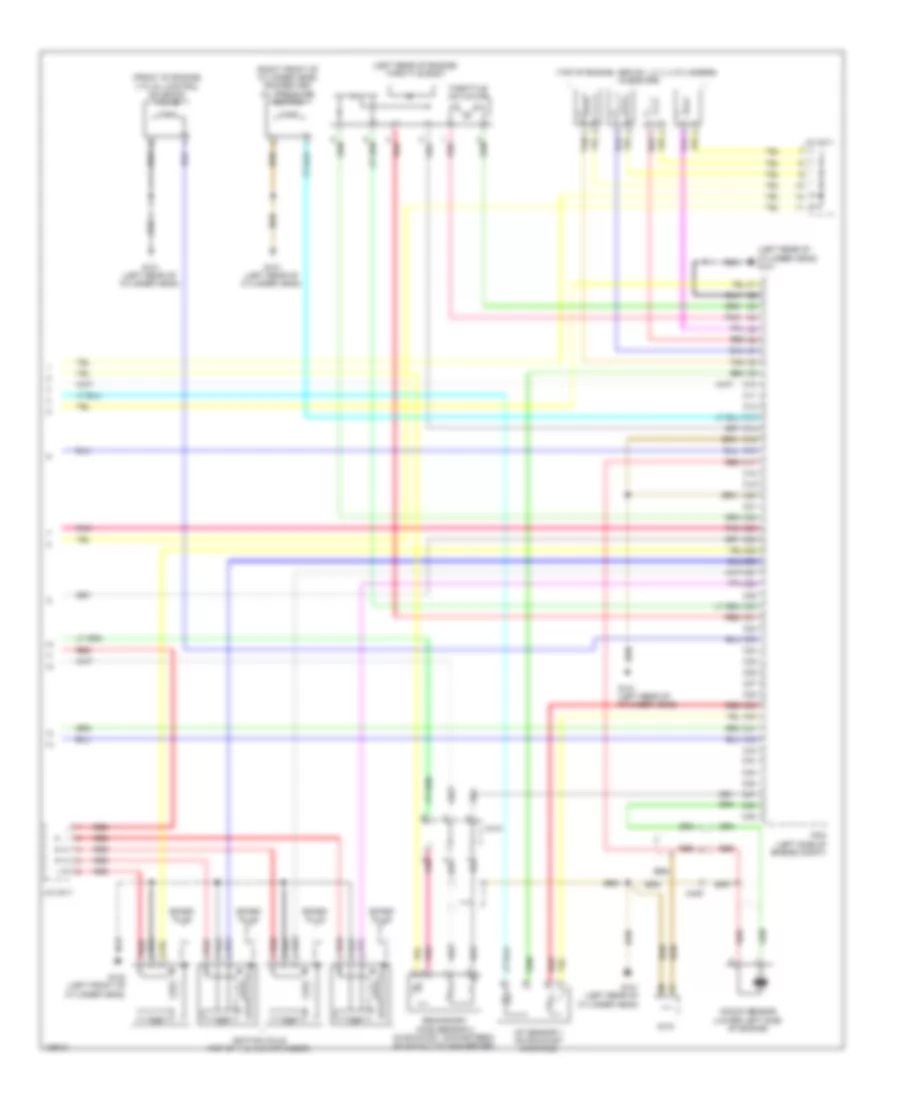
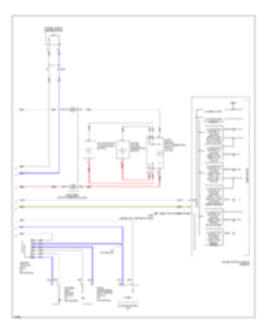
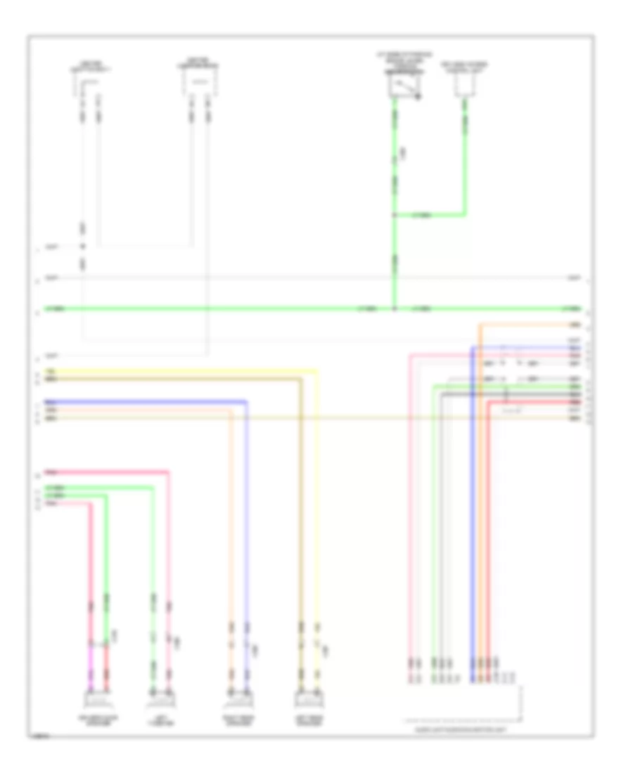
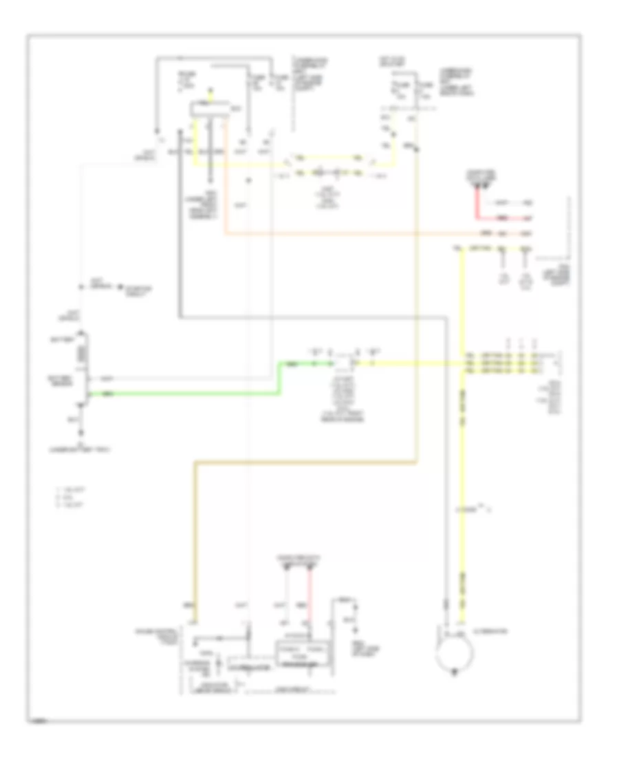
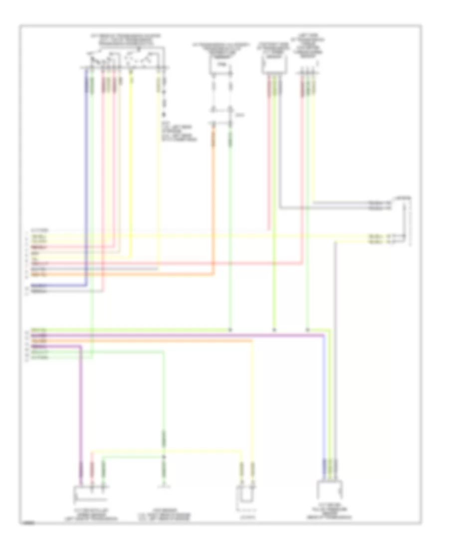
Automatic A/C Wiring Diagram, Except Hybrid (3 of 3) for Honda Civic HF 2014
List of elements for Automatic A/C Wiring Diagram, Except Hybrid (3 of 3) for Honda Civic HF 2014:
- (2.4l: left rear of cylinder head) (1.8l: left rear of engine) g101
- (lower left side of radiator) ect sensor 2
- A/c compressor clutch relay
- A/c condenser fan motor (behind right side of radiator)
- A/c condenser fan relay
- A/c pressure sensor (lower right front of engine compt)
- A/f sensor (sensor 1) (on exhaust manifold)
- A10
- A12
- A15
- A16
- A20
- A27
- A30
- A37
- A46
- B19
- B34
- B42
- B43
- B44
- C215
- C407
- Computer data lines system
- Diode a
- Diode b
- Ect sensor 1 (left rear of engine)
- Engine controls system
- Fan control relay
- Ftp sensor (under center of rear seats)
- Fuse 15a
- Fuse 2-10 20a
- Fuse 2-11 20a
- Fuse 7.5a
- G301 (under left front headlight assembly)
- Hot at all times
- J/c c005
- Pcm (left side of engine compt)
- Pgm-fi sub relay
- Radiator fan motor (behind left side of radiator)
- Radiator fan relay
- Red
- Under-hood fuse/relay box (left side of engine compt)
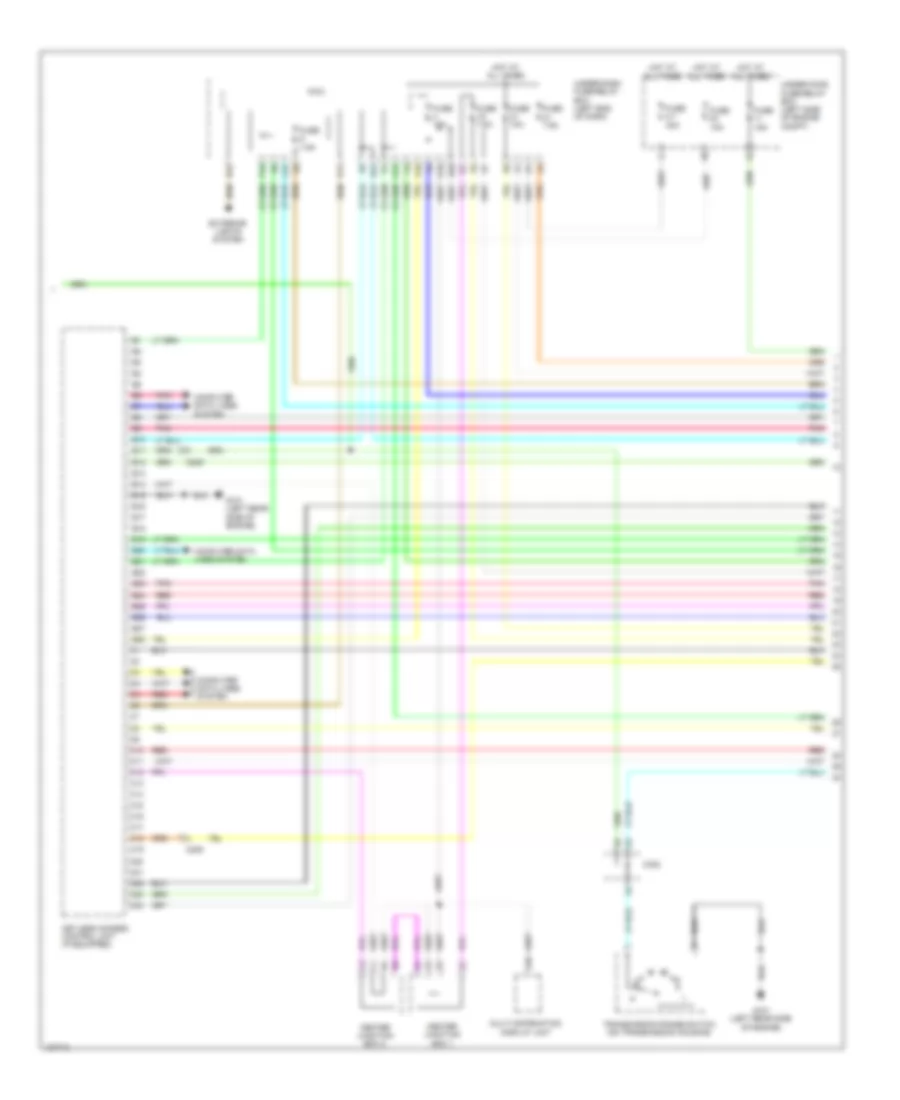
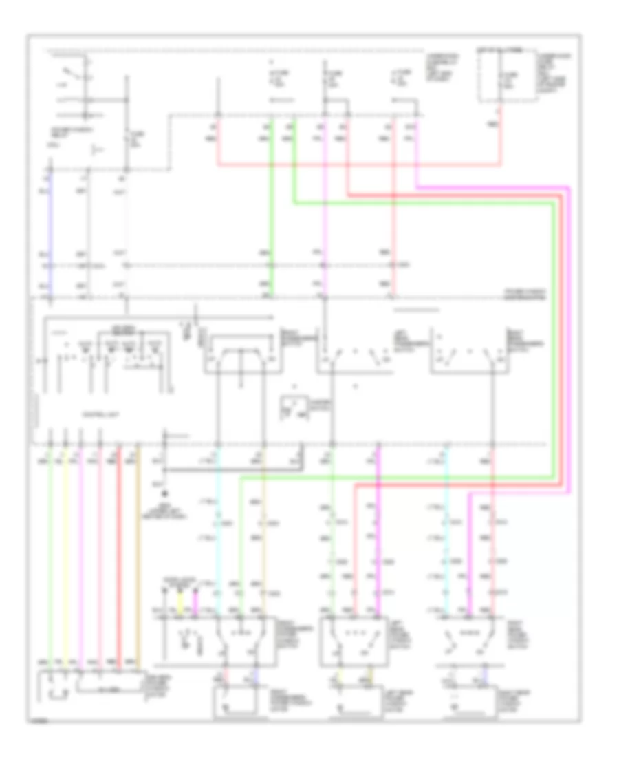
Automatic A/C Wiring Diagram, Hybrid (1 of 3) for Honda Civic HF 2014
List of elements for Automatic A/C Wiring Diagram, Hybrid (1 of 3) for Honda Civic HF 2014:
- (right side of hvac assembly) mode control motor
- Air mix control motor (left side of hvac assembly)
- Automatic lighting/ sunlight sensor (top center of windshield)
- Blower motor (bottom of blower unit)
- C204
- C205
- C208
- C209
- C222
- C306
- Climate control unit
- Computer data lines system
- D14
- Defogger system
- Evaporator temperature sensor (in evaporator)
- Fuse 7.5a
- G401 (left end of dash)
- G504 (upper right end of dash)
- Heater core temperature sensor (lower right side of hvac assembly)
- Hot in on or start
- Humidity/in-car temperature sensor (lower left center of dash)
- Interior lights system
- J/c c005
- Micu
- Outside air temperature sensor (behind left side of front bumper)
- Pnk
- Power transistor (near blower motor)
- Recirculation control motor (left side of blower unit)
- Red
- Under-dash fuse/relay box (left end of dash)
Automatic A/C Wiring Diagram, Hybrid (2 of 3) for Honda Civic HF 2014
List of elements for Automatic A/C Wiring Diagram, Hybrid (2 of 3) for Honda Civic HF 2014:
- (led) ind eco
- A/c compressor (left front of engine)
- A/c compressor clutch relay (in under-hood fuse/relay box)
- A/c compressor driver (right side of ipu module)
- A10
- A11
- Auxiliary electric water pump (right rear of engine compt)
- Auxiliary electric water pump relay
- B10
- Blower motor relay
- C17
- C302
- Circuit control
- Circuit stabilizing 10v
- Clutch compressor a/c
- Computer data lines system
- Dimming circuit
- Diode h
- Drive circuit indicator
- Econ switch
- F-can h
- F-can transceiver
- Fuse 2-8 40a
- Fuse 7.5a
- G301 (under left headlight assembly)
- G401 (left end of dash)
- G501 (upper left end of dash)
- G502 (upper left center of dash)
- G901 (right front corner of ipu module)
- Gauge control module (tach)
- Hot at all times
- Hot in on
- Hot in on or start
- Interior lights system
- J/c c014
- L f-can
- Main circuit
- Nca
- On/off
- Red
- Regulator 5v
- Relay control module (in under-hood fuse/relay box)
- Thermal protector
- Under-dash fuse/relay box (left end of dash)
- Under-hood fuse/relay box (left side of engine compt)
Automatic A/C Wiring Diagram, Hybrid (3 of 3) for Honda Civic HF 2014
List of elements for Automatic A/C Wiring Diagram, Hybrid (3 of 3) for Honda Civic HF 2014:
- (left rear side of engine) g101
- (lower left side of radiator) ect sensor 2
- A/c condenser fan motor (behind right side of radiator)
- A/c condenser fan relay
- A/c pressure sensor (right front corner of engine compt)
- A10
- A12
- A15
- A16
- A20
- A27
- A30
- A44
- B34
- B44
- C10
- C13
- C15
- C302
- Computer data lines system
- Diode g
- Ect sensor 1 (rear of engine)
- Engine controls system
- Fan control relay (in under-hood fuse/relay box)
- Fuse 15a
- Fuse 2-10 20a
- Fuse 2-11 20a
- Fuse 7.5a
- G301 (under left headlight assembly)
- Hot at all times
- Hot in on or start
- J/c c011
- Pcm (left side of engine compt)
- Pgm-fi sub relay
- Pnk
- Radiator fan motor (behind left side of radiator)
- Radiator fan relay (in under-hood fuse/relay box)
- Red
- Under-dash fuse/relay box (left end of dash)
- Under-hood fuse/relay box (left side of engine compt)
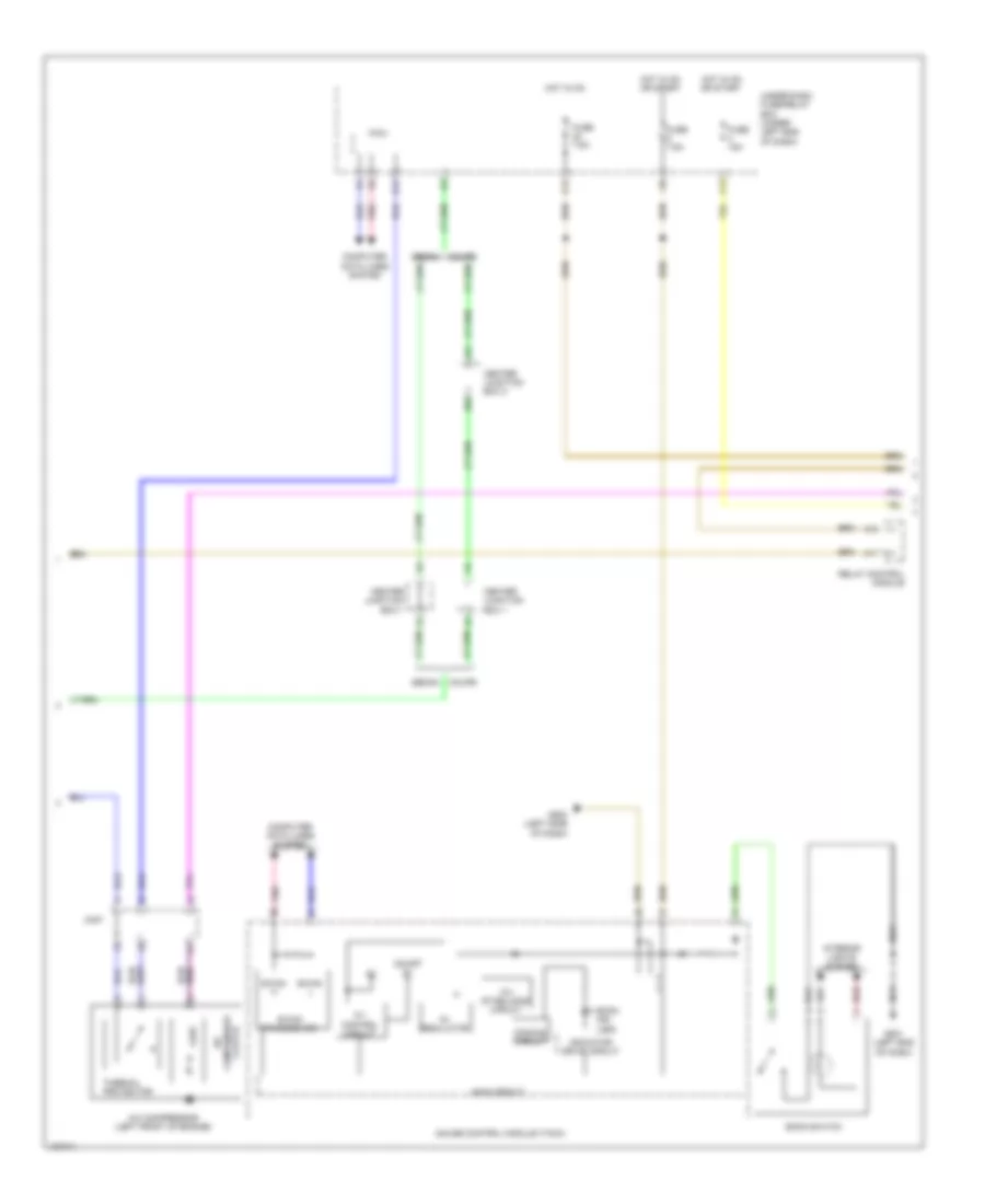
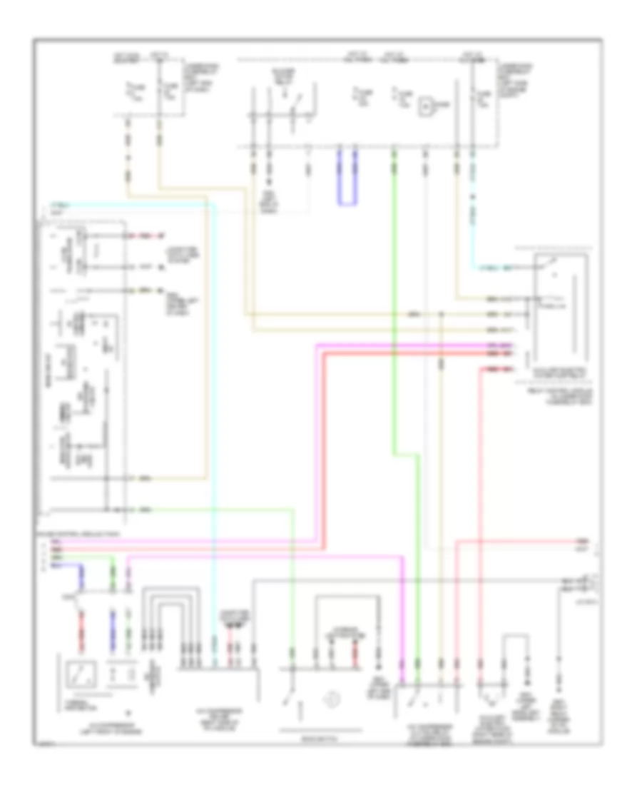
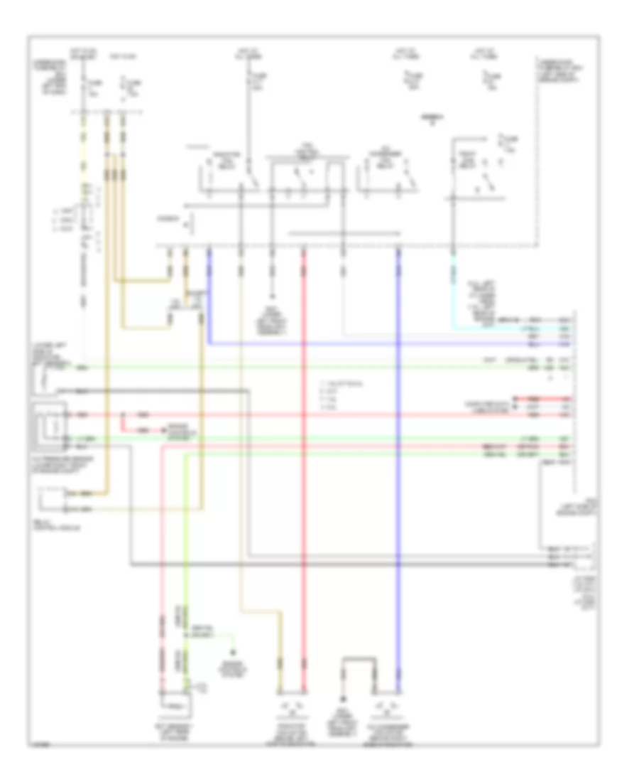
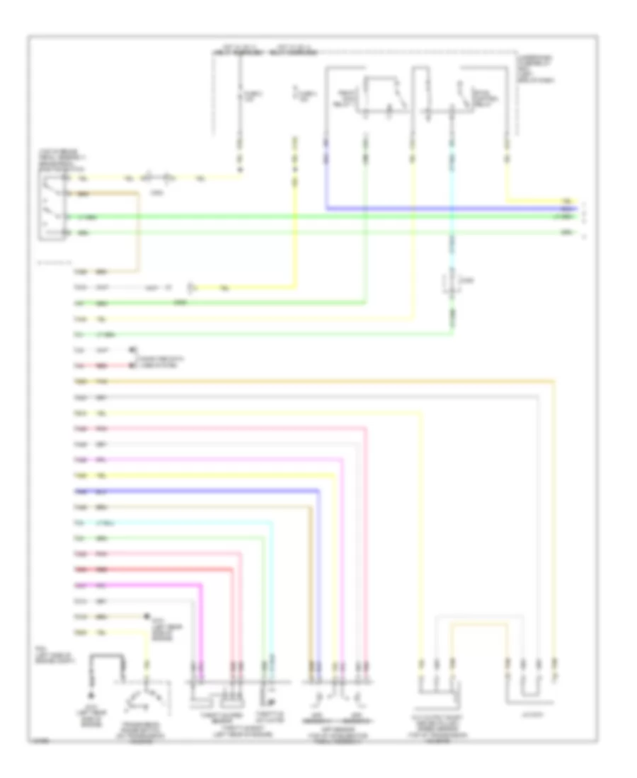
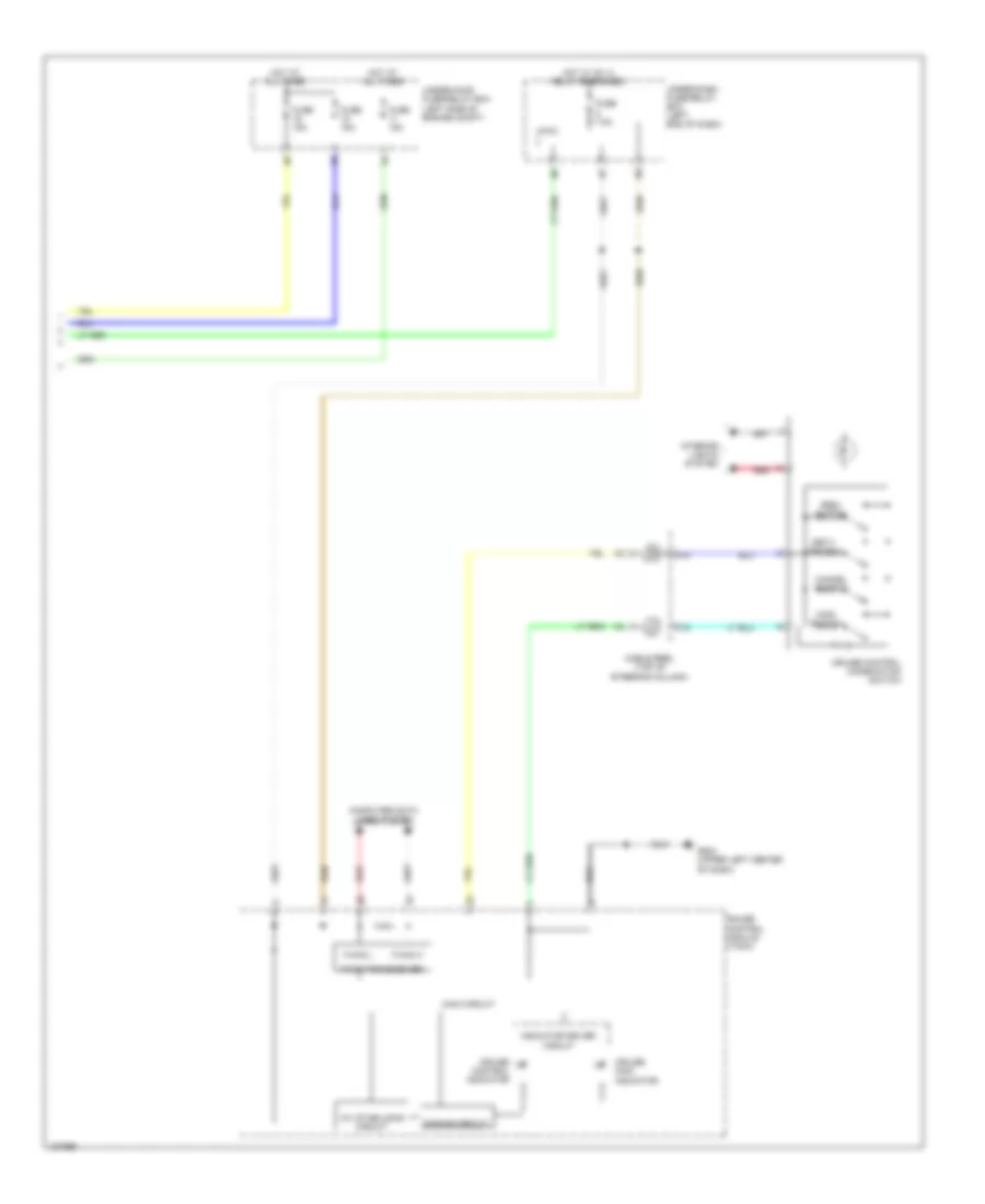
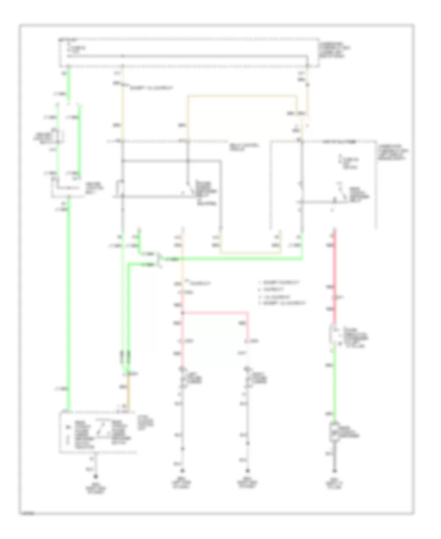
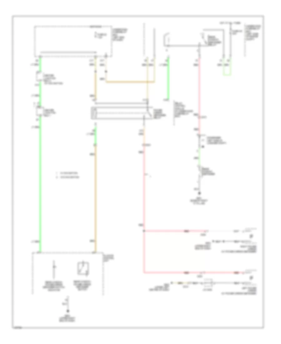
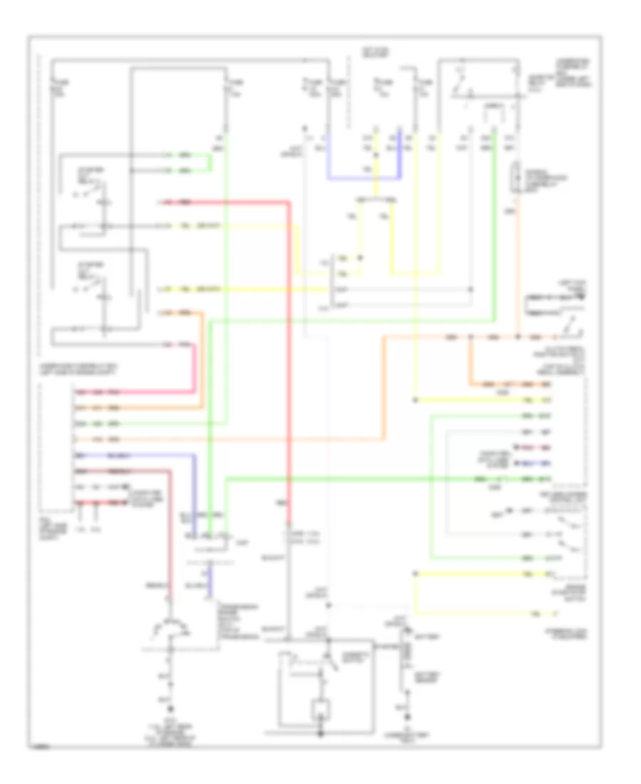
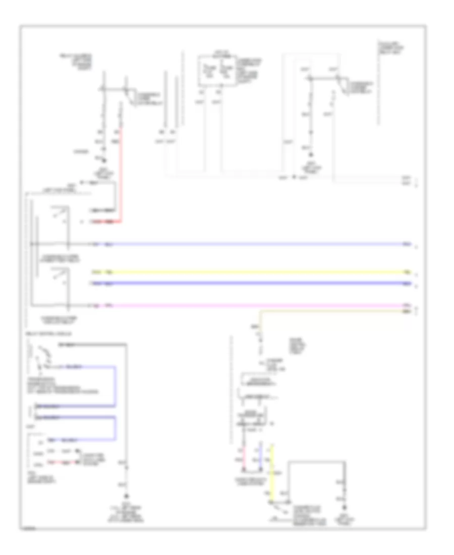
Manual A/C Wiring Diagram (1 of 3) for Honda Civic HF 2014
List of elements for Manual A/C Wiring Diagram (1 of 3) for Honda Civic HF 2014:
- (or pnk)
- (right side of hvac unit) mode control motor
- 1.8l
- 1.8l 2.4l
- 2.4l
- 2.4l 1.8l
- A/c compressor (left front of engine)
- Air mix control motor (on left side of hvac assembly)
- Blower motor (bottom of blower unit)
- Blower motor relay
- C204
- C208
- C404
- C409
- C410
- C413
- Clutch compressor a/c
- Defogger system
- Evaporator temperature sensor (left side of hvac evaporator assembly)
- Fuse 2-8 40a
- G401 (left kick panel)
- G504 (right end of dash)
- Hot at all times
- Hvac control unit/ climate control unit
- Interior lights system
- Outside air temperature sensor (behind left side of front bumper)
- Pnk
- Power transistor (bottom of blower unit)
- Recirculation control motor (left side of blower unit)
- Red
- Thermal protector
- Under-hood fuse/relay box (left side of engine compt)
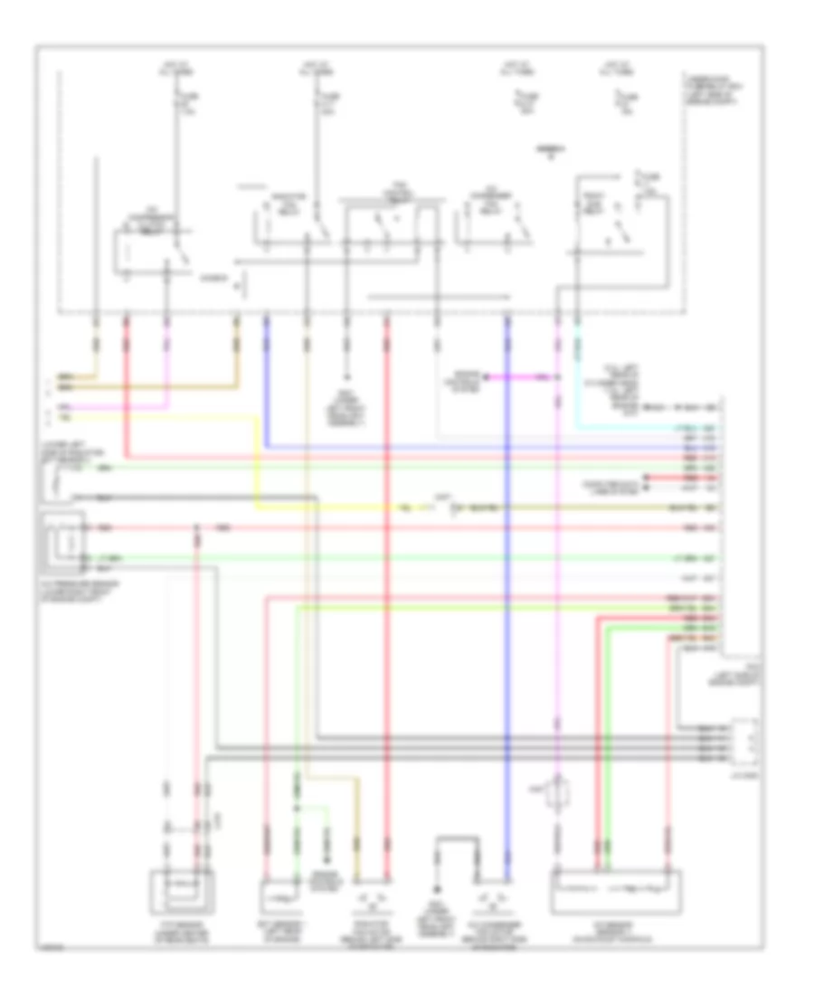
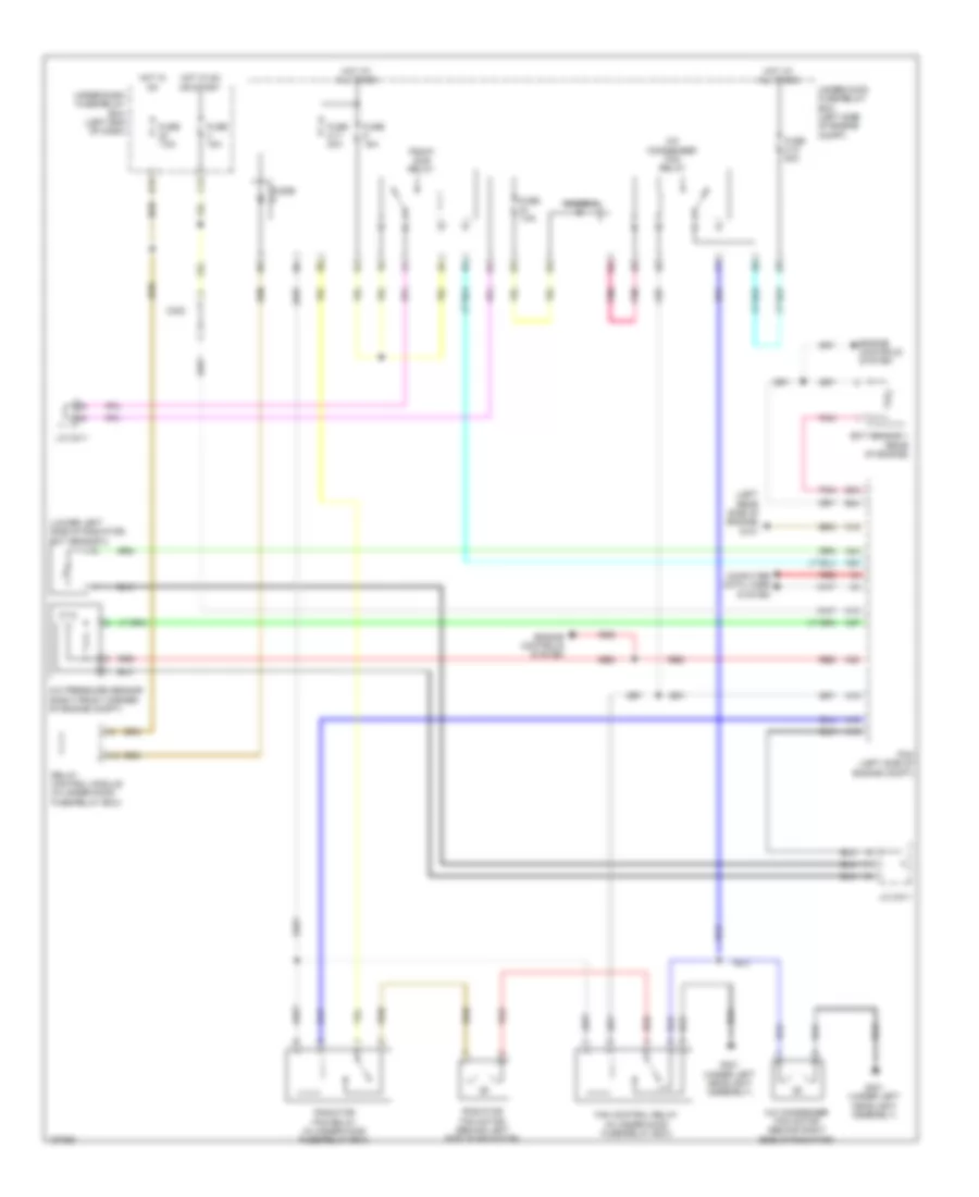
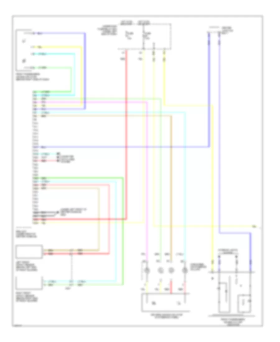
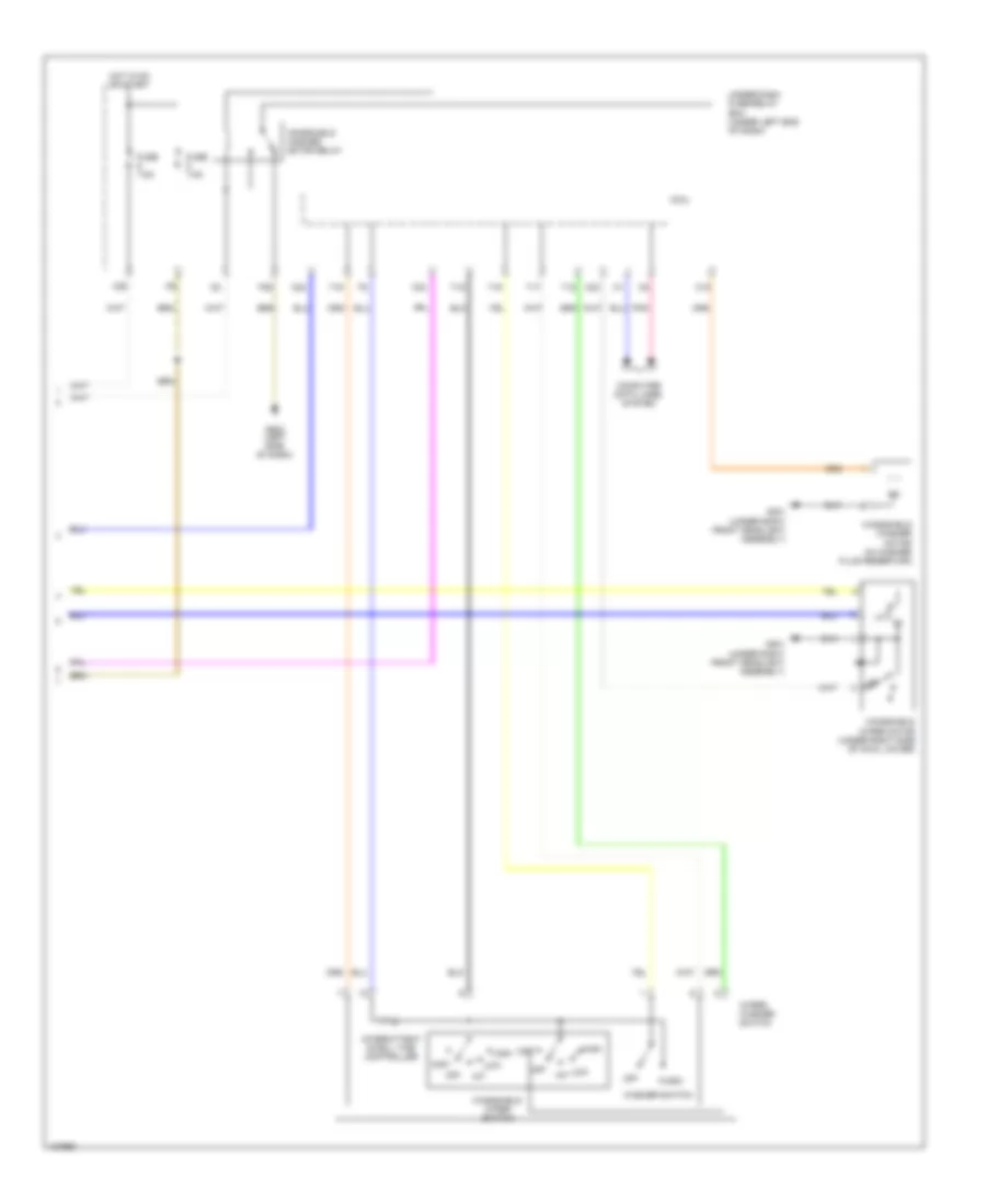
Manual A/C Wiring Diagram (2 of 3) for Honda Civic HF 2014
List of elements for Manual A/C Wiring Diagram (2 of 3) for Honda Civic HF 2014:
- 1.8l
- 10v stabilizing circuit
- 2.4l
- 5v control circuit
- 5v regulator
- A10
- A11
- B-can h
- B-can l
- B-can transceiver
- C13
- C17
- C404 (1.8l) c410 (2.4l)
- Center junction box 1
- Computer data lines system
- D14
- D17
- Dimming circuit
- Econ ind (led)
- Econ switch (1.8l)
- Fuse 15a
- Fuse 7.5a
- G501 (left end of dash)
- G502 (left side of dash)
- Gauge control module (tach)
- Hot in on
- Hot in on or start
- Indicator drive circuit
- Interior lights system
- Main circuit
- Micu
- On/off 5v
- Pnk
- Red
- Relay control module
- Under-dash fuse/relay box (under left end of dash)
- W12
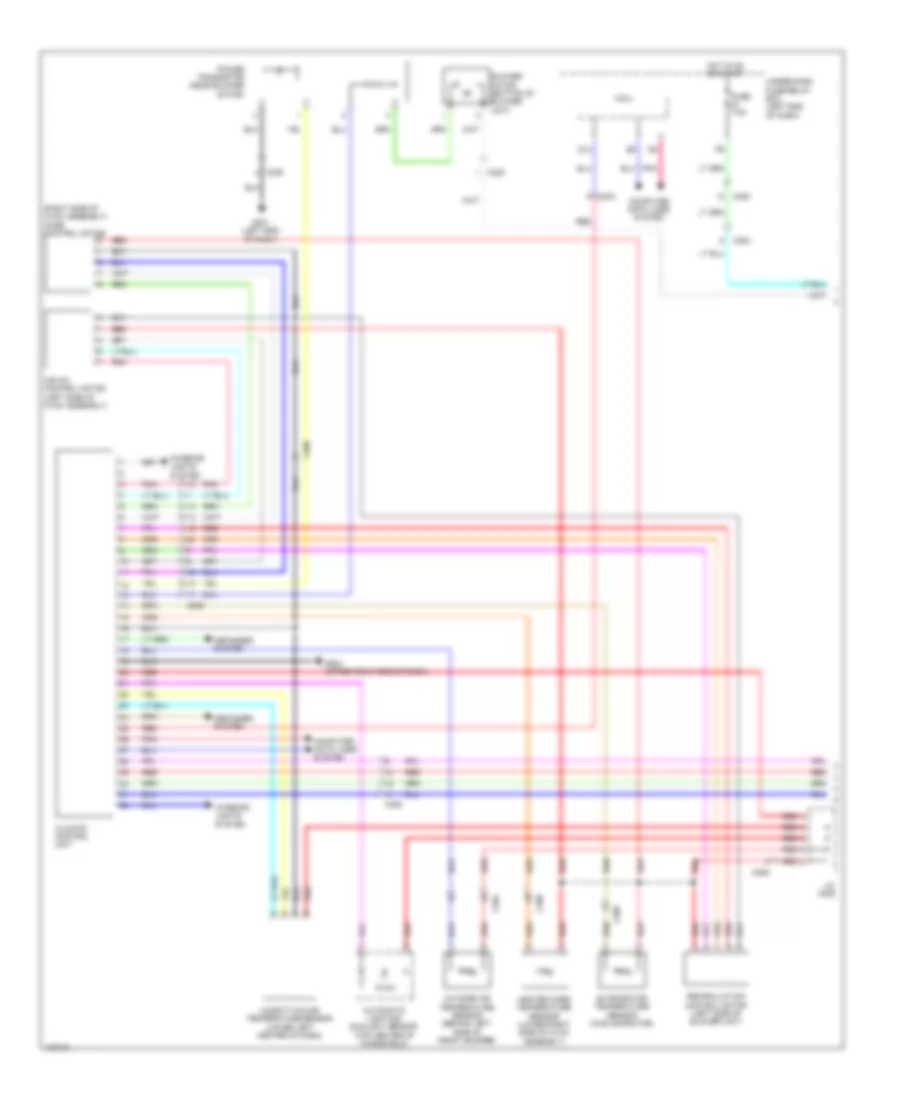
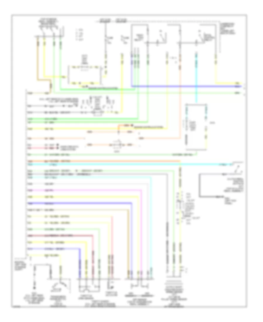
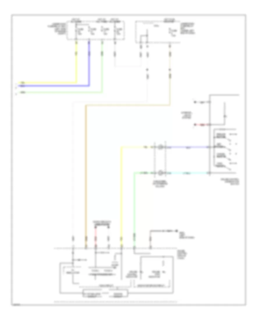
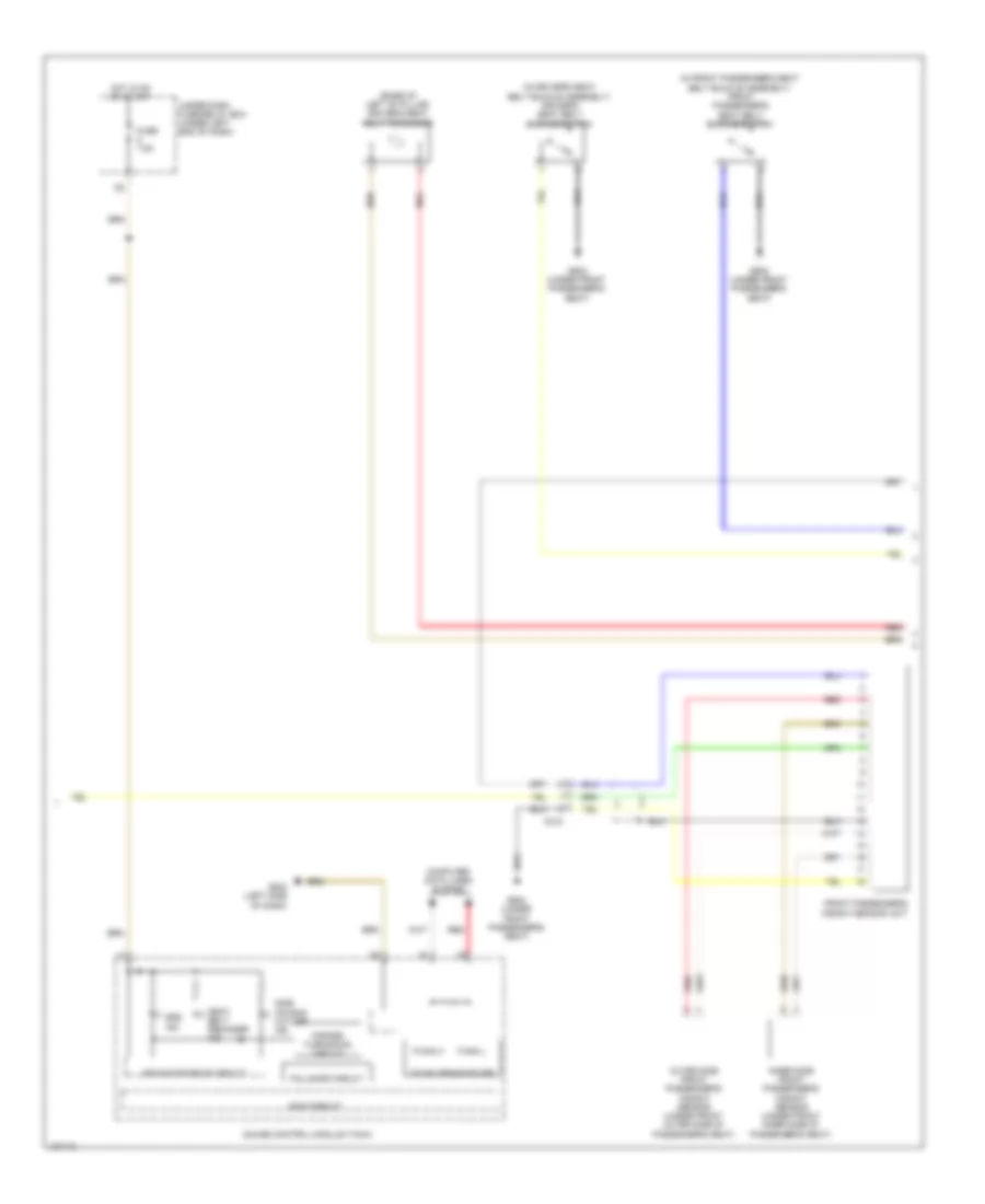
Manual A/C Wiring Diagram (3 of 3) for Honda Civic HF 2014
List of elements for Manual A/C Wiring Diagram (3 of 3) for Honda Civic HF 2014:
- (2.4l: left rear of cylinder head) (1.8l: left rear of engine) g101
- (lower left side of radiator) ect sensor 2
- (or pnk)
- (or red)
- 1.8l
- 2.4l
- 2.4l 1.8l
- A/c compressor clutch relay
- A/c condenser fan motor (behind right side of radiator)
- A/c condenser fan relay
- A/c pressure sensor (lower right front of engine compt)
- A/f sensor (sensor 1) (on exhaust manifold)
- A10
- A12
- A15
- A16
- A20
- A27
- A30
- A37
- A44
- B10
- B34
- B44
- C10
- C215
- C39
- C40
- C404
- C410
- Computer data lines system
- Diode a
- Diode b
- Ect sensor 1 (left rear of engine)
- Engine controls system
- Fan control relay
- Ftp sensor (under center of rear seats)
- Fuse 15a
- Fuse 2-10 20a
- Fuse 2-11 20a
- Fuse 7.5a
- G301 (under left front headlight assembly)
- Hot at all times
- J/c c009 (1.8l) j/c c012 (2.4l)
- Pcm (left side of engine compt)
- Pgm-fi sub relay
- Radiator fan motor (behind left side of radiator)
- Radiator fan relay
- Red
- Under-hood fuse/relay box (left side of engine compt)
ANTI-LOCK BRAKES
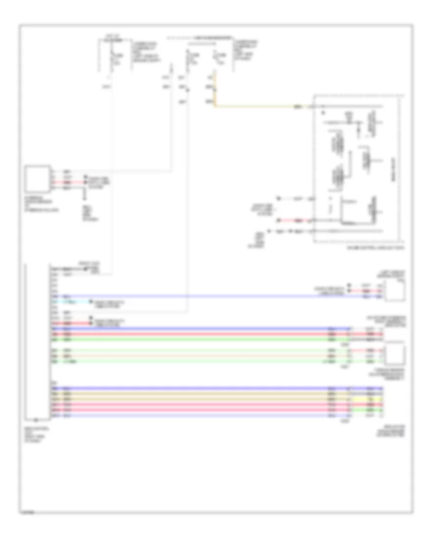
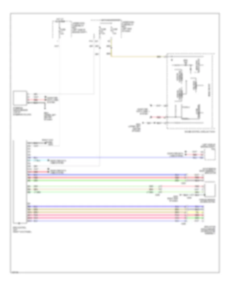
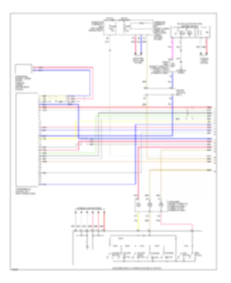
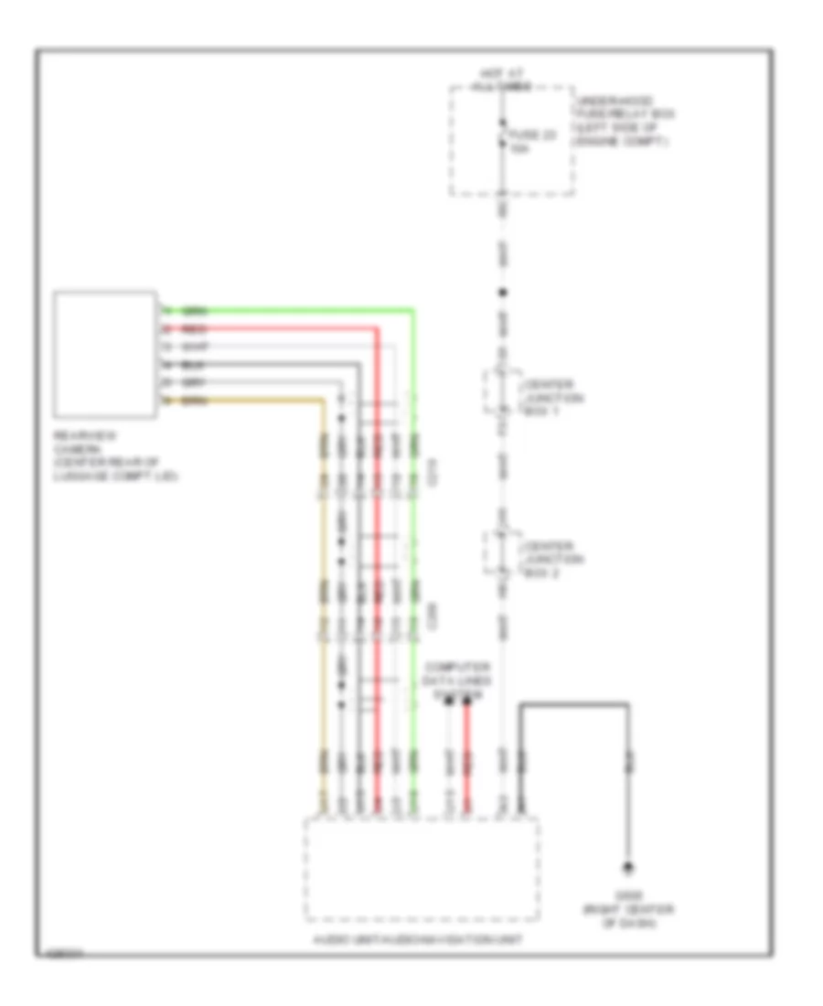
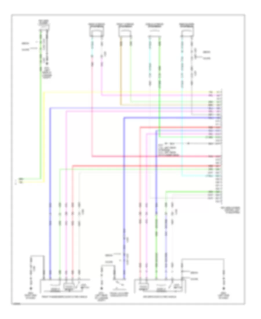
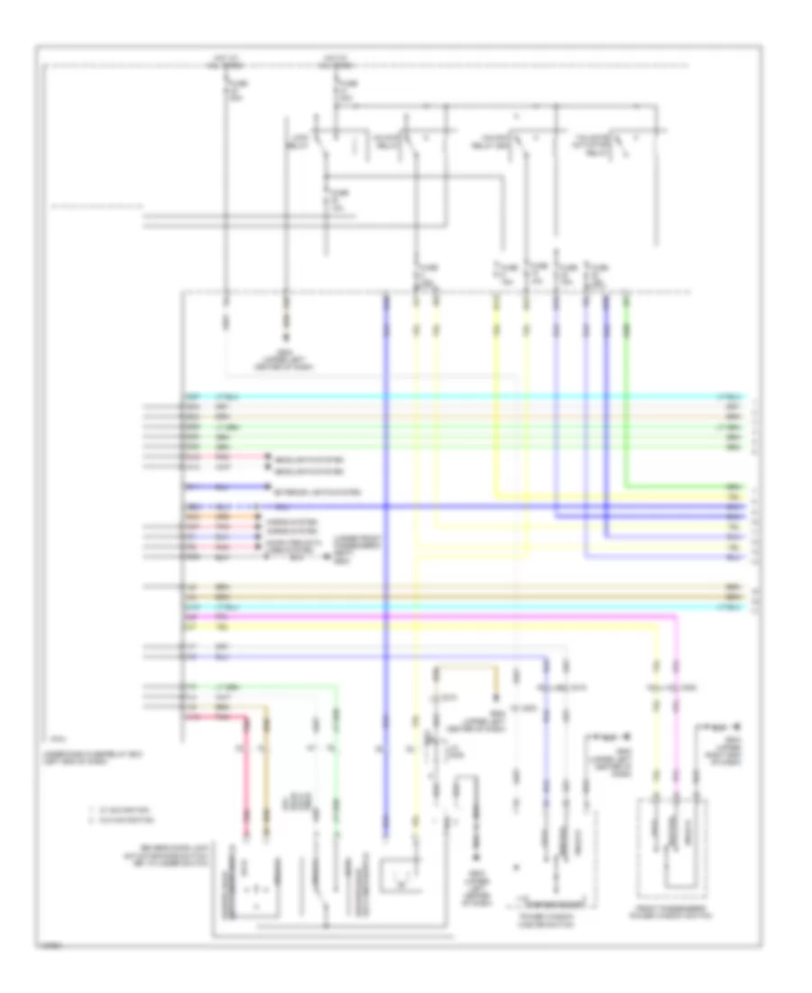
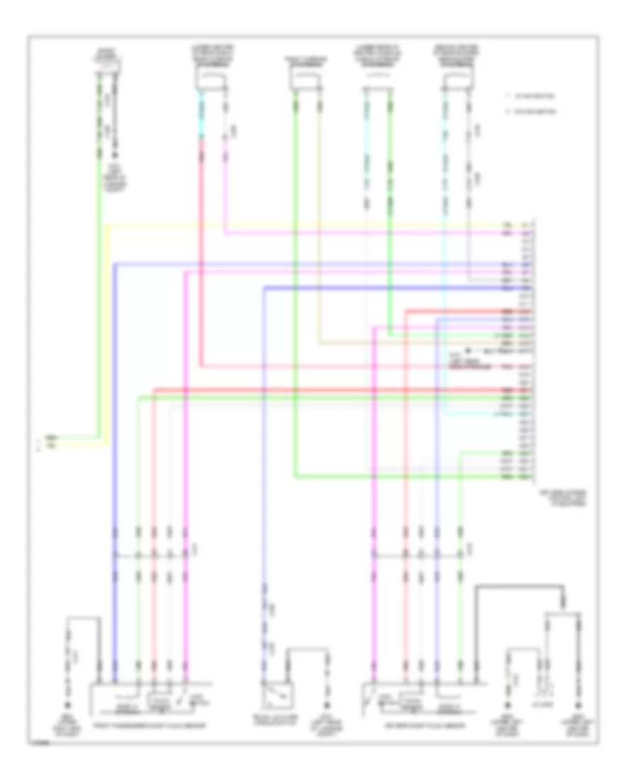
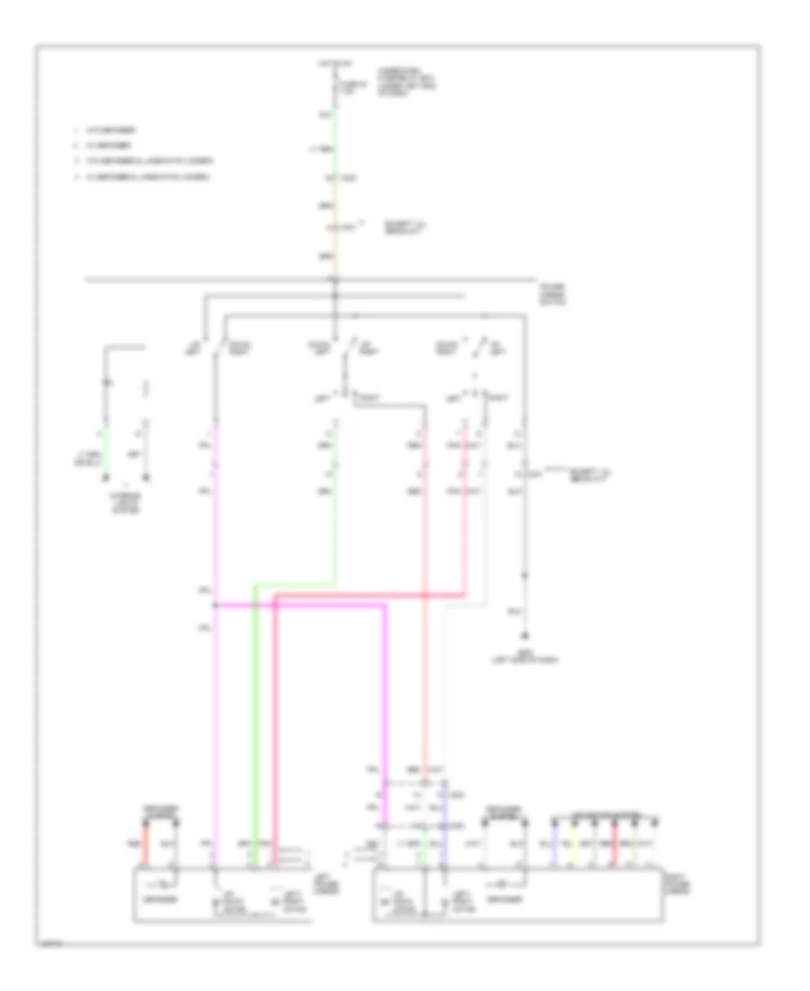
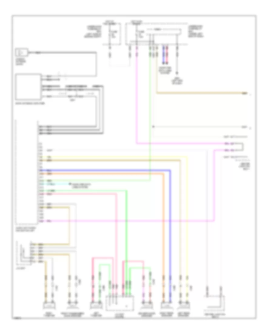
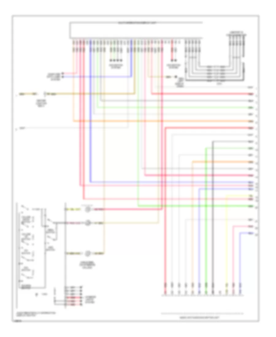
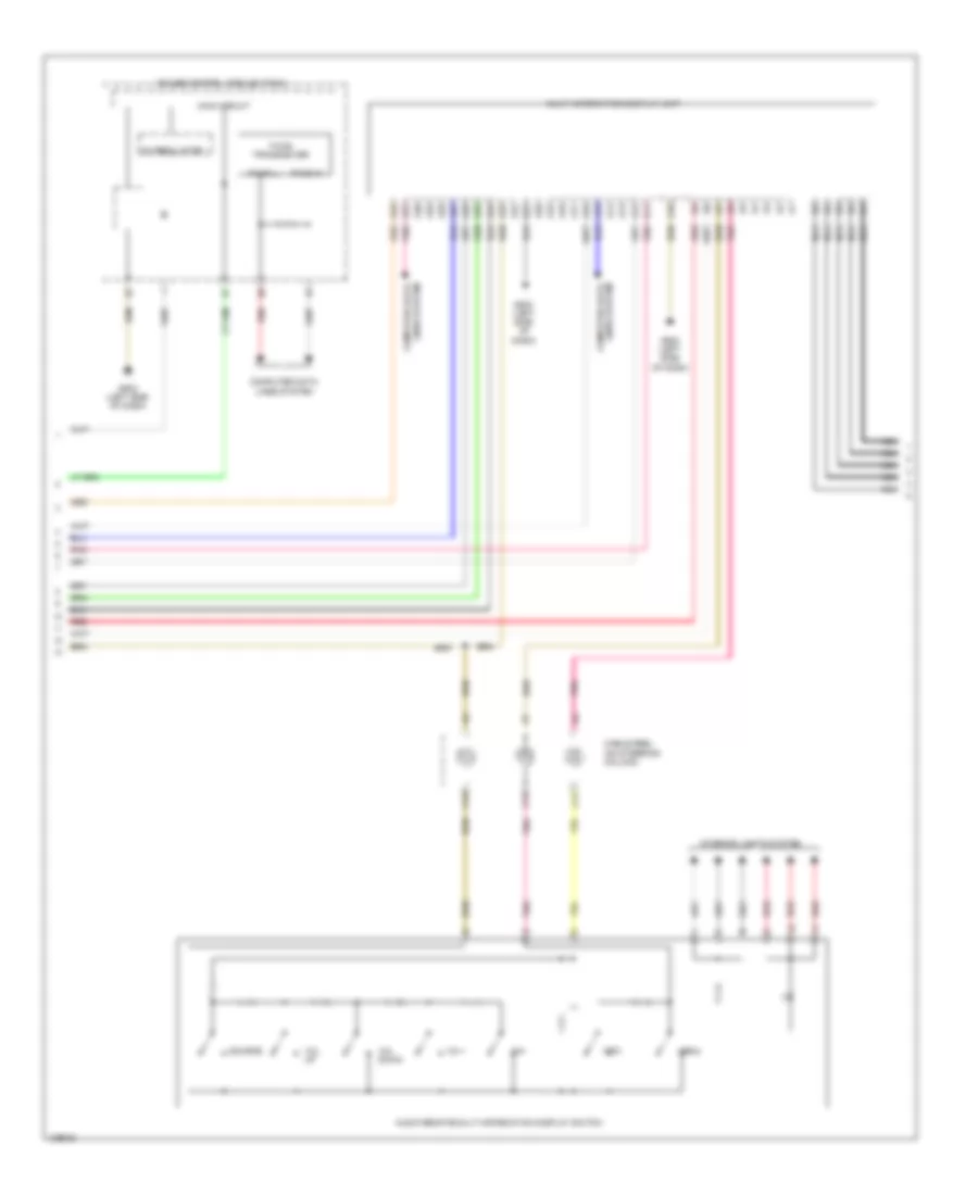
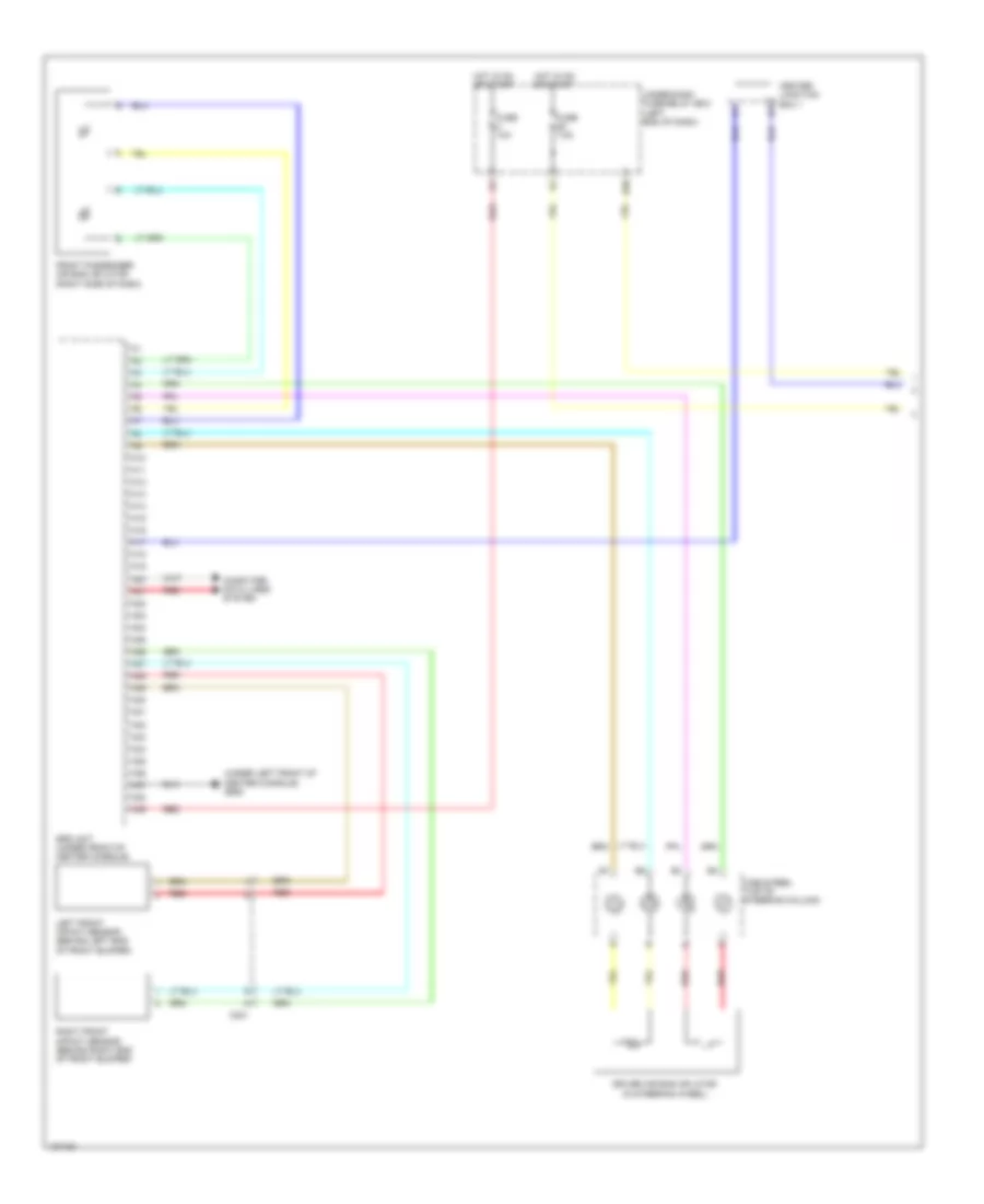
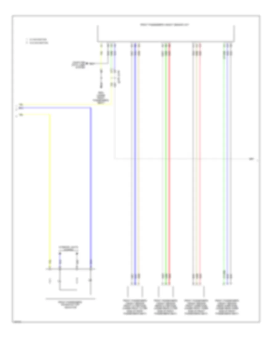
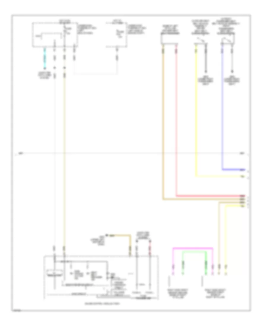
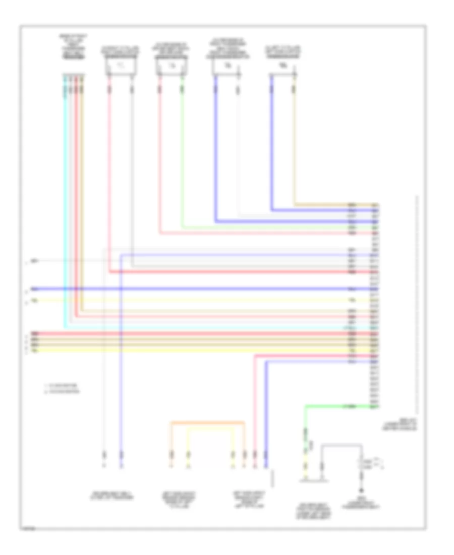
Advanced Hydraulic Booster Wiring Diagram for Honda Civic HF 2014
List of elements for Advanced Hydraulic Booster Wiring Diagram for Honda Civic HF 2014:
- 5v regulator
- A13
- Audio unit/ audio navigation unit
- B11
- B19
- Brake fluid level switch (on brake master cylinder reservoir)
- Brake ind (red)
- Brake pedal position switch (top of brake pedal assembly)
- Brake pedal stroke sensor (top of brake pedal assembly)
- Brake system ind (amber)
- C16
- C204
- C206
- Computer data lines system
- D17
- D31
- F can transceiver
- F-can h
- F-can l
- Fail safe circuit
- Forced turning on circuit
- Fuse 1-2 40a
- Fuse 10a
- Fuse 15a
- Fuse 7.5a
- G202 (right front of engine compt)
- G401 (left end of dash)
- Gauge control module (tach)
- Hot at all times
- Hot in on
- Hot in on or start
- Indicator drive circuit
- Keyless access control unit
- Main circuit
- Parking brake switch (at base of parking brake lever)
- Pcm (left side of engine compt)
- Power unit (bottom right rear of engine compt)
- Red
- Servo unit (left rear corner of engine compt)
- Under-dash fuse/relay box (left end of dash)
- Under-hood fuse/relay box (left side of engine compt)
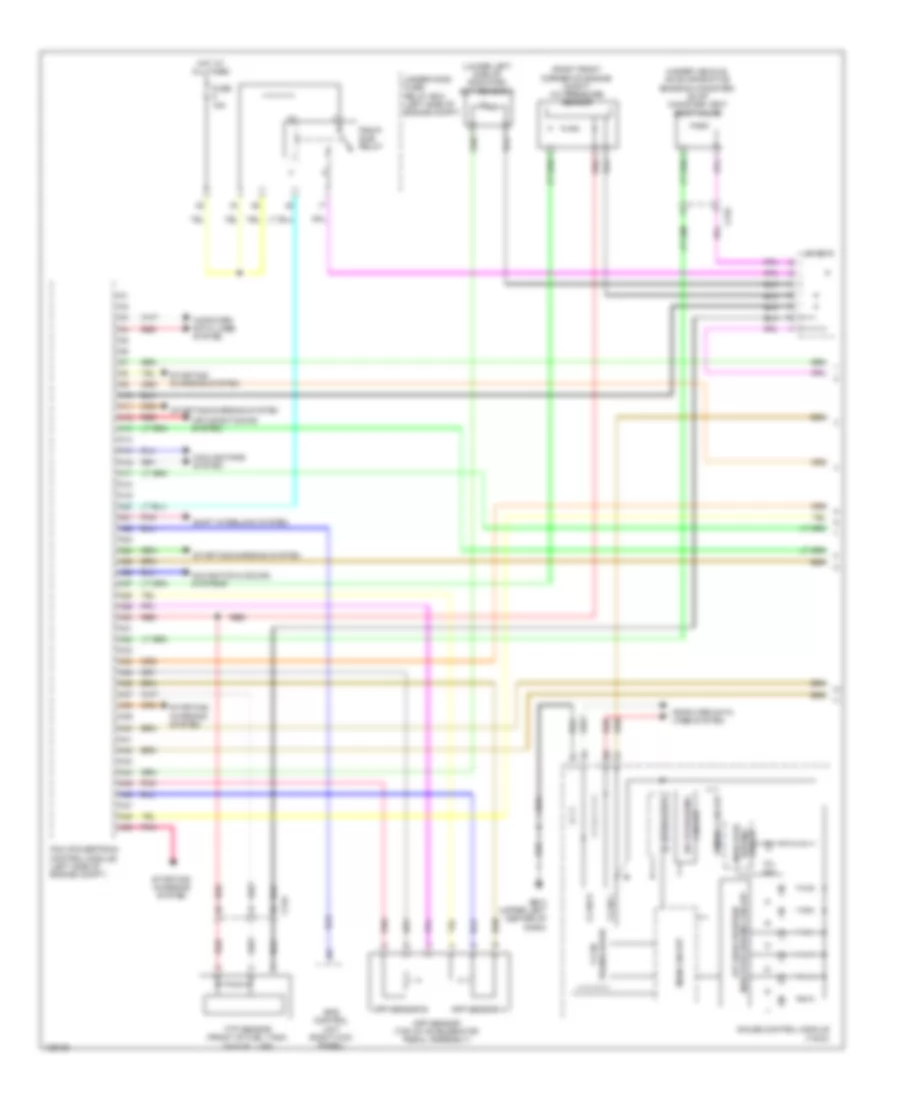
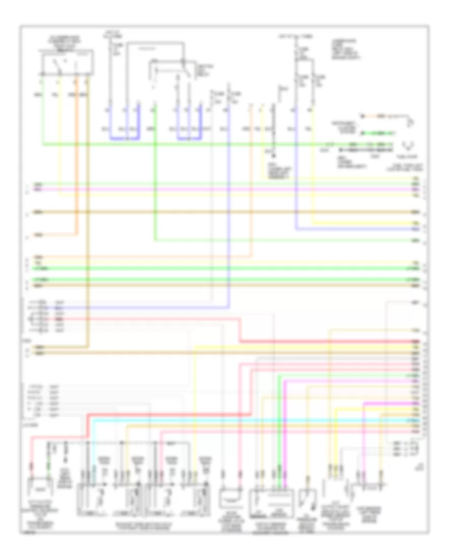
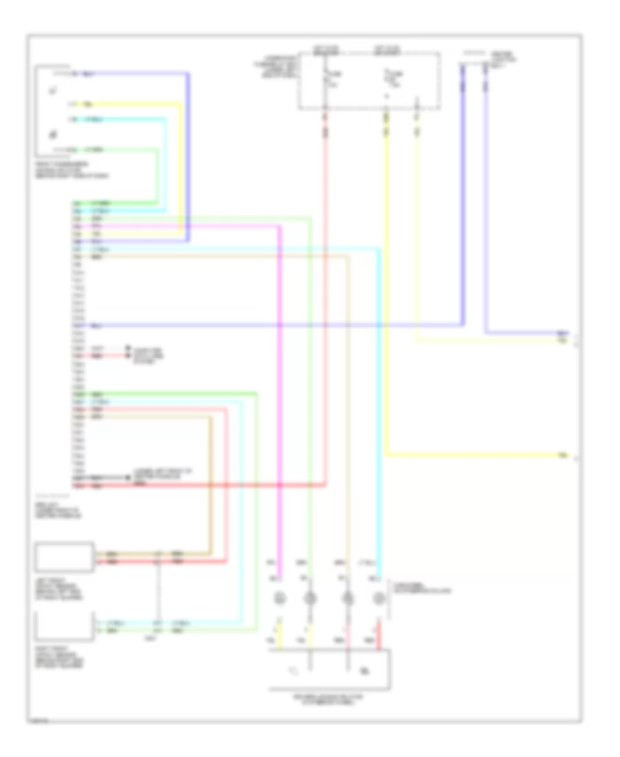
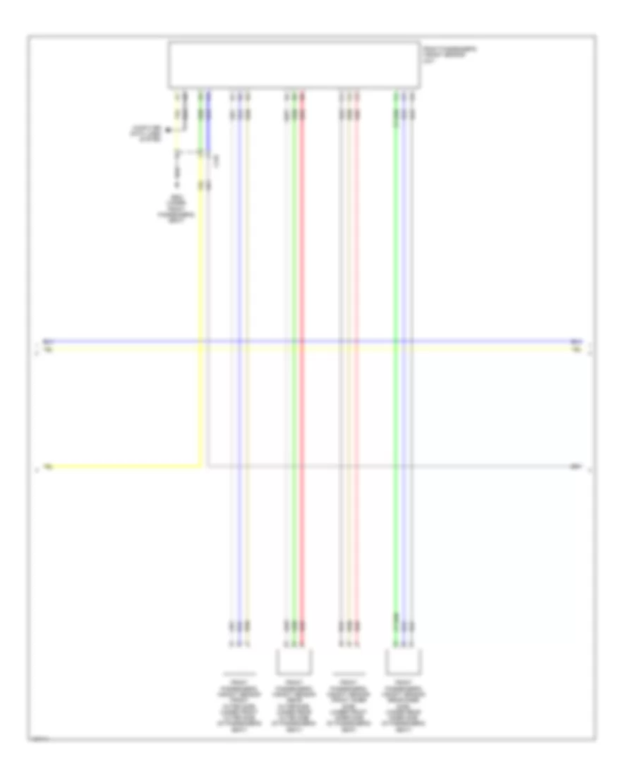
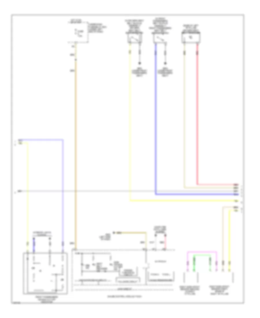
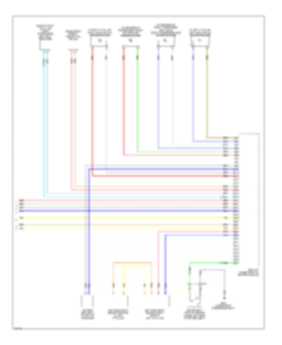
Anti-Lock Brakes Wiring Diagram, Except Hybrid for Honda Civic HF 2014
List of elements for Anti-Lock Brakes Wiring Diagram, Except Hybrid for Honda Civic HF 2014:
- (1.8l)
- (at base of parking brake lever) parking brake switch
- (or red)
- (right front of engine compt) g202
- 1.8l
- 2.4l
- A13
- Abs ind
- Audio unit/ audio navigation unit
- B11
- B19
- Brake fluid level switch (on brake master cylinder reservoir)
- Brake ind
- Brake pedal position switch (top of brake pedal assembly)
- C16
- C204
- C205
- C215
- Circuit fail-safe
- Column)
- Computer data lines system
- D31
- Econ switch
- Except 1.8l m/t
- F can transceiver
- F-can h
- F-can l
- Fuse 1-3 30a
- Fuse 1-4 30a
- Fuse 10a
- Fuse 15a
- Fuse 7.5a
- G401 (left kick panel)
- G501 (left end of dash)
- G503 (left side of dash)
- Gauge control module (tach)
- Hot at all times
- Hot in on or start
- Indicator drive circuit
- Interior lights system
- Keyless access control unit
- Left front wheel speed sensor (on left front wheel hub assembly)
- Left rear wheel speed sensor (on left rear wheel hub assembly)
- Main circuit
- On circuit
- P15
- Pcm (left side of engine compt)
- Pnk
- Red
- Regulator 5v
- Right front wheel speed sensor (on right front wheel hub assembly)
- Right rear wheel speed sensor (on right rear wheel hub assembly)
- Steering angle sensor (in steering
- Turning- forced
- Under-dash fuse/relay box (under left end of dash)
- Under-hood fuse/relay box (left side of engine compt)
- Vsa ind
- Vsa modulator control unit (right front of engine compt)
- Vsa off ind
- Vsa off switch
Anti-Lock Brakes Wiring Diagram, Hybrid for Honda Civic HF 2014
List of elements for Anti-Lock Brakes Wiring Diagram, Hybrid for Honda Civic HF 2014:
- (at base of parking brake lever) parking brake switch
- (if equipped)
- (right front of engine compt) g202
- 5v regulator
- A13
- Abs ind
- Audio unit/ audio navigation unit
- B11
- B19
- Brake fluid level switch (on brake master cylinder reservoir)
- Brake ind (red)
- Brake pedal position switch (top of brake pedal assembly)
- Brake system ind (amber)
- C16
- C204
- C206
- C216
- Computer data lines system
- D31
- Econ switch
- F can transceiver
- F-can h
- F-can l
- Fail safe circuit
- Forced turning on circuit
- Fuse 1-3 30a
- Fuse 1-4 30a
- Fuse 10a
- Fuse 15a
- Fuse 7.5a
- G401 (left end of dash)
- G501 (upper left end of dash)
- G503 (upper left center of dash)
- Gauge control module (tach)
- Hot at all times
- Hot in on or start
- Indicator drive circuit
- Interior lights system
- Keyless access control unit
- Left front wheel speed sensor (on left front wheel hub assembly)
- Left rear wheel speed sensor (on left rear wheel hub assembly)
- Main circuit
- P15
- Pcm (left side of engine compt)
- Pnk
- Red
- Right front wheel speed sensor (on right front wheel hub assembly)
- Right rear wheel speed sensor (on right rear wheel hub assembly)
- Steering angle sensor (top of
- Steering column)
- Under-dash fuse/relay box (left end of dash)
- Under-hood fuse/relay box (left side of engine compt)
- Vsa ind
- Vsa modulator control unit (right front of engine compt)
- Vsa off ind
- Vsa off switch
ANTI-THEFT
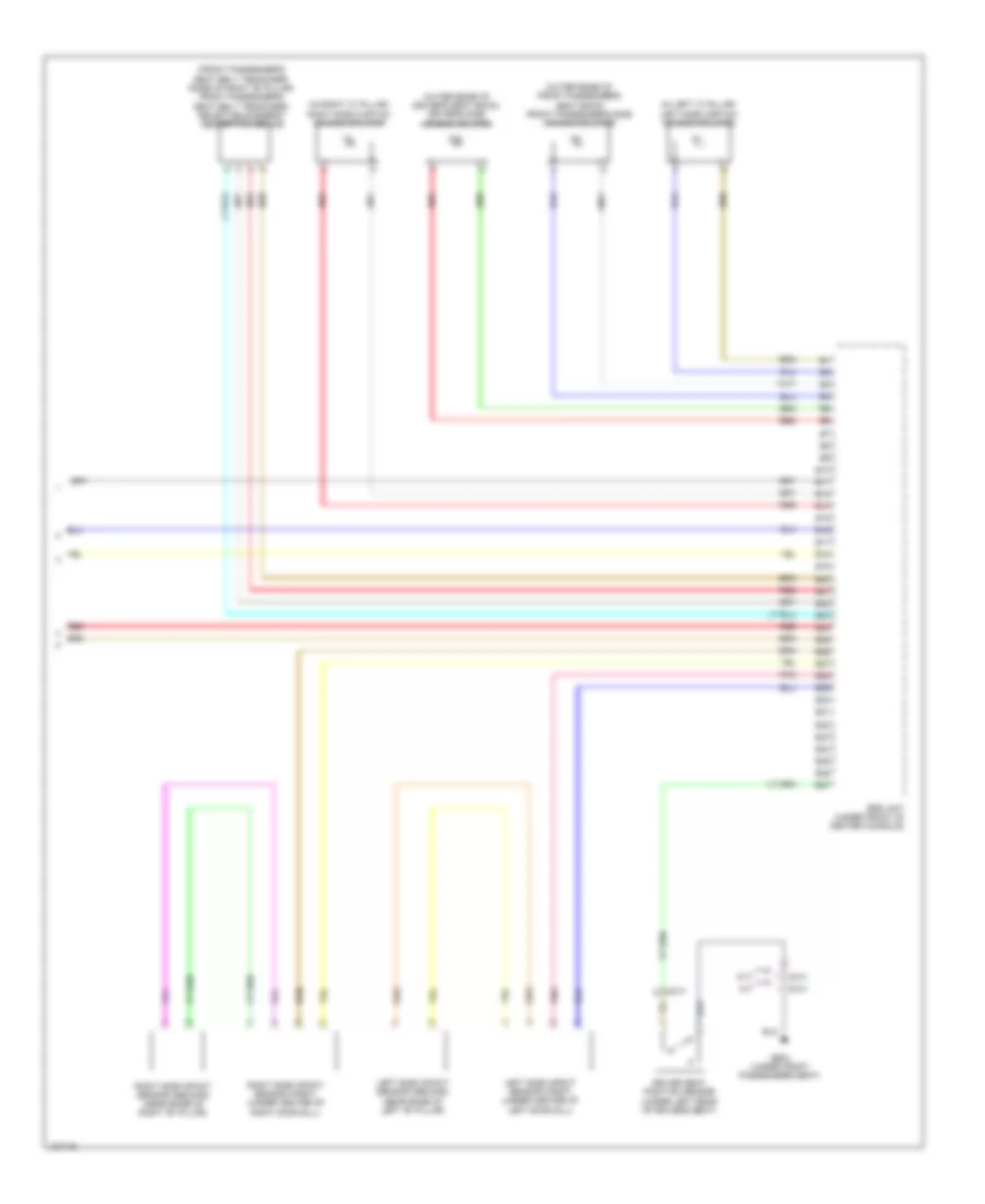
Forced Entry Wiring Diagram, Except Hybrid (1 of 6) for Honda Civic HF 2014
List of elements for Forced Entry Wiring Diagram, Except Hybrid (1 of 6) for Honda Civic HF 2014:
- (under front passenger's seat) g602
- 1.8l
- B11
- B15
- B18
- B22
- B29
- B32
- B33
- B34
- B40
- C19
- C202
- C210
- C37
- Computer data lines system
- D/l dr unlock relay
- D/l lock relay
- D/l unlock relay
- D23
- D29
- Driver's door lock actuator/knob switch/key cylinder switch
- Driver's door lock knob switch
- Exterior lights system
- Front passenger's power window switch
- Fuse 10a
- Fuse 15a
- Fuse 20a
- G502 (left side of dash)
- G503 (left side of dash)
- G504 (right end of dash)
- Headlights system
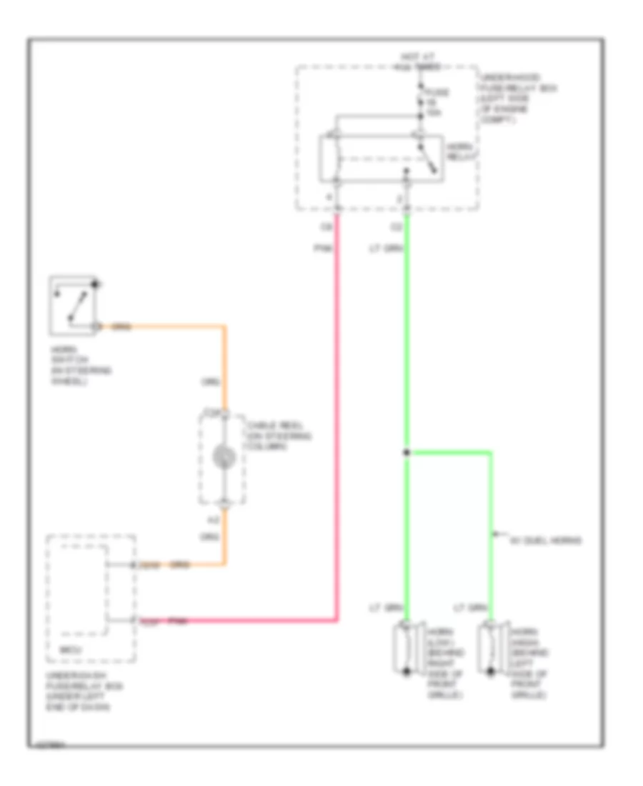
- Horns system
- Hot at all times
- Ignition key switch
- Key cylinder switch driver's door
- Knob lock door key
- Lock
- Micu
- N10
- N12
- Neutral
- P11
- P20
- Pnk
- Power window master switch
- Q10
- Trunk release actuator relay
- Under-dash fuse/relay box (under left end of dash)
- Unlock
- W/ keyless access
- W/o keyless access
- W10
- X10
Forced Entry Wiring Diagram, Except Hybrid (2 of 6) for Honda Civic HF 2014
List of elements for Forced Entry Wiring Diagram, Except Hybrid (2 of 6) for Honda Civic HF 2014:
- C202
- C207
- C212
- C213
- C217
- C219
- Coupe
- Door lock knob
- Driver's door switch (in driver's "b" pillar)
- Front passenger's door lock actuator/knob switch
- Front passenger's door switch (in front passenger's "b" pillar)
- G504 (right end of dash)
- G602 (under front passenger's seat)
- G701 (left rear of luggage compt)
- Key
- Left rear door lock actuator/knob switch (sedan)
- Left rear door switch (sedan) (in left rear "c" pillar)
- Lock
- Pnk
- Right rear door lock actuator/knob switch (sedan)
- Right rear door switch (sedan) (in right rear "c" pillar)
- Sedan
- Trunk lid latch switch/trunk release actuator (trunk release actuator: bottom rear of luggage compt lid)
- Unlock
Forced Entry Wiring Diagram, Except Hybrid (3 of 6) for Honda Civic HF 2014
List of elements for Forced Entry Wiring Diagram, Except Hybrid (3 of 6) for Honda Civic HF 2014:
- 1.8l
- 2.4l
- A16
- B10
- B11
- B12
- B13
- B14
- B15
- B16
- B17
- B18
- B19
- B20
- B21
- B22
- B23
- B24
- B25
- B26
- B27
- B28
- B44
- C10
- C11
- C12
- C13
- C14
- C15
- C16
- C17
- C18
- C19
- C20
- C21
- C22
- C225
- C23
- C24
- C27
- C407
- Center junction box 1
- Center junction box 2
- Computer data lines system
- D28
- Exterior lights system
- Fuse 10a
- Fuse 15a
- Fuse 2-1 50a
- Fuse 7.5a
- G101 (1.8l: left rear of engine) (2.4l: left rear of cylinder head)
- G101 (left rear of engine)
- Headlights system
- Hot at all times
- Hot in on or start
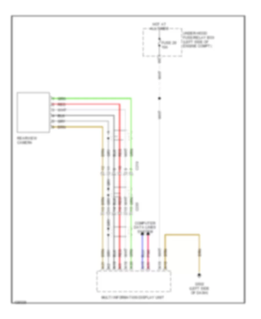
- Keyless access control unit (if equipped)
- Micu
- Multi-information display unit
- P18
- P19
- Pnk
- Q16
- Red
- Transmission range switch (cvt) (top of transmission)
- Under-dash fuse/relay box (under left end of dash)
- Under-hood fuse/relay box (left side of engine compt)
- W/ keyless access
- W/o keyless access
- W11
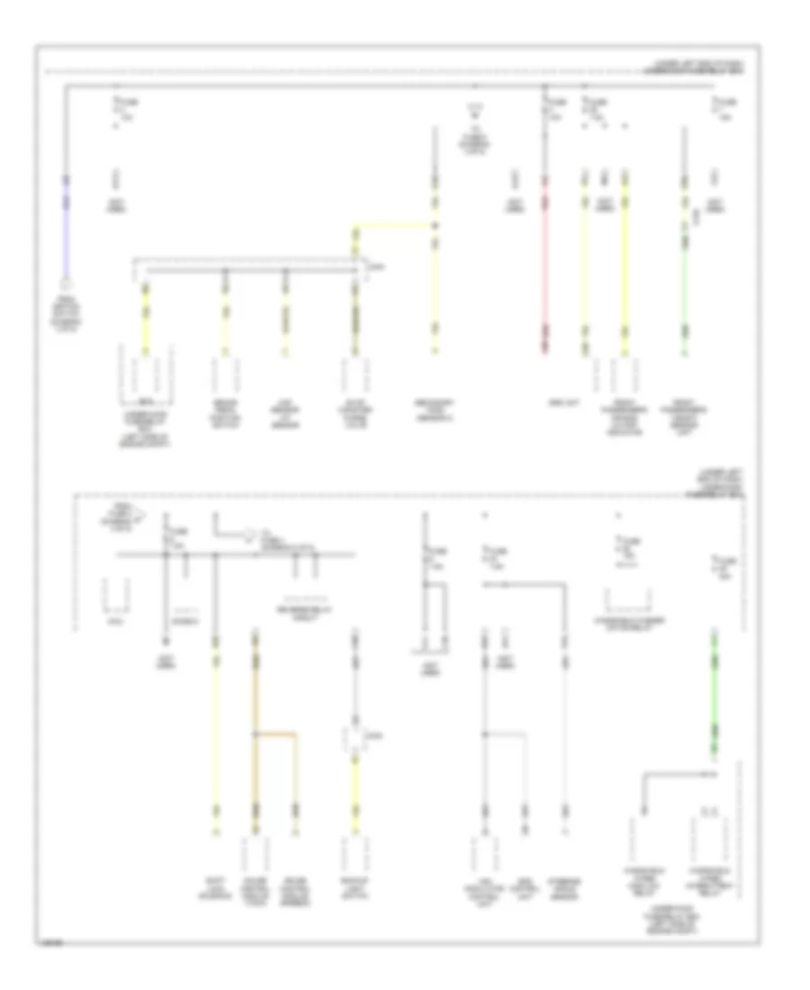
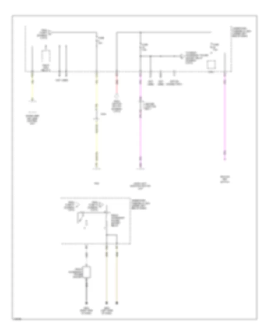
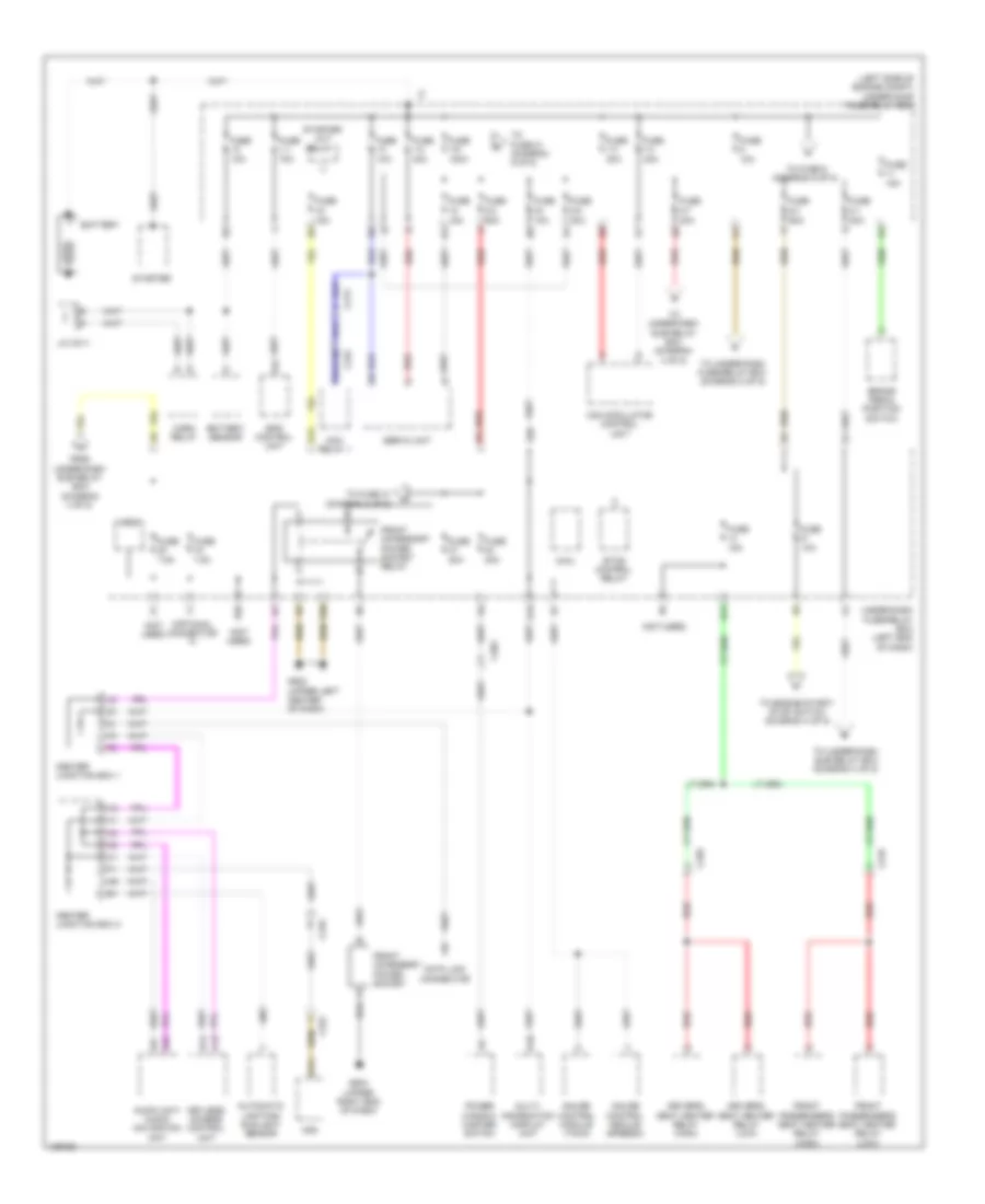
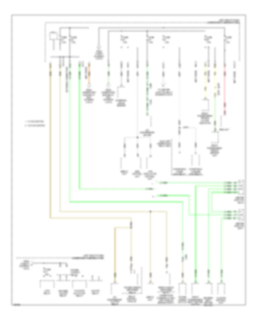
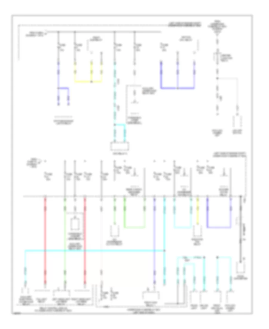
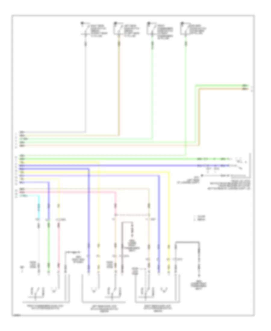
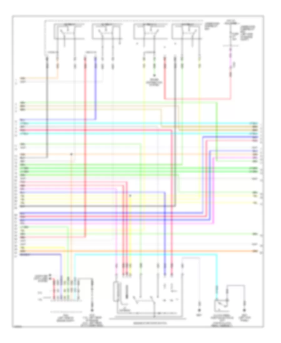
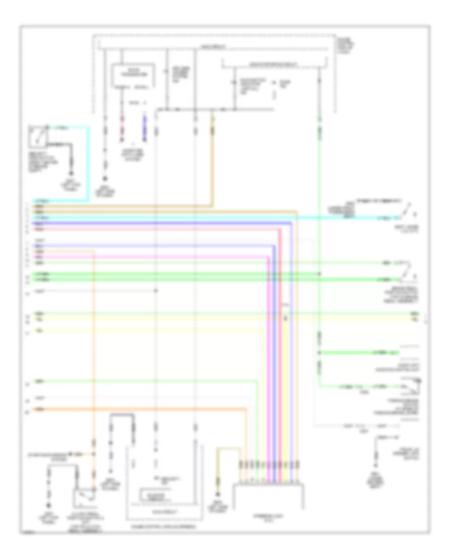
Forced Entry Wiring Diagram, Except Hybrid (4 of 6) for Honda Civic HF 2014
List of elements for Forced Entry Wiring Diagram, Except Hybrid (4 of 6) for Honda Civic HF 2014:
- 1.8l
- 2.4l
- 5v regulator
- A14
- A17
- A18
- Acc relay
- B21
- C224
- Clutch pedal position switch b (m/t) (top of clutch pedal assembly)
- Computer data lines system
- Engine start/stop switch
- Fuse 2-7 30a
- G101 (1.8l: left rear of engine) (2.4l: left rear of cylinder head)
- G401 (left kick panel)
- G507
- Hot at all times
- Ig1 relay 1
- Ig1 relay 2
- Ig2 relay
- Immobilizer
- Lf antenna
- Pcm (left side of engine compt)
- Pnk
- Power distribution system
- Red
- Under-dash sub-relay box
- Under-hood fuse/relay box (left side of engine compt)
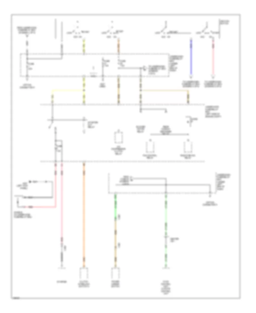
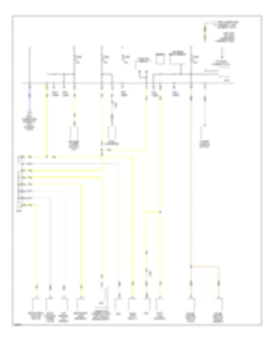
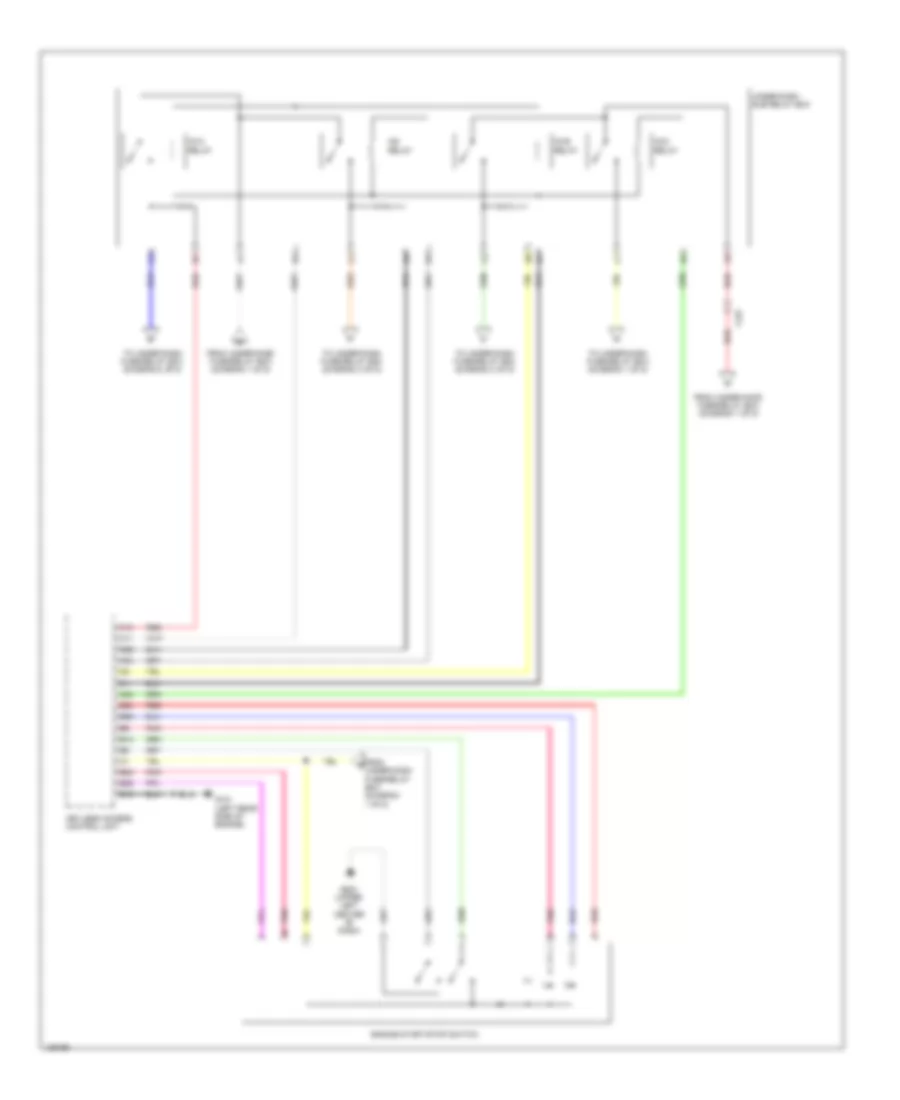
Forced Entry Wiring Diagram, Except Hybrid (5 of 6) for Honda Civic HF 2014
List of elements for Forced Entry Wiring Diagram, Except Hybrid (5 of 6) for Honda Civic HF 2014:
- 2.4l
- Audio unit/ audio-navigation unit
- B-can h
- B-can l
- B-can transceiver
- B11
- Blinking circuit
- Brake pedal position switch (top of brake pedal assembly)
- C205
- C207
- Clutch pedal position switch a (m/t) (top of clutch pedal assembly)
- Computer data lines system
- Door ind
- G401 (left kick panel)
- G502 (left side of dash)
- G503 (left side of dash)
- G601 (under driver's seat)
- G602 (under front passenger's seat)
- Gauge control module (speedo)
- Gauge control module (tach)
- Indicator drive circuit
- Keyless access system ind
- Main circuit
- Malfunction indicator lamp (mil) ind
- Parking brake switch (at base of parking brake lever)
- Pnk
- Security hood switch (front center of engine compt)
- Security ind
- Shift lever (1.8l cvt)
- Starting/charging system
- Steering lock (2.4l)
- Trunk lid opener lock switch
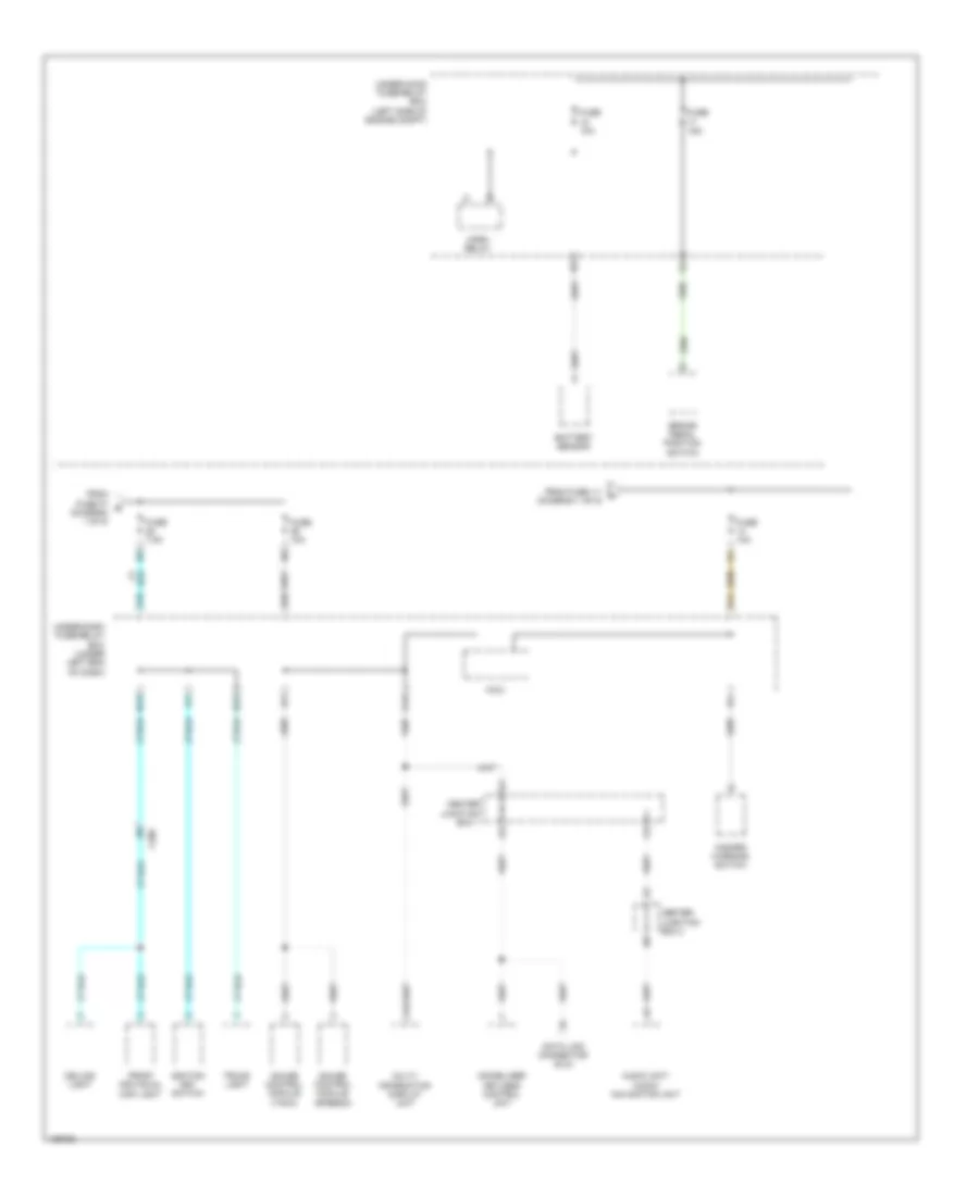
Forced Entry Wiring Diagram, Except Hybrid (6 of 6) for Honda Civic HF 2014
List of elements for Forced Entry Wiring Diagram, Except Hybrid (6 of 6) for Honda Civic HF 2014:
- A10
- A11
- A12
- A13
- A14
- A15
- A16
- A17
- A18
- A19
- A20
- A21
- A22
- A23
- A24
- A25
- A26
- A27
- A28
- A29
- A30
- A31
- A32
- C210
- C217
- C219
- C226
- C227
- Coupe
- Door lf antenna
- Driver's door outer handle
- Front interior lf antenna
- Front passenger's door outer handle
- G101 (1.8l: left rear of engine) (2.4l: left rear of cylinder head)
- G502 (left side of dash)
- G504 (right end of dash)
- G701 (left rear of luggage compt)
- Keyless access control unit (if equipped)
- Keyless buzzer
- Lock switch
- Middle interior lf antenna
- Pnk
- Rear bumper lf antenna
- Rear interior lf antenna
- Red
- Sedan
- Touch sensor
- Trunk lid outer handle switch
Forced Entry Wiring Diagram, Hybrid (1 of 6) for Honda Civic HF 2014
List of elements for Forced Entry Wiring Diagram, Hybrid (1 of 6) for Honda Civic HF 2014:
- (under front passenger's seat) g602
- B11
- B15
- B18
- B22
- B29
- B32
- B33
- B34
- B40
- C11
- C14
- C18
- C202
- C203
- C212
- C27
- C37
- Computer data lines system
- Control block
- D23
- Driver's door lock actuator/knob switch/ key cylinder switch
- Driver's door lock knob switch
- Exterior lights system
- Front passenger's power window switch
- Fuse 10a
- Fuse 15a
- Fuse 20a
- G502 (upper left center of dash)
- G504 (upper right end of dash)
- Headlights system
- Horns system
- Hot at all times
- J/c c008
- Key cylinder switch driver's door
- Knob lock door key
- Lock
- Lock relay
- Micu
- N10
- N12
- Neutral
- P20
- Pnk
- Power window master switch
- Q10
- Tailgate actuator relay
- U10
- Under-dash fuse/relay box (left end of dash)
- Unlock
- Unlock relay
- Unlock relay (dr)
- V10
- W/ navigation
- W/o navigation
Forced Entry Wiring Diagram, Hybrid (2 of 6) for Honda Civic HF 2014
List of elements for Forced Entry Wiring Diagram, Hybrid (2 of 6) for Honda Civic HF 2014:
- (on engine compt hood latch assembly) security hood switch
- (under front passenger's seat) g602
- (upper right end of dash) g504
- C202
- C208
- C214
- C215
- C219
- Door lock knob
- Driver's door switch (on driver's "b" pillar)
- Front passenger's door lock actuator/knob switch
- Front passenger's door switch (on front passenger's "b" pillar)
- G401 (left end of dash)
- G701 (left rear of luggage compt)
- Knob switch door lock front passenger's
- Knob switch door lock left rear
- Knob switch door lock right rear
- Left rear door lock actuator/knob switch
- Left rear door switch (on left rear "c" pillar)
- Lock
- Pnk
- Right rear door lock actuator/knob switch
- Right rear door switch (on right rear "c" pillar)
- Trunk lid latch switch/ trunk release actuator (trunk lid latch switch: part of trunk lid release actuator)
- Unlock
Forced Entry Wiring Diagram, Hybrid (3 of 6) for Honda Civic HF 2014
List of elements for Forced Entry Wiring Diagram, Hybrid (3 of 6) for Honda Civic HF 2014:
- A16
- B10
- B11
- B12
- B13
- B14
- B15
- B16
- B17
- B18
- B19
- B20
- B21
- B22
- B23
- B24
- B25
- B26
- B27
- B28
- B44
- C10
- C11
- C12
- C13
- C14
- C15
- C16
- C17
- C18
- C19
- C20
- C205
- C21
- C22
- C23
- C24
- C27
- C302
- Center junction box 1
- Center junction box 2
- Computer data lines system
- D28
- Exterior lights system
- Fuse 10a
- Fuse 15a
- Fuse 2-1 30a
- Fuse 7.5a
- G101 (left rear side of engine)
- Hot at all times
- Keyless access control unit (if equipped)
- Micu
- Multi-information display unit
- P11
- P18
- P19
- Pnk
- Q16
- Red
- Transmission range switch (on transmission housing)
- Under-dash fuse/relay box (left end of dash)
- Under-hood fuse/relay box (left side of engine compt)
Forced Entry Wiring Diagram, Hybrid (4 of 6) for Honda Civic HF 2014
List of elements for Forced Entry Wiring Diagram, Hybrid (4 of 6) for Honda Civic HF 2014:
- A17
- Accry relay
- B24
- C15
- C227
- Computer data lines system
- Engine start/stop switch
- Fuse 2-7 30a
- G101 (left rear side of engine)
- G503 (upper left center of dash)
- Hot at all times
- Ig1a relay
- Ig1b relay
- Ig2 relay
- Pcm (left side of engine compt)
- Pnk
- Power distribution system
- Red
- Under-dash sub-relay box
- Under-hood fuse/relay box (left side of engine compt)
Forced Entry Wiring Diagram, Hybrid (5 of 6) for Honda Civic HF 2014
List of elements for Forced Entry Wiring Diagram, Hybrid (5 of 6) for Honda Civic HF 2014:
- Audio unit/ audio-navigation unit
- B-can h
- B-can l
- B-can transceiver
- B11
- Blinking circuit
- Brake pedal position switch (top of brake pedal assembly)
- C206
- Computer data lines system
- Door ind
- G401 (left end of dash)
- G503 (upper left center of dash)
- G602 (under front passenger's seat)
- Gauge control module (speedo)
- Gauge control module (tach)
- Immobilizer ind
- Indicator drive circuit
- Keyless access system ind
- Main circuit
- Park pin switch/ a/t gear position indicator panel light (park pin switch: base of a/t shift lever)
- Parking brake switch (at base of parking brake lever)
- Pnk
- Security hood switch (on engine compt hood latch assembly)
- Security ind
Forced Entry Wiring Diagram, Hybrid (6 of 6) for Honda Civic HF 2014
List of elements for Forced Entry Wiring Diagram, Hybrid (6 of 6) for Honda Civic HF 2014:
- (behind center of rear bumper) rear bumper lf antenna
- (under center of rear shelf) rear interior lf antenna
- (under rear of center console) middle interior lf antenna
- A10
- A11
- A12
- A13
- A14
- A15
- A16
- A17
- A18
- A19
- A20
- A21
- A22
- A23
- A24
- A25
- A26
- A27
- A28
- A29
- A30
- A31
- A32
- C211
- C212
- C219
- C228
- Door lf antenna
- Driver's door touch sensor
- Front interior lf antenna
- Front passenger's door touch sensor
- G101 (left rear side of engine)
- G502 (upper left center of dash)
- G504 (upper right end of dash)
- G701 (left rear of luggage compt)
- J/c c008
- Keyless access control unit (if equipped)
- Lock switch
- Pnk
- Red
- Smart buzzer
- Touch sensor
- Trunk lid outer handle switch
- W/ navigation
- W/o navigation
Immobilizer Wiring Diagram, Except Hybrid for Honda Civic HF 2014
List of elements for Immobilizer Wiring Diagram, Except Hybrid for Honda Civic HF 2014:
- 5v regulator
- A17
- A40
- B-can h
- B-can l
- C10
- C13
- C20
- C204
- C205
- C24
- C25
- C35
- C404
- Center junction box 1
- Computer data lines system
- D28
- Data link connector (dlc) (under left side of dash)
- F-can h
- F-can l
- Fuel tank unit (in top of fuel tank)
- Fuse 10a
- Fuse 15a
- Fuse 7.5a
- G101 (left rear of engine)
- G503 (left side of dash)
- G601 (under driver's seat)
- Gauge control module (tach)
- Hot at all times
- Hot in on or start
- Ignition key switch
- Immobilizer ind (led)
- Immobilizer keyless control unit (on steering column)
- Main circuit
- Micu
- P11
- P18
- Parking brake switch (at base of parking brake lever)
- Pcm (left side of engine compt)
- Pgm-fi main relay 1
- Pgm-fi main relay 2
- Pnk
- Q16
- Red
- Transceiver b-can
- Transceiver f-can
- Under-dash fuse/relay box (under left end of dash)
- Under-hood fuse/relay box (left side of engine compt)
BODY CONTROL MODULES
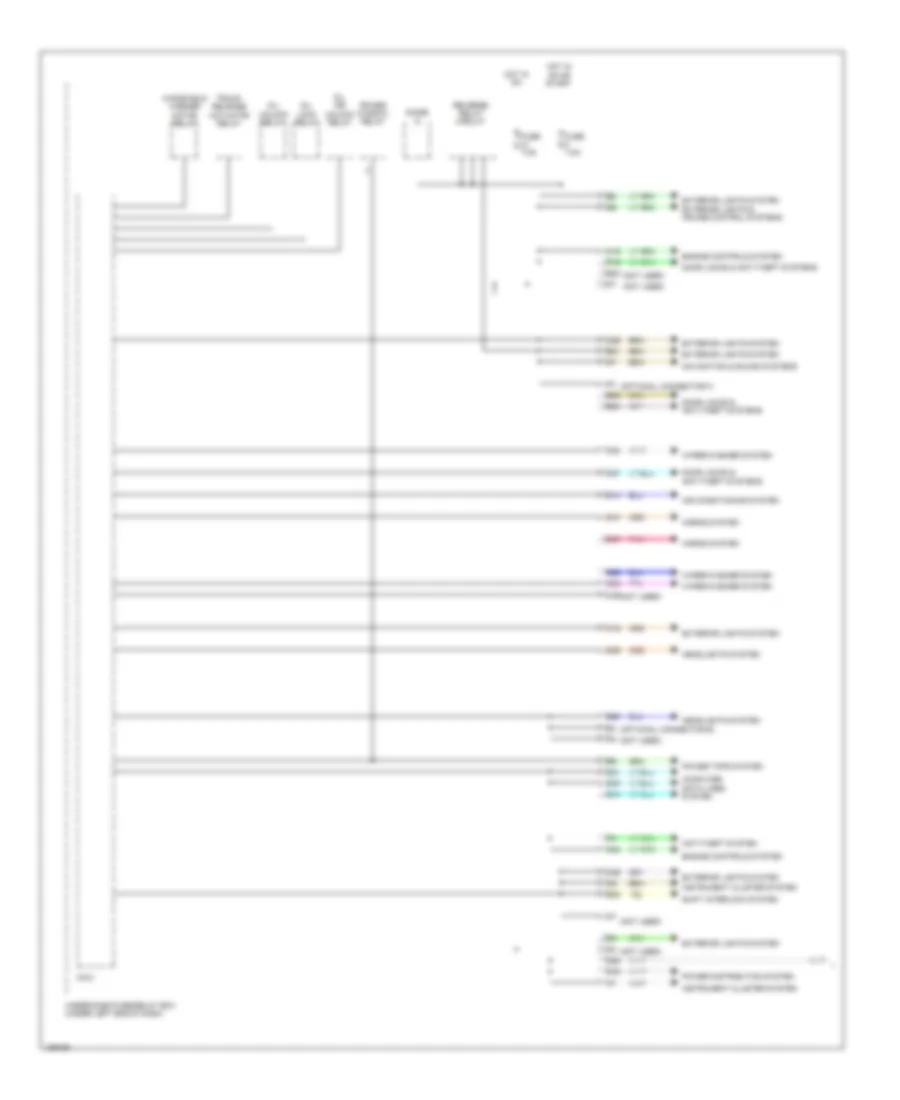
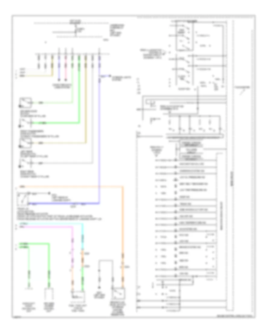
Body Control Modules Wiring Diagram, Except Hybrid (1 of 2) for Honda Civic HF 2014
List of elements for Body Control Modules Wiring Diagram, Except Hybrid (1 of 2) for Honda Civic HF 2014:
- (not used)
- (optional connector e)
- (optional connector f)
- Air conditioning system
- Anti-theft system
- B20
- B21
- B28
- B33
- B34
- C16
- C19
- C22
- C23
- C24
- C26
- C27
- C29
- C32
- C36
- C37
- Computer data lines system
- D/l dr
- D/l lock relay
- D/l unlock relay
- D14
- D20
- D21
- D28
- D29
- D30
- Diode d
- Door locks & anti-theft systems
- Engine controls system
- Exterior lights system
- Exterior lights system exterior lights & cruise control systems
- Fuse 7.5a
- Headlights system
- Horns system
- Hot in on
- Hot in on or start
- Instrument cluster system
- Micu
- Navigation & sound systems
- P19
- Pnk
- Power distribution system
- Power tops system
- Power window relay
- Q10
- Q14
- Q16
- Reverse relay circuit
- Shift interlock system
- Trunk release actuator relay
- Under-dash fuse/relay box (under left end of dash)
- Unlock relay
- Windshield washer motor relay
- Wiper/washer system
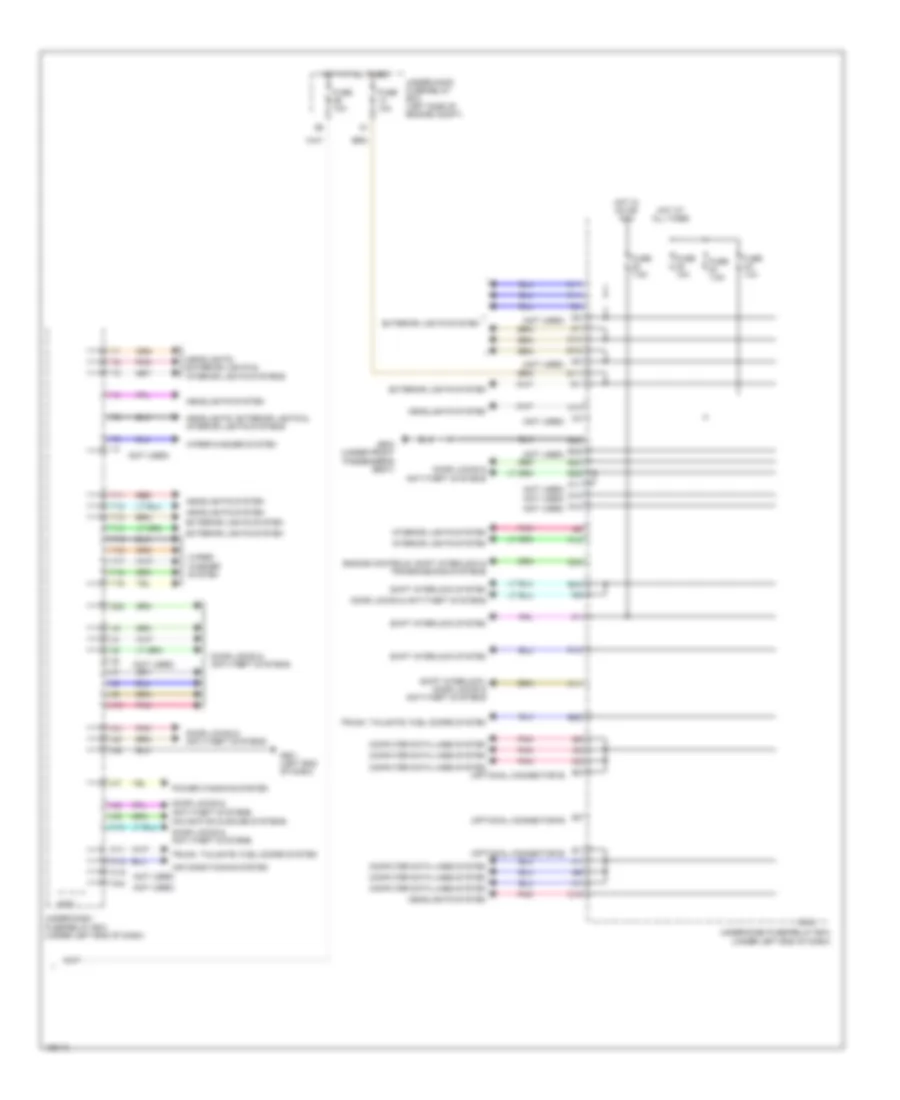
Body Control Modules Wiring Diagram, Except Hybrid (2 of 2) for Honda Civic HF 2014
List of elements for Body Control Modules Wiring Diagram, Except Hybrid (2 of 2) for Honda Civic HF 2014:
- (not used)
- (optional connector e)
- Air conditioning system
- B12
- B22
- B29
- B32
- B38
- B40
- B44
- C11
- C14
- C18
- Computer data lines system
- D11
- D23
- Door locks & anti-theft systems
- Engine controls, shift interlock & transmissions systems
- Exterior lights system
- Fuse 10a
- Fuse 7.5a
- G501 (left end of dash)
- G602 (under front passenger's seat)
- Headlights system
- Headlights, exterior lights & interior lights systems
- Hot at all times
- Hot in on or acc
- Interior lights system
- K10
- K11
- Micu
- N11
- Navigation & sound systems
- P10
- P11
- P12
- Pnk
- Power windows system
- Q12
- Q13
- Red
- Shift interlock system
- Shift interlock, door locks & anti-theft systems
- T11
- T12
- T13
- T14
- T15
- T16
- T17
- T18
- T19
- Trunk, tailgate, fuel doors system
- Under-dash fuse/relay box (under left end of dash)
- Under-hood fuse/relay box (left side of engine compt)
- W10
- W11
- W12
- W19
- W24
- Wiper/ washer system
- Wiper/washer system
- X10
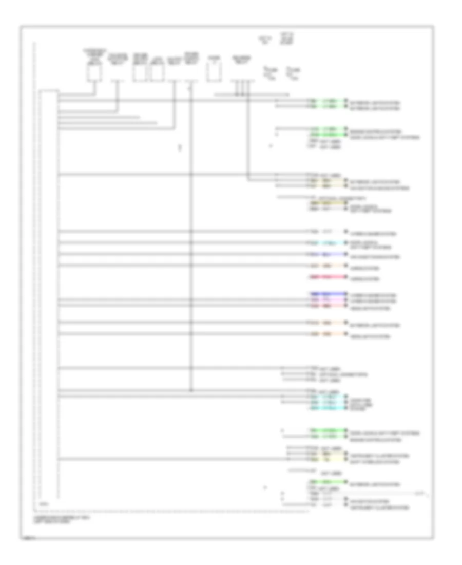
Body Control Modules Wiring Diagram, Hybrid (1 of 2) for Honda Civic HF 2014
List of elements for Body Control Modules Wiring Diagram, Hybrid (1 of 2) for Honda Civic HF 2014:
- (not used)
- (optional connector e)
- (optional connector f)
- Air conditioning system
- B20
- B21
- B28
- B33
- B34
- C16
- C19
- C22
- C23
- C24
- C26
- C27
- C29
- C32
- C36
- C37
- Computer data lines system
- D14
- D20
- D21
- D28
- D29
- D30
- Diode c
- Door locks & anti-theft systems
- Driver unlock relay
- Engine controls system
- Exterior lights system
- Fuse 7.5a
- Headlights system
- Horns system
- Hot in on
- Hot in on or start
- Instrument cluster system
- Lock relay
- Micu
- Navigation & sound systems
- Navigation system
- P19
- Pnk
- Power window relay
- Q10
- Q14
- Q16
- Red
- Reverse relay
- Shift interlock system
- Tailgate actuator relay
- Under-dash fuse/relay box (left end of dash)
- Unlock relay
- Windshield washer main relay
- Wiper/washer system
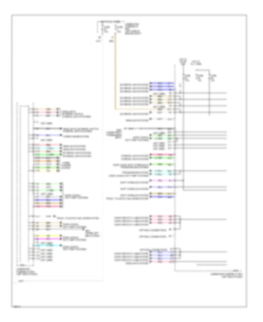
Body Control Modules Wiring Diagram, Hybrid (2 of 2) for Honda Civic HF 2014
List of elements for Body Control Modules Wiring Diagram, Hybrid (2 of 2) for Honda Civic HF 2014:
- (not used)
- (optional connector e)
- B12
- B22
- B29
- B32
- B38
- B40
- B44
- C11
- C14
- C18
- Computer data lines system
- D11
- D23
- Door locks & anti-theft systems
- Door locks, shift interlock & transmissions systems
- Exterior lights system
- Fuse 10a
- Fuse 7.5a
- G501 (upper left end of dash)
- G602 (under front passenger's seat)
- Headlights system
- Headlights, exterior lights & interior lights systems
- Hot at all times
- Hot in on or acc
- Interior lights system
- K10
- K11
- Micu
- N11
- P10
- P11
- P12
- Pnk
- Q12
- Q13
- Red
- Shift interlock system
- T11
- T12
- T13
- T14
- T15
- T16
- T17
- T18
- T19
- Transmissions system
- Trunk, tailgate, fuel doors system
- U10
- U11
- U12
- U17
- U19
- U24
- Under-dash fuse/relay box (left end of dash)
- Under-hood fuse/relay box (left side of engine compt)
- V10
- Washer system
- Wiper/
- Wiper/washer system
COMPUTER DATA LINES
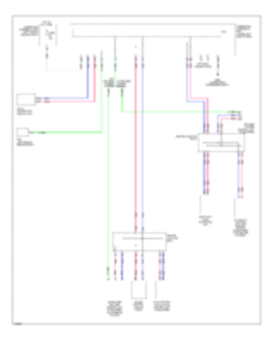
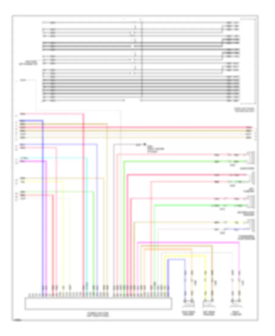
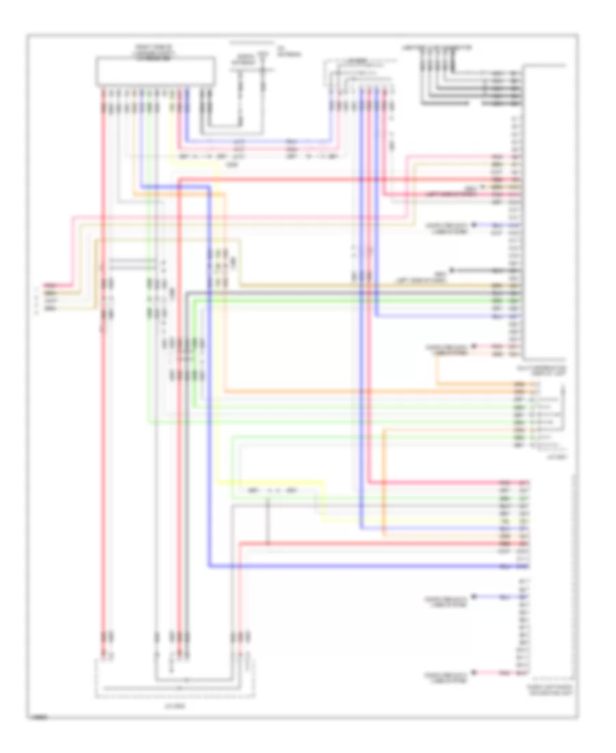
B-CAN Wiring Diagram & S-NET Wiring Diagram, Except Hybrid for Honda Civic HF 2014
List of elements for B-CAN Wiring Diagram & S-NET Wiring Diagram, Except Hybrid for Honda Civic HF 2014:
- (optional connector e)
- A15
- A17
- A31
- Audio unit/ audio navigation unit
- Automatic lighting/ sunlight sensor (if equipped) (top center of dash)
- B13
- B21
- B32
- C24
- Center junction box 1
- Center junction box 2
- D28
- Fuse 10a
- G602 (under front passenger's seat)
- Gauge control module (tach)
- H10
- Hot at all times
- Hvac control unit/climate control unit (if equipped)
- Immobilizer keyless control unit (if equipped) (on steering column)
- Keyless access control unit (if equipped)
- Micu
- Multi- information display unit
- Pcm (left side of engine compt)
- Pnk
- Under-dash fuse/relay box (under left end of dash)
- Under-hood fuse/relay box (left side of engine compt)
- W/ keyless access system
- W/o keyless access system
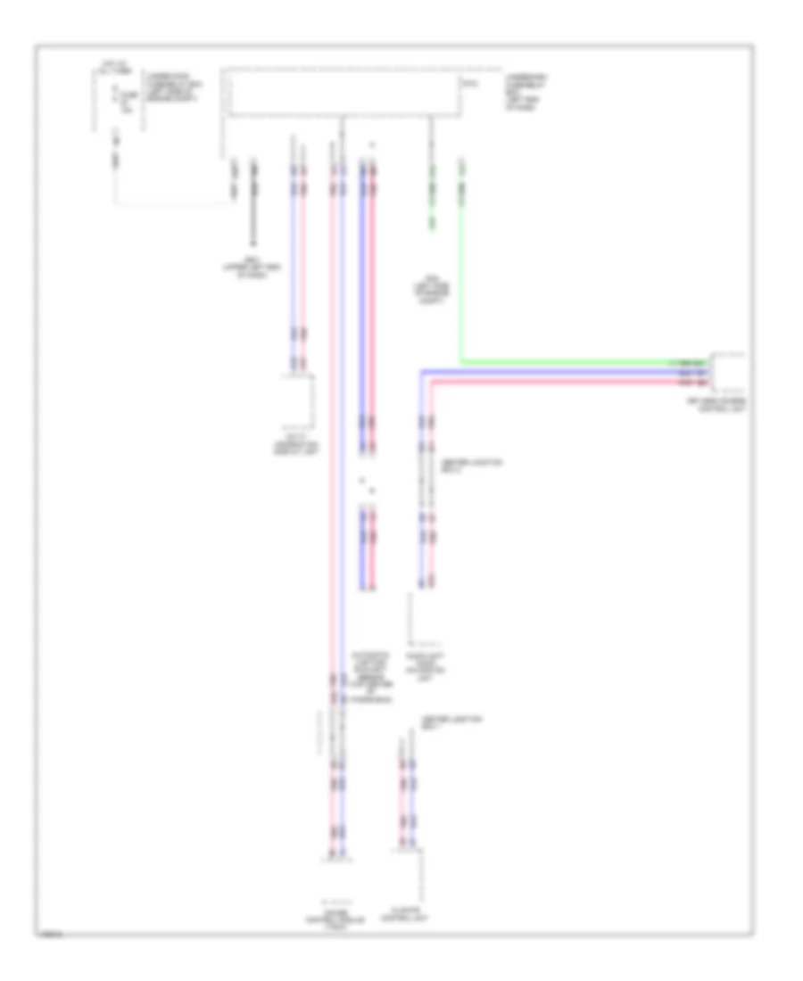
B-CAN Wiring Diagram & S-NET Wiring Diagram, Hybrid for Honda Civic HF 2014
List of elements for B-CAN Wiring Diagram & S-NET Wiring Diagram, Hybrid for Honda Civic HF 2014:
- A15
- A17
- A31
- Audio unit/ audio navigation unit
- Automatic lighting/ sunlight sensor (top center of windshield)
- B13
- B21
- C24
- Center junction box 1
- Center junction box 2
- Climate control unit
- D28
- Fuse 10a
- G501 (upper left end of dash)
- Gauge control module (tach)
- H10
- Hot at all times
- Keyless access control unit
- Micu
- Multi- information display unit
- Pcm (left side of engine compt)
- Pnk
- Under-dash fuse/relay box (left end of dash)
- Under-hood fuse/relay box (left side of engine compt)
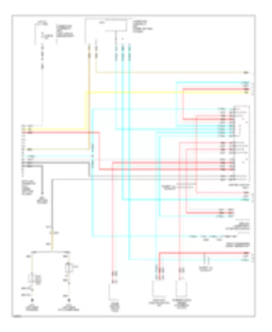
Data Link Connector Wiring Diagram, Except Hybrid (1 of 2) for Honda Civic HF 2014
List of elements for Data Link Connector Wiring Diagram, Except Hybrid (1 of 2) for Honda Civic HF 2014:
- 1.8l
- 2.4l
- A13
- A19
- A20
- A21
- Audio unit/ audio-navigation unit
- C20
- C204
- C205
- C218
- C407 (cvt) c404 (m/t)
- C410
- Center junction box 1
- D21
- D30
- Data link connector (dlc) (under left side of dash)
- Except 1.8l coupe m/t
- Front passenger's weight sensor unit
- Fuse 29 10a
- G101 (left rear of cylinder head)
- G101 (left rear of engine)
- G501 (left end of dash)
- Gauge control module (tach)
- Hot at all times
- J13
- Micu
- Q14
- Red
- Srs unit (under front of center console)
- Steering angle sensor (in steering column)
- Under-dash fuse/relay box (under left end of dash)
- Under-hood fuse/relay box (left side of engine compt)
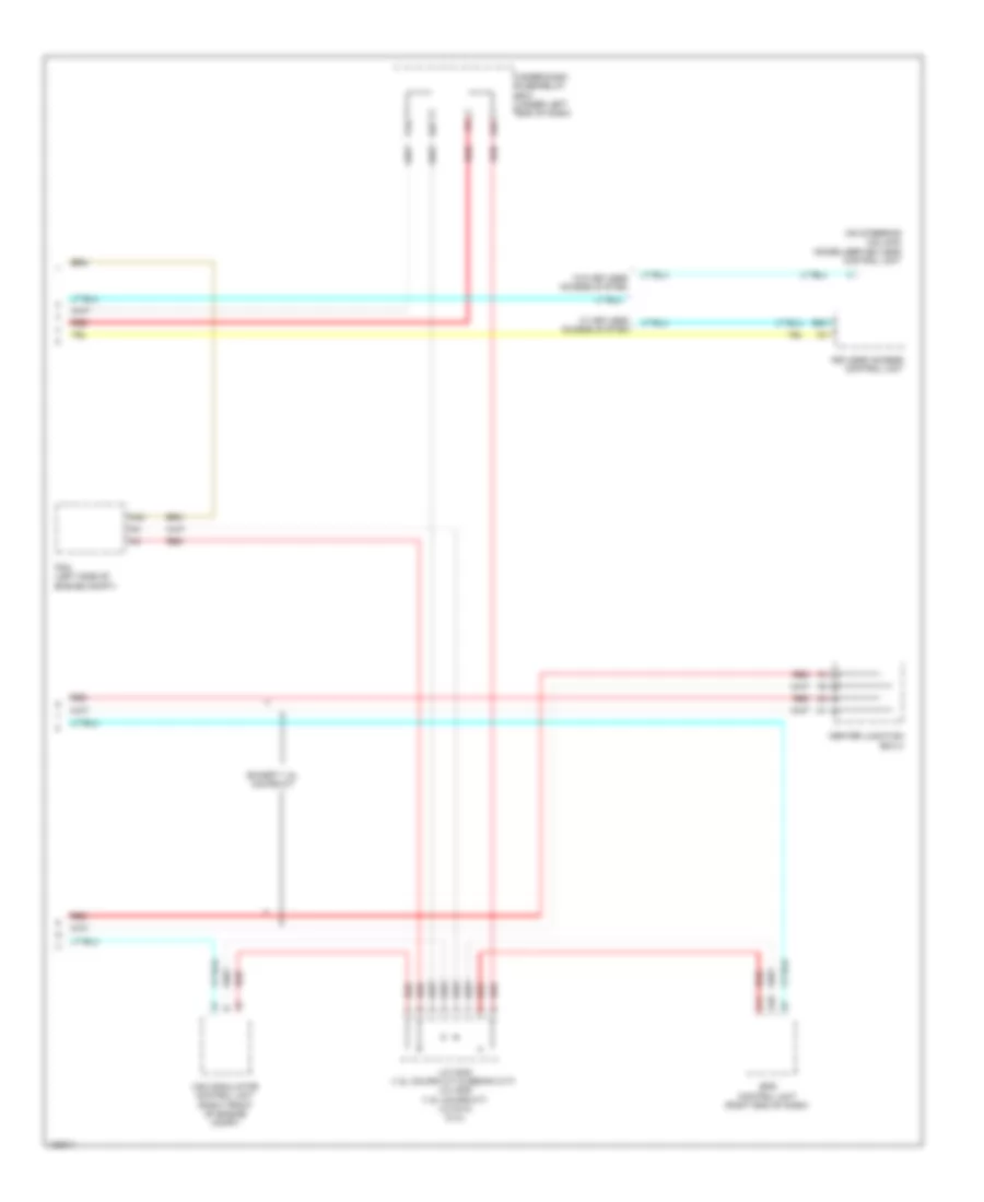
Data Link Connector Wiring Diagram, Except Hybrid (2 of 2) for Honda Civic HF 2014
List of elements for Data Link Connector Wiring Diagram, Except Hybrid (2 of 2) for Honda Civic HF 2014:
- (on steering column) immobilizer keyless control unit
- A10
- A11
- A42
- B20
- Center junction box 2
- D26
- D27
- Eps control unit (right end of dash)
- Except 1.8l coupe m/t
- J/c c005 (1.8l coupe cvt & sedan cvt) j/c c009 (1.8l coupe m/t) j/c c012 (2.4l)
- Keyless access control unit
- P16
- Pcm (left side of engine compt)
- Red
- Under-dash fuse/relay box (under left end of dash)
- Vsa modulator control unit (right front of engine compt)
- W/ keyless access system
- W/o keyless access system
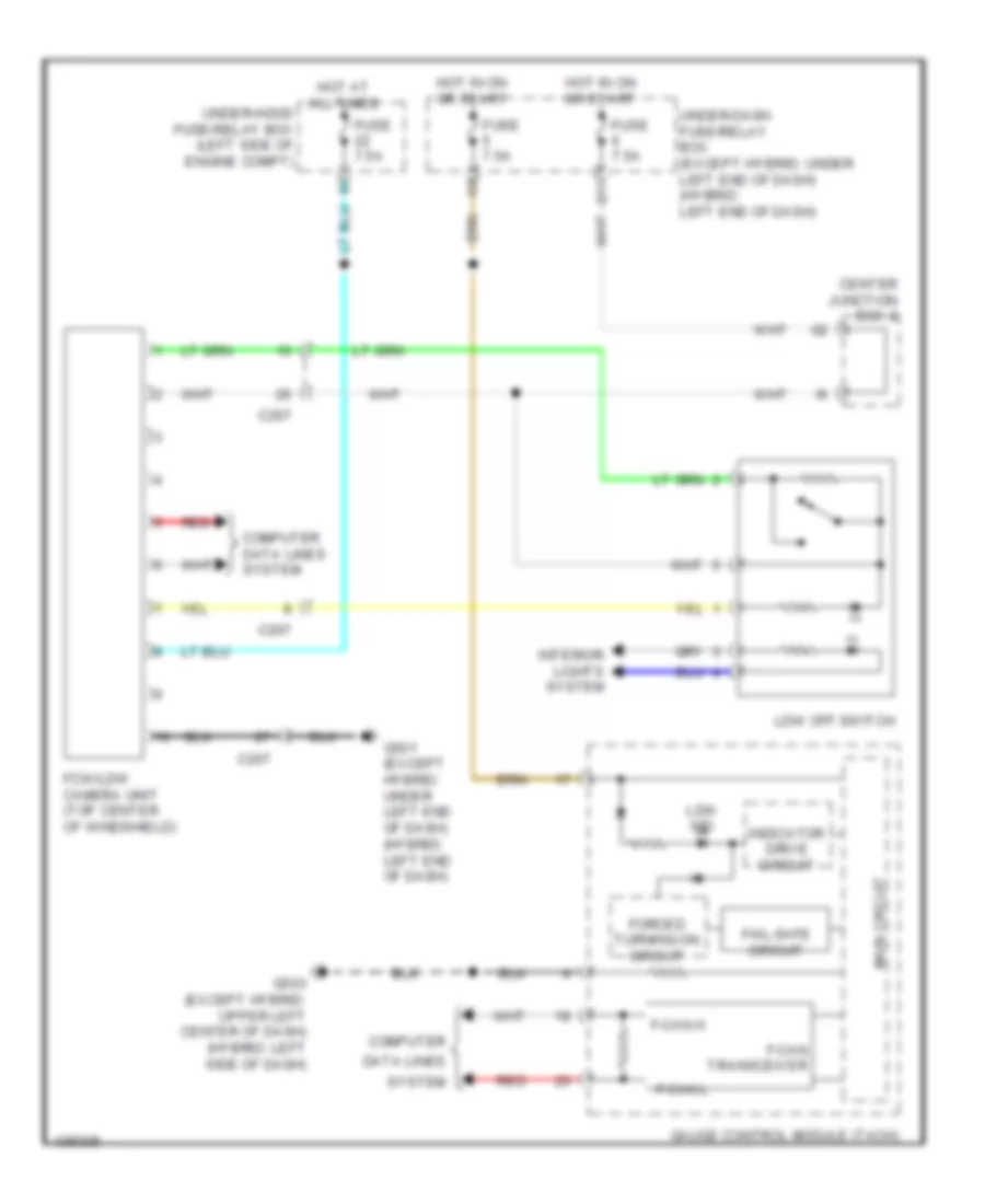
Data Link Connector Wiring Diagram, Hybrid (1 of 2) for Honda Civic HF 2014
List of elements for Data Link Connector Wiring Diagram, Hybrid (1 of 2) for Honda Civic HF 2014:
- A13
- A20
- A21
- Audio unit/ audio-navigation unit
- C20
- C204
- C206
- C207
- C218
- C302
- Center junction box 1
- D21
- D30
- Data link connector (dlc) (under left side of dash)
- Fcw/ldw camera unit (top center of windshield)
- Front passenger's weight sensor unit
- Fuse 10a
- G101 (left rear side of engine)
- G501 (upper left end of dash)
- Gauge control module (tach)
- Hot at all times
- J/c c007
- J13
- Micu
- Q14
- Red
- Srs unit (under front of center console)
- Steering angle sensor (top of steering column)
- Under-dash fuse/relay box (left end of dash)
- Under-hood fuse/relay box (left side of engine compt)
- W/ navigation
- W/o navigation
Data Link Connector Wiring Diagram, Hybrid (2 of 2) for Honda Civic HF 2014
List of elements for Data Link Connector Wiring Diagram, Hybrid (2 of 2) for Honda Civic HF 2014:
- A10
- A11
- A17
- A42
- B20
- C207
- C210
- C222
- Center junction box 2
- D26
- D27
- Eps control unit (right kick panel)
- J/c c011
- Keyless access control unit (if equipped)
- Mcm (top right side of ipu module)
- P16
- Pcm (left side of engine compt)
- Red
- Servo unit (left rear corner of engine compt)
- Under-dash fuse/relay box (left end of dash)
- Vsa modulator control unit (right front of engine compt)
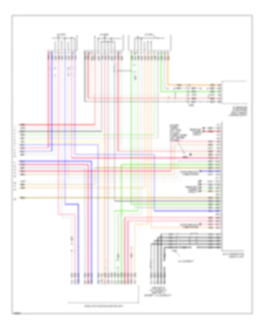
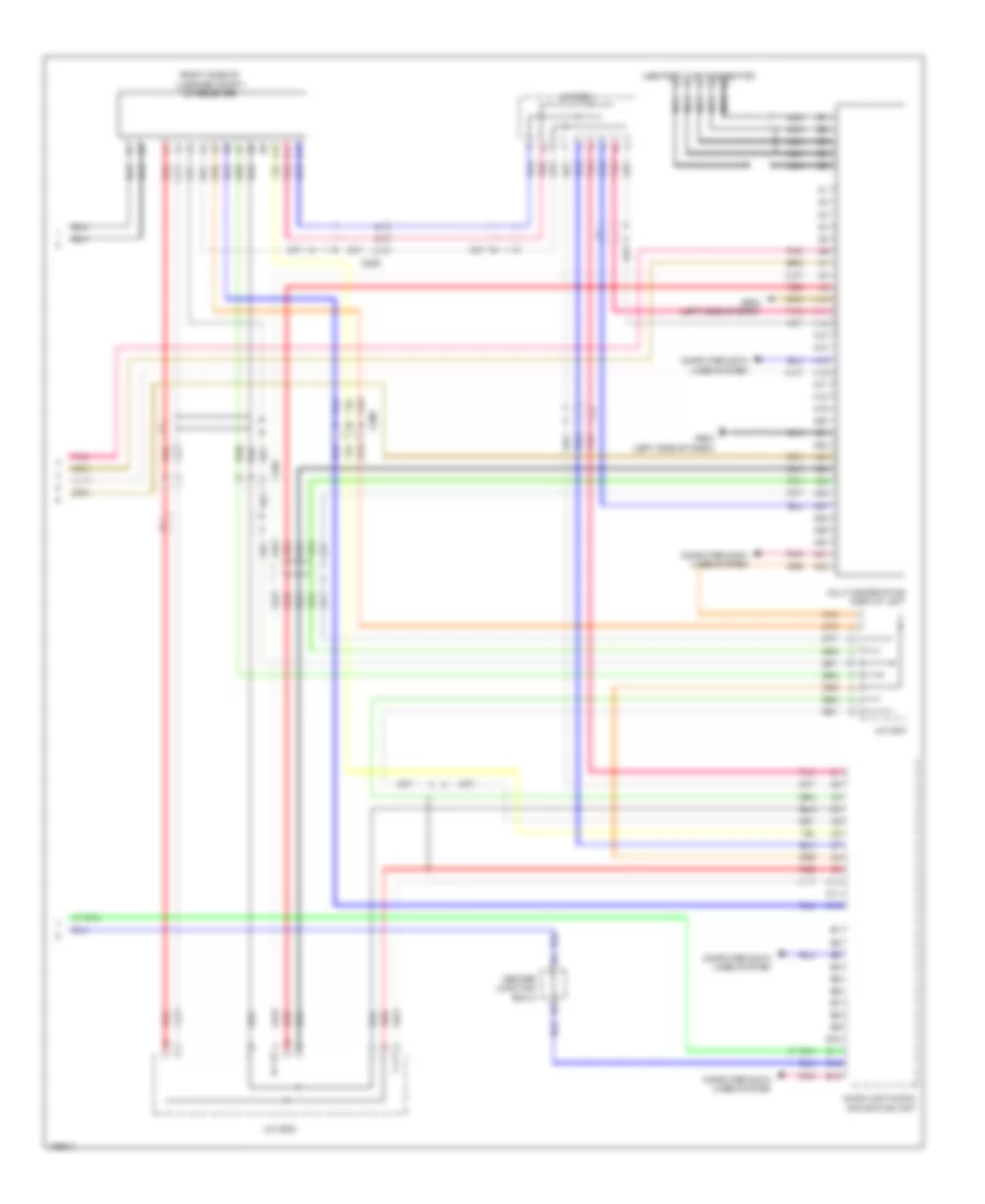
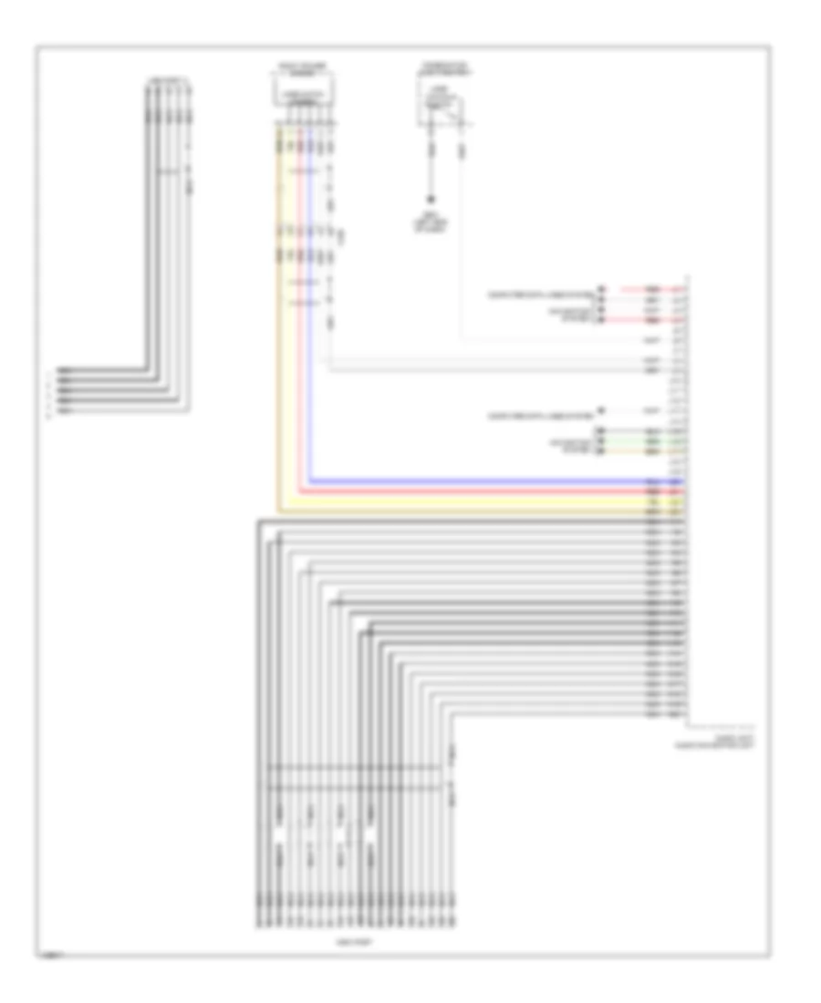
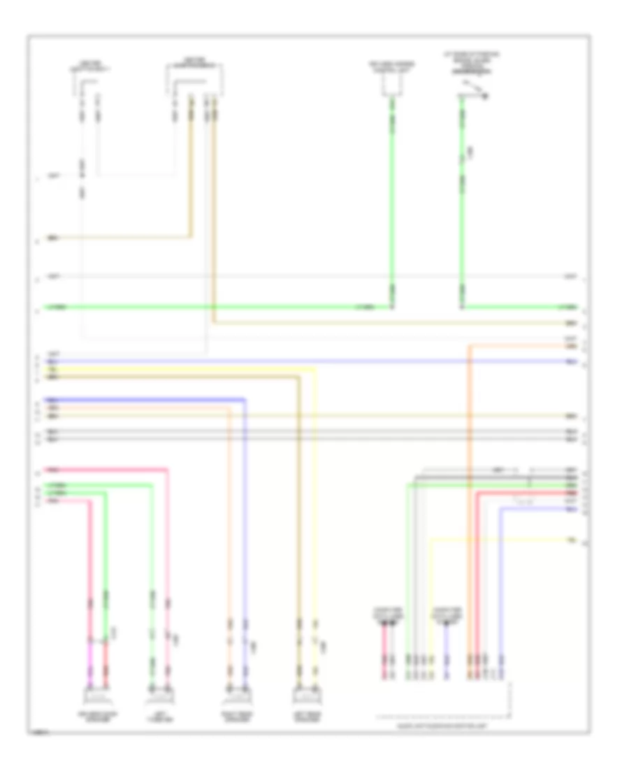
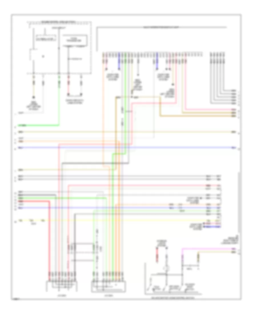
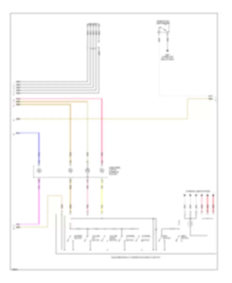
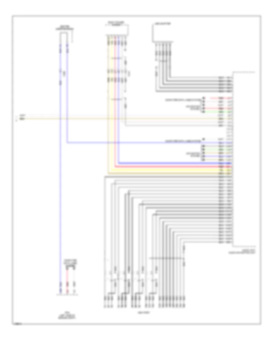
GA-NET Bus/GA-NET Audio Wiring Diagram, Except Hybrid for Honda Civic HF 2014
List of elements for GA-NET Bus/GA-NET Audio Wiring Diagram, Except Hybrid for Honda Civic HF 2014:
- A11
- A12
- A24
- A25
- A26
- A27
- A32
- Audio unit/audio navigation unit
- C10
- C209
- Handsfreelink control unit (if equipped) (right side of dash)
- J/c c001
- J/c c002
- J/c c003
- Multi information display unit
- Pnk
- Red
- Xm receiver (if equipped) (right side of luggage compt)
GA-NET Bus/GA-NET Audio Wiring Diagram, Hybrid for Honda Civic HF 2014
List of elements for GA-NET Bus/GA-NET Audio Wiring Diagram, Hybrid for Honda Civic HF 2014:
- A11
- A12
- A24
- A25
- A26
- A27
- A32
- Audio unit/audio-navigation unit
- C10
- C210
- J/c c002
- J/c c003
- J/c c004
- Multi-information display unit
- Pnk
- Red
- Xm receiver (if equipped) (right side of luggage compt)
COOLING FAN
Cooling Fan Wiring Diagram, Except Hybrid for Honda Civic HF 2014
List of elements for Cooling Fan Wiring Diagram, Except Hybrid for Honda Civic HF 2014:
- (2.4l: left rear of cylinder head) (1.8l: left rear of engine) g101
- (lower left side of radiator) ect sensor 2
- (or pnk)
- 1.8l
- 1.8l m/t
- 1.8l m/t & 2.4l
- 2.4l
- 2.4l 1.8l
- A/c condenser fan motor (behind right side of radiator)
- A/c condenser fan relay
- A/c pressure sensor (lower right front of engine compt)
- A10
- A15
- A16
- A20
- A27
- A30
- A44
- A46
- B10
- B34
- B44
- C10
- C13
- C17
- C404
- C407
- C410
- Computer data lines system
- Cvt
- D17
- Diode a
- Diode b
- Ect sensor 1 (left rear of engine)
- Engine controls system
- Except 1.8l m/t
- Fan control relay
- Fuse 15a
- Fuse 2-10 20a
- Fuse 2-11 20a
- Fuse 7.5a
- G301 (under left front headlight assembly)
- Hot at all times
- Hot in on
- Hot in on or start
- J/c c009 (1.8l m/t) j/c c012 (2.4l) j/c c005 (cvt)
- Pcm (left side of engine compt)
- Pgm-fi sub relay
- Radiator fan motor (behind left side of radiator)
- Radiator fan relay
- Red
- Relay control module
- Under-dash fuse/relay box (under left end of dash)
- Under-hood fuse/relay box (left side of engine compt)
Cooling Fan Wiring Diagram, Hybrid for Honda Civic HF 2014
List of elements for Cooling Fan Wiring Diagram, Hybrid for Honda Civic HF 2014:
- (left rear side of engine) g101
- (lower left side of radiator) ect sensor 2
- A/c condenser fan motor (behind right side of radiator)
- A/c condenser fan relay
- A/c pressure sensor (right front corner of engine compt)
- A10
- A15
- A16
- A20
- A27
- A30
- A44
- B34
- B44
- C10
- C13
- C15
- C17
- C302
- Computer data lines system
- Diode g
- Diode h
- Ect sensor 1 (rear of engine)
- Engine controls system
- Fan control relay (in under-hood fuse/relay box)
- Fuse 15a
- Fuse 2-10 20a
- Fuse 2-11 20a
- Fuse 7.5a
- G301 (under left headlight assembly)
- Hot at all times
- Hot in on
- Hot in on or start
- J/c c011
- Pcm (left side of engine compt)
- Pgm-fi sub relay
- Pnk
- Radiator fan motor (behind left side of radiator)
- Radiator fan relay (in under-hood fuse/relay box)
- Red
- Relay control module (in under-hood fuse/relay box)
- Under-dash fuse/relay box (left end of dash)
- Under-hood fuse/relay box (left side of engine compt)
CRUISE CONTROL
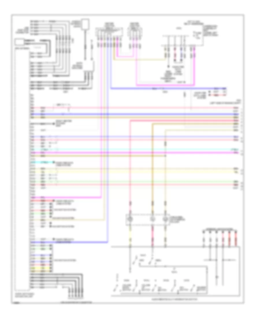
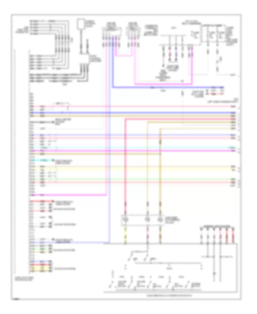
Cruise Control Wiring Diagram, Except Hybrid (1 of 2) for Honda Civic HF 2014
List of elements for Cruise Control Wiring Diagram, Except Hybrid (1 of 2) for Honda Civic HF 2014:
- (1.8l m/t) c404 (cvt) c407 (2.4l) c410
- (2.4l: left rear of cylinder head) (1.8l: left rear of engine) g101
- (cvt) c407 (m/t) c404
- (or pnk)
- (or red)
- (or tan)
- (top of brake pedal assembly) brake pedal position switch
- 1.8l
- 1.8l m/t
- 1.8l m/t cvt
- 2.4l
- A13
- A14
- A25
- A28
- A29
- A35
- A36
- A38
- A45
- A46
- A47
- A48
- A50
- App sensor (top of accelerator pedal assembly)
- App sensor a
- App sensor b
- B41
- B44
- B46
- B48
- C10
- C13
- C14
- C16
- C17
- C18
- C19
- C22
- C23
- C24
- C25
- C30
- C31
- C34
- C40
- C407 (cvt) c404 (m/t)
- C410
- Clutch pedal position switch b (m/t) (top of clutch pedal assembly)
- Computer data lines system
- Cvt
- D10
- D12
- Ecm/pcm (left side of engine compt)
- Engine controls system
- Etcs control relay
- Fuse 10a
- Fuse 15a
- G101 (2.4l: left rear of cylinder head) (1.8l: left rear of engine)
- G401 (left kick panel)
- Hot in on or start
- J/c c014 (1.8l m/t) j/c c013 (cvt) j/c c011 (2.4l)
- M/t
- Output shaft (counter shaft) speed sensor (m/t) cvt drive pulley speed sensor (cvt) (left side of transmission)
- Pgm-fi main relay 1
- Red
- Throttle actuator
- Throttle body (2.4l: left rear of engine) (1.8l: right rear of engine)
- Throttle open sensor
- Transmission range switch (cvt) (top of transmission)
- Under-dash fuse/relay box (under left end of dash)
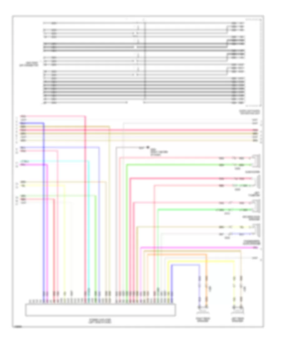
Cruise Control Wiring Diagram, Except Hybrid (2 of 2) for Honda Civic HF 2014
List of elements for Cruise Control Wiring Diagram, Except Hybrid (2 of 2) for Honda Civic HF 2014:
- 10v stabilizing circuit
- 5v regulator
- C15
- C16
- Cable reel (on steering column)
- Cancel button
- Computer data lines system
- Cruise control combination switch
- Cruise control indicator
- Cruise main indicator
- D28
- Dimming circuit
- F-can h
- F-can l
- F-can transceiver
- Fuse 10a
- Fuse 15a
- Fuse 7.5a
- G503 (left side of dash)
- Gauge control module (tach)
- Hot at all times
- Hot in on or start
- Indicator drive circuit
- Interior lights system
- Main button
- Main circuit
- Micu
- On/off 5v
- Red
- Resume button
- Set button
- Under-dash fuse/relay box (under left end of dash)
- Under-hood fuse/relay box (left side of engine compt)
Cruise Control Wiring Diagram, Hybrid (1 of 2) for Honda Civic HF 2014
List of elements for Cruise Control Wiring Diagram, Hybrid (1 of 2) for Honda Civic HF 2014:
- (top of brake pedal assembly) brake pedal position switch
- A25
- A28
- A29
- A35
- A36
- A45
- A46
- A48
- App sensor (top of accelerator pedal assembly)
- App sensor a
- App sensor b
- B15
- B35
- C10
- C13
- C14
- C15
- C22
- C23
- C24
- C25
- C30
- C302
- C31
- C34
- Computer data lines system
- Cvt output shaft (driven pulley) speed sensor (top of transmission housing)
- D10
- D12
- Etcs control relay
- Fuse 2 10a
- Fuse 4 15a
- G101 (left rear side of engine)
- Hot w/ ig1 a relay energized
- J/c c010
- Pcm (left side of engine compt)
- Pgm-fi main relay 1
- Pnk
- Red
- Tan
- Throttle actuator
- Throttle body (left rear of engine)
- Throttle open sensor
- Transmission range switch (on transmission housing)
- Under-dash fuse/relay box (left end of dash)
Cruise Control Wiring Diagram, Hybrid (2 of 2) for Honda Civic HF 2014
List of elements for Cruise Control Wiring Diagram, Hybrid (2 of 2) for Honda Civic HF 2014:
- 10v stabilizing circuit
- C15
- C16
- Cable reel (top of steering column)
- Cancel switch
- Computer data lines system
- Cruise control combination switch
- Cruise control indicator
- Cruise main indicator
- Dimming circuit
- F-can h
- F-can l
- F-can transceiver
- Fuse 15a
- Fuse 7.5a
- G503 (upper left center of dash)
- Gauge control module (tach)
- Hot at all times
- Hot w/ ig1 a relay energized
- Indicator driver circuit
- Interior lights system
- Main circuit
- Main switch
- Micu
- Red
- Res/- switch
- Set/+ switch
- Under-dash fuse/relay box (left end of dash)
- Under-hood fuse/relay box (left side of engine compt)
DEFOGGERS
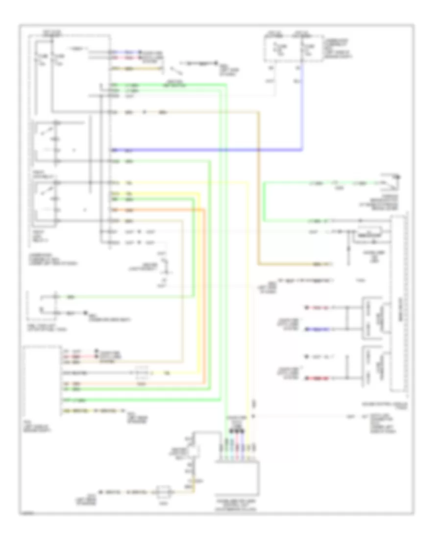
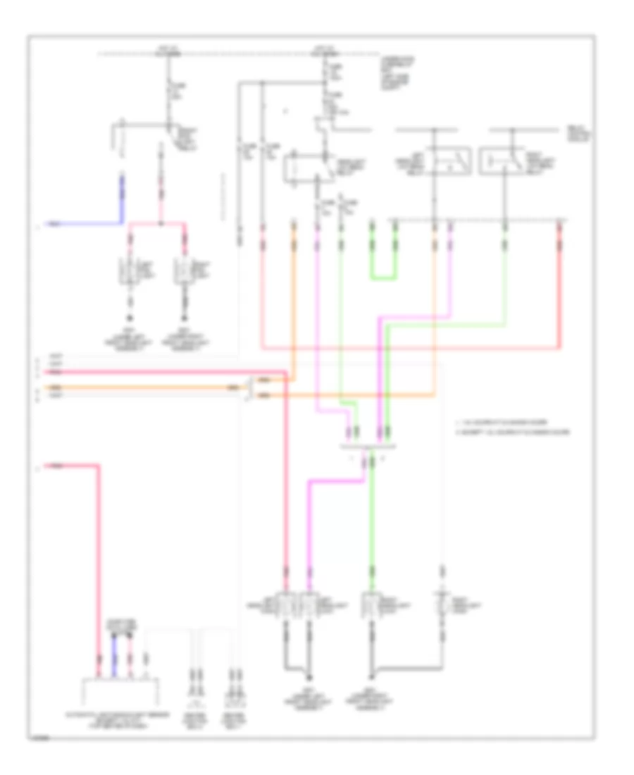
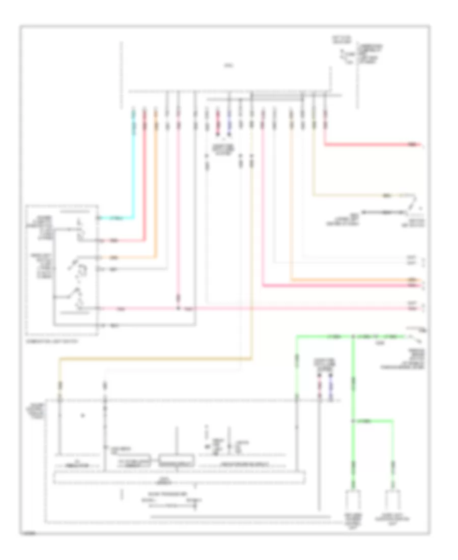
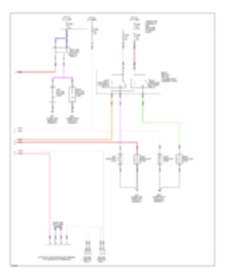
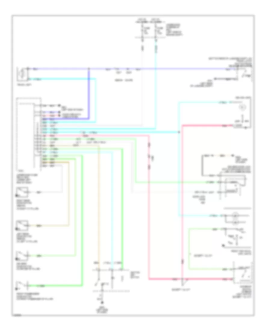
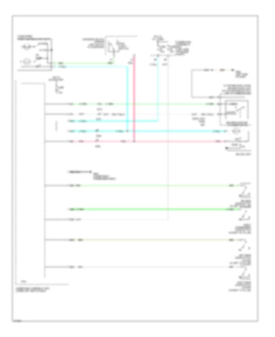
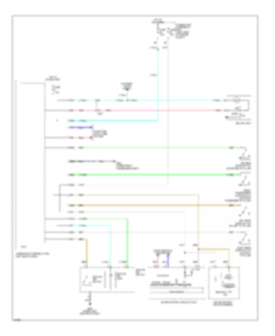
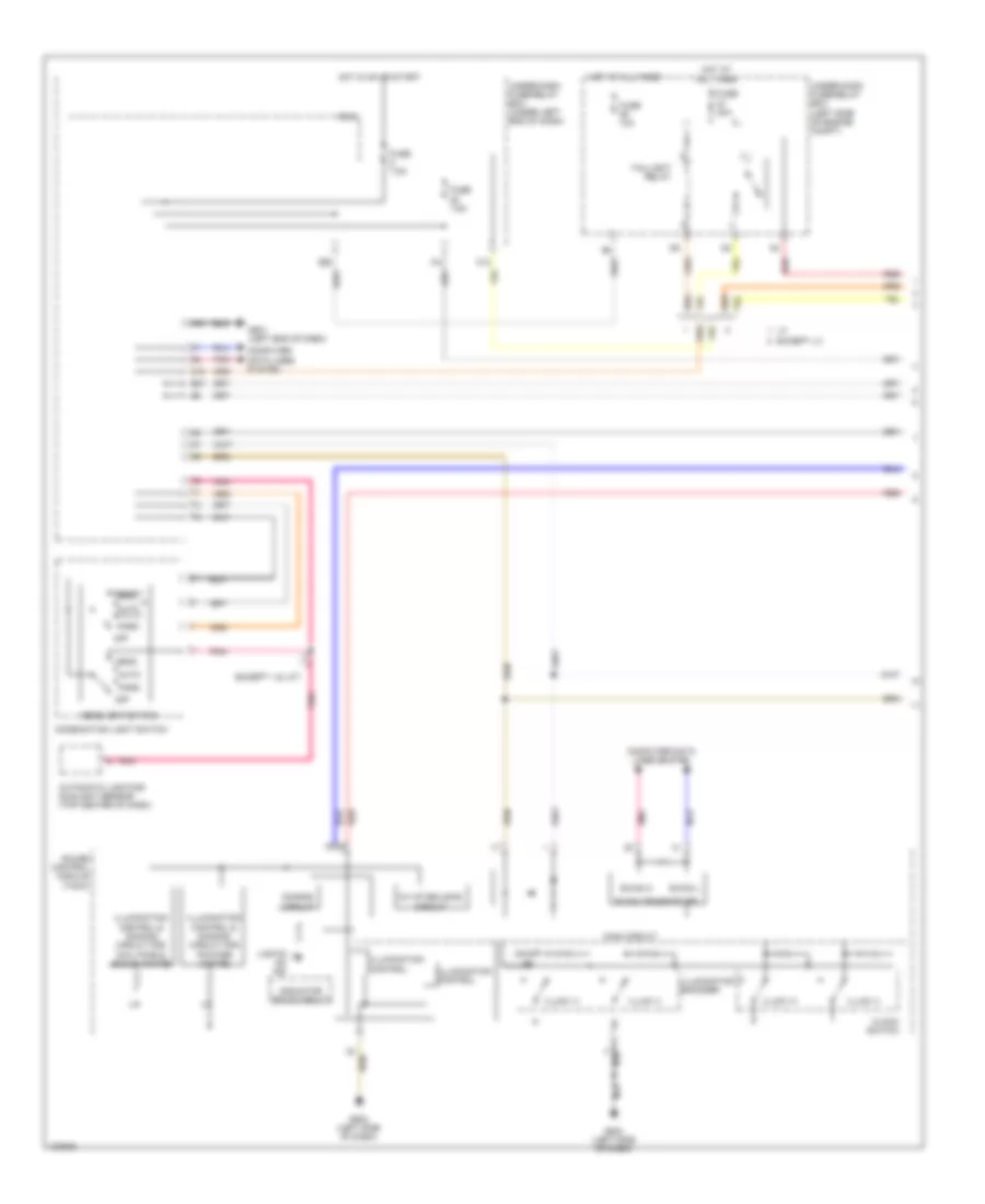
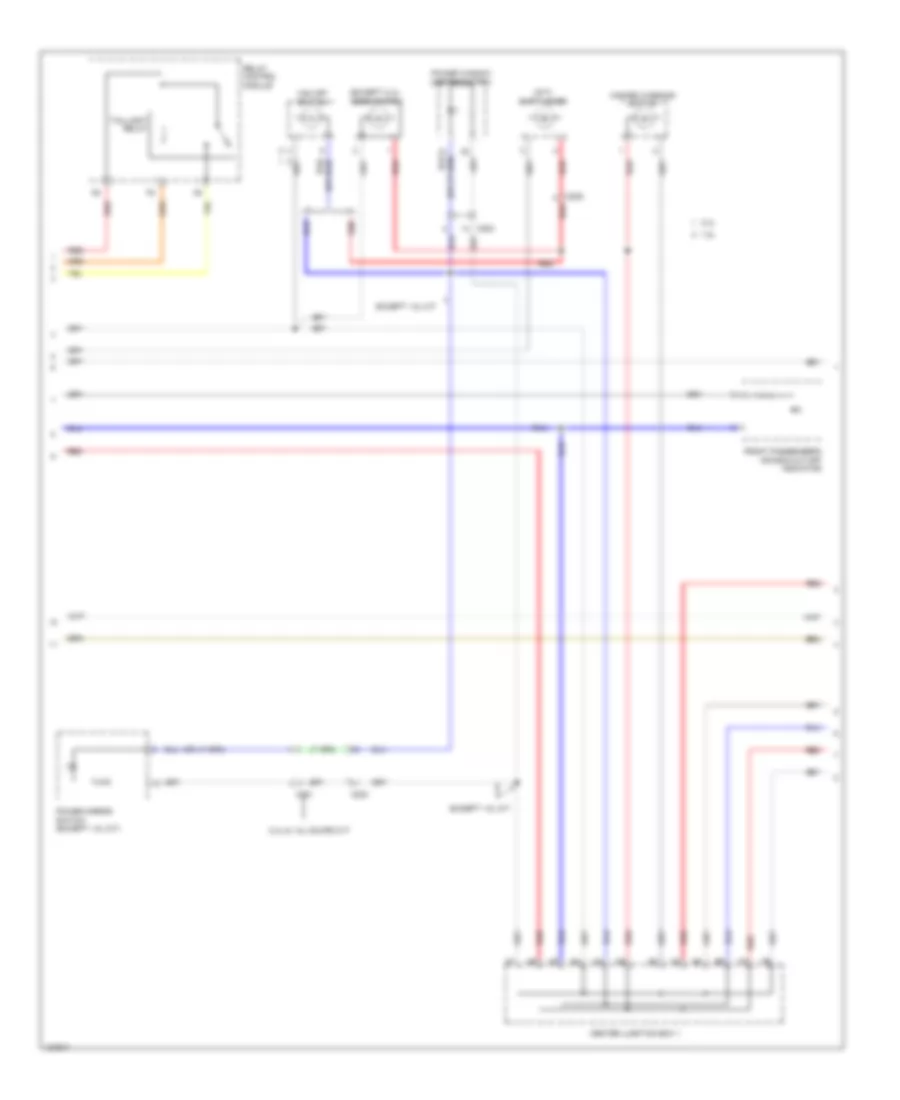
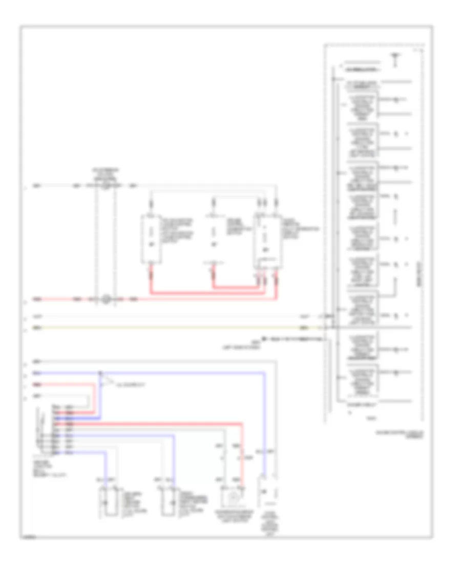
Defoggers Wiring Diagram, Except Hybrid for Honda Civic HF 2014
List of elements for Defoggers Wiring Diagram, Except Hybrid for Honda Civic HF 2014:
- 1.8l coupe m/t
- A10
- A11
- A12
- A15
- C17
- C202
- C203
- C204
- C211
- Center junction box 1
- Center junction box 2
- Coupe cvt
- D17
- Except 1.8l coupe m/t
- Except coupe cvt
- Fuse 2-6 30a (or 40a)
- Fuse 22 7.5a
- G502 (left side of dash)
- G504 (right end of dash)
- G801 (right "c" pillar)
- H10
- Hot at all times
- Hot in on
- Hvac/ climate control unit
- Left power mirror
- Noise reduction condenser (in left "c" pillar)
- Power mirror defogger relay (if equipped)
- Rear window defogger
- Rear window defogger relay
- Rear window/ power mirror defogger switch
- Rear window/ power mirror defogger switch indicator
- Red
- Relay control module
- Right power mirror
- Under-dash fuse/relay box (under left end of dash)
- Under-hood fuse/relay box (left side of engine compt)
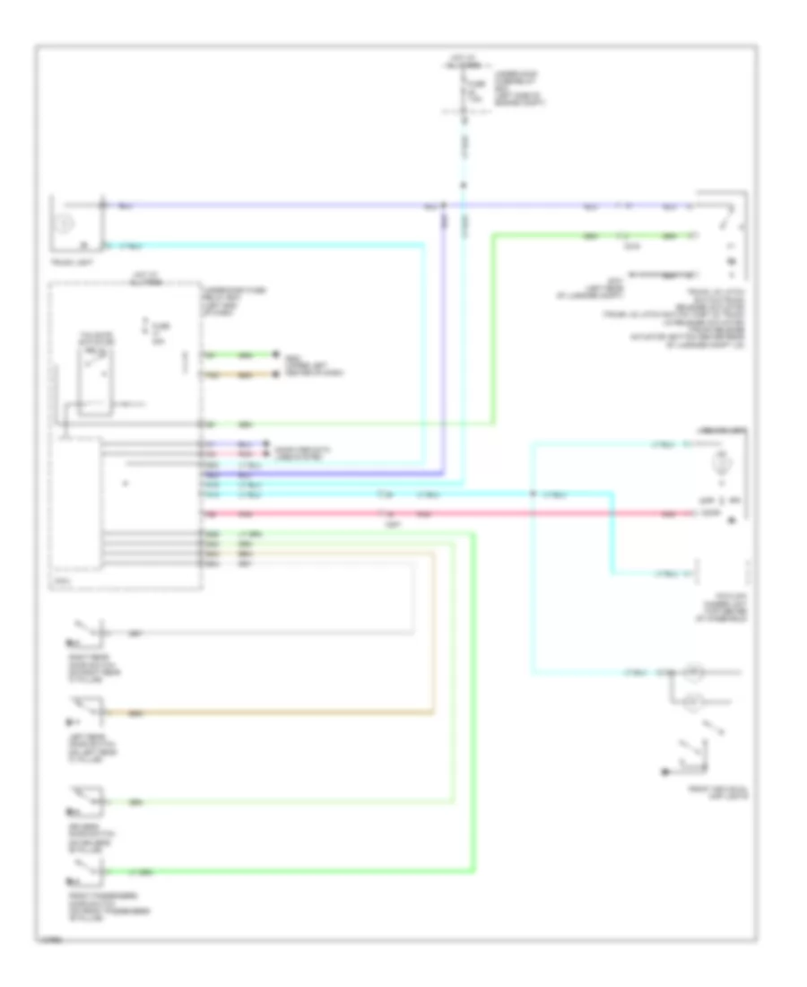
Defoggers Wiring Diagram, Hybrid for Honda Civic HF 2014
List of elements for Defoggers Wiring Diagram, Hybrid for Honda Civic HF 2014:
- 7.5a
- A11
- A12
- A15
- C17
- C202
- C203
- C204
- C212
- Center junction box 1
- Center junction box 2 (w/ navigation)
- Climate control unit
- Condenser (left side of luggage compt)
- D17
- Fuse 2-6 30a
- Fuse 22
- G502 (upper left center of dash)
- G504 (upper right end of dash)
- G801 (base of right "c" pillar)
- H10
- Hot at all times
- Hot in on
- J/c c008
- Left power mirror (w/ power mirror defogger)
- Power mirror defogger relay
- Rear window defogger
- Rear window defogger relay
- Rear window/ power mirror defogger switch
- Rear window/ power mirror defogger switch indicator
- Red
- Red c213
- Relay control module (in under-hood fuse/relay box)
- Right power mirror (w/ power mirror defogger)
- Under-dash fuse/relay box (left end of dash)
- Under-hood fuse/relay box (left side of engine compt)
- W/ navigation
- W/o navigation
ELECTRONIC POWER STEERING
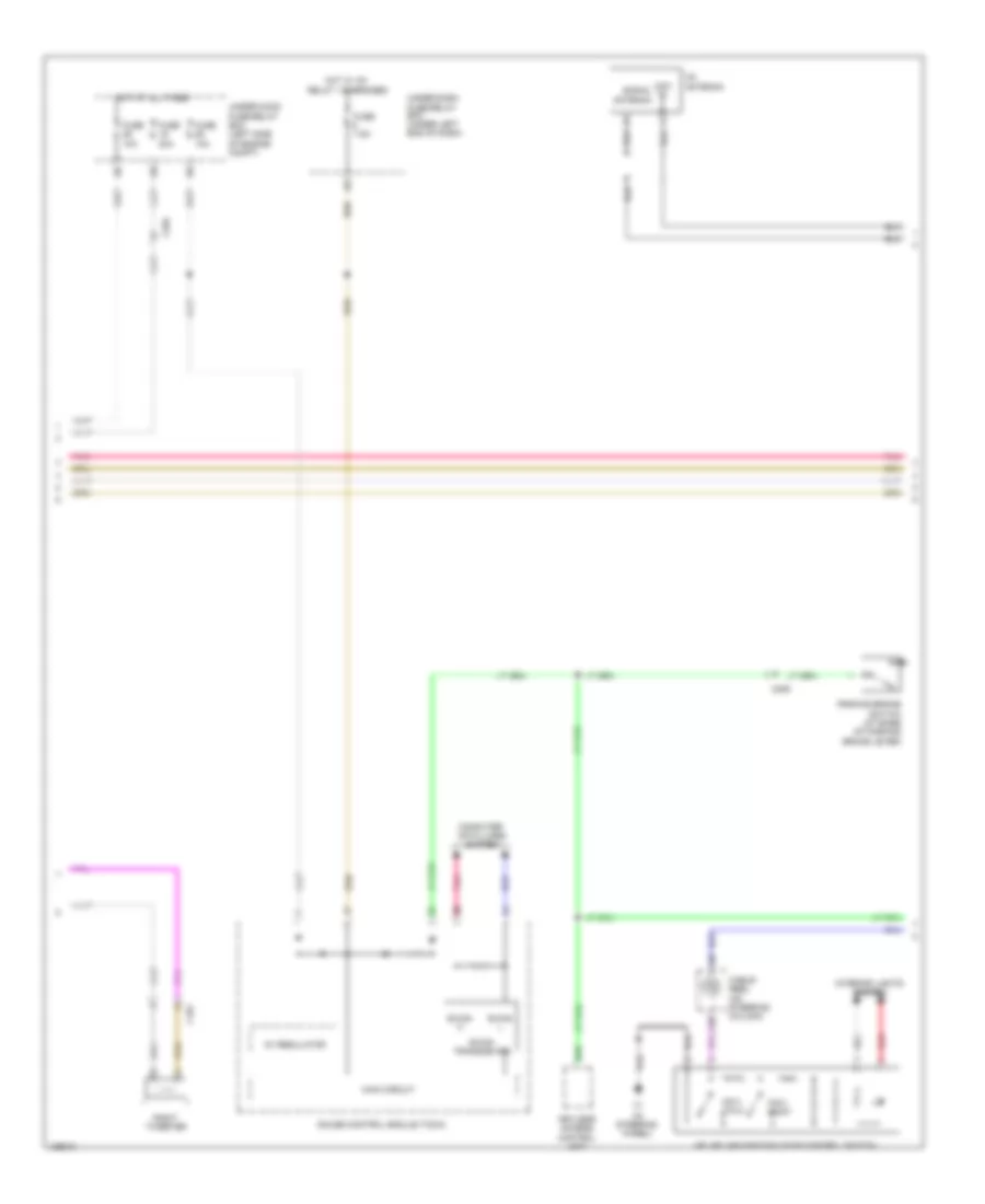
Electronic Power Steering Wiring Diagram, Except Hybrid for Honda Civic HF 2014
List of elements for Electronic Power Steering Wiring Diagram, Except Hybrid for Honda Civic HF 2014:
- (left side of engine compt) pcm
- (on power steering rack assembly) eps motor
- (right kick panel) g403
- A10
- A11
- A22
- B10
- B11
- B12
- B13
- C220
- C221
- C222
- Circuit
- Computer data lines system
- D31
- Drive circuit indicator
- Eps control unit (right end of dash)
- Eps ind
- Eps motor angle sensor (on eps motor)
- F-can h
- F-can l
- Fail-safe circuit
- Forced turning-on circuit
- Fuse 1-1 70a
- Fuse 7.5a
- G503 (left side of dash)
- Gauge control module (tach)
- Hot at all times
- Hot in on or start
- Main circuit
- P15
- Pnk
- Red
- Steering angle sensor (in steering column)
- Torque sensor (on steering rack assembly)
- Transceiver f-can
- Turning-off forced
- Under-dash fuse/relay box (left end of dash)
- Under-hood fuse/relay box (left side of engine compt)
Electronic Power Steering Wiring Diagram, Hybrid for Honda Civic HF 2014
List of elements for Electronic Power Steering Wiring Diagram, Hybrid for Honda Civic HF 2014:
- (left side of engine compt) pcm
- (on steering rack assembly) eps motor
- (right kick panel) g403
- A10
- A11
- A22
- B10
- B11
- B12
- B13
- C224
- C225
- C226
- Circuit
- Computer data lines system
- D31
- Drive circuit indicator
- Eps control unit (right kick panel)
- Eps ind
- Eps motor angle sensor (on eps motor assembly)
- F-can h
- F-can l
- Fail-safe circuit
- Forced turning-on circuit
- Fuse 1-1 70a
- Fuse 7.5a
- G402 (right end of dash)
- G503 (upper left center of dash)
- Gauge control module (tach)
- Hot at all times
- Hot in on or start
- Main circuit
- P15
- Pnk
- Red
- Steering angle sensor (top of steering column)
- Torque sensor (on eps motor)
- Transceiver f-can
- Turning-off forced
- Under-dash fuse/relay box (left end of dash)
- Under-hood fuse/relay box (left side of engine compt)
ENGINE PERFORMANCE
1.5L HYBRID
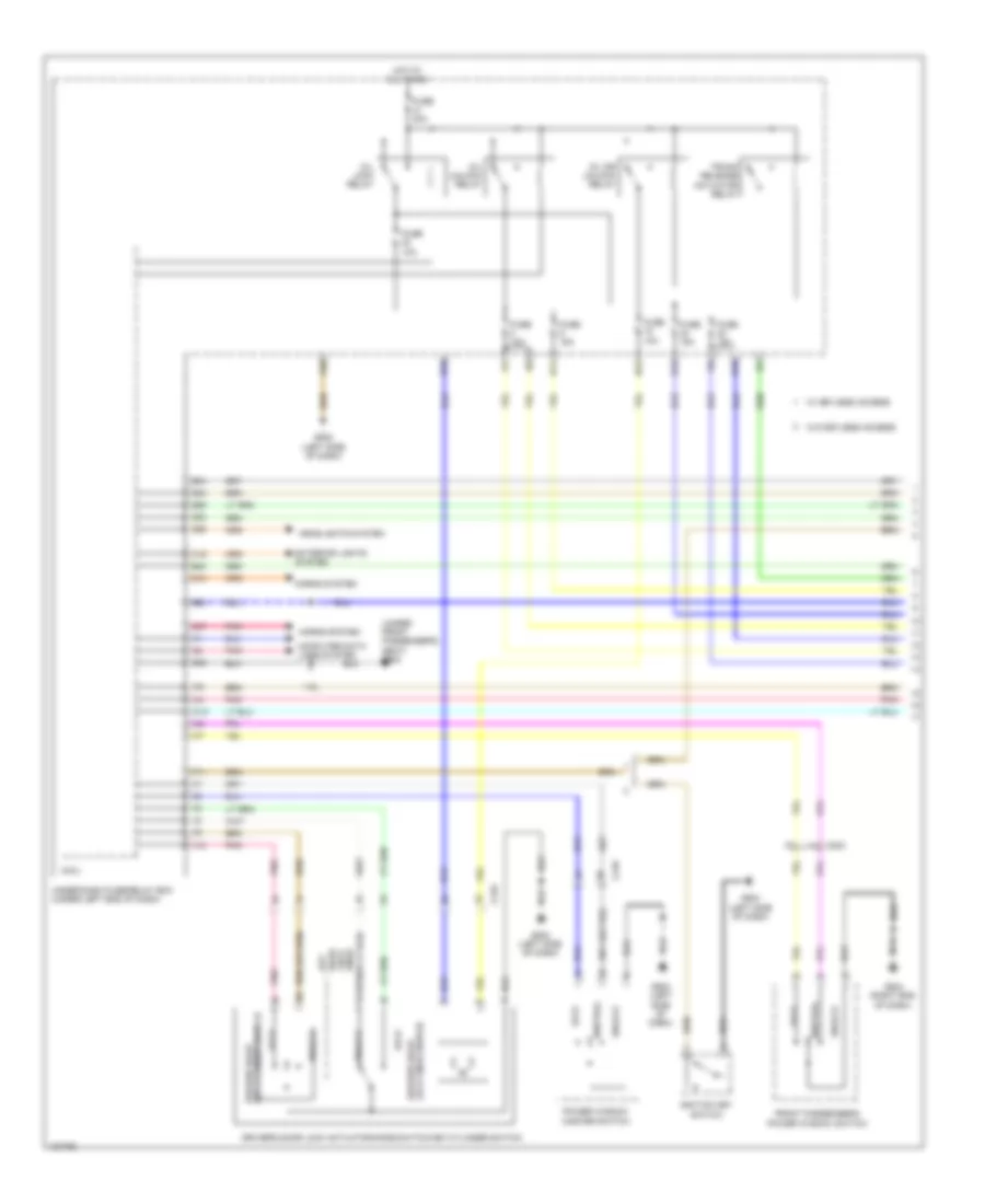
1.5L Hybrid, Engine Controls Wiring Diagram (1 of 5) for Honda Civic HF 2014
List of elements for 1.5L Hybrid, Engine Controls Wiring Diagram (1 of 5) for Honda Civic HF 2014:
- (lower left side of radiator) ect sensor 2
- (right front corner of engine compt) a/c pressure sensor
- (under vehicle, on evaporative emission canister) evap canister vent shut valve
- 5v regulator
- A10
- A11
- A12
- A13
- A14
- A15
- A16
- A17
- A18
- A19
- A20
- A21
- A22
- A23
- A24
- A25
- A26
- A27
- A28
- A29
- A30
- A31
- A32
- A33
- A34
- A35
- A36
- A37
- A38
- A39
- A40
- A41
- A42
- A43
- A44
- A45
- A46
- A47
- A48
- A49
- Air conditioning system
- App sensor (top of accelerator pedal assembly)
- App sensor a
- App sensor b
- C216
- Circuit 10v stabilizing
- Circuit driving indicator
- Computer data lines system
- Cooling fans system
- Dimming circuit
- Eps control unit (right kick panel)
- F-can h
- F-can l
- Ftp sensor (front of fuel tank, on fuel line)
- Fuse 15a
- G503 (upper left center of dash)
- Gauge control module (tach)
- Hot at all times
- Indicator driving circuit a/t gear position
- J/c c011
- Main circuit
- Mil ind
- Navigation & sound systems
- Pcm (powertrain control module) (left side of engine compt)
- Pgm-fi sub- relay
- Pnk
- Red
- Shift interlock system
- Starting/ charging system
- Starting/charging system
- Transceiver f-can
- Under-hood fuse/ relay box (left side of engine compt)
1.5L Hybrid, Engine Controls Wiring Diagram (2 of 5) for Honda Civic HF 2014
List of elements for 1.5L Hybrid, Engine Controls Wiring Diagram (2 of 5) for Honda Civic HF 2014:
- (in under-hood fuse/relay box) pgm-fi main relay 2
- C216
- C223
- C301
- C302
- Cvt clutch pressure control solenoid valve (on transmission valve body)
- Cvt output shaft (drive pulley) speed sensor (top of transmission housing)
- Eld
- Evap canister purge valve (top rear of engine)
- Exhaust side ignition coils (top right side of engine)
- Fuel pump
- Fuel tank unit (top of fuel tank)
- Fuse 1-6 100a
- Fuse 15a
- Fuse 20a
- G101 (left rear side of engine)
- G301 (under left headlight assembly)
- G601 (under driver's seat)
- Hot at all times
- Iat sensor
- Icm
- Ignition coil relay
- Instrument cluster system
- J/c c009
- J/c c010
- Maf sensor
- Maf/iat sensor (on engine air cleaner housing)
- Map sensor (left rear side of engine)
- Oil pressure switch (near oil filter)
- Pnk
- Red
- Spark plug
- Tan
- Under-hood fuse/ relay box (left side of engine compt)
1.5L Hybrid, Engine Controls Wiring Diagram (3 of 5) for Honda Civic HF 2014
List of elements for 1.5L Hybrid, Engine Controls Wiring Diagram (3 of 5) for Honda Civic HF 2014:
- (bottom rear of transmission housing) atf temperature sensor
- (left front of engine) egr valve & egr valve position sensor
- (left front of oil pan) engine oil temperature sensor
- (on rocker arm oil control valve) rocker arm oil pressure sensor a
- (on rocker arm oil control valve) rocker arm oil pressure sensor b
- (rear of cylinder bank) rocker arm oil control solenoid a
- (rear of cylinder bank) rocker arm oil control solenoid b
- (rear of engine) ect sensor 1
- B10
- B11
- B12
- B13
- B14
- B15
- B16
- B17
- B18
- B19
- B20
- B21
- B22
- B23
- B24
- B25
- B26
- B27
- B28
- B29
- B30
- B31
- B32
- B33
- B34
- B35
- B36
- B37
- B38
- B39
- B40
- B41
- B42
- B43
- B44
- B45
- B46
- B47
- B48
- B49
- C301
- C305
- Cvt drive pulley pressure control solenoid valve (on transmission lower valve body)
- G101 (left rear side of engine)
- G902 (rear of transmission)
- J/c c010
- Pcm (powertrain control module) (left side of engine compt)
- Pnk
- Red
- Tan
1.5L Hybrid, Engine Controls Wiring Diagram (4 of 5) for Honda Civic HF 2014
List of elements for 1.5L Hybrid, Engine Controls Wiring Diagram (4 of 5) for Honda Civic HF 2014:
- Brake pedal position switch (top of brake pedal assembly)
- C13
- C16
- C20
- C24
- C25
- C301
- C302
- C303
- C34
- Ckp sensor (lower right rear of engine)
- Cmp sensor (rear of engine)
- Computer data lines system
- Cvt driven pulley pressure control solenoid valve (on transmission lower valve body)
- Cvt driven pulley pressure sensor (bottom rear transmission housing)
- Cvt input shaft (drive pulley) speed sensor (left side of transmission housing)
- D10
- D12
- D19
- D23
- Etcs control relay
- Fuse 10a
- Fuse 15a
- Fuse 7.5a
- G101 (left rear side of engine)
- G902 (rear of transmission)
- Gauge control module (speedo)
- Hot in on or start
- Inhibitor solenoid (on transmission lower valve body)
- Micu
- Pgm-fi main relay 1
- Pnk
- Red
- Tan
- Under-dash fuse/relay box (left end of dash)
- Vehicle speed sensor (in transmission)
1.5L Hybrid, Engine Controls Wiring Diagram (5 of 5) for Honda Civic HF 2014
List of elements for 1.5L Hybrid, Engine Controls Wiring Diagram (5 of 5) for Honda Civic HF 2014:
- (left rear of engine) throttle body
- (left rear side of engine) g101
- (on transmission housing) transmission range switch
- (top left side of engine) injectors
- A/f sensor (sensor 1) (right rear of engine)
- C10
- C11
- C12
- C13
- C14
- C15
- C16
- C17
- C18
- C19
- C20
- C21
- C22
- C23
- C24
- C25
- C26
- C27
- C28
- C29
- C30
- C302
- C31
- C32
- C33
- C34
- C35
- C36
- C37
- C38
- C39
- C40
- C41
- C42
- C43
- C44
- C45
- C46
- C47
- C48
- C49
- Computer data lines system
- Exterior lights system
- G101 (left rear side of engine)
- Icm
- Intake side ignition coils (top left side of engine)
- J/c c009
- J/c c010
- Knock sensor (front left side of engine)
- P r
- Pcm (powertrain control module) (left side of engine compt)
- Pnk
- Red
- Secondary ho2s (sensor 2) (in exhaust, downstream of catalytic converter)
- Spark plug
- Tan
- Throttle actuator
- Throttle open sensor
1.5L Hybrid, IMA Wiring Diagram (1 of 3) for Honda Civic HF 2014
List of elements for 1.5L Hybrid, IMA Wiring Diagram (1 of 3) for Honda Civic HF 2014:
- (center front of ipu) junction board
- (lower right side of ipu) dc-dc converter
- A10
- A11
- A12
- A13
- A14
- A15
- A16
- A17
- A18
- A19
- A20
- A21
- A22
- A23
- A24
- A25
- A26
- A27
- A28
- A29
- A30
- A31
- A32
- B10
- B11
- B12
- B13
- B14
- B15
- B16
- B17
- B18
- B19
- B20
- B21
- B22
- B23
- B24
- C210
- C222
- Computer data lines system
- Fuse 10a
- Fuse 7.5a
- G5 (right front corner of ipu module compt)
- Hot in on or start
- Ima motor (rear of engine)
- Motor control module (mcm)
- Motor current sensor (center of ipu module)
- Nca
- Pnk
- Red
- T10
- T11
- T12
- Tan
- Under-dash fuse/relay box (left end of dash)
1.5L Hybrid, IMA Wiring Diagram (2 of 3) for Honda Civic HF 2014
List of elements for 1.5L Hybrid, IMA Wiring Diagram (2 of 3) for Honda Civic HF 2014:
- Battery module (in ipu module)
- C213
- C216
- C222
- C501
- Central junction box 1
- Central junction box 2
- Computer data lines system
- D28
- Fuse 1-6 100a
- Fuse 10a
- Fuse 7.5a
- G901 (right front corner of ipu module compt)
- Gauge control module (speedo)
- Hot at all times
- Ipu module fan (right side of ipu)
- J/c c014
- J/c c016
- Mcm relay 1 (in ipu relay holder)
- Mcm relay 2 (in ipu relay holder)
- Nca
- Pnk
- Red
- Sound systems
- T101
- Tan
- Under-dash fuse/relay box (left end of dash)
- Under-hood fuse/relay box (left side of engine compt)
- V-sensor 1
- V-sensor 2
- V-sensor 3
- V-sensor 4
1.5L Hybrid, IMA Wiring Diagram (3 of 3) for Honda Civic HF 2014
List of elements for 1.5L Hybrid, IMA Wiring Diagram (3 of 3) for Honda Civic HF 2014:
- (right side of ipu module compt) a/c compressor driver
- (under left headlight assembly)
- 10v stabilizing circuit
- A/c compressor (left front of engine)
- A/c compressor clutch/ thermal protector
- Auto stop indicator
- C208
- C221
- C222
- C305
- C501
- Charging system indicator
- Computer data lines system
- Dimming circuit
- F can transceiver
- F-can h
- F-can l
- Fuse 7.5a
- G101 (left rear side of engine)
- G301
- G302 (center front of engine compt)
- G503 (upper left center of dash)
- G901 (right front corner of ipu module compt)
- Gauge control module (tach)
- Hot in on or start
- Ima system indicator
- Indicator drive circuit
- J/c c014
- Main circuit
- Motor rotor position sensor (on ima motor housing)
- Mpi module (right front of ipu module)
- Nca
- Pnk
- Red
- T16 (top right of ipu module)
- Tan
- Under-dash fuse/relay box (left end of dash)
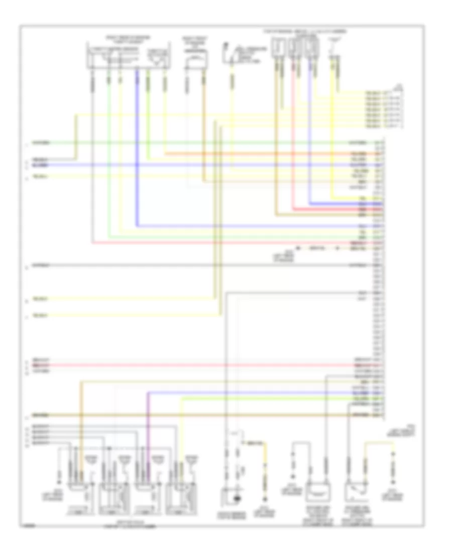
1.8L
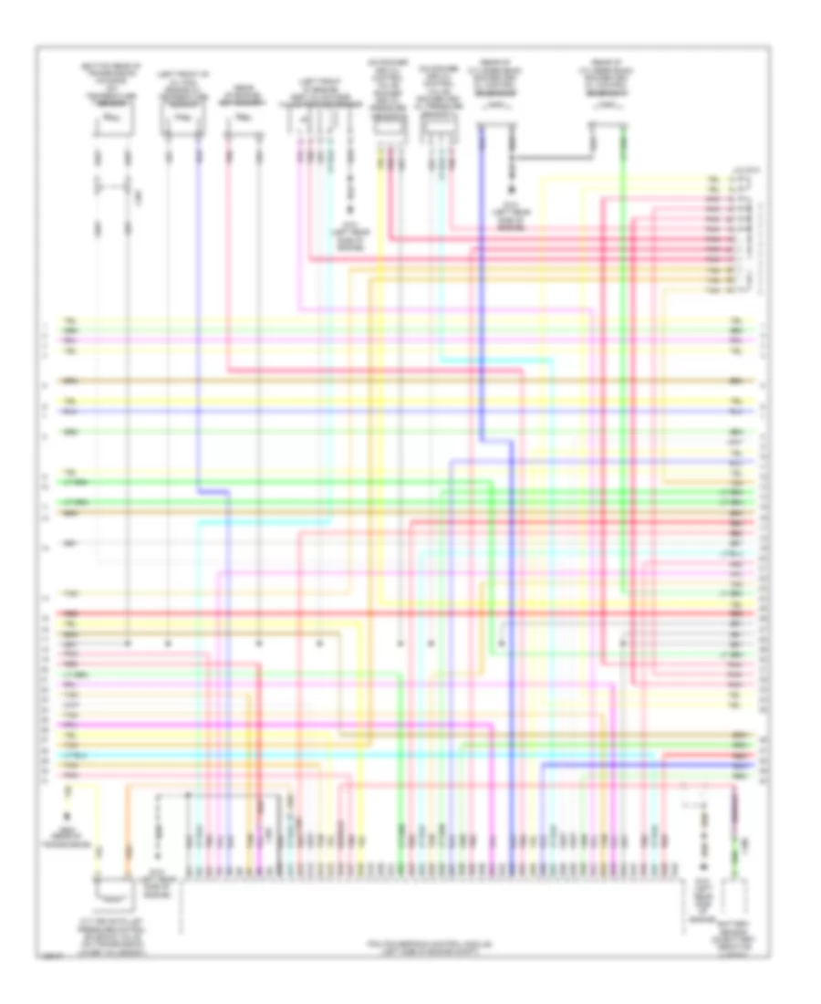
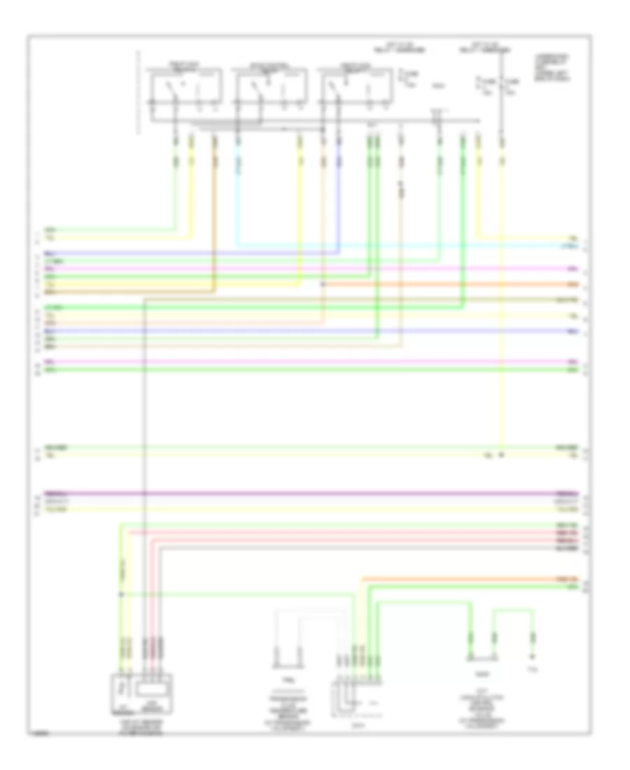
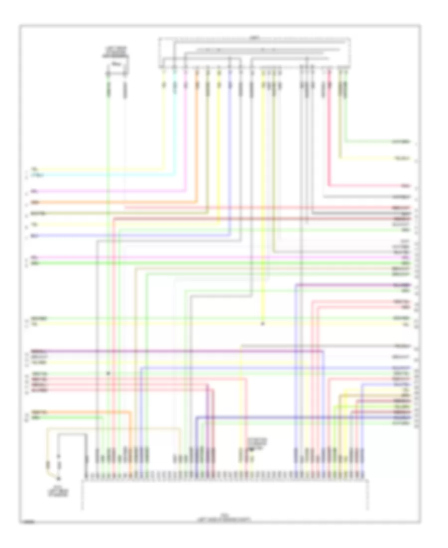
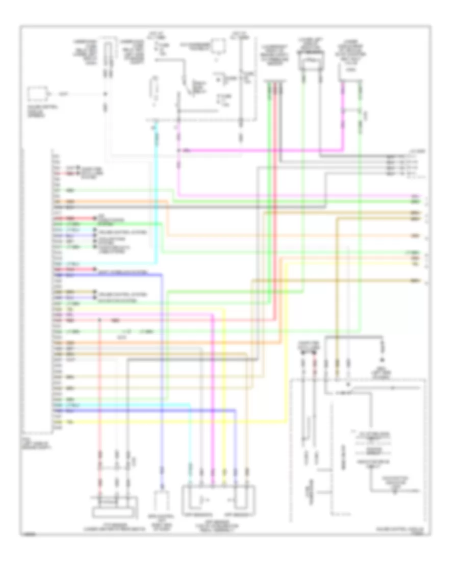
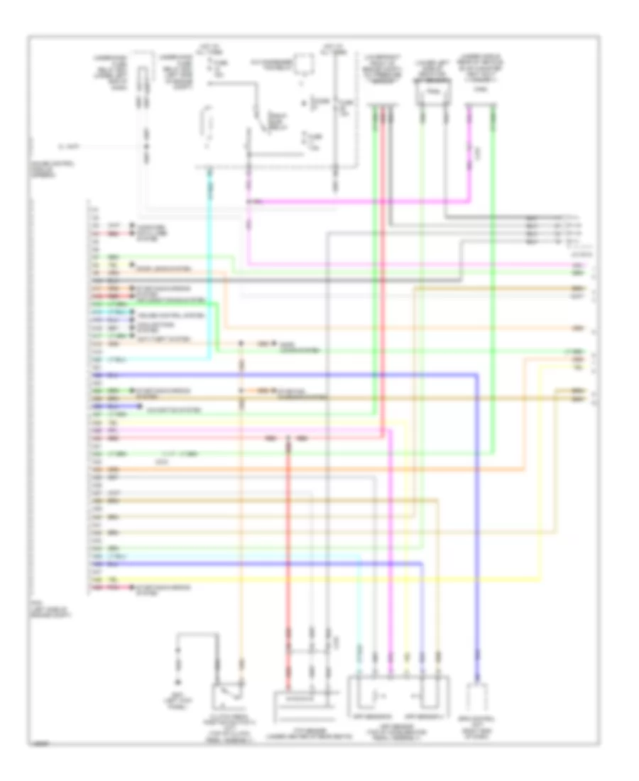
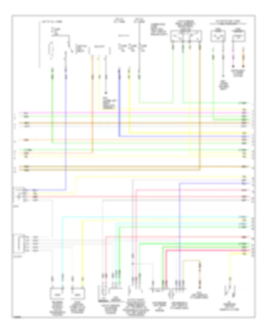
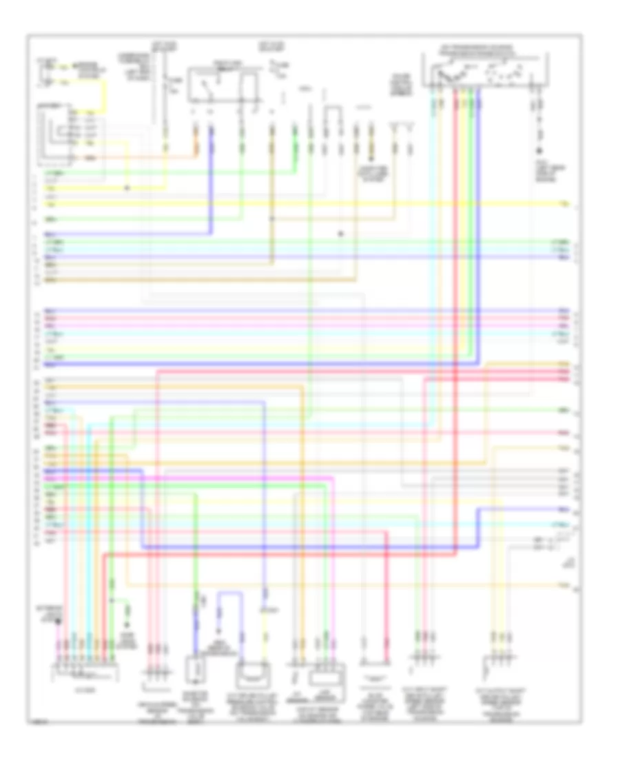
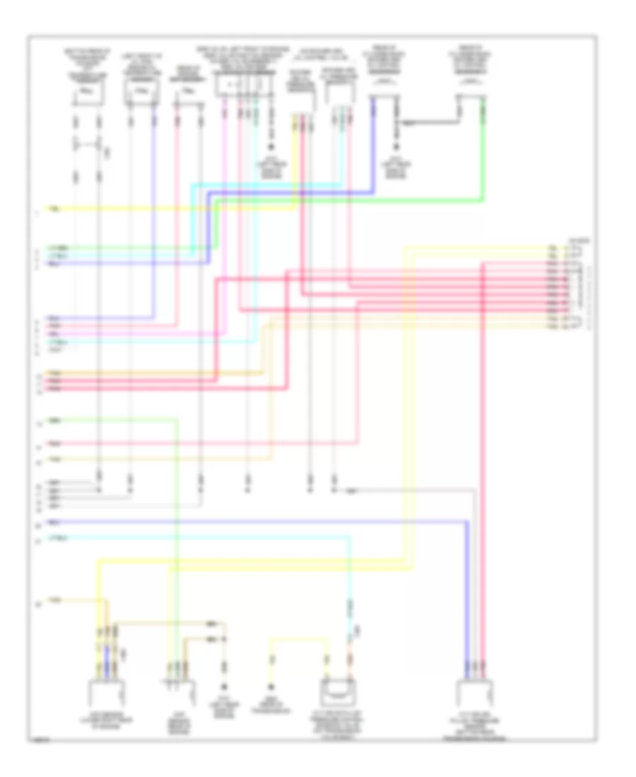
1.8L, Engine Performance Wiring Diagram, CVT (1 of 7) for Honda Civic HF 2014
List of elements for 1.8L, Engine Performance Wiring Diagram, CVT (1 of 7) for Honda Civic HF 2014:
- (lower left side of radiator) ect sensor 2
- (lower right front of engine compt) a/c pressure sensor
- (under left end of dash)
- (under middle rear of vehicle) evap canister vent shut valve
- A/c condenser fan relay
- A10
- A11
- A12
- A13
- A14
- A15
- A16
- A17
- A18
- A19
- A20
- A21
- A22
- A23
- A24
- A25
- A26
- A27
- A28
- A29
- A30
- A31
- A32
- A33
- A34
- A35
- A36
- A37
- A38
- A39
- A40
- A41
- A42
- A43
- A44
- A45
- A46
- A47
- A48
- A49
- A50
- A51
- App sensor (top of accelerator pedal assembly)
- App sensor a
- App sensor b
- C215
- Computer data lines system
- Cooling fans system
- Cruise control system
- D28
- Diode a
- Door locks system
- Eps control unit (right end of dash)
- Ftp sensor (under center of rear seats)
- Fuse 10a
- Fuse 15a
- Fuse 7.5a
- Hot at all times
- Hot w/ ig1 relay 1 energized
- J/c c005
- Micu
- Pcm (left side of engine compt)
- Pgm-fi sub relay
- Pnk
- Power tops & navigation systems
- Red
- Shift interlock system
- Starting/ charging system
- Starting/ charging system air conditioning system
- Starting/charging system
- Under- dash fuse/ relay box
- Under- hood fuse/ relay box (left side of engine compt)
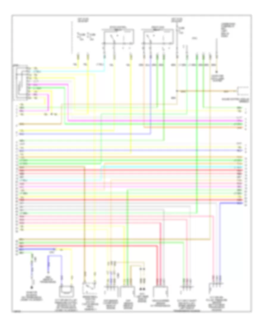
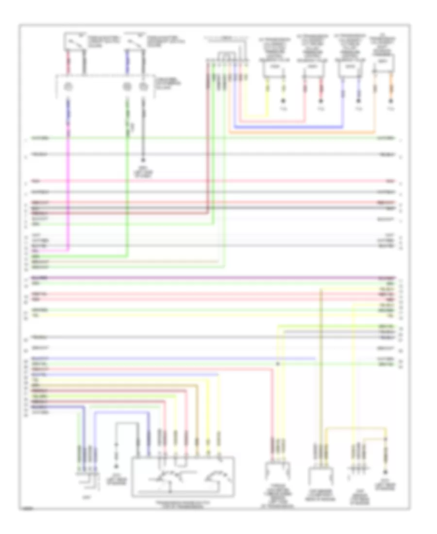
1.8L, Engine Performance Wiring Diagram, CVT (2 of 7) for Honda Civic HF 2014
List of elements for 1.8L, Engine Performance Wiring Diagram, CVT (2 of 7) for Honda Civic HF 2014:
- (in top of fuel tank) fuel tank unit
- (top of brake pedal assembly) brake pedal position switch
- (under
- 5v regulator
- B-can h
- B-can l
- B-can transceiver
- Computer data lines system
- Cvt drive pulley speed sensor (left side of transmission)
- Driver's seat)
- Eld unit
- Fail-safe circuit
- Forced turning-off circuit
- Forced turning-on circuit
- Fuse 15a
- G301 (under left front headlight assembly)
- G503 (left side of dash)
- G601
- Gauge control module (tach)
- Hot at all times
- Ignition coil relay
- Indicator driver circuit
- J/c c013
- Main circuit
- Malfunction indicator lamp (mil)
- Map sensor (right rear of engine)
- Pnk
- Starter cut relay 1
- Starter cut relay 2
- Under- hood fuse/ relay box (left side of engine compt)
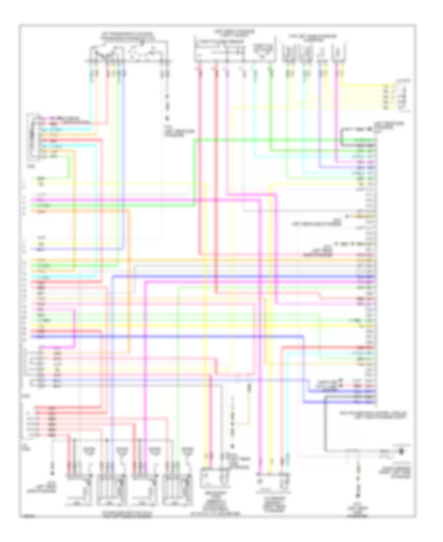
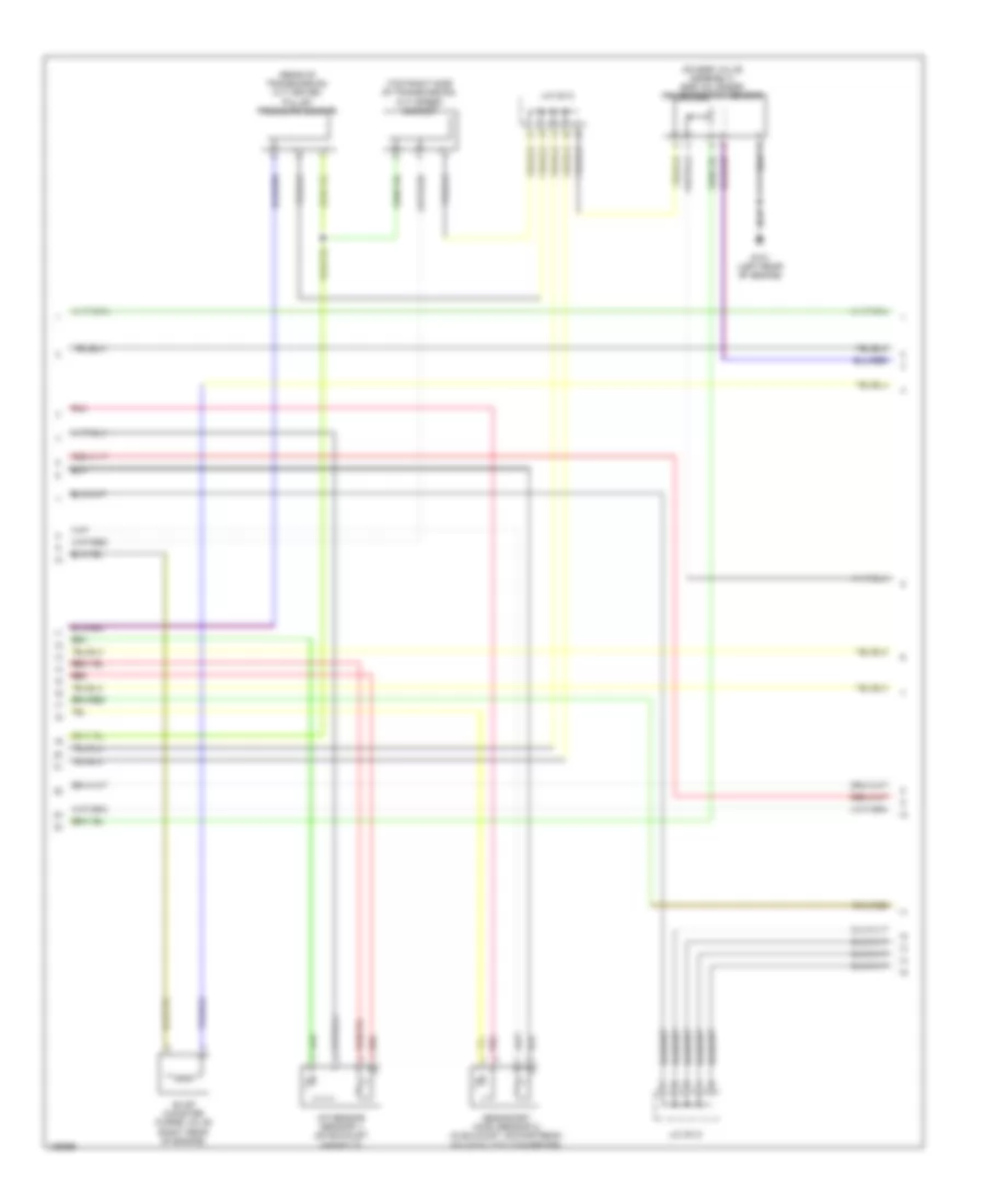
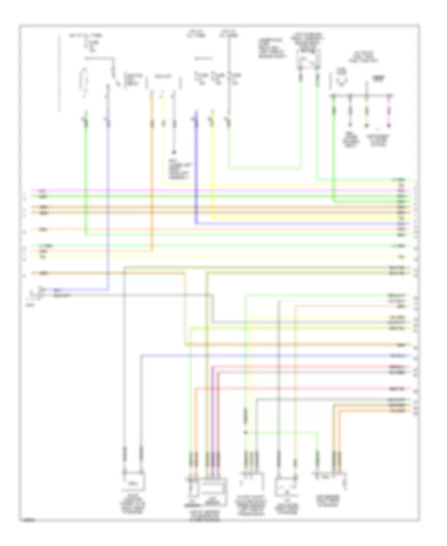
1.8L, Engine Performance Wiring Diagram, CVT (3 of 7) for Honda Civic HF 2014
List of elements for 1.8L, Engine Performance Wiring Diagram, CVT (3 of 7) for Honda Civic HF 2014:
- C13
- C16
- C25
- C34
- C35
- C414
- Cvt lock-up clutch control solenoid valve (in transmission valve body)
- D10
- D12
- D19
- Etcs control relay
- Fuse 10a
- Fuse 15a
- Fuse 7.5a
- Hot w/ ig1 relay 1 energized
- Iat sensor
- Maf sensor
- Maf/iat sensor (on engine air filter housing)
- Micu
- Pgm-fi main relay 1
- Pgm-fi main relay 2
- T12
- Transmission fluid temperature sensor (in transmission valve body)
- Under-dash fuse/relay box (under left end of dash)
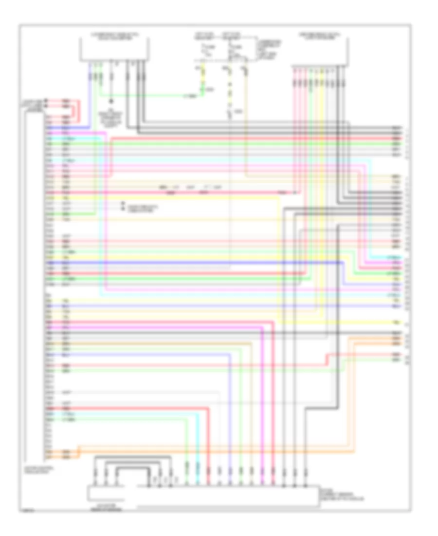
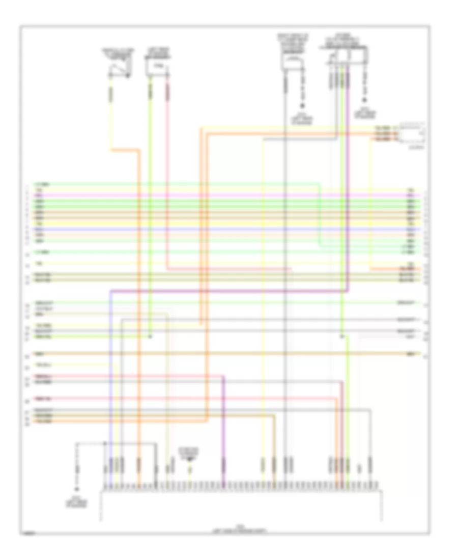
1.8L, Engine Performance Wiring Diagram, CVT (4 of 7) for Honda Civic HF 2014
List of elements for 1.8L, Engine Performance Wiring Diagram, CVT (4 of 7) for Honda Civic HF 2014:
- (left rear of engine) ect sensor 1
- B10
- B11
- B12
- B13
- B14
- B15
- B16
- B17
- B18
- B19
- B20
- B21
- B22
- B23
- B24
- B25
- B26
- B27
- B28
- B29
- B30
- B31
- B32
- B33
- B34
- B35
- B36
- B37
- B38
- B39
- B40
- B41
- B42
- B43
- B44
- B45
- B46
- B47
- B48
- B49
- B50
- B51
- C407
- G101 (left rear of engine)
- Pcm (left side of engine compt)
- Pnk
- Red
- Starting/ charging system
1.8L, Engine Performance Wiring Diagram, CVT (5 of 7) for Honda Civic HF 2014
List of elements for 1.8L, Engine Performance Wiring Diagram, CVT (5 of 7) for Honda Civic HF 2014:
- (in transmission valve body) cvt clutch pressure control solenoid valve
- (in transmission valve body) cvt drive pulley pressure control solenoid valve
- (in transmission valve body) cvt driven pulley pressure control solenoid valve
- (in transmission valve body) shift solenoid valve b
- A17
- A18
- C11
- C12
- C225
- C407
- C414
- Cable reel (on steering column)
- Ckp sensor (lower right rear of engine)
- Cmp sensor (top rear of engine)
- G101 (left rear of engine)
- G503 (left side of dash)
- Paddle shifter + (upshift switch) (coupe)
- Paddle shifter - (downshift switch) (coupe)
- Pnk
- R p
- Red
- T12
- T13
- Torque converter turbine speed sensor (left side of transmission)
- Transmission range switch (top of transmission)
1.8L, Engine Performance Wiring Diagram, CVT (6 of 7) for Honda Civic HF 2014
List of elements for 1.8L, Engine Performance Wiring Diagram, CVT (6 of 7) for Honda Civic HF 2014:
- (on egr valve assembly) egr valve/egr valve position sensor
- (rear of transmission) cvt driven pulley pressure sensor
- (top right side of transmission) cvt speed sensor
- A/f sensor (sensor 1) (on exhaust manifold)
- Evap canister purge valve (right rear of engine)
- G101 (left rear of engine)
- J/c c013
- Pnk
- Red
- Secondary ho2s (sensor 2) (in exhaust, downstream of catalytic converter)
1.8L, Engine Performance Wiring Diagram, CVT (7 of 7) for Honda Civic HF 2014
List of elements for 1.8L, Engine Performance Wiring Diagram, CVT (7 of 7) for Honda Civic HF 2014:
- (right front of engine) imt actuator
- (right rear of engine) throttle body
- (top of engine, above 1, 2, 3 & 4 cylinders) injectors
- C10
- C11
- C12
- C13
- C14
- C15
- C16
- C17
- C18
- C19
- C20
- C21
- C22
- C23
- C24
- C25
- C26
- C27
- C28
- C29
- C30
- C31
- C32
- C33
- C34
- C35
- C36
- C37
- C38
- C39
- C40
- C402
- C41
- C42
- C43
- C44
- C45
- C46
- C47
- C48
- C49
- C50
- G101 (left rear of engine)
- Icm
- Ignition coils (top of 1, 2, 3 & 4 cylinder)
- J/c c013
- Knock sensor (top of engine)
- Oil pressure switch (near oil filter)
- Pcm (left side of engine compt)
- Red
- Rocker arm oil control solenoid (right front of cylinder head)
- Rocker arm oil pressure switch (right front of cylinder head)
- Spark plug
- Throttle actuator
- Throttle open sensor
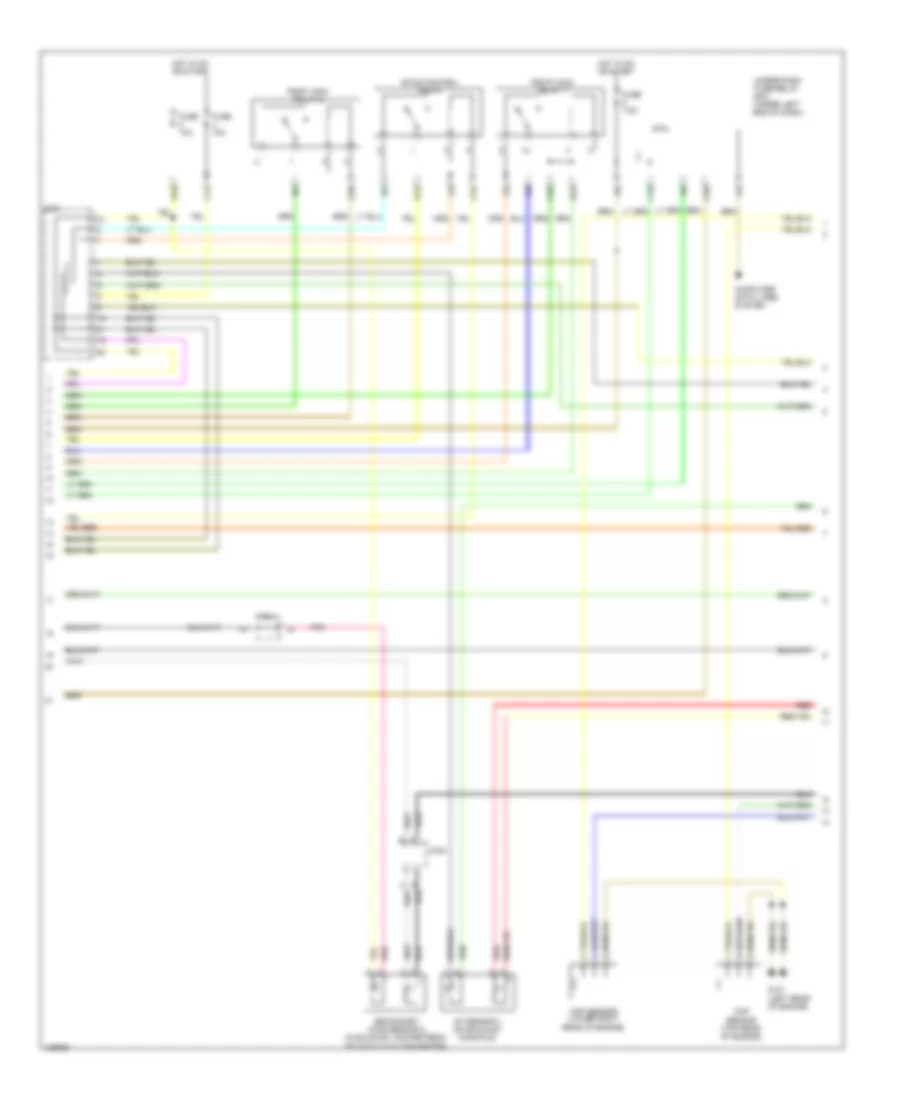
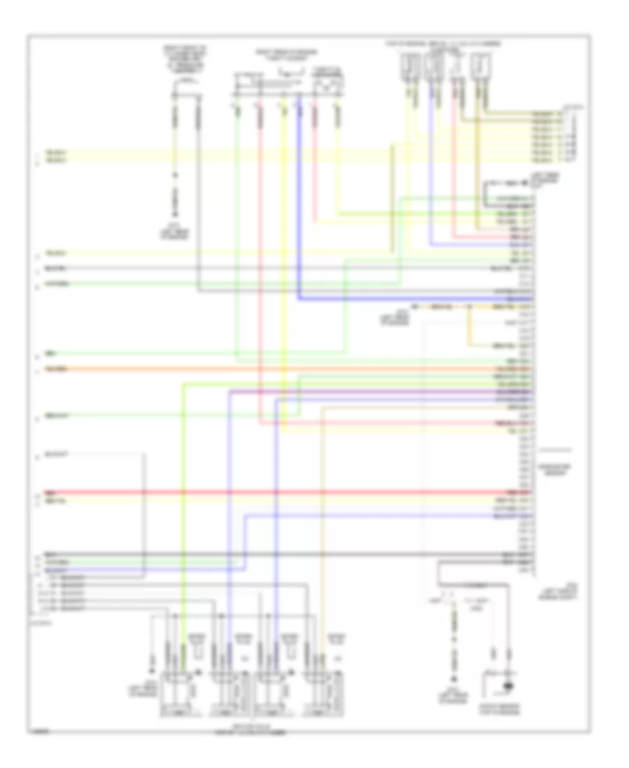
1.8L, Engine Performance Wiring Diagram, M/T (1 of 5) for Honda Civic HF 2014
List of elements for 1.8L, Engine Performance Wiring Diagram, M/T (1 of 5) for Honda Civic HF 2014:
- (lower left side of radiator) ect sensor 2
- (lower right front of engine compt) a/c pressure sensor
- (under middle rear of vehicle) evap canister vent shut valve
- 10v stabilizing
- A/c condenser fan relay
- A10
- A11
- A12
- A13
- A14
- A15
- A16
- A17
- A18
- A19
- A20
- A21
- A22
- A23
- A24
- A25
- A26
- A27
- A28
- A29
- A30
- A31
- A32
- A33
- A34
- A35
- A36
- A37
- A38
- A39
- A40
- A41
- A42
- A43
- A44
- A45
- A46
- A47
- A48
- A49
- Air conditioning system
- App sensor (top of accelerator pedal assembly)
- App sensor a
- App sensor b
- C215
- Circuit
- Computer data lines system
- Cooling fans system
- Cruise control system
- D28
- Dimming circuit
- Diode a
- Eps control unit (right end of dash)
- F-can h
- F-can l
- Ftp sensor (under center of rear seats)
- Fuse 10a
- Fuse 15a
- Fuse 7.5a
- G503 (left side of dash)
- Gauge control module (speedo)
- Gauge control module (tach)
- Hot at all times
- Indicator drive circuit
- J/c c009
- Main circuit
- Malfunction indicator lamp
- Navigation system
- Pcm (left side of engine compt)
- Pgm-fi sub- relay
- Pnk
- Red
- Shift interlock system
- Transceiver f-can
- Under-dash fuse/ relay box (under left end of dash)
- Under-hood fuse/ relay box (left side of engine compt)
1.8L, Engine Performance Wiring Diagram, M/T (2 of 5) for Honda Civic HF 2014
List of elements for 1.8L, Engine Performance Wiring Diagram, M/T (2 of 5) for Honda Civic HF 2014:
- (in top of fuel tank) fuel tank unit
- (top of brake pedal assembly) brake pedal position switch
- (under
- C404
- Driver's seat)
- Eld unit
- Evap canister purge valve (right rear of engine)
- Fuel pump
- Fuse 15a
- G301 (under left front headlight assembly)
- G601
- Gauge
- Hot at all times
- Iat sensor
- Ignition coil relay
- Imt actuator (right front of engine)
- Instrument cluster system
- Maf sensor
- Maf/iat sensor (on engine air filter housing)
- Map sensor (right rear of engine)
- Output shaft (counter shaft) speed sensor (left side of transmission)
- Under-hood fuse/ relay box (left side of engine compt)
1.8L, Engine Performance Wiring Diagram, M/T (3 of 5) for Honda Civic HF 2014
List of elements for 1.8L, Engine Performance Wiring Diagram, M/T (3 of 5) for Honda Civic HF 2014:
- (left rear of engine) ect sensor 1
- (near oil filter) oil pressure switch
- (on egr valve assembly) egr valve & egr valve position sensor
- (right front of cylinder head) rocker arm oil control solenoid
- B10
- B11
- B12
- B13
- B14
- B15
- B16
- B17
- B18
- B19
- B20
- B21
- B22
- B23
- B24
- B25
- B26
- B27
- B28
- B29
- B30
- B31
- B32
- B33
- B34
- B35
- B36
- B37
- B38
- B39
- B40
- B41
- B42
- B43
- B44
- B45
- B46
- B47
- B48
- B49
- G101 (left rear of engine)
- J/c c014
- Pcm (left side of engine compt)
- Starting/ charging system
1.8L, Engine Performance Wiring Diagram, M/T (4 of 5) for Honda Civic HF 2014
List of elements for 1.8L, Engine Performance Wiring Diagram, M/T (4 of 5) for Honda Civic HF 2014:
- A/f sensor 1 (on exhaust manifold)
- C13
- C16
- C20
- C25
- C34
- C35
- C404
- Ckp sensor (lower right rear of engine)
- Cmp sensor (top rear of engine)
- Computer data lines system
- D10
- D12
- D19
- Etcs control relay
- Fuse 10a
- Fuse 15a
- Fuse 7.5a
- G101 (left rear of engine)
- Hot in on or start
- Micu
- Pgm-fi main relay 1
- Pgm-fi main relay 2
- Pnk
- Red
- Secondary ho2s sensor 2 (in exhaust, downstream of catalytic converter)
- Under-dash fuse/relay box (under left end of dash)
1.8L, Engine Performance Wiring Diagram, M/T (5 of 5) for Honda Civic HF 2014
List of elements for 1.8L, Engine Performance Wiring Diagram, M/T (5 of 5) for Honda Civic HF 2014:
- (left rear of engine) g101
- (right front of cylinder head) rocker arm oil pressure switch
- (right rear of engine) throttle body
- (top of engine, above 1, 2, 3 & 4 cylinders) injectors
- Barometer sensor
- C10
- C11
- C12
- C13
- C14
- C15
- C16
- C17
- C18
- C19
- C20
- C21
- C22
- C23
- C24
- C25
- C26
- C27
- C28
- C29
- C30
- C31
- C32
- C33
- C34
- C35
- C36
- C37
- C38
- C39
- C40
- C402
- C41
- C42
- C43
- C44
- C45
- C46
- C47
- C48
- C49
- G101 (left rear of engine)
- Icm
- Ignition coils (top of 1, 2, 3 & 4 cylinder)
- J/c c014
- Knock sensor (top of engine)
- Pcm (left side of engine compt)
- Red
- Spark plug
- Throttle actuator
2.4L
2.4L, Engine Performance Wiring Diagram (1 of 5) for Honda Civic HF 2014
List of elements for 2.4L, Engine Performance Wiring Diagram (1 of 5) for Honda Civic HF 2014:
- (lower left side of radiator) ect sensor 2
- (lower right front of engine compt) a/c pressure sensor
- (under middle rear of vehicle) evap canister vent shut valve
- A/c condenser fan relay
- A10
- A11
- A12
- A13
- A14
- A15
- A16
- A17
- A18
- A19
- A20
- A21
- A22
- A23
- A24
- A25
- A26
- A27
- A28
- A29
- A30
- A31
- A32
- A33
- A34
- A35
- A36
- A37
- A38
- A39
- A40
- A41
- A42
- A43
- A44
- A45
- A46
- A47
- A48
- A49
- Anti-theft system
- App sensor (top of accelerator pedal assembly)
- App sensor a
- App sensor b
- C215
- Clutch pedal position switch a (m/t) (top of clutch pedal assembly)
- Computer data lines system
- Cooling fans system
- Cruise control system
- D28
- Diode a
- Door locks system
- Eps control unit (right end of dash)
- Ftp sensor (under center of rear seats)
- Fuse 10a
- Fuse 15a
- Fuse 7.5a
- G401 (left kick panel)
- Gauge control module (speedo)
- Hot at all times
- J/c c012
- Navigation system
- Pcm (left side of engine compt)
- Pgm-fi sub- relay
- Pnk
- Red
- Starting/ charging system
- Starting/charging system
- Starting/charging system air conditioning system
- Under-dash fuse/ relay box (under left end of dash)
- Under-hood fuse/ relay box (left side of engine compt)
2.4L, Engine Performance Wiring Diagram (2 of 5) for Honda Civic HF 2014
List of elements for 2.4L, Engine Performance Wiring Diagram (2 of 5) for Honda Civic HF 2014:
- (in top of fuel tank) fuel tank unit
- (top of brake pedal assembly) brake pedal position switch
- (under
- C410
- Cmp sensor a (left rear of cylinder head)
- Driver's seat)
- Eld unit
- Evap canister purge valve (right rear of engine)
- Fuel pump
- Fuel sender
- Fuse 15a
- G101 (left rear of cylinder head)
- G301 (under left front headlight assembly)
- G601
- Hot at all times
- Iat sensor
- Ignition coil relay
- Instrument cluster system
- J/c c011
- Maf sensor
- Maf/iat sensor (on engine air filter housing)
- Map sensor (left rear of engine)
- Oil pressure switch (near oil filter)
- Output shaft (counter shaft) speed sensor (a/t: top front of transmission housing) (m/t: left side of transmission)
- Pnk
- Red
- Reverse lockout solenoid (top of transmission housing)
- Under-hood fuse/ relay box (left side of engine compt)
2.4L, Engine Performance Wiring Diagram (3 of 5) for Honda Civic HF 2014
List of elements for 2.4L, Engine Performance Wiring Diagram (3 of 5) for Honda Civic HF 2014:
- (left rear of engine) ect sensor 1
- (right front of cylinder head) rocker arm oil control solenoid
- B10
- B11
- B12
- B13
- B14
- B15
- B16
- B17
- B18
- B19
- B20
- B21
- B22
- B23
- B24
- B25
- B26
- B27
- B28
- B29
- B30
- B31
- B32
- B33
- B34
- B35
- B36
- B37
- B38
- B39
- B40
- B41
- B42
- B43
- B44
- B45
- B46
- B47
- B48
- B49
- G101 (left rear of cylinder head)
- J/c c011
- Pcm (left side of engine compt)
- Pnk
- Red
- Starting/ charging system
- Tan
2.4L, Engine Performance Wiring Diagram (4 of 5) for Honda Civic HF 2014
List of elements for 2.4L, Engine Performance Wiring Diagram (4 of 5) for Honda Civic HF 2014:
- 10v stabilizing
- A/t gear position indicator driving circuit
- C13
- C16
- C20
- C25
- C34
- C35
- C410
- C411
- Circuit
- Circuit dimming
- Ckp sensor (lower right rear of engine)
- Cmp sensor b (right rear of cylinder head)
- Computer data lines system
- D10
- D12
- D19
- Etcs control relay
- F-can h
- F-can l
- F-can transceiver
- Fuse 10a
- Fuse 15a
- Fuse 7.5a
- G101 (left rear of cylinder head)
- G503 (left side of dash)
- Gauge control module (tach)
- Hot in on or start
- Indicator drive
- Main circuit
- Malfunction indicator lamp (mil ind)
- Micu
- Pgm-fi main relay 1
- Pgm-fi main relay 2
- Pnk
- Red
- Under-dash fuse/relay box (under left end of dash)
2.4L, Engine Performance Wiring Diagram (5 of 5) for Honda Civic HF 2014
List of elements for 2.4L, Engine Performance Wiring Diagram (5 of 5) for Honda Civic HF 2014:
- (front of engine)
- (left rear of cylinder head) g101
- (left rear of engine) throttle body
- (right front of cylinder head) rocker arm oil pressure switch
- (top of engine, above 1, 2, 3, 4 cylinders) injectors
- A/f sensor 1 (on exhaust manifold)
- C10
- C11
- C12
- C13
- C14
- C15
- C16
- C17
- C18
- C19
- C20
- C21
- C22
- C23
- C24
- C25
- C26
- C27
- C28
- C29
- C30
- C31
- C32
- C33
- C34
- C35
- C36
- C37
- C38
- C39
- C40
- C408
- C41
- C410
- C42
- C43
- C44
- C45
- C46
- C47
- C48
- C49
- G101 (left rear of cylinder head)
- G102 (left front of cylinder head)
- Icm
- Ignition coils (top of 1, 2, 3 & 4 cylinder)
- J/c c011
- Knock sensor (lower left side of engine)
- Pcm (left side of engine compt)
- Pnk
- Red
- Secondary ho2s sensor 2 (in exhaust, downstream of catalytic converter)
- Spark plug
- Tan
- Throttle actuator
- Vtc oil control solenoid valve
EXTERIOR LIGHTS
Backup Lamps Wiring Diagram, Except Hybrid with CVT for Honda Civic HF 2014
List of elements for Backup Lamps Wiring Diagram, Except Hybrid with CVT for Honda Civic HF 2014:
- B21
- B22
- C217
- C219
- C407
- Coupe
- D24
- Diode c
- Diode d
- Fuse 5 7.5a
- G101 (1.8l: left rear of engine) (2.4l: left rear of cylinder head)
- G701 (left rear of luggage compt)
- Hot in on or start
- Left backup light
- Micu
- Pcm (left side of engine compt)
- Reverse relay
- Right backup light
- Sedan
- Transmission range switch (top of transmission)
- Under-dash fuse/relay box (under left end of dash)
Backup Lamps Wiring Diagram, Hybrid with CVT for Honda Civic HF 2014
List of elements for Backup Lamps Wiring Diagram, Hybrid with CVT for Honda Civic HF 2014:
- B21
- B25
- C219
- C302
- D24
- Diode c
- Diode d
- Fuse 5 7.5a
- G101 (left rear side of engine)
- G701 (left rear of luggage compt)
- Hot in on or start
- Left backup light
- Micu
- Pcm (left side of engine compt)
- Reverse relay
- Right backup light
- Tan
- Transmission range switch (on transmission housing)
- Under-dash fuse/relay box (left end of dash)
Backup Lamps Wiring Diagram, M/T for Honda Civic HF 2014
List of elements for Backup Lamps Wiring Diagram, M/T for Honda Civic HF 2014:
- B21
- Backup light switch (on transaxle housing)
- C219
- C26
- C36
- C404 (except si) c410 (si)
- Diode d
- Except si
- Fuse 5 7.5a
- G701 (left rear of luggage compt)
- Hot in on or start
- Left backup light
- Micu
- Reverse relay
- Right backup light
- Under-dash fuse/relay box (under left end of dash)
Exterior Lamps Wiring Diagram, Except Hybrid (1 of 2) for Honda Civic HF 2014
List of elements for Exterior Lamps Wiring Diagram, Except Hybrid (1 of 2) for Honda Civic HF 2014:
- 10v stabilizing circuit
- 5v regulator
- Auto
- Automatic lighting/ sunlight sensor (top center of dash)
- B-can h
- B-can l
- B-can transceiver
- B12
- B32
- B35
- C11
- C12
- C19
- C217
- C219
- C33
- C38
- Combination light switch
- Computer data lines system
- Coupe
- D11
- D28
- Dimming circuit
- Except lx & dx
- Fuse 7.5a
- G201 (under right front headlight assembly)
- G301 (under left front headlight assembly)
- G503 (left side of dash)
- G602 (under front passenger's seat)
- G701 (left rear of luggage compt)
- Gauge control module (speedo)
- Gauge control module (tach)
- Head
- Headlight switch
- Hot in on
- Hot in on or start
- Indicator
- Indicator drive circuit
- K10
- K11
- Left
- Left front turn signal light
- Left rear turn signal light
- Left turn signal
- Lights on indicator
- Main circuit
- Micu
- Off
- Park
- Pnk
- Red
- Right
- Right front turn signal light
- Right rear turn signal light
- Right turn signal
- Sedan
- T13
- T14
- Turn signal switch
- Under-dash fuse/relay box (under left end of dash)
Exterior Lamps Wiring Diagram, Except Hybrid (2 of 2) for Honda Civic HF 2014
List of elements for Exterior Lamps Wiring Diagram, Except Hybrid (2 of 2) for Honda Civic HF 2014:
- & brake light
- (top of brake pedal assembly) brake pedal position switch
- C217
- C219
- Coupe
- Except lx
- Except si
- Fuse 10a
- Fuse 15a
- Fuse 20a
- G601 (under driver's seat)
- G701 (left rear of luggage compt)
- Hazard warning switch
- High mount brake light (except si)
- High mount brake light (si)
- Hot at all times
- Interior lights system
- Left
- Left inner taillight (sedan)
- Left license plate light (sedan)
- Left taillight
- License plate light (coupe)
- Rear
- Red
- Relay control module
- Right inner taillight (sedan)
- Right license plate light (sedan)
- Right rear side marker light
- Right taillight & brake light
- Sedan
- Side marker light
- Taillight relay
- Under-hood fuse/relay box (left side of engine compt)
Exterior Lamps Wiring Diagram, Hybrid (1 of 2) for Honda Civic HF 2014
List of elements for Exterior Lamps Wiring Diagram, Hybrid (1 of 2) for Honda Civic HF 2014:
- (top center of windshield) automatic lighting/ sunlight sensor
- 5v regulator
- Auto
- B-can h
- B-can l
- B-can transceiver
- B12
- B32
- B35
- C11
- C12
- C19
- C219
- C33
- C38
- Circuit 10v stabilizing
- Combination light switch
- Computer data lines system
- D11
- D28
- Dimming circuit
- Drive circuit indicator
- Fuse 7.5a
- G201 (under right headlight assembly)
- G301 (under left headlight assembly)
- G501 (upper end of dash)
- G503 (under left center of dash)
- G602 (under front passenger's seat)
- G701 (left rear of luggage compt)
- Gauge control module (speedo)
- Gauge control module (tach)
- Head
- Headlight switch
- Hot in on or start
- Indicator
- K10
- K11
- Left
- Left front turn signal light
- Left rear turn signal light
- Left turn signal
- Lights on indicator
- Main circuit
- Micu
- Off
- Park
- Pnk
- Q16
- Red
- Right
- Right front turn signal light
- Right rear turn signal light
- Right turn signal
- T13
- T14
- Turn signal switch
- Under-dash fuse/relay box (left end of dash)
Exterior Lamps Wiring Diagram, Hybrid (2 of 2) for Honda Civic HF 2014
List of elements for Exterior Lamps Wiring Diagram, Hybrid (2 of 2) for Honda Civic HF 2014:
- (top of brake pedal assembly) brake pedal position switch
- A16
- C219
- Center junction box 1
- Center junction box 2
- Fuse 10a
- Fuse 15a
- Fuse 20a
- G601 (under driver's seat)
- G701 (left rear of luggage compt)
- Hazard warning switch
- High mount brake light
- Hot at all times
- Interior lights system
- Left inner taillight
- Left license plate light
- Left taillight & brake light
- Multi-information display unit
- Red
- Relay control module
- Right inner taillight
- Right license plate light
- Right taillight & brake light
- Taillight relay
- Under-hood fuse/relay box (left side of engine compt)
GROUND DISTRIBUTION
Ground Distribution Wiring Diagram, Except Hybrid (1 of 5) for Honda Civic HF 2014
List of elements for Ground Distribution Wiring Diagram, Except Hybrid (1 of 5) for Honda Civic HF 2014:
- (cvt) transmission range switch
- A17
- B10
- B15
- B18
- Battery
- Battery sensor
- C15
- C20
- C204
- C221
- C407
- C408
- C410
- C411
- Center j/b 1
- Center junction box 1
- Ckp sensor
- Cmp sensor
- Cmp sensor a
- Cmp sensor b
- Data link connector (dcl)
- Data link connector (dlc)
- Egr valve & egr valve position sensor
- Engine
- Eps control unit
- G1 (under battery tray)
- G101 (1.8l) (left rear of engine)
- G101 (2.4l) (left rear of cylinder head)
- G102 (2.4l) (left front of cylinder head)
- G2 (right rear of engine compt)
- G202 (right front of engine compt)
- G3 (left front of engine compt)
- G402 (right end of dash)
- G403 (right kick panel)
- Ignition coil 1
- Ignition coil 2
- Ignition coil 3
- Ignition coil 4
- Immobilizer- keyless control unit
- Keyless access control unit
- Knock sensor shield
- Lg2
- Pcm
- Rocker arm oil control solenoid
- Rocker arm oil pressure switch
- Secondary ho2s (sensor 2) shield
- Steering gear box
- Transmission housing
- Vsa modulator- control unit
- Vtc oil control solenoid valve
- W/ keyless access system
- W/o keyless access system
Ground Distribution Wiring Diagram, Except Hybrid (2 of 5) for Honda Civic HF 2014
List of elements for Ground Distribution Wiring Diagram, Except Hybrid (2 of 5) for Honda Civic HF 2014:
- (2-door)
- (4-door)
- (canada) washer fluid level switch
- (if equipped)
- (if equipped) driver's seat heater switch
- (if equipped) front passenger's seat heater switch
- (if equipped) moonroof switch/interior light switch
- (if equipped) paddle shifter (down shift switch)
- (if equipped) paddle shifter (up shift switch)
- (if equipped) right fog light
- (if equipped) security hood switch
- (if equipped) windshield washer main relay
- (left side of engine compt) under-hood fuse/relay box
- (m/t) clutch pedal position switch b
- (under left end of dash) under-dash fuse/relay box
- (w/ keyless access) windshield wiper intermittent relay
- (w/o keyless access) windshield wiper intermittent relay
- 1.8l
- 2.4l
- A/c condenser fan motor
- A21
- Blower motor relay
- Brake fluid level switch
- C11
- C12
- C13
- C206
- C413
- Cable reel (on steering column)
- Clutch pedal position switch a
- Combination light switch
- Data link connector (dlc)
- Diode e
- Econ switch
- Eld
- Fan control relay
- G201 (under right front headlight assembly)
- G301 (under left front headlight assembly)
- G302 (front of engine compt)
- G401 (left kick panel)
- G501 (left end of dash)
- G503 (left side of dash)
- Gauge control module (speedo)
- Gauge control module (tach)
- Hfl-navigation voice control switch/ hft-navigation voice control switch
- Ignition key switch
- Left fog light
- Left front turn signal light
- Left headlight (high)
- Left headlight (low)
- Micu
- Multi- information display unit
- Power transistor
- Relay control module
- Right front turn signal light
- Right headlight (high)
- Right headlight (low)
- S-gnd
- Steering angle sensor
- T7 (in steering wheel)
- Under-hood fuse/relay box (left side of engine compt)
- Vsa off switch
- Windshield washer motor
- Windshield wiper motor
- Windshield wiper motor relay
Ground Distribution Wiring Diagram, Except Hybrid (3 of 5) for Honda Civic HF 2014
List of elements for Ground Distribution Wiring Diagram, Except Hybrid (3 of 5) for Honda Civic HF 2014:
- (if equipped) driver's door outer handle
- (if equipped) moonroof control unit/ motor
- (not used)
- 1.8l coupe cvt
- A10
- C203
- C206
- C210
- C301
- Cvt clutch pressure control solenoid valve
- Cvt drive pulley pressure control solenoid valve
- Cvt driven pulley pressure control solenoid valve
- Cvt lock-up clutch control solenoid valve
- D/l lock relay
- D/l or unlock relay
- D/l unlock relay
- Driver's door lock actuator/ knob switch/key cylinder switch
- Except 1.8l sedan cvt
- Front accessory power socket relay
- G502 (left side of dash)
- Gauge control module (tach)
- Left power mirror
- Multi- information display unit
- P20
- Power mirror switch
- Power window master switch
- Red
- Shift solenoid valve b
- T12 (cvt)
- T13 (cvt)
- Trunk release actuator relay
- Under-dash fuse/relay box (under left end of dash)
- Windshield washer main relay
Ground Distribution Wiring Diagram, Except Hybrid (4 of 5) for Honda Civic HF 2014
List of elements for Ground Distribution Wiring Diagram, Except Hybrid (4 of 5) for Honda Civic HF 2014:
- (2-door)
- (4-door)
- (4-door) left rear side marker light
- (4-door) right rear side marker light
- (if equipped)
- (if equipped) left inner taillight
- (if equipped) right inner taillight
- A36
- A37
- C214
- C218
- Coupe
- Driver's power seat adjustment switch
- Driver's seat cushion heater
- Driver's seat heater relay (high)
- Driver's seat heater relay (low)
- Front passenger's seat cushion heater
- Front passenger's seat heater relay (high)
- Front passenger's seat heater relay (low)
- Fuel tank unit
- G506 (under left front of center console)
- G601 (under driver's seat)
- G701 (left rear of luggage compt)
- G801 (right "c" pillar)
- High mount brake light
- Keyless buzzer
- Left backup light
- Left license plate light
- Left rear turn signal light
- Left taillight & brake light
- License plate light
- Rear window defogger
- Right backup light
- Right license plate light
- Right rear turn signal
- Right taillight & brake light
- Sedan
- Srs unit
- Trunk lid latch switch/ trunk release actuator
- Trunk lid opener lock switch
- Trunk lid outer handle switch
- W/ license plate light
- W/o license plate light
Ground Distribution Wiring Diagram, Except Hybrid (5 of 5) for Honda Civic HF 2014
List of elements for Ground Distribution Wiring Diagram, Except Hybrid (5 of 5) for Honda Civic HF 2014:
- (4-door)
- (if equipped) automatic lighting/ sunlight sensor
- (if equipped) right power mirror
- (under left end of dash) under-dash fuse/relay box
- 1.8l coupe cvt
- Audio unit/ audio- navigation unit
- B32
- C202
- C212
- C213
- C214
- C218
- C226
- Coupe
- Driver's seat belt buckle switch
- Driver's seat position sensor
- Engine start/stop switch
- Except 1.8l coupe cvt
- Front accessory power socket
- Front passenger's door lock actuator/ knob switch
- Front passenger's door outer handle
- Front passenger's power window switch
- Front passenger's seat belt buckle switch
- Front passenger's weight sensor unit
- G504 (right end of dash)
- G505 (right center of dash)
- G507
- G602 (under front passenger's seat)
- Hvac control circuit/ climate control unit
- Left rear door lock actuator/ knob switch
- Micu
- Right rear door lock actuator/ knob switch
- S-gnd
- Sedan
- Shift lever
- Stereo amplifier
Ground Distribution Wiring Diagram, Hybrid (1 of 4) for Honda Civic HF 2014
List of elements for Ground Distribution Wiring Diagram, Hybrid (1 of 4) for Honda Civic HF 2014:
- A10
- A17
- B10
- B15
- Battery
- Battery sensor
- Battery sensor shield
- C15
- C20
- C203
- C204
- C212
- C301
- C302
- C303
- Center junction box 1
- Ckp sensor
- Cmp sensor
- Cvt clutch pressure control solenoid valve
- Data link connector (dlc)
- Dc-dc converter
- Driver door touch sensor
- Driver's door lock actuator/ knob switch/key cylinder switch
- Egr valve/ egr valve position sensor
- Engine
- Eps control unit
- Exhaust side ignition coil 1
- Exhaust side ignition coil 2
- Exhaust side ignition coil 3
- Exhaust side ignition coil 4
- Front accessory power socket relay
- G1 (under battery tray)
- G101 (left rear side of engine)
- G2 (right rear corner of engine compt)
- G202 (right front of engine compt)
- G3 (left front of engine compt)
- G403 (right kick panel)
- G5 (right front corner of ipu module compt)
- G502 (upper left center of dash)
- Gauge control module (tach)
- Intake side ignition coil 1
- Intake side ignition coil 2
- Intake side ignition coil 3
- Intake side ignition coil 4
- J/c c008
- Keyless access control unit
- Knock sensor shield
- Left power mirror
- Lock relay
- Motor rotor position sensor shield
- Multi- information display unit
- P20
- Pcm
- Power mirror switch
- Power unit
- Power window master switch
- Rocker arm oil control solenoid a
- Rocker arm oil control solenoid b
- Secondary ho2s (sensor 2) shield
- Secondary ho2s sensor 2 shield
- Servo unit
- Tailgate actuator relay
- Transmission housing
- Transmission range switch
- Under-dash fuse/relay box (left end of dash)
- Unlock relay
- Unlock relay (dr)
- Vsa modulator control unit
- W/ defogger
- W/o defogger
- Windshield washer main relay
Ground Distribution Wiring Diagram, Hybrid (2 of 4) for Honda Civic HF 2014
List of elements for Ground Distribution Wiring Diagram, Hybrid (2 of 4) for Honda Civic HF 2014:
- (left end of dash) under-dash fuse/relay box
- (left side of engine compt) under-hood fuse/relay box
- A/c condenser fan motor
- A21
- Auxiliary electric water pump
- Blower motor relay
- Brake fluid level switch
- C13
- C207
- C225
- C306
- Cable reel (top of steering column)
- Combination light switch
- Data link connector (dlc)
- Driver's seat heater switch
- Econ switch
- Eld unit
- Engine start/stop switch
- Fan control relay
- Fcw/ldw camera unit
- Front passenger's seat heater switch
- G201 (under right headlight assembly)
- G301 (under left headlight assembly)
- G302 (center front of engine compt)
- G401 (left end of dash)
- G402 (right end of dash)
- G501 (upper left end of dash)
- G503 (upper left center of dash)
- Gauge control module (speedo)
- Gauge control module (tach)
- If equipped
- Left daytime running light
- Left front turn signal light
- Left headlight (high)
- Left headlight (low)
- Micu
- Motor rotor position sensor shield
- Multi- information display unit
- Power transistor
- Relay control module
- Right daytime running light
- Right front turn signal light
- Right headlight (high)
- Right headlight (low)
- Security hood switch
- Steering angle sensor
- T7 (in steering wheel)
- Torque sensor
- Vsa off switch
- Windshield washer main relay
- Windshield washer motor
- Windshield wiper intermittent relay
- Windshield wiper main relay
- Windshield wiper motor
Ground Distribution Wiring Diagram, Hybrid (3 of 4) for Honda Civic HF 2014
List of elements for Ground Distribution Wiring Diagram, Hybrid (3 of 4) for Honda Civic HF 2014:
- (if equipped)
- A37
- C218
- C220
- C223
- Cvt drive pulley pressure control solenoid valve
- Cvt driven pulley pressure control solenoid valve
- Driver's seat heater
- Driver's seat heater relay (high)
- Driver's seat heater relay (low)
- Front passenger's seat heater
- Front passenger's seat heater relay (high)
- Front passenger's seat heater relay (low)
- Fuel tank unit
- G506 (under left front of center console)
- G601 (under driver's seat)
- G701 (left rear luggage compt)
- G801 (base of right "c" pillar)
- G902 (rear of transmission)
- High mount brake light
- Left backup light
- Left inner taillight
- Left license plate light
- Left rear turn signal light
- Left taillight & brake light
- Rear window defogger
- Right backup light
- Right inner taillight
- Right license plate light
- Right rear turn signal light
- Right taillight & brake light
- Smart buzzer
- Srs unit
- Trunk lid latch switch/ trunk release actuator
- Trunk lid opener lock switch
- Trunk lid outer handle switch
Ground Distribution Wiring Diagram, Hybrid (4 of 4) for Honda Civic HF 2014
List of elements for Ground Distribution Wiring Diagram, Hybrid (4 of 4) for Honda Civic HF 2014:
- (left end of dash) under-dash fuse/relay box
- A/c compressor driver
- A/t gear position indicator panel light/park-pin switch
- A32
- Audio unit/ audio- navigation unit
- Automatic lighting/sunlight sensor
- B32
- Battery module
- C202
- C211
- C214
- C215
- C218
- C220
- C501
- Climate control unit
- Driver's seat belt buckle switch
- Driver's seat position sensor
- Front accessory power socket
- Front passenger's door lock actuator/ knob switch
- Front passenger's door touch sensor
- Front passenger's power window switch
- Front passenger's seat belt buckle switch
- Front passenger's weight sensor unit
- G504 (upper right end of dash)
- G505 (right center of dash)
- G602 (under front passenger's seat)
- G901 (right front corner of ipu module)
- Ipu fan module
- J/c c014
- J/c c016
- Left rear door lock actuator/ knob switch
- Mcm
- Micu
- Motor rotor position sensor shield
- Mpi module
- Right power mirror
- Right rear door lock actuator/ knob switch
- T16 (right side of ipu module compt)
- V-sensor1
- V-sensor2
- V-sensor3
- V-sensor4
- W/ navigation
- W/o navigation
HEADLIGHTS
Headlights Wiring Diagram, Except Hybrid (1 of 2) for Honda Civic HF 2014
List of elements for Headlights Wiring Diagram, Except Hybrid (1 of 2) for Honda Civic HF 2014:
- 10v stabilizing circuit
- 5v regulator
- Audio unit/ audio-navigation unit
- B-can h
- B-can l
- B-can transceiver
- B11
- B19
- B32
- C14
- C18
- C205
- Combination light switch
- Computer data lines system
- D20
- D28
- D29
- Dimmer/ flash-to- pass switch 0) low 1) high 2) pass
- Dimming circuit
- Drl ind
- Except 1.8l coupe m/t & canada coupe
- Fog light switch
- Front fog lights ind
- Fuse 7.5a
- G503 (left side of dash)
- G602 (under front passenger's seat)
- Gauge control module (tach)
- Headlight switch 0) off 1) park 2) auto 3) head
- High beam ind
- Hot in on or start
- Ignition key switch
- Indicator drive circuit
- Keyless access control unit
- Lights on ind
- Main circuit
- Micu
- Off
- P11
- Parking brake switch (at base of parking brake lever)
- Pnk
- Q16
- Red
- T11
- T12
- Under-dash fuse/relay box (under left end of dash)
Headlights Wiring Diagram, Except Hybrid (2 of 2) for Honda Civic HF 2014
List of elements for Headlights Wiring Diagram, Except Hybrid (2 of 2) for Honda Civic HF 2014:
- (under left front headlight assembly)
- (under right front headlight assembly)
- 1.8l coupe m/t & canada coupe
- Automatic lighting/sunlight sensor (except 1.8l m/t) (top center of dash)
- Center junction box 1
- Center junction box 2
- Computer data lines system
- Except 1.8l coupe m/t & canada coupe
- Front fog light relay
- Fuse 1-6 100a
- Fuse 10a
- Fuse 20a
- Fuse 20a (or 10a)
- G201
- G201 (under right front headlight assembly)
- G301
- G301 (under left front headlight assembly)
- Headlight low beam relay
- Hot at all times
- Left fog light
- Left headlight (high)
- Left headlight (low)
- Left headlight low beam relay
- Pnk
- Red
- Relay control module
- Right fog light
- Right headlight (high)
- Right headlight (low)
- Right headlight low beam relay
- Under-hood fuse/relay box (left side of engine compt)
Headlights Wiring Diagram, Hybrid (1 of 2) for Honda Civic HF 2014
List of elements for Headlights Wiring Diagram, Hybrid (1 of 2) for Honda Civic HF 2014:
- 10v stabilizing circuit
- 5v regulator
- Audio unit/ audio-navigation unit
- B-can h
- B-can l
- B-can transceiver
- B11
- B19
- C14
- C18
- C206
- C29
- Combination light switch
- Computer data lines system
- D28
- D29
- Dimmer/ flash-to- pass switch 0) low 1) high 2) pass
- Dimming circuit
- Front fog light ind
- Fuse 7.5a
- G503 (upper left center of dash)
- Gauge control module (tach)
- Headlight switch 0) off 1) park 2) auto 3) head
- High beam ind
- Hot in on or start
- Ignition key switch
- Indicator drive circuit
- Keyless access control unit
- Lights on ind
- Main circuit
- Micu
- P11
- Parking brake switch (at base of parking brake lever)
- Pnk
- Q16
- Red
- T11
- T12
- Under-dash fuse/relay box (left end of dash)
Headlights Wiring Diagram, Hybrid (2 of 2) for Honda Civic HF 2014
List of elements for Headlights Wiring Diagram, Hybrid (2 of 2) for Honda Civic HF 2014:
- (under left headlight assembly)
- (under right headlight assembly)
- Automatic lighting/sunlight sensor (top center of windshield)
- Center junction box 1
- Center junction box 2
- Computer data lines system
- Daytime running lights relay
- Fuse 1-6 100a
- Fuse 10a
- Fuse 14-1 10a
- Fuse 17-1 10a
- G201
- G201 (under right headlight assembly)
- G301
- G301 (under left headlight assembly)
- Hot at all times
- Left daytime running light
- Left headlight (high)
- Left headlight (low)
- Left headlight low beam relay
- Pnk
- Red
- Relay control module (in under-hood fuse/relay box)
- Right daytime running light
- Right headlight (high)
- Right headlight (low)
- Right headlight low beam relay
- Under-hood fuse/relay box (left side of engine compt)
HORN
Horn Wiring Diagram, Except Hybrid for Honda Civic HF 2014
List of elements for Horn Wiring Diagram, Except Hybrid for Honda Civic HF 2014:
- C14
- C37
- Cable reel (on steering column)
- Fuse 10a
- Horn (high) (behind left side of front grille)
- Horn (low) (behind right side of front grille)
- Horn relay
- Horn switch (in steering wheel)
- Hot at all times
- Micu
- Pnk
- Q10
- Under-dash fuse/relay box (under left end of dash)
- Under-hood fuse/relay box (left side of engine compt)
- W/ duel horns
Horn Wiring Diagram, Hybrid for Honda Civic HF 2014
List of elements for Horn Wiring Diagram, Hybrid for Honda Civic HF 2014:
- C14
- C37
- Cable reel (top of steering column)
- Fuse 10a
- Horn (low) (behind right side of front grille)
- Horn relay (in under-hood fuse/relay box)
- Horn switch (in steering wheel)
- Hot at all times
- J/c c011
- Micu
- Pnk
- Q10
- Under-dash fuse/relay box (left end of dash)
- Under-hood fuse/relay box (left side of engine compt)
INSTRUMENT CLUSTER
Instrument Cluster Wiring Diagram, Except Hybrid (1 of 2) for Honda Civic HF 2014
List of elements for Instrument Cluster Wiring Diagram, Except Hybrid (1 of 2) for Honda Civic HF 2014:
- 1.8l w/ start/stop
- 10v stabilizing circuit
- 2.4l & 1.8l w/o start/stop
- 5v control circuit
- 5v on/off
- 5v regulator
- Amp
- Anti-lock brakes system
- Audio unit/ audio- navigation unit (if equipped)
- B-can h
- B-can l
- B-can transceiver
- B11
- B19
- Blinking circuit
- C204
- C205
- Computer data lines system
- Cruise control ind
- Cruise control system
- Cruise main ind
- D28
- Dimming circuit
- Ecm/pcm (left side of engine compt)
- Econ ind
- Exterior lights system
- F-can h
- F-can l
- F-can transceiver
- Front fog light ind
- Fuel display
- Fuse 10a
- G502 (left side of dash)
- G503 (left side of dash)
- Gauge control module (speedo)
- Gauge control module (tach)
- High beam ind
- Hot at all times
- I- vtec ind
- Illumination control & dimming circuit for ambient (green)
- Illumination control & dimming circuit for ambient (red)
- Illumination control & dimming circuit for dial face & scale (white)
- Illumination control & dimming circuit for fuel lcd back light (white)
- Illumination control & dimming circuit for gradation (white)
- Illumination control & dimming circuit for i-vtec letter back light (white)
- Illumination control & dimming circuit for instant fuel lcd back light (white)
- Illumination control & dimming circuit for pointer (white)
- Illumination control & dimming circuit for rev belt back light (white)
- Illumination control & dimming circuit for sp lcd back light (white)
- Immobilizer ind
- Indicator drive circuit
- Instant fuel display
- Interior lights system
- Keyless access control unit (if equipped)
- Keyless access ind
- Left turn signal ind
- Lights on ind
- Low fuel ind
- Low temperature ind
- Main circuit
- Message ind
- Outside air temperature sensor (behind left side of front bumper)
- Parking brake switch (at base of parking brake lever)
- Pnk
- Red
- Resonator
- Rev ind
- Rev ind 1
- Right turn signal ind
- Security ind
- Speaker
- Speedo display
- To forced turning-on circuit (diagram 2 of 2)
- To illumination encoder (diagram 2 of 2)
- To mil ind (diagram 2 of 2)
- To park indicator (diagram 2 of 2)
- Under-dash fuse/relay box (under left end of dash)
- Under-hood fuse/relay box (left side of engine compt)
- Warning drive circuit
Instrument Cluster Wiring Diagram, Except Hybrid (2 of 2) for Honda Civic HF 2014
List of elements for Instrument Cluster Wiring Diagram, Except Hybrid (2 of 2) for Honda Civic HF 2014:
- 2/l
- 5v on/off
- A/t gear position indicator driving circuit
- Abs ind
- B22
- B29
- B33
- B40
- B44
- Brake fluid level switch (on brake master cylinder reservoir)
- Brake ind
- C204
- C207
- C217
- C219
- Charging system ind
- Clock sw
- Computer data lines system
- Coupe
- D3/5
- Door ind
- Driver's door switch (in driver's "b" pillar)
- Drl ind
- Eps ind
- Fail-safe circuit
- Forced turning- off circuit
- Forced turning- on circuit
- From cruise control ind (diagram 1 of 2)
- From illumination control & b dimming circuit (diagram 1 of 2)
- From low temp ind (diagram 1 of 2)
- From pin 17 (diagram 1 of 2)
- Front passenger's door switch (in front passenger's "b" pillar)
- Fuel gauge sending unit
- Fuel tank unit (in top of fuel tank)
- Fuse 5 7.5a
- G401 (left kick panel)
- G701 (left rear of luggage compt)
- Gauge control module (tach)
- High temperature ind
- Hot in on or start
- Hvac control unit/ climate control unit (if equipped)
- Ill +
- Ill -
- Illumination encoder
- Indicator drive circuit
- Interior lights system
- Km/h-mhp/ clock adj
- Left rear door switch (4 door) (in left rear "c" pillar)
- Low oil pressure ind
- Low tire pressure ind
- Main circuit
- Maintenance required ind
- Malfunction indicator lamp ind (mil)
- Micu
- Oil pressure switch (if equipped) (near oil filter)
- Pnk
- Right rear door switch (4 door) (in right rear "c" pillar)
- Seat belt reminder ind
- Sedan
- Sel reset
- Side air bag cut-off ind
- Srs ind
- Tachometer
- Tpms ind
- Trunk ind
- Trunk lid latch/ trunk release actuator (bottom rear of luggage compt lid)
- Under-dash fuse/relay box (under left end of dash)
- Vsa ind
- Vsa off ind
- Washer fluid level ind
- Washer fluid level switch (canada) (in washer fluid reservoir tank)
Instrument Cluster Wiring Diagram, Hybrid (1 of 2) for Honda Civic HF 2014
List of elements for Instrument Cluster Wiring Diagram, Hybrid (1 of 2) for Honda Civic HF 2014:
- 10v stabilizing circuit
- 5v control circuit
- 5v on/off
- 5v regulator
- Amp
- Anti-lock brakes system
- Auto stop ind
- B-can h
- B-can l
- B-can transceiver
- Blinking circuit
- C204
- C206
- Computer data lines system
- Cruise control ind
- Cruise control system
- Cruise main ind
- Dimming circuit
- Eco ind
- Exterior lights system
- F-can h
- F-can l
- F-can transceiver
- Front fog light ind
- Fuel display
- Fuse 10a
- G401 (left end of dash)
- G502 (upper left center of dash)
- G503 (upper left center of dash)
- Gauge control module (speedo)
- Gauge control module (tach)
- High beam ind
- Hot at all times
- Illumination control & dimming circuit for ambient (green)
- Illumination control & dimming circuit for dial face & scale (white)
- Illumination control & dimming circuit for fuel lcd back light (white)
- Illumination control & dimming circuit for gradation (white)
- Illumination control & dimming circuit for instant fuel lcd back light (white)
- Illumination control & dimming circuit for pointer (white)
- Illumination control & dimming circuit for sp lcd back light (white)
- Immobilizer ind
- Indicator drive circuit
- Instant fuel display
- Interior lights system
- Keyless access system ind
- Left turn signal ind
- Lights on ind
- Low fuel ind
- Low temperature ind
- Main circuit
- Message ind
- Oil pressure switch (near oil filter)
- Parking brake switch (at base of parking brake lever)
- Pcm (left side of engine compt)
- Pnk
- Red
- Right turn signal ind
- Security ind
- Speaker
- Speedo display
- Tan
- To illumination encoder (diagram 2 of 2)
- To malfunction (mil) ind (diagram 2 of 2)
- To park indicator (diagram 2 of 2)
- Under-hood fuse/relay box (left side of engine compt)
- Warning drive circuit
- Washer fluid level switch (canada) (in washer fluid reservoir)
Instrument Cluster Wiring Diagram, Hybrid (2 of 2) for Honda Civic HF 2014
List of elements for Instrument Cluster Wiring Diagram, Hybrid (2 of 2) for Honda Civic HF 2014:
- 5v on/ off
- A/t gear position indicator driving circuit
- Abs ind
- Audio unit/ audio- navigation unit
- B11
- B19
- B22
- B29
- B33
- B34
- B40
- Brake fluid level switch (on brake master cylinder reservoir)
- Brake ind
- Brake system ind
- C204
- C208
- C219
- C223
- Charging system ind
- Clock adj
- Clock sw
- Computer data lines system
- D28
- Door ind
- Driver's door switch (in driver's "b" pillar)
- Eps ind
- Fail-safe circuit
- Fcw ind
- Forced turning- off circuit
- Forced turning- on circuit
- From auto stop ind (diagram 1 of 2)
- From illumination control & b dimming circuit (diagram 1 of 2)
- From pin 17 (diagram 1 of 2)
- Front passenger's door switch (in front passenger's "b" pillar)
- Fuel tank unit (top of fuel tank)
- Fuse 5 7.5a
- G401 (left end of dash)
- G701 (left rear of luggage compt)
- Gauge control module (tach)
- High temperature ind
- Hot in on or start
- Ill +
- Ill -
- Illumination encoder
- Ima system ind
- Indicator drive circuit
- Interior lights system
- Keyless access control unit
- Ldw ind
- Left rear door switch (in left rear "c" pillar)
- Low oil pressure ind
- Low tire pressure ind
- Main circuit
- Malfunction (mil) ind
- Micu
- Pnk
- Right rear door switch (in right rear "c" pillar)
- Seat belt reminder ind
- Side air bag cut-off ind
- Srs ind
- Tachometer
- Trip reset
- Trunk ind
- Trunk lid latch switch/ trunk release actuator (trunk lid latch switch: part of trunk lid release actuator) (trunk release actuator: bottom center rear of luggage compt lid)
- Under-dash fuse/relay box (left end of dash)
- Vsa ind
- Vsa off ind
INTERIOR LIGHTS
Courtesy Lamps Wiring Diagram, Except Hybrid for Honda Civic HF 2014
List of elements for Courtesy Lamps Wiring Diagram, Except Hybrid for Honda Civic HF 2014:
- (bottom rear of luggage compt lid) trunk latch switch/trunk release actuator
- (in right "c" pillar)
- B22
- B23
- B29
- B33
- B34
- B40
- C206
- C210
- C217
- C219
- Ceiling light
- Computer data lines system
- Coupe
- D18
- D28
- Door
- Door lock knob
- Driver's door lock actuator/knob switch/ key cylinder switch
- Driver's door switch (in driver "b" pillar)
- Except 1.8l m/t
- Front individual map lights
- Front passengers door switch (in front passenger "b" pillar)
- Fuse 10a
- Fuse 7.5a
- G501 (left end of dash)
- G502 (left side of dash)
- G503 (left side of dash)
- G701 (left rear of luggage compt)
- Hot at all times
- Ignition key switch
- Key
- Key in
- Left rear door switch (sedan) (in left "c" pillar)
- Lock
- Map light
- Micu
- Moonroof switch/ interior light switch (except 1.8l m/t)
- N13
- Off
- Open
- P11
- P12
- Pnk
- Right rear door switch (sedan)
- Sedan
- Trunk light
- Under-dash fuse/ relay box (under left end of dash)
- Under-hood fuse/relay box (left side of engine compt)
- Unlock
Courtesy Lamps Wiring Diagram, Hybrid for Honda Civic HF 2014
List of elements for Courtesy Lamps Wiring Diagram, Hybrid for Honda Civic HF 2014:
- (on driver's "b" pillar)
- B22
- B23
- B29
- B33
- B34
- B40
- C207
- C219
- Ceiling light
- Computer data lines system
- D18
- Door
- Driver's door switch
- Fcw/ldw camera unit (top center of windshield)
- Front individual map lights
- Front passengers door switch (on front passengers "b" pillar)
- Fuse 20a
- Fuse 7.5a
- G502 (upper left center of dash)
- G701 (left rear of luggage compt)
- Hot at all times
- Left rear door switch (on left rear "c" pillar)
- Micu
- N13
- Off
- P20
- Pnk
- Right rear door switch (on right rear "c" pillar)
- Tailgate actuator relay
- Trunk lid latch switch/trunk release actuator (trunk lid latch switch: part of trunk lid release actuator) (trunk release actuator: bottom center rear of luggage compt lid)
- Trunk light
- Under-dash fuse/ relay box (left end of dash)
- Under-hood fuse/relay box (left side of engine compt)
Entry Light Timer Wiring Diagram, Except Hybrid for Honda Civic HF 2014
List of elements for Entry Light Timer Wiring Diagram, Except Hybrid for Honda Civic HF 2014:
- (if equipped) front individual map light
- (w/ power door locks) driver's door lock actuator/knob switch/ key cylinder switch
- B29
- B32
- B33
- B34
- B40
- C206
- C210
- Ceiling light
- D18
- D28
- Door
- Door lock knob
- Driver's door key cylinder switch
- Driver's door switch (in left "b" pillar)
- Front passenger's door switch (in right "b" pillar)
- Fuse 10a
- Fuse 7.5a
- G502 (left side of dash)
- G602 (under front passenger's seat)
- Hot at all times
- Hot in on or start
- Key
- Left rear door switch (4 door) (in left "c" pillar)
- Lock
- Map light switch
- Micu
- Moonroof switch/ interior light switch (w/ moon roof)
- N13
- Off
- Pnk
- Right rear door switch (4 door) (in right "c" pillar)
- Under-dash fuse/relay box (under left end of dash)
- Under-hood fuse/relay box (left side of engine compt)
- Unlock
Entry Light Timer Wiring Diagram, Hybrid for Honda Civic HF 2014
List of elements for Entry Light Timer Wiring Diagram, Hybrid for Honda Civic HF 2014:
- 5v regulator
- B can transceiver
- B-canh
- B-canl
- B29
- B32
- B33
- B34
- B40
- Blinking circuit
- C207
- Ceiling light
- Computer data lines system
- Courtesy lamps circuit
- D18
- D28
- Door
- Driver's door switch (on driver "b" pillar)
- Front passenger's door switch (on front passenger "b" pillar)
- Fuse 10a
- Fuse 7.5a
- G503 (upper left center of dash)
- G602 (under front passenger's seat)
- Gauge control module (speedo)
- Gauge control module (tach)
- Hot at all times
- Hot in on or start
- Ignition key light
- Ignition key switch
- Left rear door switch (on left "c" pillar)
- Main circuit
- Micu
- N13
- Off
- P11
- P12
- Pnk
- Right rear door switch (on right "c" pillar)
- Security ind
- Under-dash fuse/relay box (left end of dash)
- Under-hood fuse/relay box (left side of engine compt)
Instrument Illumination Wiring Diagram, Except Hybrid (1 of 3) for Honda Civic HF 2014
List of elements for Instrument Illumination Wiring Diagram, Except Hybrid (1 of 3) for Honda Civic HF 2014:
- 10v stabilizing circuit
- Auto
- Automatic lighting/ sunlight sensor (top center of dash)
- B-can h
- B-can l
- B-can transceiver
- B27
- C12
- C19
- Clock switch
- Combination light switch
- Computer data lines system
- D28
- Dimming circuit
- Except 1.8l m/t
- Except lx
- Fuse 10a
- Fuse 20a
- Fuse 7.5a
- G501 (left end of dash)
- G502 (left side of dash)
- G503 (left side of dash)
- Gauge control module (tach)
- Head
- Headlight switch
- Hot at all times
- Hot in on or start
- Illumi (+)
- Illumi (-)
- Illumination control
- Illumination control & dimming circuit for dial face & scale (white)
- Illumination control & dimming circuit for pointer (white)
- Illumination encoder
- Indicator drive circuit
- Lights on ind
- Main circuit
- Micu
- Off
- On/off 5v
- Park
- Pnk
- Red
- Taillight relay
- Under-dash fuse/relay box (under left end of dash)
- Under-hood fuse/relay box (left side of engine compt)
Instrument Illumination Wiring Diagram, Except Hybrid (2 of 3) for Honda Civic HF 2014
List of elements for Instrument Illumination Wiring Diagram, Except Hybrid (2 of 3) for Honda Civic HF 2014:
- (cvt)
- (except 2.4l)
- 1.8l
- 2.4l
- 2.4l & 1.8l coupe cvt
- C203
- C205
- C301
- Center junction box 1
- Econ switch
- Except 1.8l m/t
- Front passenger's air bag cut-off indicator
- Hazard warning switch
- Power mirror switch (except 1.8l m/t)
- Power window master switch
- Red
- Relay control module
- Shift lever
- Taillight relay
- Vsa off switch
Instrument Illumination Wiring Diagram, Except Hybrid (3 of 3) for Honda Civic HF 2014
List of elements for Instrument Illumination Wiring Diagram, Except Hybrid (3 of 3) for Honda Civic HF 2014:
- (left side of dash)
- (on steering column) cable reel
- 1.8l coupe cvt
- 10v stabilizing circuit
- 5v regulator
- A10
- Audio remote/ multi information display switch
- C206
- Center junction box 2 (except 1.8l m/t)
- Cruise control combination switch
- Dimmer circuit
- Driver's seat heater switch (1.8l coupe cvt)
- Front passenger's seat heater switch (1.8l coupe cvt)
- G503
- Gauge control module (speedo)
- Hfl-navigation voice control switch/ hft-navigation voice control switch
- Hvac control unit/ climate control unit
- Illumination control & dimming circuit for ambient (green)
- Illumination control & dimming circuit for ambient (red)
- Illumination control & dimming circuit for fuel lcd back light (white)
- Illumination control & dimming circuit for gradation (white)
- Illumination control & dimming circuit for i-vtec letter back light (white)
- Illumination control & dimming circuit for instant fuel lcd back light (white)
- Illumination control & dimming circuit for rev belt back light (white)
- Illumination control & dimming circuit for sp lcd back light (white)
- Main circuit
- Moonroof/sunroof switch/interior light switch
- Red
Instrument Illumination Wiring Diagram, Hybrid (1 of 3) for Honda Civic HF 2014
List of elements for Instrument Illumination Wiring Diagram, Hybrid (1 of 3) for Honda Civic HF 2014:
- 10v stabilizing circuit
- Auto
- Automatic lighting/sunlight sensor (top center of windshield)
- B-can h
- B-can l
- B-can transceiver
- B27
- B32
- C12
- C19
- Clock switch
- Combination light switch
- Computer data lines system
- D28
- Dimming circuit
- Fuse 10a
- Fuse 20a
- Fuse 7.5a
- G502 (upper left center of dash)
- G503 (upper left center of dash)
- G602 (under front passenger's seat)
- Gauge control module (tach)
- Head
- Headlight switch
- Hot at all times
- Hot in on or start
- Illumi (+)
- Illumi (-)
- Illumination control
- Illumination control & dimming circuit for dial face & scale (white)
- Illumination control & dimming circuit for pointer (white)
- Illumination encoder
- Indicator drive circuit
- Lights on indicator
- Main circuit
- Micu
- Off
- On/off 5v
- Park
- Pnk
- Red
- Relay control module (in under-hood fuse/relay box)
- Taillight relay
- Under-dash fuse/relay box (left end of dash)
- Under-hood fuse/relay box (left side of engine compt)
Instrument Illumination Wiring Diagram, Hybrid (2 of 3) for Honda Civic HF 2014
List of elements for Instrument Illumination Wiring Diagram, Hybrid (2 of 3) for Honda Civic HF 2014:
- (park pin switch: base of a/t shift lever) a/t gear position indicator panel light/park-pin switch
- C203
- C206
- Center junction box 1
- Econ switch
- Front passenger's airbag cutoff indicator
- Hazard warning switch
- Ldw off switch
- Power mirror switch
- Red
- Vsa off switch
Instrument Illumination Wiring Diagram, Hybrid (3 of 3) for Honda Civic HF 2014
List of elements for Instrument Illumination Wiring Diagram, Hybrid (3 of 3) for Honda Civic HF 2014:
- (upper left center of dash)
- 10v stabilizing circuit
- 5v regulator
- A10
- Audio remote/ multi information display switch
- C203
- Cable reel (top of steering column)
- Center junction box 2 (w/ navigation)
- Climate control unit
- Cruise control combination switch
- Driver's seat heater switch (w/ navigation)
- Front passenger's seat heater switch (w/ navigation)
- G503
- Gauge control module (speedo)
- Hfl-navigation voice control switch
- Illumination control & dimming circuit for ambient (green)
- Illumination control & dimming circuit for fuel lcd back light (white)
- Illumination control & dimming circuit for gradation (white)
- Illumination control & dimming circuit for instant fuel lcd back light (white)
- Illumination control & dimming circuit for sp lcd back light (white)
- Main circuit
- Power window master switch
- Red
- W/ navigation
NAVIGATION
Hands Free Module Wiring Diagram (1 of 2) for Honda Civic HF 2014
List of elements for Hands Free Module Wiring Diagram (1 of 2) for Honda Civic HF 2014:
- Audio remote/multi information display switch
- C17
- C18
- C19
- C20
- C206
- Cable reel (except hybrid: on steering wheel) (hybrid: top of steering wheel)
- Center junction box 2
- Channel + switch
- Channel - switch
- Computer data lines system
- Fuse 10a
- Fuse 7.5a
- Handsfreelink control unit (right side of dash)
- Hfl/hfl-navigation voice control switch
- Hot at all times
- Hot in on or start
- Info switch
- Interior lights system
- Menu switch
- Microphone (except hybrid: in roof console) (hybrid: center front of roof)
- Micu
- Navi back
- Navi talk
- Pnk
- Red
- Source switch
- T7 (in steering wheel)
- Under-dash fuse/relay box (except hybrid: under left end of dash) (hybrid: left end of dash)
- Under-hood fuse/relay box (left side of engine compt)
- Volume down switch
- Volume up switch
Hands Free Module Wiring Diagram (2 of 2) for Honda Civic HF 2014
List of elements for Hands Free Module Wiring Diagram (2 of 2) for Honda Civic HF 2014:
- (except hybrid: left side of dash) (hybrid: upper left center of dash)
- 1.8l coupe m/t
- A10
- A11
- A12
- A13
- A14
- A15
- A16
- A17
- A18
- A19
- A20
- A21
- A22
- A23
- A24
- A25
- A26
- A27
- A28
- A29
- A30
- A31
- A32
- Audio unit/audio-navigation unit
- B12
- B14
- B15
- C10
- C11
- C12
- C209
- C701
- Computer data lines system
- G502
- J/c c001
- J/c c002
- J/c c003
- Multi-information display unit
- Nca
- Pnk
- Rearview camera circuit
- Red
- Usb port b (1.8l coupe m/t) usb port c (except 1.8l coupe m/t)
- Xm receiver (if equipped) (right side of luggage compt)
Lane Departure Warning Wiring Diagram for Honda Civic HF 2014
List of elements for Lane Departure Warning Wiring Diagram for Honda Civic HF 2014:
- C207
- Center junction box 2
- Computer
- Computer data lines system
- Data lines
- F-can h
- F-can l
- F-can transceiver
- Fail-safe circuit
- Fcw/ldw camera unit (top center of windshield)
- Forced turning-on circuit
- Fuse 7.5a
- G501 (except hybrid: under left end of dash) (hybrid: left end of dash)
- G503 (except hybrid: upper left center of dash) (hybrid: left side of dash)
- Gauge control module (tach)
- Hot at all times
- Hot in on or start
- Indicator drive circuit
- Interior lights system
- Ldw ind
- Ldw off switch
- Main circuit
- Q11
- Red
- System
- Under-dash fuse/relay box (except hybrid: under left end of dash) (hybrid: left end of dash)
- Under-hood fuse/relay box (left side of engine compt)
Lane Watch Camera Wiring Diagram for Honda Civic HF 2014
List of elements for Lane Watch Camera Wiring Diagram for Honda Civic HF 2014:
- A24
- Audio unit/ audio navigation unit
- C211
- C226
- Center junction box 1
- Center junction box 2
- Combination light switch
- Computer data lines system
- Except hybrid
- Fuse 7.5a
- G501 (hybrid: upper left end of dash) (except hybrid: left end of dash)
- G505 (right center of dash)
- Hot in on or acc
- Hybrid
- J13
- J20
- J21
- J22
- J23
- Lane watch camera
- Lane watch switch
- Red
- Right power mirror
- Under-dash fuse/relay box (hybrid: left end of dash) (except hybrid: under left end of dash)
Navigation Wiring Diagram, Except Hybrid (1 of 4) for Honda Civic HF 2014
List of elements for Navigation Wiring Diagram, Except Hybrid (1 of 4) for Honda Civic HF 2014:
- (right center of dash) g505
- A10
- A11
- A12
- A13
- A14
- A15
- A16
- A17
- A18
- A19
- A20
- A21
- A22
- A23
- A24
- A26
- Am/fm antenna amplifier
- Audio remote multi-information switch
- Audio unit/audio- navigation unit
- B32
- C17
- C18
- C19
- C204
- C501
- C701
- Cable reel (on steering column)
- Center junction box 1
- Center junction box 2
- Ch+ switch
- Ch- switch
- Computer data lines system
- D28
- Fuse 7.5a
- G602 (under front passenger's seat)
- Gps antenna
- Hot w/ acc relay energized
- Info
- Interior lights system
- J10
- J11
- J12
- J13
- J14
- J15
- J16
- J17
- J18
- J19
- J20
- J21
- J22
- J23
- Menu
- Micu
- Navigation system
- Nca
- Pcm (left side of engine compt)
- Pnk
- Q16
- Red
- Source switch
- Under-dash fuse/relay box (under left end of dash)
- Usb adapter 5p connector
- Usb port b 5p connector
- Volume down switch
- Volume up switch
- Window antenna (am/fm)
Navigation Wiring Diagram, Except Hybrid (2 of 4) for Honda Civic HF 2014
List of elements for Navigation Wiring Diagram, Except Hybrid (2 of 4) for Honda Civic HF 2014:
- A10
- A11
- A12
- A13
- A14
- A15
- A16
- A17
- A18
- A19
- A20
- A21
- A22
- A23
- A24
- Audio unit/audio- navigation unit
- B10
- B11
- B12
- B13
- B14
- B15
- B16
- B17
- C202
- C205
- C206
- C207
- C210
- Driver's door speaker
- G505 (right center of dash)
- H10
- H11
- H12
- H13
- H14
- H15
- H16
- H17
- H18
- H19
- H20
- Hdmi port 20p connector
- Left rear speaker
- Left tweeter
- Nca
- Passenger's door speaker
- Pnk
- Red
- Right rear speaker
- Stereo amplifier (left side of dash)
- Subwoofer
Navigation Wiring Diagram, Except Hybrid (3 of 4) for Honda Civic HF 2014
List of elements for Navigation Wiring Diagram, Except Hybrid (3 of 4) for Honda Civic HF 2014:
- 5v regulator
- B-can h
- B-can l
- B-can transceiver
- B19
- C101
- C20
- C204
- C205
- Cable reel (on steering column)
- Computer data lines system
- Fuse 10a
- Fuse 20a
- Fuse 7.5a
- Gauge control module (tach)
- Hfl/hfl-navigation voice control switch
- Hot at all times
- Hot w/ ig1 relay 1 energized
- Interior lights system
- Keyless access control unit
- Main circuit
- Navi back
- Navi talk
- Parking brake switch (at base of parking brake lever)
- Pnk
- Red
- Right tweeter
- Signal antenna
- T7 (in steering wheel)
- Under-dash fuse/relay box (under left end of dash)
- Under-hood fuse/relay box (left side of engine compt)
- Xm antenna
Navigation Wiring Diagram, Except Hybrid (4 of 4) for Honda Civic HF 2014
List of elements for Navigation Wiring Diagram, Except Hybrid (4 of 4) for Honda Civic HF 2014:
- (right side of luggage compt) xm receiver
- A10
- A11
- A12
- A13
- A14
- A15
- A16
- A17
- A18
- A19
- A20
- A21
- A22
- A23
- A24
- A25
- A26
- A27
- A28
- A29
- A30
- A31
- A32
- Audio unit/audio- navigation unit
- B10
- B11
- B12
- B13
- C10
- C11
- C12
- C209
- Center junction box 2
- Computer data lines system
- G502 (left side of dash)
- G503 (left side of dash)
- J/c c001
- J/c c002
- J/c c003
- Multi-information display unit
- Nca
- Pnk
- Red
- Usb port c 5p connector
Navigation Wiring Diagram, Hybrid (1 of 5) for Honda Civic HF 2014
List of elements for Navigation Wiring Diagram, Hybrid (1 of 5) for Honda Civic HF 2014:
- A10
- A11
- A12
- A13
- A14
- A15
- A16
- A17
- A18
- A19
- A20
- A21
- A22
- A23
- A24
- Am/fm & xm antenna
- Amplifier amp
- Audio unit/audio- navigation unit
- B10
- B11
- B12
- B13
- C101
- C202
- C401
- C402
- C601
- Center junction box 1
- Center junction box 2
- Computer data lines system
- D28
- Front passenger's door speaker
- Fuse 10a
- Fuse 7.5a
- G505 (right center of dash)
- Gps antenna
- Hot at all times
- Hot in on or acc
- Hot in on or start
- J/c c001
- Lna
- Micu
- Nca
- Pnk
- Q16
- Right tweeter
- Under-dash fuse/relay box (left end of dash)
- Under-hood fuse/relay box (left side of engine compt)
- Usb port b
Navigation Wiring Diagram, Hybrid (2 of 5) for Honda Civic HF 2014
List of elements for Navigation Wiring Diagram, Hybrid (2 of 5) for Honda Civic HF 2014:
- (at base of parking brake lever) parking brake switch
- Audio unit/audio-navigation unit
- B19
- C10
- C11
- C12
- C206
- C207
- C208
- C212
- Center junction box 1
- Center junction box 2
- Computer data lines system
- Driver's door speaker
- Keyless access control unit
- Left rear speaker
- Left tweeter
- Pnk
- Red
- Right rear speaker
Navigation Wiring Diagram, Hybrid (3 of 5) for Honda Civic HF 2014
List of elements for Navigation Wiring Diagram, Hybrid (3 of 5) for Honda Civic HF 2014:
- 5v regulator
- A10
- A11
- A12
- A13
- A14
- A15
- A16
- A17
- A18
- A19
- A20
- A21
- A22
- A23
- A24
- A25
- A26
- A27
- A28
- A29
- A30
- A31
- A32
- C210
- Computer data lines system
- F-can h
- F-can l
- F-can transceiver
- G502 (upper left center of dash)
- G503 (upper left center of dash)
- Gauge control module (tach)
- Hfl-navigation voice control switch
- Interior lights system
- J/c c003
- J/c c004
- Main circuit
- Multi-information display unit
- Nca
- Off hook switch
- On hook/ back switch
- Pnk
- Red
- Talk switch
- Xm receiver (right side of luggage compt)
Navigation Wiring Diagram, Hybrid (4 of 5) for Honda Civic HF 2014
List of elements for Navigation Wiring Diagram, Hybrid (4 of 5) for Honda Civic HF 2014:
- Audio remote/multi-information display switch
- C17
- C18
- C19
- C20
- Cable reel (top of steering column)
- Channel + switch
- Channel - switch
- Combination light switch
- G501 (upper left end of dash)
- Info switch
- Interior lights system
- Menu switch
- Nca
- Pnk
- Red
- Source switch
- Usb port c
- Volume down switch
- Volume up switch
Navigation Wiring Diagram, Hybrid (5 of 5) for Honda Civic HF 2014
List of elements for Navigation Wiring Diagram, Hybrid (5 of 5) for Honda Civic HF 2014:
- A26
- Audio unit/ audio navigation unit
- C204
- C211
- Center junction box 2
- Computer data lines system
- H10
- H11
- H12
- H13
- H14
- H15
- H16
- H17
- H18
- H19
- H20
- Hdmi port
- J10
- J11
- J12
- J13
- J14
- J15
- J16
- J17
- J18
- J19
- J20
- J21
- J22
- J23
- Navigation system
- Pcm (left side of engine compt)
- Red
- Right power mirror
- Usb adapter
Rear Camera Wiring Diagram, Except Hybrid with Multi-Information Display for Honda Civic HF 2014
List of elements for Rear Camera Wiring Diagram, Except Hybrid with Multi-Information Display for Honda Civic HF 2014:
- A10
- A15
- A16
- A18
- A19
- A20
- A21
- A31
- C205
- C219
- Computer data lines system
- Fuse 29 10a
- G502 (left side of dash)
- Hot at all times
- Multi information display unit
- Pnk
- Rearview camera
- Red
- Under-hood fuse/relay box (left side of engine compt)
Rear Camera Wiring Diagram, Except Hybrid without Multi-Information Display for Honda Civic HF 2014
List of elements for Rear Camera Wiring Diagram, Except Hybrid without Multi-Information Display for Honda Civic HF 2014:
- A24
- Audio unit/audio navigation unit
- C205
- C219
- Center junction box 1
- Center junction box 2
- Computer data lines system
- Fuse 19 7.5a
- Hot w/ acc relay energized
- J13
- J15
- J16
- J18
- J19
- Rearview camera
- Red
- Under-dash fuse/relay box (left end of dash)
Rear Camera Wiring Diagram, Hybrid with Navigation for Honda Civic HF 2014
List of elements for Rear Camera Wiring Diagram, Hybrid with Navigation for Honda Civic HF 2014:
- Audio unit/audio-navigation unit
- C206
- C219
- Center junction box 1
- Center junction box 2
- Computer data lines system
- Fuse 23 10a
- G505 (right center of dash)
- Hot at all times
- J13
- J15
- J16
- J18
- J19
- Rearview camera (center rear of luggage compt lid)
- Red
- Under-hood fuse/relay box (left side of engine compt)
Rear Camera Wiring Diagram, Hybrid without Navigation for Honda Civic HF 2014
List of elements for Rear Camera Wiring Diagram, Hybrid without Navigation for Honda Civic HF 2014:
- Audio unit/audio-navigation unit
- C206
- C219
- Center junction box 1
- Center junction box 2
- Computer data lines system
- Fuse 23 10a
- G505 (right center of dash)
- Hot at all times
- J13
- J15
- J16
- J17
- Rearview camera (center rear of luggage compt lid)
- Red
- Under-hood fuse/relay box (left side of engine compt)
POWER DISTRIBUTION
Power Distribution Wiring Diagram, Except Hybrid with Keyless Access (1 of 6) for Honda Civic HF 2014
List of elements for Power Distribution Wiring Diagram, Except Hybrid with Keyless Access (1 of 6) for Honda Civic HF 2014:
- (left side of engine compt) under-hood fuse/relay box
- (not used)
- A/c compressor clutch relay
- A/c condenser fan relay
- Alternator
- Battery
- Blower motor relay
- C203
- C206
- C211
- C214
- C215
- D/l dr unlock relay
- D/l lock relay
- D/l unlock relay
- D12
- Driver's power seat adjustment switch (if equipped)
- Eld
- Eps control unit
- Etcs control relay
- Fuse 1-1 70a
- Fuse 1-3 30a
- Fuse 1-4 30a
- Fuse 1-6 100a
- Fuse 10a
- Fuse 15a
- Fuse 2-1 50a
- Fuse 2-10 20a
- Fuse 2-11 20a
- Fuse 2-2 60a
- Fuse 2-3 60a
- Fuse 2-4 30a
- Fuse 2-5 30a
- Fuse 2-6 30a (or 40a)
- Fuse 2-7 30a
- Fuse 2-8 40a
- Fuse 20a
- Fuse 7.5a
- Left headlight low beam relay
- Micu
- Moonroof control unit/motor (if equipped)
- Pgm-fi main relay 1
- Pnk
- Power window master switch
- Power window relay
- Radiator fan relay
- Rear window defogger relay
- Red
- Relay control module
- Right headlight low beam relay
- Starter
- Starter cut relay 1
- T101
- Taillight relay
- To front accessory power socket relay (diagram 5 of 6)
- To fuse 16 (diagram 2 of 6)
- To fuse 26 (diagram 2 of 6)
- To fuse 31 (diagram 2 of 6)
- To under-dash fuse/relay box (diagram 3 of 6)
- To under-dash sub-relay box (diagram 6 of 6)
- Trunk release actuator relay
- Under- dash fuse/ relay box (under left end of dash)
- Under-dash fuse/relay box (under left end of dash)
- Vsa modulator control unit
Power Distribution Wiring Diagram, Except Hybrid with Keyless Access (2 of 6) for Honda Civic HF 2014
List of elements for Power Distribution Wiring Diagram, Except Hybrid with Keyless Access (2 of 6) for Honda Civic HF 2014:
- (not used)
- (under left end of dash) under-dash fuse/relay box
- A16
- Audio unit/ audio- navigation unit
- Automatic lighting/ sunlight sensor
- Auxiliary under hood relay box
- B13
- B14
- B23
- Battery sensor
- Brake pedal position switch
- C204
- C206
- C214
- C218
- Ceiling light
- Center junction box 1
- Center junction box 2
- D11
- D18
- D28
- Data link connector (dlc)
- Driver's seat heater relay (high) (if equipped)
- Driver's seat heater relay (low) (if equipped)
- From c fuse 11 (diagram 1 of 6)
- From fuse 13 a (diagram 1 of 6)
- From fuse 20 b (diagram 1 of 6)
- Front fog light relay
- Front individual map light
- Front passenger's seat heater relay (high) (if equipped)
- Front passenger's seat heater relay (low) (if equipped)
- Fuse 1-5 30a
- Fuse 10a
- Fuse 15a
- Fuse 20a
- Fuse 7.5a
- Gauge control module (speedo)
- Gauge control module (tach)
- Hazard warning switch
- Horn relay
- Ignition coil relay
- Keyless access control unit
- Micu
- Multi- information display unit
- N13
- Pgm-fi sub-relay
- Q16
- Red
- Stereo amplifier (if equipped)
- To engine start/stop switch (diagram 6 of 6)
- Trunk light
- Under- hood fuse/relay box (left side of engine compt)
- Under-dash fuse/relay box (under left end of dash)
- Windshield washer main relay
- Windshield wiper motor relay
Power Distribution Wiring Diagram, Except Hybrid with Keyless Access (3 of 6) for Honda Civic HF 2014
List of elements for Power Distribution Wiring Diagram, Except Hybrid with Keyless Access (3 of 6) for Honda Civic HF 2014:
- (not used)
- (optional connector f)
- 1.8l coupe cvt
- A/c compressor clutch relay
- Auxiliary under- hood relay box
- C17
- C203
- C28
- C301
- Center j/b 1
- Center j/b 2
- Driver's seat heater switch
- Except 1.8l coupe cvt
- Except 1.8l sedan cvt
- From fuse 22 e (diagram 3 of 6)
- From fuse 6 (diagram 4 of 6)
- From under-dash sub relay box (diagram 6 of 6)
- From under-hood fuse/relay box (diagram 1 of 6)
- Front passenger's seat heater switch
- Fuse 20a
- Fuse 7.5a
- H10
- Hvac control unit/ climate control unit
- Hvac control unit/climate control unit
- Micu
- Power mirror defogger relay
- Power mirror switch
- Relay control module
- S10
- To under-dash fuse/relay box (diagram 3 of 6)
- To under-dash sub relay box (diagram 6 of 6)
- Under-dash fuse/relay box (under left end of dash)
- Under-hood fuse/relay box (left side of engine compt)
- Windshield washer main relay
- Windshield wiper motor relay
Power Distribution Wiring Diagram, Except Hybrid with Keyless Access (4 of 6) for Honda Civic HF 2014
List of elements for Power Distribution Wiring Diagram, Except Hybrid with Keyless Access (4 of 6) for Honda Civic HF 2014:
- (not used)
- (under left end of dash) under-dash fuse/relay box
- 1.8l
- 1.8l cvt
- 2.4l
- A38
- B17
- B28
- B31
- Backup light switch (m/t)
- Brake pedal position switch
- C206
- C36
- C407
- C410
- Center j/b 2
- Cmp sensor a
- D10
- D31
- Diode d
- Ecm/pcm
- Eld
- Eps control unit
- Evap canister purge valve
- From fuse 2 r (diagram 4 of 6)
- From under- dash sub relay box (diagram 6 of 6)
- From under-dash sub relay box (diagram 6 of 6)
- Fuse 10a
- Fuse 15a
- Fuse 7.5a
- Gauge control module (speedo)
- Gauge control module (tach)
- Inhibitor relay
- J/c c011
- K12
- Maf sensor/ iat sensor
- Micu
- Moonroof control unit/ motor (if equipped)
- P15
- Q11
- Red
- Reverse lockout solenoid
- Reverse relay circuit
- Secondary ho2s (sensor 2)
- Shift lock solenoid (if equipped)
- Srs unit
- Starter cut relay 1
- Starter cut relay 2
- Steering angle sensor
- To fuse 29 (diagram 5 of 6)
- To fuse 4 (diagram 5 of 6)
- To fuse 5 (diagram 4 of 6)
- To under- dash fuse/ relay box (diagram 3 of 6)
- Under-dash fuse/relay box (under left end of dash)
- Under-hood fuse/relay box (left side of engine compt)
- Vsa modulator control unit
Power Distribution Wiring Diagram, Except Hybrid with Keyless Access (5 of 6) for Honda Civic HF 2014
List of elements for Power Distribution Wiring Diagram, Except Hybrid with Keyless Access (5 of 6) for Honda Civic HF 2014:
- (not used)
- (optional connector f)
- 1.8l
- 2.4l
- A24
- A39
- Audio unit/ audio-navigation unit
- B26
- B28
- B30
- C10
- C12
- C13
- C218
- C407 (1.8l) c410 (2.4l)
- Center junction box 1
- Center junction box 2
- Coupe
- Ecm/pcm
- From fuse 19 l (diagram 5 of 6)
- From fuse 24 (diagram 4 of 6)
- From fuse 27 k (diagram 1 of 6)
- From fuse 5 h (diagram 4 of 6)
- From under-dash sub-relay box (diagram 6 of 6)
- Front accessory power socket
- Front accessory power socket relay
- Front passenger's air bag cutoff indicator
- Front passenger's weight sensor unit
- Fuse 15a
- Fuse 7.5a
- G502 (left side of dash)
- G504 (right end of dash)
- Keyless access control unit
- Micu
- P14
- P18
- P20
- Pgm-fi main relay 2
- Sedan
- Srs unit
- Steering lock (2.4l)
- To front accessory power socket relay (diagram 5 of 6)
- Under- dash fuse/ relay box (under left end of dash)
- Under-dash fuse/relay box (under left end of dash)
Power Distribution Wiring Diagram, Except Hybrid with Keyless Access (6 of 6) for Honda Civic HF 2014
List of elements for Power Distribution Wiring Diagram, Except Hybrid with Keyless Access (6 of 6) for Honda Civic HF 2014:
- 2.4l
- 5v regulator
- Acc relay
- B12
- B15
- B23
- B24
- B25
- B26
- C10
- C11
- C22
- C224
- C23
- C24
- Engine start/stop switch
- From under-dash fuse/relay box (diagram 3 of 6)
- From under-dash fuse/relay f box (diagram 2 of 6)
- From under-hood fuse/relay box (diagram 1 of 6)
- G101 (1.8l: left rear of engine) (2.4l: left rear of cylinder head)
- G507
- Ig1 relay 1
- Ig1 relay 2
- Ig2 relay
- Immobilizer
- Keyless access control unit
- Lf antenna
- Pnk
- Red
- Steering lock (2.4l)
- To under- dash fuse/ relay box (diagram 4 of 6)
- To under-dash fuse/relay box (diagram 3 of 6)
- To under-dash fuse/relay box (diagram 4 of 6)
- To under-dash fuse/relay box (diagram 5 of 6)
- Under-dash sub-relay box
Power Distribution Wiring Diagram, Except Hybrid without Keyless Access (1 of 5) for Honda Civic HF 2014
List of elements for Power Distribution Wiring Diagram, Except Hybrid without Keyless Access (1 of 5) for Honda Civic HF 2014:
- (left side of engine compt) under-hood fuse/relay box
- (not used)
- A/c compressor clutch relay
- A/c condenser fan relay
- Alternator
- B13
- Battery
- Blower motor relay
- C203
- C206
- C211
- C214
- C215
- D/l dr unlock relay
- D/l lock relay
- D/l unlock relay
- D12
- Driver's power seat adjustment switch (if equipped)
- Eld unit
- Eps control unit
- Etcs control relay
- Fuse 1-1 70a
- Fuse 1-3 30a
- Fuse 1-4 30a
- Fuse 1-6 100a
- Fuse 10a
- Fuse 15a
- Fuse 2-1 50a
- Fuse 2-10 20a
- Fuse 2-11 20a
- Fuse 2-2 60a
- Fuse 2-3 60a
- Fuse 2-4 30a
- Fuse 2-6 40a
- Fuse 2-8 40a
- Fuse 20a
- Fuse 7.5a
- Headlight low beam relay
- Ignition coil relay
- Micu
- Moonroof/ sunroof control unit/motor (if equipped)
- Pgm-fi main relay 1
- Pgm-fi sub-relay
- Pnk
- Power window master switch
- Power window relay
- Radiator fan relay
- Rear window defogger relay
- Red
- Starter
- T101
- Taillight relay
- To front accessory power socket relay (diagram 5 of 5)
- To fuse 14 (diagram 2 of 5)
- To fuse 28 (diagram 2 of 5)
- To under-dash fuse/relay box (diagram 3 of 5)
- Trunk release actuator relay
- Under- dash fuse/ relay box (under left end of dash)
- Under-dash fuse/relay box (under left end of dash)
- Vsa modulator control unit
Power Distribution Wiring Diagram, Except Hybrid without Keyless Access (2 of 5) for Honda Civic HF 2014
List of elements for Power Distribution Wiring Diagram, Except Hybrid without Keyless Access (2 of 5) for Honda Civic HF 2014:
- A16
- Audio unit/ audio- navigation unit
- B23
- Battery sensor
- Brake pedal position switch
- C206
- Ceiling light
- Center junction box 1
- Center junction box 2
- D11
- D18
- D28
- Data link connector (dlc)
- From fuse 1-1 a (diagram 1 of 5)
- From fuse 27 b (diagram 1 of 5)
- Front individual map light
- Fuse 10a
- Fuse 15a
- Fuse 7.5a
- Gauge control module (speedo)
- Gauge control module (tach)
- Hazard warning switch
- Horn relay
- Ignition key switch
- Immobilizer keyless control unit
- Micu
- Multi- information display unit
- N13
- Q16
- Trunk light
- Under-dash fuse/relay box (under left end of dash)
- Under-hood fuse/relay box (left side of engine compt)
Power Distribution Wiring Diagram, Except Hybrid without Keyless Access (3 of 5) for Honda Civic HF 2014
List of elements for Power Distribution Wiring Diagram, Except Hybrid without Keyless Access (3 of 5) for Honda Civic HF 2014:
- (not used)
- (option connector f)
- A/c compressor clutch relay
- Acc
- Blower motor relay
- C17
- C203
- C301
- C403
- Center j/b 1
- Clutch interlock switch a
- D17
- Diode b
- Diode e (in under-hood fuse/relay box)
- Fan control relay
- From fuse 22 e (diagram 3 of 5)
- From under-hood fuse/relay box (diagram 1 of 5)
- Fuse 20a
- Fuse 7.5a
- G401 (left kick panel)
- Hvac control unit/ climate control unit
- Ignition switch
- Lock
- Micu
- On acc
- Power mirror switch
- Radiator fan relay
- Rear window defogger relay
- Red
- S10
- Start
- Starter
- Starter cut relay
- To under-dash fuse/relay box (diagram 3 of 5)
- To under-dash fuse/relay box (diagram 4 of 5)
- To under-dash fuse/relay box (diagram 5 of 5)
- Under-dash fuse/relay box (under left end of dash)
- Under-hood fuse/relay box (left side of engine compt)
Power Distribution Wiring Diagram, Except Hybrid without Keyless Access (4 of 5) for Honda Civic HF 2014
List of elements for Power Distribution Wiring Diagram, Except Hybrid without Keyless Access (4 of 5) for Honda Civic HF 2014:
- (not used)
- (under left end of dash) under-dash fuse/relay box
- A38
- A39
- B17
- B28
- B30
- B31
- Backup light switch
- Brake pedal position switch
- C218
- C28
- C36
- C404
- D10
- D31
- Diode d
- Eld
- Eps control unit
- Evap canister purge valve
- From fuse 2 g (diagram 4 of 5)
- From ignition switch (diagram 3 of 5)
- Front passenger's air bag cutoff indicator
- Front passenger's weight sensor unit
- Fuse 10a
- Fuse 15a
- Fuse 30a
- Fuse 7.5a
- Gauge control module (speedo)
- Gauge control module (tach)
- K12
- Maf sensor/ iat sensor
- Micu
- P15
- Q11
- Red
- Reverse relay circuit
- Secondary ho2s (sensor 2)
- Shift lock solenoid
- Srs unit
- Steering angle sensor
- To fuse 4 (diagram 5 of 5)
- To fuse 5 (diagram 4 of 5)
- Under-hood fuse/relay box (left side of engine compt)
- Vsa modulator control unit
- Windshield washer motor relay
- Windshield wiper high/low relay
- Windshield wiper intermittent relay
Power Distribution Wiring Diagram, Except Hybrid without Keyless Access (5 of 5) for Honda Civic HF 2014
List of elements for Power Distribution Wiring Diagram, Except Hybrid without Keyless Access (5 of 5) for Honda Civic HF 2014:
- (not used)
- (option connector f)
- A24
- Audio unit/ audio-navigation unit
- B26
- C10
- C13
- C404
- Center junction box 1
- From fuse 19 c (diagram 5 of 5)
- From fuse 27 k (diagram 1 of 5)
- From fuse 5 h (diagram 4 of 5)
- From ignition switch (diagram 3 of 5)
- Front accessory power socket
- Front accessory power socket relay
- Fuse 15a
- Fuse 7.5a
- G502 (left side of dash)
- G504 (right end of dash)
- Ignition key switch
- Immobilizer keyless control unit
- Micu
- P14
- P18
- P20
- Pcm
- Pgm-fi main relay 2
- Red
- To front accessory power socket relay (diagram 5 of 5)
- Under-dash fuse/relay box (under left end of dash)
Power Distribution Wiring Diagram, Hybrid (1 of 5) for Honda Civic HF 2014
List of elements for Power Distribution Wiring Diagram, Hybrid (1 of 5) for Honda Civic HF 2014:
- (left side of engine compt) under-hood fuse/relay box
- (not used)
- (optional connector f)
- 100a
- 10a
- 15a
- 20a
- 30a
- 40a
- 60a
- 7.5a
- 70a
- A14
- A16
- A24
- Audio unit/ audio- navigation unit
- Automatic lighting/ sunlight sensor
- B13
- B14
- B26
- Battery
- Battery sensor
- Brake pedal position switch
- C12
- C203
- C210
- C213
- C218
- C220
- C222
- Center junction box 1
- Center junction box 2
- D12
- D28
- Data link connector
- Driver's seat heater relay (high)
- Driver's seat heater relay (low)
- Eps control unit
- Etcs control relay
- From under-dash sub relay box (diagram 4 of 5)
- Front accessory power socket
- Front accessory power socket relay
- Front passenger's seat heater relay (high)
- Front passenger's seat heater relay (low)
- Fuse
- Fuse 1-1
- Fuse 1-2
- Fuse 1-3
- Fuse 1-4
- Fuse 1-6
- Fuse 2-1
- Fuse 2-2
- Fuse 2-3
- Fuse 2-5
- Fuse 2-7
- G502 (upper left center of dash)
- G504 (upper right end of dash)
- Gauge control module (speedo)
- Gauge control module (tach)
- Horn relay
- J/c c011
- Keyless access control unit
- Mcm
- Mcm relay 1
- Micu
- Multi- information display unit
- P20
- Power window master switch
- Q16
- Red
- Servo unit
- Starter
- Starter cut relay 1
- To engine start/ stop switch (diagram 4 of 5)
- To fuse 21 (diagram 5 of 5)
- To fuse 41 (diagram 3 of 5)
- To fuse 6 (diagram 5 of 5)
- To under-dash fuse/relay box (diagram 2 of 5)
- To under-dash sub relay box (diagram 4 of 5)
- Under-dash fuse/relay box (left end of dash)
- Vsa modulator control unit
Power Distribution Wiring Diagram, Hybrid (2 of 5) for Honda Civic HF 2014
List of elements for Power Distribution Wiring Diagram, Hybrid (2 of 5) for Honda Civic HF 2014:
- (left end of dash) under-dash fuse/relay box
- (not used)
- 10a
- 15a
- 7.5a
- A29
- B17
- B28
- Brake pedal position switch
- C10
- C13
- C222
- C302
- C36
- D10
- D11
- Dc-dc converter
- Diode c
- Eld
- Evap canister purge valve
- From under-dash sub relay box (diagram 4 of 5)
- From under-hood fuse/relay box (diagram 1 of 5)
- Fuse
- Gauge control module (speedo)
- Gauge control module (tach)
- Hazard warning switch
- Inhibitor relay
- Keyless access control unit
- Maf sensor/ iat sensor
- Mcm
- Micu
- P18
- Pcm
- Pgm-fi main relay 2
- Reverse relay circuit
- Secondary ho2s (sensor 2)
- Shift lock solenoid
- To fuse 6 (diagram 3 of 5)
- Under-hood fuse/relay box (left side of engine compt)
Power Distribution Wiring Diagram, Hybrid (3 of 5) for Honda Civic HF 2014
List of elements for Power Distribution Wiring Diagram, Hybrid (3 of 5) for Honda Civic HF 2014:
- (left end of dash) under-dash fuse/relay box
- (not used)
- (optional connector)
- 10a
- 20a
- 7.5a
- A/c compressor clutch relay
- A/c compressor driver
- A39
- Auxiliary under-hood relay box
- B30
- B31
- C17
- C203
- C208
- C218
- C222
- C28
- Center junction box 1
- Center junction box 2
- Climate control unit
- D17
- D31
- Driver's seat heater switch
- Driver's unlock relay
- Eps control unit
- From fuse 27 h (diagram 1 of 5)
- From fuse 5 (diagram 2 of 5)
- From under-dash sub relay box (diagram 4 of 5)
- Front passenger's air bag cutoff indicator
- Front passenger's seat heater switch
- Front passenger's weight sensor unit
- Fuse
- H10
- K12
- Lock relay
- Micu
- P15
- Power mirror defogger relay
- Power mirror switch
- Power window relay
- Q11
- Rear window defogger relay
- Red
- Relay control module
- S10
- Servo unit
- Srs unit
- Steering angle sensor
- Tailgate actuator relay
- To center junction box 2 (diagram 5 of 5)
- Under-hood fuse/relay box (left side of engine compt)
- Unlock relay
- Vsa modulator control unit
- W/ navigation
- W/o navigation
- Windshield washer main relay
- Windshield wiper main relay
Power Distribution Wiring Diagram, Hybrid (4 of 5) for Honda Civic HF 2014
List of elements for Power Distribution Wiring Diagram, Hybrid (4 of 5) for Honda Civic HF 2014:
- Acc relay
- B12
- B15
- B23
- B24
- B25
- B26
- C10
- C11
- C22
- C227
- C23
- C24
- Engine start/stop switch
- From p under-dash fuse/relay box (diagram 1 of 5)
- From under-dash fuse/relay box (diagram 1 of 5)
- From under-hood fuse/relay box (diagram 1 of 5)
- G101 (left rear side of engine)
- G503 (upper left center of dash)
- Ig1a relay
- Ig1b relay
- Ig2 relay
- Keyless access control unit
- Pnk
- Red
- To under-dash fuse/relay box (diagram 1 of 5)
- To under-dash fuse/relay box (diagram 2 of 5)
- To under-dash fuse/relay box (diagram 3 of 5)
- Under-dash sub relay box
Power Distribution Wiring Diagram, Hybrid (5 of 5) for Honda Civic HF 2014
List of elements for Power Distribution Wiring Diagram, Hybrid (5 of 5) for Honda Civic HF 2014:
- (left side of engine compt) under-hood fuse/relay box
- 10a
- 15a
- 20a
- 30a
- 7.5a
- A/c compressor clutch relay
- A/c condenser fan relay
- Auxiliary electrical water pump relay
- Auxiliary under-hood relay box
- B23
- Blower motor relay
- C207
- C216
- C222
- Ceiling light
- Center junction box 2
- D18
- Daytime running lights relay
- Dc-dc converter
- Fcw/ldw camera unit
- From fuse 1-6 g (diagram 1 of 5)
- From fuse 8 m (diagram 1 of 5)
- From under-dash fuse/relay box (diagram 3 of 5)
- Front individual map light
- Fuse
- Fuse 1-5
- Fuse 10a
- Fuse 14-1 10a
- Fuse 15a
- Fuse 17-1 10a
- Fuse 2-10 20a
- Fuse 2-11 20a
- Fuse 2-4 30a
- Fuse 2-6 30a
- Fuse 2-8 40a
- Fuse 20a
- Fuse 7.5a
- Ignition coil relay
- Ldw off switch
- Left headlight low beam relay
- Mcm relay 2
- Micu
- N13
- Pgm-fi main relay 1
- Pgm-fi sub relay
- Radiator fan relay
- Rear window defogger relay
- Red
- Relay control module (in under-hood fuse/relay box)
- Right headlight low beam relay
- T101
- Taillight relay
- Trunk light
- Under-dash fuse/relay box (left end of dash)
- Windshield washer main relay
- Windshield wiper main relay
POWER DOOR LOCKS
Power Door Locks Wiring Diagram, Except Hybrid (1 of 6) for Honda Civic HF 2014
List of elements for Power Door Locks Wiring Diagram, Except Hybrid (1 of 6) for Honda Civic HF 2014:
- (under front passenger's seat) g602
- 1.8l
- B11
- B15
- B18
- B22
- B29
- B32
- B33
- B34
- B40
- C19
- C202
- C210
- C37
- Computer data lines system
- D/l dr unlock relay
- D/l lock relay
- D/l unlock relay
- D23
- D29
- Driver's door lock actuator/knob switch/key cylinder switch
- Driver's door lock knob switch
- Exterior lights system
- Front passenger's power window switch
- Fuse 10a
- Fuse 15a
- Fuse 20a
- G502 (left side of dash)
- G503 (left side of dash)
- G504 (right end of dash)
- Headlights system
- Horns system
- Hot at all times
- Ignition key switch
- Key cylinder switch driver's door
- Knob lock door key
- Lock
- Micu
- N10
- N12
- Neutral
- P11
- P20
- Pnk
- Power window master switch
- Q10
- Trunk release actuator relay
- Under-dash fuse/relay box (under left end of dash)
- Unlock
- W/ keyless access
- W/o keyless access
- W10
- X10
Power Door Locks Wiring Diagram, Except Hybrid (2 of 6) for Honda Civic HF 2014
List of elements for Power Door Locks Wiring Diagram, Except Hybrid (2 of 6) for Honda Civic HF 2014:
- C202
- C207
- C212
- C213
- C217
- C219
- Coupe
- Door lock knob
- Driver's door switch (in driver's "b" pillar)
- Front passenger's door lock actuator/knob switch
- Front passenger's door switch (in front passenger's "b" pillar)
- G504 (right end of dash)
- G602 (under front passenger's seat)
- G701 (left rear of luggage compt)
- Key
- Left rear door lock actuator/knob switch (sedan)
- Left rear door switch (sedan) (in left rear "c" pillar)
- Lock
- Pnk
- Right rear door lock actuator/knob switch (sedan)
- Right rear door switch (sedan) (in right rear "c" pillar)
- Sedan
- Trunk lid latch switch/trunk release actuator (trunk release actuator: bottom rear of luggage compt lid)
- Unlock
Power Door Locks Wiring Diagram, Except Hybrid (3 of 6) for Honda Civic HF 2014
List of elements for Power Door Locks Wiring Diagram, Except Hybrid (3 of 6) for Honda Civic HF 2014:
- 1.8l
- 2.4l
- A16
- B10
- B11
- B12
- B13
- B14
- B15
- B16
- B17
- B18
- B19
- B20
- B21
- B22
- B23
- B24
- B25
- B26
- B27
- B28
- B44
- C10
- C11
- C12
- C13
- C14
- C15
- C16
- C17
- C18
- C19
- C20
- C21
- C22
- C225
- C23
- C24
- C27
- C407
- Center junction box 1
- Center junction box 2
- Computer data lines system
- D28
- Exterior lights system
- Fuse 10a
- Fuse 15a
- Fuse 2-1 50a
- Fuse 7.5a
- G101 (1.8l: left rear of engine) (2.4l: left rear of cylinder head)
- G101 (left rear of engine)
- Headlights system
- Hot at all times
- Hot in on or start
- Keyless access control unit (if equipped)
- Micu
- Multi-information display unit
- P18
- P19
- Pnk
- Q16
- Red
- Transmission range switch (cvt) (top of transmission)
- Under-dash fuse/relay box (under left end of dash)
- Under-hood fuse/relay box (left side of engine compt)
- W/ keyless access
- W/o keyless access
- W11
Power Door Locks Wiring Diagram, Except Hybrid (4 of 6) for Honda Civic HF 2014
List of elements for Power Door Locks Wiring Diagram, Except Hybrid (4 of 6) for Honda Civic HF 2014:
- 1.8l
- 2.4l
- 5v regulator
- A14
- A17
- A18
- Acc relay
- B21
- C224
- Clutch pedal position switch b (m/t) (top of clutch pedal assembly)
- Computer data lines system
- Engine start/stop switch
- Fuse 2-7 30a
- G101 (1.8l: left rear of engine) (2.4l: left rear of cylinder head)
- G401 (left kick panel)
- G507
- Hot at all times
- Ig1 relay 1
- Ig1 relay 2
- Ig2 relay
- Immobilizer
- Lf antenna
- Pcm (left side of engine compt)
- Pnk
- Power distribution system
- Red
- Under-dash sub-relay box
- Under-hood fuse/relay box (left side of engine compt)
Power Door Locks Wiring Diagram, Except Hybrid (5 of 6) for Honda Civic HF 2014
List of elements for Power Door Locks Wiring Diagram, Except Hybrid (5 of 6) for Honda Civic HF 2014:
- 2.4l
- Audio unit/ audio-navigation unit
- B-can h
- B-can l
- B-can transceiver
- B11
- Blinking circuit
- Brake pedal position switch (top of brake pedal assembly)
- C205
- C207
- Clutch pedal position switch a (m/t) (top of clutch pedal assembly)
- Computer data lines system
- Door ind
- G401 (left kick panel)
- G502 (left side of dash)
- G503 (left side of dash)
- G601 (under driver's seat)
- G602 (under front passenger's seat)
- Gauge control module (speedo)
- Gauge control module (tach)
- Indicator drive circuit
- Keyless access system ind
- Main circuit
- Malfunction indicator lamp (mil) ind
- Parking brake switch (at base of parking brake lever)
- Pnk
- Security hood switch (front center of engine compt)
- Security ind
- Shift lever (1.8l cvt)
- Starting/charging system
- Steering lock (2.4l)
- Trunk lid opener lock switch
Power Door Locks Wiring Diagram, Except Hybrid (6 of 6) for Honda Civic HF 2014
List of elements for Power Door Locks Wiring Diagram, Except Hybrid (6 of 6) for Honda Civic HF 2014:
- A10
- A11
- A12
- A13
- A14
- A15
- A16
- A17
- A18
- A19
- A20
- A21
- A22
- A23
- A24
- A25
- A26
- A27
- A28
- A29
- A30
- A31
- A32
- C210
- C217
- C219
- C226
- C227
- Coupe
- Door lf antenna
- Driver's door outer handle
- Front interior lf antenna
- Front passenger's door outer handle
- G101 (1.8l: left rear of engine) (2.4l: left rear of cylinder head)
- G502 (left side of dash)
- G504 (right end of dash)
- G701 (left rear of luggage compt)
- Keyless access control unit (if equipped)
- Keyless buzzer
- Lock switch
- Middle interior lf antenna
- Pnk
- Rear bumper lf antenna
- Rear interior lf antenna
- Red
- Sedan
- Touch sensor
- Trunk lid outer handle switch
Power Door Locks Wiring Diagram, Hybrid (1 of 6) for Honda Civic HF 2014
List of elements for Power Door Locks Wiring Diagram, Hybrid (1 of 6) for Honda Civic HF 2014:
- (under front passenger's seat) g602
- B11
- B15
- B18
- B22
- B29
- B32
- B33
- B34
- B40
- C11
- C14
- C18
- C202
- C203
- C212
- C27
- C37
- Computer data lines system
- Control block
- D23
- Driver's door lock actuator/knob switch/ key cylinder switch
- Driver's door lock knob switch
- Exterior lights system
- Front passenger's power window switch
- Fuse 10a
- Fuse 15a
- Fuse 20a
- G502 (upper left center of dash)
- G504 (upper right end of dash)
- Headlights system
- Horns system
- Hot at all times
- J/c c008
- Key cylinder switch driver's door
- Knob lock door key
- Lock
- Lock relay
- Micu
- N10
- N12
- Neutral
- P20
- Pnk
- Power window master switch
- Q10
- Tailgate actuator relay
- U10
- Under-dash fuse/relay box (left end of dash)
- Unlock
- Unlock relay
- Unlock relay (dr)
- V10
- W/ navigation
- W/o navigation
Power Door Locks Wiring Diagram, Hybrid (2 of 6) for Honda Civic HF 2014
List of elements for Power Door Locks Wiring Diagram, Hybrid (2 of 6) for Honda Civic HF 2014:
- (on engine compt hood latch assembly) security hood switch
- (under front passenger's seat) g602
- (upper right end of dash) g504
- C202
- C208
- C214
- C215
- C219
- Door lock knob
- Driver's door switch (on driver's "b" pillar)
- Front passenger's door lock actuator/knob switch
- Front passenger's door switch (on front passenger's "b" pillar)
- G401 (left end of dash)
- G701 (left rear of luggage compt)
- Knob switch door lock front passenger's
- Knob switch door lock left rear
- Knob switch door lock right rear
- Left rear door lock actuator/knob switch
- Left rear door switch (on left rear "c" pillar)
- Lock
- Pnk
- Right rear door lock actuator/knob switch
- Right rear door switch (on right rear "c" pillar)
- Trunk lid latch switch/ trunk release actuator (trunk lid latch switch: part of trunk lid release actuator)
- Unlock
Power Door Locks Wiring Diagram, Hybrid (3 of 6) for Honda Civic HF 2014
List of elements for Power Door Locks Wiring Diagram, Hybrid (3 of 6) for Honda Civic HF 2014:
- A16
- B10
- B11
- B12
- B13
- B14
- B15
- B16
- B17
- B18
- B19
- B20
- B21
- B22
- B23
- B24
- B25
- B26
- B27
- B28
- B44
- C10
- C11
- C12
- C13
- C14
- C15
- C16
- C17
- C18
- C19
- C20
- C205
- C21
- C22
- C23
- C24
- C27
- C302
- Center junction box 1
- Center junction box 2
- Computer data lines system
- D28
- Exterior lights system
- Fuse 10a
- Fuse 15a
- Fuse 2-1 30a
- Fuse 7.5a
- G101 (left rear side of engine)
- Hot at all times
- Keyless access control unit (if equipped)
- Micu
- Multi-information display unit
- P11
- P18
- P19
- Pnk
- Q16
- Red
- Transmission range switch (on transmission housing)
- Under-dash fuse/relay box (left end of dash)
- Under-hood fuse/relay box (left side of engine compt)
Power Door Locks Wiring Diagram, Hybrid (4 of 6) for Honda Civic HF 2014
List of elements for Power Door Locks Wiring Diagram, Hybrid (4 of 6) for Honda Civic HF 2014:
- A17
- Accry relay
- B24
- C15
- C227
- Computer data lines system
- Engine start/stop switch
- Fuse 2-7 30a
- G101 (left rear side of engine)
- G503 (upper left center of dash)
- Hot at all times
- Ig1a relay
- Ig1b relay
- Ig2 relay
- Pcm (left side of engine compt)
- Pnk
- Power distribution system
- Red
- Under-dash sub-relay box
- Under-hood fuse/relay box (left side of engine compt)
Power Door Locks Wiring Diagram, Hybrid (5 of 6) for Honda Civic HF 2014
List of elements for Power Door Locks Wiring Diagram, Hybrid (5 of 6) for Honda Civic HF 2014:
- Audio unit/ audio-navigation unit
- B-can h
- B-can l
- B-can transceiver
- B11
- Blinking circuit
- Brake pedal position switch (top of brake pedal assembly)
- C206
- Computer data lines system
- Door ind
- G401 (left end of dash)
- G503 (upper left center of dash)
- G602 (under front passenger's seat)
- Gauge control module (speedo)
- Gauge control module (tach)
- Immobilizer ind
- Indicator drive circuit
- Keyless access system ind
- Main circuit
- Park pin switch/ a/t gear position indicator panel light (park pin switch: base of a/t shift lever)
- Parking brake switch (at base of parking brake lever)
- Pnk
- Security hood switch (on engine compt hood latch assembly)
- Security ind
Power Door Locks Wiring Diagram, Hybrid (6 of 6) for Honda Civic HF 2014
List of elements for Power Door Locks Wiring Diagram, Hybrid (6 of 6) for Honda Civic HF 2014:
- (behind center of rear bumper) rear bumper lf antenna
- (under center of rear shelf) rear interior lf antenna
- (under rear of center console) middle interior lf antenna
- A10
- A11
- A12
- A13
- A14
- A15
- A16
- A17
- A18
- A19
- A20
- A21
- A22
- A23
- A24
- A25
- A26
- A27
- A28
- A29
- A30
- A31
- A32
- C211
- C212
- C219
- C228
- Door lf antenna
- Driver's door touch sensor
- Front interior lf antenna
- Front passenger's door touch sensor
- G101 (left rear side of engine)
- G502 (upper left center of dash)
- G504 (upper right end of dash)
- G701 (left rear of luggage compt)
- J/c c008
- Keyless access control unit (if equipped)
- Lock switch
- Pnk
- Red
- Smart buzzer
- Touch sensor
- Trunk lid outer handle switch
- W/ navigation
- W/o navigation
POWER MIRRORS
Power Mirrors Wiring Diagram, Except Hybrid for Honda Civic HF 2014
List of elements for Power Mirrors Wiring Diagram, Except Hybrid for Honda Civic HF 2014:
- C202
- C203
- C301
- Defogger
- Defogger system
- Down/ left
- Down/ right
- Except 1.8l sedan cvt
- Fuse 22 7.5a
- G502 (left side of dash)
- Hot in on
- Interior lights system
- Left
- Left power mirror
- Left/ right motor
- Navigation system
- Pnk
- Power mirror switch
- Red
- Right
- Right power mirror
- S10
- Under-dash fuse/relay box (under left end of dash)
- Up/ down motor
- Up/ left
- Up/ right
- W/ defogger
- W/ defogger & lanewatch camera
- W/o defogger
- W/o defogger & lanewatch camera
Power Mirrors Wiring Diagram, Hybrid for Honda Civic HF 2014
List of elements for Power Mirrors Wiring Diagram, Hybrid for Honda Civic HF 2014:
- C202
- C203
- C212
- Camera unit
- Defogger
- Defogger system
- Down/ left
- Down/ right
- Fuse 22 7.5a
- G502 (upper left center of dash)
- G504 (upper right end of dash)
- Hot in on
- Interior lights system
- J/c c008
- Left
- Left power mirror
- Left/ right motor
- Navigation system
- Pnk
- Power mirror switch
- Red
- Right
- Right power mirror
- S10
- Under-dash fuse/relay box (left end of dash)
- Up/ down motor
- Up/ left
- Up/ right
- W/ power mirror defogger
- W/o power mirror defogger
POWER SEATS
Driver Power Seat Wiring Diagram for Honda Civic HF 2014
List of elements for Driver Power Seat Wiring Diagram for Honda Civic HF 2014:
- Backward
- C211
- C214
- C215
- Down
- Driver's power seat adjustment switch
- Driver's power seat front up-down motor
- Driver's power seat rear up-down motor
- Driver's power seat recline motor
- Driver's power seat slide motor
- Forward
- Fuse 13 20a
- Fuse 24 20a
- G601 (under driver's seat)
- Hot at all times
- Pnk
- Red
- Under-hood fuse/relay box (left side of engine compt)
Heated Seats Wiring Diagram for Honda Civic HF 2014
List of elements for Heated Seats Wiring Diagram for Honda Civic HF 2014:
- (except hybrid) driver's seat cushion heater (hybrid) driver's seat heater
- B13
- C209
- C210
- C214
- C218
- C220
- Center junction box 2
- Driver's seat heater relay (high)
- Driver's seat heater relay (low)
- Driver's seat heater switch
- Driver's seat-back heater
- Except hybrid
- Front passenger's seat heater (hybrid) front passenger's seat cushion heater (except hybrid)
- Front passenger's seat heater relay (high)
- Front passenger's seat heater relay (low)
- Front passenger's seat heater switch
- Front passenger's seat-back heater
- Fuse 15a
- Fuse 7.5a
- G503 (except hybrid: left side of dash) (hybrid: upper left center of dash)
- G601 (under driver's seat)
- High
- High indicator
- Hot at all times
- Hot in on
- Hybrid
- Interior lights system
- Low
- Low indicator
- Red
- Under-dash fuse/relay box (hybrid: left end of dash) (except hybrid: under left end of dash)
POWER TOP/SUNROOF
Power Top/Sunroof Wiring Diagram for Honda Civic HF 2014
List of elements for Power Top/Sunroof Wiring Diagram for Honda Civic HF 2014:
- A/t
- A26
- Audio unit/ audio-navigation unit
- Auto close
- Auto open
- B29
- B40
- C204
- C206
- C210
- Center junction box 2
- Close
- Close relay
- Computer data lines system
- Cpu
- Driver's door key cylinder unlock
- Driver's door lock actuator/ knob switch/ key cylinder switch
- Driver's door switch (in driver's "b" pillar)
- Front passenger's door switch (in front passenger's "b" pillar)
- Fuse 11 20a
- Fuse 6 7.5a
- G501 (left end of dash)
- G502 (left side of dash)
- Hall sensor
- Hot at all times
- Hot in on or start
- Interior lights system
- J/c c010
- J14
- Key/door lock knob
- Lock
- M/t
- Map light switch
- Micu
- Moonroof switch/interior light switch
- Moonroof/sunroof control unit/motor (center rear of moon roof)
- Motor
- Off
- Open
- Open relay
- Pcm (left side of engine compt)
- Pnk
- Q11
- Red
- Switch
- Tilt switch
- Under-dash fuse/relay box (under left end of dash)
- X10
POWER WINDOWS
Power Windows Wiring Diagram, Except Hybrid for Honda Civic HF 2014
List of elements for Power Windows Wiring Diagram, Except Hybrid for Honda Civic HF 2014:
- 1.8l sedan cvt
- Auto dn
- Auto up
- B19
- C202
- C203
- C205
- C207
- C210
- C212
- C213
- Control unit
- Door locks system
- Driver's power window motor
- Driver's switch
- Except 1.8l sedan cvt
- Front passenger's power window motor
- Front passenger's power window switch
- Front passenger's switch
- Fuse 2-2 60a
- Fuse 20a
- Fuse 20a (1.8l sedan cvt)
- G502 (left side of dash)
- Hot at all times
- Left rear passenger's switch
- Left rear power window motor
- Left rear power window switch (1.8l sedan cvt)
- Lock
- Master switch
- Micu
- Off
- Pnk
- Power window master switch
- Power window relay
- Pulser
- Red
- Right rear passenger's switch
- Right rear power window motor
- Right rear power window switch (1.8l sedan cvt)
- Under-dash fuse/relay box (under left end of dash)
- Under-hood fuse/ relay box (left side of engine compt)
- Unlock
Power Windows Wiring Diagram, Hybrid for Honda Civic HF 2014
List of elements for Power Windows Wiring Diagram, Hybrid for Honda Civic HF 2014:
- Auto dn
- Auto up
- B19
- C202
- C203
- C206
- C208
- C212
- C214
- C215
- Control unit
- Door locks system
- Driver's power window motor
- Driver's switch
- Front passenger's power window motor
- Front passenger's power window switch
- Front passenger's switch
- Fuse 2-2 60a
- Fuse 20a
- G502 (upper left center of dash)
- Hot at all times
- Left rear passenger's switch
- Left rear power window motor
- Left rear power window switch
- Lock
- Master switch
- Micu
- Off
- Pnk
- Power window master switch
- Power window relay
- Pulser
- Red
- Right rear passenger's switch
- Right rear power window motor
- Right rear power window switch
- Under-dash fuse/relay box (left end of dash)
- Under-hood fuse/ relay box (left side of engine compt)
- Unlock
RADIO
Base Radio Wiring Diagram, Except Hybrid Coupe (1 of 3) for Honda Civic HF 2014
List of elements for Base Radio Wiring Diagram, Except Hybrid Coupe (1 of 3) for Honda Civic HF 2014:
- A10
- A11
- A12
- A13
- A14
- A15
- A16
- A17
- A18
- A19
- A20
- A21
- A22
- A23
- A24
- Am/fm antenna amplifier
- Audio unit/audio- navigation unit
- C101
- C202
- C205
- C206
- C207
- C210
- C501
- Center junction box 1
- Center junction box 2
- Computer data lines system
- D28
- Driver's door speaker
- Front passenger's door speaker
- Fuse 10a
- Fuse 7.5a
- G501 (left end of dash)
- Hot at all times
- Hot in on or acc
- J/c c007
- J/c c007 (coupe)
- Left rear speaker
- Left tweeter
- Micu
- Nca
- Pnk
- Q16
- Red
- Right rear speaker
- Right tweeter
- Under-dash fuse/relay box (under left end of dash)
- Under-hood fuse/relay box (left side of engine compt)
- Window antenna (am/fm)
Base Radio Wiring Diagram, Except Hybrid Coupe (2 of 3) for Honda Civic HF 2014
List of elements for Base Radio Wiring Diagram, Except Hybrid Coupe (2 of 3) for Honda Civic HF 2014:
- A10
- A11
- A12
- A13
- A14
- A15
- A16
- A17
- A18
- A19
- A20
- A21
- A22
- A23
- A24
- A25
- A26
- A27
- A28
- A29
- A30
- A31
- A32
- Audio remote/multi-information display switch
- Audio unit/audio-navigation unit
- C10
- C11
- C12
- C17
- C18
- C19
- C701
- Cable reel (on steering column)
- Center junction box 2
- Ch+ switch
- Ch- switch
- Computer data lines system
- G502 (left side of dash)
- Info switch
- Interior lights system
- Menu switch
- Multi-information display unit
- Navigation system
- Nca
- Pnk
- Red
- Source switch
- Usb port b 5 pin connector
- Volume down switch
- Volume up switch
Base Radio Wiring Diagram, Except Hybrid Coupe (3 of 3) for Honda Civic HF 2014
List of elements for Base Radio Wiring Diagram, Except Hybrid Coupe (3 of 3) for Honda Civic HF 2014:
- (right side of dash) handsfreelink control unit
- Audio unit/audio-navigation unit
- Auxiliary jack assembly 5 pin connector
- B10
- B11
- B12
- B13
- B14
- B15
- B16
- B17
- B18
- Computer data lines system
- J/c c001
- J/c c002
- J/c c003
- Pnk
- Red
Base Radio Wiring Diagram, Except Hybrid Sedan (1 of 4) for Honda Civic HF 2014
List of elements for Base Radio Wiring Diagram, Except Hybrid Sedan (1 of 4) for Honda Civic HF 2014:
- A10
- A11
- A12
- A13
- A14
- A15
- A16
- A17
- A18
- A19
- A20
- A21
- A22
- A23
- A24
- Am/fm antenna amplifier
- Audio unit/audio- navigation unit
- B10
- B11
- B12
- B13
- C101
- C202
- C501
- C701
- Center junction box 1
- Center junction box 2
- Computer data lines system
- D28
- Front passenger's door speaker
- Fuse 10a
- Fuse 7.5a
- Hot at all times
- Hot in on or acc
- Hot in on or start
- J/c c007
- Micu
- Nca
- Pnk
- Q16
- Right tweeter
- Under-dash fuse/relay box (under left end of dash)
- Under-hood fuse/relay box (left side of engine compt)
- Usb port b 5p connector
- Window antenna (am/fm)
Base Radio Wiring Diagram, Except Hybrid Sedan (2 of 4) for Honda Civic HF 2014
List of elements for Base Radio Wiring Diagram, Except Hybrid Sedan (2 of 4) for Honda Civic HF 2014:
- (at base of parking brake lever) parking brake switch
- Audio unit/audio-navigation unit
- B19
- C10
- C11
- C12
- C205
- C206
- C207
- C210
- Center junction box 1
- Center junction box 2
- Driver's door speaker
- Keyless access control unit
- Left rear speaker
- Left tweeter
- Pnk
- Red
- Right rear speaker
Base Radio Wiring Diagram, Except Hybrid Sedan (3 of 4) for Honda Civic HF 2014
List of elements for Base Radio Wiring Diagram, Except Hybrid Sedan (3 of 4) for Honda Civic HF 2014:
- 5v regulator
- A10
- A11
- A12
- A13
- A14
- A15
- A16
- A17
- A18
- A19
- A20
- A21
- A22
- A23
- A24
- A25
- A26
- A27
- A28
- A29
- A30
- A31
- A32
- Audio remote/multi-information display switch
- C17
- C18
- C19
- Cable reel (on steering column)
- Ch +
- Ch-
- Computer data lines system
- F-can h
- F-can l
- F-can transceiver
- G502 (left side of dash)
- G503 (left side of dash)
- Gauge control module (tach)
- Info
- Interior lights system
- Lines system computer data
- Main circuit
- Menu
- Multi-information display unit
- Nca
- Pnk
- Red
- Source
- Vol down
- Vol up
Base Radio Wiring Diagram, Except Hybrid Sedan (4 of 4) for Honda Civic HF 2014
List of elements for Base Radio Wiring Diagram, Except Hybrid Sedan (4 of 4) for Honda Civic HF 2014:
- Audio unit/ audio navigation unit
- C226
- Combination light switch
- Computer data lines system
- G501 (left end of dash)
- H10
- H11
- H12
- H13
- H14
- H15
- H16
- H17
- H18
- H19
- H20
- Hdmi port
- J10
- J11
- J12
- J13
- J14
- J15
- J16
- J17
- J18
- J19
- J20
- J21
- J22
- J23
- Lane watch camera
- Lane watch switch
- Navigation system
- Nca
- Red
- Right power mirror
- Usb port c
Base Radio Wiring Diagram, Hybrid (1 of 5) for Honda Civic HF 2014
List of elements for Base Radio Wiring Diagram, Hybrid (1 of 5) for Honda Civic HF 2014:
- A10
- A11
- A12
- A13
- A14
- A15
- A16
- A17
- A18
- A19
- A20
- A21
- A22
- A23
- A24
- Am/fm & xm antenna
- Amplifier amp
- Audio unit/audio- navigation unit
- B10
- B11
- B12
- B13
- C101
- C202
- C401
- C402
- C601
- Center junction box 1
- Center junction box 2
- Computer data lines system
- D28
- Front passenger's door speaker
- Fuse 10a
- Fuse 7.5a
- G505 (right center of dash)
- Gps antenna
- Hot at all times
- Hot in on or acc
- Hot in on or start
- J/c c001
- Lna
- Micu
- Nca
- Pnk
- Q16
- Right tweeter
- Under-dash fuse/relay box (left end of dash)
- Under-hood fuse/relay box (left side of engine compt)
- Usb port b
Base Radio Wiring Diagram, Hybrid (2 of 5) for Honda Civic HF 2014
List of elements for Base Radio Wiring Diagram, Hybrid (2 of 5) for Honda Civic HF 2014:
- (at base of parking brake lever) parking brake switch
- Audio unit/audio-navigation unit
- B19
- C10
- C11
- C12
- C206
- C207
- C208
- C212
- Center junction box 1
- Center junction box 2
- Computer data lines system
- Driver's door speaker
- Keyless access control unit
- Left rear speaker
- Left tweeter
- Pnk
- Red
- Right rear speaker
Base Radio Wiring Diagram, Hybrid (3 of 5) for Honda Civic HF 2014
List of elements for Base Radio Wiring Diagram, Hybrid (3 of 5) for Honda Civic HF 2014:
- 5v regulator
- A10
- A11
- A12
- A13
- A14
- A15
- A16
- A17
- A18
- A19
- A20
- A21
- A22
- A23
- A24
- A25
- A26
- A27
- A28
- A29
- A30
- A31
- A32
- C210
- Computer data lines system
- F-can h
- F-can l
- F-can transceiver
- G502 (upper left center of dash)
- G503 (upper left center of dash)
- Gauge control module (tach)
- Hfl-navigation voice control switch
- Interior lights system
- J/c c003
- J/c c004
- Main circuit
- Multi-information display unit
- Nca
- Off hook switch
- On hook/ back switch
- Pnk
- Red
- Talk switch
- Xm receiver (right side of luggage compt)
Base Radio Wiring Diagram, Hybrid (4 of 5) for Honda Civic HF 2014
List of elements for Base Radio Wiring Diagram, Hybrid (4 of 5) for Honda Civic HF 2014:
- Audio remote/multi-information display switch
- C17
- C18
- C19
- C20
- Cable reel (top of steering column)
- Channel + switch
- Channel - switch
- Combination light switch
- G501 (upper left end of dash)
- Info switch
- Interior lights system
- Menu switch
- Nca
- Pnk
- Red
- Source switch
- Usb port c
- Volume down switch
- Volume up switch
Base Radio Wiring Diagram, Hybrid (5 of 5) for Honda Civic HF 2014
List of elements for Base Radio Wiring Diagram, Hybrid (5 of 5) for Honda Civic HF 2014:
- A26
- Audio unit/ audio navigation unit
- C204
- C211
- Center junction box 2
- Computer data lines system
- H10
- H11
- H12
- H13
- H14
- H15
- H16
- H17
- H18
- H19
- H20
- Hdmi port
- J10
- J11
- J12
- J13
- J14
- J15
- J16
- J17
- J18
- J19
- J20
- J21
- J22
- J23
- Navigation system
- Pcm (left side of engine compt)
- Red
- Right power mirror
- Usb adapter
Premium Radio Wiring Diagram, with Navigation (1 of 4) for Honda Civic HF 2014
List of elements for Premium Radio Wiring Diagram, with Navigation (1 of 4) for Honda Civic HF 2014:
- (right center of dash) g505
- A10
- A11
- A12
- A13
- A14
- A15
- A16
- A17
- A18
- A19
- A20
- A21
- A22
- A23
- A24
- A26
- Am/fm antenna amplifier
- Audio remote multi-information switch
- Audio unit/audio- navigation unit
- B32
- C17
- C18
- C19
- C204
- C501
- C701
- Cable reel (on steering column)
- Center junction box 1
- Center junction box 2
- Ch+ switch
- Ch- switch
- Computer data lines system
- D28
- Fuse 7.5a
- G602 (under front passenger's seat)
- Gps antenna
- Hot w/ acc relay energized
- Info
- Interior lights system
- J10
- J11
- J12
- J13
- J14
- J15
- J16
- J17
- J18
- J19
- J20
- J21
- J22
- J23
- Menu
- Micu
- Navigation system
- Nca
- Pcm (left side of engine compt)
- Pnk
- Q16
- Red
- Source switch
- Under-dash fuse/relay box (under left end of dash)
- Usb adapter 5p connector
- Usb port b 5p connector
- Volume down switch
- Volume up switch
- Window antenna (am/fm)
Premium Radio Wiring Diagram, with Navigation (2 of 4) for Honda Civic HF 2014
List of elements for Premium Radio Wiring Diagram, with Navigation (2 of 4) for Honda Civic HF 2014:
- A10
- A11
- A12
- A13
- A14
- A15
- A16
- A17
- A18
- A19
- A20
- A21
- A22
- A23
- A24
- Audio unit/audio- navigation unit
- B10
- B11
- B12
- B13
- B14
- B15
- B16
- B17
- C202
- C205
- C206
- C207
- C210
- Driver's door speaker
- G505 (right center of dash)
- H10
- H11
- H12
- H13
- H14
- H15
- H16
- H17
- H18
- H19
- H20
- Hdmi port 20p connector
- Left rear speaker
- Left tweeter
- Nca
- Passenger's door speaker
- Pnk
- Red
- Right rear speaker
- Stereo amplifier (left side of dash)
- Subwoofer
Premium Radio Wiring Diagram, with Navigation (3 of 4) for Honda Civic HF 2014
List of elements for Premium Radio Wiring Diagram, with Navigation (3 of 4) for Honda Civic HF 2014:
- 5v regulator
- B-can h
- B-can l
- B-can transceiver
- B19
- C101
- C20
- C204
- C205
- Cable reel (on steering column)
- Computer data lines system
- Fuse 10a
- Fuse 20a
- Fuse 7.5a
- Gauge control module (tach)
- Hfl/hfl-navigation voice control switch
- Hot at all times
- Hot w/ ig1 relay 1 energized
- Interior lights system
- Keyless access control unit
- Main circuit
- Navi back
- Navi talk
- Parking brake switch (at base of parking brake lever)
- Pnk
- Red
- Right tweeter
- Signal antenna
- T7 (in steering wheel)
- Under-dash fuse/relay box (under left end of dash)
- Under-hood fuse/relay box (left side of engine compt)
- Xm antenna
Premium Radio Wiring Diagram, with Navigation (4 of 4) for Honda Civic HF 2014
List of elements for Premium Radio Wiring Diagram, with Navigation (4 of 4) for Honda Civic HF 2014:
- (right side of luggage compt) xm receiver
- A10
- A11
- A12
- A13
- A14
- A15
- A16
- A17
- A18
- A19
- A20
- A21
- A22
- A23
- A24
- A25
- A26
- A27
- A28
- A29
- A30
- A31
- A32
- Audio unit/audio- navigation unit
- B10
- B11
- B12
- B13
- C10
- C11
- C12
- C209
- Center junction box 2
- Computer data lines system
- G502 (left side of dash)
- G503 (left side of dash)
- J/c c001
- J/c c002
- J/c c003
- Multi-information display unit
- Nca
- Pnk
- Red
- Usb port c 5p connector
Premium Radio Wiring Diagram, without Navigation (1 of 3) for Honda Civic HF 2014
List of elements for Premium Radio Wiring Diagram, without Navigation (1 of 3) for Honda Civic HF 2014:
- (right center of dash) g505
- A10
- A11
- A12
- A13
- A14
- A15
- A16
- A17
- A18
- A19
- A20
- A21
- A22
- A23
- A24
- A26
- Am/fm antenna amplifier
- Audio remote multi-information switch
- Audio unit/audio- navigation unit
- B32
- C17
- C18
- C19
- C204
- C501
- C701
- Cable reel (on steering column)
- Center junction box 1
- Center junction box 2
- Ch+ switch
- Ch- switch
- Computer data lines system
- D28
- Fuse 10a
- Fuse 20a
- Fuse 7.5a
- G602 (under front passenger's seat)
- Hot at all times
- Hot w/ acc relay energized
- Info
- Interior lights system
- J10
- J11
- J12
- J13
- J14
- J15
- J16
- J17
- J18
- J19
- J20
- J21
- J22
- J23
- Menu
- Micu
- Navigation system
- Nca
- Pcm (left side of engine compt)
- Pnk
- Q16
- Red
- Source switch
- Under- hood fuse/ relay box (left side of engine compt)
- Under-dash fuse/relay box (under left end of dash)
- Usb port b 5p connector
- Volume down switch
- Volume up switch
- Window antenna (am/fm)
Premium Radio Wiring Diagram, without Navigation (2 of 3) for Honda Civic HF 2014
List of elements for Premium Radio Wiring Diagram, without Navigation (2 of 3) for Honda Civic HF 2014:
- A10
- A11
- A12
- A13
- A14
- A15
- A16
- A17
- A18
- A19
- A20
- A21
- A22
- A23
- A24
- Audio unit/audio- navigation unit
- B10
- B11
- B12
- B13
- B14
- B15
- B16
- B17
- C101
- C202
- C205
- C206
- C207
- C210
- Driver's door speaker
- G505 (right center of dash)
- H10
- H11
- H12
- H13
- H14
- H15
- H16
- H17
- H18
- H19
- H20
- Hdmi port 20p connector
- Left rear speaker
- Left tweeter
- Nca
- Passenger's door speaker
- Pnk
- Red
- Right rear speaker
- Right tweeter
- Stereo amplifier (left side of dash)
- Subwoofer
Premium Radio Wiring Diagram, without Navigation (3 of 3) for Honda Civic HF 2014
List of elements for Premium Radio Wiring Diagram, without Navigation (3 of 3) for Honda Civic HF 2014:
- (right side of luggage compt) xm receiver
- A10
- A11
- A12
- A13
- A14
- A15
- A16
- A17
- A18
- A19
- A20
- A21
- A22
- A23
- A24
- A25
- A26
- A27
- A28
- A29
- A30
- A31
- A32
- Audio unit/audio- navigation unit
- B10
- B11
- B12
- B13
- C10
- C11
- C12
- C209
- Computer data lines system
- G502 (left side of dash)
- G503 (left side of dash)
- J/c c001
- J/c c002
- J/c c003
- Multi-information display unit
- Nca
- Pnk
- Red
- Signal antenna
- Usb port c 5p connector
- Xm antenna
SHIFT INTERLOCK
Reverse Lockout Wiring Diagram for Honda Civic HF 2014
List of elements for Reverse Lockout Wiring Diagram for Honda Civic HF 2014:
- (under left end of dash)
- B49
- C410
- D10
- Fuse 2 10a
- Hot w/ ig1 1 relay energized
- J/c c011
- Pcm (left side of engine compt)
- Reverse lockout solenoid (top of transmission housing)
- Under-dash fuse/relay box
Shift Interlock Wiring Diagram, Except Hybrid for Honda Civic HF 2014
List of elements for Shift Interlock Wiring Diagram, Except Hybrid for Honda Civic HF 2014:
- A13
- A21
- A28
- A29
- A36
- A38
- A47
- A48
- App sensor (top of accelerator pedal assembly)
- App sensor a
- App sensor b
- B21
- B28
- B44
- Brake pedal position switch (top of brake pedal assembly)
- C16
- C215
- C407
- D23
- Fuse 15a
- Fuse 7.5a
- G101 (1.8l: left rear of engine) (2.4l: left rear of cylinder head)
- G503 (left side of dash)
- G602 (under front passenger's seat)
- Hot at all times
- Hot in acc or on
- Hot in on or start
- Ignition key switch
- Key interlock solenoid
- Micu
- P10
- P11
- Pcm (left side of engine compt)
- Pnk
- Shift lever
- Shift lock solenoid (base of shift lever assembly)
- Transmission range switch
- Under-dash fuse/relay box (under left end of dash)
- Under-hood fuse/relay box (left side of engine compt)
Shift Interlock Wiring Diagram, Hybrid for Honda Civic HF 2014
List of elements for Shift Interlock Wiring Diagram, Hybrid for Honda Civic HF 2014:
- A/t gear position indicator panel light/park pin switch (park pin switch: base of a/t shift lever)
- A13
- A21
- A28
- A29
- A35
- A36
- A45
- A46
- App sensor (top of accelerator pedal assembly)
- App sensor a
- App sensor b
- B11
- B24
- B28
- B32
- B44
- Brake pedal position switch (top of brake pedal assembly)
- C16
- C216
- C222
- C302
- D23
- Fuse 15a
- Fuse 7.5a
- G101 (left rear side of engine)
- G503 (upper left center of dash)
- G602 (under front passenger's seat)
- Hot at all times
- Hot in acc or on
- Hot in on or start
- Ignition key switch
- Interior lights system
- Key interlock solenoid
- Keyless access control unit
- Mcm
- Micu
- P10
- P11
- Pcm (left side of engine compt)
- Pnk
- Red
- Shift lock solenoid (base of a/t shift lever)
- Transmission range switch (on transmission housing)
- Under-dash fuse/relay box (left end of dash)
- Under-hood fuse/relay box (left side of engine compt)
STARTING/CHARGING
1.5L HYBRID
1.5L Hybrid, Starting Wiring Diagram for Honda Civic HF 2014
List of elements for 1.5L Hybrid, Starting Wiring Diagram for Honda Civic HF 2014:
- A11
- A24
- A49
- B11
- B12
- B23
- B24
- Battery
- Battery sensor
- C18
- C205
- C302
- C304
- Computer data lines system
- D10
- D13
- D23
- Diode f (in under-hood fuse/relay box)
- Engine start/stop switch
- Fuse 1-6 100a
- Fuse 10a
- Fuse 2-5 30a
- Fuse 7.5a
- G1 (under battery tray)
- G101 (left rear side of engine)
- G503 (upper left center of dash)
- Hot at all times
- Hot in on or start
- Inhibitor relay
- Keyless access control unit
- Magnetic switch
- Micu
- Pcm (left side of engine compt)
- Pnk
- Red
- Starter
- Starter cut relay 1
- Starter cut relay 2
- Transmission range switch (on transmission housing)
- Under-dash fuse/relay box (left end of dash)
- Under-hood fuse/relay box (left side of engine compt)
1.8L
1.8L, Charging Wiring Diagram for Honda Civic HF 2014
List of elements for 1.8L, Charging Wiring Diagram for Honda Civic HF 2014:
- (or tan)
- 1.8l cvt
- 1.8l m/t
- 1.8l m/t & 2.4l
- 2.4l
- 5v regulator
- A34
- Alternator
- B16
- B31
- Battery
- Battery sensor
- C014 (1.8l m/t) c013 (1.8l cvt) c011 (2.4l)
- C407 (1.8l cvt) c404 (1.8l m/t)
- C409
- Charging system ind
- Computer data lines system
- D10
- Eld
- F-can
- F-can h
- F-can l
- Fuse 1-6 100a
- Fuse 10a
- Fuse 7.5a
- G1 (under battery tray)
- G301 (under left front headlight assembly)
- G503 (left side of dash)
- Gauge control module (tach)
- Hot in on or start
- Indicator drive circuit
- J/c c407 (1.8l cvt) j/c c404 (1.8l m/t) j/c c410 (2.4l) (1.8l cvt: right rear of engine)
- Main circuit
- Pcm (left side of engine compt)
- Red
- Starting circuit
- T101
- Transceiver
- Under-dash fuse/relay box (under left end of dash)
- Under-hood fuse/relay box (left side of engine compt)
- Vol
1.8L, Starting Wiring Diagram, CVT for Honda Civic HF 2014
List of elements for 1.8L, Starting Wiring Diagram, CVT for Honda Civic HF 2014:
- (1.8l)
- (2.4l)
- (left kick panel) g401
- 1.8l
- 2.4l
- A11
- A18
- A24
- A49
- A51
- B11
- B12
- B21
- B49
- Battery
- Battery sensor
- C225
- C406
- C407
- C412
- Clutch pedal position switch a (m/t) (top of clutch pedal assembly)
- Computer data lines system
- D10
- D13
- D23
- Diode e (in under-hood fuse/relay box)
- Engine start/stop switch
- Fuse 1-6 100a
- Fuse 10a
- Fuse 2-3 60a
- Fuse 2-5 30a
- Fuse 7.5a
- G1 (under battery tray)
- G101 (1.8l: left rear of engine) (2.4l: left rear of cylinder head)
- G507
- Hot in on or start
- Inhibitor relay (2.4l)
- Keyless access control unit
- Magnetic switch
- Micu
- Pcm (left side of engine compt)
- Pnk
- Red
- Starter
- Starter cut relay 1
- Starter cut relay 2
- Steering lock (if equipped)
- Transmission range switch (cvt) (top of transmission)
- Under-dash fuse/relay box (under left end of dash)
- Under-hood fuse/relay box (left side of engine compt)
1.8L, Starting Wiring Diagram, M/T for Honda Civic HF 2014
List of elements for 1.8L, Starting Wiring Diagram, M/T for Honda Civic HF 2014:
- (left kick panel)
- (under battery tray)
- 100a
- Acc
- Battery
- Battery sensor
- C403
- Clutch pedal position switch a (top of clutch pedal assembly)
- Diode e (in under-hood fuse/relay box)
- Fuse 1-6
- Fuse 2-1 50a
- Fuse 5 7.5a
- G401
- Ignition switch
- Lock
- Magnetic
- Motor
- Red
- Relay
- Start
- Starter
- Starter cut
- Switch
- Under-dash fuse/relay box (under left end of dash)
- Under-hood fuse/relay box (left side of engine compt)
2.4L
2.4L, Charging Wiring Diagram for Honda Civic HF 2014
List of elements for 2.4L, Charging Wiring Diagram for Honda Civic HF 2014:
- (or tan)
- 1.8l cvt
- 1.8l m/t
- 1.8l m/t & 2.4l
- 2.4l
- 5v regulator
- A34
- Alternator
- B16
- B31
- Battery
- Battery sensor
- C014 (1.8l m/t) c013 (1.8l cvt) c011 (2.4l)
- C407 (1.8l cvt) c404 (1.8l m/t)
- C409
- Charging system ind
- Computer data lines system
- D10
- Eld
- F-can
- F-can h
- F-can l
- Fuse 1-6 100a
- Fuse 10a
- Fuse 7.5a
- G1 (under battery tray)
- G301 (under left front headlight assembly)
- G503 (left side of dash)
- Gauge control module (tach)
- Hot in on or start
- Indicator drive circuit
- J/c c407 (1.8l cvt) j/c c404 (1.8l m/t) j/c c410 (2.4l) (1.8l cvt: right rear of engine)
- Main circuit
- Pcm (left side of engine compt)
- Red
- Starting circuit
- T101
- Transceiver
- Under-dash fuse/relay box (under left end of dash)
- Under-hood fuse/relay box (left side of engine compt)
- Vol
2.4L, Starting Wiring Diagram for Honda Civic HF 2014
List of elements for 2.4L, Starting Wiring Diagram for Honda Civic HF 2014:
- (1.8l)
- (2.4l)
- (left kick panel) g401
- 1.8l
- 2.4l
- A11
- A18
- A24
- A49
- A51
- B11
- B12
- B21
- B49
- Battery
- Battery sensor
- C225
- C406
- C407
- C412
- Clutch pedal position switch a (m/t) (top of clutch pedal assembly)
- Computer data lines system
- D10
- D13
- D23
- Diode e (in under-hood fuse/relay box)
- Engine start/stop switch
- Fuse 1-6 100a
- Fuse 10a
- Fuse 2-3 60a
- Fuse 2-5 30a
- Fuse 7.5a
- G1 (under battery tray)
- G101 (1.8l: left rear of engine) (2.4l: left rear of cylinder head)
- G507
- Hot in on or start
- Inhibitor relay (2.4l)
- Keyless access control unit
- Magnetic switch
- Micu
- Pcm (left side of engine compt)
- Pnk
- Red
- Starter
- Starter cut relay 1
- Starter cut relay 2
- Steering lock (if equipped)
- Transmission range switch (cvt) (top of transmission)
- Under-dash fuse/relay box (under left end of dash)
- Under-hood fuse/relay box (left side of engine compt)
SUPPLEMENTAL RESTRAINTS
Supplemental Restraints Wiring Diagram, Except Hybrid Coupe (1 of 3) for Honda Civic HF 2014
List of elements for Supplemental Restraints Wiring Diagram, Except Hybrid Coupe (1 of 3) for Honda Civic HF 2014:
- (under left front of center console) g506
- A10
- A11
- A12
- A13
- A14
- A15
- A16
- A17
- A18
- A19
- A20
- A21
- A22
- A23
- A24
- A25
- A26
- A27
- A28
- A29
- A30
- A31
- A32
- A33
- A34
- A35
- A36
- A37
- A38
- A39
- B30
- C201
- Cable reel (on steering column)
- Center junction box 1
- Computer data lines system
- Driver's air bag inflator (in steering wheel)
- Front passenger's air bag cut-off indicator
- Front passenger's air bag inflator (behind right side of dash)
- Fuse 10a
- Fuse 7.5a
- Hot in on or start
- Interior lights system
- Left front impact sensor (behind left end of front bumper)
- Red
- Right front impact sensor (behind right end of front bumper)
- Srs unit (under front of center console)
- Under-dash fuse/relay box (under left end of dash)
Supplemental Restraints Wiring Diagram, Except Hybrid Coupe (2 of 3) for Honda Civic HF 2014
List of elements for Supplemental Restraints Wiring Diagram, Except Hybrid Coupe (2 of 3) for Honda Civic HF 2014:
- (base of left "b" pillar) driver's seat belt tensioner
- (in driver's seat belt buckle assembly) driver's seat belt buckle switch
- (in front passenger's seat belt buckle assembly) front passenger's seat belt buckle switch
- C218
- Computer data lines system
- F-can h
- F-can l
- F-can transceiver
- Fail-safe circuit
- Forced turning-on circuit
- Front passenger's weight sensor unit
- Fuse 7.5a
- G502 (left side of dash)
- G602 (under front passenger's seat)
- Gauge control module (tach)
- Hot in on or start
- Indicator drive circuit
- Inner side front passenger's weight sensor (under front inner side of passenger's seat)
- Main circuit
- Outer side front passenger's weight sensor (under front outer side of passenger's seat)
- Red
- Seat belt reminder ind
- Side air bag cut-off ind
- Srs ind
- Under-dash fuse/relay box (under left end of dash)
Supplemental Restraints Wiring Diagram, Except Hybrid Coupe (3 of 3) for Honda Civic HF 2014
List of elements for Supplemental Restraints Wiring Diagram, Except Hybrid Coupe (3 of 3) for Honda Civic HF 2014:
- (front passenger's seat belt tensioner: base of right "b" pillar) front passenger's seat belt tensioner/ selectable energy absorption device
- (in left "c" pillar) left side curtain air bag inflator
- (in right "c" pillar) right side curtain air bag inflator
- (outer edge of driver's seat back) driver's side air bag inflator
- (outer edge of front passenger's seat back) front passenger's side air bag inflator
- B10
- B11
- B12
- B13
- B15
- B16
- B17
- B18
- B19
- B20
- B21
- B22
- B23
- B24
- B25
- B26
- B27
- B28
- B29
- B30
- B31
- B32
- B33
- B34
- B35
- B36
- B37
- C214
- Cvt
- Driver seat position sensor (under left rear of driver's seat)
- G602 (under front passenger's seat)
- Left side impact sensor (first) (under center of left door sill)
- Left side impact sensor (second) (near base of left "b" pillar)
- M/t
- Pnk
- Red
- Right side impact sensor (first) (under center of right door sill)
- Right side impact sensor (second) (near base of right "b" pillar)
- Srs unit (under front of center console)
Supplemental Restraints Wiring Diagram, Except Hybrid Sedan (1 of 4) for Honda Civic HF 2014
List of elements for Supplemental Restraints Wiring Diagram, Except Hybrid Sedan (1 of 4) for Honda Civic HF 2014:
- (under left front of center console) g506
- A10
- A11
- A12
- A13
- A14
- A15
- A16
- A17
- A18
- A19
- A20
- A21
- A22
- A23
- A24
- A25
- A26
- A27
- A28
- A29
- A30
- A31
- A32
- A33
- A34
- A35
- A36
- A37
- A38
- B30
- C201
- Cable reel (on steering column)
- Center junction box 1
- Computer data lines system
- Driver's air bag inflator (in steering wheel)
- Front passenger's air bag inflator (behind right side of dash)
- Fuse 10a
- Fuse 7.5a
- Hot in on or start
- Left front impact sensor (behind left end of front bumper)
- Red
- Right front impact sensor (behind right end of front bumper)
- Srs unit (under front of center console)
- Under-dash fuse/relay box (under left end of dash)
Supplemental Restraints Wiring Diagram, Except Hybrid Sedan (2 of 4) for Honda Civic HF 2014
List of elements for Supplemental Restraints Wiring Diagram, Except Hybrid Sedan (2 of 4) for Honda Civic HF 2014:
- C218
- Computer data lines system
- Front passenger's weight sensor (front inner side) (under front inner side of passenger's seat)
- Front passenger's weight sensor (front outer side) (under front outer side of passenger's seat)
- Front passenger's weight sensor (rear inner side) (under rear inner side of passenger's seat)
- Front passenger's weight sensor (rear outer side) (under rear outer side of passenger's seat)
- Front passenger's weight sensor unit
- G602 (under front passenger's seat)
- Red
Supplemental Restraints Wiring Diagram, Except Hybrid Sedan (3 of 4) for Honda Civic HF 2014
List of elements for Supplemental Restraints Wiring Diagram, Except Hybrid Sedan (3 of 4) for Honda Civic HF 2014:
- (base of left "b" pillar) driver's seat belt tensioner
- (in driver's seat belt buckle assembly) driver's seat belt buckle switch
- (in front passenger's belt buckle assembly) front passenger's seat belt buckle switch
- Computer data lines system
- F-can h
- F-can l
- F-can transceiver
- Fail-safe circuit
- Forced turning-on circuit
- Front passenger's air bag cut-off indicator
- Fuse 7.5a
- G502 (left side of dash)
- G602 (under front passenger's seat)
- Gauge control module (tach)
- Hot in on or start
- Indicator drive circuit
- Interior lights system
- Main circuit
- Red
- Right side impact sensor (first) (base of right "b" pillar)
- Right side impact sensor (second) (in right "c" pillar)
- Seat belt reminder ind
- Side air bag cut-off ind
- Srs ind
- Under-dash fuse/relay box (under left end of dash)
Supplemental Restraints Wiring Diagram, Except Hybrid Sedan (4 of 4) for Honda Civic HF 2014
List of elements for Supplemental Restraints Wiring Diagram, Except Hybrid Sedan (4 of 4) for Honda Civic HF 2014:
- (base of right "b" pillar) front passenger's seat belt tensioner
- (in left "c" pillar) left side curtain air bag inflator
- (in right "c" pillar) right side curtain air bag inflator
- (outer edge of driver's seat back) driver's side air bag inflator
- (outer edge of front passenger's seat back) front passenger's side air bag inflator
- B10
- B11
- B12
- B13
- B14
- B15
- B16
- B17
- B18
- B19
- B20
- B21
- B22
- B23
- B24
- B25
- B26
- B27
- B28
- B29
- B30
- B31
- B32
- B33
- B34
- B35
- B36
- B37
- C214
- Driver seat position sensor (under left rear of driver's seat)
- Driver's seat belt outer lap tensioner
- G602 (under front passenger's seat)
- Left side impact sensor (first) (base of left "b" pillar)
- Left side impact sensor (second) (in left "c" pillar)
- Pnk
- Red
- Selectable energy absorption device
- Srs unit (under front of center console)
Supplemental Restraints Wiring Diagram, Hybrid (1 of 4) for Honda Civic HF 2014
List of elements for Supplemental Restraints Wiring Diagram, Hybrid (1 of 4) for Honda Civic HF 2014:
- (under left front of center console) g506
- A10
- A11
- A12
- A13
- A14
- A15
- A16
- A17
- A18
- A19
- A20
- A21
- A22
- A23
- A24
- A25
- A26
- A27
- A28
- A29
- A30
- A31
- A32
- A33
- A34
- A35
- A36
- A37
- A38
- A39
- B30
- C201
- Cable reel (top of steering column)
- Center junction box 1
- Computer data lines system
- Driver air bag inflator (in steering wheel)
- Front passenger air bag inflator (right side of dash)
- Fuse 10a
- Fuse 7.5a
- Hot in on or start
- Left front impact sensor (behind left end of front bumper)
- Red
- Right front impact sensor (behind right end of front bumper)
- Srs unit (under front of center console)
- Under-dash fuse/relay box (left end of dash)
Supplemental Restraints Wiring Diagram, Hybrid (2 of 4) for Honda Civic HF 2014
List of elements for Supplemental Restraints Wiring Diagram, Hybrid (2 of 4) for Honda Civic HF 2014:
- C218
- Computer data lines system
- Front passenger's air bag cut-off indicator
- Front passenger's weight sensor (front inner side) (under front inner side of front passenger's seat)
- Front passenger's weight sensor (front outer side) (under front outer side of front passenger's seat)
- Front passenger's weight sensor (rear inner side) (under rear inner side of front passenger's seat)
- Front passenger's weight sensor (rear outer side) (under rear outer side of front passenger's seat)
- Front passenger's weight sensor unit
- G602 (under front passenger's seat)
- Interior lights system
- Red
- W/ navigation
- W/o navigation
Supplemental Restraints Wiring Diagram, Hybrid (3 of 4) for Honda Civic HF 2014
List of elements for Supplemental Restraints Wiring Diagram, Hybrid (3 of 4) for Honda Civic HF 2014:
- (base of left "b" pillar) driver's seat belt tensioner
- (in driver seat belt buckle assembly) driver seat belt buckle switch
- (in front passenger seat belt buckle assembly) front passenger's seat belt buckle switch
- 5v regulator
- Computer data lines system
- D28
- F-can h
- F-can l
- F-can transceiver
- Fail-safe circuit
- Forced turning-on circuit
- Fuse 10a
- Fuse 7.5a
- G502 (upper left center of dash)
- G602 (under front passenger's seat)
- Gauge control module (tach)
- Hot at all times
- Hot in on or start
- Indicator drive circuit
- Main circuit
- Micu
- Red
- Right side impact sensor (first) (base of right "b" pillar)
- Right side impact sensor (second) (base of right "c" pillar)
- Seat belt reminder ind
- Side air bag cut-off ind
- Srs ind
- Under-dash fuse/relay box (left end of dash)
- Under-hood fuse/relay box (left side of engine compt)
Supplemental Restraints Wiring Diagram, Hybrid (4 of 4) for Honda Civic HF 2014
List of elements for Supplemental Restraints Wiring Diagram, Hybrid (4 of 4) for Honda Civic HF 2014:
- (base of right "b" pillar) front passenger seat belt tensioner
- (in left "c" pillar) left side curtain air bag inflator
- (in right "c" pillar) right side curtain air bag inflator
- (outer edge of driver seat back) driver side air bag inflator
- (outer edge of front passenger seat back) front passenger side air bag inflator
- B10
- B11
- B12
- B13
- B14
- B15
- B16
- B17
- B18
- B19
- B20
- B21
- B22
- B23
- B24
- B25
- B26
- B27
- B28
- B29
- B30
- B31
- B32
- B33
- B34
- B35
- B36
- B37
- C220
- Driver's seat belt outer lap tensioner
- Driver's seat position sensor (under left rear of driver's seat)
- G602 (under front passenger's seat)
- Left side impact sensor (first) (base of left "b" pillar)
- Left side impact sensor (second) (base of left "c" pillar)
- Pnk
- Red
- Srs unit (under front of center console)
- W/ navigation
- W/o navigation
TRANSMISSION
Transmission Wiring Diagram, Except Hybrid (1 of 3) for Honda Civic HF 2014
List of elements for Transmission Wiring Diagram, Except Hybrid (1 of 3) for Honda Civic HF 2014:
- (1.8l: left rear of engine) (2.4l: left rear of cylinder head)
- (top of brake pedal assembly) brake pedal position switch
- 10v stabilizing circuit
- 2/l
- A/t gear position indicator driving circuit
- A13
- A18
- A19
- A21
- A28
- A29
- A36
- A38
- A47
- A48
- App sensor (top of accelerator pedal assembly)
- App sensor a
- App sensor b
- B10
- B18
- B21
- B22
- B29
- B39
- B41
- B44
- B45
- B46
- B47
- B48
- B49
- B50
- B51
- C40
- Computer data lines system
- D3/s
- Dimming circuit
- F-can h
- F-can l
- F-can transceiver
- Fail-safe circuit
- Forced turning-off circuit
- Forced turning-on circuit
- Fuse 17 15a
- Fuse 21 15a
- Fuse 29 10a
- G101
- G503 (left side of dash)
- Gauge control module (tach)
- Hot at all times
- Main circuit
- Pcm (left side of engine compt)
- Pnk
- Red
- Shift interlock system
- Under-hood fuse/relay box (left side of engine compt)
Transmission Wiring Diagram, Except Hybrid (2 of 3) for Honda Civic HF 2014
List of elements for Transmission Wiring Diagram, Except Hybrid (2 of 3) for Honda Civic HF 2014:
- A17
- A18
- C11
- C12
- C16
- C225
- C25
- C407
- C414
- Cable reel (on steering column)
- Cvt clutch pressure control solenoid valve (in transmission valve body)
- Cvt drive pulley pressure control solenoid valve (in transmission valve body)
- Cvt driven pulley pressure control solenoid valve (in transmission valve body)
- Cvt lock-up clutch control solenoid valve (in transmission valve body)
- D23
- Engine controls system
- Exterior lights system
- Fuse 7.5a
- G503 (left side of dash)
- Hot w/ ig1 relay 1 energized
- Micu
- Paddle shifter + (upshift switch)
- Paddle shifter - (downshift switch)
- Pgm-fi main relay 1
- Pnk
- Red
- T12
- Under-dash fuse/relay box (under left end of dash)
Transmission Wiring Diagram, Except Hybrid (3 of 3) for Honda Civic HF 2014
List of elements for Transmission Wiring Diagram, Except Hybrid (3 of 3) for Honda Civic HF 2014:
- (a/t: rear of transmission housing) (cvt: top of transmission) transmission range switch
- (in transmission valve body) transmission fluid temperature sensor
- (left side of transmission) torque converter turbine speed sensor
- (top right side of transmission) cvt speed sensor
- C414
- Cvt drive pulley speed sensor (left side of transmission)
- Cvt driven pulley pressure sensor (rear of transmission)
- G101 (1.8l: left rear of engine) (2.4l: left rear of cylinder head)
- J/c c013
- Map sensor (1.8l: right rear of engine) (2.4l: left rear of engine)
- P r
Transmission Wiring Diagram, Hybrid (1 of 3) for Honda Civic HF 2014
List of elements for Transmission Wiring Diagram, Hybrid (1 of 3) for Honda Civic HF 2014:
- (in underhood fuse/relay box) pgm-fi main relay 2
- (left rear side of engine) g101
- (top of brake pedal assembly) brake pedal position switch
- (top of fuel tank) fuel tank unit
- (under driver's seat) g601
- 10v stabilizing circuit
- A/t gear position indicator driving circuit
- A21
- A28
- A29
- A35
- A36
- A40
- A42
- A45
- A46
- App sensor (top of accelerator pedal assembly)
- App sensor a
- App sensor b
- B10
- B11
- B15
- B22
- B23
- B24
- B25
- B26
- B27
- B28
- B29
- B33
- B34
- B35
- B36
- B37
- B38
- B39
- B40
- B41
- B42
- B43
- B44
- B48
- C10
- C15
- C20
- C216
- C223
- C23
- C24
- C301
- C34
- C35
- C41
- C42
- C49
- Computer data lines system
- Cvt clutch pressure control solenoid valve (on transmission lower valve body)
- Dimming circuit
- F-can h
- F-can l
- F-can transceiver
- Fail-safe circuit
- Forced turning-off circuit
- Forced turning-on circuit
- Fuel pump
- Fuse 11 15a
- Fuse 15 15a
- Fuse 23 10a
- G101 (left rear side of engine)
- Gauge control module (tach)
- Hot at all times
- Main circuit
- Pcm (left side of engine compt)
- Pnk
- Red
- Shift interlock system
- Tan
- Under-hood fuse/relay box (left side of engine compt)
Transmission Wiring Diagram, Hybrid (2 of 3) for Honda Civic HF 2014
List of elements for Transmission Wiring Diagram, Hybrid (2 of 3) for Honda Civic HF 2014:
- (on transmission housing) transmission range switch
- C13
- C20
- C25
- C301
- Computer data lines system
- Cvt driven pulley pressure control solenoid valve (on transmission valve body)
- Cvt input shaft (drive pulley) speed sensor (left side of transmission housing)
- Cvt output shaft (driven pulley) speed sensor (top of transmission housing)
- D23
- D28
- Door locks system
- Engine controls system
- Evap canister purge valve (top rear of engine)
- Exterior lights system
- Fuse 15a
- Fuse 7.5a
- G101 (left rear side of engine)
- G902 (rear of transmission)
- Gauge control module (speedo)
- Hot in on or start
- Iat sensor
- Inhibitor solenoid (on transmission valve body)
- J/c c010
- J/c c302
- Maf sensor
- Maf/iat sensor (on engine air cleaner housing)
- Micu
- P r
- Pgm-fi main relay 1
- Pnk
- Red
- Tan
- Under-dash fuse/relay box (left end of dash)
- Vehicle speed sensor (in transmission)
Transmission Wiring Diagram, Hybrid (3 of 3) for Honda Civic HF 2014
List of elements for Transmission Wiring Diagram, Hybrid (3 of 3) for Honda Civic HF 2014:
- (bottom rear of transmission housing) atf temperature sensor
- (egr valve: left front of engine) (egr valve position sensor: on egr valve assembly) egr valve & egr valve position sensor
- (left front of oil pan) engine oil temperature sensor
- (on rocker arm oil control valve)
- (rear of cylinder bank) rocker arm oil control solenoid a
- (rear of cylinder bank) rocker arm oil control solenoid b
- (rear of engine) ect sensor 1
- C301
- C303
- Ckp sensor (lower right rear of engine)
- Cmp sensor (rear of engine)
- Cvt drive pulley pressure control solenoid valve (on transmission valve body)
- Cvt driven pulley pressure sensor (bottom rear transmission housing)
- G101 (left rear side of engine)
- G902 (rear of transmission)
- J/c c010
- Pnk
- Rocker arm oil pressure sensor a
- Rocker arm oil pressure sensor b
- Tan
TRUNK, TAILGATE, FUEL DOOR
Trunk Release Wiring Diagram, Except Hybrid for Honda Civic HF 2014
List of elements for Trunk Release Wiring Diagram, Except Hybrid for Honda Civic HF 2014:
- 1.8l sedan cvt
- B-can transceiver
- B22
- B23
- C217
- C219
- C227
- Computer data lines system
- D18
- Except 1.8l sedan cvt
- Fuse 41 20a
- Fuse 5 7.5a
- Fuse 7.5a
- G502 (left side of dash)
- G503 (left side of dash)
- G701 (left rear of luggage compt)
- Gauge control module (tach)
- Hot at all times
- Hot in on or start
- Indicator drive circuit
- Keyless access control unit
- Main circuit
- Micu
- Pnk
- Red
- Trunk ind
- Trunk lid latch switch/trunk release actuator (bottom rear of luggage compt lid)
- Trunk lid outer handle switch
- Trunk light
- Trunk release actuator relay
- Under-dash fuse/relay box (under left end of dash)
- Under-hood fuse/relay box (left side of engine compt)
Trunk Release Wiring Diagram, Hybrid for Honda Civic HF 2014
List of elements for Trunk Release Wiring Diagram, Hybrid for Honda Civic HF 2014:
- B-can transceiver
- B22
- B23
- C208
- C219
- C228
- Computer data lines system
- D18
- Drive circuit indicator
- Fuse 41 20a
- Fuse 5 7.5a
- Fuse 7.5a
- G502 (upper left center of dash)
- G503 (upper left center of dash)
- G601 (under driver's seat)
- G701 (left rear of luggage compt)
- Gauge control module (tach)
- H b-can
- Hot at all times
- Hot in on or start
- Keyless access control unit
- L b-can
- Main circuit
- Micu
- P20
- Pnk
- Red
- Tailgate actuator relay
- Trunk ind
- Trunk lid latch switch/trunk release actuator (trunk lid latch switch: part of trunk lid release actuator) (trunk release actuator: bottom center rear of luggage compt lid)
- Trunk lid opener lock switch
- Trunk lid outer handle switch
- Trunk light
- U11
- Under-dash fuse/relay box (left end of dash)
- Under-hood fuse/relay box (left side of engine compt)
WARNING SYSTEMS
Warning Systems Wiring Diagram, Except Hybrid for Honda Civic HF 2014
List of elements for Warning Systems Wiring Diagram, Except Hybrid for Honda Civic HF 2014:
- (left side of dash) g502
- (left side of dash) g503
- 0) off 1) park 2) auto 3) head
- 10v stabilizing circuit
- A20
- A21
- Amplifier
- Audio unit/ audio-navigation unit
- B-can transceiver
- B11
- B16
- B18
- B19
- B29
- B33
- B34
- B40
- Beeper
- Brake indicator
- C205
- Circuit fail-safe
- Combination light switch
- Computer data lines system
- D18
- D28
- Dimming circuit
- Door indicator
- Driver's door switch (in driver's "b" pillar)
- Driver's seat belt buckle switch (in driver's seat belt buckle assembly)
- Except 1.8l coupe m/t
- F-can transceiver
- Front passenger's door switch (in front passenger's "b" pillar)
- Front passenger's seat belt buckle switch (in front passenger's seat belt buckle assembly)
- Fuse 10a
- Fuse 7.5a
- G501 (left end of dash)
- G602 (under front passenger's seat)
- Gauge control module (speedo)
- Gauge control module (tach)
- Headlight switch
- Headlights system
- Hot at all times
- Hot in on or acc
- Hot in on or start
- Ignition key light
- Ignition key switch
- Ignition key switch (if equipped)
- Indicator drive circuit
- Keyless access control unit
- Left rear door switch (4-door) (in left "c" pillar)
- Lights on indicator
- Low oil pressure indicator
- Low tire pressure indicator
- Main circuit
- Micu
- Oil pressure switch (if equipped) (near oil filter)
- On circuit turning forced
- P11
- P12
- Parking brake switch (at base of parking brake lever)
- Pcm (left side of engine compt)
- Pnk
- Red
- Right rear door switch (4-door) (in right "c" pillar)
- Seat belt reminder indicator
- Srs unit (under front of center console)
- Tpms indicator
- Under-dash fuse/relay box (under left end of dash)
- Under-hood fuse/relay box (left side of engine compt)
- W/ moonroof
Warning Systems Wiring Diagram, Hybrid for Honda Civic HF 2014
List of elements for Warning Systems Wiring Diagram, Hybrid for Honda Civic HF 2014:
- (upper left center of dash) g503
- 0) off 1) park 2) auto 3) head
- 10v stabilizing circuit
- A20
- A21
- Amplifier
- Audio unit audio-navigation unit
- B-can transceiver
- B11
- B16
- B18
- B19
- B29
- B33
- B34
- B40
- Brake ind (red)
- Brake system indicator
- C206
- Circuit fail-safe
- Combination light switch
- Computer data lines system
- D28
- Dimming circuit
- Door indicator
- Driver's door switch (on driver's "b" pillar)
- Driver's seat belt buckle switch (in driver's seat belt buckle assembly)
- F-can transceiver
- Front passenger's belt buckle switch (in front passenger's seat belt buckle assembly)
- Front passenger's door switch (on front passenger's "b" pillar)
- Fuse 10a
- Fuse 7.5a
- G501 (upper left end of dash)
- G503 (upper left center of dash)
- G602 (under front passenger's seat)
- Gauge control module (speedo)
- Gauge control module (tach)
- Headlight switch
- Headlights system
- Hot at all times
- Hot in on or acc
- Hot in on or start
- Indicator drive circuits
- Keyless access control unit
- Left rear door switch (on left "c" pillar)
- Lights on indicator
- Low oil pressure indicator
- Low tire pressure indicator
- Main circuit
- Micu
- Oil pressure switch (near oil filter)
- On circuit turning forced
- P11
- Parking brake switch (at base of parking brake lever)
- Pcm (left side of engine compt)
- Pnk
- Red
- Right rear door switch (on right "c" pillar)
- Seat belt reminder indicator
- Speaker
- Srs unit (under front of center console)
- Tan
- Under-dash fuse/relay box (left end of dash)
- Under-hood fuse/relay box (left side of engine compt)
WIPER/WASHER
Wiper/Washer Wiring Diagram, Except Hybrid with Keyless Access (1 of 2) for Honda Civic HF 2014
List of elements for Wiper/Washer Wiring Diagram, Except Hybrid with Keyless Access (1 of 2) for Honda Civic HF 2014:
- A13
- A14
- A16
- Auxiliary under hood relay box
- B- can h
- B- can l
- B-can transceiver
- B21
- C204
- C407
- Canada
- Canh
- Canl
- Computer data lines system
- Fuse 1-5 30a
- Fuse 15a
- G101 (1.8l: left rear of engine) (2.4l: left rear of cylinder head)
- G401 (left kick panel)
- Gauge control module (tach)
- Hot at all times
- Indicator drive circuit
- Main circuit
- Pcm (left side of engine compt)
- Pnk
- Red
- Relay control module
- Relay holder b (left side of engine compt)
- Transmission range switch (cvt: top of transmission) (a/t: rear of transmission housing)
- Under hood fuse/relay box (left side of engine compt)
- Washer fluid level ind
- Washer fluid level switch (canada) (in washer fluid reservoir tank)
- Windshield washer main relay
- Windshield wiper high/low relay
- Windshield wiper intermittent relay
- Windshield wiper motor relay
Wiper/Washer Wiring Diagram, Except Hybrid with Keyless Access (2 of 2) for Honda Civic HF 2014
List of elements for Wiper/Washer Wiring Diagram, Except Hybrid with Keyless Access (2 of 2) for Honda Civic HF 2014:
- C15
- C22
- C23
- C28
- C32
- Computer data lines system
- Fuse 7.5a
- G201 (under right front headlight assembly)
- G502 (left side of dash)
- High
- Hot in on or start
- Int
- Intermittent dwell time controller
- Low
- Micu
- Mist
- Off
- P20
- Pnk
- T15
- T16
- T17
- T18
- T19
- Under-dash fuse/relay box (under left end of dash)
- Wash
- Washer switch
- Windshield washer motor (in washer fluid reservoir)
- Windshield washer motor relay
- Windshield wiper motor (under right side of cowl cover)
- Windshield wiper switch
- Wiper/ washer switch
Wiper/Washer Wiring Diagram, Except Hybrid without Keyless Access for Honda Civic HF 2014
List of elements for Wiper/Washer Wiring Diagram, Except Hybrid without Keyless Access for Honda Civic HF 2014:
- (left kick panel) g401
- B- can h
- B- can l
- B-can transceiver
- B21
- C15
- C204
- C22
- C23
- C32
- C405
- C407
- Computer data lines system
- D23
- E10
- Ecm/pcm (left side of engine compt)
- Fuse 15a
- Fuse 30a
- Fuse 5 7.5a
- G101 (1.8l: left rear of engine) (2.4l: left rear of cylinder head)
- G201 (under right front headlight assembly)
- G401 (left kick panel)
- G502 (left side of dash)
- Gauge control module (tach)
- High
- Hot at all times
- Hot in on or start
- Indicator drive circuit
- Int low
- Intermittent dwell time controller
- Low
- Main circuit
- Micu
- Mist
- Off
- P20
- Park
- Pnk
- Range switch (a/t) (rear of transmission p housing)
- Red
- Run
- T15
- T16
- T17
- T18
- T19
- Transmission
- Under-dash fuse/relay box (under left end of dash)
- Under-hood fuse/relay box (left side of engine compt)
- Wash
- Washer fluid level ind
- Washer fluid level switch (canada) (in washer fluid reservoir tank)
- Window washer motor (in washer fluid reservoir)
- Windshield washer motor relay
- Windshield washer switch
- Windshield wiper high/low relay
- Windshield wiper intermittent relay
- Windshield wiper motor (under right side of cowl cover)
- Windshield wiper switch
- Wiper/ washer switch
Wiper/Washer Wiring Diagram, Hybrid (1 of 2) for Honda Civic HF 2014
List of elements for Wiper/Washer Wiring Diagram, Hybrid (1 of 2) for Honda Civic HF 2014:
- A13
- A14
- A16
- Auxiliary under hood relay box
- B- can h
- B- can l
- B-can transceiver
- B24
- C204
- C302
- Canada
- Canh
- Canl
- Computer data lines system
- Fuse 1-5 30a
- Fuse 15a
- G101 (left rear side of engine)
- G401 (left end of dash)
- Gauge control module (tach)
- Hot at all times
- Main circuit
- Pcm (left side of engine compt)
- Pnk
- Red
- Relay control module (in under-hood fuse/relay box)
- Transmission range switch (on transmission housing)
- Under hood fuse/relay box (left side of engine compt)
- Washer fluid level switch (canada) (in washer fluid reservoir)
- Windshield washer main relay
- Windshield wiper high/low relay
- Windshield wiper intermittent relay
- Windshield wiper main relay
Wiper/Washer Wiring Diagram, Hybrid (2 of 2) for Honda Civic HF 2014
List of elements for Wiper/Washer Wiring Diagram, Hybrid (2 of 2) for Honda Civic HF 2014:
- C15
- C22
- C23
- C28
- C32
- Computer data lines system
- Fuse 7.5a
- G201 (under right headlight assembly)
- G502 (upper left center of dash)
- High
- Hot in on or start
- Int
- Intermittent dwell time controller
- Low
- Micu
- Mist
- Off
- P20
- Pnk
- T15
- T16
- T17
- T18
- T19
- Under-dash fuse/relay box (left end of dash)
- Wash
- Washer switch
- Windshield washer main relay
- Windshield washer motor (in washer fluid reservoir)
- Windshield wiper motor (under right side of cowl cover)
- Windshield wiper switch
- Wiper/ washer switch