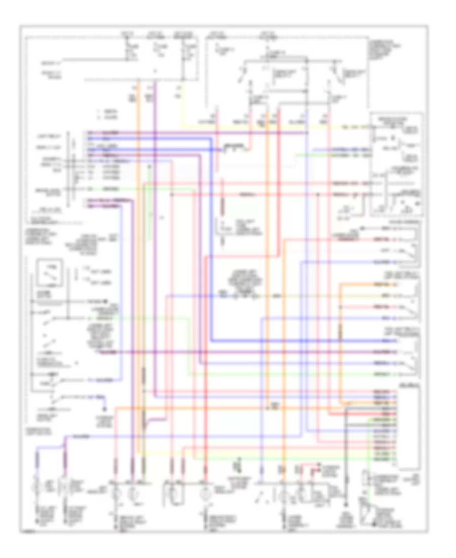
AIR CONDITIONING
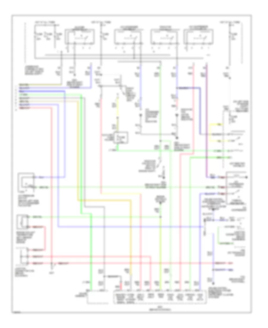
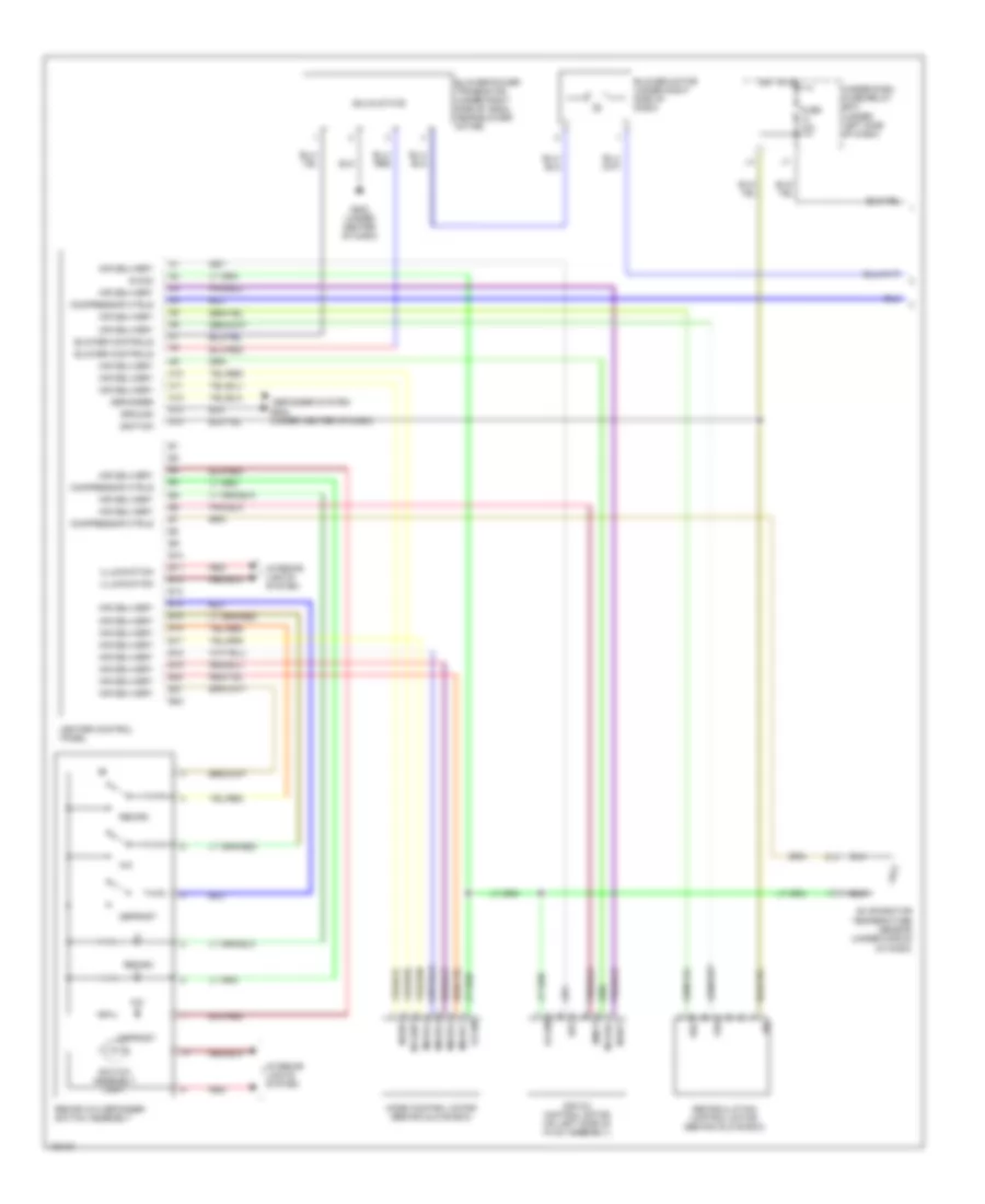
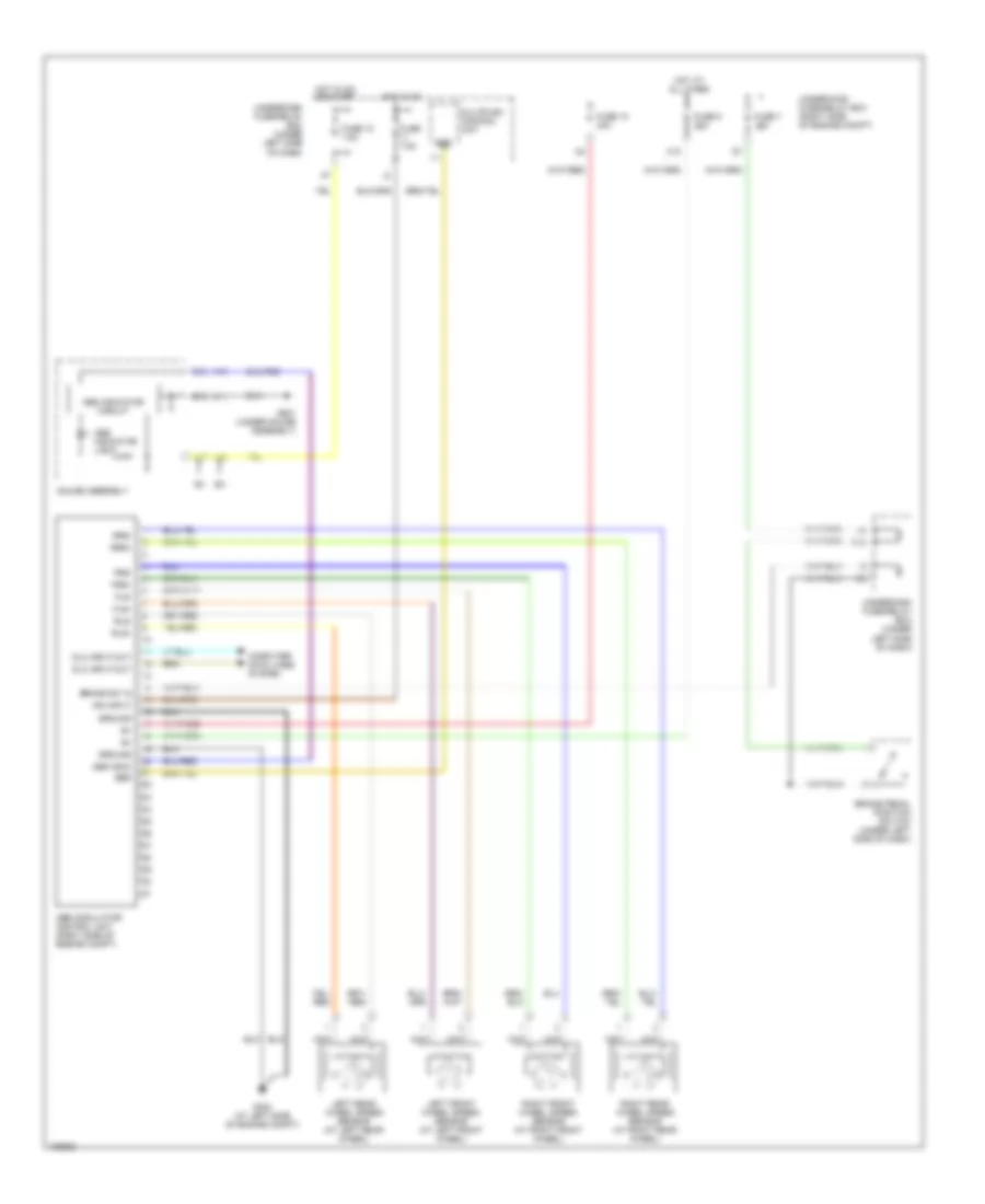
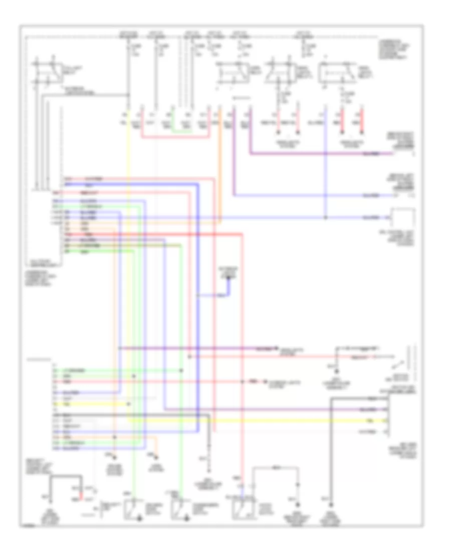
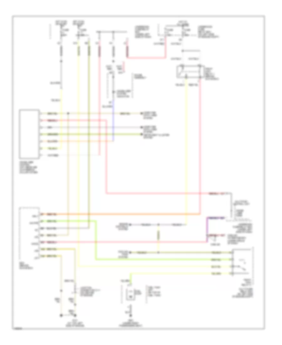
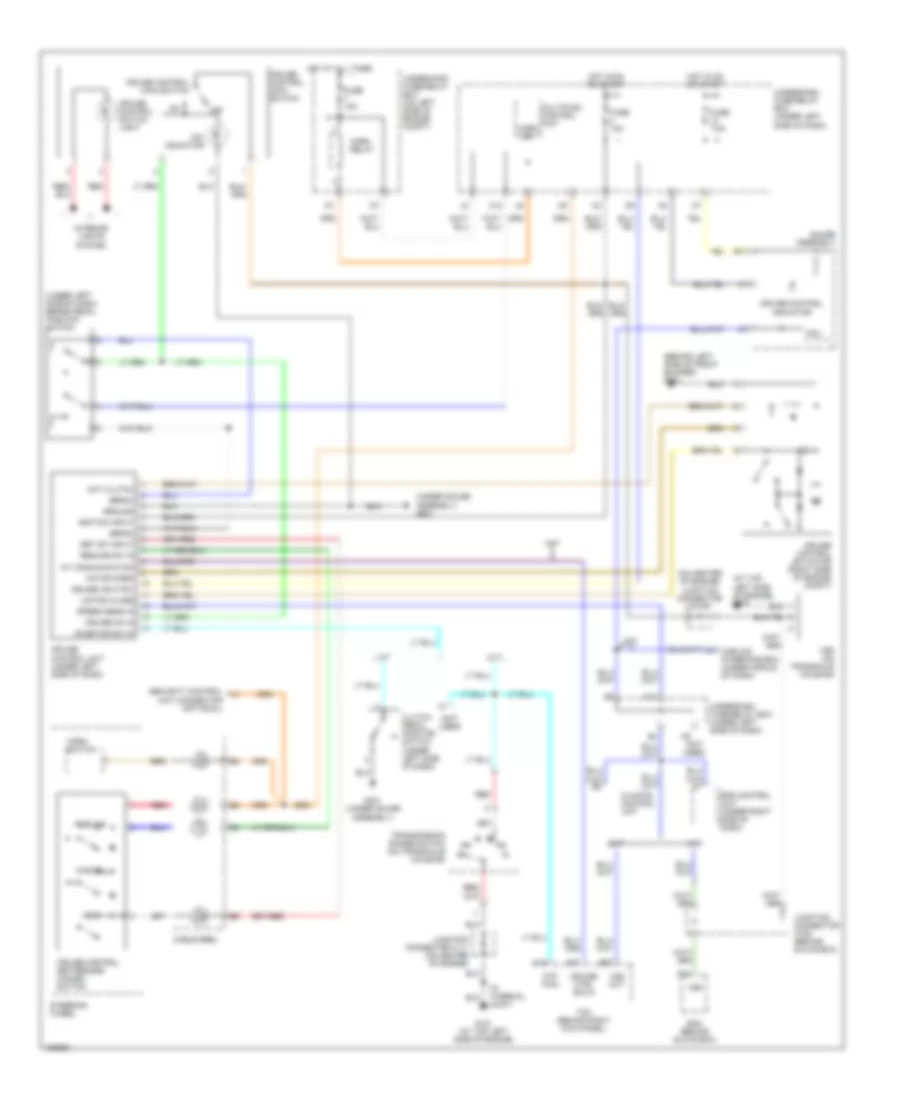
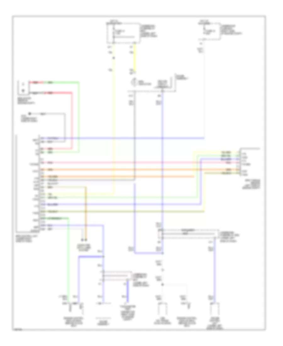
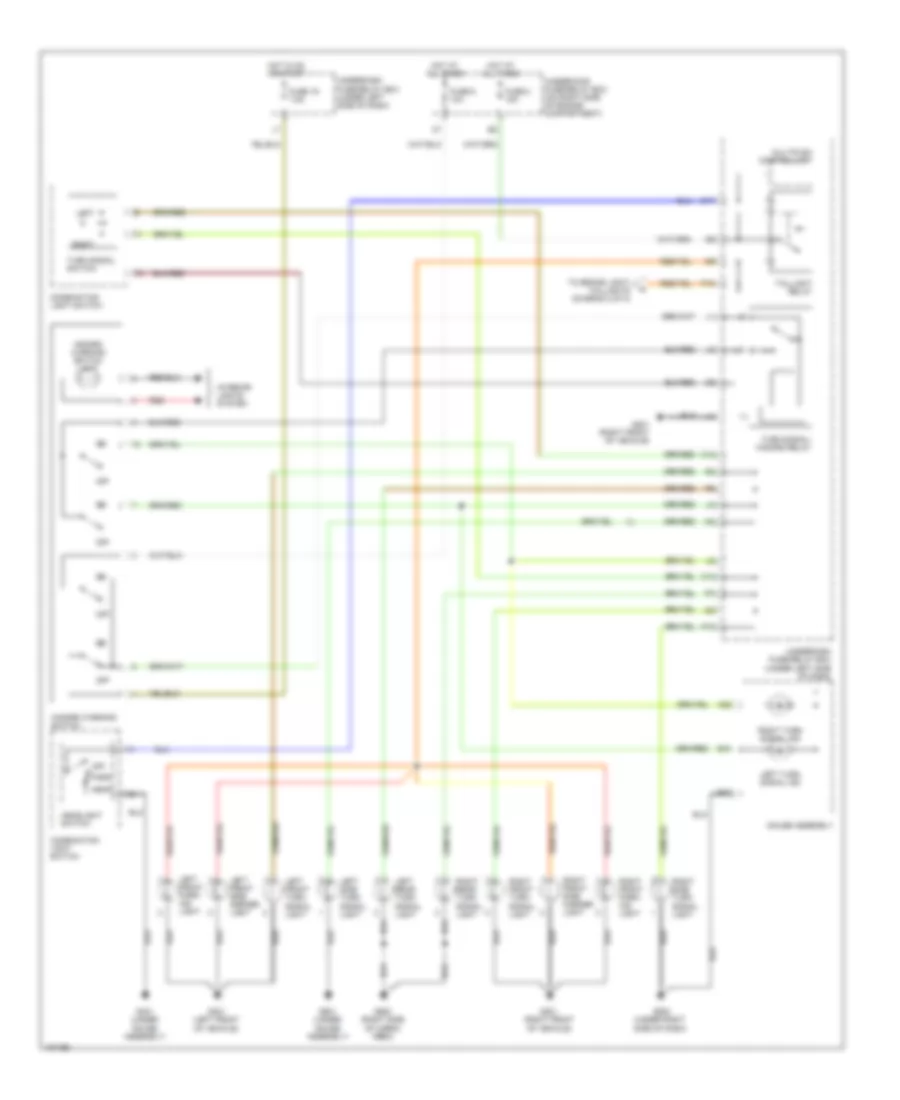
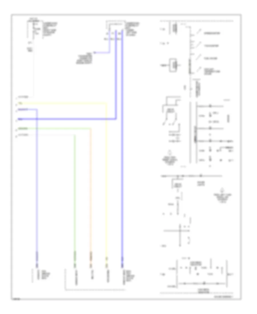
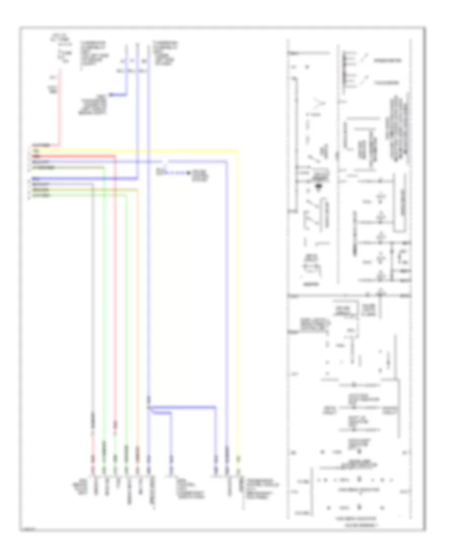
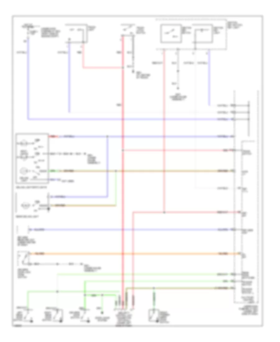
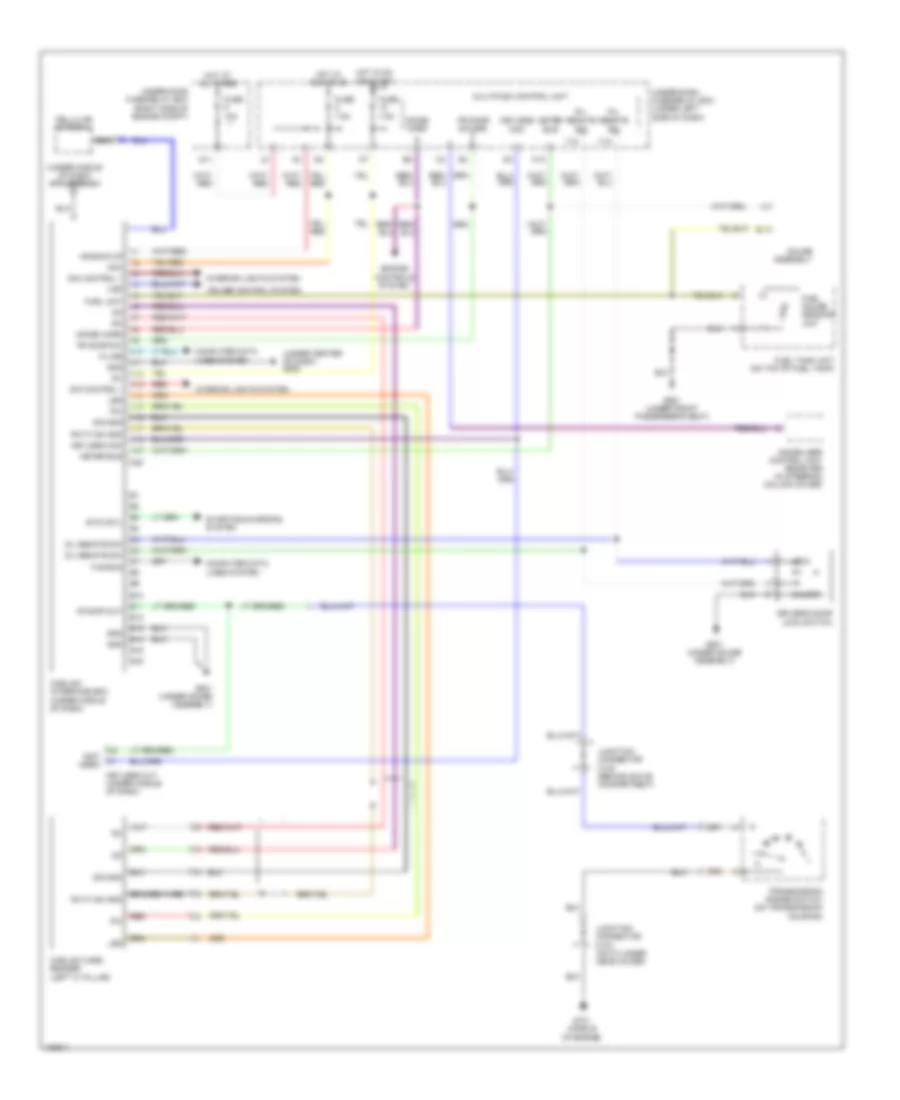
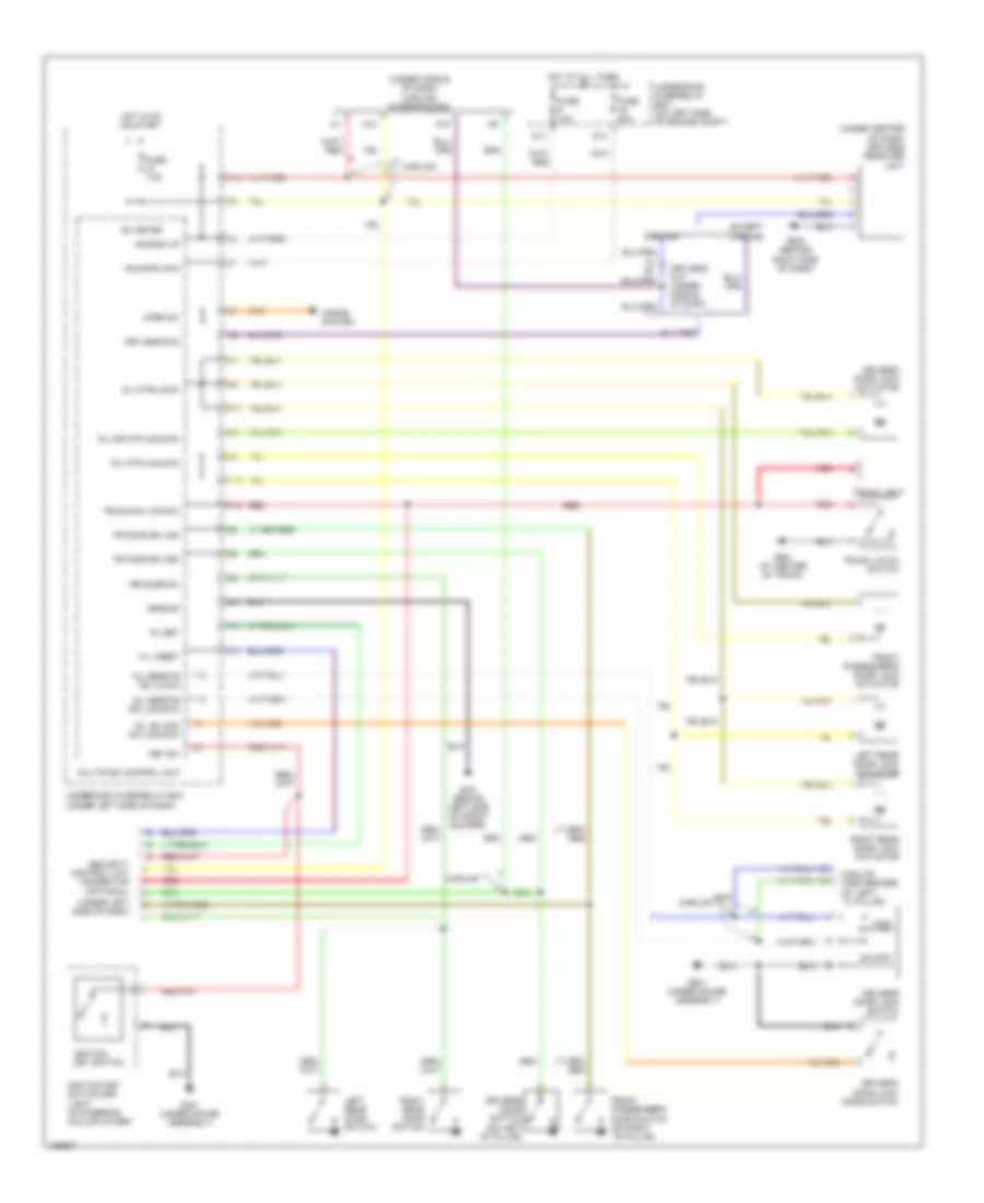
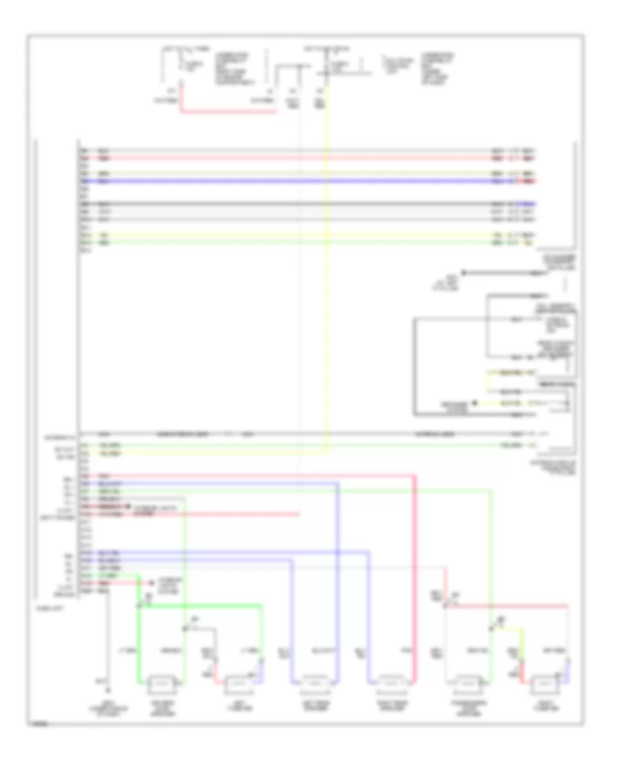
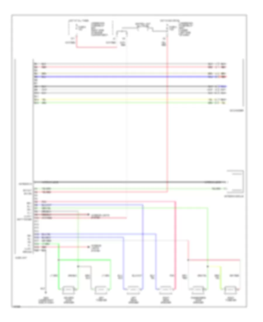
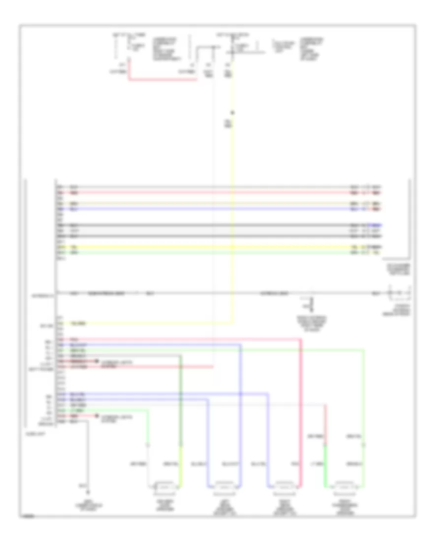
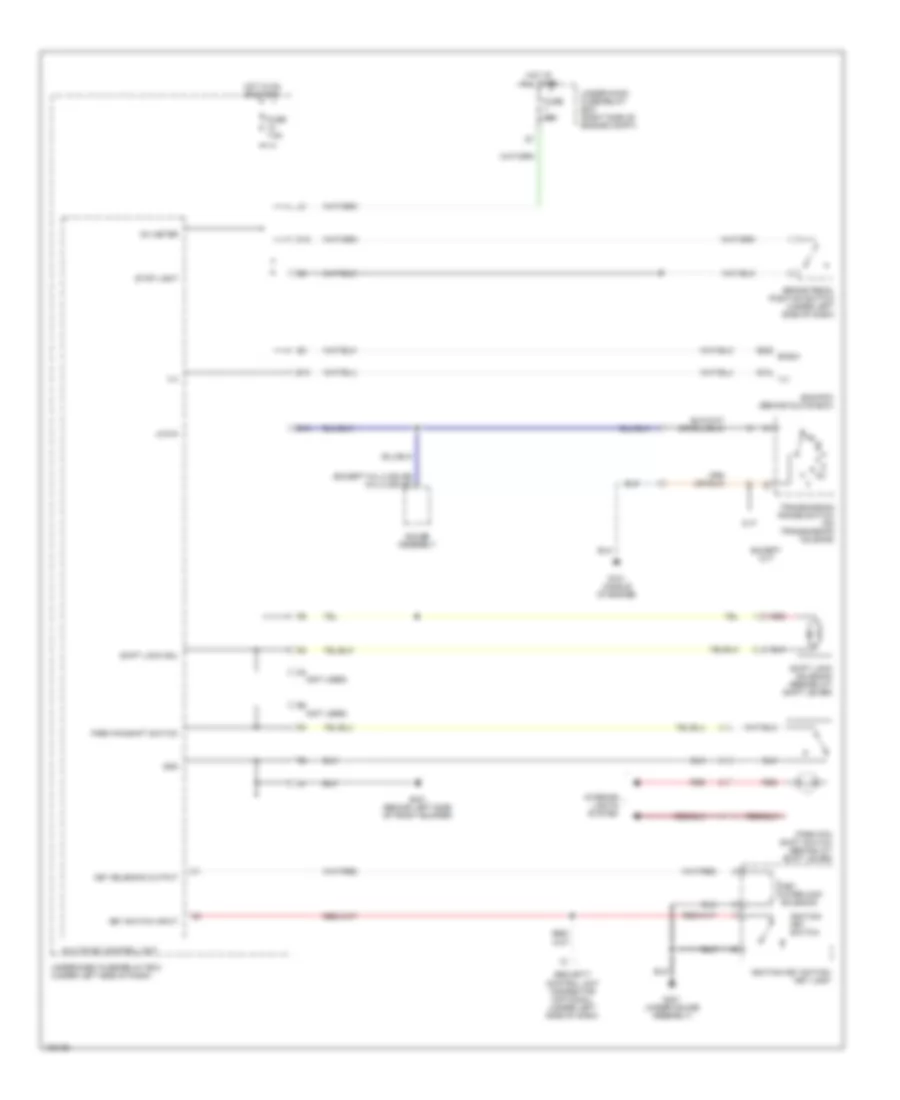
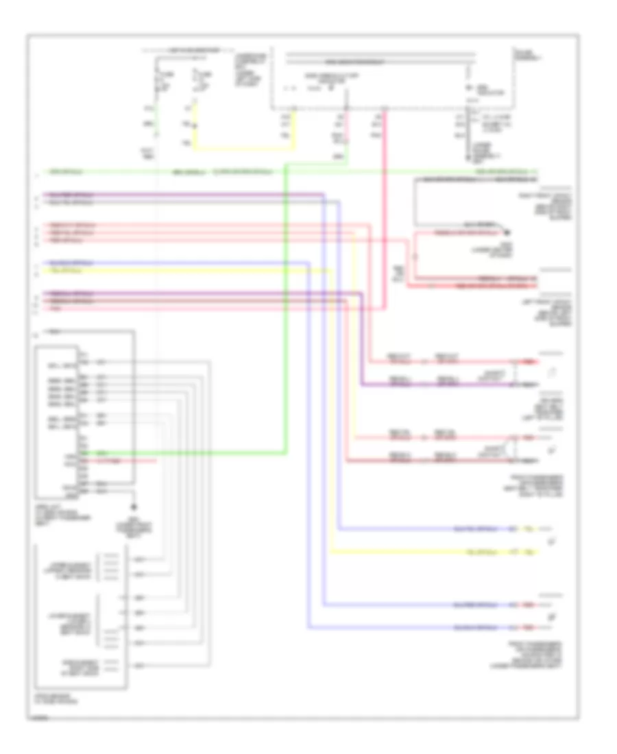
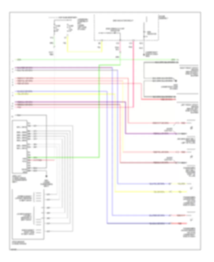
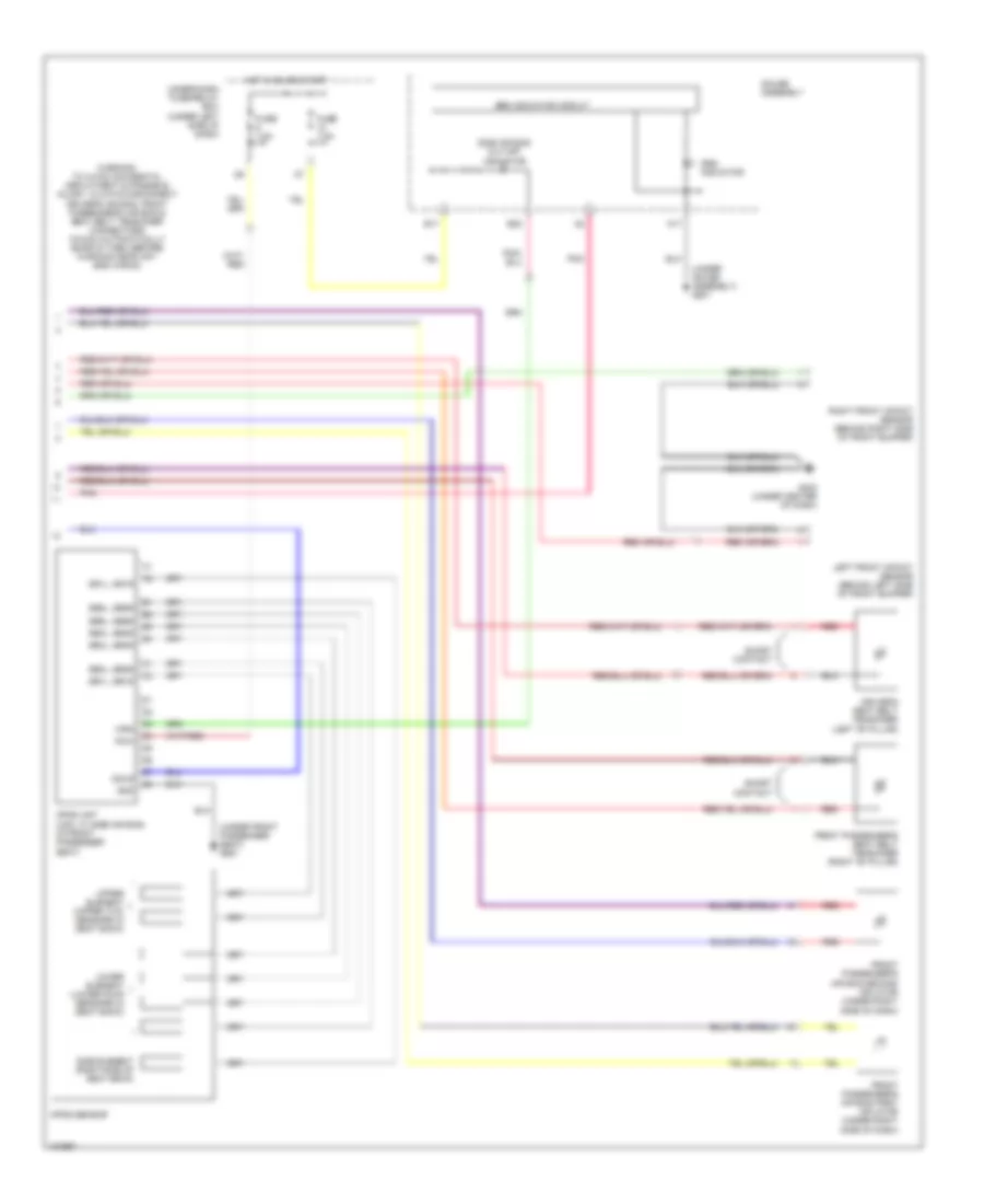
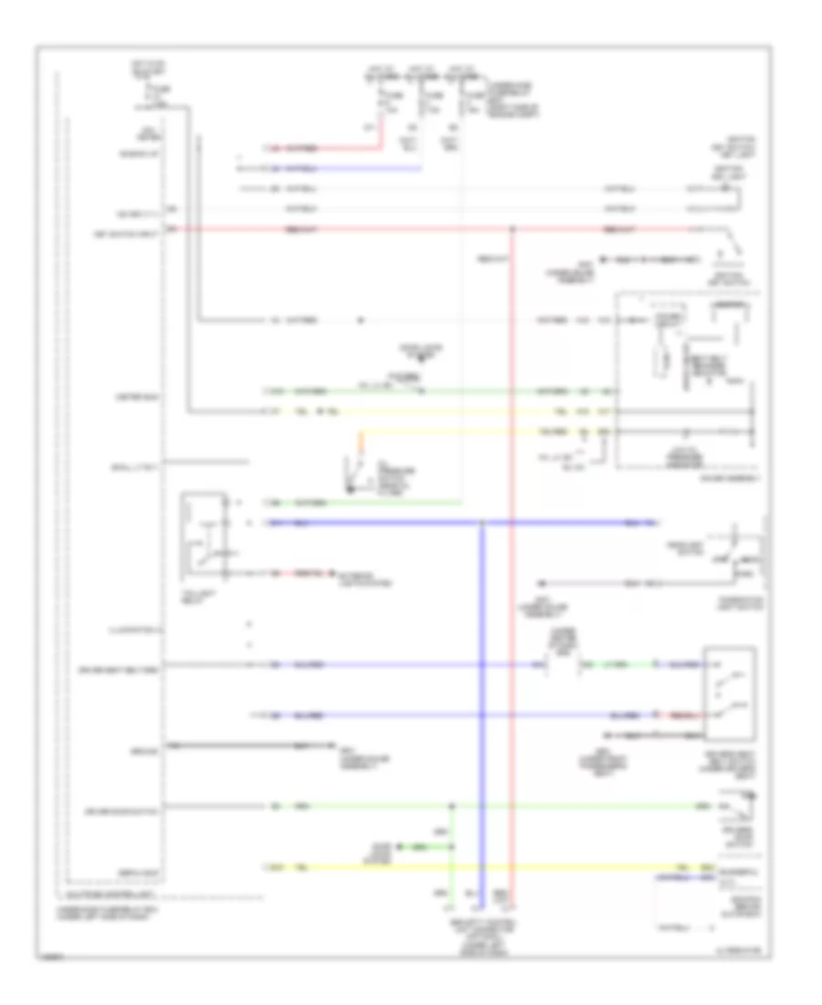
Automatic A/C Wiring Diagram, Hybrid (1 of 2) for Honda Civic HX 2004

List of elements for Automatic A/C Wiring Diagram, Hybrid (1 of 2) for Honda Civic HX 2004:
- A/c
- A/c pressure sw
- A/c sw led
- A/c switch
- A10
- A11
- A12
- A13
- A14
- A15
- A16
- A17
- A18
- A19
- A20
- Air mix control motor (on left side of hvac assembly)
- Air mix cool
- Air mix hot
- Air mix poten +5v
- Air mix potential
- Air temp sens
- Amd-p
- B10
- B11
- B12
- B13
- B14
- B15
- B16
- B17
- B18
- B19
- B20
- B21
- B22
- Base
- Blower feedback
- Blower motor (under right side of dash)
- Blower power transistor (under right side of dash, near blower motor)
- Climate control unit
- Climate control unit light
- Defog sw led
- Defogger system
- Econ
- Econ switch
- Econ switch led
- Ect sensor
- Eng ready sig
- Evap temp sens
- Evaporator
- Fresh
- Frs
- Fuse 10a
- G502 (behind right side of dash)
- Gauges & ind
- Ground
- Heater signal
- Hot in on
- Ig2
- Ig2 (power)
- Ign (power)
- In-car temp sens
- In-car temperature sensor
- Interior lights system
- M-cool
- M-def
- M-hot
- M-vent
- Mode 1
- Mode 2
- Mode 3
- Mode 4
- Mode control motor (on center of hvac assembly)
- Mode def
- Mode vent
- Outside air temperature sensor (behind left side of front bumper)
- Pnk
- R window defog sw
- Rec
- Recir
- Recir ctrl sw led
- Recir ctrl switch
- Recir-a/c-econ switch assembly
- Recir-a/c-econ switch light
- Recirc
- Recirculate
- Recirculation control motor (on center of hvac assembly)
- Red
- S-com
- S5v
- Sens common gnd
- Sunlight sensor
- Sunlight sensor (under top center of dash)
- Temperature sensor (on left side of hvac assembly)
- Under-dash fuse/relay box (under left side of dash)
- Vsp sensor
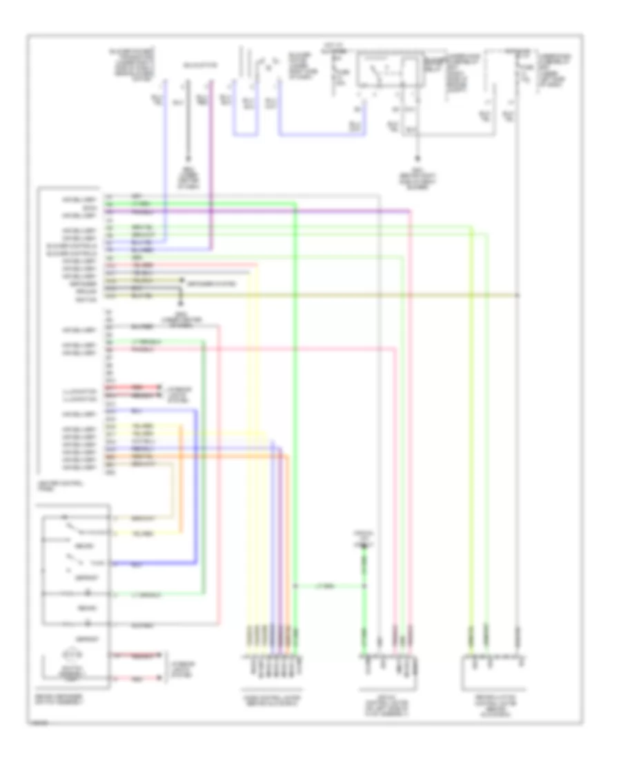
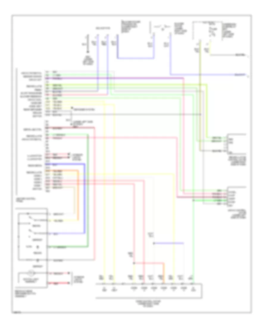
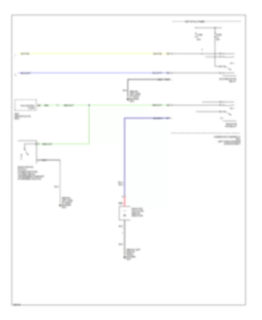
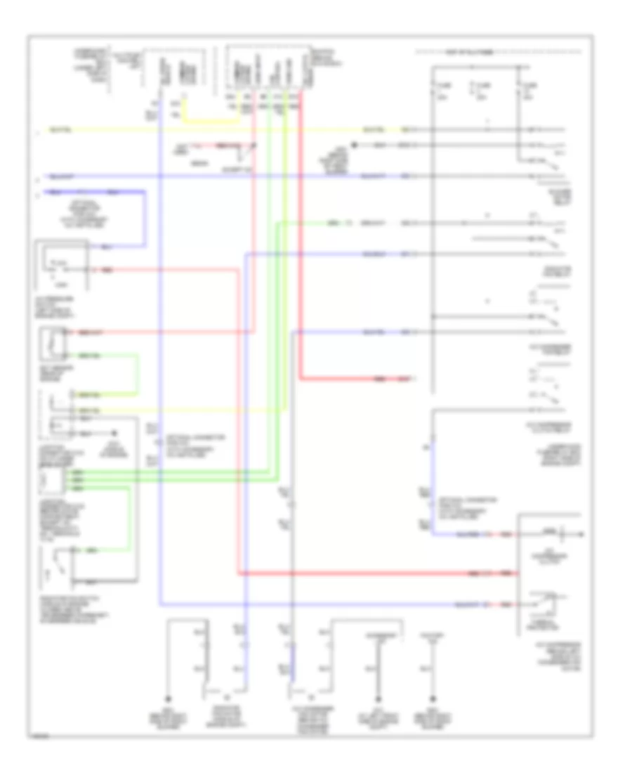
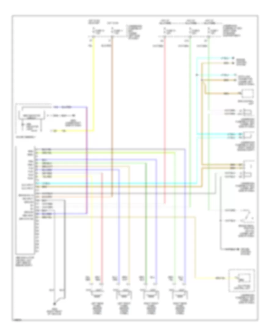
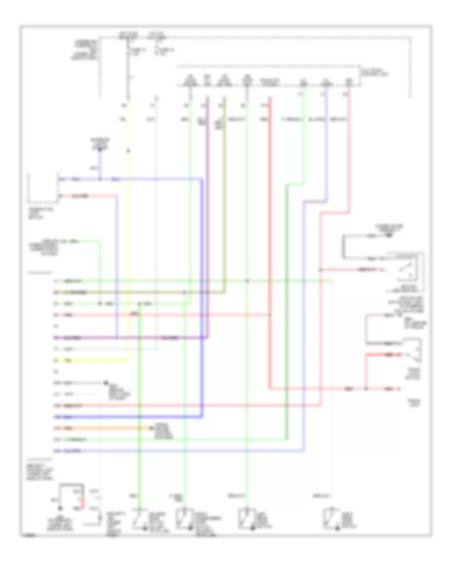
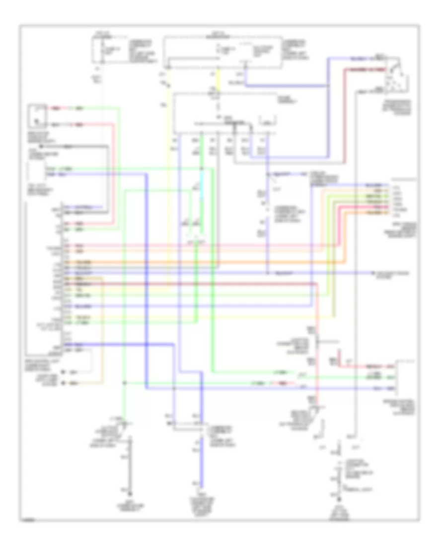
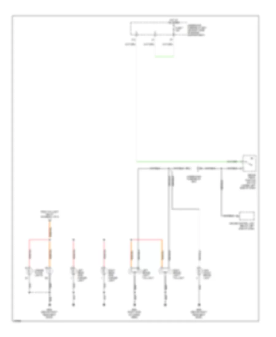
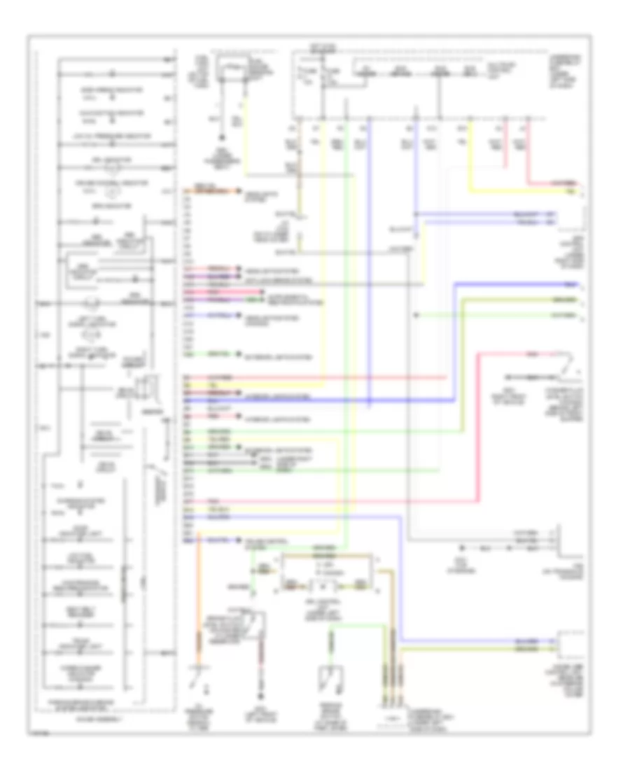
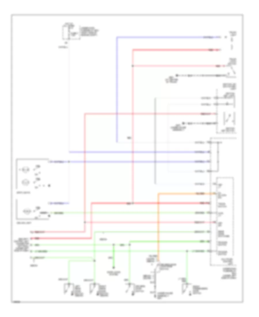
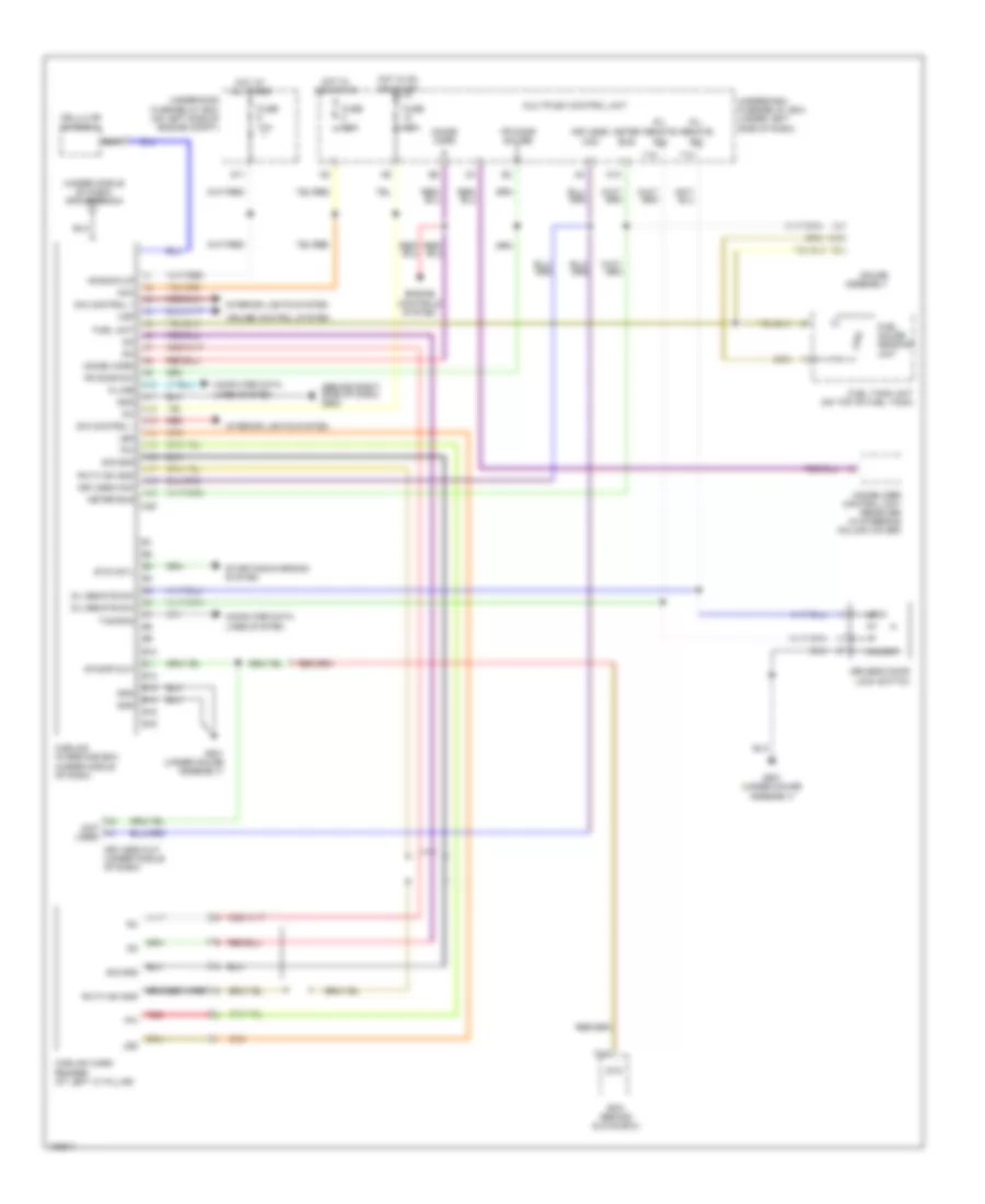
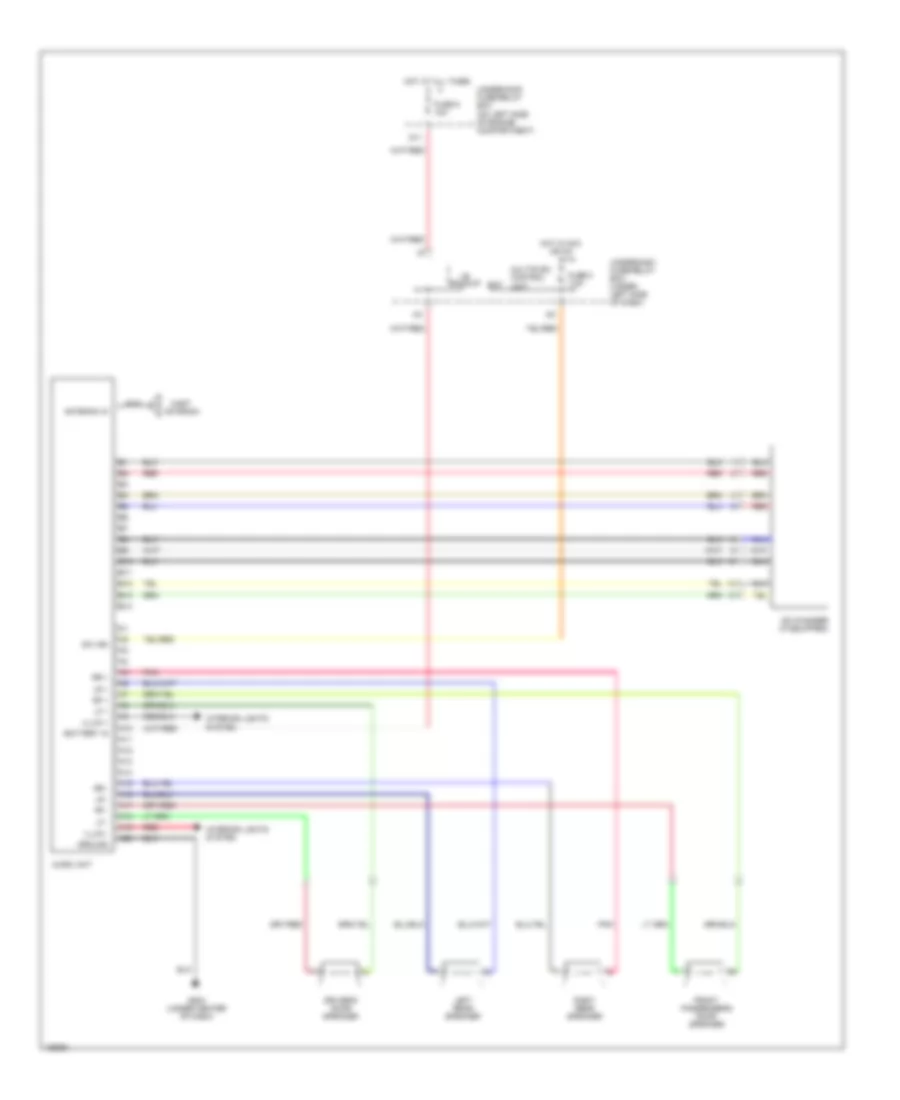
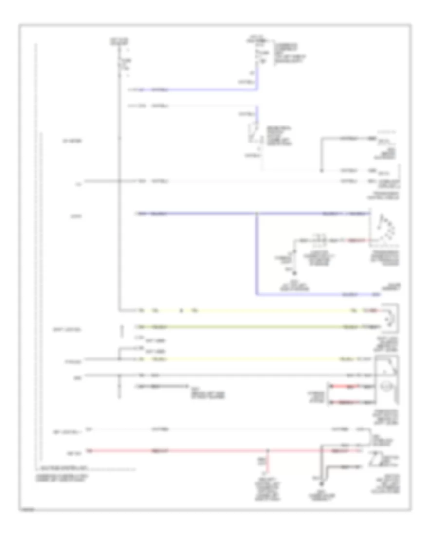
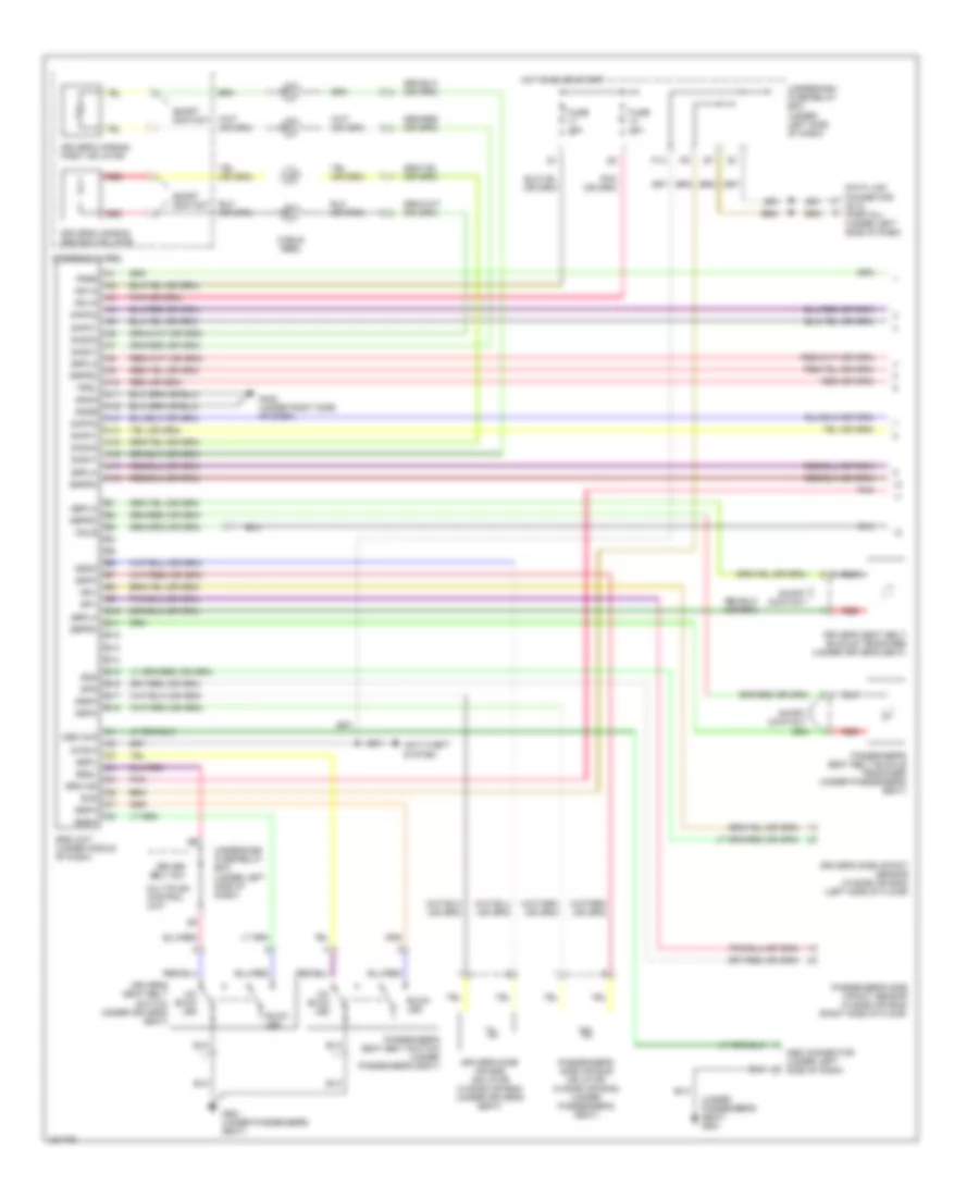
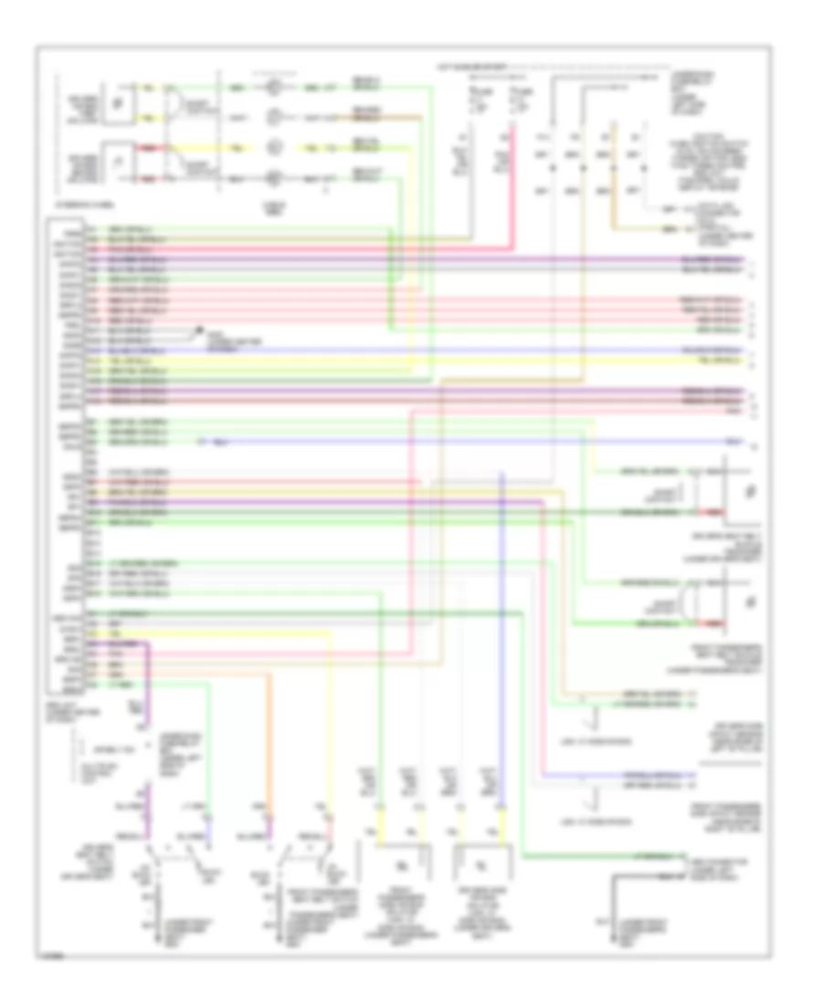
Automatic A/C Wiring Diagram, Hybrid (2 of 2) for Honda Civic HX 2004
List of elements for Automatic A/C Wiring Diagram, Hybrid (2 of 2) for Honda Civic HX 2004:
- (acc) relay ctrl
- (acs) a/c sw in
- (eng rdy) engine ready signal
- (fanc) fan ctrl
- (hrfanc) fan ctrl
- (htrs) htr standby signal
- (mrly) relay ctrl
- (on left side of engine compt) multi-fuse/ relay box
- A/c compressor
- A/c compressor clutch
- A/c compressor clutch relay
- A/c condenser fan motor (forward of radiator)
- A/c condenser fan relay
- A/c pressure switch (behind left side of a/c condenser fan motor)
- A10
- A20
- Auxiliary fuse holder
- B14
- B22
- Blower motor relay
- C11
- C13
- Cruise control electronic power steering & instrument cluster systems
- Cvt
- Cvt cvt
- D10
- D13
- E11
- E18
- E28
- Ecm (behind glove box)
- Engine controls system
- Engine coolant temperature (ect) sensor (rear of engine)
- Fuse 15a
- Fuse 20a
- Fuse 40a
- Fuse 7.5a
- G201 (behind right side of front bumper)
- Gauge assembly
- High
- Hot at all times
- Hot restart fan relay
- Junction connector c106 (behind glove box)
- Low
- M m
- M/t
- Pgm-fi main relay 1 (behind glove box)
- Radiator fan motor (behind radiator)
- Radiator fan relay
- Radiator fan switch (bottom front of engine compt)
- Red
- Sens gnd
- Sens input
- Tcm (behind right kick panel)
- Thermal protector
- Underhood fuse/relay box (on left side of engine compt)
- Vss (on transaxle housing)
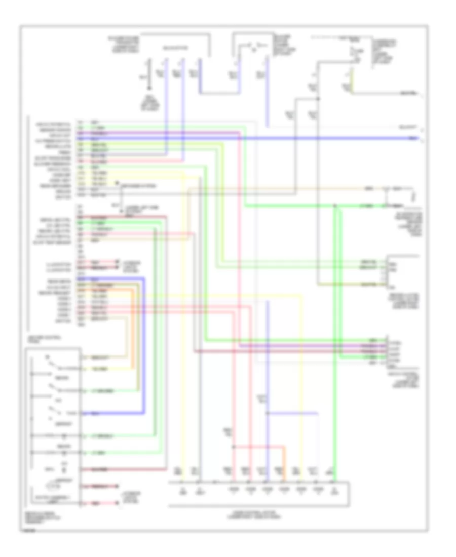
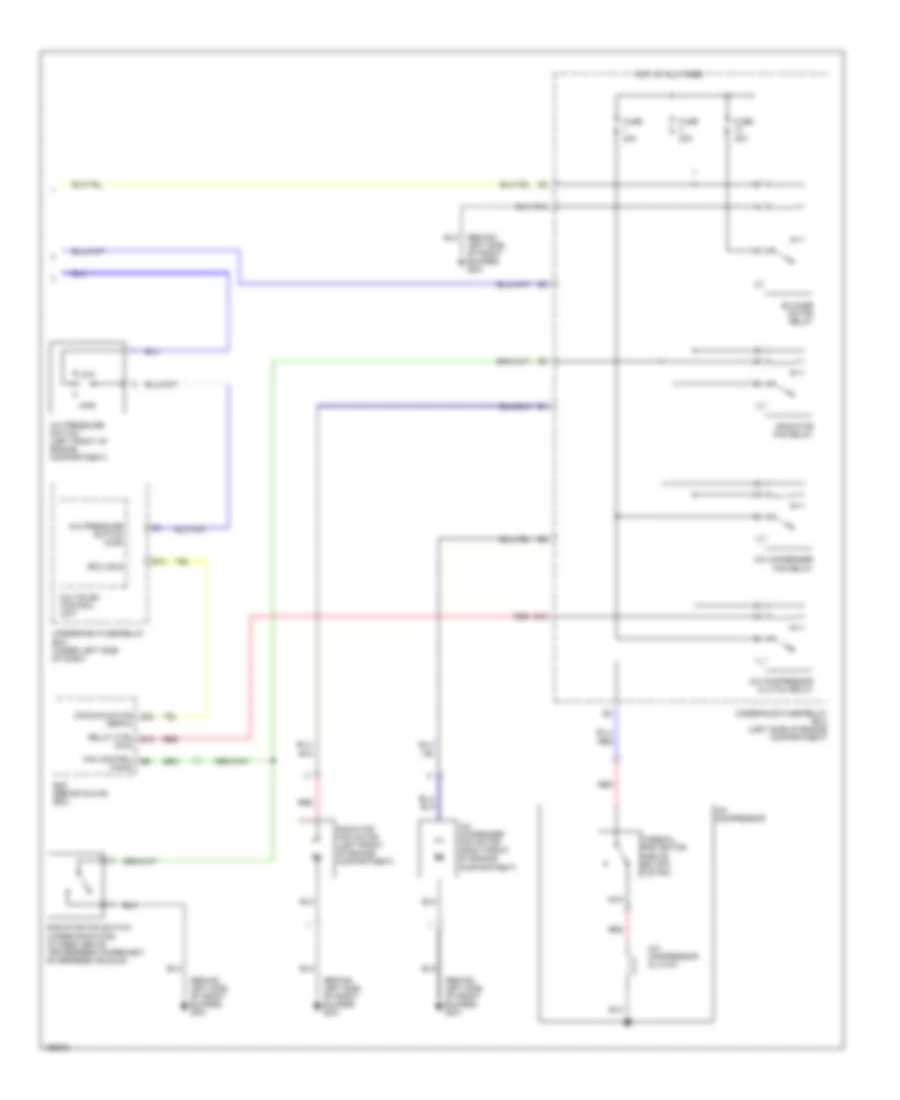
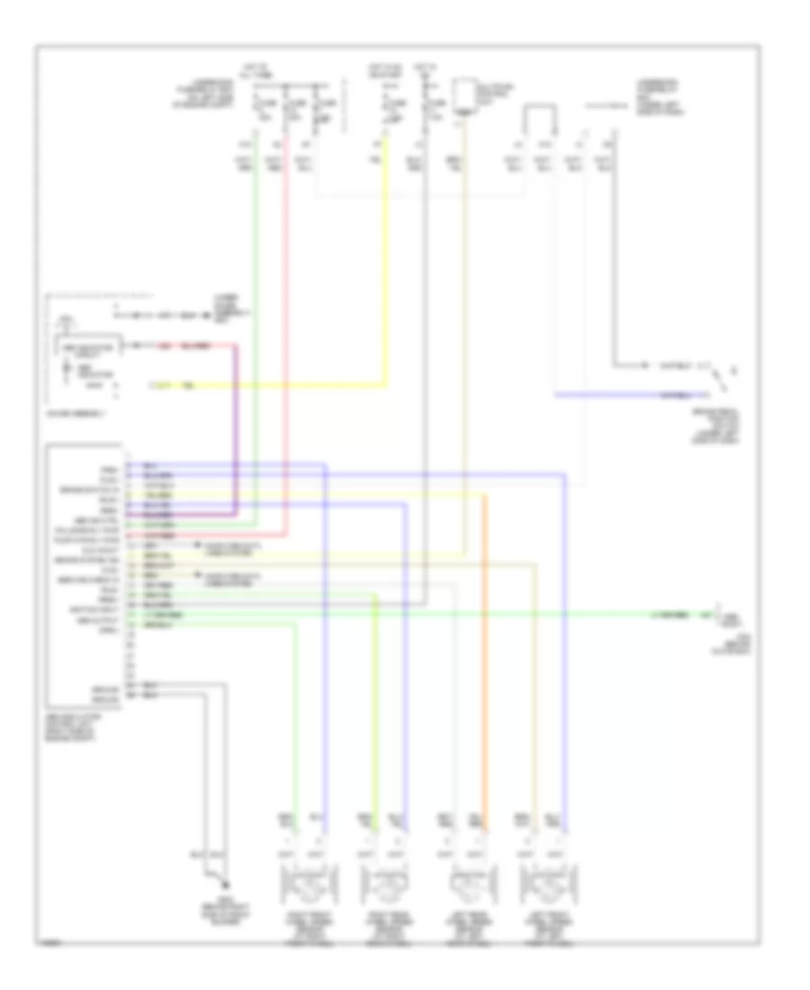
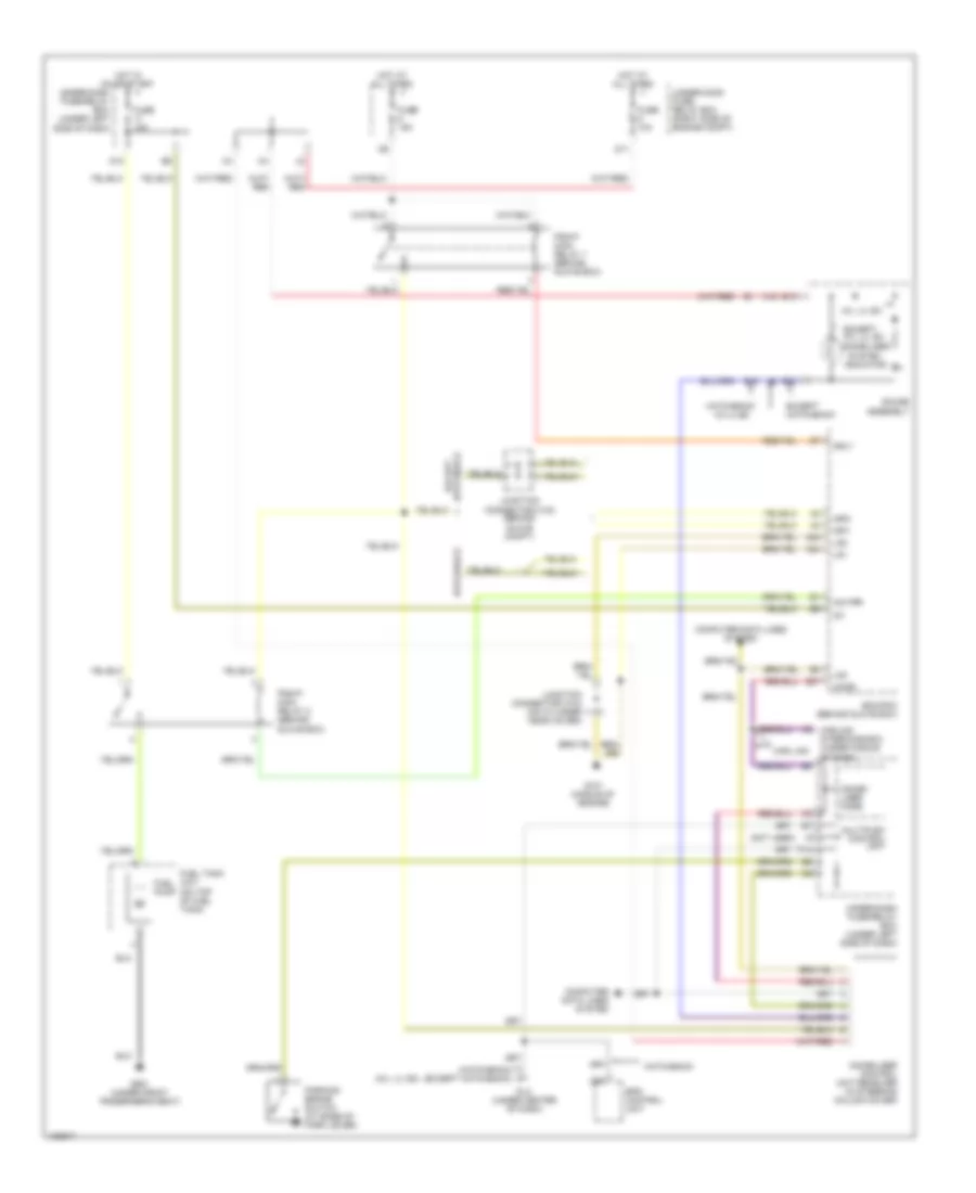
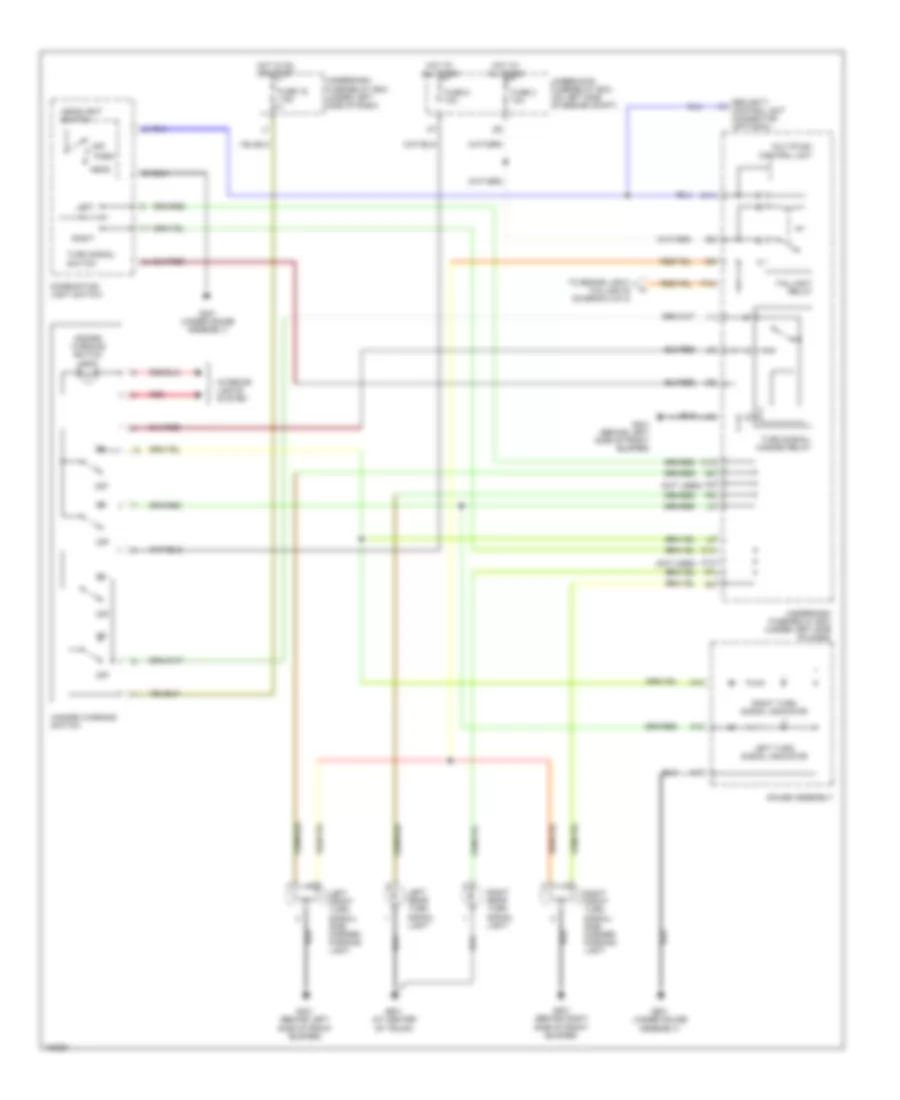
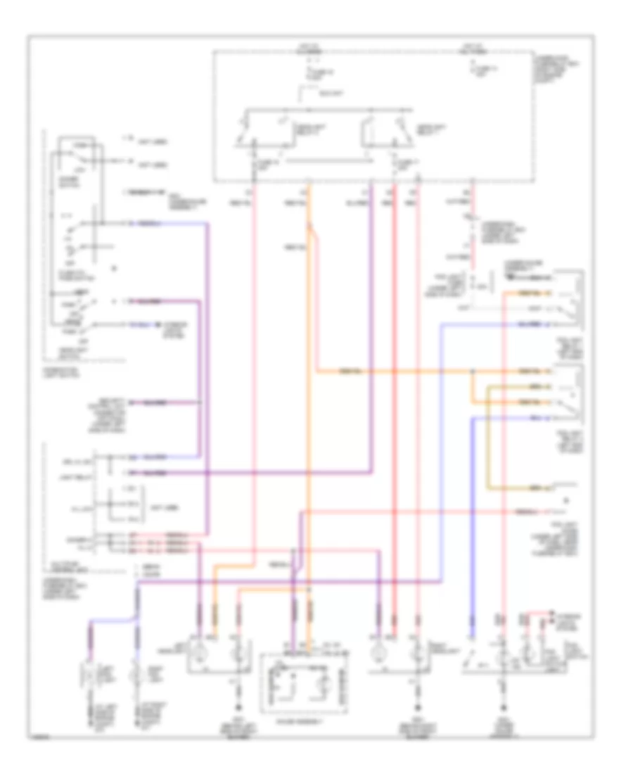
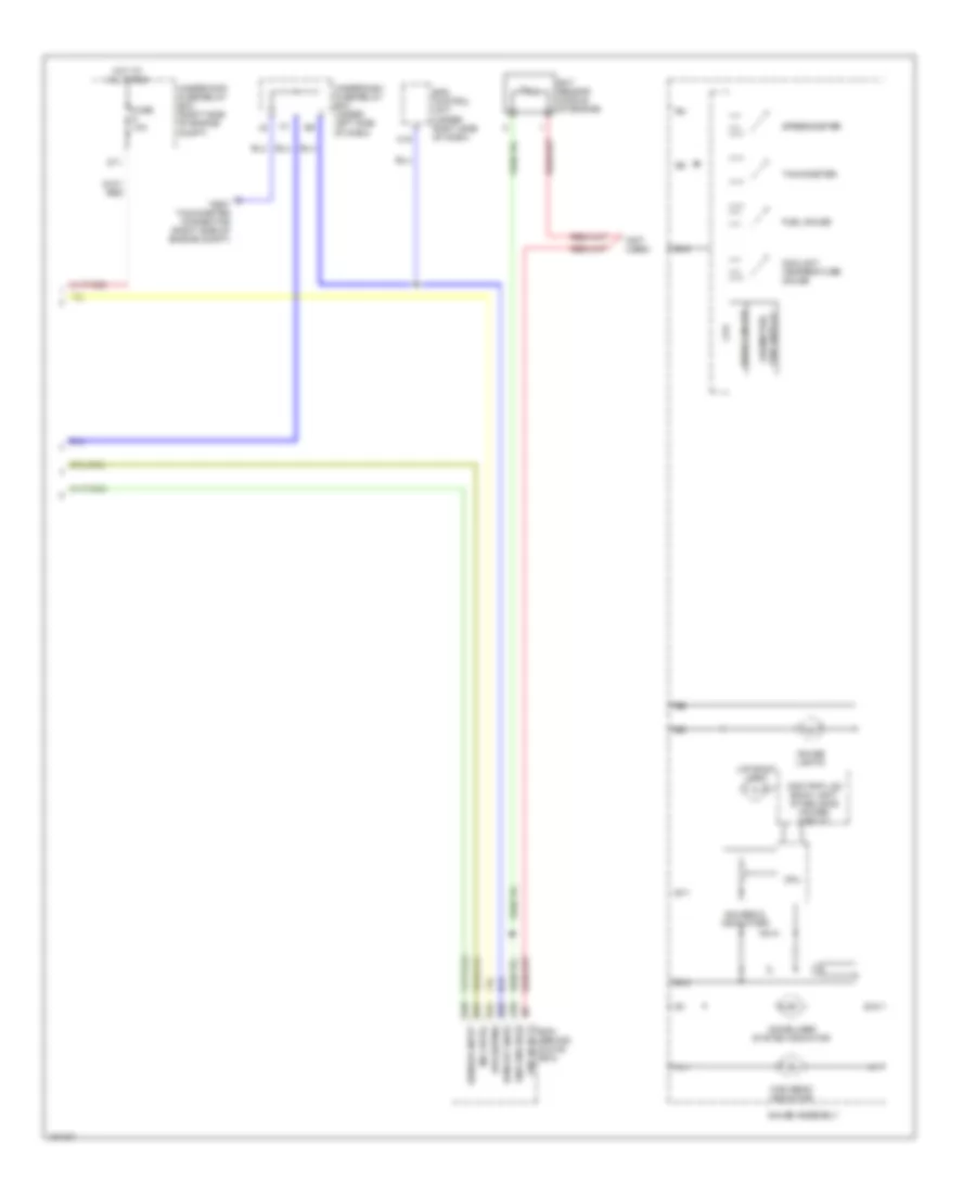
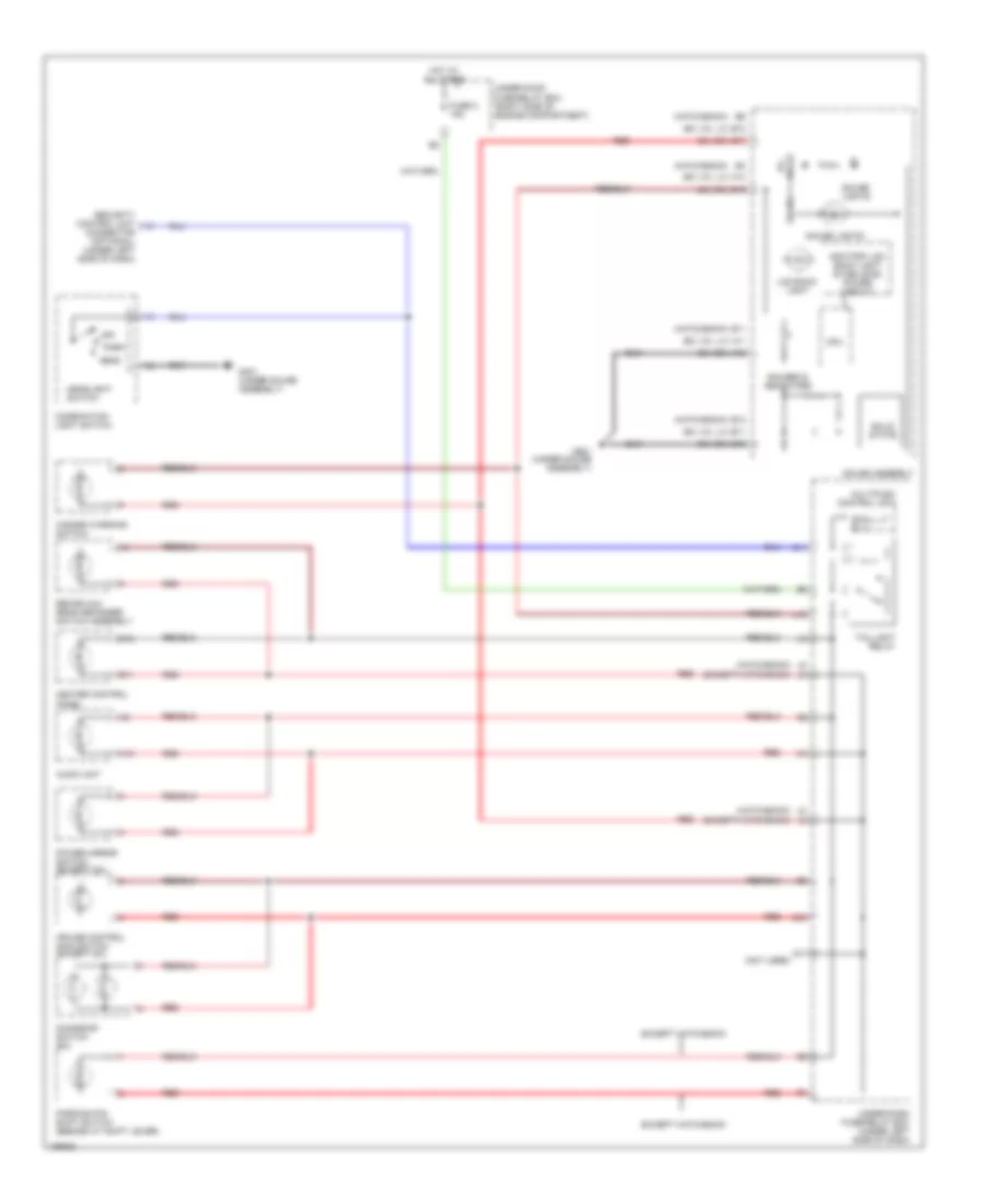
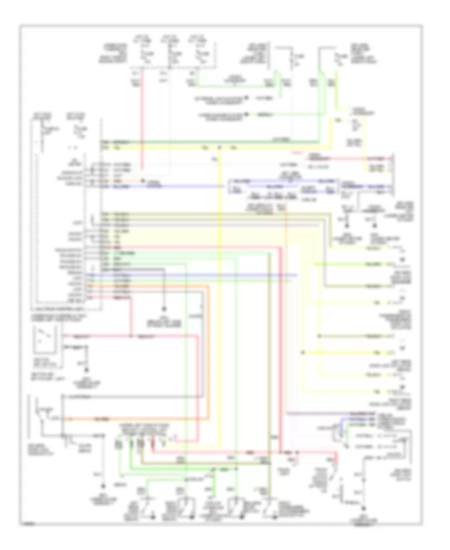
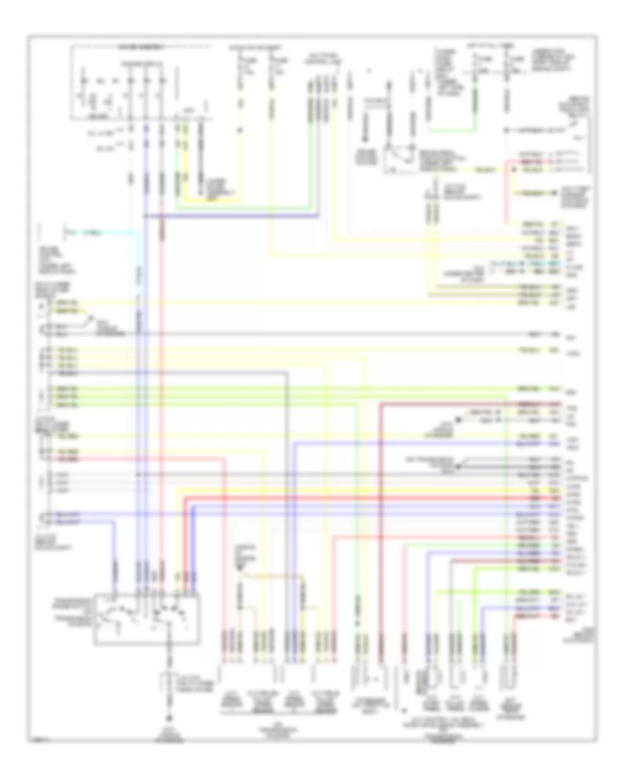
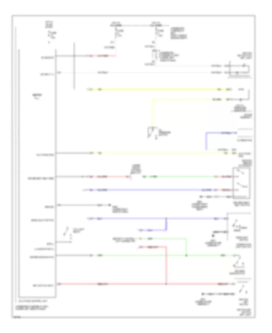
Heater Wiring Diagram, Except Hatchback & Hybrid for Honda Civic HX 2004
List of elements for Heater Wiring Diagram, Except Hatchback & Hybrid for Honda Civic HX 2004:
- A10
- A11
- A12
- A13
- A14
- Air delivery
- Air mix control motor (on left side of hvac assembly)
- Amd-p
- B10
- B11
- B12
- B13
- B14
- B15
- B16
- B17
- B18
- B19
- B20
- B21
- B22
- Blower controls
- Blower motor (under right side of dash)
- Blower motor relay
- Blower power transistor (under right side of dash, near blower motor)
- D13
- Defogger
- Defogger system
- Defrost
- Frs
- Fuse 10a
- Fuse 40a
- G201 (behind right side of front bumper)
- G502 (under center of dash)
- Ground
- Heater control panel
- Hot at all times
- Hot in on
- Ig2
- Ignition
- Illumination
- Interior lights system
- M-cool
- M-def
- M-hot
- M-vent
- Manual a/c circuit
- Mode control motor (behind glove box)
- Mode-1
- Mode-2
- Mode-3
- Mode-4
- Rec
- Recirc
- Recirc defogger switch assembly
- Recirculation control motor (behind glove box)
- Red
- S-com
- S5v
- Scom
- Solid state
- Switch assembly light
- Under-dash fuse/relay box (under left side of dash)
- Under-hood fuse/relay box (right side of engine compt)
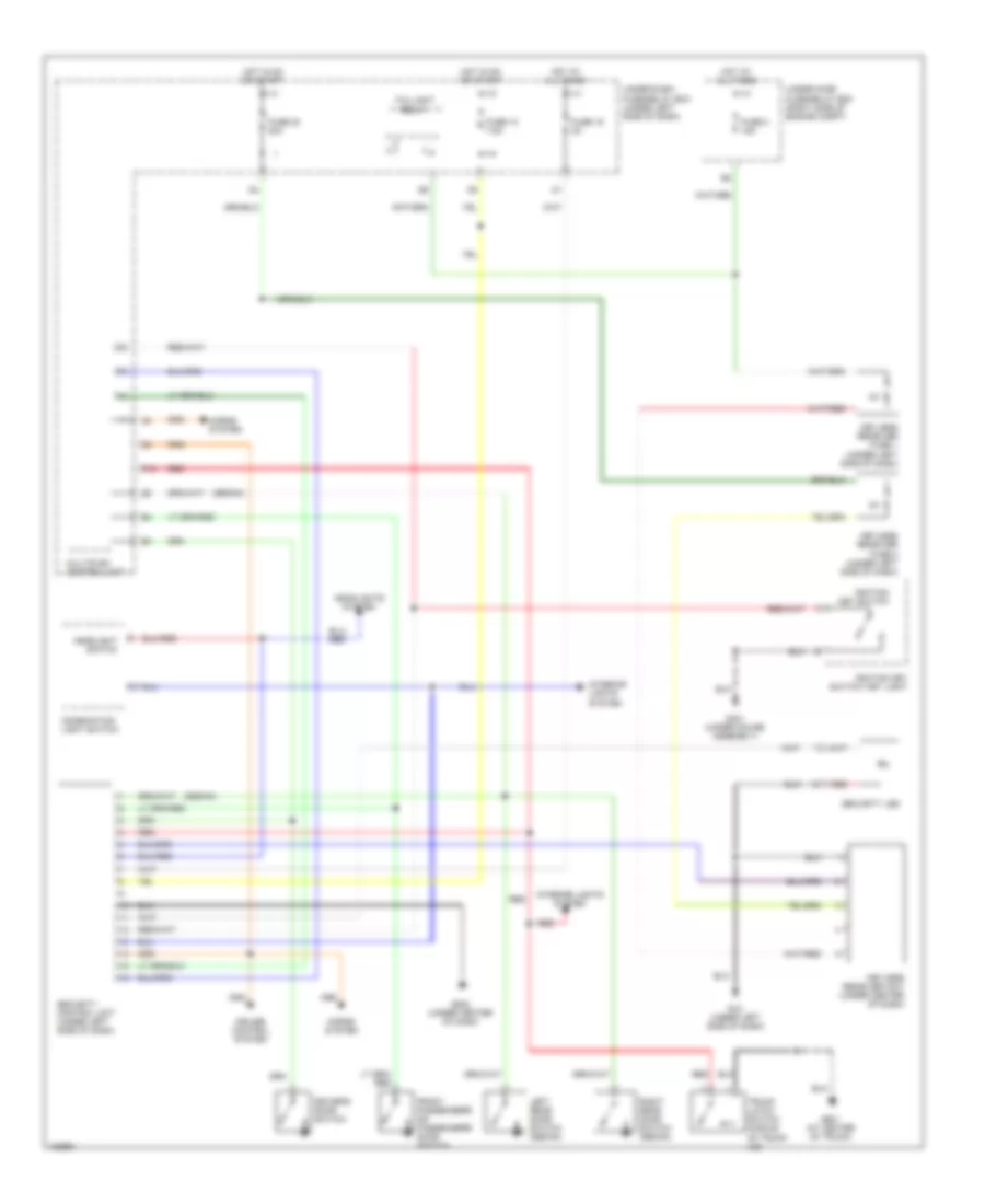
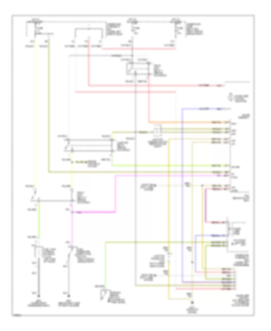
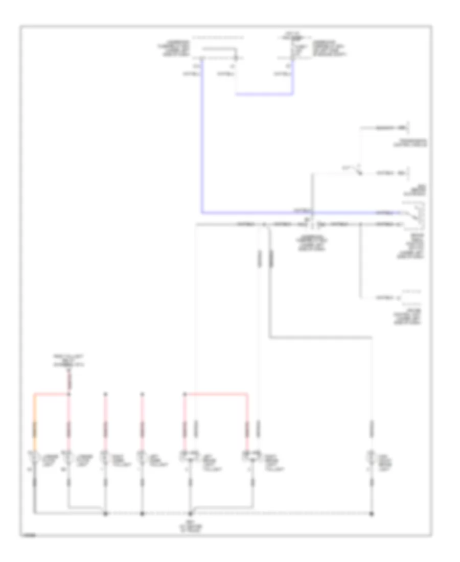
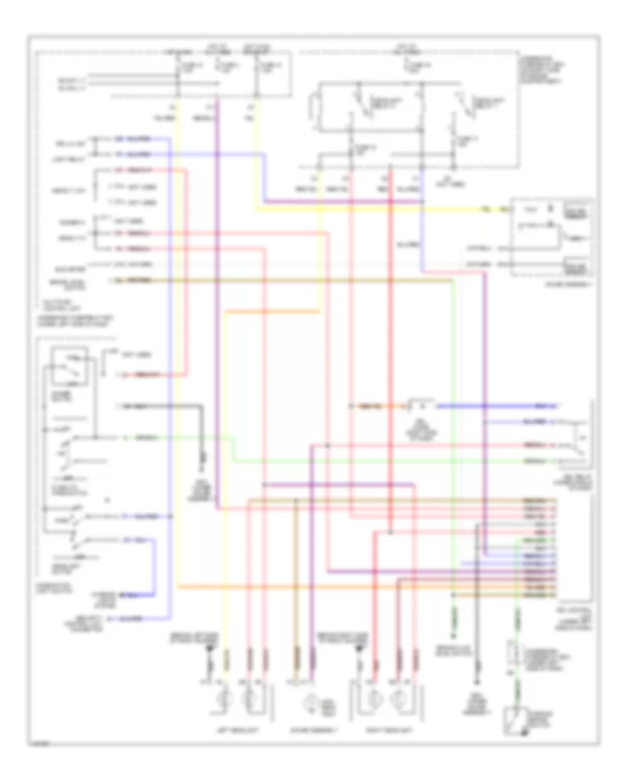
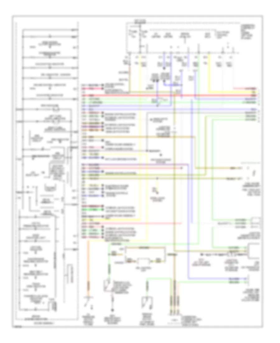
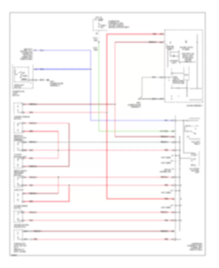
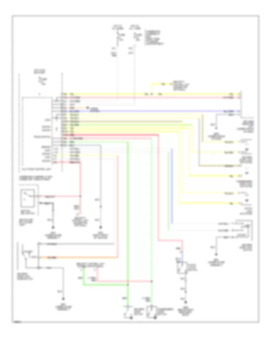
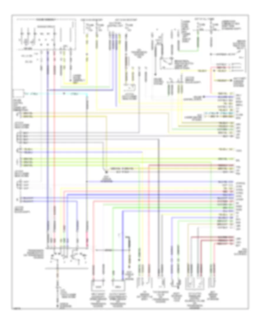
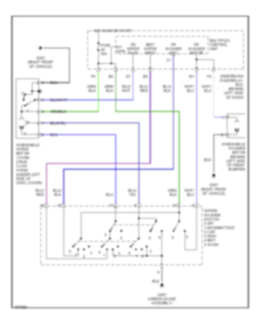
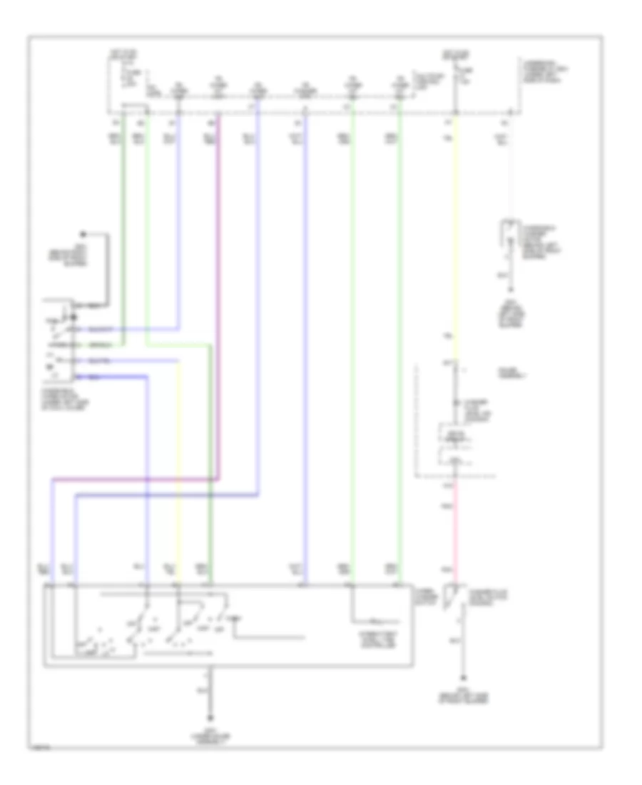
Heater Wiring Diagram, Hatchback (1 of 2) for Honda Civic HX 2004
List of elements for Heater Wiring Diagram, Hatchback (1 of 2) for Honda Civic HX 2004:
- (under left side of dash) g501
- A10
- A11
- A12
- A13
- A14
- Air mix control motor (under left side of dash)
- Air mix cool
- Air mix hot
- Air mix potental
- Air mix potential
- Amd-p
- B10
- B11
- B12
- B13
- B14
- B15
- B16
- B17
- B18
- B19
- B20
- B21
- B22
- Blower feedback
- Blower motor (under right side of dash)
- Blower power transistor (under right side of dash)
- Blwr trans base
- Defog led ctrl
- Defogger system
- Defrost
- Fresh
- Frs
- Fuse 10a
- G501 (under left side of dash)
- Ground
- Heater control panel
- Hot in on
- Ig2
- Ignition
- Illumination
- Interior lights system
- M- def
- M- vent
- M-cool
- M-hot
- Mode -1
- Mode -2
- Mode -3
- Mode -4
- Mode 1
- Mode 2
- Mode 3
- Mode 4
- Mode control motor (under right side of dash)
- Mode def
- Mode vent
- Rear defog
- Rear defogger
- Rec
- Recir-a/c rear defogger switch assembly
- Recirc
- Recirculate
- Recirculation control motor (under right side of dash)
- Red
- S- com
- S-com
- S5v
- Sensor common
- Solid state
- Switch light assembly
- Underdash fuse/relay box (under left side of dash)
Heater Wiring Diagram, Hatchback (2 of 2) for Honda Civic HX 2004
List of elements for Heater Wiring Diagram, Hatchback (2 of 2) for Honda Civic HX 2004:
- (behind left side of front bumper) g301
- Blower motor relay
- D13
- Ecm (behind glove box)
- Fan control (fanc)
- Fuse 20a
- Fuse 40a
- Hot at all times
- Radiator fan motor (behind radiator)
- Radiator fan relay
- Radiator fan switch (under radiator) (closed above: 199 degrees fahenheit 93 degrees celsius)
- Red
- Underhood fuse/relay box (left side of engine compartment)
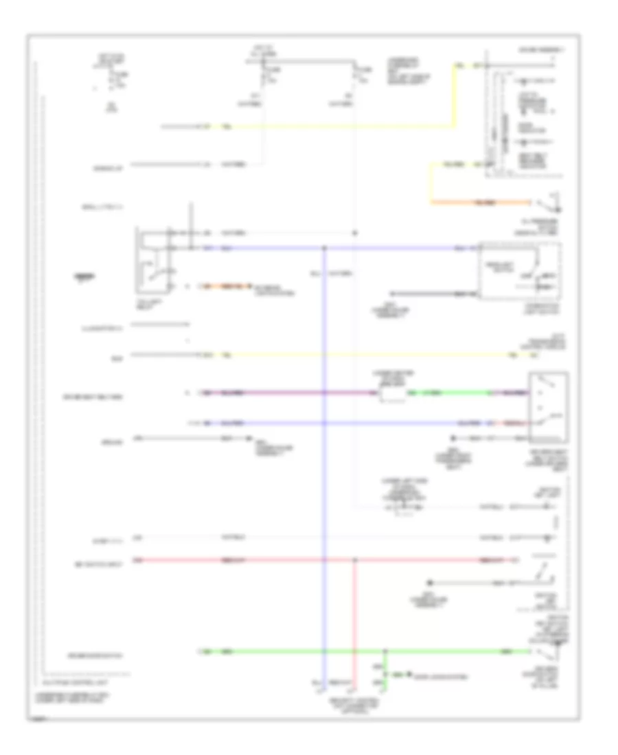
Manual A/C Wiring Diagram, Except Hatchback & Hybrid (1 of 2) for Honda Civic HX 2004
List of elements for Manual A/C Wiring Diagram, Except Hatchback & Hybrid (1 of 2) for Honda Civic HX 2004:
- A/c
- A10
- A11
- A12
- A13
- A14
- Air delivery
- Air mix control motor (on left side of hvac assembly)
- Amd-p
- B10
- B11
- B12
- B13
- B14
- B15
- B16
- B17
- B18
- B19
- B20
- B21
- B22
- Blower controls
- Blower motor (under right side of dash)
- Blower power transistor (under right side of dash, near blower motor)
- Compressor ctrls
- Defogger
- Defogger system
- Defrost
- Evaporator temperature sensor (under middle of dash)
- Frs
- Fuse 10a
- G502 (under center of dash)
- Ground
- Heater control panel
- Hot in on
- Ig2
- Ignition
- Illumination
- Interior lights system
- M-cool
- M-def
- M-hot
- M-vent
- Mode control motor (behind glove box)
- Mode-1
- Mode-2
- Mode-3
- Mode-4
- Rec
- Recirc
- Recirc-a/c defogger switch assembly
- Recirculation control motor (behind glove box)
- Red
- S-com
- S5v
- Solid state
- Switch assembly light
- Under-dash fuse/relay box (under left side of dash)
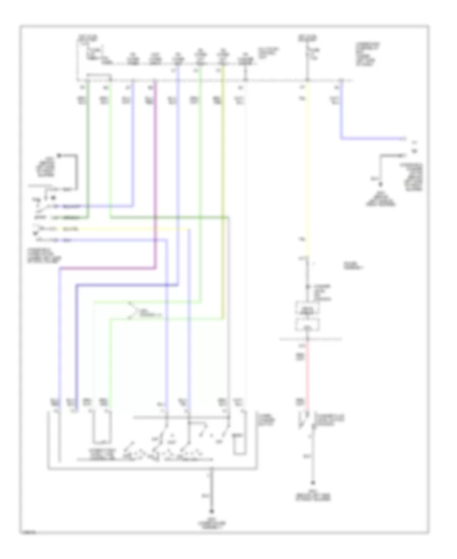
Manual A/C Wiring Diagram, Except Hatchback & Hybrid (2 of 2) for Honda Civic HX 2004
List of elements for Manual A/C Wiring Diagram, Except Hatchback & Hybrid (2 of 2) for Honda Civic HX 2004:
- (not used)
- A/c clutch relay
- A/c compressor (behind left side of a/c condenser fan motor)
- A/c compressor clutch
- A/c compressor clutch relay
- A/c condenser fan motor (behind a/c condenser fan motor)
- A/c condenser fan relay
- A/c press switch
- A/c pressure switch (left side of engine compt)
- A10
- Accessory a/c
- Blower motor relay
- Communi- cation (sefmj)
- D10
- D13
- E10
- E18
- E24
- Ecm/pcm (behind glove box)
- Ect sensor (rear of engine)
- Except gx
- Factory a/c
- Fan control
- Fuse 20a
- Fuse 40a
- G101 (middle of engine)
- G13 (at left front side of engine compt)
- G201 (behind right side of front bumper)
- High
- Hot at all times
- Junction connector c102 (behind glove compartment) (except gx: terminals 5-7) (gx: terminals 14-16)
- Junction connector c103 (on cylinder head cover)
- Low
- Multiplex control unit
- Optional connector (for a/c) (with accessory a/c installed)
- Radiator fan motor (middle of engine compt)
- Radiator fan relay
- Radiator fan switch (middle of engine) (closed above: 199 degrees fahrenheit, 93 degrees celsius)
- Red
- Sedan
- Sens gnd
- Sens input
- Thermal protector
- Under-dash fuse/relay box (under left side of dash)
- Under-hood fuse/relay box (right side of engine compt)
Manual A/C Wiring Diagram, Hatchback (1 of 2) for Honda Civic HX 2004
List of elements for Manual A/C Wiring Diagram, Hatchback (1 of 2) for Honda Civic HX 2004:
- (under left side of dash) g501
- A/c
- A/c led ctrl
- A/c on input
- A/c press switch
- A10
- A11
- A12
- A13
- A14
- Air mix control motor (under left side of dash)
- Air mix cool
- Air mix hot
- Air mix potential
- Amd-p
- B10
- B11
- B12
- B13
- B14
- B15
- B16
- B17
- B18
- B19
- B20
- B21
- B22
- Blower feedback
- Blower motor (under right side of dash)
- Blower power transistor (under right side of dash)
- Blwr trans base
- Defog led ctrl
- Defogger system
- Defrost
- Evap temp sensor
- Evaporator temperature sensor (under left side of dash)
- Fresh
- Frs
- Fuse 10a
- G501 (under left side of dash)
- Ground
- Heater control panel
- Hot in on
- Ig2
- Ignition
- Illumination
- Interior lights system
- M- def
- M- vent
- M-cool
- M-hot
- Mode -1
- Mode -2
- Mode -3
- Mode -4
- Mode 1
- Mode 2
- Mode 3
- Mode 4
- Mode control motor (under right side of dash)
- Mode def
- Mode vent
- Rear defog
- Rear defogger
- Rec
- Recir-a/c rear defogger switch assembly
- Recirc
- Recirc led ctrl
- Recirc request
- Recirculate
- Recirculation control motor (under right side of dash)
- Red
- S- com
- S-com
- S5v
- Sensor common
- Solid state
- Switch assembly light
- Underdash fuse/relay box (under left side of dash)
Manual A/C Wiring Diagram, Hatchback (2 of 2) for Honda Civic HX 2004
List of elements for Manual A/C Wiring Diagram, Hatchback (2 of 2) for Honda Civic HX 2004:
- (acc)
- (behind left side of front bumper) g301
- (ecu) bus
- (fanc)
- (sefmj)
- A/c compressor
- A/c compressor clutch
- A/c compressor clutch relay
- A/c condenser fan motor (right front of engine compartment)
- A/c condenser fan relay
- A/c pressure switch (acs)
- A/c pressure switch (left front of engine compartment)
- Blower motor relay
- Communication e24
- D10
- D13
- E10
- Ecm (behind glove box)
- Fan control b6
- Fuse 20a
- Fuse 40a
- High
- Hot at all times
- Low
- Multiplex control unit
- Nca
- Radiator fan motor (left front of engine compartment)
- Radiator fan relay
- Radiator fan switch (under radiator) (closed above: 199 degrees fahrenheit, 93 degrees celsius)
- Red
- Relay ctrl e18
- Thermal protector (above 252 kpa (122 psi)
- Underdash fuse/relay box (under left side of dash)
- Underhood fuse/relay box (left side of engine compartment)
ANTI-LOCK BRAKES
Anti-lock Brakes Wiring Diagram, Except Hatchback & Hybrid for Honda Civic HX 2004
List of elements for Anti-lock Brakes Wiring Diagram, Except Hatchback & Hybrid for Honda Civic HX 2004:
- A11
- A15
- A17
- A19
- Abs indic
- Abs indicator circuit
- Abs indicator light
- Abs modulator control unit (right side of engine compt)
- B15
- B18
- Brake pedal position switch (under left side of dash)
- Brake sw in
- C10
- Computer data lines system
- Dlc input/out
- Ebd
- Fls+
- Fls-
- Frs+
- Frs-
- Fuse 10 40a
- Fuse 10 7.5a
- Fuse 7 15a
- Fuse 7.5a
- Fuse 8 20a
- G302 (at left side of engine compt)
- G501 (under gauge assembly)
- Gauge assembly
- Ground
- Hot at all times
- Hot in on
- Hot in on or start
- Ign input
- Left front wheel speed sensor (at left front wheel)
- Left rear wheel speed sensor (at left rear wheel)
- Multiplex control unit
- O12
- Right front wheel speed sensor (at right front wheel)
- Right rear wheel speed sensor (at right rear wheel)
- Rls+
- Rls-
- Rrs+
- Rrs-
- Underdash fuse/relay box (under left side of dash)
- Underhood fuse/relay box (right side of engine compt)
Anti-lock Brakes Wiring Diagram, Hatchback for Honda Civic HX 2004
List of elements for Anti-lock Brakes Wiring Diagram, Hatchback for Honda Civic HX 2004:
- A12
- Abs indic
- Abs indicator circuit
- Abs indicator light
- Abs modulator control unit (left side of engine compt)
- B12
- Brake pedal position switch (under left side of dash)
- Brake sw in
- Brk sys ind
- C10
- Cruise control system
- Data link connector (under left side of dash)
- Dlc input
- Ebd
- Engine control system
- Eps control unit
- Fls+
- Fls-
- Frs+
- Frs-
- Fuse 10 40a
- Fuse 10 7.5a
- Fuse 11 7.5a
- Fuse 7 15a
- Fuse 8 20a
- G202 (right front of vehicle)
- G502 (under right side of dash)
- Gauge assembly
- Ground
- Hot at all times
- Hot in on
- Hot in on or start
- Ign input
- Left front wheel sensor (inside wheel)
- Left rear wheel sensor (inside wheel)
- Multiplex control unit
- O12
- Right front wheel sensor (inside wheel)
- Right rear wheel sensor (inside wheel)
- Rls+
- Rls-
- Rrs+
- Rrs-
- Underdash fuse/relay box (under left side of dash)
- Underhood fuse/relay box (right side of engine compartment)
- Underhood fuse/relay box (right side of engine compt)
Anti-lock Brakes Wiring Diagram, Hybrid for Honda Civic HX 2004
List of elements for Anti-lock Brakes Wiring Diagram, Hybrid for Honda Civic HX 2004:
- (abs busy)
- (fls+)
- (fls-)
- (frs+)
- (frs-)
- (rls+)
- (rls-)
- (rrs+)
- (rrs-)
- (under gauge assembly) g501
- A17
- A22
- A27
- Abs ind ctrl
- Abs indicator
- Abs indicator circuit
- Abs modulator- control unit (right side of engine compt)
- Abs output
- B17
- Brake pedal position switch (under left side of dash)
- Brake switch in
- Brake system ind
- C10
- Computer data lines system
- Cpu
- Dlc in/out
- Ebd
- Fail-safe rly pwr
- Fuse 15a
- Fuse 20a
- Fuse 40a
- Fuse 7.5a
- G202 (behind right side of front bumper)
- Gauge assembly
- Ground
- Hot at all times
- Hot in on
- Hot in on or start
- Ignition input
- Left front wheel speed sensor (at left front wheel)
- Left rear wheel speed sensor (at left rear wheel)
- Mcm (behind glove box)
- Multiplex control unit
- O12
- Pump mtr rly pwr
- Right front wheel speed sensor (at right front wheel)
- Right rear wheel speed sensor (at right rear wheel)
- Service check in
- Underdash fuse/relay box (under left side of dash)
- Underhood fuse/relay box (on left side of engine compt)
ANTI-THEFT
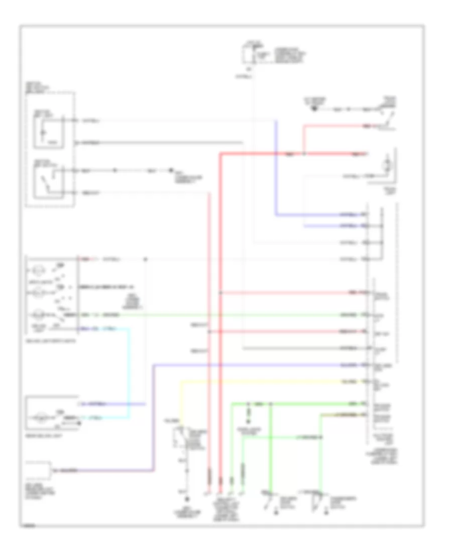
Forced Entry Wiring Diagram, Except Hatchback & Hybrid for Honda Civic HX 2004
List of elements for Forced Entry Wiring Diagram, Except Hatchback & Hybrid for Honda Civic HX 2004:
- (sedan)
- Combination light switch
- Cruise control system
- Driver's door switch
- Front passenger's or passenger's door switch
- Fuse 10 7.5a
- Fuse 15 2a
- Fuse 2 15a
- Fuse 20 20a
- G12 (under left side of dash)
- G401 (under gauge assembly)
- G502 (under center of dash)
- G601 (at center of trunk)
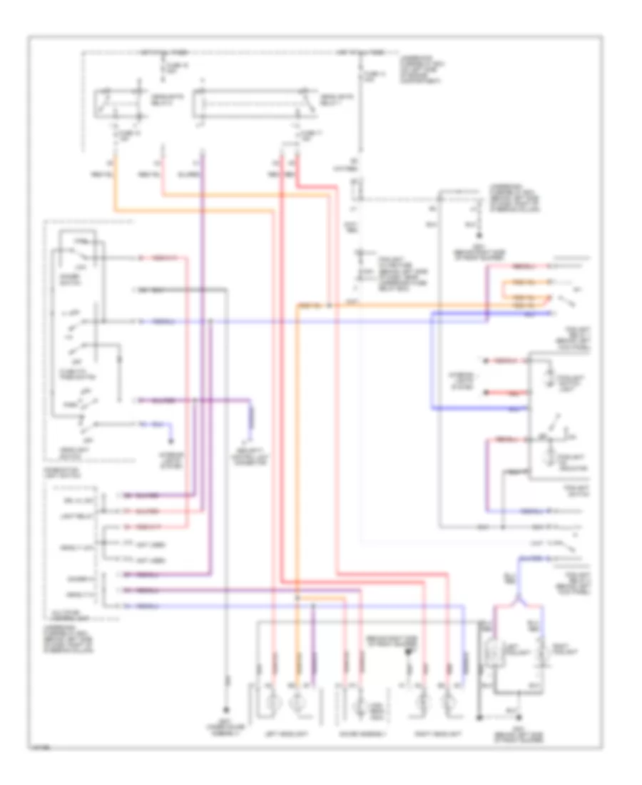
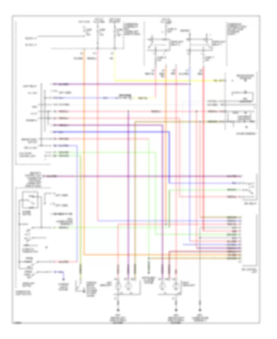
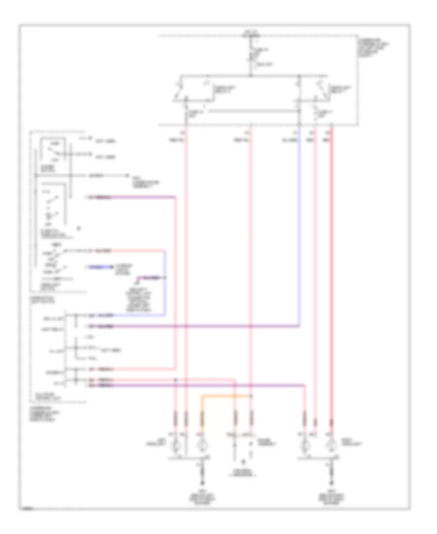
- Headlight switch
- Headlights system
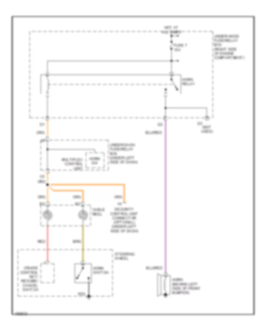
- Horns system
- Hot at all times
- Hot in on or start
- Ignition key switch
- Ignition key switch/ key light
- Interior lights system
- Keyless receiver fuse 1 (under left side of dash)
- Keyless receiver fuse 2 (under left side of dash)
- Keyless receiver unit (under center of dash)
- Left rear door switch (sedan)
- Multiplex control unit
- P18
- Red
- Right rear door switch (sedan)
- Security control unit (under left side of dash)
- Security led
- Taillight relay
- Trunk latch switch (middle of trunk lid)
- Under-dash fuse/relay box (under left side of dash)
- Under-hood fuse/relay box (right side of engine compt)
Forced Entry Wiring Diagram, Hatchback for Honda Civic HX 2004
List of elements for Forced Entry Wiring Diagram, Hatchback for Honda Civic HX 2004:
- (behind left side of front bumper) high horn
- (behind right side of front bumper) low horn
- C11
- Cruise control system
- D11
- Driver's door switch
- Drl control unit (under left side of dash) (canada)
- Exterior lights system
- Fuse 10a
- Fuse 15a
- Fuse 2a
- Fuse 7.5a
- Fuse 80a
- G401 (under gauge assembly)
- G50 (under left side of dash)
- G501 (under gauge assembly)
- G502 (under right side of dash)
- G552 (behind right rear seat back)
- Hatch latch switch
- Head- lights relay 1
- Head- lights relay 2
- Headlights system
- Horn relay
- Horn system
- Hot at all times
- Hot in on or start
- Ignition key switch
- Ignition key switch/ key light
- Interior lights system
- K13
- Keyless receiver unit (under middle of dash)
- Multiplex control unit
- P18
- Passenger's door switch
- Red
- Security control unit (under left side of dash)
- Security led
- Taillight relay
- Underdash fuse/relay box (under left side of dash)
- Underhood fuse/relay box (on right side of engine compartment)
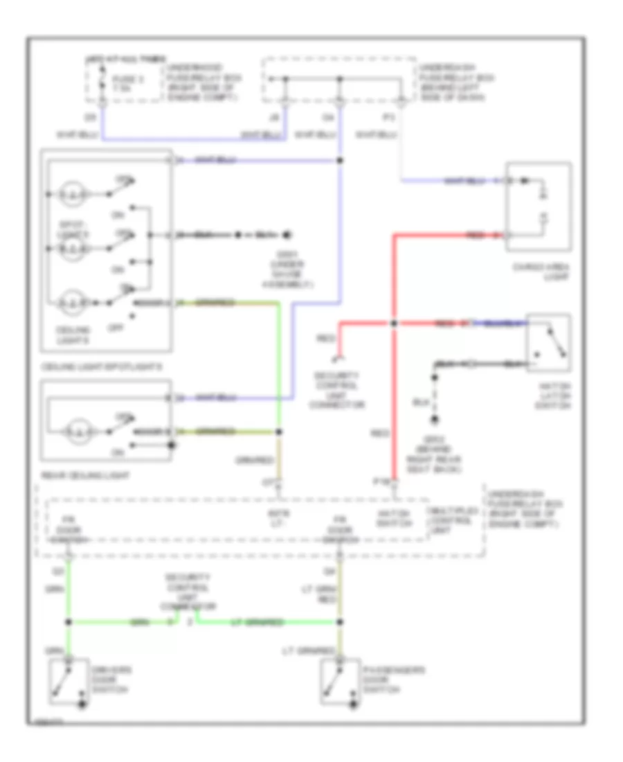
Forced Entry Wiring Diagram, Hybrid for Honda Civic HX 2004
List of elements for Forced Entry Wiring Diagram, Hybrid for Honda Civic HX 2004:
- (under gauge assembly) g401
- Carlink a9
- Combination light switch
- Driver's door switch (on left ``b" pillar)
- Drl h/l sw
- Exterior lights system
- Fr door sw (as)
- Fr door sw (dr)
- Front passenger's door switch (on right ``b" pillar)
- Fuse 10 7.5a
- Fuse 15 10a
- G50 (accessory) (under left side of dash)
- G502 (behind right side of dash)
- G601 (at center of trunk)
- Horns, cruise control systems
- Hot at all times
- Hot in on or start
- Ignition key switch
- Ignition key switch/key light (in steering column cover)
- Interface box (under middle of dash)
- K/l set
- K/l unset
- Key sw
- Left rear door switch
- Multiplex control unit
- P18
- Red
- Right rear door switch
- Rr door sw
- Security control unit (under left side of dash)
- Security led (under left side of dash)
- Trunk latch switch
- Trunk light
- Trunk sw (t/g sw)
- Underdash fuse/relay box (under left side of dash)
Immobilizer Wiring Diagram, Except GX & Hybrid for Honda Civic HX 2004
List of elements for Immobilizer Wiring Diagram, Except GX & Hybrid for Honda Civic HX 2004:
- (hatchback) (except hatchback)
- (hx, lx, ex)
- (not used)
- A16
- A23
- A24
- A8 carlink interface box (under middle of dash)
- B10
- B19
- B22
- C20
- Car link
- Computer data lines system
- D11
- D12
- Dlc (under center of dash)
- E27
- Ecm/pcm (behind glove box)
- Eps control unit
- Except hatchback
- Except hx, lx, ex
- Fuel pump
- Fuel tank unit (on top of fuel tank)
- Fuse 10a
- Fuse 15a
- G101 (middle of engine)
- G551 (under front passenger's seat)
- Gauge assembly
- Hatchback
- Hatchback except
- Hot at all times
- Hot in on or start
- Hx, lx, ex
- Hx,lx,ex
- Ig1
- Igp1
- Igp2
- Immobi- lizer code
- Immobilizer control unit receiver (in steering column cover)
- Immobilizer system indicator
- Imo fpr
- Imocd
- Junction connector c102 (behind glove compt)
- Junction connector c104 (on cylinder head cover)
- Lg1
- Lg2
- Lg3
- Mrly
- Multiplex control unit
- P14
- Parking brake switch (at base of park lever)
- Pgm-fi main relay 1 (behind glove box)
- Pgm-fi main relay 2 (behind glove box)
- Under-dash fuse/relay box (under left side of dash)
- Under-hood fuse/ relay box (right side of engine compt)
Immobilizer Wiring Diagram, GX for Honda Civic HX 2004
List of elements for Immobilizer Wiring Diagram, GX for Honda Civic HX 2004:
- A23
- A24
- A3 a3
- B10
- B22
- Computer data lines system
- D11
- D12
- E27
- E28
- Engine controls system
- Fuel pressure regulator switch (right side of engine compt)
- Fuel tank internal solenoid valve (left side of trunk)
- Fuse 10a
- Fuse 15a
- G101 (middle of engine)
- G201 (behind right side of front bumper)
- G551 (under front passenger's seat)
- Gauge assembly
- Hot at all times
- Hot in on or start
- Ig1
- Igp1
- Igp2
- Immobi- lizer code
- Immobilizer control unit receiver (in steering column cover)
- Immobilizer system indicator
- Imo fpr
- Imocd
- Injector relay (behind glove box)
- Junction connector c102 (behind glove compt)
- Junction connector c104 (on cylinder head cover)
- Lg1
- Lg2
- Lg3
- Mrly
- Multiplex control unit
- P1sw
- Parking brake switch (at base of park lever)
- Pcm (behind glove box)
- Pgm-fi main relay 1 (behind glove box)
- Pgm-fi main relay 2 (behind glove box)
- Under-dash fuse/relay box (under left side of dash)
- Under-hood fuse/ relay box (right side of engine compt)
Immobilizer Wiring Diagram, Hybrid for Honda Civic HX 2004
List of elements for Immobilizer Wiring Diagram, Hybrid for Honda Civic HX 2004:
- A23
- A24
- B18
- Carlink
- Carlink iinterface box (under middle of dash)
- Computer data lines system
- Cooling fans system
- D11
- D12
- E27
- Ecm (behind glove box)
- Engine controls system
- Fuel pump
- Fuel tank unit (on top of fuel tank)
- Fuse 10a
- Fuse 15a
- G101 (at top left side of engine)
- G551 (under front passenger's seat)
- Gauge assembly
- Hot at all times
- Hot in on or start
- Ig1
- Immobi- lizer cord
- Immobilizer control unit receiver (in steering column cover)
- Immobilizer system indicator
- Imo fpr
- Imocd
- Instrument cluster system
- Junction connector c111 (on center of engine)
- Lg1
- Lg2
- Lg3
- Mrly
- Multi-fuse/ relay box (on left side of engine compt)
- Multiplex control unit
- Pgm-fi main relay 1 (behind glove box)
- Pgm-fi main relay 2
- Underdash fuse/relay box (under left side of dash)
- Underhood fuse/ relay box (on left side of engine compt)
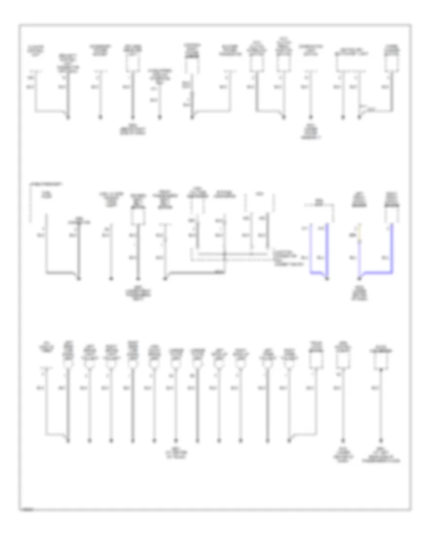
BODY CONTROL MODULES
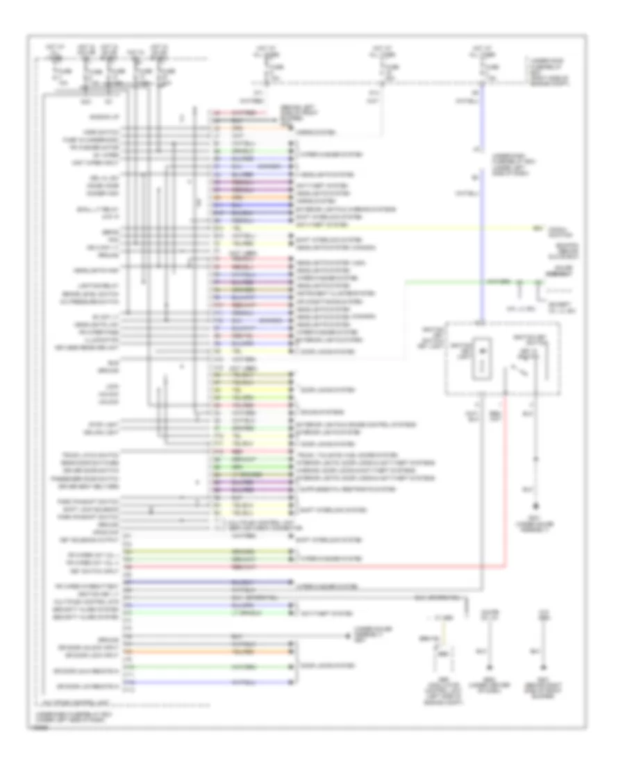
Body Control Modules Wiring Diagram, Except Hatchback & Hybrid for Honda Civic HX 2004
List of elements for Body Control Modules Wiring Diagram, Except Hatchback & Hybrid for Honda Civic HX 2004:
- (behind left side of front bumper) g301
- (canada)
- (except
- (hx, lx, ex)
- (not used)
- (under gauge assembly) g501
- (usa)
- +b back up
- A/c pressure switch
- Abs modulator control unit (left side of engine compt)
- Acc
- Air conditioning system
- Anti-theft system
- Atp -p
- B+ day lt
- Brake level switch
- Bus
- C11
- Ceiling light
- Commu- nication
- Coupe dx, hx
- D10
- D11
- D14
- Dimmer high
- Door locks system
- Dr door lck remote in
- Dr door lock input
- Dr door unlk remote in
- Dr door unlock input
- Driver door switch
- Driver seat belt/srs
- Drl h/l sw
- E10
- E13
- E24
- Ebd
- Ecm/pcm (behind glove box)
- Exterior lights & cruise control systems
- Exterior lights & warning systems
- Exterior lights system
- F10
- F11
- F12
- Fr washer motor
- Fr wiper (int vol +)
- Fr wiper (int vol -)
- Fr wiper intermittent
- Fr wiper pass
- Fuse 10a
- Fuse 16 (underhood)
- Fuse 20a
- Fuse 7.5a
- G201 (behind right side of front bumper)
- G401 (under gauge assembly)
- G502 (under center of dash)
- Gauge assembly
- Ground
- Headlights high
- Headlights low
- Headlights system
- Horn switch
- Horns system
- Hot at all times
- Hot in acc or on
- Hot in on
- Hot in on or start
- Hx, lx, ex)
- Ig1
- Ig1 wiper
- Ign 2 day lt
- Ignition key light
- Ignition key lt
- Ignition key switch
- Ignition key switch/ key light
- Illumination
- Immobi code
- Instrument cluster system
- Interior lights system
- Interior lights, door locks & anti-theft systems
- K10
- K16
- Key in ignition
- Key solenoid output
- Key switch input
- Keyless receiver unit
- Lighting relay
- Lock
- Mist wiper input
- Mpcs chk
- Multiplex control sys
- Multiplex control unit
- Multiplex control unit service check connector
- P16
- P17
- P18
- Park pin/shift switch
- Passenger door switch
- Pcm
- Rear door switches
- Red
- Security alarm system
- Sefms
- Shift interlock system
- Shift lock solenoid
- Small lt relay
- Sound systems
- Stop light
- Trunk latch switch
- Trunk, tailgate, fuel doors system
- Under-dash fuse/relay box (under left side of dash)
- Under-hood fuse/relay box (right side of engine compt)
- Unlock
- W/ abs
- W/o abs
- Warning, door locks & anti-theft systems
- Wiper/washer system
- Y10
- Y11
- Y12
- Y13
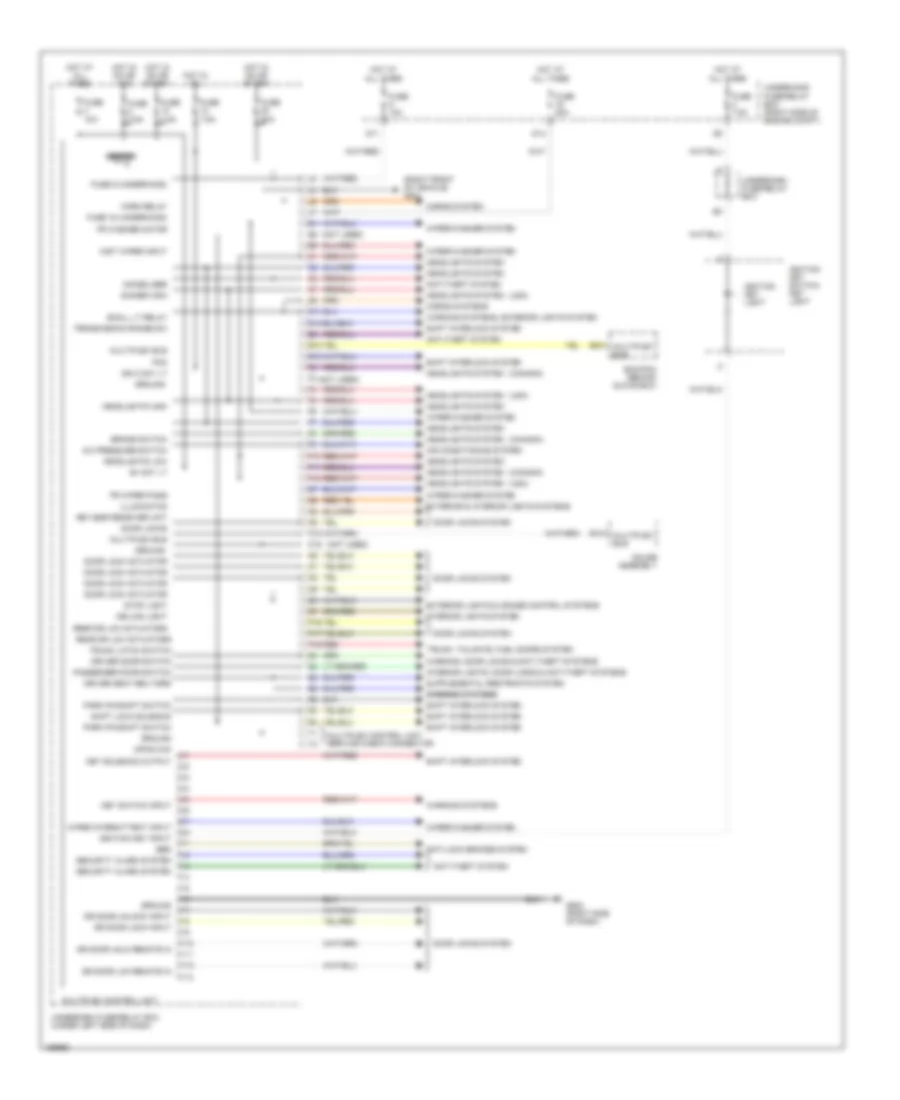
Body Control Modules Wiring Diagram, Hatchback for Honda Civic HX 2004
List of elements for Body Control Modules Wiring Diagram, Hatchback for Honda Civic HX 2004:
- (canada)
- (not used)
- (right front of vehicle) g201
- (usa)
- A/c pressure switch
- Air conditioning system
- Anti-lock brakes system
- Anti-theft system
- B+ day lt
- B13
- Beeper
- Brake switch
- C11
- Ceiling light
- D10
- D11
- D14
- Dimmer high
- Door lock actuator
- Door locks
- Door locks system
- Dr door lck remote in
- Dr door lock input
- Dr door unlk remote in
- Dr door unlock input
- Driver door switch
- Driver seat belt/srs
- E10
- E13
- E24
- Ebd
- Ecm/pcm (behind glove box)
- Exterior & interior lights systems
- Exterior lights & cruise control systems
- F10
- F11
- F12
- Fr washer motor
- Fr wiper pass
- Fuse 10a
- Fuse 16 (underhood)
- Fuse 20a
- Fuse 30a
- Fuse 7.5a
- Fuse 9 (underhood)
- G502 (right side of dash)
- Gauge assembly
- Ground
- Headlights high
- Headlights low
- Headlights system
- Horn relay
- Horns system
- Horns systems
- Hot at all times
- Hot in on
- Hot in on or acc
- Hot in on or start
- Ign 2 day lt
- Ignition key input
- Ignition key light
- Ignition key switch/ key light
- Illuminaton
- Immobilizer
- Interior lights system
- Interior lights, door locks & anti-theft systems
- K10
- K16
- Key solenoid output
- Key switch input
- Keyless receiver unit
- Mist wiper input
- Mpcs chk
- Multiplex bus
- Multiplex control unit
- Multiplex control unit service check connector
- P16
- P17
- P18
- Park pin/shift switch
- Passenger door switch
- Pcm
- Rear dr lck actuators
- Red
- Security alarm system
- Shift interlock system
- Shift lock solenoid
- Small lt relay
- Stop light
- Transmission range sw
- Trunk latch switch
- Trunk, tailgate, fuel doors system
- Underdash fuse/relay box
- Underdash fuse/relay box (under left side of dash)
- Underhood fuse/relay box (right side of engine compt)
- Warning systems
- Warning systems warning systems
- Warning systems, exterior lights system
- Warning, door locks & anti-theft systems
- Wiper intermittent input
- Wiper/washer system
- Y10
- Y11
- Y12
- Y13
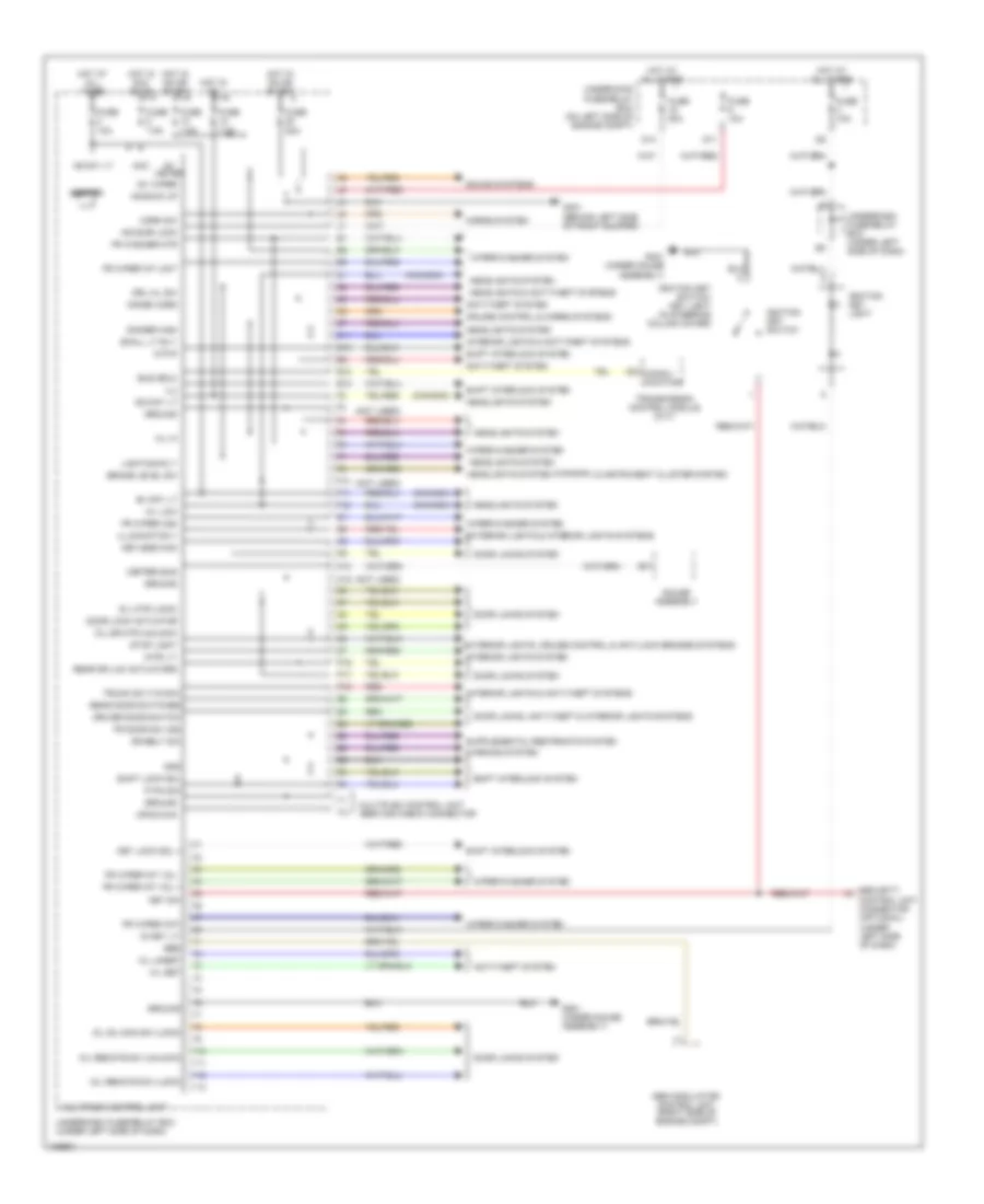
Body Control Modules Wiring Diagram, Hybrid for Honda Civic HX 2004
List of elements for Body Control Modules Wiring Diagram, Hybrid for Honda Civic HX 2004:
- & instrument cluster system
- (canada)
- (meter) bus
- (not used)
- +b back up
- +b day lt
- +b door lock
- A2 commu- nication
- Abs modulator- control unit (right side of engine compt)
- Acc
- Anti-theft system
- Atp-p
- B+ day lt
- Beeper
- Brake level sw
- Bus (ecu)
- C11
- Cruise control & horns systems
- D/l dr mtr (unlock)
- D/l mtr (lock)
- D/l remote sw (lock)
- D/l remote sw (unlock)
- D/l sil-con sw (lock)
- D10
- D11
- D14
- Dimmer high
- Door lock actuator
- Door locks system
- Door locks, anti-theft & interior lights systems
- Dr belt sw
- Driver door switch
- Drl h/l sw
- E10
- E13
- Ebd
- Exterior lights & interior lights systems
- Exterior lights, cruise control & anti-lock brakes systems
- F10
- F11
- F12
- Fr door sw (as)
- Fr washer mtr
- Fr wiper (as)
- Fr wiper (int)
- Fr wiper int unit
- Fr wiper int vol +
- Fr wiper int vol -
- Fuse 10a
- Fuse 20a
- Fuse 7.5a
- G301 (behind left side of front bumper)
- G401 (under gauge assembly)
- G501 (under gauge assembly)
- Gauge assembly
- Gnd
- Ground
- H/l hi
- H/l low
- Headlights & anti-theft systems
- Headlights system
- Horn sw
- Horns system
- Hot at all times
- Hot in acc or on
- Hot in on
- Hot in on or start
- Ig key lt-
- Ig1 meter
- Ig1 wiper
- Ig2 day lt
- Ignition key light
- Ignition key switch
- Ignition key switch/ key light (in steering column cover)
- Illumination +
- Ilu
- Immobi cord
- Interior lights & anti-theft systems
- Interior lights system
- Intr lt-
- K/l set
- K/l unset
- K10
- K16
- Key lock sol +
- Key sw
- Keyless com
- Lighting rly-
- Mpcs chk
- Multiplex control unit
- Multiplex control unit service check connector
- P pin sw
- P16
- P17
- P18
- Rear door switches
- Rear dr lck actuators
- Red
- Security control unit connector (optional) (under left side of dash)
- Shift interlock system
- Shift lock sol
- Small lt rly-
- Sound systems
- Stop light
- Transmission control module (cvt)
- Trunk sw (t/g sw)
- Underdash fuse/relay box (under left side of dash)
- Underhood fuse/relay box (on left side of engine compt)
- Warning system
- Wiper/washer system
- Y10
- Y11
- Y12
- Y13
COMPUTER DATA LINES
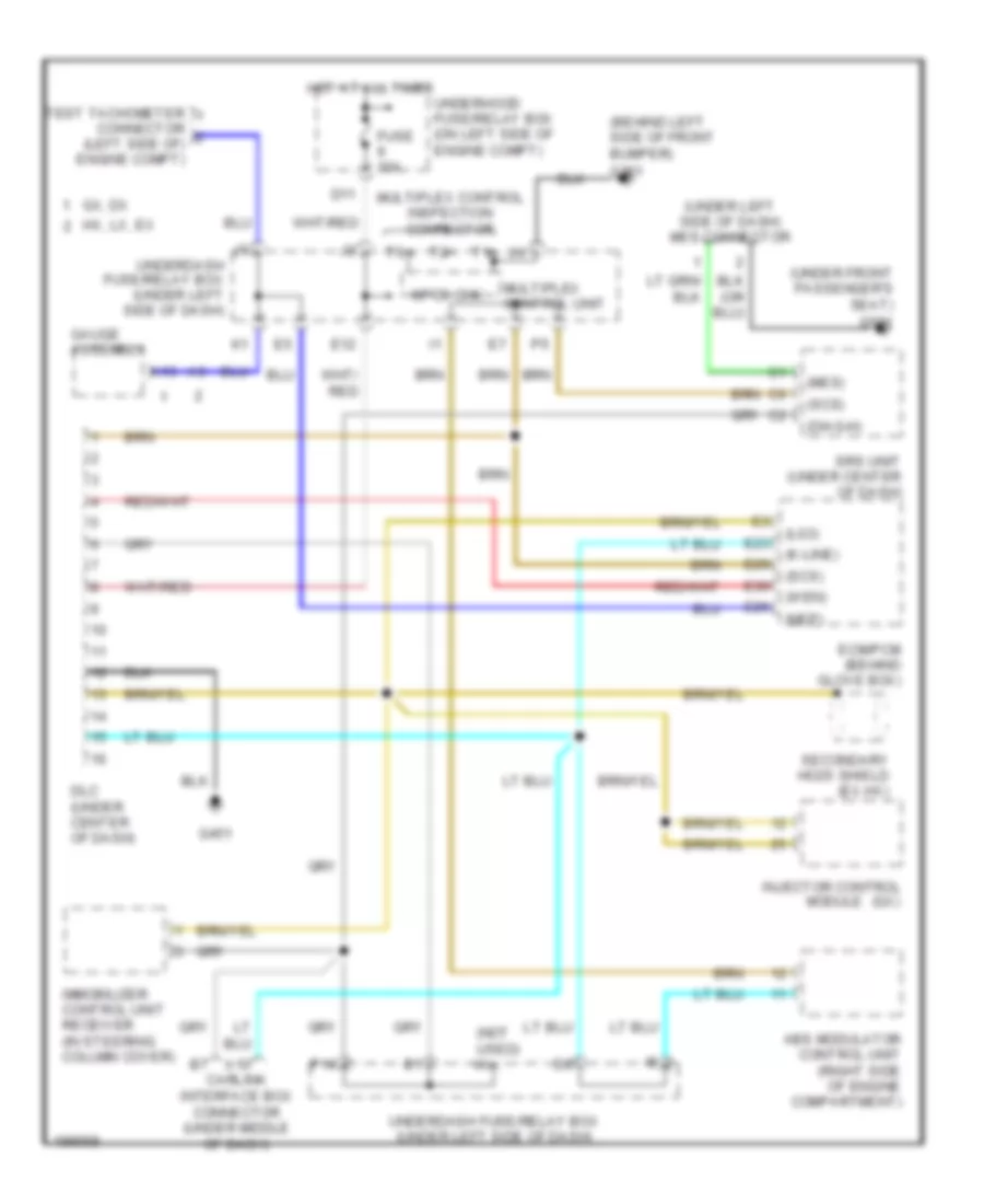
Computer Data Lines Wiring Diagram, Except Hatchback & Hybrid for Honda Civic HX 2004
List of elements for Computer Data Lines Wiring Diagram, Except Hatchback & Hybrid for Honda Civic HX 2004:
- (behind left side of front bumper)
- (diag-h)
- (k-line)
- (lg3)
- (mes)
- (nep)
- (not used)
- (scs)
- (under front passenger's seat)
- (under left side of dash) mes connector
- (wen)
- A10
- A13
- Abs modulator control unit (right side of engine compartment)
- Carlink interface box connector (under middle of dash)
- D11
- Dlc (under center of dash)
- E12
- E23
- E26
- E29
- E30
- Ecm/pcm (behind glove box)
- Fuse 10a
- G301
- G451
- G551
- Gauge assembly
- Gx, dx
- Hot at all times
- Hx, lx, ex
- Immobilizer control unit receiver (in steering column cover)
- Injector control (gx)
- Module
- Mpcs chk
- Multiplex control inspection connector
- Multiplex control unit
- P14
- Secondary ho2s shield (ex,hx)
- Srs unit (under center of dash)
- Test tachometer connector (left side of) engine compt)
- Underdash fuse/relay box (under left side of dash)
- Underhood fuse/relay box (on left side of engine compt)
Computer Data Lines Wiring Diagram, Hatchback for Honda Civic HX 2004
List of elements for Computer Data Lines Wiring Diagram, Hatchback for Honda Civic HX 2004:
- (k-line)
- (not used) i4
- (scs)
- (under middle of dash) g451
- (wen)
- Abs modulator control unit (ex & gx) (left side of engine compartment)
- Braided wire
- C20
- D11
- Data link connector (dlc) (under middle of dash)
- E12
- E23
- E29
- E30
- Engine control module (ecm) (behind glove box)
- Eps control unit (under right side of dash)
- Fuse 9 10a
- Hot at all times
- Immobilizer control unit receiver (in steering column cover)
- P14
- Secondary ho2s shields
- Sensor gnd
- Srs unit (under middle of dash)
- Underdash fuse/relay box (under left side of dash)
- Underhood fuse/relay box (right side of engine compartment)
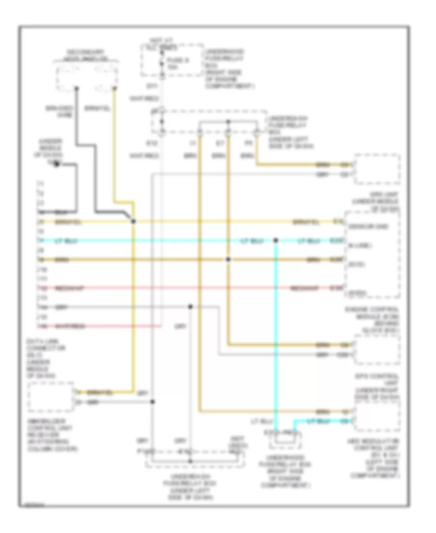
Computer Data Lines Wiring Diagram, Hybrid for Honda Civic HX 2004
List of elements for Computer Data Lines Wiring Diagram, Hybrid for Honda Civic HX 2004:
- (diag-h)
- (dlc)
- (k-line)
- (lg3)
- (mes)
- (nep)
- (scs)
- (sulev)
- (ulev)
- (under center of dash) g504
- (under front passenger's seat) g551
- (under left side of dash) underdash fuse/relay box
- (vbu)
- (wen)
- A13
- A17
- A25
- A28
- A30
- A31
- Abs modulator control unit (right side of engine compt)
- B7 carlink interface a10
- Box (under middle of dash)
- Braided wire
- C19
- C20
- D11
- Data link connector (dlc) (under center of dash)
- E12
- E23
- E26
- E29
- E30
- Ecm (behind glove box)
- Eps control unit (under right side of dash)
- Fuse 9 10a
- G301 (behind left side of front bumper)
- Gauge assembly
- Hot at all times
- Immobilizer control unit receiver (in steering column cover)
- Mcm (behind glove box)
- Mes connector (under left side of dash)
- Multiplex control inspection connector
- Multiplex control unit
- P14
- Srs unit (under center of dash)
- Test tachometer connector (left side of engine compt)
- Third ho2s shield secondary ho2s shield
- Transmission control module (tcm) (cvt) (behind right kick panel)
- Underhood fuse/relay box (on left side of engine compartment)
COOLING FAN
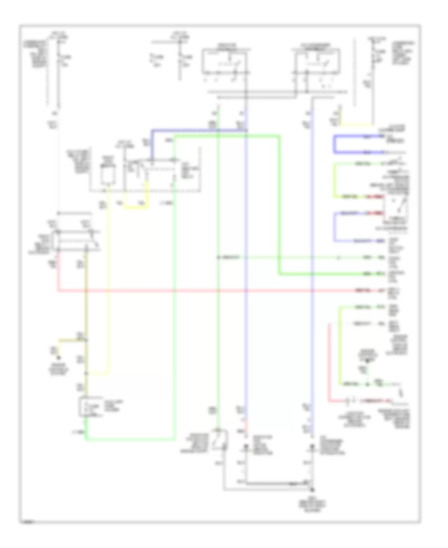
Cooling Fan Wiring Diagram, Except Hatchback & Hybrid for Honda Civic HX 2004
List of elements for Cooling Fan Wiring Diagram, Except Hatchback & Hybrid for Honda Civic HX 2004:
- (not used)
- A/c compressor
- A/c condenser fan motor (forward of radiator)
- A/c condenser fan relay
- A/c on
- A/c pressure switch (behind left side of a/c condenser fan motor)
- A10
- Accessory a/c
- Acs
- Connector c102 (except gx: terminals 5-7) (gx: terminals' 14-16) (under right side of dash)
- E10
- E24
- Ecm/pcm (behind glove box)
- Engine coolant temperature (ect) sensor (rear of engine)
- Except gx
- Factory a/c
- Fanc
- Fuse 10a
- Fuse 20a
- G101 (at top left side of engine)
- G13 (at left front side of engine compartment)
- G201 (behind right side of front bumper)
- Heater control panel
- High
- Hot at all times
- Hot in on
- Junction
- Junction connector c103 (under right side of dash)
- Low
- Multiplex control unit
- Radiator fan motor (behind radiator)
- Radiator fan relay
- Radiator fan switch (bottom front of engine compt)
- Red
- Sedan
- Sefmj
- Sens gnd
- Sens input
- Thermal protector
- Underdash fuse/relay box (under left side of dash)
- Underhood fuse/relay box (on left side of engine compt)
Cooling Fan Wiring Diagram, Hatchback for Honda Civic HX 2004
List of elements for Cooling Fan Wiring Diagram, Hatchback for Honda Civic HX 2004:
- (left front of vehicle) g301
- A/c clutch
- A/c compressor
- A/c compressor clutch
- A/c compressor clutch relay
- A/c compressor thermal protector
- A/c condenser fan motor (forward of radiator)
- A/c on
- A/c pressure switch (behind left side of a/c condenser fan)
- Acc
- Acs
- Condenser fan relay
- D10
- E10
- E18
- E24
- Ecm/pcm (behind glove box)
- Fuse 10a
- Fuse 20a
- G301 (left front of vehicle)
- Heater control panel
- High
- Hot at all times
- Hot in on
- J/c c103 (on cylinder head cover)
- Low
- Nca
- Radiator fan motor (behind radiator)
- Radiator fan relay
- Radiator fan switch (middle of engine)
- Red
- Sefmj
- Underdash fuse/relay box (under left side of dash)
- Underhood fuse/relay box (right side of engine compt)
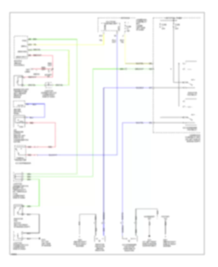
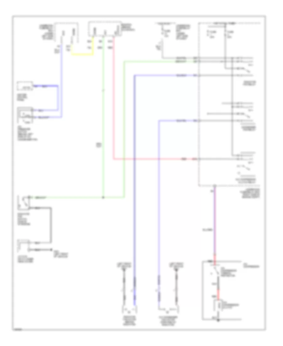
Cooling Fan Wiring Diagram, Hybrid for Honda Civic HX 2004
List of elements for Cooling Fan Wiring Diagram, Hybrid for Honda Civic HX 2004:
- (acs) a/c switch input
- (ect) sens input
- (fanc) fan ctrl
- (hrfanc) fan ctrl
- (mrly) relay ctrl
- (sg2) sens gnd
- A/c compressor
- A/c condenser fan motor (forward of radiator)
- A/c condenser fan relay
- A/c pressure switch (behind left side of a/c condenser fan motor)
- A10
- A6 a/c pres sw
- Auxiliary fuse holder
- Climate control unit
- E11
- E28
- Engine control module (behind glove box)
- Engine controls system
- Engine coolant temperature (ect) sensor (rear of engine)
- Fuse 10a
- Fuse 15a
- Fuse 20a
- Fuse 7.5a
- G201 (behind right side of front bumper)
- High
- Hot at all times
- Hot in on
- Hot restart fan relay
- Junction connector c106 (behind glove box)
- Low
- M m
- Multi-fuse/ relay box (on left side of engine compt)
- Pgm-fi main relay 1 (behind glove box)
- Pgm-fi main relay 2
- Radiator fan motor (behind radiator)
- Radiator fan relay
- Radiator fan switch (bottom front of engine compt)
- Red
- Thermal protector
- Underdash fuse/ relay box (under left side of dash)
- Underhood fuse/relay box (on left side of engine compt)
CRUISE CONTROL
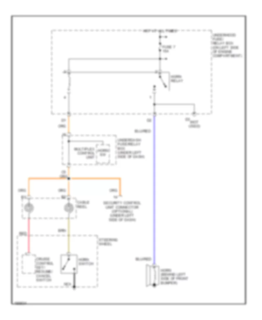
Cruise Control Wiring Diagram, Except Hatchback & Hybrid for Honda Civic HX 2004
List of elements for Cruise Control Wiring Diagram, Except Hatchback & Hybrid for Honda Civic HX 2004:
- "on" indicator
- (at)
- (behind left side of front bumper) g301
- (clh)
- (clp)
- (gnd)
- (ig)
- (inh)
- (mc)
- (middle
- (mo)
- (not used)
- (on cylinder head cover) junction connector c103
- (res)
- (set)
- (spd)
- (under left side of dash) brake pedal position switch
- A/t
- A/t except cvt
- A/t except cvt, cvt
- A14
- A15
- A17
- A18
- A21
- C18
- Cable reel (on steering column)
- Cancel switch
- Clutch pedal position switch (under left side of dash)
- Coupe lx, ex
- Cruise control actuator (usa hx & sedan lx, ex, gx) (right side of of engine compt)
- Cruise control main switch
- Cruise control set/resume cancel switch
- Cruise control switch light
- Cruise control unit (usa hx & sedan lx, ex, gx) cruise control actuator (coupe lx, ex) (usa hx & sedan lx, ex, gx: under left side of dash) (coupe lx, ex: right side of engine compt)
- Cruise indicator
- Cvt
- E12
- E25
- Ecm/pcm (behind glove box)
- Except cvt
- Except hx, lx, ex
- Fuse 10a
- Fuse 15a
- Fuse 7.5a
- G101 (middle of engine)
- G301 (coupe lx, ex) (behind left side of front bumper)
- G401 (under gauge assembly)
- G501 (under gauge assembly)
- G501 (usa hx & sedan lx, ex, gx) (under gauge assembly)
- Gauge assembly
- Horn relay
- Horns system
- Hot at all times
- Hot in on or start
- Hx, lx, ex
- Interior lights system
- Junction connector c102 (behind glove compt)
- Junction connector c103 (on cylinder head cover)
- Junction connector c104 (on cylinder head cover)
- M/t
- Multiplex control unit
- O11
- O12
- Of engine) g101
- Off
- On input
- Pcm (behind glove box)
- Pnk
- Red
- Resume switch
- Security control unit connector (optional) (under left side of dash)
- Set switch
- Steering wheel
- Transmission range switch (on transmission housing)
- Under-dash fuse/relay box (under left side of dash)
- Under-hood fuse/relay box (right side of engine compt)
- Usa hx & sedan lx, ex, gx
- Vss (on transmission housing)
Cruise Control Wiring Diagram, Hatchback for Honda Civic HX 2004
List of elements for Cruise Control Wiring Diagram, Hatchback for Honda Civic HX 2004:
- "on" indicator
- (behind left side of front bumper) g301
- (clh)
- (clp)
- (gnd)
- (ig)
- (inh)
- (mc)
- (mo)
- (res)
- (set)
- (spd)
- (under left side of dash) brake pedal position switch
- B22
- Cable reel
- Clutch pedal position switch (under left side of dash)
- Cruise control actuator (right side of engine compt)
- Cruise control main switch
- Cruise control main switch light
- Cruise control set/resume cancel switch
- Cruise control unit (under left side of dash)
- Cruise indicator
- Exterior lights system
- Fuse 10a
- Fuse 15a
- Fuse 7.5a
- G501 (under gauge assembly)
- Horn relay
- Horns system
- Hot at all times
- Hot in on or start
- Instrument cluster
- Interior lights system
- J/c c102 (behind glove box)
- Multiplex control unit
- O11
- O12
- Off
- On input
- Red
- Security control unit connector (under left side of dash)
- Steering wheel
- Underdash fuse/relay box (behind left side of dash)
- Underhood fuse/relay box (right side of engine compt)
- Vss (transmission housing)
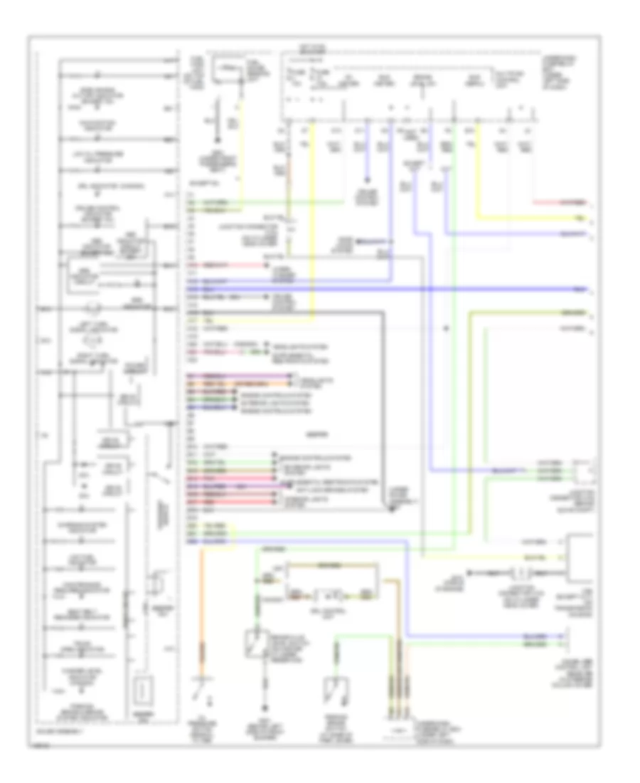
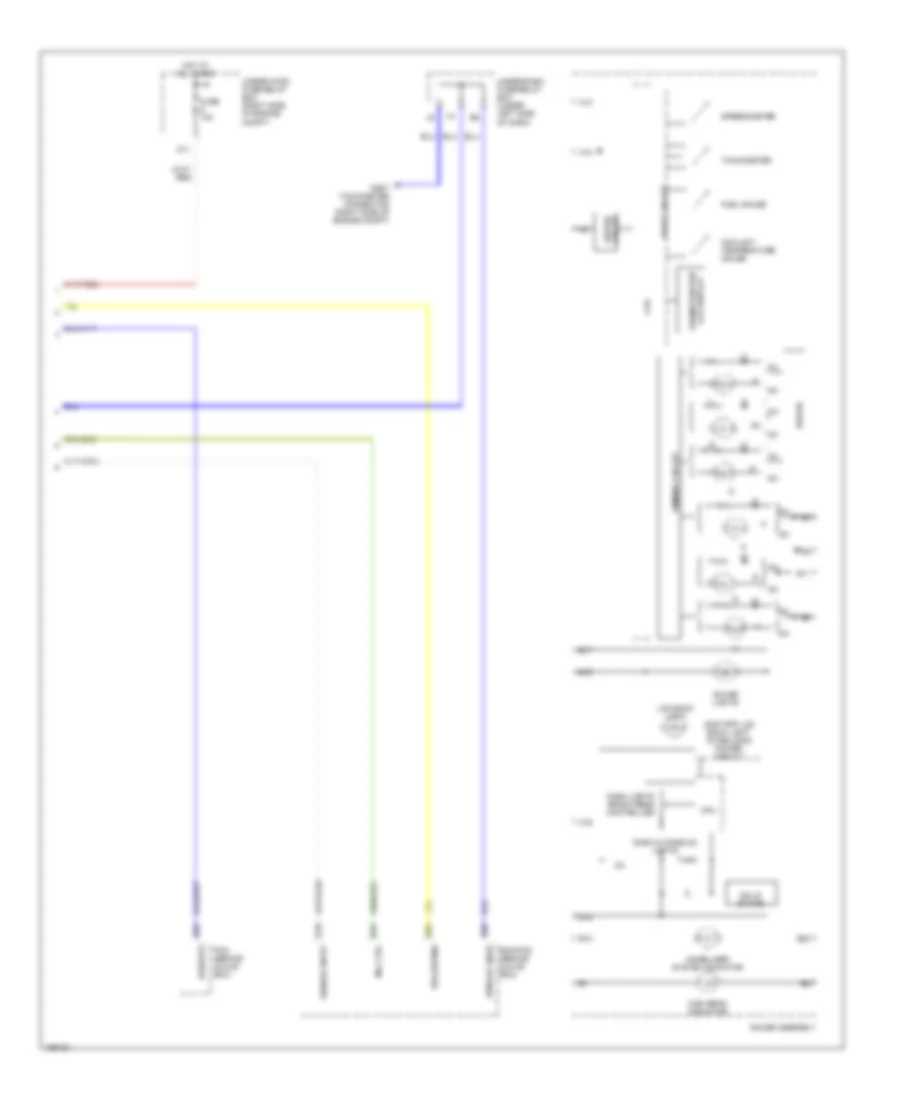
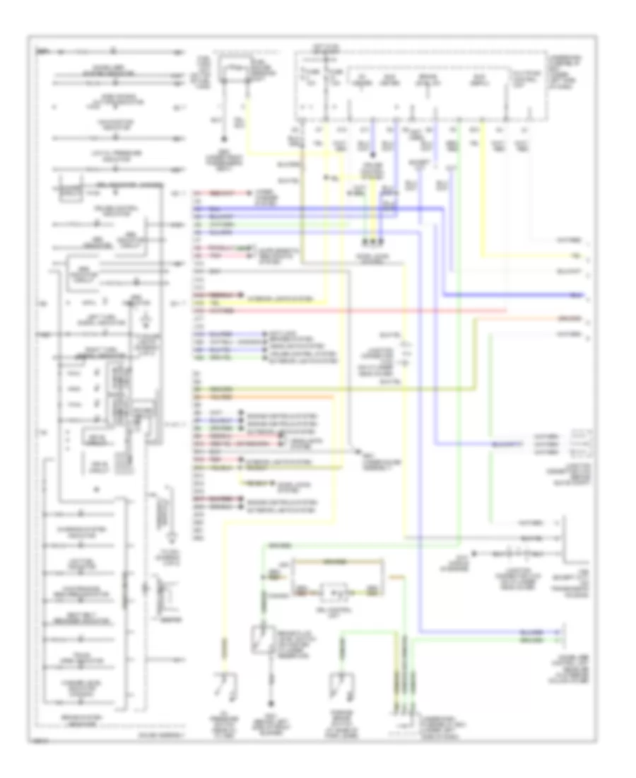
Cruise Control Wiring Diagram, Hybrid for Honda Civic HX 2004
List of elements for Cruise Control Wiring Diagram, Hybrid for Honda Civic HX 2004:
- "on" indicator
- (at top left side of engine) g101
- (behind left side of front bumper) g301
- (not used)
- (on center of engine) junction connector c110
- (under gauge assembly) g501
- (under left side of dash) brake pedal position switch
- A/t communication
- A14
- A18
- A27
- A4 carlink interface box (under middle of dash)
- Act clutch
- Atp fwd
- B17
- B22
- Cable reel
- Cancel
- Climate control unit
- Clutch pedal position switch (under left side of dash)
- Cpu
- Cruise control actuator (right side of engine compt)
- Cruise control indicator
- Cruise control main switch
- Cruise control set/resume/ cancel switch
- Cruise control switch light
- Cruise control unit (under left side of dash)
- Cruise ctrl sig in
- Cruise ind ctrl
- Cruise on in
- Cvt
- Ecm (behind glove box)
- Eps control unit (under right side of dash)
- Fuse 10a
- Fuse 15a
- Fuse 7.5a
- G101 (at top left side of engine)
- G401 (under gauge assembly)
- Gauge assembly
- Ground
- Horn relay
- Horn sw
- Horn switch
- Hot at all times
- Hot in on or start
- Ignition input
- Inhibitor sw in
- Interior lights system
- Joint)
- Junction connector c106 (behind glove box)
- Junction connector c111 (on center of engine)
- K9 (not used)
- M/t
- Motor close
- Motor open
- Multiplex control unit
- O11
- O12
- Off
- Red
- Resume
- Resume sw in
- Security control
- Set
- Set sw input
- Speed sens in
- Steering wheel
- Tcm (behind right kick panel)
- Transmission range switch (on transaxle housing)
- Underdash fuse/relay box (under left side of dash)
- Underhood fuse/relay box (on left side of engine compt)
- Unit connector (optional)
- Vss
- Vss (on transaxle housing)
- Vss out
DEFOGGERS
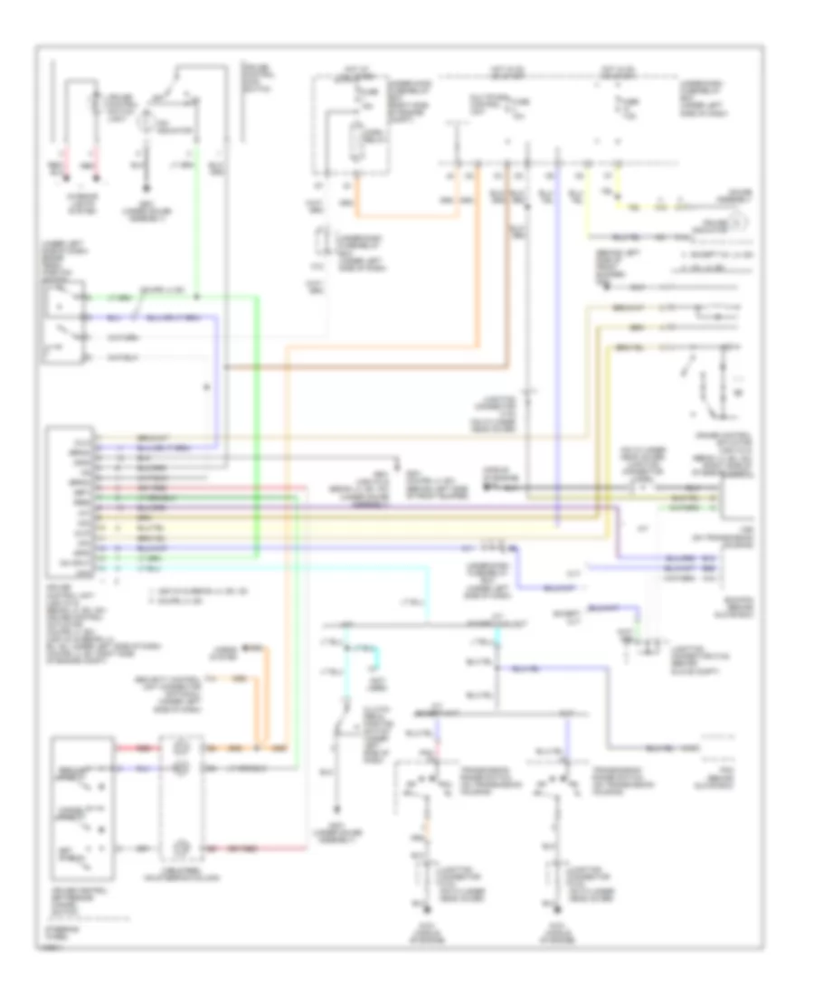
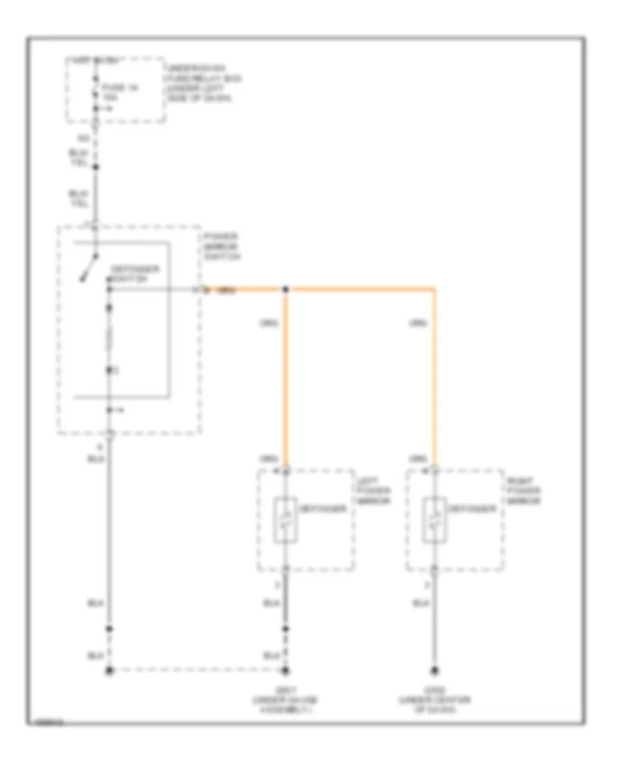
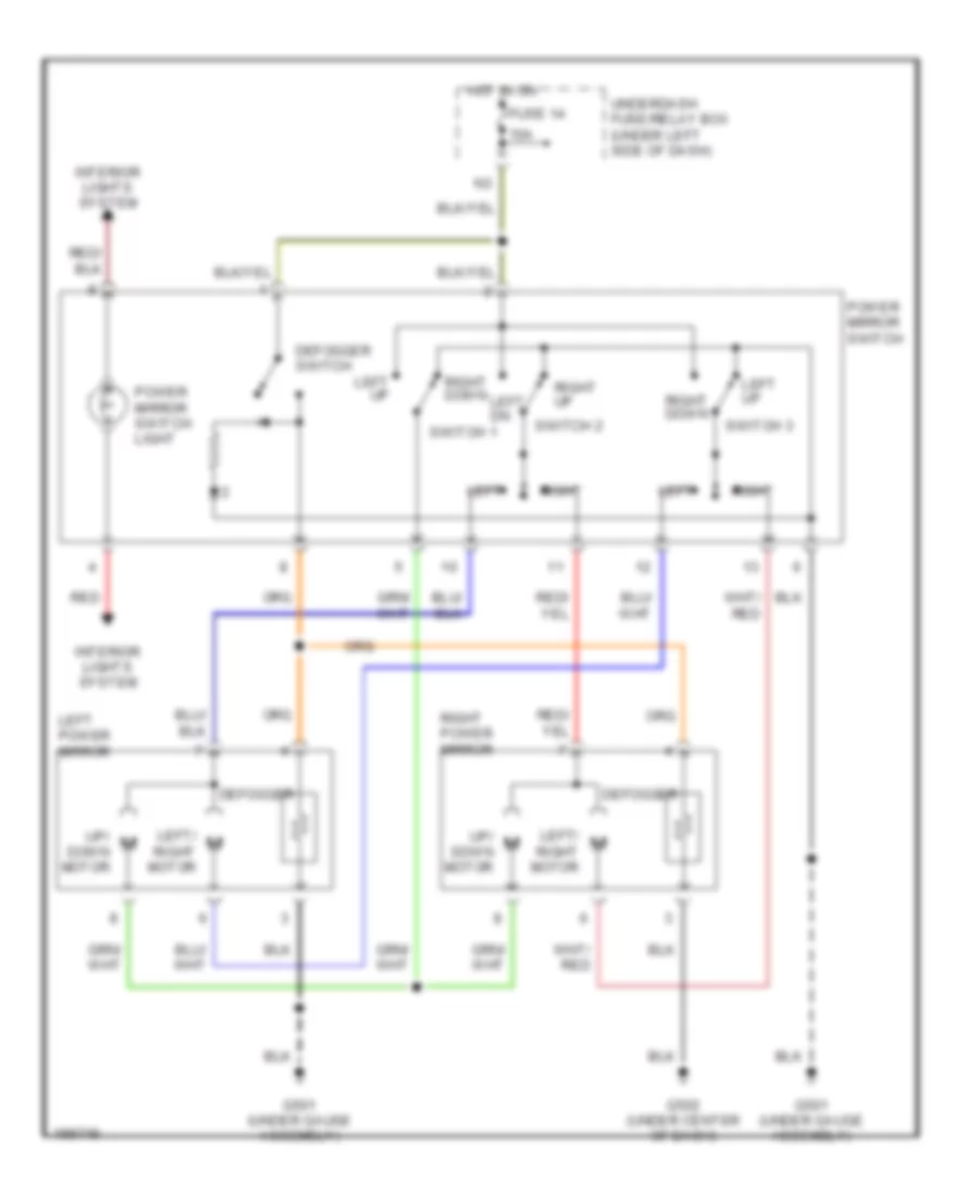
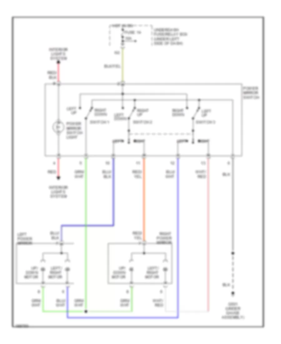
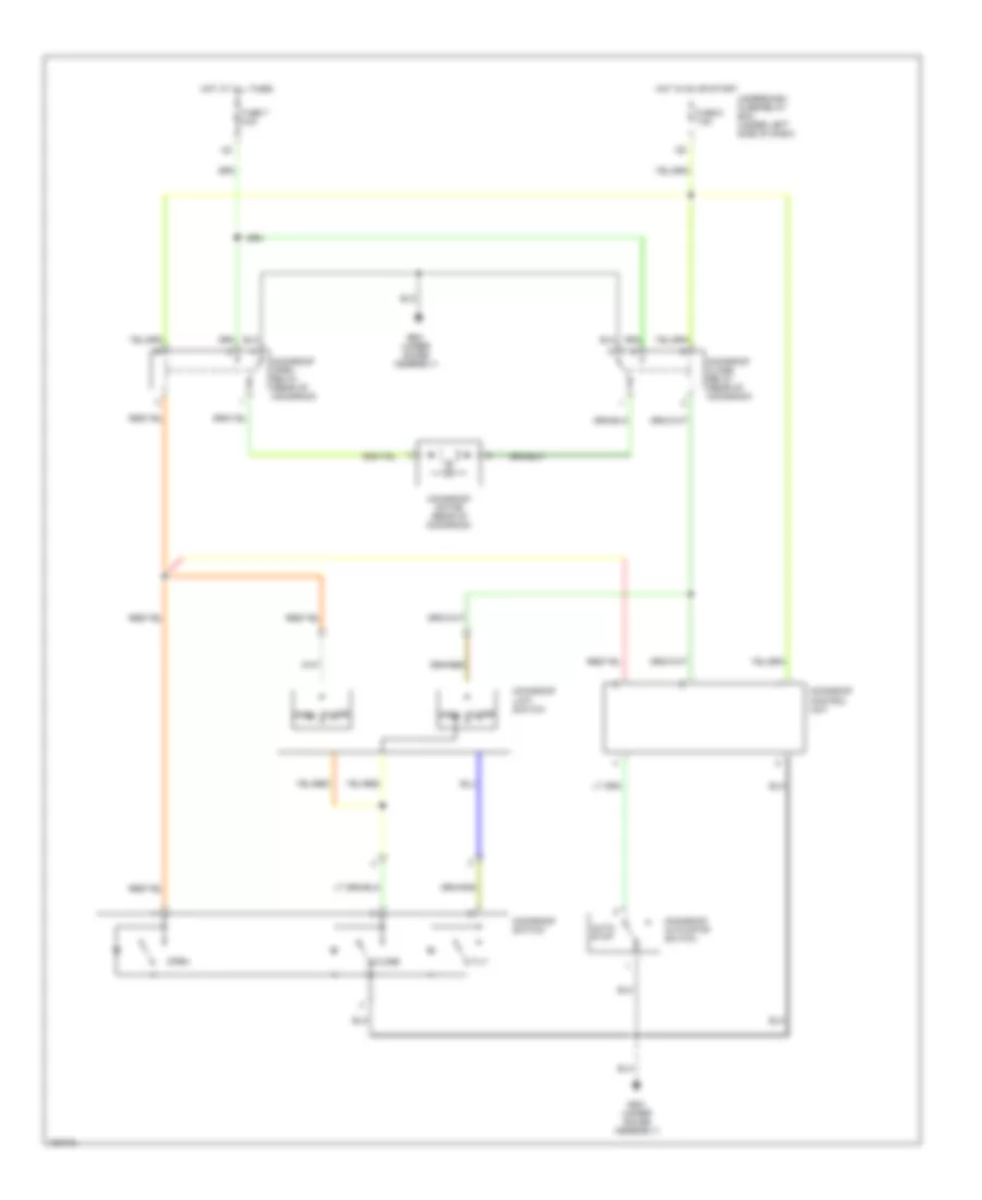
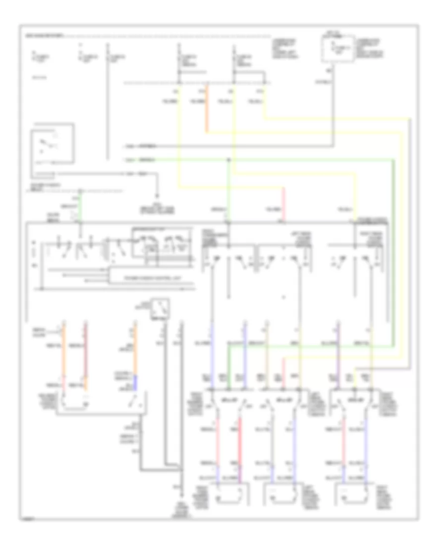
Heated Mirrors Wiring Diagram, Except Hatchback & Hybrid for Honda Civic HX 2004
List of elements for Heated Mirrors Wiring Diagram, Except Hatchback & Hybrid for Honda Civic HX 2004:
- Defogger
- Defogger switch
- Fuse 14 10a
- G501 (under gauge assembly)
- G502 (under center of dash)
- Hot in on
- Left power mirror
- Power mirror switch
- Right power mirror
- Under-dash fuse/relay box (under left side of dash)
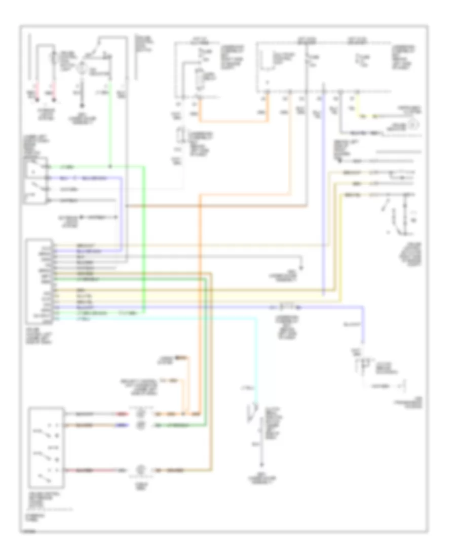
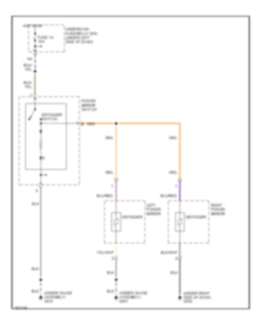
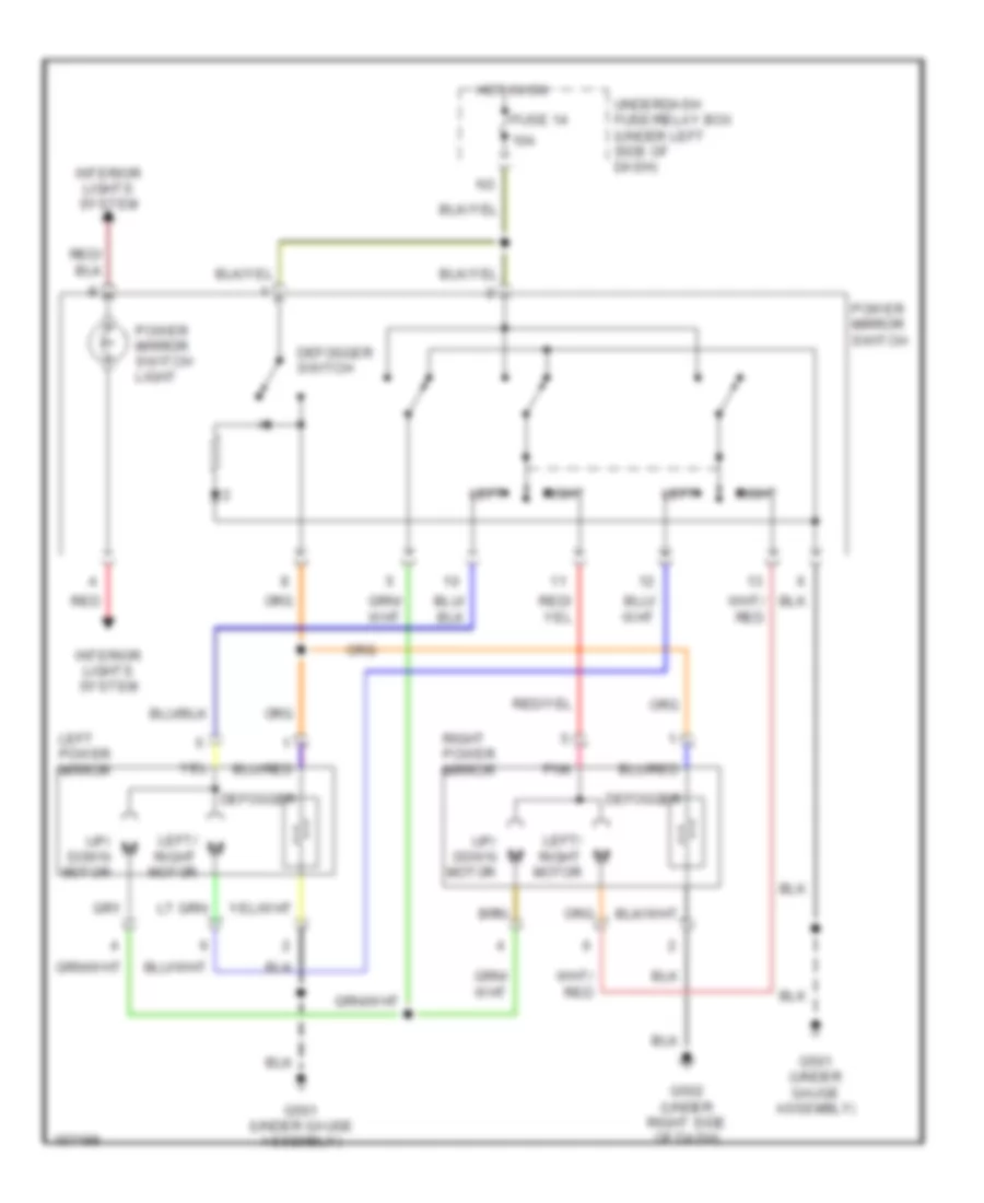
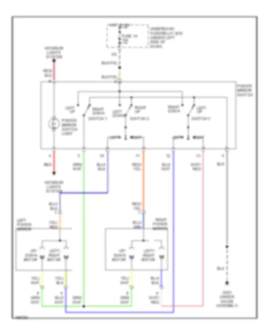
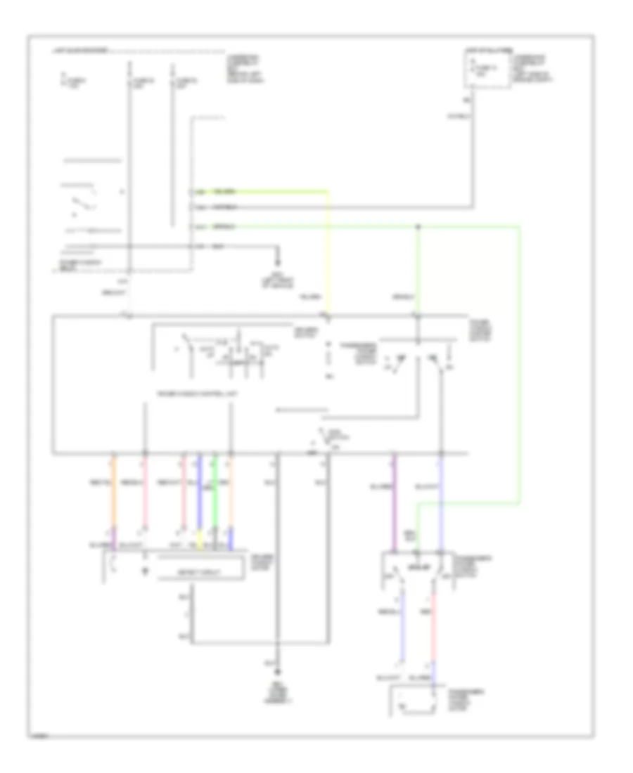
Heated Mirrors Wiring Diagram, Hatchback for Honda Civic HX 2004
List of elements for Heated Mirrors Wiring Diagram, Hatchback for Honda Civic HX 2004:
- (under gauge assembly) g501
- (under right side of dash) g502
- Defogger
- Defogger switch
- Fuse 14 10a
- Hot in on
- Left power mirror
- Power mirror switch
- Right power mirror
- Underdash fuse/relay box (under left side of dash)
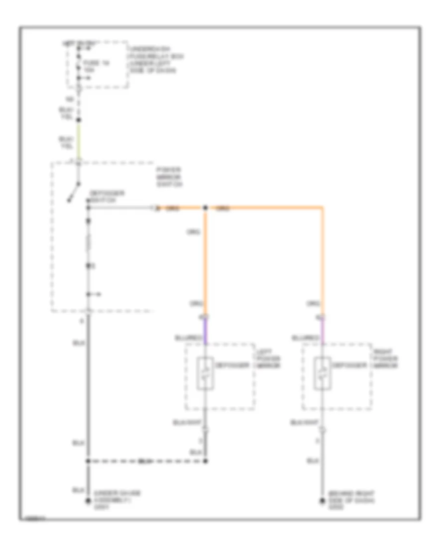
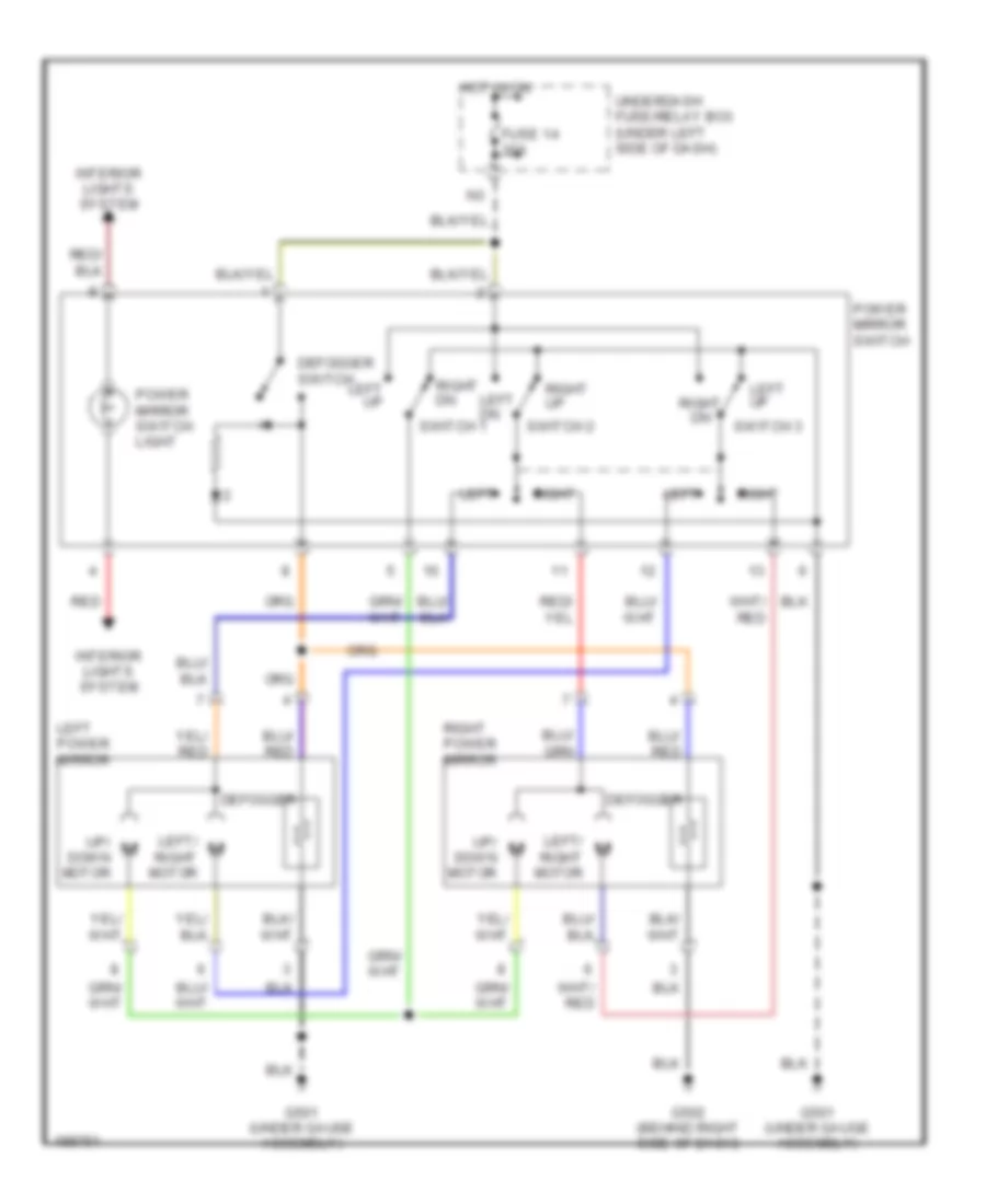
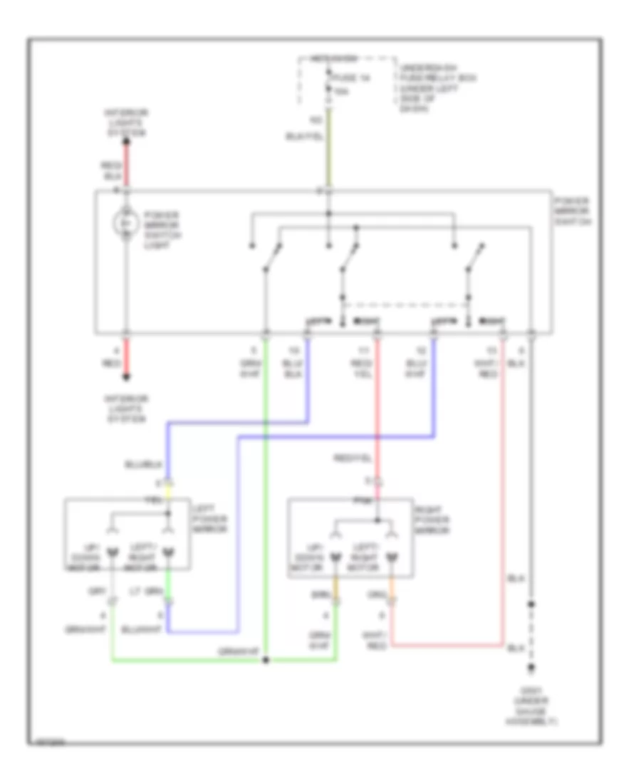
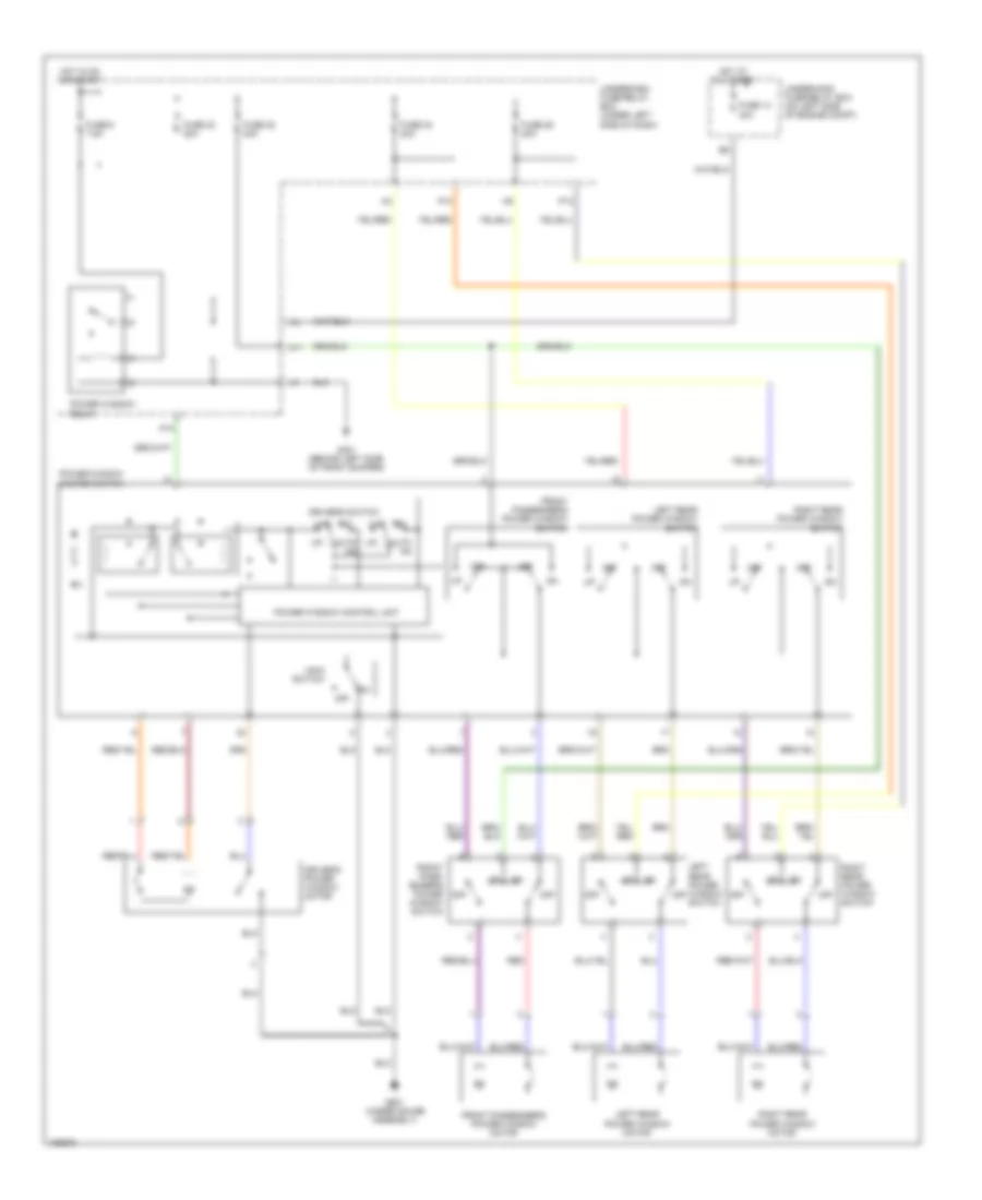
Heated Mirrors Wiring Diagram, Hybrid for Honda Civic HX 2004
List of elements for Heated Mirrors Wiring Diagram, Hybrid for Honda Civic HX 2004:
- (behind right side of dash) g502
- (under gauge assembly) g501
- Defogger
- Defogger switch
- Fuse 14 10a
- Hot in on
- Left power mirror
- Power mirror switch
- Right power mirror
- Underdash fuse/relay box (under left side of dash)
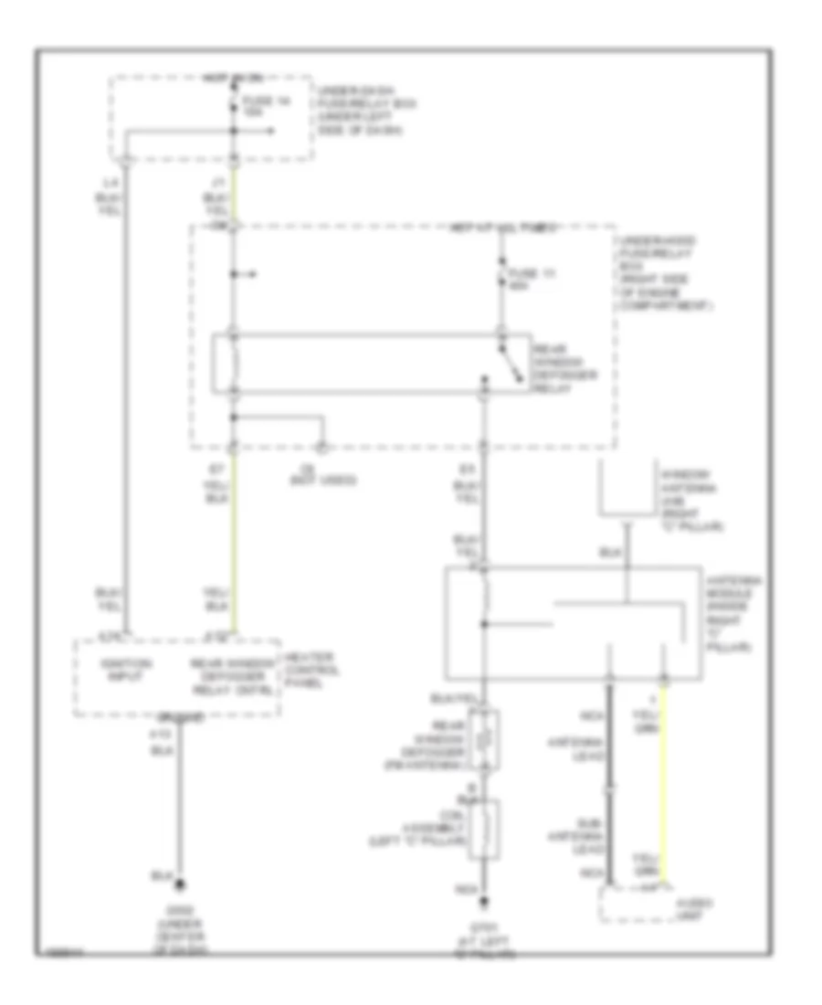
Rear Defogger Wiring Diagram, Coupe for Honda Civic HX 2004
List of elements for Rear Defogger Wiring Diagram, Coupe for Honda Civic HX 2004:
- (not used)
- A12
- A13
- A14
- Antenna lead
- Antenna module (inside
- Audio unit
- Coil assembly (left "c" pillar)
- Fuse 11 40a
- Fuse 14 10a
- G502 (under center of dash)
- G701 (at left "c" pillar)
- Ground
- Heater control panel
- Hot at all times
- Hot in on
- Ignition input
- Nca
- Rear window defogger (fm antenna)
- Rear window defogger relay
- Rear window defogger relay cntrl
- Right "c" pillar)
- Sub- antenna lead
- Under-dash fuse/relay box (under left side of dash)
- Under-hood fuse/relay box (right side of engine compartment)
- Window antenna (am) (right "c" pillar)
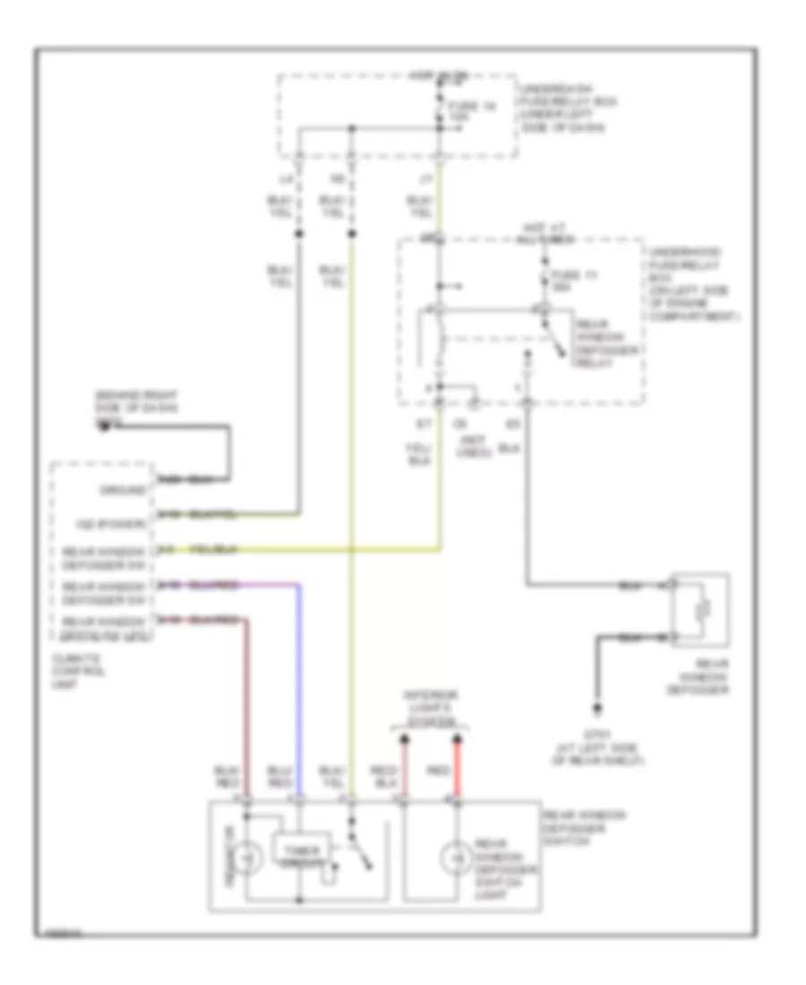
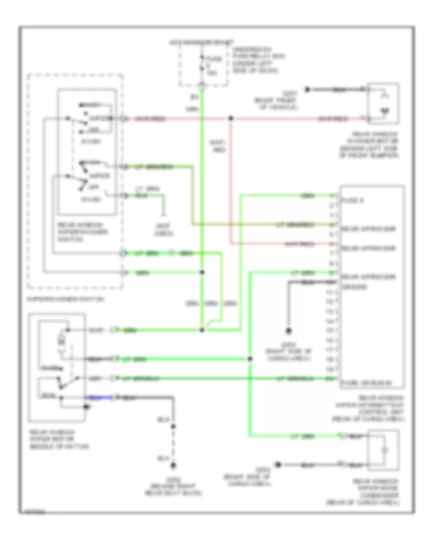
Rear Defogger Wiring Diagram, Hatchback for Honda Civic HX 2004
List of elements for Rear Defogger Wiring Diagram, Hatchback for Honda Civic HX 2004:
- (not used)
- A12
- A13
- A14
- Air cond- itioning system
- B14
- B21
- Fuse 11 30a
- Fuse 14 10a
- G501 (under gauge assembly)
- G552 (behind right rear seat back)
- Ground
- Heater control unit panel
- Hot at all times
- Hot in on
- Ign
- Ignition input
- Rear defog led cntrl
- Rear defog on input
- Rear window defogger
- Rear window defogger noise condenser
- Rear window defogger relay
- Rear window defogger relay cntrl
- Recir-a/c rear defogger switch assembly
- Underdash fuse/relay box (under left side of dash)
- Underhood fuse/relay box (right side of engine compartment)
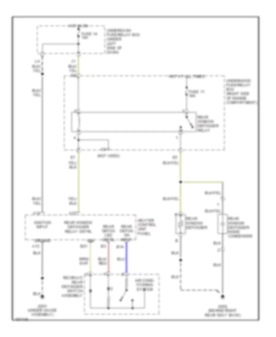
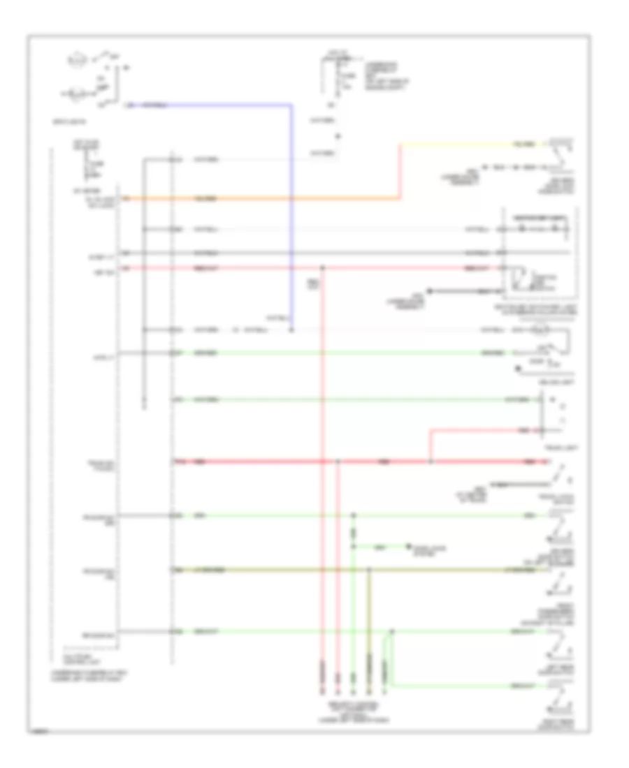
Rear Defogger Wiring Diagram, Hybrid for Honda Civic HX 2004
List of elements for Rear Defogger Wiring Diagram, Hybrid for Honda Civic HX 2004:
- (behind right side of dash) g502
- (not used)
- A10
- A18 rear window defogger sw
- A19 rear window defog sw led
- A20
- A5 rear window defogger sw
- Climate control unit
- Fuse 11 30a
- Fuse 14 10a
- G701 (at left side of rear shelf)
- Ground
- Hot at all times
- Hot in on
- Ig2 (power)
- Indicator
- Interior lights system
- Rear window defogger
- Rear window defogger relay
- Rear window defogger switch
- Rear window defogger switch light
- Red
- Timer circuit
- Underdash fuse/relay box (under left side of dash)
- Underhood fuse/relay box (on left side of engine compartment)
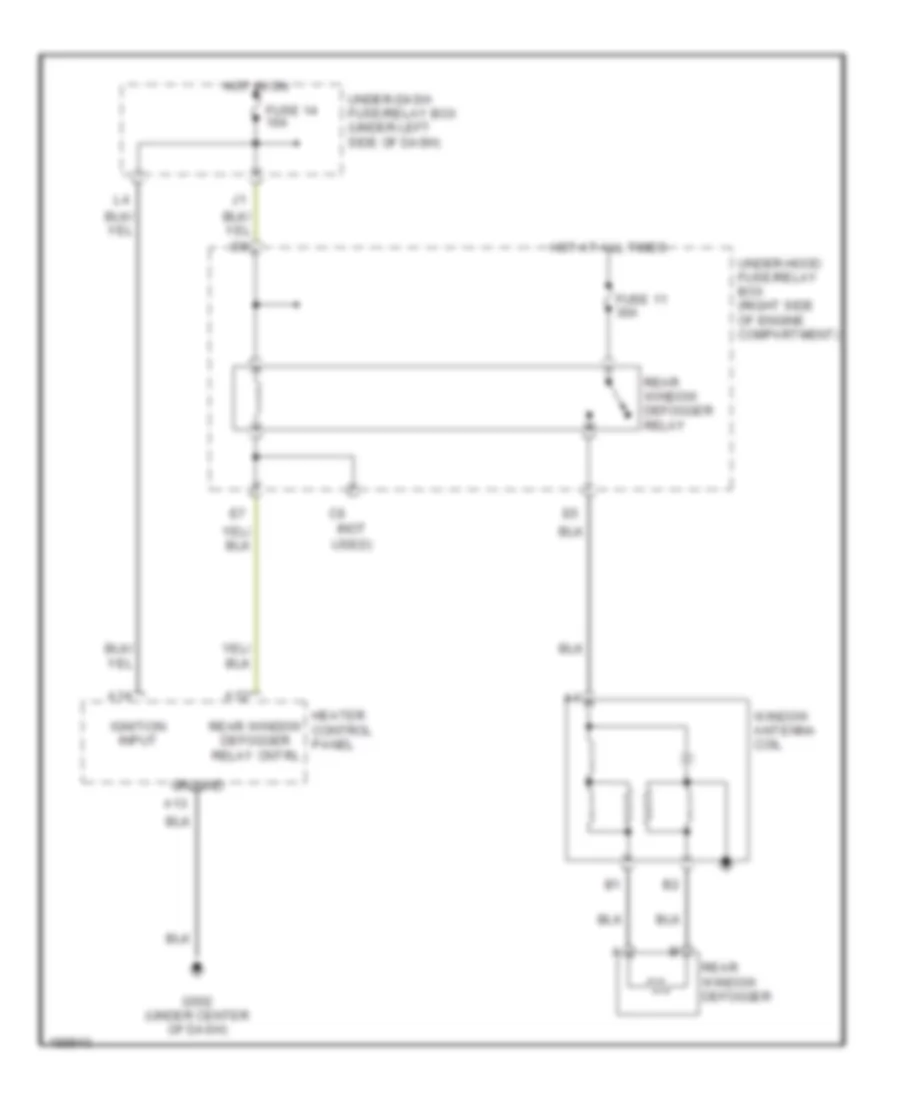
Rear Defogger Wiring Diagram, Sedan for Honda Civic HX 2004
List of elements for Rear Defogger Wiring Diagram, Sedan for Honda Civic HX 2004:
- (not
- A12
- A13
- A14
- Fuse 11 30a
- Fuse 14 10a
- G502 (under center of dash)
- Ground
- Heater control panel
- Hot at all times
- Hot in on
- Ignition input
- Rear window defogger
- Rear window defogger relay
- Rear window defogger relay cntrl
- Under-dash fuse/relay box (under left side of dash)
- Under-hood fuse/relay box (right side of engine compartment)
- Used)
- Window antenna coil
ELECTRONIC POWER STEERING
Electronic Power Steering Wiring Diagram, Hatchback for Honda Civic HX 2004
List of elements for Electronic Power Steering Wiring Diagram, Hatchback for Honda Civic HX 2004:
- (not used)
- (under left side of dash)
- +bat
- A13
- A18
- C10
- C11
- C12
- C13
- C14
- C15
- C16
- C17
- C18
- C19
- C20
- Computer data lines system
- Cruise control unit (under left side of dash)
- D11
- Diag-h
- Driving circuit (vss out)
- E16
- E26
- Engine control module (ecm) (behind glove box)
- Eps control unit (under right side of dash)
- Eps indicator
- Eps motor (rear of engine compt)
- Eps torque sensor (left side of engine compt)
- Epsld
- Fuse 10 7.5a
- Fuse 18 60a
- G151 (under right side of dash)
- Gauge assembly
- Hot at all times
- Hot in on or start
- Ig1
- Nep
- O11
- Pnk
- Psw
- Red
- Scs
- Side of dash)
- T/s gnd
- T/sig
- Tachometer test connector (right side of engine compt)
- Underdash fuse/relay box
- Underdash fuse/relay box (under left
- Underdash fuse/relay box (under left side of dash)
- Underhood fuse box (right side of engine compt)
- Vcc1
- Vcc2
- Vsp
- Vss
- Vss (on trans- axle housing)
- Vt3
- Vt6
- Wlp
Electronic Power Steering Wiring Diagram, Hybrid for Honda Civic HX 2004
List of elements for Electronic Power Steering Wiring Diagram, Hybrid for Honda Civic HX 2004:
- (cvt)
- (under left
- (under left side of dash)
- +bat
- A19
- A28
- Air conditioning system
- B10
- B12
- B13
- B17
- B20
- C10
- C11
- C12
- C13
- C14
- C15
- C16
- C17
- C18
- C19
- C20
- Carlink a4
- Clutch interlock switch
- Computer data lines system
- Cpu
- Cvt
- Cvt: atp np, m/t: cl sw
- D10
- D11
- Diag-h
- E26
- Engine control module (ecm) (behind glove box)
- Eps control unit (under right side of dash)
- Eps indicator
- Eps motor (middle of engine compt)
- Eps torque sensor (rear center of engine compt)
- Fuse 10 7.5a
- Fuse 18 60a
- G101 (at top left side of engine)
- G151 (under center of dash)
- G401 (under gauge assembly)
- Gauge assembly
- Glove box)
- Hot at all times
- Hot in on or start
- Housing)
- Ig1
- Intreface box (under middle of dash)
- Junction connector c106 (behind
- Junction connector c111 (on center of engine)
- M/t
- Multiplex control unit
- Nep
- Neutral position switch (on transaxle
- Pnk
- Red
- Scs
- Side of dash)
- T/s gnd
- T/sig
- T5 (thermal joint)
- Tcm (behind right kick panel)
- Test tachometer connector (left side of engine compt)
- Transmission range switch (on transaxle housing)
- Underdash fuse/relay box
- Underdash fuse/relay box (under left
- Underdash fuse/relay box (under left side of dash)
- Underhood fuse/relay box (on left side of engine compartment)
- Vcc1
- Vcc2
- Vsp
- Vt3
- Vt6
- Wlp
ENGINE PERFORMANCE
IMA Wiring Diagram (1 of 3) for Honda Civic HX 2004
List of elements for IMA Wiring Diagram (1 of 3) for Honda Civic HX 2004:
- (at center of trunk) g601
- (at top left side of engine) g101
- (behind glove box) mcm relay 1
- (behind glove box) mcm relay 2
- (m/t)
- (under front passenger's seat) g551
- (under gauge assembly) g501
- (under the mpi) j/c c801
- A10
- A11
- A12
- A13
- A14
- A15
- A16
- A17
- A18
- A19
- A20
- A21
- A22
- A23
- A24
- A25
- A26
- A27
- A28
- A29
- A30
- A31
- Absbusy
- Anti-lock brakes system
- B10
- B11
- B12
- B13
- B14
- B15
- B16
- B17
- B18
- B19
- B20
- B21
- B22
- B23
- B24
- Battery current sensor (behind right side of dash)
- Braided
- Charge ind
- Cma
- Cmb
- Cmc
- Cnt
- Computer data lines system
- Cpu
- Cylout
- D11
- Dvct
- Dvinh
- Fanctl
- Fuse 10a
- Fuse 7.5a
- G101
- G601
- Gauge assembly
- Hot at all times
- Hot in on or start
- Ig1
- Iga1
- Iga2
- Ighld
- Ighld2
- Ima ind
- Ima sys
- Ipu a
- Ipu fan module
- Ipua
- Isoc
- J/c c801 (under the mpi)
- K-line
- Lg1
- Lg2
- Mcm (behind glove box)
- Mota
- Motb
- Mpi module (behind right side of dash)
- Nca
- Nfan
- Pg1
- Pg2
- Pnk
- Pre
- Pwr +
- Pwr -
- Red
- Rscd
- Scs
- Sgcma
- Sgcmb
- Sgcmc
- Underdash fuse/relay box (under left side of dash)
- Underhood fuse/relay box (on left side of engine compt)
- Vbu
- Vcccma
- Vcccmb
- Vcccmc
- Warn
- Wen
IMA Wiring Diagram (2 of 3) for Honda Civic HX 2004
List of elements for IMA Wiring Diagram (2 of 3) for Honda Civic HX 2004:
- (at left rear side of passenger's floor) g651
- (at top left side of engine) g101
- (m/t)
- (middle of ipu) bypass contractor
- (middle of ipu) high voltage contractor
- (under front
- + terminal
- - terminal
- Braided
- By-pass resistor (left side of battery module)
- C13
- C15
- C21
- Capacitors
- Cvt
- Cylout
- Dc-dc converter
- Dvc
- E13
- E16
- E17
- Ecm (behind glove box)
- Fuse 10a
- Fuse 80a
- Hot at all times
- Hot in on or start
- J/c c106 (behind glove box)
- J/c c801 (under the mpi)
- M/t
- Mota
- Motb
- Motor commutation sensor (middle of engine compt)
- Mpi module (behind right side of dash)
- Nca
- Passenger's seat) g551
- Pdu
- Pnk
- Red
- Rscd
- Rscdc
- Sensor a
- Sensor b
- Sensor c
- Snubber unit
- T101
- Transmission control module
- Under dash fuse/ relay box (under left side of dash)
- Under hood fuse/ relay box (on left side of engine compt)
IMA Wiring Diagram (3 of 3) for Honda Civic HX 2004
List of elements for IMA Wiring Diagram (3 of 3) for Honda Civic HX 2004:
- (behind right side of dash) mpi module current sensor
- Battery module (behind right side of dash)
- Battery module fuse 100a
- Battery module switch
- C10
- C11
- C12
- C13
- C14
- C15
- C16
- C17
- Dc-dc converter
- Dc-dc converter fuse 20a
- E10
- E11
- E12
- E13
- E14
- E15
- E16
- E17
- E18
- E19
- E20
- E21
- E22
- F10
- F11
- F12
- F13
- F14
- Ipin
- Iuph
- Ivph
- Mcm (behind glove box)
- Motor stator
- Mpi module (behind right side of dash)
- Nca
- Pdu
- Ptc +
- Ptc -
- Red
- Sgdv
- Sgip
- Sgiu
- Sgiv
- Sgiw
- Sgtb
- Tbatt1
- Tbatt2
- Tbatt3
- Tdv
- U phase motor current sensor
- V phase motor current sensor
- Vccip
- Vcciu
- Vcciv
- Vcciw
- Vhb0
- Vhb1
- Vhb10
- Vhb11
- Vhb2
- Vhb3
- Vhb4
- Vhb5
- Vhb6
- Vhb7
- Vhb8
- Vhb9
- W phase motor current sensor
- Wph
- Y capacitor
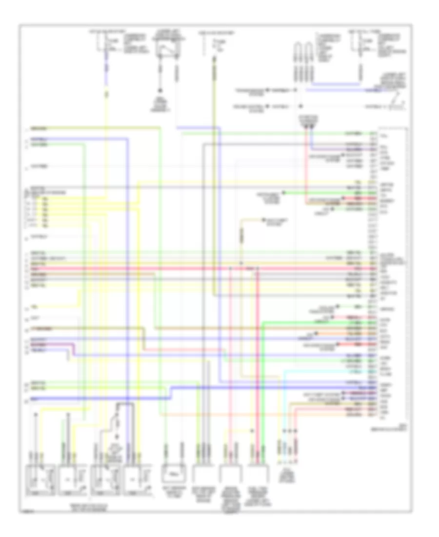
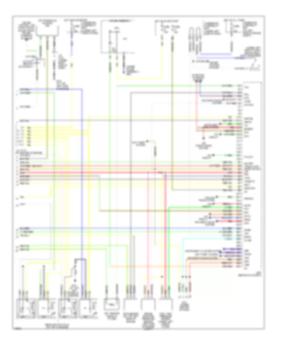
1.3L
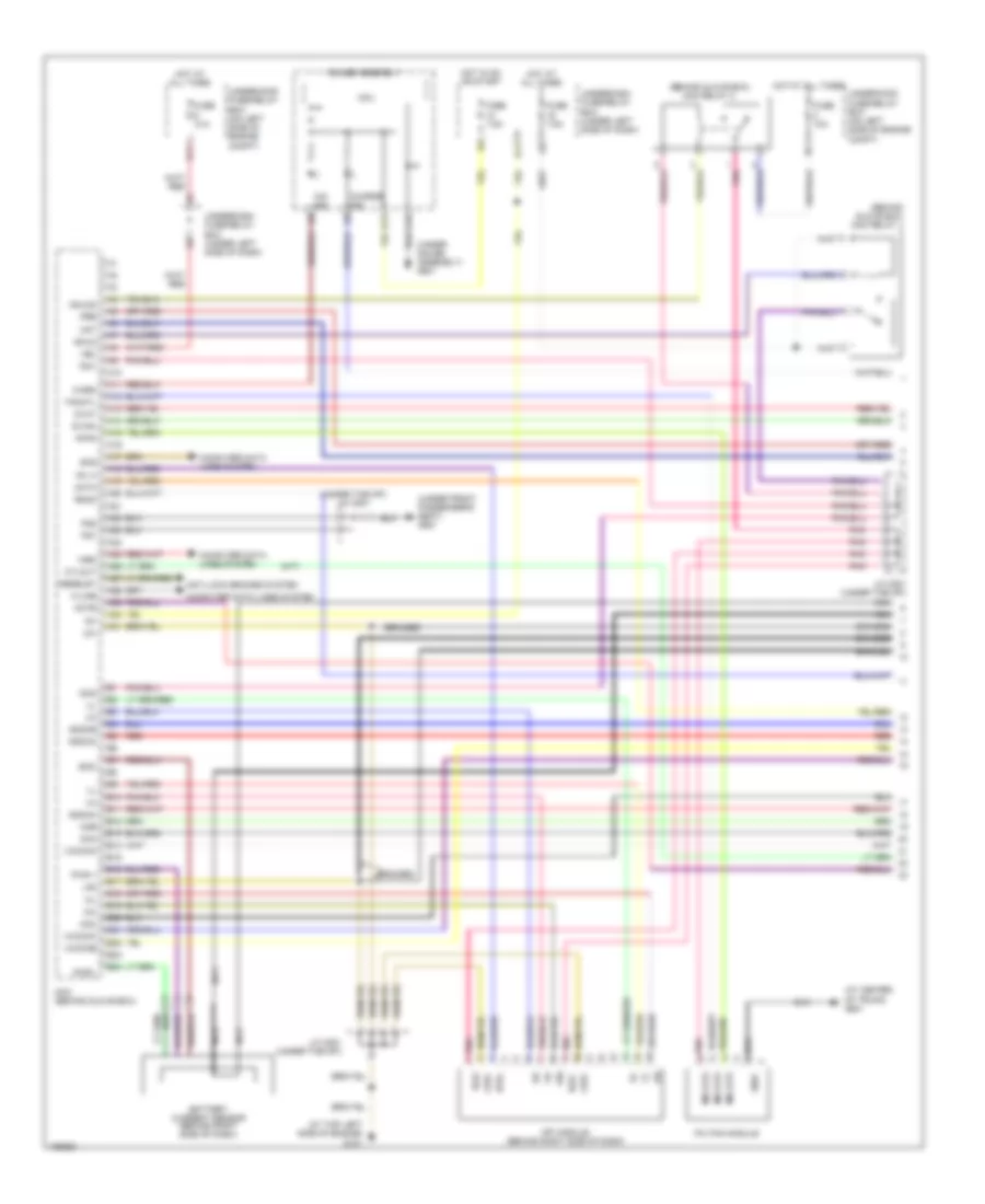
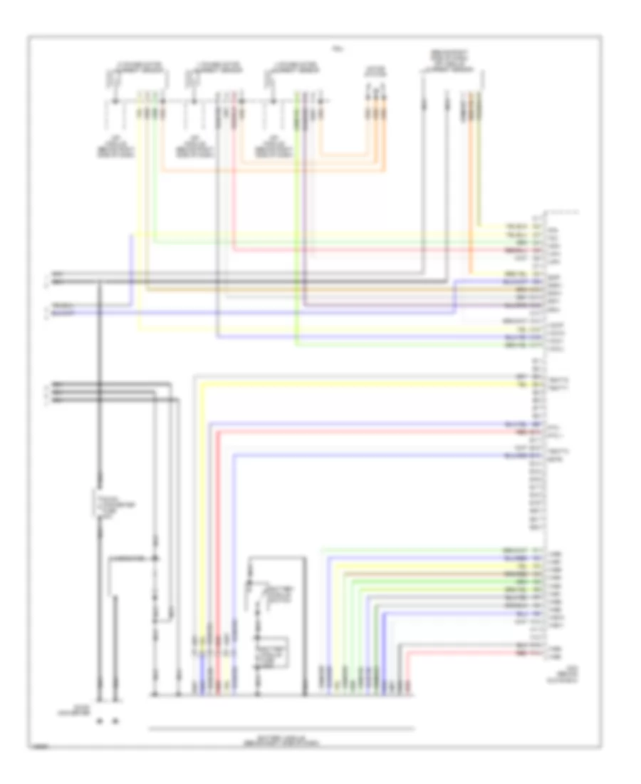
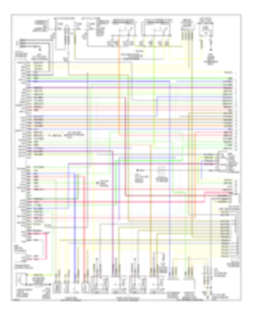
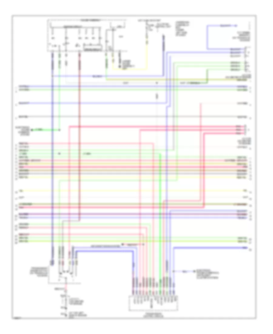
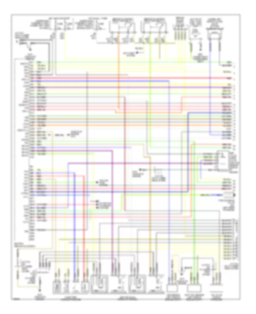
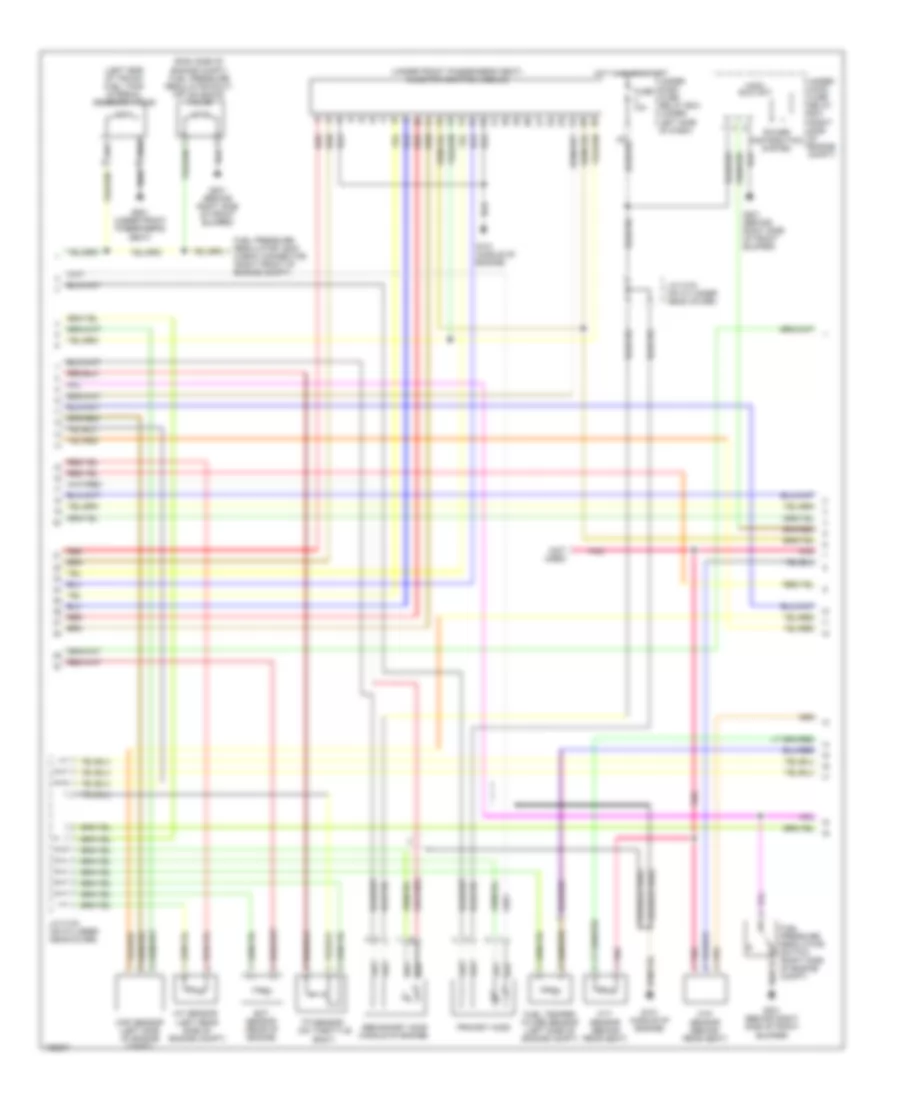
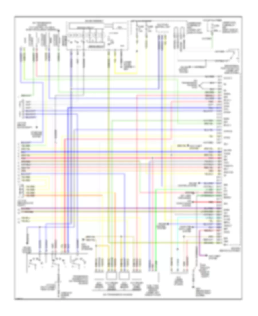
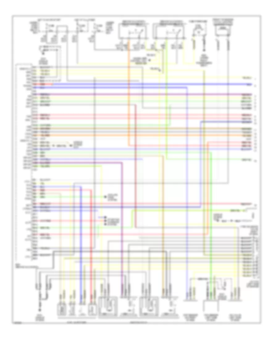
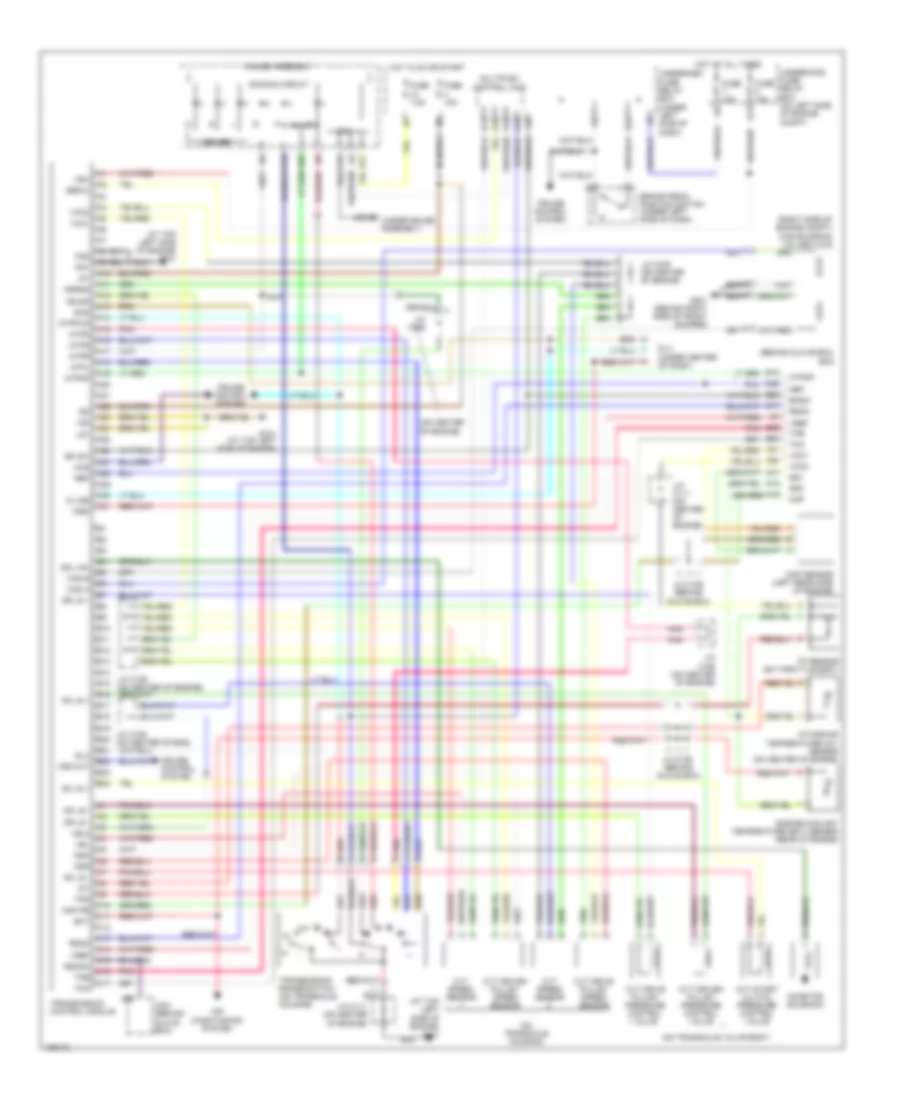
1.3L, Engine Performance Wiring Diagram, A/T (1 of 4) for Honda Civic HX 2004
List of elements for 1.3L, Engine Performance Wiring Diagram, A/T (1 of 4) for Honda Civic HX 2004:
- (-)
- (at top left side of engine) g101
- (behind glove box) j/c c106
- (behind glove box) pgm-fi main relay 1
- (in multi-fuse/relay box) pgm-fi main relay 2
- (on center of engine)
- (on center of engine) j/c c111
- (on top of fuel tank) fuel tank unit
- A10
- A11
- A12
- A13
- A14
- A15
- A16
- A17
- A18
- A19
- A20
- A21
- A22
- A23
- A24
- A25
- A26
- A27
- A28
- A29
- A30
- A31
- Afs (+)
- Afs (-)
- Afshtc +
- Afshtc a1
- Air conditioning & cooling fans systems
- Atpd
- Atpnp
- Atpr
- B10
- B11
- B12
- B13
- B14
- B15
- B16
- B17
- B18
- B19
- B20
- B21
- B22
- B23
- B24
- C16
- C17
- Camshaft position sensor (cmp) (on top rear of engine)
- Ckp
- Ckp sensor (on front of engine)
- Cmp
- Cooling fans system
- Ecm (behind glove box)
- Ect
- Egr
- Egr valve & egr valve position sensor (top front of engine)
- Egrp
- Fanc
- Front ignition coils (on top of engine)
- Fuel pump
- Fuse 15a
- G101 (at top left side of engine)
- G551 (under front passenger's seat)
- Hot at all times
- Hot in on or start
- Iac valve (left rear of eng)
- Iacv
- Iat
- Icm
- Igp1
- Igp2
- Igpls1
- Igpls1e
- Igpls2
- Igpls2e
- Igpls3
- Igpls3e
- Igpls4
- Igpls4e
- Inj1
- Inj2
- Inj3
- Inj4
- Injectors (on top of engine)
- J/c c110 (on center of engine)
- J/c c111
- J/c c111 (on center of engine)
- Lg1
- Lg2
- Map
- Pcs
- Pg1
- Pg2
- Pnk
- Red
- Sg1
- Sg2
- Sho2s
- So2shtc
- Sulev
- Tma
- Tmb
- Tps
- Transmission control module
- Ulev
- Underdash fuse/relay box (under left side of dash)
- Underhood fuse/relay box (on left side of engine compt)
- Vcc1
- Vcc2
- Vel2
- Vtec solenoid valve (left rear of engine)
- Vts
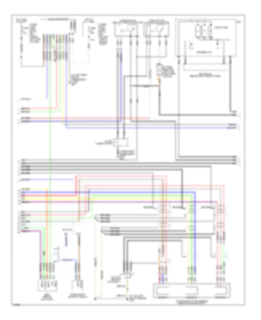
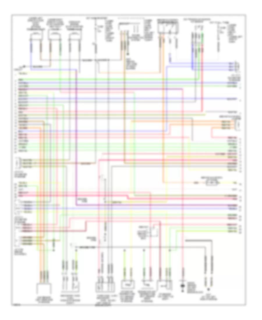
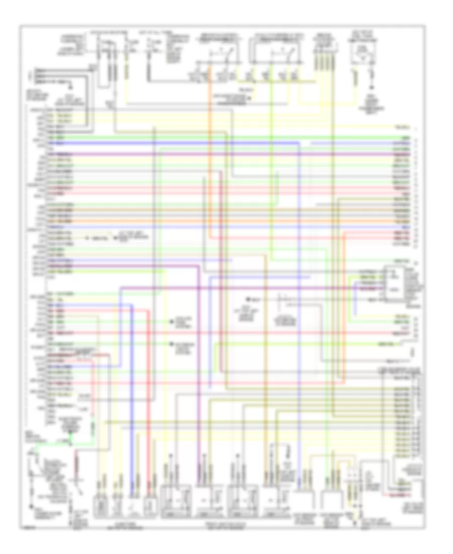
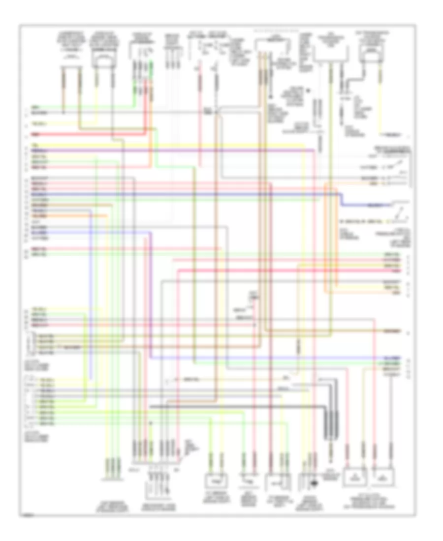
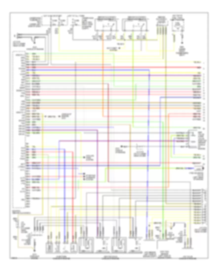
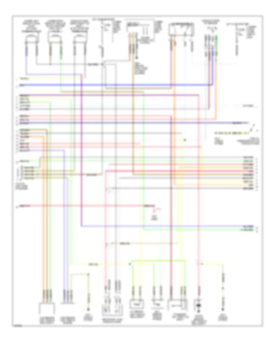
1.3L, Engine Performance Wiring Diagram, A/T (2 of 4) for Honda Civic HX 2004
List of elements for 1.3L, Engine Performance Wiring Diagram, A/T (2 of 4) for Honda Civic HX 2004:
- (behind glove box) a/f diode
- (behind glove box) a/f sensor relay
- (behind glove box) j/c c106
- (middle of engine) evap canister purge valve
- (on transaxle housing) a/f sensor
- (sulev)
- (ulev)
- (under left side of floor) (ulev) evap by-pass solenoid valve
- (under right side of floor) evap canister vent shut valve
- Braided wire
- Eld unit
- Engine coolant temperature (ect) sensor (rear of engine)
- Fuse 10a
- Fuse 20a
- G101 (at top left side of engine)
- G301 (behind left side of front bumper)
- Hot at all times
- Hot in on or start
- Ima circuit
- Intake air temperature (iat) sensor (on center of engine)
- J/c c111 (on center of engine)
- J/c c106 (behind glove box)
- J/c c110 (on center of engine)
- J/c c111 (on center of engine)
- Knock sensor (on left side of engine block)
- Map sensor (left rear side of engine)
- Pnk
- Power distribution system
- Red
- Secondary ho2s (left side of engine compt)
- Secondary ho2s (ulev) (middle of engine compt)
- Third ho2s
- Tp sensor (on throttle body)
- Under dash fuse/ relay box (under left side of dash)
- Under hood fuse/ relay box (on left side of engine compt)
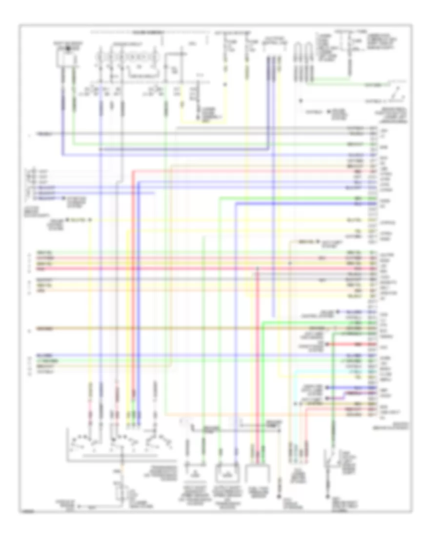
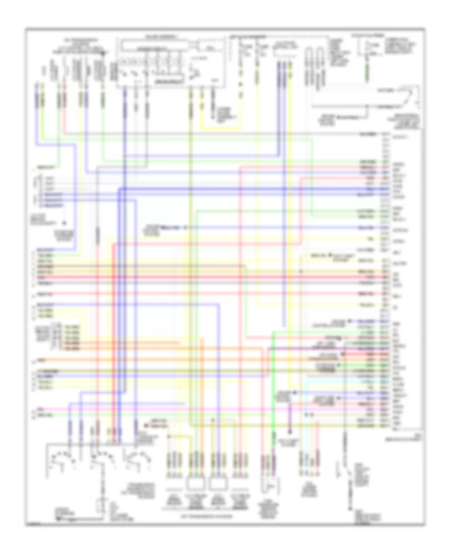
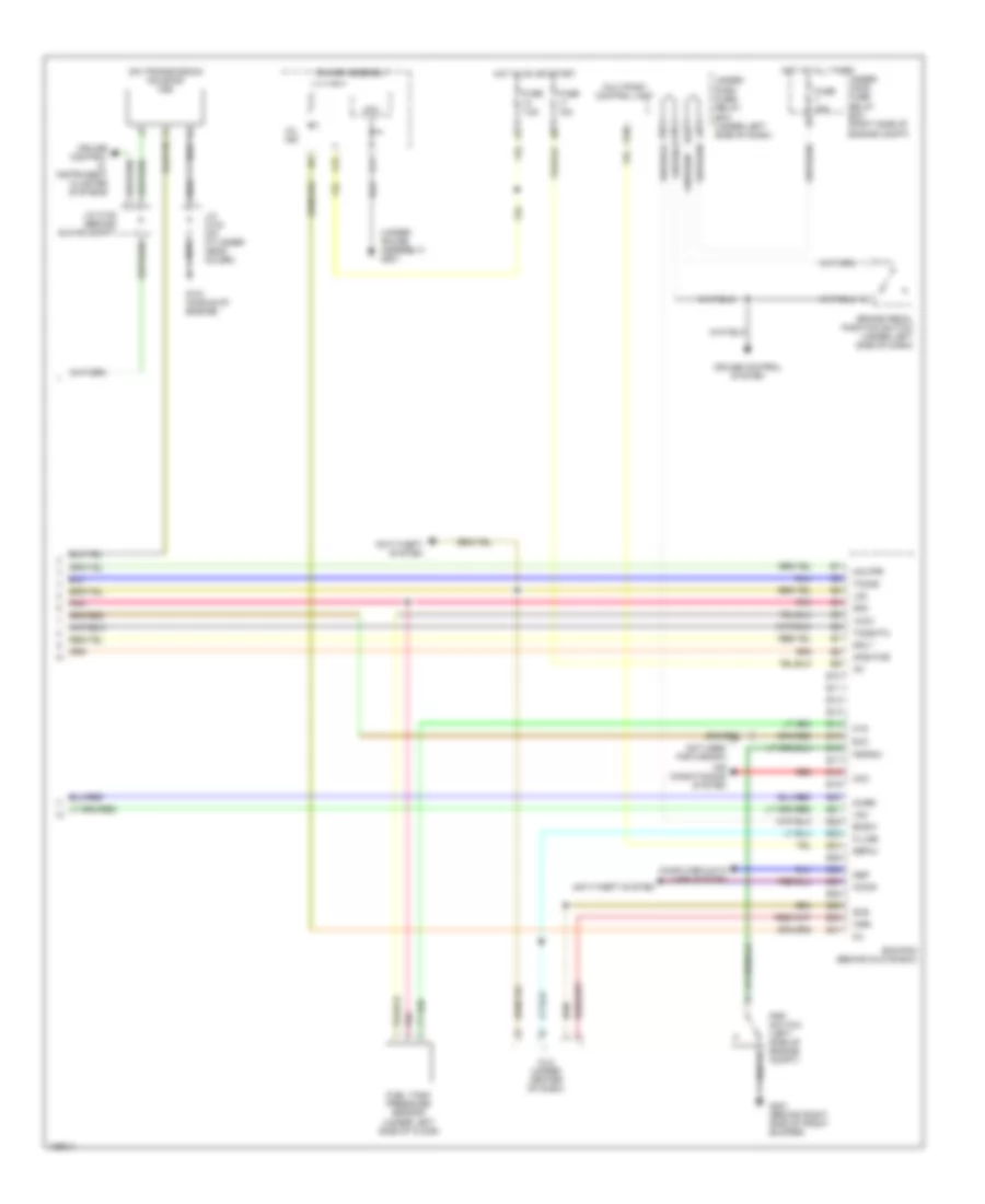
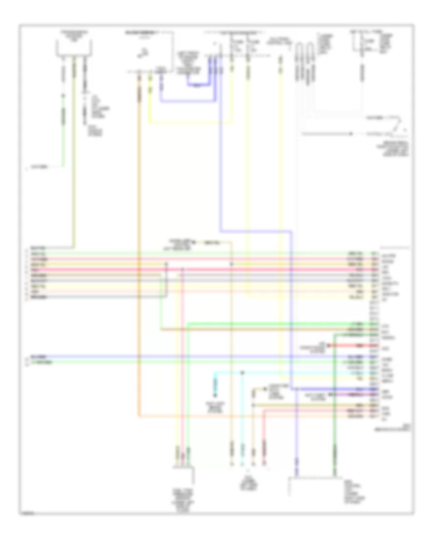
1.3L, Engine Performance Wiring Diagram, A/T (3 of 4) for Honda Civic HX 2004
List of elements for 1.3L, Engine Performance Wiring Diagram, A/T (3 of 4) for Honda Civic HX 2004:
- (at top left side of engine) g101
- (under gauge assembly) g501
- A15
- A16
- A17
- A18
- A19
- A28
- Air conditioning system
- Atp d
- Atp l
- Atp np
- Atp r
- Atp s
- B10
- B17
- B20
- C10
- C11
- C13
- C14
- Cpu
- Cvt speed sensor 2 (on transaxle housing)
- D10
- Dimming circuit
- Drive circuit
- Ect
- Electronic power steering & instrument cluster systems
- Electronic power steering system
- Fuse 7.5a
- Gauge assembly
- Hot in on or start
- Iat
- J/c c109 (on center of engine)
- J/c c111 (on center of engine)
- Map (pb)
- Mil ind
- Multiplex control unit
- Nep
- Pnk
- Red
- Rscd
- Tps
- Transmission control module
- Transmission range switch (on transaxle housing)
- Underdash fuse/relay box (under left side of dash)
- Vel2
- Vref
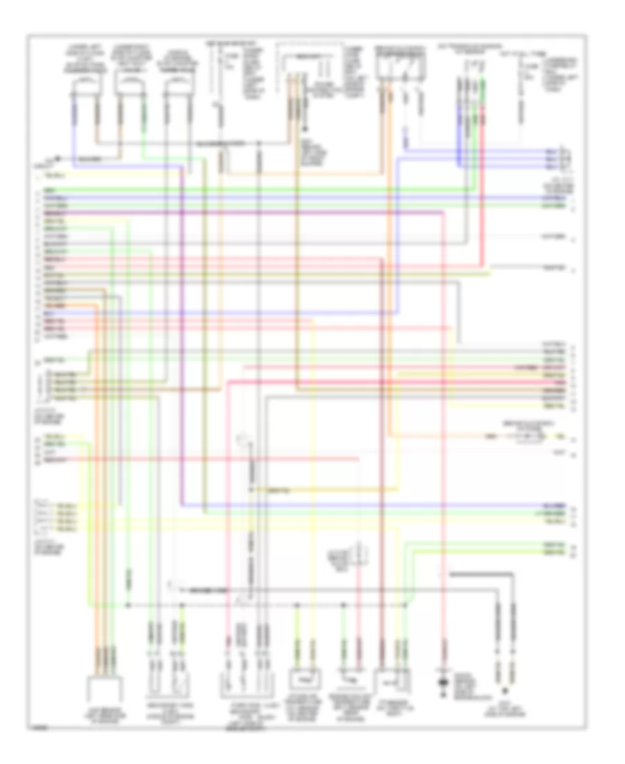
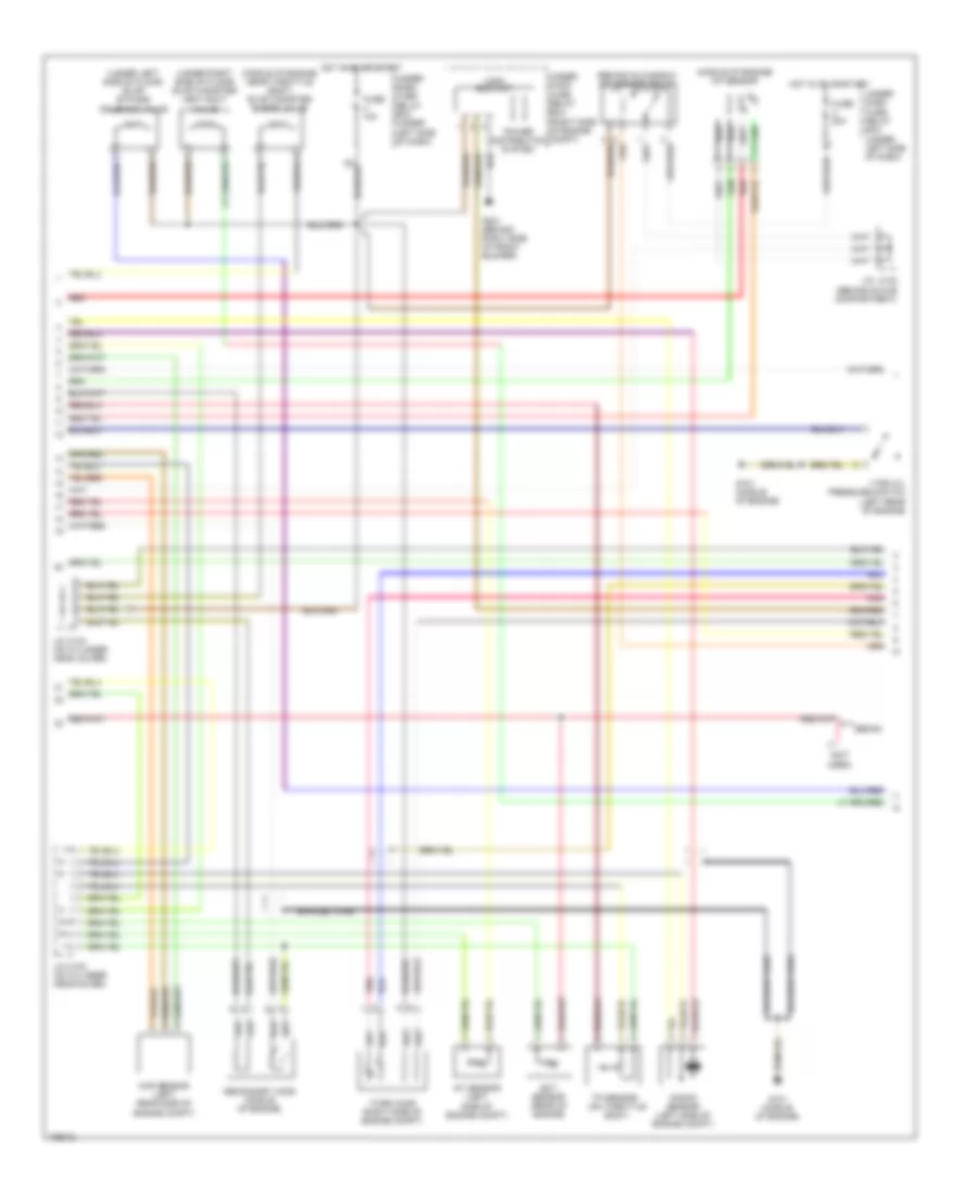
1.3L, Engine Performance Wiring Diagram, A/T (4 of 4) for Honda Civic HX 2004
List of elements for 1.3L, Engine Performance Wiring Diagram, A/T (4 of 4) for Honda Civic HX 2004:
- (on center of engine) j/c c110
- (ulev) (sulev)
- (under left side of dash) brake pedal position switch
- (under left side of dash) idle stop switch
- 2wbs
- Acc
- Acs
- Afshtcr
- Air conditioning system
- Anti-theft system
- Bksw
- Brake booster pressure sensor (left side of engine compt)
- C10
- C11
- C12
- C13
- C14
- C15
- C16
- C17
- C18
- C19
- C20
- C21
- C22
- Cooling fans system
- Cruise control system
- Dlc (under center of dash)
- Dvc
- E10
- E11
- E12
- E13
- E14
- E15
- E16
- E17
- E18
- E19
- E20
- E21
- E22
- E23
- E24
- E25
- E26
- E27
- E28
- E29
- E30
- E31
- Ecm (behind glove box)
- Eld
- Engrdy
- Eop sensor (on top left rear of engine)
- Eot sensor (near oil filter)
- Ftp
- Fuel tank pressure sensor (under left side of floor)
- Fuse 15a
- G101 (at top left side of engine)
- G501 (under gauge assembly)
- Ho2shtc
- Hot at all times
- Hot in on or start
- Hrfanc
- Htrs
- Icm
- Idssw
- Ig1
- Igrtne
- Igrtni
- Ima circuit
- Imo fpr tho2s sho2s lg3
- Imocd
- Instrument cluster system
- K-line
- M/p mon
- Mil
- Mota
- Motb
- Mrly
- Nep
- P12
- Pnk
- Poil
- Rear ignition coils (on top of engine)
- Red
- Rscd
- Scs
- Sg3
- Starting/ charging system
- Stc
- Sts
- Tim
- Toil
- Transmissions system
- Underdash fuse/relay box (under left side of dash)
- Underhood fuse/relay box (on left side of engine compt)
- Vcc3
- Vref
- Vsv
- Wen
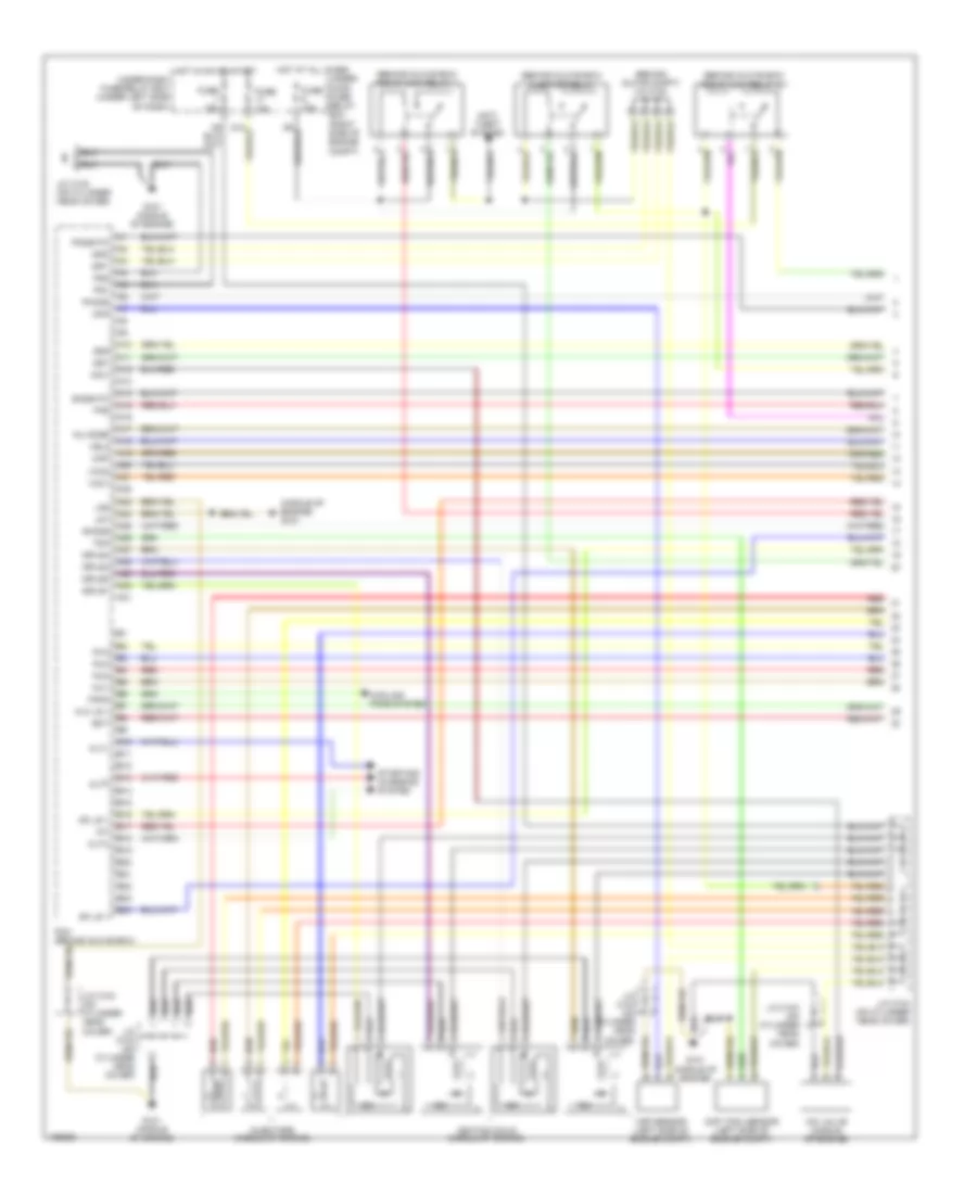
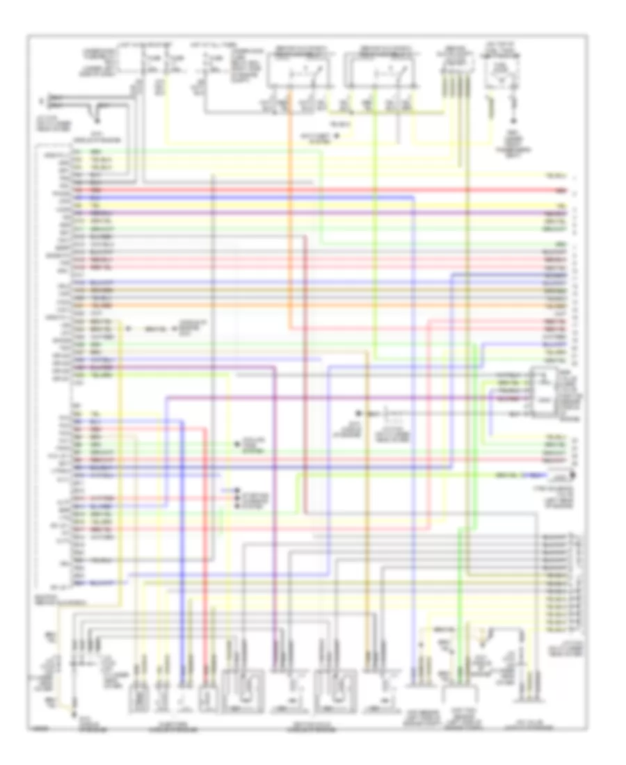
1.3L, Engine Performance Wiring Diagram, M/T (1 of 3) for Honda Civic HX 2004
List of elements for 1.3L, Engine Performance Wiring Diagram, M/T (1 of 3) for Honda Civic HX 2004:
- (at top left side of engine) g101
- (behind glove box)
- (behind glove box) j/c c106
- (behind glove box) pgm-fi main relay 1
- (in multi-fuse/relay box) pgm-fi main relay 2
- (on center of engine)
- (on top of fuel tank) fuel tank unit
- A1 afshtc (-) igp2
- A10
- A11
- A12
- A13
- A14
- A15
- A16
- A17
- A18
- A19
- A20
- A21
- A22
- A23
- A24
- A25
- A26
- A27
- A28
- A29
- A30
- A31
- Afs (+)
- Afs (-)
- Afshtc +
- Air conditioning & cooling fans systems
- Altf
- B10
- B11
- B12
- B13
- B14
- B15
- B16
- B17
- B18
- B19
- B20
- B21
- B22
- B23
- B24
- Ckp
- Ckp sensor (on front of engine)
- Clutch interlock switch (under left side of dash)
- Cmp
- Cmp sensor (on top rear of engine)
- Cooling fans system
- D12
- Ecm (behind glove box)
- Ect
- Egr
- Egr valve & egr valve position sensor (top front of engine)
- Egrp
- Electronic power steering system
- Exterior lights system
- Fanc
- Front ignition coils (on top of engine)
- Fuel pump
- Fuse 15a
- G101 (at top left side of engine)
- G401 (under gauge assembly)
- G551 (under front passenger's seat)
- Hot at all times
- Hot in on or start
- Iac valve (left rear of engine)
- Iacv
- Iat
- Icm
- Igp1
- Igpls1
- Igpls1e
- Igpls2
- Igpls2e
- Igpls3
- Igpls3e
- Igpls4
- Igpls4e
- Inj1
- Inj2
- Inj3
- Inj4
- Injectors (on top of engine)
- J/c c106
- J/c c110 (middle of engine)
- J/c c111
- J/c c111 (on center of eng)
- J/c c111 j/c c111 (on center of engine)
- Lg1
- Lg2
- Map
- Neutral position switch (on transaxle housing)
- Ntsw
- Pcs
- Pg1
- Pg2
- Red
- Rvssw
- Sg1
- Sg2
- Sho2s
- So2shtc
- Sulev
- Tps
- Ulev
- Underdash fuse/relay box (under left side of dash)
- Underhood fuse/relay box (on left side of engine compt)
- Vbu
- Vcc1
- Vcc2
- Vss
- Vtec solenoid valve (left rear of engine)
- Vts
1.3L, Engine Performance Wiring Diagram, M/T (2 of 3) for Honda Civic HX 2004
List of elements for 1.3L, Engine Performance Wiring Diagram, M/T (2 of 3) for Honda Civic HX 2004:
- (behind glove box) a/f diode
- (behind glove box) a/f sensor relay
- (middle of engine) evap canister purge valve
- (on transaxle housing) a/f sensor
- (sulev)
- (ulev)
- (under left side of floor) (ulev) evap by-pass solenoid valve
- (under right side of floor) evap canister vent shut valve
- Braided
- Braided wire
- Eld unit
- Engine coolant temperature (ect) sensor (rear of engine)
- Fuse 10a
- Fuse 20a
- G101 (at top left side of engine)
- G301 (behind left side of front bumper)
- Hot at all times
- Hot in on or start
- Ima circuit
- Intake air temperature (iat) sensor (on center of engine)
- J/c c111 (on center of engine)
- J/c c106 (behind glove box)
- J/c c110 (on center of engine)
- J/c c111 (on center of engine)
- Knock sensor (on left side of engine block)
- Map sensor (left rear side of engine)
- Pnk
- Power distribution system
- Red
- Secondary ho2s (left side of engine compt)
- Secondary ho2s (ulev) (middle of engine compt)
- Third ho2s
- Tp sensor (on throttle body)
- Under dash fuse/ relay box (under left side of dash)
- Under hood fuse/ relay box (on left side of engine compt)
- Underdash fuse/relay box (under left side of dash)
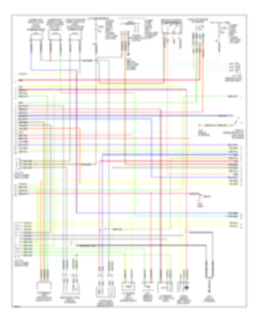
1.3L, Engine Performance Wiring Diagram, M/T (3 of 3) for Honda Civic HX 2004
List of elements for 1.3L, Engine Performance Wiring Diagram, M/T (3 of 3) for Honda Civic HX 2004:
- (on transaxle housing) vss
- (ulev) (sulev)
- (under gauge assembly) g501
- (under left side of dash) brake pedal position switch
- 2wbs
- A17
- Acc
- Acs
- Afshtcr
- Air conditioning system
- Anti-theft system
- B17
- Bksw
- Brake booster pressure sensor (left side of engine compt)
- C10
- C11
- C12
- C13
- C14
- C15
- C16
- C17
- C18
- C19
- C20
- C21
- C22
- Cooling fans system
- Cpu
- Cruise control system
- Cruise control, air conditioning, & electronic power steering systems
- Cylout
- Dlc (under center of dash)
- Dvc
- E10
- E11
- E12
- E13
- E14
- E15
- E16
- E17
- E18
- E19
- E20
- E21
- E22
- E23
- E24
- E25
- E26
- E27
- E28
- E29
- E30
- E31
- Ecm (behind glove box)
- Eld
- Engrdy
- Eop sensor (on top left rear of engine)
- Eot sensor (near oil filter)
- Ftp
- Fuel tank pressure sensor (under left side of floor)
- Fuse 15a
- Fuse 7.5a
- G101 (at top left side of engine)
- Gauge assembly
- Hot at all times
- Hot in on or start
- Hrfanc
- Htrs
- Icm
- Ig1
- Igrtne
- Igrtni
- Ima circuit
- Imo fpr tho2s sho2s lg3
- Imocd
- Instrument cluster system
- J/c c110 (on center of engine)
- J/c c103 (under right side of dash)
- J/c c106 (behind glove box)
- K-line
- M/p mon
- Mil
- Mil ind
- Mota
- Motb
- Mrly
- Nep
- P12
- Pnk
- Poil
- Rear ignition coils (on top of engine)
- Red
- Rscd
- Scs
- Sg3
- Starting/ charging system
- Stc
- Sts
- Tim
- To2shtc
- Toil
- Underdash fuse/relay box (under left side of dash)
- Underhood fuse/relay box (on left side of engine compt)
- Vcc3
- Vsv
- Wen
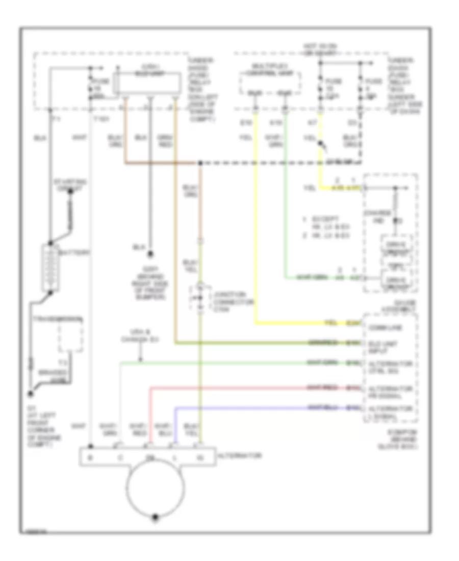
1.7L
1.7L, Engine Performance Wiring Diagram, Except HX & GX (1 of 3) for Honda Civic HX 2004
List of elements for 1.7L, Engine Performance Wiring Diagram, Except HX & GX (1 of 3) for Honda Civic HX 2004:
- (behind glove box) pgm-fi main relay 1
- (behind glove box) pgm-fi main relay 2
- (behind glove compt) j/c c102
- (middle of engine) g101
- (on top of fuel tank) fuel tank unit
- (under left side of floor) evap bypass solenoid valve
- A10
- A11
- A12
- A13
- A14
- A15
- A16
- A17
- A18
- A19
- A20
- A21
- A22
- A23
- A24
- A25
- A26
- A27
- A28
- A29
- A30
- A31
- Afs (+)
- Afs (-)
- Afshtc
- Afshtc (+)
- Altc
- Altf
- Altl
- Anti-theft system
- B10
- B11
- B12
- B13
- B14
- B15
- B16
- B17
- B18
- B19
- B20
- B21
- B22
- B23
- B24
- Ckp
- Ckp sensor (left side of engine compt)
- Cmp (tdc) sensor (left side of engine compt)
- Cooling fans system
- Ecm/pcm (behind glove box)
- Ect
- Egr
- Egr valve & egr valve position sensor (middle of engine)
- Egrp
- Fanc
- Fuel pump
- Fuse 15a
- G101 (middle of engine)
- G551 (under front passenger's seat)
- Hot at all times
- Hot in on or start under-dash fuse/relay box (under left side of dash)
- Iac valve (middle of engine)
- Iacv
- Iat
- Icm
- Ignition coils (middle of engine)
- Igp1
- Igp2
- Igpls1
- Igpls2
- Igpls3
- Igpls4
- Inj1
- Inj2
- Inj3
- Inj4
- Injectors (middle of engine)
- J/c c103 (on cylinder head cover)
- J/c c104 (on cylinder head cover)
- Lg1
- Lg2
- Lsa+
- Lsb+
- Map
- Pg1
- Pg2
- Red
- Sg1
- Sg2
- Sho2s
- So2shtc
- Starting/ charging system
- Tdc
- Tps
- Under-hood fuse/relay box (right side of engine compt)
- Vbu
- Vcc1
- Vcc2
- Vccr
- Vss
- Vtec solenoid valve (ex) (left rear of engine)
- Vtpsw
- Vts
1.7L, Engine Performance Wiring Diagram, Except HX & GX (2 of 3) for Honda Civic HX 2004
List of elements for 1.7L, Engine Performance Wiring Diagram, Except HX & GX (2 of 3) for Honda Civic HX 2004:
- (behind glove box) a/f sensor relay
- (behind glove compt) j/c c102
- (middle of engine) a/f sensor
- (middle of engine, near throttle body) evap canister purge valve
- (not used)
- (on transmission housing) tcc solenoid valve
- (on transmission housing) vss
- (under right side of floor) evap canister vent shut valve
- (usa) eld unit
- A/t clutch pressure control solenoid valves (on transmission housing)
- Braided wire
- Cruise control & instrument cluster systems
- Dx/lx
- Ect sensor (rear of engine)
- Fuse 10a
- Fuse 20a
- G101 (middle of engine)
- G201 (behind right side of front bumper)
- Hot at all times
- Hot in on or start
- Iat sensor (left side of engine compt)
- J/c c102 (behind glove compt)
- J/c c103 (on cylinder head cover)
- J/c c104 (on cylinder head cover)
- Knock sensor (left side of engine compt)
- Map sensor (left rear side of engine compt)
- Not used except ex
- Pnk
- Power distribution system
- Red
- Secondary ho2s (middle of engine)
- Sedan
- Tp sensor (on throttle body)
- Under- dash fuse/ relay box (under left side of dash)
- Under- hood fuse/ relay box (right side of engine compt)
- Vtec oil pressure switch (ex) (left rear of engine)
1.7L, Engine Performance Wiring Diagram, Except HX & GX (3 of 3) for Honda Civic HX 2004
List of elements for 1.7L, Engine Performance Wiring Diagram, Except HX & GX (3 of 3) for Honda Civic HX 2004:
- (ex)
- (middle of engine) g101
- (not used for canada)
- (under gauge assembly) g501
- 2wbs
- A11
- A15
- A16
- A17
- Acc
- Afshtcr
- Air conditioning system
- Anti-theft system
- Atp2
- Atpd3
- Atpd4
- Atpfwd
- Atpnp
- Atpr
- B11
- B17
- B21
- Bksw
- Braided wire
- Brake pedal position switch (under left side of dash)
- C10
- C11
- C12
- C13
- C14
- C15
- C16
- C17
- C18
- C19
- C20
- C21
- C22
- Ccs
- Computer data lines system
- Cpu
- Cruise control system
- D10
- Dimming circuit
- Dlc (under center of dash)
- Drive circuit
- E10
- E11
- E12
- E13
- E14
- E15
- E16
- E17
- E18
- E19
- E20
- E21
- E22
- E23
- E24
- E25
- E26
- E27
- E28
- E29
- E30
- E31
- Ecm/pcm (behind glove box)
- Eld
- Ftp
- Fuel tank pressure sensor
- Fuse 15a
- Fuse 7.5a
- G101 (middle of engine)
- G201 (behind right side of front bumper)
- Gauge assembly
- Hot at all times
- Hot in on or start
- Ig1
- Ilu
- Imo fpr
- Imocd
- Input shaft (mainshaft) speed sensor (on transmission housing)
- J/c c102 (behind glove compt)
- J/c c103 (on cylinder head cover)
- K-line
- Lg3
- Lsa-
- Lsb-
- Lx, ex
- Mil
- Mil ind
- Mrly
- Multiplex control unit
- Ncsg
- Nep
- Nmsg
- Output shaft (countershaft) speed sensor (on transmission housing)
- Pnk
- Psp switch (left side of engine compt)
- Pspsw
- Red
- Scs
- Sefmj
- Sg3
- Sha
- Shb
- Shift solenoid valve a & b
- So2s
- So2shtc
- Starting/ charging system
- Transmission range switch (on transmission housing)
- Under- dash fuse/ relay box (under left side of dash)
- Under-hood fuse/relay box (right side of engine compt)
- Vcc3
- Vsv
- Wen input
1.7L, Engine Performance Wiring Diagram, GX (1 of 3) for Honda Civic HX 2004
List of elements for 1.7L, Engine Performance Wiring Diagram, GX (1 of 3) for Honda Civic HX 2004:
- (behind glove box) injector relay
- (behind glove box) pgm-fi main relay 1
- (behind glove box) pgm-fi main relay 2
- (behind glove compt) j/c c102
- (middle of engine) g101
- A10
- A11
- A12
- A13
- A14
- A15
- A16
- A17
- A18
- A19
- A20
- A21
- A22
- A23
- A24
- A25
- A26
- A27
- A28
- A29
- A30
- A31
- Altc
- Altf
- Altl
- Anti- theft system
- B10
- B11
- B12
- B13
- B14
- B15
- B16
- B17
- B18
- B19
- B20
- B21
- B22
- B23
- B24
- Ckp
- Ckp sensor (left side of engine compt)
- Cmp (tdc) sensor (left side of engine compt)
- Cooling fans system
- Ect
- Fanc
- Fuse 15a
- G101 (middle of engine)
- Hlc ls +
- Hot at all times
- Hot in on or start
- Iac valve (middle of engine)
- Iacv
- Iat
- Icm
- Ignition coils (middle of engine)
- Igp1
- Igp2
- Igpls1
- Igpls2
- Igpls3
- Igpls4
- Inj mode
- Inj1
- Inj2
- Inj3
- Inj4
- Injectors (middle of engine)
- J/c c103 (on cylinder head cover)
- J/c c104 (on cylinder head cover)
- Lg1
- Lg2
- Map
- Pcm (behind glove box)
- Pg1
- Pg2
- Pho2s
- Po2shtc
- Red
- Sc ls +
- Sg1
- Sg2
- Sh ls +
- Sho2s
- So2shtc
- Starting/ charging system
- Tdc
- Tps
- Under- hood fuse/ relay box (right side of engine compt)
- Under-dash fuse/relay box (under left side of dash)
- Vcc1
- Vcc2
- Vel2
1.7L, Engine Performance Wiring Diagram, GX (2 of 3) for Honda Civic HX 2004
List of elements for 1.7L, Engine Performance Wiring Diagram, GX (2 of 3) for Honda Civic HX 2004:
- (left side of trunk) fuel tank internal solenoid valve
- (not used)
- (righ side of engine compt) fuel pressure regulator shut- off solenoid valve
- (under front passenger's seat) injector control module
- (usa) eld unit
- Braided wire
- Ect sensor (rear of engine)
- Ftp sensor (behind rear seat)
- Ftt sensor (behind rear seat)
- Fuel pressure regulator leak check connector (right front of engine compt)
- Fuel pressure regulator switch (right side of engine compt)
- Fuel temper- ature sensor (left side of engine compt)
- Fuse 10a
- G101 (middle of engine)
- G201 (behind right side of front bumper)
- G551 (under front passenger's seat)
- Hot in on or start
- Iat sensor (left rear side of engine compt)
- J/c c103 (on cylinder head cover)
- J/c c104 (on cylinder head cover)
- Map sensor (left side of engine compt)
- Pnk
- Power distribution system
- Primary ho2s
- Red
- Secondary ho2s (middle of engine)
- Tp sensor (on throttle body)
- Under- dash fuse/ relay box (under left side of dash)
- Under- hood fuse/ relay box (right side of engine compt)
1.7L, Engine Performance Wiring Diagram, GX (3 of 3) for Honda Civic HX 2004
List of elements for 1.7L, Engine Performance Wiring Diagram, GX (3 of 3) for Honda Civic HX 2004:
- (middle of engine) g101
- (on transmission housing)
- (on transmission housing) cvt control valves & inhibitor solenoid assembly
- (under gauge assembly) g501
- A16
- A17
- Acc
- Air condi- tioning system
- Anti-theft system
- Atpd4
- Atpfwd
- Atpl
- Atpnp
- Atpr
- Atps
- B11
- B21
- Bksw
- Brake pedal position switch (under left side of dash)
- C10
- C11
- C12
- C13
- C14
- C15
- C16
- C17
- C18
- C19
- C20
- C21
- C22
- Computer data lines system
- Cpu
- Crs
- Cruise control system
- Cvt drive pulley speed sensor
- Cvt driven pulley speed sensor
- Cvt speed change
- Cvt speed sensor
- D10
- Dimming circuit
- Dlc (under center of dash)
- Drive circuit
- E10
- E11
- E12
- E13
- E14
- E15
- E16
- E17
- E18
- E19
- E20
- E21
- E22
- E23
- E24
- E25
- E26
- E27
- E28
- E29
- E30
- E31
- Eld
- Fuel pressure sensor (middle of engine)
- Fuse 15a
- Fuse 7.5a
- G101 (middle of engine)
- G201 (behind right side of front bumper)
- Gauge assembly
- Hlcls (-)
- Hot at all times
- Hot in on or start
- Ig1
- Ilu
- Imo fpr
- Imocd
- Inhsol
- J/c c102 (behind glove compt)
- J/c c103 (on cylinder head cover)
- K-line
- Lg3
- Mil
- Mil ind
- Mrly
- Multiplex control unit
- Ncsg
- Ndn
- Ndr
- Nep
- Not used for canada
- P1sw
- Pcm (behind glove box)
- Pf2
- Pfo
- Pnk
- Pressure cvt pulley
- Pressure cvt start
- Psp switch (left side of engine compt)
- Pspsw
- Red
- Scls (-)
- Scs
- Sefmj
- Sg3
- Shls (-)
- Solenoid inhibitor
- Starting/ charging system
- Stswc
- Tf2
- Tfo
- Transmission range switch (on transmission housing)
- Under- dash fuse/ relay box (under left side of dash)
- Under-hood fuse/relay box (right side of engine compt)
- Vcc3
- Vel1
- Vssout
- Wen
1.7L, Engine Performance Wiring Diagram, HX A/T (1 of 3) for Honda Civic HX 2004
List of elements for 1.7L, Engine Performance Wiring Diagram, HX A/T (1 of 3) for Honda Civic HX 2004:
- (behind glove box) pgm-fi main relay 1
- (behind glove box) pgm-fi main relay 2
- (behind glove compt) j/c c102
- (middle of engine) g101
- (on top of fuel tank) fuel tank unit
- A10
- A11
- A12
- A13
- A14
- A15
- A16
- A17
- A18
- A19
- A20
- A21
- A22
- A23
- A24
- A25
- A26
- A27
- A28
- A29
- A30
- A31
- Afs -
- Afshtc (-)
- Afshtc +
- Altc
- Altf
- Altl
- Anti-theft system
- B10
- B11
- B12
- B13
- B14
- B15
- B16
- B17
- B18
- B19
- B20
- B21
- B22
- B23
- B24
- Ckp
- Ckp sensor (left side of engine compt)
- Cmp (tdc) sensor (left side of engine compt)
- Cooling fans system
- Ecm/pcm (behind glove box)
- Ect
- Egr
- Egr valve & egr valve position sensor (middle of engine)
- Egrp
- Fanc
- Fuel pump
- Fuse 15a
- G101 (middle of engine)
- G551 (under front passenger's seat)
- Hlc ls +
- Hot at all times
- Hot in on or start
- Iac valve (middle of engine)
- Iacv
- Iat
- Icm
- Ignition coils (middle of engine)
- Igp1
- Igp2
- Igpls1
- Igpls2
- Igpls3
- Igpls4
- Inj1
- Inj2
- Inj3
- Inj4
- Injectors (middle of engine)
- J/c c103 (on cylinder head cover)
- J/c c104 (on cylinder head cover)
- Lg1
- Lg2
- Map
- Pg1
- Pg2
- Pho2s
- Red
- Sc ls +
- Sg1
- Sg2
- Sh ls +
- Sho2s
- So2shtc
- Starting/ charging system
- Tdc
- Tps
- Under-dash fuse/relay box (under left side of dash)
- Under-hood fuse/ relay box (right side of engine compt)
- Vbu
- Vcc1
- Vcc2
- Vccr
- Vel2
- Vtec solenoid valve (left rear of engine)
- Vtpsw
- Vts
1.7L, Engine Performance Wiring Diagram, HX A/T (2 of 3) for Honda Civic HX 2004
List of elements for 1.7L, Engine Performance Wiring Diagram, HX A/T (2 of 3) for Honda Civic HX 2004:
- (behind glove box) a/f sensor relay
- (middle of engine) a/f sensor
- (middle of engine, near throttle body) evap canister purge valve
- (not used)
- (under left side of floor) evap bypass solenoid valve
- (under right side of floor) evap canister vent shut valve
- (usa) eld unit
- Braided wire
- Ect sensor (rear of engine)
- Fuse 10a
- Fuse 20a
- G101 (middle of engine)
- G201 (behind right side of front bumper)
- Hot at all times
- Hot in on or start
- Iat sensor (left side of engine compt)
- J/c c102 (behind glove compartment)
- J/c c103 (on cylinder head cover)
- J/c c104 (on cylinder head cover)
- Knock sensor (left side of eng compt)
- Map sensor (left rear side of engine compt)
- Pnk
- Power distribution system
- Red
- Secondary ho2s (middle of engine)
- Sedan
- Third ho2s (right side of engine compt)
- Tp sensor (on throttle body)
- Under- dash fuse/ relay box (under left side of dash)
- Under- hood fuse/ relay box (right side of engine compt)
- Vtec oil pressure switch (left rear of engine)
1.7L, Engine Performance Wiring Diagram, HX A/T (3 of 3) for Honda Civic HX 2004
List of elements for 1.7L, Engine Performance Wiring Diagram, HX A/T (3 of 3) for Honda Civic HX 2004:
- (0n transmission housing) cvt control valves & inhibitor solenoid assembly
- (middle of engine) g101
- (on transmission housing)
- (on transmission housing) g102
- (under gauge assembly) g501
- 2wbs
- A11
- A15
- Acc
- Afshtor
- Air conditioning system
- Anti-theft system
- Atpd4
- Atpfwd
- Atpl
- Atpnp
- Atpr
- Atps
- B17
- Bksw
- Brake pedal position switch (under left side of dash)
- C10
- C11
- C12
- C13
- C14
- C15
- C16
- C17
- C18
- C19
- C20
- C21
- C22
- Computer data lines system
- Cpu
- Crs
- Cruise control system
- Cvt driven pulley speed sensor
- Cvt speed change
- Cvt speed sensor
- D10
- Dimming circuit
- Dlc (under center of dash)
- Drive circuit
- E10
- E11
- E12
- E13
- E14
- E15
- E16
- E17
- E18
- E19
- E20
- E21
- E22
- E23
- E24
- E25
- E26 e26
- E27
- E28
- E29
- E30
- E31
- Ecm/pcm (behind glove box)
- Eld
- Ftp
- Fuel tank pressure sensor (under left side of floor)
- Fuse 15a
- Fuse 7.5a
- G101 (middle of engine)
- G201 (behind right side of front bumper)
- Gauge assembly
- Hlcls (-)
- Hot at all times
- Hot in on or start
- Ig1
- Ilu
- Imo fpr
- Imocd
- Inhsol
- J/c c102 (behind glove compt)
- J/c c103 (on cylinder head cover)
- K-line
- Lg3
- Mil
- Mil ind
- Mrly
- Multiplex control unit
- Ncsg
- Ndn
- Ndr
- Nep
- Not used for canada
- Pnk
- Pressure cvt pulley
- Pressure cvt start
- Psp switch (left side of engine compt)
- Pspsw
- Red
- Scls (-)
- Scs
- Sefmj
- Sg3
- Shls (-)
- Solenoid inhibitor
- Starting/ charging system
- Tho2s
- To2shtc
- Transmission range switch (on transmission housing)
- Under-dash fuse/relay box (under left side of dash)
- Under-hood fuse/relay box (right side of engine compt)
- Vcc3
- Vel1
- Vssout
- Vsv
- Wen
1.7L, Engine Performance Wiring Diagram, HX M/T (1 of 3) for Honda Civic HX 2004
List of elements for 1.7L, Engine Performance Wiring Diagram, HX M/T (1 of 3) for Honda Civic HX 2004:
- (behind glove box) j/c c102
- (behind glove box) pgm-fi main relay 1
- (behind glove box) pgm-fi main relay 2
- (middle of engine) g101
- (on top of fuel tank) fuel tank unit
- A10
- A11
- A12
- A13
- A14
- A15
- A16
- A17
- A18
- A19
- A20
- A21
- A22
- A23
- A24
- A25
- A26
- A27
- A28
- A29
- A30
- A31
- Afs -
- Afshtc (-)
- Afshtc +
- Altc
- Altf
- Altl
- Anti-theft system
- B10
- B11
- B12
- B13
- B14
- B15
- B16
- B17
- B18
- B19
- B20
- B21
- B22
- B23
- B24
- Ckp
- Ckp sensor (left side of engine compt)
- Cmp (tdc) sensor (left side of engine compt)
- Cooling fans system
- Ecm/pcm (behind glove box)
- Ect
- Egr
- Egr valve & egr valve position sensor (middle of engine)
- Egrp
- Fanc
- Fuel pump
- Fuse 15a
- G101 (middle of engine)
- G551 (under front passenger's seat)
- Hot at all times
- Hot in on or start
- Iac valve (middle of engine)
- Iacv
- Iat
- Icm
- Ignition coils (middle of engine)
- Igp1
- Igp2
- Igpls1
- Igpls2
- Igpls3
- Igpls4
- Inj1
- Inj2
- Inj3
- Inj4
- Injectors (middle of engine)
- J/c c103 (on cylinder head cover)
- J/c c104 (on cylinder head cover)
- Lg1
- Lg2
- Map
- Pg1
- Pg2
- Pho2s
- Red
- Sg1
- Sg2
- Sho2s
- So2shtc
- Starting/ charging system
- Tdc
- Tps
- Under-dash fuse/relay box (under left side of dash)
- Under-hood fuse/ relay box (right side of engine compt)
- Vbu
- Vcc1
- Vcc2
- Vccr
- Vss
- Vtec solenoid valve (left rear of engine)
- Vtpsw
- Vts
1.7L, Engine Performance Wiring Diagram, HX M/T (2 of 3) for Honda Civic HX 2004
List of elements for 1.7L, Engine Performance Wiring Diagram, HX M/T (2 of 3) for Honda Civic HX 2004:
- (behind glove box) a/f sensor relay
- (middle of engine) a/f sensor
- (middle of engine, near throttle body) evap canister purge valve
- (not used)
- (under left side of floor) evap bypass solenoid valve
- (under right side of floor) evap canister vent shut valve
- (usa) eld unit
- Braided wire
- Ect sensor (rear of engine)
- Fuse 10a
- Fuse 20a
- G101 (middle of engine)
- G201 (behind right side of front bumper)
- Hot in on or start
- Iat sensor (left side of engine compt)
- J/c c102 (behind glove compartment)
- J/c c103 (on cylinder head cover)
- J/c c104 (on cylinder head cover)
- Knock sensor (left side of engine compt)
- Map sensor (left rear side of engine compt)
- Pnk
- Power distribution system
- Red
- Secondary ho2s (middle of engine)
- Sedan
- Third ho2s (right side of engine compt)
- Tp sensor (on throttle body)
- Under- dash fuse/ relay box (under left side of dash)
- Under- hood fuse/ relay box (right side of engine compt)
- Vtec oil pressure switch (left rear of engine)
1.7L, Engine Performance Wiring Diagram, HX M/T (3 of 3) for Honda Civic HX 2004
List of elements for 1.7L, Engine Performance Wiring Diagram, HX M/T (3 of 3) for Honda Civic HX 2004:
- (on transmission housing) vss
- (under gauge assembly) g501
- 2wbs
- A11
- A15
- Acc
- Afshtor
- Air conditioning system
- Anti-theft system
- Bksw
- Brake pedal position switch (under left side of dash)
- Computer data lines system
- Cpu
- Cruise control & instrument cluster systems
- Cruise control system
- Dlc (under center of dash)
- E10
- E11
- E12
- E13
- E14
- E15
- E16
- E17
- E18
- E19
- E20
- E21
- E22
- E23
- E24
- E25
- E26
- E27
- E28
- E29
- E30
- E31
- Ecm/pcm (behind glove box)
- Eld
- Ftp
- Fuel tank pressure sensor (under left side of floor)
- Fuse 15a
- Fuse 7.5a
- G101 (middle of engine)
- G201 (behind right side of front bumper)
- Gauge assembly
- Hot at all times
- Hot in on or start
- Ig1
- Imo fpr
- Imocd
- J/c c102 (behind glove compt)
- J/c c103 (on cylinder head cover)
- K-line
- Lg3
- Mil
- Mil ind
- Mrly
- Multiplex control unit
- Nep
- Not used for canada
- Pnk
- Psp switch (left side of engine compt)
- Pspsw
- Red
- Scs
- Sefmj
- Sg3
- Tho2s
- To2shtc
- Under- dash fuse/ relay box (under left side of dash)
- Under- hood fuse/ relay box (right side of engine compt)
- Vcc3
- Vsv
- Wen
2.0L
2.0L, Engine Performance Wiring Diagram (1 of 3) for Honda Civic HX 2004
List of elements for 2.0L, Engine Performance Wiring Diagram (1 of 3) for Honda Civic HX 2004:
- (behind glove box) pgm-fi main relay 1
- (behind glove box) pgm-fi main relay 2
- (front of engine) vtc oil control solenoid valve
- (middle of eng) g101
- A10
- A11
- A12
- A13
- A14
- A15
- A16
- A17
- A18
- A19
- A20
- A21
- A22
- A23
- A24
- A25
- A26
- A27
- A28
- A29
- A30
- A31
- Afs -
- Afshtc (-)
- Afshtc +
- Altc
- Altf
- Altl
- B10
- B11
- B12
- B13
- B14
- B15
- B16
- B17
- B18
- B19
- B20
- B21
- B22
- B23
- B24
- Box
- Ckp
- Ckp sensor (on front of eng)
- Cmp
- Cooling fans system
- Ecm (behind glove box)
- Ect
- Fanc
- Fuel injectors
- Fuel pump
- Fuel tank unit
- Fuse 15a
- G101 (middle of eng)
- G551 (under front passenger's seat)
- Hot at all times
- Hot in on or start under- dash fuse/ relay box
- Iac valve (left side of eng)
- Iacv
- Iat
- Icm
- Ignition coils
- Igp1
- Igp2
- Igpls1
- Igpls2
- Igpls3
- Igpls4
- Immobilizer control unit receiver
- Inj1
- Inj2
- Inj3
- Inj4
- J/c c104 (left side of engine)
- Lg1
- Lg2
- Map
- Pg1
- Pg2
- Pho2s
- Red
- Sg1
- Sg2
- Starting/ charging system
- Tdc
- Tdc sensor (left side of eng)
- Tps
- Under- hood fuse/ relay
- Vbu
- Vcc1
- Vcc2
- Vss
- Vtc +
- Vtc -
- Vtec solenoid valve (right of eng)
- Vtpsw
- Vts
2.0L, Engine Performance Wiring Diagram (2 of 3) for Honda Civic HX 2004
List of elements for 2.0L, Engine Performance Wiring Diagram (2 of 3) for Honda Civic HX 2004:
- (middle of eng) a/f sensor
- (middle of eng, near throttle body) evap canister purge valve
- (not used)
- (under left side of floor) evap by-pass solenoid valve
- (under right rear of vehicle) evap canister vent shut valve
- (usa only) eld unit
- A/f sensor relay
- Box
- Braided
- Cmp sensor (left side of engine)
- Ect sensor (middle of eng)
- Fuse 10a
- Fuse 20a
- G101 (middle of eng)
- G201 (behind right side of front bumper)
- Hot in on or start
- Iat sensor (left side of eng compt)
- J/c c104 (left side of engine)
- Knock sensor (left side of eng compt)
- Map sensor (left side of eng compt)
- Pnk
- Power distribution system
- Secondary ho2s (middle of eng)
- Tp sensor (on throttle body)
- Under- dash fuse/ relay
- Under- dash fuse/ relay box
- Under- hood fuse/ relay box
- Vtec oil pressure switch (middle of eng)
2.0L, Engine Performance Wiring Diagram (3 of 3) for Honda Civic HX 2004
List of elements for 2.0L, Engine Performance Wiring Diagram (3 of 3) for Honda Civic HX 2004:
- (left front of engine compt) test tachometer connector
- (transmission housing) vss
- 2wbs
- Acc
- Afshtor
- Air conditioning system
- Anti-lock brake system
- Anti-theft system
- Bksw
- Box
- Braided
- Brake pedal position switch (under left side of dash)
- C17
- C19
- Computer data lines system
- Dlc (under left side of dash)
- E10
- E11
- E12
- E13
- E14
- E15
- E16
- E17
- E18
- E19
- E20
- E21
- E22
- E23
- E24
- E25
- E26
- E27
- E28
- E29
- E30
- E31
- Ecm (behind glove box)
- Eld
- Eps control unit (under right side of dash)
- Ftp
- Fuel tank pressure sensor (under left side of floor)
- Fuse 15a
- Fuse 7.5a
- G101 (middle of eng)
- Gauge assembly
- Hot at all times
- Hot in on or start
- Ig1
- Immobilizer control unit receiver
- Imo fpr
- Imocd
- J/c c103 (on cylinder head cover)
- K-line
- Lg3
- Mil
- Mil ind
- Mrly
- Multiplex control unit
- Nep
- Pnk
- Pspsw
- Red
- Scs
- Sefmj
- Sg3
- Sho2s
- So2shtc
- Tach input
- Under- dash fuse/ relay
- Under- hood fuse/ relay
- Vcc3
- Vsv
- Wen
EXTERIOR LIGHTS
Back-up Lamps Wiring Diagram, Except Hatchback & Hybrid for Honda Civic HX 2004
List of elements for Back-up Lamps Wiring Diagram, Except Hatchback & Hybrid for Honda Civic HX 2004:
- (at center of trunk) g601
- (coupe)
- (middle of engine) g101
- (sedan)
- A/t
- A/t reverse relay (behind glove box)
- B18 b4
- B6 b11
- Back-up light switch (on transaxle housing)
- C10
- Cvt
- D11
- Except cvt
- Fuse 10 7.5a
- Gauge assembly
- Hot in on or start
- Hx, lx, ex except hx, lx, ex
- Junction connector c102 (behind glove compt)
- Junction connector c103 (on cylinder head cover)
- Left back-up light
- M/t
- Pcm (behind glove box)
- Right back-up light
- Transmission range switch (on transmission housing)
- Under-dash fuse/relay box (under left side of dash)
Back-up Lamps Wiring Diagram, Hatchback for Honda Civic HX 2004
List of elements for Back-up Lamps Wiring Diagram, Hatchback for Honda Civic HX 2004:
- (not used)
- Back-up light switch (transmission housing)
- D11
- Fuse 10 7.5a
- G553 (right side of cargo area)
- Hot in on or start
- Left back-up light
- Right back-up light
- Underdash fuse/relay box (under left side of dash)
Back-up Lamps Wiring Diagram, Hybrid for Honda Civic HX 2004
List of elements for Back-up Lamps Wiring Diagram, Hybrid for Honda Civic HX 2004:
- A/t reverse relay (behind glove box)
- A17
- B10
- B11
- B21
- Back-up light switch (on transaxle housing)
- Cvt
- D11
- Ecm (behind glove box)
- Fuse 10 7.5a
- G101 (at top left side of engine)
- G601 (at center of trunk)
- Gauge assembly
- Hot in on or start
- Junction connector c106 (behind glove box)
- Junction connector c109 (on center of engine)
- Junction connector c111 (on center of engine)
- Left back-up light
- M/t
- Right back-up light
- T5 (thermal joint)
- Tcm (behind right kick panel)
- Transmission range switch (on transaxle housing)
- Underdash fuse/relay box (under left side of dash)
Exterior Lamps Wiring Diagram, Except Hatchback & Hybrid (1 of 2) for Honda Civic HX 2004
List of elements for Exterior Lamps Wiring Diagram, Except Hatchback & Hybrid (1 of 2) for Honda Civic HX 2004:
- (not used)
- A22
- B11
- B12
- B13
- B18
- C11
- C12
- C13
- Combination light switch
- Except hx, lx, ex
- Fuse 19 7.5a
- Fuse 2 15a
- Fuse 5 10a
- G201 (behind right side of front bumper)
- G301 (behind left side of front bumper)
- G401 (under gauge assembly)
- G501 (under gauge assembly)
- G601 (at center of trunk)
- Gauge assembly
- Hazard warning switch
- Hazard warning switch light
- Head
- Headlight switch
- Hot at all times
- Hot in on or start
- Hx, lx, ex
- Interior lights system
- Left
- Left front turn signal/ side marker/ parking light
- Left rear turn signal light
- Left turn signal indicator
- M12
- Multiplex control unit
- Off
- P15
- Park
- Red
- Right
- Right front turn signal/ side marker/ parking light
- Right rear turn signal light
- Right turn signal indicator
- Security control unit connector (optional) (under left side of dash)
- Taillight relay
- To brake light/ taillights (diagram 2 0f 2)
- Turn signal switch
- Turn signal/ hazard relay
- Under-dash fuse/relay box (under left side of dash)
- Under-hood fuse/relay box (right side of engine compt)
Exterior Lamps Wiring Diagram, Except Hatchback & Hybrid (2 of 2) for Honda Civic HX 2004
List of elements for Exterior Lamps Wiring Diagram, Except Hatchback & Hybrid (2 of 2) for Honda Civic HX 2004:
- (right side of engine compt)
- (under left side of dash)
- Brake pedal position switch (under left side of dash)
- Coupe
- Coupe lx & ex
- Cruise control actuator
- Cruise control unit
- E22
- Ecm/pcm (behind glove box)
- From taillight relay (diagram 1 of 2)
- Fuse 7 15a
- G601 (at center of trunk)
- High mount brake light
- Hot at all times
- Left brake light/ tail- light
- Left inner taillight (sedan)
- License plate light
- O12
- Right brake light/ taillight
- Right inner taillight (sedan)
- Sedan
- Under-dash fuse/relay box (under left side of dash)
- Under-hood fuse/relay box (right side of engine compt)
- Usa hx & sedan lx, gx & ex
- W/ accessory rear spoiler
- W/o accessory rear spoiler
Exterior Lamps Wiring Diagram, Hatchback (1 of 2) for Honda Civic HX 2004
List of elements for Exterior Lamps Wiring Diagram, Hatchback (1 of 2) for Honda Civic HX 2004:
- A22
- B10
- B12
- C11
- C12
- C13
- Combination light switch
- Fuse 19 7.5a
- Fuse 2 15a
- Fuse 5 10a
- G201 (right front of vehicle)
- G301 (left front of vehicle)
- G401 (under gauge assembly)
- G501 (under gauge assembly)
- G502 (under right side of dash)
- G553 (right side of cargo area)
- Gauge assembly
- Hazard warning switch
- Hazard warning switch light
- Head
- Headlight switch
- Hot at all times
- Hot in on or start
- Interior lights system
- Left
- Left front park- ing light
- Left front side marker light
- Left front turn signal light
- Left rear turn signal light
- Left side turn signal light
- Left turn signal ind
- M12
- Multiplex control unit
- Off
- P15
- Park
- Red
- Right
- Right front park- ing light
- Right front side marker light
- Right front turn signal light
- Right rear turn signal light
- Right side turn signal light
- Right turn signal ind
- Taillight relay
- To brake light/ taillights (diagram 2 0f 2)
- Turn signal switch
- Turn signal/ hazard relay
- Underdash fuse/relay box (under left side of dash)
- Underhood fuse/relay box (on right side of engine compartment)
Exterior Lamps Wiring Diagram, Hatchback (2 of 2) for Honda Civic HX 2004
List of elements for Exterior Lamps Wiring Diagram, Hatchback (2 of 2) for Honda Civic HX 2004:
- (under left side of dash)
- Brake pedal position switch
- Cruise control unit (below left side of dash)
- From taillight relay (diagram 1 of 2)
- Fuse 7 15a
- G552 (behind right rear seat back)
- G553 (right side of cargo area)
- High mount brake light
- Hot at all times
- Left brake light/ taillight
- Left rear side marker light
- License plate lights
- Right brake light/ taillight
- Right rear side marker light
- Under-dash fuse/relay box
- Underhood fuse/relay box (on right side of engine compartment)
Exterior Lamps Wiring Diagram, Hybrid (1 of 2) for Honda Civic HX 2004
List of elements for Exterior Lamps Wiring Diagram, Hybrid (1 of 2) for Honda Civic HX 2004:
- (not used)
- A10
- A12
- A17
- C11
- C12
- C13
- Combination light switch
- Fuse 19 7.5a
- Fuse 3 10a
- Fuse 5 10a
- G201 (behind right side of front bumper)
- G301 (behind left side of front bumper)
- G401 (under gauge assembly)
- G501 (under gauge assembly)
- G601 (at center of trunk)
- Gauge assembly
- Hazard warning switch
- Hazard warning switch light
- Head
- Headlight switch
- Hot at all times
- Hot in on or start
- Interior lights system
- Left
- Left front turn signal/ side marker/ parking light
- Left rear turn signal light
- Left turn signal indicator
- M12
- Multiplex control unit
- Off
- P15
- Park
- Red
- Right
- Right front turn signal/ side marker/ parking light
- Right rear turn signal light
- Right turn signal indicator
- Security control unit connector (optional)
- Taillight relay
- To brake light/ taillights (diagram 2 0f 2)
- Turn signal switch
- Turn signal/ hazard relay
- Underdash fuse/relay box (under left side of dash)
- Underhood fuse/relay box (on left side of engine compt)
Exterior Lamps Wiring Diagram, Hybrid (2 of 2) for Honda Civic HX 2004
List of elements for Exterior Lamps Wiring Diagram, Hybrid (2 of 2) for Honda Civic HX 2004:
- (under left side of dash)
- A26
- Brake pedal position switch
- Cruise control unit (under left side of dash)
- Cvt
- E22
- Ecm (behind glove box)
- From taillight relay (diagram 1 of 2)
- Fuse 7 15a
- G601 (at center of trunk)
- High mount brake light
- Hot at all times
- Left brake light/ taillight
- Left inner taillight
- License plate light
- O12
- Right brake light/ taillight
- Right inner taillight
- Transmission control module
- Underdash fuse/relay box (under left side of dash)
- Underhood fuse/relay box (on left side of engine compt)
GROUND DISTRIBUTION
Ground Distribution Wiring Diagram, Except Hatchback & Hybrid (1 of 3) for Honda Civic HX 2004
List of elements for Ground Distribution Wiring Diagram, Except Hatchback & Hybrid (1 of 3) for Honda Civic HX 2004:
- (cvt) pcm
- (ex & hx) vtec oil pressure switch
- (except ex & hx) secondary ho2s shield
- (hx) secondary ho2s shield
- A/t except cvt
- A20
- A23
- A24
- Audio unit
- Battery
- Braided wire
- Ckp sensor
- Cmp (tdc) sensor
- Coil assembly
- Coupe
- Cvt
- Cvt drive pulley speed sensor
- Cvt driven pulley speed sensor
- Cvt speed sensor 1
- Cvt speed sensor 2
- Data link connector
- Ecm/ pcm
- Ecm/pcm
- Egr valve & egr valve position sensor
- Engine
- Ex, hx dx & lx
- Except cvt
- G1 (at right side of engine compt)
- G101 (middle of engine)
- G102 (on transmission housing)
- G2 (at top right rear side of engine)
- G451 (under center of dash)
- G503 (under middle of dash)
- G701 (at left "c" pillar)
- Iac valve
- Ignition coil 1
- Ignition coil 2
- Ignition coil 3
- Ignition coil 4
- Injector control module
- Input shaft (countershaft) speed sensor shield
- Junction connector c103 (on cylinder head cover)
- Junction connector c104 (on cylinder head cover)
- Knock sensor shield
- Output shaft (mainshaft) speed sensor shield
- Radiator fan switch
- Rear window defogger
- Tcc solenoid valve
- Transmission
- Transmission range switch
- Vss
Ground Distribution Wiring Diagram, Except Hatchback & Hybrid (2 of 3) for Honda Civic HX 2004
List of elements for Ground Distribution Wiring Diagram, Except Hatchback & Hybrid (2 of 3) for Honda Civic HX 2004:
- (canada) drl control unit
- (canada) left power mirror
- (canada) windshield washer fluid level switch
- (ex & gx) abs modulator- control unit
- (except dx) driver's door lock switch
- (except dx) power mirror switch
- (except sedan)
- (if equipped) carlink interface box connector
- (not used)
- (right side of engine compartment) under-hood fuse/relay box
- (sedan)
- (under left side of dash) under-dash fuse/relay box
- A/c condenser fan motor
- A11
- A16
- B11
- B13
- B14
- B18
- Blower motor relay
- Brake fluid level switch
- Ceiling light/ spotlights
- Coupe lx, ex
- Cruise control actuator
- Cruise control main switch
- Cruise control unit
- D13
- Driver's door lock knob switch
- Driver's power window motor
- Eld unit
- Except abs
- Except dx
- Except dx, hx
- Except hx, lx, ex
- Fuel pressure regulator shut-off solenoid valve
- Fuel pressure regulator switch
- G201 (behind right side of front bumper)
- G301 (behind left side of front bumper)
- G302 (at left side of engine compt)
- G501 (under gauge assembly)
- Gauge assembly
- Gnd
- Hx, lx, ex
- K16
- Left front turn signal/ side marker/ parking light
- Left headlight
- Moonroof close relay
- Moonroof open relay
- Moonroof switch
- Multiplex control unit
- Multiplex control unit service check connector
- Park pin/ shift switch
- Power window master switch
- Power window relay
- Psp switch
- Radiator fan motor
- Right front turn signal/ side marker/ parking light
- Right headlight
- Turn/ signal hazard relay
- Usa
- Usa hx & sedan lx ex, gx
- Usa hx & sedan lx, ex, gx
- Windshield washer motor
- Windshield wiper motor
Ground Distribution Wiring Diagram, Except Hatchback & Hybrid (3 of 3) for Honda Civic HX 2004
List of elements for Ground Distribution Wiring Diagram, Except Hatchback & Hybrid (3 of 3) for Honda Civic HX 2004:
- (canada) right power mirror
- (ex, lx & gx) keyless receiver unit
- (except gx) fuel tank unit
- (except sedan)
- (gx) fuel tank internal solenoid valve
- (if equipped) carlink interface box connector
- (sedan)
- (sedan) left inner taillight
- (sedan) right inner taillight
- (under left side of dash) under-dash fuse/relay box
- (w/ side air bag) opds unit
- A/c condenser fan motor
- A11
- A12
- A13
- Accessory power socket
- Blower power transistor
- Clutch interlock switch
- Clutch pedal position switch
- Combination light switch
- Coupe dx, hx
- Driver's seat belt switch
- Front passenger's seat belt switch
- Fuel gauge sending unit
- Fuel pump
- G10 (at left side of engine compt)
- G11 (at right side of engine compt)
- G12 (under left side of dash)
- G13 (at left front side of engine compt)
- G401 (under gauge assembly)
- G402 (under center of dash)
- G502 (under center of dash)
- G551 (under front passenger's seat)
- G601 (at center of trunk)
- Heater control panel
- High mount brake light
- Ignition key switch/key light
- Keyless receiver unit
- Left back-up light
- Left brake light/ taillight
- Left fog light
- Left front impact sensor
- Left rear turn signal light
- License plate light
- M/t
- Mes connector
- Multiplex control unit
- Optional
- Red
- Right back-up light
- Right brake light/ taillight
- Right fog light
- Right front impact sensor
- Right rear turn signal light
- Security control
- Security led
- Security led connector (honda accessory)
- Srs unit
- Trunk latch switch
- Unit connector (optional)
- W/ accessory rear spoiler
- W/o accessory rear spoiler
- Wiper/ washer switch
Ground Distribution Wiring Diagram, Hatchback (1 of 3) for Honda Civic HX 2004
List of elements for Ground Distribution Wiring Diagram, Hatchback (1 of 3) for Honda Civic HX 2004:
- (not used)
- (right side of engine compartment) underhood fuse/relay box
- A23
- A24
- Battery
- Canada
- Ckp sensor
- Cmp sensor
- Dlc
- Ecm
- Electrical load detector (eld) unit
- Engine
- Eps unit
- G1 (left side of engine compt)
- G101 (top of engine)
- G151 (under right side of dash)
- G2 (right side of engine compt)
- G201 (right front of vehicle)
- G451 (under middle of dash)
- Gnd
- Iac valve
- Ignition coil 1
- Ignition coil 2
- Ignition coil 3
- Ignition coil 4
- J/c c104 (left side of engine)
- K16
- Knock sensor shield
- Multiplex control unit
- Multiplex control unit service check connector
- Power window relay
- Rear window washer motor
- Right front parking light
- Right front side marker light
- Right front turn signal light
- Tdc sensor
- Transmission
- Turn/ signal hazard relay
- Underhood fuse/relay box
- Vss
- Vtec oil pressure switch
- Vtec solenoid valve
- Windshield washer fluid level switch
- Windshield washer motor
- Windshield wiper motor
Ground Distribution Wiring Diagram, Hatchback (2 of 3) for Honda Civic HX 2004
List of elements for Ground Distribution Wiring Diagram, Hatchback (2 of 3) for Honda Civic HX 2004:
- A/c condensor fan motor
- A11
- A12
- A13
- A20
- Abs modulator- control unit
- Audio unit
- Blower motor relay
- Brake fluid level switch
- Canada
- Ceiling light/ spotlights
- Clutch interlock switch
- Clutch pedal position switch
- Combination light switch
- Cruise control actuator
- Cruise control main switch
- Cruise control unit
- D13
- Driver's door lock knob switch
- Driver's door lock switch
- Drl control unit
- G202 (right front of vehicle)
- G301 (left front of vehicle)
- G401 (under gauge assembly)
- G402 (under right side of dash)
- G501 (under gauge assembly)
- G503 (under middle of dash)
- Heater control panel
- Ignition key switch/key light
- Left front impact sensor
- Left front parking light
- Left front side marker light
- Left front turn signal light
- Left power mirror
- Left side turn signal light
- Moonroof auto-stop switch
- Moonroof close relay
- Moonroof control unit
- Moonroof open relay
- Moonroof switch
- Power mirror switch
- Power transistor
- Power window master switch
- Radiator fan motor
- Radiator fan switch
- Right front impact sensor
- Security control unit connector
- Srs unit
- Underhood fuse/relay box
- Wiper/ washer switch
Ground Distribution Wiring Diagram, Hatchback (3 of 3) for Honda Civic HX 2004
List of elements for Ground Distribution Wiring Diagram, Hatchback (3 of 3) for Honda Civic HX 2004:
- Accessory power socket
- B11
- B12
- Canada
- Driver's seat belt switch
- Fuel gauge sending unit
- Fuel pump
- Fuel tank unit
- G502 (under right side of dash)
- G551 (under passenger's seat)
- G552 (behind right rear seat back)
- G553 (right side of cargo area)
- Gauge assembly
- Hatch latch switch
- High mount brake light
- Keyless receiver unit
- Left back-up light
- Left brake light/ taillight
- Left rear side marker light
- Left rear turn signal light
- License plate light
- Mes connector
- Multiplex control unit
- Opds unit
- Passenger's seat belt switch
- Rear window defogger
- Rear window defogger noise condenser
- Rear window wiper intermittent control unit
- Rear window wiper motor
- Rear window wiper noise condenser
- Right back-up light
- Right brake light/ taillight
- Right power mirror
- Right rear side marker light
- Right rear turn signal light
- Right side turn signal light
- Underdash fuse/relay box
- W/side airbag
Ground Distribution Wiring Diagram, Hybrid (1 of 3) for Honda Civic HX 2004
List of elements for Ground Distribution Wiring Diagram, Hybrid (1 of 3) for Honda Civic HX 2004:
- (cvt) tcm
- (m/t) vss
- (ulev) secondary ho2s shield
- A20
- A23
- A24
- A31
- Audio unit
- B17
- Battery
- Braided wire
- Ckp sensor
- Cmp sensor
- Cvt
- Data link connector
- Ecm
- Egr valve & egr valve position sensor
- Engine
- Front ignition coil 1
- Front ignition coil 2
- Front ignition coil 3
- Front ignition coil 4
- G1 (at left front corner of engine compartment)
- G101 (at top left side of engine)
- G2 (at right side of engine compartment)
- G503 (under center of dash)
- G504 (under center of dash)
- G701 (at left side of rear shelf)
- Iac valve
- Junction connector c106 (behind glove box)
- Junction connector c111 (on center of engine)
- Junction connector c801 (under the mpi)
- Knock sensor shield
- M/t
- Mcm
- Mcm shield
- Mpi module
- Neutral position switch
- Rear ignition coil 1
- Rear ignition coil 2
- Rear ignition coil 3
- Rear ignition coil 4
- Rear window defogger
- T5 (thermal joint)
- Transmission
- Transmission range switch
- Vtec solenoid valve
Ground Distribution Wiring Diagram, Hybrid (2 of 3) for Honda Civic HX 2004
List of elements for Ground Distribution Wiring Diagram, Hybrid (2 of 3) for Honda Civic HX 2004:
- (canada) drl control unit
- (canada) left power mirror
- (canada) washer fluid level switch
- (cvt) cas solenoid valves a & b
- (cvt) idle stop switch
- (cvt) park pin/ shift switch
- (if equipped) carlink interface box
- (not used)
- (on left side of engine compartment) underhood fuse/relay box
- (under left side of dash) underdash fuse/relay box
- A/c condenser fan motor
- A17
- Abs modulator- control unit
- B13
- B14
- B16
- Blower motor relay
- Brake fluid level switch
- Cruise control actuator
- Cruise control main switch
- Cruise control unit
- D13
- Driver's door lock knob switch
- Driver's door lock switch
- Driver's power window motor
- Eld unit
- G201 (behind right side of front bumper)
- G202 (behind right side of front bumper)
- G301 (behind left side of front bumper)
- G501 (under gauge assembly)
- Gauge assembly
- Gnd
- K16
- Left front turn signal/ side marker/ parking light
- Left headlight
- Multiplex control inspection connector
- Multiplex control unit
- Power mirror switch
- Power window master switch
- Power window relay
- Radiator fan motor
- Radiator fan switch
- Right front turn signal/ side marker/ parking light
- Right headlight
- Turn signal/ hazard relay
- Windshield washer motor
- Windshield wiper motor
Ground Distribution Wiring Diagram, Hybrid (3 of 3) for Honda Civic HX 2004
List of elements for Ground Distribution Wiring Diagram, Hybrid (3 of 3) for Honda Civic HX 2004:
- (canada) right power mirror
- (if equipped) carlink interface box
- (m/t) clutch interlock switch
- (m/t) clutch pedal position switch
- (usa, w/ side air bag) opds unit
- A11
- A12
- A20
- A22
- A23
- Accessory power socket
- Blower power transistor
- Bypass contactor
- Climate control unit
- Combination light switch
- Cvt
- Dc-dc converter
- Driver's seat belt switch
- Eps control unit
- Front passenger's seat belt switch
- Fuel pump
- Fuel tank unit
- G151 (under center of dash)
- G401 (under gauge assembly)
- G402 (under center of dash)
- G502 (behind right side of dash)
- G551 (under front passenger's seat)
- G601 (at center of trunk)
- G651 (at left rear side of passenger's floor)
- High mount brake light
- High voltage contactor
- Ignition key switch/key light
- Ipu module fan
- Junction connector c801 (under the mpi)
- Keyless receiver unit
- Left back-up light
- Left brake light/ taillight
- Left front impact sensor
- Left inner taillight
- Left rear turn signal light
- License plate light
- Mcm
- Mes connector
- Right back-up light
- Right brake light/ taillight
- Right front impact sensor
- Right inner taillight
- Right rear turn signal light
- Security control unit connector (optional)
- Srs unit
- Trunk latch switch
- Wiper/ washer switch
HEADLIGHTS
Headlights Wiring Diagram, Except Hatchback or Hybrid with DRL for Honda Civic HX 2004
List of elements for Headlights Wiring Diagram, Except Hatchback or Hybrid with DRL for Honda Civic HX 2004:
- (at left side of engine compt) g10
- (at right side of engine compt) g11
- (behind left side of front bumper) g301
- (behind right side of front bumper) g201
- (not used)
- (under gauge assembly) g401
- (under left side of dash) (optional) security control unit connector
- (under left side of dash, near under-dash fuse/relay box) fog light diode
- +b day lt/ fr fog
- 20a
- A15
- A17
- A20
- B10
- Brake level switch
- Brake system indicator
- Bus
- Carlink a19 interface box connector (under middle of dash)
- Combination light switch
- Coupe
- Cpu
- Dimmer hi
- Dimmer switch
- Drive circuit
- Drl control unit
- Drl diode
- Drl h/l sw
- Drl ind
- Drl relay
- Dx, gx
- F10
- F11
- F12
- Flash-to- pass switch
- Fog light fuse (under left side of dash)
- Fog light relay 1 (left end of dash)
- Fog light relay 2 (left end of dash)
- Fog light switch
- Fog light switch light
- Fuse 10a
- Fuse 14 40a
- Fuse 15 20a
- Fuse 17 20a
- Fuse 19 80a
- Fuse 7.5a
- G401 (under gauge assembly)
- G501 (under gauge assembly)
- Gauge assembly
- Head
- Head lt hi
- Head lt low
- Headlight relay 1
- Headlight relay 2
- Headlight switch
- High
- High beam ind
- Hot at all times
- Hot in on
- Hot in on or start
- Hx, lx, ex
- Ig2 day lt
- Instrument cluster system
- Interior lights system
- K10
- Left fog light
- Left headlight
- Light relay
- Low
- Multiplex control unit
- Off
- On ind
- Park
- Parking brake switch (at base of park lever)
- Red
- Right fog light
- Right headlight
- Sedan
- Under-dash fuse/relay box (under left side of dash)
- Under-hood fuse/relay box (right side of engine compt)
Headlights Wiring Diagram, Except Hatchback or Hybrid without DRL for Honda Civic HX 2004
List of elements for Headlights Wiring Diagram, Except Hatchback or Hybrid without DRL for Honda Civic HX 2004:
- (at left side of engine compt) g10
- (at right side of engine compt) g11
- (not used)
- (under gauge assembly) g401
- 20a
- B10
- Combination light switch
- Control unit connector (optional) (under left side of dash)
- Coupe
- Dimmer hi
- Dimmer switch
- Drl h/l sw
- Dx, gx
- Eld unit
- F10
- F12
- Flash-to- pass switch
- Fog light diode (under left side of dash, near under-dash fuse/relay box)
- Fog light fuse (under left side of dash)
- Fog light relay 1 (left end of dash)
- Fog light relay 2 (left end of dash)
- Fog light switch
- Fog light switch light
- Fuse 14 40a
- Fuse 15 20a
- Fuse 17 20a
- Fuse 19 80a
- G201 (behind right side of front bumper)
- G301 (behind left side of front bumper)
- G401 (under gauge assembly)
- Gauge assembly
- H/l hi
- H/l low
- Head
- Headlight relay 1
- Headlight relay 2
- Headlight switch
- High
- High beam ind
- Hot at all times
- Hx, lx, ex
- Interior lights system
- Left fog light
- Left headlight
- Light relay
- Low
- Multiplex control unit
- Off
- On ind
- Park
- Red
- Right fog light
- Right headlight
- Security
- Sedan
- Under-dash fuse/relay box (under left side of dash)
- Under-hood fuse/relay box (right side of engine compt)
Headlights Wiring Diagram, Hatchback with DRL for Honda Civic HX 2004
List of elements for Headlights Wiring Diagram, Hatchback with DRL for Honda Civic HX 2004:
- (behind left side of front bumper) g301
- (behind right side of front bumper) g201
- (not used)
- A11
- A17
- B+ day lt
- B13
- Brake fluid level switch
- Brake level switch
- Bus meter
- Combination light switch
- Control unit connector
- Cpu
- Dimmer hi
- Dimmer switch
- Driver circuit
- Drl control unit (under left side of dash)
- Drl diode (right side of dash)
- Drl h/l sw
- Drl relay (under middle of dash)
- F10
- F11
- F12
- Flash-to- pass switch
- Fuse 10 7.5a
- Fuse 12 7.5a
- Fuse 15 15a
- Fuse 17 15a
- Fuse 19 80a
- Fuse 3 10a
- G401 (under gauge assembly)
- G501 (under gauge assembly)
- Gauge assembly
- Headlight relay 1
- Headlight relay 2
- Headlight switch
- Headlt hi
- Headlt low
- High
- High beam indic
- Hot at all times
- Hot in on
- Hot in on or start
- Ig2 day lt
- Interior lights system
- K10
- Left headlight
- Light relay
- Low
- Multiplex control unit
- Off
- Park
- Parking brake switch
- Red
- Right headlight
- Security
- Underdash fuse/relay box (under left side of dash)
- Underhood fuse/relay box (on right side of engine compartment)
Headlights Wiring Diagram, Hatchback without DRL for Honda Civic HX 2004
List of elements for Headlights Wiring Diagram, Hatchback without DRL for Honda Civic HX 2004:
- (behind right side of front bumper) g201
- (not used)
- 20a
- A11
- Combination light switch
- Dimmer hi
- Dimmer switch
- Drl h/l sw
- F10
- F12
- Flash-to- pass switch
- Foglight in-line fuse (behind left side of dash, near underdash fuse/ relay box)
- Foglight on indicator
- Foglight relay 1 (behind left kick panel)
- Foglight relay 2 (behind left kick panel)
- Foglight switch
- Foglight switch light
- Fuse 14 40a
- Fuse 15 15a
- Fuse 17 15a
- Fuse 19 80a
- G201 (behind right side of front bumper)
- G301 (behind left side of front bumper)
- G401 (under gauge assembly)
- Gauge assembly
- Headlight switch
- Headlights relay 1
- Headlights relay 2
- Headlt hi
- Headlt low
- High
- High beam indic
- Hot at all times
- Interior lights system
- Left foglight
- Left headlight
- Light relay
- Low
- Multiplex control unit
- Off
- Park
- Red
- Right foglight
- Right headlight
- Security control unit connector
- Underdash fuse/relay box (behind left side of dash, right of steering column)
- Underhood fuse/relay box (on left side of engine compartment)
Headlights Wiring Diagram, Hybrid with DRL for Honda Civic HX 2004
List of elements for Headlights Wiring Diagram, Hybrid with DRL for Honda Civic HX 2004:
- (not used)
- A11
- A13
- A14
- B+ day lt
- B17
- Brake level switch
- Brake system indicator
- Bus
- Combination light switch
- Dimmer hi
- Dimmer switch
- Drl control unit
- Drl diode
- Drl h/l sw
- Drl indicator
- Drl relay
- Eld unit
- F10
- F11
- F12
- Flash-to- pass switch
- Fuse 10a
- Fuse 15 20a
- Fuse 17 20a
- Fuse 19 80a
- Fuse 7.5a
- G201 (behind right side of front bumper)
- G301 (behind left side of front bumper)
- G401 (under gauge assembly)
- G501 (under gauge assembly)
- Gauge assembly
- H/l hi
- H/l low
- Head
- Headlight relay 1
- Headlight relay 2
- Headlight switch
- High
- High beam indicator
- Hot at all times
- Hot in on
- Hot in on or start
- Ig2 day lt
- Instrument cluster system
- Interior lights system
- K10
- Left headlight
- Light relay
- Low
- Multiplex control unit
- Off
- Park
- Parking brake switch (at base of park lever)
- Red
- Right headlight
- Security control unit connector (optional) (under left side of dash)
- Underdash fuse/relay box (under left side of dash)
- Underhood fuse/relay box (on left side of engine compt)
Headlights Wiring Diagram, Hybrid without DRL for Honda Civic HX 2004
List of elements for Headlights Wiring Diagram, Hybrid without DRL for Honda Civic HX 2004:
- (not used)
- A13
- A14
- Combination light switch
- Dimmer hi
- Dimmer switch
- Drl h/l sw
- Eld unit
- F10
- F12
- Flash-to- pass switch
- Fuse 15 20a
- Fuse 17 20a
- Fuse 19 80a
- G201 (behind right side of front bumper)
- G301 (behind left side of front bumper)
- G401 (under gauge assembly)
- Gauge assembly
- H/l hi
- H/l low
- Head
- Headlight relay 1
- Headlight relay 2
- Headlight switch
- High
- High beam indicator
- Hot at all times
- Interior lights system
- Left headlight
- Light relay
- Low
- Multiplex control unit
- Off
- Park
- Red
- Right headlight
- Security control unit connector (optional) (under left side of dash)
- Underdash fuse/relay box (under left side of dash)
- Underhood fuse/relay box (on left side of engine compt)
HORN
Horn Wiring Diagram, Except Hybrid for Honda Civic HX 2004
List of elements for Horn Wiring Diagram, Except Hybrid for Honda Civic HX 2004:
- (not used)
- Cable reel
- Cruise control set/ resume/ cancel switch
- Fuse 7 15a
- Horn (behind left side of front bumper)
- Horn relay
- Horn sw
- Horn switch
- Hot at all times
- Multiplex control unit
- Nca
- Red
- Security control unit connector (optional) (under left side of dash)
- Steering wheel
- Under-dash fuse/relay box (under left side of dash)
- Under-hood fuse/relay box (right side of engine compartment)
Horn Wiring Diagram, Hybrid for Honda Civic HX 2004
List of elements for Horn Wiring Diagram, Hybrid for Honda Civic HX 2004:
- (not used)
- Cable reel
- Cruise control set/ resume/ cancel switch
- Fuse 7 15a
- Horn (behind left side of front bumper)
- Horn relay
- Horn sw
- Horn switch
- Hot at all times
- Multiplex control unit
- Nca
- Red
- Security control unit connector (optional) (under left side of dash)
- Steering wheel
- Underdash fuse/relay box (under left side of dash)
- Underhood fuse/ relay box (on left side of engine compartment)
INSTRUMENT CLUSTER
Instrument Cluster Wiring Diagram, DX, GX (1 of 2) for Honda Civic HX 2004
List of elements for Instrument Cluster Wiring Diagram, DX, GX (1 of 2) for Honda Civic HX 2004:
- (canada)
- (dx)
- (gx)
- (not used)
- (under gauge assembly) g501
- A10
- A11
- A12
- A13
- A14
- A15
- A16
- A17
- A18
- A19
- A20
- A21
- A22
- Abs indicator (except dx)
- Abs indicator circuit (except dx)
- Anti-lock brakes system
- B10
- B11
- B12
- B13
- B14
- B15
- B16
- B17
- B18
- B19
- B20
- B21
- B22
- Beeper
- Beeper (dx)
- Beeper (gx)
- Brake fluid level switch (on master cylinder reservoir)
- Brake level sw
- Bus (meter)
- Bus (sefmj)
- Canada
- Charging system indicator
- Cpu
- Cruise control indicator (except dx)
- Cruise control system
- Cvt
- Door locks system
- Drive circuit
- Drl control unit
- Drl indicator
- E10
- Engine controls system
- Except cvt
- Except gx
- Exterior lights system
- Fuel gauge sending unit
- Fuel tank unit (on top of fuel tank)
- Fuse 10a
- Fuse 7.5a
- G101 (middle of engine)
- G301 (behind left side of front bumper)
- G551 (under front passenger's seat)
- Gauge assembly
- Headlights system
- Hot in on or start
- Ig1 (meter)
- Immobilizer control unit receiver (in steering column cover)
- Interior lights system
- Junction connector c102 (behind glove compt)
- Junction connector c103 (on cylinder head cover)
- Junction connector c104 (on cylinder head cover)
- K10
- Left turn signal indicator
- Low fuel indicator
- Low oil pressure indicator
- Maintenance required indicator
- Malfunction indicator
- Multiplex control unit
- O11
- Oil pressure switch (near oil filter)
- Parking brake & brake system indicator
- Parking brake switch (at base of park lever)
- Pnk
- Power circuit
- Red
- Right turn signal indicator
- Seat belt reminder indicator
- Side air bag cut-off indicator (except dx)
- Srs indicator
- Srs indicator circuit
- Switch trip/reset
- Trunk open indicator
- Under-dash fuse/relay box (under left side of dash)
- Usa
- Vss (except cvt) (on transmission housing)
- Washer level indicator (canada)
- Wiper/ washer system
Instrument Cluster Wiring Diagram, DX, GX (2 of 2) for Honda Civic HX 2004
List of elements for Instrument Cluster Wiring Diagram, DX, GX (2 of 2) for Honda Civic HX 2004:
- (vssout)
- A12
- A13
- A16
- A18
- B10
- B11
- B16
- B17
- B18
- B22
- Bus (sefmj)
- Coolant temperature gauge
- Cpu
- D11
- Dash & console lights
- Dash lights brightness controller
- Dimming circuit
- Drive circuit
- Driver
- Driver circuit
- E24
- E25
- E26
- E31
- Ecm/pcm (behind glove box)
- Fuel gauge
- Fuse 10a
- Gauge assembly
- Gauge lights
- High beam indicator
- Hot at all times
- Immobilizer system indicator
- Lcd back light
- Mil ctrl
- Odo/trip lcd back light stabilizing power circuit
- Odometer/trip lcd display
- Pcm (behind glove box)
- Rpm out (nep)
- Sensor input
- Solid state
- Speedometer
- Tachometer
- Test tachometer connector (right side of engine compt)
- Under-dash fuse/relay box (under left side of dash)
- Under-hood fuse/relay box (right side of engine compt)
Instrument Cluster Wiring Diagram, EX, HX, LX (1 of 2) for Honda Civic HX 2004
List of elements for Instrument Cluster Wiring Diagram, EX, HX, LX (1 of 2) for Honda Civic HX 2004:
- (canada)
- (not used)
- (under gauge assembly)
- A10
- A11
- A12
- A13
- A14
- A15
- A16
- A17
- A18
- A19
- A20
- A21
- A22
- Abs indicator
- Abs indicator circuit
- Anti-lock brakes system
- B10
- B11
- B12
- B13
- B14
- B15
- B16
- B17
- B18
- B19
- B20
- B21
- B22
- Beeper
- Brake fluid level switch (on master cylinder reservoir)
- Brake level sw
- Brake system indicator
- Bus (meter)
- Bus (sefmj)
- Canada
- Charging system indicator
- Circuit
- Cpu
- Cruise control indicator
- Cruise control system
- Cvt
- Dimmer circuit
- Door locks system
- Drive circuit
- Drl control unit
- Drl indicator
- E10
- Engine controls system
- Except cvt
- Exterior lights system
- Fuel gauge sending unit
- Fuel tank unit (on top of fuel tank)
- Fuse 10a
- Fuse 7.5a
- G101 (middle of engine)
- G301 (behind left side of front bumper)
- G501
- G551 (under front passenger's seat)
- Gauge assembly
- Headlights system
- Hot in on or start
- Ig1 (meter)
- Immobilizer control unit receiver (in steering column cover)
- Immobilizer system indicator
- Interior lights system
- Junction connector c102 (behind glove compt)
- Junction connector c103 (on cylinder head cover)
- Junction connector c104 (on cylinder head cover)
- K10
- Lcd/dual diameter circuit
- Left turn signal indicator
- Low fuel indicator
- Low oil pressure indicator
- Maintenance required indicator
- Malfunction indicator
- Multiplex control unit
- O11
- Oil pressure switch (near oil filter)
- Parking brake switch (at base of park lever)
- Pnk
- Pointer diameter
- Power circuit
- Red
- Right turn signal indicator
- Seat belt reminder indicator
- Side air bag cut-off indicator
- Srs indicator
- Srs indicator circuit
- Switch trip/reset
- To cpu (diagram 2 of 2)
- To gauge lights (diagram 2 of 2)
- Trunk open indicator
- Under-dash fuse/relay box (under left side of dash)
- Usa
- Vss (except cvt) (on transmission housing)
- Washer level indicator (canada)
- Wiper/ washer system
Instrument Cluster Wiring Diagram, EX, HX, LX (2 of 2) for Honda Civic HX 2004
List of elements for Instrument Cluster Wiring Diagram, EX, HX, LX (2 of 2) for Honda Civic HX 2004:
- (or l)
- (or s)
- (vssout)
- A14
- A18
- B10
- B12
- B13
- B17
- B18
- Bus (sefmj)
- Coolant temperature gauge
- Cpu
- D11
- Dimming circuit
- Drive circuit
- Driver
- Driver circuit
- E24
- E25
- E26
- E31
- Ecm/ pcm (behind glove box)
- From left turn signal ind (diagram 1 of 2)
- From trip/ reset signal (diagram 1 of 2)
- Fuel gauge
- Fuse 10a
- Gauge assembly
- Gauge lights
- High beam indicator
- Hot at all times
- Mil ctrl
- Odometer/trip lcd display
- Pcm (behind glove box)
- Rpm out (nep)
- Sensor input
- Speedometer
- Tachometer
- Test tachometer connector (right side of engine compt)
- Under-dash fuse/relay box (under left side of dash)
- Under-hood fuse/relay box (right side of engine compt)
- W/ drl
- W/o drl
Instrument Cluster Wiring Diagram, Hatchback (1 of 2) for Honda Civic HX 2004
List of elements for Instrument Cluster Wiring Diagram, Hatchback (1 of 2) for Honda Civic HX 2004:
- (under right side of dash)
- A10
- A11
- A12
- A13
- A14
- A15
- A16
- A17
- A18
- A19
- A20
- A21
- A22
- Abs indicator
- Abs indicator circuit
- Anti-lock brake system
- B canada
- B10
- B11
- B12
- B13
- B14
- B15
- B16
- B17
- B18
- B19
- B20
- B21
- B22
- Beeper
- Brake fluid level switch (on master cylinder reservoir)
- Bus (brake)
- Bus (ecu)
- Bus (meter)
- Charging system indicator
- Cpu
- Cruise control indicator
- Cruise control system
- Door indicator light
- Drive circuit
- Drl control unit (under left side of dash)
- Drl indicator
- E10
- Eps control unit (under right side of dash)
- Eps indicator
- Exterior lights system
- Fuel gauge sending unit
- Fuel tank unit (on top of fuel tank)
- Fuse 10a
- Fuse 7.5a
- G101 (top of engine)
- G201 (right front of vehicle)
- G301 (left front of vehicle)
- G502
- G551 (under passenger's seat)
- Gauge assembly
- Headlights system
- Headlights system (canada)
- Hot in on or start
- Ig1 (meter)
- Immobilizer control unit- receiver (in steering column cover)
- Interior lights system
- J/c c104 (on cylinder head cover)
- K10
- Left turn signal indicator
- Low fuel indicator
- Low oil pressure indicator
- Maintenance required indicator
- Malfunction indicator
- Multiplex control unit
- Oil pressure switch (near oil filter)
- Parking brake & brake system indicator
- Parking brake switch (at base of park lever)
- Pnk
- Power circuit
- Red
- Right turn signal indicator
- Seat belt reminder
- Side airbag indicator
- Srs indicator
- Srs indicator circuit
- Switch trip/reset
- Trunk indicator light
- Underdash fuse/relay box (under left side of dash)
- Usa a
- Vss (on transaxle housing)
- Washer fluid level switch (canada) (behind left side of front bumper)
- Wiper/washer indicator (canada)
Instrument Cluster Wiring Diagram, Hatchback (2 of 2) for Honda Civic HX 2004
List of elements for Instrument Cluster Wiring Diagram, Hatchback (2 of 2) for Honda Civic HX 2004:
- (not used)
- A10
- A11
- A18
- B11
- B12
- B18
- B19
- Bus (sefmj)
- C19
- Coolant temperature gauge
- Cpu
- D11
- Drive circuit
- E24
- E26
- E31
- Ecm (behind glove box)
- Ect sensor (middle of engine)
- Eps control unit (under right side of dash)
- Fuel gauge
- Fuse 10a
- Gauge assembly
- Gauge lights
- Gauges & indicators
- High beam indicator
- Hot at all times
- Immobilizer system indicator
- Lcd back light
- Mil cntrl
- Odo/trip lcd back light stabilizing power circuit
- Odometer/ trip display
- Rpm out (nep)
- Sensor input
- Sns gnd (sg2)
- Sns in (ect)
- Speedometer
- Tachometer
- Test tachometer connector (right side of engine compt)
- Underdash fuse/relay box (under left side of dash)
- Underhood fuse/relay box (right side of engine compt)
Instrument Cluster Wiring Diagram, Hybrid (1 of 2) for Honda Civic HX 2004
List of elements for Instrument Cluster Wiring Diagram, Hybrid (1 of 2) for Honda Civic HX 2004:
- (canada)
- (not used)
- (under gauge assembly) g501
- A10
- A11
- A12
- A13
- A14
- A15
- A16
- A17
- A18
- A19
- A20
- A21
- A22
- Abs indicator
- Abs indicator circuit
- Air conditioning system
- Anti-lock brakes system
- B10
- B11
- B12
- B13
- B14
- B15
- B16
- B17
- B18
- B19
- B20
- B21
- B22
- Brake fluid level switch (on master cylinder reservoir)
- Brake level sw
- Brake system indicator
- Bus (ecu)
- Bus (meter)
- Canada
- Charging system indicator
- Cpu
- Cruise control indicator
- Cruise control system
- Cvt
- Door indicator light
- Door locks system
- Drive circuit
- Drl control unit
- Drl indicator
- E10
- Electronic power steering system
- Engine controls system
- Eps indicator
- Exterior lights system
- Exterior lights system (canada)
- Fuel gauge sending unit
- Fuel tank unit (on top of fuel tank)
- Fuse 10a
- Fuse 7.5a
- G101 (at top left side of engine)
- G201 (behind right side of front bumper)
- G501 (under gauge assembly)
- Gauge assembly
- Headlights system
- Hot in on or start
- Ig1 (meter)
- Ima system indicator
- Immobilizer control unit receiver (in steering column cover)
- Interior lights system
- Junction connector c106 (behind glove box)
- Junction connector c110 (on center of engine)
- Junction connector c111 (on center of engine)
- K10
- Lcd back light
- Left turn signal indicator
- Low fuel indicator
- Low oil pressure indicator
- M/t
- Maintenance required indicator
- Malfunction indicator
- Multiplex control unit
- O11
- Odo/trip lcd circuit back light stabilizing power circuit
- Oil pressure switch (near oil filter)
- Parking brake switch (at base of park lever)
- Pnk
- Power circuit
- Red
- Right turn signal indicator
- Rxd
- Seat belt reminder indicator
- Side air bag cut-off indicator
- Srs indicator
- Srs indicator circuit
- Trunk open indicator
- Txd
- Underdash fuse/relay box (under left side of dash)
- Usa
- Vss (m/t) (on transaxle housing)
- Washer fluid level indicator (canada)
- Wiper/washer system
Instrument Cluster Wiring Diagram, Hybrid (2 of 2) for Honda Civic HX 2004
List of elements for Instrument Cluster Wiring Diagram, Hybrid (2 of 2) for Honda Civic HX 2004:
- (cvt)
- (engrdy)
- (sefmj)
- (vss out)
- A13
- A14
- A16
- A17
- A18
- A28
- Auto idle stop indicator (m/t)
- B10
- B13
- B14
- B16
- B19
- B20
- B21
- B22
- Beeper
- C12
- C13
- C19
- Coolant temperature gauge
- Cpu
- Cruise control system
- D (cvt)
- D11
- Dash lights brightness controller
- Dimming cancel circuit
- Dimming circuit
- Down shift indicator (m/t)
- Drive circuit
- Driver circuit
- E19
- E26
- E31
- Ecm (behind glove box)
- Eps control unit (under right side of dash)
- Fuel consumption information
- Fuel gauge
- Fuse 10a
- Gauge assembly
- Gauge lights (5 leds)
- High beam indicator
- Hot at all times
- Ima battery charge level gauge
- Ima battery level gauge
- Ima motor assist level gauge
- Immobilizer system indicator
- Mil ctrl
- Mtra sig
- Odo/trip indicator
- P (cvt)
- R (cvt)
- Red
- Rpm out (nep)
- Sensor input
- Shift up indicator (m/t)
- Speedometer
- Switch trip
- Tachometer
- Test tachometer connector (left side of engine compt)
- Ti sig
- Transmission control module (cvt) (behind right kick panel)
- Underdash fuse/relay box (under left side of dash)
- Underhood fuse/relay box (on left side of engine compt)
- W/ drl
- W/o drl
INTERIOR LIGHTS
Courtesy Lamps Wiring Diagram, Coupe with Sunroof for Honda Civic HX 2004
List of elements for Courtesy Lamps Wiring Diagram, Coupe with Sunroof for Honda Civic HX 2004:
- (at center of trunk) g601
- Ceiling light
- Ceiling light/spotlights
- D/l sil-con sw
- Door
- Door locks system
- Driver's door lock knob switch
- Driver's door switch
- Fr door switch
- Fuse 3 7.5a
- G401 (under gauge assembly)
- G501 (under gauge assembly)
- Hot at all times
- Ignition key light
- Ignition key switch
- Ignition key switch/ key light
- Intr lt-
- Key sw
- Keyless com
- Keyless receiver unit (under center of dash)
- Multiplex control unit
- Off
- P18
- Passenger's door switch
- Rear ceiling light
- Red
- Security control unit connector (optional) (under left side of dash)
- Spotlights
- Trunk latch switch
- Trunk light
- Trunk switch
- Under-dash fuse/relay box (under left side of dash)
- Under-hood fuse/relay box (right side of engine compt)
- X8 ig key lt-
Courtesy Lamps Wiring Diagram, Hatchback for Honda Civic HX 2004
List of elements for Courtesy Lamps Wiring Diagram, Hatchback for Honda Civic HX 2004:
- Cargo area light
- Ceiling light/spotlights
- Ceiling lights
- Door
- Driver's door switch
- Fr door switch
- Fuse 3 7.5a
- G501 (under gauge assembly)
- G552 (behind right rear seat back)
- Hatch latch switch
- Hatch switch
- Hot at all times
- Intr lt-
- Multiplex control unit
- Off
- P18
- Passenger's door switch
- Rear ceiling light
- Red
- Security control unit connector
- Spot- lights
- Underdash fuse/relay box (behind left side of dash)
- Underdash fuse/relay box (right side of engine compt)
- Underhood fuse/relay box (right side of engine compt)
Courtesy Lamps Wiring Diagram, Hybrid for Honda Civic HX 2004
List of elements for Courtesy Lamps Wiring Diagram, Hybrid for Honda Civic HX 2004:
- Ceiling light
- D/l sil-con sw (lock)
- Door
- Door locks system
- Driver's door lock knob switch
- Driver's door switch (on left "b" pillar)
- Fr door sw (as)
- Fr door sw (dr)
- Front passenger's door switch (on right "b" pillar)
- Fuse 10a
- Fuse 7.5a
- G401 (under gauge assembly)
- G501 (under gauge assembly)
- G601 (at center of trunk)
- Hot at all times
- Hot in on or start
- Ig key lt-
- Ig1 meter
- Ignition key light
- Ignition key switch
- Ignition key switch/key light (in steering column cover)
- Intr lt-
- Key sw
- Left rear door switch
- Multiplex control unit
- Off
- P18
- Red
- Right rear door switch
- Rr door sw
- Security control unit connector (optional) (under left side of dash)
- Spotlights
- Trunk latch switch
- Trunk light
- Trunk sw (t/g sw)
- Underdash fuse/relay box (under left side of dash)
- Underhood fuse/relay box (on left side of engine compt)
Courtesy Lamps Wiring Diagram, Sedan with Sunroof for Honda Civic HX 2004
List of elements for Courtesy Lamps Wiring Diagram, Sedan with Sunroof for Honda Civic HX 2004:
- (not used)
- Ceiling light
- Ceiling light/spotlights
- Door
- Door locks system
- Driver's door lock knob switch
- Driver's door switch
- Fr door switch
- Front passen- ger's door switch
- Fuse 3 7.5a
- G401 (under gauge assembly)
- G501 (under gauge assembly)
- G601 (at center of trunk)
- Hot at all times
- Ignition key light
- Ignition key switch
- Ignition key switch/ key light
- Intr lt-
- Keyless com
- Keyless receiver unit (under center of dash)
- Left rear door switch
- Multiplex control unit
- Off
- P18
- Rear ceiling light
- Rear door switches
- Red
- Right rear door switch
- Security control unit connector (optional) (under left side of dash)
- Spot- lights
- Trunk latch switch
- Trunk light
- Trunk switch
- Under-dash fuse/relay box (under left side of dash)
- Under-hood fuse/relay box (right side of engine compt)
- X5 key sw
- X8 key lt (-)
- Y8 d/l sw
Courtesy Lamps Wiring Diagram, without Sunroof for Honda Civic HX 2004
List of elements for Courtesy Lamps Wiring Diagram, without Sunroof for Honda Civic HX 2004:
- (coupe) (sedan)
- (sedan) (coupe)
- (under gauge assembly) g501
- Ceiling light
- D/l sil-con sw
- Door
- Door locks system
- Driver's door lock knob switch
- Driver's door switch
- Fr door switch
- Front passenger's door switch
- Fuse 3 7.5a
- G401 (under gauge assembly)
- G601 (at center of trunk)
- Hot at all times
- Ignition key light
- Ignition key switch
- Ignition ley switch/key light
- Intr lt-
- Key lt
- Key sw
- Left rear door switch (sedan)
- Multiplex control unit
- Off
- P18
- Rear door switches
- Red
- Right rear door switch (sedan)
- Security control unit connector (optional) (under left side of dash)
- Sedan
- Spotlights
- Trunk latch switch
- Trunk light
- Trunk switch
- Under-dash fuse/relay box (under left side of dash)
- Under-hood fuse/relay box (right side of engine compt)
Instrument Illumination Wiring Diagram, Except Hybrid for Honda Civic HX 2004
List of elements for Instrument Illumination Wiring Diagram, Except Hybrid for Honda Civic HX 2004:
- (ex, hx, lx)
- (gx, dx)
- (hatchback)
- (hatchback) (except hatchback)
- (not used)
- A11
- A14
- A16
- A19
- Audio unit
- B11
- B12
- B16
- B17
- B18
- C11
- Combination light switch
- Connector (optional) (under left side of dash)
- Cpu
- Cruise control main switch (except dx)
- Except hatchback
- Fuse 2 15a
- G401 (under gauge assembly)
- G501 (under gauge assembly)
- Gauge assembly
- Gauge lights
- Gauges & indicators
- Gx, dx
- Hazard warning switch
- Head
- Headlight switch
- Heater control panel
- Hot at all times
- Hx, lx ex,
- K17
- L10
- L5 l6
- L6 l5
- Lcd back light
- Moonroof switch (ex)
- Multiplex control unit
- O10
- Odo/trip lcd back light stabilizing power circuit
- Off
- Park
- Parking pin/ shift switch (beside a/t shift lever)
- Power mirror switch (except dx)
- Recirc-a/c- rear defogger switch assembly
- Red
- Security control unit
- Small lt rly-
- Solid state
- Taillight relay
- Under-dash fuse/relay box (under left side of dash)
- Under-hood fuse/relay box (right side of engine compartment)
Instrument Illumination Wiring Diagram, Hybrid for Honda Civic HX 2004
List of elements for Instrument Illumination Wiring Diagram, Hybrid for Honda Civic HX 2004:
- (not used)
- (option connector)
- A17
- A19
- Audio unit
- B13
- B16
- B19
- B21
- B22
- C11
- Climate control unit
- Combination light switch
- Cpu
- Cruise control main switch
- Dash lights brightness controller
- Driver circuit
- Fuse 3 10a
- G401 (under gauge assembly)
- G501 (under gauge assembly)
- Gauge assembly
- Gauge lights (5 leds)
- Hazard warning switch
- Head
- Headlight switch
- Hot at all times
- Illum 1+
- K11
- K17
- L10
- Lcd back light
- Multiplex control unit
- O10
- Odo/trip lcd back light stabilizing power circuit
- Off
- P11
- Park
- Parking pin/ shift switch (cvt) (behind a/t shift lever)
- Power mirror switch
- Rear window defogger switch
- Recir-a/c- econ switch assembly
- Red
- Security control unit connector (optional) (under left side of dash)
- Small
- Small lt rly-
- Taillight relay
- Underdash fuse/relay box (under left side of dash)
- Underhood fuse/relay box (on left side of engine compartment)
POWER DISTRIBUTION
Power Distribution Wiring Diagram, Except Hybrid (1 of 4) for Honda Civic HX 2004
List of elements for Power Distribution Wiring Diagram, Except Hybrid (1 of 4) for Honda Civic HX 2004:
- (exc ex, hx, lx) a18 (ex, hx, lx) a16
- (on left side of engine compartment) underhood fuse/relay box
- A/c compressor clutch relay
- A/c condenser fan relay
- A10
- Abs modulator control unit (ex, gx)
- Alternator
- Audio unit
- B10
- Battery
- Brake pedal position switch
- C10
- Carlink interface box connector
- Ceiling light
- Ceiling light/ spotlights
- D11
- Dlc
- E12
- Electrical load detector (eld) unit (usa)
- Eps control unit
- Ex,dx,lx
- Except ex
- Except ex, hx, lx
- Except hatchback
- From battery a (diagram 1 of 4)
- Fuse 10a
- Fuse 15a
- Fuse 20a
- Fuse 40a
- Fuse 60a
- Fuse 7.5a
- Fuse 80a
- Gauge assembly
- Hatchback
- Hazard warning switch
- Horn relay
- Ignition key switch/ key light
- Immobilizer control unit- receiver
- Injector relay
- K13
- Keyless receiver unit
- Multiplex control unit
- O12
- Pgm-fi main relay 1
- Radiator fan relay
- Rear ceiling light
- Red
- Spotlights
- Starter
- Starter solenoid
- T101
- T102
- Taillight relay
- To ignition switch (diagram 3 of 4)
- To underhood fuse/relay box (fuse 13, 40a) (diagram 2 of 4)
- To underhood fuse/relay box (fuse 5, 10a) (diagram 1 of 4)
- To underhood fuse/relay box (headlight relay 2) (diagram 2 of 4)
- Trunk light
- Underdash fuse/relay box (under left side of dash)
- Underhood fuse/relay box (on left side of engine compartment)
- W/ carlink
Power Distribution Wiring Diagram, Except Hybrid (2 of 4) for Honda Civic HX 2004
List of elements for Power Distribution Wiring Diagram, Except Hybrid (2 of 4) for Honda Civic HX 2004:
- (not used)
- (on left side of engine compartment) underhood fuse/relay box
- (sedan) (coupe)
- A/f sensor relay (hx, dx, ex, lx)
- Blower motor relay
- Canada
- D14
- Drl control unit
- Except dx
- From underhood fuse/relay box b (fuse 9, 10a) (diagram 1 of 4)
- From underhood fuse/relay box c (fuse 6, 15a) (diagram 1 of 4)
- Fuse 10a
- Fuse 11 30a 40a
- Fuse 20a
- Fuse 2a
- Fuse 40a
- Fuse 5 (not used)
- Hatchback
- Headlight relay 1
- Headlight relay 2
- Moonroof close relay
- Moonroof open relay
- Multiplex control unit
- Option connector
- Power window relay
- Rear window defogger relay
- Security control unit
- Security control unit connector (optional)
- Underdash fuse/relay box (under left side of dash)
- Underhood fuse/relay box (on left side of engine compartment)
- W/ accessory installed
- W/o accessory installed
Power Distribution Wiring Diagram, Except Hybrid (3 of 4) for Honda Civic HX 2004
List of elements for Power Distribution Wiring Diagram, Except Hybrid (3 of 4) for Honda Civic HX 2004:
- (ex, hx, lx)
- (exc ex, hx, lx)
- (hatchback)
- (hatchback) (other)
- (not used)
- (under left side of dash) underdash fuse/relay box
- A/c compressor clutch relay
- A/t a2
- A/t reverse relay
- A12
- A14
- A15
- A17
- Abs modulator control unit
- Acc
- Accessory power socket
- Audio unit
- Backup light switch (m/t)
- Blower motor relay
- C10
- Canada
- Carlink
- Carlink interface box connector
- Condenser fan relay
- D11
- D12
- Drl control unit
- Ecm/ pcm
- Eps control unit
- From underdash fuse/relay box (diagram 1 of 4)
- Fuse 10a
- Fuse 15a
- Fuse 20a
- Fuse 7.5a
- G502 (below right side of dash)
- Gauge assembly
- Hatch- back
- Hazard warning switch
- Heater control panel
- Ignition switch
- K12
- K14
- Keyless receiver unit (ex, lx, gx, hatchback)
- Lock
- Multiplex control unit
- Off
- On off
- Opds unit (side air bag)
- Option connector
- P12
- Pgm-fi main relay 2
- Power mirror switch (except dx)
- Radiator fan relay
- Rear window defogger relay
- Rear window wiper intermittent control unit
- Rear window wiper motor
- Recirculation control motor
- Security control unit connector (optional)
- Shift lock solenoid
- Srs unit
- Start
- Starter cut relay
- To under- dash fuse/ relay box (diagram 4 of 4)
- Underdash fuse/relay box (under left side of dash)
- Underhood fuse/relay box (on left side of engine compartment)
- W/ carlink
- Windshield wiper motor
- Wiper/ washer switch
Power Distribution Wiring Diagram, Except Hybrid (4 of 4) for Honda Civic HX 2004
List of elements for Power Distribution Wiring Diagram, Except Hybrid (4 of 4) for Honda Civic HX 2004:
- (behind glove box) j/c c104
- (ex)
- (lx, dx, gx)
- (not used) (except dx, hx)
- (under left side of dash) underdash fuse/relay box
- A/f sensor relay (hx, hatchback dx,ex,lx)
- Alternator
- Cmp sensor
- Coupe lx, ex
- Cruise control actuator
- Cruise control main switch
- Cruise control unit
- Eld unit
- Evap bypass solenoid valve
- Evap canister purge valve
- Evap canister vent shut valve
- Ex, hatchback
- Except dx
- Except gx, hatchback
- From underdash f fuse/relay box (diagram 3 of 4)
- Fuse 10a
- Fuse 15a
- Fuse 7.5a
- Hatchback
- Hatchback, except cvt
- Hatchback, except gx
- Ignition coil 1
- Ignition coil 2
- Ignition coil 3
- Ignition coil 4
- J/c c104 (behind glove box)
- Lx, dx, gx, hx
- Moonroof close relay
- Moonroof control unit (hatchback)
- Moonroof open relay
- Power window relay
- Primary ho2s
- Secondary ho2s
- Secondary ho2s (ex, hatchback) third ho2s (hx)
- Sedan/coupe
- Underdash fuse/relay box (under left side of dash)
- Underhood fuse/relay box (on left side of of engine compartment)
- Usa
- Usa hx & sedan lx, ex, gx, hatchback
- Vss
Power Distribution Wiring Diagram, Hybrid (1 of 4) for Honda Civic HX 2004
List of elements for Power Distribution Wiring Diagram, Hybrid (1 of 4) for Honda Civic HX 2004:
- A/c compressor clutch relay
- A/c condenser fan relay
- A10
- Acc
- Audio unit
- B+ back up
- B18
- Battery
- Carlink interface box
- Ceiling light
- Cvt
- D11
- Dc-dc converter
- Dlc
- E12
- Electrical load detector unit
- Fuse 10a
- Fuse 15a
- Fuse 20a
- Fuse 50a
- Fuse 80a
- Gauge assembly
- Headlight relay 1
- Headlight relay 2
- Ignition key switch/ key light
- Ignition switch
- Immobilizer control unit- receiver
- K13
- Keyless receiver unit
- Lock
- Mcm relay 2
- Motor control module
- Multiplex control unit
- Off
- Pgm-fi main relay 1
- Radiator fan relay
- Spotlights
- Start
- Starter
- Starter solenoid
- T101
- Taillight relay
- Tcm
- To fuse 10 (diagram 3 of 4)
- To fuse 13 (diagram 2 of 4)
- To fuse 14 (diagram 3 of 4)
- To fuse 21 (diagram 3 of 4)
- To fuse 5 (diagram 2 of 4)
- To fuse 8 (diagram 3 of 4)
- Trunk light
- Underdash fuse/relay box (under left side of dash)
- Underhood fuse/relay box (on left side of engine compt)
- W/ carlink
Power Distribution Wiring Diagram, Hybrid (2 of 4) for Honda Civic HX 2004
List of elements for Power Distribution Wiring Diagram, Hybrid (2 of 4) for Honda Civic HX 2004:
- (diagram 1 of 4)
- (not used)
- A/f sensor relay
- Abs modulator control unit
- B+ day lt
- B+ door lock
- B+ rr fog
- Blower motor relay
- Brake pedal position switch
- C10
- D14
- Drl control unit (canada)
- Eps control unit
- F11
- From battery a (diagram 1 of 4)
- From fuse 9 b
- Fuse (not used)
- Fuse 10a
- Fuse 10a (accessory installed)
- Fuse 15a
- Fuse 20a
- Fuse 30a
- Fuse 40a
- Fuse 5 (not used)
- Fuse 60a
- Fuse 7.5a
- Hazard warning switch
- Horn relay
- Hot restart fan relay
- Mcm relay 1
- Multi-fuse/ relay box (on left side of engine compt)
- Multiplex control unit
- O12
- Option connector
- Power window relay
- Rear window defogger relay
- Security control unit connector (optional)
- Underdash fuse/relay box (under left side of dash)
- Underhood fuse/relay box (on left side of engine compartment)
Power Distribution Wiring Diagram, Hybrid (3 of 4) for Honda Civic HX 2004
List of elements for Power Distribution Wiring Diagram, Hybrid (3 of 4) for Honda Civic HX 2004:
- (not used)
- (under left side of dash) underdash fuse/relay box
- A/c compressor clutch relay
- A/c condenser fan relay
- A/t reverse relay
- A10
- A12
- A30
- Abs modulator control unit
- Acc
- Audio unit
- B17
- Back-up light switch (m/t)
- Blower motor relay
- C10
- Canada
- Carlink interface box
- Carlink interface box (if equipped)
- Cigarette lighter or accessory power socket
- Climate control unit
- Cvt
- D11
- Drl control unit (canada)
- E11
- Ecm
- Eps control unit
- From ignition switch (diagram 1 of 4)
- Fuse 10a
- Fuse 15a
- Fuse 7.5a
- G502 (behind right side of dash)
- Gauge assembly
- Ig1 meter
- Ig2 day lt
- Junction connector c110 (on center of engine)
- Keyless receiver unit
- Mcm
- Multiplex control unit
- Option connector
- P12
- Power mirror switch
- Radiator fan relay
- Rear ignition coil 1
- Rear ignition coil 2
- Rear ignition coil 3
- Rear ignition coil 4
- Rear window defogger relay
- Rear window defogger switch
- Recirculation control motor
- Red
- Security control unit connector (optional)
- Shift lock solenoid
- Srs unit
- Starter cut relay
- To fuse 17 (diagram 4 of 4)
- Underhood fuse/relay box (on left side of engine compartment)
- W/ carlink
Power Distribution Wiring Diagram, Hybrid (4 of 4) for Honda Civic HX 2004
List of elements for Power Distribution Wiring Diagram, Hybrid (4 of 4) for Honda Civic HX 2004:
- (diagram 3 of 4)
- (diagram 4 of 4)
- (not used)
- (sulev) (ulev)
- (ulev) secondary ho2s
- (under left side of dash) underdash fuse/relay box
- A/f sensor relay
- A10
- A22
- C11
- Cruise control main switch
- Cruise control unit
- D12
- Dc-dc converter
- Ecm
- Eld unit
- Evap bypass solenoid valve
- Evap canister purge valve
- Evap canister vent shut valve
- From fuse 10 f
- From fuse 19 h
- Front ignition coil 1
- Front ignition coil 2
- Front ignition coil 3
- Front ignition coil 4
- Fuse 10a
- Fuse 15a
- Fuse 20a
- Fuse 7.5a
- Hazard warning switch
- Ig1 wiper
- Immobilizer control unit- receiver
- Junction connector c110 (on center of engine)
- K12
- K14
- Multi-fuse/ relay box (on left side of engine compt)
- Multiplex control unit
- Opds unit (side air bag usa)
- Pgm-fi main relay 2
- Power window relay
- Secondary ho2s (sulev)
- Srs unit
- Tcm (a/t)
- Third ho2s (ulev)
- To fuse 1 (diagram 4 of 4)
- Underdash fuse/relay box (under left side of dash)
- Underhood fuse/relay box (on left side of engine compt)
- Vss (m/t)
- Windshield wiper motor
- Wiper/ washer switch
POWER DOOR LOCKS
Carlink Wiring Diagram, Except Hybrid for Honda Civic HX 2004
List of elements for Carlink Wiring Diagram, Except Hybrid for Honda Civic HX 2004:
- (not used)
- (under center of dash) g502
- (under middle of dash) gps antenna
- +b back-up
- A10
- A11
- A12
- A13
- A14
- A15
- A16
- A17
- A18
- A19
- A20
- Acc
- B10
- B11
- B12
- B13
- B14
- B15
- B16
- Braided wire
- Carlink card reader (left "c" pillar)
- Carlink interface box (under middle of dash)
- Cellular antenna
- Computer data lines system
- Cruise control system
- D/l remote sw
- D11
- Dim control +
- Dim control -
- Driver's door lock switch
- Engine controls system
- Fr door sw
- Fr door sw (dr)
- Fuel gauge sending unit
- Fuel tank unit (on top of fuel tank)
- Fuel unit
- Fuse 10a
- Fuse 7.5a
- G101 (middle of engine)
- G501 (under gauge assembly)
- G551 (under front passenger's seat)
- Gauge assembly
- Gnd
- Hot at all times
- Hot in acc or on
- Hot in on or start
- Ig1
- Immobi cord
- Immobilizer control unit receiver (in steering column cover)
- Interior lights system
- Junction connector c102 (behind glove compartment)
- Junction connector c103 (on cylinder head cover)
- K-line
- K10
- Keyless com
- Keyless cut (under middle of dash)
- Led
- Lock
- Meter bus
- Multiplex control unit
- Red
- Rx/tx sh gnd
- Sig gnd
- Starting/charging system
- Stnoff-out
- Sts cntl
- Transmission range switch (on transmission housing)
- Txd/rxd
- Under-dash fuse/relay box (under left side of dash)
- Under-hood fuse/relay box (right side of engine compt)
- Unlock
- Vsp
- Y10
- Y12
Carlink Wiring Diagram, Hybrid for Honda Civic HX 2004
List of elements for Carlink Wiring Diagram, Hybrid for Honda Civic HX 2004:
- (behind right side of dash) g502
- (not a1 used)
- (under middle of dash) gps antenna
- +b back-up
- A10
- A11
- A12
- A13
- A14
- A15
- A16
- A17
- A18
- A19
- A20
- Acc
- B10
- B11
- B12
- B13
- B14
- B15
- B16
- Braided wire
- C14
- Carlink card reader (at left "c" pillar)
- Carlink interface box (under middle of dash)
- Cellular antenna
- Computer data lines system
- Cruise control system
- D/l remote sw
- D11
- Dim control +
- Dim control -
- Driver's door lock switch
- Ecm (behind glove box)
- Engine controls system
- Fr door sw
- Fr door sw (dr)
- Fuel gauge sending unit
- Fuel tank unit (on top of fuel tank)
- Fuel unit
- Fuse 10a
- Fuse 7.5a
- G501 (under gauge assembly)
- Gauge assembly
- Gnd
- Hot at all times
- Hot in acc or on
- Hot in on or start
- Ig1
- Immobi cord
- Immobilizer control unit receiver (in steering column cover)
- Interior lights system
- K-line
- K10
- Keyless com
- Keyless cut (under middle of dash)
- Led
- Lock
- Meter bus
- Multiplex control unit
- Red
- Rx/tx sh gnd
- Sig gnd
- Starting/charging system
- Stc
- Stnoff-out
- Sts cntl
- Txd/rxd
- Underdash fuse/relay box (under left side of dash)
- Underhood fuse/relay box (on left side of engine compt)
- Unlock
- Vsp
- Y10
- Y12
Door Lock Wiring Diagram, Except Hatchback & Hybrid for Honda Civic HX 2004
List of elements for Door Lock Wiring Diagram, Except Hatchback & Hybrid for Honda Civic HX 2004:
- (under left side of dash) security control unit connector (optional)
- +b back-up
- +b door lock
- A18 carlink interface box (under middle b6 of dash)
- B1 a1
- Carlink
- Carlink interface box (under middle of dash)
- Coupe
- D11
- D14
- Driver's door lock actuator
- Driver's door lock knob switch
- Driver's door lock switch
- Driver's door switch
- Ex, lx & gx
- Except carlink
- Exterior lights system (honda accessory)
- Fr door sw
- Front passenger's or passenger's door lock actuator
- Front passenger's or passenger's door switch
- Fuse 10a
- Fuse 15a
- Fuse 20 20a
- Fuse 20a
- Fuse 2a
- Fuse 7.5a
- G301 (behind left side of front bumper)
- G401 (under gauge assembly)
- G451 (under center of dash)
- G501 (under gauge assembly)
- G502 (under center of dash)
- Ground
- Honda accessory
- Horn sw
- Horns system
- Hot at all times
- Hot in on or start
- Ig1 meter
- Ignition key switch
- Ignition key switch/key light
- K13
- Key less connector
- Key sw
- Keyless cut (under middle of dash)
- Keyless receiver fuse 1 (under left side of dash)
- Keyless receiver fuse 2 (under left side of dash)
- Keyless receiver unit (under center of dash)
- Left rear door lock actuator (sedan)
- Left rear door switch (sedan)
- Lock
- Multiplex control unit
- P16
- P17
- P18
- Red
- Right rear door lock actuator (sedan)
- Right rear door switch (sedan)
- Rr door sw
- Sedan
- Trunk latch switch (middle of trunk lid)
- Trunk light
- Trunk switch
- Under-dash fuse/relay box (under left side of dash)
- Under-hood fuse/relay box (right side of engine compt)
- Unlock
- Wiper/washer system (honda accessory)
- Y10
- Y12
Door Lock Wiring Diagram, Hatchback for Honda Civic HX 2004
List of elements for Door Lock Wiring Diagram, Hatchback for Honda Civic HX 2004:
- D11
- D14
- Driver's door lock actuator
- Driver's door lock knob switch
- Driver's door lock switch
- Driver's door switch
- Fuse 10a
- Fuse 20a
- Fuse 7.5a
- G201 (right front of vehicle)
- G401 (under gauge assembly)
- G501 (under gauge assembly)
- G502 (under middle of dash)
- G552 (behind right rear seat back)
- Ground
- Hatch latch switch
- Hatch lock actuator
- Horns system
- Hot at all times
- Hot in on or start
- Ignition key switch
- Ignition key switch/key light
- K13
- Keyless receiver unit (under middle of dash)
- Lock
- Multiplex control unit
- P16
- P17
- P18
- Passenger's door lock actuator
- Passenger's door switch
- Red
- Security control unit connector (optional)
- Trunk switch
- Underdash fuse/relay box (under left side of dash)
- Underhood fuse/relay box (right side of engine compartment)
- Unlock
- Y10
- Y12
Door Lock Wiring Diagram, Hybrid for Honda Civic HX 2004
List of elements for Door Lock Wiring Diagram, Hybrid for Honda Civic HX 2004:
- (under center of dash) keyless receiver unit
- (under left side of dash)
- (under middle of dash) carlink interface box
- +b back up
- +b door lock
- A1 b1
- A12
- A18
- Carlink
- Carlink card reader (at left ``c" pillar)
- D/l dr mtr (unlock)
- D/l mtr (lock)
- D/l mtr (unlock)
- D/l remote sw (lock)
- D/l remote sw (unlock)
- D/l sil-con sw (unlock)
- D11
- D14
- Driver's door lock actuator
- Driver's door lock knob switch
- Driver's door lock switch
- Driver's door switch (on left ``b" pillar)
- Except carlink
- Fr door sw (as)
- Fr door sw (dr)
- Front passenger's door lock actuator
- Front passenger's door switch (on right ``b" pillar)
- Fuse 10a
- Fuse 20a
- Fuse 7.5a
- G301 (behind left side of front bumper)
- G401 (under gauge assembly)
- G501 (under gauge assembly)
- G502 (behind right side of dash)
- G601 (at center of trunk)
- Ground
- Horn sw
- Horns system
- Hot at all times
- Hot in on or start
- Ig1 meter
- Ignition key switch
- Ignition key switch/key light (in steering column cover)
- K/l set
- K/l unset
- K13
- Key sw
- Keyless com
- Keyless cut (under middle of dash)
- Left rear door lock actuator
- Left rear door switch
- Lock
- Multiplex control unit
- P16
- P17
- P18
- Red
- Right rear door lock actuator
- Right rear door switch
- Rr door sw
- Security control unit connector (optional)
- Trunk latch switch
- Trunk light
- Trunk sw (t/g sw)
- Underdash fuse/relay box (under left side of dash)
- Underhood fuse/relay box (on left side of engine compt)
- Unlock
- Y10
- Y12
POWER MIRRORS
Power Mirrors Wiring Diagram, with Defogger Except Hatchback & Hybrid for Honda Civic HX 2004
List of elements for Power Mirrors Wiring Diagram, with Defogger Except Hatchback & Hybrid for Honda Civic HX 2004:
- 10a
- Defogger
- Defogger switch
- Fuse 14
- G501 (under gauge assembly)
- G502 (under center of dash)
- Hot in on
- Interior lights system
- Left
- Left dn
- Left power mirror
- Left up
- Left/ right motor
- Power mirror switch
- Power mirror switch light
- Red
- Right
- Right down
- Right power mirror
- Right up
- Switch 1
- Switch 2
- Switch 3
- Underdash fuse/relay box (under left side of dash)
- Up/ down motor
Power Mirrors Wiring Diagram, with Defogger Hatchback for Honda Civic HX 2004
List of elements for Power Mirrors Wiring Diagram, with Defogger Hatchback for Honda Civic HX 2004:
- 10a
- Defogger
- Defogger switch
- Fuse 14
- G501 (under gauge assembly)
- G502 (under right side of dash)
- Hot in on
- Interior lights system
- Left
- Left power mirror
- Left/ right motor
- Pnk
- Power mirror switch
- Power mirror switch light
- Red
- Right
- Right power mirror
- Underdash fuse/relay box (under left side of dash)
- Up/ down motor
Power Mirrors Wiring Diagram, with Defogger Hybrid for Honda Civic HX 2004
List of elements for Power Mirrors Wiring Diagram, with Defogger Hybrid for Honda Civic HX 2004:
- Defogger
- Defogger switch
- Fuse 14 10a
- G501 (under gauge assembly)
- G502 (behind right side of dash)
- Hot in on
- Interior lights system
- Left
- Left dn
- Left power mirror
- Left up
- Left/ right motor
- Power mirror switch
- Power mirror switch light
- Red
- Right
- Right dn
- Right power mirror
- Right up
- Switch 1
- Switch 2
- Switch 3
- Underdash fuse/relay box (under left side of dash)
- Up/ down motor
Power Mirrors Wiring Diagram, without Defogger Except Hatchback & Hybrid for Honda Civic HX 2004
List of elements for Power Mirrors Wiring Diagram, without Defogger Except Hatchback & Hybrid for Honda Civic HX 2004:
- 10a
- Fuse 14
- G501 (under gauge assembly)
- Hot in on
- Interior lights system
- Left
- Left down
- Left power mirror
- Left up
- Left/ right motor
- Power mirror switch
- Power mirror switch light
- Red
- Right
- Right down
- Right power mirror
- Right up
- Switch 1
- Switch 2
- Switch 3
- Underdash fuse/relay box (under left side of dash)
- Up/ down motor
Power Mirrors Wiring Diagram, without Defogger Hatchback for Honda Civic HX 2004
List of elements for Power Mirrors Wiring Diagram, without Defogger Hatchback for Honda Civic HX 2004:
- 10a
- Fuse 14
- G501 (under gauge assembly)
- Hot in on
- Interior lights system
- Left
- Left power mirror
- Left/ right motor
- Pnk
- Power mirror switch
- Power mirror switch light
- Red
- Right
- Right power mirror
- Underdash fuse/relay box (under left side of dash)
- Up/ down motor
Power Mirrors Wiring Diagram, without Defogger Hybrid for Honda Civic HX 2004
List of elements for Power Mirrors Wiring Diagram, without Defogger Hybrid for Honda Civic HX 2004:
- Fuse 14 10a
- G501 (under gauge assembly)
- Hot in on
- Interior lights system
- Left
- Left down
- Left power mirror
- Left up
- Left/ right motor
- Power mirror switch
- Power mirror switch light
- Red
- Right
- Right down
- Right power mirror
- Right up
- Switch 1
- Switch 2
- Switch 3
- Underdash fuse/relay box (under left side of dash)
- Up/ down motor
POWER TOP/SUNROOF
Power Top/Sunroof Wiring Diagram, Except Hatchback for Honda Civic HX 2004
List of elements for Power Top/Sunroof Wiring Diagram, Except Hatchback for Honda Civic HX 2004:
- (rear of moonroof)
- Close
- Close or tilt
- Fuse 6 7.5a
- Fuse 7 20a
- G501 (under gauge assembly)
- Hot at all times
- Hot in on or start
- Interior lights system
- Moonroof close relay (rear of moonroof)
- Moonroof limit switch (rear of moonroof)
- Moonroof motor
- Moonroof open relay (rear of moonroof)
- Moonroof switch
- Moonroof switch lights
- Open
- Red
- Tilt
- Under-dash fuse/relay box (under left side of dash)
Power Top/Sunroof Wiring Diagram, Hatchback for Honda Civic HX 2004
List of elements for Power Top/Sunroof Wiring Diagram, Hatchback for Honda Civic HX 2004:
- Auto- stop
- Close
- Close open
- Fuse 6 7.5a
- Fuse 7 20a
- G501 (under gauge assembly)
- Hot at all times
- Hot in on or start
- Moonroof auto-stop switch
- Moonroof close relay (rear of moonroof)
- Moonroof control unit
- Moonroof limit switch
- Moonroof motor (rear of moonroof)
- Moonroof open relay (rear of moonroof)
- Moonroof switch
- Open
- Tilt
- Underdash fuse/relay box (under left side of dash)
POWER WINDOWS
Power Windows Wiring Diagram, Except Hatchback & Hybrid for Honda Civic HX 2004
List of elements for Power Windows Wiring Diagram, Except Hatchback & Hybrid for Honda Civic HX 2004:
- (coupe)
- (sedan)
- 40a
- Auto dn
- Coupe
- Driver's power window motor
- Driver's switch
- Front pass- enger's power window motor
- Front pass- enger's power window switch
- Front passenger's power window switch
- Fuse 13
- Fuse 22 20a
- Fuse 23 20a
- Fuse 24 20a (sedan)
- Fuse 25 20a (sedan)
- Fuse 6 7.5a
- G301 (behind left side of front bumper)
- G501 (under gauge assembly)
- Hot at all times
- Hot in on or start
- Left rear power window motor (sedan)
- Left rear power window switch
- Left rear power window switch (sedan)
- M10
- M11
- Main switch
- Off
- Off on
- P10
- P13
- Power window control unit
- Power window master switch
- Power window relay
- Red
- Right rear power window motor (sedan)
- Right rear power window switch
- Right rear power window switch (sedan)
- Sedan
- Under-dash fuse/relay box (under left side of dash)
- Under-hood fuse/relay box (right side of engine compt)
Power Windows Wiring Diagram, Hatchback for Honda Civic HX 2004
List of elements for Power Windows Wiring Diagram, Hatchback for Honda Civic HX 2004:
- 40a
- Auto dn
- Auto up
- Detect circuit
- Driver's switch
- Driver's window motor
- Fuse 13
- Fuse 22 20a
- Fuse 23 20a
- Fuse 6 7.5a
- G301 (left front of vehicle)
- G501 (under gauge assembly)
- Hot at all times
- Hot in on or start
- M10
- M11
- Main switch
- Off
- Passenger's power window motor
- Passenger's power window switch
- Power window control unit
- Power window master switch
- Power window relay
- Red
- Underdash fuse/relay box (behind left side of dash)
- Underhood fuse/relay box (left side of engine compt)
Power Windows Wiring Diagram, Hybrid for Honda Civic HX 2004
List of elements for Power Windows Wiring Diagram, Hybrid for Honda Civic HX 2004:
- 40a
- Auto dn
- Driver's power window motor
- Driver's switch
- Front pass- enger's power window switch
- Front passenger's power window motor
- Front passenger's power window switch
- Fuse 13
- Fuse 22 20a
- Fuse 23 20a
- Fuse 24 20a
- Fuse 25 20a
- Fuse 6 7.5a
- G301 (behind left side of front bumper)
- G501 (under gauge assembly)
- Hot at all times
- Hot in on or start
- Left rear power window motor
- Left rear power window switch
- M10
- M11
- Main switch
- Off
- P10
- P13
- Power window control unit
- Power window master switch
- Power window relay
- Red
- Right rear power window motor
- Right rear power window switch
- Underdash fuse/relay box (under left side of dash)
- Underhood fuse/relay box (on left side of engine compt)
RADIO
Radio Wiring Diagram, Coupe for Honda Civic HX 2004
List of elements for Radio Wiring Diagram, Coupe for Honda Civic HX 2004:
- A10
- A11
- A12
- A13
- A14
- A15
- A16
- A17
- A18
- A19
- A20
- Antenna in
- Antenna lead
- Antenna module (inside right "c" pillar)
- Audio unit
- B10
- B11
- B12
- B13
- B14
- Batt power
- Cd changer (accessory installed)
- Coil assembly (left "c" pillar)
- D11
- Defogger system
- Driver's door speaker
- Fl +
- Fl -
- Fr +
- Fr -
- Fuse 8 7.5a
- Fuse 9 10a
- G503 (under middle of dash)
- G701 (at left "c" pillar)
- Ground
- Hot at all times
- Hot in acc or on
- Illum +
- Illum -
- Interior lights system
- Left rear speaker
- Left tweeter
- Multiplex control unit
- Nca
- Passenger's door speaker
- Pnk
- Rear window
- Rear window defogger (fm antenna)
- Red
- Right rear speaker
- Right tweeter
- Rl +
- Rl -
- Rr +
- Rr -
- Sub-antenna lead
- Sw ign
- Sw out
- Under-dash fuse/relay box (under left side of dash)
- Under-hood fuse/relay box (right side of engine compartment)
- Window antenna (am)
Radio Wiring Diagram, Hatchback for Honda Civic HX 2004
List of elements for Radio Wiring Diagram, Hatchback for Honda Civic HX 2004:
- A1 a2 a3 a4
- A10
- A11
- A12
- A13 a14 a15
- A16 a17
- A18 a19 a20
- Antenna in
- Antenna lead
- Antenna module
- Audio unit
- B10
- B11
- B12
- B13
- Batt power
- Cd changer
- Control unit multiplex
- D11
- Driver's door speaker
- Fl +
- Fl -
- Fr +
- Fr -
- Fuse 8 7.5a
- Fuse 9 10a
- G503 (under right side of dash)
- Ground
- Hot at all times
- Hot in acc or on
- Illum +
- Illum -
- Interior lights system
- Left rear speaker
- Left tweeter
- Passenger's door speaker
- Pnk
- Red
- Right rear speaker
- Right tweeter
- Rl +
- Rl -
- Rr +
- Rr -
- Sw ign
- Sw out
- Underdash fuse/relay box (under left side of dash)
- Underhood fuse/relay box (right side of engine compartment)
Radio Wiring Diagram, Hybrid for Honda Civic HX 2004
List of elements for Radio Wiring Diagram, Hybrid for Honda Civic HX 2004:
- +b backup
- A10
- A11
- A12
- A13
- A14
- A15
- A16
- A17
- A18
- A19
- A20
- Acc
- Antenna in
- Audio unit
- B10
- B11
- B12
- B13
- B14
- Battery in
- Cd changer (if equipped)
- D11
- Driver's door speaker
- Front passenger's door speaker
- Fuse 8 7.5a
- Fuse 9 10a
- G503 (under center of dash)
- Ground
- Hot at all times
- Hot in acc or on
- Illum +
- Illum -
- Interior lights system
- Left rear speaker
- Lf +
- Lf -
- Lr +
- Lr -
- Mast antenna
- Multiplex control unit
- Nca
- Pnk
- Red
- Rf +
- Rf -
- Right rear speaker
- Rr +
- Rr -
- Sw ign
- Underdash fuse/relay box (under left side of dash)
- Underhood fuse/relay box (on left side of engine compartment)
Radio Wiring Diagram, Sedan for Honda Civic HX 2004
List of elements for Radio Wiring Diagram, Sedan for Honda Civic HX 2004:
- A10
- A11
- A12
- A13
- A14
- A15
- A16
- A17
- A18
- A19
- A20
- Antenna in
- Antenna lead
- Audio unit
- B10
- B11
- B12
- B13
- B14
- Batt power
- Cd changer (accessory installed)
- D11
- Driver's door speaker
- Fl +
- Fl -
- Fr +
- Fr -
- Front passenger's door speaker
- Fuse 8 7.5a
- Fuse 9 10a
- G503 (under middle of dash)
- Ground
- Hot at all times
- Hot in acc or on
- Illum +
- Illum -
- Interior lights system
- Left rear speaker (except gx)
- Multiplex control unit
- Nca
- Pnk
- Radio antenna shield ground (right rear of roof)
- Red
- Right rear speaker (except gx)
- Rl +
- Rl -
- Rr +
- Rr -
- Sub-antenna lead
- Sw ign
- Under-dash fuse/relay box (under left side of dash)
- Under-hood fuse/relay box (right side of engine compartment)
- Window antenna (rear of roof)
SHIFT INTERLOCK
Shift Interlock Wiring Diagram, Except Hybrid for Honda Civic HX 2004
List of elements for Shift Interlock Wiring Diagram, Except Hybrid for Honda Civic HX 2004:
- (except hx,lx,ex) (hx,lx,ex)
- (not used)
- Atp-p
- B5 b7
- Bksw
- Brake pedal position switch (under left side of dash)
- Cvt
- D10
- E13
- E22
- Ecm/pcm (behind glove box)
- Except cvt
- Fuse 15a
- Fuse 7.5a
- G101 (middle of engine)
- G301 (behind left side of front bumper)
- G401 (under gauge assembly)
- Gauge assembly
- Gnd
- Hot at all times
- Hot in on or start
- Ig1 meter
- Ignition key switch
- Ignition key switch/ key light
- Ilu
- Interior lights system
- Key interlock solenoid
- Key solenoid output
- Key switch input
- Multiplex control unit
- O12
- Park pin/ shift switch (behind a/t shift lever)
- Park pin/shift switch
- Red
- Security control unit connector (optional) (under left side of dash)
- Shift lock sol
- Shift lock solenoid (beside a/t shift lever)
- Stop light
- Transmission range switch (on transmission housing)
- Under-dash fuse/relay box (under left side of dash)
- Under-hood fuse/relay box (right side of engine compt)
Shift Interlock Wiring Diagram, Hybrid for Honda Civic HX 2004
List of elements for Shift Interlock Wiring Diagram, Hybrid for Honda Civic HX 2004:
- (not used)
- A26
- Atp-p
- B10
- B21 interlock ctrl out
- Brake pedal position switch (under left side of dash)
- D10
- E13
- E22
- Ecm (behind glove box)
- Fuse 15a
- Fuse 7.5a
- G101 (at top left side of engine)
- G301 (behind left side of front bumper)
- G401 (under gauge assembly)
- Gauge assembly
- Gnd
- Hot at all times
- Hot in on or start
- Ig1 meter
- Ignition key switch
- Ignition key switch/ key light (in steering column cover)
- Ilu
- Interior lights system
- Junction connector c111 (on center of engine)
- Key interlock solenoid
- Key lock sol +
- Key sw
- Multiplex control unit
- O12
- P pin sw
- Parking pin/ shift switch (behind a/t shift lever)
- Red
- Security control unit connector (optional) (under left side of dash)
- Shift lock sol
- Shift lock solenoid (behind a/t shift lever)
- Sw in
- T5 (thermal joint)
- Transmission control module
- Transmission range switch (on transaxle housing)
- Underdash fuse/relay box (under left side of dash)
- Underhood fuse/relay box (on left side of engine compt)
STARTING/CHARGING
Charging Wiring Diagram, Except Hatchback & Hybrid for Honda Civic HX 2004
List of elements for Charging Wiring Diagram, Except Hatchback & Hybrid for Honda Civic HX 2004:
- (usa) eld unit
- A15
- A17
- Alternator
- Alternator ctrl sig
- Alternator fr signal
- Alternator l signal
- B10
- B13
- B18
- Battery
- Braided wire
- Bus
- Carlink
- Charge ind
- Comm line
- Cpu
- Drive circuit
- E10
- E15
- E24
- Ecm/pcm (behind glove box)
- Eld unit input
- Except hx, lx & ex
- Fuse 10a
- Fuse 7.5a
- Fuse 80a
- G1 (at left front corner of engine compt)
- G201 (behind right side of front bumper)
- Gauge assembly
- Hot in on or start
- Hx, lx & ex
- Junction connector c104
- K10
- Multiplex control unit
- Starting circuit
- T101
- Transmission
- Under- dash fuse/ relay box (under left side of dash)
- Under- hood fuse/ relay box (on left side of engine compt)
- Usa & canada ex
Charging Wiring Diagram, Hatchback for Honda Civic HX 2004
List of elements for Charging Wiring Diagram, Hatchback for Honda Civic HX 2004:
- Alternator
- Alternator cntrl sig
- Alternator fr signal
- Alternator l signal
- B10
- B13
- B18
- Battery
- Bus
- Comm line
- Control unit
- Cpu
- Driver circuit
- E10
- E15
- E24
- Ecm/pcm (behind glove box)
- Eld unit
- Eld unit input
- Fuse 10a
- Fuse 7.5a
- Fuse 80a
- G1 (left side of engine compt)
- G201 (right front of vehicle)
- Gauge assembly
- Hot in on or start
- J/c c104 (on cylinder head cover)
- K10
- Multiplex
- T101
- T102
- Under- dash fuse/ relay box (under left side of dash)
- Under- hood fuse/ relay box (on right side of engine compt)
Starting Wiring Diagram, Except Hatchback & Hybrid for Honda Civic HX 2004
List of elements for Starting Wiring Diagram, Except Hatchback & Hybrid for Honda Civic HX 2004:
- (3.0l: left side of engine) (2.4l: at top middle of engine) g101
- (not
- A/t w/ cvt
- A/t w/o cvt
- Acc
- B11
- Battery
- Braided wire
- Car link
- Car link interface box connector
- Clutch interlock switch (under left side of dash)
- E11
- E20
- Eld unit (usa)
- Except car link
- Except gx
- Fuse 19 80a
- Fuse 20 40a
- Fuse 21 (not used)
- G1 (at left front corner of engine compt)
- G101 (2.4l: at top middle of engine) (3.0l: left side of engine)
- G401 (under gauge assembly)
- Ignition switch
- J/c c103 (2.4l: at left side of engine compt) (3.0l: at left rear of engine)
- Junction connector c102 (2.4l: at left side of engine compt)
- Keyless cut
- Lock
- M/t
- On off
- Pcm
- Relay control
- Start
- Starter
- Starter control relay
- Starter cut relay
- Starter motor
- Starter solenoid
- Transmission
- Transmission range switch (on transaxle housing)
- Underdash fuse/relay box (under left side of dash)
- Underhood fuse/relay box (on left side of engine compt)
- Used)
Starting Wiring Diagram, Hatchback for Honda Civic HX 2004
List of elements for Starting Wiring Diagram, Hatchback for Honda Civic HX 2004:
- (canada)
- Acc (i)
- Battery
- Clutch interlock switch (under left side of dash)
- Eld unit
- Fuse 19 80a
- Fuse 20 40a 50a
- G1 (left side of engine comp)
- G501 (under gauge assembly)
- Ignition switch
- Lock (0)
- On (ii)
- Start (iii)
- Starter
- Starter cut relay
- Starter motor
- Starter solenoid
- Underdash fuse/relay box (under left side of dash)
- Underhood fuse/relay box (on right side of engine compartment)
Starting Wiring Diagram, Hybrid for Honda Civic HX 2004
List of elements for Starting Wiring Diagram, Hybrid for Honda Civic HX 2004:
- Acc
- B11
- Battery
- Carlink
- Carlink interface box
- Ctrl (stc)
- E11
- Ecm (behind glove box)
- Eld unit
- Except carlink
- Fuse 19 80a
- Fuse 20 50a
- Fuse 7.5a
- G1 (at left front corner of engine compt)
- Ignition switch
- Input (sts)
- Keyless cut
- Lock
- Off
- Start
- Start c14
- Start c4
- Starter
- Starter cut relay (in underdash fuse/relay box)
- Starter motor
- Starter solenoid
- Transmission
- Underdash fuse/relay box (under left side of dash)
- Underhood fuse/relay box (on left side of engine compt)
SUPPLEMENTAL RESTRAINTS
Supplemental Restraints Wiring Diagram, Except Hatchback & Hybrid (1 of 2) for Honda Civic HX 2004
List of elements for Supplemental Restraints Wiring Diagram, Except Hatchback & Hybrid (1 of 2) for Honda Civic HX 2004:
- (under front passenger's seat) g551
- A10
- A11
- A12
- A13
- A14
- A15
- A16
- A17
- A18
- B10
- B11
- B12
- B13
- B14
- B15
- B16
- B17
- B18
- Bsdh
- Bsdl
- Bsph
- Bspl
- Buck- led
- Cable reel
- Computer data lines system
- Diag-h
- Dlc (under center of dash)
- Driver belt sw
- Driver's air bag first & second inflators
- Driver's seat belt buckle tensioner (under driver's seat)
- Driver's seat belt switch (under driver's seat)
- Driver's side airbag inflator (w/ side air bag) (under driver's seat)
- Driver's side impact sensor (w/ side air bag) (near base of left "b" pillar)
- Front passenger's (or passenger's) seat belt buckle tensioner (under passenger's seat)
- Front passenger's (or passenger's) side air bag inflator (w/ side air bag) (under passenger's seat)
- Front passenger's (or passenger's) side impact sensor (w/ side air bag) (near base of right "b" pillar)
- Front passenger's seat belt switch (or passenger's seat belt switch) (under passenger's seat)
- Frsl
- Frsr
- Fuse 10a
- Fuse 15a
- G402 (under center of dash)
- G551 (under front passenger's seat)
- Gnd 1
- Gnd 2
- Hot in on or start
- Ign in
- Mes con
- Mes connector (under left side of dash)
- Multiplex control unit
- Odus
- P14
- Pnk
- Red
- Sadc1
- Sadc2
- Sadh1
- Sadh2
- Sapc1
- Sapc2
- Saph1
- Saph2
- Sbdc
- Sbdh
- Sbpc
- Sbph
- Scs
- Sdg
- Sdv
- Short contact
- Spg
- Splc
- Splh
- Sprc
- Sprh
- Spv
- Srs ind
- Srs unit (under center of dash)
- Ssdc
- Ssdh
- Sspc
- Ssph
- Steering wheel
- Un- buck led
- Under-dash fuse/relay box (under left side of dash)
Supplemental Restraints Wiring Diagram, Except Hatchback & Hybrid (2 of 2) for Honda Civic HX 2004
List of elements for Supplemental Restraints Wiring Diagram, Except Hatchback & Hybrid (2 of 2) for Honda Civic HX 2004:
- (under gauge assembly) g501
- A11
- A15
- A17
- A21
- B14
- B18
- Driver's seat belt tensioner (left "b" pillar)
- Except hx, lx & ex
- Front passenger's (or passenger's seat belt tensioner) (right "b" pillar)
- Front passenger's (or passenger's) air bag first & second inflators (under passenger's seat)
- Fuse 10a
- Fuse 7.5a
- G402 (under center of dash)
- G551 (under front passenger's seat)
- Gauge assembly
- Gnd
- Hot in on or start
- Hx, lx & ex
- Left front impact sensor (behind left side of front bumper)
- Lower element (lower 4 sensors in seat back)
- Odus
- Opds sensor (w/ side air bag)
- Opds unit (w/ side air bag) (in front passenger seat)
- P12
- Pnk
- Pow
- Red
- Right front impact sensor (behind right side of front bumper)
- Sb1l, sb1s
- Sb2l, sb2s
- Sb3s, sb3l
- Sb4s, sb4l
- Sb5s, sb5l
- Sb6s, sb6l
- Short contact
- Side airbag cut-off indicator
- Side element (right side of seat back)
- Srs indicator
- Srs indicator circuit
- Ss1l, ss1s
- Under-dash fuse/relay box (under left side of dash)
- Upper element (upper 2 sensors in seat back)
- Wrn
Supplemental Restraints Wiring Diagram, Hatchback (1 of 2) for Honda Civic HX 2004
List of elements for Supplemental Restraints Wiring Diagram, Hatchback (1 of 2) for Honda Civic HX 2004:
- (dlc) (partial) (under left side of dash)
- (under passenger's seat) g551
- A10
- A11
- A12
- A13
- A14
- A15
- A16
- A17
- A18
- Anti-theft system
- B10
- B11
- B12
- B13
- B14
- B15
- B16
- B17
- B18
- Bsdh
- Bsdl
- Bsph
- Bspl
- Buck- led
- Cable reel
- Data link connector
- Diag-h
- Driver belt sw
- Driver's air bag first inflator
- Driver's air bag second inflator
- Driver's seat belt buckle tensioner (under driver's seat)
- Driver's seat belt switch (under driver's seat)
- Driver's side air bag inflator (w/side air bag) (under driver's seat)
- Driver's side impact sensor (w/side air bag) (left side of floor)
- Frsl
- Frsr
- Fuse 10a
- Fuse 15a
- G402 (under right side of dash)
- G551 (under passenger's seat)
- Gnda
- Gndb
- Hot in on or start
- Ign in
- Mes con
- Mes connector (under left side of dash)
- Multiplex control unit
- Odus
- P14
- Passenger's seat belt buckle tensioner (under passenger's seat)
- Passenger's seat belt switch (under passenger's seat)
- Passenger's side air bag inflator (w/side air bag) (under passenger's seat)
- Passenger's side impact sensor (w/side air bag) (right side of floor,
- Pnk
- Red
- Sadc1
- Sadc2
- Sadh1
- Sadh2
- Sapc1
- Sapc2
- Saph1
- Saph2
- Sbplc
- Sbplh
- Sbprc
- Sbprh
- Scs
- Sdg
- Sdv
- Short contact
- Spg
- Spv
- Srplc
- Srplh
- Srprc
- Srprh
- Srs ind
- Srs unit (under middle of dash)
- Ssdc
- Ssdh
- Sspc
- Ssph
- Steering wheel
- Un- buck led
- Underdash fuse/relay box (under left side of dash)
Supplemental Restraints Wiring Diagram, Hatchback (2 of 2) for Honda Civic HX 2004
List of elements for Supplemental Restraints Wiring Diagram, Hatchback (2 of 2) for Honda Civic HX 2004:
- (under right side of dash) g502
- A14
- A15
- B12
- Driver's seat belt tensioner (left "b" pillar)
- Fuse 10a
- Fuse 7.5a
- G402 (under right side of dash)
- G551 (under passenger's seat)
- Gauge assembly
- Gnd
- Hot in on or start
- Left front impact sensor (behind left side of front bumper)
- Lower element (lower 4 sensors in seat back)
- Odus
- Opds sensor (w/side air bag)
- Opds unit (w/side airbag) (in passenger's seat)
- P12
- Passenger's air bag first inflator (under right side of dash)
- Passenger's air bag second inflator (under right side of dash)
- Passenger's seat belt tensioner (right "b" pillar)
- Pnk
- Pow
- Red
- Right front impact sensor (behind right side of front bumper)
- Sb1l, sb1s
- Sb2l, sb2s
- Sb3l, sb3s
- Sb4l, sb4s
- Sb5l, sb5s
- Sb6l, sb6s
- Short contact
- Side airbag cut-off indicator
- Side element (right side of seat back)
- Srs indicator
- Srs indicator circuit
- Ss1l, ss1s
- Underdash fuse/relay box (under left side of dash)
- Upper element (upper 2 sensors in seat back)
- Wrn
Supplemental Restraints Wiring Diagram, Hybrid (1 of 2) for Honda Civic HX 2004
List of elements for Supplemental Restraints Wiring Diagram, Hybrid (1 of 2) for Honda Civic HX 2004:
- (under front passenger seat) g551
- (under front passenger's seat) g551
- A10
- A11
- A12
- A13
- A14
- A15
- A16
- A17
- A18
- B10
- B11
- B12
- B13
- B14
- B15
- B16
- B17
- B18
- Bsdh
- Bsdl
- Bsph
- Bspl
- Buck led
- Buck- led
- Cable reel
- Caution: when ignition switch is on, or has been turned off for less than three minutes, srs unit if bumped, could deploy air bags
- Data link connector (dlc) (partial) (under center of dash)
- Diag-h
- Dr belt sw
- Driver's air bag first inflator
- Driver's air bag second inflator
- Driver's seat belt buckle tensioner (under driver's seat)
- Driver's seat belt switch (under driver's seat)
- Driver's side air bag inflator (usa, w/ side air bag) (under driver's seat)
- Driver's side impact sensor (near base of left "b" pillar)
- Front passenger's seat belt buckle tensioner (under passenger's seat)
- Front passenger's seat belt switch (under passenger's seat)
- Front passenger's side air bag inflator (usa, w/ side air bag) (under passenger's seat)
- Front passenger's side impact sensor (near base of right "b" pillar)
- Frsl
- Frsr
- Fuse 10a
- Fuse 15a
- G402 (under center of dash)
- Gnda
- Gndb
- Hot in on or start
- Ignition
- Mes con
- Mes connector (under left side of dash)
- Multiplex control unit
- Odus
- P14
- Pnk
- Red
- Sadc1
- Sadc2
- Sadh1
- Sadh2
- Sapc1
- Sapc2
- Saph1
- Saph2
- Sbpdc
- Sbpdh
- Sbprc
- Sbprh
- Scs
- Sdg
- Sdv
- Short contact
- Spg
- Spv
- Srplc
- Srplh
- Srprc
- Srprh
- Srs ind
- Srs unit (under center of dash)
- Ssdc
- Ssdh
- Sspc
- Ssph
- Steering wheel
- Un buck- led
- Un- buck led
- Under-dash fuse/relay box (under left side of dash)
- Usa, w/ side air bag
Supplemental Restraints Wiring Diagram, Hybrid (2 of 2) for Honda Civic HX 2004
List of elements for Supplemental Restraints Wiring Diagram, Hybrid (2 of 2) for Honda Civic HX 2004:
- (under front passenger seat) g551
- (under gauge assembly) g501
- A17
- B17
- B22
- Driver's seat belt tensioner (left "b" pillar)
- Front passenger's air bag first inflator (under right side of dash)
- Front passenger's air bag second inflator (under right side of dash)
- Front passenger's seat belt tensioner (right "b" pillar)
- Fuse 7.5a
- G402 (under center of dash)
- Gauge assembly
- Gnd
- Hot in on or start
- Left front impact sensor (behind left side of front bumper)
- Lower element (lower four sensors in seat back)
- Odus
- Opds sensor
- Opds unit (usa, w/ side air bag) (in front passenger seat)
- Pnk
- Pow
- Red
- Right front impact sensor (behind right side of front bumper)
- Sb1l, sb1s
- Sb2l, sb2s
- Sb3l, sb3s
- Sb4l, sb4s
- Sb5l, sb5s
- Sb6l, sb6s
- Short contact
- Side air bag cut-off indicator
- Side element (right side of seat back)
- Srs indicator
- Srs indicator circuit
- Ss1l, ss1s
- Under-dash fuse/relay box (under left side of dash)
- Upper element (upper two sensors in seat back)
- Warning: to avoid accidental deployment & possible injury, always disconnect driver's air bag, front passenger's air bag & seat belt tensioner connectors (which automatically shorts them) before working near any srs wiring
- Wrn
TRANSMISSION
A/T Wiring Diagram, Hybrid for Honda Civic HX 2004
List of elements for A/T Wiring Diagram, Hybrid for Honda Civic HX 2004:
- (at top left side of engine)
- (at top left side of engine) g101
- (behind glove box) ecm
- (on center of engine)
- (on transaxle housing)
- (on transaxle valve body)
- (right side of engine compt) cas solenoid valves a & b
- (under gauge assembly)
- A10
- A11
- A12
- A13
- A14
- A15
- A16
- A17
- A18
- A19
- A20
- A21
- A22
- A23
- A24
- A25
- A26
- A27
- A28
- A29
- A30
- A31
- Air conditioning system
- Atpd
- Atpfwd
- Atpl
- Atpnp
- Atpr
- Atps
- B10
- B11
- B12
- B13
- B14
- B15
- B16
- B17
- B18
- B19
- B20
- B21
- B22
- B23
- B24
- Bk sw
- Bksw
- Brake pedal position switch (under left side of dash)
- C10
- C11
- C12
- C13
- C14
- C15
- C16
- C17
- Cas a
- Cas b
- Ccs
- Cpu
- Cruise control system
- Cvt drive pulley pressure control valve
- Cvt drive pulley speed sensor
- Cvt driven pulley pressure control valve
- Cvt driven pulley speed sensor
- Cvt speed sensor
- Cvt start clutch pressure control valve
- D10
- D11
- Dimming circuit
- Dlc (under center of dash)
- Dn ls +
- Dn ls -
- Dr ls +
- Dr ls -
- Driver
- E10
- E13
- E17
- E22
- E26
- Ect
- Engine coolant temperature (ect) sensor (rear of engine)
- Fuse 10a
- Fuse 15a
- Fuse 7.5a
- G101
- G101 (at top left side of engine)
- G201 (behind right side of front bumper)
- G501
- Gauge assembly
- Hot at all times
- Hot in on or start
- Iat
- Ig1
- Ig2
- Inhibitor solenoid
- Intake air temperature (iat) sensor (on center of engine)
- J/c c106 (behind glove box)
- J/c c109
- J/c c109 (on center of engine)
- J/c c111 (on center of engine)
- K-line
- K10
- Lg1
- Lg2
- Map
- Map pb
- Map sensor (left rear side of engine)
- Mcm (behind glove box)
- Multiplex control unit
- Ndn
- Ndr
- Ndrsg
- Nep
- Pg1
- Pg2
- Pnk
- Red
- Rscd
- Rscdc
- Sc ls +
- Sc ls -
- Scs
- Sefmj
- Sg1
- Sg2
- Slu
- Sol inh
- Tma
- Tmb
- Tp sensor (on throttle body)
- Tps
- Transmission control module
- Transmission range switch (on transaxle housing)
- Underdash fuse/ relay box (under left side of dash)
- Underhood fuse/ relay box (on left side of engine compt)
- Vbu
- Vcc1
- Vcc2
- Vel
- Vel2
- Velsg
- Vref
- Vss out
- Wen
A/T Wiring Diagram, with CVT Except Hybrid for Honda Civic HX 2004
List of elements for A/T Wiring Diagram, with CVT Except Hybrid for Honda Civic HX 2004:
- (behind glove box) pgm-fi main relay 1
- (middle of engine) g101
- (on cylinder head cover) j/c c104
- (on transmission housing)
- (on transmission housing) g102
- (or l)
- (or s)
- (under gauge assembly) g501
- A10
- A11
- A15
- A16
- A17
- A18
- A20
- A21
- A23
- A24
- Anti-theft & engine controls systems
- Atpd
- Atpfwd
- Atpl
- Atpnp
- Atpr
- Atps
- B11
- B16
- B17
- B24
- Bksw
- Brake pedal position switch (under left side of dash)
- C10
- C11
- C12
- C15
- C16
- C18
- C20
- C22
- Cpu
- Cruise control system
- Cruise control unit (under left side of dash)
- Cvt control valves & inhibitor solenoid assembly (on transmission housing)
- Cvt drive pulley speed sensor
- Cvt driven pulley speed sensor
- Cvt pulley press
- Cvt speed change
- Cvt speed sensor
- Cvt start press
- D10
- Dimming circuit
- Dlc (under center of dash)
- Driver
- Dx, gx
- E10
- E13
- E22
- E23
- E24
- E29
- Ect
- Ect sensor (rear of engine)
- Fuse 15a
- Fuse 7.5a
- G101 (middle of engine)
- Gauge assembly
- Hlc ls +
- Hlcls(-)
- Hot at all times
- Hot in on or start
- Hx, lx, ex
- Ig1
- Igp1
- Igp2
- Ilu
- Inhibitor solenoid
- Inhsol
- J/c c102 (behind glove compt)
- J/c c103 (on cylinder head cover)
- K-line
- K10
- Lg1
- Lg2
- Mrly
- Multiplex control unit
- Ndn
- Ndr
- Pcm (behind glove box)
- Pg1
- Pg2
- Red
- Sc ls +
- Scls (-)
- Scs
- Sefmj
- Sg2
- Sh ls +
- Shls (-)
- Tp sensor (on throttle body)
- Tps
- Transmission range switch (on transmission housing)
- Under- dash fuse/ relay box (under left side of dash)
- Under-hood fuse/relay box (right side of engine compt)
- Vcc1
- Vcc2
- Vel1
- Vel2
A/T Wiring Diagram, without CVT for Honda Civic HX 2004
List of elements for A/T Wiring Diagram, without CVT for Honda Civic HX 2004:
- (behind glove box) pgm-fi main relay 1
- (middle of engine) g101
- (on transmission housing) vss
- (or l)
- (under gauge assembly) g501
- A/t clutch pressure control solenoid valves (on transmission housing)
- A10
- A11
- A15
- A16
- A17
- A18
- A20
- A23
- A24
- Anti-theft & engine control systems
- Atp2
- Atpd3
- Atpd4
- Atpfwd
- Atpnp
- Atpr
- B11
- B16
- B17
- Bksw
- Braid
- Brake pedal position switch (under left side of dash)
- C10
- C11
- C12
- C14
- C15
- C18
- C20
- C21
- Ccs
- Cpu
- Cruise control syetm
- Cruise control system
- Cruise control unit (under left side of dash)
- D10
- D3 (or s)
- Dimming circuit
- Dlc (under center of dash)
- Driver
- Dx, gx
- E10
- E12
- E13
- E22
- E23
- E24
- E29
- Ect
- Ect sensor (rear of engine)
- Fuse 10a
- Fuse 15a
- Fuse 7.5a
- G101 (middle of engine)
- Gauge assembly
- Hot at all times
- Hot in on or start
- Hx, lx, ex
- Ig1
- Igp1
- Igp2
- Ilu
- Input shaft (mainshaft) speed sensor (on transmission housing)
- J/c c102 (behind glove compt)
- J/c c103 (on cylinder head cover)
- J/c c104 (on cylinder head cover)
- K-line
- K10
- Lg1
- Lg2
- Lsa+
- Lsa-
- Lsb+
- Lsb-
- Mrly
- Multiplex control unit
- Ncsg
- Nmsg
- Output shaft (countershaft) speed sensor (on transmission housing)
- Pcm (behind glove box)
- Pg1
- Pg2
- Pnk
- Red
- Scs
- Sefmj
- Sgl
- Sha
- Shb
- Shift solenoid valve a & b
- Tcc solenoid valve (on (transmission housing)
- Tp sensor (on throttle body)
- Tps
- Transmission range switch (on transmission housing)
- Under- dash fuse/ relay box (under left side of dash)
- Under-hood fuse/relay box (right side of engine compt)
- Vcc2
- Vss
WARNING SYSTEMS
Warning Systems Wiring Diagram, Except Hatchback & Hybrid for Honda Civic HX 2004
List of elements for Warning Systems Wiring Diagram, Except Hatchback & Hybrid for Honda Civic HX 2004:
- (ig) keylt (-)
- (ig1) meter
- (meter) bus
- (sefmj) bus
- (under center of dash) srs
- +b back up
- A15
- A16
- A17
- A18
- Alternator
- Altl
- B10
- B20
- Beeper
- Bus(sefmj)
- C11
- Combination light switch
- Cpu
- D11
- Door locks system
- Drive circuit
- Driver door switch
- Driver seat belt/srs
- Driver's door switch
- Driver's seat belt switch (under driver's seat)
- E10
- E24
- Ecm/pcm (behind glove box)
- Exterior lights system
- Fuse 10a
- Fuse 15a
- Fuse 7.5a
- G401 (under gauge assembly)
- G501 (under gauge assembly)
- G551 (under front passenger's seat)
- Gauge assembly
- Ground
- Gx, dx
- Head
- Headlight switch
- Hot at all times
- Hot in on or start
- Hx, lx, ex
- Ignition key light
- Ignition key switch
- Ignition key switch/ key light
- Illumination (+)
- K10
- Key switch input
- Low oil pressure indicator
- Multiplex control unit
- Off
- Oil pressure switch (near oil filter)
- Park
- Power circuit
- Seat belt reminder indicator
- Security control unit connector (optional) (under left side of dash)
- Small lt rly-
- Taillight relay
- Under-dash fuse/relay box (under left side of dash)
- Under-hood fuse/relay box (right side of engine compt)
Warning Systems Wiring Diagram, Hatchback for Honda Civic HX 2004
List of elements for Warning Systems Wiring Diagram, Hatchback for Honda Civic HX 2004:
- (ig) keylt (-)
- (under middle of dash) srs unit
- Alternator
- B+ backup
- B10
- Beeper
- C11
- Combination light switch
- D11
- Driver door switch
- Driver seat belt/srs
- Driver's door switch
- Driver's seat belt switch
- E10
- E24
- Ecm/pcm (behind glove box)
- Fuse 10a
- Fuse 7.5a
- G401 (under gauge assembly)
- G502 (under right side of dash)
- G551 (under front passenger's seat)
- Gauge assembly
- Ground
- Head
- Headlight switch
- Headliglht switch
- Hot at all times
- Hot in on or start
- Ignition key switch
- Ignition key switch/ key light
- Illummination (+)
- Key switch input
- Low oil pressure indicator
- Multiplex bus
- Multiplex control unit
- Oil pressure switch
- Park
- Security control unit connector
- Small
- Taillight relay
- Underdash fuse/relay box (under left side of dash)
- Underhood fuse/relay box (right side of engine compt)
Warning Systems Wiring Diagram, Hybrid for Honda Civic HX 2004
List of elements for Warning Systems Wiring Diagram, Hybrid for Honda Civic HX 2004:
- (cvt) transmission control module
- (under center of dash) srs unit
- (under left side of dash) underdash fuse/relay box
- +b back up
- A21
- B17
- Beeper
- Bus
- C11
- Combination light switch
- Cpu
- D11
- Door indicator
- Door locks system
- Driver circuit
- Driver door switch
- Driver seat belt/srs
- Driver's door switch (on left ``b" pillar)
- Driver's seat belt switch (under driver's seat)
- E10
- Exterior lights system
- Fuse 10a
- Fuse 7.5a
- G401 (under gauge assembly)
- G501 (under gauge assembly)
- G551 (under front passenger's seat)
- Gauge assembly
- Ground
- Head
- Headlight switch
- Hot at all times
- Hot in on or start
- Ig key lt (-)
- Ig1 mtr
- Ignition key light
- Ignition key switch
- Ignition key switch/ key light (in steering column cover)
- Illumination (+)
- Key switch input
- Low oil pressure indicator
- Multiplex control unit
- Off
- Oil pressure switch (near oil filter)
- Park
- Seat belt reminder indicator
- Security control unit connector (optional)
- Small lt rly (-)
- Taillight relay
- Underdash fuse/relay box (under left side of dash)
- Underhood fuse/relay box (on left side of engine compt)
WIPER/WASHER
Front Wiper/Washer Wiring Diagram, Except Hatchback & Hybrid for Honda Civic HX 2004
List of elements for Front Wiper/Washer Wiring Diagram, Except Hatchback & Hybrid for Honda Civic HX 2004:
- A10
- A17
- Cpu
- Drive circuit
- Fr washer motor
- Fr wiper (int vol+)
- Fr wiper (int vol-)
- Fr wiper (int)
- Fr wiper pass
- Fuse 20a
- Fuse 7.5a
- G301 (behind left side of front bumper)
- G401 (under gauge assembly)
- Gauge assembly
- Hot in on or start
- Ig1 wpr
- Int
- Intermittent dwell time controller
- Mist
- Mist wiper input
- Multiplex control unit
- Off
- Park
- Run
- Under-dash fuse/relay box (under left side of dash)
- Usa, canada: lx
- Wash
- Washer fluid level switch (canada)
- Washer level ind (canada)
- Windshield washer motor (behind left side of front bumper)
- Windshield wiper motor (under left side of cowl cover)
- Wiper/ washer switch
Front Wiper/Washer Wiring Diagram, Hatchback for Honda Civic HX 2004
List of elements for Front Wiper/Washer Wiring Diagram, Hatchback for Honda Civic HX 2004:
- Fr washer (int)
- Fr washer motor
- Fr wiper pass
- Fuse 30a
- G201 (right front of vehicle)
- G401 (under gauge assembly)
- Hot in on or start
- Ig1 wpr
- Mist wiper input
- Multiplex control unit
- Underdash fuse/relay box (behind left side of dash)
- Windshield washer motor (behind left side of front bumper)
- Windshield wiper motor 1 park 2 run 3 low 4 high (under left side of cowl cover)
- Wiper/ washer switch 0 off 1 intermittent 2 low 3 high 4 mist 5 wash
Front Wiper/Washer Wiring Diagram, Hybrid for Honda Civic HX 2004
List of elements for Front Wiper/Washer Wiring Diagram, Hybrid for Honda Civic HX 2004:
- A19
- B17
- Cpu
- Drive circuit
- Fr washer mtr
- Fr wiper (as)
- Fr wiper (int)
- Fr wiper int unit
- Fr wiper int vol+
- Fr wiper int vol-
- Fuse 20a
- Fuse 7.5a
- G201 (behind right side of front bumper)
- G301 (behind left side of front bumper)
- G401 (under gauge assembly)
- Gauge assembly
- Hot in on or start
- Ig1 wpr
- Int
- Intermittent dwell time controller
- Mist
- Multiplex control unit
- Off
- Park
- Pnk
- Run
- Underdash fuse/relay box (under left side of dash)
- Wash
- Washer fluid level ind (canada)
- Washer fluid level switch (canada)
- Windshield washer motor (behind left side of front bumper)
- Windshield wiper motor (under left side of cowl cover)
- Wiper/ washer switch
Rear Washer/Wiper Wiring Diagram for Honda Civic HX 2004
List of elements for Rear Washer/Wiper Wiring Diagram for Honda Civic HX 2004:
- (not used)
- Fuse 10a
- Fuse 9
- G201 (right front of vehicle)
- G552 (behind right rear seat back)
- G553 (right side of cargo area)
- Ground
- Hot in on or start
- Off
- Park
- Park or run in
- Rear window washer motor (behind left side of front bumper)
- Rear window wiper intermittent control unit (rear of cargo area)
- Rear window wiper motor (middle of hatch)
- Rear window wiper noise condenser (rear of cargo area)
- Rear window wiper/washer switch
- Rear wpr/wshr
- Run
- Underdash fuse/relay box (under left side of dash)
- Wash
- Wiper
- Wiper/washer switch