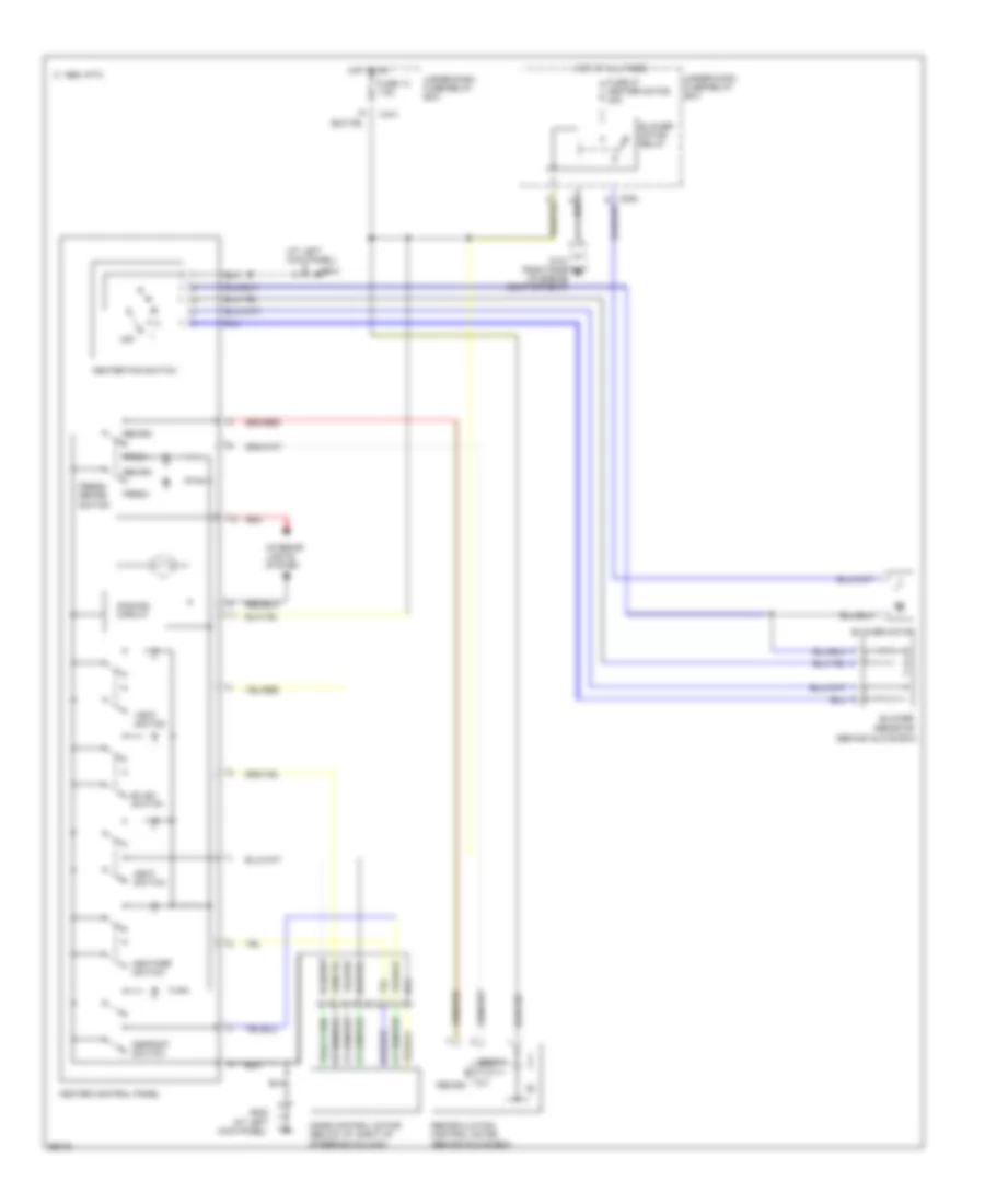
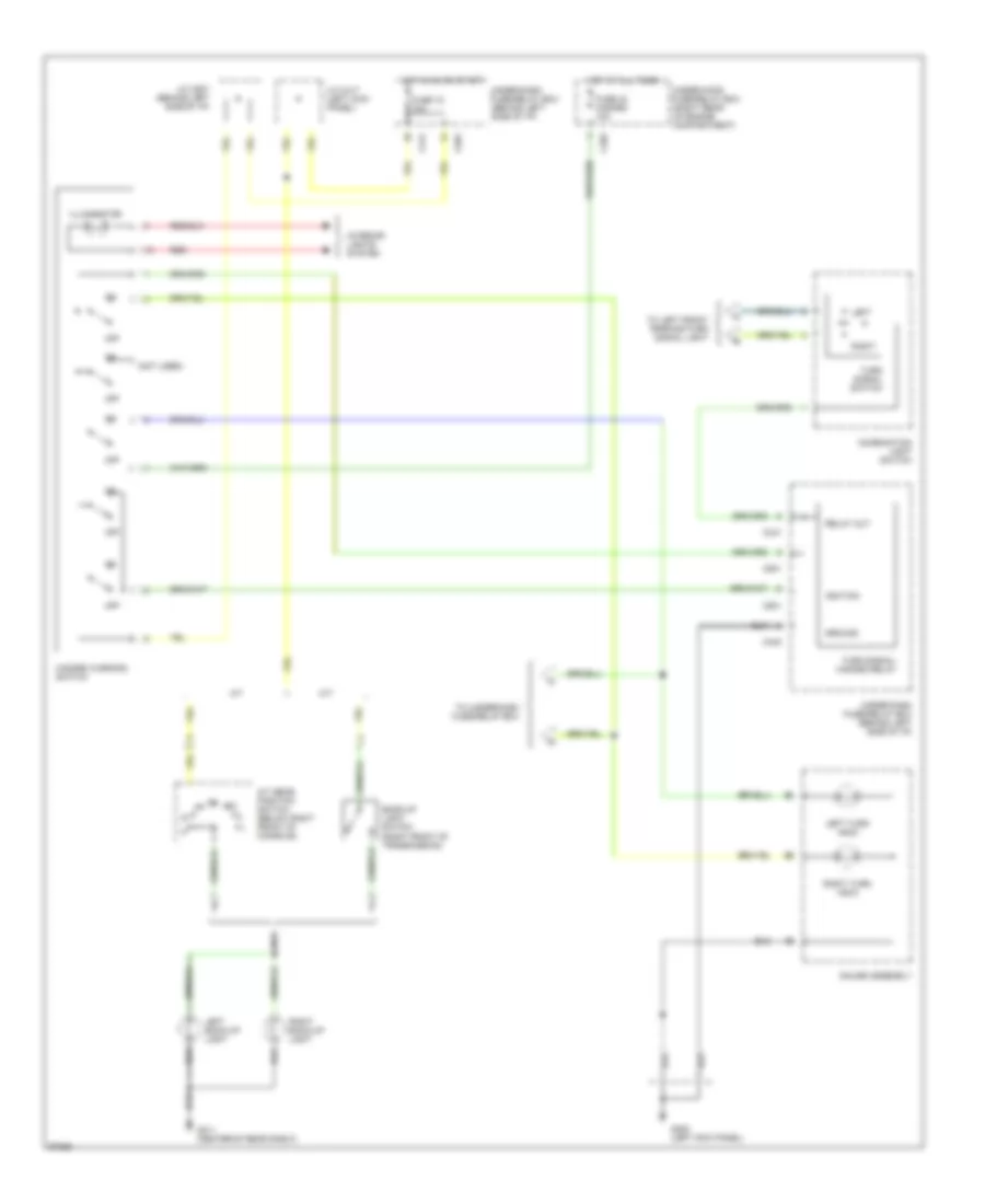
AIR CONDITIONING
A/C Wiring Diagram for Honda Civic Si 1994

List of elements for A/C Wiring Diagram for Honda Civic Si 1994:
- (at left
- (at left kick panel)
- (at right
- (behind glove box)
- (civic)
- (del sol)
- (on bracket)
- (right front corner of engine compartment)
- (right side of engine) g120
- 1994,
- A/c compressor clutch
- A/c compressor clutch relay (left front of engine compartment)
- A/c compressor thermal protector
- A/c diode (left front of engine compartment)
- A/c pressure switch (left front of engine compartment)
- A/c switch
- A/c thermostat (behind glove box)
- A12
- A15
- Bi-lev switch
- Blower motor
- Blower motor relay
- Blower resistor
- C 1995 vftc
- C205
- C206
- C441
- Condenser fan motor
- Condenser fan relay (behind left side of front bumper)
- Control
- Defrost switch
- Dimming circuit
- Engine
- Engine coolant temperature switch a (right rear of engine)
- Fresh
- Fresh/ recirc switch
- Fuse 13 7.5a
- Fuse 33 cooling fan 15a
- Fuse 35 condenser fan 20a
- Fuse 37 heater motor 30a
- G101
- G101 (right side of engine compartment)
- G200
- Heat switch
- Heat/def switch
- Heater control panel
- Heater fan switch
- High
- Hot at all times
- Hot in on
- Interior lights system
- Kick panel)
- Low
- Mode control motor (below i/p, right of steering column)
- Module
- Off
- Radiator fan motor
- Radiator fan relay
- Recirc
- Recirculation control motor
- Red
- Under-dash fuse/relay box
- Under-hood fuse/relay box
- Vent switch
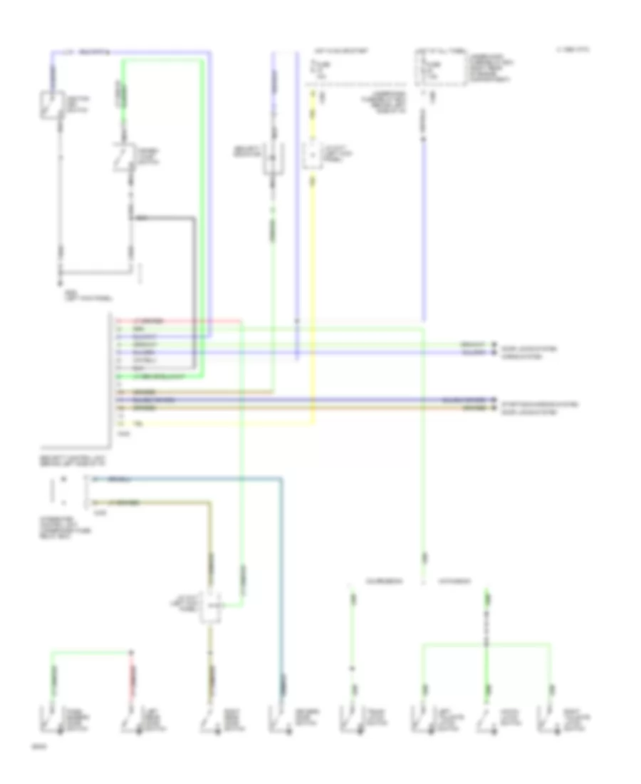
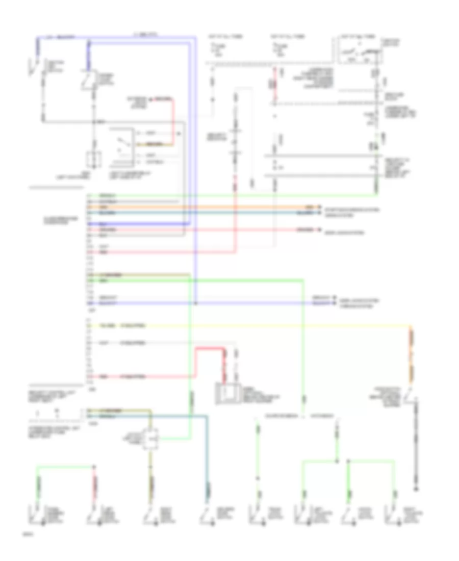
Heater Wiring Diagram for Honda Civic Si 1994
List of elements for Heater Wiring Diagram for Honda Civic Si 1994:
- (at left
- (at left kick panel)
- (behind glove box)
- Bi-lev switch
- Blower motor
- Blower motor relay
- Blower resistor
- C 1995 vftc
- C254
- C441
- Defrost switch
- Dimming circuit
- Fresh
- Fresh/ recirc switch
- Fuse 13 7.5a
- Fuse 37 heater motor 30a
- G101 (right side of engine compartment)
- G200
- Heat switch
- Heat/def switch
- Heater control panel
- Heater fan switch
- Hot at all times
- Hot in on
- Interior lights system
- Kick panel)
- Mode control motor (below i/p, right of steering column)
- Off
- Recirc
- Recirculation control motor
- Red
- Under-dash fuse/relay box
- Under-hood fuse/relay box
- Vent switch
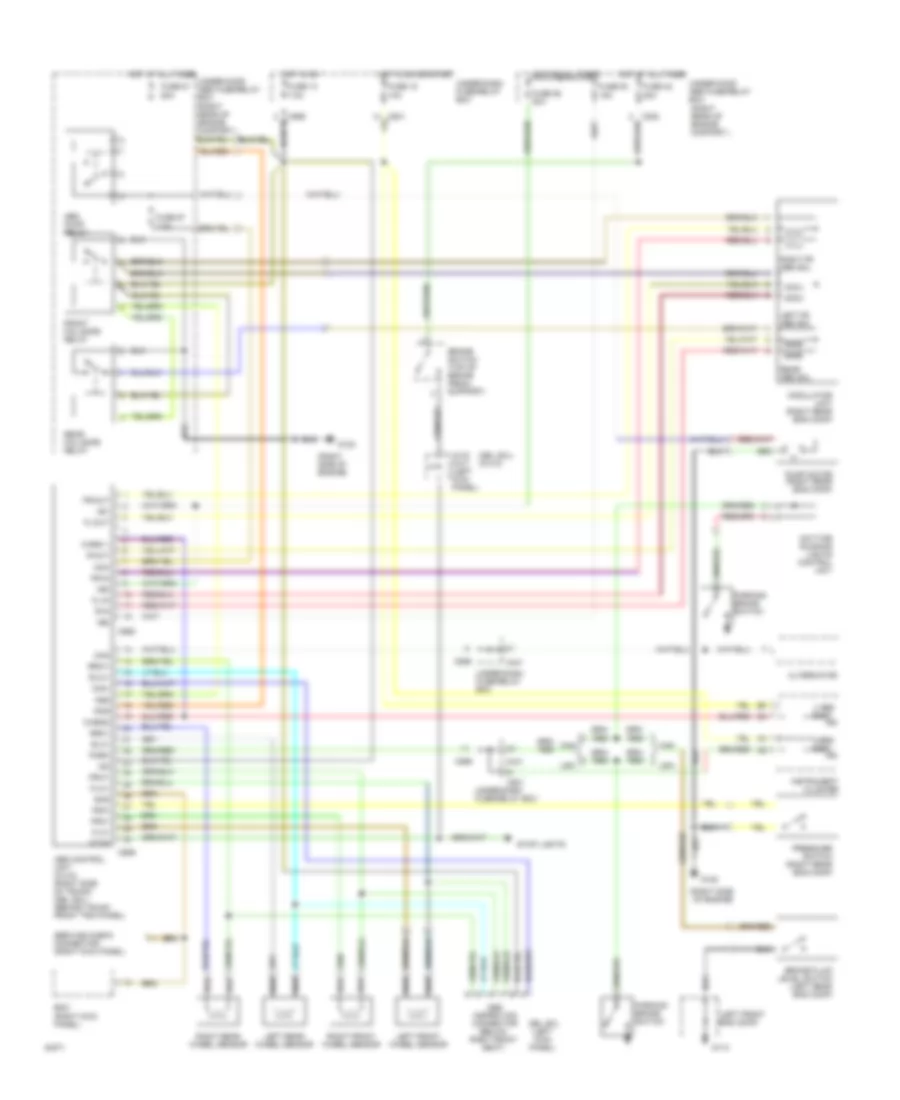
ANTI-LOCK BRAKES
Anti-lock Brake Wiring Diagrams for Honda Civic Si 1994
List of elements for Anti-lock Brake Wiring Diagrams for Honda Civic Si 1994:
- (del sol) (civic)
- (left front eng comp)
- (right kick panel)
- (right rear of engine compart.)
- (right side of engine)
- +b1
- +b2
- +b3
- 4
- Abs control unit (civic) (right side of trunk) (del sol) (behind trunk front trim panel)
- Abs ind
- Abs inspection connector (below right front seat)
- Abs pump relay
- Alternator
- Brake fluid level switch (left rear eng comp)
- Brake switch (top of brake pedal support)
- Brk ind
- C415 c417 (left kick panel)
- C441
- C501
- C556
- C568
- C569
- Can
- Chg
- Com-
- Daytime running lights control unit
- Del sol (left kick panel)
- Ecm
- Fl-in
- Fl-out
- Flw+
- Flw-
- Fr-in
- Fr-out
- Front fail-safe relay
- Frw+
- Frw-
- Fsr
- Fuse 13 7.5a
- Fuse 15 10a
- Fuse 42 20a
- Fuse 51 50a
- Fuse 54 15a
- Fuse 55 20a
- Fuse 57 7.5a
- G110
- G120
- Hot at all times
- Hot at all times under-hood abs fuse/relay box
- Hot in on
- Hot in on or start
- Ig2
- Ind
- Instrument cluster
- Left fr abs sol
- Left front wheel sensor
- Left rear wheel sensor
- Mck
- Modulator unit (right rear eng comp)
- Park
- Parking brake switch
- Pmr
- Pressure switch (right rear eng comp)
- Psw
- Pump motor (right rear eng comp)
- R-in
- R-out
- Rear abs sol
- Rear fail-safe relay
- Right fr abs sol
- Right front wheel sensor
- Right rear wheel sensor
- Rlw+
- Rlw-
- Rrw+
- Rrw-
- Scs
- Service check connector (right kick panel)
- Stop
- Stop lights
- Under-dash fuse/relay box
- Under-hood abs fuse/relay box
- Usa
- Warn 1
- Warn2
ANTI-THEFT
Anti-theft Wiring Diagram, Canada for Honda Civic Si 1994
List of elements for Anti-theft Wiring Diagram, Canada for Honda Civic Si 1994:
- 10a
- 1995 vftc c
- 7.5a
- C205
- C438
- C442
- C501
- Coupe/sedan
- Disarm/ valet switch
- Door locks system
- Driver's door switch
- Fuse
- G200 (left kick panel)
- Hatch latch switch
- Hatchback
- Horns system
- Hot at all times
- Hot in on or start
- Ignition key switch
- Integrated control unit (under-dash fuse/ relay box)
- J/c c417 (left kick panel)
- Left rear door switch
- Left tailgate latch switch
- Nca
- Pass- enger's door switch
- Right rear door switch
- Right tailgate latch switch
- Security control unit (behind left side of i/p)
- Security indicator
- Starting/charging system
- Trunk latch switch
- Under-dash fuse/relay box (behind left side of i/p)
- Under-hood fuse/relay box (right rear of engine compartment)
Anti-theft Wiring Diagram, USA for Honda Civic Si 1994
List of elements for Anti-theft Wiring Diagram, USA for Honda Civic Si 1994:
- (if equipped)
- 1995 vftc c
- 20a
- 40a
- 50a
- Acc
- C203
- C438
- C440m
- C57
- C58
- C915a
- C934
- Coupe or sedan
- Disarm/ valet switch
- Door locks system
- Driver's door switch
- Exterior lights system
- Fuse
- G200 (left kick panel)
- Glass breakage microphone
- Hatch latch switch
- Hatchback
- Hood switch (optional) (behind center of front bumper)
- Horns system
- Hot at all times
- Ignition key switch
- Ignition switch
- Integrated control unit (under-dash fuse/ relay box)
- J/c c417 (left kick panel)
- Left rear door switch
- Left tailgate latch switch
- Light flasher relay (left side of i/p)
- Lock
- Nca
- Pass- enger's door switch
- Red
- Right rear door switch
- Right tailgate latch switch
- Security control unit (underside of left front seat)
- Security in- line fuse holder (behind left end of i/p)
- Security indicator
- Siren (optional) (behind center of front bumper)
- Srs fuse block
- Start
- Starting/charging system
- Trunk latch switch
- Under-dash fuse/relay box (under left i/p)
- Under-hood fuse/relay box (right rear corner of engine compartment)
- Warning system
COMPUTER DATA LINES
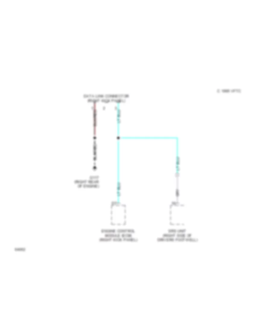
Data Link Connector Wiring Diagram for Honda Civic Si 1994
List of elements for Data Link Connector Wiring Diagram for Honda Civic Si 1994:
- C 1995 vftc
- Data link connector (right kick panel)
- Engine control module (ecm) (right kick panel)
- G117 (right rear of engine)
- Srs unit (right side of drivers footwell)
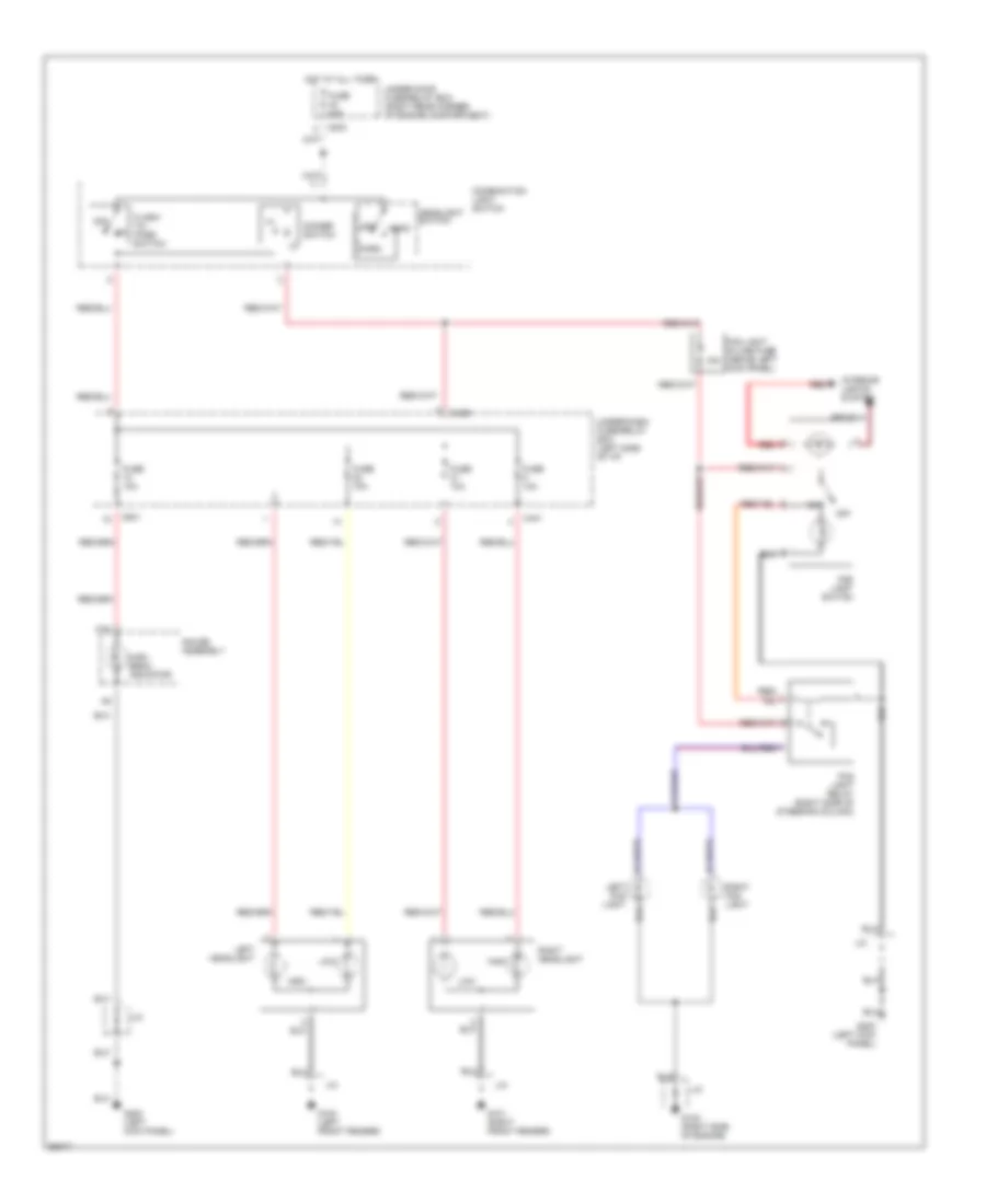
COOLING FAN
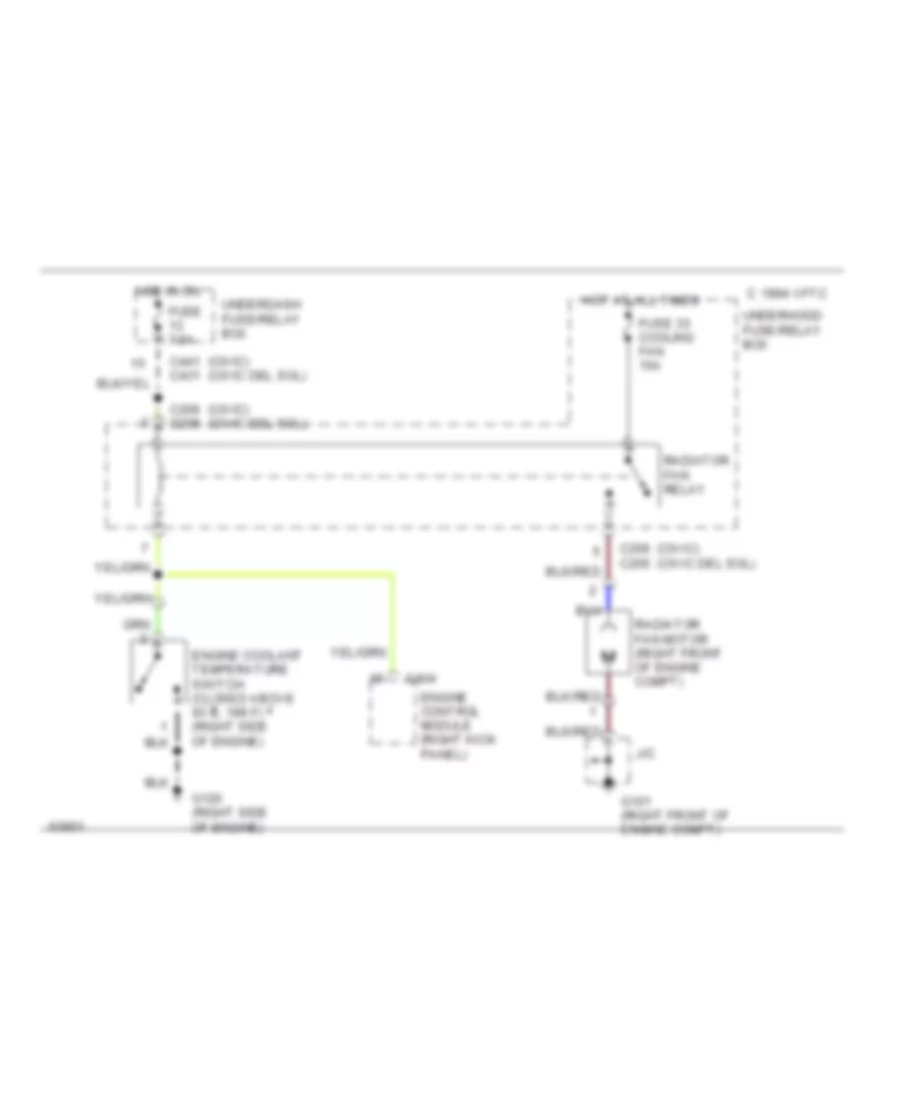
Cooling Fan Wiring Diagram for Honda Civic Si 1994
List of elements for Cooling Fan Wiring Diagram for Honda Civic Si 1994:
- (civic) (civic del sol)
- 1994 vftc c
- C206 c205
- C404
- C441 c431
- Engine control module (right kick panel)
- Engine coolant temperature switch (closed above 93 c, 199 f) (right side of engine)
- Fuse 33 cooling fan 15a
- Fuse 7.5a
- G101 (right front of engine compt)
- G120 (right side of engine)
- Hot at all times
- Hot in on
- J/c
- Radiator fan motor (right front of engine compt)
- Radiator fan relay
- Underdash fuse/relay box
- Underhood fuse/relay box
CRUISE CONTROL
Cruise Control Wiring Diagram for Honda Civic Si 1994
List of elements for Cruise Control Wiring Diagram for Honda Civic Si 1994:
- 1995 vftc c
- A/t
- A/t gear position switch (below center console)
- Actuator input
- Brake input
- Brake switch
- C202
- C440
- C501
- Clutch
- Clutch switch
- Cruise control actuator (left front of engine compartment)
- Cruise control indicator
- Cruise control main switch
- Cruise control set/ resume switch
- Cruise control unit (left kick panel)
- Dimmer
- Disengage input
- Engine control system (ecm)
- Engine rpm input
- Fuse 10a
- Fuse 15a c922
- Fuse 20a
- G100 (left front fender)
- G200 (left kick panel)
- Gauge assembly
- Ground
- Horn relay (left side of i/p)
- Horn switches
- Hot at all times
- Hot in on or start
- Ignition input
- Indicator light control
- Instrument cluster system
- Interior lights system
- J/c
- J/c c417 (left kick panel)
- J/c c507 (left of i/p)
- J/c c507 (left side of i/p)
- Limit switch
- M/t
- Nca
- Off
- Pnk
- Power input
- Red
- Resume/ accel sig input
- Resume/ accel switch
- Set/decel sig input
- Set/decel switch
- Srs cable reel (top of steering column)
- Srs fuse block (left side of i/p)
- Steering wheel
- Under-dash fuse/relay box (left of i/p)
- Under-dash fuse/relay box (left side of i/p)
- Under-hood fuse/relay box (right rear corner of engine compartmet)
- Vehicle speed input
DEFOGGERS
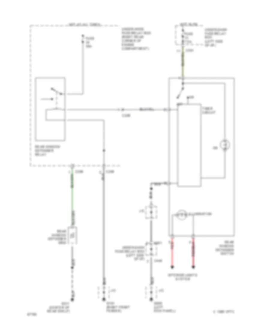
Defogger Wiring Diagram for Honda Civic Si 1994
List of elements for Defogger Wiring Diagram for Honda Civic Si 1994:
- 1995 vftc c
- C206
- C440
- C501
- Fuse 30a
- Fuse 7.5a
- G101 (right front fender)
- G200 (left kick panel)
- Hot at all times
- Hot in on
- Illumination
- Interior lights system
- J/c
- Off
- Rear window defogger grid
- Rear window defogger relay
- Rear window defogger switch
- Red
- Timer circuit
- Under-dash fuse/relay box (left side of i/p)
- Under-hood fuse/relay box (right rear corner of engine compartment)
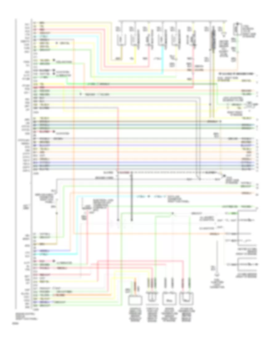
ENGINE PERFORMANCE
1.5L
1.5L, Engine Performance Wiring Diagrams, Except VX (1 of 2) for Honda Civic Si 1994
List of elements for 1.5L, Engine Performance Wiring Diagrams, Except VX (1 of 2) for Honda Civic Si 1994:
- (right front of engine)
- (right side
- (right side of engine)
- A/c system
- A10
- A11
- A12
- A13
- A14
- A15
- A16
- A17
- A18
- A19
- A20
- A21
- A22
- A23
- A24
- A25
- A26
- Acc
- Acs
- All except cx 49-state
- Altc
- Alternator
- Altf
- Atlsa
- Atlsb
- Atp d3
- Atp d4
- Atp/clsw
- B10
- B11
- B12
- B13
- B14
- B15
- B16
- Bksw
- Braided wire
- Braided wires
- C204
- C404
- C405
- C406
- Ckp m
- Ckp p
- Connector (right kick panel)
- Control valve
- Cooling fans
- Cx 49-state
- Cyp m
- Cyp p
- D10
- D11
- D12
- D13
- D14
- D15
- D16
- D17
- D18
- D19
- D20
- D21
- D22
- Data link
- Dlc
- Ect
- Electrical load detector unit (under-hood fuse/relay box)
- Engine control module (right kick panel)
- Engine coolant temperature sensor (right front of engine)
- Evaporative emission
- Fanc
- Flr1
- Flr2
- Fuel injector #1
- Fuel injector #2
- Fuel injector #3
- Fuel injector #4
- Fuel injectors (joint connector)
- G120
- G120 of engine)
- Heated oxygen sensor (all except cx 49- state)
- Heated oxygen sensor (front of engine)
- Iacv
- Iat
- Icm 1
- Idle air
- Igp1
- Igp2
- Inj1
- Inj2
- Inj3
- Inj4
- Intake air temperature sensor (center rear of engine)
- Lg1
- Lg2
- Load output
- Lock up control solenoid valves
- Manifold absolute pressure sensor (middle of engine)
- Map
- Mil
- Nca
- Not used
- O2s
- O2shtc
- Oxygen sensor (front of engine)
- Pcs
- Pg1
- Pg2
- Pnk
- Pspsw
- Purge control solenoid valve
- Red
- Red (coupe)
- Scs
- Service check connector (right kick panel)
- Sg1
- Sg2
- Slu/sil
- Sts
- Tdc m
- Tdc p
- Throttle position sensor center rear of engine)
- Tps
- Vbu
- Vcc1
- Vcc2
- Vss
- Vtec solenoid valve (right side of engine)
- Vtm
- Vts
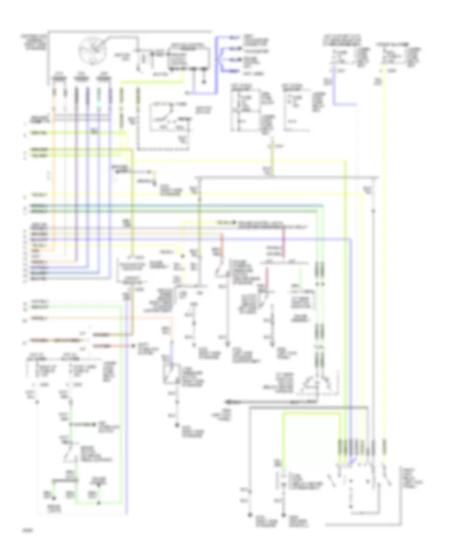
1.5L, Engine Performance Wiring Diagrams, Except VX (2 of 2) for Honda Civic Si 1994
List of elements for 1.5L, Engine Performance Wiring Diagrams, Except VX (2 of 2) for Honda Civic Si 1994:
- (not used)
- A/t
- A/t gear position indicator
- A/t gear position switch (below center console)
- Acc
- Back up fuse 32 7.5a
- Braided wire
- Brake lights
- Brake switch (on brake pedal support)
- C202
- C205
- C441
- C509
- C510
- C512
- Ckp sensor
- Clutch switch (behind left side of dash)
- Cruise control
- Cruise control unit
- Cruise control unit & odometer/tripmeter drive circuit
- Cyp sensor
- Distributor assembly (right side of engine)
- Ecu fuse 31 15a
- Fuel pump (below center of rear seat)
- Fuse 15a
- Fuse 15a c922
- Fuse 7.5a
- G100 (left side of engine compartment)
- G100 (right side of engine)
- G120 (right side of engine)
- G200 (left kick panel)
- G309 (driver's door sill)
- Gauge assembly
- Gnd
- Hot at all times
- Hot in run or start
- Hot in start with a/t gear selector in park or neutral
- Ign
- Ignition coil
- Ignition control module
- Ignition switch
- Key interlock switch
- Lock
- M/t
- Malfunction indicator
- Pgm-fi main relay (left kick panel)
- Power steering pressure switch (center rear of engine)
- Primary output control
- Pwr
- Rpm
- Run
- Shift interlock system
- Srs fuse block
- Start
- Stop, horn fuse 42 20a
- Tachometer
- Tdc sensor
- Test tachometer connector)
- Under- dash fuse/ relay box
- Under- hood fuse/ relay box
- Upshift indicator
- Vehicle speed sensor (right rear of engine compartment)
- Vss out
- Vtec pressure switch (right side of engine)
1.5L, Engine Performance Wiring Diagrams, VX (1 of 2) for Honda Civic Si 1994
List of elements for 1.5L, Engine Performance Wiring Diagrams, VX (1 of 2) for Honda Civic Si 1994:
- (right side
- (right side of engine)
- A/c system
- A10
- A11
- A12
- A13
- A14
- A15
- A16
- A17
- A18
- A19
- A20
- A21
- A22
- A23
- A24
- A25
- A26
- Acc
- Acs
- Altc
- Alternator
- Altf
- B10
- B11
- B12
- B13
- B14
- B15
- B16
- Bksw
- Braided wire
- Braided wires
- C204
- C404
- C405
- C406
- Ckp m
- Ckp p
- Clsw
- Connector (right kick panel)
- Cyp m
- Cyp p
- D10
- D11
- D12
- D13
- D14
- D15
- D16
- D17
- D18
- D19
- D20
- D21
- D22
- Data link
- Dlc
- Ect
- Egrl
- Electrical load detector unit (under-hood fuse/relay box)
- Engine control module (right kick panel)
- Engine coolant temperature sensor (right front of engine)
- Evaporative emission purge control solenoid valve
- Exhaust gas recirculation valve lift sensor (right side of engine)
- Fanc
- Fans
- Flr1
- Flr2
- Fuel injector #1
- Fuel injector #2
- Fuel injector #3
- Fuel injector #4
- G120
- G120 (right side of engine)
- G120 of engine)
- Heated oxygen sensor (right front of engine)
- Htcntl
- Iacv
- Iat
- Icm 1
- Idle air control valve
- Igp1
- Igp2
- Inj1
- Inj2
- Inj3
- Inj4
- Intake air temperature sensor (center rear of engine)
- Ip+
- Ip-, vs-
- Label
- Lg1
- Lg2
- Load output
- Manifold absolute pressure sensor (middle of engine)
- Map
- Mil
- Nca
- Not used
- Pcs
- Pg1
- Pg2
- Pnk
- Pspsw
- Red
- Red (coupe)
- Scs
- Service check connector (right kick panel)
- Sg1
- Sg2
- Sil
- Sts
- Tdc m
- Tdc p
- Throttle position sensor center rear of engine)
- Tps
- Vbu
- Vcc1
- Vcc2
- Vs+
- Vss
- Vtec solenoid valve (right side of engine)
- Vtm
- Vts
1.5L, Engine Performance Wiring Diagrams, VX (2 of 2) for Honda Civic Si 1994
List of elements for 1.5L, Engine Performance Wiring Diagrams, VX (2 of 2) for Honda Civic Si 1994:
- (not used)
- (rear of engine compartment)
- Acc
- Back up fuse 32 7.5a
- Braided wire
- Brake lights
- Brake switch (on brake pedal support)
- C202
- C205
- C441
- C509
- C510
- Ckp sensor
- Clutch switch (behind left side of dash)
- Cruise control unit
- Cruise control unit & odometer/tripmeter drive circuit
- Cyp sensor
- Distributor assembly (right side of engine)
- Ecu fuse 31 15a
- Exhaust gas recirculation control solenoid valve
- Fuel pump (below center of rear seat)
- Fuse 15a c922
- Fuse 7.5a
- G100 (left side of engine compartment)
- G100 (right side of engine)
- G120 (right side of engine)
- G200 (left kick panel)
- G309 (driver's door sill)
- Gauge assembly
- Gnd
- Hot at all times
- Hot in run or start
- Hot in start with clutch pedal depressed
- Ign
- Ignition coil
- Ignition control module
- Ignition switch
- Key interlock switch
- Lock
- Malfunction indicator
- Pgm-fi main relay (left kick panel)
- Power steering pressure switch (center rear of engine)
- Primary output control
- Pwr
- Rpm
- Run
- Srs fuse block
- Start
- Stop, horn fuse 42 20a
- Tachometer
- Tdc sensor
- Test tachometer connector)
- Under- dash fuse/ relay box
- Under- hood fuse/ relay box
- Upshift indicator
- Vehicle speed sensor (right rear of engine compartment)
- Vss out
- Vtec pressure switch (right side of engine)
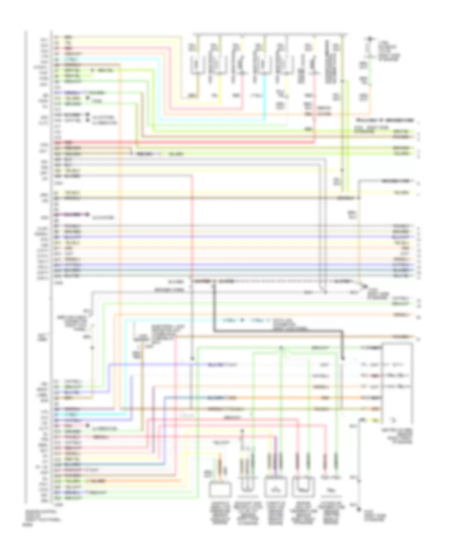
1.6L
1.6L, Engine Performance Wiring Diagrams, Except VX (1 of 2) for Honda Civic Si 1994
List of elements for 1.6L, Engine Performance Wiring Diagrams, Except VX (1 of 2) for Honda Civic Si 1994:
- (right front of engine)
- (right side
- (right side of engine)
- A/c system
- A10
- A11
- A12
- A13
- A14
- A15
- A16
- A17
- A18
- A19
- A20
- A21
- A22
- A23
- A24
- A25
- A26
- Acc
- Acs
- All except cx 49-state
- Altc
- Alternator
- Altf
- Atlsa
- Atlsb
- Atp d3
- Atp d4
- Atp/clsw
- B10
- B11
- B12
- B13
- B14
- B15
- B16
- Bksw
- Braided wire
- Braided wires
- C204
- C404
- C405
- C406
- Ckp m
- Ckp p
- Connector (right kick panel)
- Control valve
- Cooling fans
- Cx 49-state
- Cyp m
- Cyp p
- D10
- D11
- D12
- D13
- D14
- D15
- D16
- D17
- D18
- D19
- D20
- D21
- D22
- Data link
- Dlc
- Ect
- Electrical load detector unit (under-hood fuse/relay box)
- Engine control module (right kick panel)
- Engine coolant temperature sensor (right front of engine)
- Evaporative emission
- Fanc
- Flr1
- Flr2
- Fuel injector #1
- Fuel injector #2
- Fuel injector #3
- Fuel injector #4
- Fuel injectors (joint connector)
- G120
- G120 of engine)
- Heated oxygen sensor (all except cx 49- state)
- Heated oxygen sensor (front of engine)
- Iacv
- Iat
- Icm 1
- Idle air
- Igp1
- Igp2
- Inj1
- Inj2
- Inj3
- Inj4
- Intake air temperature sensor (center rear of engine)
- Lg1
- Lg2
- Load output
- Lock up control solenoid valves
- Manifold absolute pressure sensor (middle of engine)
- Map
- Mil
- Nca
- Not used
- O2s
- O2shtc
- Oxygen sensor (front of engine)
- Pcs
- Pg1
- Pg2
- Pnk
- Pspsw
- Purge control solenoid valve
- Red
- Red (coupe)
- Scs
- Service check connector (right kick panel)
- Sg1
- Sg2
- Slu/sil
- Sts
- Tdc m
- Tdc p
- Throttle position sensor center rear of engine)
- Tps
- Vbu
- Vcc1
- Vcc2
- Vss
- Vtec solenoid valve (right side of engine)
- Vtm
- Vts
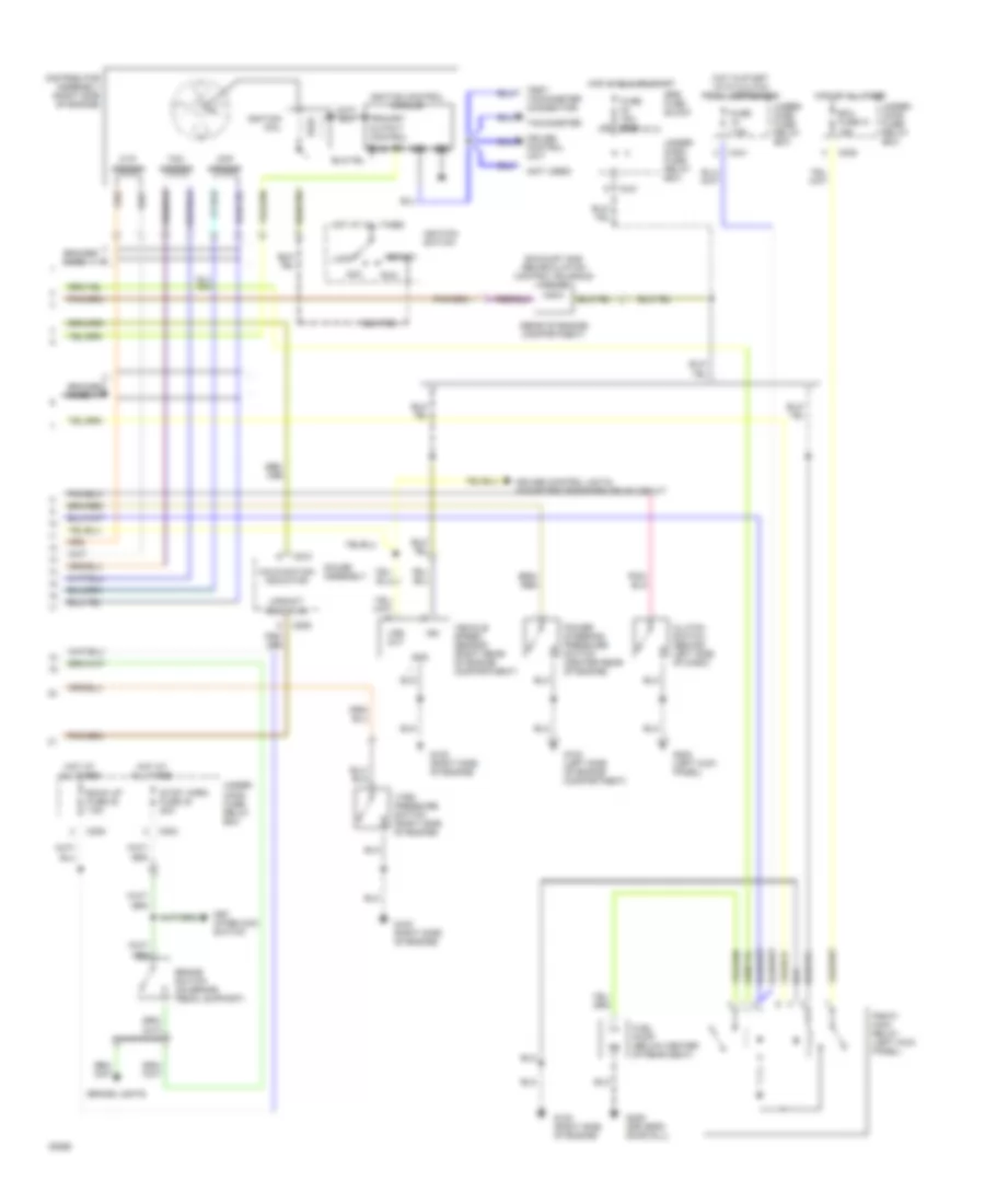
1.6L, Engine Performance Wiring Diagrams, Except VX (2 of 2) for Honda Civic Si 1994
List of elements for 1.6L, Engine Performance Wiring Diagrams, Except VX (2 of 2) for Honda Civic Si 1994:
- (not used)
- A/t
- A/t gear position indicator
- A/t gear position switch (below center console)
- Acc
- Back up fuse 32 7.5a
- Braided wire
- Brake lights
- Brake switch (on brake pedal support)
- C202
- C205
- C441
- C509
- C510
- C512
- Ckp sensor
- Clutch switch (behind left side of dash)
- Cruise control
- Cruise control unit
- Cruise control unit & odometer/tripmeter drive circuit
- Cyp sensor
- Distributor assembly (right side of engine)
- Ecu fuse 31 15a
- Fuel pump (below center of rear seat)
- Fuse 15a
- Fuse 15a c922
- Fuse 7.5a
- G100 (left side of engine compartment)
- G100 (right side of engine)
- G120 (right side of engine)
- G200 (left kick panel)
- G309 (driver's door sill)
- Gauge assembly
- Gnd
- Hot at all times
- Hot in run or start
- Hot in start with a/t gear selector in park or neutral
- Ign
- Ignition coil
- Ignition control module
- Ignition switch
- Key interlock switch
- Lock
- M/t
- Malfunction indicator
- Pgm-fi main relay (left kick panel)
- Power steering pressure switch (center rear of engine)
- Primary output control
- Pwr
- Rpm
- Run
- Shift interlock system
- Srs fuse block
- Start
- Stop, horn fuse 42 20a
- Tachometer
- Tdc sensor
- Test tachometer connector)
- Under- dash fuse/ relay box
- Under- hood fuse/ relay box
- Upshift indicator
- Vehicle speed sensor (right rear of engine compartment)
- Vss out
- Vtec pressure switch (right side of engine)
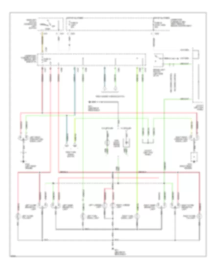
EXTERIOR LIGHTS
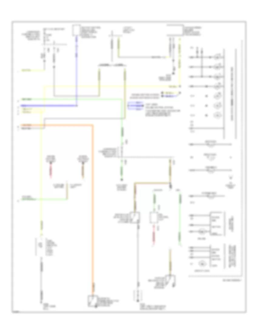
Exterior Light Wiring Diagram for Honda Civic Si 1994
List of elements for Exterior Light Wiring Diagram for Honda Civic Si 1994:
- (not used)
- A/t
- A/t gear position switch (below right front of console)
- Back-up light switch (right front of transmission)
- C202
- C440
- C441
- C501
- Combination light switch
- Fuse 15 10a
- Fuse 43 hazard 10a
- G200 (left kick panel)
- G311 (center of rear shelf)
- Gauge assembly
- Ground
- Hazard warning switch
- Hot at all times
- Hot in on or start
- Ignition
- Illumination
- Interior lights system
- J/c c417 (left kick panel)
- J/c c507 (behind left side of i/p)
- Left
- Left back-up light
- Left turn indic
- M/t
- Nca
- Off
- Red
- Relay out
- Right
- Right back-up light
- Right turn indic
- To left front parking/turn signal light
- To under-dash fuse/relay box
- Turn signal switch
- Turn signal/ hazard relay
- Under-dash fuse/relay box (behind left side of i/p)
- Under-hood fuse/relay box (right rear of engine compartment)
Exterior Light Wiring Diagram, Coupe & Sedan for Honda Civic Si 1994
List of elements for Exterior Light Wiring Diagram, Coupe & Sedan for Honda Civic Si 1994:
- Brake light switch (left side of i/p)
- C202
- C203
- C431
- C440
- C441
- C501
- C556
- From hazard warning switch
- From turn signal switch
- Fuse 19 10a
- Fuse 40 light 40a
- Fuse 42 stop, horn 20a
- G100 (left front fender)
- G101 (right front fender)
- G311 (center of rear shelf)
- Head
- Headlight switch (combination light switch)
- High mount brake lights
- Hot at all times
- J/c c417 (left kick panel)
- Left front parking/turn signal light
- Left inner brake/tail- light
- Left license light
- Left outer brake/tail- light
- Left outer taillight
- Left turn signal light
- Nca
- Off
- Park
- Right front parking/turn signal light
- Right inner brake/tail- light
- Right license light
- Right outer brake/tail- light
- Right outer taillight
- Right turn signal light
- Under-dash fuse/relay box (behind left side of i/p)
- Under-hood fuse/relay box (right rear of engine compartment)
- W/ cruise control
- W/ spoiler
- W/o cruise control
- W/o spoiler
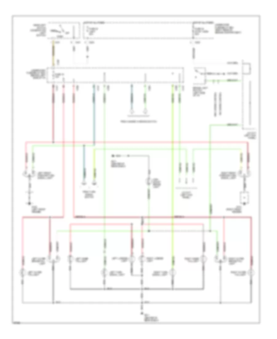
Exterior Light Wiring Diagram, Hatchback for Honda Civic Si 1994
List of elements for Exterior Light Wiring Diagram, Hatchback for Honda Civic Si 1994:
- Brake light switch (left side of i/p)
- C202
- C203
- C431
- C440
- C441
- C501
- C556
- From hazard warning switch
- From turn signal switch
- Fuse 19 10a
- Fuse 40 light 40a
- Fuse 42 stop, horn 20a
- G100 (left front fender)
- G101 (right front fender)
- G311 (center of rear shelf)
- Head
- Headlight switch (combination light switch)
- High mount brake light
- Hot at all times
- J/c c417 (left kick panel)
- Left front parking/turn signal light
- Left inner taillight
- Left license light
- Left outer brake/tail- light
- Left outer taillight
- Left turn signal light
- Nca
- Off
- Park
- Right front parking/turn signal light
- Right inner taillight
- Right license light
- Right outer brake/tail- light
- Right outer taillight
- Right turn signal light
- Under-dash fuse/relay box (behind left side of i/p)
- Under-hood fuse/relay box (right rear of engine compartment)
- W/ cruise control
- W/o cruise control
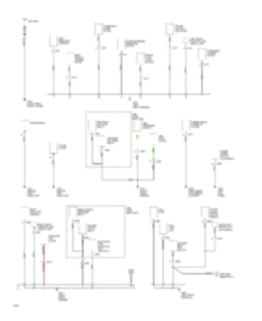
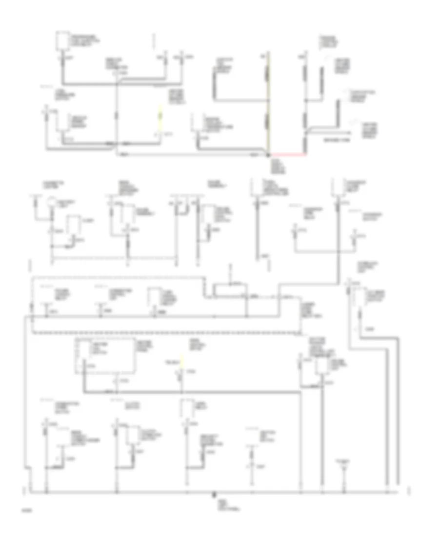
GROUND DISTRIBUTION
Ground Distribution Wiring Diagram (1 of 4) for Honda Civic Si 1994
List of elements for Ground Distribution Wiring Diagram (1 of 4) for Honda Civic Si 1994:
- (hatchback)
- (sedan only)
- Abs front fail-safe relay
- Abs fuse/ relay box
- Abs pressure switch
- Abs pump motor
- Abs rear fail-safe relay
- Battery
- Blower motor relay
- Brake fluid level switch
- C204
- C206
- C207
- C208
- C219
- C221
- C222
- C307
- C310
- C311
- C313
- C315
- C316
- C317
- C341
- C517
- C558
- C559
- C563
- C564
- C575
- C905
- C906
- C930
- C931
- Cruise control actuator
- Driver's seat belt switch
- Electrical load detector unit (usa only)
- From g200
- Fuel pump
- Fuel tank unit
- G100 (left front fender)
- G101 (right front fender)
- G103 (right front shock tower)
- G106 (behind left headlamp)
- G107 (behind right headlamp)
- G200 (left kick panel)
- G205 (right rear of steering support)
- G309 (left front door sill)
- High mount brake light
- Left front parking/turn signal lamp
- Left headlamp assembly
- Mirror switch (sedan)
- Nca
- Power
- Power mirror switch (hatchback)
- Power steering pressure switch
- Radiator fan motor
- Rear window defogger relay
- Rear window washer motor
- Right front parking/turn signal lamp
- Right headlamp assembly
- Stereo radio/ cassette player
- Transmission
- Valve cover
- Windshield washer motor
- Windshield wiper motor
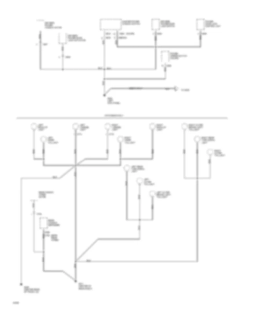
Ground Distribution Wiring Diagram (2 of 4) for Honda Civic Si 1994
List of elements for Ground Distribution Wiring Diagram (2 of 4) for Honda Civic Si 1994:
- A/t gear position switch
- A26
- Ashtray light
- Braided wire
- C111
- C112
- C128
- C404
- C409
- C410
- C412
- C413
- C421
- C422
- C424
- C427
- C430
- C432
- C434
- C440
- C442
- C501
- C507
- C512
- C513
- C515
- C516
- C711
- C712
- C713
- C714
- C732
- C733
- C734
- C914
- C920 c920
- C928
- Cigarette lighter
- Ckp/cyp/ tdc sensor shield braided wire
- Ckp/cyp/tdc sensor shield
- Clock
- Clutch interlock switch
- Clutch switch
- Combination wiper switch
- Cruise control main switch
- Cruise control unit
- Dash lights brightness controller
- Daytime running lights control unit (canada only)
- Engine control module
- Engine coolant temperature switch
- G120 (right side of engine)
- G200 (left kick panel)
- Gauge assembly
- Heated oxygen sensor (vx only)
- Heated oxygen sensor shield
- Heater control panel
- Heater fan switch
- Horn relay
- Ignition key switch
- Integrated control unit
- Interlock control unit
- Mode control motor
- Moonroof close relay
- Moonroof open relay
- Moonroof switch
- Power window relay
- Programmed fuel injection main relay
- Rear window defogger switch
- Rear window wiper/washer switch
- Security system connector
- Service check connector
- To g101
- Turn signal/ hazard relay
- Under- dash fuse/ relay box
- Vehicle speed sensor
- Vtec pressure switch
Ground Distribution Wiring Diagram (3 of 4) for Honda Civic Si 1994
List of elements for Ground Distribution Wiring Diagram (3 of 4) for Honda Civic Si 1994:
- (coupe)
- (sedan)
- (with (with rear wiper)
- C558
- C604
- C605
- C606
- C607
- C608
- C609
- C774
- C775
- C794
- Driver's power door lock switch
- Driver's power door lock actuator
- Driver's power window motor
- G200 (left kick panel)
- G311 (center of rear shelf)
- G406 (center rear of trunk lid)
- Hatchback only
- Left back-up light
- Left inner taillight
- Left license light
- Left outer taillight
- Left outer brake light/ taillight
- Left rear turn signal light
- Master power window switch
- Power door lock control unit
- Power mirror switch (coupe)
- Rear window defogger
- Rear window wiper motor
- Right back-up light
- Right inner taillight
- Right license light
- Right outer brake light/ taillight
- Right outer taillight
- Right rear turn signal light
- Sedan only
- To g309
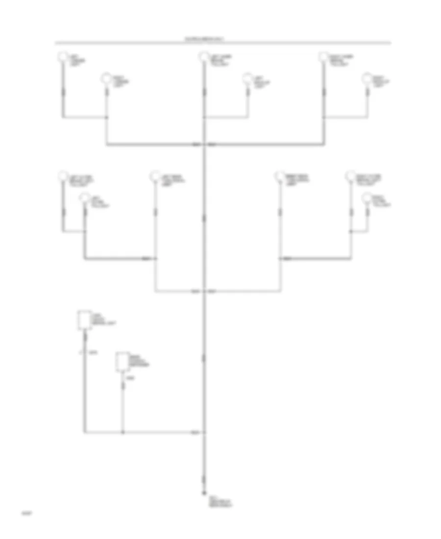
Ground Distribution Wiring Diagram (4 of 4) for Honda Civic Si 1994
List of elements for Ground Distribution Wiring Diagram (4 of 4) for Honda Civic Si 1994:
- C575
- C588
- Coupe & sedan only
- G311 (center of rear shelf)
- High mount brake light
- Left back-up light
- Left inner brake/ taillight
- Left license light
- Left outer brake light/ taillight
- Left outer taillight
- Left rear turn signal light light
- Rear window defogger
- Right outer taillight
- Right back-up light
- Right inner brake/ taillight
- Right license light
- Right outer brake light/ taillight
- Right right rear turn signal light light
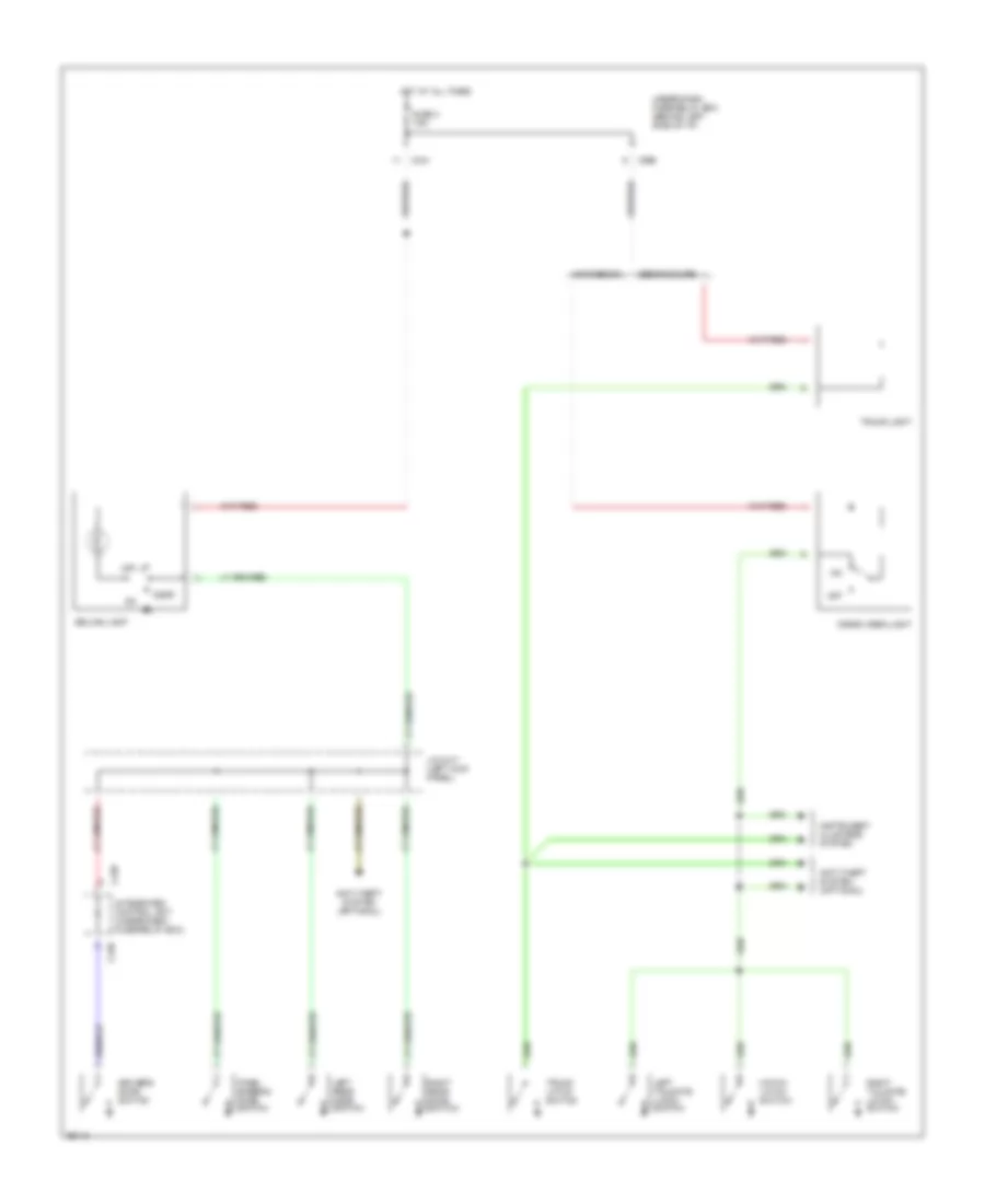
HEADLIGHTS
Headlight Wiring Diagram, with DRL for Honda Civic Si 1994
List of elements for Headlight Wiring Diagram, with DRL for Honda Civic Si 1994:
- 15a
- A10
- Battery
- Brake system indicator
- C203
- C412
- C439
- C441
- C501
- Combination light switch
- Daytime running lights control unit (left side of i/p)
- Daytime running lights resistor (left rear of engine compartment)
- Dimmer switch
- Flash- to- pass switch
- Fog light in-line fuse (above left kick panel)
- Fog light relay (right side of steering column)
- Fog light switch
- Fuse 10a
- Fuse 10a
- Fuse 40a
- Fuse 7.5a
- G100 (left front fender)
- G101 (right front fender)
- G102 (right side of engine)
- G200 (left kick panel)
- Gauge assembly
- Ground
- Head
- Headlight control
- Headlight switch
- High
- High beam indicator
- Hot at all times
- Hot in on
- Ignitoin
- Instrument cluster system
- Interior lights system
- J/c
- Left fog light
- Left headlight
- Light control
- Lights-on input c411
- Low
- Nca
- Off
- Park
- Parking brake input
- Parking brake switch (below center console)
- Red
- Right fog light
- Right headlight
- Under-dash fuse/relay box (left side of i/p)
- Under-hood fuse/relay box (right rear corner of engine compartment)
Headlight Wiring Diagram, without DRL for Honda Civic Si 1994
List of elements for Headlight Wiring Diagram, without DRL for Honda Civic Si 1994:
- 15a
- A10
- C203
- C439
- C441
- C501
- Combination light switch
- Dimmer switch
- Flash- to- pass switch
- Fog light in-line fuse (above left kick panel)
- Fog light relay (right side of steering column)
- Fog light switch
- Fuse 10a
- Fuse 40a
- G100 (left front fender)
- G101 (right front fender)
- G102 (right side of engine)
- G200 (left kick panel)
- Gauge assembly
- Head
- Headlight switch
- High
- High beam indicator
- Hot at all times
- Interior lights system
- J/c
- Left fog light
- Left headlight
- Low
- Off
- Park
- Red
- Right fog light
- Right headlight
- Under-dash fuse/relay box (left side of i/p)
- Under-hood fuse/relay box (right rear corner of engine compartment)
HORN
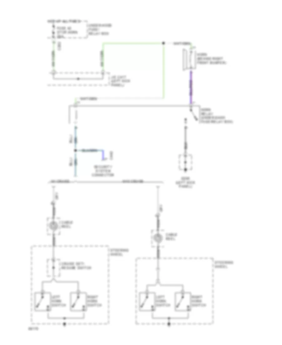
Horn Wiring Diagram, with Air Bag for Honda Civic Si 1994
List of elements for Horn Wiring Diagram, with Air Bag for Honda Civic Si 1994:
- C202
- C442
- Cable reel
- Cruise set/ resume switch
- Fuse 42 stop,horn 20a
- G200 (left kick panel)
- Horn (behind right front bumper)
- Horn relay (under-dash fuse/relay box)
- Hot at all times
- J/c c417 (left kick panel)
- Left horn switch
- Nca
- Right horn switch
- Security system connector
- Steering wheel
- Under-hood fuse/ relay box
- W/ cruise
- W/o cruise
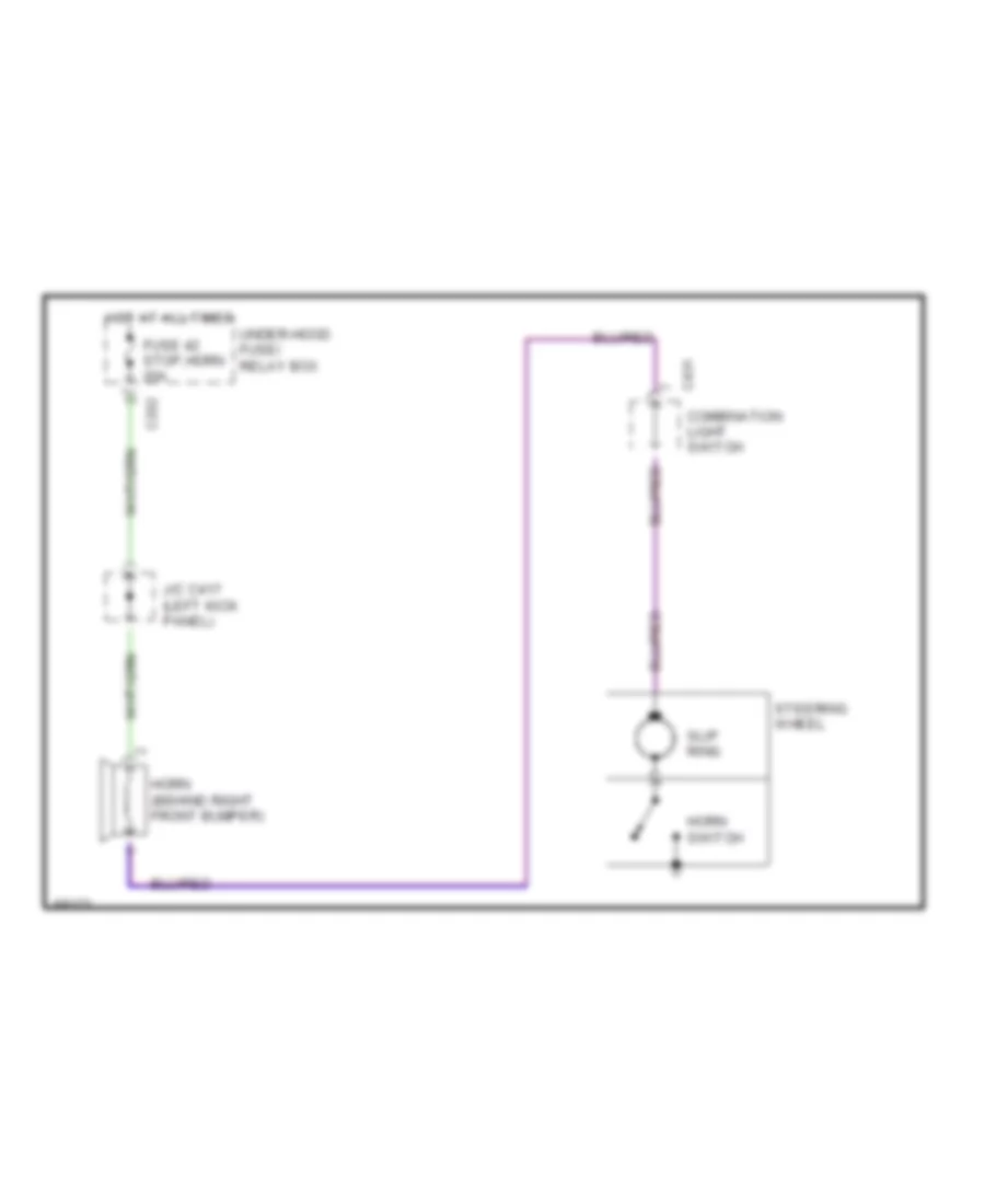
Horn Wiring Diagram, without Air Bag for Honda Civic Si 1994
List of elements for Horn Wiring Diagram, without Air Bag for Honda Civic Si 1994:
- C202
- C431
- Combination light switch
- Fuse 42 stop,horn 20a
- Horn (behind right front bumper)
- Horn switch
- Hot at all times
- J/c c417 (left kick panel)
- Slip ring
- Steering wheel
- Under-hood fuse/ relay box
INSTRUMENT CLUSTER
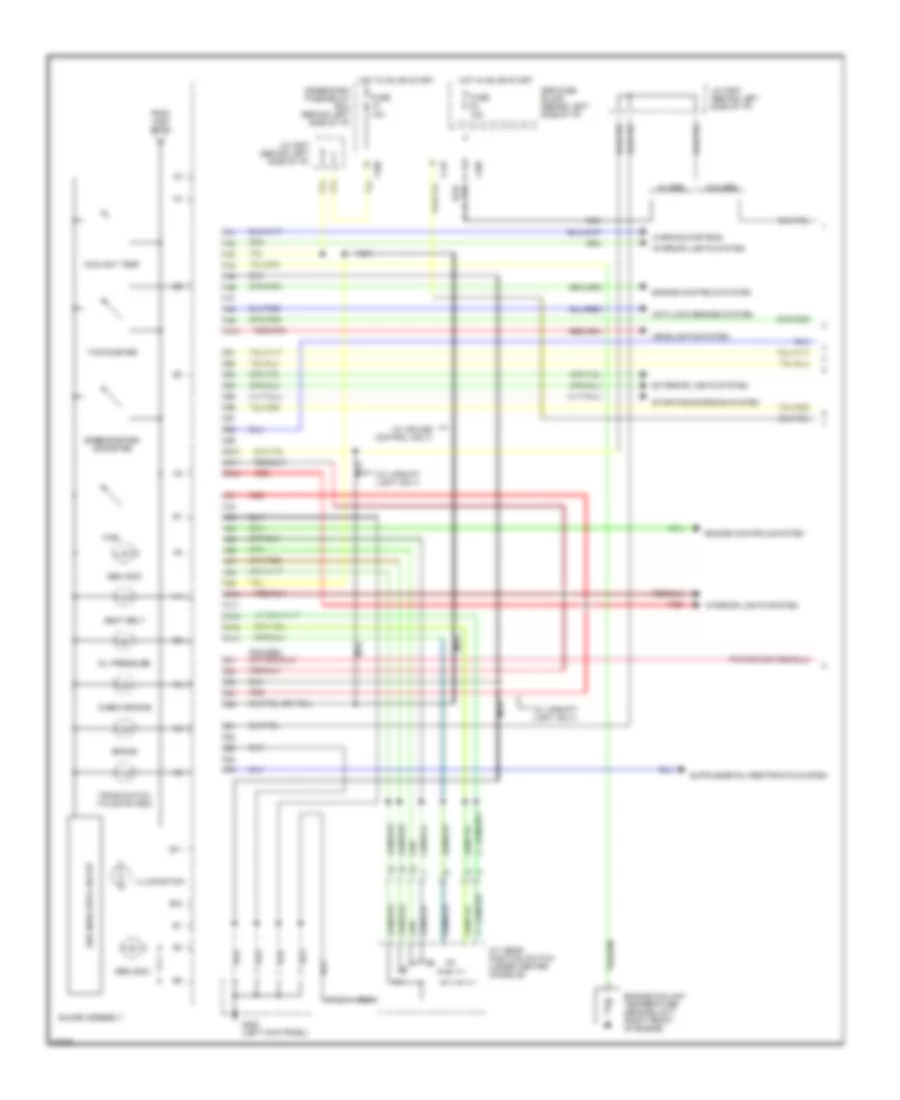
Instrument Cluster Wiring Diagram (1 of 2) for Honda Civic Si 1994
List of elements for Instrument Cluster Wiring Diagram (1 of 2) for Honda Civic Si 1994:
- (w/ cruise control only)
- (w/ upshift light only)
- 10a
- 15a
- A/t gear position switch (under center console)
- A10
- Abs indic
- Anti-lock brakes system
- B10
- B11
- B12
- Brake
- C10
- C11
- C12
- C13
- C14
- C441
- C501
- Check engine
- Coolant temp
- Engine controls system
- Engine coolant temperature sending unit (right front of engine)
- Exterior lights system
- From high beam
- Fuel
- Fuse
- G200 (left kick panel)
- Gauge assembly
- Headlights system
- Hot in on or start
- Illumination
- Interior lights system
- J/c c507 (behind left side of i/p)
- Nca
- Oil pressure
- Red
- Seat belt
- Speedometer/ odometer
- Srs fuse block (behind left side of i/p)
- Srs indic
- Srs indicator circuit
- Starting/charging system
- Tachometer
- Trunk/hatch/ tailgate indic
- Under-dash fuse/relay box (behind left side of i/p)
- W/ srs
- W/o srs
- Warning systems
Instrument Cluster Wiring Diagram (2 of 2) for Honda Civic Si 1994
List of elements for Instrument Cluster Wiring Diagram (2 of 2) for Honda Civic Si 1994:
- (not used)
- 15a
- A10
- Anti-lock brakes system
- B10
- Brake fluid level switch (master cylinder)
- C10
- C12
- C13
- C14
- C412
- C441
- C501
- C556
- Canada
- Charge indic
- Cruise
- Cruise control system
- Dim sig
- Drl control unit
- Engine controls system
- Engine oil pressure switch (lower rear of engine)
- Except california
- Fuel gauge sending unit (fuel tank unit)
- Fuse
- G100 (left front corner of engine compartment)
- G120 (right side of engine)
- G309 (left door sill)
- Gauge assembly
- Grd
- High beam
- Hot in on or start
- Ignition
- Ignition control module (icm) (right side of engine, in distributor)
- Indic
- J/c c417 (left kick panel)
- Left turn
- Nca
- Parking brake switch (below center console)
- Right turn
- Solid state dimming & indicators control unit
- Tachometer test connector (left rear corner of engine compartment)
- To coolant temp
- Under-dash fuse/relay box (behind left side of i/p)
- Upshift indic
- Usa
- Vehicle speed sensor (right end of transmission)
- Vx: all & cx: usa w/o cruise control:
- W/ cruise control
- W/ cruise control only
- W/ srs
- W/ upshift light
- W/o srs
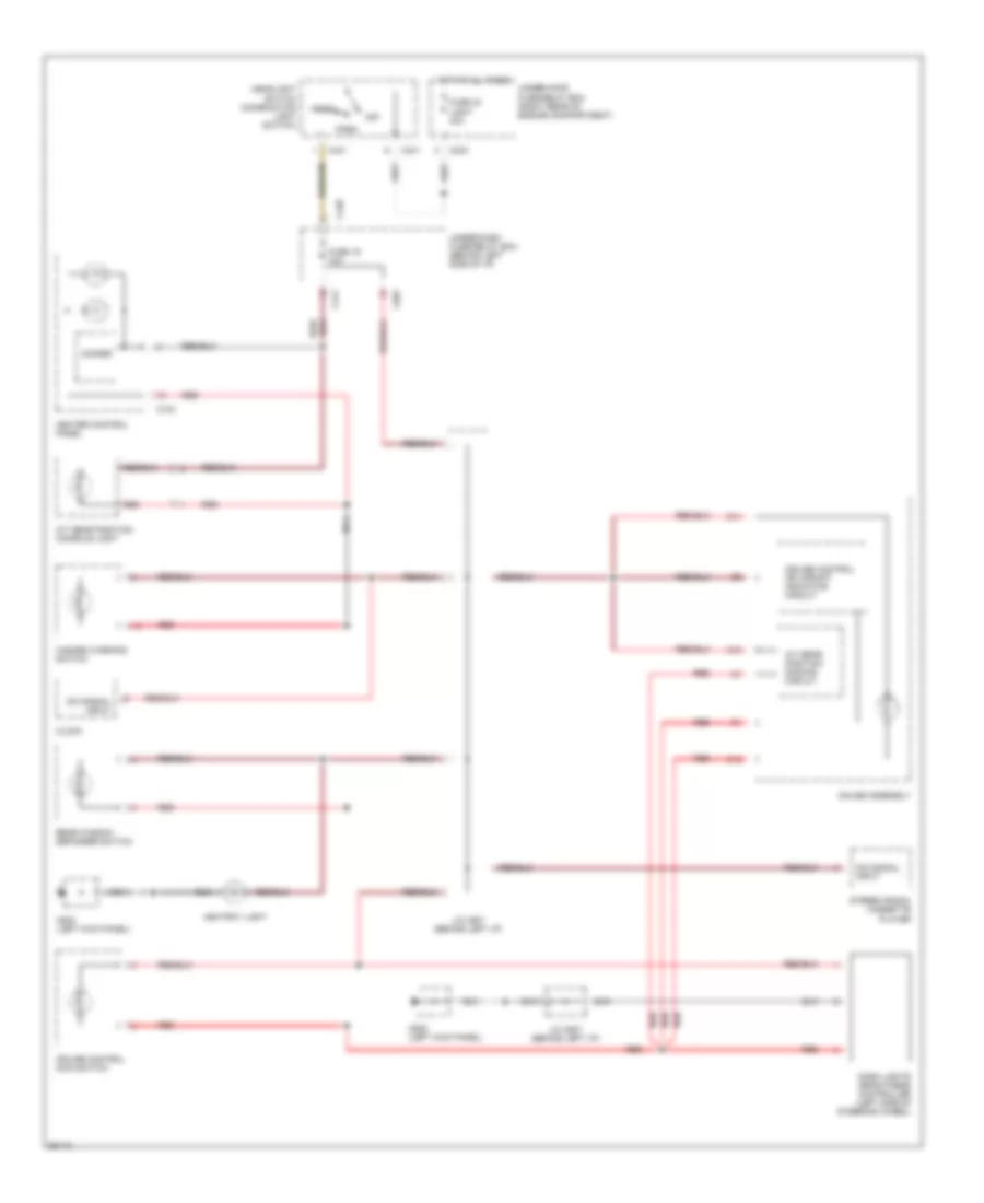
INTERIOR LIGHTS
Interior Light Wiring Diagram (1 of 2) for Honda Civic Si 1994
List of elements for Interior Light Wiring Diagram (1 of 2) for Honda Civic Si 1994:
- A/t gear position console light
- A/t gear position dimming circuit
- Ashtray light
- B11
- B12
- C10
- C203
- C431
- C440
- C441
- C501
- C733
- Clock
- Cruise control main switch
- Cruise control or upshift indicator circuit
- Dash lights brightness controller (left side of steering wheel)
- Dim signal input
- Dimmer
- Fuse 19 10a
- Fuse 40 light 40a
- G200 (left kick panel)
- Gauge assembly
- Hazard warning switch
- Head
- Headlight switch (combination light switch)
- Heater control panel
- Hot at all times
- J/c c507 (behind left i/p)
- Nca
- Off
- Park
- Rear window defogger switch
- Red
- Stereo radio/ cassette player
- Under-dash fuse/relay box (behind left side of i/p)
- Under-hood fuse/relay box (right rear of engine compartment)
Interior Light Wiring Diagram (2 of 2) for Honda Civic Si 1994
List of elements for Interior Light Wiring Diagram (2 of 2) for Honda Civic Si 1994:
- Anti-theft system (optional)
- C438
- C441
- C556
- Cargo area light
- Ceiling light
- Door
- Driver's door switch
- Fuse 3 7.5a
- Hatch latch switch
- Hatchback
- Hot at all times
- Instrument clusters system
- Integrated control unit (under-dash fuse/relay box)
- J/c c417 (left kick panel)
- Left rear door switch
- Left tailgate latch switch
- Off
- Pass- enger's door switch
- Right rear door switch
- Right tailgate latch switch
- Sedan/coupe
- Trunk latch switch
- Trunk light
- Under-dash fuse/relay box (behind left side of i/p)
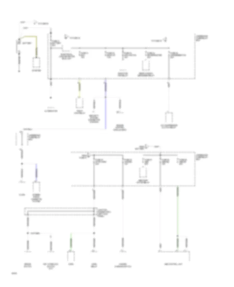
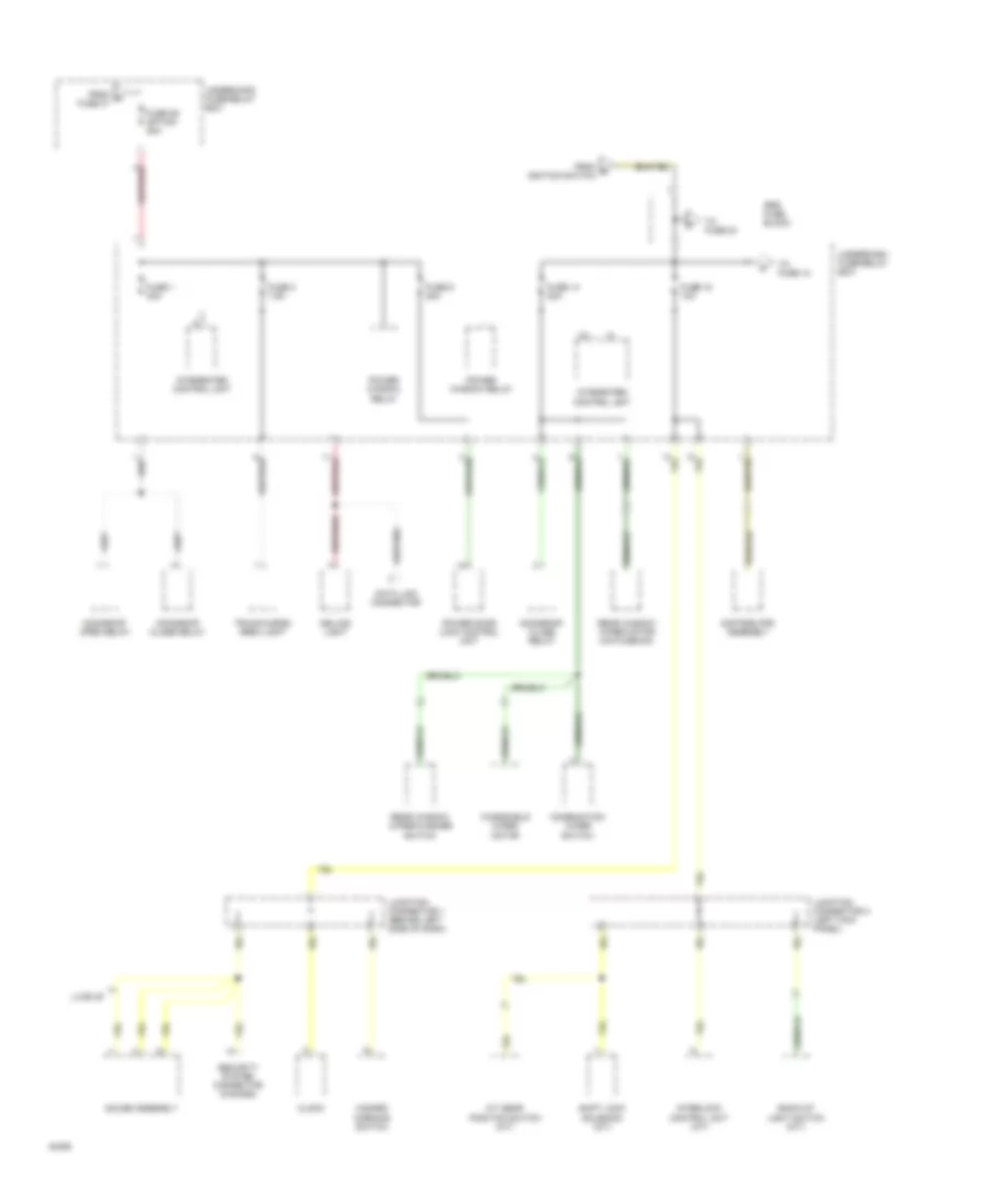
POWER DISTRIBUTION
Power Distribution Wiring Diagram (1 of 4) for Honda Civic Si 1994
List of elements for Power Distribution Wiring Diagram (1 of 4) for Honda Civic Si 1994:
- A/c compressor clutch relay
- Abs control unit
- Abs pump motor relay
- Alternator
- Battery
- Brake switch
- Clock
- Electrical load detector (eld) unit
- Engine control module (ecm)
- From a battery
- From b fuse 41
- Fuse 31 ecu 15a
- Fuse 32 back-up 7.5a
- Fuse 33 cooling fan 15a
- Fuse 34 rr defroster 30a
- Fuse 35 condenser fan 20a
- Fuse 41 battery 80a
- Fuse 42 stop,horn 20a
- Fuse 43 hazard 10a
- Fuse 51 abs 50a
- Fuse 54 abs+b2 15a
- Fuse 55 abs+b1 20a
- Hazard warning switch
- Horn
- Horn relay
- Junction connector 2 (left kick panel)
- Key interlock switch (a/t)
- Pgm-fi main relay
- Radiator fan relay
- Rear window defogger relay
- Security system connector (canada)
- Starter
- Stereo radio/ cassette player
- To fuse 40
- To fuse 42
- To fuse 54
- Underdash fuse/relay box
- Underhood fuse/relay box
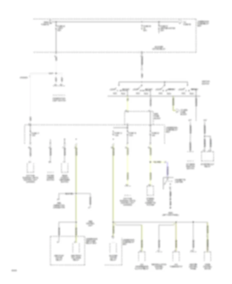
Power Distribution Wiring Diagram (2 of 4) for Honda Civic Si 1994
List of elements for Power Distribution Wiring Diagram (2 of 4) for Honda Civic Si 1994:
- A/c compressor clutch relay
- A/c thermostat
- A/t
- A/t gear position switch
- Abs control unit
- Abs front fail-safe relay
- Abs inspection connector
- Abs pump motor relay
- Acc
- Blower motor relay
- Canada
- Cigarette lighter
- Combination light switch
- Daytime running lights control unit (canada)
- From c fuse 35
- Fuse 13 7.5a
- Fuse 16 7.5a
- Fuse 17 10a
- Fuse 23 15a
- Fuse 37 heater motor 30a
- Fuse 39 ig 50a
- Fuse 40 light 40a
- G200 left kick panel)
- Heater control panel
- Ignition switch
- Lock
- M/t
- Mode control motor
- Power mirror switch
- Rear window defogger switch
- Recirculation control motor
- Run
- Srs fuse block
- Start
- Starter cut relay
- Stereo radio/ cassette player
- To fuse 36
- To srs fuse block
- Underdash fuse/relay box
- Underhood abs fuse/ relay box
- Underhood fuse/relay box
Power Distribution Wiring Diagram (3 of 4) for Honda Civic Si 1994
List of elements for Power Distribution Wiring Diagram (3 of 4) for Honda Civic Si 1994:
- A/t gear position switch (a/t)
- Back-up light switch (m/t)
- Ceiling light
- Clock
- Combination wiper switch
- Data link connector
- Distributor assembly
- From d fuse 37
- From e ignition switch
- Fuse 1 30a
- Fuse 14 20a
- Fuse 15 10a
- Fuse 3 7.5a
- Fuse 36 option 50a
- Fuse 6 20a
- Gauge assembly
- Hazard warning switch
- Integrated control unit
- Interlock control unit (a/t)
- Junction connector 1 (behind left side of dash)
- Junction connector 2 (left kick panel)
- Lx,ex,si
- Moonroof close relay
- Moonroof open relay
- Power door lock control unit
- Power window relay
- Rear window wiper motor (hatchback)
- Rear window wiper/washer switch
- Security system connector (canada)
- Shift lock solenoid (a/t)
- Srs fuse block
- To fuse 12
- To fuse 24
- Trunk/cargo area light
- Underdash fuse/relay box
- Underhood fuse/relay box
- Windshield wiper motor
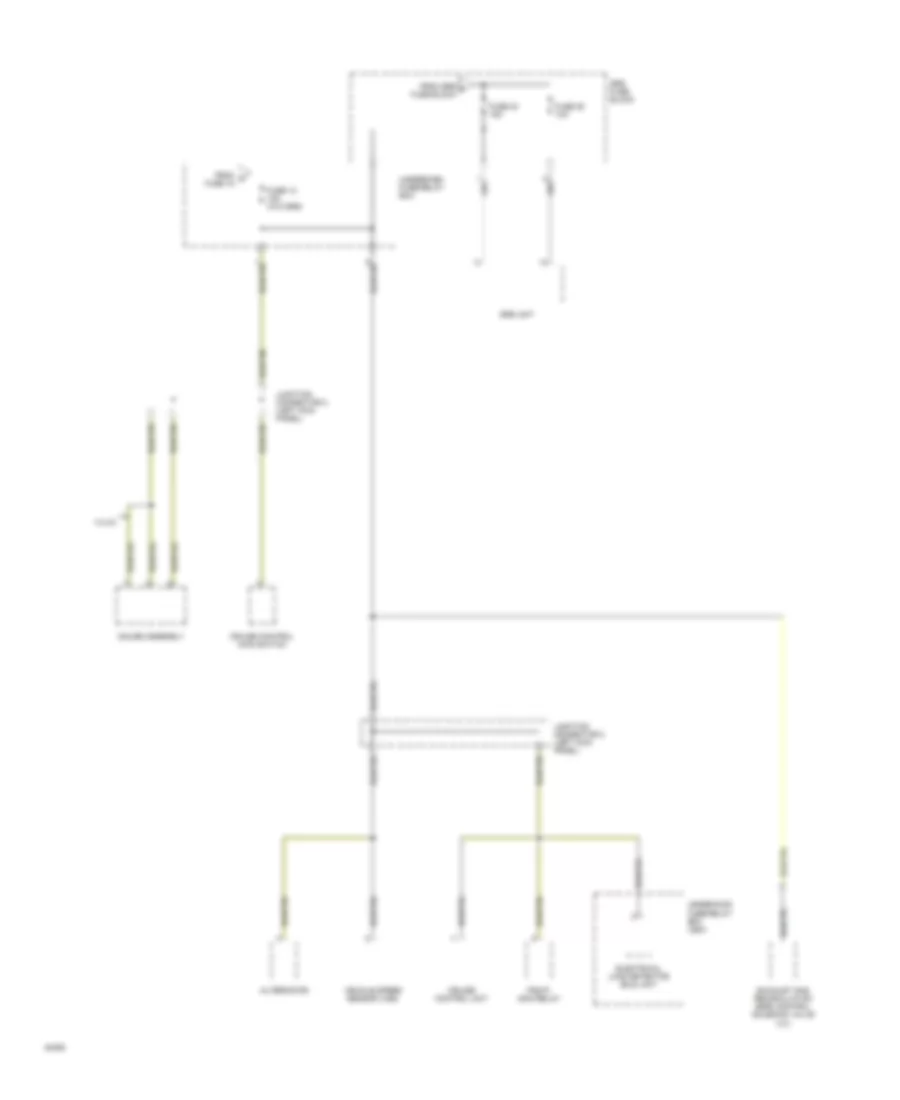
Power Distribution Wiring Diagram (4 of 4) for Honda Civic Si 1994
List of elements for Power Distribution Wiring Diagram (4 of 4) for Honda Civic Si 1994:
- Alternator
- Cruise control main switch
- Cruise control unit
- Electrical load detector (eld) unit
- Exhaust gas recirculation (egr) control solenoid valve (vx)
- From g fuse 15
- From srs f fuse block
- Fuse 12 15a (w/o srs)
- Fuse 24 15a
- Fuse 25 10a
- Gauge assembly
- Junction connector 2 (left kick panel)
- Pgm-fi main relay
- Srs fuse block
- Srs unit
- Underdash fuse/relay box
- Underhood fuse/relay box (usa)
- Vehicle speed sensor (vss)
- Vx,cx
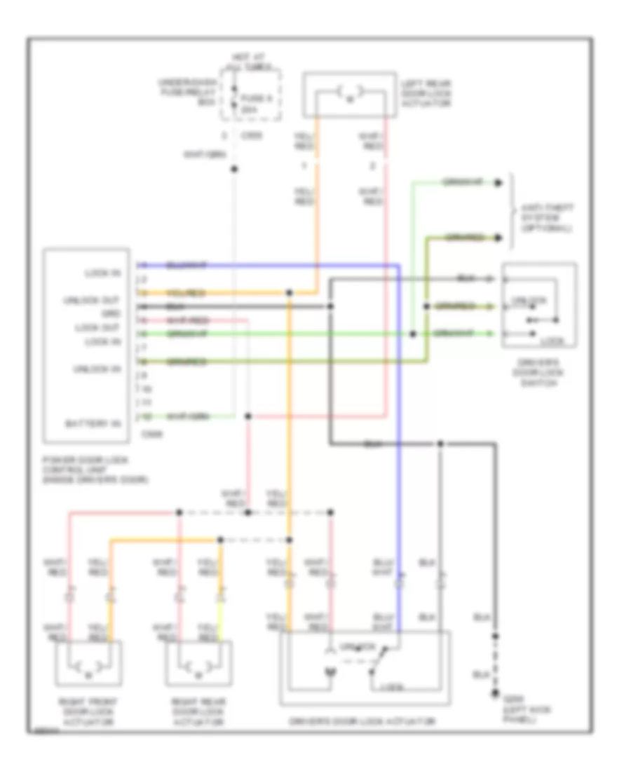
POWER DOOR LOCKS
Power Door Lock Wiring Diagram for Honda Civic Si 1994
List of elements for Power Door Lock Wiring Diagram for Honda Civic Si 1994:
- 20a
- Anti-theft system (optional)
- Battery in
- C555
- C606
- Driver's door lock actuator
- Driver's door lock switch
- Fuse 6
- G200 (left kick panel)
- Grd
- Hot at all times
- Left rear door lock actuator
- Lock
- Lock in
- Lock out
- Power door lock control unit (inside driver's door)
- Right front door lock actuator
- Right rear door lock actuator
- Under-dash fuse/relay box
- Unlock
- Unlock in
- Unlock out
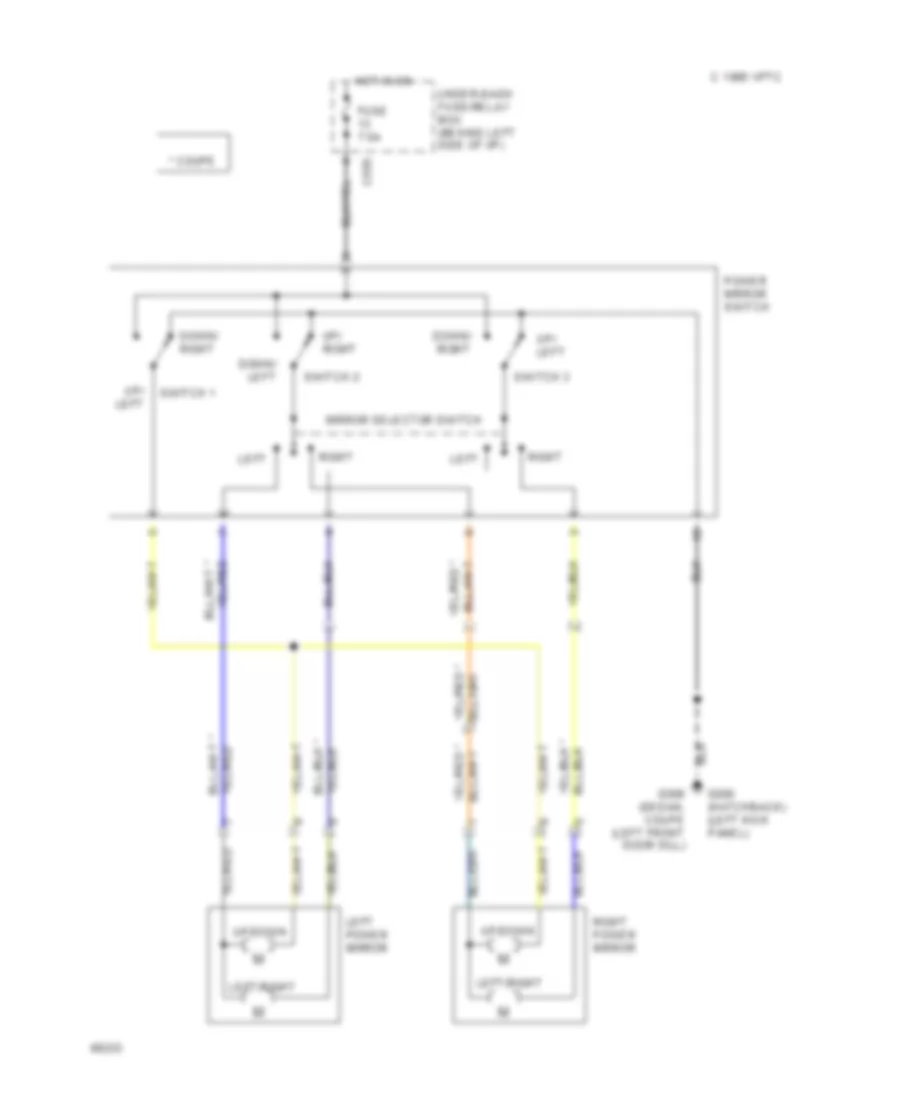
POWER MIRRORS
Power Mirror Wiring Diagram for Honda Civic Si 1994
List of elements for Power Mirror Wiring Diagram for Honda Civic Si 1994:
- * coupe
- 1995 vftc c
- C555
- Down/ left
- Down/ right
- Fuse 7.5a
- G200 (hatchback) (left kick panel)
- G309 (sedan, coupe (left front door sill)
- Hot in on
- Left
- Left power mirror
- Left/right
- Mirror selector switch
- Power mirror switch
- Right
- Right power mirror
- Switch 1
- Switch 2
- Switch 3
- Under-dash fuse/relay box (behind left side of i/p)
- Up/ left
- Up/ right
- Up/down
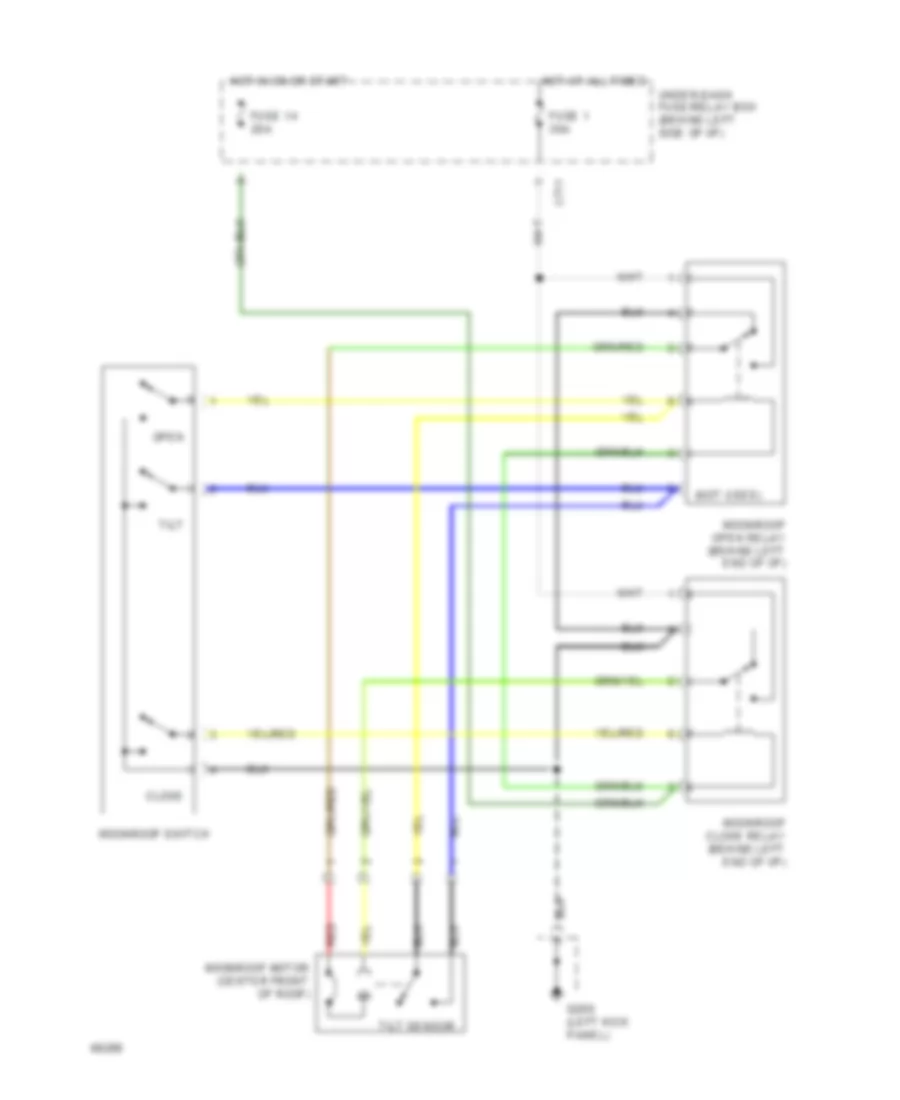
POWER TOP/SUNROOF
Moonroof Wiring Diagram, Coupe & Hatchback for Honda Civic Si 1994
List of elements for Moonroof Wiring Diagram, Coupe & Hatchback for Honda Civic Si 1994:
- (not used)
- C711
- Close
- Fuse 1 30a
- Fuse 14 20a
- G200 (left kick panel)
- Hot at all times
- Hot in on or start
- Moonroof close relay (behind left end of i/p)
- Moonroof motor (center front of roof)
- Moonroof open relay (behind left end of i/p)
- Moonroof switch
- Open
- Red
- Tilt
- Tilt sensor
- Under-dash fuse/relay box (behind left side of i/p)
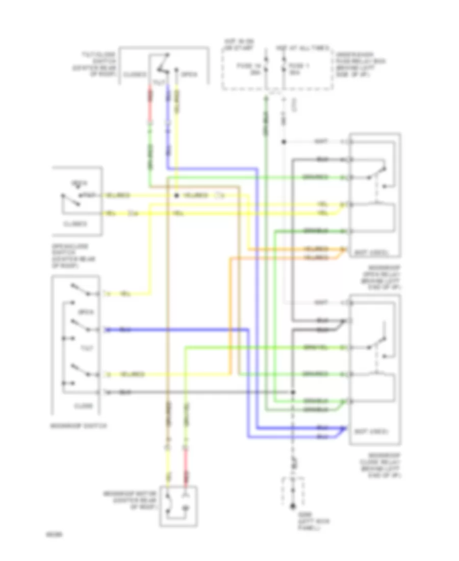
Moonroof Wiring Diagram, Sedan for Honda Civic Si 1994
List of elements for Moonroof Wiring Diagram, Sedan for Honda Civic Si 1994:
- (not used)
- C711
- Close
- Closed
- Fuse 1 30a
- Fuse 14 20a
- G200 (left kick panel)
- Hot at all times
- Hot in on or start
- Moonroof close relay (behind left end of i/p)
- Moonroof motor (center rear of roof)
- Moonroof open relay (behind left end of i/p)
- Moonroof switch
- Open
- Open/close switch (center rear of roof)
- Red
- Tilt
- Tilt/close switch (center rear of roof)
- Under-dash fuse/relay box (behind left side of i/p)
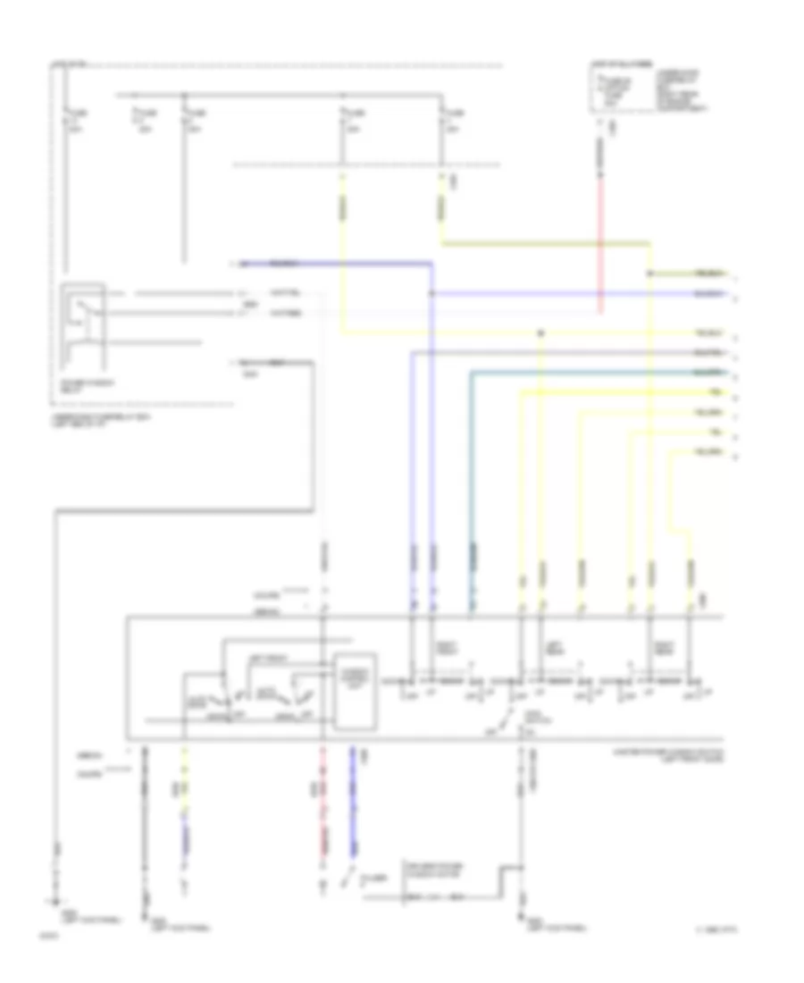
POWER WINDOWS
Power Window Wiring Diagram (1 of 2) for Honda Civic Si 1994
List of elements for Power Window Wiring Diagram (1 of 2) for Honda Civic Si 1994:
- (coupe)
- (sedan)
- 1995 vftc c
- 20a
- 50a
- Auto down
- C203
- C440
- C555
- C604 or c605
- C605
- Down
- Driver's power window motor
- Fuse
- Fuse 36 option fuse
- G200 (left kick panel)
- Hot at all times
- Hot in on
- Left front
- Left rear
- Main switch
- Master power window switch (left front door)
- Off
- Power window relay
- Pulser
- Red/
- Right front
- Right rear
- Under-dash fuse/relay box (left end of i/p)
- Under-hood fuse/relay box (right rear of engine compartment)
- Window control unit
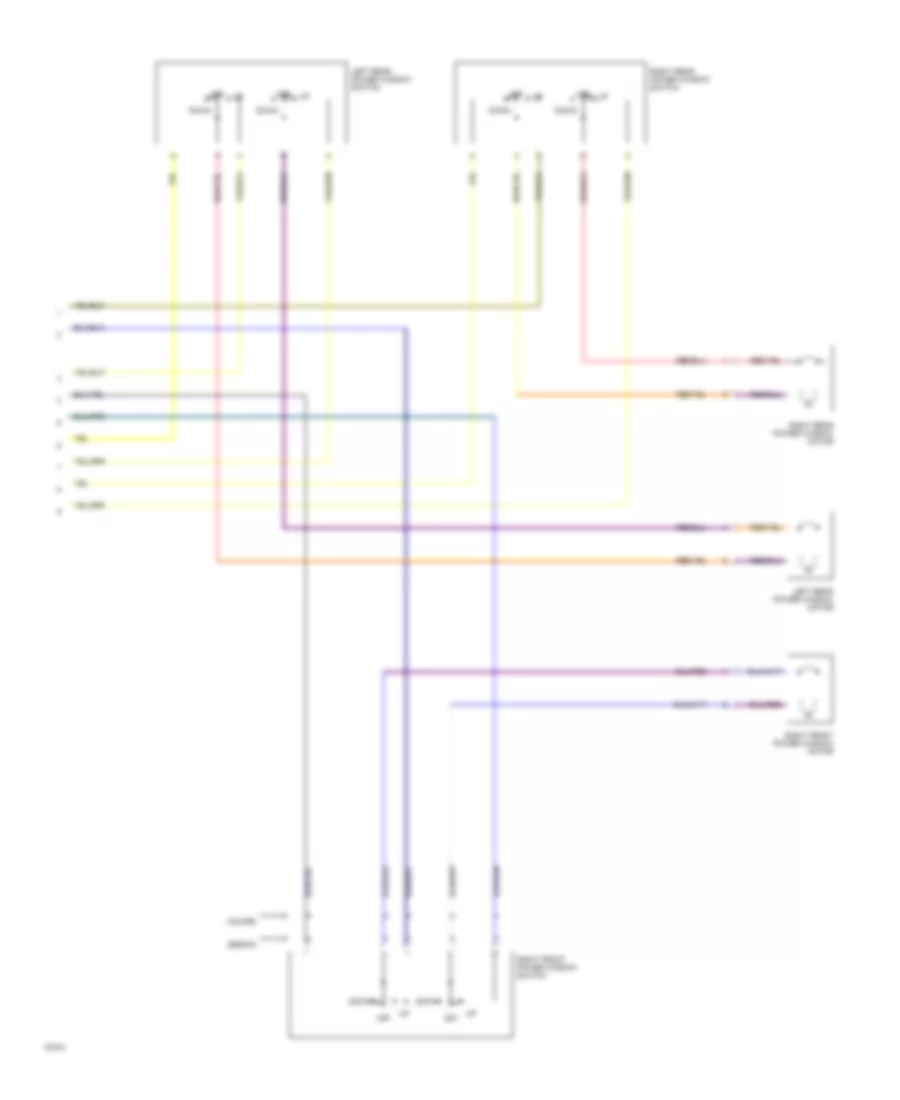
Power Window Wiring Diagram (2 of 2) for Honda Civic Si 1994
List of elements for Power Window Wiring Diagram (2 of 2) for Honda Civic Si 1994:
- (coupe)
- (sedan)
- Down
- Left rear power window motor
- Left rear power window switch
- Off
- Right front power window motor
- Right front power window switch
- Right rear power window motor
- Right rear power window switch
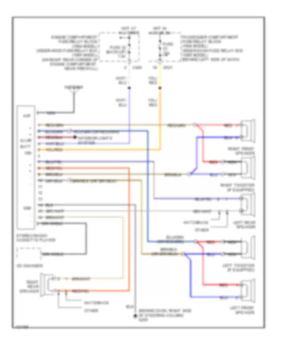
RADIO
Radio Wiring Diagrams, Base Radio for Honda Civic Si 1994
List of elements for Radio Wiring Diagrams, Base Radio for Honda Civic Si 1994:
- (behind dash, right side of steering column) g205
- Ant
- Antenna
- Batt
- C205
- C501
- Cd changer
- Din cable
- Engine compartment fuse/relay block (1994 model) under-hood fuse/relay box (1995 model) (on right rear corner of engine compartment, near firewall)
- Fuse 15a
- Fuse 32 (back-up) 7.5a
- Gnd
- Hatchback
- Hot at all times
- Hot in acc or on
- Ign
- Illum
- Interior lights system
- Left front speaker
- Left rear speaker
- Left tweeter (if equipped)
- Nca
- Other
- Passenger compartment fuse/relay block (1994 model) under-dash fuse relay box (1995 model) (behind left side of dash)
- Red
- Right front speaker
- Right rear speaker
- Right tweeter (if equipped)
- Stereo radio/ cassette player
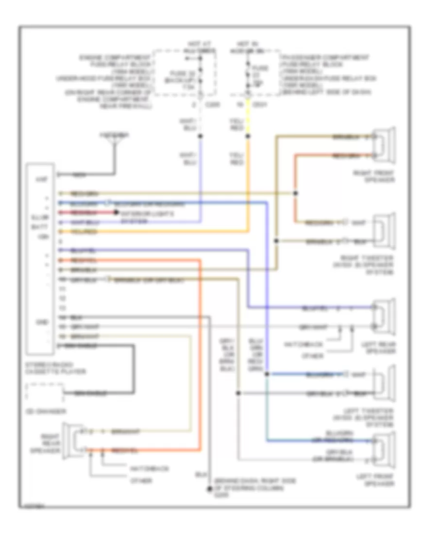
Radio Wiring Diagrams, Premium Radio for Honda Civic Si 1994
List of elements for Radio Wiring Diagrams, Premium Radio for Honda Civic Si 1994:
- (behind dash, right side of steering column) g205
- Ant
- Antenna
- Batt
- C205
- C501
- Cd changer
- Din cable
- Engine compartment fuse/relay block (1994 model) under-hood fuse/relay box (1995 model) (on right rear corner of engine compartment, near firewall)
- Fuse 15a
- Fuse 32 (back-up) 7.5a
- Gnd
- Hatchback
- Hot at all times
- Hot in acc or on
- Ign
- Illum
- Interior lights system
- Left front speaker
- Left rear speaker
- Left tweeter (w/six (6) speaker system)
- Nca
- Other
- Passenger compartment fuse/relay block (1994 model) under-dash fuse relay box (1995 model) (behind left side of dash)
- Right front speaker
- Right rear speaker
- Right tweeter (w/six (6) speaker system)
- Stereo radio/ cassette player
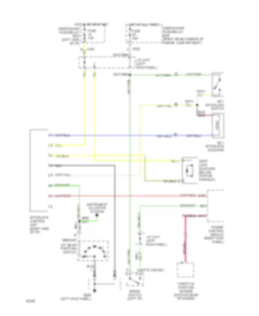
SHIFT INTERLOCKS
Shift Interlock Wiring Diagram for Honda Civic Si 1994
List of elements for Shift Interlock Wiring Diagram for Honda Civic Si 1994:
- (with cruise)
- A/t gear position switch
- Brake switch (left i/p)
- C202
- C441
- D11
- D18
- Engine control module (right kick panel)
- Fuse 10a
- Fuse 20a
- G200 (left kick panel)
- Hot at all times
- Hot in on or start
- Instrument clluster system
- Interlock control unit (right side of i/p)
- J/c c417 (left kick panel)
- Key interlock solenoid
- Key interlock switch
- Shift lock solenoid (below center console)
- Throttle position sensor (center rear of engine)
- Under-dash fuse/relay box (left side of i/p)
- Under-hood fuse/relay box (right rear corner of engine compartment)
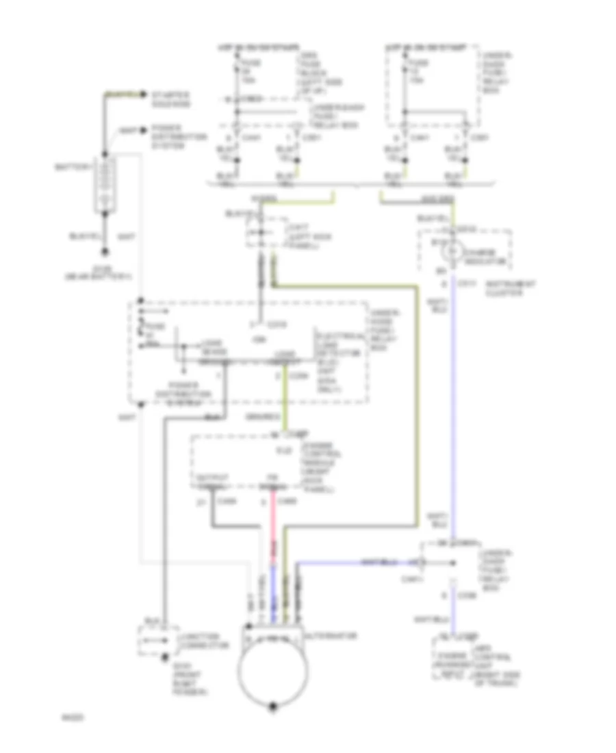
STARTING/CHARGING
Charging Wiring Diagram for Honda Civic Si 1994
List of elements for Charging Wiring Diagram for Honda Civic Si 1994:
- (left kick panel)
- (near battery)
- (usa only)
- Abs control unit (right side of trunk)
- Alternator
- B10
- Battery
- C204
- C218
- C404
- C406
- C417
- C441
- C501
- C511
- C556
- C569
- C922
- Charge indicator
- Eld
- Electrical load detector (eld) unit
- Engine control module (right kick panel)
- Engine running input
- Fr signal
- Fuse 15a
- Fuse 80a
- G101 (front right fender)
- G105
- Ground
- Hot in on or start
- Ign
- Instrument cluster
- Junction connector
- Load
- Load sense
- Output
- Output signal
- Pnk
- Power distribution system
- Srs fuse block (left side of i/p)
- Starter solenoid
- Under- dash fuse/ relay box
- Under- hood fuse/ relay box
- Under-dash fuse/ relay box
- W/o srs
- W/srs
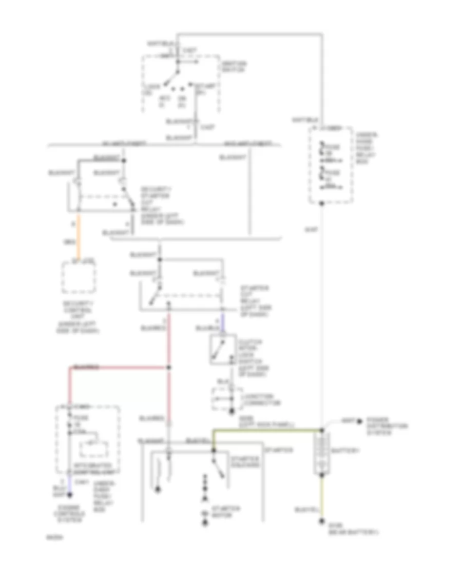
Starting Wiring Diagram, A/T Canada for Honda Civic Si 1994
List of elements for Starting Wiring Diagram, A/T Canada for Honda Civic Si 1994:
- (below center
- (not used)
- A/t gear position switch
- Acc (i)
- Battery
- C203
- C427
- C440
- C441
- C442
- Console)
- Engine controls system
- Fuse 50a
- Fuse 7.5a
- Fuse 80a
- G105 (near battery)
- Ignition switch
- Integrated control unit
- Lock (0)
- On (ii)
- Power distribution system
- Security control unit (under left side of dash)
- Security starter cut relay (under left side of dash)
- Start (iii)
- Starter
- Starter motor
- Starter solenoid
- Under- dash fuse/ relay box
- Under- hood fuse/ relay box
- W/ anti-theft
- W/o anti-theft
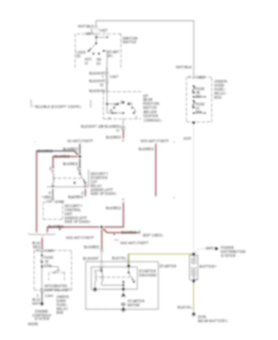
Starting Wiring Diagram, A/T U.S. for Honda Civic Si 1994
List of elements for Starting Wiring Diagram, A/T U.S. for Honda Civic Si 1994:
- (below center
- (under left side of dash)
- A/t gear position switch
- Acc (i)
- Battery
- C203
- C427
- C440
- C441
- C57
- Console)
- Engine controls system
- Fuse 50a
- Fuse 7.5a
- Fuse 80a
- G105 (near battery)
- Ignition switch
- Integrated control unit
- Lock (0)
- On (ii)
- Power distribution system
- Security control unit
- Security starter cut relay (under left side of dash)
- Start (iii)
- Starter
- Starter motor
- Starter solenoid
- Under- dash fuse/ relay box
- Under- hood fuse/ relay box
- W/ anti-theft
- W/o anti-theft
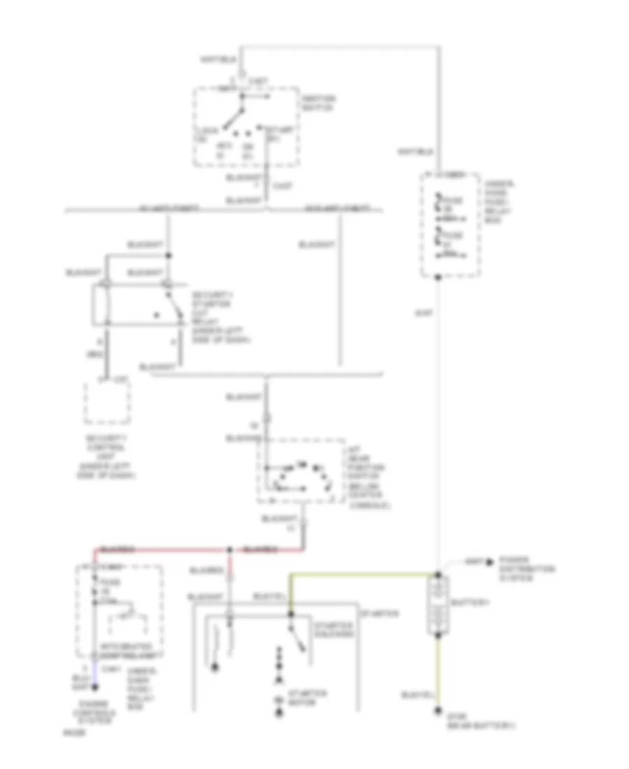
Starting Wiring Diagram, M/T Canada for Honda Civic Si 1994
List of elements for Starting Wiring Diagram, M/T Canada for Honda Civic Si 1994:
- (not used)
- Acc (i)
- Battery
- C203
- C427
- C440
- C441
- C442
- Clutch inter- lock switch (left side of dash)
- Engine controls system
- Fuse 50a
- Fuse 7.5a
- Fuse 80a
- G105 (near battery)
- G200 (left kick panel)
- Ignition switch
- Integrated control unit
- Junction connector
- Lock (0)
- On (ii)
- Power distribution system
- Security control unit (under left side of dash)
- Security starter cut relay (under left side of dash)
- Start (iii)
- Starter
- Starter cut relay (left side of dash)
- Starter motor
- Starter solenoid
- Under- dash fuse/ relay box
- Under- hood fuse/ relay box
- W/ anti-theft
- W/o anti-theft
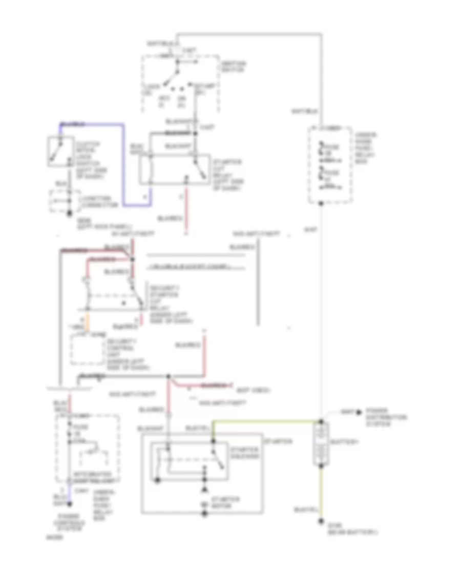
Starting Wiring Diagram, M/T U.S. for Honda Civic Si 1994
List of elements for Starting Wiring Diagram, M/T U.S. for Honda Civic Si 1994:
- (under left side of dash)
- Acc (i)
- Battery
- C203
- C427
- C440
- C441
- C57
- Clutch inter- lock switch (left side of dash)
- Engine controls system
- Fuse 50a
- Fuse 7.5a
- Fuse 80a
- G105 (near battery)
- G200 (left kick panel)
- Ignition switch
- Integrated control unit
- Junction connector
- Lock (0)
- On (ii)
- Power distribution system
- Security control unit
- Security starter cut relay (under left side of dash)
- Start (iii)
- Starter
- Starter cut relay (left side of dash)
- Starter motor
- Starter solenoid
- Under- dash fuse/ relay box
- Under- hood fuse/ relay box
- W/ anti-theft
- W/o anti-theft
SUPPLEMENTAL RESTRAINTS
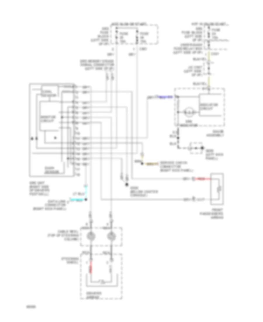
Supplemental Restraint Wiring Diagram for Honda Civic Si 1994
List of elements for Supplemental Restraint Wiring Diagram for Honda Civic Si 1994:
- C501
- C801
- Cable reel (top of steering column)
- Connector (right kick panel)
- Cowl sensor
- Dash sensor
- Data link connector (right kick panel)
- Driver's airbag
- Front passenger's airbag
- Fuse 10a
- Fuse 15a
- G200 (left kick panel)
- G302 (below center console)
- Gauge assembly
- Hot in on or start
- Indicator circuit
- J/c c507 (left side of i/p)
- Monitor circuit
- Nca
- Red
- Service check
- Srs fuse block (left side of i/p)
- Srs indicator
- Srs memory erase signal connector (left side of i/p)
- Srs unit (right side of driver's footwell)
- Steering wheel
- Under-dash fuse/relay box (left side of i/p)
WARNING SYSTEMS
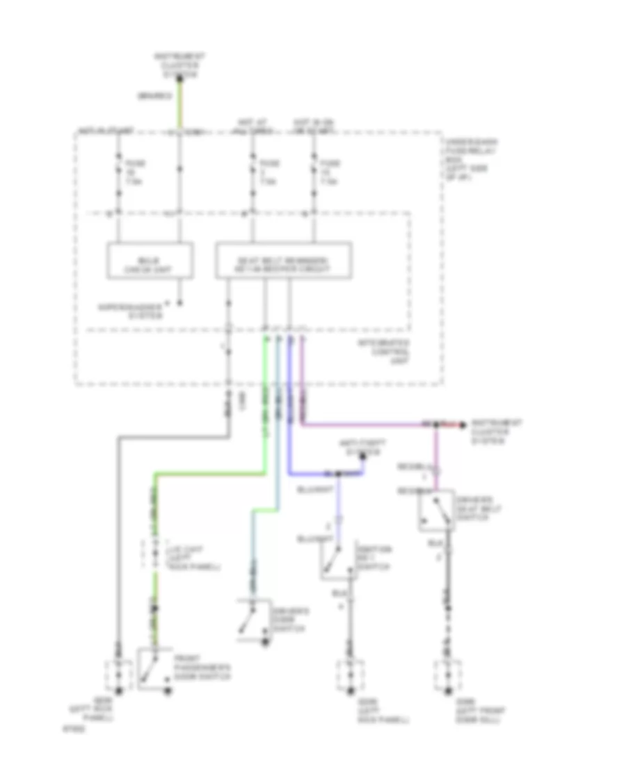
Warning System Wiring Diagrams for Honda Civic Si 1994
List of elements for Warning System Wiring Diagrams for Honda Civic Si 1994:
- Anti-theft system
- Bulb check unit
- C440
- C501
- Driver's door switch
- Driver's seat belt switch
- Front passenger's door switch
- Fuse 7.5a
- G200 (left kick panel)
- G309 (left front door sill)
- Hot at all times
- Hot in on or start
- Hot in start
- Ignition key switch
- Instrument cluster system
- Integrated control unit
- J/c c417 (left kick panel)
- Seat belt reminder/ key-in beeper circuit
- Under-dash fuse/relay box (left side of i/p)
- Wiper/washer system
WIPER/WASHER
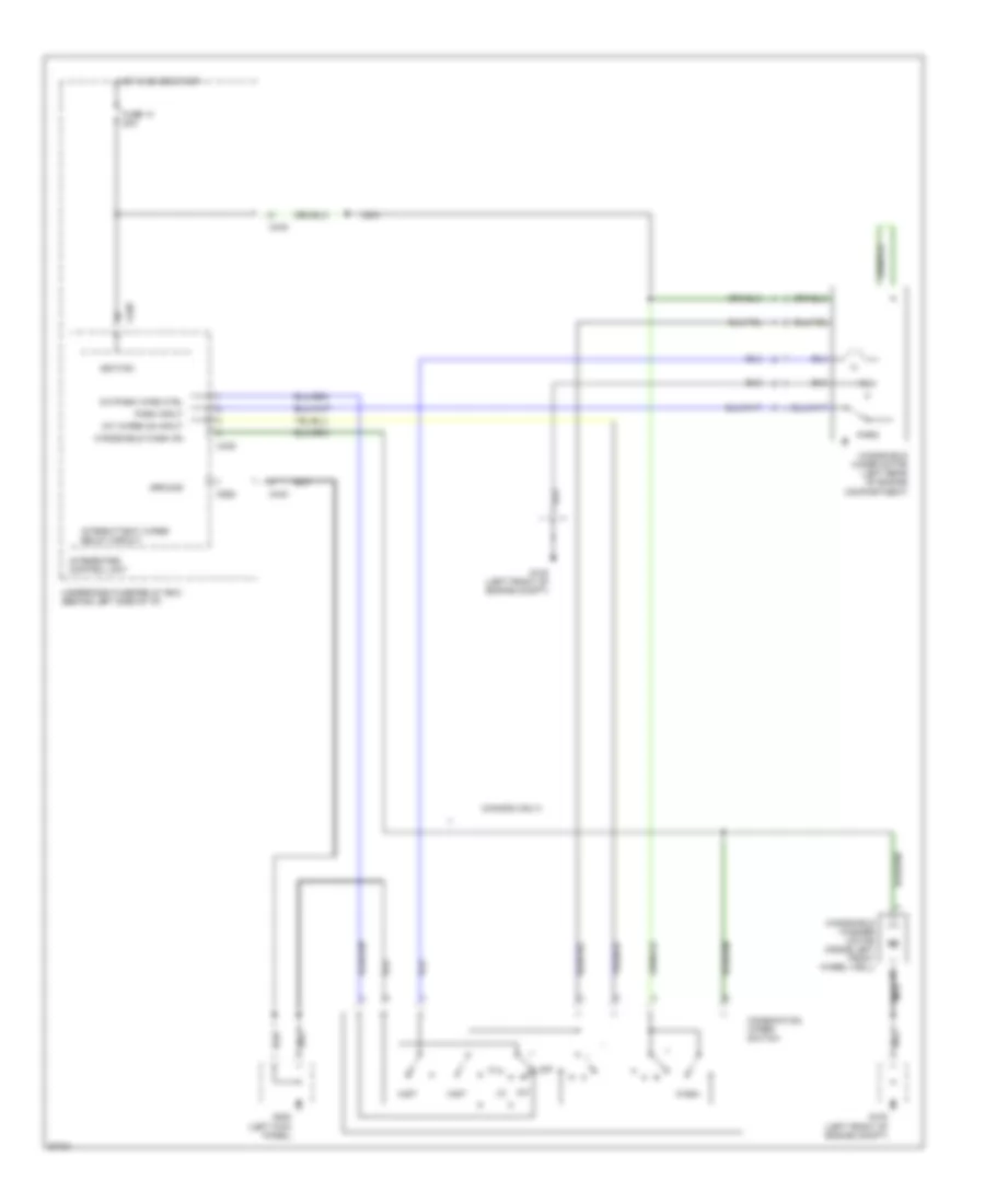
Front Wiper/Washer Wiring Diagram for Honda Civic Si 1994
List of elements for Front Wiper/Washer Wiring Diagram for Honda Civic Si 1994:
- (canada only)
- C438
- C440
- C928
- Combination wiper switch
- Fuse 14 20a
- G100 (left front of engine comp't)
- G200 (left kick panel)
- Ground
- Hot in on or start
- Ignition
- Int
- Int wiper on input
- Int/park wipe ctrl
- Integrated control unit
- Intermittent wiper relay circuit
- Mist
- Nca
- Off
- Park
- Park input
- Run
- Under-dash fuse/relay box (behind left side of i/p)
- Wash
- Windshield wash on
- Windshield washer motor (inside left front wheel well)
- Windshield wiper motor (left rear of engine compartment)
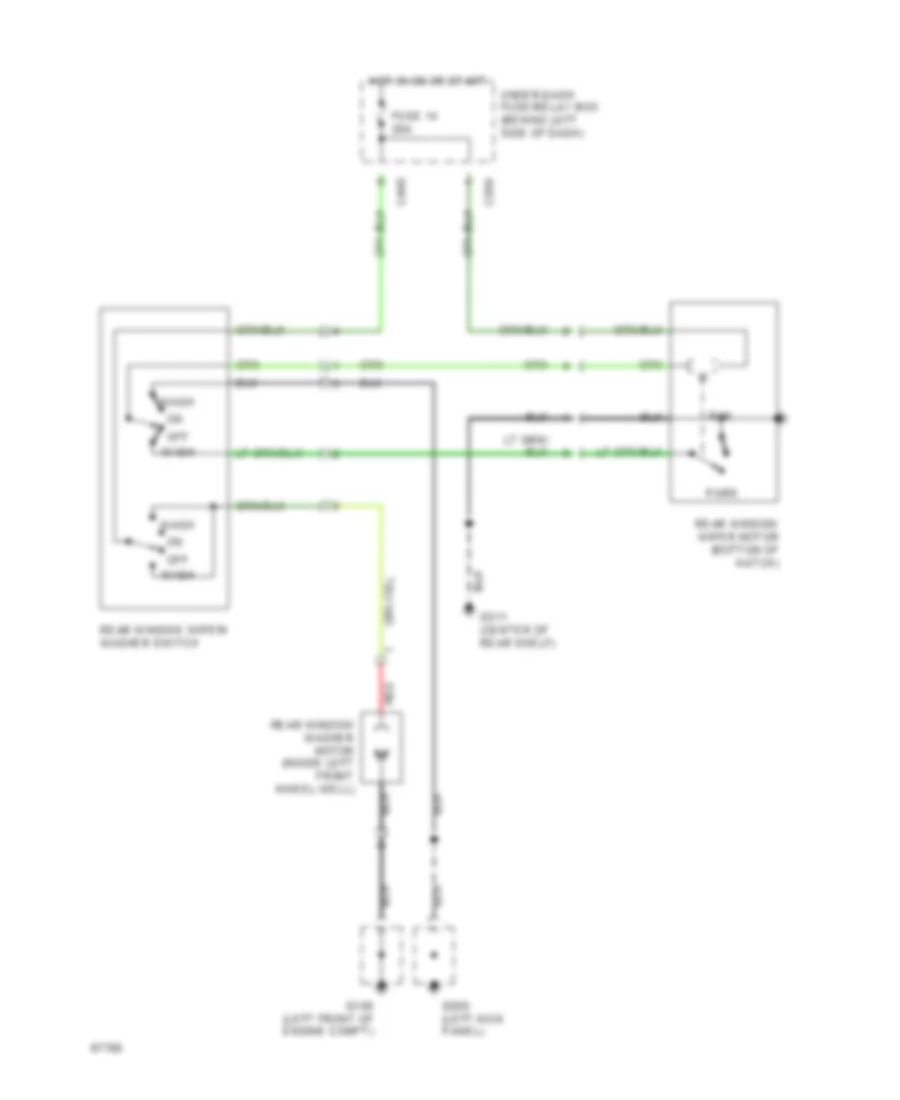
Rear Wiper/Washer Wiring Diagram for Honda Civic Si 1994
List of elements for Rear Wiper/Washer Wiring Diagram for Honda Civic Si 1994:
- C440
- C556
- Fuse 14 20a
- G100 (left front of engine comp't)
- G200 (left kick panel)
- G311 (center of rear shelf)
- Hot in on or start
- Off
- Park
- Rear window washer motor (inside left front wheel well)
- Rear window wiper motor (bottom of hatch)
- Rear window wiper/ washer switch
- Red
- Run
- Under-dash fuse/relay box (behind left side of dash)
- Wash