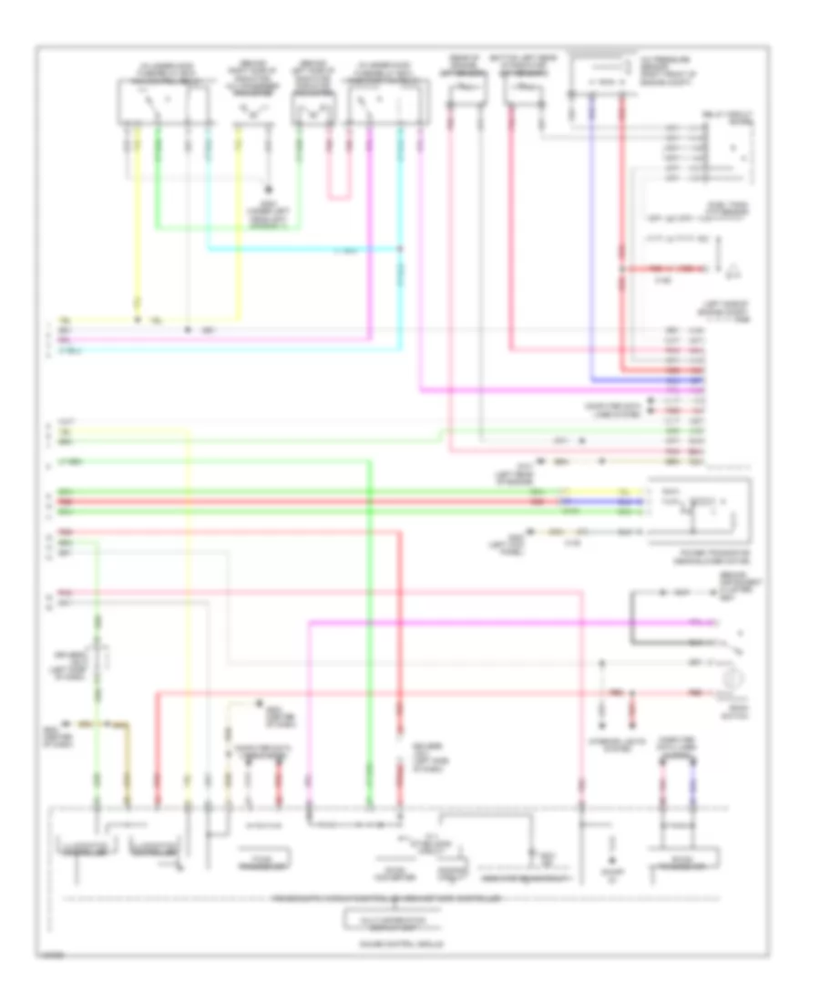
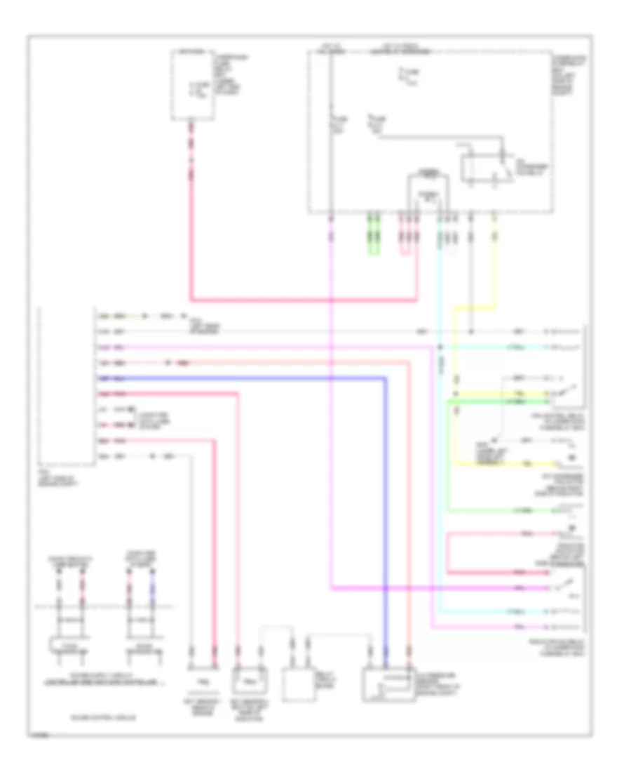
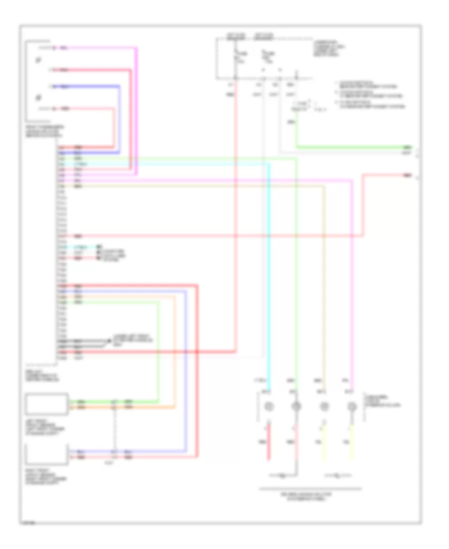
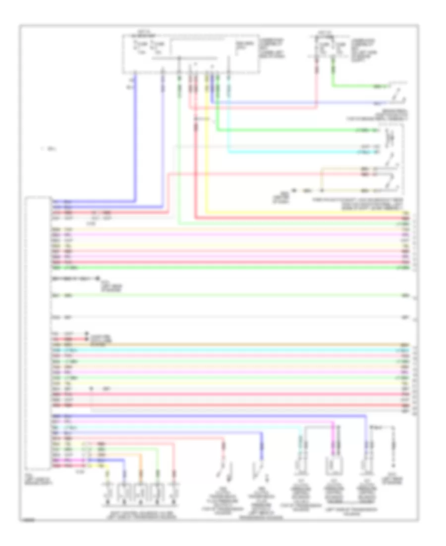
AIR CONDITIONING
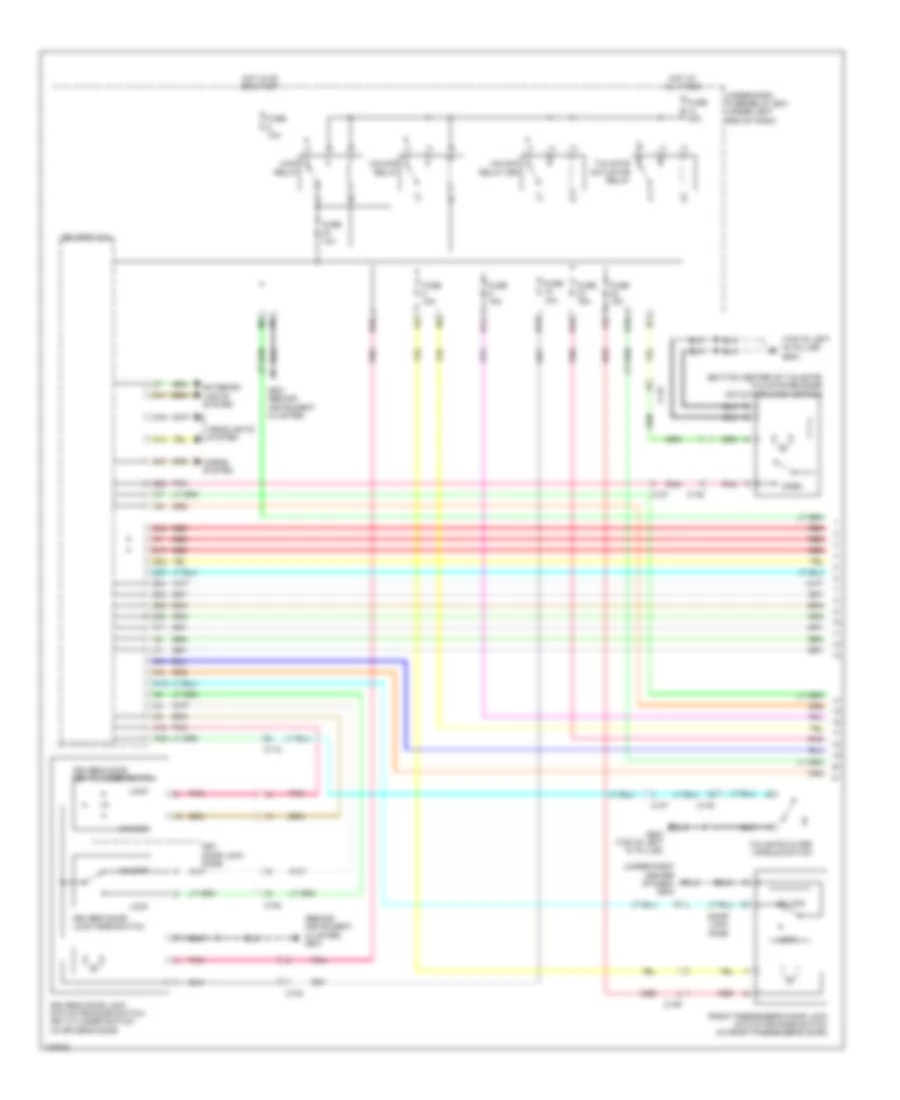
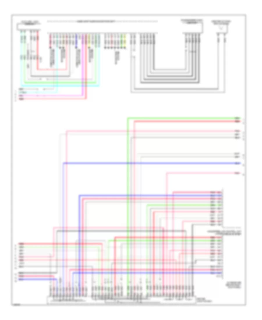
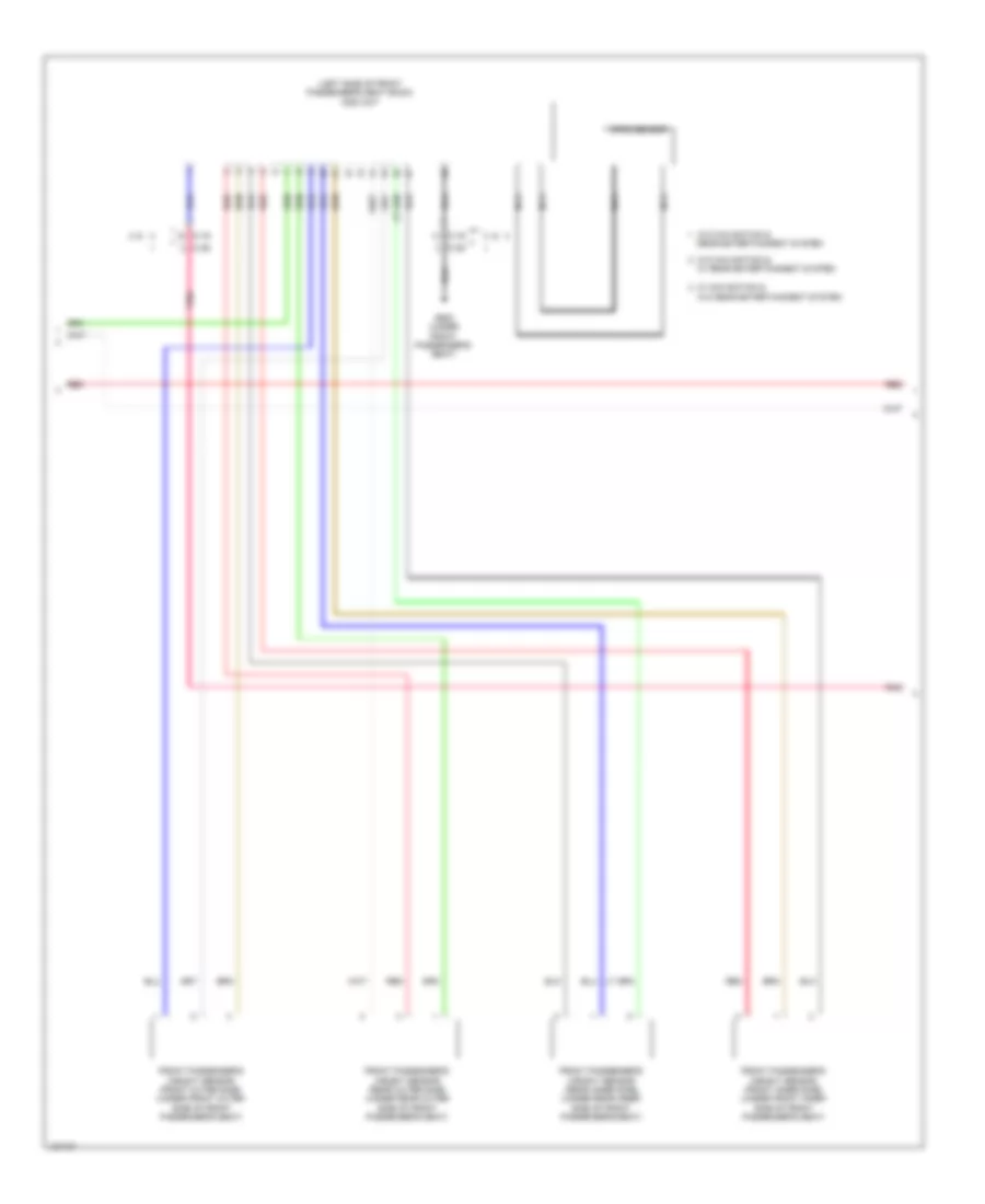
Automatic A/C Wiring Diagram (1 of 3) for Honda CR-V EX-L 2014

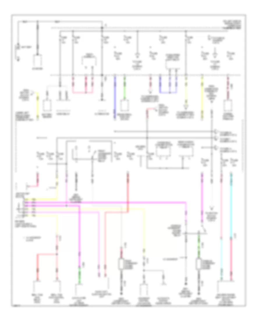
List of elements for Automatic A/C Wiring Diagram (1 of 3) for Honda CR-V EX-L 2014:
- (center of dash) g502
- 10a
- 7.5a
- Automatic lighting/ sunlight sensor (top center of dash)
- B42
- B43
- C106
- C108
- C12
- C17
- C19
- Computer data lines system
- D17
- D28
- D31
- Driver's air mix control motor (left side of hvac unit)
- Driver's j/b 2 (left side of dash)
- Engine controls system
- Evaporator temperature sensor (on evaporator)
- Fuse
- Fuse 7.5a
- G502 (center of dash)
- Hot in on
- Hot in on or start
- Hvac control unit/ climate control unit
- Micu
- Mode control motor (right side of hvac unit)
- Passenger's air mix control motor (lower right side of hvac unit)
- Pgm-fi sub relay
- Pnk
- Q16
- Rear window defogger relay
- Rear window defogger switch/ power mirror defogger switch
- Rear window defogger switch/ power mirror defogger switch indicator (led)
- Recirculation control motor (upper left side of blower unit)
- Red
- Relay circuit board
- Tail light relay
- Under-dash fuse/relay box (under left end of dash)
- Under-hood fuse/relay box (on left side of engine compt)
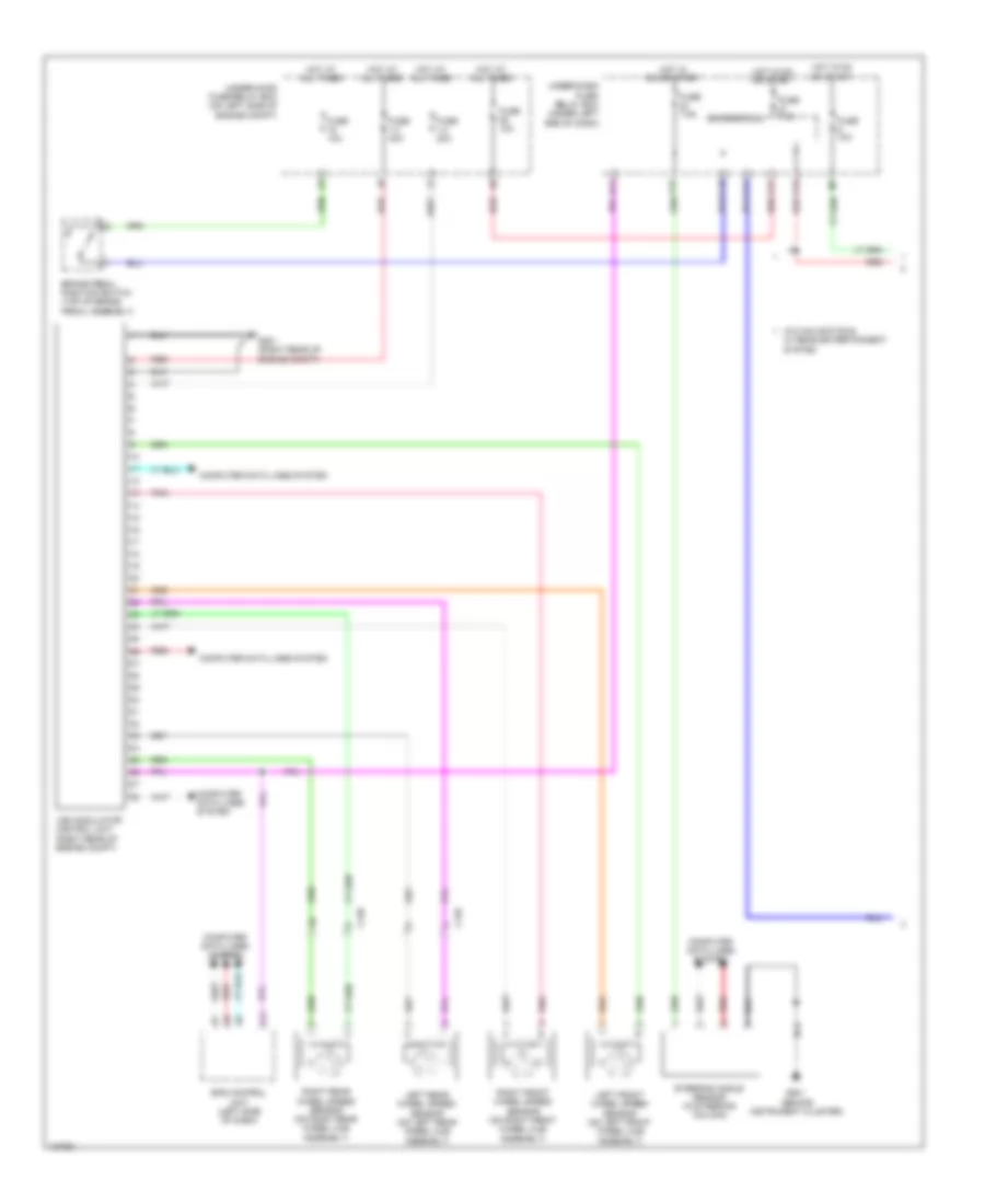
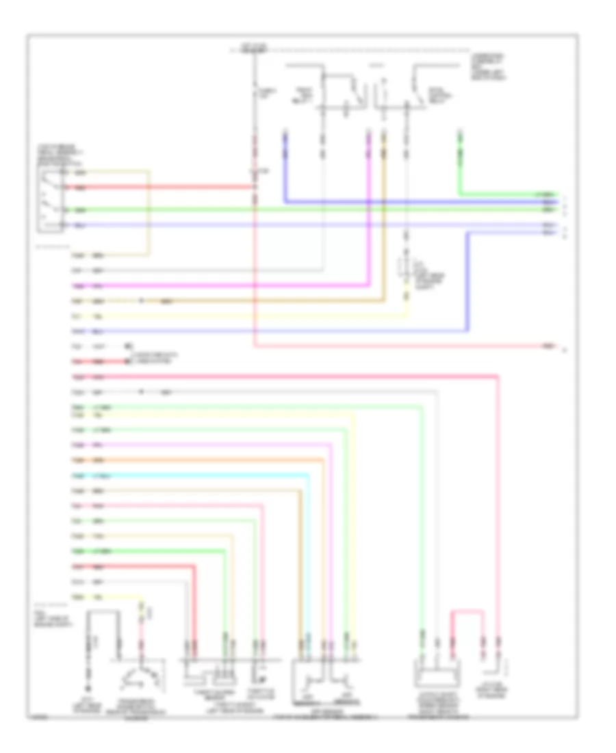
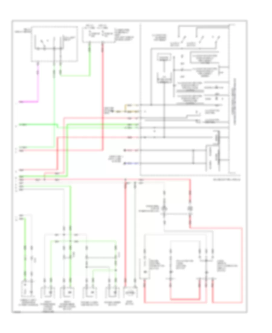
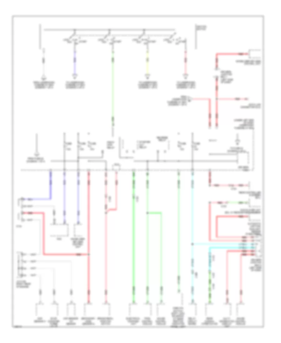
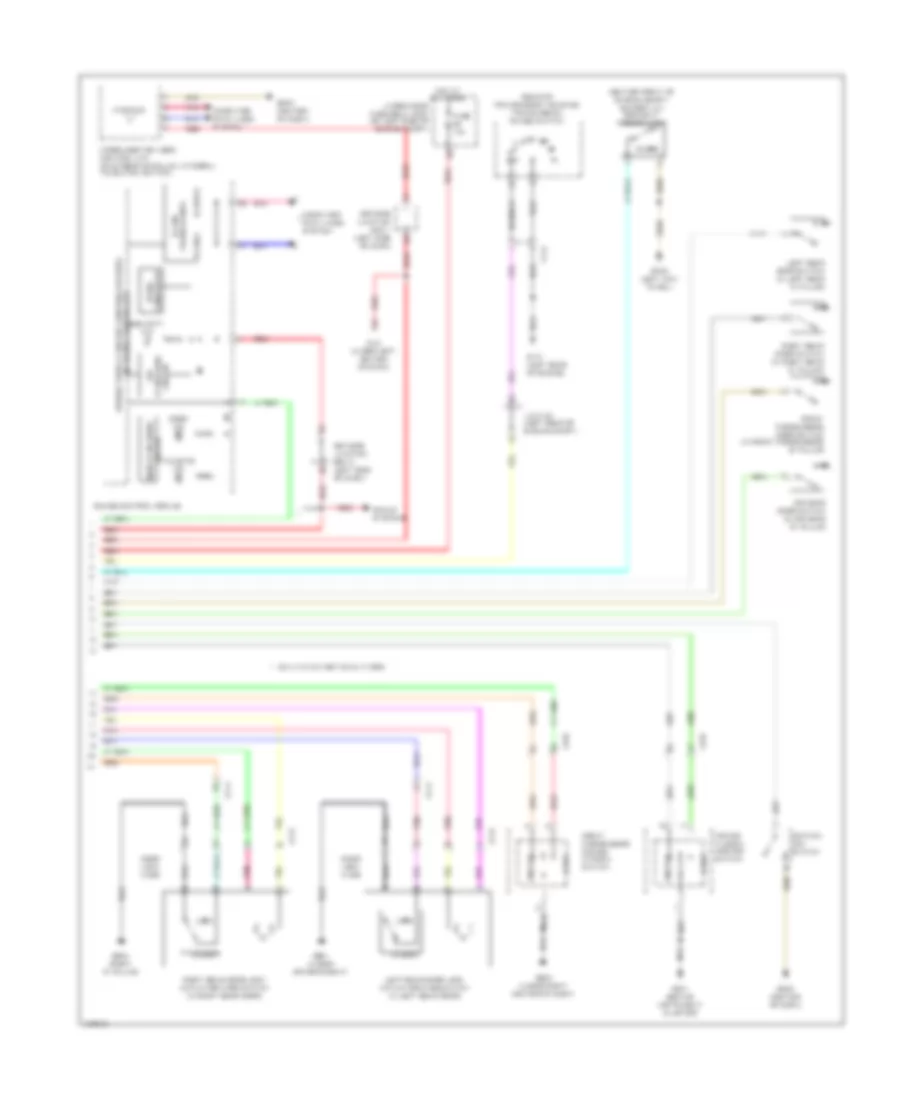
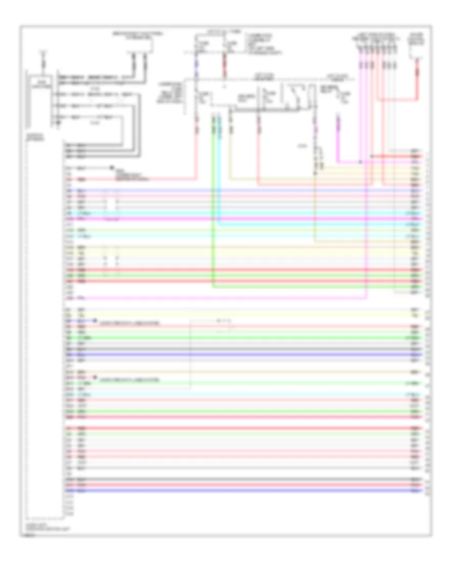
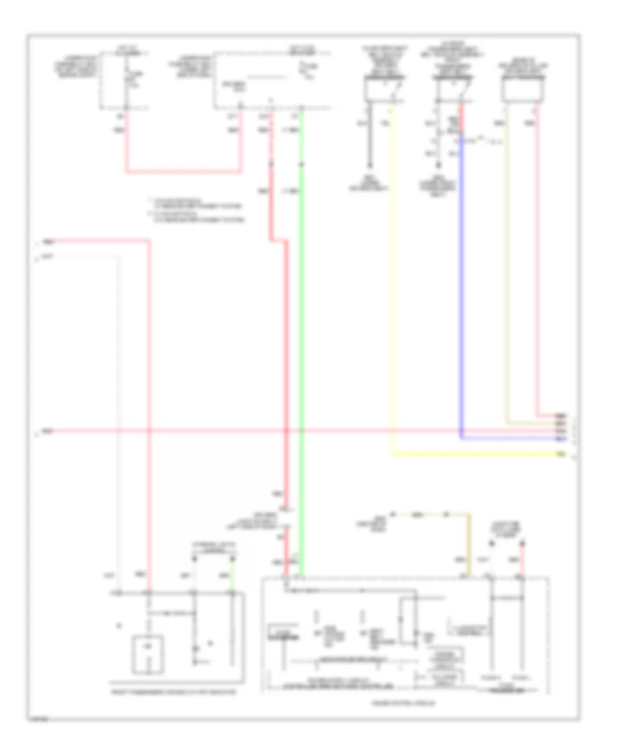
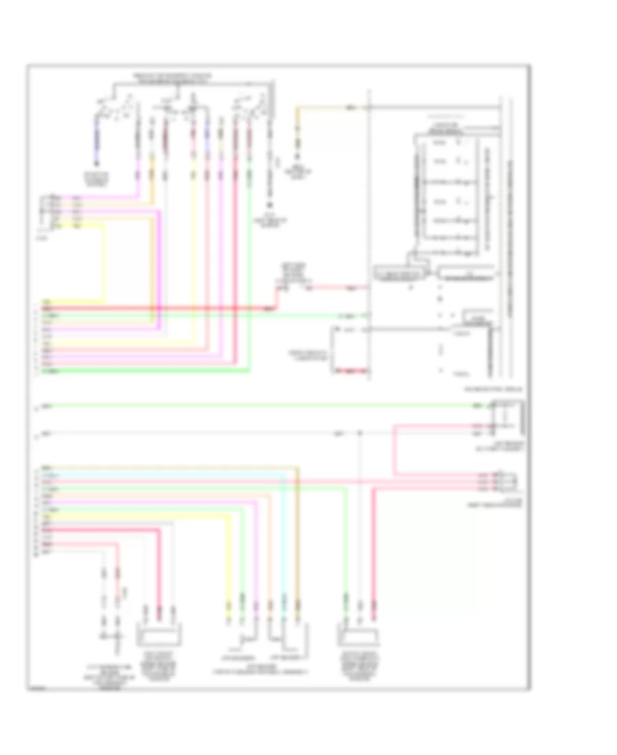
Automatic A/C Wiring Diagram (2 of 3) for Honda CR-V EX-L 2014
List of elements for Automatic A/C Wiring Diagram (2 of 3) for Honda CR-V EX-L 2014:
- A/c compressor clutch (a/c compressor clutch/ thermal protector) (lower left front of engine)
- A/c compressor clutch relay (in under-hood fuse/relay box)
- A/c condenser fan relay
- Blower motor (bottom of a/c blower unit)
- Blower motor relay
- C105
- C108
- C133
- C134
- C138
- Diode a
- Diode b
- Driver's j/b 2 (left side of dash)
- Fuse 1-6 100a
- Fuse 10a
- Fuse 15a
- Fuse 2-10 20a
- Fuse 2-11 20a
- Fuse 2-8 40a
- Fuse 20a
- Fuse 7.5a
- G402 (left kick panel)
- Hot at all times
- Humidity sensor
- Humidity/in-car temperature sensor (lower left center of dash)
- In-car temperature sensor
- Outside air temperature sensor (behind left side of front bumper)
- Pnk
- Red
- Under-hood fuse/relay box (on left side of engine compt)
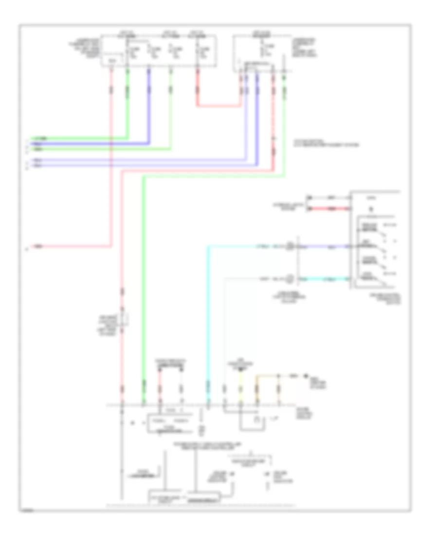
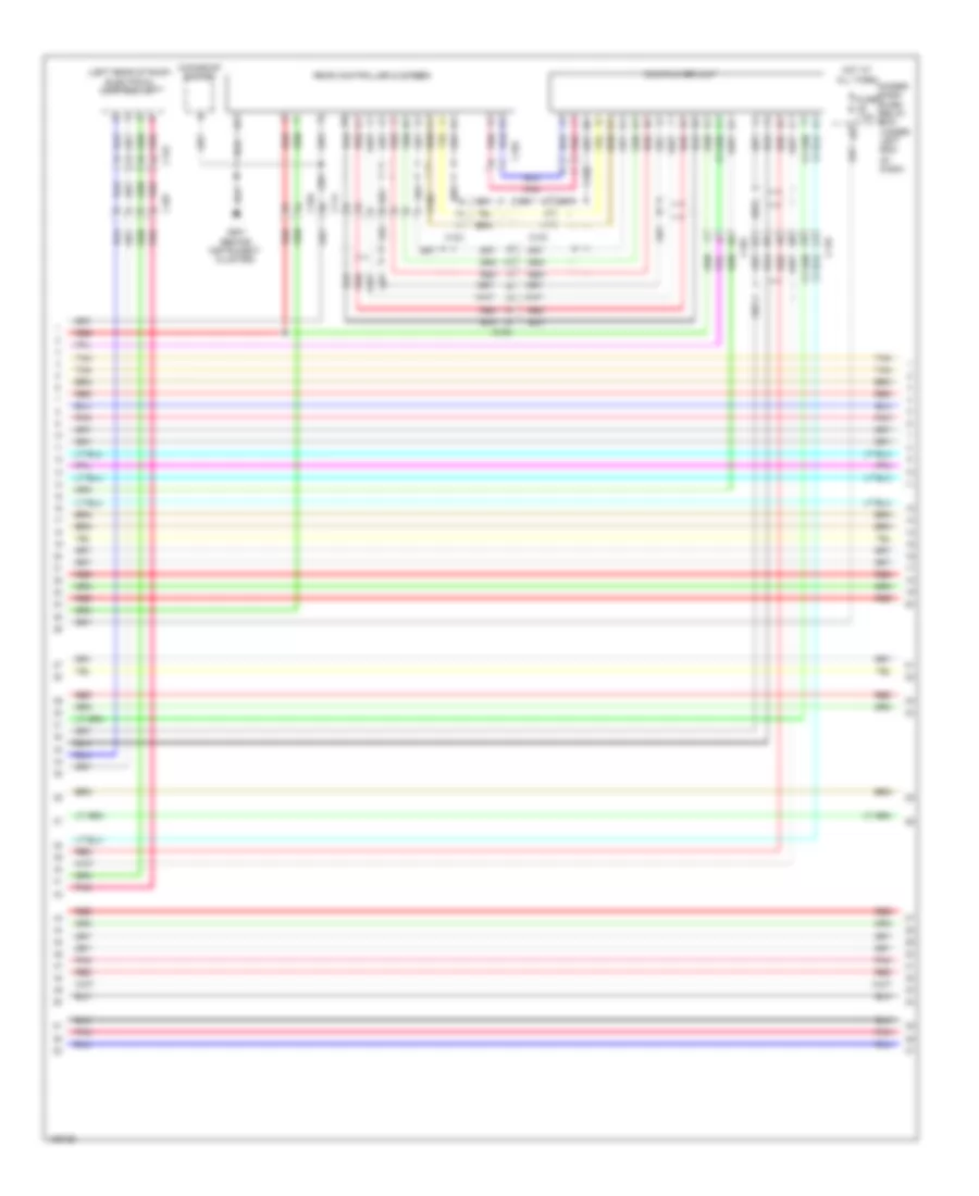
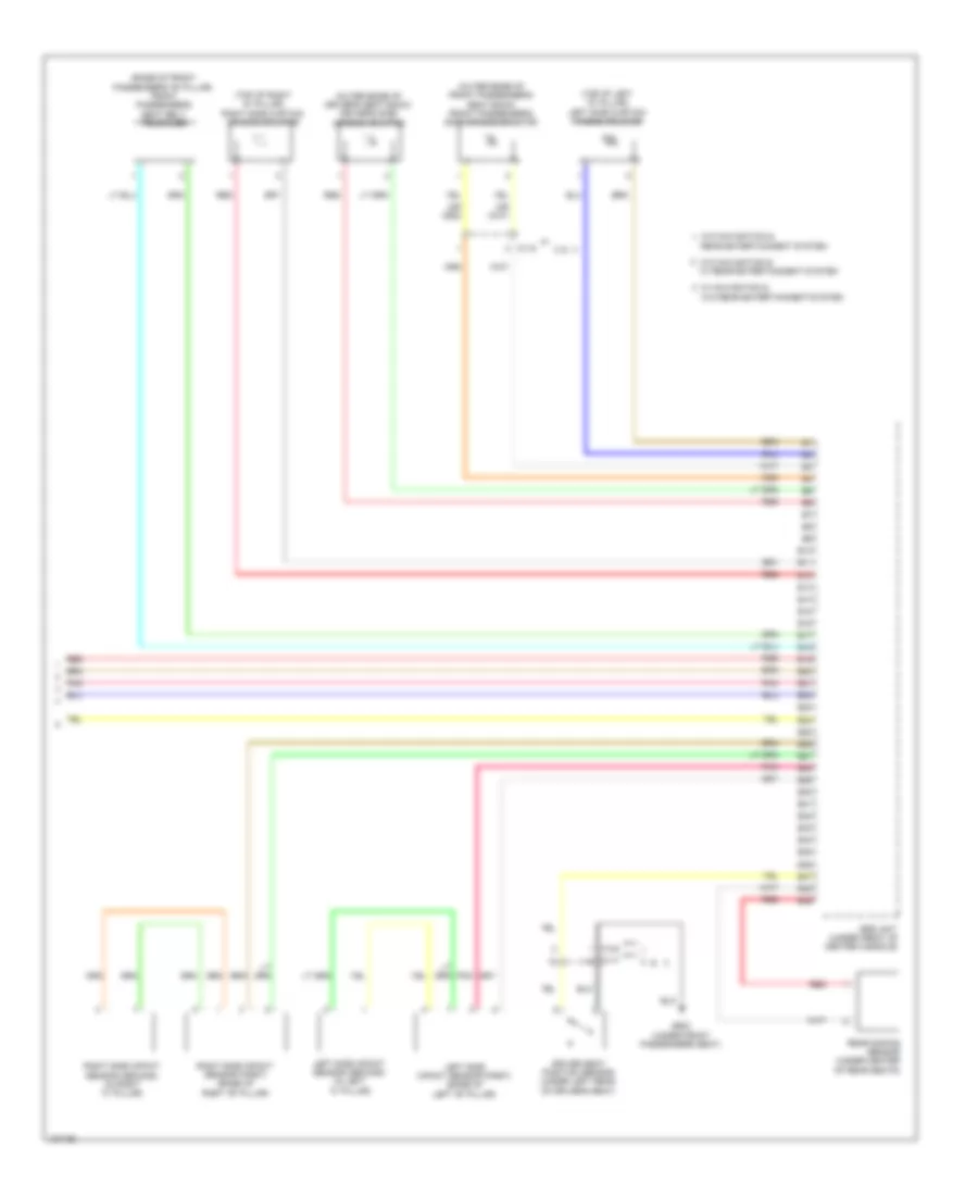
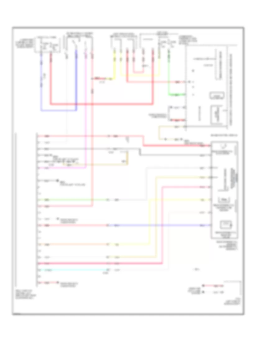
Automatic A/C Wiring Diagram (3 of 3) for Honda CR-V EX-L 2014
List of elements for Automatic A/C Wiring Diagram (3 of 3) for Honda CR-V EX-L 2014:
- (behind instrument cluster) g501
- (behind left side of radiator) radiator fan motor
- (behind right side of radiator) a/c condenser fan motor
- (bottom left rear of radiator) ect sensor 2
- (fuel tank) ftp sensor
- (in under-hood fuse/relay box) fan control relay
- (in under-hood fuse/relay box) radiator fan relay
- (left side of engine compt) pcm
- (rear of engine) ect sensor 1
- 10 v stabilizing circuit
- A/c pressure sensor (right front of engine compt)
- A10
- A11
- A12
- A14
- A15
- A16
- A20
- A27
- A30
- A37
- A44
- B-can transceiver
- B34
- B44
- C106
- C126
- C138
- C20
- Computer data lines system
- Dc/dc converter
- Dimming circuit
- Driver's j/b 2 (left side of dash)
- Eco ind
- Econ switch
- F-can transceiver
- G101 (left rear of engine)
- G302 (under left headlight assembly)
- G402 (left kick panel)
- G502 (center of dash)
- Gauge control module
- Illumination controller
- Indicator drive circuit
- Interior lights system
- Multi-information display unit
- Pnk
- Power transistor (near blower motor)
- Red
- Relay circuit board
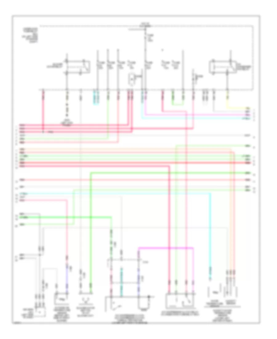
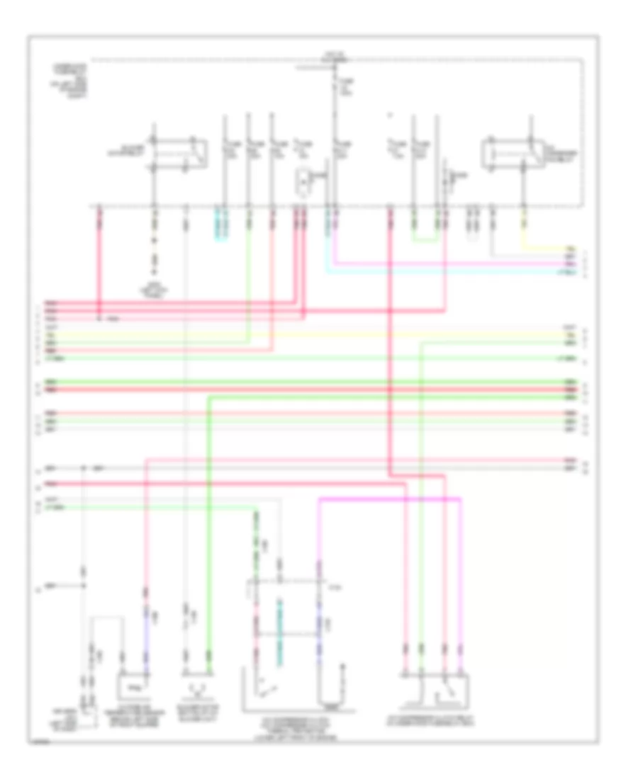
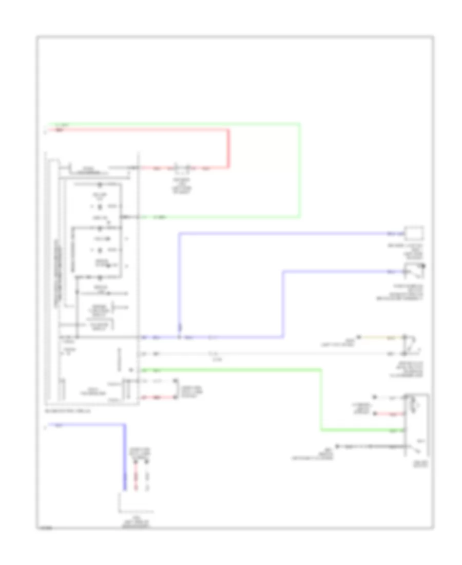
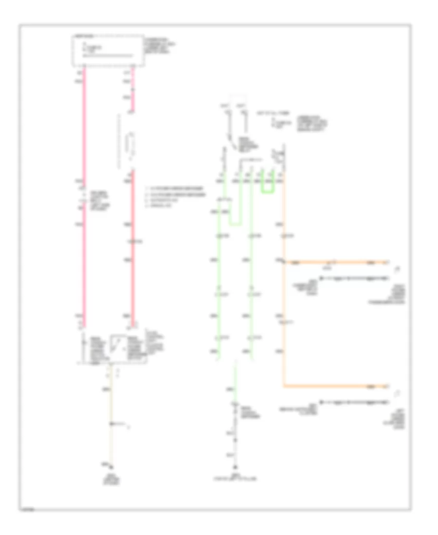
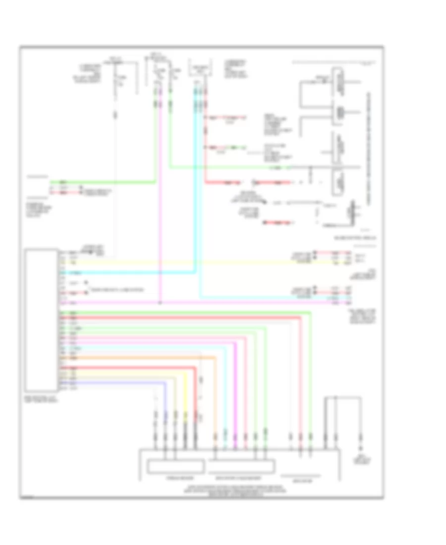
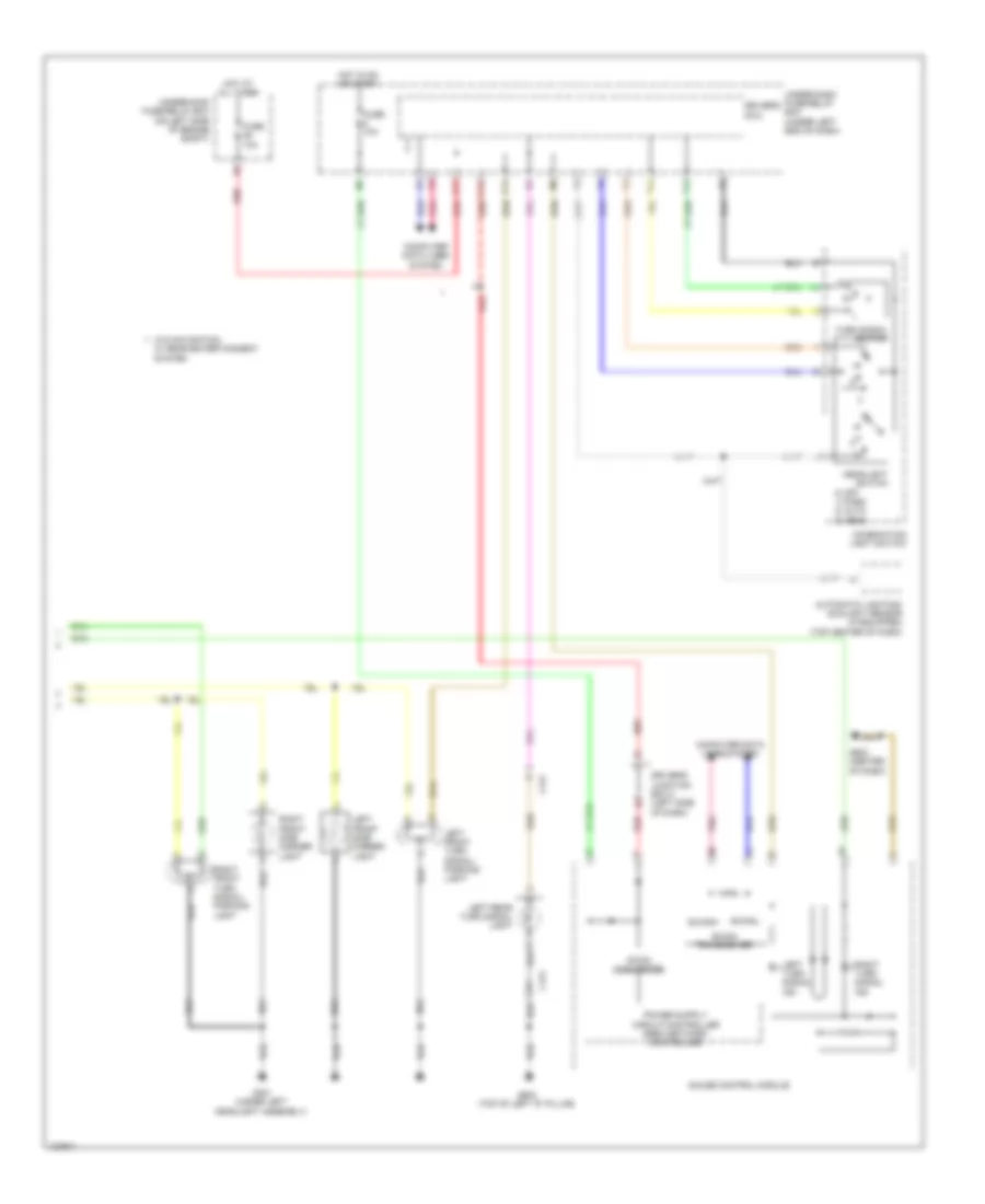
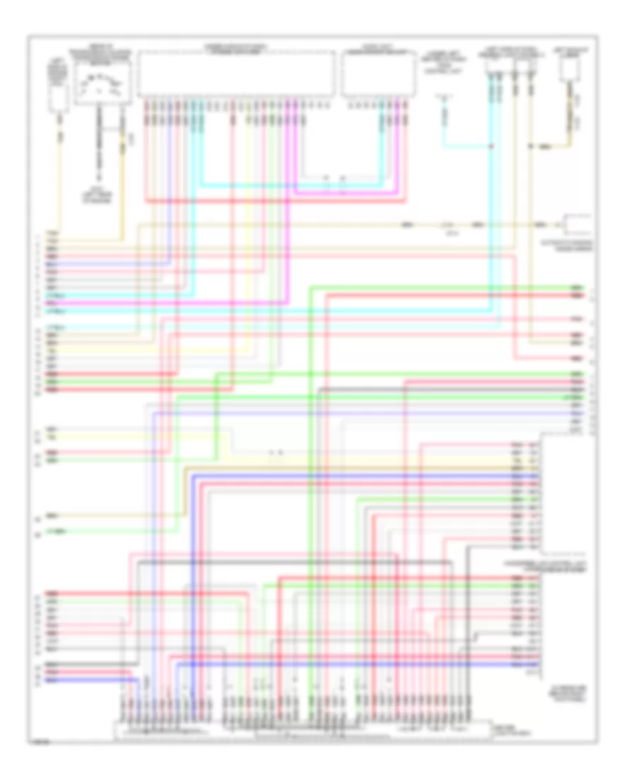
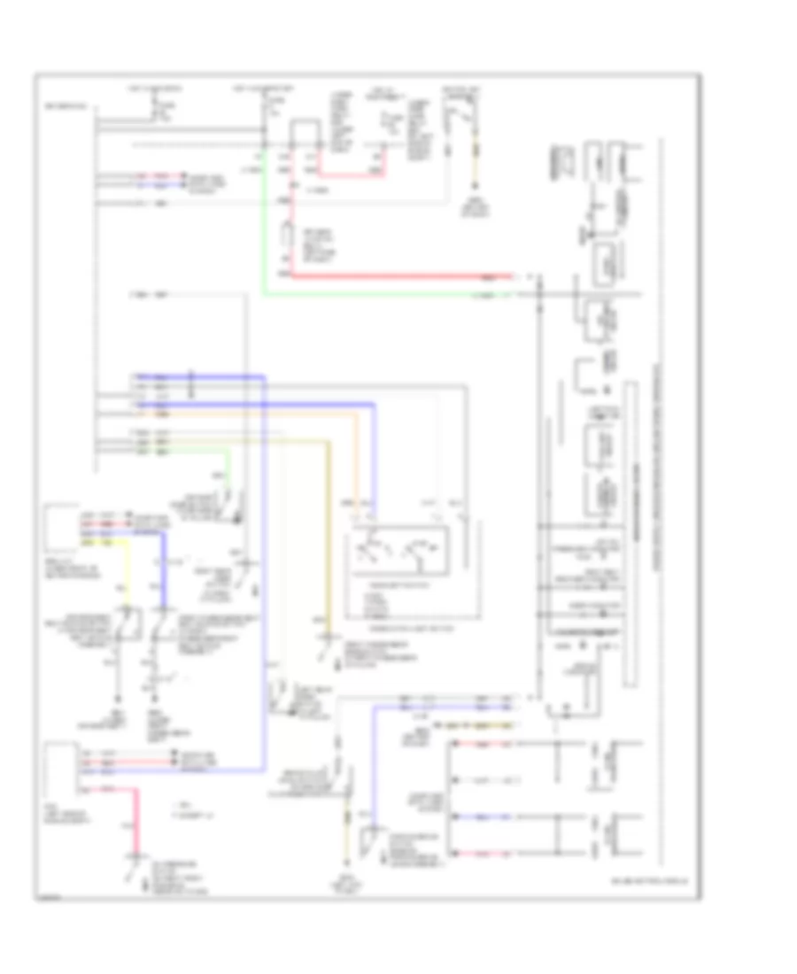
Manual A/C Wiring Diagram (1 of 3) for Honda CR-V EX-L 2014
List of elements for Manual A/C Wiring Diagram (1 of 3) for Honda CR-V EX-L 2014:
- 10a
- 7.5a
- C106
- C108
- C12
- C17
- C19
- Computer data lines system
- D17
- D28
- D31
- Driver's air mix control motor (left side of hvac unit)
- Driver's j/b 2 (left side of dash)
- Engine controls system
- Evaporator temperature sensor (on evaporator)
- Fuse
- Fuse 7.5a
- G502 (center of dash)
- Hot in on
- Hot in on or start
- Hvac control unit/ climate control unit
- Micu
- Mode control motor (right side of hvac unit)
- Pgm-fi sub relay
- Pnk
- Q16
- Rear window defogger relay
- Rear window defogger switch/ power mirror defogger switch
- Rear window defogger switch/ power mirror defogger switch indicator (led)
- Recirculation control motor (upper left side of blower unit)
- Red
- Relay circuit board
- Tail light relay
- Under-dash fuse/relay box (under left end of dash)
- Under-hood fuse/relay box (on left side of engine compt)
- W12
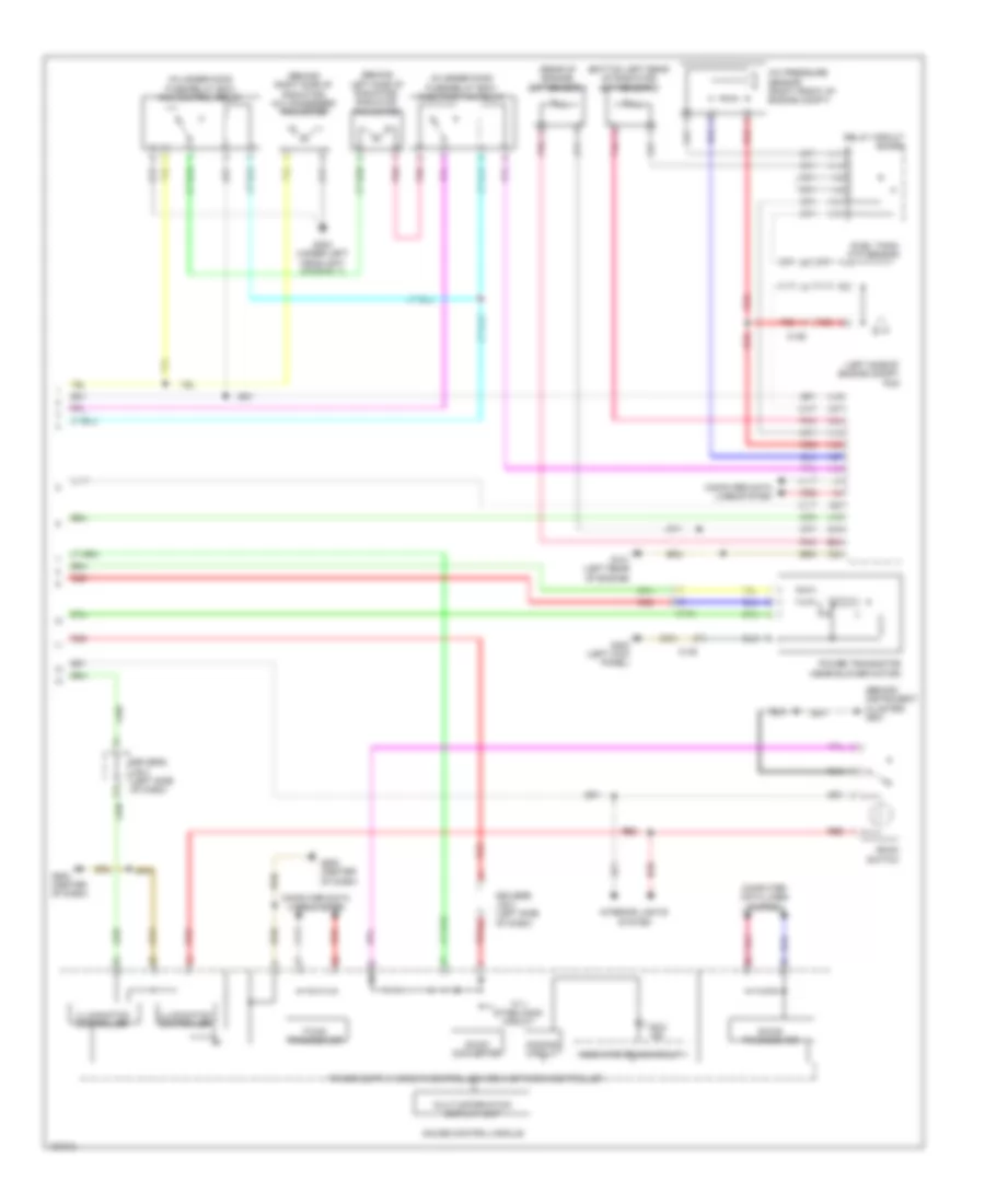
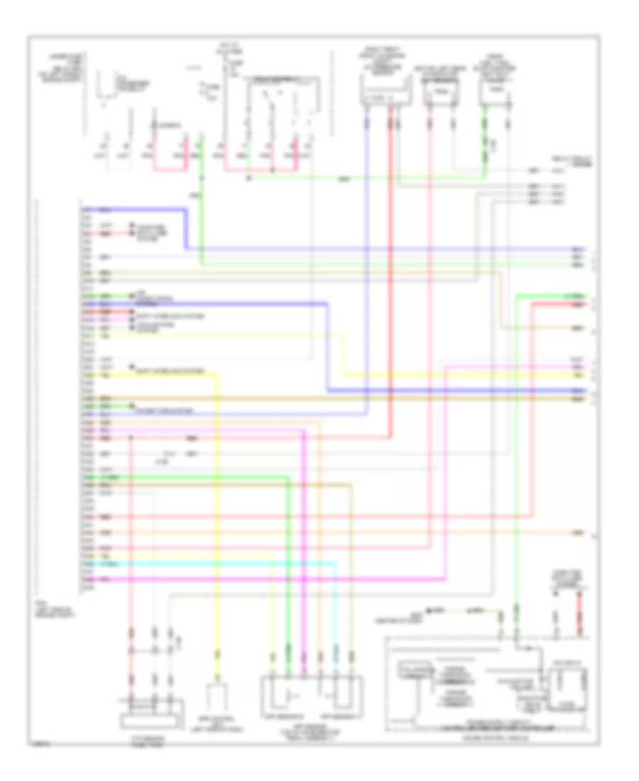
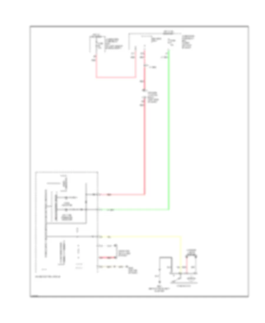
Manual A/C Wiring Diagram (2 of 3) for Honda CR-V EX-L 2014
List of elements for Manual A/C Wiring Diagram (2 of 3) for Honda CR-V EX-L 2014:
- A/c compressor clutch (a/c compressor clutch/ thermal protector) (lower left front of engine)
- A/c compressor clutch relay (in under-hood fuse/relay box)
- A/c condenser fan relay
- Blower motor (bottom of a/c blower unit)
- Blower motor relay
- C105
- C108
- C133
- C134
- C138
- Diode a
- Diode b
- Driver's j/b 2 (left side of dash)
- Fuse 1-6 100a
- Fuse 10a
- Fuse 15a
- Fuse 2-10 20a
- Fuse 2-11 20a
- Fuse 2-8 40a
- Fuse 20a
- Fuse 7.5a
- G402 (left kick panel)
- Hot at all times
- Outside air temperature sensor (behind left side of front bumper)
- Pnk
- Red
- Under-hood fuse/relay box (on left side of engine compt)
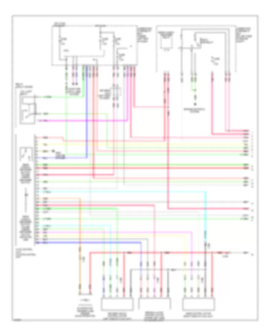
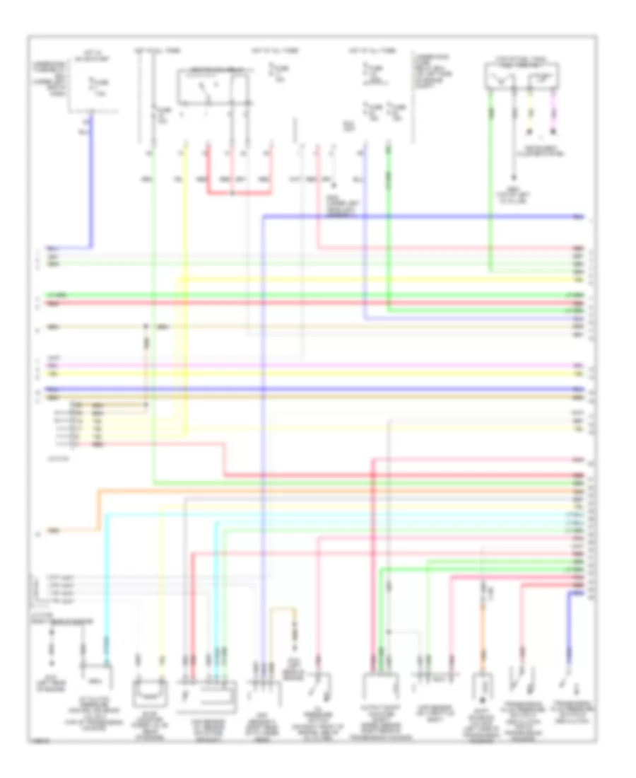
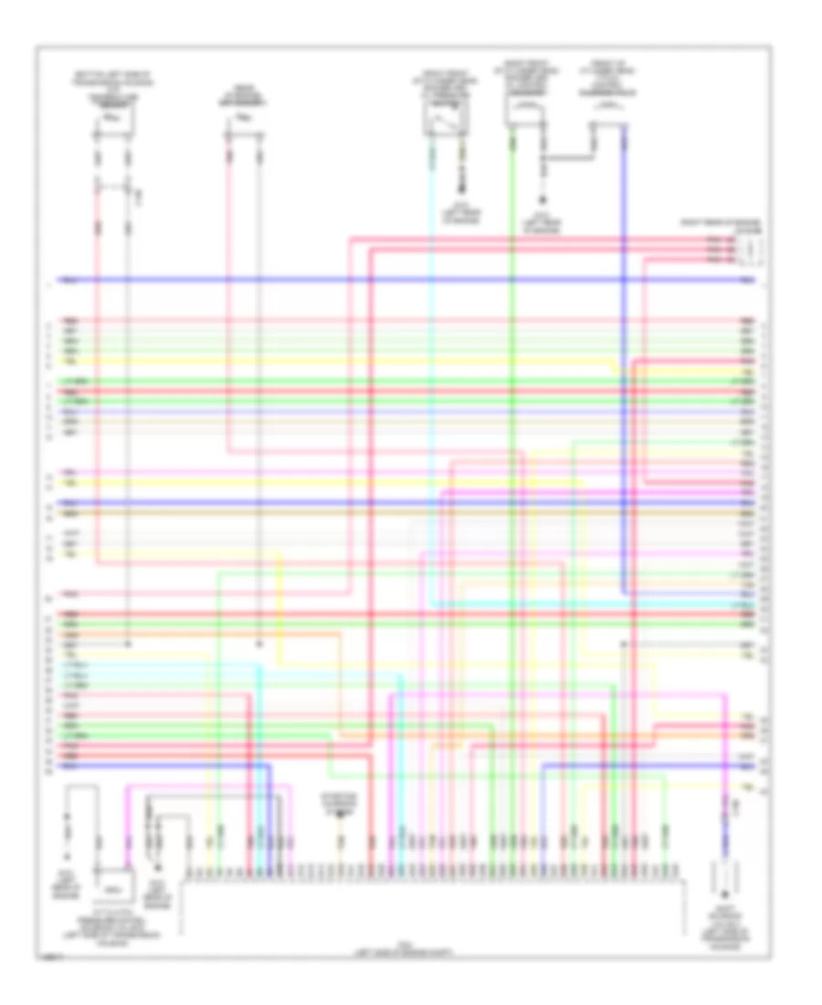
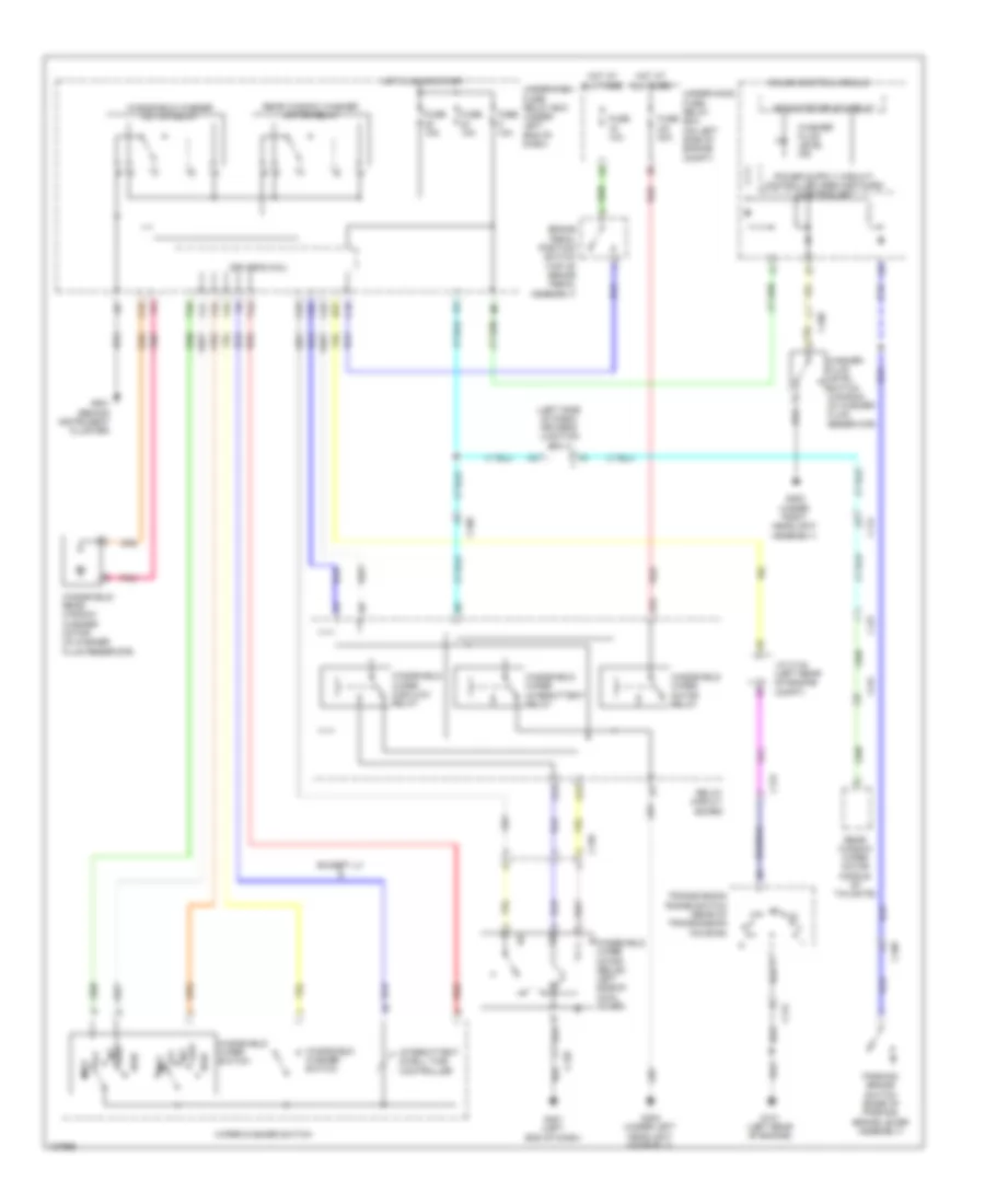
Manual A/C Wiring Diagram (3 of 3) for Honda CR-V EX-L 2014
List of elements for Manual A/C Wiring Diagram (3 of 3) for Honda CR-V EX-L 2014:
- (behind instrument cluster) g501
- (behind left side of radiator) radiator fan motor
- (behind right side of radiator) a/c condenser fan motor
- (bottom left rear of radiator) ect sensor 2
- (fuel tank) ftp sensor
- (in under-hood fuse/relay box) fan control relay
- (in under-hood fuse/relay box) radiator fan relay
- (left side of engine compt) pcm
- (rear of engine) ect sensor 1
- 10 v stabilizing circuit
- A/c pressure sensor (right front of engine compt)
- A10
- A11
- A12
- A14
- A15
- A16
- A20
- A27
- A30
- A37
- A44
- B-can transceiver
- B34
- B44
- C106
- C126
- C138
- C20
- Computer data lines system
- Dc/dc converter
- Dimming circuit
- Driver's j/b 2 (left side of dash)
- Eco ind
- Econ switch
- F-can transceiver
- G101 (left rear of engine)
- G302 (under left headlight assembly)
- G402 (left kick panel)
- G502 (center of dash)
- Gauge control module
- Illumination controller
- Indicator drive circuit
- Interior lights system
- Multi-information display unit
- On/off 5v
- Pnk
- Power transistor (near blower motor)
- Red
- Relay circuit board
ANTI-LOCK BRAKES
Anti-lock Brakes Wiring Diagram (1 of 2) for Honda CR-V EX-L 2014
List of elements for Anti-lock Brakes Wiring Diagram (1 of 2) for Honda CR-V EX-L 2014:
- (behind instrument cluster)
- A11
- Brake pedal position switch (top of brake pedal assembly)
- C120
- C126
- C16
- Computer data lines system
- D11
- D14
- D17
- Driver's micu
- Eps control unit (left side of dash)
- Fuse 1-3 40a
- Fuse 1-4 20a
- Fuse 10a
- Fuse 7.5a
- G201 (right rear of engine compt)
- G501
- Hot at all times
- Hot in on or start
- Left front wheel speed sensor (on left front wheel hub assembly)
- Left rear wheel speed sensor (on left rear wheel hub assembly)
- P15
- Pnk
- Q16
- Red
- Right front wheel speed sensor (on right front wheel hub assembly)
- Right rear wheel speed sensor (on right rear wheel hub assembly)
- Steering angle sensor (in steering column)
- Under-dash fuse/ relay box (under left end of dash)
- Under-hood fuse/relay box (on left side of engine compt)
- Vsa modulator control unit (right rear of engine compt)
- W/ rear entertainment system
- W/o navigation &
Anti-lock Brakes Wiring Diagram (2 of 2) for Honda CR-V EX-L 2014
List of elements for Anti-lock Brakes Wiring Diagram (2 of 2) for Honda CR-V EX-L 2014:
- A13
- Abs ind
- Brake fluid level switch (on brake fluid reservoir)
- Brake ind
- Brake system ind
- C108
- Computer data lines system
- Dc/dc converter
- Driver's j/b 2 (left side of dash)
- Driver's junction box 1 (left side of dash)
- F-can h
- F-can l
- F-can transceiver
- Fail-safe circuit
- Forced turning-on circuit
- G402 (left kick panel)
- G501 (behind instrument cluster)
- Gauge control module
- Indicator drive circuit
- Interior lights system
- Parking brake switch (base of parking brake lever assembly)
- Pcm (left side of engine compt)
- Red
- Vsa ind
- Vsa off ind
- Vsa off switch
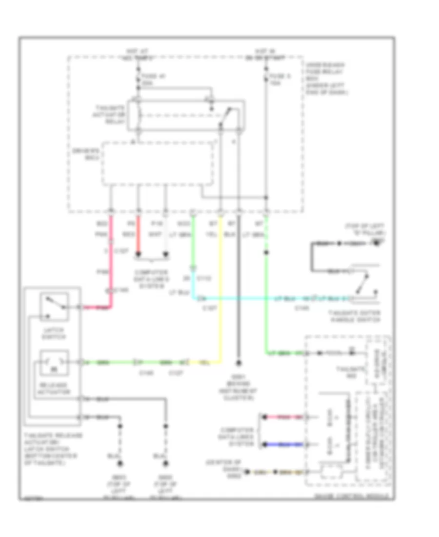
ANTI-THEFT
Forced Entry Wiring Diagram (1 of 2) for Honda CR-V EX-L 2014
List of elements for Forced Entry Wiring Diagram (1 of 2) for Honda CR-V EX-L 2014:
- (behind instrument cluster) g501
- (bottom center of tailgate) tailgate release actuator/latch switch
- (top of left "d" pillar) g603
- (under right center of dash) g503
- B11
- B16
- B18
- B22
- B29
- B33
- B34
- B40
- C102
- C109
- C11
- C112
- C127
- C14
- C145
- C18
- C27
- D17
- D22
- Door lock knob
- Driver's door key cylinder switch
- Driver's door lock actuator/knob switch/ key cylinder switch (in driver's door)
- Driver's door lock knob switch
- Driver's micu
- Exterior lights system
- Front passenger's door lock actuator/knob switch (in front passenger's door)
- Fuse 10a
- Fuse 15a
- Fuse 20a
- G501 (behind instrument cluster)
- G603 (top of left "d" pillar)
- Headlights system
- Horns system
- Hot at all times
- Hot in on or start
- Key door lock knob
- Lock
- Lock relay
- N10
- N12
- Open
- P11
- Pnk
- Q10
- Q16
- Red
- Tailgate actuator relay
- Tailgate outer handle switch
- Under-dash fuse/relay box (under left end of dash)
- Unlock
- Unlock relay
- Unlock relay (dr)
- W10
- W23
- X10
Forced Entry Wiring Diagram (2 of 2) for Honda CR-V EX-L 2014
List of elements for Forced Entry Wiring Diagram (2 of 2) for Honda CR-V EX-L 2014:
- (center front of engine compt) (except lx) security hood switch
- (rear of transmission housing) transmission range switch
- 10v
- Antenna
- B-can h
- B-can l
- B-can transceiver
- C102
- C109
- C112
- C113
- C118
- C119
- C131
- Circuit
- Circuit stabilizing
- Close
- Computer data lines system
- Dc/dc converter
- Dlc (under left center of dash)
- Door ind
- Door lock knob
- Driver's door switch (in driver's "b" pillar)
- Driver's junction box 1 (left side of dash)
- Driver's junction box 2 (left side of dash)
- Exl w/o navigation & w/ res
- Front passenger's door switch (in front passenger's "b" pillar)
- Front passenger's power window switch
- Fuse 10a
- G101 (left rear of engine)
- G402 (left kick panel)
- G501 (behind instrument cluster)
- G502 (center of dash)
- G503 (under right center of dash)
- G601 (under driver's seat)
- G604 (right "d" pillar)
- Gauge control module
- Hot at all times
- Ignition key switch
- Immobilizer keyless control unit (on steering column, integral to ignition switch)
- Indicator drive
- J/c c134 (left rear of engine compt)
- Left rear door lock actuator/knob switch (in left rear door)
- Left rear door switch (in left rear "c" pillar)
- Lock
- Network controller
- Pnk
- Power window master switch
- R p
- Red
- Right rear door lock actuator/knob switch (in right rear door)
- Right rear door switch (in right rear "c" pillar)
- Security ind
- Sound systems
- Tailgate ind
- Under-hood fuse/relay box (on left side of engine compt)
- Unlock
Immobilizer Wiring Diagram for Honda CR-V EX-L 2014
List of elements for Immobilizer Wiring Diagram for Honda CR-V EX-L 2014:
- (left rear of engine compt) j/c c134
- (left side of dash) driver's junction box 2
- A17
- A40
- Antenna
- B-can h
- B-can l
- B10
- C10
- C108
- C13
- C15
- C24
- C35
- Computer data lines system
- D17
- D26
- Dc/dc converter
- Driver's junction box 1 (left side of dash)
- Driver's micu
- Exl w/o navigatiom & w/ res
- F-can h
- F-can l
- Fuel tank unit (top of fuel tank)
- Fuse 10a
- Fuse 15a
- G101 (left rear of engine)
- G502 (center of dash)
- G603 (top of left "d" pillar)
- Gauge control module
- Hot at all times
- Hot in on or start
- Ignition key switch
- Immobilizer ind
- Immobilizer keyless control unit (on steering column, integral to ignition switch)
- P11
- P18
- Parking brake switch (base of parking brake lever assembly)
- Pcm (left side of engine compt)
- Pgm-fi main relay 1
- Pgm-fi main relay 2
- Pnk
- Q16
- Red
- Transceiver b-can
- Transceiver f-can
- Under-dash fuse/relay box (under left end of dash)
- Under-hood fuse/relay box (on left side of engine compt)
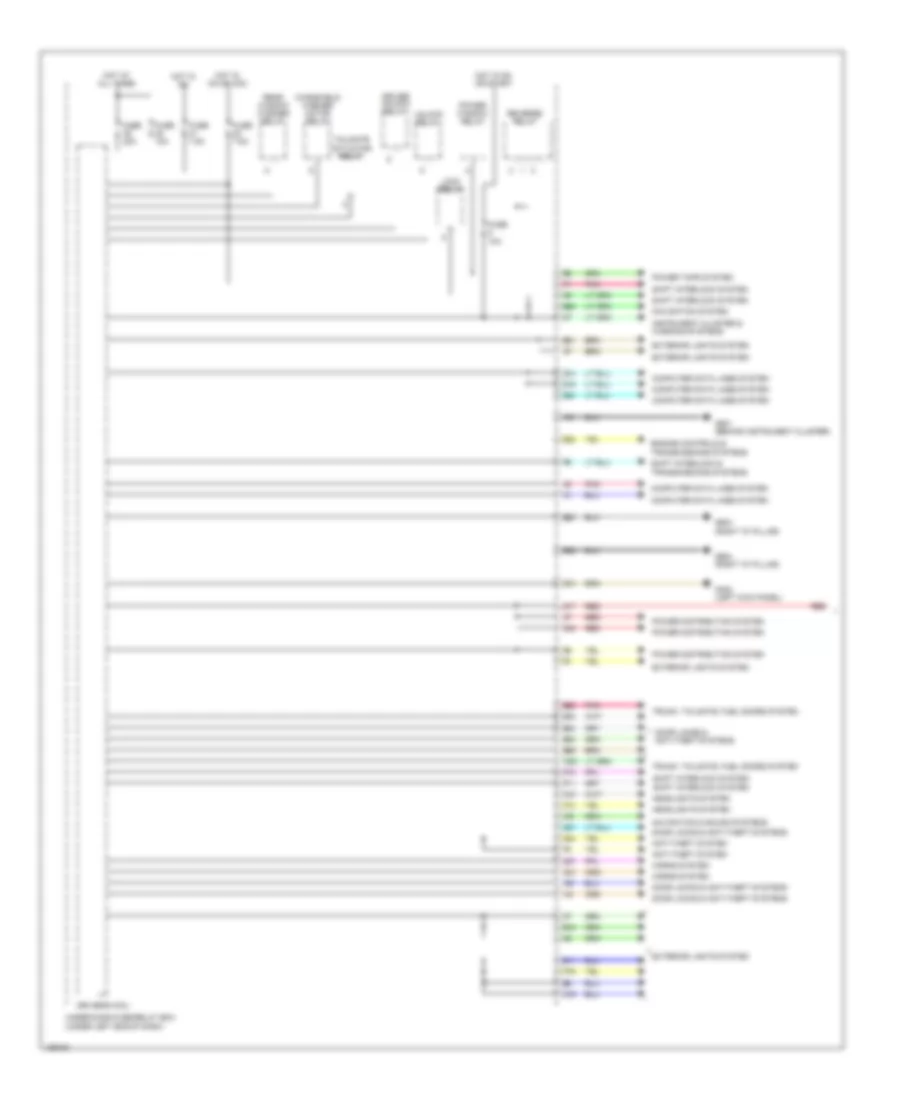
BODY CONTROL MODULES
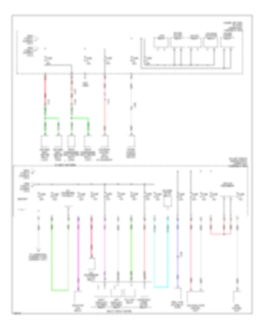
Body Control Modules Wiring Diagram (1 of 2) for Honda CR-V EX-L 2014
List of elements for Body Control Modules Wiring Diagram (1 of 2) for Honda CR-V EX-L 2014:
- Anti-theft system
- B12
- B20
- B21
- B22
- B28
- B29
- B32
- B33
- B34
- B40
- C14
- C16
- C18
- C24
- C27
- C37
- Computer data lines system
- D10
- D11
- D15
- D17
- D22
- D24
- Door locks & anti-theft systems
- Driver unlock relay
- Driver's micu
- Engine controls & transmissions systems
- Exterior lights system
- Fuse 10a
- Fuse 20a
- Fuse 7.5a
- G402 (left kick panel)
- G501 (behind instrument cluster)
- G604 (right "d" pillar)
- Headlights system
- Horns system
- Hot at all times
- Hot in on
- Hot in on or acc
- Hot in on or start
- Instrument cluster & warning systems
- Lock relay
- Navigation & sound systems
- Navigation system
- P10
- P11
- P19
- Pnk
- Power distribution system
- Power tops system
- Power window relay
- Q10
- Q14
- Q16
- Rear window washer relay
- Red
- Reverse relay
- Shift interlock & transmissions systems
- Shift interlock system
- Tailgate actuator relay
- Trunk, tailgate, fuel doors system
- Under-dash fuse/relay box (under left end of dash)
- Unlock relay
- W23
- Windshield washer motor relay
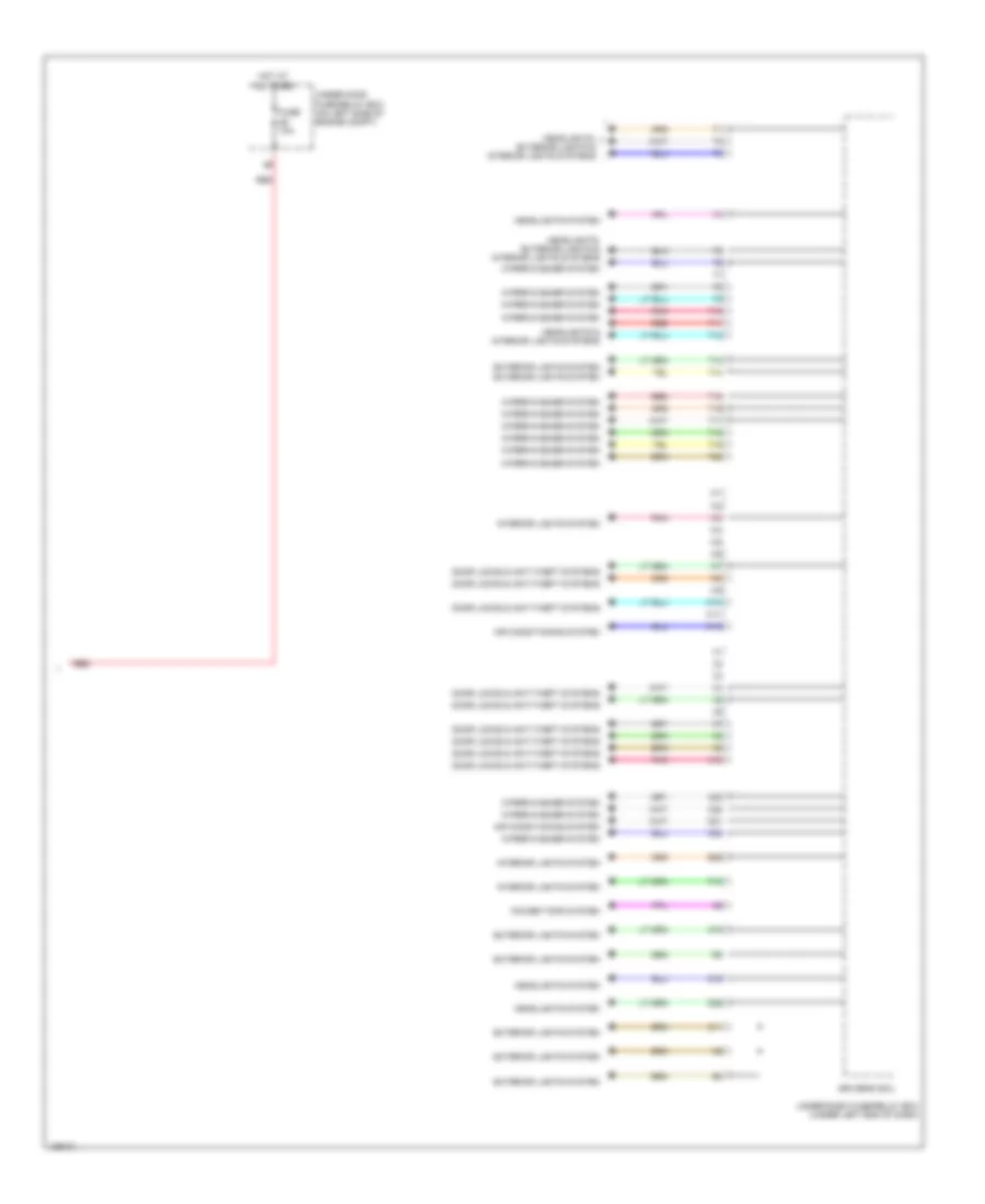
Body Control Modules Wiring Diagram (2 of 2) for Honda CR-V EX-L 2014
List of elements for Body Control Modules Wiring Diagram (2 of 2) for Honda CR-V EX-L 2014:
- Air conditioning system
- B39
- C11
- C19
- C22
- C23
- C32
- D16
- D25
- D31
- Door locks & anti-theft systems
- Driver's micu
- Exterior lights system
- Exterior lights system exterior lights system
- Fuse 10a
- Headlights & interior lights systems
- Headlights system
- Headlights, exterior lights & interior lights systems
- Hot at all times
- Interior lights system
- P12
- Pnk
- Power tops system
- Red
- T10
- T11
- T12
- T13
- T14
- T15
- T16
- T17
- T18
- T19
- T20
- Under-dash fuse/relay box (under left end of dash)
- Under-hood fuse/relay box (on left side of engine compt)
- W10
- W11
- W12
- Wiper/washer system
- X10
COMPUTER DATA LINES
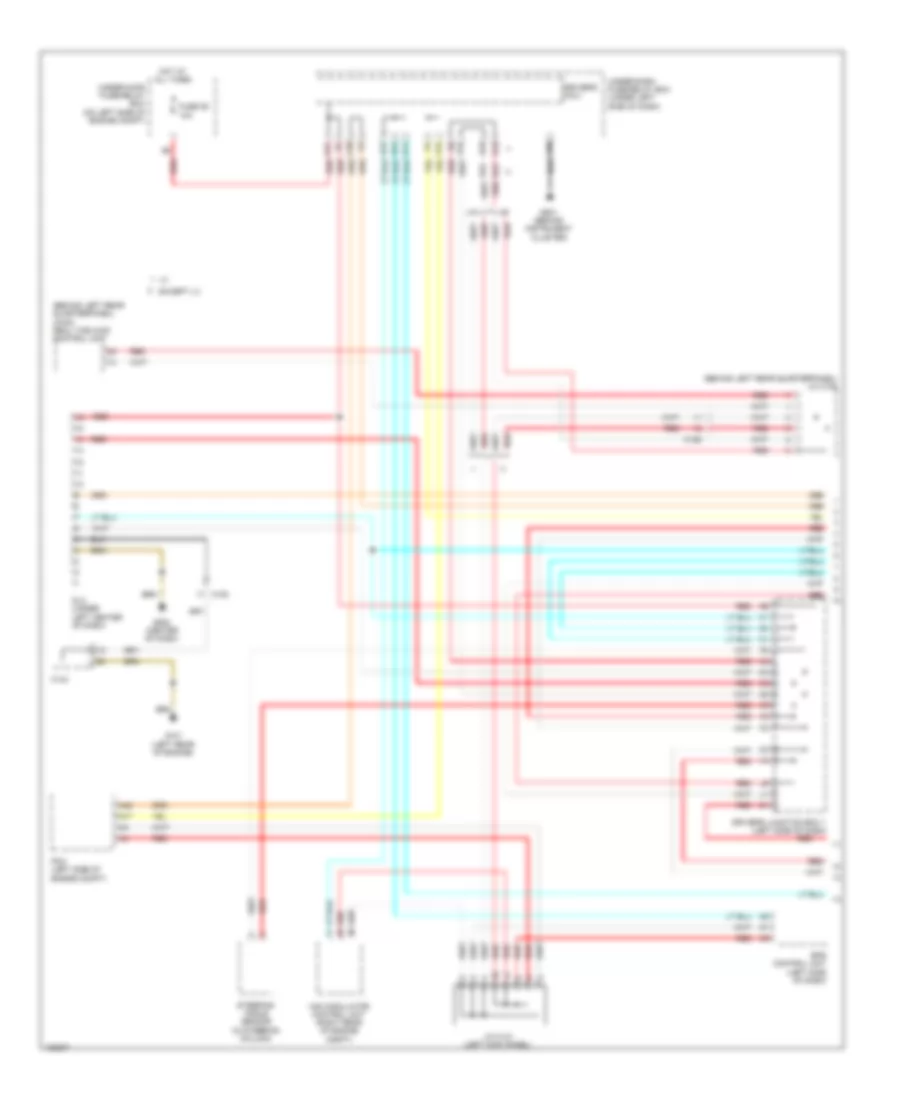
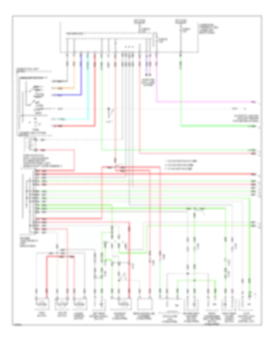
Computer Data Lines Wiring Diagram (1 of 2) for Honda CR-V EX-L 2014
List of elements for Computer Data Lines Wiring Diagram (1 of 2) for Honda CR-V EX-L 2014:
- (behind left rear quarterpanel) (awd) real time awd control unit
- (behind left rear quarterpanel) j/c c128
- A17
- A42
- B42
- B43
- C105
- C126
- C134
- C20
- C24
- D15
- D17
- D18
- D19
- D24
- Dlc (under left center of dash)
- Driver's junction box 1 (left side of dash)
- Driver's micu
- Eps control unit (left side of dash)
- Except lx
- Fuse 29 10a
- G101 (left rear of engine)
- G501 (behind instrument cluster)
- G502 (center of dash)
- Hot at all times
- J/c c141 (left kick panel)
- P16
- Pcm (left side of engine compt)
- Q14
- Red
- Steering angle sensor (in steering column)
- Under-dash fuse/relay box (under left side of dash)
- Under-hood fuse/relay box (on left side of engine compt)
- Vsa modulator control unit (right rear of engine compt)
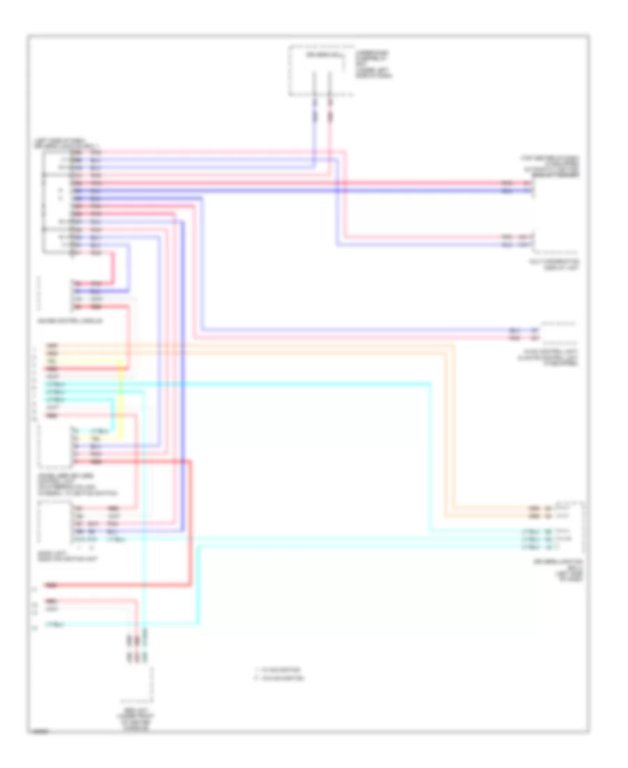
Computer Data Lines Wiring Diagram (2 of 2) for Honda CR-V EX-L 2014
List of elements for Computer Data Lines Wiring Diagram (2 of 2) for Honda CR-V EX-L 2014:
- (left side of dash) driver's junction box 1
- (top center of dash) (if equipped) automatic lighting/ sunlight sensor
- A13
- A15
- A19
- A20
- A21
- A31
- Audio unit/ audio navigation unit
- B13
- Driver's junction box 2 (left side of dash)
- Driver's micu
- Gauge control module
- Hvac control unit/ climate control unit (if equipped)
- Immobilizer keyless control unit (on steering column, integral to ignition switch)
- Multi-information display unit
- Pnk
- Red
- Srs unit (under front of center console)
- Under-dash fuse/relay box (under left side of dash)
- W/ navigation
- W/o navigation
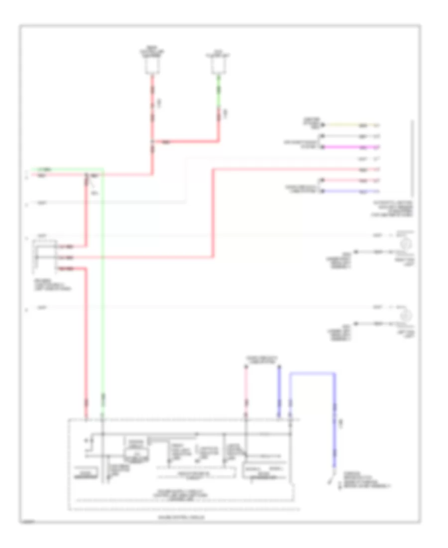
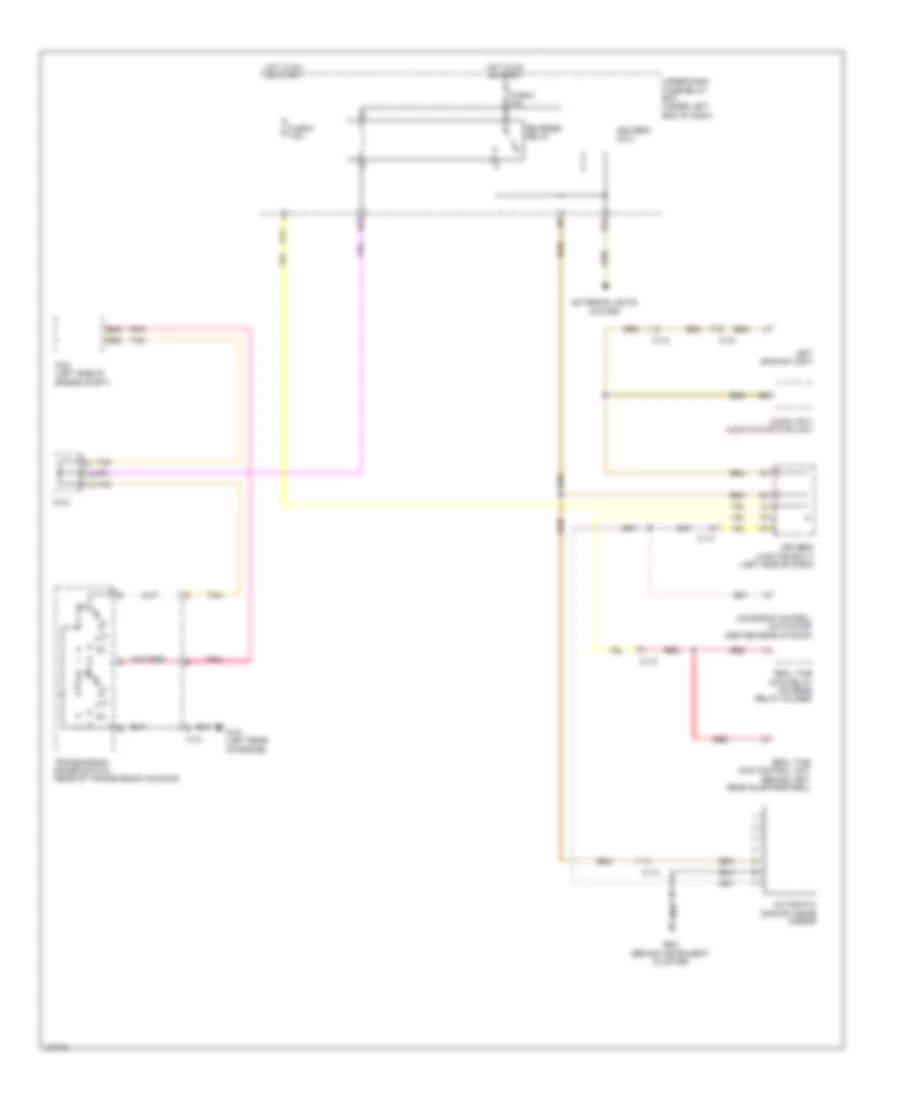
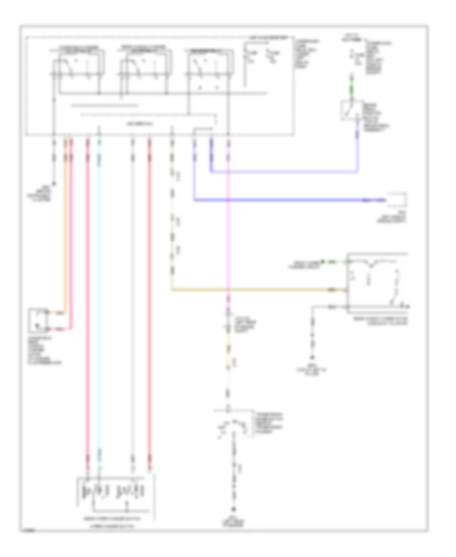
COOLING FAN
Cooling Fan Wiring Diagram for Honda CR-V EX-L 2014
List of elements for Cooling Fan Wiring Diagram for Honda CR-V EX-L 2014:
- A/c condenser fan motor (behind right side of radiator)
- A/c condenser fan relay
- A/c pressure sensor (right front of engine compt)
- A11
- A14
- A15
- A16
- A27
- A30
- A44
- B-can transceiver
- B34
- B44
- C20
- Computer data lines system
- D28
- Diode a
- Diode b
- Ect sensor 1 (rear of engine)
- Ect sensor 2 (bottom left rear of radiator)
- F-can transceiver
- Fan control relay (in under-hood fuse/relay box)
- Fuse 2-10 20a
- Fuse 2-11 20a
- Fuse 7.5a
- G101 (left rear of engine)
- G302 (under left headlight assembly)
- Gauge control module
- Hot at all times
- Hot in on
- Hot w/ pgm-fi sub relay energized
- Pcm (left side of engine compt)
- Pnk
- Radiator fan motor (behind left side of radiator)
- Radiator fan relay (in under-hood fuse/relay box)
- Red
- Relay circuit board
- Under-dash fuse/ relay box (under left end of dash)
- Under-hood fuse/relay box (on left side of engine compt)
CRUISE CONTROL
Cruise Control Wiring Diagram (1 of 2) for Honda CR-V EX-L 2014
List of elements for Cruise Control Wiring Diagram (1 of 2) for Honda CR-V EX-L 2014:
- (top of brake pedal assembly) brake pedal position switch
- A13
- A25
- A28
- A29
- A35
- A36
- A45
- A46
- A48
- App sensor (top of accelerator pedal assembly)
- App sensor a
- App sensor b
- B17
- B35
- B48
- C126 red
- C131
- C14
- C22
- C23
- C24
- C30
- C31
- C34
- Computer data lines system
- D12
- D26
- Etcs control relay
- Fuse 2 10a
- G101 (left rear of engine)
- Hot in on or start
- J/c c134 (left rear of engine compt)
- J/c c136 (right rear of engine)
- Output shaft (countershaft) speed sensor (right rear of transmission housing)
- Pcm (left side of engine compt)
- Pgm-fi main relay 1
- Pnk
- Red
- Tan
- Throttle actuator
- Throttle body (left rear of engine)
- Throttle open sensor
- Transmission range switch (rear of transmission housing)
- Under-dash fuse/relay box (under left end of dash)
Cruise Control Wiring Diagram (2 of 2) for Honda CR-V EX-L 2014
List of elements for Cruise Control Wiring Diagram (2 of 2) for Honda CR-V EX-L 2014:
- 10v stabilizing circuit
- Air conditioning system
- C15
- C16
- Cable reel (top of steering column)
- Cancel switch
- Computer data lines system
- Cruise control combination switch
- Cruise control indicator
- Cruise main indicator
- D11
- D17
- Dc/dc converter
- Dimming circuit
- Driver's junction box 2 (left side of dash)
- Driver's micu
- Eld
- F-can h
- F-can l
- F-can transceiver
- Fuse 10a
- Fuse 15a
- G502 (center of dash)
- Gauge control module
- Hot at all times
- Hot in on or start
- Indicator driver circuit
- Interior lights system
- Main switch
- On/ off 5v
- Q16
- Red
- Resume switch
- Set switch
- Under-dash fuse/relay box (under left end of dash)
- Under-hood fuse/relay box (on left side of engine compt)
- W/o navigation & w/ rear entertainment system
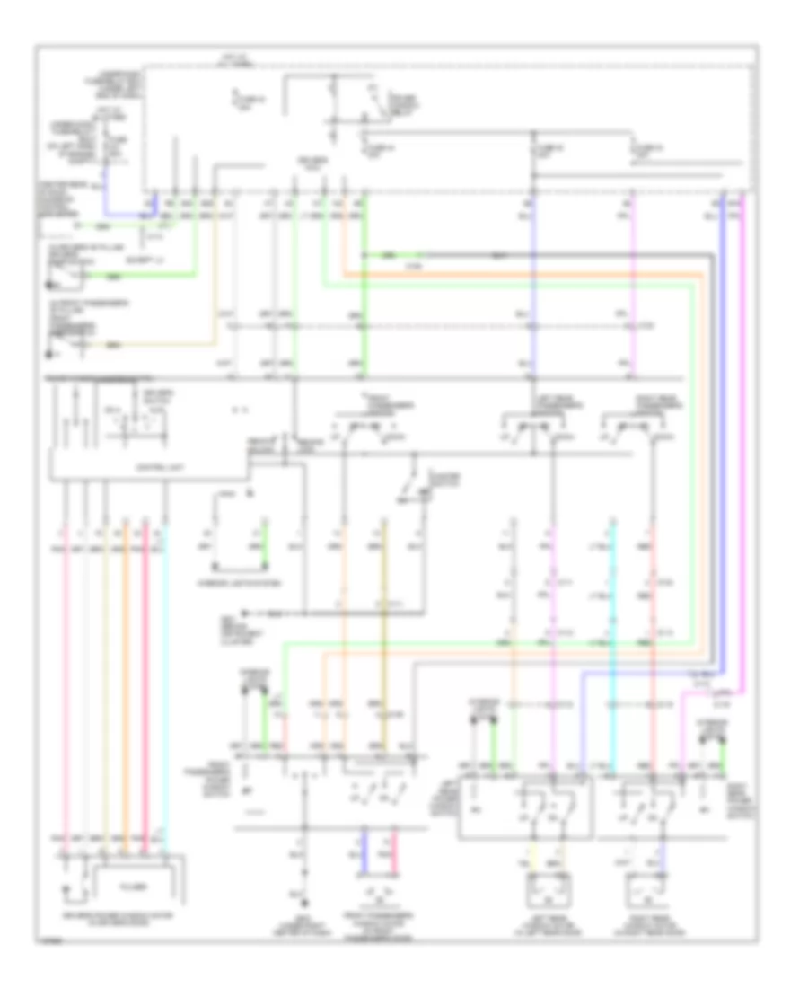
DEFOGGERS
Defoggers Wiring Diagram for Honda CR-V EX-L 2014
List of elements for Defoggers Wiring Diagram for Honda CR-V EX-L 2014:
- Automatic a/c
- C108
- C109
- C111
- C126
- C127
- C144
- C17
- Driver's junction box 2 (left side of dash)
- Fuse 2-6 30a
- Fuse 22 7.5a
- Fuse 7.5a
- G501 (behind instrument cluster)
- G502 (center of dash)
- G503 (under right center of dash)
- G603 (top of left "d" pillar)
- Hot at all times
- Hot in on
- Hvac control unit/ climate control unit
- Left power mirror (in driver's door)
- Manual a/c
- Pnk
- Rear window defogger
- Rear window defogger relay
- Rear window/ power mirror defogger switch
- Rear window/ power mirror switch indicator (led)
- Red
- Right power mirror (in front passenger's door)
- Under-dash fuse/relay box (under left end of dash)
- Under-hood fuse/relay box (on left side of engine compt)
- W/ power mirror defogger
- W/o power mirror defogger
ELECTRONIC POWER STEERING
Electronic Power Steering Wiring Diagram for Honda CR-V EX-L 2014
List of elements for Electronic Power Steering Wiring Diagram for Honda CR-V EX-L 2014:
- (in steering column)
- (upper left end of dash) g403
- A10
- A11
- A22
- All times
- B10
- B11
- B12
- B13
- B14
- B15
- B16
- C103
- C104
- C140
- Can h
- Can l
- Circuit 10 v stablizing
- Circuit dimming
- Computer data lines system
- Converter dc/dc
- D14
- D15
- D24
- Driver circuit indicator
- Driver's junction box 2 (left side of dash)
- Driver's micu
- Dvd player unit (w/ rear entertainment system)
- Eps control unit (left side of dash)
- Eps ind
- Eps motor
- Eps motor angle sensor
- Eps motor/eps motor angle sensor/torque sensor (eps motor angle sensor/torque sensor: on eps motor) (eps motor: on steering rack)
- F-can h
- F-can l
- Fuse 1-1 70a
- Fuse 10a
- Fuse 7.5a
- G401 (left end of dash)
- Gauge control module
- Hot at
- Hot in on or start
- Nca
- P15
- Pcm (left side of engine compt)
- Pnk
- Q16
- Rear controller & screen (w/ rear entertainment system)
- Red
- Steering angle sensor
- Torque sensor
- Transceiver f-can
- Under-dash fuse/relay box (under left end of dash)
- Under-hood fuse/relay box (on left side of engine compt)
- Vsa modulator control unit (right rear of engine compt)
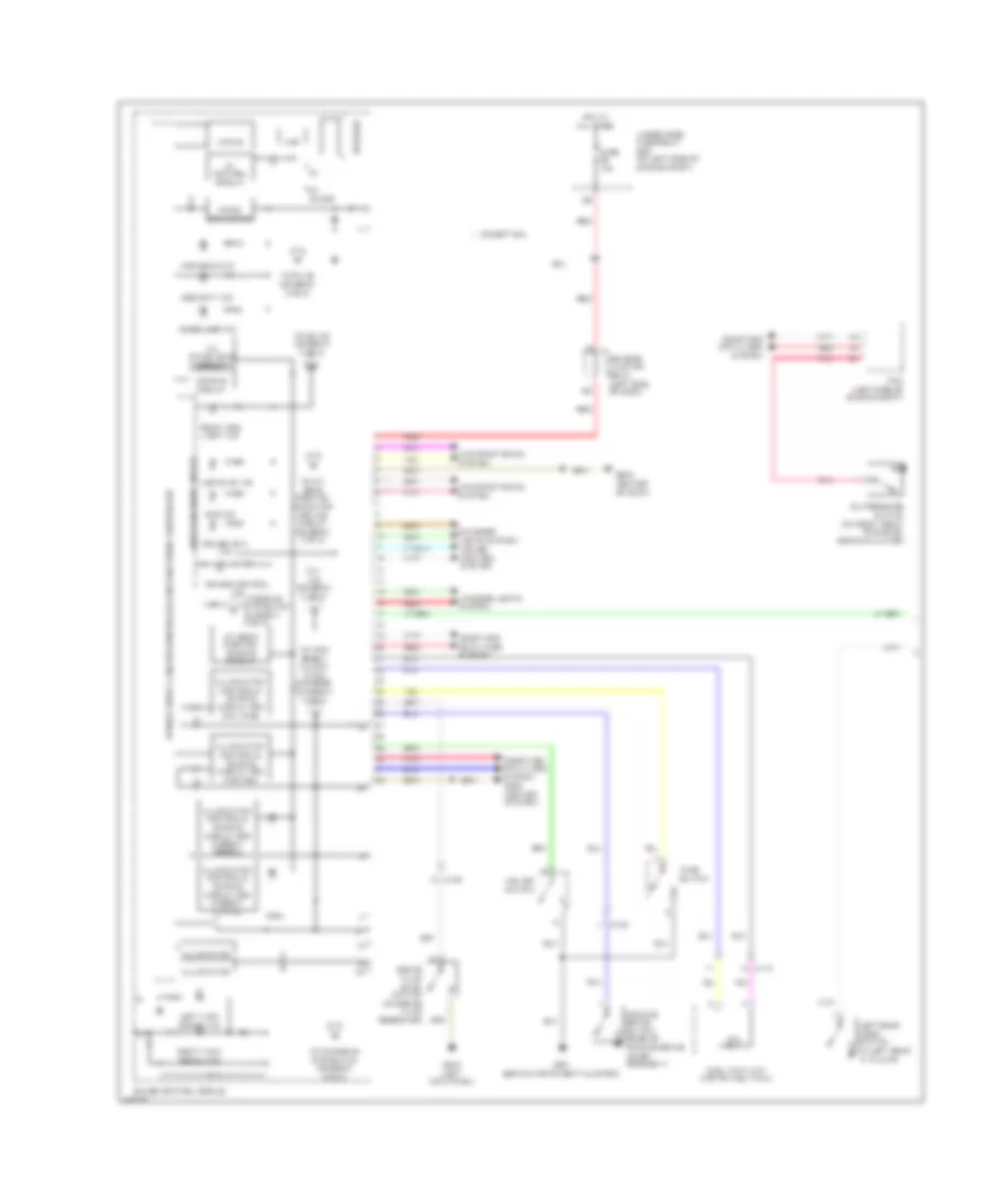
ENGINE PERFORMANCE
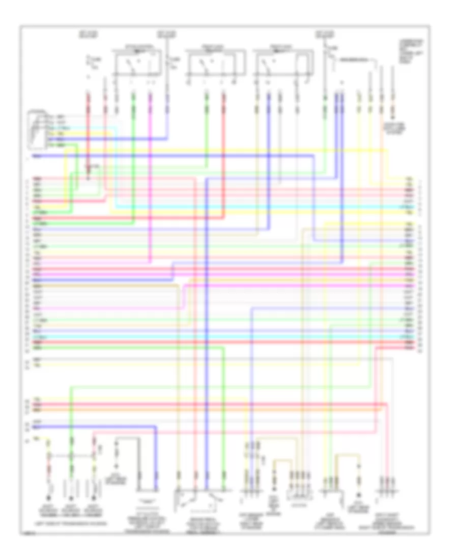
2.4L
2.4L, Engine Performance Wiring Diagram (1 of 5) for Honda CR-V EX-L 2014
List of elements for 2.4L, Engine Performance Wiring Diagram (1 of 5) for Honda CR-V EX-L 2014:
- (bottom left rear of radiator) ect sensor 2
- (near fuel tank) evap canister vent shut valve
- (right front front of engine compt) a/c pressure sensor
- A/c condenser fan relay
- A10
- A11
- A12
- A13
- A14
- A15
- A16
- A17
- A18
- A19
- A20
- A21
- A22
- A23
- A24
- A25
- A26
- A27
- A28
- A29
- A30
- A31
- A32
- A33
- A34
- A35
- A36
- A37
- A38
- A39
- A40
- A41
- A42
- A43
- A44
- A45
- A46
- A47
- A48
- A49
- Air conditioning system
- App sensor (top of accelerator pedal assembly)
- App sensor a
- App sensor b
- C126
- Computer data lines system
- Cooling fans system
- Diode b
- Eps control unit (left side of dash)
- F-can h
- F-can l
- F-can transceiver
- Fail-safe circuit
- Forced turning-off circuit
- Forced turning-on circuit
- Ftp sensor (fuel tank)
- Fuse 15a
- Fuse 7.5a
- G502 (center of dash)
- Gauge control module
- Hot at all times
- Indicator drive circuit
- Malfunction ind lamp
- Pcm (left side of engine compt)
- Pgm-fi sub-relay
- Pnk
- Power tops system
- Red
- Relay circuit board
- Shift interlock system
- Under-hood fuse/ relay box (on left side of engine compt)
2.4L, Engine Performance Wiring Diagram (2 of 5) for Honda CR-V EX-L 2014
List of elements for 2.4L, Engine Performance Wiring Diagram (2 of 5) for Honda CR-V EX-L 2014:
- (top of fuel tank) fuel tank unit
- A/t clutch pressure control solenoid valve a (top of transmission housing)
- C130
- Cmp sensor a (right rear of cylinder head)
- Eld unit
- Evap canister purge valve (rear of engine)
- Fuse 1-6 100a
- Fuse 10a
- Fuse 15a
- Fuse 7.5a
- G101 (left rear of engine)
- G302 (under left headlight assembly)
- G603 (top of left "d" pillar)
- Hot at all times
- Hot in on or start
- Ignition coil relay
- Instrument cluster system
- J/c c134
- J/c c136 (right rear of engine)
- Maf sensor/ iat sensor (on intake air duct)
- Map sensor (on throttle body)
- Oil pressure switch (on right front of engine, above oil filter)
- Output shaft (counter shaft) speed sensor (right rear of transmission housing)
- Pnk
- Red
- Shift solenoid valve b (left side of transmission housing)
- Transmission fluid pressure switch a (2nd clutch) (top of transmission housing)
- Transmission fluid pressure switch b (3rd clutch)
- Under-dash fuse/relay box (under left end of dash)
- Under-hood fuse/ relay box (on left side of engine compt)
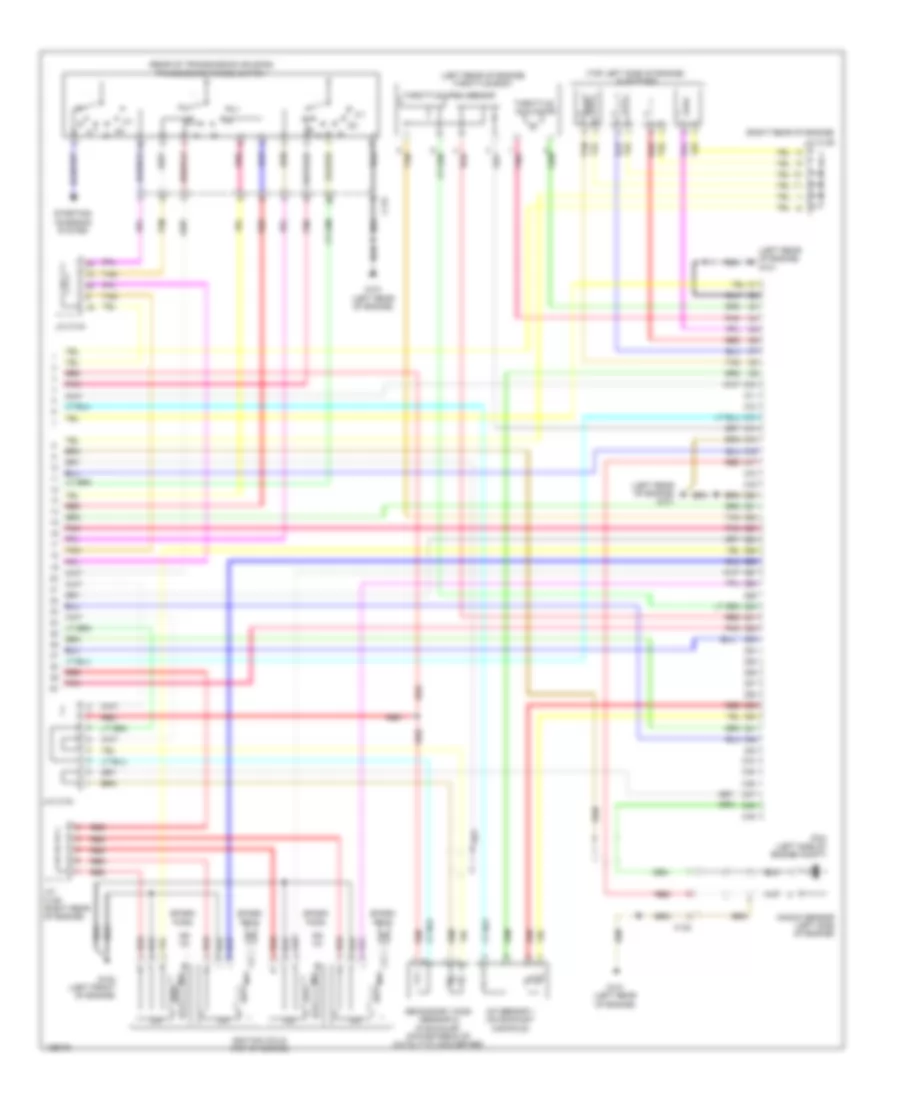
2.4L, Engine Performance Wiring Diagram (3 of 5) for Honda CR-V EX-L 2014
List of elements for 2.4L, Engine Performance Wiring Diagram (3 of 5) for Honda CR-V EX-L 2014:
- (bottom left side of transmission housing) atf temperature sensor
- (front of cylinder head) vtc oil control solenoid valve
- (rear of engine) ect sensor 1
- (right front of cylinder head) rocker arm oil control solenoid
- (right front of cylinder head) rocker arm oil pressure switch
- (right rear of engine) j/c c136
- A/t clutch pressure control solenoid valve b (left side of transmission housing)
- B10
- B11
- B12
- B13
- B14
- B15
- B16
- B17
- B18
- B19
- B20
- B21
- B22
- B23
- B24
- B25
- B26
- B27
- B28
- B29
- B30
- B31
- B32
- B33
- B34
- B35
- B36
- B37
- B38
- B39
- B40
- B41
- B42
- B43
- B44
- B45
- B46
- B47
- B48
- B49
- C130
- G101 (left rear of engine)
- Pcm (left side of engine compt)
- Pnk
- Red
- Shift solenoid valve a (left side of transmission housing)
- Starting/ charging system
- Tan
2.4L, Engine Performance Wiring Diagram (4 of 5) for Honda CR-V EX-L 2014
List of elements for 2.4L, Engine Performance Wiring Diagram (4 of 5) for Honda CR-V EX-L 2014:
- (left side of transmission housing)
- A/t clutch pressure control solenoid valve c (left side of transmission housing)
- B17
- Brake pedal position switch (top of brake pedal assembly)
- C126 red
- C13
- C130
- C135
- C16
- C20
- C24
- C25
- C34
- C35
- Ckp sensor (lower right rear of engine)
- Cmp sensor b (left rear of cylinder head)
- Computer data lines system
- D11
- D12
- D22
- D26
- Driver's micu
- Etcs control relay
- Fuse 10a
- Fuse 15a
- G101 (left rear of engine)
- Hot in on or start
- Input shaft (mainshaft) speed sensor (right side of transmission housing)
- J/c c134
- Pgm-fi main relay 1
- Pgm-fi main relay 2
- Pnk
- Red
- Shift solenoid valve c
- Shift solenoid valve d
- Shift solenoid valve e
- Tan
- Under-dash fuse/relay box (under left end of dash)
2.4L, Engine Performance Wiring Diagram (5 of 5) for Honda CR-V EX-L 2014
List of elements for 2.4L, Engine Performance Wiring Diagram (5 of 5) for Honda CR-V EX-L 2014:
- (left rear of engine) g101
- (left rear of engine) throttle body
- (rear of transmission housing) transmission range switch
- (right rear of engine)
- (top left side of engine) injectors
- 2-1
- A/f sensor 1 (on exhaust manifold)
- C10
- C11
- C12
- C13
- C131
- C132
- C14
- C15
- C16
- C17
- C18
- C19
- C20
- C21
- C22
- C23
- C24
- C25
- C26
- C27
- C28
- C29
- C30
- C31
- C32
- C33
- C34
- C35
- C36
- C37
- C38
- C39
- C40
- C41
- C42
- C43
- C44
- C45
- C46
- C47
- C48
- C49
- G101 (left rear of engine)
- G102 (left front of engine)
- Icm
- Ignition coils (top of engine)
- J/c c134
- J/c c136
- J/c c136 (right rear of engine)
- Knock sensor (left side of engine)
- Pcm (left side of engine compt)
- Pnk
- Red
- Secondary ho2s (sensor 2) (in exhaust, downstream of catalytic converter)
- Spark plug
- Starting/ charging system
- Tan
- Throttle actuator
- Throttle open sensor
EXTERIOR LIGHTS
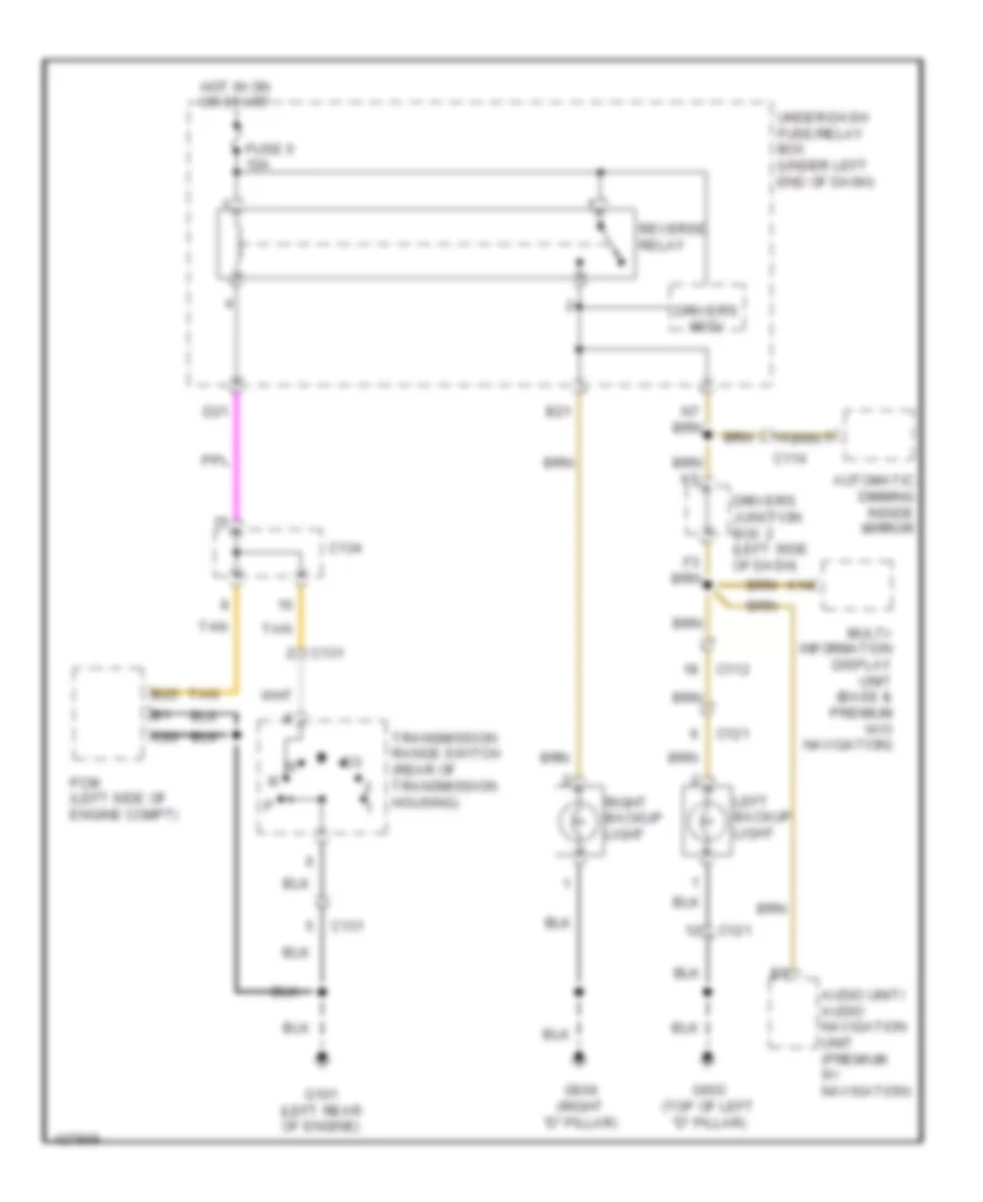
Backup Lamps Wiring Diagram for Honda CR-V EX-L 2014
List of elements for Backup Lamps Wiring Diagram for Honda CR-V EX-L 2014:
- A14
- Audio unit/ audio navigation unit (premium w/ navigation)
- Automatic dimming inside mirror
- B21
- B25
- C112
- C114
- C121
- C131
- C134
- C20
- D21
- Driver's junction box 2 (left side of dash)
- Driver's micu
- Fuse 5 10a
- G101 (left rear of engine)
- G603 (top of left "d" pillar)
- G604 (right "d" pillar)
- Hot in on or start
- Left backup light
- Multi- information display unit (base & premium w/o navigation)
- Pcm (left side of engine compt)
- Reverse relay
- Right backup light
- Tan
- Transmission range switch (rear of transmission housing)
- Under-dash fuse/relay box (under left end of dash)
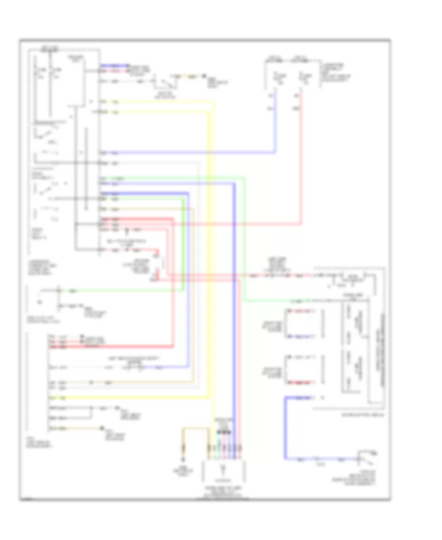
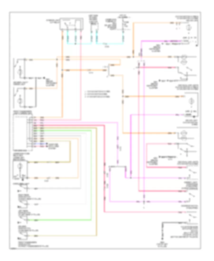
Exterior Lamps Wiring Diagram (1 of 2) for Honda CR-V EX-L 2014
List of elements for Exterior Lamps Wiring Diagram (1 of 2) for Honda CR-V EX-L 2014:
- (top of brake pedal assembly) brake pedal position switch
- A13
- B12
- B35
- C112
- C12
- C121
- C127
- C145
- C16
- C19
- C33
- C38
- D11
- Driver's micu
- Fuse 10a
- Fuse 20a
- G101 (left rear of engine)
- G603 (top of left "d" pillar)
- G604 (right "d" pillar)
- Hazard warning switch
- Hazard warning switch light
- High mount brake light
- Hot at all times
- Interior lights system
- J/c c128 (behind left rear quarterpanel)
- Left license plate light
- Left lower taillight
- Left upper taillight
- P19
- Pcm (left side of engine compt)
- Q15
- Red
- Relay circuit board
- Right license plate light
- Right lower taillight
- Right rear turn signal light
- Right upper taillight
- Taillight relay
- Under-dash fuse/relay box (under left end of dash)
- Under-hood fuse/relay box (on left side of engine compt)
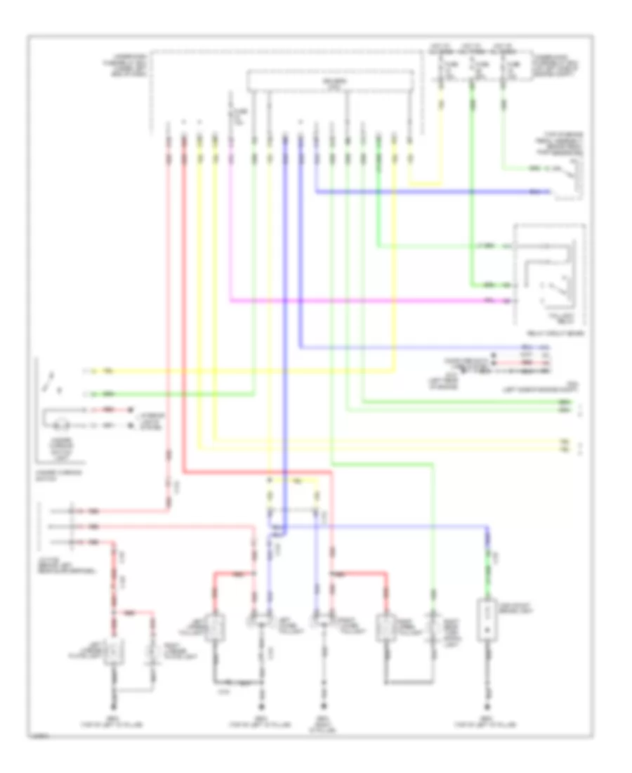
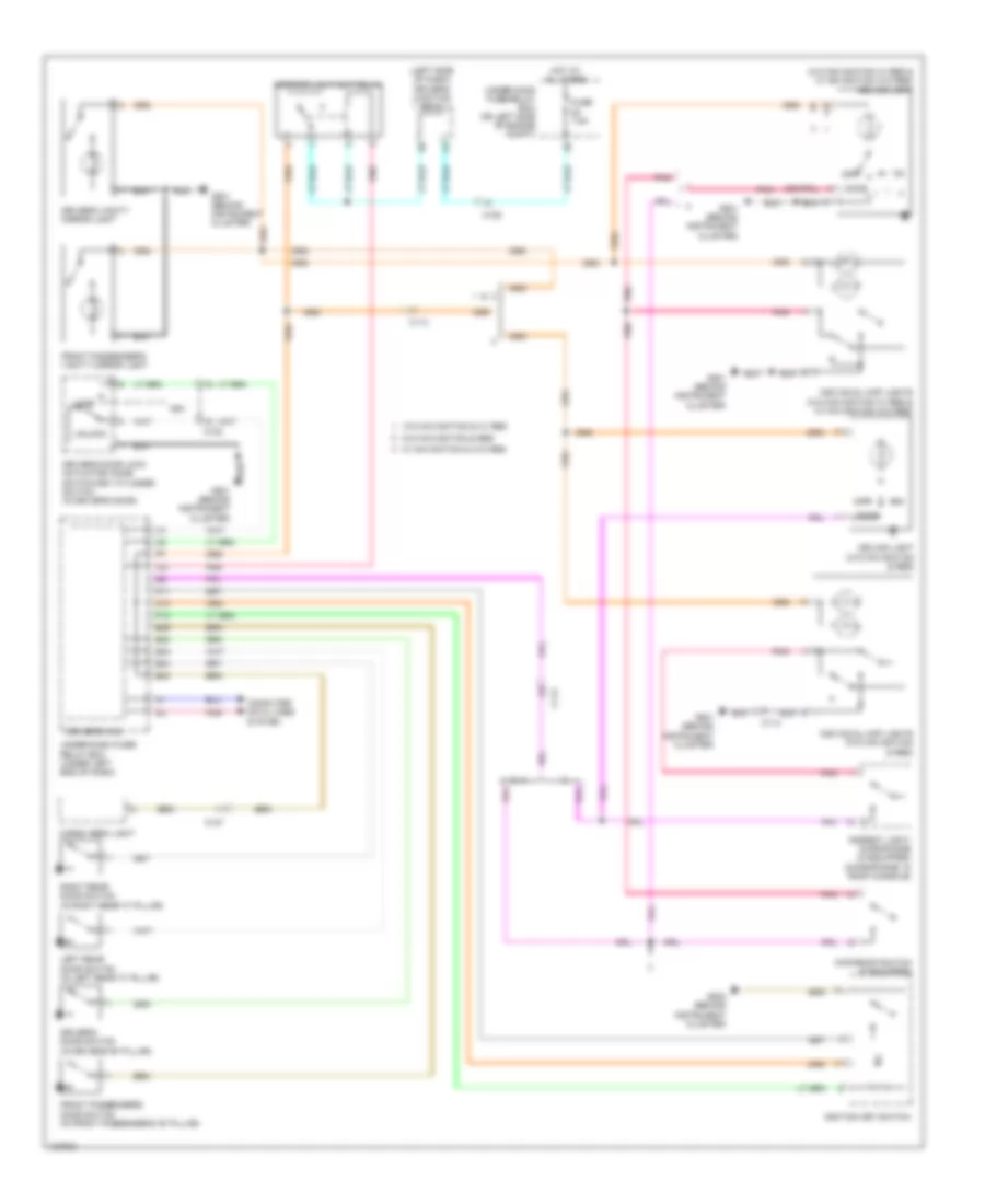
Exterior Lamps Wiring Diagram (2 of 2) for Honda CR-V EX-L 2014
List of elements for Exterior Lamps Wiring Diagram (2 of 2) for Honda CR-V EX-L 2014:
- 0) off 1) park 2) auto 3) head
- Automatic lighting/ sunlight sensor (if equipped) (top center of dash)
- B-can transceiver
- B-canh
- B-canl
- C11
- C121
- Combination light switch
- Computer data lines system
- D17
- Dc/dc converter
- Driver's junction box 2 (left side of dash)
- Driver's micu
- Fuse 10a
- G301 (under left headlight assembly)
- G502 (center of dash)
- G603 (top of left "d" pillar)
- Gauge control module
- Headlight switch
- Hot at all times
- Hot in on or start
- Left front side marker light
- Left front turn signal/ parking light
- Left rear turn signal light
- Left turn signal ind
- Pnk
- Q16
- Red
- Right front side marker light
- Right front turn signal/ parking light
- Right turn signal ind
- T13
- T14
- Turn signal switch
- Under-dash fuse/relay box (under left end of dash)
- Under-hood fuse/relay box (on left side of engine compt)
- W/o navigation w/ rear entertainment system
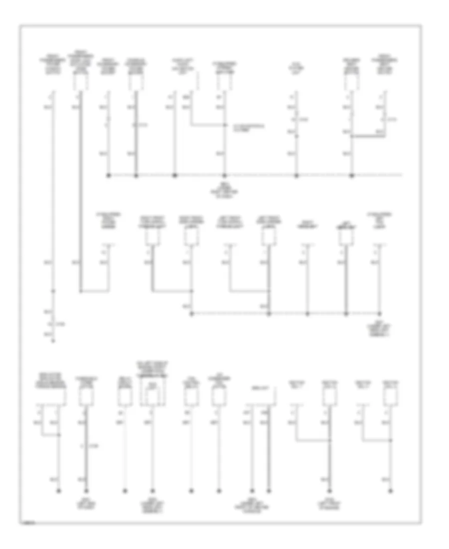
GROUND DISTRIBUTION
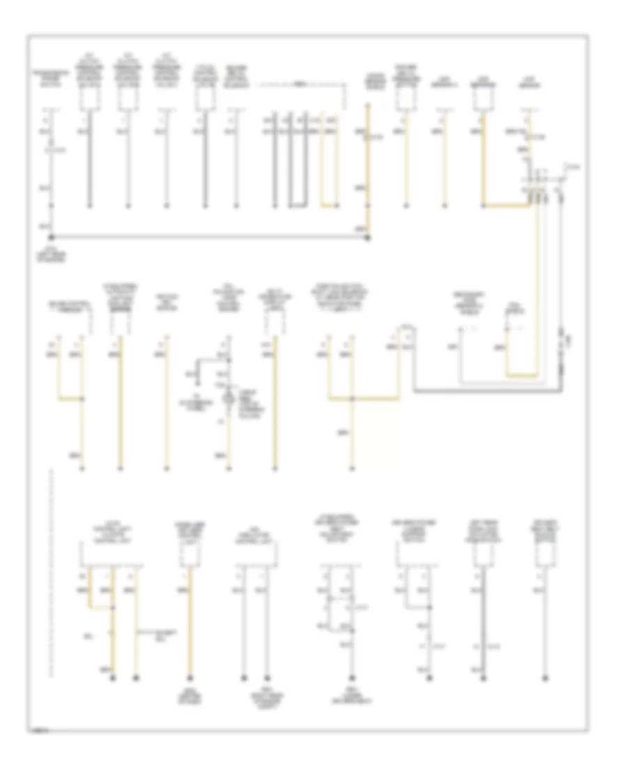
Ground Distribution Wiring Diagram (1 of 4) for Honda CR-V EX-L 2014
List of elements for Ground Distribution Wiring Diagram (1 of 4) for Honda CR-V EX-L 2014:
- (if equipped) automatic lighting/ sunlight sensor
- (if equipped) driver's power seat adjustment switch
- A/t clutch pressure control solenoid valve a
- A/t clutch pressure control solenoid valve b
- A/t clutch pressure control solenoid valve c
- A10
- B10
- C105
- C117
- C118
- C13
- C131
- C132
- C134
- C135
- C15
- C20
- Cable reel (top of steering column)
- Ckp sensor
- Cmp sensor a
- Cmp sensor b
- Dlc
- Driver's power lumbar support switch
- Driver's seat belt buckle switch
- Except exl
- Exl
- G101 (left rear of engine)
- G201 (right rear of engine compt)
- G502 (center of dash)
- G601 (under driver's seat)
- Gauge control module
- Hfl- navigation voice control switch
- Hvac control unit/ climate control unit
- Ignition key switch
- Imm0bilizer keyless control unit
- Knock sensor shield
- Left rear door lock actuator/ knob switch
- Multi- information display unit
- Park pin switch/ shift lock solenoid/ a/t gear position indicator panel light
- Pcm
- Pcm shield
- Rocker arm oil control solenoid
- Rocker arm oil pressure switch
- Secondary ho2s (sensor 2) shield
- T6 (in steering wheel)
- Transmission range switch
- Vsa modulator control unit
- Vtc oil control solenoid valve
Ground Distribution Wiring Diagram (2 of 4) for Honda CR-V EX-L 2014
List of elements for Ground Distribution Wiring Diagram (2 of 4) for Honda CR-V EX-L 2014:
- (canada) automatic dimming inside mirror
- (canada) washer fluid level switch
- (if equipped) left power mirror
- (if equipped) moonroof control unit/ motor
- (if equipped) right fog light
- (on left side of engine compt) under-hood fuse/relay box
- (under left end of dash) under-dash fuse/relay box
- (w/ rear
- (w/ rear entertainment) rear controller & screen
- B20
- B32
- Battery sensor
- Blower motor relay
- Brake fluid level switch
- C111
- C114
- C119
- C138
- Console accessory power socket relay
- D10
- Diode c
- Driver's door lock actuator/ knob switch/ key cylinder switch
- Driver's micu
- Driver's vanity mirror light
- Econ switch
- Engine
- Entertainment) ceiling light
- Eps control unit
- G1 (under battery tray)
- G2 (right side of engine compt)
- G202 (under right headlight assembly)
- G3 (lower left front of engine compt)
- G402 (left kick panel)
- G403 (upper left end of dash)
- G501 (behind instrument cluster)
- G604 (right "d" pillar)
- Individual map light
- Moonroof switch
- Passenger's vanity mirror light
- Power mirror switch
- Power transistor
- Power window master switch
- Right backup light
- Right lower taillight
- Right rear door lock actuator/ knob switch
- Right rear turn signal light
- Right upper taillight
- Security hood switch
- Steering angle sensor
- Tpms switch
- Transmission housing
- Vsa off switch
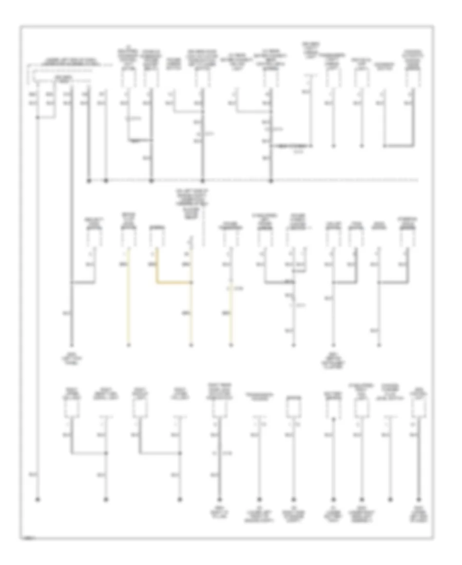
Ground Distribution Wiring Diagram (3 of 4) for Honda CR-V EX-L 2014
List of elements for Ground Distribution Wiring Diagram (3 of 4) for Honda CR-V EX-L 2014:
- C116
- C117
- C121
- C124
- C125
- C127
- C129
- C144
- C145
- Driver's seat heater
- Driver's seat heater relay (high)
- Driver's seat heater relay (low)
- Driver's seat position sensor
- Electrical compass unit
- Front passenger's heater relay (low)
- Front passenger's seat belt buckle switch
- Front passenger's seat heater
- Front passenger's seat heater relay (high)
- Fuel tank unit
- G602 (under front passenger's seat)
- G603 (top of left "d" pillar)
- High mount brake light
- Left backup light
- Left license plate light
- Left lower taillight
- Left rear turn signal light
- Left upper taillight
- Ods unit
- Real time awd control unit
- Rear differential assembly shield
- Rear window defogger
- Rear window wiper motor
- Right license plate light
- T7 (on differential assembly)
- Tailgate outer handle switch
- Tailgate release actuator/ latch switch (built into the tailgate latch)
- W/ heated seats
- W/ navigation & w/o rear entertainment system
- W/o navigation & rear entertainment system
- W/o navigation & w/ rear entertainment system
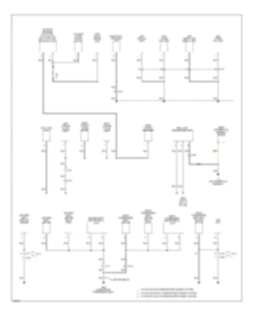
Ground Distribution Wiring Diagram (4 of 4) for Honda CR-V EX-L 2014
List of elements for Ground Distribution Wiring Diagram (4 of 4) for Honda CR-V EX-L 2014:
- (if equipped) left fog light
- (if equipped) right power mirror
- (if equipped) stereo amplifier
- (on left side of engine compt) under-hood fuse/relay box
- A/c condenser fan motor
- A36
- A37
- Audio unit/ audio- navigation unit
- B20
- C103
- C109
- C110
- C139
- Console accessory power socket
- Driver's seat heater switch
- Dvd player unit
- Eld unit
- Eps motor/ eps motor angle sensor/ torque sensor
- Fan control relay
- Front accessory power socket
- Front passenger's door lock actuator/ knob switch
- Front passenger's power window switch
- Front passenger's seat heater switch
- G102 (left front of engine)
- G301 (under left headlight assembly)
- G302 (under left headlight assembly)
- G401 (left end of dash)
- G503 (under right center of dash)
- G504 (under left front of center console)
- Ignition coil 1
- Ignition coil 2
- Ignition coil 3
- Ignition coil 4
- Left front side marker light
- Left front turn signal/ parking light
- Left headlight
- Relay circuit board
- Right front side marker light
- Right front turn signal/ parking light
- Right headlight
- Srs unit
- W/ navigation & w/o res
- Windshield wiper motor
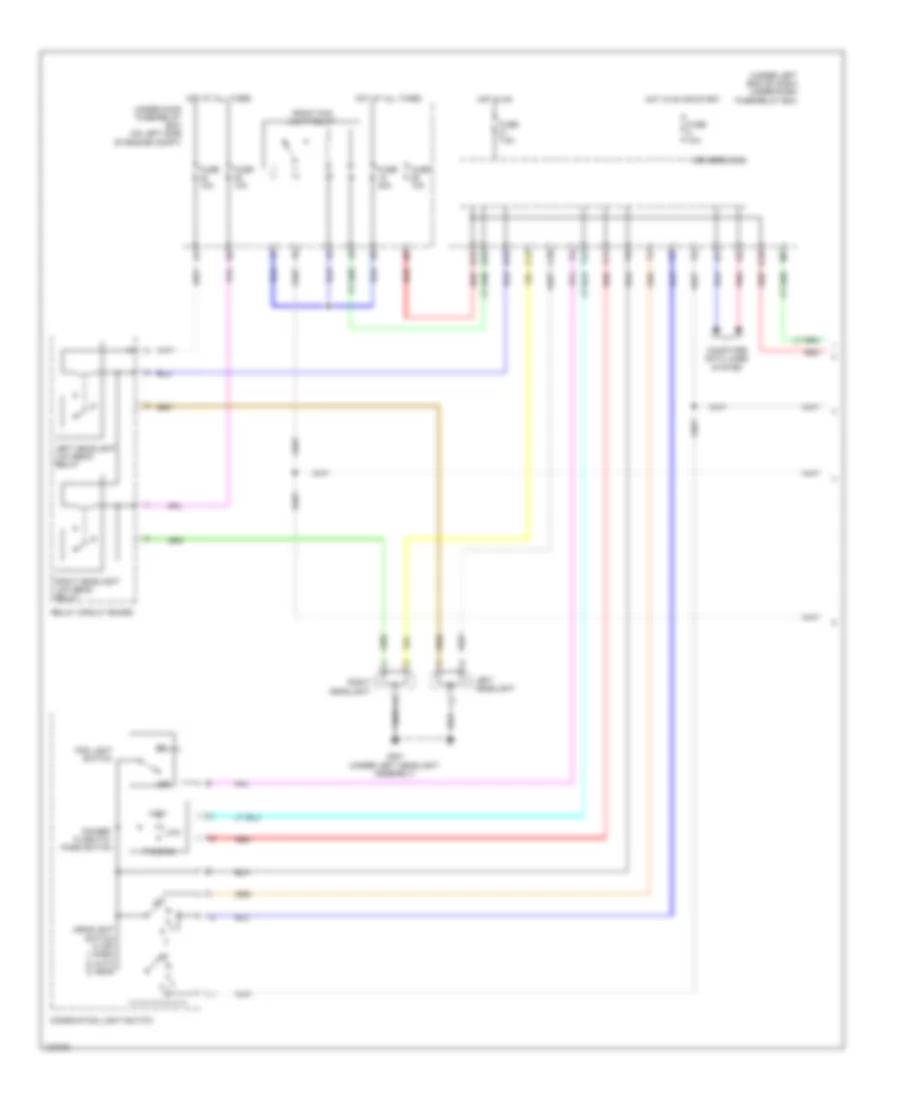
HEADLIGHTS
Headlights Wiring Diagram (1 of 2) for Honda CR-V EX-L 2014
List of elements for Headlights Wiring Diagram (1 of 2) for Honda CR-V EX-L 2014:
- (under left end of dash) under-dash fuse/relay box
- C14
- C18
- Combination light switch
- Computer data lines system
- D16
- D17
- D25
- Dimmer/ flash-to- pass switch
- Driver's micu
- Fog light switch
- Front fog light relay
- Fuse 10a
- Fuse 20a
- Fuse 7.5a
- G301 (under left headlight assembly)
- Headlight switch 0) off 1) park 2) auto 3) head
- High
- Hot at all times
- Hot in on
- Hot in on or start
- Left headlight
- Left headlight low beam relay
- Low
- Off
- Passing
- Pnk
- Q16
- Red
- Relay circuit board
- Right headlight
- Right headlight low beam relay
- T11
- T12
- Under-hood fuse/relay box (on left side of engine compt)
Headlights Wiring Diagram (2 of 2) for Honda CR-V EX-L 2014
List of elements for Headlights Wiring Diagram (2 of 2) for Honda CR-V EX-L 2014:
- (center of dash) g502
- 10v stabilizing circuit
- Air conditioning system
- Automatic lighting/ sunlight sensor (if equipped) (top center of dash)
- B-can h
- B-can l
- B-can transceiver
- C103
- C104
- C108
- Computer data lines system
- Dc/dc converter
- Dimming circuit
- Driver's junction box 2 (left side of dash)
- Dvd player unit
- Exl
- Front fog light indicator (led)
- G202 (under right headlight assembly)
- G301 (under left headlight assembly)
- Gauge control module
- High beam indicator (led)
- Indicator drive circuit
- Left fog light
- Lights control indicator (led)
- Lights on indicator (led)
- Parking brake switch (base of parking brake lever assembly)
- Pnk
- Rear controller & screen
- Red
- Right fog light
HORN
Horn Wiring Diagram for Honda CR-V EX-L 2014
List of elements for Horn Wiring Diagram for Honda CR-V EX-L 2014:
- C14
- C37
- Cable reel (top of steering column)
- Driver's mcu
- Fuse 10a
- Horn (high) (behind right end of front bumper)
- Horn (low) (behind center of front grille)
- Horn relay (in under-hood fuse/relay box)
- Horn switch (in steering wheel)
- Hot at all times
- Q10
- Under-dash fuse/relay box (under left end of dash)
- Under-hood fuse/relay box (on left side of engine compt)
INSTRUMENT CLUSTER
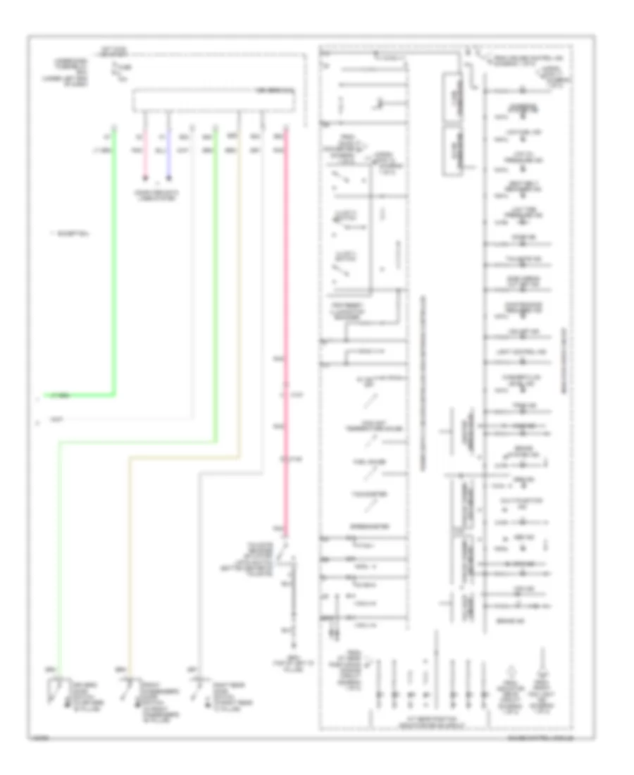
Instrument Cluster Wiring Diagram (1 of 2) for Honda CR-V EX-L 2014
List of elements for Instrument Cluster Wiring Diagram (1 of 2) for Honda CR-V EX-L 2014:
- 10v stabilizing circuit
- 5v control circuit
- 5v on/off
- A/t gear position dimming circuit
- Air conditioning system
- Amp
- Brake fluid level switch (on brake fluid reservoir)
- C108
- C112
- Computer data lines system
- Cruise control ind to brake system ind (diagram 2 of 2)
- Cruise control system
- Cruise main ind
- Dc/dc converter
- Dimming circuit
- Driver's junction box 2 (left side of dash)
- Eco ind
- Except exl
- Exl
- Exterior lights system
- Front fog light ind
- Fuel tank unit (top of fuel tank)
- Fuse 10a
- G402 (left kick panel)
- G501 (behind instrument cluster)
- G502 (center of dash)
- Gauge control module
- High beam ind
- Hot at all times
- Illumination
- Illumination control & dimming circuit for ambient (green)
- Illumination control & dimming circuit for ambient (white)
- Illumination control & dimming circuit for dial face
- Illumination control & dimming circuit for pointer
- Immobilizer ind
- Indicator drive circuit
- Interior lights system
- Left rear door switch (in left rear "c" pillar)
- Left turn signal ind
- Lights on ind
- Mixing
- Oil pressure switch (on right front of engine, above oil filter)
- Parking brake switch (base of parking brake lever assembly)
- Pcm (left side of engine compt)
- Pnk
- Red
- Right turn signal ind
- Security ind
- Speaker
- To 1 ind (diagram 2 of 2)
- To a/t gear position indicator driving circuit (diagram 2 of 2)
- To charging system ind (diagram 2 of 2)
- To d3 ind (diagram 2 of 2)
- To pin 22 (diagram 2 of 2)
- To trip reset/ illumin- ation encoder (diagram 2 of 2)
- Tpms switch
- Under-hood fuse/relay box (on left side of engine compt)
- Vsa off switch
Instrument Cluster Wiring Diagram (2 of 2) for Honda CR-V EX-L 2014
List of elements for Instrument Cluster Wiring Diagram (2 of 2) for Honda CR-V EX-L 2014:
- (diagram 1 of 2)
- 5v on/ off
- A/t gear position indicator drive circuit
- Abs ind
- Awd ind
- B22
- B29
- B33
- B34
- B40
- Brake ind
- Brake system ind
- C127
- C145
- Charging system ind
- Circuit fall safe
- Computer data lines system
- Coolant temperature gauge
- Dimming circuit (diagram 1 of 2)
- Display (lcd) odo/trip
- Door ind
- Driver's door switch (in driver's "b" pillar)
- Driver's micu
- Eps ind
- Except exl
- From a/t gear positioning g
- From cruise control ind (diagram 1 of 2)
- From dc/dc converter f
- From front fog light ind (diagram 1 of 2)
- From indicator drive circuit (diagram 1 of 2)
- From pin 12 e
- From pin 17 a
- Front passenger's door switch (in front passenger's "b" pillar)
- Fuel gauge
- Fuse 10a
- G603 (top of left "d" pillar)
- Gauge control module
- Hot in on or start
- Illum (+) switch
- Illum (-) switch
- Indicator drive circuit
- Level ind
- Light control ind
- Low fuel ind
- Low oil pressure ind
- Low tire pressure ind
- Maintenance required ind
- Multi-function ind
- Off circuit forced turning
- On circuit forced turning
- Pnk
- Right rear door switch (in right rear "c" pillar)
- Seat belt reminder ind
- Side airbag cut off ind
- Speedometer
- Srs ind
- Tachometer
- Tailgate ind
- Tailgate release actuator/ latch switch (bottom center of tailgate)
- Tpms ind
- Transciever b-can
- Transciever f-can
- Trip reset/ illumination encoder
- Under-dash fuse/relay box (under left end of dash)
- Vsa ind
- Vsa off ind
- Washer fluid
INTERIOR LIGHTS
Courtesy Lamps Wiring Diagram for Honda CR-V EX-L 2014
List of elements for Courtesy Lamps Wiring Diagram for Honda CR-V EX-L 2014:
- (behind instrument cluster)
- (left side of dash) driver's junction box 2
- (or pnk)
- (w/o navigation w/ res & w/ navigation w/o res) ceiling light
- Ambient light/ microphone (if equipped) (in roof console)
- B22
- B23
- B29
- B33
- B34
- B39
- B40
- C108
- C114
- C127
- C145
- Cargo area light
- Ceiling light (w/o navigation & res)
- Computer data lines system
- Door
- Driver's door switch (in driver's "b" pillar)
- Driver's micu
- Driver's vanity mirror light
- Front passenger's door switch (in front passenger's "b" pillar)
- Front passenger's vanity mirror light
- Fuse 7.5a
- G501
- G501 (behind instrument cluster)
- G603 (top of left "d" pillar)
- Hot at all times
- Individual map lights (w/o navigation & res)
- Individual map lights (w/o navigation w/ res & w/ navigation w/o res)
- Interior light cut relay
- Left rear door switch (in left rear "c" pillar)
- Moonroof switch (if equipped)
- Off
- Pnk
- Right rear door switch (in right rear "c" pillar)
- Tailgate release actuator/latch switch (built into the tailgate latch) (bottom center of tailgate)
- Under-dash fuse/ relay box (under left end of dash)
- Under-hood fuse/relay box (on left side of engine compt)
- W/ navigation & w/o res
- W/o navigation & res
- W/o navigation & w/ res
Entry Light Timer Wiring Diagram for Honda CR-V EX-L 2014
List of elements for Entry Light Timer Wiring Diagram for Honda CR-V EX-L 2014:
- (left side of dash) driver's junction box 2
- (w/o navigation w/ res & w/ navigation w/o res) ceiling light
- Ambient light/ microphone (if equipped) (microphone: in roof console)
- B23
- B29
- B33
- B34
- B40
- C102
- C108
- C114
- C127
- Cargo area light
- Ceiling light (w/o navigation & res)
- Computer data lines system
- Door
- Driver's door lock actuator/ knob switch/key cylinder switch (in driver's door)
- Driver's door switch (in driver's "b" pillar)
- Driver's micu
- Driver's vanity mirror light
- Front passenger's vanity mirror light
- Front passengers door switch (in front passenger's "b" pillar)
- Fuse 7.5a
- G501 (behind instrument cluster)
- G502 (behind instrument cluster)
- Hot at all times
- Ignition key switch
- Individual map lights (w/o navigation & res)
- Individual map lights (w/o navigation w/ res & w/ navigation w/o res)
- Interior light cut relay
- Key
- Left rear door switch (in left rear "c" pillar)
- Lock
- Moonroof switch (if equipped)
- N13
- Off
- P11
- P12
- Pnk
- Right rear door switch (in right rear "c" pillar)
- Under-dash fuse/ relay box (under left end of dash)
- Under-hood fuse/relay box (on left side of engine compt)
- Unlock
- W/ navigation & w/o res
- W/o navigation & res
- W/o navigation & w/ res
Instrument Illumination Wiring Diagram (1 of 2) for Honda CR-V EX-L 2014
List of elements for Instrument Illumination Wiring Diagram (1 of 2) for Honda CR-V EX-L 2014:
- Auto
- Automatic lighting/ sunlight sensor (top center of dash)
- B27
- C103
- C104
- C110
- C112
- C113
- C114
- C118
- C119
- C12
- C19
- Combination light switch
- Computer data lines system
- D17
- Dimmer/flash-to-pass switch
- Driver's junction box 2 (left side of dash)
- Driver's micu
- Driver's seat heaters switch (if equipped)
- Dvd player unit (if equipped)
- Front passengers seat heaters switch (if equipped)
- Fuse 20 7.5a
- Fuse 35 7.5a
- Fuse 5 10a
- Hazard warning switch
- Head
- Headlight switch
- Hot in on or start
- Hvac control unit/ climate control unit
- K10
- Left rear power window switch
- Moonroof switch (if equipped)
- Off
- Park
- Park pin switch/ shift lock solenoid/ a/t gear position indicator panel light (base of shift lever assembly)
- Pass
- Pnk
- Q16
- Rear controller & screen (if equipped)
- Red
- Right rear power window switch
- T11
- T12
- Tpms switch
- Under-dash fuse/relay box (under left end of dash)
- Vsa off switch
- W/ navigation & res
- W/o navigation & res
- W/o navigation & w/ res
Instrument Illumination Wiring Diagram (2 of 2) for Honda CR-V EX-L 2014
List of elements for Instrument Illumination Wiring Diagram (2 of 2) for Honda CR-V EX-L 2014:
- (center of dash) g502
- 10v stabilizing circuit
- A10
- Ambient light/ microphone (in roof console)
- Audio remote multi-information display switch
- B-can h
- B-can l
- C109
- C111
- C114
- Cable reel (top of steering column)
- Computer data lines system
- Converter dc/dc
- Cruise control combination switch
- Dimming circuit
- Econ switch
- Front passengers air bag cut-off indicator
- Front passengers power window switch
- Fuse 26 20a
- Fuse 29 10a
- Gauge control module
- Hfl-navigation voice control switch
- Hot at all times
- Illumi (+) switch
- Illumi (-) switch
- Illumination control
- Illumination control dimming circuit for ambient (green)
- Illumination control dimming circuit for ambient (white)
- Illumination control dimming circuit for dial face (white)
- Illumination control dimming circuit for pointer (white)
- Illumination encoder/ trip reset
- Led
- Pnk
- Power mirror switch
- Power window master switch
- Red
- Relay circuit board
- Tail light relay
- Transceiver b-can
- Under-hood fuse/relay box (on left side of engine compt)
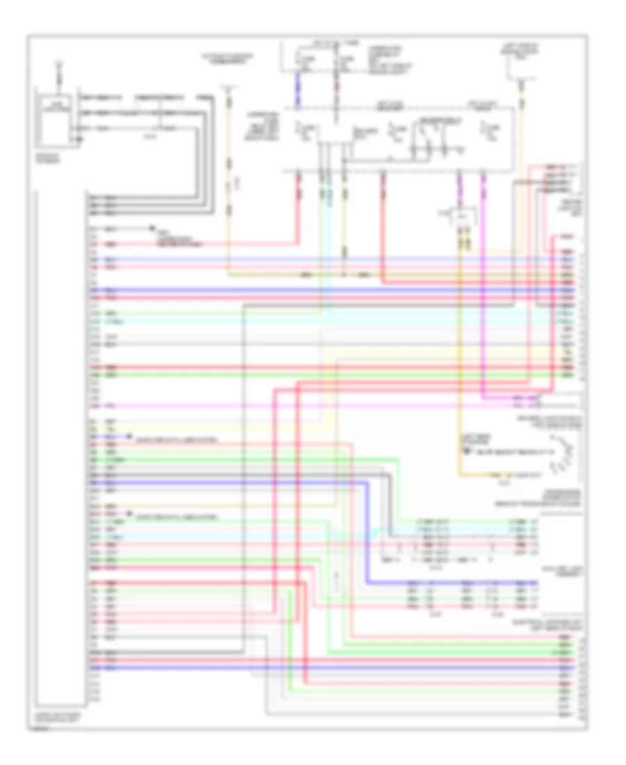
NAVIGATION
Compass Wiring Diagram for Honda CR-V EX-L 2014
List of elements for Compass Wiring Diagram for Honda CR-V EX-L 2014:
- (top of left "d" pillar) g603
- A24
- Audio unit/ audio-navigation unit
- B10
- B13
- B19
- B20
- B28
- C107
- C122
- Computer data lines system
- Driver's junction box 2 (left side of dash)
- Electrical compass unit (left rear of roof)
- Fuse 10a
- Fuse 7.5a
- G503 (under right center of dash)
- Hot in on or acc
- Hot in on or start
- Pnk
- Under-dash fuse/relay box (under left end of dash)
- W/ rear entertainment
Hands Free Module Wiring Diagram (1 of 2) for Honda CR-V EX-L 2014
List of elements for Hands Free Module Wiring Diagram (1 of 2) for Honda CR-V EX-L 2014:
- Ambient light/microphone
- C114
- C13
- C20
- Cable reel (top of steering column)
- Driver's junction box 2 (left side of dash)
- Fuse 7.5a
- G502 (center of dash)
- Handsfreelink control unit (under middle of dash)
- Hfl navigation voice control switch
- Hot in acc or on
- Interior lights system
- Microphone
- Microphone (in roof console)
- Off hook
- On hook/ back
- Pnk
- Red
- T6 (in steering wheel)
- Talk
- Under-dash fuse/relay box (under left end of dash)
- W/ navigation
- W/o navigation
Hands Free Module Wiring Diagram (2 of 2) for Honda CR-V EX-L 2014
List of elements for Hands Free Module Wiring Diagram (2 of 2) for Honda CR-V EX-L 2014:
- (under middle of dash) g503
- A10
- A11
- A12
- A24
- A25
- A26
- A27
- A32
- Audio unit/ audio-navigation unit
- B11
- B12
- B13
- C10
- C11
- C12
- Center junction box
- Computer data lines system
- E10
- E13
- G10
- H10
- Multi-information display unit
- Pnk
- Red
- W/ navigation
- W/o navigation
- Xm receiver (if equipped) (behind right kick panel)
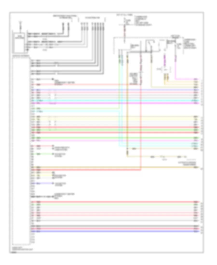
Navigation Wiring Diagram (1 of 4) for Honda CR-V EX-L 2014
List of elements for Navigation Wiring Diagram (1 of 4) for Honda CR-V EX-L 2014:
- (behind right kick panel) xm receiver
- (under right center of dash) g503
- A10
- A11
- A12
- A13
- A14
- A15
- A16
- A17
- A18
- A19
- A20
- A21
- A22
- A23
- A24
- Am/fm/xm antenna
- Audio unit/ audio-navigation unit
- Automatic dimming inside mirror
- B10
- B11
- B12
- B13
- B14
- B15
- B16
- B17
- B18
- B19
- B20
- B21
- C10
- C11
- C114
- C12
- C13
- C134
- C14
- C142
- C143
- C15
- C16
- Computer data lines system
- D17
- D21
- Driver's junction box 1 (left side of dash)
- Driver's micu
- Fm distributor
- Fuse 10a
- Fuse 7.5a
- G503 (under right center of dash)
- Hot at all times
- Hot in on or acc
- Navigation system
- Nca
- Pnk
- Q14
- Red
- Reverse relay
- Sub amplifier
- Tan
- Under-dash fuse/ relay box (under left end of dash)
- Under-hood fuse/relay box (on left side of engine compt)
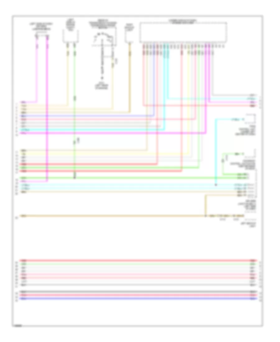
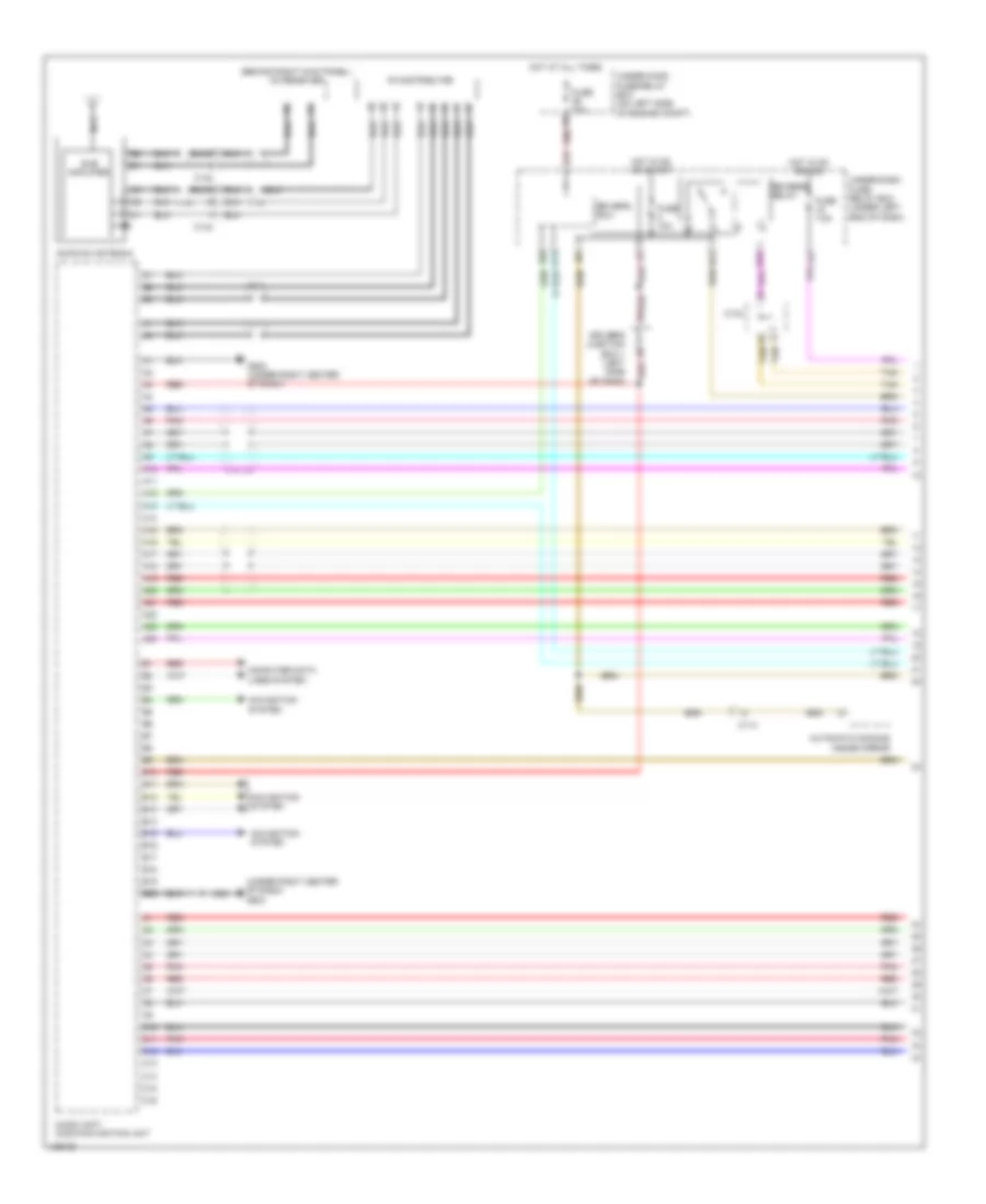
Navigation Wiring Diagram (2 of 4) for Honda CR-V EX-L 2014
List of elements for Navigation Wiring Diagram (2 of 4) for Honda CR-V EX-L 2014:
- (left side of dash) driver's junction box 2
- (left side of engine compt) pcm
- (rear of transmission housing) transmission range switch
- (under middle of dash) stereo amplifier
- A10
- A11
- A12
- A13
- A14
- A15
- A16
- A17
- A18
- A19
- A20
- A21
- A22
- A23
- A24
- A26
- B25
- C105
- C112
- C114
- C121
- C131
- Driver's junction box 2 (left side of dash)
- G101 (left rear of engine)
- Left backup light
- Moonroof control unit/motor (center rear of roof)
- Pnk
- Red
- Right backup light
- Tan
- Tpms control unit (under left center of dash)
Navigation Wiring Diagram (3 of 4) for Honda CR-V EX-L 2014
List of elements for Navigation Wiring Diagram (3 of 4) for Honda CR-V EX-L 2014:
- (center of dash) gps antenna
- (passenger's dash) usb port
- A10
- A11
- A12
- A13
- Audio unit/audio-navigation unit
- Auxiliary jack assembly
- C110
- Center junction box
- Computer data lines system
- E10
- E11
- E12
- E13
- E14
- E15
- E16
- G10
- H10
- Handsfree link control unit (under middle of dash)
- Lines system computer data
- Navigation system
- Nca
- Pnk
- Red
- System navigation
- Xm receiver (behind right kick panel)
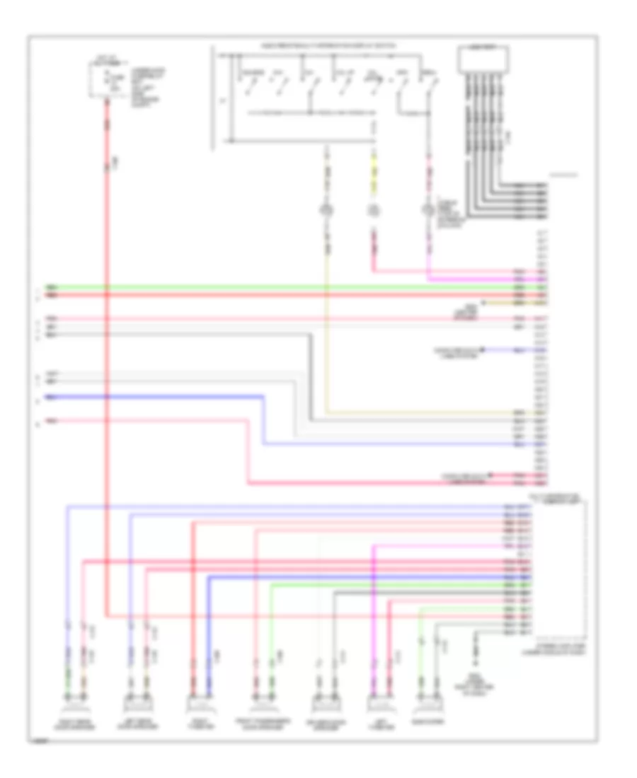
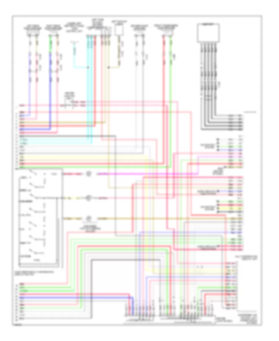
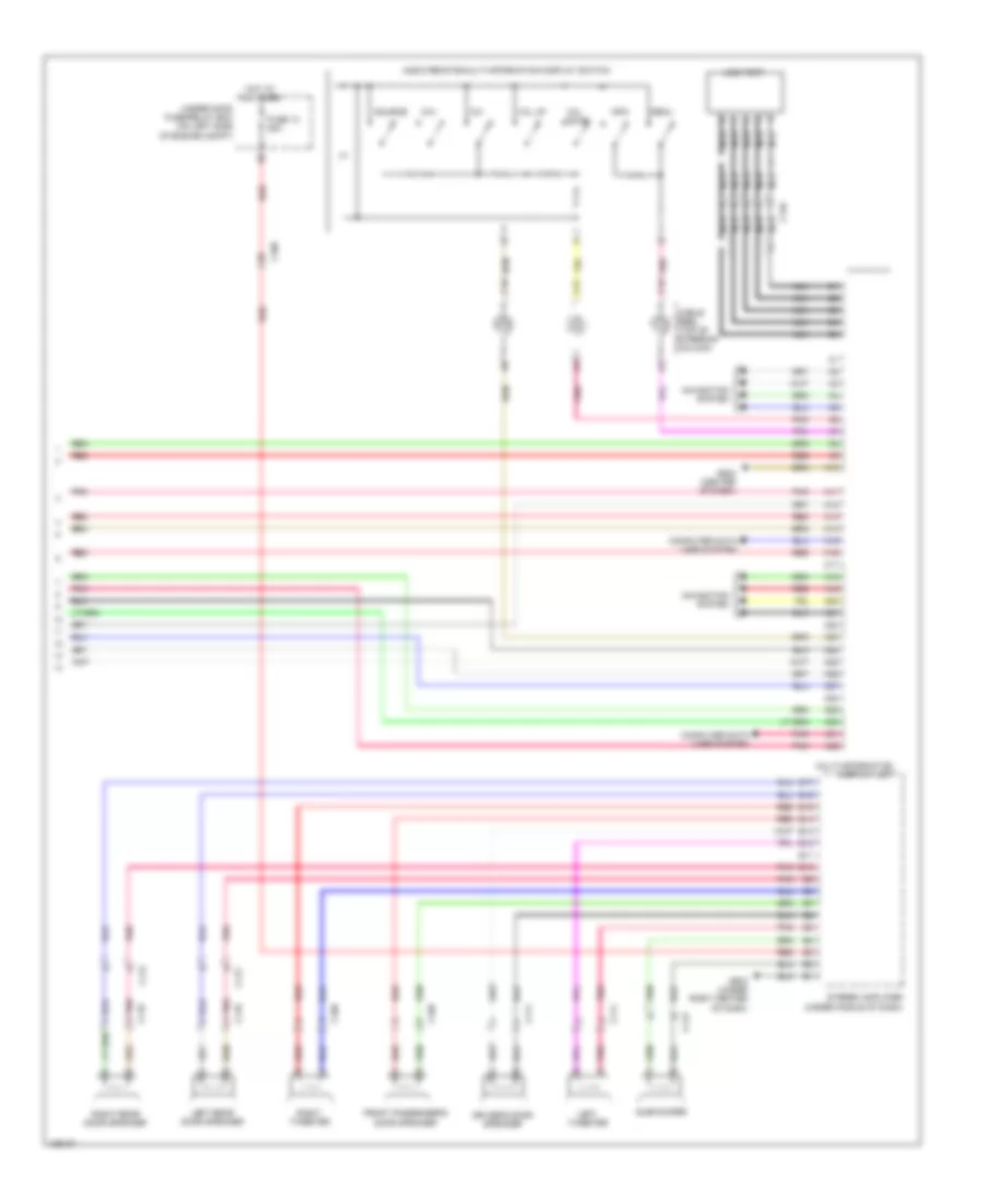
Navigation Wiring Diagram (4 of 4) for Honda CR-V EX-L 2014
List of elements for Navigation Wiring Diagram (4 of 4) for Honda CR-V EX-L 2014:
- A10
- A11
- A12
- A13
- A14
- A15
- A16
- A17
- A18
- A19
- A20
- A21
- A22
- A23
- A24
- A25
- A26
- A27
- A28
- A29
- A30
- A31
- A32
- Audio remote/multi-information display switch
- B10
- B11
- B12
- B13
- B14
- B15
- B16
- B17
- C108
- C109
- C111
- C112
- C113
- C118
- C119
- C146
- C17
- C18
- C19
- Cable reel (top of steering column)
- Ch+
- Ch-
- Computer data lines system
- Driver's door speaker
- Front passenger's door speaker
- Fuse 20a
- G502 (center of dash)
- G503 (under right center of dash)
- Hot at all times
- Info
- Left rear door speaker
- Left tweeter
- Menu
- Multi-information display unit
- Nca
- Pnk
- Red
- Right rear door speaker
- Right tweeter
- Source
- Stereo amplifier (under middle of dash)
- Subwoofer
- Under-hood fuse/relay box (on left side of engine compt)
- Usb port
- Vol down
- Vol up
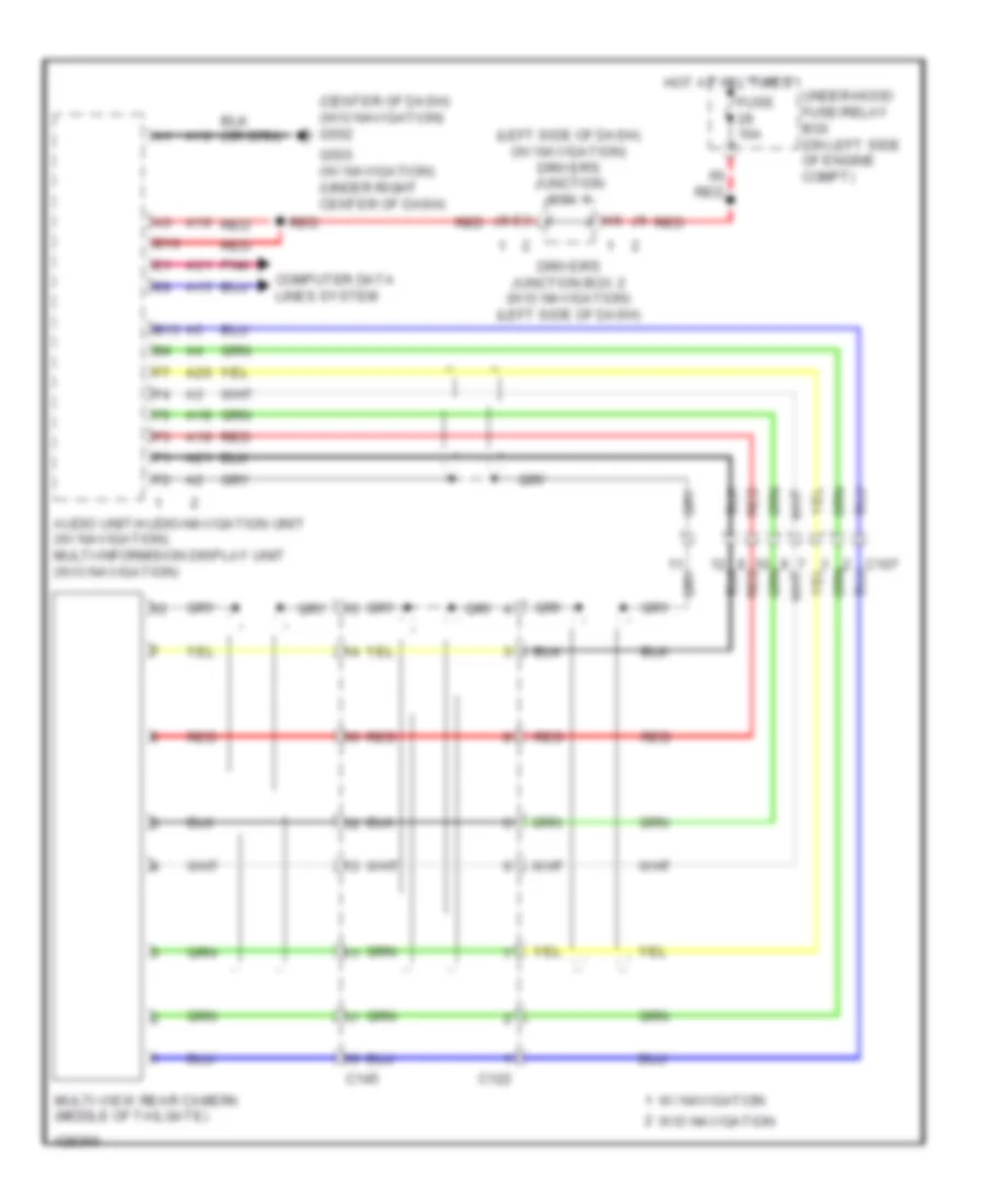
Rear Camera Wiring Diagram for Honda CR-V EX-L 2014
List of elements for Rear Camera Wiring Diagram for Honda CR-V EX-L 2014:
- (center of dash) (w/o navigation) g502
- (left side of dash) (w/ navigation) driver's junction box 1
- A10
- A15
- A16
- A18
- A19
- A20
- A21
- A31
- Audio unit/audio-navigation unit (w/ navigation) multi-informision display unit (w/o navigation)
- B10
- B15
- C122
- C145
- Computer data lines system
- Driver's junction box 2 (w/o navigation) (left side of dash)
- Fuse 10a
- G503 (w/ navigation) (under right center of dash)
- Hot at all times
- Multi-view rear camera (middle of tailgate)
- Pnk
- Red
- Under-hood fuse/relay box (on left side of engine compt)
- W/ navigation
- W/o navigation
POWER DISTRIBUTION
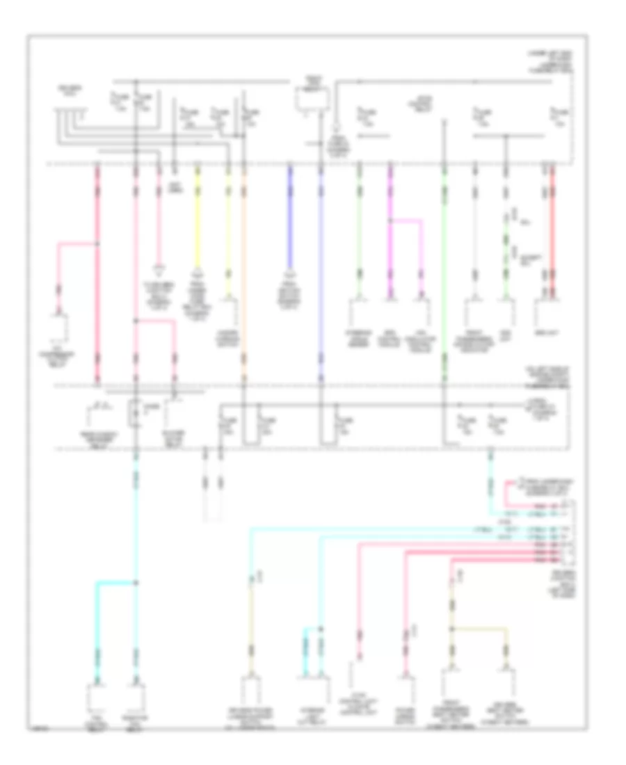
Power Distribution Wiring Diagram (1 of 4) for Honda CR-V EX-L 2014
List of elements for Power Distribution Wiring Diagram (1 of 4) for Honda CR-V EX-L 2014:
- & awd
- (if equipped) front fog light relay
- (on left side of engine compt) under-hood fuse/relay box
- (under left end of dash) under-dash fuse/relay box
- 100a
- 10a
- 15a
- 20a
- 60a
- 7.5a
- A24
- Alternator
- Audio unit/ audio navigation unit
- Automatic dimming inside mirror
- Battery
- Battery sensor
- Brake pedal position switch
- C103
- C108
- C110
- C112
- C114
- C117
- Console accessory power socket
- Console accessory power socket relay
- Driver's junction box 2 (left side of dash)
- Driver's micu
- Driver's power seat adjustment switch (w/ driver's power seat)
- Dvd player unit (w/ rear entertainment)
- From ignition switch (diagram 2 of 4)
- From under-hood fuse/relay box (diagram 3 of 4)
- Front accessory power socket
- Front accessory power socket relay
- Fuse
- Fuse 1-6
- Fuse 2-2
- Fuse 2-3
- G501 (behind instrument cluster)
- G503 (under right center of dash)
- Horn relay
- Ignition key switch
- Moonroof control unit/motor (w/ moonroof)
- Pgm-fi subrelay
- Pnk
- Q11
- Real time awd control unit (awd)
- Real time awd relay (awd)
- Rear window washer motor relay
- Red
- Starter
- Stereo amplifier (premium)
- T101
- To fuse 1-5 (diagram 3 of 4)
- To fuse 14 (diagram 3 of 4)
- To fuse 2-1 (diagram 3 of 4)
- To fuse 28 (diagram 4 of 4)
- To fuse 42 (diagram 3 of 4)
- To fuse 7 (diagram 2 of 4)
- To ignition switch (diagram 2 of 4)
- To under-dash fuse/relay box (diagram 2 of 4)
- To under-dash fuse/relay box (diagram 4 of 4)
- W/ moonroof
- Windshield washer motor relay
Power Distribution Wiring Diagram (2 of 4) for Honda CR-V EX-L 2014
List of elements for Power Distribution Wiring Diagram (2 of 4) for Honda CR-V EX-L 2014:
- (under left end of dash) under-dash fuse/relay box
- 10a
- 15a
- 7.5a
- A16
- Acc
- Automatic lighting/ sunlight sensor (if equipped)
- B17
- B28
- Brake pedal position switch
- C10
- C103
- C104
- C108
- C112
- C122
- C126
- C127
- C13
- C134
- C145
- Cmp sensor a
- D17
- Data link connector (dlc)
- Driver's junction box 1 (left side of dash)
- Driver's junction box 2 (left side of dash)
- Driver's micu
- Dvd player unit (exl w/ rear entertainment)
- Eld
- Electrical compass unit
- Evap canister purge valve
- From fuse 28 (diagram 1 of 4)
- From under-dash fuse/relay box (diagram 1 of 4)
- From under-hood g fuse/relay box (diagram 1 of 4)
- Fuse
- Gauge control module
- Ignition switch
- Immobilizer keyless control unit
- Immobilizer- keyless control unit
- J/c c136 (right rear of engine)
- Lock
- Maf sensor/ iat sensor
- Multi- information display unit
- P18
- Park pin switch/ shift lock solenoid/ a/t gear position indicator panel light
- Pcm
- Pgm-fi main relay
- Q16
- Rear controller & screen (exl)
- Rear window wiper motor
- Red
- Relay circuit board
- Reverse relay
- Secondary ho2s (sensor 2)
- Start
- Start on
- Starter cut relay
- To fuse 24 (diagram 4 of 4)
- To under-dash fuse/relay box (diagram 1 of 4)
- To under-dash fuse/relay box (diagram 4 of 4)
- Tpms control module
Power Distribution Wiring Diagram (3 of 4) for Honda CR-V EX-L 2014
List of elements for Power Distribution Wiring Diagram (3 of 4) for Honda CR-V EX-L 2014:
- (not used)
- (on left side of engine compt) under-hood fuse/relay box
- (under left end of dash) under-dash fuse/relay box
- (w/ seat heaters)
- 10a
- 15a
- 20a
- 30a
- 40a
- 50a
- 7.5a
- 70a
- A/c compressor clutch relay
- A/c condenser fan relay
- A16
- B13
- Blower motor relay
- C102
- C113
- C114
- C116
- C117
- C126
- Driver unlock relay
- Driver's seat heater relay (high)
- Driver's seat heater relay (low)
- Eld unit
- Eps control unit
- From fuse 12 (diagram 1 of 4)
- From fuse 16 (diagram 1 of 4)
- From fuse 2-3 (diagram 1 of 4)
- From fuse 27 l (diagram 1 of 4)
- Front passenger's seat heater relay (high)
- Front passenger's seat heater relay (low)
- Fuse
- Fuse 1-1
- Fuse 1-3
- Fuse 1-4
- Fuse 1-5
- Fuse 2-1
- Fuse 2-10
- Fuse 2-11
- Fuse 2-8
- Fuse 2-9
- Fuse 20a
- Ignition coil relay
- Left headlight low beam relay
- Lock relay
- Moonroof control unit/ motor (w/ moonroof)
- Pnk
- Power window master switch
- Power window relay
- Radiator fan relay
- Real time awd relay (awd)
- Red
- Relay circuit board
- Right headlight low beam relay
- Tailgate actuator relay
- Taillight relay
- To under-dash fuse/relay box (diagram 1 of 4)
- Unlock relay
- Vsa modulator control unit
- Windshield wiper motor relay
Power Distribution Wiring Diagram (4 of 4) for Honda CR-V EX-L 2014
List of elements for Power Distribution Wiring Diagram (4 of 4) for Honda CR-V EX-L 2014:
- (not used)
- (on left side of engine compt) under-hood fuse/relay box
- (under left end of dash) under-dash fuse/relay box
- 10a
- 15a
- 30a
- 7.5a
- A/c compressor clutch relay
- A11
- A38
- A39
- B1 pnk
- B30
- Blower motor relay
- C108
- C110
- C111
- C113
- C116
- C117
- C125
- C17
- D14
- D28
- D6 pnk
- Diode a
- Driver's junction box 2 (left side of dash)
- Driver's micu
- Driver's power lumbar support switch (w/ lumbar seats)
- Driver's seat heater switch (w/seat heaters)
- E5 pnk
- Eps control module
- Etcs control relay
- Except exl
- Exl
- Fan control relay
- From fuse 2-3 (diagram 1 of 4)
- From fuse 23 (diagram 2 of 4)
- From ignition switch (diagram 2 of 4)
- From under- hood fuse/ relay box (diagram 1 of 4)
- From under-dash fuse/relay box (diagram 4 of 4)
- Front passenger's air bag cutoff indicator
- Front passenger's seat heater switch (w/seat heaters)
- Fuse
- Fuse 2-4
- Fuse 2-6
- Hazard warning switch
- Hvac control unit/ climate control unit
- Interior light cut relay
- J8 pnk
- Ods unit
- P15
- Pgm-fi main relay 1
- Pnk
- Power mirror switch
- Radiator fan relay
- Rear window defogger relay
- Red
- Srs unit
- Steering angle sensor
- To driver's junction box 2 (diagram 4 of 4)
- Vsa modulator control module
POWER DOOR LOCKS
Power Door Locks Wiring Diagram (1 of 2) for Honda CR-V EX-L 2014
List of elements for Power Door Locks Wiring Diagram (1 of 2) for Honda CR-V EX-L 2014:
- (behind instrument cluster) g501
- (bottom center of tailgate) tailgate release actuator/latch switch
- (top of left "d" pillar) g603
- (under right center of dash) g503
- B11
- B16
- B18
- B22
- B29
- B33
- B34
- B40
- C102
- C109
- C11
- C112
- C127
- C14
- C145
- C18
- C27
- D17
- D22
- Door lock knob
- Driver's door key cylinder switch
- Driver's door lock actuator/knob switch/ key cylinder switch (in driver's door)
- Driver's door lock knob switch
- Driver's micu
- Exterior lights system
- Front passenger's door lock actuator/knob switch (in front passenger's door)
- Fuse 10a
- Fuse 15a
- Fuse 20a
- G501 (behind instrument cluster)
- G603 (top of left "d" pillar)
- Headlights system
- Horns system
- Hot at all times
- Hot in on or start
- Key door lock knob
- Lock
- Lock relay
- N10
- N12
- Open
- P11
- Pnk
- Q10
- Q16
- Red
- Tailgate actuator relay
- Tailgate outer handle switch
- Under-dash fuse/relay box (under left end of dash)
- Unlock
- Unlock relay
- Unlock relay (dr)
- W10
- W23
- X10
Power Door Locks Wiring Diagram (2 of 2) for Honda CR-V EX-L 2014
List of elements for Power Door Locks Wiring Diagram (2 of 2) for Honda CR-V EX-L 2014:
- (center front of engine compt) (except lx) security hood switch
- (rear of transmission housing) transmission range switch
- 10v
- Antenna
- B-can h
- B-can l
- B-can transceiver
- C102
- C109
- C112
- C113
- C118
- C119
- C131
- Circuit
- Circuit stabilizing
- Close
- Computer data lines system
- Dc/dc converter
- Dlc (under left center of dash)
- Door ind
- Door lock knob
- Driver's door switch (in driver's "b" pillar)
- Driver's junction box 1 (left side of dash)
- Driver's junction box 2 (left side of dash)
- Exl w/o navigation & w/ res
- Front passenger's door switch (in front passenger's "b" pillar)
- Front passenger's power window switch
- Fuse 10a
- G101 (left rear of engine)
- G402 (left kick panel)
- G501 (behind instrument cluster)
- G502 (center of dash)
- G503 (under right center of dash)
- G601 (under driver's seat)
- G604 (right "d" pillar)
- Gauge control module
- Hot at all times
- Ignition key switch
- Immobilizer keyless control unit (on steering column, integral to ignition switch)
- Indicator drive
- J/c c134 (left rear of engine compt)
- Left rear door lock actuator/knob switch (in left rear door)
- Left rear door switch (in left rear "c" pillar)
- Lock
- Network controller
- Pnk
- Power window master switch
- R p
- Red
- Right rear door lock actuator/knob switch (in right rear door)
- Right rear door switch (in right rear "c" pillar)
- Security ind
- Sound systems
- Tailgate ind
- Under-hood fuse/relay box (on left side of engine compt)
- Unlock
POWER MIRRORS
Automatic Day/Night Mirror Wiring Diagram for Honda CR-V EX-L 2014
List of elements for Automatic Day/Night Mirror Wiring Diagram for Honda CR-V EX-L 2014:
- Audio unit/ audio navigation unit
- Automatic dimming inside mirror
- B21
- B25
- B45
- C112
- C114
- C121
- C131
- C134
- D21
- Driver's junction box 2 (left side of dash)
- Driver's micu
- Exterior lights system
- Fuse 5 10a
- Fuse 6 7.5a
- G101 (left rear of engine)
- G501 (behind instrument cluster)
- Hot in on or start
- Left backup light
- Moonroof control unit/motor (center rear of roof)
- Pcm (left side of engine compt)
- Pnk
- Q11
- Real time awd control unit (behind left rear quarterpanel)
- Real time awd relay (on rear relay holder)
- Red
- Reverse relay
- Tan
- Transmission range switch (rear of transmission housing)
- Under-dash fuse/relay box (under left end of dash)
Power Mirrors Wiring Diagram for Honda CR-V EX-L 2014
List of elements for Power Mirrors Wiring Diagram for Honda CR-V EX-L 2014:
- C109
- C111
- Defogger (if equipped)
- Defogger system
- Down/ left
- Down/ right
- Driver's junction box 2 (left side of dash)
- Fuse 22 7.5a
- G501 (behind instrument cluster)
- Hot in on
- Interior lights system
- Left
- Left power mirror (in driver's door)
- Left/ right motor
- Pnk
- Power mirror switch
- Right
- Right power mirror (in front passenger's door)
- Under-dash fuse/relay box (under left end of dash)
- Up/ down motor
- Up/ left
- Up/ right
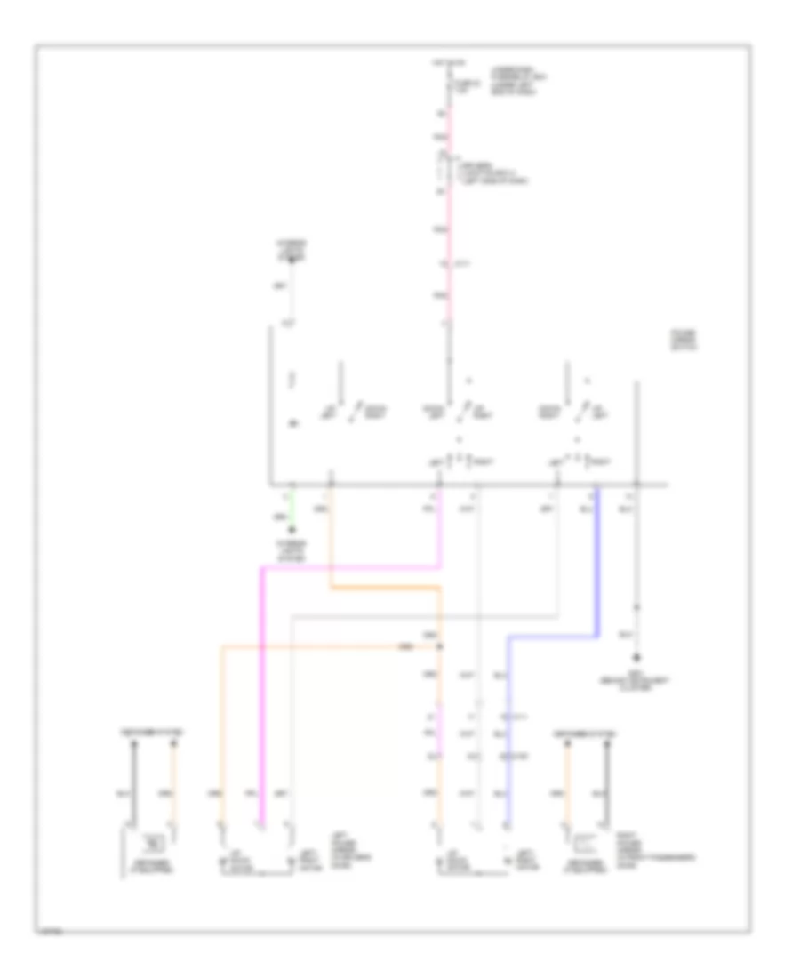
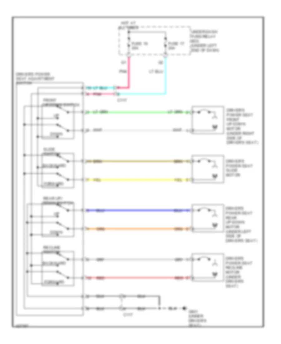
POWER SEATS
Driver Power Seat Wiring Diagram for Honda CR-V EX-L 2014
List of elements for Driver Power Seat Wiring Diagram for Honda CR-V EX-L 2014:
- Backward
- C117
- Down
- Driver's power seat adjustment switch
- Driver's power seat front up-down motor (under right side of driver's seat)
- Driver's power seat rear up-down motor (under left side of driver's seat)
- Driver's power seat recline motor (under driver's seat)
- Driver's power seat slide motor
- Forward
- Front up-down switch
- Fuse 16 20a
- Fuse 17 20a
- G601 (under driver's seat)
- Hot at all times
- Pnk
- Rear up/ down switch
- Recline switch
- Red
- Slide switch
- Under-dash fuse/relay box (under left end of dash)
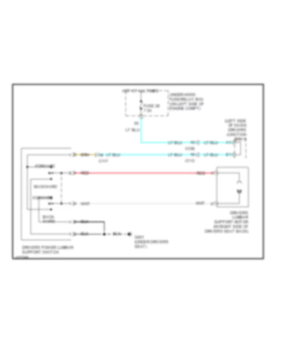
Driver"s Lumbar Wiring Diagram for Honda CR-V EX-L 2014
List of elements for Driver"s Lumbar Wiring Diagram for Honda CR-V EX-L 2014:
- (left side of dash) driver's junction box 2
- Back- ward
- Backward
- C108
- C113
- C117
- Driver's lumbar support motor (in right side of driver's seat back)
- Driver's power lumbar support switch
- Forward
- Fuse 28 7.5a
- G601 (under driver's seat)
- Hot at all times
- Red
- Under-hood fuse/relay box (on left side of engine compt)
Heated Seats Wiring Diagram for Honda CR-V EX-L 2014
List of elements for Heated Seats Wiring Diagram for Honda CR-V EX-L 2014:
- (under driver's seat) driver's seat heater relay (high)
- (under driver's seat) driver's seat heater relay (low)
- (under front passenger's seat) front passenger's seat heater relay (high)
- (under front passenger's seat) front passenger's seat heater relay (low)
- B13
- Back
- C110
- C113
- C116
- C117
- Cushion
- Driver's junction box 2 (left side of dash)
- Driver's seat heater
- Driver's seat heater switch
- Front passenger's seat heater
- Front passenger's seat heater switch
- Fuse 14 20a
- Fuse 22 7.5a
- G503 (under right center of dash)
- G602 (under front passenger's seat)
- High
- High indicator
- Hot at all times
- Hot in on
- Illumination
- Indicator
- Interior lights system
- Low
- Low indicator
- Pnk
- Red
- Under-dash fuse/relay box (under left end of dash)
POWER TOP/SUNROOF
Power Top/Sunroof Wiring Diagram for Honda CR-V EX-L 2014
List of elements for Power Top/Sunroof Wiring Diagram for Honda CR-V EX-L 2014:
- A26
- Auto close
- Auto open
- B29
- B40
- C105
- C114
- Close
- Cpu
- Driver's door switch (in driver's "b" pillar)
- Driver's junction box 2 (left side of dash)
- Driver's micu
- Front passenger's door switch (in front passenger's "b" pillar)
- Fuse 11 20a
- Fuse 6 7.5a
- G501 (behind instrument cluster)
- Hall sensor
- Hot at all times
- Hot in on or start
- Input circuit
- Interior lights system
- Map light switch
- Mirrors system
- Moonroof close relay
- Moonroof motor
- Moonroof motor/ control unit (center rear of roof)
- Moonroof open relay
- Moonroof switch
- Off
- Open
- Pcm (left side of engine compt)
- Pnk
- Q11
- Rcv
- Red
- Tilt
- Under-dash fuse/relay box (under left end of dash)
POWER WINDOWS
Power Windows Wiring Diagram for Honda CR-V EX-L 2014
List of elements for Power Windows Wiring Diagram for Honda CR-V EX-L 2014:
- (center rear of roof) moonroof control unit/motor
- (in driver's "b" pillar) driver's door switch
- (in front passenger's "b" pillar) front passenger's door switch
- B19
- B29
- B40
- C102
- C109
- C111
- C112
- C113
- C114
- C118
- C119
- Control unit
- Down
- Driver's micu
- Driver's power window motor (in driver's door)
- Driver's switch
- Except lx
- Front passenger's power window switch
- Front passenger's switch
- Front passenger's window motor (in front passenger's door)
- Fuse 2-2 60a
- Fuse 42 20a
- Fuse 43 20a
- Fuse 44 20a
- Fuse 45 20a
- G501 (behind instrument cluster)
- G503 (under right center of dash)
- Hot at all times
- Interior lights system
- Left rear passenger's switch
- Left rear power window switch
- Left rear window motor (in left rear door)
- Master switch
- Off
- Pnk
- Power window master switch
- Power window relay
- Pulser
- Red
- Remote lock
- Remote unlock
- Right rear passenger's switch
- Right rear power window switch
- Right rear window motor (in right rear door)
- Under-dash fuse/relay box (under left end of dash)
- Under-hood fuse/relay box (on left side of engine compt)
RADIO
Base Radio Wiring Diagram (1 of 2) for Honda CR-V EX-L 2014
List of elements for Base Radio Wiring Diagram (1 of 2) for Honda CR-V EX-L 2014:
- (left rear of engine)
- (left side of engine compt) pcm
- A10
- A11
- A12
- A13
- A14
- A15
- A16
- A17
- A18
- A19
- A20
- A21
- A22
- A23
- A24
- Am/fm/xm antenna
- Audio unit/audio- navigation unit
- Automatic dimming inside mirror
- Auxiliary jack assembly
- B10
- B11
- B12
- B13
- B14
- B15
- B16
- B17
- B18
- B19
- B20
- B25
- C10
- C107
- C11
- C110
- C114
- C12
- C122
- C13
- C131
- C134
- C14
- C143
- C15
- C16
- Center junction box
- Computer data lines system
- D17
- D21
- Driver's junction box 2 (left side of dash)
- Driver's micu
- Electrical compass unit (left rear of roof)
- Fuse 10a
- Fuse 2-2 60a
- Fuse 7.5a
- G101
- G503 (under right center of dash)
- H10
- Hot at all times
- Hot in acc or on
- Hot in on or start
- Nca
- Pnk
- Q14
- Q16
- Red
- Reverse relay
- Sub amplifier
- Tan
- Transmission range switch (rear of transmission housing)
- Under-dash fuse/ relay box (under left end of dash)
- Under-hood fuse/relay box (on left side of engine compt)
Base Radio Wiring Diagram (2 of 2) for Honda CR-V EX-L 2014
List of elements for Base Radio Wiring Diagram (2 of 2) for Honda CR-V EX-L 2014:
- (left side of dash) driver's junction box 2
- (under left center of dash) tpms control unit
- A10
- A11
- A12
- A13
- A14
- A15
- A16
- A17
- A18
- A19
- A20
- A21
- A22
- A23
- A24
- A25
- A26
- A27
- A28
- A29
- A30
- A31
- A32
- Audio remote/multi-information display switch
- C109
- C111
- C112
- C113
- C118
- C119
- C121
- C146
- C17
- C18
- C19
- Cable reel (top of steering column)
- Center junction box
- Ch+
- Ch-
- Computer data lines system
- Driver's door speaker
- Front passenger's door speaker
- G10
- G502 (center of dash)
- Handsfree link control unit (under middle of dash)
- Info
- Left backup light
- Left rear door speaker
- Menu
- Multi-information display unit
- Navigation system
- Nca
- Pnk
- Red
- Right rear door speaker
- Source
- Usb port
- Vol down
- Vol up
Premium Radio Wiring Diagram, with Navigation (1 of 4) for Honda CR-V EX-L 2014
List of elements for Premium Radio Wiring Diagram, with Navigation (1 of 4) for Honda CR-V EX-L 2014:
- (behind right kick panel) xm receiver
- (under right center of dash) g503
- A10
- A11
- A12
- A13
- A14
- A15
- A16
- A17
- A18
- A19
- A20
- A21
- A22
- A23
- A24
- Am/fm/xm antenna
- Audio unit/ audio-navigation unit
- Automatic dimming inside mirror
- B10
- B11
- B12
- B13
- B14
- B15
- B16
- B17
- B18
- B19
- B20
- B21
- C10
- C11
- C114
- C12
- C13
- C134
- C14
- C142
- C143
- C15
- C16
- Computer data lines system
- D17
- D21
- Driver's junction box 1 (left side of dash)
- Driver's micu
- Fm distributor
- Fuse 10a
- Fuse 7.5a
- G503 (under right center of dash)
- Hot at all times
- Hot in on or acc
- Hot in on or start
- Navigation system
- Nca
- Pnk
- Q14
- Red
- Reverse relay
- Sub amplifier
- Tan
- Under-dash fuse/ relay box (under left end of dash)
- Under-hood fuse/relay box (on left side of engine compt)
Premium Radio Wiring Diagram, with Navigation (2 of 4) for Honda CR-V EX-L 2014
List of elements for Premium Radio Wiring Diagram, with Navigation (2 of 4) for Honda CR-V EX-L 2014:
- (left side of dash) driver's junction box 2
- (left side of engine compt) pcm
- (rear of transmission housing) transmission range switch
- (under middle of dash) stereo amplifier
- A10
- A11
- A12
- A13
- A14
- A15
- A16
- A17
- A18
- A19
- A20
- A21
- A22
- A23
- A24
- A26
- B25
- C105
- C112
- C114
- C121
- C131
- Driver's junction box 2 (left side of dash)
- G101 (left rear of engine)
- Left backup light
- Moonroof control unit/motor (center rear of roof)
- Pnk
- Red
- Right backup light
- Tan
- Tpms control unit (under left center of dash)
Premium Radio Wiring Diagram, with Navigation (3 of 4) for Honda CR-V EX-L 2014
List of elements for Premium Radio Wiring Diagram, with Navigation (3 of 4) for Honda CR-V EX-L 2014:
- (center of dash) gps antenna
- (passenger's dash) usb port
- A10
- A11
- A12
- A13
- Audio unit/audio-navigation unit
- Auxiliary jack assembly
- C110
- Center junction box
- Computer data lines system
- E10
- E11
- E12
- E13
- E14
- E15
- E16
- G10
- H10
- Handsfree link control unit (under middle of dash)
- Lines system computer data
- Navigation system
- Nca
- Pnk
- Red
- System navigation
- Xm receiver (behind right kick panel)
Premium Radio Wiring Diagram, with Navigation (4 of 4) for Honda CR-V EX-L 2014
List of elements for Premium Radio Wiring Diagram, with Navigation (4 of 4) for Honda CR-V EX-L 2014:
- A10
- A11
- A12
- A13
- A14
- A15
- A16
- A17
- A18
- A19
- A20
- A21
- A22
- A23
- A24
- A25
- A26
- A27
- A28
- A29
- A30
- A31
- A32
- Audio remote/multi-information display switch
- B10
- B11
- B12
- B13
- B14
- B15
- B16
- B17
- C108
- C109
- C111
- C112
- C113
- C118
- C119
- C146
- C17
- C18
- C19
- Cable reel (top of steering column)
- Ch+
- Ch-
- Computer data lines system
- Driver's door speaker
- Front passenger's door speaker
- Fuse 20a
- G502 (center of dash)
- G503 (under right center of dash)
- Hot at all times
- Info
- Left rear door speaker
- Left tweeter
- Menu
- Multi-information display unit
- Nca
- Pnk
- Red
- Right rear door speaker
- Right tweeter
- Source
- Stereo amplifier (under middle of dash)
- Subwoofer
- Under-hood fuse/relay box (on left side of engine compt)
- Usb port
- Vol down
- Vol up
Premium Radio Wiring Diagram, without Navigation (1 of 4) for Honda CR-V EX-L 2014
List of elements for Premium Radio Wiring Diagram, without Navigation (1 of 4) for Honda CR-V EX-L 2014:
- (behind right kick panel) xm receiver
- (left side of dash) driver's junction box 2
- A10
- A11
- A12
- A13
- A14
- A15
- A16
- A17
- A18
- A19
- A20
- A21
- A22
- A23
- A24
- Am/fm/xm antenna
- Audio unit/ audio-navigation unit
- B10
- B11
- B12
- B13
- B14
- B15
- B16
- B17
- B18
- B19
- B20
- C10
- C11
- C12
- C13
- C134
- C14
- C142
- C143
- C15
- C16
- Computer data lines system
- D17
- D21
- Driver's micu
- Fuse 10a
- Fuse 2-2 60a
- Fuse 7.5a
- G503 (under right center of dash)
- Gauge control module
- Hot at all times
- Hot in acc or on
- Hot in on or start
- Nca
- Pnk
- Q14
- Q16
- Red
- Reverse relay
- Sub amplifier
- Tan
- Under-dash fuse/ relay box (under left end of dash)
- Under-hood fuse/relay box (on left side of engine compt)
Premium Radio Wiring Diagram, without Navigation (2 of 4) for Honda CR-V EX-L 2014
List of elements for Premium Radio Wiring Diagram, without Navigation (2 of 4) for Honda CR-V EX-L 2014:
- (behind instrument cluster)
- (left rear of roof) electrical compass unit
- C103
- C104
- C107
- C110
- C114
- C122
- Dvd player unit
- Fuse 7.5a
- G501
- Hot at all times
- Moonroof switch
- Of dash)
- Pnk
- Rear controller & screen
- Red
- Tan
- Under- dash fuse/ relay box (under left end
Premium Radio Wiring Diagram, without Navigation (3 of 4) for Honda CR-V EX-L 2014
List of elements for Premium Radio Wiring Diagram, without Navigation (3 of 4) for Honda CR-V EX-L 2014:
- (left side of dash) driver's junction box 2
- (left side of engine compt) pcm
- (rear of transmission housing) transmission range switch
- (under left center of dash) tpms control unit
- (under middle of dash) stereo amplifier
- A10
- A11
- A12
- A13
- A14
- A15
- A16
- A17
- A18
- A19
- A20
- A21
- A22
- A23
- A24
- Audio unit/ audio-navigation unit
- Automatic dimming inside mirror
- B25
- C112
- C114
- C121
- C131
- Center junction box
- E10
- G10
- G101 (left rear of engine)
- H10
- Handsfree link control unit (under middle of dash)
- Left backup light
- Pnk
- Red
- Tan
- Xm receiver (behind right kick panel)
Premium Radio Wiring Diagram, without Navigation (4 of 4) for Honda CR-V EX-L 2014
List of elements for Premium Radio Wiring Diagram, without Navigation (4 of 4) for Honda CR-V EX-L 2014:
- A10
- A11
- A12
- A13
- A14
- A15
- A16
- A17
- A18
- A19
- A20
- A21
- A22
- A23
- A24
- A25
- A26
- A27
- A28
- A29
- A30
- A31
- A32
- Audio remote/multi-information display switch
- B10
- B11
- B12
- B13
- B14
- B15
- B16
- B17
- C108
- C109
- C111
- C112
- C113
- C118
- C119
- C146
- C17
- C18
- C19
- Cable reel (top of steering column)
- Ch+
- Ch-
- Computer data lines system
- Driver's door speaker
- Front passenger's door speaker
- Fuse 13 20a
- G502 (center of dash)
- G503 (under right center of dash)
- Hot at all times
- Info
- Left rear door speaker
- Left tweeter
- Menu
- Multi-information display unit
- Navigation system
- Nca
- Pnk
- Red
- Right rear door speaker
- Right tweeter
- Source
- Stereo amplifier (under middle of dash)
- Subwoofer
- Under-hood fuse/relay box (on left side of engine compt)
- Usb port
- Vol down
- Vol up
SHIFT INTERLOCK
Shift Interlock Wiring Diagram for Honda CR-V EX-L 2014
List of elements for Shift Interlock Wiring Diagram for Honda CR-V EX-L 2014:
- A13
- A21
- A28
- A29
- A35
- A36
- A45
- A46
- App sensor a
- App sensor b app sensor (top of accelerator pedal assembly)
- B24
- Brake pedal position switch (top of brake pedal assembly)
- C10
- C105
- C13
- C131
- C134
- C16
- C20
- D11
- D22
- Driver's micu
- Fuse 10a
- Fuse 15a
- Fuse 16 10a
- Fuse 7.5a
- G101 (left rear of engine)
- G502 (center of dash)
- Hot at all times
- Hot in acc or on
- Hot in on or start
- Ignition key switch
- Interior lights system
- Key interlock solenoid
- P10
- P11
- Park pin switch/ shift lock solenoid/ a/t gear position indicator panel light (park pin switch: base of shift lever assembly)
- Pcm (left side of engine compt)
- Pnk
- Power distribution system
- Transmission range switch (rear of transmission housing)
- Under-dash fuse/relay box (under left end of dash)
- Under-hood fuse/relay box (on left side of engine compt)
STARTING/CHARGING
Charging Wiring Diagram for Honda CR-V EX-L 2014
List of elements for Charging Wiring Diagram for Honda CR-V EX-L 2014:
- 12v
- A34
- Alternator
- B16
- B17
- Battery
- Battery sensor
- Brake pedal position switch (top of brake pedal assembly)
- C126
- C133
- C134
- Can-h
- Can-l
- Charging system ind
- Computer data lines system
- D17
- Dc/dv converter
- Driver's junction box 2 (left side of dash)
- Driver's micu
- Eld unit
- Fast controller area network transceiver
- Fuse 1-6 100a
- Fuse 10a
- Fuse 14 10a
- Fuse 2-1 50a
- Fuse 29 10a
- G1 (under battery tray)
- G302 (under left headlight assembly)
- Gauge control module
- Hot in on or start
- Ignition switch
- Indicator drive circuit
- Junction connector c136 (right rear of engine)
- Pcm (left side of engine compt)
- Q16
- Red
- Starting circuit
- T101
- Tan
- Under-dash fuse/relay box (under left end of dash)
- Under-hood fuse/relay box (on left side of engine compt)
- W/o navigation w/ rear entertainment system
Starting Wiring Diagram for Honda CR-V EX-L 2014
List of elements for Starting Wiring Diagram for Honda CR-V EX-L 2014:
- Acc
- Battery
- Battery sensor
- C131
- C137
- D32
- Diode c (left kick panel)
- Fuse 1-6 100a
- Fuse 11 7.5a
- Fuse 2-1 50a
- G1 (under battery tray)
- G101 (left rear of engine)
- G402 (left kick panel)
- Ignition switch
- Junction connector c134 (left rear of engine compt)
- Lock
- Magnetic switch
- Red
- Run
- Start
- Starter
- Starter cut relay
- Starter motor
- Transmission range switch (rear of transmission housing)
- Under-dash fuse/relay box (under left end of dash)
- Under-hood fuse/relay box (on left side of engine compt)
SUPPLEMENTAL RESTRAINTS
Supplemental Restraints Wiring Diagram (1 of 4) for Honda CR-V EX-L 2014
List of elements for Supplemental Restraints Wiring Diagram (1 of 4) for Honda CR-V EX-L 2014:
- (under left front of center console) g504
- A10
- A11
- A12
- A13
- A14
- A15
- A16
- A17
- A18
- A19
- A20
- A21
- A22
- A23
- A24
- A25
- A26
- A27
- A28
- A29
- A30
- A31
- A32
- A33
- A34
- A35
- A36
- A37
- A38
- A39
- B30
- C101
- C116
- C125
- Cable reel (top of steering column)
- Computer data lines system
- Driver's air bag inflator (in steering wheel)
- Front passenger's air bag inflator (behind glove box)
- Fuse 10a
- Fuse 7.5a
- Hot in on or start
- Left front impact sensor (left front corner of engine compt)
- Pnk
- Rear entertainment system
- Red
- Right front impact sensor (right front corner of engine compt)
- Srs unit (under front of center console)
- Under-dash fuse/relay box (under left end of dash)
- W/ navigation & w/o rear entertainment system
- W/o navigation &
- W/o navigation & w/ rear entertainment system
Supplemental Restraints Wiring Diagram (2 of 4) for Honda CR-V EX-L 2014
List of elements for Supplemental Restraints Wiring Diagram (2 of 4) for Honda CR-V EX-L 2014:
- (left side of front passenger's seat back) ods unit
- C116
- C125
- Front passenger's weight sensor (front inner side) (under front inner side of front passenger's seat)
- Front passenger's weight sensor (front outer side) (under front outer side of front passenger's seat)
- Front passenger's weight sensor (rear inner side) (under rear inner side of front passenger's seat)
- Front passenger's weight sensor (rear outer side) (under rear outer side of front passenger's seat)
- G602 (under front passenger's seat)
- Nca
- Opds sensor
- Pnk
- Rear entertainment system
- Red
- W/ navigation & w/o rear entertainment system
- W/o navigation &
- W/o navigation & w/ rear entertainment system
Supplemental Restraints Wiring Diagram (3 of 4) for Honda CR-V EX-L 2014
List of elements for Supplemental Restraints Wiring Diagram (3 of 4) for Honda CR-V EX-L 2014:
- (base of driver's "b" pillar) driver's seat belt tensioner
- (in driver's seat belt buckle assembly) driver's seat belt buckle switch
- (in front passenger's seat belt buckle assembly) front passenger's seat belt buckle switch
- C116
- Computer data lines system
- D17
- Dc/dc converter
- Driver's junction box 2 (left side of dash)
- Driver's micu
- F-can h
- F-can l
- F-can transceiver
- Fail-safe circuit
- Forced turning-on circuit
- Front passenger's air bag cut-off indicator
- Fuse 10a
- G502 (center of dash)
- G601 (under driver's seat)
- G602 (under front passenger's seat)
- Gauge control module
- Hot at all times
- Hot in on or start
- Illumination control
- Indicator driver circuit
- Interior lights system
- Pnk
- Q16
- Red
- Seat belt reminder ind
- Side air bag cut-off ind
- Srs ind
- Under-dash fuse/relay box (under left end of dash)
- Under-hood fuse/relay box (on left side of engine compt)
- W/ navigation & w/o rear entertainment system
- W/o navigation & w/ rear entertainment system
Supplemental Restraints Wiring Diagram (4 of 4) for Honda CR-V EX-L 2014
List of elements for Supplemental Restraints Wiring Diagram (4 of 4) for Honda CR-V EX-L 2014:
- (base of front passenger's "b" pillar) front passenger's seat belt tensioner
- (outer edge of driver's seat back) driver's side air bag inflator
- (outer edge of front passenger's seat back) front passenger's side air bag inflator
- (top of left "d" pillar) left side curtain air bag inflator
- (top of right "d" pillar) right side curtain air bag inflator
- (under front of center console)
- B10
- B11
- B12
- B13
- B14
- B15
- B16
- B17
- B18
- B19
- B20
- B21
- B22
- B23
- B24
- B25
- B26
- B27
- B28
- B29
- B30
- B31
- B32
- B33
- B34
- B35
- B36
- B37
- B38
- B39
- C115
- C117
- C124
- Driver seat position sensor (under left rear of driver's seat)
- G602 (under front passenger's seat)
- Left side impact sensor (first) (base of left "b" pillar)
- Left side impact sensor (second) (in left "c" pillar)
- Pnk
- Rear entertainment system
- Rear safing sensor (under center of rear seats)
- Red
- Right side impact sensor (first) (base of right "b" pillar)
- Right side impact sensor (second) (in right "c" pillar)
- Srs unit
- W/ navigation & w/o rear entertainment system
- W/o navigation &
- W/o navigation & w/ rear entertainment system
TRANSMISSION
A/T Wiring Diagram (1 of 2) for Honda CR-V EX-L 2014
List of elements for A/T Wiring Diagram (1 of 2) for Honda CR-V EX-L 2014:
- (left side of transmission housing)
- 2nd clutch transmission fluid pressure switch a (top of transmission housing)
- 3rd clutch transmission fluid pressure switch a (left rear of transmission housing)
- A/t clutch pressure control solenoid valve a (top of transmission housing)
- A/t clutch pressure control solenoid valve b
- A/t clutch pressure control solenoid valve c
- A13
- A14
- A21
- A28
- A29
- A35
- A36
- A45
- A46
- B11
- B19
- B21
- B23
- B24
- B25
- B26
- B27
- B28
- B29
- B31
- B32
- B35
- B36
- B38
- B39
- B40
- B44
- B45
- B48
- Brake pedal position switch (top of brake pedal assembly)
- C105
- C130
- C16
- C21
- C23
- C24
- C32
- Computer data lines system
- D11
- D17
- D22
- Driver's micu
- Ex-l
- Fuse 10a
- Fuse 7.5a
- G101 (left rear of engine)
- G502 (center of dash)
- Hot at all times
- Hot in on or start
- Park pin switch/shift lock solenoid/a/t gear position indicator panel light (base of shift lever assembly)
- Pcm (left side of engine compt)
- Pnk
- Q16
- Red
- Shift control solenoid valves (left side of transmission housing)
- Tan
- Under-dash fuse/relay box (under left end of dash)
- Under-hood fuse/relay box (on left side of engine compt)
A/T Wiring Diagram (2 of 2) for Honda CR-V EX-L 2014
List of elements for A/T Wiring Diagram (2 of 2) for Honda CR-V EX-L 2014:
- (left side of dash) driver's junction box 2
- (rear of transmission housing) transmission range switch
- 10v stabilizing circuit
- A/t gear position dimming circuit
- A/t gear position indicator drive circuit
- App sensor (top of accelerator pedal assembly)
- App sensor a
- App sensor b
- Atf temperature sensor (bottom left side of transmission housing)
- C130
- C131
- C134
- Computer data lines system
- Dc/dc converter
- F-can transceiver
- F-canh
- F-canl
- G101 (left rear of engine)
- G502 (center of dash)
- Gauge control module
- Indicator drive circuit
- Input shaft (mainshaft) speed sensor (right side of transmission housing)
- J/c c136 (right rear of engine)
- Map sensor (on throttle body)
- Output shaft (countershaft) speed sensor (right rear of transmission housing)
- Pnk
- Red
- Starting/ charging system
- Tan
AWD Wiring Diagram for Honda CR-V EX-L 2014
List of elements for AWD Wiring Diagram for Honda CR-V EX-L 2014:
- (left side of dash) driver's junction box 2
- (on rear relay holder) real time awd relay
- Awd ind
- C112
- C123
- C126
- C129
- Computer data lines system
- D17
- Dc/dc converter
- Ex-l
- Fuse 1-5 30a
- Fuse 10a
- Fuse 7.5a
- G502 (center of dash)
- G603 (top of left "d" pillar)
- Gauge control module
- Hot at all times
- Hot in on or start
- Indicator drive circuit
- Pcm (left side of engine compt)
- Pnk
- Pressure sensor
- Q11
- Q16
- Real time awd control unit (behind left rear quarterpanel)
- Rear differential assembly (on differential assembly)
- Rear differential pump motor
- Rear differential solenoid valve
- Rear differential temperature sensor
- Red
- Sensor fluid pressure rear differential
- Tan
- Transceiver f-can
- Under-dash fuse/relay box (under left end of dash)
- Under-hood fuse/relay box (on left side of engine compt)
TRUNK, TAILGATE, FUEL DOOR
Tailgate Release Wiring Diagram for Honda CR-V EX-L 2014
List of elements for Tailgate Release Wiring Diagram for Honda CR-V EX-L 2014:
- (center of dash) g502
- (top of left "d" pillar) g603
- B-can transceiver
- B22
- C112
- C127
- C145
- Circuit ind drive
- Computer data lines system
- Driver's micu
- Fuse 41 20a
- Fuse 5 10a
- G501 (behind instrument cluster)
- G603 (top of left "d" pillar)
- Gauge control module
- H b-can
- Hot at all times
- Hot in on or start
- L b-can
- Latch switch
- Network controller controller area power suply circuit/
- P16
- Pnk
- Red
- Release actuator
- Tailgate actuator relay
- Tailgate ind
- Tailgate outer handle switch
- Tailgate release actuator/ latch switch (bottom center of tailgate)
- Under-dash fuse/relay box (under left end of dash)
- W23
WARNING SYSTEMS
Chime Wiring Diagram for Honda CR-V EX-L 2014
List of elements for Chime Wiring Diagram for Honda CR-V EX-L 2014:
- (in right "c" pillar)
- 0) off 1) park 2) auto 3) head
- 5v on/off
- A13
- A20
- A21
- Amp
- B-can transceiver
- B22
- B24
- B29
- B33
- B34
- B40
- Brake fluid level switch (on brake fluid reservoir)
- Brake indicator
- C108
- C116
- Can h
- Can l
- Circuit
- Circuit 5v control
- Circuit dimming
- Combination light switch
- Computer data lines system
- Converter dc/dc
- D11
- D17
- Door indicator
- Driver's door switch (in driver's "b" pillar)
- Driver's junction box 2 (left side of dash)
- Driver's micu
- Driver's seat belt buckle switch (in driver's seat belt buckle assembly)
- Except lx
- Exl
- F-can transceiver
- Fail-safe circuit
- Front passenger's door switch (in front passenger's "b" pillar)
- Front passenger's seat belt buckle switch (in front passenger's seat belt buckle assembly)
- Fuse 10a
- Fuse 7.5a
- G402 (left kick panel)
- G502 (center of dash)
- G601 (under driver's seat)
- G602 (under front passenger's seat)
- Gauge control module
- Headlight switch
- Hot at all times
- Hot in acc or on
- Hot in on or start
- Ignition key switch
- Indicator drive circuit
- Left rear door switch (in left "c" pillar)
- Lights on indicator
- Low oil pressure indicator
- Mixing
- Oil pressure switch (on right front of engine, above oil filter)
- P11
- Parking brake switch (base of parking brake lever assembly)
- Pcm (left side of engine compt)
- Pnk
- Q16
- Red
- Right rear door switch
- Seat belt reminder indicator
- Speaker
- Srs unit (under front of center console)
- Stabilizing 10v
- Tailgate indicator
- Turning-on forced
- Under- dash fuse/ relay box (under left end of dash)
- Under- hood fuse/ relay box (on left side of engine compt)
- W/ res
Tire Pressure Monitoring Wiring Diagram for Honda CR-V EX-L 2014
List of elements for Tire Pressure Monitoring Wiring Diagram for Honda CR-V EX-L 2014:
- Can h
- Can l
- Computer data lines system
- Converter dc/dc
- D17
- Driver's junction box 2 (left side of dash)
- Driver's micu
- F-can transceiver
- Fuse 10a
- G501 (behind instrument cluster)
- G502 (center of dash)
- Gauge control module
- Hot at all times
- Hot in on or start
- Indicator drive circuit
- Interior lights system
- Low tire pressure indicator
- Q16
- Red
- Tpms indicator
- Tpms switch
- Under-dash fuse/relay box (under left end of dash)
- Under-hood fuse/relay box (on left side of engine compt)
- W/ res
WIPER/WASHER
Front Wiper/Washer Wiring Diagram for Honda CR-V EX-L 2014
List of elements for Front Wiper/Washer Wiring Diagram for Honda CR-V EX-L 2014:
- (left side of dash) driver's junction box 2
- A12
- A13
- A16
- Brake pedal position switch (top of brake pedal assembly)
- C108
- C112
- C127
- C131
- C139
- C145
- C15
- C16
- C22
- C23
- C32
- D22
- Driver's micu
- Except lx
- Fuse 10a
- Fuse 15a
- Fuse 2-9 30a
- G101 (left rear of engine)
- G202 (under right headlight assembly)
- G302 (under left headlight assembly)
- G401 (left end of dash)
- G501 (behind instrument cluster)
- Gauge control module
- Hi windshield wiper motor (below left side of cowl cover)
- High
- Hot at all times
- Hot in on or start
- Indicator drive circuit
- Int low
- Intermittent dwell time controller
- J/c c134 (left rear of engine compt)
- Mist
- Off
- Parking brake switch (base of parking brake lever assembly)
- Pnk
- Rear window washer motor relay
- Rear window wiper motor (middle of tailgate)
- Red
- Relay circuit board
- T15
- T16
- T17
- T18
- T19
- Transmission range switch (rear of transmission housing)
- Under-dash fuse/ relay box (under left end of dash)
- Under-hood fuse/ relay box (on left side of engine compt)
- Washer fluid level ind
- Washer fluid level switch (canada) (in washer fluid reservoir)
- Windshield washer motor relay
- Windshield washer switch
- Windshield wiper high/low relay
- Windshield wiper intermittent relay
- Windshield wiper motor relay
- Windshield wiper switch
- Windshield/ rear window washer motor (in washer fluid reservoir)
- Wiper/washer switch
Rear Wiper/Washer Wiring Diagram for Honda CR-V EX-L 2014
List of elements for Rear Wiper/Washer Wiring Diagram for Honda CR-V EX-L 2014:
- A13
- Brake pedal position switch (top of brake pedal assembly)
- C112
- C127
- C131
- C145
- C15
- C16
- D11
- D21
- Driver's micu
- Front wiper/ washer circuit
- Fuse 10a
- Fuse 15a
- G101 (left rear of engine)
- G501 (behind instrument cluster)
- G603 (top of left "d" pillar)
- Hot at all times
- Hot in on or start
- Int
- J/c c134 (left rear of engine compt)
- Off
- Off int
- Pcm (left side of engine compt)
- Pnk
- Rear window washer motor relay
- Rear window wiper motor (middle of tailgate)
- Rear wiper washer switch
- Red
- Reverse relay
- T10
- T15
- T20
- Tan
- Transmission range switch (rear of transmission housing)
- Under-dash fuse/ relay box (under left end of dash)
- Under-hood fuse/ relay box (on left side of engine compt)
- Wash
- Windshield washer motor relay
- Windshield/ rear window washer motor (in washer fluid reservoir)
- Wiper/washer switch