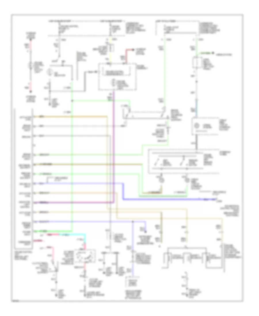
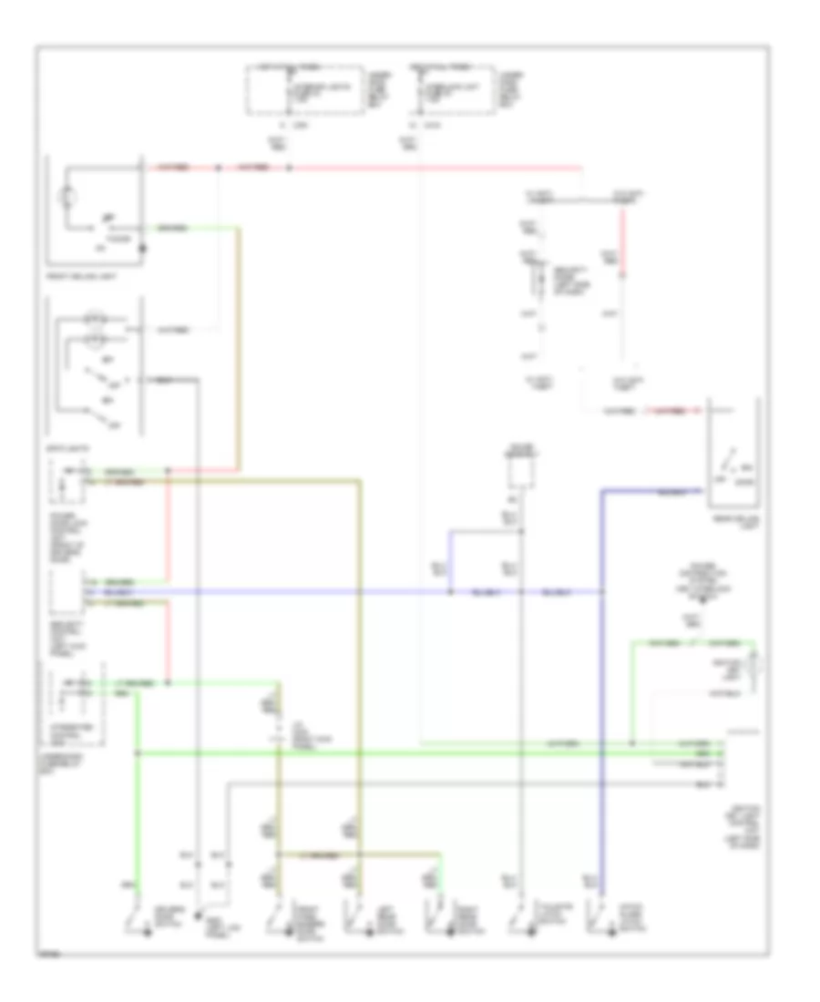
AIR CONDITIONING
Air Conditioning Wiring Diagrams for Honda CR-V LX 1997

List of elements for Air Conditioning Wiring Diagrams for Honda CR-V LX 1997:
- A/c pressure switch (left front of engine compt, on receiver/dryer)
- A17
- A27
- Acc
- Acs
- Air mix control motor (below center of heater plenum)
- B/l
- Blower motor
- Blower motor high relay (on right side of plenum)
- Blower motor relay
- Compressor clutch
- Compressor clutch relay
- Condenser fan motor
- Condenser fan relay
- Def
- Defogger system
- Evaporator temperature sensor (center of heater plenum)
- Fanc
- Frs
- Fuse 20a
- Fuse 40a
- Fuse 7.5a
- G100 (left side of engine compt)
- G101 (right side of engine compt)
- G133 (center of engine)
- G200 (left kick panel)
- H/d
- Heater control panel
- Hot at all times
- Hot in on
- Ig2
- Interior lights system
- M-com
- Mode control motor (on left side of heater plenum)
- Power transistor (right side of heater plenum)
- Powertrain control module (at right kick panel)
- Radiator fan motor
- Radiator fan relay
- Radiator fan switch (middle of engine)
- Rec
- Recirculation control motor (right side of heater plenum)
- Red
- S-com
- S5v
- Under- dash fuse/ relay box
- Under- hood fuse/ relay box
- Vent
ANTI-LOCK BRAKES
Anti-lock Brake Wiring Diagrams for Honda CR-V LX 1997
List of elements for Anti-lock Brake Wiring Diagrams for Honda CR-V LX 1997:
- (1997)
- (1997-01)
- (1998-01)
- (1999)
- (behind right kick panel) g203
- (right front shock tower) g103
- (right kick panel) j/c c433
- +b1
- +b2
- A10
- A11
- A12
- A13
- A14
- A15
- A16
- A17
- A18
- A19
- A20
- A21
- A22
- Abs +b fuse 62 20a
- Abs control unit (behind right kick panel)
- Abs fuse 16 7.5a
- Abs indicator circuit
- Abs indicator light
- Abs modulator unit (on right rear of engine compartment)
- Abs pump motor (on right rear of engine compartment)
- Abs pump motor relay
- B10
- B11
- B12
- B13
- B14
- B15
- B16
- B17
- B18
- B19
- B20
- B21
- B22
- B23
- B24
- B25
- B26
- Brake switch (on brake pedal support)
- C352
- C359
- C360
- C417
- C502
- Conn a
- Conn b
- Data link connector (dlc) (partial) (behind right side of front console)
- Dlc
- Fl-in
- Fl-out
- Fl0
- Fl1
- Fr-in
- Fr-out
- Fr0
- Fr1
- Fuse 63 mtr check 7.5a
- G200 (left kick panel)
- Gauge assembly
- Gnd1
- Gnd2
- Gnd3
- Horn, stop fuse 52 15a
- Hot at all times
- Hot in on
- Hot in on or start
- Ig2
- J/c c433 (right kick panel)
- J/c c508 (behind left side of dash)
- Left front abs sol (in)
- Left front abs sol (out)
- Left front wheel sensor (inside wheel)
- Left rear abs sol (in)
- Left rear abs sol (out)
- Left rear wheel sensor (inside wheel)
- Mck
- Meter fuse 25 7.5a
- Pcom
- Pmr
- Pump motor fuse 61 40a
- Red
- Right front abs sol (in)
- Right front abs sol (out)
- Right front wheel sensor (inside wheel)
- Right rear abs sol (in)
- Right rear abs sol (out)
- Right rear wheel sensor (inside wheel)
- Rl-in
- Rl-out
- Rl0
- Rl1
- Rr-in
- Rr-out
- Rr0
- Rr1
- Scom
- Scs
- Service check connector (partial) (behind right side of front console)
- Stop
- Underdash fuse/relay box (behind dash, left of steering column)
- Underhood abs fuse/relay box (on right rear corner of engine compartment)
- Underhood fuse/relay box (on right rear corner of engine compt)
- Walp
ANTI-THEFT
Anti-theft Wiring Diagram for Honda CR-V LX 1997
List of elements for Anti-theft Wiring Diagram for Honda CR-V LX 1997:
- (left kick panel) g200
- (left side of engine compartment) g100
- 1997 model
- 1998-01
- B13
- B14
- Battery
- C352
- C419
- C552
- Ceiling light
- Disarm/valet sw input
- Disarm/valet switch (behind left side of dash)
- Door locks system
- Door sw input
- Door switch input
- Driver's door switch
- Front passenger's door switch
- Fuse 2 security 3a
- Fuse 25 meter 7.5a
- Fuse 48 headlight 30a
- Gauge assembly
- Glass breakage microphone
- Ground
- Hatch glass latch switch
- Hatch glass open ctrl
- Hood sw input
- Hood switch (optional) (right front corner of engine compartment)
- Horn ctrl
- Horns system
- Hot at all times
- Hot in on or start
- Ign key sw input
- Ignition
- Ignition key light control unit (behind left side of dash)
- Ignition key switch (closed with key in ignition)
- Integrated control unit
- Interior & exterior lights systems
- Interior lights system (rear ceiling light)
- J/c c433 (behind right kick panel)
- Key in
- Left rear door switch
- Light flasher relay (behind right side of dash)
- Light flasher rly ctrl
- Lock input
- Lock output
- Model
- Nca
- Pnk
- Power door lock control unit (in driver's door)
- Red
- Right rear door switch
- Security control unit (behind left kick panel)
- Security ind ctrl
- Security indicator
- Security siren (optional) (left rear of engine compartment)
- Select unlock rly ctrl
- Siren ctrl
- Starter cut rly ctrl
- Starting/ charging system
- Steering lock
- Tailgate latch switch
- Tailgate open ind
- Tailgate/hatch sw in
- Trunk, tailgate, fuel doors system
- Underdash fuse/relay box (behind dash, left of steering column)
- Underhood fuse/relay box (on right rear corner of engine compartment)
- Unlock input
- Unlock output
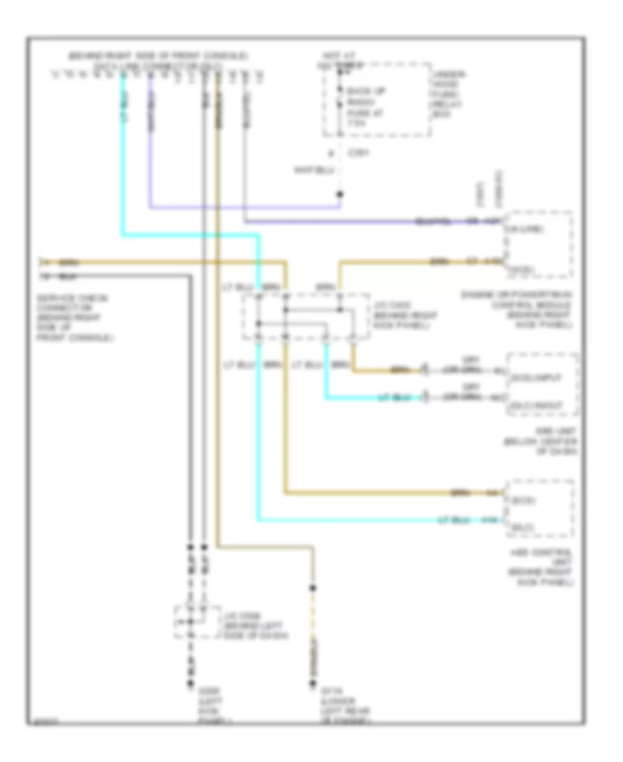
COMPUTER DATA LINES
Computer Data Lines for Honda CR-V LX 1997
List of elements for Computer Data Lines for Honda CR-V LX 1997:
- (1997) c8
- (1998-01) a21
- (behind right side of front console) data link connector (dlc)
- (dlc)
- (dlc) in/out
- (k-line)
- (scs)
- (scs) input
- A10
- A14
- Abs control unit (behind right kick panel)
- Back up
- C351
- Engine or powertrain control module (behind right kick panel)
- Fuse 47 7.5a
- G114 (lower left rear of engine)
- G200 (left kick panel)
- Hot at all times
- J/c c433 (behind right kick panel)
- J/c c508 (behind left side of dash)
- Radio
- Service check connector (behind right side of front console)
- Srs unit (below center of dash)
- Under- hood fuse/ relay box
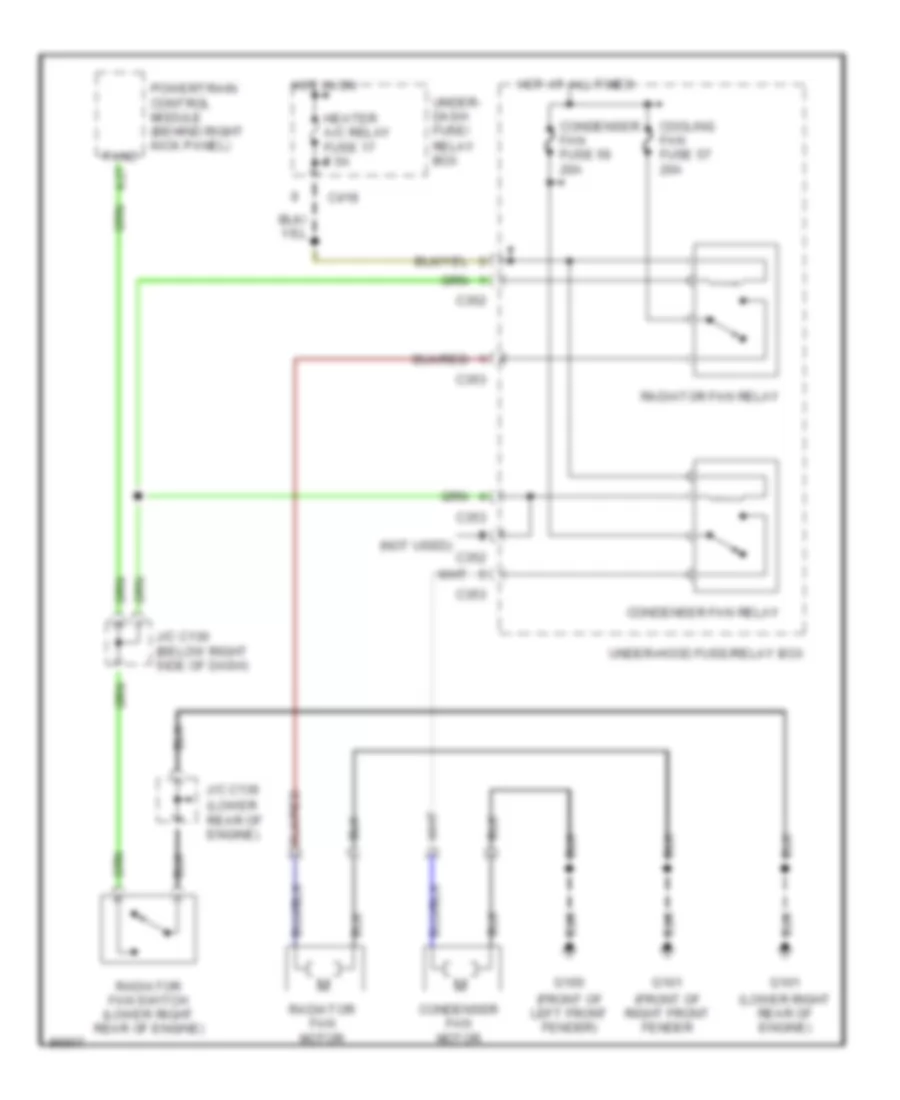
COOLING FAN
Cooling Fan Wiring Diagram for Honda CR-V LX 1997
List of elements for Cooling Fan Wiring Diagram for Honda CR-V LX 1997:
- (front of left front fender)
- (front of right front fender
- (lower rear of engine)
- (lower right rear of engine)
- (not used)
- A27
- C352
- C353
- C418
- Condenser fan fuse 56 20a
- Condenser fan motor
- Condenser fan relay
- Cooling fan fuse 57 20a
- Fanc
- G100
- G101
- Heater a/c relay fuse 17 7.5a
- Hot at all times
- Hot in on
- J/c c130 (below right side of dash)
- J/c c136
- Powertrain control module (behind right kick panel)
- Radiator fan motor
- Radiator fan relay
- Radiator fan switch (lower right rear of engine)
- Under- dash fuse/ relay box
- Under-hood fuse/relay box
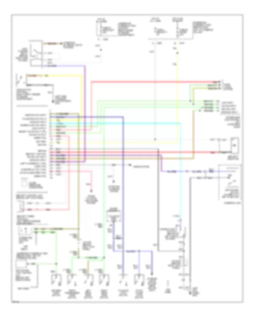
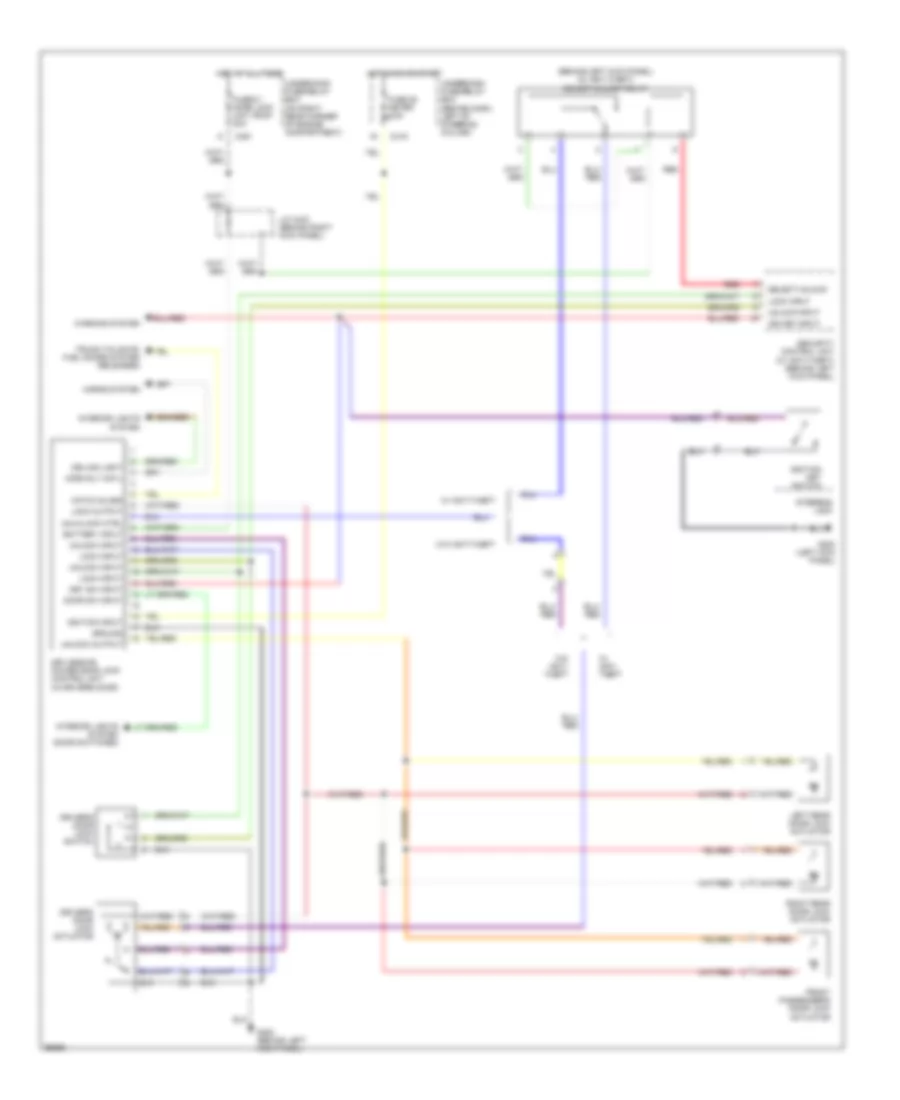
CRUISE CONTROL
Cruise Control Wiring Diagram for Honda CR-V LX 1997
List of elements for Cruise Control Wiring Diagram for Honda CR-V LX 1997:
- "on" indicator
- (front of left front fender) g100
- (left kick panel) g200
- (lower left rear of engine) g114
- 1998 models w/ a/t
- 1998 models w: a/t
- A/t
- A/t gear position switch (on lower rear of transaxle)
- Actuator ctrl
- Brake switch (on brake pedal support)
- Brake switch input
- C352
- C353
- C502
- Cable reel (top of steering column)
- Clutch pedal switch (on clutch pedal support)
- Crs
- Cruise control actuator (on left side of engine compartment)
- Cruise control dimming circuit
- Cruise control fuse 14 7.5a
- Cruise control indicator light
- Cruise control main switch
- Cruise control main switch light
- Cruise control set/ resume switch
- Cruise control unit (behind left kick panel)
- Cruise on input
- Disengage input
- Gauge assembly
- Ground
- Horn relay (behind left kick panel)
- Horn, stop fuse 52 15a
- Horns system
- Hot at all times
- Hot in on or start
- Indicator light control
- Instrument cluster system (speedometer)
- Interior lights system
- J/c c122 (below right side of dash, taped back to harness)
- J/c c136 (lower left front side of engine)
- J/c c433 (behind right kick panel)
- J/c c508 (behind left side of dash)
- M/t
- Meter fuse 25 7.5a
- Nca
- Off
- Pnk
- Power input
- Powertrain control module (pcm) (behind right kick panel)
- Red
- Resume/ accel sig input
- Resume/ accel switch
- Safety solenoid
- Set/ decel switch
- Set/decel sig input
- Steering wheel
- Underdash fuse/relay box (behind dash, left of steering column)
- Underhood fuse/relay box (on right rear corner of engine compartment)
- Vacuum solenoid
- Vehicle speed input
- Vehicle speed output
- Vehicle speed sensor (vss) (on top left of transaxle)
- Vent solenoid
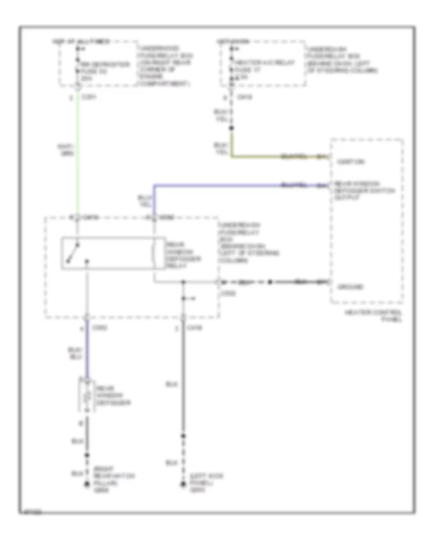
DEFOGGERS
Defogger Wiring Diagram for Honda CR-V LX 1997
List of elements for Defogger Wiring Diagram for Honda CR-V LX 1997:
- (left kick panel) g200
- (right rear hatch pillar) g998
- C351
- C418
- C502
- C552
- Ground
- Heater a/c relay fuse 17 7.5a
- Heater control panel
- Hot at all times
- Hot in on
- Ignition
- Rear window defogger
- Rear window defogger relay
- Rear window defogger switch output
- Rr defroster fuse 50 20a
- Underdash fuse/relay box (behind dash, left of steering column)
- Underdash fuse/relay box (behind dash, left of steering column)
- Underhood fuse/relay box (on right rear corner of engine compartment)
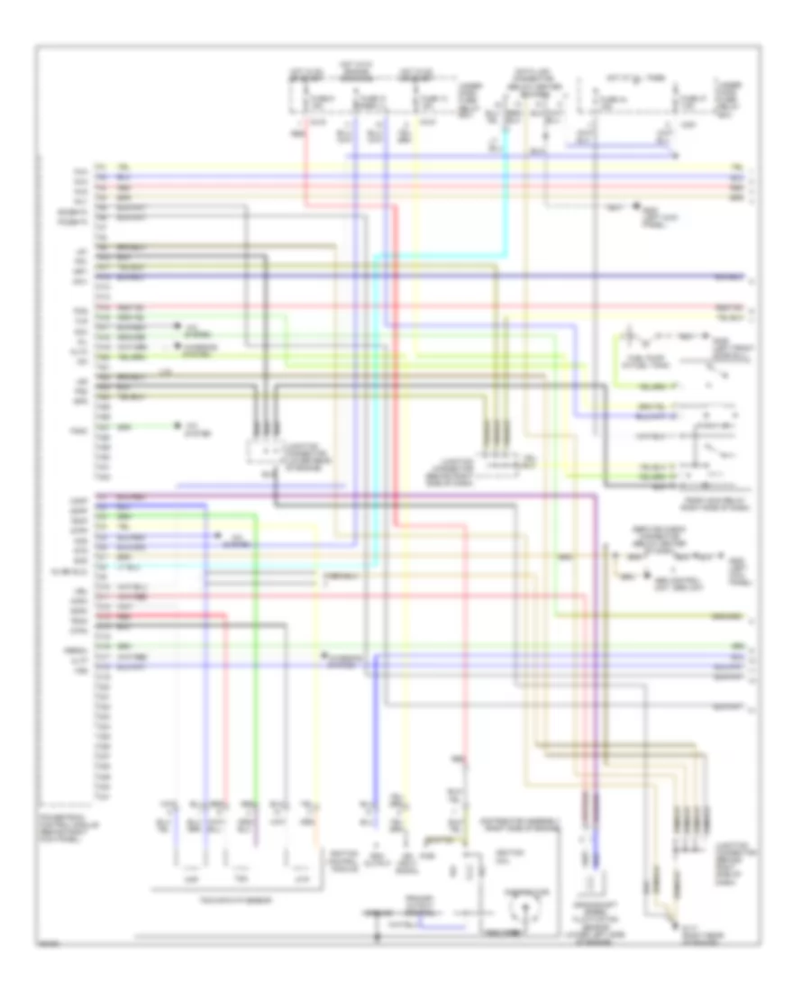
ENGINE PERFORMANCE
2.0L
2.0L, Engine Performance Wiring Diagrams (1 of 3) for Honda CR-V LX 1997
List of elements for 2.0L, Engine Performance Wiring Diagrams (1 of 3) for Honda CR-V LX 1997:
- (below center of dash)
- A/c
- A/c system
- A10
- A11
- A12
- A13
- A14
- A15
- A16
- A17
- A18
- A19
- A20
- A21
- A22
- A23
- A24
- A25
- A26
- A27
- A28
- A29
- A30
- A31
- A32
- Abs control unit, srs unit
- Acc
- Acs
- Altc
- Altf
- Box
- C10
- C11
- C12
- C13
- C14
- C15
- C16
- C17
- C18
- C19
- C20
- C21
- C22
- C23
- C24
- C25
- C26
- C27
- C28
- C29
- C30
- C31
- C351
- C418
- C419
- Charging
- Ckfm
- Ckfp
- Ckp
- Ckpm
- Ckpp
- Coil wire
- Crankshaft speed fluctuation sensor (lower left side of engine)
- Cyp
- Cypm
- Cypp
- Data link connector
- Distributor
- Distributor assembly (right side of engine)
- Fanc
- Flr
- Fuel pump (in fuel tank)
- Fuse 13 15a
- Fuse 31 7.5a
- Fuse 44 15a
- Fuse 47 7.5a
- Fuse 9 15a
- G117 (right rear of engine)
- G200 (left kick panel)
- G309 (left front door sill)
- Ground
- Hot at all times
- Hot in on or start
- Hot with engine cranking
- Iacv
- Icm
- Ign input signal
- Ignition coil
- Ignition control module
- Igp1
- Igp2
- Inj1
- Inj2
- Inj3
- Inj4
- Junction connector (behind right side of dash)
- Junction connector (lower rear of engine)
- Kline (dlc)
- Lg1
- Lg2
- Mil
- Pcs
- Pg1
- Pg2
- Pgm-fi main relay (right side of dash)
- Po2shtc
- Powertrain control module (behind right kick panel)
- Pri
- Primary output control
- Pspsw
- Pwr
- Red
- Rpm output
- Scs
- Sec
- Service check connector (below center of dash)
- So2shtc
- Sts
- System
- Tdc
- Tdc/ckp/cyp sensor
- Tdcm
- Tdcp
- U.s.
- Under- dash fuse/ relay box
- Under- hood fuse/ relay
- Vbu
- Vss
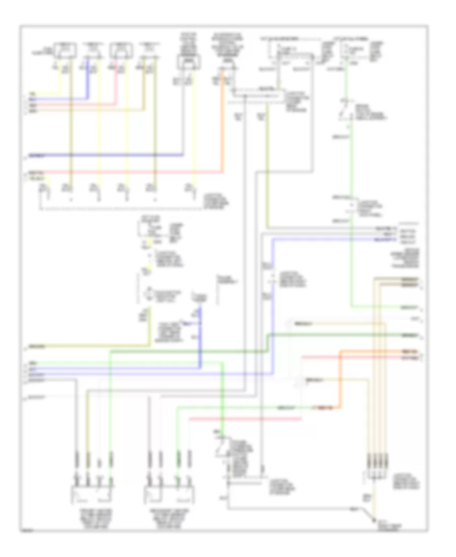
2.0L, Engine Performance Wiring Diagrams (2 of 3) for Honda CR-V LX 1997
List of elements for 2.0L, Engine Performance Wiring Diagrams (2 of 3) for Honda CR-V LX 1997:
- Brake switch (top of brake pedal support)
- C352
- C417
- C419
- C502
- Evaporative emission purge control solenoid valve (top center of engine)
- Fuel injectors
- Fuse 15 7.5a
- Fuse 52 15a
- Fuse 7.5a
- G117 (right rear of engine)
- Gauge assembly
- Ground
- Hot at all times
- Hot in on or start
- Idle air control valve (center rear of engine)
- Ignition
- Junction connector (behind left side of dash)
- Junction connector (behind right side of dash)
- Junction connector (lower rear of engine)
- Junction connector (right kick panel)
- Malfunction indicator light (mil)
- No. 1
- No. 2
- No. 3
- No. 4
- Power steering pressure switch (lower center rear of engine compt)
- Primary heated oxygen sensor (below vehicle, front of twc converter)
- Red
- Secondary heated oxygen sensor (below vehicle, rear of twc converter)
- Tach test connector (left rear corner of engine compt)
- Tacho- meter
- Under- dash fuse/ relay box
- Under- hood fuse/ relay box
- Vehicle speed sensor (lower right rear of transmission)
- Vss out
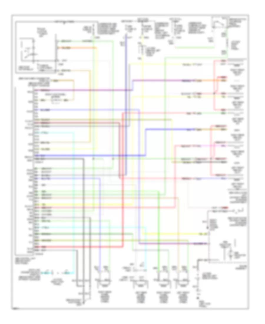
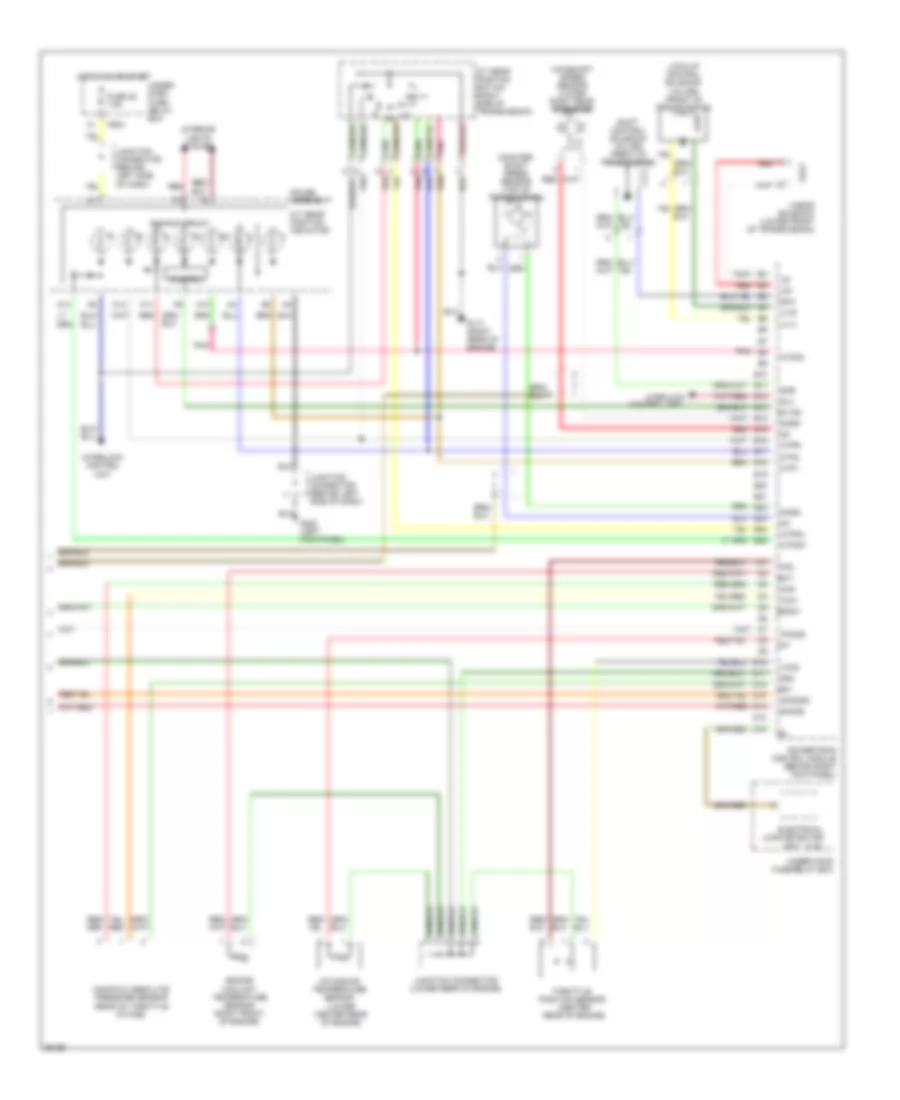
2.0L, Engine Performance Wiring Diagrams (3 of 3) for Honda CR-V LX 1997
List of elements for 2.0L, Engine Performance Wiring Diagrams (3 of 3) for Honda CR-V LX 1997:
- A/t gear position indicator
- A/t gear position switch (right side of transmission)
- A10
- A11
- A12
- A14
- Atp1
- Atp2
- Atpd3
- Atpd4
- Atpnp
- Atpr
- B10
- B19
- B20
- B21
- Bksw
- C502
- Control
- Control unit
- Counter- shaft speed sensor (top of transmission)
- D10
- D11
- D12
- D13
- D14
- D15
- D16
- D4 ind
- Dimming circuit
- Ect
- Electrical load detector (u.s.)
- Engine coolant temperature sensor (right front of engine)
- Fuse 25 7.5a
- G117 (right rear of engine)
- G200 (left kick panel)
- Gauge assembly
- Hot in on or start
- Iat
- Intake air temperature sensor (lower center rear of engine)
- Interior lights system
- Interlock
- Interlock control unit
- Junction connector (behind left side of dash)
- Junction connector (behind left side of dash)
- Junction connector (lower rear of engine)
- Lc a
- Lc b
- Linear solenoid (lower front of transmission)
- Lock-up control solenoid valves (front of transmission)
- Ls+
- Ls-
- Mainshaft speed sensor (lower right rear of engine)
- Manifold absolute pressure sensor (rear of throttle intake)
- Map
- Ncsg
- Nmsg
- Pho2s
- Pnk
- Pnk b8
- Powertrain control module (behind right kick panel)
- Red
- Red b15
- Red b2
- Sg1
- Sg2
- Sh02sg
- Sha
- Shb
- Shift control solenoid valves (front of transmission)
- Sho2s
- Slu
- Throttle position sensor (center rear of engine)
- Tps
- Under- dash fuse/ relay box
- Under-hood fuse/relay box
- Unit
- Vcc1
- Vcc2
EXTERIOR LIGHTS
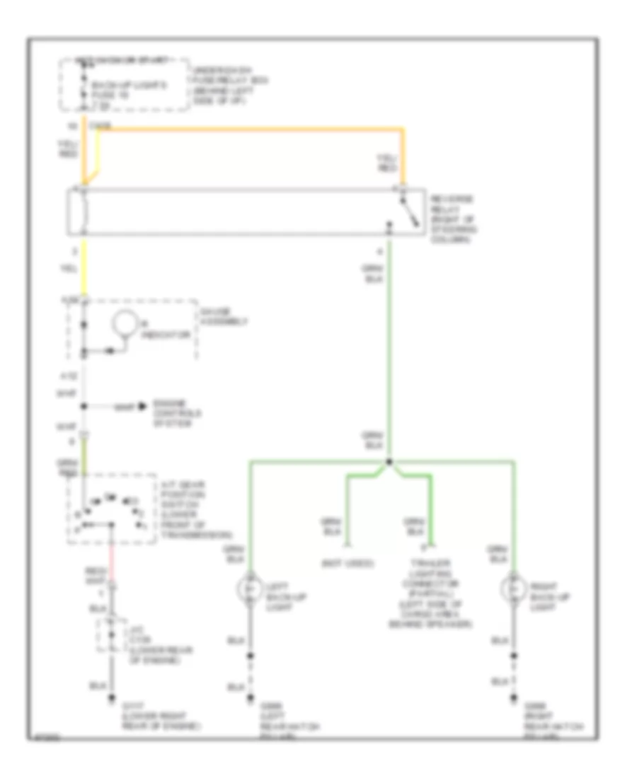
Back-up Lamps Wiring Diagram for Honda CR-V LX 1997
List of elements for Back-up Lamps Wiring Diagram for Honda CR-V LX 1997:
- (not used)
- A/t gear position switch (lower front of transmission)
- A12
- A13
- Back-up lights fuse 19 7.5a
- C419
- Engine controls system
- G117 (lower right rear of engine)
- G998 (right rear hatch pillar)
- G999 (left rear hatch pillar)
- Gauge assembly
- Hot in on or start
- J/c c136 (lower rear of engine)
- Left back-up light
- R indicator
- Reverse relay (right of steering column)
- Right back-up light
- Trailer lighting connector (partial) (left side of cargo area behind speaker)
- Under-dash fuse/relay box (behind left side of i/p)
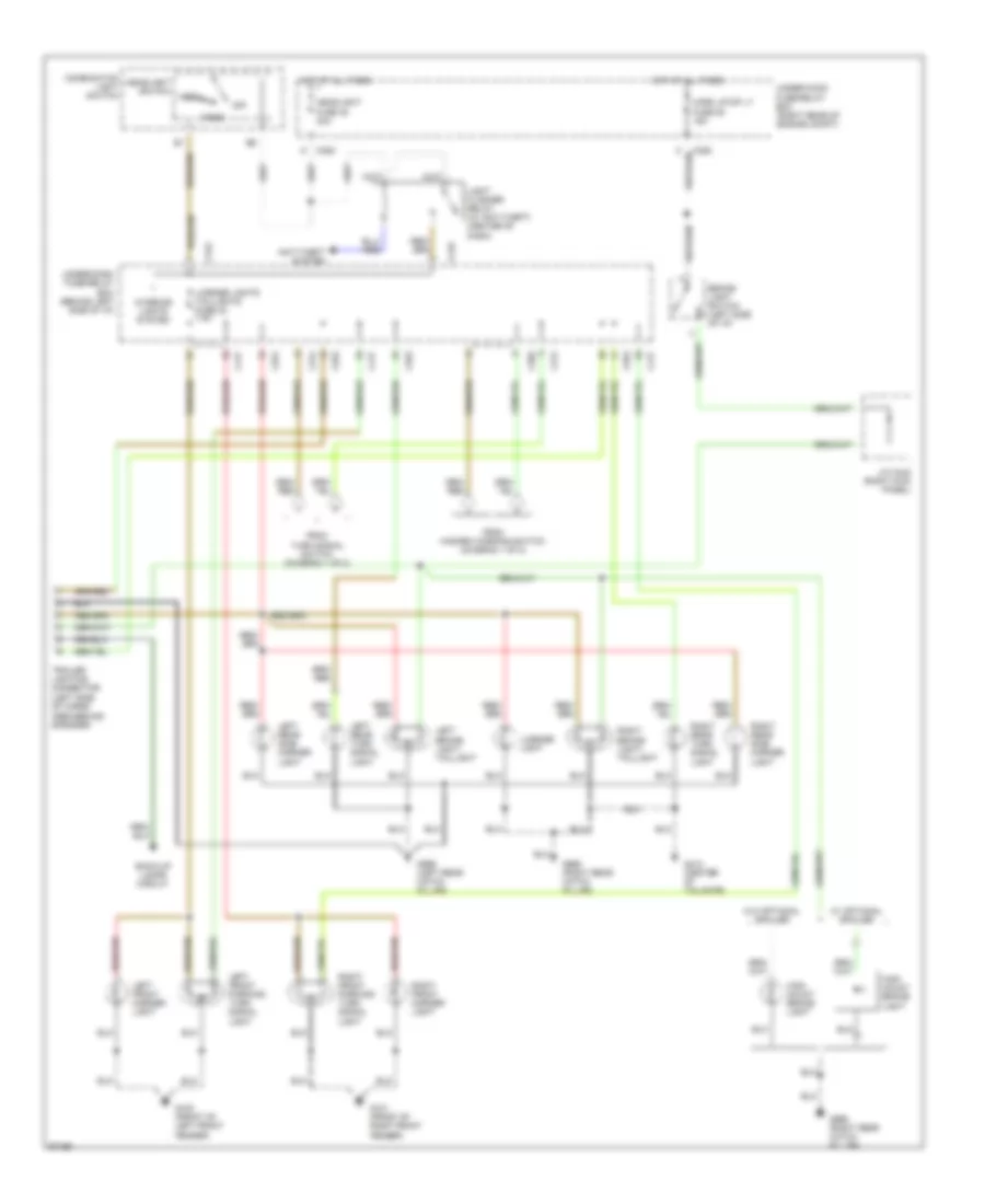
Exterior Lamps Wiring Diagram (1 of 2) for Honda CR-V LX 1997
List of elements for Exterior Lamps Wiring Diagram (1 of 2) for Honda CR-V LX 1997:
- C352
- C418
- C502
- C751
- Combination light switch
- G200 (left kick panel)
- Gauge assembly
- Ground
- Hazard fuse 53 10a
- Hazard warning switch
- Hot at all times
- Hot in on or start
- Ign/pwr
- Illumination lamp
- Interior lights system
- J/c c508 (left side of dash)
- Left
- Left turn signal indicator light
- Off
- Red
- Relay out
- Right
- Right turn signal indicator light
- To under-dash fuse/relay box (turn signal lights) (diagram 2 of 2)
- Turn lights fuse 12 7.5a
- Turn signal switch
- Turn signal/ hazard relay
- Under-dash fuse/relay box (behind left side of dash)
- Under-dash fuse/relay box (behind left side of i/p)
- Under-hood fuse/relay box (right rear of engine compt)
Exterior Lamps Wiring Diagram (2 of 2) for Honda CR-V LX 1997
List of elements for Exterior Lamps Wiring Diagram (2 of 2) for Honda CR-V LX 1997:
- (left side of cargo area behind speaker)
- Anti-theft system
- Back-up lamps circuit
- Brake light switch (left side of i/p)
- C352
- C417
- C418
- C502
- C551
- C552
- C751
- C752
- Combination light switch
- From hazard warning switch (diagram 1 of 2)
- From turn signal switch (diagram 1 of 2)
- G100 (front of left front fender)
- G101 (front of right front fender)
- G412 (center of tailgate)
- G998 (right rear hatch pillar)
- G999 (left rear hatch pillar)
- Head
- Headlight fuse 48 30a
- Headlight switch
- High mount brake light
- Horn, stop lt fuse 52 15a
- Hot at all times
- Interior lights system
- J/c c442 (right kick panel)
- Left brake light/ taillight
- Left front marker light
- Left front parking/ turn signal light
- Left rear side marker light
- Left rear turn signal light
- License light
- License lights taillights fuse 32 7.5a
- Light flasher relay (w/ anti-theft) (center of dash)
- Off
- Park
- Right brake light/ taillight
- Right front marker light
- Right front parking/ turn signal light
- Right rear side marker light
- Right rear turn signal light
- Trailer lighting connector
- Under-dash fuse/relay box (behind left side of i/p)
- Under-hood fuse/relay box (right rear of engine compt)
- W/ optional spoiler
- W/o optional spoiler
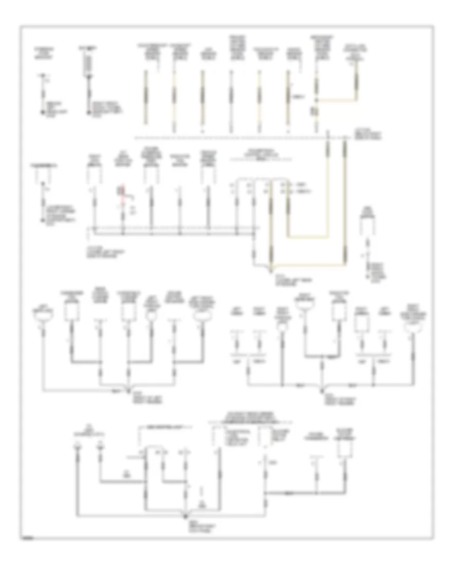
GROUND DISTRIBUTION
Ground Distribution Wiring Diagram (1 of 3) for Honda CR-V LX 1997
List of elements for Ground Distribution Wiring Diagram (1 of 3) for Honda CR-V LX 1997:
- (1998-01) b
- (behind left headlamp) g106
- (lower right front corner of engine compartment) g101
- (on right rear corner of engine compartment) underhood fuse/relay box
- (right front shock tower) g103
- (right front shock tower, near battery) g103
- 1998-01
- 1999-01
- A (1997)
- A/t
- A/t gear position switch
- Abs control unit
- Abs pump motor
- Battery
- Blower motor high relay
- Blower motor relay
- C351
- Ckf sensor shield
- Condenser fan motor
- Countershaft speed sensor shield
- Cruise control actuator
- Data link connector (dlc) (partial)
- Electrical load detector (eld) unit
- G100 (front of left front fender)
- G101 (front of right front fender)
- G114 (lower left rear of engine)
- G203 (behind right kick panel)
- J/c c122 (below right side of dash)
- J/c c136 (lower left front side of engine)
- Knock sensor shield
- Left front parking light
- Left front side marker/ turn signal light
- Left headlight
- Left horn
- Mainshaft speed sensor shield
- Pgm-fi main relay
- Power steering pressure (psp) switch
- Power transistor
- Powertrain control module (pcm)
- Primary heated oxygen sensor (ho2s) shield
- Radiator fan motor
- Radiator fan switch
- Rear window washer motor
- Right front parking light
- Right front side marker/ turn signal light
- Right headlight
- Right horn
- Secondary heated oxygen sensor (ho2s) shield
- Steering pump bracket
- Tdc/ckp/cyp sensor shield
- To g200 (diagram 2 of 3)
- Transmission
- Vehicle speed sensor (vss)
- W/ abs
- Windshield washer motor
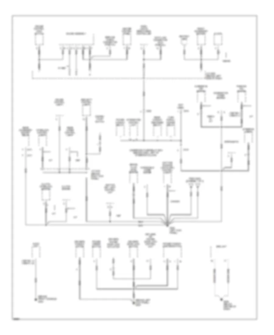
Ground Distribution Wiring Diagram (2 of 3) for Honda CR-V LX 1997
List of elements for Ground Distribution Wiring Diagram (2 of 3) for Honda CR-V LX 1997:
- (1997-98) (1999-01)
- (a/t)
- (behind front console) g302
- (behind left kick panel) g200
- (m/t)
- (not used)
- 1998-99
- 1999-01 w/ a/t
- A/t
- Ashtray light
- Audio unit
- Brake fluid level switch
- C418
- C502
- C910
- Canada
- Clock
- Clutch interlock switch
- Clutch switch
- Combination wiper switch
- Cruise control main switch
- Cruise control unit
- Dash lights brightness controller
- Data link connector (dlc) (partial)
- Daytime running lights (drl) control unit
- Disarm/ valet switch
- Driver's door lock switch
- Driver's power door lock actuator
- Driver's window motor
- From g203 (diagram 1 of 3)
- Front accessory socket
- G200 (left kick panel)
- G206 (below center of dash)
- Gauge assembly
- Heater control panel
- Ignition key light control unit
- Integrated control unit
- Interlock control unit
- J/c c433 (behind right kick panel)
- J/c c508 (behind left side of dash)
- Keyless or power door lock control unit
- M/t
- Overdrive off switch
- Parking pin switch
- Power mirror switch
- Power window master switch
- Power window relay
- Rear accessory socket relay
- Rear window defogger relay
- Rear wiper control unit
- Security control unit
- Service check connector (partial)
- Spotlights
- Srs unit
- Steering lock
- Turn signal/ hazard relay
- Underdash fuse/relay box (behind dash, left of steering column)
- W/ abs
- Windshield wiper motor
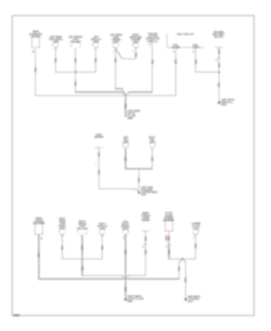
Ground Distribution Wiring Diagram (3 of 3) for Honda CR-V LX 1997
List of elements for Ground Distribution Wiring Diagram (3 of 3) for Honda CR-V LX 1997:
- (center of tailgate) g412
- (left front door sill) g309
- (left rear hatch pillar) g999
- (left side of engine compartment) g100
- (right rear hatch pillar) g998
- Driver's seat belt switch
- Fuel gauge
- Fuel pump
- Fuel tank unit
- Hatch glass opener solenoid
- High mount brake- light
- Hood switch
- Left back-up light
- Left brake- light/ taillight
- Left fog- light
- Left rear side marker light
- Left rear turn signal light
- License plate light
- Rear accessory socket
- Rear window defogger
- Rear window wiper motor
- Right back-up light
- Right brake light/ taillight
- Right fog- light
- Right rear side marker light
- Right rear turn signal light
- Trailer lighting connector (partial)
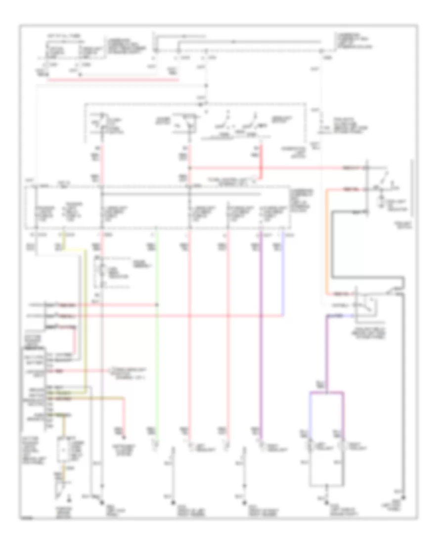
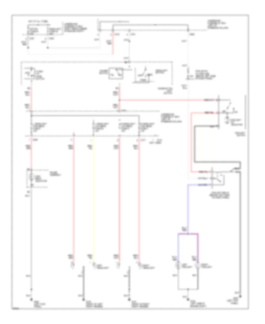
HEADLIGHTS
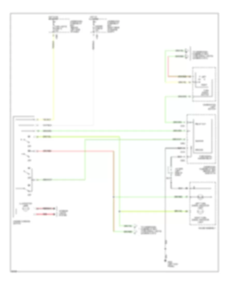
Headlight Wiring Diagram, with DRL for Honda CR-V LX 1997
List of elements for Headlight Wiring Diagram, with DRL for Honda CR-V LX 1997:
- 15a
- Battery
- Brake sys ind ctrl
- C351
- C352
- C417
- C418
- C419
- C502
- C552
- C751
- C925
- Combination light switch
- Daytime running lights control unit (behind left kick panel)
- Daytime running lights resistor
- Dimmer switch
- Flash- to- pass switch
- Fog light on indicator
- Foglight relay (behind left side of dash panel)
- Foglight switch
- Foglights in-line fuse (behind left side of dash panel)
- From headlight switch (diagram 1 of 1)
- G100 (front of left front fender)
- G100 (left side of engine compt)
- G101 (front of right front fender)
- G200 (left kick panel)
- Gauge assembly
- Ground
- Hdlt ctrl
- Head
- Headlight fuse 48 30a
- Headlight switch
- High beam indicator
- Hot at all times
- Hot in on
- Ignition
- Instrument cluster system
- L headlight high beam fuse 5 10a
- L headlight low beam fuse 22 10a
- Left foglight
- Left headlight
- Lights-on input
- Nca
- Off
- Option fuse 54 40a
- Park
- Park brake in
- Parking brake switch
- R headlight high beam fuse 4 10a
- R headlight low beam fuse 21 10a
- Red
- Right foglight
- Right headlight
- Running light relay fuse 18 7.5a
- Running lights fuse 20 7.5a
- To drl control unit (diagram 1 of 1)
- Under- dash fuse/ relay box
- Underdash fuse/relay box (left of steering column)
- Underhood fuse/relay box (right rear corner of engine compt)
Headlight Wiring Diagram, without DRL for Honda CR-V LX 1997
List of elements for Headlight Wiring Diagram, without DRL for Honda CR-V LX 1997:
- (not used)
- 15a
- C351
- C352
- C417
- C418
- C419
- C502
- C751
- C925
- Combination light switch
- Dimmer switch
- Flash- to- pass switch
- Foglight on indicator
- Foglight relay (behind left side of dash panel)
- Foglight switch
- Foglights in-line fuse (behind left side of dash panel)
- G100 (front of left front fender)
- G100 (left side of engine compt)
- G101 (front of right front fender)
- G200 (left kick panel)
- Gauge assembly
- Head
- Headlight fuse 48 30a
- Headlight switch
- High beam indicator
- Hot at all times
- L headlight high beam fuse 5 10a
- L headlight low beam fuse 22 10a
- Left foglight
- Left headlight
- Off
- Option fuse 54 40a
- Park
- R headlight high beam fuse 4 10a
- R headlight low beam fuse 21 10a
- Right foglight
- Right headlight
- Underdash fuse/relay box (left of steering column)
- Underhood fuse/relay box (right rear corner of engine compt)
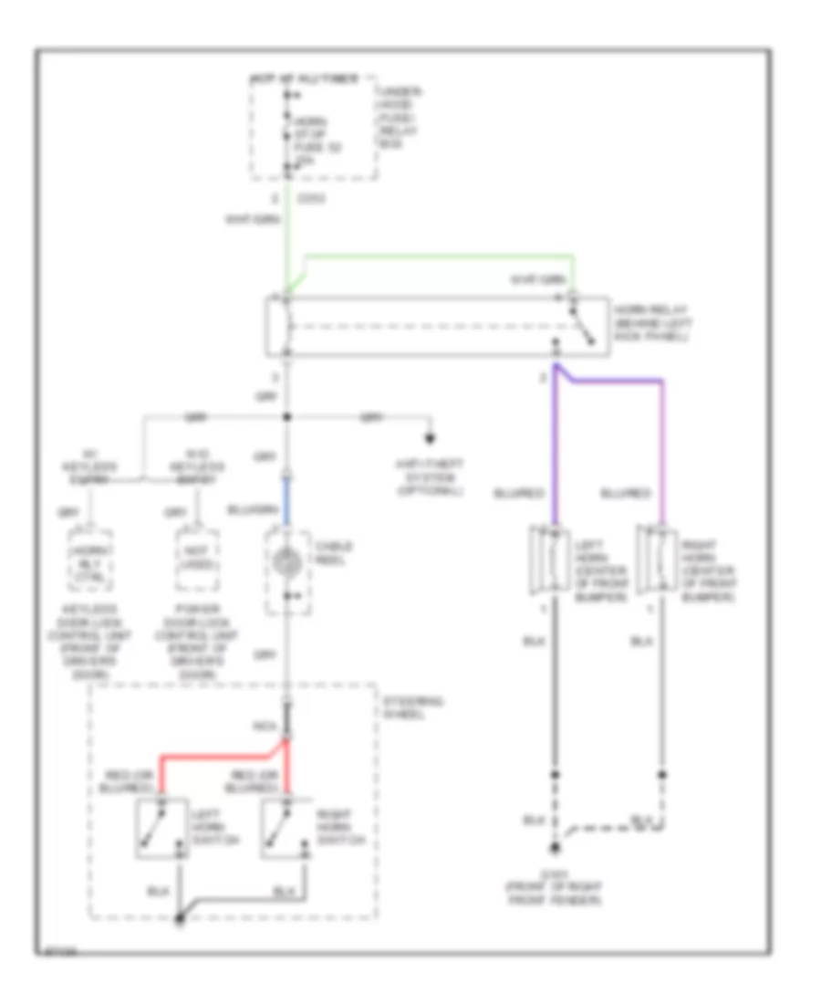
HORN
Horn Wiring Diagram for Honda CR-V LX 1997
List of elements for Horn Wiring Diagram for Honda CR-V LX 1997:
- Anti-theft system (optional)
- C353
- Cable reel
- G101 (front of right front fender)
- Horn relay (behind left kick panel)
- Horn rly ctrl
- Horn stop fuse 52 15a
- Hot at all times
- Keyless door lock control unit (front of driver's door)
- Left horn (center of front bumper)
- Left horn switch
- Nca
- Not used
- Power door lock control unit (front of driver's door)
- Right horn (center of front bumper)
- Right horn switch
- Steering wheel
- Under- hood fuse/ relay box
- W/ keyless entry
- W/o keyless entry
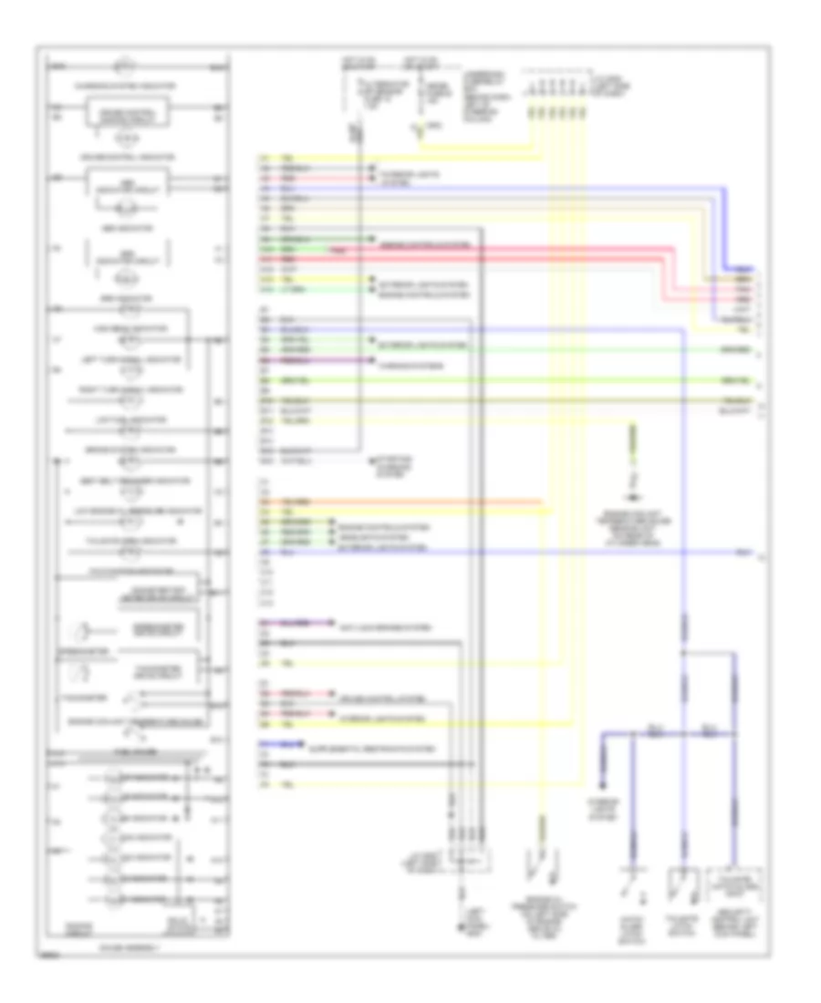
INSTRUMENT CLUSTER
Instrument Cluster Wiring Diagram (1 of 2) for Honda CR-V LX 1997
List of elements for Instrument Cluster Wiring Diagram (1 of 2) for Honda CR-V LX 1997:
- (left kick panel) g200
- 1 indicator
- 2 indicator
- A10
- A11
- A12
- A13
- A14
- Abs indicator
- Abs indicator circuit
- Alternator sp sensor fuse 15 7.5a
- Anti-lock brakes system
- B10
- B11
- B12
- B13
- B14
- B15
- B16
- Brake system indicator
- C10
- C11
- C12
- C13
- C502
- Charging system indicator
- Cruise control dimming circuit
- Cruise control indicator
- Cruise control system
- D3 indicator
- D4 indicator
- Dimming circuit
- Engine controls system
- Engine coolant temperature gauge
- Engine coolant temperature gauge sending unit (on rear of cylinder head)
- Engine oil pressure switch (on left side of engine, above oil filter)
- Exterior lights system
- Fuel gauge
- Gauge assembly
- Hatch glass latch switch
- Headlights system
- High beam indicator
- Hot in on or start
- Interior lights system
- J/c c508 (left side of dash)
- Left turn signal indicator
- Low engine oil pressure indicator
- Low fuel indicator
- Malfunction indicator
- Meter fuse 25 15a
- N indicator
- Odometer/trip meter drive circuit
- P indicator
- Pnk
- R indicator
- Red
- Right turn signal indicator
- Seat belt reminder indicator
- Security control unit (behind left kick panel)
- Solid state
- Speedometer
- Speedometer drive circuit
- Srs indicator
- Srs indicator circuit
- Starting/ charging system
- Tachometer
- Tachometer drive circuit
- Tailgate latch switch
- Tailgate open indicator
- Tailgate/ hatch glass input
- Underdash fuse/relay box (behind dash, left of steering column)
- Warning systems
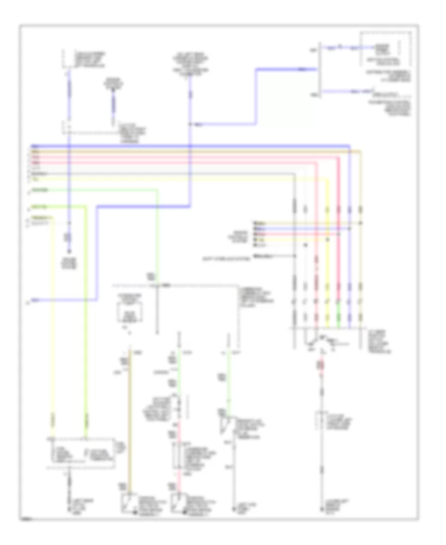
Instrument Cluster Wiring Diagram (2 of 2) for Honda CR-V LX 1997
List of elements for Instrument Cluster Wiring Diagram (2 of 2) for Honda CR-V LX 1997:
- (left kick panel) g200
- (left rear hatch pillar) g999
- (lower left rear of engine) g114
- (on left rear corner of engine compartment) (partial) test tachometer connector
- A/t gear position switch (on lower rear of transaxle)
- A19
- Brake fluid level switch (on brake fluid reservoir)
- Bulb check output
- C417
- C419
- C552
- Canada
- Cruise control system
- Daytime running lights (drl) control unit (behind left kick panel)
- Distributor assembly (on rear of cylinder head)
- Engine controls system
- Engine speed output
- Fuel gauge sending unit
- Fuel tank unit
- Ignition control module (icm)
- Integrated control unit
- J/c c122 (below right side of dash, taped to harness)
- J/c c136 (lower left front side of engine)
- Low fuel indicator thermistor
- Parking brake switch (on top of park brake assembly)
- Pnk
- Powertrain control module (pcm) (behind right kick panel)
- Red
- Rpm output
- Shift interlock system
- Underdash fuse/relay box (behind dash, left of steering column)
- Usa
- Vehicle speed sensor (vss) (on top left of transaxle)
INTERIOR LIGHTS
Courtesy Lamp Wiring Diagram for Honda CR-V LX 1997
List of elements for Courtesy Lamp Wiring Diagram for Honda CR-V LX 1997:
- C351
- C418
- Door
- Driver's door switch
- Front ceiling light
- Front pass- enger's door switch
- G200 (left lick panel)
- Gauge assembly
- Hatch glass latch switch
- Hot at all times
- Ignition key light
- Ignition key light control unit (left side of dash)
- Integrated control unit
- Interior lights fuse 43 7.5a
- Interlock unit fuse 33 7.5a
- J/c c433 (right kick panel)
- Left rear door switch
- Off
- Power distribution system (key interlock switch)
- Power door lock control unit (front of driver's door)
- Rear ceiling light
- Right rear door switch
- Security control unit (left kick panel)
- Security diode (left side of dash)
- Spotlights
- Tailgate latch switch
- Under- dash fuse/ relay box
- Under- hood fuse/ relay box
- Under-dash fuse/relay box
- W/ anti- theft
- W/o anti- theft
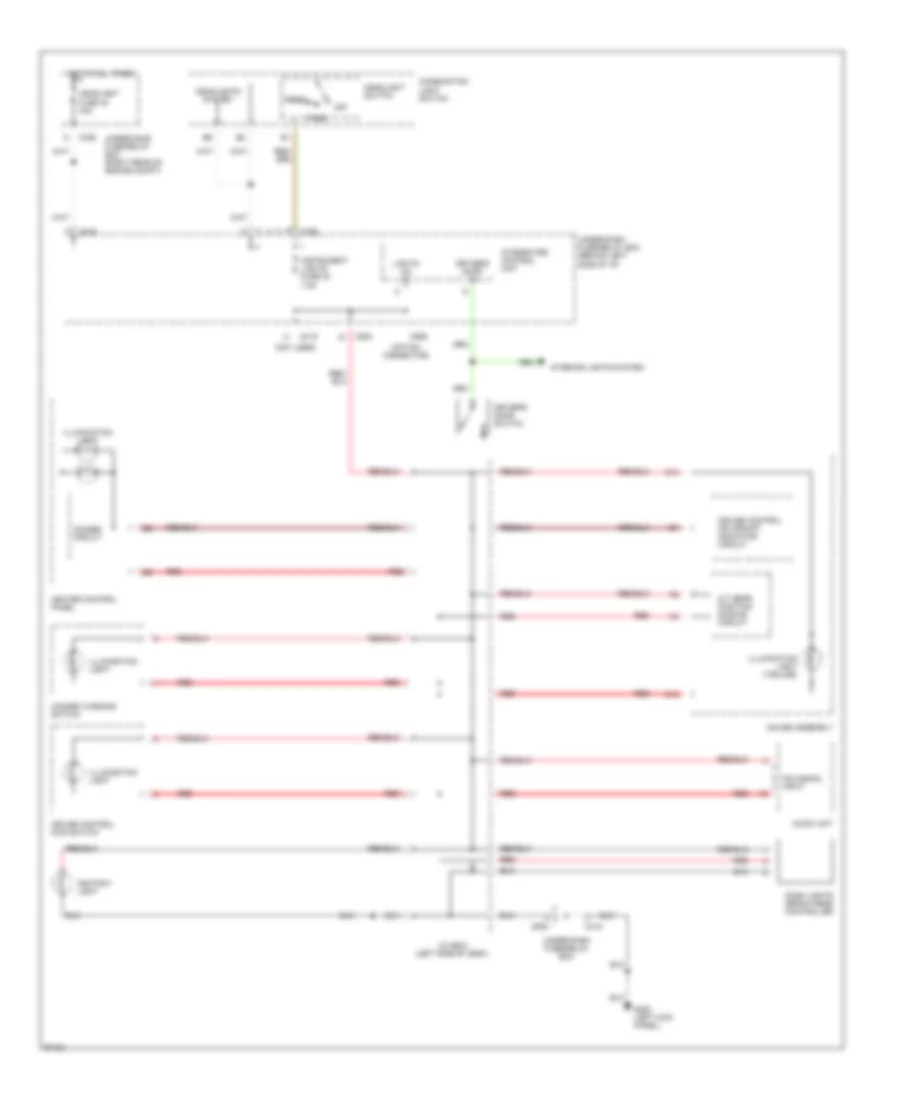
Instrument Illumination Wiring Diagram for Honda CR-V LX 1997
List of elements for Instrument Illumination Wiring Diagram for Honda CR-V LX 1997:
- (not used)
- (option connector)
- A/t gear position dimming circuit
- Ashtray light
- Audio unit
- C12
- C13
- C352
- C418
- C419
- C502
- C752
- C926
- Combination light switch
- Cruise control main switch
- Cruise control or upshift indicator circuit
- Dash lights brightness controller
- Dim signal input
- Dimmer circuit
- Driver's door in
- Driver's door switch
- G200 (left kick panel)
- Gauge assembly
- Hazard warning switch
- Head
- Headlight fuse 48 40a
- Headlight switch
- Headlights system
- Heater control panel
- Hot at all times
- Illumination light
- Illumination light (7-bulbs)
- Instrument lights fuse 30 7.5a
- Integrated control unit
- Interior lights system
- J/c c508 (left side of dash)
- Lights on in
- Off
- Park
- Red
- Under-dash fuse/relay box
- Under-dash fuse/relay box (behind left side of i/p)
- Under-hood fuse/relay box (right rear of engine compt)
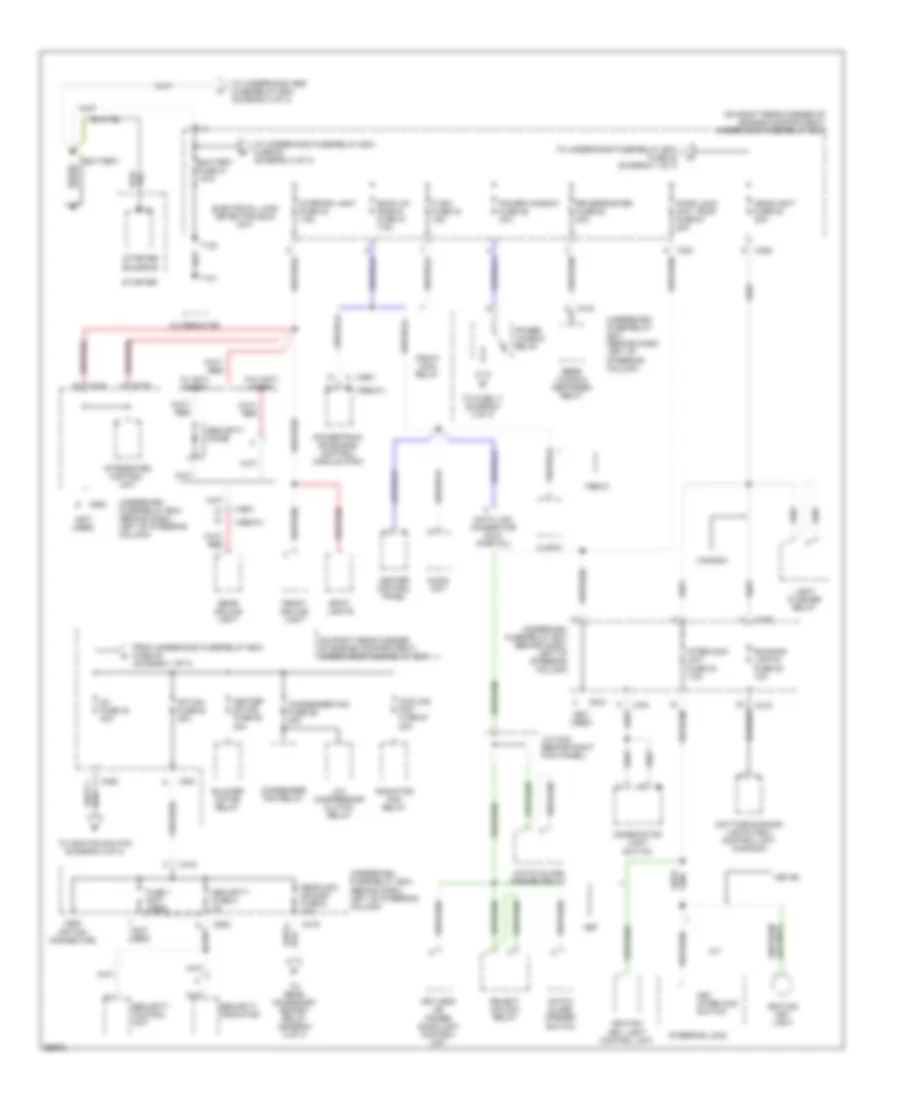
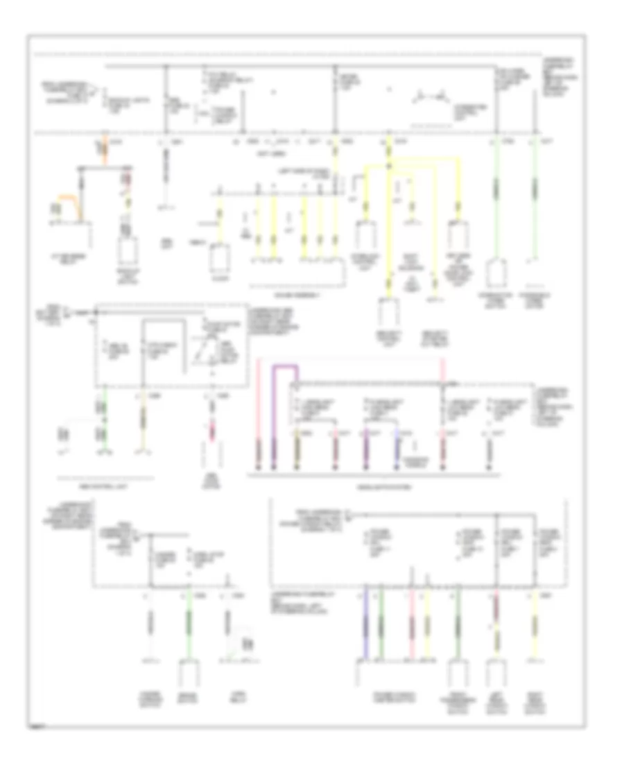
POWER DISTRIBUTION
Power Distribution Wiring Diagram (1 of 3) for Honda CR-V LX 1997
List of elements for Power Distribution Wiring Diagram (1 of 3) for Honda CR-V LX 1997:
- (1997)
- (1997) c
- (1998-01)
- (not used)
- (on right rear corner of engine compartment) underhood fuse/relay box
- (on right rear corner of engine compartment) underhood fuse/relay box
- (option connector)
- 1997-98
- 1998-01
- 20a
- 40a
- A/c compressor clutch relay
- A/t
- Alternator
- Audio unit
- Back up, (radio) fuse 47 7.5a
- Battery
- Battery fuse 41 100a
- Blower motor relay
- C351
- C352
- C418
- C419
- C552
- C751
- C910
- C925
- Canada
- Clock
- Combination light switch
- Condenser fan fuse 56 20a
- Condenser fan relay
- Cooling fan fuse 57
- Data link connector (dlc) (partial)
- Daytime running lights (drl) control unit (canada)
- Door lock unit, roof fuse 51 20a
- Electrical load detector (eld) unit
- Fi e/m fuse 44 15a
- From underhood fuse/relay box fuse 48 (diagram 1 of 3)
- Front ceiling light
- Fuse 1 (not used)
- Hatch glass opener relay
- Hatch glass opener switch
- Headlight fuse 48 30a
- Heater control panel
- Heater motor fuse 55
- Ig1 fuse 42 40a
- Ignition key light
- Ignition key light control unit
- Integrated control unit
- Interior light fuse 43 7.5a
- Interlock unit fuse 33 7.5a
- J/c c433 (behind right kick panel)
- Key interlock switch
- Keyless or power door lock control unit
- Light flasher relay
- Option fuse 54 40a
- Pgm-fi main relay
- Power window fuse 46 40a
- Power window relay
- Powertrain or engine control module (pcm)
- Radiator fan relay
- Rear acc socket fuse 6 10a
- Rear ceiling light
- Rear window defogger relay
- Rr defroster fuse 50 20a
- Running lights fuse 20 10a
- Security control unit
- Security diode
- Security fuse 2 3a
- Security indicator
- Select unlock relay
- Spot- lights
- Starter
- Starter solenoid
- Steering lock
- T101
- T102
- To fuse 11 (diagram 3 of 3)
- To ignition switch (diagram 2 of 3)
- To rear accessory socket relay (diagram 2 of 3)
- To underhood abs fuse/relay box (diagram 3 of 3)
- To underhood fuse/relay box fuse 42 (diagram 1 of 3)
- To underhood fuse/relay box fuse 52 (diagram 3 of 3)
- Underdash fuse/relay box (behind dash, left of steering column)
- W/ anti- theft
- W/o anti- theft
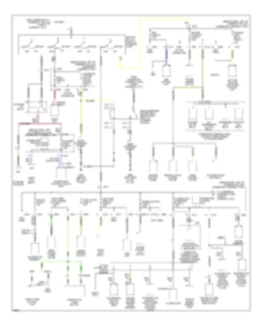
Power Distribution Wiring Diagram (2 of 3) for Honda CR-V LX 1997
List of elements for Power Distribution Wiring Diagram (2 of 3) for Honda CR-V LX 1997:
- (1997-98) (1999-01)
- (1998) (1999-01)
- (a/t)
- (behind dash, left of steering column)
- (behind dash, left of steering column) underdash fuse/relay box
- (canada)
- (m/t)
- (not used)
- (option connector)
- 1998-01
- 1998-01 w/a/t
- 7.5a
- A (1998-01)
- A/c compressor clutch relay
- Abs control unit
- Abs fuse 16 7.5a
- Acc
- Alternator
- Alternator sp sensor fuse 15 7.5a
- Audio unit
- Blower motor high relay
- Blower motor relay
- Bulb chk
- C (1997)
- C352
- C412
- C417
- C418
- C419
- C439
- C502
- C551
- C552
- C752
- C758(b)
- C801
- C913
- C927
- C928
- Canada
- Cigarette lighter fr acc socket fuse 27 10a
- Coil
- Combination wiper switch
- Condenser fan relay
- Cruise control fuse 14 7.5a
- Cruise control main switch
- Daytime running lights (drl) control unit
- Distributor assembly
- Electrical load detector (eld) unit
- Evaporative emission (evap) by-pass solenoid valve
- Evaporative emission (evap) control canister vent shut valve
- Evaporative emission (evap) purge control solenoid valve
- From underdash fuse/relay box fuse 6 (diagram 1 of 3)
- From underhood fuse/relay box e fuse 42 (diagram 1 of 3)
- Front accessory socket
- Fuel pump (srs unit) fuse 13 15a
- G200 (behind left kick panel)
- G999 (left rear hatch pillar)
- Gauge assembly
- Hazard warning switch
- Heated oxygen sensor (ho2s) (primary)
- Heated oxygen sensor (ho2s) (secondary)
- Heater a/c relay fuse 17 7.5a
- Heater control panel
- Ign coil fuse 9 15a
- Ignition switch (part of steering lock)
- Integrated control unit
- J/c c134 (lower left side of engine)
- Lock
- Mode control motor
- Pgm-fi main relay
- Power mirror switch
- Powertrain control module (pcm)
- Radiator fan relay
- Radio fuse 28 10a
- Rear accessory socket
- Rear accessory socket relay (behind dash, right of steering column)
- Rear window wiper motor
- Rear wiper control unit
- Recirculation control motor
- Rr wiper rr washer fuse 3 10a
- Running light relay fuse 18
- Srs unit
- Start
- Starter cut relay
- Starter signal fuse 31 7.5a
- Starter solenoid
- To underdash fuse/relay box fuse 19 (diagram 3 of 3)
- Turn lights fuse 12 7.5a
- Underdash fuse/relay box
- Underhood fuse/relay box (on right rear corner of compartment)
- Underhood fuse/relay box (on right rear corner of engine compartment)
- Usa
- Vehicle speed sensor (vss)
- W/ abs
Power Distribution Wiring Diagram (3 of 3) for Honda CR-V LX 1997
List of elements for Power Distribution Wiring Diagram (3 of 3) for Honda CR-V LX 1997:
- (left side of dash) j/c 508
- (not used)
- (power window relay) (diagram 1 of 3)
- 1998-01
- A/t
- A/t reverse relay
- Abs +b fuse 62 20a
- Abs control unit
- Abs pump motor
- Abs pump motor relay
- Back-up light switch
- Backup lights fuse 19 7.5a
- Brake switch
- C352
- C353
- C359
- C360
- C417
- C418
- C419
- C502
- C551
- C751
- C752
- C801
- Canadian models
- Clock
- Coil
- Combination wiper switch
- Fr wiper fr washer fuse 26 20a
- From battery (diagram 1 of 3)
- From underdash fuse/relay box d
- From underdash fuse/relay box g fuse 15 (diagram 2 of 3)
- From underhood fuse/relay b box (diagram 1 of 3)
- Front passenger's window switch
- Gauge assembly
- Hazard fuse 53 10a
- Hazard warning switch
- Headlights system
- Horn relay
- Horn, stop fuse 52 15a
- Integrated control unit
- Interlock control unit
- Keyless or power door lock control unit
- L headlight high beam fuse 5 10a
- L headlight low beam fuse 22 10a
- Left rear window switch
- M/t
- Meter fuse 25 7.5a
- Mtr check fuse 63 7.5a
- Nca
- P/w relay (sunroof relay) fuse 24 7.5a
- Pnk
- Power window fr-l fuse 11 20a
- Power window fr-r fuse 10 20a
- Power window master switch
- Power window relay
- Power window rr-l fuse 7 20a
- Power window rr-r fuse 8 20a
- Pump motor fuse 61 40a
- R headlight high beam fuse 4 10a
- R headlight low beam fuse 21 10a
- Right rear window switch
- Security control unit
- Security starter cut relay
- Shift lock solenoid
- Srs fuse 23 10a
- Srs unit
- Underdash fuse/relay box (behind dash, left of steering column)
- Underhood abs fuse/relay box (on right rear corner of engine compartment)
- Underhood fuse/relay box (on right rear corner of engine compartment)
- W/ abs
- W/ anti- theft
- Windshield wiper motor
POWER DOOR LOCKS
Power Door Lock Wiring Diagram for Honda CR-V LX 1997
List of elements for Power Door Lock Wiring Diagram for Honda CR-V LX 1997:
- (behind left kick panel) (w/ anti-theft) select unlock relay
- Battery input
- C351
- C419
- Ceiling light
- Door sw input
- Driver's door lock actuator
- Driver's door lock switch
- Front passenger's door lock actuator
- Fuse 25 meter 7.5a
- Fuse 51 door lock unit, roof 20a
- G200 (behind left kick panel)
- G200 (left kick panel)
- Ground
- Hatch glass
- Horn rly cntl
- Horns system
- Hot at all times
- Hot in on or start
- Ign key input
- Ignition input
- Ignition key switch
- Interior lights system
- Interior lights system (door switches)
- J/c c433 (behind right kick panel)
- Key sw input
- Keyless or power door lock control unit (in driver's door)
- Left rear door lock actuator
- Lock input
- Lock output
- Red
- Right rear door lock actuator
- Security control unit (w/ anti-theft) (behind left kick panel)
- Select unlock
- Steering lock
- Trunk,tailgate, fuel doors system (releases)
- Underdash fuse/relay box (behind dash, left of steering column)
- Underhood fuse/relay box (on right rear corner of engine compartment)
- Unlk/lock ctrl
- Unlock input
- Unlock output
- W/ anti- theft
- W/ anti-theft
- W/0 anti- theft
- W/o anti-theft
- Warning system
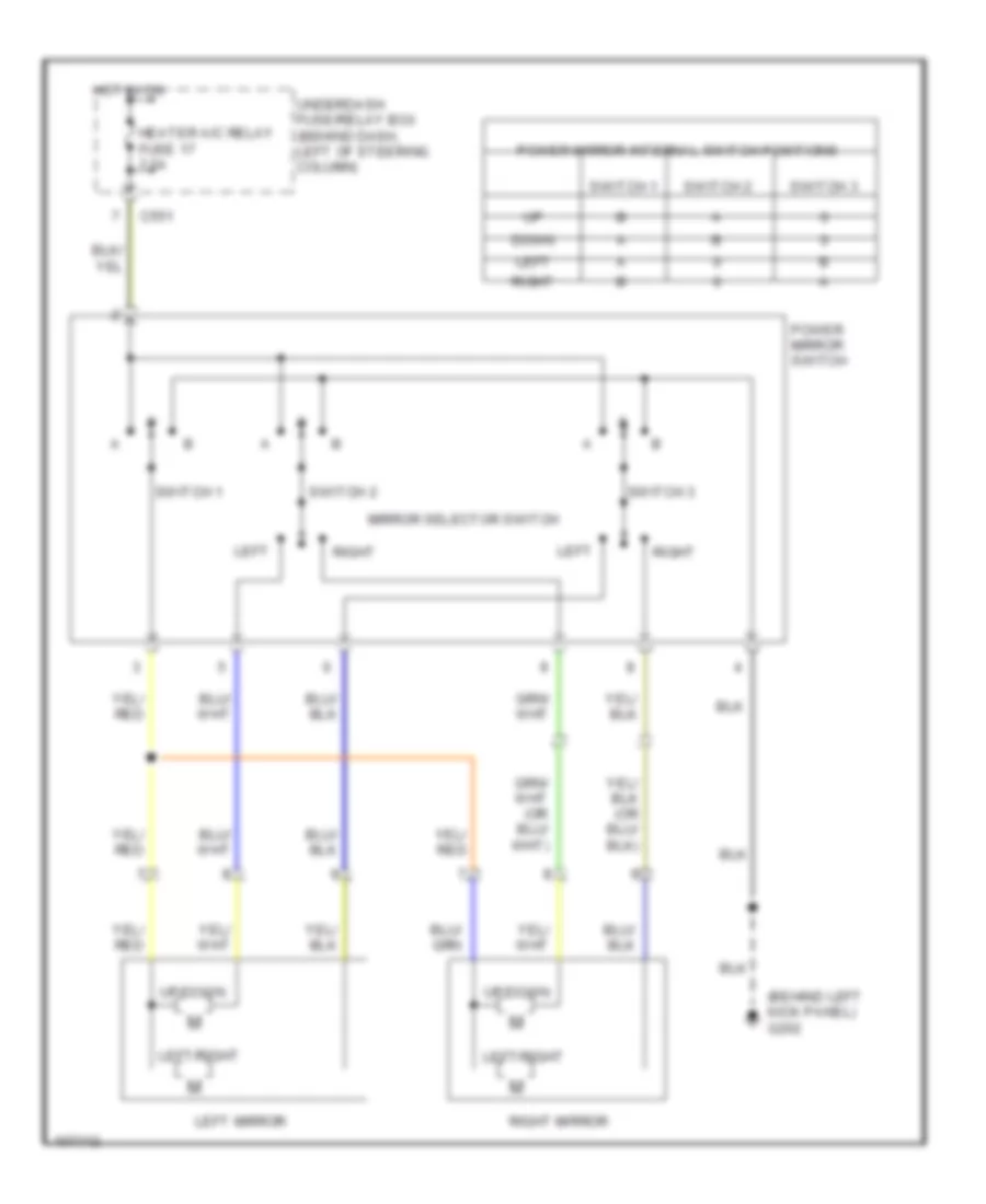
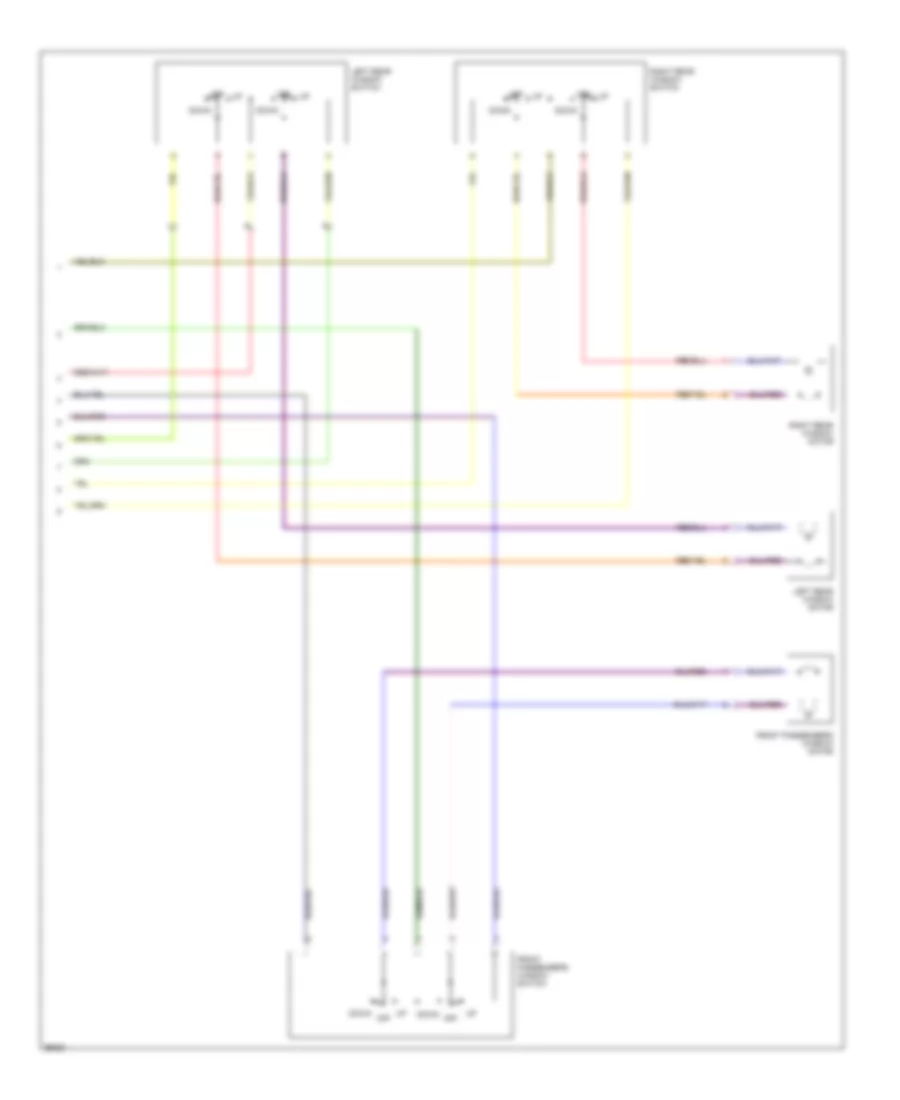
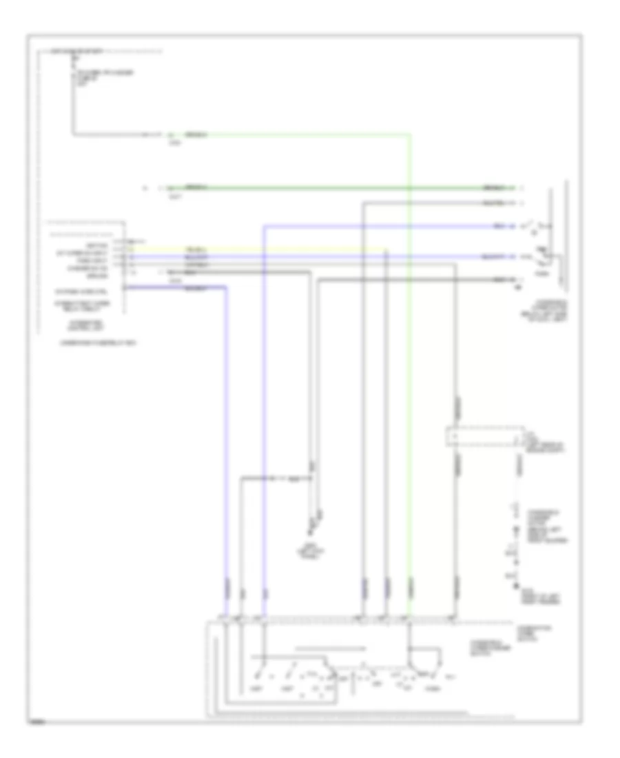
POWER MIRRORS
Power Mirror Wiring Diagram for Honda CR-V LX 1997
List of elements for Power Mirror Wiring Diagram for Honda CR-V LX 1997:
- (behind left kick panel) g202
- C551
- Down
- Heater a/c relay fuse 17 7.5a
- Hot in on
- Left
- Left mirror
- Left/right
- Mirror selector switch
- Power mirror internal switch positions
- Power mirror switch
- Right
- Right mirror
- Switch 1
- Switch 2
- Switch 3
- Underdash fuse/relay box (behind dash, left of steering column)
- Up/down
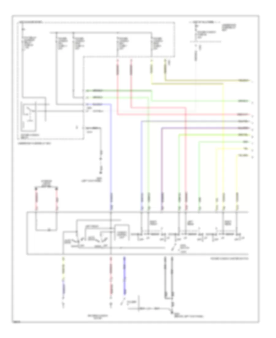
POWER WINDOWS
Power Window Wiring Diagram (1 of 2) for Honda CR-V LX 1997
List of elements for Power Window Wiring Diagram (1 of 2) for Honda CR-V LX 1997:
- 40a
- A10
- A11
- A12
- A13
- A14
- Auto down
- C351
- C418
- C551
- Down
- Driver's window motor
- G200 (behind left kick panel)
- G200 (left kick panel)
- Hot at all times
- Hot in on or start
- Interior lights system
- Left front
- Left rear
- Lock
- Main switch
- Off
- P/w relay sunroof relay fuse 24 7.5a
- Power window fr-l fuse 11 20a
- Power window fr-r fuse 10 20a
- Power window fuse 46
- Power window master switch
- Power window relay
- Power window rr-l fuse 7 20a
- Power window rr-r fuse 8 20a
- Pulser
- Red
- Right front
- Right rear
- Underdash fuse/relay box
- Underhood fuse/relay box
- Window control unit
Power Window Wiring Diagram (2 of 2) for Honda CR-V LX 1997
List of elements for Power Window Wiring Diagram (2 of 2) for Honda CR-V LX 1997:
- Down
- Front passenger's window motor
- Front passenger's window switch
- Left rear window motor
- Left rear window switch
- Off
- Right rear window motor
- Right rear window switch
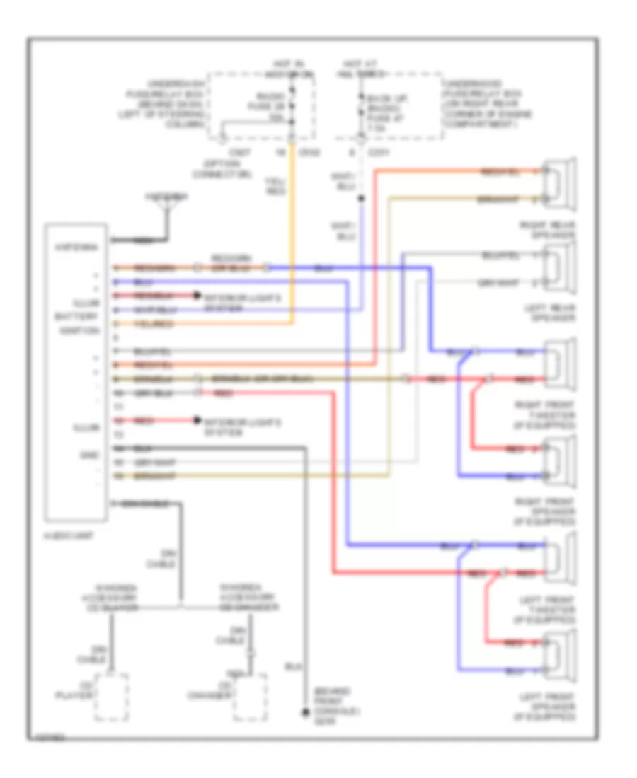
RADIO
Radio Wiring Diagrams for Honda CR-V LX 1997
List of elements for Radio Wiring Diagrams for Honda CR-V LX 1997:
- (behind front console) g206
- (option connector)
- Antenna
- Audio unit
- Back up, (radio) fuse 47 7.5a
- Battery
- C351
- C502
- C927
- Cd changer
- Cd player
- Din cable
- Gnd
- Hot at all times
- Hot in acc or on
- Ignition
- Illum
- Interior lights system
- Left front speaker (if equipped)
- Left front tweeter (if equipped)
- Left rear speaker
- Nca
- Radio fuse 28 10a
- Red
- Right front speaker (if equipped)
- Right front tweeter (if equipped)
- Right rear speaker
- Underdash fuse/relay box (behind dash, left of steering column)
- Underhood fuse/relay box (on right rear corner of engine compartment)
- W/honda accessory cd changer
- W/honda accessory cd player
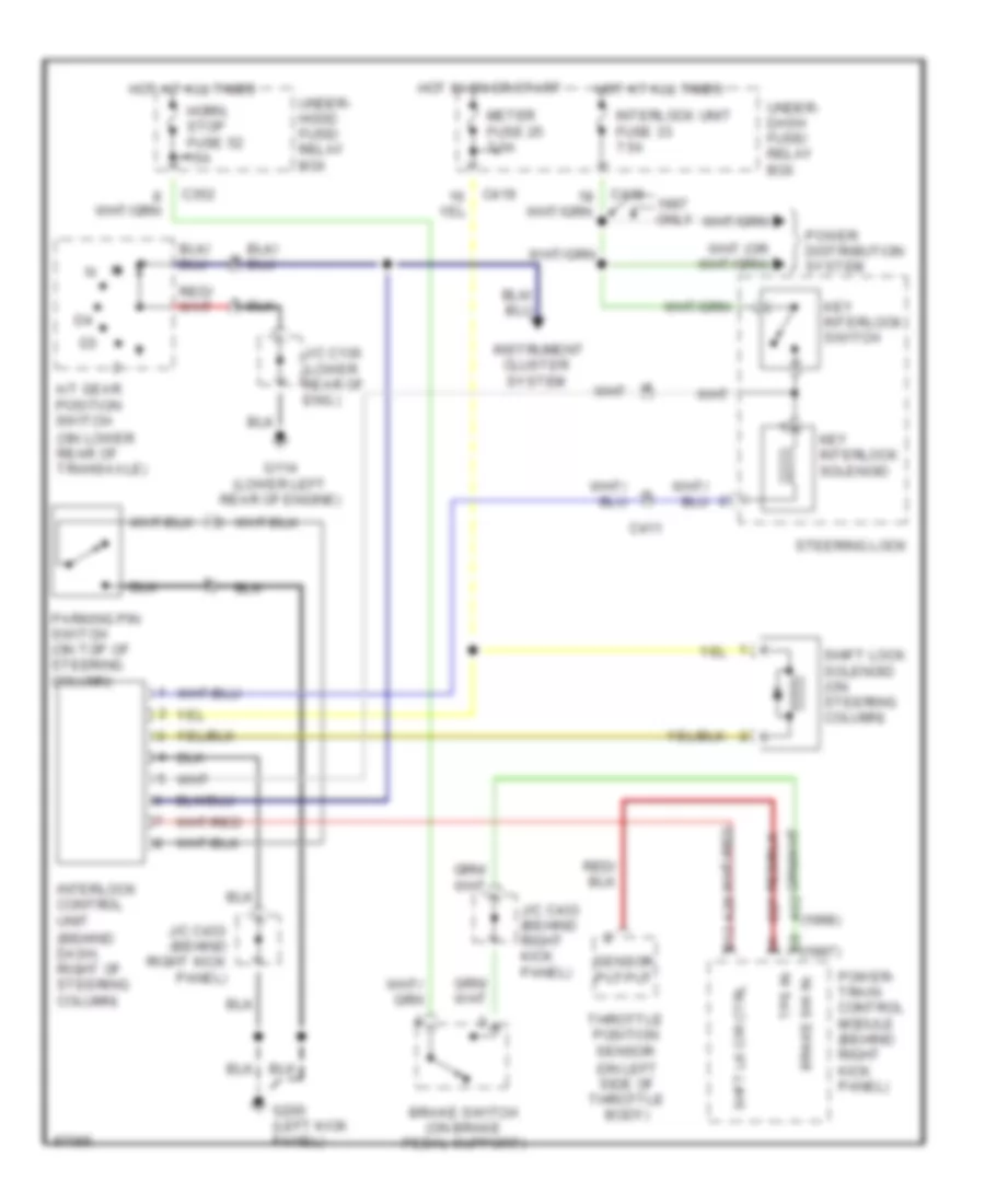
SHIFT INTERLOCKS
Shift Interlock Wiring Diagram for Honda CR-V LX 1997
List of elements for Shift Interlock Wiring Diagram for Honda CR-V LX 1997:
- (1997)
- (1998)
- (behind dash, right of steering column)
- (on left side of throttle body)
- (on lower rear of transaxle)
- A/t gear position switch
- A28
- A32
- B12
- Brake sw in
- Brake switch (on brake pedal support)
- C27
- C352
- C411
- C418
- C419
- G114 (lower left rear of engine)
- G200 (left kick panel)
- Horn, stop fuse 52 15a
- Hot at all times
- Hot in on or start
- Instrument cluster system
- Interlock control unit
- Interlock unit fuse 33 7.5a
- J/c c136 (lower rear of eng.)
- J/c c433 (behind right kick panel)
- Key interlock solenoid
- Key interlock switch
- Meter fuse 25 7.5a
- Only
- Parking pin switch (on top of steering column)
- Power distribution system
- Power- train control module (behind right kick panel)
- Sensor putput
- Shft lk cir ctrl
- Shift lock solenoid (on steering column)
- Steering lock
- Throttle position sensor
- Tps in
- Under- dash fuse/ relay box
- Under- hood fuse/ relay box
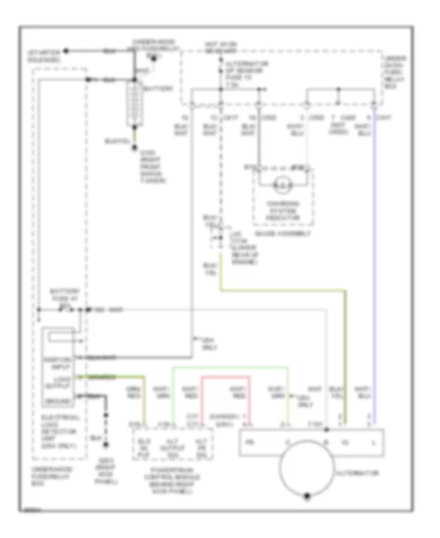
STARTING/CHARGING
Charging Wiring Diagram for Honda CR-V LX 1997
List of elements for Charging Wiring Diagram for Honda CR-V LX 1997:
- (canada)
- (starter solenoid)
- (under-hood abs fuse/relay box)
- (usa)
- A19
- Alt fr sig
- Alt output sig
- Alternator
- Alternator sp sensor fuse 15 7.5a
- B15
- B16
- Battery
- Battery fuse 41 80a
- C17
- C417
- C420 (not used)
- C502
- Charging system indicator
- D16
- Eld in- put
- Electrical load detector unit (usa only)
- G103 (right front shock tower)
- G203 (right kick panel)
- Gauge assembly
- Ground
- Hot in on or start
- Ignition input
- J/c c134 (lower rear of engine)
- Load output
- Powertrain control module (behind right kick panel)
- T101
- T102
- Under dash- fuse/ relay box
- Under-hood fuse/relay box
- Usa only
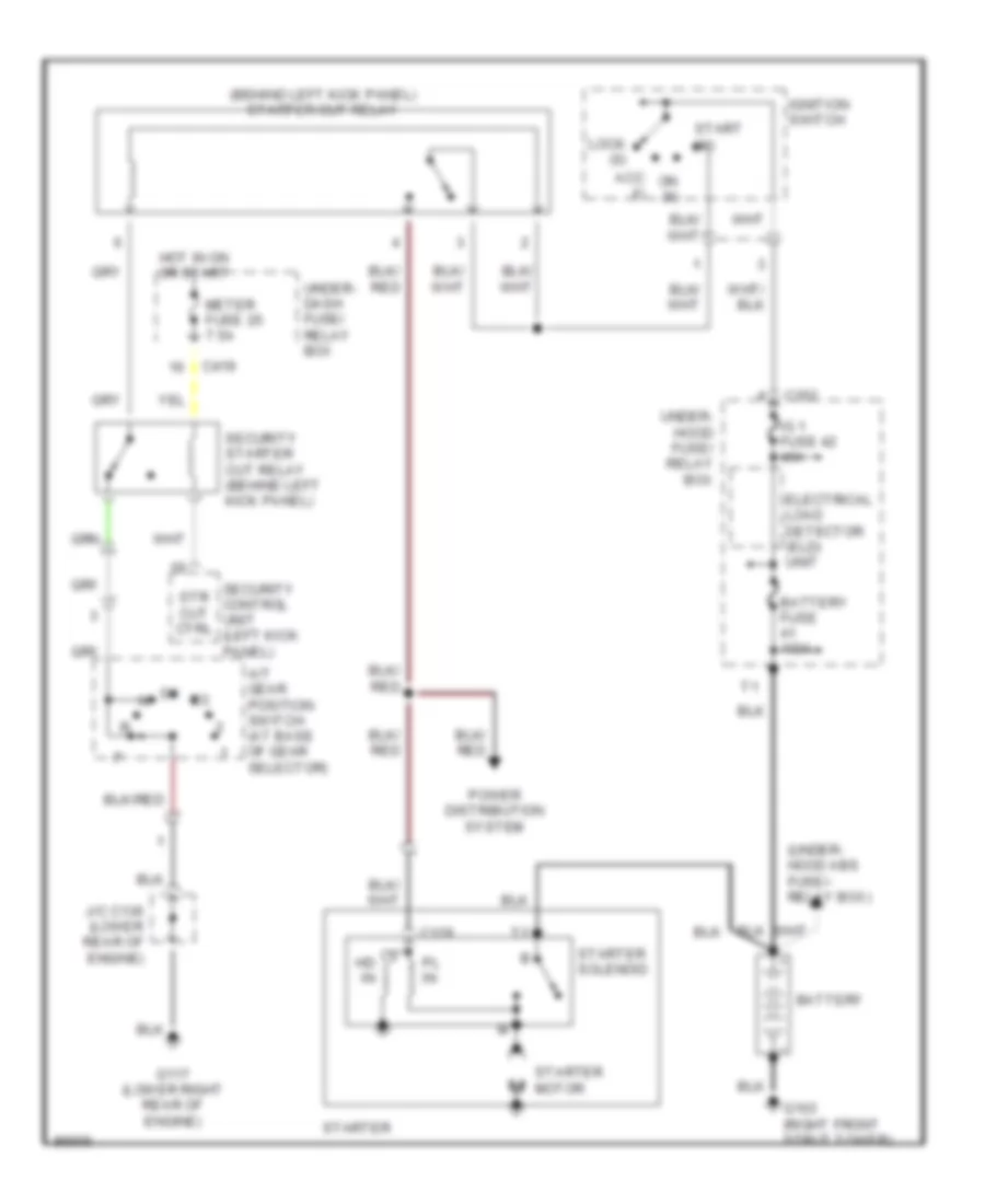
Starting Wiring Diagram, with Anti-theft for Honda CR-V LX 1997
List of elements for Starting Wiring Diagram, with Anti-theft for Honda CR-V LX 1997:
- (behind left kick panel) starter cut relay
- (under- hood abs fuse/- relay box)
- A/t gear position switch (at base of gear selector)
- Acc (i)
- Battery
- Battery fuse 100a
- C129
- C352
- C419
- Electrical load detector (eld) unit
- G103 (right front strut tower)
- G117 (lower right rear of engine)
- Hd in
- Hot in on or start
- Ig 1 fuse 42 40a
- Ignition switch
- J/c c136 (lower rear of engine)
- Lock (0)
- Meter fuse 25 7.5a
- On (ii)
- Pl in
- Power distribution system
- Security control unit (left kick panel)
- Security starter cut relay (behind left kick panel)
- Start (iii)
- Starter
- Starter motor
- Starter solenoid
- Str cut ctrl
- Under- dash fuse/ relay box
- Under- hood fuse/ relay box
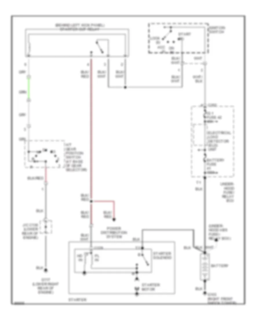
Starting Wiring Diagram, without Anti-theft for Honda CR-V LX 1997
List of elements for Starting Wiring Diagram, without Anti-theft for Honda CR-V LX 1997:
- (behind left kick panel) starter cut relay
- (under- hood abs fuse/- relay box)
- A/t gear position switch (at base of gear selector)
- Acc (i)
- Battery
- Battery fuse 100a
- C129
- C352
- Electrical load detector (eld) unit
- G103 (right front shock tower)
- G117 (lower right rear of engine)
- Hd in
- Ig 1 fuse 42 40a
- Ignition switch
- J/c c136 (lower rear of engine)
- Lock (0)
- On (ii)
- Pl in
- Power distribution system
- Start (iii)
- Starter
- Starter motor
- Starter solenoid
- Under- hood fuse/ relay box
SUPPLEMENTAL RESTRAINTS
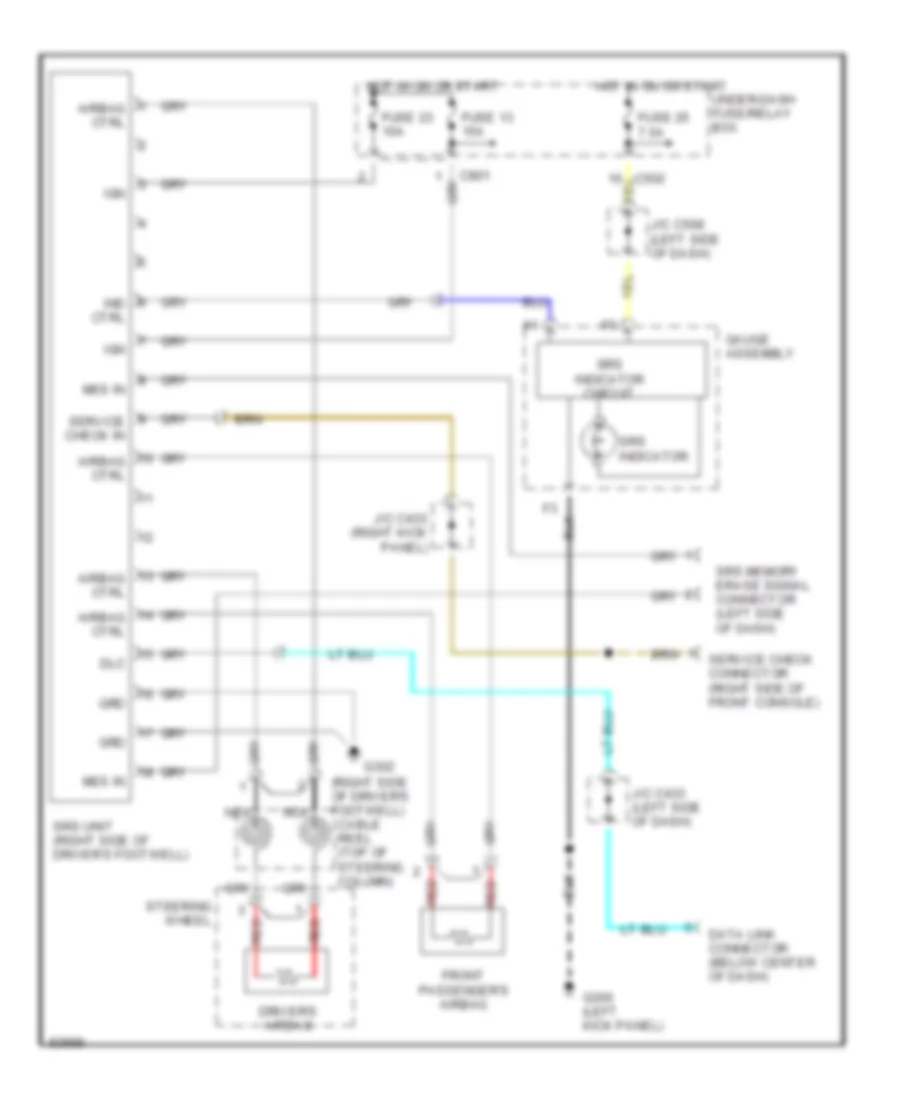
Supplemental Restraint Wiring Diagram for Honda CR-V LX 1997
List of elements for Supplemental Restraint Wiring Diagram for Honda CR-V LX 1997:
- (right side of driver's footwell) cable reel (top of steering column)
- Airbag ctrl
- C502
- C801
- Data link connector (below center of dash)
- Dlc
- Driver's airbag
- Front passenger's airbag
- Fuse 13 15a
- Fuse 23 10a
- Fuse 25 7.5a
- G200 (left kick panel)
- G302
- Gauge assembly
- Grd
- Hot in on or start
- Ign
- Ind ctrl
- J/c c433 (left side of dash)
- J/c c433 (right kick panel)
- J/c c508 (left side of dash)
- Mes in
- Nca
- Red
- Service check connector (right side of front console)
- Service check in
- Srs indicator
- Srs indicator circuit
- Srs memory erase signal connector (left side of dash)
- Srs unit (right side of driver's footwell)
- Steering wheel
- Under-dash fuse/relay box
TRANSMISSION
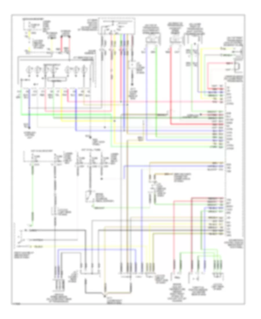
A/T Wiring Diagram for Honda CR-V LX 1997
List of elements for A/T Wiring Diagram for Honda CR-V LX 1997:
- (j/c c508 (behind left side of dash)
- (on front of transmission)
- (on lower front of transmission) shift control solenoid valves
- (on top front transmission) lock-up control solenoid valves
- (on top of transmission)
- A/t gear position indicator
- A/t gear position switch (on right side of transmission)
- A10
- A11
- A12
- A13
- A14
- A22
- A23
- A24
- Atp1
- Atp2
- Atpd3
- Atpd4
- Atpnp
- Atpr
- B11
- B12
- B13
- B14
- B15
- B16
- B17
- B18
- B22
- B23
- B24
- B25
- Bksw
- Brake switch (on brake pedal support)
- C10
- C18
- C351
- C352
- C417
- C418
- C502
- Control
- Control unit
- Countershaft speed sensor
- D10
- D11
- D4 ind
- Dimming circuit
- Ect
- Engine coolant temperature sensor (right front of eng, on coolant outlet housing)
- Exterior lights system
- Fuse 15a
- Fuse 25 7.5a
- Fuse 7.5a
- G117 (lower right rear of eng)
- G200 (left kock panel)
- Gauge assembly
- Ground
- Hot at all times
- Hot in on or start
- Ignition
- Igp1
- Igp2
- Interior lights system
- Interlock
- Interlock control unit
- J/c c122 (below right side of dash)
- J/c c134 (left rear of eng)
- J/c c136 (lower rear of eng)
- J/c c433 (behind right side of dash)
- Lc a
- Lc b
- Lg1
- Lg2
- Linear solenoid (on lower front transmission)
- Ls+
- Ls-
- Mainshaft speed sensor
- Ncsg
- Nmsg
- Pg1
- Pg2
- Pgm-fi main relay (behind right side of dash)
- Pnk
- Powertrain control module (behind right kick panel)
- Red
- Scs
- Service check connector (under middle of dash)
- Sg2
- Sha
- Shb
- Slu
- Throttle position sensor (on center rear of eng)
- Tps
- Under- dash fuse/ relay box
- Under- hood fuse/ relay box
- Vbu
- Vcc2
- Vehicle speed sensor (on lower right rear of transmission)
- Vss
- Vss out
TRUNK, TAILGATE, FUEL DOOR
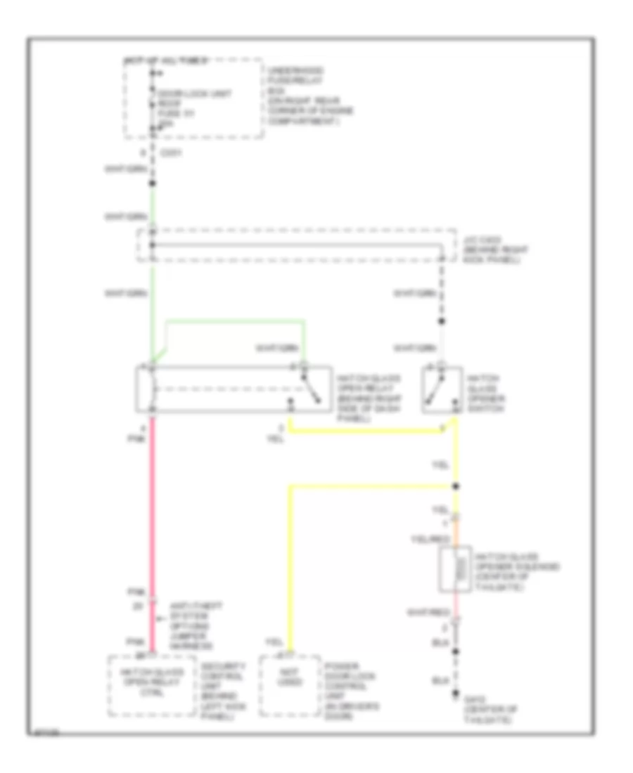
Liftglass Release Wiring Diagram, with Security for Honda CR-V LX 1997
List of elements for Liftglass Release Wiring Diagram, with Security for Honda CR-V LX 1997:
- Anti-theft system options jumper harness
- C351
- Door lock unit roof fuse 51 20a
- G412 (center of tailgate)
- Hatch glass open relay (behind right side of dash panel)
- Hatch glass open relay ctrl
- Hatch glass opener solenoid (center of tailgate)
- Hatch glass opener switch
- Hot at all times
- J/c c433 (behind right kick panel)
- Not used
- Pnk
- Power door lock control unit (in driver's door)
- Security control unit (behind left kick panel)
- Underhood fuse/relay box (on right rear corner of engine compartment)
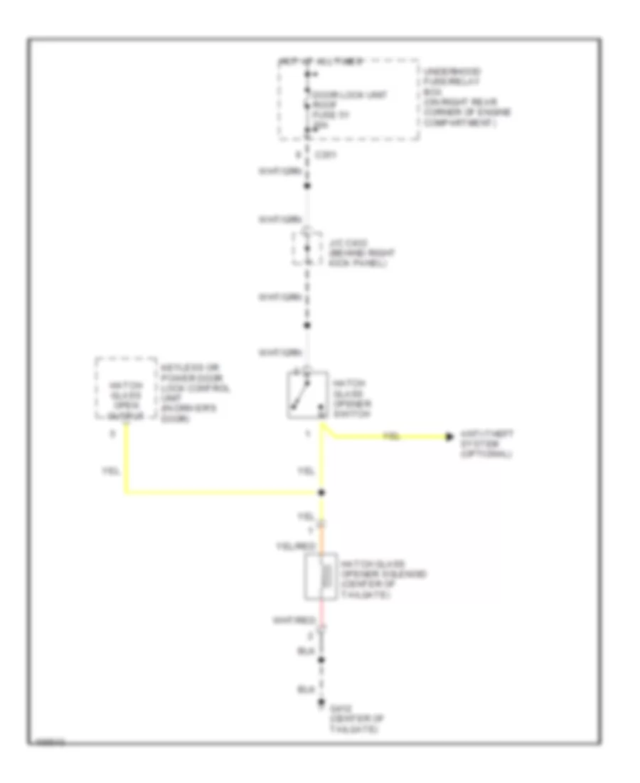
Liftglass Release Wiring Diagram, without Security for Honda CR-V LX 1997
List of elements for Liftglass Release Wiring Diagram, without Security for Honda CR-V LX 1997:
- Anti-theft system (optional)
- C351
- Door lock unit roof fuse 51 20a
- G412 (center of tailgate)
- Hatch glass open output
- Hatch glass opener solenoid (center of tailgate)
- Hatch glass opener switch
- Hot at all times
- J/c c433 (behind right kick panel)
- Keyless or power door lock control unit (in driver's door)
- Underhood fuse/relay box (on right rear corner of engine compartment)
WARNING SYSTEMS
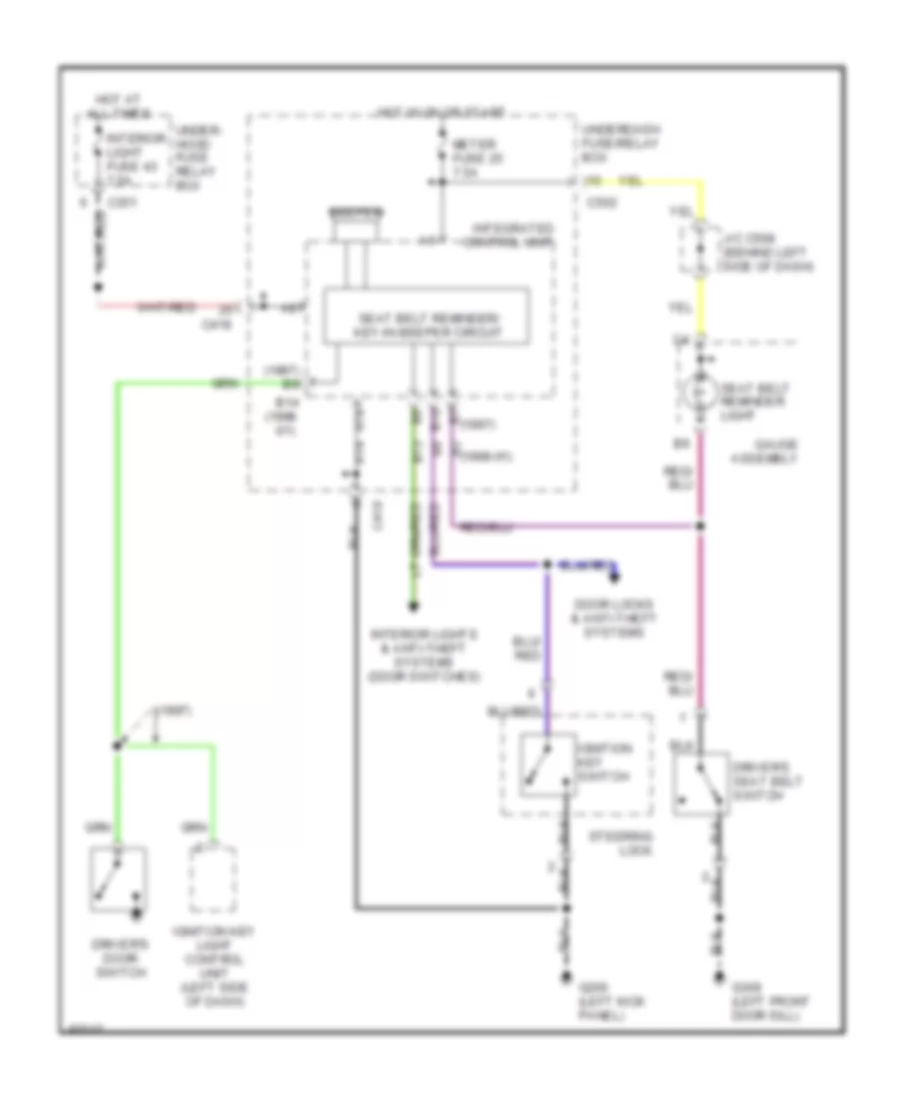
Warning System Wiring Diagrams for Honda CR-V LX 1997
List of elements for Warning System Wiring Diagrams for Honda CR-V LX 1997:
- (1997)
- (1997) b9
- (1998 -01)
- A14
- B10
- B13
- B14
- B2 (1998-01)
- B7 (1997)
- Beeper
- C351
- C418
- C502
- Door locks & anti-theft systems
- Driver's door switch
- Driver's seat belt switch
- G200 (left kick panel)
- G309 (left front door sill)
- Gauge assembly
- Hot at all times
- Hot in on or start
- Ignition key light control unit (left side of dash)
- Ignition key switch
- Integrated control unit
- Interior light fuse 43 7.5a
- Interior lights & anti-theft systems (door switches)
- J/c c508 (behind left side of dash)
- Meter fuse 25 7.5a
- Seat belt reminder light
- Seat belt reminder/ key-in beeper circuit
- Steering lock
- Under- hood fuse relay box
- Underdash fuse/relay box
WIPER/WASHER
Front Wiper/Washer Wiring Diagram for Honda CR-V LX 1997
List of elements for Front Wiper/Washer Wiring Diagram for Honda CR-V LX 1997:
- C417
- C418
- C751
- Combination wiper switch
- Fr wiper, fr washer fuse 26 20a
- G100 (front of left front fender)
- G200 (left kick panel)
- Ground
- Hot in on or start
- Ignition
- Int
- Int wiper on input
- Int/park wipe ctrl
- Integrated control unit
- Intermittent wiper relay circuit
- J/c c433 (left rear of engine compt)
- Mist
- Off
- Park
- Park input
- Run
- Under-dash fuse/relay box
- Wash
- Washer sw on
- Windshield washer motor (behind left side of front bumper)
- Windshield wiper motor (below left side of cowl vent)
- Windshield wiper/washer switch
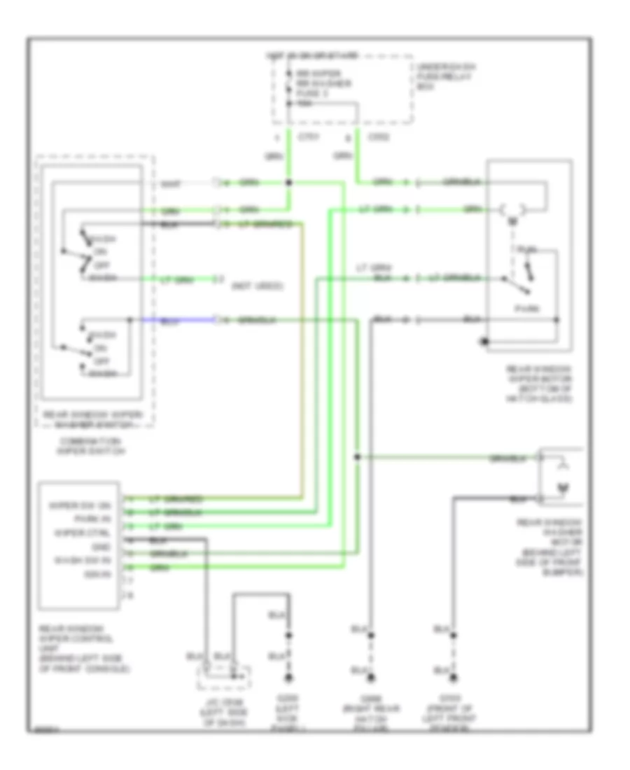
Rear Wiper/Washer Wiring Diagram for Honda CR-V LX 1997
List of elements for Rear Wiper/Washer Wiring Diagram for Honda CR-V LX 1997:
- (not used)
- C552
- C751
- Combination wiper switch
- G100 (front of left front fender)
- G200 (left kick panel)
- G998 (right rear hatch pillar)
- Gnd
- Hot in on or start
- Ign in
- J/c c508 (left side of dash)
- Off
- Park
- Park in
- Rear window washer motor (behind left side of front bumper)
- Rear window wiper control unit (behind left side of front console)
- Rear window wiper motor (bottom of hatch glass)
- Rear window wiper/ washer switch
- Rr wiper rr washer fuse 3 10a
- Run
- Under-dash fuse/relay box
- Wash
- Wash sw in
- Wiper ctrl
- Wiper sw on