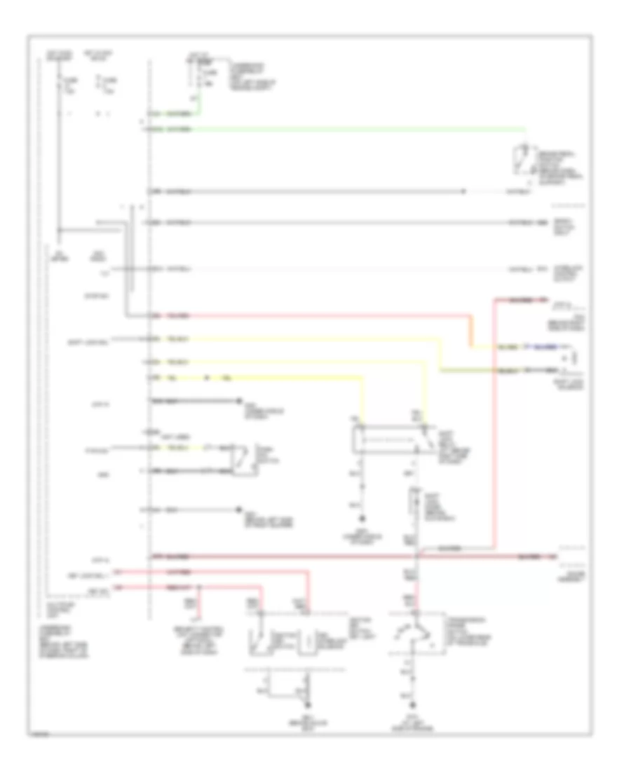
AIR CONDITIONING
Manual A/C Wiring Diagram (1 of 2) for Honda CR-V LX 2004

List of elements for Manual A/C Wiring Diagram (1 of 2) for Honda CR-V LX 2004:
- (ecu) bus
- (under left side of dash) g501
- A/c compressor
- A/c compressor clutch
- A/c compressor clutch relay
- A/c press sw
- A/c pressure switch (on left front of engine compartment, on receiver-drier)
- A10
- Air mix control motor (below left side of dash, on hvac unit)
- Air mix cool
- Air mix hot
- Air mix potential
- Air mix potential +5v
- Amd- p
- Blower feedback
- Blower pwr trans
- Communication
- D10
- Defogger system
- E10
- E18
- E24
- Ecm/pcm (behind right side of dash)
- Ect sensor (on rear of cylinder head)
- Engine controls system
- Evap sensor
- Evaporator temperature sensor (behind left side of dash, on hvac unit)
- Fan control
- Fresh
- Frs
- Fuse 10a
- Fuse 20a
- Ground
- Heater control unit- panel
- High
- Hot at all times
- Hot in on
- Ig2
- Ignition
- Illumination
- Interior lights system
- Low
- M- cool
- M- def
- M- hot
- M- vent
- Mode
- Mode 1
- Mode 2
- Mode 3
- Mode 4
- Mode control motor (below right side of dash, on hvac unit)
- Mode def
- Mode vent
- Multiplex control unit
- Nca
- Rear defog
- Rec
- Recirculate
- Recirculation control motor (behind right side of dash, on blower unit)
- Red
- Relay ctrl
- S- com
- S5v
- Sens gnd
- Sens input
- Sensor ground
- Thermal protector
- To blower motor relay (diagram 2 of 2)
- Underdash fuse/relay box (behind left side of dash, right of steering column)
- Underhood fuse/relay box (on left side of engine compt)
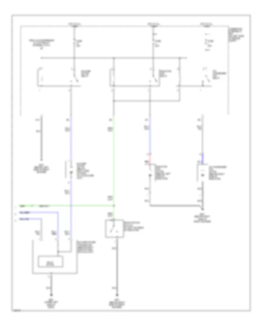
Manual A/C Wiring Diagram (2 of 2) for Honda CR-V LX 2004
List of elements for Manual A/C Wiring Diagram (2 of 2) for Honda CR-V LX 2004:
- A/c condenser fan motor (behind right side of radiator)
- A/c condenser fan relay
- Blower motor (below right side of dash, on a/c blower unit)
- Blower motor relay
- Blower power transistor (behind right side of dash, on hvac unit)
- D13
- From a/c compressor clutch relay (diagram 1 of 2)
- Fuse 20a
- Fuse 40a
- G201 (behind right side of front bumper)
- G301 (behind left side of front bumper)
- G501 (under left side of dash)
- Hot at all times
- Radiator fan motor (behind left side of radiator)
- Radiator fan relay
- Radiator fan switch (at bottom rear of radiator)
- Red
- Solid state
- Underhood fuse/relay box (on left side of engine compt)
ANTI-LOCK BRAKES
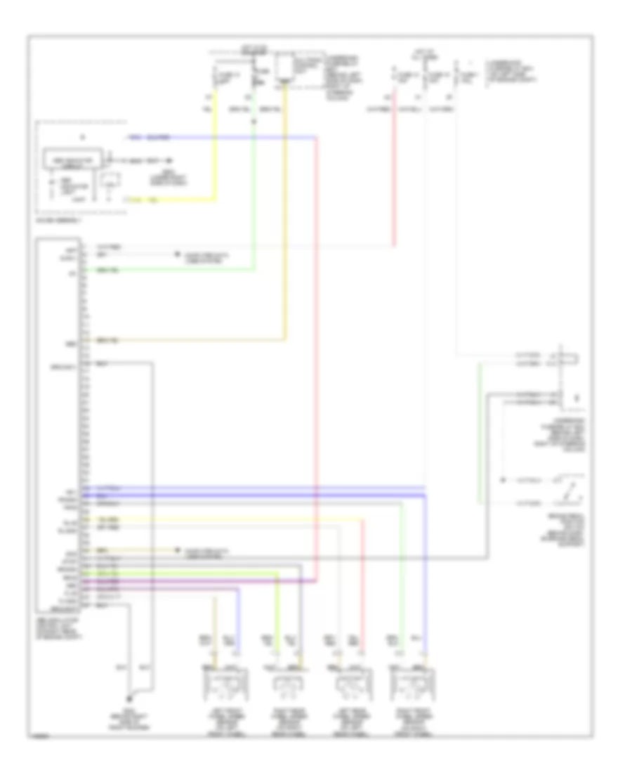
Anti-lock Brakes Wiring Diagram for Honda CR-V LX 2004
List of elements for Anti-lock Brakes Wiring Diagram for Honda CR-V LX 2004:
- +b-p
- +b-v
- A18
- Abs
- Abs indicator circuit
- Abs indicator light
- Abs modulator control unit (on right rear of engine compt)
- B13
- B15
- Brake pedal position switch (behind dash, on brake pedal support)
- Computer data lines system
- Cpu
- Diag ii
- Ebd
- Fl+b
- Fl-gnd
- Fr+b
- Fr-gnd
- Fuse 10 30a
- Fuse 10 7.5a
- Fuse 10a
- Fuse 18 30a
- Fuse 7 15a
- G202 (behind right side of front bumper)
- G502 (under right side of dash)
- Gauge assembly
- Ground-p
- Ground-v
- Hot at all times
- Hot in on or start
- Ig1
- Left front wheel speed sensor (on left front wheel)
- Left rear wheel speed sensor (on left rear wheel)
- Multiplex control unit
- O12
- Right front wheel speed sensor (on right front wheel)
- Right rear wheel speed sensor (on right rear wheel)
- Rl+b
- Rl-gnd
- Rr+b
- Rr-gnd
- Scs
- Stop
- Underdash fuse/relay box (behind left side of dash, right of steering column)
- Underhood fuse/relay box (on left side of engine compt)
ANTI-THEFT
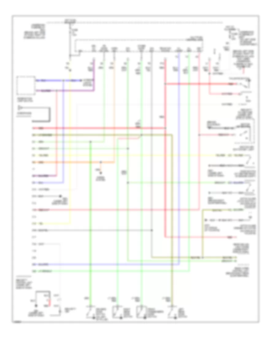
Anti-theft Wiring Diagram for Honda CR-V LX 2004
List of elements for Anti-theft Wiring Diagram for Honda CR-V LX 2004:
- (behind glove box) g401
- (behind left side of dash, right of steering column) (not used) underdash fuse/relay box connector u1
- Combination light switch
- Driver's door switch (on left "b" pillar)
- Drl h/l sw
- Fr door sw (dr)
- Front passenger's door switch
- Fuse 40a
- Fuse 7.5a
- G/h act
- G/h sw
- G50 (under left side of dash)
- G501 (under left side of dash)
- G601 (behind right quarterpanel)
- G701 (at middle of tailgate)
- Hatch glass latch switch 1 (on middle of tailgate)
- Hatch glass opener actuator (on middle of tailgate)
- Hood switch (at center front of engine compt)
- Horn sw
- Horns system
- Hot at all times
- Hot in on or start
- Ig2
- Ignition key switch
- Ignition key switch/key light
- Interior lights system
- K/l set
- K/l unset
- Key sw
- Left rear door switch
- Microphone
- Multiplex control unit
- Other door sw
- P18
- Rear ceiling light diode (under right side of dash)
- Rear wiper control unit (behind right rear quarterpanel)
- Red
- Right rear door switch
- Security control unit (under left side of dash)
- Security in-line fuse (under left side of dash)
- Security led
- Tailgate switch
- Trunk sw (t/g sw)
- Underdash fuse/relay box (behind left side of dash, right of steering column)
- Underhood fuse/relay box (on left side of engine compartment)
Immobilizer Wiring Diagram for Honda CR-V LX 2004
List of elements for Immobilizer Wiring Diagram for Honda CR-V LX 2004:
- A19
- A23
- A24
- B10
- B22
- Computer data lines system
- D11
- D12
- E27
- Ecm/pcm (behind right side of dash)
- Engine controls system
- Fuel pump
- Fuel tank unit (in top of fuel tank)
- Fuse 10a
- Fuse 15a
- G101 (at left side of engine)
- G551 (under driver's seat)
- Gauge assembly
- Ground
- Hot at all times
- Hot in on or start
- Ig1
- Igp1
- Igp2
- Immobi- lizer cord
- Immobilizer control unit receiver (on steering column, integral to ignition switch)
- Immobilizer system indicator
- Imo fpr
- Imocd
- Lg3
- Mrly
- Multiplex control unit
- Parking brake switch (under left side of dash)
- Pgm-fi main relay 1 (behind right side of dash)
- Pgm-fi main relay 2 (behind right side of dash)
- Underdash fuse/ relay box (behind left side of dash, right of steering column)
- Underdash fuse/relay box (behind left side of dash, right of steering column)
- Underhood fuse/ relay box (on left side of engine compt)
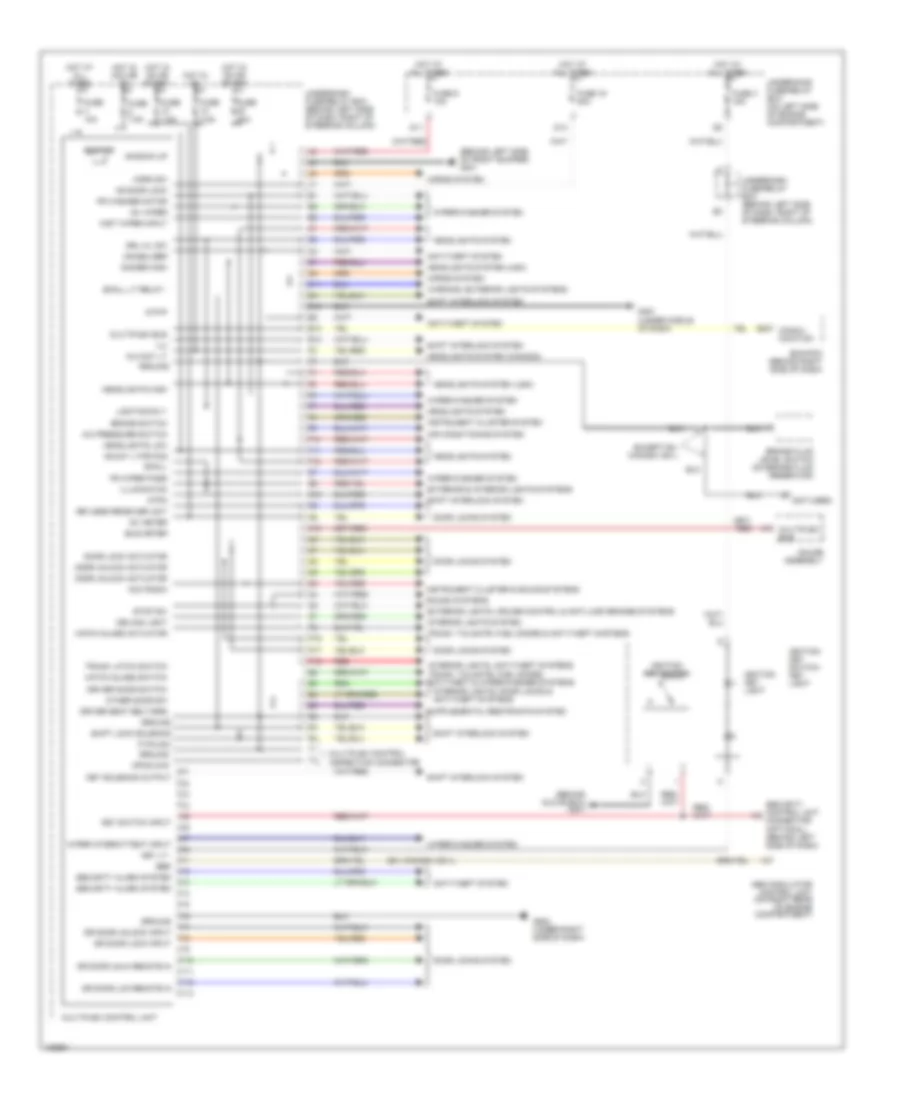
BODY CONTROL MODULES
Body Control Modules Wiring Diagram for Honda CR-V LX 2004
List of elements for Body Control Modules Wiring Diagram for Honda CR-V LX 2004:
- (behind glove box) g401
- (behind left side of front bumper) g301
- (canada)
- (ex, canada: ex-l)
- (not used)
- (usa)
- +b back up
- +b day lt/fr fog
- +b door lock
- A/c pressure switch
- Abs modulator control unit (on right rear of engine compartment)
- Acc radio
- Air conditioning system
- Anti-theft system
- Atp-p
- Atpn
- Beeper
- Brake fluid level switch (on brake fluid reservoir)
- Brake switch
- Bus meter
- C11
- Ceiling light
- Commu- nication
- D10
- D11
- D14
- Dimmer high
- Door lock actuator
- Door locks system
- Door unlock actuator
- Dr door lck remote in
- Dr door lock input
- Dr door unlk remote in
- Dr door unlock input
- Driver door switch
- Driver seat belt/srs
- Drl h/l sw
- E10
- E13
- E24
- Ebd
- Ecm/pcm (behind right side of dash)
- Except ex, canada: ex-l
- Exterior & interior lights systems
- Exterior lights, cruise control & anti-lock brakes systems
- F10
- F11
- F12
- Fr washer motor
- Fr wiper pass
- Fuse 10a
- Fuse 16 20a
- Fuse 20a
- Fuse 3 15a
- Fuse 7.5a
- Fuse 9 10a
- G10
- G451 (under middle of dash)
- G502 (under right side of dash)
- Gauge assembly
- Ground
- Hatch glass actuator
- Hatch glass switch
- Headlights high
- Headlights low
- Headlights system
- Horn sw
- Horns system
- Hot at all times
- Hot in acc or on
- Hot in on
- Hot in on or start
- Ig 2 day lt
- Ig1 meter
- Ig1 wiper
- Ignition key light
- Ignition key switch
- Ignition key switch/ key light
- Illuminaton
- Ilu
- Immobilizer
- Instrument cluster & sound systems
- Instrument cluster system
- Interior lights system
- Interior lights, anti-theft systems
- Interior lights, door locks & anti-theft systems
- K10
- Key lt -
- Key solenoid output
- Key switch input
- Keyless receiver unit
- Lighting rly-
- Mist wiper input
- Mpcs chk
- Multiplex bus
- Multiplex control inspection connector
- Multiplex control unit
- Other door sw
- P pin sw
- P16
- P17
- P18
- Red
- Security alarm system
- Security control unit connector (optional) (behind left side of dash)
- Shift interlock system
- Shift lock solenoid
- Small
- Small lt relay -
- Sound systems
- Stop sw
- Trunk latch switch
- Trunk, tailgate, fuel doors & anti-theft systems
- Trunk, tailgate, fuel doors, anti-theft & wiper/washer systems
- Underdash fuse/relay box (behind left side of dash, right of steering column)
- Underhood fuse/relay box (on left side of engine compartment)
- Warning, exterior lights systems
- Wiper intermittent input
- Wiper/washer system
- Y10
- Y11
- Y12
- Y13
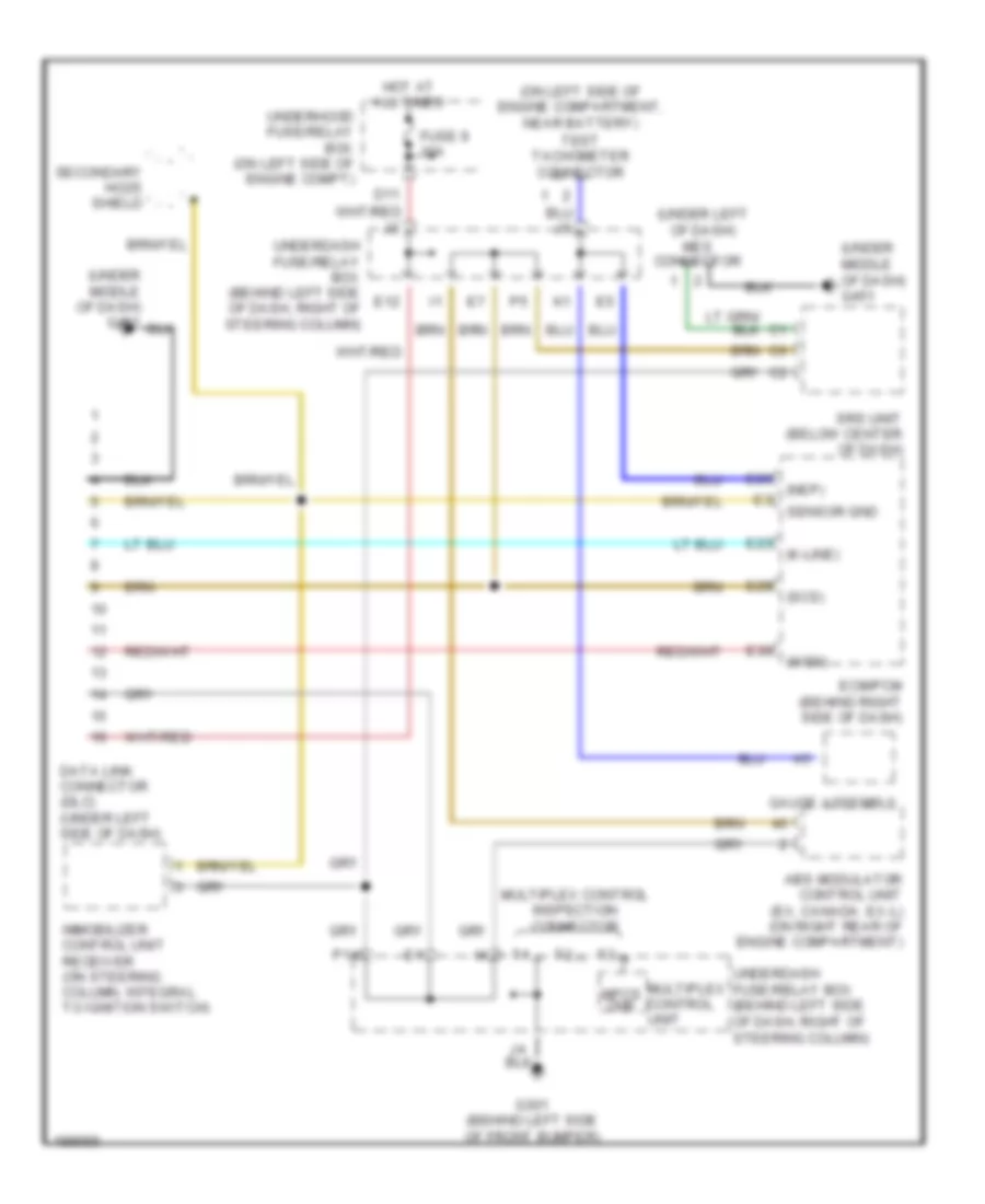
COMPUTER DATA LINES
Computer Data Lines Wiring Diagram for Honda CR-V LX 2004
List of elements for Computer Data Lines Wiring Diagram for Honda CR-V LX 2004:
- (k-line)
- (nep)
- (on left side of engine compartment, near battery) test tachometer connector
- (scs)
- (under left of dash)
- (under middle of dash) g451
- (wen)
- Abs modulator control unit (ex, canada: ex-l) (on right rear of engine compartment)
- D11
- Data link connector (dlc) (under left side of dash)
- E12
- E23
- E26
- E29
- E30
- Ecm/pcm (behind right side of dash)
- Fuse 9 10a
- G301 (behind left side of front bumper)
- Gauge assembly
- Hot at all times
- Immobilizer control unit receiver (on steering column, integral to ignition switch)
- Mes connector
- Mpcs chk
- Multiplex control inspection connector
- Multiplex control unit
- P14
- Secondary ho2s shield
- Sensor gnd
- Srs unit (below center of dash)
- Underdash fuse/relay box (behind left side of dash, right of steering column)
- Underhood fuse/relay box (on left side of engine compt)
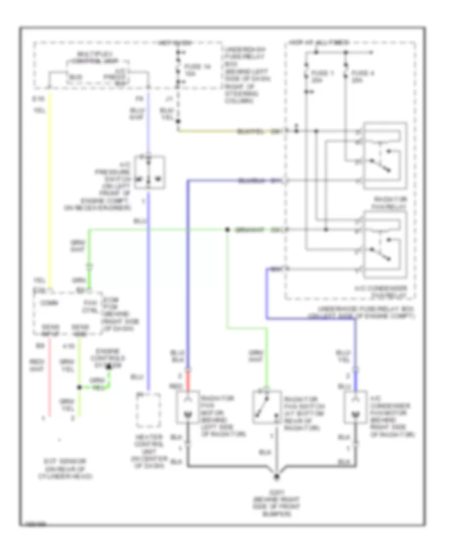
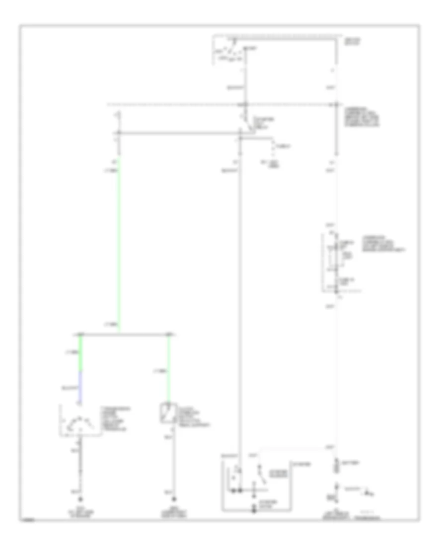
COOLING FAN
Cooling Fan Wiring Diagram for Honda CR-V LX 2004
List of elements for Cooling Fan Wiring Diagram for Honda CR-V LX 2004:
- A/c condenser fan motor (behind right side of radiator)
- A/c condenser fan relay
- A/c press sw
- A/c pressure switch (on left front of engine compt, on receiver-drier)
- A10
- Bus
- Comm
- E10
- E24
- Ecm/ pcm (behind right side of dash)
- Ect sensor (on rear of cylinder head)
- Engine controls system
- Fan ctrl
- Fuse 1 20a
- Fuse 14 10a
- Fuse 4 20a
- G201 (behind right side of front bumper)
- Heater control unit (in center of dash)
- Hot at all times
- Hot in on
- Multiplex control unit
- Radiator fan motor (behind left side of radiator)
- Radiator fan relay
- Radiator fan switch (at bottom rear of radiator)
- Red
- Sens gnd
- Sens input
- Underdash fuse/relay box (behind left side of dash, right of steering column)
- Underhood fuse/relay box (on left side of engine compt)
CRUISE CONTROL
Cruise Control Wiring Diagram for Honda CR-V LX 2004
List of elements for Cruise Control Wiring Diagram for Honda CR-V LX 2004:
- "on" indicator
- (at left side of engine) g101
- (at left side of engine) g101
- (at rear of engine) junction connector c103
- (not used) k9
- (under left side of dash) g501
- A/t
- A/t communi- cation
- A15
- A18
- Actuator ctrl
- Brake pedal positon switch (behind dash, on brake pedal support)
- Brake switch input
- Cable reel
- Cancel switch
- Clutch pedal position switch (on clutch pedal support)
- Cruise control actuator (on right rear of engine compt)
- Cruise control indicator light
- Cruise control main switch
- Cruise control set/ resume/ cancel switch
- Cruise control signal input
- Cruise control switch light
- Cruise control unit (below left side of dash)
- D10
- D12
- E25
- Ecm (behind right side of dash)
- Fuse 10 7.5a
- Fuse 4 10a
- Fuse 7 15a
- G201 (behind right side of front bumper)
- G501 (under left side of dash)
- Gauge assembly
- Ground
- Horn relay
- Horn sw
- Horn switch
- Hot at all times
- Hot in on or start
- Ign input
- Indicator light control
- Inhibitor input
- Interior lights system
- M/t
- Main on
- Motor close
- Motor open
- Multiplex control unit
- O11
- O12
- Off
- Pcm (behind right side of dash)
- Pnk
- Red
- Resume/ sw input
- Resume/ switch
- Security control unit connector (optional)
- Set switch
- Set/sw input
- Speed sensor input
- Steering wheel
- Transmission range switch (on lower rear of transaxle)
- Underdash fuse/relay box (behind left side of dash, right of steering column)
- Underhood fuse/relay box (on left side of engine compt)
- Vehicle speed output
- Vss (on top left of transaxle)
DEFOGGERS
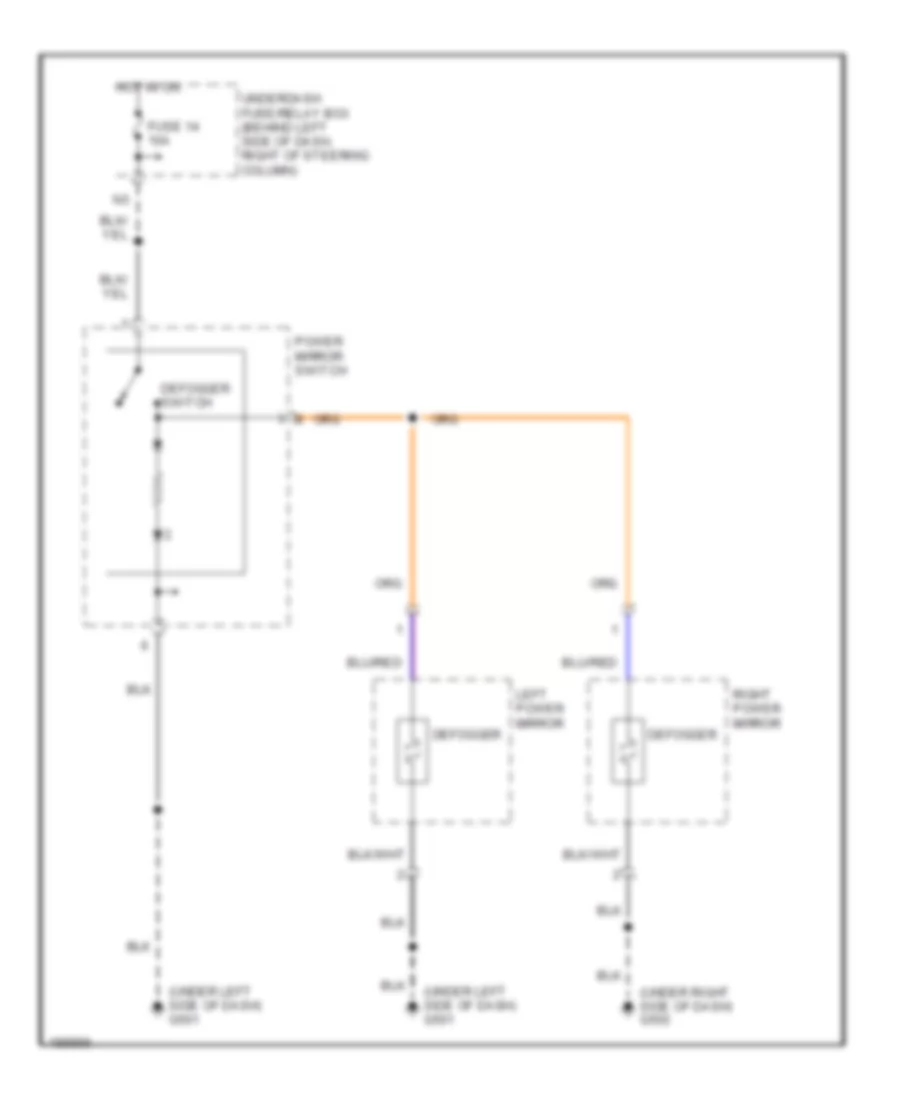
Heated Mirrors Wiring Diagram for Honda CR-V LX 2004
List of elements for Heated Mirrors Wiring Diagram for Honda CR-V LX 2004:
- (under left side of dash) g501
- (under right side of dash) g502
- Defogger
- Defogger switch
- Fuse 14 10a
- Hot in on
- Left power mirror
- Power mirror switch
- Right power mirror
- Underdash fuse/relay box (behind left side of dash, right of steering column)
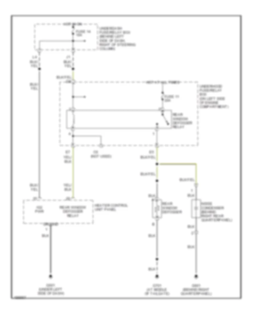
Rear Defogger Wiring Diagram for Honda CR-V LX 2004
List of elements for Rear Defogger Wiring Diagram for Honda CR-V LX 2004:
- (not used)
- Fuse 11 20a
- Fuse 14 10a
- G501 (under left side of dash)
- G601 (behind right quarterpanel)
- G701 (at middle of tailgate)
- Ground
- Heater control unit panel
- Hot at all times
- Hot in on
- Ig2 pwr
- Noise condenser (behind right rear quarterpanel)
- Rear window defogger
- Rear window defogger relay
- Underdash fuse/relay box (behind left side of dash, right of steering column)
- Underhood fuse/relay box (on left side of engine compartment)
ENGINE PERFORMANCE
2.4L
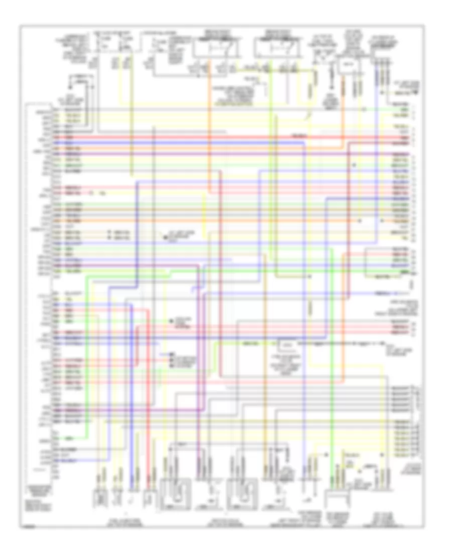
2.4L, Engine Performance Wiring Diagram (1 of 3) for Honda CR-V LX 2004
List of elements for 2.4L, Engine Performance Wiring Diagram (1 of 3) for Honda CR-V LX 2004:
- (at left side of engine)
- (at left side of engine) g101
- (behind right side of dash) pgm-fi main relay 1
- (behind right side of dash) pgm-fi main relay 2
- (in top of fuel tank) fuel tank unit
- (on imrc valve, on top left side of engine) imrc valve position sensor
- (on rear of cylinder head) cmp sensor
- A10
- A11
- A12
- A13
- A14
- A15
- A16
- A17
- A18
- A19
- A20
- A21
- A22
- A23
- A24
- A25
- A26
- A27
- A28
- A29
- A30
- A31
- Afs (+)
- Afs (-)
- Afshtc
- Afshtc (+)
- Altc
- Altf
- Altl
- Atpn
- Atpp
- Atpr
- B10
- B11
- B12
- B13
- B14
- B15
- B16
- B17
- B18
- B19
- B20
- B21
- B22
- B23
- B24
- Barometer pressure sensor
- Ckp
- Ckp sensor (on lower left front of engine, near crankshaft pulley)
- Cmp
- Cooling fans system
- Ecm/pcm (behind right side of dash)
- Ect
- Fanc
- Fuel injectors (on top of engine)
- Fuel pump
- Fuse 15a
- G101
- G101 (at left side of engine)
- G551 (under driver's seat)
- Hot at all times
- Hot in on or start
- Iac valve (on lower left side of throttle assembly)
- Iacv
- Iat
- Icm
- Ignition coils (on top of engine)
- Igp1
- Igp2
- Igpls1
- Igpls2
- Igpls3
- Igpls4
- Immobilizer control unit receiver (on steering column, integral to ignition switch)
- Imrc
- Imrc solenoid valve (on upper left front side of engine)
- Imrc vps
- Inj1
- Inj2
- Inj3
- Inj4
- J/c c103 (at rear of engine)
- Lg1
- Lg2
- Lsa+
- Lsb+
- Lsc (+)
- Map
- Odsw
- Pcs
- Pg1
- Pg2
- Red
- Sg1
- Sg2
- Starting/ charging system
- Tdc
- Tdc sensor (on rear of cylinder head)
- Tps
- Underdash fuse/relay box (behind left side of dash, right of steering column)
- Underhood fuse/relay box (on left side of engine compt)
- Vcc1
- Vcc2
- Vss
- Vtc (+)
- Vtc (-)
- Vtec solenoid valve (on right front of cylinder head)
- Vtpsw
- Vts
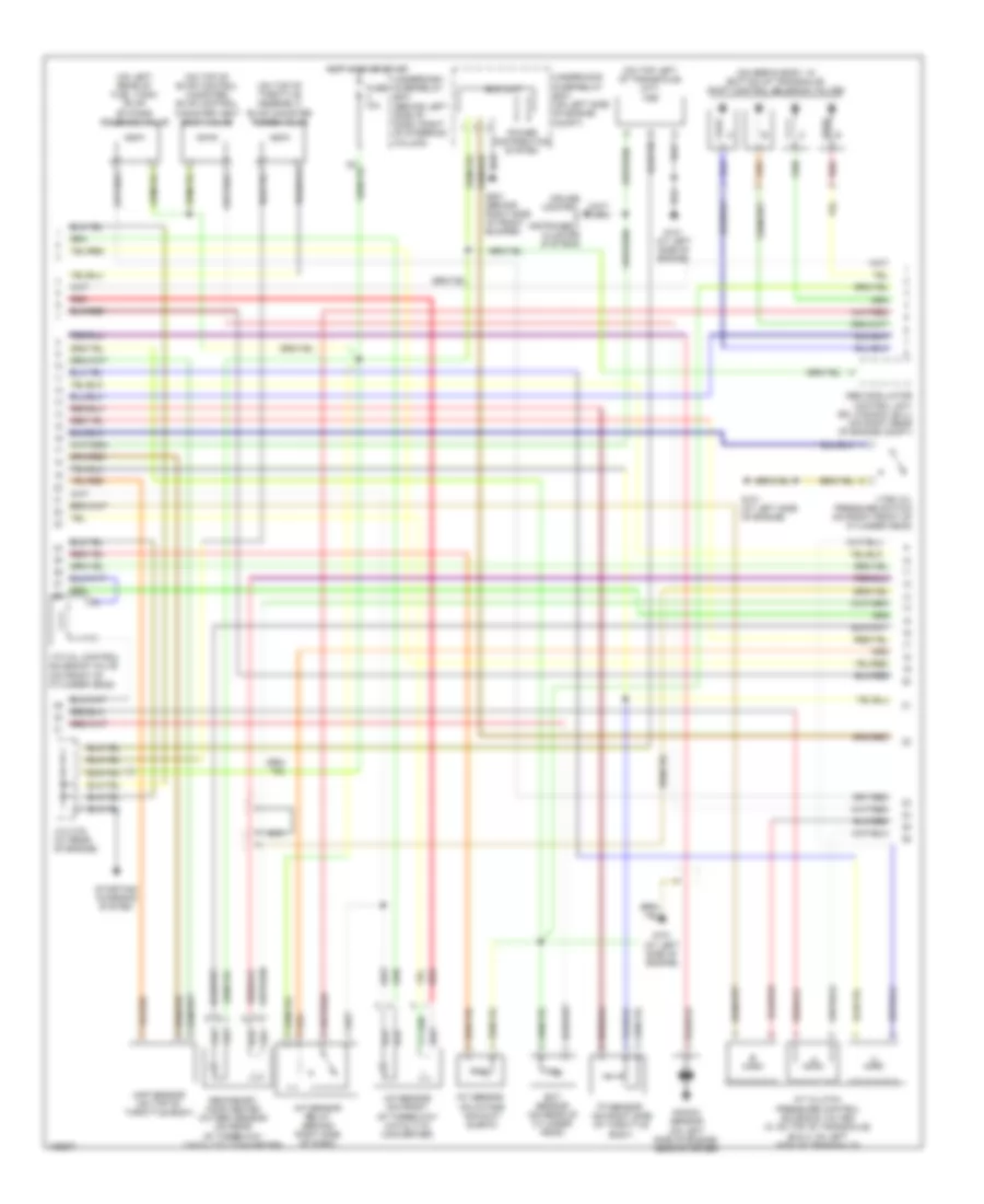
2.4L, Engine Performance Wiring Diagram (2 of 3) for Honda CR-V LX 2004
List of elements for 2.4L, Engine Performance Wiring Diagram (2 of 3) for Honda CR-V LX 2004:
- (on left rear of fuel tank) evap by-pass solenoid valve
- (on servo body, in bottom of transaxle) shift control solenoid valves
- (on top left of transaxle) (m/t) vss
- (on top of evap control canister) evap control canister vent shut valve
- (on top of throttle assembly) evap canister purge valve
- A/f sensor (on front of three-way catalytic converter)
- A/f sensor relay (behind right side of dash)
- A/t clutch pressure control solenoid valves (a: on top of transaxle) (b & c: on left side of transaxle)
- Abs modulator control unit (ex; canada: ex-l) (on right rear of engine compt)
- Cruise control & instrument cluster systems
- Ect sensor (on rear of cylinder head)
- Eld unit
- Fuse 10a
- G101 (at left side of engine)
- G201 (behind right side of front bumper)
- Hot in on or start
- Iat sensor (on intake air duct elbow)
- J/c c103 (at rear of engine)
- Knock sensor (on left side of engine, near starter)
- Map sensor (on top of throttle body)
- Nca
- Power distribution system
- Red
- Secondary ho2s heated oxygen sensor (on rear of three-way catalytic converter)
- Starting/ charging system
- Tp sensor (on right side of throttle body)
- Underdash fuse/relay box (behind left side of dash, right of steering column)
- Underhood fuse/relay box (on left side of engine compt)
- Vtc oil control solenoid valve (on front of cylinder head)
- Vtec oil pressure switch (on right front of cylinder head)
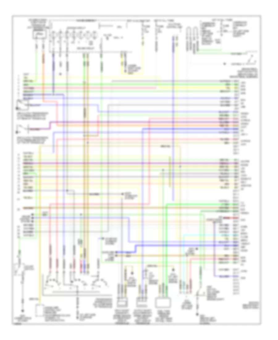
2.4L, Engine Performance Wiring Diagram (3 of 3) for Honda CR-V LX 2004
List of elements for 2.4L, Engine Performance Wiring Diagram (3 of 3) for Honda CR-V LX 2004:
- (at left side of engine) g101
- (on left side of engine compt)
- (on servo body, in bottom of transaxle) atf temperature sensor
- (under right side of dash) g502
- 2nd clutch transmission fluid pressure switch (at top of transaxle)
- 2wbs
- 3rd clutch transmission fluid pressure switch (at rear of transaxle)
- A14
- A16
- A18
- Acc
- Afshtcr
- Air conditioning system
- Anti- theft system
- Atft
- Atp1
- Atp2
- Atpd
- Atpfwd
- Atprvs
- B20
- Bksw
- Brake pedal position switch (behind dash, on brake pedal support)
- C10
- C11
- C12
- C13
- C14
- C15
- C16
- C17
- C18
- C19
- C20
- C21
- C22
- Ccs
- Computer data lines system
- Cpu
- Cruise control system
- D10
- D11
- D12
- D13
- D14
- D15
- D16
- D17
- Dimming circuit
- Dlc (under left side of dash)
- Driver circuit
- E10
- E11
- E12
- E13
- E14
- E15
- E16
- E17
- E18
- E19
- E20
- E21
- E22
- E23
- E24
- E25
- E26
- E27
- E28
- E29
- E30
- E31
- Ecm/pcm (behind right side of dash)
- Eld
- Ftp
- Fuel tank pressure sensor (on left rear of fuel tank)
- Fuse 15a
- Fuse 20a
- Fuse 7.5a
- Fuse/relay box
- G101 (at left side of engine)
- G301 (behind left side of front bumper)
- G451 (under middle of dash)
- Gauge assembly
- Hot at all times
- Hot in on or start
- Ig1
- Ilu
- Immobilizer control unit receiver (on steering column, integral to ignition switch)
- Imo fpr
- Imocd
- Input shaft (mainshaft) speed sensor (on rear right side of transaxle)
- J/c c103 (at rear of engine)
- K-line
- Lg3
- Lsa-
- Lsb-
- Lsc (-)
- Mil
- Mil ind
- Mrly
- Multiplex control unit
- Nep
- O/d off
- O/d off switch
- Op2sw
- Op3sw
- Output shaft (countershaft) speed sensor (on front right side of transaxle)
- Pnk
- Psp switch (on lower center rear of engine compt)
- Pspsw
- Red
- Scs
- Sefmj
- Sg3
- Sha
- Shb
- Shc
- She
- Shift interlock system
- Sho2s
- So2shtc
- Starting/ charging system
- Transmission range switch (on lower rear of transaxle)
- Underdash fuse/relay box (behind left side of dash, right of steering column)
- Underhood
- Vcc3
- Vssout
- Vsv
- Wen
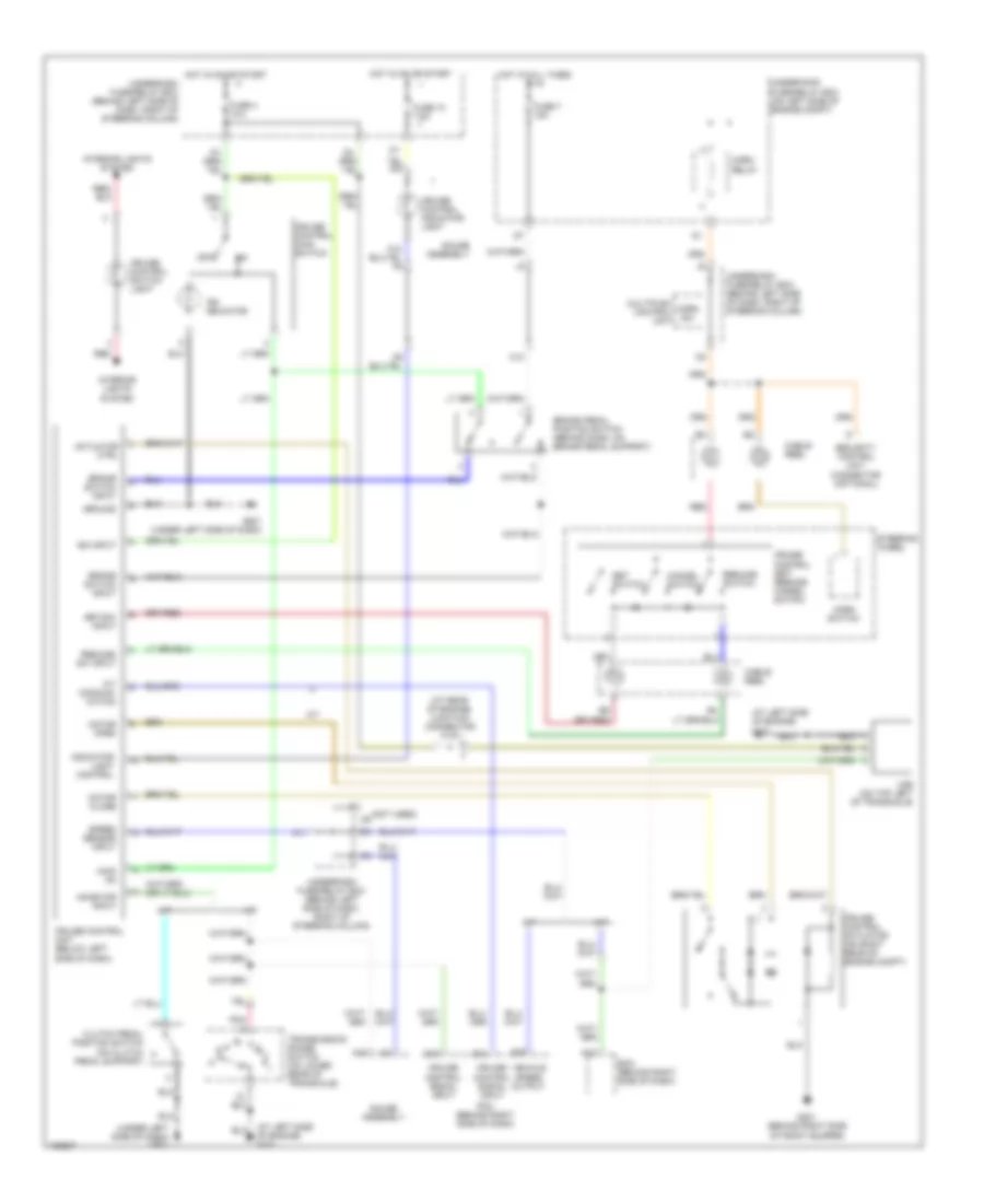
EXTERIOR LIGHTS
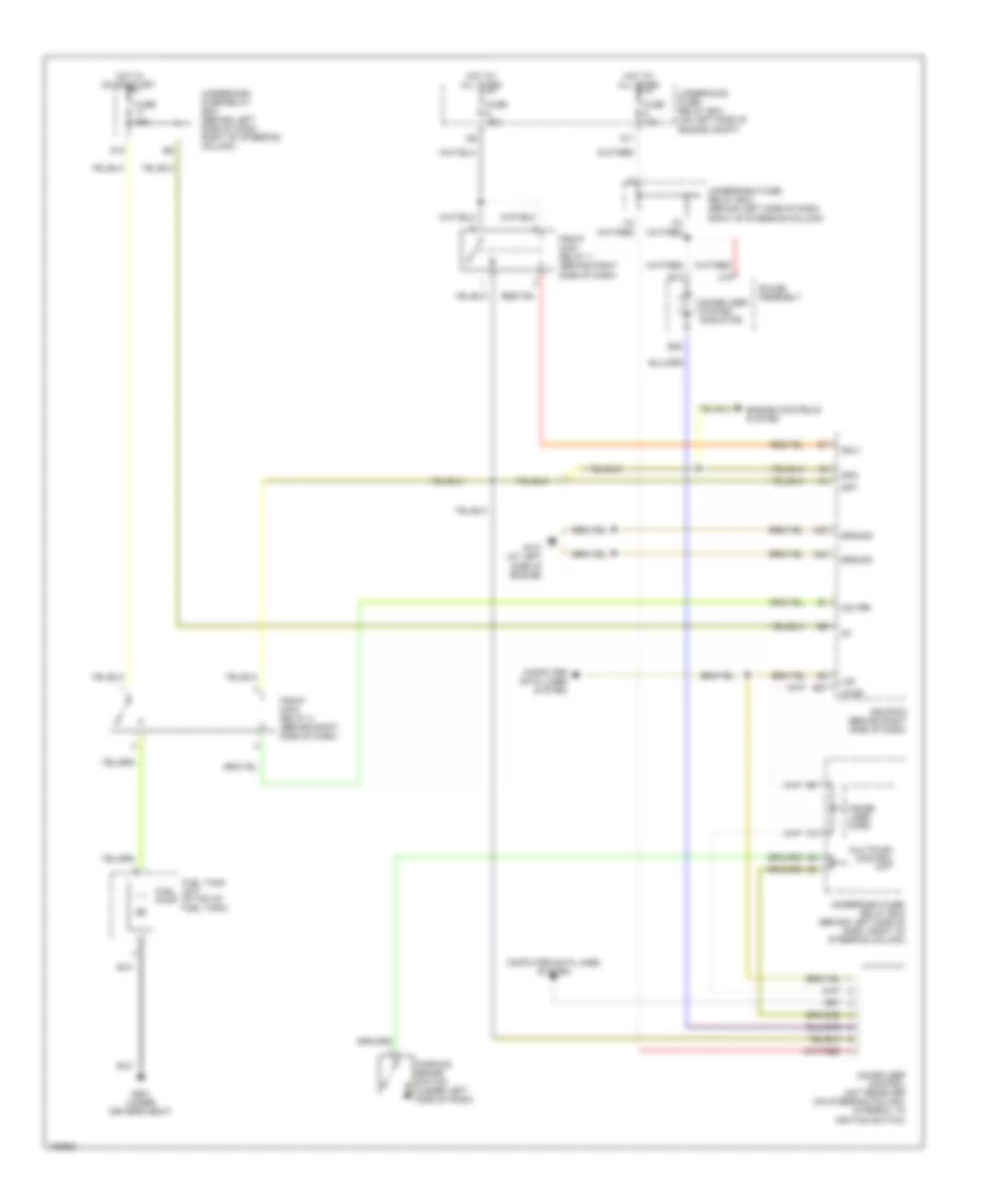
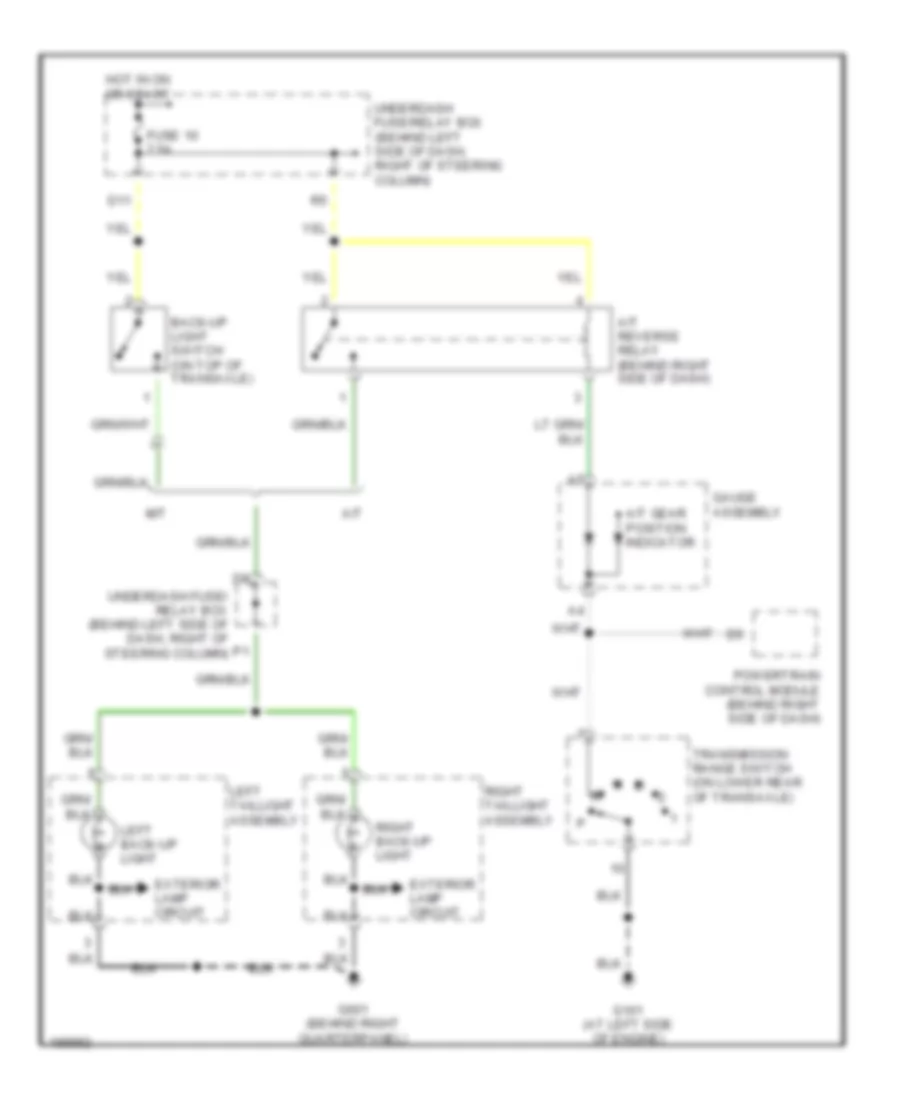
Back-up Lamps Wiring Diagram for Honda CR-V LX 2004
List of elements for Back-up Lamps Wiring Diagram for Honda CR-V LX 2004:
- A/t
- A/t gear position indicator
- A/t reverse relay (behind right side of dash)
- Back-up light switch (on top of transaxle)
- D11
- Exterior lamp circuit
- Fuse 10 7.5a
- G101 (at left side of engine)
- G601 (behind right quarterpanel)
- Gauge assembly
- Hot in on or start
- Left back-up light
- Left taillight assembly
- M/t
- Powertrain control module (behind right side of dash)
- Right back-up light
- Right taillight assembly
- Transmission range switch (on lower rear of transaxle)
- Underdash fuse/ relay box (behind left side of dash, right of steering column)
- Underdash fuse/relay box (behind left side of dash, right of steering column)
Exterior Lamps Wiring Diagram (1 of 2) for Honda CR-V LX 2004
List of elements for Exterior Lamps Wiring Diagram (1 of 2) for Honda CR-V LX 2004:
- (not used)
- B11
- B12
- B15
- Back-up lamps circuit
- C11
- C12
- C13
- Combination light switch
- Fuse 19 7.5a
- Fuse 2 15a
- Fuse 5 15a
- G201 (behind right side of front bumper)
- G301 (behind left side of front bumper)
- G401 (behind glove box)
- G502 (under right side of dash)
- G601 (behind right quarterpanel)
- Gauge assembly
- Hazard warning switch
- Hazard warning switch light
- Head
- Headlight switch
- Hot at all times
- Hot in on or start
- Interior lights system
- Left
- Left front parking light
- Left front turn signal/ side marker light
- Left rear turn signal light
- Left taillight assembly
- Left turn signal indicator
- M12
- Multiplex control unit
- Off
- P15
- Park
- Red
- Right
- Right front parking light
- Right front turn signal/ side marker light
- Right rear turn signal light
- Right taillight assembly
- Right turn signal indicator
- Taillight relay
- To brake light/ taillights (diagram 2 0f 2)
- To trailer lighting connector (diagram 2 of 2)
- Turn signal switch
- Turn signal/ hazard relay
- Underdash fuse/relay box (behind left side of dash, right of steering column)
- Underhood fuse/relay box (on left side of engine compartment)
Exterior Lamps Wiring Diagram (2 of 2) for Honda CR-V LX 2004
List of elements for Exterior Lamps Wiring Diagram (2 of 2) for Honda CR-V LX 2004:
- (behind dash, on brake pedal support)
- (behind left side of dash, right of steering column)
- Brake pedal position switch
- Connector
- Cruise control unit (below left side of dash)
- From fuse 5 (diagram 1 of 2)
- From left taillight assembly (diagram 1 of 2)
- From right taillight assembly (diagram 1 of 2)
- From taillight relay (diagram 1 of 2)
- Fuse 7 15a
- G60 (left quarter panel)
- G601 (behind right quarterpanel)
- G701 (at middle of tailgate)
- High mount brake light
- Hot at all times
- Left brake light/ taillight
- Left rear side marker light
- Left taillight assembly
- Left turn input
- Left turn output
- License plate light
- Right brake light/ taillight
- Right rear side marker light
- Right taillight assembly
- Right turn input
- Right turn output
- Trailer connector
- Trailer lighting connector (behind left rear quarterpanel)
- Underdash fuse/relay box
- Underhood fuse/relay box (on left side of engine compartment)
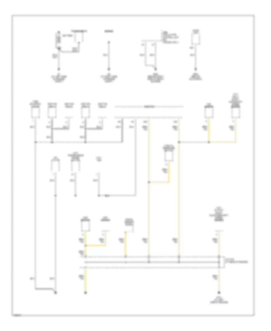
GROUND DISTRIBUTION
Ground Distribution Wiring Diagram (1 of 4) for Honda CR-V LX 2004
List of elements for Ground Distribution Wiring Diagram (1 of 4) for Honda CR-V LX 2004:
- (a/t) input shaft (mainshaft) speed sensor
- (a/t) output shaft (countershaft) speed sensor
- (a/t) transmission range switch
- (at rear of engine)
- (m/t) vss
- A20
- A23
- A24
- Abs modulator control unit (ex, canada: ex-l)
- Audio unit
- Battery
- Ckp sensor
- Cmp sensor
- Ecm/pcm
- Engine
- G1 (at left side of engine compt)
- G101 (at left side of engine)
- G2 (at right side of engine compt)
- G202 (behind right side of front bumper)
- G503 (behind glove box)
- Iac valve
- Ignition coil 1
- Ignition coil 2
- Ignition coil 3
- Ignition coil 4
- J/c c103
- Knock sensor shield
- Tdc sensor
- Transmission
- Vtec oil pressure switch
- Vtec solenoid valve
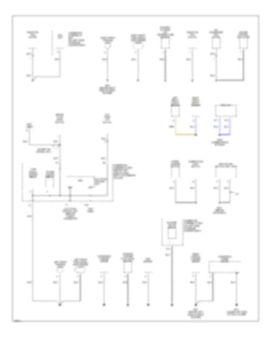
Ground Distribution Wiring Diagram (2 of 4) for Honda CR-V LX 2004
List of elements for Ground Distribution Wiring Diagram (2 of 4) for Honda CR-V LX 2004:
- (a/t) park pin switch
- (canada) outside air temperature sensor
- (canada) washer fluid level switch
- (not used)
- A/c condenser fan motor
- A/t
- A11
- A12
- Blower motor relay
- Brake fluid level switch
- Combination light switch
- Cruise control actuator
- D13
- Eld unit
- Except ex, canada: ex-l
- G201 (behind right side of front bumper)
- G301 (behind left side of front bumper)
- G401 (behind glove box)
- G402 (under middle of dash)
- G811 (under left side of cowl cover)
- Gnd
- Ignition key switch/ key light
- K16
- Left front impact sensor
- Left front parking light
- Left front turn signal/ side marker light
- Multiplex control unit
- Multiplex control unit service check connector
- Power window relay
- Psp switch
- Radiator fan motor
- Radiator fan switch
- Rear window washer motor
- Right front impact sensor
- Right front parking light
- Right front turn signal/ side marker light
- Srs unit
- Turn signal/ hazard relay
- Underdash fuse/relay box (behind left side of dash, right of steering column)
- Underhood fuse/relay box (on left side of engine compartment)
- Windshield washer motor
- Windshield wiper motor
- Wiper/ washer switch
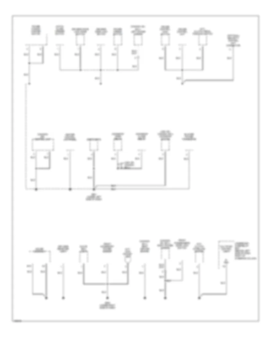
Ground Distribution Wiring Diagram (3 of 4) for Honda CR-V LX 2004
List of elements for Ground Distribution Wiring Diagram (3 of 4) for Honda CR-V LX 2004:
- (canada) drl control unit
- (canada: ex, ex-l) left power mirror
- (canada: ex, ex-l) right power mirror
- (canada: ex-l) seat heater switch
- (m/t) clutch interlock switch
- (m/t) clutch pedal position switch
- (m/t) coin pocket light
- (optional) security control unit connector
- (usa: ex, canada: ex-l)
- (usa: ex, canada: ex-l) moonroof switch
- B15
- Blower power transistor
- Cruise control main switch
- Cruise control unit
- Driver's door lock knob switch
- Driver's door lock switch
- Front accessory power socket
- Front passenger's door lock switch
- G501 (under left side of dash)
- G502 (under right side of dash)
- Gauge assembly
- Glove box light
- Hatch glass opener switch
- Heater control unit-panel
- Keyless receiver unit
- Moonroof close relay
- Moonroof open relay
- Multiplex control unit
- Power mirror switch
- Power window master switch
- S- gnd
- Spotlights
- Underdash fuse/relay box (behind left side of dash, right of steering column)
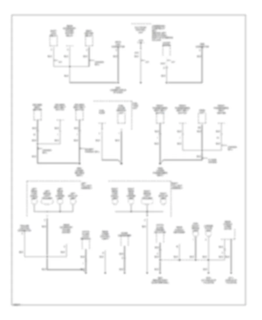
Ground Distribution Wiring Diagram (4 of 4) for Honda CR-V LX 2004
List of elements for Ground Distribution Wiring Diagram (4 of 4) for Honda CR-V LX 2004:
- A/t
- Atp -p
- Canada: ex-l
- D10
- Data link connector
- Driver's seat belt switch
- Driver's seat heater
- Except canada: ex-l
- Front passenger's seat belt switch
- Front passenger's seat heater
- Fuel gauge sending unit
- Fuel pump
- Fuel tank unit
- G451 (under middle of dash)
- G551 (under driver's seat)
- G552 (under passenger's seat)
- G601 (behind right quarterpanel)
- G701 (at middle of tailgate)
- G711 (middle of tailgate)
- Hatch glass latch switch 1
- Hatch glass opener actuator
- High mount brake light
- Left back-up light
- Left brake light/ taillight
- Left rear side marker light
- Left rear turn signal light
- Left taillight assembly
- License plate light
- Mes connector
- Multiplex control unit
- Noise condenser
- O/d off switch
- Opds unit
- Rear accessory power socket
- Rear accessory power socket relay
- Rear window defogger
- Rear window wiper motor
- Rear wiper control unit
- Right back-up light
- Right brake light/ taillight
- Right rear side marker light
- Right rear turn signal light
- Right taillight assembly
- Seat heater relay
- Shift lock relay
- Trailer lighting connector
- Underdash fuse/relay box (behind left side of dash, right of steering column)
- W/ side air bag
HEADLIGHTS
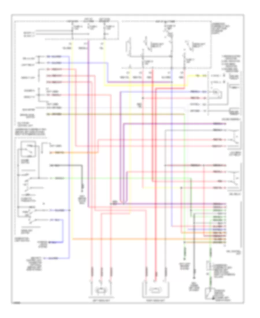
Headlamps Wiring Diagram, with DRL for Honda CR-V LX 2004
List of elements for Headlamps Wiring Diagram, with DRL for Honda CR-V LX 2004:
- (not used)
- 1) brake system
- 2) drl indicator
- 3) high beam
- 4) gauges and
- A18
- A21
- Anti-lock brakes
- B+ day lt
- B14
- Brake level switch
- Bus meter
- Combination light switch
- Control unit connector (optional) (behind left side of dash)
- Cpu
- Dimmer hi
- Dimmer switch
- Driver circuit
- Drl control unit
- Drl h/l sw
- Drl relay
- Eld unit
- F10
- F11
- F12
- F4 (not used)
- Flash-to- pass switch
- Fuse 10 7.5a
- Fuse 12 7.5a
- Fuse 15 15a
- Fuse 17 15a
- Fuse 19 100a
- Fuse 3 10a
- G401 (behind glove box)
- G501 (under left side of dash)
- Gauge assembly
- Head
- Headlight relay 1
- Headlight relay 2
- Headlight switch
- Headlt hi
- Headlt low
- High
- Hot at all times
- Hot in on
- Hot in on or start
- Ig2 day lt
- Indicator
- Indicators
- Interior lights system
- K10
- Left headlight
- Light relay
- Low
- Low beam cut relay
- Multiplex control unit
- Off
- Park
- Parking brake switch (under left side of dash)
- Red
- Right headlight
- Security
- System
- Underdash fuse/relay box (behind left side of dash, right of steering column)
- Underhood fuse/relay box (on left side of engine compt)
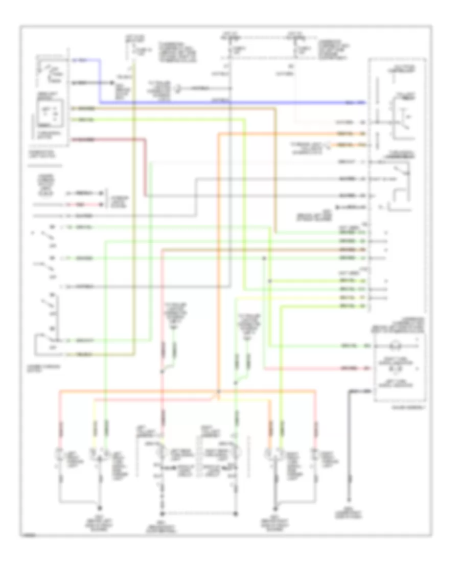
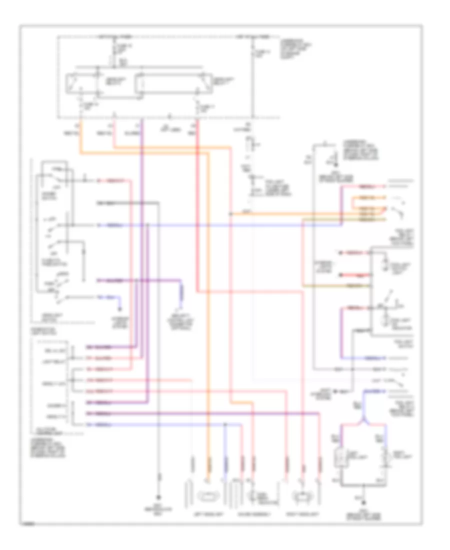
Headlamps Wiring Diagram, without DRL with Double Relay Fog Lamps for Honda CR-V LX 2004
List of elements for Headlamps Wiring Diagram, without DRL with Double Relay Fog Lamps for Honda CR-V LX 2004:
- (not used)
- 20a
- B14
- Combination light switch
- Dimmer hi
- Dimmer switch
- Drl h/l sw
- Eld unit
- F10
- F12
- Flash-to- pass switch
- Fog light in-line fuse (under left side of dash)
- Fog light on indicator
- Fog light relay 1 (behind left kick panel)
- Fog light relay 2 (behind left kick panel)
- Fog light switch
- Fog light switch light
- Fuse 14 40a
- Fuse 15 15a
- Fuse 17 15a
- Fuse 19 100a
- G301 (behind left side of front bumper)
- G401 (behind glove box)
- Gauge assembly
- Head
- Headlight relay 1
- Headlight relay 2
- Headlight switch
- Headlt hi
- Headlt low
- High
- High beam indicator
- Hot at all times
- Interior lights system
- Left fog light
- Left headlight
- Light relay
- Low
- Multiplex control unit
- Off
- Park
- Red
- Right fog light
- Right headlight
- Security control unit connector (optional)
- Shift interlock system
- Underdash fuse/relay box (behind left side of dash, right of steering column)
- Underhood fuse/relay box (on left side of engine compt)
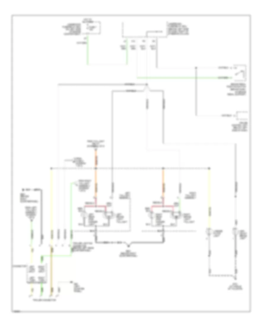
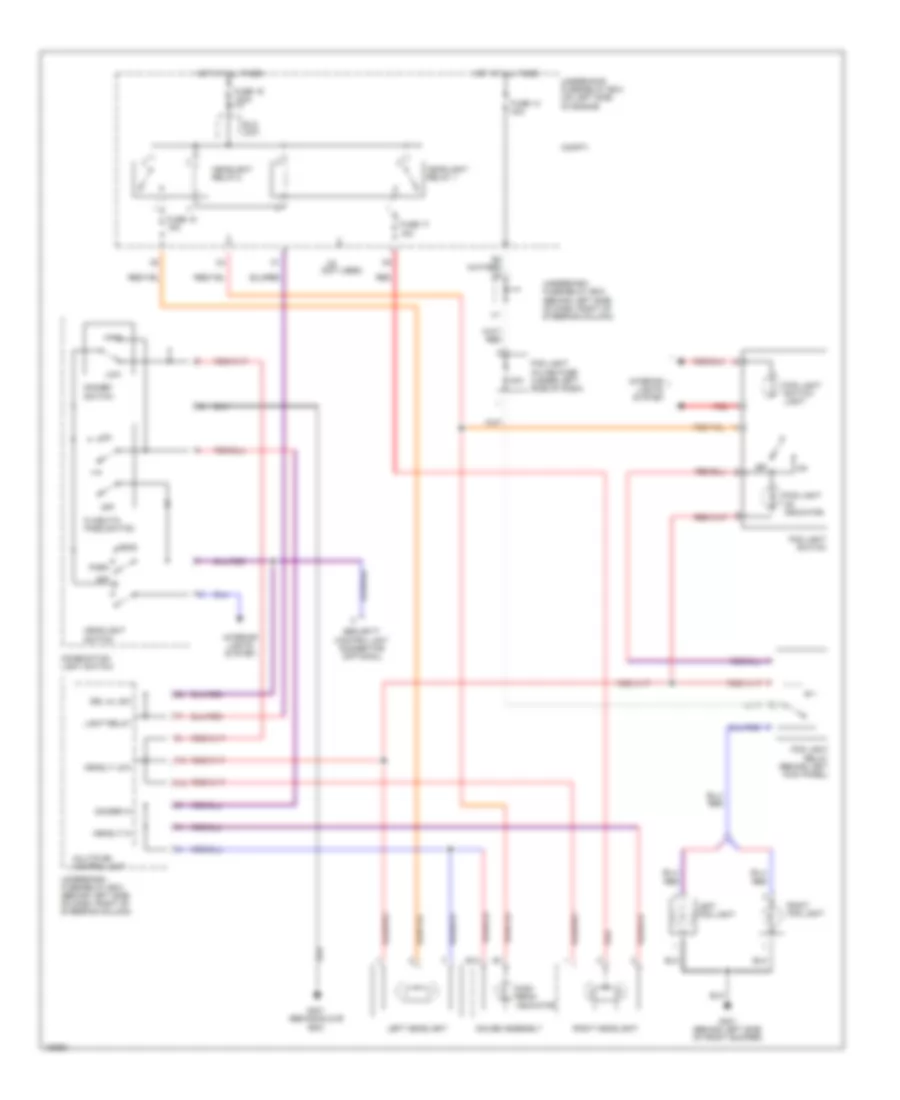
Headlamps Wiring Diagram, without DRL with Single Relay Fog Lamps for Honda CR-V LX 2004
List of elements for Headlamps Wiring Diagram, without DRL with Single Relay Fog Lamps for Honda CR-V LX 2004:
- (not used)
- 20a
- B14
- Combination light switch
- Compt)
- Dimmer hi
- Dimmer switch
- Drl h/l sw
- Eld unit
- F10
- F12
- Flash-to- pass switch
- Fog light in-line fuse (under left side of dash)
- Fog light on indicator
- Fog light relay (behind left kick panel)
- Fog light switch
- Fog light switch light
- Fuse 14 40a
- Fuse 15 15a
- Fuse 17 15a
- Fuse 19 100a
- G301 (behind left side of front bumper)
- G401 (behind glove box)
- Gauge assembly
- Head
- Headlight relay 1
- Headlight relay 2
- Headlight switch
- Headlt hi
- Headlt low
- High
- High beam indicator
- Hot at all times
- Interior lights system
- Left fog light
- Left headlight
- Light relay
- Low
- Multiplex control unit
- Off
- Park
- Red
- Right fog light
- Right headlight
- Security control unit connector (optional)
- Underdash fuse/relay box (behind left side of dash, right of steering column)
- Underhood fuse/relay box (on left side of engine
HORN
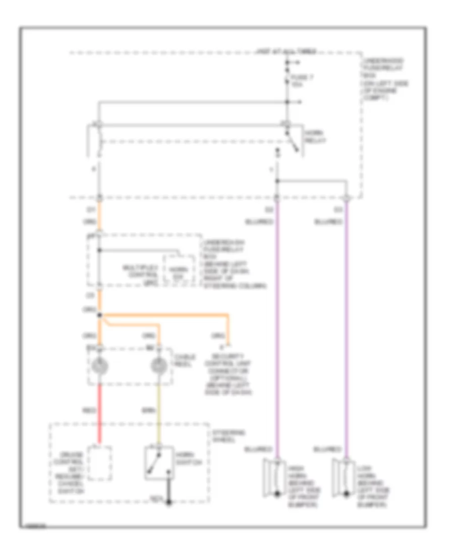
Horn Wiring Diagram for Honda CR-V LX 2004
List of elements for Horn Wiring Diagram for Honda CR-V LX 2004:
- (on left side of engine compt)
- Cable reel
- Cruise control set/ resume/ cancel switch
- Fuse 7 15a
- High horn (behind left side of front bumper)
- Horn relay
- Horn sw
- Horn switch
- Hot at all times
- Low horn (behind left side of front bumper)
- Multiplex control unit
- Nca
- Red
- Security control unit connector (optional) (behind left side of dash)
- Steering wheel
- Underdash fuse/relay box (behind left side of dash, right of steering column)
- Underhood fuse/relay box
INSTRUMENT CLUSTER
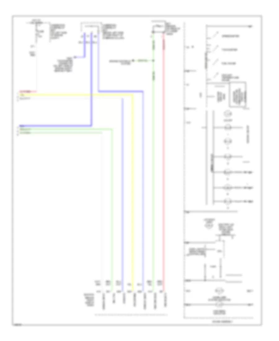
Instrument Cluster Wiring Diagram (1 of 2) for Honda CR-V LX 2004
List of elements for Instrument Cluster Wiring Diagram (1 of 2) for Honda CR-V LX 2004:
- (canada)
- (ex canada: ex-l)
- (side airbag)
- (under right side of dash) g502
- A/t
- A10
- A11
- A12
- A13
- A14
- A15
- A16
- A17
- A18
- A19
- A20
- A21
- A22
- Abs indicator
- Abs indicator circuit
- Abs modulator control unit (on right rear of engine compt)
- Acc radio
- B10
- B11
- B12
- B13
- B14
- B15
- B16
- B17
- B18
- B19
- B20
- B21
- B22
- Beeper
- Brake fluid level switch (on brake fluid reservoir)
- Brake level sw
- Brake system indicator
- Bus (ecu)
- Bus meter
- Canada
- Charging system indicator
- Cpu
- Cruise control indicator
- Cruise control system
- Dash lights brightness controller
- Door indicator light
- Drive circuit
- Drl control unit
- Drl indicator
- E10
- Engine controls system
- Ex, canada:ex-l
- Exterior lights system
- Fuel gauge sending unit
- Fuel tank unit (in top of fuel tank)
- Fuse 10a
- Fuse 7.5a
- G101 (at left side of engine)
- G201 (behind right side of front bumper)
- G301 (behind left side of front bumper)
- G551 (under driver's seat)
- Gauge assembly
- Headlights system
- Hot in acc or on
- Hot in on or start
- Ig1 (meter)
- Immobilizer control unit receiver (on steering column, integral to ignition switch)
- Interior lights system
- Junction connector c103 (at rear of engine)
- K10
- Left turn signal indicator
- Low fuel indicator
- Low oil pressure indicator
- M/t
- Maintenance required indicator
- Mil indicator
- Multiplex control unit
- Oil pressure switch (on right front of engine, above oil filter)
- Outside air temperature sensor (canada)
- Parking brake switch (under left side of dash)
- Pnk
- Power circuit
- Red
- Right turn signal indicator
- Rxd
- Seat belt reminder indicator
- Side air bag cut-off indicator
- Srs indicator
- Srs indicator circuit
- Switch trip/reset
- Tailgate and hatch glass open indicator
- Txd
- Underdash fuse/relay box (behind left side of dash, right of steering column)
- Usa
- Vss (on top left of transaxle)
- Washer fluid level indicator (canada)
- Washer fluid level switch (canada)
Instrument Cluster Wiring Diagram (2 of 2) for Honda CR-V LX 2004
List of elements for Instrument Cluster Wiring Diagram (2 of 2) for Honda CR-V LX 2004:
- (behind right side of dash)
- (canada)
- (usa)
- (vssout)
- A10
- A13
- A18
- B10
- B14
- B15
- B22
- Bus (sefmj)
- Coolant temperature gauge
- Cpu
- D11
- Dash lights brightness controller
- Dimming circuit
- Drive circuit
- Driver circuit
- E24
- E25
- E26
- E31
- Ecm/pcm
- Ect sensor (on rear of cylinder head)
- Engine controls system
- Fuel gauge
- Fuse 10a
- Gauge assembly
- High beam indicator
- Hot at all times
- Immobilizer system indicator
- Lcd back light
- Mil ctrl
- O/d off
- Odo/trip display
- Odo/trip lcd back light stabilizing power circuit
- Odo/trip/ outside air temperature display
- Rpm out (nep)
- Sensor input
- Sns gnd (sg2)
- Sns in (ect)
- Speedometer
- Tachometer
- Test tachometer connector (on left side of engine compt, near battery)
- Underdash fuse/relay box (behind left side of dash,right of steering column)
- Underhood fuse/relay box (on left side of engine compt)
INTERIOR LIGHTS
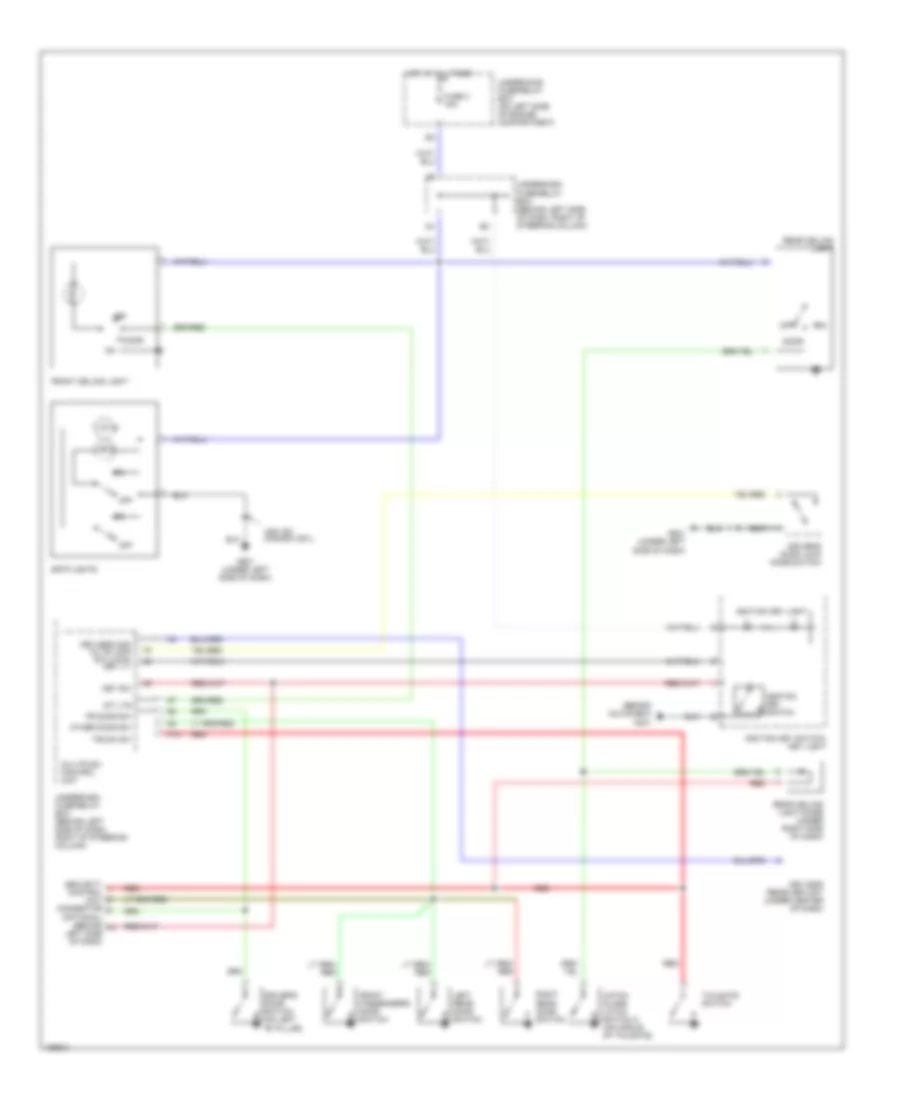
Courtesy Lamps Wiring Diagram for Honda CR-V LX 2004
List of elements for Courtesy Lamps Wiring Diagram for Honda CR-V LX 2004:
- (behind glove box)
- Door
- Driver's door lock knob switch
- Driver's door switch (on left "b" pillar)
- Fr door sw
- Front ceiling light
- Front passenger's door switch
- Fuse 3 15a
- G401
- G501 (under left side of dash)
- Hatch glass latch switch 2 (on middle of tailgate)
- Hot at all times
- Ignition key light
- Ignition key switch
- Ignition key switch/ key light
- Int lts
- Key sw
- Keyless com d/l sil-con sw (lock) key lt-
- Keyless receiver unit (under center of dash)
- Left rear door switch
- Multiplex control unit
- Off
- Other door sw
- P18
- Rear ceiling light
- Rear ceiling light diode (under right side of dash)
- Red
- Right rear door switch
- Security control unit connector (optional) (behind left side of dash)
- Spotlights
- Tailgate switch
- Trunk sw
- Underdash fuse/relay box (behind left side of dash, right of steering column)
- Underhood fuse/relay box (on left side of engine compartment)
- Usa: ex canada: ex-l
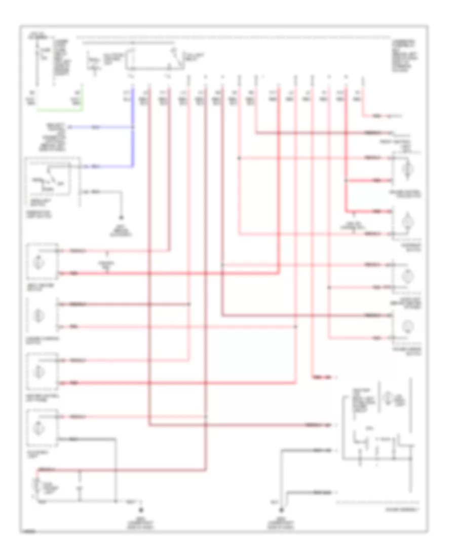
Instrument Illumination Wiring Diagram for Honda CR-V LX 2004
List of elements for Instrument Illumination Wiring Diagram for Honda CR-V LX 2004:
- A19
- Audio unit (behind center of dash)
- B15
- C11
- Canada: ex-l
- Coin pocket light
- Combination light switch
- Cpu
- Cruise control main switch
- Front ashtray light (a/t)
- Fuse 15a
- G401 (behind glove box)
- G502 (under right side of dash)
- Gauge assembly
- Glove box light
- Hazard warning switch
- Head
- Headlight switch
- Heater control unit panel
- Hot at all times
- K11
- K17
- L10
- Lcd back light
- M/t
- Moonroof switch
- Multiplex control unit
- O10
- Odo/trip lcd back light stabilizing power circuit
- Off
- Park
- Power mirror switch
- Red
- Seat heater switch
- Security control unit connector (optional) (behind left side of dash)
- Small lt rly-
- Taillight relay
- Under hood fuse/ relay box (on left side of engine compt)
- Underdash fuse/relay box (behind left side of dash, right of steering column)
- Usa: ex canada: ex-l
POWER DISTRIBUTION
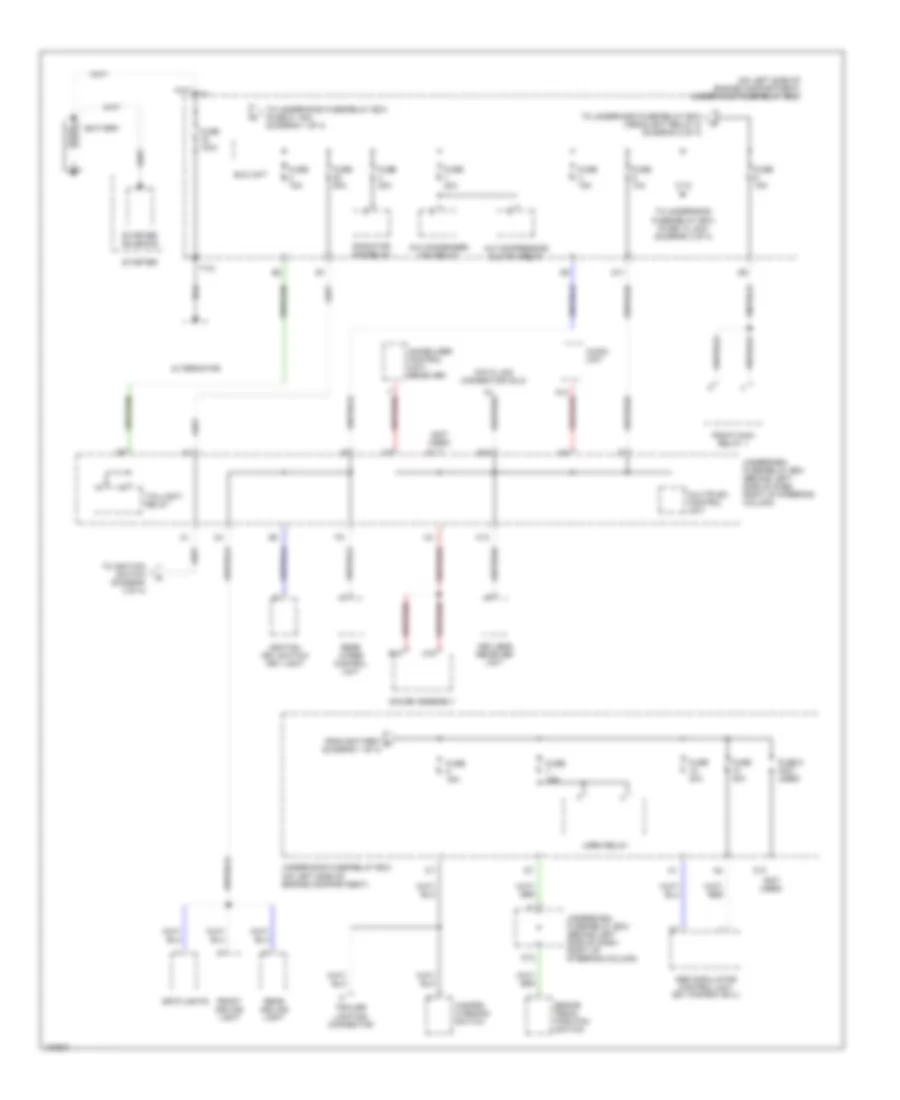
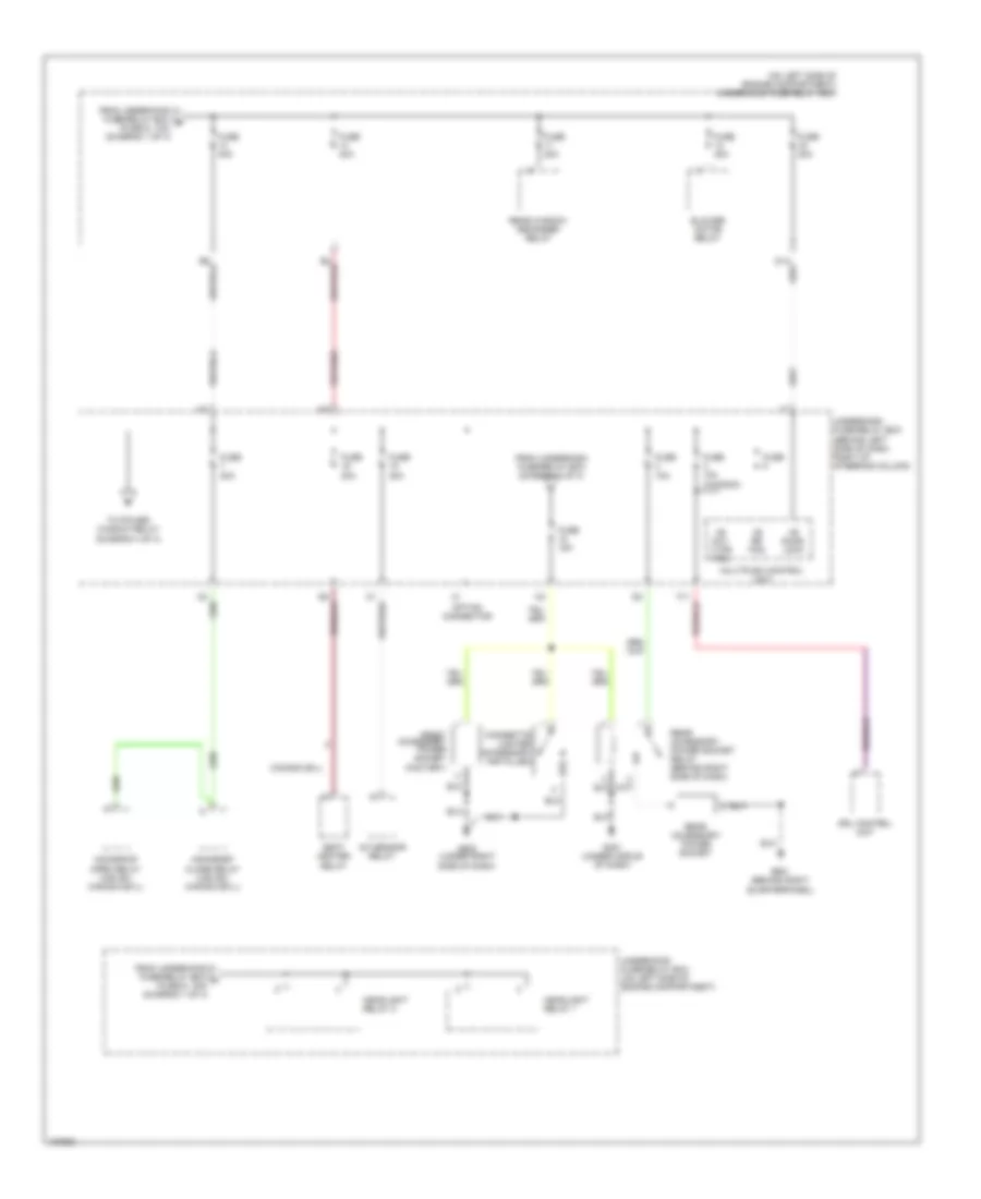
Power Distribution Wiring Diagram (1 of 4) for Honda CR-V LX 2004
List of elements for Power Distribution Wiring Diagram (1 of 4) for Honda CR-V LX 2004:
- (not used)
- (on left side of engine compartment) underhood fuse/relay box
- A/c compressor clutch relay
- A/c condenser fan relay
- A19
- Abs modulator control unit (ex, canada: ex-l)
- Alternator
- Audio unit
- B10
- Battery
- Brake pedal position switch
- C10
- D11
- Data link connector (dlc)
- E12
- Eld unit
- From battery a (diagram 1 of 4)
- Front ceiling light
- Fuse 100a
- Fuse 10a
- Fuse 15a
- Fuse 20a
- Fuse 30a
- Fuse 50a
- Fuse 8 (not used)
- Gauge assembly
- Hazard warning switch
- Horn relay
- Ignition key switch/ key light
- Immobilizer control unit- receiver
- K13
- Keyless receiver unit
- Multiplex control unit
- O12
- Pgm-fi main relay 1
- Radiator fan relay
- Rear ceiling light
- Rear wiper control unit
- Spotlights
- Starter
- Starter solenoid
- T101
- Taillight relay
- To ignition switch (diagram 3 of 4)
- To underhood fuse/relay box (fuse 13, 40a) (diagram 2 of 4)
- To underhood fuse/relay box (fuse 5, 15a) (diagram 1 of 4)
- To underhood fuse/relay box (headlight relay 2) (diagram 2 of 4)
- Trailer lighting connector
- Underdash fuse/relay box (behind left side of dash, right of steering column)
- Underhood fuse/relay box (on left side of engine compartment)
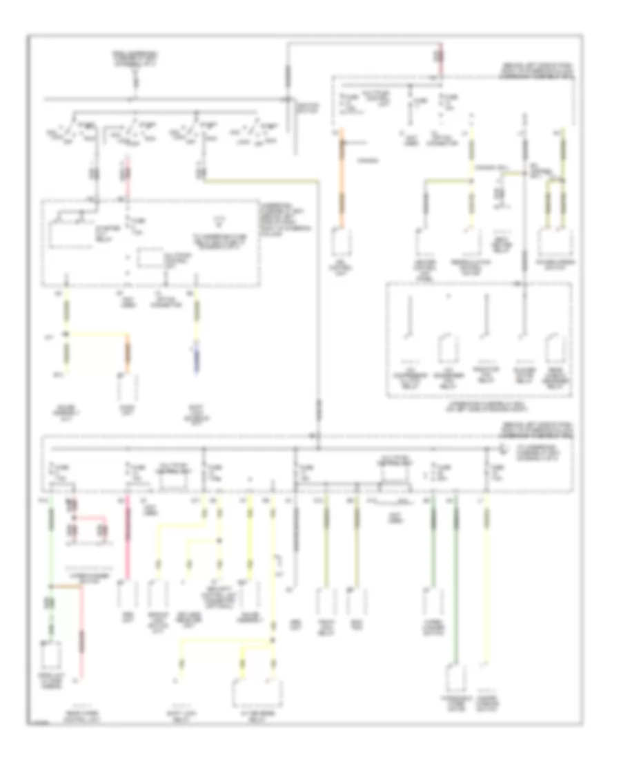
Power Distribution Wiring Diagram (2 of 4) for Honda CR-V LX 2004
List of elements for Power Distribution Wiring Diagram (2 of 4) for Honda CR-V LX 2004:
- (behind left side of dash, right of steering column)
- (on left side of engine compartment) underhood fuse/relay box
- +b day lt/fr fog
- +b door lock
- +b rr fog
- A/f sensor relay
- Blower motor relay
- Canada ex-l
- Cigarette lighter (accessory installed)
- Drl control unit
- From underdash fuse/relay box (diagram 3 of 4)
- From underhood fuse/relay box b (fuse 9, 10a) (diagram 1 of 4)
- From underhood fuse/relay box c (fuse 6, 15a) (diagram 1 of 4)
- Front accessory power socket (factory)
- Fuse
- Fuse 10a
- Fuse 10a (canada)
- Fuse 15a
- Fuse 20a
- Fuse 40a
- G451 (under middle of dash)
- G502 (under right side of dash)
- G601 (behind right quarterpanel)
- Headlight relay 1
- Headlight relay 2
- Moonroof close relay (usa ex, canada ex-l)
- Moonroof open relay (usa ex, canada ex-l)
- Multiplex control unit
- Option connector
- Rear accessory power socket
- Rear accessory power socket relay (behind right side of dash)
- Rear window defogger relay
- Seat heater relay
- To power window relay (diagram 4 of 4)
- Underdash fuse/relay box
- Underhood fuse/relay box (on left side of engine compartment)
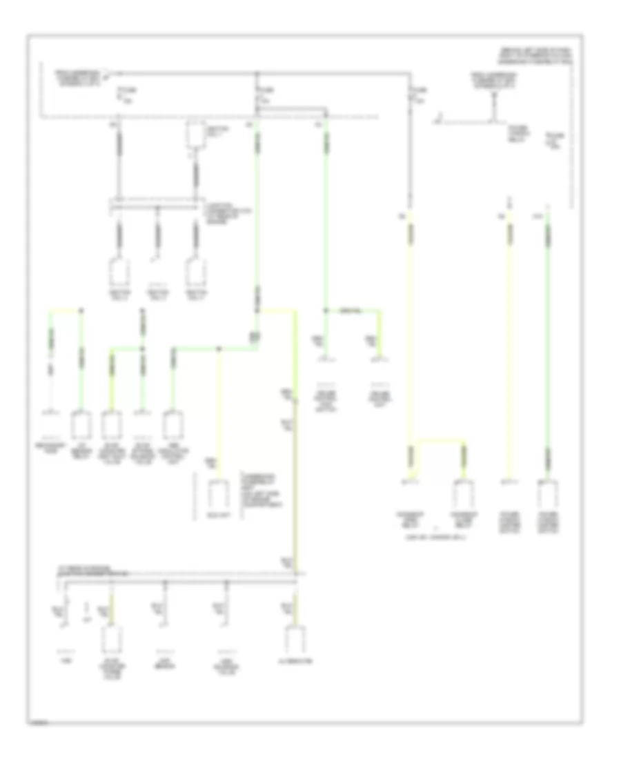
Power Distribution Wiring Diagram (3 of 4) for Honda CR-V LX 2004
List of elements for Power Distribution Wiring Diagram (3 of 4) for Honda CR-V LX 2004:
- (behind left side of dash, right of steering column) underdash fuse/relay box
- (not used)
- A/c compressor clutch relay
- A/c condenser fan relay
- A/t
- A/t reverse relay
- A18
- Acc
- Audio unit
- B13
- B4 red/
- Backup light switch (m/t)
- Blower motor relay
- Canada
- Canada: ex-l
- D11
- D12
- Drl control unit
- Ecm/ pcm
- Ex, canada: ex-l
- From underdash fuse/relay box (diagram 1 of 4)
- Fuse
- Fuse 10a
- Fuse 15a
- Fuse 20a
- Fuse 7.5a
- Gauge assembly
- Gauge assembly (a/t)
- Hazard warning switch
- Heater control unit panel
- Ignition switch
- K12
- K14
- Keyless receiver unit
- Lock off
- Multiplex control unit
- Opds unit (w/ side airbag)
- Option connector
- P12
- Pgm-fi main relay
- Power mirror switch
- Radiator fan relay
- Rear window defogger relay
- Rear wiper control unit
- Recirculation control motor
- Run
- Seat heater relay
- Security control unit connector (optional)
- Shift lock relay
- Shift lock solenoid (a/t)
- Srs unit
- Start
- Starter cut relay
- To underdash fuse/relay box (diagram 4 of 4)
- To underdash fuse relay box fuse 18 (diagram 2 of 4)
- Underdash fuse/relay box (behind left side of dash, right of steering column)
- Underhood fuse/relay box (on left side of engine compt)
- Windshield wiper motor
- Wiper/ washer switch
- Wiper/washer switch
Power Distribution Wiring Diagram (4 of 4) for Honda CR-V LX 2004
List of elements for Power Distribution Wiring Diagram (4 of 4) for Honda CR-V LX 2004:
- (at rear of engine) junction connector c103
- (behind left side of dash, right of steering column) underdash fuse/relay box
- (usa: ex, canada: ex-l)
- A/f sensor relay
- Abs modulator control unit
- Alternator
- Cmp sensor
- Cruise control main switch
- Cruise control unit
- Eld unit
- Evap bypass solenoid valve
- Evap canister purge valve
- Evap canister vent shut valve
- From underdash fuse/relay box (diagram 2 of 4)
- From underdash g fuse/relay box (diagram 3 of 4)
- Fuse 10a
- Fuse 15a
- Fuse 20a
- Fuse 7.5a
- Ignition coil 1
- Ignition coil 2
- Ignition coil 3
- Ignition coil 4
- Imrc solenoid valve
- Junction connector c103 (at rear of engine)
- M/t
- M10
- Moonroof close relay
- Moonroof open relay
- Power window master switch
- Power window relay
- Secondary ho2s
- Underhood fuse/relay box (on left side of engine compartment)
- Vss
POWER DOOR LOCKS
Power Door Locks Wiring Diagram for Honda CR-V LX 2004
List of elements for Power Door Locks Wiring Diagram for Honda CR-V LX 2004:
- Back up (b+)
- D11
- D14
- Door lock (b+)
- Driver's door lock actuator (in driver's door)
- Driver's door lock knob switch
- Driver's door lock switch
- Driver's door switch (on left "b" pillar)
- Fr door sw (dr)
- Front passenger's door lock actuator (in front passenger's door)
- Front passenger's door lock switch
- Front passenger's door switch
- Fuse 10a
- Fuse 20a
- Fuse 7.5a
- G301 (behind left side of front bumper)
- G401 (behind glove box)
- G501 (under left side of dash)
- G502 (under right side of dash)
- Ground
- Horn sw
- Horns system
- Hot at all times
- Hot in on or start
- Ignition key switch
- Ignition key switch/key light
- K13
- Key sw
- Keyless com
- Keyless receiver unit (under middle of dash)
- Left rear door lock actuator
- Left rear door switch
- Lock
- Multiplex control unit
- Other door sw
- P16
- P17
- P18
- Rear ceiling light diode (under right side of dash)
- Red
- Right rear door lock actuator
- Right rear door switch
- Security control unit connector (optional) (behind left side of dash)
- Tailgate lock actuator (in tailgate)
- Tailgate switch
- Trunk switch
- Underdash fuse/relay box (behind left side of dash, right of steering column)
- Underhood fuse/relay box (on left side of engine compartment)
- Unlock
- Y10
- Y12
POWER MIRRORS
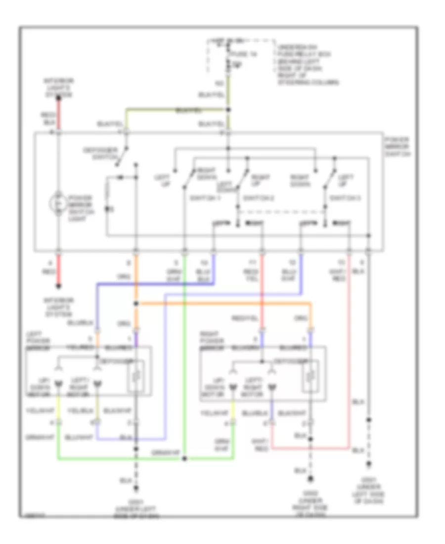
Power Mirrors Wiring Diagram, with Defogger for Honda CR-V LX 2004
List of elements for Power Mirrors Wiring Diagram, with Defogger for Honda CR-V LX 2004:
- 10a
- Defogger
- Defogger switch
- Fuse 14
- G501 (under left side of dash)
- G502 (under right side of dash)
- Hot in on
- Interior lights system
- Left
- Left down
- Left power mirror
- Left up
- Left/ right motor
- Power mirror switch
- Power mirror switch light
- Red
- Right
- Right down
- Right power mirror
- Right up
- Switch 1
- Switch 2
- Switch 3
- Underdash fuse/relay box (behind left side of dash, right of steering column)
- Up/ down motor
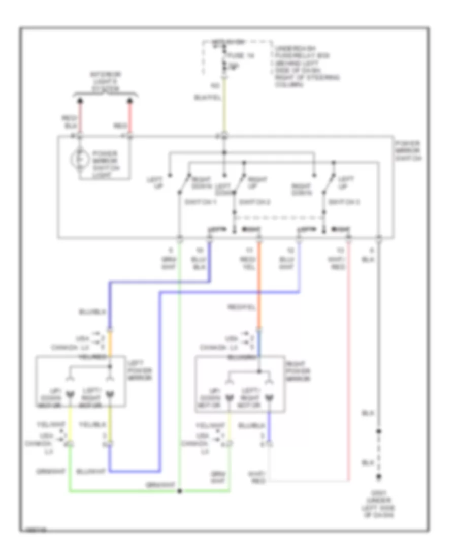
Power Mirrors Wiring Diagram, without Defogger for Honda CR-V LX 2004
List of elements for Power Mirrors Wiring Diagram, without Defogger for Honda CR-V LX 2004:
- 10a
- Canada: lx
- Fuse 14
- G501 (under left side of dash)
- Hot in on
- Interior lights system
- Left
- Left down
- Left power mirror
- Left up
- Left/ right motor
- Power mirror switch
- Power mirror switch light
- Red
- Right
- Right down
- Right power mirror
- Right up
- Switch 1
- Switch 2
- Switch 3
- Underdash fuse/relay box (behind left side of dash, right of steering column)
- Up/ down motor
- Usa
- Usa canada: lx
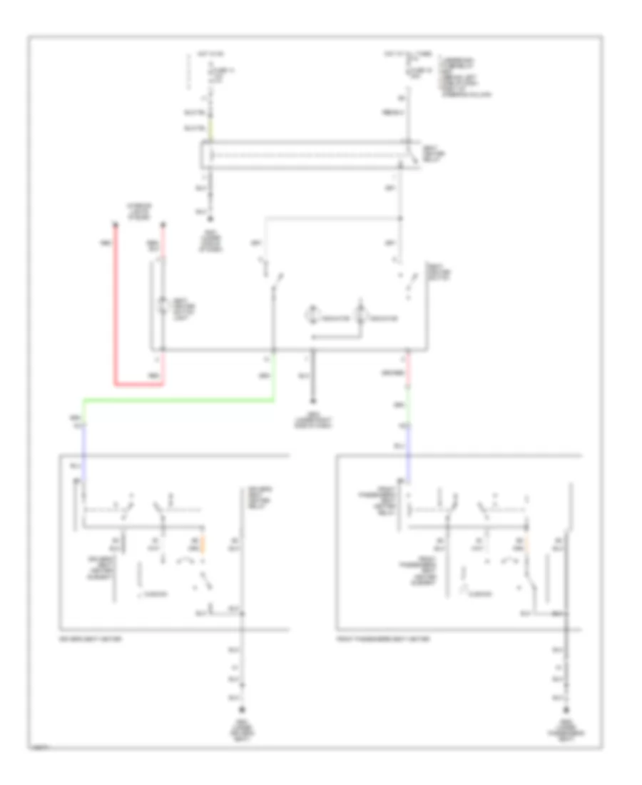
POWER SEATS
Power Seats Wiring Diagram, Canada for Honda CR-V LX 2004
List of elements for Power Seats Wiring Diagram, Canada for Honda CR-V LX 2004:
- Cushion
- Driver's seat heater
- Driver's seat heater element
- Driver's seat heater relay
- Front passenger's seat heater
- Front passenger's seat heater element
- Front passenger's seat heater relay
- Fuse 14 10a
- Fuse 16 20a
- G451 (under middle of dash)
- G502 (under right side of dash)
- G551 (under driver's seat)
- G552 (under passenger's seat)
- Hot at all times
- Hot in on
- Indicator
- Interior lights system
- Red
- Seat heater relay
- Seat heater switch
- Seat heater switch light
- Underdash fuse/relay box (behind left side of dash, right of steering column)
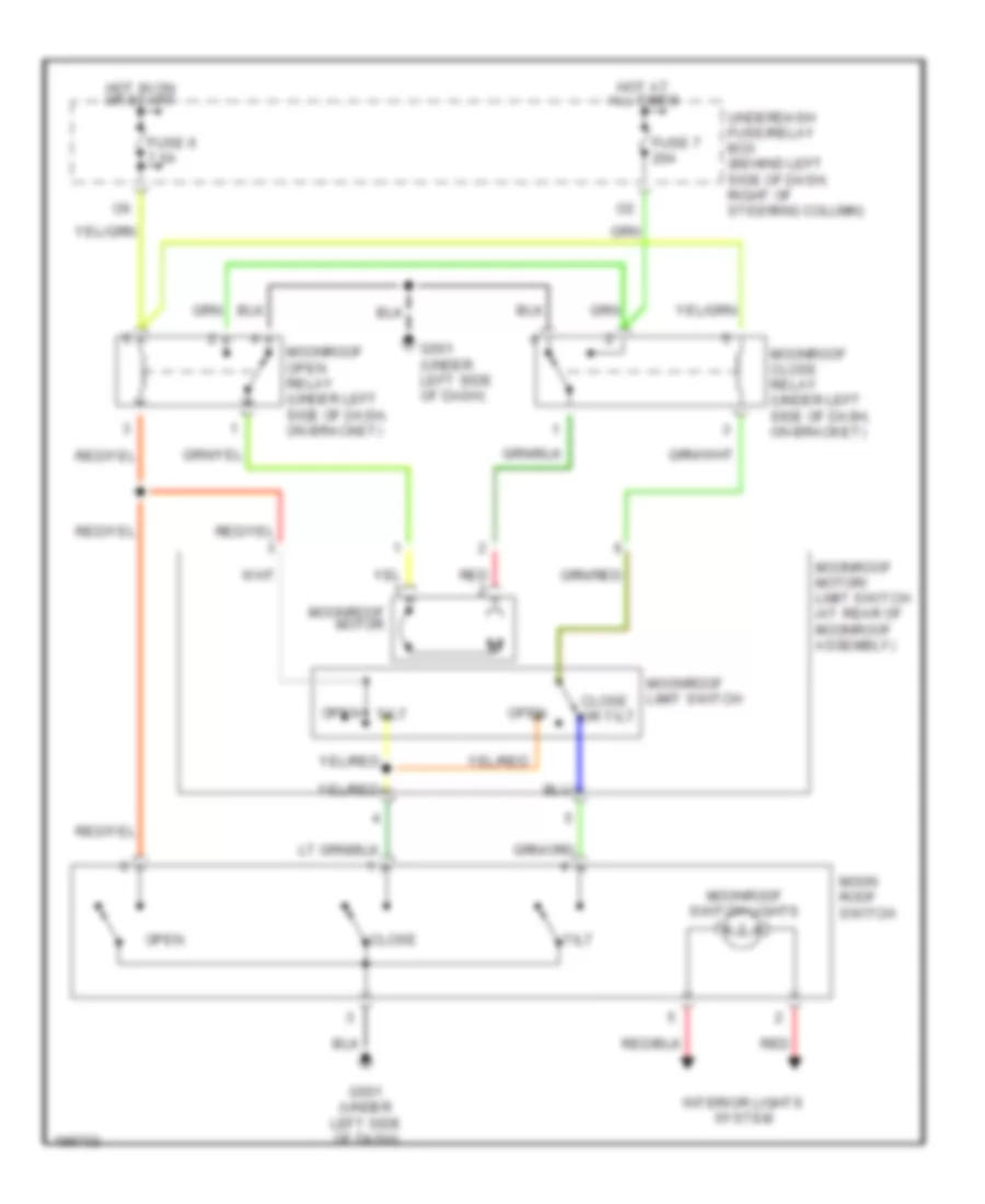
POWER TOP/SUNROOF
Power Top/Sunroof Wiring Diagram for Honda CR-V LX 2004
List of elements for Power Top/Sunroof Wiring Diagram for Honda CR-V LX 2004:
- Close
- Close or tilt
- Fuse 6 7.5a
- Fuse 7 20a
- G501 (under left side of dash)
- Hot at all times
- Hot in on or start
- Interior lights system
- Moon roof switch
- Moonroof close relay (under left side of dash, on bracket)
- Moonroof limit switch
- Moonroof motor
- Moonroof motor/ limit switch (at rear of moonroof assembly)
- Moonroof open relay (under left side of dash, on bracket)
- Moonroof switch lights
- Open
- Open tilt
- Red
- Tilt
- Underdash fuse/relay box (behind left side of dash, right of steering column)
POWER WINDOWS
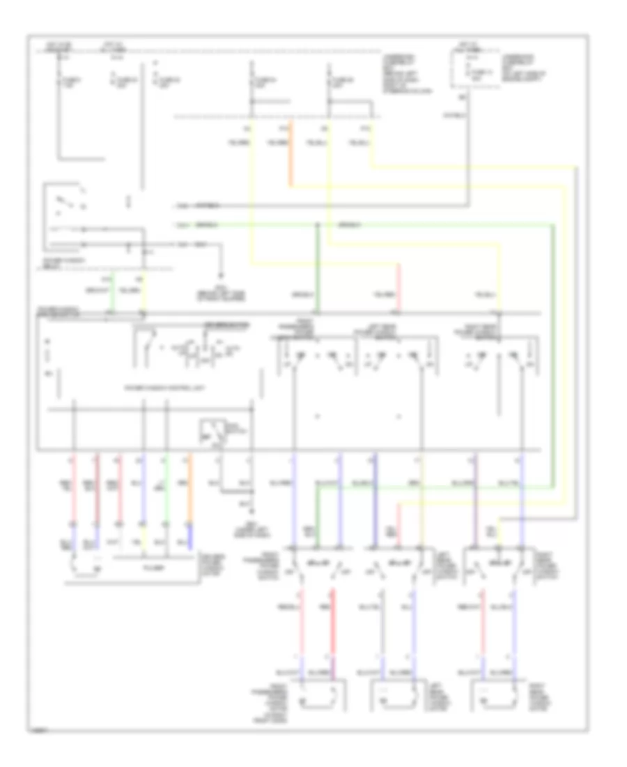
Power Windows Wiring Diagram for Honda CR-V LX 2004
List of elements for Power Windows Wiring Diagram for Honda CR-V LX 2004:
- 40a
- Auto dn
- Auto up
- Driver's power window motor
- Driver's switch
- Front passenger's power window motor (in right front door)
- Front passenger's power window switch
- Fuse 13
- Fuse 22 20a
- Fuse 23 20a
- Fuse 24 20a
- Fuse 25 20a
- Fuse 6 7.5a
- G301 (behind left side of front bumper)
- G501 (under left side of dash)
- Hot at all times
- Hot in on or start
- Left rear power window motor
- Left rear power window switch
- M10
- M11
- Main switch
- Off
- P10
- P13
- Power window control unit
- Power window master switch
- Power window relay
- Pulser
- Red
- Right rear power window motor
- Right rear power window switch
- Underdash fuse/relay box (behind left side of dash, right of steering column)
- Underhood fuse/relay box (on left side of engine compt)
RADIO
Radio Wiring Diagram, Except LX for Honda CR-V LX 2004
List of elements for Radio Wiring Diagram, Except LX for Honda CR-V LX 2004:
- (behind center of dash) audio unit
- (on left side of engine compt)
- A/t
- A10
- A11
- A12
- A13
- A14
- A15
- A16
- A17
- A18
- A19
- A20
- Acc radio
- Antenna input
- B+ back up
- Batt in
- D11
- Dim ctrl +
- Dim ctrl -
- Driver's door speaker
- Front passenger's door speaker
- Fuse 8 7.5a
- Fuse 9 10a
- G503 (behind glove box)
- Ground
- Hot at all times
- Hot in acc or on
- Interior lights system
- Left rear door speaker
- Left tweeter
- Lf (+)
- Lf (-)
- Lr (+)
- Lr (-)
- Mast antenna
- Multiplex control unit
- Nca
- Pnk
- Red
- Rf (+)
- Rf (-)
- Right rear door speaker
- Right tweeter
- Rr (+)
- Rr (-)
- Sw ign
- Underdash fuse/relay box (behind left side of dash, right of steering column)
- Underhood fuse/relay box
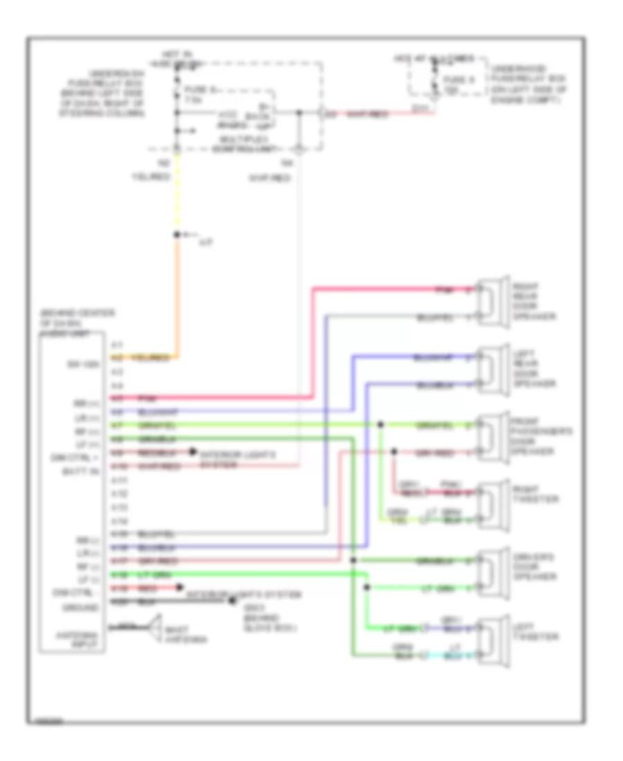
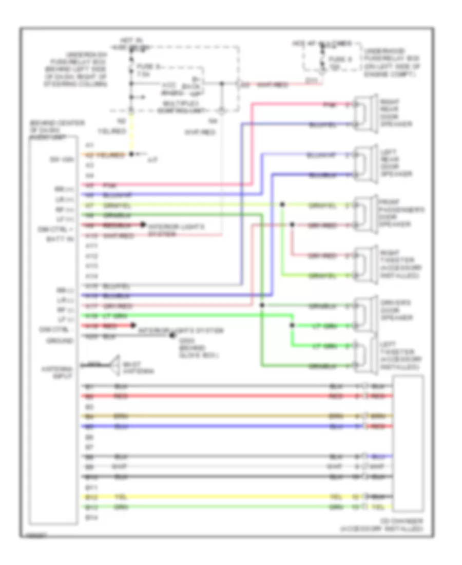
Radio Wiring Diagram, LX for Honda CR-V LX 2004
List of elements for Radio Wiring Diagram, LX for Honda CR-V LX 2004:
- (behind center of dash) audio unit
- (on left side of engine compt)
- A/t
- A10
- A11
- A12
- A13
- A14
- A15
- A16
- A17
- A18
- A19
- A20
- Acc radio
- Antenna input
- B+ back up
- B10
- B11
- B12
- B13
- B14
- Batt in
- Cd changer (accessory installed)
- D11
- Dim ctrl +
- Dim ctrl -
- Driver's door speaker
- Front passenger's door speaker
- Fuse 8 7.5a
- Fuse 9 10a
- G503 (behind glove box)
- Ground
- Hot at all times
- Hot in acc or on
- Interior lights system
- Left rear door speaker
- Left tweeter (accessory installed)
- Lf (+)
- Lf (-)
- Lr (+)
- Lr (-)
- Mast antenna
- Multiplex control unit
- Nca
- Pnk
- Red
- Rf (+)
- Rf (-)
- Right rear door speaker
- Right tweeter (accessory installed)
- Rr (+)
- Rr (-)
- Sw ign
- Underdash fuse/relay box (behind left side of dash, right of steering column)
- Underhood fuse/relay box
Radio Wiring Diagram, with Subwoofer for Honda CR-V LX 2004
List of elements for Radio Wiring Diagram, with Subwoofer for Honda CR-V LX 2004:
- 7.5a
- A/t
- A10
- A11
- A12
- A13
- A14
- A15
- A16
- A17
- A18
- A19
- A20
- Acc radio
- Ant in
- Audio unit (behind center of dash)
- B+ back up
- Batt in
- D11
- Dim
- Driver's door speaker
- Front passenger's door speaker
- Fuse 10a
- Fuse 7.5a
- G503 (behind
- Glove box)
- Ground
- Hot at all times
- Hot in acc or on
- Hot in on
- Ign input
- Interior lights system
- Junction connector c110 (behind glove box)
- Left rear door speaker
- Left tweeter (ex, canada: ex-l)
- Lf (+)
- Lf (-)
- Lr (+)
- Lr (-)
- Mast antenna
- Multiplex conrol unit
- Nca
- Pnk
- Red
- Rf (+)
- Rf (-)
- Right rear door speaker
- Right tweeter (ex, canada: ex-l)
- Rr (+)
- Rr (-)
- Sub on in
- Subwoofer
- Subwoofer in-line fuse 1 (under left side of dash)
- Subwoofer in-line fuse 2 (under left side of dash)
- Subwoofer switch
- Sw ign
- Underdash fuse/relay box (behind left side of dash, right of steering column)
- Underdash fuse/relay box connector (behind left side of dash, right of steering column)
- Underhood fuse/relay box (on left side of engine compartment)
- V2 (not used)
- V3 (not used)
SHIFT INTERLOCK
Shift Interlock Wiring Diagram for Honda CR-V LX 2004
List of elements for Shift Interlock Wiring Diagram for Honda CR-V LX 2004:
- (bksw) switch input
- (not used)
- Acc radio
- Atp -n
- Atp -p
- Brake pedal position switch (behind dash, on brake pedal support)
- D10
- E13
- E22
- Fuse 15a
- Fuse 7.5a
- G10
- G101 (at left side of engine)
- G301 (behind left side of front bumper)
- G401 (behind glove box)
- G451 (under middle of dash)
- Gauge assembly
- Gnd
- Hot at all times
- Hot in acc or on
- Hot in on or start
- Ig1 meter
- Ignition key switch
- Ignition key switch/ key light
- Ilu
- Interlock control output
- Key interlock solenoid
- Key lock sol +
- Key sw
- Multiplex control unit
- O12
- P pin sw
- Park pin switch
- Pcm (behind right side of dash)
- Security control unit connector (optional) (behind left side of dash)
- Shift lock diode (behind glove box)
- Shift lock relay (a/t :behind right side of dash)
- Shift lock sol
- Shift lock solenoid
- Stop sw
- Transmission range switch (on lower rear of transaxle)
- Underdash fuse/relay box (behind left side of dash, right of steering column)
- Underhood fuse/relay box (on left side of engine compt)
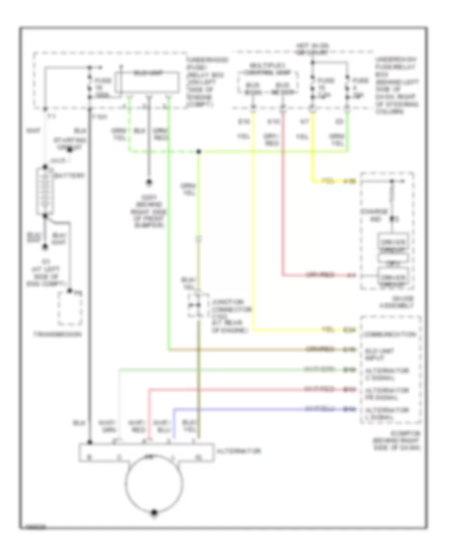
STARTING/CHARGING
Charging Wiring Diagram for Honda CR-V LX 2004
List of elements for Charging Wiring Diagram for Honda CR-V LX 2004:
- A18
- Alternator
- Alternator c signal
- Alternator fr signal
- Alternator l signal
- B10
- B13
- B18
- Battery
- Bus (ecu)
- Bus meter
- Charge
- Communication
- Cpu
- Driver circuit
- E10
- E15
- E24
- Ecm/pcm (behind right side of dash)
- Eld unit
- Eld unit input
- Fuse 100a
- Fuse 10a
- Fuse 7.5a
- G1 (at left side of eng compt)
- G201 (behind right side of front bumper)
- Gauge assembly
- Hot in on or start
- Ind
- Junction connector c103 (at rear of engine)
- K10
- Multiplex control unit
- Starting circuit
- T101
- Transmission
- Underdash fuse/relay box (behind left side of dash, right of steering column)
- Underhood fuse/ relay box (on left side of engine compt)
Starting Wiring Diagram for Honda CR-V LX 2004
List of elements for Starting Wiring Diagram for Honda CR-V LX 2004:
- (not used)
- A/t
- Acc
- Battery
- Clutch interlock switch (on clutch pedal support)
- E11
- Eld unit
- Fuse 19 100a
- Fuse 20 50a
- Fuse 21
- G1 (left side of engine compt)
- G101 (at left side of engine)
- G502 (under right side of dash)
- Ignition switch
- Lock
- M/t
- Off
- Start
- Starter
- Starter cut relay
- Starter motor
- Starter solenoid
- Transmission
- Transmission range switch (on lower rear of transaxle)
- Underdash fuse/relay box (behind left side of dash, right of steering column)
- Underhood fuse/relay box (on left side of engine compartment)
SUPPLEMENTAL RESTRAINTS
Supplemental Restraints Wiring Diagram (1 of 2) for Honda CR-V LX 2004
List of elements for Supplemental Restraints Wiring Diagram (1 of 2) for Honda CR-V LX 2004:
- (not used)
- (under driver's seat) g551
- (under middle of dash) g451
- (under passenger's seat) g552
- A10
- A11
- A12
- A13
- A14
- A15
- A16
- A17
- A18
- B10
- B11
- B12
- B13
- B14
- B15
- B16
- B17
- B18
- Bsdh
- Bsdl
- Bsph
- Bspl
- Buck- led
- Cable reel
- Computer data lines system
- Diag-h
- Dlc (under left side of dash)
- Dr belt sw
- Driver's air bag first inflator
- Driver's air bag second inflator
- Driver's seat air bag inflator (w/ side air bag) (under driver's seat)
- Driver's seat belt buckle tensioner (under driver's seat)
- Driver's seat belt switch (in driver's seat belt buckle)
- Driver's side impact sensor (w/ side air bag) (at base of left "b" pillar)
- Front passenger's seat belt buckle tensioner (under front passenger's seat)
- Front passenger's seat belt switch (under front passenger's seat)
- Front passenger's side air bag inflator (w/ side air bag) (under front passenger's seat)
- Front passenger's side impact sensor (w/ side air bag) (at base of right "b" pillar)
- Frsl
- Frsr
- Fuse 10a
- Fuse 15a
- G402 (under middle of dash)
- Gnda
- Gndb
- Hot in on or start
- Ign in
- Mes con
- Mes connector (under left side of dash)
- Multiplex control unit
- Odus
- P14
- Pnk
- Red
- Sadc1
- Sadc2
- Sadh1
- Sadh2
- Sapc1
- Sapc2
- Saph1
- Saph2
- Sbplc
- Sbplh
- Sbprc
- Sbprh
- Scs
- Sdg
- Sdv
- Short contact
- Spg
- Spv
- Srplc
- Srplh
- Srprc
- Srprh
- Srs ind
- Srs unit (below center of dash)
- Ssdc
- Ssdh
- Sspc
- Ssph
- Steering wheel
- Un- buck led
- Underdash fuse/relay box (behind left side of dash, right of steering column)
Supplemental Restraints Wiring Diagram (2 of 2) for Honda CR-V LX 2004
List of elements for Supplemental Restraints Wiring Diagram (2 of 2) for Honda CR-V LX 2004:
- (under passenger's seat) g552
- (under right side of dash) g502
- A18
- A20
- B15
- B16
- Driver's seat belt tensioner (at left "b" pillar)
- Front passenger's air bag first inflator (behind right side of dash)
- Front passenger's air bag second inflator (behind right side of dash)
- Front passenger's seat belt tensioner (at right "b" pillar)
- Fuse 7.5a
- G402 (under middle of dash)
- Gauge assembly
- Gnd
- Hot in on or start
- Left front impact sensor (behind left side of front bumper)
- Lower element (lower 4 sensors in seat back)
- Odus
- Opds sensor (w/ side air bag)
- Opds unit (w/ side air bag) (in front passenger's seat)
- P12
- Pnk
- Pow
- Red
- Right front impact sensor (behind right side of front bumper)
- Sb1l, sb1s
- Sb2l, sb2s
- Sb3l, sb3s
- Sb4l, sb4s
- Sb5l, sb5s
- Sb6l, sb6s
- Short contact
- Side air bag off indicator
- Side element (right side of seat back)
- Srs indicator
- Srs indicator circuit
- Ss1l, ss1s
- Underdash fuse/relay box (behind left side of dash, right of steering column)
- Upper element (upper two sensors in seat back)
- Wrn
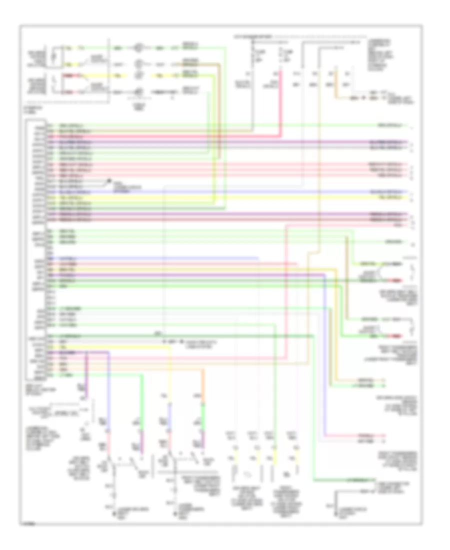
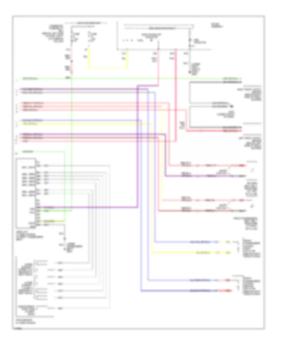
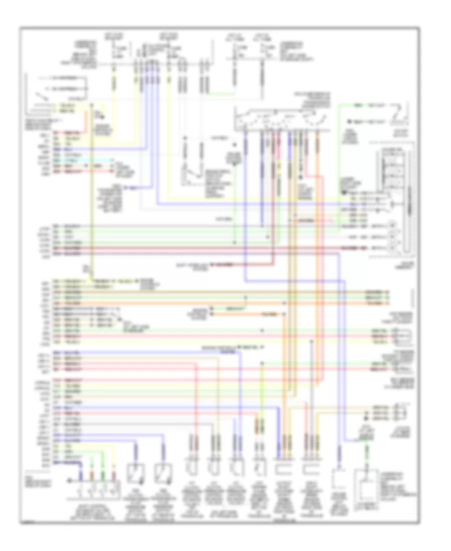
TRANSMISSION
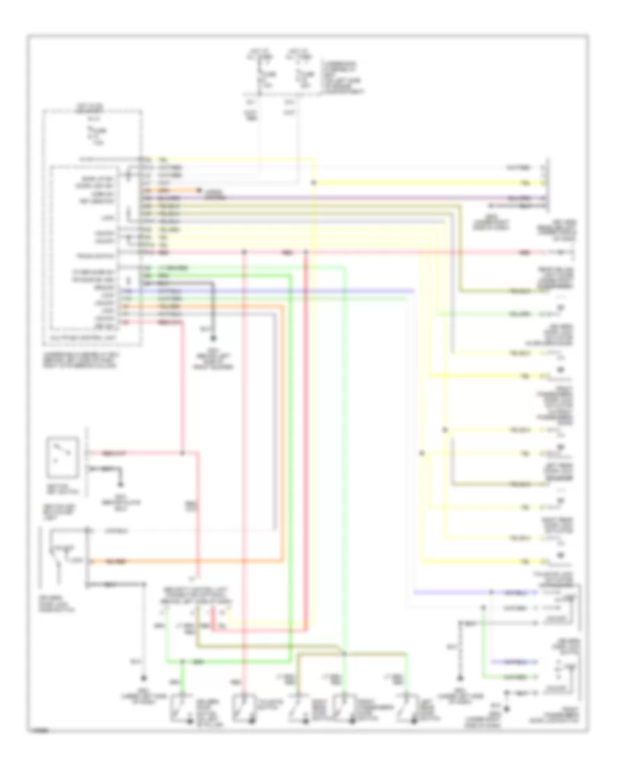
A/T Wiring Diagram for Honda CR-V LX 2004
List of elements for A/T Wiring Diagram for Honda CR-V LX 2004:
- (at rear of transaxle)
- (on left side of transaxle)
- (on lower rear of transaxle) transmission range switch
- (under right side of dash) g502
- 2nd clutch transmission fluid pressure switch (at top of transaxle)
- 3rd clutch transmission fluid pressure switch
- A/t clutch pressure control solenoid valve a (on top of transaxle)
- A/t clutch pressure control solenoid valve b
- A/t clutch pressure control solenoid valve c
- A10
- A11
- A14
- A15
- A16
- A18
- A19
- A20
- A21
- A23
- A24
- Atf temper- ature sensor (on servo body, in bottom of transaxle)
- Atft
- Atp1
- Atp2
- Atpd
- Atpfwd
- Atpn
- Atpp
- Atpr
- Atprvs
- B14
- B16
- B24
- Bksw
- Brake pedal position switch (behind dash, on brake pedal support)
- C10
- C11
- C12
- C13
- C14
- C15
- C16
- C18
- C19
- Ccs
- Cpu
- Cruise control system
- Cruise control unit (below left side of dash)
- D10
- D12
- Dimming circuit
- Dlc (under left side of dash)
- Drive circuit
- E10
- E22
- E23
- E24
- E26
- E29
- E30
- Ect
- Ect sensor (on rear of cylinder head)
- Ecu
- Engine controls system
- Fuse 15a
- Fuse 7.5a
- G101 (at left side of engine)
- G451 (under middle of dash)
- Gauge assembly
- Hot at all times
- Hot in on or start
- Ig1
- Igp1
- Igp2
- Input shaft (mainshaft) speed sensor (on rear right side of transaxle)
- J/c c103 (at rear of engine)
- K-line
- K10
- Lg1
- Lg2
- Lsa (+)
- Lsa (-)
- Lsb (+)
- Lsb (-)
- Lsc (+)
- Lsc (-)
- Map
- Map sensor (on top of throttle body)
- Meter
- Mrly
- Multiplex control unit
- Nep
- O/d off ind
- O/d off switch
- O12
- Od sw
- Op2sw
- Op3sw
- Output shaft (counter- shaft) speed sensor (on front right side of transaxle)
- Pcm (behind right side of dash)
- Pg1
- Pg2
- Pgm-fi main relay 1 (behind right side of dash)
- Pnk
- Red
- Scs
- Sefmj
- Sg1
- Sg2
- Sha
- Shb
- Shc
- She
- Shift control solenoid valves (on servo body, in bottom of transaxle)
- Shift interlock system
- Starter cut relay
- Test tachometer connector (on left side of engine compt, near battery)
- Tp sensor (on right side of throttle body)
- Tps
- Underdash fuse/relay box (behind left side of dash, right of steering column)
- Underhood fuse/relay box (on left side of engine compt)
- Vcc1
- Vcc2
- Wen
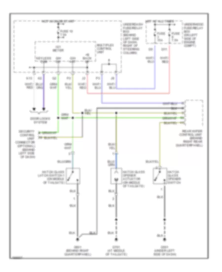
TRUNK, TAILGATE, FUEL DOOR
Liftglass Release Wiring Diagram for Honda CR-V LX 2004
List of elements for Liftglass Release Wiring Diagram for Honda CR-V LX 2004:
- +b back up
- D11
- Door locks system
- Fuse 10 7.5a
- Fuse 15a
- Fuse 7.5a
- G/h act
- G/h sw
- G501 (under left side of dash)
- G601 (behind right quarterpanel)
- G701 (at middle of tailgate)
- Hatch glass latch switch 1 (on middle of tailgate)
- Hatch glass opener actuator (on middle of tailgate)
- Hatch glass opener switch
- Hot at all times
- Hot in on or start
- Ig1 meter
- K13
- Keyless com
- Multiplex control unit
- Rear wiper control unit (behind right rear quarterpanel)
- Security control unit connector (optional) (behind left side of dash)
- Underdash fuse/relay box (behind left side of dash, right of steering column)
- Underhood fuse/relay box (on left side of engine compt)
WARNING SYSTEMS
Warning Systems Wiring Diagram for Honda CR-V LX 2004
List of elements for Warning Systems Wiring Diagram for Honda CR-V LX 2004:
- (below center of dash) srs unit
- (ig) key lt (-)
- (not used)
- (on right rear of engine compt) (ex, canada: ex-l) abs modulator control unit
- +b backup
- A18
- Alternator
- Altl
- B10
- Beeper
- Bus meter
- C11
- Canada: ex-l
- Combination light switch
- Cpu
- D11
- Door ind
- Drive circuit
- Driver door switch
- Driver seat belt/srs
- Driver's door switch (on left "b" pillar)
- Driver's seat belt switch (in driver's seat belt buckle)
- E10
- E24
- Ebd
- Ecm/pcm (behind right side of dash)
- Exterior lights system
- Fuse 10a
- Fuse 15a
- Fuse 7.5a
- G401 (behind glove box)
- G502 (under right side of dash)
- G551 (under driver's seat)
- Gauge assembly
- Ground
- Head
- Headlight switch
- Hot at all times
- Hot in on or start
- Ig1 meter
- Ignition key light
- Ignition key switch
- Ignition key switch/ key light
- Illumination (+)
- K10
- Key switch input
- Low oil
- Multiplex bus
- Multiplex control unit
- Off
- Oil pressure switch (on right front of engine, above oil filter)
- P15
- Park
- Pressure ind
- Seat belt reminder ind
- Security control unit connector (optional) (behind left side of dash)
- Small lt rly-
- Taillight relay
- Underdash fuse/relay box (behind left side of dash, right of steering column)
- Underhood fuse/relay box (on left side of engine compt)
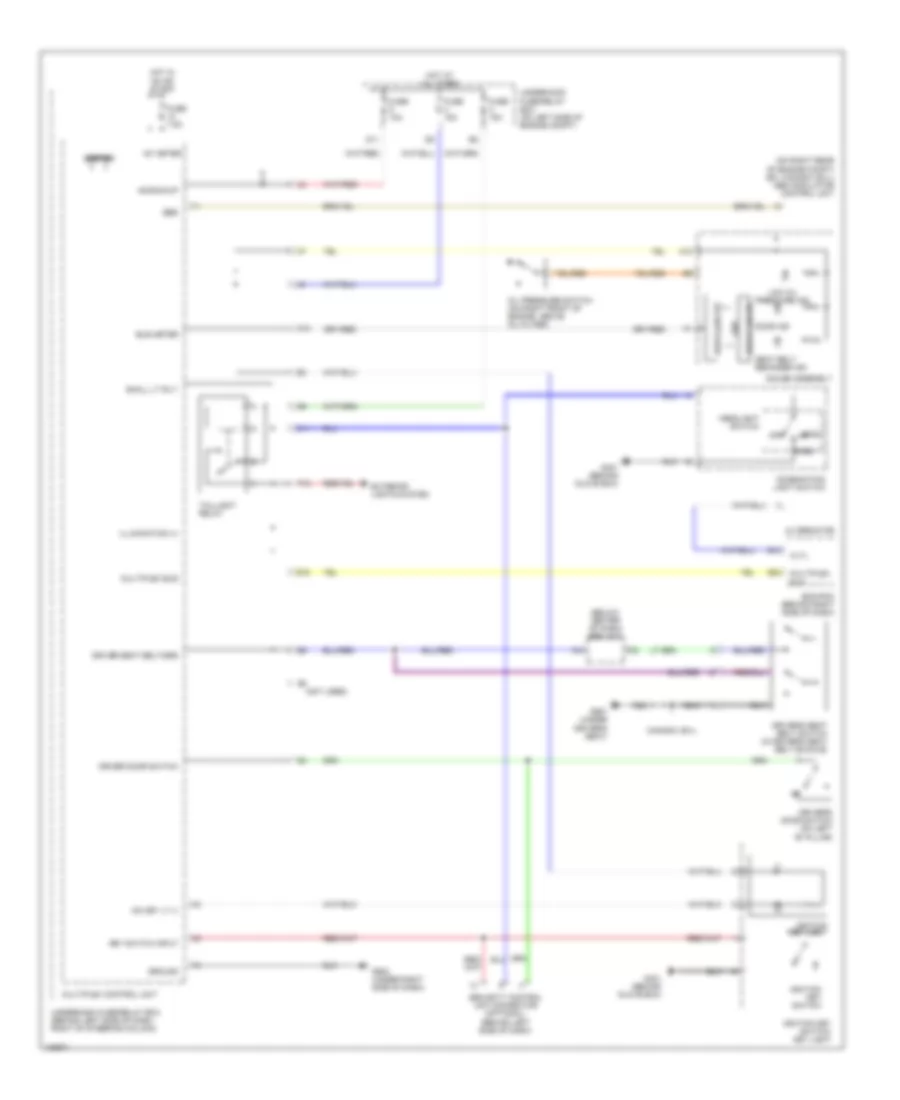
WIPER/WASHER
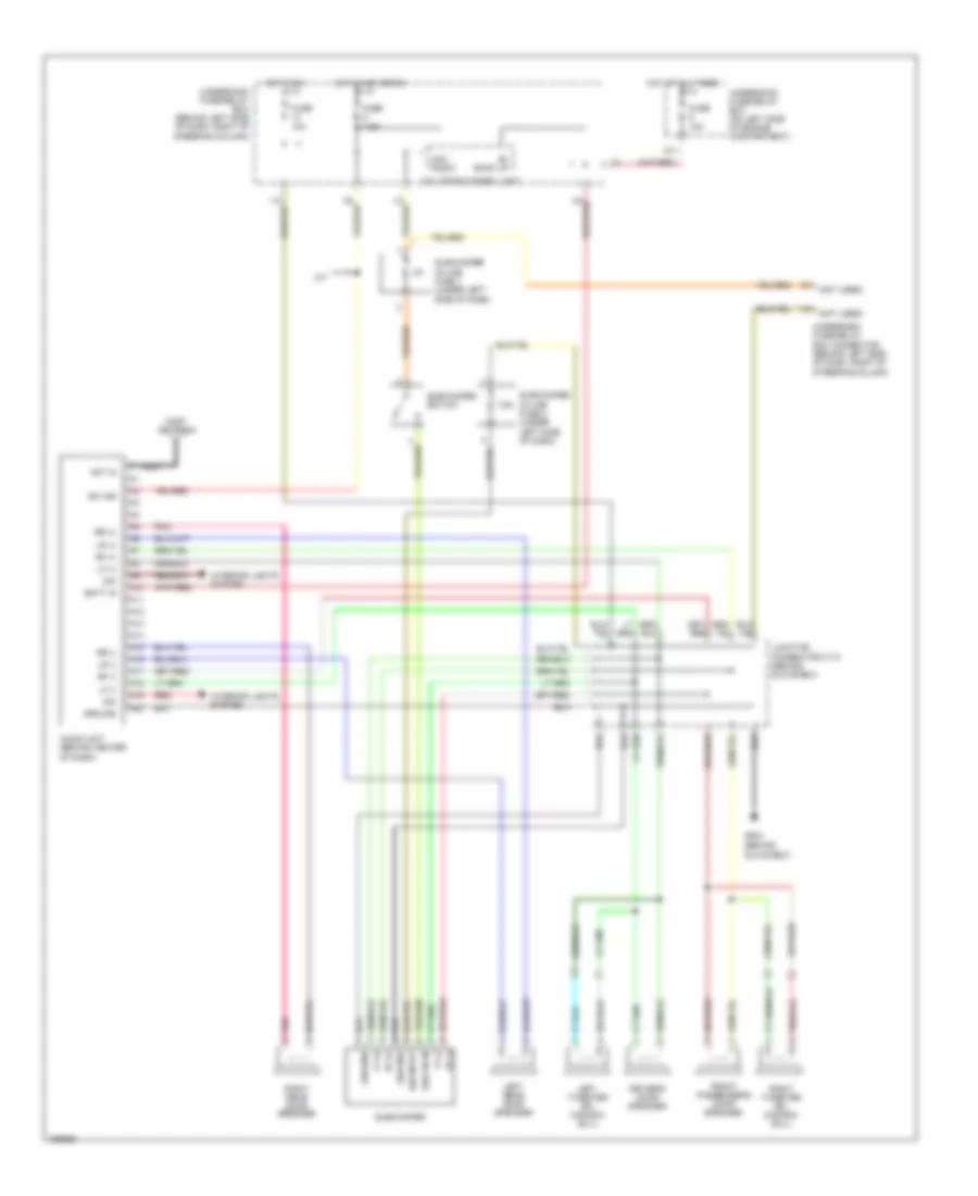
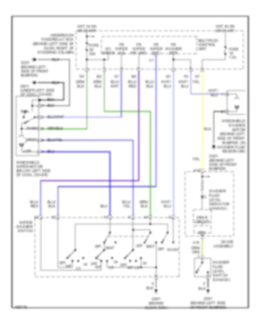
Front Wiper/Washer Wiring Diagram for Honda CR-V LX 2004
List of elements for Front Wiper/Washer Wiring Diagram for Honda CR-V LX 2004:
- A10
- A18
- Cpu
- Drive circuit
- Fr washer mtr
- Fr wiper (as)
- Fr wiper (int)
- Fr wiper int unit
- Fuse 20a
- Fuse 7.5a
- G301 (behind left side of front bumper)
- G401 (behind glove box)
- G811 (under left side of cowl cover)
- Gauge assembly
- High
- Hot in on or start
- Ig1 wiper
- Int
- Low
- Mist
- Multiplex control unit
- Off
- Park
- Run
- Underdash fuse/relay box (behind left side of dash, right of steering column)
- Wash
- Washer fluid level indicator (canada)
- Washer fluid level switch (canada)
- Windshield washer motor (behind left side of front bumper, on washer fluid reservoir)
- Windshield wiper motor (below left side of cowl cover)
- Wiper/ washer switch
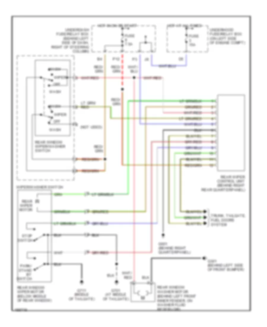
Rear Wiper/Washer Wiring Diagram for Honda CR-V LX 2004
List of elements for Rear Wiper/Washer Wiring Diagram for Honda CR-V LX 2004:
- (not used)
- Fuse 15a
- Fuse 7.5a
- G301 (behind left side of front bumper)
- G601 (behind right quarterpanel)
- G701 (at middle of tailgate)
- G711 (middle of tailgate)
- Hot at all times
- Hot in on or start
- Off
- P12
- Park/ stand by switch
- Rear window washer motor (behind left front inner fender, on washer fluid reservoir)
- Rear window wiper motor (below middle of rear window)
- Rear window wiper/washer switch
- Rear wiper control unit (behind right rear quarterpanel)
- Rear wiper motor
- Stop switch
- Trunk, tailgate, fuel doors system
- Underdash fuse/relay box (behind left side of dash, right of steering column)
- Underhood fuse/relay box (on left side of engine compt)
- Wash
- Wiper
- Wiper/washer switch