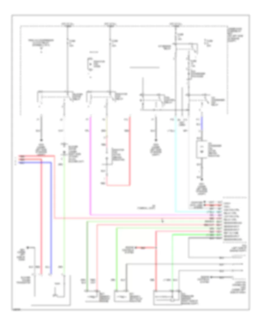
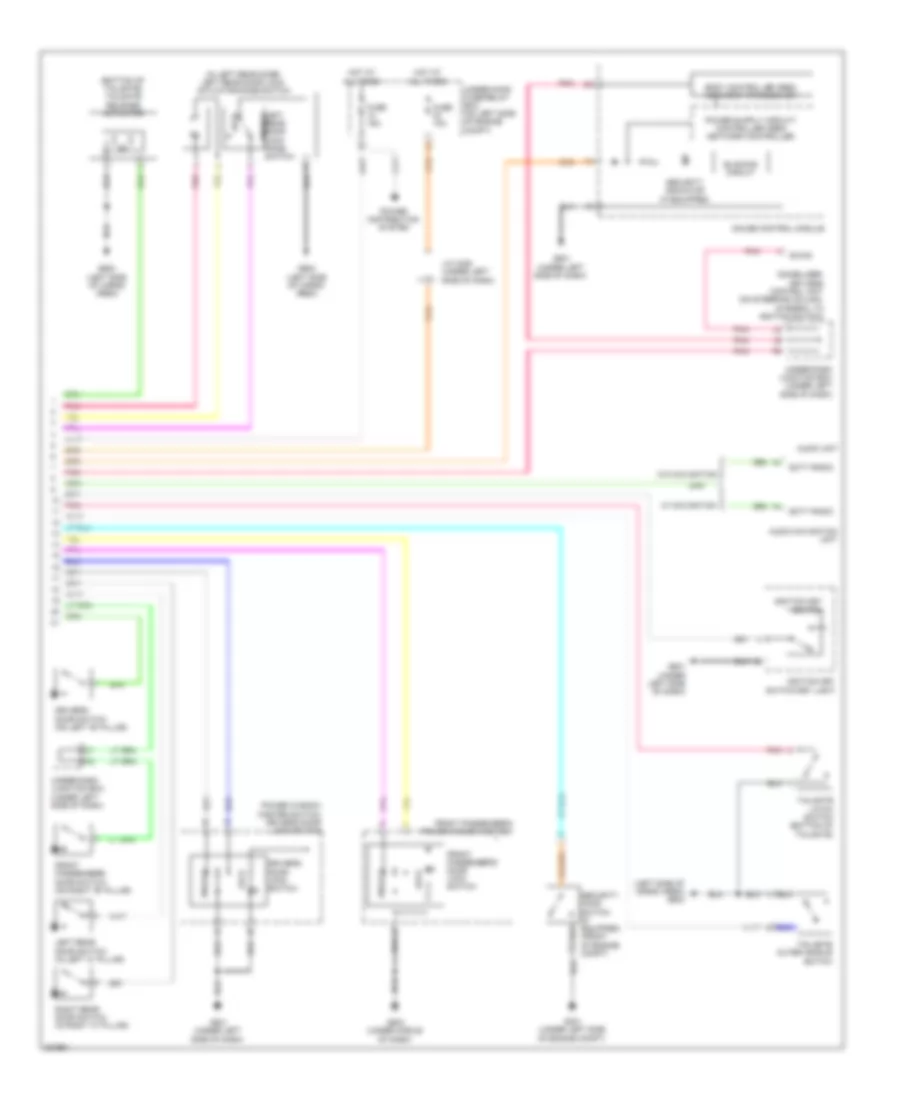
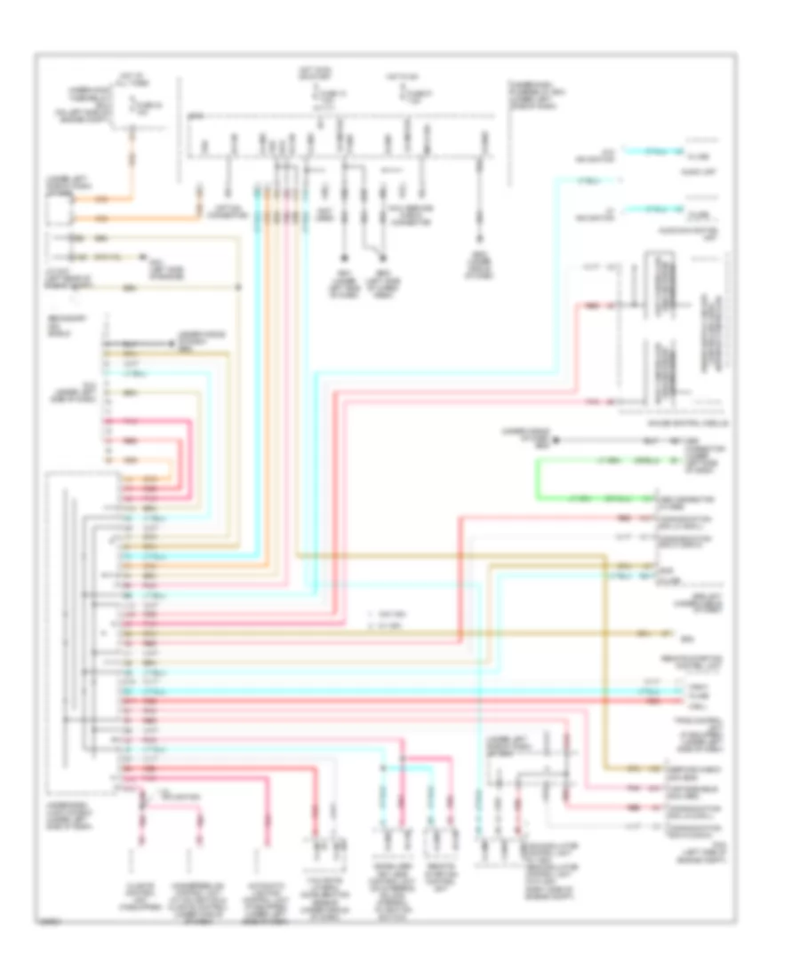
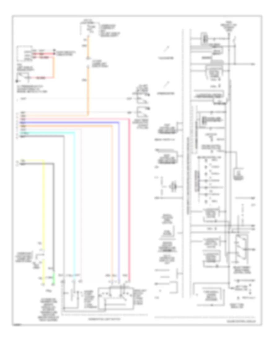
AIR CONDITIONING
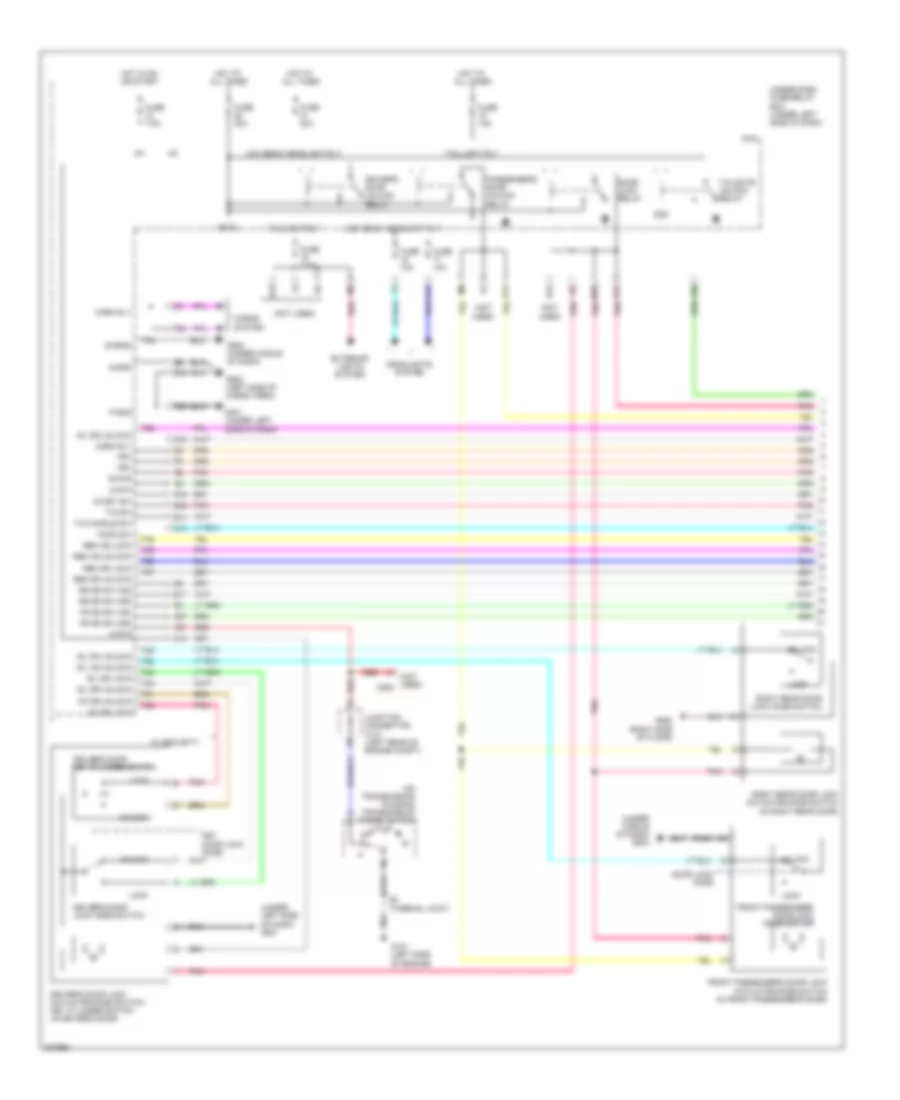
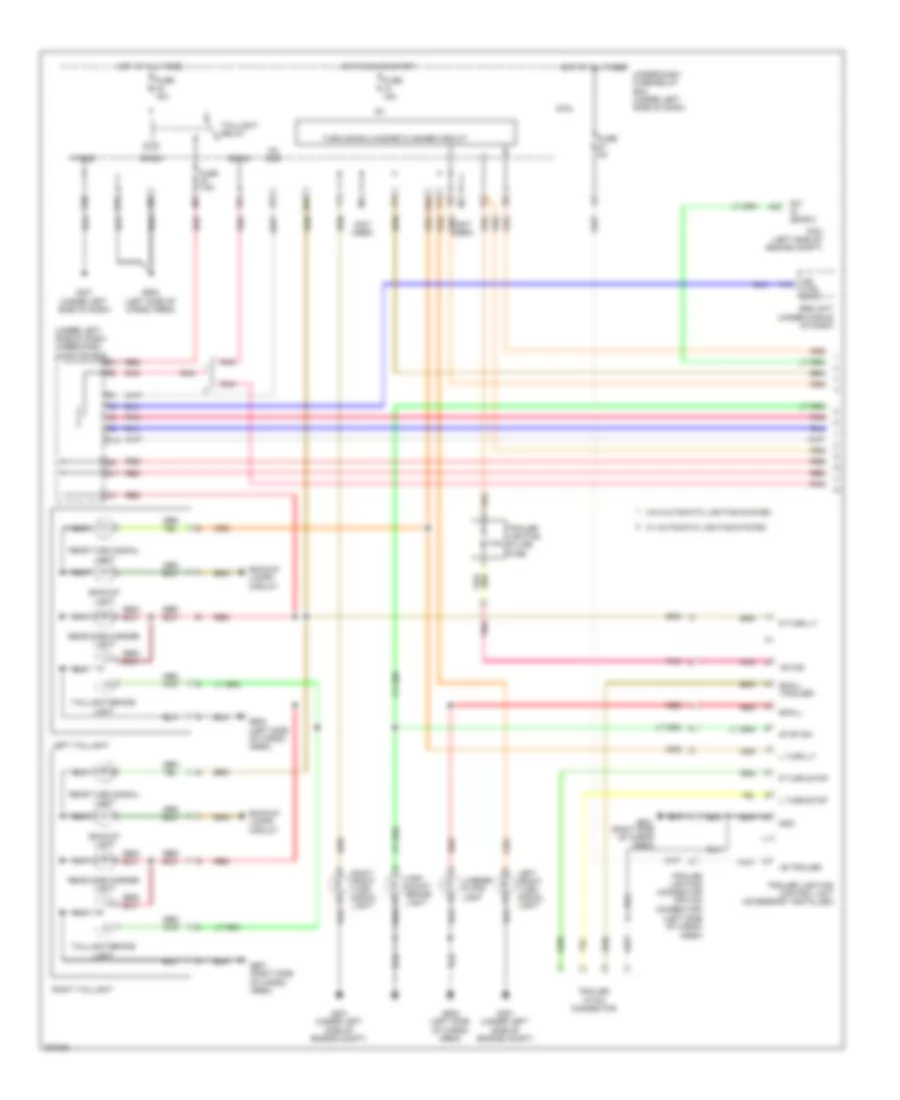
Automatic A/C Wiring Diagram (1 of 2) for Honda CR-V LX 2010

List of elements for Automatic A/C Wiring Diagram (1 of 2) for Honda CR-V LX 2010:
- (lower left front of engine) a/c compressor
- (under left side of dash) under-dash junction box
- (under middle of dash) g503
- A/c compressor clutch
- A/c compressor clutch relay
- A13
- Acs
- Am- d
- Am- p
- Amd-p
- B-can
- B13
- B20
- B21
- Blw-g
- Blw-v
- Climate control unit
- Computer data lines system
- Defog sw
- Defogger system
- Driver's air mix control motor (under left side of dash, on hvac unit)
- Evaporator temperature sensor (under middle of dash)
- F/r d-p
- F20
- F26
- Front passenger's air mix control motor (under right side of dash)
- Frs
- Fuse 10a
- Fuse 7.5a
- G12
- Gnd
- H- hot
- Hot at all times
- Hot in on
- Ig2
- Ig2 hac
- Ill-
- In-car temperature sensor (in left side of dash)
- Interior lights
- Junction connector c101 (left rear of engine compt)
- M- cool
- M- def
- M- hot
- M- vent
- M-cool
- M-def
- M-frs
- M-hot
- M-rec
- M-vent
- Micu
- Mode
- Mode 1
- Mode 2
- Mode 3
- Mode 4
- Mode control motor (behind right side of dash, on hvac unit)
- N11
- Navi-clk
- Navi-si acs
- Navi-so
- Navigation system
- Option connector
- Outside air temperature sensor (behind middle of front bumper)
- Pnk
- Rec
- Recirculation control motor (behind right side of dash, on blower unit)
- Red
- Rfd-p
- S5v
- Sens gnd
- Sens-com
- Small
- Sunlight sensor (top center of dash)
- System
- Tam
- Teva
- Thermal protector
- To blower motor relay (diagram 2 of 2)
- Tsun
- Under-dash fuse/relay box (under left side of dash)
- Under-hood fuse/relay box (on left side of engine compt)
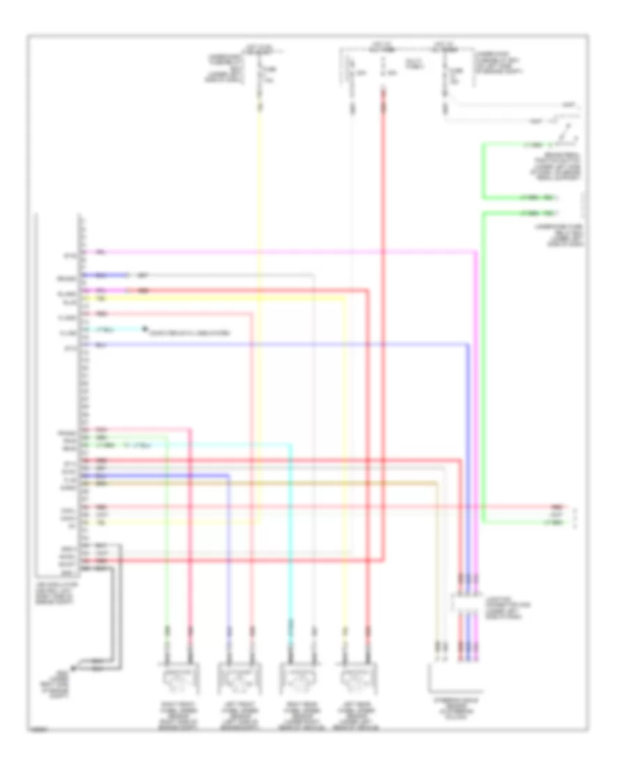
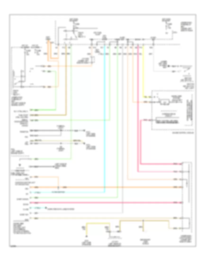
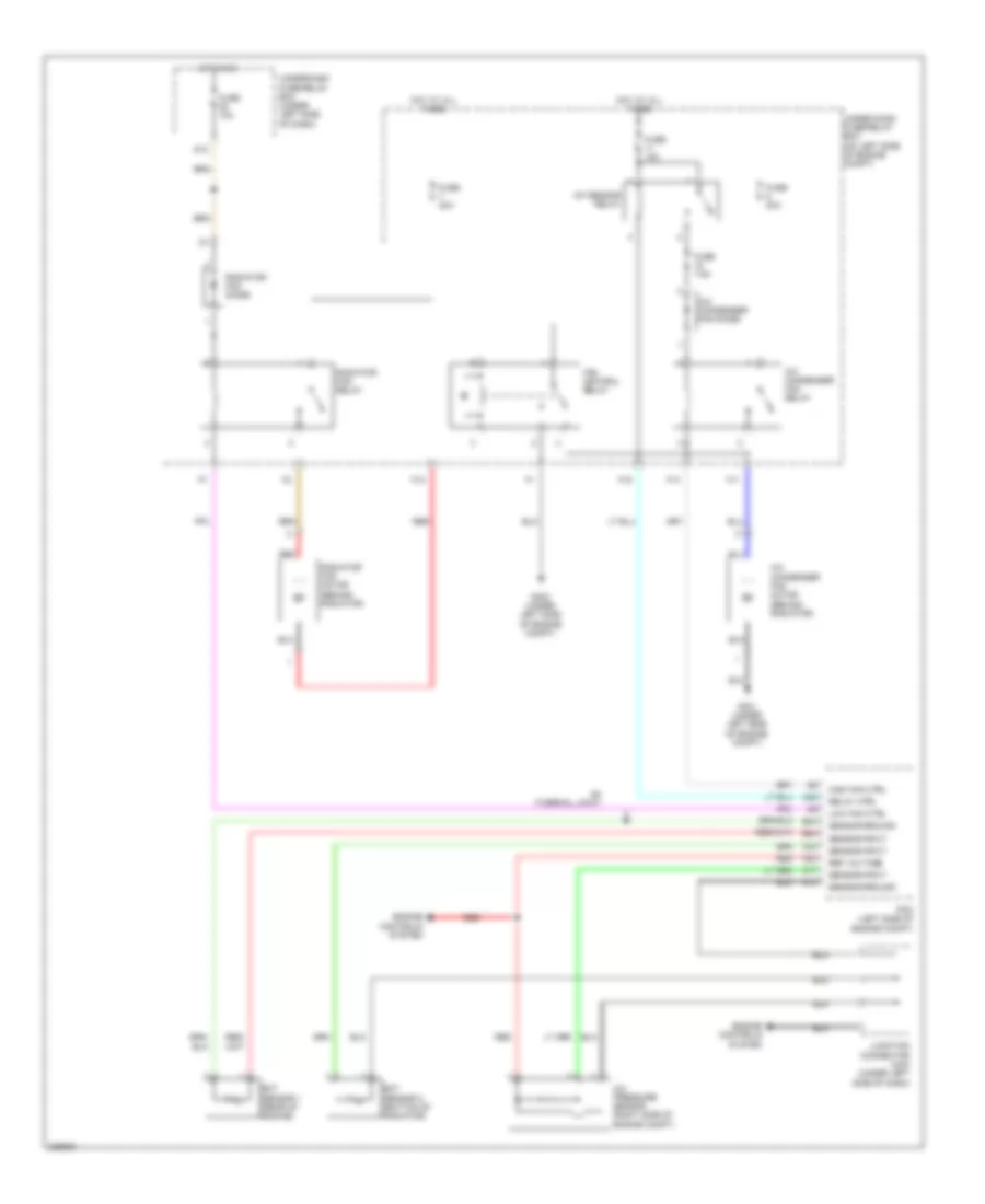
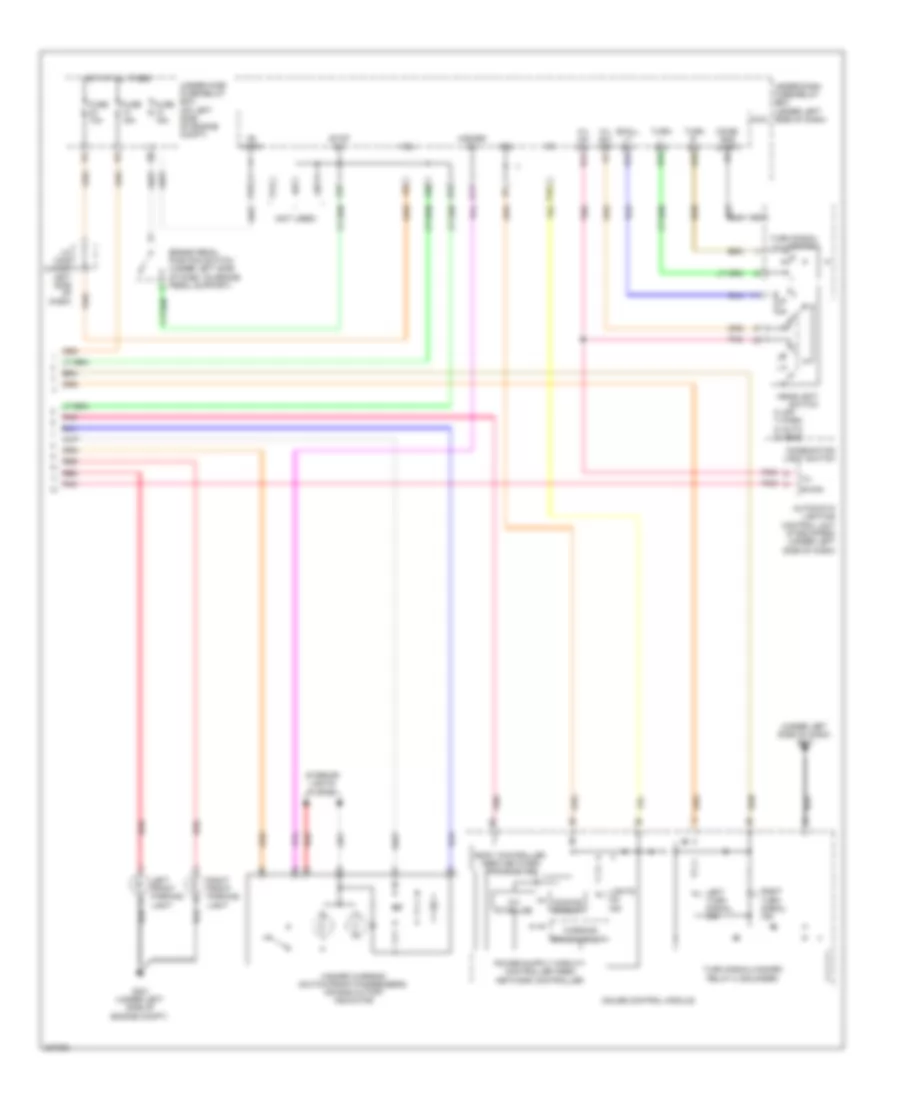
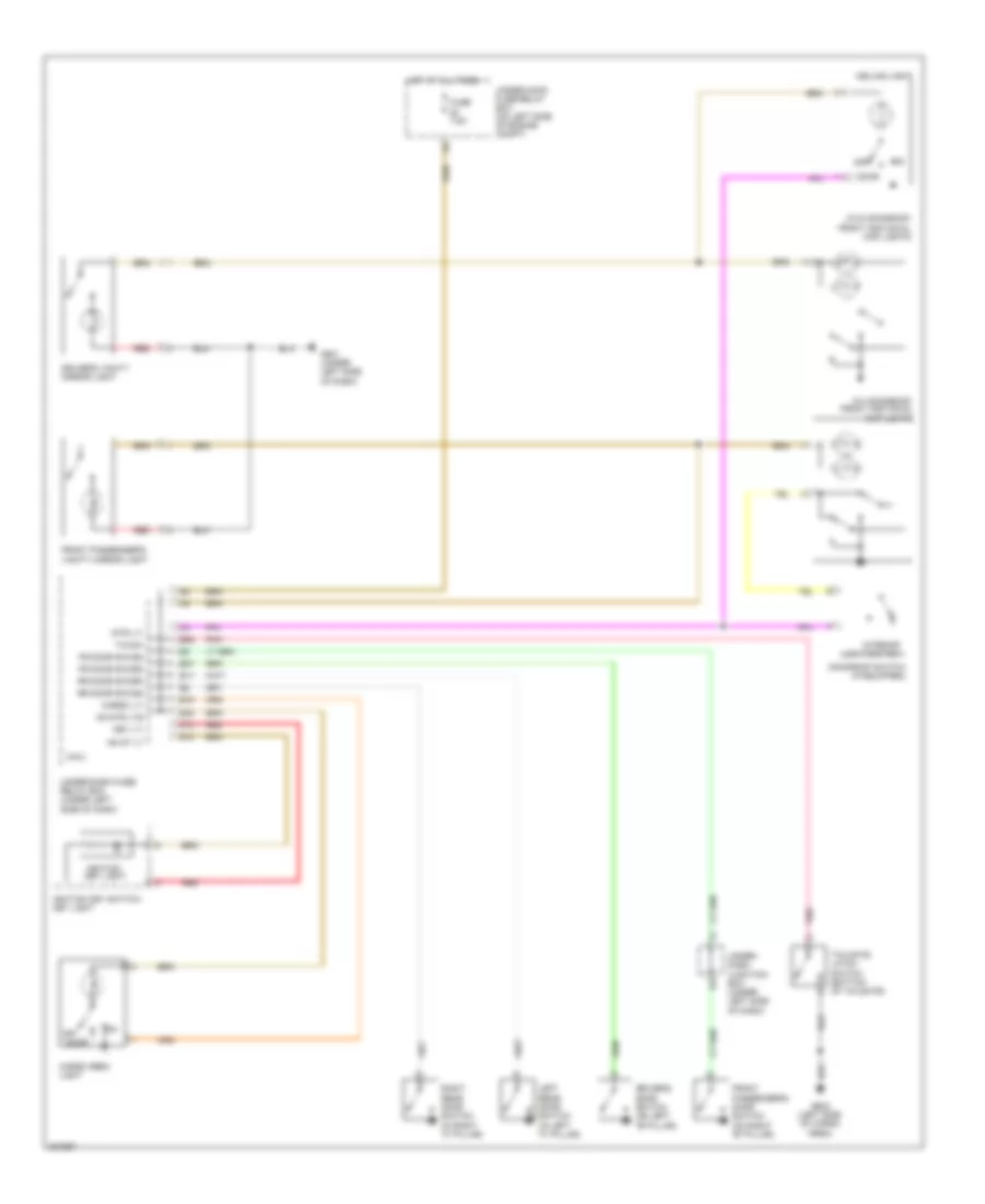
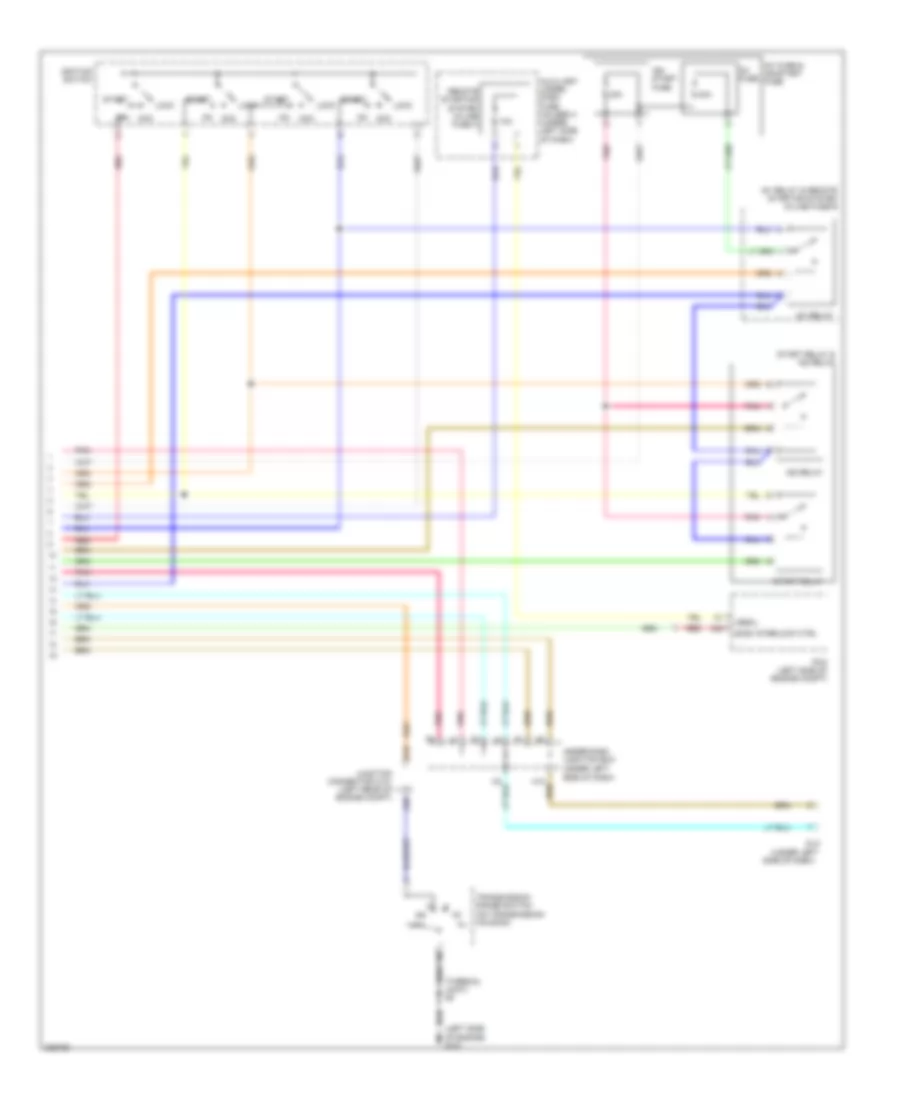
Automatic A/C Wiring Diagram (2 of 2) for Honda CR-V LX 2010
List of elements for Automatic A/C Wiring Diagram (2 of 2) for Honda CR-V LX 2010:
- (not used)
- A/c condenser fan diode
- A/c condenser fan motor (behind radiator)
- A/c condenser fan relay
- A/c pressure sensor (right side of engine compt)
- A/f sensor relay
- A10
- A15
- A17
- A20
- A22
- A34
- B24
- B34
- Blower motor (under right side of dash, on a/c blower unit)
- Blower motor relay
- Blower power transistor
- Can-h
- Can-l
- Computer data lines system
- Ect sensor 1 (rear of engine)
- Ect sensor 2 (bottom of radiator)
- Engine controls system
- F11
- F12
- F14
- F16
- Fan control relay
- From a/c compressor clutch relay (diagram 1 of 2)
- Fuse 15a
- Fuse 20a
- Fuse 40a
- Fuse 7.5a
- G301 (under left side of engine compt)
- G302 (under left side of engine compt)
- G401 (under left side of dash)
- High fan ctrl
- Hot at all times
- Junction connector c404 (under left side of dash)
- Low fan ctrl
- Pcm (left side of engine compt)
- Radiator fan diode
- Radiator fan motor (behind radiator)
- Radiator fan relay
- Red
- Ref voltage
- Relay ctrl
- S4 (thermal joint)
- Sensor ground
- Sensor input
- Under-hood fuse/relay box (on left side of engine compt)
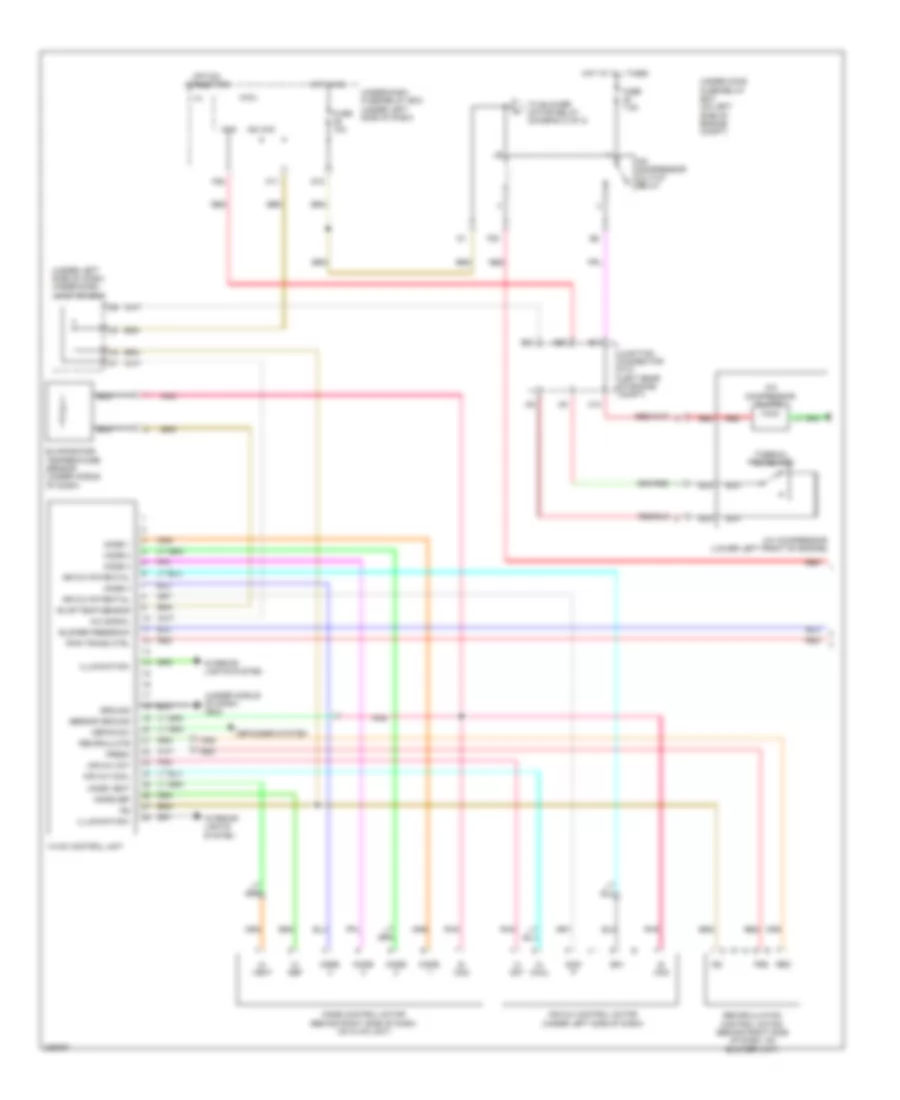
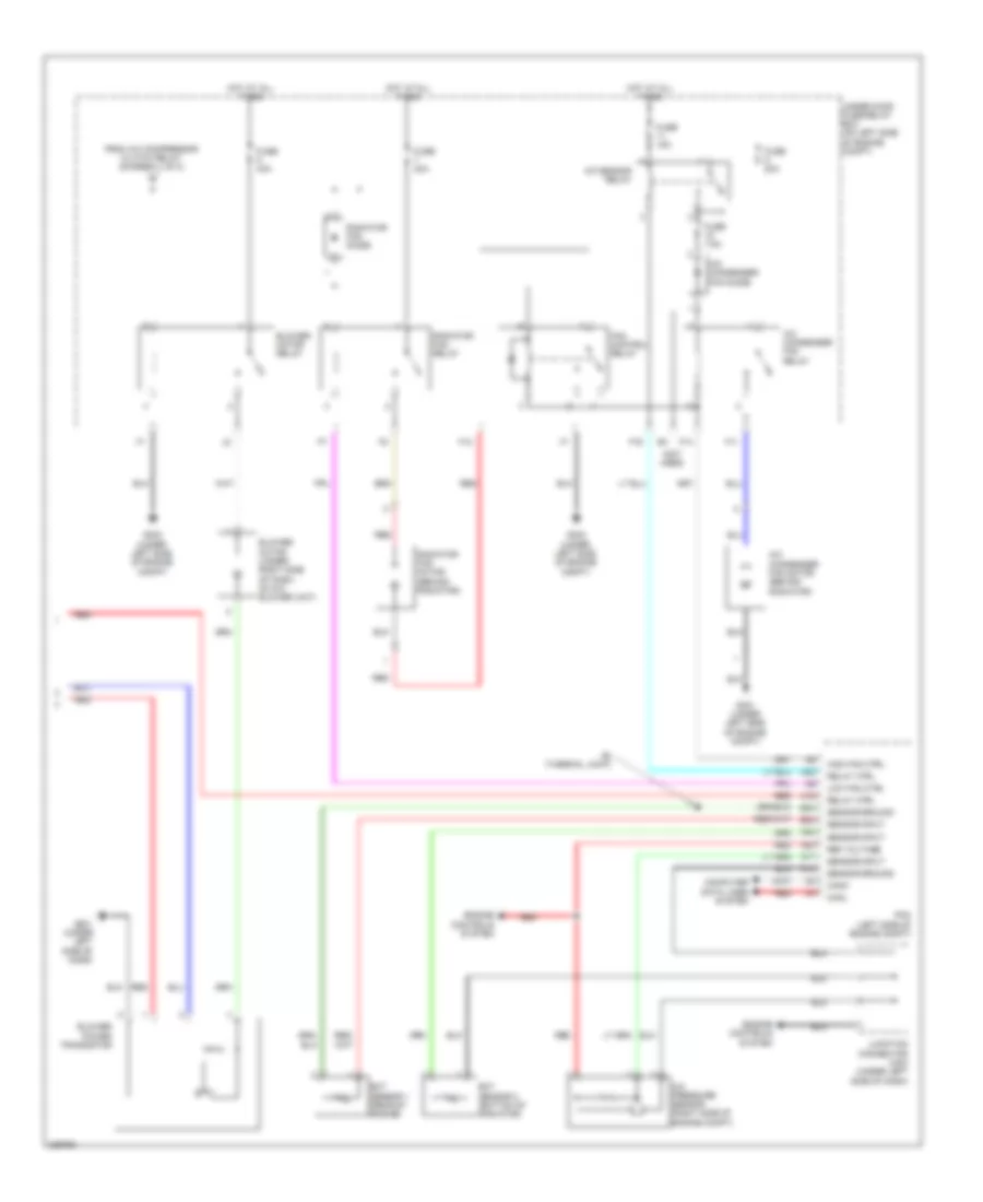
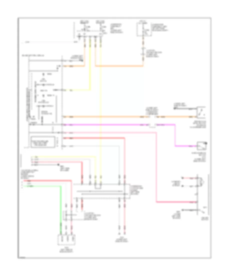
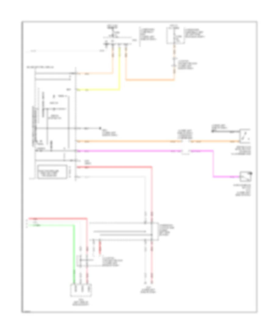
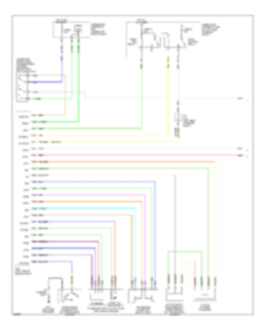
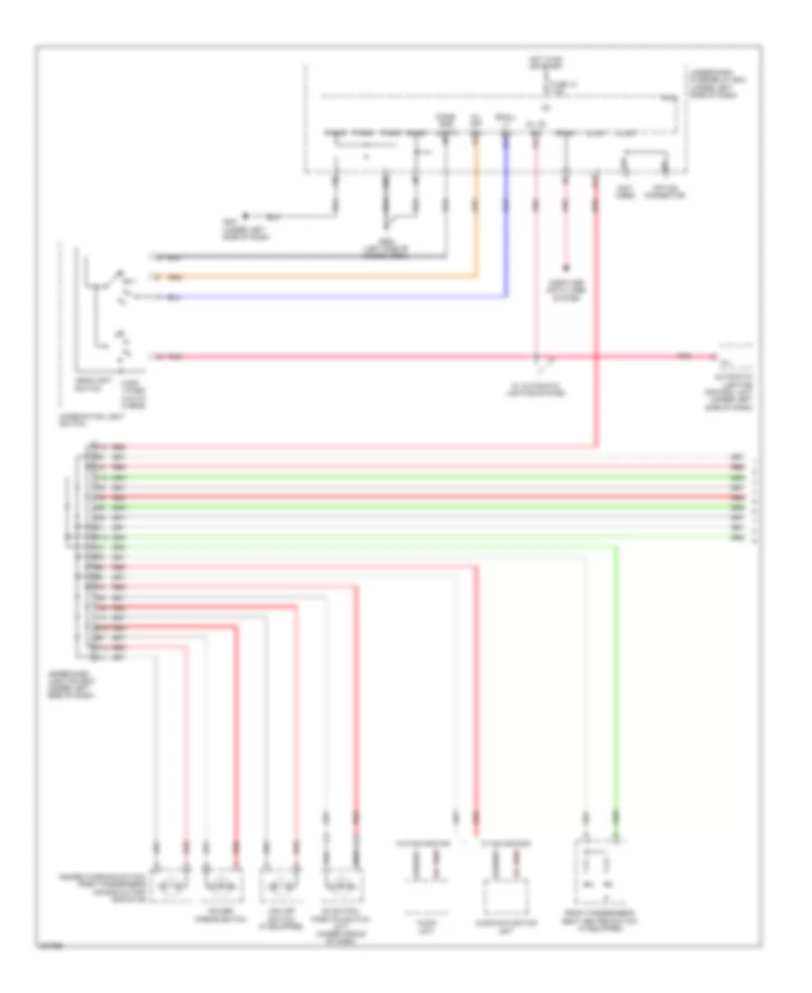
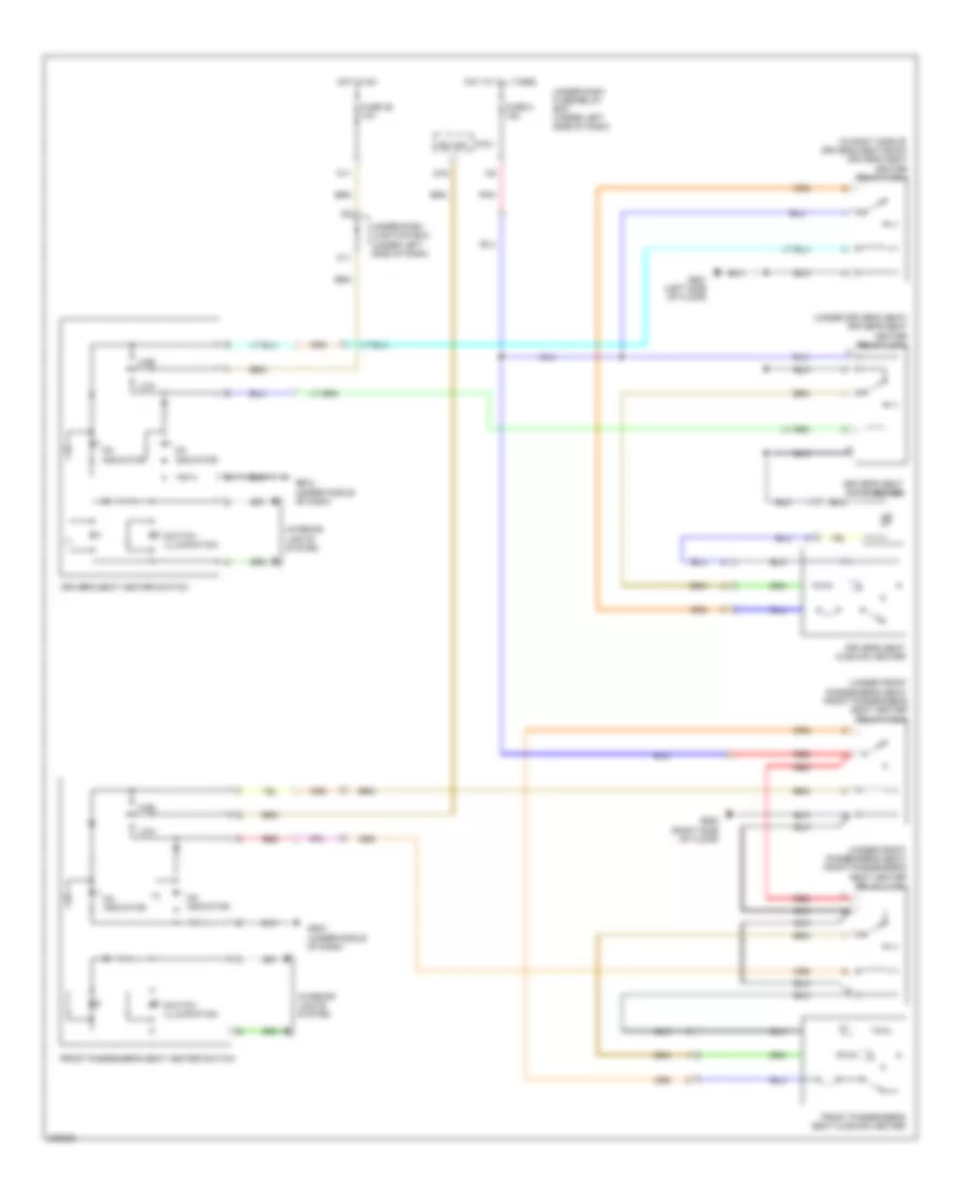
Manual A/C Wiring Diagram (1 of 2) for Honda CR-V LX 2010
List of elements for Manual A/C Wiring Diagram (1 of 2) for Honda CR-V LX 2010:
- (under left side of dash) under-dash junction box
- (under middle of dash) g503
- A/c compressor (lower left front of engine)
- A/c compressor clutch
- A/c compressor clutch relay
- A/c signal
- A13
- Acs
- Air mix control motor (under left side of dash)
- Air mix cool
- Air mix hot
- Air mix potential
- Amd- p
- B13
- B20
- B21
- Blower feedback
- Defog sw
- Defogger system
- Evap temp sensor
- Evaporator temperature sensor (under middle of dash)
- F20
- F26
- Fresh
- Frs
- Fuse 10a
- Fuse 7.5a
- G12
- Ground
- H- hot
- Hot at all times
- Hot in on
- Hvac control unit
- Ig2
- Ig2 hac
- Illumination+
- Illumination-
- Interior lights system
- Junction connector c101 (left rear of engine compt)
- M- cool
- M- def
- M- vent
- Micu
- Mode
- Mode 1
- Mode 2
- Mode 3
- Mode 4
- Mode control motor (behind right side of dash, on hvac unit)
- Mode def
- Mode vent
- N11
- Option connector
- Pnk
- Pwr trans ctrl
- Rec
- Recirculate
- Recirculation control motor (behind right side of dash, on blower unit)
- Red
- S- com
- S5v
- Sensor ground
- Thermal protector
- To blower motor relay (diagram 2 of 2)
- Under-dash fuse/relay box (under left side of dash)
- Under-hood fuse/relay box (on left side of engine compt)
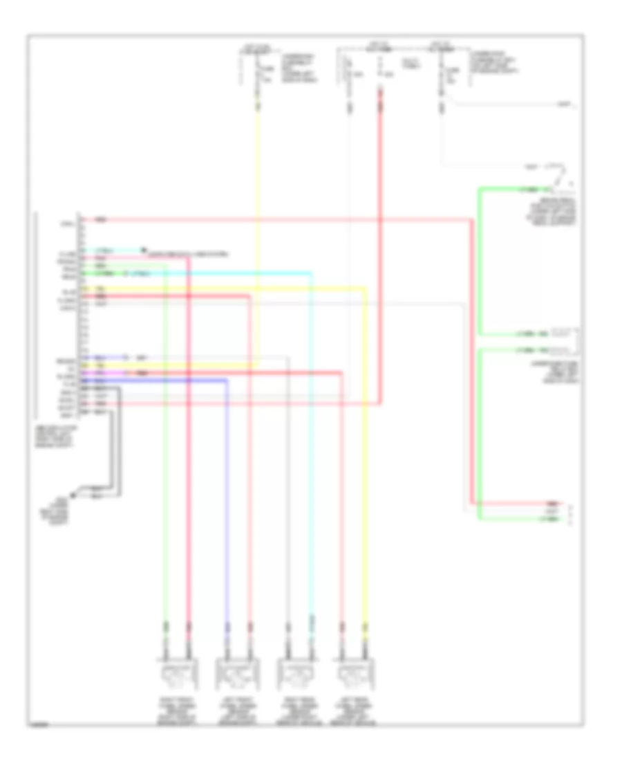
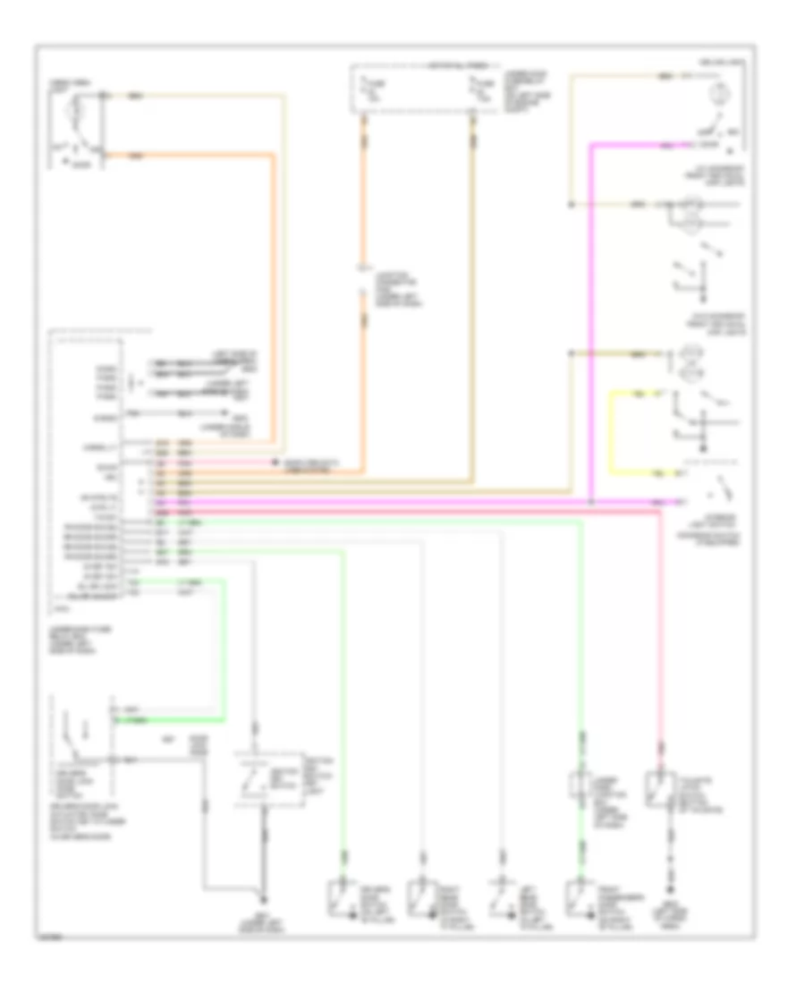
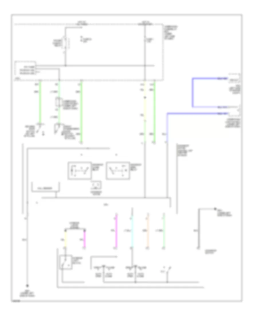
Manual A/C Wiring Diagram (2 of 2) for Honda CR-V LX 2010
List of elements for Manual A/C Wiring Diagram (2 of 2) for Honda CR-V LX 2010:
- (not used)
- A/c condenser fan diode
- A/c condenser fan motor (behind radiator)
- A/c condenser fan relay
- A/c pressure sensor (right side of engine compt)
- A/f sensor relay
- A10
- A15
- A17
- A20
- A22
- A34
- B24
- B34
- Blower motor (under right side of dash, on a/c blower unit)
- Blower motor relay
- Blower power transistor
- Canh
- Canl
- Computer data lines system
- Ect sensor 1 (rear of engine)
- Ect sensor 2 (bottom of radiator)
- Engine controls system
- F11
- F12
- F14
- F16
- Fan control relay
- From a/c compressor clutch relay (diagram 1 of 2)
- Fuse 15a
- Fuse 20a
- Fuse 40a
- Fuse 7.5a
- G301 (under left side of engine compt)
- G302 (under left side of engine compt)
- G401 (under left side of dash)
- High fan ctrl
- Hot at all times
- Junction connector c404 (under left side of dash)
- Low fan ctrl
- Pcm (left side of engine compt)
- Radiator fan diode
- Radiator fan motor (behind radiator)
- Radiator fan relay
- Red
- Ref voltage
- Relay ctrl
- S4 (thermal joint)
- Sensor ground
- Sensor input
- Under-hood fuse/relay box (on left side of engine compt)
ANTI-LOCK BRAKES
Anti-lock Brakes Wiring Diagram, with VSA (1 of 2) for Honda CR-V LX 2010
List of elements for Anti-lock Brakes Wiring Diagram, with VSA (1 of 2) for Honda CR-V LX 2010:
- +b mot
- +b sol
- 20a
- 40a
- Brake pedal position switch (under left side of dash, on brake pedal support)
- Can-h
- Can-l
- Computer data lines system
- F16
- F25
- F30
- Fl+b
- Fl-gnd
- Fr+b
- Fr-gnd
- Fuse 15a
- Fuse 7.5a
- G202 (under right side of engine compt)
- Gnd 1
- Gnd 2
- Hot at all times
- Hot in on or start
- Ig1
- Junction connector c405 (under left side of dash)
- K-line
- Left front wheel speed sensor (left side of engine compt)
- Left rear wheel speed sensor (under left rear of vehicle)
- Multi- fuse 3
- Pnk
- Red
- Right front wheel speed sensor (right side of engine compt)
- Right rear wheel speed sensor (under right rear of vehicle)
- Rl+b
- Rl-gnd
- Rr+b
- Rr-gnd
- S-gnd
- St-a
- St-b
- St-z
- Steering angle sensor (in steering column)
- Svcc
- Under-dash fuse/ relay box (under left side of dash)
- Under-dash fuse/relay box (under left side of dash)
- Under-hood fuse/relay box (on left side of engine compt)
- Vsa modulator control unit (right side of engine compt)
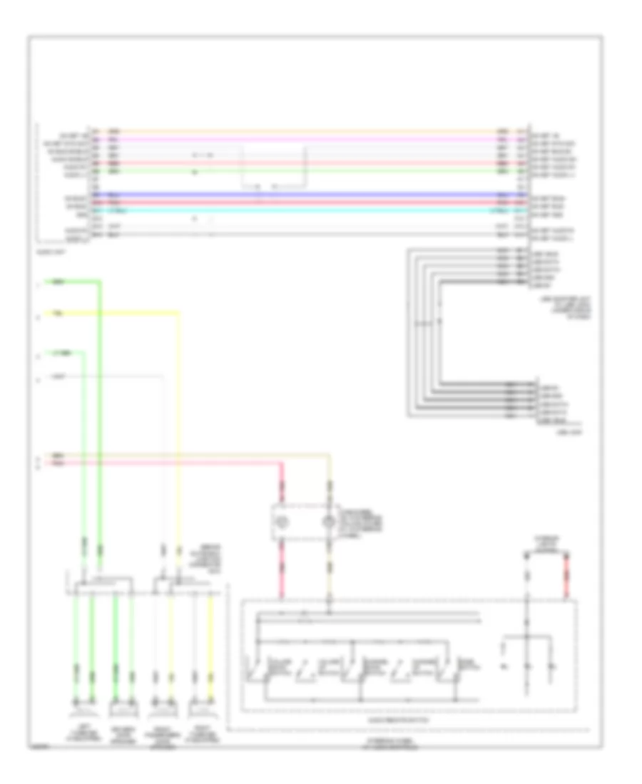
Anti-lock Brakes Wiring Diagram, with VSA (2 of 2) for Honda CR-V LX 2010
List of elements for Anti-lock Brakes Wiring Diagram, with VSA (2 of 2) for Honda CR-V LX 2010:
- (under left side of dash)
- (under left side of dash) g401
- (under left side of dash) g501
- (under left side of dash) under-dash junction box
- A42
- Abs ind
- Area network controller
- Bksw
- Brake fluid level switch (on brake fluid reservoir)
- Brake system ind
- Can-h
- Can-l
- Dlc (under left side of dash)
- E12
- Fast controller area network transceiver
- Fuse 10a
- Fuse 7.5a
- G10
- G16
- G501
- G551 (left side of floor)
- Gauge control module
- Horn
- Hot at all times
- Hot in on or start
- Ig1
- Interior lights system
- J12
- J13
- Junction connector c404 (under left side of dash)
- Junction connector c405 (under left side of dash)
- Micu
- P10
- Parking brake switch (a/t) (under left side of dash)
- Pcm (left side of engine compt)
- Pnk
- R20
- Red
- Under-dash fuse/relay box (under left side of dash)
- Under-dash junction box (under left side of dash)
- Under-hood fuse/relay box (on left side of engine compt)
- Vbu
- Vsa off ind
- Vsa off switch
- Vsa system ind
- Warning drive circuit
- Yaw rate-lateral acceleration sensor (under middle of dash)
Anti-lock Brakes Wiring Diagram, without VSA (1 of 2) for Honda CR-V LX 2010
List of elements for Anti-lock Brakes Wiring Diagram, without VSA (1 of 2) for Honda CR-V LX 2010:
- +b mot
- +b sol
- 20a
- 40a
- Abs modulator control unit (right side of engine compt)
- Brake pedal position switch (under left side of dash, on brake pedal support)
- Can-h
- Can-l
- Computer data lines system
- F16
- F25
- F30
- Fl+b
- Fl-gnd
- Fr+b
- Fr-gnd
- Fuse 15a
- Fuse 7.5a
- G202 (under right side of engine compt)
- Gnd 1
- Gnd 2
- Hot at all times
- Hot in on or start
- Ig1
- K-line
- Left front wheel speed sensor (left side of engine compt)
- Left rear wheel speed sensor (under left rear of vehicle)
- Multi- fuse 3
- Pnk
- Red
- Right front wheel speed sensor (right side of engine compt)
- Right rear wheel speed sensor (under right rear of vehicle)
- Rl+b
- Rl-gnd
- Rr+b
- Rr-gnd
- Under-dash fuse/ relay box (under left side of dash)
- Under-dash fuse/relay box (under left side of dash)
- Under-hood fuse/relay box (on left side of engine compt)
Anti-lock Brakes Wiring Diagram, without VSA (2 of 2) for Honda CR-V LX 2010
List of elements for Anti-lock Brakes Wiring Diagram, without VSA (2 of 2) for Honda CR-V LX 2010:
- (not used)
- (under left side of dash) g401
- (under left side of dash) under-dash junction box
- A36
- A37
- A40
- Abs ind
- Area network controller
- Bksw
- Brake fluid level switch (on brake fluid reservoir)
- Brake system ind
- Can-h
- Can-l
- Dlc (under left side of dash)
- Fast controller area network transceiver
- Fuse 10a
- Fuse 7.5a
- G10
- G16
- G501 (under left side of dash)
- Gauge control module
- Horn
- Hot at all times
- Hot in on or start
- Ig1
- J12
- J13
- Junction connector c404 (under left side of dash)
- Junction connector c405 (under left side of dash)
- Micu
- P10
- Parking brake switch (a/t) (under left side of dash)
- Pcm (left side of engine compt)
- Red
- Under-dash fuse/relay box (under left side of dash)
- Under-dash junction box (under left side of dash)
- Under-hood fuse/relay box (on left side of engine compt)
- Vbu
- Warning drive circuit
ANTI-THEFT
Forced Entry Wiring Diagram (1 of 2) for Honda CR-V LX 2010
List of elements for Forced Entry Wiring Diagram (1 of 2) for Honda CR-V LX 2010:
- (not used)
- (not used) c502
- (on transmission housing) transmission range switch
- (under left side of dash) g501
- (under middle of dash) g503
- +b d/l
- Atp-p
- B-can
- Door lock knob
- Door lock relay
- Driver's door key cylinder switch
- Driver's door lock actuator/knob switch/ key cylinder switch (in driver's door)
- Driver's door lock knob switch
- Driver's door unlock relay
- E13
- E14
- E17
- E19
- E20
- E21
- E31
- E33
- E36
- E37
- Exterior lights system
- F20
- F23
- F27
- Fr dr sw (as)
- Fr dr sw (dr)
- Front passenger's door lock actuator/knob switch (in front passenger's door)
- Front passenger's door lock knob switch
- Fuse 10a
- Fuse 15a
- Fuse 20a
- Fuse 7.5a
- G101 (left side of engine)
- G13
- G16
- G17
- G401 (under left side of dash)
- G502 (under middle of dash)
- G552 (right side of floor)
- G602 (left side of cargo area)
- Headlights system
- Hood sw
- Horn rly
- Horns system
- Hot at all times
- Hot in on or start
- Ig key sw
- Ig1
- Junction connector c101 (left rear of engine compt)
- Kc dr lock
- Kc dr unlock
- Key door lock knob
- Lock
- Low beam headlight rly
- M10
- Micu
- N13
- P-gnd
- Passenger's door unlock relay
- Pnk
- R16
- Red
- Red b1
- Rem as lock
- Rem as unlock
- Rem dr lock
- Rem dr unlock
- Right rear door lock actuator/knob switch (in right rear door)
- Right rear door lock knob switch
- Rr dr sw (as)
- Rr dr sw (dr)
- S-gnd
- S-gnd2
- S2 (thermal joint)
- Sil as unlock
- Sil dr lock
- Sil dr unlock
- Sil ra unlock
- Sil rd unlock
- T/g handle sw
- T/g sw
- T22
- T23
- T24
- T25
- T26
- T27
- T28
- T29
- T30
- T31
- T32
- T34
- Tailgate unlock relay
- Taillight rly
- Under-dash fuse/relay box (under left side of dash)
- Unlock
- Vbu
- W/ security
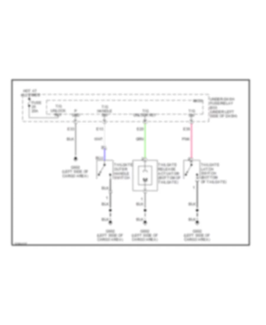
Forced Entry Wiring Diagram (2 of 2) for Honda CR-V LX 2010
List of elements for Forced Entry Wiring Diagram (2 of 2) for Honda CR-V LX 2010:
- (bottom of tailgate) tailgate release actuator
- (in left rear door) left rear door lock actuator/knob switch
- (left side of cargo area) g602
- Audio navigation unit
- Audio unit
- B-can
- Blinking circuit
- Body controller area network transceiver
- Driver's door lock switch
- Driver's door switch (on left "b" pillar)
- Front passenger's door lock switch
- Front passenger's door switch (on right "b" pillar)
- Front passenger's power window switch
- Fuse 10a
- Fuse 15a
- G301 (under left side of engine compt)
- G501 (under left side of dash)
- G503 (under middle of dash)
- G602 (left side of cargo area)
- Gauge control module
- Hot at all times
- Ignition key switch
- Ignition key switch/key light
- Immobilizer- keyless control unit (on steering column, integral to ignition switch)
- J/c c405 (under left side of dash)
- Left rear door switch (in left "c" pillar)
- Left unlock
- Lock
- Pnk
- Power distribution system
- Power window master switch/ driver's door lock switch
- Rear door lock knob switch
- Right rear door switch (in right "c" pillar)
- Scty radio
- Security hood switch (if equipped) (front of engine compt)
- Security indicator (if equipped)
- Tailgate latch switch (bottom of tailgate)
- Tailgate outer handle switch
- Under-dash junction box (under left side of dash)
- Under-hood fuse/relay box (on left side of engine compt)
- Unlock
- W/ navigation
- W/o navigation
Immobilizer Wiring Diagram for Honda CR-V LX 2010
List of elements for Immobilizer Wiring Diagram for Honda CR-V LX 2010:
- (ig1) fuel pump
- (imocd)
- (left side of cargo area) g602
- (not used)
- (thermal joint) s1
- (under left side of dash) g501
- 10v stabilize
- A16
- A20
- A46
- Audio-navigation unit (w/ navigation)
- B-can
- B10
- Body controller area network transceiver
- C401
- C44
- Computer data lines system
- F10
- Fuel pump
- Fuel pump ctrl (imo fpr)
- Fuel tank unit (top of fuel tank)
- Fuse 10a
- Fuse 15a
- Fuse 7.5a
- G101 (left side of engine)
- Gauge control module
- Gnd
- Ho2s shield
- Hot at all times
- Hot in on or start
- Ig key sw
- Ig1
- Ignition key switch
- Ignition key switch/ key light
- Immobilizer system indicator
- Immobilizer- keyless control unit (on steering column, integral to ignition switch)
- Imocd
- J/c c101 (left rear of engine compt)
- J/c c405 (under left side of dash)
- K-line
- L10
- Lg1 pg2
- Micu
- P10
- Pcm (left side of engine compt)
- Pg1
- Pgm-fi main relay 1
- Pgm-fi main relay 2
- Pgmetcs
- Pnk
- R11
- R12
- R16
- Rly ctrl (mrly)
- S-net (imocd)
- S2 (thermal joint)
- Secondary
- Serial communication (s-net5v)
- Under-dash fuse/relay box (under left side of dash)
- Under-dash junction box (under left side of dash)
- Under-hood fuse/relay box (on left side of engine compt)
- Vbu
- W/ navigation
- Warning drive circuit
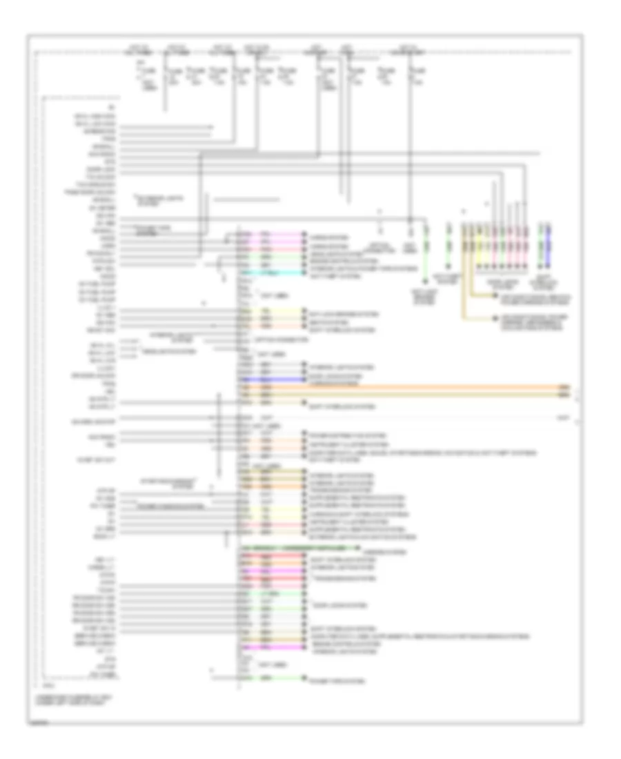
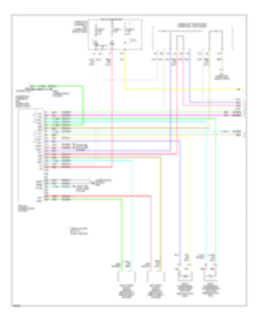
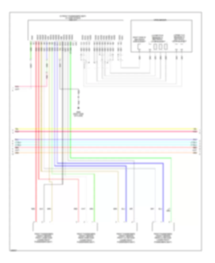
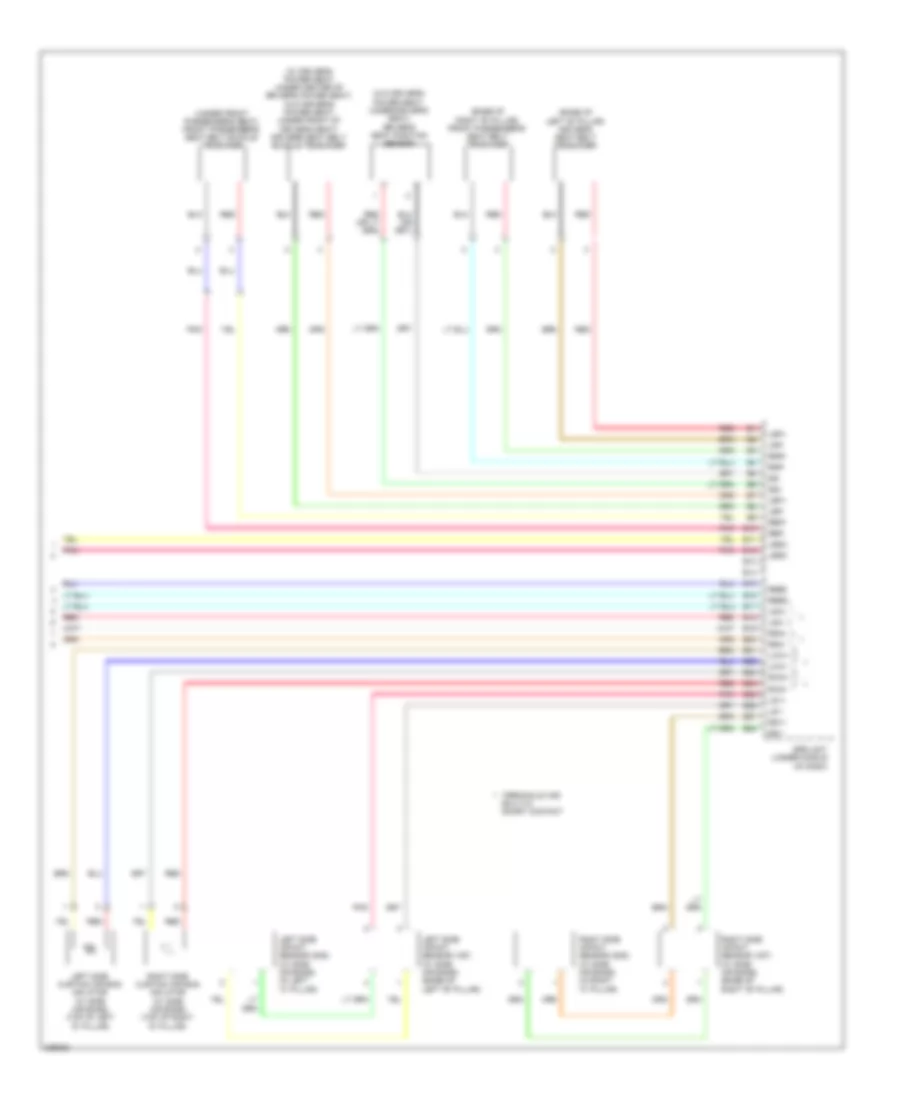
BODY CONTROL MODULES
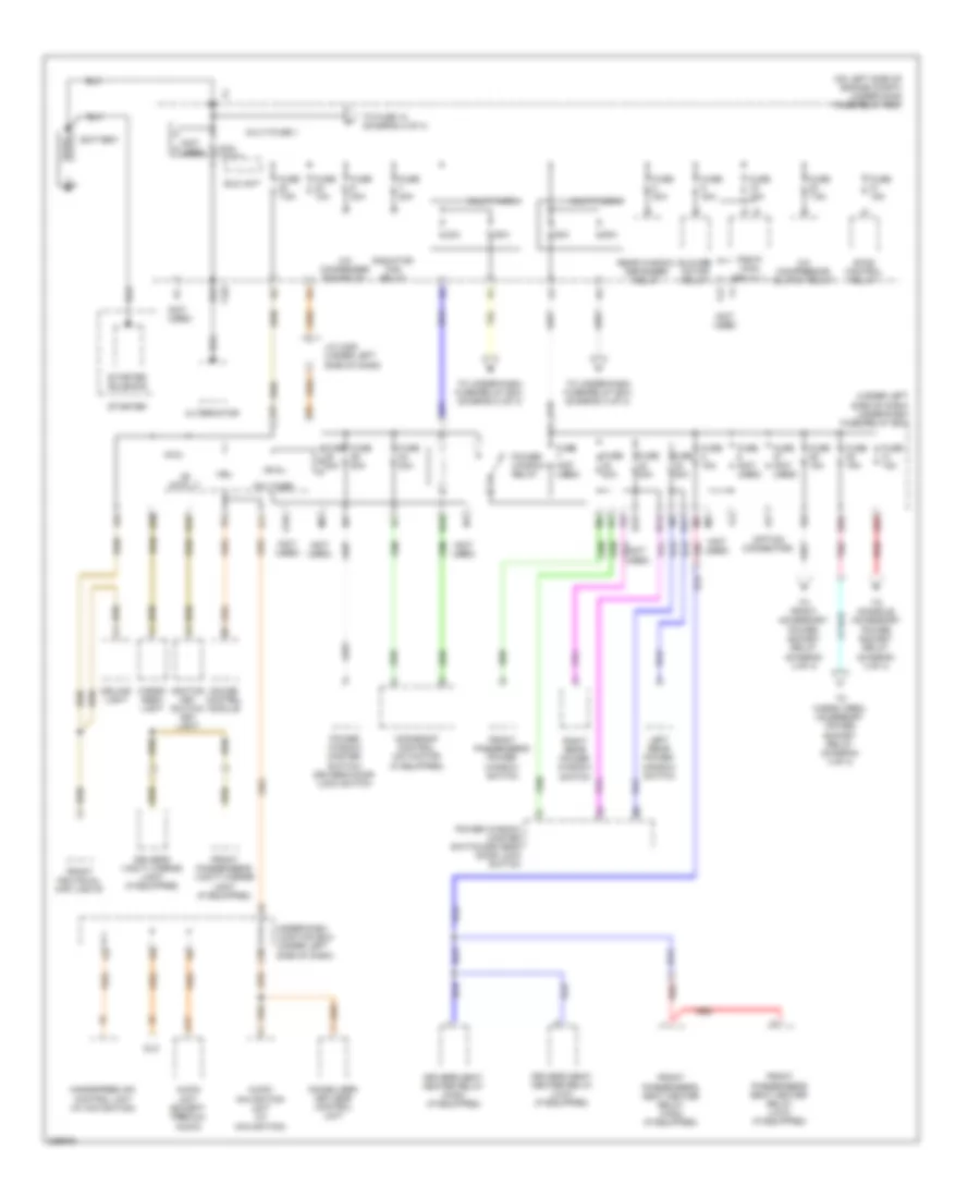
Body Control Modules Wiring Diagram (1 of 2) for Honda CR-V LX 2010
List of elements for Body Control Modules Wiring Diagram (1 of 2) for Honda CR-V LX 2010:
- (accessory installed)
- (not used)
- (option connector)
- +b h/l hi-l
- +b h/l hi-r
- +b h/l high main
- +b h/l low
- +b h/l low main
- +b horn,+b stop
- +b intr lt
- +b rear fog
- +b small
- Acc radio
- Air conditioning, power mirrors, defoggers & cooling fans systems
- Air conditioning, seats & power mirrors systems
- Anti-lock brakes system
- Anti-theft system
- Atp np
- Atp-p
- Atp-r
- Back lt
- Cargo lt -
- Computer data lines, sound, starting/charging, navigation & anti-theft systems
- Door lock
- Door locks system
- Dr door unlock
- E14
- E15
- E16
- E17
- E20
- E21
- E24
- E25
- E36
- E37
- E38
- Engine controls system
- Exterior lights & navigation systems
- Exterior lights system
- F11
- F16
- F21
- F23
- F27
- F29
- F31
- Fr door sw (as)
- Fr door sw (dr)
- Fr fog rly
- Fuse (not used)
- Fuse 10a
- Fuse 15a
- Fuse 20a
- Fuse 7.5a
- G12
- G16
- Headlights system
- Horn
- Horns system
- Hot at all times
- Hot in on
- Hot in on or acc
- Hot in on or start
- Hot in start
- Ig key sw in
- Ig key sw out
- Ig1
- Ig1 abs
- Ig1 fuel pump
- Ig1 meter
- Ig1 ods
- Ig1 srs
- Ig2 hac
- Illum +
- Illumi+
- Imocd
- Instrument cluster system
- Int lt -
- Interior lights & power tops systems
- Interior lights system
- Ke sw acc
- Key lt -
- Key sol
- M10
- Micu
- Mirrors system
- N10
- N11
- N13
- P-pin sw
- P10
- Pass door unlock
- Pnk
- Power distribution system
- Power tops system
- Power windows system
- Pw timer
- Q12
- Q15
- Q16
- R10
- R11
- R12
- R13
- R16
- R17
- R18
- R20
- Red
- Rr door sw (as)
- Rr door sw (dr)
- Seats system
- Service check
- Shift interlock system
- Starting/charging system
- Sts
- T/g handle sw
- T/g sw
- T/g unlock
- Tpms
- Transmissions system
- Under-dash fuse/relay box (under left side of dash)
- Vbu
- Warning & shift interlock systems
- Warning systems
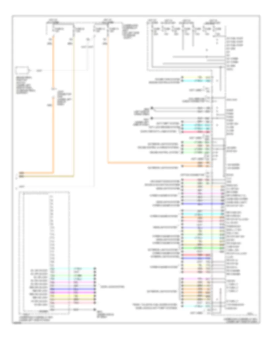
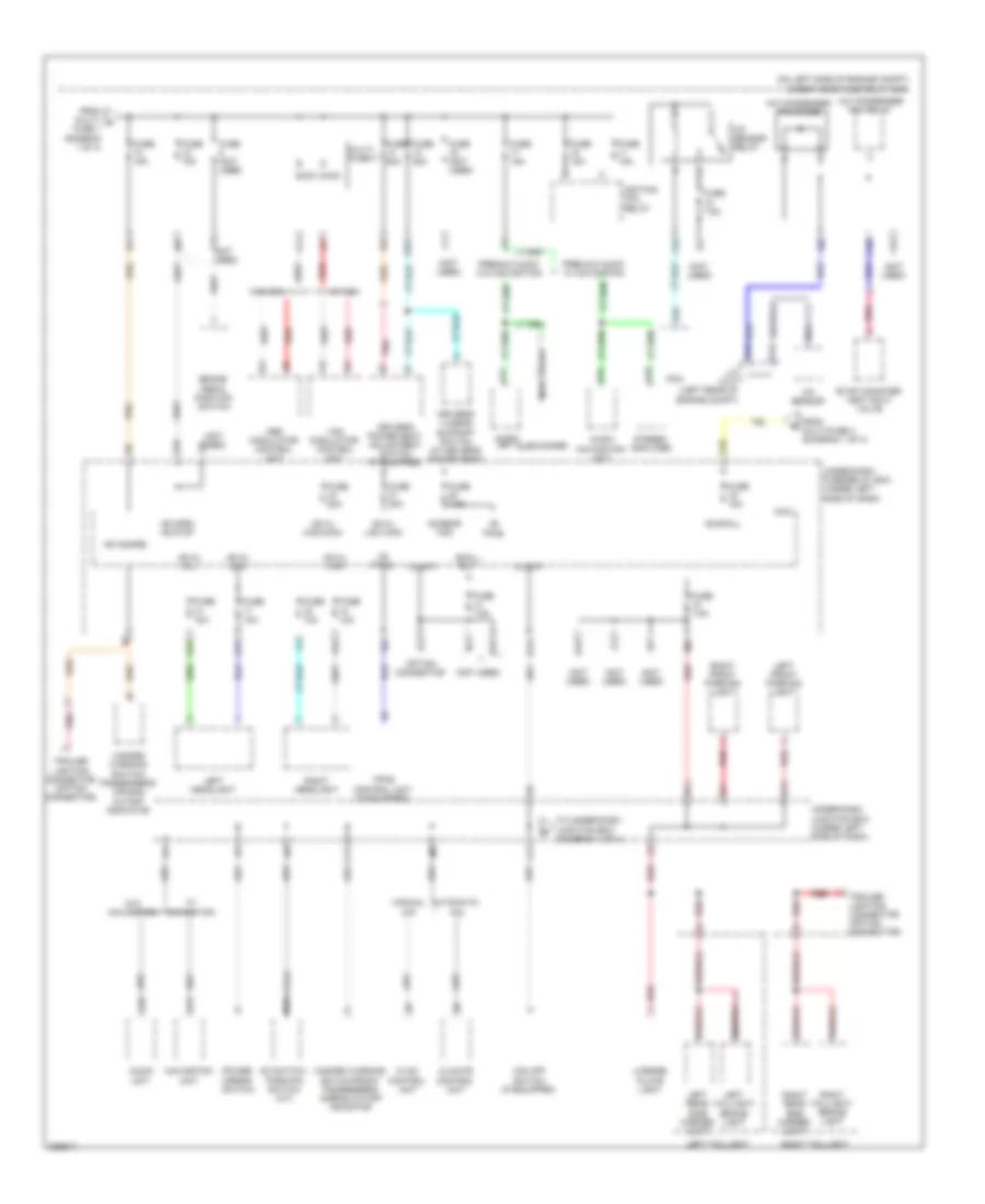
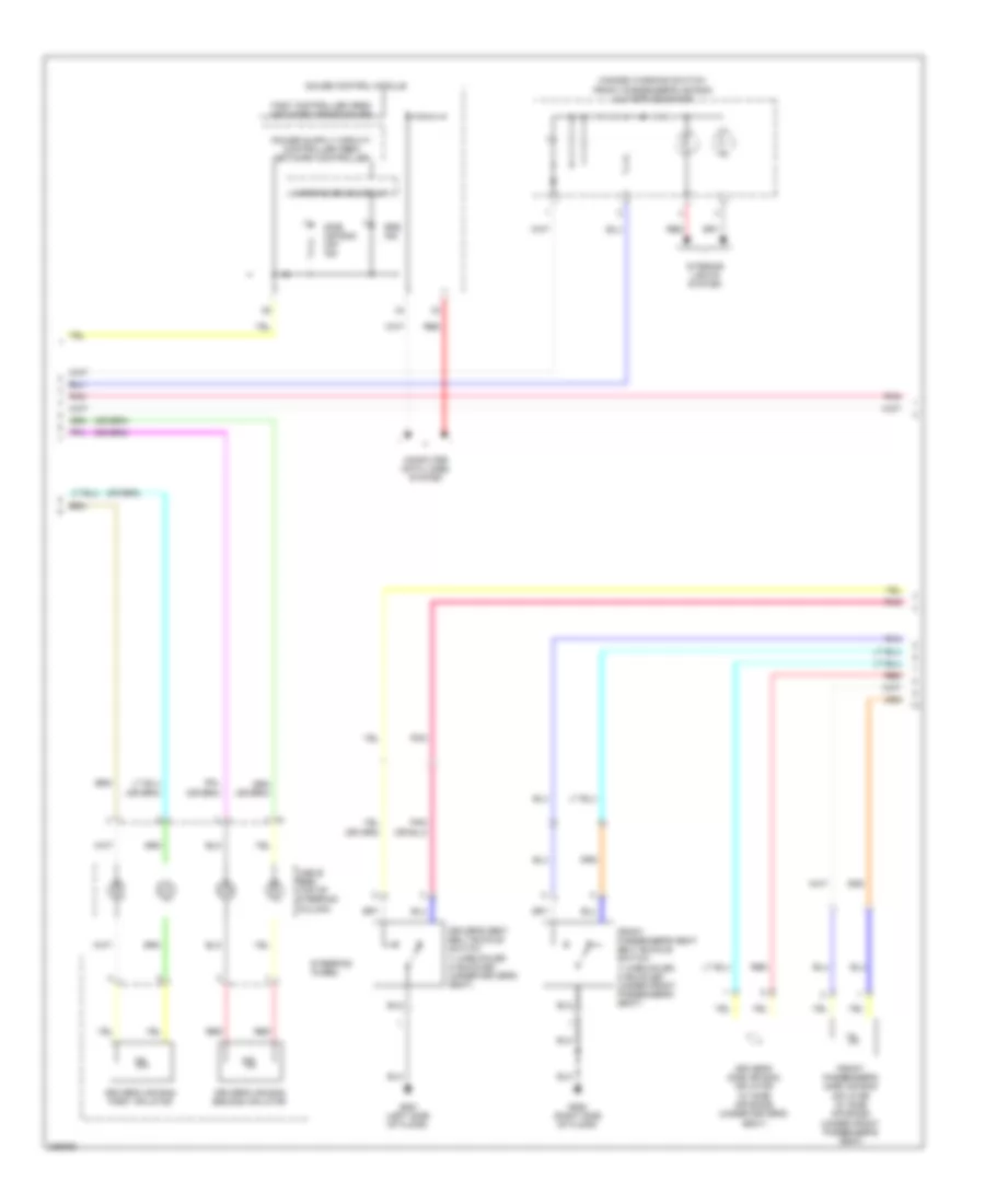
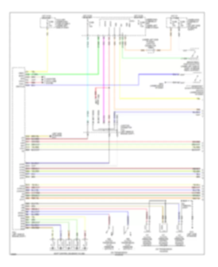
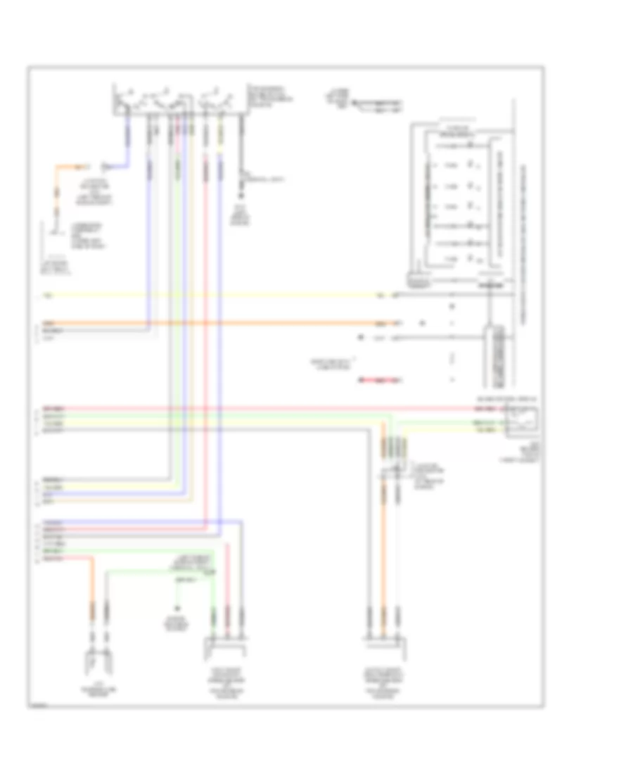
Body Control Modules Wiring Diagram (2 of 2) for Honda CR-V LX 2010
List of elements for Body Control Modules Wiring Diagram (2 of 2) for Honda CR-V LX 2010:
- (not used)
- (option connector)
- + b hazard
- +b d/l
- +b horn
- Acs
- Air conditioning system
- Anti-lock brakes system
- Anti-theft system
- B-can
- Brake pedal position switch (under left side of dash, on brake pedal support)
- Combi gnd (light)
- Combi gnd (wiper)
- Computer data lines system
- Cruise control & horns systems
- Cruise control system
- Dim sw
- Door locks & anti-theft systems
- Door locks system
- E13
- E26
- E33
- E34
- E39
- E40
- Engine controls system
- Exterior lights system
- F14
- F18
- F19
- F20
- F24
- F25
- F26
- F28
- F30
- F32
- F33
- F34
- Fog lt sw
- Fr wash sw
- Fr washer
- Fr wip as
- Fr wip hi
- Fr wip hi & lo sw
- Fr wip int & lo sw
- Fr wip int vr +
- Fr wip lo
- Fr wip mist sw
- Fuse 10 15a
- Fuse 10a
- Fuse 12 15a
- Fuse 15a
- Fuse 20a
- Fuse 22 7.5a
- Fuse 23 10a
- Fuse 30a
- Fuse 7.5a
- G11
- G13
- G401 (under left side of dash)
- G502 (under middle of dash)
- G602 (left side of cargo area)
- H/l off sw
- H/l on sw
- Haz sw
- Headlights system
- Hood sw
- Hot at all times
- Hot in on or start
- Ig key sw
- Ig1
- Ig1 fuel pump
- Ig1 ods
- Ig1 srs
- Ig1 wiper
- Illu
- Illum-
- Interior lights system
- Joint connector c405 (under left side of dash)
- K-line
- Kc dr lock
- Kc dr unlock
- L turn lt
- Micu
- Micu chk
- Micu service check connector
- N12
- P-gnd
- Passing sw
- Pnk
- Power tops system
- Q11
- Q13
- R turn lt
- Radio sw
- Red
- Rem as lock
- Rem as unlock
- Rem dr lock
- Rem dr unlock
- Rr wash sw
- Rr washer
- Rr wipe sw
- Rr wiper
- Rr wiper rly cl
- S gnd2
- S-gnd
- S10
- S11
- S12
- S13
- S14
- S15
- S16
- S17
- S18
- S19
- S20
- Sil as unlock
- Sil dr lock
- Sil dr unlock
- Sil ra unlock
- Sil rd unlock
- Small lt sw
- Sound & navigation systems
- Stop sw
- T/g handle sw
- T10
- T11
- T12
- T13
- T14
- T15
- T16
- T17
- T18
- T19
- T20
- T21
- T22
- T23
- T24
- T25
- T26
- T27
- T28
- T29
- T30
- T31
- T32
- T33
- T34
- Trunk, tailgate, fuel doors system
- Turn l sw
- Turn r sw
- Under-dash fuse/relay box (under left side of dash)
- Under-hood fuse/relay box (on left side of engine compt)
- Wiper/washer system
COMPUTER DATA LINES
Computer Data Lines Wiring Diagram for Honda CR-V LX 2010
List of elements for Computer Data Lines Wiring Diagram for Honda CR-V LX 2010:
- (not used)
- (option connector)
- (under left side of dash) j/c c404
- (under left side of dash) j/c c405
- (under middle of dash) g502
- (under middle of dash) g505
- A11
- A12
- A20
- A24
- A32
- A44
- Audio navigation unit
- Audio unit
- Automatic lighting control unit (if equipped) (under left side of dash)
- B-can
- B2 mes connector (under b1 left side of dash)
- Body controller area network transceiver
- C10
- Can-h
- Can-l
- Can-l vsa modulator control unit (w/ vsa) abs modulator control unit (w/o vsa) (right side of engine compt)
- Climate control unit (if equipped)
- Communication sig hi (can-h)
- Communication sig lo (can-l)
- Dlc (under left side of dash)
- E17
- E18
- E33
- F-can hi
- F-can lo
- F11
- F14
- F20
- F28
- Fuse 10 7.5a
- Fuse 23 10a
- Fuse 37 7.5a
- G101 (left side of engine)
- G401 (under left side of dash)
- G502 (under middle of dash)
- G602 (left side of cargo area)
- Gauge control module
- H10
- Handsfreelink control unit (w/ navigation & climate control) (under middle of dash)
- Hot at all times
- Hot in on
- Hot in on or start
- Ig1
- Ig1 meter
- Immobilizer key less control unit (on steering column, integral to ignition switch)
- J/c c101 (left rear of engine compt)
- J12
- J13
- K-line
- K12
- Mes connector in (mes)
- Micu
- Micu chk
- Micu service check connector
- P-gnd
- Pcm (left side of engine compt)
- Pnk
- Red
- Remote starting control unit
- S-gnd
- S-gnd2
- Scs
- Secondary ho2 shield
- Service check sig (scs)
- Srs unit (under middle of dash)
- T34
- Tpms control unit (if equipped) (under left side of dash)
- Transceiver area network fast controller
- Under-dash fuse/relay box (under left side of dash)
- Under-dash junction box (under left side of dash)
- Under-hood fuse/relay box (on left side of engine compt)
- Vbu
- W/ navigation
- W/ vsa
- W/o navigation
- W/o vsa
- Write enable sig (wen)
- Yaw rate- lateral acceleration sensor (under middle of dash)
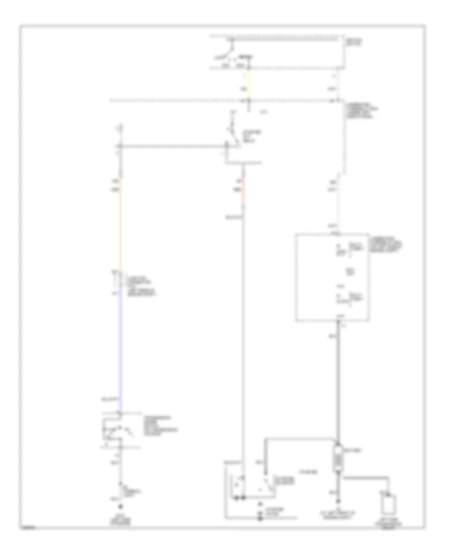
COOLING FAN
Cooling Fan Wiring Diagram for Honda CR-V LX 2010
List of elements for Cooling Fan Wiring Diagram for Honda CR-V LX 2010:
- A/c condenser fan diode
- A/c condenser fan motor (behind radiator)
- A/c condenser fan relay
- A/c pressure sensor (right side of engine compt)
- A/f sensor relay
- A10
- A17
- A20
- A22
- A34
- B24
- B34
- Ect sensor 1 (rear of engine)
- Ect sensor 2 (bottom of radiator)
- Engine controls system
- F11
- F12
- F14
- F16
- Fan control relay
- Fuse 10a
- Fuse 15a
- Fuse 20a
- Fuse 7.5a
- G12
- G301 (under left side of engine compt)
- G302 (under left side of engine compt)
- High fan ctrl
- Hot at all times
- Hot in on
- Junction connector c404 (under left side of dash)
- Low fan ctrl
- Pcm (left side of engine compt)
- Radiator fan diode
- Radiator fan motor (behind radiator)
- Radiator fan relay
- Red
- Ref voltage
- Relay ctrl
- S4 (thermal joint)
- Sensor ground
- Sensor input
- Under-dash fuse/relay box (under left side of dash)
- Under-hood fuse/relay box (on left side of engine compt)
CRUISE CONTROL
Cruise Control Wiring Diagram (1 of 2) for Honda CR-V LX 2010
List of elements for Cruise Control Wiring Diagram (1 of 2) for Honda CR-V LX 2010:
- (under left side of dash, on brake pedal support) brake pedal position switch
- A10
- A18
- A19
- A21
- A25
- A26
- A35
- A36
- A41
- A42
- A43
- App sensor (under left side of dash)
- Apsa
- Apsb
- Atp-fwd
- B10
- B29
- B38
- Bksw
- Bkswnc
- C12
- C13
- C14
- C20
- C21
- Can-h
- Can-l
- Etcs control relay
- Etcsm+
- Etcsm-
- Etcsrly
- F25
- F30
- Fuse 19 15a
- Fuse 21 15a
- Fuse 3 10a
- G101 (left side of engine)
- Hot at all times
- Hot in on or start
- Ig1 etcs
- J/c c101 (left rear of engine compt)
- J/c c103 (at rear of engine)
- Micu
- Mrly
- Output shaft (countershaft) speed sensor (on transmission housing)
- Pcm (left side of engine compt)
- Pgm-fi main relay 1
- Red
- S2 (thermal joint)
- Sg1
- Sg3
- Sg4
- Sg5
- Stop sw
- Throttle actuator
- Tp sensor
- Tp sensor/throttle actuator (left rear of engine)
- Tpsa
- Tpsb
- Transmission range switch (on transmission housing)
- Under-dash fuse/relay box (under left side of dash)
- Under-hood fuse/relay box (on left side of engine compt)
- Vcc1
- Vcc3
- Vcc4
- Vcc5
Cruise Control Wiring Diagram (2 of 2) for Honda CR-V LX 2010
List of elements for Cruise Control Wiring Diagram (2 of 2) for Honda CR-V LX 2010:
- +b horn
- +b stop
- 10v stabilize
- C11
- Cable reel (b: in steering column cover) (c: in steering wheel)
- Cancel switch
- Cruise control combination switch
- Cruise control indicator
- Cruise control main switch indicator
- Dimming circuit
- Fast controller area network transceiver
- Fuse 10a
- Fuse 15a
- Fuse 7.5a
- G16
- G501 (under left side of dash)
- Gauge control module
- Horns system
- Hot at all times
- Hot in on or start
- Ig1
- Interior lights system
- J/c c404 (under left side of dash)
- J/c c405 (under left side of dash)
- J12
- J13
- J15
- J17
- K14
- Main switch
- Micu
- P10
- Red
- Resume switch
- Set switch
- Steering wheel
- Under-dash fuse/relay box (under left side of dash)
- Under-dash junction box (under left side of dash)
- Under-hood fuse/relay box (on left side of engine compt)
- Vbu
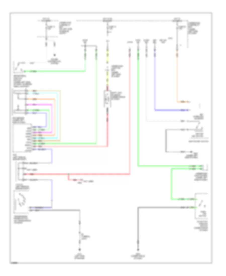
DEFOGGERS
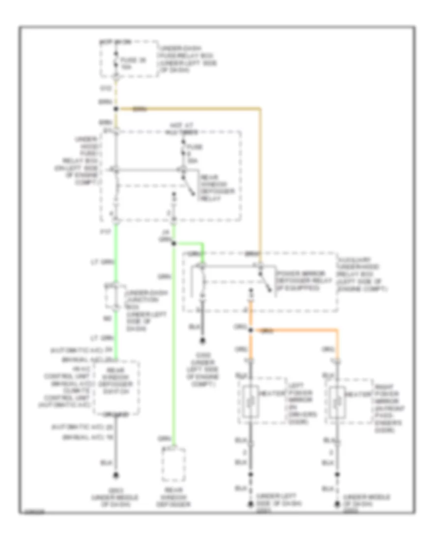
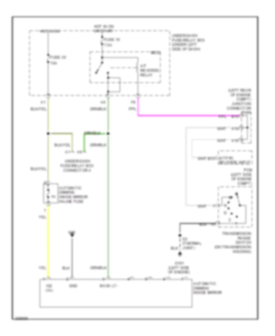
Heated Mirrors Wiring Diagram for Honda CR-V LX 2010
List of elements for Heated Mirrors Wiring Diagram for Honda CR-V LX 2010:
- (automatic a/c)
- (manual a/c)
- (under left side of dash) g501
- (under middle of dash) g503
- Auxiliary under-hood relay box (left side of engine compt)
- F17
- Fuse 30a
- Fuse 36 10a
- G12
- G302 (under left side of engine compt)
- G503 (under middle of dash)
- Ground
- Heater
- Hot at all times
- Hot in on
- Hvac control unit (manual a/c) climate control unit (automatic a/c)
- Left power mirror (in driver's door)
- Power mirror defogger relay (if equipped)
- Rear window defogger
- Rear window defogger relay
- Rear window defogger switch
- Right power mirror (in front pass- enger's door)
- Under- hood fuse/ relay box (on left side of engine compt)
- Under-dash fuse/relay box (under left side of dash)
- Under-dash junction box (under left side of dash)
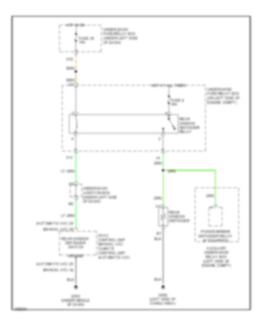
Rear Defogger Wiring Diagram for Honda CR-V LX 2010
List of elements for Rear Defogger Wiring Diagram for Honda CR-V LX 2010:
- (automatic a/c)
- (manual a/c)
- Auxiliary under-hood relay box (left side of engine compt)
- F17
- Fuse 36 10a
- Fuse 8 30a
- G12
- G503 (under middle of dash)
- G602 (left side of cargo area)
- Ground
- Hot at all times
- Hot in on
- Hvac control unit (manual a/c) climate control unit (automatic a/c)
- Power mirror defogger relay (if equipped)
- Rear window defogger
- Rear window defogger relay
- Rear window defogger switch
- Under-dash fuse/relay box (under left side of dash)
- Under-dash junction box (under left side of dash)
- Under-hood fuse/relay box (on left side of engine compt)
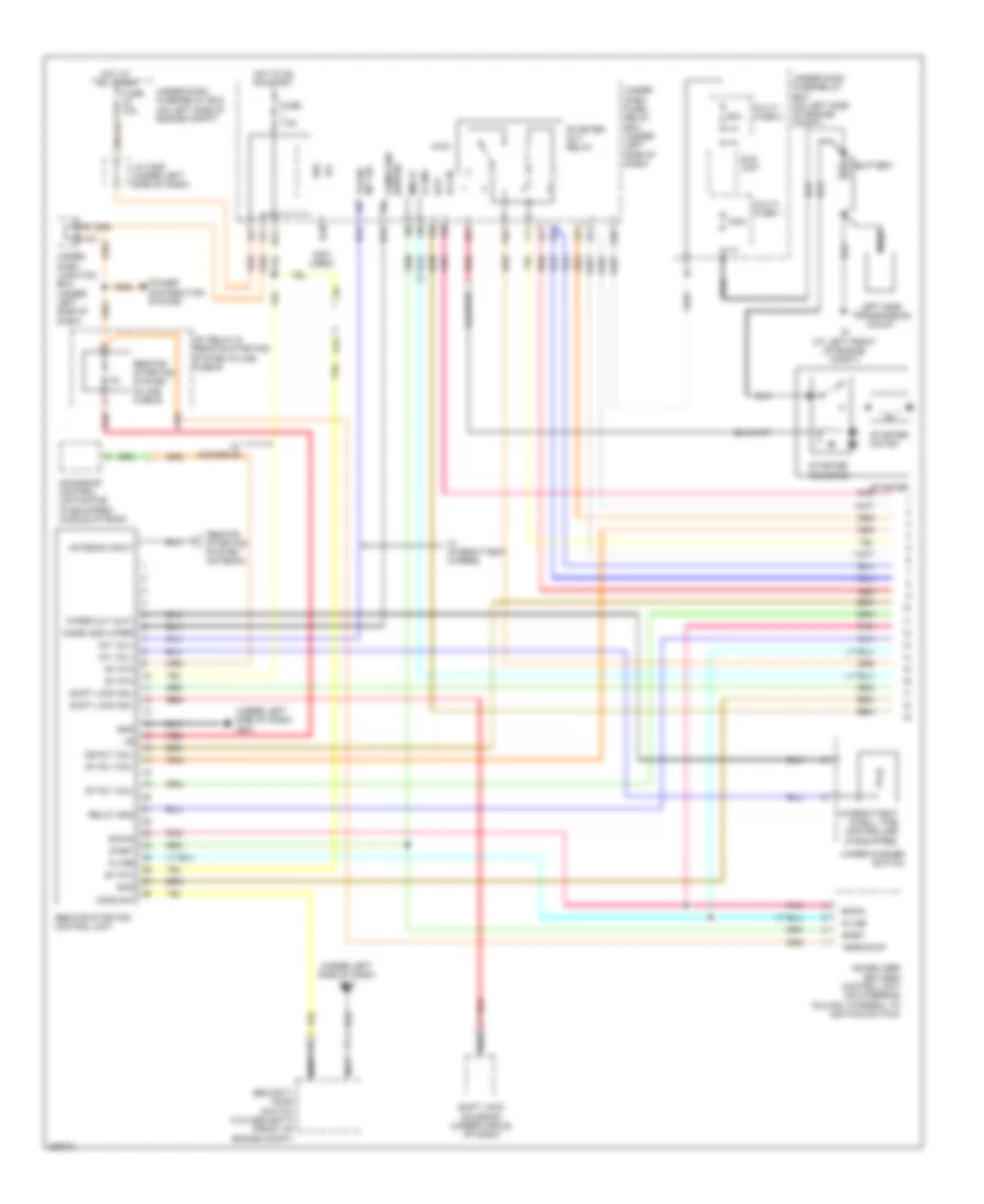
ENGINE PERFORMANCE
2.4L
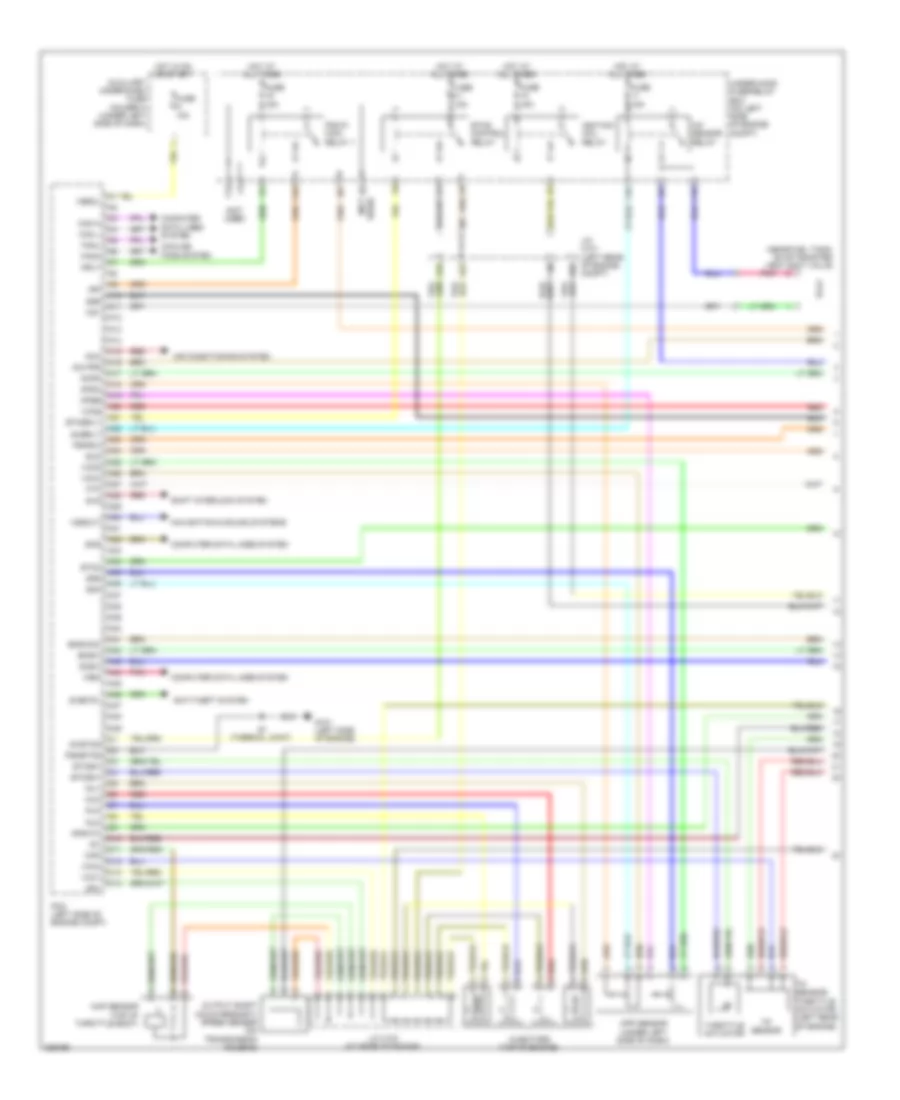
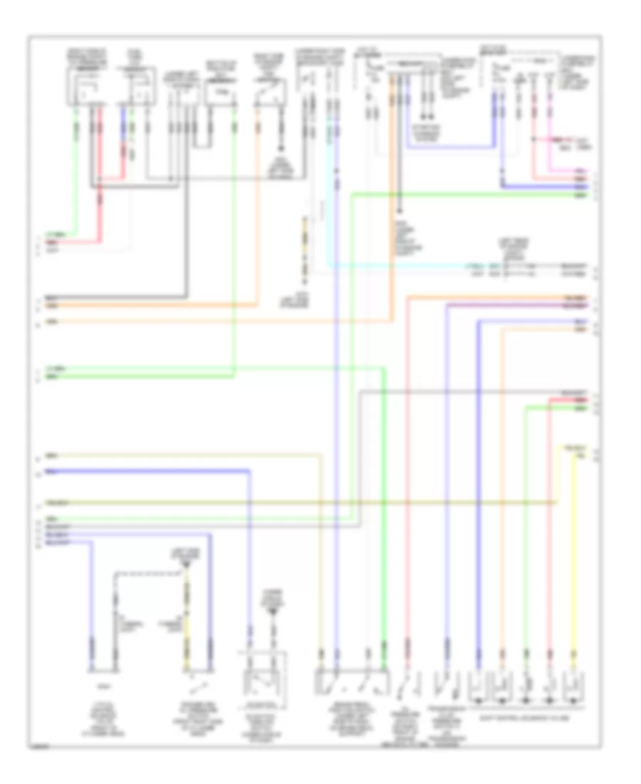
2.4L, Engine Performance Wiring Diagram (1 of 5) for Honda CR-V LX 2010
List of elements for 2.4L, Engine Performance Wiring Diagram (1 of 5) for Honda CR-V LX 2010:
- (near fuel tank) evap canister vent shut valve
- (not used)
- A/f sensor relay
- A10
- A11
- A12
- A13
- A14
- A15
- A16
- A17
- A18
- A19
- A20
- A21
- A22
- A23
- A24
- A25
- A26
- A27
- A28
- A29
- A30
- A31
- A32
- A33
- A34
- A35
- A36
- A37
- A38
- A39
- A40
- A41
- A42
- A43
- A44
- A45
- A46
- A47
- A48
- A49
- Acc
- Acpd
- Afshtc
- Air conditioning system
- Anti-theft system
- App sensor (under left side of dash)
- Apsa
- Apsb
- Auxiliary under-dash fuse holder a (under left side of dash)
- B10
- B23
- Bksw
- Bkswnc
- C10
- C11
- C12
- C13
- C14
- Can h
- Can l
- Computer data lines system
- Cooling fans system
- D3sw
- Eld
- Etc2
- Etcs control relay
- Etcsm+
- Etcsm-
- Etcsrly
- F10
- F13
- F16
- F18
- Fanh
- Fanl
- Ftp
- Fuse 15a
- Fuse a 10a
- G101 (left side of engine)
- Hot at all times
- Hot in on or start
- Ig1
- Ig1etcs
- Ignition coil relay
- Igp
- Imo fpr
- Inj1
- Inj2
- Inj3
- Inj4
- Injectors (top of engine)
- J/c c101 (left rear of engine compt)
- J/c c103 (at rear of engine)
- Map
- Map sensor (top of throttle body)
- Mrly
- Navigation & sound systems
- Output shaft (countershaft) speed sensor (on transmission housing)
- Pcm (left side of engine compt)
- Pgm-fi main relay 1
- Pgmetcs
- Pnk
- Pspsw
- Red
- S-net5v
- S1 (thermal joint)
- Scs
- Sg1
- Sg4
- Sg5
- Sg6
- Shift interlock system
- Sls
- Subrly
- Throttle actuator
- Tp sensor
- Tp sensor/ throttle actuator (left rear of engine)
- Under-hood fuse/relay box (on left side of engine compt)
- Used) (not
- Vbsol
- Vcc1
- Vcc3
- Vcc4
- Vcc5
- Vcc6
- Vssout
- Vsv
- Wen
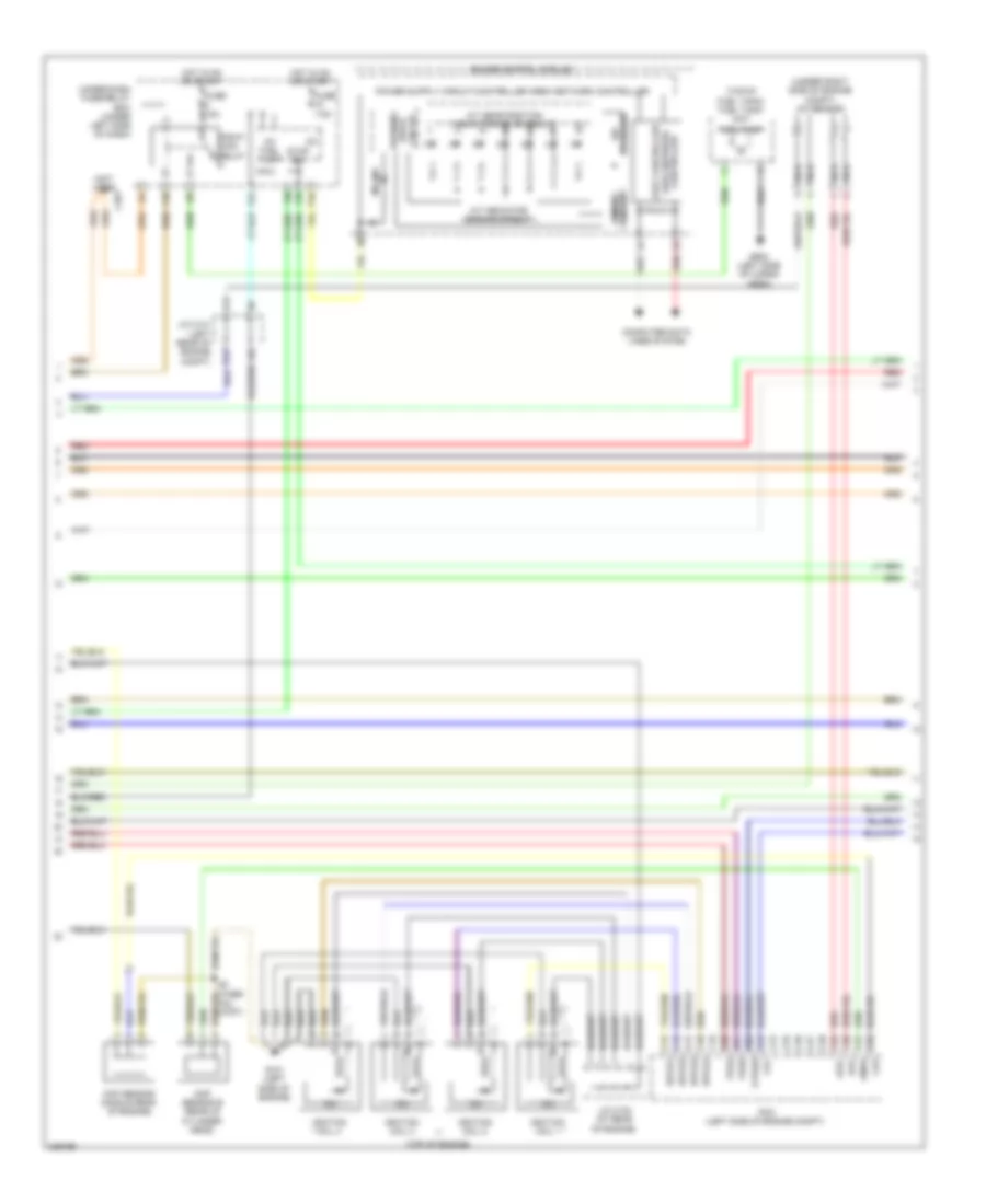
2.4L, Engine Performance Wiring Diagram (2 of 5) for Honda CR-V LX 2010
List of elements for 2.4L, Engine Performance Wiring Diagram (2 of 5) for Honda CR-V LX 2010:
- (not used)
- (top of engine)
- (top of fuel tank) fuel tank unit
- (under right side of engine compt) a/f sensor
- A/t gear position indicator drive circuit
- A/t indicator dimming circuit
- A12
- Afs+
- Afs-
- Area network fast controller
- B12
- C15
- C16
- C17
- C18
- C19
- C20
- C21
- C22
- C23
- C24
- C25
- C26
- C27
- C28
- C29
- C30
- C31
- C32
- C401
- Ckp
- Ckp sensor (middle rear of engine)
- Cmp sensor b (rear of cylinder head)
- Cmpb
- Computer data lines system
- Controller
- Dimming circuit
- Drive circuit
- F10
- F24
- F25
- F30
- Fuel pump
- Fuse 15a
- Fuse 7.5a
- G101 (left side of engine)
- G602 (left side of cargo area)
- Gauge control module
- Hot in on or start
- Icm
- Ig1
- Ig1 fuel pump
- Ignition coil 1
- Ignition coil 2
- Ignition coil 3
- Ignition coil 4
- Igpls1
- Igpls2
- Igpls3
- Igpls4
- J/c c101 (left rear of engine compt)
- J/c c103 (at rear of engine)
- Micu
- Mil ind
- Nca
- P10
- Pcm (left side of engine compt)
- Pgm-fi main relay
- Red
- S3 (ther- mal joint)
- Stabilize 10v
- Stop sw
- Tpsa
- Tpsb
- Under-dash fuse/relay box (under left side of dash)
- Vtc
- Vtpsw
- Warning
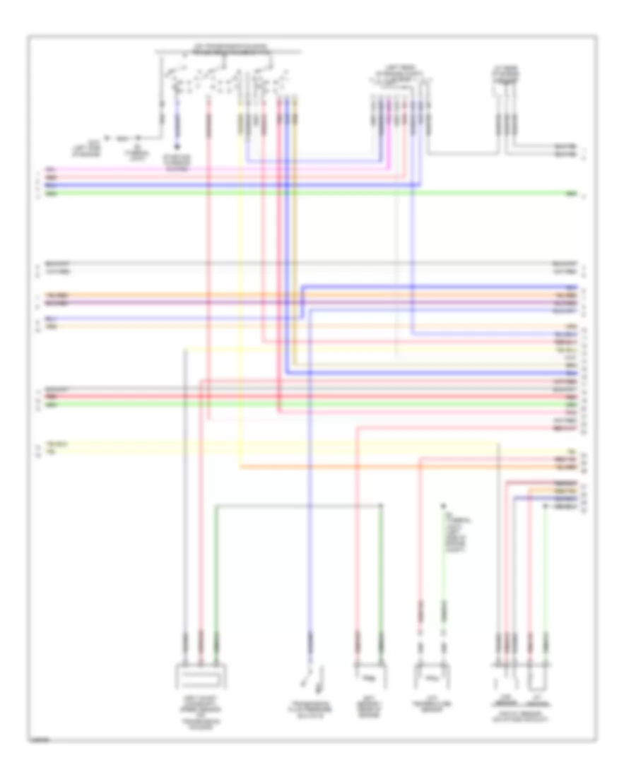
2.4L, Engine Performance Wiring Diagram (3 of 5) for Honda CR-V LX 2010
List of elements for 2.4L, Engine Performance Wiring Diagram (3 of 5) for Honda CR-V LX 2010:
- (bottom of radiator) ect sensor 2
- (fuel tank) ftp sensor
- (left rear of engine compt) j/c c101
- (left side of engine) g101
- (not used) c502
- (right side of engine compt) a/c pressure sensor
- (right side of engine compt) psp switch
- (under left side of dash) j/c c404
- (under middle of dash) g503
- (under right side of engine compt) secondary ho2s
- +b horn
- Atp -p
- Atp -r
- B18
- B19
- Brake pedal position switch (under left side of dash, on brake pedal support)
- D3 switch
- D3 switch/ park pin switch (under middle of dash)
- Eld unit
- F15
- F27
- Fuse 10a
- Fuse 15a
- G101 (left side of engine)
- G16
- G302 (under left side of of engine compt)
- G401 (under left side of dash)
- Hot at all times
- Hot in on or start
- Micu
- Oil pressure switch (on right front of engine, above oil filter)
- Red
- Rocker arm oil pressure switch (front right side of cylinder head)
- S1 (thermal joint)
- S3 (thermal joint)
- Shift control solenoid valves
- Starting/ charging system
- Transmission fluid pressure switch a (on transmission housing)
- Under-dash fuse/relay box (under left side of dash)
- Under-hood fuse/relay box (on left side of engine compt)
- Vtc oil control solenoid valve (front of cylinder head)
2.4L, Engine Performance Wiring Diagram (4 of 5) for Honda CR-V LX 2010
List of elements for 2.4L, Engine Performance Wiring Diagram (4 of 5) for Honda CR-V LX 2010:
- (at rear of engine) j/c c103
- (left rear of engine compt) j/c c101
- (on transmission housing) transmission range switch
- A14
- A15
- A16
- A17
- Atf temperature sensor
- B15
- B22
- Ect sensor 1 (rear of engine)
- G101 (left side of engine)
- Iat sensor
- Input shaft (mainshaft) speed sensor (on transmission housing)
- Maf sensor
- Maf/iat sensor (on intake air duct)
- Pnk
- Red
- S2 (thermal joint)
- S4 (thermal joint) (left side of engine compt)
- Starting/ charging system
- Transmission fluid pressure switch b
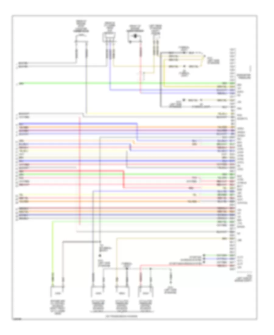
2.4L, Engine Performance Wiring Diagram (5 of 5) for Honda CR-V LX 2010
List of elements for 2.4L, Engine Performance Wiring Diagram (5 of 5) for Honda CR-V LX 2010:
- (front of engine) knock sensor
- (left rear of engine compt) j/c c101
- (on transmission housing)
- (rear of cylinder head) cmp sensor a
- (rear of engine) evap canister purge valve
- (thermal joint) s2
- A/t clutch pressure control solenoid valve a
- A/t clutch pressure control solenoid valve b
- A/t clutch pressure control solenoid valve c
- A18
- A20
- Altc
- Altf
- Altl
- Atft
- Atp-2
- Atp-fwd
- Atpd
- Atpn
- Atpp
- Atpr
- Atprvs
- Atps
- B10
- B11
- B12
- B13
- B14
- B15
- B16
- B17
- B18
- B19
- B20
- B21
- B22
- B23
- B24
- B25
- B26
- B27
- B28
- B29
- B30
- B31
- B32
- B33
- B34
- B35
- B36
- B37
- B38
- B39
- B40
- B41
- B42
- B43
- B44
- B45
- B46
- B47
- B48
- B49
- Barometer pressure
- C33
- C34
- C35
- C36
- C37
- C38
- C39
- C40
- C41
- C42
- C43
- C44
- C45
- C46
- C47
- C48
- C49
- Cmpa
- Ect1
- G101 (left side of engine)
- Iat
- Lg1
- Lg2
- Lsa
- Lsb
- Lsc
- Op2sw
- Op3sw
- Opsw
- Pcm (left side of engine compt)
- Pcs
- Pg1
- Pg2
- Pnk
- Red
- Rocker arm oil control solenoid (right front of cylinder head)
- S3 (thermal joint)
- Sg2
- Sg3
- Sha
- Shb
- Shc
- Shd
- She
- Sho2s
- So2shtc
- Starting/ charging system
- Starting/charging system
- Vcc2
- Vg+
- Vg-
- Vts
EXTERIOR LIGHTS
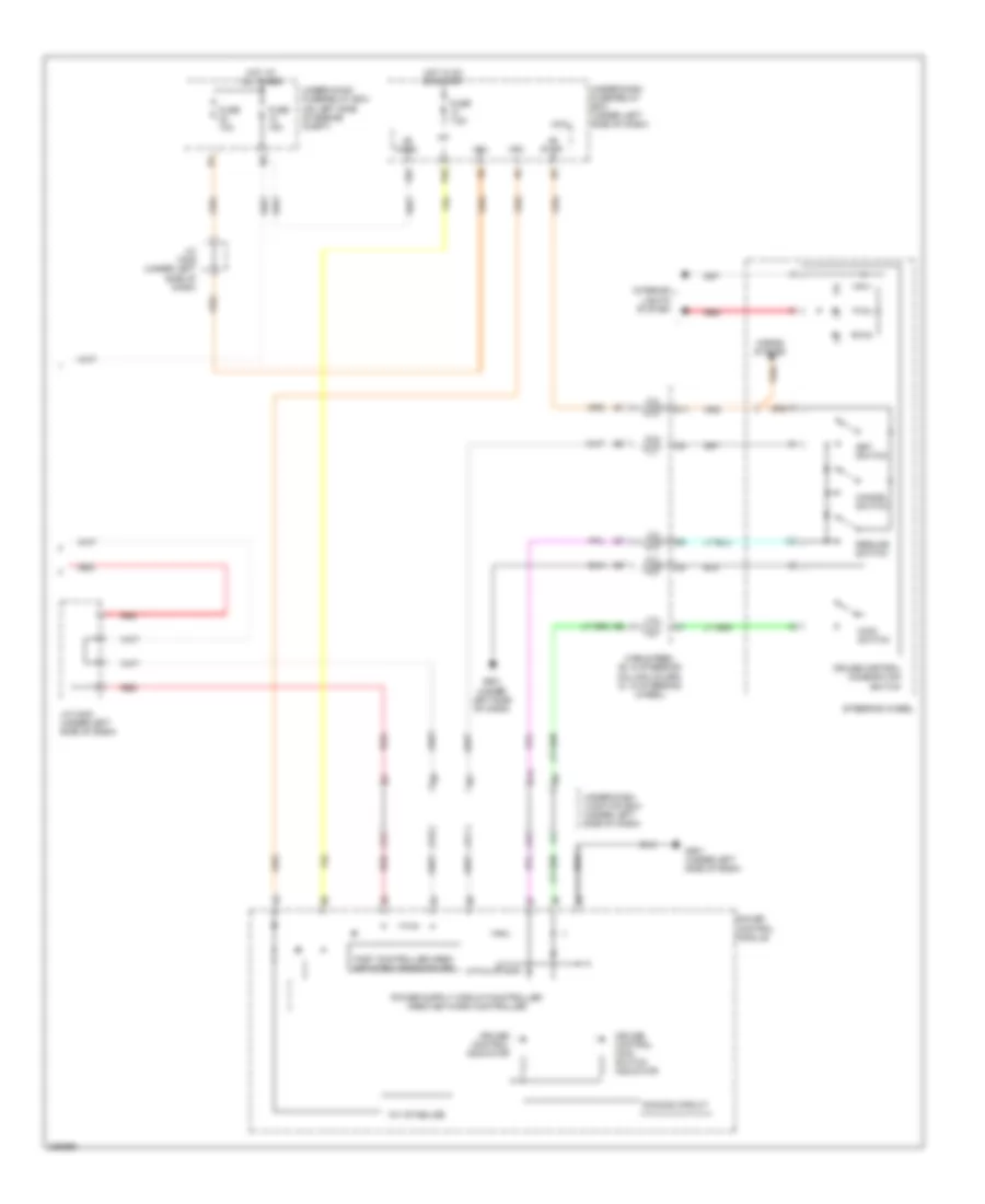
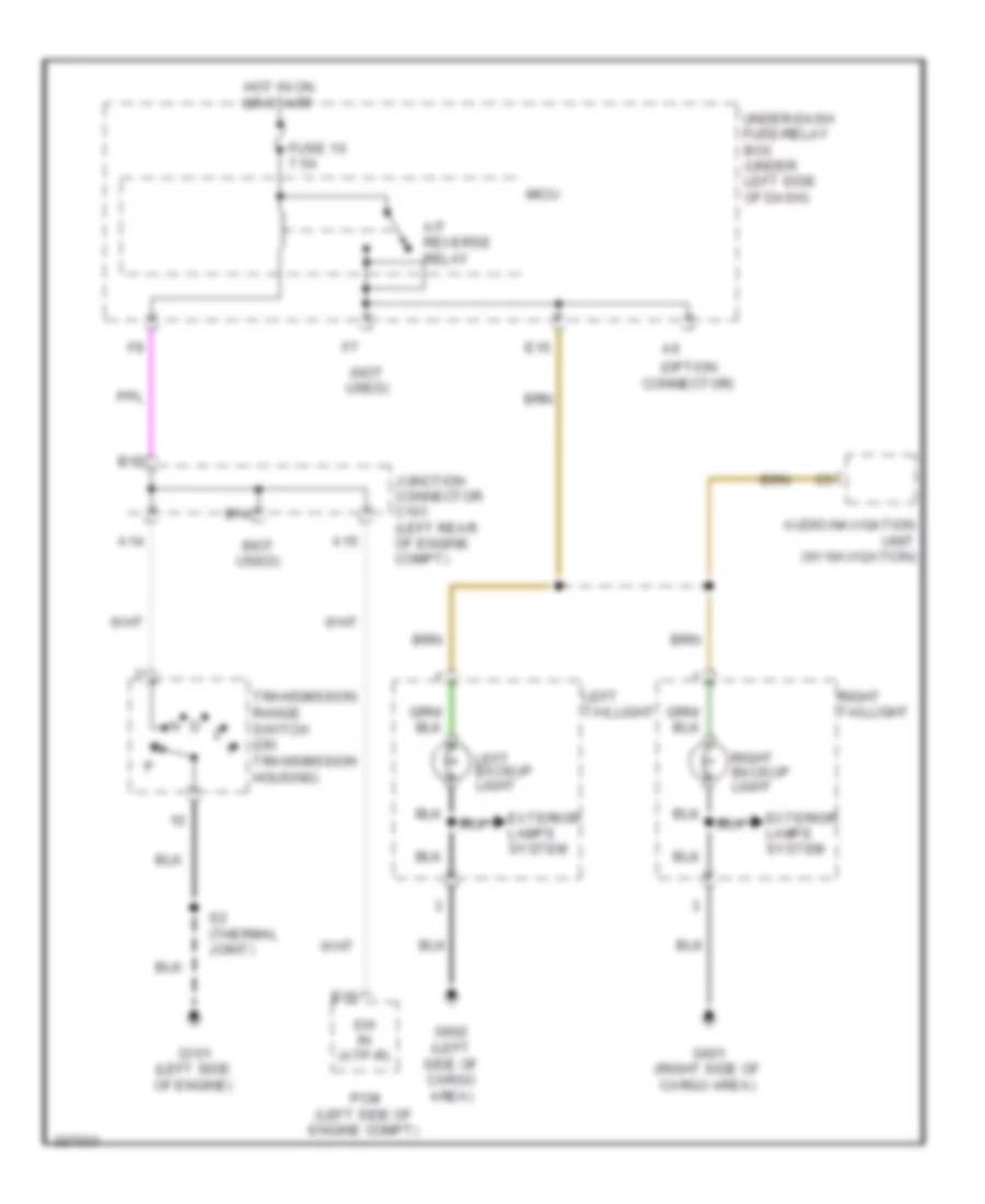
Backup Lamps Wiring Diagram for Honda CR-V LX 2010
List of elements for Backup Lamps Wiring Diagram for Honda CR-V LX 2010:
- (not used)
- (option connector)
- A/t reverse relay
- A14
- A15
- Audio-navigation unit (w/ navigation)
- B14
- B15
- E15
- Exterior lamps system
- Fuse 10 7.5a
- G101 (left side of engine)
- G601 (right side of cargo area)
- G602 (left side of cargo area)
- Hot in on or start
- Junction connector c101 (left rear of engine compt)
- Left backup light
- Left taillight
- Micu
- Pcm (left side of engine compt)
- Right backup light
- Right taillight
- S2 (thermal joint)
- Sw in (atp-r)
- Transmission range switch (on transmission housing)
- Under-dash fuse/relay box (under left side of dash)
Exterior Lamps Wiring Diagram (1 of 2) for Honda CR-V LX 2010
List of elements for Exterior Lamps Wiring Diagram (1 of 2) for Honda CR-V LX 2010:
- (left side of cargo area)
- (not used)
- (under left side of dash) under-dash junction box
- +b haz
- +b trailer
- 7.5a
- A13
- A42
- B-can
- Backup lamps circuit
- Backup light
- C14
- Connector)
- E11
- E33
- E39
- E40
- F20
- Fuse 15a
- Fuse 5a
- Fuse 7.5a
- G11
- G301 (under left side of engine compt)
- G401 (under left side of dash)
- G601 (right side of cargo area)
- G602 (left side of cargo area)
- Gnd
- High mount brake light
- Hot at all times
- Hot in on or start
- Ig1
- Ig1 ods
- Ind ctrl (ptt)
- L turn lt
- L turn/stop
- Left front turn signal light
- Left taillight
- License plate light
- Micu
- P-gnd
- Pcm (left side of engine compt)
- Pnk
- R turn lt
- R turn stop
- Rear side marker light
- Rear turn signal light
- Red
- Right front turn signal light
- Right taillight
- S-gnd
- Small
- Small (trailer)
- Srs unit (under middle of dash)
- Stop sw
- Sw in (bksw)
- Taillight relay
- Taillight/brake light
- Trailer hitch connector
- Trailer lighting connector (option
- Trailer lighting control unit (accessory installed)
- Trailer lighting in-line fuse
- Turn signal/hazard flasher circuit
- Under-dash fuse/relay box (under left side of dash)
- W/ automatic lighting system
- W/o automatic lighting system
Exterior Lamps Wiring Diagram (2 of 2) for Honda CR-V LX 2010
List of elements for Exterior Lamps Wiring Diagram (2 of 2) for Honda CR-V LX 2010:
- (not used)
- (under left side of dash) g501
- +b horn
- 0) off 1) park 2) auto 3) head
- 10v stabilize
- Automatic lighting control unit (if equipped) (under left side of dash)
- B-can
- Body controller area network transceiver
- Brake pedal position switch (under left side of dash, on brake pedal support)
- Combi gnd (light)
- Combination light switch
- Dimming circuit
- E34
- F25
- F30
- F31
- Fuse 10a
- Fuse 15a
- G16
- G301 (under left side of engine compt)
- Gauge control module
- H/l
- H/l on sw
- H/l sw off
- Hazard sw
- Hazard warning switch/front passenger's air bag cutoff indicator
- Headlight switch
- Hot at all times
- Ig1
- Interior lights system
- J/c c405 (under left side of dash)
- Left front parking light
- Left turn signal ind
- Lights on ind
- Micu
- P10
- Pnk
- Q11
- Red
- Right front parking light
- Right turn signal ind
- S11
- S13
- S18
- S19
- Small lt sw
- Stop sw
- Turn l sw
- Turn r sw
- Turn signal switch
- Turn signal/hazard relay 2 (sounder)
- Under-dash fuse/relay box (under left side of dash)
- Under-hood fuse/relay box (on left side of engine compt)
- Vbu
- Warning drive circuit
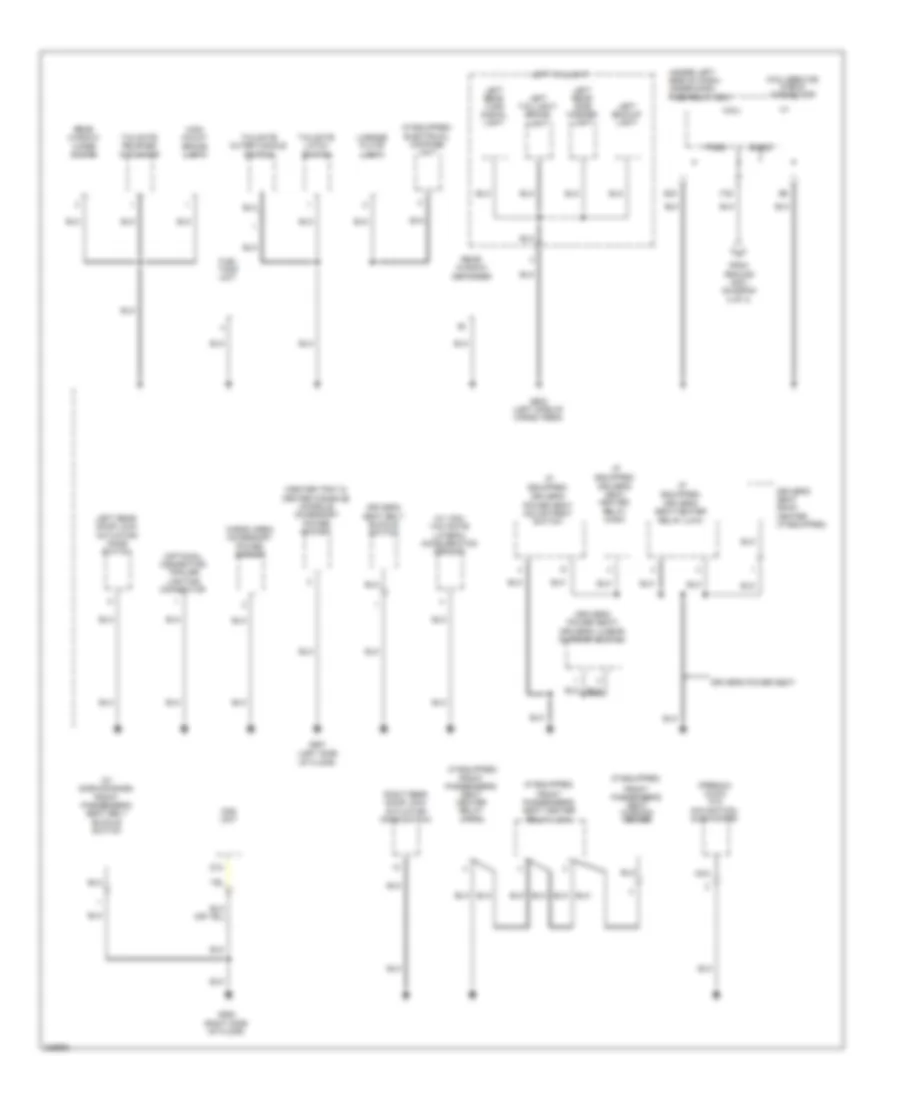
GROUND DISTRIBUTION
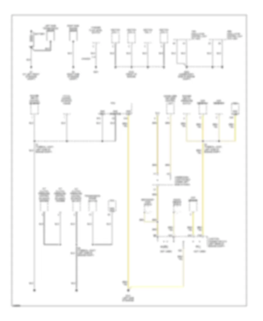
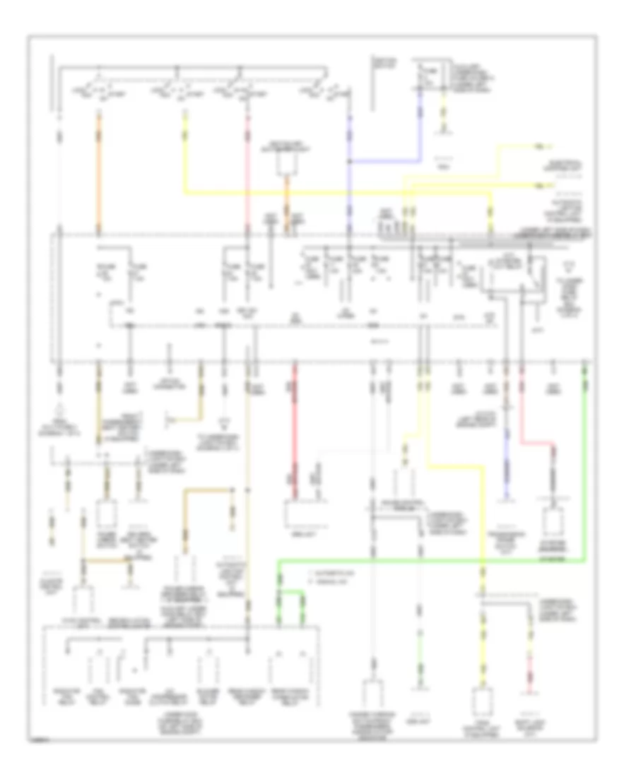
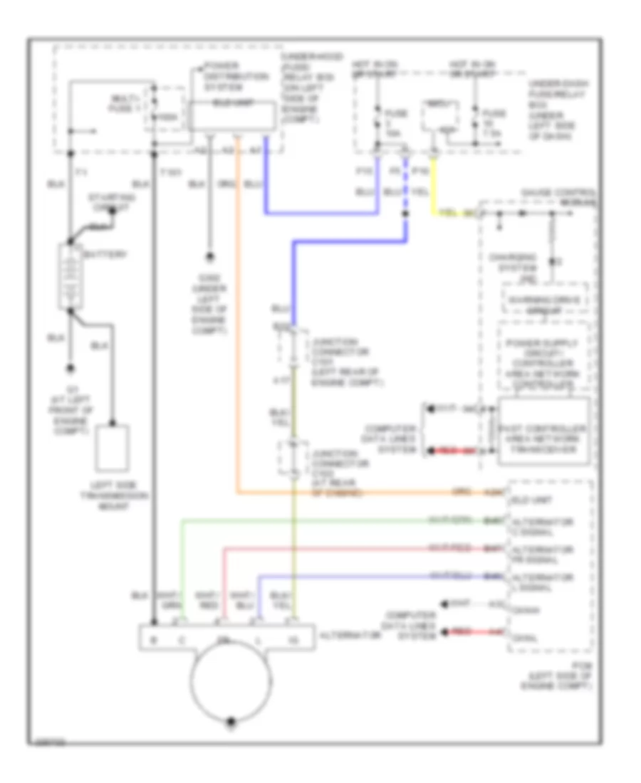
Ground Distribution Wiring Diagram (1 of 4) for Honda CR-V LX 2010
List of elements for Ground Distribution Wiring Diagram (1 of 4) for Honda CR-V LX 2010:
- (not used)
- A/t clutch pressure control solenoid valve a
- A/t clutch pressure control solenoid valve b
- A/t clutch pressure control solenoid valve c
- A18
- A19
- A20
- A21
- Abs modulator control unit (w/o vsa)
- B10
- Battery
- C44
- C48
- Canada
- Ckp sensor
- Cmp sensor a
- Cmp sensor b
- Dlc
- G1 (at left front of engine compt)
- G101 (left side of engine)
- G102 (front of engine)
- G2 (right side of engine compt)
- G201
- G202 (under right side of engine compt)
- Gnd (lg1)
- Gnd (lg2)
- Gnd (pg1)
- Gnd (pg2)
- Gnd (pgmetcs)
- Ignition coil 1
- Ignition coil 2
- Ignition coil 3
- Ignition coil 4
- Immobilizer- keyless control unit
- Junction connector c101 (left rear of engine compt)
- Knock sensor shield
- Left side transmission mount
- Pcm
- Right side engine mount
- Rocker arm oil control solenoid
- Rocker arm oil pressure switch
- S1 (thermal joint) (left side of engine compt)
- S2 (thermal joint) (left side of engine compt)
- S3 (thermal joint) (left side of engine compt)
- Secondary ho2s shield
- Transmission range switch
- Under-dash junction box (under left side of dash)
- Vsa modulator control unit (w/ vsa)
- Vtc oil control solenoid valve
- Washer fluid level switch
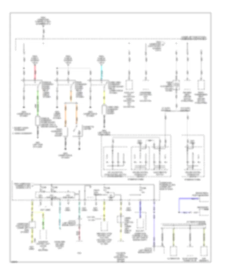
Ground Distribution Wiring Diagram (2 of 4) for Honda CR-V LX 2010
List of elements for Ground Distribution Wiring Diagram (2 of 4) for Honda CR-V LX 2010:
- (if equipped) automatic lighting control unit
- (if equipped) driver's vanity mirror light
- (if equipped) front passenger's vanity mirror light
- (if equipped) moonroof control unit/ motor
- (if equipped) moonroof switch
- (if equipped) security hood switch
- (if equipped) vsa off switch
- A/c condenser fan motor
- Auxiliary under-hood relay box
- Blower motor relay
- Blower power transistor
- Brake fluid level switch
- Cable reel (connector c: in steering wheel) (connector b: in steering column cover)
- Cruise control combination switch
- Driver's door lock actuator/ knob switch/ key cylinder switch
- Eld unit
- Fan control relay
- G301 (under left side of engine compt)
- G302 (under left side of engine compt)
- G401 (under left side of dash)
- G501 (under left side of dash)
- Gauge control module
- Ignition key switch/ key light
- Left front parking light
- Left front turn signal light
- Left headlight
- Left power mirror
- Power mirror defogger relay
- Power mirror defoggers
- Power mirror switch
- Power window master switch/ driver's door lock switch
- Psp switch
- Rear window wiper motor relay
- Red
- Right front parking light
- Right front turn signal light
- Right headlight
- Steering wheel
- To under-dash fuse/relay box (diagram 4 of 4)
- Under-hood fuse/relay box (on left side of engine compartment)
- W/ power mirror defogger
- Windshield wiper motor
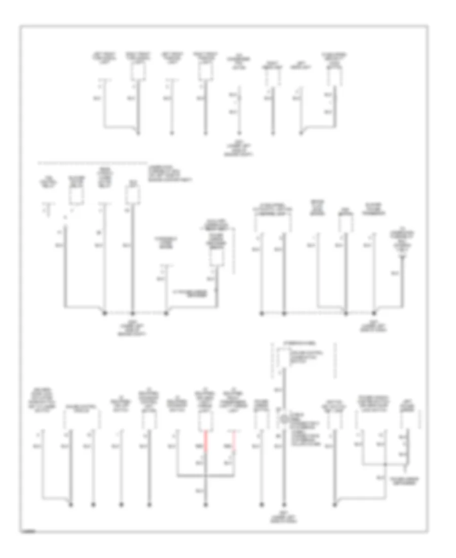
Ground Distribution Wiring Diagram (3 of 4) for Honda CR-V LX 2010
List of elements for Ground Distribution Wiring Diagram (3 of 4) for Honda CR-V LX 2010:
- (a/t) d3 switch/ park-pin switch
- (if equipped)
- (if equipped) front passenger's seat heater switch
- (if equipped) tpms control unit
- (under left side of dash) under-dash fuse/relay box
- (w/
- (w/ navigation) audio navigation unit
- (w/ navigation) handsfree- link control unit
- (w/ power mirror defoggers) right power mirror
- A12
- A20
- A22
- A23
- Audio navigation unit
- Audio unit
- Automatic a/c
- Cargo area accessory power socket relay
- Climate control unit
- Console accessory power socket relay
- D3 switch
- Dlc
- Driver's seat heater switch
- Front accessory power socket
- Front accessory power socket relay
- Front passenger's door lock actuator/ knob switch
- Front passenger's power window switch
- G502 (under middle of dash)
- G503 (under middle of dash)
- G504 (under middle of dash)
- G505 (under middle of dash)
- G601 (right side of cargo area)
- Hvac control unit
- Manual a/c
- Micu
- Navigation
- Navigation) stereo amplifier
- Nes conn- ector
- Park-pin switch
- Right backup light
- Right rear side marker light
- Right rear turn signal light
- Right taillight
- Right taillight/ brake light
- S- gnd2
- Srs unit
- T34
- W/o navigation
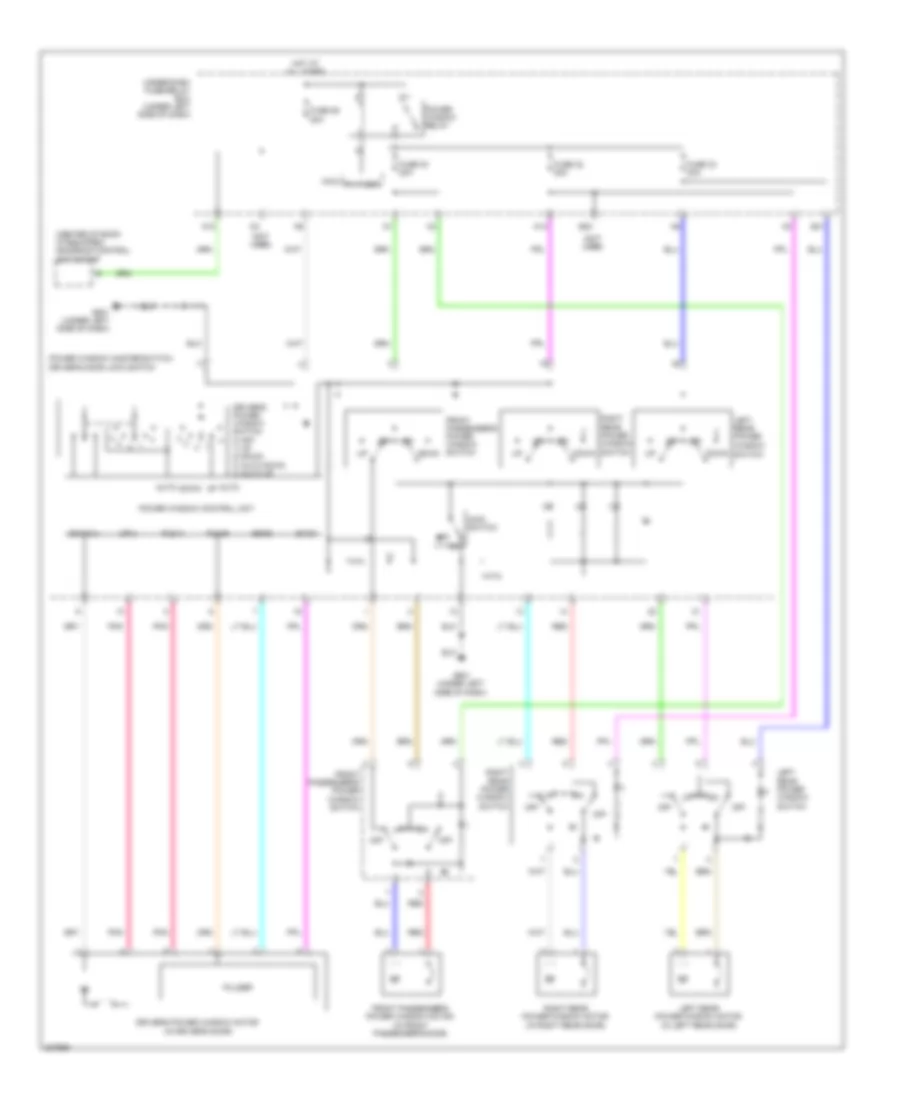
Ground Distribution Wiring Diagram (4 of 4) for Honda CR-V LX 2010
List of elements for Ground Distribution Wiring Diagram (4 of 4) for Honda CR-V LX 2010:
- (center tray & center console) console accessory power socket
- (driver's power seat) driver's lumbar support switch
- (if
- (if equipped)
- (if equipped) electrical compass unit
- (if equipped) front passenger's seat heater relay (high)
- (left side
- (optional connector) trailer lighting connector
- (premium audio w/o navigation) subwoofer
- (under left side of dash) under-dash fuse/relay box
- (w/ side air bags) front passenger's seat belt buckle switch
- (w/ vsa) yaw rate- lateral acceleration sensor
- Cargo area accessory power socket
- D12
- Driver's power seat
- Driver's power seat adjustment switch
- Driver's seat back heater (if equipped)
- Driver's seat belt buckle switch
- Driver's seat heater relay (high)
- E33
- Equipped)
- Equipped) driver's seat heater relay (low)
- F20
- From ground g401 (diagram 2 of 4)
- Front passenger's seat cushion heater
- Front passenger's seat heater relay (low)
- Fuel tank unit
- G551
- G552 (right side of floor)
- G602 (left side of cargo area)
- High mount brake light
- Left backup light
- Left rear door lock actuator/ knob switch
- Left rear side marker light
- Left rear turn signal light
- Left taillight
- Left taillight/ brake light
- License plate light
- Micu
- Micu service check connector
- Nca
- Ods unit
- Of floor)
- P-gnd
- Rear window defogger
- Rear window wiper motor
- Right rear door lock actuator/ knob switch
- S-gnd
- Tailgate latch switch
- Tailgate outer handle switch
- Tailgate release actuator
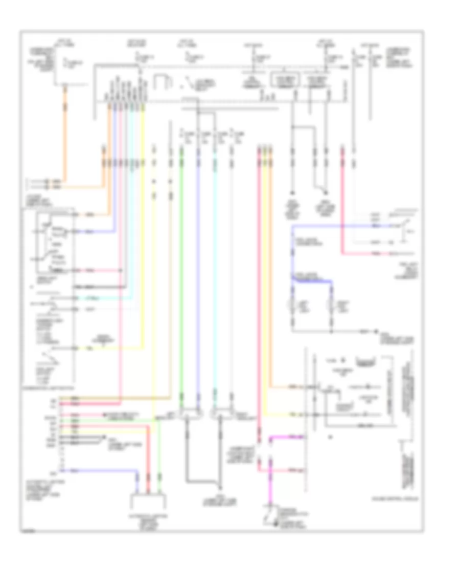
HEADLIGHTS
Headlights Wiring Diagram for Honda CR-V LX 2010
List of elements for Headlights Wiring Diagram for Honda CR-V LX 2010:
- 0 = low 1 = high 2 = passing
- 0 = off 1 = on
- 10v stabilize
- Auto
- Automatic lighting control unit (if equipped) (under left side of dash)
- Automatic lighting sensor (left side of dash)
- B-can
- Body controller area network transceiver
- Combi gnd
- Combination light switch
- Computer data lines system
- Controller
- Dim sw
- Dimmer/flash- to-pass switch
- Dimming circuit
- Drl control circuit
- Drl ind
- E33
- F20
- F21
- F22
- Fog light relay (honda accessory)
- Fog light switch
- Fog lights connector a
- Fog lights connector b
- Fog lt sw
- Fr fog rly
- Fuse 10 7.5a
- Fuse 10a
- Fuse 18 20a
- Fuse 20a
- Fuse 21 20a
- Fuse 23 10a
- Fuse 37 7.5a
- G10
- G12
- G15
- G17
- G301 (under left side of engine compt)
- G302 (under left side of engine compt)
- G401 (under left side of dash)
- G602 (left side of cargo area)
- Gauge control module
- Gnd1
- Gnd2
- H/l
- H/l on sw
- H/l sw off
- Head
- Headlight switch
- High beam control circuit
- High beam ind
- Honda accessory
- Hot at all times
- Hot in on
- Hot in on or start
- Ig1
- Ig2
- J/c c405 (under left side of dash)
- Left fog light
- Left headlight
- Lights on ind
- Low beam headlight relay
- Micu
- Off
- P-gnd
- P10
- Park
- Parking brake switch (a/t) (under left side of dash)
- Passing sw
- Pnk
- Red
- Right fog light
- Right headlight
- S-gnd
- S11
- S12
- S13
- S14
- S16
- Sig
- Sio
- Sip
- Small lt sw
- Under-dash fuse/relay box (under left side of dash)
- Under-dash junction box (under left side of dash)
- Under-hood fuse/relay box (on left side of engine compt)
- Vbu
- Warning drive circuit
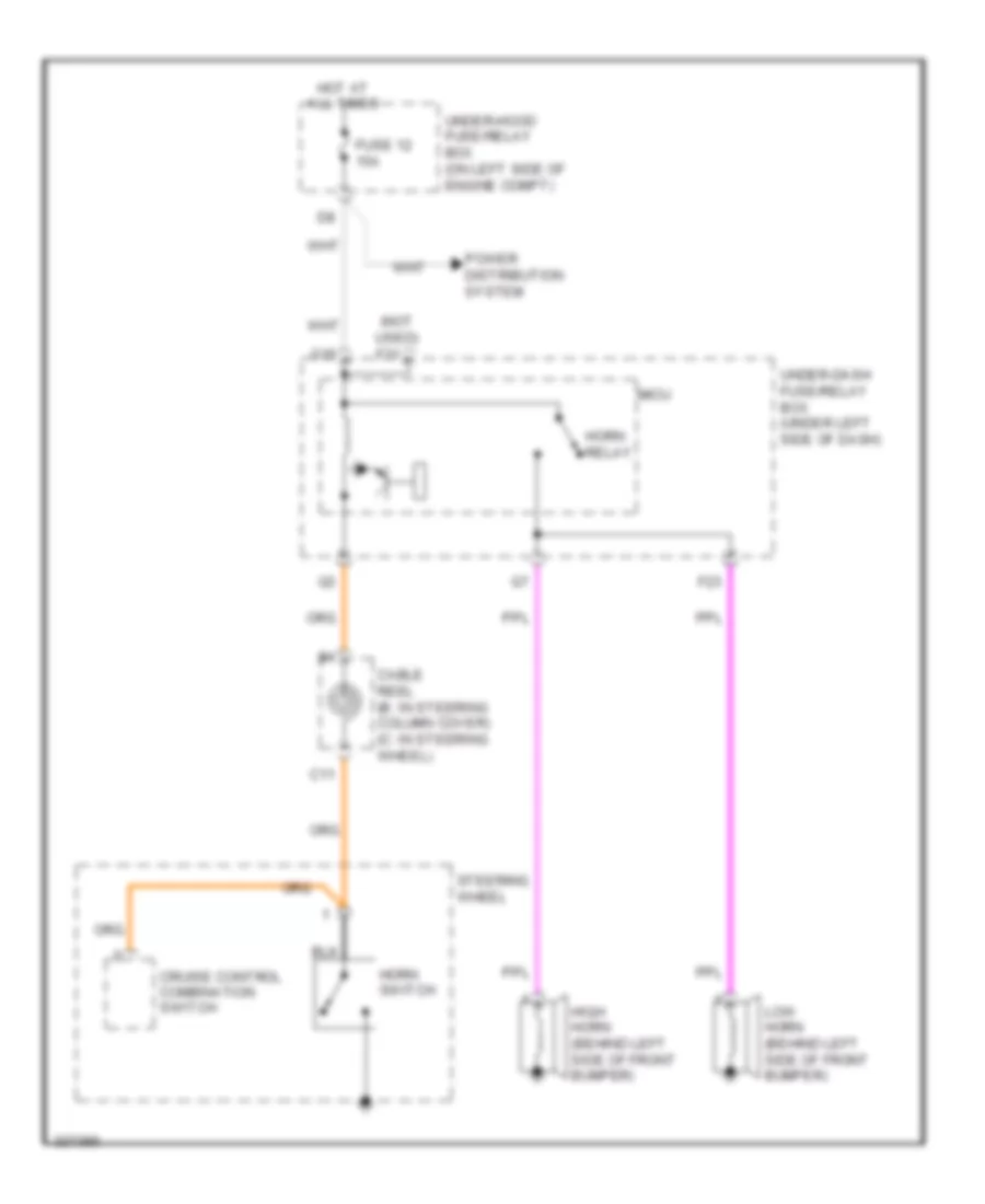
HORN
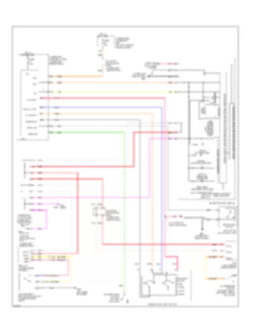
Horn Wiring Diagram for Honda CR-V LX 2010
List of elements for Horn Wiring Diagram for Honda CR-V LX 2010:
- (not used) f31
- C11
- Cable reel (b: in steering column cover) (c: in steering wheel)
- Cruise control combination switch
- F23
- Fuse 12 15a
- G16
- High horn (behind left side of front bumper)
- Horn relay
- Horn switch
- Hot at all times
- Low horn (behind left side of front bumper)
- Micu
- Power distribution system
- Steering wheel
- Under-dash fuse/relay box (under left side of dash)
- Under-hood fuse/relay box (on left side of engine compt)
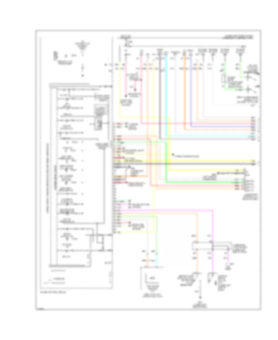
INSTRUMENT CLUSTER
Instrument Cluster Wiring Diagram (1 of 2) for Honda CR-V LX 2010
List of elements for Instrument Cluster Wiring Diagram (1 of 2) for Honda CR-V LX 2010:
- (not used)
- (on left "b" pillar) driver's door switch
- (under left side of dash) under-dash fuse/relay box
- A/t gear position ind drive circuit
- Abs ind
- Anti-lock brakes system
- B-can
- Blinking circuit
- Brake fluid level switch (on brake fluid reservoir)
- Brake system ind
- C507
- Charging system ind
- Combi gnd (light)
- Compulsory turning-off circuit
- Compulsory turning-on circuit
- Computer data lines system
- Cruise control system
- Dim sw
- Disp rx+
- Disp rx-
- Disp tx+
- Disp tx-
- Drl ind
- E17
- E28
- E37
- Electrical compass unit (rear of roof)
- Exterior lights system
- Fail-safe circuit
- Fr door switch (as)
- Fr door switch (dr)
- Front passenger's door switch (on right "b" pillar)
- Fuel gauge sending unit
- Fuel tank unit (top of fuel tank)
- Fuse 7.5a
- G10
- G401 (under left side of dash)
- G501 (under left side of dash)
- G602 (left side of cargo area)
- Gauge control module
- Gnd
- H/l off sw
- H/l on sw
- Headlights system
- Hot in on or start
- Ig1
- Interface
- Interior lights system
- Low fuel ind
- Low oil pressure ind
- Low tire pressure ind
- Low washer fluid ind (canada)
- Maintenance required ind
- Micu
- Mil ind
- P10
- Parking brake switch (a/t) (under left side of dash)
- Passing sw
- Pnk
- Red
- Rr door switch (as)
- Rr door switch (dr)
- S11
- S12
- S13
- S16
- Seat belt reminder ind
- Security ind (if equipped)
- Side air bag cut-off ind
- Small lt sw
- Srs ind
- To high beam ind (diagram 2 of 2)
- Tpms ind
- Under dash junction box (under left side of dash)
- Under-dash junction box (under left side of dash)
- Vbu
- Vsa off ind
- Vsa off system ind
- W/ automatic lighting system
- Warning drive circuit
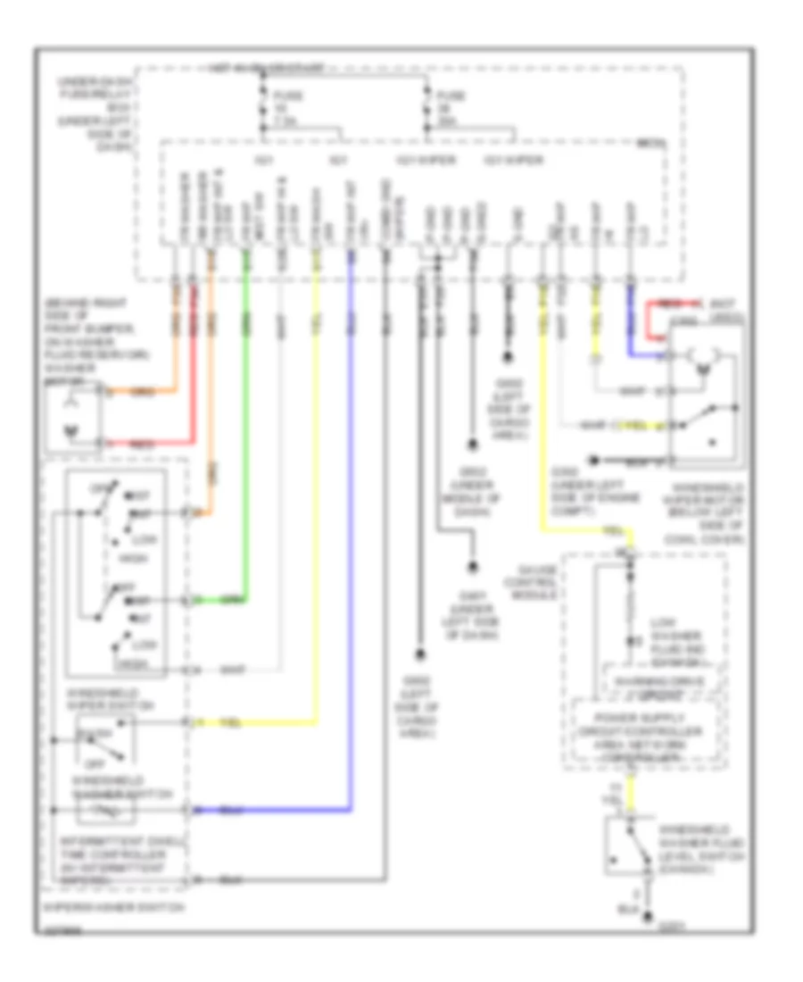
- Wiper/washer system
Instrument Cluster Wiring Diagram (2 of 2) for Honda CR-V LX 2010
List of elements for Instrument Cluster Wiring Diagram (2 of 2) for Honda CR-V LX 2010:
- (engine coolant temperature gauge)
- (fuel gauge)
- (in left "c" pillar) left rear door switch
- 10v stabilize
- A/t ind dimming circuit
- Beeper
- Body controller area network transceiver
- Can-h
- Can-l
- Circuit dimming
- Combination light switch
- Computer data lines system
- Control (red)
- Cruise control ind
- Cruise control main switch ind
- Dimmer/ flash- to-pass switch 0) off 1) high 2) passing
- Dimming circuit
- Door & tailgate open monitor
- Drive circuit
- Fast controller area network transceiver
- For pointers
- From security ind (diagram 1 of 2)
- Fuse 10a
- Gauge control module
- Headlight switch 0) off 1) park 2) auto 3) head
- High beam ind
- Hot at all times
- Illumination
- Illumination control for dial (white)
- Illumination control for ft lcd (white)
- Illumination control for lcd (amber)
- Illumination control for lcd (white)
- Immobilizer system ind
- Ind drive circuit a/t gear position
- J/c c405 (under left side of dash)
- Left turn signal ind
- Lights on ind
- M9 (not used)
- Multi- information display (mid) unit
- Oil pressure switch (on right front of engine, above oil filter)
- Opsw
- Outside air temperature sensor (manual a/c: exterior temperature indicator) (behind middle of front bumper)
- Pcm (left side of engine compt)
- Pnk
- Red
- Right rear door switch (in right "c" pillar)
- Right turn signal ind
- Select/reset/ brightness control knob
- Speedometer
- Tachometer
- Turn signal/ hazard relay 2 (sounder)
- Under-dash junction box (under left side of dash)
- Under-hood fuse/relay box (on left side of engine compt)
- Unit control 5v
- Warning drive circuit
INTERIOR LIGHTS
Courtesy Lamps Wiring Diagram for Honda CR-V LX 2010
List of elements for Courtesy Lamps Wiring Diagram for Honda CR-V LX 2010:
- (w/ moonroof) front individual map lights
- (w/o moonroof) front individual map lights
- +b int lt
- +b intr lts
- Cargo area light
- Cargo lt-
- Ceiling light
- Door
- Driver's door switch (on left "b" pillar)
- Driver's vanity mirror light
- E16
- E17
- E36
- E37
- E38
- Fr door sw(as)
- Fr door sw(dr)
- Front passenger's door switch (on right "b" pillar)
- Front passenger's vanity mirror light
- Fuse 7.5a
- G501 (under left side of dash)
- G602 (left side of cargo area)
- Hot at all times
- Ignition key light
- Ignition key switch/ key light
- Interior light switch
- Intr lt-
- Key lt-
- Left rear door switch (in left "c" pillar)
- Micu
- Moonroof switch (if equipped)
- Off
- Pnk
- R10
- R13
- Red
- Right rear door switch (in right "c" pillar)
- Rr door sw(as)
- Rr door sw(dr)
- T/g sw
- Tailgate latch switch (bottom of tailgate)
- Under- dash junction box (under left side of dash)
- Under-dash fuse/ relay box (under left side of dash)
- Under-hood fuse/relay box (on left side of engine compt)
Entry Light Timer Wiring Diagram for Honda CR-V LX 2010
List of elements for Entry Light Timer Wiring Diagram for Honda CR-V LX 2010:
- (left side of cargo area) g602
- (under left side of dash)
- (under middle of dash)
- (w/ moonroof) front individual map lights
- (w/o moonroof)
- +b intrlts
- B-can
- Cargo area light
- Cargo lt-
- Ceiling light
- Computer data lines system
- Door
- Door lock knob
- Driver's door lock actuator/ knob switch key cylinder switch (in driver's door)
- Driver's door lock knob switch
- Driver's door switch (on left "b" pillar)
- E16
- E17
- E33
- E36
- E37
- E38
- F20
- Fr door sw(as)
- Fr door sw(dr)
- Front individual map lights
- Front passenger's door switch (on right "b" pillar)
- Fuse 10a
- Fuse 7.5a
- G401
- G501 (under left side of dash)
- G502
- G602 (left side of cargo area)
- Hot at all times
- Ig key sw
- Ignition key switch
- Ignition key switch/ key light
- Interior light switch
- Intr lt-
- Junction connector c405 (under left side of dash)
- Key
- Left rear door switch (in left "c" pillar)
- Micu
- Moonroof switch (if equipped)
- Off
- P-gnd
- Pnk
- R16
- Right rear door switch (in right "c" pillar)
- Rr door sw(as)
- Rr door sw(dr)
- S-gnd
- S-gnd2
- Sil dr lock
- Sil dr unlock
- T/g sw
- T23
- T24
- T34
- Tailgate latch switch (bottom of tailgate)
- Under- dash junction box (under left side of dash)
- Under-dash fuse/ relay box (under left side of dash)
- Under-hood fuse/relay box (on left side of engine compt)
- Vbu
Instrument Illumination Wiring Diagram (1 of 2) for Honda CR-V LX 2010
List of elements for Instrument Illumination Wiring Diagram (1 of 2) for Honda CR-V LX 2010:
- (light) s5
- (not used)
- 0-off 1-park 2-auto 3-head
- A10
- A13
- Audio unit
- Audio-navigation unit
- Automatic lighting control unit (under left side of dash)
- B-can
- C11
- C12
- Combi gnd
- Combination light switch
- Computer data lines system
- D3 switch/ park pin switch (a/t) (under middle of dash)
- E16
- E26
- E33
- F10
- F20
- Front passenger's seat heater switch (if equipped)
- Fuse 10 7.5a
- G401 (under left side of dash)
- G602 (left side of cargo area)
- H/l
- H/l off
- H/l on
- Hazard warning switch/ front passenger's air bag cutoff indicator
- Headlight switch
- Hot in on or start
- Ig1
- Illum-
- J11
- J14
- J21
- J22
- K13
- Micu
- Option connector
- P-gnd
- Pnk
- Power mirror switch
- Q13
- Red
- S-gnd
- Small lt
- Sw s1
- Sw s11
- Sw s13
- Under-dash fuse/relay box (under left side of dash)
- Under-dash junction box (under left side of dash)
- Vsa off switch (if equipped)
- W/ automatic lighting system
- W/ navigation
- W/o navigation
Instrument Illumination Wiring Diagram (2 of 2) for Honda CR-V LX 2010
List of elements for Instrument Illumination Wiring Diagram (2 of 2) for Honda CR-V LX 2010:
- (not used)
- (option connector)
- Area network transceiver body controller
- Audio remote switch
- Automatic a/c
- B10
- Cable reel (b: in steering column cover) (c: in steering wheel)
- Climate control unit (automatic a/c)
- Computer data lines system
- Cruise control combi- nation switch
- Driver's seat heater switch (if equipped)
- E25
- Fuse 10 7.5a
- Fuse 14 7.5a
- Fuse 19 15a
- Fuse 23 10a
- G501 (under left side of dash)
- Gauge control module
- Hfl- navigation voice control switch (w/ navigation)
- Hot at all times
- Hot in on or start
- Hvac control unit (manual a/c)
- Ig1
- Illumi +
- Junction connector c405 (under left side of dash)
- Manual a/c
- Micu
- P10
- Pnk
- Q12
- Red
- Select/reset/ brightness control knob
- Steering wheel
- Taillight relay
- Under-dash fuse/relay box (under left side of dash)
- Under-hood fuse/relay box (on left side of engine compt)
- Vbu
- W/ audio controls
- W/o audio controls
NAVIGATION
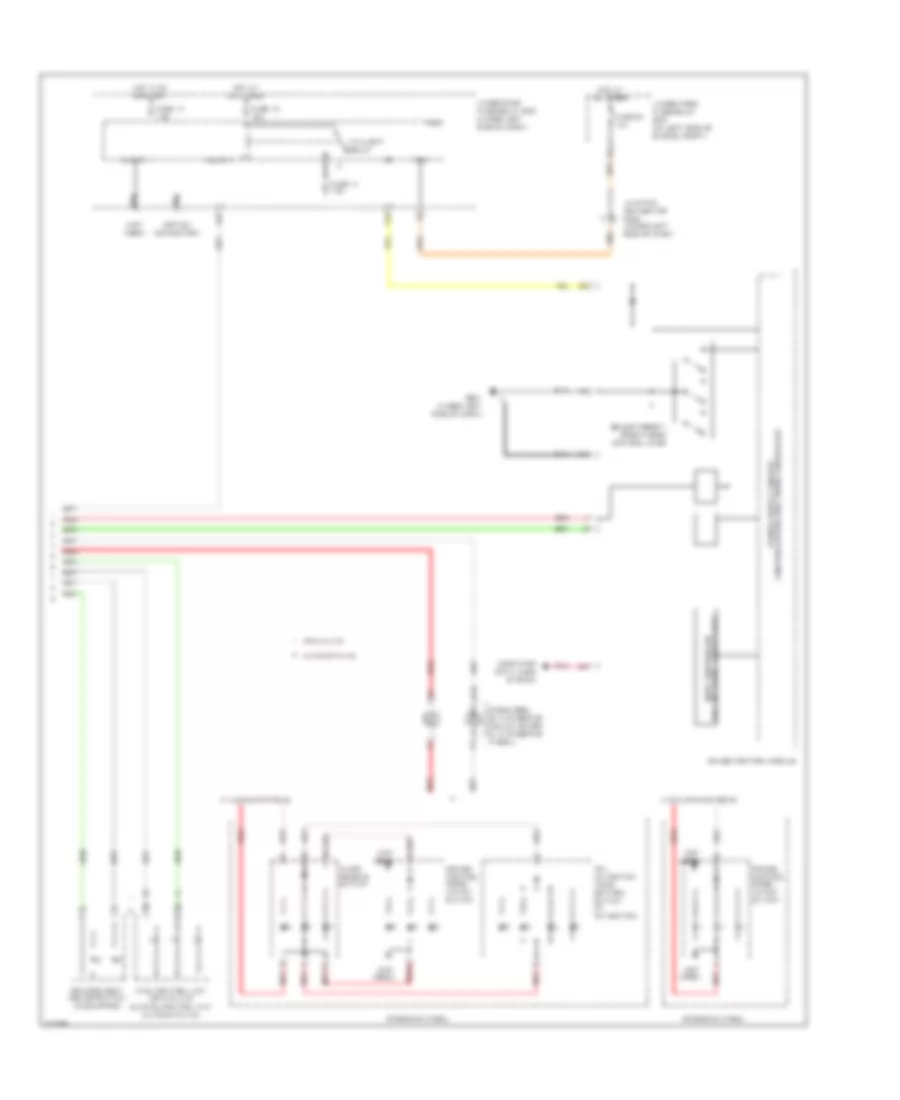
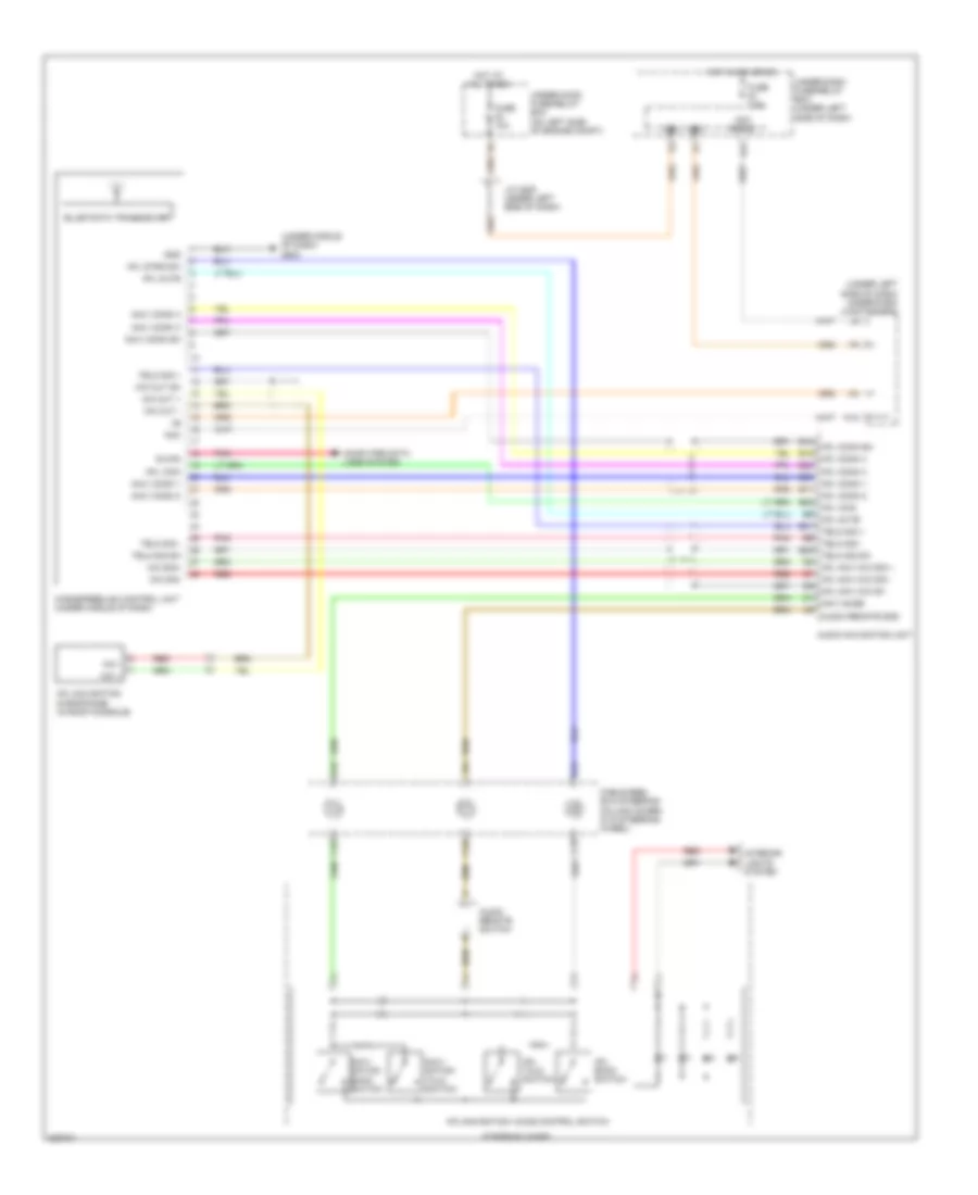
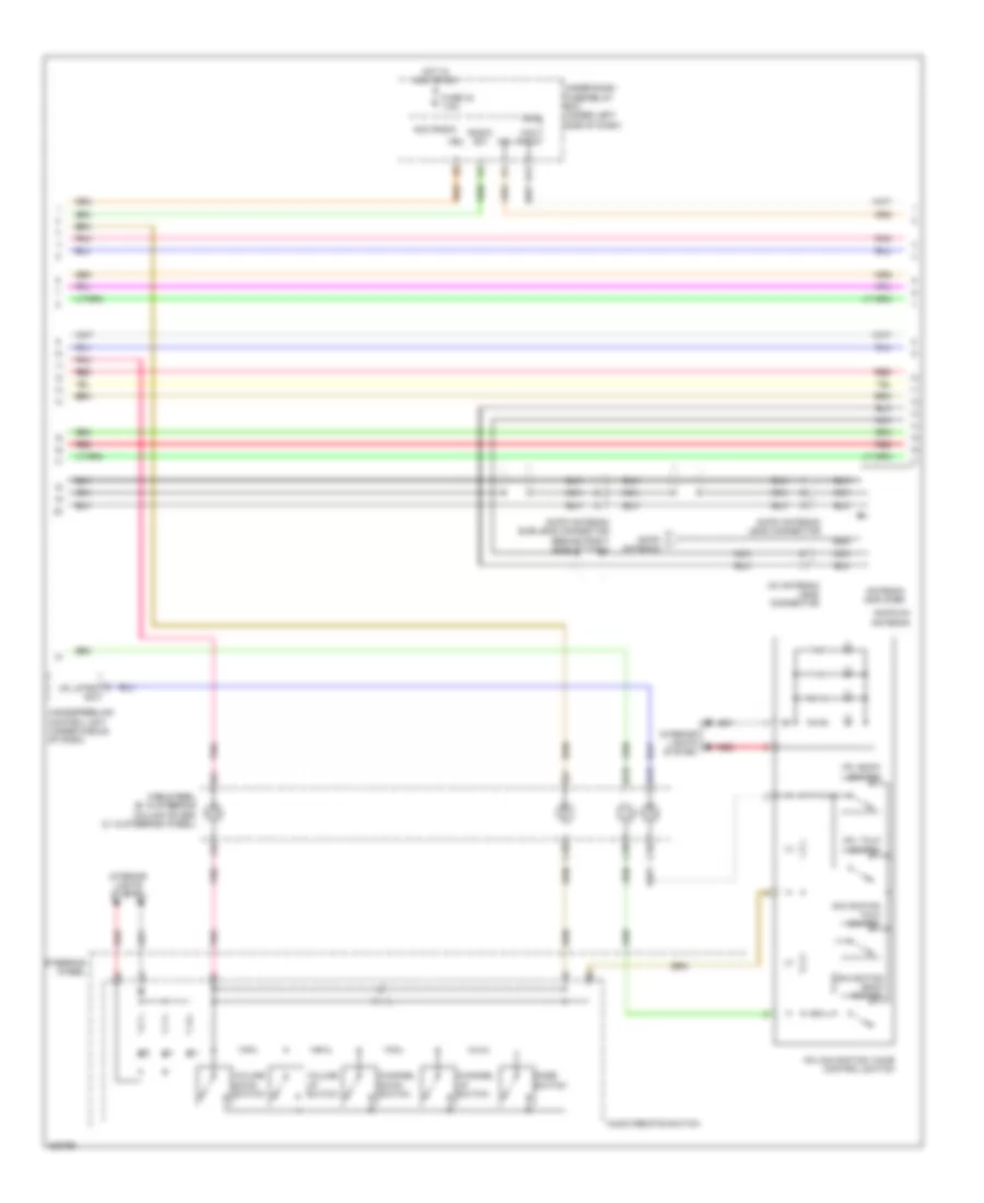
Hands Free Module Wiring Diagram, Except Honda Accessory for Honda CR-V LX 2010
List of elements for Hands Free Module Wiring Diagram, Except Honda Accessory for Honda CR-V LX 2010:
- (under left side of dash) under-dash junction box
- (under middle of dash) g503
- Acc
- Acc radio
- Audio navigation unit
- Audio remote gnd
- Audio remote switch
- B can
- B10
- B11
- B12
- B18
- B19
- B20
- B21
- B22
- B23
- B24
- C10
- C18
- C19
- Cable reel (b:in steering column cover) (c:in steering wheel)
- Computer data lines system
- Fuse 10a
- Fuse 7.5a
- Gnd
- Handsfreelink control unit (under middle of dash)
- Hfl back switch
- Hfl comm 1
- Hfl comm 2
- Hfl comm 3
- Hfl comm 4
- Hfl comm sh
- Hfl icon
- Hfl mute
- Hfl navi mic sh
- Hfl navi mic sig +
- Hfl navi mic sig -
- Hfl navigation microphone (in roof console)
- Hfl strg sw
- Hfl talk switch
- Hfl-navigation voice control switch
- Hot at all times
- Hot in acc or on
- Interior lights system
- J/c c405 (under left side of dash)
- K10
- Mic +
- Mic -
- Mic out +
- Mic out -
- Mic out sh
- Mic sig+
- Mic sig-
- Navi comm 1
- Navi comm 2
- Navi comm 3
- Navi comm 4
- Navi comm sh
- Navi gude
- Navi- gation back switch
- Navi- gation talk switch
- Pnk
- R17
- Red
- Steering wheel
- Telm sig +
- Telm sig -
- Telm sig sh
- Under-dash fuse/relay box (under left side of dash)
- Under-hood fuse/relay box (on left side of engine compt)
- Vbu
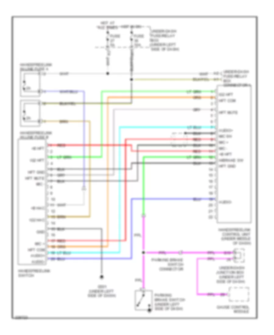
Hands Free Module Wiring Diagram, Honda Accessory for Honda CR-V LX 2010
List of elements for Hands Free Module Wiring Diagram, Honda Accessory for Honda CR-V LX 2010:
- +b hac
- +b hft
- Audio+
- Audio-
- Fuse 10a
- Fuse 5a
- G10
- G501 (under left side of dash)
- Gauge control module
- Gnd
- H/brake sw
- Handsfreelink control unit (under middle of dash)
- Handsfreelink in line fuse a
- Handsfreelink in line fuse b
- Handsfreelink switch
- Hft com
- Hft gnd
- Hft mute
- Hot at all times
- Hot in on
- Ig2 hac
- Ig2 hft
- Mic +
- Mic -
- Mic sh
- Parking brake switch (under left side of dash)
- Parking brake switch connector
- Red
- Under-dash fuse/relay box (under left side of dash)
- Under-dash fuse/relay box connector a
- Under-dash junction box (under left side of dash)
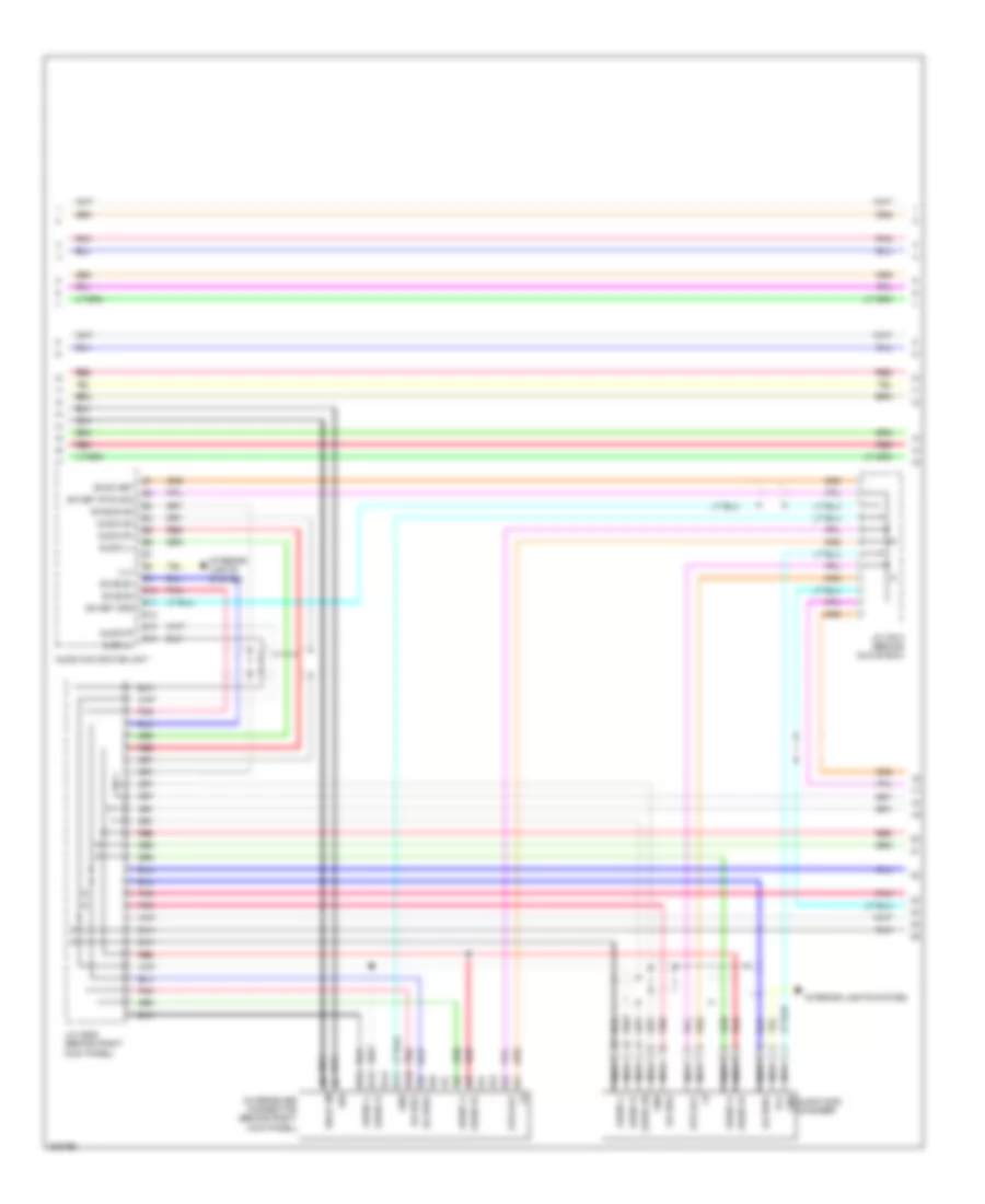
Navigation Wiring Diagram (1 of 4) for Honda CR-V LX 2010
List of elements for Navigation Wiring Diagram (1 of 4) for Honda CR-V LX 2010:
- +b back up
- A10
- A11
- A12
- A13
- A14
- A15
- A16
- A17
- A18
- A19
- A20
- A21
- A22
- A23
- A24
- Ac-clk
- Ac-si
- Ac-so
- Acc radio
- Ant +b
- Audio navigation unit
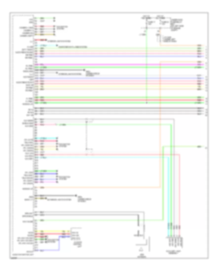
- Audio remote gnd
- Audio remote sw
- Aux det
- Aux gnd
- Aux lch
- Aux rch
- Aux sgnd
- Auxiliary jack assembly
- B10
- B11
- B12
- B13
- B14
- B15
- B16
- B17
- B18
- B19
- B20
- B21
- B22
- B23
- B24
- Back lt-
- Camera adpt
- Camera sh
- Camera v
- Camera v gnd
- Climate control unit
- Computer data lines system
- D10
- D11
- D12
- Exterior lights system
- Fl pre+
- Fl pre-
- Fr pre+
- Fr pre-
- Fuse 17 15a
- Fuse 23 10a
- G502 (under middle of dash)
- G504 (under middle of dash)
- Gnd
- Gps ant
- Gps antenna
- Gps shield
- Hfl comm sh
- Hfl comm1
- Hfl comm2
- Hfl comm3
- Hfl comm4
- Hfl icon
- Hfl mute
- Hfl navi mic sh
- Hfl navi mic sig+
- Hfl navi mic sig-
- Hot at all times
- Ill+
- Ill-
- Interior lights system
- J/c c405 (under left side of dash)
- K-line
- Navi clk
- Navi guide
- Navi si
- Navi so
- Navigation system
- Nca
- Pnk
- Radio gnd
- Red
- Rf in
- Rf sh
- Rl pre+
- Rl pre-
- Rr pre+
- Rr pre-
- Scty radio
- Shield gnd
- Swd +b
- Telm sig sh
- Telm sig+
- Telm sig-
- Under-hood fuse/relay box (on left side of engine compt)
- Vcc
- Vsp
Navigation Wiring Diagram (2 of 4) for Honda CR-V LX 2010
List of elements for Navigation Wiring Diagram (2 of 4) for Honda CR-V LX 2010:
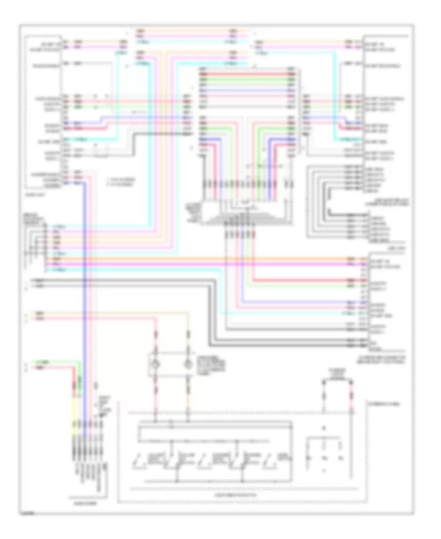
- Acc radio
- Am/fm antenna
- Am/fm antenna lead connector
- Am/fm antenna sub-lead connector (behind right side of dash)
- Am/fm/xm antenna
- Antenna amplifier
- Audio remote switch
- B18
- B19
- C10
- C18
- C19
- Cable reel (b: in steering column cover) (c: in steering wheel)
- Channel down switch
- Channel up switch
- Fuse 34 7.5a
- Handsfreelink control unit (under middle of dash)
- Hfl back switch
- Hfl strg sw
- Hfl talk switch
- Hfl-navigation voice control switch
- Hot in acc or on
- Interior lights system
- Micu
- Mode switch
- Navigation back switch
- Navigation talk switch
- Nca
- Pnk
- R17
- Radio sw
- Red
- Steering wheel
- Under-dash fuse/relay box (under left side of dash)
- Vbu
- Volume down switch
- Volume up switch
- Xm antenna lead connector
Navigation Wiring Diagram (3 of 4) for Honda CR-V LX 2010
List of elements for Navigation Wiring Diagram (3 of 4) for Honda CR-V LX 2010:
- +b ga net
- A10
- A11
- A12
- A13
- A14
- Audio disc changer
- Audio l+
- Audio l-
- Audio navigation unit
- Audio r+
- Audio r-
- Audio sh
- E10
- E11
- E12
- E13
- E14
- Ga bus sh
- Ga bus+
- Ga bus-
- Ga net gnd
- Ga net sys acc
- Gnd
- Ill+
- Interior lights system
- J/c c509 (behind right kick panel)
- J/c c514 (behind glove box)
- Nca
- Pnk
- Red
- Shld xm
- Sig
- Sys acc
- Xm receiver connector (behind right kick panel)
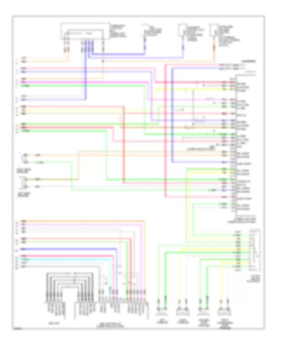
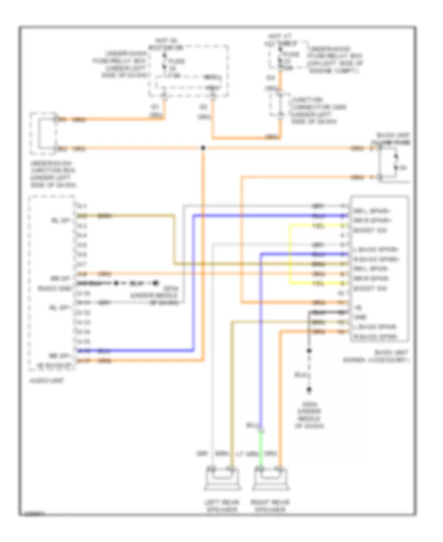
Navigation Wiring Diagram (4 of 4) for Honda CR-V LX 2010
List of elements for Navigation Wiring Diagram (4 of 4) for Honda CR-V LX 2010:
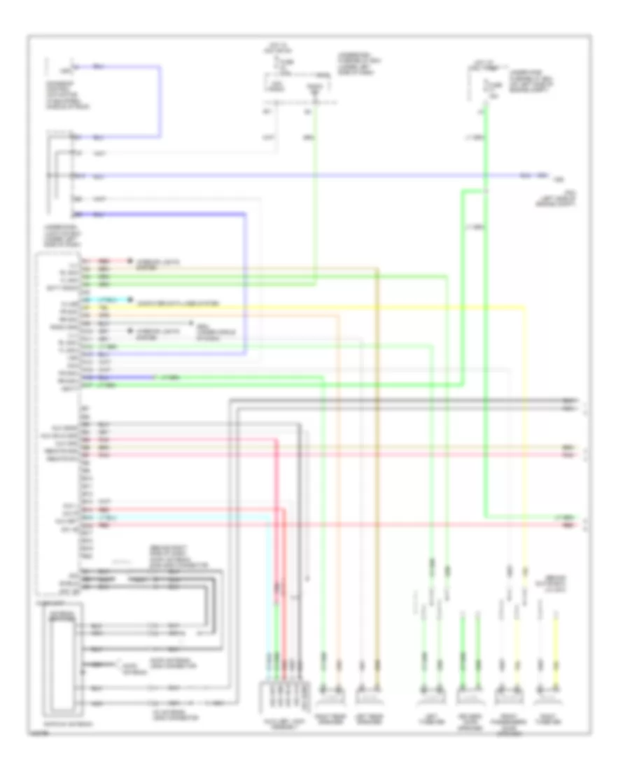
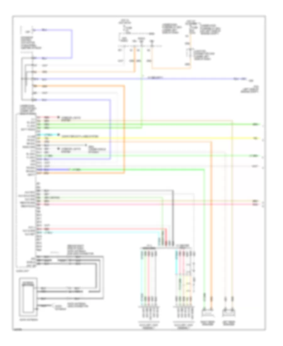
- +b back up
- A10
- A11
- A12
- A13
- A14
- A15
- A16
- A17
- A18
- A19
- A20
- A30
- Audio l+
- Audio l-
- Audio r+
- Audio r-
- Audio sh
- B10
- B11
- B12
- B13
- B14
- Driver's door speaker
- Fl pre+
- Fl pre-
- Fr l spkr+
- Fr l spkr-
- Fr pre+
- Fr pre-
- Fr r spkr+
- Fr r spkr-
- Front passenger's door speaker
- G13
- G502 (under middle of dash)
- Ga bus sh
- Ga bus+
- Ga bus-
- Gnd
- Immobilizer- keyless control unit (on steering column, integral to ignition switch)
- J/c c510 (behind glove box)
- L10
- Left rear speaker
- Left tweeter
- Moonroof control unit/ motor (if equipped) (middle of roof)
- Nca
- Pcm (left side of engine compt) out
- Pnk
- Red
- Right rear speaker
- Right tweeter
- Rl pre+
- Rl pre-
- Rr l spkr+
- Rr l spkr-
- Rr pre+
- Rr pre-
- Rr r spkr+
- Rr r spkr-
- Sh fl gnd
- Sh fr gnd
- Sh rl gnd
- Sh rr gnd
- Stereo amplifier (under middle of dash)
- Subw spkr+
- Subw spkr-
- Subwoofer
- Swd +b
- Sys acc
- Under-dash junction box (under left side of dash)
- Usb adapter unit (under middle of dash)
- Usb data+
- Usb data-
- Usb gnd
- Usb jack
- Usb sh
- Usb vbus
- Vsp
- Vss
Parking Assistant Wiring Diagram for Honda CR-V LX 2010
List of elements for Parking Assistant Wiring Diagram for Honda CR-V LX 2010:
- Back lt
- Backup light
- Backup sensor beeper
- Backup sensor control unit (honda accessory)
- Backup sensor in-line fuse (right side of cargo area)
- Buzzer+
- Cor snsr l
- Cor snsr r
- Ctr snsr l
- Ctr snsr r
- E15
- Exterior lights system
- Fuse 10a
- G601 (right side of cargo area)
- Gnd
- Hot in on or start
- Ig1 srs
- Left center backup sensor
- Left corner backup sensor
- Micu
- Nca
- Pnk
- Right center backup sensor
- Right corner backup sensor
- Right taillight
- Snsr+
- Snsr-
- Under-dash fuse/relay box (under left side of dash)
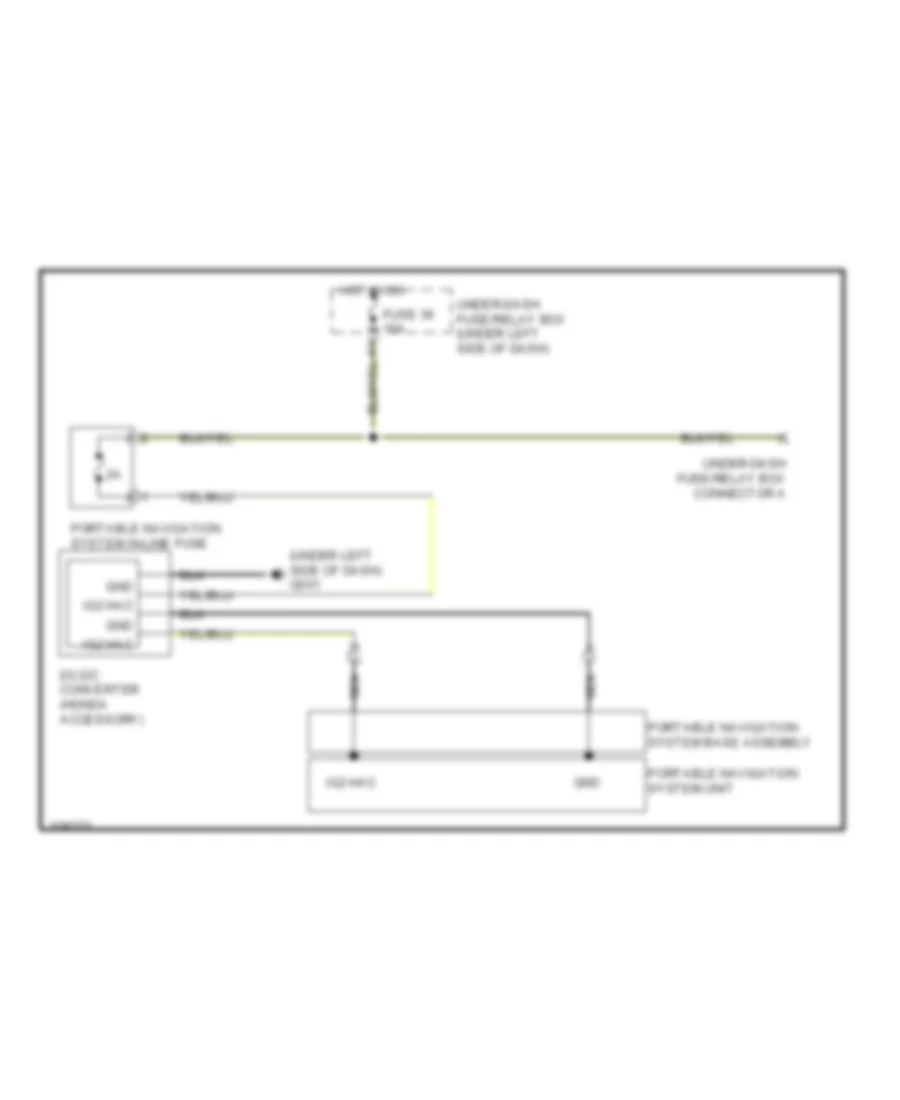
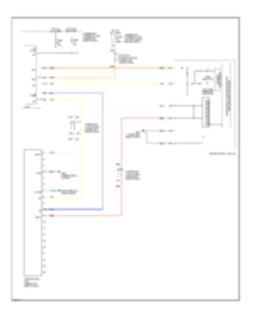
Portable Navigation Wiring Diagram for Honda CR-V LX 2010
List of elements for Portable Navigation Wiring Diagram for Honda CR-V LX 2010:
- (under left side of dash) g501
- Dc-dc converter (honda accessory)
- Fuse 36 10a
- Gnd
- Hot in on
- Ig2 hac
- Nca
- Portable navigation system base assembly
- Portable navigation system in-line fuse
- Portable navigation system unit
- Under-dash fuse/relay box (under left side of dash)
- Under-dash fuse/relay box connector a
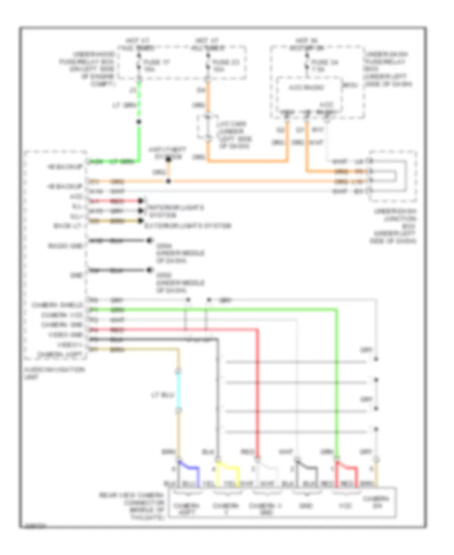
Rear Camera Wiring Diagram for Honda CR-V LX 2010
List of elements for Rear Camera Wiring Diagram for Honda CR-V LX 2010:
- +b backup
- A12
- A13
- A14
- A24
- Acc
- Acc radio
- Anti-theft system
- Audio navigation unit
- Back lt-
- Camera adpt
- Camera gnd
- Camera sh
- Camera shield
- Camera v
- Camera v gnd
- Camera vcc
- Exterior lights system
- Fuse 17 15a
- Fuse 23 10a
- Fuse 34 7.5a
- G502 (under middle of dash)
- G504 (under middle of dash)
- Gnd
- Hot at all times
- Hot in acc or on
- Ill+
- Ill-
- Interior lights system
- J/c c405 (under left side of dash)
- L10
- Micu
- R17
- Radio gnd
- Rear view camera connector (middle of tailgate)
- Red
- Under-dash fuse/relay box (under left side of dash)
- Under-dash junction box (under left side of dash)
- Under-hood fuse/relay box (on left side of engine compt)
- Vbu
- Vcc
- Video gnd
- Video v
POWER DISTRIBUTION
Power Distribution Wiring Diagram (1 of 4) for Honda CR-V LX 2010
List of elements for Power Distribution Wiring Diagram (1 of 4) for Honda CR-V LX 2010:
- (not used)
- (on left side of engine compt) under-hood fuse/relay box
- (option connector)
- (under left side of dash) under-dash fuse/relay box
- +b d/l
- +b intr lt
- 100a
- 40a
- 50a
- 80a
- A/c compressor clutch relay
- A/c condenser fan relay
- A17
- Alternator
- Audio navigation unit (w/ navigation)
- Audio unit (except premium audio)
- Battery
- Blower motor relay
- Cargo area light
- Ceiling light
- Dlc
- Driver's seat heater relay (high) (if equipped)
- Driver's seat heater relay (low) (if equipped)
- Driver's vanity mirror light (if equipped)
- E22
- E23
- E35
- E38
- E41
- Eld unit
- Etcs control relay
- F13
- Front individual map lights
- Front passenger's power window switch
- Front passenger's seat heater relay (high) (if equipped)
- Front passenger's seat heater relay (low) (if equipped)
- Front passenger's vanity mirror light (if equipped)
- Fuse (not used)
- Fuse 10a
- Fuse 15a
- Fuse 20a
- Fuse 30a
- Fuse 40a
- Fuse 7.5a
- G19
- G21
- Gauge control module
- Handsfreelink control unit (w/ navigation)
- Ignition key switch/ key light
- Immobilizer- keyless control unit
- J/c c405 (under left side of dash)
- L10
- Left rear power window switch
- Micu
- Moonroof control unit/motor (if equipped)
- Multi-fuse 1
- Multi-fuse 2
- Multi-fuse 4
- N10
- N14
- Pgm-fi main relay 1
- Pnk
- Power window master switch/ driver's door lock switch
- Power window master switch/driver's door lock switch
- Power window relay
- Pw timer
- Q10
- R10
- Radiator fan relay
- Rear window defogger relay
- Red
- Right rear power window switch
- Starter
- Starter solenoid
- T101
- To cargo area accessory power socket relay (diagram 4 of 4)
- To console accessory power socket relay (diagram 4 of 4)
- To front accessory power socket relay (diagram 4 of 4)
- To fuse 10 (diagram 2 of 4)
- To under-dash fuse/relay box (diagram 2 of 4)
- To under-dash fuse/relay box (diagram 3 of 4)
- Under-dash junction box (under left side of dash)
- Vbu
Power Distribution Wiring Diagram (2 of 4) for Honda CR-V LX 2010
List of elements for Power Distribution Wiring Diagram (2 of 4) for Honda CR-V LX 2010:
- (not used)
- (on left side of engine compt) under-hood fuse/relay box
- +b h/l hi-l
- +b h/l hi-r
- +b h/l high main
- +b h/l low
- +b h/l low main
- +b hazard
- +b horn +b stop
- +b rear fog
- +b small
- +b tpms
- 20a
- 40a
- A/c condenser fan diode
- A/c condenser fan relay
- A/f sensor
- A/f sensor relay
- A10
- A12
- A13
- A17
- A22
- A24
- Abs modulator control unit
- Audio navigation unit
- Audio unit
- Automatic a/c
- B12
- Brake pedal position switch
- C11
- Climate control unit
- D3 switch/ park-pin switch (a/t)
- Driver's lumbar support switch (w/ driver's power seat)
- Driver's power seat adjustment switch (if equipped)
- E10
- E11
- E19
- E25
- Evap canister vent shut valve
- F16
- F18
- F19
- F22
- F3 (not used)
- F31
- From multi- a fuse 1 (diagram 1 of 4)
- From multi-fuse 4 (diagram 1 of 4)
- Fuse (not used)
- Fuse 10a
- Fuse 15a
- Fuse 20a
- Fuse 7.5a
- G11
- G15
- G16
- G17
- G18
- Hazard warning switch/ passenger's air bag cutoff indicator
- Hazard warning switch/front passenger's airbag cutoff indicator
- Hvac control unit
- Ignition coil relay
- Illumi+
- J/c c101 (left rear of engine compt)
- J11
- Left front parking light
- Left headlight
- Left rear side marker light
- Left taillight
- Left taillight/ brake light
- License plate light
- Manual a/c
- Micu
- Multi- fuse 3
- Navigation unit
- Nca
- Option connector
- Pcm
- Pnk
- Power mirror switch
- Premium audio w/ navigation
- Premium audio w/o navigation
- Q12
- Red
- Right front parking light
- Right headlight
- Right rear side marker light
- Right taillight
- Right taillight/ brake light
- Small rly-
- Stereo amplifier
- Subwoofer
- To under-dash junction box (diagram 4 of 4 )
- Tpms control unit (if equipped)
- Trailer lighting connector (option connector)
- Under-dash fuse/relay box (under left side of dash)
- Under-dash junction box (under left side of dash)
- Vsa modulator control unit
- Vsa off switch (if equipped)
- W/ navigation
- W/ vsa
- W/o navigation
- W/o vsa
Power Distribution Wiring Diagram (3 of 4) for Honda CR-V LX 2010
List of elements for Power Distribution Wiring Diagram (3 of 4) for Honda CR-V LX 2010:
- (a/t) starter cut relay
- (m/t)
- (not used)
- (under left side of dash) under-dash fuse/relay box
- A/c compressor clutch relay
- A11
- A17
- A18
- Acc
- Atp np
- Automatic a/c
- Automatic lighting control unit (if equipped)
- Auxiliary under- hood relay box (left side of engine compt)
- Auxiliary under-dash fuse holder a (under left side of dash)
- B11
- Blower motor relay
- C13
- C14
- Climate control unit
- Driver's seat heater switch (if equipped)
- Drl
- E13
- E28
- E30
- E32
- Electrical compass unit
- F15
- F17
- F29
- Fan control relay
- From multi-fuse 2 (diagram 1 of 4)
- Front passenger's seat heater switch (if equipped)
- Fuse (not used)
- Fuse 10a
- Fuse 30a
- Fuse 7.5a
- Fuse a 10a
- G12
- G20
- Gauge control module
- Hac
- Hazard warning switch/front passenger's air bag cutoff indicator
- Hvac control unit
- Ig1
- Ig1 srs
- Ig1 wiper
- Ig2
- Ignition key switch/key light
- Ignition switch
- J/c c101 (left rear of engine compt)
- K11
- Key sw acc
- Lock
- Manual a/c
- Micu
- N11
- Ods
- Ods unit
- Option connector
- P10
- Pcm
- Power mirror defogger relay (if equipped)
- Power mirror switch
- Q14
- Q15
- Q16
- R17
- R19
- Radiator fan diode
- Radiator fan relay
- Radio
- Rear window defogger relay
- Rear window wiper motor relay
- Recirculation control motor
- Red
- Shift lock solenoid (a/t)
- Srs unit
- Start
- Start on
- Starter
- Starter solenoid
- Sts
- To under -dash fuse/ relay box (diagram 4 of 4)
- To under-dash junction box (diagram 4 of 4 )
- Tpms control unit (if equipped)
- Transmission range switch (a/t)
- Under-dash junction box (under left side of dash)
- Under-hood fuse/relay box (on left side of engine compt)
Power Distribution Wiring Diagram (4 of 4) for Honda CR-V LX 2010
List of elements for Power Distribution Wiring Diagram (4 of 4) for Honda CR-V LX 2010:
- (at rear of engine) j/c c103
- (diagram 3 of 4)
- (ig1) fuel pump
- (ig1) p/w
- (left side
- (not used)
- (under left side of dash) under-dash junction box
- A14
- Abs modulator control unit (w/o vsa) vsa modulator control unit (w/ vsa)
- Alternator
- Audio remote switch
- Audio unit (w/o navigation) audio- navigation unit (w/ navigation)
- B10
- B22
- Brake pedal position switch
- C10
- C501
- Cable reel (in steering column cover)
- Cargo area accessory power socket
- Cargo area accessory power socket relay (under middle of dash)
- Cigarette lighter
- Cmp sensor a
- Console accessory power socket (center tray & center console)
- Console accessory power socket relay (under middle of dash)
- Controls
- Cruise control combination switch
- Driver's seat heater switch (if equipped)
- E12
- E24
- E27
- Eld unit
- Evap canister purge valve
- Except honda accessory
- F15
- F16
- F24
- From fuse 28 (diagram 1 of 4)
- From fuse 29 (diagram 1 of 4)
- From fuse 31 (diagram 1 of 4)
- From under-dash d junction box (diagram 2 of 4)
- From under-dash fuse/relay box (diagram 3 of 4)
- From under-dash fuse/relay box f
- Front accessory power socket
- Front accessory power socket relay (under middle of dash)
- Front passenger's seat heater switch (if equipped)
- Fuse 10a
- Fuse 15a
- Fuse 7.5a
- G11
- G14
- G502 (under middle of dash)
- G551
- G602 (left side of cargo area)
- Handsfree- link control unit (w/ navigation)
- Hfl navigation voice control switch (w/ navigation)
- Honda accessory
- Ig1 abs
- Immoblizer- keyless control unit
- J/c c101 (left rear of engine compt)
- K10
- Micu
- Moonroof control unit/
- Motor (if equipped)
- N12
- Of floor)
- Pcm
- Pgm-fi main relay 2
- R11
- R12
- R18
- R20
- Red
- Secondary ho2s
- Steering wheel
- Under- dash junction box (under left side of dash)
- Under-dash fuse/relay box (under left side of dash)
- Under-dash junction box (under left side of dash)
- Under-hood fuse/relay box (on left side of engine compt)
- W/ audio
- W/ vsa
- W/o audio
- W/o vsa
- Yaw rate- lateral acceleration sensor (w/ vsa)
POWER DOOR LOCKS
Power Door Locks Wiring Diagram (1 of 2) for Honda CR-V LX 2010
List of elements for Power Door Locks Wiring Diagram (1 of 2) for Honda CR-V LX 2010:
- (not used)
- (not used) c502
- (on transmission housing) transmission range switch
- (under left side of dash) g501
- (under middle of dash) g503
- +b d/l
- Atp-p
- B-can
- Door lock knob
- Door lock relay
- Driver's door key cylinder switch
- Driver's door lock actuator/knob switch/ key cylinder switch (in driver's door)
- Driver's door lock knob switch
- Driver's door unlock relay
- E13
- E14
- E17
- E19
- E20
- E21
- E31
- E33
- E36
- E37
- Exterior lights system
- F20
- F23
- F27
- Fr dr sw (as)
- Fr dr sw (dr)
- Front passenger's door lock actuator/knob switch (in front passenger's door)
- Front passenger's door lock knob switch
- Fuse 10a
- Fuse 15a
- Fuse 20a
- Fuse 7.5a
- G101 (left side of engine)
- G13
- G16
- G17
- G401 (under left side of dash)
- G502 (under middle of dash)
- G552 (right side of floor)
- G602 (left side of cargo area)
- Headlights system
- Hood sw
- Horn rly
- Horns system
- Hot at all times
- Hot in on or start
- Ig key sw
- Ig1
- Junction connector c101 (left rear of engine compt)
- Kc dr lock
- Kc dr unlock
- Key door lock knob
- Lock
- Low beam headlight rly
- M10
- Micu
- N13
- P-gnd
- Passenger's door unlock relay
- Pnk
- R16
- Red
- Red b1
- Rem as lock
- Rem as unlock
- Rem dr lock
- Rem dr unlock
- Right rear door lock actuator/knob switch (in right rear door)
- Right rear door lock knob switch
- Rr dr sw (as)
- Rr dr sw (dr)
- S-gnd
- S-gnd2
- S2 (thermal joint)
- Sil as unlock
- Sil dr lock
- Sil dr unlock
- Sil ra unlock
- Sil rd unlock
- T/g handle sw
- T/g sw
- T22
- T23
- T24
- T25
- T26
- T27
- T28
- T29
- T30
- T31
- T32
- T34
- Tailgate unlock relay
- Taillight rly
- Under-dash fuse/relay box (under left side of dash)
- Unlock
- Vbu
- W/ security
Power Door Locks Wiring Diagram (2 of 2) for Honda CR-V LX 2010
List of elements for Power Door Locks Wiring Diagram (2 of 2) for Honda CR-V LX 2010:
- (bottom of tailgate) tailgate release actuator
- (in left rear door) left rear door lock actuator/knob switch
- (left side of cargo area) g602
- Audio navigation unit
- Audio unit
- B-can
- Blinking circuit
- Body controller area network transceiver
- Driver's door lock switch
- Driver's door switch (on left "b" pillar)
- Front passenger's door lock switch
- Front passenger's door switch (on right "b" pillar)
- Front passenger's power window switch
- Fuse 10a
- Fuse 15a
- G301 (under left side of engine compt)
- G501 (under left side of dash)
- G503 (under middle of dash)
- G602 (left side of cargo area)
- Gauge control module
- Hot at all times
- Ignition key switch
- Ignition key switch/key light
- Immobilizer- keyless control unit (on steering column, integral to ignition switch)
- J/c c405 (under left side of dash)
- Left rear door switch (in left "c" pillar)
- Left unlock
- Lock
- Pnk
- Power distribution system
- Power window master switch/ driver's door lock switch
- Rear door lock knob switch
- Right rear door switch (in right "c" pillar)
- Scty radio
- Security hood switch (if equipped) (front of engine compt)
- Security indicator (if equipped)
- Tailgate latch switch (bottom of tailgate)
- Tailgate outer handle switch
- Under-dash junction box (under left side of dash)
- Under-hood fuse/relay box (on left side of engine compt)
- Unlock
- W/ navigation
- W/o navigation
POWER MIRRORS
Automatic Day/Night Mirror Wiring Diagram for Honda CR-V LX 2010
List of elements for Automatic Day/Night Mirror Wiring Diagram for Honda CR-V LX 2010:
- (atp-r) b15
- (left rear of engine compt) junction connector c101
- 10a
- 7.5a
- A/t reverse relay
- A14
- A15
- Automatic dimming inside mirror
- Automatic dimming inside mirror in-line fuse
- B15
- Back lt-
- Fuse 10
- Fuse 36
- G101 (left side of engine)
- G40
- Gnd
- Hot in on
- Hot in on or start
- Ig2 (1a)
- Micu
- Pcm (left side of engine compt)
- Reverse input
- Transmission range switch (on transmission housing)
- Under-dash fuse/relay box (under left side of dash)
- Under-dash fuse/relay box connector a
Power Mirrors Wiring Diagram for Honda CR-V LX 2010
List of elements for Power Mirrors Wiring Diagram for Honda CR-V LX 2010:
- (under middle of dash)
- 10a
- Defogger system
- Down
- Down motor
- E13
- Fuse 36
- G501 (under left side of dash)
- G503
- Heater
- Hot in on
- Interior lights system
- Internal switch positions
- Left
- Left power mirror (in driver's door)
- Left/ right
- Left/ right motor
- Mirror direction selected
- Motor
- N11
- Pnk
- Power mirror switch
- Red
- Right
- Right power mirror (in front passenger's door)
- Switch 1
- Switch 2
- Switch 3
- Under-dash fuse/relay box (under left side of dash)
- Under-dash junction box (under left side of dash)
- Up/
POWER SEATS
Driver Power Seat Wiring Diagram for Honda CR-V LX 2010
List of elements for Driver Power Seat Wiring Diagram for Honda CR-V LX 2010:
- Backward
- Down
- Driver's power seat adjustment switch
- Driver's power seat front up-down motor (under right side of driver's seat)
- Driver's power seat rear up-down motor (under left side of driver's seat)
- Driver's power seat recline motor (under driver's seat)
- Driver's power seat slide motor
- E10
- Forward
- Front up-down switch
- Fuse 13 20a
- Fuse 14 20a
- G551 (left side of floor)
- Hot at all times
- Pnk
- Rear up/ down switch
- Recline switch
- Red
- Slide switch
- Under-hood fuse/relay box (on left side of engine compt)
Driver"s Lumbar Wiring Diagram for Honda CR-V LX 2010
List of elements for Driver"s Lumbar Wiring Diagram for Honda CR-V LX 2010:
- Back
- Driver's lumbar support switch
- Driver's power lumbar support motor (in right side of driver's seat back)
- E10
- For- ward
- Forward
- Fuse 13 20a
- G551 (left side of floor)
- Hot at all times
- Pnk
- Under-hood fuse/relay box (on left side of engine compt)
Heated Seats Wiring Diagram for Honda CR-V LX 2010
List of elements for Heated Seats Wiring Diagram for Honda CR-V LX 2010:
- (in right side of driver's seat back) driver's seat heater relay (high)
- (under driver's seat) driver's seat heater relay (low)
- (under front passenger's seat) front passenger's seat heater relay (high)
- (under front passenger's seat) front passenger's seat heater relay (low)
- Driver's seat back heater
- Driver's seat cushion heater
- Driver's seat heater switch
- Front passenger's seat cushion heater
- Front passenger's seat heater switch
- Fuse 36 10a
- Fuse 5 15a
- G502 (under middle of dash)
- G503 (under middle of dash)
- G551 (left side of floor)
- G552 (right side of floor)
- High
- Hot at all times
- Hot in on
- Ig2 hac
- Indicator
- Interior lights system
- K11
- Low
- Micu
- N11
- On indicator
- Pnk
- Q16
- Red
- Switch illumination
- Under-dash fuse/relay box (under left side of dash)
- Under-dash junction box (under left side of dash)
POWER TOP/SUNROOF
Power Top/Sunroof Wiring Diagram for Honda CR-V LX 2010
List of elements for Power Top/Sunroof Wiring Diagram for Honda CR-V LX 2010:
- A30
- Auto close
- Auto open
- Close
- Cpu
- Driver's door switch (on left "b" pillar)
- E37
- Fr dr sw (as)
- Fr dr sw (dr)
- Front passenger's door switch (on right "b" pillar)
- Fuse 1 7.5a
- Fuse 24 20a
- G13
- G501 (under left side of dash)
- Hall sensor
- Hot at all times
- Hot in on or start
- Interior light switch
- Interior lights system
- Micu
- Moonroof close relay
- Moonroof motor
- Moonroof motor/ control unit (center of roof)
- Moonroof open relay
- Moonroof switch
- N10
- N12
- Off
- Open
- Pcm (left side of engine compt)
- Power window relay
- Pw timer
- Tilt
- Under-dash fuse/relay box (under left side of dash)
- Under-dash junction box (under left side of dash)
- Vss out
POWER WINDOWS
Power Windows Wiring Diagram for Honda CR-V LX 2010
List of elements for Power Windows Wiring Diagram for Honda CR-V LX 2010:
- (center of roof) (if equipped) moonroof control unit/motor
- (not used)
- Auto
- Down
- Down(+)
- Driver's power window motor (in driver's door)
- Driver's power window switch 0) off 1) up 2) down 3) auto down 4) auto up
- E23
- E41
- Front passenger's power window motor (in front passenger's door)
- Front passenger's power window switch
- Fuse 26 20a
- Fuse 30 20a
- Fuse 32 20a
- Fuse 33 20a
- G501 (under left side of dash)
- Hot at all times
- Left rear power
- Left rear power window motor (in left rear door)
- Left rear power window switch
- Main switch
- Micu
- N10
- N14
- Off
- Pls a
- Pls b
- Pnk
- Power window control unit
- Power window master switch/ driver's door lock switch
- Power window relay
- Pulser
- Pw timer
- Red
- Right rear power window motor (in right rear door)
- Right rear power window switch
- Sgnd
- Svcc
- Under-dash fuse/relay box (under left side of dash)
- Up(+)
- Window switch
RADIO
Bass Speaker Wiring Diagram for Honda CR-V LX 2010
List of elements for Bass Speaker Wiring Diagram for Honda CR-V LX 2010:
- +b backup
- A10
- A11
- A12
- A13
- A14
- A15
- A16
- A17
- Audio unit
- Bass unit (honda accessory)
- Bass unit in-line fuse
- Boost sw
- Fuse 10a
- Fuse 7.5a
- G504 (under middle of dash)
- Gnd
- Hot at all times
- Hot in acc or on
- Junction connector c405 (under left side of dash)
- L bass spkr+
- L bass spkr-
- Left rear speaker
- Micu
- R bass spkr+
- R bass spkr-
- Radio gnd
- Right rear speaker
- Rl sp+
- Rl sp-
- Rr l spkr+
- Rr l spkr-
- Rr r spkr+
- Rr r spkr-
- Rr sp+
- Rr sp-
- Under-dash fuse/relay box (under left side of dash)
- Under-dash junction box (under left side of dash)
- Under-hood fuse/relay box (on left side of engine compt)
- Vbu
Radio Wiring Diagram, Premium Audio with Navigation (1 of 4) for Honda CR-V LX 2010
List of elements for Radio Wiring Diagram, Premium Audio with Navigation (1 of 4) for Honda CR-V LX 2010:
- +b back up
- A10
- A11
- A12
- A13
- A14
- A15
- A16
- A17
- A18
- A19
- A20
- A21
- A22
- A23
- A24
- Ac-clk
- Ac-si
- Ac-so
- Acc radio
- Ant +b
- Audio navigation unit
- Audio remote gnd
- Audio remote sw
- Aux det
- Aux gnd
- Aux lch
- Aux rch
- Aux sgnd
- Auxiliary jack assembly
- B10
- B11
- B12
- B13
- B14
- B15
- B16
- B17
- B18
- B19
- B20
- B21
- B22
- B23
- B24
- Back lt-
- Camera adpt
- Camera sh
- Camera v
- Camera v gnd
- Climate control unit
- Computer data lines system
- D10
- D11
- D12
- Exterior lights system
- Fl pre+
- Fl pre-
- Fr pre+
- Fr pre-
- Fuse 17 15a
- Fuse 23 10a
- G502 (under middle of dash)
- G504 (under middle of dash)
- Gnd
- Gps ant
- Gps antenna
- Gps shield
- Hfl comm sh
- Hfl comm1
- Hfl comm2
- Hfl comm3
- Hfl comm4
- Hfl icon
- Hfl mute
- Hfl navi mic sh
- Hfl navi mic sig+
- Hfl navi mic sig-
- Hot at all times
- Ill+
- Ill-
- Interior lights system
- J/c c405 (under left side of dash)
- K-line
- Navi clk
- Navi guide
- Navi si
- Navi so
- Navigation system
- Nca
- Pnk
- Radio gnd
- Red
- Rf in
- Rf sh
- Rl pre+
- Rl pre-
- Rr pre+
- Rr pre-
- Scty radio
- Shield gnd
- Swd +b
- Telm sig sh
- Telm sig+
- Telm sig-
- Under-hood fuse/relay box (on left side of engine compt)
- Vcc
- Vsp
Radio Wiring Diagram, Premium Audio with Navigation (2 of 4) for Honda CR-V LX 2010
List of elements for Radio Wiring Diagram, Premium Audio with Navigation (2 of 4) for Honda CR-V LX 2010:
- Acc radio
- Am/fm antenna
- Am/fm antenna lead connector
- Am/fm antenna sub-lead connector (behind right side of dash)
- Am/fm/xm antenna
- Antenna amplifier
- Audio remote switch
- B18
- B19
- C10
- C18
- C19
- Cable reel (b: in steering column cover) (c: in steering wheel)
- Channel down switch
- Channel up switch
- Fuse 34 7.5a
- Handsfreelink control unit (under middle of dash)
- Hfl back switch
- Hfl strg sw
- Hfl talk switch
- Hfl-navigation voice control switch
- Hot in acc or on
- Interior lights system
- Micu
- Mode switch
- Navigation back switch
- Navigation talk switch
- Nca
- Pnk
- R17
- Radio sw
- Red
- Steering wheel
- Under-dash fuse/relay box (under left side of dash)
- Vbu
- Volume down switch
- Volume up switch
- Xm antenna lead connector
Radio Wiring Diagram, Premium Audio with Navigation (3 of 4) for Honda CR-V LX 2010
List of elements for Radio Wiring Diagram, Premium Audio with Navigation (3 of 4) for Honda CR-V LX 2010:
- +b ga net
- A10
- A11
- A12
- A13
- A14
- Audio disc changer
- Audio l+
- Audio l-
- Audio navigation unit
- Audio r+
- Audio r-
- Audio sh
- E10
- E11
- E12
- E13
- E14
- Ga bus sh
- Ga bus+
- Ga bus-
- Ga net gnd
- Ga net sys acc
- Gnd
- Ill+
- Interior lights system
- J/c c509 (behind right kick panel)
- J/c c514 (behind glove box)
- Nca
- Pnk
- Red
- Shld xm
- Sig
- Sys acc
- Xm receiver connector (behind right kick panel)
Radio Wiring Diagram, Premium Audio with Navigation (4 of 4) for Honda CR-V LX 2010
List of elements for Radio Wiring Diagram, Premium Audio with Navigation (4 of 4) for Honda CR-V LX 2010:
- +b back up
- A10
- A11
- A12
- A13
- A14
- A15
- A16
- A17
- A18
- A19
- A20
- A30
- Audio l+
- Audio l-
- Audio r+
- Audio r-
- Audio sh
- B10
- B11
- B12
- B13
- B14
- Driver's door speaker
- Fl pre+
- Fl pre-
- Fr l spkr+
- Fr l spkr-
- Fr pre+
- Fr pre-
- Fr r spkr+
- Fr r spkr-
- Front passenger's door speaker
- G13
- G502 (under middle of dash)
- Ga bus sh
- Ga bus+
- Ga bus-
- Gnd
- Immobilizer- keyless control unit (on steering column, integral to ignition switch)
- J/c c510 (behind glove box)
- L10
- Left rear speaker
- Left tweeter
- Moonroof control unit/ motor (if equipped) (middle of roof)
- Nca
- Pcm (left side of engine compt) out
- Pnk
- Red
- Right rear speaker
- Right tweeter
- Rl pre+
- Rl pre-
- Rr l spkr+
- Rr l spkr-
- Rr pre+
- Rr pre-
- Rr r spkr+
- Rr r spkr-
- Sh fl gnd
- Sh fr gnd
- Sh rl gnd
- Sh rr gnd
- Stereo amplifier (under middle of dash)
- Subw spkr+
- Subw spkr-
- Subwoofer
- Swd +b
- Sys acc
- Under-dash junction box (under left side of dash)
- Usb adapter unit (under middle of dash)
- Usb data+
- Usb data-
- Usb gnd
- Usb jack
- Usb sh
- Usb vbus
- Vsp
- Vss
Radio Wiring Diagram, Premium Audio without Navigation (1 of 2) for Honda CR-V LX 2010
List of elements for Radio Wiring Diagram, Premium Audio without Navigation (1 of 2) for Honda CR-V LX 2010:
- (behind glove box) j/c c510
- (behind right side of dash) am/fm antenna sub-lead connector
- +batt
- A10
- A11
- A12
- A13
- A14
- A15
- A16
- A17
- A30
- Acc
- Acc radio
- Am/fm antenna
- Am/fm antenna lead connector
- Am/fm/xm antenna
- Ant +b
- Antenna amplifier
- Audio unit
- Aux det
- Aux gnd
- Aux l
- Aux lch
- Aux r
- Aux rch
- Aux sgnd
- Aux shld gnd
- Auxiliary jack assembly
- B10
- B11
- B12
- B13
- B14
- B15
- B16
- B17
- B18
- B19
- B20
- Computer data lines system
- Driver's door speaker
- Fl sig+
- Fl sig-
- Fr sig+
- Fr sig-
- Front passenger's door speaker
- Fuse 15a
- Fuse 7.5a
- G13
- G504 (under middle of dash)
- Hot at all times
- Hot in acc or on
- Ill+
- Ill-
- Interior lights system
- K-line
- Left rear speaker
- Left tweeter
- Micu
- Moonroof control unit/motor (if equipped) (middle of roof)
- Nca
- Pcm (left side of engine compt)
- Pnk
- R17
- Radio gnd
- Radio sw
- Red
- Remote gnd
- Remote sw
- Right rear speaker
- Right tweeter
- Rl sig+
- Rl sig-
- Rr sig+
- Rr sig-
- Scty radio
- Shield
- Sig
- Sw +b
- Under-dash fuse/relay box (under left side of dash)
- Under-dash junction box (under left side of dash)
- Under-hood fuse/relay box (on left side of engine compt)
- Vsp
- Vss
- Xm antenna lead connector
Radio Wiring Diagram, Premium Audio without Navigation (2 of 2) for Honda CR-V LX 2010
List of elements for Radio Wiring Diagram, Premium Audio without Navigation (2 of 2) for Honda CR-V LX 2010:
- (behind glove box) j/c c514
- (right side of floor) g552
- +b woofer
- A10
- A11
- A12
- A13
- A14
- Audio l+
- Audio l-
- Audio r+
- Audio r-
- Audio remote switch
- Audio shield
- Audio unit
- C10
- Cable reel (b: in steering column cover) (c: in steering wheel)
- Channel down switch
- Channel up switch
- E10
- E11
- E12
- E13
- E14
- Ga bus shield
- Ga bus+
- Ga bus-
- Ga net +b
- Ga net audio l+
- Ga net audio l-
- Ga net audio r+
- Ga net audio r-
- Ga net audio shield
- Ga net bus shield
- Ga net bus+
- Ga net bus-
- Ga net gnd
- Ga net sys acc
- Gnd
- Interior lights system
- J/c c509 (behind right kick panel)
- Mode switch
- Nca
- Pnk
- Red
- Sig
- Steering wheel
- Subwoofer
- Sw +b
- Usb adapter unit (under middle of dash)
- Usb data+
- Usb data-
- Usb gnd
- Usb jack
- Usb sh
- Usb vbus
- Volume down switch
- Volume up switch
- W/ xm radio
- W/o xm radio
- Woofer shield
- Woofer+
- Woofer-
- Xm receiver connector (behind right kick panel)
- Xm sh
Radio Wiring Diagram, without Premium Audio (1 of 2) for Honda CR-V LX 2010
List of elements for Radio Wiring Diagram, without Premium Audio (1 of 2) for Honda CR-V LX 2010:
- (behind right side of dash) am/fm antenna sub-lead connector
- (or pnk)
- +batt
- A10
- A11
- A12
- A13
- A14
- A15
- A16
- A17
- A30
- Acc
- Acc radio
- Am/fm antenna
- Am/fm antenna lead connector
- Ant +b
- Antenna amplifier
- Audio unit
- Aux det
- Aux gnd
- Aux l
- Aux lch
- Aux rch
- Aux s gnd
- Aux sgnd
- Aux shld gnd
- Auxiliary jack assembly
- B10
- B11
- B12
- B13
- B14
- B15
- B16
- B17
- B18
- B19
- B20
- Computer data lines system
- Fl sig+
- Fl sig-
- Fr sig+
- Fr sig-
- Fuse 10a
- Fuse 7.5a
- G13
- G504 (under middle of dash)
- Hot at all times
- Hot in acc or on
- Ill+
- Ill-
- Interior lights system
- Junction connector c405 (under left side of dash)
- K-line
- Left rear speaker
- Micu
- Moonroof control unit/motor (if equipped) (center of roof)
- Nca
- Pcm (left side of engine compt)
- Pnk
- R17
- Radio gnd
- Radio sw
- Red
- Remote gnd
- Remote sw
- Right rear speaker
- Rl sig+
- Rl sig-
- Rr sig+
- Rr sig-
- Scty radio
- Shield
- Sig
- Under-dash fuse/relay box (under left side of dash)
- Under-dash junction box (under left side of dash)
- Under-hood fuse/relay box (on left side of engine compt)
- Vbu
- Vsp
- Vss
- W/ 4 speakers
- W/ center tray
- W/ security
Radio Wiring Diagram, without Premium Audio (2 of 2) for Honda CR-V LX 2010
List of elements for Radio Wiring Diagram, without Premium Audio (2 of 2) for Honda CR-V LX 2010:
- (behind glove box) junction connector c510
- A10
- A11
- A12
- A13
- A14
- Audio l+
- Audio l-
- Audio r+
- Audio r-
- Audio remote switch
- Audio shield
- Audio unit
- C10
- Cable reel (b: in steering column cover) (c: in steering wheel)
- Channel down switch
- Channel up switch
- Driver's door speaker
- E10
- E11
- E12
- E13
- E14
- Front passenger's door speaker
- Ga bus shield
- Ga bus+
- Ga bus-
- Ga net +b
- Ga net audio l+
- Ga net audio l-
- Ga net audio r+
- Ga net audio r-
- Ga net audio sh
- Ga net bus sh
- Ga net bus+
- Ga net bus-
- Ga net gnd
- Ga net sys acc
- Gnd
- Interior lights system
- Left tweeter (if equipped)
- Mode switch
- Nca
- Pnk
- Red
- Right tweeter (if equipped)
- Steering wheel (w/ audio controls)
- Usb adapter unit (w/ usb jack) (under middle of dash)
- Usb data+
- Usb data-
- Usb gnd
- Usb jack
- Usb sh
- Usb vbus
- Volume down switch
- Volume up switch
SHIFT INTERLOCK
Shift Interlock Wiring Diagram for Honda CR-V LX 2010
List of elements for Shift Interlock Wiring Diagram for Honda CR-V LX 2010:
- (not used)
- (not used) c502
- (thermal
- A16
- A18
- A19
- A25
- A26
- A28
- A35
- A36
- A42
- App sensor (under left side of dash)
- Apsa
- Apsb
- Atp-p
- B14
- Bksw
- Brake pedal position switch (under left side of dash, on brake pedal support)
- C13
- D3 switch/ park-pin switch (under middle of dash)
- F25
- F27
- F30
- Fuse 10 7.5a
- Fuse 12 15a
- Fuse 35 7.5a
- G101 (left side of engine)
- G501 (under left side of dash)
- G503 (under middle of dash)
- Hot at all times
- Hot in acc or on
- Hot in on or start
- Ig 1
- Ig key sw
- Ignition key switch
- J/c c101 (left rear of engine compt)
- J18
- Joint)
- Key interlock solenoid
- Key sol
- Key sw acc
- Micu
- P-pin sw
- Park- pin switch
- Pcm (left side of engine compt)
- Power distribution system
- R16
- Red
- Sg4
- Sg5
- Shift lock solenoid (under middle of dash)
- Sls
- Stop sw
- Transmission range switch (on transmission housing)
- Under-dash fuse/relay box (under left side of dash)
- Under-dash junction box (under left side of dash)
- Under-hood fuse/relay box (on left side of engine compt)
- Vcc4
- Vcc5
STARTING/CHARGING
Charging Wiring Diagram for Honda CR-V LX 2010
List of elements for Charging Wiring Diagram for Honda CR-V LX 2010:
- 100a
- A17
- A24
- Alternator
- B22
- B45 alternator c signal
- B46 alternator l signal
- B47 alternator fr signal
- Battery
- Can-h
- Can-l
- Charging system ind
- Computer data lines system
- Eld unit
- F15
- Fast controller area network transceiver
- Fuse 10a
- Fuse 7.5a
- G1 (at left front of engine compt)
- G302 (under left side of engine compt)
- Gauge control module
- Hot in on or start
- Ig1
- Junction connector c101 (left rear of engine compt)
- Junction connector c103 (at rear of engine)
- Left side transmission mount
- Micu
- Multi- fuse 1
- P10
- Pcm (left side of engine compt)
- Power distribution system
- Red
- Starting circuit
- T101
- Under-dash fuse/relay box (under left side of dash)
- Under-hood fuse/ relay box (on left side of engine compt)
- Warning drive circuit
Remote Starting Wiring Diagram (1 of 2) for Honda CR-V LX 2010
List of elements for Remote Starting Wiring Diagram (1 of 2) for Honda CR-V LX 2010:
- (not used)
- (under left side of dash) g501
- +b backup
- 100a
- 50a
- Antenna input
- B-can
- Battery
- Combi gnd (wiper)
- Combi gnd wiper
- Eld unit
- F29
- Fr wip int vr+
- Fuse 10a
- Fuse 7.5a
- G1 (at left front of engine compt)
- G14
- G20
- Gnd
- Hood sw
- Hot at all times
- Hot in on or start
- Ig1
- Ig1 p/w
- Ig1 relay & remote starting system in-line fuse b
- Ig1 rly coil
- Ig2 rly coil
- Immobilizer keyless control unit (on steering column, integral to ignition switch)
- Imocd
- Int vol+
- Intermittent dwell time controller (if equipped)
- J/c c405 (under left side of dash)
- K-line
- L10
- Left side transmission mount
- Micu
- Moonroof control unit/motor (if equipped) (middle of roof)
- Multi- fuse 1
- Multi- fuse 2
- N12
- Nca
- Pnk
- Power distribution system
- R18
- Red
- Relay gnd
- Remote starting control unit
- Remote starting system antenna
- Remote starting system in-line fuse b
- S-net
- Scs
- Security hood switch (w/o security) (front of engine compt)
- Shift lock sol
- Shift lock solenoid (under middle of dash)
- St rly coil
- Starter
- Starter cut relay
- Starter motor
- Starter solenoid
- Under- dash fuse/ relay box (under left side of dash)
- Under- dash junction box (under left side of dash)
- Under-hood fuse/relay box (on left side of engine compt)
- Vbu
- W/ intermittent wipers
- W/ moonroof
- Wiper cut (out)
- Wiper/washer switch
Remote Starting Wiring Diagram (2 of 2) for Honda CR-V LX 2010
List of elements for Remote Starting Wiring Diagram (2 of 2) for Honda CR-V LX 2010:
- (left side of engine) g101
- (scs) interlock ctrl
- (thermal joint) s2
- (under left
- (under left side of dash)
- 10a
- 30a
- 40a
- A20
- A28
- Acc
- Auxiliary under- dash fuse holder a (under left side of dash)
- B19
- Dlc
- Ig1 fuse
- Ig1 fuse & ig2/start fuse
- Ig1 relay
- Ig1 relay & remote starting system in-line fuse b
- Ig2 relay
- Ig2/ start fuse
- Ignition switch
- Junction connector c101 (left rear of engine compt)
- Lock
- Pcm (left side of engine compt)
- Pnk
- Red
- Remote starting system in-line fuse a
- Side of dash)
- Start
- Start relay
- Start relay & ig2 relay
- Transmission range switch (on transmission housing)
- Under-dash junction box
- Vbsol
Starting Wiring Diagram for Honda CR-V LX 2010
List of elements for Starting Wiring Diagram for Honda CR-V LX 2010:
- 100a
- 50a
- A/t
- A11
- Acc
- B11
- Battery
- Eld unit
- F29
- G1 (at left front of engine compt)
- G101 (left side of engine)
- G20
- Ignition switch
- Junction connector c101 (left rear of engine compt)
- Left side transmission mount
- Lock
- M/t
- Multi- fuse 1
- Multi- fuse 2
- Red
- Run
- S2 (thermal joint)
- Start
- Starter
- Starter cut relay
- Starter motor
- Starter solenoid
- Transmission range switch (on transmission housing)
- Under-dash fuse/relay box (under left side of dash)
- Under-hood fuse/relay box (on left side of engine compt)
SUPPLEMENTAL RESTRAINTS
Supplemental Restraints Wiring Diagram (1 of 4) for Honda CR-V LX 2010
List of elements for Supplemental Restraints Wiring Diagram (1 of 4) for Honda CR-V LX 2010:
- (behind glove box)
- (under left side of dash) under-dash junction box
- (under middle of dash) g505
- A10
- A11
- A12
- A13
- A14
- A15
- A16
- A17
- A18
- A19
- A20
- A21
- A22
- A23
- A24
- A25
- A26
- A27
- A28
- Built-in short contact
- C14
- Can-h
- Can-l
- Computer data lines system
- Dlc (under left side of dash)
- Front passenger's air bag first inflator
- Front passenger's air bag second inflator (behind glove box)
- Fuse 10 7.5a
- Fuse 11 10a
- Fuse 9 7.5a
- G505 (under middle of dash)
- Gnda
- Gndb
- H10
- Hot in on or start
- Ig1
- Ig1 ods
- Ig1 srs
- K-line
- La1+
- La1-
- La2+
- La2-
- Left front impact sensor (behind left side of front bumper)
- Lfs+
- Lfs-
- Mes
- Mes connector
- Micu
- Ods
- P10
- Pnk
- Ptt
- Ra1+
- Ra1-
- Ra2+
- Ra2-
- Red
- Rfs+
- Rfs-
- Right front impact sensor (behind right side of front bumper)
- Scs
- Srs unit (under middle of dash)
- Terminals has
- Under-dash fuse/relay box (under left side of dash)
Supplemental Restraints Wiring Diagram (2 of 4) for Honda CR-V LX 2010
List of elements for Supplemental Restraints Wiring Diagram (2 of 4) for Honda CR-V LX 2010:
- Cable reel (top of steering column)
- Computer data lines system
- Driver's air bag first inflator
- Driver's air bag second inflator
- Driver's seat belt buckle switch 1) unbuckled 2) buckled (under driver's seat)
- Driver's side air bag inflator (w/ side air bags) (under driver's seat)
- Fast controller area network transceiver
- Front passenger's seat belt buckle switch 1) unbuckled 2) buckled (under front passenger's seat)
- Front passenger's side air bag inflator (w/ side air bags) (under front passenger's seat)
- G551 (left side of floor)
- G552 (right side of floor)
- Gauge control module
- Hazard warning switch/ front passenger's air bag cut-off indicator
- Interior lights system
- Pnk
- Red
- Side air bag off ind
- Srs ind
- Steering wheel
- Warning drive circuit
Supplemental Restraints Wiring Diagram (3 of 4) for Honda CR-V LX 2010
List of elements for Supplemental Restraints Wiring Diagram (3 of 4) for Honda CR-V LX 2010:
- (in front passenger's seat) (w/ side air bag) ods unit
- (lower four sensors in seatback) lower element
- (right side of seatback) side element
- (under front passenger's seat)
- (upper two sensors in seatback)
- D10
- D11
- D12
- D13
- D14
- D15
- D16
- D17
- D18
- Front passenger's weight sensor (front inner side) (under front passenger's seat)
- Front passenger's weight sensor (front outer side)
- Front passenger's weight sensor (rear inner side)
- Front passenger's weight sensor (rear outer side)
- G552 (right side of floor)
- Gnd
- Ods
- Opds sensor
- Os1l
- Os1s
- Os2l
- Os2s
- Os3l
- Os3s
- Os4l
- Os4s
- Os5l
- Os5s
- Os6l
- Os6s
- Os7l
- Os7s
- Pnk
- Pow
- Red
- Upper element
- Ws1g
- Ws1o
- Ws1p
- Ws2g
- Ws2o
- Ws2p
- Ws3g
- Ws3o
- Ws3p
- Ws4g
- Ws4o
- Ws4p
Supplemental Restraints Wiring Diagram (4 of 4) for Honda CR-V LX 2010
List of elements for Supplemental Restraints Wiring Diagram (4 of 4) for Honda CR-V LX 2010:
- (base of
- (base of left "b" pillar) driver's seat belt tensioner
- (under front passenger's seat) front passenger's seat belt buckle tensioner
- (w/ driver's power seat: under center of driver's power seat) (w/o driver's power seat: under front of driver's seat) driver's seat belt buckle tensioner
- (w/o driver's power seat: under driver's seat) driver's seat position sensor
- B10
- B11
- B12
- B13
- B14
- B15
- B16
- B17
- B18
- B19
- B20
- B21
- B22
- B23
- B24
- B25
- B26
- B27
- B28
- Lbp+
- Lbp-
- Lbsc
- Lbso
- Lca1+
- Lca1-
- Left side curtain air bag inflator (w/ side air bags) (top of left "d" pillar)
- Left side impact sensor (1st) (w/ side air bags) (base of left "b" pillar)
- Left side impact sensor (2nd) (w/ side air bags) (in left "c" pillar)
- Lrp+
- Lrp-
- Ls1+
- Ls1-
- Lsa+
- Lsa-
- Pnk
- Rbp+
- Rbp-
- Rbsc
- Rbso
- Rca1+
- Rca1-
- Red
- Right "b" pillar) front passenger's seat belt tensioner
- Right side curtain air bag inflator (w/ side air bags) (top of right "d" pillar)
- Right side impact sensor (1st) (w/ side air bags) (base of right "b" pillar)
- Right side impact sensor (2nd) (w/ side air bags) (in right "c" pillar)
- Rrp+
- Rrp-
- Rs1+
- Rs1-
- Rsa+
- Rsa-
- Srs unit (under middle of dash)
- Ss+
- Ss-
- Terminals has built-in short contact
TRANSMISSION
Transmission Wiring Diagram (1 of 2) for Honda CR-V LX 2010
List of elements for Transmission Wiring Diagram (1 of 2) for Honda CR-V LX 2010:
- (left side of engine) g101
- (not used)
- (on transmission housing)
- (under left side of dash) junction connector c405
- 2nd clutch transmission fluid pressure switch a
- 3rd clutch transmission fluid pressure switch a
- A/t clutch pressure control solenoid valve a
- A/t clutch pressure control solenoid valve b
- A/t clutch pressure control solenoid valve c
- A14
- A15
- A16
- A17
- A32
- A42
- A43
- Atft
- Atp-p
- Atp-r
- Atp1
- Atp2
- Atpd
- Atpfwd
- Atpn
- Atpp
- Atpr
- Atprvs
- Auxiliary under-dash fuse holder a (under left side of dash)
- B11
- B12
- B13
- B14
- B15
- B16
- B17
- B18
- B19
- B21
- B22
- B23
- B25
- B26
- B27
- B28
- B29
- B34
- B38
- B40
- B48
- Bksw
- Brake pedal position switch (under left side of dash, on brake pedal support)
- C10
- C11
- C13
- C14
- C44
- C502
- Can-h
- Can-l
- Computer data lines system
- Crmtcls
- D3 switch
- D3 switch/park-pin switch (under middle of dash)
- F24
- F25
- F27
- F30
- Fuse 10a
- Fuse 15a
- Fuse 7.5a
- Fuse a 10a
- G101 (left side of engine)
- G503 (under middle of dash)
- Hot at all times
- Hot in on or start
- Ig1
- Junction connector c101 (left rear of engine compt)
- Lg1
- Lsa
- Lsb
- Lsc
- Map
- Micu
- Op2sw
- Op3sw
- P10
- Pcm (left side of engine compt)
- Red
- S2 (terminal joint)
- Scs
- Sg1
- Sg2
- Sha
- Shb
- Shc
- Shd
- She
- Shift control solenoid valves
- Under-dash fuse/relay box (under left side of dash)
- Under-hood fuse/relay box (on left side of engine compt)
- Vbsol
- Vbu
- Vcc1
- Vcc2
Transmission Wiring Diagram (2 of 2) for Honda CR-V LX 2010
List of elements for Transmission Wiring Diagram (2 of 2) for Honda CR-V LX 2010:
- (left side of engine compt) (terminal joint) s4
- (under left side of dash) g501
- 10v stabilize
- A/t gear position indicator drive circuit
- A/t indicator dimming circuit
- A11
- Atf temperature sensor
- B11
- Computer data lines system
- Dimming circuit
- Engine controls system
- F29
- Fast controller area network transceiver
- G101 (left side of engine)
- Gauge control module
- Input shaft (mainshaft) speed sensor (on transmission housing)
- Junction connector c101 (left rear of engine compt)
- Junction connector c103 (at rear of engine)
- Map sensor (top of throttle body)
- Output shaft (countershaft) speed sensor (on transmission housing)
- P r
- Pnk
- Red
- Starter cut relay
- Transmission range switch (on transmission housing)
- Under-dash fuse/relay box (under left side of dash)
- Warning drive circuit
TRUNK, TAILGATE, FUEL DOOR
Tailgate Release Wiring Diagram for Honda CR-V LX 2010
List of elements for Tailgate Release Wiring Diagram for Honda CR-V LX 2010:
- E13
- E20
- E33
- E36
- Fuse 20a
- G602 (left side of cargo area)
- Hot at all times
- Micu
- P gnd
- Pnk
- T/g handle sw
- T/g sw
- T/g unlock rly
- Tailgate latch switch (bottom of tailgate)
- Tailgate outer handle switch
- Tailgate release actuator (bottom of tailgate)
- Under-dash fuse/relay box (under left side of dash)
WARNING SYSTEMS
Chime Wiring Diagram for Honda CR-V LX 2010
List of elements for Chime Wiring Diagram for Honda CR-V LX 2010:
- (left side of floor)
- (not c507 used)
- (under left side of dash)
- (under left side of dash) g501
- 0) off
- 1) park
- 10v stabilize
- 2) auto
- 3) head
- A11
- A12
- Area network transceiver
- B11
- B12
- Beeper
- Body controller area network transceiver
- Brake system indicator
- Can-h
- Can-l
- Circuit drive
- Combi gnd
- Combination light switch
- Computer data lines system
- Door & tailgate open monitor
- Driver's door switch (on left "b" pillar)
- Driver's seat belt buckle switch (under driver's seat)
- Drswdr
- E37
- Fast controller
- Fuse 10a
- Fuse 7.5a
- G10
- G501 (under left side of dash)
- G551
- Gauge control module
- H/l off sw
- H/l on sw
- Headlight switch
- Headlights system
- Hot at all times
- Hot in on or start
- Ig key sw
- Ig1
- Ignition key switch
- Ignition key switch/key light
- J12
- J13
- Junction connector c404 (under left side of dash)
- Junction connector c405 (under left side of dash)
- Lbsc
- Lbso
- Lighting system
- Lights on indicator
- Low oil pressure indicator
- Micu
- Multi-information display (mid) unit
- Oil pressure switch (on right front of engine, above oil filter)
- Opsw
- P10
- Parking brake switch (a/t)
- Pcm (left side of engine compt)
- Pnk
- R16
- Red
- S11
- S13
- Seat belt reminder indicator
- Small lt sw
- Srs unit (under middle of dash)
- Under-dash fuse/relay box (under left side of dash)
- Under-dash junction box (under left side of dash)
- Under-hood fuse/relay box (on left side of engine compt)
- Vbu
- W/ automatic
- Warning drive circuit
Tire Pressure Monitoring Wiring Diagram for Honda CR-V LX 2010
List of elements for Tire Pressure Monitoring Wiring Diagram for Honda CR-V LX 2010:
- +b tpms
- Can-h
- Can-l
- Computer data lines system
- E17
- E18
- Fast controller area network transceiver
- Fuse 10a
- Fuse 7.5a
- G501 (under left side of dash)
- G502 (under middle of dash)
- Gauge control module
- Gnd
- Hot at all times
- Hot in on or start
- Ig1
- J12
- J13
- Junction connector c405 (under left side of dash)
- K-line
- Low tire pressure indicator
- Micu
- P10
- Red
- Tpms control unit (under left side of dash)
- Tpms indicator
- Under-dash fuse/relay box (under left side of dash)
- Under-dash junction box (under left side of dash)
- Under-hood fuse/relay box (on left side of engine compt)
- Vbu
- Warning drive circuit
WIPER/WASHER
Front Wiper/Washer Wiring Diagram for Honda CR-V LX 2010
List of elements for Front Wiper/Washer Wiring Diagram for Honda CR-V LX 2010:
- (behind right side of front bumper, on washer fluid reservoir) washer motor
- (not
- Combi gnd (wiper)
- Cowl cover)
- E33
- F18
- F19
- F20
- F32
- F33
- F34
- Fr wash sw
- Fr washer
- Fr wip as
- Fr wip hi
- Fr wip hi & lo sw
- Fr wip int vr+
- Fr wip mist sw
- Fuse 30a
- Fuse 7.5a
- G201
- G302 (under left side of engine compt)
- G401 (under left side of dash)
- G502 (under middle of dash)
- G602 (left side of cargo area)
- Gauge control module
- High
- Hot in on or start
- Ig1
- Ig1 wiper
- Int
- Intermittent dwell time controller (w/ intermittent wipers)
- Lo fr wip
- Lo sw fr wip int &
- Low
- Low washer fluid ind (canada)
- Micu
- Mist
- Off
- P-gnd
- P-gnd t34
- P10
- Red
- Rr washer s10
- S-gnd
- S-gnd2
- S15
- S17
- S20
- Under-dash fuse/relay box (under left side of dash)
- Used) c302
- Warning drive circuit
- Wash
- Windshield washer fluid level switch (canada)
- Windshield washer switch
- Windshield wiper motor (below left side of
- Windshield wiper switch
- Wiper/washer switch
Rear Wiper/Washer Wiring Diagram for Honda CR-V LX 2010
List of elements for Rear Wiper/Washer Wiring Diagram for Honda CR-V LX 2010:
- (on left side of engine compt) under-hood fuse/relay box
- 1) rr wash 2) off
- 3) rr wipe 4) rr wash
- E33
- F15
- F20
- F33
- F34
- Fr washer
- Fuse 10a
- Fuse 30a
- Fuse 7.5a
- G302 (under left side of engine compt)
- G401 (under left side of dash)
- G502 (under middle of dash)
- G602 (left side of cargo area)
- Hot in on or start
- Ig1
- Ig1 wiper
- Micu
- P-gnd
- Rear window wiper motor (middle of tailgate)
- Rear window wiper motor relay
- Rear window wiper/washer switch
- Red
- Rr washer
- Rr wiper
- S-gnd
- S-gnd2
- S3 rr wiper rly cl
- S4 combi gnd (wiper)
- S8 rr wash sw
- S9 rr wipe sw
- T34
- Under-dash fuse/relay box (under left side of dash)
- Washer motor (behind right side of front bumper, on washer fluid reservoir)
- Wiper/washer switch