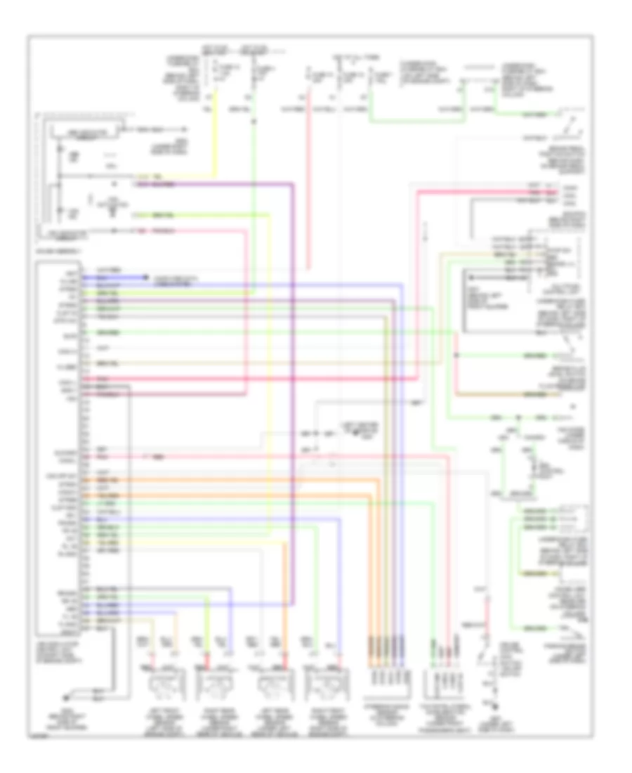
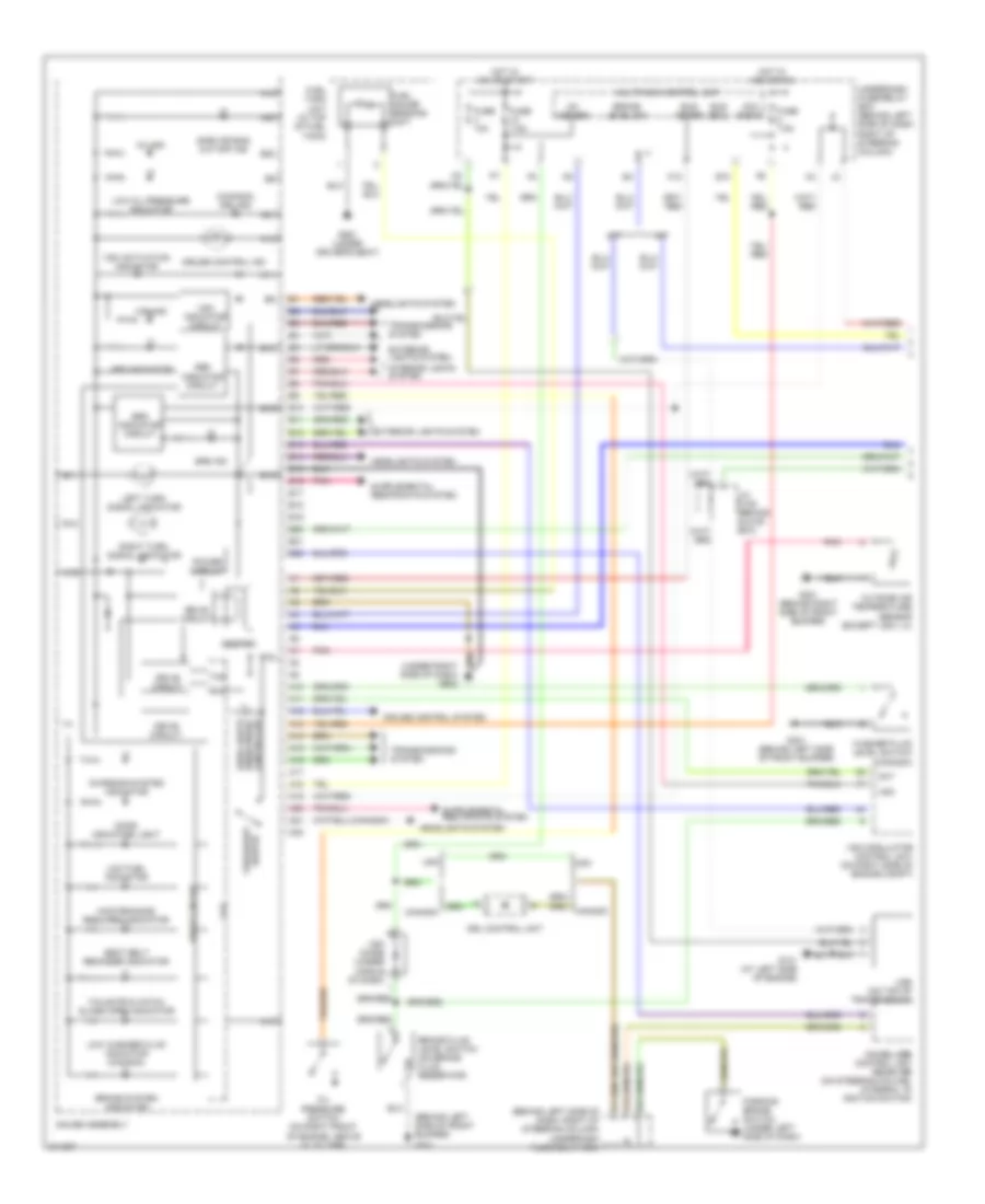
AIR CONDITIONING
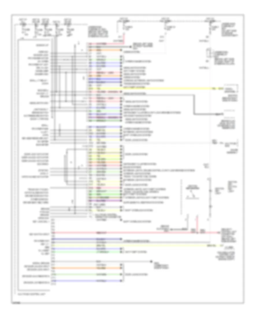
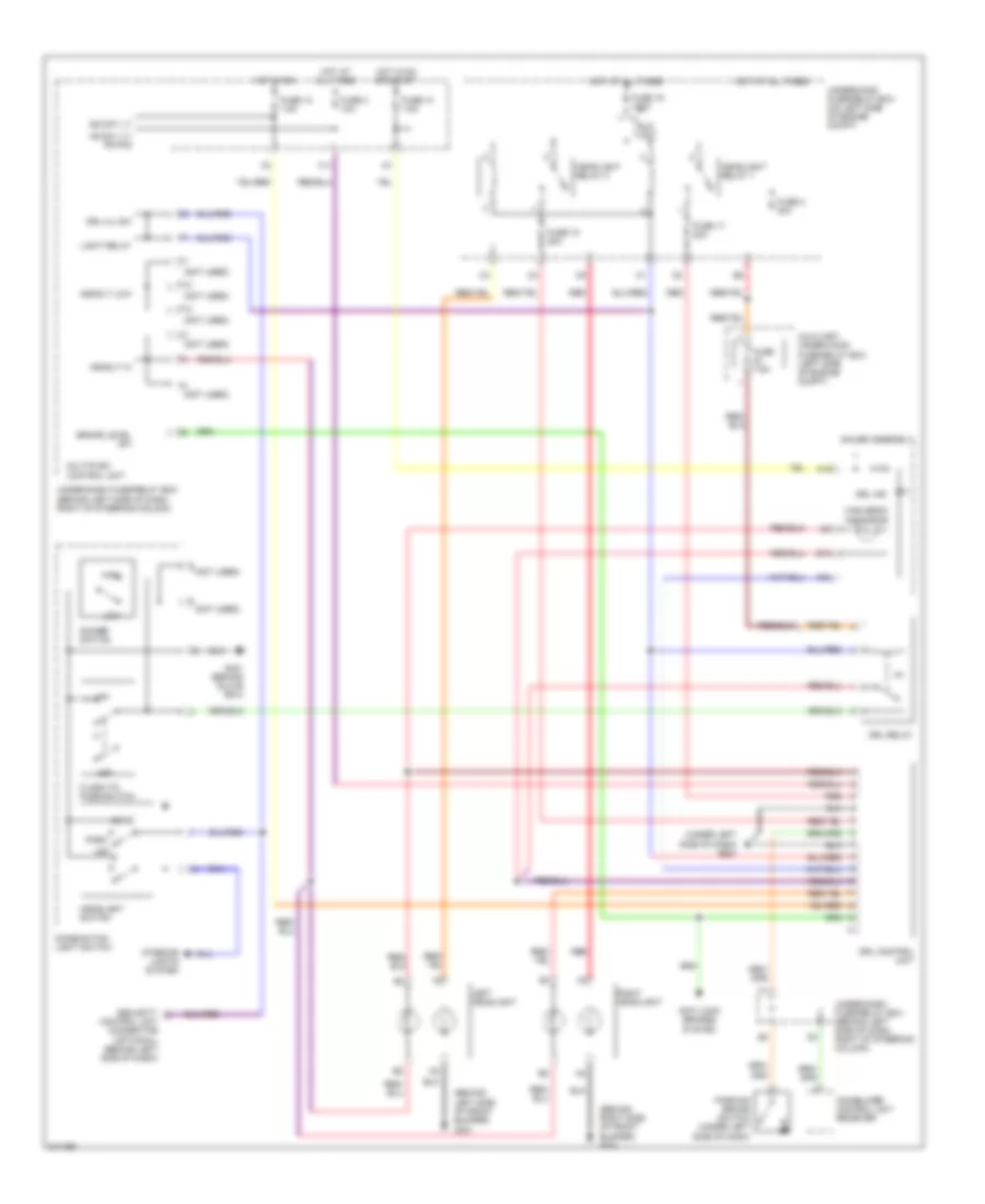
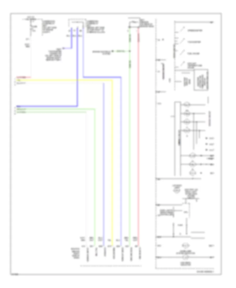
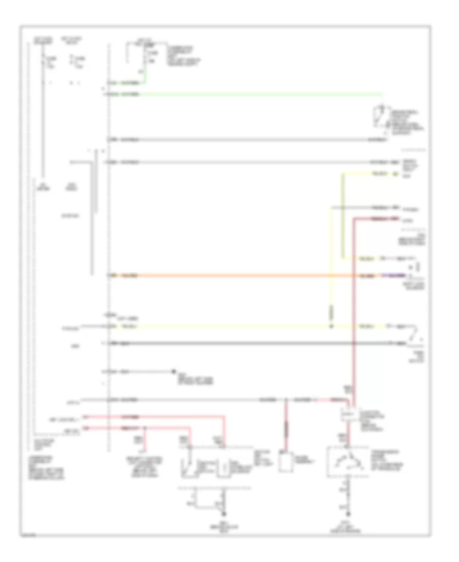
Manual A/C Wiring Diagram (1 of 2) for Honda CR-V SE 2006

List of elements for Manual A/C Wiring Diagram (1 of 2) for Honda CR-V SE 2006:
- (behind left side of dash, right of steering column)
- (ecu) bus
- (under left side of dash) g501
- A/c compressor
- A/c compressor clutch
- A/c compressor clutch relay
- A/c press sw
- A/c pressure switch (on right front of engine compartment)
- A23
- Air mix control motor (below left side of dash, on hvac unit)
- Air mix cool
- Air mix hot
- Air mix potential
- Air mix potential +5v
- Amd- p
- Blower feedback
- Blower pwr trans
- Communication
- D10
- Defogger system
- E10
- E12
- E13
- E18
- Ecm/pcm (behind right side of dash)
- Ect sensor (on rear of engine head)
- Engine controls system
- Evap sensor
- Evaporator temperature sensor (behind left side of dash)
- Fan control
- Fresh
- Frs
- Fuse 10a
- Fuse 20a
- Ground
- Heater control unit- panel
- High
- Hot at all times
- Hot in on
- Ig2
- Ignition
- Illumination
- Interior lights system
- Key pushed in
- Low
- M- cool
- M- def
- M- hot
- M- vent
- Mode
- Mode 1
- Mode 2
- Mode 3
- Mode 4
- Mode control motor (behind right side of dash, on hvac unit)
- Mode def
- Multiplex control unit
- Nca
- Rear defog
- Rec
- Recirculate
- Recirculation control motor (behind right side of dash, on blower unit)
- Red
- Relay ctrl
- S- com
- S5v
- Sens gnd
- Sens input
- Sensor ground
- Thermal protector
- To blower motor relay (diagram 2 of 2)
- Under-dash fuse/relay box
- Under-hood fuse/relay box (on left side of engine compt)
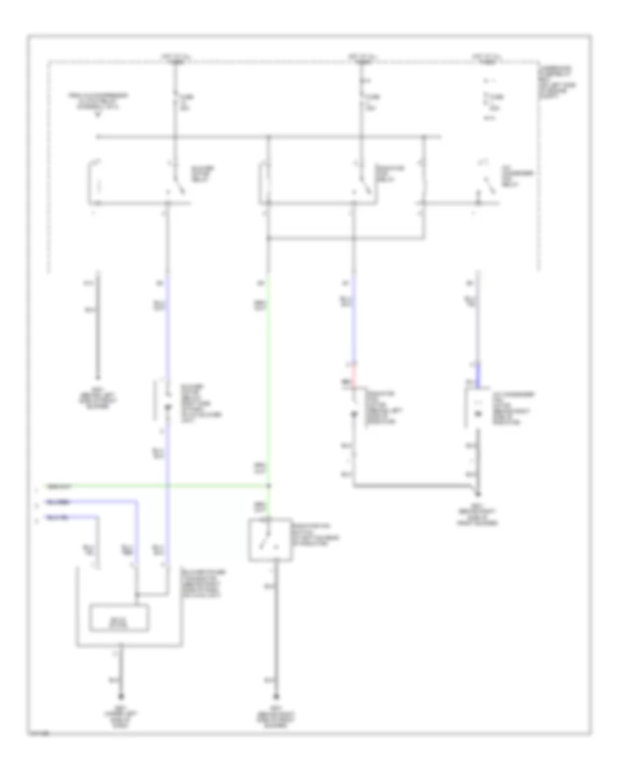
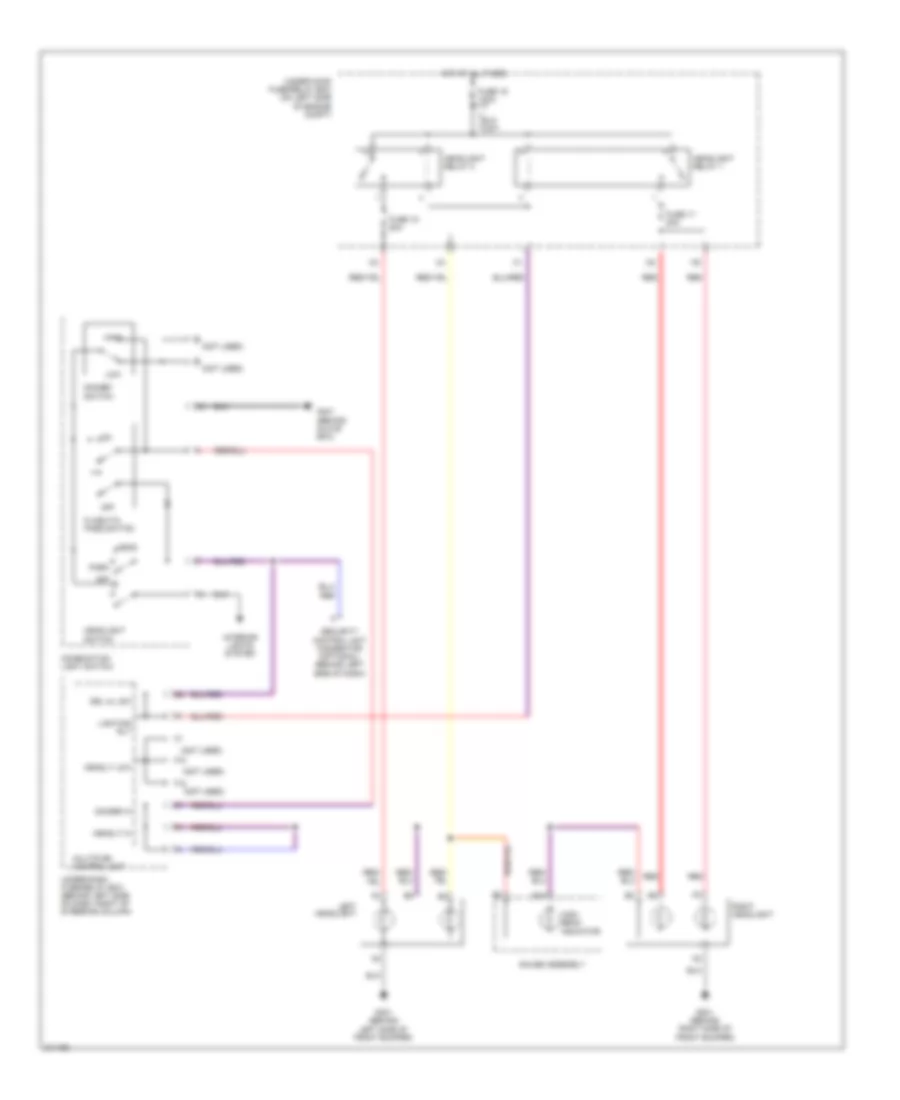
Manual A/C Wiring Diagram (2 of 2) for Honda CR-V SE 2006
List of elements for Manual A/C Wiring Diagram (2 of 2) for Honda CR-V SE 2006:
- A/c condenser fan motor (behind right side of radiator)
- A/c condenser fan relay
- Blower motor (below right side of dash, on a/c blower unit)
- Blower motor relay
- Blower power transistor (behind right side of dash, on hvac unit)
- D13
- From a/c compressor clutch relay (diagram 1 of 2)
- Fuse 20a
- Fuse 40a
- G201 (behind right side of front bumper)
- G301 (behind left side of front bumper)
- G501 (under left side of dash)
- Hot at all times
- Radiator fan motor (behind left side of radiator)
- Radiator fan relay
- Radiator fan switch (at bottom rear of radiator)
- Red
- Solid state
- Underhood fuse/relay box (on left side of engine compt)
ANTI-LOCK BRAKES
Anti-lock Brakes Wiring Diagram for Honda CR-V SE 2006
List of elements for Anti-lock Brakes Wiring Diagram for Honda CR-V SE 2006:
- (left center of console)
- +b-p
- +b-v
- Abs
- Abs ind
- Abs indicator circuit
- Act
- Blfs
- Brake fluid level switch (on brake fluid reservoir)
- Brake pedal position switch (behind dash, on brake pedal support)
- Can1-h
- Can1-l
- Can2-h
- Can2-l
- Can22
- Can24
- Canada
- Canh
- Canl
- Clst-gnd
- Clst-ig
- Computer data lines system
- Cpu
- Cruise control main
- Drl control unit
- E11
- E22
- E24
- Ecm/pcm (behind right side of dash)
- Fl +b
- Fl-gnd
- Fr +b
- Fr-gnd
- Fuse 10 30a
- Fuse 10 7.5a
- Fuse 18 30a
- Fuse 4 10a
- Fuse 7 15a
- G202 (behind right side of front bumper)
- G301 (behind left side of front bumper)
- G451
- G501 (under left side of dash)
- G502 (under right side of dash)
- Gauge assembly
- Gnd-p
- Gnd-v
- Hot at all times
- Hot in on or start
- Ig1
- Immobilizer control unit receiver (on steering column)
- K-line
- Left front wheel speed sensor (left side of engine compt)
- Left rear wheel speed sensor (under left rear of vehicle)
- Multiplex control unit
- O12
- Parking brake switch (under left side of dash)
- Passenger's seat)
- Pnk
- Red
- Right front wheel speed sensor (right side of engine compt)
- Right rear wheel speed sensor (under right rear of vehicle)
- Rl +b
- Rl-gnd
- Rr +b
- Rr-gnd
- Sld-gnd
- Steering angle sensor (in steering column)
- Stop sw
- Str-vcc
- Stra
- Strb
- Strg
- Strga
- Strgb
- Strgg
- Strgz
- Strz
- Svcc
- Switch/ vsa off switch
- Under-dash fuse/ relay box (behind left side of dash, right of steering column)
- Under-dash fuse/relay box (behind left side of dash, right of steering column)
- Under-hood fuse/relay box (on left side of engine compt)
- Usa
- Vsa
- Vsa activation ind
- Vsa diode (under middle of dash)
- Vsa ind
- Vsa indicator circuit
- Vsa modulator control unit (on right side of engine compt)
- Vsa off sw
- Wl-ebd
- Y1 ebd brake lvl sw gnd
- Yaw rate-lateral acceleration sensor (under front
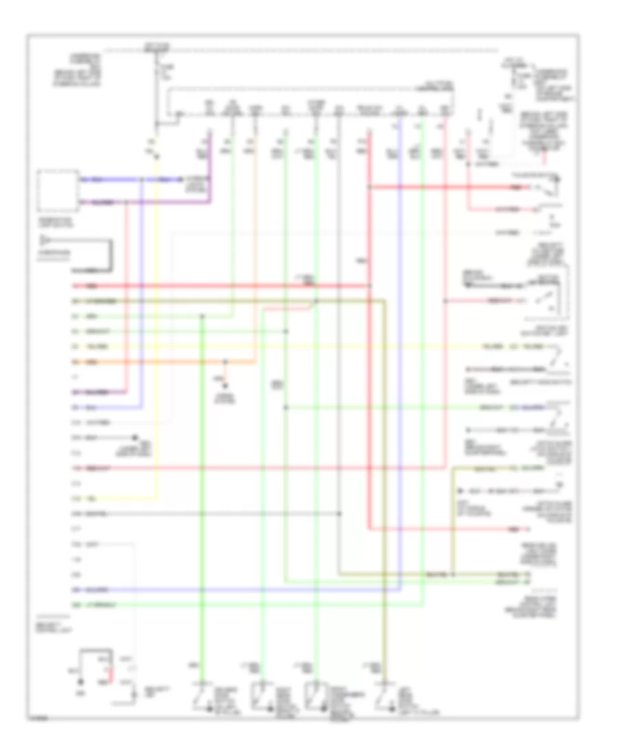
ANTI-THEFT
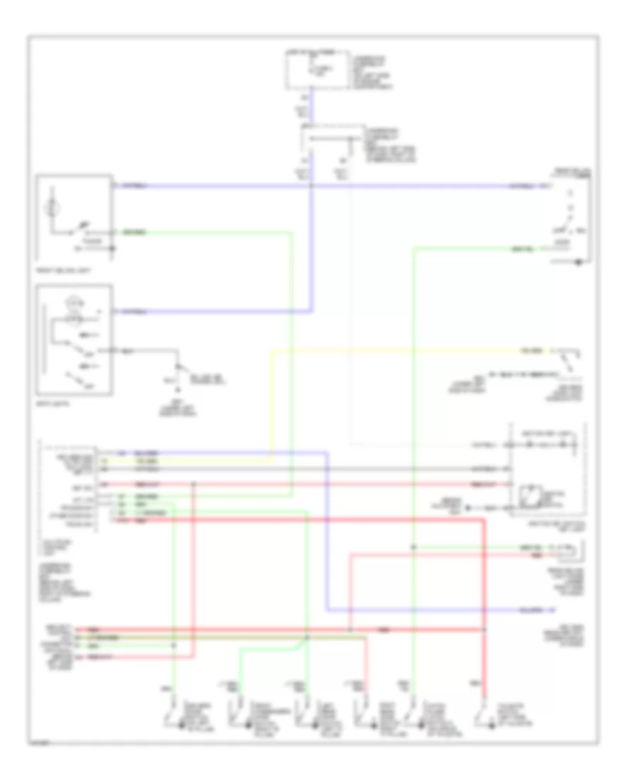
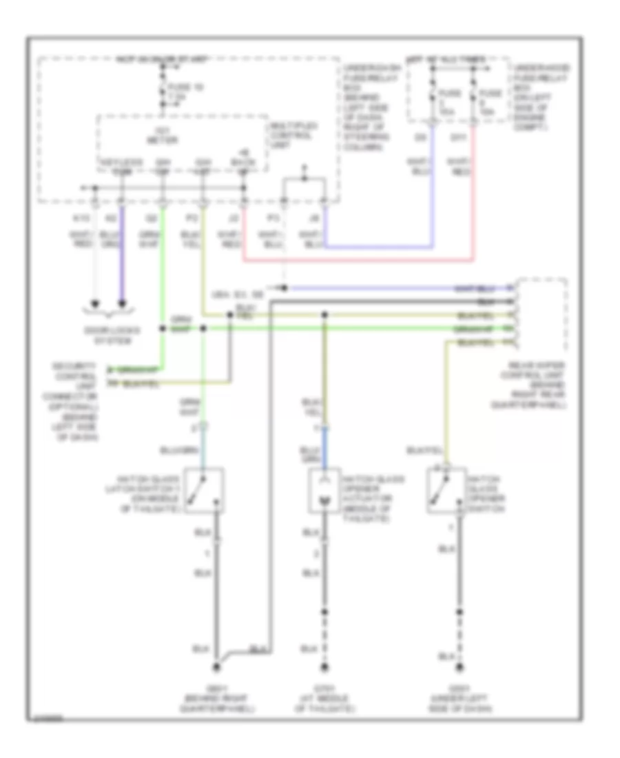
Anti-theft Wiring Diagram for Honda CR-V SE 2006
List of elements for Anti-theft Wiring Diagram for Honda CR-V SE 2006:
- (behind glove box) g401
- (behind left side of dash, right of steering column) (not used) underdash fuse/relay box connector u1
- Combination light switch
- Driver's door switch (on left "b" pillar)
- Drl h/l sw
- Fr door sw (dr)
- Front passenger's door switch switch (right "b" pillar)
- Fuse 40a
- Fuse 7.5a
- G/h act
- G/h sw
- G50
- G501 (under left side of dash)
- G601 (behind right quarterpanel)
- G701 (at middle of tailgate)
- Hatch glass latch switch 1 (on middle of tailgate)
- Hatch glass opener actuator (on middle of tailgate)
- Horn sw
- Horns system
- Hot at all times
- Hot in on or start
- Ig2
- Ignition key switch
- Ignition key switch/key light
- Interior lights system
- K/l set
- K/l unset
- Key sw
- Left rear door switch (left "c" pillar)
- Microphone
- Multiplex control unit
- Nca
- Other door sw
- P18
- Rear ceiling light diode (under right side of dash)
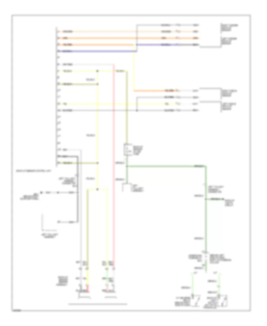
- Rear wiper control unit (behind right rear quarter panel)
- Red
- Right rear door switch (right "c" pillar)
- Security control unit
- Security hood switch
- Security in-line fuse (under left side of dash)
- Security led
- Tailgate switch
- Trunk sw (t/g sw)
- Underdash fuse/relay box (behind left side of dash, right of steering column)
- Underhood fuse/relay box (on left side of engine compartment)
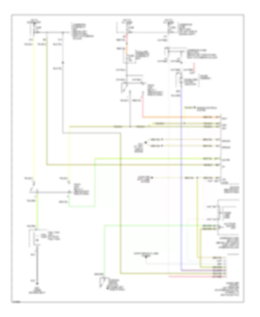
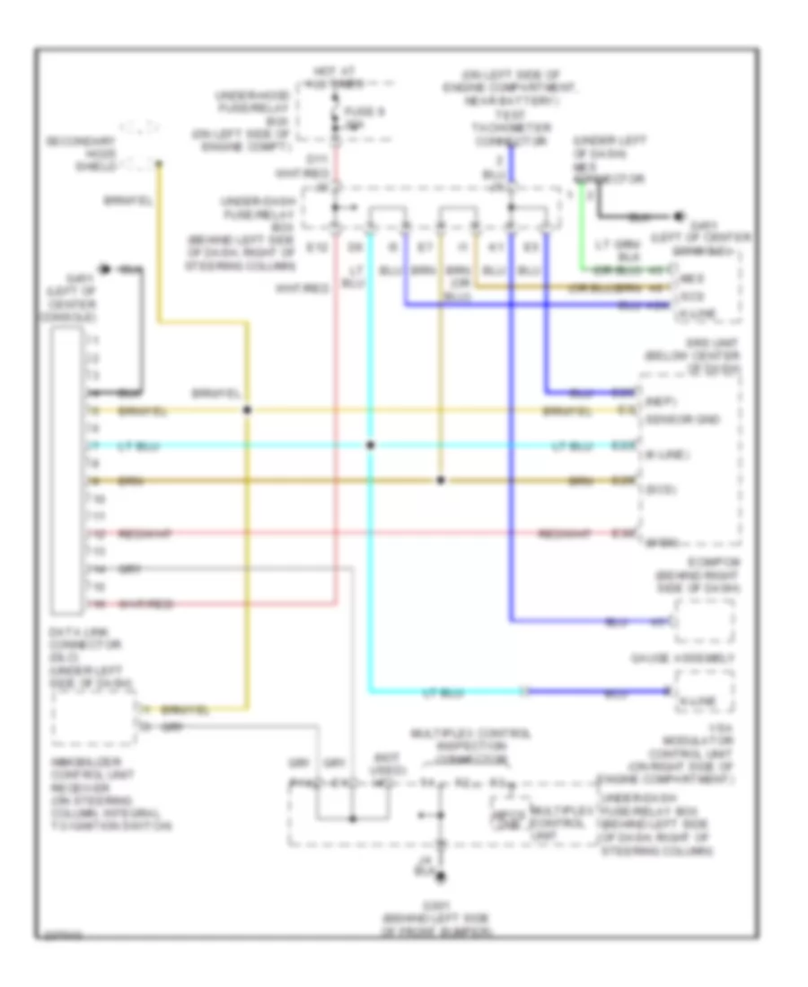
Immobilizer Wiring Diagram for Honda CR-V SE 2006
List of elements for Immobilizer Wiring Diagram for Honda CR-V SE 2006:
- A19
- Auxilliary underhood fuse/relay box
- B10
- B22
- Computer data lines system
- D11
- D12
- E17
- E27
- Ecm/pcm (behind right side of dash)
- Engine controls system
- Fuel pump
- Fuel tank unit (in top of fuel tank)
- Fuse 10a
- Fuse 15a
- Fuse 30a
- G101 (at left side of engine)
- G551 (under driver's seat)
- Gauge assembly
- Ground
- Hot at all times
- Hot in on or start
- Ig1
- Igp1
- Igp2
- Immobi- lizer cord
- Immobilizer control unit receiver (on steering column, integral to ignition switch)
- Immobilizer system indicator
- Imo fpr
- Imocd
- K14
- Lg3
- Mrly
- Multiplex control unit
- Parking brake switch (under left side of dash)
- Pgm-fi main relay 1 (behind right side of dash)
- Pgm-fi main relay 2 (behind right side of dash)
- Underdash fuse/ relay box (behind left side of dash, right of steering column)
- Underdash fuse/relay box (behind left side of dash, right of steering column)
- Underhood fuse/ relay box (on left side of engine compt)
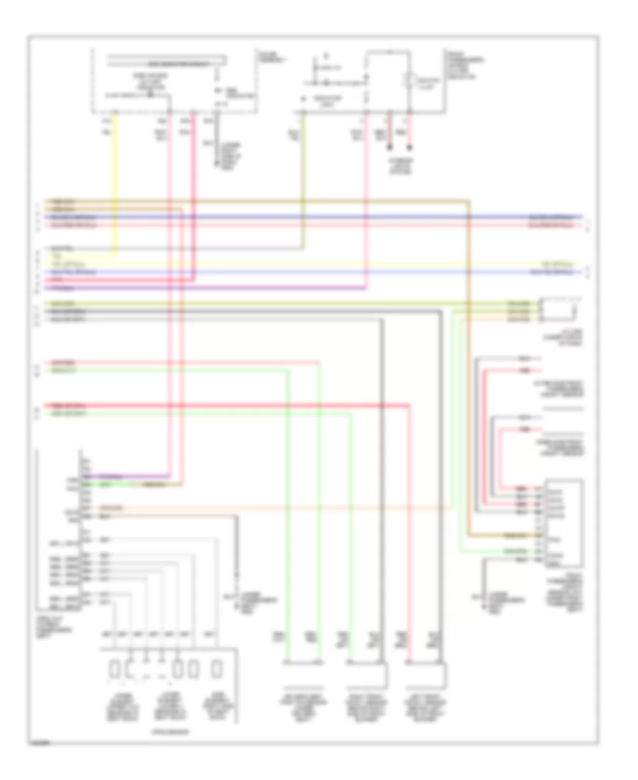
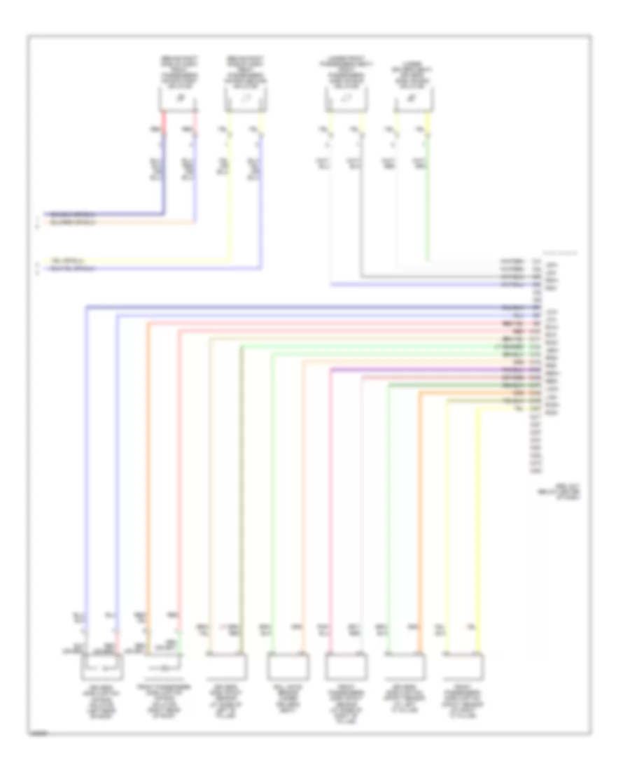
BODY CONTROL MODULES
Body Control Modules Wiring Diagram for Honda CR-V SE 2006
List of elements for Body Control Modules Wiring Diagram for Honda CR-V SE 2006:
- (behind glove box) g401
- (behind left side of front bumper) g301
- (canada)
- (not used)
- (usa)
- +b back up
- +b day lt/fr fog
- +b door lock
- A/c pressure switch
- Acc radio
- Air conditioning system
- Anti-theft system
- Atp-p
- Atpn
- Brake fluid level switch (on brake fluid reservoir)
- Brake switch
- Bus (ecu)
- Bus meter
- C11
- Commu- nication
- D10
- D11
- D14
- Dimmer high
- Door lock actuator
- Door locks system
- Door unlock actuator
- Dr door lck remote in
- Dr door lock input
- Dr door unlk remote in
- Dr door unlock input
- Driver door switch
- Driver seat belt/srs
- Drl h/l sw
- E10
- E13
- Ebd
- Ecm/pcm (behind right side of dash)
- Exterior lights system
- Exterior lights systems
- Exterior lights, cruise control & anti-lock brakes systems
- F11
- Fr washer motor
- Fr wiper (int)
- Fr wiper int unit
- Fr wiper pass
- Fuse 10a
- Fuse 16 20a
- Fuse 20a
- Fuse 3 15a
- Fuse 7.5a
- Fuse 9 10a
- G10
- G502 (under right side of dash)
- Gauge assembly
- Ground
- Hatch glass actuator
- Hatch glass switch
- Headlights high
- Headlights system
- Horn sw
- Horns system
- Hot at all times
- Hot in acc or on
- Hot in on
- Hot in on or start
- Ig 2 day lt
- Ig1 meter
- Ig1 wiper
- Ignition key light
- Ignition key switch
- Ignition key switch/ key light
- Illum +
- Immobilizer
- Instrument cluster & anti-lock brakes systems
- Instrument cluster system
- Interior lights & anti-theft systems
- Interior lights system
- Interior lights, anti-theft systems
- Intr lt
- K/l set
- K/l unset
- K10
- K13
- Key lock sol +
- Key lt -
- Key switch input
- Keyless receiver unit
- Lighting rly-
- Mpcs chk
- Multiplex bus
- Multiplex control inspection connector
- Multiplex control unit
- Other door sw
- P pin sw
- P16
- P17
- P18
- Red
- Security control unit connector (optional) (behind left side of dash)
- Shift interlock system
- Signal ground
- Small
- Small lt relay -
- Sound systems
- Stop sw
- Transmissions system
- Trunk sw (t/g sw)
- Trunk, tailgate, fuel doors
- Trunk, tailgate, fuel doors & anti-theft systems
- Under-dash fuse/relay box (behind left side of dash, right of steering column)
- Under-hood fuse/relay box (on left side of engine compartment)
- Vsa modulator control unit (on right side of engine compt)
- Warning, exterior lights systems
- Wiper/washer system
- Wl-ebd
- Y10
- Y11
- Y12
- Y13
COMPUTER DATA LINES
Computer Data Lines Wiring Diagram for Honda CR-V SE 2006
List of elements for Computer Data Lines Wiring Diagram for Honda CR-V SE 2006:
- (k-line)
- (left of center console)
- (nep)
- (not used) i4
- (on left side of engine compartment, near battery) test tachometer connector
- (scs)
- (under left of dash) mes connector
- (wen)
- A24
- D11
- Data link connector (dlc) (under left side of dash)
- E12
- E23
- E25
- E29
- E30
- Ecm/pcm (behind right side of dash)
- Fuse 9 10a
- G301 (behind left side of front bumper)
- G451
- G451 (left of center console)
- Gauge assembly
- Hot at all times
- Immobilizer control unit receiver (on steering column, integral to ignition switch)
- K-line
- Mes
- Mpcs chk
- Multiplex control inspection connector
- Multiplex control unit
- P14
- Scs
- Secondary ho2s shield
- Sensor gnd
- Srs unit (below center of dash)
- Under-dash fuse/relay box (behind left side of dash, right of steering column)
- Under-hood fuse/relay box (on left side of engine compt)
- Vsa modulator control unit (on right side of engine compartment)
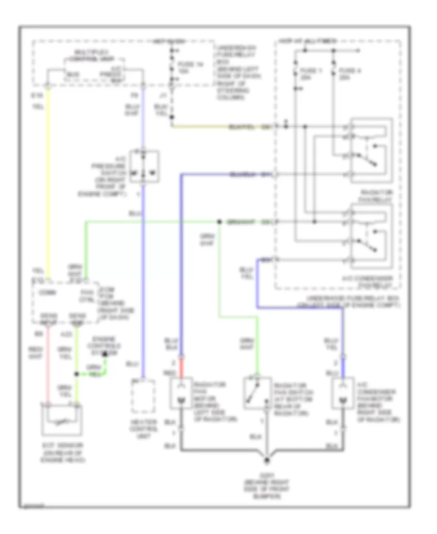
COOLING FAN
Cooling Fan Wiring Diagram for Honda CR-V SE 2006
List of elements for Cooling Fan Wiring Diagram for Honda CR-V SE 2006:
- A/c condenser fan motor (behind right side of radiator)
- A/c condenser fan relay
- A/c press sw
- A/c pressure switch (on right front of engine compt)
- A23
- Bus
- Comm
- E10
- E13
- Ecm/ pcm (behind right side of dash)
- Ect sensor (on rear of engine head)
- Engine controls system
- Fan ctrl
- Fuse 1 20a
- Fuse 14 10a
- Fuse 4 20a
- G201 (behind right side of front bumper)
- Heater control unit
- Hot at all times
- Hot in on
- Multiplex control unit
- Radiator fan motor (behind left side of radiator)
- Radiator fan relay
- Radiator fan switch (at bottom rear of radiator)
- Red
- Sens gnd
- Sens input
- Underdash fuse/relay box (behind left side of dash, right of steering column)
- Underhood fuse/relay box (on left side of engine compt)
CRUISE CONTROL
Cruise Control Wiring Diagram for Honda CR-V SE 2006
List of elements for Cruise Control Wiring Diagram for Honda CR-V SE 2006:
- "on"
- (at left side of engine) g101
- (on left side of engine) g101
- A/t
- A12
- A18
- A20
- A21
- A23
- A24
- A25
- A26
- App sensor (right rear of engine compartment)
- Apsa
- Apsb
- Atpfwd
- Auxiliary under-hood fuse/relay box (left side of engine compt)
- B19
- B20
- Bksw
- Bkswnc
- Brake pedal position switch (behind dash, on brake pedal support)
- C10
- C18
- Cable reel
- Cancel switch
- Clutch pedal position switch (m/t) (on clutch pedal support)
- Controls system
- Crmsw
- Crmtcls
- Crressw
- Crsetsw
- Cruise control ind
- Cruise control main switch
- Cruise control main switch/ vsa off switch
- Cruise control set/ resume/ cancel switch
- D15
- D16
- Dbw m+
- Dbw m-
- Dbwrly
- E22
- Ecm/pcm (behind right side of dash)
- Engine
- Ex, usa: se, canada: ex-l
- Fuse 10 7.5a
- Fuse 15a
- Fuse 2 30a
- Fuse 4 10a
- Fuse 7 15a
- Fuse 8 15a
- G101 (at left side of engine)
- G501 (under left side of dash)
- Gauge assembly
- Horn relay
- Horn sw
- Horns system
- Hot at all times
- Hot in on or start
- Indicator
- Interior lights system
- J/c c105 (behind glove box)
- Junction connector c103 (at rear of engine)
- Junction connector c105 (behind glove box)
- Junction connector c105 (behind glove box)
- M/t
- Mrly
- Multiplex control unit
- O12
- Output shaft (counter shaft) speed sensor (a/t) (on front right side of transmission)
- Pg2
- Pgm-fi main relay 1 (behind right side of dash)
- Pnk c3
- Red
- Resume switch
- Sedf
- Sefd
- Set ind
- Set switch
- Sg1
- Sg2
- Steering wheel
- Thl 2
- Thl1
- Throttle actuator control module (behind right side of dash)
- Throttle actuator control module relay
- Tp sensor/ throttle actuator (on right side of throttle body)
- Transmission range switch (a/t) (on lower rear transaxle)
- Under-dash fuse/relay box (behind left side of dash right of steering column)
- Under-dash fuse/relay box (behind left side of dash, right of steering column)
- Under-hood fuse/relay box (on left side of engine compartment)
- Vcc
- Vcc1
- Vcc2
- Vss (m/t) (on top of transmission)
- Vss/nc
DEFOGGERS
Heated Mirrors Wiring Diagram, USA: SE; Canada: EX, EX-L for Honda CR-V SE 2006
List of elements for Heated Mirrors Wiring Diagram, USA: SE; Canada: EX, EX-L for Honda CR-V SE 2006:
- (ig2) power
- (not used)
- (under left side of dash) g501
- (under right side of dash) g502
- Defogger
- Fuse 14 10a
- Fuse 20a
- G451 (left of center console)
- G501 (under left side of dash)
- Gnd
- Heater control unit panel
- Hot at all times
- Hot in on
- Left power mirror
- Noise condenser
- Power mirror defogger relay (behind glove box)
- Rear window defogger
- Rear window defogger relay
- Right power mirror
- Under- hood fuse/ relay box
- Under-dash fuse/relay box (behind left side of dash, right of steering column)
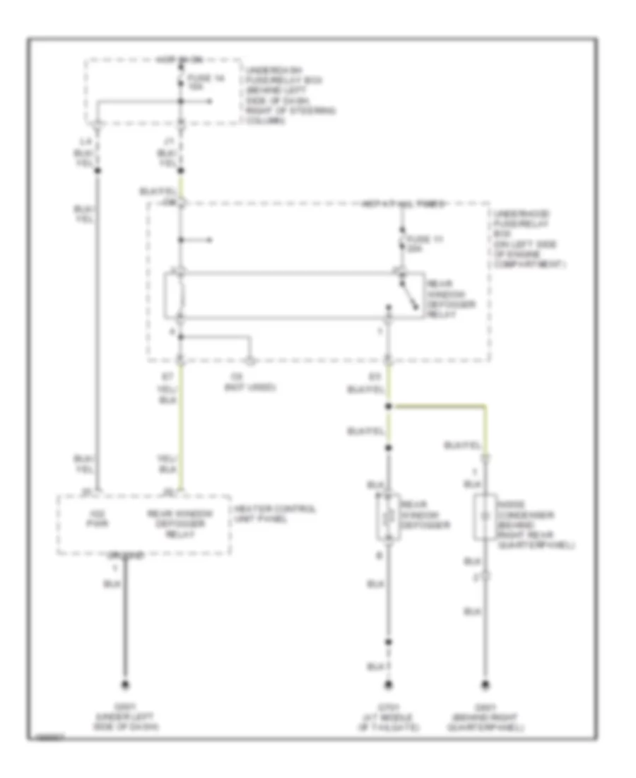
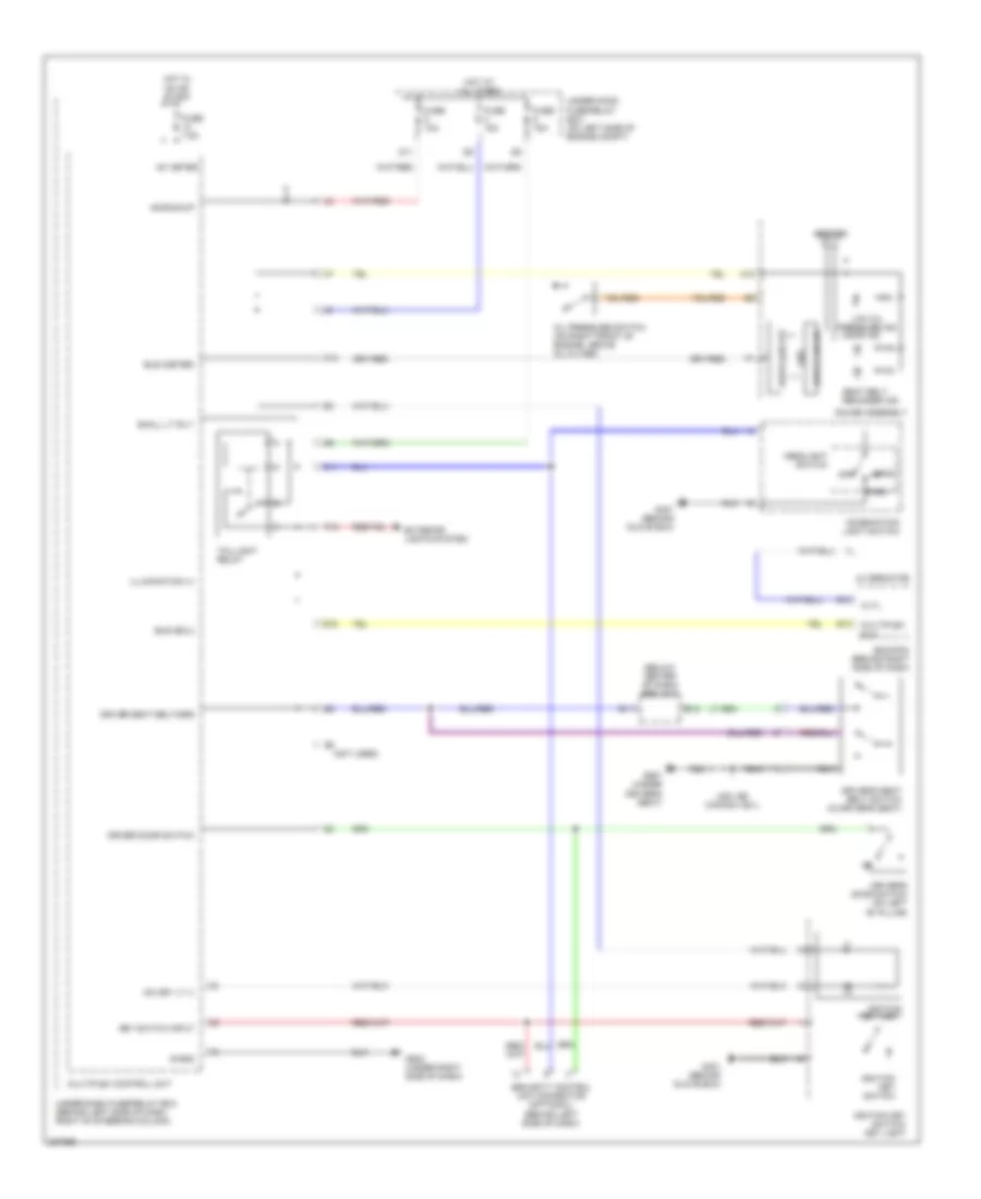
Rear Defogger Wiring Diagram for Honda CR-V SE 2006
List of elements for Rear Defogger Wiring Diagram for Honda CR-V SE 2006:
- (not used)
- Fuse 11 20a
- Fuse 14 10a
- G501 (under left side of dash)
- G601 (behind right quarterpanel)
- G701 (at middle of tailgate)
- Ground
- Heater control unit panel
- Hot at all times
- Hot in on
- Ig2 pwr
- Noise condenser (behind right rear quarterpanel)
- Rear window defogger
- Rear window defogger relay
- Underdash fuse/relay box (behind left side of dash, right of steering column)
- Underhood fuse/relay box (on left side of engine compartment)
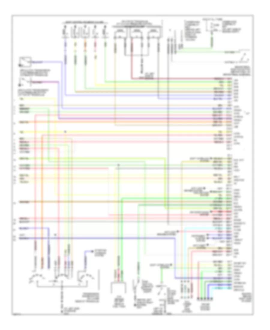
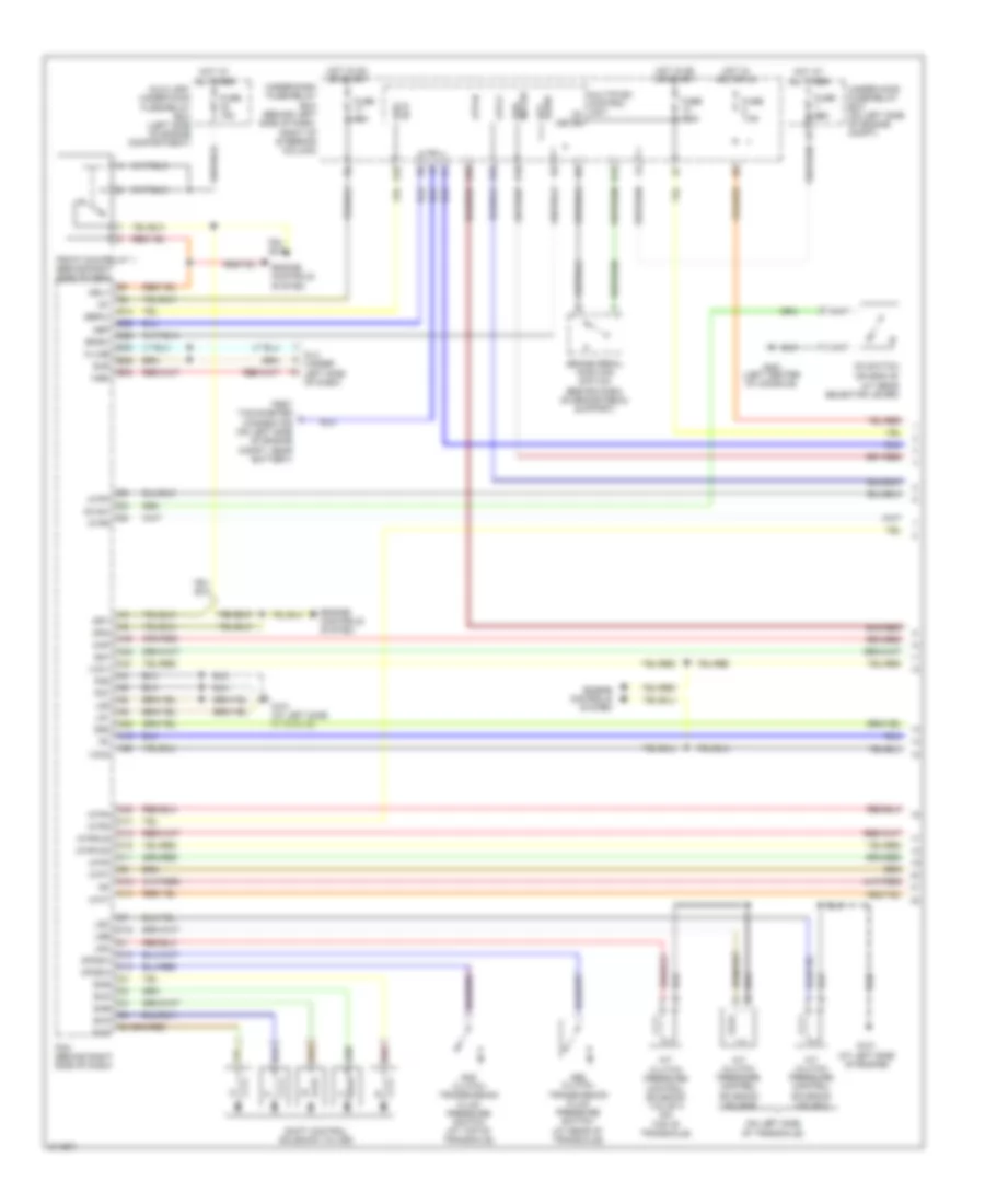
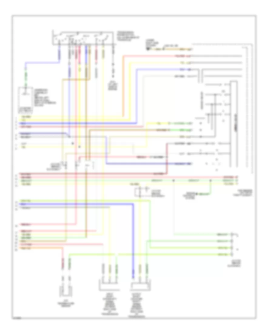
ENGINE PERFORMANCE
2.4L
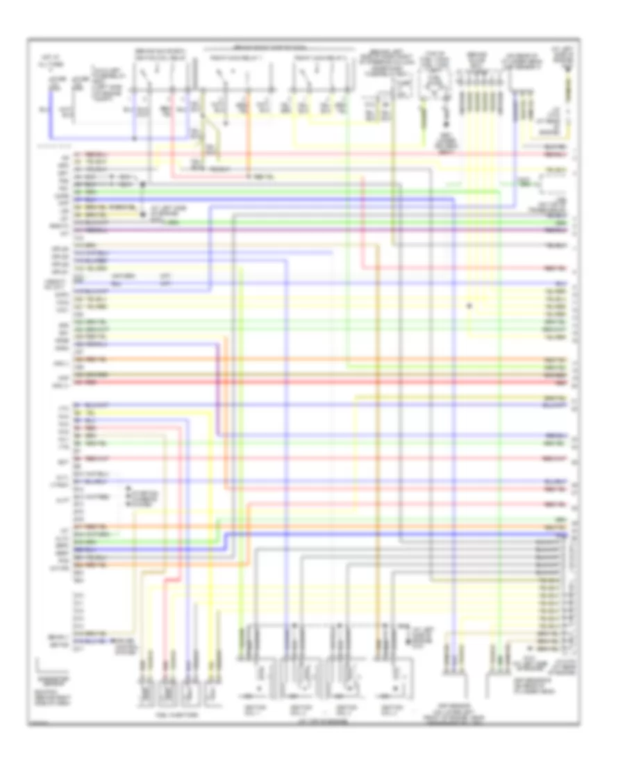
2.4L, Engine Performance Wiring Diagram (1 of 4) for Honda CR-V SE 2006
List of elements for 2.4L, Engine Performance Wiring Diagram (1 of 4) for Honda CR-V SE 2006:
- (a/t)
- (at left side of engine) g101
- (at top of engine)
- (behind glove box)
- (behind glove box) j/c c105
- (behind left side of dash, right of steering column) under-dash fuse/relay box
- (behind right side of dash)
- (m/t)
- (on rear of cylinder head) cmp sensor a
- (top of fuel tank) fuel tank unit
- A10
- A11
- A12
- A13
- A14
- A15
- A16
- A17 a18
- A19
- A20
- A21
- A22
- A23
- A24
- A25
- A26
- A27
- A28
- A29
- A30
- A31
- Afs (+)
- Afs (-)
- Afshtc
- All times
- Altc
- Altf
- Altl
- Apsa
- Apsb
- Auxiliary fuse/relay box (left side of engine compt)
- B10
- B11
- B12
- B13
- B14
- B15
- B16
- B17
- B18
- B19
- B20
- B21
- B22
- B23
- B24
- Barometer sensor
- Ckp
- Ckp sensor (on lower left front of engine, near crankshaft pulley)
- Cmp sensor b (on rear of cylinder head)
- Cmpa
- Cmpb
- Cruise control system
- D10
- D11
- D12
- D13
- D14
- D15
- D16
- D17
- Dbwrly
- Ecm/pcm (behind right side of dash)
- Ect
- Fuel injectors
- Fuel pump
- Fuse 15a
- G101 (at left side of engine)
- G551 (under driver's seat)
- Hot at
- Iat
- Icm
- Ignition coil 1
- Ignition coil 2
- Ignition coil 3
- Ignition coil 4
- Ignition coil relay
- Igp1
- Igp2
- Igpls1
- Igpls2
- Igpls3
- Igpls4
- Imt
- Imtvps
- Inj1
- Inj2
- Inj3
- Inj4
- J/c c103 (at rear of engine)
- Lg1
- Lg2
- Map
- Pcs
- Pg1
- Pg2
- Pgm-f1 main relay 1
- Pgm-f1 main relay 2
- Red
- Sedf
- Sefd
- Setind
- Sg1
- Sg2
- Starting/ charging system
- Vcc1
- Vcc2
- Vss(m/t) nc (a/t)
- Vtc
- Vtpsw
- Vts
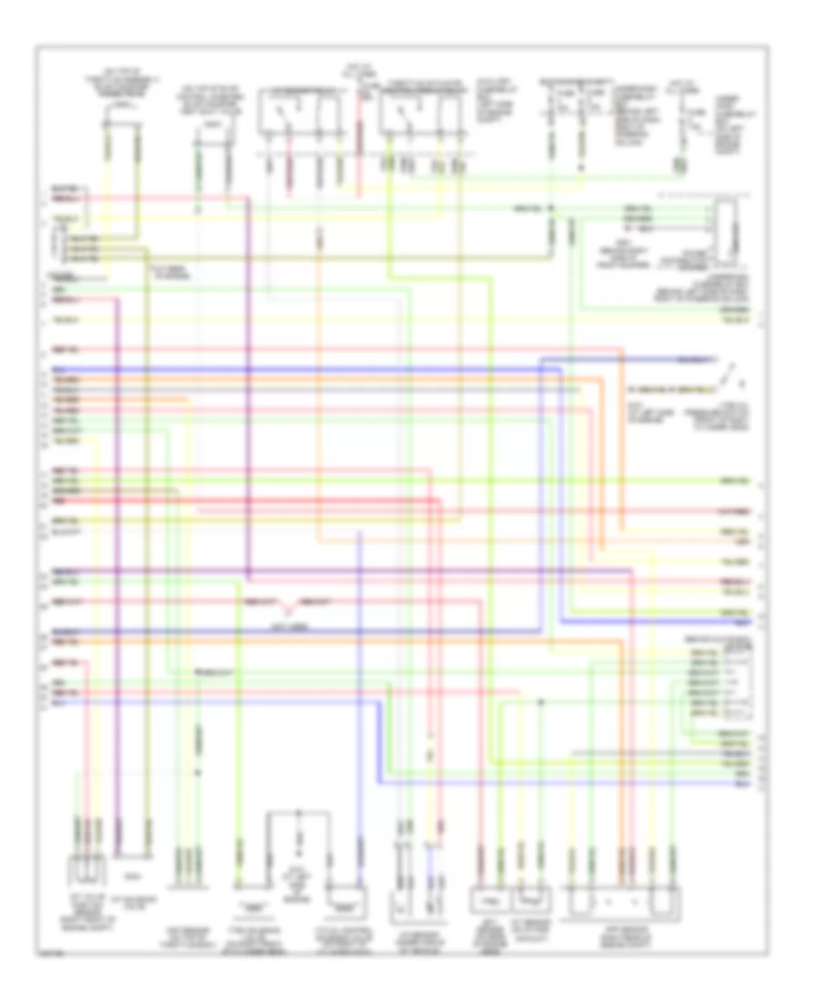
2.4L, Engine Performance Wiring Diagram (2 of 4) for Honda CR-V SE 2006
List of elements for 2.4L, Engine Performance Wiring Diagram (2 of 4) for Honda CR-V SE 2006:
- (at rear of engine)
- (behind glove box) j/c c105
- (not used)
- (on top of evap control canister) evap canister vent shut valve
- (on top of throttle assembly) evap canister purge valve
- A/f sensor (under middle of vehicle)
- A/f sensor relay
- Air duct)
- App sensor (right rear of engine compt)
- Auxiliary fuse/relay box (left side of engine compt)
- C10
- Ect sensor (on rear of engine head)
- Eld unit
- Fuse 10a
- Fuse 20a
- Fuse 7.5a
- G101 (at left side of engine)
- G201 (behind right side of front bumper)
- Hot at all times
- Hot in on or start
- Iat sensor (on intake
- Imt solenoid valve
- Imt valve position sensor (right front of engine compt)
- Map sensor (on top of throttle body)
- Power distribution system
- Red
- Throttle actuator control module relay
- Under- hood fuse/relay box (on left side of engine compt)
- Under-dash fuse/relay box (behind left side of dash, right of steering column)
- Vtc oil control solenoid valve (on front of cylinder head)
- Vtec oil pressure switch (front of right cylinder head)
- Vtec solenoid valve (on right front of cylinder head)
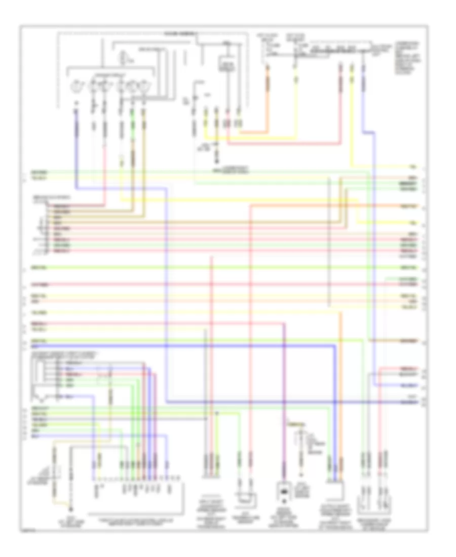
2.4L, Engine Performance Wiring Diagram (3 of 4) for Honda CR-V SE 2006
List of elements for 2.4L, Engine Performance Wiring Diagram (3 of 4) for Honda CR-V SE 2006:
- (behind glove box)
- (on right side of throttle body.) tp/sensor/throttle actuator
- (under right side of dash)
- A13
- A14
- A15
- A16
- A18
- Acc radio
- Atf temperature sensor
- Atp-p
- B20
- Bus (ecu)
- Bus meter
- Cpu
- D10
- Dbw m+
- Dbwm-
- Dimming circuit
- Drive circuit
- E10
- Fuse 7.5a
- G101 (at left side of engine)
- G502
- Gauge assembly
- Hot in acc or on
- Hot in on or start
- Ig1 meter
- Input shaft (mainshaft) speed sensor (a/t) (on rear right side of transmission)
- J/c c103 (at rear of engine)
- J/c c105
- K10
- Knock sensor (on left side of engine, near starter)
- Mil ind
- Multiplex control unit
- Output shaft (countershaft) speed sensor (a/t) (on front right of transmission)
- Pg2
- Secondary ho2s (under middle of vehicle)
- Sedf
- Sefd
- Thl1
- Thl2
- Throttle actuator control module (behind right side of dash)
- Under-dash fuse/relay box (behind left side of dash, right of steering column)
- Usa: ex, se
- Vcc
2.4L, Engine Performance Wiring Diagram (4 of 4) for Honda CR-V SE 2006
List of elements for 2.4L, Engine Performance Wiring Diagram (4 of 4) for Honda CR-V SE 2006:
- anti-lock brakes system
- (a/t)
- (at left side of engine)
- (at left side of engine) g101
- (behind left side of front bumper) g301
- (left of center console)
- (on top of transaxle) a/t clutch pressure control solenoid valves
- 2nd clutch transmission fluid pressure switch (at top of transaxle)
- 3rd clutch transmission fluid pressure switch (at rear of transaxle)
- A/t
- Acc
- Afshtcr
- Air conditioning system
- Anti-lock brakes system
- Anti-theft system
- Atft
- Atp1
- Atp2
- Atpd
- Atpfwd
- Atpn
- Atpp
- Atpr
- Atprvs
- Bksw
- Bkswnc
- Brake pedal position switch (behind dash, on brake pedal support)
- C10
- C11
- C12
- C13
- C14
- C15
- C16
- C17
- C18
- C19
- C20
- C21
- C22
- Canh
- Canl
- Cooling fans system
- Cr res sw
- Cr set sw
- Crmsw
- Crmtcls
- Cruise control system
- D3 switch (on end of a/t gear selector lever)
- D3sw
- Dlc (under left side of dash)
- E10
- E11
- E12
- E13
- E14
- E15
- E16
- E17
- E18
- E19
- E20
- E21
- E22
- E23
- E24
- E25
- E26
- E27
- E28
- E29
- E30
- E31
- Ecm/pcm (behind right side of dash)
- Eld
- Fanc
- Ftp
- Ftp sensor (on left rear of fuel tank)
- Fuse 15a
- G101
- G451
- Hot at all times
- Ig1
- Imo fpr
- Imocd
- Instrument cluster system
- K-line
- Lg3
- Lsa
- Lsb
- Lsc
- Mil
- Mrly
- Nep
- O12
- Op2sw
- Op3sw
- P-pin sw
- Pnk
- Psp switch (rear of engine compt)
- Pspsw
- Red
- Scs
- Sefmj
- Sg3
- Sha
- Shb
- Shc
- Shd
- She
- Shift control solenoid valves
- Shift interlock system
- Sho2s
- Sho2shtc
- Sls
- Starting/ charging system
- Transmission range switch (on lower rear of transaxle)
- Under-dash fuse/relay box (behind left side of dash, right of steering column)
- Under-hood fuse/relay box (on left side of engine compt)
- Vcc3
- Vssout
- Vsv
- Wen
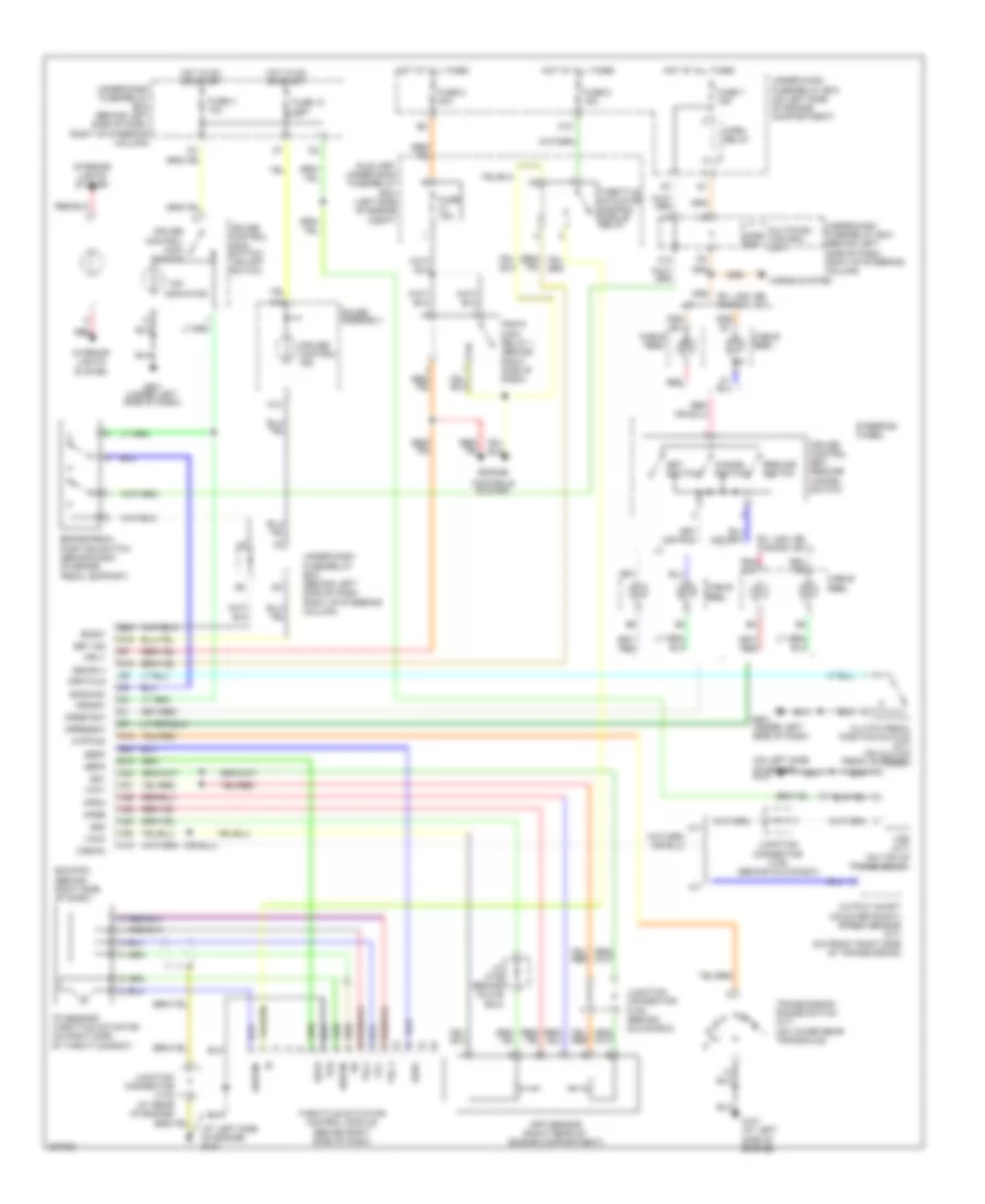
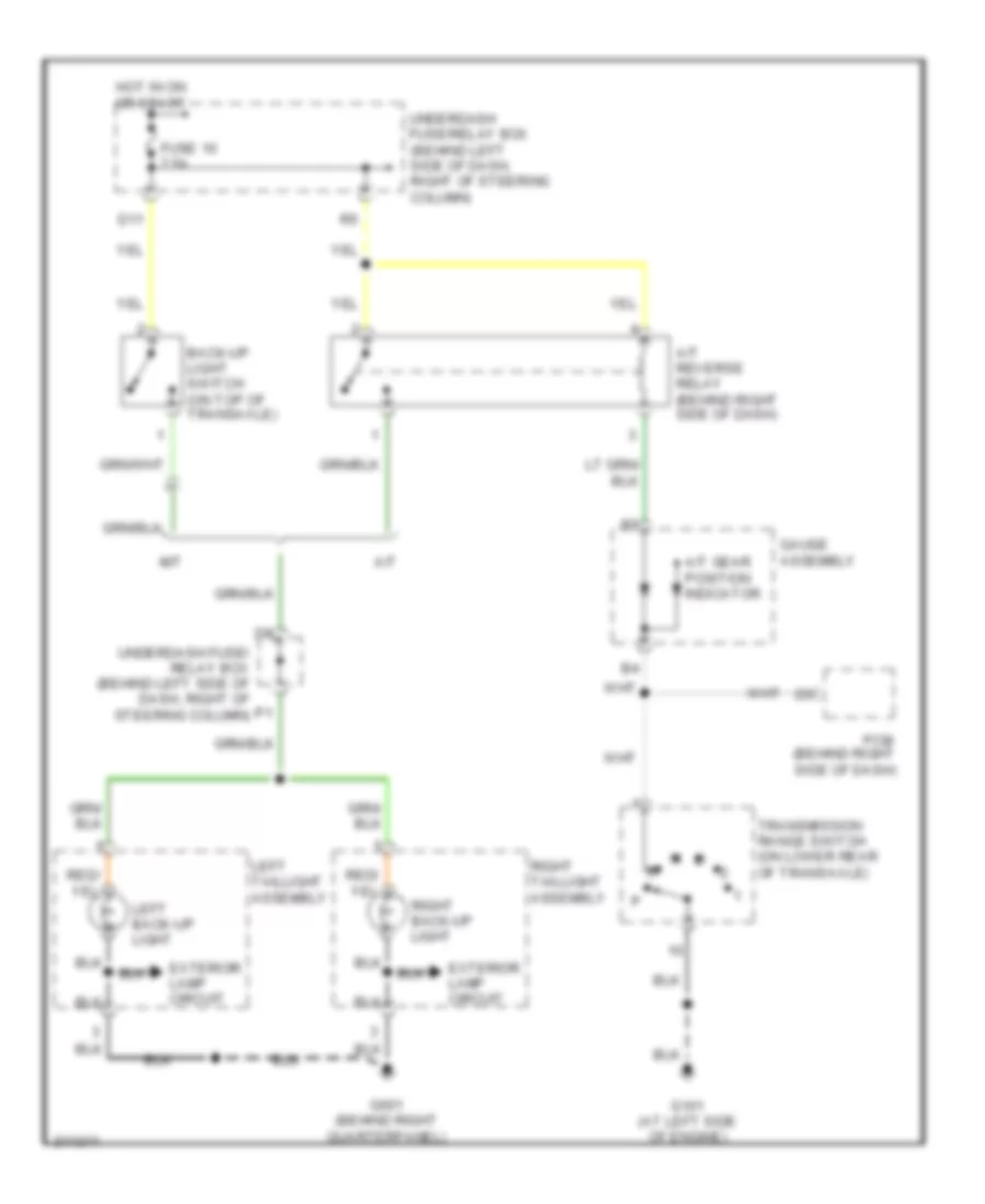
EXTERIOR LIGHTS
Back-up Lamps Wiring Diagram for Honda CR-V SE 2006
List of elements for Back-up Lamps Wiring Diagram for Honda CR-V SE 2006:
- A/t
- A/t gear position indicator
- A/t reverse relay (behind right side of dash)
- Back-up light switch (on top of transaxle)
- D11
- Exterior lamp circuit
- Fuse 10 7.5a
- G101 (at left side of engine)
- G601 (behind right quarterpanel)
- Gauge assembly
- Hot in on or start
- Left back-up light
- Left taillight assembly
- M/t
- Pcm (behind right side of dash)
- Right back-up light
- Right taillight assembly
- Transmission range switch (on lower rear of transaxle)
- Underdash fuse/ relay box (behind left side of dash, right of steering column)
- Underdash fuse/relay box (behind left side of dash, right of steering column)
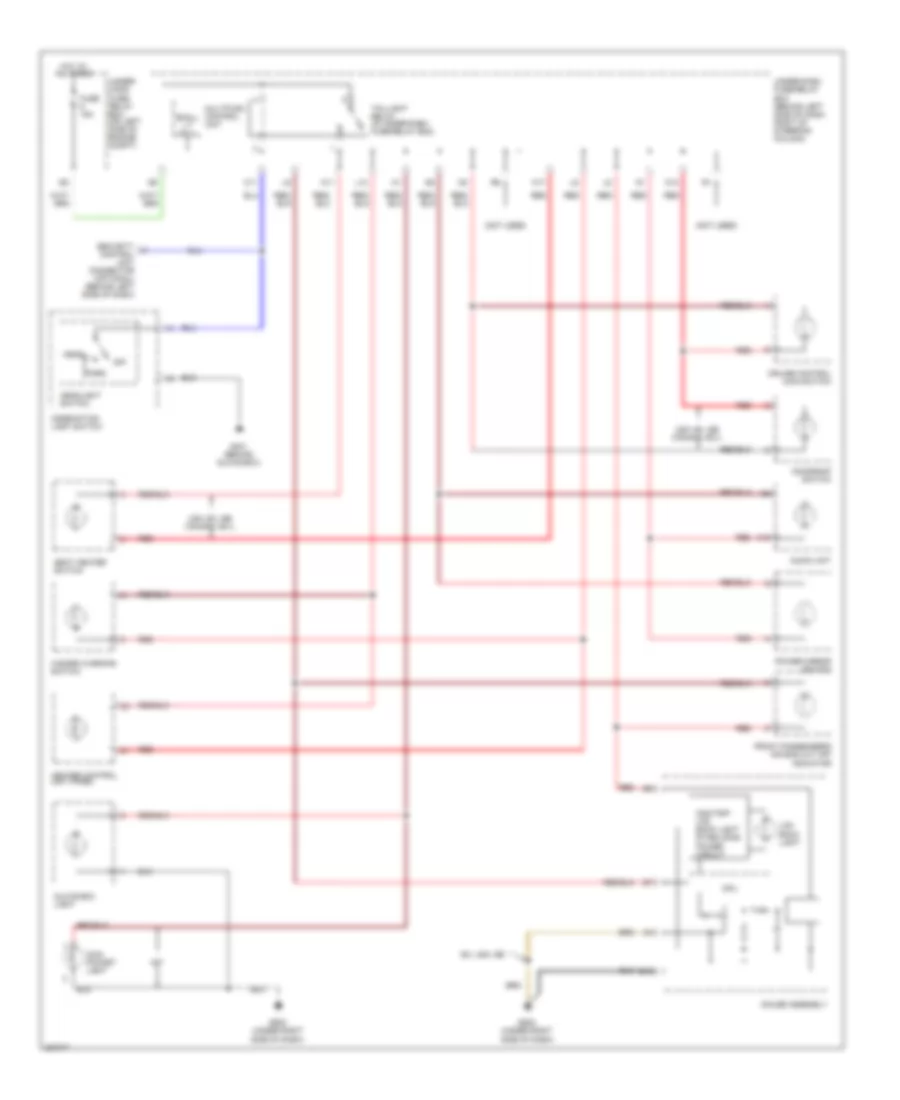
Exterior Lamps Wiring Diagram (1 of 2) for Honda CR-V SE 2006
List of elements for Exterior Lamps Wiring Diagram (1 of 2) for Honda CR-V SE 2006:
- (behind left side of dash) security control unit connector
- (not used)
- B11
- B12
- B15
- Back-up lamps circuit
- C11
- C12
- C13
- Combination light switch
- Compartment)
- Fuse 19 7.5a
- Fuse 5 15a
- Fuse 6 15a
- G201 (behind right side of front bumper)
- G301 (behind left side of front bumper)
- G401 (behind glove box)
- G502 (under right side of dash)
- G601 (behind right quarterpanel)
- Gauge assembly
- Hazard warning switch
- Hazard warning switch light
- Head
- Headlight switch
- Hot at all times
- Hot in on or start
- Interior lights system
- Left
- Left back up light
- Left front parking light
- Left front turn signal/ side marker light
- Left rear turn signal light
- Left taillight assembly
- Left turn signal indicator
- M12
- Multiplex control unit
- Off
- P15
- Park
- Red
- Right
- Right back up light
- Right front parking light
- Right front turn signal/ side marker light
- Right rear turn signal light
- Right taillight assembly
- Right turn signal indicator
- Taillight relay
- To brake light/ taillights (diagram 2 0f 2)
- To trailer lighting connector (diagram 2 of 2)
- Turn signal switch
- Turn signal/ hazard relay
- Under-dash fuse/relay box (behind left side of dash, right of steering column)
- Under-hood fuse/relay box (on left side of engine
Exterior Lamps Wiring Diagram (2 of 2) for Honda CR-V SE 2006
List of elements for Exterior Lamps Wiring Diagram (2 of 2) for Honda CR-V SE 2006:
- (behind dash, on brake pedal support)
- (behind left side of dash, right of steering column)
- Brake pedal position switch
- Converter
- From fuse 5 (diagram 1 of 2)
- From left taillight assembly (diagram 1 of 2)
- From right taillight assembly (diagram 1 of 2)
- From taillight relay (diagram 1 of 2)
- Fuse 7 15a
- G60 (left quarter panel)
- G601 (behind right quarterpanel)
- G701 (at middle of tailgate)
- High mount brake light
- Hot at all times
- Left brake light/ taillight
- Left rear side marker light
- Left taillight assembly
- Left turn input
- Left turn output
- License plate light
- Right brake light/ taillight
- Right rear side marker light
- Right taillight assembly
- Right turn input
- Right turn output
- Trailer connector
- Trailer lighting connector (behind left rear quarterpanel)
- Under-dash fuse/relay box
- Under-hood fuse/relay box (on left side of engine compartment)
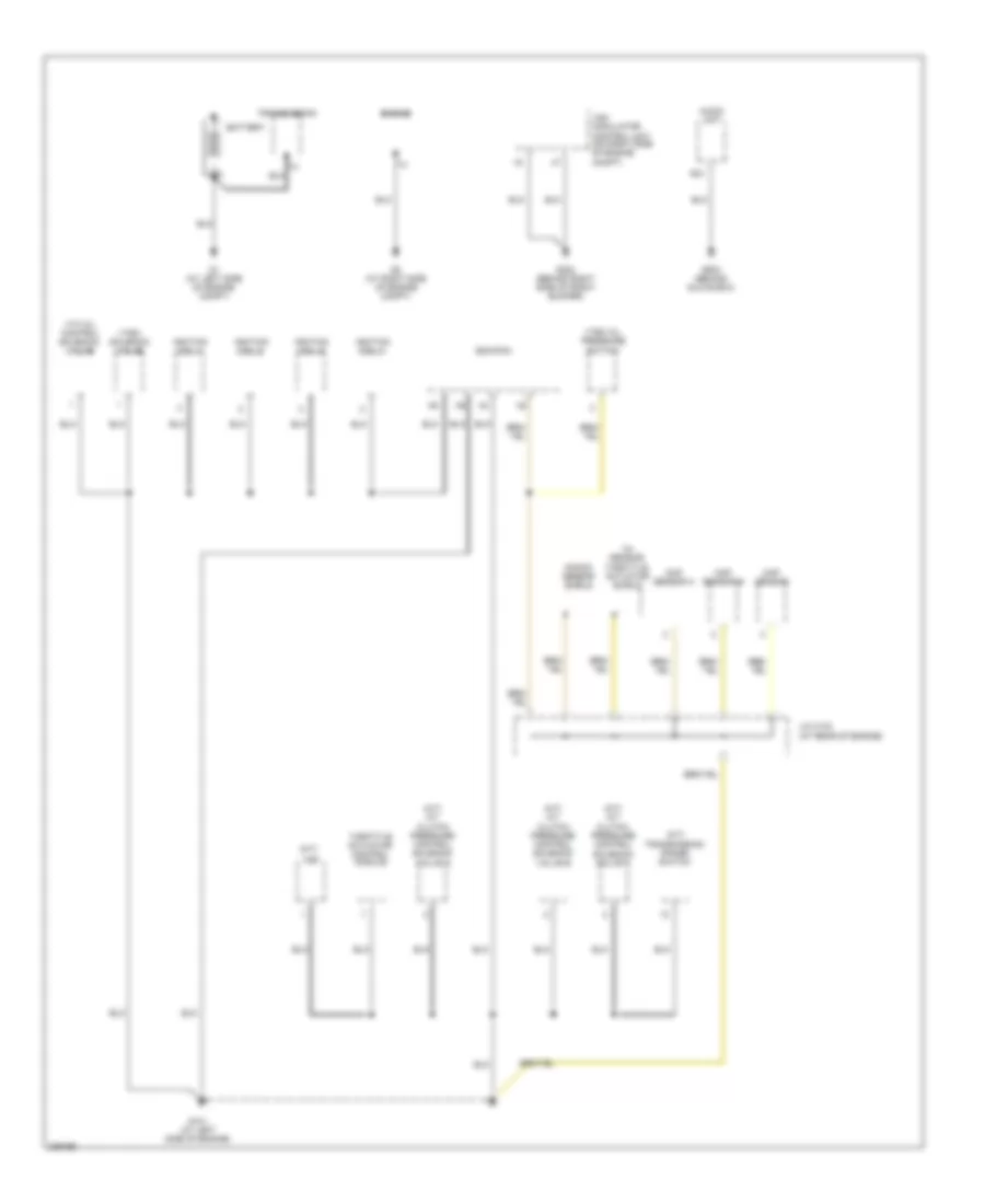
GROUND DISTRIBUTION
Ground Distribution Wiring Diagram (1 of 4) for Honda CR-V SE 2006
List of elements for Ground Distribution Wiring Diagram (1 of 4) for Honda CR-V SE 2006:
- (a/t) a/t clutch pressure control solenoid valve a
- (a/t) a/t clutch pressure control solenoid valve b
- (a/t) a/t clutch pressure control solenoid valve c
- (a/t) transmission range switch
- (at rear of engine)
- (m/t)
- A20
- Audio unit
- Battery
- Ckp sensor
- Cmp sensor a
- Cmp sensor b
- Ecm/pcm
- Engine
- G1 (at left side of engine compt)
- G101 (at left side of engine)
- G2 (at right side of engine compt)
- G202 (behind right side of front bumper)
- G503 (behind glove box)
- Ignition coil 1
- Ignition coil 2
- Ignition coil 3
- Ignition coil 4
- J/c c103
- Knock sensor shield
- Throttle actuator control module
- Throttle actuator shield
- Tp sensor/
- Transmission
- Vsa modulator control unit (on right side of engine compt)
- Vss
- Vtc oil control solenoid valve
- Vtec oil pressure switch
- Vtec solenoid valve
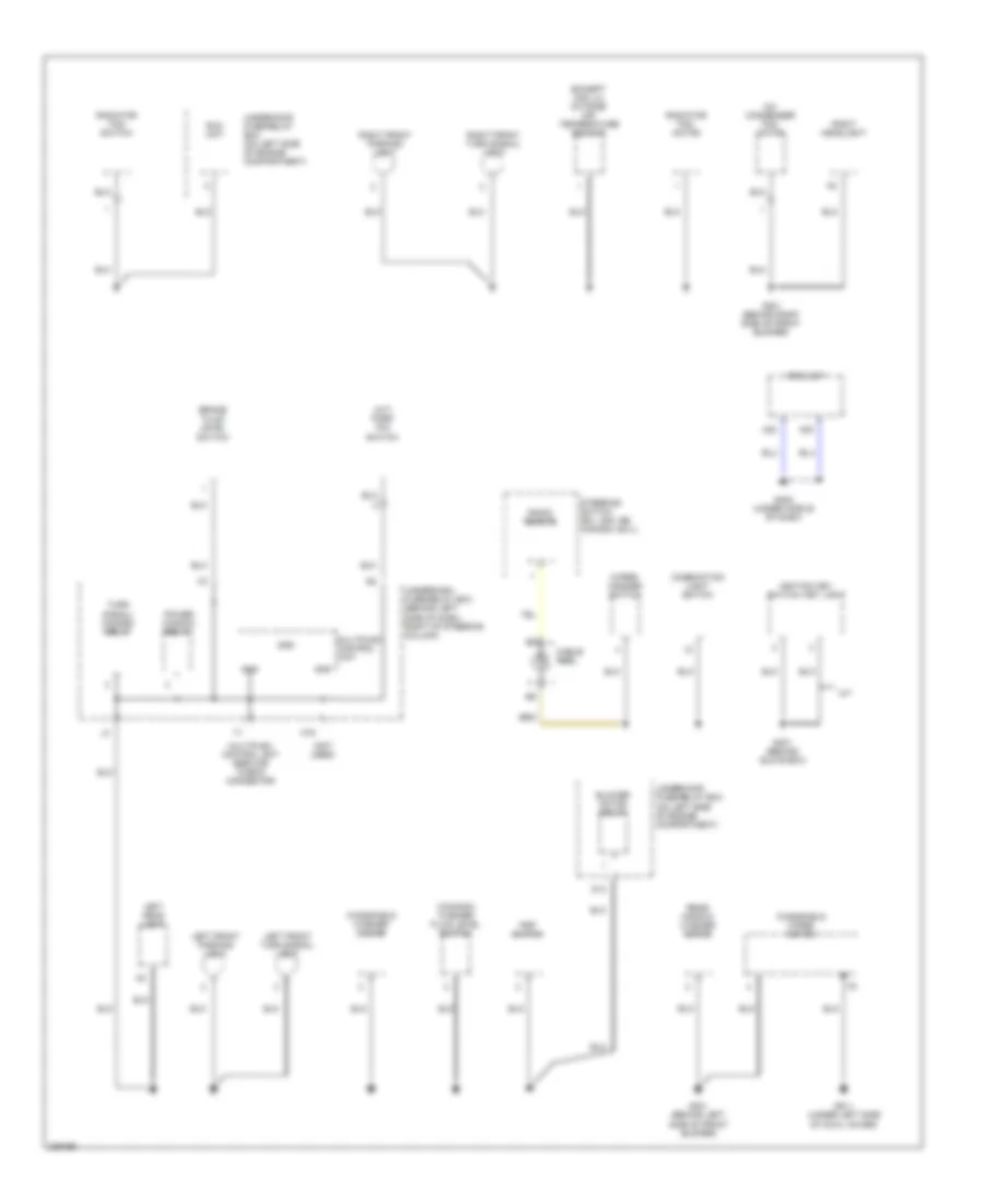
Ground Distribution Wiring Diagram (2 of 4) for Honda CR-V SE 2006
List of elements for Ground Distribution Wiring Diagram (2 of 4) for Honda CR-V SE 2006:
- (a/t) park pin switch
- (canada) washer fluid level switch
- (except usa lx) outside air temperature sensor
- (not used)
- A/c condenser fan motor
- A/t
- A22
- A23
- Blower motor relay
- Brake fluid level switch
- Cable reel
- Combination light switch
- D13
- Eld unit
- G201 (behind right side of front bumper)
- G301 (behind left side of front bumper)
- G401 (behind glove box)
- G402 (under middle of dash)
- G811 (under left side of cowl cover)
- Gnd
- Ignition key switch/ key light
- K16
- Left front parking light
- Left front turn signal/ light
- Left head light
- Multiplex control unit
- Multiplex control unit service check connector
- Power window relay
- Psp switch
- Radiator fan motor
- Radiator fan switch
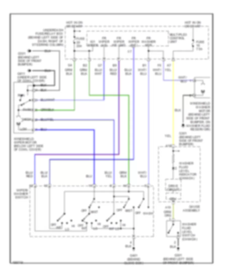
- Radio remote
- Rear window washer motor
- Right front parking light
- Right front turn signal/ light
- Right headlight
- Srs unit
- Steering switch (ex, usa: se, canada: ex-l)
- Turn signal/ hazard relay
- Underdash fuse/relay box (behind left side of dash, right of steering column)
- Underhood fuse/relay box (on left side of engine compartment)
- Windshield washer motor
- Windshield wiper motor
- Wiper/ washer switch
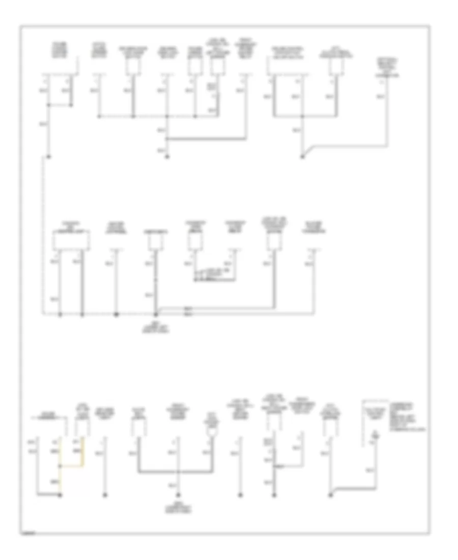
Ground Distribution Wiring Diagram (3 of 4) for Honda CR-V SE 2006
List of elements for Ground Distribution Wiring Diagram (3 of 4) for Honda CR-V SE 2006:
- (canada) drl control unit
- (m/t) clutch interlock switch
- (m/t) clutch pedal position switch
- (m/t) coin pocket light
- (optional) security control unit connector
- (usa: ex, se)
- (usa: ex, se, canada: ex-l)
- (usa: ex, se, canada: ex-l) moonroof switch
- (usa: se canada: ex, ex-l) right power mirror
- (usa: se, canada: ex, ex-l) left power mirror
- (usa: se, canada: ex-l) seat heater switch
- Audio unit
- B11
- B15
- Blower power transistor
- Cruise control main switch/ vsa off switch
- Driver's door lock knob switch
- Driver's door lock switch
- Front accessory power socket
- Front accessory power socket relay
- Front passenger's door lock switch
- G501 (under left side of dash)
- G502 (under right side of dash)
- Gauge assembly
- Glove box light
- Hatch glass opener switch
- Heater control unit-panel
- Keyless receiver unit
- Moonroof close relay
- Moonroof open relay
- Multiplex control unit
- Power mirror switch
- Power window master switch
- S- gnd
- Spotlights
- Underdash fuse/relay box (behind left side of dash, right of steering column)
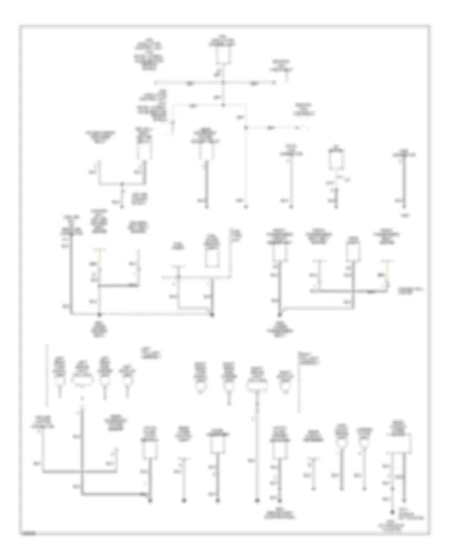
Ground Distribution Wiring Diagram (4 of 4) for Honda CR-V SE 2006
List of elements for Ground Distribution Wiring Diagram (4 of 4) for Honda CR-V SE 2006:
- (canada: ex-l usa: se) driver's seat heater
- (middle of tailgate)
- (se, ex-l) seat heater relay
- (usa: se, ex) xm receiver connector
- A/t
- A11
- Canada: ex-l usa:se
- D3 switch
- Data link connector
- Driver's seat belt switch
- Ecm/pcm can line shield
- Front passenger's seat belt switch
- Front passenger's seat heater
- Front passenger's weight sensor unit
- Fuel gauge sending unit
- Fuel pump
- Fuel tank unit
- G451
- G551 (under driver's seat)
- G552 (under passenger's seat)
- G601 (behind right quarter panel)
- G701 (at middle of tailgate)
- G711
- Hatch glass latch switch 1
- Hatch glass opener actuator
- High mount brake light
- Left back-up light
- Left brake light/ taillight
- Left rear side marker light
- Left rear turn signal light
- Left taillight assembly
- License plate light
- Mes connector
- Noise condenser
- Opds unit
- Power mirror defogger relay
- Rear accessory power socket
- Rear accessory power socket relay
- Rear window defogger
- Rear window wiper motor
- Rear wiper control unit
- Right back-up light
- Right brake light/ taillight
- Right rear side marker light
- Right rear turn signal light
- Right taillight assembly
- Trailer lighting connector
- Usa: se, canada: ex,ex-l
- Vsa modulator control unit
- Yaw rate- lateral acceleration sensor shield
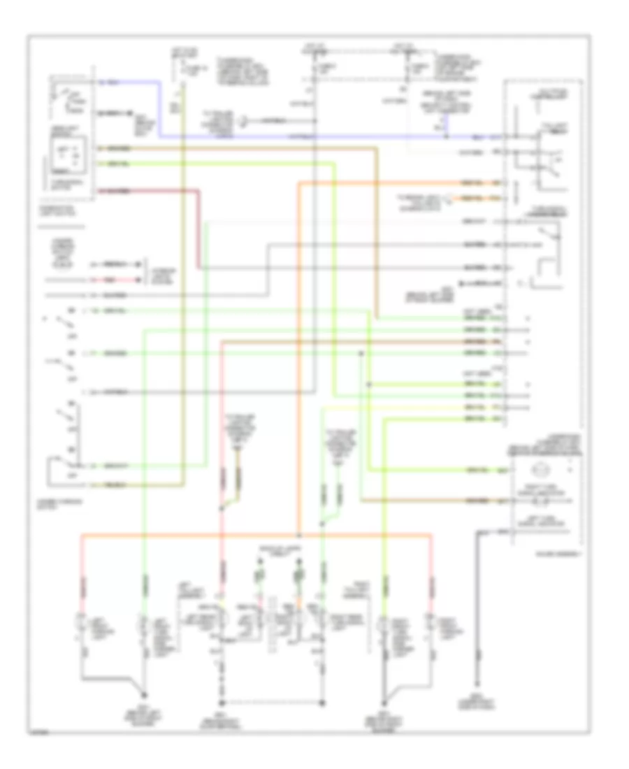
HEADLIGHTS
Headlights Wiring Diagram, with DRL for Honda CR-V SE 2006
List of elements for Headlights Wiring Diagram, with DRL for Honda CR-V SE 2006:
- (behind left side of front bumper) g301
- (behind right side of front bumper) g201
- (not used)
- (under left side of dash) g501
- +b day lt/ fr fog
- A18
- A21
- Anti-lock brakes
- Auxiliary under-hood fuse/relay box (left side of engine compt)
- B14
- Brake level sw
- Combination light switch
- Control unit connector (optional) (behind left side of dash)
- Dimmer switch
- Drl control unit
- Drl h/l sw
- Drl ind
- Drl relay
- Eld unit
- F10
- F11
- F12
- Flash-to- pass switch
- Fuse 10 7.5a
- Fuse 12 7.5a
- Fuse 15 20a
- Fuse 17 20a
- Fuse 19 100a
- Fuse 2 30a
- Fuse 3 10a
- Fuse 7.5a
- G401 (behind glove box)
- Gauge assembly
- Head
- Headlight relay 1
- Headlight relay 2
- Headlight switch
- Headlt hi
- Headlt low
- High
- High beam indicator
- Hot at all times
- Hot in on
- Hot in on or start
- Ig2 day lt
- Immobilizer control unit receiver
- Interior lights system
- Left headlight
- Light relay
- Low
- Multiplex control unit
- Off
- Park
- Parking brake switch (under left side of dash)
- Red
- Right headlight
- Security
- System
- Under-dash fuse/relay box (behind left side of dash, right of steering column)
- Under-hood fuse/relay box (on left side of engine compt)
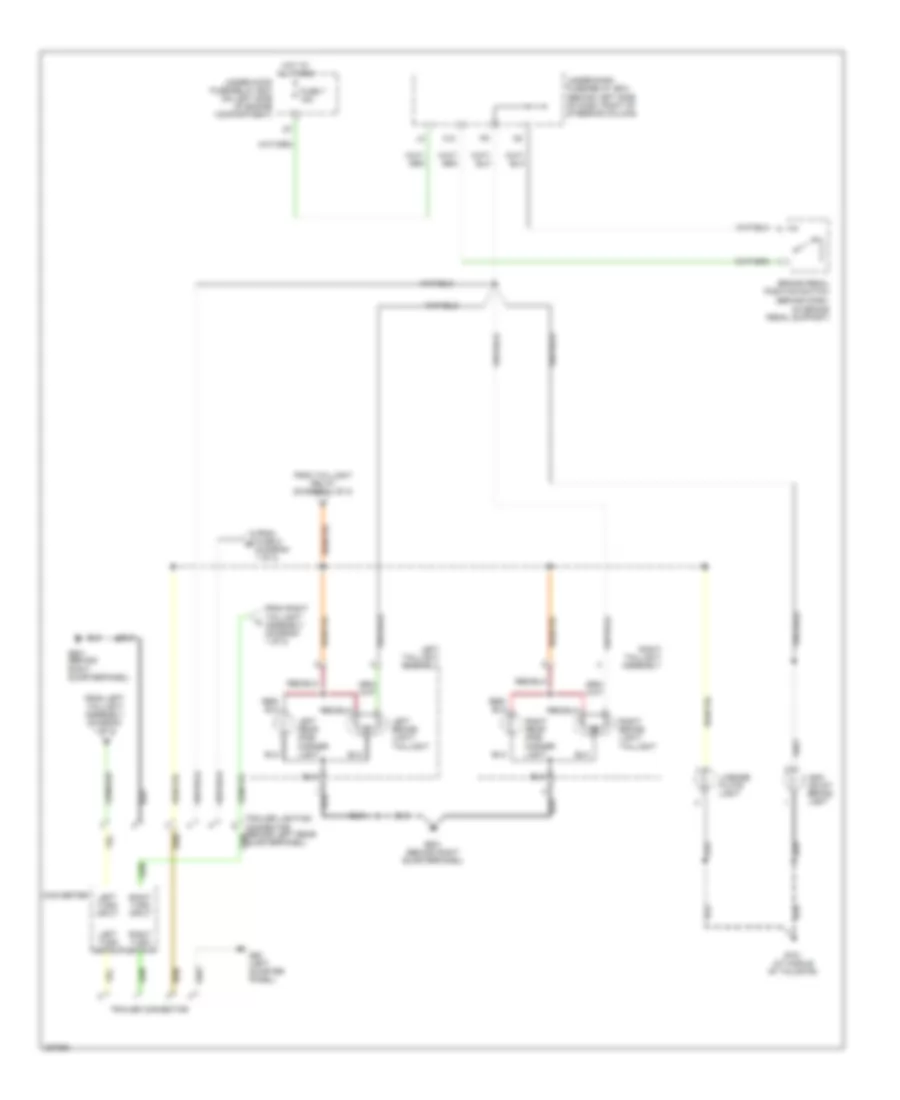
Headlights Wiring Diagram, without DRL for Honda CR-V SE 2006
List of elements for Headlights Wiring Diagram, without DRL for Honda CR-V SE 2006:
- (not used)
- B14
- Combination light switch
- Dimmer hi
- Dimmer switch
- Drl h/l sw
- Eld unit
- F10
- F12
- Flash-to- pass switch
- Fuse 15 20a
- Fuse 17 20a
- Fuse 19 100a
- G201 (behind right side of front bumper)
- G301 (behind left side of front bumper)
- G401 (behind glove box)
- Gauge assembly
- Head
- Headlight relay 1
- Headlight relay 2
- Headlight switch
- Headlt hi
- Headlt low
- High
- High beam indicator
- Hot at all times
- Interior lights system
- Left headlight
- Lighting rly
- Low
- Multiplex control unit
- Off
- Park
- Red
- Right headlight
- Security control unit connector (optional) (behind left side of dash)
- Under-dash fuse/relay box (behind left side of dash, right of steering column)
- Under-hood fuse/relay box (on left side of engine compt)
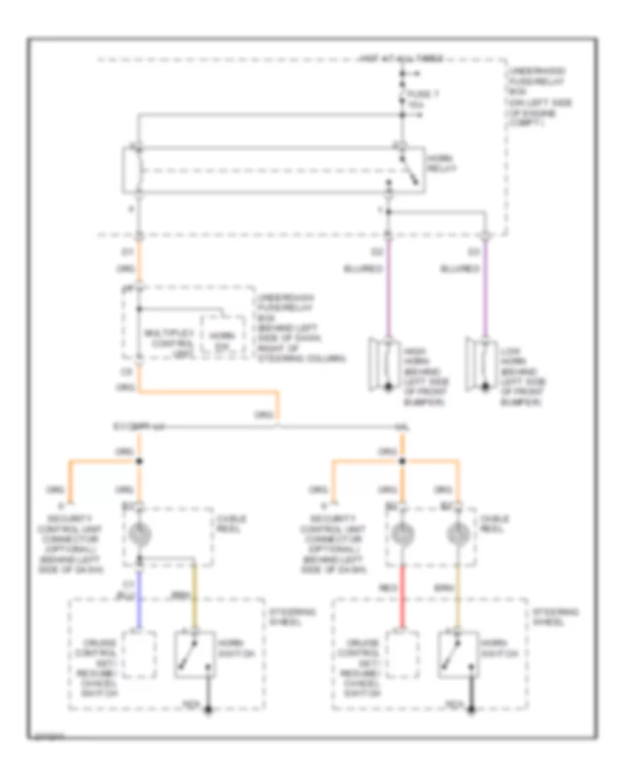
HORN
Horn Wiring Diagram for Honda CR-V SE 2006
List of elements for Horn Wiring Diagram for Honda CR-V SE 2006:
- (on left side of engine compt)
- Cable reel
- Cruise control set/ resume/ cancel switch
- Except lx
- Fuse 7 15a
- High horn (behind left side of front bumper)
- Horn relay
- Horn sw
- Horn switch
- Hot at all times
- Low horn (behind left side of front bumper)
- Multiplex control unit
- Nca
- Red
- Security control unit connector (optional) (behind left side of dash)
- Steering wheel
- Underdash fuse/relay box (behind left side of dash, right of steering column)
- Underhood fuse/relay box
INSTRUMENT CLUSTER
Instrument Cluster Wiring Diagram (1 of 2) for Honda CR-V SE 2006
List of elements for Instrument Cluster Wiring Diagram (1 of 2) for Honda CR-V SE 2006:
- (behind left side of dash, right of steering column) underdash fuse/relay box
- (behind left side of front bumper)
- (canada)
- (canada) drl ind
- (under right side of dash) g502
- A/t
- A10
- A11
- A12
- A13
- A14
- A15
- A16
- A17
- A18
- A19
- A20
- A21
- A22
- Abs indicator
- Abs indicator circuit
- Acc radio
- Act
- B10
- B11
- B12
- B13
- B14
- B15
- B16
- B17
- B18
- B19
- B20
- B21
- B22
- Beeper
- Brake fluid level switch (on brake fluid reservoir)
- Brake level sw
- Brake system indicator
- Bus (ecu)
- Bus meter
- Canada
- Charging system indicator
- Cpu
- Cruise control ind
- Cruise control system
- Dash lights brightness controller
- Door indicator light
- Drive circuit
- Drl control unit
- E10
- Exterior lights system
- Fuel gauge sending unit
- Fuel tank unit (in top of fuel tank)
- Fuse 10a
- Fuse 7.5a
- G101 (at left side of engine)
- G201 (behind right side of front bumper)
- G301
- G301 (behind left side of front bumper)
- G551 (under driver's seat)
- Gauge assembly
- Headlights system
- Hot in acc or on
- Hot in on or start
- Ig1 (meter)
- Immobilizer control unit receiver (on steering column, integral to ignition switch)
- Interior lights system
- J/c c105 (behind glove box)
- K10
- Left turn signal indicator
- Low fuel indicator
- Low oil pressure indicator
- Low washer fluid indicator (canada)
- M/t
- Maintenance required indicator
- Mil ind
- Multiplex control unit
- Oil pressure switch (on right front of engine, above oil filter)
- Outside air temperature sensor (except usa: lx)
- Parking brake switch (under left side of dash)
- Pnk
- Power circuit
- Red
- Right turn signal indicator
- Rxd
- Seat belt reminder indicator
- Side air bag cut-off ind
- Srs ind
- Srs indicator circuit
- Switch trip/reset
- Tailgate & hatch glass open indicator
- Transmissions system
- Txd
- Underdash fuse/relay box (behind left side of dash, right of steering column)
- Usa
- Vsa
- Vsa activation indicator
- Vsa diode (under middle of dash)
- Vsa ind
- Vsa indicator circuit
- Vsa modulator control unit (on right side of engine compt)
- Vss (on top of transmission)
- Washer fluid level switch (canada)
Instrument Cluster Wiring Diagram (2 of 2) for Honda CR-V SE 2006
List of elements for Instrument Cluster Wiring Diagram (2 of 2) for Honda CR-V SE 2006:
- (behind right side of dash)
- (except usa: lx)
- (usa)
- (vssout)
- A13
- A14
- A15
- A16
- A18
- A23
- B10
- B14
- B15
- B22
- Bus (sefmj)
- Coolant temperature gauge
- Cpu
- D11
- Dash lights brightness controller
- Dimming circuit
- Drive circuit
- Driver circuit
- E13
- E25
- E26
- E31
- Ecm/pcm
- Ect sensor (on rear of engine head)
- Engine controls system
- Fuel gauge
- Fuse 10a
- Gauge assembly
- High beam indicator
- Hot at all times
- Immobilizer system indicator
- Lcd back light
- Mil ctrl
- Odo/trip display
- Odo/trip lcd back light stabilizing power circuit
- Odo/trip/ outside air temperature display
- Rpm out (nep)
- Sensor input
- Sns gnd (sg2)
- Sns in (ect)
- Speedometer
- Tachometer
- Test tachometer connector (on left side of engine compt, near battery)
- Underdash fuse/relay box (behind left side of dash,right of steering column)
- Underhood fuse/relay box (on left side of engine compt)
INTERIOR LIGHTS
Courtesy Lamps Wiring Diagram for Honda CR-V SE 2006
List of elements for Courtesy Lamps Wiring Diagram for Honda CR-V SE 2006:
- (behind glove box)
- Door
- Driver's door lock knob switch
- Driver's door switch (on left "b" pillar)
- Ex; usa: se canada: ex-l
- Fr door sw
- Front ceiling light
- Front passenger's door switch (right "b" pillar)
- Fuse 3 15a
- G401
- G501 (under left side of dash)
- Hatch glass latch switch 2 (on middle of tailgate)
- Hot at all times
- Ignition key light
- Ignition key switch
- Ignition key switch/ key light
- Int lts
- Key sw
- Keyless com d/l sil-con sw (lock) key lt-
- Keyless receiver unit (under middle of dash)
- Left rear door switch (left "c" pillar)
- Multiplex control unit
- Off
- Other door sw
- P18
- Rear ceiling light
- Rear ceiling light diode (under right side of dash)
- Red
- Right rear door switch (right "c" pillar)
- Security control unit connector (optional) (behind left side of dash)
- Spotlights
- Tailgate switch (left side of tailgate)
- Trunk sw
- Underdash fuse/relay box (behind left side of dash, right of steering column)
- Underhood fuse/relay box (on left side of engine compartment)
Instrument Illumination Wiring Diagram for Honda CR-V SE 2006
List of elements for Instrument Illumination Wiring Diagram for Honda CR-V SE 2006:
- (not used)
- A19
- Audio unit
- B15
- C11
- Coin pocket light
- Combination light switch
- Cpu
- Cruise control main switch
- Ex, usa: se
- Front passenger's air bag cut off indicator
- Fuse 15a
- G401 (behind glove box)
- G502 (under right side of dash)
- Gauge assembly
- Glove box light
- Hazard warning switch
- Head
- Headlight switch
- Heater control unit panel
- Hot at all times
- K11
- K17
- L10
- Lcd back light
- M/t
- Moonroof switch
- Multiplex control unit
- O10
- Odo/trip lcd back light stabilizing power circuit
- Off
- Park
- Power mirror switch
- Red
- Seat heater switch
- Security control unit connector (optional) (behind left side of dash)
- Small lt rly-
- Taillight relay (in under-dash fuse/relay box)
- Under- hood fuse/ relay box (on left side of engine compt)
- Under-dash fuse/relay box (behind left side of dash, right of steering column)
- Usa: ex, se; canada: ex-l
POWER DISTRIBUTION
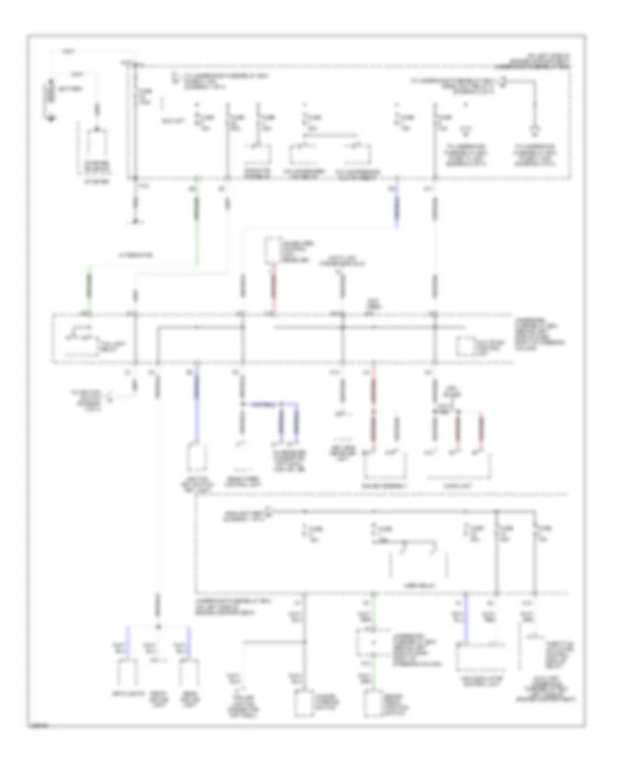
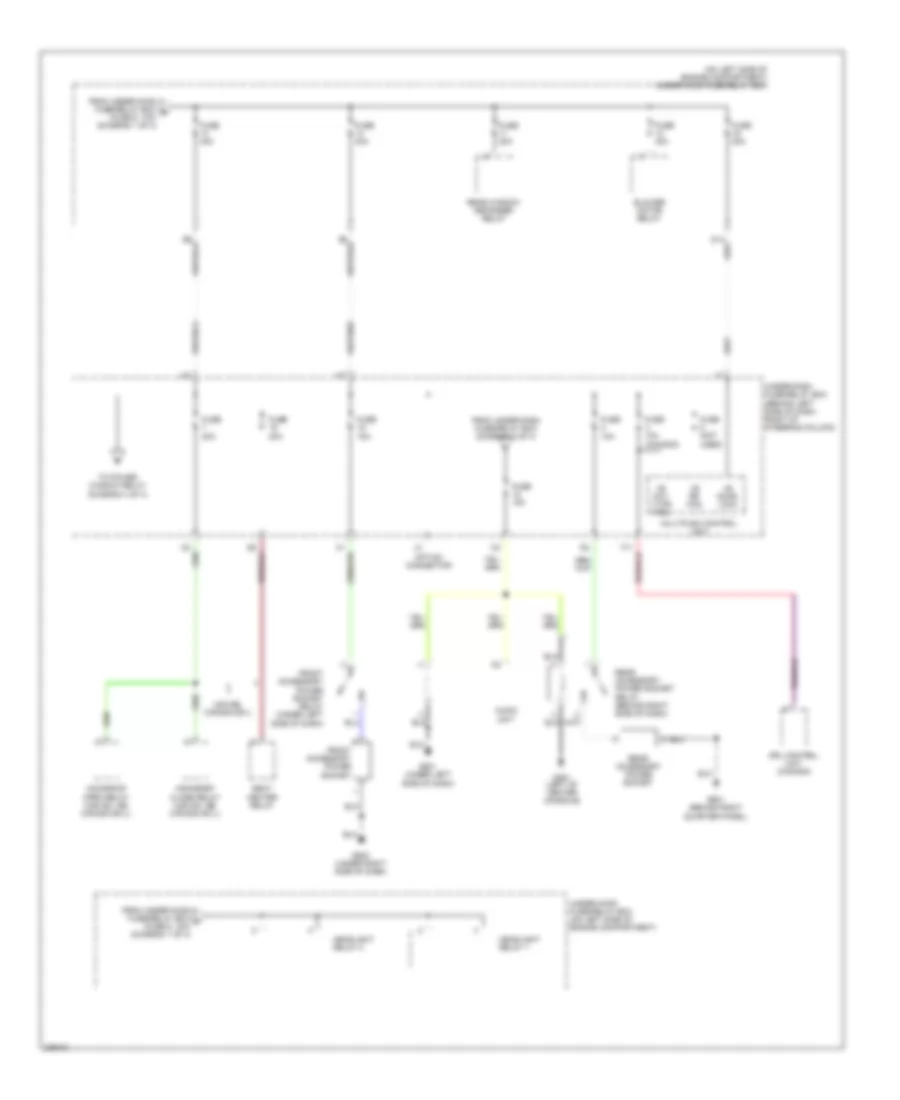
Power Distribution Wiring Diagram (1 of 4) for Honda CR-V SE 2006
List of elements for Power Distribution Wiring Diagram (1 of 4) for Honda CR-V SE 2006:
- (not used)
- (on left side of engine compartment) underhood fuse/relay box
- A/c compressor clutch relay
- A/c condenser fan relay
- A10
- A19
- Alternator
- Audio unit
- Auxiliary underhood fuse/relay box (left side of engine compartment)
- B10
- Battery
- Brake pedal position switch
- C10
- D11
- Data link connector (dlc)
- E12
- Eld unit
- From battery a (diagram 1 of 4)
- Front ceiling light
- Fuse 100a
- Fuse 10a
- Fuse 15a
- Fuse 20a
- Fuse 30a
- Fuse 50a
- Gauge assembly
- Hazard warning switch
- Horn relay
- Ignition key switch/ key light
- Immobilizer control unit- receiver
- K13
- Keyless receiver unit
- Multiplex control unit
- O12
- Radiator fan relay
- Rear ceiling light
- Rear wiper control unit
- Spotlights
- Starter
- Starter solenoid
- T101
- Taillight relay
- Throttle actuator control module relay
- To ignition switch (diagram 3 of 4)
- To underhood fuse/relay box (fuse 13, 40a) (diagram 2 of 4)
- To underhood fuse/relay box (fuse 2, 30a) (diagram 4 of 4)
- To underhood fuse/relay box (fuse 5, 15a) (diagram 1 of 4)
- To underhood fuse/relay box (headlight relay 2) (diagram 2 of 4)
- Trailer lighting connector (optional)
- Underdash fuse/relay box (behind left side of dash, right of steering column)
- Underhood fuse/relay box (on left side of engine compartment)
- Usa: ex, se
- Vsa modulator control unit
- Xm receiver connector (optional) (usa: ex, se)
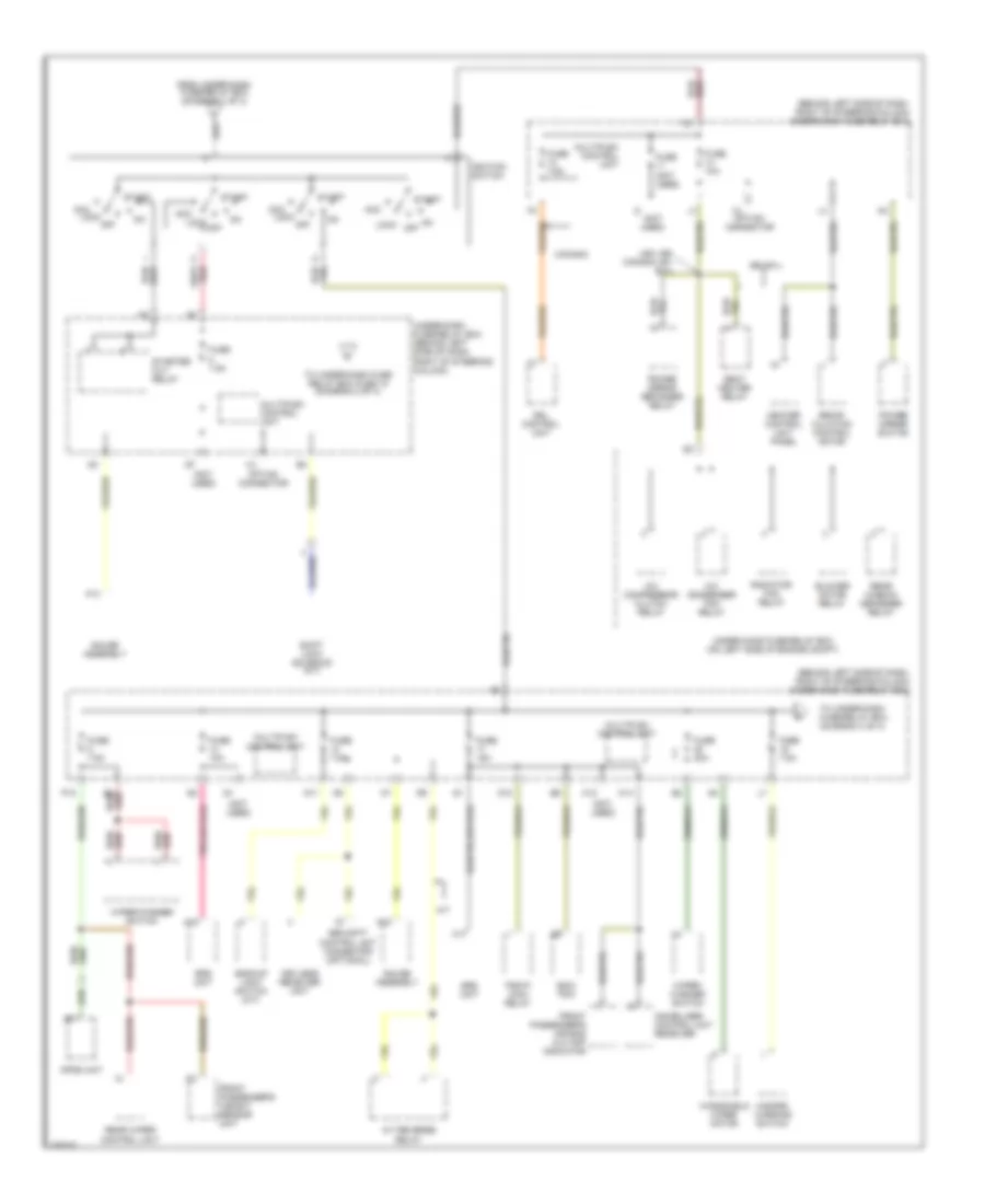
Power Distribution Wiring Diagram (2 of 4) for Honda CR-V SE 2006
List of elements for Power Distribution Wiring Diagram (2 of 4) for Honda CR-V SE 2006:
- (behind left side of dash, right of steering column)
- (on left side of engine compartment) under-hood fuse/relay box
- +b day lt/fr fog
- +b door lock
- +b rr fog
- Audio unit
- Blower motor relay
- Drl control unit (canada)
- From under-dash fuse/relay box (diagram 3 of 4)
- From under-hood fuse/relay box b (fuse 9, 10a) (diagram 1 of 4)
- From under-hood fuse/relay box c (fuse 6, 15a) (diagram 1 of 4)
- Front accessory power socket
- Front accessory power socket relay (under left side of dash)
- Fuse (not used)
- Fuse 10a
- Fuse 10a (canada)
- Fuse 15a
- Fuse 20a
- Fuse 40a
- G451 (left of center console)
- G501 (under left side of dash)
- G502 (under right side of dash)
- G601 (behind right quarter panel)
- Headlight relay 1
- Headlight relay 2
- Moonroof close relay (usa ex, se, canada ex-l)
- Moonroof open relay (usa ex, se, canada ex-l)
- Multiplex control unit
- Option connector
- Rear accessory power socket
- Rear accessory power socket relay (behind right side of dash)
- Rear window defogger relay
- Seat heater relay
- To power window relay (diagram 4 of 4)
- Under-dash fuse/relay box
- Under-hood fuse/relay box (on left side of engine compartment)
- Usa:se, canada ex-l
Power Distribution Wiring Diagram (3 of 4) for Honda CR-V SE 2006
List of elements for Power Distribution Wiring Diagram (3 of 4) for Honda CR-V SE 2006:
- (behind left side of dash, right of steering column) under-dash fuse/relay box
- (not used)
- A/c compressor clutch relay
- A/c condenser fan relay
- A/t
- A/t reverse relay
- A13
- A17
- A18
- Acc
- B4 red/
- Backup light switch (m/t)
- Blower motor relay
- Canada
- D11
- D12
- Drl control unit
- Ecm/ pcm
- From under-dash fuse/relay box (diagram 1 of 4)
- Front passenger's air bag cut-off indicator
- Front passenger's weight sensor unit
- Fuse (not used)
- Fuse 10a
- Fuse 15a
- Fuse 20a
- Fuse 7.5a
- Gauge assembly
- Hazard warning switch
- Heater control unit panel
- Ignition switch
- Immobilizer control unit receiver
- K12
- K14
- Keyless receiver unit
- Lock off
- Multiplex control unit
- Opds unit
- Option connector
- P12
- Pgm-fi main relay
- Power mirror defogger relay
- Power mirror switch
- Radiator fan relay
- Rear window defogger relay
- Rear wiper control unit
- Recir- culation control motor
- Se, ex-l
- Seat heater relay
- Security control unit connector (optional)
- Shift lock solenoid (a/t)
- Srs unit
- Start
- Starter cut relay
- To under-dash fuse/relay box (diagram 4 of 4)
- To under-dash fuse relay box fuse 18 (diagram 2 of 4)
- Under-dash fuse/relay box (behind left side of dash, right of steering column)
- Under-hood fuse/relay box (on left side of engine compt)
- Usa: se, canada: ex, ex-l
- Windshield wiper motor
- Wiper/ washer switch
- Wiper/washer switch
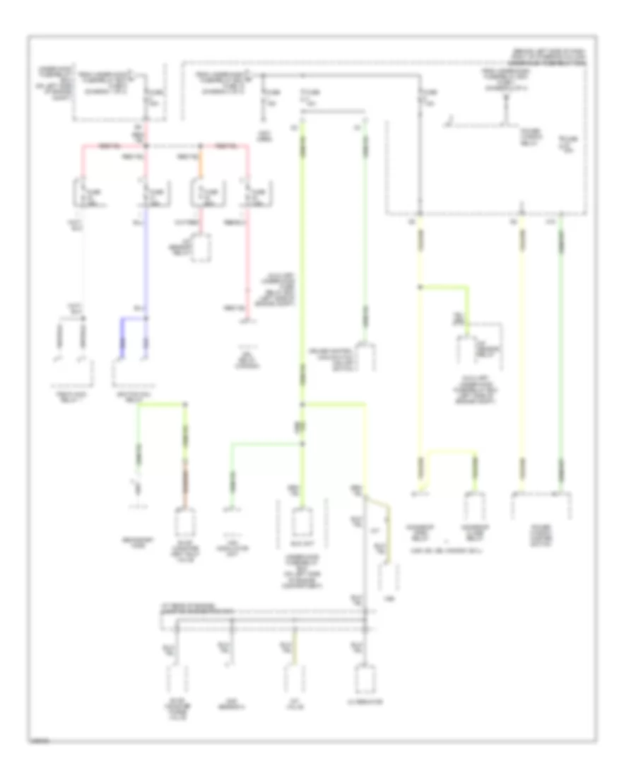
Power Distribution Wiring Diagram (4 of 4) for Honda CR-V SE 2006
List of elements for Power Distribution Wiring Diagram (4 of 4) for Honda CR-V SE 2006:
- (at rear of engine) junction connector c103
- (behind left side of dash, right of steering column) under-dash fuse/relay box
- (not used)
- (usa: ex, se, canada: ex-l)
- A/f sensor relay
- Alternator
- Auxiliary under-hood fuse/ relay box (left side of engine compt)
- Auxiliary under-hood fuse/relay box (left side of engine compt)
- Cmp sensor a
- Cruise control main switch/ vsa off switch
- Drl relay (canada)
- Eld unit
- Evap canister purge valve
- Evap canister vent shut valve
- From under-dash fuse/relay box fuse 7 (diagram 2 of 4)
- From under-dash g fuse/relay box fuse 19 (diagram 3 of 4)
- From under-hood h fuse/relay box fuse 9 (diagram 1 of 4)
- Fuse 10a
- Fuse 15a
- Fuse 20a
- Fuse 30a
- Fuse 7.5a
- Ignition coil relay
- Imt valve
- M/t
- M10
- Moonroof close relay
- Moonroof open relay
- Pgm-fi main relay 1
- Power window master switch
- Power window relay
- Secondary ho2s
- Under-hood fuse/relay box (on left side of engine compartment)
- Under-hood fuse/relay box (on left side of engine compt)
- Vsa modulator unit
- Vss
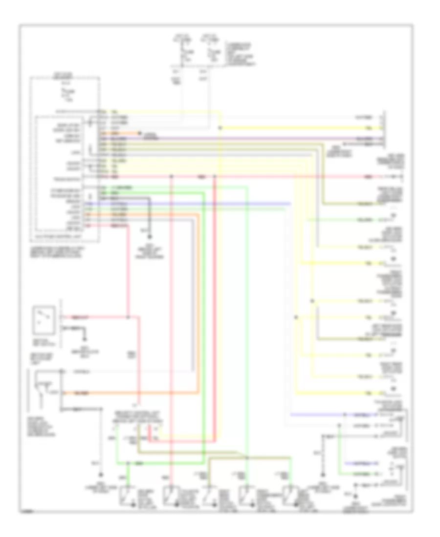
POWER DOOR LOCKS
Power Door Locks Wiring Diagram for Honda CR-V SE 2006
List of elements for Power Door Locks Wiring Diagram for Honda CR-V SE 2006:
- (under right side of dash)
- Back up (b+)
- D11
- D14
- Door lock (b+)
- Driver's door lock actuator (in driver's door)
- Driver's door lock knob switch (in rear of driver's door)
- Driver's door lock switch
- Driver's door switch (on left "b" pillar)
- Fr door sw (dr)
- Front passenger's door lock actuator (in front passenger's door)
- Front passenger's door lock switch
- Front passenger's door switch (on right "b" pillar)
- Fuse 10a
- Fuse 20a
- Fuse 7.5a
- G301 (behind left side of front bumper)
- G401 (behind glove box)
- G501 (under left side of dash)
- G502
- G502 (under right side of dash)
- Ground
- Horn sw
- Horns system
- Hot at all times
- Hot in on or start
- Ignition key switch
- Ignition key switch/key
- K13
- Key sw
- Keyless com
- Keyless receiver unit (under middle of dash)
- Left rear door lock actuator (in left rear door)
- Left rear door switch (on left "c" pillar)
- Light
- Lock
- Multiplex control unit
- Other door sw
- P16
- P17
- P18
- Rear ceiling light diode (under right side of dash)
- Red
- Right rear door lock actuator
- Right rear door switch (on right "c" pillar)
- Security control unit connector (optional) (behind left side of dash)
- Tailgate lock actuator (in tailgate)
- Tailgate switch (on left side of tailgate)
- Trunk switch
- Under-dash fuse/relay box (behind left side of dash, right of steering column)
- Under-hood fuse/relay box (on left side of engine compartment)
- Unlock
- Y10
- Y12
POWER MIRRORS
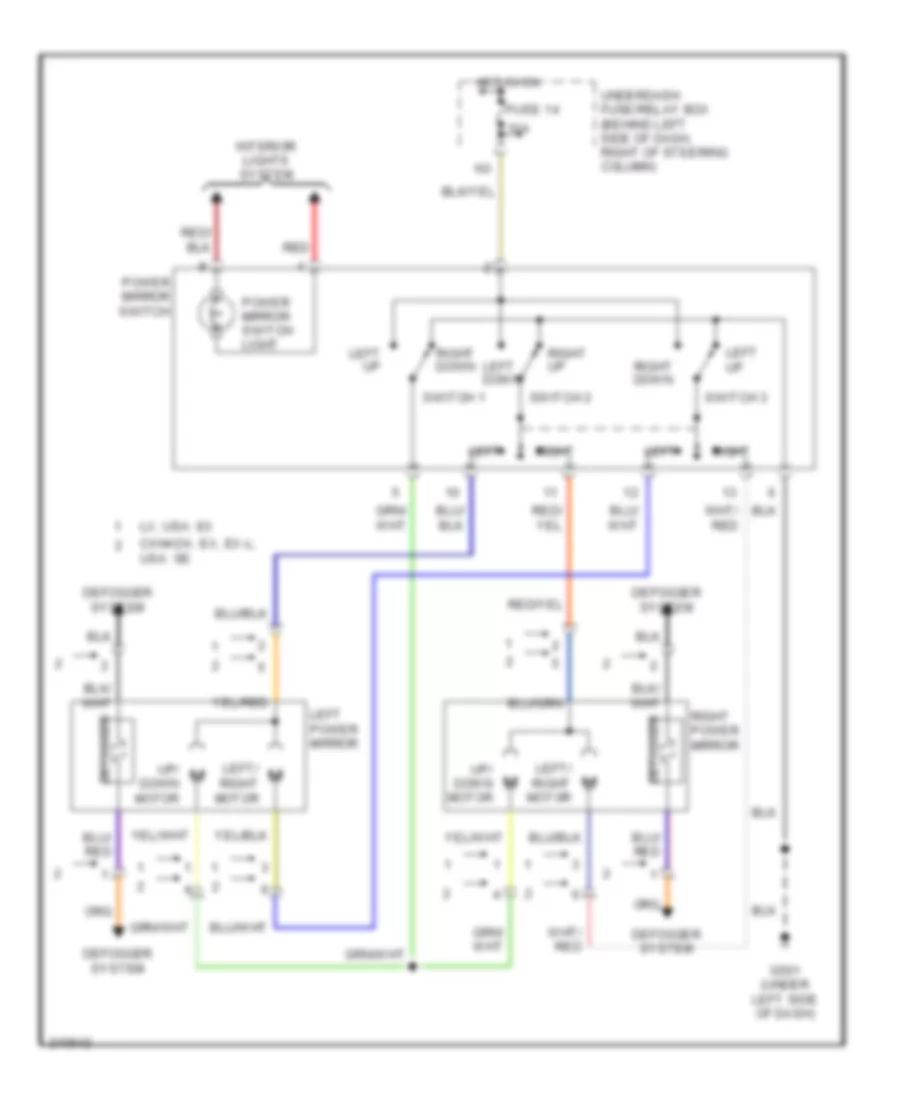
Power Mirrors Wiring Diagram, with Auto Dimming Inside Mirror for Honda CR-V SE 2006
List of elements for Power Mirrors Wiring Diagram, with Auto Dimming Inside Mirror for Honda CR-V SE 2006:
- (behind right side of dash) a/t reverse relay
- (on top of transaxle) back-up light switch
- 10a
- A/t
- Automatic dimming inside mirror
- Automatic dimming inside mirror in-line fuse
- Canada: ex, ex-l; usa: se
- Defogger
- Defogger system
- Exterior lights system
- Fuse 14
- G501 (under left side of dash)
- G70
- Hot in on
- Interior lights system
- Left
- Left down
- Left power mirror
- Left up
- Left/ right motor
- Lx; usa: ex
- M/t
- Power mirror switch
- Power mirror switch light
- Red
- Right
- Right down
- Right power mirror
- Right up
- Switch 1
- Switch 2
- Switch 3
- Under-dash fuse/relay box (behind left side of dash, right of steering column)
- Up/ down motor
Power Mirrors Wiring Diagram, without Auto Dimming Inside Mirror for Honda CR-V SE 2006
List of elements for Power Mirrors Wiring Diagram, without Auto Dimming Inside Mirror for Honda CR-V SE 2006:
- 10a
- Canada: ex, ex-l; usa: se
- Defogger
- Defogger system
- Fuse 14
- G501 (under left side of dash)
- Hot in on
- Interior lights system
- Left
- Left down
- Left power mirror
- Left up
- Left/ right motor
- Lx; usa: ex
- Power mirror switch
- Power mirror switch light
- Red
- Right
- Right down
- Right power mirror
- Right up
- Switch 1
- Switch 2
- Switch 3
- Underdash fuse/relay box (behind left side of dash, right of steering column)
- Up/ down motor
POWER SEATS
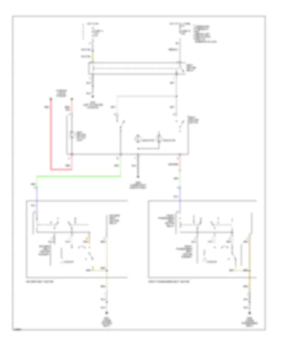
Power Seats Wiring Diagram for Honda CR-V SE 2006
List of elements for Power Seats Wiring Diagram for Honda CR-V SE 2006:
- Cushion
- Driver's seat heater
- Driver's seat heater element
- Driver's seat heater relay
- Front passenger's seat heater
- Front passenger's seat heater element
- Front passenger's seat heater relay
- Fuse 14 10a
- Fuse 16 20a
- G451 (left of center console)
- G502 (under right side of dash)
- G551 (under driver's seat)
- G552 (under passenger's seat)
- Hot at all times
- Hot in on
- Indicator
- Interior lights system
- Red
- Seat heater relay
- Seat heater switch
- Seat heater switch light
- Under-dash fuse/relay box (behind left side of dash, right of steering column)
POWER TOP/SUNROOF
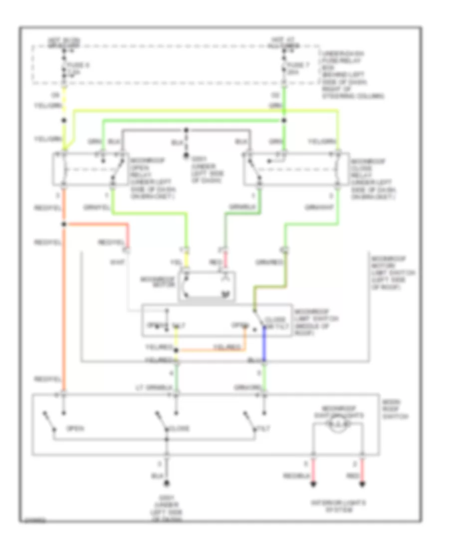
Power Top/Sunroof Wiring Diagram for Honda CR-V SE 2006
List of elements for Power Top/Sunroof Wiring Diagram for Honda CR-V SE 2006:
- Close
- Close or tilt
- Fuse 6 7.5a
- Fuse 7 20a
- G501 (under left side of dash)
- Hot at all times
- Hot in on or start
- Interior lights system
- Moon roof switch
- Moonroof close relay (under left side of dash, on bracket)
- Moonroof limit switch (middle of roof)
- Moonroof motor
- Moonroof motor/ limit switch (left side of roof)
- Moonroof open relay (under left side of dash, on bracket)
- Moonroof switch lights
- Open
- Open tilt
- Red
- Tilt
- Under-dash fuse/relay box (behind left side of dash, right of steering column)
POWER WINDOWS
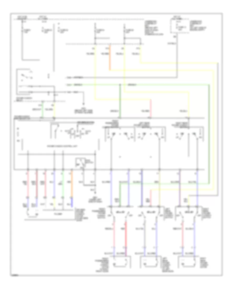
Power Windows Wiring Diagram for Honda CR-V SE 2006
List of elements for Power Windows Wiring Diagram for Honda CR-V SE 2006:
- 40a
- Auto dn
- Auto up
- Driver's power window motor (in driver's door)
- Driver's switch
- Front passenger's power window motor (in right front door)
- Front passenger's power window switch
- Fuse 13
- Fuse 22 20a
- Fuse 23 20a
- Fuse 24 20a
- Fuse 25 20a
- Fuse 6 7.5a
- G301 (behind left side of front bumper)
- G501 (under left side of dash)
- Hot at all times
- Hot in on or start
- Left rear power window motor (in left rear door)
- Left rear power window switch
- M10
- M11
- Main switch
- Off
- P10
- P13
- Power window control unit
- Power window master switch
- Power window relay
- Pulser
- Red
- Right rear power window motor
- Right rear power window switch
- Underdash fuse/relay box (behind left side of dash, right of steering column)
- Underhood fuse/relay box (on left side of engine compt)
RADIO
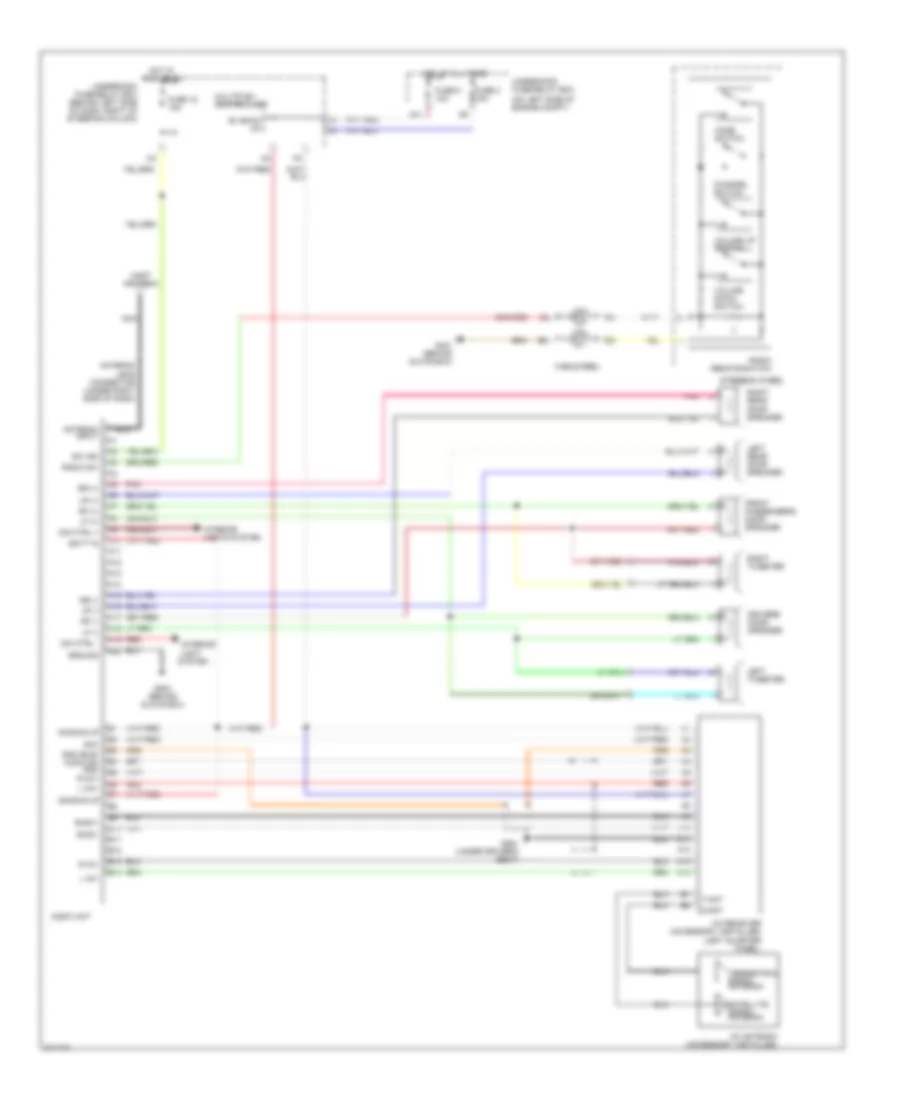
Radio Wiring Diagram, Except LX with Satellite Radio for Honda CR-V SE 2006
List of elements for Radio Wiring Diagram, Except LX with Satellite Radio for Honda CR-V SE 2006:
- (on left side of engine compt)
- +b back up
- A10
- A11
- A12
- A13
- A14
- A15
- A16
- A17
- A18
- A19
- A20
- Acc
- Antenna input
- Antenna lead connector (under right side of dash)
- Audio unit
- B+ back up
- B10
- B11
- B12
- B13
- B14
- Batt in
- Bus(+)
- Bus(-)
- Cable reel
- Channel switch
- D11
- Dim ctrl +
- Dim ctrl -
- Driver's door speaker
- Front passenger's door speaker
- Fuse 18 15a
- Fuse 3 15a
- Fuse 9 10a
- G401 (behind glove box)
- G503 (behind glove box)
- G551 (under driver's seat)
- Gnd (bus) audio sh gnd r ch+
- Ground
- Hot at all times
- Hot in acc or on
- Interior light system
- Interior lights system
- L ch+
- L ch-
- Left rear door speaker
- Left tweeter
- Lf (+)
- Lf (-)
- Lr (+)
- Lr (-)
- Mast antenna
- Mode switch
- Multiplex control unit
- Nca
- Pnk
- R ch-
- Radio remote switch
- Radio sw
- Red
- Rf (+)
- Rf (-)
- Right rear door speaker
- Right tweeter
- Rr (+)
- Rr (-)
- S-ant
- Satellite signal antenna
- Steering wheel
- Sw ign
- T-ant
- Terrestrial signal antenna
- Underdash fuse/relay box (behind left side of dash, right of steering column)
- Underhood fuse/relay box
- Volume down switch
- Volume up switch
- Xm antenna (accessory installed)
- Xm receiver (accessory installed) (left quarter panel)
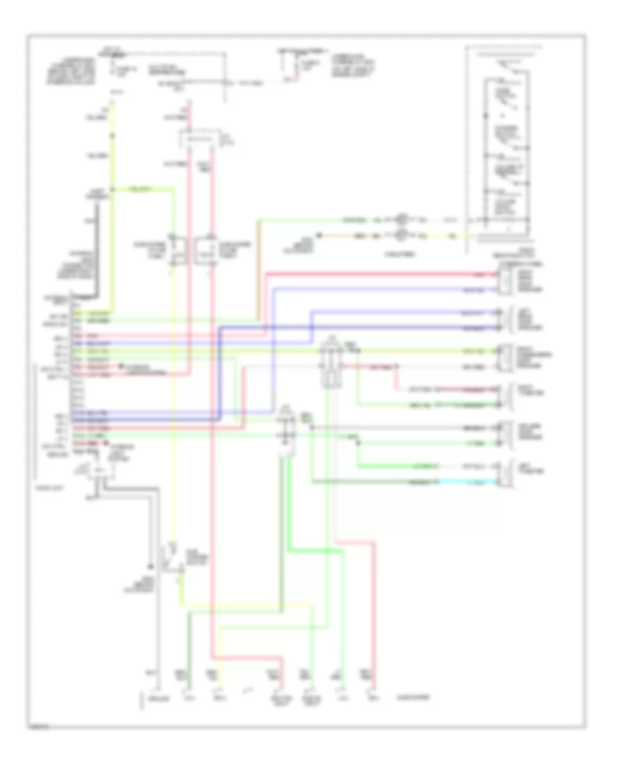
Radio Wiring Diagram, Except LX with Subwoofer for Honda CR-V SE 2006
List of elements for Radio Wiring Diagram, Except LX with Subwoofer for Honda CR-V SE 2006:
- (on left side of engine compt)
- 7.5a
- A10
- A11
- A12
- A13
- A14
- A15
- A16
- A17
- A18
- A19
- A20
- Antenna input
- Antenna lead connector (under right side of dash)
- Audio unit
- B+ back up
- Batt in
- Cable reel
- Channel switch
- D11
- Dim ctrl +
- Dim ctrl -
- Driver's door speaker
- Front passenger's door speaker
- Fuse 18 15a
- Fuse 9 10a
- G401 (behind glove box)
- G503 (behind glove box)
- Ground
- Hot at all times
- Hot in acc or on
- Ignition input
- Interior light system
- Interior lights system
- J/c c110
- Left rear door speaker
- Left tweeter
- Lf (+)
- Lf (-)
- Lf(+)
- Lf(-)
- Lr (+)
- Lr (-)
- Mast antenna
- Mode switch
- Multiplex control unit
- Nca
- Pnk
- Radio remote switch
- Radio sw
- Red
- Rf (+)
- Rf (-)
- Rf(+)
- Rf(-)
- Right rear door speaker
- Right tweeter
- Rr (+)
- Rr (-)
- Steering wheel
- Sub on input
- Sub- woofer switch
- Subwoofer
- Subwoofer in-line fuse 1
- Subwoofer in-line fuse 2
- Sw ign
- Under-dash fuse/relay box (behind left side of dash, right of steering column)
- Under-hood fuse/relay box
- Volume down switch
- Volume up switch
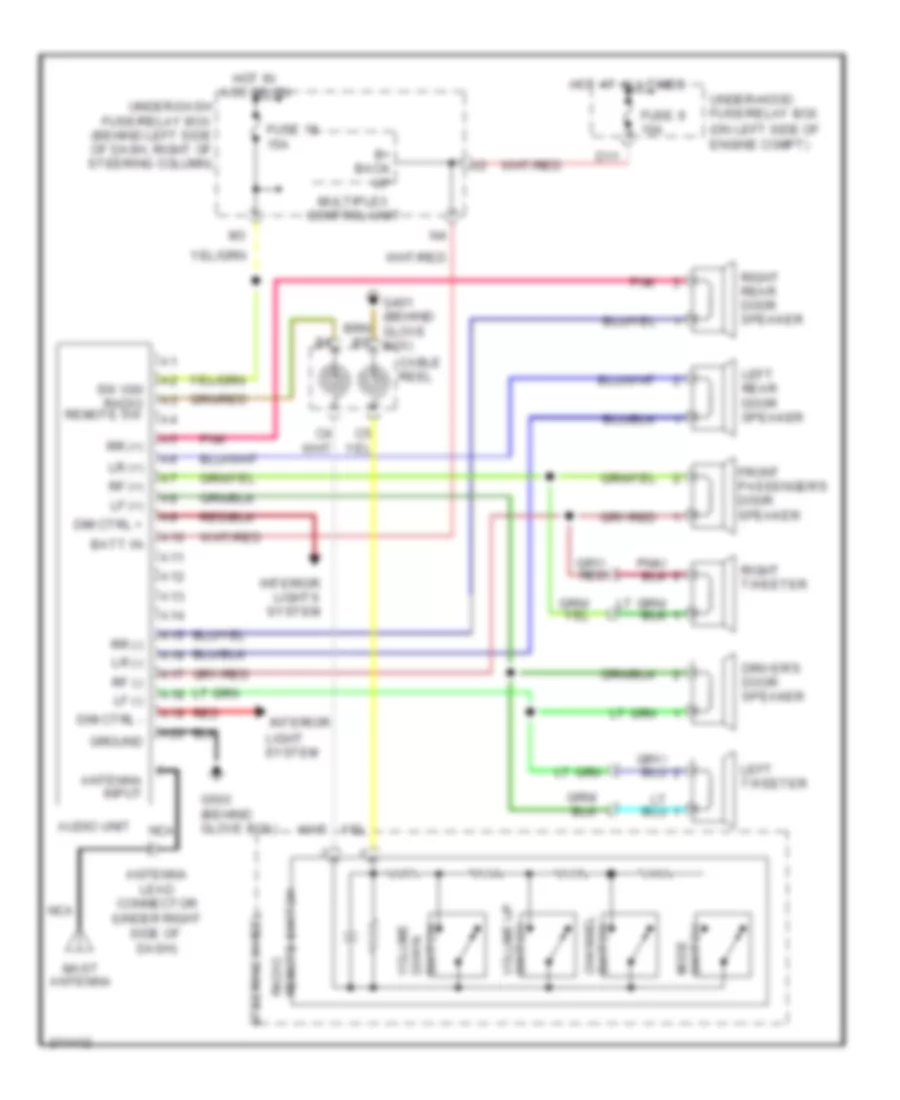
Radio Wiring Diagram, Except LX without Satellite Radio for Honda CR-V SE 2006
List of elements for Radio Wiring Diagram, Except LX without Satellite Radio for Honda CR-V SE 2006:
- (on left side of engine compt)
- A10
- A11
- A12
- A13
- A14
- A15
- A16
- A17
- A18
- A19
- A20
- Antenna input
- Antenna lead connector (under right side of dash)
- Audio unit
- B+ back up
- Batt in
- Cable reel
- D11
- Dim ctrl +
- Dim ctrl -
- Down switch
- Driver's door speaker
- Front passenger's door speaker
- Fuse 18 15a
- Fuse 9 10a
- G401 (behind glove box)
- G503 (behind glove box)
- Ground
- Hot at all times
- Hot in acc or on
- Interior
- Interior lights system
- Left rear door speaker
- Left tweeter
- Lf (+)
- Lf (-)
- Light system
- Lr (+)
- Lr (-)
- Mast antenna
- Mode switch
- Multiplex control unit
- Nca
- Pnk
- Radio remote switch
- Red
- Rf (+)
- Rf (-)
- Right rear door speaker
- Right tweeter
- Rr (+)
- Rr (-)
- Steering wheel
- Sw ign radio remote sw
- Switch channel
- Under-dash fuse/relay box (behind left side of dash, right of steering column)
- Under-hood fuse/relay box
- Volume
- Volume up switch
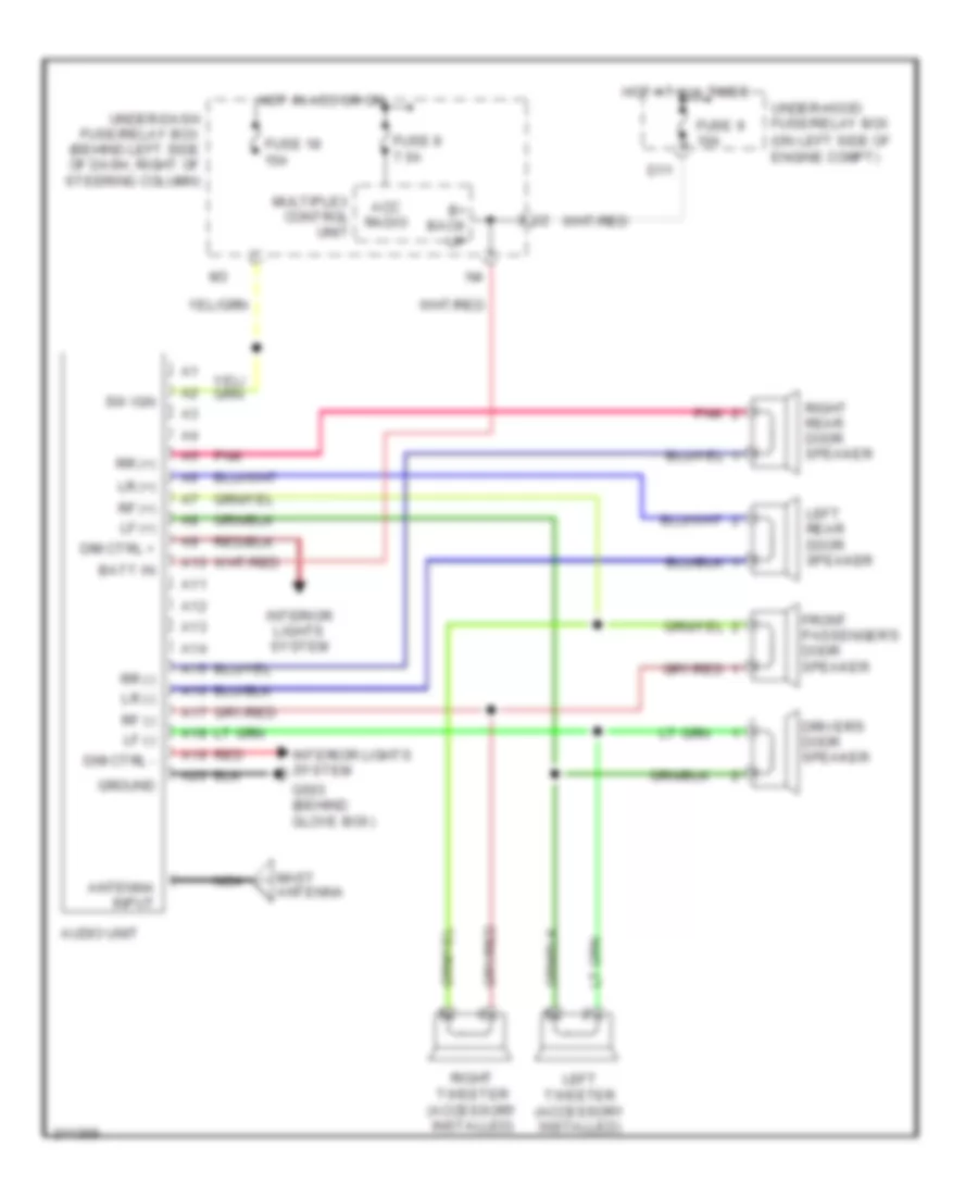
Radio Wiring Diagram, LX for Honda CR-V SE 2006
List of elements for Radio Wiring Diagram, LX for Honda CR-V SE 2006:
- (on left side of engine compt)
- A10
- A11
- A12
- A13
- A14
- A15
- A16
- A17
- A18
- A19
- A20
- Acc radio
- Antenna input
- Audio unit
- B+ back up
- Batt in
- D11
- Dim ctrl +
- Dim ctrl -
- Driver's door speaker
- Front passenger's door speaker
- Fuse 18 15a
- Fuse 8 7.5a
- Fuse 9 10a
- G503 (behind glove box)
- Ground
- Hot at all times
- Hot in acc or on
- Interior lights system
- Left rear door speaker
- Left tweeter (accessory installed)
- Lf (+)
- Lf (-)
- Lr (+)
- Lr (-)
- Mast antenna
- Multiplex control unit
- Nca
- Pnk
- Red
- Rf (+)
- Rf (-)
- Right rear door speaker
- Right tweeter (accessory installed)
- Rr (+)
- Rr (-)
- Sw ign
- Under-dash fuse/relay box (behind left side of dash, right of steering column)
- Under-hood fuse/relay box
SHIFT INTERLOCK
Shift Interlock Wiring Diagram for Honda CR-V SE 2006
List of elements for Shift Interlock Wiring Diagram for Honda CR-V SE 2006:
- (bksw) switch input
- (not used)
- Acc radio
- Atp -n
- Atpn
- Brake pedal position switch (behind dash, on brake pedal support)
- C20
- E22
- Fuse 15a
- Fuse 7.5a
- G10
- G101 (at left side of engine)
- G301 (behind left side of front bumper)
- G401 (behind glove box)
- Gauge assembly
- Gnd
- Hot at all times
- Hot in acc or on
- Hot in on or start
- Ig1 meter
- Ignition key switch
- Ignition key switch/ key light
- Junction connector c105 (behind glove box)
- Key interlock solenoid
- Key lock sol +
- Key sw
- Multiplex control unit
- O12
- P pin sw
- P-pinsw
- Park pin switch
- Pcm (behind right side of dash)
- Security control unit connector (optional) (behind left side of dash)
- Shift lock solenoid
- Sls
- Stop sw
- Transmission range switch (on lower rear of transaxle)
- Under-dash fuse/relay box (behind left side of dash, right of steering column)
- Under-hood fuse/relay box (on left side of engine compt)
STARTING/CHARGING
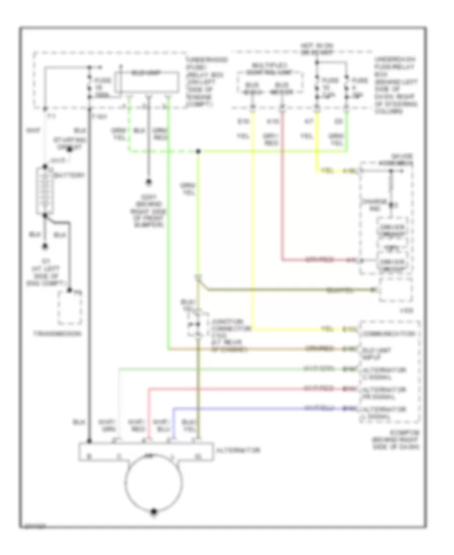
Charging Wiring Diagram for Honda CR-V SE 2006
List of elements for Charging Wiring Diagram for Honda CR-V SE 2006:
- A18
- Alternator
- B10 alternator l signal
- B13 alternator fr signal
- B18 alternator c signal
- Battery
- Bus (ecu)
- Bus meter
- Charge
- Communication
- Cpu
- Driver circuit
- E10
- E13
- E15 eld unit input
- Ecm/pcm (behind right side of dash)
- Eld unit
- Fuse 100a
- Fuse 10a
- Fuse 7.5a
- G1 (at left side of eng compt)
- G201 (behind right side of front bumper)
- Gauge assembly
- Hot in on or start
- Ind
- Junction connector c103 (at rear of engine)
- K10
- Multiplex control unit
- Starting circuit
- T101
- Transmission
- Underdash fuse/relay box (behind left side of dash, right of steering column)
- Underhood fuse/ relay box (on left side of engine compt)
- Vss
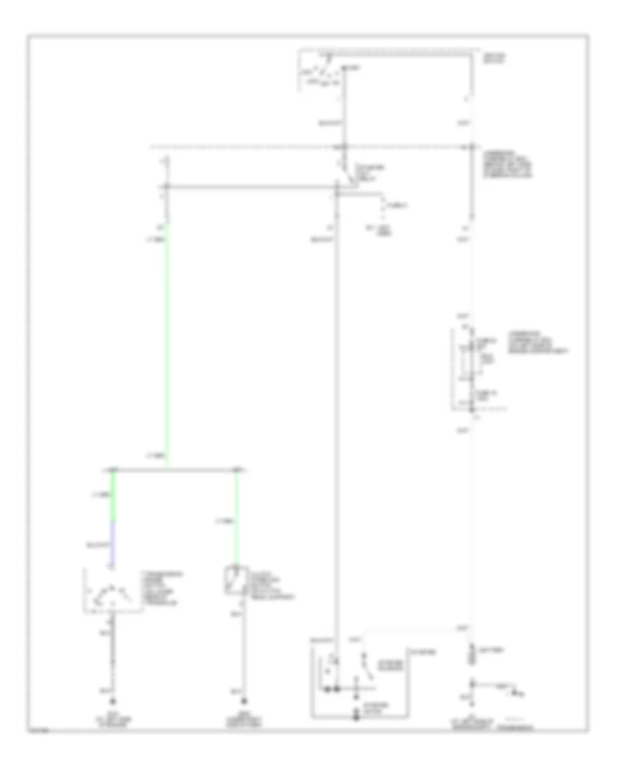
Starting Wiring Diagram for Honda CR-V SE 2006
List of elements for Starting Wiring Diagram for Honda CR-V SE 2006:
- (not used)
- A/t
- Acc
- Battery
- Clutch interlock switch (on clutch pedal support)
- E11
- Eld unit
- Fuse 19 100a
- Fuse 20 50a
- Fuse 21
- G1 (at left side of engine compt)
- G101 (at left side of engine)
- G502 (under right side of dash)
- Ignition switch
- Lock
- M/t
- Off
- Start
- Starter
- Starter cut relay
- Starter motor
- Starter solenoid
- Transmission
- Transmission range switch (on lower rear of transaxle)
- Underdash fuse/relay box (behind left side of dash, right of steering column)
- Underhood fuse/relay box (on left side of engine compartment)
SUPPLEMENTAL RESTRAINTS
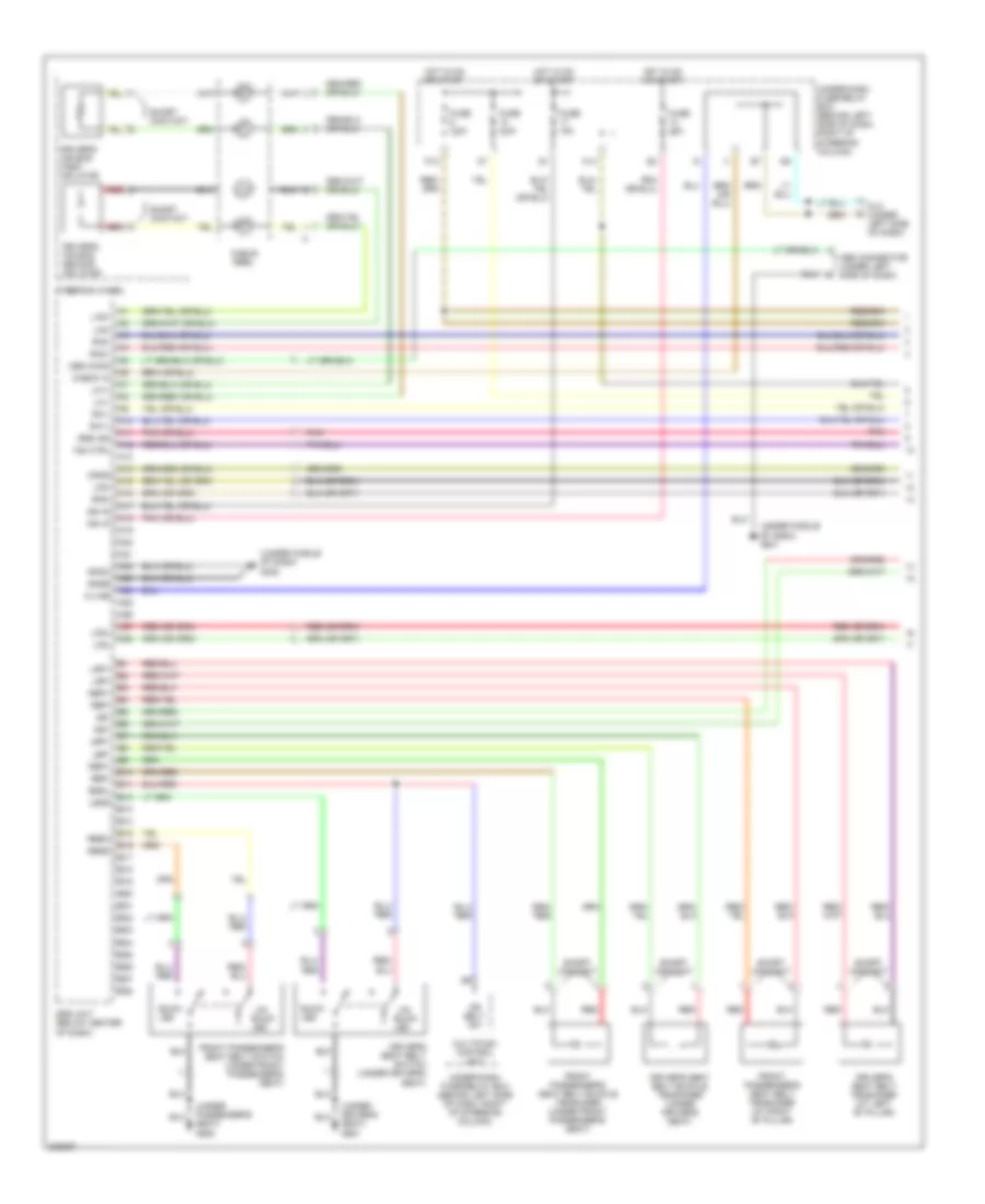
Supplemental Restraints Wiring Diagram (1 of 3) for Honda CR-V SE 2006
List of elements for Supplemental Restraints Wiring Diagram (1 of 3) for Honda CR-V SE 2006:
- (under driver's seat) g551
- (under middle of dash) g402
- (under middle of dash) g451
- (under passenger's seat) g552
- A10
- A11
- A12
- A13
- A14
- A15
- A16
- A17
- A18
- A19
- A20
- A21
- A22
- A23
- A24
- A25
- A26
- A27
- A28
- B10
- B11
- B12
- B13
- B14
- B15
- B16
- B17
- B18
- B19
- B20
- B21
- B22
- B23
- B24
- B25
- B26
- B27
- B28
- Bsdl
- Buck- led
- Cable reel
- Check in
- Dlc (under left side of dash)
- Dr belt sw
- Driver's air bag first inflator
- Driver's air bag second inflator
- Driver's seat belt buckle tensioner (under driver's seat)
- Driver's seat belt switch (under driver's seat)
- Driver's seat belt tensioner (at left "b" pillar)
- Front passenger's seat belt buckle tensioner (under front passenger's seat)
- Front passenger's seat belt switch (under front passenger's seat)
- Front passenger's seat belt tensioner (at right "b" pillar)
- Fuse 10a
- Fuse 15a
- Fuse 7.5a
- Gnda
- Gndb
- Hot in on or start
- Ign in
- Ind ctrl
- K-line
- K14
- La1+
- La1-
- La2+
- La2-
- Lbp+
- Lbp-
- Lfs+
- Lfs-
- Lrp+
- Lrp-
- Lssd
- Mes conn
- Mes connector (under left side of dash)
- Multiplex control unit
- Opds
- P12
- Pnk
- Ra1+
- Ra1-
- Ra2+
- Ra2-
- Rbp+
- Rbp-
- Rbsc
- Rbsd
- Red
- Rfs-
- Short contact
- Srs ind
- Srs unit (below center of dash)
- Ss+
- Ss-
- Steering wheel
- Un-
- Under-dash fuse/relay box (behind left side of dash, right of steering column)
Supplemental Restraints Wiring Diagram (2 of 3) for Honda CR-V SE 2006
List of elements for Supplemental Restraints Wiring Diagram (2 of 3) for Honda CR-V SE 2006:
- (under passenger's seat) g552
- (under right side of dash) g502
- A18
- A20
- B15
- B16
- Driver's seat position sensor (under driver's seat)
- Front passenger's air bag cut-off indicator
- Front passenger's weight sensor unit (under front passenger's seat)
- Gauge assembly
- Gnd
- Indicator light
- Inner side front passenger's weight sensor
- Interior lights system
- J/c c456 (under middle of dash)
- Left front impact sensor (behind left side of front bumper)
- Lower element (lower 4 sensors in seat back)
- Odus
- Opds sensor
- Opds unit (in front passenger's seat)
- Outer side front passenger's weight sensor
- Pnk
- Pow
- Red
- Right front impact sensor (behind right side of front bumper)
- Sb1l, sb1s
- Sb2l, sb2s
- Sb3l, sb3s
- Sb4l, sb4s
- Sb5l, sb5s
- Sb6l, sb6s
- Side air bag cut-off indicator
- Side element (right side of seat back)
- Srs indicator
- Srs indicator circuit
- Ss1l, ss1s
- Swig
- Swip
- Switch illum
- Swog
- Swop
- Upper element (upper two sensors in seat back)
- Wrn
Supplemental Restraints Wiring Diagram (3 of 3) for Honda CR-V SE 2006
List of elements for Supplemental Restraints Wiring Diagram (3 of 3) for Honda CR-V SE 2006:
- (behind right side of dash) front passenger's air bag first inflator
- (behind right side of dash) front passenger's air bag second inflator
- (under driver's seat) driver's side air bag inflator
- (under front passenger's seat) front passenger's side air bag inflator
- C10
- C11
- C12
- C13
- C14
- C15
- C16
- C17
- C18
- C19
- C20
- C21
- C22
- C23
- C24
- C25
- C27
- C28
- Driver's side curtain air bag inflator (left rear of roof)
- Driver's side curtain impact sensor (at left "c" pillar)
- Driver's side impact sensor (at base of left "b" pillar)
- Front passenger's side curtain air bag inflator (right rear of roof)
- Front passenger's side curtain impact sensor (at right "c" pillar)
- Front passenger's side impact sensor (at base of right "b" pillar)
- Lbsi+
- Lca+
- Lca-
- Lcsi+
- Lcsi-
- Lsa+
- Lsa-
- Rbsi+
- Rbsi-
- Rca+
- Rca-
- Rcsi+
- Rcsi-
- Red
- Roll rate sensor (under driver's seat)
- Rrs+
- Rrs-
- Rsa+
- Rsa-
- Srs unit (below center of dash)
TRANSMISSION
A/T Wiring Diagram (1 of 2) for Honda CR-V SE 2006
List of elements for A/T Wiring Diagram (1 of 2) for Honda CR-V SE 2006:
- (at rear of transaxle)
- (on left side of transaxle)
- 2nd clutch transmission fluid pressure switch (at top of transaxle)
- 3rd clutch transmission fluid pressure switch
- A/t clutch pressure control solenoid valve a (on top of transaxle)
- A/t clutch pressure control solenoid valve b
- A/t clutch pressure control solenoid valve c
- A/t gear selector lever)
- A18
- A20
- A21
- A23
- A24
- A30
- Atft
- Atp-n
- Atp-p
- Atp1
- Atp2
- Atpd
- Atpfwd
- Atpn
- Atpp
- Atpr
- Atprvs
- Auxiliary under-hood fuse/relay box (left side of engine compartment)
- Bksw
- Brake pedal position switch (behind dash, on brake pedal support)
- C10
- C11
- C12
- C13
- C14
- C15
- C17
- C18
- C19
- C20
- D10
- D3 sw
- D3 switch (on end of
- Dlc (under left side of dash)
- E10
- E13
- E22
- E23
- E26
- E29
- E30
- Ecu bus
- Engine controls system
- Fuse 15a
- Fuse 7.5a
- G10
- G101 (at left side of engine)
- G451 (left center of console)
- Hot at all times
- Hot in acc or on
- Hot in on or start
- Ig1
- Igp1
- Igp2
- K-line
- K10
- Lg1
- Lg2
- Lsa
- Lsb
- Lsc
- Map
- Meter bus
- Mrly
- Multiplex control unit ig1 meter
- Nep
- O12
- Op2sw
- Op3sw
- Pcm (behind right side of dash)
- Pg1
- Pg2
- Pgm-fi main relay 1 (behind right side of dash)
- Radio acc
- Red
- Scs
- Sefmj
- Sg1
- Sg2
- Sha
- Shb
- Shc
- Shd
- She
- Shift control solenoid valves
- Test tachometer connector (on left side of engine compt, near battery)
- Under-dash fuse/relay box (behind left side of dash, right of steering column)
- Under-hood fuse/relay box (on left side of engine compt)
- Vcc1
- Vcc2
- Wen
A/T Wiring Diagram (2 of 2) for Honda CR-V SE 2006
List of elements for A/T Wiring Diagram (2 of 2) for Honda CR-V SE 2006:
- (under right side of dash) g502
- A13
- A14
- A15
- A16
- A18
- Atf temperature sensor
- Dimming circuit
- Driver circuit
- Engine controls system
- G101 (at left side of engine)
- Input shaft (mainshaft) speed sensor (on rear right side of transmission)
- J/c c105 (behind glove box)
- Map sensor (on top of throttle body)
- Output shaft (counter- shaft) speed sensor (on front right side of transmission)
- Pnk
- Starter cut relay
- Transmission range switch (on lower rear of transaxle)
- Underdash fuse/relay box (behind left side of dash, right of steering column)
- Usa: ex, se
TRUNK, TAILGATE, FUEL DOOR
Liftglass Release Wiring Diagram for Honda CR-V SE 2006
List of elements for Liftglass Release Wiring Diagram for Honda CR-V SE 2006:
- +b back up
- D11
- Door locks system
- Fuse 10 7.5a
- Fuse 10a
- Fuse 15a
- G/h act
- G/h sw
- G501 (under left side of dash)
- G601 (behind right quarterpanel)
- G701 (at middle of tailgate)
- Hatch glass latch switch 1 (on middle of tailgate)
- Hatch glass opener actuator (middle of tailgate)
- Hatch glass opener switch
- Hot at all times
- Hot in on or start
- Ig1 meter
- K13
- Keyless com
- Multiplex control unit
- Rear wiper control unit (behind right rear quarterpanel)
- Security control unit connector (optional) (behind left side of dash)
- Under-dash fuse/relay box (behind left side of dash, right of steering column)
- Under-hood fuse/relay box (on left side of engine compt)
- Usa: ex, se
WARNING SYSTEMS
Back-Up Alarm Wiring Diagram for Honda CR-V SE 2006
List of elements for Back-Up Alarm Wiring Diagram for Honda CR-V SE 2006:
- (behind left side of dash, right of steering column)
- A-t reverse relay (behind right side of dash)
- A/t
- Back-up light switch (on top of transaxle)
- Back-up lights circuit
- Back-up sensor beeper assembly
- Back-up sensor control unit
- Back-up sensor in-line fuse
- G601 (behind right quarter panel)
- Left corner back-up sensor
- Left middle back-up sensor
- Left tailight assembly connector
- Left taillight assembly
- Left taillight assembly connector
- M/t
- Red
- Right corner back-up sensor
- Right middle back-up sensor
- Under-dash fuse/relay box
Warning Systems Wiring Diagram for Honda CR-V SE 2006
List of elements for Warning Systems Wiring Diagram for Honda CR-V SE 2006:
- (below center of dash) srs unit
- (ig) key lt (-)
- (not used)
- +b backup
- A18
- Alternator
- Altl
- B10
- B11
- B12
- Beeper
- Bus (ecu)
- Bus (meter)
- C11
- Combination light switch
- Cpu
- D11
- Drive circuit
- Driver door switch
- Driver seat belt/srs
- Driver's door switch (on left "b" pillar)
- Driver's seat belt switch (in driver's seat)
- E10
- E13
- Ecm/pcm (behind right side of dash)
- Exterior lights system
- Fuse 10a
- Fuse 15a
- Fuse 7.5a
- G401 (behind glove box)
- G502 (under right side of dash)
- G551 (under driver's seat)
- Gauge assembly
- Head
- Headlight switch
- Hot at all times
- Hot in on or start
- Ig1 meter
- Ignition key light
- Ignition key switch
- Ignition key switch/ key light
- Illumination (+)
- K10
- Key switch input
- Low oil
- Multiplex bus
- Multiplex control unit
- Off
- Oil pressure switch (on right front of engine, above oil filter)
- P15
- Park
- Pressure ind door ind
- S-gnd
- Seat belt reminder ind
- Security control unit connector (optional) (behind left side of dash)
- Small lt rly-
- Taillight relay
- Under-dash fuse/relay box (behind left side of dash, right of steering column)
- Under-hood fuse/relay box (on left side of engine compt)
- Usa: se canada: ex-l
WIPER/WASHER
Front Wiper/Washer Wiring Diagram for Honda CR-V SE 2006
List of elements for Front Wiper/Washer Wiring Diagram for Honda CR-V SE 2006:
- A10
- A18
- Cpu
- Drive circuit
- Fr washer mtr
- Fr wiper (as)
- Fr wiper (int)
- Fr wiper int unit
- Fuse 20a
- Fuse 7.5a
- G301 (behind left side of front bumper)
- G401 (behind glove box)
- G811 (under left side of cowl cover)
- Gauge assembly
- High
- Hot in on or start
- Ig1 wiper
- Int
- Low
- Mist
- Multiplex control unit
- Off
- Park
- Run
- Underdash fuse/relay box (behind left side of dash, right of steering column)
- Wash
- Washer fluid level indicator (canada)
- Washer fluid level switch (canada)
- Windshield washer motor (behind left side of front bumper, on washer fluid reservoir)
- Windshield wiper motor (below left side of cowl cover)
- Wiper/ washer switch
Rear Wiper/Washer Wiring Diagram for Honda CR-V SE 2006
List of elements for Rear Wiper/Washer Wiring Diagram for Honda CR-V SE 2006:
- (not used)
- Fuse 15a
- Fuse 7.5a
- G301 (behind left side of front bumper)
- G601 (behind right quarter panel)
- G701 (at middle of tailgate)
- G711 (middle of tailgate)
- Hot at all times
- Hot in on or start
- Off
- P12
- Park/ stand- by switch
- Rear window washer motor (behind left front inner fender, on washer fluid reservoir)
- Rear window wiper motor (below middle of rear window)
- Rear window wiper/washer switch
- Rear wiper control unit (behind right rear quarter panel)
- Rear wiper motor
- Stop switch
- Trunk, tailgate, fuel doors system
- Underdash fuse/relay box (behind left side of dash, right of steering column)
- Underhood fuse/relay box (on left side of engine compt)
- Wash
- Wiper
- Wiper/washer switch