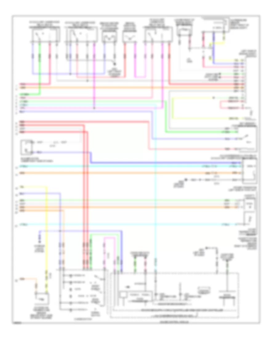
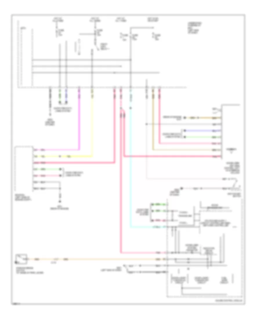
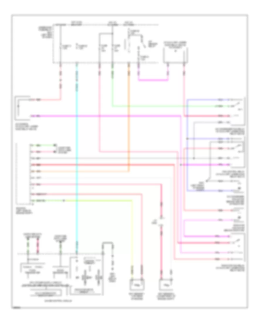
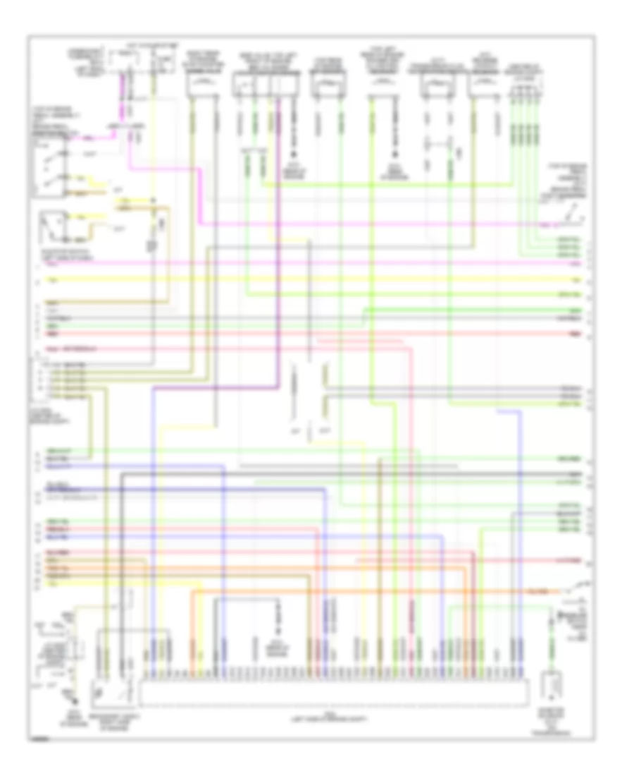
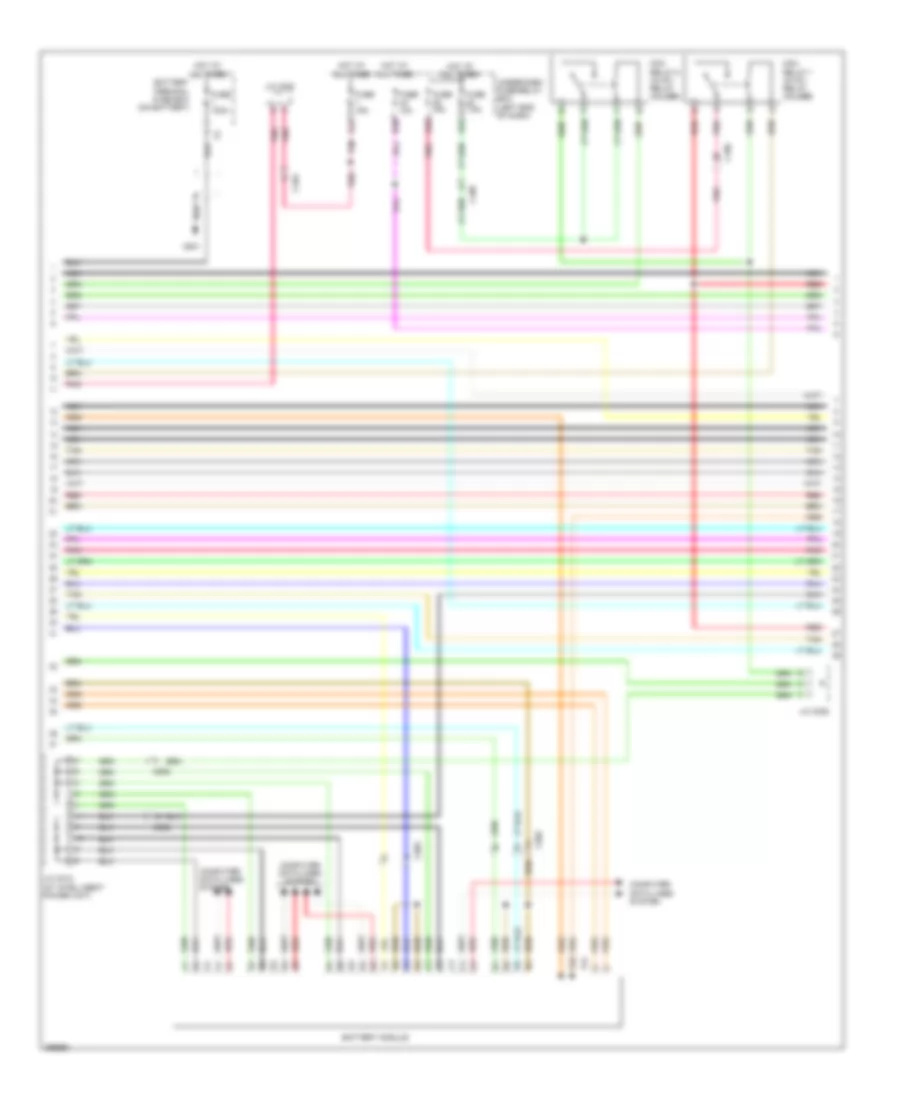
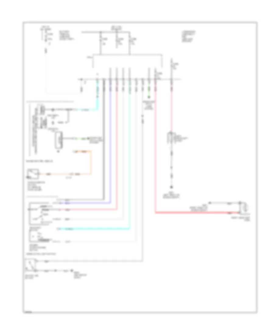
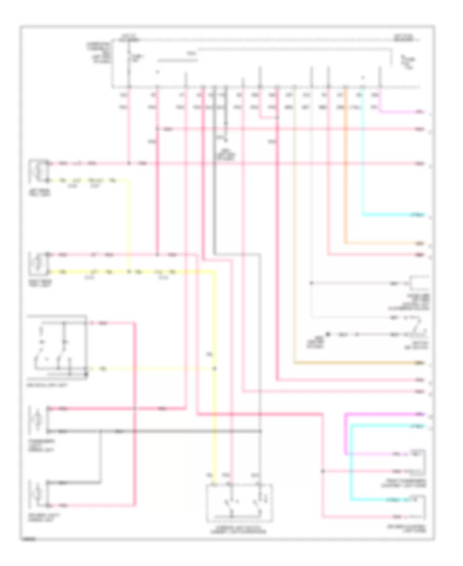
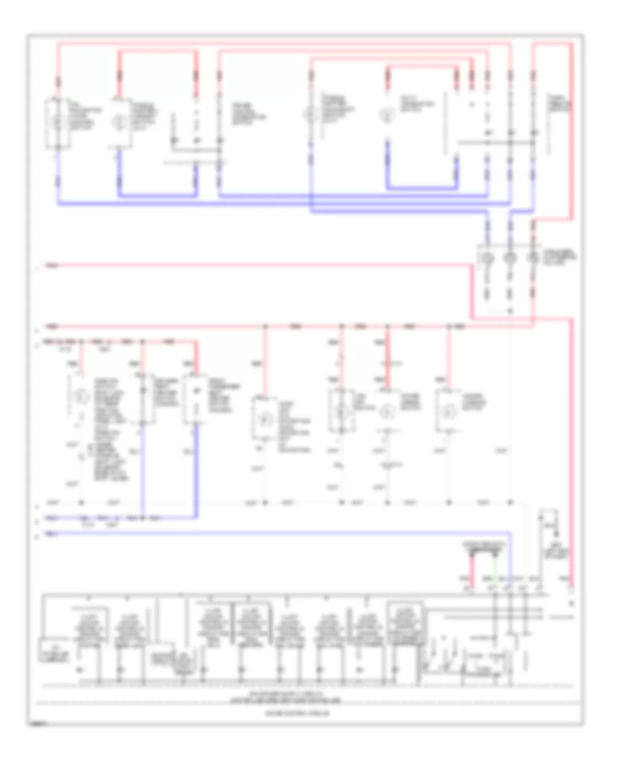
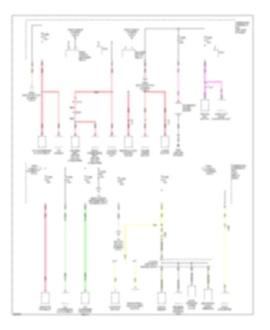
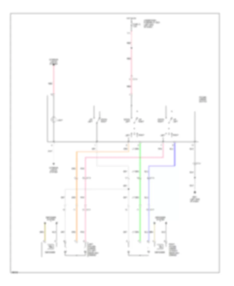
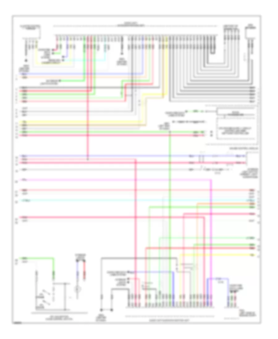
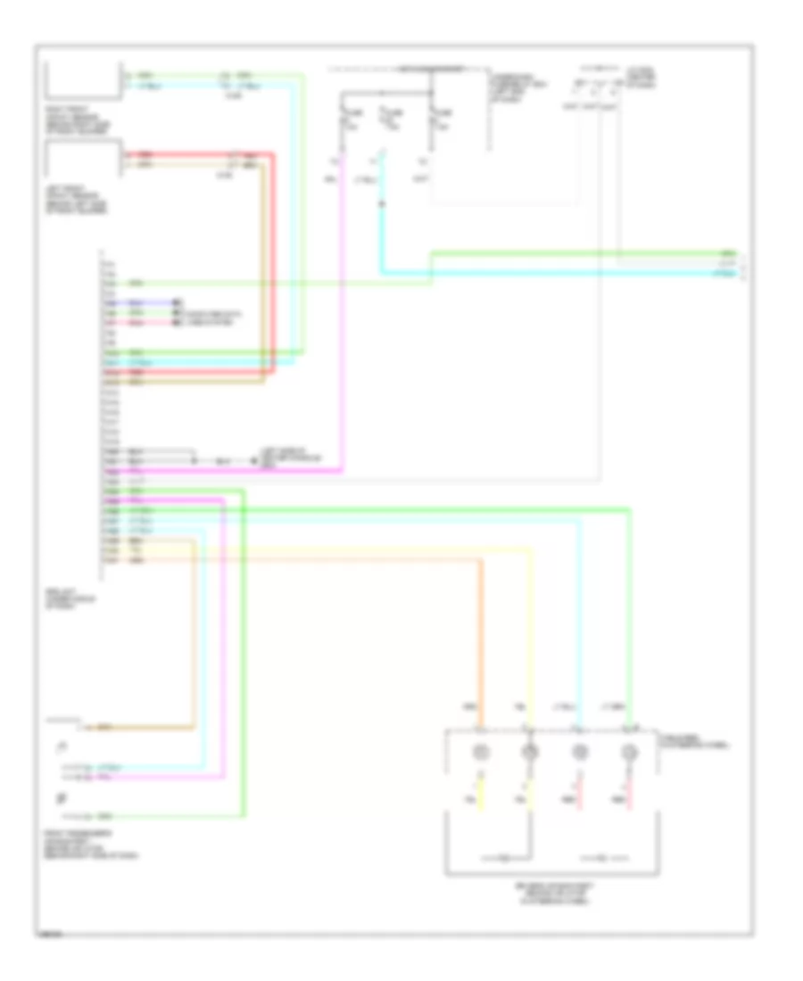
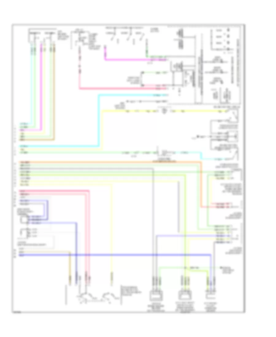
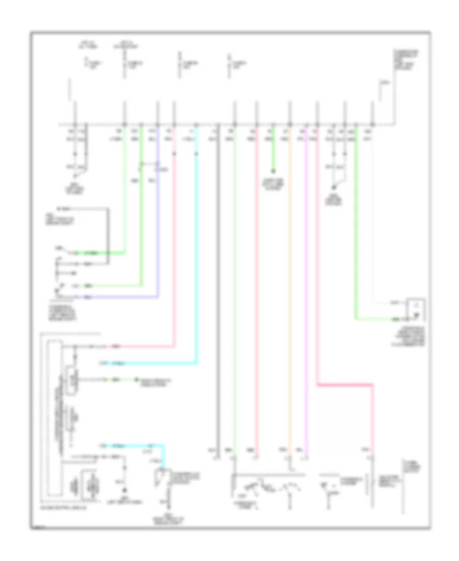
AIR CONDITIONING
Automatic A/C Wiring Diagram (1 of 2) for Honda CR-Z EX 2013

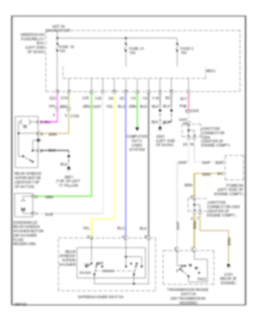
List of elements for Automatic A/C Wiring Diagram (1 of 2) for Honda CR-Z EX 2013:
- (in auxiliary under- hood relay box b) a/c diode a
- (in auxiliary under- hood relay box b) a/c diode b
- A/c compressor clutch (left front of engine)
- A/f sensor relay
- Ab3
- Air mix control motor (left side of hvac assembly)
- Automatic lighting/ sunlight sensor (top right side of dash)
- B10
- B24
- B33
- B34
- Blower motor relay
- C113
- C115
- C116
- C302
- Climate control unit
- Computer data lines system
- Defogger system
- Evaporator temperature sensor (upper right side of dash)
- Fuse 10 7.5a
- Fuse 26 10a
- Fuse 29 10a
- Fuse 30a
- Fuse 31 7.5a
- Fuse 57 30a
- Fuse 7.5a
- G502 (center of dash)
- Hot at all times
- Hot in on
- Hot in on or start
- Micu
- Mode control motor (upper left side of hvac assembly)
- Navigation system
- Pnk
- Power mirror/ rear window defogger switch
- Power mirror/ rear window defogger switch/ ind
- Recirculation control motor (right side of hvac assembly)
- Red
- Under-dash fuse/relay box (left end of dash)
- Y11
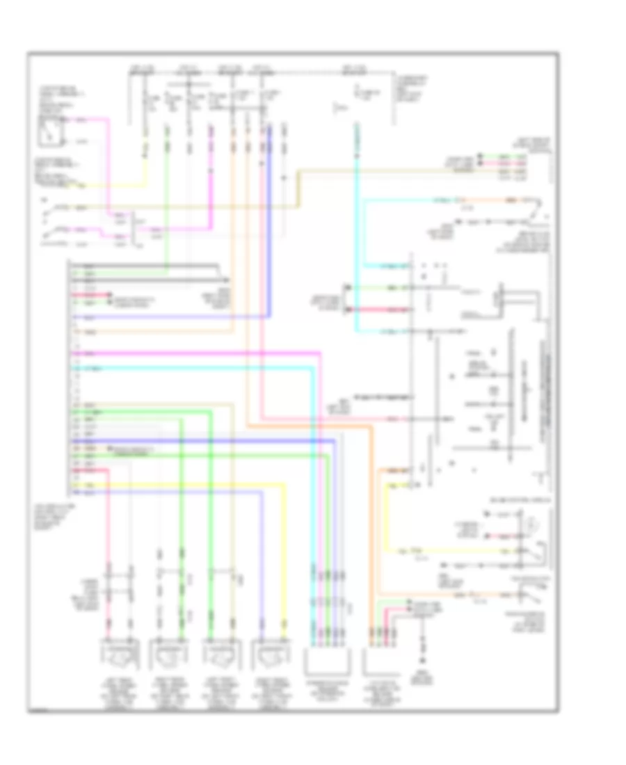
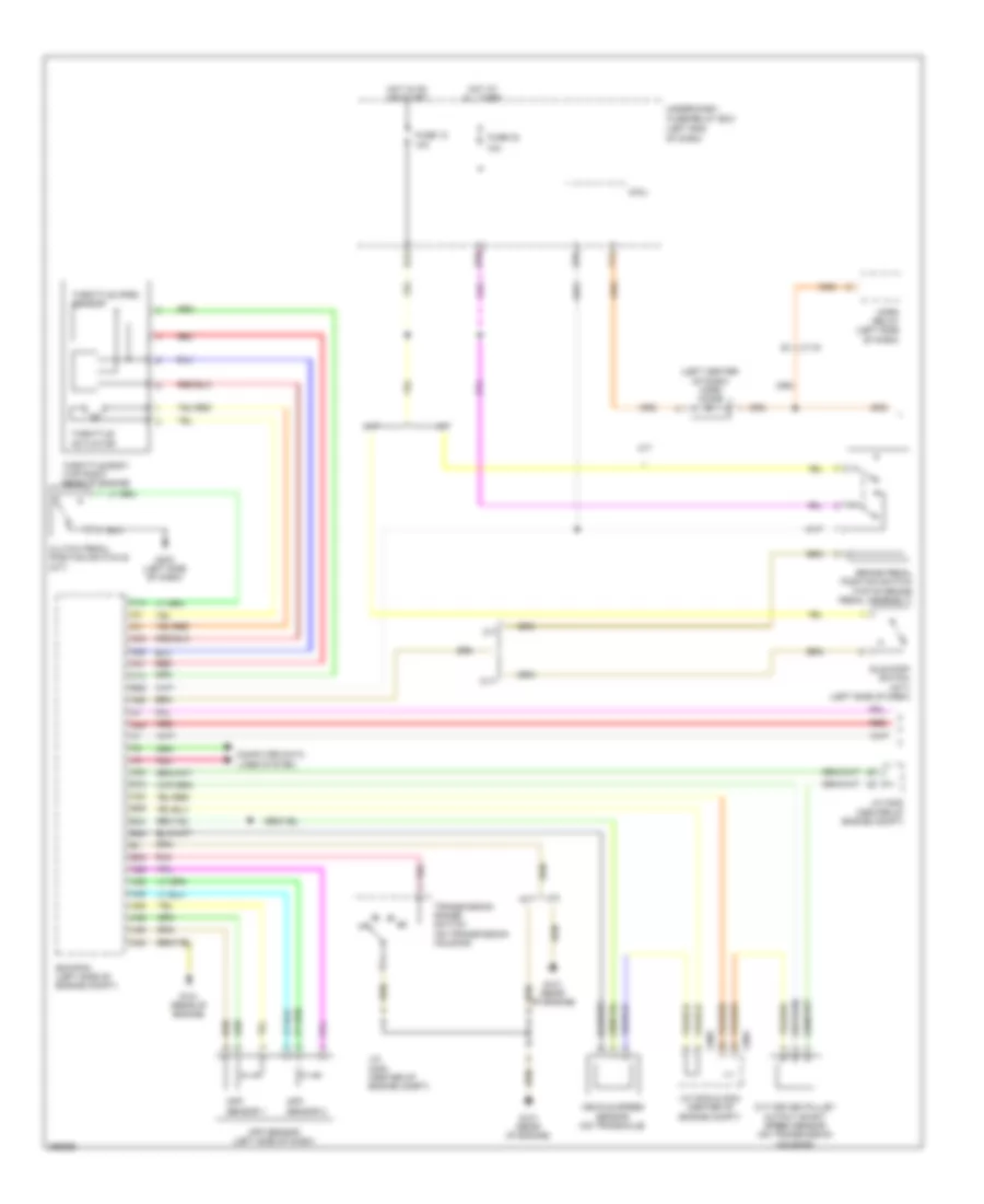
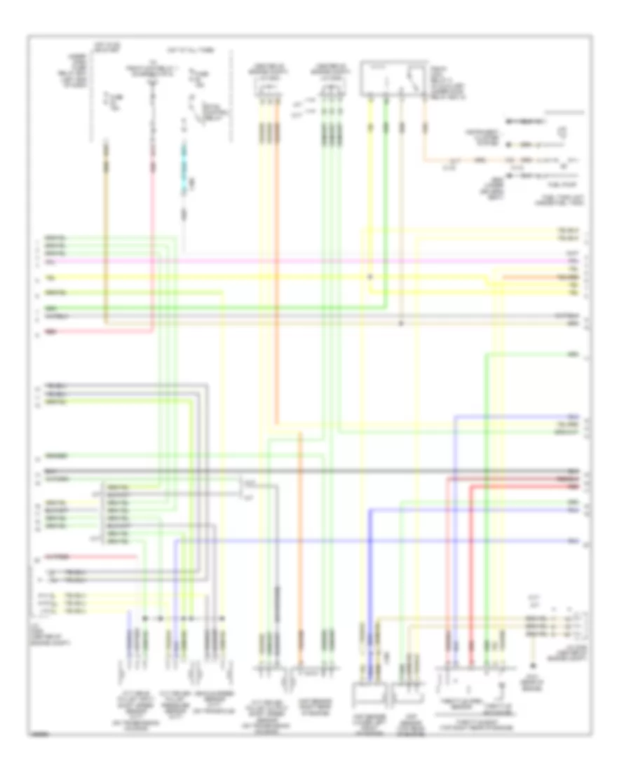
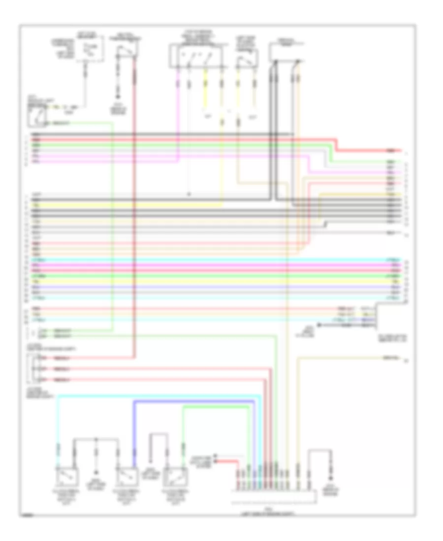
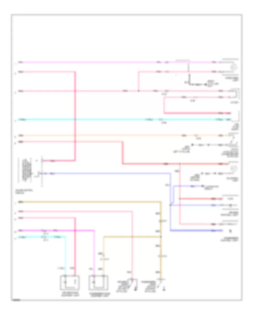
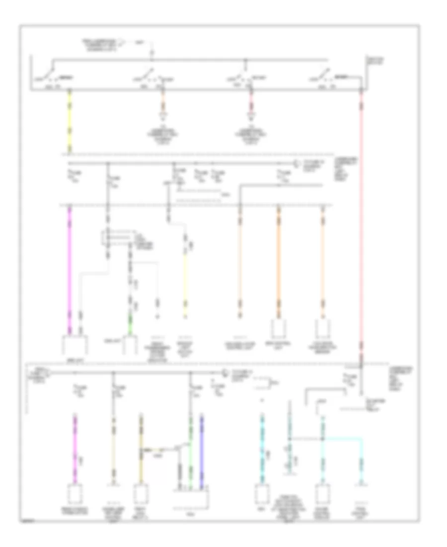
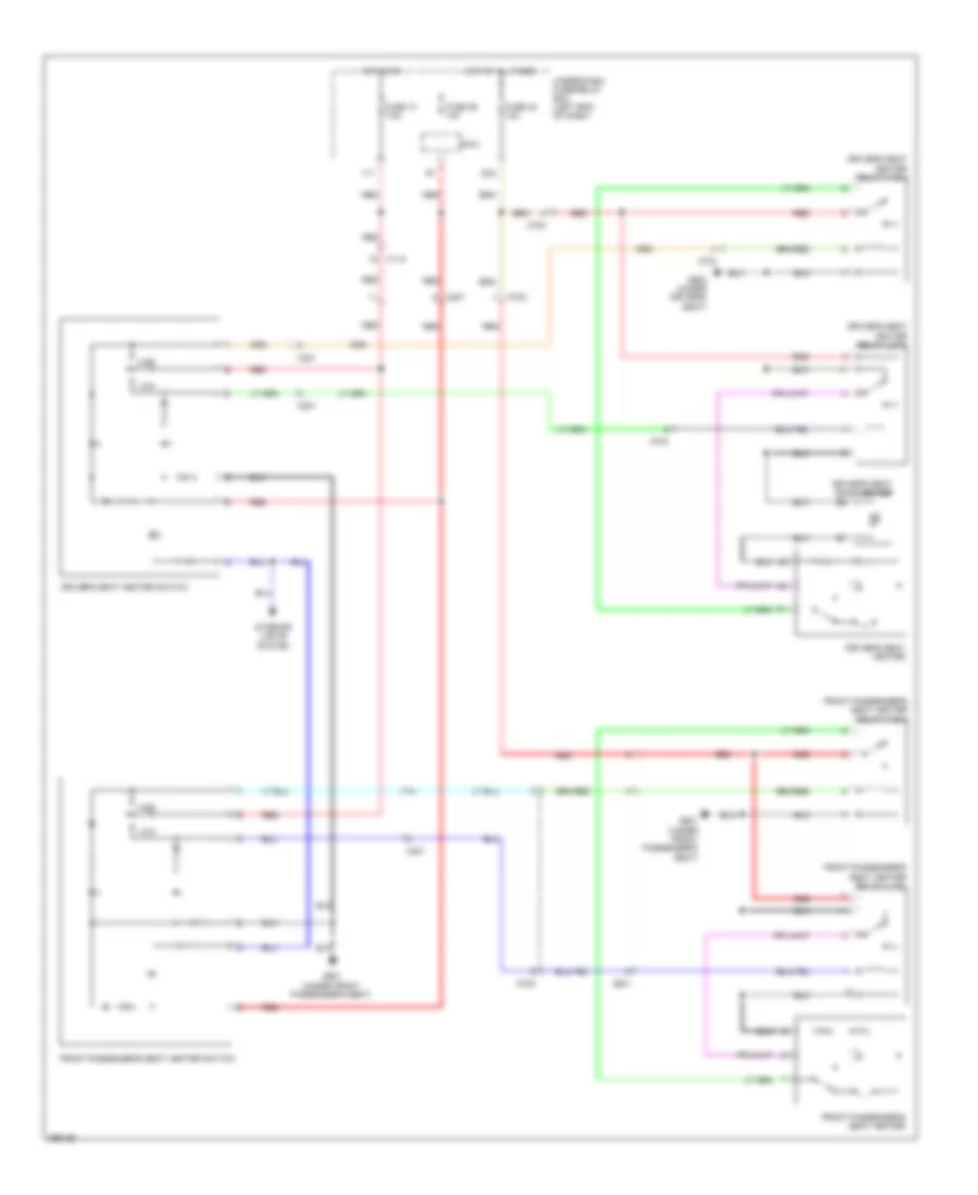
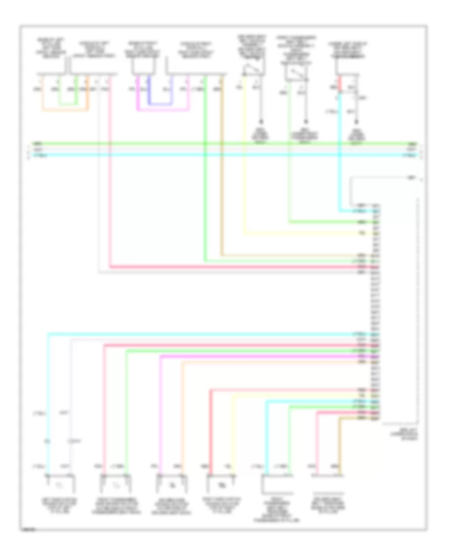
Automatic A/C Wiring Diagram (2 of 2) for Honda CR-Z EX 2013
List of elements for Automatic A/C Wiring Diagram (2 of 2) for Honda CR-Z EX 2013:
- (behind center of radiator) a/c condenser fan motor
- (behind radiator) radiator fan motor
- (in auxiliary under-hood relay box a) fan control relay
- (in auxiliary under-hood relay box b) a/c condenser fan relay
- (in auxiliary under-hood relay box b) radiator fan relay
- (left side of engine compt) ecm/pcm
- (lower front of engine compt) ect sensor 2
- 3 mode switch
- A/c compressor clutch relay (in auxiliary under-hood relay box a)
- A/c pressure sensor (right front of engine compt)
- B-can transceiver
- Blower motor (under right side of dash)
- C110
- C113
- C114
- C115
- Computer data lines system
- Dimming circuit
- Econ switch
- Ect sensor 1 (top rear of engine)
- F-can h
- F-can l
- F-can transceiver
- G401 (left front of engine compt)
- G501 (left end of dash)
- G502 (center of dash)
- Gauge control module
- High temperature ind
- Humidity sensor
- Humidity/in-car temperature sensor (right of steering column)
- In-car temperature sensor
- Indicator drive circuit
- Interior lights system
- J/c c006
- Low temperature ind
- Multi-information display unit
- Normal switch
- Outside air temperature sensor (behind right side of front bumper)
- Pnk
- Power transistor (left side of hvac unit)
- Red
- Sport switch
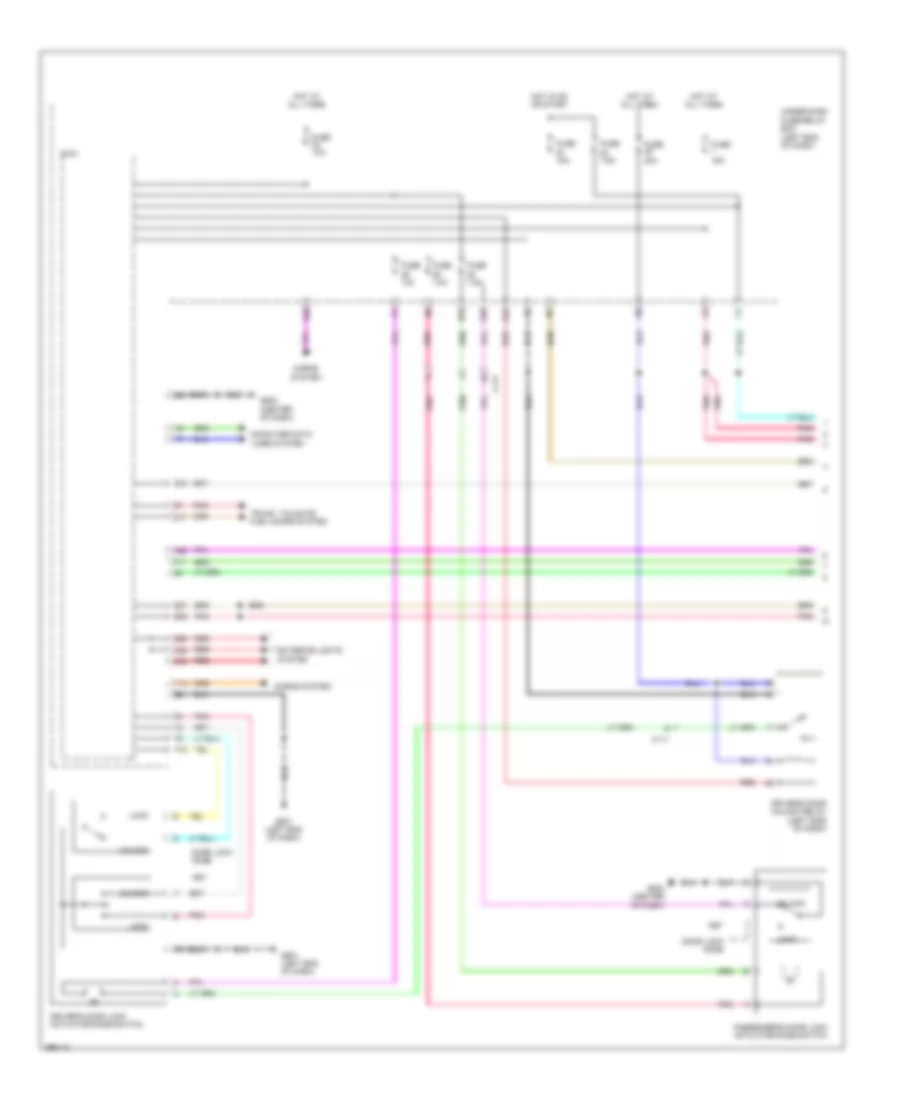
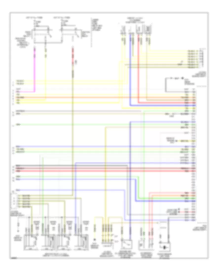
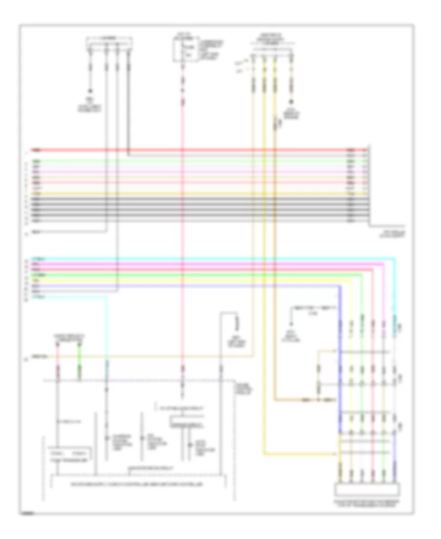
ANTI-LOCK BRAKES
Anti-lock Brakes Wiring Diagram for Honda CR-Z EX 2013
List of elements for Anti-lock Brakes Wiring Diagram for Honda CR-Z EX 2013:
- (left side of engine compt) ecm/pcm
- (top of brake pedal assembly) (cvt) brake pedal position switch
- (top of brake pedal assembly) (m/t) brake pedal position switch
- A10
- A13
- A14
- A18
- A25
- A32
- A35
- Abs ind
- Area network controller
- B12
- B26
- B30
- Brake fluid level switch (on brake master cylinder reservoir)
- Brake system ind
- C114
- C115
- C116
- C118
- C302
- Computer data lines system
- Cvt
- F-can h
- F-can l
- Fuse 1 15a
- Fuse 10a
- Fuse 11 7.5a
- Fuse 22 7.5a
- Fuse 30a
- G202 (right side of engine compt)
- G403 (left side of dash)
- G501 (left end of dash)
- G502 (center of dash)
- Gauge control module
- Hot at all times
- Hot in on or start
- Indicator drive circuit
- Interior lights system
- Left front wheel speed sensor (on left front wheel hub assembly)
- Left rear wheel speed sensor (on left rear wheel hub assembly)
- M/t
- Micu
- Parking brake switch (at base of park lever)
- Pnk
- Red
- Right front wheel speed sensor (on right front wheel hub assembly)
- Right rear wheel speed sensor (on right rear wheel hub assembly)
- Steering angle sensor (on steering column)
- Transceiver f-can
- Under- dash fuse/ relay box (left end of dash)
- Under-dash fuse/relay box (left end of dash)
- Vsa ind
- Vsa modulator- control unit (right rear of engine compt)
- Vsa off ind
- Vsa off switch
- Yaw rate acceleration sensor (under middle of dash)
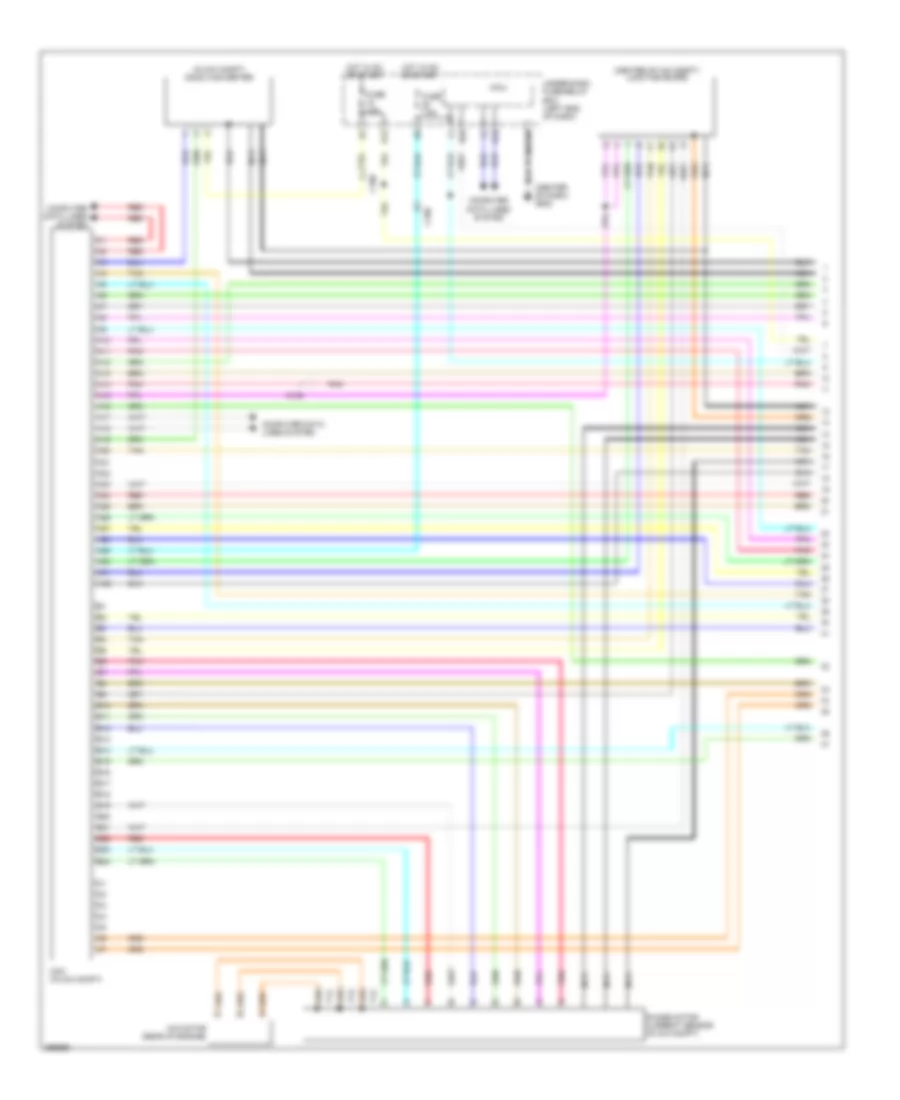
ANTI-THEFT
Forced Entry Wiring Diagram (1 of 2) for Honda CR-Z EX 2013
List of elements for Forced Entry Wiring Diagram (1 of 2) for Honda CR-Z EX 2013:
- A22
- A28
- Aa6
- B28
- B30
- C111
- C117
- Computer data
- D17
- D26
- D27
- D40
- Door lock knob
- Driver's door lock actuator/knob switch
- Driver's door unlock relay (left side of dash)
- Exterior lights system
- F10
- F11
- Fuse 10a
- Fuse 15a
- Fuse 20a
- Fuse 7.5a
- G501 (left end of dash)
- G502 (center of dash)
- Horns system
- Hot at all times
- Hot in on or start
- Key
- Lines system
- Lock
- Micu
- N10
- Passenger's door lock actuator/knob switch
- Pnk
- Q18
- Q28
- Red
- Trunk, tailgate, fuel doors system
- Under-dash fuse/relay box (left end of dash)
- Unlock
- Y14
Forced Entry Wiring Diagram (2 of 2) for Honda CR-Z EX 2013
List of elements for Forced Entry Wiring Diagram (2 of 2) for Honda CR-Z EX 2013:
- (rear of engine) g101
- Antenna
- B-can transceiver
- Blinking circuit
- C118
- C302
- Computer data lines system
- Driver's door switch (on left "b" pillar)
- G403 (left side of dash)
- G501 (left end of dash)
- G502 (center of dash)
- Gauge control module
- Ignition key switch
- Immobilizer- keyless control unit (in steering column)
- Lock
- Passenger's door switch (on right "b" pillar)
- Pnk
- Power window master switch
- Security hood switch (on engine compt hood latch assembly)
- Security indicator led
- Unlock
Immobilizer Wiring Diagram for Honda CR-Z EX 2013
List of elements for Immobilizer Wiring Diagram for Honda CR-Z EX 2013:
- (rear of engine) g101
- A14
- Antenna
- B-can transceiver
- B10
- B22
- C118
- Compulsory turning off circuit
- Compulsory turning on circuit
- Computer data
- Computer data lines system
- Ecm/pcm (left side of engine compt)
- F-can h
- F-can l
- Fuel safe circuit
- Fuse 10a
- Fuse 15a
- Fuse 7.5a
- G101 (rear of engine)
- G501 (left end of dash)
- G502 (center of dash)
- Gauge control module
- Hot at all times
- Hot in on or start
- Ignition key switch
- Immobilizer system indicator
- Immobilizer- keyless control unit (in steering column)
- Indicator drive circuit
- Key
- Lines system
- Micu
- Parking brake switch (at base of park lever)
- Pgm-fi main relay 1
- Pnk
- Q18
- Tranceiver
- Under-dash fuse/relay box (left end of dash)
BODY CONTROL MODULES
Body Control Modules Wiring Diagram (1 of 2) for Honda CR-Z EX 2013
List of elements for Body Control Modules Wiring Diagram (1 of 2) for Honda CR-Z EX 2013:
- (center of dash) g502
- (micu service check connector)
- A16
- A18
- A22
- A27
- A29
- Aa24
- Aa25
- Air conditioning system
- Anti-lock brakes system
- Anti-theft system
- B16
- B27
- B28
- Computer data lines system
- D26
- D29
- D31
- D40
- D41
- D42
- Door locks & interior lights systems
- Door locks system
- Eld
- Electronic power steering system
- Engine controls system
- Exterior lights system
- Exterior lights, interior lights & headlights systems
- F12
- Fuse 10a
- Fuse 15a
- Fuse 20a
- Fuse 30a
- Fuse 7.5a
- G501 (left end of dash)
- Headlights system
- Headlights, exterior lights & interior lights systems
- Hot at all times
- Hot in on or start
- Instrument cluster & mirrors systems
- Instrument cluster system
- Instrument cluster, shift interlock & warning systems
- Interior lights system
- Micu
- Mirrors system
- N10
- Pnk
- Power windows system
- Q10
- Q19
- Q32
- Q34
- Red
- Shift interlock, navigation & sound systems
- Under-dash fuse/relay box (left end of dash)
- Wiper/washer system
- Y11
- Y16
Body Control Modules Wiring Diagram (2 of 2) for Honda CR-Z EX 2013
List of elements for Body Control Modules Wiring Diagram (2 of 2) for Honda CR-Z EX 2013:
- A19
- A20
- A23
- A25
- A26
- A28
- Aa6
- Air conditioning system
- Anti-theft & warning systems
- Anti-theft system
- B14
- B17
- B26
- B29
- Computer data lines system
- D10
- D17
- D18
- D27
- D30
- Door locks & interior lights systems
- Door locks system
- Engine controls & anti-lock brakes systems
- Engine controls & transmissions systems
- Exterior lights & interior lights systems
- Exterior lights system
- Exterior lights, interior lights & headlights systems
- Exterior lights, interior lights systems & headlights systems
- F10
- F11
- Fuse 10a
- Fuse 20a
- G502 (center of dash)
- Headlights system
- Horns system
- Hot at all times
- Instrument cluster, sound & navigation systems
- Interior lights & headlights systems
- Interior lights system
- Micu
- Pnk
- Power windows system
- Q10
- Q11
- Q12
- Q13
- Q14
- Q15
- Q16
- Q18
- Q20
- Q21
- Q22
- Q27
- Q28
- Q29
- Red
- Shift interlock system
- Trunk, tailgate, fuel doors system
- Under-dash fuse/relay box (left end of dash)
- Wiper/washer system
- Y12
- Y14
- Y15
COMPUTER DATA LINES
Computer Data Lines Wiring Diagram for Honda CR-Z EX 2013
List of elements for Computer Data Lines Wiring Diagram for Honda CR-Z EX 2013:
- (center of dash)
- (center of dash) g502
- (rear of engine) g101
- A13
- A17
- A18
- A42
- Audio unit/ audio-navigation unit
- B16
- C105
- C106
- C115
- C116
- Climate control unit
- Data link connector (under left center of dash)
- Ecm/pcm (left side of engine compt)
- Eps control unit (left end of dash)
- Fuse 15a
- Gauge control module
- Hot at all times
- Immobilizer keyless control unit (in steering column)
- J/c c002
- J/c c003 (center of dash)
- J/c c007
- J/c c011
- J/c c011 (center of dash)
- K-line
- Mcm (in ima compt)
- Micu
- Pnk
- Red
- S-net
- Srs unit (under middle of dash)
- Tpms control unit (usa) (left center of dash)
- Under-dash fuse/relay box (left end of dash)
- Vsa modulator control unit (right rear of engine compt)
- Yaw rate- acceleration sensor (upper middle of dash)
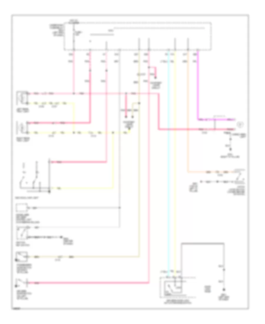
COOLING FAN
Cooling Fan Wiring Diagram for Honda CR-Z EX 2013
List of elements for Cooling Fan Wiring Diagram for Honda CR-Z EX 2013:
- (in auxiliary under- hood relay box b) a/c diode a
- A/c condenser fan motor (behind center of radiator)
- A/c condenser fan relay (in auxiliary under-hood relay box b)
- A/c diode b (in auxiliary under- hood relay box b)
- A/f sensor relay
- B-can transceiver
- B10
- B33
- B34
- Computer data lines system
- Dimming circuit
- Ecm/pcm (left side of engine compt)
- Ect sensor 1 (top rear of engine)
- Ect sensor 2 (lower front of engine compt)
- F-can h
- F-can l
- F-can transceiver
- Fan control relay (in auxiliary under-hood relay box a)
- Fuse 10 7.5a
- Fuse 22 7.5a
- Fuse 26 10a
- Fuse 30a
- Fuse 31 7.5a
- G401 (left front of engine compt)
- G501 (left end of dash)
- Gauge control module
- Hot at all times
- Hot in on
- Hot in on or start
- Ind
- Indicator drive circuit
- J/c c006
- Low temperature
- Multi-information display unit
- Pnk
- Radiator fan motor (behind radiator)
- Radiator fan relay (in auxiliary under-hood relay box b)
- Red
- Temperature high
- Under-dash fuse/relay box (left end of dash)
CRUISE CONTROL
Cruise Control Wiring Diagram (1 of 2) for Honda CR-Z EX 2013
List of elements for Cruise Control Wiring Diagram (1 of 2) for Honda CR-Z EX 2013:
- (left center of dash) horn diode
- (left end
- 10a
- A14
- A25
- A28
- A29
- A35
- A36
- A45
- A46
- A48
- App sensor (left side of dash)
- App sensor 1
- App sensor 2
- B12
- B15
- B26
- B29
- B30
- B35
- B44
- B48
- Brake pedal position switch (top of brake pedal assembly)
- C004
- C005
- C116
- C14
- C20
- C22
- C23
- C24
- C30
- C31
- Clutch pedal position switch b (m/t)
- Computer data lines system
- Cvt
- Cvt driven pulley output shaft speed sensor (on transmission housing)
- Ecm/pcm (left side of engine compt)
- Fuse 12 10a
- Fuse 24
- G101 (rear of engine)
- G403 (left side of dash)
- Horn relay (left side of dash)
- Hot at all times
- Hot in on or start
- Idle stop switch (cvt) (left side of dash)
- J/c c005 & c004 (center of engine compt)
- J/c c005 (center of engine compt)
- M/t
- Micu
- Of dash)
- Pnk
- Red
- Throttle actuator
- Throttle body (top right rear of engine)
- Throttle open sensor
- Transmission range switch (on transmission housing)
- Under-dash fuse/relay box
- Vehicle speed sensor (on transaxle)
- Y14
Cruise Control Wiring Diagram (2 of 2) for Honda CR-Z EX 2013
List of elements for Cruise Control Wiring Diagram (2 of 2) for Honda CR-Z EX 2013:
- (led) control ind cruise
- (led) main ind cruise
- A10
- A16
- A17
- A18
- B11
- B21
- C16
- C17
- C18
- C19
- C20
- C305
- Cable reel (in steering column)
- Cancel switch
- Computer data lines system
- Cruise
- Cruise control combination switch
- Desel/ set switch
- Dimmer circuit
- Etcs control relay
- F-can h
- F-can l
- F-can transceiver
- Fuse 39 15a
- Fuse 52 15a
- G501 (left end of dash)
- G502 (center of dash)
- Gauge control module
- Hot at all times
- Indicator drive circuit
- Pgm-fi main relay 1
- Pnk
- Red
- Res/ accel switch
- Under-dash fuse/relay box (left end of dash)
DEFOGGERS
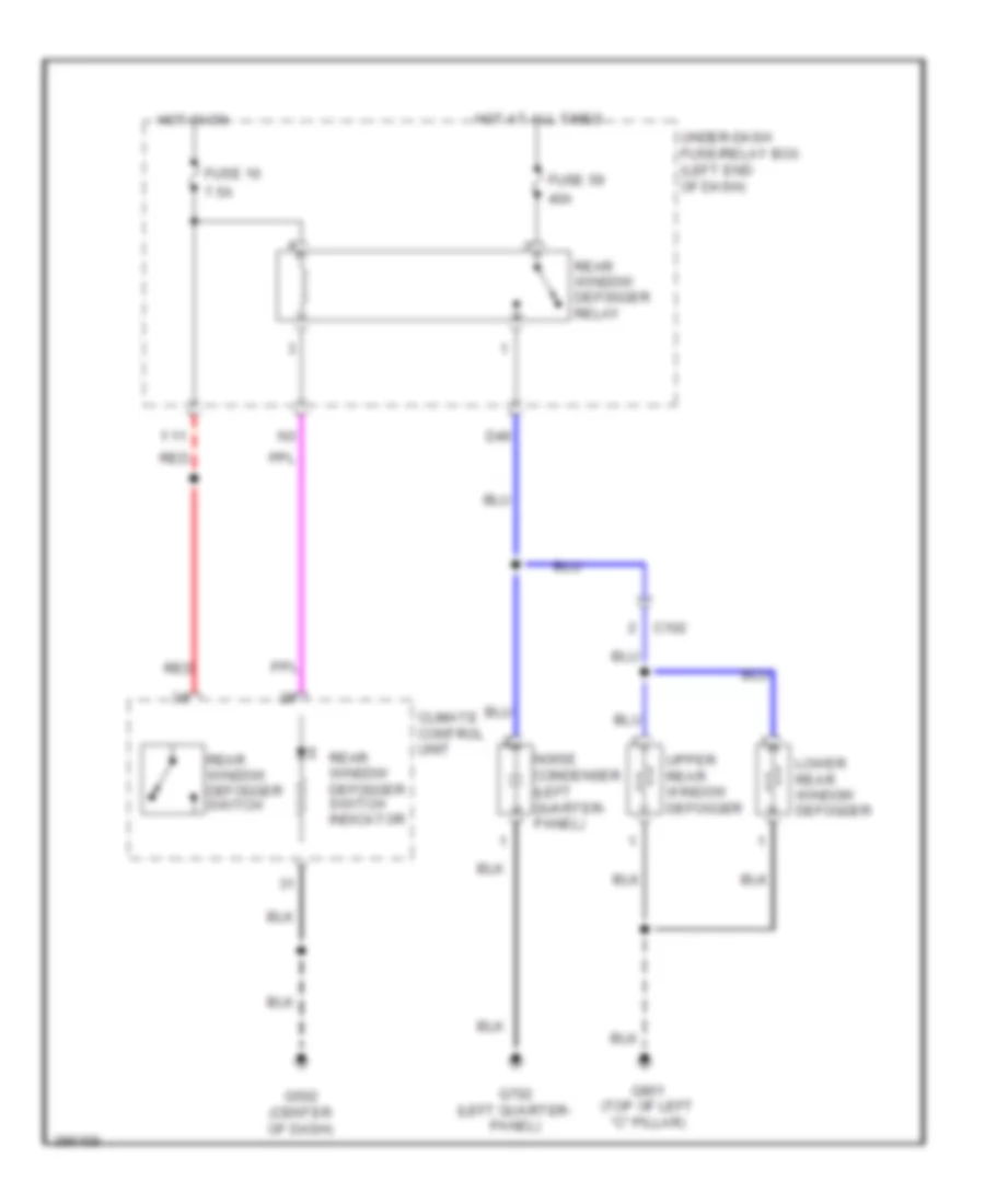
Defoggers Wiring Diagram, with Power Mirror Defogger for Honda CR-Z EX 2013
List of elements for Defoggers Wiring Diagram, with Power Mirror Defogger for Honda CR-Z EX 2013:
- 10a
- 40a
- 7.5a
- C102
- C117
- Climate control unit
- D46
- Fuse 10
- Fuse 55
- Fuse 59
- G501 (left end of dash)
- G502 (center of dash)
- G702 (left quarter- panel)
- G801 (top of left "c" pillar)
- Hot at all times
- Hot in on
- Left power mirror (in left rearview mirror)
- Lower rear window defogger
- Noise condenser (left quarter- panel)
- Q17
- Rear window defogger relay
- Rear window defogger switch/ power mirror defogger switch
- Rear window defogger switch/ power mirror defogger switch indicator
- Red
- Right power mirror (in right rearview mirror)
- Under-dash fuse/relay box (left end of dash)
- Upper rear window defogger
- Y11
Defoggers Wiring Diagram, without Power Mirror Defogger for Honda CR-Z EX 2013
List of elements for Defoggers Wiring Diagram, without Power Mirror Defogger for Honda CR-Z EX 2013:
- 40a
- 7.5a
- C102
- Climate control unit
- D46
- Fuse 10
- Fuse 59
- G502 (center of dash)
- G702 (left quarter- panel)
- G801 (top of left "c" pillar)
- Hot at all times
- Hot in on
- Lower rear window defogger
- Noise condenser (left quarter- panel)
- Rear window defogger relay
- Rear window defogger switch
- Rear window defogger switch indicator
- Red
- Under-dash fuse/relay box (left end of dash)
- Upper rear window defogger
- Y11
ELECTRONIC POWER STEERING
Electronic Power Steering Wiring Diagram for Honda CR-Z EX 2013
List of elements for Electronic Power Steering Wiring Diagram for Honda CR-Z EX 2013:
- (left kick panel) g402
- A10
- A11
- A22
- Area network controller
- B10
- B11
- B12
- B13
- B14
- B15
- B16
- Battery terminal fuse box (on battery)
- C307
- Circuit
- Compulsory turning-on circuit
- Computer data lines system
- Drive circuit indicator
- Ecm/pcm (left side of engine compt)
- Eps control unit (left end of dash)
- Eps ind
- Eps motor (left rear of engine compt)
- Eps motor angle sensor (left rear of engine compt)
- F-can h
- F-can l
- Fail-safe circuit
- Fuse 11 7.5a
- Fuse 2 70a
- Fuse 22 7.5a
- G501 (left end of dash)
- Gauge control module
- Hot at all times
- Hot in on or start
- Micu
- Nca
- Pnk
- Red
- Torque sensor (left rear of engine compt)
- Transceiver f-can
- Turning-off compulsory
- Under-dash fuse/relay box (left end of dash)
ENGINE PERFORMANCE
1.5L
1.5L, Engine Controls Wiring Diagram (1 of 5) for Honda CR-Z EX 2013
List of elements for 1.5L, Engine Controls Wiring Diagram (1 of 5) for Honda CR-Z EX 2013:
- (left end of dash) g501
- (lower front of engine compt) ect sensor 2
- (right front of engine compt) a/c pressure sensor
- (under left rear of vehicle) evap canister vent shut valve
- A/f sensor relay
- A10
- A11
- A12
- A13
- A14
- A15
- A16
- A17
- A18
- A19
- A20
- A21
- A22
- A23
- A24
- A25
- A26
- A27
- A28
- A29
- A30
- A31
- A32
- A33
- A34
- A35
- A36
- A37
- A38
- A39
- A40
- A41
- A42
- A43
- A44
- A45
- A46
- A47
- A48
- A49
- Air conditioning system
- App sensor (left side of dash)
- B10
- B18
- B25
- Brake booster pressure sensor a (on brake booster assembly)
- Brake booster pressure sensor b (on brake booster assembly)
- C105
- C116
- C118
- C305
- Clutch pedal position switch b (m/t)
- Computer data lines system
- Cvt
- Eld unit
- Electronic power steering system
- Ftp sensor (in fuel tank unit)
- Fuse 10a
- Fuse 7.5a
- G403 (left side of dash)
- Hot at all times
- Hot in on or start
- J/c c006
- Park pin switch/ shift lock solenoid/ a/t gear position indicator panel light (cvt) (park pin switch: under center console) (shift lock solenoid: base of a/t shift lever)
- Pcm (left side of engine compt)
- Pnk
- Red
- Sound & navigation systems
- Starting/charging system
- Under-dash fuse/relay box (left end of dash)
1.5L, Engine Controls Wiring Diagram (2 of 5) for Honda CR-Z EX 2013
List of elements for 1.5L, Engine Controls Wiring Diagram (2 of 5) for Honda CR-Z EX 2013:
- (center of engine compt) j/c c004
- (center of engine compt) j/c c005
- (rear of engine) g101
- 10v stabilizing circuit
- A/t dimming circuit
- A/t gear position indicator drive circuit
- B14
- B17
- C116
- C301
- C305
- Cable reel (cvt) (in steering column)
- Clutch pedal position switch a
- Clutch pedal position switch c (m/t)
- Computer data lines system
- Cruise control combination switch
- Cvt
- Cvt clutch pressure control solenoid valve (on transmission)
- Cvt drive pulley pressure control solenoid valve (cvt) (on transmission)
- Cvt driven pulley pressure control solenoid valve (cvt) (on transmission)
- D18
- Dimming circuit
- Exterior
- F-can transceiver
- Fuse 15a
- Fuse 7.5a
- Fwd
- G101 (rear of engine)
- G151 (in trans- mission)
- G403 (left side of dash)
- G501 (left end of dash)
- Gauge control module
- Hot at all times
- Hot in on or start
- Iat sensor
- Indicator drive circuit
- J/c c004 (center of engine compt)
- J/c c005 (center of engine compt)
- J/c c005 (cvt) (center of engine compt)
- Lights system
- Low fuel ind
- Low oil pressure ind
- M/t
- Maf sensor
- Maf/iat sensor (on engine air intake duct)
- Micu
- Mil ind
- Neutral position switch
- Paddle shifter (+) (upshift switch)
- Paddle shifter (-) (downshift switch)
- Pnk
- Red
- T10
- Transmission range switch (cvt) (on transmission housing)
- Under-dash fuse/relay box (left end of dash)
1.5L, Engine Controls Wiring Diagram (3 of 5) for Honda CR-Z EX 2013
List of elements for 1.5L, Engine Controls Wiring Diagram (3 of 5) for Honda CR-Z EX 2013:
- (center of engine compt) j/c c005
- (cvt) transmission fluid temperature sensor
- (egr valve: top left front of engine) egr valve/egr valve position sensor
- (m/t) reverse lockout solenoid
- (right rear of engine) evap canister purge valve
- (top left rear of engine) rocker arm oil control solenoid
- (top of brake pedal assembly) (cvt) brake pedal position switch
- (top of brake pedal assembly) (m/t) brake pedal position switch
- (top rear of engine) ect sensor 1
- B10
- B11
- B12
- B13
- B14
- B15
- B16
- B17
- B18
- B19
- B20
- B21
- B22
- B23
- B24
- B25
- B26
- B27
- B28
- B29
- B30
- B31
- B32
- B33
- B34
- B35
- B36
- B37
- B38
- B39
- B40
- B41
- B42
- B43
- B44
- B45
- B46
- B47
- B48
- B49
- C301
- C305
- Cvt
- Fuse 10a
- G101 (rear of engine)
- Hot in 0n or start
- Idle stop switch (left side of dash)
- Inhibitor solenoid (cvt) (on transmission)
- J/c c004 (center of engine compt)
- J/c c005 (center of engine compt)
- M/t
- Micu
- Oil pressure switch (near oil filter)
- Pcm (left side of engine compt)
- Pnk
- Red
- Secondary ho2s 2 (right side of engine)
- Under-dash fuse/relay box (left end of dash)
1.5L, Engine Controls Wiring Diagram (4 of 5) for Honda CR-Z EX 2013
List of elements for 1.5L, Engine Controls Wiring Diagram (4 of 5) for Honda CR-Z EX 2013:
- (center of engine compt) j/c c004
- (center of engine compt) j/c c005
- (on transmission housing)
- B11
- B19
- B21
- C116
- C118
- C304
- C305
- Ckp sensor (lower left front of engine)
- Cmp sensor (top rear of engine)
- Cvt
- Cvt drive pulley input shaft speed sensor (cvt)
- Cvt driven pulley output shaft speed sensor (on transmission housing)
- Cvt driven pulley pressure sensor (cvt)
- Etcs control relay
- Fuel pump
- Fuel tank unit (inside fuel tank)
- Fuse 15a
- G101 (rear of engine)
- G602 (under driver's seat)
- Hot at all times
- Hot in on or start
- Instrument cluster system
- J/c c005 (center of engine compt)
- M/t
- Map sensor (right rear of engine)
- Pgm-fi main relay 2 (in auxiliary under-hood relay box a)
- Red
- Throttle actuator
- Throttle body (top right rear of engine)
- Throttle open sensor
- To pgm-fi main relay 1 (diagram 5 of 5)
- Under- dash fuse/ relay box (left end of dash)
- Vehicle speed sensor (cvt) (on transaxle)
1.5L, Engine Controls Wiring Diagram (5 of 5) for Honda CR-Z EX 2013
List of elements for 1.5L, Engine Controls Wiring Diagram (5 of 5) for Honda CR-Z EX 2013:
- (above 1, 2, 3 & 4 cylinders) injectors 1, 2, 3 & 4
- (rear of engine) g101
- A/f sensor 1 (right rear of engine)
- B22
- B31
- C10
- C11
- C12
- C13
- C14
- C15
- C16
- C17
- C18
- C19
- C20
- C21
- C22
- C23
- C24
- C25
- C26
- C27
- C28
- C29
- C30
- C305
- C31
- C32
- C33
- C34
- C35
- C36
- C37
- C38
- C39
- C40
- C41
- C42
- C43
- C44
- C45
- C46
- C47
- C48
- C49
- Computer data lines system
- Cvt
- From etcs control relay (diagram a 4 of 5)
- Fuse 15a
- G101 (rear of engine)
- Hot at all times
- Icm
- Ignition coil relay
- Ignition coils 1, 2, 3 & 4 (above 1, 2, 3 & 4 cylinders)
- J/c c004 (center of engine compt)
- J/c c005 (center of engine compt)
- Knock sensor (left side of engine)
- M/t
- Pcm (left side of engine compt)
- Pgm-fi main relay 1
- Red
- Rocker arm oil pressure switch (top left rear of engine)
- Spark plug
- Under- dash fuse/ relay box (left end of dash)
1.5L, IMA Wiring Diagram (1 of 4) for Honda CR-Z EX 2013
List of elements for 1.5L, IMA Wiring Diagram (1 of 4) for Honda CR-Z EX 2013:
- (center of dash) g502
- (center of ima compt) junction board
- (in ima compt) dc-dc converter
- A10
- A11
- A12
- A13
- A14
- A15
- A16
- A17
- A18
- A19
- A20
- A21
- A22
- A23
- A24
- A25
- A26
- A27
- A28
- A29
- A30
- A31
- A32
- B10
- B11
- B12
- B13
- B14
- B15
- B16
- B17
- B18
- B19
- B20
- B21
- B22
- B23
- B24
- B26
- C106
- Computer data lines system
- Fuse 10a
- Fuse 7.5a
- Hot in on or start
- Ima motor (rear of engine)
- Mcm (in ima compt)
- Micu
- Nca
- Phase motor current sensor (in ima compt)
- Pnk
- Red
- T12
- T13
- T14
- Tan
- Under-dash fuse/relay box (left end of dash)
1.5L, IMA Wiring Diagram (2 of 4) for Honda CR-Z EX 2013
List of elements for 1.5L, IMA Wiring Diagram (2 of 4) for Honda CR-Z EX 2013:
- B30
- Battery module
- Battery terminal fuse box (on battery)
- C103
- C106
- C502
- Computer data lines system
- D32
- D42
- D48
- Fuse 100a
- Fuse 10a
- Fuse 15a
- Fuse 7.5a
- G301
- Hot at all times
- J/c c001
- J/c c008
- J/c c010 (at intelligent power unit)
- Mcm relay 1 (in ipu relay holder)
- Mcm relay 2 (in ipu relay holder)
- Nca
- Pnk
- Red
- T21
- T22
- Tan
- Under-dash fuse/relay box (left end of dash)
1.5L, IMA Wiring Diagram (3 of 4) for Honda CR-Z EX 2013
List of elements for 1.5L, IMA Wiring Diagram (3 of 4) for Honda CR-Z EX 2013:
- (left side of dash) idle stop switch
- (m/t) backup light switch
- (top of brake pedal assembly) brake pedal position switch
- A13
- A14
- A18
- A23
- A25
- A35
- B10
- B24
- B25
- C106
- C15
- C305
- C45
- C46
- Clutch pedal position switch a (m/t)
- Clutch pedal position switch b (m/t)
- Clutch pedal position switch c (m/t)
- Computer data lines system
- Cvt
- Fuse 10a
- G101 (rear of engine)
- G403 (left side of dash)
- G701 (right "c" pillar)
- Hot in on or start
- Ipu module fan (behind ipu lid)
- J/c c004 (center of engine compt)
- J/c c005 (center of engine compt)
- M/t
- Nca
- Neutral position switch
- Pcm (left side of engine compt)
- Pnk
- Red
- Tan
- Terminal base
- Under-dash fuse/relay box (left end of dash)
1.5L, IMA Wiring Diagram (4 of 4) for Honda CR-Z EX 2013
List of elements for 1.5L, IMA Wiring Diagram (4 of 4) for Honda CR-Z EX 2013:
- (center of engine compt) j/c c005
- 10v stabilizing circuit
- Auto stop indicator (led)
- C105
- C106
- C305
- C306
- Charging system indicator (led)
- Computer data lines system
- Cvt
- Dimming circuit
- F-can h
- F-can l
- F-can transceiver
- Fuse 15a
- G101 (rear of engine)
- G501 (left end of dash)
- G701 (right "c" pillar)
- G901 (at intelligent power unit)
- Gauge control module
- Hot at all times
- Ima motor rotor position sensor (top of transmission housing)
- Ima system indicator (led)
- Indicator drive circuit
- J/c c008
- M/t
- Mpi module (in ima compt)
- Nca
- Pnk
- Red
- Tan
- Under-dash fuse/relay box (left end of dash)
EXTERIOR LIGHTS
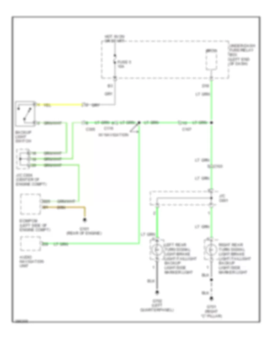
Backup Lamps Wiring Diagram, CVT for Honda CR-Z EX 2013
List of elements for Backup Lamps Wiring Diagram, CVT for Honda CR-Z EX 2013:
- B17
- B25
- C103
- C305
- D18
- Ecm/pcm (left side of engine compt)
- Fuse 5 10a
- G101 (rear of engine)
- G701 (right "c" pillar)
- G702 (left quarterpanel)
- Hot in on or start
- J/c c001
- J/c c004 (center of engine compt)
- J/c c005 (center of engine compt)
- Left rear turn signal light/brake light/taillight backup light/side marker light
- Micu
- Pnk
- Right rear turn signal light/brake light/taillight backup light/side marker light
- Transmission range switch (on transmission housing) fwd
- Under-dash fuse/relay box (left end of dash)
Backup Lamps Wiring Diagram, M/T for Honda CR-Z EX 2013
List of elements for Backup Lamps Wiring Diagram, M/T for Honda CR-Z EX 2013:
- Audio navigation unit
- B25
- Backup light switch
- C103
- C107
- C116
- C305
- D18
- Ecm/pcm (left side of engine compt)
- Fuse 5 10a
- G101 (rear of engine)
- G701 (right "c" pillar)
- G702 (left quarterpanel)
- Hot in on or start
- J/c c001
- J/c c004 (center of engine compt)
- Left rear turn signal light/brake light/taillight backup light/side marker light
- Micu
- Right rear turn signal light/brake light/taillight backup light/side marker light
- Under-dash fuse/relay box (left end of dash)
- W/ navigation
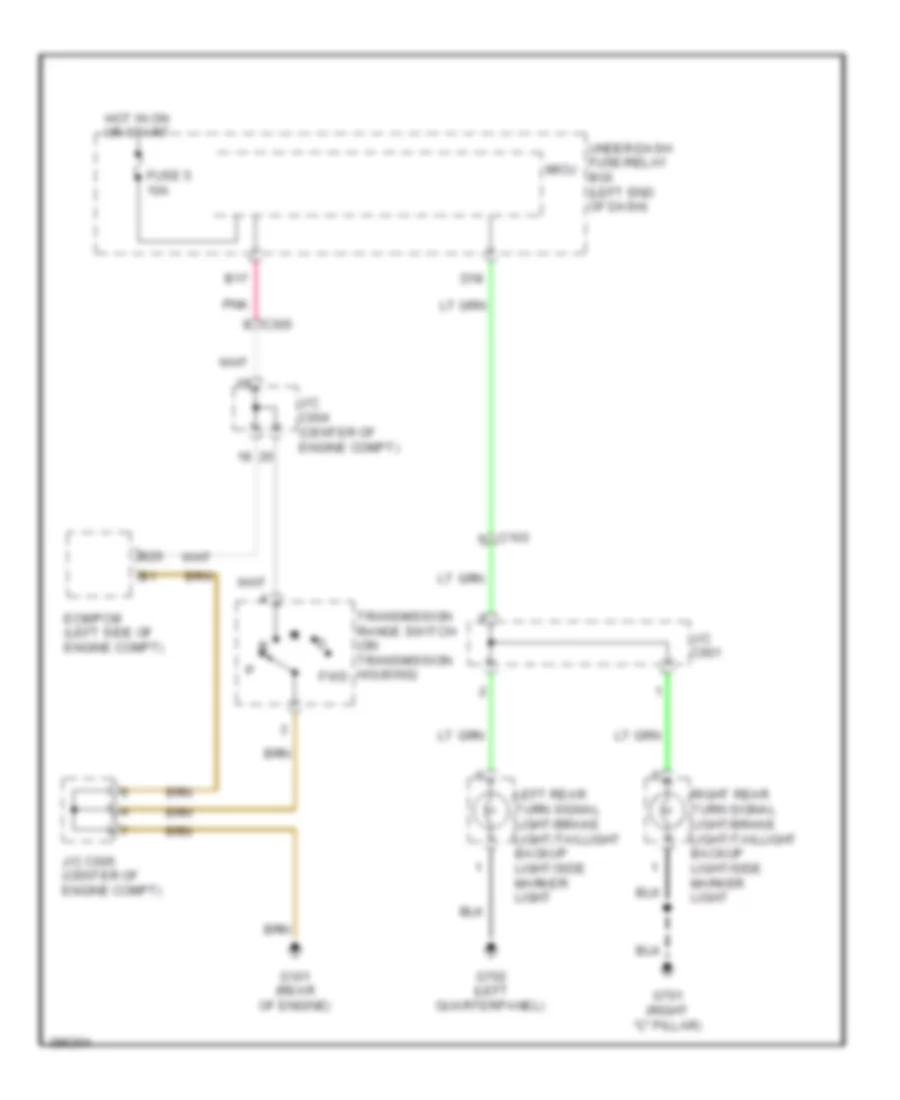
Exterior Lamps Wiring Diagram (1 of 2) for Honda CR-Z EX 2013
List of elements for Exterior Lamps Wiring Diagram (1 of 2) for Honda CR-Z EX 2013:
- A13
- A22
- A29
- B26
- B27
- B28
- B30
- Backup lamps circuit
- Brake pedal position switch (top of brake pedal assembly)
- C102
- C103
- C104
- D30
- D31
- D40
- D41
- Ecm/pcm (left side of engine compt)
- F12
- Fuse 1 15a
- Fuse 22 7.5a
- Fuse 23 10a
- Fuse 24 10a
- Fuse 29 10a
- G701 (right "c" pillar)
- G702 (left quarterpanel)
- G801 (top of left "c" pillar)
- Hazard warning switch
- High mount brake light
- Hot at all times
- Hot in on or start
- Interior lights system
- J/c c001
- Left license plate light
- Left rear turn signal light/brake light/ taillight/backup light/side marker light
- Micu
- Off
- Pnk
- Q32
- Red
- Right license plate light
- Right rear turn signal light/brake light/ taillight/backup light/side marker light
- Under-dash fuse/relay box (left end of dash)
- Y12
Exterior Lamps Wiring Diagram (2 of 2) for Honda CR-Z EX 2013
List of elements for Exterior Lamps Wiring Diagram (2 of 2) for Honda CR-Z EX 2013:
- (left end of dash) g501
- Auto
- B-can transceiver
- C117
- Combination light switch
- Computer data lines system
- G201 (right front of engine compt)
- G401 (left front of engine compt)
- G501 (left end of dash)
- G502 (center of dash)
- Gauge control module
- Head
- Headlight switch
- Left front turn signal/side marker light
- Left power mirror (in left rearview mirror)
- Left turn signal ind
- Micu
- Off
- Park
- Pnk
- Q10
- Q11
- Q12
- Q13
- Q16
- Q19
- Red
- Right front turn signal/side marker light
- Right power mirror (in right rearview mirror)
- Signal ind right turn
- Turn signal switch
- Under-dash fuse/relay box (left end of dash)
GROUND DISTRIBUTION
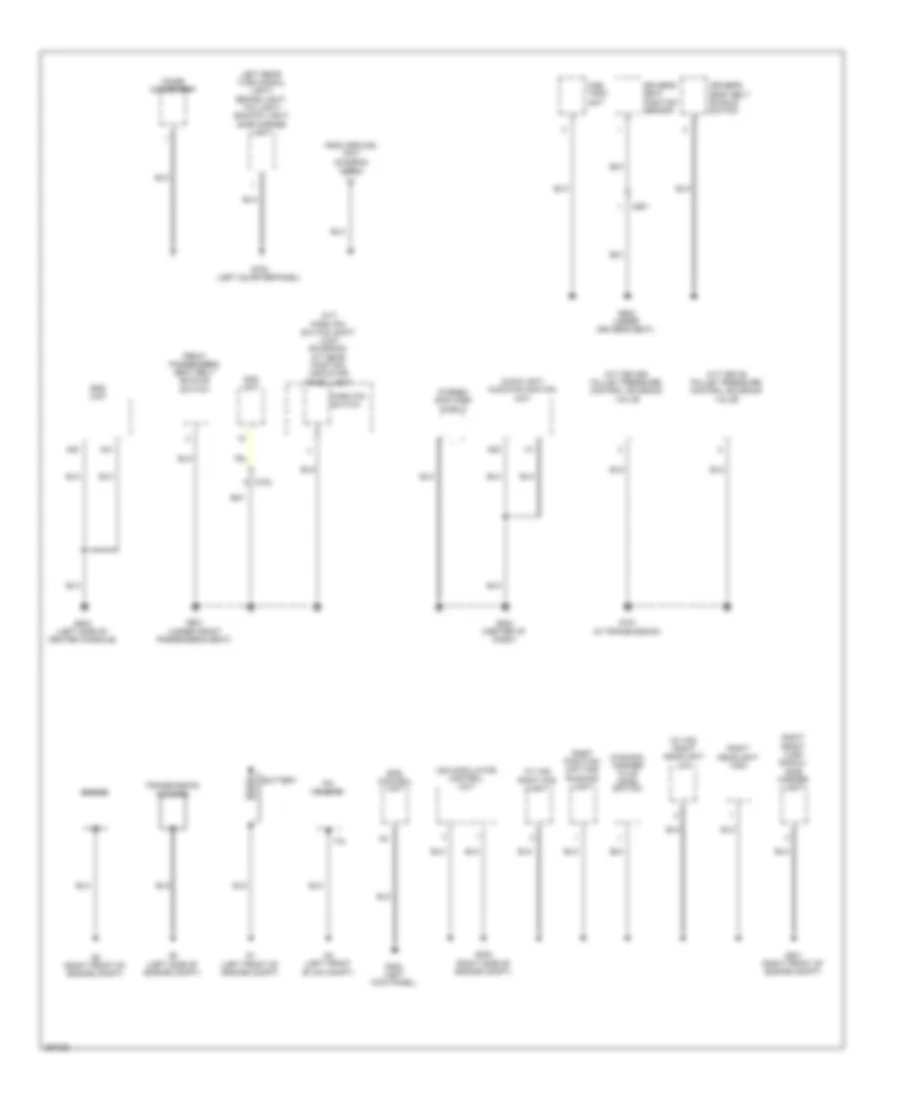
Ground Distribution Wiring Diagram (1 of 4) for Honda CR-Z EX 2013
List of elements for Ground Distribution Wiring Diagram (1 of 4) for Honda CR-Z EX 2013:
- (cvt) ignition key switch
- (left end of dash) under-dash fuse/relay box
- (m/t) clutch pedal position switch a
- (m/t) clutch pedal position switch b
- (m/t) clutch pedal position switch c
- (w/ hid)
- (w/ hid) left headlight low
- A/c condenser fan motor
- A12
- Accessory power socket
- Brake fluid level switch
- C110
- C111
- C114
- C117
- C12
- C19
- Cable reel (in steering column)
- Climate control unit
- Cruise control combination switch
- Data link connector (dlc)
- Driver's door lock actuator/ knob switch
- Driver's door unlock relay
- Eld
- Fan control relay
- G401 (left front of engine compt)
- G403 (left side of dash)
- G501 (left end of dash)
- G502 (center of dash)
- Gauge control module
- Glove box light
- Hatch release actuator relay 1/ hatch release actuator relay 2
- Km/h, mph change switch
- Left fog light
- Left front turn signal/ side marker light
- Left headlight high
- Left position/ daytime running light
- Left power mirror
- Micu
- Multi- information switch
- Passenger's door lock actuator/ knob switch
- Power mirror switch
- Power transistor
- Power window master switch
- Right power mirror
- Security hood switch
- Stereo amplifier
- T10
- Tpms control unit
- Vsa off switch
- Windshield wiper motor
- Y16
- Yaw rate acceleration sensor
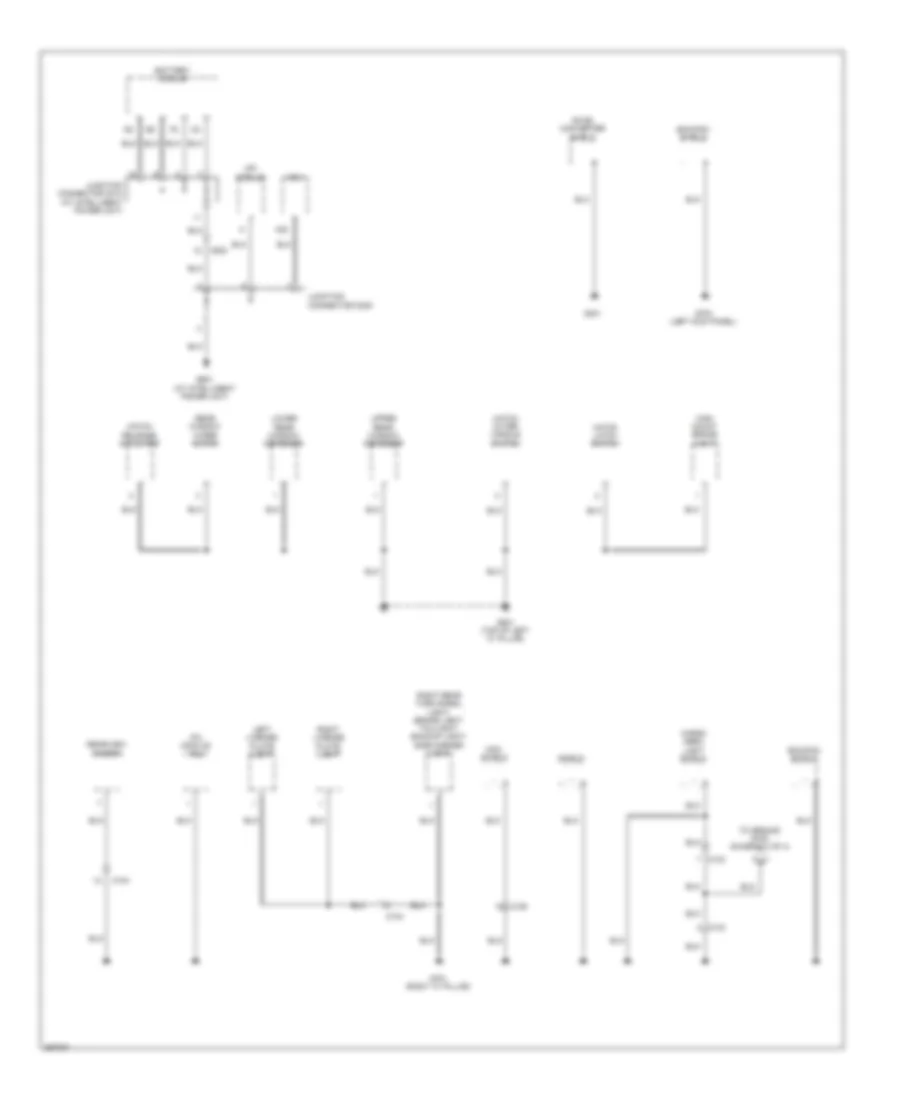
Ground Distribution Wiring Diagram (2 of 4) for Honda CR-Z EX 2013
List of elements for Ground Distribution Wiring Diagram (2 of 4) for Honda CR-Z EX 2013:
- (a/t) park pin switch/ shift lock solenoid/ a/t gear position indicator panel light
- (canada) washer fluid level switch
- (w/ hid) right fog light
- (w/ hid) right headlight low
- A20
- A21
- Audio unit/ audio-navigation unit
- Battery
- C601
- C702
- Cvt drive pulley pressure control solenoid valve
- Cvt driven pulley pressure control solenoid valve
- D20
- Driver's seat belt buckle switch
- Driver's seat position sensor
- Engine
- Eps control unit
- From ground g701 (diagram 3 of 4)
- Front passenger's seat belt buckle switch
- Fuel tank unit
- G1 (left front of engine compt)
- G151 (in transmission)
- G2 (right front of engine compt)
- G201 (right front of engine compt)
- G202 (right side of engine compt)
- G3 (left side of engine compt)
- G4 (left front of ima compt)
- G402 (left kick panel)
- G503 (center of dash)
- G504 (left side of center console)
- G601 (under front passenger's seat)
- G602 (under driver's seat)
- G702 (left quarterpanel)
- Ipu housing
- Left rear turn signal light/ brake light/ taillight/ backup light/ side marker light
- Noise condenser
- Ods unit
- Park pin switch
- Right front turn signal/ side marker light
- Right headlight high
- Right position/ daytime running light
- Srs unit
- Stereo amplifier shield
- T18
- Transmission housing
- Vsa modulator control unit
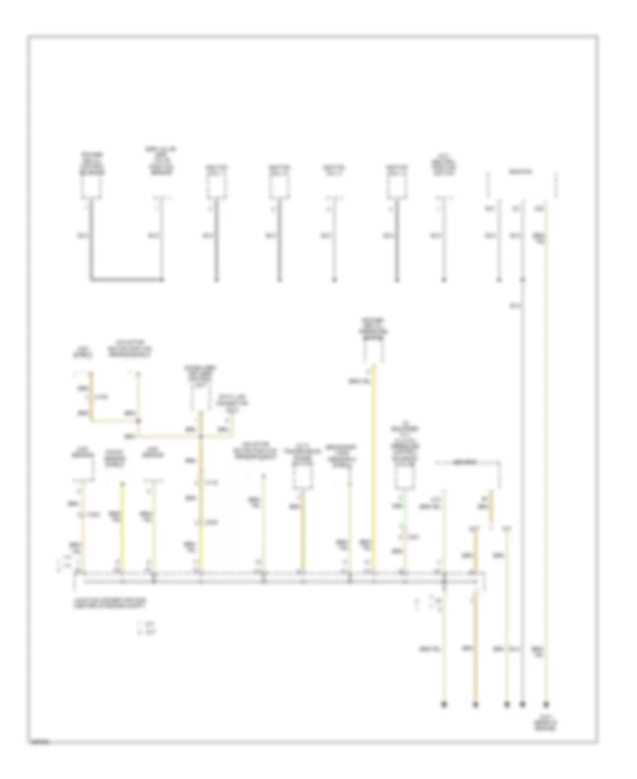
Ground Distribution Wiring Diagram (3 of 4) for Honda CR-Z EX 2013
List of elements for Ground Distribution Wiring Diagram (3 of 4) for Honda CR-Z EX 2013:
- A32
- Battery module
- C103
- C104
- C106
- C502
- Cargo area light shield
- Dc-dc converter shield
- Ecm/pcm shield
- G301
- G701 (right "c" pillar)
- G703 (left kick panel)
- G801 (top of left "c" pillar)
- G901 (at intelligent power unit)
- Hatch latch switch
- Hatch outer handle switch
- Hatch release actuator
- High mount brake light
- Ipu module fan
- Junction connector c008
- Junction connector c010 (at intelligent power unit)
- Left license plate light
- Lower rear window defogger
- Mcm
- Mcm shield
- Mpi module
- Rear window wiper motor
- Rearview camera
- Right license plate light
- Right rear turn signal light/ brake light/ taillight/ backup light/ side marker light
- Shield
- To ground g702 (diagram 2 of 4)
- Upper rear window defogger
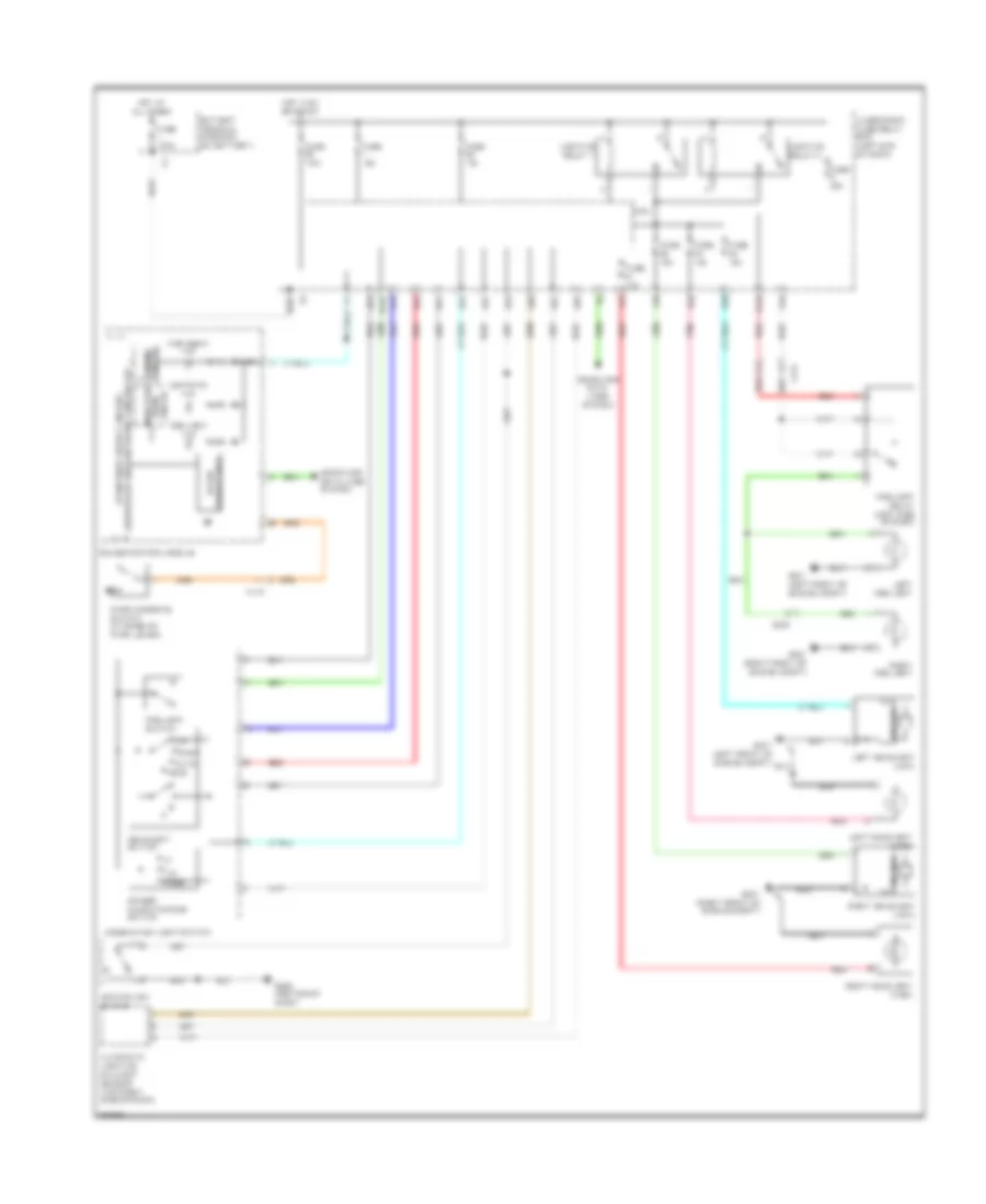
Ground Distribution Wiring Diagram (4 of 4) for Honda CR-Z EX 2013
List of elements for Ground Distribution Wiring Diagram (4 of 4) for Honda CR-Z EX 2013:
- (cvt) transmission range switch
- (if equipped) cvt clutch pressure control solenoid valve
- (m/t) neutral position switch
- B10
- C105
- C116
- C15
- C20
- C301
- C304
- C305
- Ckp sensor
- Cmp sensor
- Connector (dlc)
- Cvt
- Data link
- Ecm/pcm
- Egr valve/ egr valve position sensor
- G101 (rear of engine)
- Ignition coil 1
- Ignition coil 2
- Ignition coil 3
- Ignition coil 4
- Ima motor
- Immobilizer- keyless control unit
- Junction connector c005 (center of engine compt)
- Knock
- M/t
- Mcm shield
- Rocker arm oil control solenoid
- Rocker arm oil pressure switch
- Rotor position sensor shield
- Secondary ho2s (sensor 2) shield
- Sensor shield
HEADLIGHTS
Headlights Wiring Diagram, with HID Headlamps for Honda CR-Z EX 2013
List of elements for Headlights Wiring Diagram, with HID Headlamps for Honda CR-Z EX 2013:
- A27
- A30
- Aa24
- Aa25
- Aa4
- Auto
- Automatic lighting/ sunlight sensor (top right side of dash)
- B-can transceiver
- B20
- B29
- Battery terminal fuse box (on battery)
- C116
- C118
- C302
- Combination light switch
- Computer data lines system
- Dimmer/ flash-to-pass switch
- Dimming circuit
- Fog light ind
- Fog light relay (left side of dash)
- Fog light switch
- Fuse 100a
- Fuse 10a
- Fuse 15a
- Fuse 20a
- Fuse 7.5a
- G201 (right front of engine compt)
- G401 (left front of engine compt)
- G502 (center of dash)
- Gauge control module
- Head
- Headlight switch
- Hid unit
- High beam ind
- Hot at all times
- Hot in on or start
- Ignition key switch
- Indicator drive circuit
- Left fog light
- Left headlight (high)
- Left headlight (low)
- Lighting relay 1
- Lighting relay 2
- Lights on ind
- Micu
- Off
- Park
- Parking brake switch (at base of park lever)
- Pass
- Pnk
- Q10
- Q11
- Q13
- Q14
- Q15
- Q18
- Q19
- Q20
- Q21
- Q22
- Red
- Right fog light
- Right headlight (high)
- Right headlight (low)
- Under-dash fuse/relay box (left end of dash)
Headlights Wiring Diagram, without HID Headlamps for Honda CR-Z EX 2013
List of elements for Headlights Wiring Diagram, without HID Headlamps for Honda CR-Z EX 2013:
- A27
- B-can transceiver
- B29
- Battery terminal fuse box (on battery)
- C118
- Combination light switch
- Computer data lines system
- Dimmer/ flash-to-pass switch
- Dimming circuit
- Fuse 100a
- Fuse 10a
- Fuse 15a
- Fuse 7.5a
- G201 (right front of engine compt)
- G401 (left front of engine compt)
- G502 (center of dash)
- Gauge control module
- Head
- Headlight switch
- High beam ind
- Hot at all times
- Hot in on or start
- Ignition key switch
- Indicator drive circuit
- Left headlight (high)
- Lights on ind
- Micu
- Off
- Park
- Parking brake switch (at base of park lever)
- Passing
- Pnk
- Q10
- Q11
- Q13
- Q14
- Q15
- Q18
- Q19
- Red
- Right headlight (high)
- Under-dash fuse/relay box (left end of dash)
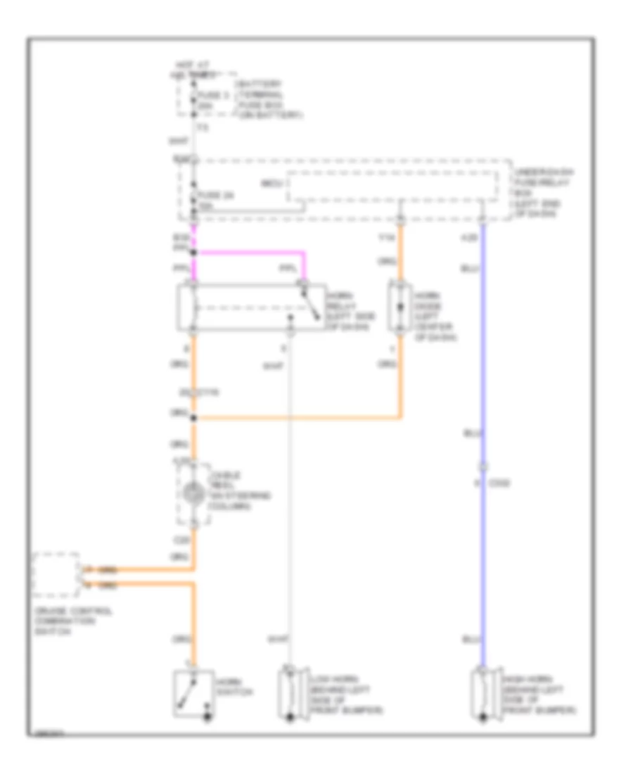
HORN
Horn Wiring Diagram for Honda CR-Z EX 2013
List of elements for Horn Wiring Diagram for Honda CR-Z EX 2013:
- A10
- A20
- B32
- Battery terminal fuse box (on battery)
- C116
- C20
- C302
- Cable reel (in steering column)
- Cruise control combination switch
- Fuse 24 10a
- Fuse 3 20a
- High horn (behind left side of front bumper)
- Horn diode (left center of dash)
- Horn relay (left side of dash)
- Horn switch
- Hot at all times
- Low horn (behind left side of front bumper)
- Micu
- Under-dash fuse/relay box (left end of dash)
- Y14
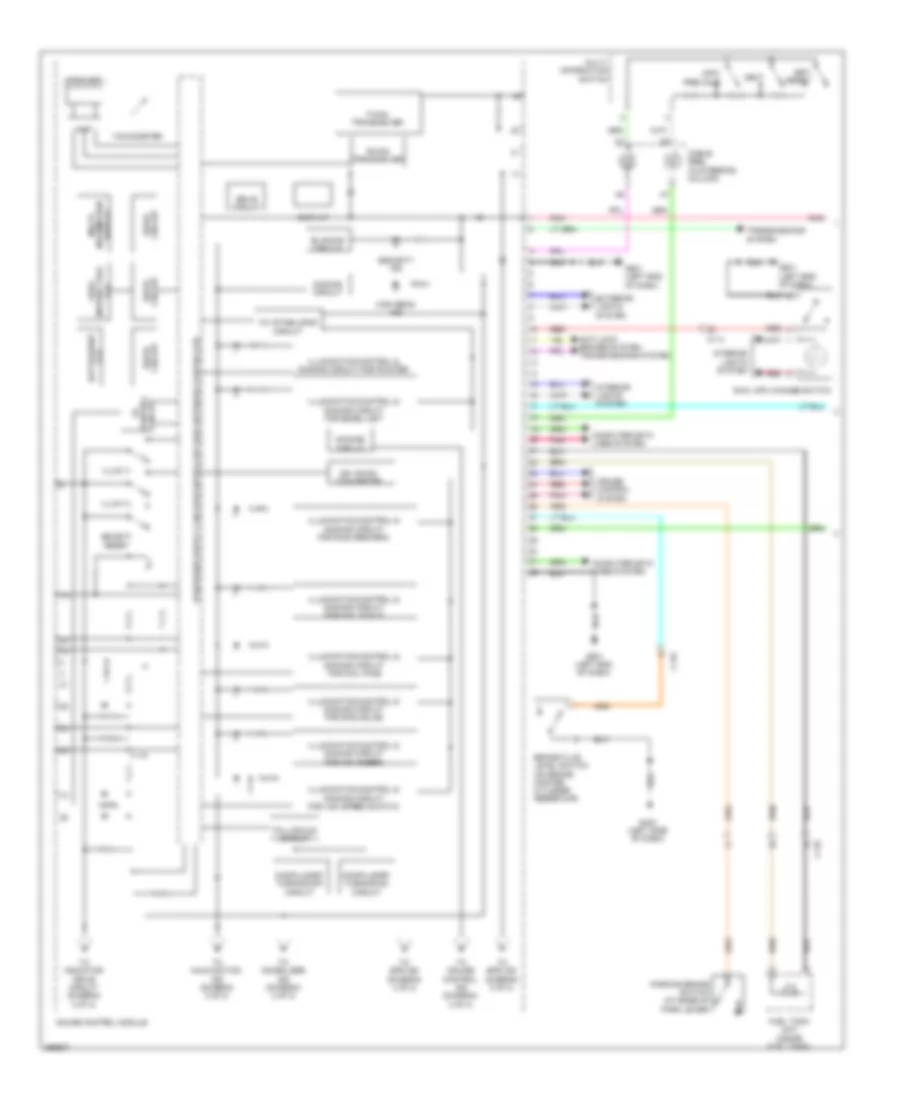
INSTRUMENT CLUSTER
Instrument Cluster Wiring Diagram (1 of 2) for Honda CR-Z EX 2013
List of elements for Instrument Cluster Wiring Diagram (1 of 2) for Honda CR-Z EX 2013:
- 10v stabilizing circuit
- 26v dc/dc converter
- Amp
- Anti-lock brakes system transmissions system
- B-can transceiver
- Blinking circuit
- Brake fluid level switch (on brake master cylinder reservoir)
- C114
- C116
- C118
- Cable reel (in steering column)
- Circuit drive
- Compulsory turning-off circuit
- Compulsory turning-on circuit
- Computer data lines system
- Control circuit
- Cruise control system
- Dimming circuit
- Display
- Drive circuit
- Exterior lights system
- F-can transceiver
- Fall-scale circuit
- Fuel tank unit (inside fuel tank)
- Fuel/
- G403 (left side of dash)
- G501 (left end of dash)
- Gauge control module
- High beam ind
- Illum (+)
- Illum (-)
- Illumination control & dimming circuit for dial face
- Illumination control & dimming circuit for dial scale
- Illumination control & dimming circuit for edge light
- Illumination control & dimming circuit for lcd (speed s-matic)
- Illumination control & dimming circuit for mid (amber)
- Illumination control & dimming circuit for pointer
- Information display
- Instant fuel lcd
- Interior lights system
- Km/h, mph change switch
- Lcd batt/assist
- Multi-
- Multi- information switch
- Next
- Parking brake switch (at base of park lever)
- Pnk
- Red
- Security ind
- Select/ reset
- Set/ reset
- Speaker
- Tachometer
- To cruise control ind (diagram 2 of 2)
- To eps ind (diagram 2 of 2)
- To immobilizer ind (diagram 2 of 2)
- To indicator drive circuit (diagram 2 of 2)
- To malfunction ind (diagram 2 of 2)
- Transmissions system
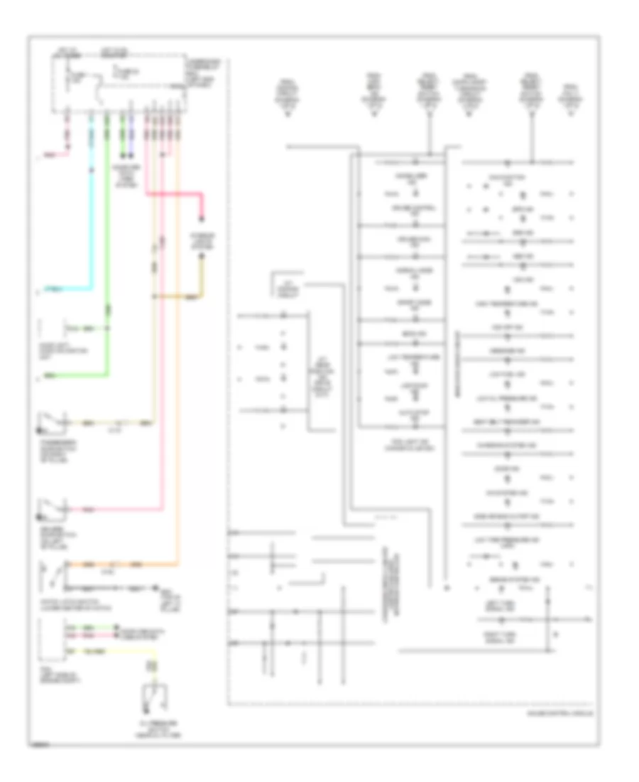
Instrument Cluster Wiring Diagram (2 of 2) for Honda CR-Z EX 2013
List of elements for Instrument Cluster Wiring Diagram (2 of 2) for Honda CR-Z EX 2013:
- A/t dimming circuit
- A/t gear position ind drive circuit (cvt)
- A12
- Abs ind
- Audio unit/ audio navigation unit
- Auto stop ind
- Brake system ind
- C102
- C107
- C118
- Charging system ind
- Computer data lines system
- Cruise control ind
- Cruise main ind
- D17
- D26
- D27
- D45
- Door ind
- Driver's door switch (on left "b" pillar)
- Econ ind
- Eps ind
- Fog light ind (canada & usa ex)
- From compulsory turning-on circuit (diagram 1 of 2)
- From dimming circuit (diagram 1 of 2)
- From high beam ind (diagram 1 of 2)
- From pin 17 (diagram 1 of 2)
- From select/ reset switch (diagram 1 of 2)
- Fuse 1 15a
- Fuse 22 7.5a
- G801 (top of left "c" pillar)
- Gauge control module
- Hatch latch switch (lower center of hatch)
- High temperature ind
- Hot at all times
- Hot in on or start
- Ima system ind
- Immobilizer ind
- Indicator drive circuit
- Interior lights system
- Left turn signal ind
- Lights-on ind
- Low fuel ind
- Low oil pressure ind
- Low temperature ind
- Low tire pressure ind (usa)
- Malfunction ind
- Message ind
- Network controller controller area
- Normal mode ind
- Oil pressure switch (near oil filter)
- Passenger's door switch (on right "b" pillar)
- Pcm (left side of engine compt)
- Pnk
- Q29
- Right turn signal ind
- Seat belt reminder ind
- Side air bag cutoff ind
- Sport mode ind
- Srs ind
- Under-dash fuse/relay box (left end of dash) micu
- Vsa ind
- Vsa off ind
INTERIOR LIGHTS
Courtesy Lamps Wiring Diagram (1 of 2) for Honda CR-Z EX 2013
List of elements for Courtesy Lamps Wiring Diagram (1 of 2) for Honda CR-Z EX 2013:
- C102
- C107
- C112
- C118
- D17
- D26
- D27
- D29
- D42
- D45
- Driver's courtesy light diode
- Driver's vanity mirror light
- Front passenger's courtesy light diode
- Fuse 1 15a
- Fuse 7.5a
- G501 (left end of dash)
- G502 (center of dash)
- Hot at all times
- Hot in on or start
- Ignition key switch
- Immobilizer keyless control unit (in steering column)
- Individual map light
- Interior light switch (ambient light)/microphone
- Left rear tray light
- Micu
- Passenger's vanity mirror light
- Pnk
- Q18
- Red
- Right rear tray light
- Under-dash fuse/relay box (left end of dash)
- Y16
Courtesy Lamps Wiring Diagram (2 of 2) for Honda CR-Z EX 2013
List of elements for Courtesy Lamps Wiring Diagram (2 of 2) for Honda CR-Z EX 2013:
- (right "c" pillar) g701
- A14
- A29
- C102
- C103
- C106
- C107
- C111
- C117
- C118
- Cargo area light
- Driver's door courtesy light
- Driver's door switch (on left "b" pillar)
- Driver's footwell light
- G502 (center of dash)
- G801 (top of left "c" pillar)
- Gauge control module
- Glove box light
- Hatch latch switch (lower center of hatch)
- Illumination circuit
- J/c c001
- Mcm (in ima compt)
- Passenger's door courtesy light
- Passenger's door switch (on right "b" pillar)
- Passenger's footwell light
- Pnk
- Red
Entry Light Timer Wiring Diagram for Honda CR-Z EX 2013
List of elements for Entry Light Timer Wiring Diagram for Honda CR-Z EX 2013:
- C102
- C103
- C107
- C112
- C118
- Cargo area light
- Courtesy lamps circuit
- D17
- D26
- D27
- D29
- D42
- Door lock knob
- Driver's door lock actuator/knob switch
- Driver's door switch (on left "b" pillar)
- F10
- Fuse 1 15a
- G501 (left end of dash)
- G502 (center of dash)
- G701 (right "c" pillar)
- G801 (top of left "c" pillar)
- Hatch latch switch (lower center of hatch)
- Hot at all times
- Ignition key switch
- Immobilizer keyless control unit (in steering column)
- Individual map light
- Left rear tray light
- Lock
- Micu
- Passenger's door switch (on right "b" pillar)
- Pnk
- Q18
- Right rear tray light
- Un lock
- Under-dash fuse/relay box (left end of dash)
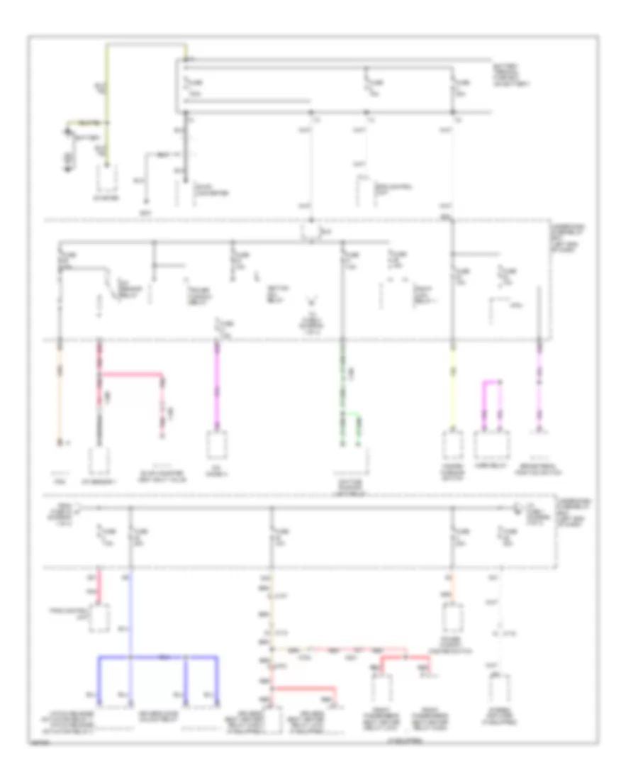
Instrument Illumination Wiring Diagram (1 of 2) for Honda CR-Z EX 2013
List of elements for Instrument Illumination Wiring Diagram (1 of 2) for Honda CR-Z EX 2013:
- 3-mode switch
- Auto
- C112
- C114
- Climate control unit
- Combination light switch
- Console box light
- Driver's footwell light
- Front passenger's air bag cutoff indicator
- Fuse 29 10a
- G501 (left end of dash)
- G502 (center of dash)
- Glove box light
- Head
- Hot at all times
- Interior light switch (ambient light)/ microphone
- Km/h, mph change switch
- Micu
- Off
- Park
- Pass
- Passenger's footwell light
- Pnk
- Q10
- Q11
- Q13
- Q14
- Q15
- Q19
- Red
- Under-dash fuse/relay box (left end of dash)
- Y16
Instrument Illumination Wiring Diagram (2 of 2) for Honda CR-Z EX 2013
List of elements for Instrument Illumination Wiring Diagram (2 of 2) for Honda CR-Z EX 2013:
- 10v stabilize circuit
- 26v dc/dc conv- erter
- A11
- Audio remote switch
- Audio unit (w/o navigation) audio navigation unit (w/ navigation)
- C11
- C114
- C118
- C201
- Cable reel (in steering column)
- Computer data lines system
- Cruise control combination switch
- Dimming circuit
- Driver's seat heater switch (canada)
- F-can h
- F-can l
- F-can transceiver
- Front passenger seat heater switch (canada)
- G501 (left end of dash)
- Gauge control module
- Hazard warning switch
- Hfl - navigation voice control switch
- Illumi- nation control & dimming circuit for dial face
- Illumi- nation control & dimming circuit for dial scale
- Illumi- nation control & dimming circuit for edge light
- Illumi- nation control & dimming circuit for lcd (speed s-matic)
- Illumi- nation control & dimming circuit for mid (amber)
- Illumi- nation control & dimming circuit for pointer
- Multi- information switch
- Paddle shifter + (upshift switch) (cvt)
- Paddle shifter - (downshift switch) (cvt)
- Park pin switch/ shift lock solenoid/ a/t gear position indicator panel light (cvt) (park pin switch: under center console) (shift lock solenoid: base of a/t shift lever)
- Pnk
- Power mirror switch
- Red
- Vsa off switch
NAVIGATION
Navigation Wiring Diagram (1 of 3) for Honda CR-Z EX 2013
List of elements for Navigation Wiring Diagram (1 of 3) for Honda CR-Z EX 2013:
- (on transmission housing) (cvt) transmission range switch
- (right end of dash)
- A14
- Audio remote switch
- Audio unit/ audio-navigation unit
- Auxiliary jack assembly
- B10
- B11
- B12
- B13
- B14
- B15
- B16
- B17
- C14
- C305
- Cable reel (in steering column)
- Ch+
- Ch-
- Fuse 15a
- Fuse 7.5a
- G101 (rear of engine)
- Handsfreelink control unit
- Hot at all times
- Hot in on or acc
- Interior lights system
- J/c c004 (center of engine compt)
- J/c c005 (center of engine compt)
- Micu
- Mode
- Pnk
- Q29
- Q34
- Rearview camera circuit
- Red
- Under-dash fuse/relay box (left end of dash)
- Vol down
- Vol up
Navigation Wiring Diagram (2 of 3) for Honda CR-Z EX 2013
List of elements for Navigation Wiring Diagram (2 of 3) for Honda CR-Z EX 2013:
- A10
- A11
- A12
- A13
- A14
- A15
- A16
- A17
- A18
- A19
- A20
- A21
- A22
- A23
- A24
- A26
- Audio unit/ audio-navigation unit
- Audio unit/audio-navigation unit
- B-can transceiver
- C112
- C116
- Climate control module
- Computer data lines system
- D10
- D11
- D12
- D13
- D14
- D15
- D16
- D17
- D18
- D19
- D20
- E10
- E11
- E12
- Exterior lights system
- G501 (left end of dash)
- G502 (center of dash)
- G503 (center of dash)
- Gauge control module
- Gps antenna
- Hfl back
- Hfl navigation voice control switch
- Hfl talk
- Interior light switch (ambient light/ microphone)
- Interior lights system
- Nca
- Pcm (left side of engine compt)
- Pnk
- Rearview camera circuit
- Red
- Usb port 5p connector
Navigation Wiring Diagram (3 of 3) for Honda CR-Z EX 2013
List of elements for Navigation Wiring Diagram (3 of 3) for Honda CR-Z EX 2013:
- 3p connector
- 5p connector
- A10
- A11
- A12
- A13
- A14
- A15
- A16
- A17
- A18
- A21
- Am/fm antenna
- B10
- B11
- B12
- B13
- B14
- B15
- B16
- B17
- B18
- B19
- B20
- B21
- B22
- B23
- B24
- C107
- C111
- C115
- C117
- C118
- C401
- Driver's door speaker
- Fm distributor
- Fuse 20a
- G502 (center of dash)
- Hot at all times
- Left rear speaker
- Left tweeter
- Passenger's door speaker
- Pnk
- Red
- Right rear speaker
- Right tweeter
- Stereo amplifier (middle of dash)
- Sub amplifier
- Subwoofer
- Under-dash fuse/relay box (left end of dash)
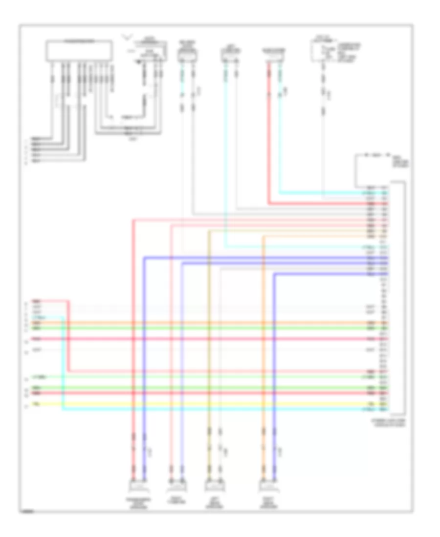
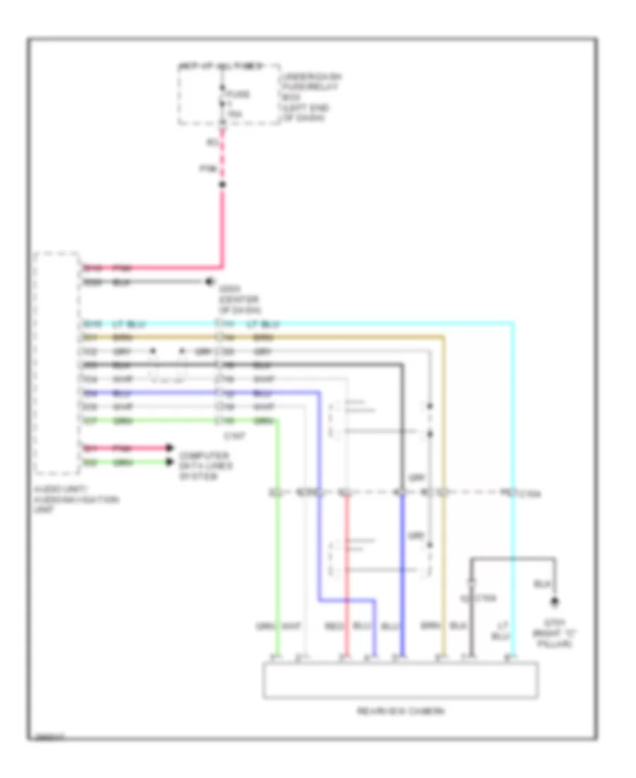
Rear Camera Wiring Diagram for Honda CR-Z EX 2013
List of elements for Rear Camera Wiring Diagram for Honda CR-Z EX 2013:
- Audio unit/ audio-navigation unit
- C104
- C107
- Computer data lines system
- D10
- D15
- D20
- Fuse 15a
- G503 (center of dash)
- G701 (right "c" pillar)
- Hot at all times
- Pnk
- Rearview camera
- Red
- Under-dash fuse/relay box (left end of dash)
POWER DISTRIBUTION
Power Distribution Wiring Diagram (1 of 4) for Honda CR-Z EX 2013
List of elements for Power Distribution Wiring Diagram (1 of 4) for Honda CR-Z EX 2013:
- (diagram 1 of 4)
- (if equipped)
- A/c diode a
- A/f sensor 1
- A/f sensor relay
- A21
- B10
- B25
- B30
- B32
- Battery
- Battery terminal fuse box (on battery)
- Brake pedal position switch
- C105
- C107
- C115
- C118
- C305
- C702
- C703
- C801
- D33
- D47
- Daytime running light relay
- Dc-dc converter
- Driver's door unlock relay
- Driver's seat heater relay (high) (if equipped)
- Driver's seat heater relay (low) (if equipped)
- Eld
- Eps control unit
- Evap canister vent shut valve
- From fuse 33 a
- Front passenger's seat heater relay (high)
- Front passenger's seat heater relay (low)
- Fuse 100a
- Fuse 10a
- Fuse 15a
- Fuse 20a
- Fuse 7.5a
- Fuse 70a
- G301
- Hatch release actuator relay 1/ hatch release actuator relay 2
- Hazard warning switch
- Horn relay
- Ignition coil relay
- Micu
- Pcm
- Pgm-fi main relay 1
- Pnk
- Power window master switch
- Power window relay
- Q31
- Red
- Starter
- Stereo amplifier (if equipped)
- To fuse 1 (diagram 4 of 4)
- To fuse 2 (diagram 1 of 4)
- Tpms control unit
- Under-dash fuse/relay box (left end of dash)
Power Distribution Wiring Diagram (2 of 4) for Honda CR-Z EX 2013
List of elements for Power Distribution Wiring Diagram (2 of 4) for Honda CR-Z EX 2013:
- 3 mode switch
- 50a
- A/c compressor clutch relay
- A/c condenser fan motor relay
- A/c diode b
- A24
- Ab1
- Ab2
- Ac2
- Accessory power socket
- Audio unit/ audio- navigation unit
- B12
- B24
- B33
- B34
- Blower motor relay
- Brake pedal position (bpp) switch
- C106
- C113
- C114
- C118
- C201
- C305
- Climate control unit
- Cvt
- Dc-dc converter
- Driver's seat heater switch (if equipped)
- Evap canister purge valve
- From fuse 22 (diagram 3 of 4)
- From fuse 53 f (diagram 4 of 4)
- From fuse 57 (diagram 4 of 4)
- From fuse 59 (diagram 2 of 4)
- From ignition switch (diagram 3 of 4)
- Front passenger's seat heater switch (if equipped)
- Fuse
- Fuse 10a
- Fuse 20a
- Fuse 30a
- Fuse 40a
- Fuse 7.5a
- G502 (center of dash)
- Idle stop switch
- Ignition key switch
- J/c c004 (center of engine compt)
- M/t
- Maf/iat sensor
- Micu
- Pnk
- Power mirror switch
- Q34
- Radiator fan relay
- Rear window defogger relay
- Recirculation control motor
- Red
- Reverse lockout solenoid (m/t)
- Secondary ho2s 2 (sensor 2)
- To ignition switch (diagram 3 of 4)
- To rear window defogger relay (diagram 2 of 4)
- Under-dash fuse/relay box (left end of dash)
- Y11
Power Distribution Wiring Diagram (3 of 4) for Honda CR-Z EX 2013
List of elements for Power Distribution Wiring Diagram (3 of 4) for Honda CR-Z EX 2013:
- A11
- A14
- A22
- A23
- A29
- Acc
- Acc on
- Ad1
- Ae2
- B18
- B19
- Backup light switch (m/t)
- C102
- C106
- C118
- C305
- C702
- Cvt
- D23
- Eld
- Eps control unit
- From fuse 11 j (diagram 3 of 4)
- From under-dash fuse/relay box (diagram 2 of 4)
- Front passenger's air bag cut-off indicator
- Fuse 10a
- Fuse 15a
- Fuse 30a
- Fuse 7.5a
- Gauge control module
- Ignition switch
- Immobilizer keyless control unit
- J/c c002 (center of dash)
- Lock
- M/t
- Mcm
- Micu
- Ods unit
- On acc
- Park pin switch/shift lock solenoid/ a/t gear position indicator panel light (cvt)
- Pcm
- Pgm-fi main relay 2
- Rear window wiper motor
- Red
- Srs unit
- Start
- Starter cut relay
- To fuse 12 (diagram 2 0f 4)
- To fuse 16 (diagram 3 of 4)
- To under-dash fuse/relay box (diagram 2 of 4)
- Tpms control unit
- Under-dash fuse/relay box (left end of dash)
- Vsa modulator control unit
- Yaw rate acceleration sensor
Power Distribution Wiring Diagram (4 of 4) for Honda CR-Z EX 2013
List of elements for Power Distribution Wiring Diagram (4 of 4) for Honda CR-Z EX 2013:
- A14
- A32
- A35
- Aa4
- Audio unit/ audio navigation unit
- C102
- C103
- C106
- C116
- C118
- C901
- Cargo area light
- D10
- D32
- D42
- D48
- Dlc
- Driver's courtesy light diode
- Driver's vanity mirror light
- Etcs control relay
- Fog light relay
- From fuse 25 b (diagram 1 of 4)
- From fuse 27 k (diagram 4 of 4)
- Front passenger's courtesy light diode
- Fuse 10a
- Fuse 15a
- Fuse 20a
- Fuse 30a
- Fuse 7.5a
- Gauge control module
- Immobilizer keyless control unit
- Individual map light
- J/c c001
- Left rear tray light
- Lighting relay 1 (w/ hid)
- Lighting relay 2 (w/ hid)
- Mcm
- Mcm relay 1
- Mcm relay 2
- Micu
- Passenger's vanity mirror light
- Pnk
- Right rear tray light
- To blower motor relay (diagram 2 of 4)
- To fuse 30 (diagram 2 of 4)
- To lighting relay 1 (diagram 4 of 4)
- Under-dash fuse/relay box (left end of dash)
- Vsa modulator control unit
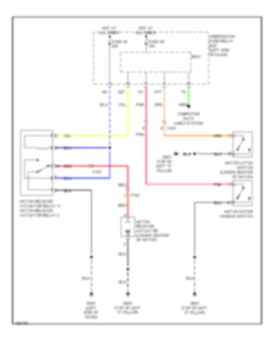
POWER DOOR LOCKS
Power Door Locks Wiring Diagram (1 of 2) for Honda CR-Z EX 2013
List of elements for Power Door Locks Wiring Diagram (1 of 2) for Honda CR-Z EX 2013:
- A22
- A28
- Aa6
- B28
- B30
- C111
- C117
- Computer data
- D17
- D26
- D27
- D40
- Door lock knob
- Driver's door lock actuator/knob switch
- Driver's door unlock relay (left side of dash)
- Exterior lights system
- F10
- F11
- Fuse 10a
- Fuse 15a
- Fuse 20a
- Fuse 7.5a
- G501 (left end of dash)
- G502 (center of dash)
- Horns system
- Hot at all times
- Hot in on or start
- Key
- Lines system
- Lock
- Micu
- N10
- Passenger's door lock actuator/knob switch
- Pnk
- Q18
- Q28
- Red
- Trunk, tailgate, fuel doors system
- Under-dash fuse/relay box (left end of dash)
- Unlock
- Y14
Power Door Locks Wiring Diagram (2 of 2) for Honda CR-Z EX 2013
List of elements for Power Door Locks Wiring Diagram (2 of 2) for Honda CR-Z EX 2013:
- (rear of engine) g101
- Antenna
- B-can transceiver
- Blinking circuit
- C118
- C302
- Computer data lines system
- Driver's door switch (on left "b" pillar)
- G403 (left side of dash)
- G501 (left end of dash)
- G502 (center of dash)
- Gauge control module
- Ignition key switch
- Immobilizer- keyless control unit (in steering column)
- Lock
- Passenger's door switch (on right "b" pillar)
- Pnk
- Power window master switch
- Security hood switch (on engine compt hood latch assembly)
- Security indicator led
- Unlock
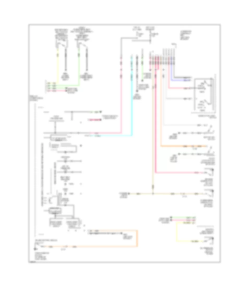
POWER MIRRORS
Power Mirrors Wiring Diagram for Honda CR-Z EX 2013
List of elements for Power Mirrors Wiring Diagram for Honda CR-Z EX 2013:
- (left end of dash)
- C111
- C114
- C117
- Defogger
- Defogger system
- Down/ left
- Down/ right
- Fuse 10 7.5a
- G501
- Hot in on
- Interior lights system
- Left
- Left power mirror (in left rearview mirror)
- Light
- Pnk
- Power mirror switch
- Red
- Right
- Right power mirror (in right rearview mirror)
- Under-dash fuse/relay box (left end of dash)
- Up/ left
- Up/ right
- Y11
POWER SEATS
Power Seats Wiring Diagram for Honda CR-Z EX 2013
List of elements for Power Seats Wiring Diagram for Honda CR-Z EX 2013:
- C118
- C201
- C702
- C703
- C801
- D33
- Driver's seat back heater
- Driver's seat heater
- Driver's seat heater relay (high)
- Driver's seat heater relay (low)
- Driver's seat heater switch
- Front passenger's seat heater
- Front passenger's seat heater relay (high)
- Front passenger's seat heater relay (low)
- Front passenger's seat heater switch
- Fuse 10 7.5a
- Fuse 29 10a
- Fuse 40 10a
- G601 (under front passenger's seat)
- G602 (under driver's seat)
- High
- Hot at all times
- Hot in on
- Interior lights system
- Low
- Micu
- Red
- Under-dash fuse/relay box (left end of dash)
- Y11
POWER WINDOWS
Power Windows Wiring Diagram for Honda CR-Z EX 2013
List of elements for Power Windows Wiring Diagram for Honda CR-Z EX 2013:
- Battery terminal fuse box (on battery)
- C111
- C117
- Control unit
- Down
- Down (auto)
- Driver's
- Driver's power window motor (in driver's door)
- F11
- Fuse 1 100a
- Fuse 1 15a
- Fuse 17 20a
- Fuse 3 20a
- Fuse 7.5a
- G501 (left end of dash)
- Hot at all times
- Hot in on or start
- Main switch
- Micu
- Off
- Passenger's
- Passenger's power window motor (in passenger's door)
- Passenger's power window switch
- Pnk
- Power window master switch
- Power window relay
- Pulsar
- Red
- Under- dash fuse/ relay box (left end of dash)
- Up (auto)
RADIO
Radio Wiring Diagram (1 of 3) for Honda CR-Z EX 2013
List of elements for Radio Wiring Diagram (1 of 3) for Honda CR-Z EX 2013:
- (on transmission housing) (cvt) transmission range switch
- (right end of dash)
- A14
- Audio remote switch
- Audio unit/ audio-navigation unit
- Auxiliary jack assembly
- B10
- B11
- B12
- B13
- B14
- B15
- B16
- B17
- C14
- C305
- Cable reel (in steering column)
- Ch+
- Ch-
- Fuse 15a
- Fuse 7.5a
- G101 (rear of engine)
- Handsfreelink control unit
- Hot at all times
- Hot in on or acc
- Interior lights system
- J/c c004 (center of engine compt)
- J/c c005 (center of engine compt)
- Micu
- Mode
- Pnk
- Q29
- Q34
- Rearview camera circuit
- Red
- Under-dash fuse/relay box (left end of dash)
- Vol down
- Vol up
Radio Wiring Diagram (2 of 3) for Honda CR-Z EX 2013
List of elements for Radio Wiring Diagram (2 of 3) for Honda CR-Z EX 2013:
- A10
- A11
- A12
- A13
- A14
- A15
- A16
- A17
- A18
- A19
- A20
- A21
- A22
- A23
- A24
- A26
- Audio unit/ audio-navigation unit
- Audio unit/audio-navigation unit
- B-can transceiver
- C112
- C116
- Climate control module
- Computer data lines system
- D10
- D11
- D12
- D13
- D14
- D15
- D16
- D17
- D18
- D19
- D20
- E10
- E11
- E12
- Exterior lights system
- G501 (left end of dash)
- G502 (center of dash)
- G503 (center of dash)
- Gauge control module
- Gps antenna
- Hfl back
- Hfl navigation voice control switch
- Hfl talk
- Interior light switch (ambient light/ microphone)
- Interior lights system
- Nca
- Pcm (left side of engine compt)
- Pnk
- Rearview camera circuit
- Red
- Usb port 5p connector
Radio Wiring Diagram (3 of 3) for Honda CR-Z EX 2013
List of elements for Radio Wiring Diagram (3 of 3) for Honda CR-Z EX 2013:
- 3p connector
- 5p connector
- A10
- A11
- A12
- A13
- A14
- A15
- A16
- A17
- A18
- A21
- Am/fm antenna
- B10
- B11
- B12
- B13
- B14
- B15
- B16
- B17
- B18
- B19
- B20
- B21
- B22
- B23
- B24
- C107
- C111
- C115
- C117
- C118
- C401
- Driver's door speaker
- Fm distributor
- Fuse 20a
- G502 (center of dash)
- Hot at all times
- Left rear speaker
- Left tweeter
- Passenger's door speaker
- Pnk
- Red
- Right rear speaker
- Right tweeter
- Stereo amplifier (middle of dash)
- Sub amplifier
- Subwoofer
- Under-dash fuse/relay box (left end of dash)
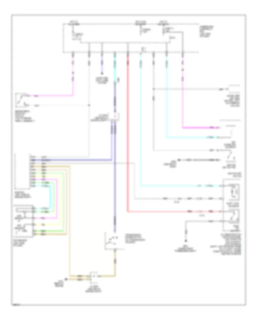
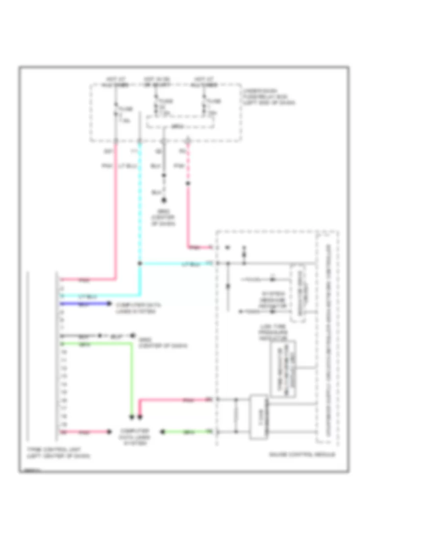
SHIFT INTERLOCK
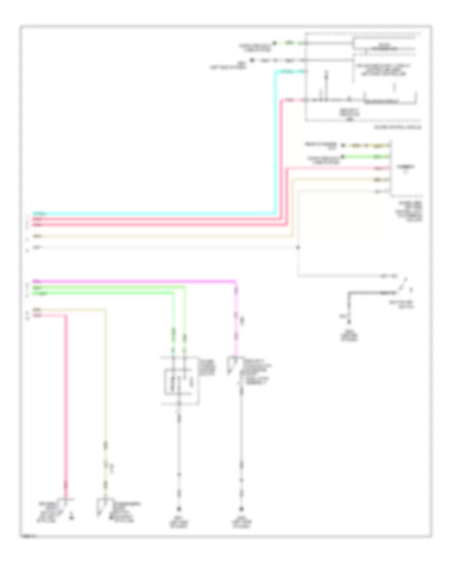
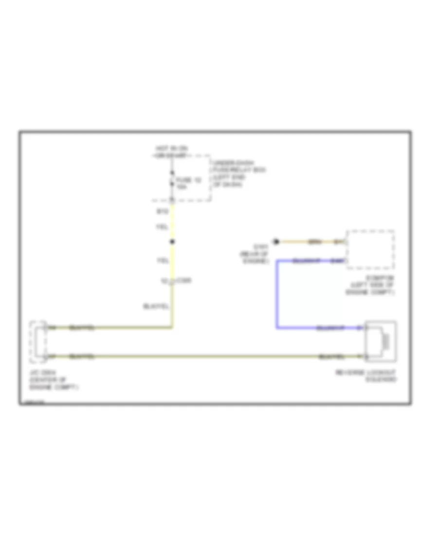
Reverse Lockout Wiring Diagram for Honda CR-Z EX 2013
List of elements for Reverse Lockout Wiring Diagram for Honda CR-Z EX 2013:
- B12
- B49
- C305
- Ecm/pcm (left side of engine compt)
- Fuse 12 10a
- G101 (rear of engine)
- Hot in on or start
- J/c c004 (center of engine compt)
- Reverse lockout solenoid
- Under-dash fuse/relay box (left end of dash)
Shift Interlock Wiring Diagram for Honda CR-Z EX 2013
List of elements for Shift Interlock Wiring Diagram for Honda CR-Z EX 2013:
- A/t gear position indicator panel light/park pin switch/shift lock solenoid (shift lock solenoid: base of a/t shift lever) (park pin switch: under center console)
- A13
- A21
- A28
- A29
- A35
- A36
- A45
- A46
- App sensor (left side of dash)
- App sensor a
- App sensor b
- B14
- B24
- B26
- B30
- Brake pedal position switch (top of brake pedal assembly)
- C116
- C118
- C305
- Computer data lines system
- Ecm/pcm (left side of engine compt)
- Eld
- Fuse 14 7.5a
- Fuse 22 7.5a
- Fuse 24 10a
- G101 (rear of engine)
- G502 (center of dash)
- G601 (under front passenger's seat)
- Hot at all times
- Hot in acc or on
- Hot in on or start
- Ignition key switch
- Immobilizer keyless control unit (in steering column)
- J/c c005 (center of engine compt)
- Key interlock solenoid
- Micu
- Park pin switch
- Q18
- Q34
- Red
- Shift lock solenoid
- Transmission range switch (on transmission housing)
- Under-dash fuse/relay box (left end of dash)
- Y15
STARTING/CHARGING
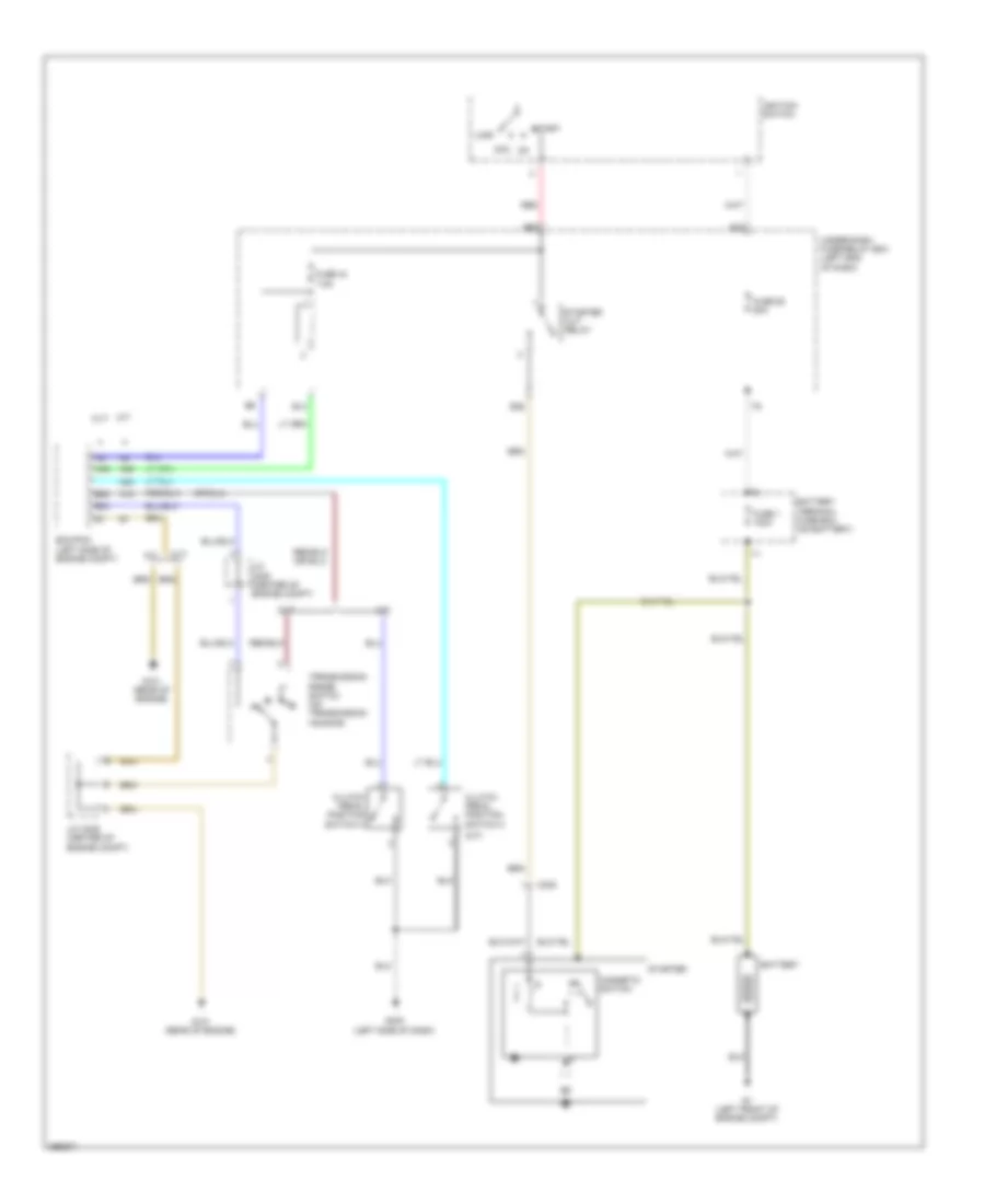
Starting Wiring Diagram for Honda CR-Z EX 2013
List of elements for Starting Wiring Diagram for Honda CR-Z EX 2013:
- (m/t)
- 7.5a
- A18
- A23
- A49
- Ac2
- Acc
- Ae2
- B13
- B23
- B24
- B36
- Battery
- Battery terminal fuse box (on battery)
- C305
- Clutch pedal position switch a
- Clutch pedal position switch c
- Cvt
- Ecm/pcm (left side of engine compt)
- Fuse 1 100a
- Fuse 44
- Fuse 60 50a
- G1 (left front of engine compt)
- G101 (rear of engine)
- G403 (left side of dash)
- Ignition switch
- J/c c005 (center of engine compt)
- Lock
- M/t
- Magnetic switch
- N d
- Red
- Start
- Starter
- Starter cut relay
- Transmission range switch (on transmission housing)
- Under-dash fuse/relay box (left end of dash)
SUPPLEMENTAL RESTRAINTS
Supplemental Restraints Wiring Diagram (1 of 3) for Honda CR-Z EX 2013
List of elements for Supplemental Restraints Wiring Diagram (1 of 3) for Honda CR-Z EX 2013:
- (left side of center console) g504
- A10
- A11
- A12
- A13
- A14
- A15
- A16
- A17
- A18
- A19
- A20
- A21
- A22
- A23
- A24
- A25
- A26
- A27
- A28
- A29
- A30
- A31
- C108
- C109
- Cable reel (in steering wheel)
- Computer data lines system
- Driver's air bag first/ second inflator (in steering wheel)
- Front passenger's air bag first / second inflator (behind right side of dash)
- Fuse 10a
- Fuse 7.5a
- Hot in on or start
- J/c c002 (center of dash)
- Left front impact sensor (behind left side of front bumper)
- Pnk
- Red
- Right front impact sensor (behind right side of front bumper)
- Srs unit (under middle of dash)
- Under-dash fuse/relay box (left end of dash)
Supplemental Restraints Wiring Diagram (2 of 3) for Honda CR-Z EX 2013
List of elements for Supplemental Restraints Wiring Diagram (2 of 3) for Honda CR-Z EX 2013:
- (base of left "b" pillar) left side impact sensor (second)
- (base of right "b" pillar) right side impact sensor (second)
- (driver's seat belt buckle assembly) driver's seat belt buckle switch
- (front passenger's seat belt buckle assembly) front passenger's seat belt buckle switch
- (middle of left door sill) left side impact sensor (first)
- (middle of right door sill) right side impact sensor (first)
- (under left side of driver's seat) driver's seat position sensor
- (under middle of dash)
- B10
- B11
- B12
- B13
- B14
- B15
- B16
- B17
- B18
- B19
- B20
- B21
- B22
- B23
- B24
- B25
- B26
- B27
- B28
- B29
- B30
- B31
- B32
- B33
- B34
- B35
- B36
- B37
- B38
- B39
- C101
- C601
- Driver's seat belt tensioner (base of driver's "b" pillar)
- Driver's side air bag inflator (outer side of driver's seat back)
- Front passenger's seat belt tensioner (base of front passenger's "b" pillar)
- Front passenger's side air bag inflator (outer side of front passenger's seat back)
- G601 (under front passenger's seat)
- G602 (under driver's seat)
- Left side curtain air bag inflator (top of left "c" pillar)
- Pnk
- Red
- Right side curtain air bag inflator (top of right "c" pillar)
- Srs unit
Supplemental Restraints Wiring Diagram (3 of 3) for Honda CR-Z EX 2013
List of elements for Supplemental Restraints Wiring Diagram (3 of 3) for Honda CR-Z EX 2013:
- (under left side of right front seat) front passenger's weight sensor (front inner side)
- (under right side of right front seat) front passenger's weight sensor (front outer side)
- C118
- C702
- Compulsory turning on circuit
- Computer data lines system
- Controller area network controller
- F can tranceiver
- F-can h
- F-can l
- Fail-safe circuit
- Front passenger's air bag cut-off indicator
- G501 (left end of dash)
- G601 (under front passenger's seat)
- Gauge control module
- Indicator drive circuit
- Interior lights system
- Nca
- Ods unit (outer side of right front seat back)
- Opds sensor
- Pnk
- Red
- Seat belt reminder ind
- Side air bag cut-off ind
- Srs ind
TRANSMISSION
Transmission Wiring Diagram (1 of 2) for Honda CR-Z EX 2013
List of elements for Transmission Wiring Diagram (1 of 2) for Honda CR-Z EX 2013:
- (in transmission) g151
- (shift lock solenoid: base of a/t shift lever) (park pin switch: under center console) a/t gear position indicator panel light/park pin switch/shift lock solenoid
- (top of brake pedal assembly) brake pedal position switch
- A13
- A17
- A18
- A19
- A21
- A28
- A29
- A35
- A36
- A42
- A45
- A46
- B11
- B14
- B15
- B17
- B18
- B19
- B22
- B23
- B24
- B25
- B26
- B28
- B29
- B30
- B35
- B36
- B39
- B40
- B44
- B48
- C10
- C116
- C118
- C15
- C20
- C23
- C24
- C301
- C305
- C49
- Computer data lines system
- Cvt clutch pressure control solenoid valve (on transmission)
- Cvt drive pulley pressure control solenoid valve (on transmission)
- Cvt driven pulley pressure control solenoid valve (on transmission)
- Eld
- Engine controls system
- Fuse 20 15a
- Fuse 22 7.5a
- Fuse 24 10a
- Fuse 39 15a
- Fuse 7 10a
- G101 (rear of engine)
- Hot at all times
- Hot in on or start
- Inhibitor solenoid (on transmission)
- J/c c005 (center of engine compt)
- Micu
- Pcm (left side of engine compt)
- Pgm-fi main relay 1
- Pnk
- Red
- Shift lock solenoid
- Under-dash fuse/relay box (left end of dash)
Transmission Wiring Diagram (2 of 2) for Honda CR-Z EX 2013
List of elements for Transmission Wiring Diagram (2 of 2) for Honda CR-Z EX 2013:
- (center of engine compt) j/c c005
- 10v
- 3-mode switch
- A/t
- A/t gear position indicator drive circuit
- App sensor (left side of dash)
- C114
- C116
- Cable reel (in steering column)
- Circuit -izing stabil-
- Computer
- Cruise control combination switch
- Cvt driven pulley pressure sensor
- Cvt input shaft (drive pulley) speed sensor (on transmission housing)
- Cvt output shaft (driven pulley) speed sensor (on transmission housing)
- Data lines system
- Dimming circuit
- Display
- Drive circuit
- Econ
- Econ mode ind
- Engine controls system
- F-can transceiver
- Fuse 1 15a
- Fwd
- G501 (left end of dash)
- Gauge control module
- H f-can
- Hot at all times
- Indicator drive circuit
- J/c c004 (center of engine compt)
- J/c c005 (center of engine compt)
- L f-can
- Micu
- Multi- information
- Normal
- Normal mode ind
- Paddle shifter (downshift switch)
- Paddle shifter (upshift switch)
- Pnk
- Sensor a
- Sensor b
- Sport
- Sport mode ind
- T10
- Transmission range switch (on transmission housing)
- Under- dash fuse/ relay box (left end of dash)
- Vehicle speed sensor sensor (on transaxle)
TRUNK, TAILGATE, FUEL DOOR
Hatch Release Wiring Diagram for Honda CR-Z EX 2013
List of elements for Hatch Release Wiring Diagram for Honda CR-Z EX 2013:
- C102
- C107
- Computer data lines system
- D17
- Fuse 29 10a
- Fuse 45 20a
- G501 (left end of dash)
- G801 (top of left "c" pillar)
- Hatch latch switch (lower center of hatch)
- Hatch outer handle switch
- Hatch release actuator (lower center of hatch)
- Hatch release actuator relay 1/ hatch release actuator relay 2
- Hot at all times
- Micu
- Pnk
- Q27
- Red
- Under-dash fuse/relay box (left end of dash)
WARNING SYSTEMS
Chime Wiring Diagram for Honda CR-Z EX 2013
List of elements for Chime Wiring Diagram for Honda CR-Z EX 2013:
- (driver's seat belt buckle assembly) driver's seat belt buckle switch
- (front passenger's seat belt buckle assembly) front passenger's seat belt buckle switch
- 10v stabilizing circuit
- Amp
- Auto
- Brake system ind
- C102
- C107
- C118
- Combination light
- Compulsory turning-off circuit
- Compulsory turning-on circuit
- Computer data lines system
- D17
- D26
- D27
- D45
- Dimming circuit
- Door ind
- Driver's door switch (on left "b" pillar)
- Ecm/pcm (left side of engine compt)
- F-can transceiver
- Fall-scale circuit
- Fuse 1 15a
- Fuse 22 7.5a
- G501 (left end of dash)
- G502 (center of dash)
- G601 (under front passenger's seat)
- G602 (under driver's seat)
- G801 (top of left "c" pillar)
- Gauge control module
- Hatch latch switch (lower center of hatch)
- Head
- Hot at all times
- Hot in on or start
- Ignition key switch
- Indicator drive circuit
- Interior lights system
- Lights-on ind
- Low oil pressure ind
- Micu
- Off
- Oil pressure switch (near oil filter)
- Park
- Parking brake switch (at base of park lever)
- Passenger's door switch (on right "b" pillar)
- Pnk
- Q10
- Q11
- Q13
- Q18
- Q19
- Red
- Seat belt reminder ind
- Speaker
- Srs unit (under middle of dash)
- Switch
- Under-dash fuse/relay box (left end of dash)
Tire Pressure Monitoring Wiring Diagram for Honda CR-Z EX 2013
List of elements for Tire Pressure Monitoring Wiring Diagram for Honda CR-Z EX 2013:
- Circuit
- Computer data lines system
- Display unit multi-information tpms indicator
- F-can transceiver
- Fuse 15a
- Fuse 7.5a
- G502 (center of dash)
- Gauge control module
- Hot at all times
- Hot in on or start
- Indicator drive
- Low tire pressure indicator
- Micu
- Pnk
- Q31
- System message indicator
- Tpms control unit (left center of dash)
- Under-dash fuse/relay box (left end of dash)
WIPER/WASHER
Front Wiper/Washer Wiring Diagram for Honda CR-Z EX 2013
List of elements for Front Wiper/Washer Wiring Diagram for Honda CR-Z EX 2013:
- 5v control unit
- A19
- A23
- A25
- A26
- Adjuster sensitivity rainfall
- B-can tranceiver
- C115
- C302
- Computer data lines system
- Drive circuit
- Fuse 1 15a
- Fuse 21 15a
- Fuse 22 7.5a
- Fuse 56 30a
- G201 (right front of engine compt)
- G401 (left front of engine compt)
- G501 (left end of dash)
- G502 (center of dash)
- Gauge control module
- High
- Hot at all times
- Hot in on or start
- Int
- Low
- Micu
- Mist
- Multi information display
- Off
- Pnk
- Red
- Under-dash fuse/relay box (left end of dash)
- Wash
- Washer fluid level switch (canada)
- Windshield washer
- Windshield wiper
- Windshield wiper motor (left rear of engine compt)
- Windshield/ rear window washer motor (on washer fluid reservoir)
- Wiper/ washer switch
- Y16
Rear Wiper/Washer Wiring Diagram for Honda CR-Z EX 2013
List of elements for Rear Wiper/Washer Wiring Diagram for Honda CR-Z EX 2013:
- A25
- A26
- B17
- B25
- C102
- C305
- Computer data lines system
- D10
- D23
- Fuse 16 10a
- Fuse 21 15a
- Fuse 5 10a
- Fwd
- G101 (rear of engine)
- G501 (left end of dash)
- G801 (top of left "c" pillar)
- Hot in on or start
- Junction connector c004 (center of engine compt)
- Junction connector c005 (center of engine compt)
- Micu
- Off
- Pcm/ecm (left side of engine compt)
- Pnk
- Rear window wiper motor (center top of hatch)
- Rear window wiper/ washer
- Transmission range switch (on transmission housing)
- Under-dash fuse/relay box (left end of dash)
- Wash
- Windshield/ rear window washer motor (on washer fluid reservoir)
- Wiper/washer switch
- Y16