AIR CONDITIONING
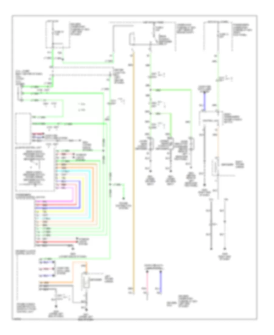
2.4L
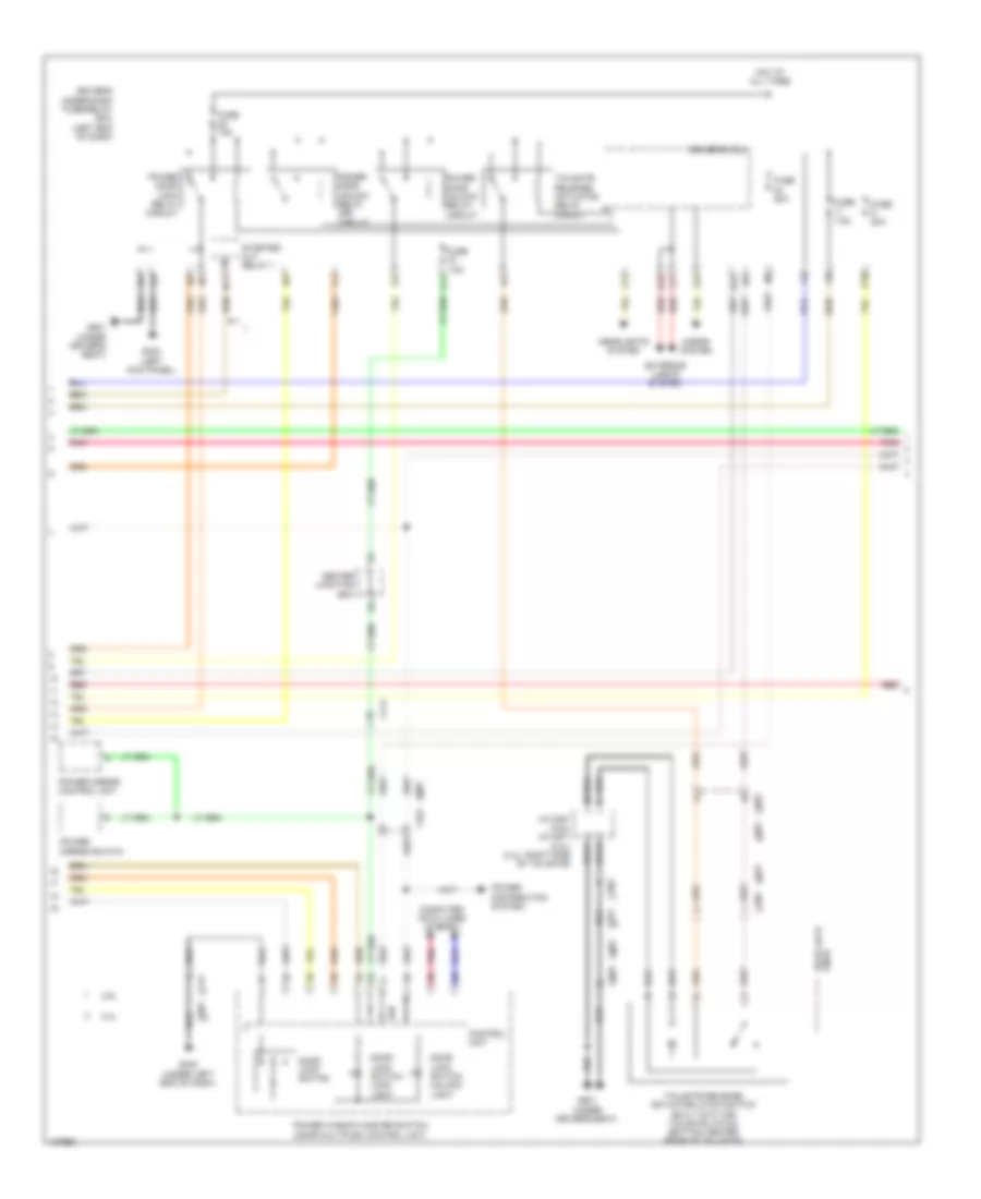
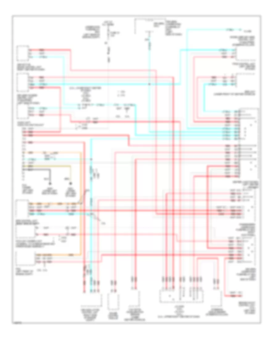
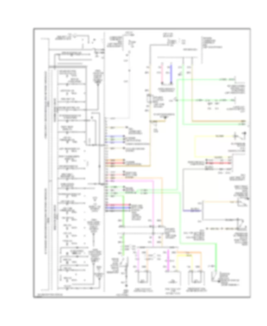
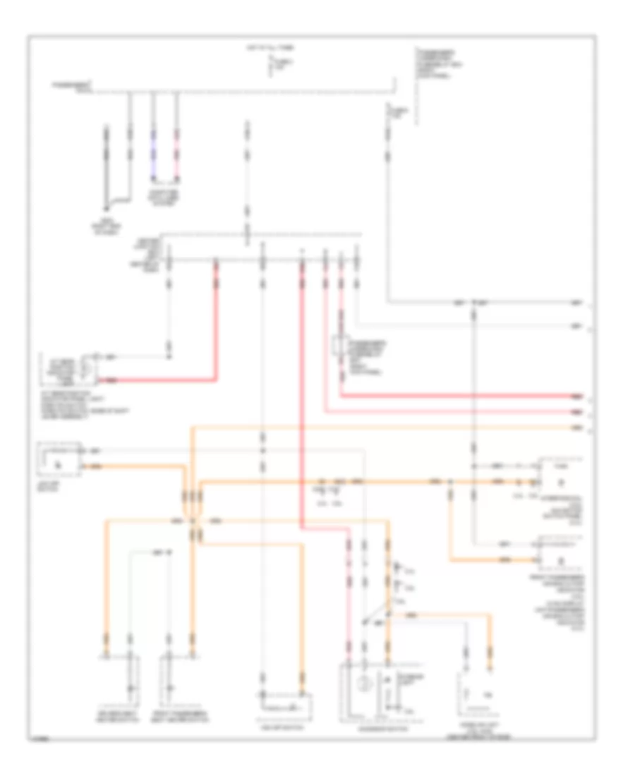
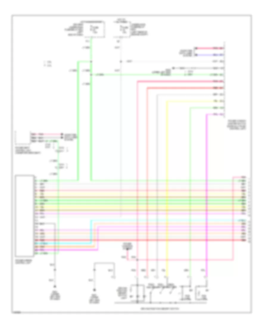
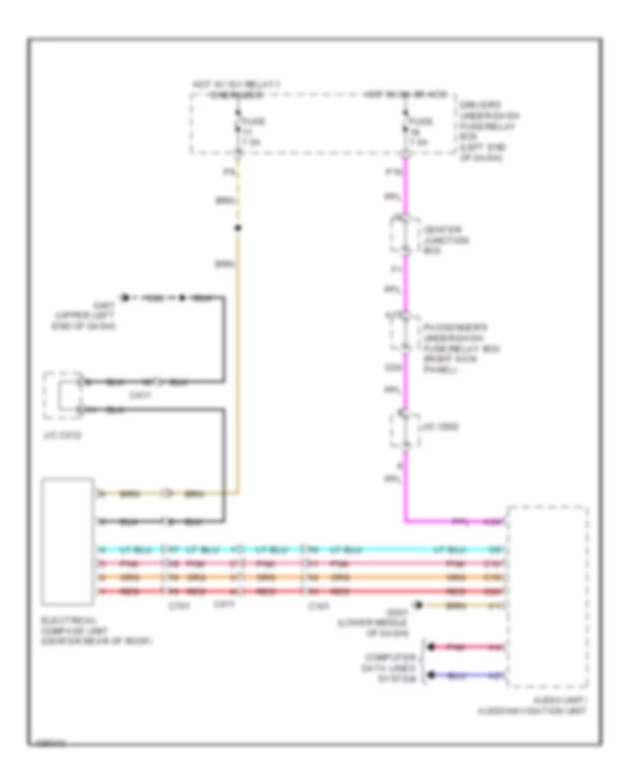
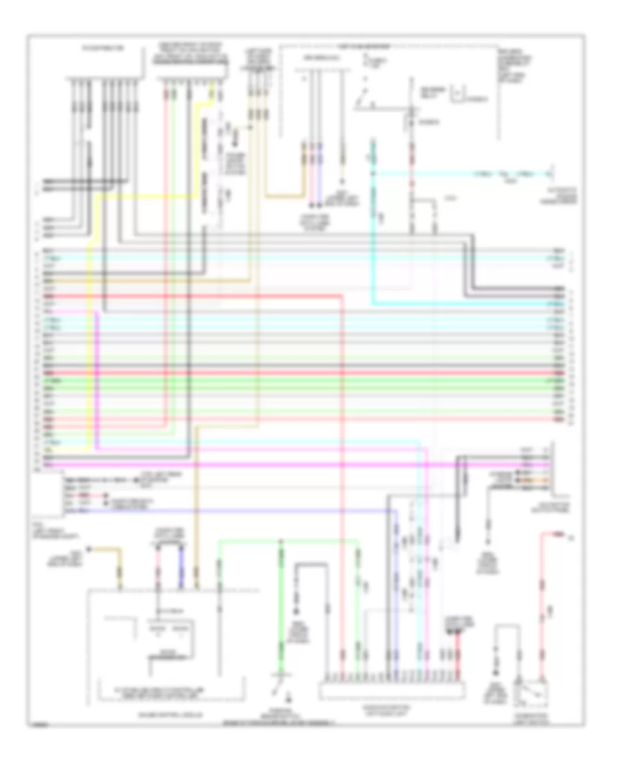
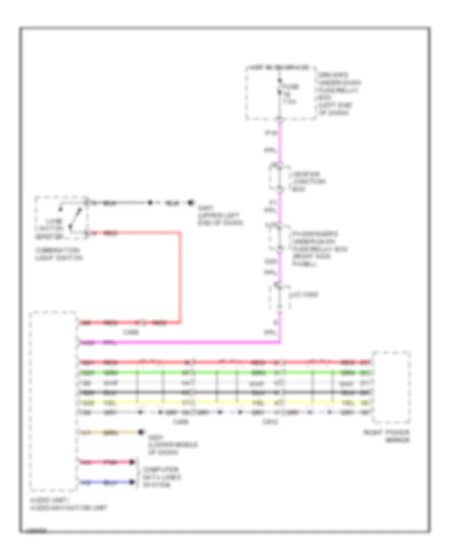
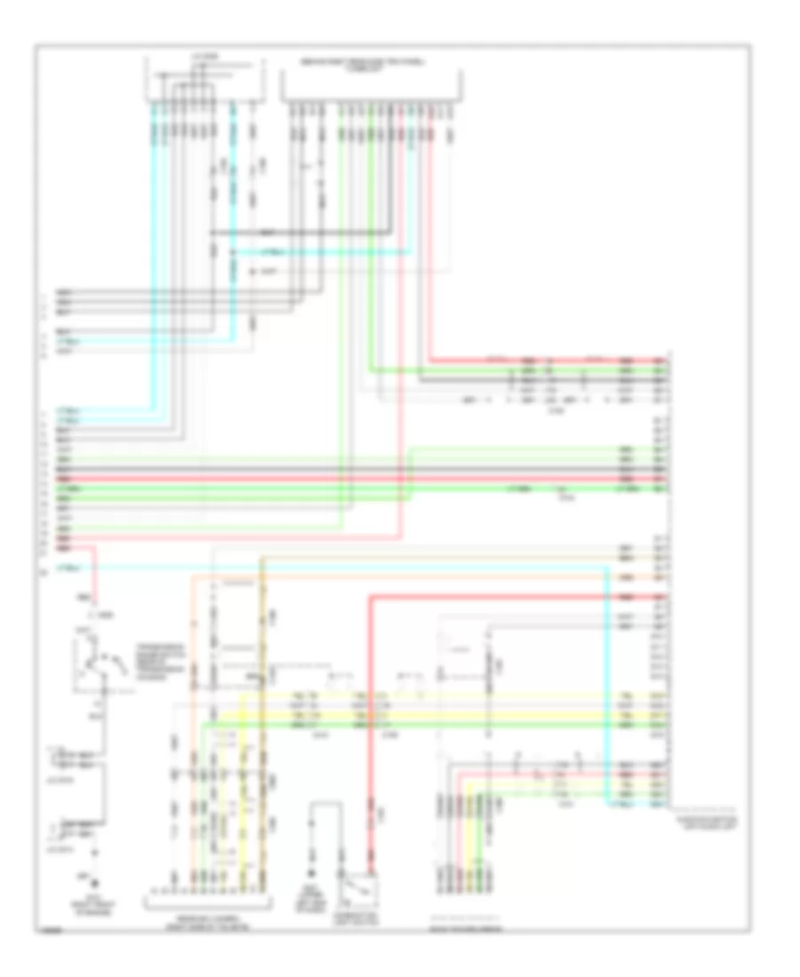
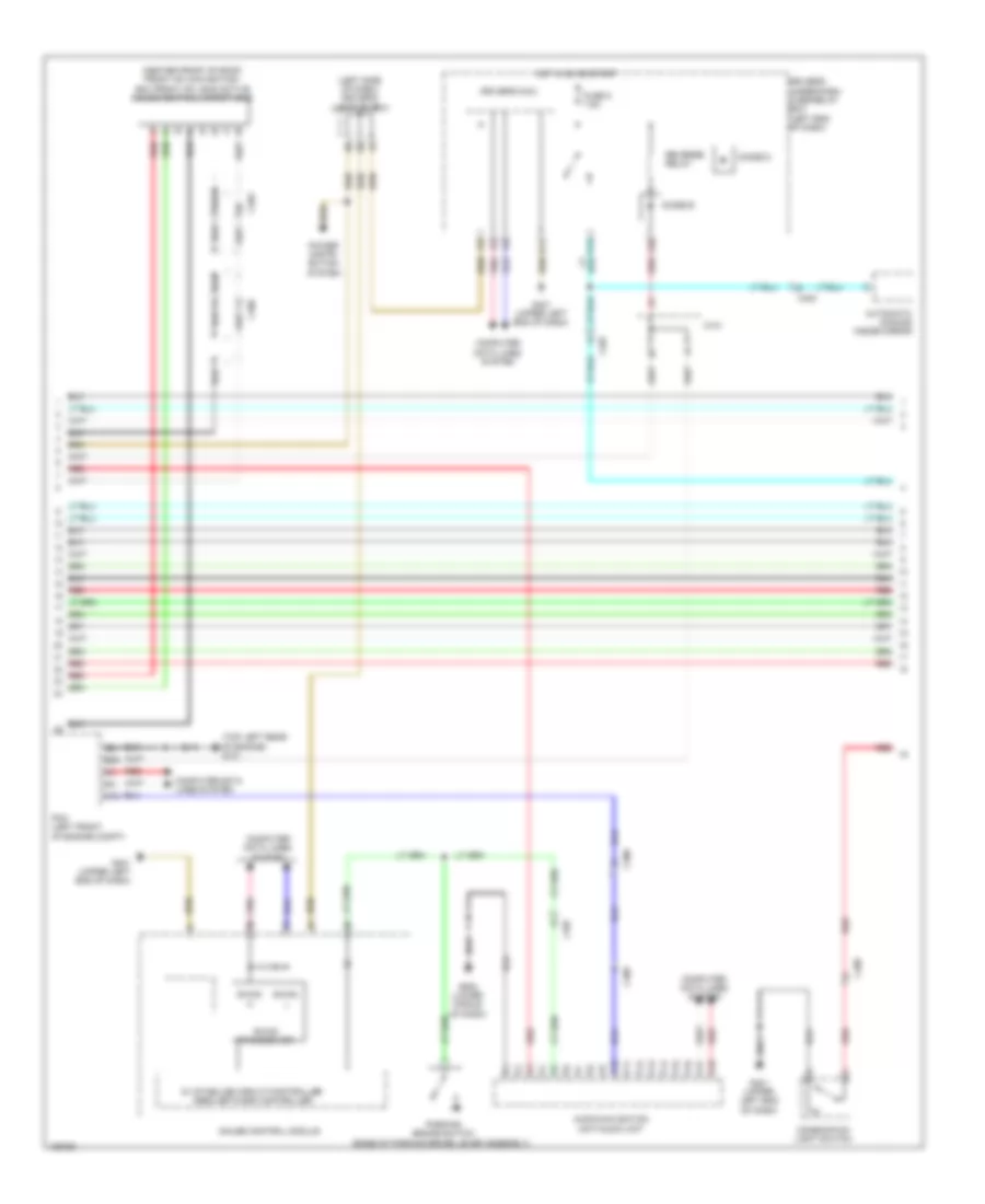
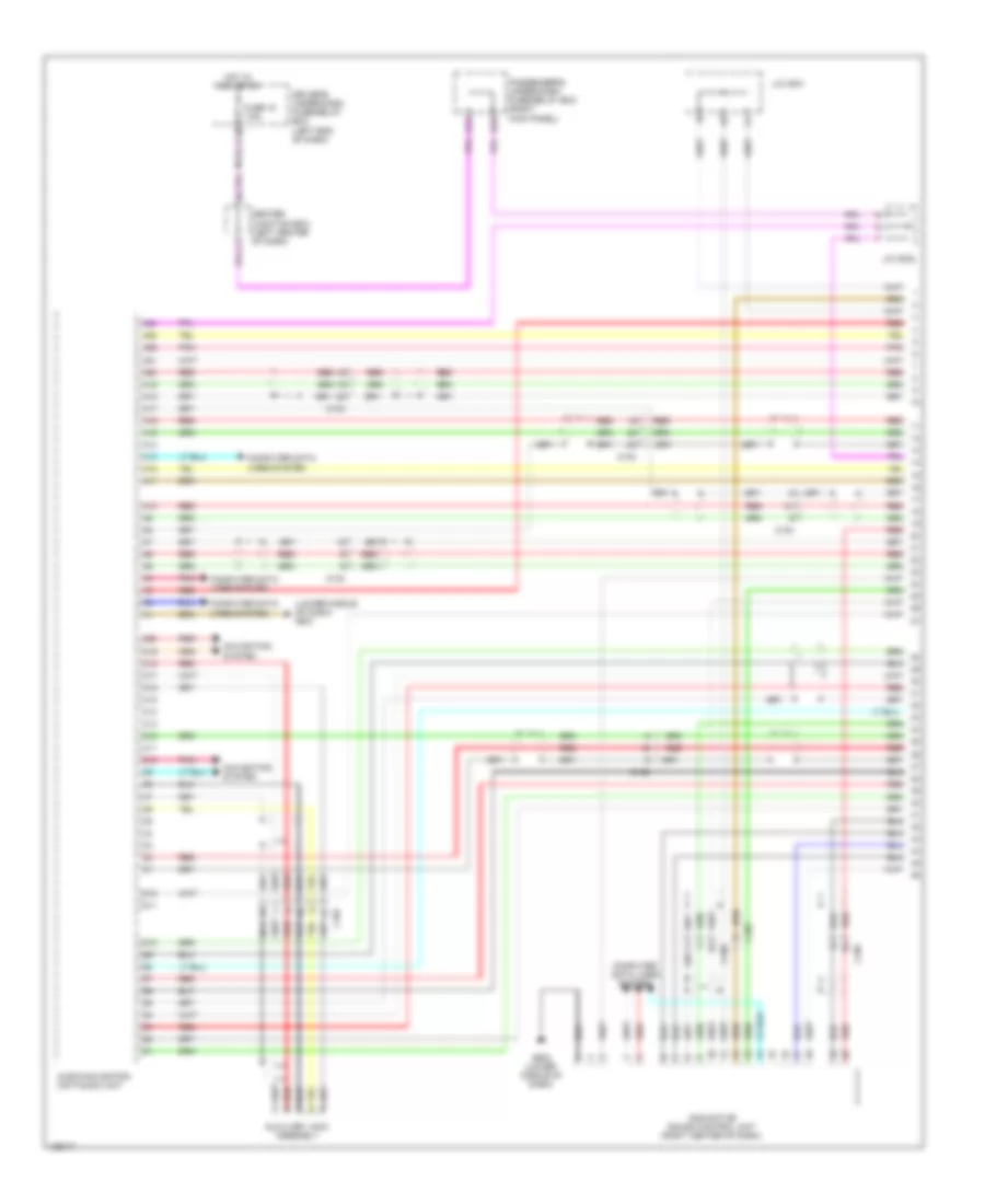
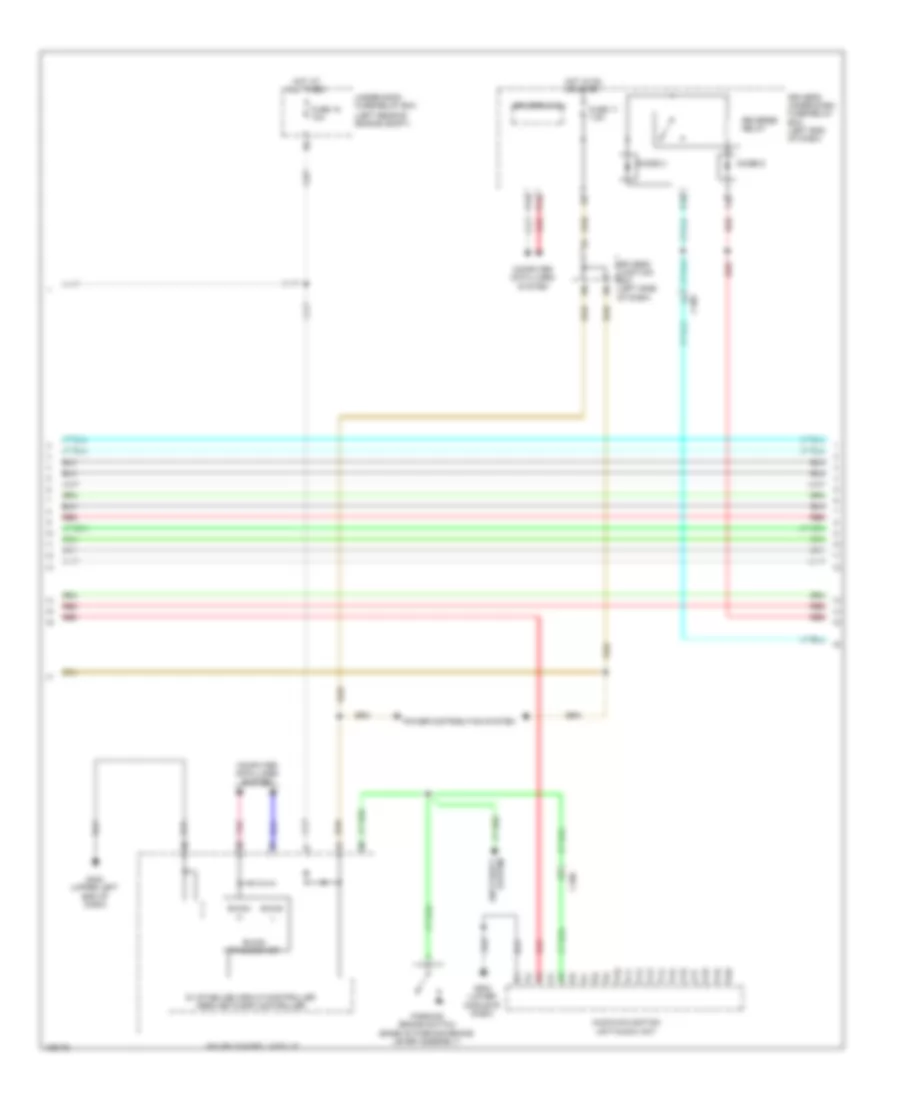
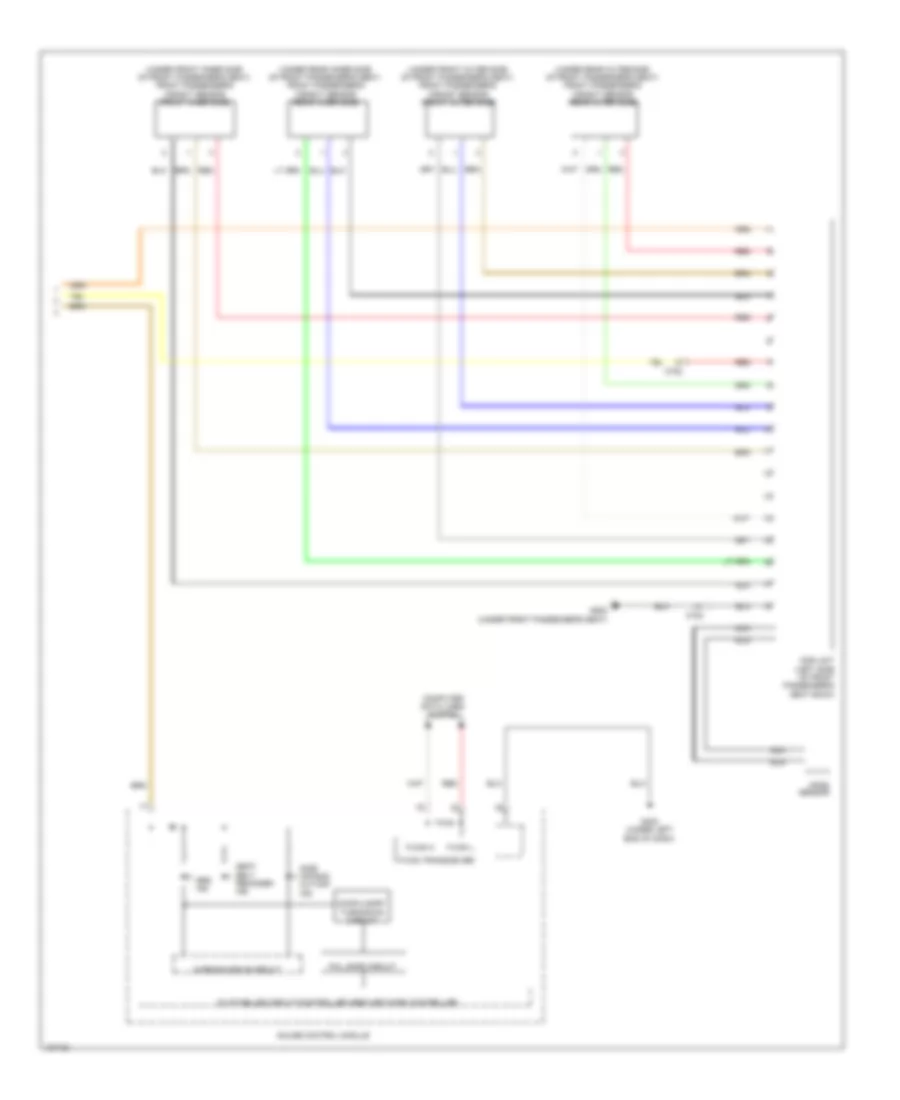
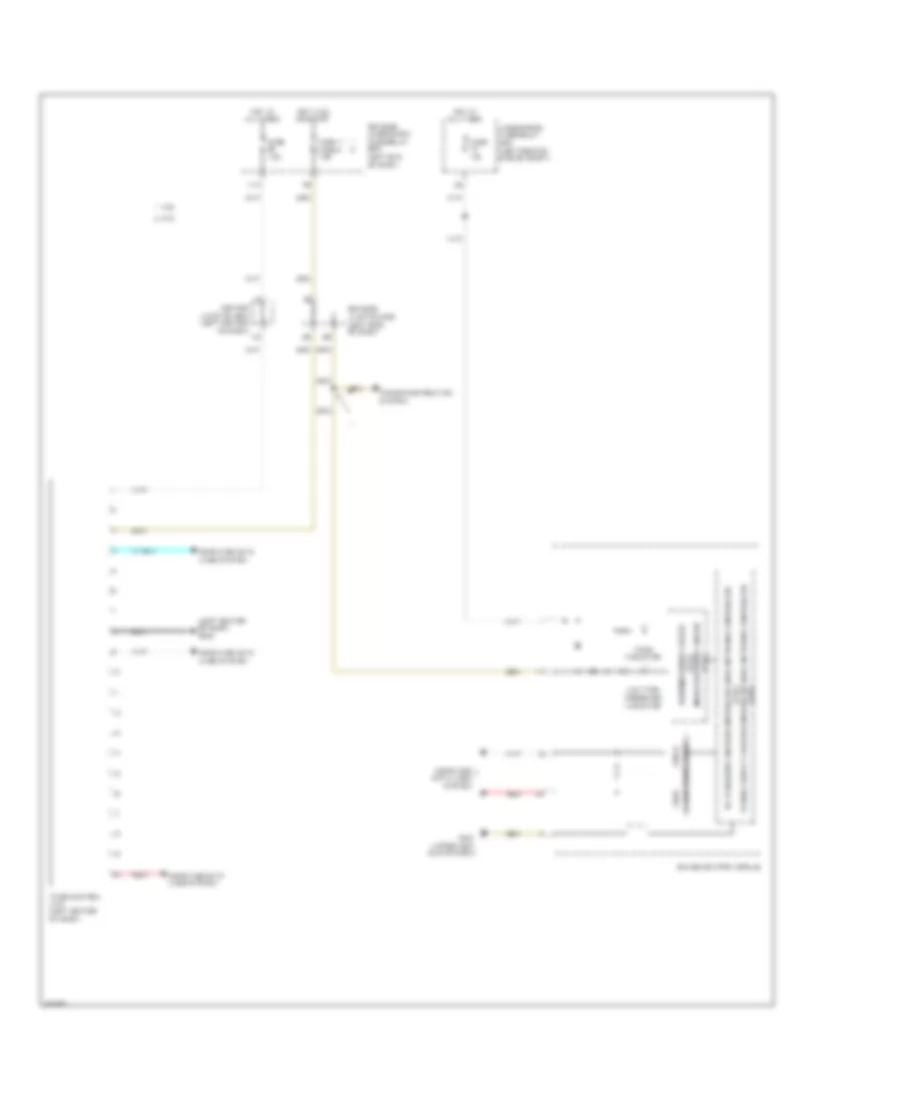
2.4L, Automatic A/C Wiring Diagram (1 of 3) for Honda Crosstour EX-L 2014

List of elements for 2.4L, Automatic A/C Wiring Diagram (1 of 3) for Honda Crosstour EX-L 2014:
- (lower middle of dash) g502
- A10
- A11
- A12
- A13
- A14
- A15
- A16
- A17
- A18
- A19
- A20
- A21
- A22
- A23
- A24
- Automatic lighting sensor/sunlight sensor (top middle of dash)
- Blower motor (under right side of dash)
- C303
- C306
- C406
- C407
- C409
- C507
- Center junction box (left center of dash)
- Climate control unit
- Computer data lines system
- Driver's junction box (left side of dash)
- Driver's micu
- Driver's under-dash fuse/relay box (left end of dash)
- Engine controls system
- F22
- F29
- Fuse 15a
- Fuse 7.5a
- G302 (left kick panel)
- Hot at all times
- Hot in on
- Humidity sensor
- Humidity/in-car temperature sensor (lower left center of dash)
- Hvac display unit/ passenger's airbag cut-off indicator
- In-car temperature sensor
- J/c c503 (lower right center of dash)
- J/c c506 (lower right center of dash)
- Outside air temperature sensor (behind middle of front bumper)
- P11
- Pgm-fi sub- relay
- Pnk
- Power transistor (bottom center of hvac unit)
- Red
- Under-hood fuse/relay box (left rear of engine compt)
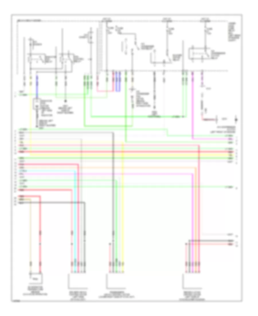
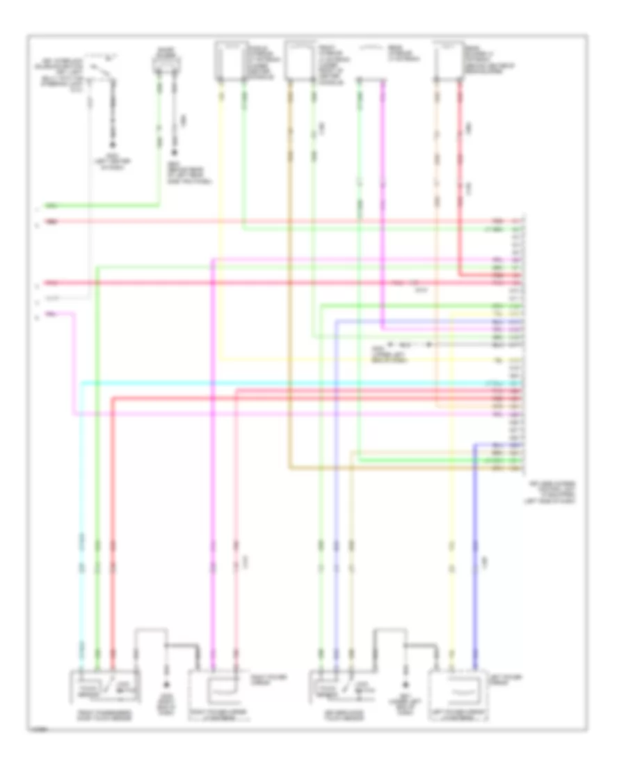
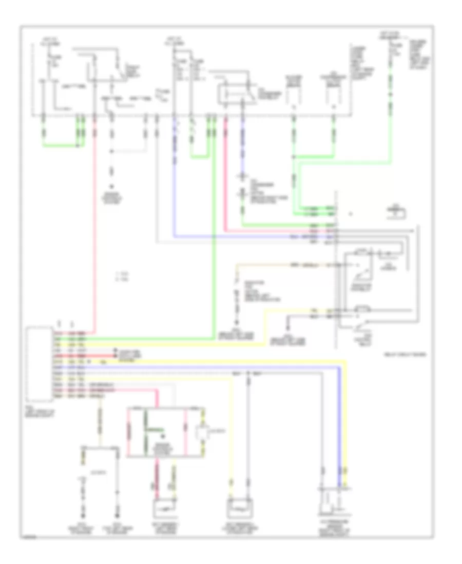
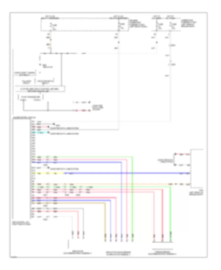
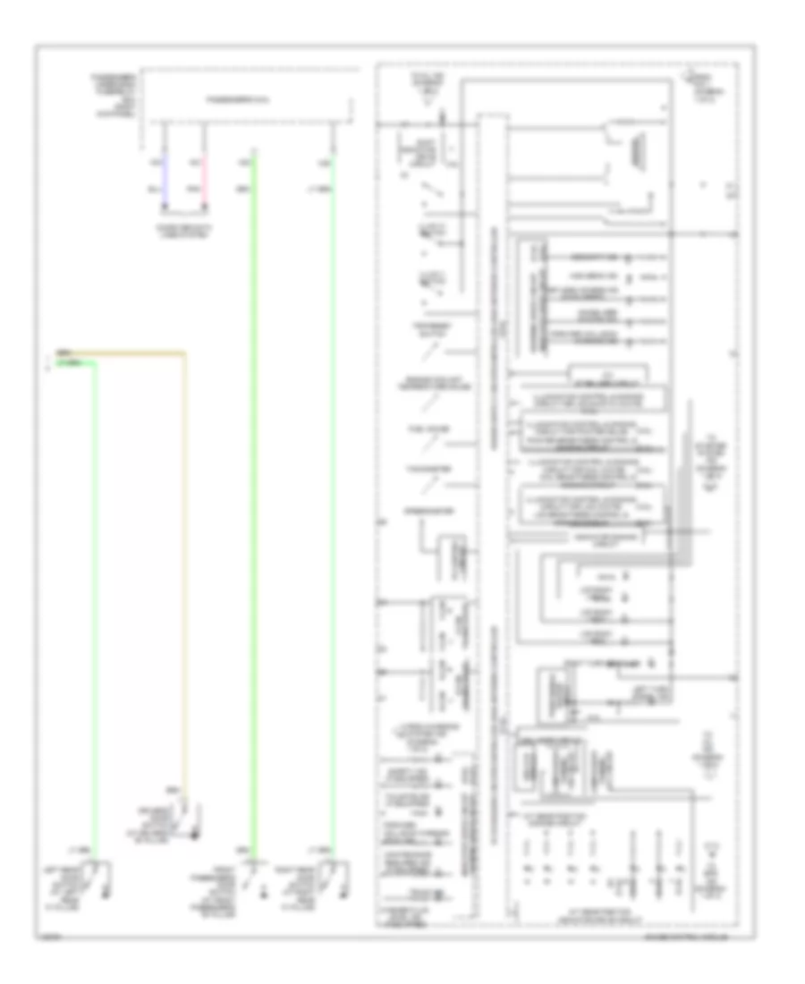
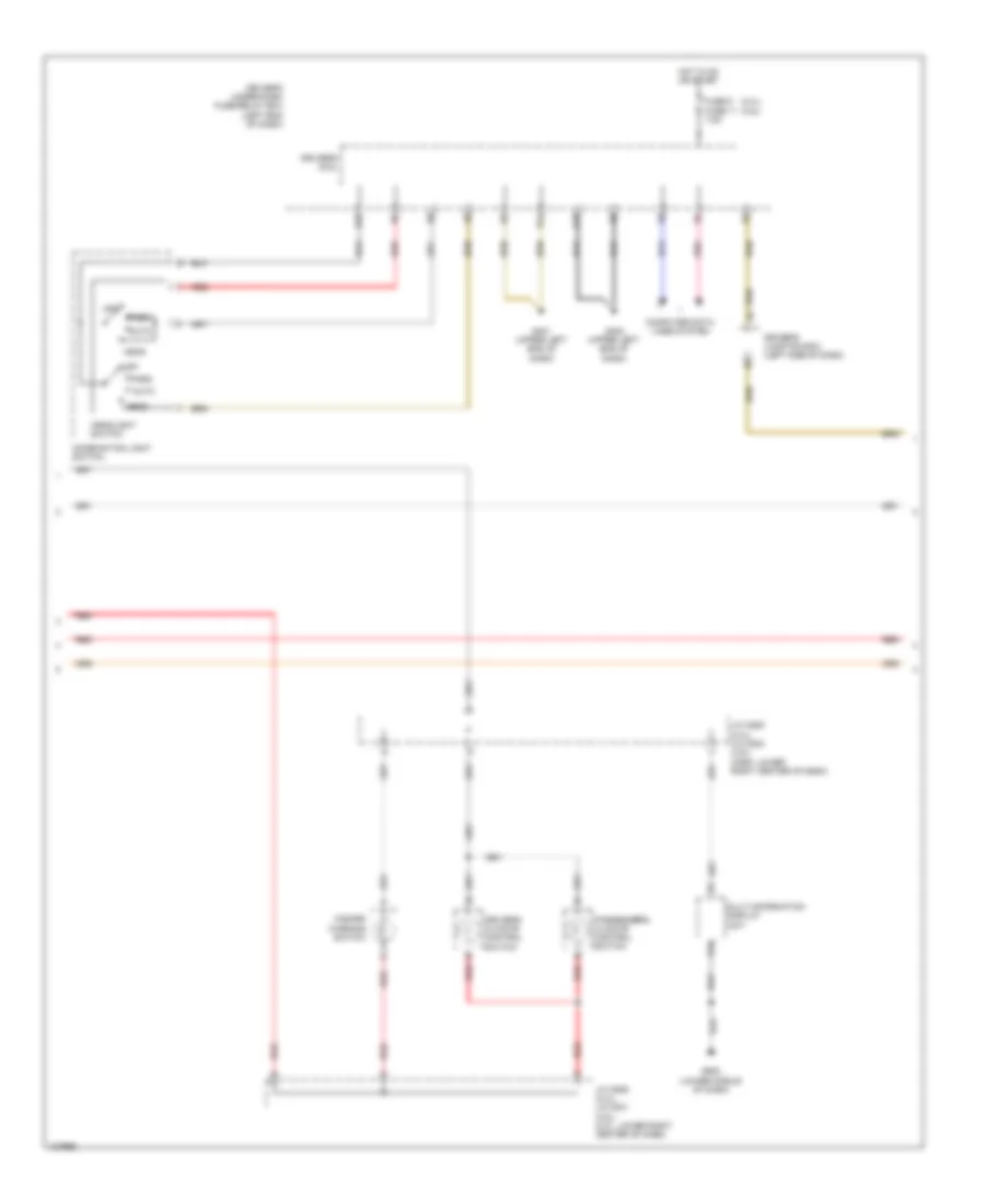
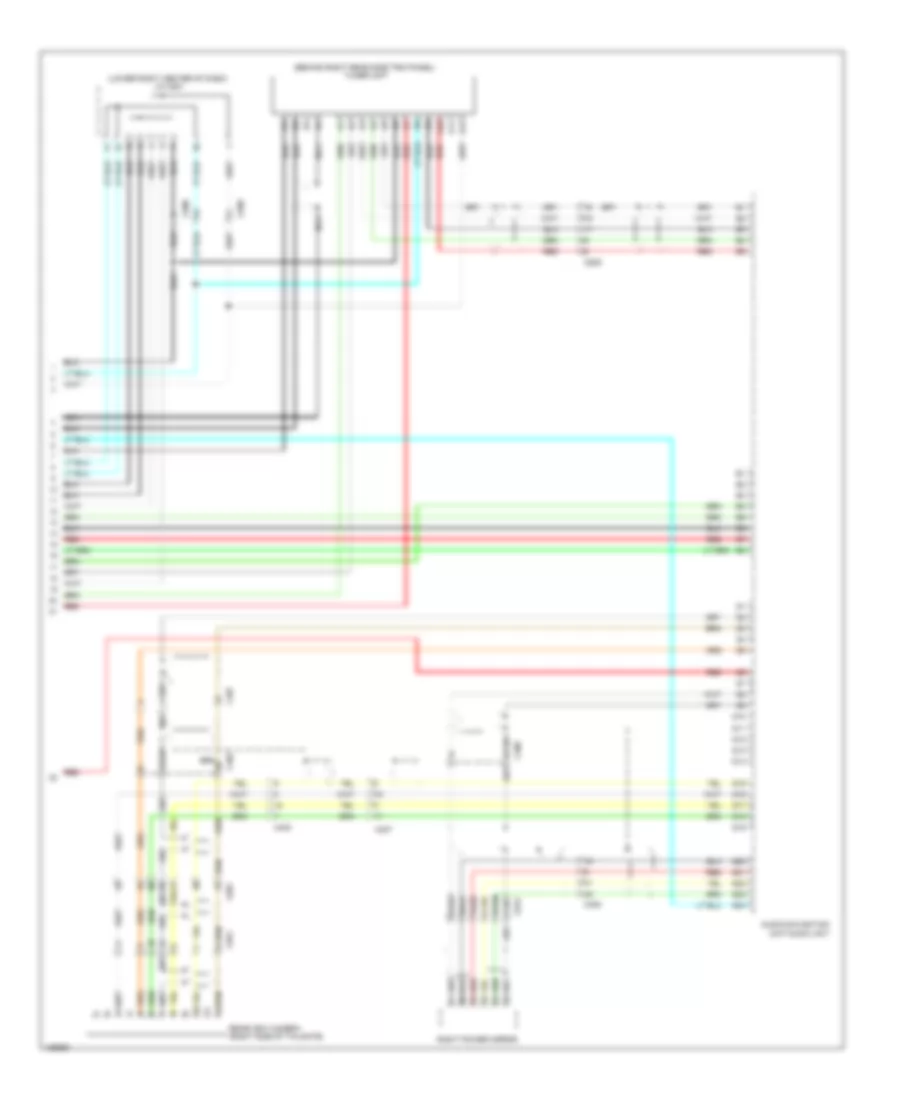
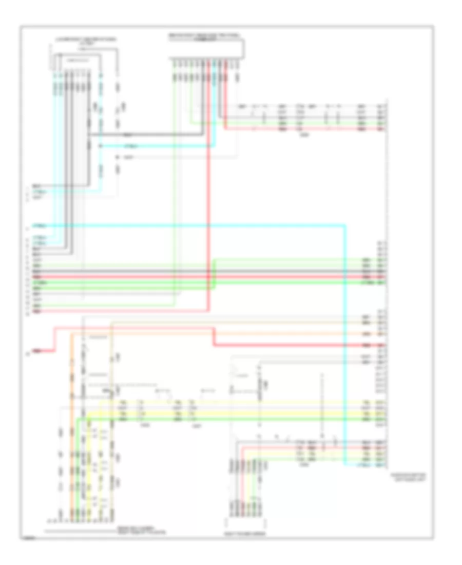
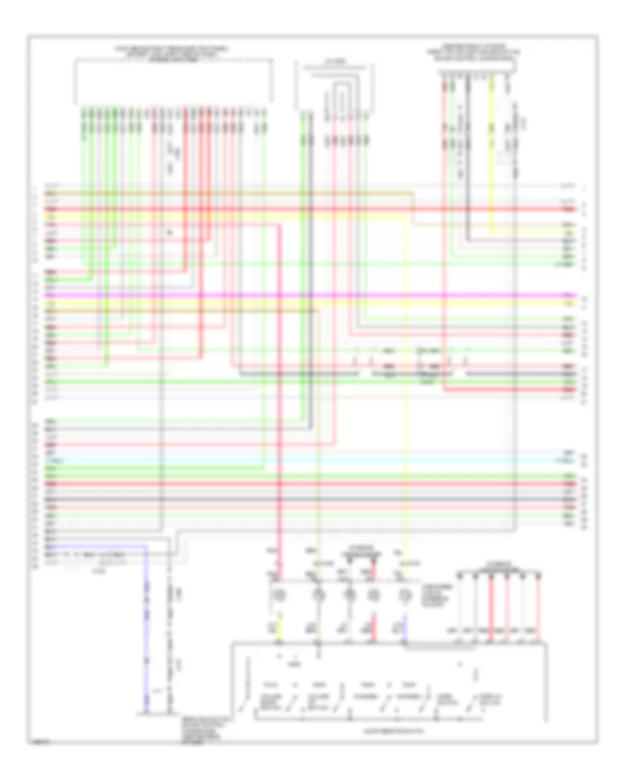
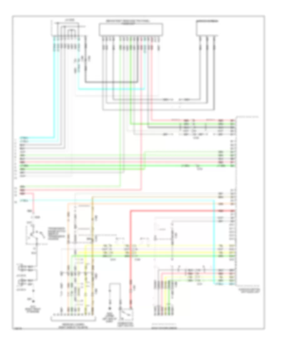
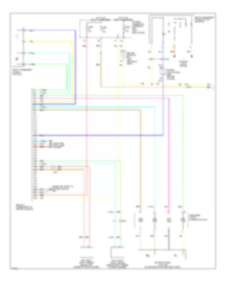
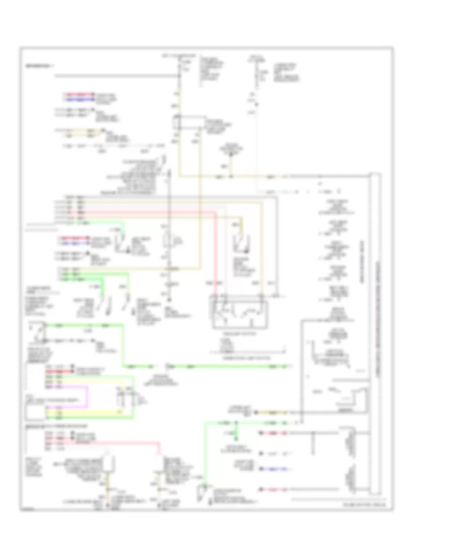
2.4L, Automatic A/C Wiring Diagram (2 of 3) for Honda Crosstour EX-L 2014
List of elements for 2.4L, Automatic A/C Wiring Diagram (2 of 3) for Honda Crosstour EX-L 2014:
- (behind left side of front bumper) g301
- A/c compressor clutch (left front of engine)
- A/c compressor clutch relay
- A/c condenser fan motor (behind right side of radiator)
- A/c condenser fan relay
- A/c diode a
- A/c diode b
- B10
- B11
- B12
- B13
- Blower motor relay
- C101
- C102
- Driver's air mix control motor (left side of hvac unit)
- Evaporator temperature sensor (in hvac evaporator)
- Fan control relay
- Fuse 20a
- Fuse 3-6 30a
- Fuse 40a
- Fuse 7.5a
- G301 (behind left side of front bumper)
- G302 (left kick panel)
- Hot at all times
- Passenger's air mix control motor (lower right side of hvac unit)
- Pnk
- Radiator fan motor (behind left side of radiator)
- Radiator fan relay
- Recirculation control motor (left side of hvac blower housing)
- Red
- Relay circuit board
- Under- hood fuse/ relay box (left rear of engine compt)
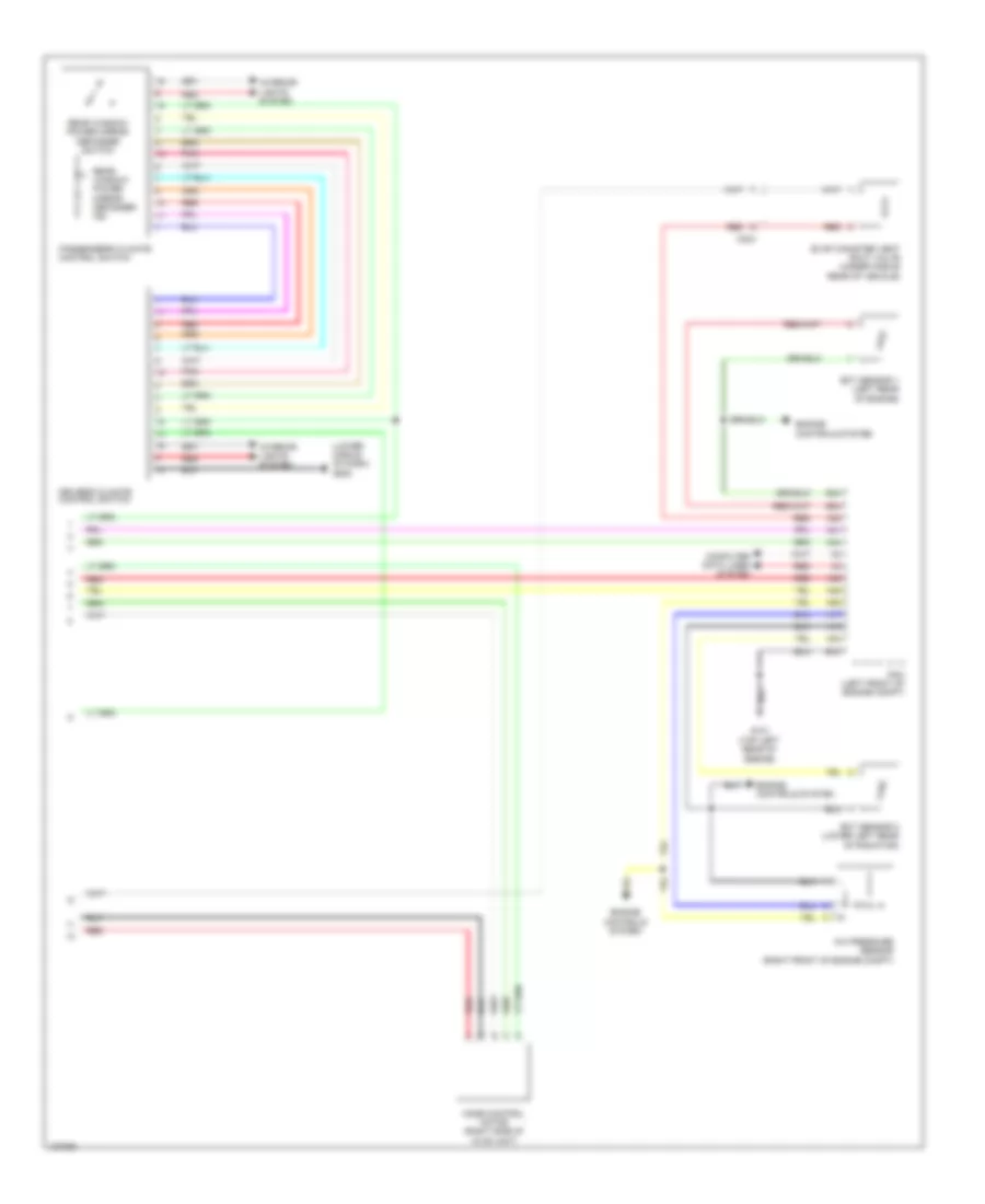
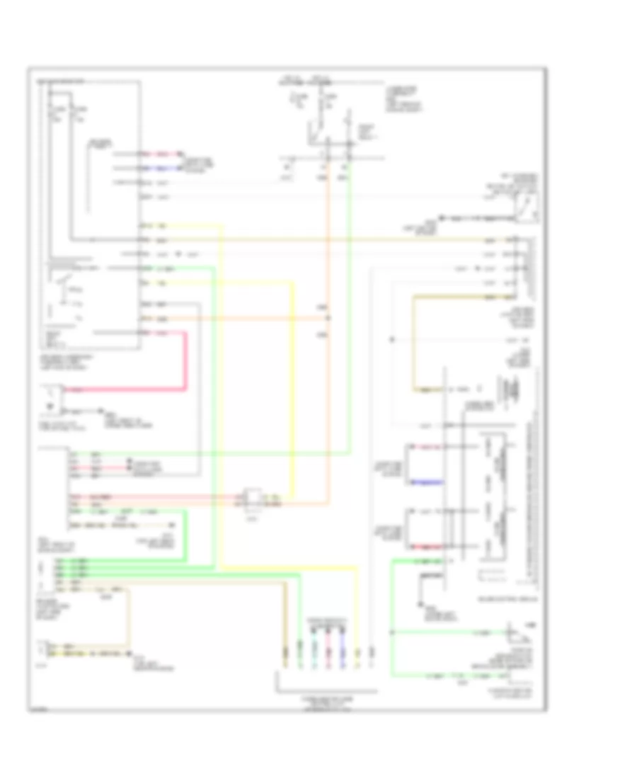
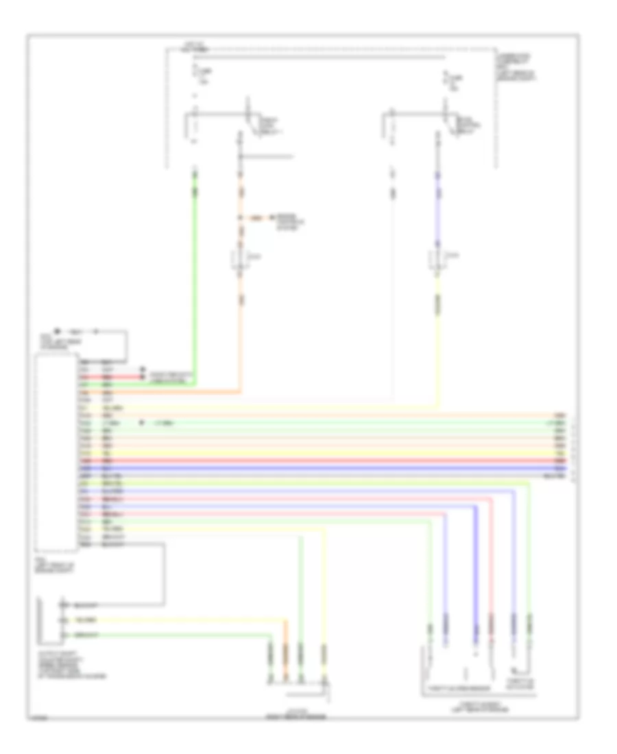
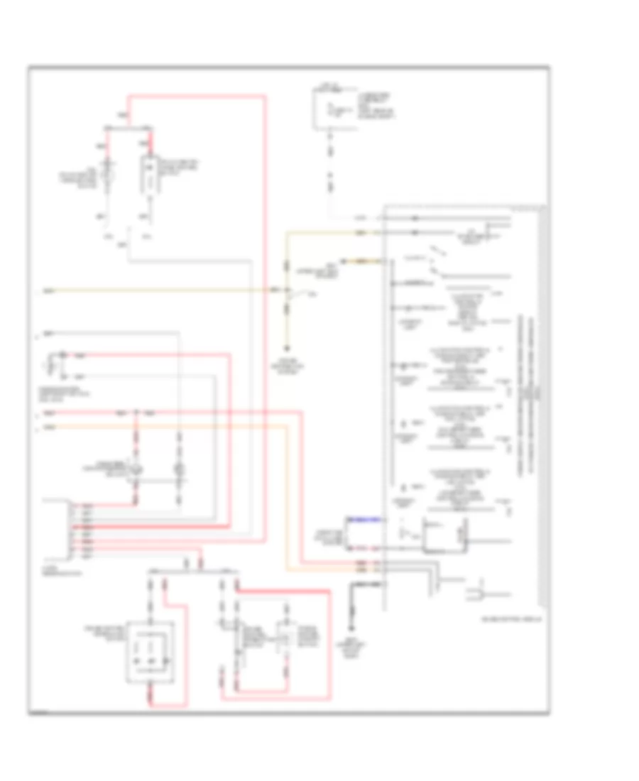
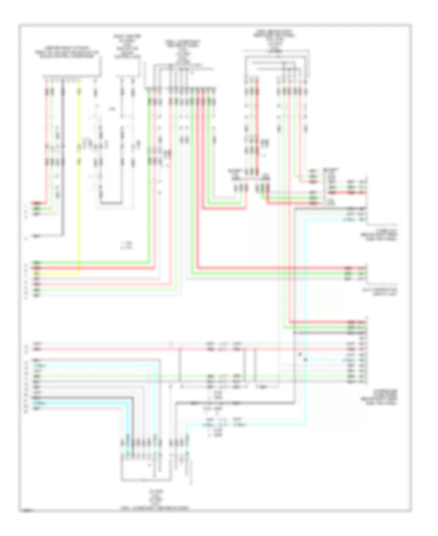
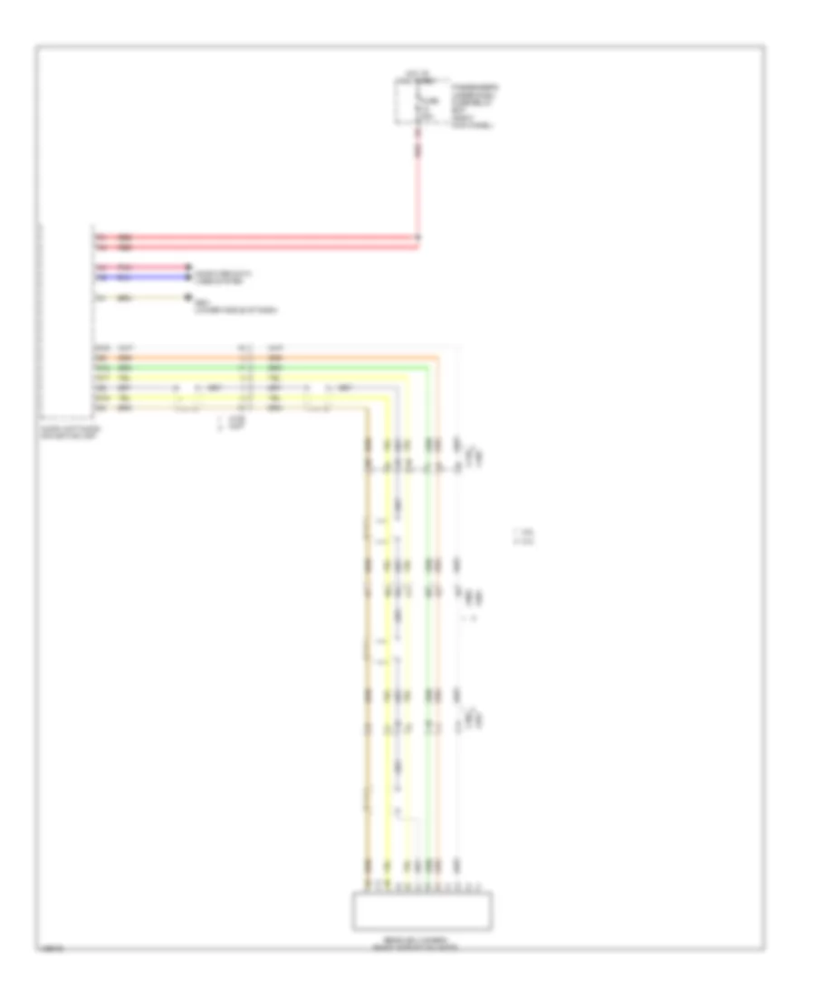
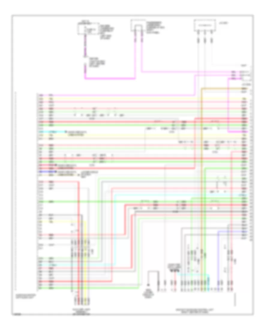
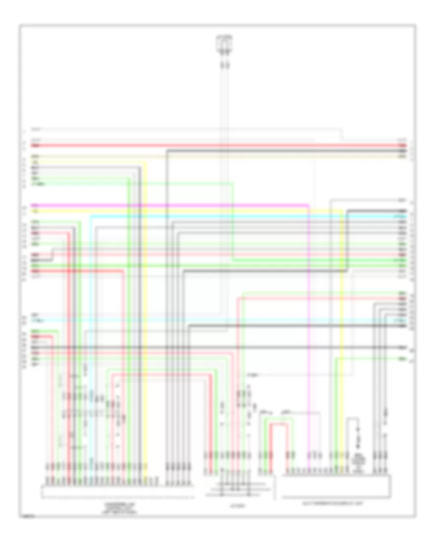
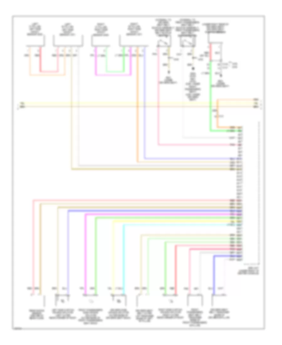
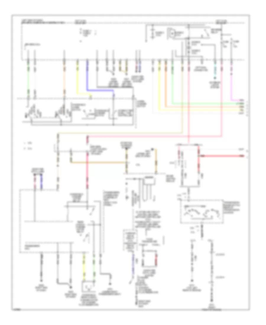
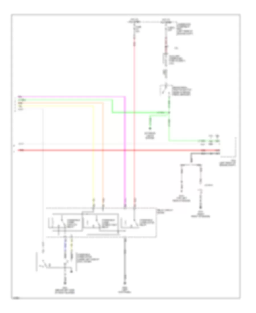
2.4L, Automatic A/C Wiring Diagram (3 of 3) for Honda Crosstour EX-L 2014
List of elements for 2.4L, Automatic A/C Wiring Diagram (3 of 3) for Honda Crosstour EX-L 2014:
- (lower middle of dash) g502
- A/c pressure sensor (right front of engine compt)
- A10
- A17
- A20
- A22
- A34
- A41
- A44
- A45
- A49
- B10
- B34
- B44
- C304
- Computer data lines system
- Driver's climate control switch
- Ect sensor 1 (left rear of engine)
- Ect sensor 2 (lower left rear of radiator)
- Engine controls system
- Engine)
- Evap canister vent shut valve (under middle rear of vehicle)
- G101 (top left rear of
- Interior lights system
- Mode control motor (right side of hvac unit)
- Passenger's climate control switch
- Pcm (left front of engine compt)
- Pnk
- Rear window/ power mirror defogger ind
- Rear window/ power mirror defogger switch
- Red
3.5L
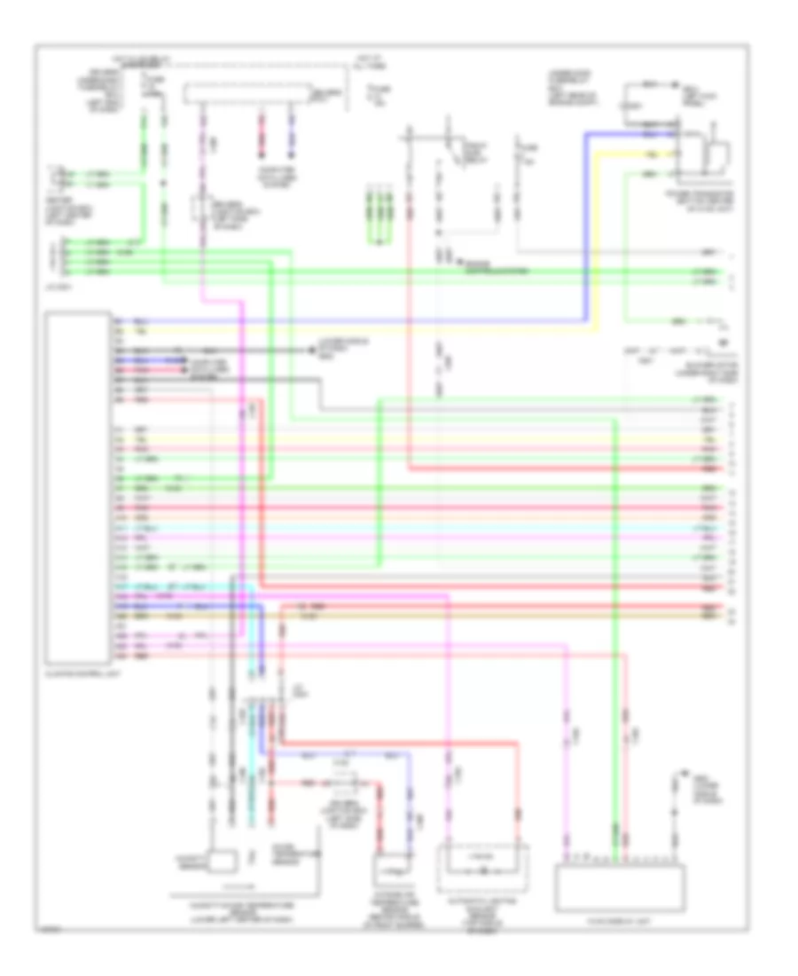
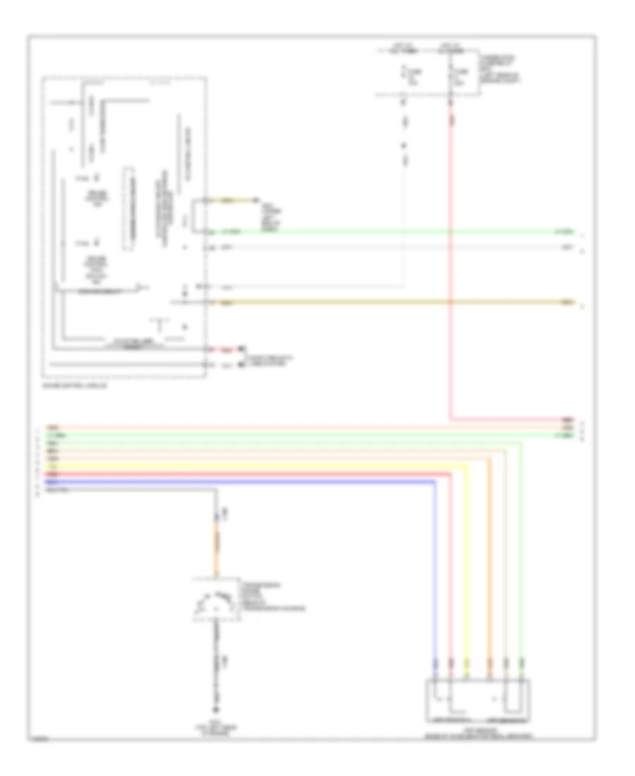
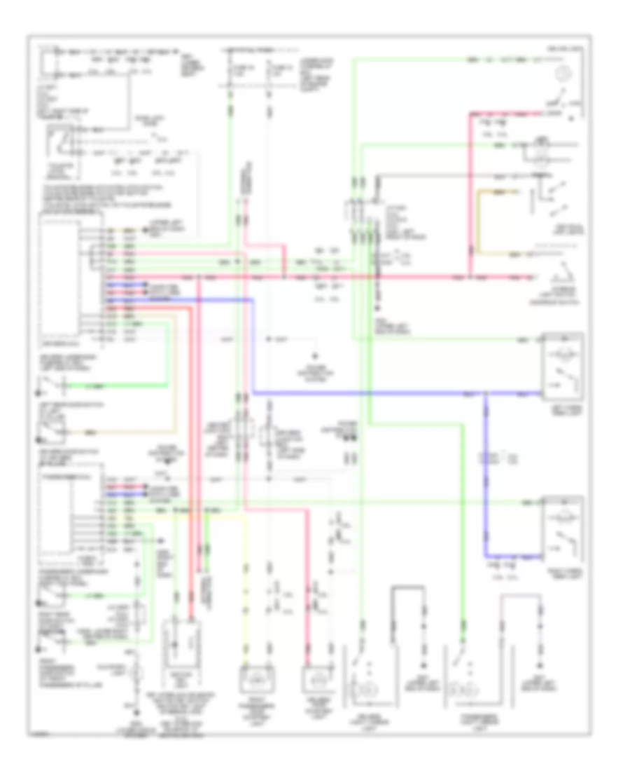
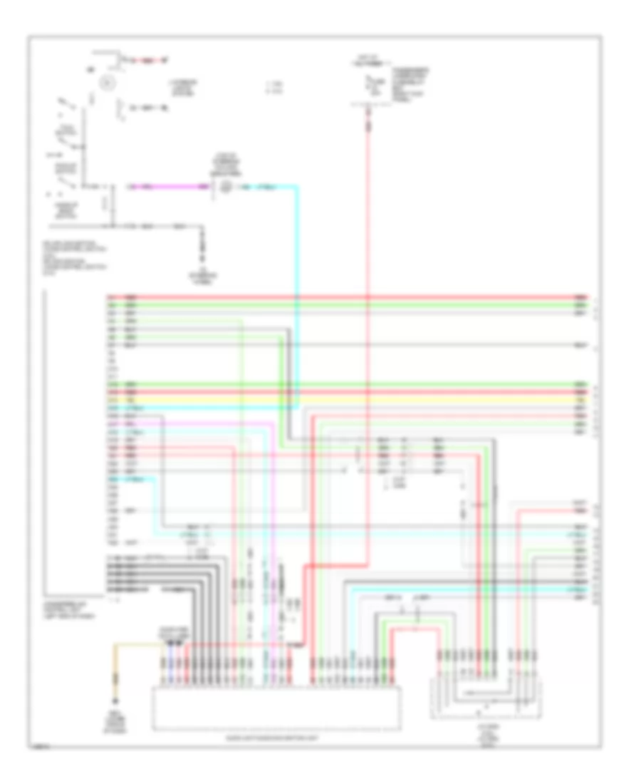
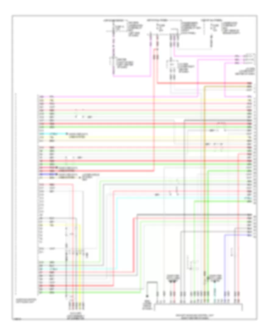
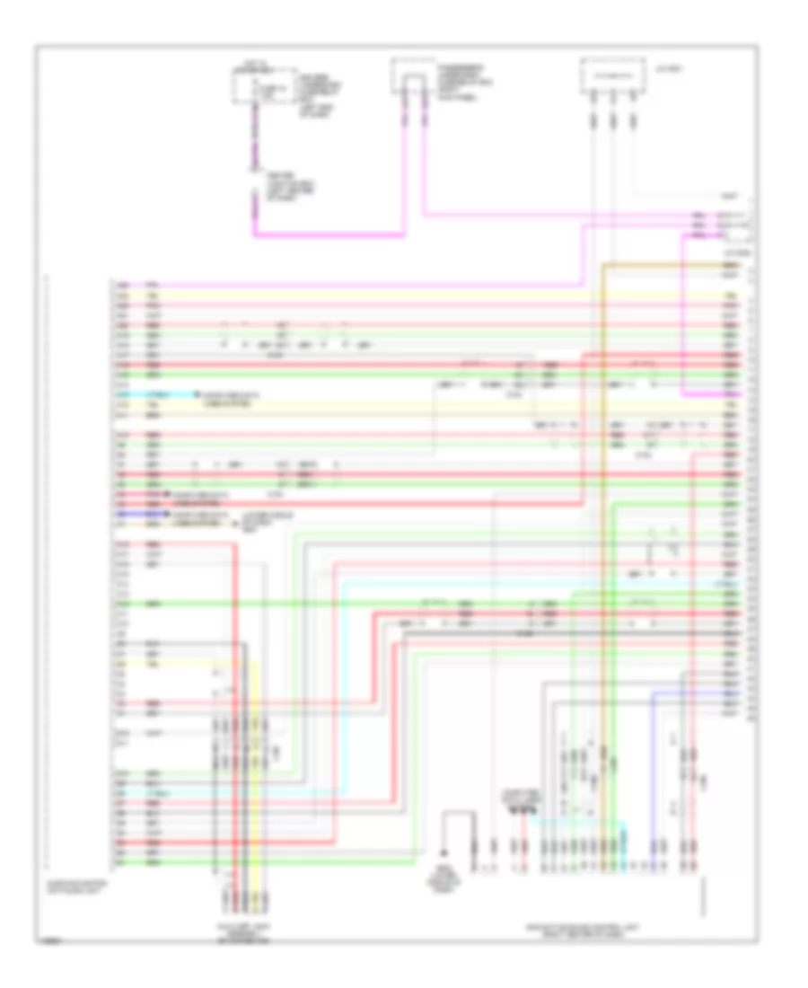
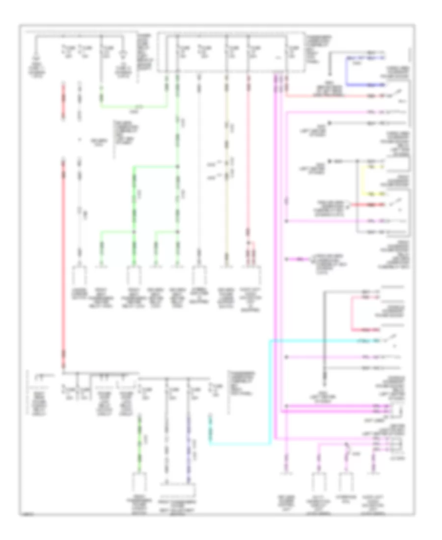
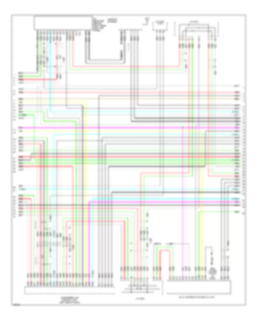
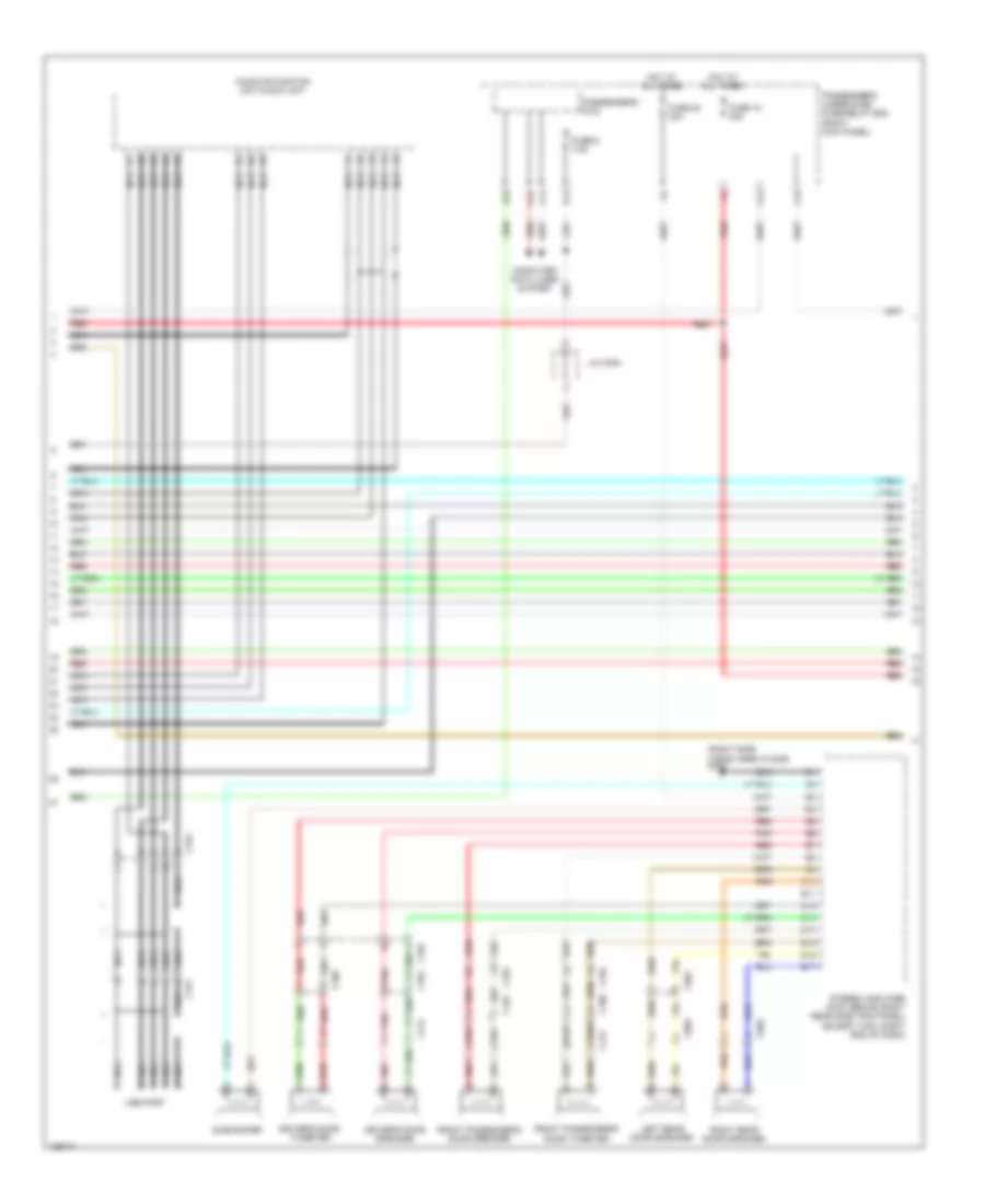
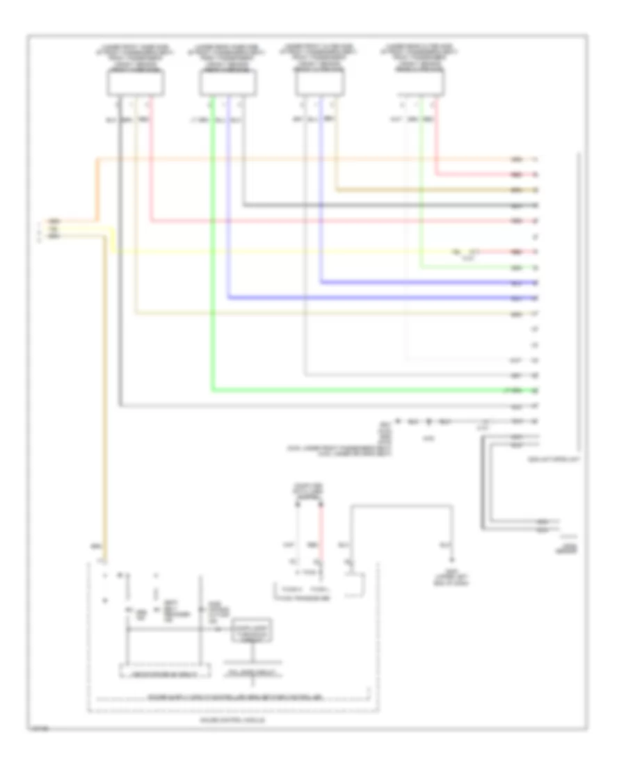
3.5L, Automatic A/C Wiring Diagram (1 of 3) for Honda Crosstour EX-L 2014
List of elements for 3.5L, Automatic A/C Wiring Diagram (1 of 3) for Honda Crosstour EX-L 2014:
- (lower middle of dash) g502
- A10
- A11
- A12
- A13
- A14
- A15
- A16
- A17
- A18
- A19
- A20
- A21
- A22
- A23
- A24
- Automatic lighting sunlight sensor (top middle of dash)
- Blower motor (under right side of dash)
- C102
- C103
- C106
- C107
- C408
- C501
- C507
- Center junction box (left center of dash)
- Climate control unit
- Computer data lines system
- Driver's junction box (left side of dash)
- Driver's micu
- Driver's under-dash fuse/relay box (left end of dash)
- Engine controls system
- F22
- F29
- Fuse 15a
- Fuse 7.5a
- G302 (left kick panel)
- G502 (lower middle of dash)
- Hot at all times
- Hot w/ ig2 relay energized
- Humidity sensor
- Humidity/in-car temperature sensor (lower left center of dash)
- Hvac display unit
- In-car temperature sensor
- J/c c001
- J/c c004
- Outside air temperature sensor (behind middle of front bumper)
- P11
- Pgm-fi sub- relay
- Pnk
- Power transistor (bottom center of hvac unit)
- Red
- Under-hood fuse/relay box (left rear of engine compt)
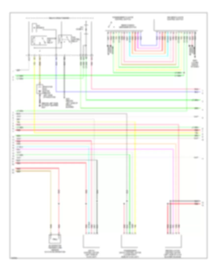
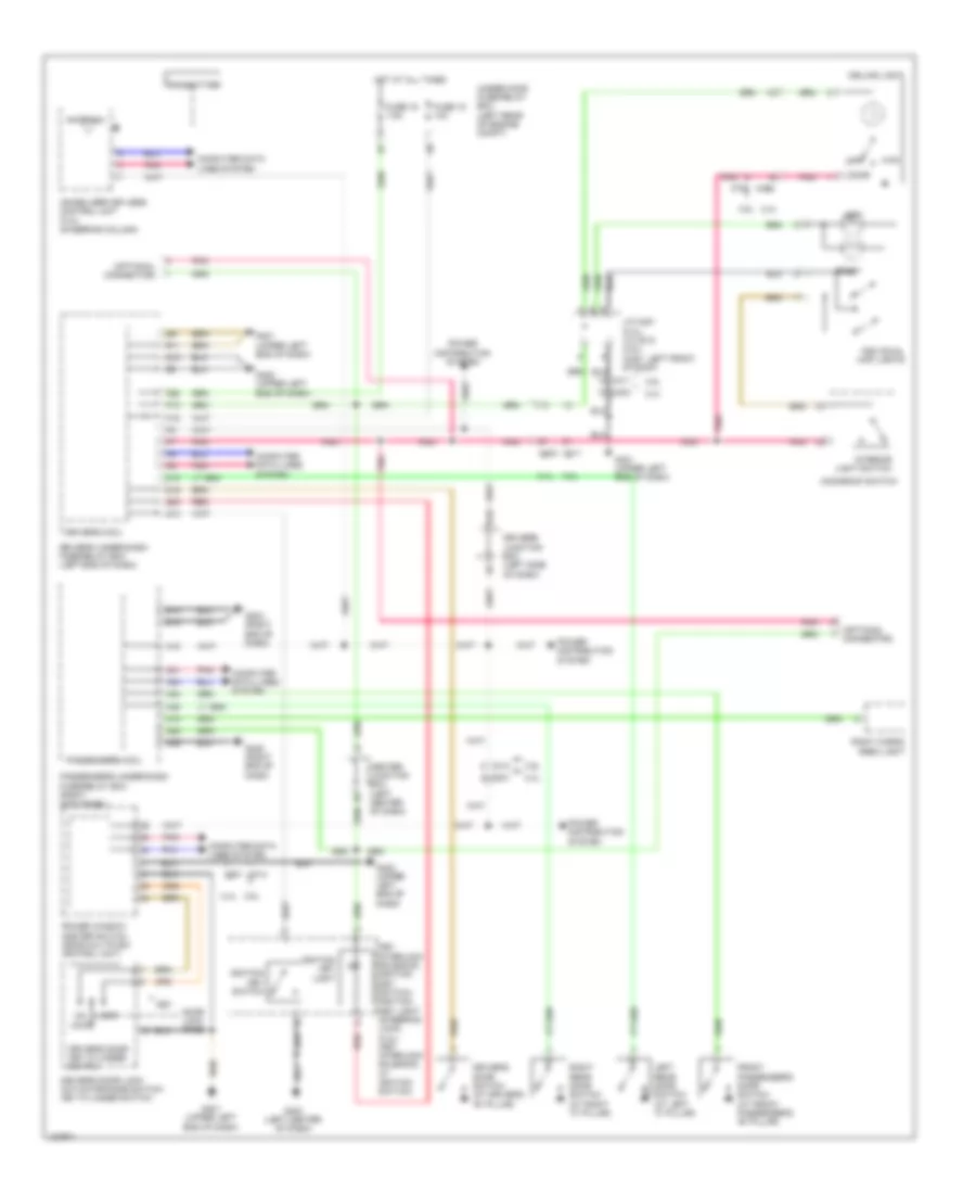
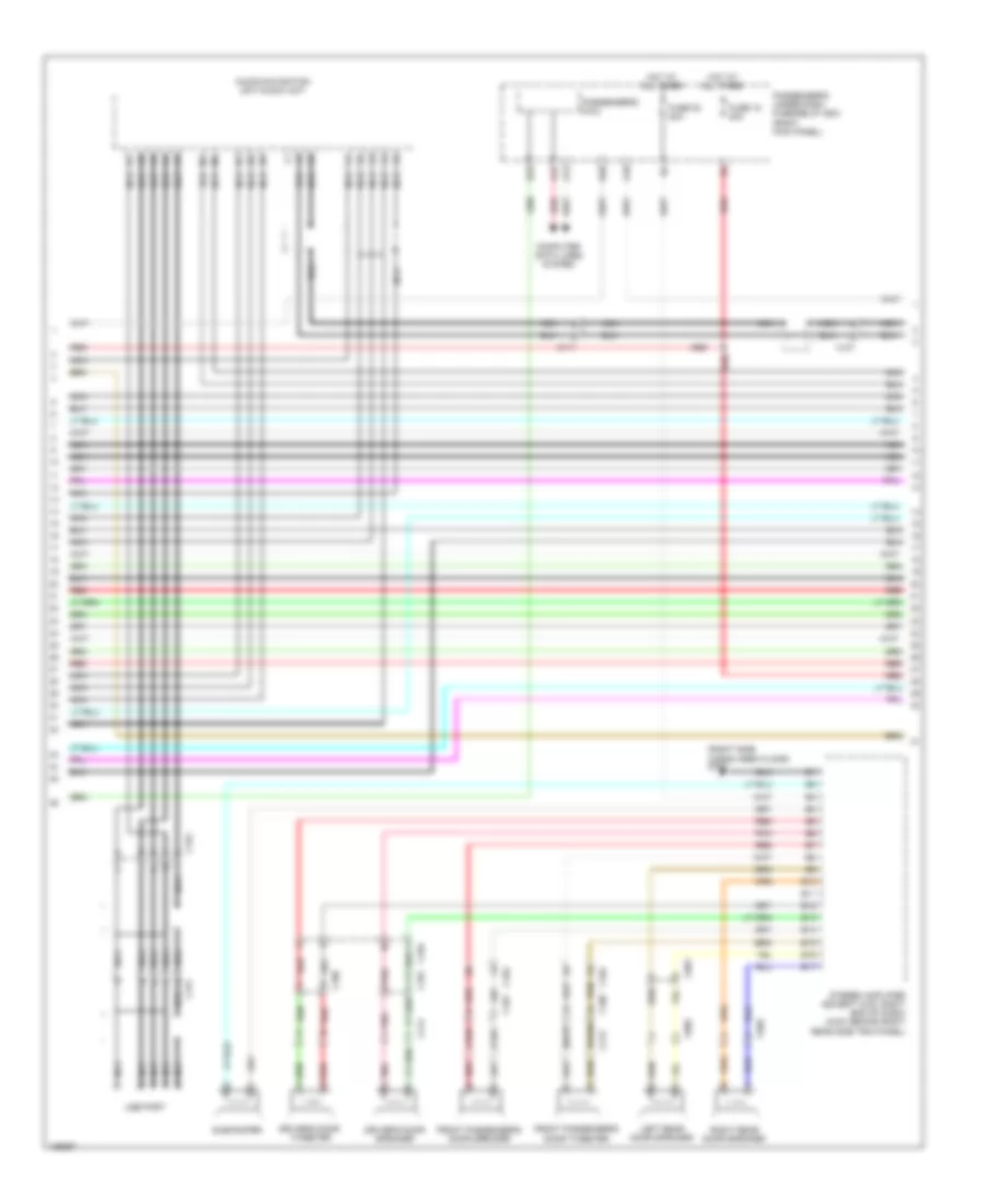
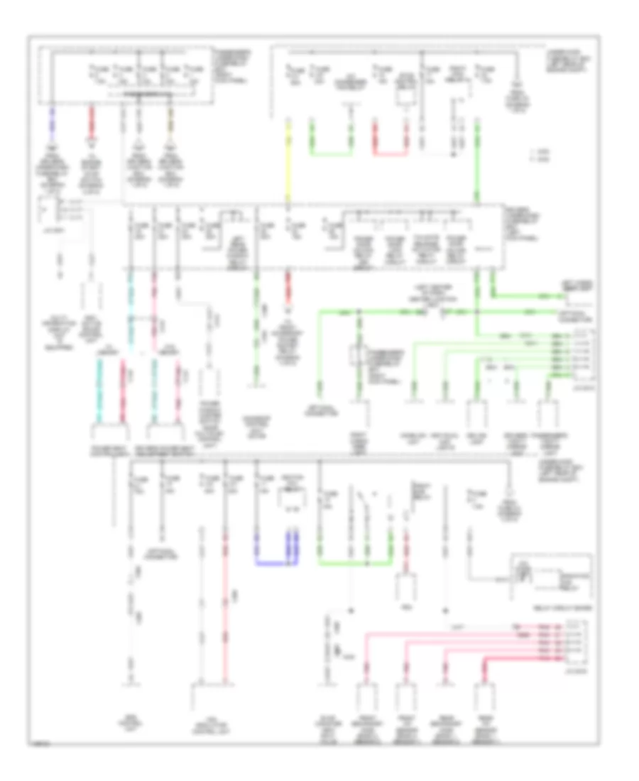
3.5L, Automatic A/C Wiring Diagram (2 of 3) for Honda Crosstour EX-L 2014
List of elements for 3.5L, Automatic A/C Wiring Diagram (2 of 3) for Honda Crosstour EX-L 2014:
- (behind left side of front bumper) g301
- A/c diode a
- A/c diode b
- Air mix control motor (left side of hvac unit)
- B10
- B11
- B12
- B13
- Driver's climate control switch
- Evaporator temperature sensor (in hvac evaporator)
- Fan control relay
- G301 (behind left side of front bumper)
- G502 (lower middle of dash)
- Interior
- Lights
- Passenger's air mix control motor (lower right side of hvac unit)
- Passenger's climate control switch
- Pnk
- Radiator fan motor (behind left side of radiator)
- Radiator fan relay
- Rear window defogger switch
- Recirculation control motor (left side of hvac blower housing)
- Red
- Relay circuit board
- System
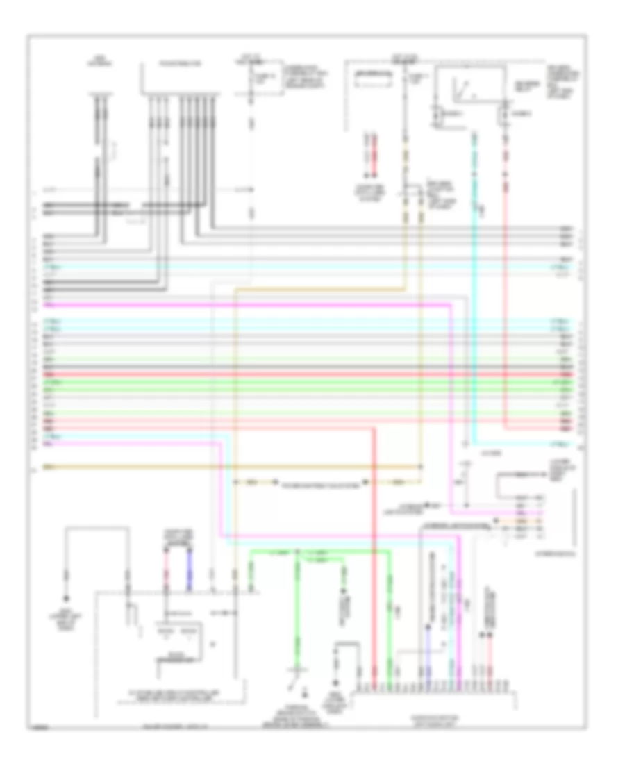
3.5L, Automatic A/C Wiring Diagram (3 of 3) for Honda Crosstour EX-L 2014
List of elements for 3.5L, Automatic A/C Wiring Diagram (3 of 3) for Honda Crosstour EX-L 2014:
- 4wd
- A/c compressor clutch (left front of engine)
- A/c compressor clutch relay
- A/c condenser fan motor (behind right side of radiator)
- A/c condenser fan relay
- A/c pressure sensor (right front of engine compt)
- A10
- A14
- A15
- A19
- A20
- A23
- A31
- A47
- B20
- B45
- Blower motor relay
- C48
- C506
- C507
- C603
- Computer data lines system
- Ect sensor 1 (left rear of engine)
- Ect sensor 2 (lower left rear of radiator)
- Engine controls system
- Engine)
- Evap canister vent shut valve (2wd: under middle rear of vehicle) (4wd: under right middle rear of vehicle)
- Fuse 3-6 30a
- Fuse 3-8 30a
- Fuse 40a
- Fuse 7.5a
- G101 (right front of
- G302 (left kick panel)
- Hot at all times
- J/c c014
- J/c c103 (right rear of engine)
- Mode control motor (right side of hvac unit)
- Pcm (left front of engine compt)
- Pnk
- Red
- Under-hood fuse/relay box (left rear of engine compt)
ANTI-LOCK BRAKES
Anti-lock Brakes Wiring Diagram for Honda Crosstour EX-L 2014
List of elements for Anti-lock Brakes Wiring Diagram for Honda Crosstour EX-L 2014:
- (3.5l)
- (base of parking brake lever assembly) parking brake switch
- (behind right side of front bumper) g202
- (left kick panel) g302
- (or red)
- 2.4l
- 2.4l & 3.5l 4wd
- 2.4l 3.5l
- 3.5l
- 3.5l 2.4l
- 3.5l 2wd
- A10
- A25
- A42
- Abs ind (led)
- Auxiliary under-dash fuse holder a (3.5l) (under driver's under-dash fuse/relay box)
- Brake fluid level switch (brake fluid reservoir)
- Brake pedal position switch (base of brake pedal bracket)
- Brake system ind (led)
- C202
- C204 c201
- C205
- C306
- C401
- C404
- C408
- Center junction box (left center of dash)
- Computer data lines system
- D27
- Driver's junction box (left side of dash)
- Driver's under-dash fuse/relay box (left end of dash)
- E10
- Eps control unit (right end of dash)
- F-can h
- F-can l
- F-can transceiver
- Fuse 10a
- Fuse 2-2 40a
- Fuse 2-3 30a
- Fuse 20a
- Fuse 7.5a
- G401 (upper left end of dash)
- G402 (under left side of dash)
- G403 (left center of dash)
- Gauge control module
- H22
- H23
- Hot at all times
- Hot in on or start
- Indicator drive circuit (2.4l)
- Instrument cluster system
- Interior lights system
- Left front wheel speed sensor (left front wheel hub assembly)
- Left rear wheel speed sensor (left rear wheel hub assembly)
- Passenger's under-dash fuse/relay box (right kick panel)
- Pcm (left front of engine compt)
- Pnk
- Red
- Right front wheel speed sensor (right front wheel hub assembly)
- Right rear wheel speed sensor (right rear wheel hub assembly)
- Steering angle sensor (steering column)
- Under-hood fuse/relay box (left rear of engine compt)
- Vsa ind (led)
- Vsa modulator control unit (right side of engine compt)
- Vsa off ind
- Vsa off switch
- Warning drive circuit
- Yaw rate- acceleration sensor (under center console)
ANTI-THEFT
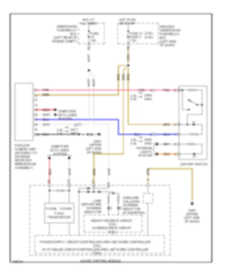
Forced Entry Wiring Diagram (1 of 6) for Honda Crosstour EX-L 2014
List of elements for Forced Entry Wiring Diagram (1 of 6) for Honda Crosstour EX-L 2014:
- (at driver "b" pillar) driver's door switch
- (integral to interior rearview mirror base assembly) fcw/ldw camera unit
- 2.4l
- 3.5l
- B10
- B11
- B12
- B13
- B14
- B15
- B16
- B17
- B18
- B19
- B20
- B21
- B22
- B23
- B24
- B25
- B26
- B27
- B28
- B35
- C10
- C11
- C12
- C13
- C14
- C15
- C16
- C17
- C18
- C19
- C20
- C21
- C22
- C23
- C24
- C306
- C403
- C411
- C701
- Computer data lines system
- D10
- D13
- D15
- Driver's micu
- Driver's under-dash fuse/relay box (left end of dash)
- Etcs control relay
- F14
- F16
- F23
- Front accessory power socket relay
- Fuse 10a
- Fuse 15a
- Fuse 7.5a
- G302 (left kick panel)
- G402 (upper left end of dash)
- G405 (right end of dash)
- G601 (under driver's seat)
- Hot at all times
- Keyless access control unit (if equipped) (left side of dash)
- N10
- P16
- Pnk
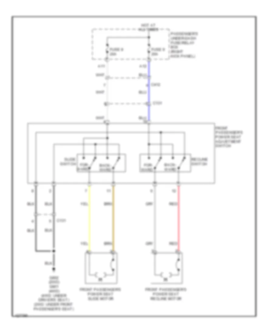
- Power seat control unit (under driver's seat)
- Q13
- Q16
- Q18
- Red
- Rf unit
- Security hood switch (middle front engine compt)
- Steering lock
- Transmitter
- Under- hood fuse/ relay box (left rear of engine compt)
Forced Entry Wiring Diagram (2 of 6) for Honda Crosstour EX-L 2014
List of elements for Forced Entry Wiring Diagram (2 of 6) for Honda Crosstour EX-L 2014:
- (left side of dash) driver's junction box
- (w/ keyless access) acc sub relay
- (w/ keyless access) ig1 relay 1
- (w/ keyless access) ig1 relay 2
- (w/ keyless access) ig2 relay
- 2.4l
- 3.5l
- 5v control circuit
- A10
- A25
- A27
- A37
- A38
- Audio unit/ audio navigation unit
- B20
- B24
- C101
- C106
- C20
- C408
- Computer data lines system
- Engine start/stop switch
- Exterior lights system
- G101 (right front of engine)
- G101 (top left rear of engine)
- G405 (right end of dash)
- Immobilizer
- J/c c014
- Lf antenna
- Parking brake switch (base of parking brake lever assembly)
- Pcm (left front of engine compt)
- Pnk
- Red
- Under-dash sub-relay box
Forced Entry Wiring Diagram (3 of 6) for Honda Crosstour EX-L 2014
List of elements for Forced Entry Wiring Diagram (3 of 6) for Honda Crosstour EX-L 2014:
- (left center of dash) g403
- 2.4l
- 3.5l
- 30a
- 5v stabilize circuit/controller area network controller
- B-can h
- B-can l
- B-can transceiver
- C106
- C401
- C402
- C404
- C408
- C414
- C506
- C801
- C802
- C821
- Computer data lines system
- Dlc (under left end of dash)
- Door lock knob
- Driver's door ind
- Driver's door key cylinder switch
- Driver's door lock actuator/ knob switch/key cylinder switch (built into the front door latch)
- Driver's door lock knob switch
- Driver's junction box (left side of dash)
- Front passenger's door ind
- Fuel fill door lock actuator (behind left rear side trim panel)
- Fuse
- G10
- G101 (right front of engine)
- G101 (top left rear of engine)
- G401 (upper left end of dash)
- G402 (under left end of dash)
- G601 (under driver's seat)
- Gauge control module
- Hot at all times
- Indicator drive circuit
- J/c c014
- J/c c015
- Key
- Keyless access ind
- Knob door lock
- Left rear door ind
- Left rear door lock actuator/knob switch (built into the rear door latch)
- Left rear door switch (at left rear "c" pillar)
- Lock
- Park pin switch/ a/t gear position indicator panel light (base of shift lever assembly)
- Pnk
- Red
- Right rear door ind
- Security ind
- Transmission range switch (2.4l) (rear of transmission housing)
- Transmission range switch (3.5l) (rear of transmission housing)
- Under-hood fuse/relay box (left rear of engine compt)
- Unlock
- Warning drive circuit
Forced Entry Wiring Diagram (4 of 6) for Honda Crosstour EX-L 2014
List of elements for Forced Entry Wiring Diagram (4 of 6) for Honda Crosstour EX-L 2014:
- 2.4l
- 3.5l
- C302
- C414
- C601
- C651
- C801
- C803
- Center junction box
- Computer data lines system
- Control unit
- D12
- D16
- Door lock switch
- Door lock switch lock light
- Door lock switch unlock light
- Driver's micu
- Driver's under-dash fuse/relay box (left end of dash)
- Exterior lights system
- F13
- F17
- F32
- Fuse 15a
- Fuse 20a
- Fuse 7.5a
- G302 (left kick panel)
- G402 (under left end of dash)
- G601 (under driver's seat)
- Headlights system
- Horns system
- Hot at all times
- J/c c007 (3.5l) j/c c671 (2.4l) (2.4l: right side of tailgate)
- Knob door lock
- N11
- P11
- P19
- Pnk
- Power distribution system
- Power door lock relay circuit
- Power door unlock relay (dr) circuit
- Power door unlock relay circuit
- Power mirror control unit
- Power mirror switch
- Power window master switch (door multiplex control unit)
- Red
- Starter cut relay 1
- Tailgate release actuator relay circuit
- Tailgate release actuator/latch switch (built into the tailgate latch) (bottom center rear of tailgate)
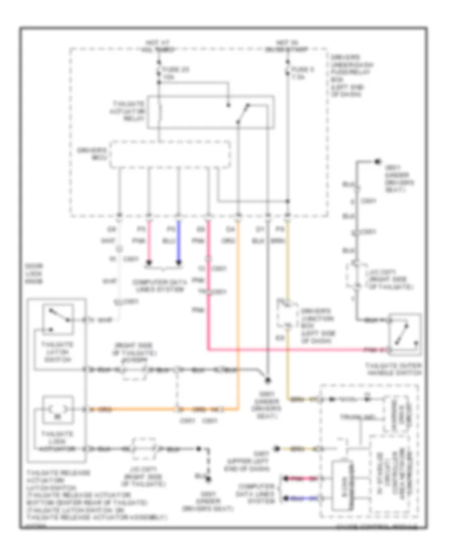
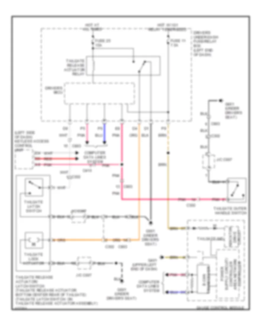
Forced Entry Wiring Diagram (5 of 6) for Honda Crosstour EX-L 2014
List of elements for Forced Entry Wiring Diagram (5 of 6) for Honda Crosstour EX-L 2014:
- 2.4l
- 3.5l
- A16
- A18
- Auxiliary underdash fuse holder a
- Brake pedal position switch (base of brake pedal bracket)
- C302
- C404
- C410
- C413
- C601
- C602
- C651
- C803
- C811
- C831
- Control unit
- Door lock knob
- Door lock switch
- Door lock switch lock light
- Door lock switch unlock light
- E18
- Exterior lights system
- Front passenger's door lock actuator/knob switch (built into the front door latch)
- Front passenger's door switch (at passenger's "b" pillar)
- Front passenger's power window switch
- Fuse 10a
- Fuse 20a
- Fuse 7.5a
- Fuse n/a
- G405 (right end of dash)
- G601 (under driver's seat)
- G701 (under front passenger's seat)
- H10
- H24
- H35
- H38
- Headlights system
- Hot at all times
- J/c c007 (3.5l) j/c c671 (2.4l) (2.4l: right side of tailgate)
- Passenger's micu
- Passenger's under-dash fuse/relay box (right kick panel)
- Pnk
- Power door lock relay (lock) circuit
- Power door lock relay (unlock) circuit
- Red
- Right rear door lock actuator/knob switch (built into the rear door latch)
- Right rear door switch (at right rear "c" pillar)
- Tailgate lock switch
- Tailgate outer handle switch
- Under-hood fuse/relay box (left rear of engine compt)
Forced Entry Wiring Diagram (6 of 6) for Honda Crosstour EX-L 2014
List of elements for Forced Entry Wiring Diagram (6 of 6) for Honda Crosstour EX-L 2014:
- (2.4l)
- A10
- A11
- A12
- A13
- A14
- A15
- A16
- A17
- A18
- A19
- A20
- A21
- A22
- A23
- A24
- A25
- A26
- A27
- A28
- A29
- A30
- A31
- A32
- C102
- C407
- C410
- C413
- C804
- Driver's door touch sensor
- Front interior lf antenna (under front of center console)
- Front passenger's door touch sensor
- G401 (under left end of dash)
- G402 (upper left end of dash)
- G403 (left center of dash)
- G405 (right end of dash)
- G603 (behind rear of left rear side trim panel)
- Key interlock solenoid/ignition key light (built into the steering lock)
- Keyless access control unit (if equipped) (left side of dash)
- Left power mirror
- Left power mirror lf antenna
- Lock switch
- Middle interior lf antenna (under center console)
- Pnk
- Rear bumper lf antenna (behind center of rear bumper)
- Rear interior lf antenna
- Red
- Right power mirror
- Right power mirror lf antenna
- Smart buzzer
- Touch sensor
Immobilizer Wiring Diagram for Honda Crosstour EX-L 2014
List of elements for Immobilizer Wiring Diagram for Honda Crosstour EX-L 2014:
- 5v stabilize circuit/controller area network controller
- A30
- A46
- Audio-navigation unit/audio unit
- B-can h
- B-can l
- C10
- C101
- C20
- C306
- C407
- Circuit drive warning
- Computer data lines system
- Dlc (under left side of dash)
- Driver's
- Driver's junction box (left side of dash)
- Driver's under-dash fuse/relay box (left end of dash)
- F-can h
- F-can l
- F12
- F16
- F33
- Fuel tank unit (top of fuel tank)
- Fuse 10a
- Fuse 15a
- Fuse 20a
- Fuse 7.5a
- G10
- G101 (top left rear of engine)
- G402 (upper left end of dash)
- G403 (left center of dash)
- G602 (left front of cargo area floor)
- Gauge control module
- Hot at all times
- Hot in on or start
- Immobilizer keyless control unit (steering column)
- Immobilizer system ind
- Key interlock solenoid/ ignition key switch/ ignition key light
- Micu
- P19
- Parking brake switch (base of parking brake lever assembly)
- Pcm (left front of engine compt)
- Pgm-fi main relay 1
- Pgm-fi main relay 2
- Pnk
- Q13
- Q16
- Red
- Transceiver b-can
- Transceiver f-can
- Under-hood fuse/relay box (left rear of engine compt)
BODY CONTROL MODULES
2.4L
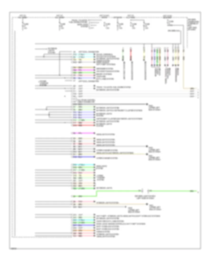
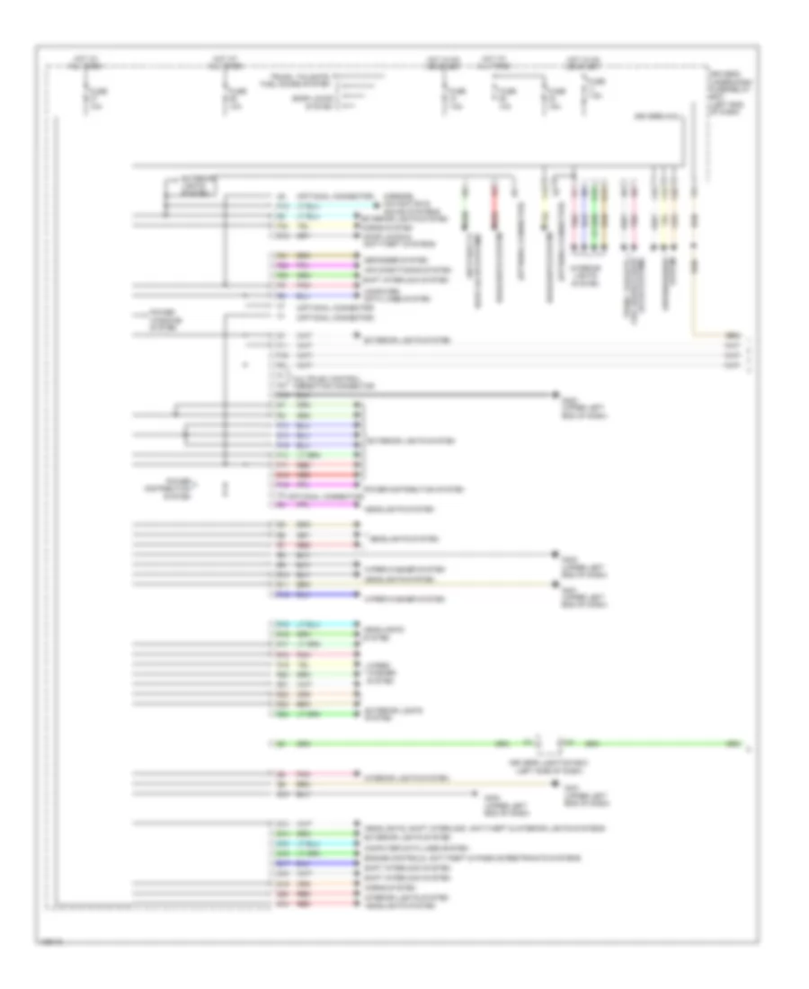
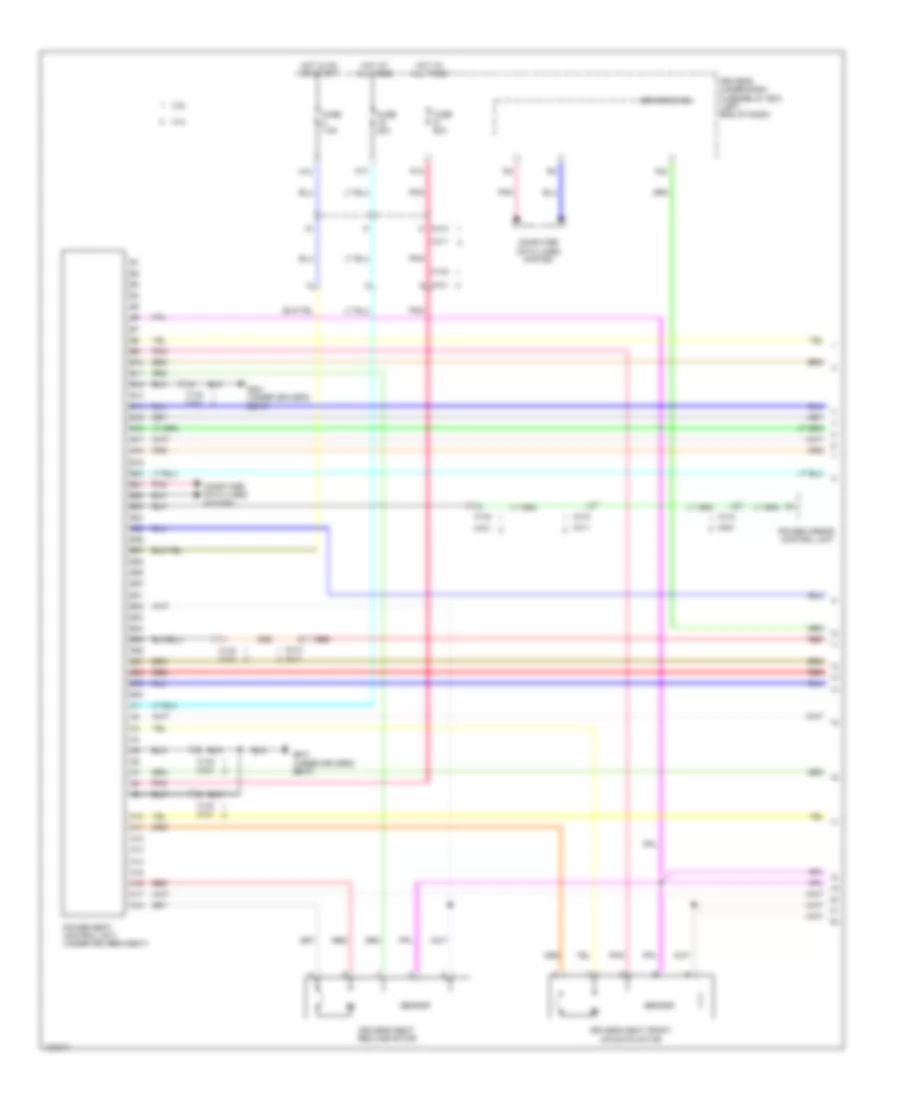
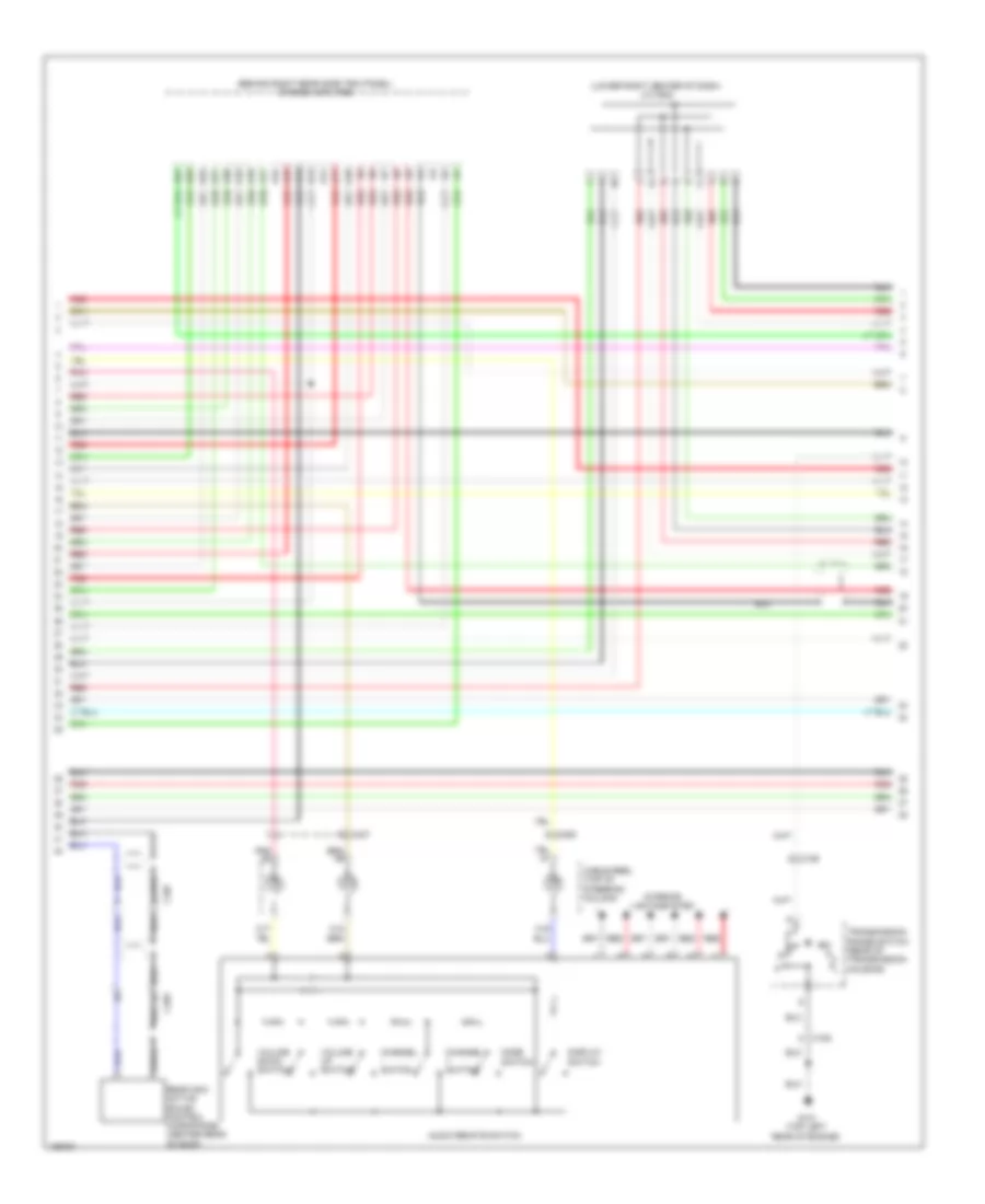
2.4L, Body Control Modules Wiring Diagram (1 of 2) for Honda Crosstour EX-L 2014
List of elements for 2.4L, Body Control Modules Wiring Diagram (1 of 2) for Honda Crosstour EX-L 2014:
- (optional connector)
- Air conditioning system
- Anti-theft system
- Anti-theft, interior lights, headlights & shift interlock systems
- Computer
- Computer data lines system
- D10
- D12
- D14
- D15
- D16
- Data lines system
- Defogger system
- Door locks system
- Door locks, engine controls & anti-theft systems
- Driver's junction box (left side of dash)
- Driver's micu
- Driver's under-dash fuse/relay box (left end of dash)
- Exterior lights
- Exterior lights & instrument cluster systems
- Exterior lights system
- F10
- F11
- F13
- F14
- F16
- F17
- F18
- F19
- F20
- F21
- F22
- F23
- F32
- Fuse 10a
- Fuse 15a
- Fuse 7.5a
- G10
- G401 (upper left end of dash)
- G402 (upper left end of dash)
- Headlights & exterior lights systems
- Headlights system
- Horns system
- Horns system door locks & anti-theft systems
- Hot at all times
- Hot in acc or on
- Hot in on
- Hot in on or start
- Instrument cluster & exterior lights systems
- Interior
- Interior lights system
- Lights system
- Memory systems
- Multiplex control check connector
- N15
- P12
- P15
- Pnk
- Power windows system
- Q10
- Q13
- Q14
- Q15
- Q16
- Q17
- Q18
- Q19
- Q20
- R10
- R11
- R12
- R15
- R16
- R17
- R18
- R19
- R20
- R21
- R22
- R23
- R24
- Red
- Shift interlock system
- Sound, mirrors & navigation systems exterior lights system
- Trunk, tailgate, fuel doors system
- Wiper/ washer system
- Wiper/washer system
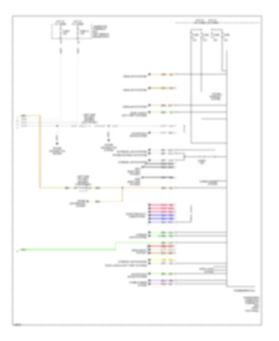
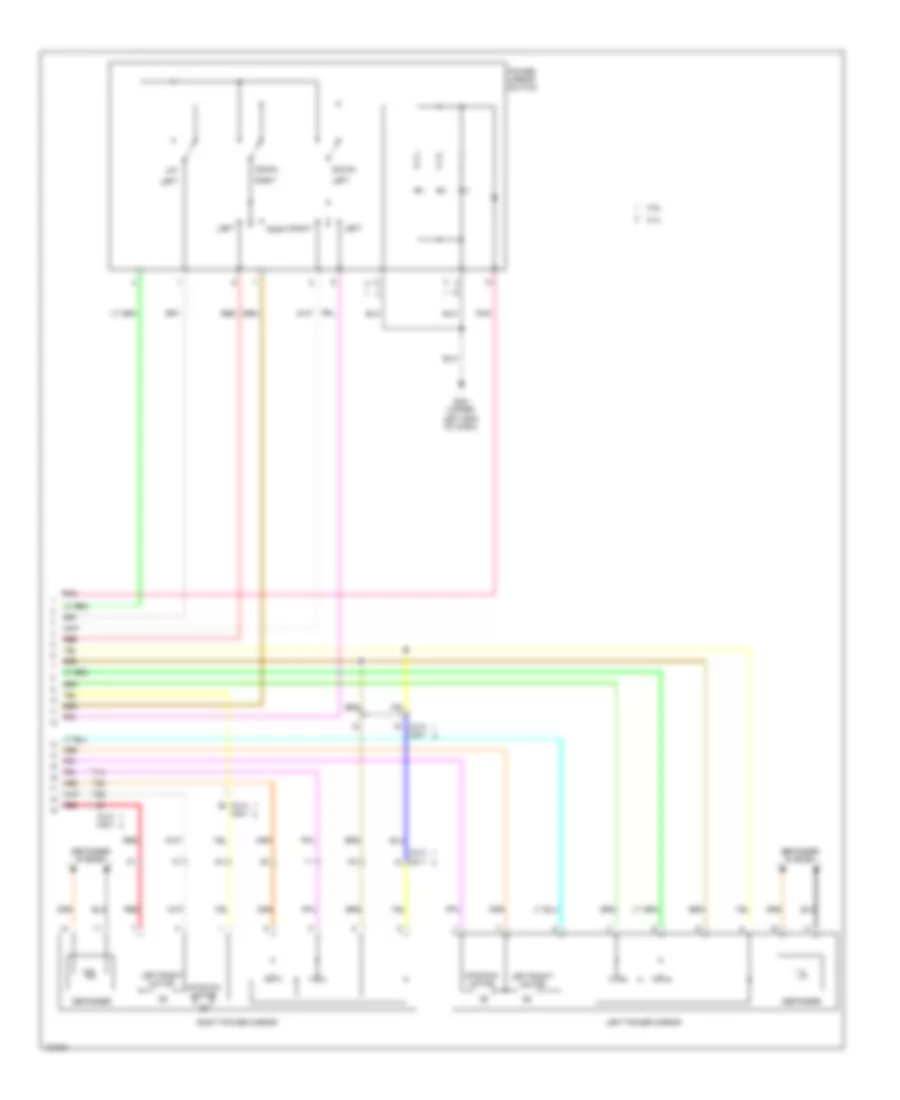
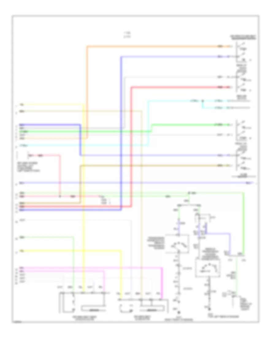
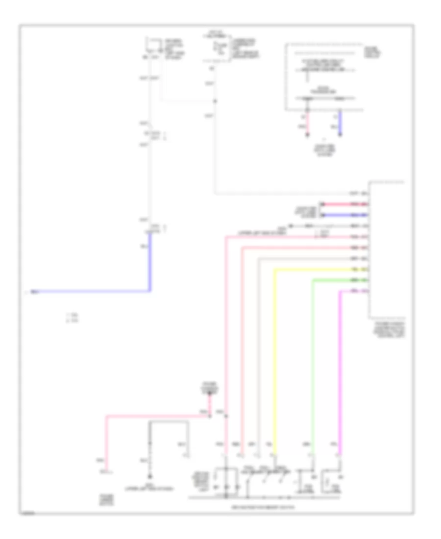
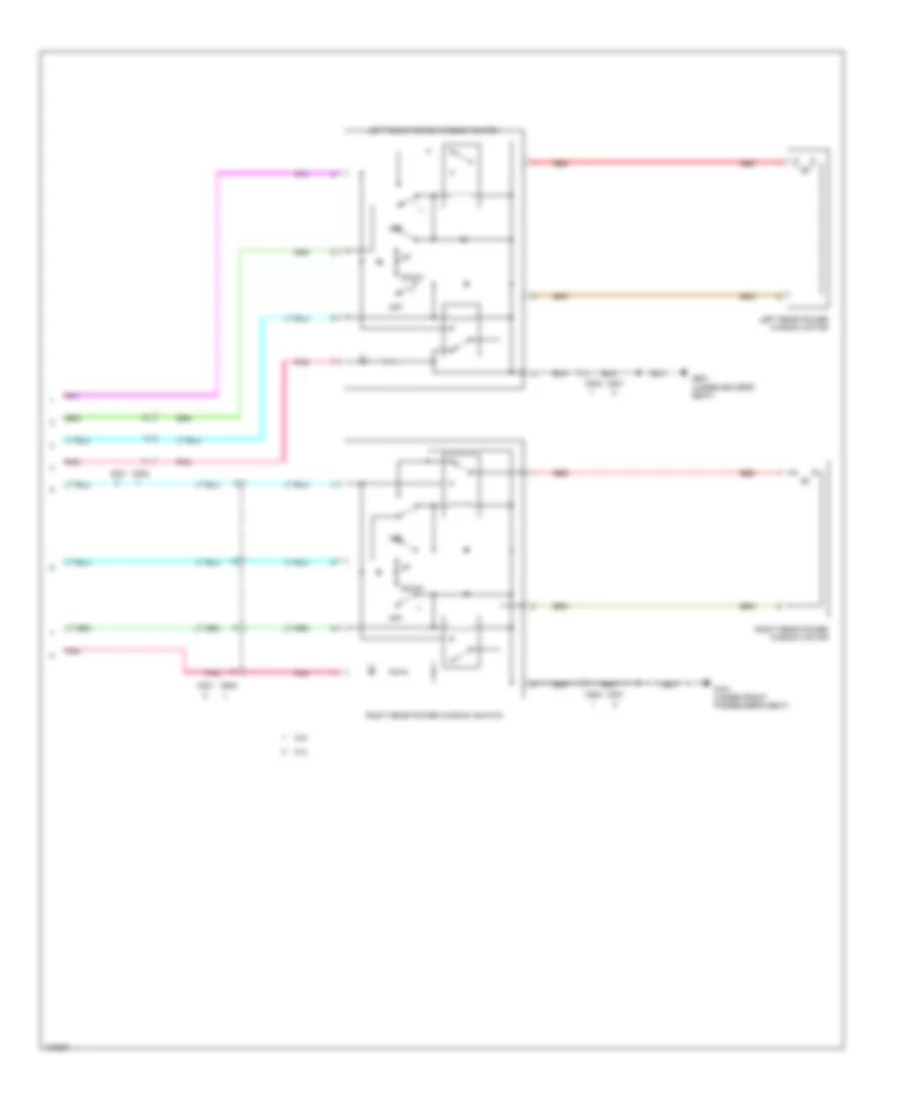
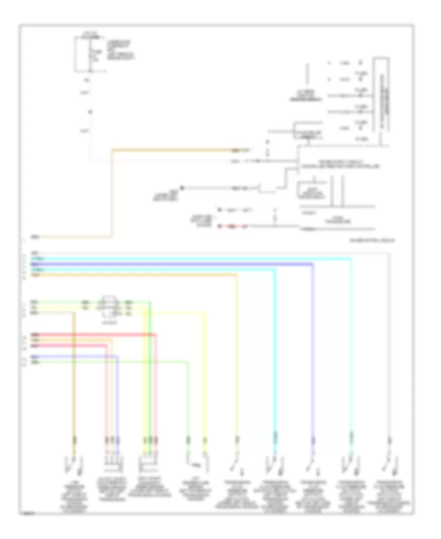
2.4L, Body Control Modules Wiring Diagram (2 of 2) for Honda Crosstour EX-L 2014
List of elements for 2.4L, Body Control Modules Wiring Diagram (2 of 2) for Honda Crosstour EX-L 2014:
- (left side of dash) driver's junction box
- A15
- A18
- A19
- A21
- A26
- A28
- A30
- A34
- A38
- Computer data lines system
- D10
- D11
- D12
- D13
- D14
- D23
- D25
- D26
- Door locks & anti-theft systems
- Door locks system
- E14
- E15
- E17
- E18
- Exterior lights system
- Fuse 10a
- Fuse 15 10a
- Fuse 15a
- Fuse 6 7.5a
- Fuse 7 15a
- G10
- G203 (right end of dash)
- G405 (right end of dash)
- H24
- H31
- H35
- H38
- Headlights system
- Hot at all times
- Interior lights system
- Navigation & sound system
- Navigation & sound systems
- Passenger's micu
- Passenger's under-dash fuse/relay box (right kick panel)
- Pnk
- Power distribution system
- Power windows system
- Red
- Under-hood fuse/relay box (left rear of engine compt)
- Wiper/washer system
3.5L
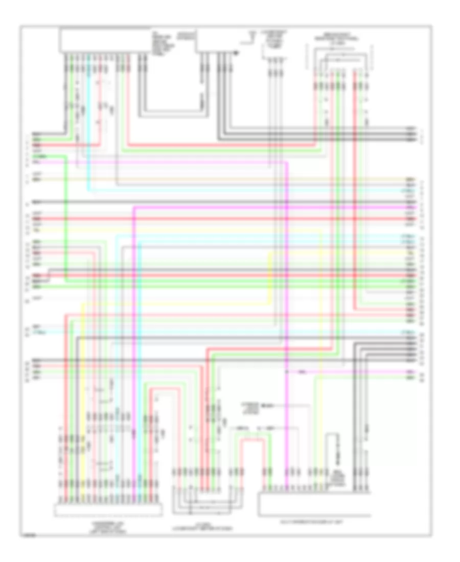
3.5L, Body Control Modules Wiring Diagram (1 of 2) for Honda Crosstour EX-L 2014
List of elements for 3.5L, Body Control Modules Wiring Diagram (1 of 2) for Honda Crosstour EX-L 2014:
- (optional connector)
- Air conditioning system
- Anti-theft & door locks systems
- Computer data lines system
- D10
- D12
- D14
- D15
- D16
- Defogger system
- Door locks & anti-theft systems
- Door locks system
- Driver's junction box (left side of dash)
- Driver's micu
- Driver's under-dash fuse/relay box (left end of dash)
- Engine controls, anti-theft & passive restraints systems
- Exterior lights system
- F10
- F11
- F13
- F14
- F16
- F17
- F18
- F19
- F20
- F21
- F22
- F23
- F32
- Fuse 10a
- Fuse 15a
- Fuse 7.5a
- G10
- G401 (upper left end of dash)
- G402 (upper left end of dash)
- Headlights system
- Headlights, shift interlock, anti-theft & interior lights systems
- Horns system
- Hot at all times
- Hot in on or start
- Interior lights system
- Mirrors, navigation & sound systems
- Multiplex control inspection connector
- N15
- P12
- P15
- P16
- Pnk
- Power distribution system
- Power windows system
- Q10
- Q13
- Q14
- Q15
- Q16
- Q17
- Q18
- Q19
- Q20
- R10
- R11
- R12
- R15
- R16
- R17
- R18
- R19
- R20
- R21
- R22
- R23
- R24
- Red
- Shift interlock system
- Trunk, tailgate, fuel doors & door locks systems
- Trunk, tailgate, fuel doors system
- Wiper/ washer system
- Wiper/washer system
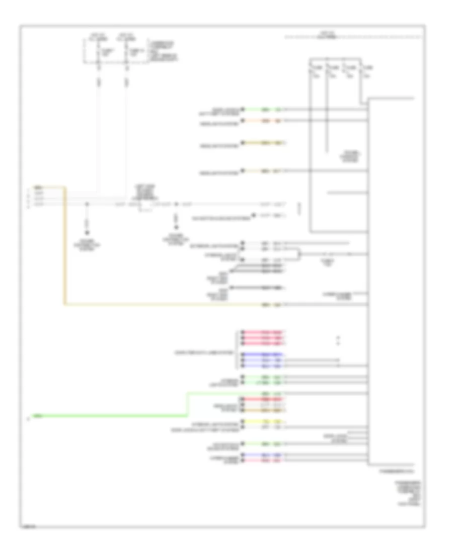
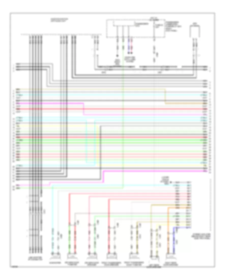
3.5L, Body Control Modules Wiring Diagram (2 of 2) for Honda Crosstour EX-L 2014
List of elements for 3.5L, Body Control Modules Wiring Diagram (2 of 2) for Honda Crosstour EX-L 2014:
- (left side of dash) driver's junction box
- A15
- A18
- A19
- A21
- A26
- A28
- A30
- A34
- A38
- Computer data lines system
- D10
- D11
- D12
- D13
- D14
- D23
- D25
- D26
- Door locks & anti-theft systems
- Door locks system
- E14
- E15
- E17
- E18
- Exterior lights system
- Fuse 10a
- Fuse 15 10a
- Fuse 15a
- Fuse 6 7.5a
- Fuse 7 15a
- G10
- G203 (right end of dash)
- G405 (right end of dash)
- H24
- H31
- H35
- H38
- Headlights system
- Hot at all times
- Interior lights system
- Navigation & sound systems
- Passenger's micu
- Passenger's under-dash fuse/relay box (right kick panel)
- Pnk
- Power distribution system
- Power windows system
- Red
- Under-hood fuse/relay box (left rear of engine compt)
- Wiper/washer system
COMPUTER DATA LINES
B-CAN Wiring Diagram & S-NET Wiring Diagram for Honda Crosstour EX-L 2014
List of elements for B-CAN Wiring Diagram & S-NET Wiring Diagram for Honda Crosstour EX-L 2014:
- 2.4l
- 3.5l
- A21
- A34
- A38
- A46
- Audio unit/ audio navigation unit
- B21
- B22
- C103
- C142
- C306
- C408
- C411
- C412
- C414
- C507
- C701
- C801
- Climate control unit
- Connector) (optional
- D11
- D12
- Driver's junction box (left side of dash)
- Driver's micu
- Driver's under-dash fuse/relay box (left end of dash)
- F16
- Fuse 10a
- G402 (upper left end of dash)
- Gauge control module
- H10
- Hot at all times
- Immobilizer keyless control unit (if equipped) (steering column)
- J/c c008 j/c c405 (2.4l: upper right center of dash)
- Keyless access control unit (if equipped) (left side of dash)
- Passenger's micu
- Passenger's under-dash fuse/relay box (right kick panel)
- Pcm (left front of engine compt)
- Pnk
- Power seat control unit (w/ memory) (under driver's seat)
- Power window master switch (door multiplex control unit)
- Q10
- Q16
- Under-hood fuse/relay box (left rear of engine compt)
Data Link Connector Wiring Diagram for Honda Crosstour EX-L 2014
List of elements for Data Link Connector Wiring Diagram for Honda Crosstour EX-L 2014:
- (2.4l: lower right center of dash) (3.5l) j/c c002 (2.4l) j/c c505
- 2.4l
- 3.5l
- A10
- A13
- A14
- A19
- A20
- A21
- A32
- A39
- Anc/active sound control unit (right center of dash)
- Audio unit/ audio navigation unit
- B20
- C102
- C107
- C202
- C205
- C207
- C306
- C405
- C406
- C408
- C409
- C421
- C702
- Center junction box (left center of dash)
- D14
- D19
- D20
- D26
- D28
- Dlc (under left end of dash)
- Driver's micu
- Driver's under-dash fuse/relay box (left end of dash)
- E10
- E11
- Engine mount control unit (3.5l) (left end of dash)
- Eps control unit (right end of dash)
- F17
- F18
- F30
- F31
- Fcw/ldw camera unit (integral to interior rearview mirror base assembly)
- Fuse 15 10a
- G12
- G13
- G401 (upper left end of dash)
- G402 (upper left end of dash)
- Gauge control module
- H18
- H19
- Hot at all times
- Immobilizer keyless control unit (if equipped) (steering column)
- J/c c009 (3.5l) j/c c413 (2.4l) (2.4l: upper right center of dash)
- K-line
- Keyless access control unit (if equipped) (left side of dash)
- P13
- P14
- Passenger's under-dash fuse/relay box (right kick panel)
- Pcm (left front of engine compt)
- Q15
- Red
- Srs unit (under front of center console)
- Steering angle sensor (steering column)
- Tpms control unit (left center of dash)
- Under-hood fuse/relay box (left rear of engine compt)
- Vsa modulator control unit (right side of engine compt)
- Yaw rate- acceleration sensor (under center console)
COOLING FAN
Cooling Fan Wiring Diagram for Honda Crosstour EX-L 2014
List of elements for Cooling Fan Wiring Diagram for Honda Crosstour EX-L 2014:
- 2.4l
- 3-6 30a
- 3-8 30a
- 3.5l
- A/c compressor clutch relay
- A/c condenser fan motor (behind right side of radiator)
- A/c condenser fan relay
- A/c diode a
- A/c diode b
- A/c pressure sensor (right front of engine compt)
- A10
- A14
- A17
- A19
- A20
- A31
- A34
- A44
- A45
- A47
- A49
- B10
- B11
- B12
- B13
- B20
- B34
- B44
- B45
- Blower motor relay
- C48
- Computer data lines system
- Driver's under- dash fuse/ relay box (left end of dash)
- Ect sensor 1 (left rear of engine)
- Ect sensor 2 (lower left rear of radiator)
- Engine controls system
- F29
- Fan control relay
- Fuse 15a
- Fuse 20a
- Fuse 3-6 30a
- Fuse 7.5a
- G101 (right front of engine)
- G101 (top left rear of engine)
- G301 (behind left side of front bumper)
- Hot at all times
- Hot in on or start
- J/c c013
- J/c c014
- Pcm (left front of engine compt)
- Pgm-fi sub- relay
- Pnk
- Radiator fan motor (behind left side of radiator)
- Radiator fan relay
- Red
- Relay circuit board
- Under- hood fuse/ relay box (left rear of engine compt)
CRUISE CONTROL
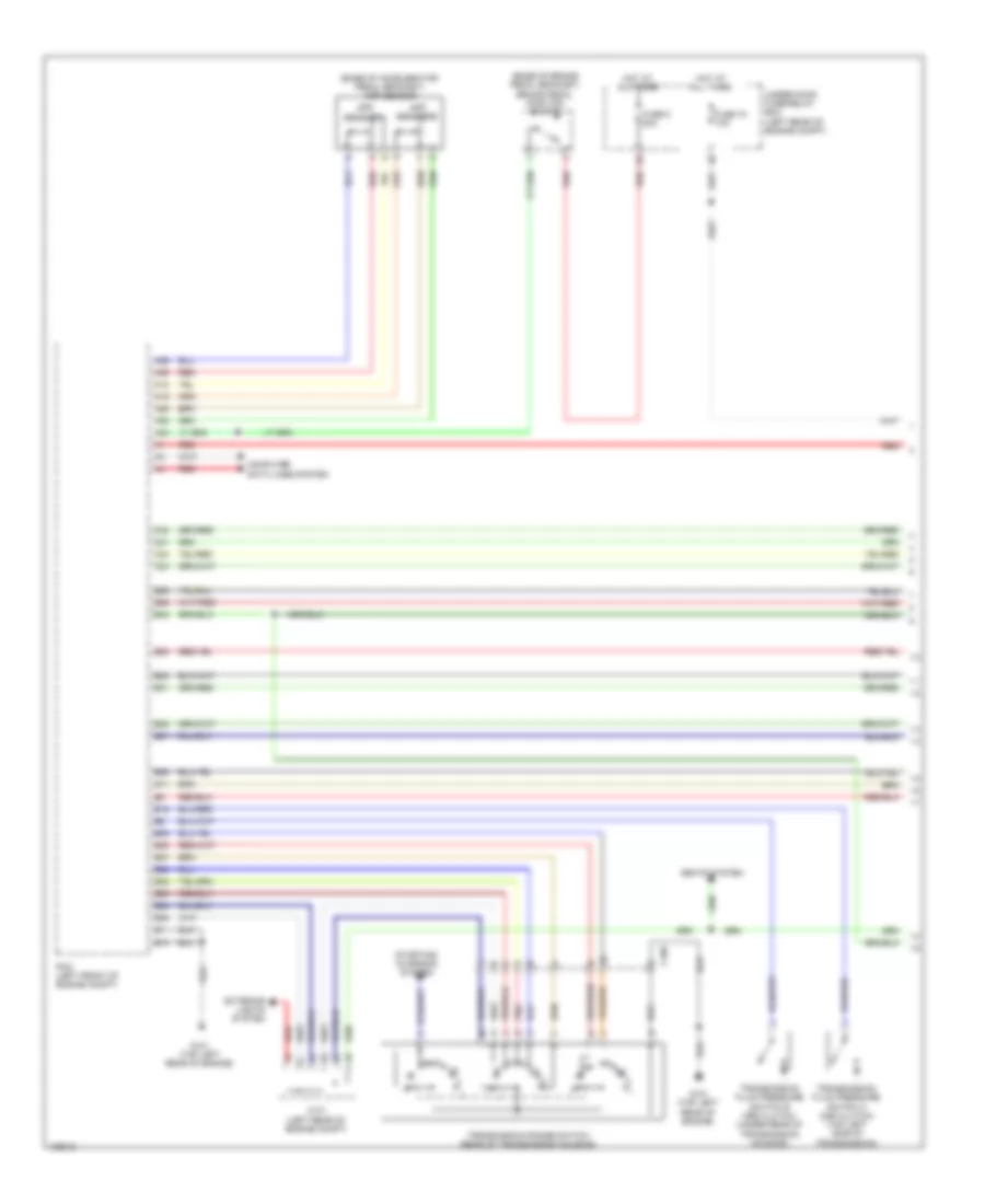
2.4L
2.4L, Cruise Control Wiring Diagram (1 of 3) for Honda Crosstour EX-L 2014
List of elements for 2.4L, Cruise Control Wiring Diagram (1 of 3) for Honda Crosstour EX-L 2014:
- A15
- A18
- A19
- A25
- A26
- A35
- A36
- A38
- A42
- B39
- B48
- C101
- C14
- C22
- C23
- C24
- C30
- C31
- Computer data lines system
- Engine controls system
- Etcs control relay
- Fuse 15a
- G101 (top left rear of engine)
- Hot at all times
- J/c c103 (right rear of engine)
- Output shaft (counter shaft) speed sensor (top right side of transmission housing)
- Pcm (left front of engine compt)
- Pgm-fi main relay 1
- Red
- Throttle actuator
- Throttle body (left rear of engine)
- Throttle open sensor
- Under-hood fuse/relay box (left rear of engine compt)
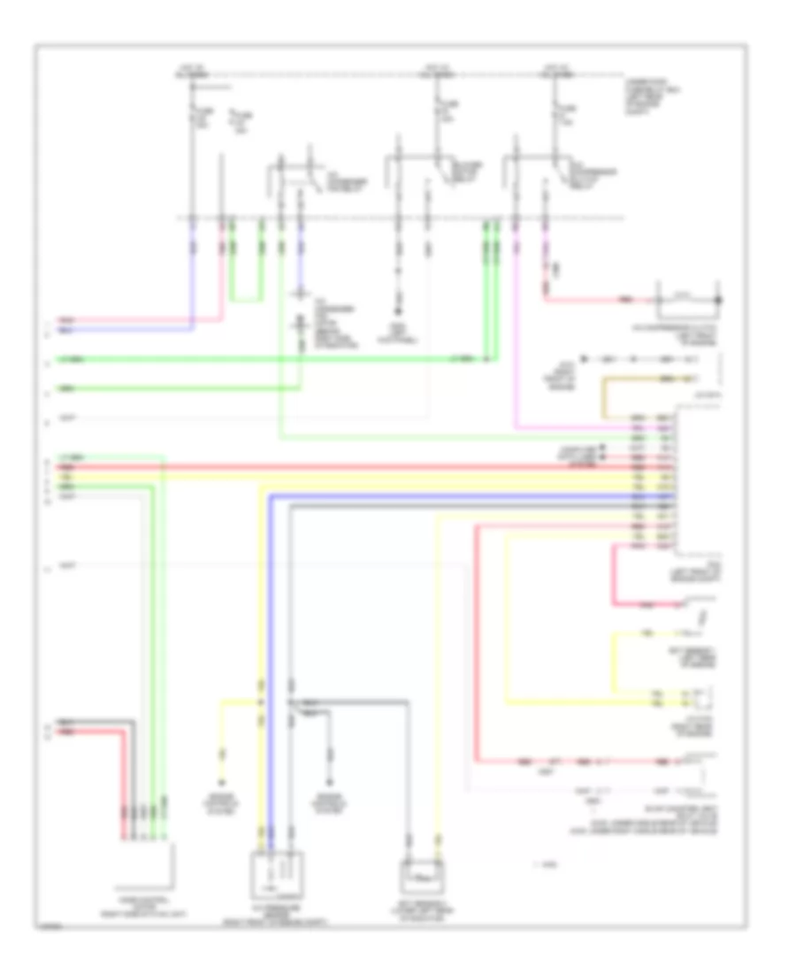
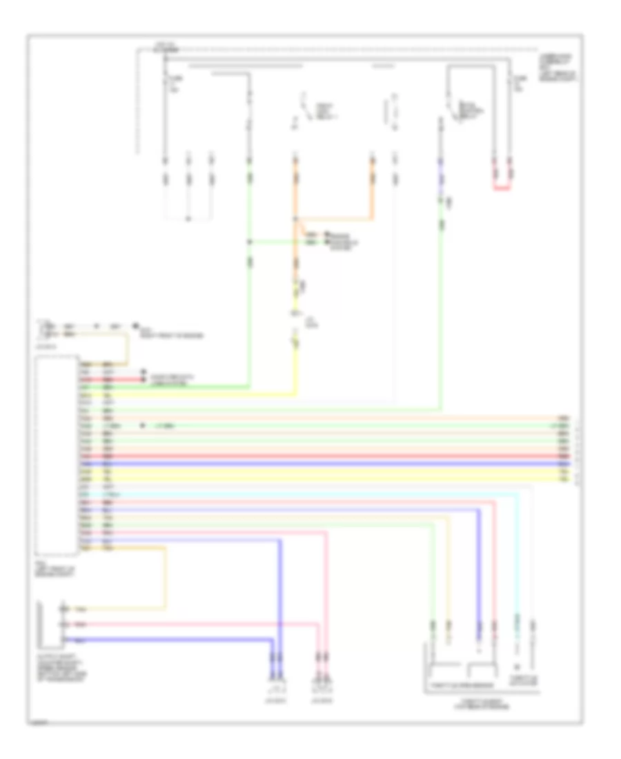
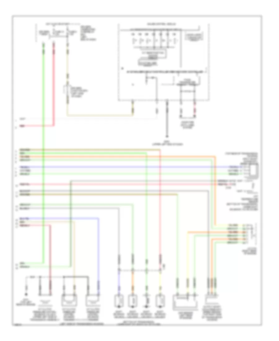
2.4L, Cruise Control Wiring Diagram (2 of 3) for Honda Crosstour EX-L 2014
List of elements for 2.4L, Cruise Control Wiring Diagram (2 of 3) for Honda Crosstour EX-L 2014:
- 10a stabilizer circuit
- 5v control circuit
- App sensor (base of accelerator pedal bracket)
- App sensor a
- App sensor b
- C106
- Computer data lines system
- Controller
- Controller area network 5v stabilize circuit/
- Cruise control ind
- Cruise control main switch ind
- Dimming circuit
- F-can h
- F-can l
- F-can transceiver
- Fuse 10a
- Fuse 20a
- G101 (top left rear of engine)
- G401 (upper left end of dash)
- Gauge control module
- Hot at all times
- Red
- Transmission range switch (rear of transmission housing)
- Under-hood fuse/relay box (left rear of engine compt)
- Warning drive circuit
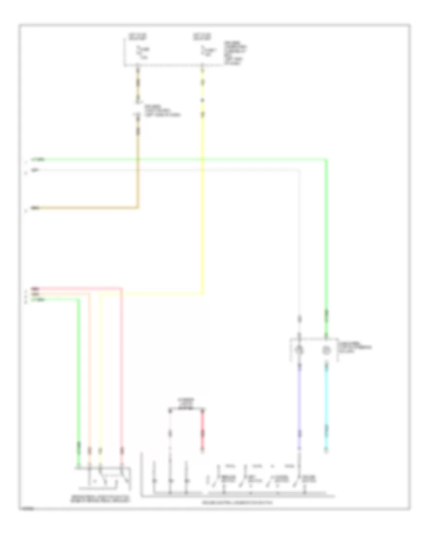
2.4L, Cruise Control Wiring Diagram (3 of 3) for Honda Crosstour EX-L 2014
List of elements for 2.4L, Cruise Control Wiring Diagram (3 of 3) for Honda Crosstour EX-L 2014:
- Brake pedal position switch (base of brake pedal bracket)
- C15
- C16
- Cable reel (top of steering column)
- Cancel switch
- Cruise control combination switch
- Cruise switch
- Driver's junction box (left side of dash)
- Driver's under-dash fuse/relay box (left end of dash)
- Fuse 7 15a
- Fuse 7.5a
- Hot in on or start
- Interior lights system
- Red
- Resume switch
- Set switch
3.5L
3.5L, Cruise Control Wiring Diagram (1 of 3) for Honda Crosstour EX-L 2014
List of elements for 3.5L, Cruise Control Wiring Diagram (1 of 3) for Honda Crosstour EX-L 2014:
- A10
- A13
- A24
- A25
- A41
- A42
- A43
- A44
- A45
- A46
- B10
- B20
- B29
- B31
- B40
- B44
- B46
- C21
- C32
- C33
- C506
- Computer data lines system
- Engine controls system
- Etcs control relay
- Fuse 15a
- G101 (right front of engine)
- Hot at all times
- J/c c013
- J/c c014
- J/c c015
- J/c c016
- Output shaft (counter shaft) speed sensor (bottom left side of transmission)
- Pcm (left front of engine compt)
- Pgm-fi main relay 1
- Pnk
- Red
- Tan
- Throttle actuator
- Throttle body (top rear of engine)
- Throttle open sensor
- Under-hood fuse/relay box (left rear of engine compt)
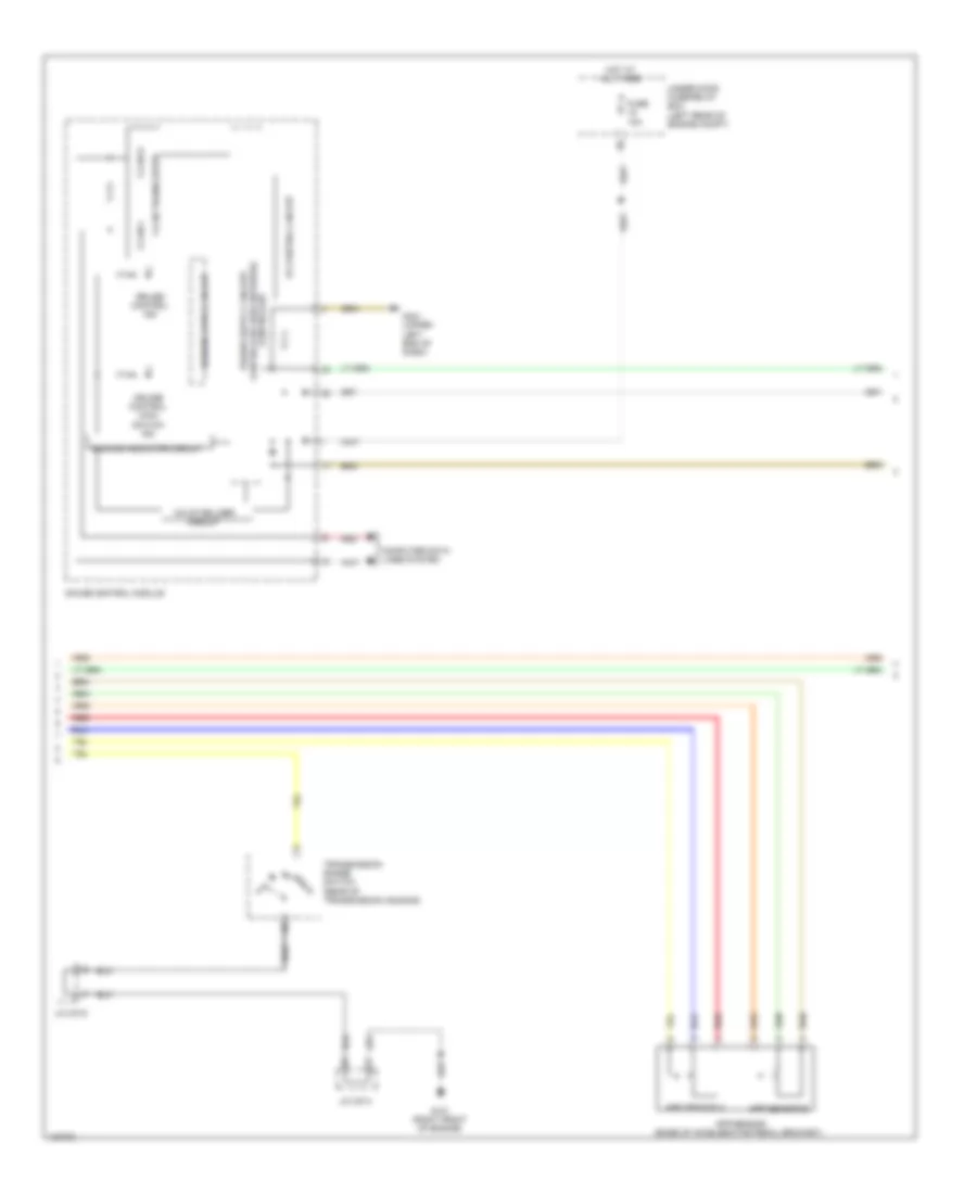
3.5L, Cruise Control Wiring Diagram (2 of 3) for Honda Crosstour EX-L 2014
List of elements for 3.5L, Cruise Control Wiring Diagram (2 of 3) for Honda Crosstour EX-L 2014:
- 10a stabilizer circuit
- 5v control circuit
- App sensor (base of accelerator pedal bracket)
- App sensor a
- App sensor b
- Computer data lines system
- Controller
- Cruise control ind
- Cruise control main switch ind
- Dimming indicator circuit
- F-can h
- F-can l
- F-can transceiver
- Fuse 10a
- G101 (right front of engine)
- G401 (upper left end of dash)
- Gauge control module
- Hot at all times
- J/c c014
- J/c c015
- Red
- Transmission range switch (rear of transmission housing)
- Under-hood fuse/relay box (left rear of engine compt)
- Warning drive circuit
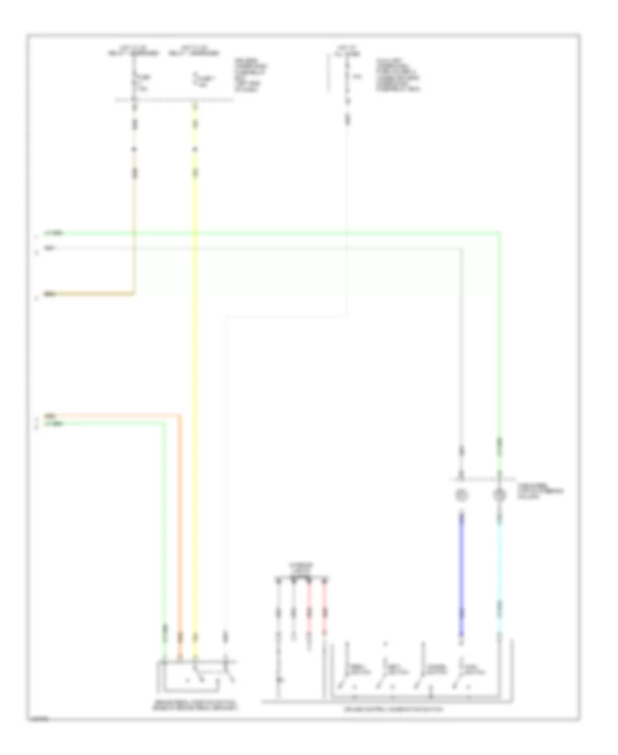
3.5L, Cruise Control Wiring Diagram (3 of 3) for Honda Crosstour EX-L 2014
List of elements for 3.5L, Cruise Control Wiring Diagram (3 of 3) for Honda Crosstour EX-L 2014:
- Auxiliary under-dash fuse holder a (under driver's under-dash fuse/relay box)
- Brake pedal position switch (base of brake pedal bracket)
- C15
- C16
- Cable reel (top of steering column)
- Cancel switch
- Cruise control combination switch
- Driver's under-dash fuse/relay box (left end of dash)
- Fuse 7 15a
- Fuse 7.5a
- Hot at all times
- Hot w/ ig1 relay 1 energized
- Interior lights system
- Main switch
- N/a
- Red
- Res/+ switch
- Set/- switch
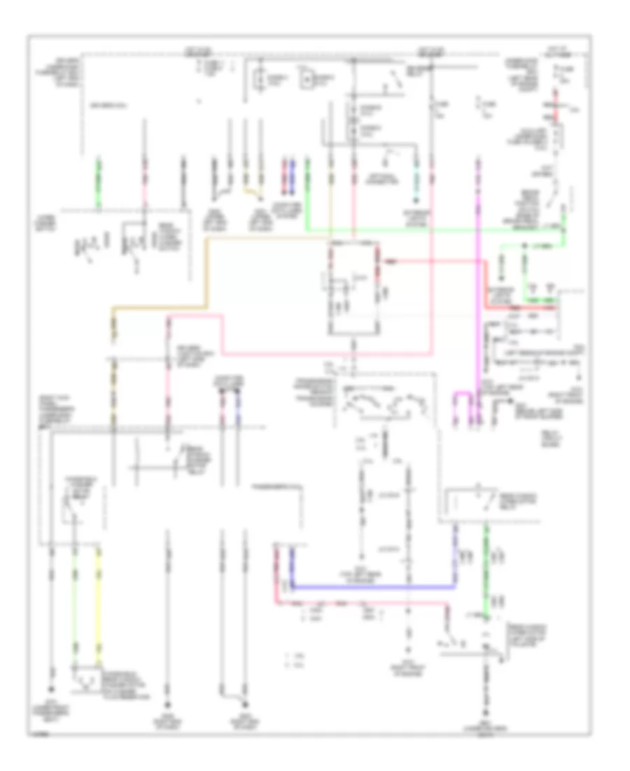
DEFOGGERS
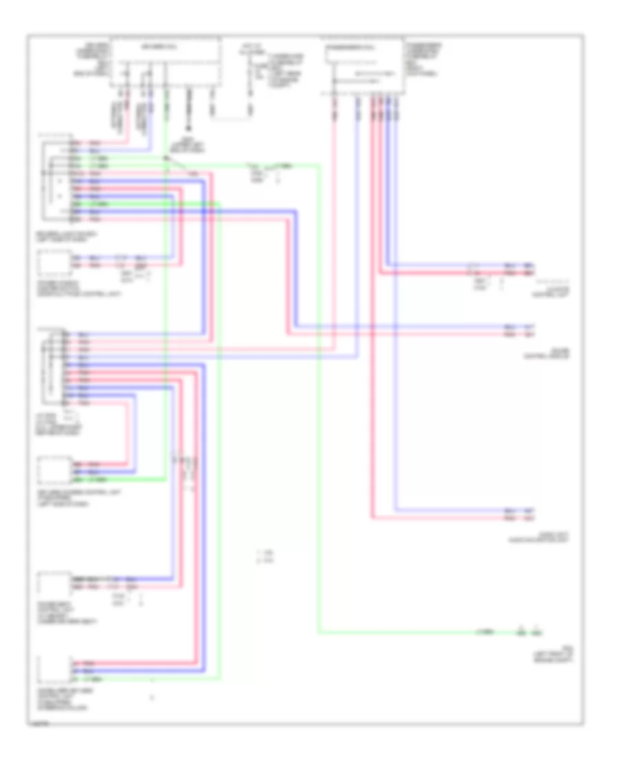
Defoggers Wiring Diagram for Honda Crosstour EX-L 2014
List of elements for Defoggers Wiring Diagram for Honda Crosstour EX-L 2014:
- (2.4l: lower right center of dash) (3.5l) j/c c001 (2.4l) j/c c506
- 2.4l
- 3.5l
- A15
- C103
- C106
- C301
- C304
- C407
- C413 c811
- C414
- C507
- C602
- C652
- C801
- C811
- Center junction box (left center of dash)
- Climate control unit
- Computer data lines system
- Control unit
- Defogger
- Driver's climate control switch
- Driver's micu
- Driver's under-dash fuse/relay box (left end of dash)
- F21
- F29
- Front passenger's power window switch
- Fuse 13 20a
- Fuse 16 7.5a
- Fuse 5 40a
- G401 (upper left end of dash)
- G402 (upper left end of dash)
- G405 (right end of dash)
- G502 (lower middle of dash)
- G601 (under driver's seat)
- G603 (behind rear of left rear side trim panel)
- Hot at all times
- Hot in on
- Interior lights system
- Left power mirror
- Lower rear window defogger
- Noise reduction condenser (behind rear of left rear side trim panel)
- P11
- Passenger's climate control switch
- Passenger's under-dash fuse/relay box (right kick panel)
- Pnk
- Power distribution system
- Power window master switch (door multiplex control unit)
- Rear window defogger relay
- Rear window defogger switch/ power mirror defogger switch
- Rear window defogger switch/ power mirror defogger switch indicator
- Red
- Right power mirror
- Under-hood fuse/relay box (left rear of engine compt)
- Upper rear window defogger
ELECTRONIC POWER STEERING
Electronic Power Steering Wiring Diagram for Honda Crosstour EX-L 2014
List of elements for Electronic Power Steering Wiring Diagram for Honda Crosstour EX-L 2014:
- 5v stabilizer circuit/controller area
- A10
- A39
- A40
- C202
- C203
- C206
- C207
- C504
- C505
- C508
- Compulsory turning
- Computer data lines system
- D10
- D11
- D12
- D13
- D14
- D15
- D16
- D17
- D18
- D19
- D20
- D21
- D22
- D23
- D24
- D25
- D26
- D27
- D28
- Driver's under-dash fuse/relay box (left end of dash)
- Eps control unit (right end of dash)
- Eps indicator
- Eps motor (on steering rack assembly)
- Eps motor angle sensor (on eps motor assembly)
- F-can h
- F-can l
- F-can transceiver
- Fail-safe circuit
- Fuse 10a
- Fuse 2-1 70a
- Fuse 7.5a
- G204
- Gauge control module
- Hot at all times
- Hot w/ ig1 relay 1 energized
- Hot w/ ig1 relay 2 energized
- Indicator drive circuit
- Network controller
- On circuit
- Pcm (left front of engine compt)
- Pnk
- Red
- Torque sensor (on steering rack assembly)
- Under-hood fuse/relay box (left rear of engine compt)
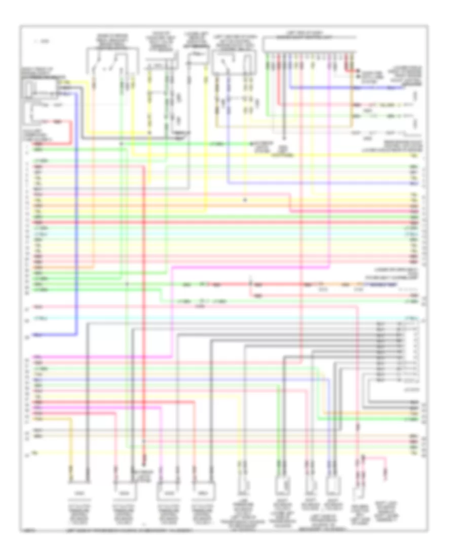
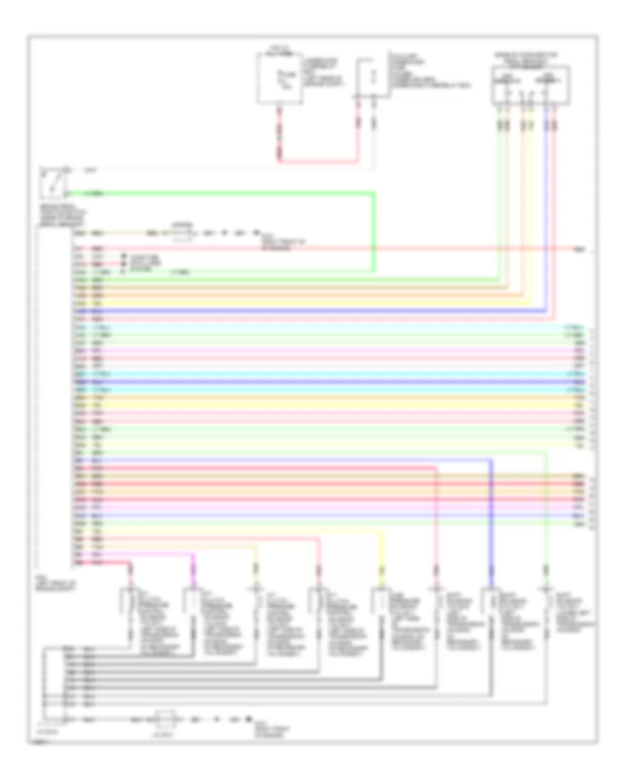
ENGINE PERFORMANCE
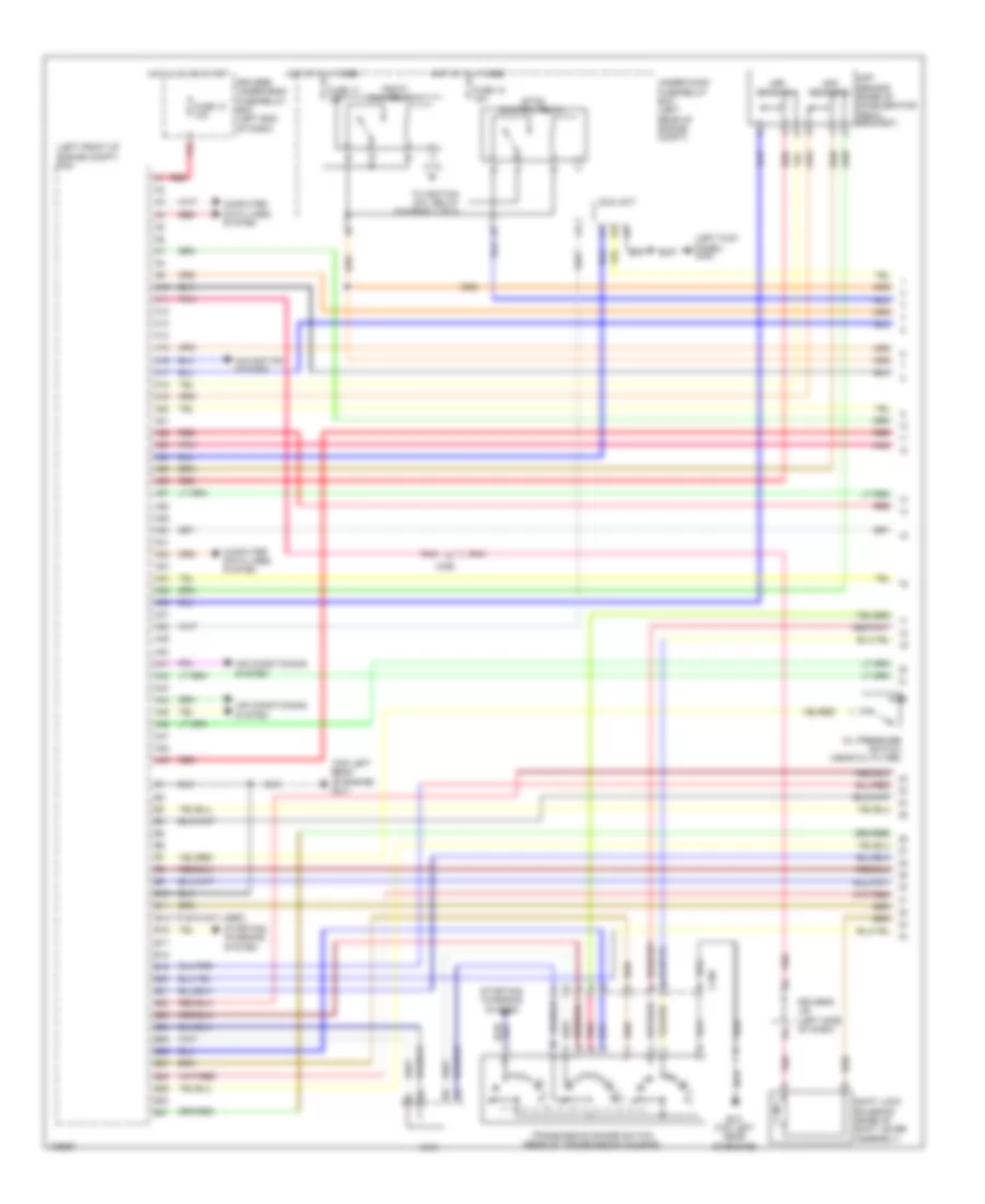
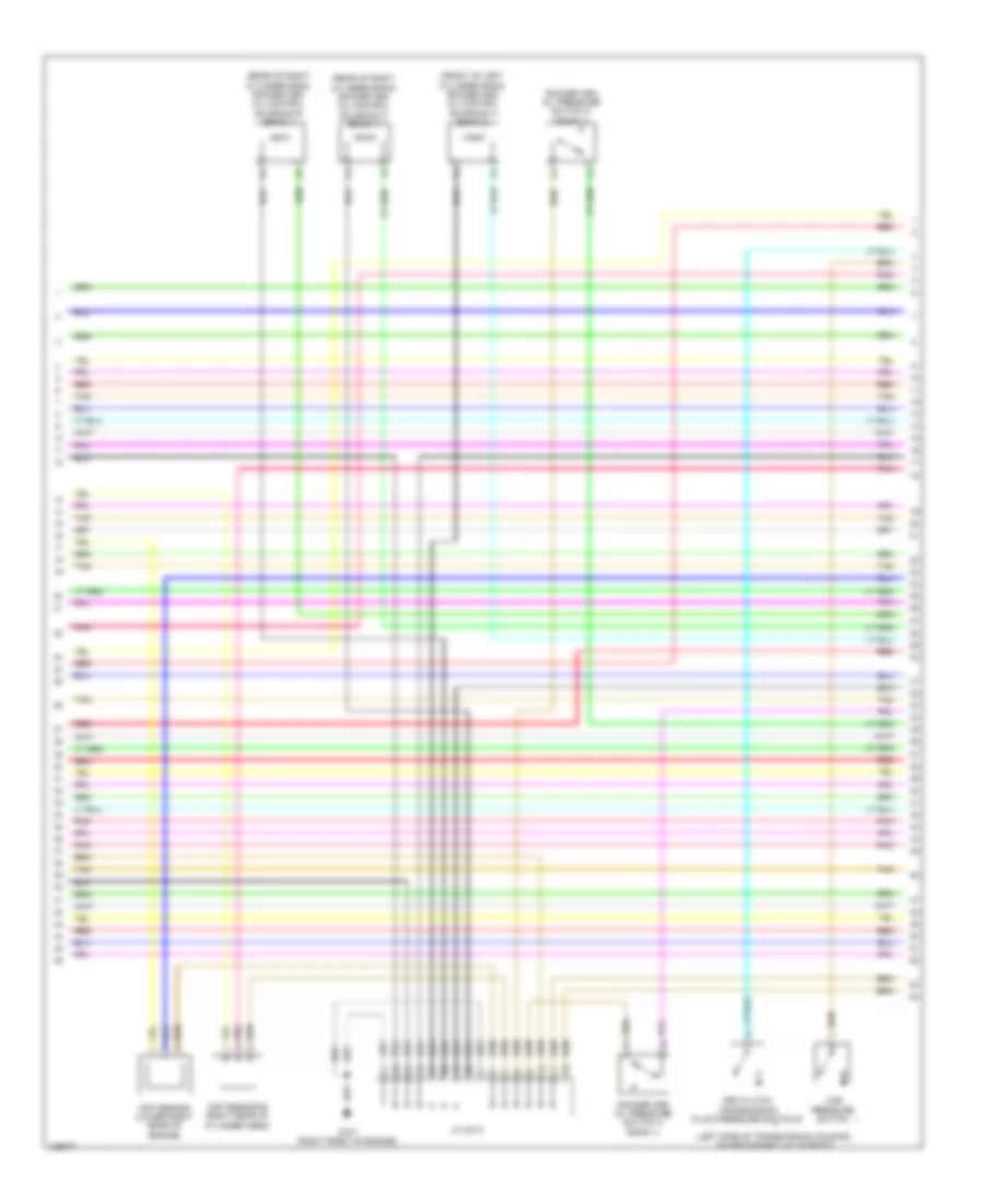
2.4L
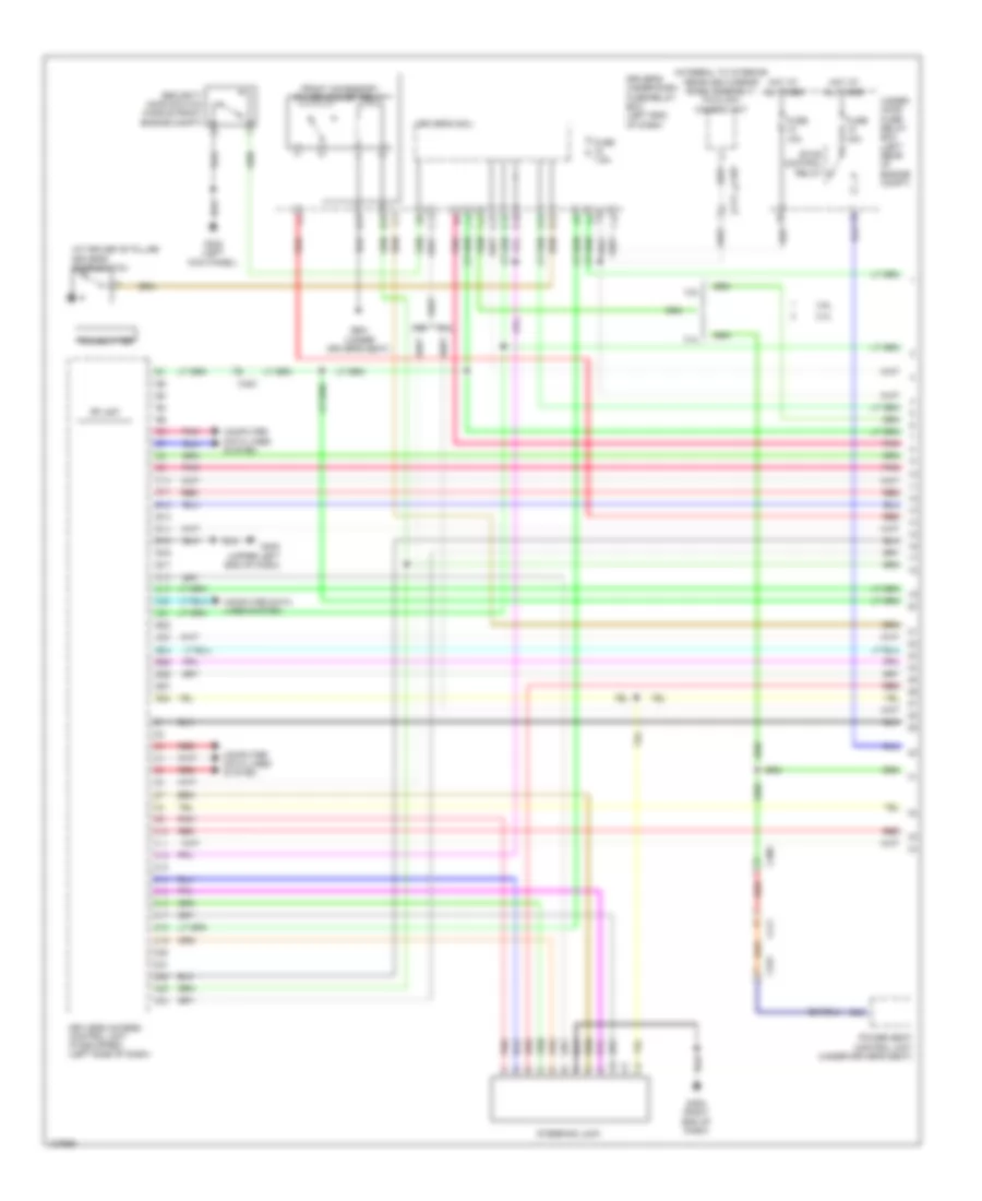
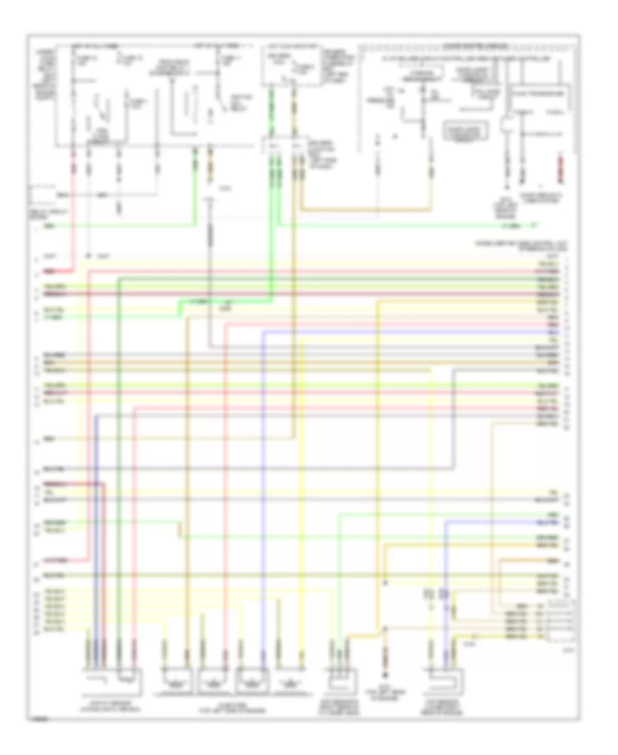
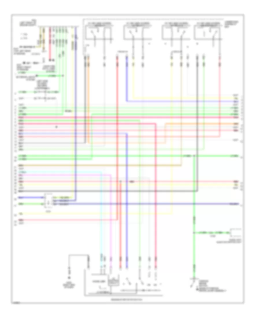
2.4L, Engine Performance Wiring Diagram (1 of 5) for Honda Crosstour EX-L 2014
List of elements for 2.4L, Engine Performance Wiring Diagram (1 of 5) for Honda Crosstour EX-L 2014:
- (b12 to b15 not used)
- (left front of engine compt) pcm
- (left kick panel) g302
- (top left rear of engine) g101
- A10
- A11
- A12
- A13
- A14
- A15
- A16
- A17
- A18
- A19
- A20
- A21
- A22
- A23
- A24
- A25
- A26
- A27
- A28
- A29
- A30
- A31
- A32
- A33
- A34
- A35
- A36
- A37
- A38
- A39
- A40
- A41
- A42
- A43
- A44
- A45
- A46
- A47
- A48
- A49
- Air conditioning system
- App sensor (base of accelerator pedal bracket)
- App sensor a
- App sensor b
- B10
- B11
- B16
- B17
- B18
- B19
- B20
- B21
- B22
- B23
- B24
- B25
- B26
- B27
- B28
- B29
- B30
- B31
- C101
- C106
- C306
- Computer data lines system
- Driver's j/b (left side of dash)
- Driver's under-dash fuse/relay box (left end of dash)
- Eld unit
- Etcs control relay
- F15
- Fuse 10 10a
- Fuse 17 15a
- Fuse 18 15a
- G101 (top left rear of engine)
- Hot at all times
- Hot in on or start
- Navigation system
- Oil pressure switch (near oil filter)
- Pgm-fi main relay 1
- Pnk
- Red
- Shift lock solenoid (base of shift lever assembly)
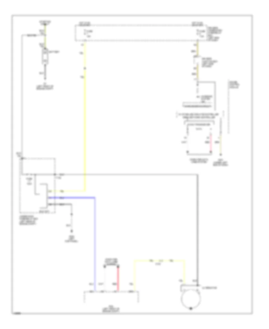
- Starting/ charging system
- To ignition coil relay (diagram 3 of 5)
- Transmission range switch (rear of transmission housing)
- Under-hood fuse/relay box (left rear of engine compt)
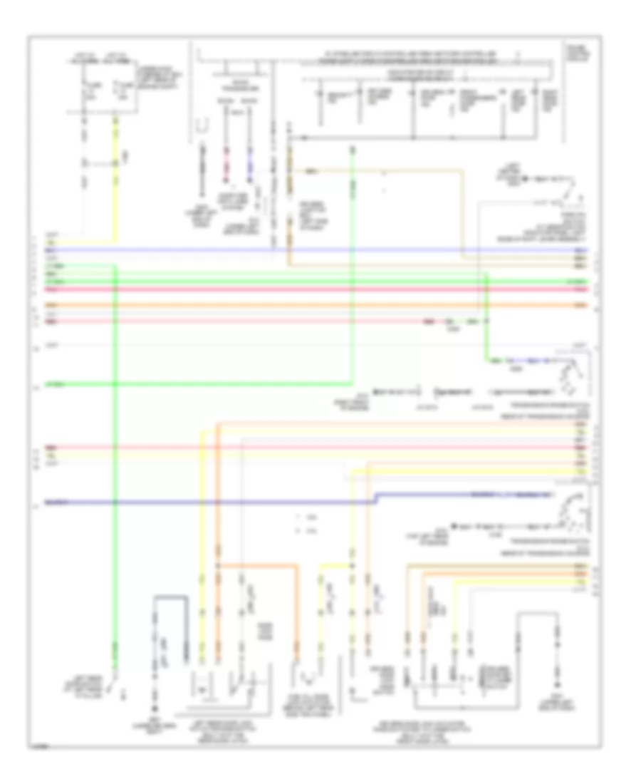
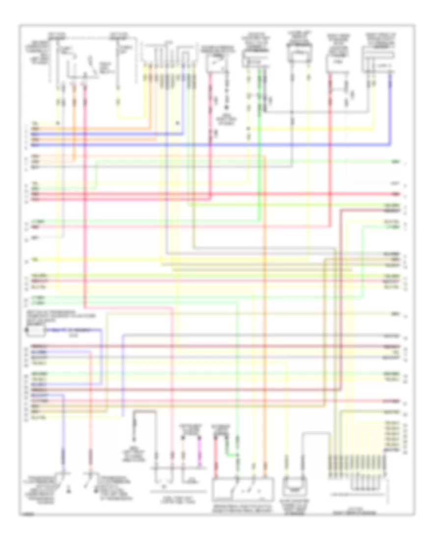
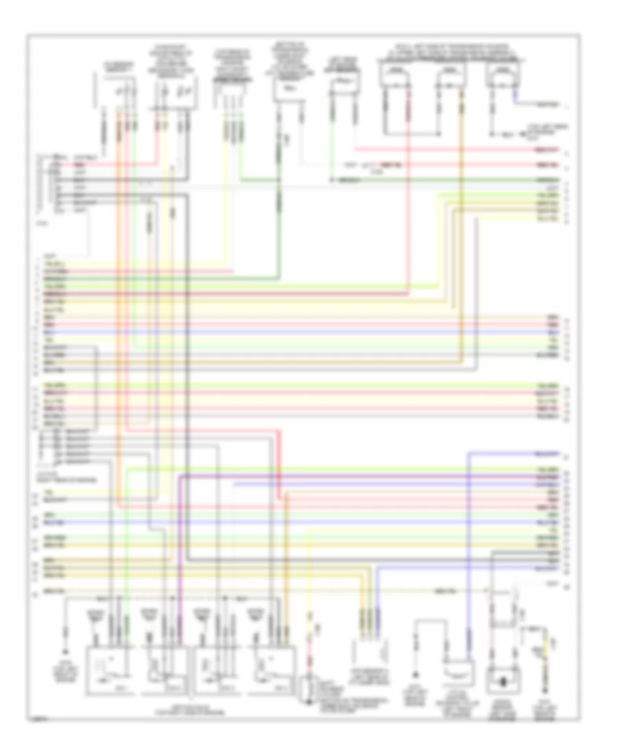
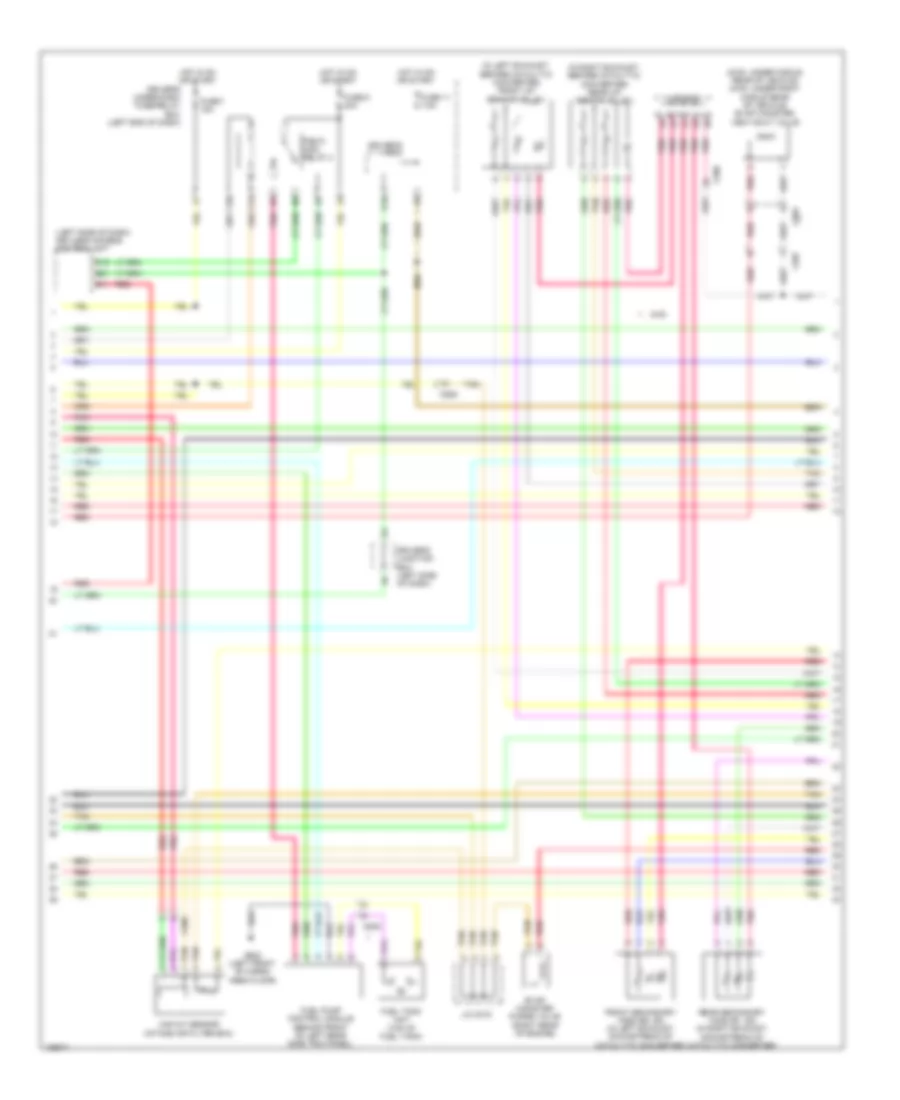
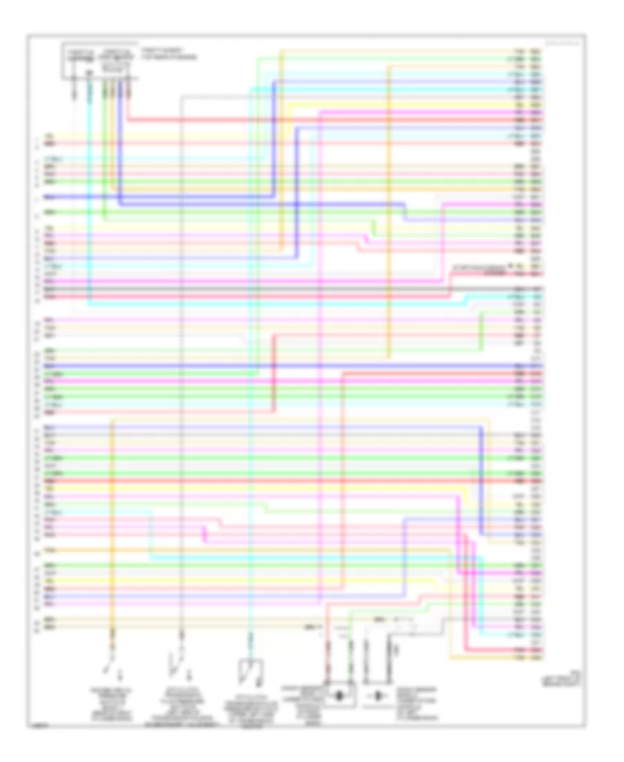
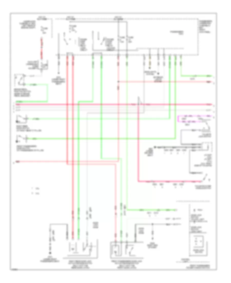
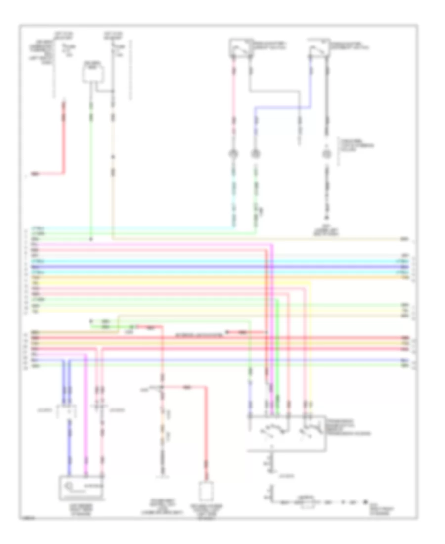
2.4L, Engine Performance Wiring Diagram (2 of 5) for Honda Crosstour EX-L 2014
List of elements for 2.4L, Engine Performance Wiring Diagram (2 of 5) for Honda Crosstour EX-L 2014:
- (bottom of transmission, under shift solenoid valve cover) shift solenoid valve a
- (lower left rear of radiator) ect sensor 2
- (on evap canister vent shut valve assembly) ftp sensor
- (right front of engine compt) a/c pressure sensor
- (right rear of engine) evap canister vent shut valve
- Brake pedal position switch (base of brake pedal bracket)
- C101
- C202
- C304
- C306
- Driver's under-dash fuse/relay box (left end of dash)
- Evap canister purge valve (right rear of engine)
- Exterior lights system
- F12
- F33
- Fuel tank unit (top of fuel tank)
- Fuse 7 15a
- Fuse 9 20a
- G105
- G203 (right end of dash)
- G602 (left front of cargo area floor)
- Hot in on or start
- Instrument cluster system
- J/c c103 (right rear of engine)
- Pgm-fi main relay 2
- Pnk
- Power steering pressure switch (psp)
- Red
- Transmission fluid pressure switch a (2nd clutch) (top left side of transmission)
- Transmission fluid pressure switch b (3rd clutch) (under rear of transmission housing)
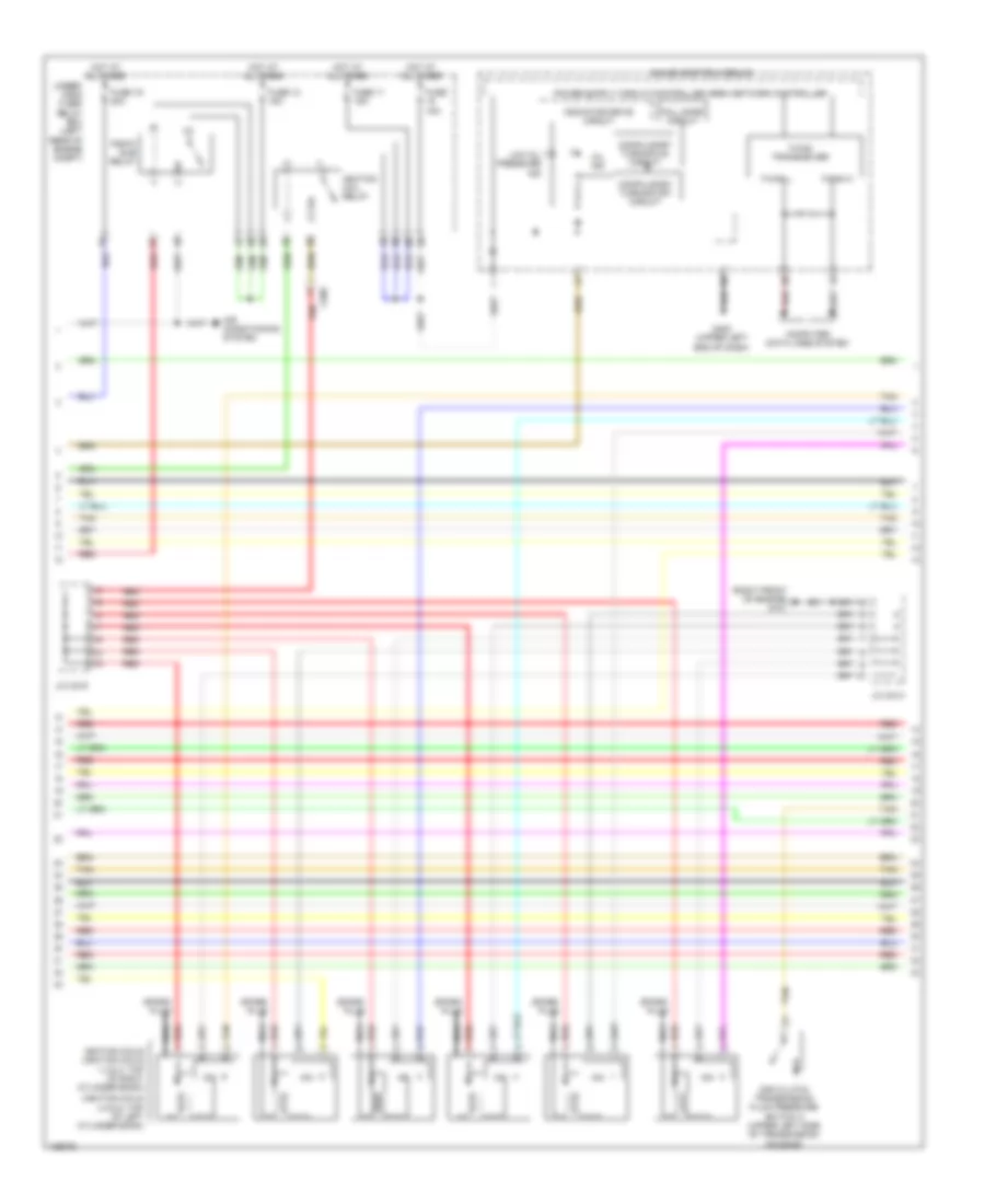
2.4L, Engine Performance Wiring Diagram (3 of 5) for Honda Crosstour EX-L 2014
List of elements for 2.4L, Engine Performance Wiring Diagram (3 of 5) for Honda Crosstour EX-L 2014:
- 5v stabilizer circuit/controller area network controller
- B13
- C101
- C104
- C306
- Ckp sensor (lower right rear of engine)
- Cmp sensor b (right rear of cylinder head)
- Compulsory turning off circuit
- Compulsory turning on circuit
- Computer data lines system
- Driver's junction box (left side of dash)
- Driver's micu
- Driver's under-dash fuse/relay box (left end of dash)
- F-can h
- F-can l
- F-can transceiver
- Fail safe circuit
- From pgm-fi main relay 1 (diagram 1 of 5)
- Fuse 11 15a
- Fuse 12 15a
- Fuse 15 10a
- Fuse 4 7.5a
- Fuse 5 7.5a
- G101 (top left rear of engine)
- Gauge control module
- Hot at all times
- Hot in on or start
- Ignition coil relay
- Immobilizer keyless control unit (steering column)
- Injectors (top left side of engine)
- Low oil pressure ind
- Maf/iat sensor (intake air filter box)
- Mil ind
- Pgm- fi sub relay
- Q16
- Red
- Relay circuit board
- Under- hood fuse/ relay box (left rear of engine compt)
- Warning drive circuit
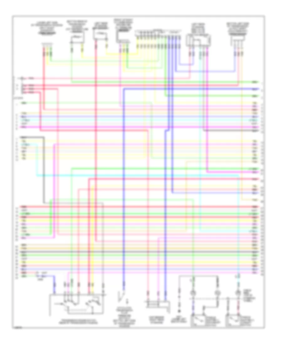
2.4L, Engine Performance Wiring Diagram (4 of 5) for Honda Crosstour EX-L 2014
List of elements for 2.4L, Engine Performance Wiring Diagram (4 of 5) for Honda Crosstour EX-L 2014:
- (b & c: left side of transmission housing) (a: upper left side of transmission assembly) a/t clutch pressure control solenoid valves
- (bottom of transmission, under shift solenoid valve cover) atf temperature sensor
- (in exhaust, downstream of catalytic converter) secondary ho2s (sensor 2)
- (left rear of engine) ect sensor 1
- (top left rear of engine) g101
- (top rear of transmission housing) input shaft (mainshaft) speed sensor
- A/f sensor (sensor 1)
- C101
- C105
- C107
- Cmp sensor a (left rear of cylinder head)
- G101 (top left rear of engine)
- G102 (top left front of engine)
- Icm 1
- Icm 2
- Icm 3
- Icm 4
- Ignition coils (top right side of engine)
- J/c c103 (right rear of engine)
- Knock sensor (left side of engine)
- N/a
- Red
- Shift solenoid valve e (bottom of transmission, under shift solenoid valve cover)
- Spark plug
- Vtc oil control solenoid valve (left front of engine)
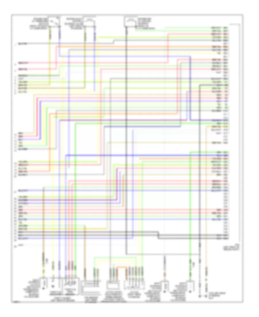
2.4L, Engine Performance Wiring Diagram (5 of 5) for Honda Crosstour EX-L 2014
List of elements for 2.4L, Engine Performance Wiring Diagram (5 of 5) for Honda Crosstour EX-L 2014:
- (bottom of transmission, under shift solenoid valve cover)
- (top left rear of engine) g101
- B32
- B33
- B34
- B35
- B36
- B37
- B38
- B39
- B40
- B41
- B42
- B43
- B44
- B45
- B46
- B47
- B48
- C10
- C105
- C11
- C12
- C13
- C14
- C15
- C16
- C17
- C18
- C19
- C20
- C21
- C22
- C23
- C24
- C25
- C26
- C27
- C28
- C29
- C30
- C31
- C32
- C33
- C34
- C35
- C36
- C37
- C38
- C39
- C40
- C41
- C42
- C43
- C44
- C45
- C46
- C47
- C48
- Engine mount control solenoid valve (left front of engine)
- J/c c103 (right rear of engine)
- Map sensor (left rear of engine)
- Output shaft (countershaft) speed sensor (top right side of transmission housing)
- Pcm (left front of engine compt)
- Red
- Rocker arm oil control solenoid (front of cylinder bank)
- Shift solenoid valve b
- Shift solenoid valve c (bottom of transmission, under shift solenoid valve cover)
- Shift solenoid valve d (bottom of transmission, under shift solenoid valve cover)
- Throttle actuator
- Throttle body (left rear of engine)
- Throttle open sensor
3.5L
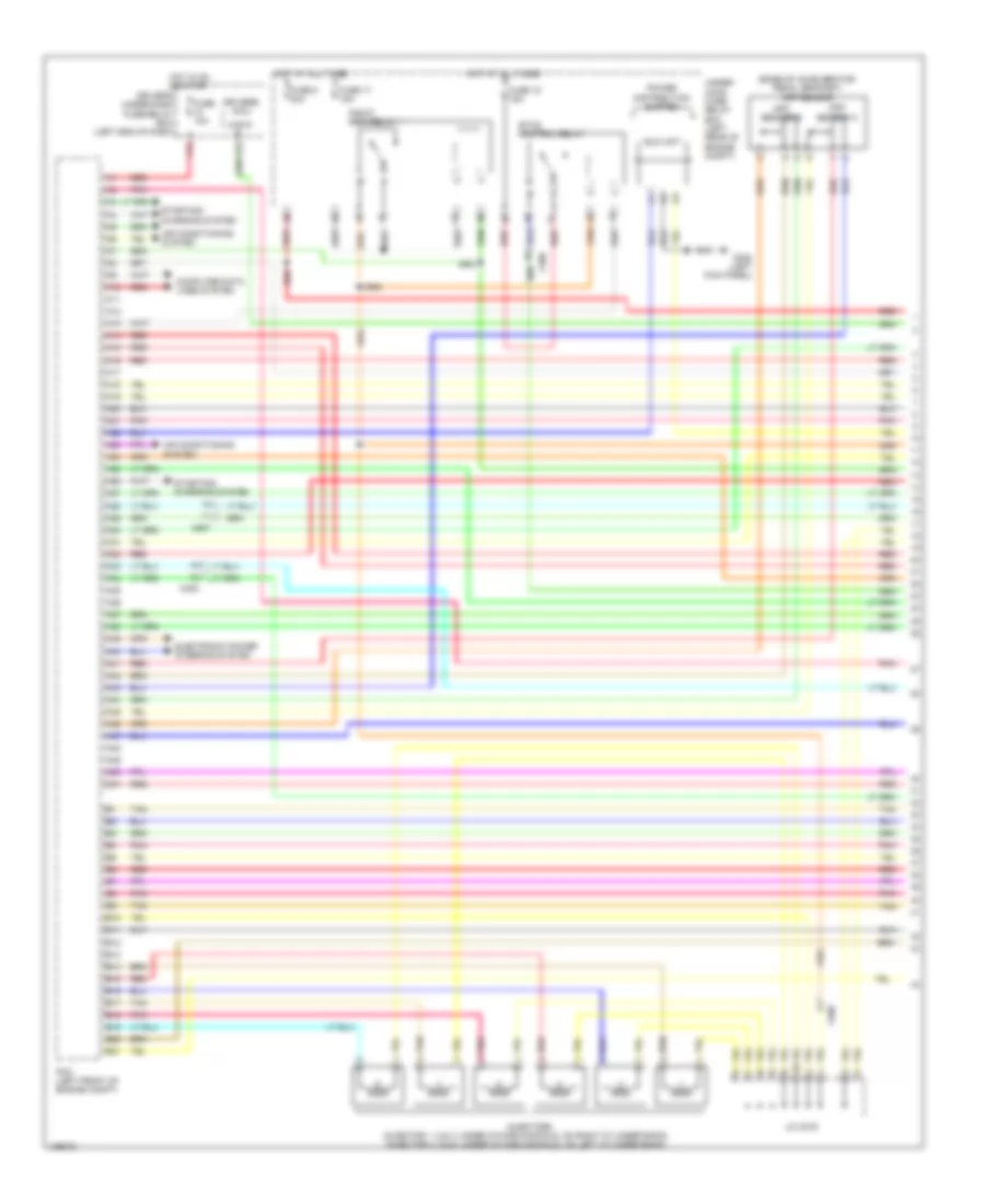
3.5L, Engine Performance Wiring Diagram (1 of 7) for Honda Crosstour EX-L 2014
List of elements for 3.5L, Engine Performance Wiring Diagram (1 of 7) for Honda Crosstour EX-L 2014:
- (base of accelerator pedal bracket) app sensor
- (injector 1, 2 & 3: under intake manifold, on right cylinder bank) (injector 4, 5 & 6: under intake manifold, on left cylinder bank)
- A10
- A11
- A12
- A13
- A14
- A15
- A16
- A17
- A18
- A19
- A20
- A21
- A22
- A23
- A24
- A25
- A26
- A27
- A28
- A29
- A30
- A31
- A32
- A33
- A34
- A35
- A36
- A37
- A38
- A39
- A40
- A41
- A42
- A43
- A44
- A45
- A46
- A47
- A48
- A49
- A50
- A51
- Air conditioning system
- App sensor a
- App sensor b
- Atp-p
- B10
- B11
- B12
- B13
- B14
- B15
- B16
- B17
- B18
- B19
- B20
- B21
- C408
- C506
- C507
- Computer data lines system
- Driver's micu
- Driver's under-dash fuse/relay box (left end of dash)
- Eld unit
- Electronic power steering system
- Etcs control relay
- F15
- F23
- Fuse 10a
- Fuse 17 15a
- Fuse 18 15a
- Fuse 8 20a
- G302 (left kick panel)
- Hot at all times
- Hot in on or start
- Injectors
- J/c c016
- Pcm (left front of engine compt)
- Pgm-fi main relay 1
- Pnk
- Power distribution system
- Red
- Starting/ charging system
- Tan
- Under- hood fuse/ relay box (left rear of engine compt)
3.5L, Engine Performance Wiring Diagram (2 of 7) for Honda Crosstour EX-L 2014
List of elements for 3.5L, Engine Performance Wiring Diagram (2 of 7) for Honda Crosstour EX-L 2014:
- (base of brake pedal bracket) brake pedal position switch
- (left center of dash) active control engine mount (acm) control relay
- (left end of dash) engine mount control unit
- (left side of transmission housing, on secondary valve body)
- (lower left rear of radiator) ect sensor 2
- (lower middle front of engine) front engine mount control actuator
- (on evap canister vent shut valve assembly) ftp sensor
- (right front of engine compt) a/c pressure sensor
- (under driver's seat) (4wd) power seat control unit
- 4wd
- A/t clutch pressure control solenoid valve a
- A/t clutch pressure control solenoid valve b
- A/t clutch pressure control solenoid valve c
- A/t clutch pressure control solenoid valve d
- Auxiliary under-dash fuse holder a
- B35
- C142
- C403
- C408
- C412
- C502
- C503
- C507
- C603
- Computer data lines system
- Driver's junction box (left side of dash)
- Exterior lights system
- G302 (left kick panel)
- J/c c015
- Line pressure solenoid valve a (left side of transmission housing, on secondary valve body)
- Pnk
- Rear engine mount control actuator (lower middle rear of engine)
- Red
- Shift lock solenoid (base of shift lever assembly)
- Shift solenoid valve a
- Shift solenoid valve b
- Shift solenoid valve c (lower left side of transmission housing)
- Tan
3.5L, Engine Performance Wiring Diagram (3 of 7) for Honda Crosstour EX-L 2014
List of elements for 3.5L, Engine Performance Wiring Diagram (3 of 7) for Honda Crosstour EX-L 2014:
- (2wd: under middle rear of vehicle) (4wd: under right middle rear of vehicle) evap canister vent shut valve
- (in left exhaust, before catalytic converter) front a/f sensor (b2, s1)
- (in right exhaust, before catalytic converter) rear a/f sensor (b1, s1)
- (left side of dash) keyless access control unit
- 4wd
- B11
- B21
- C18
- C506
- C507
- C603
- C805
- Driver"s micu
- Driver's junction box (left side of dash)
- Driver's under-dash fuse/relay box (left end of dash)
- Evap canister purge valve (right rear of engine)
- F12
- F33
- Front secondary ho2s (b2, s2) (in left exhaust, downstream of catalytic converter)
- Fuel pump control module (behind front of left rear side trim panel)
- Fuel tank unit (top of fuel tank)
- Fuse 11 7.5a
- Fuse 7 15a
- Fuse 9 20a
- G602 (left front of cargo area floor)
- Hot in on or start
- J/c c015
- J/c c016
- Maf/iat sensor (intake air filter box)
- Pgm-fi main relay 2
- Pnk
- Q16
- Rear secondary ho2s (b1, s2) (in right exhaust, downstream of catalytic converter)
- Red
- Tan
3.5L, Engine Performance Wiring Diagram (4 of 7) for Honda Crosstour EX-L 2014
List of elements for 3.5L, Engine Performance Wiring Diagram (4 of 7) for Honda Crosstour EX-L 2014:
- (ignition coils 4 5 & 6: top of left cylinder bank)
- (right front of engine) g101
- 2nd clutch transmission fluid pressure switch a (upper left side of transmission housing)
- Air conditioning system
- C506
- Compulsory turning off circuit
- Compulsory turning on circuit
- Computer data lines system
- F-can h
- F-can l
- F-can transceiver
- Fall safe circuit
- Fuse 11 15a
- Fuse 12 15a
- Fuse 15a
- Fuse 19 20a
- G402 (upper left end of dash)
- Gauge control module
- Hot at all times
- Icm
- Ignition coil relay
- Ignition coils (ignition coils 1 2 & 3: top of right cylinder bank)
- Indicator drive circuit
- J/c c013
- J/c c016
- Low oil pressure ind
- Mil ind
- Nca
- Pgm-fi sub relay
- Red
- Spark plug
- Tan
- Under- hood fuse/ relay box (left rear of engine compt)
3.5L, Engine Performance Wiring Diagram (5 of 7) for Honda Crosstour EX-L 2014
List of elements for 3.5L, Engine Performance Wiring Diagram (5 of 7) for Honda Crosstour EX-L 2014:
- (bottom left side of transmission) output shaft (countershaft) speed sensor
- (bottom rear of transmission housing) atf temperature sensor
- (front of right cylinder bank) rocker arm oil pressure sensor
- (left rear of engine) ect sensor 1
- (left rear of engine) egr valve/ egr valve position sensor
- (lower left side of transmission housing) input shaft (mainshaft) speed sensor
- 4th clutch transmission fluid pressure switch c (bottom left side of transmission housing)
- A17
- A18
- C11
- C12
- C506
- Cable reel (top of steering wheel)
- G401 (under left end of dash)
- J/c c013
- J/c c015
- Map sensor (right rear of engine)
- Paddle shifter (+) (upshift switch)
- Paddle shifter (-) (downshift switch)
- Pnk
- Red
- Tan
- Transmission range switch (rear of transmission housing)
3.5L, Engine Performance Wiring Diagram (6 of 7) for Honda Crosstour EX-L 2014
List of elements for 3.5L, Engine Performance Wiring Diagram (6 of 7) for Honda Crosstour EX-L 2014:
- (front of left cylinder bank) rocker arm oil control solenoid a (bank 2)
- (left side of transmission housing, on secondary valve body)
- (rear of right cylinder bank) rocker arm oil control solenoid a (bank 1)
- (rear of right cylinder bank) rocker arm oil control solenoid b (bank 1)
- 3rd clutch transmission fluid pressure switch b
- Ckp sensor (lower right rear of engine)
- Cmp sensor b (right rear of cylinder head)
- G101 (right front of engine)
- J/c c014
- Line pressure switch
- Pnk
- Red
- Rocker arm oil pressure switch a (bank 1)
- Rocker arm oil pressure switch a (bank 2)
- Tan
3.5L, Engine Performance Wiring Diagram (7 of 7) for Honda Crosstour EX-L 2014
List of elements for 3.5L, Engine Performance Wiring Diagram (7 of 7) for Honda Crosstour EX-L 2014:
- (top rear of engine)
- 5th clutch transmission fluid pressure switch d (upper left side of transmission housing)
- 6th clutch transmission fluid pressure switch e (left side of transmission housing, on secondary valve body)
- B22
- B23
- B24
- B25
- B26
- B27
- B28
- B29
- B30
- B31
- B32
- B33
- B34
- B35
- B36
- B37
- B38
- B39
- B40
- B41
- B42
- B43
- B44
- B45
- B46
- B47
- B48
- B49
- B50
- B51
- C10
- C11
- C12
- C13
- C14
- C15
- C16
- C17
- C18
- C19
- C20
- C21
- C22
- C23
- C24
- C25
- C26
- C27
- C28
- C29
- C30
- C31
- C32
- C33
- C34
- C35
- C36
- C37
- C38
- C39
- C40
- C41
- C42
- C43
- C44
- C45
- C46
- C47
- C48
- C49
- C901
- Knock sensor (bank 1) (under intake manifold, on right cylinder bank)
- Knock sensor (bank 2) (under intake manifold, on left cylinder bank)
- Pcm (left front of engine compt)
- Pnk
- Red
- Rocker arm oil pressure switch b (bank 1) (rear of right cylinder bank)
- Starting/charging system
- Tan
- Throttle actuator
- Throttle body
- Throttle open sensor
EXTERIOR LIGHTS
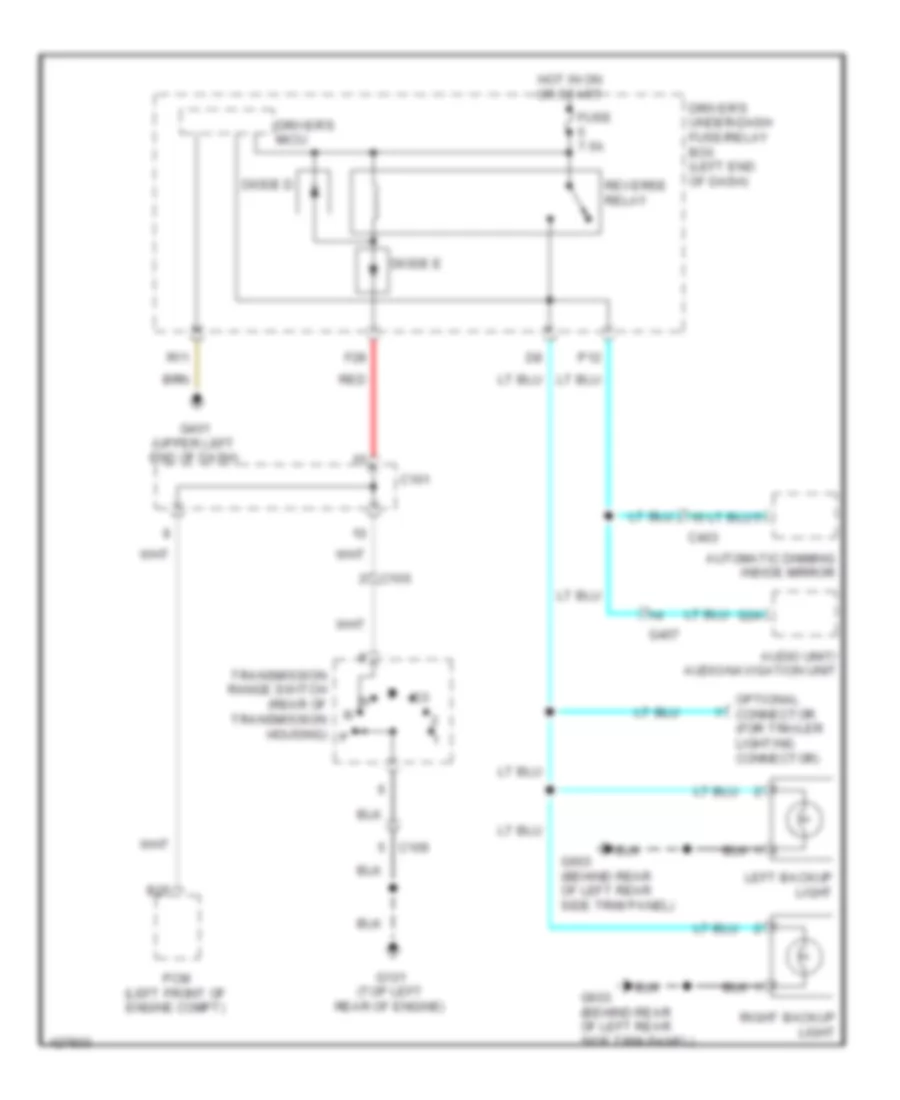
2.4L
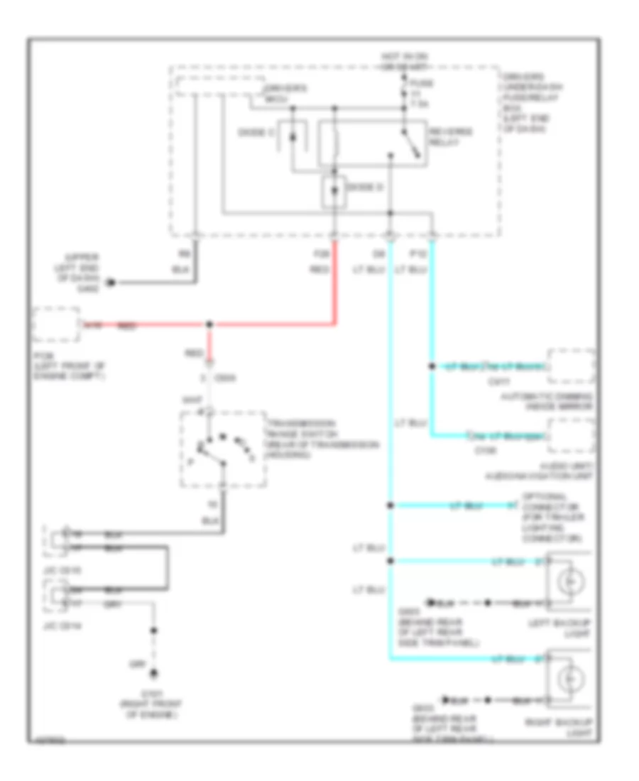
2.4L, Backup Lamps Wiring Diagram for Honda Crosstour EX-L 2014
List of elements for 2.4L, Backup Lamps Wiring Diagram for Honda Crosstour EX-L 2014:
- Audio unit/ audio-navigation unit
- Automatic dimming inside mirror
- B25
- C101
- C106
- C403
- Diode d
- Diode e
- Driver's micu
- Driver's under-dash fuse/relay box (left end of dash)
- F28
- Fuse 7.5a
- G101 (top left rear of engine)
- G24
- G401 (upper left end of dash)
- G407
- G603 (behind rear of left rear side trim panel)
- Hot in on or start
- Left backup light
- Optional connector (for trailer lighting connector)
- P12
- Pcm (left front of engine compt)
- R11
- Red
- Reverse relay
- Right backup light
- Transmission range switch (rear of transmission housing)
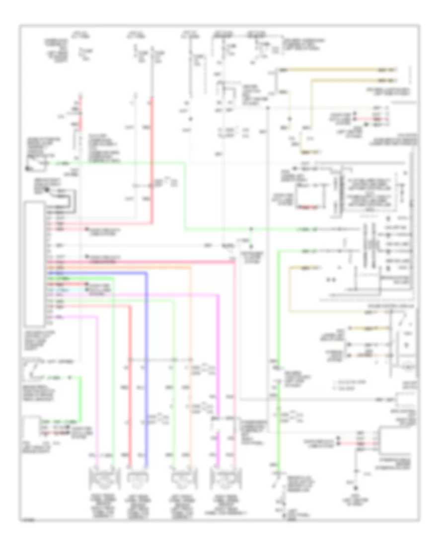
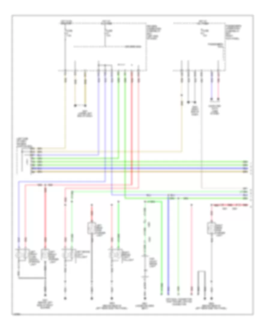
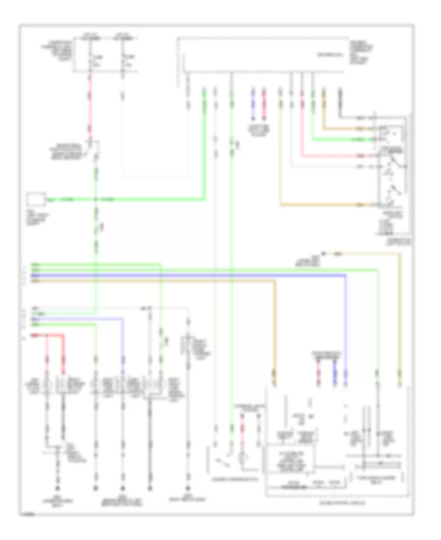
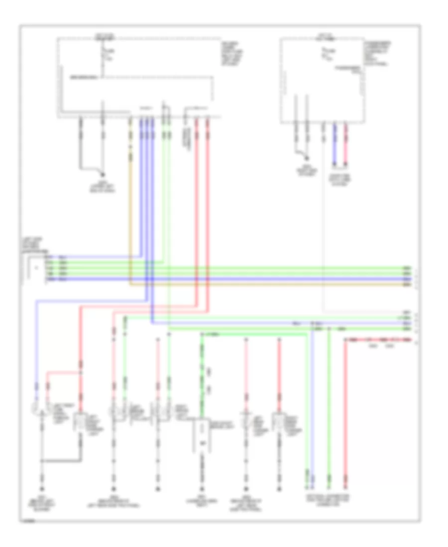
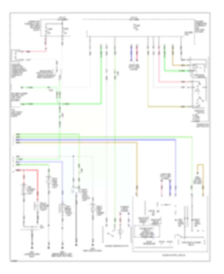
2.4L, Exterior Lamps Wiring Diagram (1 of 2) for Honda Crosstour EX-L 2014
List of elements for 2.4L, Exterior Lamps Wiring Diagram (1 of 2) for Honda Crosstour EX-L 2014:
- (left side of dash) driver's junction box
- (optional connector) (for trailer lighting connector)
- A21
- A28
- A34
- C601
- C651
- Computer data lines system
- D14
- D16
- Driver's micu
- Driver's under-dash fuse/relay box (left end of dash)
- E10
- E14
- E15
- E18
- F10
- F17
- Fuse 10a
- Fuse 7.5a
- G203 (right end of dash)
- G301 (behind left side of front bumper)
- G401 (upper left end of dash)
- G601 (under driver's seat)
- G603 (behind rear of left rear side trim panel)
- High mount brake light
- Hot at all times
- Hot in on or start
- Left brake light/ taillight
- Left front side marker light
- Left front turn signal/ parking light
- Left rear side marker light
- P15
- Passenger's micu
- Passenger's under-dash fuse/relay box (right kick panel)
- Pnk
- R11
- Red
- Right brake light/ taillight
- Right rear side marker light
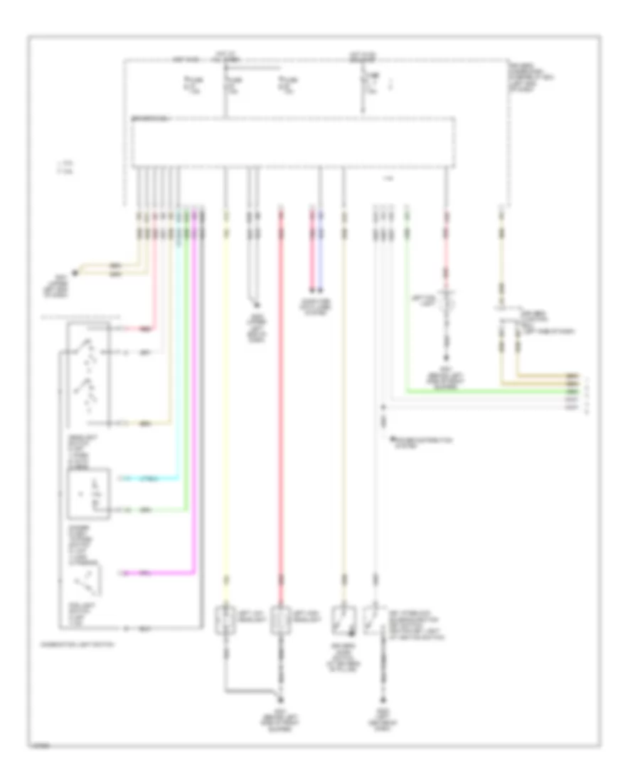
2.4L, Exterior Lamps Wiring Diagram (2 of 2) for Honda Crosstour EX-L 2014
List of elements for 2.4L, Exterior Lamps Wiring Diagram (2 of 2) for Honda Crosstour EX-L 2014:
- 0) off 1) park 2) auto 3) head
- 5v stabilize circuit/ controller area network controller
- A42
- B-can h
- B-can l
- B-can transceiver
- Brake pedal position switch (base of brake pedal bracket)
- C202
- C304
- C407
- Combination light switch
- Computer data lines system
- Dimming circuit
- Driver's micu
- Driver's under-dash fuse/relay box (left end of dash)
- F11
- F14
- Fuse 15a
- Fuse 20a
- G203 (right end of dash)
- G401 (upper left end of dash)
- G601 (under driver's seat)
- G603 (behind rear of left rear side trim panel)
- Gauge control module
- Hazard warning switch
- Headlight switch
- Hot at all times
- Interior lights system
- J/c c671 (right side of tailgate)
- Left license plate light
- Left rear turn signal light
- Left turn signal ind
- Lights on ind
- Pcm (left front of engine compt)
- Pnk
- Q14
- R10
- R23
- R24
- Red
- Right front side marker light
- Right front turn signal/ parking light
- Right license plate light
- Right rear turn signal light
- Right turn signal ind
- Turn signal switch
- Turn signal/hazard relay
- Under-hood fuse/relay box (left rear of engine compt)
- Warning drive circuit
3.5L
3.5L, Backup Lamps Wiring Diagram for Honda Crosstour EX-L 2014
List of elements for 3.5L, Backup Lamps Wiring Diagram for Honda Crosstour EX-L 2014:
- (upper left end of dash) g402
- A16
- Audio unit/ audio-navigation unit
- Automatic dimming inside mirror
- C106
- C411
- C506
- Diode c
- Diode d
- Driver's micu
- Driver's under-dash fuse/relay box (left end of dash)
- F28
- Fuse 7.5a
- G101 (right front of engine)
- G24
- G603 (behind rear of left rear side trim panel)
- Hot in on or start
- J/c c014
- J/c c015
- Left backup light
- Optional connector (for trailer lighting connector)
- P12
- Pcm (left front of engine compt)
- Red
- Reverse relay
- Right backup light
- Transmission range switch (rear of transmission housing)
3.5L, Exterior Lamps Wiring Diagram (1 of 2) for Honda Crosstour EX-L 2014
List of elements for 3.5L, Exterior Lamps Wiring Diagram (1 of 2) for Honda Crosstour EX-L 2014:
- (left side of dash) driver's junction box
- (optional connector) (for trailer lighting connector)
- A21
- A34
- C302
- C803
- Computer data lines system
- Connector) (optional
- D14
- D16
- Driver's micu
- Driver's under- dash fuse/ relay box (left end of dash)
- E10
- E14
- E15
- E18
- F10
- F17
- Fuse 10a
- Fuse 7.5a
- G203 (right end of dash)
- G301 (behind left side of front bumper)
- G402 (upper left end of dash)
- G601 (under driver's seat)
- G603 (behind rear of left rear side trim panel)
- High mount brake light
- Hot at all times
- Hot in on or start
- Left brake light/ taillight
- Left front side marker light
- Left front turn signal/ parking light
- Left rear side marker light
- P15
- Passenger's micu
- Passenger's under-dash fuse/relay box (right kick panel)
- Pnk
- Q10
- Red
- Right brake light/ taillight
- Right rear side marker light
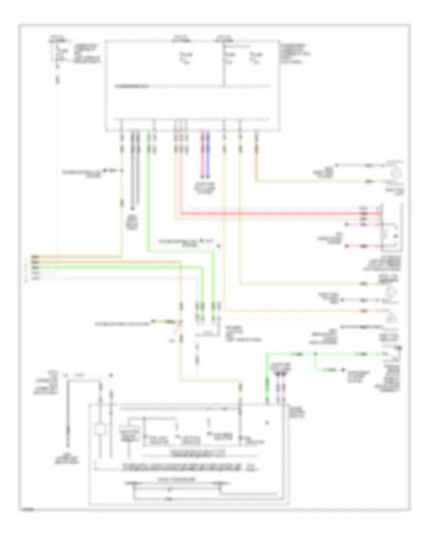
3.5L, Exterior Lamps Wiring Diagram (2 of 2) for Honda Crosstour EX-L 2014
List of elements for 3.5L, Exterior Lamps Wiring Diagram (2 of 2) for Honda Crosstour EX-L 2014:
- 0) off 1) park 2) auto 3) head
- A25
- Auxiliary under-dash fuse holder a (under driver's under-dash fuse/relay box)
- B-can h
- B-can l
- B-can transceiver
- Brake pedal position switch (base of brake pedal bracket)
- C106
- C205
- C403
- C507
- Combination light switch
- Computer data lines system
- Driver's micu
- Driver's under-dash fuse/relay box (left end of dash)
- F11
- F14
- Fuse 10a
- Fuse 15a
- Fuse 20a
- G203 (right end of dash)
- G401 (upper left end of dash)
- G601 (under driver's seat)
- G603 (behind rear of left rear side trim panel)
- Gauge control module
- Hazard warning switch
- Headlight switch
- Hot at all times
- Indicator dimming circuit
- Indicator drive circuit
- Interior lights system
- J/c c007
- Keyless access control unit (left side of dash)
- Left license plate light
- Left rear turn signal light
- Left turn signal ind
- Lights on ind
- Pcm (left front of engine compt)
- Pnk
- Q14
- R10
- R23
- R24
- Red
- Right front side marker light
- Right front turn signal/ parking light
- Right license plate light
- Right rear turn signal light
- Right turn signal ind
- Turn signal switch
- Turn signal/hazard relay
- Under-hood fuse/relay box (left rear of engine compt)
GROUND DISTRIBUTION
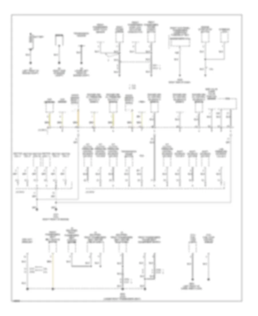
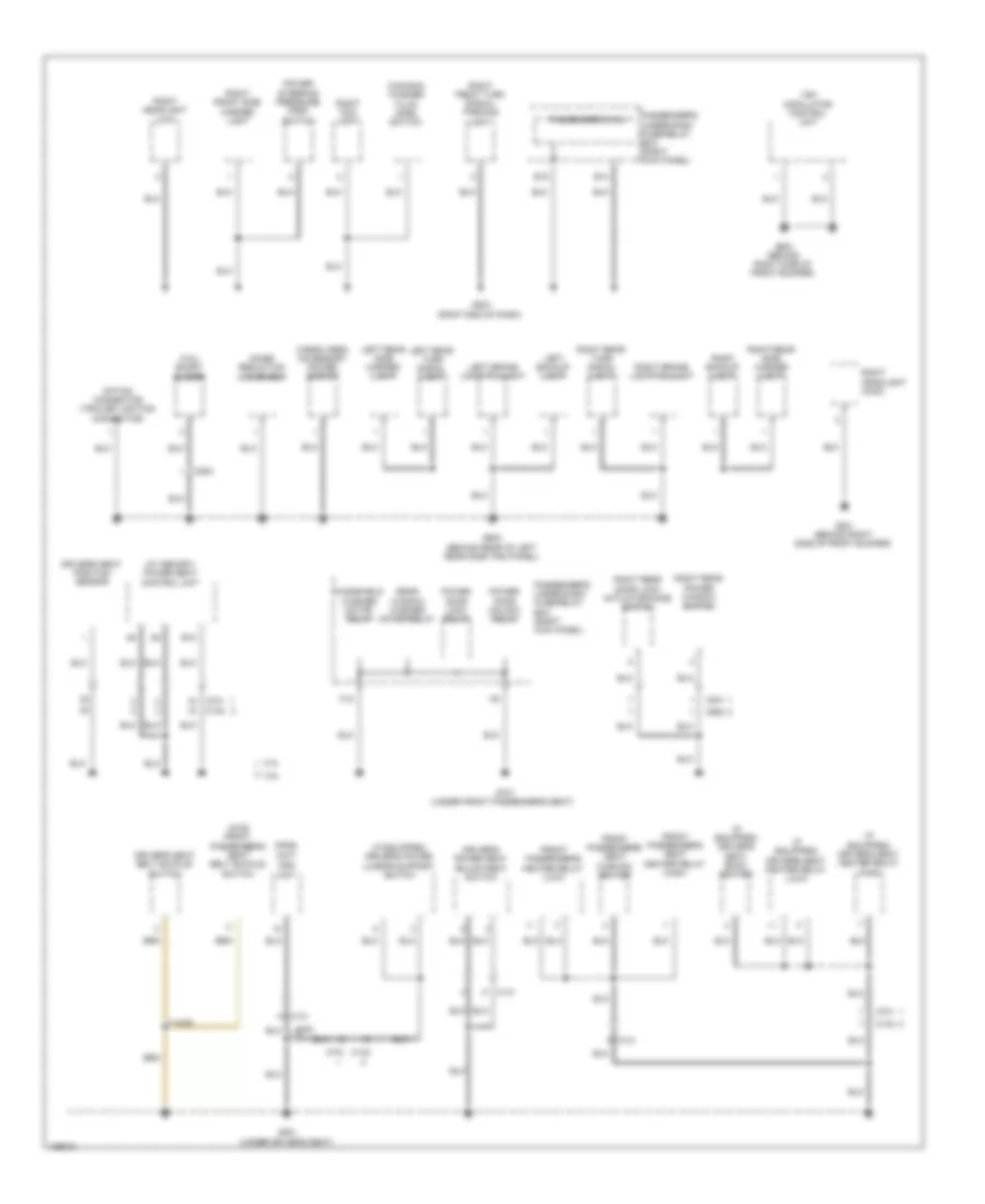
Ground Distribution Wiring Diagram (1 of 5) for Honda Crosstour EX-L 2014
List of elements for Ground Distribution Wiring Diagram (1 of 5) for Honda Crosstour EX-L 2014:
- (2.4l) fuel tank unit
- (3.5l) fuel pump control module
- (if equipped) front passenger's seat cushion heater
- (if equipped) front passenger's seat heater relay (high)
- (if equipped) front passenger's seat heater relay (low)
- (right kick panel) passenger's under-dash fuse/relay box
- 2.4l
- 3.5l
- A/t clutch pressure control solenoid valve a
- A/t clutch pressure control solenoid valve b
- A/t clutch pressure control solenoid valve c
- A/t clutch pressure control solenoid valve d
- A26
- B11
- B20
- Battery
- C131
- C20
- C413
- C702
- C811
- Ckp sensor
- Cmp sensor b
- Egr valve & egr valve position sensor
- Engine
- Engine start/stop switch
- Front passenger's door lock actuator/ knob switch
- Front passenger's door touch sensor
- Front passenger's power seat adjustment switch
- Front passenger's power window switch
- Front passenger's seat belt buckle switch
- G1 (left front of engine compt)
- G101 (3.5l) (right front of engine)
- G2 (right side of engine compt)
- G3 (lower left front of engine compt)
- G405 (right end of dash)
- G602 (left front of cargo area floor)
- G802 (2wd) (under front passenger's seat)
- Ignition coil 1
- Ignition coil 2
- Ignition coil 3
- Ignition coil 4
- Ignition coil 5
- Ignition coil 6
- J/c c013
- J/c c014
- J/c c015
- Knock sensor (bank 1) shield
- Knock sensor (bank 2) shield
- Line pressure solenoid valve a
- Ods unit/ opds unit
- Passenger's micu
- Pcm
- Right power mirror
- Rocker arm oil control solenoid a (bank 1)
- Rocker arm oil control solenoid a (bank 2)
- Rocker arm oil control solenoid b (bank 1)
- Rocker arm oil pressure switch a (bank 1)
- Rocker arm oil pressure switch a (bank 2)
- Shift solenoid valve a
- Shift solenoid valve b
- Shift solenoid valve c
- Steering lock
- Transmission housing
- Transmission range switch
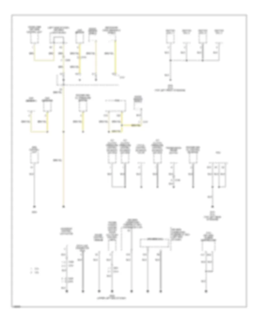
Ground Distribution Wiring Diagram (2 of 5) for Honda Crosstour EX-L 2014
List of elements for Ground Distribution Wiring Diagram (2 of 5) for Honda Crosstour EX-L 2014:
- (3.5l) keyless access control unit
- (left side of dash) driver's junction box
- 2.4l
- 3.5l
- A/t clutch pressure control solenoid valve a
- A/t clutch pressure control solenoid valve b
- A/t clutch pressure control solenoid valve c
- A17
- B10
- B15
- C101
- C104
- C106
- C107
- C15
- C20
- C306
- C404
- C409
- C414
- C452
- C701
- C801
- Ckp sensor
- Cmp sensor a
- Cmp sensor b
- Data link connector (dlc)
- Driver's micu
- Driver's under-dash fuse/relay box (left end of dash)
- Driver's under-dash fuse/relay box connector k (3p)
- Eps control unit
- G101 (2.4l) (top left rear of engine)
- G102 (2.4l) (top left front of engine)
- G204
- G402 (upper left end of dash)
- Gauge control module
- Ignition coil 1
- Ignition coil 2
- Ignition coil 3
- Ignition coil 4
- Immobilizer keyless control unit
- Knock sensor shield
- Moonroof control unit/motor
- N15
- Pcm
- Power window master switch (door multiplex control unit)
- Q10
- Rocker arm oil control solenoid
- Rocker arm oil pressure switch
- Secondary ho2s (sensor 2) shield
- Transmission range switch
- Vtc oil control solenoid valve
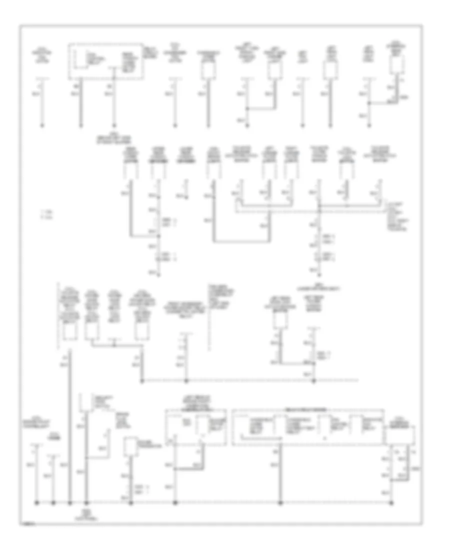
Ground Distribution Wiring Diagram (3 of 5) for Honda Crosstour EX-L 2014
List of elements for Ground Distribution Wiring Diagram (3 of 5) for Honda Crosstour EX-L 2014:
- (2.4l) a/c condenser fan motor
- (2.4l) diode
- (3.5l) driver's power door unlock relay (2.4l) driver's unlock relay
- (3.5l) engine mount control unit
- (3.5l) power door lock relay (2.4l) lock relay
- (3.5l) power door unlock relay (2.4l) unlock relay
- (3.5l) radiator fan motor
- (3.5l) steering gear box
- (3.5l) tailgate lock switch
- (3.5l) tailgate release actuator relay (2.4l) tailgate actuator relay
- (left rear of engine compt) under-hood fuse/relay box
- 2.4l
- 3.5l
- Blower motor relay
- Brake fluid level switch
- C301
- C302
- C303
- C501
- C508
- C601
- C602
- C651
- C652
- C801
- C803
- C821 c802
- D13
- Driver's under-dash fuse/relay box (left end of dash)
- Eld unit
- Fan control relay
- Front accessory power socket relay (cigarette lighter relay)
- G301 (behind left side of front bumper)
- G302 (left kick panel)
- G601 (under driver's seat)
- High mount brake light
- J/c c007 (3.5l) j/c c671 (2.4l) (2.4l: right side of tailgate)
- Left fog light
- Left front side marker light
- Left front turn signal/ parking light
- Left head light (high)
- Left head light (low)
- Left license plate light
- Left rear door lock actuator/knob switch
- Left rear power window switch
- Lower rear window defogger
- Power transistor
- Radiator fan relay
- Rear window wiper motor
- Rear window wiper motor relay
- Relay circuit board
- Right license plate light
- Security hood switch
- Tailgate outer handle switch
- Tailgate release actuator/latch switch
- Upper rear window defogger
- Windshield wiper intermittent relay
- Windshield wiper motor
- Windshield wiper motor relay
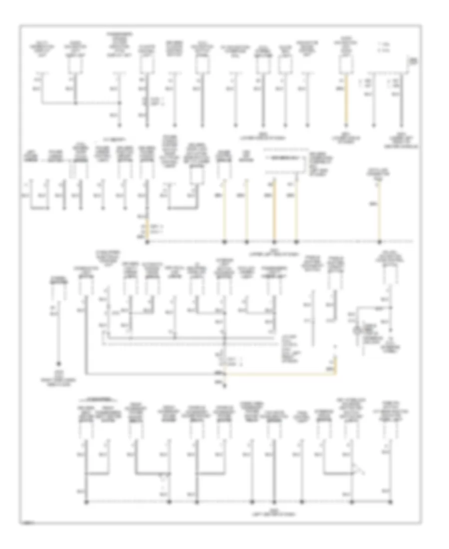
Ground Distribution Wiring Diagram (4 of 5) for Honda Crosstour EX-L 2014
List of elements for Ground Distribution Wiring Diagram (4 of 5) for Honda Crosstour EX-L 2014:
- (2.4l) navigation switch panel
- (2.4l) stereo amplifier
- (3.5l) drivers door touch sensor
- (if equipped)
- (if equipped) electrical compass unit
- (if equipped) homelink unit
- (w/ memory)
- (w/ navigation) interface dial
- 2.4l
- 3.5l
- A12
- A20
- A21
- A36
- A37
- Anc/active sound control unit
- Audio navigation unit/ audio unit
- Audio navigation/ unit audio unit
- Automatic dimming inside mirror
- C103
- C11
- C12
- C13
- C403
- C411
- C414
- C507
- C701
- C801
- Cable reel (top of steering column)
- Cargo area accessory power socket relay
- Climate control unit
- Combination light switch
- Console accessory power socket
- Console accessory power socket relay
- Data link connector (dlc)
- Driver's climate control switch
- Driver's door lock actuator/ knob switch/ key cylinder switch
- Driver's micu
- Driver's position memory switch
- Driver's power window motor
- Driver's seat heater switch
- Driver's under-dash fuse/relay box (left end of dash)
- Driver's vanity mirror light
- Fcw/ldw camera unit
- Front accessory power socket
- Front accessory power socket relay
- Front passenger's seat heater switch
- G401 (upper left end of dash)
- G403 (left center of dash)
- G404 (under left front of center console)
- G501 (lower middle of dash)
- G502 (lower middle of dash)
- G702 (3.5l) (right side cargo area floor)
- Gauge control module
- Glove box light
- Hfl/hfl- navigation voice control switch
- Individual map lights
- Interior light switch (moonroof switch)
- J/c c451 (2.4l) j/c c012 (3.5l) (2.4l: left front of roof)
- Key interlock solenoid/ ignition key switch/ ignition key light
- Left power mirror
- Multi- information display unit
- Paddle shifter+ (upshift switch)
- Paddle shifter- (downshift switch)
- Park pin switch/ a/t gear position indicator panel light
- Passenger's air bag cutoff indicator, hvac display unit
- Passenger's vanity mirror light
- Power mirror control unit
- Power mirror switch
- Power window master switch (door multiplex control unit)
- R11
- Srs unit
- Steering angle sensor
- Stereo amplifier
- T6 (2.4l) (steering wheel)
- Tpms control unit
- Vsa off switch
- Yaw rate acceleration sensor
Ground Distribution Wiring Diagram (5 of 5) for Honda Crosstour EX-L 2014
List of elements for Ground Distribution Wiring Diagram (5 of 5) for Honda Crosstour EX-L 2014:
- (3.5l) smart buzzer
- (4wd) front passenger's seat belt buckle switch
- (canada) washer fluid level switch
- (if equipped) driver's power lumbar support switch
- (if equipped) driver's seat back heater
- (if equipped) driver's seat heater relay (high)
- (if equipped) driver's seat heater relay (low)
- (w/ memory) power seat control unit
- 2.4l
- 3.5l
- 4wd
- B12
- C131
- C141
- C142
- C602
- C701
- C804
- C831
- Cargo area accessory power socket
- Driver's power seat adjustment switch
- Driver's seat belt buckle switch
- Driver's seat position sensor
- E14
- E15
- Front passenger's heater relay (low)
- Front passenger's seat cushion heater
- Front passenger's seat heater relay (high)
- G201 (behind right side of front bumper)
- G202 (behind right side of front bumper)
- G203 (right end of dash)
- G603 (behind rear of left rear side trim panel)
- G701 (under front passenger's seat)
- G801 (under driver's seat)
- H12
- Left backup light
- Left brake light/taillight
- Left rear side marker light
- Left rear turn signal light
- Noise reduction condenser
- Ods unit
- Opds unit/
- Option connector (trailer lighting connector)
- Passenger's micu
- Passenger's under-dash fuse/relay box (right kick panel)
- Power door lock relay
- Power door unlock relay
- Power steering pressure (psp) switch
- Rear window washer motor relay
- Right backup light
- Right brake light/taillight
- Right fog light
- Right front side marker light
- Right front turn signal/ parking light
- Right headlight (high)
- Right headlight (low)
- Right rear door lock actuator/knob switch
- Right rear power window switch
- Right rear side marker light
- Right rear turn signal light
- Vsa modulator control unit
- Windshield washer motor relay
HEADLIGHTS
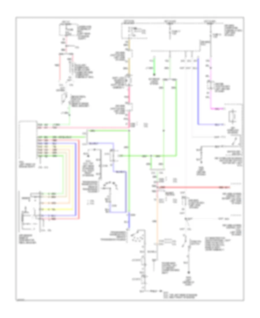
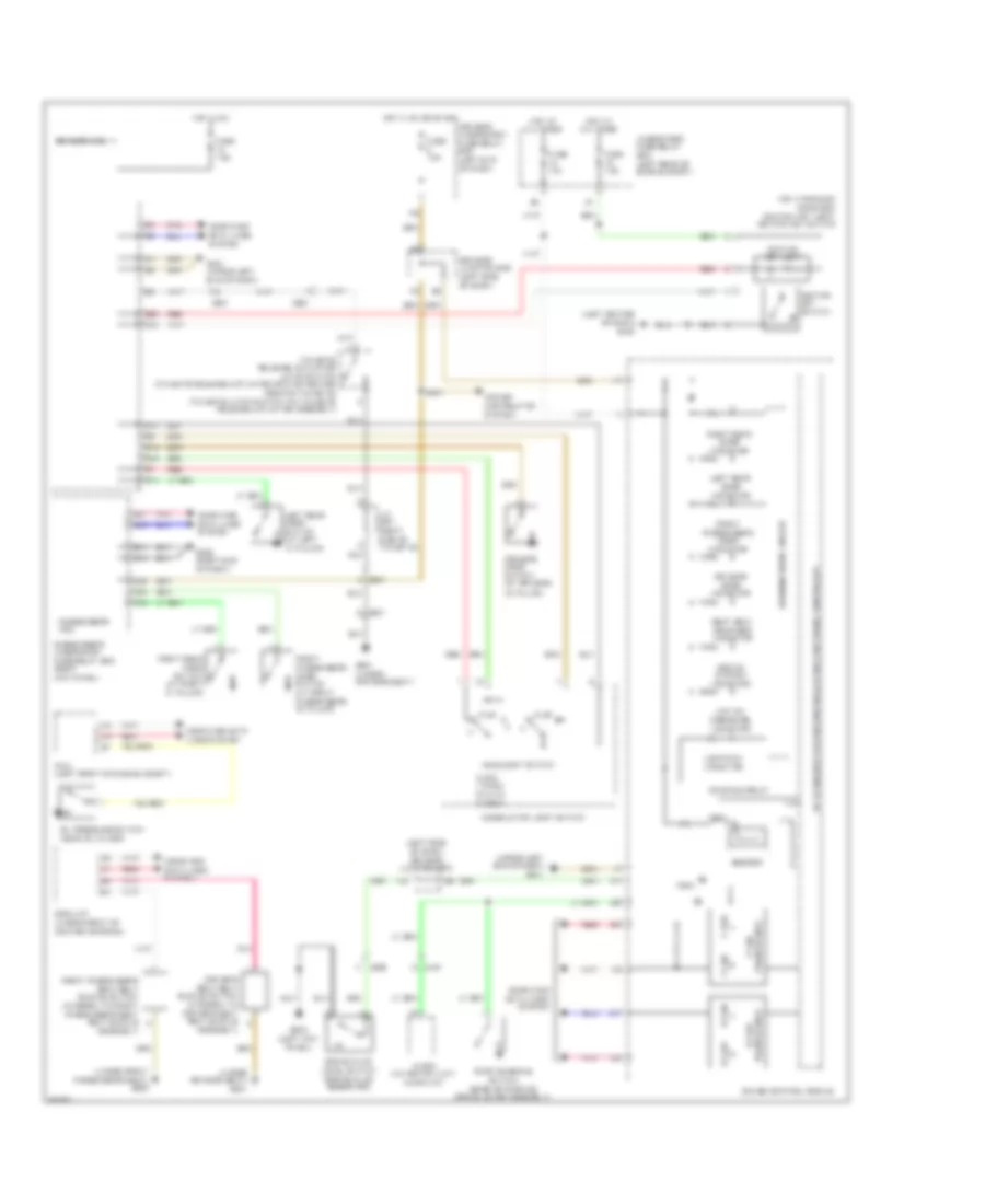
Headlights Wiring Diagram (1 of 2) for Honda Crosstour EX-L 2014
List of elements for Headlights Wiring Diagram (1 of 2) for Honda Crosstour EX-L 2014:
- 2.4l
- 3.5l
- Combination light switch
- Computer data lines system
- D15
- Dimmer/ flash- to-pass switch 0) low 1) high 2) passing
- Driver's door switch (at driver's "b" pillar)
- Driver's junction box (left side of dash)
- Driver's micu
- Driver's under-dash fuse/relay box (left end of dash)
- F13
- F16
- Fog light switch 0) off 1) on
- Fuse 10a
- Fuse 15a
- Fuse 7.5a
- G10
- G301 (behind left side of front bumper)
- G401 (upper left end of dash)
- G402 (upper left end of dash)
- G403 (left center of dash)
- Headlight switch 0) off 1) park 2) auto 3) head
- Hot at all times
- Hot in on
- Hot in on or start
- Key interlock solenoid/ignition key switch/ ignition key light (at ignition switch)
- Left fog light
- Left high headlight
- Left low headlight
- Pnk
- Power distribution system
- Q10
- Q13
- R10
- R11
- R15
- R16
- Red
Headlights Wiring Diagram (2 of 2) for Honda Crosstour EX-L 2014
List of elements for Headlights Wiring Diagram (2 of 2) for Honda Crosstour EX-L 2014:
- (2.4l)
- (3.5l)
- (3.5l) (2.4l)
- (right end of dash) g203
- 3.5l
- A15
- A18
- A21
- A28
- A34
- Air conditioning system
- Automatic lighting sensor/ sunlight sensor (top middle of dash)
- B-can h
- B-can l
- B-can transceiver
- Computer data lines system
- D10
- D13
- D25
- Data link connector (dlc) (under left end of dash)
- Driver's junction box (left side of dash)
- Drl indicator
- E14
- E15
- E17
- Fog light indicator
- Fuse 10a
- Fuse 15a
- G10
- G201 (behind right side of front bumper)
- G203 (right end of dash)
- G402 (upper left end of dash)
- Gauge control module
- High beam indicator
- Hot at all times
- Indicator dimming circuit
- Indicator drive circuit warning drive circuit
- Instrument cluster system
- Lights on indicator
- Parking brake switch (base of parking brake lever assembly)
- Passenger's micu
- Passenger's under-dash fuse/relay box (right kick panel)
- Pnk
- Power distribution system
- Red
- Right fog light
- Right high headlight
- Right low headlight
- Under-hood fuse/relay box (left rear of engine compt)
HORN
Horn Wiring Diagram for Honda Crosstour EX-L 2014
List of elements for Horn Wiring Diagram for Honda Crosstour EX-L 2014:
- 2.4l
- 3.5l
- C14
- Cable reel (top of steering column)
- Driver's junction box (left side of dash)
- Driver's micu
- Driver's under-dash fuse/relay box (left end of dash)
- F32
- Fuse 20a
- Horn (high) (behind right center of front grille)
- Horn (low) (behind left center of front grille)
- Horn relay
- Horn switch (steering wheel)
- Hot at all times
- Q19
- Red
- Under-hood fuse/relay box (left rear of engine compt)
INSTRUMENT CLUSTER
Instrument Cluster Wiring Diagram (1 of 2) for Honda Crosstour EX-L 2014
List of elements for Instrument Cluster Wiring Diagram (1 of 2) for Honda Crosstour EX-L 2014:
- (2.4l)
- (3.5l)
- (if equipped) eps ind
- (near oil filter)
- (right front of cylinder head) rocker arm oil pressure switch
- 2.4l
- 2wd
- 3.5l
- 3.5l 4wd
- 4wd
- 5v stabilizer circuit/controller area network controller
- A10
- Abs ind
- Anti-lock brakes system
- Audio unit/ audio-navigation unit
- B19
- Brake fluid level switch (brake fluid reservoir)
- Brake system ind
- C106
- C13
- C306
- C34
- C402
- C407
- C408
- C410
- C412
- Charging system ind
- Computer data lines system
- Cruise control ind
- Cruise control main switch ind
- Cruise control system
- D10
- D15
- Driver's door ind
- Driver's junction box (left side of dash)
- Driver's micu
- Driver's under-dash fuse/relay box (left end of dash)
- Drl ind
- Eco ind (if equipped)
- Exterior lights system
- Fog light ind
- From compulsory turning off circuit (diagram 2 of 2)
- From compulsory turning on circuit (diagram 2 of 2)
- From indicator dimming circuit (diagram 2 of 2)
- From pin (diagram 2 of 2)
- Front passenger's door ind
- Fuel tank unit (top of fuel tank)
- Fuse 10a
- Fuse 5 fuse 11 7.5a
- G101 (2.4l: top left rear of engine) (3.5l: right front of engine)
- G302 (left kick panel)
- G401 (upper left end of dash)
- G402 (upper left end of dash)
- Gauge control module
- Hot at all times
- Hot in on or start
- Indicator drive circuit
- Interior lights system
- Keyless access control unit (if equipped) (left side of dash)
- Ldw ind
- Left rear door ind
- Lights on ind
- Low fuel ind
- Low oil pressure ind
- Low tire pressure ind
- Mil ind
- Oil pressure switch (2.4l)
- Parking brake switch (base of parking brake lever assembly)
- Pcm (left front of engine compt)
- Pnk
- Red
- Right rear door ind
- Rocker arm oil pressure switch (right front of cylinder head)
- Seat belt reminder ind
- Secondary fuel gauge sending unit
- Side air bag cut-off ind
- Srs ind
- Starter system ind (if equipped)
- Starting/charging system
- Tan
- To safety ind (diagram 2 of 2)
- To security ind (diagram 2 of 2)
- Tpms ind
- Under-hood fuse/relay box (left rear of engine compt)
- Vsa ind
- Vsa off ind
- Warning drive circuit
- Wiper/washer system
Instrument Cluster Wiring Diagram (2 of 2) for Honda Crosstour EX-L 2014
List of elements for Instrument Cluster Wiring Diagram (2 of 2) for Honda Crosstour EX-L 2014:
- (2.4l)
- (3.5l)
- (3.5l) s (2.4l) d3
- -off circuit turning
- 10v stabilizer circuit
- 2.4l
- 3.5l
- 5v stabilizer circuit/controller area network controller
- A/t gear position dimming circuit
- A/t gear position indicator drive circuit
- A21
- A34
- B-can
- Beeper
- Circuit 5v control
- Compulsory
- Computer data lines system
- Dial brightness control & dimming circuit
- Display seg lcd
- Driver's door switch (at driver's "b" pillar)
- Engine coolant temperature gauge
- F-can
- Fail-safe circuit
- Forward collision warning (fcw) ind
- Forward collision warning ind
- From charging system ind (diagram 1 of 2)
- From pin 1 (diagram 1 of 2)
- Front passenger's door switch (at front passenger's "b" pillar)
- Fuel gauge
- Gauge control module
- H24
- H35
- High beam ind
- Illum (+) switch
- Illum (-) switch
- Illumination control & dimming circuit for dial (white)
- Illumination control & dimming circuit for lcd (white)
- Illumination control & dimming circuit for lcd s-matic (white) (3.5l)
- Immobilizer system ind
- Indicator dimming circuit
- Indicator drive circuit
- Keyless access ind (if equipped)
- Lcd back light
- Lcd brightness control & dimming circuit
- Left rear door switch (at left rear "c" pillar)
- Left turn signal ind
- Maintenance required ind (if equipped)
- Passenger's micu
- Passenger's under-dash fuse/relay box (right kick panel)
- Pnk
- Pointer brightness control & dimming circuit
- Relay hazard turn signal/
- Right rear door switch (at right rear "c" pillar)
- Right turn signal ind
- Safety ind (if equipped)
- Security ind
- Shift indicator drive circuit
- Speedometer
- Tachometer
- Tailgate ind (if equipped)
- To eps ind (diagram 1 of 2)
- To mil ind (diagram 1 of 2)
- To starter system ind (diagram 1 of 2)
- Transceiver b-can
- Transceiver f-can
- Trip/reset switch
- Trunk ind
- Turning -on circuit
- Warning drive circuit
- Washer fluid level ind (if equipped)
INTERIOR LIGHTS
Courtesy Lamps Wiring Diagram for Honda Crosstour EX-L 2014
List of elements for Courtesy Lamps Wiring Diagram for Honda Crosstour EX-L 2014:
- (optional connector)
- (upper left end of dash) g401
- 2.4l
- 2.4l c801
- 3.5l
- 3.5l c414
- A18
- A21
- A22
- A26
- A30
- A34
- C302
- C401
- C403
- C404
- C405
- C411
- C412
- C413
- C452
- C601
- C651
- C701
- C803
- C811
- Ceiling light
- Center junction box (left center of dash)
- Computer data lines system
- D10
- D11
- D14
- D15
- Door
- Door lock knob
- Driver's door courtesy light
- Driver's door switch (at driver's "b" pillar)
- Driver's junction box (left side of dash)
- Driver's micu
- Driver's under-dash fuse/relay box (left end of dash)
- Driver's vanity mirror light
- F16
- F26
- Front passenger's door courtesy light
- Front passenger's door switch (at front passenger's "b" pillar)
- Fuse 15 10a
- Fuse 16 7.5a
- Fuse 6 7.5a
- G10
- G401 (upper left end of dash)
- G405 (right end of dash)
- G502 (lower middle of dash)
- G601 (under driver's seat)
- Glove box light
- H13
- H24
- H35
- Hot at all times
- Ignition key light
- Individual map lights
- Interior light switch
- J/c c451 (2.4l) j/c c012 (3.5l) (c451: left front of roof)
- J/c c505 (2.4l) j/c c002 (3.5l) (c505: lower right center of dash)
- J/c c671 (2.4l) j/c c007 (3.5l) (c671: right side of tailgate)
- Key interlock solenoid/ ignition key switch/ ignition key light (steering lock) (2.4l) (key interlock solenoid: at ignition switch)
- Left
- Left cargo area light
- Left rear door switch (at left "c" pillar)
- Moonroof switch
- Off
- P10
- Passenger's micu
- Passenger's under-dash fuse/relay box (right kick panel)
- Passenger's vanity mirror light
- Pnk
- Power distribution system
- Q20
- Red
- Right
- Right cargo area light
- Right rear door switch (at right "c" pillar)
- Tailgate latch switch
- Tailgate release actuator/latch switch (tailgate release actuator: bottom center rear of tailgate) (tailgate latch switch: on tailgate release actuator assembly)
- Under-hood fuse/relay box (left rear of engine compt)
Entry Light Timer Wiring Diagram for Honda Crosstour EX-L 2014
List of elements for Entry Light Timer Wiring Diagram for Honda Crosstour EX-L 2014:
- (optional connector)
- 2.4l
- 3.5l
- A18
- A21
- A22
- A26
- A34
- Antenna
- C403
- C411
- C414
- C452
- C701
- C801
- Ceiling light
- Center junction box (left center of dash)
- Computer data lines system
- D10
- D15
- Door
- Door lock knob
- Driver's door key cylinder switch
- Driver's door lock actuator/knob switch/ key cylinder switch
- Driver's door switch (at driver's "b" pillar)
- Driver's junction box (left side of dash)
- Driver's micu
- Driver's under-dash fuse/relay box (left end of dash)
- E14
- E15
- F16
- F26
- Front passenger's door switch (at front passenger's "b" pillar)
- Fuse 15 10a
- Fuse 16 7.5a
- G10
- G203 (right end of dash)
- G401 (upper left end of dash)
- G402 (upper left end of dash)
- G403 (left center of dash)
- G405 (right end of dash)
- H13
- H24
- H35
- Hot at all times
- Ignition key light
- Ignition key switch
- Immobilizer keyless control unit (2.4l) (steering column)
- Individual map lights
- Interior light switch
- J/c c451 (2.4l) j/c c012 (3.5l) (c451: left front of roof)
- Key
- Key interlock solenoid/ ignition key switch/ ignition key light (steering lock) (2.4l) (key interlock solenoid: at ignition switch)
- Left
- Left rear door switch (at left "c" pillar)
- Lock
- Moonroof switch
- Off
- P10
- Passenger's micu
- Passenger's under-dash fuse/relay box (right kick panel)
- Pnk
- Power distribution system
- Power window master switch (door multiplex control unit)
- Q10
- Q13
- Q20
- R11
- Red
- Right
- Right cargo area light
- Right rear door switch (at right "c" pillar)
- Transmitter
- Un- lock
- Under-hood fuse/relay box (left rear of engine compt)
Instrument Illumination Wiring Diagram (1 of 3) for Honda Crosstour EX-L 2014
List of elements for Instrument Illumination Wiring Diagram (1 of 3) for Honda Crosstour EX-L 2014:
- (3.5l)
- 2.4l
- 3.5l
- A/t gear position indicator panel light
- A/t gear position indicator panel light/ park pin switch (park pin switch: base of shift lever assembly)
- A19
- A21
- A33
- A34
- Air bag cutoff
- Air bag cutoff indicator (2.4l)
- C107
- C403
- C409
- C411
- Center junction box (left center of dash)
- Computer data lines system
- D14
- Driver's seat heater switch
- E14
- E15
- Front passenger's
- Front passenger's seat heater switch
- Fuse 2 10a
- Fuse 6 7.5a
- G203 (right end of dash)
- Homelink unit (3.5l 4wd) (center front of roof)
- Hot at all times
- Hvac display
- Indicator
- Interface dial (3.5l) navigation switch panel (2.4l)
- Interior light
- K10
- Ldw off switch
- Moonroof switch
- Passenger's micu
- Passenger's under-dash fuse/relay box (right kick panel)
- Pnk
- Red
- Unit/passenger's
- Vsa off switch
Instrument Illumination Wiring Diagram (2 of 3) for Honda Crosstour EX-L 2014
List of elements for Instrument Illumination Wiring Diagram (2 of 3) for Honda Crosstour EX-L 2014:
- (2.4l) (3.5l)
- A12
- Auto
- Combination light switch
- Computer data lines system
- Driver's climate control switch
- Driver's junction box (left side of dash)
- Driver's micu
- Driver's under-dash fuse/relay box (left end of dash)
- Fuse 5 fuse 11 7.5a
- G401 (upper left end of dash)
- G402 (upper left end of dash)
- G502 (lower middle of dash)
- Hazard warning switch
- Head
- Headlight switch
- Hot in on or start
- J/c c505 (2.4l) j/c c002 (3.5l) (c505: lower right center of dash)
- J/c c506 (2.4l) j/c c001 (3.5l) (2.4l: lower right center of dash)
- Multi-information display unit
- Off
- Park
- Passenger's climate control switch
- Pnk
- Q10
- R10
- R11
- Red
Instrument Illumination Wiring Diagram (3 of 3) for Honda Crosstour EX-L 2014
List of elements for Instrument Illumination Wiring Diagram (3 of 3) for Honda Crosstour EX-L 2014:
- (2.4l)
- 10v stabilizer circuit
- 2.4l
- 3.5l
- 5v stabilize circuit/controller area network controller (3.5l)
- A10
- Audio remote switch
- B-can h
- B-can l
- Cable reel (top of steering column)
- Computer data lines system
- Cruise control combination switch
- Fuse 15 10a
- G401 (upper left end of dash)
- G402 (upper left end of dash)
- Gauge control module
- Hfl-navigation voice control switch
- Hfl/ hfl-navigation voice control switch
- Hot at all times
- Illumi (+)
- Illumi (-)
- Illumination control & dimming circuit for dial (white) (3.5l) dial brightness control & dimming circuit (2.4l)
- Illumination control & dimming circuit for lcd (white) (3.5l) lcd brightness control & dimming circuit (2.4l)
- Illumination control & dimming circuit for lcd s-matic (white) (3.5l)
- Lcd back light
- Paddle shifter (downshift switch) (3.5l 4wd)
- Paddle shifter (up-shift switch)
- Pnk
- Power distribution system
- Red
- Transceiver b-can
- Under-hood fuse/relay box (left rear of engine compt)
MEMORY SYSTEMS
Memory Mirrors Wiring Diagram (1 of 2) for Honda Crosstour EX-L 2014
List of elements for Memory Mirrors Wiring Diagram (1 of 2) for Honda Crosstour EX-L 2014:
- (door multiplex control unit)
- (left rear of engine compt)
- 2.4l
- 3.5l
- B21
- B22
- B23
- C142
- C411
- C412
- C414
- C701
- C801
- Computer data lines system
- Driver's under-dash fuse/relay box (left end of dash)
- Driving position memory switch
- Driving position memory switch light
- Fuse 10a
- Fuse 7.5a
- G401 (upper left end of dash)
- G402 (upper left end of dash)
- Hot at all times
- Hot in on or start
- Memo button
- P11
- Pnk
- Pos 1 button
- Pos 1 ind
- Pos 2 button
- Pos 2 ind
- Power mirror control unit
- Power seat control unit (under driver's seat)
- Power window master switch
- Power windows system
- Red
- Under-hood fuse/relay box
Memory Mirrors Wiring Diagram (2 of 2) for Honda Crosstour EX-L 2014
List of elements for Memory Mirrors Wiring Diagram (2 of 2) for Honda Crosstour EX-L 2014:
- 2.4l
- 3.5l
- C413
- C414
- C414 c801
- C801
- C811
- Defogger
- Defogger system
- Down/
- G401 (upper left end of dash)
- Left
- Left power mirror
- Left/right motor
- Pnk
- Power mirror switch
- Red
- Right
- Right power mirror
- Up/
- Up/down motor
Memory Seat Wiring Diagram (1 of 3) for Honda Crosstour EX-L 2014
List of elements for Memory Seat Wiring Diagram (1 of 3) for Honda Crosstour EX-L 2014:
- 2.4l
- 3.5l
- A10
- A11
- A12
- A13
- A14
- A15
- A16
- A17
- A18
- B10
- B11
- B12
- B13
- B14
- B15
- B16
- B17
- B18
- B19
- B20
- B21
- B22
- B23
- B24
- B25
- B26
- B27
- B28
- B29
- B30
- B31
- B32
- B33
- B34
- B35
- B36
- B37
- B38
- B39
- B40
- C142
- C411
- C412
- C414
- C701
- C801
- Computer data lines system
- Driver's micu
- Driver's seat front up-down motor
- Driver's seat recline motor
- Driver's under-dash fuse/relay box (left end of dash)
- F23
- Fuse 20a
- Fuse 7.5a
- G801 (under driver's seat)
- Hot at all times
- Hot in on or start
- N12
- P17
- P18
- Pnk
- Power mirror control unit
- Power seat control unit (under driver's seat)
- Red
- Sensor
Memory Seat Wiring Diagram (2 of 3) for Honda Crosstour EX-L 2014
List of elements for Memory Seat Wiring Diagram (2 of 3) for Honda Crosstour EX-L 2014:
- (rear of transmission housing) transmission range switch
- 2.4l
- 2.4l 3.5l
- 3.5l
- A37
- B11
- B24
- Bwd
- C101
- C106
- C306
- C408
- C506
- Down
- Driver's power seat adjustment switch
- Driver's seat rear up-down motor
- Driver's seat slide motor
- Front up- down switch
- Fwd
- G101 (right front of engine)
- G101 (top left rear of engine)
- J/c c014
- J/c c015
- Keyless access control unit (if equipped) (left side of dash)
- Pcm (left front of engine compt)
- Rear up down switch
- Recline switch
- Red
- Sensor
- Slide switch
- Transmission range switch (rear of transmission housing)
Memory Seat Wiring Diagram (3 of 3) for Honda Crosstour EX-L 2014
List of elements for Memory Seat Wiring Diagram (3 of 3) for Honda Crosstour EX-L 2014:
- (left rear of engine compt)
- 2.4l
- 3.5l
- 5v stabilizer circuit/ controller area network controller
- B-can transceiver
- C142
- C411
- C412
- C414 c801
- C701
- Canh
- Canl
- Computer data lines system
- Driver's junction box (left side of dash)
- Driving position memory switch
- Driving position memory switch light
- Fuse 10a
- G10
- G401 (upper left end of dash)
- G402 (upper left end of dash)
- Gauge control module
- Hot at all times
- Memo button
- Pnk
- Pos 1 button
- Pos 1 ind
- Pos 2 button
- Pos 2 ind
- Power mirror switch
- Power window master switch (door multiplex control unit)
- Power windows system
- Red
- Under-hood fuse/relay box
NAVIGATION
2.4L
2.4L, Compass Wiring Diagram for Honda Crosstour EX-L 2014
List of elements for 2.4L, Compass Wiring Diagram for Honda Crosstour EX-L 2014:
- A17
- A24
- Audio unit/ audio-navigation unit
- C10
- C101
- C19
- C20
- C411
- C701
- Center junction box
- Computer data lines system
- D24
- Driver's under-dash fuse/relay box (left end of dash)
- Electrical compass unit (center rear of roof)
- Fuse 7.5a
- G401 (upper left end of dash)
- G501 (lower middle of dash)
- Hot in on or acc
- Hot w/ ig1 relay1 energized
- J/c c002
- J/c c012
- P16
- Passenger's under-dash fuse/relay box (right kick panel)
- Pnk
- Red
2.4L, Hands Free Module Wiring Diagram (1 of 2) for Honda Crosstour EX-L 2014
List of elements for 2.4L, Hands Free Module Wiring Diagram (1 of 2) for Honda Crosstour EX-L 2014:
- (top of steering column) cable reel
- 2.4l
- 3.5l
- A10
- A11
- A12
- A13
- A14
- A15
- A16
- A17
- A18
- A19
- A20
- A21
- A22
- A23
- A24
- A25
- A26
- A27
- A28
- A29
- A30
- A31
- A32
- Audio unit/audio-navigation unit
- C102
- C107 c409
- C12
- C20
- C406
- Computer data lines system
- D10
- D12
- F13
- F14
- Fuse 20a
- G501 (lower middle of dash)
- Handsfreelink control unit (left end of dash)
- Hang-up back switch
- Hfl/hfl-navigation voice control switch (3.5l) hfl-navigation voice control switch (2.4l)
- Hot at all times
- Interior lights system
- J/c c005 (3.5l) j/c c502 (2.4l)
- Nca
- Passenger's under-dash fuse/relay box (right kick panel)
- Pick-up switch
- Pnk
- Red
- T6 (steering wheel)
- Talk switch
2.4L, Hands Free Module Wiring Diagram (2 of 2) for Honda Crosstour EX-L 2014
List of elements for 2.4L, Hands Free Module Wiring Diagram (2 of 2) for Honda Crosstour EX-L 2014:
- (c504: lower right center of dash) (3.5l) j/c c003 (2.4l) j/c c504
- (c604: behind right rear side trim panel) (3.5l 4wd) j/c c010 (2.4l) j/c c604
- (center front of roof) front hfl-navigation-anc/active sound control microphone
- (right center of dash) (3.5l) anc/active sound control unit
- 2.4l
- 3.5l
- 3.5l 2wd
- A10
- A11
- A12
- C102
- C104
- C105
- C107
- C403
- C409
- C411
- C509
- Except 3.5l 2wd
- J/c c006 (3.5l) j/c c501 (2.4l) (c501: lower right center of dash)
- Multi-information display unit
- Red
- Tuner unit (behind right rear side trim panel)
- Xm receiver (if equipped) (behind right rear side trim panel)
2.4L, Home Link Remote Control Wiring Diagram for Honda Crosstour EX-L 2014
List of elements for 2.4L, Home Link Remote Control Wiring Diagram for Honda Crosstour EX-L 2014:
- C411
- Fuse 7.5a
- G401 (upper left end of dash)
- Homelink unit (center front of roof)
- Hot at all times
- Interior lights system
- J/c c012
- Under-hood fuse/relay box (left rear of engine compt)
2.4L, Lane Departure Warning Wiring Diagram for Honda Crosstour EX-L 2014
List of elements for 2.4L, Lane Departure Warning Wiring Diagram for Honda Crosstour EX-L 2014:
- (2.4l)
- (3.5l)
- (3.5l) (2.4l)
- 3.5l 2.4l
- 5v stabilize circuit/controller area network controller
- C409 c404
- C411 c403
- Computer data lines system
- Driver's under-dash fuse/relay box (left end of dash)
- F-can transceiver
- F-canh
- F-canl
- Fcw/ldw camera unit (integral to interior rearview mirror base assembly)
- Forward collision warning indicator (if equipped)
- Fuse 10a
- Fuse 11 fuse 5 7.5a
- G401 (upper left end of dash)
- Gauge control module
- Hot at all times
- Hot in on or start
- Indicator drive circuit (3.5l) warning drive circuit (2.4l)
- Interior lights system
- Lane departure warning indicator
- Ldw/off switch
- Pnk
- Red
- Under-hood fuse/relay box (left rear of engine compt)
2.4L, Lane Watch Camera Wiring Diagram for Honda Crosstour EX-L 2014
List of elements for 2.4L, Lane Watch Camera Wiring Diagram for Honda Crosstour EX-L 2014:
- A17
- A24
- Audio unit/ audio-navigation unit
- C408
- C812
- Center junction box
- Combination light switch
- Computer data lines system
- D24
- Driver's under-dash fuse/relay box (left end of dash)
- Fuse 7.5a
- G20
- G21
- G22
- G23
- G401 (upper left end of dash)
- G501 (lower middle of dash)
- Hot in on or acc
- J/c c002
- Lane watch switch
- P16
- Passenger's under-dash fuse/relay box (right kick panel)
- Pnk
- Red
- Right power mirror
2.4L, Navigation Wiring Diagram (1 of 6) for Honda Crosstour EX-L 2014
List of elements for 2.4L, Navigation Wiring Diagram (1 of 6) for Honda Crosstour EX-L 2014:
- (lower middle of dash) g501
- A10
- A11
- A12
- A13
- A14
- A15
- A16
- A17
- A18
- A19
- A20
- A21
- A22
- A23
- A24
- Anc/active sound control unit (right center of dash)
- Audio-navigation unit/audio unit
- Auxiliary jack assembly 5p connector
- C10
- C11
- C12
- C13
- C14
- C15
- C16
- C17
- C18
- C409
- Center junction box (left center of dash)
- Computer data lines system
- D10
- D11
- D12
- D24
- D26
- Driver's under-dash fuse/relay box (left end of dash)
- Fuse 10a
- Fuse 18 7.5a
- Fuse 20a
- G502 (lower middle of dash)
- Hot at all times
- Hot in acc or on
- J/c c505 (lower right center of dash)
- J/c c506 (lower right center of dash)
- Nca
- P16
- Passenger's under-dash fuse/relay box (right kick panel)
- Pnk
- Red
- Under-hood fuse/relay box (left rear of engine compt)
2.4L, Navigation Wiring Diagram (2 of 6) for Honda Crosstour EX-L 2014
List of elements for 2.4L, Navigation Wiring Diagram (2 of 6) for Honda Crosstour EX-L 2014:
- (behind right rear side trim panel) stereo amplifier
- (lower right center of dash) j/c c502
- A10
- A11
- A12
- A13
- A14
- A15
- A16
- A17
- A18
- A19
- A20
- A21
- A22
- A23
- A24
- Audio remote switch
- C106
- C403
- C406
- C407
- Cable reel (top of steering column)
- Channel + switch
- Channel - switch
- Display switch
- G101 (top left rear of engine)
- Interior lights system
- Mode switch
- Pnk
- Pnk a5
- Rear anc/ active sound control microphone (center rear of roof)
- Red
- Transmission range switch (rear of transmission housing)
- Volume down switch
- Volume up switch
2.4L, Navigation Wiring Diagram (3 of 6) for Honda Crosstour EX-L 2014
List of elements for 2.4L, Navigation Wiring Diagram (3 of 6) for Honda Crosstour EX-L 2014:
- (behind right rear side trim panel) j/c c604
- (lower right center of dash) j/c c501
- A10
- A11
- A12
- A13
- A14
- A16
- A17
- A18
- A21
- A22
- A23
- A24
- A28
- A32
- Am/fm/xm antenna
- C403
- C409
- C509
- G502 (lower middle of dash)
- Handsfree link control unit (left end of dash)
- Interior lights system
- J/c c504 (lower right center of dash)
- Multi-information display unit
- Nca
- Red
- Xm receiver (behind right rear side trim panel)
2.4L, Navigation Wiring Diagram (4 of 6) for Honda Crosstour EX-L 2014
List of elements for 2.4L, Navigation Wiring Diagram (4 of 6) for Honda Crosstour EX-L 2014:
- (lower middle of dash) g502
- A21
- A34
- Audio-navigation unit/audio unit
- B10
- B11
- B12
- B13
- B14
- B15
- B16
- B17
- C401
- C407
- C408
- C508
- C553
- C571
- C581
- C801
- C811
- C821
- C831
- Computer data lines system
- D23
- Driver's door speaker
- Driver's door tweeter
- E15
- Front passenger's door speaker
- Front passenger's door tweeter
- Fuse 22 20a
- G203 (right end of dash)
- Gps antenna
- Hot at all times
- Left rear door speaker
- Nca
- Passenger's micu
- Passenger's under-dash fuse/relay box (right kick panel)
- Pnk
- Red
- Right rear door speaker
- Stereo amplifier (behind right rear side trim panel)
- Subwoofer
- Usb adapter 4p connector
2.4L, Navigation Wiring Diagram (5 of 6) for Honda Crosstour EX-L 2014
List of elements for 2.4L, Navigation Wiring Diagram (5 of 6) for Honda Crosstour EX-L 2014:
- (center front of roof) front hfl-navigation- anc (front hfl-anc)/active sound control microphone
- (left side of dash) driver's junction box
- (top left rear of engine) g101
- 5v stabilize circuit/controller area network controller
- A16
- Audio-navigation unit/audio unit
- Automatic dimming inside mirror
- B-can h
- B-can l
- B-can transceiver
- B25
- C101
- C306
- C403
- C406
- C407
- C408
- Combination light switch
- Computer data lines system
- Diode d
- Diode e
- Driver's micu
- Driver's under-dash fuse/relay box (left end of dash)
- F10
- F11
- F12
- F13
- F14
- F15
- F16
- F17
- F18
- F28
- Fm distributor
- Fuse 5 7.5a
- G401 (upper left end of dash)
- G502 (lower middle of dash)
- Gauge control module
- Hot in on or start
- Interior lights system
- Navigation switch panel
- Nca
- P12
- Parking brake switch (base of parking brake lever assembly)
- Pcm (left front of engine compt)
- Pnk
- Power distri- bution system
- R11
- Red
- Reverse relay
2.4L, Navigation Wiring Diagram (6 of 6) for Honda Crosstour EX-L 2014
List of elements for 2.4L, Navigation Wiring Diagram (6 of 6) for Honda Crosstour EX-L 2014:
- (behind right rear side trim panel) tuner unit
- (lower right center of dash) j/c c501
- A10
- A11
- A12
- Audio-navigation unit/audio unit
- C402
- C407
- C408
- C508
- C509
- C601
- C651
- C812
- G10
- G11
- G12
- G13
- G14
- G15
- G16
- G17
- G18
- G19
- G20
- G21
- G22
- G23
- G24
- Nca
- Rearview camera (right side of tailgate)
- Red
- Right power mirror
2.4L, Rear Camera Wiring Diagram for Honda Crosstour EX-L 2014
List of elements for 2.4L, Rear Camera Wiring Diagram for Honda Crosstour EX-L 2014:
- 2.4l
- 3.5l
- Audio unit/audio- navigation unit
- C106 c407
- C302
- C402
- C410
- C601
- C651
- C803
- Computer data lines system
- Fuse 20a
- G15
- G16
- G17
- G18
- G501 (lower middle of dash)
- Hot at all times
- Passenger's under-dash fuse/relay box (right kick panel)
- Pnk
- Rearview camera (right side of tailgate)
- Red
3.5L
3.5L, Compass Wiring Diagram for Honda Crosstour EX-L 2014
List of elements for 3.5L, Compass Wiring Diagram for Honda Crosstour EX-L 2014:
- A17
- A24
- Audio unit/ audio-navigation unit
- C10
- C101
- C19
- C20
- C411
- C701
- Center junction box
- Computer data lines system
- D24
- Driver's under-dash fuse/relay box (left end of dash)
- Electrical compass unit (center rear of roof)
- Fuse 7.5a
- G401 (upper left end of dash)
- G501 (lower middle of dash)
- Hot in on or acc
- Hot w/ ig1 relay1 energized
- J/c c002
- J/c c012
- P16
- Passenger's under-dash fuse/relay box (right kick panel)
- Pnk
- Red
3.5L, Hands Free Module Wiring Diagram (1 of 2) for Honda Crosstour EX-L 2014
List of elements for 3.5L, Hands Free Module Wiring Diagram (1 of 2) for Honda Crosstour EX-L 2014:
- (top of steering column) cable reel
- 2.4l
- 3.5l
- A10
- A11
- A12
- A13
- A14
- A15
- A16
- A17
- A18
- A19
- A20
- A21
- A22
- A23
- A24
- A25
- A26
- A27
- A28
- A29
- A30
- A31
- A32
- Audio unit/audio-navigation unit
- C102
- C107 c409
- C12
- C20
- C406
- Computer data lines system
- D10
- D12
- F13
- F14
- Fuse 20a
- G501 (lower middle of dash)
- Handsfreelink control unit (left end of dash)
- Hang-up back switch
- Hfl/hfl-navigation voice control switch (3.5l) hfl-navigation voice control switch (2.4l)
- Hot at all times
- Interior lights system
- J/c c005 (3.5l) j/c c502 (2.4l)
- Nca
- Passenger's under-dash fuse/relay box (right kick panel)
- Pick-up switch
- Pnk
- Red
- T6 (steering wheel)
- Talk switch
3.5L, Hands Free Module Wiring Diagram (2 of 2) for Honda Crosstour EX-L 2014
List of elements for 3.5L, Hands Free Module Wiring Diagram (2 of 2) for Honda Crosstour EX-L 2014:
- (c504: lower right center of dash) (3.5l) j/c c003 (2.4l) j/c c504
- (c604: behind right rear side trim panel) (3.5l 4wd) j/c c010 (2.4l) j/c c604
- (center front of roof) front hfl-navigation-anc/active sound control microphone
- (right center of dash) (3.5l) anc/active sound control unit
- 2.4l
- 3.5l
- 3.5l 2wd
- A10
- A11
- A12
- C102
- C104
- C105
- C107
- C403
- C409
- C411
- C509
- Except 3.5l 2wd
- J/c c006 (3.5l) j/c c501 (2.4l) (c501: lower right center of dash)
- Multi-information display unit
- Red
- Tuner unit (behind right rear side trim panel)
- Xm receiver (if equipped) (behind right rear side trim panel)
3.5L, Home Link Remote Control Wiring Diagram for Honda Crosstour EX-L 2014
List of elements for 3.5L, Home Link Remote Control Wiring Diagram for Honda Crosstour EX-L 2014:
- C411
- Fuse 7.5a
- G401 (upper left end of dash)
- Homelink unit (center front of roof)
- Hot at all times
- Interior lights system
- J/c c012
- Under-hood fuse/relay box (left rear of engine compt)
3.5L, Lane Departure Warning Wiring Diagram for Honda Crosstour EX-L 2014
List of elements for 3.5L, Lane Departure Warning Wiring Diagram for Honda Crosstour EX-L 2014:
- (2.4l)
- (3.5l)
- (3.5l) (2.4l)
- 3.5l 2.4l
- 5v stabilize circuit/controller area network controller
- C409 c404
- C411 c403
- Computer data lines system
- Driver's under-dash fuse/relay box (left end of dash)
- F-can transceiver
- F-canh
- F-canl
- Fcw/ldw camera unit (integral to interior rearview mirror base assembly)
- Forward collision warning indicator (if equipped)
- Fuse 10a
- Fuse 11 fuse 5 7.5a
- G401 (upper left end of dash)
- Gauge control module
- Hot at all times
- Hot in on or start
- Indicator drive circuit (3.5l) warning drive circuit (2.4l)
- Interior lights system
- Lane departure warning indicator
- Ldw/off switch
- Pnk
- Red
- Under-hood fuse/relay box (left rear of engine compt)
3.5L, Lane Watch Camera Wiring Diagram for Honda Crosstour EX-L 2014
List of elements for 3.5L, Lane Watch Camera Wiring Diagram for Honda Crosstour EX-L 2014:
- A17
- A24
- Audio unit/ audio-navigation unit
- C408
- C812
- Center junction box
- Combination light switch
- Computer data lines system
- D24
- Driver's under-dash fuse/relay box (left end of dash)
- Fuse 7.5a
- G20
- G21
- G22
- G23
- G401 (upper left end of dash)
- G501 (lower middle of dash)
- Hot in on or acc
- J/c c002
- Lane watch switch
- P16
- Passenger's under-dash fuse/relay box (right kick panel)
- Pnk
- Red
- Right power mirror
3.5L, Navigation Wiring Diagram (1 of 6) for Honda Crosstour EX-L 2014
List of elements for 3.5L, Navigation Wiring Diagram (1 of 6) for Honda Crosstour EX-L 2014:
- (lower middle of dash) g501
- A10
- A11
- A12
- A13
- A14
- A15
- A16
- A17
- A18
- A19
- A20
- A21
- A22
- A23
- A24
- Anc/active sound control unit (right center of dash)
- Audio-navigation unit/audio unit
- Auxiliary jack assembly 5p connector
- C10
- C102
- C104
- C105
- C107
- C11
- C12
- C13
- C14
- C15
- C16
- C17
- C18
- Center junction box (left center of dash)
- Computer data lines system
- D10
- D11
- D12
- D24
- Driver's under-dash fuse/relay box (left end of dash)
- Fuse 18 7.5a
- G502 (lower middle of dash)
- Hot in on or acc
- J/c c001
- J/c c002
- Nca
- P16
- Passenger's under-dash fuse/relay box (right kick panel)
- Pnk
- Red
3.5L, Navigation Wiring Diagram (2 of 6) for Honda Crosstour EX-L 2014
List of elements for 3.5L, Navigation Wiring Diagram (2 of 6) for Honda Crosstour EX-L 2014:
- (center front of roof) front hfl-navigation-anc/active sound control microphone
- (except 4wd: right end of dash) (4wd: behind right rear side trim panel) stereo amplifier
- A10
- A11
- A12
- A13
- A14
- A15
- A16
- A17
- A18
- A19
- A20
- A21
- A22
- A23
- A24
- Audio remote switch
- C102
- C104
- C106
- C2 red
- C411
- Cable reel (top of steering column)
- Channel+
- Channel-
- Display switch
- Interior lights system
- J/c c005
- Mode switch
- Pnk
- Pnk a5
- Rear anc/active sound control microphone (center rear of roof)
- Red
- Volume down switch
- Volume up switch
3.5L, Navigation Wiring Diagram (3 of 6) for Honda Crosstour EX-L 2014
List of elements for 3.5L, Navigation Wiring Diagram (3 of 6) for Honda Crosstour EX-L 2014:
- A10
- A11
- A12
- A13
- A14
- A16
- A17
- A18
- A19
- A20
- A21
- A22
- A23
- A24
- A28
- A32
- Am/fm/xm antenna
- C105
- C107
- G502 (lower middle of dash)
- Handsfree link control unit (left end of dash)
- J/c c003
- J/c c006
- J/c c010
- Multi-information display unit
- Nca
- Red
- Xm receiver (behind right rear side trim panel)
3.5L, Navigation Wiring Diagram (4 of 6) for Honda Crosstour EX-L 2014
List of elements for 3.5L, Navigation Wiring Diagram (4 of 6) for Honda Crosstour EX-L 2014:
- (right side cargo area floor) g702
- A13
- A14
- A18
- Audio-navigation unit/audio unit
- B10
- B11
- B12
- B13
- B14
- B15
- B16
- B17
- C101
- C104
- C106
- C111
- C121
- C151
- C152
- C413
- C414
- C601
- C602
- C802
- Computer data lines system
- D23
- D26
- Driver's door speaker
- Driver's door tweeter
- Front passenger's door speaker
- Front passenger's door tweeter
- Fuse 15 20a
- Fuse 22 20a
- Hot at all times
- Left rear door speaker
- Nca
- Passenger's micu
- Passenger's under-dash fuse/relay box (right kick panel)
- Pnk
- Red
- Right rear door speaker
- Stereo amplifier (except 4wd: right end of dash) (4wd: behind right rear side trim panel)
- Subwoofer
- Usb port
3.5L, Navigation Wiring Diagram (5 of 6) for Honda Crosstour EX-L 2014
List of elements for 3.5L, Navigation Wiring Diagram (5 of 6) for Honda Crosstour EX-L 2014:
- (left rear of engine compt)
- (lower middle of dash) g502
- 5v stabilize circuit/controller area network controller
- Audio-navigation unit/audio unit
- B-can h
- B-can l
- B-can transceiver
- C102
- C106
- Computer data lines system
- Diode c
- Diode d
- Driver's junction box (left side of dash)
- Driver's micu
- Driver's under-dash fuse/relay box (left end of dash)
- Engine controls system
- F10
- F11
- F12
- F13
- F14
- F15
- F16
- F17
- F18
- F19
- F20
- F28
- Fm distributor
- Fuse 11 7.5a
- Fuse 15 10a
- G402 (upper left end of dash)
- G502 (lower middle of dash)
- Gauge control module
- Gps antenna
- Hot at all times
- Hot in on or start
- Interface dial
- Interior lights system
- J/c c002
- Nca
- P12
- P13
- P14
- Parking brake switch (base of parking brake lever assembly)
- Pnk
- Power distribution system
- Red
- Reverse relay
- System anti-theft
- Under-hood fuse/relay box
3.5L, Navigation Wiring Diagram (6 of 6) for Honda Crosstour EX-L 2014
List of elements for 3.5L, Navigation Wiring Diagram (6 of 6) for Honda Crosstour EX-L 2014:
- (behind right rear side trim panel) tuner unit
- A10
- A11
- A12
- Audio-navigation unit/audio unit
- C101
- C104
- C105
- C106
- C302
- C406
- C410
- C506
- C803
- Combination light switch
- G10
- G101 (right front of engine)
- G11
- G12
- G13
- G14
- G15
- G16
- G17
- G18
- G19
- G20
- G21
- G22
- G23
- G24
- G401 (upper left end of dash)
- J/c c006
- J/c c014
- J/c c015
- Nca
- Rearview camera (right side of tailgate)
- Red
- Right power mirror
- Transmission range switch (rear of transmission housing)
3.5L, Rear Camera Wiring Diagram for Honda Crosstour EX-L 2014
List of elements for 3.5L, Rear Camera Wiring Diagram for Honda Crosstour EX-L 2014:
- 2.4l
- 3.5l
- Audio unit/audio- navigation unit
- C106 c407
- C302
- C402
- C410
- C601
- C651
- C803
- Computer data lines system
- Fuse 20a
- G15
- G16
- G17
- G18
- G501 (lower middle of dash)
- Hot at all times
- Passenger's under-dash fuse/relay box (right kick panel)
- Pnk
- Rearview camera (right side of tailgate)
- Red
POWER DISTRIBUTION
2.4L
2.4L, Power Distribution Wiring Diagram (1 of 7) for Honda Crosstour EX-L 2014
List of elements for 2.4L, Power Distribution Wiring Diagram (1 of 7) for Honda Crosstour EX-L 2014:
- (diagram 4 of 7)
- (left rear of engine compt) under-hood fuse/relay box
- A/c diode b
- A/f sensor (sensor 1)
- A49
- B13
- Battery
- Brake pedal position switch
- C101
- C201
- C304
- C307
- C407
- Driver's micu
- Driver's under-dash fuse/relay box (left end of dash)
- Driver's under-dash fuse/relay box (left kick panel)
- Evap canister vent shut valve
- F11
- Fuse 1-2 40a
- Fuse 12 15a
- Fuse 15a
- Fuse 2-2 40a
- Fuse 2-3 30a
- Fuse 2-4 40a
- Fuse 4 7.5a
- Fuse 7 15a
- Fuse 8 20a
- G1 (left front of engine compt)
- Hazard warning switch/ front passenger's air bag cut-off indicator
- Horn relay
- Ignition coil relay
- Pcm
- Pgm-fi sub-relay
- Radiator fan relay
- Red
- Relay circuit board
- Starter
- To fuse 1-1
- To passenger's under-dash fuse/relay box (diagram 2 of 7)
- Vsa modulator control unit
2.4L, Power Distribution Wiring Diagram (2 of 7) for Honda Crosstour EX-L 2014
List of elements for 2.4L, Power Distribution Wiring Diagram (2 of 7) for Honda Crosstour EX-L 2014:
- (right kick panel) passenger's under-dash fuse/relay box
- A10
- A11
- A12
- A17
- A24
- Audio- navigation unit/audio unit
- Audio-navigation unit/audio unit
- C401
- C411
- C508
- C701
- C702
- C811
- Cargo area accessory power socket
- Cargo area accessory power socket relay (left side of dash)
- Center junction box (left center of dash)
- Console accessory power socket
- Console accessory power socket relay (left center of dash)
- D13
- D24
- Driver's micu
- Driver's power lumbar support switch
- Driver's seat heater relay (high)
- Driver's seat heater relay (low)
- Driver's under-dash fuse/relay box (left end of dash)
- From driver's under-dash fuse/relay box (diagram 1 of 7)
- From fuse (diagram 4 of 7)
- From ignition switch (diagram 3 of 7)
- From under-hood fuse/relay box (diagram 1 of 7)
- Front accessory power socket
- Front accessory power socket relay (cigar lighter relay)
- Front passenger's power seat adjustment switch
- Front passenger's power window switch
- Front passenger's seat heater relay (high)
- Front passenger's seat heater relay (low)
- Fuse 10a
- Fuse 15a
- Fuse 20a
- Fuse 7.5a
- G403 (left center of dash)
- G601 (left side of floor)
- G603 (behind rear of left rear side trim panel)
- J/c c505 (lower right center of dash)
- Key interlock solenoid/ignition key switch/ignition key light (built into the steering lock)
- Lock relay
- Multi- information display unit
- Navigation switch panel
- P16
- P20
- Pnk
- Red
- Right rear power window relay
- Stereo amplifier
- Unlock relay
2.4L, Power Distribution Wiring Diagram (3 of 7) for Honda Crosstour EX-L 2014
List of elements for 2.4L, Power Distribution Wiring Diagram (3 of 7) for Honda Crosstour EX-L 2014:
- (left rear of engine compt) under-hood fuse/relay box
- (left side of dash) driver's junction box
- (right kick panel) passenger's under-dash fuse/relay box
- A/c compressor clutch relay
- A18
- Acc
- Alternator
- Anc/active sound control unit
- B12
- B14
- B25
- Blower motor relay
- C403
- C411
- C701
- C801
- C811
- D26
- Dlc
- Driver's door courtesy light
- Driver's micu
- Driver's under-dash fuse/relay box (left end of dash)
- E17
- E18
- Eld
- Etcs control relay
- F16
- Fcw/ldw camera unit
- From driver's under-dash fuse/relay box (diagram 4 of 7)
- From fuse 3-7 (diagram 4 of 7)
- Front passenger's door courtesy light
- Fuse 10a
- Fuse 15a
- Fuse 2 10a
- Fuse 3 10a
- Fuse 40a
- Fuse 6 7.5a
- Fuse 7.5a
- G10
- Gauge control module
- H14
- Ignition switch
- Immobilizer keyless control unit
- J/c c506 (lower right center of dash)
- Keyless access control unit
- Lock
- Multi- information display unit
- Navigation unit
- Passenger's micu
- Pgm-fi main relay 1
- Power mirror control unit
- Power seat control unit (w/ memory)
- Power window master switch (door multiplex control unit)
- Rear window defogger relay
- Red
- Right fog light (if equipped)
- Right front side marker light
- Right front turn signal/ parking light
- Right headlight (high)
- Right headlight (low)
- Start
- T102
- To driver's under-dash fuse/relay box (diagram 2 of 7)
- To driver's under-dash fuse/relay box (diagram 5 of 7)
- To driver's under-dash fuse/relay box (diagram 6 of 7)
- To driver's under-dash fuse/relay box (diagram 7 of 7)
- To passenger's under- dash fuse/ relay box diagram 5 of 7)
2.4L, Power Distribution Wiring Diagram (4 of 7) for Honda Crosstour EX-L 2014
List of elements for 2.4L, Power Distribution Wiring Diagram (4 of 7) for Honda Crosstour EX-L 2014:
- (left kick panel) driver's under-dash fuse/relay box
- (left rear of engine compt) under-hood fuse/relay box
- A/c condenser fan relay
- C404
- C411
- C452
- C701
- C801
- Center junction box (left center of dash)
- Driver's micu
- From fuse 1-2 (diagram 1 of 7)
- Fuse 1-1 100a
- Fuse 15a
- Fuse 20a
- Fuse 26 10a
- Fuse 27 10a
- Fuse 28 10a
- Fuse 29 7.5a
- Fuse 3-1 50a
- Fuse 3-3 30a
- Fuse 3-4 60a
- Fuse 3-5 30a
- Fuse 3-6 30a
- Fuse 3-7 30a
- Fuse 30 15a
- Left rear power window relay
- Lock relay
- Moonroof control unit/ motor
- N13
- P17
- P18
- Pnk
- Power seat control unit
- Power window master switch (door multiplex control unit)
- Radiator control relay
- Red
- Relay circuit board
- Tailgate actuator relay
- To front accessory power socket relay (cigar lighter relay) (diagram 2 of 7)
- To fuse 18 (diagram 3 of 7)
- To ignition switch (diagram 3 of 7)
- To passenger's under-dash fuse/relay box (diagram 3 of 7)
- Tpms control unit
- Unlock relay
- Windshield wiper motor relay
2.4L, Power Distribution Wiring Diagram (5 of 7) for Honda Crosstour EX-L 2014
List of elements for 2.4L, Power Distribution Wiring Diagram (5 of 7) for Honda Crosstour EX-L 2014:
- (left center of dash) center junction box
- (left end of dash) driver's under-dash fuse/relay box
- (left front of roof) j/c c451
- (optional connector)
- (right kick panel) passenger's under-dash fuse/relay box
- A/t gear position indicator panel light/park pin switch
- A10
- A19
- A22
- Audio remote switch
- C403
- C452
- Cable reel (top of steering column)
- Ceiling light
- Center junction box (left center of dash)
- D11
- D14
- Driver's climate control switch
- Driver's seat heater switch
- Driver's vanity mirror light
- F26
- From fuse 6 m (diagram 3 of 7)
- From under-hood fuse/relay box (diagram 3 of 7)
- Front passenger's seat heater switch
- Glove box light
- H13
- Hazard warning switch
- Hvac display unit/passenger's air bag cutoff indicator
- Individual map lights
- Interior light switch (moonroof switch)
- J/c c505 (lower right center of dash)
- Key interlock solenoid/ ignition key switch/ignition key light (built into the steering lock)
- Ldw off switch
- Left cargo area light
- Navigation switch panel
- P10
- Passenger's climate control switch
- Passenger's under-dash fuse/relay box (right kick panel)
- Passenger's vanity mirror light
- Right cargo area light
- Steering wheel
- Vsa off switch
2.4L, Power Distribution Wiring Diagram (6 of 7) for Honda Crosstour EX-L 2014
List of elements for 2.4L, Power Distribution Wiring Diagram (6 of 7) for Honda Crosstour EX-L 2014:
- (left end of dash) driver's under-dash fuse/relay box
- (left side of dash) driver's junction box
- A22
- A23
- A28
- A32
- Anc/active sound control unit (if equipped)
- Automatic dimming inside mirror
- B25
- B27
- Brake pedal position switch
- C101
- C106
- C202
- C403
- C407
- C409
- C411
- C701
- C702
- Camshaft position (cmp) sensor a
- Center junction box (left center of dash)
- D10
- Diode d
- Diode e
- Driver's junction box (left side of dash)
- Driver's micu
- Eld
- Engine mount control solenoid valve
- Evap canister purge valve
- F15
- F25
- F28
- Fcw/ ldw camera unit
- From ignition switch (diagram 3 of 7)
- Fuse 10 10a
- Fuse 11 10a
- Fuse 12 7.5a
- Fuse 2 7.5a
- Fuse 3 15a
- Fuse 4 10a
- Fuse 5 7.5a
- Fuse 6 7.5a
- Fuse 7 15a
- Gauge control module
- Hvac display unit/ passenger's air bag cutoff indicator
- J/c c103 (top front of engine)
- Ldw off switch
- Maf iat sensor
- N12
- Ods unit
- Passenger's micu
- Passenger's under-dash fuse/relay box (left end of dash)
- Passenger's under-dash fuse/relay box (right kick panel)
- Pcm
- Pnk
- Power seat control unit
- Rear window washer motor relay
- Rear window wiper motor relay
- Red
- Relay circuit board
- Reverse relay
- Secondary ho2s (sensor 2)
- Shift lock solenoid
- Srs unit
- Starter cut relay
- Steering angle sensor
- To fuse 9 (diagram 7 of 7)
- Tpms control unit
- Transmission range switch
- Under-hood fuse/relay box (left end of dash)
- Vsa modulator control unit
- Windshield washer motor relay
- Windshield wiper motor relay
- Yaw rate- acceleration sensor
2.4L, Power Distribution Wiring Diagram (7 of 7) for Honda Crosstour EX-L 2014
List of elements for 2.4L, Power Distribution Wiring Diagram (7 of 7) for Honda Crosstour EX-L 2014:
- (left center of dash) center junction box
- (left end of dash) driver's under-dash fuse/relay box
- A/c compressor clutch relay
- A/c condenser fan relay
- A/c diode a
- B11
- B12
- Blower motor relay
- C10
- C101
- C407
- C507
- C801
- Climate control unit
- Driver's climate control switch
- Driver's micu
- Driver's seat heater switch
- F29
- Fan control relay
- From fuse 12 (diagram 6 of 7)
- From ignition switch (diagram 3 of 7)
- Front passenger's seat heater switch
- Fuse 15 7.5a
- Fuse 16 7.5a
- Fuse 9 20a
- Hvac display display unit/ passenger's air bag cut off indicator
- Immobilizer keyless control unit
- J/c c506 (lower right center of dash)
- P11
- P19
- Passenger's climate control switch
- Pcm
- Pgm-fi main relay 2
- Pnk
- Power mirror control unit
- Power mirror switch
- Power window master switch (door multiplex control unit)
- Rear window defogger relay
- Relay circuit board
- Under-hood fuse/relay box (left rear of engine compt)
3.5L
3.5L, Power Distribution Wiring Diagram (1 of 5) for Honda Crosstour EX-L 2014
List of elements for 3.5L, Power Distribution Wiring Diagram (1 of 5) for Honda Crosstour EX-L 2014:
- (left rear of engine compt) under-hood fuse/relay box
- (left side of dash) driver's junction box
- (not used)
- 120a
- 20a
- 4wd
- A/c compressor clutch relay
- A26
- Active control engine mount (acm) control relay
- Alternator
- Anc/ active sound control unit (if equipped)
- Automatic dimming inside mirror
- Auxiliary under-
- B14
- B25
- Battery
- Blower motor relay
- Brake pedal position switch
- C107
- C142
- C403
- C408
- C411
- C412
- C413
- C414
- C701
- Center junction box (left center of dash)
- Dash fuse holder a
- Dash fuse holder b
- Dlc
- Driver's door courtesy light
- Driver's junction box (left side of dash)
- Driver's micu
- Driver's under-dash fuse/relay box (left end of dash)
- Eld
- Electrical compass unit (if equipped)
- F16
- F24
- Fcw/ ldw camera unit
- Fcw/ ldw camera unit (if equipped)
- From driver's under-dash fuse/relay box (diagram 3 of 5)
- Front passenger's door courtesy light
- Fuse
- Fuse 1-1
- Fuse 10a
- Fuse 15a
- Fuse 20a
- Fuse 3-1 50a
- Fuse 3-3 30a
- Fuse 3-5 30a
- Fuse 3-6 30a
- Fuse 3-7 20a
- Fuse 40a
- Fuse 7.5a
- G10
- Gauge control module
- Horn relay
- Keyless access control unit
- Lwd off switch (if equipped)
- N/a
- N11
- N13
- Passenger's under-dash fuse/relay box (diagram 5 of 5)
- Pcm
- Power mirror control unit
- Power seat control unit (if equipped)
- Power window master switch (door multiplex control unit)
- Radiator fan relay
- Rear window defogger relay
- Red
- Relay circuit board
- Shift lock solenoid
- Starter
- Starter cut relay 1
- Starter cut relay 2
- T102
- To fuse 1-2 (diagram 4 of 5)
- To fuse 14 (diagram 2 of 5)
- To fuse 16 (diagram 5 of 5)
- To passenger's under-dash fuse/relay box (diagram 5 of 5)
- Tpms control unit
3.5L, Power Distribution Wiring Diagram (2 of 5) for Honda Crosstour EX-L 2014
List of elements for 3.5L, Power Distribution Wiring Diagram (2 of 5) for Honda Crosstour EX-L 2014:
- (optional connector)
- 30a
- 5v control circuit
- A/c compressor clutch relay
- A/c condenser fan relay
- A/c diode a
- Acc sub relay
- B11
- B12
- B23
- B24
- B25
- B26
- B28
- Blower motor relay
- C10
- C103
- C106
- C11
- C22
- C23
- C24
- C402
- C414
- Center junction box (left center of dash)
- Climate control unit
- Computer data lines system
- Driver's climate control switch
- Driver's micu
- Driver's seat heater switch (if equipped)
- Driver's under-dash fuse/relay box (left end of dash)
- Engine start/ stop switch
- F29
- Fan control relay
- From driver's under-dash fuse/relay box (diagram 3 of 5)
- From fuse 21 (diagram 1 of 5)
- From passenger's under-dash fuse/relay box (diagram 5 of 5)
- From under-dash sub relay s box (diagram 2 of 5)
- Front passenger's seat heater switch (if equipped)
- Fuse
- Fuse 7.5a
- G405 (right end of dash)
- Hvac display unit
- Ig1 relay 1
- Ig1 relay 2
- Ig2 relay
- Immobilizer
- J/c c001
- Keyless access control unit
- Lf antenna
- P11
- Passenger's climate control switch
- Pnk
- Power mirror control unit (if equipped)
- Power mirror switch
- Power window master switch (door multiplex control unit)
- Rear window defogger relay
- Red
- Relay circuit board
- Steering lock
- To driver's under-dash fuse/relay box (diagram 2 of 5)
- To driver's under-dash fuse/relay box (diagram 3 of 5)
- Under-dash sub relay box
- Under-hood fuse/relay box (left rear of engine compt)
3.5L, Power Distribution Wiring Diagram (3 of 5) for Honda Crosstour EX-L 2014
List of elements for 3.5L, Power Distribution Wiring Diagram (3 of 5) for Honda Crosstour EX-L 2014:
- (optional connector)
- 10a
- 15a
- 20a
- 7.5a
- A16
- A18
- A32
- A38
- A39
- Active control engine mount control relay
- B27
- Brake pedal position switch
- C106
- C131
- C142
- C205
- C403
- C412
- C506
- Center junction box (left center of dash)
- D10
- D13
- D27
- Diode c
- Diode d
- Driver's junction box (left side of dash)
- Driver's micu
- Driver's under-dash fuse/relay box (left end of dash)
- Engine mount control unit
- Eps control unit
- Evap canister purge valve
- F15
- F25
- F28
- From keyless access control unit (diagram 2 of 5)
- From under-dash sub relay box (diagram 2 of 5)
- Front accessory power socket relay (cigarette lighter relay)
- Front passenger's air bag cutoff indicator
- Fuse
- Fuse 10a
- Fuse 15a
- Fuse 7.5a
- G601 (left side of floor)
- J/c c015
- Maf iat sensor
- N10
- N12
- Ods unit/ opds unit
- P16
- P19
- Passenger's under-dash fuse/relay box (right kick panel)
- Pcm
- Pgm-fi main relay 2
- Pnk
- Power seat control unit (if equipped)
- Rear window washer motor relay circuit
- Rear window wiper motor relay
- Red
- Relay circuit board
- Reverse relay
- Srs unit
- Steering angle sensor
- Tan
- To driver's junction box (diagram 1 of 5)
- To front accessory power socket relay (diagram 4 of 5)
- To keyless access control unit (diagram 2 of 5)
- To under-hood fuse/relay box (diagram 1 of 5)
- Transmission range switch
- Vsa modulator control unit
- Windshield washer motor relay circuit
- Yaw rate- acceleration sensor
3.5L, Power Distribution Wiring Diagram (4 of 5) for Honda Crosstour EX-L 2014
List of elements for 3.5L, Power Distribution Wiring Diagram (4 of 5) for Honda Crosstour EX-L 2014:
- (not used)
- 10a
- 15a
- 20a
- 2wd
- 40a
- 4wd
- A10
- A11
- A12
- A17
- A24
- Audio unit/ audio navigation unit (if equipped)
- Audio unit/ audio- navigation unit (if equipped)
- C106
- C12
- C131
- C141
- C142
- C402
- C404
- C412
- C413
- Cargo area accessory power socket
- Cargo area accessory power socket relay (left side of dash)
- Center junction box (left center of dash)
- Console accessory power socket
- Console accessory power socket relay (left center of dash)
- D24
- Driver's micu
- Driver's power lumbar support switch
- Driver's seat heater relay (high)
- Driver's seat heater relay (low)
- Driver's under-dash fuse/relay box (left end of dash)
- F11
- From driver's under-dash fuse/relay box (diagram 3 of 5)
- From driver's under-dash q fuse/relay box (diagram 5 of 5)
- From fuse 1-1 (diagram 1 of 5)
- Front accessory power socket
- Front accessory power socket relay (driver's under-dash fuse/relay box)
- Front passenger's power seat adjustment switch
- Front passenger's power window switch
- Front seat passenger's heater relay (high)
- Front seat passenger's heater relay (low)
- Fuse
- Fuse 1-2
- Fuse 10a
- Fuse 2-4
- Fuse 20a
- G403 (left center of dash)
- G603 (behind rear of left rear side trim panel)
- Hazard warning switch
- Interface dial
- J/c c002
- Keyless access control unit
- Multi- information display unit (if equipped)
- Passenger's under-dash fuse/relay box (right kick panel)
- Pnk
- Power door lock relay (lock) circuit
- Power door lock relay (unlock) circuit
- Red
- Right rear power window relay circuit
- Stereo amplifier (if equipped)
- To fuse 12 (diagram 5 of 5)
- Under- hood fuse/ relay box (left rear of engine compt)
3.5L, Power Distribution Wiring Diagram (5 of 5) for Honda Crosstour EX-L 2014
List of elements for 3.5L, Power Distribution Wiring Diagram (5 of 5) for Honda Crosstour EX-L 2014:
- (left center of dash) center junction box
- (optional connector)
- 10a
- 15a
- 2wd
- 30a
- 40a
- 4wd
- 7.5a
- A/c condenser fan relay
- A/c diode b
- A14
- A16
- A18
- A22
- A28
- Anc/ active sound control unit
- B13
- C141
- C142
- C203
- C204
- C409
- C411
- C412
- C414
- C504
- C506
- C507
- C603
- C701
- Ceiling light
- D11
- D26
- Driver's power seat adjustment switch
- Driver's under-dash fuse/relay box (left kick panel)
- Driver's vanity mirror light
- Eps control unit
- Etcs control relay
- Evap canister vent shut valve
- F26
- From driver's junction box (diagram 1 of 5)
- From driver's under-dash fuse/relay box (diagram 1 of 5)
- From fuse 2-4 (diagram 4 of 5)
- From fuse 3-5 (diagram 1 of 5)
- Front a/f sensor (bank 2, sensor 1)
- Front secondary ho2s (bank 2, sensor 2)
- Fuse
- Fuse 15a
- Fuse 2-1 70a
- Fuse 2-2
- Fuse 2-3
- Fuse 20a
- Fuse 3-4 60a
- Fuse 3-8
- Fuse 7.5a
- Homelink unit
- Ignition coil relay
- Individual map lights
- J/c c001
- J/c c012
- J/c c016
- Left cargo area light
- Left rear power window relay circuit
- Moonroof control unit/ motor
- Multi- information display unit (if equipped)
- P10
- P17
- P18
- P20
- Passenger's micu
- Passenger's under-dash fuse/relay box (right kick panel)
- Passenger's vanity mirror light
- Pcm
- Pgm-fi main relay 1
- Pgm-fi sub relay
- Pnk
- Power door lock relay circuit
- Power door unlock relay (dr) circuit
- Power door unlock relay circuit
- Power seat control unit
- Power window master switch (door multiplex control unit)
- Radiation fan relay
- Rear a/f sensor (bank 1, sensor 1)
- Rear secondary ho2s (bank 1, sensor 2)
- Red
- Relay circuit board
- Right cargo area light
- Tailgate release actuator relay circuit
- To engine start/ stop switch (diagram 2 of 5)
- To front accessory power socket relay (diagram 4 of 5)
- Under-hood fuse/relay box (left rear of engine compt)
- Vsa modulator control unit
- W/ memory
- W/o memory
POWER DOOR LOCKS
Power Door Locks Wiring Diagram (1 of 6) for Honda Crosstour EX-L 2014
List of elements for Power Door Locks Wiring Diagram (1 of 6) for Honda Crosstour EX-L 2014:
- (at driver "b" pillar) driver's door switch
- (integral to interior rearview mirror base assembly) fcw/ldw camera unit
- 2.4l
- 3.5l
- B10
- B11
- B12
- B13
- B14
- B15
- B16
- B17
- B18
- B19
- B20
- B21
- B22
- B23
- B24
- B25
- B26
- B27
- B28
- B35
- C10
- C11
- C12
- C13
- C14
- C15
- C16
- C17
- C18
- C19
- C20
- C21
- C22
- C23
- C24
- C306
- C403
- C411
- C701
- Computer data lines system
- D10
- D13
- D15
- Driver's micu
- Driver's under-dash fuse/relay box (left end of dash)
- Etcs control relay
- F14
- F16
- F23
- Front accessory power socket relay
- Fuse 10a
- Fuse 15a
- Fuse 7.5a
- G302 (left kick panel)
- G402 (upper left end of dash)
- G405 (right end of dash)
- G601 (under driver's seat)
- Hot at all times
- Keyless access control unit (if equipped) (left side of dash)
- N10
- P16
- Pnk
- Power seat control unit (under driver's seat)
- Q13
- Q16
- Q18
- Red
- Rf unit
- Security hood switch (middle front engine compt)
- Steering lock
- Transmitter
- Under- hood fuse/ relay box (left rear of engine compt)
Power Door Locks Wiring Diagram (2 of 6) for Honda Crosstour EX-L 2014
List of elements for Power Door Locks Wiring Diagram (2 of 6) for Honda Crosstour EX-L 2014:
- (left side of dash) driver's junction box
- (w/ keyless access) acc sub relay
- (w/ keyless access) ig1 relay 1
- (w/ keyless access) ig1 relay 2
- (w/ keyless access) ig2 relay
- 2.4l
- 3.5l
- 5v control circuit
- A10
- A25
- A27
- A37
- A38
- Audio unit/ audio navigation unit
- B20
- B24
- C101
- C106
- C20
- C408
- Computer data lines system
- Engine start/stop switch
- Exterior lights system
- G101 (right front of engine)
- G101 (top left rear of engine)
- G405 (right end of dash)
- Immobilizer
- J/c c014
- Lf antenna
- Parking brake switch (base of parking brake lever assembly)
- Pcm (left front of engine compt)
- Pnk
- Red
- Under-dash sub-relay box
Power Door Locks Wiring Diagram (3 of 6) for Honda Crosstour EX-L 2014
List of elements for Power Door Locks Wiring Diagram (3 of 6) for Honda Crosstour EX-L 2014:
- (left center of dash) g403
- 2.4l
- 3.5l
- 30a
- 5v stabilize circuit/controller area network controller
- B-can h
- B-can l
- B-can transceiver
- C106
- C401
- C402
- C404
- C408
- C414
- C506
- C801
- C802
- C821
- Computer data lines system
- Dlc (under left end of dash)
- Door lock knob
- Driver's door ind
- Driver's door key cylinder switch
- Driver's door lock actuator/ knob switch/key cylinder switch (built into the front door latch)
- Driver's door lock knob switch
- Driver's junction box (left side of dash)
- Front passenger's door ind
- Fuel fill door lock actuator (behind left rear side trim panel)
- Fuse
- G10
- G101 (right front of engine)
- G101 (top left rear of engine)
- G401 (upper left end of dash)
- G402 (under left end of dash)
- G601 (under driver's seat)
- Gauge control module
- Hot at all times
- Indicator drive circuit
- J/c c014
- J/c c015
- Key
- Keyless access ind
- Knob door lock
- Left rear door ind
- Left rear door lock actuator/knob switch (built into the rear door latch)
- Left rear door switch (at left rear "c" pillar)
- Lock
- Park pin switch/ a/t gear position indicator panel light (base of shift lever assembly)
- Pnk
- Red
- Right rear door ind
- Security ind
- Transmission range switch (2.4l) (rear of transmission housing)
- Transmission range switch (3.5l) (rear of transmission housing)
- Under-hood fuse/relay box (left rear of engine compt)
- Unlock
- Warning drive circuit
Power Door Locks Wiring Diagram (4 of 6) for Honda Crosstour EX-L 2014
List of elements for Power Door Locks Wiring Diagram (4 of 6) for Honda Crosstour EX-L 2014:
- 2.4l
- 3.5l
- C302
- C414
- C601
- C651
- C801
- C803
- Center junction box
- Computer data lines system
- Control unit
- D12
- D16
- Door lock switch
- Door lock switch lock light
- Door lock switch unlock light
- Driver's micu
- Driver's under-dash fuse/relay box (left end of dash)
- Exterior lights system
- F13
- F17
- F32
- Fuse 15a
- Fuse 20a
- Fuse 7.5a
- G302 (left kick panel)
- G402 (under left end of dash)
- G601 (under driver's seat)
- Headlights system
- Horns system
- Hot at all times
- J/c c007 (3.5l) j/c c671 (2.4l) (2.4l: right side of tailgate)
- Knob door lock
- N11
- P11
- P19
- Pnk
- Power distribution system
- Power door lock relay circuit
- Power door unlock relay (dr) circuit
- Power door unlock relay circuit
- Power mirror control unit
- Power mirror switch
- Power window master switch (door multiplex control unit)
- Red
- Starter cut relay 1
- Tailgate release actuator relay circuit
- Tailgate release actuator/latch switch (built into the tailgate latch) (bottom center rear of tailgate)
Power Door Locks Wiring Diagram (5 of 6) for Honda Crosstour EX-L 2014
List of elements for Power Door Locks Wiring Diagram (5 of 6) for Honda Crosstour EX-L 2014:
- 2.4l
- 3.5l
- A16
- A18
- Auxiliary underdash fuse holder a
- Brake pedal position switch (base of brake pedal bracket)
- C302
- C404
- C410
- C413
- C601
- C602
- C651
- C803
- C811
- C831
- Control unit
- Door lock knob
- Door lock switch
- Door lock switch lock light
- Door lock switch unlock light
- E18
- Exterior lights system
- Front passenger's door lock actuator/knob switch (built into the front door latch)
- Front passenger's door switch (at passenger's "b" pillar)
- Front passenger's power window switch
- Fuse 10a
- Fuse 20a
- Fuse 7.5a
- Fuse n/a
- G405 (right end of dash)
- G601 (under driver's seat)
- G701 (under front passenger's seat)
- H10
- H24
- H35
- H38
- Headlights system
- Hot at all times
- J/c c007 (3.5l) j/c c671 (2.4l) (2.4l: right side of tailgate)
- Passenger's micu
- Passenger's under-dash fuse/relay box (right kick panel)
- Pnk
- Power door lock relay (lock) circuit
- Power door lock relay (unlock) circuit
- Red
- Right rear door lock actuator/knob switch (built into the rear door latch)
- Right rear door switch (at right rear "c" pillar)
- Tailgate lock switch
- Tailgate outer handle switch
- Under-hood fuse/relay box (left rear of engine compt)
Power Door Locks Wiring Diagram (6 of 6) for Honda Crosstour EX-L 2014
List of elements for Power Door Locks Wiring Diagram (6 of 6) for Honda Crosstour EX-L 2014:
- (2.4l)
- A10
- A11
- A12
- A13
- A14
- A15
- A16
- A17
- A18
- A19
- A20
- A21
- A22
- A23
- A24
- A25
- A26
- A27
- A28
- A29
- A30
- A31
- A32
- C102
- C407
- C410
- C413
- C804
- Driver's door touch sensor
- Front interior lf antenna (under front of center console)
- Front passenger's door touch sensor
- G401 (under left end of dash)
- G402 (upper left end of dash)
- G403 (left center of dash)
- G405 (right end of dash)
- G603 (behind rear of left rear side trim panel)
- Key interlock solenoid/ignition key light (built into the steering lock)
- Keyless access control unit (if equipped) (left side of dash)
- Left power mirror
- Left power mirror lf antenna
- Lock switch
- Middle interior lf antenna (under center console)
- Pnk
- Rear bumper lf antenna (behind center of rear bumper)
- Rear interior lf antenna
- Red
- Right power mirror
- Right power mirror lf antenna
- Smart buzzer
- Touch sensor
POWER MIRRORS
Power Mirrors Wiring Diagram for Honda Crosstour EX-L 2014
List of elements for Power Mirrors Wiring Diagram for Honda Crosstour EX-L 2014:
- (2.4l)
- (3.5l)
- 2.4l
- 2.4l & 3.5l 4wd
- 3.5l
- 3.5l 2wd
- A16
- Audio unit/ audio-navigation unit
- Automatic dimming inside mirror
- B25
- C101
- C106
- C403
- C407
- C411
- C506
- C701
- Diode c
- Diode d
- Diode e
- Driver's junction box (left side of dash)
- Driver's micu
- Driver's under-dash fuse/relay box (left end of dash)
- Electrical compass unit (3.5l 2wd) (center rear of roof)
- Exterior lights system
- F28
- Fcw/lwc camera unit (integral to interior rearview mirror base assembly)
- Fuse 11 (3.5l) fuse 5 (2.4l) 7.5a
- G101 (right front of engine)
- G101 (top left rear of engine)
- G24
- G401 (under left end of dash)
- Hot in on or start
- J/c c014
- J/c c015
- P12
- Pcm (left front of engine compt)
- Red
- Reverse relay circuit
- Transmission range switch (rear of transmission housing)
POWER SEATS
Driver Power Seat Wiring Diagram for Honda Crosstour EX-L 2014
List of elements for Driver Power Seat Wiring Diagram for Honda Crosstour EX-L 2014:
- Backward
- C141
- C412
- Down
- Driver's power seat adjustment switch
- Driver's seat front up-down motor
- Driver's seat rear up-down motor
- Driver's seat recline motor
- Driver's seat slide motor
- Driver's under-dash fuse/relay box (left end of dash)
- Forward
- Fuse 19 20a
- Fuse 21 20a
- G801 (under driver's seat)
- Hot at all times
- P17
- P18
- Pnk
- Red
Driver"s Lumbar Wiring Diagram for Honda Crosstour EX-L 2014
List of elements for Driver"s Lumbar Wiring Diagram for Honda Crosstour EX-L 2014:
- 2.4l
- 2wd
- 3.5l
- 3.5l 2wd
- 3.5l 4wd
- 4wd
- Backward
- C141
- C142
- C411
- C412
- C701
- Driver's power lumbar support motor
- Driver's power lumbar support switch
- Forward
- Fuse 18 10a
- G801 (under driver's seat)
- Hot at all times
- Passenger's under-dash fuse/relay box (right kick panel)
- Pnk
Heated Seats Wiring Diagram for Honda Crosstour EX-L 2014
List of elements for Heated Seats Wiring Diagram for Honda Crosstour EX-L 2014:
- 2.4l
- 3.5l
- A10
- C131
- C142
- C411
- C412
- C701
- C702
- Center junction box (left center of dash)
- Driver's seat back heater
- Driver's seat cushion heater
- Driver's seat heater relay (high) (under driver's seat)
- Driver's seat heater relay (low) (under driver's seat)
- Driver's seat heater switch
- Driver's under-dash fuse/relay box (left end of dash)
- Front passenger's seat cushion heater
- Front passenger's seat heater relay (high) (under front passenger's seat)
- Front passenger's seat heater relay (low) (under front passenger's seat)
- Front passenger's seat heater switch
- Fuse 16 7.5a
- Fuse 19 15a
- G403 (left center of dash)
- G801 (4wd) g802 (2wd) (4wd: under driver's seat) (2wd: under front passenger's seat)
- G801 (under driver's seat)
- High
- High indicator
- Hot at all times
- Hot in on
- Interior lights system
- Low
- Low indicator
- P11
- Passenger's under-dash fuse/relay box (right kick panel)
- Red
- Seat cushion
- Switch illumination
Passenger Power Seat Wiring Diagram for Honda Crosstour EX-L 2014
List of elements for Passenger Power Seat Wiring Diagram for Honda Crosstour EX-L 2014:
- A11
- A12
- Back- ward
- C131
- C412
- For- ward
- Front passenger's power seat adjustment switch
- Front passenger's power seat recline motor
- Front passenger's power seat slide motor
- Fuse 8 20a
- Fuse 9 20a
- G802 (2wd) g801 (4wd) (4wd: under driver's seat) (2wd: under front passenger's seat)
- Hot at all times
- Passenger's under-dash fuse/relay box (right kick panel)
- Recline switch
- Red
- Slide switch
POWER TOP/SUNROOF
Power Top/Sunroof Wiring Diagram for Honda Crosstour EX-L 2014
List of elements for Power Top/Sunroof Wiring Diagram for Honda Crosstour EX-L 2014:
- (left front of roof) j/c c451
- (upper left end of dash) g401
- 2.4l
- 3.5l
- 3.5l 2.4l
- A21
- A34
- Auto close
- Auto open
- C403
- C404
- C409
- C411
- C414
- C452
- C701
- C801
- Center junction box (left center of dash)
- Close
- Computer data lines system
- D15
- Driver's door key cylinder lock switch
- Driver's door lock actuator/ knob switch/ key cylinder switch
- Driver's door switch (at driver's "b" pillar)
- Driver's micu
- Driver's under-dash fuse/relay box (left end of dash)
- Front passenger's door switch (at front passenger's "b" pillar)
- Fuse 11 fuse 5 7.5a
- Fuse 20 20a
- G401 (upper left end of dash)
- G402 (upper left end of dash)
- H24
- Hall sensor
- Hot at all times
- Hot in on or start
- Interior light-switch (moonroof switch)
- Interior lights system
- Key/ door lock knob
- Moonroof close relay
- Moonroof control unit/motor (behind middle of moonroof assembly)
- Moonroof motor
- Moonroof open relay
- Off
- Open
- Passenger's micu
- Passenger's under-dash fuse/relay box (right kick panel)
- Pnk
- Power window master switch (door multiplex control unit)
- Red
- Switch light
- Tilt switch
- Unlock
POWER WINDOWS
Power Windows Wiring Diagram (1 of 3) for Honda Crosstour EX-L 2014
List of elements for Power Windows Wiring Diagram (1 of 3) for Honda Crosstour EX-L 2014:
- 2.4l
- 3.5l
- 7.5a
- C414
- C801
- C802
- C821
- Computer data lines system
- Door lock knob
- Driver's door lock actuator/knob switch/key cylinder switch (built into the 1) unlock front door latch) 2) lock
- Driver's micu
- Driver's power window motor
- Driver's switch
- Driver's under-dash fuse/relay box (left end of dash)
- Fuse 11 fuse 5
- Fuse 16 7.5a
- Fuse 22 20a
- Fuse 24 20a
- G401 (upper left end of dash)
- G402 (upper left end of dash)
- Hot at all times
- Hot in on
- Hot in on or start
- Key
- Left rear power window relay
- Left rear switch
- Main switch
- N15
- P11
- Passenger's switch
- Pnk
- Power window master switch (door multiplex control unit)
- Pulser
- R11
- Right rear switch
Power Windows Wiring Diagram (2 of 3) for Honda Crosstour EX-L 2014
List of elements for Power Windows Wiring Diagram (2 of 3) for Honda Crosstour EX-L 2014:
- 2.4l
- 3.5l
- A18
- A20
- A21
- A26
- A28
- A29
- A31
- A34
- C401
- C404
- C413
- C414
- C801
- C811
- Center junction box (left center of of dash)
- Computer data lines system
- Driver's junction box (left side g3
- Driver's junction box (left side of dash)
- Driving position memory switch
- E14
- E15
- Front passenger's power window motor
- Front passenger's power window switch
- Front passenger's switch light
- Fuse 11 20a
- Fuse 13 20a
- Fuse 15 10a
- G203 (right end of dash)
- G405 (right end of dash)
- H11
- H20
- H25
- H32
- Hot at all times
- Of dash)
- Passenger's micu
- Passenger's switch
- Passenger's under-dash fuse/relay box (right kick panel)
- Pnk
- Power mirror switch
- Pulser
- Red
- Right rear power window relay
- Under-hood fuse/relay box (left rear of engine compt)
Power Windows Wiring Diagram (3 of 3) for Honda Crosstour EX-L 2014
List of elements for Power Windows Wiring Diagram (3 of 3) for Honda Crosstour EX-L 2014:
- 2.4l
- 3.5l
- C602
- C802
- C821
- C831
- Down
- G601 (under driver's seat)
- G701 (under front passenger's seat)
- Left rear power window motor
- Left rear power window switch
- Off
- Pnk
- Red
- Right rear power window motor
- Right rear power window switch
RADIO
2.4L
2.4L, Radio Wiring Diagram, with Navigation (1 of 6) for Honda Crosstour EX-L 2014
List of elements for 2.4L, Radio Wiring Diagram, with Navigation (1 of 6) for Honda Crosstour EX-L 2014:
- (lower middle of dash) g501
- A10
- A11
- A12
- A13
- A14
- A15
- A16
- A17
- A18
- A19
- A20
- A21
- A22
- A23
- A24
- Anc/active sound control unit (right center of dash)
- Audio-navigation unit/audio unit
- Auxiliary jack assembly 5p connector
- C10
- C11
- C12
- C13
- C14
- C15
- C16
- C17
- C18
- C409
- Center junction box (left center of dash)
- Computer data lines system
- D10
- D11
- D12
- D24
- D26
- Driver's under-dash fuse/relay box (left end of dash)
- Fuse 10a
- Fuse 18 7.5a
- Fuse 20a
- G502 (lower middle of dash)
- Hot at all times
- Hot in acc or on
- J/c c505 (lower right center of dash)
- J/c c506 (lower right center of dash)
- Nca
- P16
- Passenger's under-dash fuse/relay box (right kick panel)
- Pnk
- Red
- Under-hood fuse/relay box (left rear of engine compt)
2.4L, Radio Wiring Diagram, with Navigation (2 of 6) for Honda Crosstour EX-L 2014
List of elements for 2.4L, Radio Wiring Diagram, with Navigation (2 of 6) for Honda Crosstour EX-L 2014:
- (behind right rear side trim panel) stereo amplifier
- (lower right center of dash) j/c c502
- A10
- A11
- A12
- A13
- A14
- A15
- A16
- A17
- A18
- A19
- A20
- A21
- A22
- A23
- A24
- Audio remote switch
- C106
- C403
- C406
- C407
- Cable reel (top of steering column)
- Channel + switch
- Channel - switch
- Display switch
- G101 (top left rear of engine)
- Interior lights system
- Mode switch
- Pnk
- Pnk a5
- Rear anc/ active sound control microphone (center rear of roof)
- Red
- Transmission range switch (rear of transmission housing)
- Volume down switch
- Volume up switch
2.4L, Radio Wiring Diagram, with Navigation (3 of 6) for Honda Crosstour EX-L 2014
List of elements for 2.4L, Radio Wiring Diagram, with Navigation (3 of 6) for Honda Crosstour EX-L 2014:
- (behind right rear side trim panel) j/c c604
- (lower right center of dash) j/c c501
- A10
- A11
- A12
- A13
- A14
- A16
- A17
- A18
- A21
- A22
- A23
- A24
- A28
- A32
- Am/fm/xm antenna
- C403
- C409
- C509
- G502 (lower middle of dash)
- Handsfree link control unit (left end of dash)
- Interior lights system
- J/c c504 (lower right center of dash)
- Multi-information display unit
- Nca
- Red
- Xm receiver (behind right rear side trim panel)
2.4L, Radio Wiring Diagram, with Navigation (4 of 6) for Honda Crosstour EX-L 2014
List of elements for 2.4L, Radio Wiring Diagram, with Navigation (4 of 6) for Honda Crosstour EX-L 2014:
- (lower middle of dash) g502
- A21
- A34
- Audio-navigation unit/audio unit
- B10
- B11
- B12
- B13
- B14
- B15
- B16
- B17
- C401
- C407
- C408
- C508
- C553
- C571
- C581
- C801
- C811
- C821
- C831
- Computer data lines system
- D23
- Driver's door speaker
- Driver's door tweeter
- E15
- Front passenger's door speaker
- Front passenger's door tweeter
- Fuse 22 20a
- G203 (right end of dash)
- Gps antenna
- Hot at all times
- Left rear door speaker
- Nca
- Passenger's micu
- Passenger's under-dash fuse/relay box (right kick panel)
- Pnk
- Red
- Right rear door speaker
- Stereo amplifier (behind right rear side trim panel)
- Subwoofer
- Usb adapter 4p connector
2.4L, Radio Wiring Diagram, with Navigation (5 of 6) for Honda Crosstour EX-L 2014
List of elements for 2.4L, Radio Wiring Diagram, with Navigation (5 of 6) for Honda Crosstour EX-L 2014:
- (center front of roof) front hfl-navigation- anc (front hfl-anc)/active sound control microphone
- (left side of dash) driver's junction box
- (top left rear of engine) g101
- 5v stabilize circuit/controller area network controller
- A16
- Audio-navigation unit/audio unit
- Automatic dimming inside mirror
- B-can h
- B-can l
- B-can transceiver
- B25
- C101
- C306
- C403
- C406
- C407
- C408
- Combination light switch
- Computer data lines system
- Diode d
- Diode e
- Driver's micu
- Driver's under-dash fuse/relay box (left end of dash)
- F10
- F11
- F12
- F13
- F14
- F15
- F16
- F17
- F18
- F28
- Fm distributor
- Fuse 5 7.5a
- G401 (upper left end of dash)
- G502 (lower middle of dash)
- Gauge control module
- Hot in on or start
- Interior lights system
- Navigation switch panel
- Nca
- P12
- Parking brake switch (base of parking brake lever assembly)
- Pcm (left front of engine compt)
- Pnk
- Power distri- bution system
- R11
- Red
- Reverse relay
2.4L, Radio Wiring Diagram, with Navigation (6 of 6) for Honda Crosstour EX-L 2014
List of elements for 2.4L, Radio Wiring Diagram, with Navigation (6 of 6) for Honda Crosstour EX-L 2014:
- (behind right rear side trim panel) tuner unit
- (lower right center of dash) j/c c501
- A10
- A11
- A12
- Audio-navigation unit/audio unit
- C402
- C407
- C408
- C508
- C509
- C601
- C651
- C812
- G10
- G11
- G12
- G13
- G14
- G15
- G16
- G17
- G18
- G19
- G20
- G21
- G22
- G23
- G24
- Nca
- Rearview camera (right side of tailgate)
- Red
- Right power mirror
2.4L, Radio Wiring Diagram, without Navigation (1 of 6) for Honda Crosstour EX-L 2014
List of elements for 2.4L, Radio Wiring Diagram, without Navigation (1 of 6) for Honda Crosstour EX-L 2014:
- (lower middle of dash) g501
- A10
- A11
- A12
- A13
- A14
- A15
- A16
- A17
- A18
- A19
- A20
- A21
- A22
- A23
- A24
- Anc/active sound control unit (right center of dash)
- Audio-navigation unit/audio unit
- Auxiliary jack assembly 5p connector
- C10
- C11
- C12
- C13
- C14
- C15
- C16
- C17
- C18
- C406
- C409
- Center junction box (left center of dash)
- Computer data lines system
- D10
- D11
- D12
- D24
- D26
- Driver's under-dash fuse/relay box (left end of dash)
- Fuse 10a
- Fuse 18 7.5a
- Fuse 20a
- G502 (lower middle of dash)
- Hot at all times
- Hot in on or acc
- J/c c505 (lower right center of dash)
- J/c c506 (lower right center of dash)
- Nca
- P16
- Passenger's under-dash fuse/relay box (right kick panel)
- Pnk
- Red
- Under-hood fuse/relay box (left rear of engine compt)
2.4L, Radio Wiring Diagram, without Navigation (2 of 6) for Honda Crosstour EX-L 2014
List of elements for 2.4L, Radio Wiring Diagram, without Navigation (2 of 6) for Honda Crosstour EX-L 2014:
- (behind right rear side trim panel) stereo amplifier
- (lower right center of dash) j/c c502
- A10
- A11
- A12
- A13
- A14
- A15
- A16
- A17
- A18
- A19
- A20
- A21
- A22
- A23
- A24
- Audio remote switch
- C106
- C403
- C406
- C407
- Cable reel (top of steering column)
- Channel + switch
- Channel - switch
- Display switch
- G101 (top left rear of engine)
- Interior lights system
- Mode switch
- Pnk
- Pnk a5
- Rear anc/ active sound control microphone (center rear of roof)
- Red
- Transmission range switch (rear of transmission housing)
- Volume down switch
- Volume up switch
2.4L, Radio Wiring Diagram, without Navigation (3 of 6) for Honda Crosstour EX-L 2014
List of elements for 2.4L, Radio Wiring Diagram, without Navigation (3 of 6) for Honda Crosstour EX-L 2014:
- (behind right rear side trim panel) j/c c604
- (lower right center of dash) j/c c501
- A10
- A11
- A12
- A13
- A16
- A19
- A20
- A21
- A22
- A23
- A24
- A28
- A32
- Am/fm/xm antenna
- C403
- C409
- C509
- G502 (lower middle of dash)
- Handsfree link control unit (left end of dash)
- Interior lights system
- J/c c504 (lower right center of dash)
- Multi-information display unit
- Nca
- Red
- Xm receiver (behind right rear side trim panel)
2.4L, Radio Wiring Diagram, without Navigation (4 of 6) for Honda Crosstour EX-L 2014
List of elements for 2.4L, Radio Wiring Diagram, without Navigation (4 of 6) for Honda Crosstour EX-L 2014:
- (lower middle of dash) g502
- A21
- A34
- Audio-navigation unit/audio unit
- B10
- B11
- B12
- B13
- B14
- B15
- B16
- B17
- C401
- C407
- C408
- C508
- C571
- C801
- C811
- C821
- C831
- Computer data lines system
- D23
- Driver's door speaker
- Driver's door tweeter
- E15
- Front passenger's door speaker
- Front passenger's door tweeter
- Fuse 22 20a
- G203 (right end of dash)
- Hot at all times
- Left rear door speaker
- Nca
- Passenger's micu
- Passenger's under-dash fuse/relay box (right kick panel)
- Pnk
- Red
- Right rear door speaker
- Stereo amplifier (behind right rear side trim panel)
- Subwoofer
- Usb adapter 4p connector
2.4L, Radio Wiring Diagram, without Navigation (5 of 6) for Honda Crosstour EX-L 2014
List of elements for 2.4L, Radio Wiring Diagram, without Navigation (5 of 6) for Honda Crosstour EX-L 2014:
- (center front of roof) front hfl-navigation- anc (front hfl-anc)/active sound control microphone
- (left side of dash) driver's junction box
- (top left rear of engine) g101
- 5v stabilize circuit/controller area network controller
- A16
- Audio-navigation unit/audio unit
- Automatic dimming inside mirror
- B-can h
- B-can l
- B-can transceiver
- B25
- C101
- C306
- C403
- C406
- C407
- C408
- Combination light switch
- Computer data lines system
- Diode d
- Diode e
- Driver's micu
- Driver's under-dash fuse/relay box (left end of dash)
- F10
- F11
- F12
- F13
- F14
- F15
- F16
- F17
- F18
- F28
- Fuse 5 7.5a
- G401 (upper left end of dash)
- G502 (lower middle of dash)
- Gauge control module
- Hot in on or start
- P12
- Parking brake switch (base of parking brake lever assembly)
- Pcm (left front of engine compt)
- Pnk
- Power distri- bution system
- R11
- Red
- Reverse relay
2.4L, Radio Wiring Diagram, without Navigation (6 of 6) for Honda Crosstour EX-L 2014
List of elements for 2.4L, Radio Wiring Diagram, without Navigation (6 of 6) for Honda Crosstour EX-L 2014:
- (behind right rear side trim panel) tuner unit
- (lower right center of dash) j/c c501
- A10
- A11
- A12
- Audio-navigation unit/audio unit
- C402
- C407
- C408
- C508
- C509
- C601
- C651
- C812
- G10
- G11
- G12
- G13
- G14
- G15
- G16
- G17
- G18
- G19
- G20
- G21
- G22
- G23
- G24
- Rearview camera (right side of tailgate)
- Red
- Right power mirror
3.5L
3.5L, Radio Wiring Diagram, with Navigation (1 of 6) for Honda Crosstour EX-L 2014
List of elements for 3.5L, Radio Wiring Diagram, with Navigation (1 of 6) for Honda Crosstour EX-L 2014:
- (lower middle of dash) g501
- A10
- A11
- A12
- A13
- A14
- A15
- A16
- A17
- A18
- A19
- A20
- A21
- A22
- A23
- A24
- Anc/active sound control unit (right center of dash)
- Audio-navigation unit/audio unit
- Auxiliary jack assembly 5p connector
- C10
- C102
- C104
- C105
- C107
- C11
- C12
- C13
- C14
- C15
- C16
- C17
- C18
- Center junction box (left center of dash)
- Computer data lines system
- D10
- D11
- D12
- D24
- Driver's under-dash fuse/relay box (left end of dash)
- Fuse 18 7.5a
- G502 (lower middle of dash)
- Hot in on or acc
- J/c c001
- J/c c002
- Nca
- P16
- Passenger's under-dash fuse/relay box (right kick panel)
- Pnk
- Red
3.5L, Radio Wiring Diagram, with Navigation (2 of 6) for Honda Crosstour EX-L 2014
List of elements for 3.5L, Radio Wiring Diagram, with Navigation (2 of 6) for Honda Crosstour EX-L 2014:
- (center front of roof) front hfl-navigation-anc/active sound control microphone
- (except 4wd: right end of dash) (4wd: behind right rear side trim panel) stereo amplifier
- A10
- A11
- A12
- A13
- A14
- A15
- A16
- A17
- A18
- A19
- A20
- A21
- A22
- A23
- A24
- Audio remote switch
- C102
- C104
- C106
- C2 red
- C411
- Cable reel (top of steering column)
- Channel+
- Channel-
- Display switch
- Interior lights system
- J/c c005
- Mode switch
- Pnk
- Pnk a5
- Rear anc/active sound control microphone (center rear of roof)
- Red
- Volume down switch
- Volume up switch
3.5L, Radio Wiring Diagram, with Navigation (3 of 6) for Honda Crosstour EX-L 2014
List of elements for 3.5L, Radio Wiring Diagram, with Navigation (3 of 6) for Honda Crosstour EX-L 2014:
- A10
- A11
- A12
- A13
- A14
- A16
- A17
- A18
- A19
- A20
- A21
- A22
- A23
- A24
- A28
- A32
- Am/fm/xm antenna
- C105
- C107
- G502 (lower middle of dash)
- Handsfree link control unit (left end of dash)
- J/c c003
- J/c c006
- J/c c010
- Multi-information display unit
- Nca
- Red
- Xm receiver (behind right rear side trim panel)
3.5L, Radio Wiring Diagram, with Navigation (4 of 6) for Honda Crosstour EX-L 2014
List of elements for 3.5L, Radio Wiring Diagram, with Navigation (4 of 6) for Honda Crosstour EX-L 2014:
- (right side cargo area floor) g702
- A13
- A14
- A18
- Audio-navigation unit/audio unit
- B10
- B11
- B12
- B13
- B14
- B15
- B16
- B17
- C101
- C104
- C106
- C111
- C121
- C151
- C152
- C413
- C414
- C601
- C602
- C802
- Computer data lines system
- D23
- D26
- Driver's door speaker
- Driver's door tweeter
- Front passenger's door speaker
- Front passenger's door tweeter
- Fuse 15 20a
- Fuse 22 20a
- Hot at all times
- Left rear door speaker
- Nca
- Passenger's micu
- Passenger's under-dash fuse/relay box (right kick panel)
- Pnk
- Red
- Right rear door speaker
- Stereo amplifier (except 4wd: right end of dash) (4wd: behind right rear side trim panel)
- Subwoofer
- Usb port
3.5L, Radio Wiring Diagram, with Navigation (5 of 6) for Honda Crosstour EX-L 2014
List of elements for 3.5L, Radio Wiring Diagram, with Navigation (5 of 6) for Honda Crosstour EX-L 2014:
- (left rear of engine compt)
- (lower middle of dash) g502
- 5v stabilize circuit/controller area network controller
- Audio-navigation unit/audio unit
- B-can h
- B-can l
- B-can transceiver
- C102
- C106
- Computer data lines system
- Diode c
- Diode d
- Driver's junction box (left side of dash)
- Driver's micu
- Driver's under-dash fuse/relay box (left end of dash)
- Engine controls system
- F10
- F11
- F12
- F13
- F14
- F15
- F16
- F17
- F18
- F19
- F20
- F28
- Fm distributor
- Fuse 11 7.5a
- Fuse 15 10a
- G402 (upper left end of dash)
- G502 (lower middle of dash)
- Gauge control module
- Gps antenna
- Hot at all times
- Hot in on or start
- Interface dial
- Interior lights system
- J/c c002
- Nca
- P12
- P13
- P14
- Parking brake switch (base of parking brake lever assembly)
- Pnk
- Power distribution system
- Red
- Reverse relay
- System anti-theft
- Under-hood fuse/relay box
3.5L, Radio Wiring Diagram, with Navigation (6 of 6) for Honda Crosstour EX-L 2014
List of elements for 3.5L, Radio Wiring Diagram, with Navigation (6 of 6) for Honda Crosstour EX-L 2014:
- (behind right rear side trim panel) tuner unit
- A10
- A11
- A12
- Audio-navigation unit/audio unit
- C101
- C104
- C105
- C106
- C302
- C406
- C410
- C506
- C803
- Combination light switch
- G10
- G101 (right front of engine)
- G11
- G12
- G13
- G14
- G15
- G16
- G17
- G18
- G19
- G20
- G21
- G22
- G23
- G24
- G401 (upper left end of dash)
- J/c c006
- J/c c014
- J/c c015
- Nca
- Rearview camera (right side of tailgate)
- Red
- Right power mirror
- Transmission range switch (rear of transmission housing)
3.5L, Radio Wiring Diagram, without Navigation (1 of 6) for Honda Crosstour EX-L 2014
List of elements for 3.5L, Radio Wiring Diagram, without Navigation (1 of 6) for Honda Crosstour EX-L 2014:
- (lower middle of dash) g501
- A10
- A11
- A12
- A13
- A14
- A15
- A16
- A17
- A18
- A19
- A20
- A21
- A22
- A23
- A24
- Anc/active sound control unit (right center of dash)
- Audio-navigation unit/audio unit
- Auxiliary jack assembly
- C10
- C102
- C104
- C105
- C107
- C11
- C12
- C13
- C14
- C15
- C16
- C17
- C18
- C19
- C20
- Center junction box (left center of dash)
- Computer data lines system
- D10
- D11
- D12
- D24
- Driver's under-dash fuse/relay box (left end of dash)
- Fuse 18 7.5a
- G502 (lower middle of dash)
- Hot in acc or on
- J/c c001
- J/c c002
- Navigation system
- Nca
- P16
- Passenger's under-dash fuse/relay box (right kick panel)
- Pnk
- Red
3.5L, Radio Wiring Diagram, without Navigation (2 of 6) for Honda Crosstour EX-L 2014
List of elements for 3.5L, Radio Wiring Diagram, without Navigation (2 of 6) for Honda Crosstour EX-L 2014:
- (4wd: behind right rear side trim panel) (except 4wd: right end of dash) stereo amplifier
- (center front of roof) front hfl-navigation-anc/active sound control microphone
- A10
- A11
- A12
- A13
- A14
- A15
- A16
- A17
- A18
- A19
- A20
- A21
- A22
- A23
- A24
- Audio remote switch
- C102
- C104
- C106
- C2 red
- C411
- Cable reel (top of steering column)
- Channel+
- Channel-
- Display switch
- Interior lights system
- J/c c005
- Mode switch
- Pnk
- Pnk a5
- Rear anc/active sound control microphone (center rear of roof)
- Red
- Volume down switch
- Volume up switch
3.5L, Radio Wiring Diagram, without Navigation (3 of 6) for Honda Crosstour EX-L 2014
List of elements for 3.5L, Radio Wiring Diagram, without Navigation (3 of 6) for Honda Crosstour EX-L 2014:
- A10
- A11
- A12
- A13
- A14
- A16
- A17
- A18
- A19
- A20
- A21
- A22
- A23
- A24
- A28
- A32
- C105
- C107
- G502 (lower middle of dash)
- Handsfree link control unit (left end of dash)
- J/c c003
- J/c c006
- Multi-information display unit
- Nca
- Red
3.5L, Radio Wiring Diagram, without Navigation (4 of 6) for Honda Crosstour EX-L 2014
List of elements for 3.5L, Radio Wiring Diagram, without Navigation (4 of 6) for Honda Crosstour EX-L 2014:
- (right side cargo area floor) g702
- A13
- A14
- A18
- Audio-navigation unit/audio unit
- B10
- B11
- B12
- B13
- B14
- B15
- B16
- B17
- C101
- C104
- C106
- C151
- C152
- C413
- C414
- C601
- C602
- C802
- Computer data lines system
- D14
- D23
- D26
- Driver's door speaker
- Driver's door tweeter
- Front passenger's door speaker
- Front passenger's door tweeter
- Fuse 15 20a
- Fuse 22 20a
- Fuse 6 7.5a
- Hot at all times
- J/c c002
- Left rear door speaker
- Nca
- Passenger's micu
- Passenger's under-dash fuse/relay box (right kick panel)
- Pnk
- Red
- Right rear door speaker
- Stereo amplifier (4wd: behind right rear side trim panel) (except 4wd: right end of dash)
- Subwoofer
- Usb port
3.5L, Radio Wiring Diagram, without Navigation (5 of 6) for Honda Crosstour EX-L 2014
List of elements for 3.5L, Radio Wiring Diagram, without Navigation (5 of 6) for Honda Crosstour EX-L 2014:
- (left rear of engine compt)
- 5v stabilize circuit/controller area network controller
- Audio-navigation unit/audio unit
- B-can h
- B-can l
- B-can transceiver
- C106
- Computer data lines system
- Diode c
- Diode d
- Driver's junction box (left side of dash)
- Driver's micu
- Driver's under-dash fuse/relay box (left end of dash)
- F10
- F11
- F12
- F13
- F14
- F15
- F16
- F17
- F18
- F19
- F20
- F28
- Fuse 11 7.5a
- Fuse 15 10a
- G402 (upper left end of dash)
- G502 (lower middle of dash)
- Gauge control module
- Hot at all times
- Hot in on or start
- P12
- P13
- P14
- Parking brake switch (base of parking brake lever assembly)
- Pnk
- Power distribution system
- Red
- Reverse relay
- System anti-theft
- Under-hood fuse/relay box
3.5L, Radio Wiring Diagram, without Navigation (6 of 6) for Honda Crosstour EX-L 2014
List of elements for 3.5L, Radio Wiring Diagram, without Navigation (6 of 6) for Honda Crosstour EX-L 2014:
- (behind right rear side trim panel) tuner unit
- A10
- A11
- A12
- Am/fm/xm antenna
- Audio-navigation unit/audio unit
- C101
- C104
- C105
- C106
- C302
- C406
- C410
- C506
- C803
- Combination light switch
- G10
- G101 (right front of engine)
- G11
- G12
- G13
- G14
- G15
- G16
- G17
- G18
- G19
- G20
- G21
- G22
- G23
- G24
- G402 (upper left end of dash)
- J/c c006
- J/c c014
- J/c c015
- Nca
- Rearview camera (right side of tailgate)
- Red
- Right power mirror
- Transmission range switch (rear of transmission housing)
SHIFT INTERLOCK
Shift Interlock Wiring Diagram for Honda Crosstour EX-L 2014
List of elements for Shift Interlock Wiring Diagram for Honda Crosstour EX-L 2014:
- (left center of dash)
- 2.4l
- 2.4l 3.5l
- 3.5l
- 3.5l 2.4l
- A/t gear position indicator panel light/ park pin switch (park pin switch: base of shift lever assembly)
- A11
- A18
- A19
- A25
- A26
- A35
- A36
- A37
- A41
- A42
- A43
- A44
- A45
- A46
- App sensor (base of accelerator pedal bracket)
- Auxiliary under-dash fuse holder (under driver's under-dash fuse/relay box)
- B10
- B11
- B24
- B35
- Brake pedal position switch (base of brake pedal bracket)
- C101
- C106
- C142
- C306 c408
- C408 c306
- C411 c412
- C506
- C701
- Center junction box (left center of dash)
- Driver's junction box (left side of dash)
- Driver's micu
- Driver's under-dash fuse/relay box (left end of dash)
- Except 3.5l 2wd
- Exterior lights system
- F14
- F23
- Fuse 17 7.5a
- Fuse 18 7.5a
- Fuse 20a
- Fuse 7.5a
- G101 (2.4l: top left rear of engine) (3.5l: right front of engine)
- G403
- G403 (left center of dash)
- Hot at all times
- Hot in acc or on
- Hot in on or start
- Ignition key switch
- J/c c014
- J/c c015
- Key interlock solenoid
- Key interlock solenoid/ ignition key switch/ ignition key light (2.4l)
- Keyless access control unit (3.5l) (left side of dash)
- Keyless access control unit (except 3.5l 2wd) (left side of dash)
- P16
- Park pin switch
- Pcm (left front of engine compt)
- Pnk
- Power seat control unit (w/ memory) (under driver's seat)
- Q13
- Q17
- Q18
- Red
- Sensor a
- Sensor b
- Shift lock solenoid (base of shift lever assembly)
- Transmission range switch (rear of transmission housing)
- Under-hood fuse/relay box (left rear of engine compt)
STARTING/CHARGING
2.4L
2.4L, Charging Wiring Diagram for Honda Crosstour EX-L 2014
List of elements for 2.4L, Charging Wiring Diagram for Honda Crosstour EX-L 2014:
- 5v stabilize circuite/controller
- A24
- Alternator
- Area network controller
- B16
- Battery
- C102
- Charging system ind
- Computer data lines system
- Driver's junction box (left side of dash)
- Driver's under-dash fuse/relay box (left end of dash)
- Eld unit
- F-can transceiver
- Fuse 1-1 100a
- Fuse 15a
- Fuse 7.5a
- G1 (left front of engine compt)
- G302 (left kick panel)
- G401 (under left end of dash)
- Gauge control module
- Hot in on or start
- Pcm (left front of engine compt)
- Red
- Starting circuit
- T102
- Under-hood fuse/relay box (left rear of engine compt)
- Warning drive circuit
2.4L, Starting Wiring Diagram for Honda Crosstour EX-L 2014
List of elements for 2.4L, Starting Wiring Diagram for Honda Crosstour EX-L 2014:
- (left front of engine compt) g1
- Acc
- Auxiliary under-dash fuse holder (under driver's under-dash fuse/relay box)
- Battery
- C101
- C106
- C151
- Diode c
- Driver's under-dash fuse/relay box (left end of dash)
- F24
- Fuse 1-1 100a
- Fuse 3-1 50a
- G101 (top left rear of engine)
- G302 (left kick panel)
- Ignition switch
- Lock
- Magnetic switch
- Power distribution system
- Start
- Starter
- Starter cut relay
- Starter motor
- Transmission range switch (rear of transmission housing)
- Under-hood fuse/relay box (left rear of engine compt)
3.5L
3.5L, Charging Wiring Diagram for Honda Crosstour EX-L 2014
List of elements for 3.5L, Charging Wiring Diagram for Honda Crosstour EX-L 2014:
- A10
- A22
- Alternator
- Area network controller
- B50
- Battery
- C506
- Charging system ind
- Computer data lines system
- Driver's under-dash fuse/relay box (left end of dash)
- Eld unit
- F-can transceiver
- F-canh
- F-canl
- Fuse 1-1 120a
- Fuse 15a
- Fuse 7.5a
- G1 (left front of engine compt)
- G101 (right front of engine)
- G302 (left kick panel)
- Gauge control module
- Hot w/ ig1 1 relay energized
- Indicator drive circuit
- J/c c014
- J/c c015
- Pcm (left front of engine compt)
- Power distribution system
- Red
- Starting circuit
- T102
- Tan
- Under-hood fuse/relay box (left rear of engine compt)
3.5L, Starting Wiring Diagram for Honda Crosstour EX-L 2014
List of elements for 3.5L, Starting Wiring Diagram for Honda Crosstour EX-L 2014:
- A10
- A16
- A26
- A37
- Auxiliary under- dash fuse holder b
- B11
- B12
- B30
- B35
- Battery
- C142
- C402
- C403
- C408
- C412
- C506
- Computer data lines system
- Driver's junction box (left side of dash)
- Driver's micu
- Driver's under-dash fuse/relay box (left end of dash)
- Engine start/ stop switch
- F23
- F24
- Fuse 1-1 120a
- Fuse 3-1 50a
- Fuse 7.5a
- G1 (left front of engine compt)
- G101 (right front of engine)
- G405 (right end of dash)
- Hot at all times
- Hot w/ ig1 1 relay energized
- J/c c014
- J/c c015
- Keyless access control unit (left side of dash)
- Magnetic switch
- N/a
- N11
- P13
- P14
- Passenger's under-dash fuse/relay box (right kick panel)
- Pcm (left front of engine compt)
- Power distribution system
- Power seat control unit (under driver's seat)
- Red
- Starter
- Starter cut relay 1
- Starter cut relay 2 (left center of dash)
- Starter motor
- Transmission range switch (rear of transmission housing)
- Under-hood fuse/relay box (left rear of engine compt)
SUPPLEMENTAL RESTRAINTS
2.4L
2.4L, Supplemental Restraints Wiring Diagram (1 of 3) for Honda Crosstour EX-L 2014
List of elements for 2.4L, Supplemental Restraints Wiring Diagram (1 of 3) for Honda Crosstour EX-L 2014:
- (under left front of center console) g404
- A10
- A11
- A12
- A13
- A14
- A15
- A16
- A17
- A18
- A19
- A20
- A21
- A22
- A23
- A24
- A25
- A26
- A27
- A28
- A29
- A30
- A31
- A32
- A33
- A34
- A35
- A36
- A37
- A38
- A39
- C203
- C305
- C407
- C411
- Cable reel (top of steering column)
- Center junction box (left center of dash)
- Computer data lines system
- Driver's air bag inflator
- Driver's junction box (left side of dash)
- Driver's under-dash fuse/relay box (left end of dash)
- Front passenger's air bag inflator (outer edge of front passenger's seat back)
- Fuse 10a
- Fuse 7.5a
- Hot in on or start
- Hvac display unit/ passenger's air bag cut-off indicator
- Interior lights system
- Left front impact sensor (behind left corner of front bumper)
- Red
- Right front impact sensor (behind right corner of front bumper)
- Srs unit (under front of center console)
2.4L, Supplemental Restraints Wiring Diagram (2 of 3) for Honda Crosstour EX-L 2014
List of elements for 2.4L, Supplemental Restraints Wiring Diagram (2 of 3) for Honda Crosstour EX-L 2014:
- (integral to driver's seat belt buckle assembly) driver's seat belt buckle switch
- (integral to front passenger's seat belt buckle assembly) front passenger's seat belt buckle switch
- (left "b" pillar) left side impact sensor (1st)
- (left "c" pillar) left side impact sensor (2nd)
- (right "b" pillar) right side impact sensor (1st)
- (right "c" pillar) right side impact sensor (2nd)
- (under right rear of driver's seat) driver's seat position sensor
- B10
- B11
- B12
- B13
- B14
- B15
- B16
- B17
- B18
- B19
- B20
- B21
- B22
- B23
- B24
- B25
- B26
- B27
- B28
- B29
- B30
- B31
- B32
- B33
- B34
- B35
- B36
- B37
- B38
- B39
- C701
- C702
- Driver's seat belt outer lap tensioner (base of left "b" pillar)
- Driver's seat belt tensioner (base of driver's b-pillar)
- Driver's side air bag inflator (outer edge of driver's seat back)
- Front passenger's seat belt tensioner (base of front passenger's b-pillar)
- Front passenger's side air bag inflator (outer edge of front passenger's seat back)
- G801 (under driver's seat)
- G802 (under front passenger's seat)
- Left side curtain air bag inflator (left outer rear corner of roof)
- Pnk
- Rear safing sensor (center of rear floor)
- Red
- Right side curtain air bag inflator (right outer rear corner of roof)
- Srs unit (under front of center console)
2.4L, Supplemental Restraints Wiring Diagram (3 of 3) for Honda Crosstour EX-L 2014
List of elements for 2.4L, Supplemental Restraints Wiring Diagram (3 of 3) for Honda Crosstour EX-L 2014:
- (under front inner side of front passenger's seat) front passenger's weight sensor (front inner side)
- (under front outer side of front passenger's seat) front passenger's weight sensor (front outer side)
- (under rear inner side of front passenger's seat) front passenger's weight sensor (rear inner side)
- (under rear outer side of front passenger's seat) front passenger's weight sensor (rear outer side)
- 5v stabilize circuit/controller area network controller
- C702
- Compulsory turning-on circuit
- Computer data lines system
- F-can h
- F-can l
- F-can transceiver
- Fail safe circuit
- G402 (under left end of dash)
- G802 (under front passenger's seat)
- Gauge control module
- Nca
- Ods unit (left side of front passenger's seat back)
- Opds sensor
- Red
- Seat belt reminder ind
- Side air bag cut-off ind
- Srs ind
- Warning drive circuit
3.5L
3.5L, Supplemental Restraints Wiring Diagram (1 of 3) for Honda Crosstour EX-L 2014
List of elements for 3.5L, Supplemental Restraints Wiring Diagram (1 of 3) for Honda Crosstour EX-L 2014:
- (under left front of center console) g404
- A10
- A11
- A12
- A13
- A14
- A15
- A16
- A17
- A18
- A19
- A20
- A21
- A22
- A23
- A24
- A25
- A26
- A27
- A28
- A29
- A30
- A31
- A32
- A33
- A34
- A35
- A36
- A37
- A38
- A39
- C106
- C201
- C401
- C412
- Cable reel (top of steering column)
- Center junction box (left center of dash)
- Computer data lines system
- Driver's air bag inflator (outer edge of driver's seat back)
- Driver's under-dash fuse/relay box (left end of dash)
- Front passenger's air bag cut-off indicator
- Front passenger's air bag inflator
- Fuse 10a
- Fuse 7.5a
- Hot w/ ig1 relay 1 energized
- Hot w/ ig1 relay 2 energized
- Interior lights system
- Left front impact sensor (behind left corner of front bumper)
- Red
- Right front impact sensor (behind right corner of front bumper)
- Srs unit (under front of center console)
3.5L, Supplemental Restraints Wiring Diagram (2 of 3) for Honda Crosstour EX-L 2014
List of elements for 3.5L, Supplemental Restraints Wiring Diagram (2 of 3) for Honda Crosstour EX-L 2014:
- (integral to driver's seat belt buckle assembly) driver's seat belt buckle switch
- (integral to front passenger's seat belt buckle assembly) front passenger's seat belt buckle switch
- (left "b" pillar) left side impact sensor (1st)
- (left "c" pillar) left side impact sensor (2nd)
- (right "b" pillar) right side impact sensor (1st)
- (right "c" pillar) right side impact sensor (2nd)
- (under right rear of driver's seat) driver's seat position sensor
- 2wd
- 4wd
- B10
- B11
- B12
- B13
- B14
- B15
- B16
- B17
- B18
- B19
- B20
- B21
- B22
- B23
- B24
- B25
- B26
- B27
- B28
- B29
- B30
- B31
- B32
- B33
- B34
- B35
- B36
- B37
- B38
- B39
- C131
- C141
- C142
- Driver's seat belt outer lap tensioner (base of left "b" pillar)
- Driver's seat belt tensioner (base of driver's b-pillar)
- Driver's side air bag inflator (outer edge of driver's seat back)
- Front passenger's seat belt tensioner (base of front passenger's b-pillar)
- Front passenger's side air bag inflator (outer edge of front passenger's seat back)
- G801 (under driver's seat)
- G802 (2wd) g801 (4wd) (2wd: under front passenger's seat) (4wd: under driver's seat)
- Left side curtain air bag inflator (left outer rear corner of roof)
- Pnk
- Rear safing sensor (center of rear floor)
- Red
- Right side curtain air bag inflator (right outer rear corner of roof)
- Srs unit (under front of center console)
3.5L, Supplemental Restraints Wiring Diagram (3 of 3) for Honda Crosstour EX-L 2014
List of elements for 3.5L, Supplemental Restraints Wiring Diagram (3 of 3) for Honda Crosstour EX-L 2014:
- (under front inner side of front passenger's seat) front passenger's weight sensor (front inner side)
- (under front outer side of front passenger's seat) front passenger's weight sensor (front outer side)
- (under rear inner side of front passenger's seat) front passenger's weight sensor (rear inner side)
- (under rear outer side of front passenger's seat) front passenger's weight sensor (rear outer side)
- 4wd
- C131
- Compulsory turning-on circuit
- Computer data lines system
- F-can h
- F-can l
- F-can transceiver
- Fail safe circuit
- G402 (upper left end of dash)
- G801 (4wd) g802 (2wd) (2wd: under front passenger's seat) (4wd: under driver's seat)
- Gauge control module
- Indicator drive circuit
- Nca
- Ods unit/opds unit
- Opds sensor
- Red
- Seat belt reminder ind
- Side air bag cut-off ind
- Srs ind
TRANSMISSION
2.4L
2.4L, Transmission Wiring Diagram (1 of 2) for Honda Crosstour EX-L 2014
List of elements for 2.4L, Transmission Wiring Diagram (1 of 2) for Honda Crosstour EX-L 2014:
- (base of accelerator pedal bracket) app sensor
- (base of brake pedal bracket) brake pedal position switch
- A18
- A19
- A25
- A26
- A35
- A36
- A42
- App sensor a
- App sensor b
- B10
- B11
- B19
- B21
- B23
- B24
- B25
- B26
- B27
- B28
- B29
- B31
- B32
- B35
- B36
- B38
- B39
- B44
- B45
- B48
- C101 (left rear of engine compt)
- C106
- C21
- C23
- C24
- C32
- Computer data lines system
- Exterior lights system
- Fuse 15 10a
- Fuse 8 20a
- G101 (top left rear of engine)
- Hot at all times
- Pcm (left front of engine compt)
- Pnk
- Red
- Seats system
- Starting/ charging system
- Transmission fluid pressure switch a (2nd clutch) (top left side of transmission)
- Transmission fluid pressure switch b (3rd clutch) (under rear of transmission housing)
- Transmission range switch (rear of transmission housing)
- Under-hood fuse/relay box (left rear of engine compt)
2.4L, Transmission Wiring Diagram (2 of 2) for Honda Crosstour EX-L 2014
List of elements for 2.4L, Transmission Wiring Diagram (2 of 2) for Honda Crosstour EX-L 2014:
- (bottom of transmission, under shift solenoid valve cover)
- (left side of dash)
- (left side of transmission housing)
- (top rear of transmission housing) input shaft (mainshaft) speed sensor
- 10a stabilizer circuit
- 5v stabilizer circuit/controller area network controller
- A/t clutch pressure control solenoid valve a (upper left side of transmission assembly)
- A/t clutch pressure control solenoid valve b
- A/t clutch pressure control solenoid valve c
- A/t gear position dimming circuit
- A/t gear position indicator drive circuit
- Atf temperature sensor (bottom of transmission, under shift solenoid valve cover)
- C105
- Compulsory turning off circuit
- Computer data lines system
- Driver's junction box
- Driver's micu
- Driver's under-dash fuse/relay box (left end of dash)
- F-can h
- F-can l
- F-can transceiver
- F15
- F23
- Fuse 10 10a
- Fuse 5 7.5a
- G101 (top left rear of engine)
- G402 (upper left end of dash)
- Gauge control module
- Hot in on or start
- J/c c103 (right rear of engine)
- Map sensor (left rear of engine)
- Output shaft (countershaft) speed sensor (top right side of transmission housing)
- Red
- Shift solenoid valve a
- Shift solenoid valve b
- Shift solenoid valve c
- Shift solenoid valve d
3.5L
3.5L, Transmission Wiring Diagram (1 of 3) for Honda Crosstour EX-L 2014
List of elements for 3.5L, Transmission Wiring Diagram (1 of 3) for Honda Crosstour EX-L 2014:
- (base of accelerator pedal bracket) app sensor
- A/t clutch pressure control solenoid valve a (left side of transmission housing, on secondary valve body)
- A/t clutch pressure control solenoid valve b (left side of transmission housing, on secondary valve body)
- A/t clutch pressure control solenoid valve c (left side of transmission housing, on secondary valve body)
- A/t clutch pressure control solenoid valve d (left side of transmission housing, on secondary valve body)
- A10
- A16
- A25
- A33
- A34
- A37
- A41
- A42
- A43
- A44
- A45
- A46
- App sensor a
- App sensor b
- Auxiliary under-dash fuse holder (under driver's under-dash fuse/relay box)
- B20
- B23
- B24
- B25
- B26
- B27
- B28
- B29
- B30
- B34
- B37
- B38
- B39
- B43
- B45
- B48
- Brake pedal position switch (base of brake pedal bracket)
- C21
- C32
- C33
- C45
- Computer data lines system
- Fuse 20a
- G101 (right front of engine)
- G101 (right front of of engine)
- Hot at all times
- J/c c014
- J/c c015
- Line pressure solenoid valve a (left side of transmission housing, on secondary valve body)
- Pcm (left front of engine compt)
- Pnk
- Red
- Shift solenoid valve a (left side of transmission housing, on secondary valve body)
- Shift solenoid valve b (left side of transmission housing, on secondary valve body)
- Shift solenoid valve c (lower left side of transmission housing)
- Tan
- Under-hood fuse/relay box (left rear of engine compt)
3.5L, Transmission Wiring Diagram (2 of 3) for Honda Crosstour EX-L 2014
List of elements for 3.5L, Transmission Wiring Diagram (2 of 3) for Honda Crosstour EX-L 2014:
- 4wd
- A17
- A18
- B11
- B35
- C11
- C12
- C142
- C408
- C412
- C506
- Cable reel (top of steering column)
- Driver's micu
- Driver's under-dash fuse/relay box (left end of dash)
- Exterior lights system
- F15
- F23
- Fuse 10a
- Fuse 7.5a
- G101 (right front of engine)
- G401 (under left end of dash)
- Hot in on or start
- J/c c013
- J/c c014
- J/c c015
- Keyless access control unit (left side of dash)
- Map sensor (right rear of engine)
- Paddle shifter + (upshift switch)
- Paddle shifter - (downshift switch)
- Pnk
- Power seat control unit (4wd) (under driver's seat)
- Red
- Tan
- Transmission range switch (rear of transmission housing)
3.5L, Transmission Wiring Diagram (3 of 3) for Honda Crosstour EX-L 2014
List of elements for 3.5L, Transmission Wiring Diagram (3 of 3) for Honda Crosstour EX-L 2014:
- 10a stabilize circuit
- A/t gear position dimming circuit
- A/t gear position indicator
- Atf temperature sensor (bottom rear of transmission housing)
- Computer data lines system
- D (led)
- Drive circuit
- F-can h
- F-can l
- F-can transceiver
- Fuse 10a
- G402 (upper left end of dash)
- Gauge control module
- Hot at all times
- Input shaft (mainshaft) speed sensor (lower left side of transmission housing)
- J/c c013
- Line pressure switch (left side of transmission housing, on secondary valve body)
- N (led)
- Output shaft (countershaft) speed sensor (bottom left side of transmission)
- P (led)
- Pnk
- R (led)
- Red
- S (led)
- Shift indicator drive circuit
- Tan
- Transmission fluid pressure switch a (2nd clutch) (upper left side of transmission housing)
- Transmission fluid pressure switch b (3rd clutch) (left side of transmission housing, on secondary valve body)
- Transmission fluid pressure switch c (4th clutch) (bottom left side of transmission housing)
- Transmission fluid pressure switch d (5th clutch) (upper left side of transmission housing)
- Transmission fluid pressure switch e (6th clutch) (left side of transmission housing, on secondary valve body)
- Under-hood fuse/relay box (left rear of engine compt)
TRUNK, TAILGATE, FUEL DOOR
2.4L
2.4L, Tailgate Release Wiring Diagram for Honda Crosstour EX-L 2014
List of elements for 2.4L, Tailgate Release Wiring Diagram for Honda Crosstour EX-L 2014:
- (right side of tailgate) j/c c671
- C601
- C651
- Circuit drive warning
- Computer data lines system
- Controller area network controller circuit/ 5v stabilize
- Door lock knob
- Driver's junction box (left side of dash)
- Driver's micu
- Driver's under-dash fuse/relay box (left end of dash)
- Fuse 25 15a
- Fuse 5 7.5a
- G401 (upper left end of dash)
- G601 (under driver's seat)
- Gauge control module
- Hot at all times
- Hot in on or start
- J/c c671 (right side of tailgate)
- Pnk
- Tailgate actuator relay
- Tailgate latch switch
- Tailgate lock actuator
- Tailgate outer handle switch
- Tailgate release actuator/ latch switch (tailgate release actuator: bottom center rear of tailgate) (tailgate latch switch: on tailgate release actuator assembly)
- Transceiver b-can
- Trunk ind
3.5L
3.5L, Tailgate Release Wiring Diagram for Honda Crosstour EX-L 2014
List of elements for 3.5L, Tailgate Release Wiring Diagram for Honda Crosstour EX-L 2014:
- (left side of dash) keyless access control unit
- C302
- C410
- C803
- Circuit drive indicator
- Computer data lines system
- Driver's micu
- Driver's under-dash fuse/relay box (left end of dash)
- Fuse 11 7.5a
- Fuse 25 15a
- G401 (upper left end of dash)
- G601 (under driver's seat)
- Gauge control module
- Hot at all times
- Hot w/ ig1 relay 1 energized
- J/c c007
- Pnk
- Red
- Tailgate ind
- Tailgate latch switch
- Tailgate lock actuator
- Tailgate outer handle switch
- Tailgate release actuator relay
- Tailgate release actuator/ latch switch (tailgate release actuator: bottom center rear of tailgate) (tailgate latch switch: on tailgate release actuator assembly)
- Transceiver b-can
WARNING SYSTEMS
2.4L
2.4L, Chime Wiring Diagram for Honda Crosstour EX-L 2014
List of elements for 2.4L, Chime Wiring Diagram for Honda Crosstour EX-L 2014:
- "b" pillar)
- (left center of dash) g403
- (left side of dash) driver's junction box
- (under driver's seat) g801
- (under front passenger's seat) g802
- (upper left end of dash) g401
- 0) off 1) park 2) auto 3) head
- 5v stabilizer circuit/controller area network controller
- A21
- A28
- A34
- Audio- navigation unit/ audio unit
- B can transceiver
- Beeper
- Brake fluid level switch (brake fluid reservoir)
- Brake system indicator
- C306
- C407
- C601
- C651
- Combination light switch
- Computer data lines system
- D10
- D15
- Dimming circuit
- Driver's door indicator
- Driver's door switch (at driver's
- Driver's junction box (left side of dash)
- Driver's micu
- Driver's seat belt buckle switch (integral to driver's seat belt buckle assembly)
- Driver's under-dash fuse/relay box (left end of dash)
- E14
- E15
- F can transceiver
- Front passenger's door indicator
- Front passenger's door switch (at front passenger's "b" pillar)
- Front passenger's seat belt buckle switch (integral to front passenger's seat belt buckle assembly)
- Fuse 10a
- Fuse 7.5a
- G203 (right end of dash)
- G302 (left kick panel)
- G401 (upper left end of dash)
- G601 (under driver's seat)
- Gauge control module
- H b can
- H f can
- H24
- H35
- Headlight switch
- Hot at all times
- Hot in on
- Hot in on or start
- Ignition key light
- Ignition key switch
- J/c c671 (right side of tailgate)
- Key interlock solenoid/ ignition key light/ ignition key switch
- L b can
- L f can
- Left rear door indicator
- Left rear door switch (at left "c" pillar)
- Lights on indicator
- Low oil pressure indicator
- Oil pressure switch (near oil filter)
- Parking brake switch (base of parking brake lever assembly)
- Passenger's micu
- Passenger's under-dash fuse/relay box (right kick panel)
- Pcm (left front of engine compt)
- Pnk
- Power distribution system
- Q13
- Q20
- R10
- R11
- R16
- Red
- Right rear door indicator
- Right rear door switch (at right "c" pillar)
- Seat belt reminder indicator
- Srs unit (under front of center console)
- Tailgate release actuator/ latch switch (tailgate release actuator: bottom center rear of tailgate) (tailgate latch switch: on tailgate release actuator assembly)
- Under-hood fuse/relay box (left rear of engine compt)
- Warning drive circuit
2.4L, Tire Pressure Monitoring Wiring Diagram for Honda Crosstour EX-L 2014
List of elements for 2.4L, Tire Pressure Monitoring Wiring Diagram for Honda Crosstour EX-L 2014:
- (3.5l)
- (left center of dash) g403
- 2.4l
- 3.5l
- 5v stabilizer circuit/controller area network controller
- Can h
- Can l
- Center junction box (left center of dash)
- Computer data lines system
- Driver's junction box (left side of dash)
- Driver's under-dash fuse/relay box (left end of dash)
- F-can transceiver
- Fuse 10a
- Fuse 11 fuse 5 7.5a
- Fuse 7.5a
- G401 (upper left end of dash)
- Gauge control module
- Hot at all times
- Hot in on or start
- Indicator drive circuit (2.4l)
- Low tire pressure indicator
- N13
- Power distribution system
- Red
- Tpms control unit (left center of dash)
- Tpms indicator
- Under-hood fuse/relay box (left rear of engine compt)
- Warning drive circuit
3.5L
3.5L, Chime Wiring Diagram for Honda Crosstour EX-L 2014
List of elements for 3.5L, Chime Wiring Diagram for Honda Crosstour EX-L 2014:
- "b" pillar)
- (left side of floor) g801
- (under driver's seat) (4wd) g801
- (under front passenger's seat) (2wd) g802
- (upper left end of dash) g401
- 0) off 1) park 2) auto 3) head
- 4wd
- A10
- A20
- A21
- A28
- A34
- B can transceiver
- B43
- B45
- B47
- Beeper
- Brake fluid level switch (brake fluid reservoir)
- Brake system indicator
- C302
- C408
- C803
- Combination light switch
- Computer data lines system
- D10
- D15
- Driver's door indicator
- Driver's door switch (at driver's
- Driver's junction box (left side of dash)
- Driver's micu
- Driver's seat belt buckle switch (integral to driver's seat belt buckle assembly)
- Driver's under-dash fuse/relay box (left end of dash)
- E14
- E15
- F can transceiver
- Front passenger's door indicator
- Front passenger's door switch (at front passenger's "b" pillar)
- Front passenger's seat belt buckle switch (integral to front passenger's seat belt buckle assembly)
- Fuse 10a
- Fuse 7.5a
- G203 (right end of dash)
- G302 (left kick panel)
- G401 (upper left end of dash)
- G402 (upper left end of dash)
- G601 (under driver's seat)
- Gauge control module
- H24
- H35
- Headlight switch
- Hot at all times
- Hot in on or start
- Indicator drive circuit
- Instrument cluster system
- Interior dimming circuit
- J/c c007
- J/c c013
- Left rear door indicator
- Left rear door switch (at left "c" pillar)
- Lights on indicator
- Low oil pressure indicator
- Parking brake switch (base of parking brake lever assembly)
- Passenger's micu
- Passenger's under-dash fuse/relay box (right kick panel)
- Pcm (left front of engine compt)
- Pnk
- Power distribution system
- Q10
- R10
- R11
- Red
- Right rear door indicator
- Right rear door switch (at right "c" pillar)
- Rocker arm oil pressure sensor
- Seat belt reminder indicator
- Srs unit (under front of center console)
- Tailgate release actuator/ latch switch (tailgate release actuator: bottom center rear of tailgate) (tailgate latch switch: on tailgate release actuator assembly)
- Under-hood fuse/relay box (left rear of engine compt)
3.5L, Tire Pressure Monitoring Wiring Diagram for Honda Crosstour EX-L 2014
List of elements for 3.5L, Tire Pressure Monitoring Wiring Diagram for Honda Crosstour EX-L 2014:
- (3.5l)
- (left center of dash) g403
- 2.4l
- 3.5l
- 5v stabilizer circuit/controller area network controller
- Can h
- Can l
- Center junction box (left center of dash)
- Computer data lines system
- Driver's junction box (left side of dash)
- Driver's under-dash fuse/relay box (left end of dash)
- F-can transceiver
- Fuse 10a
- Fuse 11 fuse 5 7.5a
- Fuse 7.5a
- G401 (upper left end of dash)
- Gauge control module
- Hot at all times
- Hot in on or start
- Indicator drive circuit (2.4l)
- Low tire pressure indicator
- N13
- Power distribution system
- Red
- Tpms control unit (left center of dash)
- Tpms indicator
- Under-hood fuse/relay box (left rear of engine compt)
- Warning drive circuit
WIPER/WASHER
Front Wiper/Washer Wiring Diagram (1 of 2) for Honda Crosstour EX-L 2014
List of elements for Front Wiper/Washer Wiring Diagram (1 of 2) for Honda Crosstour EX-L 2014:
- (2.4l) level ind washer fluid
- (left end of dash) driver's under-dash fuse/relay box
- (optional connector)
- (or int) auto off
- (right end of dash) g203
- 2.4l
- 3.5l
- A21
- A28
- A32
- A34
- Beeper
- C101
- C106
- C205
- C506
- Computer data lines system
- Diode c (3.5l)
- Diode d (2.4l)
- Diode d (3.5l)
- Diode e (2.4l)
- Driver's junction box (left side of dash)
- Driver's micu
- Exterior lights system
- F-can h
- F-can l
- F-can transceiver
- F14
- F18
- F19
- F20
- F25
- F28
- Fuse 10a
- Fuse 11 fuse 5 7.5a
- Fuse 15a
- G101 (right front of engine)
- G101 (top left rear of engine)
- G203 (right end of dash)
- G401 (upper left end of dash)
- G402 (upper left end of dash)
- G405 (right end of dash)
- G701 (under front passenger's seat)
- Gauge control module
- High
- Hot in on or start
- Intermittent dwell time controller
- J/c c014
- J/c c015
- Low
- Mist
- N d
- Passenger's micu
- Passenger's under-dash fuse/relay box (right kick panel)
- Pnk
- Q10
- R11
- R12
- R19
- R20
- R21
- R22
- Rear window washer motor relay
- Red
- Reverse relay
- Starting/ charging system
- Transmission range switch (rear of transmission housing)
- Warning drive circuit (2.4l) indicator drive circuit (3.5l)
- Wash
- Washer fluid level switch (canada) (in washer fluid reservoir)
- Windshield washer motor relay
- Windshield washer switch
- Windshield wiper switch
- Windshield/ rear window washer motor (on washer fluid reservoir)
- Wiper/ washer switch
Front Wiper/Washer Wiring Diagram (2 of 2) for Honda Crosstour EX-L 2014
List of elements for Front Wiper/Washer Wiring Diagram (2 of 2) for Honda Crosstour EX-L 2014:
- 2.4l
- 3.5l
- A16
- A25
- A42
- Auxiliary under-dash fuse holder a (3.5l)
- B25
- Brake pedal position switch (base of brake pedal bracket)
- Exterior lights system
- Fuse 3-7 30a
- Fuse 8 20a
- G101 (right front of engine)
- G101 (top left rear of engine)
- G301 (behind left side of front bumper)
- G302 (left kick panel)
- High
- Hot at all times
- J/c c014
- Low
- Pcm (left front of engine compt)
- Red
- Relay circuit board
- Under-hood fuse/relay box (left rear of engine compt)
- Windshield wiper high/low relay
- Windshield wiper intermittent relay
- Windshield wiper motor (under left side of cowl cover)
- Windshield wiper motor relay
Rear Wiper/Washer Wiring Diagram for Honda Crosstour EX-L 2014
List of elements for Rear Wiper/Washer Wiring Diagram for Honda Crosstour EX-L 2014:
- (optional connector)
- (right kick panel) passenger's under-dash fuse/relay box
- 2.4l
- 3.5l
- A16
- A21
- A25
- A28
- A32
- A34
- A42
- Auxiliary under-dash fuse holder a (3.5l)
- B25
- Brake pedal position switch (base of brake pedal bracket)
- C101
- C106
- C304
- C306
- C401
- C404
- C405
- C408
- C412
- C506
- C507
- C601
- C803
- Computer data lines system
- D10
- Diode c (3.5l)
- Diode d (2.4l)
- Diode d (3.5l)
- Diode e (2.4l)
- Driver's junction box (left side of dash)
- Driver's micu
- Driver's under-dash fuse/relay box (left end of dash)
- Exterior lights system
- F14
- F25
- F28
- Fuse 10a
- Fuse 11 fuse 5 7.5a
- Fuse 15a
- Fuse 20a
- G101 (right front of engine)
- G101 (top left rear of engine)
- G203 (right end of dash)
- G301 (behind left side of front bumper)
- G401 (upper left end of dash)
- G402 (upper left end of dash)
- G405 (right end of dash)
- G601 (under driver's seat)
- G701 (under front passenger's seat)
- H31 pnk
- Hot at all times
- Hot in on or start
- J/c c014
- J/c c015
- N d
- Off
- Passenger's micu
- Pcm (left front of engine compt)
- Pnk
- Q10
- R11
- R17
- R18
- Rear window washer motor relay
- Rear window wiper motor (left side of tailgate)
- Rear window wiper motor relay
- Rear window wiper/ washer switch
- Red
- Relay circuit board
- Reverse relay
- Transmission range switch (rear of transmission housing)
- Under-hood fuse/relay box (left rear of engine compt)
- Wash
- Windshield washer motor relay
- Windshield/ rear window washer motor (on washer fluid reservoir)
- Wiper/ washer switch