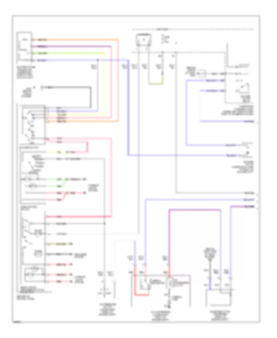
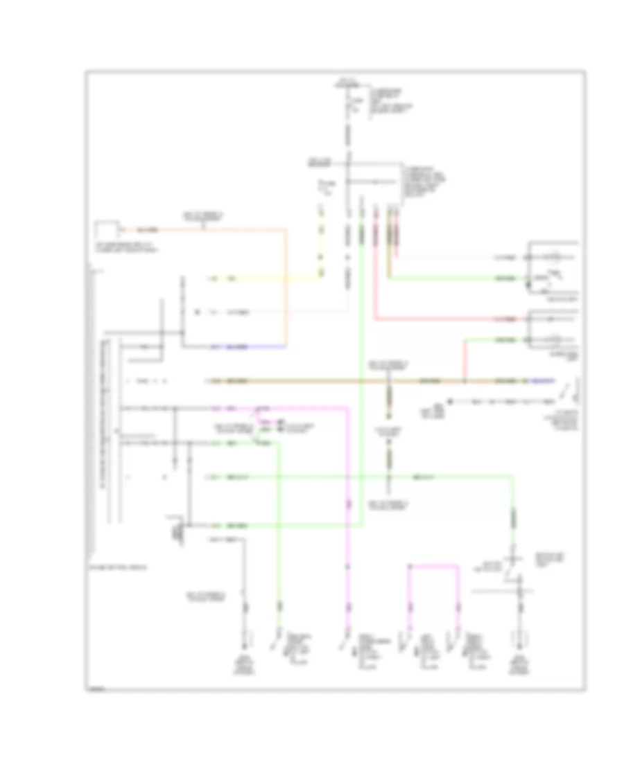
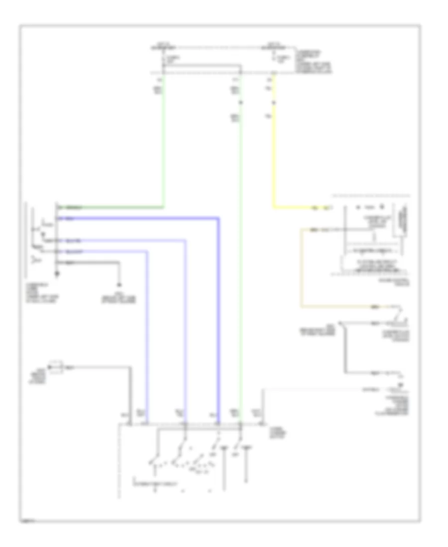
AIR CONDITIONING
Heater Wiring Diagram for Honda Fit 2008

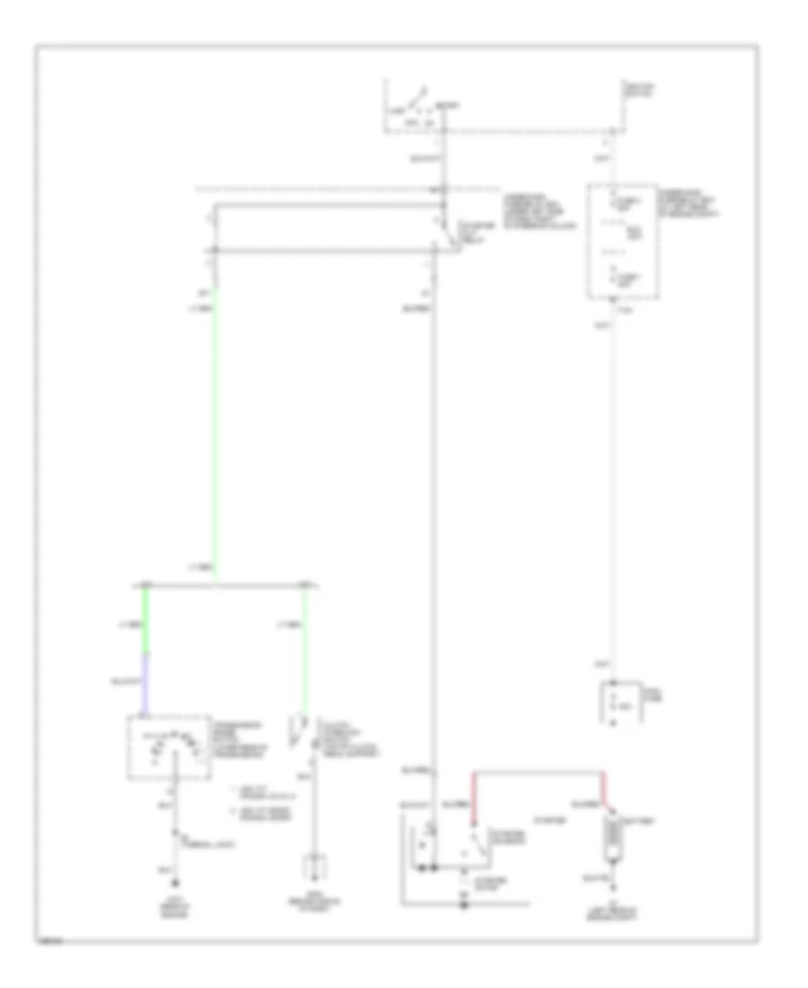
List of elements for Heater Wiring Diagram for Honda Fit 2008:
- Blower motor (under right side of dash, on blower unit)
- Blower motor relay
- Blower power transistor (under right side of dash, on hvac unit)
- Blower switch
- Fuse 40a
- Fuse 7.5a
- G402 (behind middle of dash)
- G403 (behind middle of dash)
- Heater control panel
- Hot at all times
- Hot in on
- Off
- Under-dash fuse/relay box (under left side of dash, right of steering column)
- Under-hood fuse/relay box (at left rear of engine compt)
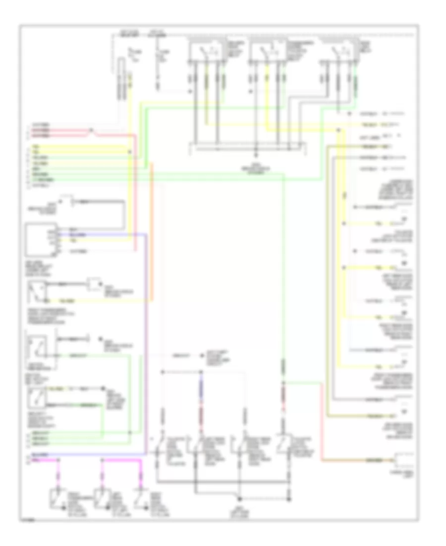
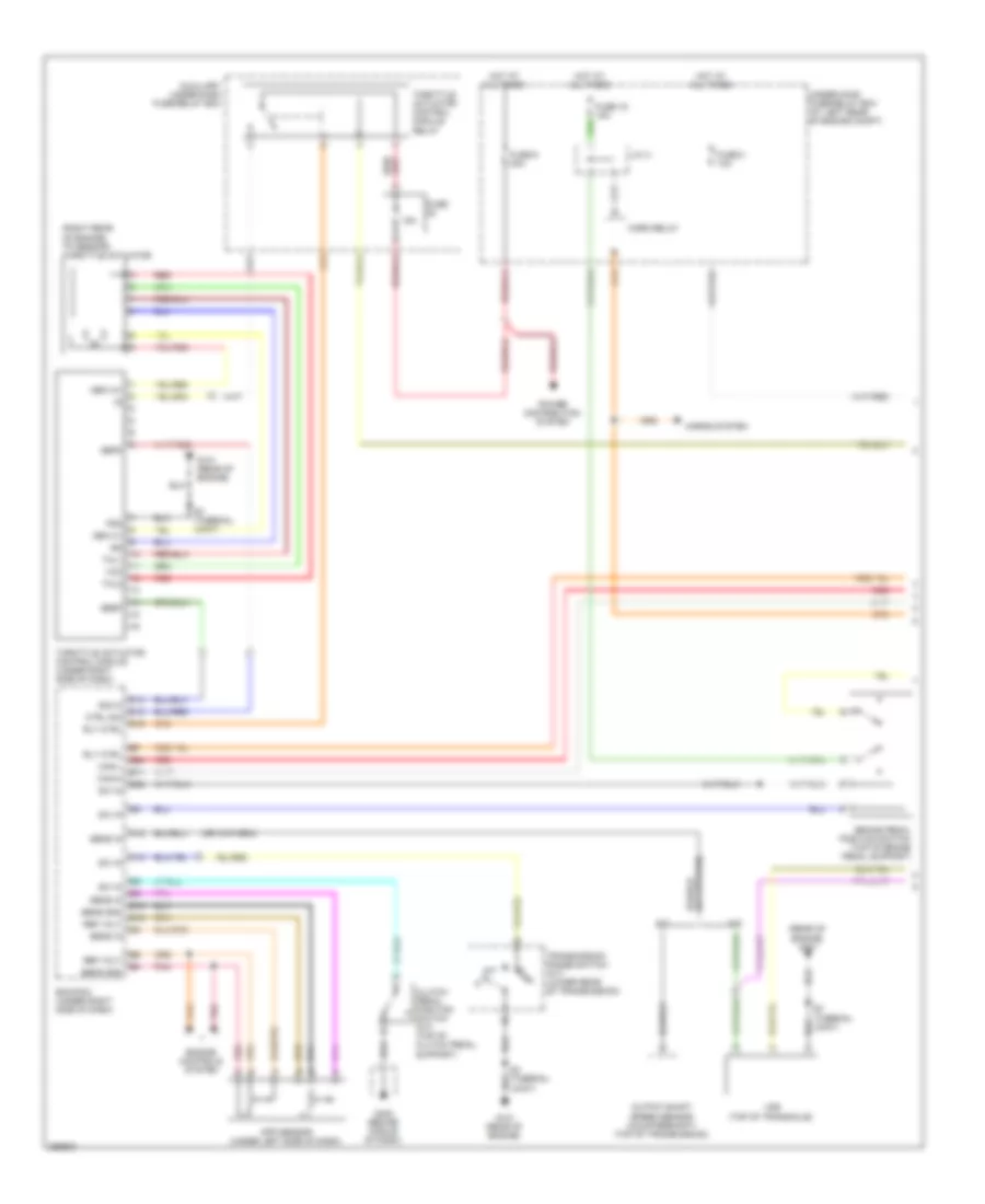
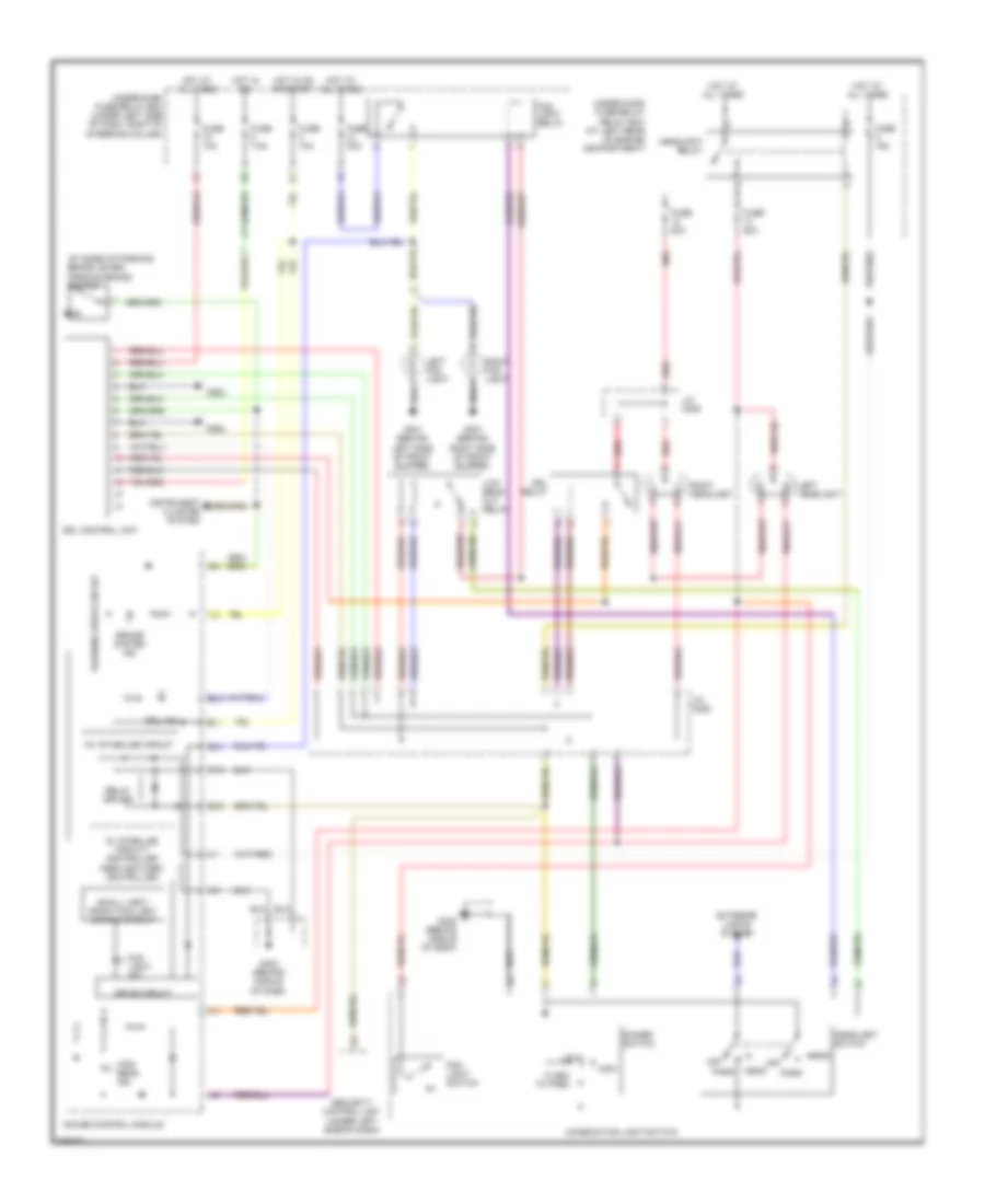
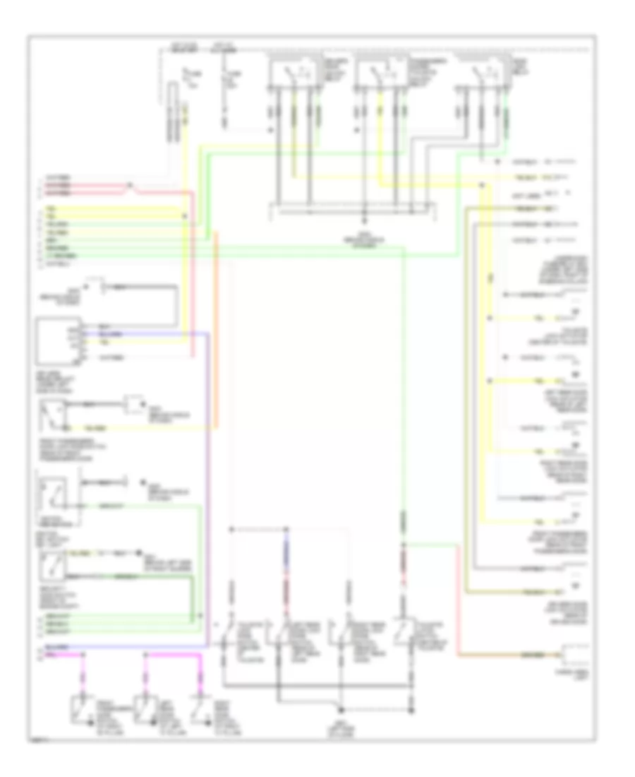
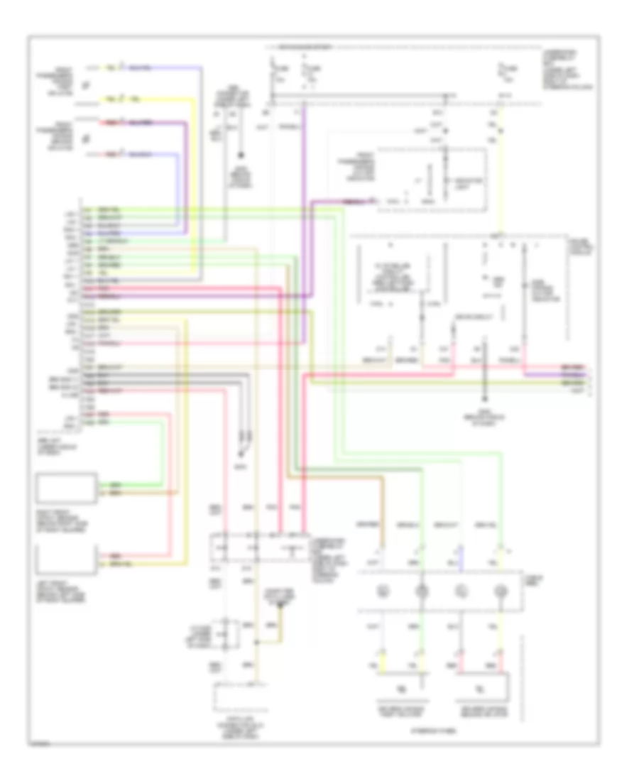
Manual A/C Wiring Diagram (1 of 2) for Honda Fit 2008
List of elements for Manual A/C Wiring Diagram (1 of 2) for Honda Fit 2008:
- (behind middle of dash) g402
- (behind right side of front bumper) g201
- A/c compressor (lower right front of engine compt)
- A/c compressor clutch
- A/c diode
- A/c pressure switch (lower right front of engine compt)
- Blower motor (under right side of dash, on blower unit)
- Blower motor relay
- Blower power transistor (under right side of dash, on hvac unit)
- Blower switch
- Defogger system
- Fuse 7.5a
- G403 (behind middle of dash)
- Heater-a/c control panel
- High
- Hot in on
- Interior lights system
- Low
- Mode 1
- Mode 2
- Mode 3
- Mode 4
- Mode 5
- Mode control switch
- Noise reduction condenser (front of engine compt)
- Off
- On ind
- Pnk
- Rear window defogger switch & a/c switch
- Red
- Thermal fuse
- Thermal protector
- Under-dash fuse/relay box (under left side of dash, right of steering column)
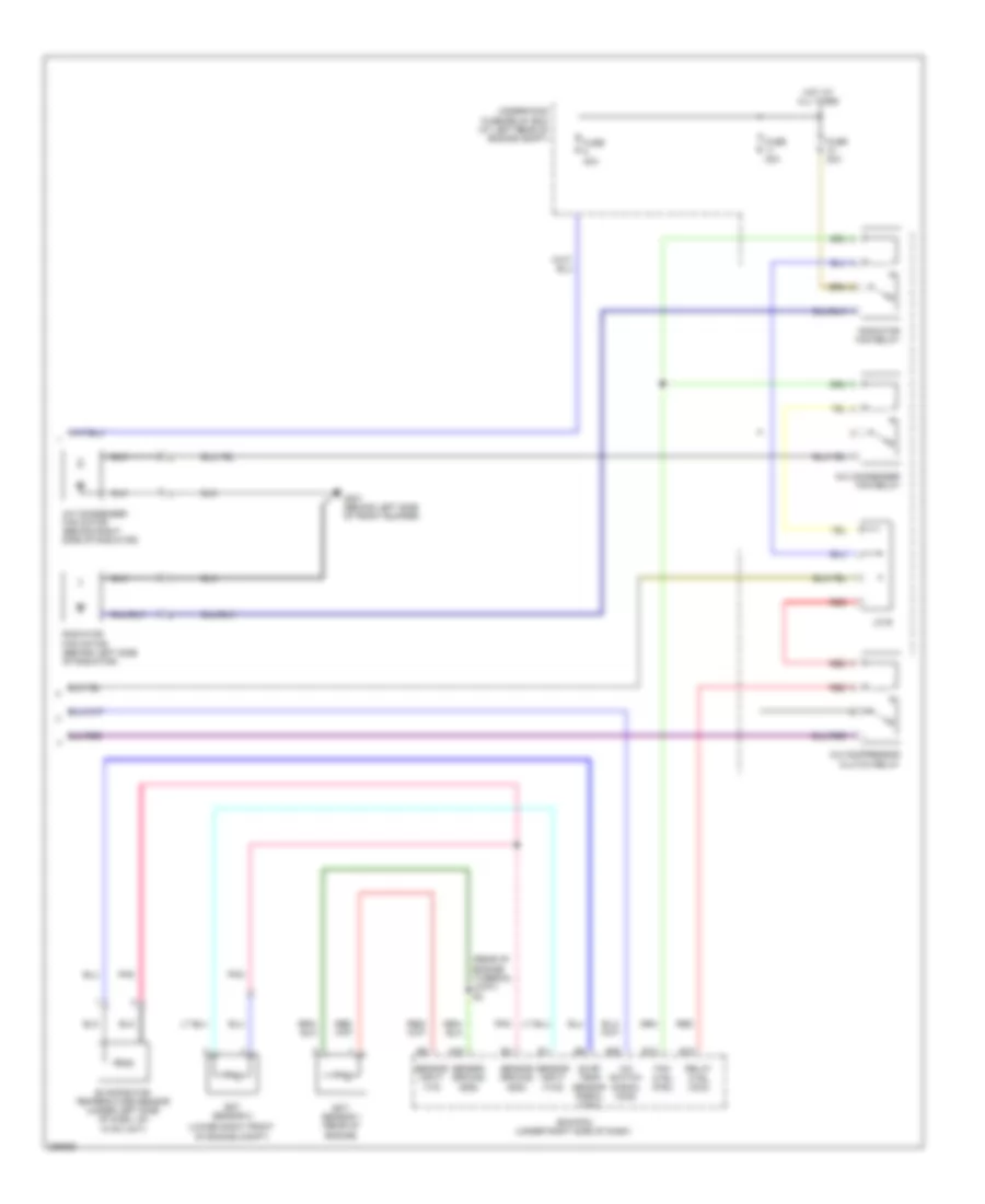
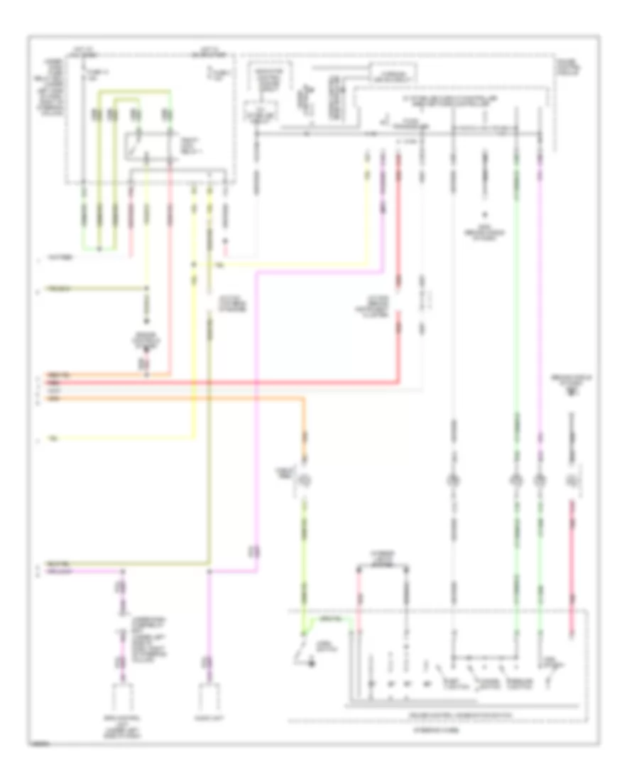
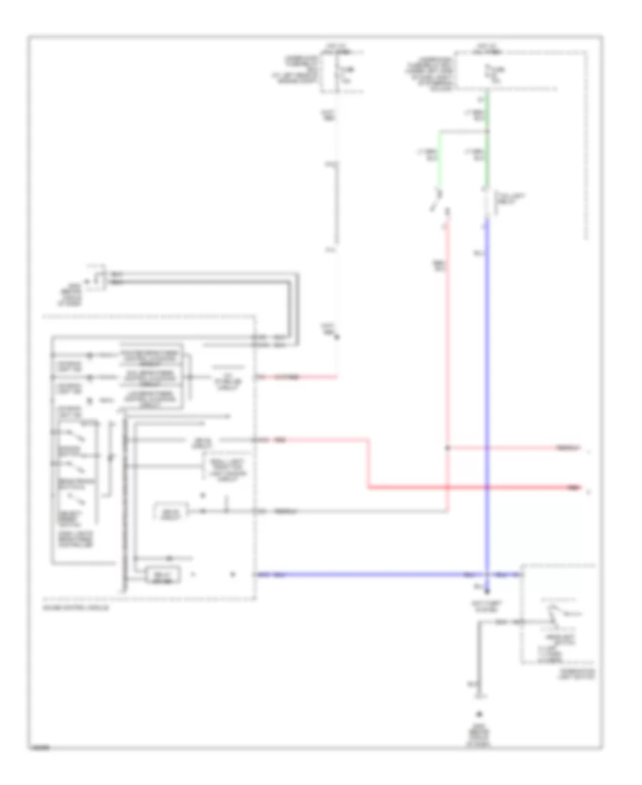
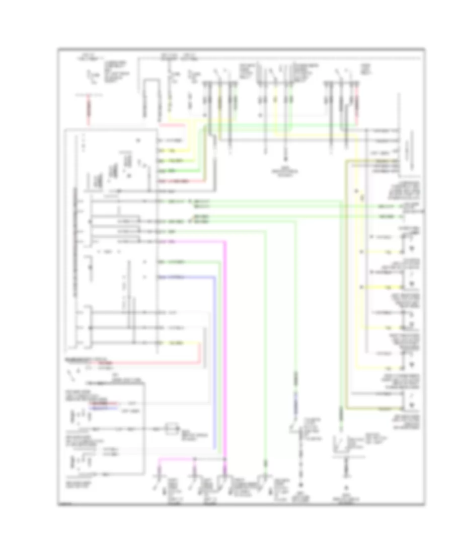
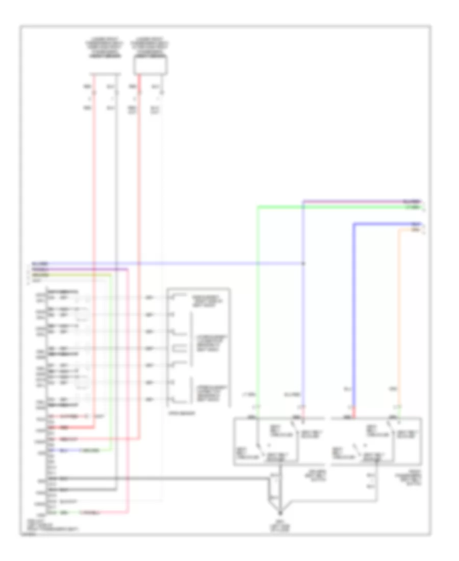
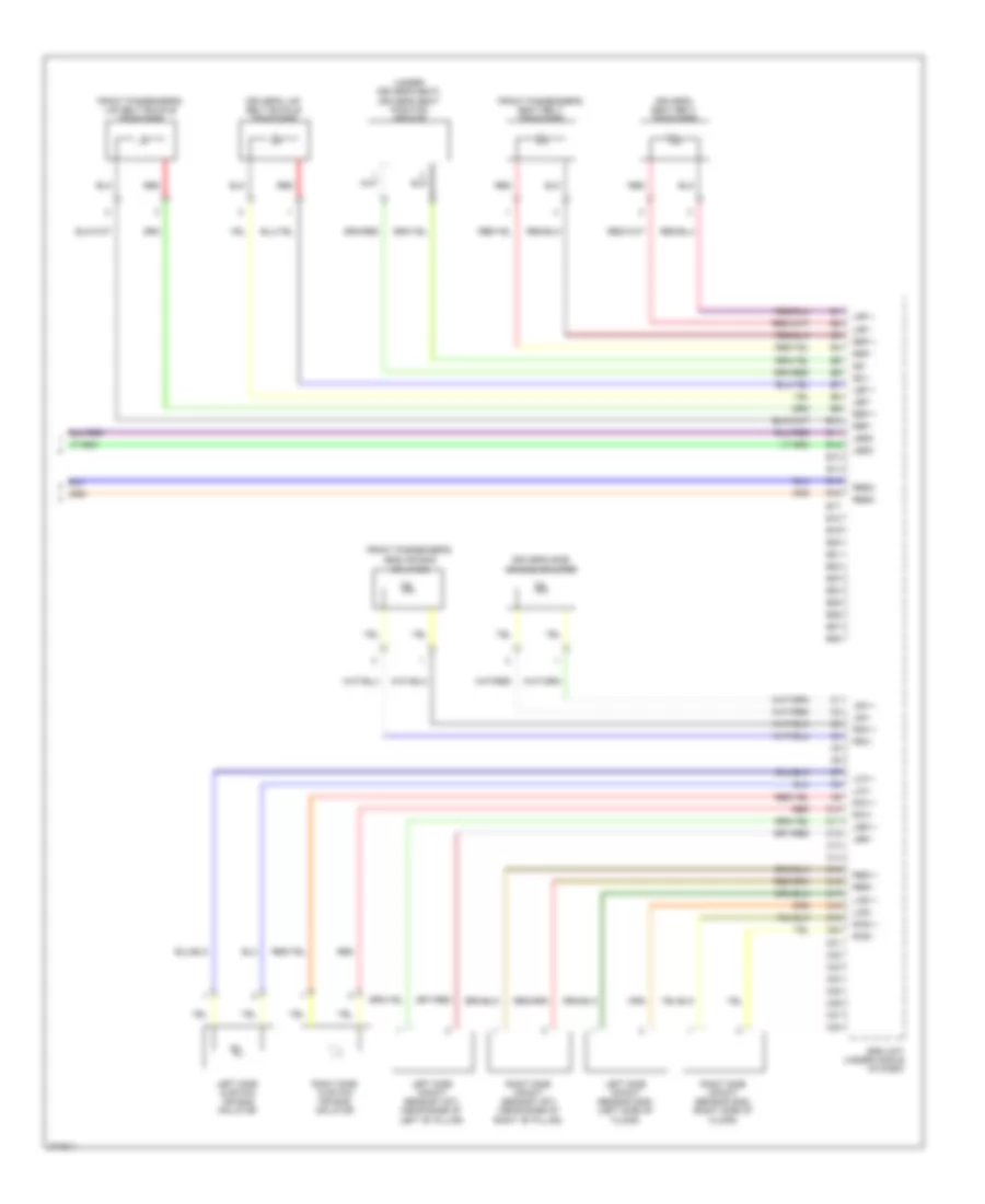
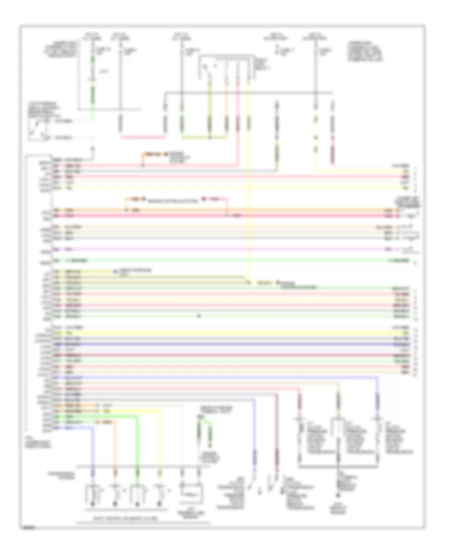
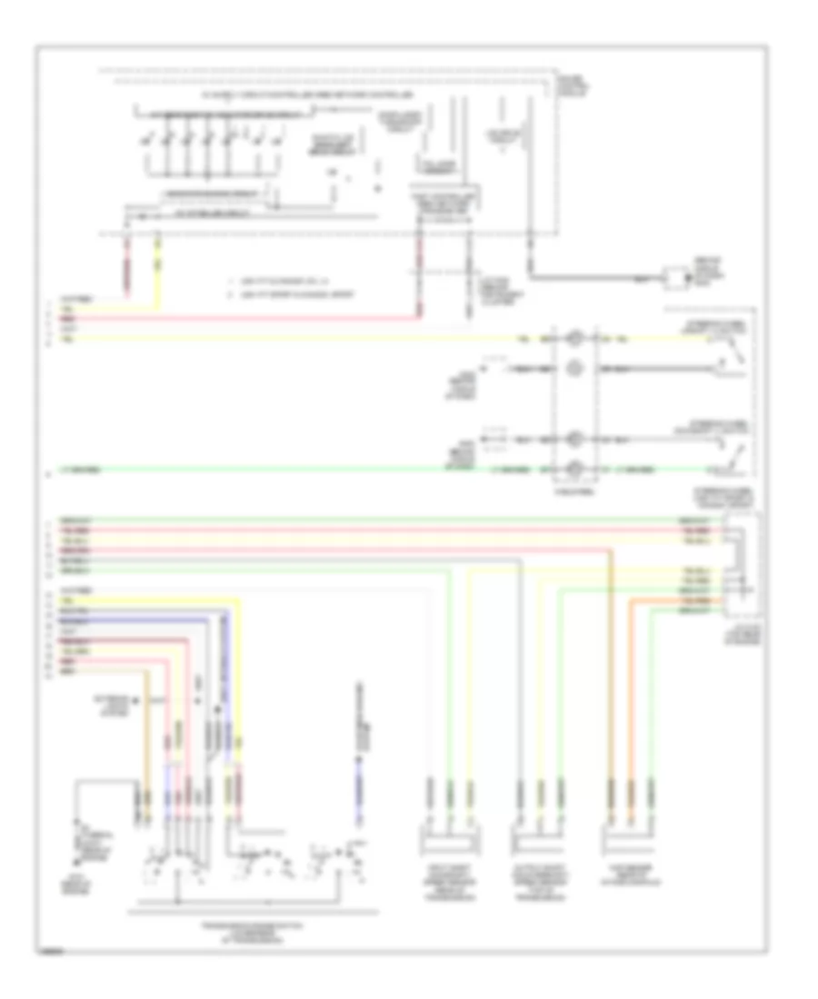
Manual A/C Wiring Diagram (2 of 2) for Honda Fit 2008
List of elements for Manual A/C Wiring Diagram (2 of 2) for Honda Fit 2008:
- (lower right front of engine compt)
- (rear of engine) (thermal joint) s2
- A/c compressor clutch relay
- A/c condenser fan motor (behind right side of radiator)
- A/c condenser fan relay
- A/c switch signal (acs)
- A23
- E12
- E18
- E28
- Ecm/pcm (under right side of dash)
- Ect sensor 1 (rear of engine)
- Ect sensor 2
- Evap temp sensor signal (tac)
- Evaporator temperature sensor (under left side of dash, on hvac unit)
- Fan ctrl (fan)
- Fuse 30a
- Fuse 40a
- G301 (behind left side of front bumper)
- Hot at all times
- J/c b
- Pnk
- Radiator fan motor (behind left side of radiator)
- Radiator fan relay
- Red
- Relay ctrl (acc)
- Sensor ground (sg2)
- Sensor ground (sg4)
- Sensor input (tw)
- Sensor input (tw2)
- Under-hood fuse/relay box (at left rear of engine compt)
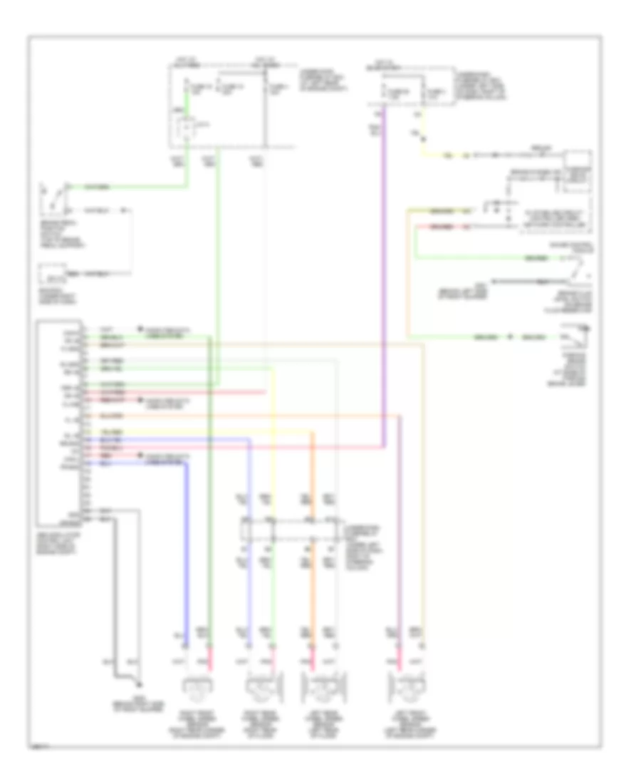
ANTI-LOCK BRAKES
Anti-lock Brakes Wiring Diagram for Honda Fit 2008
List of elements for Anti-lock Brakes Wiring Diagram for Honda Fit 2008:
- 5v stabilize circuit/ controller area network controller
- Abs ind
- Abs modulator control unit (right side of engine compt)
- Brake fluid level switch (on brake fluid reservoir)
- Brake pedal position switch (top of brake pedal support)
- Brake system ind
- Can-h
- Can-l
- Computer data lines system
- E22
- Ecm/pcm (under right side of dash)
- Fl +b
- Fl-gnd
- Fr +b
- Fr-gnd
- Fsr +b
- Fuse 15 30a
- Fuse 16 15a
- Fuse 25 7.5a
- Fuse 3 10a
- Fuse 4 30a
- G202 (behind right side of front bumper)
- G301 (behind left side of front bumper)
- Gauge control module
- Gnd
- Hot at all times
- Hot in on or start
- Ig1
- J/c a
- K-line
- Left front wheel speed sensor (left rear corner of engine compt)
- Left rear wheel speed sensor (left rear of floor)
- Mr +b
- Mr-gnd
- P11
- Parking brake switch (at base of parking brake lever)
- Pnk
- Red
- Right front wheel speed sensor (right rear corner of engine compt)
- Right rear wheel speed sensor (right rear of floor)
- Rl +b
- Rl-gnd
- Rr +b
- Rr-gnd
- Sw in
- Under-dash fuse/relay box (under left side of dash, right of steering column)
- Under-hood fuse/relay box (at left rear of engine compt)
- Warning drive circuit
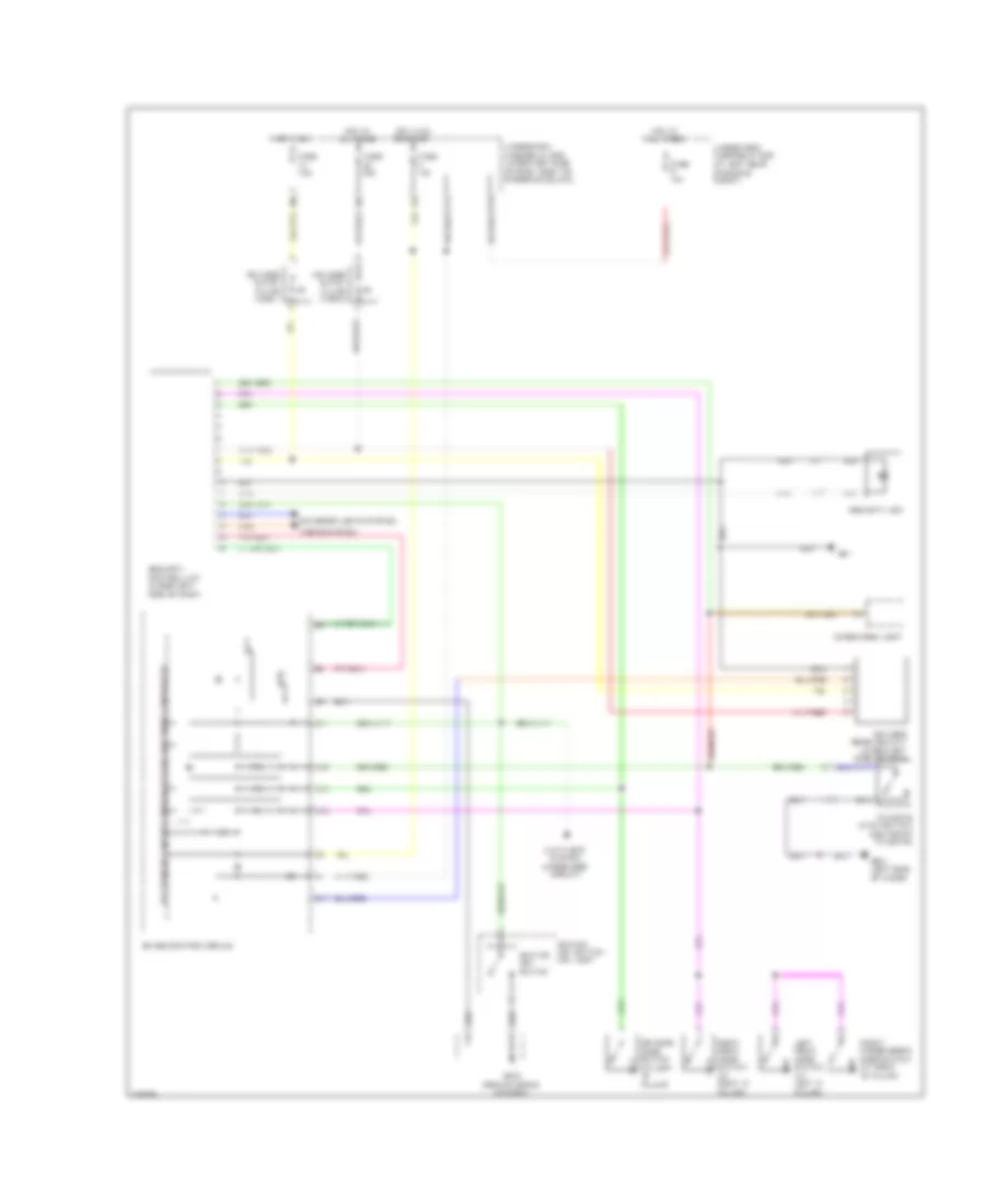
ANTI-THEFT
Forced Entry Wiring Diagram, Accessory for Honda Fit 2008
List of elements for Forced Entry Wiring Diagram, Accessory for Honda Fit 2008:
- 5v stabilize circuit/ controller area network controller
- A13
- A14
- A16
- Anti-theft system (immobilizer circuit)
- C11
- C17
- Cargo area light
- Driver's door switch (at left "b" pillar)
- Exterior lights system
- F14
- Front passenger's door switch (at right "b" pillar)
- Fuse 10a
- Fuse 20a
- Fuse 7.5a
- G402 (behind middle of dash)
- G501 (left side of floor)
- G51
- Gauge control module
- Horns system
- Hot at all times
- Hot in on
- Hot in on or start
- I/f
- Ignition key switch
- Ignition key switch/ key light
- Keyless entry in-line fuse 1
- Keyless entry in-line fuse 2
- Keyless receiver unit (under left side of dash)
- Left rear door switch (at left "c" pillar)
- P10
- Right rear door switch (at right "c" pillar)
- Security control unit (under left side of dash)
- Security led
- Tailgate latch switch (center of tailgate)
- Under-dash fuse/relay box (under left side of dash, right of steering column)
- Under-hood fuse/relay box (at left rear of engine compt)
Forced Entry Wiring Diagram, Sport (1 of 2) for Honda Fit 2008
List of elements for Forced Entry Wiring Diagram, Sport (1 of 2) for Honda Fit 2008:
- (behind right side of front bumper) horn
- 5v stabilize circuit/controller area network controller
- A10
- A11
- A12
- A13
- A14
- A15
- A16
- A17
- A18
- A19
- A20
- Audio unit
- B10
- B11
- B12
- B13
- B14
- B15
- B16
- C10
- C11
- C16
- C17
- C19
- C20
- C36
- C38
- C40
- Door lock knob
- Driver relay
- Driver's door key cylinder switch (in driver's door)
- Driver's door lock knob switch (rear of driver's door)
- Driver's door lock switch
- Driver's door switch (at left "b" pillar)
- Exterior lights system
- Fuse 10a
- Fuse 15a
- G402 (behind middle of dash)
- G403 (behind middle of dash)
- Gauge control module
- Headlights system
- Horn relay
- Horns system
- Hot at all times
- I/f
- Junction connector a
- Key
- Lock
- Security control unit (under left side of dash)
- Security ind
- Under-hood fuse/relay box (at left rear of engine compt)
- Unlock
Forced Entry Wiring Diagram, Sport (2 of 2) for Honda Fit 2008
List of elements for Forced Entry Wiring Diagram, Sport (2 of 2) for Honda Fit 2008:
- (not used)
- Anti-theft system (immobilizer circuit)
- Cargo area light
- Door lock relay
- Driver's door lock actuator (rear of drive's door)
- Driver's door unlock relay
- F10
- F14
- Front passenger's door lock actuator (rear of front passenger's door)
- Front passenger's door lock knob switch (rear of front passenger's door)
- Front passenger's door switch (at right "b" pillar)
- Fuse 10a
- Fuse 20a
- G301 (behind left side of front bumper)
- G402 (behind middle of dash)
- G403 (behind middle of dash)
- G501 (left side of floor)
- Gnd
- Hot at all times
- Hot in on or start
- Ig1
- Ignition key switch
- Ignition key switch/ key light
- Keyless receiver unit (under left side of dash)
- Left rear door lock actuator (rear of left rear door)
- Left rear door lock knob switch (rear of left rear door)
- Left rear door switch (at left "c" pillar)
- Out
- P10
- Passenger's doors/ tailgate unlock relay
- Right rear door lock actuator (rear of right rear door)
- Right rear door lock knob switch (rear of right rear door)
- Right rear door switch (at right "c" pillar)
- Security hood switch (front of engine compt)
- Tailgate latch switch (center of tailgate)
- Tailgate lock actuator (center of tailgate)
- Tailgate lock knob switch (center of tailgate)
- Under-dash fuse/relay box (under left side of dash, right of steering column)
Immobilizer Wiring Diagram for Honda Fit 2008
List of elements for Immobilizer Wiring Diagram for Honda Fit 2008:
- 5v stabilize circuit/ controller area network controller
- Anti-theft system (forced entry circuit)
- C34
- Diag-h
- Dlc (under left
- E14
- E17
- E27
- Ecm/pcm (under right side of dash)
- Engine controls system
- F14
- Fuel pump
- Fuel pump ctrl
- Fuel tank unit (in fuel tank)
- Fuse 10a
- Fuse 15a
- G403 (behind middle of dash)
- G403 (under middle of dash)
- Gauge control module
- H-brk sw
- Hot at all times
- Hot in on or start
- Ig1
- Ign in
- Ignition key switch
- Ignition key switch/ key light
- Immo code in
- Immobilizer control unit-receiver (under steering wheel cover)
- Immobilizer system indicator
- Imoarm
- Imocd
- Imoes unit (under left side of dash)
- Lg3
- Lgs
- P10
- Parking brake switch (at base of parking brake lever)
- Pgm-fi main relay 1
- Pgm-fi main relay 2
- Pwr in
- Rly ctrl
- Sens gnd
- Side of dash)
- Under-dash fuse/relay box (under left side of dash, right of steering column)
- Under-hood fuse/relay box (at left rear of engine compt)
COMPUTER DATA LINES
Computer Data Lines Wiring Diagram for Honda Fit 2008
List of elements for Computer Data Lines Wiring Diagram for Honda Fit 2008:
- (not used)
- A24
- Abs modulator control unit (right side of engine compt)
- Audio unit
- C12
- C13
- C37
- Can-h
- Can-l
- D12
- D13
- D17
- Diag-h
- Dlc (under left side of dash)
- E11
- E24
- E29
- E30
- Ecm/pcm (under right side of dash)
- Eps control unit (under left side of dash)
- F-can (hi)
- F-can (lo)
- F14
- Fuse 8 10a
- Fuse/relay box (under left side of dash, right of steering column)
- G402 (behind middle of dash)
- G403 (behind middle of dash)
- Gauge control module
- Hot at all times
- Immobilizer control unit receiver (under steering wheel cover)
- J/c c402 (behind instrument cluster)
- J/c c405 (under left side of dash)
- K-line
- Lg3
- Mes
- Mes connector
- P10
- Red
- Scs
- Secondary ho2s sensor shield
- Srs unit (under middle of dash)
- Tpms control unit (behind middle of dash)
- Under-hood fuse/relay box (at left rear of engine compt)
- Wen
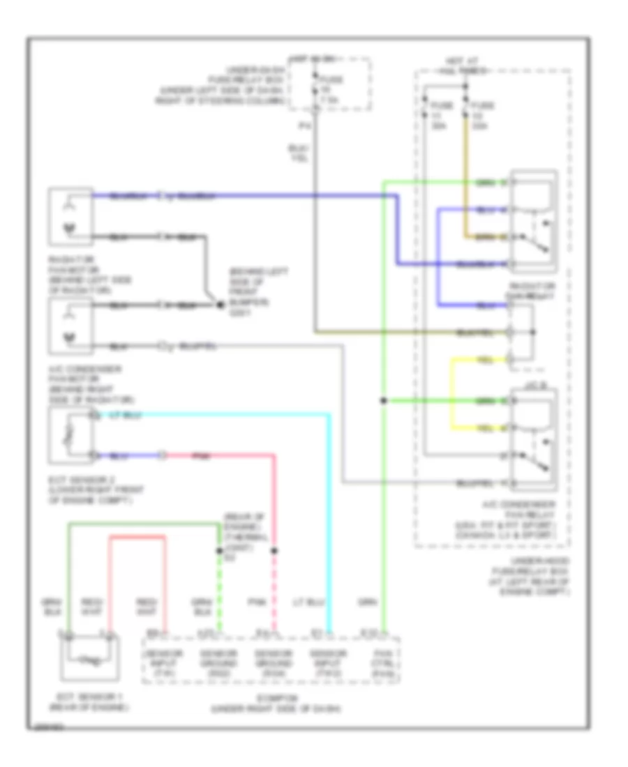
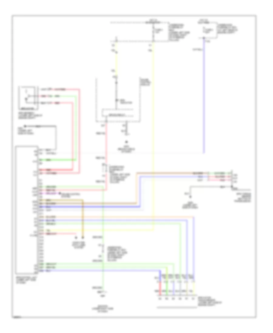
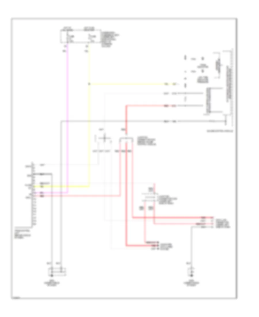
COOLING FAN
Cooling Fan Wiring Diagram for Honda Fit 2008
List of elements for Cooling Fan Wiring Diagram for Honda Fit 2008:
- (behind left side of front bumper) g301
- (rear of engine) (thermal joint) s2
- A/c condenser fan motor (behind right side of radiator)
- A/c condenser fan relay (usa: fit & fit sport) (canada: lx & sport)
- A23
- E12
- Ecm/pcm (under right side of dash)
- Ect sensor 1 (rear of engine)
- Ect sensor 2 (lower right front of engine compt)
- Fan ctrl (fan)
- Fuse 30a
- Fuse 7.5a
- Hot at all times
- Hot in on
- J/c b
- Pnk
- Radiator fan motor (behind left side of radiator)
- Radiator fan relay
- Sensor ground (sg2)
- Sensor ground (sg4)
- Sensor input (tw)
- Sensor input (tw2)
- Under-dash fuse/relay box (under left side of dash, right of steering column)
- Under-hood fuse/relay box (at left rear of engine compt)
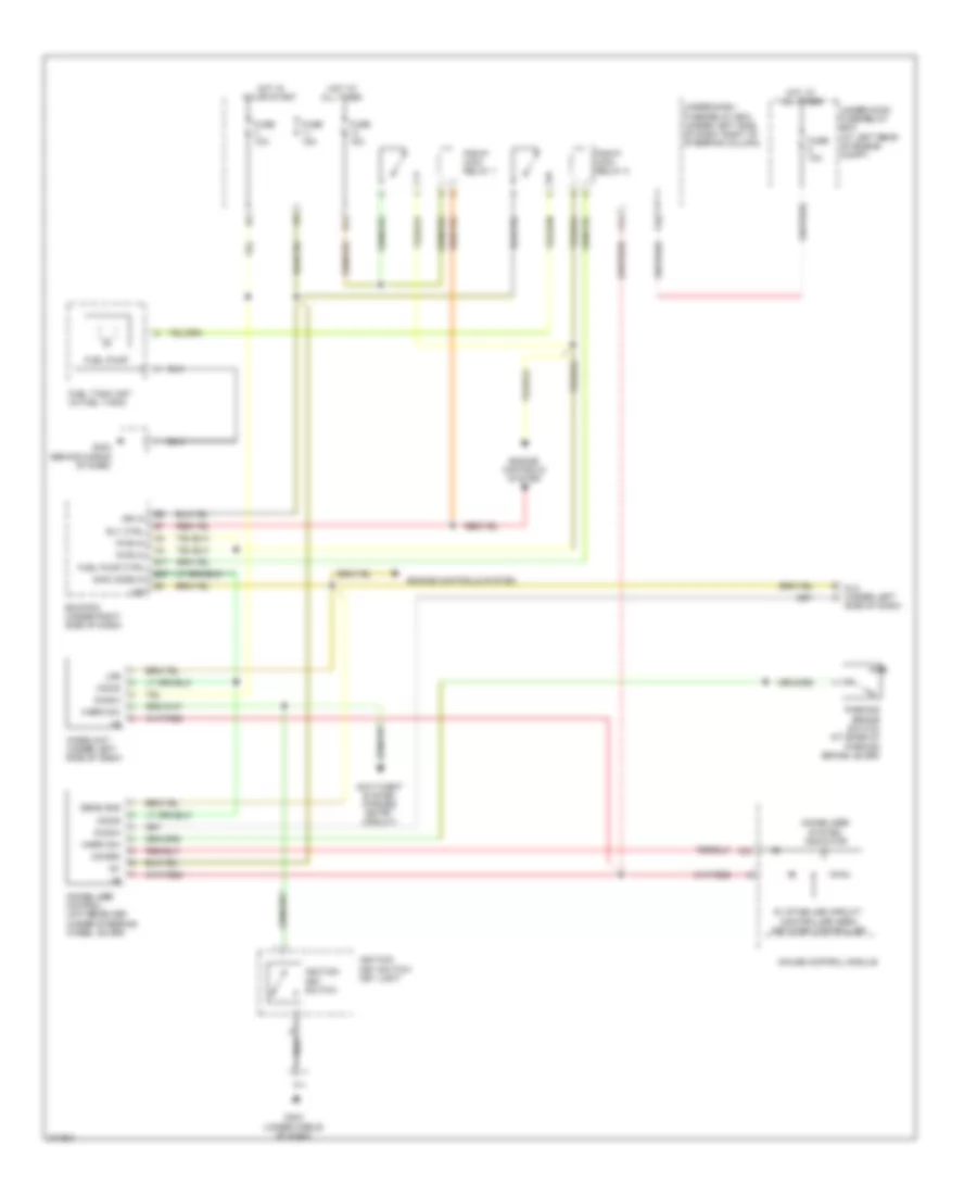
CRUISE CONTROL
Cruise Control Wiring Diagram (1 of 2) for Honda Fit 2008
List of elements for Cruise Control Wiring Diagram (1 of 2) for Honda Fit 2008:
- (rear of engine) g101
- (right rear of engine) tp sensor/ throttle actuator
- 15a
- A/t
- A18
- App sensor (under left side of dash)
- Auxiliary under-dash fuse/relay box
- Brake pedal position switch (top of brake pedal support)
- C18
- Can-h
- Can-l
- Clutch pedal position switch (m/t) (top of clutch pedal support)
- Ctrl sig
- D10
- D12
- D13
- D14
- D15
- Dbw m+
- Dbw m-
- E11
- E22
- E24
- Ecm/pcm (under right side of dash)
- Engine controls system
- Fuse
- Fuse 16 15a
- Fuse 8 10a
- Fuse 9 30a
- G101 (rear of engine)
- G402 (behind middle of dash)
- Horn relay
- Horns system
- Hot at all times
- J/c a
- M/t
- Output shaft speed sensor (countershaft) (top of transmission)
- Pg2
- Pnk
- Power distribution system
- Red
- Ref volt
- Rly ctrl
- S3 (thermal joint)
- Sedf
- Sefd
- Sens gnd
- Sens in
- Sig in
- Sw in
- Thl1
- Thl2
- Throttle actuator control module (under right side of dash)
- Throttle actuator control module relay
- Transmission range switch (a/t) (lower rear of transmission)
- Under-hood fuse/relay box (at left rear of engine compt)
- Vcc
- Vss (top of transaxle)
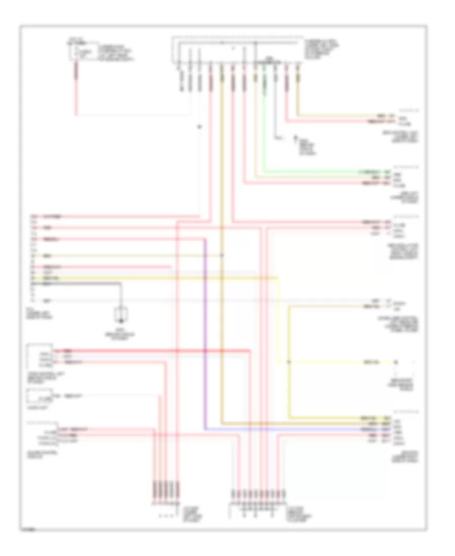
Cruise Control Wiring Diagram (2 of 2) for Honda Fit 2008
List of elements for Cruise Control Wiring Diagram (2 of 2) for Honda Fit 2008:
- (behind middle of dash) g403
- (m/t)
- 10v stabilize circuit
- 5v stabilize curcuit/controller area network controller
- A13
- Audio unit
- B10
- B11
- B12
- B13
- C10
- C11
- C12
- C13
- C15
- C28
- C29
- C30
- Cable reel
- Cancel switch
- Control id cruise
- Cruise control combination switch
- D10
- E14
- Engine controls system
- Eps control unit (under left side of dash)
- F-can transceiver
- F14
- Fuse 14 15a
- Fuse 3 10a
- G402 (behind middle of dash)
- Gauge control module
- Horn switch
- Hot at all times
- Hot in on or start
- Indicator control dimming circuit
- Interior lights system
- J/c c103 (top rear of engine)
- J/c c402 (behind instrument cluster)
- Main switch
- Main switch ind cruise control
- P10
- Pgm-f1 main relay 1
- Pnk
- Red
- Resume switch
- Set switch
- Steering wheel
- Under- dash fuse/ relay box (under left side of dash, right of steering column)
- Under-dash fuse/relay box (under left side of dash, right of steering column)
- Warning drive circuit
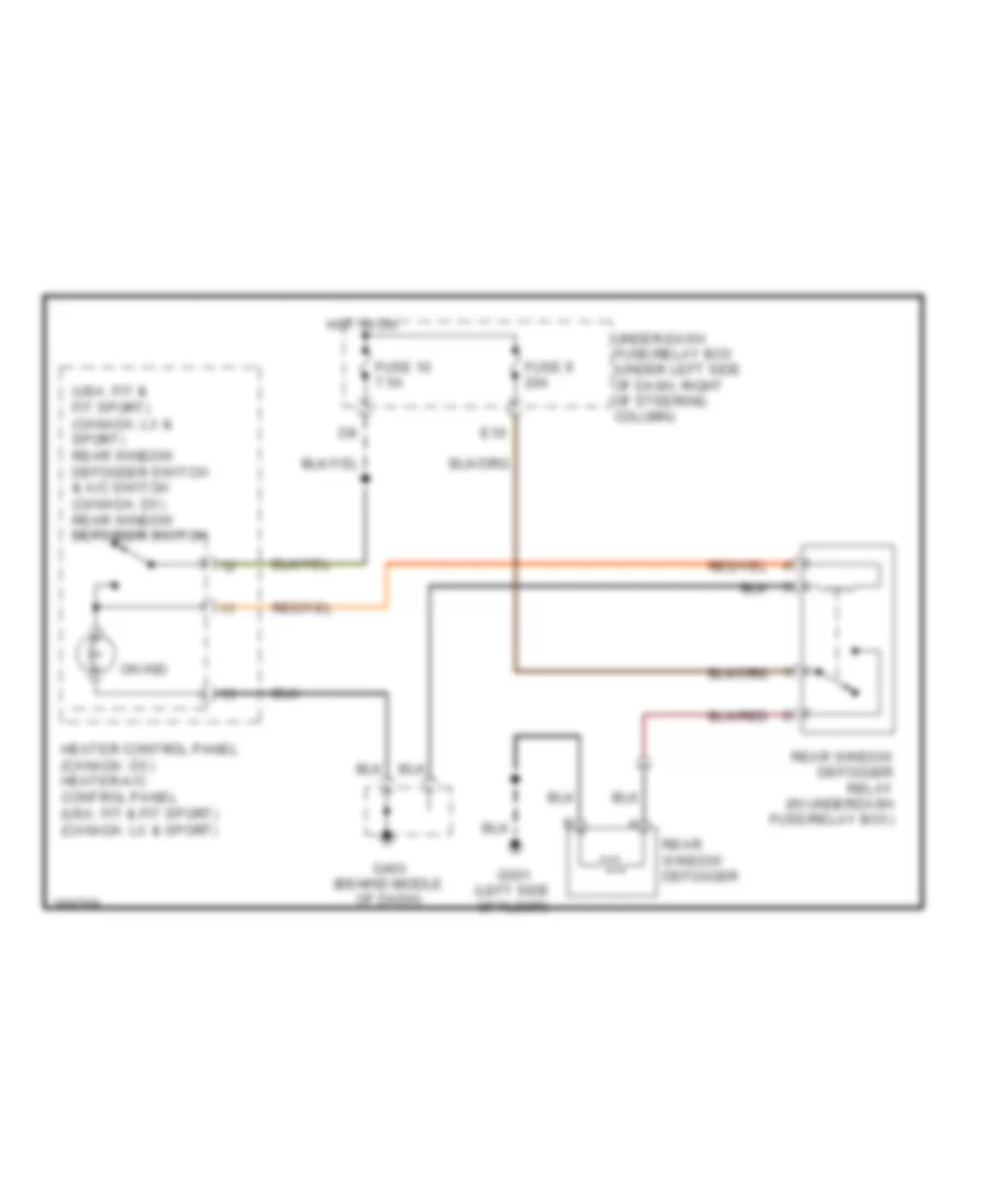
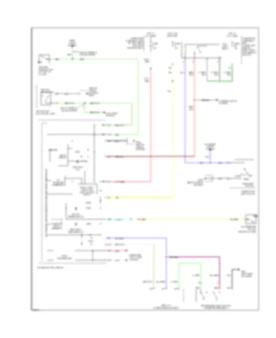
DEFOGGERS
Defoggers Wiring Diagram for Honda Fit 2008
List of elements for Defoggers Wiring Diagram for Honda Fit 2008:
- (usa: fit & fit sport) (canada: lx & sport) rear window defogger switch & a/c switch (canada: dx) rear window defogger switch
- E10
- Fuse 10 7.5a
- Fuse 9 20a
- G403 (behind middle of dash)
- G501 (left side of floor)
- Heater control panel (canada: dx) heater-a/c control panel (usa: fit & fit sport) (canada: lx & sport)
- Hot in on
- On ind
- Rear window defogger
- Rear window defogger relay (in underdash fuse/relay box)
- Under-dash fuse/relay box (under left side of dash, right of steering column)
ELECTRONIC POWER STEERING
Electronic Power Steering Wiring Diagram for Honda Fit 2008
List of elements for Electronic Power Steering Wiring Diagram for Honda Fit 2008:
- C27
- Computer data lines system
- Cruise control system
- D10
- D11
- D12
- D13
- D14
- D15
- D16
- D17
- D18
- D19
- D20
- D21
- D22
- D23
- D24
- D25
- D26
- D27
- D28
- Drive circuit
- E25
- Ecm/pcm (under right side of dash)
- Eps control unit (under left side of dash)
- Eps gearbox (lower left side of engine compt)
- Eps indicator
- Eps motor
- Eps motor angle sensor (lower left side of engine compt)
- Eps torque sensor (bottom of transmission)
- Fuse 2 60a
- Fuse 3 10a
- G402 (behind middle of dash)
- G451 (under left side of dash)
- G452 (under left side of dash)
- Gauge control module
- Gnd
- H-u
- H-v
- H-w
- Hot at all times
- Hot in on or start
- Ig1
- K-line
- Nep
- Pnk
- Pvf
- Red
- Scs
- T102
- Under-dash fuse/relay box (under left side of dash, right of steering column)
- Under-hood fuse/relay box (at left rear of engine compt)
- Vs1
- Vs2
- Vsp
- Wlp
ENGINE PERFORMANCE
1.5L
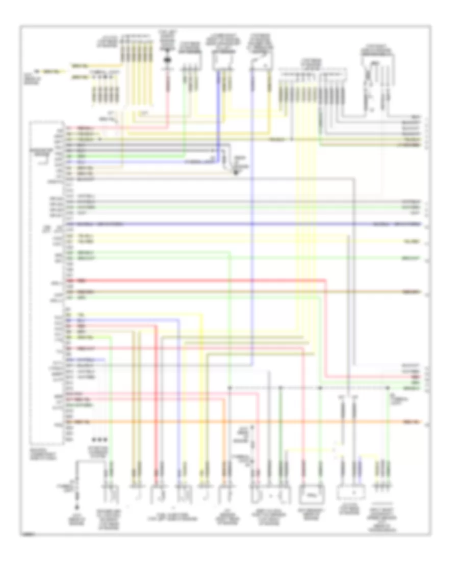
1.5L, Engine Performance Wiring Diagram (1 of 4) for Honda Fit 2008
List of elements for 1.5L, Engine Performance Wiring Diagram (1 of 4) for Honda Fit 2008:
- (lower right front of engine, near crankshaft pulley) ckp sensor
- (rear of engine) g101
- (thermal joint) s1
- (thermal joint) s3
- (top left side of engine) knock sensor
- (top rear of engine) cmp sensor
- (top rear of engine) j/c c103
- (top rear of engine) rocker arm oil pressure switch
- (top right side of engine) ignition coil 4
- A/t
- A10
- A11
- A12
- A13
- A14
- A15
- A16
- A17
- A18
- A19
- A20
- A21
- A22
- A23
- A24
- A25
- A26
- A27
- A28
- A29
- A30
- A31
- Afs (+)
- Afs (-)
- Afshtc
- Altc
- Altf
- Altl
- B10
- B11
- B12
- B13
- B14
- B15
- B16
- B17
- B18
- B19
- B20
- B21
- B22
- B23
- B24
- Barometer sensor
- Ckp
- Cmp
- Ecm/pcm (under right side of dash)
- Ect sensor 1 (rear of engine)
- Egr
- Egr valve & position sensor (top front of engine)
- Egrp
- Fuel injectors (top left side of engine)
- G101 (rear of engine)
- Iat
- Iat sensor (right rear of engine)
- Icm
- Igp1
- Igp2
- Igpls1
- Igpls2
- Igpls3
- Igpls4
- Inj1
- Inj2
- Inj3
- Inj4
- Input shaft (mainshaft) speed sensor (a/t) (rear of transmission)
- J/c c103 (top rear of engine)
- Lg1
- Lg2
- M/t
- Map
- Nc (a/t)
- Pcs
- Pg1
- Pg2
- Pnk
- Red
- Rocker arm oil control solenoid (top rear of engine)
- S2 (thermal joint)
- S3 (thermal joint)
- Sg1
- Sg2
- Starting/ charging system
- Vcc1
- Vcc2
- Vss (m/t)
- Vtpsw
- Vts
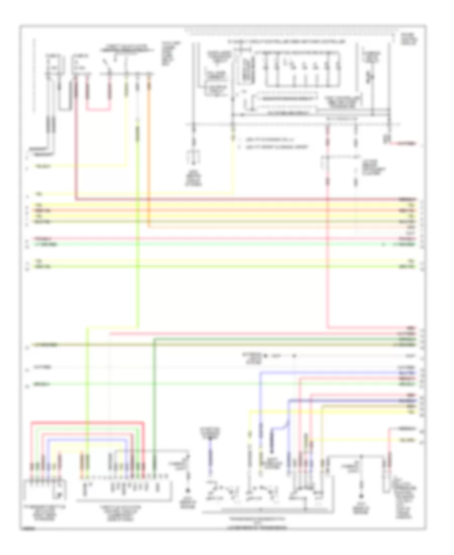
1.5L, Engine Performance Wiring Diagram (2 of 4) for Honda Fit 2008
List of elements for 1.5L, Engine Performance Wiring Diagram (2 of 4) for Honda Fit 2008:
- (behind middle of dash) g402
- (top of transaxle) vss
- (top right side of engine) ignition coil 1
- (top right side of engine) ignition coil 2
- (top right side of engine) ignition coil 3
- A/f sensor (top rear of engine)
- A/f sensor relay (in underdash fuse/relay box)
- A/t
- Cable reel
- Cruise control system
- E14
- Evap canister purge valve (right rear of engine)
- Evap canister vent shut valve (under left side of floor)
- Fuel gauge sending unit
- Fuel pump
- Fuel tank unit (in fuel tank)
- Fuse 11 15a
- Fuse 14 15a
- Fuse 23 10a
- Fuse 3 10a
- Fuse 31 7.5a
- G101 (rear of engine)
- G403 (behind middle of dash)
- Hot at all times
- Hot in on or start
- Icm
- Ignition coil relay
- Instrument cluster system
- J/c c103 (top rear of engine)
- M/t
- Map sensor (rear of intake manifold)
- Output shaft (countershaft) speed sensor (a/t) (top of transmission)
- Pgm-f1 main relay 1
- Pgm-f1 main relay 2
- Pnk
- Red
- S3 (thermal joint)
- Steering wheel
- Steering wheel downshift (-) switch
- Steering wheel upshift (+) switch
- Under-dash fuse/relay box (under left side of dash, right of steering column)
- Usa: fit sport & canada: sport
1.5L, Engine Performance Wiring Diagram (3 of 4) for Honda Fit 2008
List of elements for 1.5L, Engine Performance Wiring Diagram (3 of 4) for Honda Fit 2008:
- 10v stabilize circuit
- 15a
- A/t clutch pressure control solenoid valve a (a/t) (top of trans- mission)
- A/t gear position indicator drive circuit
- Auxiliary under- dash fuse/ relay box
- C12
- C13
- Compulsory turning-off circuit
- Dbw m+
- Dbw m-
- Drive circuit backlight
- Exterior lights system
- Fail safe circuit
- Fast controller area network transceiver
- Fuse 32
- Fuse 33
- G101 (rear of engine)
- G402 (behind middle of dash)
- Gauge control module
- Indicator dimming circuit
- J/c c402 (behind instrument cluster)
- Lcd drive circuit
- Mil ind
- Nca
- Pg2
- Pnk
- Red
- S-matic lcd
- S3 (thermal joint)
- Sedf
- Sefd
- Shift interlock system
- Starting/ charging system
- Thl1
- Thl2
- Throttle actuator control module (under right side of dash)
- Throttle actuator control module relay
- Tp sensor/throttle actuator (right rear of engine)
- Transmission range switch (a/t) (lower rear of transmission)
- Usa: fit & canada: dx, lx
- Usa: fit sport & canada: sport
- Vcc
- Warning drive circuit
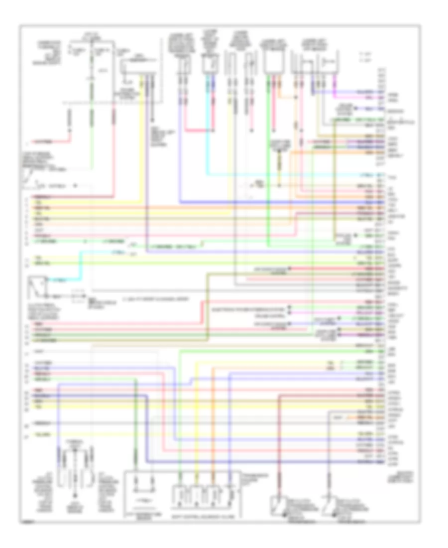
1.5L, Engine Performance Wiring Diagram (4 of 4) for Honda Fit 2008
List of elements for 1.5L, Engine Performance Wiring Diagram (4 of 4) for Honda Fit 2008:
- (lower right front of engine compt) ect sensor 2
- (thermal joint) s3
- (top of brake pedal support) brake pedal position switch
- (top of clutch pedal support)
- (under center console) secondary ho2s
- (under left side of dash) app sensor
- (under left side of dash, on hvac unit) evaporator temperature sensor
- (under left side of floor) ftp sensor
- (usa) eld unit
- 2nd clutch transmission fluid pressure switch (top of transmission)
- 3rd clutch transmission fluid pressure switch (rear of transmission)
- A/t
- A/t clutch pressure control solenoid valve b (a/t) (top of trans- mission)
- A/t clutch pressure control solenoid valve c (a/t) (top of trans- mission)
- Acc
- Acs
- Afshtcr
- Air conditioning system
- Anti-theft system
- Apsa
- Apsb
- Atf temperature sensor
- Atft
- Atp2-1
- Atpd
- Atpd3
- Atpfwd
- Atpn
- Atpp
- Atpr
- Atprvs
- Bksw
- Bkswnc
- C10
- C11
- C12
- C13
- C14
- C15
- C16
- C17
- C18
- C19
- C20
- C21
- C22
- Can-h
- Can-l
- Clutch pedal position switch
- Computer data lines system
- Cooling fan system
- Crmtcls
- Cruise control
- Cruise control system
- D10
- D11
- D12
- D13
- D14
- D15
- D16
- D17
- Dbwrly
- E10
- E11
- E12
- E13
- E14
- E15
- E16
- E17
- E18
- E19
- E20
- E21
- E22
- E23
- E24
- E25
- E26
- E27
- E28
- E29
- E30
- E31
- Ecm/pcm (under right side of dash)
- Eld
- Electronic power steering system
- Fan
- Ftp
- Fuse 16 15a
- Fuse 8 10a
- Fuse 9 30a
- G101 (rear of engine)
- G301 (behind left side of front bumper)
- G402 (behind middle of dash)
- Hot at all times
- Ig1
- Imocd
- Imofpr
- J/c a
- Lsa
- Lsb
- Lsc
- M/t
- Mrly
- Nep
- Op2sw
- Op3sw
- Pnk
- Power distribution system
- Red
- Scs
- Sdnp
- Sedf
- Sefd
- Sg3
- Sg4
- Sha
- Shb
- Shc
- Shd
- Shift control solenoid valves
- Sho2s
- Sho2shtc
- Supp
- Tac
- Transmission housing (a/t)
- Tw2
- Under-hood fuse/relay box (at left rear of engine compt)
- Usa: fit sport & canada: sport
- Vcc3
- Vcc4
- Vss out
- Vsv
- Wen
EXTERIOR LIGHTS
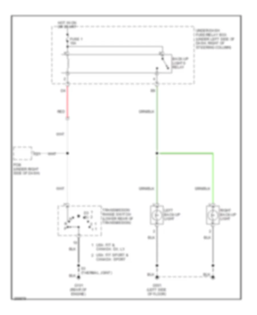
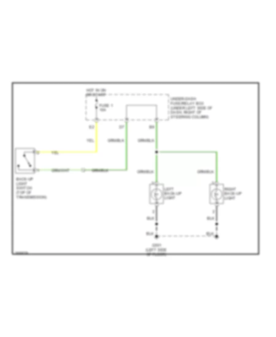
Back-up Lamps Wiring Diagram, A/T for Honda Fit 2008
List of elements for Back-up Lamps Wiring Diagram, A/T for Honda Fit 2008:
- Back-up lights relay
- C21
- Canada: sport
- D3 (s)
- Fuse 1 10a
- G101 (rear of engine)
- G501 (left side of floor)
- Hot in on or start
- Left back-up light
- Pcm (under right side of dash)
- Red
- Right back-up light
- S3 (thermal joint)
- Transmission range switch (lower rear of transmission)
- Under-dash fuse/relay box (under left side of dash, right of steering column)
- Usa: fit & canada: dx, lx
- Usa: fit sport &
Back-up Lamps Wiring Diagram, M/T for Honda Fit 2008
List of elements for Back-up Lamps Wiring Diagram, M/T for Honda Fit 2008:
- Back-up light switch (top of transmission)
- Fuse 1 10a
- G501 (left side of floor)
- Hot in on or start
- Left back-up light
- Right back-up light
- Under-dash fuse/relay box (under left side of dash, right of steering column)
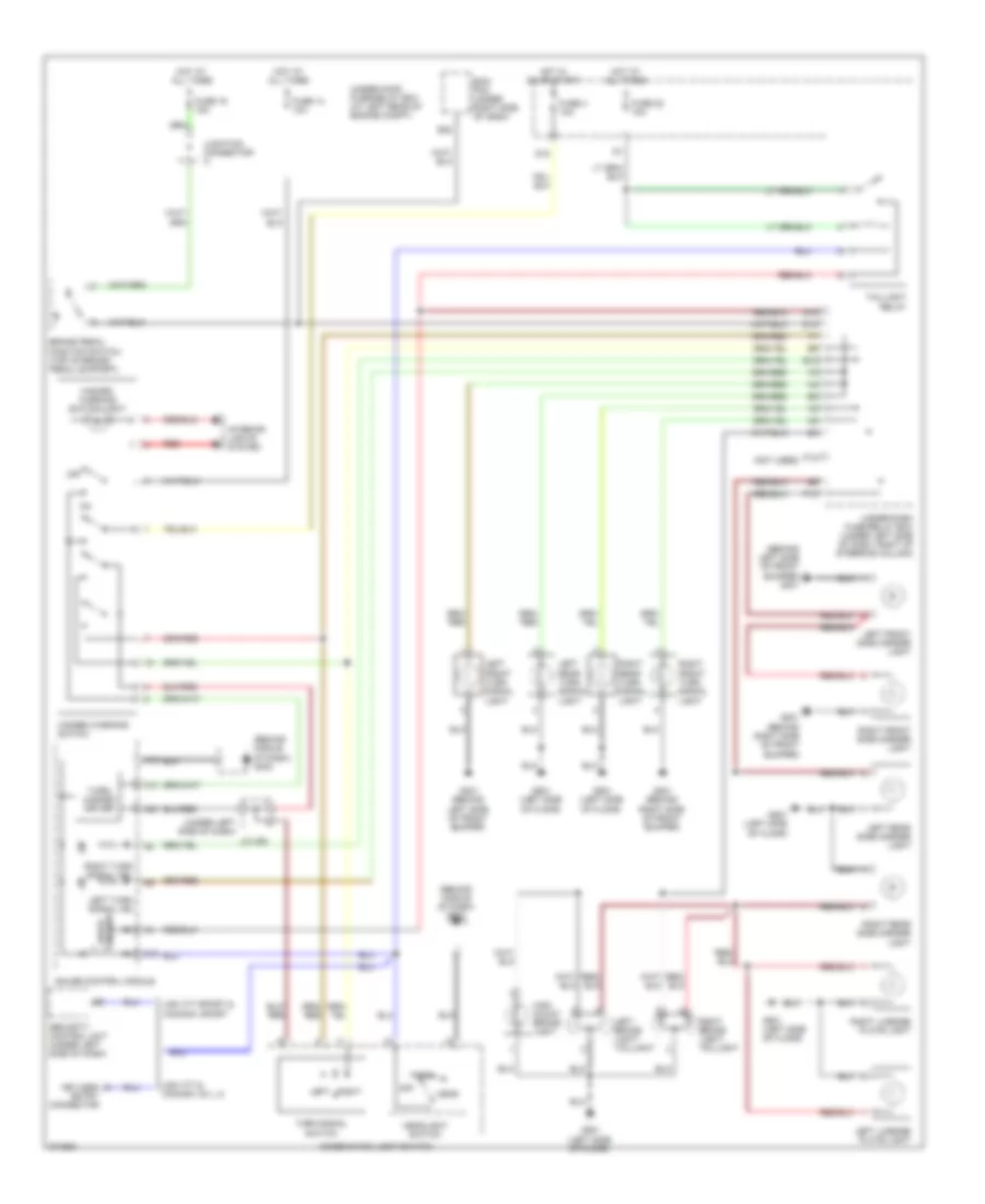
Exterior Lamps Wiring Diagram for Honda Fit 2008
List of elements for Exterior Lamps Wiring Diagram for Honda Fit 2008:
- (behind left side of front bumper) g301
- (behind middle of dash) g402
- (not used)
- (under left side of dash)
- A10
- A19
- A20
- Brake pedal position switch (top of brake pedal support)
- C19
- Combination light switch
- D14
- D15
- D18
- Drive circuit
- E12
- E22
- Ecm/ pcm (under right side of dash)
- Fuse 14 10a
- Fuse 16 15a
- Fuse 22 10a
- Fuse 4 10a
- G201 (behind right side of front bumper)
- G301 (behind left side of front bumper)
- G501 (left side of floor)
- Gauge control module
- Hazard warning switch
- Hazard warning switch light
- Head
- Headlight switch
- High mount brake light
- Hot at all times
- Hot in on or start
- Interior lights system
- J/c 405
- Junction connector a
- Keyless entry connector
- Left
- Left brake light/ taillight
- Left front side marker light
- Left front turn signal light
- Left license plate light
- Left rear side marker light
- Left rear turn signal light
- Left turn signal ind
- Off
- P12
- P13
- Park
- Red
- Right
- Right brake light/ taillight
- Right front side marker light
- Right front turn signal light
- Right license plate light
- Right rear side marker light
- Right rear turn signal light
- Right turn signal ind
- Security control unit (under left side of dash)
- Taillight relay
- Turn signal switch
- Turn/ hazard driver
- Under-dash fuse/relay box (under left side of dash, right of steering column)
- Under-hood fuse/relay box (at left rear of engine compt)
- Usa: fit & canada: dx, lx
- Usa: fit sport & canada: sport
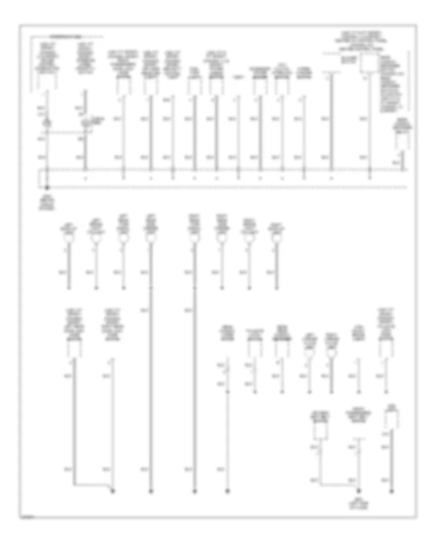
GROUND DISTRIBUTION
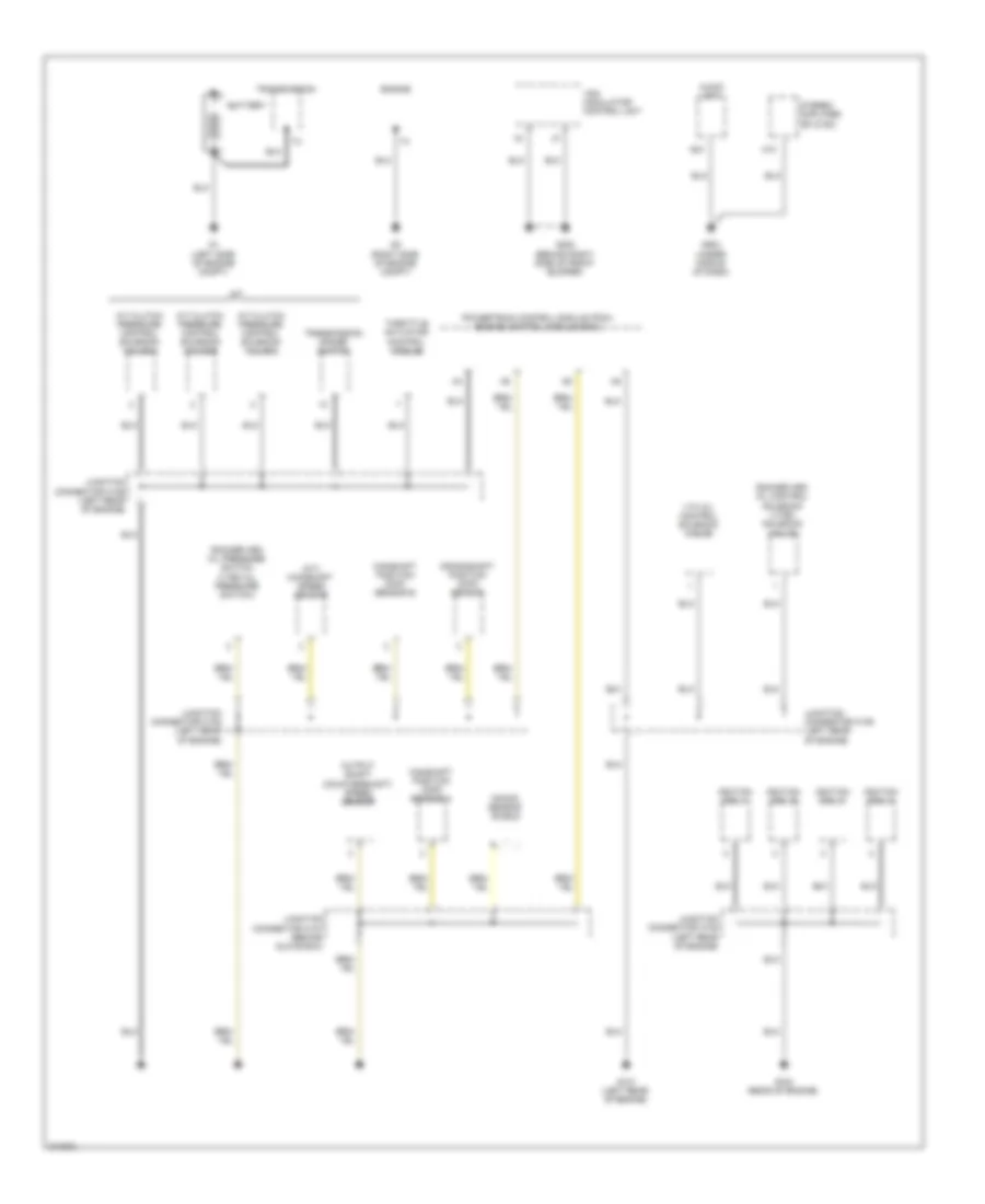
Ground Distribution Wiring Diagram (1 of 3) for Honda Fit 2008
List of elements for Ground Distribution Wiring Diagram (1 of 3) for Honda Fit 2008:
- (a/t) mainshaft speed sensor
- A/t
- A/t clutch pressure control solenoid valve a
- A/t clutch pressure control solenoid valve b
- A/t clutch pressure control solenoid valve c
- A10
- A20
- Audio unit
- Battery
- Camshaft position (cmp) sensor a
- Camshaft position (cmp) sensor b
- Crankshaft position (ckp) sensor
- Engine
- G1 (left side of engine compt)
- G101 (left rear of engine)
- G102 (rear of engine)
- G2 (right side of engine compt)
- G202 (behind right side of front bumper)
- G503 (under middle of dash)
- Ignition coil 1
- Ignition coil 2
- Ignition coil 3
- Ignition coil 4
- Junction connector c105 (left rear of engine)
- Junction connector c106 (left rear of engine)
- Junction connector c107 (behind glove box)
- Knock sensor shield
- Output shaft (countershaft) speed sensor
- Powertrain control module (pcm)/ engine control module (ecm)
- Rocker arm oil control solenoid (vtec solenoid valve)
- Rocker arm oil pressure switch (vtec oil pressure switch)
- Stereo amplifier (ex & sc)
- Throttle actuator control module
- Transmission
- Transmission range switch
- Vsa modulator control unit
- Vtc oil control solenoid valve
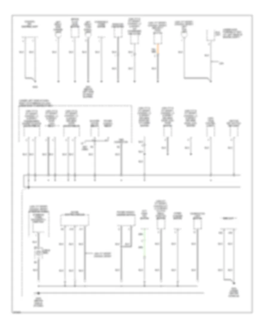
Ground Distribution Wiring Diagram (2 of 3) for Honda Fit 2008
List of elements for Ground Distribution Wiring Diagram (2 of 3) for Honda Fit 2008:
- (a/t) park pin switch
- (canada) drl control unit
- (not used)
- (under left side of dash, right of steering column) under-dash fuse/relay box
- (usa m/t: fit sport) (canada m/t: lx & sport) clutch pedal position switch
- (usa)
- (usa: fit & fit sport) (canada: lx & sport) a/c condenser fan motor
- (usa: fit & fit sport) (canada: lx & sport) door lock relay
- (usa: fit & fit sport) (canada: lx & sport) driver's door key cylinder switch
- (usa: fit & fit sport) (canada: lx & sport) driver's door lock knob switch
- (usa: fit & fit sport) (canada: lx & sport) driver's door lock switch
- (usa: fit & fit sport) (canada: lx & sport) driver's door unlock relay
- (usa: fit & fit sport) (canada: lx & sport) passenger's doors/tailgate unlock relay
- (usa: fit sport) (canada: sport) left fog light
- (usa: fit sport) (canada: sport) security hood switch
- (usa: fit sport) (canada: sport) steering wheel
- A11
- A19
- A22
- A23
- Blower motor relay
- Brake fluid level switch
- Cable reel
- Combination light switch
- Eld unit
- G301 (behind left side of front bumper)
- G302
- G402 (behind middle of dash)
- G404 (under center console)
- Gauge control module
- Ignition key switch/ key light
- Left front side marker light
- Left front turn signal light
- Mes connector
- Power window master switch
- Power window relay
- Radiator fan motor
- Srs unit
- Steering wheel downshift(-) switch
- Tpms control unit
- Under-hood fuse/relay box (at left rear of engine compt)
- Usa
- Usa: fit sport canada: sport
- Windshield wiper motor
- Wiper/ washer switch
Ground Distribution Wiring Diagram (3 of 3) for Honda Fit 2008
List of elements for Ground Distribution Wiring Diagram (3 of 3) for Honda Fit 2008:
- (m/t) clutch interlock switch
- (usa: fit & fit sport) (canada: lx & sport) heater a/c control panel (canada: dx) heater control panel
- (usa: fit & fit sport) (canada: lx & sport) power mirror switch
- (usa: fit sport) (canada: lx & sport) cruise control combination switch
- (usa: fit sport) (canada: sport) front passenger's door lock knob switch
- (usa: fit sport) (canada: sport) keyless receiver unit
- (usa: fit sport) (canada: sport) left rear door lock knob switch
- (usa: fit sport) (canada: sport) right rear door lock knob switch
- (usa: fit sport) (canada: sport) security control unit
- (usa: fit sport) (canada: sport) steering wheel upshift(+) switch
- (usa: fit sport) (canada: sport) tailgate lock knob switch
- Accessory power socket
- B13
- B16
- Blower switch
- C13
- Cable reel
- D12
- Dlc
- Driver's seat belt switch
- Front passenger's seat belt switch
- Fuel tank unit
- G403 (behind middle of dash)
- G501 (left side of floor)
- High mount brake light
- Left back-up light
- Left brake light/ taillight
- Left license plate light
- Left rear side marker light
- Left rear turn signal light
- Ods unit
- Rear rear window defogger
- Rear window defogger relay
- Rear window defogger switch (canada: dx) rear window defogger switch & a/c switch (usa: fit & fit sport) (canada: lx & sport)
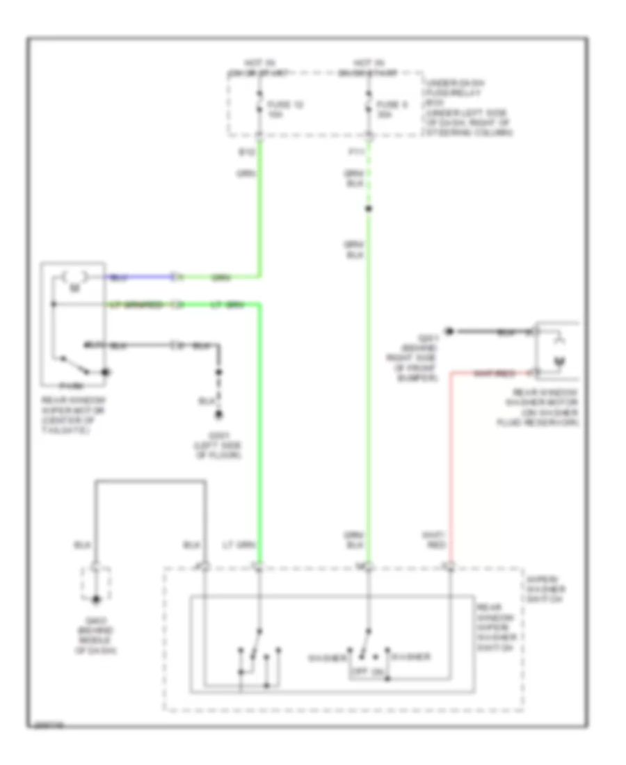
- Rear window wiper motor
- Right back-up light
- Right brake light/ taillight
- Right license plate light
- Right rear side marker light
- Right rear turn signal light
- Steering wheel
- Tailgate latch switch
- Wiper/ washer switch
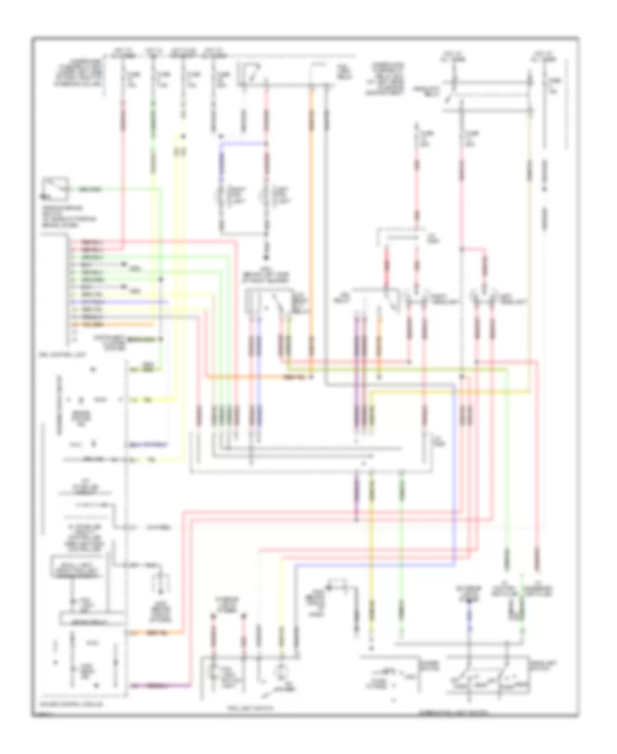
HEADLIGHTS
Headlights Wiring Diagram, DX LX with DRL for Honda Fit 2008
List of elements for Headlights Wiring Diagram, DX LX with DRL for Honda Fit 2008:
- 10v stabilize circuit
- 5v stabilize circuit/ controller area network controller
- B10
- B11
- Brake system ind
- Combination light switch
- Dimmer switch
- Drive circuit
- Drl control unit
- Drl ind
- Drl relay
- Exterior lights system
- Flash to pass
- Fog light ind
- Fog light relay
- Fog light switch
- Fog light switch light
- Fuse 10a
- Fuse 20a
- Fuse 7.5a
- G301 (behind left side of front bumper)
- G302
- G402 (behind middle of dash)
- Gauge control module
- Head
- Headlight relay
- Headlight switch
- High
- High beam ind
- Hot at all times
- Hot in on
- Hot in on or start
- Instrument cluster system
- Interior lights system
- J/c c205
- Left fog light
- Left headlight
- Low
- Low beam cut relay
- Off
- On ind
- Park
- Parking brake switch (at base of parking brake lever)
- Red
- Right fog light
- Right headlight
- Small light/ front fog light dimming circuit
- Under-dash fuse/relay box (under left side of dash, right of steering column)
- Under-hood fuse/relay relay box (at left rear of engine compartment)
- W/ accessory installed
- W/ factory installed
- Warning drive circuit
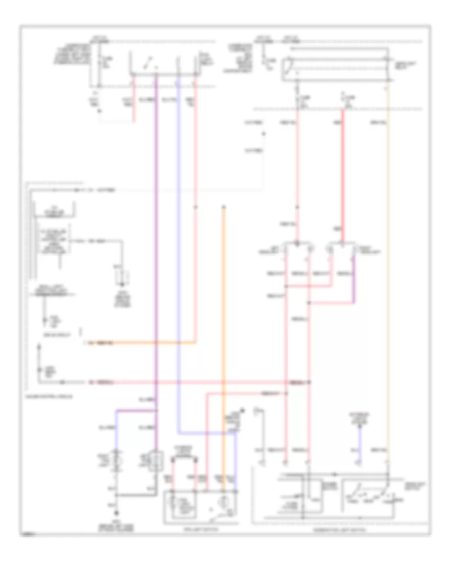
Headlights Wiring Diagram, Fit Sport without DRL for Honda Fit 2008
List of elements for Headlights Wiring Diagram, Fit Sport without DRL for Honda Fit 2008:
- 10v stabilize circuit
- 5v stabilize circuit/ controller area network controller
- A19
- C21
- C36
- Combination light switch
- Dimmer switch
- Drive circuit
- Exterior lights system
- Flash to pass
- Fog light ind
- Fog light relay
- Fog light switch
- Fuse 10a
- Fuse 20a
- G201 (behind right side of front bumper)
- G301 (behind left side of front bumper)
- G402 (behind middle of dash)
- Gauge control module
- Head
- Headlight relay
- Headlight switch
- High
- High beam ind
- Hot at all times
- Left fog light
- Left headlight
- Low
- Off
- Park
- Red
- Relay driver
- Right fog light
- Right headlight
- Security control unit (under left side of dash)
- Small light/ front fog light dimming circuit
- Under-dash fuse/relay box (under left side of dash, right of steering column)
- Under-hood fuse/relay box (at left rear of engine compartment)
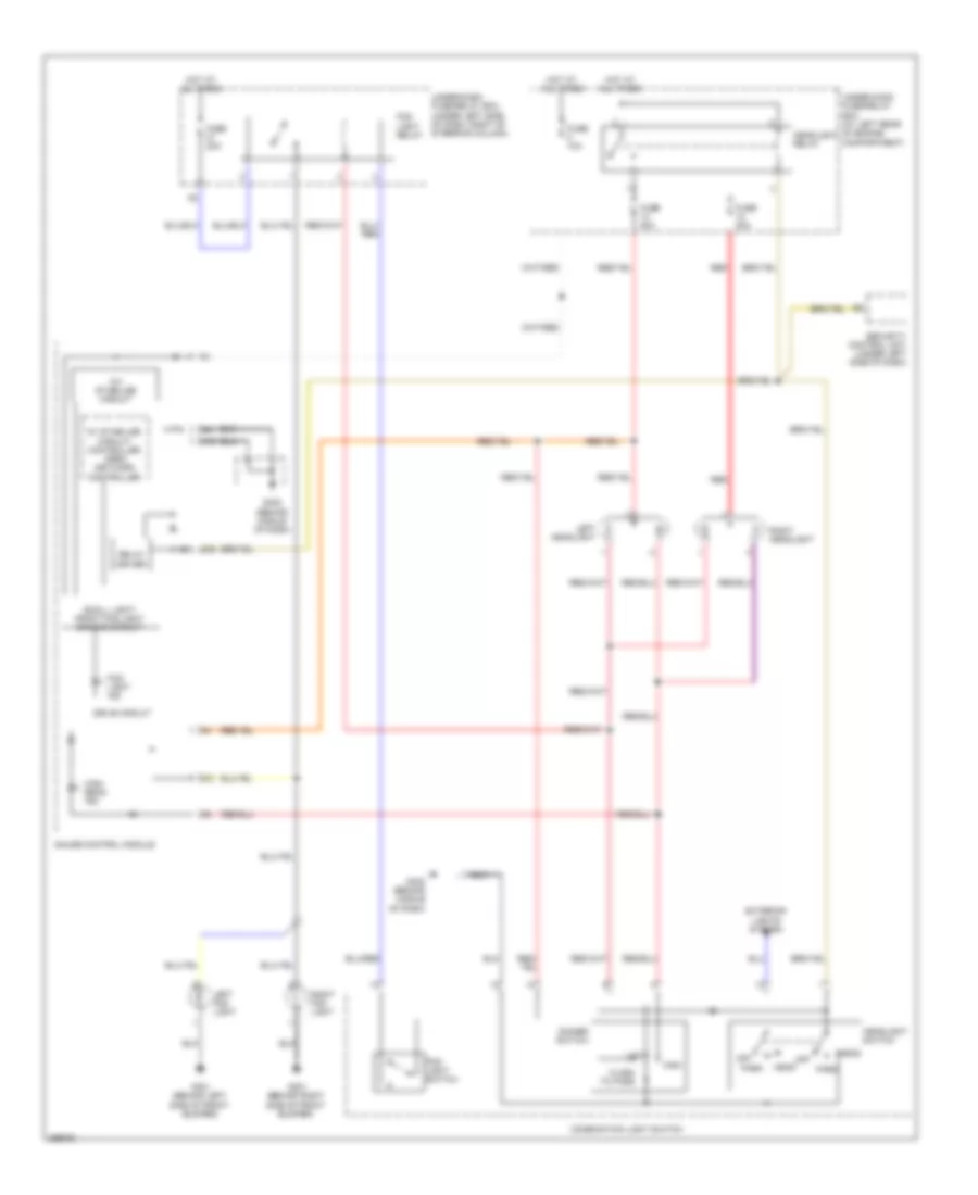
Headlights Wiring Diagram, Fit without DRL for Honda Fit 2008
List of elements for Headlights Wiring Diagram, Fit without DRL for Honda Fit 2008:
- 10v stabilize circuit
- 5v stabilize circuit/ controller area network controller
- Combination light switch
- Dimmer switch
- Drive circuit
- Exterior lights system
- Flash to pass
- Fog light ind
- Fog light relay
- Fog light switch
- Fog light switch light
- Fuse 10a
- Fuse 20a
- G301 (behind left side of front bumper)
- G402 (behind middle of dash)
- Gauge control module
- Head
- Headlight relay
- Headlight switch
- High
- High beam ind
- Hot at all times
- Interior lights system
- Left fog light
- Left headlight
- Low
- Off
- On ind
- Park
- Red
- Right fog light
- Right headlight
- Small light/ front fog light dimming circuit
- Under-dash fuse/relay box (under left side of dash, right of steering column)
- Under-hood fuse/relay box (at left rear of engine compartment)
Headlights Wiring Diagram, Sport with DRL for Honda Fit 2008
List of elements for Headlights Wiring Diagram, Sport with DRL for Honda Fit 2008:
- (at base of parking brake lever) parking brake switch
- 10v stabilize circuit
- 5v stabilize circuit/ controller area network controller
- A19
- B10
- B11
- Brake system ind
- C21
- C36
- Combination light switch
- Dimmer switch
- Drive circuit
- Drl control unit
- Drl ind
- Drl relay
- Exterior lights system
- Flash to pass
- Fog light ind
- Fog light relay
- Fog light switch
- Fuse 10a
- Fuse 20a
- Fuse 7.5a
- G201 (behind right side of front bumper)
- G301 (behind left side of front bumper)
- G302
- G402 (behind middle of dash)
- Gauge control module
- Head
- Headlight relay
- Headlight switch
- High
- High beam ind
- Hot at all times
- Hot in on
- Hot in on or start
- Instrument cluster system
- J/c c205
- Left fog light
- Left headlight
- Low
- Low beam cut relay
- Off
- Park
- Red
- Relay driver
- Right fog light
- Right headlight
- Security control unit (under left side of dash)
- Small light/ front fog light dimming circuit
- Under-dash fuse/relay box (under left side of dash, right of steering column)
- Under-hood fuse/relay relay box (at left rear of engine compartment)
- Warning drive circuit
HORN
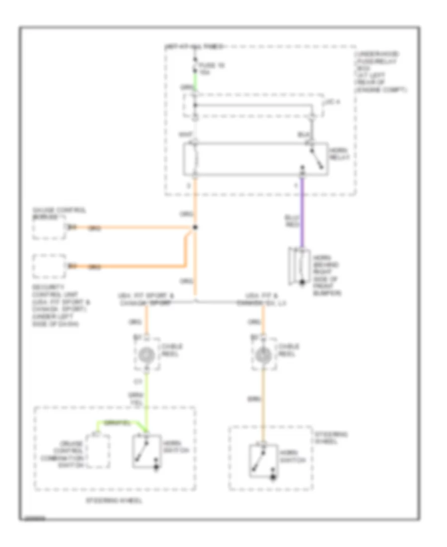
Horn Wiring Diagram for Honda Fit 2008
List of elements for Horn Wiring Diagram for Honda Fit 2008:
- Cable reel
- Cruise control combination switch
- Fuse 16 15a
- Gauge control module
- Horn (behind right side of front bumper)
- Horn relay
- Horn switch
- Hot at all times
- J/c a
- Security control unit (usa: fit sport & canada: sport) (under left side of dash)
- Steering wheel
- Under-hood fuse/relay box (at left rear of engine compt)
- Usa: fit & canada: dx, lx
- Usa: fit sport & canada: sport
INSTRUMENT CLUSTER
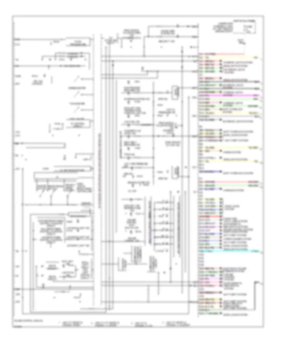
Instrument Cluster Wiring Diagram (1 of 2) for Honda Fit 2008
List of elements for Instrument Cluster Wiring Diagram (1 of 2) for Honda Fit 2008:
- (canada)
- 10v stabilize circuit
- 5v control circuit
- 5v stabilize circuit/controller area network controller
- A/t gear position indicator drive circuit
- A10
- A11
- A12
- A13
- A14
- A15
- A16
- A17
- A18
- A19
- A20
- Abs ind
- Anti-theft system
- Anti-theft system computer data lines system anti-theft system
- B10
- B11
- B12
- B13
- B14
- Beeper
- Brake system ind
- Brightening switch
- C10
- C11
- C12
- C13
- C14
- C15
- C16
- C17
- C18
- C19
- C20
- C21
- C22
- C23
- C24
- C25
- C26
- C27
- C28
- C29
- C30
- C31
- C32
- C33
- C34
- C35
- C36
- C37
- C38
- C39
- C40
- Charging system ind
- Circuit drive
- Circuit fail-safe
- Circuit turning-off compulsory
- Circuit turning-on compulsory
- Computer data lines system
- Coolant high temperature warning light ind
- Coolant low temperature ind
- Cruise control ind
- Cruise control main switch ind
- Cruise control system
- Cruise control system door locks system
- Dash lights brightness controller
- Dial brightness control & dimming circuit
- Dimming switch
- Door locks system
- Drive circuit
- Drl ind (canada)
- Electronic power steering system
- Eps ind
- Exterior lights system
- F-can transceiver
- Fog light ind
- From door & tailgate open b ind (diagram 2 of 2)
- From door & tailgate open ind (diagram 2 of 2)
- Fuel gauge
- Fuse 10a
- Gauge control module
- Headlights system
- High beam ind
- Horns system
- Hot at all times
- I/f
- Immobilizer system ind
- Indicator control dimming circuit
- Interior lights system
- K-line transceiver
- Lcd back light ind
- Lcd brightness control & dimming circuit
- Lights on ind
- Low fuel ind
- Low oil pressure ind
- Low tire pressure ind
- Maintenance required ind
- Mil ind
- Pnk
- Pointer brightness control & dimming circuit
- Red
- Seat belt reminder ind
- Security ind
- Select/ reset switch
- Shift interlock system
- Side air bag cut-off ind
- Small light/ front fog light dimming circuit
- Speedometer
- Srs ind
- Tachometer
- Tpms ind
- Under-hood fuse/relay box (at left rear of engine compt)
- Usa: fit & canada: lx, dx
- Usa: fit sport & canada: lx & sport
- Usa: fit sport & canada: sport
- Usa: fit, fit sport & canada: lx, sport
- Warning drive circuit
- Warning system
- Washer fluid level ind
- Wiper/washer system
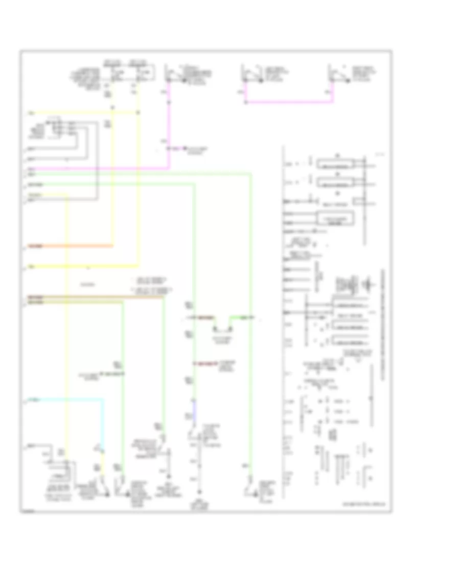
Instrument Cluster Wiring Diagram (2 of 2) for Honda Fit 2008
List of elements for Instrument Cluster Wiring Diagram (2 of 2) for Honda Fit 2008:
- (a/t)
- 5v stabilize circuit/controller area network controller
- A10
- A11
- A12
- A13
- A14
- A15
- A16
- A17
- A19
- A20
- Anti-theft system
- B14
- Brake fluid level switch (on brake fluid reservoir)
- C10
- C11
- C16
- C19
- C20
- C36
- C40
- Canada
- Canada: lx, sport
- Circuit drive
- D21
- Door & tailgate open ind
- Drive circuit
- Drive lcd
- Driver's door switch (at left "b" pillar)
- Front passenger's door switch (at right "b" pillar)
- Fuel gauge sending unit
- Fuel tank unit (in fuel tank)
- Fuse 10a
- Fuse 7.5a
- G301 (behind left side of front bumper)
- G402 (behind middle of dash)
- G501 (left side of floor)
- Gauge control module
- Hot in on or start
- I/f
- Interior lights system
- Key lock circuit
- Left rear door switch (at left "c" pillar)
- Left turn signal ind
- Maintence smart trip &
- Meter/ lcd odo-
- Oil pressure switch (near oil filter)
- Parking brake switch (at base of parking brake lever)
- Relay driver
- Right rear door switch (at right "c" pillar)
- Right turn signal ind
- Tailgate latch switch (center of tailgate)
- To 10v stabilize circuit (diagram 1 of 2)
- To low fuel ind (diagram 1 of 2)
- Turn/hazard driver
- Under-dash fuse/relay box (under left side of dash, right of steering column)
- Usa: fit sport & canada: sport
- Usa: fit, fit sport &
INTERIOR LIGHTS
Courtesy Lamps Wiring Diagram for Honda Fit 2008
List of elements for Courtesy Lamps Wiring Diagram for Honda Fit 2008:
- 5v stabilize circuit/controller area network controller
- A11
- A12
- A13
- A14
- A16
- Anti-theft system
- B13
- C11
- C17
- Cargo area light
- Ceiling light
- Door
- Drive circuit
- Driver's door switch (at left "b" pillar)
- F14
- F16
- Front passenger's door switch (at right "b" pillar)
- Fuse 10a
- G402 (behind middle of dash)
- G501 (left side of floor)
- Gauge control module
- Hot at all times
- Hot in on or start
- I/f
- Ignition key switch
- Ignition key switch/key light
- Keyless receiver unit (under left side of dash)
- Left rear door switch (at left "c" pillar)
- Off
- P10
- Right rear door switch (at right "c" pillar)
- Tailgate latch switch (center of tailgate)
- Under-dash fuse/relay box (under left side of dash, right of steering column)
- Under-hood fuse/relay box (at left rear of engine compt)
- Usa: fit sport & canada: sport
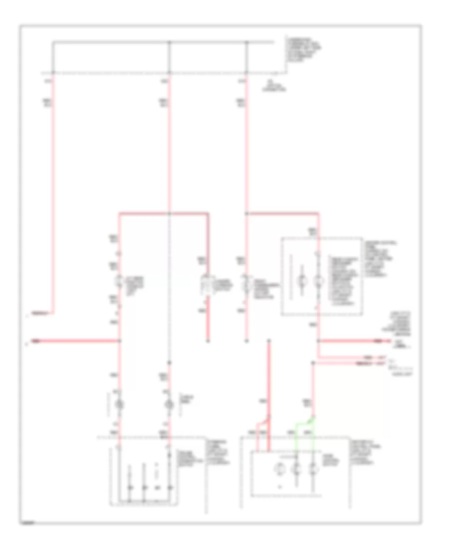
Instrument Illumination Wiring Diagram (1 of 2) for Honda Fit 2008
List of elements for Instrument Illumination Wiring Diagram (1 of 2) for Honda Fit 2008:
- 0 = off 1 = park 2 = head
- 10v stabilize circuit
- 5v stabilize circuit/controller area network controller
- A15
- A19
- Anti-theft system
- Brightening switch
- C19
- Combination light switch
- Dash lights brightness controller
- Dial brightness control & dimming circuit
- Dimming switch
- Drive circuit
- F14
- Fuse 10a
- G402 (behind middle of dash)
- Gauge control module
- Headlight switch
- Hot at all times
- I/f
- Lcd back light ind
- Lcd brightness control & dimming circuit
- P10
- Pointer brightness control & dimming circuit
- Red
- Relay driver
- Select/ reset switch
- Small light/ front fog light dimming circuit
- Taillight relay
- Under-dash fuse/relay box (under left side of dash, right of steering column)
- Under-hood fuse/relay box (at left rear of engine compt)
Instrument Illumination Wiring Diagram (2 of 2) for Honda Fit 2008
List of elements for Instrument Illumination Wiring Diagram (2 of 2) for Honda Fit 2008:
- (option connector)
- (usa: fit & fit sport) (canada: lx & sport) power mirror switch
- A/t gear position console light (a/t)
- A10
- Audio unit
- Cable reel
- Cruise control combination switch
- D18
- D19
- D20
- Front passenger's air bag cut-off indicator
- Hazard warning switch
- Heater control panel (canada: dx) a/c control panel heater (usa: fit & fit sport) (canada: lx & sport)
- Heater-a/c control panel (usa: fit & fit sport) (canada: lx & sport)
- Ill +
- Ill -
- Mode control switch
- Not used
- Rear window defogger switch (canada: dx) rear window defogger switch & a/c switch (usa: fit & fit sport) (canada: lx & sport)
- Red
- Steering wheel (usa: fit & fit sport) (canada: lx & sport)
- Under-dash fuse/relay box (under left side of dash, right of steering column)
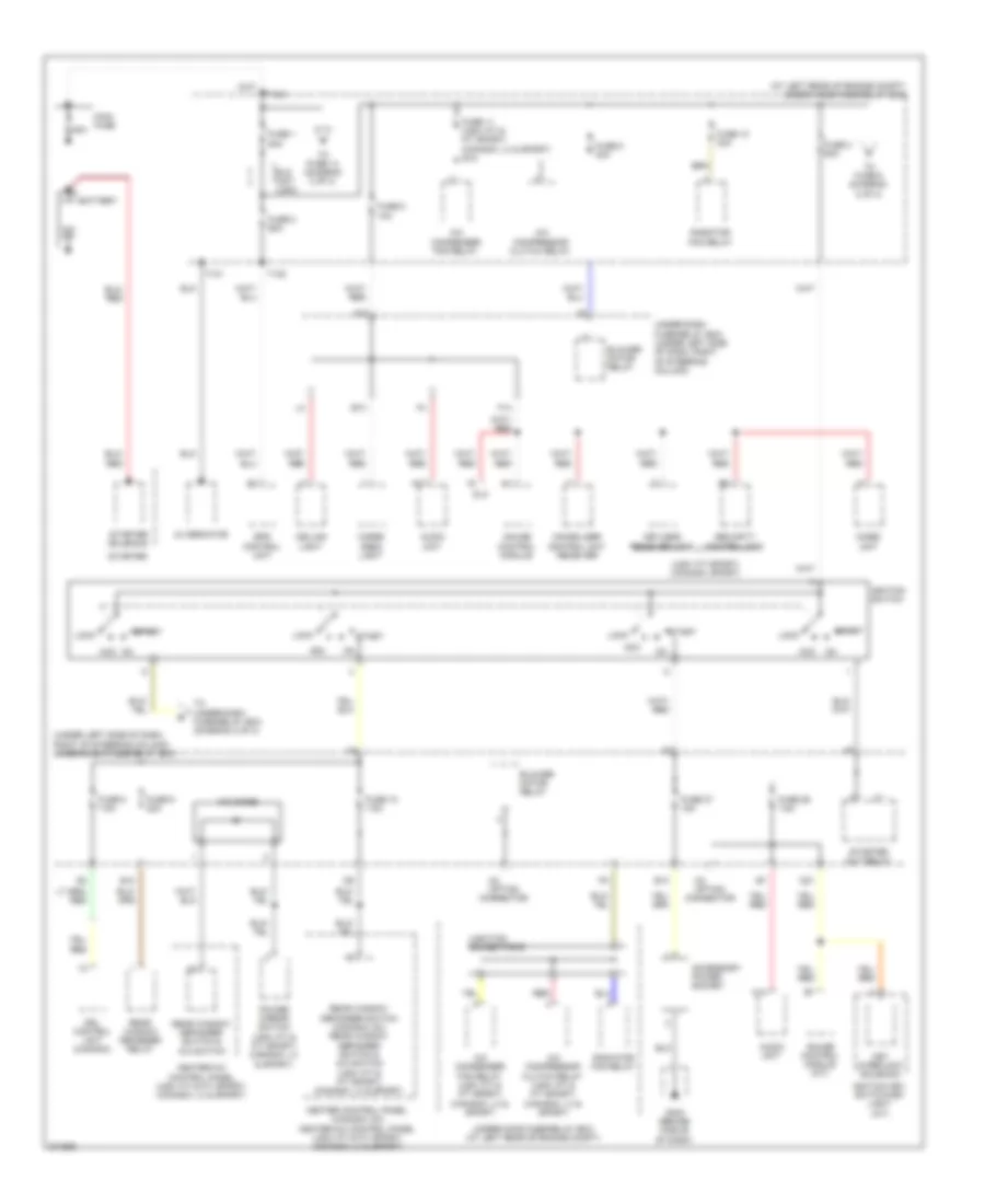
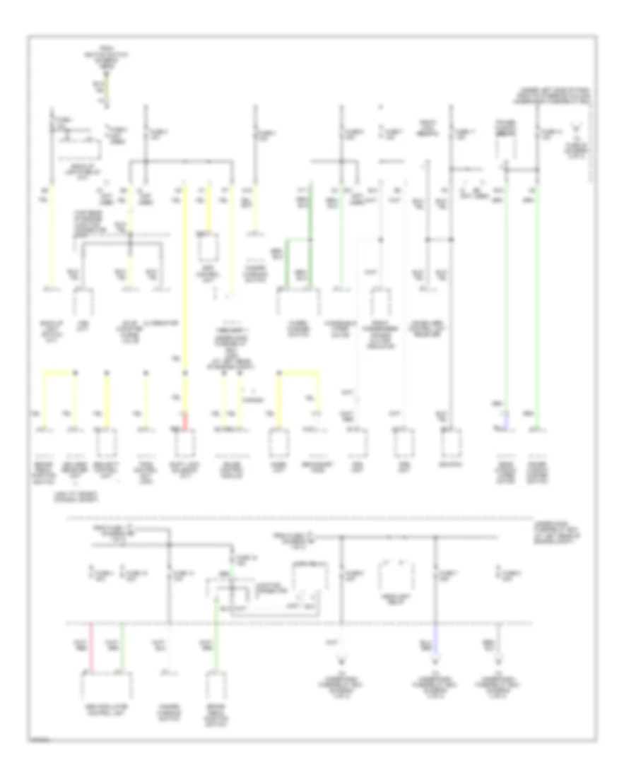
POWER DISTRIBUTION
Power Distribution Wiring Diagram (1 of 3) for Honda Fit 2008
List of elements for Power Distribution Wiring Diagram (1 of 3) for Honda Fit 2008:
- (at left rear of engine compt) under-hood fuse/relay box
- (under left side of dash, right of steering column) under-dash fuse/relay box
- (usa: fit sport) (canada: sport)
- 80a
- A/c compressor clutch relay
- A/c compressor clutch relay (usa: fit & fit sport) (canada: lx & sport)
- A/c condenser fan relay
- A/c condenser fan relay (usa: fit & fit sport) (canada: lx & sport)
- A/c diode
- A14
- A17
- Acc
- Accessory power socket
- Alternator
- Audio unit
- B13
- Battery
- Blower motor relay
- Cargo area light
- Ceiling light
- D21
- Dlc
- Drl control unit (canada)
- E10
- E13
- Eld unit (usa)
- Eps control unit
- F14
- Fuse 1 80a
- Fuse 10 30a
- Fuse 10 7.5a
- Fuse 11 (usa: fit & fit sport) (canada: lx & sport) 30a
- Fuse 2 60a
- Fuse 26 7.5a
- Fuse 27 15a
- Fuse 3 50a
- Fuse 5 40a
- Fuse 8 10a
- Fuse 8 7.5a
- Fuse 9 20a
- G403 (behind middle of dash)
- Gauge control module
- Gauge control module (a/t)
- Heater control panel (canada: dx) heater-a/c control panel (usa: fit & fit sport) (canada: lx & sport)
- Heater-a/c control panel (usa: fit & fit sport) (canada: lx & sport)
- Ignition key switch/key light (a/t)
- Ignition switch
- Immobilizer control unit receiver
- Imoes unit
- Junction connector b
- Key interlock solenoid
- Keyless receiver unit
- Lock
- Main fuse
- On acc
- Option connector
- P10
- Power mirror switch (usa: fit & fit sport) (canada: lx & sport)
- Radiator fan relay
- Rear window defogger relay
- Rear window defogger switch & a/c switch
- Rear window defogger switch (canada: dx) rear window defogger switch & a/c switch (usa: fit & fit sport) (canada: lx & sport)
- Red
- Security control unit
- Start
- Starter
- Starter cut relay
- Starter solenoid
- T101
- T102
- T104
- To fuse 14 (diagram 2 of 3)
- To fuse 6 (diagram 2 of 3)
- To under-dash fuse/relay box (diagram 2 of 3)
- Under-dash fuse/relay box (under left side of dash, right of steering column)
- Under-hood fuse/relay box (at left rear of engine compt)
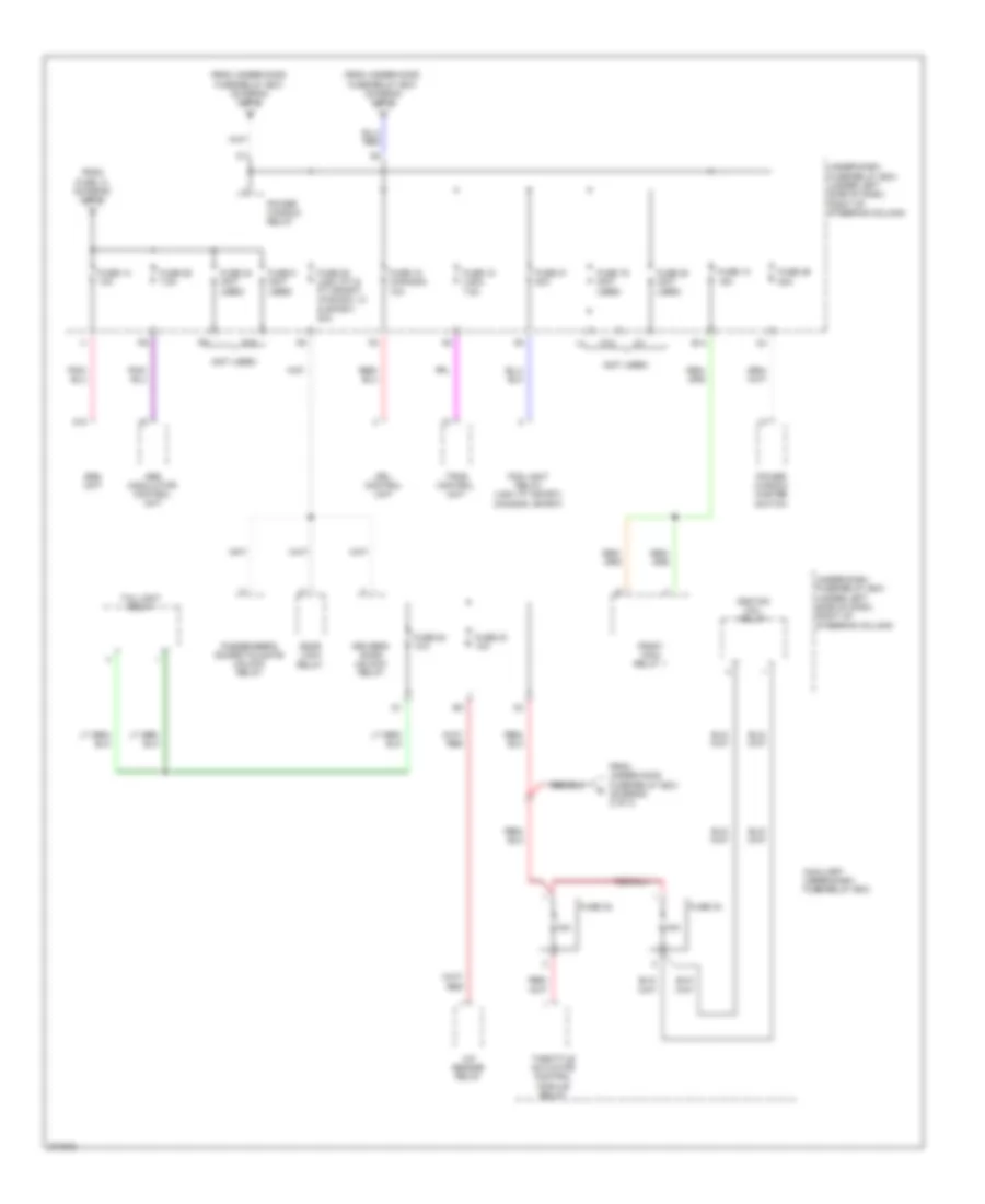
Power Distribution Wiring Diagram (2 of 3) for Honda Fit 2008
List of elements for Power Distribution Wiring Diagram (2 of 3) for Honda Fit 2008:
- (not used)
- (top rear of engine) junction connector c103
- (under left side of dash, right of steering column) under-dash fuse/relay box
- (usa: fit sport) (canada: sport)
- A11
- A17
- Abs modulator control unit
- Alternator
- B11
- B12
- B14
- Back-up light switch (m/t)
- Back-up lights relay (a/t)
- Brake pedal position switch
- Canada
- D15
- D16
- Ecm/pcm
- Eld unit
- Eps control unit
- Evap canister purge valve
- F11
- From fuse 1 (diagram 1 of 3)
- From fuse 3 (diagram 1 of 3)
- From ignition switch (diagram 1 of 3)
- Front passenger's air bag cut-off indicator
- Fuse 1 10a
- Fuse 11 15a
- Fuse 12 10a
- Fuse 14 10a
- Fuse 15 30a
- Fuse 16 15a
- Fuse 2 (not used)
- Fuse 3 10a
- Fuse 4 10a
- Fuse 4 30a
- Fuse 6 30a
- Fuse 6 40a
- Fuse 7 10a
- Fuse 7 30a
- Fuse 9 30a
- Gauge control module
- Hazard warning switch
- Headlight relay
- Horn relay
- Immobilizer control unit receiver
- Imoes unit
- Junction connector a
- Keyless receiver unit
- Ods unit
- Pgm-fi main relay 2
- Power window master switch
- Power window relay
- Rear window wiper motor
- Red
- Secondary ho2s
- Security control unit
- Shift lock solenoid (a/t)
- Srs unit
- To fuse 25 (diagram 3 of 3)
- To under-dash fuse/relay box (diagram 3 of 3)
- Tpms control unit (usa)
- Under-hood fuse/relay box (at left rear of engine compt)
- Under-hood fuse/relay box (usa) (at left rear of engine compt)
- Vss (m/t)
- Windshield wiper motor
- Wiper/ washer switch
Power Distribution Wiring Diagram (3 of 3) for Honda Fit 2008
List of elements for Power Distribution Wiring Diagram (3 of 3) for Honda Fit 2008:
- (not used)
- 15a
- A/f sensor relay
- A18
- Abs modulator control unit
- Auxiliary under-dash fuse/relay box
- D16
- Door lock relay
- Driver's door unlock relay
- Drl control unit
- E14
- F12
- Fog light relay (usa: fit sport) (canada: sport)
- From fuse 13 (diagram 2 of 3)
- From under-hood fuse/relay box (diagram 2 of 3)
- Fuse 13 10a
- Fuse 14 15a
- Fuse 18 (canada) 10a
- Fuse 18 (usa) 7.5a
- Fuse 19 (not used)
- Fuse 20 (not used)
- Fuse 21 20a
- Fuse 22 10a
- Fuse 23 10a
- Fuse 24 (not used)
- Fuse 25 7.5a
- Fuse 28 (usa: fit & fit sport) (canada: lx & sport) 20a
- Fuse 29 20a
- Fuse 32
- Fuse 33
- Fuse 5 (not used)
- Ignition coil relay
- Passenger's doors/tailgate unlock relay
- Pgm-fi main relay 1
- Power window master switch
- Power window relay
- Srs unit
- Taillight relay
- Throttle actuator control module relay
- Tpms control unit
- Under-dash fuse/relay box (under left side of dash, right of steering column)
POWER DOOR LOCKS
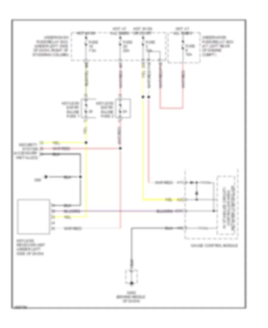
Keyless Entry Wiring Diagram, Accessory for Honda Fit 2008
List of elements for Keyless Entry Wiring Diagram, Accessory for Honda Fit 2008:
- C17
- Controller area 5v stabilize circuit/
- F14
- Fuse 10a
- Fuse 20a
- Fuse 7.5a
- G402 (behind middle of dash)
- G90
- Gauge control module
- Hot at all times
- Hot in on
- Hot in on or start
- Installed)
- Keyless entry in-line fuse 1
- Keyless entry in-line fuse 2
- Keyless receiver unit (under left side of dash)
- Network controller
- P10
- Security system (accessory
- Under-dash fuse/relay box (under left side of dash, right of steering column)
- Under-hood fuse/relay box (at left rear of engine compt)
Keyless Entry Wiring Diagram, Sport (1 of 2) for Honda Fit 2008
List of elements for Keyless Entry Wiring Diagram, Sport (1 of 2) for Honda Fit 2008:
- (behind right side of front bumper) horn
- 5v stabilize circuit/controller area network controller
- A10
- A11
- A12
- A13
- A14
- A15
- A16
- A17
- A18
- A19
- A20
- Audio unit
- B10
- B11
- B12
- B13
- B14
- B15
- B16
- C10
- C11
- C16
- C17
- C19
- C20
- C36
- C38
- C40
- Door lock knob
- Driver relay
- Driver's door key cylinder switch (in driver's door)
- Driver's door lock knob switch (rear of driver's door)
- Driver's door lock switch
- Driver's door switch (at left "b" pillar)
- Exterior lights system
- Fuse 10a
- Fuse 15a
- G402 (behind middle of dash)
- G403 (behind middle of dash)
- Gauge control module
- Headlights system
- Horn relay
- Horns system
- Hot at all times
- I/f
- Junction connector a
- Key
- Lock
- Security control unit (under left side of dash)
- Security ind
- Under-hood fuse/relay box (at left rear of engine compt)
- Unlock
Keyless Entry Wiring Diagram, Sport (2 of 2) for Honda Fit 2008
List of elements for Keyless Entry Wiring Diagram, Sport (2 of 2) for Honda Fit 2008:
- (not used)
- Cargo area light
- Door lock relay
- Driver's door lock actuator (rear of drive's door)
- Driver's door unlock relay
- F10
- F14
- Front passenger's door lock actuator (rear of front passenger's door)
- Front passenger's door lock knob switch (rear of front passenger's door)
- Front passenger's door switch (at right "b" pillar)
- Fuse 10a
- Fuse 20a
- G301 (behind left side of front bumper)
- G402 (behind middle of dash)
- G403 (behind middle of dash)
- G501 (left side of floor)
- Gnd
- Hot at all times
- Hot in on or start
- Ig1
- Ignition key switch
- Ignition key switch/ key light
- Keyless receiver unit (under left side of dash)
- Left rear door lock actuator (rear of left rear door)
- Left rear door lock knob switch (rear of left rear door)
- Left rear door switch (at left "c" pillar)
- Out
- P10
- Passenger's doors/ tailgate unlock relay
- Right rear door lock actuator (rear of right rear door)
- Right rear door lock knob switch (rear of right rear door)
- Right rear door switch (at right "c" pillar)
- Security hood switch (front of engine compt)
- Tailgate latch switch (center of tailgate)
- Tailgate lock actuator (center of tailgate)
- Tailgate lock knob switch (center of tailgate)
- Under-dash fuse/relay box (under left side of dash, right of steering column)
Power Door Locks Wiring Diagram for Honda Fit 2008
List of elements for Power Door Locks Wiring Diagram for Honda Fit 2008:
- (not used)
- 5v stabilize circuit/controller area network controller
- A13
- A14
- A16
- A19
- C10
- C11
- C16
- C20
- C40
- Cargo area light
- Door lock knob
- Door lock relay
- Driver relay
- Driver's door key cylinder switch (in driver's door)
- Driver's door lock actuator (rear of driver's door)
- Driver's door lock knob switch (rear of driver's door)
- Driver's door lock switch
- Driver's door switch (at left "b" pillar)
- Driver's door unlock relay
- F10
- F14
- Front passenger's door lock actuator (rear of front passenger's door)
- Front passenger's door switch (at right "b" pillar)
- Fuse 10a
- Fuse 20a
- G402 (behind middle of dash)
- G501 (left side of floor)
- Gauge control module
- Hot at all times
- Hot in on or start
- I/f
- Ignition key switch
- Ignition key switch/ key light
- Key
- Keyless entry connector
- Left rear door lock actuator (rear of left rear door)
- Left rear door switch (at left "c" pillar)
- Lock
- P10
- Passenger's doors/ tailgate unlock relay
- Right rear door lock actuator (rear of right rear door)
- Right rear door switch (at right "c" pillar)
- Tailgate latch switch (center of tailgate)
- Tailgate lock actuator (center of tailgate)
- Under-dash fuse/relay box (under left side of dash, right of steering column)
- Under-hood fuse/relay box (at left rear of engine compt)
- Unlock
POWER MIRRORS
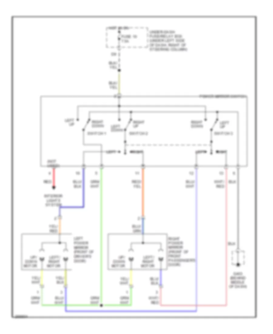
Power Mirrors Wiring Diagram for Honda Fit 2008
List of elements for Power Mirrors Wiring Diagram for Honda Fit 2008:
- (not used)
- Fuse 10 7.5a
- G403 (behind middle of dash)
- Hot in on
- Interior lights system
- Left
- Left down
- Left power mirror (front of driver's door)
- Left up
- Left/ right motor
- Power mirror switch
- Red
- Right
- Right down
- Right power mirror (front of front passenger's door)
- Right up
- Switch 1
- Switch 2
- Switch 3
- Under-dash fuse/relay box (under left side of dash, right of steering column)
- Up/ down motor
POWER WINDOWS
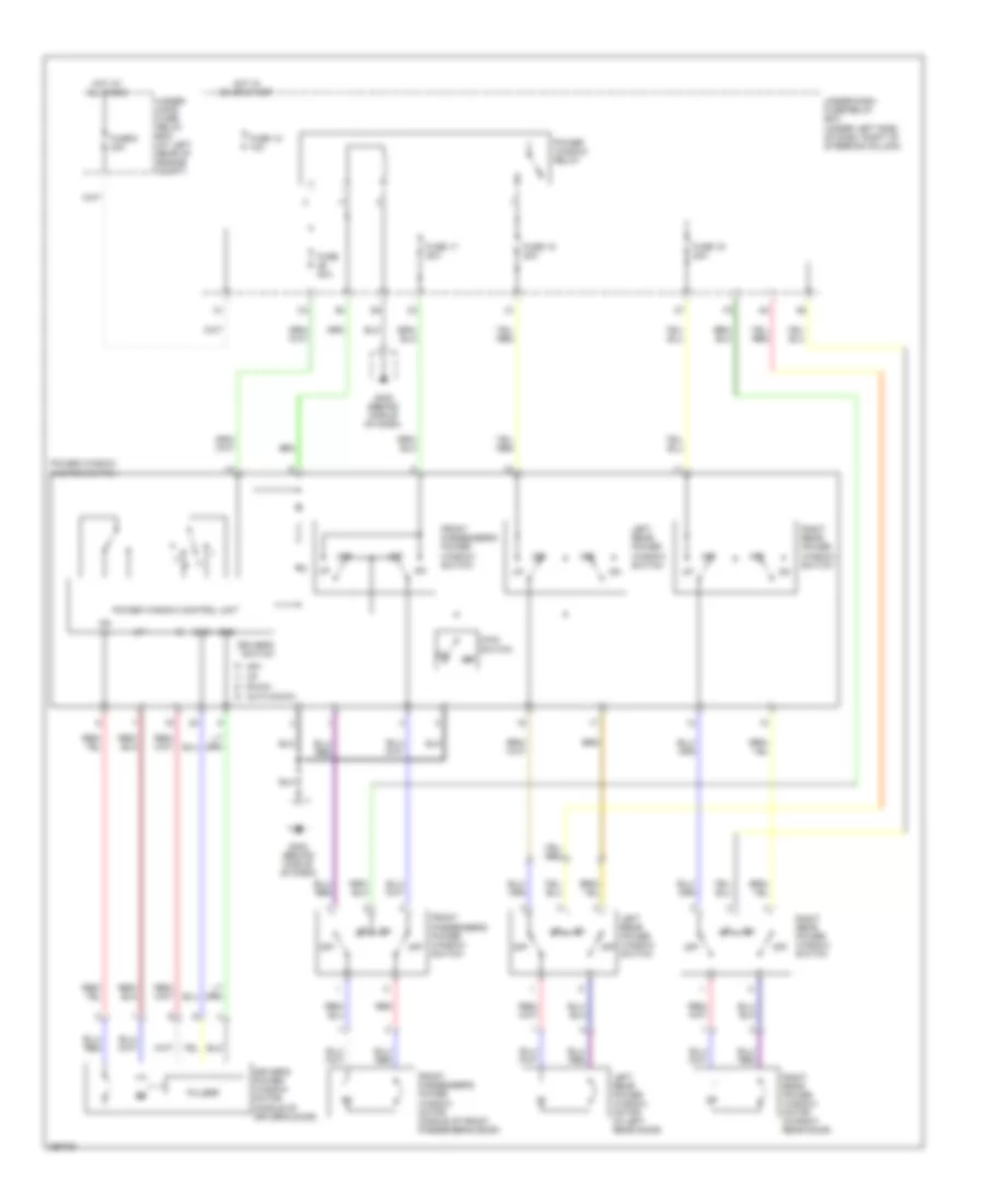
Power Windows Wiring Diagram for Honda Fit 2008
List of elements for Power Windows Wiring Diagram for Honda Fit 2008:
- Auto down
- Dn (+)
- Down
- Driver's power window motor (middle of driver's door)
- Driver's switch
- Front passenger's power window motor (middle of front passenger's door)
- Front passenger's power window switch
- Fuse 12 10a
- Fuse 15 20a
- Fuse 16 20a
- Fuse 17 20a
- Fuse 20a
- Fuse 6 40a
- G402 (behind middle of dash)
- Gnd
- Hot at all times
- Hot in on or start
- Left rear power window motor (in left rear door)
- Left rear power window switch
- Main switch
- Off
- Power window control unit
- Power window master switch
- Power window relay
- Pulser
- Red
- Right rear power window motor (in right rear door)
- Right rear power window switch
- S1g1
- Under- hood fuse/ relay box (at left rear of engine compt)
- Under-dash fuse/relay box (under left side of dash, right of steering column)
- Up+
RADIO
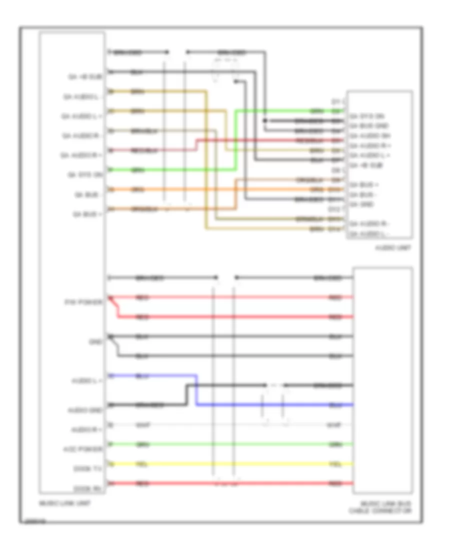
Music Link Wiring Diagram, Accessory for Honda Fit 2008
List of elements for Music Link Wiring Diagram, Accessory for Honda Fit 2008:
- Acc power
- Audio gnd
- Audio l +
- Audio r +
- Audio unit
- Braided
- D10
- D11
- D12
- D13
- D14
- Dock rx
- Dock tx
- F/w power
- Ga +b sub
- Ga audio l +
- Ga audio l -
- Ga audio r +
- Ga audio r -
- Ga audio sh
- Ga bus +
- Ga bus -
- Ga bus gnd
- Ga gnd
- Ga sys on
- Gnd
- Music link bus cable connector
- Music link unit
- Red
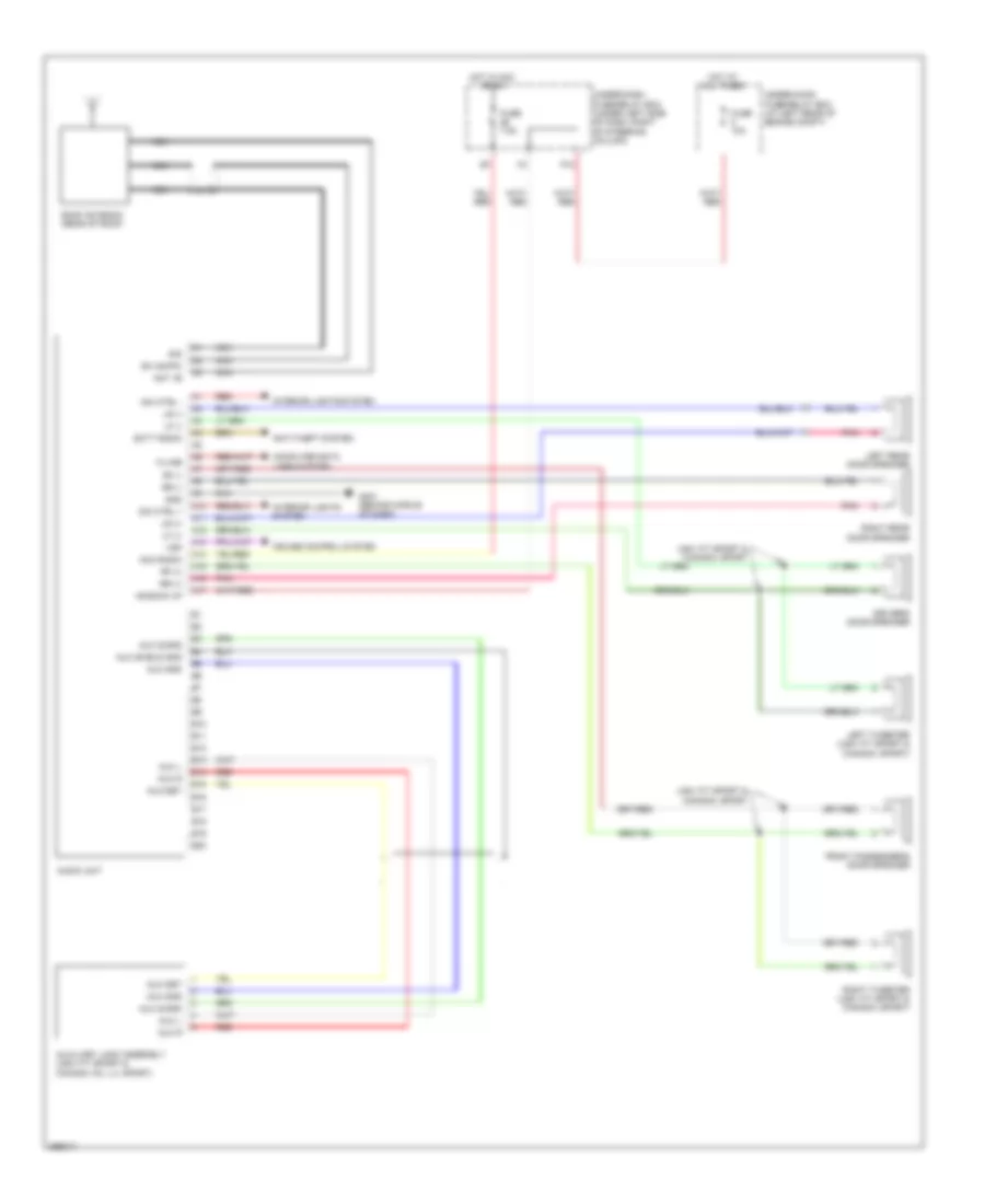
Radio Wiring Diagram for Honda Fit 2008
List of elements for Radio Wiring Diagram for Honda Fit 2008:
- +b back up
- A10
- A11
- A12
- A13
- A14
- A15
- A16
- A17
- Acc radio
- Ant +b
- Anti-theft system
- Audio unit
- Aux det
- Aux gnd
- Aux l
- Aux r
- Aux s-gnd
- Aux shield gnd
- Aux-det
- Auxiliary jack assembly (usa: fit sport & canada: dx, lx, sport)
- B10
- B11
- B12
- B13
- B14
- B15
- B16
- B17
- B18
- B19
- B20
- Computer data lines system
- Cruise control system
- Dim ctrl +
- Dim ctrl -
- Driver's door speaker
- Front passenger's door speaker
- Fuse 10a
- Fuse 7.5a
- G401 (behind middle of dash)
- Gnd
- Hot at all times
- Hot in acc or on
- Interior lights system
- K-line
- Left rear door speaker
- Left tweeter (usa: fit sport & canada: sport)
- Lf (+)
- Lf (-)
- Lr (+)
- Lr (-)
- Nca
- P10
- Pnk
- Red
- Rf (+)
- Rf (-)
- Right rear door speaker
- Right tweeter (usa: fit sport & canada: sport)
- Roof antenna (rear of roof)
- Rr (+)
- Rr (-)
- Scty radio
- Sh (am/fm)
- Sig
- Under-dash fuse/relay box (under left side of dash, right of steering column)
- Under-hood fuse/relay box (at left rear of engine compt)
- Usa: fit sport & canada: sport
- Vsp
SHIFT INTERLOCK
Shift Interlock Wiring Diagram for Honda Fit 2008
List of elements for Shift Interlock Wiring Diagram for Honda Fit 2008:
- 5v stabilize circuit/ controller area network controller
- A17
- A19
- Anti-theft system
- Atpp
- B14
- Bksw
- Brake pedal position switch (top of brake pedal support)
- C11
- C22
- Canada: dx & lx
- Canada: sport
- D21
- E22
- Ecm/pcm (under right side of dash)
- Fuse 10a
- Fuse 15a
- Fuse 7.5a
- G101 (rear of engine)
- G402 (behind middle of dash)
- Gauge control module
- Hot at all times
- Hot in acc or on
- Hot in on or start
- I/f
- Ignition key switch
- Ignition key switch/ key light
- Junction connector a
- Key interlock solenoid
- Key lock circuit
- Park pin switch (under center console)
- Red
- S3 (thermal joint)
- Shift lock solenoid
- Sls
- Transmission range switch (lower rear of transmission)
- Under-dash fuse/relay box (under left side of dash, right of steering column)
- Under-hood fuse/relay box (at left rear of engine compt)
- Usa: fit &
- Usa: fit sport &
STARTING/CHARGING
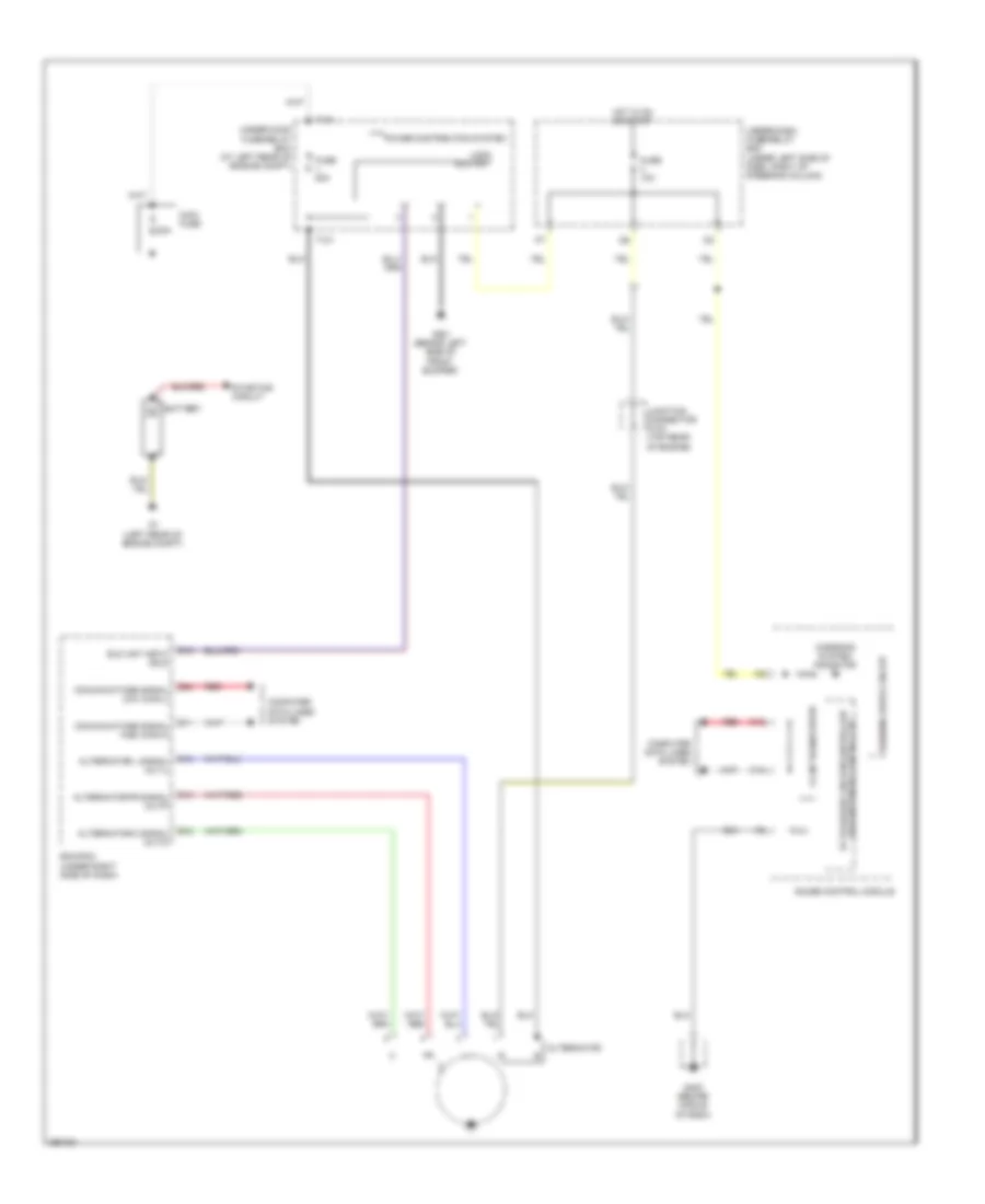
Charging Wiring Diagram for Honda Fit 2008
List of elements for Charging Wiring Diagram for Honda Fit 2008:
- (usa) eld unit
- 80a
- Alternator
- Alternator c signal (altc)
- Alternator fr signal (altf)
- Alternator l signal (altl)
- Area network controller 5v stabilize circuit/controller
- B10
- B13
- B18
- Battery
- C12
- C13
- Charging system indicator
- Computer data lines system
- Comunications signal high (can-h)
- Comunications signal low (can-l)
- E11
- E15
- E24
- Ecm/pcm (under right side of dash)
- Eld unit input (eld)
- F-can transceiver
- Fuse 10a
- Fuse 80a
- G1 (left rear of engine compt)
- G301 (behind left side of front bumper)
- G402 (behind middle of dash)
- Gauge control module
- Hot in on or start
- Junction connector c103 (top rear of engine)
- Main fuse
- Power distribution system
- Red
- Starting circuit
- T101
- T104
- Under-dash fuse/relay box (under left side of dash, right of steering column)
- Under-hood fuse/relay box (at left rear of engine compt)
- Warning drive circuit
Starting Wiring Diagram for Honda Fit 2008
List of elements for Starting Wiring Diagram for Honda Fit 2008:
- 80a
- A/t
- Acc
- Battery
- Canada: dx & lx
- Canada: sport
- Clutch interlock switch (top of clutch pedal support)
- E11
- Eld unit
- Fuse 1 80a
- Fuse 3 50a
- G1 (left rear of engine compt)
- G101 (rear of engine)
- G403 (behind middle of dash)
- Ignition switch
- Lock
- M/t
- Main fuse
- S3 (thermal joint)
- Start
- Starter
- Starter cut relay
- Starter motor
- Starter solenoid
- T104
- Transmission range switch (lower rear of transmission)
- Under-dash fuse/relay box (under left side of dash, right of steering column)
- Under-hood fuse/relay box (at left rear of engine compt)
- Usa: fit
- Usa: fit sport
SUPPLEMENTAL RESTRAINTS
Supplemental Restraints Wiring Diagram (1 of 3) for Honda Fit 2008
List of elements for Supplemental Restraints Wiring Diagram (1 of 3) for Honda Fit 2008:
- 5v stabilize circuit/ controller area network controller
- A10
- A11
- A12
- A13
- A14
- A15
- A16
- A17
- A18
- A19
- A20
- A21
- A22
- A23
- A24
- A25
- A26
- A27
- A28
- B14
- C14
- C31
- C32
- Cable reel
- Cds
- Computer data lines system
- D11
- D12
- D13
- Data link connector (dlc) (under left side of dash)
- Drive circuit
- Driver's air bag first inflator
- Driver's air bag second inflator
- Front passenger's air bag cut-off indicator
- Front passenger's air bag first inflator
- Front passenger's air bag second inflator
- Fuse 10a
- G402 (behind middle of dash)
- G404
- Gauge control module
- Hot in on or start
- Idc
- Indicator light
- J/c c405 (under left side of dash)
- K-line
- La1 +
- La1 -
- La2 +
- La2 -
- Left front impact sensor (behind left side of front bumper)
- Lfs +
- Lfs -
- Mes
- Mes connector (under left side of dash)
- Ods
- Pnk
- Ptt
- Ra1 +
- Ra1 -
- Ra2 +
- Ra2 -
- Red
- Rfs +
- Rfs -
- Right front impact sensor (behind right side of front bumper)
- Scs
- Side air bag cut-off indicator
- Srs gnd (1)
- Srs gnd (2)
- Srs ind
- Srs unit (under middle of dash)
- Steering wheel
- Under-dash fuse/relay box (under left side of dash, right of steering column)
Supplemental Restraints Wiring Diagram (2 of 3) for Honda Fit 2008
List of elements for Supplemental Restraints Wiring Diagram (2 of 3) for Honda Fit 2008:
- (lower four
- (right side of
- (under front passenger's seat) inner side front passenger's weight sensor
- (under front passenger's seat) outer side front passenger's weight sensor
- (upper two sensors in seat back)
- D10
- D11
- D12
- D13
- D14
- D15
- D16
- D17
- D18
- Driver's seat belt switch
- Front passenger's seat belt switch
- G501 (left side of floor)
- Gnd
- Lower element
- Nca
- Ods
- Ods unit (left side of front passenger's seat)
- Opds sensor
- Os1l
- Os1s
- Os2l
- Os2s
- Os3l
- Os3s
- Os4l
- Os4s
- Os5l
- Os5s
- Os6l
- Os6s
- Os7l
- Os7s
- Pow
- Red
- Seat back)
- Seat belt buckled
- Seat belt unbuckled
- Sensors in seat back)
- Side element
- Upper element
- Wrn
- Wsig
- Wsip
- Wsog
- Wsop
Supplemental Restraints Wiring Diagram (3 of 3) for Honda Fit 2008
List of elements for Supplemental Restraints Wiring Diagram (3 of 3) for Honda Fit 2008:
- (under driver's seat) driver's seat position sensor
- B10
- B11
- B12
- B13
- B14
- B15
- B16
- B17
- B18
- B19
- B20
- B21
- B22
- B23
- B24
- B25
- B26
- B27
- B28
- C10
- C11
- C12
- C13
- C14
- C15
- C16
- C17
- C18
- C19
- C20
- C21
- C22
- C23
- C24
- C25
- C26
- C27
- C28
- Driver's lap belt buckle tensioner
- Driver's seat belt tensioner
- Driver's side air bag inflator
- Front passenger's lap belt buckle tensioner
- Front passenger's seat belt tensioner
- Front passenger's side air bag inflator
- Lbp +
- Lbp -
- Lbsc
- Lbsi +
- Lbsi -
- Lbso
- Lca +
- Lca -
- Lcsi +
- Lcsi -
- Left side curtain air bag inflator
- Left side impact sensor (1st) (near base of left "b" pillar)
- Left side impact sensor (2nd) (left side of floor)
- Lrp +
- Lrp -
- Lsa +
- Lsa -
- Rbp +
- Rbp -
- Rbsc
- Rbsi +
- Rbsi -
- Rbso
- Rca +
- Rca -
- Rcsi +
- Rcsi -
- Red
- Right side curtain air bag inflator
- Right side impact sensor (1st) (near base of right "b" pillar)
- Right side impact sensor (2nd) (right side of floor)
- Rrp +
- Rrp -
- Rsa +
- Rsa -
- Srs unit (under middle of dash)
- Ss +
- Ss -
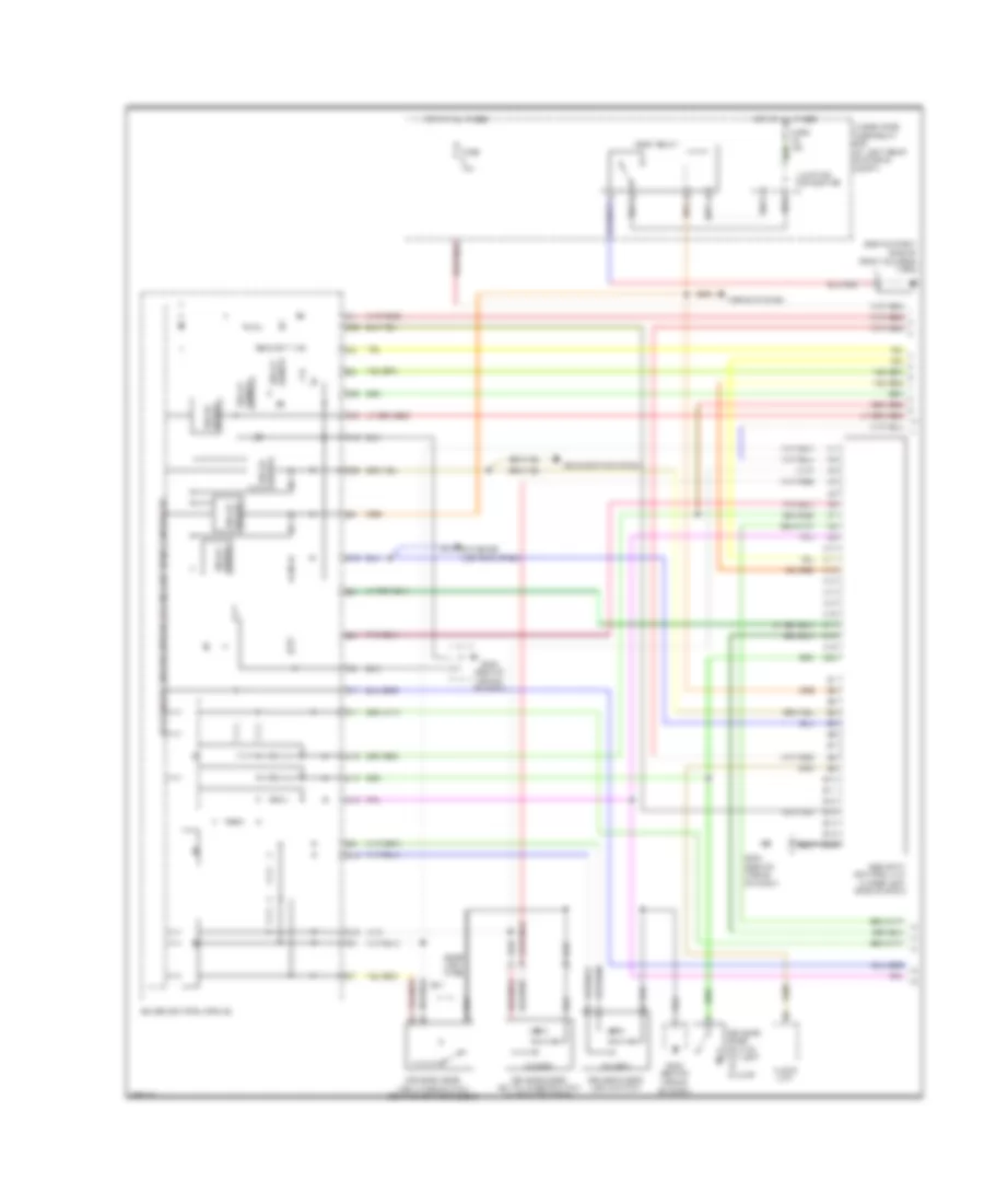
TRANSMISSION
A/T Wiring Diagram (1 of 2) for Honda Fit 2008
List of elements for A/T Wiring Diagram (1 of 2) for Honda Fit 2008:
- (rear of engine) (thermal joint)
- (rear of engine) g101
- (top of brake pedal support) brake pedal position switch
- (under left side of dash) app sensor
- 2nd clutch transmission fluid pressure switch (top of transmission)
- 3rd clutch transmission fluid pressure switch (rear of transmission)
- A/t clutch pressure control solenoid valve a (top of transmission)
- A/t clutch pressure control solenoid valve b (top of transmission)
- A/t clutch pressure control solenoid valve c (top of transmission)
- A18
- A20
- A21
- A23
- A24
- A30
- Apsa
- Apsb
- Atf temperature sensor
- Atft
- Atp2-1
- Atpd
- Atpd3
- Atpfwd
- Atpn
- Atpp
- Atpr
- Atprvs
- Bksw
- C10
- C11
- C12
- C13
- C14
- C15
- C17
- C18
- C19
- C20
- C21
- C22
- Can-h
- Can-l
- D10
- D12
- E11
- E14
- E16
- E22
- E24
- Engine controls system
- F14
- Fuse 11 15a
- Fuse 14 15a
- Fuse 16 15a
- Fuse 3 10a
- Fuse 8 10a
- G101 (rear of engine)
- Hot at all times
- Hot in on or start
- Ig1
- Igp1
- Igp2
- J/c a
- Lg1
- Lsa
- Lsb
- Lsc
- Map
- Mrly
- Op2sw
- Op3sw
- P10
- Pcm (under right side of dash)
- Pgm-fi main relay 1
- Pnk
- Red
- Sdnp
- Sg1
- Sg2
- Sg3
- Sg4
- Sha
- Shb
- Shc
- Shd
- Shift control solenoid valves
- Supp
- Transmission housing
- Under-dash fuse/relay box (under left side of dash, right of steering column)
- Under-hood fuse/relay box (at left rear of engine compt)
- Vcc1
- Vcc2
- Vcc3
- Vcc4
A/T Wiring Diagram (2 of 2) for Honda Fit 2008
List of elements for A/T Wiring Diagram (2 of 2) for Honda Fit 2008:
- (behind middle of dash) g402
- 10v stabilize circuit
- A/t gear position indicator drive circuit
- C12
- C13
- Cable reel
- Compulsory turning-off circuit
- Engine)
- Exterior lights system
- Fail safe circuit
- Fast controller area network transceiver
- G101 (rear of engine)
- G402 (behind middle of dash)
- G403 (behind middle of dash)
- Gauge control module
- Indicator dimming circuit
- Input shaft (mainshaft) speed sensor (rear of transmission)
- J/c c103 (top rear of engine)
- J/c c402 (behind instrument cluster)
- Lcd drive circuit
- Map sensor (rear of intake manifold)
- Output shaft (countershaft) speed sensor (top of transmission)
- Pnk
- Red
- S-matic lcd backlight backlight drive circuit drive circuit
- Shift interlock system
- Starting/charging system
- Steering wheel (usa: fit sport & canada: sport)
- Steering wheel downshift (-) switch
- Steering wheel upshift (+) switch
- Transmission range switch (lower rear of transmission)
- Usa: fit & canada: dx, lx
- Usa: fit sport & canada: sport
WARNING SYSTEMS
Chime Wiring Diagram for Honda Fit 2008
List of elements for Chime Wiring Diagram for Honda Fit 2008:
- (behind middle of dash) g402
- 10v stabilize circuit
- 5v stabilize circuit/controller area network controller
- A14
- A21
- Anti-theft system
- B11
- B12
- Beeper
- C11
- C12
- C13
- C14
- C22
- Combination light switch
- Computer data lines system
- Door locks system
- Drive circuit
- Driver's door switch (at left "b" pillar)
- Driver's seat belt switch (under driver's seat)
- Exterior lights system
- F-can transceiver
- Fuse 10a
- G402 (behind middle of dash)
- G501 (left side of floor)
- Gauge control module
- Head
- Headlight switch
- Hot at all times
- Hot in on or start
- Ignition key switch
- Ignition key switch/key light
- Interior lights system
- Lights on ind
- Low oil pressure ind
- Off
- Oil pressure switch (near oil filter)
- Park
- Red
- Seat belt reminder ind
- Small light/ front fog light dimming circuit
- Srs unit (under middle of dash)
- Tail- light relay
- Under-dash fuse/relay box (under left side of dash, right of steering column)
- Under-hood fuse/relay box (at left rear of engine compartment)
- Usa fit sport & canada sport
- Warning drive circuit
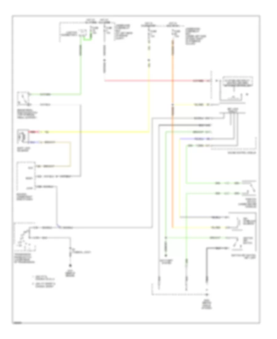
Tire Pressure Monitoring Wiring Diagram for Honda Fit 2008
List of elements for Tire Pressure Monitoring Wiring Diagram for Honda Fit 2008:
- 5v stabilize circuit/controller area network controller
- C12
- C13
- Can-h
- Can-l
- Computer data lines system
- Data link connector (under left side of dash)
- Fast controller area network transceiver
- Fuse 10a
- Fuse 7.5a
- G402 (under middle of dash)
- G403 (under middle of dash)
- Gauge control module
- Gnd
- Hot at all times
- Hot in on or start
- Ig1
- Junction connector c402 (behind gauge control module)
- Junction connector c405 (under left side of dash)
- K-line
- Low tire indicator pressure
- Red
- Tpms control unit (behind middle of dash)
- Tpms indicator
- Under-dash fuse/relay box (under left side of dash, right of steering column)
- Warning drive circuit
WIPER/WASHER
Front Wiper/Washer Wiring Diagram for Honda Fit 2008
List of elements for Front Wiper/Washer Wiring Diagram for Honda Fit 2008:
- 5v control circuit
- 5v stabilize circuit/ controller area network controller
- C18
- F11
- Fuse 3 10a
- Fuse 6 30a
- G201 (behind right side of front bumper)
- G301 (behind left side of front bumper)
- G403 (behind middle of dash)
- Gauge control module
- High
- Hot in on or start
- Int
- Intermittent circuit
- Low
- Mist
- Off
- Park
- Run
- Under-dash fuse/relay box (under left side of dash, right of steering column)
- Warning drive circuit
- Wash
- Washer fluid level ind (canada)
- Washer fluid level switch (canada)
- Windshield washer motor (on washer fluid reservoir)
- Windshield wiper motor (under left side of cowl cover)
- Wiper/ washer switch
Rear Wiper/Washer Wiring Diagram for Honda Fit 2008
List of elements for Rear Wiper/Washer Wiring Diagram for Honda Fit 2008:
- B12
- F11
- Fuse 12 10a
- Fuse 6 30a
- G201 (behind right side of front bumper)
- G402 (behind middle of dash)
- G501 (left side of floor)
- Hot in on or start
- Off
- Park
- Rear window washer motor (on washer fluid reservoir)
- Rear window wiper motor (center of tailgate)
- Rear window wiper/ washer switch
- Run
- Under-dash fuse/relay box (under left side of dash, right of steering column)
- Washer
- Wiper/ washer switch