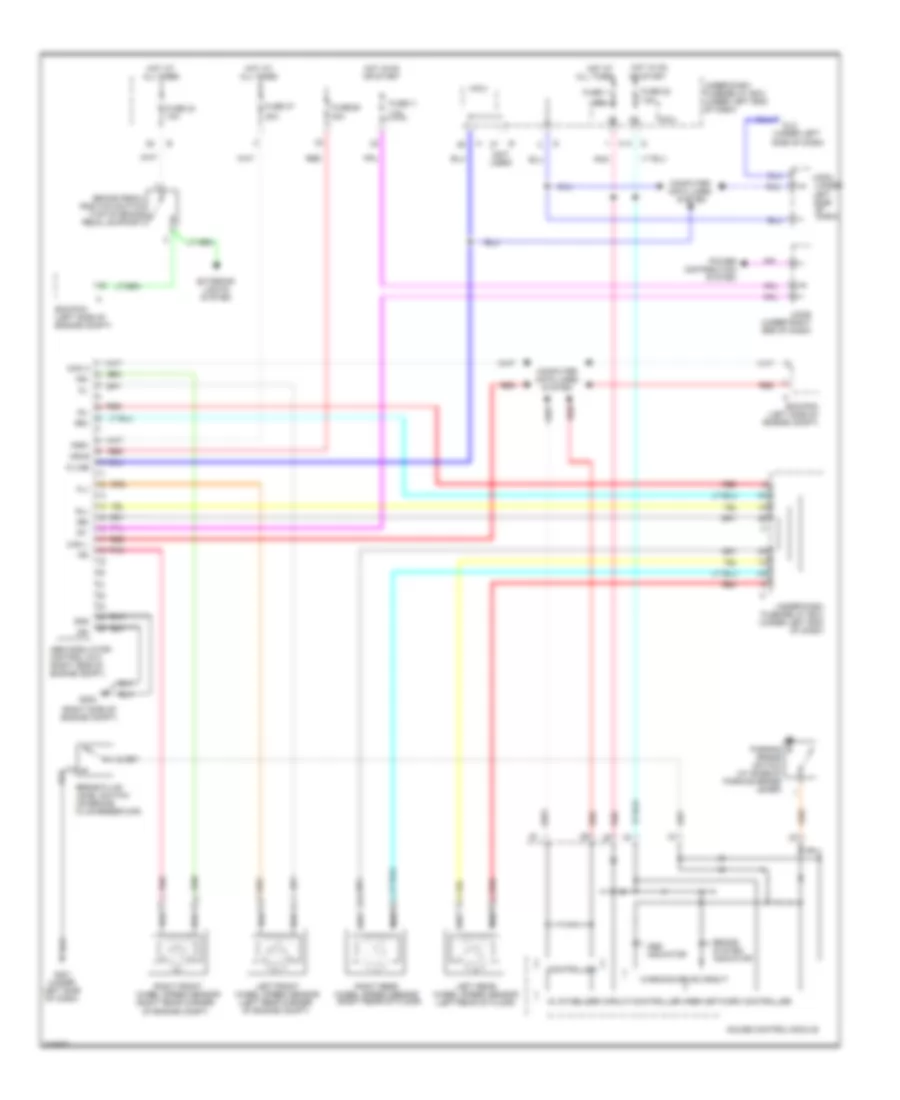
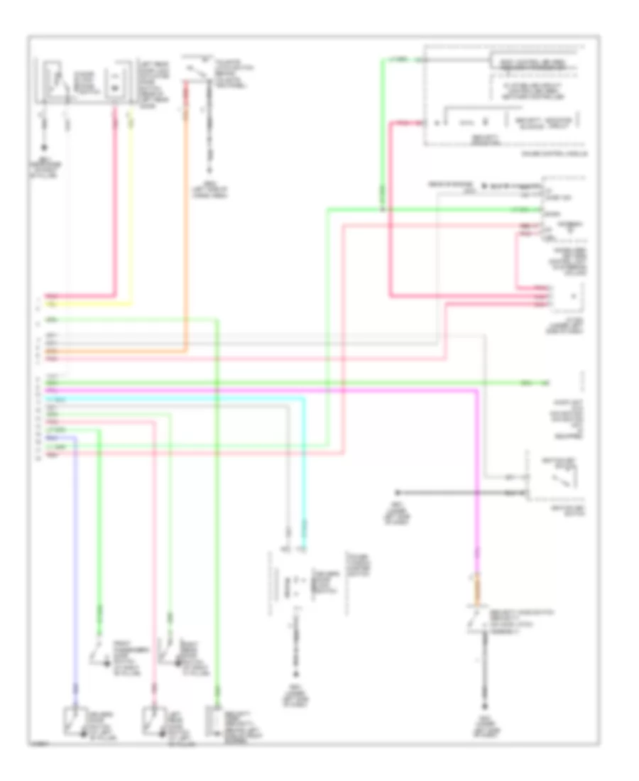
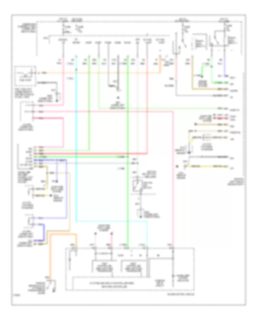
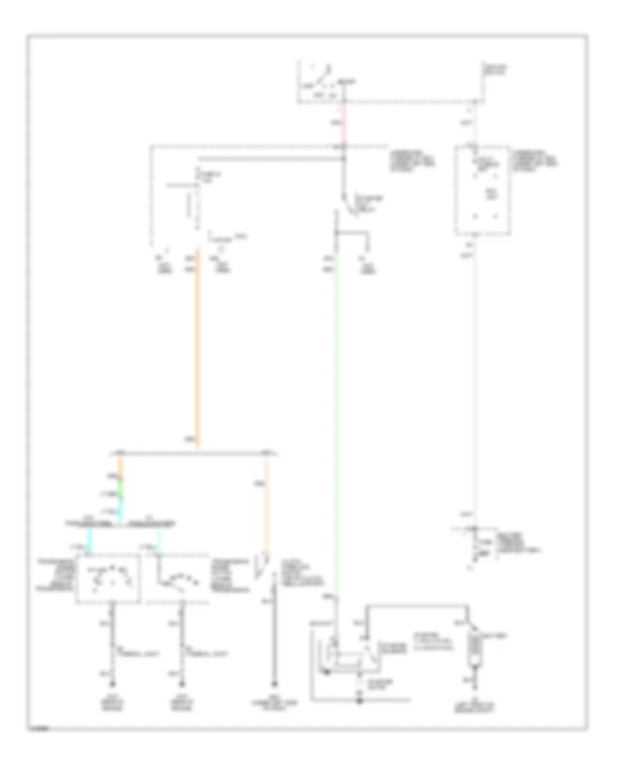
AIR CONDITIONING
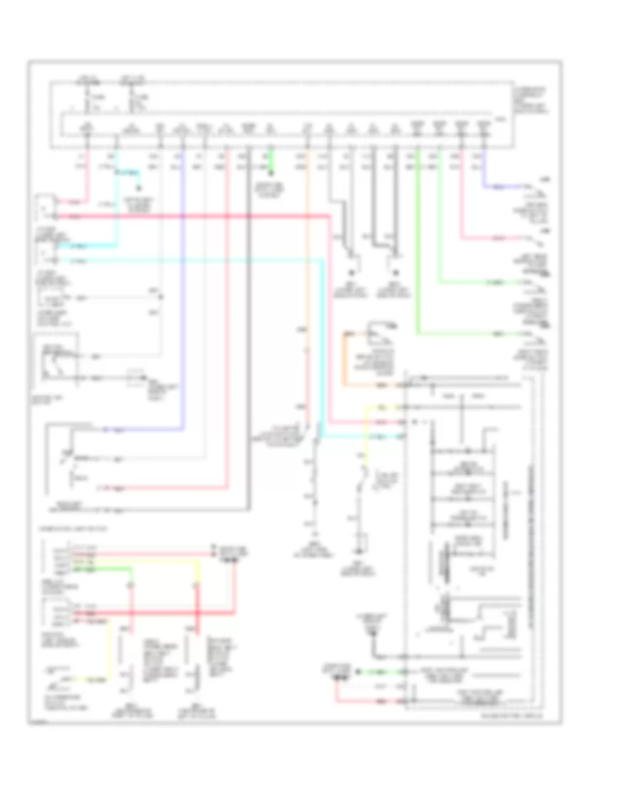
Heater Wiring Diagram for Honda Fit 2009

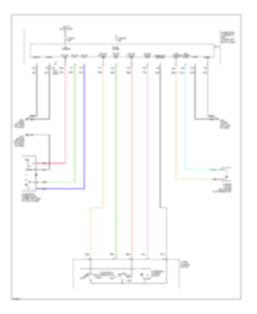
List of elements for Heater Wiring Diagram for Honda Fit 2009:
- (under left side)
- Bkl
- Blower motor (under right side of dash)
- Blower motor relay
- Blower resisitor (behind glove box)
- Blower switch
- Fuse 30a
- Fuse 7.5a
- G501 (under left side of dash)
- G502 (under left side of dash)
- Heater-a/c control panel
- Hot at all times
- Hot in on
- Interior lights system
- Micu
- Of dash)
- Off
- Red
- Under-dash fuse/relay box
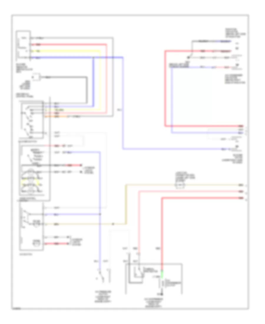
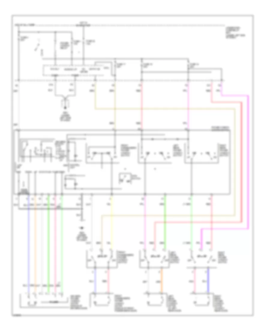
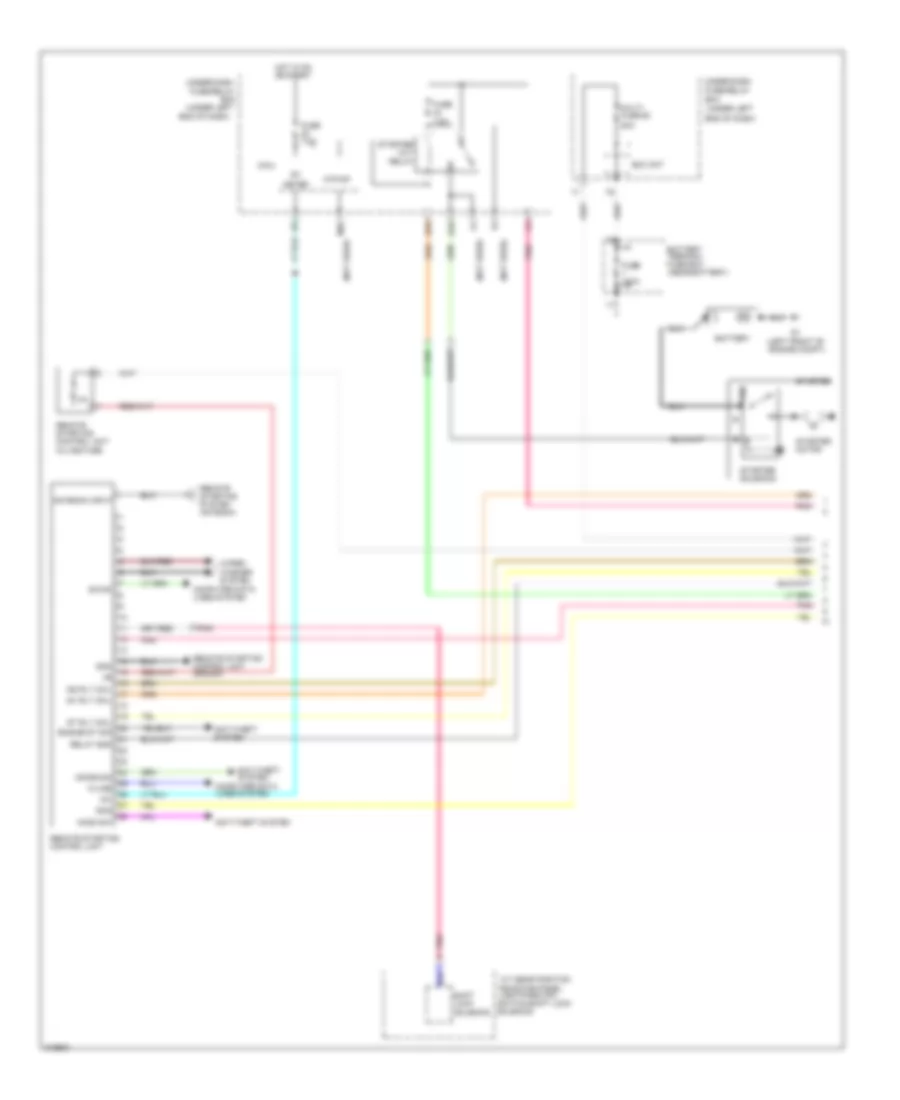
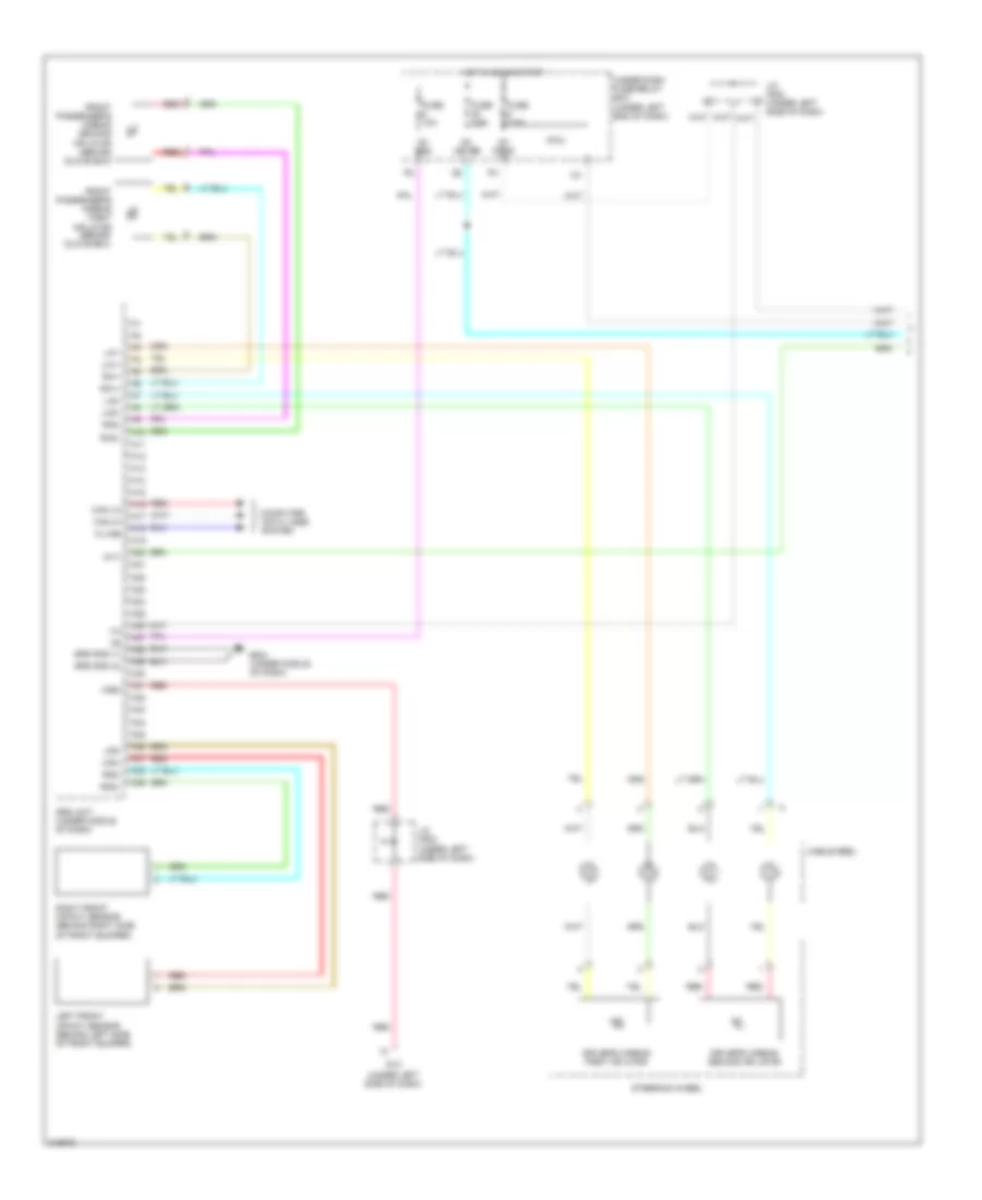
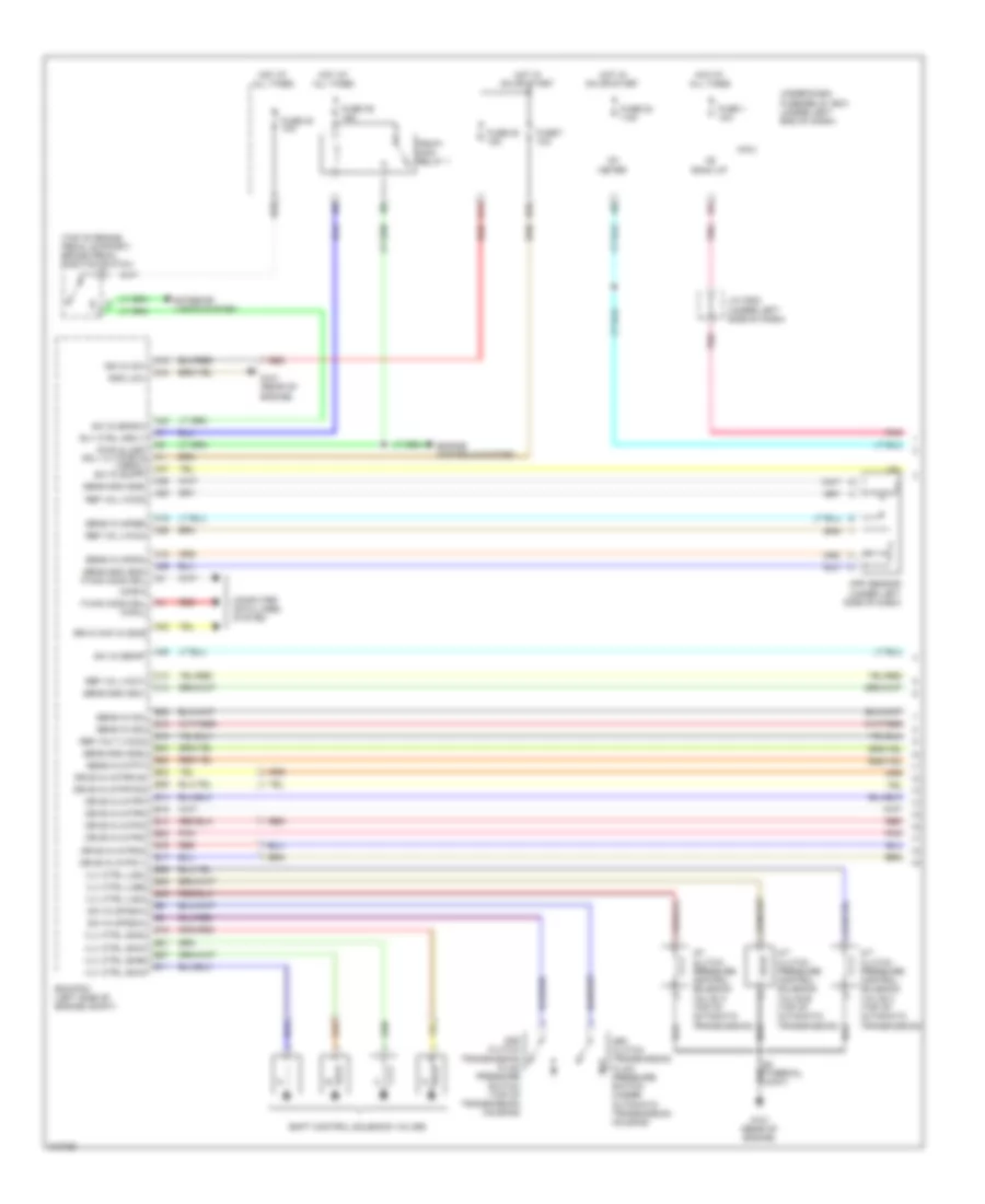
Manual A/C Wiring Diagram (1 of 2) for Honda Fit 2009
List of elements for Manual A/C Wiring Diagram (1 of 2) for Honda Fit 2009:
- (behind left side of front bumper)
- A/c compressor (lower right front of engine compt)
- A/c compressor clutch
- A/c condenser fan motor (behind right side of radiator)
- A/c pressure switch (lower right front of engine compt)
- A/c switch
- Blower motor (under right side of dash)
- Blower resistor (behind glove box)
- Blower switch
- G301
- G502 (under left side of dash)
- Heater-a/c control panel
- Interior lights system
- Juncition connector c502 (under left side of dash)
- Mode 1
- Mode 2
- Mode 3
- Mode 4
- Mode 5
- Mode control switch
- Off
- On ind
- Qrg
- Radiator fan motor (behind left side of radiator)
- Red
- Thermal protector
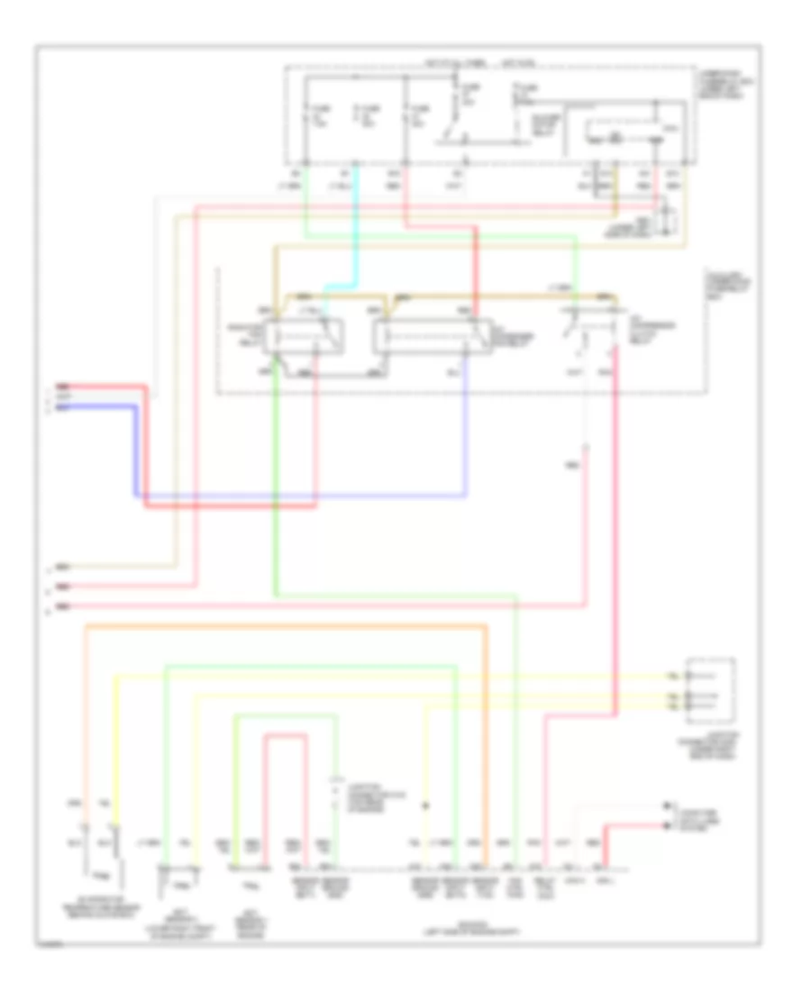
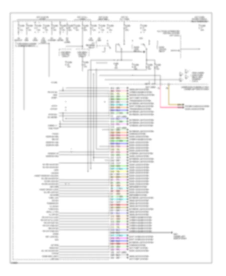
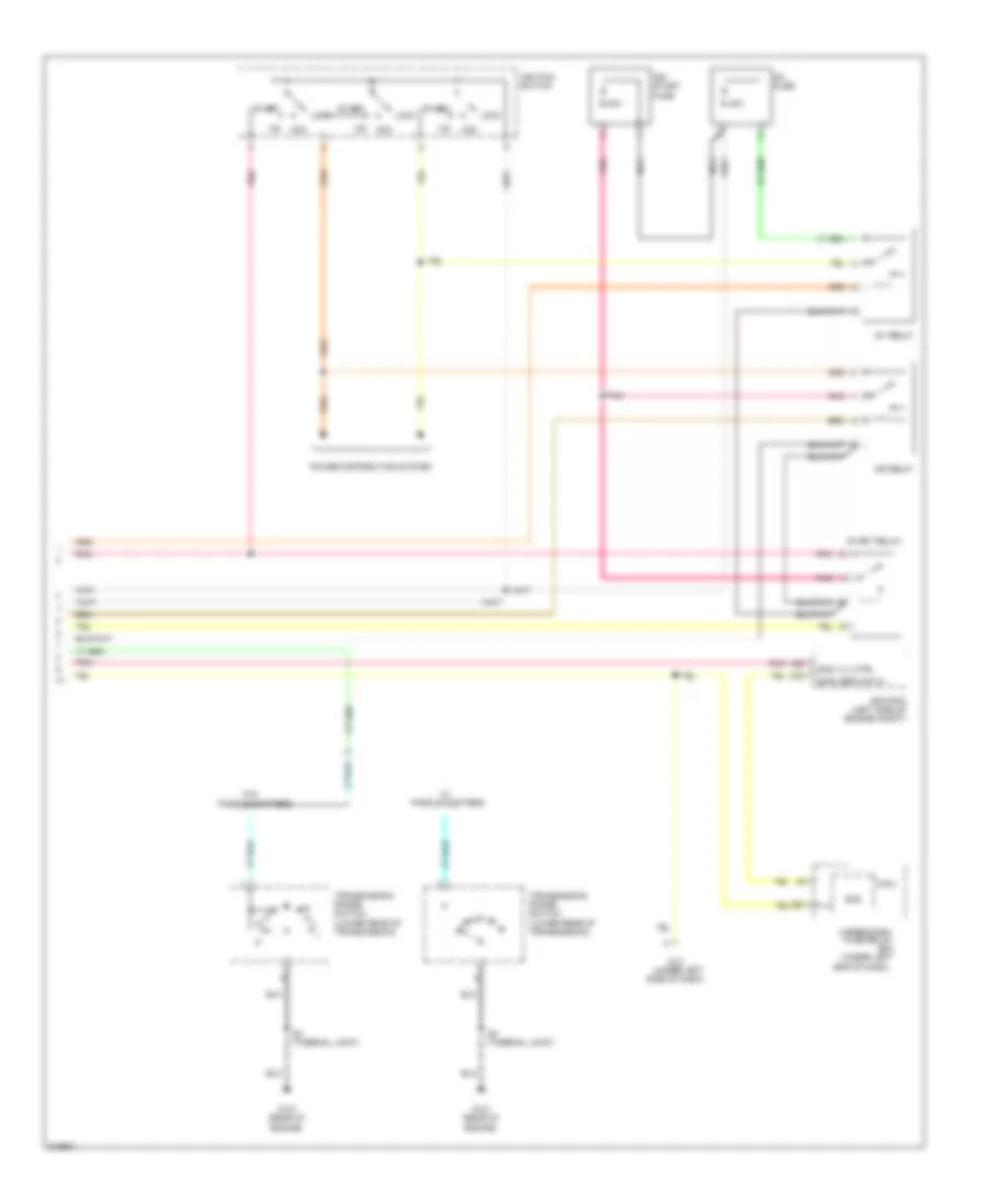
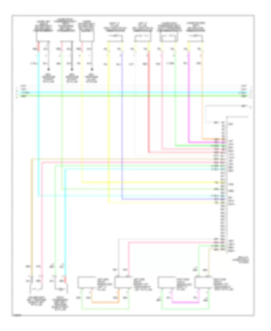
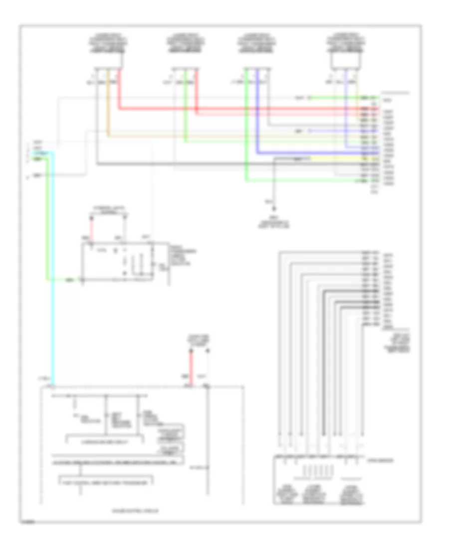
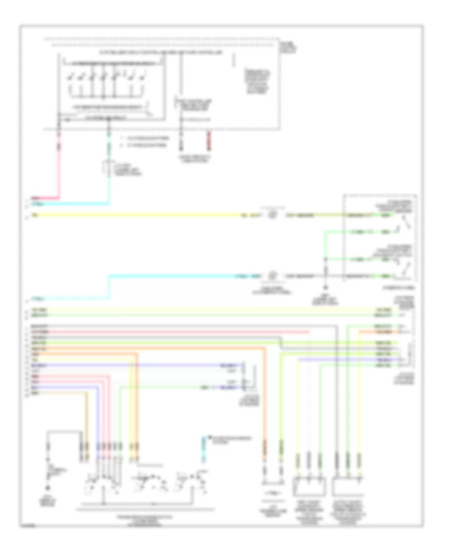
Manual A/C Wiring Diagram (2 of 2) for Honda Fit 2009
List of elements for Manual A/C Wiring Diagram (2 of 2) for Honda Fit 2009:
- (lower right front of engine compt)
- A/c compressor clutch relay
- A/c condenser fan relay
- A10
- A15
- A21
- A34
- A38
- Acs
- Auxiliary under-hood fuse/relay box
- B12
- B15
- B24
- B34
- Blower motor relay
- Can h
- Can l
- Computer data lines system
- Connector c205 (under right end of dash)
- Ecm/pcm (left side of engine compt)
- Ect sensor 1 (rear of engine)
- Ect sensor 2
- Evaporator temperature sensor (behind glove box)
- Fan ctrl (fan)
- Fuse 30a
- Fuse 7.5a
- G501 (under left side of dash)
- Gnd
- Hot at all times
- Hot in on
- Ig2 hac
- Junction
- Junction connector c103 (top rear of engine)
- Micu
- Pnk
- Q14
- Radiator fan relay
- Red
- Relay ctrl (acc)
- Sensor ground (sg2)
- Sensor ground (sg6)
- Sensor input (ect1)
- Sensor input (ect2)
- Sensor input (tac)
- Under-dash fuse/relay box (under left end of dash)
ANTI-LOCK BRAKES
Anti-lock Brakes Wiring Diagram for Honda Fit 2009
List of elements for Anti-lock Brakes Wiring Diagram for Honda Fit 2009:
- (not used)
- (right rear corner of engine compt)
- (right side of engine compt)
- (under
- (under left
- 10a
- 30a
- 7.5a
- Abs indicator
- Abs modulator- control unit (right side of engine compt)
- All times
- Brake fluid level switch (on brake fluid reservoir)
- Brake pedal position switch (top of brake pedal support)
- Brake system indicator
- Can h
- Can l
- Computer data lines system
- Computer data lines system
- Dash)
- Dlc
- Ecm/pcm (left side of engine compt)
- Exterior lights system
- Fl+
- Fl-
- Fr+
- Fr-
- Fsr+
- Fuse 1
- Fuse 11
- Fuse 22
- Fuse 24 10a
- Fuse 37
- Fuse 58
- G202
- G401 (under left side of dash)
- Gauge control module
- Gnd
- Hot at
- Hot at all times
- Hot in on or start
- Ig1
- Jc205 (under right end of dash)
- Jc504
- K-line
- Left side
- Left front wheel speed sensor (left rear corner of engine compt)
- Left rear wheel speed sensor (left rear of floor)
- Micu
- Mr+b
- Mr-
- Of
- Parking brake switch (at base of parking brake lever)
- Pnk
- Power distribution system
- Red
- Right front wheel speed sensor
- Right rear wheel speed sensor (right rear of floor)
- Rl+
- Rl-
- Rr+
- Rr-
- Side of dash)
- Under-dash fuse/relay box (under left end of dash)
- Warning drive circuit
ANTI-THEFT
Forced Entry Wiring Diagram (1 of 2) for Honda Fit 2009
List of elements for Forced Entry Wiring Diagram (1 of 2) for Honda Fit 2009:
- (behind tailgate
- (near base of
- (not
- (not used)
- (rear of driver's door)
- (security)
- (under left
- (under left side
- (under left side of dash) g502
- +b back up
- 10a
- 15a
- A13
- A29
- B-can
- C22
- C26
- C32
- C33
- C35 pnk
- C40
- C45
- C46
- D/l unlock
- Door
- Door lock knob
- Door lock knob switch
- Door lock relay
- Door unlock relay
- Dr rly
- Driver' door lock actuator/knob switch/ key cylinder switch
- Driver's
- Drswas
- Drswdr
- Drswra
- Drswrd
- E11
- Exterior lights system
- F2 pnk
- Front passenger's door lock actuator/knob switch (rear of front passenger's door)
- Fuse
- Fuse 10a
- Fuse 15a
- Fuse 30a
- Fuse 7.5a
- G501
- G502
- G603
- Gnd
- Handy dr sw
- Hood sw
- Horn relay
- Hot at all times
- Hot in on or start
- Ig1
- Ig1 fuel pump
- K10
- Kc dr lock
- Kc dr unlock
- Key
- Key cylinder switch
- Key sw
- Lock
- M16
- M23
- M24
- M34
- Meter
- Micu
- Of dash)
- P-gnd
- Pnk
- Q11
- Radio sw
- Red
- Relay
- Right "b" pillar)
- Right rear door lock actuator/knob switch (rear of right rear door)
- S-gnd
- Security
- Side of dash)
- Sil as unlock
- Sil dr lock
- Sil dr unlock
- Sil ra unlock
- Sil rd unlock
- T/g sw
- Tailgate lock actuator
- Trim panel)
- Turn signal/hazard
- Under-dash fuse/relay box (under left end of dash)
- Unlock
- Used)
- Warning circuit
Forced Entry Wiring Diagram (2 of 2) for Honda Fit 2009
List of elements for Forced Entry Wiring Diagram (2 of 2) for Honda Fit 2009:
- "b" pillar)
- (behind left side of front bumper)
- (on hood latch
- (rear of engine)
- (security)
- (under
- (under left side of dash)
- 5v stabilize circuit/ controller area network controller
- Antenna
- Assembly)
- Audio unit (w/o navigation) navigation unit (if equipped)
- B-can
- Blinking
- Body controller area network transceiver
- Door unlock
- Driver's door lock switch lock
- Driver's door switch (at left "b" pillar)
- Front passenger's door switch (at right "b" pillar)
- G101
- G401
- G501
- G501 (under left side of dash)
- G601 (near base of right
- G602 (left side of cargo area)
- Gauge control module
- Ig key sw
- Ig1
- Ignition key switch
- Immobilizer- keyless control unit (in steering column)
- Indicator circuit
- J/c 502 (under left side of dash)
- Left rear door lock actuator/ knob switch (rear of left rear door)
- Left rear door switch (at left "c" pillar)
- Left side of dash)
- Lock
- Lock knob switch
- Pnk
- Power window master switch
- Red
- Right rear door switch (at right "c" pillar)
- Security
- Security hood switch
- Security horn
- Security indicator
- Tailgate latch switch (behind tailgate trim panel)
- Unlock
- Vbu
Immobilizer Wiring Diagram for Honda Fit 2009
List of elements for Immobilizer Wiring Diagram for Honda Fit 2009:
- side of dash)
- (not
- (rear of
- (top rear
- (under left
- (under left side of dash)
- +b back
- 5v stabilize circuit/controller area
- A16
- A46
- B-can
- B10
- B14
- B22
- B31
- Body controller area network transceiver
- C10
- C19
- C44
- C48
- Canh
- Canl
- Center console, in fuel tank)
- Computer data lines system
- Dlc
- Ecm/pcm (left side of
- Engine compt)
- Engine control system
- Engine)
- Fast controller area network transceiver
- Fuel pump
- Fuel tank unit (under rear of
- Fuse 10a
- Fuse 15a
- Fuse 7.5a
- G101
- G101 (rear of engine)
- G501
- G501 (under left side of dash)
- G502
- Gauge control module
- Hot at all times
- Hot in 0n or start
- Hot in on or start
- Ig1
- Ig1 fuel
- Ig1 key sw
- Ignition key switch
- Ignition key switch/ key light
- Igp
- Immobilizer keyless control unit (in steering column)
- Immobilizer system indicator
- Imofpr
- J/c c103
- J/c c502
- J/c c504
- K-line
- Key
- Lg1
- Lg2
- M16
- M34
- Meter
- Micu
- Mrly
- Network controller
- Of engine)
- P-gnd
- Parking brake switch (at base of parking brake lever)
- Pg1
- Pg2
- Pgm-f1 main relay 1
- Pgm-f1 main relay 2
- Pgmetcs
- Pnk
- Pump
- Red
- S-gnd
- S-net
- S-net 5v
- Side of dash)
- Under-dash fuse/relay box (under left end of dash)
- Used)
- Vbu
- Warning drive circuit
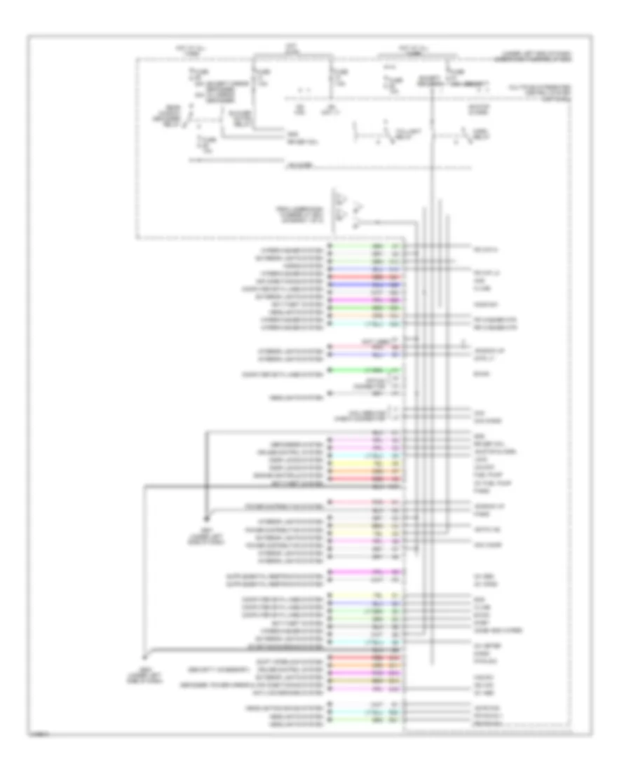
BODY CONTROL MODULES
Body Control Modules Wiring Diagram (1 of 2) for Honda Fit 2009
List of elements for Body Control Modules Wiring Diagram (1 of 2) for Honda Fit 2009:
- (not used)
- (under left side of dash)
- +b back up
- +b backup
- +b h/mirr
- +b p/w as
- +b tpms
- +b/h mirr
- A/t reverse relay
- Acc
- Anti-theft system
- Atp-np
- Atp-p
- B13
- B20
- B21
- B22
- B26
- B27
- B30
- B32
- B33
- B34
- B35
- C13
- C14
- C18
- C19
- C21
- C22
- C26
- C29
- C32
- C33
- C35
- C36
- C37
- C40
- C41
- C42
- C45
- C46
- C47
- C48
- Cargo lt
- Combi gnd (light)
- Defogger system
- Dim sw
- Door lock relay
- Door locks system
- Door sw (as)
- Door sw (dr)
- Door sw (ra)
- Door sw (rd)
- Door unlock relay
- Engine controls system
- Exterior lights system
- Fr wip as
- Fr wip hi & lo sw
- Fr wip int & lo sw
- Fr wip mist sw
- Fr wip wash sw
- From under- dash fuse/ relay box (diagram 2 of 2)
- Fuel pump
- Fuse 10a
- Fuse 15a
- Fuse 20a
- Fuse 30a
- Fuse 7.5a
- G501
- Handy door sw (unlock)
- Handy dr sw (lock)
- Headlights system
- High beam control circuit
- Hl off sw
- Hl on sw
- Hot at all times
- Hot in on or start
- Hot when power window relay energized
- Ig1 abs
- Ig1 fr wiper
- Ig1 fuel pump
- Ig1 meter
- Ig1 opds
- Ig1 srs
- Ig1 washer
- Interior lights system
- K-line
- Kc dr lock sw
- Kc dr unlock sw
- Key lock sol
- Key sw
- Lock
- M10
- M11
- M12
- M13
- M14
- M15
- M16
- M17
- M18
- M20
- M21
- M23
- M24
- M26
- M33
- M34
- Multiplex integrated control system unit (micu)
- Passing sw
- Pnk
- Power windows system
- Radio sw
- Red
- Rr wip
- Rr wip sw
- S-gnd
- S-net
- Scs
- Shift interlock system
- Sil as unlock sw
- Sil dr lock sw
- Sil dr unlock sw
- Sil ra unlck sw
- Sil rd unlck sw
- Small lt sw
- Stop sw
- T/g sw
- Transmission system
- Turn l sw
- Turn r sw
- Turn signal/hazard warning circuit
- Under-dash fuse/relay box (under left end of dash)
- Unlock
- Warning system
- Wiper/washer system
Body Control Modules Wiring Diagram (2 of 2) for Honda Fit 2009
List of elements for Body Control Modules Wiring Diagram (2 of 2) for Honda Fit 2009:
- (except mirror defogger) (w/ mirror defogger)
- (not used)
- (security accessory)
- (under left end of dash) under-dash fuse/relay box
- +b back up
- +b fr fog
- +b h/mirr
- +b p/w as
- +b stop & horn
- 30a
- A13
- A14
- A21
- A25
- A28
- A29
- A30
- A34
- A35
- Acc cigar
- Acs
- Air conditioning system
- Anti-lock brakes system
- Anti-theft system
- B-can
- Blower motor relay
- Chk
- Chk s-gnd
- Combi gnd (wiper)
- Computer data lines system
- Cruise control system
- Defogger, power mirror & air conditioning system
- Defoggers system
- Door locks system
- Engine controls system
- Except security
- Exterior lights system
- Fr fog rly
- Fr fog sw
- Fr washer mtr
- Fr wip hi
- Fr wip lo
- From under-dash fuse/relay box (diagram 1 of 2)
- Fuel pump
- Fuse 10a
- Fuse 20a
- Fuse 7.5a
- G501 (under left side of dash)
- G502 (under left side of dash)
- Gnd
- Haz sw
- Headlights & sound system
- Headlights system
- Hood sw
- Horn relay
- Horns system
- Hot at all times
- Hot in on
- Ig1 abs
- Ig1 fuel pump
- Ig1 meter
- Ig1 opds
- Ig1 srs
- Ig2 day lt
- Ig2 hac
- Interior lights system
- Intr lt-
- K-line
- K10
- Lock
- Micu service check connector
- Multiplex integrated control system unit (micu)
- Option connector
- P-gnd
- P-pin sw
- Pnk
- Power distributi0n system
- Power distribution system
- Q10
- Q11
- Q13
- Q14
- Q16
- R20
- R21
- Rear window defogger relay
- Red
- Rr def coil
- Rr washer mtr
- S-gnd
- S-net
- Scs
- Security
- Shift interlock system
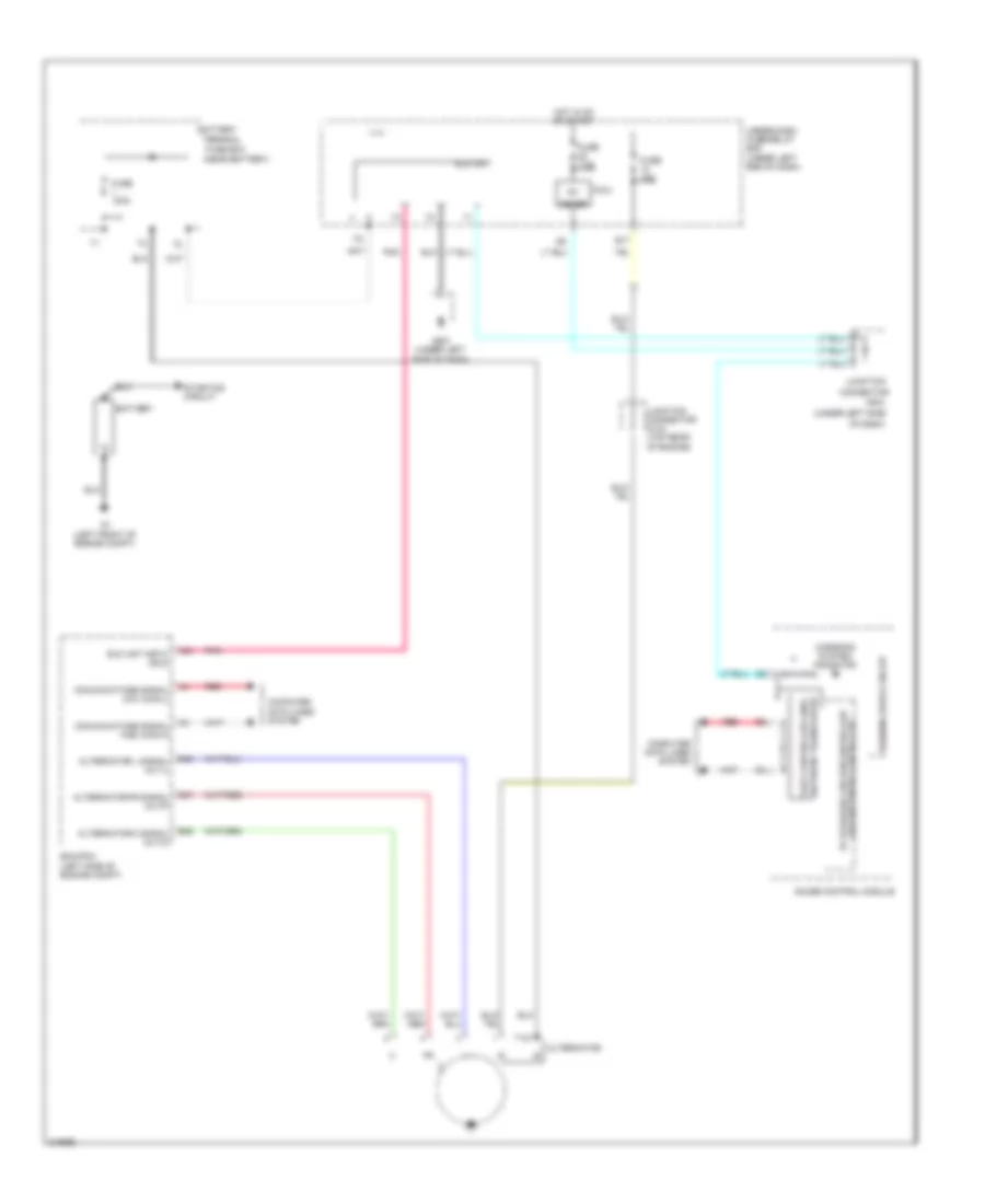
- Starting/charging system
- Taillight relay
- Unlock
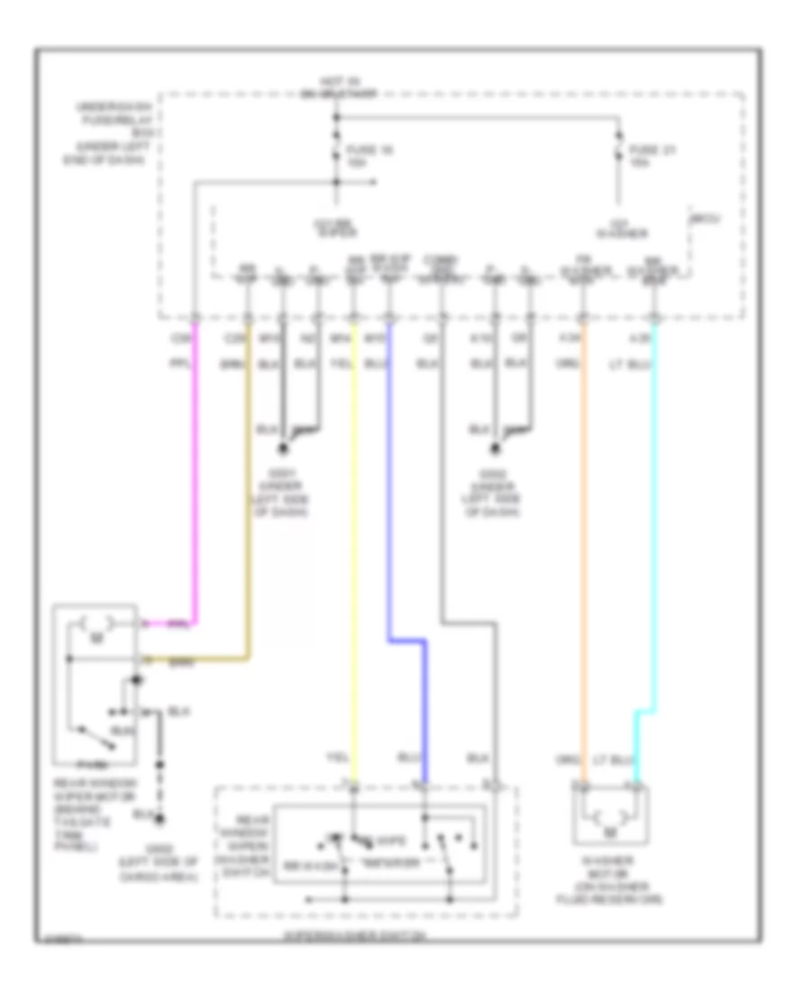
- Wiper/washer system
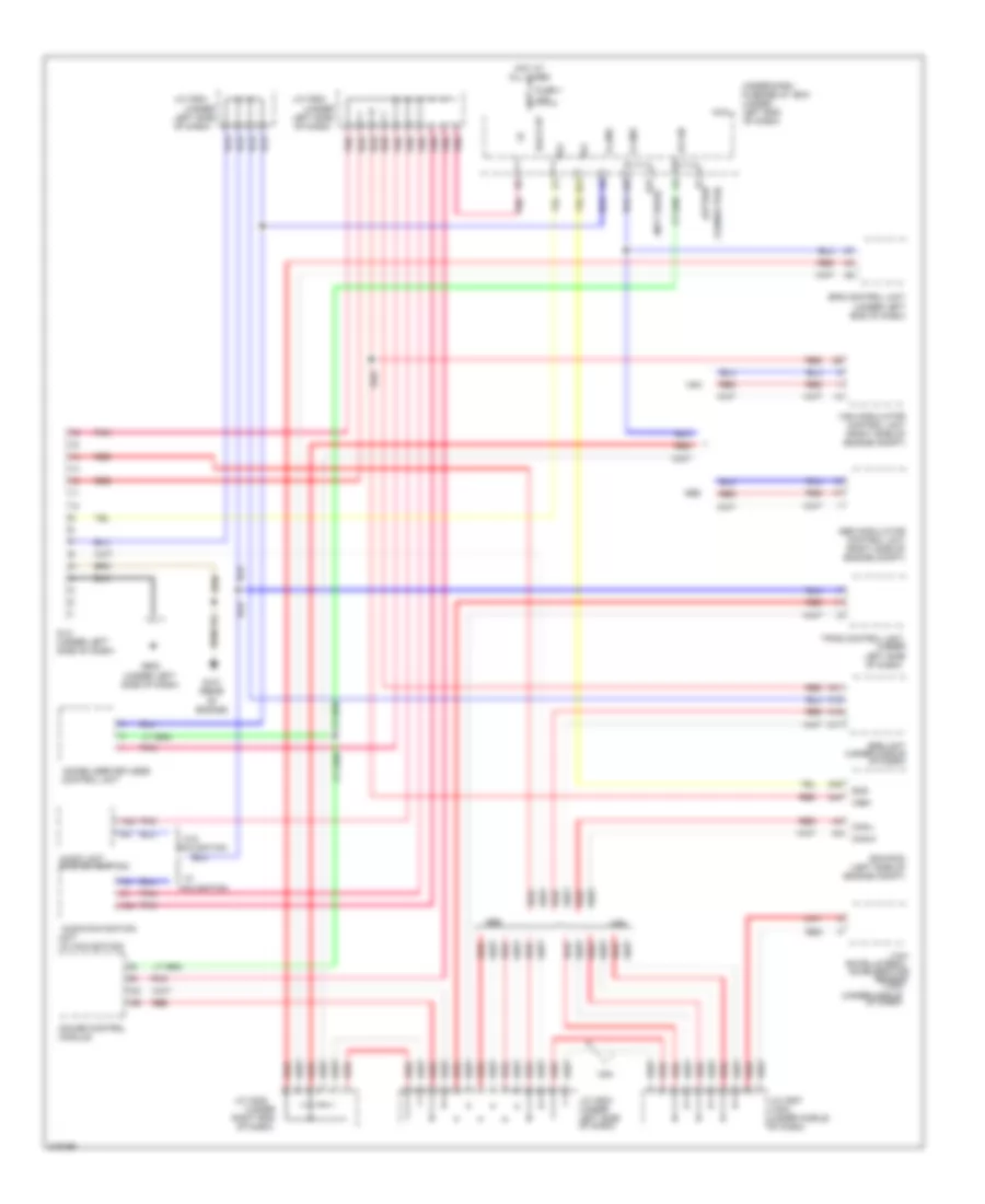
COMPUTER DATA LINES
Computer Data Lines Wiring Diagram for Honda Fit 2009
List of elements for Computer Data Lines Wiring Diagram for Honda Fit 2009:
- (not used)
- (option
- (under
- (under middle
- (vsa)
- (w/ navigation)
- A16
- A17
- A18
- A24
- A25
- A31
- A32
- A44
- Abs
- Abs modulator control unit (right side of engine compt)
- Audio unit (w/o navigation)
- Audio-navigation
- B-can
- B21
- B27
- Back up
- Can-h
- Can-l
- Connector)
- Control unit
- Dlc
- Dlc (under left side of dash)
- Ecm/pcm (left side of engine compt)
- Eps control unit (under left end of dash)
- Fuse 1 10a
- G101 (rear of engine)
- G502 (under left side of dash)
- Gauge control module
- Hot at all times
- Immobilizer-keyless
- J/c c205
- J/c c502
- J/c c503 (under left side of dash)
- J/c c504
- J/c c507 (vsa) (under middle of dash)
- K-line
- Left side of dash)
- Micu
- Navigation
- Of dash)
- Pnk
- Rate-lateral acceleration
- Rde
- Red
- Right end
- Scs
- Sensor
- Srs unit (under middle of dash)
- Tpms control unit
- Under-dash fuse/relay box (under left end of dash)
- Unit
- Vsa
- Vsa modulator control unit (right side of engine compt)
- W/o
- Wen
- Yaw
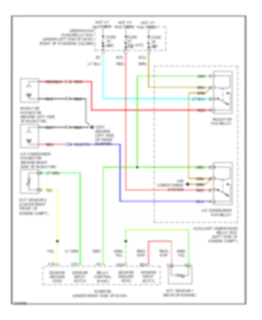
COOLING FAN
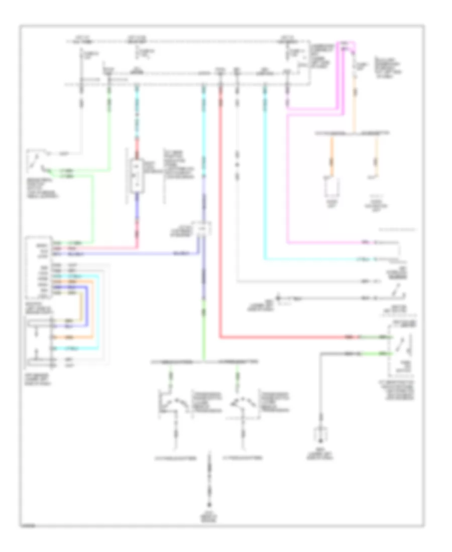
Cooling Fan Wiring Diagram for Honda Fit 2009
List of elements for Cooling Fan Wiring Diagram for Honda Fit 2009:
- (a/c)
- (under right side of dash)
- A/c condenser fan motor (behind right side of radiator)
- A/c condenser fan relay
- A10
- A34
- Air conditioning system
- Auxiliary under-hood relay box (left side of engine compt)
- B12
- B15
- B24
- B34
- Ecm/pcm
- Ect sensor 1 (rear of engine)
- Ect sensor 2 (lower right front of
- Engine compt)
- Fuse 30a
- Fuse 7.5a
- G301 (behind left side of front bumper)
- Hot at all times
- Radiator fan motor (behind left side of radiator)
- Radiator fan relay
- Red
- Relay control (fanc)
- Sensor ground (sg2)
- Sensor ground (sg6)
- Sensor input (ect1)
- Sensor input (ect2)
- Under-dash fuse/relay box (under left end of dash, right of steering column)
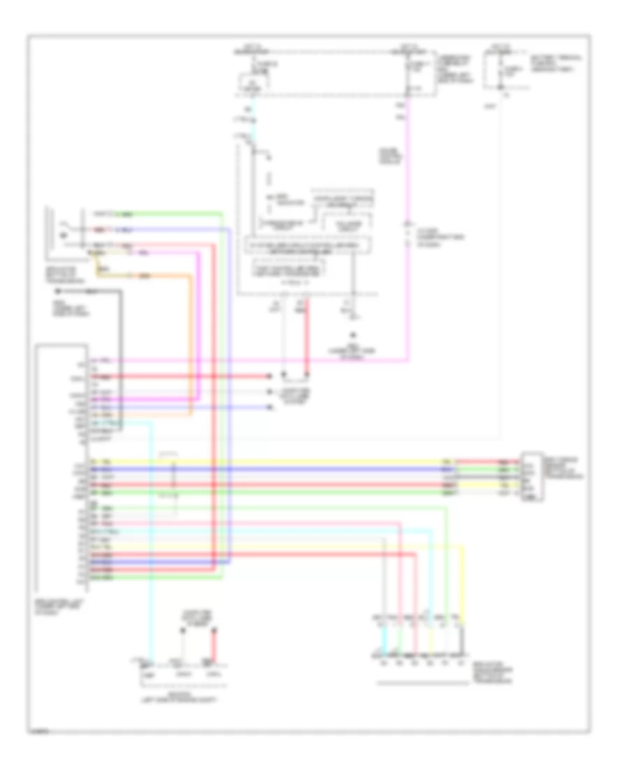
CRUISE CONTROL
Cruise Control Wiring Diagram (1 of 2) for Honda Fit 2009
List of elements for Cruise Control Wiring Diagram (1 of 2) for Honda Fit 2009:
- & horn
- (on throttle body) tp sensor/ throttle actuator
- (rear of engine)
- (under left end
- +b stop
- 10a
- A/t: w/ paddle
- A/t: w/o
- A18
- A19
- A21
- A25
- A26
- A35
- A36
- A41
- A42
- A43
- Anti-lock brakes system
- App sensor (under left side of dash)
- Apsa
- Apsb
- Atpfwd
- B17
- B28
- B29
- B38
- Bksw
- Bkswnc
- Brake pedal position switch (top of brake pedal support)
- C12
- C20
- C21
- C43
- Canh
- Canl
- Clutch pedal position switch (m/t) (top of clutch pedal support)
- Computer data lines system
- Crmtcls
- Ecm/pcm (left side of engine compartment)
- Etcsm+
- Etcsm-
- Etcsrly
- Fuse 12 10a
- Fuse 24
- G101 (rear of engine)
- G401 (under left side of dash)
- Horn relay
- Hot at all times
- Hot in no or start
- Ig1etcs
- Micu
- Mrly
- Of dash)
- Output shaft speed sensor (countershaft) (at: top of the automatic transmission housing) (mt: under rear of manual transmission)
- Paddle shifters
- Q11
- Red
- S2 (thermal joint)
- Sg3
- Sg4
- Sg5
- Shifters
- Tpsa
- Tpsb
- Transmission range switch (a/t) (lower rear of transmission)
- Under-dash fuse/relay box
- Vcc3
- Vcc4
- Vcc5
- W/ security
- W/o security
Cruise Control Wiring Diagram (2 of 2) for Honda Fit 2009
List of elements for Cruise Control Wiring Diagram (2 of 2) for Honda Fit 2009:
- (under left end of dash)
- +b back up
- 10v stabilize circuit
- 5v stabilize curcuit/controller area network controller
- 7.5a
- B18
- C10
- C11
- C12
- Cable reel (under steering column cover)
- Cancel switch
- Computer data lines system
- Control id cruise
- Etcs control relay
- F-can transceiver
- Fuse 1 10a
- Fuse 22
- Fuse 39 15a
- Fuse 52 15a
- Fuse/relay box
- G501 (under left side of dash)
- Gauge control module
- Horns system
- Hot at all times
- Hot in on or start
- Ig1
- Indicator control dimming circuit
- Interior lights system
- Main switch
- Main switch ind cruise control
- Meter
- Micu
- Pgm-f1 main relay 1
- Pnk
- Red
- Resume switch
- Set switch
- Steering wheel
- Under-dash
- Warning drive circuit
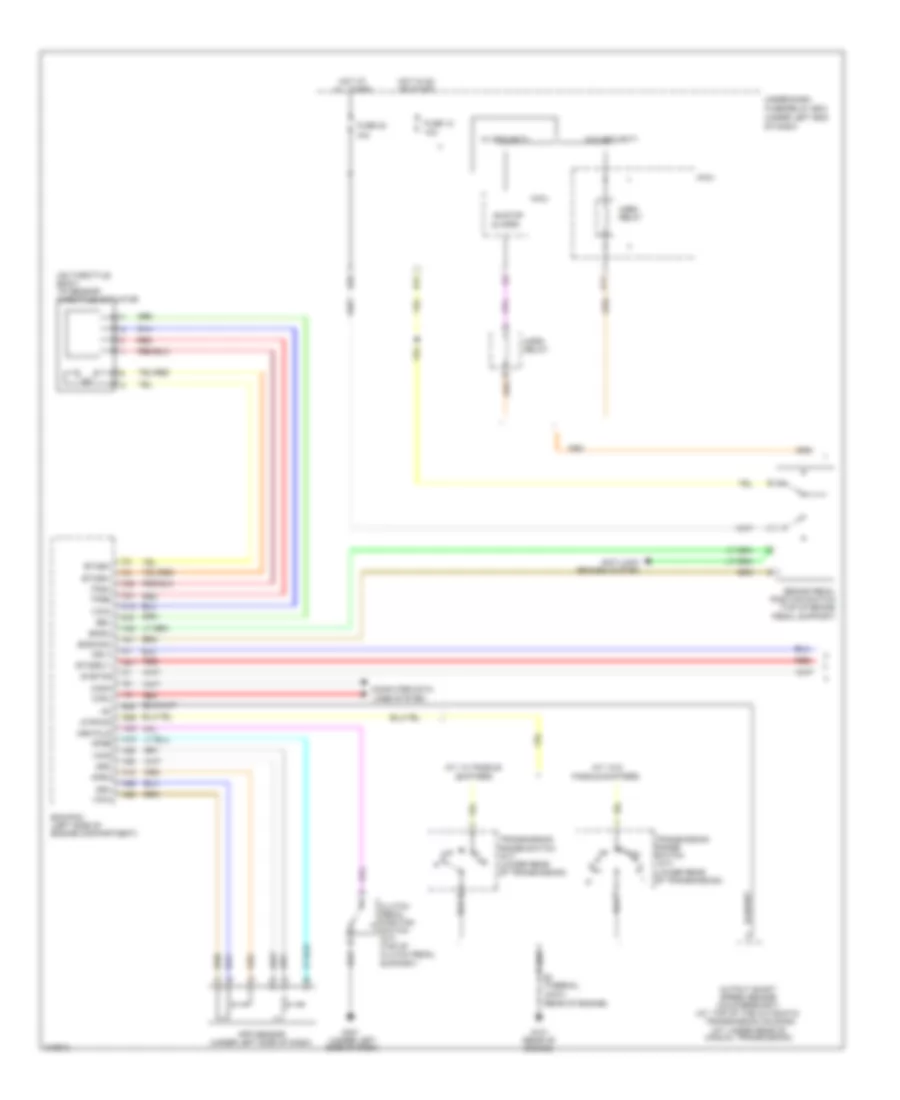
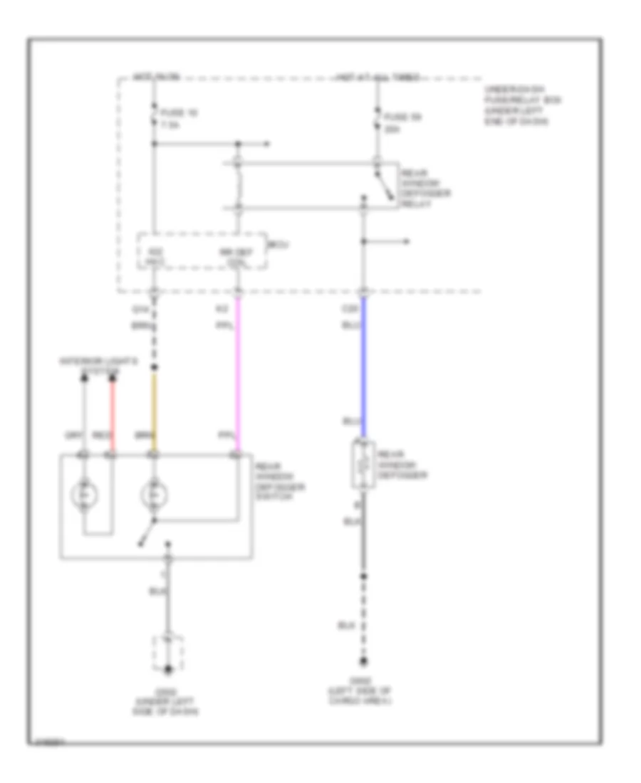
DEFOGGERS
Defoggers Wiring Diagram, with Power Mirror Defogger for Honda Fit 2009
List of elements for Defoggers Wiring Diagram, with Power Mirror Defogger for Honda Fit 2009:
- 10a
- 20a
- 30a
- 7.5a
- C43
- Coil
- Defogger
- Fuse 10
- Fuse 54
- Fuse 55
- Fuse 59
- G501 (under left side of dash)
- G502 (under left side of dash)
- G602 (left side of cargo area)
- H/mirr
- Hac
- Hot at all times
- Hot in on
- Ig2
- Interior lights system
- Left power mirror
- Micu
- Nca
- Q14
- Rear window defogger
- Rear window defogger relay
- Rear window/ power mirror defogger switch
- Red
- Right power mirror
- Rr def
- Under-dash fuse/relay box (under left end of dash)
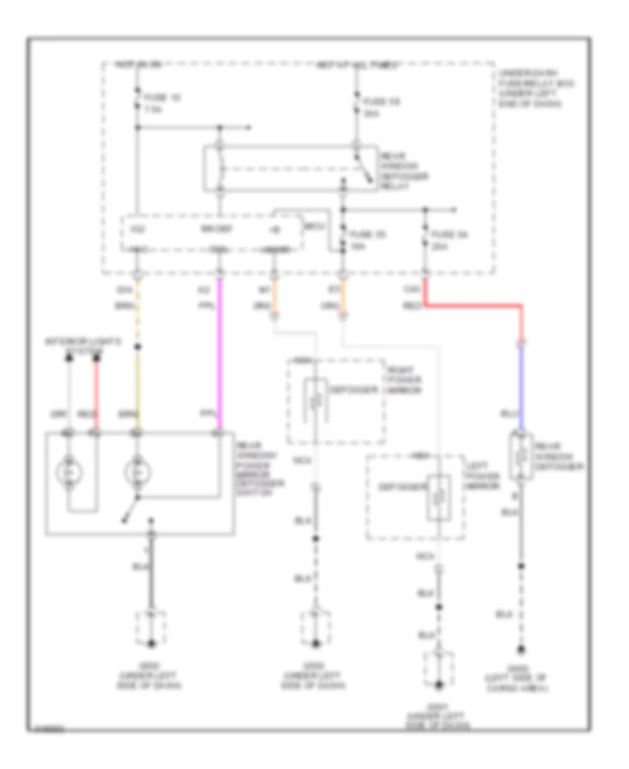
Defoggers Wiring Diagram, without Power Mirror Defogger for Honda Fit 2009
List of elements for Defoggers Wiring Diagram, without Power Mirror Defogger for Honda Fit 2009:
- 20a
- 7.5a
- C20
- Fuse 10
- Fuse 59
- G502 (under left side of dash)
- G602 (left side of cargo area)
- Hot at all times
- Hot in on
- Ig2 hac
- Interior lights system
- Micu
- Q14
- Rear window defogger
- Rear window defogger relay
- Rear window defogger switch
- Red
- Rr def coil
- Under-dash fuse/relay box (under left end of dash)
ELECTRONIC POWER STEERING
Electronic Power Steering Wiring Diagram for Honda Fit 2009
List of elements for Electronic Power Steering Wiring Diagram for Honda Fit 2009:
- (under right end
- 5v stabilizer circuit/controller area
- A10
- A11
- A32
- B10
- B11
- B12
- B13
- B14
- B15
- B16
- B6 b7
- Battery terminal fuse box (near battery)
- Can-h
- Can-l
- Compulsory turning
- Computer data lines system
- Ecm/pcm (left side of engine compt)
- Eps control unit (under left end of dash)
- Eps indicator
- Eps motor (bottom of transmission)
- Eps motor angle sensor (bottom of transmission)
- Eps torque sensor (bottom of transmission)
- Fail-safe circuit
- Fast controller area network transceiver
- Fuse 11 7.5a
- Fuse 2 70a
- Fuse 22 7.5a
- G203 (under left side of dash)
- G501 (under left side of dash)
- Gauge control module
- Hot at all times
- Hot in on or start
- Ig1
- J/c c205
- K-line
- Main
- Meter
- Mg1
- Mg2
- Nep
- Network controller
- Of dash)
- On circuit
- Pnk
- Red
- Sub
- Under-dash fuse/relay box (under left end of dash)
- Vcc
- Vref
- Warning drive circuit
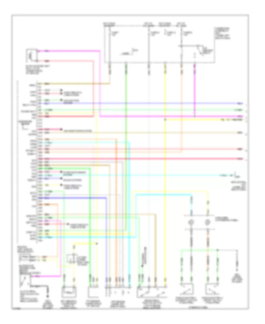
ENGINE PERFORMANCE
1.5L
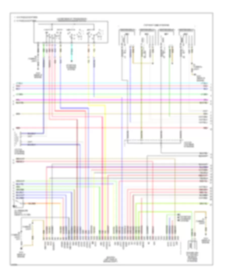
1.5L, Engine Performance Wiring Diagram (1 of 5) for Honda Fit 2009
List of elements for 1.5L, Engine Performance Wiring Diagram (1 of 5) for Honda Fit 2009:
- A/f sensor relay
- A10
- A11
- A12
- A13
- A14
- A15
- A16
- A17
- A18
- A19
- A20
- A21
- A22
- A23
- A24
- A25
- A26
- A27
- A28
- A29
- A30
- A31
- A32
- A33
- A34
- A35
- A36
- A37
- A38
- A39
- A40
- A41
- A42
- A43
- A44
- A45
- A46
- A47
- A48
- A49
- Acc
- Air conditioning system
- App sensor (under left side of dash)
- Apsa
- Apsb
- B14
- B15
- B17
- B22
- B25
- B28
- Barometer sensor
- Bksw
- Bkswnc
- Brake pedal position switch (top of brake pedal support)
- C14
- C15
- Cable reel (in steering wheel)
- Canh
- Canl
- Clutch pedal position switch (m/t) (top of clutch pedal support)
- Computer data lines system
- Cooling fans system
- Crmtcls
- Ecm/pcm (left side of engine compt)
- Ect sensor 2 (lower right front of engine compt)
- Ect2
- Eld
- Eps control unit (under left end of dash)
- Etcsrly
- Evap canister vent shut valve (under middle of vehicle)
- Evaporator temperature sensor (behind glove box)
- Fanc
- Ftp
- Ftp sensor (under middle of vehicle)
- Fuse 12 10a
- Fuse 24 10a
- Fuse 26 10a
- Fuse 7 10a
- G401 (under left side of dash)
- G501 (under left side of dash)
- Hot at all times
- Hot in run or start
- Imofpr
- J/c c205 (under right end of dash)
- Lights system exterior
- Micu
- Nep
- Paddle shifter (+) upshift switch (if equipped)
- Paddle shifter (-) downshift switch (if equipped)
- Pnk
- Power input
- Red
- Relay ctrl
- S-net
- S-net 5v
- Scs
- Sdnp
- Sg4
- Sg5
- Sg6
- Sls
- Sound systems
- Starting/charging system
- Steering wheel
- Subrly
- Supp
- Tac
- Under-dash fuse/relay box (under left end of dash)
- Vbsol
- Vcc4
- Vcc5
- Vcc6
- Vssout
- Vsv
- Wen
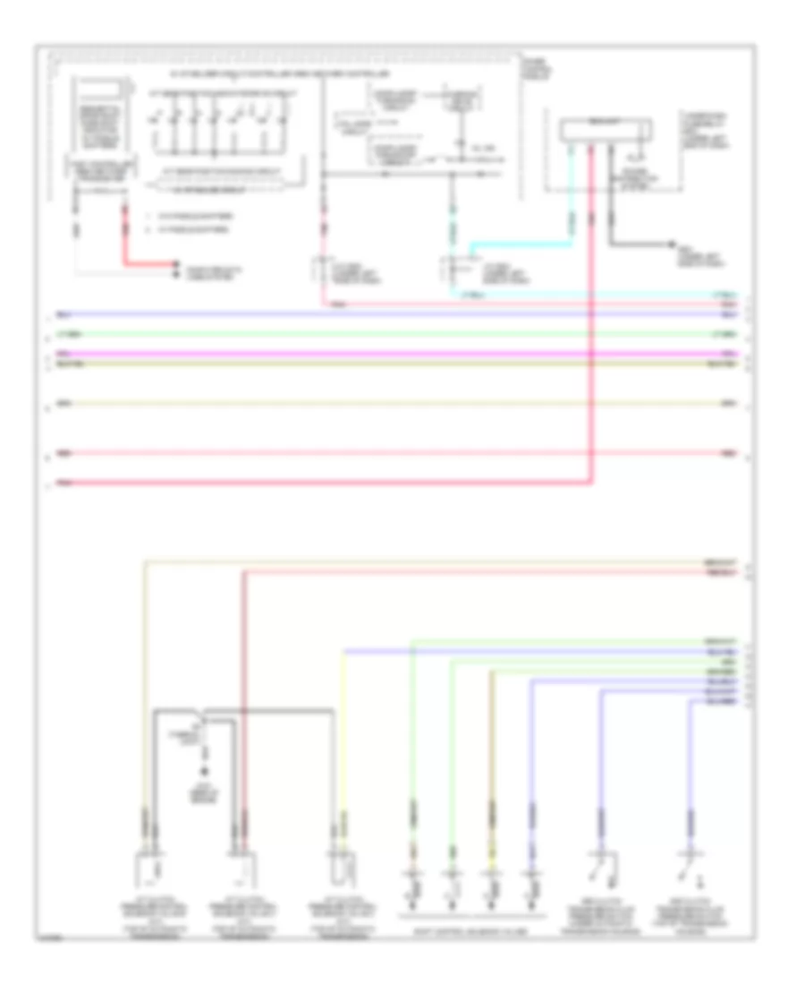
1.5L, Engine Performance Wiring Diagram (2 of 5) for Honda Fit 2009
List of elements for 1.5L, Engine Performance Wiring Diagram (2 of 5) for Honda Fit 2009:
- 10v stabilize circuit
- 2nd clutch transmission fluid pressure switch (top of transmission housing)
- 3rd clutch transmission fluid pressure switch (under automatic transmission housing)
- 5v stabilizer circuit/controller area network controller
- A/t clutch pressure control solenoid valve a (a/t) (top of automatic transmission)
- A/t clutch pressure control solenoid valve b (a/t) (top of automatic transmission)
- A/t clutch pressure control solenoid valve c (a/t) (top of automatic transmission)
- A/t gear position dimming circuit
- A/t gear position indicator drive circuit
- Compulsory turning-off circuit
- Compulsory turning-on circuit
- Computer data lines system
- Eld unit
- Fail safe circuit
- Fast controller area network transceiver
- G101 (rear of engine)
- G501 (under left side of dash)
- Gauge control module
- J/c c502 (under left side of dash)
- J/c c504 (under left side of dash)
- Mil ind
- Pnk
- Power distribution system
- Red
- S2 (thermal joint)
- Sequential sportshift mode shift indicator (w/ paddle shifters)
- Shift control solenoid valves
- Under-dash fuse/relay box (under left end of dash)
- W/ paddle shifters
- W/o paddle shifters
- Warning drive circuit
1.5L, Engine Performance Wiring Diagram (3 of 5) for Honda Fit 2009
List of elements for 1.5L, Engine Performance Wiring Diagram (3 of 5) for Honda Fit 2009:
- (lower rear of transmission) transmission range switch
- (top right side of engine)
- Altc
- Altf
- Altl
- Atft
- Atp2-1
- Atpd
- Atpd3
- Atpfwd
- Atpn
- Atpp
- Atpr
- Atprvs
- B10
- B11
- B12
- B13
- B14
- B15
- B16
- B17
- B18
- B19
- B20
- B21
- B22
- B23
- B24
- B25
- B26
- B27
- B28
- B29
- B30
- B31
- B32
- B33
- B34
- B35
- B36
- B37
- B38
- B39
- B40
- B41
- B42
- B43
- B44
- B45
- B46
- B47
- B48
- B49
- Ecm/pcm (left side of engine compt)
- Ect1
- Egr
- Egrp
- G101 (rear of engine)
- Gnd pg1
- Gnd pg2
- Iat
- Icm
- Ignition coil 1
- Ignition coil 2
- Ignition coil 3
- Ignition coil 4
- J/c c103 (top rear of engine)
- J/c c104 (top rear of engine)
- Lsa
- Lsb
- Lsc
- Oil pressure switch (near oil filter)
- Op2sw
- Op3sw
- Opsw
- Pcs
- Pnk
- Red
- Rocker arm oil control solenoid (top rear of engine)
- S1 (thermal joint)
- S2 (thermal joint)
- S2 (thermal joint) (a/t)
- Sg2
- Sha
- Shb
- Shc
- Shd
- Sho2s
- So2shtc
- Starting/ charging system
- Vcc2
- Vg+
- Vg-
- Vts
- W/ paddle shifters
- W/o paddle shifters
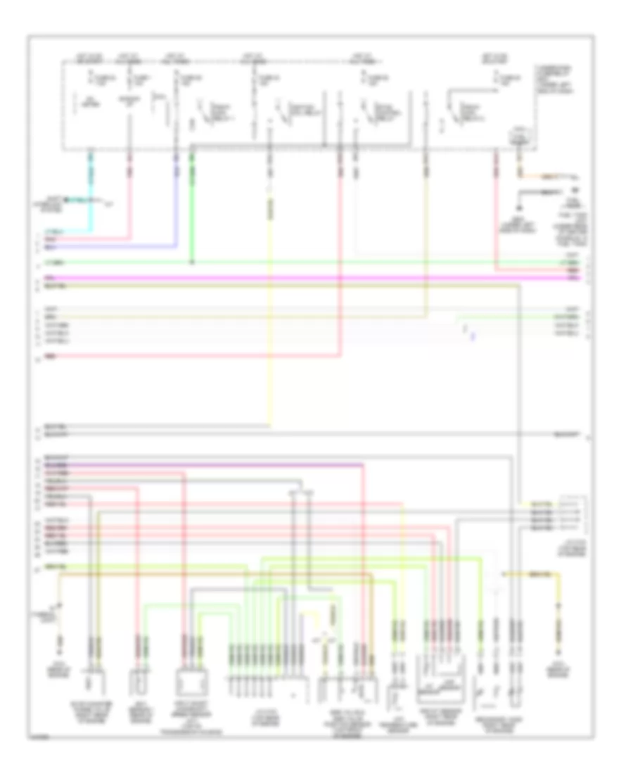
1.5L, Engine Performance Wiring Diagram (4 of 5) for Honda Fit 2009
List of elements for 1.5L, Engine Performance Wiring Diagram (4 of 5) for Honda Fit 2009:
- +b back up
- A/t
- Atf temperature sensor
- B14
- B18
- B24
- B31
- Ect sensor 1 (rear of engine)
- Egr valve & egr valve position sensor (top front of engine)
- Etcs control relay
- Evap canister purge valve (right rear of engine)
- Fuel pump
- Fuel tank unit (under rear of center console, in fuel tank)
- Fuse 1 10a
- Fuse 20 15a
- Fuse 22 7.5a
- Fuse 33 15a
- Fuse 39 15a
- Fuse 52 15a
- G101 (rear of engine)
- G502 (under left side of dash)
- Hot at all times
- Hot in on or start
- Iat sensor
- Ig1 meter
- Ignition coil relay
- Input shaft (mainshaft) speed sensor (a/t) (top of transmission housing)
- J/c c103 (top rear of engine)
- J/c c104 (top rear of engine)
- M/t
- Maf sensor
- Maf/iat sensor (right rear of engine)
- Micu
- Pgm-fi main relay 1
- Pgm-fi main relay 2
- Pnk
- Red
- S1 (thermal joint)
- Secondary ho2s (right rear of engine)
- Shift interlock system
- Under-dash fuse/relay box (under left end of dash)
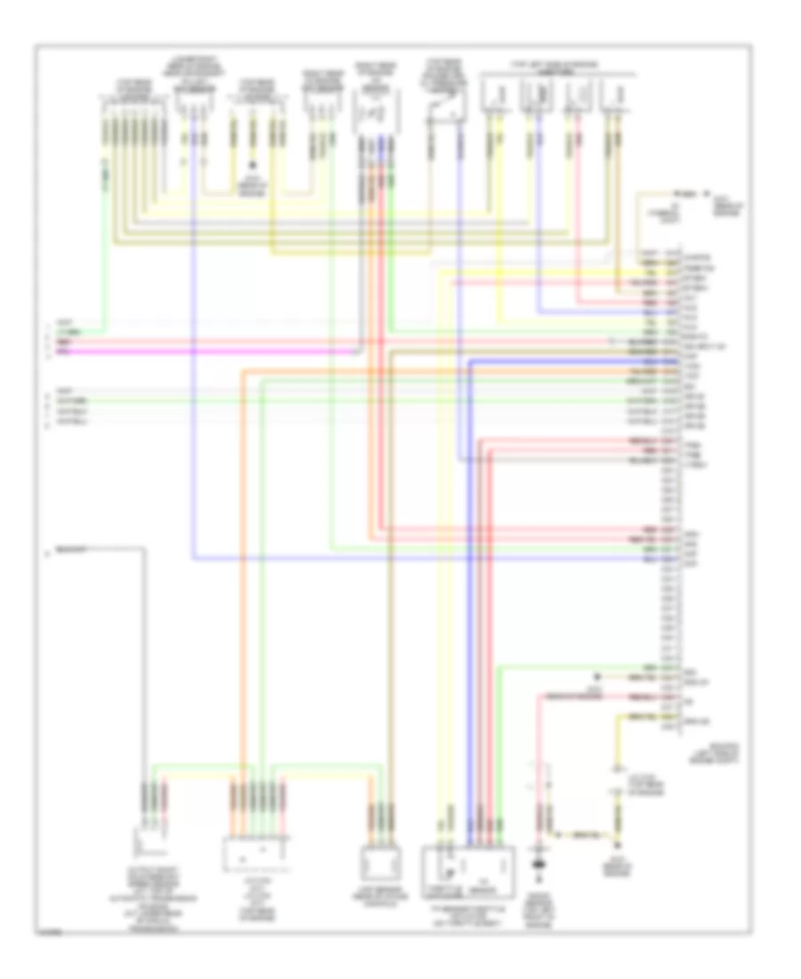
1.5L, Engine Performance Wiring Diagram (5 of 5) for Honda Fit 2009
List of elements for 1.5L, Engine Performance Wiring Diagram (5 of 5) for Honda Fit 2009:
- (lower right rear of engine, near crankshaft pulley) ckp sensor
- (right rear of engine) a/f sensor
- (right rear of engine) cmp sensor
- (top left side of engine) injectors
- (top rear of engine) j/c c103
- (top rear of engine) j/c c104
- (top rear of engine) rocker arm oil pressure switch
- Afs+
- Afs-
- Afshtc
- C10
- C11
- C12
- C13
- C14
- C15
- C16
- C17
- C18
- C19
- C20
- C21
- C22
- C23
- C24
- C25
- C26
- C27
- C28
- C29
- C30
- C31
- C32
- C33
- C34
- C35
- C36
- C37
- C38
- C39
- C40
- C41
- C42
- C43
- C44
- C45
- C46
- C47
- C48
- C49
- Ckp
- Cmp
- Ecm/pcm (left side of engine compt)
- Etcsm+
- Etcsm-
- G101 (rear of engine)
- Gnd lg1
- Gnd lg2
- Ig1etcs
- Ign input ig1
- Igpls1
- Igpls2
- Igpls3
- Igpls4
- Inj1
- Inj2
- Inj3
- Inj4
- J/c c103 (m/t) j/c c104 (a/t) (top rear of engine)
- J/c c103 (top rear of engine)
- Knock sensor (top left front of engine)
- Map
- Map sensor (rear of intake manifold)
- Output shaft countershaft speed sensor (a/t: top of automatic transmission housing) (m/t: under rear of manual transmission)
- Pgmetcs
- Red
- S1 (thermal joint)
- Sg1
- Sg3
- Throttle actuator
- Tp sensor
- Tp sensor/throttle actuator (on throttle body)
- Tpsa
- Tpsb
- Vcc1
- Vcc3
- Vtpsw
EXTERIOR LIGHTS
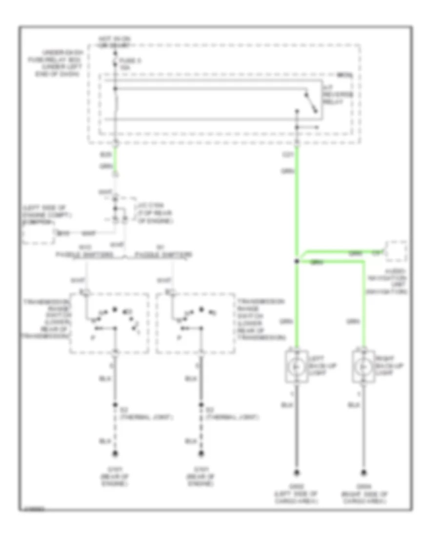
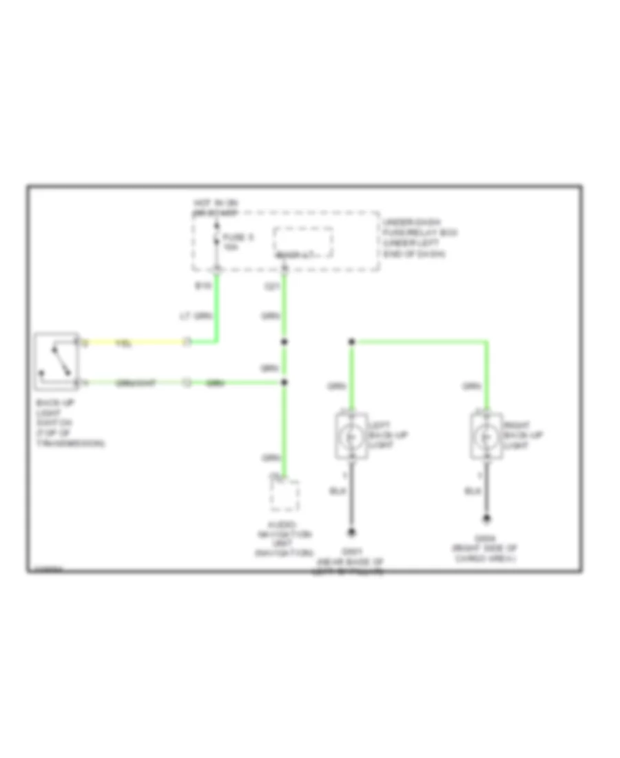
Back-up Lamps Wiring Diagram, A/T for Honda Fit 2009
List of elements for Back-up Lamps Wiring Diagram, A/T for Honda Fit 2009:
- (left side of engine compt) ecm/pcm
- (top rear of engine)
- (under left
- A/t reverse relay
- Audio- navigation unit (navigation)
- B15
- B26
- C21
- End of dash)
- Fuse 5 10a
- Fuse/relay box
- G101 (rear of engine)
- G602 (left side of cargo area)
- G604 (right side of cargo area)
- Hot in on or start
- J/c c104
- Left back-up light
- Micu
- Paddle shifters
- Range switch (lower
- Rear of
- Rear of transmission)
- Right back-up light
- S2 (thermal joint)
- Transmission
- Transmission range switch (lower
- Transmission)
- Under-dash
- W/o
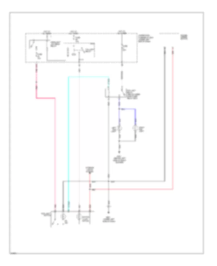
Back-up Lamps Wiring Diagram, M/T for Honda Fit 2009
List of elements for Back-up Lamps Wiring Diagram, M/T for Honda Fit 2009:
- (navigation)
- Audio-
- B10
- Back lt
- Back-up light switch (top of transmission)
- C21
- End of dash)
- Fuse 5 10a
- G601 (near base of
- G604 (right side of cargo area)
- Hot in on or start
- Left "b" pillar)
- Left back-up light
- Navigation
- Right back-up light
- Under-dash fuse/relay box (under left
- Unit
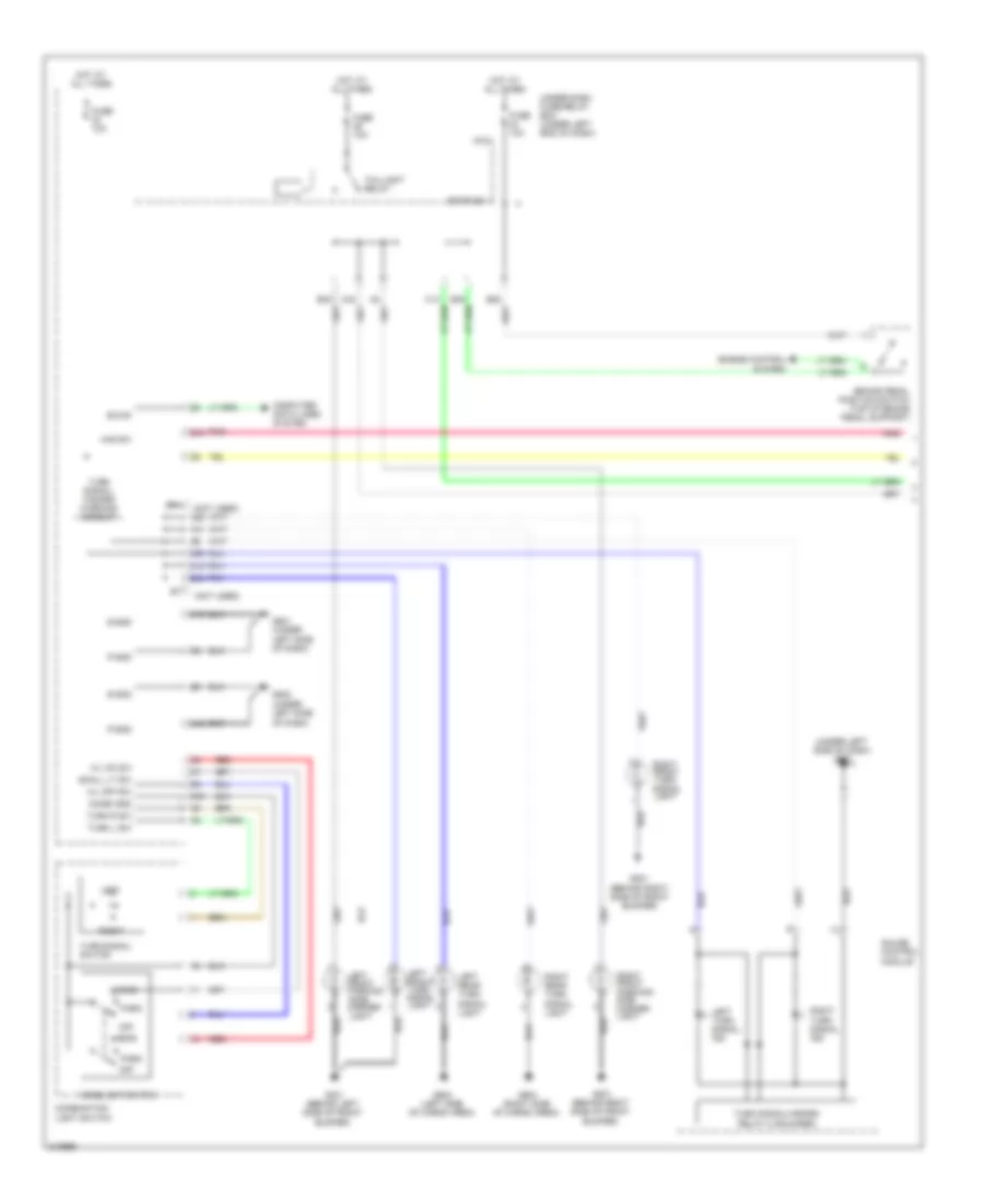
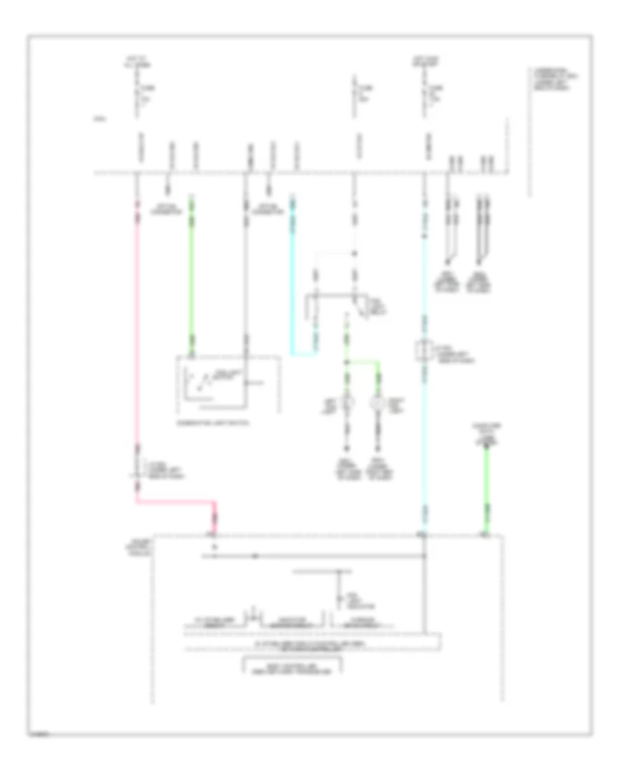
Exterior Lamps Wiring Diagram (1 of 2) for Honda Fit 2009
List of elements for Exterior Lamps Wiring Diagram (1 of 2) for Honda Fit 2009:
- (not used)
- (under left side of dash)
- (under left side of dash) g501
- A28
- B-can
- B28
- B30
- B34
- B35
- Brake pedal position switch (top of brake pedal support)
- C13
- C14
- C41
- C42
- Combi gnd
- Combination light switch
- Computer data lines system
- E11
- Engine control
- Fuse 10a
- G201 (behind right side of front bumper)
- G301 (behind left side of front bumper)
- G501 (under left side of dash)
- G502
- G602 (left side of cargo area)
- G604 (right side of cargo area)
- Gauge control module
- H/l off sw
- H/l on sw
- Haz sw
- Head
- Headlight switch
- Hot at all times
- K10
- Left
- Left front parking /side marker light
- Left front turn signal light
- Left rear turn signal light
- Left turn signal ind
- M16
- M20
- M33
- Micu
- Off
- P-gnd
- Park
- Pnk
- Q13
- Red
- Relay 2 (sounder)
- Right
- Right front parking/ side marker light
- Right front turn signal light
- Right rear turn signal light
- Right turn signal ind
- S-gnd
- Small lt sw
- Stop sw
- System
- Taillight relay
- Turn l sw
- Turn r sw
- Turn signal switch
- Turn signal/ hazard warning circuit
- Turn signal/hazard
- Under-dash fuse/relay box (under left end of dash)
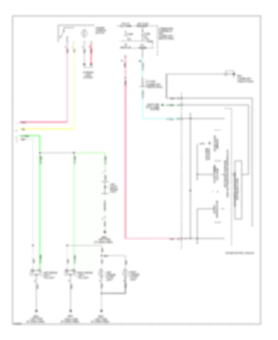
Exterior Lamps Wiring Diagram (2 of 2) for Honda Fit 2009
List of elements for Exterior Lamps Wiring Diagram (2 of 2) for Honda Fit 2009:
- (left side
- (right side
- (under left
- (under left side of dash)
- 10v stabilizer circuit
- 5v stabilizer circuit/controller area network controller
- Back up
- Body controller area network transceiver
- Computer data lines
- Drive circuit
- Fuse 10a
- Fuse 7.5a
- G501
- G602
- G604
- Gauge control module
- Hazard warning switch
- High mount brake light
- Hot at all times
- Hot in on or start
- Ig1
- Indicator dimming circuit
- Indicator lights on
- Interior light system
- J/c c504
- Left brake light/ taillight
- Left license plate light
- Meter
- Micu
- Of cargo area)
- Pnk
- Red
- Right brake light/ taillight
- Right license plate light
- Side of dash)
- System
- Under-dash fuse/relay box (under left end of dash)
- Warning
GROUND DISTRIBUTION
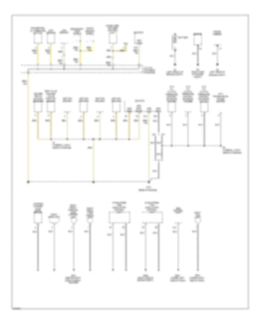
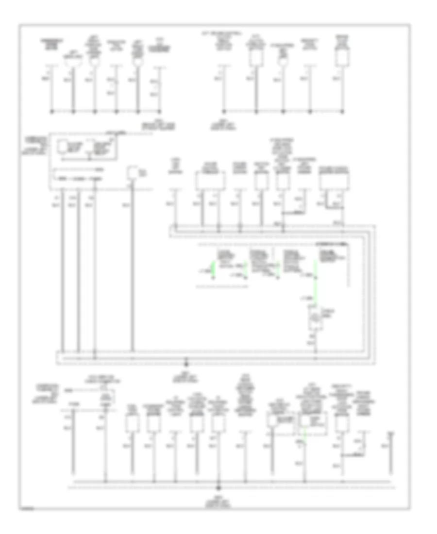
Ground Distribution Wiring Diagram (1 of 3) for Honda Fit 2009
List of elements for Ground Distribution Wiring Diagram (1 of 3) for Honda Fit 2009:
- (a/t)
- (a/t) a/t clutch pressure control solenoid valve b
- (a/t) a/t clutch pressure control solenoid valve c
- (canada) washer fluid level switch
- (if equipped) abs modulator- control unit
- (if equipped) vsa modulator- control unit
- (lg1)
- (lg2)
- (pg1)
- (pg2)
- (pgm-
- (rear of engine)
- (under right end of dash)
- A/t
- A/t clutch pressure control solenoid valve a
- A10
- B10
- Battery
- C44
- C48
- Ckp sensor
- Cmp sensor
- Dlc
- Ecm/pcm
- Egr valve and egr valve position sensor
- Engine
- Engine compt)
- Eps control unit
- Etcs)
- G1 (left front of engine compt)
- G101
- G2 (right side of engine compt)
- G201 (behind right side of front bumper)
- G202 (right side of engine compt)
- G203 (under left
- G204
- G3 (left rear of
- Gnd
- Ignition coil no.1
- Ignition coil no.2
- Ignition coil no.3
- Ignition coil no.4
- Immobilizer- keyless control unit
- J/c c103 (top rear of engine)
- Knock sensor shield
- M/t
- Right fog light
- Right front parking/ side marker light
- Right front turn signal light
- Right headlight
- Rocker arm oil control solenoid
- Rocker arm oil pressure switch
- S1 (thermal joint) (rear of engine)
- S2 (thermal joint)
- Secondary ho2s shield
- Side of dash)
- Trans- mission
- Transmission range switch
Ground Distribution Wiring Diagram (2 of 3) for Honda Fit 2009
List of elements for Ground Distribution Wiring Diagram (2 of 3) for Honda Fit 2009:
- (a/c)
- (a/t)
- (if equipped)
- (if equipped) audio- navigation unit
- (if equipped) left fog light
- (if equipped) tpms control unit
- (m/t) clutch interlock switch
- (m/t: cruise control)
- (not used)
- (power mirror
- (security)
- (under left end of dash)
- (under left side of dash)
- (vsa)
- (vsa) yaw rate- lateral acceler- ation sensor
- A/c condenser fan motor
- A/t gear position indicator panel lignt/park pin switch/ shift lock solenoid
- Accessory power socket
- B17
- Blower motor relay
- Blower switch
- Box
- Brake fluid level switch
- C12
- Cable
- Check connector
- Chk s-gnd
- Clutch pedal position switch
- Combination
- Control switch (navi- gation)
- Cruise control
- Defoggers)
- Dlc
- Door unlock relay
- Driver's
- Driver's door lock actuator/ knob switch/ key cylinder switch
- Eld unit
- Front passenger's door lock actuator/ knob switch
- Fuel tank unit
- G301 (behind left side of front bumper)
- G401 (under left side of dash)
- G501 (under left side of dash)
- G502
- Gauge control module
- Gnd
- Heater-a/c control panel
- Ignition key switch
- K10
- Left front parking/ side marker light
- Left front turn signal light
- Left headlight
- Left power mirror
- M16
- Micu
- Micu service
- Nca
- P-gnd
- Paddle shifter+ (upshift switch) (paddle
- Paddle shifter- (downshift
- Park pin
- Power mirror switch
- Power window master switch
- Radiator fan motor
- Rear window defogger switch rear window power mirror defoggers switch
- Reel
- Right power mirror
- S-gnd
- Security hood switch
- Shifters)
- Steering wheel
- Switch
- Switch) (paddle
- Under-dash fuse/relay
- Under-dash fuse/relay box
- Voice
- Vsa off switch
- Windshield windshield wiper wiper motor motor
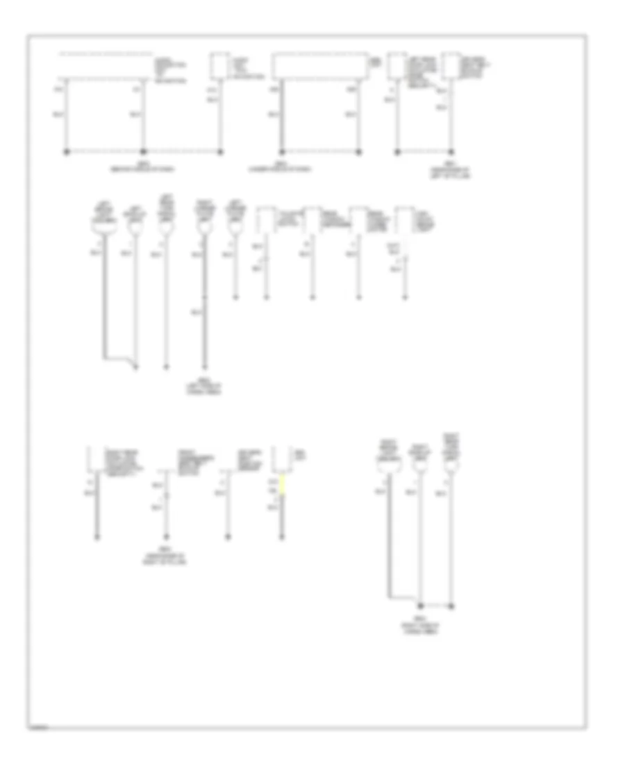
Ground Distribution Wiring Diagram (3 of 3) for Honda Fit 2009
List of elements for Ground Distribution Wiring Diagram (3 of 3) for Honda Fit 2009:
- (near base of
- (right side of
- (security)
- (w/
- (w/o
- A12
- A28
- A29
- Audio unit
- Audio- navigation unit
- Cargo area)
- D12
- Driver's seat belt buckle switch
- Driver's seat position sensor
- Front passenger's seat belt buckle switch
- G503 (behind middle of dash)
- G504 (under middle of dash)
- G601 (near base of
- G602 (left side of
- G603
- G604
- High mount brake light
- Left "b" pillar)
- Left back-up light
- Left brake light/ taillight
- Left license plate light
- Left rear door lock actuator/ knob switch
- Left rear turn signal light
- Navigation)
- Ods unit
- Rear window defogger
- Rear window wiper motor
- Right "b" pillar)
- Right back-up light
- Right brake light/ taillight
- Right license plate light
- Right rear door lock actuator/ knob switch
- Right rear turn signal light
- Srs unit
- Tailgate latch switch
HEADLIGHTS
Fog Lamp Wiring Diagram, Accessory for Honda Fit 2009
List of elements for Fog Lamp Wiring Diagram, Accessory for Honda Fit 2009:
- (behind left side of front bumper)
- (under left side of dash)
- A24
- Fog light
- Fog light relay (above under- dash fuse/ relay box)
- Fuse 10a
- Fuse 20a
- G301
- G501
- H/l lo rly
- Headlight low beam relay
- Hot at all times
- Interior lights system
- Left fog light
- Micu
- On ind
- Pnk
- Power mirror switch
- Red
- Right fog light
- Switch
- Switch illumi- nation
- Taillight relay
- Under-dash fuse/relay box (under left end of dash)
Fog Lamp Wiring Diagram, Factory Installed for Honda Fit 2009
List of elements for Fog Lamp Wiring Diagram, Factory Installed for Honda Fit 2009:
- (under
- (under left
- +b back up
- +b fr fog
- 10v stabilizer circuit
- 5v stabilizer circuit/controller area network controller
- Body controller area network transceiver
- Combi gnd
- Combination light switch
- Computer data lines system
- Connector
- Fog light
- Fog light indicator
- Fog light relay
- Fr fog rly
- Fr fog sw
- Fuse 10a
- Fuse 20a
- Fuse 7.5a
- G204
- G401
- G501 (under
- G502 (under
- Gauge control module
- Hot at all times
- Hot in on or start
- Ig1 meter
- Indicator dimming circuit
- J/c 502 (under left side of dash)
- J/c 504
- K10
- Left fog light
- Left side of dash)
- M16
- M33
- Micu
- Option
- P-gnd
- Pnk
- R20
- R21
- Right end of dash)
- Right fog light
- S-gnd
- Side of dash)
- Switch
- Under-dash fuse/relay box (under left end of dash)
- Warning drive circuit
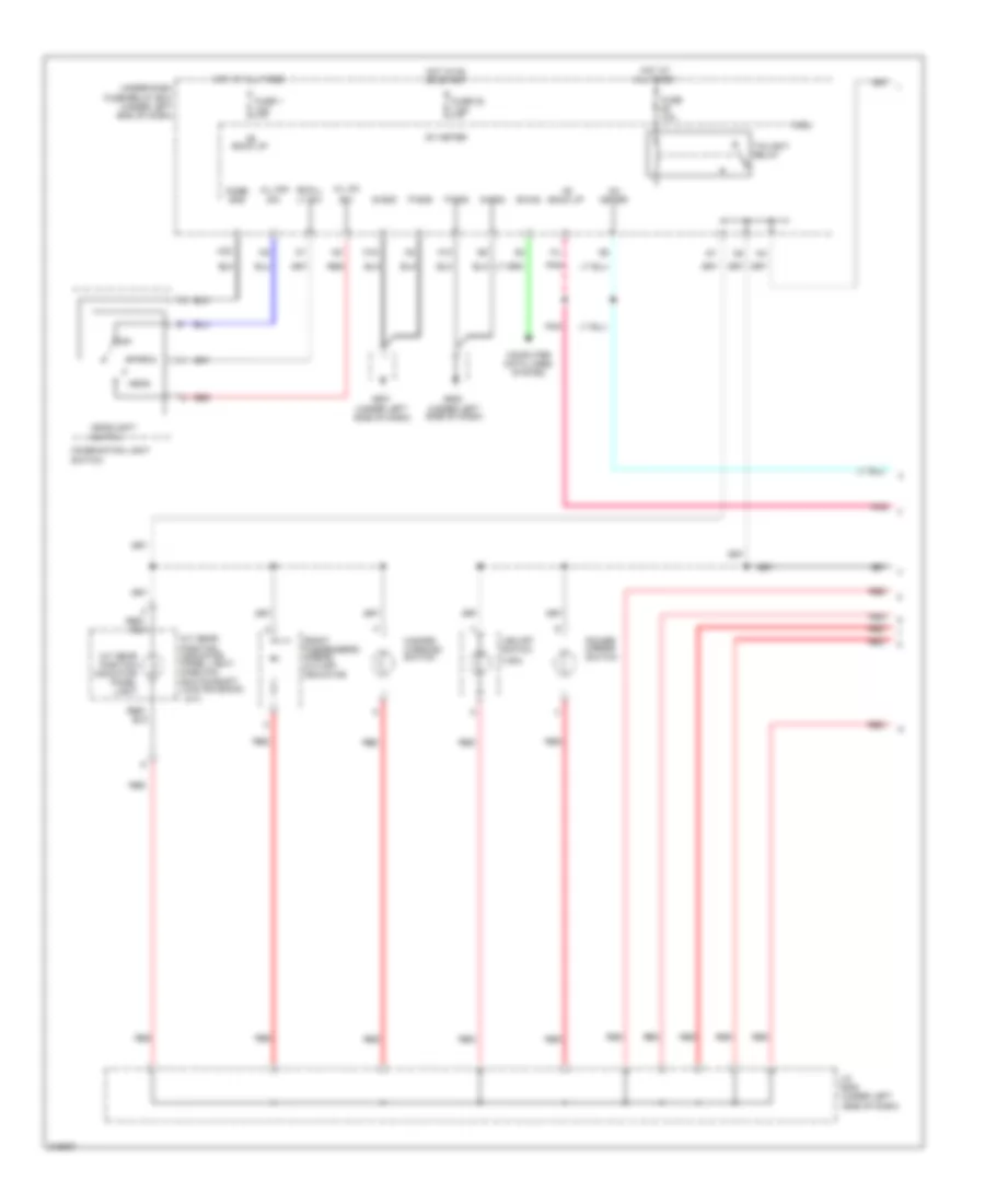
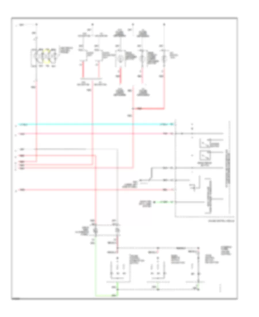
Headlamps Wiring Diagram for Honda Fit 2009
List of elements for Headlamps Wiring Diagram for Honda Fit 2009:
- (behind left side of front bumper)
- (behind right
- (under left
- +b back up
- 10v stabilizer circuit
- 5v stabilizer circuit/controller area network controller
- A24
- A30
- Accessory fog lights connector
- Anti-theft system
- B-can
- B13
- B29
- Body controller area network transceiver
- Bumper)
- Combi gnd
- Combination light switch
- Computer data lines system
- Dim sw
- Dimmer/ flash- to-pass switch 0) low 1) high 2) passing
- Drl indicator
- Exterior lights system
- Fuse 10a
- Fuse 20a
- Fuse 7.5a
- G201
- G301
- G501
- G501 (under left side of dash)
- G502 (under left side of dash)
- Gauge control module
- H/l lo rly
- H/l off sw
- H/l on sw
- Headlight
- Headlight low beam relay
- Headlight switch 0) off 1) park 2) head
- High beam control circuit
- High beam dimming circuit
- High beam indicator
- Hot at all times
- Hot in on
- Hot in on or start
- Ig1 meter
- Ig2 day lt
- Ignition key switch
- Indicator dimming circuit
- J/c 502
- J/c 504
- K10
- Key sw
- Left
- Lights on indicator
- M16
- M33
- M34
- Micu
- P-gnd
- Parking brake switch (at base of parking brake lever)
- Passing sw
- Pnk
- Red
- Right headlight
- S-gnd
- Side of dash)
- Side of front
- Small lt sw
- Under-dash fuse/relay box (under left end of dash)
- Warning drive circuit
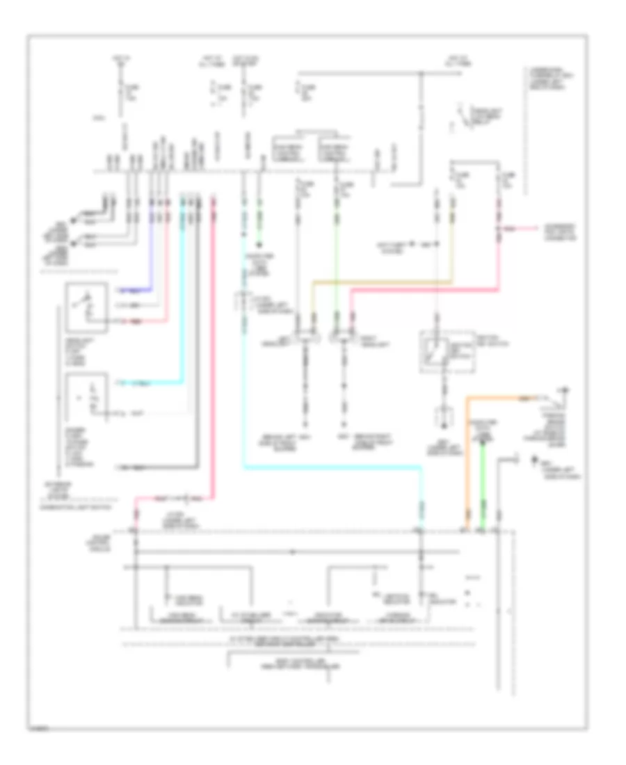
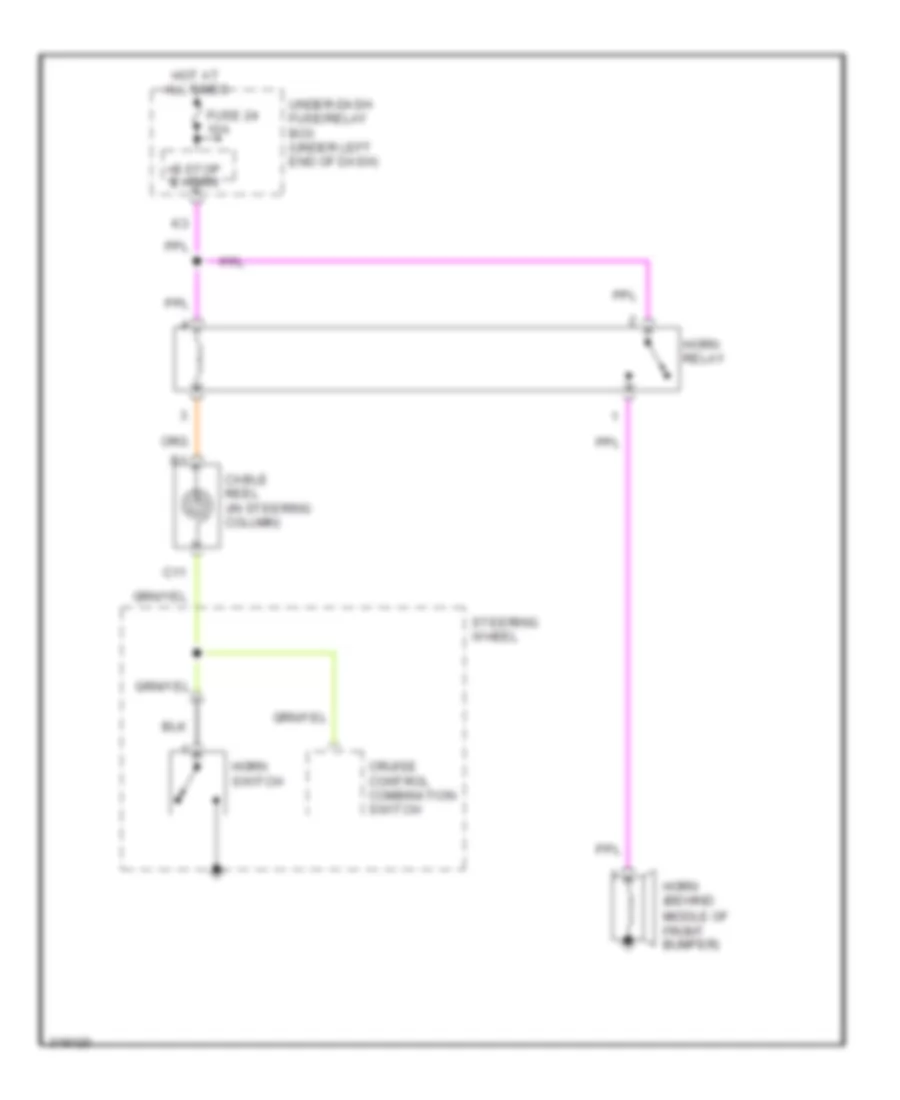
HORN
Horn Wiring Diagram, with Security for Honda Fit 2009
List of elements for Horn Wiring Diagram, with Security for Honda Fit 2009:
- +b stop & horn
- C11
- Cable reel (in steering column)
- Cruise control combination switch
- Fuse 24 10a
- Horn (behind middle of front bumper)
- Horn relay
- Horn switch
- Hot at all times
- Steering wheel
- Under-dash fuse/relay box (under left end of dash)
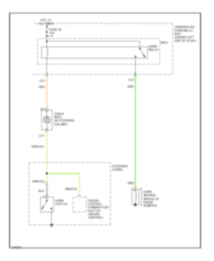
Horn Wiring Diagram, without Security for Honda Fit 2009
List of elements for Horn Wiring Diagram, without Security for Honda Fit 2009:
- (cruise
- A13
- C11
- Cable reel (in steering column)
- Control)
- Cruise control combination switch
- Fuse 24 10a
- Horn (behind middle of front bumper)
- Horn relay
- Horn switch
- Hot at all times
- Micu
- Q11
- Steering wheel
- Under-dash fuse/relay box (under left end of dash)
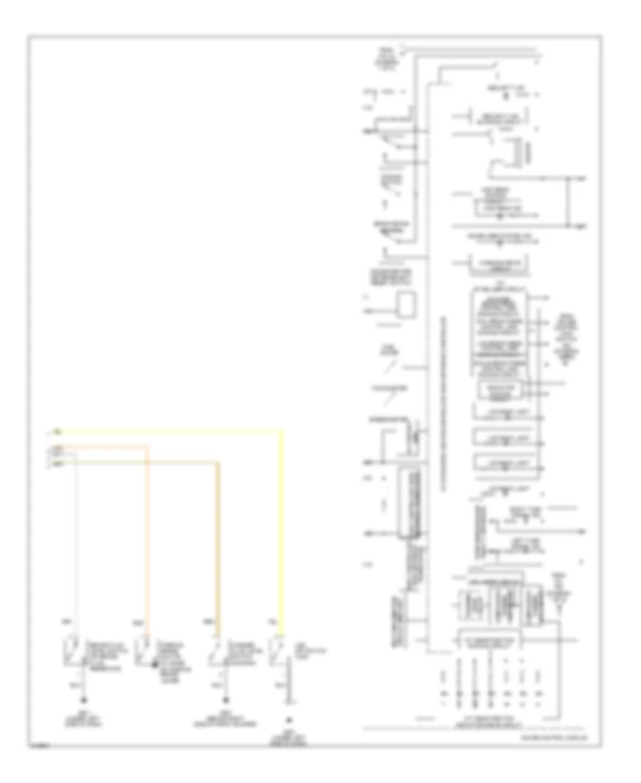
INSTRUMENT CLUSTER
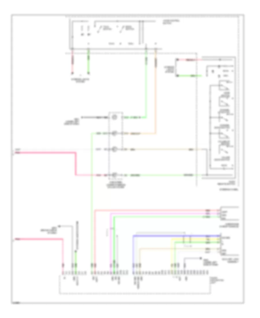
Instrument Cluster Wiring Diagram (1 of 2) for Honda Fit 2009
List of elements for Instrument Cluster Wiring Diagram (1 of 2) for Honda Fit 2009:
- micu
- +b back up
- 10a
- 5v stabilizer circuit/controller area network controller
- 7.5a
- Abs ind
- Activation ind
- B-can
- Brake system ind
- Center console, in fuel tank)
- Charging system ind
- Compulsory
- Computer data lines system
- Coolant high temperature ind
- Coolant low
- Cruise control ind
- Cruise control main switch ind
- Cruise control system
- Door open ind
- Drl ind
- Eps ind
- Exterior lights system
- Fog light ind
- Fuel gauge sending unit
- Fuel tank unit (under rear of
- Fuse1
- Fuse22
- G501 (under left side of dash)
- Gauge control module
- Hot at all times
- Hot in on or start
- Ig1 meter
- Interior lights system
- Lights on ind
- Low fuel ind
- Low oil pressure ind
- Low tire pressure ind
- Maintenance required ind
- Mil ind
- Pnk
- Red
- Seat belt reminder ind
- Side airbag cut-off ind
- Srs ind
- Temperature ind
- To indicator dimming circuit (diagram 2 of 2)
- To security ind (diagram 2 of 2)
- Tpms ind
- Turning off circuit (diagram 2 of 2)
- Under-dash fuse/relay box (under left end of dash)
- Vsa malfunction
- Vsa off ind
- Warning drive circuit
- Washer fluid level ind
Instrument Cluster Wiring Diagram (2 of 2) for Honda Fit 2009
List of elements for Instrument Cluster Wiring Diagram (2 of 2) for Honda Fit 2009:
- -off circuit turning
- 10v stabilizer circuit
- 5v stabilizer circuit/controller area network controller
- A/t gear position indicator drive circuit
- A/t gear position dimming circuit
- Beeper
- Body controller area network transceiver
- Brake fluid level switch (on brake fluid reservoir)
- Brightening switch
- Circuit
- Compulsory
- Dial brightness control and dimming circuit
- Dimming switch
- Display (mid) unit multi-information
- Drive warning
- Fail-safe
- From cruise control main switch ind (diagram 1 of 2)
- From mil ind (diagram 1 of 2)
- From pin 16 (diagram 1 of 2)
- Fuel gauge
- G201 (behind right side of front bumper)
- G401 (under left side of dash)
- G501 (under left side of dash)
- Gauge control module
- High beam dimming circuit
- High beam ind
- Immobilizer system ind
- Indicator dimming circuit
- Lcd back light
- Lcd brightness control and dimming circuit
- Left turn signal ind
- Lever)
- Network transceiver fast controller area
- Odometer/trip meter/select/ reset switch
- Parking brake switch (at base of parking brake
- Pointer brightness control and dimming circuit
- Relay 2 (sounder) turn signal/hazard
- Right turn signal ind
- Scale brightness control and dimming circuit
- Security ind
- Security ind blinking circuit
- Speedometer
- Tachometer
- Turning -on circuit
- Unit 5v control
- Vsa off switch (vsa)
- Warning drive circuit
- Washer fluid level switch (canada)
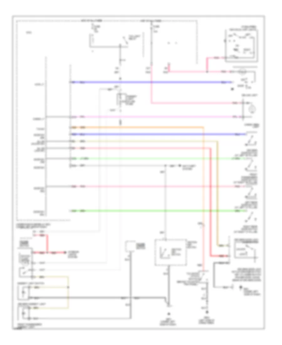
INTERIOR LIGHTS
Courtesy Lamps Wiring Diagram for Honda Fit 2009
List of elements for Courtesy Lamps Wiring Diagram for Honda Fit 2009:
- (behind tailgate trim panel)
- (if equipped)
- (left side of cargo area)
- (power door locks)
- (rear of driver's door)
- (under left
- (under left side of dash)
- 20a
- Ambient light in-line fuse
- Ambient light switch
- Anti-theft system
- C18
- C22
- C26
- C32
- C33
- C37
- C40
- Cargo area light
- Cargo lt
- Ceiling light
- Door
- Door sw
- Door sw (as)
- Door sw (dr)
- Door sw (ra)
- Door sw (rd)
- Driver's ambient light
- Driver's door lock actuator/knob switch/ key cylinder switch
- Driver's door lock knob switch
- Driver's door switch (at left "b" pillar)
- Front passenger's ambient light
- Front passenger's door switch (at right "b" pillar)
- Fuse 10a
- G501
- G602
- Hot at all times
- Ignition key switch
- Individual map lights
- Interior lights system
- Intr lt-
- Left
- Left rear door switch (at left "c" pillar)
- Lock
- M34
- Micu
- Off
- Pnk
- Power mirror switch
- Red
- Right
- Right rear door switch (at right "c" pillar)
- Side of dash)
- Sil dr lock sw
- Sil dr unlock sw
- Switch illumi- nation
- T/g sw
- Tailgate latch switch
- Taillight relay
- Under-dash fuse/relay box (under left end of dash)
- Unlock
Instrument Illumination Wiring Diagram (1 of 2) for Honda Fit 2009
List of elements for Instrument Illumination Wiring Diagram (1 of 2) for Honda Fit 2009:
- (a/t)
- (under left
- (under left side of dash)
- (vsa)
- +b back up
- A/t gear position indicator panel light
- A/t gear position indicator panel light/ park pin switch/shift lock solenoid
- B-can
- Combi gnd
- Combination light switch
- Computer data lines system
- Front passenger's airbag cut-off indicator
- Fuse 1 10a
- Fuse 10a
- Fuse 22 7.5a
- G501
- G502
- H/l off sw
- H/l on
- Hazard warning switch
- Head
- Headlight switch
- Hot at all times
- Hot in on or start
- Ig1 meter
- J/c c505
- K10
- M16
- M33
- Micu
- Off
- P-gnd
- Park
- Pnk
- Power mirror switch
- Red
- Red/
- S-gnd
- Side of dash)
- Small lt sw
- Tailight relay
- Under-dash fuse/relay box (under left end of dash)
- Vsa off switch
Instrument Illumination Wiring Diagram (2 of 2) for Honda Fit 2009
List of elements for Instrument Illumination Wiring Diagram (2 of 2) for Honda Fit 2009:
- (a/c)
- (under left side of dash)
- A/c switch
- A13
- Area network controller 5v stabilizer circuit/controller
- Area network transceiver body controller
- Audio unit
- Audio- navigation unit
- B10
- Brightening switch
- Cable reel (in steering wheel)
- Computer data lines system
- Cruise control combination switch
- Dimming switch
- G501
- Gauge control module
- Heater-a/c control pannel
- Pnk
- Radio remote switch (navigation)
- Rear window defogger switch
- Rear window/ power mirror defogger switch
- Red
- Steering wheel (cruise control)
- Voice control switch (navigation)
- W/ navigation
- W/ power mirror defoggers
- W/o navigation
- W/o power mirror defoggers
NAVIGATION
Navigation Wiring Diagram (1 of 2) for Honda Fit 2009
List of elements for Navigation Wiring Diagram (1 of 2) for Honda Fit 2009:
- A10
- A11
- A12
- A13
- A14
- A15
- A16
- A17
- A18
- A19
- A20
- A21
- A22
- A23
- A24
- A30
- Acc
- Am/fm antenna amplifier (right "d" pillar)
- Amplifier
- Ant +b
- Audio l (+)
- Audio l (-)
- Audio navigation unit
- Audio r (+)
- Audio r (-)
- Audio sh
- Auxiliary under-dash fuse box (under left end of dash)
- Backup
- Bus (+)
- Bus (-)
- Bus sh
- Computer data lines system
- Data (+)
- Data (-)
- Driver's door speaker
- E10
- E11
- E12
- E13
- E14
- Ecm/pcm (left side of engine compt)
- Fr l (+)
- Fr l (-)
- Fr r (+)
- Fr r (-)
- Front passenger's door speaker
- Fuse 10a
- Fuse 30a
- Fuse 7.5a
- G503 (behind middle of dash)
- Gnd
- Gps antenna (behind left side of dash)
- Hot at all times
- Hot in acc or on
- Ill+
- Ill-
- Interior lights system
- J/c c502 (under left side of dash)
- J/c c506 (behind middle of dash)
- K-line
- Left rear door speaker
- Left tweeter
- M18
- M23
- Micu
- Nca
- Pnk
- Power distribution system
- Radio sw
- Red
- Remote
- Rf in
- Rf sh
- Right rear door speaker
- Right tweeter
- Rr l (+)
- Rr l (-)
- Rr r (+)
- Rr r (-)
- Scty
- Sig
- Under-dash fuse/relay box (under left end of dash)
- Usb adapter (behind glove box)
- Usb jack
- Vbus
- Vss out
Navigation Wiring Diagram (2 of 2) for Honda Fit 2009
List of elements for Navigation Wiring Diagram (2 of 2) for Honda Fit 2009:
- Adpt
- Audio navigation unit
- Audio remote switch
- Auxiliary jack assembly
- B10
- B11
- B12
- B13
- B14
- B15
- B16
- B17
- B18
- B19
- B20
- B21
- B22
- B23
- B24
- Back lt
- Back switch
- C12
- C13
- Cable reel (under steering column cover)
- Channel down switch
- Channel up switch
- D10
- D11
- D12
- Det
- Exterior lights system
- G501 (under left side of dash)
- G502 (under left side of dash)
- G503 (behind middle of dash)
- Gnd
- Interior lights system
- Microphone (in roof console)
- Mode switch
- Pnk
- Red
- Sh gnd
- Shield gnd
- Sig
- Sig gnd
- Steering wheel
- Talk switch
- Voice control switch
- Volume down switch
- Volume up switch
POWER DISTRIBUTION
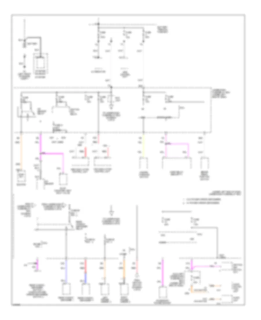
Power Distribution Wiring Diagram (1 of 5) for Honda Fit 2009
List of elements for Power Distribution Wiring Diagram (1 of 5) for Honda Fit 2009:
- (diagram 3 of 5)
- (not used)
- (under left end of dash) under-dash fuse/relay box
- +b
- A/c
- A/f sensor
- A/f sensor relay
- A11
- A14
- A22
- A23
- A27
- Abs
- Abs modulator- control unit
- Acc
- Accessory power socket
- Alternator
- Audio naviga- tion unit
- Audio unit
- Auxiliary under-dash fuse/relay box (under left end of dash)
- B19
- B23
- B28
- Battery
- Battery terminal fuse box
- Brake pedal position switch
- C20
- C43
- Cigar
- Coil
- Ecm/pcm
- Eld unit
- Eps control unit
- Evap canister vent shut valve
- From ignition switch (diagram 4 of 5)
- From under-dash fuse/relay box f
- From under-dash i
- Fuse 100a
- Fuse 10a
- Fuse 15a
- Fuse 20a
- Fuse 30a
- Fuse 31 (not used)
- Fuse 54 20a
- Fuse 55 10a
- Fuse 59 20a 30a
- Fuse 7.5a
- Fuse 70a
- Fuse/relay box (diagram 4 of 5)
- G1 (left front of engine compt)
- H/mirr
- Haz
- Hazard warining switch
- Horn relay (security)
- Ignition coil relay
- Ignition key switch (a/t)
- Left power mirror
- M18
- Micu
- Nca
- Rear window defogger
- Rear window defogger relay
- Rear window defogger switch window/power mirror defoggers switch
- Red
- Right power mirror
- Rr def
- Starter
- Starter solenoid
- Stop & horn
- Sub- rly
- T101
- T102
- To under-dash fuse/relay box (diagram 2 of 5)
- To under-dash fuse/relay box (diagram 5 of 5)
- Under-dash fuse/relay box (under left end of dash)
- Vsa
- Vsa modulator- control unit
- W/ navigation
- W/ power mirror defoggers
- W/o navigation
- W/o power mirror defoggers
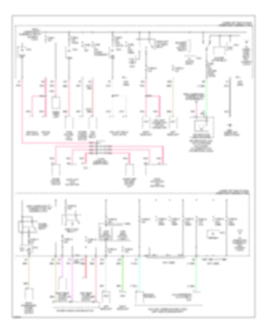
Power Distribution Wiring Diagram (2 of 5) for Honda Fit 2009
List of elements for Power Distribution Wiring Diagram (2 of 5) for Honda Fit 2009:
- (a/c)
- (diagram 5 of 5)
- (fog
- (not used)
- (tpms)
- (under left
- (under left end of dash) under-dash fuse/relay box
- +b p/w as
- 20a
- A/c compressor
- A22
- A24
- A30
- Audio unit (w/o navigation)
- Audio- navigation unit (navigation)
- Auxiliary under-hood relay box (left side of engine compt)
- B13
- B29
- Back up
- Blower motor relay
- C12
- C31
- C37
- Cargo area light
- Ceiling light
- Clutch relay
- Dl unlock dr rly
- Dlc
- Driver's door lock actuator
- Driver's door lock actuator/knob switch/key cylinder switch (power door locks)
- Driver's door unlock relay
- Fan relay
- Fog light connector 1 (option connector)
- Fog light relay
- Fog light relay (fog lights)
- Fr fog
- From under-dash a fuse/relay box (diagram 1 of 5)
- From under-dash fuse/relay box
- From under-dash fuse/relay box (diagram 2 of 5)
- Front passenger's power window switch
- Fuse
- Fuse 20a (honda accessory)
- Fuse 1 10a
- Fuse 15a (power door locks)
- Fuse 17 20a
- Fuse 18 20a
- Fuse 19 20a
- Fuse 2 7.5a
- Fuse 28 20a
- Fuse 30 30a
- Fuse 32 10a
- Fuse 34 10a
- Fuse 39 15a
- Fuse 40
- Fuse 41
- Fuse 42
- Fuse 43 7.5a
- Fuse 45
- Fuse 46
- Fuse 48 10a
- Fuse 51 10a
- Fuse 9 20a
- G501
- Gauge control module
- Gnd
- H/l lo rly
- Headlight low beam relay
- High
- High beam control unit
- Immobilizer keyless control unit
- Individual map lights
- J/c 502 (under left side of dash)
- Left headlight
- Left rear power window switch
- Lights)
- Low
- M21
- Micu
- Option
- P/w rly
- Pgm-f1 main relay 1
- Pnk
- Power window master switch
- Power window relay
- Red
- Ridiator
- Right headlight
- Right rear power window switch
- Side of dash)
- To under- dash fuse/ relay box (diagram 2 of 5)
- To under-dash fuse/relay box (diagram 3 of 5)
- Tpms
- Tpms control unit (tpms)
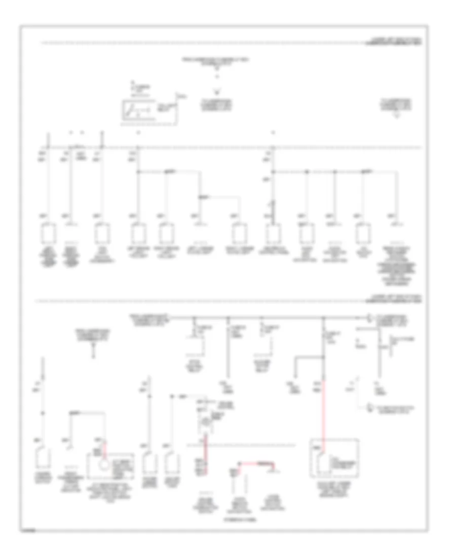
Power Distribution Wiring Diagram (3 of 5) for Honda Fit 2009
List of elements for Power Distribution Wiring Diagram (3 of 5) for Honda Fit 2009:
- (a/c)
- (not used)
- (under left end of dash) under-dash fuse/relay box
- 40a
- 50a
- A/c
- A/c condenser fan relay
- A/t gear position indicator panel light
- A/t gear position indicator panel light/ park pin switch/ shift lock solenoid (a/c)
- A13
- A36
- Audio
- Audio remote switch (navigation)
- Audio- navigation unit (navigation)
- Auxiliary under- hood relay box (left side of engine compt)
- B10
- B15
- B30
- Blower motor relay
- C42
- C49
- Cable
- Control panel
- Cruise control
- Cruise control combination switch
- Etcs control relay
- Fog light switch (accessory)
- From under-dash fuse/relay box (diagram 2 of 5)
- From under-dash fuse/relay box (diagram 3 of 5)
- From under-dash fuse/relay box e (diagram 3 of 5)
- Front passenger's airbag cut-off indicator
- Fuse 29 10a
- Fuse 47 30a
- Fuse 52 15a
- Fuse 53
- Fuse 57 30a
- Hazard warning switch
- Heater-a/c
- Left brake light/ taillight
- Left front parking/ side marker light
- Left license
- Micu
- Multi-fuse
- Plate light
- Power mirror switch
- Rear window defogger switch (w/o power mirror defoggers) window/power mirror defoggers switch (power mirror defoggers)
- Red
- Reel
- Right brake light/ taillight
- Right front parking/ side marker light
- Right license
- Steering wheel
- Switch (a/c)
- Taillight relay
- To ignition switch (diagram 4 of 5)
- To under-dash fuse/relay box (diagram 1 of 5)
- To under-dash fuse/relay box (diagram 3 of 5)
- Unit (w/o navigation)
- Voice control switch (navigation)
- Vsa off switch (vsa)
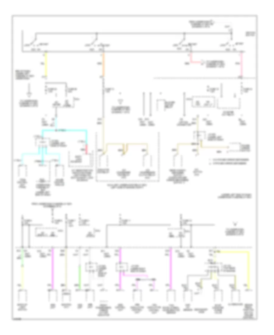
Power Distribution Wiring Diagram (4 of 5) for Honda Fit 2009
List of elements for Power Distribution Wiring Diagram (4 of 5) for Honda Fit 2009:
- (a/t)
- (diagram 3 of 5)
- (not used)
- (option connector)
- (under left
- (under left end of dash) under-dash fuse/relay box
- (under right end of dash)
- A/c compressor clutch relay (a/c)
- A/c condenser fan relay (a/c)
- A/c switch (a/c)
- A/t gear position indicator panel light/park pin switch/shift lock solenoid
- A26
- A27
- A31
- A32
- A33
- Abs
- Abs modulator control unit
- Acc
- Alternator
- Auxiliary under-hood relay box (left side of engine compt)
- B10
- B11
- B12
- B17
- B25
- Back-up light switch
- Blower motor relay
- Brake pedal position switch (cruise control)
- Day lt
- E10
- Ecm/pcm (a/t)
- Eld
- End of dash) (under left fuse/relay box under-dash
- Eps control unit
- Evap canister purge valve
- From under-dash fuse/relay box (diagram 4 of 5)
- From under-dash fuse/relay box g
- Front passenger's airbag cut-off indicator
- Fuse 10 7.5a
- Fuse 11 7.5a
- Fuse 12 10a
- Fuse 15 7.5a
- Fuse 22 7.5a
- Fuse 44 7.5a
- Fuse 5 10a
- Fuse 56 30a
- Fuse 6 10a
- Fuse 7 10a
- Fuse 8 7.5a
- Gauge control module
- Ig1
- Ig1 abs
- Ig1 acg
- Ig1 back lt
- Ig1 fr
- Ig1 srs
- Ig2
- Ig2 hac
- Ignition switch
- J/c 104 (top rear of engine)
- J/c 205
- J/c 502
- J/c 504 (under left side of dash)
- J/c 504 (under left side of dash)
- Lock
- M27
- Maf/ iat sensor
- Meter
- Micu
- Ods unit
- On acc
- Opds
- Pnk
- Power mirror switch
- Q12
- Q14
- Q15
- Q16
- Radiator fan relay
- Rear window defogger switch window/power mirror defoggers switch
- Red
- Secondary ho2s
- Shift lock solenoid
- Side of dash)
- Srs unit
- Start
- Starter cut relay
- To under-dash fuse/relay box (diagram 1 of 5)
- To under-dash fuse/relay box (diagram 4 of 5)
- To under-dash fuse/relay box (diagram 5 of 5)
- Tpms control unit (tpms)
- Under-dash fuse/relay box (under left end of dash)
- Unit
- Vbsol
- Vsa
- Vsa modulator control unit
- W/o power mirror defoggers
- W/power mirror defoggers
- Wiper
- Yaw rate-lateral acceleration sensor
Power Distribution Wiring Diagram (5 of 5) for Honda Fit 2009
List of elements for Power Distribution Wiring Diagram (5 of 5) for Honda Fit 2009:
- (not
- (not used)
- (power door locks)
- (under left end of dash) under-dash fuse/relay box
- B14
- C10
- C35
- C36
- C39
- C47
- C48
- Door lock relay
- Door unlock relay
- Ecm/pcm
- Front passenger's door lock actuator
- Front passenger's door lock actuator/knob switch (power door locks)
- Fuse 16 10a
- Fuse 20 15a
- Fuse 21 15a
- Fuse 27 30a (power door locks)
- Fuse 35 15a
- Fuse 36 15a (power door locks)
- Fuse 49 15a (power door locks)
- Fuse 50 15a (power door locks)
- Fuse/relay box from under-dash (diagram 1 of 5)
- Fuse/relay box from under-dash (diagram 4 of 5)
- Ig1
- Ig1 fuel pump
- Ig1 rr wiper
- Immobilizer- keyless control unit
- Left rear door lock actuator
- Left rear door lock actuator/knob switch (power door locks)
- Lock
- Micu
- Pgm-fi main relay 2
- Pnk
- R14
- Rear window wiper motor
- Red
- Right rear door lock actuator
- Right rear door lock actuator/knob switch (power door locks)
- Tailgate lock actuator (power door locks)
- To driver's door lock actuator (diagram 2 of 5)
- Unlock
- Used)
- Washer
POWER DOOR LOCKS
Power Door Locks Wiring Diagram (1 of 2) for Honda Fit 2009
List of elements for Power Door Locks Wiring Diagram (1 of 2) for Honda Fit 2009:
- (behind tailgate
- (near base of
- (not
- (not used)
- (rear of driver's door)
- (security)
- (under left
- (under left side
- (under left side of dash) g502
- +b back up
- 10a
- 15a
- A13
- A29
- B-can
- C22
- C26
- C32
- C33
- C35 pnk
- C40
- C45
- C46
- D/l unlock
- Door
- Door lock knob
- Door lock knob switch
- Door lock relay
- Door unlock relay
- Dr rly
- Driver' door lock actuator/knob switch/ key cylinder switch
- Driver's
- Drswas
- Drswdr
- Drswra
- Drswrd
- E11
- Exterior lights system
- F2 pnk
- Front passenger's door lock actuator/knob switch (rear of front passenger's door)
- Fuse
- Fuse 10a
- Fuse 15a
- Fuse 30a
- Fuse 7.5a
- G501
- G502
- G603
- Gnd
- Handy dr sw
- Hood sw
- Horn relay
- Hot at all times
- Hot in on or start
- Ig1
- Ig1 fuel pump
- K10
- Kc dr lock
- Kc dr unlock
- Key
- Key cylinder switch
- Key sw
- Lock
- M16
- M23
- M24
- M34
- Meter
- Micu
- Of dash)
- P-gnd
- Pnk
- Q11
- Radio sw
- Red
- Relay
- Right "b" pillar)
- Right rear door lock actuator/knob switch (rear of right rear door)
- S-gnd
- Security
- Side of dash)
- Sil as unlock
- Sil dr lock
- Sil dr unlock
- Sil ra unlock
- Sil rd unlock
- T/g sw
- Tailgate lock actuator
- Trim panel)
- Turn signal/hazard
- Under-dash fuse/relay box (under left end of dash)
- Unlock
- Used)
- Warning circuit
Power Door Locks Wiring Diagram (2 of 2) for Honda Fit 2009
List of elements for Power Door Locks Wiring Diagram (2 of 2) for Honda Fit 2009:
- "b" pillar)
- (behind left side of front bumper)
- (on hood latch
- (rear of engine)
- (security)
- (under
- (under left side of dash)
- 5v stabilize circuit/ controller area network controller
- Antenna
- Assembly)
- Audio unit (w/o navigation) navigation unit (if equipped)
- B-can
- Blinking
- Body controller area network transceiver
- Door unlock
- Driver's door lock switch lock
- Driver's door switch (at left "b" pillar)
- Front passenger's door switch (at right "b" pillar)
- G101
- G401
- G501
- G501 (under left side of dash)
- G601 (near base of right
- G602 (left side of cargo area)
- Gauge control module
- Ig key sw
- Ig1
- Ignition key switch
- Immobilizer- keyless control unit (in steering column)
- Indicator circuit
- J/c 502 (under left side of dash)
- Left rear door lock actuator/ knob switch (rear of left rear door)
- Left rear door switch (at left "c" pillar)
- Left side of dash)
- Lock
- Lock knob switch
- Pnk
- Power window master switch
- Red
- Right rear door switch (at right "c" pillar)
- Security
- Security hood switch
- Security horn
- Security indicator
- Tailgate latch switch (behind tailgate trim panel)
- Unlock
- Vbu
POWER MIRRORS
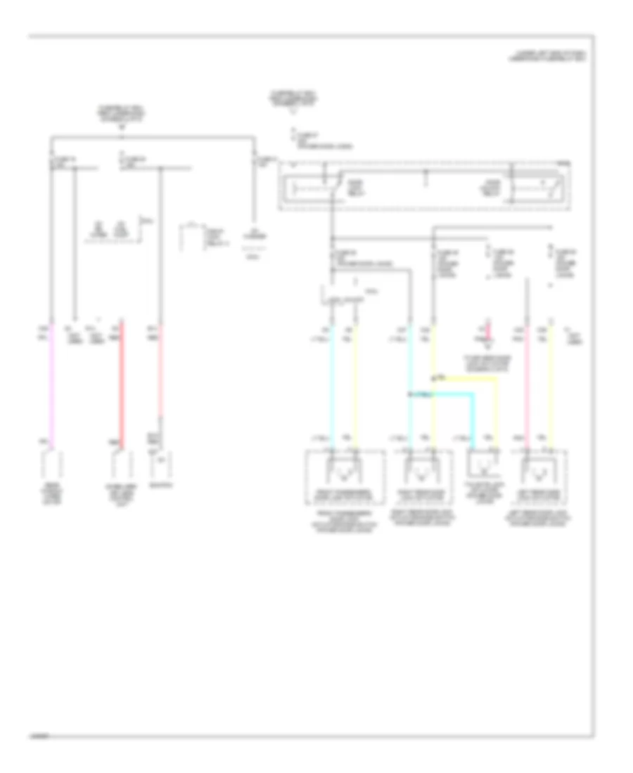
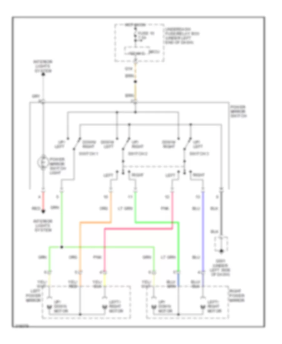
Power Mirrors Wiring Diagram for Honda Fit 2009
List of elements for Power Mirrors Wiring Diagram for Honda Fit 2009:
- Down/ left
- Down/ right
- Fuse 10 7.5a
- G501 (under left side of dash)
- Hot in on
- Ig2 hac
- Interior lights system
- Left
- Left power mirror
- Left/ right motor
- Micu
- Pnk
- Power mirror switch
- Power mirror switch light
- Q14
- Red
- Right
- Right power mirror
- Switch 1
- Switch 2
- Switch 3
- Underdash fuse/relay box (under left end of dash)
- Up/ down motor
- Up/ left
- Up/ right
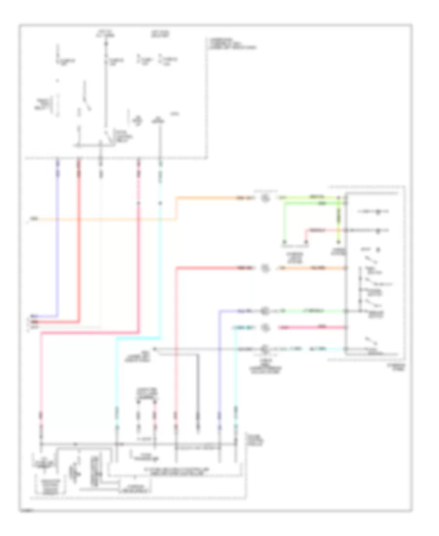
POWER WINDOWS
Power Windows Wiring Diagram for Honda Fit 2009
List of elements for Power Windows Wiring Diagram for Honda Fit 2009:
- +b back up
- +b p/w as
- 0) of 1) up 2) down 3) auto
- 5) auto
- C31
- Control unit
- Door locks system
- Down
- Driver's
- Driver's power window motor (middle of driver's door)
- Front passenger's power window motor (middle of front passenger's door)
- Front passenger's power window switch
- Fuse 1 10a
- Fuse 17 20a
- Fuse 18 20a
- Fuse 19 20a
- Fuse 22 7.5a
- Fuse 3 20a
- G501 (under left side of dash)
- Gnd
- Hot at all times
- Hot in
- Ig1 meter
- Left rear power window motor (in left rear door)
- Left rear power window switch
- M16
- Main switch
- Micu
- Off
- On or start
- P-gnd
- P/w rly
- Plsa
- Plsb
- Pnk
- Power window master switch
- Power window relay
- Pulser
- Red
- Right rear power window motor (in right rear door)
- Right rear power window switch
- S-gnd
- Sgnd
- Svcc
- Switch
- Under-dash fuse/relay box (under left end of dash)
- Vmp dr
RADIO
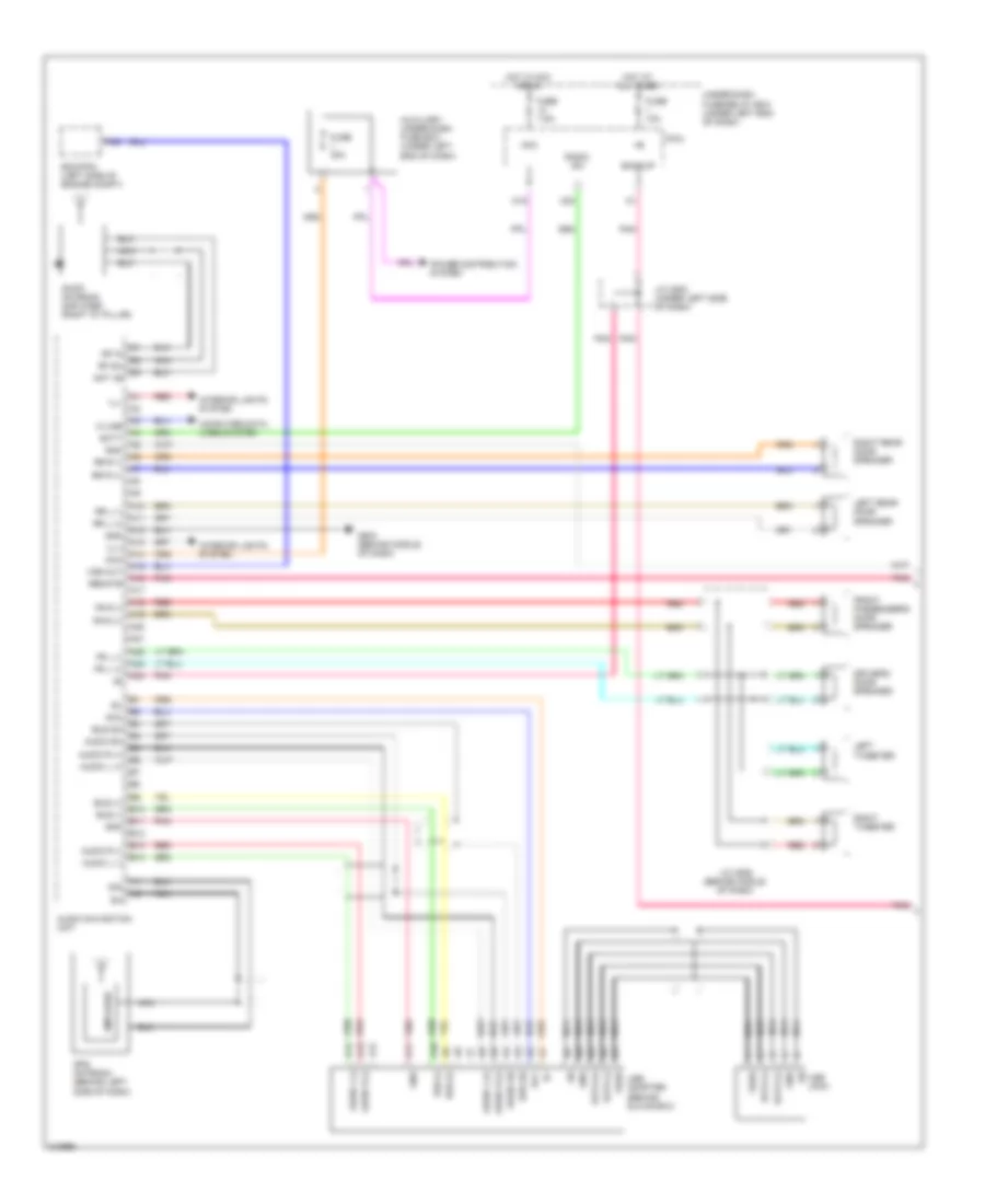
Radio Wiring Diagram, with Navigation (1 of 2) for Honda Fit 2009
List of elements for Radio Wiring Diagram, with Navigation (1 of 2) for Honda Fit 2009:
- A10
- A11
- A12
- A13
- A14
- A15
- A16
- A17
- A18
- A19
- A20
- A21
- A22
- A23
- A24
- A30
- Acc
- Am/fm antenna amplifier (right "d" pillar)
- Amplifier
- Ant +b
- Audio l (+)
- Audio l (-)
- Audio navigation unit
- Audio r (+)
- Audio r (-)
- Audio sh
- Auxiliary under-dash fuse box (under left end of dash)
- Backup
- Bus (+)
- Bus (-)
- Bus sh
- Computer data lines system
- Data (+)
- Data (-)
- Driver's door speaker
- E10
- E11
- E12
- E13
- E14
- Ecm/pcm (left side of engine compt)
- Fr l (+)
- Fr l (-)
- Fr r (+)
- Fr r (-)
- Front passenger's door speaker
- Fuse 10a
- Fuse 30a
- Fuse 7.5a
- G503 (behind middle of dash)
- Gnd
- Gps antenna (behind left side of dash)
- Hot at all times
- Hot in acc or on
- Ill+
- Ill-
- Interior lights system
- J/c c502 (under left side of dash)
- J/c c506 (behind middle of dash)
- K-line
- Left rear door speaker
- Left tweeter
- M18
- M23
- Micu
- Nca
- Pnk
- Power distribution system
- Radio sw
- Red
- Remote
- Rf in
- Rf sh
- Right rear door speaker
- Right tweeter
- Rr l (+)
- Rr l (-)
- Rr r (+)
- Rr r (-)
- Scty
- Sig
- Under-dash fuse/relay box (under left end of dash)
- Usb adapter (behind glove box)
- Usb jack
- Vbus
- Vss out
Radio Wiring Diagram, with Navigation (2 of 2) for Honda Fit 2009
List of elements for Radio Wiring Diagram, with Navigation (2 of 2) for Honda Fit 2009:
- Adpt
- Audio navigation unit
- Audio remote switch
- Auxiliary jack assembly
- B10
- B11
- B12
- B13
- B14
- B15
- B16
- B17
- B18
- B19
- B20
- B21
- B22
- B23
- B24
- Back lt
- Back switch
- C12
- C13
- Cable reel (under steering column cover)
- Channel down switch
- Channel up switch
- D10
- D11
- D12
- Det
- Exterior lights system
- G501 (under left side of dash)
- G502 (under left side of dash)
- G503 (behind middle of dash)
- Gnd
- Interior lights system
- Microphone (in roof console)
- Mode switch
- Pnk
- Red
- Sh gnd
- Shield gnd
- Sig
- Sig gnd
- Steering wheel
- Talk switch
- Voice control switch
- Volume down switch
- Volume up switch
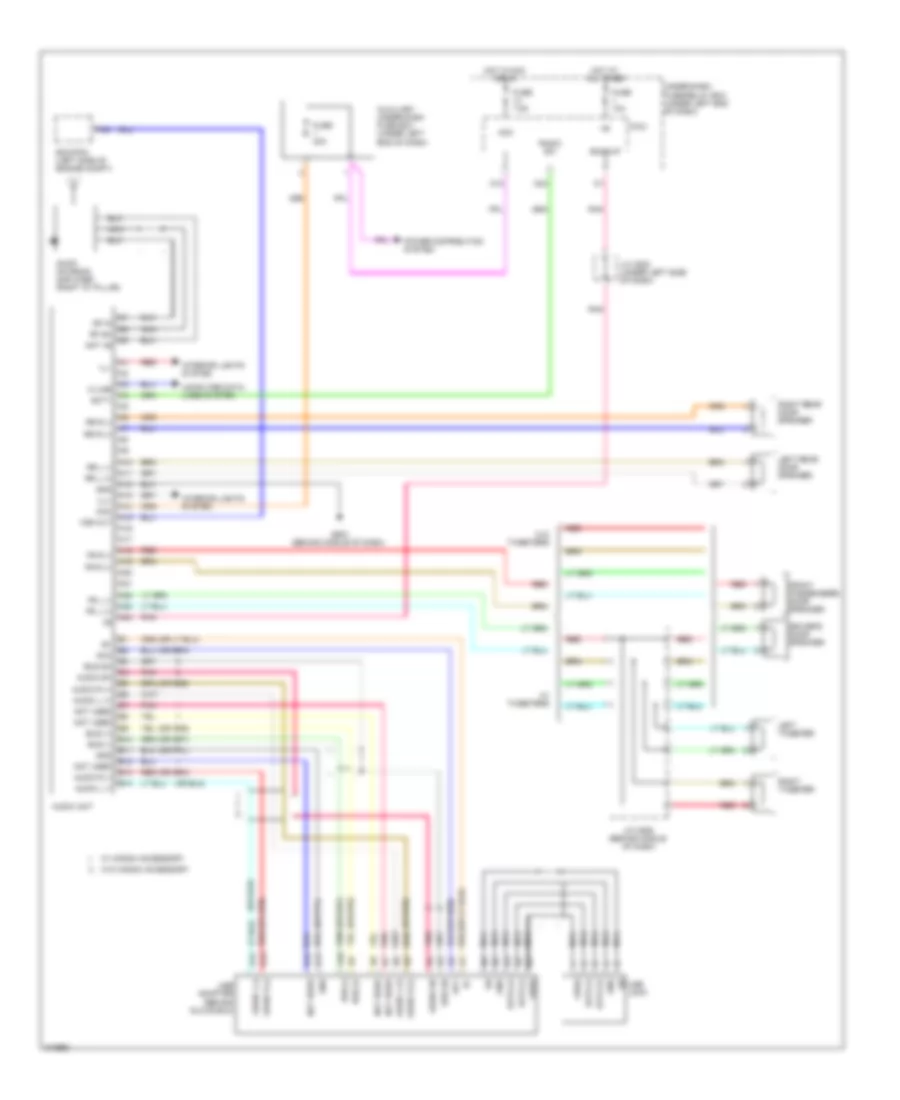
Radio Wiring Diagram, without Navigation for Honda Fit 2009
List of elements for Radio Wiring Diagram, without Navigation for Honda Fit 2009:
- (or red)
- A10
- A11
- A12
- A13
- A14
- A15
- A16
- A17
- A18
- A19
- A20
- A21
- A22
- A23
- A24
- A30
- Acc
- Am/fm antenna amplifier (right "d" pillar)
- Ant +b
- Audio l (+)
- Audio l (-)
- Audio r (+)
- Audio r (-)
- Audio sh
- Audio unit
- Auxiliary under-dash fuse box (under left end of dash)
- Backup
- Bus (+)
- Bus (-)
- Bus sh
- Computer data lines system
- Data (+)
- Data (-)
- Driver's door speaker
- E10
- E11
- E12
- E13
- E14
- Ecm/pcm (left side of engine compt)
- Fr l (+)
- Fr l (-)
- Fr r (+)
- Fr r (-)
- Front passenger's door speaker
- Fuse 10a
- Fuse 30a
- Fuse 7.5a
- G503 (behind middle of dash)
- Gnd
- Hot at all times
- Hot in acc or on
- Ill+
- Ill-
- Interior lights system
- J/c c502 (under left side of dash)
- J/c c506 (behind middle of dash)
- K-line
- Left rear door speaker
- Left tweeter
- M18
- M23
- Micu
- Nca
- Not used
- Pnk
- Power distribution system
- Radio sw
- Red
- Rf in
- Rf sh
- Right rear door speaker
- Right tweeter
- Rr l (+)
- Rr l (-)
- Rr r (+)
- Rr r (-)
- Scty
- Under-dash fuse/relay box (under left end of dash)
- Usb adapter (behind glove box)
- Usb jack
- Vbus
- Vss out
- W/ honda accessory
- W/ tweeters
- W/o honda accessory
- W/o tweeters
SHIFT INTERLOCK
Shift Interlock Wiring Diagram for Honda Fit 2009
List of elements for Shift Interlock Wiring Diagram for Honda Fit 2009:
- A/t gear position indicator panel light/park pin switch/shift lock solenoid
- A14
- A18
- A19
- A25
- A26
- A28
- A35
- A36
- A42
- Acc
- App sensor (under left side of dash)
- Apsa
- Apsb
- Atp-p
- Atpp
- Audio navigation unit
- Audio unit
- Auxiliary under-dash fuse box (at left end
- B14
- B28
- B32
- B35
- Bksw
- Brake pedal position switch (top of brake pedal support)
- Ecm/pcm (left side of engine compt)
- Fuse 1 30a
- Fuse 14 7.5a
- Fuse 22 7.5a
- Fuse 24 10a
- G101 (rear of engine)
- G501 (under left side of dash)
- G502 (under left side of dash)
- Hot at all times
- Hot in acc or on
- Hot in on or start
- Ig 1 meter
- Ignition key switch
- J/c 104 (top rear of engine)
- Key interlock solenoid
- Key lock sol
- Key sw
- M17
- M18
- M34
- Micu
- Of dash)
- P-pin sw
- Park pin switch
- Pnk
- Q10
- Red
- Sg4
- Sg5
- Shift lock solenoid
- Sls
- Stop sw
- Transmission range switch (lower rear of transmission)
- Under-dash fuse/relay box (under left side of dash)
- Vcc4
- Vcc5
- W/ navigation
- W/ paddle shifters
- W/o navigation
- W/o paddle shifters
STARTING/CHARGING
Charging Wiring Diagram for Honda Fit 2009
List of elements for Charging Wiring Diagram for Honda Fit 2009:
- (near battery)
- (under left side
- A24
- Alternator
- Alternator c signal (altc)
- Alternator fr signal (altf)
- Alternator l signal (altl)
- Area network controller 5v stabilize circuit/controller
- B17
- B45
- B46
- B47
- Battery
- C504
- Charging system indicator
- Computer data lines system
- Comunications signal high (can-h)
- Comunications signal low (can-l)
- Connector
- Ecm/pcm (left side of engine compt)
- Eld unit
- Eld unit input (eld)
- Fast controller area
- Fuse 100a
- Fuse 10a
- Fuse 7.5a
- Fuse box
- G1 (left front of engine compt)
- G501 (under left side of dash)
- Gauge control module
- Hot in on or start
- Ig1
- Junction
- Junction connector c104 (top rear of engine)
- Meter
- Micu
- Network transceiver
- Of dash)
- Pnk
- Red
- Starting circuit
- T101
- Terminal
- Under-dash fuse/relay box (under left end of dash)
- Warning drive circuit
Remote Starting Wiring Diagram (1 of 2) for Honda Fit 2009
List of elements for Remote Starting Wiring Diagram (1 of 2) for Honda Fit 2009:
- (left front of engine compt)
- (not used)
- (under left
- 50a
- 7.5a
- A/t gear position
- Antenna input
- Anti-theft system
- Atp-np
- B-can
- B16
- B33
- Battery
- Battery terminal fuse box (near battery)
- Box
- Computer data lines system
- Eld unit
- End of dash)
- Engine st sig
- Fuse
- Fuse 100a
- Fuse 7.5a
- Fuse/relay
- Gnd
- Hood sw
- Hot in on or start
- Ig1
- Ig1 rly coil
- Ig2 rly coil
- Immob sig
- Indicator panel light/park pin
- K-line
- M26
- Meter
- Micu
- Multi- fuse
- Pnk
- Relay gnd
- Remote starting control unit
- Remote starting control unit ground
- Remote starting control unit in-line fuse
- Remote starting system antenna
- Scs
- Shift lock
- Solenoid
- St rly coil
- Starter
- Starter cut relay
- Starter motor
- Starter solenoid
- Switch/shift lock
- T102
- Under-dash
- Wiper/ washer system
Remote Starting Wiring Diagram (2 of 2) for Honda Fit 2009
List of elements for Remote Starting Wiring Diagram (2 of 2) for Honda Fit 2009:
- (scs) ser chk in
- (sls) vlv ctrl
- (under left
- 40a
- A28
- A32
- Acc
- B21
- Box
- Dlc
- Ecm/pcm (left side of engine compt)
- End of dash)
- G101 (rear of engine)
- Ig1 fuse
- Ig1 relay
- Ig2 relay
- Ig2/ start fuse
- Ignition switch
- Lock
- Micu
- Nca
- Paddle shifters
- Pnk
- Power distribution system
- S2 (thermal joint)
- Scs
- Side of dash)
- Start
- Start relay
- Transmission range switch (lower rear of transmission)
- Under-dash fuse/relay
- W/o
Starting Wiring Diagram for Honda Fit 2009
List of elements for Starting Wiring Diagram for Honda Fit 2009:
- (near battery)
- (not used)
- 2 = hold-in coil
- 7.5a
- A/t
- Acc
- B16
- B33
- Battery
- Battery terminal fuse box
- Clutch interlock switch (top of clutch pedal support)
- Eld unit
- Fuse 100a
- Fuse 44
- G1 (left front of engine compt)
- G101 (rear of engine)
- G401 (under left side of dash)
- Ignition switch
- Lock
- M/t
- M26
- Micu atp-np
- Multi fuse 60 50a
- Paddle shifters
- Pnk
- Range switch (lower
- Rear of
- Rear of transmission)
- S2 (thermal joint)
- Start
- Starter 1 = pull-in coil
- Starter cut relay
- Starter motor
- Starter solenoid
- Transmission
- Transmission range switch (lower
- Transmission)
- Under-dash fuse/relay box (under left end of dash)
- W/o
SUPPLEMENTAL RESTRAINTS
Supplemental Restraints Wiring Diagram (1 of 3) for Honda Fit 2009
List of elements for Supplemental Restraints Wiring Diagram (1 of 3) for Honda Fit 2009:
- (under left side of dash)
- (under middle
- A10
- A11
- A12
- A13
- A14
- A15
- A16
- A17
- A18
- A19
- A20
- A21
- A22
- A23
- A24
- A25
- A26
- A27
- A28
- A29
- A30
- A31
- A32
- A33
- A34
- A35
- A36
- A37
- A38
- A39
- Cable reel
- Can hi
- Can lo
- Computer data lines
- Dlc
- Driver's airbag first inflator
- Driver's airbag second inflator
- Front passenger's airbag first inflator (behind glove box)
- Front passenger's airbag second inflator (behind glove box)
- Fuse 10a
- Fuse 7.5a
- G504
- Hot in on or start
- Ig1 meter
- Ig1 opds
- Ig1 srs
- J/c c502
- J/c c504 (under left side of dash)
- K-line
- La1+
- La1-
- La2+
- La2-
- Left front impact sensor (behind left side of front bumper)
- Lfs+
- Lfs-
- Micu
- Of dash)
- Ptt
- Ra1+
- Ra1-
- Ra2+
- Ra2-
- Red
- Rfs+
- Rfs-
- Right front impact sensor (behind right side of front bumper)
- Srs gnd (1)
- Srs gnd (2)
- Srs unit (under middle of dash)
- Steering wheel
- System
- Under-dash fuse/relay box (under left end of dash)
- Wen
Supplemental Restraints Wiring Diagram (2 of 3) for Honda Fit 2009
List of elements for Supplemental Restraints Wiring Diagram (2 of 3) for Honda Fit 2009:
- (left "c" pillar)
- (left "c" pillar) left side curtain airbag inflator
- (near base of
- (right "c" pillar)
- (under driver's seat) driver's seat belt buckle switch
- (under driver's seat) driver's side airbag inflator
- (under front passenger's seat) front passenger's side airbag inflator
- (under front passenger's seat) front passenger's seat belt buckle switch
- (under left side of driver's seat) driver's seat position sensor
- (under middle of dash)
- B10
- B11
- B12
- B13
- B14
- B15
- B16
- B17
- B18
- B19
- B20
- B21
- B22
- B23
- B24
- B25
- B26
- B27
- B28
- B29
- B30
- B31
- B32
- B33
- B34
- B35
- B36
- B37
- B38
- B39
- Driver's seat belt tensioner (base of left "b" pillar)
- Flbc
- Frbc
- Front passenger's seat belt tensioner (base of right "b" pillar)
- G601 (near base of left "b" pillar)
- G603 (near base of right "b" pillar)
- Lbs1+
- Lbs1-
- Lca1+
- Lca1-
- Left "b" pillar)
- Left side impact sensor (1st)
- Left side impact sensor (2nd)
- Lrp+
- Lrp-
- Lsa+
- Lsa-
- Ods
- Pnk
- Rbs1+
- Rbs1-
- Rca1+
- Rca1-
- Red
- Right "b" pillar)
- Right side curtain airbag inflator
- Right side impact sensor (1st)
- Right side impact sensor (2nd) (right "c" pillar)
- Rrp+
- Rrp-
- Rsa+
- Rsa-
- Srs unit
- Ss+
Supplemental Restraints Wiring Diagram (3 of 3) for Honda Fit 2009
List of elements for Supplemental Restraints Wiring Diagram (3 of 3) for Honda Fit 2009:
- (near base of right "b" pillar)
- (under front passenger's seat) front passenger's weight sensor (front inner side)
- (under front passenger's seat) front passenger's weight sensor (front outer side)
- (under front passenger's seat) front passenger's weight sensor (rear inner side)
- (under front passenger's seat) front passenger's weight sensor (rear outer side)
- 5v stabilizer circuit/controller area network controller
- Compulsory turning- on circuit
- Computer data lines system
- D10
- D11
- D12
- D13
- D14
- D15
- D16
- D17
- D18
- Fail-safe circuit
- Fast control area network transceiver
- Front passenger's airbag cut-off indicator
- G603
- Gauge control module
- Gnd
- Ind light
- Interior lights system
- Lower element (lower four sensors in seatback)
- Nca
- Ods
- Ods unit (left side of front passenger's seat back)
- Opds sensor
- Os1l
- Os1s
- Os2l
- Os2s
- Os3l
- Os3s
- Os4l
- Os4s
- Os5l
- Os5s
- Os6l
- Os6s
- Os7l
- Os7s
- Pow
- Red
- Seat belt reminder indicator
- Side airbag cut-off indicator
- Side element (right side of seat back)
- Srs indicator
- Upper element (upper two sensors in seatback)
- Warning driver circuit
- Ws1d
- Ws1g
- Ws2d
- Ws2g
- Ws2p
- Ws3d
- Ws3g
- Ws3p
- Ws4d
- Ws4g
- Ws4p
- Wsip
TRANSMISSION
Transmission Wiring Diagram (1 of 2) for Honda Fit 2009
List of elements for Transmission Wiring Diagram (1 of 2) for Honda Fit 2009:
- (canh)
- (top of brake pedal support) brake pedal position switch
- +b back up
- 2nd clutch transmission fluid pressure switch (top of transmission housing)
- 3rd clutch transmission fluid pressure switch (under automatic transmission housing)
- A/t clutch pressure control solenoid valve a (top of automatic transmission)
- A/t clutch pressure control solenoid valve b (top of automatic transmission)
- A/t clutch pressure control solenoid valve c (top of automatic transmission)
- A18
- A19
- A25
- A26
- A32
- A35
- A36
- A4 f-can comm snl (canl)
- A42
- A47
- A48
- App sensor (under left side of dash)
- B11
- B12
- B13
- B14
- B15
- B16
- B17
- B18
- B19
- B21
- B22
- B23
- B25
- B26
- B27
- B28
- B29
- B34
- B38
- B40
- B48
- C10
- C13
- C14
- C44
- Computer data lines system
- Drve in (atp2-1)
- Drve in (atpd)
- Drve in (atpd3)
- Drve in (atpfwd)
- Drve in (atpn)
- Drve in (atpp)
- Drve in (atpr)
- Drve in (atprvs)
- Ecm/pcm (left side of engine compt)
- Engine controls system
- Exterior lights system
- Fuse 1 10a
- Fuse 20 15a
- Fuse 22 7.5a
- Fuse 24 10a
- Fuse 39 15a
- Fuse 7 10a
- G101 (rear of engine)
- Gnd (lg1)
- Hot at all times
- Hot in on or start
- Ig1 meter
- Ign in (ig1)
- J/c c502 (under left side of dash)
- Micu
- Pgm-fi main relay 1
- Pnk
- Pwr in (igp) sol vlv pwr in (vbsol) sw in (supp)
- Red
- Ref vol (vcc1)
- Ref vol (vcc4)
- Ref vol (vcc5)
- Ref volt (vcc2)
- Rly ctrl (mrly)
- Sens gnd (sg1)
- Sens gnd (sg2)
- Sens gnd (sg4) f-can comm snl
- Sens gnd (sg5)
- Sens in (apsa)
- Sens in (apsb)
- Sens in (atft)
- Sens in (nc)
- Sens in (nm)
- Shift control solenoid valves
- Srvc chk in (scs)
- Sw in (bksw)
- Sw in (op2sw)
- Sw in (op3sw)
- Sw in (sdnp)
- Under-dash fuse/relay box (under left end of dash)
- Vlv ctrl (lsa)
- Vlv ctrl (lsb)
- Vlv ctrl (lsc)
- Vlv ctrl (sha)
- Vlv ctrl (shb)
- Vlv ctrl (shc)
- Vlv ctrl (shd)
Transmission Wiring Diagram (2 of 2) for Honda Fit 2009
List of elements for Transmission Wiring Diagram (2 of 2) for Honda Fit 2009:
- (if equipped) paddle shifter (+) (upshift switch)
- (if equipped) paddle shifter (-) (downshift switch)
- (top rear of engine) j/c c104
- 10v stabilize circuit
- 5v stabilizer circuit/controller area network controller
- A/t gear position dimming circuit
- A/t gear position indicator drive circuit
- Atf temperature sensor
- B14
- B15
- C14
- C15
- Cable reel (in steering wheel)
- Computer data lines system
- Fast controller area network transceiver
- G101 (rear of engine)
- G501 (under left side of dash)
- Gauge control module
- Input shaft (mainshaft) speed sensor (top of transmission housing)
- J/c c103 (top rear of engine)
- J/c c104 (top rear of engine)
- J/c c504 (under left side of dash)
- Output shaft (countershaft) speed sensor (top of automatic transmission housing)
- Pnk
- Red
- S2 (thermal joint)
- Sequential sportshift mode shift indicator (w/ paddle shifters)
- Starting/charging system
- Steering wheel
- Transmission range switch (lower rear of transmission)
- W/ paddle shifters
- W/o paddle shifters
WARNING SYSTEMS
Chime Wiring Diagram for Honda Fit 2009
List of elements for Chime Wiring Diagram for Honda Fit 2009:
- (under left side of
- +b back up
- 10v stabilizer circuit
- 5v stabilizer circuit/controller area network controller
- A16
- A17
- B- can
- B19
- B21
- Beeper
- Body controller area network transceiver
- Brake system ind
- C22
- C26
- C32
- C33
- C40
- Canh
- Canl
- Combi gnd
- Combination light switch
- Computer data lines system
- Dash)
- Dash) g501
- Door open indicator
- Door sw (as)
- Door sw (dr)
- Door sw (ra)
- Door sw (rd)
- Driver's
- Driver's door switch (in left "b" pillar)
- Ecm/pcm (left side of engine compt)
- Fast controller area network transceiver
- Flbc
- Frbc
- Front passenger's
- Front passenger's door switch (in right "b" pillar)
- Fuse 10a
- Fuse 7.5a
- G501 (under left side of
- G501 (under left side of dash)
- G502 (under left side of dash)
- G601 (near base of left "b" pillar)
- G602 (left side of cargo area)
- G603 (near base of right "b" pillar)
- Gauge control module
- H/l off sw
- H/l on sw
- Head
- Headlight switch
- Hot at all times
- Hot in on or start
- Ig key sw
- Ig meter
- Ignition key switch
- Immobilizer keyless control unit
- Indicator dimming circuit
- Instrument cluster system
- J/c c502 (under left side of dash)
- J/c c504 (under left side of dash)
- K10
- Key sw
- Left rear door switch (in left "c" pillar)
- Lights on ind
- Low oil pressure ind
- M16
- M33
- M34
- Micu
- Off
- Oil pressure switch (near oil filter)
- Opsw
- P- gnd
- Park
- Parking brake switch (at base of parking brake lever)
- Pnk
- Red
- Right rear door switch (in right "c" pillar)
- S- gnd
- Seat belt buckle switch (under driver's seat)
- Seat belt buckle switch (under front passenger's seat)
- Seat belt reminder ind
- Small lt sw
- Srs unit (under middle of dash)
- T/g sw
- Tailgate latch switch (behind tailgate trim panel)
- Under-dash fuse/relay box (under left end of dash)
- Vsa off switch (vsa)
- Warning drive circuit
Tire Pressure Monitoring Wiring Diagram for Honda Fit 2009
List of elements for Tire Pressure Monitoring Wiring Diagram for Honda Fit 2009:
- (under left side of dash) g502
- +b back up
- +b tpms
- 5v stabilizer circuit/controller area network controller
- Can h
- Can l
- Computer data lines system
- Fast controller area network transceiver
- Fuse 10a
- Fuse 7.5a
- G501 (under left side of dash)
- Gauge control module
- Gnd
- Hot at all times
- Hot in on or start
- Ig1
- Ig1 meter
- Instrument cluster system
- J/c c502 (under left side of dash)
- J/c c503 (behind middle of dash)
- J/c c504 (under left side of dash)
- K-line
- Low tire pressure indicator
- M21
- Micu
- Pnk
- Red
- Tpms control unit (under left side of dash)
- Tpms indicator
- Under-dash fuse/relay box (under left end of dash)
- Warning drive circuit
WIPER/WASHER
Front Wiper/Washer Wiring Diagram for Honda Fit 2009
List of elements for Front Wiper/Washer Wiring Diagram for Honda Fit 2009:
- (not used)
- A14
- A19
- A34
- A35
- B20
- Combi gnd (wiper)
- Fr wip
- Fr wip hi & lo
- Fr wip mist sw
- Fr wip wash sw
- Fuse 21 15a
- Fuse 56 30a
- G301 (behind left side of front bumper)
- G501 (under left side of dash)
- G502 (under left side of dash)
- High
- Hot in on or start
- Ig1
- Ig1 fr wiper
- Int
- Int & lo
- Int off
- K10
- Low
- M10
- M11
- M12
- M13
- M16
- Micu
- Mist
- Mtr
- Off
- P-gnd
- Park
- Pnk
- Red
- Run
- S-gnd
- Under-dash fuse/relay box (under left end of dash)
- Wash
- Washer
- Washer motor (on washer fluid reservoir)
- Windshield washer switch
- Windshield wiper motor (under left side of cowl cover)
- Windshield wiper switch
- Wiper/ washer switch
Rear Wiper/Washer Wiring Diagram for Honda Fit 2009
List of elements for Rear Wiper/Washer Wiring Diagram for Honda Fit 2009:
- (on washer
- (under left
- (wiper)
- A34
- A35
- Box
- C29
- C39
- Cargo area)
- Combi gnd
- End of dash)
- Fluid reservoir)
- Fuse 16 10a
- Fuse 21 15a
- Fuse/relay
- G501 (under left side of dash)
- G502 (under left side of dash)
- G602 (left side of
- Hot in on or start
- Ig1
- Ig1 rr wiper
- K10
- M14
- M15
- M16
- Micu
- Motor
- Mtr
- Off
- P- gnd
- Park
- Rear window wiper motor (behind tailgate trim panel)
- Rear window wiper/ washer switch
- Rr wash
- Rr wip
- Rr wip sw
- Rr wip wash sw
- Rr wipe
- Run
- S- gnd
- Under-dash
- Washer
- Washer mtr
- Wiper/washer switch