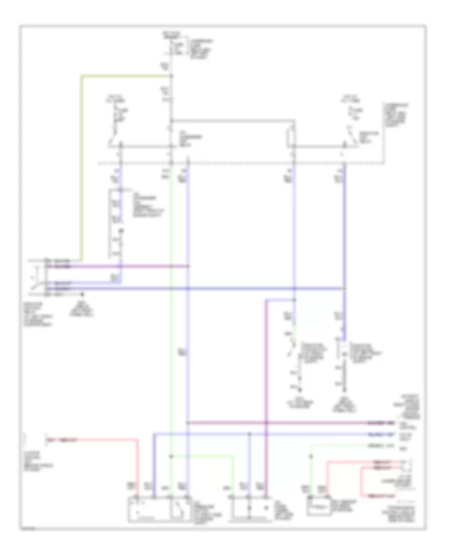
AIR CONDITIONING
Automatic A/C Wiring Diagram for Honda Insight 2006

List of elements for Automatic A/C Wiring Diagram for Honda Insight 2006:
- (above left front wheelwell)
- (at front of engine compartment) radiator fan switch
- (at top rear of engine) g101
- (behind glove box) blower power transistor
- (behind right side of dash)
- A/c
- A/c compressor clutch
- A/c compressor clutch relay
- A/c condenser fan assembly (right front of engine compartment)
- A/c condenser fan relay
- A/c diode (under left side of dash)
- A/c on
- A/c pressure switch (at right side of engine compartment)
- A10
- A11
- A12
- A17
- A18
- A19
- A20
- A23
- A27
- Air mix control motor (behind glove box)
- Amd-p
- B/l
- B10
- B11
- B12
- B13
- B14
- B15
- B16
- B17
- B18
- B19
- B20
- B21
- B22
- Blower motor (behind glove box)
- Blower motor high relay (behind glove box)
- Blower motor relay
- C18
- Climate control unit (behind middle of dash)
- Compressor
- D11
- D12
- D14
- D16
- Def
- Defogger system
- Ect sensor (on rear of engine)
- Engine control module (on right side of front floor)
- Engrdy
- Evaporator temperature sensor (behind glove box)
- Fanc
- Frs
- Fuse 20a
- Fuse 30a
- Fuse 40a
- Fuse 7.5a
- G301
- G301 (above left front wheelwell)
- G404
- G404 (behind right side of dash)
- Gauge assembly
- H/d
- Heat
- Heater core temperature sensor (behind center lower cover)
- Hot at all times
- Hot in acc or on
- Htrs
- Ig2
- In-car temperature sensor (under center of dash)
- Interior lights system
- J/c 108 (under center of dash)
- J/c c571 (under left side of dash)
- M-com
- M-cool
- M-hot
- Mode control motor (under center of dash)
- Outside air temperature sensor (behind center of bumper)
- Pnk
- Radiator fan main relay (at left front of engine compartment)
- Radiator fan motor (at left front of engine compartment)
- Radiator fan relay
- Rec
- Recirculation control motor (behind glove box)
- Red
- Rly ctrl
- S-com
- S5v
- Sg2
- Sun light sensor
- Thermal protector (open above: 252 kpa (122 psi)
- Transmission control module (behind right side of dash)
- Underdash fuse/relay box (left end of dash)
- Underhood fuse/relay box (left side of engine compartment)
- Vehicle speed sensor (on rear of transaxle)
- Vent
Heater Wiring Diagram for Honda Insight 2006
List of elements for Heater Wiring Diagram for Honda Insight 2006:
- (behind right side of dash)
- A10
- A11
- A12
- A18
- A19
- A23
- Air mix control motor (behind glove box)
- Amd-p
- B/l
- B10
- B11
- B12
- B13
- B14
- B15
- B16
- B17
- B18
- B19
- B20
- B21
- B22
- Blower motor (behind glove box)
- Blower motor high relay (behind glove box)
- Blower motor relay
- Blower power transistor (behind glove box)
- C18
- D12
- D14
- Def
- Defogger system
- Ect sensor (on rear of engine)
- Engine control module (on right side of front floor)
- Engine controls systems
- Engrdy
- Frs
- Fuse 30a
- Fuse 40a
- Fuse 7.5a
- G101 (at top rear of engine)
- G301 (above left front wheelwell)
- G404
- G404 (behind right side of dash
- G404 (behind right side of dash)
- Gauge assembly
- H/d
- Heat
- Heater control panel
- Heater core temperature sensor (behind center lower cover)
- Hot at all times
- Hot in acc or on
- Htrs
- Ig2
- Interior lights
- J/c 108 (under center of dash)
- J/c c571 (under left side of dash)
- M-com
- M-cool
- M-hot
- Mode control motor (under center of dash)
- Outside air temperature sensor (behind middle of front bumper)
- Pnk
- Radiator fan motor (at left front of engine compartment)
- Radiator fan relay
- Radiator fan switch (at front of engine compartment)
- Rec
- Recirculation control motor (behind glove box)
- Red
- S-com
- S5v
- Sg2
- Transmission control module (behind right side of dash)
- Under-dash fuse/relay box (left end of dash)
- Under-hood fuse/relay box (left side of engine compartment)
- Vehicle speed sensor (on rear of transaxle)
- Vent
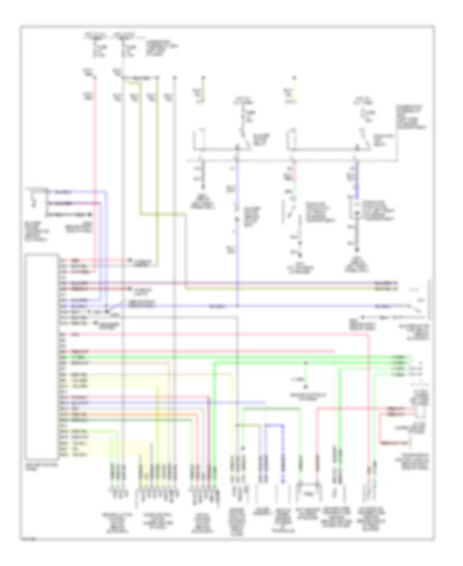
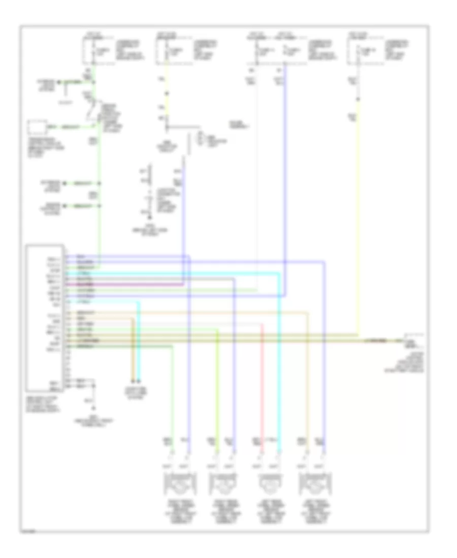
ANTI-LOCK BRAKES
Anti-lock Brakes Wiring Diagram for Honda Insight 2006
List of elements for Anti-lock Brakes Wiring Diagram for Honda Insight 2006:
- A14
- Abs busy
- Abs indicator circuit
- Abs indicator light
- Abs modulator control unit (at right front of engine compt)
- B12
- B15
- B17
- Brake pedal position switch (under left side of dash)
- Busy
- Computer data lines system
- Dlc
- Engine controls system
- Exterior lights system
- Flw (+)
- Flw (-)
- Frw (+)
- Frw (-)
- Fsr +b
- Fuse 14 20a
- Fuse 16 7.5a
- Fuse 3 30a
- Fuse 6 10a
- Fuse 6 7.5a
- G201 (above right front wheelwell)
- G402 (behind left side of dash)
- Gauge assembly
- Gnd 1
- Gnd 2
- Hot at all times
- Hot in on or acc
- Hot in on or start
- Ig2
- Interior lights system
- Junction connector c571 (under left side of dash)
- Left front wheel speed sensor (at left front wheel hub assembly)
- Left rear wheel speed sensor (at left rear wheel hub assembly)
- Motor control module (mcm) (on top front of battery module
- Mr +b
- Red
- Right front wheel speed sensor (at right front wheel hub assembly)
- Right rear wheel speed sensor (at right rear wheel hub assembly)
- Rlw (+)
- Rlw (-)
- Rrw (+)
- Rrw (-)
- Scs
- Stop
- Transmission control module (behind right side of dash) (w/ cvt)
- Underdash fuse/relay box (left end of dash)
- Underhood fuse/relay box (left side of engine compt)
- W/ cvt
- Walp
ANTI-THEFT
Anti-theft Wiring Diagram for Honda Insight 2006
List of elements for Anti-theft Wiring Diagram for Honda Insight 2006:
- (behind top of left kick panel)
- (left side of dash) security control unit
- B11
- B12
- Battery input
- Ceiling light/ spotlights
- Ceiling lt cntrl
- Cnfrm horn sig
- Cpu
- Cvt
- Disarm in
- Disarm switch
- Door open input
- Dr/hatch open
- Driver's door lock switch
- Driver's door lock switch/ actuator (rear of left front door)
- Driver's door switch
- Exterior lights system
- Fuse 10a
- Fuse 20a
- Fuse 30a
- Fuse 7.5a
- G401
- G401 (behind top of left kick panel)
- G402 (behind left side of dash)
- G601 (at center rear of cargo area)
- Gauge assembly
- Ground
- Hatch key cylinder switch
- Hatch latch switch
- Hatch latch unlock switch
- Hatch latch/ unlock switch
- Hatch lock actuator
- Horn cntrl
- Horns system
- Hot at all times
- Hot in on or start
- Ign input
- Ign key sw in
- Ignition key switch/ key light
- Ind cntrl
- Inline fuse a (left side of dash)
- Inline fuse b (left side of dash)
- Interior lights system
- Keyless door lock control unit (under left side of dash)
- Light flash in
- Lock input
- Lock input (-)
- Lock sig (+)
- M/t
- Passenger's door lock actuator (rear of passenger's door)
- Passenger's door switch
- Red
- Security led
- Taillight relay
- Taillight rly
- Under-dash fuse/ relay box (left end of dash)
- Under-hood fuse/ relay box (left side of engine compt)
- Unlck input
- Unlck rly cntrl
- Unlck sig (+)
- Unlock relay (left side of dash)
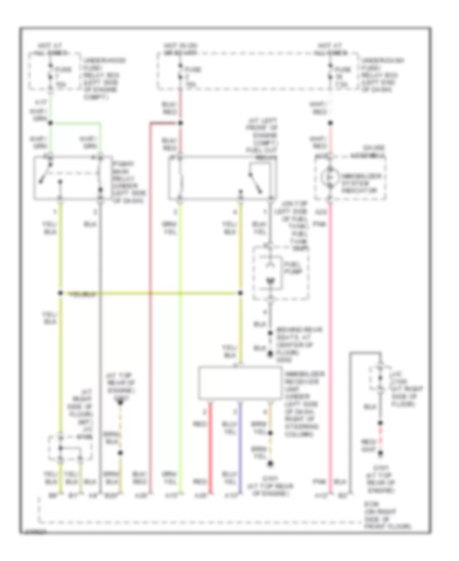
Immobilizer Wiring Diagram for Honda Insight 2006
List of elements for Immobilizer Wiring Diagram for Honda Insight 2006:
- (at left front of engine compt) fuel cut relay
- (at right side of floor) (m/t) j/c c105
- (at top
- (behind rear seats, at center of floor) g502
- (on top left side of fuel tank) fuel tank unit
- A12
- A13
- A15
- A17
- A22
- A23
- A25
- A26
- B20
- Ecm (on right side of front floor)
- Fuel pump
- Fuse 15a
- Fuse 7.5a
- G101
- G101 (at top rear of engine)
- Gauge assembly
- Hot at all times
- Hot in on or start
- Immobilizer receiver unit (under left side of dash, right of steering column)
- Immobilizer system indicator
- J/c c105 (at right side of floor)
- Pgm-fi main relay (under left side of dash)
- Pnk
- Rear of engine)
- Rear of engine) g101
- Red
- Under-dash fuse/ relay box (left end of dash)
- Under-hood fuse/ relay box (left side of engine compt)
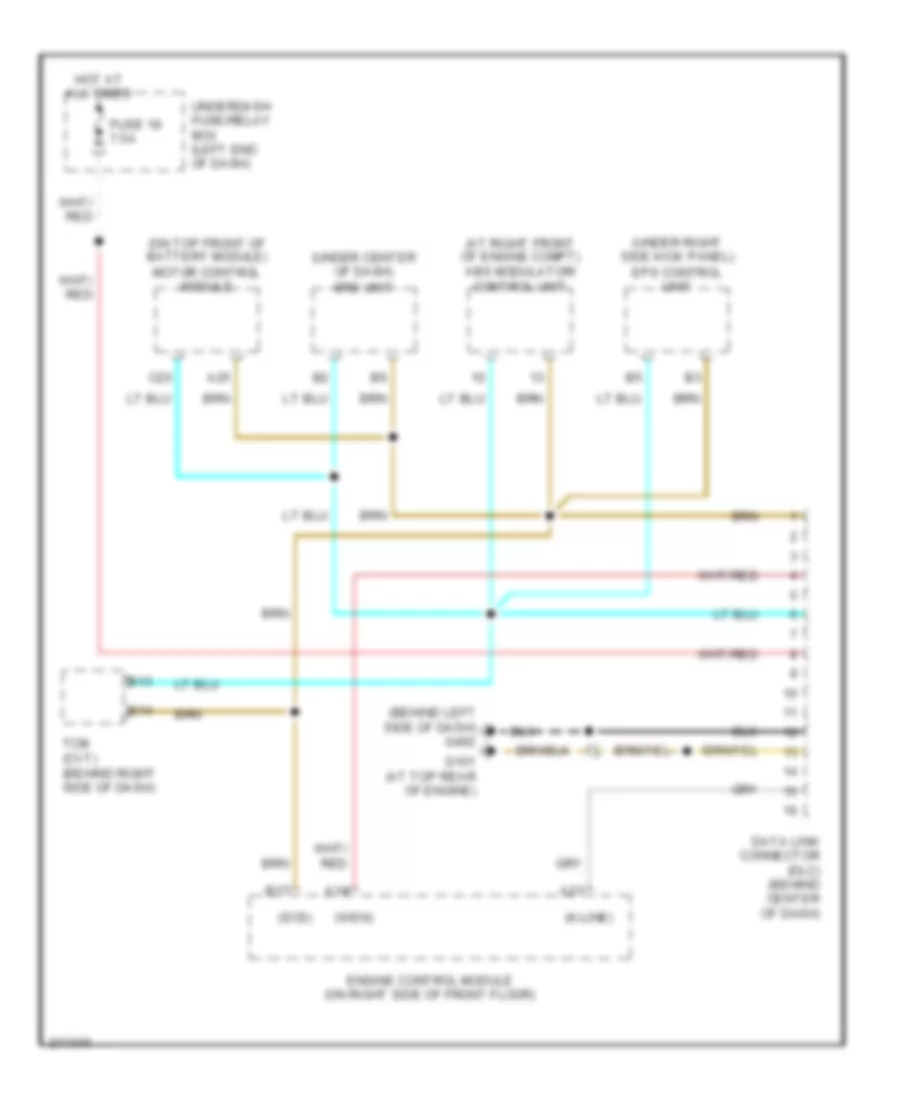
COMPUTER DATA LINES
Computer Data Lines Wiring Diagram for Honda Insight 2006
List of elements for Computer Data Lines Wiring Diagram for Honda Insight 2006:
- (at right front of engine compt) abs modulator/ control unit
- (behind left side of dash) g402
- (k-line)
- (on top front of battery module) motor control module
- (scs)
- (under center of dash) srs unit
- (under right side kick panel) eps control unit
- (wen)
- A14
- A21
- A25
- B13
- B14
- B17
- C20
- Data link connector (dlc) (behind center of dash)
- Engine control module (on right side of front floor)
- Fuse 18 7.5a
- G101 (at top rear of engine)
- Hot at all times
- Tcm (cvt) (behind right side of dash)
- Underdash fuse/relay box (left end of dash)
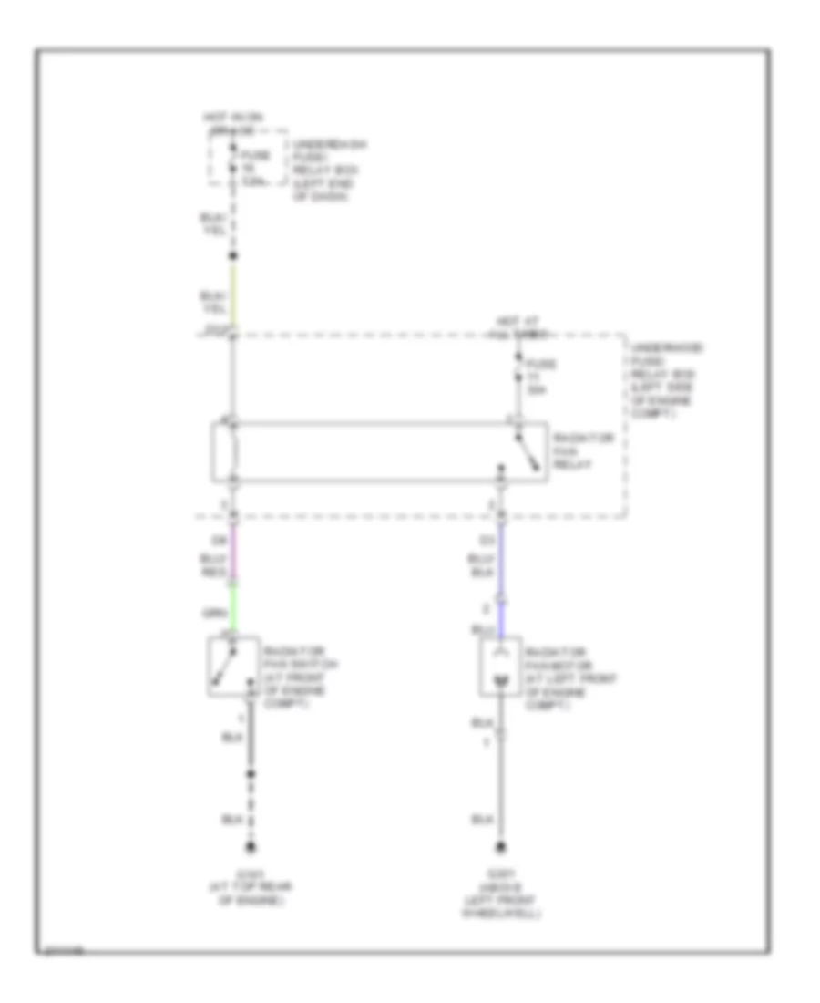
COOLING FAN
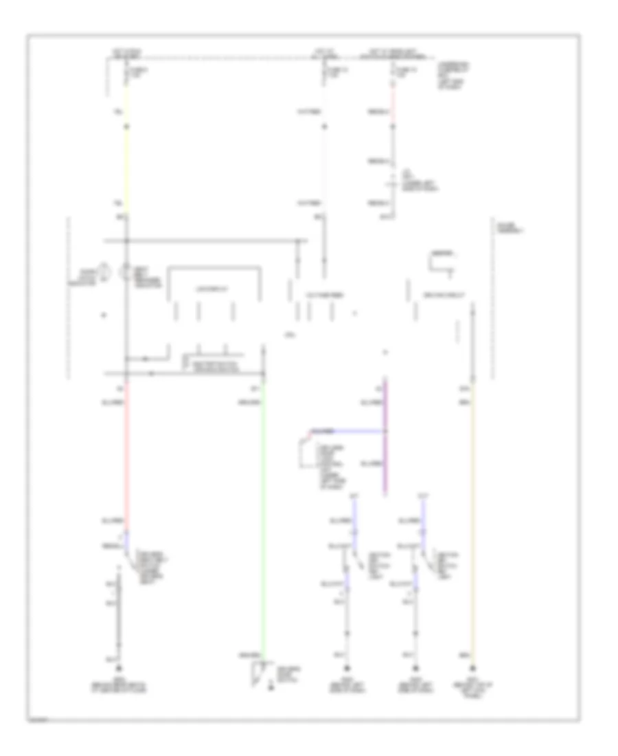
Cooling Fan Wiring Diagram, with A/C for Honda Insight 2006
List of elements for Cooling Fan Wiring Diagram, with A/C for Honda Insight 2006:
- (on right side of front floor) engine control module
- A/c condenser fan assembly (right front of engine compt)
- A/c condenser fan relay
- A/c diode (under left side of dash)
- A/c on input
- A/c pressure switch (at right side of engine compt)
- A19
- A20
- A27
- B17
- C18
- Climate control unit (behind middle of dash)
- D12
- D16
- Ect sensor (on rear of engine)
- Fan control
- Fuse 20a
- Fuse 30a
- Fuse 7.5a
- G101 (at top rear of engine)
- G301 (above left front wheelwell)
- Hot at all times
- Hot in on or acc
- J/c 108 (under center of dash)
- Radiator fan main relay (at left front of engine compartment)
- Radiator fan motor (at left front of engine compt)
- Radiator fan relay
- Radiator fan switch (at front of engine compt)
- Sg2
- Transmission control module (behind right side of dash)
- Underdash fuse/ relay box left end of dash)
- Underhood fuse/ relay box (left side of engine compt)
Cooling Fan Wiring Diagram, without A/C for Honda Insight 2006
List of elements for Cooling Fan Wiring Diagram, without A/C for Honda Insight 2006:
- D12
- Fuse 30a
- Fuse 7.5a
- G101 (at top rear of engine)
- G301 (above left front wheelwell)
- Hot at all times
- Hot in on or acc
- Radiator fan motor (at left front of engine compt)
- Radiator fan relay
- Radiator fan switch (at front of engine compt)
- Underdash fuse/ relay box (left end of dash)
- Underhood fuse/ relay box (left side of engine compt)
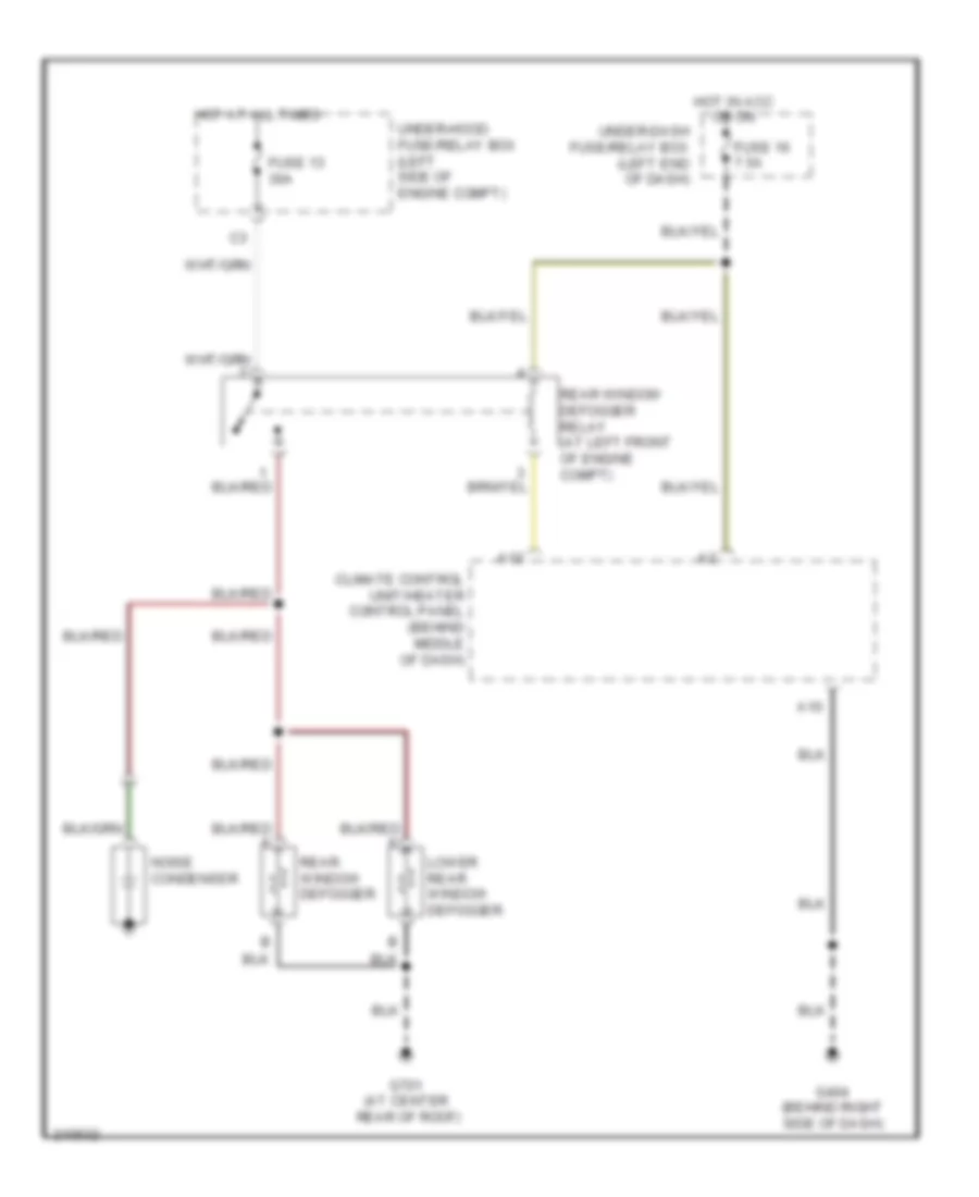
DEFOGGERS
Defoggers Wiring Diagram for Honda Insight 2006
List of elements for Defoggers Wiring Diagram for Honda Insight 2006:
- A10
- A12
- Climate control unit/heater control panel (behind middle of dash)
- Fuse 13 30a
- Fuse 16 7.5a
- G404 (behind right side of dash)
- G701 (at center rear of roof)
- Hot at all times
- Hot in acc or on
- Lower rear window defogger
- Noise condenser
- Rear window defogger
- Rear window defogger relay (at left front of engine compt)
- Under-dash fuse/relay box (left end of dash)
- Under-hood fuse/relay box (left side of engine compt)
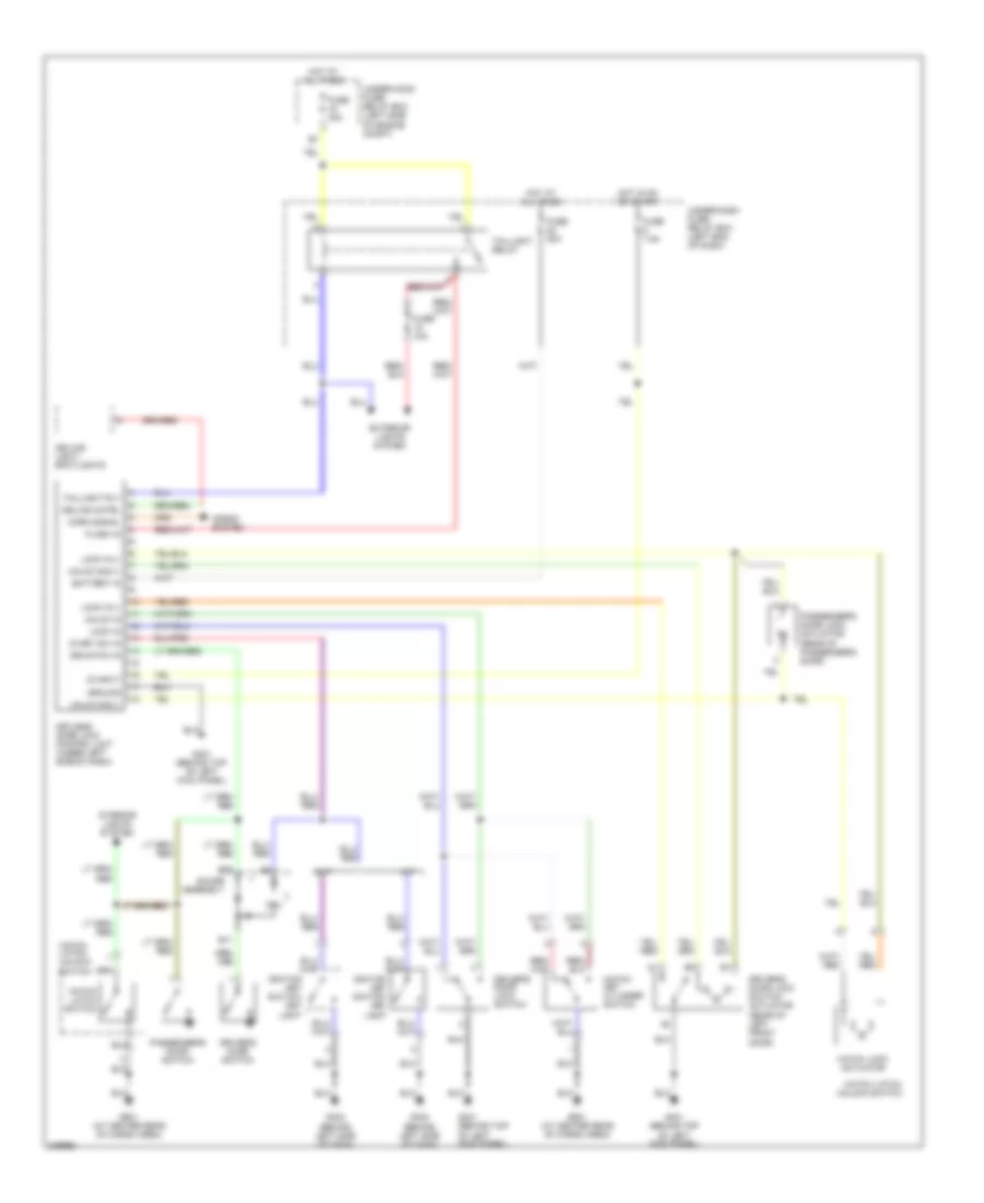
ELECTRONIC POWER STEERING
Electronic Power Steering Wiring Diagram for Honda Insight 2006
List of elements for Electronic Power Steering Wiring Diagram for Honda Insight 2006:
- (at left rear of engine compt) eps torque sensor
- (nep)
- (under right side kick panel) eps control unit
- A19
- B(+)
- B10
- B11
- B12
- B13
- B14
- Cpu
- Data link connector (behind center of dash)
- Diag-h
- Ecm (on right side of front floor)
- Eps ind- icator
- Eps motor
- Eps motor relay (under right kick panel)
- Fuse 15 40a
- Fuse 6 7.5a
- G4 (at left side of engine compt)
- G402 (behind left side of dash)
- G451 (behind right kick panel)
- Gauge assembly
- Hot at all times
- Hot in on or start
- Ig1
- Nep
- Red
- Rt(+)
- Scs
- Steering gear box
- T/s gnd
- Underdash fuse/relay box (left end of dash)
- Underhood fuse/relay box (left side of engine compt)
- Vcc1
- Vcc2
- Vsp
- Vt3
- Vt6
- Wlp
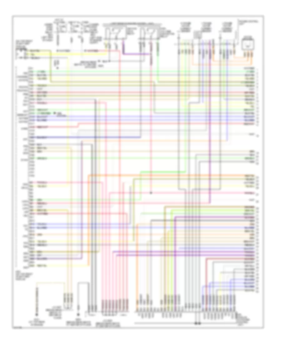
ENGINE PERFORMANCE
IMA Wiring Diagram (1 of 5) for Honda Insight 2006
List of elements for IMA Wiring Diagram (1 of 5) for Honda Insight 2006:
- (behind rear seats, at center g502 of floor)
- (left rear of power control unit)
- (on top front of battery module) ima diode
- A10
- A11
- A12
- A13
- A14
- A15
- A16
- A17
- A18
- A19
- A20
- A21
- A22
- A23
- A24
- A25
- A26
- A27
- A28
- A29
- A30
- A31
- A32
- Abs system
- Absbusy
- B10
- B11
- B12
- B13
- B14
- B15
- B16
- B17
- B18
- B19
- B20
- B21
- B22
- B23
- B24
- B25
- Cnt
- Dvinh
- Fot
- Fsc
- Fuse 7.5a
- Fuse 80a
- G101 (at top rear of engine)
- G502 (behind rear seats at center of floor)
- Gun
- Gup
- Gvn
- Gvp
- Gwn
- Gwp
- High voltage contactor relay
- Hot at all times
- Ig1
- Iga1
- Iga2
- Ighld
- Ignition hold relay
- Ipin
- Iuph
- Ivph
- Iwph
- J/c c507 (behind rear seats, at center of floor)
- J/c c508 (behind rear seats at center of floor)
- Lg1
- Lg2
- Mamode2
- Mcm (on top front of battery module)
- Motfsa
- Motfsb
- Motor stator
- Motstb
- Mpi module (in power control unit)
- Nca
- Pdufan
- Pdufanh
- Pg1
- Pg2
- Power control unit
- Pre
- Scs
- Sg4
- Sg6
- Sg7
- Sg8
- Sg9
- Tdv
- Tha
- Thb
- U phase motor current sensor
- Under- dash fuse/ relay box (left end of dash)
- Under- hood fuse/ relay box (left side of engine compt)
- V phase motor current sensor
- Vbu
- Vdd
- Vgg
- Vgln
- Vglp
- Vgun
- Vgup
- Vgvn
- Vgvp
- Vgwn
- Vgwp
- Vpin
- W phase motor current sensor
- Warn
IMA Wiring Diagram (2 of 5) for Honda Insight 2006
List of elements for IMA Wiring Diagram (2 of 5) for Honda Insight 2006:
- (at top rear of engine) g101
- (behind rear seats, at center of floor)
- (behind rear seats, at center of floor) g502
- (left rear of power control unit)
- (left rear side of pcu)
- (left rear side of pcu) mpi module fan
- (right front of power control unit) dc-dc converter fuse
- 30a
- A red
- A10
- A11
- A12
- A13
- A14
- A15
- A16
- A17
- A18
- A19
- A20
- A21
- A22
- A23
- A24
- A25
- A26
- B red
- B10
- B11
- B12
- B13
- B14
- B15
- B16
- C red
- C10
- C11
- C12
- D red
- Fot
- Fsc
- Fuse 15a
- G101
- G502
- Gun
- Gup
- Gvn
- Gvp
- Gwn
- Gwp
- High speed mpi module fan control relay
- High speed mpi module fan control resistor
- Hot at all times
- Iga
- J/c c507 (behind rear seats, at center of floor)
- J/c c508 (behind rear seats, at center of floor)
- Low speed mpi module fan control relay
- Low speed mpi module fan control resistor
- Nca
- Red
- Sg10
- Sg9
- Tha
- Thb
- Under- hood fuse/ relay box (left side of engine compt)
- Vdd
- Vgg
- Vgln
- Vglp
- Vgun
- Vgup
- Vgvn
- Vgvp
- Vgwn
- Vgwp
- Voltage converter module (in power control unit)
- Vpin
- Vref
IMA Wiring Diagram (3 of 5) for Honda Insight 2006
List of elements for IMA Wiring Diagram (3 of 5) for Honda Insight 2006:
- (at top rear of battery module)
- (at top rear of engine) g101
- (behind rear seats, at center of floor) j/c c507
- (left front of battery module) bypass contactor
- (not used)
- A21
- B19
- B20
- Battery current sensor (on top front of battery module)
- Battery module fan motor
- Battery module fan resistor (left front of battery module)
- Bypass resistor (below left side of battery module)
- Cpu
- Dc-dc converter (right front of power control unit)
- Fuse 7.5a
- G502 (behind rear seats, at center of floor)
- G651 (at left rear side of floor)
- Gauge assembly
- Gnd
- High speed battery module fan control relay (left front side of battery module)
- High voltage contactor (in left front of battery module)
- Hot in on or start
- Ig1
- Ignition
- Ima syst
- Ima system ind
- Ims syst
- J/c c104 (at top rear of engine)
- J/c c508 (behind rear seats, at center of floor)
- Low speed battery module fan control relay (left front side of battery module)
- Mpi module current sensor (on left side of battery module)
- Nca
- Not used
- Red
- Seats, at center of floor)
- Starting/ charging system
- Under-dash fuse/relay box (left end of dash)
- Voltage feed
- Vss (m/t, cvt) (on rear of transaxle)
IMA Wiring Diagram (4 of 5) for Honda Insight 2006
List of elements for IMA Wiring Diagram (4 of 5) for Honda Insight 2006:
- (at top rear of engine) g101
- 100a
- A19
- Acttrq
- B14
- Battery module
- Battery module switch
- Braided wires
- Capacitor assembly
- Cmdpwr
- D13
- D14
- D15
- Ecm (on right side of floor)
- Engtrq
- Eps control unit (under right side kick panel)
- J/c c105 (at right side of floor)
- Mamod1
- Mamod2
- Motfsa
- Motfsb
- Motor commutation sensor (on lower right rear of engine)
- Motstb
- Nca
- Nep
- Pnk
- Power control unit (pcu)
- Red
- Snubber unit
- Tcm (cvt) (behind right side of dash)
- Test tachometer connector (left rear of engine compartment)
- Y capacitor
IMA Wiring Diagram (5 of 5) for Honda Insight 2006
List of elements for IMA Wiring Diagram (5 of 5) for Honda Insight 2006:
- (at top rear of engine)
- (b1-b7 not used)
- (b13-b18 not used)
- (behind rear seats at center of floor)
- (c1-c4 not used)
- (dlc) (behind center of dash)
- (e1-e3 & e5-e7 not used)
- (not used)
- (not used) b10
- (not used) b21
- (not used) c17
- (not used) c19
- A11
- A12
- A13
- A14
- A15
- A16
- A20
- A21
- A23 not used) a17,a18,a19,a22, (a5,a6,a9,a10,
- A24
- A25
- A26
- Acttrq
- B11
- B12
- B19
- B20
- B22
- Battery condition monitor (bcm) module (on top front of battery module)
- Battery module
- Battfanh
- Battfanl
- Battsci1
- Battsci2
- C10
- C11
- C12
- C13
- C14
- C15
- C16
- C17
- C18
- C19
- C20
- C21
- C22
- C23
- C24
- C25
- C26
- C27
- C28
- C29
- C30
- C31
- Cma
- Cmb
- Cmc
- Cmdpwr
- D10
- D11
- D12
- D13
- D14
- D15
- D16
- Data link connector
- Engtrg
- G101 g502 (behind rear seats, at center of floor)
- Iga1
- Iga2
- Ipwr +
- Ipwr -
- Isoc
- J/c c507
- J/c c508 (behind rear seats at center of floor)
- Lg1
- Lg2
- Mamode1
- Mcm (on top front of battery module)
- Metsci1
- Metsci2
- Nca
- Nep
- Pg1
- Pg2
- Pnk
- Ptc +
- Ptc -
- Qbatt
- Red
- Sg1
- Sg10
- Sg2
- Sg3
- Tbatt sg
- Tbatt1
- Tbatt2
- Tbatt3
- Tbatt4
- Tdx/rdx
- Vbu
- Vcc1
- Vcc2
- Vcc3
- Vcc4
- Vcc5
- Vcc6
- Vcc7
- Vhb+
- Vhb-
- Vhb0
- Vhb1
- Vhb10
- Vhb11
- Vhb2
- Vhb3
- Vhb4
- Vhb5
- Vhb6
- Vhb7
- Vhb8
- Vhb9
- Vref
- Vss
1.0L
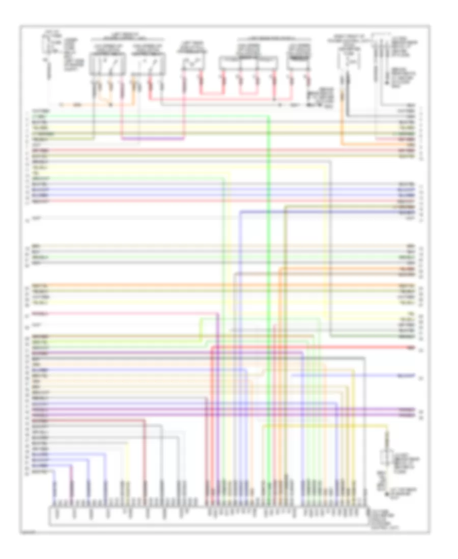
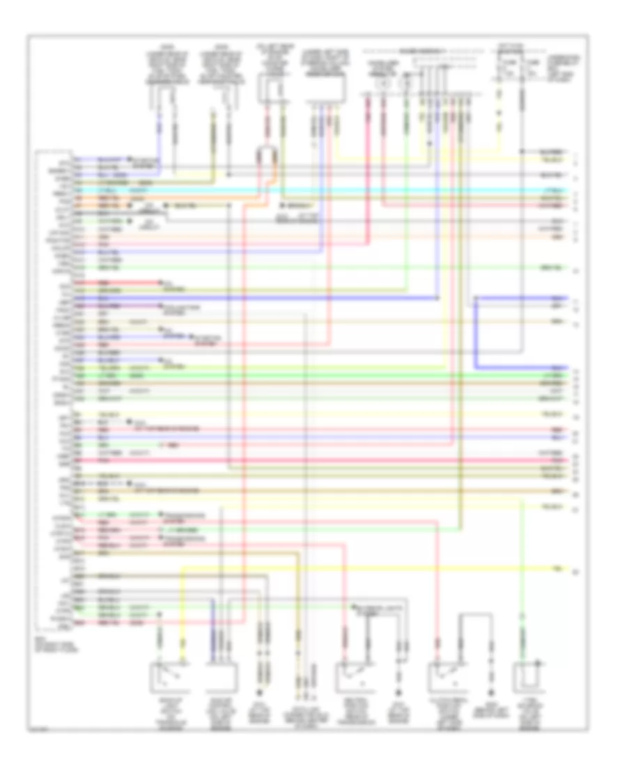
1.0L, Engine Controls Wiring Diagram (1 of 4) for Honda Insight 2006
List of elements for 1.0L, Engine Controls Wiring Diagram (1 of 4) for Honda Insight 2006:
- (2005)
- (2006)
- (at top rear of engine)
- (on left rear of engine) evap canister purge valve
- (under left side of dash, right of steering column) immobilizer receiver unit
- (under rear of vehicle, near right side of fuel tank) evap bypass solenoid valve
- (under rear of vehicle, near right side of fuel tank) evap canister vent shut valve
- (w/cvt)
- (w/m/t)
- 2wbs
- A/c system
- A10
- A11
- A12
- A13
- A14
- A15
- A16
- A17
- A18
- A19
- A20
- A21
- A22
- A23
- A24
- A25
- A26
- A27
- A28
- A29
- A30
- A31
- A32
- Acc
- Acs
- Atpd
- Atpnp
- Atpr
- B10
- B11
- B12
- B13
- B14
- B15
- B16
- B17
- B18
- B19
- B20
- B21
- B22
- B23
- B24
- B25
- Back-up light switch (on transaxle housing)
- Bksw
- Clsw
- Clutch pedal position switch (under left side of dash)
- Cooling fans system
- Cpu
- Data link connector (dlc) (behind center of dash)
- Dvc
- Dvct
- Ecm (on right side of front floor)
- Egr
- Engrdy
- Exterior lights system
- Fanc
- Fuse 15a
- Fuse 7.5a
- G101
- G101 (at top rear of engine)
- G402 (behind left side of dash)
- Gauge assembly
- Hot in on or start
- Htrs
- Iacv
- Idle air control (iac) valve (on left side of engine)
- Idssw
- Ig1
- Igp1
- Igp2
- Ima circuit
- Immobilizer system indicator
- Imocd
- Imoen
- Imoflr
- Imolmp
- Inj1
- Inj2
- Inj3
- K-line
- Lg1
- Lg2
- M/p mon
- Mil
- Mrly
- Mtrtw
- Nep
- Neutral position switch (rear of transmission)
- Ntsw
- Pbrk1
- Pbrk2
- Pcs
- Pg1
- Pg2
- Pnk
- Po2htcr
- Ptank
- Red
- Rvssw
- Scs
- Slc
- Starting system
- Stc
- Sts
- Tim
- Transmissions system
- Under-dash fuse/relay box (left end of dash)
- Vref
- Vsv
- Vtec solenoid valve (on left side of engine)
- Vts
- Wen
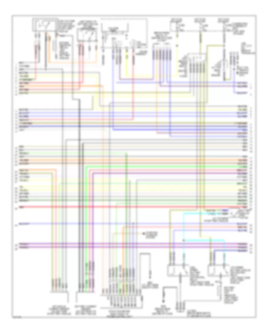
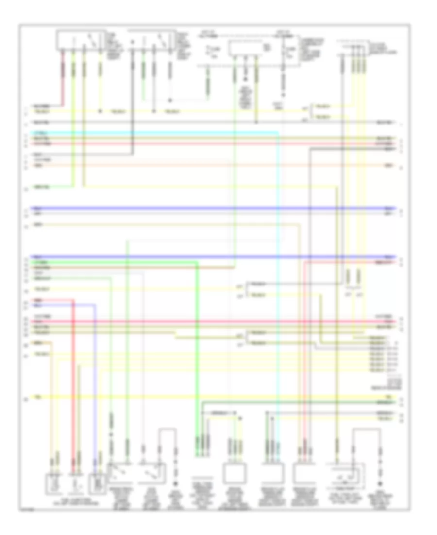
1.0L, Engine Controls Wiring Diagram (2 of 4) for Honda Insight 2006
List of elements for 1.0L, Engine Controls Wiring Diagram (2 of 4) for Honda Insight 2006:
- A/t
- A17
- Brake booster vacuum sensor (on left rear of engine compt)
- Brake fluid pressure sensor a (right side of engine compt)
- Brake fluid pressure sensor b (right side of engine compt)
- Brake pedal position switch (under left side of dash)
- Eld unit
- Fuel cut relay (at left front of engine compt)
- Fuel injectors (on left side of engine)
- Fuel pump
- Fuel tank pressure sensor (on top right side of fuel tank) (2005)
- Fuel tank unit (on top left side of fuel tank)
- Fuse 10a
- Fuse 15a
- G301 (above left front wheel- well)
- G402 (behind left side of dash)
- G502 (behind rear seats, at center of floor)
- Hot at all times
- Idle stop switch (under left side of dash)
- J/c c104 (at top rear of engine)
- J/c c105 (at right side of floor)
- M/t
- Pgm-fi main relay (under left side of dash)
- Pnk
- Red
- Under-hood fuse/relay box (left side of engine compt)
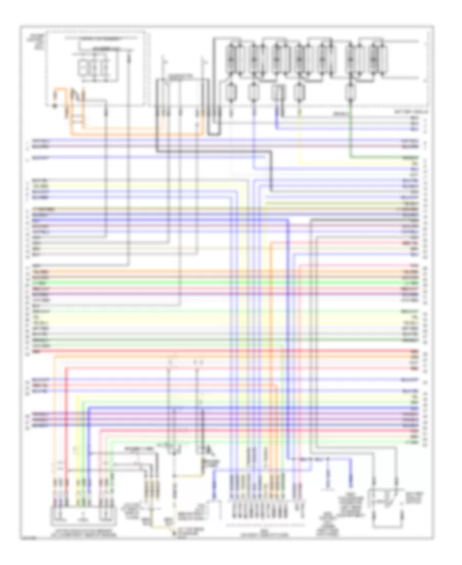
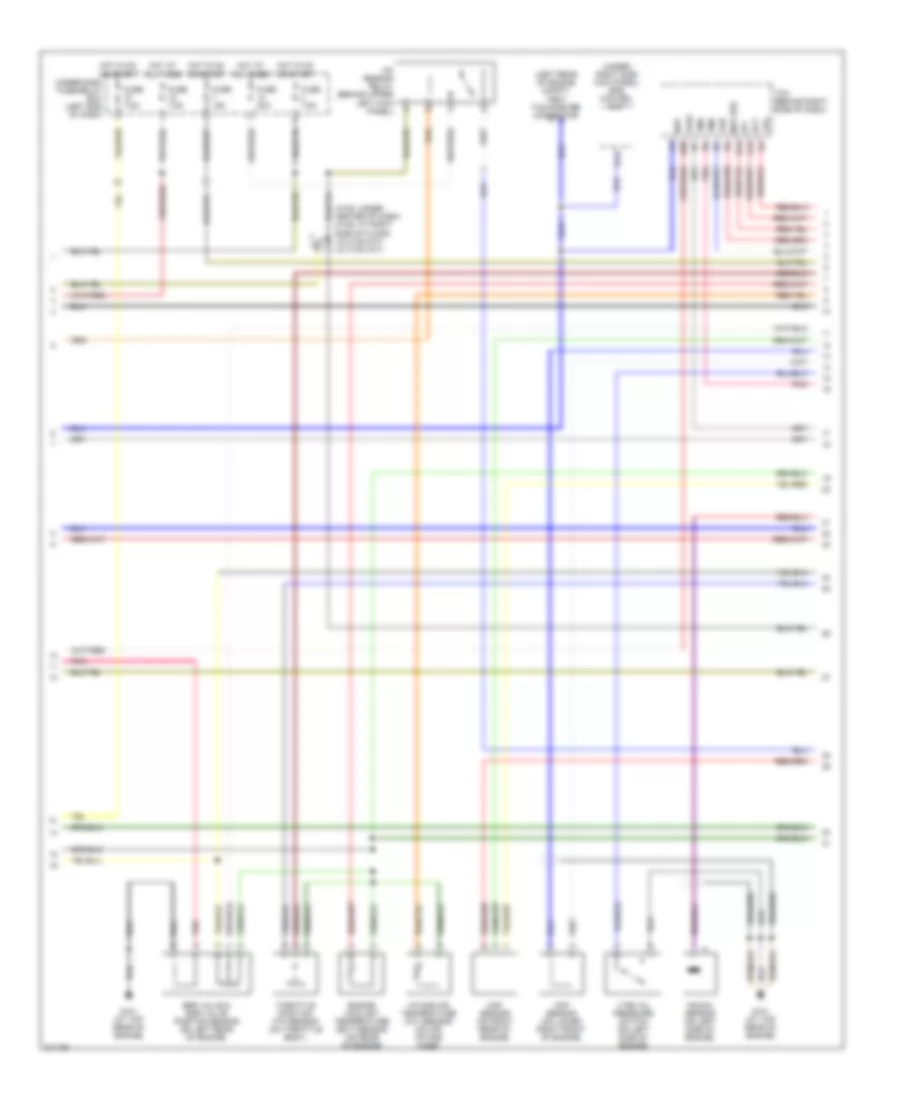
1.0L, Engine Controls Wiring Diagram (3 of 4) for Honda Insight 2006
List of elements for 1.0L, Engine Controls Wiring Diagram (3 of 4) for Honda Insight 2006:
- (c108: under center of dash) (c105: at right side of floor) j/c c105 (m/t) j/c c108 (a/t)
- (left rear of engine compt) test tachometer connector
- (under right side kick panel) eps control unit
- A/f sensor relay (behind upper left kick panel)
- A19
- B14
- B19
- B20
- Braided
- Ckp sensor (on lower right front of engine)
- Ect
- Egr valve & egr valve position sensor (on left rear of engine)
- Engine coolant temperature (ect) sensor (on rear of engine)
- Fuse 15a
- Fuse 20a
- Fuse 7.5a
- G101 (at top rear of engine)
- Hot at all times
- Hot in on or start
- Iat
- Intake air temperature (iat) sensor (on air intake hose)
- Knock sensor (on left side of engine)
- Map (pb)
- Map sensor (on right rear of engine)
- Nep
- Pnk
- Tcm (behind right side of dash)
- Throttle position (tp) sensor (on throttle body)
- Tma
- Tmb
- Tps
- Under-dash fuse/relay box (left end of dash)
- Vref
- Vss
- Vtec oil pressure switch (on left side of engine)
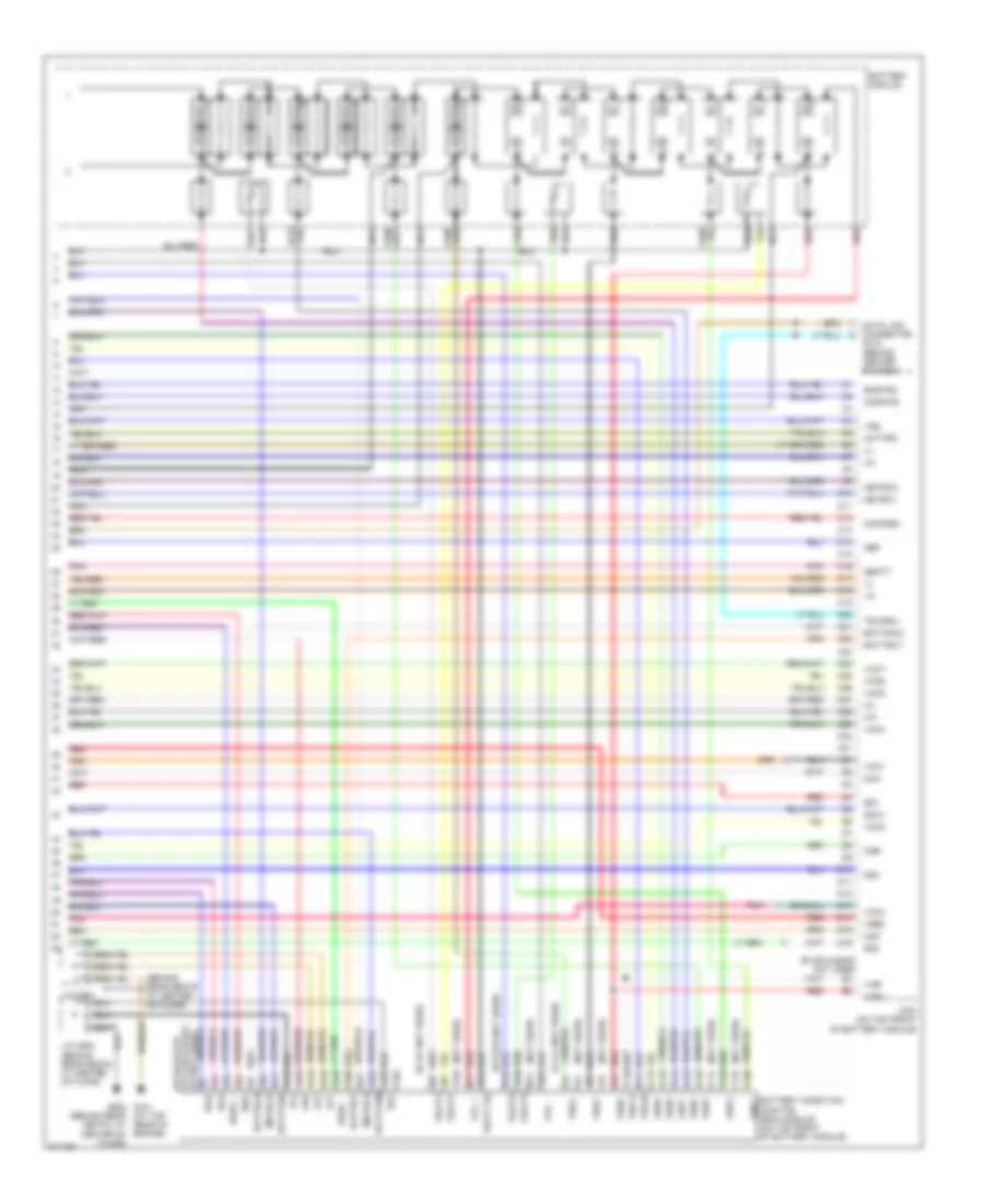
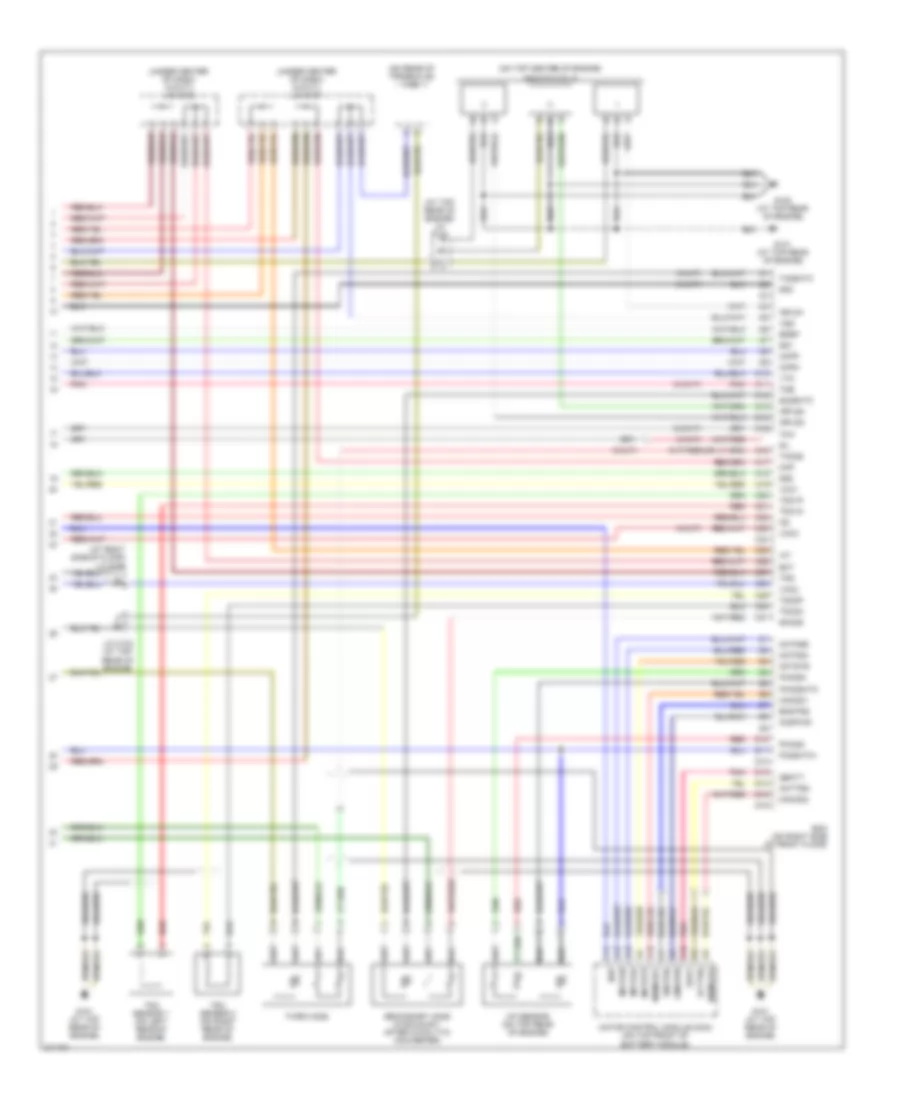
1.0L, Engine Controls Wiring Diagram (4 of 4) for Honda Insight 2006
List of elements for 1.0L, Engine Controls Wiring Diagram (4 of 4) for Honda Insight 2006:
- (at right side of floor) j/c c105
- (at top rear of engine) j/c c104
- (on rear of transaxle) vss
- (on top center of engine)
- (under center of dash) (w/cvt) j/c c107
- (under center of dash) (w/cvt) j/c c108
- (w/cvt)
- (w/m/t)
- A/f sensor (on top rear of engine)
- A15
- A16
- Acttrq
- Braided
- C10
- C11
- C12
- C13
- C14
- C15
- C16
- C17
- C18
- C19
- C20
- C21
- C22
- C23
- C24
- C25
- C26
- C27
- C28
- C29
- C30
- C31
- Ckpm
- Ckpp
- Cmdpwr
- D10
- D11
- D12
- D13
- D14
- D15
- D16
- Ecm (on right side of front floor)
- Ect
- Egrp
- Engtrq
- G101 (at top rear of engine)
- G102 (at top rear of engine)
- Iat
- Ignition coils
- Igpls1
- Igpls2
- Igpls3
- J/c c104 (at top rear of engine)
- Mamod1
- Mamod2
- Mamode1
- Mamode2
- Map
- Motfsa
- Motfsb
- Motor control module (mcm) (on top front of battery module)
- Motstb
- Nep
- Pho2s+
- Pho2s-
- Pho2shtc
- Pnk
- Po2shtc+
- Qbat
- Qbatt
- Red
- Secondary ho2s (in exhaust, after catalytic converter)
- Sg1
- Sg2
- Sg3
- Sho2s
- Sil
- So2shtc
- Tdc sensor 1 (on left rear of engine)
- Tdc sensor 2 (on right rear of engine)
- Tdc1m
- Tdc1p
- Tdc2m
- Tdc2p
- Third ho2s
- Tho2s
- Tma
- Tmb
- To2shtc
- Tps
- Vcc1
- Vcc2
- Vcc3
- Vss
- Vtm
EXTERIOR LIGHTS
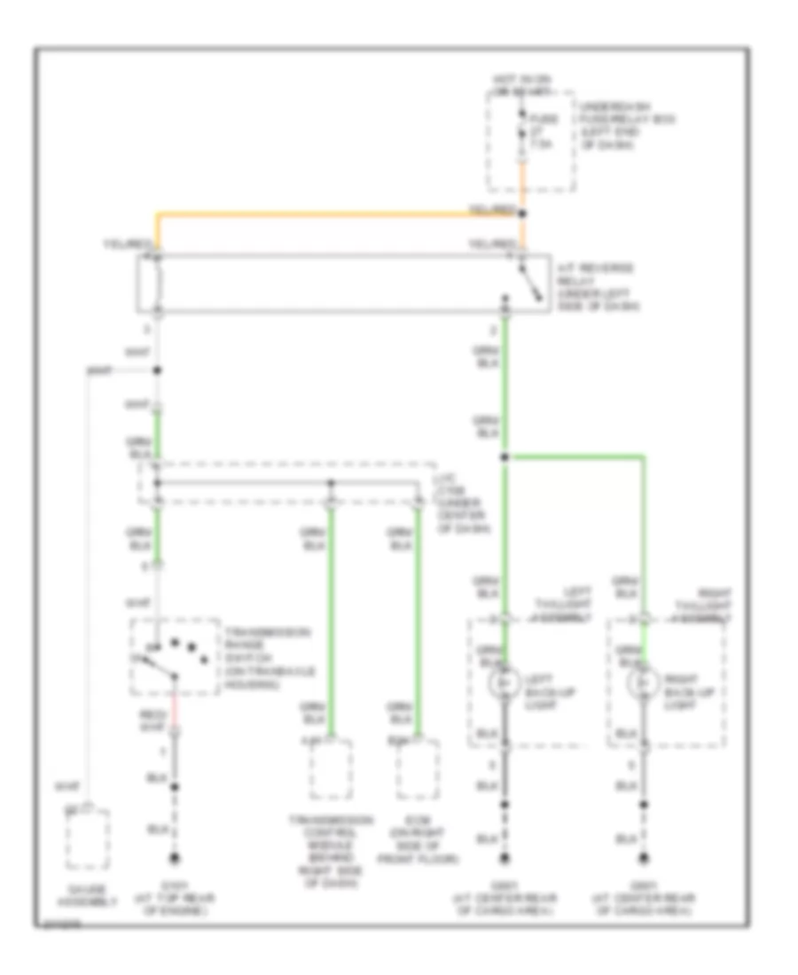
Back-up Lamps Wiring Diagram, A/T for Honda Insight 2006
List of elements for Back-up Lamps Wiring Diagram, A/T for Honda Insight 2006:
- A/t reverse relay (under left side of dash)
- A11
- B24
- Ecm (on right side of front floor)
- Fuse 7.5a
- G101 (at top rear of engine)
- G601 (at center rear of cargo area)
- Gauge assembly
- Hot in on or start
- J/c c108 (under center of dash)
- Left back-up light
- Left taillight assembly
- Right back-up light
- Right taillight assembly
- Transmission control module (behind right side of dash)
- Transmission range switch (on transaxle housing)
- Underdash fuse/relay box (left end of dash)
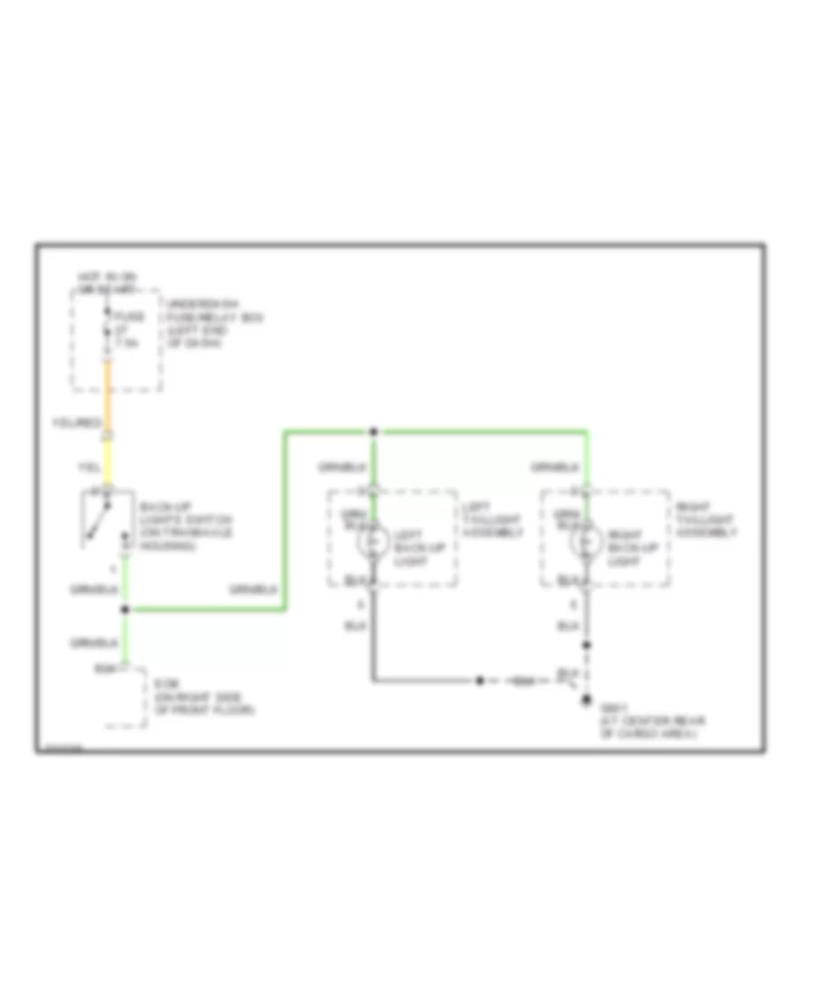
Back-up Lamps Wiring Diagram, M/T for Honda Insight 2006
List of elements for Back-up Lamps Wiring Diagram, M/T for Honda Insight 2006:
- B24
- Back-up lights switch (on transaxle housing)
- Ecm (on right side of front floor)
- Fuse 7.5a
- G601 (at center rear of cargo area)
- Hot in on or start
- Left back-up light
- Left taillight assembly
- Right back-up light
- Right taillight assembly
- Underdash fuse/relay box (left end of dash)
Exterior Lamps Wiring Diagram for Honda Insight 2006
List of elements for Exterior Lamps Wiring Diagram for Honda Insight 2006:
- (left end of dash) underdash fuse/relay box
- A14
- A30
- B17
- Brake pedal position switch (under left side of dash)
- Combination light switch
- Door locks system
- Engine controls & anti- lock brakes systems
- Fuse 10a
- Fuse 30a
- Fuse 7.5a
- G201 (above right front wheelwell)
- G301 (above left front wheelwell)
- G401 (behind top of left kick panel)
- G402 (behind left side of dash)
- G601 (at center rear of cargo area)
- G701 (at center rear of roof)
- Gauge assembly
- Hazard warning switch
- Hazard warning switch light
- Head
- Head- light switch
- High mount brake light
- Hot at all times
- Hot in on or start
- Interior lights system
- J/c c571 (under left side of dash)
- Left front parking light
- Left front side marker light
- Left front turn signal light
- Left taillight assembly
- Left taillight/ brake light
- Left turn signal indicator
- Left turn signal light
- License plate light
- Off
- Park
- Red
- Right front parking light
- Right front side marker light
- Right front turn signal light
- Right taillight assembly
- Right taillight/ brake light
- Right turn signal indicator
- Right turn signal light
- Taillight relay
- Turn signal/hazard relay
- Turn turn signal switch
- Underdash fuse/relay box (left end of dash)
- Underhood fuse/relay box (left side of engine compt)
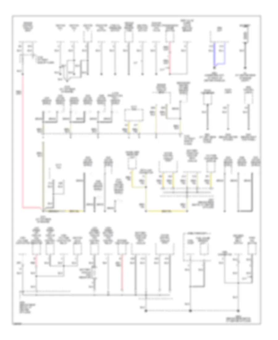
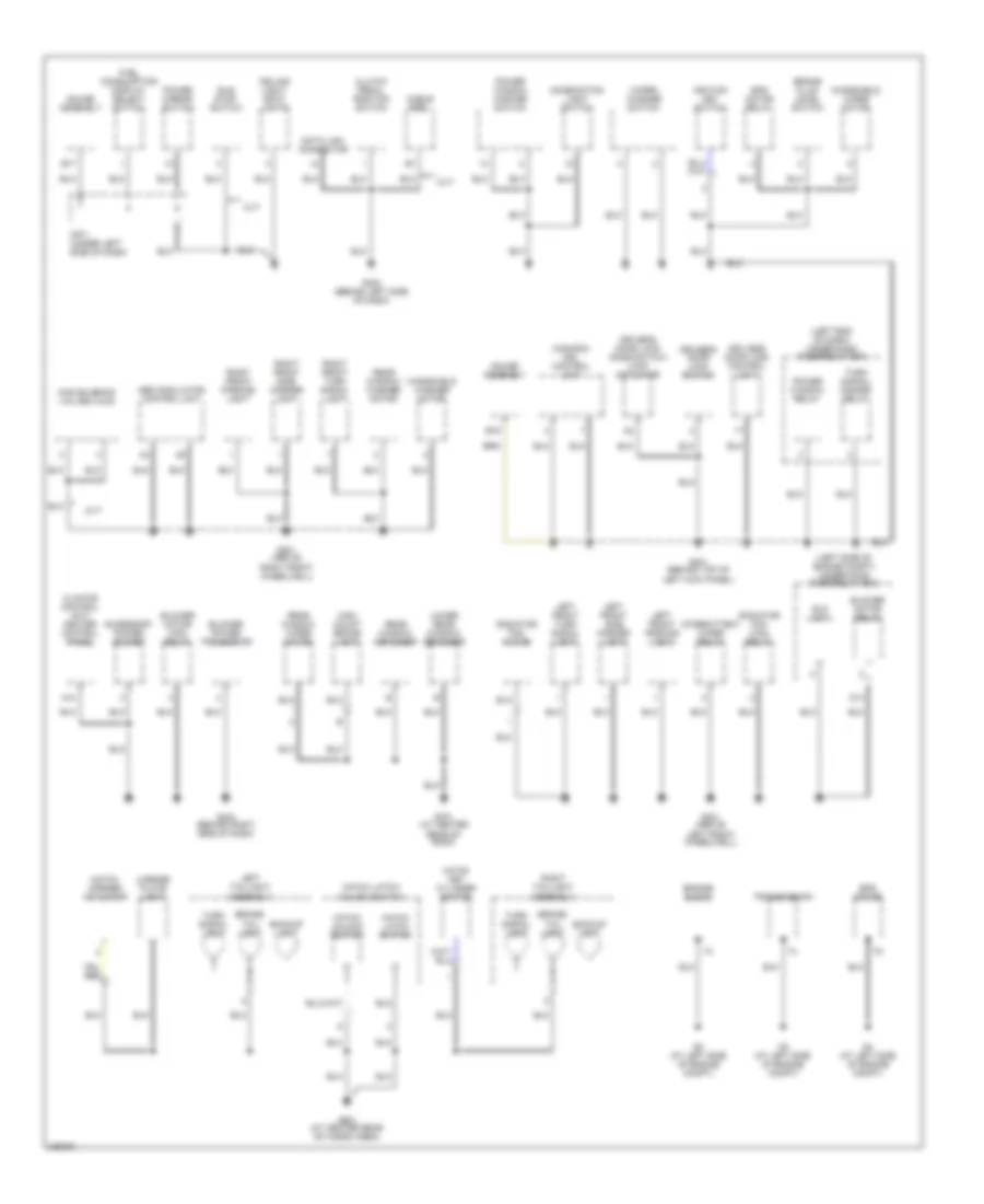
GROUND DISTRIBUTION
Ground Distribution Wiring Diagram (1 of 2) for Honda Insight 2006
List of elements for Ground Distribution Wiring Diagram (1 of 2) for Honda Insight 2006:
- (cvt) tcm
- (late production) tdc 1 sensor shield
- (m/t) third heated oxygen sensor shield
- A10
- A12
- A13
- A14
- A15
- A17
- A20
- A23
- A24
- A25
- A26
- Audio unit
- B10
- B11
- B20
- B22
- Battery
- Battery condition monitor (bcm) module
- Battery module fan resistor
- Braid
- Bypass contactor
- C105 (at right side of floor)
- C507 (behind rear seats, at center of floor)
- C508 (behind rear seats, at center of floor)
- Ckp sensor shield
- Cma motor sensor shield
- Cmb motor sensor shield
- Cmc motor sensor shield
- Cvt
- Data link connector
- Dc-dc converter
- Driver's seat belt switch
- Egr valve & egr valve position sensor
- Engine control module (ecm)
- Eps control unit
- Fuel gauge sending unit
- Fuel pump
- Fuel tank unit
- G1 (at center rear of engine compt)
- G101 (at top rear of engine)
- G102 (at top rear of engine)
- G403 (behind center of dash)
- G451 (behind right kick panel)
- G501 (under srs unit, at front of center console)
- G502 (behind rear seats, at center of floor)
- G651 (at left rear side of floor)
- High speed battery module fan control relay
- High speed mpi module fan control relay
- High voltage contactor
- High voltage contactor relay
- Idle air control (iac) valve
- Ignition coil
- Ignition hold relay
- Immobilizer receiver unit
- Knock sensor shield
- Low speed battery module fan control relay
- Low speed mpi module fan control resistor
- M/t
- Mes connector
- Motor control module (mcm)
- Neutral position switch
- Park pin switch
- Radiator fan switch
- Red
- Secondary heated oxygen sensor shield
- Srs unit
- Transmission range switch
- Vehicle speed sensor (vss)
- Voltage converter module
- Vtec oil pressure switch
Ground Distribution Wiring Diagram (2 of 2) for Honda Insight 2006
List of elements for Ground Distribution Wiring Diagram (2 of 2) for Honda Insight 2006:
- (canada) drl control unit
- (left end of dash) under-dash fuse/relay box
- (left side of engine compt) under-hood fuse/relay box
- A10
- Abs modulator control unit
- Accessory power socket
- B16
- B17
- Backup light
- Blower motor high relay
- Blower motor relay
- Blower power transistor
- Brake fluid level switch
- Brake/ tail light
- C571 (under left side of dash)
- Cable reel
- Cas solenoid valves a & b
- Ceiling light/ spot lights
- Climate control unit/ heater control panel
- Clutch pedal position switch
- Combination light switch
- Cvt
- D14
- Data link connector
- Driver's door lock knob switch/ lock actuator
- Driver's door lock switch
- Eld unit
- Engine block
- Eps motor
- Eps motor relay
- Fuel consumption display select switch
- G2 (at left side of engine compt)
- G201 (above right front wheelwell)
- G3 (at left side of engine compt)
- G301 (above left front wheelwell)
- G4 (at left side of engine compt)
- G401 (behind top of left kick panel)
- G402 (behind left side of dash)
- G404 (behind right side of dash)
- G601 (at center rear of cargo area)
- G701 (at center rear of roof)
- Gauge assembly
- Hatch key cylinder switch
- Hatch latch switch
- Hatch latch/ unlock switch
- Hatch opener actuator
- Hatch unlock switch
- High mount brake light
- Idle stop switch
- Ignition key switch
- Intermittent wiper relay
- Keyless door lock control unit
- Left front parking light
- Left front side marker light
- Left front turn signal light
- Left taillight assembly
- License plate light
- Lower rear window defogger
- Power mirror switch
- Power window master switch
- Power window relay
- Radiator fan main relay
- Radiator fan motor
- Rear window defogger
- Rear window washer motor
- Rear window wiper motor
- Right front parking light
- Right front side marker light
- Right front turn signal light
- Right taillight assembly
- Transmission
- Turn signal light
- Turn signal/ hazard relay
- Windshield washer motor
- Windshield wiper motor
- Wiper/ washer switch
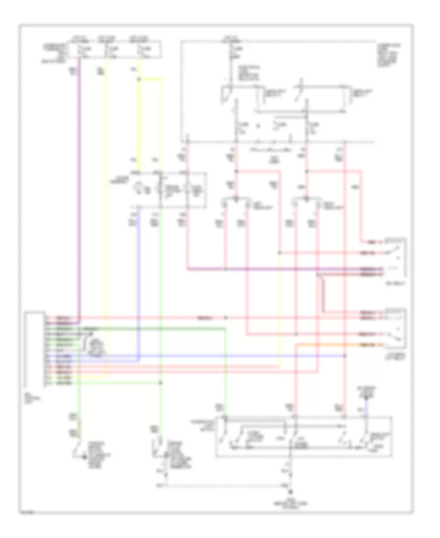
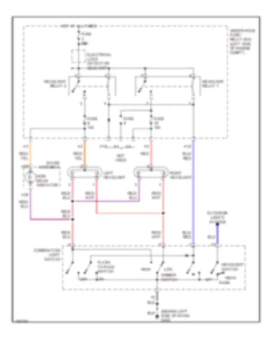
HEADLIGHTS
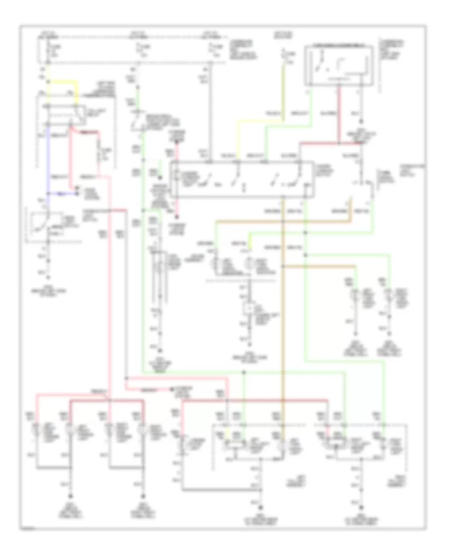
Headlights Wiring Diagram, with DRL for Honda Insight 2006
List of elements for Headlights Wiring Diagram, with DRL for Honda Insight 2006:
- (not used)
- A12
- A13
- A24
- A25
- A28
- A29
- Brake fluid level switch (on master cylinder reservoir)
- Brake system ind
- Combination light switch
- Dimmer switch
- Drl control unit
- Drl ind
- Drl relay
- Electrical load detector (eld) unit
- Exterior lights system
- Flash- to-pass switch
- Fuse
- Fuse 10a
- Fuse 15a
- Fuse 7.5a
- Fuse 80a
- G401 (behind top of left kick panel)
- G402 (behind left side of dash)
- Gauge assembly
- Head
- Headlight relay 1
- Headlight relay 2
- Headlight switch
- High
- High beam ind
- Hot at all times
- Hot in on or acc
- Hot in on or start
- Left headlight
- Low
- Low beam cut relay
- Off
- Park
- Parking brake switch (at base of parking brake lever)
- Red
- Right headlight
- Under-dash fuse/relay box (left end of dash)
- Under-hood fuse/ relay box (left side of engine compt)
Headlights Wiring Diagram, without DRL for Honda Insight 2006
List of elements for Headlights Wiring Diagram, without DRL for Honda Insight 2006:
- (behind left side of dash) g402
- A12
- A13
- A28
- A29
- Combination light switch
- Dimmer switch
- Electrical load detector (eld) unit
- Exterior lights system
- Flash- to-pass switch
- Fuse
- Fuse 15a
- Fuse 80a
- Gauge assembly
- Head
- Headlight relay 1
- Headlight relay 2
- Headlight switch
- High
- High beam indicator
- Hot at all times
- Left headlight
- Low
- Not used
- Off
- Park
- Red
- Right headlight
- Under-hood fuse/ relay box (left side of engine compt)
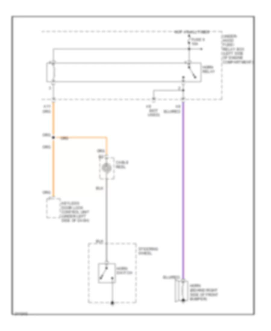
HORN
Horn Wiring Diagram for Honda Insight 2006
List of elements for Horn Wiring Diagram for Honda Insight 2006:
- (not used)
- A11
- Cable reel
- Fuse 6 10a
- Horn (behind right side of front bumper)
- Horn relay
- Horn switch
- Hot at all times
- Keyless door lock control unit (under left side of dash)
- Steering wheel
- Under- hood fuse/ relay box (left side of engine compartment)
INSTRUMENT CLUSTER
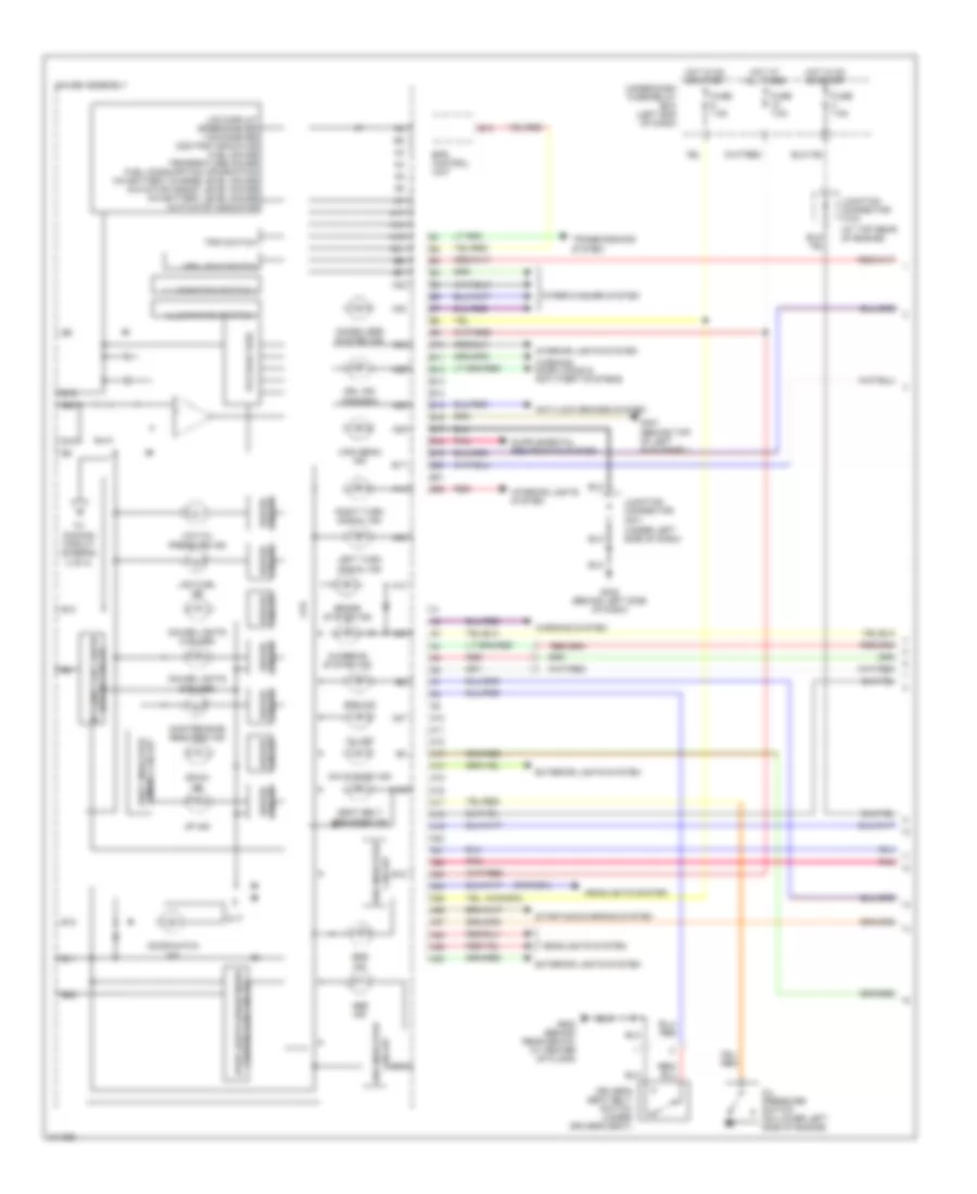
Instrument Cluster Wiring Diagram (1 of 2) for Honda Insight 2006
List of elements for Instrument Cluster Wiring Diagram (1 of 2) for Honda Insight 2006:
- (at top rear of engine)
- (canada)
- (under left side of dash)
- A10
- A11
- A12
- A13
- A14
- A15
- A16
- A17
- A18
- A19
- A20
- A21
- A22
- A23
- A24
- A25
- A26
- A27
- A28
- A29
- A30
- Abs ind
- Anti-lock brakes system
- B10
- B11
- B12
- B13
- B14
- B15
- B16
- B17
- B18
- B19
- B20
- B21
- B22
- Brake system ind
- Charging system ind
- Circuit abs indicator
- Circuit driver
- Circuit srs indicator
- Controller circuit dash lights brightness
- Cpu
- Cvt
- Dimming circuit shift indicator
- Door/hatch ind
- Down ind
- Driver circuit
- Driver's seat belt switch (under driver's seat)
- Drl ind (canada)
- Eps control unit
- Eps ind
- Exterior lights system
- Fuse 7.5a
- G401 (behind top of left kick panel)
- G402 (behind left side of dash)
- G502 (behind rear seats, at center of floor)
- Gauge assembly
- Gauge lights (2 bulbs)
- Gauge lights (5 bulbs)
- Headlights system
- High beam ind
- Hot at all times
- Hot in on or start
- Illumination switch +
- Illumination switch -
- Ima system ind
- Immobilizer system ind
- Interior lights system
- Intermittent wiper driving circuit
- Junction connector c104
- Junction connector c571
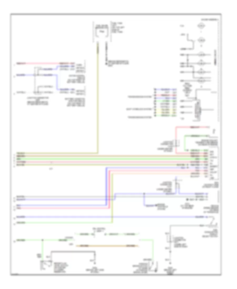
- Lcd display speedometer tachometer odo/trip indicator fuel gauge temperature gauge fuel consumption information ima battery charge level gauge ima motor assist level gauge ima battery level gauge auto stop indicator
- Left turn signal ind
- Low fuel ind
- Low oil pressure ind
- Maintenance required ind
- Mil ind
- Mph, km/h switch
- Oil pressure switch (on lower left side of engine)
- Pnk
- Red
- Right turn signal ind
- Seat belt reminder ind
- Srs ind
- Starting/charging system
- To dimming circuit (diagram 2 of 2)
- Transmissions system
- Trip switch
- Under-dash fuse/relay box (left end of dash)
- Up ind
- Voltage feed
- Warning system
- Warning, door locks & anti-theft systems
- Wiper/washer system
Instrument Cluster Wiring Diagram (2 of 2) for Honda Insight 2006
List of elements for Instrument Cluster Wiring Diagram (2 of 2) for Honda Insight 2006:
- (behind rear seats, at center of floor) g502
- (under center of dash)
- A/t interlock control system circuit
- A12
- A18
- A19
- A21
- B15
- B16
- Battery condition monitor module (on top front of battery module)
- Brake fluid level switch (on master cylinder reservoir)
- C10
- C15
- C18
- C26
- Canada
- Dimming circuit
- Drl control unit
- Ecm (on right side of front floor)
- Ect
- Engine controls system
- Engine coolant temperature sensor (on rear of engine)
- Engrdy
- From voltage feed (diagram 1 of 2)
- Fuel consumption display select switch
- Fuel gauge sending unit
- Fuel tank unit (on top left side of fuel tank)
- G101 (at top rear of engine)
- G402 (behind left side of dash)
- Gauge assembly
- Imolmp
- Junction connector c107
- Junction connector c108
- Junction connector c507 (behind rear seats, at center of floor)
- Junction connector c571 (under left side of dash)
- M/t
- Metsci1
- Metsci2
- Mil
- Motor control module (on top front of battery module)
- Mtrtw
- Nep
- Parking brake switch (at base of parking brake lever)
- Pnk
- Sg2
- Shift interlock system
- Sil
- Tim
- Transmissions system
- Usa
- Vehicle speed sensor (on rear of transaxle)
- Vss
- Warn
INTERIOR LIGHTS
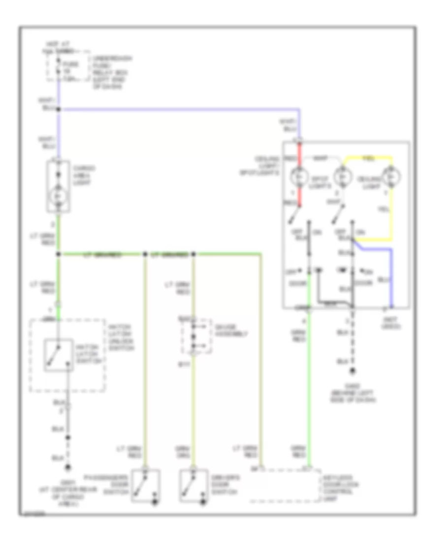
Courtesy Lamps Wiring Diagram for Honda Insight 2006
List of elements for Courtesy Lamps Wiring Diagram for Honda Insight 2006:
- (not used)
- B11
- B12
- Cargo area light
- Ceiling light
- Ceiling light/ spotlights
- Door
- Driver's door switch
- Fuse 7.5a
- G402 (behind left side of dash)
- G601 (at center rear of cargo area)
- Gauge assembly
- Hatch latch switch
- Hatch latch/ unlock switch
- Hot at all times
- Keyless door lock control unit
- Off
- Passenger's door switch
- Red
- Spot lights
- Underdash fuse/ relay box (left end of dash)
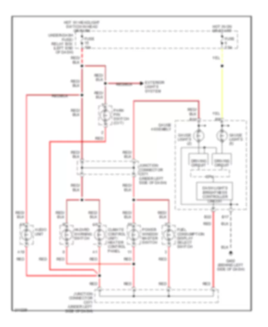
Instrument Illumination Wiring Diagram for Honda Insight 2006
List of elements for Instrument Illumination Wiring Diagram for Honda Insight 2006:
- A19
- Audio unit
- B10
- B17
- B22
- Climate control unit/ heater control panel
- Cpu
- Dash lights brightness controller circuit
- Driving circuit
- Exterior lights system
- Fuel consumption display select switch
- Fuse 10a
- Fuse 7.5a
- G402 (behind left side of dash)
- Gauge assembly
- Gauge lights (2)
- Gauge lights (5)
- Hazard warning switch
- Hot in on or start
- Hot w/ headlight swtich in head or park
- Junction connector c571 (under left side of dash)
- Park pin switch (cvt)
- Power window master switch
- Red
- Under-dash fuse/ relay box (left end of dash)
POWER DISTRIBUTION
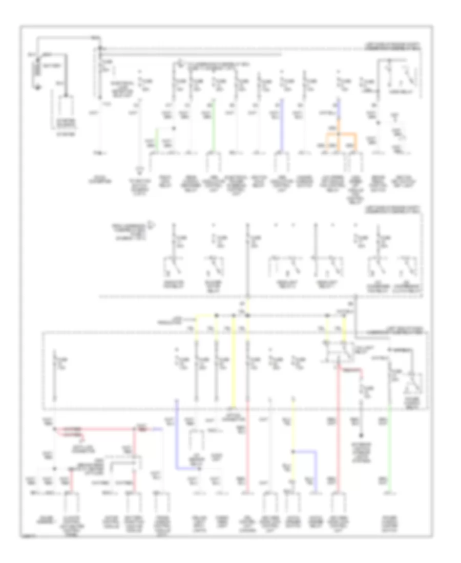
Power Distribution Wiring Diagram (1 of 3) for Honda Insight 2006
List of elements for Power Distribution Wiring Diagram (1 of 3) for Honda Insight 2006:
- (+)
- (left end of dash) underdash fuse/relay box
- (left side of engine compt) underhood fuse/relay box
- A/c compressor clutch relay
- A/c condenser fan relay
- A/f sensor relay
- A10
- A13
- A17
- A23
- Abs modulator control unit
- Audio unit
- B10
- Battery
- Battery condition monitor module
- Blower motor relay
- Brake pedal position switch
- C508 (behind rear seats at center of floor)
- Cargo area light
- Ceiling light/ spot- lights
- Climate control unit/heater control panel
- Cvt
- Data link connector
- Dc-dc converter
- Drl control unit (canada)
- Electrical load detector (eld) unit
- Electrical power steering control unit
- Exterior lights & interior lights systems
- From underhood a fuse/relay box (fuse 7) (diagram 1 of 3)
- Fuse 10a
- Fuse 15a
- Fuse 20a
- Fuse 30a
- Fuse 40a
- Fuse 50a
- Fuse 7.5a
- Fuse 80a
- Gauge assembly
- Hatch opener relay
- Hatch opener switch
- Hazard warning switch
- Headlight relay 1
- Headlight relay 2
- High speed mpi module fan control relay
- Horn relay
- Ignition hold relay
- Ignition key switch/ key light
- Keyless door lock control unit
- Late production
- Low speed mpi module fan control relay
- Motor control module
- Option connector
- Pgm-fi main relay
- Power window master switch
- Power window relay
- Radiator fan relay
- Rear window defogger relay
- Starter
- Starter solenoid
- T101
- Taillight relay
- To ignition switch (diagram 2 of 3)
- To underhood fuse/relay box (fuse 11) (diagram 1 of 3)
- Trans- mission control module (cvt)
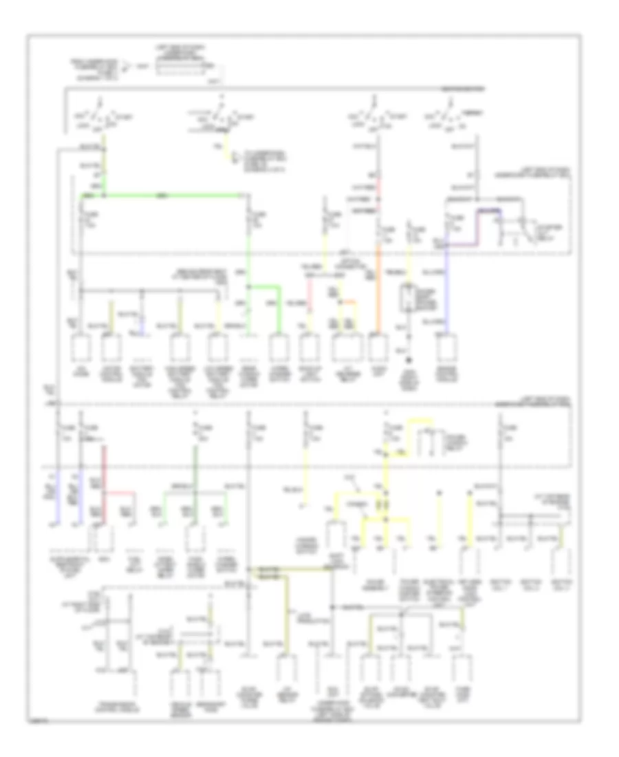
Power Distribution Wiring Diagram (2 of 3) for Honda Insight 2006
List of elements for Power Distribution Wiring Diagram (2 of 3) for Honda Insight 2006:
- (at top rear of engine) c104
- (behind rear seat at center of floor) c507
- (left end of dash) under-dash fuse/relay box
- A/f sensor relay
- A/t reverse relay
- A12
- A24
- A25
- A26
- Acc
- Acces- sory power socket
- Audio unit
- Back-up light switch
- Battery module fan motor
- C104 (at top rear of engine)
- C105 (m/t) (at right side of floor)
- Canada
- Cvt
- Dc-dc converter
- Ecm
- Eld unit
- Electrical power steering control unit
- Engine control module
- Evap bypass solenoid valve
- Evap canister purge valve
- Evap canister vent shut valve
- From under-hood fuse/relay box b (fuse 1) (diagram 1 of 3)
- Fuel cut relay
- Fuse 10a
- Fuse 15a
- Fuse 20a
- Fuse 7.5a
- G404 (right side of dash)
- Gauge assembly
- Hazard warning switch
- High speed battery module fan control relay
- Ignition coil 1
- Ignition coil 2
- Ignition coil 3
- Ignition switch
- Ima diode
- Inter- mittent wiper relay
- Keyless door lock control unit
- Late production
- Lock
- Low speed battery module fan control relay
- M/t
- Motor control module
- Off
- Option connector
- Power window master switch
- Power window relay
- Rear window wiper motor
- Secondary ho2s
- Shift lock solenoid
- Start
- Starter cut relay
- Third ho2s (m/t)
- To under-dash fuse/relay box (fuse 16) (diagram 3 of 3)
- Transmission control module
- Under-hood fuse/relay box (left side of engine compt)
- Vehicle speed sensor
- Wind- shield wiper motor
- Wiper/ washer switch
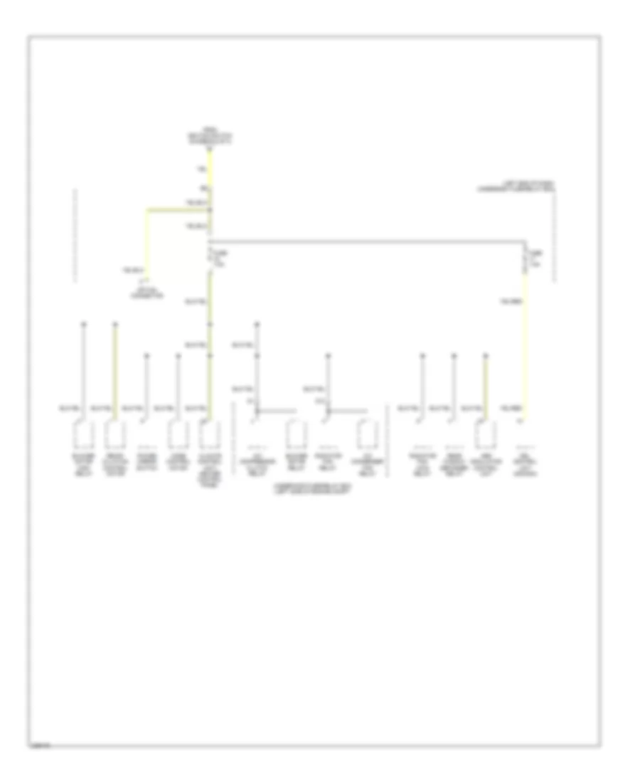
Power Distribution Wiring Diagram (3 of 3) for Honda Insight 2006
List of elements for Power Distribution Wiring Diagram (3 of 3) for Honda Insight 2006:
- (left end of dash) underdash fuse/relay box
- A/c compressor clutch relay
- A/c condenser fan relay
- Abs modulator control unit
- Blower motor high relay
- Blower motor relay
- Climate control unit/ heater control panel
- D12
- Drl control unit (canada)
- From ignition switch (diagram 2 of 3)
- Fuse 7.5a
- Mode control motor
- Option connector
- Power mirror switch
- Radiator fan main relay
- Radiator fan relay
- Rear window defogger relay
- Recir- culation control motor
- Underhood fuse/relay box (left side of engine compt
POWER DOOR LOCKS
Power Door Locks Wiring Diagram, with Anti-theft for Honda Insight 2006
List of elements for Power Door Locks Wiring Diagram, with Anti-theft for Honda Insight 2006:
- (behind top of left kick panel)
- (left side of dash) security control unit
- B11
- B12
- Battery input
- Ceiling light/ spotlights
- Ceiling lt cntrl
- Cnfrm horn sig
- Cpu
- Cvt
- Disarm in
- Disarm switch
- Door open input
- Dr/hatch open
- Driver's door lock switch
- Driver's door lock switch/ actuator (rear of left front door)
- Driver's door switch
- Exterior lights system
- Fuse 10a
- Fuse 20a
- Fuse 30a
- Fuse 7.5a
- G401
- G401 (behind top of left kick panel)
- G402 (behind left side of dash)
- G601 (at center rear of cargo area)
- Gauge assembly
- Ground
- Hatch key cylinder switch
- Hatch latch switch
- Hatch latch unlock switch
- Hatch latch/ unlock switch
- Hatch lock actuator
- Horn cntrl
- Horns system
- Hot at all times
- Hot in on or start
- Ign input
- Ign key sw in
- Ignition key switch/ key light
- Ind cntrl
- Inline fuse a (left side of dash)
- Inline fuse b (left side of dash)
- Interior lights system
- Keyless door lock control unit (under left side of dash)
- Light flash in
- Lock input
- Lock input (-)
- Lock sig (+)
- M/t
- Passenger's door lock actuator (rear of passenger's door)
- Passenger's door switch
- Red
- Security led
- Taillight relay
- Taillight rly
- Under-dash fuse/ relay box (left end of dash)
- Under-hood fuse/ relay box (left side of engine compt)
- Unlck input
- Unlck rly cntrl
- Unlck sig (+)
- Unlock relay (left side of dash)
Power Door Locks Wiring Diagram, without Anti-theft for Honda Insight 2006
List of elements for Power Door Locks Wiring Diagram, without Anti-theft for Honda Insight 2006:
- A2 a2
- B11
- B12 b12
- Battery in
- Ceiling cntrl
- Ceiling light/ spotlights
- Cpu
- Cvt
- Dr/hatch in
- Driver's door lock switch
- Driver's door lock switch/ actuator (rear of left front door)
- Driver's door switch
- Exterior lights system
- Flash in
- Fuse 10a
- Fuse 20a
- Fuse 30a
- Fuse 7.5a
- G401 (behind top of left kick panel)
- G402 (behind left side of dash)
- G601 (at center rear of cargo area)
- Gauge assembly
- Ground
- Hatch key cylinder switch
- Hatch latch switch
- Hatch latch/ unlock switch
- Hatch lock actuator
- Horn signal
- Horns system
- Hot at all times
- Hot in on or start
- Ig input
- Ig key sw in
- Ignition key switch/ key light
- Interior lights system
- Keyless door lock control unit (under left side of dash)
- Lock in
- Lock in (-)
- M/t
- Passenger's door lock actuator (rear of passenger's door)
- Passenger's door switch
- Taillight relay
- Taillight rly
- Under-dash fuse/ relay box (left end of dash)
- Under-hood fuse/ relay box (left side of engine compt)
- Unlck in
- Unlck sig (+)
- Unlck sig (-)
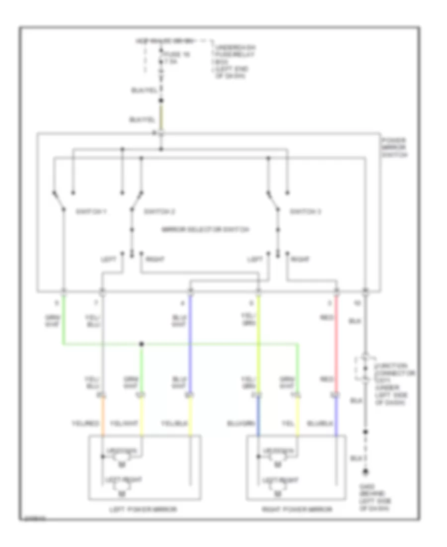
POWER MIRRORS
Power Mirrors Wiring Diagram for Honda Insight 2006
List of elements for Power Mirrors Wiring Diagram for Honda Insight 2006:
- Fuse 16 7.5a
- G402 (behind left side of dash)
- Hot in acc or on
- Junction connector c571 (under left side of dash)
- Left
- Left power mirror
- Left/right
- Mirror selector switch
- Power mirror switch
- Red
- Right
- Right power mirror
- Switch 1
- Switch 2
- Switch 3
- Underdash fuse/relay box (left end of dash)
- Up/down
POWER WINDOWS
Power Windows Wiring Diagram for Honda Insight 2006
List of elements for Power Windows Wiring Diagram for Honda Insight 2006:
- Auto dn
- Detect circuit
- Driver's window motor
- Driver's window switch
- Fuse 10 20a
- Fuse 6 7.5a
- Fuse 8 20a
- G401 (behind top of left kick panel)
- G402 (behind left side of dash)
- Hot at all times
- Hot in on or start
- Illumination
- Interior lights system
- Main switch
- Off
- Passenger's window motor
- Passenger's window switch
- Power window control unit
- Power window master switch
- Power window relay
- Red
- Underdash fuse/relay box (left end of dash)
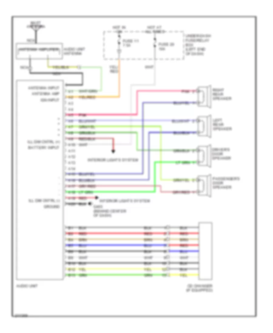
RADIO
Radio Wiring Diagram for Honda Insight 2006
List of elements for Radio Wiring Diagram for Honda Insight 2006:
- A10
- A11
- A12
- A13
- A14
- A15
- A16
- A17
- A18
- A19
- A20
- Antenna amp
- Antenna amplifier
- Antenna input
- Audio unit
- Audio unit antenna
- B10
- B12
- B13
- Battery input
- Cd changer (if equipped)
- Driver's door speaker
- Fuse 11 7.5a
- Fuse 20 10a
- G403 (behind center of dash)
- Ground
- Hot at all times
- Hot in on
- Ign input
- Ill dim cntrl (+)
- Ill dim cntrl (-)
- Interior lights system
- Left rear speaker
- Mast antenna
- Nca
- Passenger's door speaker
- Pnk
- Red
- Right rear speaker
- Under-dash fuse/relay box (left end of dash)
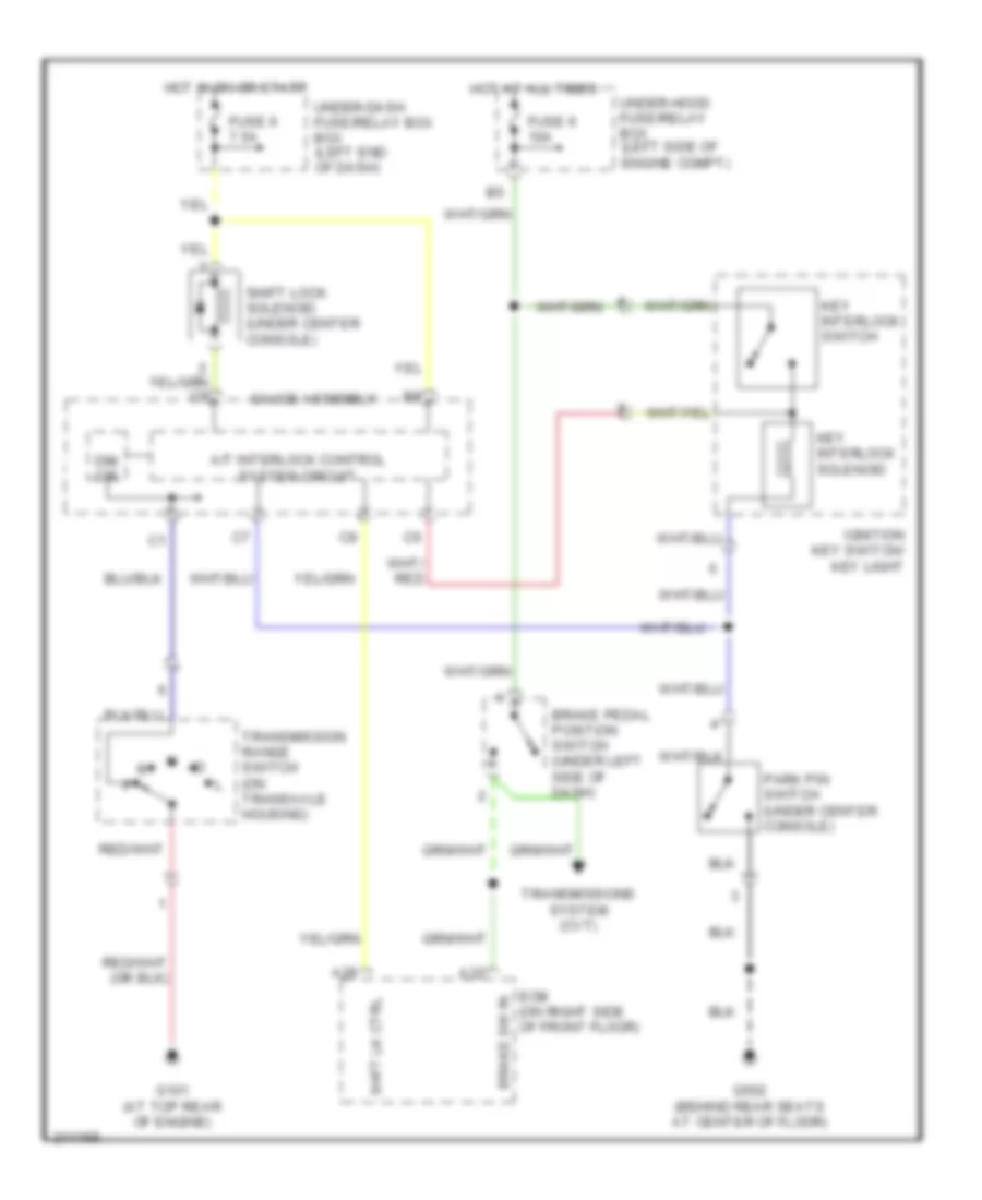
SHIFT INTERLOCK
Shift Interlock Wiring Diagram for Honda Insight 2006
List of elements for Shift Interlock Wiring Diagram for Honda Insight 2006:
- A/t interlock control system circuit
- A28
- A32
- Brake pedal position switch (under left side of dash)
- Brake sw in
- Dim cir
- Ecm (on right side of front floor)
- Fuse 6 10a
- Fuse 6 7.5a
- G101 (at top rear of engine)
- G502 (behind rear seats at center of floor)
- Gauge assembly
- Hot at all times
- Hot in on or start
- Ignition key switch/ key light
- Key interlock solenoid
- Key interlock switch
- Park pin switch (under center console)
- Shft lk ctrl
- Shift lock solenoid (under center console)
- Transmission range switch (on transaxle housing)
- Transmissions system (cvt)
- Under-dash fuse/relay box box (left end of dash)
- Under-hood fuse/relay box (left side of engine compt)
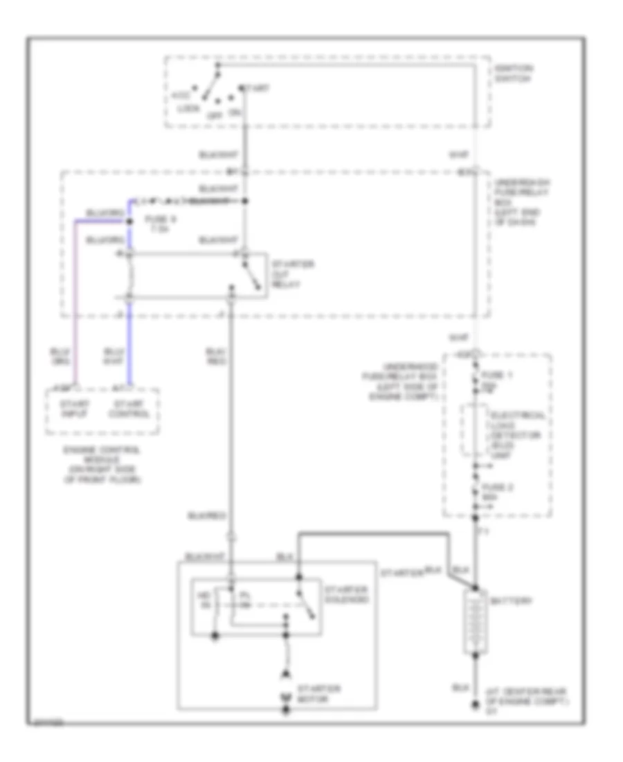
STARTING/CHARGING
Starting Wiring Diagram for Honda Insight 2006
List of elements for Starting Wiring Diagram for Honda Insight 2006:
- (at center rear of engine compt) g1
- A24
- Acc
- Battery
- Electrical load detector (eld) unit
- Engine control module (on right side of front floor)
- Fuse 1 50a
- Fuse 2 80a
- Fuse 9 7.5a
- Hd in
- Ignition switch
- Lock
- Off
- Pl in
- Start
- Start control
- Start input
- Starter
- Starter cut relay
- Starter motor
- Starter solenoid
- Underdash fuse/relay box (left end of dash)
- Underhood fuse/relay box (left side of engine compt)
SUPPLEMENTAL RESTRAINTS
Supplemental Restraints Wiring Diagram for Honda Insight 2006
List of elements for Supplemental Restraints Wiring Diagram for Honda Insight 2006:
- (behind left side of dash) g402
- (behind rear seats, at center of floor) g502
- (under srs unit, at front of center) console) g501
- A10
- A11
- A12
- A13
- A14
- A15
- A16
- A17
- A18
- Air bag ctrl
- B17
- B18
- Cable reel
- Caution when ignition switch is on or has been turned off for less than three minutes use caution not to bump srs unit. air bags could deploy
- Connector (dlc) (partial) (behind center
- Data link
- Dlc input/out
- Driver's air bag inflator
- Driver's seat belt tensioner (at left "b" pillar)
- Fuse 1 10a
- Fuse 2 15a
- Fuse 6 7.5a
- Gauge assembly
- Ground (gnda)
- Ground (gndb)
- Hot in on or start
- Ignition (va)
- Ignition (vb)
- J/c 571 (under left side of dash)
- Mes conn input
- Mes connector (behind upper left kick panel)
- Of dash)
- Passenger's air bag inflator
- Passenger's seat belt tensioner (at right "b" pillar)
- Pnk
- Red
- Service check in
- Short contact
- Srs ind ctrl
- Srs indicator circuit
- Srs indicator light
- Srs unit (under center of dash)
- Steering wheel
- Tensioner ctrl
- Under dash fuse/relay box (at left end of dash)
- W/cvt
- W/o cvt
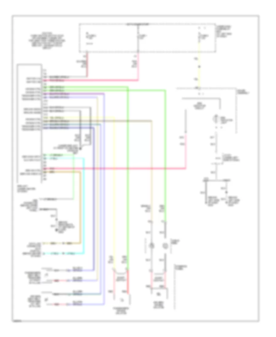
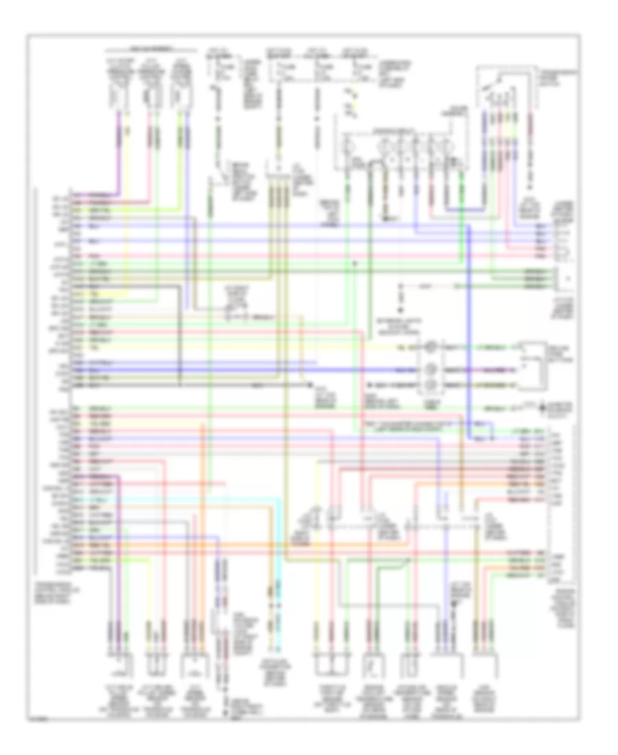
TRANSMISSION
A/T Wiring Diagram for Honda Insight 2006
List of elements for A/T Wiring Diagram for Honda Insight 2006:
- (above right front wheelwell) g201
- (at right side of floor j/c c105
- (at top rear of engine) g101
- (behind top of left kick panel)
- (left rear of eng compt)
- (on valve body)
- (under center of dash) j/c c107
- A10
- A11
- A12
- A13
- A14
- A15
- A16
- A17
- A18
- A19
- A20
- A21
- A22
- A23
- A24
- A25
- A26
- Atp d
- Atp l
- Atp np
- Atp r
- B10
- B11
- B12
- B13
- B14
- B15
- B16
- B17
- B18
- B19
- B20
- B21
- B22
- Bk sw
- Brake pedal position switch (under left side of dash)
- C10
- C11
- C15
- C17
- C18
- C19
- C25
- C26
- C27
- C28
- Cable reel
- Cas sol a
- Cas sol b
- Cas solenoid valves a & b (at right side of engine compt)
- Cvt drive pulley speed sensor (on transaxle housing)
- Cvt driven pulley speed sensor (on transaxle housing)
- Cvt pulley pressure control valve
- Cvt speed change control valve
- Cvt speed sensor (on transaxle housing)
- Cvt start clutch pressure control valve
- D ind
- D sw
- Datalink connector (behind center of dash)
- Diag-h
- Dimming circuit
- Dn ls+
- Dn ls-
- Dr ls+
- Dr ls-
- Driving mode buttons
- Ect
- Engine control module (on right side of front floor)
- Engine coolant temperature sensor (on rear of engine)
- Exterior lights system (backup lamps)
- Fuse 10a
- Fuse 7.5a
- G101 (at top rear of engine)
- G401
- G402 (behind left side of dash)
- Gauge assembly
- Hot at all times
- Hot in on or start
- Iat
- Ig1
- Ig2
- Inh sol
- Inhibitor solenoid (in cvt)
- Intake air temperature sensor (on air intake hose)
- J/c c105 (at right side of floor)
- J/c c107 (under center of dash)
- J/c c108 (under center of dash)
- Lg1
- Lg2
- Map
- Map pb
- Map sensor (on right rear of engine)
- Ndn
- Ndn sg
- Ndr
- Ndr sg
- Nep
- P/n
- Pg1
- Pg2
- Pnk
- Red
- Sc ls+
- Sc ls-
- Scs
- Sg1
- Sg2
- Spo ind
- Spo mode
- Spo sw
- Test tachometer connector
- Throttle position sensor (on throttle body)
- Tma
- Tmb
- Tps
- Transmission control module (behind right side of dash)
- Transmission range switch
- Under- hood fuse/ relay box (left side of engine compt)
- Under-dash fuse/relay box (left end of dash)
- Vbu
- Vcc1
- Vcc2
- Vcc3
- Vehicle speed sensor (on rear of transaxle)
- Vel
- Vel sg
- Vref
- Vss
TRUNK, TAILGATE, FUEL DOOR
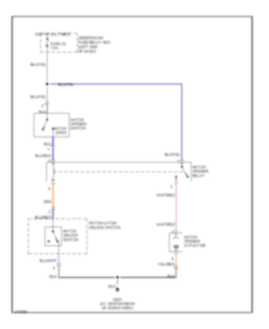
Hatch Release Wiring Diagram for Honda Insight 2006
List of elements for Hatch Release Wiring Diagram for Honda Insight 2006:
- Fuse 23 7.5a
- G601 (at center rear of cargo area)
- Hatch latch/ unlock switch
- Hatch opener actuator
- Hatch opener relay
- Hatch opener switch hatch open
- Hatch unlock switch
- Hot at all times
- Under-dash fuse/relay box (left end of dash)
WARNING SYSTEMS
Warning Systems Wiring Diagram for Honda Insight 2006
List of elements for Warning Systems Wiring Diagram for Honda Insight 2006:
- B10
- B11
- B16
- Beeper
- Cpu
- Cvt
- Door/ hatch indicator
- Driver's door switch
- Driver's seat belt switch (under driver's seat)
- Driving circuit
- Fuse 15 10a
- Fuse 18 7.5a
- Fuse 6 7.5a
- G401 (behind top of left kick panel)
- G402 (behind left side of dash)
- G502 (behind rear seats, at center of floor)
- Gauge assembly
- Hot at all times
- Hot in run or start
- Hot w/ headlight switch in head or park
- Ignition key switch key light
- Ignition key switch/ key light
- J/c c571 (under left side of dash)
- Keyless door lock control unit (under left side of dash)
- Lcd display
- M/t
- Odo/trip switch mph/km/h switch
- Seat belt reminder indicator
- Underdash fuse/relay box (left end of dash)
- Voltage feed
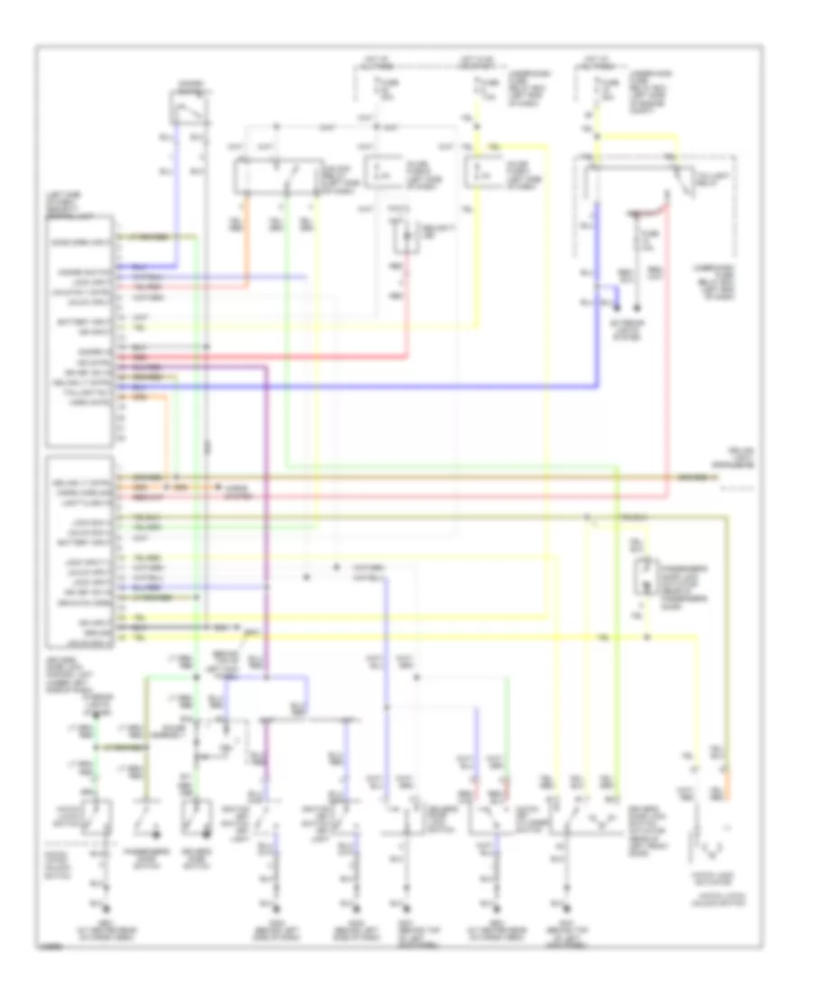
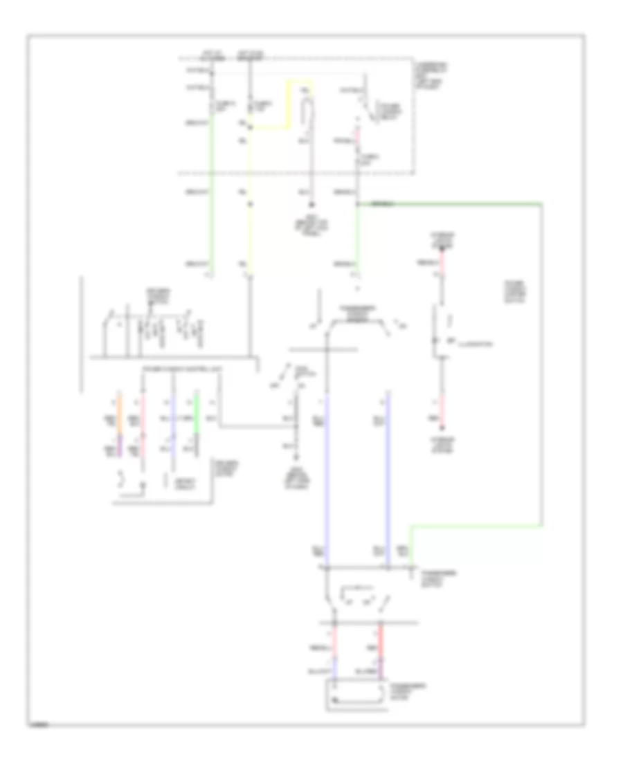
WIPER/WASHER
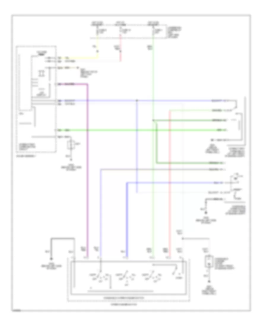
Front Wiper/Washer Wiring Diagram for Honda Insight 2006
List of elements for Front Wiper/Washer Wiring Diagram for Honda Insight 2006:
- B16
- B17
- C571
- Cpu
- Fuse 18 7.5a
- Fuse 3 20a
- Fuse 6 7.5a
- G201 (above right front wheelwell)
- G301 (above left front wheelwell)
- G401 (behind top of left kick panel)
- G402 (behind left side of dash)
- Gauge assembly
- Hot at all times
- Hot in on or start
- Int
- Intermittent wiper driving circuit
- Intermittent wiper relay (at left front of engine compt)
- Lcd display
- Mist
- Off
- Park
- Run
- Underdash fuse/relay box (left end of dash)
- Voltage feed
- Wash
- Windshield washer motor (at right front of engine compt)
- Windshield wiper motor (at right rear of engine compt)
- Windshield wiper/washer switch
- Wiper/washer switch
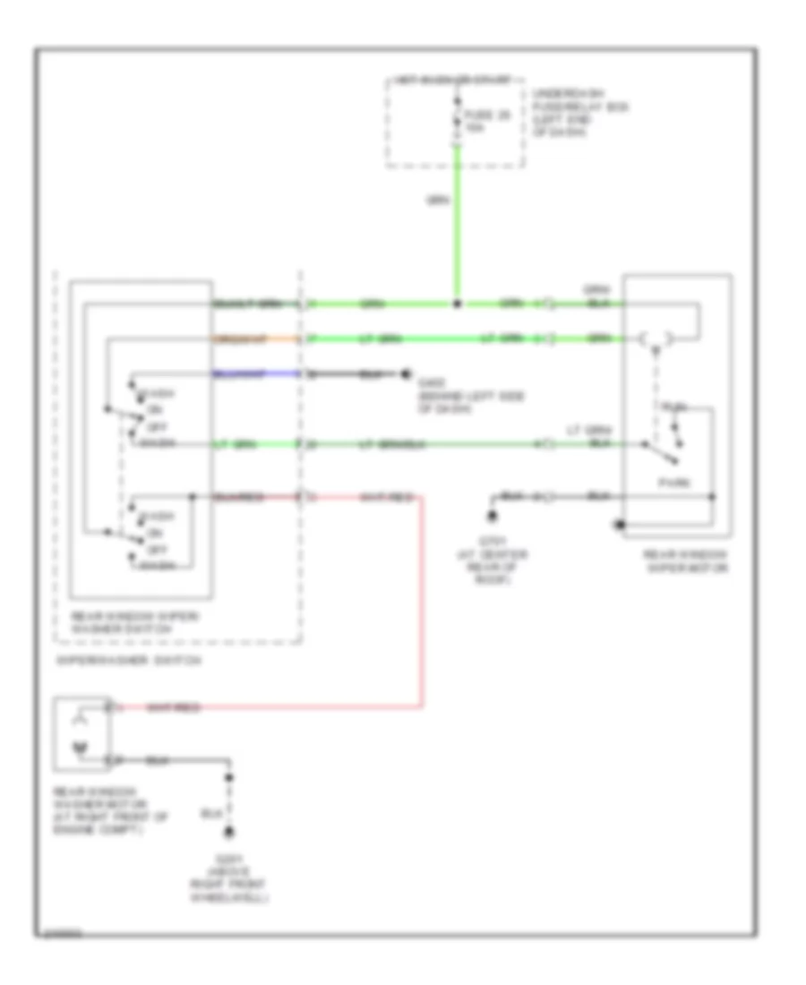
Rear Wiper/Washer Wiring Diagram for Honda Insight 2006
List of elements for Rear Wiper/Washer Wiring Diagram for Honda Insight 2006:
- Fuse 26 10a
- G201 (above right front wheelwell)
- G402 (behind left side of dash)
- G701 (at center rear of roof)
- Hot in on or start
- Off
- Park
- Rear window washer motor (at right front of engine compt)
- Rear window wiper motor
- Rear window wiper/ washer switch
- Run
- Underdash fuse/relay box (left end of dash)
- Wash
- Wiper/washer switch