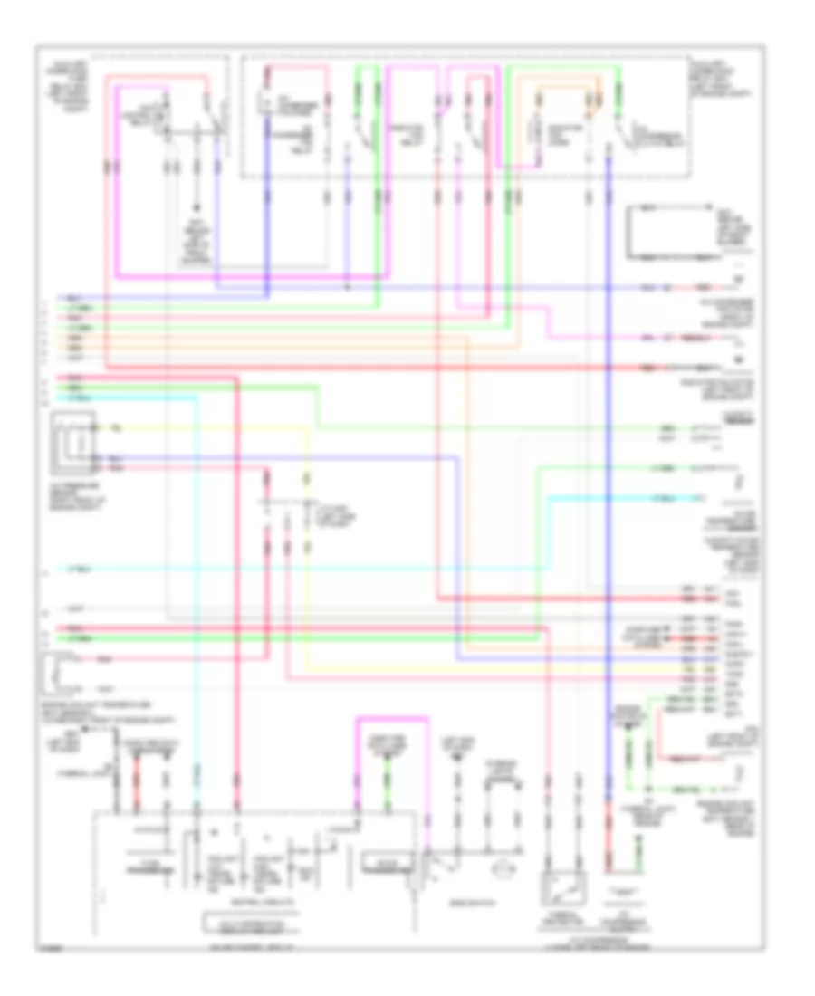
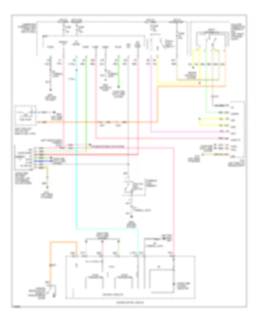
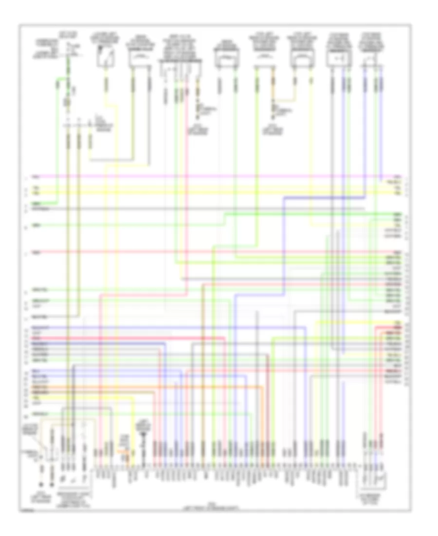
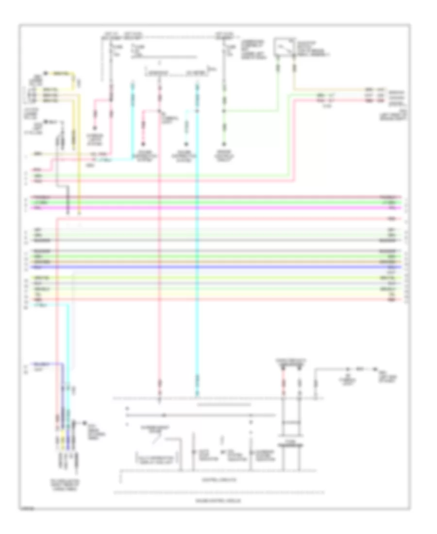
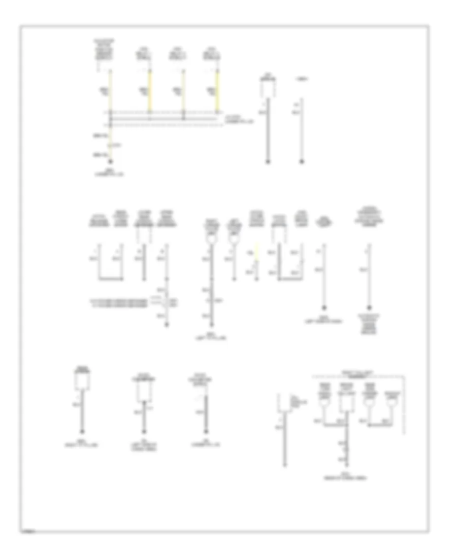
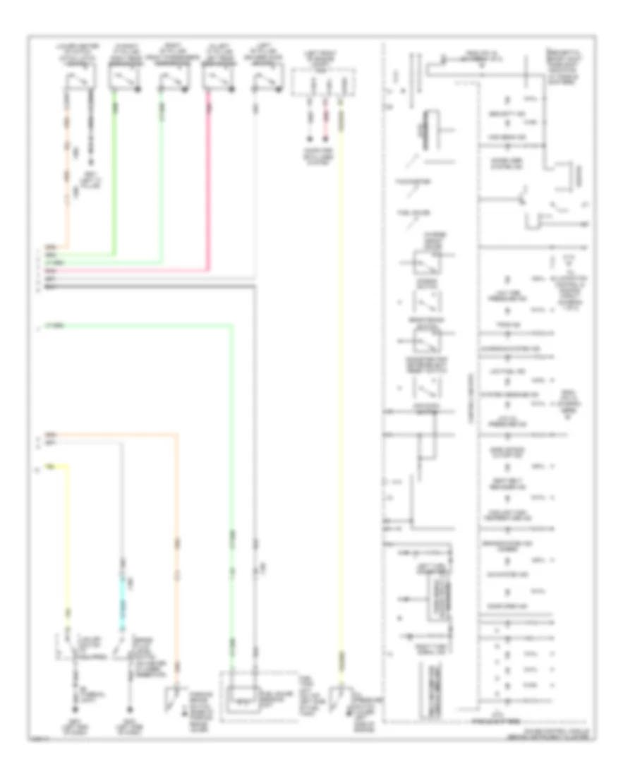
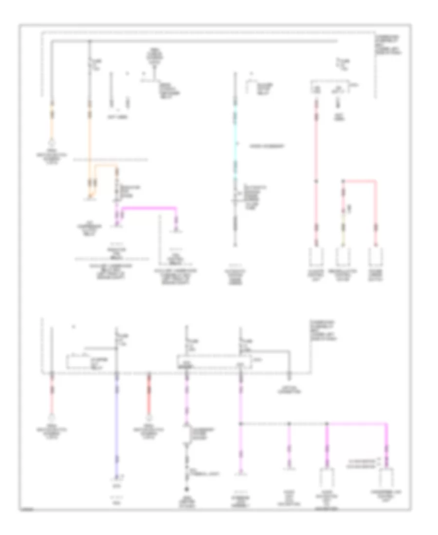
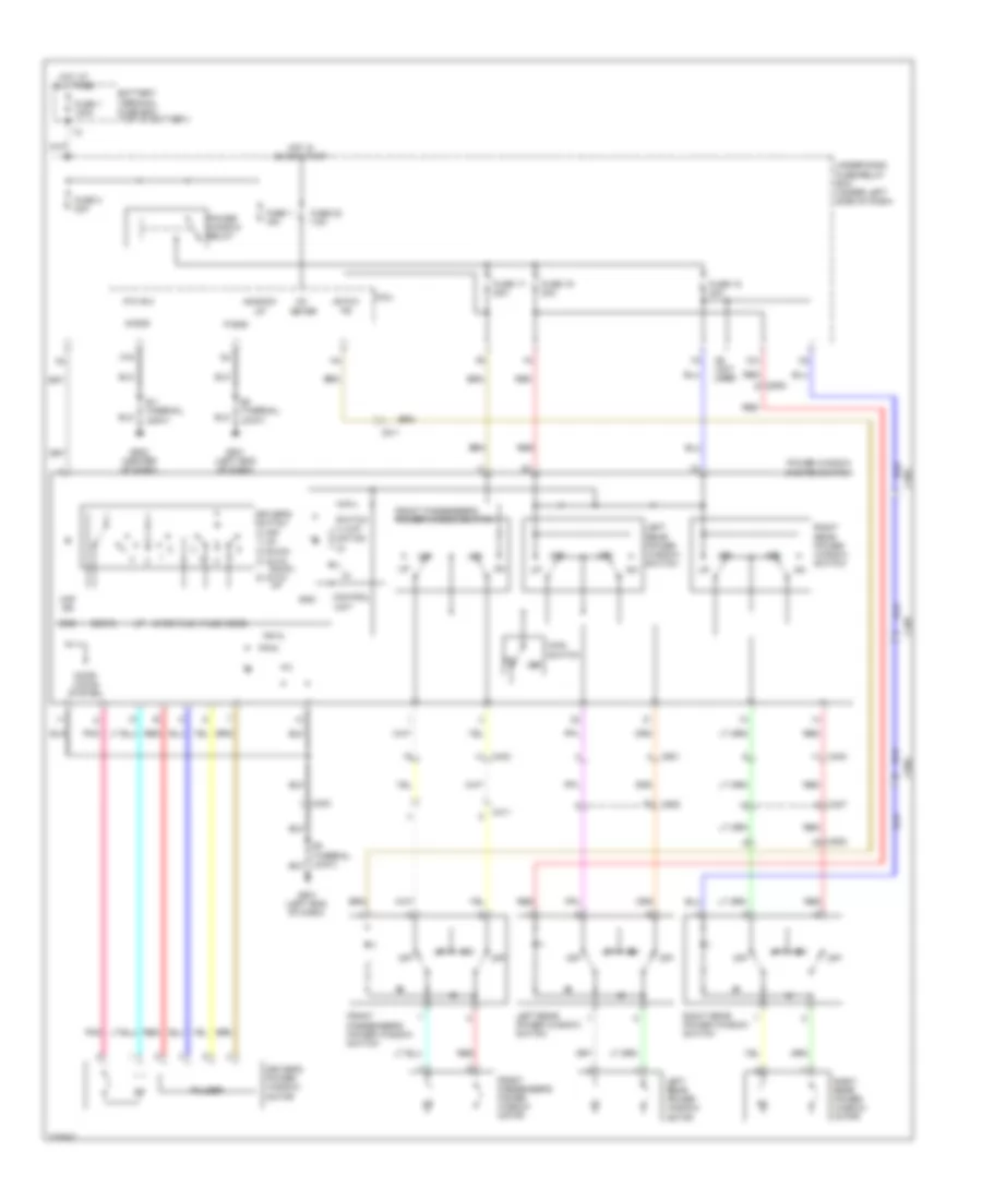
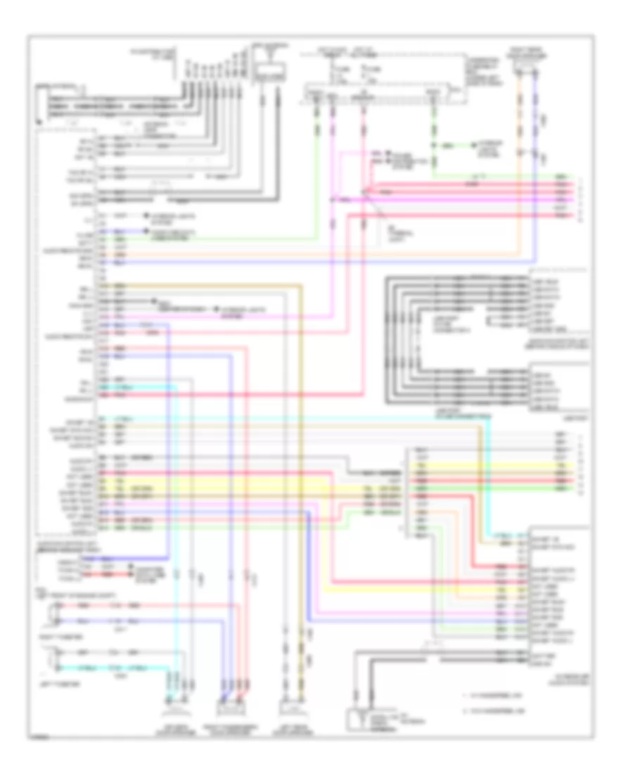
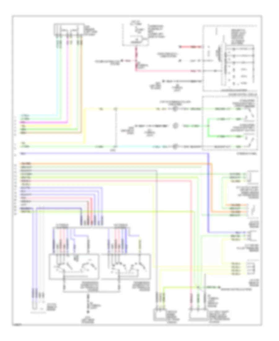
AIR CONDITIONING
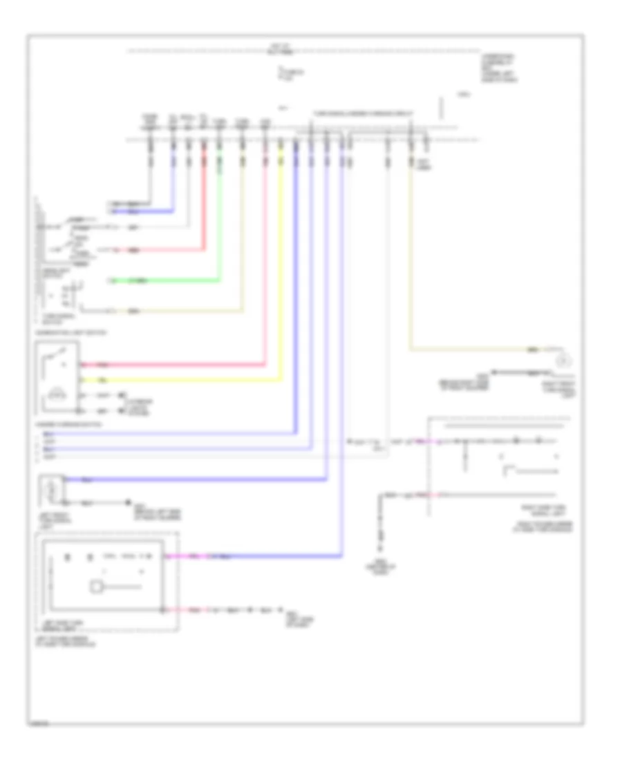
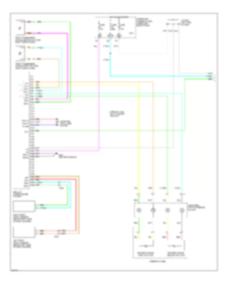
Automatic A/C Wiring Diagram (1 of 2) for Honda Insight EX 2012

List of elements for Automatic A/C Wiring Diagram (1 of 2) for Honda Insight EX 2012:
- (not used)
- +b backup
- A/f sensor relay
- A10
- A11
- A12
- A13
- A14
- A15
- A16
- A17
- A18
- A19
- A20
- A21
- A22
- A23
- A24
- A25
- A26
- A27
- A28
- A29
- A30
- A31
- A32
- A33
- A34
- A35
- A36
- Ac-clk
- Ac-si
- Ac-so
- Acs
- Air mix control motor (lower center of hvac unit)
- Amd-p
- Audio- navigation unit (w/ navigation) (behind middle of dash)
- B-can
- B12
- B15
- B19
- Blower motor (bottom of blower unit)
- Blower motor relay
- Blower power transistor (bottom center of hvac unit)
- Blw-g
- Blw-v
- C201
- C302
- C304
- C404
- C405
- Climate control unit (behind middle of dash)
- Computer data lines system
- D15
- Defogger system
- Evaporator temperature sensor (in evaporator core)
- Frs
- Fuse 1 15a
- Fuse 10 7.5a
- Fuse 22 7.5a
- Fuse 26 10a
- Fuse 30 30a
- Fuse 30a
- Fuse 31 7.5a
- Fuse 43 7.5a
- Fuse 57 30a
- G501 (left end of dash)
- G502 (center of dash)
- Gnd
- Hot at all times
- Hot in on
- Hot in on or start
- Hum
- Ig1 meter
- Ig2
- Ig2 hac
- Ill+
- Ill-
- Interior lights system
- Joint)
- M-cool
- M-def
- M-hot
- M-vent
- Micu
- Mirrors system
- Mode 1
- Mode 2
- Mode 3
- Mode 4
- Mode control motor (center of hvac unit)
- Outside air temperature sensor (behind right side of front bumper)
- Pnk
- Q14
- Rec
- Recirculation control motor (right side of blower unit)
- Red
- Rr def rly
- S 5v
- S-com
- S10 (thermal joint)
- S5v
- Sunlight sensor (top center of dash)
- Tam
- Teva
- Tsum
- Under-dash fuse/relay box (under left side of dash)
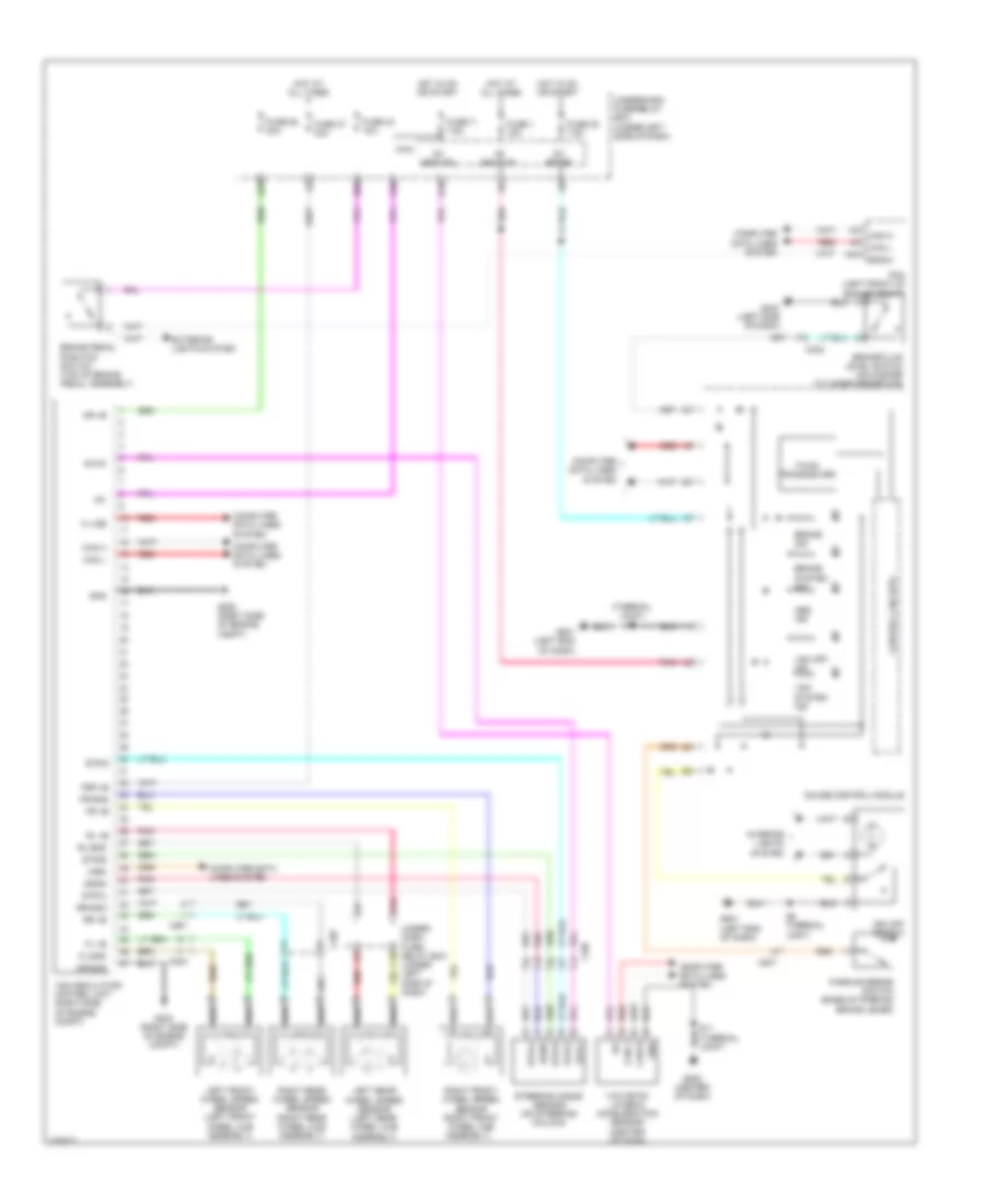
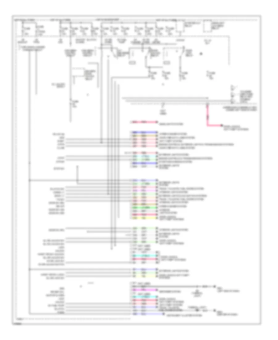
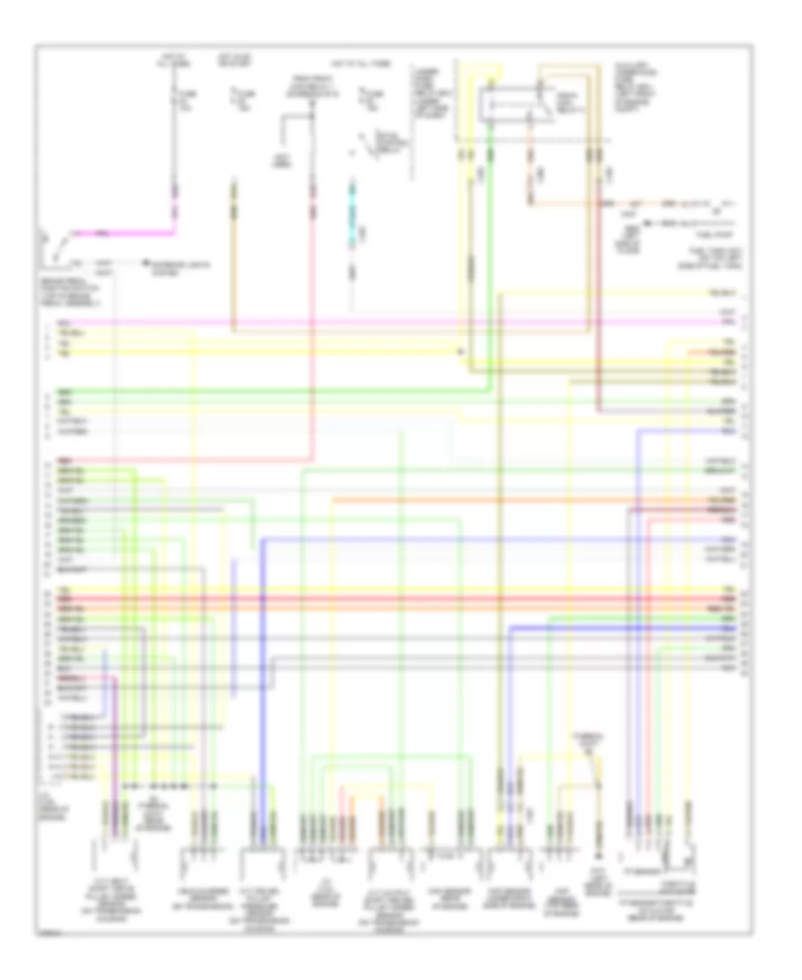
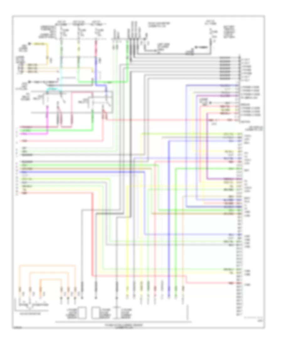
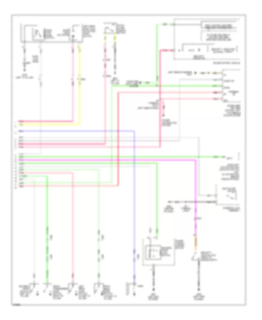
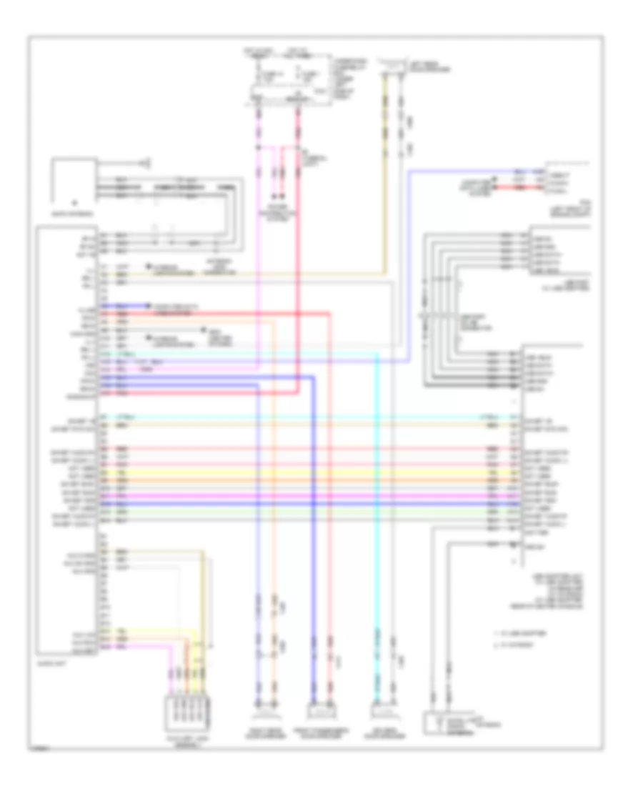
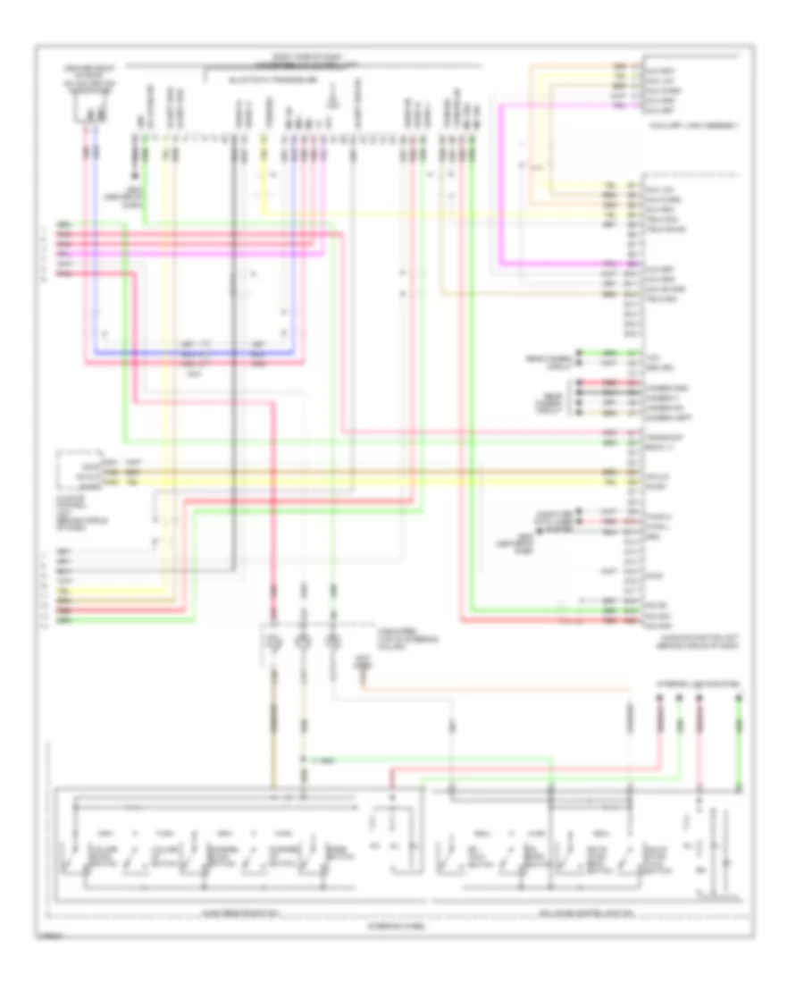
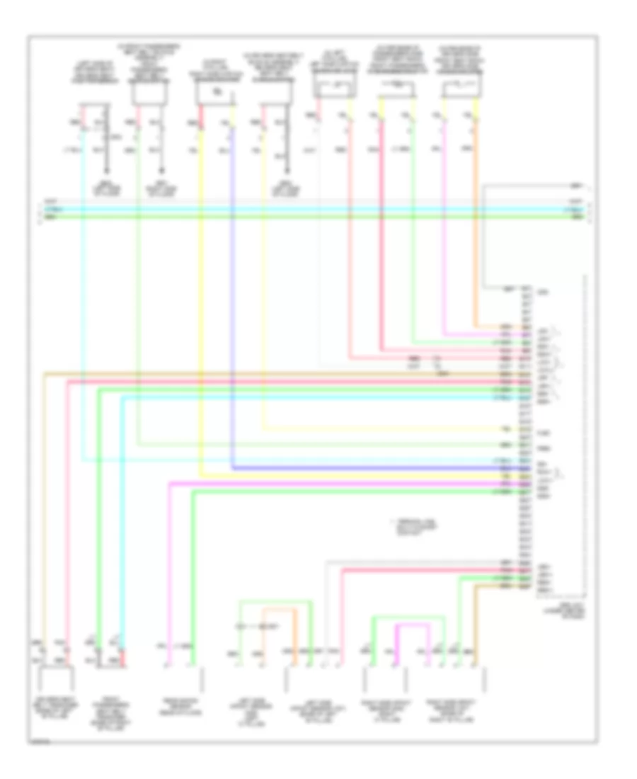
Automatic A/C Wiring Diagram (2 of 2) for Honda Insight EX 2012
List of elements for Automatic A/C Wiring Diagram (2 of 2) for Honda Insight EX 2012:
- (left end of dash) g501
- A/c compressor (lower left front of engine)
- A/c compressor clutch
- A/c compressor clutch relay
- A/c condenser fan diode
- A/c condenser fan motor (front of engine compt)
- A/c condenser fan relay
- A/c pressure sensor (right front of engine compt)
- A10
- A17
- A20
- A34
- A41
- A44
- A45
- A49
- Acc
- Acpd
- Auxiliary under-hood fuse/ relay box (left front of engine compt)
- Auxiliary under-hood relay box (left front of engine compt)
- B-can transceiver
- B24
- B34
- Can h
- Can l
- Computer data lines system
- Control circuits
- Coolant high tempe- rature ind
- Coolant low tempe- rature ind
- Eco ind
- Econ switch
- Ect1
- Ect2
- Engine controls system
- Engine coolant temperature (ect) sensor 1 (rear of engine)
- Engine coolant temperature (ect) sensor 2 (lower right front of engine compt)
- F-can transceiver
- Fan control relay
- Fanh
- Fanl
- G401 (behind left side of front bumper)
- G501 (left end of dash)
- Gauge control module
- Humidity sensor
- Humidity/in-car temperature sensor (left side of dash)
- In-car temperature sensor
- Interior lights system
- J/c c306 (left side of dash)
- Multi-information display (mid) unit
- Pcm (left front of engine compt)
- Pnk
- Radiator fan diode
- Radiator fan motor (left front of engine compt)
- Radiator fan relay
- Red
- S4 (thermal joint) (rear of engine)
- S6 (thermal joint)
- Sg2
- Sg6
- Sub rly
- Thermal protector
- Vcc6
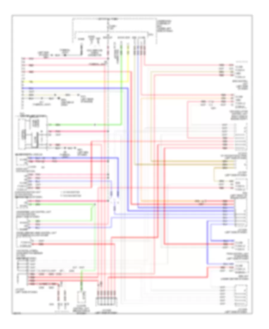
ANTI-LOCK BRAKES
Anti-lock Brakes Wiring Diagram for Honda Insight EX 2012
List of elements for Anti-lock Brakes Wiring Diagram for Honda Insight EX 2012:
- (thermal joint) s6
- +b backup
- A18
- A23
- A32
- A42
- Abs ind
- B28
- Bksw
- Brake fluid level switch (on master cylinder reservoir)
- Brake ind
- Brake pedal position switch (top of brake pedal assembly)
- Brake system ind
- C10
- C201
- C302
- C304
- C407
- Can h
- Can l
- Computer data lines system
- Control circuits
- Exterior lights system
- F-can transceiver
- Fl +b
- Fl-gnd
- Fr +b
- Fr-gnd
- Fsr +b
- Fuse 1 15a
- Fuse 11 7.5a
- Fuse 22 7.5a
- Fuse 24 10a
- Fuse 37 30a
- Fuse 58 30a
- G203 (right side of engine compt)
- G403 (left side of dash)
- G501 (left end of dash)
- G502 (center of dash)
- Gauge control module
- Gnd
- Hot at all times
- Hot in on or start
- Ig1
- Ig1 abs/vsa
- Ig1 meter
- Interior lights system
- K line
- Left front wheel speed sensor (left front wheel hub assembly)
- Left rear wheel speed sensor (left rear wheel hub assembly)
- Micu
- Mr +b
- Mr-gnd
- Parking brake switch (base of parking brake lever)
- Pcm (left front of engine compt)
- Pnk
- Q16
- Red
- Right front wheel speed sensor (right front wheel hub assembly)
- Right rear wheel speed sensor (right rear wheel hub assembly)
- Rl +b
- Rl-gnd
- Rr +b
- Rr-gnd
- S6 (thermal joint)
- Sgnd
- Steering angle sensor (on steering column)
- Str-a
- Str-b
- Str-z
- Svcc
- Under- dash fuse/ relay box (under left side of dash)
- Under-dash fuse/relay box (under left side of dash)
- Vsa modulator- control unit (right side of engine compt)
- Vsa off ind
- Vsa off switch
- Vsa system ind
- Wen
- Yaw rate- lateral acceleration sensor (center of dash)
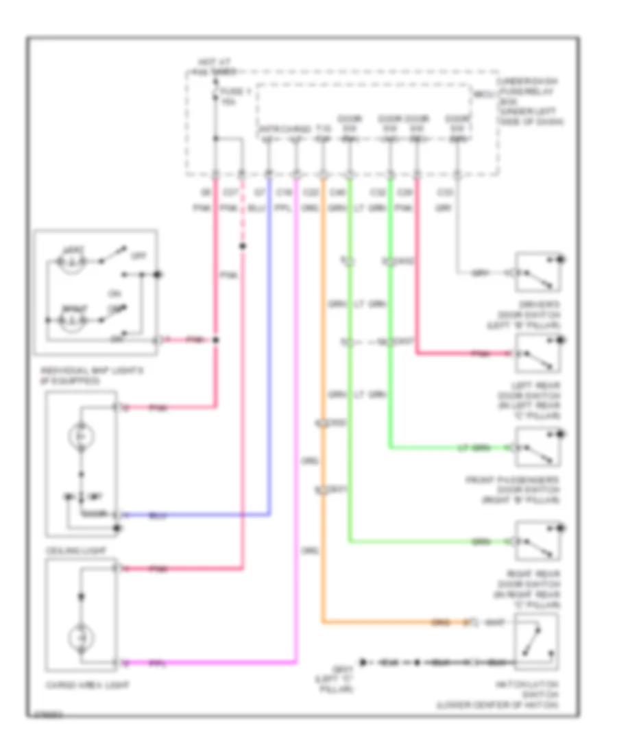
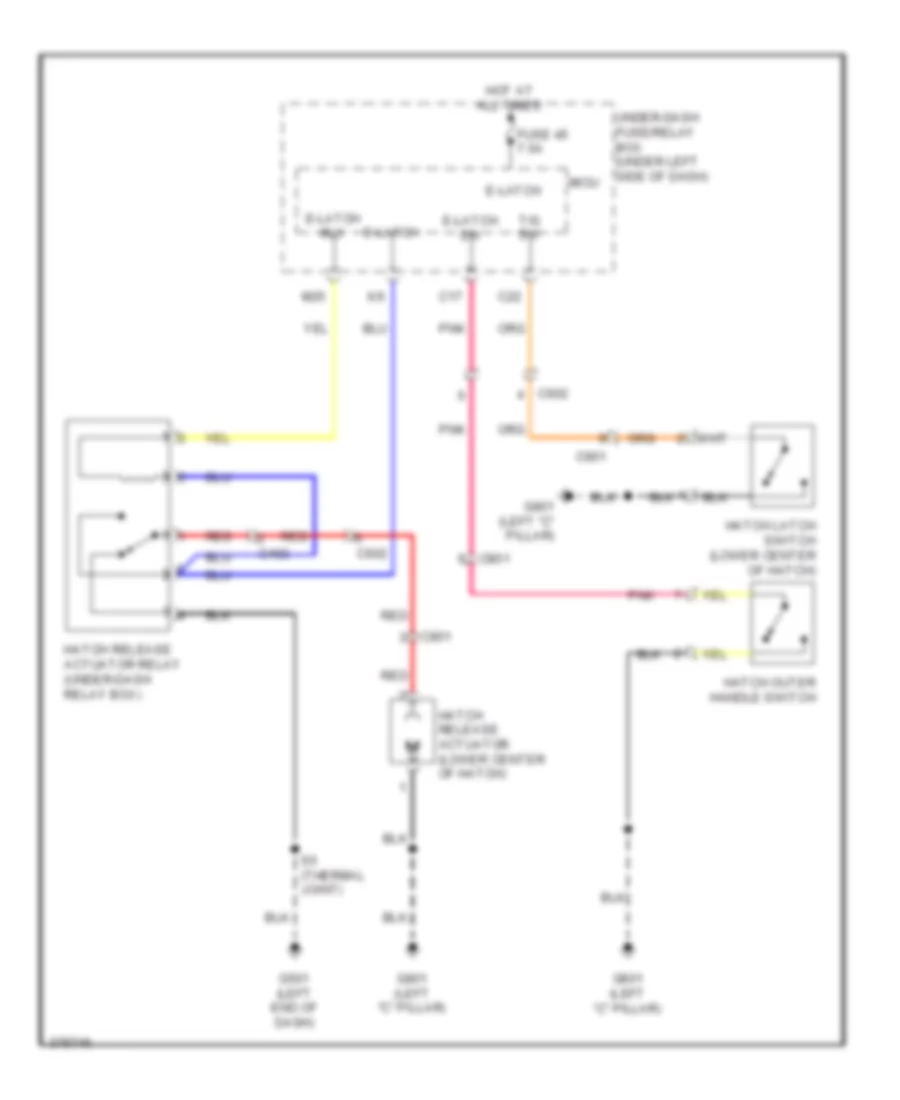
ANTI-THEFT
Forced Entry Wiring Diagram (1 of 2) for Honda Insight EX 2012
List of elements for Forced Entry Wiring Diagram (1 of 2) for Honda Insight EX 2012:
- (lk) handy dr sw
- (not
- (thermal joint) s5
- (un lk) handy dr sw
- (w/ security)
- +b back up
- +b backup
- A13
- A29
- B-can
- Battery terminal fuse box (top of battery)
- C17
- C26
- C32
- C33
- C35 pnk
- C40
- C402
- C407
- C411
- C45
- C46
- C47
- C48
- C502
- D/l unlock
- Door
- Door lock actuator
- Door lock knob
- Door lock knob switch
- Door lock relay
- Door unlock relay
- Dr rly
- Dr sw (as)
- Dr sw (dr)
- Dr sw (ra)
- Dr sw (rd)
- Driver's
- Driver's door lock actuator/knob switch/ key cylinder switch
- E-latch sw
- Eld unit
- Exterior lights system
- F2 pnk
- Front passenger's door lock actuator/knob switch
- Fuse 100a
- Fuse 10a
- Fuse 15a
- Fuse 30a
- Fuse 7.5a
- G501 (left end of dash)
- G502 (center of dash)
- G601 (right side of floor)
- Gnd
- Hood sw
- Horn relay
- Horns system
- Hot at all times
- Hot in on or start
- Ig1 fuel pump
- Ig1 meter
- K10
- K6 pnk
- Kc dr lock sw
- Kc dr unlock sw
- Key
- Key cylinder switch
- Key sw
- Lock
- M16
- M23
- M24
- M34
- Micu
- P-gnd
- Pnk
- Q11
- Radio sw
- Red
- Relay
- Right rear door lock actuator/knob switch
- S-gnd
- S10 (thermal joint)
- S11 (thermal joint)
- S5 (thermal joint)
- S6 (thermal joint)
- Sil as unlock sw
- Sil dr lock sw
- Sil dr unlock sw
- Sil ra unlock sw
- Sil rd unlock sw
- Turn signal/hazard
- Under- dash fuse/ relay box (under left side of dash)
- Unlock
- Used)
- Warning circuit
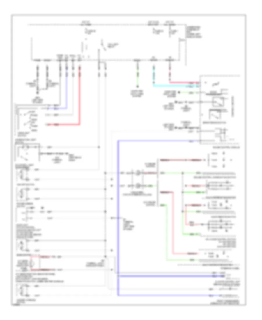
Forced Entry Wiring Diagram (2 of 2) for Honda Insight EX 2012
List of elements for Forced Entry Wiring Diagram (2 of 2) for Honda Insight EX 2012:
- (left rear of engine) g101
- 5v stabilize circuit/ controller area network controller
- Antenna
- Audio unit (w/o navigation) audio-navigation unit (w/ navigation) (behind middle of dash)
- B-can
- Blinking
- Body controller area network transceiver
- C304
- C402
- C407
- C602
- C605
- C801
- Computer data lines system
- Door lock actuator
- Door lock knob
- Door unlock
- Driver's door lock switch lock
- Driver's door switch (left "b" pillar)
- Front passenger's door switch (right "b" pillar)
- G403 (left side of dash)
- G501 (left end of dash)
- G502 (center of dash)
- G702 (left "c" pillar)
- G801 (left "c" pillar)
- Gauge control module
- Hatch outer handle switch
- Horn
- Ig key sw
- Ig1
- Ignition key switch
- Immobilizer- keyless control unit (in steering column cover)
- Indicator circuit
- Left rear door lock actuator/ knob switch
- Left rear door switch (in left "c" pillar)
- Lock
- Lock knob switch
- Pnk
- Power distribution system
- Power window master switch
- Red
- Right rear door switch (in right "c" pillar)
- S11 (thermal joint)
- S8 (thermal joint) (left side of dash)
- Scty
- Security
- Security hood switch (front of engine compt)
- Security indicator
- Steering lock assembly
- Unlock
- Vbu
Immobilizer Wiring Diagram for Honda Insight EX 2012
List of elements for Immobilizer Wiring Diagram for Honda Insight EX 2012:
- (left end of dash) g501
- (left side of dash) (thermal joint) s8
- (left side of floor)
- +b back
- A30
- A43
- A46
- Antenna
- Auxiliary under-hood fuse/relay box (left front of engine compt)
- B-can
- B-can transceiver
- B14
- B22
- C10
- C103
- C302
- C407
- C49
- Canh
- Canl
- Computer data lines system
- Control circuits
- Engine controls system
- F-can transceiver
- Fuel pump
- Fuel tank unit (on top left side of fuel tank)
- Fuse 15a
- Fuse 7.5a
- G101 (left rear of engine)
- G501 (left side of dash)
- G502 (center of dash)
- G602
- Gauge control module
- Hot at all times
- Hot in on or start
- Ig1
- Ig1 fuel pump
- Ig1 key sw
- Ignition key switch
- Igp1
- Igp2
- Immobilizer system indicator
- Immobilizer- keyless control unit (in steering column cover)
- Imocd (s-net)
- Imofpr
- K-line
- Key sw
- Lg2
- M16
- M34
- Meter
- Micu
- Mrly
- P-gnd
- Parking brake switch (base of parking brake lever)
- Pcm (left front of engine compt)
- Pgm-fi main relay 1
- Pgm-fi main relay 2
- Pnk
- Power distribution system
- Red
- S-gnd
- S-net
- S-net 5v
- S11 (thermal joint)
- S5 (thermal joint)
- S6 (thermal joint)
- Steering lock assembly
- Under-dash fuse/relay box (under left end of dash)
- Vbu
BODY CONTROL MODULES
Body Control Modules Wiring Diagram (1 of 2) for Honda Insight EX 2012
List of elements for Body Control Modules Wiring Diagram (1 of 2) for Honda Insight EX 2012:
- (not used)
- (thermal joint) s10
- +b backup
- +b haz
- +b stop & horn
- +b tpms
- A/t reverse relay
- Anti-theft system
- Atp-np
- Atp-p
- Atp-r
- B13
- B20
- B21
- B22
- B26
- B27
- B30
- B32
- B33
- B34
- B35
- Back lt
- C13
- C14
- C17
- C18
- C21
- C22
- C26
- C29
- C32
- C33
- C35
- C36
- C40
- C41
- C42
- C45
- C46
- C47
- C48
- Cargo lt
- Computer data lines system
- D/l unlock dr rly
- Defogger system
- Door lock relay
- Door locks & anti-theft systems
- Door sw (as)
- Door sw (dr)
- Door sw (ra)
- Door sw (rd)
- Door unlock relay
- Driver's door unlock relay
- E-latch sw
- E/latch
- E11
- Engine controls & transmissions systems
- Engine controls, exterior lights & transmissions systems
- Exterior lights & navigation systems
- Exterior lights system
- Fr wip as
- Fuse (tpms) 7.5a
- Fuse 10a
- Fuse 15a
- Fuse 20a
- Fuse 30a
- Fuse 7.5a
- G501 (left end of dash)
- G502 (center of dash)
- Gnd
- H/l lo rly
- Handy dr sw (lock)
- Handy dr sw (unlock)
- Headlight low beam relay
- Headlights system
- High beam control circuit
- Hot at all times
- Hot in on or start
- Ig1 fr wiper
- Ig1 fuel pump
- Ig1 meter
- Ig1 rr wiper
- Ig1 washer
- Instrument cluster system
- Interior lights system
- K-line
- K10
- Kc dr lock sw
- Kc dr unlock switch
- Lock
- M20
- Micu
- P-gnd
- Pnk
- Red
- Rr def coil
- Rr wip
- S-net
- S5 (thermal joint)
- Scs
- Sil dr lock sw
- Sil dr unlock sw
- Sil ra unlock sw
- Sil rd unlock sw
- Starter cut relay
- Starting/charging system
- Stop sw
- T/g sw
- To under dash fuse/ relay box (diagram 2 of 2)
- Trunk, tailgate, fuel doors system
- Turn signal/hazard warning circuit
- Under-dash fuse/relay box (under left side of dash)
- Unlock
- Wiper/washer system
Body Control Modules Wiring Diagram (2 of 2) for Honda Insight EX 2012
List of elements for Body Control Modules Wiring Diagram (2 of 2) for Honda Insight EX 2012:
- (not used)
- (option connector)
- +b backup
- +b fr fog
- +b h/mirr
- +b haz
- +b p/w as
- +b tpms
- A13
- A14
- A19
- A21
- A25
- A28
- A29
- A30
- A34
- A35
- Acc
- Acc socket
- Acs
- Air conditioning & mirrors systems
- Air conditioning system
- Anti-lock brakes system
- Anti-theft system
- Atp-np
- Auto lt sig
- Auto lt sio
- Auto lt sip
- B-can
- Blower motor relay
- Chk
- Chk s-gnd
- Combi gnd (light)
- Combi gnd (wiper)
- Computer data lines system
- Cruise control & horns systems
- Defogger system
- Dim sw
- Door locks & anti-theft systems
- Door locks & anti-theft systems trunk, tailgate, fuel doors system
- E-latch rly
- Exterior lights system
- Fr washer mtr
- Fr wip as
- Fr wip hi
- Fr wip hi & lo sw
- Fr wip int & lo sw
- Fr wip int vr+
- Fr wip lo
- Fr wip mist sw
- Fr wip wash sw
- From under-dash fuse/relay box (diagram 1 of 2)
- Fuse (not used)
- Fuse (w/ power mirror defogger) 10a
- Fuse 10a
- Fuse 20a
- Fuse 30a (w/o power mirror defoggers) 40a (w/ power mirror defoggers)
- Fuse 7.5a
- G501 (left end of dash)
- G502 (center of dash)
- Gnd
- H/l off sw
- H/l on sw
- Haz sw
- Headlights & exterior lights systems
- Headlights system
- Hood sw
- Horn relay
- Horns system
- Hot at all times
- Hot in acc or on
- Hot in on
- Hot in on or start
- Ig1 abs/vsa
- Ig1 back lt
- Ig1 ima
- Ig1 meter
- Ig1 opds
- Ig1 rr wiper
- Ig1 srs
- Ig2 day lt
- Ig2 hac
- Instrument cluster & exterior lights systems
- Interior lights system
- Intr lt-
- K-line
- Key lock sol
- Key sw
- M10
- M11
- M12
- M13
- M14
- M15
- M16
- M17
- M18
- M21
- M23
- M24
- M25
- M26
- M27
- M30
- M31
- M32
- M33
- M34
- Micu
- Micu service check connector
- P-gnd
- P-pin sw
- P/w rly
- Passing sw
- Pnk
- Power distribution system
- Power window relay
- Power windows system
- Q10
- Q11
- Q12
- Q13
- Q14
- Q15
- Q16
- R11
- R14
- Radio sw
- Rear window defogger relay
- Red
- Rr def coil
- Rr washer mtr
- Rr wip sw
- Rr wip wash sw
- S-gnd
- S-net
- S11 (thermal joint)
- S5 (thermal joint)
- S6 (thermal joint)
- Scs
- Shift interlock system
- Shift interlock system exterior lights system
- Shift interlock, sound & navigation systems warning systems
- Sil as unlock sw
- Small lt sw
- Sound & navigation systems
- Taillight relay
- Turn l sw
- Turn r sw
- Under-dash fuse/relay box (under left side of dash)
- Warning & anti-theft systems
- Warning, shift interlock, instrument cluster & engine controls systems
- Wiper/ washer system
- Wiper/washer system
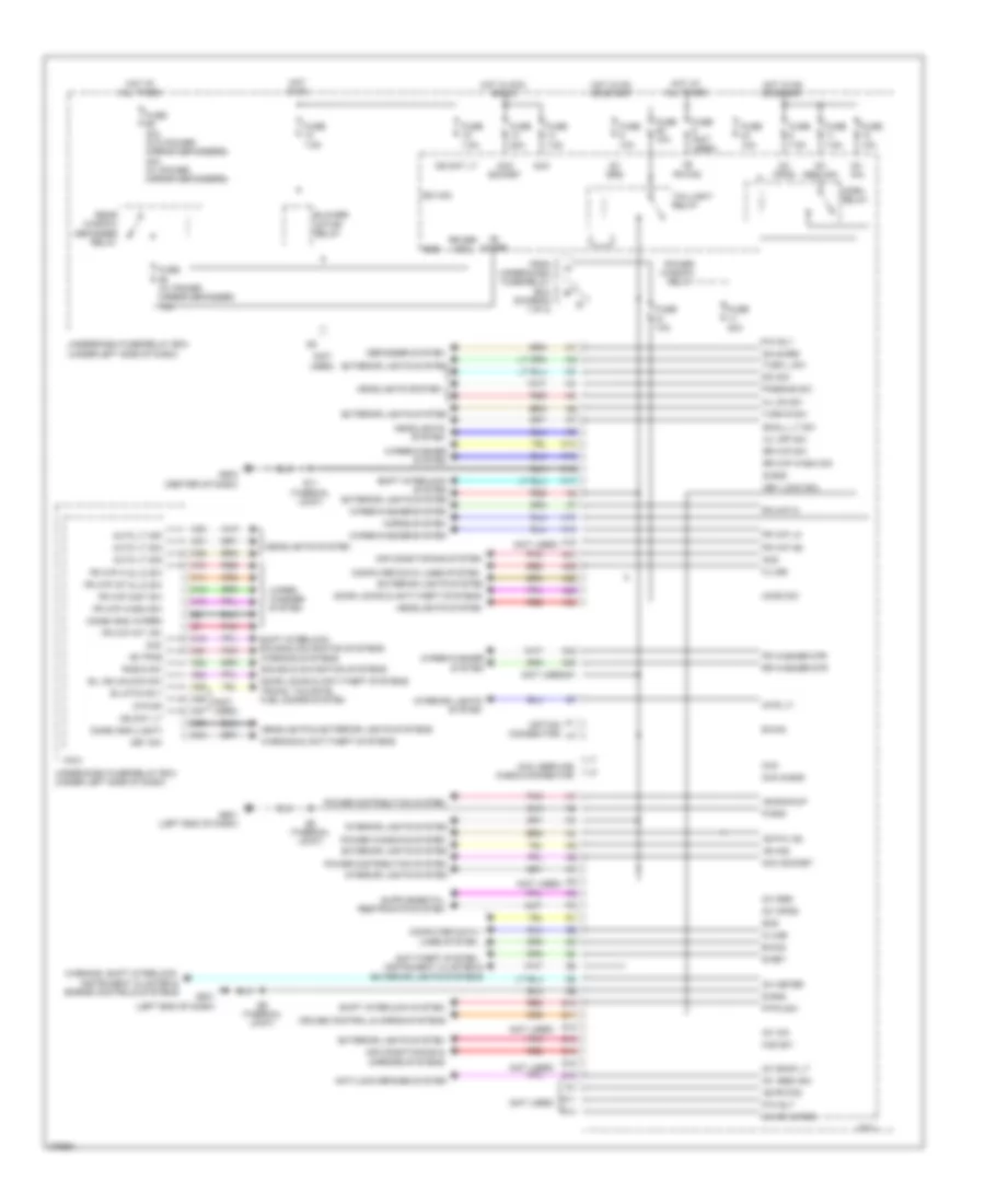
COMPUTER DATA LINES
Computer Data Lines Wiring Diagram for Honda Insight EX 2012
List of elements for Computer Data Lines Wiring Diagram for Honda Insight EX 2012:
- (left end of dash) g501
- (thermal joint) s6
- +b backup
- A16
- A17
- A18
- A24
- A25
- A30
- A31
- A32
- Audio unit (w/o navigation)
- Audio-navigation unit (w/ navigation) (behind middle of dash)
- B can
- B-can
- B21
- B27
- C10
- C16
- C201
- C302
- C305
- C603
- C702
- Ceiver trans-
- Chk
- Climate control unit (behind middle of dash)
- Connector) (option
- Control circuits
- D10
- Dlc (center left of dash)
- Eps control unit (left side of dash)
- F can hi
- F can lo
- F-can transceiver
- Fuse 1 15a
- G101 (left rear of engine)
- G501 (left end of dash)
- G502 (center of dash)
- Gauge control module
- Handsfree link control unit (w/o navigation) (right side of dash)
- Hi f can
- Hot at all times
- Immobilizer-keyless control unit (in steering column cover)
- J/c c307 (left side of dash)
- J/c c408 (left side of dash)
- J/c c409 (left side of dash)
- J/c c410 (w/ navigation & tpms) (left side of dash)
- K-line
- Lo f can
- Lx & ex
- Mcm
- Micu
- Micu service check connector
- Pcm (left front of engine compt)
- Pnk
- Red
- S-gnd
- S-gnd chk j3
- S11 (thermal joint)
- S6 (thermal joint)
- S8 (thermal joint)
- Scs
- Srs unit (under center of dash)
- Tpms control unit (if equipped) (left side of dash)
- Under-dash fuse/relay box (under left side of dash)
- Vsa modulator control unit (right side of engine compt)
- W/ navigation
- W/o navigation
- Wen
- Yaw rate-lateral acceleration sensor (w/ vsa) (center of dash)
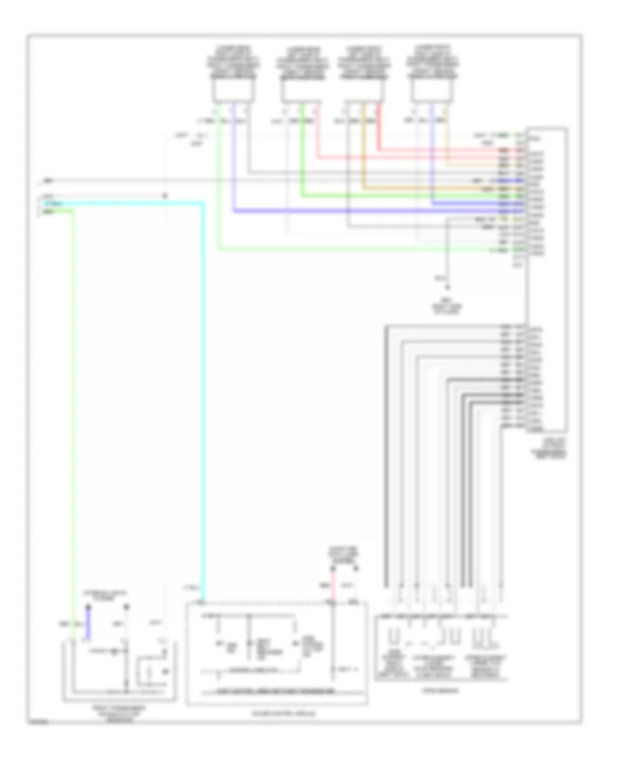
COOLING FAN
Cooling Fan Wiring Diagram for Honda Insight EX 2012
List of elements for Cooling Fan Wiring Diagram for Honda Insight EX 2012:
- (left front of engine compt) auxiliary under-hood fuse/relay box
- (left front of engine compt) auxiliary under-hood relay box
- (not used)
- (rear of engine) (thermal joint) s4
- +b backup
- A/c compressor clutch relay
- A/c condenser fan diode
- A/c condenser fan motor (front of engine compt)
- A/c condenser fan relay
- A/c pressure sensor (right front of engine compt)
- A/f sensor relay
- A10
- A18
- A20
- A22
- A27
- A33
- A36
- A44
- A45
- A49
- Acpd
- B12
- B15
- B19
- B24
- B34
- Can h
- Can l
- Computer data lines system
- Control circuits
- Coolant high tempe- rature ind
- Coolant low tempe- rature ind
- Ect1
- Ect2
- Engine controls system
- Engine coolant temperature (ect) sensor 1 (rear of engine)
- Engine coolant temperature (ect) sensor 2 (lower right front of engine compt)
- F-can transceiver
- Fan control relay
- Fanh
- Fanl
- Fuse 1 15a
- Fuse 10 7.5a
- Fuse 22 7.5a
- Fuse 26 10a
- Fuse 30 30a
- Fuse 30a
- Fuse 31 7.5a
- G401 (behind left side of front bumper)
- G501 (left end of dash)
- Gauge control module
- Hot at all times
- Hot in on
- Hot in on or start
- Ig1 meter
- J/c c306 (left side of dash)
- Micu
- Multi-information display (mid) unit
- Pcm (left front of engine compt)
- Pnk
- Radiator fan diode
- Radiator fan motor (left front of engine compt)
- Radiator fan relay
- Red
- S6 (thermal joint)
- Sg2
- Sg6
- Sub rly
- Under-dash fuse/relay box (under left side of dash)
- Vcc6
CRUISE CONTROL
Cruise Control Wiring Diagram (1 of 2) for Honda Insight EX 2012
List of elements for Cruise Control Wiring Diagram (1 of 2) for Honda Insight EX 2012:
- (under left
- 10a
- A15
- A18
- A19
- A25
- A26
- A35
- A36
- A38
- A42
- App sensor (left side of dash)
- Apsa
- Apsb
- Atpfwd
- B17
- B28
- B29
- B44
- Bksw
- Bkswnc
- Brake pedal position switch (top of brake pedal assembly)
- C12
- C13
- C14
- C20
- C21
- C43
- Canh
- Canl
- Computer data lines system
- Cvt output shaft (driven pulley) speed sensor (on transmission housing)
- Etcsm+
- Etcsm-
- Etcsrly
- Exterior lights system
- Fuse 12 10a
- Fuse 24
- G101 (left rear of engine)
- Horn relay
- Hot at all times
- Hot in on or start
- Idle stop switch (top of brake pedal assembly)
- Ig1etcs
- J/c c104 (rear of engine)
- Joint)
- Micu
- Mrly
- Ndn
- Pcm (left front of engine compt)
- Q11
- Red
- Sg1
- Sg3
- Sg4
- Sg5
- Shifters
- Side of dash)
- Tp sensor/ throttle actuator (rear of engine)
- Tpsa
- Tpsb
- Transmission range switch (on transaxle housing)
- Under-dash fuse/relay box
- Vcc1
- Vcc3
- Vcc4
- Vcc5
- W/ paddle
- W/o paddle
Cruise Control Wiring Diagram (2 of 2) for Honda Insight EX 2012
List of elements for Cruise Control Wiring Diagram (2 of 2) for Honda Insight EX 2012:
- (left end of dash) g501
- +b back up
- 7.5a
- B18
- C10
- C103
- C11
- C12
- Cable reel (top of steering column)
- Cancel switch
- Computer data lines system
- Control circuit
- Control ind cruise
- Cruise control combination switch
- Etcs control relay
- F-can transceiver
- Fuse 1 15a
- Fuse 22
- Fuse 39 15a
- Fuse 52 15a
- G502 (center of dash)
- Gauge control module
- Horns system
- Hot at all times
- Hot in on or start
- Ig1
- Interior lights system
- Main switch
- Meter
- Micu
- Pgm-fi main relay 1
- Pnk
- Red
- Resume switch
- S11 (thermal joint)
- Set switch
- Steering wheel
- Switch ind control main cruise
- Under-dash fuse/relay box (under left side of dash)
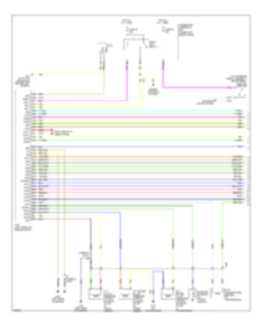
DEFOGGERS
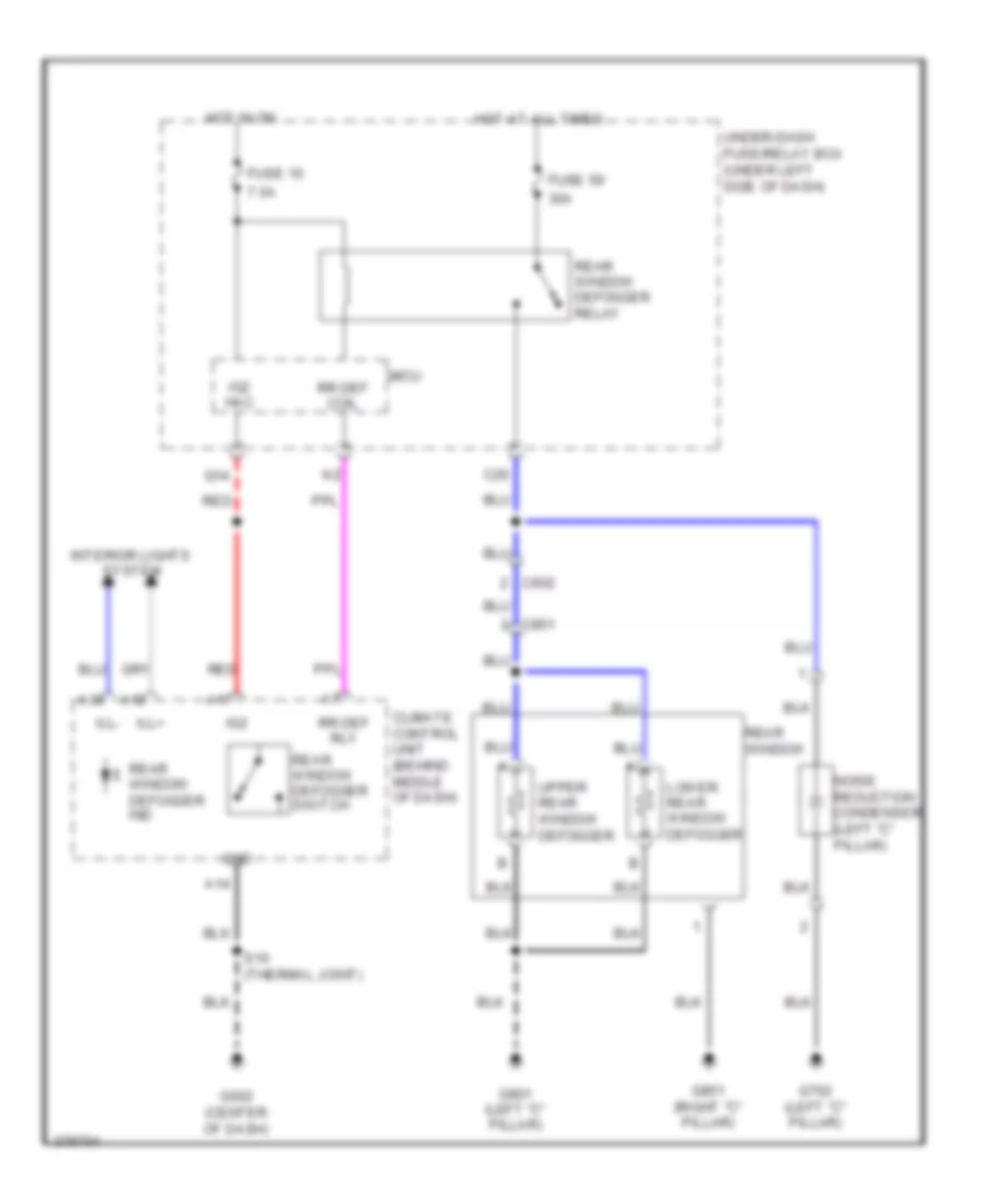
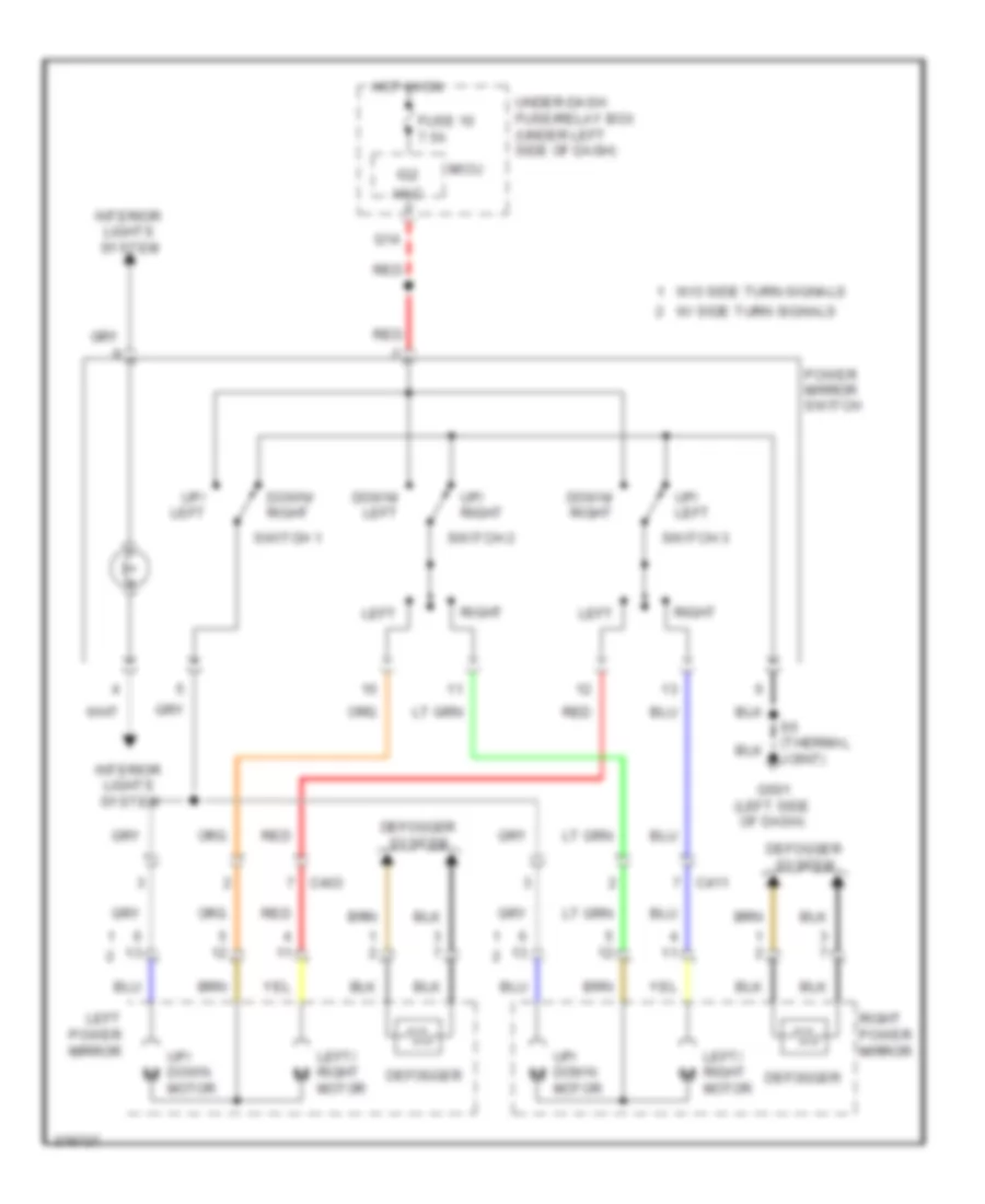
Rear Defogger Wiring Diagram, with Power Mirror Defogger for Honda Insight EX 2012
List of elements for Rear Defogger Wiring Diagram, with Power Mirror Defogger for Honda Insight EX 2012:
- +b h/mirr
- 10a
- 40a
- 7.5a
- A14
- A17
- A18
- A36
- C20
- C411
- C602
- C801
- Climate control unit (behind middle of dash)
- Defogger
- Fuse 10
- Fuse 55
- Fuse 59
- G501 (left end of dash)
- G502 (center of dash)
- G702 (left "c" pillar)
- G801 (left "c" pillar)
- G851 (right "c" pillar)
- Gnd
- Hot at all times
- Hot in on
- Ig2
- Ig2 hac
- Ill+
- Ill-
- Interior lights system
- Left power mirror
- Lower rear window defogger
- Micu
- Noise reduction condenser (left "c" pillar)
- Q14
- Rear window
- Rear window defogger relay
- Rear window/ power mirror defoggers ind
- Rear window/ power mirror defoggers switch
- Red
- Red a
- Right power mirror
- Rr def coil
- Rr def rly
- S10 (thermal joint)
- Turn signals
- Under-dash fuse/relay box (under left side of dash)
- Upper rear window defogger
- W/ side turn signals
- W/o side
Rear Defogger Wiring Diagram, without Power Mirror Defogger for Honda Insight EX 2012
List of elements for Rear Defogger Wiring Diagram, without Power Mirror Defogger for Honda Insight EX 2012:
- 30a
- 7.5a
- A14
- A17
- A18
- A36
- C20
- C602
- C801
- Climate control unit (behind middle of dash)
- Fuse 10
- Fuse 59
- G502 (center of dash)
- G702 (left "c" pillar)
- G801 (left "c" pillar)
- G851 (right "c" pillar)
- Gnd
- Hot at all times
- Hot in on
- Ig2
- Ig2 hac
- Ill+
- Ill-
- Interior lights system
- Lower rear window defogger
- Micu
- Noise reduction condenser (left "c" pillar)
- Q14
- Rear window
- Rear window defogger ind
- Rear window defogger relay
- Rear window defogger switch
- Red
- Rr def coil
- Rr def rly
- S10 (thermal joint)
- Under-dash fuse/relay box (under left side of dash)
- Upper rear window defogger
ELECTRONIC POWER STEERING
Electronic Power Steering Wiring Diagram for Honda Insight EX 2012
List of elements for Electronic Power Steering Wiring Diagram for Honda Insight EX 2012:
- (left side of dash) g402
- A12
- B11
- Battery terminal fuse box (top of battery)
- C10
- C11
- C12
- C13
- C14
- C15
- C16
- Can-h
- Can-l
- Computer data lines system
- Control circuits
- Eps control unit (left side of dash)
- Eps ind
- Eps motor
- Eps torque sensor
- Fast controller area network transceiver
- Fuse 11 7.5a
- Fuse 2 60a
- Fuse 22 7.5a
- G403 (left side of dash)
- G501 (left end of dash)
- Gauge control module
- Hot at all times
- Hot in on or start
- Ig1
- Ig1 meter
- K-line
- Micu
- Nep
- Pcm (left front of engine compt)
- Pnk
- Red
- S6 (thermal joint)
- Scs
- Steering gearbox
- Steering gearbox connector
- T/s gnd
- Under-dash fuse/relay box (under left side of dash)
- Vs1
- Vs2
ENGINE PERFORMANCE
1.3L HYBRID
1.3L Hybrid, Engine Controls Wiring Diagram (1 of 5) for Honda Insight EX 2012
List of elements for 1.3L Hybrid, Engine Controls Wiring Diagram (1 of 5) for Honda Insight EX 2012:
- (left side of fuel tank) evap canister vent shut valve
- (lower right front of engine compt) ect sensor 2
- (top of brake pedal assembly)
- A/f sensor relay
- A27
- Acc
- Acpd
- Air conditioning system
- App sensor (left side of dash)
- Apsa
- Apsb
- B19
- B25
- Baro meter sensor
- Bk sw nc
- Bksw
- Brake booster pressure sensor a (left rear of engine compt)
- Brake booster pressure sensor b (left rear of engine compt)
- C103
- C302
- C305
- Canh
- Canl
- Computer data lines system
- Ect2
- Eld
- Eld unit
- Eps control unit (left side of dash)
- Etcsrly
- Ftp
- Ftp sensor (left side of fuel tank)
- Fuse 10a
- Fuse 7.5a
- G501 (left end of dash)
- Hot at all times
- Hot in on or start
- Idle stop switch
- Igp1
- Igp2
- Imofpr
- J/c c306 (left side of dash)
- Mpmon1
- Mpmon2
- Mrly
- Nep
- Pcm (left front of engine compt)
- Pnk
- Power distribution system
- Red
- S6 (thermal joint)
- Scs
- Sdnp
- Sg4
- Sg5
- Sg6
- Starting/ charging system
- Starting/charging system
- Stc
- Sts
- Subrly
- Supp
- Under-dash fuse/relay box (under left side of dash)
- Used) (not
- Vbsol
- Vcc4
- Vcc5
- Vcc6
- Vsv
1.3L Hybrid, Engine Controls Wiring Diagram (2 of 5) for Honda Insight EX 2012
List of elements for 1.3L Hybrid, Engine Controls Wiring Diagram (2 of 5) for Honda Insight EX 2012:
- (center of dash)
- (left rear of engine) g101
- (on trans- mission) g151
- (thermal joint)
- (thermal joint) s2
- (w/ paddle shifters) sequential sport shift mode shift indicator
- B14
- B15
- C106
- C12
- C14
- C15
- C302
- Cable reel (top of steering column)
- Computer data lines system
- Control circuits
- Cvt clutch pressure control solenoid valve (in transmission)
- Cvt drive pulley pressure control solenoid valve (in transmission)
- Cvt driven pulley pressure control solenoid valve (in transmission)
- Cvtf temperature sensor (in transmission)
- F-can transceiver
- Fuse 7.5a
- G501 (left end of dash)
- G502
- Gauge control module
- Hot in on or start
- Iat sensor
- Ig1 meter
- Inhibitor solenoid (in transmission)
- J/c c104 (rear of engine)
- Maf sensor
- Maf/iat sensor (on air intake hose)
- Micu
- Mil ind
- Paddle shifter (+) (upshift switch) (if equipped)
- Paddle shifter (-) (downshift switch) (if equipped)
- Pnk
- Power distribution system
- Red
- S11 (thermal joint)
- Shifters
- Steering wheel
- Transmission range switch (on transaxle housing)
- Under-dash fuse/relay box (under left side of dash)
- Used) (not
- W/ paddle
- W/o paddle
- W/o paddle shifters
1.3L Hybrid, Engine Controls Wiring Diagram (3 of 5) for Honda Insight EX 2012
List of elements for 1.3L Hybrid, Engine Controls Wiring Diagram (3 of 5) for Honda Insight EX 2012:
- (egr valve position sensor: on egr valve) (egr valve: left front of engine) egr valve & egr valve position sensor
- (left rear of engine) g101
- (lower left side of engine) oil pressure switch
- (rear of engine) ect sensor 1
- (rear of engine) evap canister purge valve
- (the- rmal joint) s2
- (thermal joint)
- (top left rear of engine) rocker arm oil control solenoid a
- (top left rear of engine) rocker arm oil control solenoid b
- (top rear of engine) rocker arm oil pressure sensor a
- (top rear of engine) rocker arm oil pressure sensor b
- A/f sensor (on warm- up twc)
- Atpd
- Atpfwd
- Atpl
- Atpn
- Atpp
- Atpr
- Atps
- B17
- C103
- Dnls
- Drls
- Ect1
- Egr
- Egrp
- Fuse 10a
- G101 (left rear of engine)
- Hot in on or start
- Iat
- Igpls1e
- Igpls2e
- Igpls3e
- Igpls4e
- Igrtne
- Igrtni
- Inhsol
- J/c c105 (rear of engine)
- Map
- Ndn
- Ndr
- Op sw
- Pcm (left front of engine compt)
- Pcs
- Pg1
- Pg2
- Pnk
- Poilcsb
- Red
- Scls
- Secondary ho2s (in exhaust, upstream of under-floor twc)
- Sg2
- Sho2s
- So2shtc
- Tatf
- Under-dash fuse/relay box (under left side of dash)
- Vcc2
- Vel
- Vg+
- Vg-
- Vts1
1.3L Hybrid, Engine Controls Wiring Diagram (4 of 5) for Honda Insight EX 2012
List of elements for 1.3L Hybrid, Engine Controls Wiring Diagram (4 of 5) for Honda Insight EX 2012:
- (not used)
- (thermal joint) s3
- Auxiliary under-hood fuse/ relay box (left front of engine compt)
- B14
- B18
- B28
- Brake pedal position switch (top of brake pedal assembly)
- C101
- C103
- C302
- C407
- Ckp sensor (under right side of engine)
- Cmp sensor (top rear of engine)
- Cvt driven pulley pressure sensor (on transmission housing)
- Cvt input shaft (drive pulley) speed sensor (on transmission housing)
- Cvt output shaft (driven pulley) speed sensor (on transmission housing)
- Etcs control relay
- Exterior lights system
- From pgm-fi main relay 1 (diagram 5 of 5)
- Fuel pump
- Fuel tank unit (on top left side of fuel tank)
- Fuse 10a
- Fuse 15a
- G101 (left rear of engine)
- G602 (left side of floor)
- Hot at all times
- Hot in on or start
- J/c c104 (rear of engine)
- J/c c105 (rear of engine)
- Map sensor (rear of engine)
- Pgm-fi main relay 2
- Red
- S4 (thermal joint) (rear of engine)
- Throttle actuator
- Tp sensor
- Tp sensor/throttle actuator (rear of engine)
- Under- dash fuse/ relay box (under left side of dash)
- Vehicle speed sensor (on transmission)
1.3L Hybrid, Engine Controls Wiring Diagram (5 of 5) for Honda Insight EX 2012
List of elements for 1.3L Hybrid, Engine Controls Wiring Diagram (5 of 5) for Honda Insight EX 2012:
- (left rear of engine) g101
- (left side of engine) injectors
- (thermal joint) s1
- 15a
- Afs+
- Afs-
- Afshtc
- Auxiliary under-hood fuse/relay box (left front of engine compt)
- B24
- C103
- Ckp
- Cmp
- Computer data lines system
- Etc sm+
- Etc sm-
- Exhaust side ignition coils (top right of engine)
- Fuse 1
- Fuse 15a
- Fuse 2
- Fuse 20a
- G101 (left rear of engine)
- Hot at all times
- Icm
- Ig1
- Ig1etcs
- Ignition coil relay
- Igpls1i
- Igpls2i
- Igpls31
- Igpls4i
- Imacanh
- Imacanl
- Inj1
- Inj2
- Inj3
- Inj4
- Intake side ignition coils (top left of engine)
- J/c c104 (rear of engine)
- J/c c105 (rear of engine)
- Knock sensor (left side of engine)
- Ksgnd
- Lg1
- Lg2
- Pcm (left front of engine compt)
- Pdn
- Pgm-fi main relay 1
- Pgmetcs
- Poilcsa
- Red
- S2 (thermal joint)
- Sg1
- Sg3
- So2sg
- To etcs control relay (diagram 4 of 5)
- Tpsa
- Tpsb
- Under- dash fuse/ relay box (under left side of dash)
- Vcc1
- Vcc3
- Vts2
1.3L Hybrid, IMA Wiring Diagram (1 of 3) for Honda Insight EX 2012
List of elements for 1.3L Hybrid, IMA Wiring Diagram (1 of 3) for Honda Insight EX 2012:
- (rear of engine) ima motor rotor position sensor
- 125a
- A10
- A11
- A12
- A13
- A14
- A15
- A16
- A17
- A18
- A19
- A20
- A21
- A22
- A23
- A24
- A25
- A26
- A27
- A28
- A29
- A30
- A31
- B10
- B11
- B12
- B13
- B14
- B15
- B16
- B17
- B18
- B19
- B20
- B21
- B22
- B23
- B24
- Battery current sensor
- Battery module
- Battery module fuse
- Battery module switch
- Battery module temperature sensor 1
- Battery module temperature sensor 2
- Battery module temperature sensor 3
- Bus bar
- Bypass contractor
- Bypass resistor
- C102
- C305
- C603
- C701
- C702
- Canh
- Canl
- Cnt
- Cntpg
- Computer data lines system
- Contractor connector
- Fanctl
- G101 (left rear of engine)
- G702 (left "c" pillar)
- G901 (under ipu lid)
- High voltage contractor
- Ig1
- Iga
- Ighld
- Ighld2
- Imacanh
- Imacanl
- Isoc
- Isocf
- J/c c105 (rear of engine)
- J/c c703 (under ipu lid)
- Junction board (right rear of ima motor power unit)
- Junction board connector
- Mcm
- Nfan
- Pg1
- Pnk
- Pre
- Red
- Scidm
- Scimd
- Sgisoc
- Sgtb
- Tbatt1
- Tbatt2
- Tbatt3
- Vbu
- Vccisoc
1.3L Hybrid, IMA Wiring Diagram (2 of 3) for Honda Insight EX 2012
List of elements for 1.3L Hybrid, IMA Wiring Diagram (2 of 3) for Honda Insight EX 2012:
- +b backup
- A15
- Auto stop indicator
- B17
- Bkswnc
- Bus bar
- C102
- C35
- C36
- C37
- C603
- C701
- C702
- Charge/assist gauge
- Charging system indicator
- Computer data lines system
- Control circuits
- Engine controls circuit
- F-can transceiver
- Fan ctrl
- Fuse 10a
- Fuse 15a
- Fuse 7.5a
- G501 (left end of dash)
- G701 (rear of cargo area)
- G702 (left "c" pillar)
- G901 (under ipu lid)
- Gauge control module
- Ground
- Hot at all times
- Hot in on or start
- Idle stop switch (top of brake pedal assembly)
- Ig1
- Ig1 meter
- Ignition
- Ima system indicator
- Imacanh
- Imacanl
- Interior lights system
- Ipu module fan (right rear of cargo area)
- J/c c703 (under ipu lid)
- Micu
- Multi-information display (mid) unit
- Pcm (left front of engine compt)
- Pnk
- Power distribution system
- Red
- S6 (thermal joint)
- S8 (thermal joint)
- Under-dash fuse/relay box (under left side of dash)
1.3L Hybrid, IMA Wiring Diagram (3 of 3) for Honda Insight EX 2012
List of elements for 1.3L Hybrid, IMA Wiring Diagram (3 of 3) for Honda Insight EX 2012:
- (left side of cargo area)
- (under ipu lid)
- (under ipu lid) g901
- (under ipu lid) j/c c703
- Battery
- Battery terminal fuse box (top of battery)
- Bus bar
- C10
- C11
- C12
- C13
- C14
- C15
- C16
- C17
- C18
- C19
- C20
- C21
- C22
- C49
- C603
- C701
- Dc-dc converter
- E10
- E11
- E12
- E13
- E14
- E15
- E16
- E17
- E18
- E19
- E20
- E21
- E22
- E23
- E24
- E25
- E26
- E27
- E28
- E29
- E30
- E31
- Fuse 100a
- Fuse 10a
- G5 (under ipu lid)
- G702 (left "c" pillar)
- G901 (under ipu lid)
- Gnd
- Ground
- Hi volt
- High voltage
- Hot at all times
- Hot in on or start
- Ignition
- Ima motor rotor
- Input
- Ipu relay holder
- Ipu serial sig
- Ipua
- Iuph
- Ivph
- Iwph
- Mcm
- Mcm relay 1
- Mcm relay 2
- Mpi module (under ipu lid)
- Nca
- Output
- Phase motor current sensor (under ipu lid)
- Pnk
- Red
- Sgiu
- Sgiv
- Sgiw
- T10
- T11
- T12
- T13
- T14
- T15
- T16
- T17
- U phase
- U phase hi side
- U phase lo side
- U phase motor current sensor
- Under-dash fuse/relay box (under left side of dash)
- V phase
- V phase hi side
- V phase lo side
- V phase motor current sensor
- Vcciu
- Vcciv
- Vcciw
- Vhb1
- Vhb2
- Vhb3
- Vhb4
- Vhb5
- Vhb6
- Vhb7
- Vhb8
- Vhbo
- W phase
- W phase hi side
- W phase lo side
- W phase motor current sensor
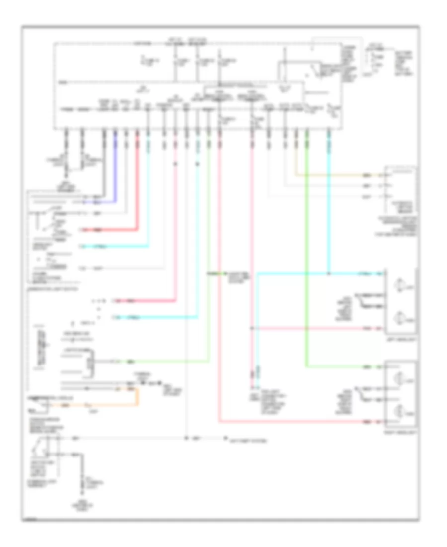
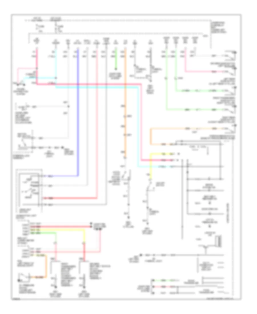
EXTERIOR LIGHTS
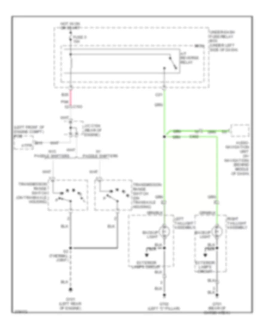
Backup Lamps Wiring Diagram for Honda Insight EX 2012
List of elements for Backup Lamps Wiring Diagram for Honda Insight EX 2012:
- (left front of engine compt) pcm
- A/t reverse relay
- Audio- navigation unit (w/ navigation) (behind middle of dash)
- B15 atpr
- B26
- Backup light
- C103
- C21
- C402
- Exterior lamps circuit
- Fuse 5 10a
- G101 (left rear of engine)
- G701 (rear of cargo area)
- G702 (left "c" pillar)
- Hot in on or start
- J/c c104 (rear of engine)
- Left taillight assembly
- Micu
- Paddle shifters
- Pnk
- Right taillight assembly
- S2 (thermal joint)
- Transmission range switch (on transaxle housing)
- Transmission range switch s (on transaxle housing)
- Under-dash fuse/relay box (under left side of dash)
- W/o
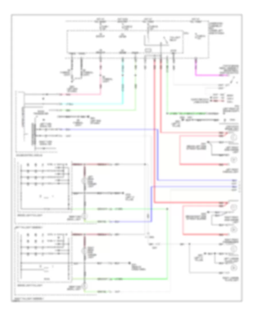
Exterior Lamps Wiring Diagram (1 of 2) for Honda Insight EX 2012
List of elements for Exterior Lamps Wiring Diagram (1 of 2) for Honda Insight EX 2012:
- (top of brake pedal assembly) brake pedal position switch
- +b backup
- A42
- B-can
- B-can transceiver
- B28
- B30
- B35
- Bksw
- Brake light/taillight
- C14
- C42
- C602
- C801
- Can h
- Can l
- Computer data lines system
- Control circuits
- Fuse 1 15a
- Fuse 22 7.5a
- Fuse 24 10a
- Fuse 29 10a
- G202 (behind right side of front bumper)
- G401 (behind left side of front bumper)
- G501 (left end of dash)
- G701 (rear of cargo area)
- G702 (left "c" pillar)
- G801 (left "c" pillar)
- Gauge control module
- High mount brake light
- Hot at all times
- Hot in on or start
- Ig1 meter
- Joint)
- Left front parking light
- Left front side marker light
- Left license plate light
- Left rear side marker light
- Left taillight assembly
- Left turn signal ind
- Micu
- P-gnd
- Pcm (left front of engine compt)
- Pnk
- Rear turn signal light
- Red
- Right front parking light
- Right front side marker light
- Right license plate light
- Right rear side marker light
- Right taillight assembly
- Right turn signal ind
- S-gnd
- S6 (thermal joint)
- S8 (thermal joint)
- Stop sw
- Taillight relay
- Turn signal/hazard relay 2 (sounder)
- Under-dash fuse/relay box (under left side of dash)
Exterior Lamps Wiring Diagram (2 of 2) for Honda Insight EX 2012
List of elements for Exterior Lamps Wiring Diagram (2 of 2) for Honda Insight EX 2012:
- (not used)
- A28
- B34
- C13
- C41
- C411
- Combi gnd (light)
- Combination light switch
- E11
- Fuse 23 10a
- G202 (behind right side of front bumper)
- G401 (behind left side of front bumper)
- G501 (left side of dash)
- G502 (center of dash)
- H/l off sw
- H/l on sw
- Haz sw
- Hazard warning switch
- Head
- Headlight switch
- Hot at all times
- Interior lights system
- Left front turn signal light
- Left power mirror (w/ side turn signals)
- Left side turn signal light
- M20
- M33
- Micu
- Off
- Park
- Pnk
- Q13
- Red
- Right front turn signal light
- Right power mirror (w/ side turn signals)
- Right side turn signal light
- Small lt sw
- Turn l sw
- Turn r sw
- Turn signal switch
- Turn signal/hazard warning circuit
- Under-dash fuse/relay box (under left side of dash)
GROUND DISTRIBUTION
Ground Distribution Wiring Diagram (1 of 4) for Honda Insight EX 2012
List of elements for Ground Distribution Wiring Diagram (1 of 4) for Honda Insight EX 2012:
- (lg1)
- (lg2)
- (pg1)
- (pg2)
- (pgm-
- B10
- C101
- C103
- C106
- C302
- C305
- C44
- C49
- Ckp sensor
- Cmp sensor
- Cvt clutch pressure control solenoid valve
- Cvt drive pulley pressure control solenoid valve
- Cvt driven pulley pressure control solenoid valve
- Dlc
- Egr valve & egr valve position sensor
- Etcs)
- Exhaust side ignition coil 1
- Exhaust side ignition coil 2
- Exhaust side ignition coil 3
- Exhaust side ignition coil 4
- G101 (left rear of engine)
- G151 (on transmission)
- Gnd
- Ima motor rotor position sensor shield a
- Ima motor rotor position sensor shield b
- Ima motor rotor position sensor shield c
- Immobilizer- keyless control unit
- Intake side ignition coil 1
- Intake side ignition coil 2
- Intake side ignition coil 3
- Intake side ignition coil 4
- J/c c105 (rear of engine)
- Knock sensor shield
- Pcm
- Rocker arm oil control solenoid a
- Rocker arm oil control solenoid b
- S1 (thermal joint) (rear of engine)
- S2 (thermal joint) (rear of engine)
- S3 (thermal joint) (rear of engine)
- Secondary ho2s shield
- Transmission range switch
Ground Distribution Wiring Diagram (2 of 4) for Honda Insight EX 2012
List of elements for Ground Distribution Wiring Diagram (2 of 4) for Honda Insight EX 2012:
- (if equipped) glove box light
- (if equipped) security hood switch
- (if equipped) tpms control unit
- (not used)
- (power mirror defogger w/o side turn signals) left power mirror
- (power mirror defoggers w/o side turn signals) right power mirror
- (under left side of dash) under-dash fuse/relay box
- (w/ side turn signal) left power mirror
- (w/ side turn signals) right power mirror
- A/c condenser fan motor
- A/t gear position indicator panel light/park pin switch/ shift lock solenoid
- A14
- Accessory power socket
- Auxiliary under-hood fuse/relay box
- Blower motor relay
- Blower power transistor
- Brake fluid level switch
- C12
- C301
- C403
- C404
- C411
- Cable
- Chk s-gnd
- Climate control unit
- Cruise control combination switch (if equipped)
- Dlc
- Door unlock relay
- Driver's
- Driver's door lock actuator/ knob switch/ key cylinder switch
- Econ switch
- Eld unit
- Fan control relay
- Front passenger's door lock actuator/ knob switch
- G401 (behind left side of front bumper)
- G403 (left side of dash)
- G404 (behind middle of front bumper)
- G501 (left end of dash)
- G502 (center of dash)
- G551
- Gauge control module
- Gnd
- High
- Horn switch
- K10
- Left front parking light
- Left front side marker light
- Left front turn signal light
- Left headlight
- Low
- M16
- Micu
- Micu service check connector
- P-gnd
- Paddle shifter+ (upshift switch) (if equipped)
- Paddle shifter- (downshift switch) (if equipped)
- Park pin switch
- Pnk
- Power mirror switch
- Power window master switch
- Reel
- S-gnd
- S10 (thermal joint) (middle of dash)
- S11 (thermal joint) (middle of dash)
- S5 (thermal joint) (left side of dash)
- S6 (thermal joint) (left side of dash)
- Steering gearbox
- Steering gearbox connector
- Steering lock assembly
- Steering wheel
- Under dash relay holder
- Vsa off switch
- Windshield wiper motor
- Yaw rate- lateral acceler- ation sensor
Ground Distribution Wiring Diagram (3 of 4) for Honda Insight EX 2012
List of elements for Ground Distribution Wiring Diagram (3 of 4) for Honda Insight EX 2012:
- (canada) washer fluid level switch
- A12
- A28
- A29
- Audio unit
- Audio- navigation unit (w/ navigation)
- Backup light
- Battery
- Brake light/ taillight
- C502
- C503
- C504
- C603
- C605
- D11
- D12
- Driver's seat belt buckle switch
- Driver's seat position sensor
- Engine
- Front passenger's seat belt buckle switch
- Fuel tank unit
- G1 (left front inner fender panel)
- G2 (right front inner fender)
- G202 (behind right side of front bumper)
- G203 (right side of engine compt)
- G3 (left rear of engine compt)
- G503 (center of dash)
- G504 (center console)
- G601 (right side of floor)
- G602 (left side of floor)
- G702 (left "c" pillar)
- Hands free link control unit (if equipped)
- High
- Ima motor rotor position sensor shield d
- Left rear door lock actuator/ knob switch
- Left taillight assembly
- Low
- Lx & ex
- Mcm relay 1 shield
- Mcm relay 2 shield a
- Mcm relay 2 shield b
- Noise reduction condenser
- Ods unit
- Rear side marker light
- Rear turn signal light
- Right front parking light
- Right front side marker light
- Right front turn signal light
- Right headlight
- Right rear door lock actuator/ knob switch
- Srs unit
- Transmission
- Vsa modulator- control unit
Ground Distribution Wiring Diagram (4 of 4) for Honda Insight EX 2012
List of elements for Ground Distribution Wiring Diagram (4 of 4) for Honda Insight EX 2012:
- (honda accessory) automatic dimming inside mirror
- Automatic dimming inside mirror ground
- Backup light
- Brake light/ taillight
- C701
- C801
- C801 c801
- Dc-dc converter
- Dc-dc converter shield
- Eps control unit
- G4 (left side of cargo area)
- G402 (left side of dash)
- G5 (under ipu lid)
- G701 (rear of cargo area)
- G801 (left "c" pillar)
- G851 (right "c" pillar)
- G901 (under ipu lid)
- Hatch latch switch
- Hatch outer handle switch
- Hatch release actuator
- High mount brake light
- Ima motor rotor position sensor shield d
- Ipu module fan
- J/c c703 (under ipu lid)
- Left license plate light
- Lower rear window defogger
- Mcm
- Mcm relay 1 shield
- Mcm relay 2 shield a
- Mcm relay 2 shield b
- Mpi module
- Nca
- Rear side marker light
- Rear turn signal light
- Rear window
- Rear window wiper motor
- Right license plate light
- Right taillight assembly
- T17
- Upper rear window defogger
- W/ power mirror defogger
- W/o power mirror defogger
HEADLIGHTS
Headlights Wiring Diagram for Honda Insight EX 2012
List of elements for Headlights Wiring Diagram for Honda Insight EX 2012:
- (not used)
- (thermal joint) s6
- +b backup
- A24
- A30
- Anti-theft system
- Auto lt si0
- Auto lt sig
- Auto lt sip
- Automatic lighting sensor
- Automatic lighting sensor/sunlight sensor (if equipped) (top center of dash)
- B-can
- B-can transceiver
- B13
- B29
- Battery terminal fuse box (top of battery)
- C407
- Combi gnd (light)
- Combination light switch
- Computer data lines system
- Dim sw
- Dimmer/ flash-to-pass switch
- Display (mid) unit multi-information
- Fog light connector 1 (option connector) (left side of dash)
- Fuse 1 15a
- Fuse 100a
- Fuse 10a
- Fuse 15 7.5a
- Fuse 22 7.5a
- Fuse 28 20a
- Fuse 32 10a
- Fuse 51 10a
- G202 (behind right side of front bumper)
- G401 (behind left side of front bumper)
- G501 (left end of dash)
- G502 (center of dash)
- Gauge control module
- H/l lo rly
- H/l off sw
- H/l on sw
- Head
- Headlight low beam relay
- Headlight switch
- High
- High beam control circuit
- High beam ind
- Hot at all times
- Hot in on
- Hot in on or start
- Ig1 meter
- Ig2 day lt
- Ignition key switch 1) key in ignition
- Key sw
- Left headlight
- Lights on ind
- Low
- M30
- M31
- M32
- M33
- M34
- Micu
- Off
- P-gnd
- Park
- Parking brake switch (base of parking brake lever)
- Passing
- Passing sw
- Pnk
- Red
- Right headlight
- S-gnd
- S11 (thermal joint)
- S6 (thermal joint)
- Small lt sw
- Steering lock assembly
- Under- dash fuse/ relay box (under left side of dash)
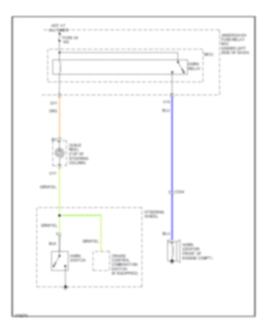
HORN
Horn Wiring Diagram for Honda Insight EX 2012
List of elements for Horn Wiring Diagram for Honda Insight EX 2012:
- A13
- C11
- C304
- Cable reel (top of steering column)
- Cruise control combination switch (if equipped)
- Fuse 24 10a
- Horn (center front of engine compt)
- Horn relay
- Horn switch
- Hot at all times
- Micu
- Q11
- Steering wheel
- Under-dash fuse/relay box (under left side of dash)
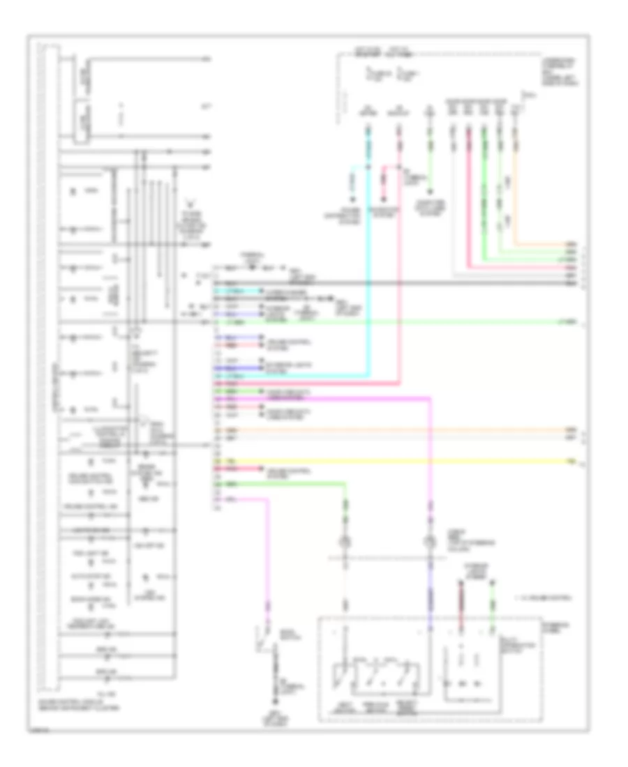
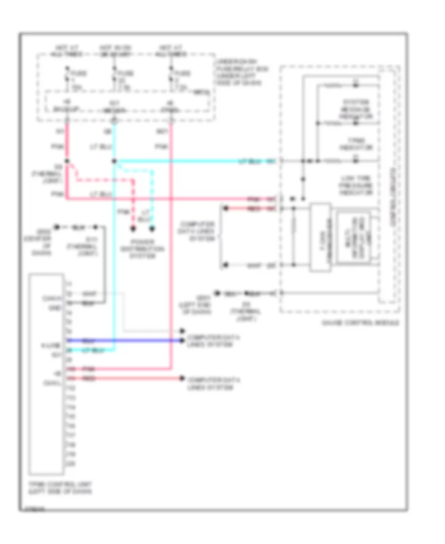
INSTRUMENT CLUSTER
Instrument Cluster Wiring Diagram (1 of 2) for Honda Insight EX 2012
List of elements for Instrument Cluster Wiring Diagram (1 of 2) for Honda Insight EX 2012:
- (thermal joint) s6
- +b backup
- Abs ind
- Auto stop ind
- B- can
- B-can transceiver
- Background
- Brake system ind (red)
- C22
- C26
- C32
- C33
- C40
- C402
- C407
- Cable reel (top of steering column)
- Computer data lines system
- Control circuits
- Coolant low temperature ind
- Cruise control ind
- Cruise control main switch ind
- Cruise control system
- Door sw (as)
- Door sw (dr)
- Door sw (ra)
- Door sw (rd)
- Econ mode ind
- Econ switch
- Eps ind
- Exterior lights system
- F-can transceiver
- Fog light ind
- From pin 5 (diagram 2 of 2)
- Fuse 1 15a
- Fuse 22 7.5a
- G501 (left end of dash)
- Gauge control module (behind instrument cluster)
- Hot at all times
- Hot in on or start
- Ig1 meter
- Illumination control & dimming circuit
- Interior lights system
- Lcd
- Lights on ind
- Micu
- Mil ind
- Multi- information switch
- Navigation system
- Next switch
- Pnk
- Pointer dial &
- Power distribution system
- Red
- S5 (thermal joint)
- S6 (thermal joint)
- S8 (thermal joint)
- Select/ reset switch
- Srs ind
- Steering wheel
- T/g sw
- To security ind (diagram 2 of 2)
- To side air bag cutoff ind (diagram 2 of 2)
- Under-dash fuse/relay box (under left side of dash)
- Vsa off ind
- Vsa system ind
- W/ cruise control
- Wiper/washer system
Instrument Cluster Wiring Diagram (2 of 2) for Honda Insight EX 2012
List of elements for Instrument Cluster Wiring Diagram (2 of 2) for Honda Insight EX 2012:
- (in left "c" pillar) left rear door switch
- (in right "c" pillar) right rear door switch
- (left "b" pillar) driver's door switch
- (left front of engine compt) pcm
- (lower center of hatch) hatch latch switch
- (right "b" pillar) front passenger's door switch
- (sounder) hazard relay 2 turn signal/
- Beeper
- Brake fluid level switch (on master cylinder reservoir)
- Brake system ind (amber)
- Brightening switch
- C302
- C407
- C602
- C801
- Can h
- Can l
- Charge/ assist gauge
- Charging system ind
- Computer data lines system
- Control circuits
- Coolant high temperature ind
- Dimming switch
- Display (mid) unit multi-information
- Door open ind
- From pin 15 (diagram 1 of 2)
- From pin 16 (diagram 1 of 2)
- Fuel gauge
- Fuel gauge sending unit
- Fuel tank unit (on top left side of fuel tank)
- G403 (left side of dash)
- G501 (left end of dash)
- G801 (left "c" pillar)
- Gauge control module (behind instrument cluster)
- High beam ind
- Ima system ind
- Immobilizer system ind
- L (w/o paddle shifters)
- Left turn signal ind
- Low fuel ind
- Low oil pressure ind
- Low tire pressure ind
- Mph/kmph switch
- Odometer/trip meter/select/ reset switch
- Oil pressure switch (lower left side of engine)
- Opsw
- Parking brake switch (base of parking brake lever)
- Pnk
- Red
- Right turn signal ind
- S6 (thermal joint)
- Seat belt reminder ind
- Security ind
- Sequential sport shift mode shift indicator (w/ paddle shifters)
- Side air bag cutoff ind
- Speedometer (lcd)
- System message ind
- Tachometer
- To illumination control & dimming circuit (diagram 1 of 2)
- Tpms ind
- Vsa off switch (if equipped)
INTERIOR LIGHTS
Courtesy Lamps Wiring Diagram for Honda Insight EX 2012
List of elements for Courtesy Lamps Wiring Diagram for Honda Insight EX 2012:
- (if equipped)
- C18
- C22
- C26
- C32
- C33
- C37
- C40
- C402
- C407
- C602
- C801
- Cargo area light
- Cargo lt
- Ceiling light
- Door
- Door sw (as)
- Door sw (dr)
- Door sw (ra)
- Door sw (rd)
- Driver's door switch (left "b" pillar)
- Front passenger's door switch (right "b" pillar)
- Fuse 1 15a
- G801 (left "c" pillar)
- Hatch latch switch (lower center of hatch)
- Hot at all times
- Individual map lights
- Intr lt-
- Left
- Left rear door switch (in left rear "c" pillar)
- Micu
- Off
- Pnk
- Right
- Right rear door switch (in right rear "c" pillar)
- T/g sw
- Under-dash fuse/relay box (under left side of dash)
Entry Light Timer Wiring Diagram for Honda Insight EX 2012
List of elements for Entry Light Timer Wiring Diagram for Honda Insight EX 2012:
- +b backup
- Antenna
- B-can
- C18
- C22
- C26
- C32
- C33
- C37
- C40
- C402
- C407
- C602
- C801
- Cargo area light
- Cargo lt
- Ceiling light
- Computer data lines system
- Door
- Door lock knob
- Door sw (as)
- Door sw (dr)
- Door sw (ra)
- Door sw (rd)
- Driver's door lock actuator/ knob switch/ key cylinder switch
- Driver's door lock knob switch
- Driver's door switch (left "b" pillar)
- Front passenger's door switch (right "b" pillar)
- Fuse 1 15a
- Fuse 22 7.5a
- G101 (left rear of engine)
- G501 (left end of dash)
- G502 (center of dash)
- G801 (left "c" pillar)
- Hatch latch
- Hot at all times
- Hot in on or start
- Ig key sw
- Ig1 meter
- Ignition key switch
- Immobilizer- keyless control unit (in steering column cover)
- Intr lt-
- Key sw
- Left rear door switch (in left rear "c" pillar)
- M34
- Micu
- Off
- P-gnd
- Pnk
- Power distribution system
- Right rear door switch (in right rear "c" pillar)
- S-gnd
- S11 (thermal joint)
- S6 (thermal joint)
- S8 (thermal joint) (left side of dash)
- Sil dr lock sw
- Sil dr unlock sw
- Steering lock assembly
- Switch
- T/g sw
- Transmitter
- Under-dash fuse/relay box (under left side of dash)
- Vbu
Instrument Illumination Wiring Diagram for Honda Insight EX 2012
List of elements for Instrument Illumination Wiring Diagram for Honda Insight EX 2012:
- (left end of dash) g501
- (thermal joint) s5
- +b backup
- A/t gear position indicator panel light
- A/t gear position indicator panel light/park pin switch/shift lock solenoid (park pin switch: under center console)
- A10
- A13
- A18
- A36
- Audio remote switch
- Audio unit (w/o navigation) audio-navigation unit (w/ navigation) (w/ navigation: behind middle of dash)
- B-can
- B-can transceiver
- B10
- Brightening switch
- Cable reel (top of steering column)
- Climate control unit (behind middle of dash)
- Combi gnd (light)
- Combination light switch
- Computer data lines system
- Control circuits
- Cruise control combination switch
- Dimming switch
- Econ switch
- Front passenger's airbag cut-off indicator
- Fuse 1 15a
- Fuse 22 7.5a
- Fuse 29 10a
- G501 (left end of dash)
- G502 (center of dash)
- Gauge control module
- Glove box light (if equipped)
- H/l off sw
- H/l on sw
- Hazard warning switch
- Head
- Headlight switch
- Hfl-voice control switch (w/ navigation) hfl switch (w/o navigation)
- Hot at all times
- Hot in on or start
- Ig1 meter
- Ill+
- Ill-
- Joint)
- Lx & ex
- M33
- Micu
- Multi-information switch
- Off
- P-gnd
- Park
- Pnk
- Power mirror switch
- Red
- S-gnd
- S10 (thermal joint)
- S6 (thermal joint)
- S7 (thermal joint) (left side of dash)
- S9 (thermal joint) (middle of dash)
- Small lt sw
- Steering wheel
- Taillight relay
- Under-dash fuse/relay box (under left side of dash)
- Vsa off switch
- W/ cruise control
- W/o cruise control
NAVIGATION
Navigation Wiring Diagram (1 of 2) for Honda Insight EX 2012
List of elements for Navigation Wiring Diagram (1 of 2) for Honda Insight EX 2012:
- (or red)
- +b backup
- A10
- A11
- A12
- A13
- A14
- A15
- A16
- A17
- A18
- A19
- A20
- A21
- A22
- A23
- A24
- Acc
- Am/fm antenna
- Amplifier
- Ant +b
- Antenna lead connector
- Audio l+
- Audio l-
- Audio r+
- Audio r-
- Audio remote gnd
- Audio remote sw
- Audio sh
- Audio-navigation unit (behind middle of dash)
- Back lt
- C21
- C302
- C402
- C403
- C407
- C411
- C502
- C605
- Computer data lines system
- Driver's door speaker
- E10
- E11
- E12
- E13
- E14
- F-can h
- F-can l
- Fm distributor (w/ usb)
- Fr l+
- Fr l-
- Fr r+
- Fr r-
- Front passenger's door speaker
- Fuse 15a
- Fuse 7.5a
- G503 (center of dash)
- Ga net bus-
- Ga-net +b
- Ga-net audio l+
- Ga-net audio l-
- Ga-net audio r+
- Ga-net audio r-
- Ga-net bus sh
- Ga-net bus+
- Ga-net bus-
- Ga-net gnd
- Ga-net sys acc
- Gnd sh
- Gps antenna
- Hot at all times
- Hot in acc or on
- Ill+
- Ill-
- Interior lights system
- K-line
- Left rear door speaker
- Left tweeter
- M18
- M23
- Main gnd
- Micu
- Nca
- Not used
- Pcm (left front of engine compt)
- Pnk
- Power distribution system
- Radio sw
- Red
- Rf in
- Rf sh
- Right rear door speaker
- Right tweeter
- Rr l+
- Rr l-
- Rr r+
- Rr r-
- S8 (thermal joint)
- Sat/ter
- Satellite signal antenna
- Scty
- Sh (gps)
- Sig (gps)
- Tmc rf in
- Tmc rf sh
- Under-dash fuse/relay box (under left side of dash)
- Usb data+
- Usb data-
- Usb det
- Usb det gnd
- Usb gnd
- Usb port
- Usb port in-line connector a
- Usb port in-line connector b
- Usb sh
- Usb vbus
- Vsp
- Vssout
- W/ handsfree link
- W/o handsfree link
- Xm antenna
- Xm receiver (audio system)
Navigation Wiring Diagram (2 of 2) for Honda Insight EX 2012
List of elements for Navigation Wiring Diagram (2 of 2) for Honda Insight EX 2012:
- (center front of roof) hfl-navigation microphone
- (not used)
- (right side of dash) handsfreelink control unit
- +b backup
- A31
- A32
- A33
- Ac-clk
- Ac-si
- Ac-so
- Acc
- Audio l+
- Audio l-
- Audio r+
- Audio r-
- Audio remote switch
- Audio sh
- Audio-navigation unit (behind middle of dash)
- Aux det
- Aux gnd
- Aux lch
- Aux rch
- Aux s gnd
- Aux sh gnd
- Auxiliary jack assembly
- B10
- B11
- B12
- B13
- B14
- B15
- B16
- B17
- Back lt
- C13
- C16
- C17
- C401
- Cable reel (top of steering column)
- Camera adpt
- Camera gnd
- Camera sh
- Camera v
- Channel down switch
- Channel up switch
- Climate control unit (behind middle of dash)
- Computer data lines system
- D10
- D11
- D12
- D13
- D14
- D15
- D16
- D17
- D18
- D19
- D20
- F-can h
- F-can l
- G503 (center of dash)
- Ga-net bus sh
- Ga-net bus+
- Ga-net bus-
- Gnd
- Gnd (rc)
- Hfl back switch
- Hfl strn sw
- Hfl talk switch
- Hfl-voice control switch
- Interior lights system
- Mic sh
- Mic sig+
- Mic sig-
- Mic+
- Mic-
- Mode switch
- Navig- ation back switch
- Navig- ation talk switch
- Nic sig-
- Pnk
- Rear camera circuit
- Red
- Steering wheel
- Telm sig sh
- Telm sig+
- Telm sig-
- Vcc
- Volume down switch
- Volume up switch
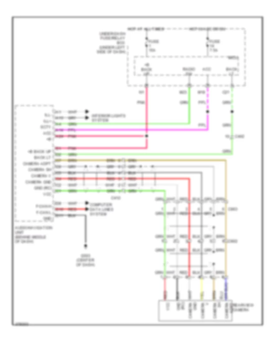
Rear Camera Wiring Diagram for Honda Insight EX 2012
List of elements for Rear Camera Wiring Diagram for Honda Insight EX 2012:
- (rc)
- +b back up
- A13
- A14
- A24
- Acc
- Adpt camera
- Audio-navigation unit (behind middle of dash)
- Back lt
- C21
- C402
- C412
- Camera adpt
- Camera gnd
- Camera sh
- Camera v
- Computer data lines system
- D10
- D11
- F-can h
- F-can l
- Fuse 15a
- Fuse 7.5a
- G503 (center of dash)
- Gnd
- Gnd (rc)
- Hot at all times
- Hot in acc or on
- Ill+
- Ill-
- Interior lights system
- M18
- M23
- Micu
- Pnk
- Radio sw
- Rearview camera
- Red
- Red vcc
- Scty
- Under-dash fuse/relay box (under left side of dash)
- Vcc
POWER DISTRIBUTION
Power Distribution Wiring Diagram (1 of 5) for Honda Insight EX 2012
List of elements for Power Distribution Wiring Diagram (1 of 5) for Honda Insight EX 2012:
- (diagram 1 of 5)
- (fog light connector 1) (option connector)
- (not used)
- +b fr fog
- +b haz
- +b stop & horn
- 7.5a
- A/c condenser fan diode
- A/c condenser fan relay
- A/f sensor
- A/f sensor relay
- A23
- A27
- A30
- Auxiliary under-hood relay box (left front of engine compt)
- B13
- B19
- B23
- B28
- Battery
- Battery terminal fuse box (top of battery)
- Brake pedal position switch
- C103
- C305
- Dc-dc converter
- Door lock relay
- Door unlock relay
- Driver's door unlock relay
- Eld unit
- Eps control unit
- Evap canister vent shut valve
- From eld unit a
- Fuse
- Fuse (not used)
- Fuse 100a
- Fuse 10a
- Fuse 20a
- Fuse 30a
- Fuse 60a
- G5 (under ipu lid)
- Hazard warning switch
- Headlight low beam relay
- High
- High beam control circuit
- Ignition coil relay
- Left headlight
- Micu
- Nca
- Pcm
- Pnk
- Power window relay
- Red
- Right headlight
- Starter
- Starter solenoid
- Sub- rly
- To fuse 2 (diagram 2 of 5)
- To fuse 27 (diagram 1 of 5)
- Under-dash fuse/relay box (under left side of dash)
- Vsa modulator control unit
Power Distribution Wiring Diagram (2 of 5) for Honda Insight EX 2012
List of elements for Power Distribution Wiring Diagram (2 of 5) for Honda Insight EX 2012:
- (left side of dash) (thermal joint) s8
- (not used)
- (option connector)
- (w/o power mirror defoggers) (w/ power mirror defoggers)
- +b back up
- +b tpms
- 30a
- 50a
- A/c compressor clutch relay
- A/c condenser fan relay
- A17 dx
- A22
- A24
- A24 lx & ex
- A36
- Audio navigation unit (w/ navigation)
- Audio unit (w/o navigation)
- Auxiliary under-hood relay box (left front of engine compt)
- B15
- B30
- Blower motor relay
- C12
- C37
- C49
- C603
- C702
- Cargo area light
- Ceiling light
- Dlc
- E/latch
- Etcs control relay
- From fuse 4 c (diagram 2 of 5)
- From fuse 45 d (diagram 2 of 5)
- From under-dash b fuse/relay box (diagram 1 of 5)
- Fuse (not used)
- Fuse 10a
- Fuse 15a
- Fuse 20a
- Fuse 30a
- Fuse 30a 40a
- Fuse 7.5a
- Fuse 7.5a (tpms)
- Gauge control module
- Glove box light (if equipped)
- Handsfree link control unit
- Hatch release actuator relay
- Immobilizer keyless control unit
- Individual map lights (if equipped)
- Ipu relay holder
- Left front parking light
- Left front side marker light
- M21
- Mcm
- Mcm relay 1
- Mcm relay 2
- Micu
- Multi- fuse 60
- Pgm-fi main relay 1
- Pnk
- Power window master switch
- Radiator fan relay
- Red
- Right front parking light
- Right front side marker light
- Taillight relay
- To fuse 30 (diagram 2 of 5)
- To fuse 53 (diagram 2 of 5)
- To ignition switch (diagram 4 of 5)
- To rear window defogger relay (diagram 5 of 5)
- To under-dash fuse/relay box (diagram 3 of 5)
- Tpms control unit (if equipped)
- Under- dash fuse/ relay box (under left side of dash)
- Under-dash fuse/relay box (under left side of dash)
- Under-dash relay holder
- W/ navigation
- W/o navigation
Power Distribution Wiring Diagram (3 of 5) for Honda Insight EX 2012
List of elements for Power Distribution Wiring Diagram (3 of 5) for Honda Insight EX 2012:
- (middle of dash) (thermal joint) s9
- A/t gear position indicator panel light
- A/t gear position indicator panel light/park pin switch/shift lock solenoid
- A10
- A13
- A18
- Audio navigation unit (w/ navigation)
- Audio remote switch (if equipped)
- Audio unit (w/o navigation)
- B10
- Brake light/ taillight
- C42
- C602
- C801
- Cable reel (top of steering column)
- Climate control unit
- Cruise control combination switch
- Econ switch
- From taillight (diagram 2 of 5)
- Front passenger's airbag cut-off indicator
- Hazard warning switch
- Hfl-voice control switch (w/ navigation) hfl switch (w/o navigation)
- Left license plate light
- Left taillight assembly
- Lx & ex
- Multi information switch
- Power mirror switch
- Rear side marker light
- Right license plate light
- Right taillight assembly
- Steering wheel
- Under-dash fuse/relay box (under left side of dash)
- Vsa off switch
- W/ cruise control
- W/ handsfree link
- W/o cruise control
Power Distribution Wiring Diagram (4 of 5) for Honda Insight EX 2012
List of elements for Power Distribution Wiring Diagram (4 of 5) for Honda Insight EX 2012:
- (diagram 2 of 5)
- (not used)
- (rear of engine) j/c c105
- A/t gear position indicator panel light/park pin switch/shift lock solenoid
- A26
- A27
- A31
- A32
- Abs modulator control unit (w/o vsa) vsa modulator control unit (w/ vsa)
- Acc
- Auxiliary under-hood fuse/relay box (left front of engine compt)
- B10
- B11
- B14
- B17
- B25
- C10
- C103
- C39
- C407
- C503
- C602
- C603
- C701
- C702
- C801
- Dc-dc converter
- Eld unit
- Eps control unit
- Evap canister purge valve
- From fuse 12 l (diagram 4 of 5)
- From under-dash fuse/relay box f
- Front passenger's air bag cut-off indicator
- Fuse 10a
- Fuse 15a
- Fuse 30a
- Fuse 7.5a
- Gauge control module
- Idle stop switch
- Ig1
- Ig1 abs/vsa
- Ig1 back lt
- Ig1 fr wiper
- Ig1 fuel pump
- Ig1 ima
- Ig1 meter
- Ig1 opds
- Ig1 rr wiper
- Ig1 srs
- Ig1 washer
- Ignition switch
- Immobilizer keyless control unit
- J/c c408 (left side of dash)
- Lock
- Maf/iat sensor
- Mcm
- Micu
- Ods unit
- On acc
- Pcm
- Pgm-fi main relay 2
- Pnk
- Q12
- Q15
- Q16
- R14
- Rear window wiper motor
- Red
- Secondary ho2s (sensor 2)
- Shift lock solenoid
- Srs unit
- Start
- To fuse 16 (diagram 4 of 5)
- To under-dash fuse/relay box (diagram 5 of 5)
- Tpms control unit (if equipped)
- Under-dash fuse/relay box (under left side of dash)
- Vbsol
- Yaw rate lateral acceleration sensor (w/ vsa)
Power Distribution Wiring Diagram (5 of 5) for Honda Insight EX 2012
List of elements for Power Distribution Wiring Diagram (5 of 5) for Honda Insight EX 2012:
- (not used)
- (option connector)
- A/c compressor clutch relay
- A14
- A17
- A33
- Acc
- Acc socket
- Accessory power socket
- Audio navigation unit (w/ navigation)
- Audio unit (w/o navigation)
- Automatic dimming inside mirror
- Automatic dimming inside mirror in-line fuse
- Auxiliary under-hood fuse/relay box (left front of engine compt)
- Auxiliary under-hood relay box (left front of engine compt)
- B12
- Blower motor relay
- C405
- Climate control unit
- E10
- Fan control relay
- From fuse 59 (diagram 2 of 5)
- From ignition switch (diagram 4 of 5)
- Fuse 20a
- Fuse 7.5a
- G502 (center of dash)
- Handsfree link control unit
- Honda accessory
- Ig2 day lt
- Ig2 hac
- M18
- M27
- Micu
- Pcm
- Power mirror switch
- Q14
- Radiator fan diode
- Radiator fan relay
- Rear window defogger relay
- Recirculation control motor
- Red
- S10 (thermal joint)
- Starter cut relay
- Steering lock assembly
- Sts
- Under-dash fuse/relay box (under left side of dash)
- W/ navigation
- W/o navigation
POWER DOOR LOCKS
Power Door Locks Wiring Diagram (1 of 2) for Honda Insight EX 2012
List of elements for Power Door Locks Wiring Diagram (1 of 2) for Honda Insight EX 2012:
- (lk) handy dr sw
- (not
- (thermal joint) s5
- (un lk) handy dr sw
- (w/ security)
- +b back up
- +b backup
- A13
- A29
- B-can
- Battery terminal fuse box (top of battery)
- C17
- C26
- C32
- C33
- C35 pnk
- C40
- C402
- C407
- C411
- C45
- C46
- C47
- C48
- C502
- D/l unlock
- Door
- Door lock actuator
- Door lock knob
- Door lock knob switch
- Door lock relay
- Door unlock relay
- Dr rly
- Dr sw (as)
- Dr sw (dr)
- Dr sw (ra)
- Dr sw (rd)
- Driver's
- Driver's door lock actuator/knob switch/ key cylinder switch
- E-latch sw
- Eld unit
- Exterior lights system
- F2 pnk
- Front passenger's door lock actuator/knob switch
- Fuse 100a
- Fuse 10a
- Fuse 15a
- Fuse 30a
- Fuse 7.5a
- G501 (left end of dash)
- G502 (center of dash)
- G601 (right side of floor)
- Gnd
- Hood sw
- Horn relay
- Horns system
- Hot at all times
- Hot in on or start
- Ig1 fuel pump
- Ig1 meter
- K10
- K6 pnk
- Kc dr lock sw
- Kc dr unlock sw
- Key
- Key cylinder switch
- Key sw
- Lock
- M16
- M23
- M24
- M34
- Micu
- P-gnd
- Pnk
- Q11
- Radio sw
- Red
- Relay
- Right rear door lock actuator/knob switch
- S-gnd
- S10 (thermal joint)
- S11 (thermal joint)
- S5 (thermal joint)
- S6 (thermal joint)
- Sil as unlock sw
- Sil dr lock sw
- Sil dr unlock sw
- Sil ra unlock sw
- Sil rd unlock sw
- Turn signal/hazard
- Under- dash fuse/ relay box (under left side of dash)
- Unlock
- Used)
- Warning circuit
Power Door Locks Wiring Diagram (2 of 2) for Honda Insight EX 2012
List of elements for Power Door Locks Wiring Diagram (2 of 2) for Honda Insight EX 2012:
- (left rear of engine) g101
- 5v stabilize circuit/ controller area network controller
- Antenna
- Audio unit (w/o navigation) audio-navigation unit (w/ navigation) (behind middle of dash)
- B-can
- Blinking
- Body controller area network transceiver
- C304
- C402
- C407
- C602
- C605
- C801
- Computer data lines system
- Door lock actuator
- Door lock knob
- Door unlock
- Driver's door lock switch lock
- Driver's door switch (left "b" pillar)
- Front passenger's door switch (right "b" pillar)
- G403 (left side of dash)
- G501 (left end of dash)
- G502 (center of dash)
- G702 (left "c" pillar)
- G801 (left "c" pillar)
- Gauge control module
- Hatch outer handle switch
- Horn
- Ig key sw
- Ig1
- Ignition key switch
- Immobilizer- keyless control unit (in steering column cover)
- Indicator circuit
- Left rear door lock actuator/ knob switch
- Left rear door switch (in left "c" pillar)
- Lock
- Lock knob switch
- Pnk
- Power distribution system
- Power window master switch
- Red
- Right rear door switch (in right "c" pillar)
- S11 (thermal joint)
- S8 (thermal joint) (left side of dash)
- Scty
- Security
- Security hood switch (front of engine compt)
- Security indicator
- Steering lock assembly
- Unlock
- Vbu
POWER MIRRORS
Automatic Day/Night Mirror Wiring Diagram for Honda Insight EX 2012
List of elements for Automatic Day/Night Mirror Wiring Diagram for Honda Insight EX 2012:
- (control unit built-in)
- A/t reverse relay
- Automatic dimming inside mirror
- Automatic dimming inside mirror ground
- Automatic dimming inside mirror in-line fuse
- B26
- C103
- C21
- Exterior lights system
- Fuse 10a
- Fuse 7.5a
- G101 (left rear of engine)
- Hot in on
- Hot in on or start
- Junction connector c104 (rear of engine)
- Micu
- Pnk
- S2 (thermal joint)
- Transmission range switch (on transaxle housing)
- Under-dash fuse/relay box (under left side of dash)
- W/ paddle shifters
- W/o paddle shifters
Power Mirrors Wiring Diagram for Honda Insight EX 2012
List of elements for Power Mirrors Wiring Diagram for Honda Insight EX 2012:
- C403
- C411
- Defogger
- Defogger system
- Down/ left
- Down/ right
- Fuse 10 7.5a
- G501 (left side of dash)
- Hac
- Hot in on
- Ig2
- Interior lights system
- Left
- Left power mirror
- Left/ right motor
- Micu
- Power mirror switch
- Q14
- Red
- Right
- Right power mirror
- S5 (thermal joint)
- Switch 1
- Switch 2
- Switch 3
- Under-dash fuse/relay box (under left side of dash)
- Up/ down motor
- Up/ left
- Up/ right
- W/ side turn signals
- W/o side turn signals
POWER WINDOWS
Power Windows Wiring Diagram for Honda Insight EX 2012
List of elements for Power Windows Wiring Diagram for Honda Insight EX 2012:
- (3)
- +b back up
- +b p/w as
- 2) down
- 3) auto
- 5) auto
- All times
- Battery terminal fuse box (top of battery)
- C31
- C402
- C403
- C407
- C411
- C502
- C601
- C605
- Control unit
- Door locks system
- Down
- Driver's power window motor
- Driver's switch 0) off 1) up
- Front passenger's power window motor
- Front passenger's power window switch
- Fuse 1 100a
- Fuse 1 15a
- Fuse 17 20a
- Fuse 18 20a
- Fuse 19 20a
- Fuse 22 7.5a
- Fuse 3 20a
- G501 (left end of dash)
- G502 (center of dash)
- G8 (not used)
- Gnd
- Hot at
- Hot in
- Ig1 meter
- Left rear power window motor
- Left rear power window switch
- M16
- Main switch
- Micu
- Off
- On or start
- P-gnd
- P/w rly
- Plsa
- Plsb
- Pnk
- Power window master switch
- Power window relay
- Pulser
- Red
- Right rear power window motor
- Right rear power window switch
- S-gnd
- S11 (thermal joint)
- S5 (thermal joint)
- Sgnd
- Svcc
- Switch illumi- nation
- Under-dash fuse/relay box (under left side of dash)
- Vmp dr
RADIO
Radio Wiring Diagram, DX without Navigation for Honda Insight EX 2012
List of elements for Radio Wiring Diagram, DX without Navigation for Honda Insight EX 2012:
- +b backup
- A10
- A11
- A12
- A13
- A14
- A15
- A16
- A17
- Acc
- Am/fm antenna
- Ant +b
- Antenna lead connector
- Audio unit
- Aux del
- Aux det
- Aux gnd
- Aux lch
- Aux rch
- Aux s gnd
- Aux sh gnd
- Auxiliary jack assembly
- B10
- B11
- B12
- B13
- B14
- B15
- C302
- C402
- C403
- C407
- C411
- C502
- C605
- Computer data lines system
- Driver's door speaker
- E10
- E11
- E12
- E13
- E14
- F-can h
- F-can l
- Fr l+
- Fr l-
- Fr r+
- Fr r-
- Front passenger's door speaker
- Fuse 1 15a
- Fuse 14 7.5a
- G503 (center of dash)
- Ga net bus+
- Ga net bus-
- Ga-net +b
- Ga-net audio l+
- Ga-net audio l-
- Ga-net audio r+
- Ga-net audio r-
- Ga-net bus+
- Ga-net bus-
- Ga-net gnd
- Ga-net sys acc
- Gnd sh
- Hot at all times
- Hot in acc or on
- Ill+
- Ill-
- Interior lights system
- K-line
- Left rear door speaker
- M18
- Main gnd
- Micu
- Nca
- Not used
- Pcm (left front of engine compt)
- Pnk
- Power distribution system
- Red
- Rf in
- Rf sh
- Right rear door speaker
- Rr l+
- Rr l-
- Rr r+
- Rr r-
- S8 (thermal joint)
- Sat/ter
- Satellite signal antenna
- Under-dash fuse/relay box (under left side of dash)
- Usb adapter unit (w/ usb adapter) xm receiver (w/ xm radio) (w/ usb adapter: rear of center console)
- Usb data+
- Usb data-
- Usb gnd
- Usb port (w/ usb adapter)
- Usb port in-line connector
- Usb sh
- Usb vbus
- Vsp
- Vssout
- W/ usb adapter
- W/ xm radio
- Xm antenna
Radio Wiring Diagram, EX & LX without Navigation (1 of 2) for Honda Insight EX 2012
List of elements for Radio Wiring Diagram, EX & LX without Navigation (1 of 2) for Honda Insight EX 2012:
- (or red)
- (thermal joint) s8
- +b backup
- A10
- A11
- A12
- A13
- A14
- A15
- A16
- A17
- A18
- A19
- A20
- A21
- A22
- A23
- A24
- Acc
- Am/fm antenna
- Ant +b
- Antenna lead connector
- Audio remote gnd
- Audio remote sw
- Audio unit
- Auxi- liary jack
- B-can
- C302
- C401
- C402
- C403
- C407
- C411
- C502
- C605
- Computer data lines system
- Driver's door speaker
- E10
- E11
- E12
- E13
- E14
- F-can h
- F-can l
- Fr l+
- Fr l-
- Fr r+
- Fr r-
- Front passenger's door speaker
- Fuse 1 15a
- Fuse 14 7.5a
- G503 (center of dash)
- Ga net bus+
- Ga net bus-
- Ga-net +b
- Ga-net audio l+
- Ga-net audio l-
- Ga-net audio r+
- Ga-net audio r-
- Ga-net audio sh
- Ga-net bus sh
- Ga-net gnd
- Ga-net sys on
- Gnd
- Hands free link control unit (right side of dash)
- Hfl icon
- Hfl microphone
- Hfl mute
- Hfl strg sw
- Hot at all times
- Hot in acc or on
- Ill+
- Ill-
- Interior lights system
- K-line
- Left rear door speaker
- Left tweeter (if equipped)
- M18
- M23
- Main gnd
- Mic sh
- Mic+
- Mic-
- Micu
- Nca
- Not used
- Pcm (left front of engine compt)
- Pnk
- Power distribution system
- Radio sw
- Red
- Rf in
- Rf sh
- Right rear door speaker
- Right tweeter (if equipped)
- Rr l+
- Rr l-
- Rr r+
- Rr r-
- Scty
- Telm sig sh
- Telm sig+
- Telm sig-
- Under-dash fuse/relay box (under left side of dash)
- Vsp
- Vssout
Radio Wiring Diagram, EX & LX without Navigation (2 of 2) for Honda Insight EX 2012
List of elements for Radio Wiring Diagram, EX & LX without Navigation (2 of 2) for Honda Insight EX 2012:
- (if equipped) audio remote switch
- (or nca)
- (or red)
- A10
- A11
- A12
- A13
- A14
- Audio remote switch
- Audio unit
- B10
- B11
- B12
- B13
- B14
- B15
- B16
- B17
- B18
- B19
- B20
- C16
- C17
- C406
- Cable reel (top of steering column)
- Channel down switch
- Channel up switch
- Data+
- Data-
- Except honda accessory
- Ga-net +b
- Ga-net audio l+
- Ga-net audio l-
- Ga-net audio r+
- Ga-net audio r-
- Ga-net audio sh
- Ga-net bus sh
- Ga-net bus+
- Ga-net bus-
- Ga-net gnd
- Ga-net sys acc
- Ga-net sys on
- Gnd
- Gnd sh usb data-
- Hfl icon
- Hfl mute
- Hfl steering switch
- Hfl switch
- Honda accessory
- Interior lights system
- Mode switch
- Nca
- Not used
- Pnk
- Red
- Sat/ter usb vbus
- Satellite signal antenna
- Steering wheel
- Telm sig sh
- Telm sig+
- Telm sig-
- Usb adapter control unit (rear of center console)
- Usb adapter unit (w/ usb adapter) xm receiver (w/ xm radio) (w/ usb adapter: rear of center console)
- Usb data+
- Usb data-
- Usb gnd
- Usb port
- Usb port (w/ factory)
- Usb port inline connector
- Usb sh
- Usb vbus
- Vbus
- Volume down switch
- Volume up switch
- W/ usb adapter
- W/ xm radio
- Xm antenna
Radio Wiring Diagram, with Navigation (1 of 2) for Honda Insight EX 2012
List of elements for Radio Wiring Diagram, with Navigation (1 of 2) for Honda Insight EX 2012:
- (or red)
- +b backup
- A10
- A11
- A12
- A13
- A14
- A15
- A16
- A17
- A18
- A19
- A20
- A21
- A22
- A23
- A24
- Acc
- Am/fm antenna
- Amplifier
- Ant +b
- Antenna lead connector
- Audio l+
- Audio l-
- Audio r+
- Audio r-
- Audio remote gnd
- Audio remote sw
- Audio sh
- Audio-navigation unit (behind middle of dash)
- Back lt
- C21
- C302
- C402
- C403
- C407
- C411
- C502
- C605
- Computer data lines system
- Driver's door speaker
- E10
- E11
- E12
- E13
- E14
- F-can h
- F-can l
- Fm distributor (w/ usb)
- Fr l+
- Fr l-
- Fr r+
- Fr r-
- Front passenger's door speaker
- Fuse 15a
- Fuse 7.5a
- G503 (center of dash)
- Ga net bus-
- Ga-net +b
- Ga-net audio l+
- Ga-net audio l-
- Ga-net audio r+
- Ga-net audio r-
- Ga-net bus sh
- Ga-net bus+
- Ga-net bus-
- Ga-net gnd
- Ga-net sys acc
- Gnd sh
- Gps antenna
- Hot at all times
- Hot in acc or on
- Ill+
- Ill-
- Interior lights system
- K-line
- Left rear door speaker
- Left tweeter
- M18
- M23
- Main gnd
- Micu
- Nca
- Not used
- Pcm (left front of engine compt)
- Pnk
- Power distribution system
- Radio sw
- Red
- Rf in
- Rf sh
- Right rear door speaker
- Right tweeter
- Rr l+
- Rr l-
- Rr r+
- Rr r-
- S8 (thermal joint)
- Sat/ter
- Satellite signal antenna
- Scty
- Sh (gps)
- Sig (gps)
- Tmc rf in
- Tmc rf sh
- Under-dash fuse/relay box (under left side of dash)
- Usb data+
- Usb data-
- Usb det
- Usb det gnd
- Usb gnd
- Usb port
- Usb port in-line connector a
- Usb port in-line connector b
- Usb sh
- Usb vbus
- Vsp
- Vssout
- W/ handsfree link
- W/o handsfree link
- Xm antenna
- Xm receiver (audio system)
Radio Wiring Diagram, with Navigation (2 of 2) for Honda Insight EX 2012
List of elements for Radio Wiring Diagram, with Navigation (2 of 2) for Honda Insight EX 2012:
- (center front of roof) hfl-navigation microphone
- (not used)
- (right side of dash) handsfreelink control unit
- +b backup
- A31
- A32
- A33
- Ac-clk
- Ac-si
- Ac-so
- Acc
- Audio l+
- Audio l-
- Audio r+
- Audio r-
- Audio remote switch
- Audio sh
- Audio-navigation unit (behind middle of dash)
- Aux det
- Aux gnd
- Aux lch
- Aux rch
- Aux s gnd
- Aux sh gnd
- Auxiliary jack assembly
- B10
- B11
- B12
- B13
- B14
- B15
- B16
- B17
- Back lt
- C13
- C16
- C17
- C401
- Cable reel (top of steering column)
- Camera adpt
- Camera gnd
- Camera sh
- Camera v
- Channel down switch
- Channel up switch
- Climate control unit (behind middle of dash)
- Computer data lines system
- D10
- D11
- D12
- D13
- D14
- D15
- D16
- D17
- D18
- D19
- D20
- F-can h
- F-can l
- G503 (center of dash)
- Ga-net bus sh
- Ga-net bus+
- Ga-net bus-
- Gnd
- Gnd (rc)
- Hfl back switch
- Hfl strn sw
- Hfl talk switch
- Hfl-voice control switch
- Interior lights system
- Mic sh
- Mic sig+
- Mic sig-
- Mic+
- Mic-
- Mode switch
- Navig- ation back switch
- Navig- ation talk switch
- Nic sig-
- Pnk
- Rear camera circuit
- Red
- Steering wheel
- Telm sig sh
- Telm sig+
- Telm sig-
- Vcc
- Volume down switch
- Volume up switch
SHIFT INTERLOCK
Shift Interlock Wiring Diagram for Honda Insight EX 2012
List of elements for Shift Interlock Wiring Diagram for Honda Insight EX 2012:
- A/t gear position indicator panel light/park pin switch/shift lock solenoid
- A11
- A18
- A19
- A25
- A26
- A35
- A36
- A42
- Acc
- App sensor a/b (left side of dash)
- Apsa
- Apsb
- Atp-p
- Atpp
- B14
- B28
- B32
- B35
- Bksw
- Brake pedal position switch (top of brake pedal assembly)
- C103
- C302
- Fuse 14 7.5a
- Fuse 22 7.5a
- Fuse 24 10a
- G101 (left rear of engine)
- G502 (center of dash)
- Hot at all times
- Hot in acc or on
- Hot in on or start
- Ig 1 meter
- Ignition key switch
- J/c c104 (rear of engine)
- Key interlock solenoid
- Key lock sol
- Key sw
- M17
- M18
- M34
- Micu
- P-pin sw
- Park pin switch
- Pcm (left front of engine compt)
- Pnk
- Q10
- Red
- S11 (thermal joint)
- S2 (thermal joint)
- Sg4
- Sg5
- Shift lock solenoid
- Sls
- Steering lock assembly
- Stop sw
- Transmission range switch (on transaxle housing)
- Transmission range switch (on transaxle housing) l
- Under-dash fuse/relay box (under left side of dash)
- Vcc4
- Vcc5
- W/ paddle shifters
- W/o paddle shifters
STARTING/CHARGING
Starting Wiring Diagram for Honda Insight EX 2012
List of elements for Starting Wiring Diagram for Honda Insight EX 2012:
- (not used)
- 50a
- 7.5a
- A39
- Acc
- Atpn
- Atpp
- B13
- B14
- B16
- B33
- Battery
- Battery terminal fuse box (top of battery)
- C103
- Eld unit
- Fuse 1 100a
- Fuse 44
- G1 (left front inner fender panel)
- G101 (left rear of engine)
- Ignition switch
- J/c c104 (rear of engine)
- Lock
- M26
- Micu atp-np
- Multi fuse 60
- Pcm (left front of engine compt)
- Red
- S2 (thermal joint)
- Start
- Starter
- Starter cut relay
- Starter motor
- Starter solenoid
- Stc
- Sts
- Transmission range switch (on transaxle housing)
- Under-dash fuse/relay box (under left side of dash)
- W/ paddle shifters
- W/o paddle shifters
SUPPLEMENTAL RESTRAINTS
Supplemental Restraints Wiring Diagram (1 of 3) for Honda Insight EX 2012
List of elements for Supplemental Restraints Wiring Diagram (1 of 3) for Honda Insight EX 2012:
- A10
- A11
- A12
- A13
- A14
- A15
- A16
- A17
- A18
- A19
- A20
- A21
- A22
- A23
- A24
- A25
- A26
- A27
- A28
- A29
- A30
- A31
- A32
- A33
- A34
- A35
- A36
- A37
- A38
- A39
- Built-in short contact
- C202
- C303
- Cable reel (top of steering column)
- Can hi
- Can lo
- Computer data lines
- Driver's air bag first inflator
- Driver's air bag second inflator
- Front passenger's air bag first inflator (right side of dash)
- Front passenger's air bag second inflator (right side of dash)
- Fuse 10a
- Fuse 7.5a
- G504 (center console)
- Gnd a
- Gnd b
- Hot in on or start
- Ig1 meter
- Ig1 opds
- Ig1 srs
- J/c c408 (left side of dash)
- K-line
- La1+
- La1-
- La2+
- La2-
- Left front impact sensor (behind left side of front bumper)
- Lfs+
- Lfs-
- Micu
- Ptt
- Ra1+
- Ra1-
- Ra2+
- Ra2-
- Red
- Rfs+
- Rfs-
- Right front impact sensor (behind right side of front bumper)
- Srs unit (under center of dash)
- Steering wheel
- System
- Terminal has
- Under-dash fuse/relay box (under left side of dash)
Supplemental Restraints Wiring Diagram (2 of 3) for Honda Insight EX 2012
List of elements for Supplemental Restraints Wiring Diagram (2 of 3) for Honda Insight EX 2012:
- (in driver's seatbelt buckle assembly) driver's seat seat belt buckle switch
- (in front passenger's seat belt buckle assembly) front passenger's seat belt buckle switch
- (in left "c"pillar) left side curtain air bag inflator
- (in right "c"pillar) right side curtain air bag inflator
- (left side of driver's seat) driver's seat position sensor
- (outer edge of driver's side front seat back) driver's side air bag inflator
- (outer edge of passenger's side front seat back) front passenger's side air bag inflator
- (under center of dash)
- B10
- B11
- B12
- B13
- B14
- B15
- B16
- B17
- B18
- B19
- B20
- B21
- B22
- B23
- B24
- B25
- B26
- B27
- B28
- B29
- B30
- B31
- B32
- B33
- B34
- B35
- B36
- B37
- B38
- B39
- Built-in short contact
- C501
- C504
- Driver's seat belt tensioner (base of left "b" pillar)
- Flbc
- Frbc
- Front passenger's seat belt tensioner (base of right "b" pillar)
- G601 (right side of floor)
- G602 (left side of floor)
- Lbs1+
- Lbs1-
- Lca1+
- Lca1-
- Left side impact sensor (1st) (base of left "b" pillar)
- Left side impact sensor (2nd) (left "c" pillar)
- Lrp+
- Lrp-
- Lsa+
- Lsa-
- Ods
- Pnk
- Rbs1+
- Rbs1-
- Rca1-
- Rear safing sensor (rear of floor)
- Red
- Right side impact sensor (1st) (base of right "b" pillar)
- Right side impact sensor (2nd) (right "c" pillar)
- Rrp+
- Rrp-
- Rsa+
- Rsa-
- Srs unit
- Ss+
- Sss+
- Sss-
- Terminal has
Supplemental Restraints Wiring Diagram (3 of 3) for Honda Insight EX 2012
List of elements for Supplemental Restraints Wiring Diagram (3 of 3) for Honda Insight EX 2012:
- (under front left side of passenger's seat) front passenger's weight sensor (front inner side)
- (under front right side of passenger's seat) front passenger's weight sensor (front outer side)
- (under rear left side of passenger's seat) front passenger's weight sensor (rear inner side)
- (under rear right side of passenger's seat) front passenger's weight sensor (rear outer side)
- C407
- C503
- Computer data lines system
- Control circuits
- D10
- D11
- D12
- D13
- D14
- D15
- D16
- D17
- D18
- Fast control area network transceiver
- Front passenger's air bag cut-off indicator
- G601 (right side of floor)
- Gauge control module
- Gnd
- Interior lights system
- Lower element (lower four sensors in seatback)
- Nca
- Ods
- Ods unit (in front passenger's seat back)
- Opds sensor
- Os1l
- Os1s
- Os2l
- Os2s
- Os3l
- Os3s
- Os4l
- Os4s
- Os5l
- Os5s
- Os6l
- Os6s
- Os7l
- Os7s
- Pow
- Red
- Seat belt reminder ind
- Side air bag cut-off ind
- Side element (right side of seat back)
- Srs ind
- Upper element (upper two sensor in seatback)
- Ws1d
- Ws1g
- Ws1p
- Ws2d
- Ws2g
- Ws2p
- Ws3d
- Ws3g
- Ws3p
- Ws4d
- Ws4g
- Ws4p
TRANSMISSION
Transmission Wiring Diagram (1 of 2) for Honda Insight EX 2012
List of elements for Transmission Wiring Diagram (1 of 2) for Honda Insight EX 2012:
- (thermal joint)
- (top of brake pedal assembly) brake pedal position switch
- A18
- A19
- A24
- A25
- A32
- A35
- A36
- A42
- A43
- A47
- A48
- Apsa
- Apsb
- Atpd
- Atpfwd
- Atpl
- Atpn
- Atpp
- Atpr
- Atps
- B10
- B13
- B14
- B15
- B16
- B17
- B18
- B19
- B21
- B25
- B26
- B28
- B29
- B30
- B34
- B38
- B40
- B44
- Bksw
- C106
- C13
- C14
- C39
- C44
- C49
- Can h
- Can l
- Computer data lines system
- Cvt clutch pressure control solenoid valve (in trans- mission)
- Cvt driven pulley pressure control solenoid valve (in trans- mission)
- Cvt driven pulley pressure control solenoid valve (in transmission)
- Cvtf temperature sensor (in transmission)
- Dlc (data link connector) (center left of dash)
- Dnls
- Drls
- Engine controls system
- Exterior lights system
- Fuse 24 10a
- Fuse 39 15a
- G101 (left rear of engine)
- G151 (on transmission)
- Hot at all times
- Igp 1
- Igp 2
- Inhibitor solenoid (in trans- mission)
- Inhsol
- Lg1
- Lg2
- Micu
- Mrly
- Ndn
- Ndr
- Pcm (left front of engine compt)
- Pdn
- Pg1
- Pgm-fi main relay 1
- Pnk
- Red
- S3 (thermal joint)
- Scls
- Scs
- Sdnp
- Sg1
- Sg2
- Sg4
- Sg5
- Supp
- Tatf
- Under-dash fuse/relay box (under left side of dash)
- Vcc1
- Vcc2
- Vcc4
- Vcc5
- Vel
Transmission Wiring Diagram (2 of 2) for Honda Insight EX 2012
List of elements for Transmission Wiring Diagram (2 of 2) for Honda Insight EX 2012:
- (if equipped) paddle shifter (+) (upshift switch)
- (if equipped) paddle shifter (-) (downshift switch)
- (not used)
- (top of steering column) cable reel
- +b backup
- App sensor (left side of dash)
- B14
- B15
- C12
- C14
- C15
- C302
- Computer data lines system
- Control circuits
- Cvt driven pulley pressure sensor
- Cvt input shaft (drive pulley) speed sensor (on transmission housing)
- Cvt output shaft (driven pulley) speed sensor (on transmission housing)
- Engine controls system
- F-can receivers
- Fuse 1 15a
- G101 (left rear of engine)
- G501 (left end of dash)
- G502 (center of dash)
- Gauge control module
- Hot at all times
- J/c c104 (rear of engine)
- J/c c105 (rear of engine)
- Micu
- Pnk
- Power distribution system
- Red
- S11 (thermal joint)
- S2 (thermal joint)
- S4 (thermal joint) (rear of engine)
- S5 (thermal joint)
- S8 (thermal joint)
- Sequential sport shift mode shift indicator (w/ paddle shifters)
- Shifters
- Steering wheel
- Transmission range switch (on transaxle housing)
- Under-dash fuse/relay box (under left side of dash)
- Vehicle speed sensor (on trans- mission)
- W/ paddle
- W/o paddle
- W/o paddle shifters
TRUNK, TAILGATE, FUEL DOOR
Hatch Release Wiring Diagram for Honda Insight EX 2012
List of elements for Hatch Release Wiring Diagram for Honda Insight EX 2012:
- C17
- C22
- C402
- C602
- C801
- E-latch
- E-latch rly
- E-latch sw
- Fuse 45 7.5a
- G501 (left end of dash)
- G801 (left "c" pillar)
- Hatch latch switch (lower center of hatch)
- Hatch outer handle switch
- Hatch release actuator (lower center of hatch)
- Hatch release actuator relay (under-dash relay box)
- Hot at all times
- M25
- Micu
- Pnk
- Red
- S5 (thermal joint)
- T/g sw
- Under-dash fuse/relay box (under left side of dash)
WARNING SYSTEMS
Chime Wiring Diagram for Honda Insight EX 2012
List of elements for Chime Wiring Diagram for Honda Insight EX 2012:
- +b back up
- A16
- A17
- B- can
- B-can transceiver
- B19
- B21
- Beeper
- Brake system ind
- C22
- C26
- C32
- C33
- C40
- C402
- C407
- C602
- C801
- Canh
- Canl
- Combi gnd (light)
- Combination light switch
- Computer data lines system
- Control circuits
- Door open ind
- Door sw (as)
- Door sw (dr)
- Door sw (ra)
- Door sw (rd)
- Driver's door switch (left "b" pillar)
- Driver's seat belt buckle switch (in driver's seatbelt buckle assembly)
- F-can transceiver
- Flbc
- Frbc
- Front passenger's door switch (right "b" pillar)
- Front passenger's seat belt buckle switch (in front passenger's seat belt buckle assembly)
- Fuse 15a
- Fuse 7.5a
- G501 (left end of dash)
- G502 (center of dash)
- G601 (right side of floor)
- G602 (left side of floor)
- G801 (left "c" pillar)
- Gauge control module
- H/l off sw
- H/l on sw
- Hatch latch switch (lower center of hatch)
- Head
- Headlight switch
- Hot at all times
- Hot in on or start
- Ig key sw
- Ig1 meter
- Ignition key switch
- Immobilizer- keyless control unit (in steering column cover)
- Joint)
- Key sw
- Left rear door switch (in left rear "c" pillar)
- Lights on ind
- Low oil pressure ind
- M33
- M34
- Micu
- Multi- information display (mid) unit
- Off
- Oil pressure switch (lower left side of engine)
- Opsw
- P- gnd
- Park
- Parking brake switch (base of parking brake lever)
- Pcm (left front of engine compt)
- Pnk
- Power distribution system
- Red
- Right rear door switch (in right rear "c" pillar)
- S- gnd
- S11 (thermal joint)
- S5 (thermal joint)
- S6 (thermal joint)
- S8 (thermal
- Seat belt reminder ind
- Small lt sw
- Srs unit (under center of dash)
- Steering lock assembly
- T/g sw
- Under-dash fuse/relay box (under left side of dash)
- Vsa off switch
Tire Pressure Monitoring Wiring Diagram for Honda Insight EX 2012
List of elements for Tire Pressure Monitoring Wiring Diagram for Honda Insight EX 2012:
- +b backup
- +b tpms
- Can h
- Can l
- Computer data lines system
- Control circuits
- F-can transceiver
- Fuse 15a
- Fuse 7.5a
- G501 (left end of dash)
- G502 (center of dash)
- Gauge control module
- Gnd
- Hot at all times
- Hot in on or start
- Ig1
- Ig1 meter
- K-line
- Low tire pressure indicator
- M21
- Micu
- Multi- information display (mid) unit
- Pnk
- Power distribution system
- Red
- S11 (thermal joint)
- S6 (thermal joint)
- S8 (thermal joint)
- System message indicator
- Tpms control unit (left side of dash)
- Tpms indicator
- Under-dash fuse/relay box (under left side of dash)
WIPER/WASHER
Front Wiper/Washer Wiring Diagram for Honda Insight EX 2012
List of elements for Front Wiper/Washer Wiring Diagram for Honda Insight EX 2012:
- (not used)
- A14
- A19
- A34
- A35
- B20
- C201
- C301
- C304
- Circuits control
- Combi gnd (wiper)
- Fr washer mtr
- Fr wip
- Fr wip as
- Fr wip hi & lo sw
- Fr wip int & lo sw
- Fr wip int vr+
- Fr wip mist sw
- Fr wip wash sw
- Fuse 21 15a
- Fuse 22 7.5a
- Fuse 56 30a
- G202 (behind right side of front bumper)
- G401 (behind left side of front bumper)
- G501 (left side of dash)
- G502 (center of dash)
- Gauge control module
- High
- Hot in on or start
- Ig1
- Ig1 fr wiper
- Ig1 washer
- Int
- Int off
- Intermittent dwell time controller (if equipped)
- K10
- Low
- M10
- M11
- M12
- M13
- M16
- Meter
- Micu
- Mist
- Off
- P-gnd
- Park
- Pnk
- Red
- Rr washer mtr
- Run
- S-gnd
- S10 (thermal joint)
- S11 (thermal joint)
- S5 (thermal joint)
- S6 (thermal joint)
- Under-dash fuse/relay box (under left side of dash)
- Wash
- Washer fluid level switch (canada) (in washer fluid reservoir)
- Washer motor (on washer fluid reservoir)
- Windshield washer switch
- Windshield wiper motor (left rear of engine compt)
- Windshield wiper switch
- Wiper/ washer switch
Rear Wiper/Washer Wiring Diagram for Honda Insight EX 2012
List of elements for Rear Wiper/Washer Wiring Diagram for Honda Insight EX 2012:
- A34
- A35
- C29
- C39
- C602
- C801
- Combi gnd (wiper)
- Fr washer mtr
- Fuse 16 10a
- Fuse 21 15a
- G501 (left end of dash)
- G502 (center of dash)
- G801 (left "c" pillar)
- Hot in on or start
- Ig1 rr wiper
- Ig1 washer
- K10
- M14
- M15
- M16
- Micu
- Off
- P- gnd
- Park
- Rear window wiper motor (left side of hatch)
- Rear window wiper/ washer switch
- Rr wash
- Rr washer mtr
- Rr wip
- Rr wip sw
- Rr wip wash sw
- Rr wipe
- Run
- S- gnd
- S10 (thermal joint)
- S11 (thermal joint)
- S5 (thermal joint)
- S6 (thermal joint)
- Under-dash fuse/relay box (under left side of dash)
- Washer motor (on washer fluid reservoir)
- Wiper/washer switch