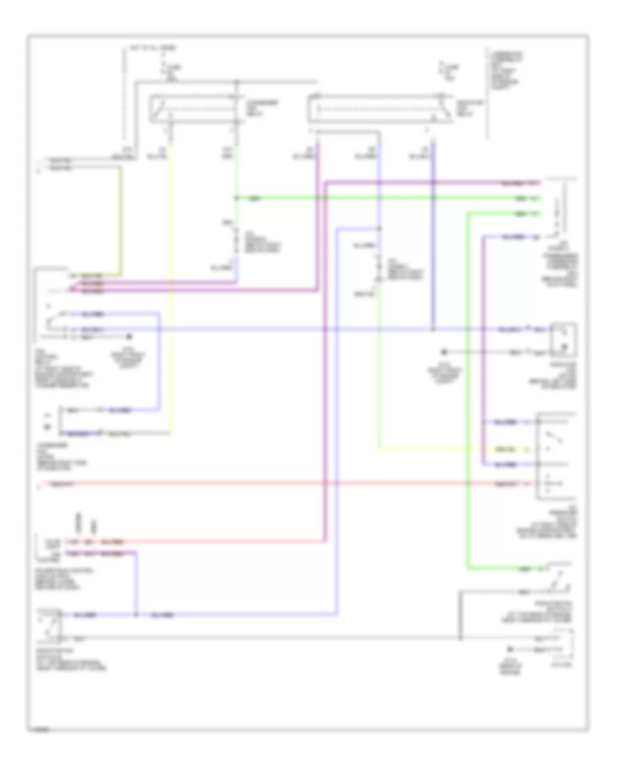
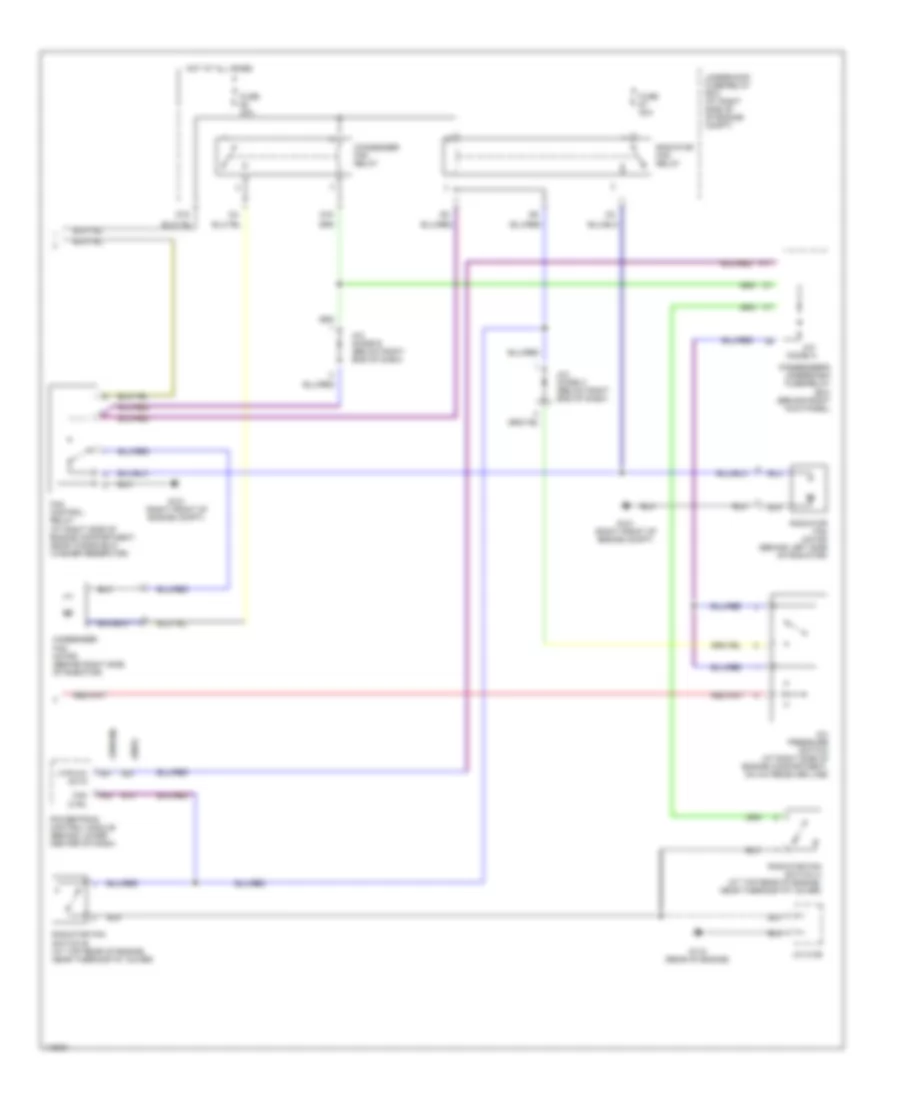
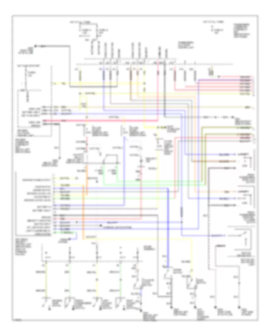
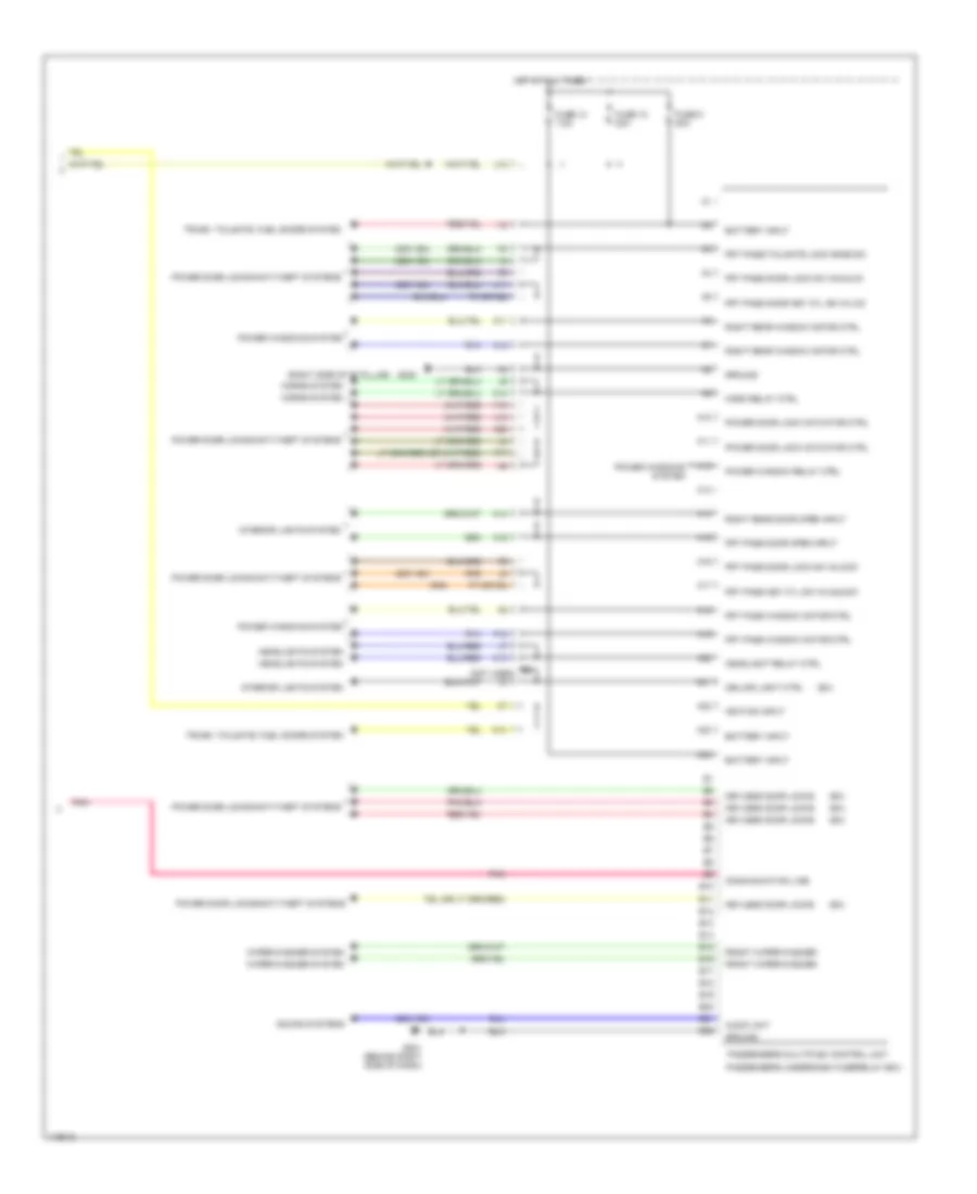
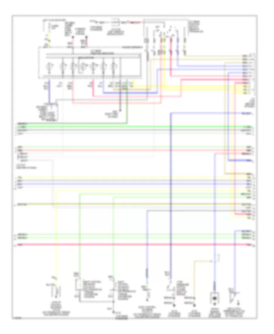
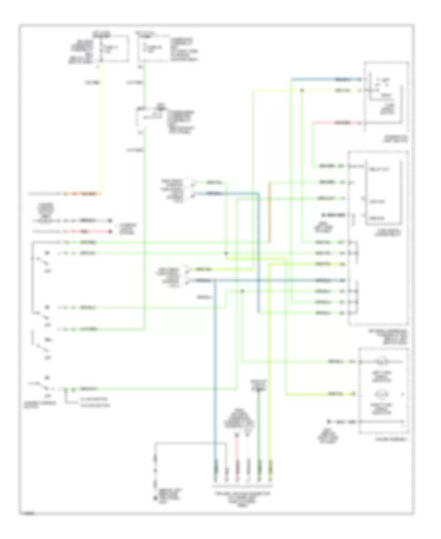
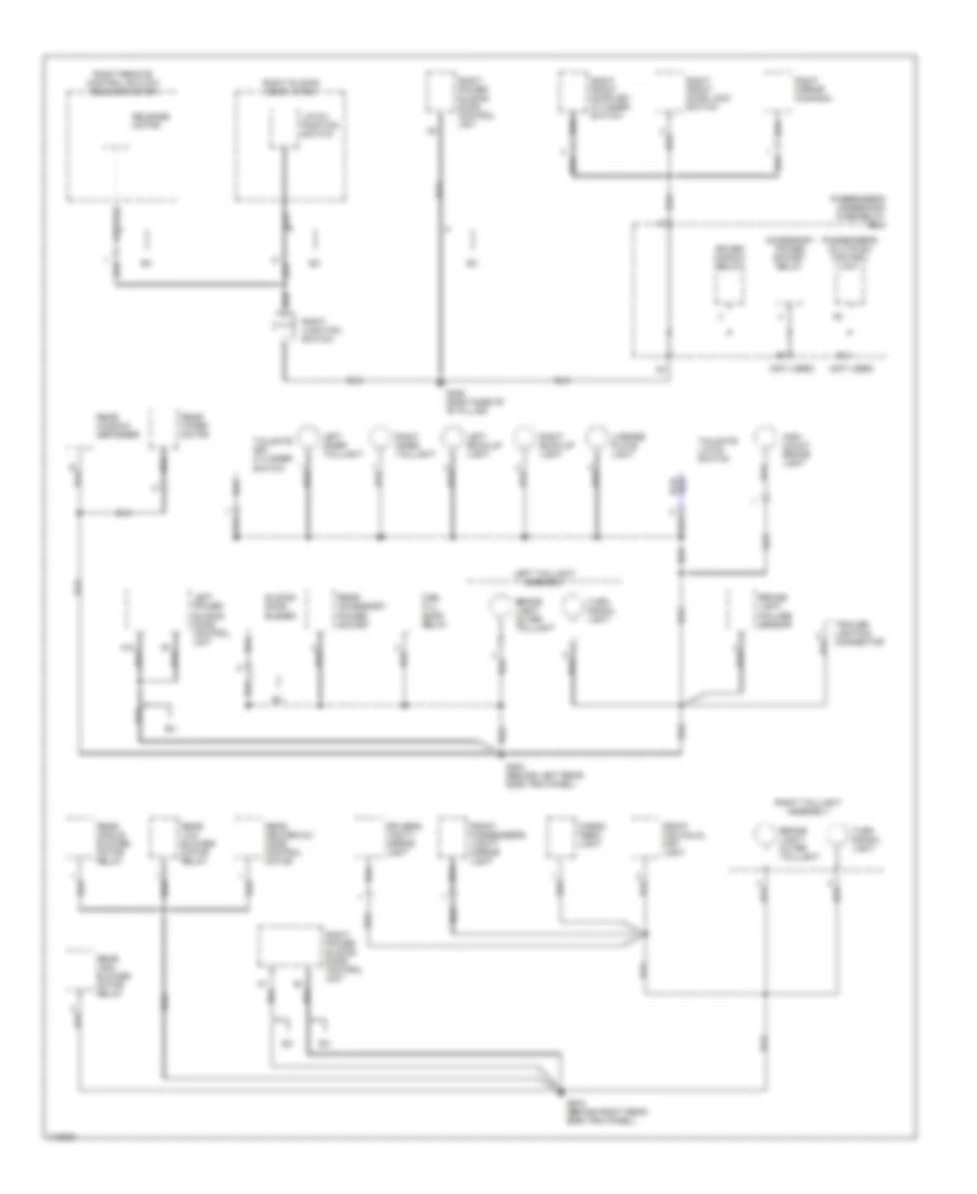
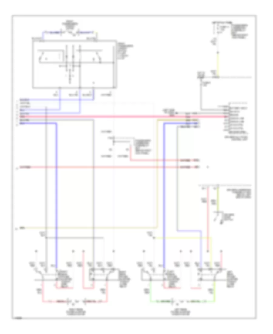
AIR CONDITIONING
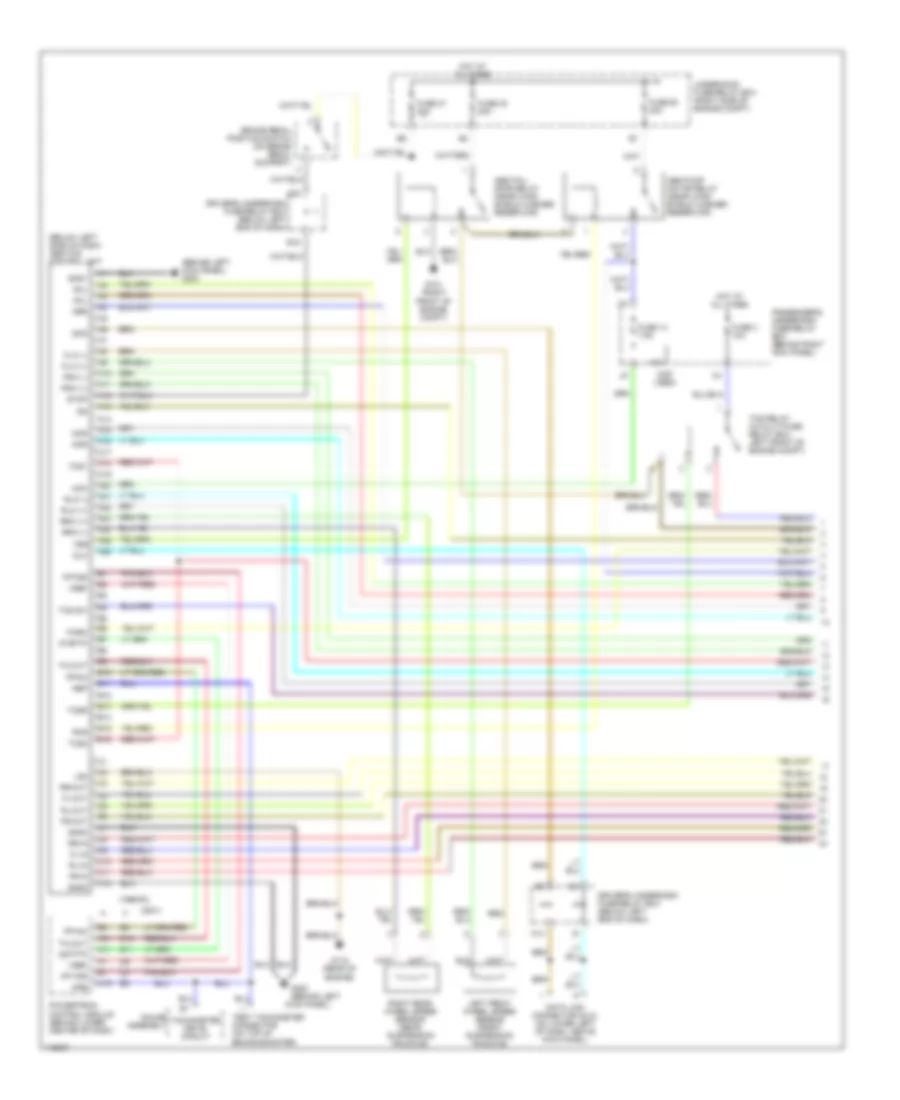
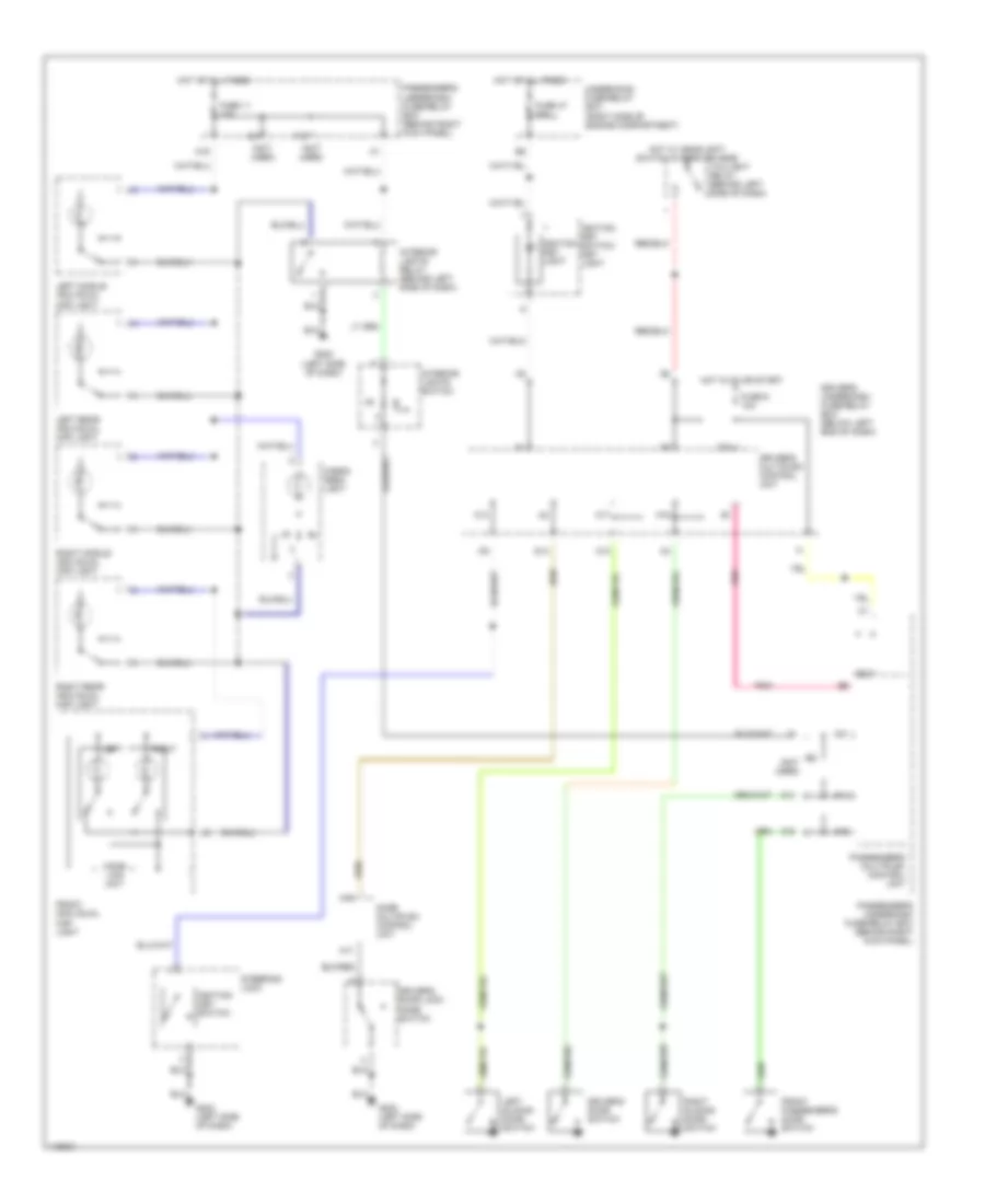
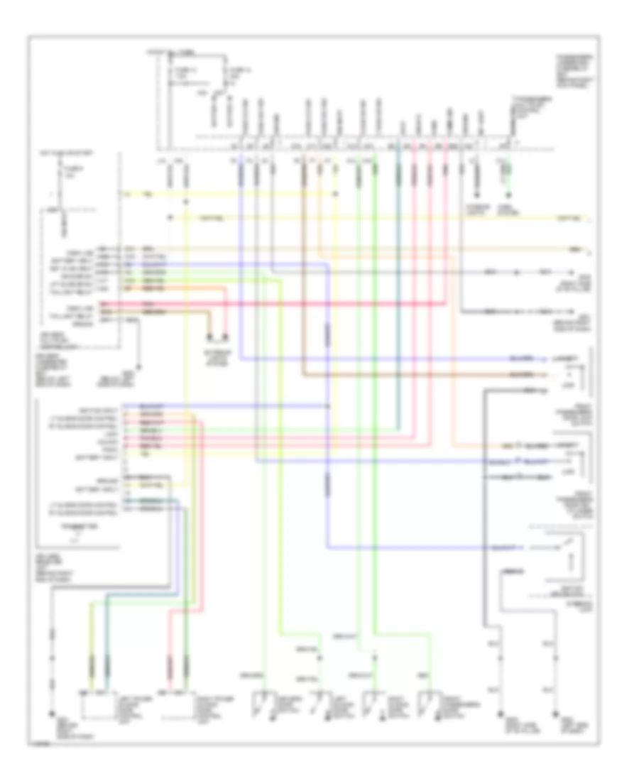
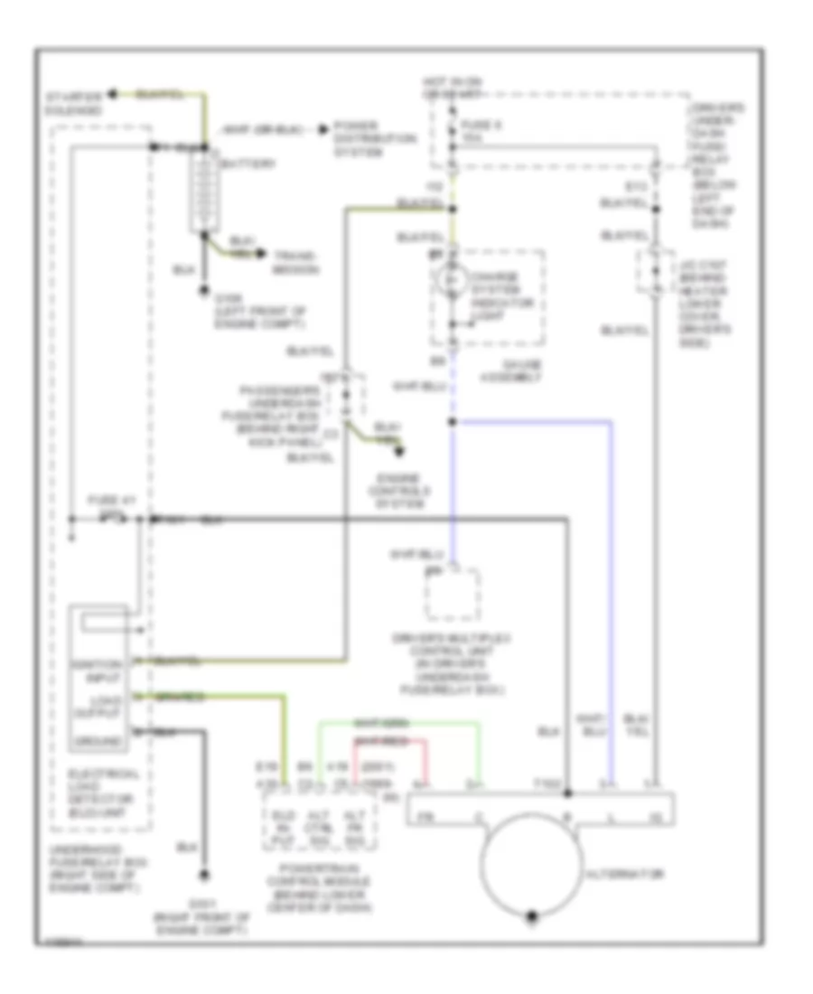
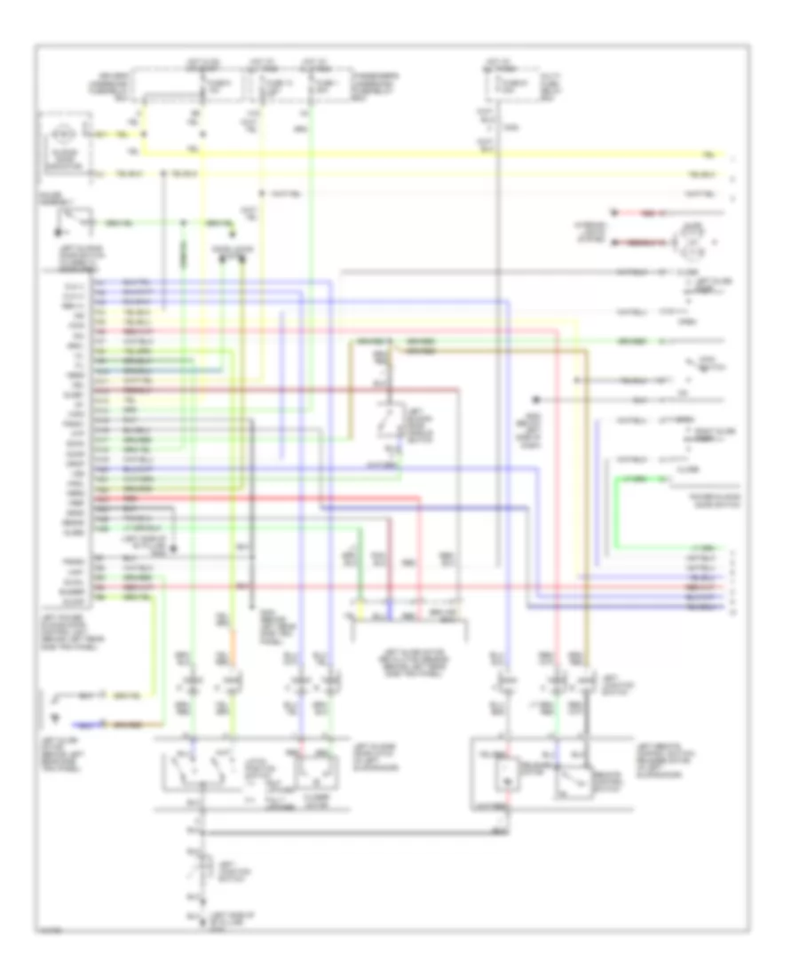
Automatic A/C Wiring Diagram (1 of 2) for Honda Odyssey EX 1999

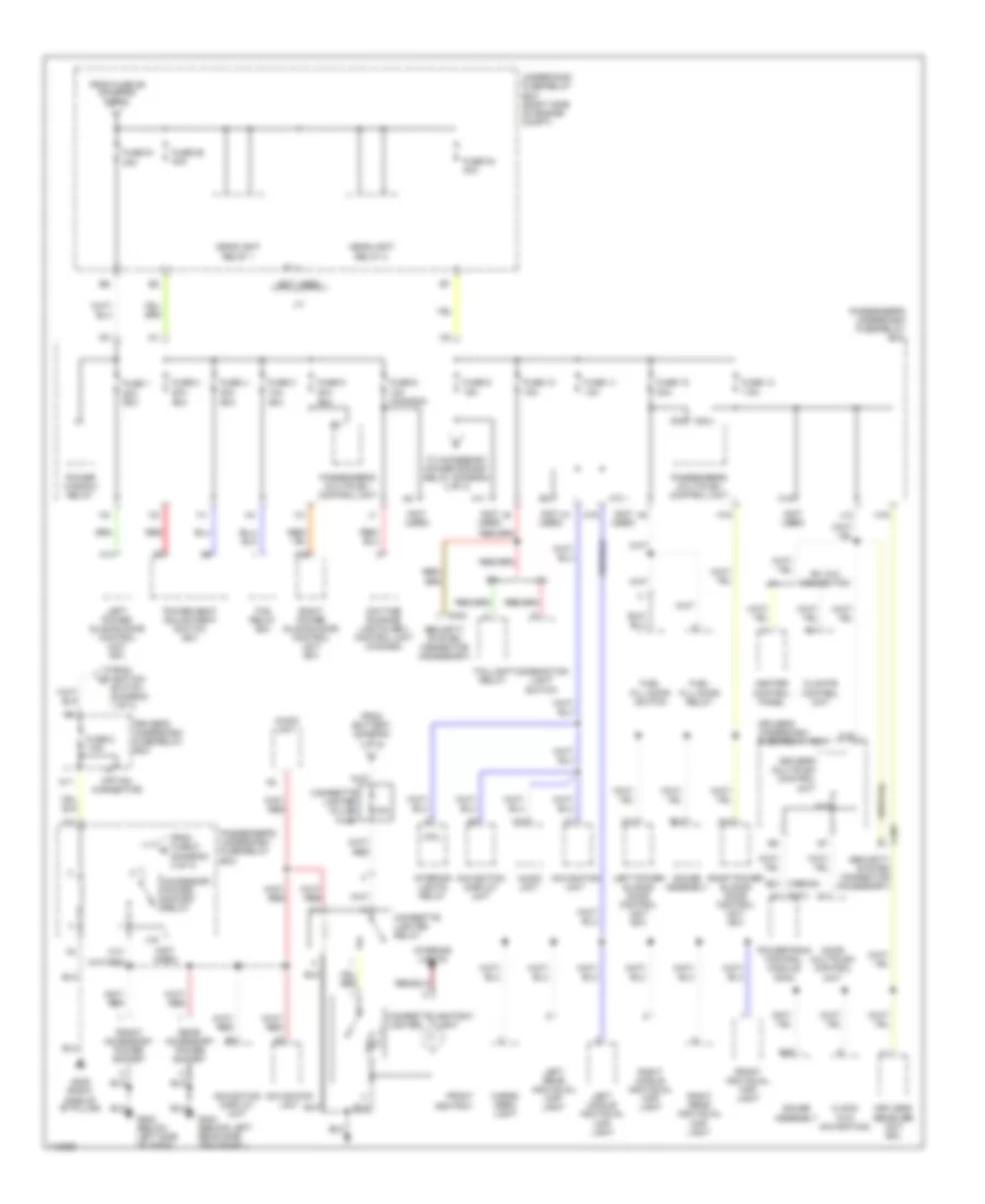
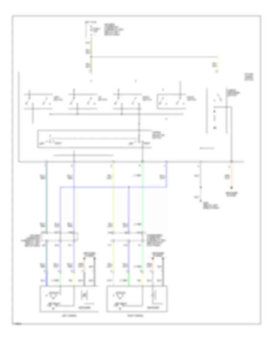
List of elements for Automatic A/C Wiring Diagram (1 of 2) for Honda Odyssey EX 1999:
- (1999-00)
- (2001)
- A/c compressor clutch
- A/c compressor clutch relay
- A/c on out
- A13
- A17
- A28
- Air mix control motor (below center of dash, on heater unit)
- Air mix cool
- Air mix hot
- Air mix pot
- Amd-p
- B10
- B11
- B12
- B13
- B14
- B15
- B16
- B17
- B18
- B19
- B20
- Battery
- Bl rly ctrl
- Blower power transistor (behind right side of dash, near blower motor)
- Blwr mtr fb
- C18
- C26
- Climate control unit
- D11
- D14
- Driver's underdash fuse/relay box (below left end of dash)
- E12
- Ect
- Ect input
- Engine controls system
- Engine coolant temperature (ect) sensor (at top rear of engine, on water jacket)
- Evap sen in
- Evaporator temperature sensor (behind glove box. on evaporator housing)
- Fresh ctrl
- Front blower motor (below glove box, on bottom of blower unit)
- Front blower motor high relay (behind glove box, on blower unit)
- Front blower motor relay
- Frs
- Fuse 40a
- Fuse 7.5a
- G101 (right front of engine compt)
- G202 (left side of dash)
- Ground
- Hot at all times
- Hot in on
- Ig2
- Ign in
- Ill +
- Ill -
- In-car in
- In-car temperature sensor (behind dash, to right of steering column)
- Interior lights system
- J/c c107 (below center of dash, taped to harness)
- J12
- K15
- M-cool
- M-def
- M-hot
- M-vent
- Mode 1
- Mode 2
- Mode 3
- Mode 4
- Mode control motor (behind left side of dash, on end of heater unit)
- Mode-def
- Mode-vent
- O13
- Out air in
- Outside air temperature sensor (behind right side of front bumper)
- Passenger's underdash fuse/relay box (behind right kick panel)
- Powertrain control module (pcm) (behind lower center of dash)
- Prw tr ctrl
- Rear defogger system
- Rec
- Recirc ctrl
- Recirculation control motor (behind glove box, on blower unit)
- Red
- Ref volt
- Rly ctrl
- Rr def on
- S-com
- S5v
- Sen gnd
- Sensor gnd
- Sun sen in
- Sunlight sensor (on top center of dash)
- Underhood fuse/relay box (at right side of of engine compt)
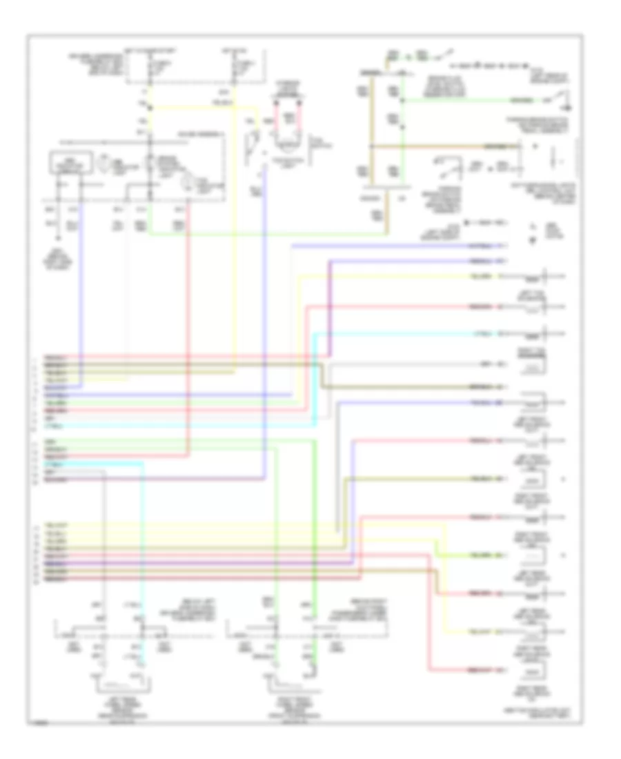
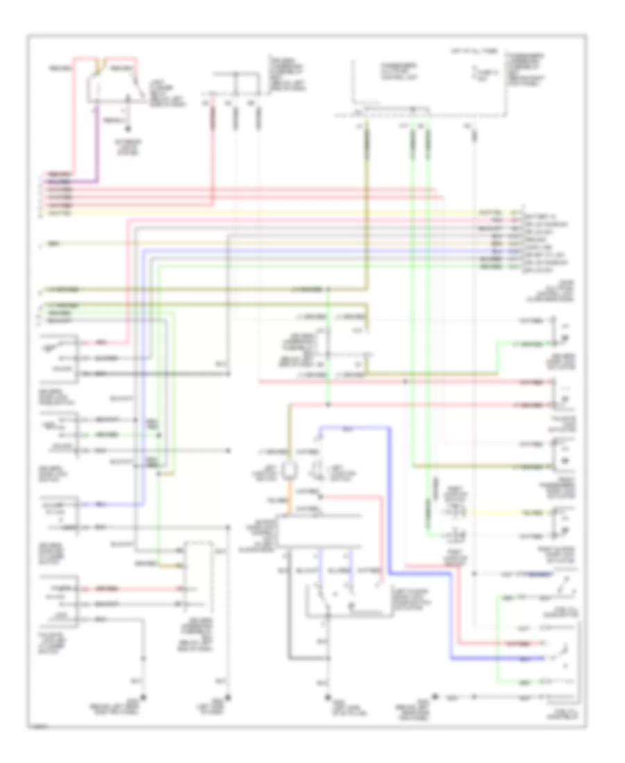
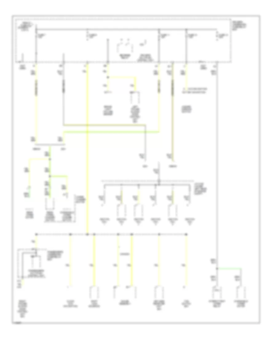
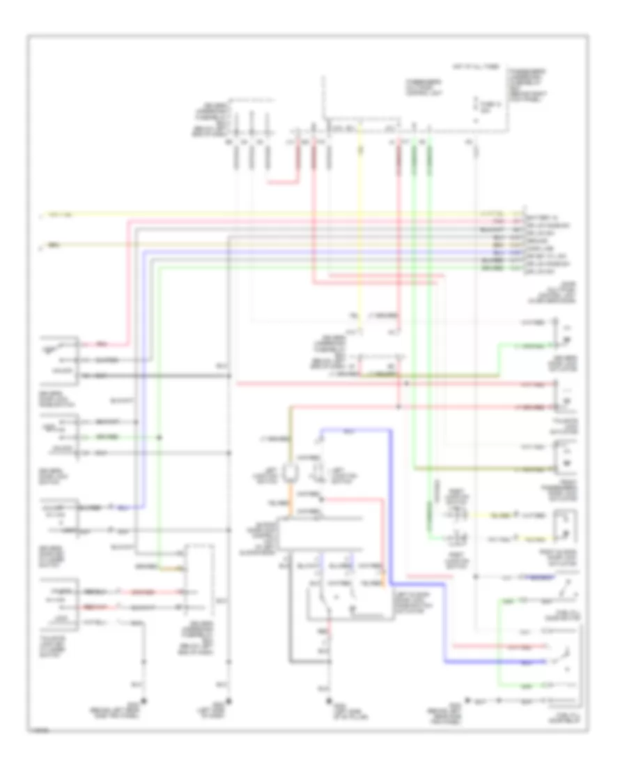
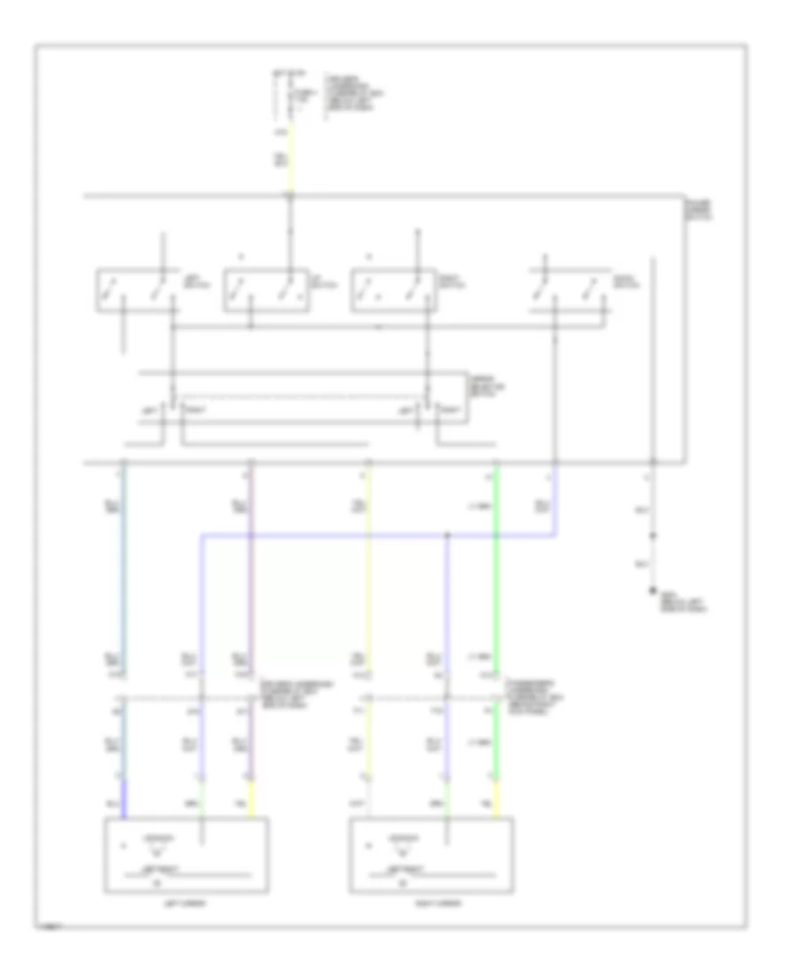
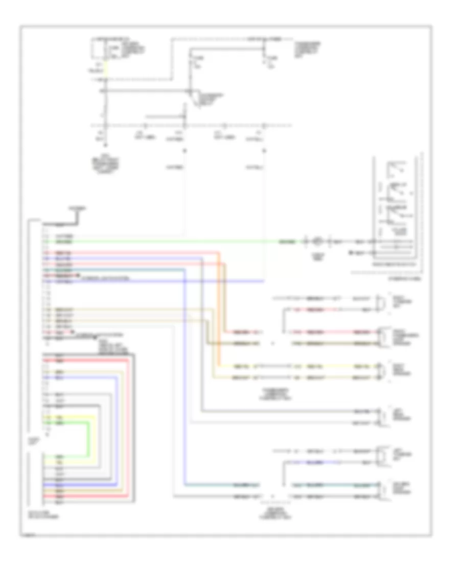
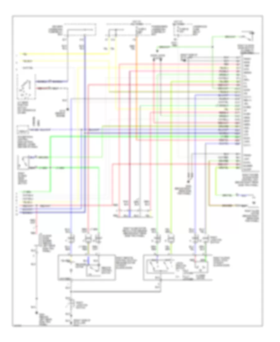
Automatic A/C Wiring Diagram (2 of 2) for Honda Odyssey EX 1999
List of elements for Automatic A/C Wiring Diagram (2 of 2) for Honda Odyssey EX 1999:
- (1999-00)
- (2001)
- A/c
- A/c diode b (below right end of dash)
- A/c diode c (below right end of dash)
- A/c on input
- A/c pressure switch (at right side of engine compartment, on a/c receiver line)
- A20
- A27
- Condenser fan motor (behind right side of radiator)
- Condenser fan relay
- D15
- D16
- Diode a
- E13
- E21
- Fan control
- Fuse 30a
- G101 (right front of engine compt)
- G115 (rear of engine)
- H17
- Hot at all times
- I17
- J/c c106
- Passenger's underdash fuse/relay box (behind right kick panel)
- Powertrain control module (pcm) (behind lower center of dash)
- Radiator fan motor (behind left side of radiator)
- Radiator fan relay
- Radiator fan switch a (at top rear of engine, near thermostat cover)
- Radiator fan switch b (at top rear of engine, near thermostat cover)
- Underhood fuse/relay box (at right side of of engine compt)
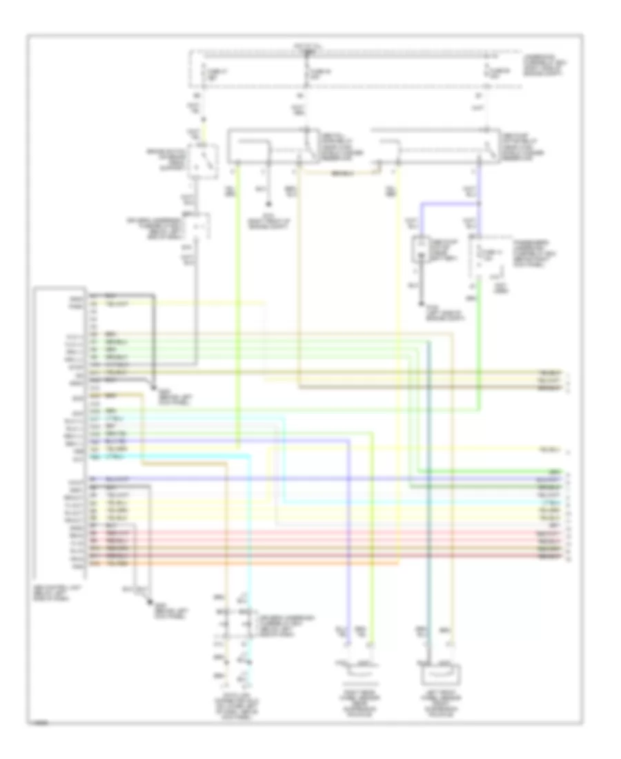
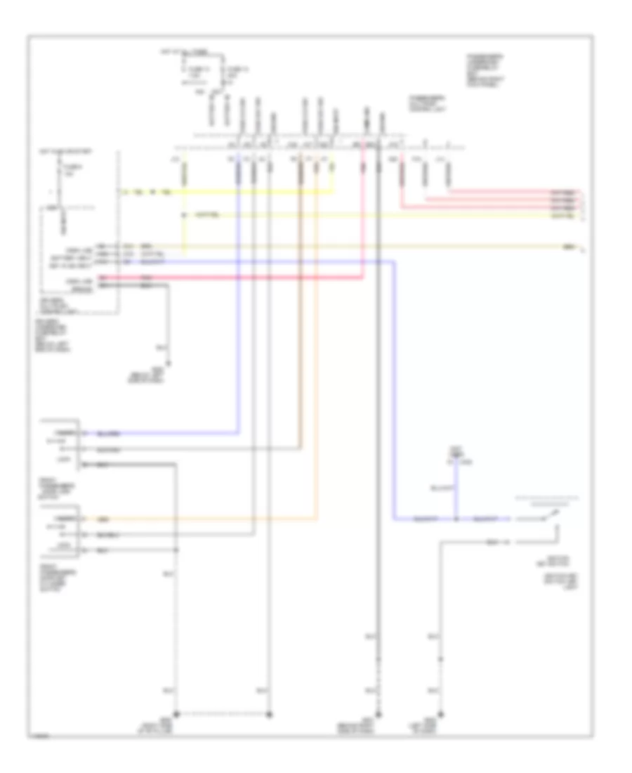
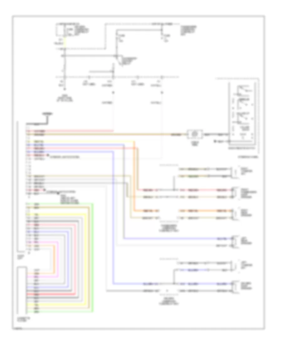
Manual A/C Wiring Diagram (1 of 2) for Honda Odyssey EX 1999
List of elements for Manual A/C Wiring Diagram (1 of 2) for Honda Odyssey EX 1999:
- (1999-00)
- (2001)
- (behind glove box)
- A/c compressor clutch
- A/c compressor clutch relay
- A/c on out
- A17
- Air mix control motor (below center of dash, on heater unit)
- Air mix cool
- Air mix hot
- Air mix pot
- Amd-p
- Battery
- D11
- D14
- Defogger system
- Driver's underdash fuse/relay box (below left end of dash)
- E12
- Evap sen in
- Evaporator temperature sensor (behind glove box. on evaporator housing)
- Fresh ctrl
- Front blower motor (below glove box, on bottom of blower unit)
- Front blower motor relay
- Front blower resistor
- Front mode control motor (behind left side of dash, on end of heater unit)
- Frs
- Fuse 40a
- Fuse 7.5a
- G101 (right front of engine compt)
- G202 (left side of dash)
- Ground
- Heater control panel
- Heater fan switch
- Hot at all times
- Hot in on
- Htr fan in
- Ig2
- Ign in
- Ill +
- Ill -
- Interior lights system
- J12
- K15
- M-cool
- M-def
- M-hot
- M-vent
- Mode 1
- Mode 1 out
- Mode 2
- Mode 2 out
- Mode 3
- Mode 3 out
- Mode 4
- Mode 4 out
- Mode-def +
- Mode-vent +
- O13
- Off
- Passenger's underdash fuse/relay box (behind right kick panel)
- Powertrain control module (pcm) (behind lower center of dash)
- Rec
- Recirc ctrl
- Recirculation control motor (behind glove box, on blower unit)
- Red
- Ref volt
- Relay control
- Rr def on
- S-com
- S5v
- Sensor gnd
- Underhood fuse/relay box (at right side of of engine compt)
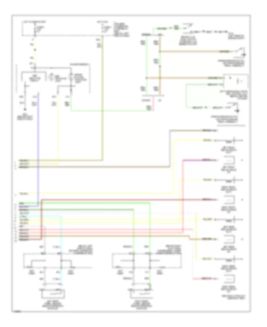
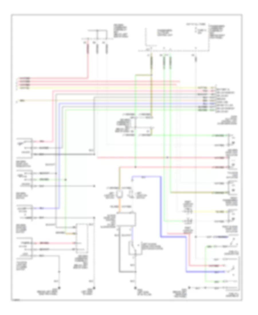
Manual A/C Wiring Diagram (2 of 2) for Honda Odyssey EX 1999
List of elements for Manual A/C Wiring Diagram (2 of 2) for Honda Odyssey EX 1999:
- (1999-00)
- (2001)
- A/c
- A/c diode b (below right end of dash)
- A/c diode c (below right end of dash)
- A/c pressure switch (at right side of engine compartment, on a/c receiver line)
- A20
- A27
- Condenser fan motor (behind right side of radiator)
- Condenser fan relay
- D15
- D16
- Diode a
- E13
- E21
- Fan ctrl
- Fuse 30a
- G101 (right front of engine compt)
- G115 (rear of engine)
- H17
- Hot at all times
- Htr-a/c on in
- I17
- J/c c106
- Passenger's underdash fuse/relay box (behind right kick panel)
- Powertrain control module (behind lower center of dash)
- Radiator fan motor (behind left side of radiator)
- Radiator fan relay
- Radiator fan switch a (at top rear of engine, near thermostat cover)
- Radiator fan switch b (at top rear of engine, near thermostat cover)
- Underhood fuse/relay box (at right side of of engine compt)
Manual A/C Wiring Diagram, Rear for Honda Odyssey EX 1999
List of elements for Manual A/C Wiring Diagram, Rear for Honda Odyssey EX 1999:
- (not used)
- Cool
- Driver's underdash fuse/relay box (below left end of dash)
- Fuse 3 7.5a
- Fuse 60 40a
- G202 (left side of dash)
- G413 (right quarter panel)
- Hot
- Hot at all times
- Hot in run
- Illumination
- Interior lights system
- Multi-fuse/ relay box (at left front of engine compt)
- Off
- Rear blower motor (back side of rear blower unit)
- Rear blower motor high relay (behind rear blower unit)
- Rear blower motor low relay (behind rear blower unit)
- Rear blower motor main relay (behind rear blower unit)
- Rear blower motor middle relay (behind rear blower unit)
- Rear blower resistor (on rear blower unit)
- Rear heater-a/c main switch (front)
- Rear heater-a/c mode control motor (back side of rear blower unit)
- Rear heater-a/c passenger control panel (rear)
- Rear mode control motor relay (behind rear blower unit)
- Red
ANTI-LOCK BRAKES
Anti-lock Brake Wiring Diagrams, with Traction Control (1 of 2) for Honda Odyssey EX 1999
List of elements for Anti-lock Brake Wiring Diagrams, with Traction Control (1 of 2) for Honda Odyssey EX 1999:
- (1999-00)
- (2001)
- (behind left kick panel) g200
- (below left side of dash) abs-tcs control unit
- (not used)
- A10
- A11
- A12
- A13
- A14
- A15
- A16
- A17
- A18
- A19
- A20
- A21
- A22
- A23
- A24
- A25
- A26
- A31
- Abs
- Abs fail- safe relay (near wind- shield washer reservoir)
- Abs pump motor relay (near wind- shield washer reservoir)
- Astftp
- Atsftp
- B10
- B11
- B12
- B13
- B14
- B15
- B16
- B4
- Brake pedal position switch (on brake pedal support)
- C10
- C11
- C12
- D11
- D16
- Data link connector (dlc) (on lower left of dash, above kick panel)
- Dlc
- Driver's underdash fuse/relay box (below left end of dash)
- E15
- Fl-in
- Fl-out
- Flw (+)
- Flw (-)
- Fp-tdr
- Fptdr
- Fr-in
- Fr-out
- Frw (+)
- Frw (-)
- Fsr
- Fuse 14 7.5a
- Fuse 3 10a
- Fuse 47 20a
- Fuse 48 20a
- Fuse 50 30a
- G101 (right front of engine compt)
- G115 (rear of engine)
- G200 (behind left
- Gauge assembly
- Gnd1
- Gnd2
- Gnd3
- H18
- Hot at all times
- Ig2
- K14
- Kick panel)
- Left front wheel speed sensor (front suspension knuckle)
- Lg2
- Mck
- Ncl
- Ncr
- Nep
- Nor
- Npe
- O20
- Park
- Passenger's underdash fuse/relay box (behind right kick panel)
- Pf-inh
- Pfinh
- Pmr
- Powertrain control module (behind lower center of dash)
- Right rear wheel speed sensor (rear suspension knuckle)
- Rl-in
- Rl-out
- Rlw (+)
- Rlw (-)
- Rr-in
- Rr-out
- Rrw (+)
- Rrw (-)
- Scs
- Stop
- Tachometer drive circuit
- Tcs relay (in multi-fuse relay box, left front of engine compt)
- Tcs sw
- Tcs1
- Tcs2
- Tcsr
- Test tachometer connector (on top of brake booster)
- Thlout
- Underhood fuse/relay box (right side of engine compt)
- Vref
Anti-lock Brake Wiring Diagrams, with Traction Control (2 of 2) for Honda Odyssey EX 1999
List of elements for Anti-lock Brake Wiring Diagrams, with Traction Control (2 of 2) for Honda Odyssey EX 1999:
- (behind right kick panel) passenger's under- dash fuse/relay box
- (below left side of dash) driver's underdash fuse/relay box
- (not used)
- A17
- A18
- Abs indicator circuit
- Abs indicator light
- Abs pump motor
- Abs-tcs modulator unit (near battery)
- B11
- B13
- B14
- B16
- Brake fluid level switch (in brake fluid reservoir cap)
- Brake system indicator light
- C10
- C11
- C14
- C16
- Canada
- Daytime running lights (drl) control unit (behind center of dash)
- Driver's underdash fuse/relay box (below left end of dash)
- E16
- Fuse 4 7.5a
- Fuse 9 7.5a
- G100 (left side of engine compt)
- G116 (left rear of engine compt)
- G201 (behind right side of dash)
- Gauge assembly
- Hot in on
- Hot in on or start
- Interior lights system
- K10
- Left front abs solenoid (in)
- Left front abs solenoid (out)
- Left rear abs solenoid (in)
- Left rear abs solenoid (out)
- Left rear wheel speed sensor (rear suspension knuckle)
- Left tcs solenoids
- O10
- Parking brake switch (on parking brake pedal assembly)
- Red
- Right front abs solenoid (in)
- Right front abs solenoid (out)
- Right front wheel speed sensor (front suspension knuckle)
- Right rear abs solenoid (in)
- Right rear abs solenoid (out)
- Right tcs solenoids
- Tcs indicator light
- Tcs switch
- Tcs switch light
Anti-lock Brake Wiring Diagrams, without Traction Control (1 of 2) for Honda Odyssey EX 1999
List of elements for Anti-lock Brake Wiring Diagrams, without Traction Control (1 of 2) for Honda Odyssey EX 1999:
- (not used)
- A10
- A11
- A12
- A13
- A14
- A15
- A16
- A17
- A18
- A19
- A20
- A21
- A22
- Abs control unit (below left side of dash)
- Abs fail- safe relay (near wind- shield washer reservoir)
- Abs pump motor (near battery)
- Abs pump motor relay (near wind- shield washer reservoir)
- B10
- B11
- B12
- B4
- Brake switch (on brake pedal support)
- Data link connector (dlc) (on lower left of dash, above kick panel)
- Dlc
- Driver's underdash fuse/relay box (below left end of dash)
- E15
- Fl-in
- Fl-out
- Flw (+)
- Flw (-)
- Fr-in
- Fr-out
- Frw (+)
- Frw (-)
- Fsr
- Fuse 14 7.5a
- Fuse 47 20a
- Fuse 48 20a
- Fuse 50 30a
- G100 (left side of engine compt)
- G101 (right front of engine compt)
- G200 (behind left kick panel)
- Gnd1
- Gnd2
- Gnd3
- Gnd4
- H18
- Hot at all times
- Ig2
- K14
- Left front wheel sensor (front suspension knuckle)
- Mck
- O20
- Park
- Passenger's underdash fuse/relay box (behind right kick panel)
- Pmr
- Right rear wheel sensor (rear suspension knuckle)
- Rl-in
- Rl-out
- Rlw (+)
- Rlw (-)
- Rr-in
- Rr-out
- Rrw (+)
- Rrw (-)
- Scs
- Stop
- Underhood fuse/relay box (right side of engine compt)
- Walp
Anti-lock Brake Wiring Diagrams, without Traction Control (2 of 2) for Honda Odyssey EX 1999
List of elements for Anti-lock Brake Wiring Diagrams, without Traction Control (2 of 2) for Honda Odyssey EX 1999:
- (behind right kick panel) passenger's under- dash fuse/relay box
- (below left side of dash) driver's underdash fuse/relay box
- (not used)
- A17
- A18
- Abs indicator circuit
- Abs indicator light
- Abs modulator unit (near battery)
- B11
- B13
- B14
- B16
- Brake fluid level switch (in brake fluid reservoir cap)
- Brake system indicator light
- C10
- C11
- C14
- C16
- Canada
- Daytime running lights (drl) control unit (behind center of dash)
- Driver's underdash fuse/relay box (below left end of dash)
- E16
- Fuse 4 7.5a
- Fuse 9 7.5a
- G116 (left rear of engine compt)
- G201 (behind right side of dash)
- Gauge assembly
- Hot in on
- Hot in on or start
- K10
- Left front abs solenoid (in)
- Left front abs solenoid (out)
- Left rear abs solenoid (in)
- Left rear abs solenoid (out)
- Left rear wheel sensor (rear suspension knuckle)
- O10
- Parking brake switch (on parking brake pedal assembly)
- Right front abs solenoid (in)
- Right front abs solenoid (out)
- Right rear abs solenoid (in)
- Right rear abs solenoid (out)
- Right rear wheel sensor (rear suspension knuckle)
ANTI-THEFT
Anti-theft Wiring Diagram, EX (1 of 2) for Honda Odyssey EX 1999
List of elements for Anti-theft Wiring Diagram, EX (1 of 2) for Honda Odyssey EX 1999:
- 10a
- 15a
- 20a
- 7.5a
- A10
- A12
- A13
- A14
- A15
- A16
- A17
- A18
- A20
- A22
- A23
- A24
- B11
- B16
- B22
- Battery in
- Battery input
- Comm line
- Cylinder
- Disarm switch
- Door key
- Dr door sw
- Driver's door switch
- Driver's multiplex control unit
- Driver's underdash fuse/relay box (below left end of dash)
- Exterior lights system
- F pass dr sw
- Front
- Front pass door switch
- Front passenger's door lock switch
- Fuse 10
- Fuse 12
- Fuse 13
- Fuse 9
- G101 (right front of engine compt)
- G14
- G200 (behind left kick panel)
- G201 (behind right side of dash)
- G202 (below left side of dash)
- G202 (left side of dash)
- G305 (right side of "b" pillar)
- Ground
- Hood switch
- Horns
- Horns system
- Hot at all times
- Hot in on or start
- Ign input
- Ignition input
- Ignition key switch
- In-line fuse 1 (behind left side of dash)
- In-line fuse 2 (behind left side of dash)
- J12
- J14 red
- Key in ign input
- Keyless receiver unit (behind right end of dash)
- Left power sliding door control unit
- Left sliding door switch
- Lft slide dr sw
- Light flasher relay
- Lock
- Lt sliding door control
- O19
- Panic
- Pass key sw
- Pass lck sw
- Passenger's
- Passenger's multiplex control unit
- Passenger's underdash fuse/relay box (behind right kick panel)
- Pnk
- R slid dr sw
- Red
- Right power sliding door control unit
- Right side of dash) g201
- Right sliding door switch
- Rt sliding door control
- Security control unit (behind dash, right of steering column)
- Security diode
- Security diode (behind right kick panel)
- Security indicator
- Security led
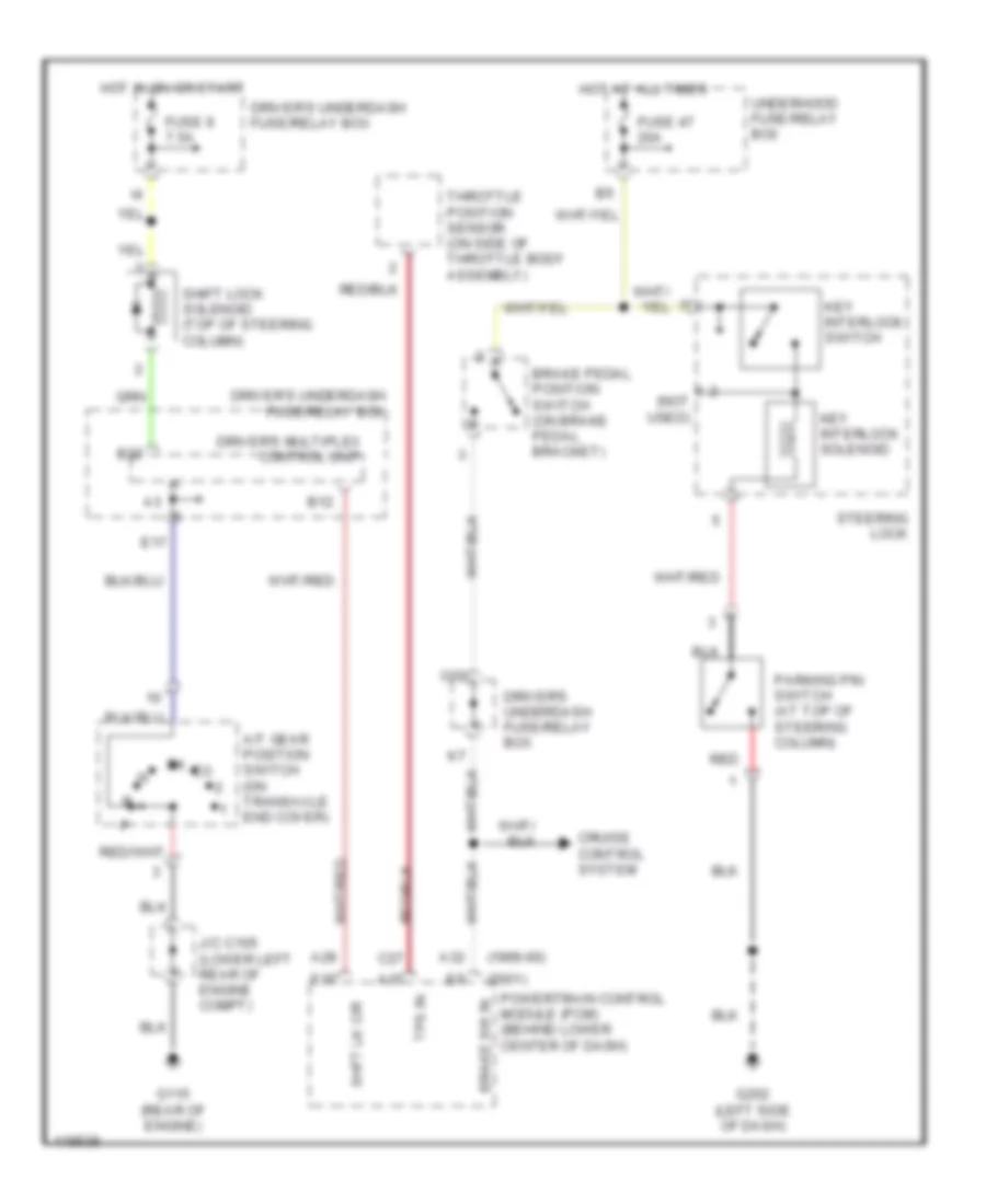
- Shift interlock system
- Steering lock
- Switch
- Taillight relay
- Transmitter
- Unlock
Anti-theft Wiring Diagram, EX (2 of 2) for Honda Odyssey EX 1999
List of elements for Anti-theft Wiring Diagram, EX (2 of 2) for Honda Odyssey EX 1999:
- (below left end of dash) driver's underdash fuse/relay box
- A11
- A12
- A15
- A16
- A17
- A18
- A21
- B11
- Battery in
- C14
- Comm line
- Door multiplex control unit (in driver's door)
- Dr key cyl sw
- Dr lck knob sw
- Dr lck sw
- Driver's door key cylinder switch
- Driver's door lock actuator
- Driver's door lock knob switch
- Driver's door lock switch
- Driver's underdash fuse/relay box (below left end of dash)
- Exterior lights system
- F17
- Front passenger's door lock actuator
- Fuel fill door relay
- Fuel fill door switch
- Fuse 20a
- G202 (left side of dash)
- G308 (left side of "b" pillar)
- G404 (behind left rear side trim panel)
- Ground
- Horn systems
- Hot at all times
- I18
- Interior lights system
- K13
- Left junction i
- Left junction switch
- Left sliding door lock knob switch/ actuator
- Light flasher relay (below left side of dash)
- Lock
- Lock key cylinder
- Passenger's multiplex control unit
- Passenger's underdash fuse/relay box (behind right kick panel)
- Pnk
- Red
- Right junction switch
- Right junction switch h
- Right sliding door lock actuator
- Sliding door lock control unit (in left sliding door)
- Switch
- Tailgate
- Tailgate lock actuator
- Unlock
Anti-theft Wiring Diagram, LX (1 of 2) for Honda Odyssey EX 1999
List of elements for Anti-theft Wiring Diagram, LX (1 of 2) for Honda Odyssey EX 1999:
- 10a
- 15a
- 20a
- 7.5a
- A10
- A12
- A13
- A16
- A17
- A20
- A22
- A23
- A24
- B11
- B22
- Battery in
- Battery input
- Comm line
- Cylinder
- Disarm switch
- Door key
- Door switches output
- Dr door lck sw lck
- Dr door lck sw unlck
- Driver's door switch
- Driver's multiplex control unit
- Driver's underdash fuse/relay box (below left end of dash)
- F15
- Front
- Front passenger's door lock switch
- Front passenger's door switch
- Fuse 10
- Fuse 12
- Fuse 13
- Fuse 9
- G101 (right front of engine compt)
- G14
- G200 (behind left kick panel)
- G201 (behind right side of dash)
- G202 (below left side of dash)
- G202 (left side of dash)
- G305 (right side of "b" pillar)
- G404 (behind left rear side trim panel)
- Gauge assembly
- Ground
- Hood switch
- Horn system
- Horns system
- Hot at all times
- Hot in on or start
- Ign input
- Ignition input
- Ignition key switch
- Ignition key switch/key light
- In-line fuse 1 (behind left side of dash)
- In-line fuse 2 (behind left side of dash)
- In-line fuse 3 (behind left side of dash)
- Int lights sw input
- Interior lights system
- J12
- J14
- Key in ign input
- Keyless & security control unit (behind dash, right of steering column)
- Left sliding door switch
- Light flasher relay
- Lock
- O19
- Pass key sw
- Pass lck sw
- Passenger's
- Passenger's multiplex control unit
- Passenger's underdash fuse/relay box (behind right kick panel)
- Pnk
- Red
- Right sliding door switch
- Security indicator
- Security led
- Shift interlock system
- Switch
- Tailgate latch switch
- Unlock
- Unlock relay
- Unlock relay (below left side of dash)
Anti-theft Wiring Diagram, LX (2 of 2) for Honda Odyssey EX 1999
List of elements for Anti-theft Wiring Diagram, LX (2 of 2) for Honda Odyssey EX 1999:
- 20a
- A11
- A12
- A15
- A16
- A17
- A18
- Battery in
- Comm line
- Door multiplex control unit (in driver's door)
- Dr key cyl sw
- Dr lck knob sw
- Dr lck sw
- Driver's door key cylinder switch
- Driver's door lock actuator
- Driver's door lock knob switch
- Driver's door lock switch
- Driver's underdash fuse/relay box (below left end of dash)
- Exterior lights system
- F17
- Front passenger's door lock actuator
- Fuel fill door relay
- Fuel fill door switch
- Fuse 12
- G202 (left side of dash)
- G308 (left side of "b" pillar)
- G404 (behind left rear side trim panel)
- Ground
- Hot at all times
- I18
- K13
- Left junction i
- Left junction switch
- Left sliding door lock knob switch/ actuator
- Light flasher relay (below left side of dash)
- Lock
- Lock key cylinder
- Passenger's multiplex control unit
- Passenger's underdash fuse/relay box (behind right kick panel)
- Pnk
- Right junction switch
- Right junction switch h
- Right sliding door lock actuator
- Sliding door lock control unit (in left sliding door)
- Switch
- Tailgate
- Tailgate lock actuator
- Unlock
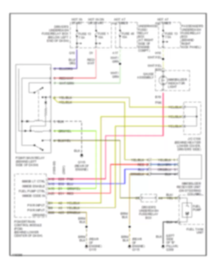
Immobilizer Wiring Diagram for Honda Odyssey EX 1999
List of elements for Immobilizer Wiring Diagram for Honda Odyssey EX 1999:
- (1999-00)
- (2001)
- (left side of "b" pillar) g308
- (rear of engine) g115
- A12
- A13
- A15
- A17
- A25
- B19
- B20
- Driver's underdash fuse/relay box
- Driver's underdash fuse/relay box (below left end of dash)
- E29
- E30
- E31
- Fuel pump
- Fuel pump ctrl
- Fuel tank unit
- Fuse 1 15a
- Fuse 13 7.5a
- Fuse 46 15a
- G115 (rear of engine)
- Gauge assembly
- Ground
- H16
- Hot at all times
- Hot in on or start
- Hot in start
- Immob code in
- Immob enable
- Immob lt ctrl
- Immobilizer indicator light
- Immobilizer receiver unit (on steering column)
- J/c c106 (behind heater lower cover, driver's side)
- Passenger's underdash fuse/relay box (behind right kick panel)
- Pgm-fi main relay (behind left side of dash)
- Pnk
- Powertrain control module (pcm) (behind lower center of dash)
- Pwr input
- Q10
- Red
- Underhood fuse/ relay box (at right side of engine compt)
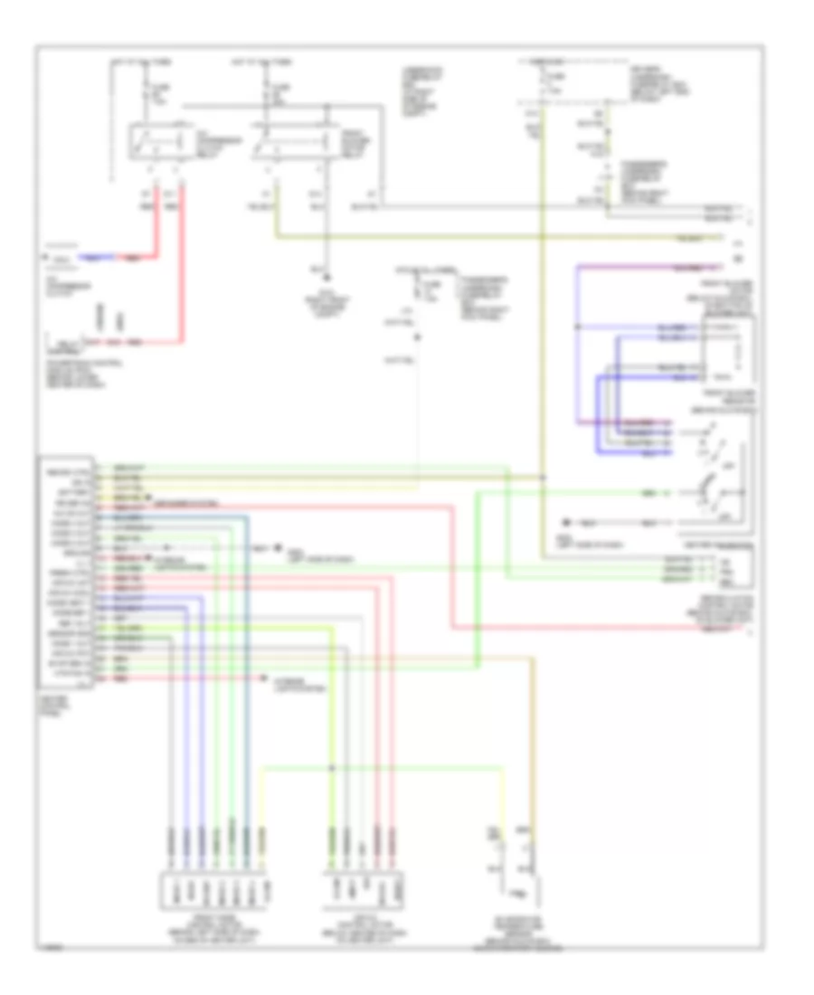
BODY COMPUTER
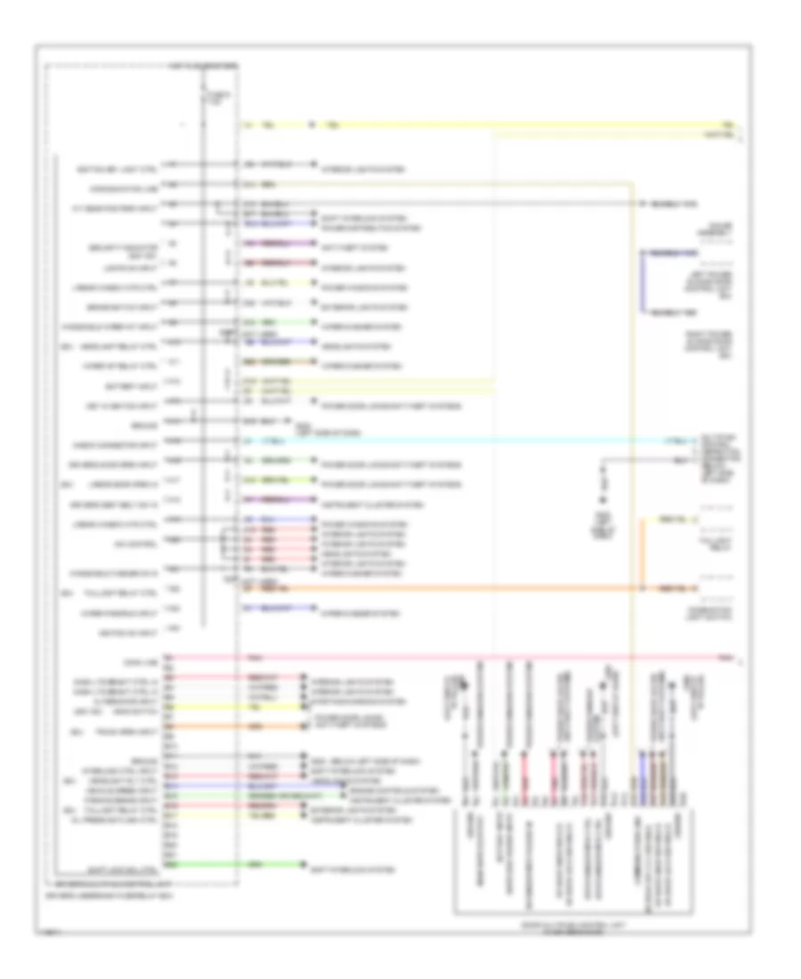
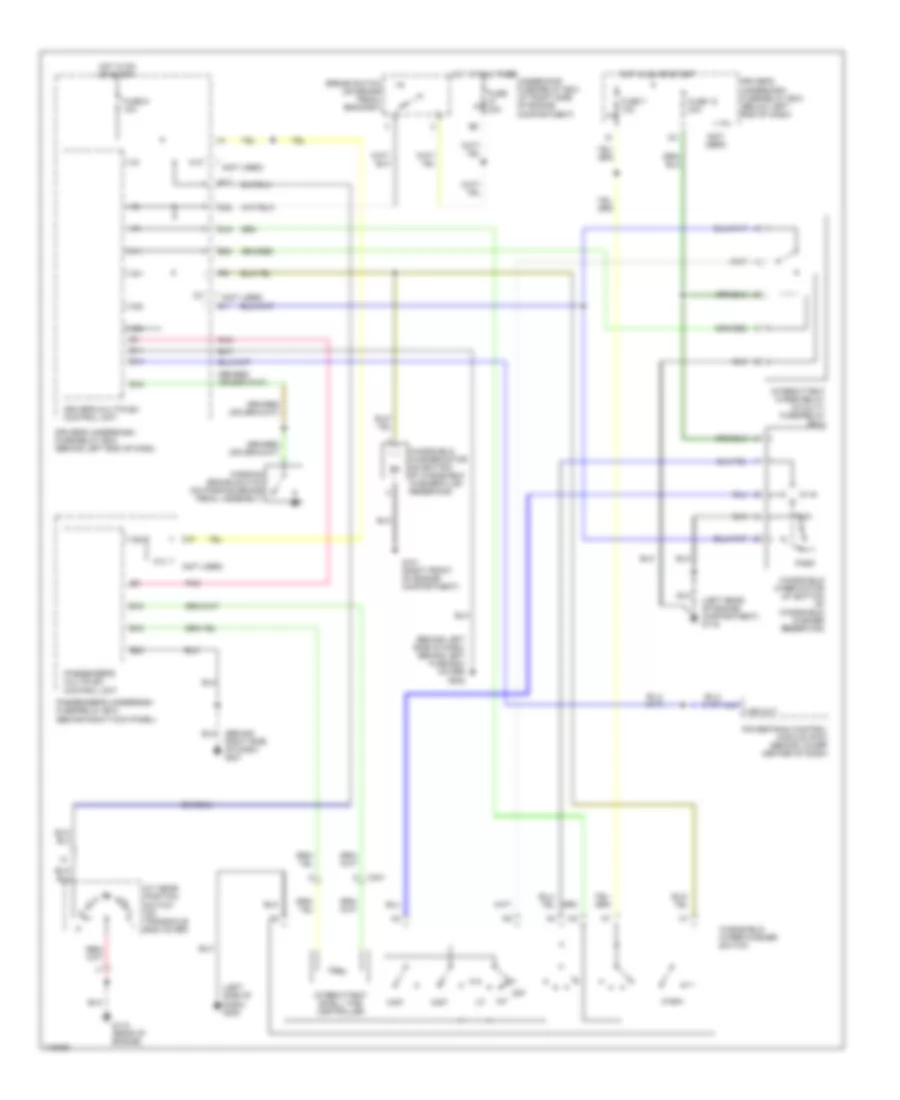
Multiplex Control Wiring Diagram (1 of 2) for Honda Odyssey EX 1999
List of elements for Multiplex Control Wiring Diagram (1 of 2) for Honda Odyssey EX 1999:
- (2001 ex)
- (below left side of dash)
- (ex)
- (left side of
- (left side of dash)
- (not used)
- (not used) q7
- A/t gear pos park input
- A10
- A11
- A12
- A13
- A14
- A15
- A16
- A17
- A18
- A19
- A20
- A21
- A22
- A23
- A24
- Alternator input
- Anti-theft system
- B10
- B11
- B12
- B13
- B14
- B15
- B16
- B17
- B18
- B19
- B20
- B21
- B22
- Battery input
- Brake switch input
- C15
- Check connector input
- Combination light switch
- Comm line
- Communication line
- Dash lts bright ctrl in
- Dim control
- Door multiplex control unit (in driver's door)
- Dr door key cly sw-unlk
- Dr door knob sw-lck
- Dr door knob sw-unlck
- Dr door lock sw-unlck
- Dr window mtr pulser in
- Driver's door open input
- Driver's multiplex control unit
- Driver's seat belt sw in
- Driver's underdash fuse/relay box
- Drv's window mtr ctrl
- E12
- E17
- E19
- E20
- Engine controls system
- Exterior lights system
- Fuse 9 7.5a
- G14
- G202
- G202 (left side of dash)
- G308 "b" pillar)
- G308 (left side of "b" pillar)
- Gauge assembly
- Ground
- Headlight relay ctrl
- Headlight rly ctrl
- Headlights system
- Hood switch
- Hot in on or start
- Ignition key light ctrl
- Ignition on input
- Instrument cluster system
- Interior lights system
- Interlock ctrl input
- K10
- K15
- Key in ignition input
- L/rear door open in
- L/rear window mtr ctrl
- Left power sliding door control unit (ex)
- Lights on input
- Main switch output
- Multiplex control inspection connector (below left side of dash)
- O19
- O20
- Oil press ind flash ctrl
- Parking brake input
- Pnk
- Pnk a7
- Power distribution system
- Power door locks/ anti-theft systems
- Power door locks/anti-theft systems
- Power window system
- Power windows system
- Q15
- Q18
- Red
- Red a4
- Right power sliding door control unit (ex)
- Security indicator (2001 ex)
- Shift interlock system
- Shift lock sol ctrl
- Starting/charging system
- Switched power input
- Taillight relay
- Taillight relay ctrl
- Trunk open input
- Vehicle speed input
- Windshield washer on in
- Windshield wiper int input
- Wiper int relay ctrl
- Wiper park/run input
- Wiper/washer system
Multiplex Control Wiring Diagram (2 of 2) for Honda Odyssey EX 1999
List of elements for Multiplex Control Wiring Diagram (2 of 2) for Honda Odyssey EX 1999:
- (2001 ex)
- (ex)
- (not used)
- (right side of "b" pillar)
- A10
- A11
- A12
- A13
- A14
- A15
- A16
- A17
- A18
- A19
- A20
- A21
- A22
- A23
- A24
- Audio unit
- B10
- B11
- B12
- B13
- B14
- B15
- B16
- B17
- B18
- B19
- B20
- B21
- B22
- Battery input
- C13
- C14
- Ceiling light ctrl
- Communication line
- F15
- F17
- F18
- F3 (or g2)
- F7 (or g3)
- Front wiper/washer
- Frt pass door key cyl sw in-lck
- Frt pass door lock sw in-lock
- Frt pass door lock sw in-unlck
- Frt pass door open input
- Frt pass key cyl sw in-unlock
- Frt pass window motor ctrl
- Frt pass/tailgate lock knob sw
- Fuse 12 20a
- Fuse 13 7.5a
- Fuse 5 20a
- G201 (behind right side of dash)
- G305
- Ground
- Headlight relay ctrl
- Headlights system
- Horn relay ctrl
- Horns system
- Hot at all times
- I18
- Ignition input
- Interior lights system
- J11
- J12
- J14
- Keyless door locks
- Passenger's multiplex control unit
- Passenger's underdash fuse/relay box
- Pnk
- Power door lock actuator ctrl
- Power door locks/anti-theft systems
- Power window relay ctrl
- Power windows system
- Right rear door open input
- Right rear window motor ctrl
- Sound systems
- Trunk, tailgate, fuel doors system
- Wiper/washer system
COMPUTER DATA LINES
Computer Data Lines for Honda Odyssey EX 1999
List of elements for Computer Data Lines for Honda Odyssey EX 1999:
- (1999-00)
- (2001)
- (below left side of dash) g202
- (dlc)
- (k-line)
- (left side of dash) g202
- (not used)
- (scs)
- A10
- A14
- A15
- A17
- A21
- A22
- A26
- Abs control unit (below left side of dash)
- Abs-tcs control unit (below left side of dash)
- Data link connector (dlc) (below left side of dash)
- Dlc in/ou
- Driver's multiplex control unit
- Driver's underdash fuse/relay box
- Driver's underdash fuse/relay box (below left side of dash)
- E16
- E27
- Fuse 46 15a
- G115 (rear of engine)
- Hot at all times
- K14
- Multiplex module inspection connector (below left side of dash)
- Powertrain control module (behind lower center of dash)
- Serv check
- Srs unit (below lower center of dash)
- Underhood fuse/relay box (right side of engine compt)
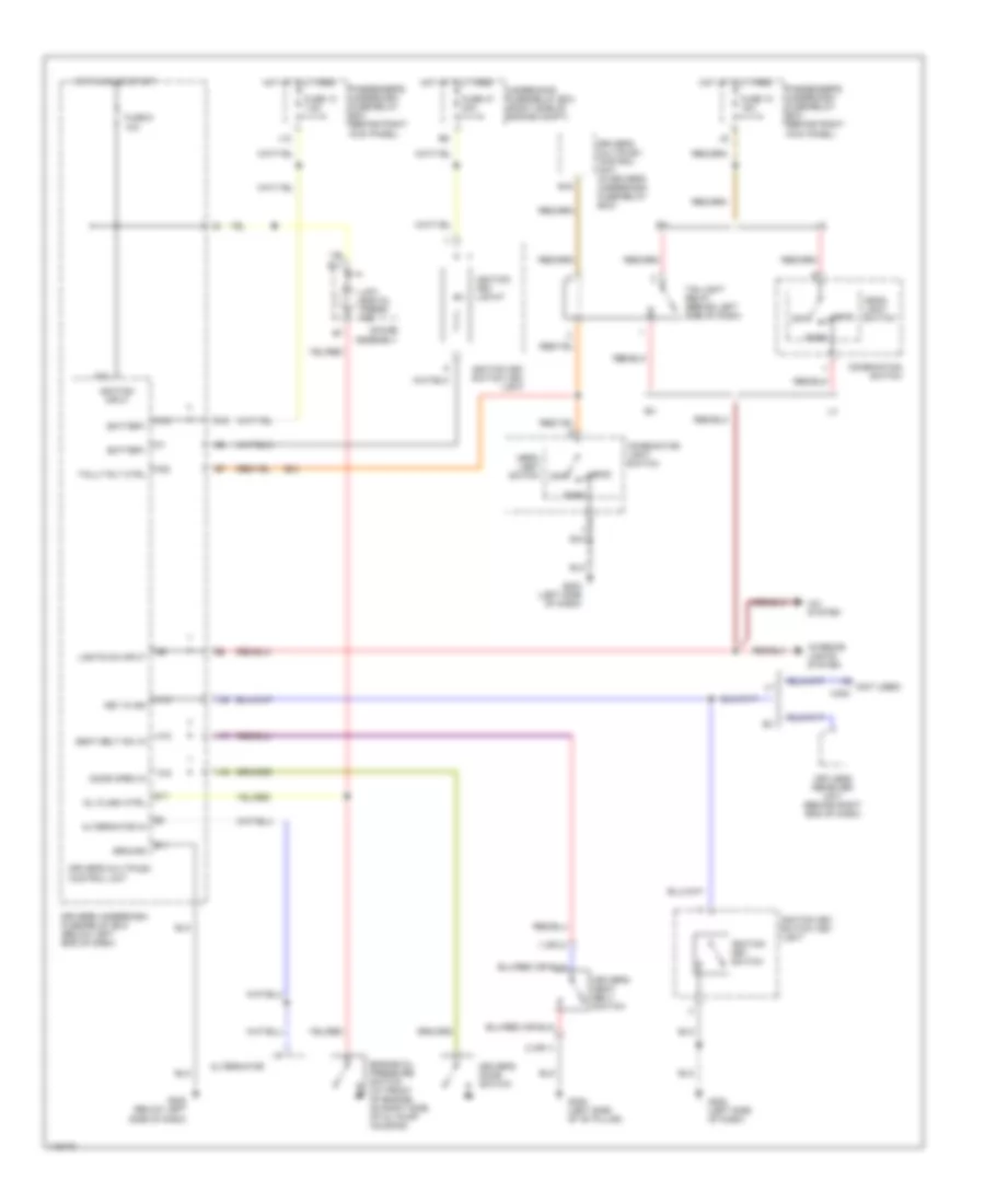
COOLING FAN
Cooling Fan Wiring Diagram for Honda Odyssey EX 1999
List of elements for Cooling Fan Wiring Diagram for Honda Odyssey EX 1999:
- (1999-00)
- (1999-00) (2001)
- (2001)
- (ex w/ navigation)
- (ex w/o navigation)
- (lx)
- (not used)
- A/c diode b (below right end of dash)
- A/c diode c (below right end of dash)
- A/c on output
- A/c pressure switch
- A20
- A27 e21
- Condenser fan motor
- Condenser fan relay
- D15
- D16
- Driver's underdash fuse/relay box
- E13
- Fan control relay (at right side of engine compt, near windsheild washer reservoir)
- Fuse 30a
- Fuse 7.5a
- G101 (right front of engine compt)
- G115 (rear of engine)
- H17
- Heater control panel (lx) or climate control unit (ex)
- Heater- a/c on intput
- Hot at all times
- Hot in on
- I17
- K14
- Lo hi
- Passenger's underdash fuse/relay box
- Powertrain control module (pcm) (behind lower center of dash)
- Radiator fan motor
- Radiator fan relay
- Radiator fan switch a (at top rear of engine, near thermostat cover)
- Radiator fan switch b (at top rear of engine, near thermostat cover)
- Underhood fuse/relay box
CRUISE CONTROL
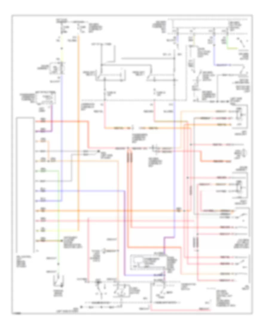
Cruise Control Wiring Diagram for Honda Odyssey EX 1999
List of elements for Cruise Control Wiring Diagram for Honda Odyssey EX 1999:
- "on" indicator
- (1999-00)
- (2001)
- (rear of engine) g115
- (right front of engine compt) g101
- A/t gear position switch (on transaxle end cover)
- A11
- Actuator ctrl
- Anti-theft system
- B11
- Brake pedal position switch (on brake pedal support)
- Brake switch input
- C14
- Cable reel (on top of steering column)
- Cancel switch
- Cruise control actuator (at right front corner of engine compt)
- Cruise control indicator light
- Cruise control main switch
- Cruise control main switch light
- Cruise control set/ resume cancel switch
- Cruise control unit (under dash, right of steering column)
- Cruise ctrl sig out
- Cruise ind lt ctrl
- Cruise input
- Disengage input
- Driver's underdash fuse/relay box (below left end of dash)
- E17
- E26
- Fuse 47 20a
- Fuse 6 15a
- Fuse 9 7.5a
- G202 (below left side of dash)
- Gauge assembly
- Ground
- Horn relay
- Horns system
- Hot at all times
- Hot in on or start
- I12
- Ignition input
- Interior lights system
- J/c c105 (lower left rear of engine compt)
- O20
- Off
- Passenger's underdash fuse/relay box (behind right kick panel)
- Pnk
- Power input
- Powertrain control module (pcm) (behind lower center of dash)
- Red
- Resume switch
- Resume/cancel sig in
- Safety solenoid
- Set switch
- Set/cancel sig input
- Steering wheel
- Underhood fuse/relay box (at right side of engine compt)
- Vacuum solenoid
- Vehicle speed input
- Vent solenoid
- Vss output
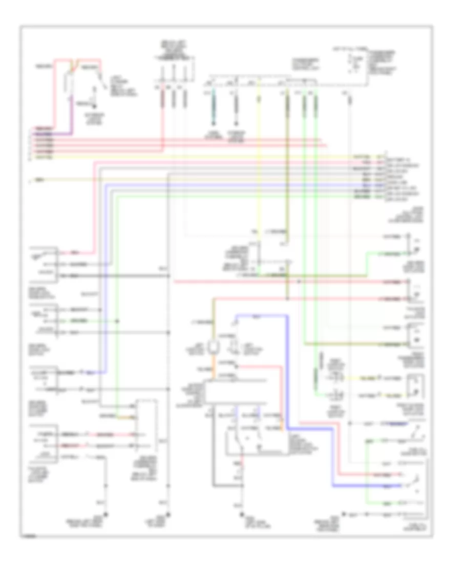
DEFOGGERS
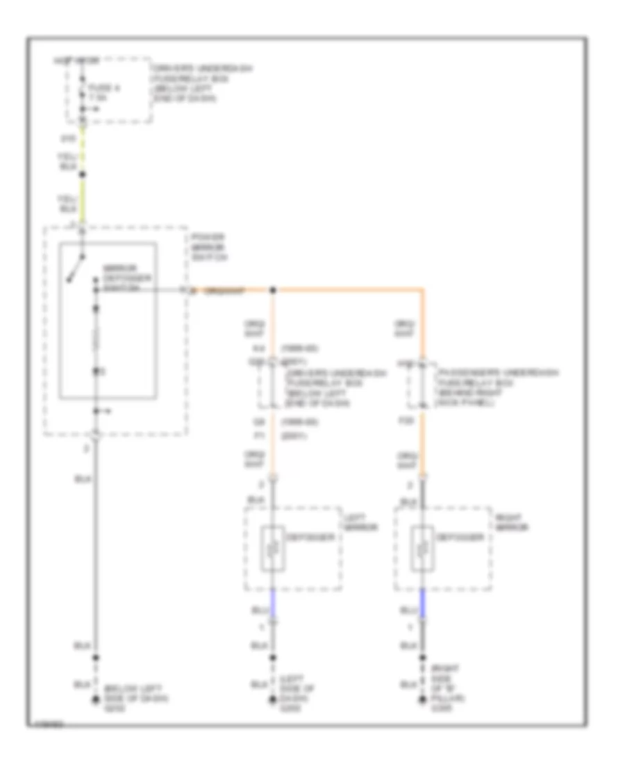
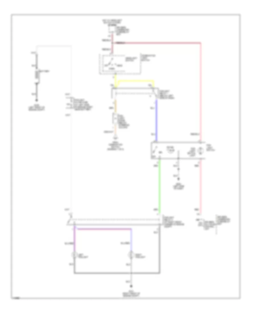
Heated Mirrors Wiring Diagram for Honda Odyssey EX 1999
List of elements for Heated Mirrors Wiring Diagram for Honda Odyssey EX 1999:
- (1999-00)
- (2001)
- (below left side of dash) g202
- (left side of dash) g202
- (right side of "b" pillar) g305
- Defogger
- Driver's underdash fuse/relay box (below left end of dash)
- F20
- Fuse 4 7.5a
- H12
- Hot in on
- Left mirror
- Mirror defogger switch
- Passenger's underdash fuse/relay box (behind right kick panel)
- Power mirror switch
- Q20
- Right mirror
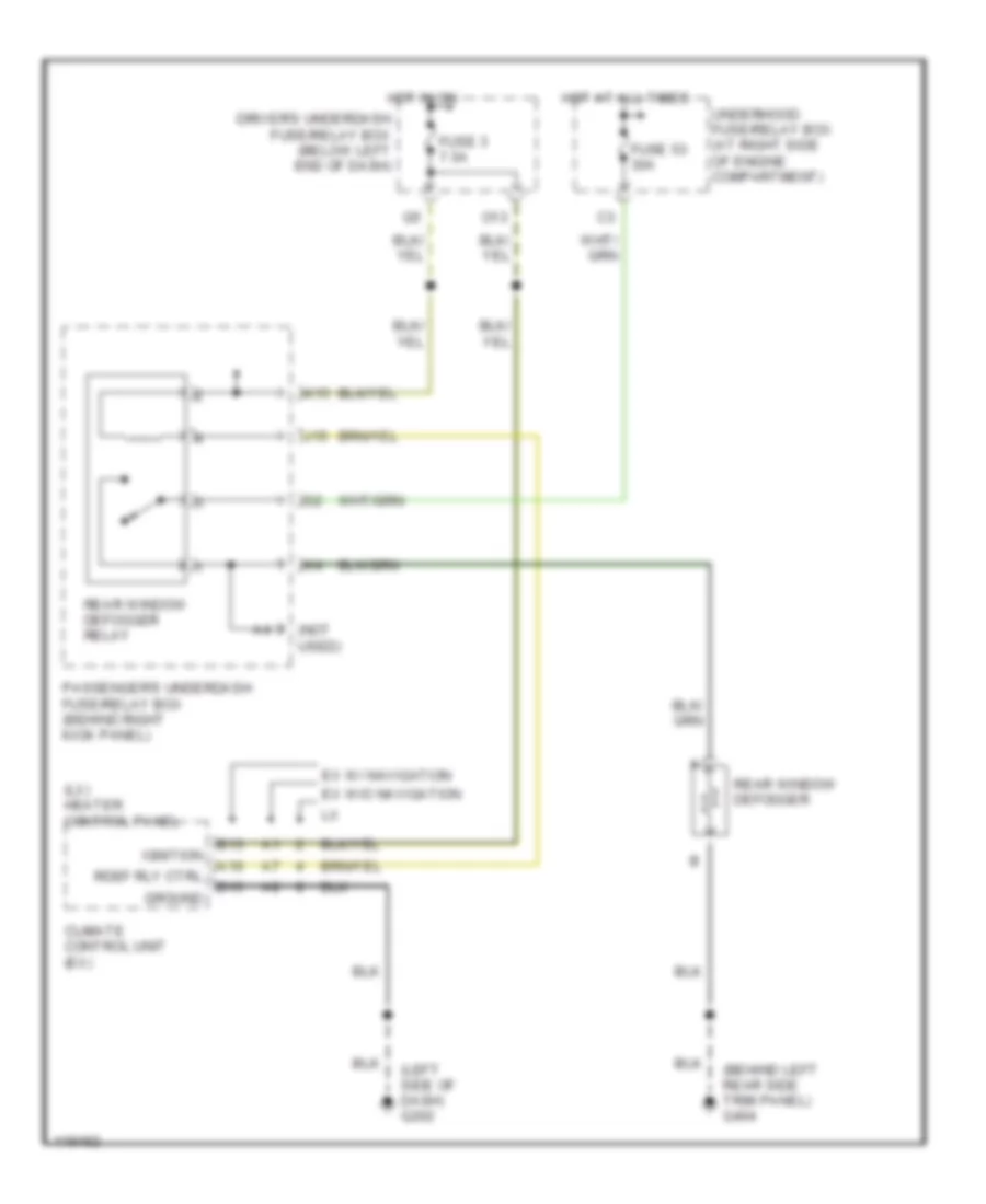
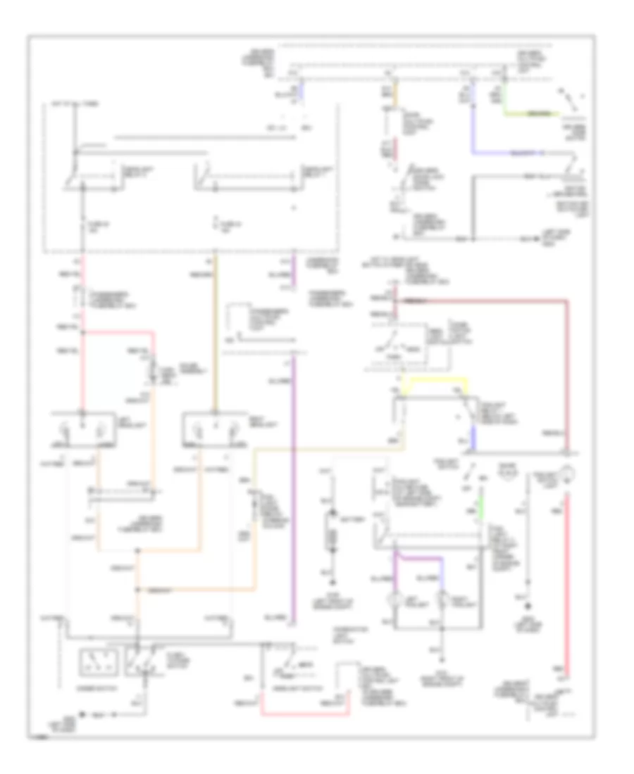
Rear Defogger Wiring Diagram for Honda Odyssey EX 1999
List of elements for Rear Defogger Wiring Diagram for Honda Odyssey EX 1999:
- (behind left rear side trim panel) g404
- (left side of dash) g202
- (lx) heater control panel
- (not used)
- A10
- B13
- B15
- Climate control unit (ex)
- Driver's underdash fuse/relay box (below left end of dash)
- Ex w/ navigation
- Ex w/o navigation
- Fuse 3 7.5a
- Fuse 53 30a
- Ground
- Hot at all times
- Hot in on
- Ignition
- J15
- K15
- O13
- Passenger's underdash fuse/relay box (behind right kick panel)
- Rdef rly ctrl
- Rear window defogger
- Rear window defogger relay
- Underhood fuse/relay box (at right side of engine compartment)
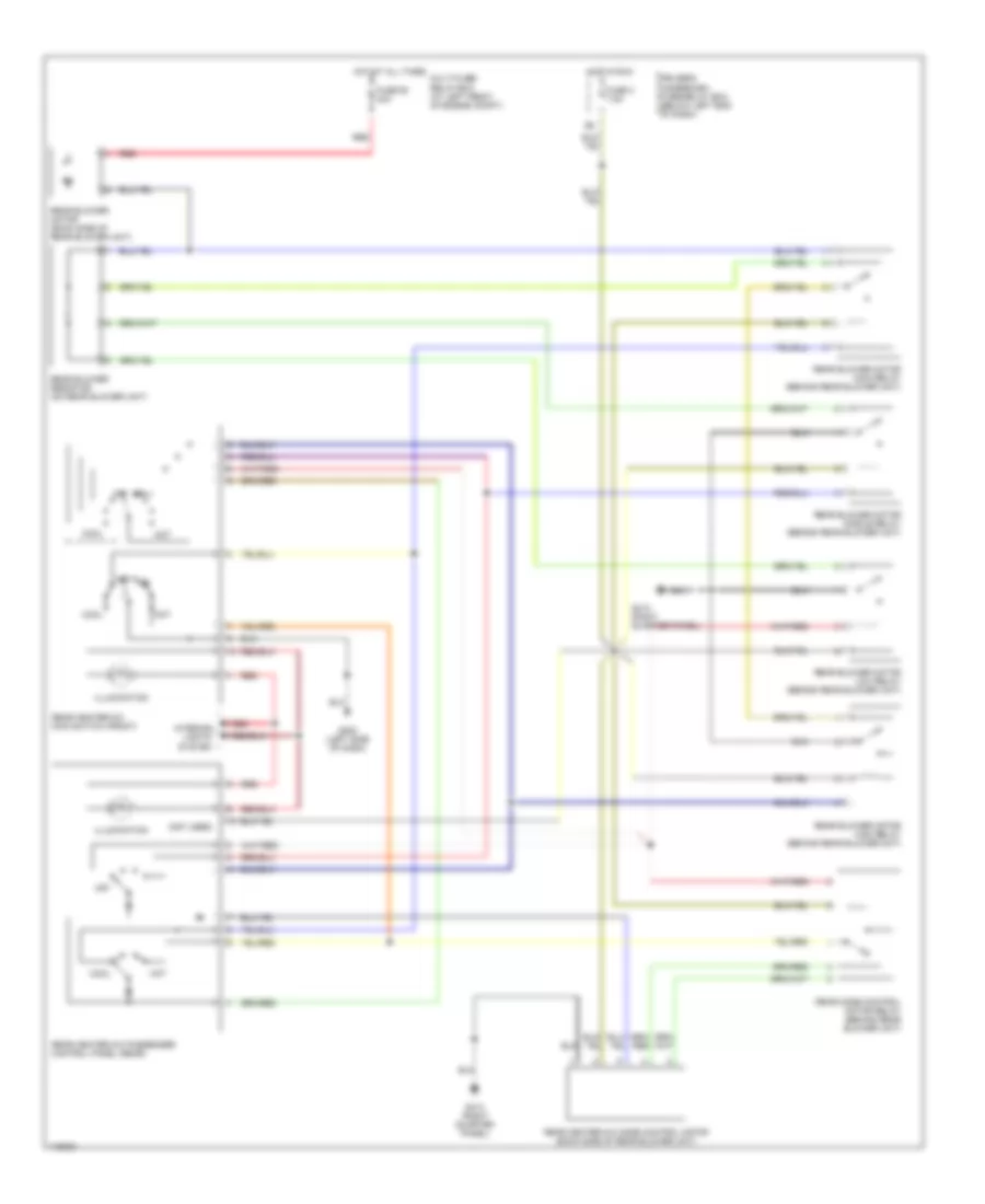
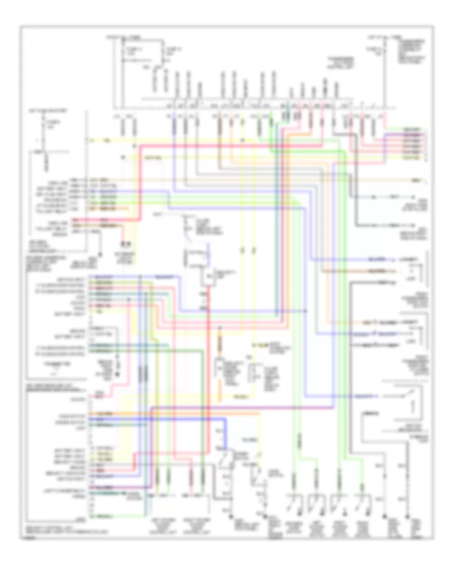
ENGINE PERFORMANCE
3.5L
3.5L, Engine Performance Wiring Diagrams (1 of 4) for Honda Odyssey EX 1999
List of elements for 3.5L, Engine Performance Wiring Diagrams (1 of 4) for Honda Odyssey EX 1999:
- (base of left "b" pillar)
- (center of dash)
- (in fuel tank unit) fuel pump
- (left side of eng compt) engine mount control solenoid valve
- (left side of eng compt) evaporative emission (evap) purge control solenoid valve
- (on left rear of transaxle)
- (top rear of engine)
- 2wbs
- A/t gear position switch (rear of transaxle)
- A10
- A11
- A12
- A13
- A14
- A15
- A16
- A17
- A18
- A19
- A20
- A21
- A22
- A23
- A24
- A25
- A26
- A27
- A28
- A29
- A30
- A31
- A32
- Abs-tcs control unit (below left side of dash)
- Acc
- Acs
- Air conditioning system
- Anti- theft system
- Anti-theft system
- Atppn
- B10
- B11
- B12
- B13
- B14
- B15
- B16
- B17
- B18
- B19
- B20
- B21
- B22
- B23
- B24
- B25
- Bksw
- Cooling fans system
- Crs
- Cruise control system
- D4ind
- Driver's under- dash fuse/ relay box
- E-egr
- Fanc
- Flr
- Fuel injectors
- Fuse 1 15a
- Fuse 13 7.5a
- Fuse 46 15a
- G115
- G115 (top rear
- G308
- Gauge assembly
- Hot at all times
- Hot in on or start
- Hot in start
- Iacv
- Idle air control valve (bottom of throttle body)
- Igp1
- Igp2
- Immobilizer receiver
- Imocd
- Imoen
- Imolmp
- Inj1
- Inj2
- Inj3
- Inj4
- Inj5
- Inj6
- J/c c105 (left rear of engine compt)
- J/c c106 (center of dash)
- J/c c106%% (near ignition coil)
- J/c c107
- J12
- K-line
- K18
- Lg1
- Lg2
- Lsa+
- Lsa-
- Lsb+
- Lsb-
- Mcs
- Mil
- Nep
- O19
- Of engine)
- Op3sw
- Passenger's under-dash fuse/relay box
- Pcs
- Pg1
- Pg2
- Pgm-fi main relay (left side of dash)
- Pnk
- Powertrain control module (forward of floor console)
- Pspsw
- Ptank
- Q10
- Red
- Rpm
- Scs
- Shift interlock system
- Sho2s
- Slu
- So2shtc
- Starting/ charging system
- Sts
- Tach
- Test tachometer connector (left side of eng compt)
- Under- hood fuse/ relay box
- Vbu
- Vssout
- Vsv
- Vtec solenoid valve (lower right of engine)
- Vts
3.5L, Engine Performance Wiring Diagrams (2 of 4) for Honda Odyssey EX 1999
List of elements for 3.5L, Engine Performance Wiring Diagrams (2 of 4) for Honda Odyssey EX 1999:
- (left kick panel)
- (next to evap canister) evaporative emission bypass solenoid valve
- (on evap canister) evaporative emission control canister vent shut valve
- (top rear of engine)
- (top rear of transaxle) a/t clutch pressure control solenoid valve "a"
- (top rear of transaxle) a/t clutch pressure control solenoid valve "b"
- Abs control unit
- B11
- Braided
- Brake switch (on brake pedal support)
- C10
- Crankshaft position sensor (behind crankshaft pulley)
- Cruise control system
- Cruise control unit
- Data link connector (lower left of dash)
- Driver's multiplex control unit
- Driver's under- dash fuse/ relay box
- Driver's under-dash fuse/relay box
- E13
- Fuse 47 20a
- Fuse 6 15a
- Fuse 9 10a
- G101 (right front of engine compt)
- G115
- G200
- Gauge assembly
- Hot at all times
- Hot in on or start
- I12
- J/c c107 (center of dash)
- Malfunction indicator light (mil)
- O20
- Passenger's under- dash fuse/ relay box
- Pnk
- Power sliding door control units
- Power steering pressure switch (on power steering line)
- Primary heated oxygen sensor (on front exhaust pipe)
- Red
- Secondary heated oxygen sensor (on twc converter)
- Tdc1
- Tdc2
- Top dead center (tdc) sensors (behind left camshaft pulley)
- Under- hood fuse/ relay box
- Vss in
3.5L, Engine Performance Wiring Diagrams (3 of 4) for Honda Odyssey EX 1999
List of elements for 3.5L, Engine Performance Wiring Diagrams (3 of 4) for Honda Odyssey EX 1999:
- (top rear of engine)
- 2nd clutch pressure switch (on right front of transaxle)
- A/t gear position indicator
- A/t gear position switch (rear of transaxle)
- B10
- B16
- B22
- C12
- C13
- C15
- C16
- Driver's under- dash fuse/ relay box
- E17
- Fuse 9 10a
- G115
- G115 (top rear of engine)
- G201 (right side of dash)
- Gauge assembly
- Hot in on or start
- Interior lights system
- J/c c105 (left rear of engine compt)
- J/c c106 (center of dash)
- J/c c107 (center of dash)
- K10
- Knock sensor (left side of engine)
- Lock-up control solenoid valve (on transaxle torque converter housing)
- Pnk
- Red
- Red/
- Shift control solenoid valve "a" (on transaxle torque converter housing)
- Shift control solenoid valve "b" (on transaxle torque converter housing)
- Shift control solenoid valve "c" (on transaxle torque converter housing)
- Shift inter- lock system
- Solid state
- Vtec pressure switch (lower right of engine)
3.5L, Engine Performance Wiring Diagrams (4 of 4) for Honda Odyssey EX 1999
List of elements for 3.5L, Engine Performance Wiring Diagrams (4 of 4) for Honda Odyssey EX 1999:
- (center of dash)
- (top rear
- A/c system
- A/t
- Altc
- Altf
- Anti-lock brakes system
- Atp1
- Atp2
- Atpd3
- Atpd4
- Atpr
- Braided
- C11
- C15
- C24
- C31
- Ckpm
- Ckpp
- Countershaft speed sensor (top right of transaxle)
- D10
- D11
- D12
- D13
- D14
- D15
- D16
- Driver's under- dash fuse/ relay box
- Driver's under- dash fuse/ relay box e4
- E10
- E11
- E12
- E14
- Ect
- Egrl
- Engine coolant temperature sensor (on rear of engine)
- Exhaust gas recirculation valve & lift sensor (on rear of engine)
- Fptdr
- Fuel tank pressure sensor (forward of fuel tank)
- Fuse 11 15a
- G115
- G115 (top rear of engine)
- Hot in on or start
- I17 (not used)
- Iat
- Icm
- Ignition coil 1
- Ignition coil 2
- Ignition coil 3
- Ignition coil 4
- Ignition coil 5
- Ignition coil 6
- Igpls1
- Igpls2
- Igpls3
- Igpls4
- Igpls5
- Igpls6
- Intake air temperature sensor (right side of intake manifold)
- J/c c105 (left rear of engine compt)
- J/c c107
- J/c c107 (center of dash)
- Mainshaft speed sensor (left rear of transaxle)
- Manifold absolute pressure sensor (on throttle body)
- Map
- Ncsg
- Nmsg
- Of engine)
- Op2sw
- Pfinh
- Pho2s
- Pnk
- Po2shtc
- Powertrain control module (forward of floor console)
- Red
- Red c14
- Red c21
- Sg1
- Sg2
- Sha
- Shb
- Snc
- Starting/ charging system
- Tdc1m
- Tdc1p
- Tdc2m
- Tdc2p
- Throttle position sensor (on throttle body)
- To spark plug
- Tps
- Vbsol
- Vcc1
- Vcc2
- Vtm
EXTERIOR LIGHTS
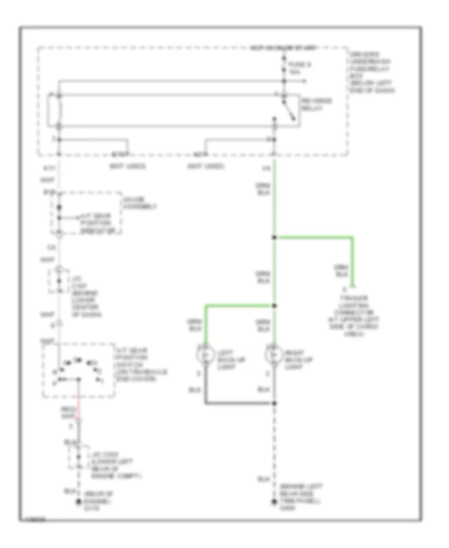
Back-up Lamps Wiring Diagram for Honda Odyssey EX 1999
List of elements for Back-up Lamps Wiring Diagram for Honda Odyssey EX 1999:
- (behind left rear side trim panel) g404
- (not used)
- (rear of engine) g115
- A/t gear position indicator
- A/t gear position switch (on transaxle end cover)
- B17
- Driver's underdash fuse/relay box (below left end of dash)
- E10
- Fuse 9 10a
- Gauge assembly
- Hot in on or start
- J/c c105 (lower left rear of engine compt)
- J/c c107 (behind lower center of dash)
- K11
- Left back-up light
- Reverse relay
- Right back-up light
- Trailer lighting connector (at upper left side of cargo area)
Exterior Lamps Wiring Diagram (1 of 2) for Honda Odyssey EX 1999
List of elements for Exterior Lamps Wiring Diagram (1 of 2) for Honda Odyssey EX 1999:
- (behind left rear side trim panel) g404
- (behind right rear side trim panel) g405
- (left rear of engine compt) g116
- (left side of dash) g202
- (right front of engine compt) g101
- A11
- B16
- Brake light failure sensor
- Brake light/ outer taillight
- Brake switch (on brake pedal bracket)
- C17
- C403
- Combination light switch
- Driver's multiplex control unit
- Driver's underdash fuse/relay box (below left end of dash)
- E18
- Fuse 10 15a
- Fuse 47 20a
- Fuse 9 10a
- G404 (behind left rear side trim panel)
- Gauge assembly
- Headlight switch head
- High mount brake light
- Hot at all times
- Hot in on or start
- Interior lights system, a/c system
- Left front turn signal/ side marker light
- Left inner taillight
- Left taillight assembly
- License plate light
- O20
- Off
- Park
- Passenger's underdash fuse/relay box (behind right kick panel)
- Right front turn signal/ side marker light
- Right inner taillight
- Right taillight assembly
- Safety indicator
- Security system connector (option)
- Taillight relay (behind left side of dash)
- To combination light switch (diagram 2 of 2)
- To driver's underdash fuse/relay box (diagram 2 of 2)
- To trailer lighting connector (diagram 2 of 2)
- Turn signal light
- Underhood fuse/relay box (at right side of engine compartment)
Exterior Lamps Wiring Diagram (2 of 2) for Honda Odyssey EX 1999
List of elements for Exterior Lamps Wiring Diagram (2 of 2) for Honda Odyssey EX 1999:
- (behind left rear side trim panel) g404
- (not used)
- A14
- B16
- Back-up lights system
- Combination light switch
- Driver's underdash fuse/relay box (below left end of dash)
- From driver's underdash fuse/relay box (diagram 1 of 2)
- From front parking/ turn signal lights (diagram 1 of 2)
- From rear turn signal lights (diagram 1 of 2)
- Fuse 10 7.5a
- Fuse 49 15a
- G201 (behind right side of dash)
- G202 (left side of dash)
- Gauge assembly
- Ground
- Hazard warning switch
- Hazard warning switch light
- Hot at all times
- Hot in on or start
- I15
- I16
- Ignition
- Interior lights system
- K11
- Left
- Left turn signal indicator
- Off
- Passenger's underdash fuse/relay box (behind right kick panel)
- Q15
- Q17
- Q21
- Red
- Relay out
- Right
- Right turn signal indicator
- Trailer lighting connector (at upper left side of cargo area)
- Turn signal switch
- Turn signal/ hazard relay
- Underhood fuse/relay box (at right side of engine compartment)
- W/ navigation
- W/o navigation
GROUND DISTRIBUTION
Ground Distribution Wiring Diagram (1 of 4) for Honda Odyssey EX 1999
List of elements for Ground Distribution Wiring Diagram (1 of 4) for Honda Odyssey EX 1999:
- A/t gear position switch
- Abs-tcs control unit
- B10
- B20
- B22
- Battery
- Braided wire
- C18
- Ckp sensor shield
- Countershaft speed sensor shield
- Data link connector
- Egr valve
- Engine mount bracket
- G106 (left front of engine compt)
- G109 (right front of engine compt)
- G115 (rear of engine)
- H14
- Iac valve
- Ignition coil
- Immobilizer receiver unit
- J/c c105
- J/c c106
- Knock sensor shield
- Mainshaft speed sensor shield
- Passenger's underdash fuse/relay box (behind right kick panel)
- Pgm-fi main relay
- Powertrain control module (pcm)
- Primary heated oxygen sensor (ho2s) shield
- Radiator fan switch a
- Radiator fan switch b
- Secondary heated oxygen sensor shields
- Shift control solenoid valve b
- Shift control solenoid valve c
- Tdc sensors shield
- Transmission
- Vtec pressure switch
Ground Distribution Wiring Diagram (2 of 4) for Honda Odyssey EX 1999
List of elements for Ground Distribution Wiring Diagram (2 of 4) for Honda Odyssey EX 1999:
- A19
- A24
- Abs control unit (lx)
- Abs fail-safe relay
- Abs pump motor
- Abs-tcs control unit (ex)
- Abs-tcs modulator unit
- B16
- B22
- Brake fluid level switch
- Canada
- Cruise control actuator
- D14
- Door multiplex control unit
- Driver's seat belt switch
- Driver's underdash fuse/relay box
- Driver's window motor
- Eld unit
- Fan control relay
- Front blower motor relay
- Fuel gauge sending unit
- Fuel pump
- Fuel tank unit
- G100 (left side of engine compt)
- G101 (right front of engine compt)
- G116 (left rear of engine compt)
- G200 (behind left kick panel)
- G201 (behind right side of dash)
- G308 (left side of "b" pillar)
- Gauge assembly
- Intermittent wiper relay
- Keyless receiver unit
- Knob switch
- Latch position switch
- Left front turn signal/ side marker light
- Left junction switch
- Left power sliding door control unit
- Left remote control switch/ release motor
- Left sliding door latch
- Left sliding door lock knob switch/ actuator
- Passenger's multiplex control unit
- Power seat adjustment switch
- Power steering pressure switch
- Radiator fan motor
- Rear washer motor
- Red
- Release motor
- Right front turn signal/ side marker light
- Sliding door lock control unit
- Underhood fuse/relay box
- Washer fluid level switch
- Windshield washer motor
- Windshield wiper motor
Ground Distribution Wiring Diagram (3 of 4) for Honda Odyssey EX 1999
List of elements for Ground Distribution Wiring Diagram (3 of 4) for Honda Odyssey EX 1999:
- (not used)
- A12
- A14
- Audio unit
- Center pocket light
- Climate control unit
- Clock
- Combination light switch
- Cruise control main switch
- Cruise control unit
- Data link connector
- Daytime running lights control unit (canada)
- Door multiplex control unit
- Driver's door key cylinder switch
- Driver's door lock knob switch
- Driver's door lock switch
- Driver's multiplex control unit
- Driver's underdash fuse/relay box
- Front accessory power socket
- Front high blower motor relay
- G16
- G202 (below left side of dash)
- G202 (left side of dash)
- G302 (above left side of lower heater cover)
- G302 (below left side of lower heater cover)
- Heater control panel
- Heater fan switch
- Ignition key switch
- Interior lights relay
- Interior lights switch
- Left mirror (canada)
- Multiplex module inspection connector
- Park pin switch
- Power mirror switch
- Power sliding door switch
- Power transistor
- Q15
- Rear heater-a/c control dial
- Rear window wiper/ washer switch
- Red
- Srs unit
- Steering lock
- Turn signal hazard relay
- Windshield wiper/ washer switch
- Wiper/washer switch
Ground Distribution Wiring Diagram (4 of 4) for Honda Odyssey EX 1999
List of elements for Ground Distribution Wiring Diagram (4 of 4) for Honda Odyssey EX 1999:
- (not used)
- Accessory power socket relay
- Brake light/ outer taillight
- Brake- light failure sensor
- Cargo area light
- Driver's vanity mirror light
- Front individual map light
- Front passenger's vanity mirror light
- Fuel fill door relay
- G305 (right side of "b" pillar)
- G404 (behind left rear side trim panel)
- G405 (behind right rear side trim panel)
- High mount brake light
- Latch position switch
- Left back-up light
- Left inner taillight
- Left power sliding door control unit
- Left taillight assembly
- License plate light
- Passenger's multiplex control unit
- Passenger's underdash fuse/relay box
- Power window relay
- Rear accessory power socket
- Rear heater-a/c mode control motor
- Rear high blower motor relay
- Rear low blower motor relay
- Rear middle blower motor relay
- Rear window defogger
- Rear wiper motor
- Release motor
- Right back-up light
- Right front door key cylinder switch
- Right front door lock switch
- Right inner taillight
- Right junction switch
- Right mirror (canada)
- Right power sliding door control unit
- Right remote control switch/ release motor
- Right sliding door latch
- Right taillight assembly
- Sliding door buzzer
- Tailgate key cylinder switch
- Tailgate latch switch
- Trailer lighting connector
- Turn signal light
HEADLIGHTS
Headlight Wiring Diagram, with DRL (1 of 2) for Honda Odyssey EX 1999
List of elements for Headlight Wiring Diagram, with DRL (1 of 2) for Honda Odyssey EX 1999:
- (dx, lx)
- (ex)
- (left side of dash) g202
- (not used)
- A10
- A12
- A13
- A15
- A16
- A17
- A20
- B13
- Combination light switch
- Dimmer switch
- Door multiplex control unit
- Driver's door lock knob switch
- Driver's door switch
- Driver's multiplex control unit
- Driver's multiplex control unit (ex) (in driver's underdash fuse/relay box)
- Driver's underdash fuse/relay box
- Driver's underdash fuse/relay box (ex)
- Drl control unit (behind center of dash)
- Drl ind light
- Drl relay
- Flash- to-pass switch
- Fuse 10a
- Fuse 43 15a
- Fuse 45 15a
- Fuse 6 10 a
- Fuse 7.5a
- G14
- G202 (left side of dash)
- Gauge assembly
- Head
- Headlight relay 1
- Headlight relay 2
- Headlight switch
- High
- High beam ind light
- Hot at all times
- Hot in on
- Hot in on or start
- I13
- Ignition key switch
- Ignition key switch/key light
- Instrument cluster system (brake system indicator light)
- Left headlight
- Low
- Low beam cut relay (behind left side of dash)
- Off
- Park
- Parking brake switch
- Pass- enger's under- dash fuse/ relay box
- Passenger's multiplex control unit
- Passenger's underdash fuse/relay box
- Q12
- Q14
- Right headlight
- To fog- light diode (diagram 2 of 2)
- Underhood fuse/relay box
Headlight Wiring Diagram, with DRL (2 of 2) for Honda Odyssey EX 1999
List of elements for Headlight Wiring Diagram, with DRL (2 of 2) for Honda Odyssey EX 1999:
- 15a
- A20
- Battery
- Combination light switch
- Dim cntl
- Driver's multiplex control unit
- Driver's underdash fuse/relay box
- Fog- light diode (below steering column)
- Fog- light switch
- Fog- light switch light
- Foglight in-line fuse (at left side of engine compt, near battery)
- Foglight relay 1 (below left side of dash)
- Foglight relay 2 (at right front corner of engine compt)
- From combination switch (diagram 1 of 2)
- G101 (right front of engine compt)
- G106 (left front of engine compt)
- G202 (left side of dash)
- Head
- Headlight switch
- Hot w/ headlight switch in park of head
- Left foglight
- Off
- On ind
- Park
- Red
- Right foglight
Headlight Wiring Diagram, without DRL for Honda Odyssey EX 1999
List of elements for Headlight Wiring Diagram, without DRL for Honda Odyssey EX 1999:
- (dx, lx)
- (ex)
- (left side of dash) g202
- 15a
- A10
- A12
- A13
- A15
- A16
- A17
- A20
- B13
- Battery
- C13
- Combi- nation light switch
- Combination light switch
- Dimmer switch
- Door multiplex control unit
- Driver's door lock knob switch
- Driver's door switch
- Driver's multiplex control unit
- Driver's multiplex control unit (ex) (in driver's underdash fuse/relay box)
- Driver's underdash fuse/relay box
- Driver's underdash fuse/relay box (ex)
- Flash- to-pass switch
- Fog- light diode (below steering column)
- Fog- light relay 2 (at right front corner of engine compt)
- Foglight in-line fuse (at left side of engine compt, near battery)
- Foglight relay 1 (below left side of dash)
- Foglight switch
- Foglight switch light
- Fuse 43 15a
- Fuse 45 15a
- G101 (right front of engine compt)
- G106 (left front of engine compt)
- G14
- G202 (left side of dash)
- Gauge assembly
- Head
- Head- light switch
- Headlight relay 1
- Headlight relay 2
- Headlight switch
- High
- High beam ind
- Hot at all times
- Hot w/ headlight switch in park or head
- I13
- Ignition key switch
- Ignition key switch/key light
- Left foglight
- Left headlight
- Low
- Off
- On ind
- Park
- Passenger's multiplex control unit
- Passenger's underdash fuse/relay box
- Q12
- Red
- Right foglight
- Right headlight
- Underhood fuse/relay box
HORN
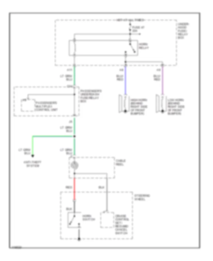
Horn Wiring Diagram for Honda Odyssey EX 1999
List of elements for Horn Wiring Diagram for Honda Odyssey EX 1999:
- A11
- Anti-theft system
- C14
- Cable reel
- Cruise control set/ resume/ cancel switch
- Fuse 47 20a
- High horn (behind right side of front bumper)
- Horn relay
- Horn switch
- Hot at all times
- Low horn (behind right side of front bumper)
- Passenger's multiplex control unit
- Passenger's underdash fuse/relay box
- Red
- Steering wheel
- Under- hood fuse/ relay box
INSTRUMENT CLUSTER
Instrument Cluster Wiring Diagram (1 of 2) for Honda Odyssey EX 1999
List of elements for Instrument Cluster Wiring Diagram (1 of 2) for Honda Odyssey EX 1999:
- (1999-00)
- (2001) e14
- (behind right side of dash) g201
- (canada)
- (check)
- (ex & 2001 lx)
- (left side of "b" pillar) g308
- 1999-00
- A/t gear position switch (on transaxle end cover)
- A10
- A11
- A12
- A13
- A14
- A18
- A19
- Abs indicator circuit
- Abs indicator light
- Abs-tcs control unit (below left side of dash)
- Anti-lock brakes system
- Anti-theft system
- B10
- B11
- B12
- B13
- B14
- B15
- B16
- B17
- B18
- B19
- B20
- B21
- B22
- Brake system indicator light
- C10
- C11
- C12
- C13
- C14
- C15
- C16
- Canada
- Charging system indicator light
- Cruise control indicator light
- Cruise control system
- D4 ind ctrl
- D4 input
- Door locks system
- Driver's underdash fuse/relay box (below left end of dash)
- E26
- E29
- Engine coolant temperature (ect) sending unit (at top rear of engine, on water jacket)
- Engine coolant temperature gauge
- Exterior lights system
- Exterior lights systems
- Fuel gauge
- Fuel gauge drive circuit
- Fuel gauge sending unit
- Fuel tank unit
- Fuse 13 7.5a
- Fuse 6 15a
- Fuse 9 10a
- G115 (rear of engine)
- Gauge assembly
- H15
- H16
- Headlights system
- High beam indicator light
- Hot at all times
- Hot in on or start
- I12
- Immob ind ctrl
- Immobilizer indicator light
- Interior lights system
- Interior lights systems
- J/c c106 (behind heater lower cover, driver's side)
- Low engine oil pressure indicator light
- Low fuel indicator light
- Maintenance required indicator light
- Malfunction indicator light
- Mil ctrl
- Mtrtw
- Odo/trip display
- Odometer/ trip/ maintenance/ washer circuit
- Passenger's underdash fuse/relay box (behind right kick panel)
- Pnk
- Powertrain control module (pcm) (behind lower center of dash)
- Red
- Rpm output
- Seat belt reminder light
- Security indicator
- Sliding door indicator light
- Speedo- meter
- Speedo- meter drive circuit
- Srs indicator circuit
- Srs indicator light
- Starting/charging system
- Tacho- meter
- Tacho- meter drive circuit
- Test tachometer connector (rear of engine compt, on top of brake booster)
- To safety indicator circuit
- To stabilizing power circuit (diagram 2 of 2)
- To turn signal indicators (diagram 2 of 2)
- Trip/ maintenance reset switch
- Trunk, tailgate, fuel doors system
- Vss out
- Washer indicator light (canada)
Instrument Cluster Wiring Diagram (2 of 2) for Honda Odyssey EX 1999
List of elements for Instrument Cluster Wiring Diagram (2 of 2) for Honda Odyssey EX 1999:
- (behind right rear side trim panel) right power sliding door control unit
- (left rear of engine compt) g116
- (left side "b" pillar) g308
- 1 (or 2)
- 2 (or 1)
- A/t gear position indicator
- A10
- A11
- A14
- A16
- A18
- A20
- B10
- B13
- B15
- B17
- B22
- Brake fluid level switch (in brake fluid reservoir cap)
- C12
- C13
- C15
- C16
- Canada
- Dash lights brightness controller
- Daytime running lights (drl) control unit (behind center of dash)
- Dimming circuit
- Driver's door switch
- Driver's multiplex control unit
- Driver's seat belt switch (on driver's seat belt buckle)
- Driver's underdash fuse/relay box (below left end of dash)
- Drl indicator light
- Engine oil pressure switch (on front of engine, on right side of oil pump housing)
- From pin b11 (diagram 1 of 2)
- From pin b16 (diagram 1 of 2)
- Front passenger's door switch
- G101 (right front of engine compt)
- Gauge assembly
- Gauge lights (6 bulbs)
- I14
- I15
- I16
- Indicators
- K12
- Lcd back light
- Left power sliding door control unit (behind left rear side trim panel)
- Left sliding door switch
- Left turn signal indicator light
- Nca
- Parking brake switch (on parking brake pedal assembly)
- Passenger's underdash fuse/relay box (behind right kick panel)
- Pnk
- Red
- Right sliding door switch
- Right turn signal indicator light
- Safety indicator circuit
- Solid state
- Stabilizing power circuit
- Tcs indicator light
- Washer fluid level switch (at washer fluid reservoir)
INTERIOR LIGHTS
Courtesy Lamps Wiring Diagram for Honda Odyssey EX 1999
List of elements for Courtesy Lamps Wiring Diagram for Honda Odyssey EX 1999:
- (below left side of dash) g202
- (not used)
- (not used) c402
- A10
- A14
- A15
- A16
- A17
- A19
- A21
- Cargo area light
- Driver's door switch
- Driver's multiplex control unit
- Driver's underdash fuse/relay box (below left end of dash)
- F10
- Front individual map light
- Front passenger's door switch
- Fuse 11 10a
- G202 (left side of dash)
- G404 (behind left rear side trim panel)
- G405 (behind right rear side trim panel)
- Gauge assembly
- Home- link unit
- Hot at all times
- I14
- I15
- I19
- Interior lights relay (behind left side of dash)
- Interior lights switch
- Interior lights switch light
- Interior lights system (instrument illumination circuit)
- Left
- Left middle individual map light
- Left rear individual map light
- Left sliding door switch
- Passenger's multiplex control unit
- Passenger's underdash fuse/relay box (behind right kick panel)
- Pnk
- Red
- Right
- Right middle individual map light
- Right rear individual map light
- Right sliding door switch
- Tailgate latch switch
Entry Light Timer Wiring Diagram for Honda Odyssey EX 1999
List of elements for Entry Light Timer Wiring Diagram for Honda Odyssey EX 1999:
- (not used)
- A10
- A13
- A14
- A15
- A16
- A17
- A19
- A21
- A22
- A24
- Cargo area light
- Door multiplex control unit
- Driver's door lock knob switch
- Driver's door switch
- Driver's multiplex control unit
- Driver's underdash fuse/relay box (below left end of dash)
- F10
- Front individual map light
- Front passenger's door switch
- Fuse 11 10a
- Fuse 47 20a
- Fuse 9 10a
- G14
- G202 (left side of dash)
- Home- link unit
- Hot at all times
- Hot in on or start
- Hot w/ headlight switch in park or head
- Ignition key light
- Ignition key switch
- Ignition key switch/ key light
- Interior lights relay (behind left side of dash)
- Interior lights switch
- Left
- Left middle individual map light
- Left rear individual map light
- Left sliding door switch
- Passenger's multiplex control unit
- Passenger's underdash fuse/relay box (behind right kick panel)
- Pnk
- Right
- Right middle individual map light
- Right rear individual map light
- Right sliding door switch
- Steering lock
- Taillight relay (behind left side of dash)
- Underhood fuse/relay box (right side of engine compartment)
Instrument Illumination Wiring Diagram for Honda Odyssey EX 1999
List of elements for Instrument Illumination Wiring Diagram for Honda Odyssey EX 1999:
- (not used)
- A/t gear position indicator
- A19
- A20
- Audio unit
- B10
- B11
- B16
- B22
- Center pocket light (ex)
- Climate control unit
- Clock
- Combination light switch
- Cruise control main switch
- Dash lights brightness controller
- Dimmer
- Driver's multiplex control unit
- Driver's underdash fuse/relay box (below left end of dash)
- Driver's vanity mirror light
- Front passenger's vanity mirror light
- Fuse 10 15a
- Fuse 9 7.5a
- G202 (left side of dash)
- G405 (behind right rear side trim panel)
- Gauge assembly
- Gauge lights (6 bulbs)
- Hazard warning switch
- Head
- Headlight switch
- Heater control panel
- Hot at all times
- Hot in on or start
- I13
- Interior lights switch
- K15
- K16
- Lcd back light
- Off
- Park
- Passenger's underdash fuse/relay box (behind right kick panel)
- Power sliding door switch (ex)
- Rear heater- a/c control dial (front)
- Rear heater- a/c passenger control panel (rear)
- Red
- Stabilizing power circuit
- Taillight relay (behind left side of dash)
- Tcs switch (ex)
POWER DISTRIBUTION
Power Distribution Wiring Diagram (1 of 4) for Honda Odyssey EX 1999
List of elements for Power Distribution Wiring Diagram (1 of 4) for Honda Odyssey EX 1999:
- (1999-00)
- (2001)
- (not used)
- 1999-00 lx
- A/t gear position switch
- A11
- A13
- A17
- A24
- Abs control unit
- Abs-tcs control unit
- Acc
- Alternator
- B14
- Battery
- C22
- Canada
- Data link connector
- Daytime running lights (drl) control unit (canada)
- Driver's multiplex control unit
- Driver's underdash fuse/relay box
- E12
- E16
- Electrical load detector (eld) unit
- Ex & 2001 lx
- Fuse 13 7.5a
- Fuse 4 7.5a
- Fuse 41 120a
- Fuse 42 50a
- Fuse 46 15a
- Fuse 5 7.5a (canada)
- Fuse 52 30a
- Fuse 53 30a
- Fuse 60 40a
- Fuse 61 30a
- Fusible link
- G17
- Ignition switch
- J/c c107
- K18
- Left power sliding door control unit
- Lock
- Multi-fuse/ relay box (left front of engine compt)
- O12
- O15
- Option connector
- Passenger's underdash fuse/relay box
- Pgm-fi main relay
- Power mirror switch
- Powertrain control module (pcm)
- Q10
- Q14
- Rear blower motor
- Rear window defogger relay
- Red
- Right power sliding door control unit
- Start
- Starter
- Starter cut relay
- Starter solenoid
- T101
- T102
- To cigarette lighter in-line fuse (diagram 3 of 4)
- To fuse 3 (diagram 2 of 4)
- To fuse 47 (diagram (2 of 4)
- To fuse 56 (diagram 2 of 4)
- To fuse 6 (diagram 2 of 4)
- To fuse 8 (diagram 3 of 4)
- Underhood fuse/relay box (right side of engine compt)
Power Distribution Wiring Diagram (2 of 4) for Honda Odyssey EX 1999
List of elements for Power Distribution Wiring Diagram (2 of 4) for Honda Odyssey EX 1999:
- (1999-00)
- (2001)
- (not used)
- (right side of engine compt) underhood fuse/relay box
- (w/ nav)
- (w/o nav)
- A/c compressor clutch relay
- Abs fail-safe relay
- Abs pump motor relay
- Alternator
- B13
- B24
- Brake pedal position switch
- C10
- Climate control panel
- Climate control unit
- Coil
- Condenser fan relay
- Cruise control main switch
- Cruise control unit
- D15
- Driver's underdash fuse/relay box
- E13
- Electrical load detector (eld) unit
- Engine mount control solenoid valve
- Evaporative emission (evap) bypass solenoid valve
- Evaporative emission (evap) canister purge valve
- Evaporative emission (evap) canister vent shut valve
- Fan control relay
- From a fuse 41 (diagram 1 of 4)
- From b fuse 42 (diagram 1 of 4)
- From fuse 4 e (diagram 1 of 4)
- From ignition switch (diagram 1 of 4)
- Front blower motor high relay
- Front blower motor relay
- Fuse 1 15a
- Fuse 2 10a
- Fuse 3 7.5a
- Fuse 47 20a
- Fuse 48 20a
- Fuse 49 15a
- Fuse 50 30a
- Fuse 56 40a
- Fuse 57 30a
- Fuse 58 30a
- Fuse 59 7.5a
- Fuse 6 15a
- Gauge assembly
- Hazard warning switch
- Heater control panel
- Horn relay
- I12
- I15
- Ignition key light
- Ignition key switch/ key light
- J/c c107
- K11
- K15
- Key interlock switch
- O13
- O14
- Passenger's underdash fuse/relay box
- Pgm-fi main relay
- Powertrain control module (pcm)
- Primary heated oxygen sensor (ho2s)
- Radiator fan relay
- Rear blower motor high relay
- Rear blower motor low relay
- Rear blower motor main relay
- Rear blower motor middle relay
- Rear heater-a/c mode control motor
- Rear heater-a/c passenger control panel (rear)
- Rear mode control motor relay
- Rear window defogger relay
- Recirculation control motor
- Secondary heated oxygen sensor (ho2s)
- Srs unit
- To fuse 51 (diagram 3 of 4)
- To fuse 7 (diagram 4 of 4)
- Underhood fuse/relay box (right side of engine compt)
- Vehicle speed pulse (vsp) sensor
- W/ nav
- W/ navigation
Power Distribution Wiring Diagram (3 of 4) for Honda Odyssey EX 1999
List of elements for Power Distribution Wiring Diagram (3 of 4) for Honda Odyssey EX 1999:
- (ex)
- (not used)
- 15a
- 20a (ex)
- 40a
- A1 (2001)
- A10
- A11
- A12
- A14
- A19
- A23
- A24
- A25
- Accessory power socket relay
- Ashtray light
- Audio unit
- B20
- B21
- B21 (1999-00)
- C15
- C403
- Cargo area light
- Cigarette lighter
- Cigarette lighter in-line fuse
- Cigarette lighter relay
- Climate control unit
- Clock (w/o navigation)
- Coil
- Combination light switch
- Daytime running lights (drl) control unit (canada)
- Door multiplex control unit
- Driver's multiplex control unit
- Driver's underdash fuse/relay box
- Ex w/o navigation
- F10
- From battery (diagram 1 of 4)
- From fuse 59 (diagram 2 of 4)
- From fuse 9 (diagram 3 of 4)
- From ignition switch (diagram 1 of 4)
- Front accessory power socket
- Front ashtray
- Front individual map light
- Fuel fill door relay
- Fuel fill door switch
- Fuse 1
- Fuse 10 15a
- Fuse 11 10a
- Fuse 12 20a
- Fuse 13 7.5a
- Fuse 2 20a
- Fuse 3 10a
- Fuse 4 20a
- Fuse 5 20a
- Fuse 51
- Fuse 54 40a
- Fuse 55 40a
- Fuse 6 10a (canada)
- Fuse 8 7.5a
- Fuse 9 15a
- G202 (below left side of dash)
- G305 (right side of "b" pillar)
- G404 (behind left rear side trim panel)
- Gauge assembly
- H11
- H13
- H15
- H16
- Headlight relay 1
- Headlight relay 2
- Heater control panel
- I18
- Interior lights
- Interior lights relay
- J12
- J16
- Keyless receiver unit (ex)
- Left middle individual map light
- Left power sliding door control unit (ex)
- Left rear individual map light
- Navigation display unit
- Navigation unit
- O11
- O19
- Option connector
- Passenger's multiplex control unit
- Passenger's underdash fuse/relay box
- Power seat adjustment switch (ex)
- Power window relay
- Powertrain control module (pcm)
- Rear accessory power socket
- Red
- Right middle individual map light
- Right power sliding door control unit (ex)
- Right rear individual map light
- Security system connector (accessory)
- Taillight relay
- Tcs relay (ex)
- To accessory power socket relay (diagram 3 of 4)
- Underhood fuse/relay box (right side of engine compt)
Power Distribution Wiring Diagram (4 of 4) for Honda Odyssey EX 1999
List of elements for Power Distribution Wiring Diagram (4 of 4) for Honda Odyssey EX 1999:
- (1999-00 only)
- (2001 only)
- (not used)
- (w/ navigation)
- (w/o navigation)
- 1999-00
- A13
- A16
- A22
- A24
- B11
- Brake light failure sensor
- Canada
- Clock (w/o navigation)
- Coil
- Driver's multiplex control unit
- Driver's underdash fuse/relay box
- E11
- From fuse 6 j (diagram 2 of 4)
- Fuse 10 7.5a
- Fuse 11 15a
- Fuse 12 30a
- Fuse 7 10a
- Fuse 9 10a
- Gauge assembly
- Hazard warning switch
- Ignition coil
- Intermittent wiper relay
- J/c c105 (lower left rear of engine compt)
- Keyless receiver unit (ex)
- Left power sliding door control unit (ex)
- Passenger's multiplex control unit
- Passenger's underdash fuse/relay box
- Rear wiper motor
- Rear wiper/ washer switch
- Reverse relay
- Right power sliding door control unit (ex)
- Shift lock solenoid
- Tcs switch (ex)
- Windshield wiper motor
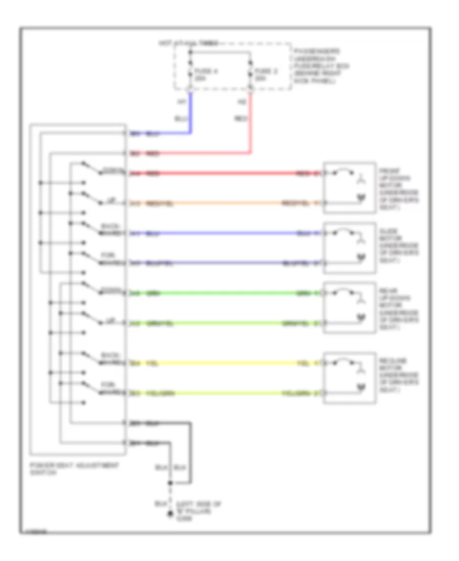
- Windshield wiper/ washer switch
- Wiper/ washer switch
POWER DOOR LOCKS
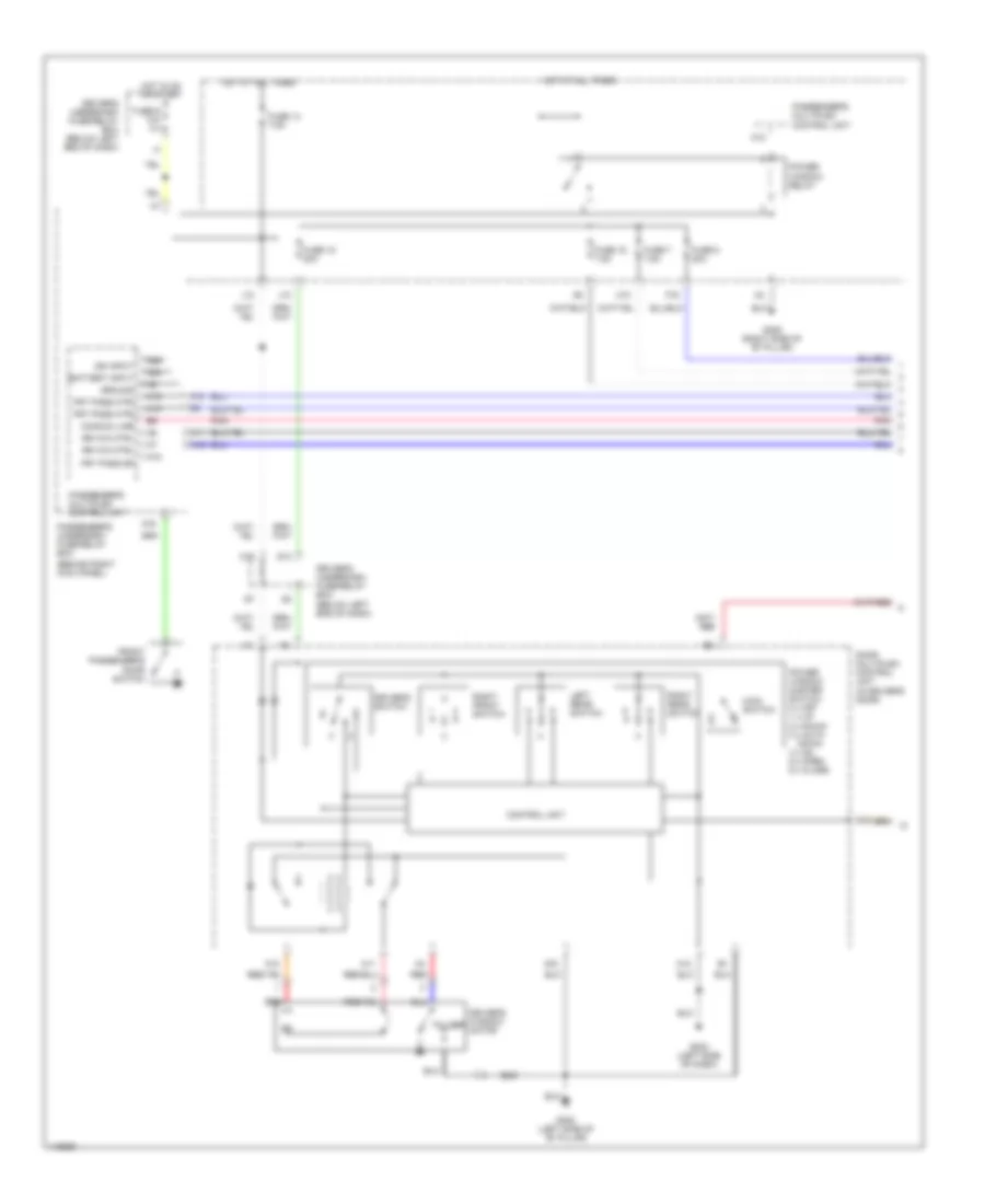
Power Door Lock Wiring Diagram, EX with Anti-theft (1 of 2) for Honda Odyssey EX 1999
List of elements for Power Door Lock Wiring Diagram, EX with Anti-theft (1 of 2) for Honda Odyssey EX 1999:
- 10a
- 15a
- 20a
- 7.5a
- A10
- A12
- A13
- A14
- A15
- A16
- A17
- A18
- A20
- A22
- A23
- A24
- B11
- B16
- B22
- Battery in
- Battery input
- Comm line
- Cylinder
- Disarm switch
- Door key
- Dr door sw
- Driver's door switch
- Driver's multiplex control unit
- Driver's underdash fuse/relay box (below left end of dash)
- Exterior lights system
- F pass dr sw
- Front
- Front pass door switch
- Front passenger's door lock switch
- Fuse 10
- Fuse 12
- Fuse 13
- Fuse 9
- G101 (right front of engine compt)
- G14
- G200 (behind left kick panel)
- G201 (behind right side of dash)
- G202 (below left side of dash)
- G202 (left side of dash)
- G305 (right side of "b" pillar)
- Ground
- Hood switch
- Horns
- Horns system
- Hot at all times
- Hot in on or start
- Ign input
- Ignition input
- Ignition key switch
- In-line fuse 1 (behind left side of dash)
- In-line fuse 2 (behind left side of dash)
- J12
- J14 red
- Key in ign input
- Keyless receiver unit (behind right end of dash)
- Left power sliding door control unit
- Left sliding door switch
- Lft slide dr sw
- Light flasher relay
- Lock
- Lt sliding door control
- O19
- Panic
- Pass key sw
- Pass lck sw
- Passenger's
- Passenger's multiplex control unit
- Passenger's underdash fuse/relay box (behind right kick panel)
- Pnk
- R slid dr sw
- Red
- Right power sliding door control unit
- Right side of dash) g201
- Right sliding door switch
- Rt sliding door control
- Security control unit (behind dash, right of steering column)
- Security diode
- Security diode (behind right kick panel)
- Security indicator
- Security led
- Shift interlock system
- Steering lock
- Switch
- Taillight relay
- Transmitter
- Unlock
Power Door Lock Wiring Diagram, EX with Anti-theft (2 of 2) for Honda Odyssey EX 1999
List of elements for Power Door Lock Wiring Diagram, EX with Anti-theft (2 of 2) for Honda Odyssey EX 1999:
- (below left end of dash) driver's underdash fuse/relay box
- A11
- A12
- A15
- A16
- A17
- A18
- A21
- B11
- Battery in
- C14
- Comm line
- Door multiplex control unit (in driver's door)
- Dr key cyl sw
- Dr lck knob sw
- Dr lck sw
- Driver's door key cylinder switch
- Driver's door lock actuator
- Driver's door lock knob switch
- Driver's door lock switch
- Driver's underdash fuse/relay box (below left end of dash)
- Exterior lights system
- F17
- Front passenger's door lock actuator
- Fuel fill door relay
- Fuel fill door switch
- Fuse 20a
- G202 (left side of dash)
- G308 (left side of "b" pillar)
- G404 (behind left rear side trim panel)
- Ground
- Horn systems
- Hot at all times
- I18
- Interior lights system
- K13
- Left junction i
- Left junction switch
- Left sliding door lock knob switch/ actuator
- Light flasher relay (below left side of dash)
- Lock
- Lock key cylinder
- Passenger's multiplex control unit
- Passenger's underdash fuse/relay box (behind right kick panel)
- Pnk
- Red
- Right junction switch
- Right junction switch h
- Right sliding door lock actuator
- Sliding door lock control unit (in left sliding door)
- Switch
- Tailgate
- Tailgate lock actuator
- Unlock
Power Door Lock Wiring Diagram, EX without Anti-theft (1 of 2) for Honda Odyssey EX 1999
List of elements for Power Door Lock Wiring Diagram, EX without Anti-theft (1 of 2) for Honda Odyssey EX 1999:
- 10a
- 20a
- 7.5a
- A10
- A12
- A13
- A14
- A15
- A16
- A17
- A18
- A20
- A21
- A22
- A23
- A24
- B11
- B16
- B22
- Battery in
- Battery input
- Comm line
- Cylinder
- Door key
- Dr door sw
- Driver's door switch
- Driver's multiplex control unit
- Driver's underdash fuse/relay box (below left end of dash)
- Exterior lights system
- F pass dr sw
- Front
- Front passenger's door lock switch
- Front passenger's door switch
- Fuse 12
- Fuse 13
- Fuse 9
- G14
- G201 (behind right side of dash)
- G202 (below left side of dash)
- G202 (left side of dash)
- G305 (right side of "b" pillar)
- Ground
- Horn ctrl
- Horn system
- Hot at all times
- Hot in on or start
- Ign input
- Ignition input
- Ignition key switch
- Int light
- Interior lights
- J12
- Key in ign input
- Keyless receiver unit (behind right end of dash)
- Left power sliding door control unit
- Left sliding door switch
- Lft slide dr sw
- Lock
- Lt sliding door control
- O19
- Panic
- Pass key sw
- Pass lck sw
- Passenger's
- Passenger's multiplex control unit
- Passenger's underdash fuse/relay box (behind right kick panel)
- Pink
- Pnk
- R slid dr sw
- Right power sliding door control unit
- Right sliding door switch
- Rt sliding door control
- Steering lock
- Switch
- Taillight relay
- Transmitter
- Unlock
Power Door Lock Wiring Diagram, EX without Anti-theft (2 of 2) for Honda Odyssey EX 1999
List of elements for Power Door Lock Wiring Diagram, EX without Anti-theft (2 of 2) for Honda Odyssey EX 1999:
- 20a
- A10
- A11
- A12
- A15
- A16
- A17
- A18
- A20
- B11
- Battery in
- Comm line
- Door multiplex control unit (in driver's door)
- Dr key cyl sw
- Dr lck knob sw
- Dr lck sw
- Driver's door key cylinder switch
- Driver's door lock actuator
- Driver's door lock knob switch
- Driver's door lock switch
- Driver's underdash fuse/relay box (below left end of dash)
- F15
- F17
- Front passenger's door lock actuator
- Fuel fill door relay
- Fuel fill door switch
- Fuse 12
- G202 (left side of dash)
- G308 (left side of "b" pillar)
- G404 (behind left rear side trim panel)
- Ground
- Hot at all times
- I18
- J14
- K13
- Left junction i
- Left junction switch
- Left sliding door lock knob switch/ actuator
- Lock
- Passenger's multiplex control unit
- Passenger's underdash fuse/relay box (behind right kick panel)
- Pnk
- Red
- Right junction switch
- Right junction switch h
- Right sliding door lock actuator
- Sliding door lock control unit (in left sliding door)
- Switch
- Tailgate lock actuator
- Tailgate lock key cylinder switch
- Unlock
Power Door Lock Wiring Diagram, LX with Keyless Entry (1 of 2) for Honda Odyssey EX 1999
List of elements for Power Door Lock Wiring Diagram, LX with Keyless Entry (1 of 2) for Honda Odyssey EX 1999:
- 10a
- 15a
- 20a
- 7.5a
- A10
- A12
- A13
- A16
- A17
- A20
- A22
- A23
- A24
- B11
- B22
- Battery in
- Battery input
- Comm line
- Cylinder
- Disarm switch
- Door key
- Door switches output
- Dr door lck sw lck
- Dr door lck sw unlck
- Driver's door switch
- Driver's multiplex control unit
- Driver's underdash fuse/relay box (below left end of dash)
- F15
- Front
- Front passenger's door lock switch
- Front passenger's door switch
- Fuse 10
- Fuse 12
- Fuse 13
- Fuse 9
- G101 (right front of engine compt)
- G14
- G200 (behind left kick panel)
- G201 (behind right side of dash)
- G202 (below left side of dash)
- G202 (left side of dash)
- G305 (right side of "b" pillar)
- G404 (behind left rear side trim panel)
- Gauge assembly
- Ground
- Hood switch
- Horn system
- Horns system
- Hot at all times
- Hot in on or start
- Ign input
- Ignition input
- Ignition key switch
- Ignition key switch/key light
- In-line fuse 1 (behind left side of dash)
- In-line fuse 2 (behind left side of dash)
- In-line fuse 3 (behind left side of dash)
- Int lights sw input
- Interior lights system
- J12
- J14
- Key in ign input
- Keyless & security control unit (behind dash, right of steering column)
- Left sliding door switch
- Light flasher relay
- Lock
- O19
- Pass key sw
- Pass lck sw
- Passenger's
- Passenger's multiplex control unit
- Passenger's underdash fuse/relay box (behind right kick panel)
- Pnk
- Red
- Right sliding door switch
- Security indicator
- Security led
- Shift interlock system
- Switch
- Tailgate latch switch
- Unlock
- Unlock relay
- Unlock relay (below left side of dash)
Power Door Lock Wiring Diagram, LX with Keyless Entry (2 of 2) for Honda Odyssey EX 1999
List of elements for Power Door Lock Wiring Diagram, LX with Keyless Entry (2 of 2) for Honda Odyssey EX 1999:
- 20a
- A11
- A12
- A15
- A16
- A17
- A18
- Battery in
- Comm line
- Door multiplex control unit (in driver's door)
- Dr key cyl sw
- Dr lck knob sw
- Dr lck sw
- Driver's door key cylinder switch
- Driver's door lock actuator
- Driver's door lock knob switch
- Driver's door lock switch
- Driver's underdash fuse/relay box (below left end of dash)
- Exterior lights system
- F17
- Front passenger's door lock actuator
- Fuel fill door relay
- Fuel fill door switch
- Fuse 12
- G202 (left side of dash)
- G308 (left side of "b" pillar)
- G404 (behind left rear side trim panel)
- Ground
- Hot at all times
- I18
- K13
- Left junction i
- Left junction switch
- Left sliding door lock knob switch/ actuator
- Light flasher relay (below left side of dash)
- Lock
- Lock key cylinder
- Passenger's multiplex control unit
- Passenger's underdash fuse/relay box (behind right kick panel)
- Pnk
- Right junction switch
- Right junction switch h
- Right sliding door lock actuator
- Sliding door lock control unit (in left sliding door)
- Switch
- Tailgate
- Tailgate lock actuator
- Unlock
Power Door Lock Wiring Diagram, LX without Keyless Entry (1 of 2) for Honda Odyssey EX 1999
List of elements for Power Door Lock Wiring Diagram, LX without Keyless Entry (1 of 2) for Honda Odyssey EX 1999:
- (not used)
- 10a
- 20a
- 7.5a
- A10
- A12
- A13
- A16
- A17
- A20
- A22
- A23
- A24
- B11
- B22
- Battery in
- Battery input
- C402
- Comm line
- Door lock
- Driver's multiplex control unit
- Driver's underdash fuse/relay box (below left end of dash)
- F15
- Front
- Front passenger's door key cylinder switch
- Fuse 12
- Fuse 13
- Fuse 9
- G14
- G201 (behind right side of dash)
- G202 (below left side of dash)
- G202 (left side of dash)
- G305 (right side of "b" pillar)
- Ground
- Hot at all times
- Hot in on or start
- Ign input
- Ignition key switch
- Ignition key switch/ key light
- J12
- J14
- Key in ign input
- Lock
- O19
- Pass key sw
- Pass lck sw
- Passenger's
- Passenger's multiplex control unit
- Passenger's underdash fuse/relay box (behind right kick panel)
- Pnk
- Switch
- Unlock
Power Door Lock Wiring Diagram, LX without Keyless Entry (2 of 2) for Honda Odyssey EX 1999
List of elements for Power Door Lock Wiring Diagram, LX without Keyless Entry (2 of 2) for Honda Odyssey EX 1999:
- 20a
- A11
- A12
- A15
- A16
- A17
- A18
- Battery in
- Comm line
- Door multiplex control unit (in driver's door)
- Dr key cyl sw
- Dr lck knob sw
- Dr lck sw
- Driver's door key cylinder switch
- Driver's door lock actuator
- Driver's door lock knob switch
- Driver's door lock switch
- Driver's underdash fuse/relay box (below left end of dash)
- F17
- Front passenger's door lock actuator
- Fuel fill door relay
- Fuel fill door switch
- Fuse 12
- G202 (left side of dash)
- G308 (left side of "b" pillar)
- G404 (behind left rear side trim panel)
- Ground
- Hot at all times
- I18
- K13
- Left junction i
- Left junction switch
- Left sliding door lock knob switch/actuator
- Lock
- Passenger's multiplex control unit
- Passenger's underdash fuse/relay box (behind right kick panel)
- Pnk
- Right junction switch
- Right junction switch h
- Right sliding door lock actuator
- Sliding door lock control unit (in left sliding door)
- Switch
- Tailgate lock actuator
- Tailgate lock key cylinder switch
- Unlock
POWER MIRRORS
Power Mirror Wiring Diagram, Canada for Honda Odyssey EX 1999
List of elements for Power Mirror Wiring Diagram, Canada for Honda Odyssey EX 1999:
- Defogger
- Defogger system
- Down switch
- Driver's underdash fuse/relay box (below left end of dash)
- F11
- F19
- Fuse 4 7.5a
- G11
- G15
- G202 (below left side of dash)
- Hot in on
- K12
- K13
- Left
- Left mirror
- Left switch
- Left/right
- Mirror defogger switch
- Mirror selector switch
- O15
- O16
- O17
- O18
- Passenger's underdash fuse/relay box (behind right kick panel)
- Power mirror switch
- Right
- Right mirror
- Right switch
- Up switch
- Up/down
Power Mirror Wiring Diagram, USA for Honda Odyssey EX 1999
List of elements for Power Mirror Wiring Diagram, USA for Honda Odyssey EX 1999:
- Down switch
- Driver's underdash fuse/relay box (below left end of dash)
- F11
- F19
- Fuse 4 7.5a
- G11
- G15
- G202 (below left side of dash)
- Hot in on
- K12
- K13
- Left
- Left mirror
- Left switch
- Left/right
- Mirror selector switch
- O15
- O16
- O17
- O18
- Passenger's underdash fuse/relay box (behind right kick panel)
- Power mirror switch
- Right
- Right mirror
- Right switch
- Up switch
- Up/down
POWER SEATS
Power Seat Wiring Diagrams for Honda Odyssey EX 1999
List of elements for Power Seat Wiring Diagrams for Honda Odyssey EX 1999:
- (left side of "b" pillar) g308
- Back- ward
- Down
- For- ward
- Front up-down motor (underside of driver's seat)
- Fuse 2 20a
- Fuse 4 20a
- Hot at all times
- Passenger's underdash fuse/relay box (behind right kick panel)
- Power seat adjustment switch
- Rear up-down motor (underside of driver's seat)
- Recline motor (underside of driver's seat)
- Red
- Slide motor (underside of driver's seat)
POWER WINDOWS
Power Window Wiring Diagram (1 of 2) for Honda Odyssey EX 1999
List of elements for Power Window Wiring Diagram (1 of 2) for Honda Odyssey EX 1999:
- (behind right kick panel)
- A10
- A11
- A12
- A15
- A16
- A18
- A19
- A22
- A24
- Battery input
- Commun line
- Control unit
- Door multiplex control unit (in driver's door)
- Driver's switch
- Driver's underdash fuse/relay box (below left end of dash)
- Driver's window motor
- F16
- F18
- Front passenger's door switch
- Frt pass ctrl
- Frt pass dr
- Fuse 13 7.5a
- Fuse 15 20a
- Fuse 16 7.5a
- Fuse 7 7.5a
- Fuse 8 20a
- Fuse 9 10a
- G202 (left side of dash)
- G305 (right side of "b" pillar)
- G308 (left side of "b" pillar)
- Ground
- H10
- Hot at all times
- Hot in on or start
- Ign input
- J10
- J12
- Left rear switch
- Main switch
- O19
- Passenger's multiplex control unit
- Passenger's underdash fuse/relay box
- Pnk
- Power window master switch 0 = off 1 = up 2 = down 3 = auto down 4 = on 5 = open 6 = close
- Power window relay
- Pulser
- Q13
- Red
- Right front switch
- Right rear switch
- Rr win ctrl
Power Window Wiring Diagram (2 of 2) for Honda Odyssey EX 1999
List of elements for Power Window Wiring Diagram (2 of 2) for Honda Odyssey EX 1999:
- (left side of dash) g202
- A12
- A14
- A16
- A19
- A24
- B11
- Battery input
- Commun line
- Dr door open
- Driver's door switch
- Driver's multiplex control unit
- Driver's underdash fuse/relay box (below left end of dash)
- F14
- Front passenger's window motor
- Front passenger's window switch o = off 1 = down 2 = up
- Fuse 13 7.5a
- Fuse 9 10a
- G14
- Ground
- Hot at all times
- Hot in on or start
- Ign on in
- J12
- Left rear power quarter window close relay
- Left rear power quarter window motor
- Left rear power quarter window open relay
- Lr win ctrl
- O19
- Passenger's underdash fuse/relay box (behind right kick panel)
- Pnk
- Q15
- Q16
- Right rear power quarter window close relay
- Right rear power quarter window motor
- Right rear power quarter window open relay
RADIO
Radio Wiring Diagrams, with CD for Honda Odyssey EX 1999
List of elements for Radio Wiring Diagrams, with CD for Honda Odyssey EX 1999:
- (not used)
- A10
- Accessory socket relay
- Antenna
- Audio unit
- Cable reel
- Cd player or cd changer
- Driver's door speaker
- Driver's underdash fuse/relay box
- F12
- F13
- Front passenger's door speaker
- Fuse 10a
- Fuse 15a
- Fuse 7.5a
- G12
- G13
- G301 (below front passenger's seat, under carpet)
- G302 (above left side of lower heater cover)
- H11
- H13
- Hot at all times
- Hot in acc or on
- I10
- I11
- I1o
- Interior lights system
- J16
- Left rear speaker
- Left tweeter (ex)
- Nca
- O11
- Passenger's underdash fuse/relay box
- Radio remote switch
- Red
- Right rear speaker
- Right tweeter (ex)
- Seek up
- Steering wheel
- Volume down
- Volume up
Radio Wiring Diagrams, with Cassette Deck for Honda Odyssey EX 1999
List of elements for Radio Wiring Diagrams, with Cassette Deck for Honda Odyssey EX 1999:
- (not used)
- A10
- Accessory socket relay
- Antenna
- Audio unit
- Cable reel
- Cassette player
- Driver's door speaker
- Driver's underdash fuse/relay box
- F12
- F13
- Front passenger's door speaker
- Fuse 10a
- Fuse 15a
- Fuse 7.5a
- G12
- G13
- G302 (above left side of lower heater cover)
- G305 (right side of "b" pillar)
- H11
- H13
- Hot at all times
- Hot in acc or on
- I10
- I11
- I1o
- Interior lights system
- J16
- Left rear speaker
- Left tweeter (ex)
- Nca
- O11
- Passenger's underdash fuse/relay box
- Radio remote switch
- Red
- Right rear speaker
- Right tweeter (ex)
- Seek up
- Steering wheel
- Volume down
- Volume up
SHIFT INTERLOCKS
Shift Interlock Wiring Diagram for Honda Odyssey EX 1999
List of elements for Shift Interlock Wiring Diagram for Honda Odyssey EX 1999:
- (1999-00)
- (2001)
- (not used)
- A/t gear position switch (on transaxle end cover)
- A15
- A28
- A32
- B12
- B22
- Brake pedal position switch (on brake pedal bracket)
- Brake sw in
- C27
- Cruise control system
- Driver's multiplex control unit
- Driver's underdash fuse/relay box
- E15
- E17
- Fuse 47 20a
- Fuse 9 7.5a
- G115 (rear of engine)
- G202 (left side of dash)
- Hot at all times
- Hot in on or start
- J/c c105 (lower left rear of engine compt)
- Key interlock solenoid
- Key interlock switch
- O20
- Parking pin switch (at top of steering column)
- Powertrain control module (pcm) (behind lower center of dash)
- Red
- Shft lk cir
- Shift lock solenoid (top of steering column)
- Steering lock
- Throttle position sensor (on side of throttle body assembly)
- Tps in
- Underhood fuse/relay box
STARTING/CHARGING
Charging Wiring Diagram for Honda Odyssey EX 1999
List of elements for Charging Wiring Diagram for Honda Odyssey EX 1999:
- 00)
- A19 (2001)
- A30
- Alt ctrl sig
- Alt fr sig
- Alternator
- Battery
- C5 (1999-
- Charge system indicator light
- Driver's multiplex control unit (in driver's underdash fuse/relay box)
- Driver's under- dash fuse/ relay box (below left end of dash)
- E13
- E19
- Eld in- put
- Electrical load detector (eld) unit
- Engine controls system
- Fuse 41 120a
- Fuse 6 15a
- G101 (right front of engine compt)
- G106 (left front of engine compt)
- Gauge assembly
- Ground
- Hot in on or start
- I12
- Ignition input
- J/c c107 (behind heater lower cover, driver's side)
- Load output
- Passenger's underdash fuse/relay box (behind right kick panel)
- Power distribution system
- Powertrain control module (behind lower center of dash)
- Starter solenoid
- T101
- T102
- Trans- mission
- Underhood fuse/relay box (right side of engine compt)
Starting Wiring Diagram for Honda Odyssey EX 1999
List of elements for Starting Wiring Diagram for Honda Odyssey EX 1999:
- (1999-00)
- (2001)
- (behind lower center of dash) powertrain control module
- (not used)
- (rear of engine) g115
- A/t gear position switch (on transaxle end cover)
- Acc (i)
- B14
- Battery
- C22
- Driver's underdash fuse/relay box (below left end of dash)
- E12
- Elec- trical load de- tector (eld) unit
- Fuse 120a
- Fuse 42 50a
- G106 (left front of engine compt)
- Hd in
- Ignition switch
- J/c c107 (behind heater lower cover, driver's side)
- Lock (0)
- On (ii)
- Pl in
- Power distribution system
- Start (iii)
- Starter
- Starter cut relay
- Starter motor
- Starter solenoid
- Trans- mission
- Under- hood fuse/ relay box (right side of engine compt)
SUPPLEMENTAL RESTRAINTS
Supplemental Restraint Wiring Diagram for Honda Odyssey EX 1999
List of elements for Supplemental Restraint Wiring Diagram for Honda Odyssey EX 1999:
- (behind right side of glove box) g201
- Air bag ctrl
- B11
- B16
- Cable reel
- Data
- Data link connector (dlc) (partial) (below left side of dash)
- Driver's air bag
- Driver's seat belt tensioner
- Driver's underdash fuse/relay box (below left end of dash)
- Front passenger's air bag
- Front passenger's seat belt tensioner
- Fuse 1 15a
- Fuse 2 10a
- Fuse 9 10a
- G206 (below center of dash)
- Gauge assembly
- Ground
- Hot in on or start
- Ignition
- Indicator ctrl
- Mes conn input
- Red
- Srs indicator
- Srs indicator circuit
- Srs memory erase signal (mes) connector (in driver's underdash fuse/relay box)
- Srs unit (behind lower center of dash)
- Steering wheel
- Tensioner ctrl
TRANSMISSION
A/T Wiring Diagram for Honda Odyssey EX 1999
List of elements for A/T Wiring Diagram for Honda Odyssey EX 1999:
- (on transaxle torque converter housing)
- 2nd clutch pressure switch (on transaxle) housing)
- 3rd clutch pressure switch (on transaxle) housing)
- A/t clutch pressure control solenoid valves (on transaxle) housing)
- A/t gear position indicators
- A/t gear position switch (on transaxle end cover)
- A10
- A14
- A28
- A32
- Atp1
- Atp2
- Atpd3
- Atpd4
- Atpr
- B10
- B11
- B14
- B16
- B17
- B18
- B20
- B21
- B22
- B24
- B25
- Bksw
- Box
- Braided
- Brake switch (on brake pedal bracket)
- C12
- C13
- C15
- C16
- Countershaft speed sensor (on transaxle) housing)
- Crs
- Cruise control system
- D10
- D11
- D12
- D13
- D14
- D15
- D16
- D4 ind
- Data link connector (below left side of dash)
- Dimming circuit
- Driver's multiplexing control unit
- Driver's under dash fuse/relay box
- Driver's under- dash fuse/ relay box
- E17
- Ect
- Engine coolant temperature sensor (top rear of eng, on water jacket)
- Fuse 15a
- Fuse 20a
- Fuse 9 10a
- G115 (rear of eng)
- G201 (behind left side of dash)
- Gauge assembly
- Hot at all times
- Hot in on or start
- Igp1
- Igp2
- Interior lights system
- J/c c105 (lower left rear of eng compt)
- J/c c106 (behind heater lower core)
- J/c c107 (behind heater lower core)
- K10
- Lg1
- Lg2
- Lock-up control solenoid valve
- Ls a+
- Ls a-
- Ls b+
- Ls b-
- Mainshaft speed sensor (on transaxle end cover)
- Ncsg
- Nmsg
- O19
- O20
- Op2sw
- Op3sw
- Passenger's under- dash fuse/ relay box
- Pg1
- Pg2
- Pgm-fi main relay (below left side of dash)
- Pnk
- Powertrain control module (behind lower center of dash)
- Red
- Scs
- Sg2
- Sh "b"
- Sh "c"
- Sha
- Shift control solenoid valve "a"
- Shift control solenoid valves (on transaxle) housing)
- Slu
- Throttle position sensor (on side of throttle body assembly)
- Tps
- Under- hood fuse/ relay
- Vbsol
- Vbu
- Vcc2
TRUNK, TAILGATE, FUEL DOOR
Power Sliding Door Wiring Diagram (1 of 2) for Honda Odyssey EX 1999
List of elements for Power Sliding Door Wiring Diagram (1 of 2) for Honda Odyssey EX 1999:
- (left side of "b" pillar) g308
- 2 =
- A10
- A11
- A12
- A13
- A14
- A15
- A16
- A17
- A18
- A19
- A20
- A21
- A22
- A23
- A24
- A25
- A26
- Atp
- B11
- Buzzer
- C302
- Clm (+)
- Clm (-)
- Close
- Closer motor
- Door
- Door locks system
- Drcl
- Driver's underdash fuse/relay box
- Drop
- F/l
- Fully latched
- Fuse 1 20a
- Fuse 13 7.5a
- Fuse 61 30a
- Fuse 9 10a
- G202 (below left side of dash)
- G404 (behind left rear side trim panel)
- Gauge assembly
- H/l
- H15
- Half latched
- Hndl
- Hot at all times
- Hot in on or start
- Ig1
- Illum
- Ind
- Interior lights system
- Kerq
- Kesg
- Latch position switch 1 =
- Left junction switch
- Left power sliding door control unit (behind left rear side trim panel)
- Left remote control switch/ release motor (in left sliding door)
- Left slide door
- Left slide motor (behind left rear side trim panel)
- Left slide motor revolution sensor (behind left rear side trim panel)
- Left sliding door handle switch
- Left sliding door latch (in left sliding door)
- Left sliding door switch (closed w/ door open)
- Main
- Main switch
- Multi- fuse/ relay box
- Open
- Passenger's underdash fuse/relay box
- Pgnd1
- Pgnd2
- Power sliding door switch
- R/c
- Red
- Release motor
- Rem (+)
- Remote control switch
- Right slide door
- Scom
- Segnd
- Sgnd
- Sliding door indicator
- Slmcl
- Slmop
- Slse1
- Slse2
- Vbu
- Vmp1
- Vmp2
- Vref
- Vss
Power Sliding Door Wiring Diagram (2 of 2) for Honda Odyssey EX 1999
List of elements for Power Sliding Door Wiring Diagram (2 of 2) for Honda Odyssey EX 1999:
- (1999-00)
- (2001)
- (right side of "b" pillar) g305
- 2 =
- A/t gear position switch (on transaxle cover)
- A10
- A11
- A12
- A13
- A14
- A15
- A16
- A17
- A18
- A19
- A20
- A21
- A22
- A23
- A24
- A25
- A26
- Atp
- Buzzer
- Clm (+)
- Clm (-)
- Closer motor
- Door
- Door locks system
- Drcl
- Driver's underdash fuse/relay box
- Drop
- E17
- E26
- F/l
- Fully latched
- Fuse 5 20a
- Fuse 52 30a
- G115 (rear of engine)
- G404 (behind left rear side trim panel)
- G405 (behind right rear side trim panel)
- H/l
- Half latched
- Hndl
- Hot at all times
- I18
- Ig1
- Ind
- K10
- Kerq
- Kesg
- Latch position switch 1 =
- Main
- Passenger's underdash fuse/relay box
- Pgnd1
- Pgnd2
- Powertrain control module (pcm) (behind lower center of dash)
- R/c
- Red
- Release motor
- Rem (+)
- Remote control switch
- Right junction switch
- Right power sliding door control unit (behind right rear side trim panel)
- Right remote control switch/ release motor (in right sliding door)
- Right slide motor (behind right rear side trim panel)
- Right slide motor revolution sensor (behind right rear side trim panel)
- Right sliding door handle switch
- Right sliding door latch (in right sliding door)
- Right sliding door switch (closed w/ door open)
- Scom
- Segnd
- Sgnd
- Sliding door buzzer (behind left rear side trim panel)
- Slmcl
- Slmop
- Slse1
- Slse2
- Underhood fuse/ relay box
- Vbu
- Vmp1
- Vmp2
- Vref
- Vss
- Vssout
WARNING SYSTEMS
Warning System Wiring Diagrams for Honda Odyssey EX 1999
List of elements for Warning System Wiring Diagrams for Honda Odyssey EX 1999:
- (ex)
- (not used) c402
- 1 (or 2)
- 10a
- 2 (or 1)
- A/c system
- A12
- A13
- A16
- A18
- A22
- A24
- Alternator
- Alternator in
- B11
- B16
- B17
- Battery
- Combination light switch
- Combination switch
- Door open in
- Driver's door switch
- Driver's multiplex control unit
- Driver's multiplex control unit (in driver's underdash fuse/relay box)
- Driver's seat belt switch
- Driver's underdash fuse/relay box (below left end of dash)
- Engine oil pressure switch (at front of engine, on right side of oil pump housing)
- Fuse 10 15a
- Fuse 13 7.5a
- Fuse 47 20a
- Fuse 9
- G202 (below left side of dash)
- G202 (left side of dash)
- G308 (left side of "b" pillar)
- Gauge assembly
- Ground
- Head
- Head- light switch
- Hot at all times
- Hot in on or start
- Ignition input
- Ignition key ligtht
- Ignition key switch
- Ignition key switch/ key light
- Interior lights system
- J12
- Key in ign
- Keyless receiver unit (behind right end of dash)
- Lights on input
- Low eng oil press ind
- O19
- Off
- Oil flash ctrl
- Park
- Passenger's underdash fuse/relay box (behind right kick panel)
- Seat belt sw in
- Taillight relay (behind left side of dash)
- Taillt rly ctrl
- Underhood fuse/relay box (right side of engine compt)
WIPER/WASHER
Front Washer/Wiper Wiring Diagram for Honda Odyssey EX 1999
List of elements for Front Washer/Wiper Wiring Diagram for Honda Odyssey EX 1999:
- (behind left side of dash, behind left fuse box cover) g202
- (behind right side of dash) g201
- (left rear of engine compartment) g116
- (left side of dash) g202
- (not used)
- A/t gear position switch (on transaxle end cover)
- A11
- A13
- A21
- A22
- A23
- A24
- B11
- B14
- B15
- B16
- B22
- Brake switch (on brake pedal bracket)
- C401
- Driver's multiplex control unit
- Driver's underdash fuse/relay box (behind left end of dash,
- Driver's underdash fuse/relay box (below left end of dash)
- E17
- E20
- Fuse 12 30a
- Fuse 20a
- Fuse 7 10a
- Fuse 9 10a
- G101 (right front of engine compartment)
- G115 (rear of engine)
- Hot at all times
- Hot in on or start
- Int
- Intermittent dwell time controller
- Intermittent wiper relay (in multi- fuse/relay box)
- K10
- Mist
- O20
- Off
- Park
- Parking brake switch (on parking brake pedal assembly)
- Passenger's multiplex control unit
- Passenger's underdash fuse/relay box (behind right kick panel)
- Pnk
- Powertrain control module (pcm) (behind lower center of dash)
- Q18
- Run
- Underhood fuse/relay box (at right side of engine compartment)
- Vss out
- Wash
- Windshield washer motor (on bottom of windshield washer fluid reservoir)
- Windshield wiper motor (at bottom of windshield washer reservoir)
- Windshield wiper/washer switch
Rear Washer/Wiper Wiring Diagram for Honda Odyssey EX 1999
List of elements for Rear Washer/Wiper Wiring Diagram for Honda Odyssey EX 1999:
- (behind left rear side trim panel) g404
- (not used)
- (right front of engine compartment) g101
- C12
- Driver's underdash fuse/relay box (below left end of dash)
- Fuse 7 10a
- G202 (left side of dash)
- Hot in on or start
- J13
- Off
- Park
- Passenger's i1 underdash fuse/relay box (behind right kick panel)
- Rear washer motor (at bottom of windshield washer reservoir)
- Rear window wiper/washer switch
- Rear wiper motor (behind tailgate trim panel)
- Red
- Run
- Washer
- Wiper/washer switch