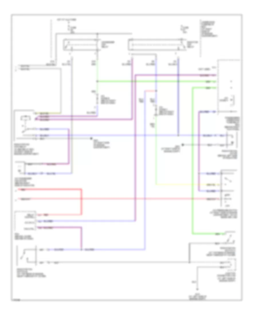
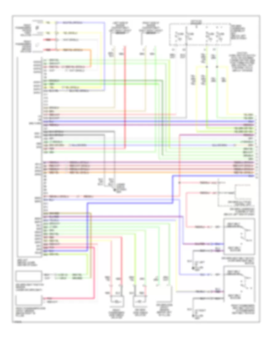
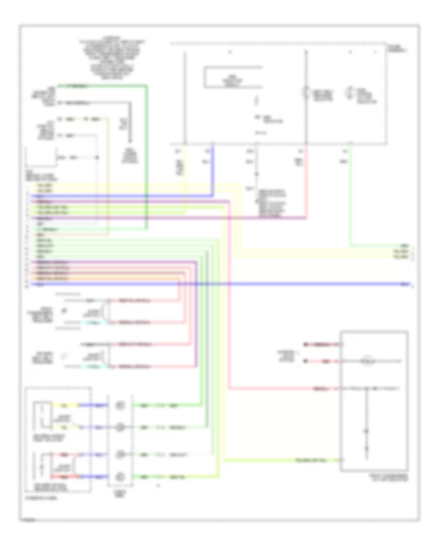
AIR CONDITIONING
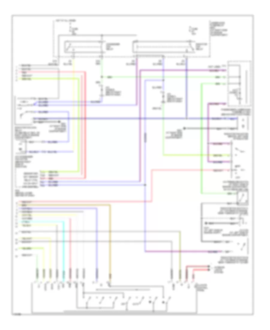
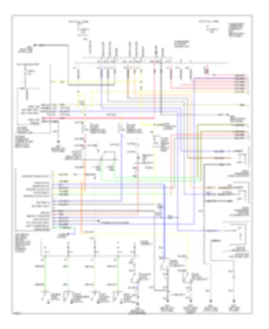
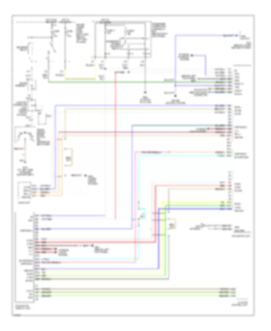
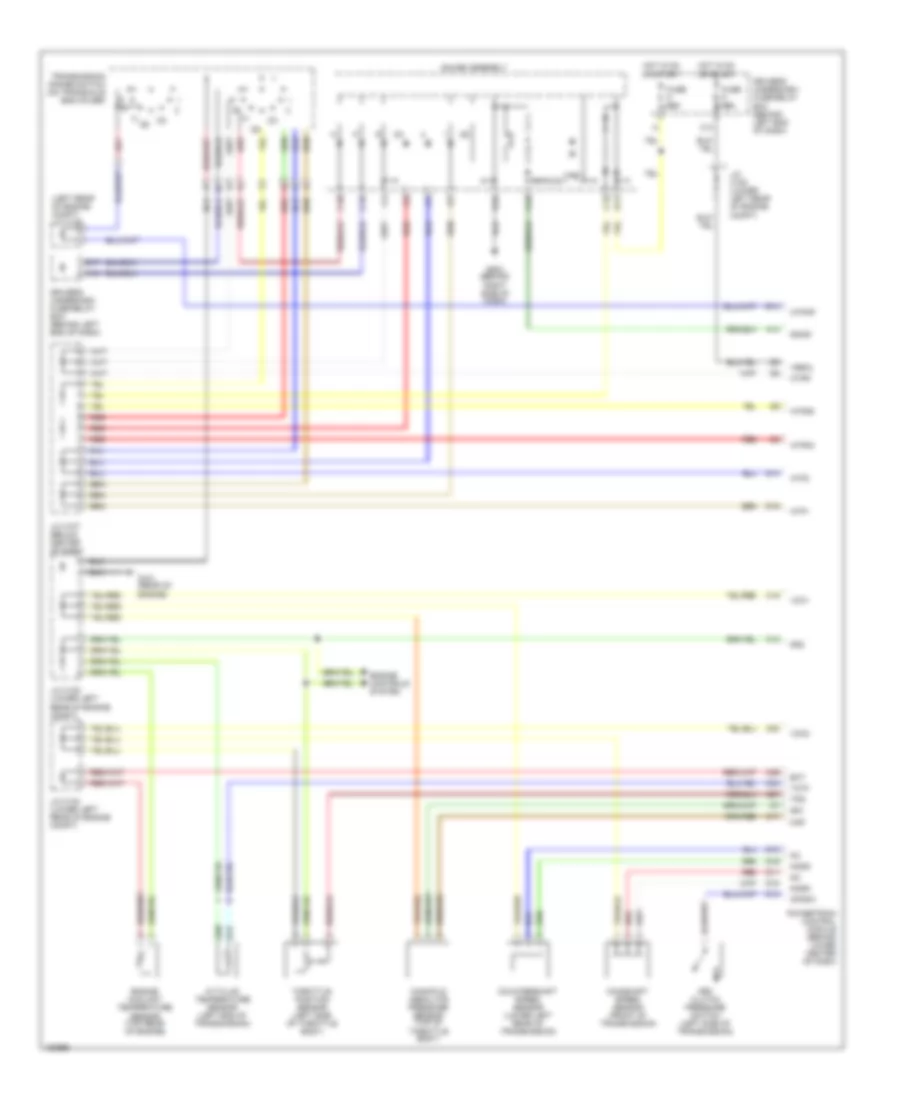
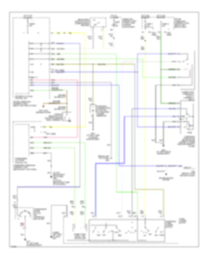
Automatic A/C Wiring Diagram, with Navigation (1 of 2) for Honda Odyssey EX 2004

List of elements for Automatic A/C Wiring Diagram, with Navigation (1 of 2) for Honda Odyssey EX 2004:
- (behind glove box, near blower motor) blower power transistor
- (behind glove box, on hvac assembly)
- (behind right kick panel) passenger's under-dash fuse/relay box
- (below glove box,
- A/c compressor clutch
- A/c compressor clutch relay
- A/c on out
- A10
- A11
- A12
- A13
- A14
- A15
- A16
- Air mix +5v
- Air mix control motor (below center of dash, on hvac assembly)
- Air mix cool
- Air mix hot
- Air mix pot
- Amd-p
- Assembly)
- B10
- B11
- B12
- B13
- B14
- B15
- B16
- B17
- B18
- B19
- B20
- B21
- B22
- B23
- B24
- B25
- B26
- Blwr fback
- Blwr hi rly
- Climate control unit
- Clk1
- Clk2
- Common
- D11
- D14
- Data
- Defogger system
- Driver's under-dash fuse/relay box (below left end of dash)
- Ds0
- Ds1
- Ds2
- Ect sensor
- Ect sensor (at top rear of engine, on water jacket)
- Engine controls system
- Evap temp
- Evaporator temperature sensor (behind glove box. on hvac assembly)
- Fl+
- Fresh
- Front blower motor
- Front blower motor high relay
- Front blower motor relay
- Front mode control motor (behind left side of dash, on end of hvac assembly)
- Frs
- Fuse 3 7.5a
- Fuse 40a
- Fuse 7.5a
- G201 (at right side of engine compartment)
- G401 (under left side of dash)
- Ground
- Hot at all times
- Hot in on
- Ig2
- In-car temp
- In-car temperature sensor (behind dash, to right of steering column)
- Junction connector c104 (at left side of engine compartment)
- Junction connector c105 (at left side of engine compartment)
- Latch
- M-cool
- M-def
- M-hot
- M-vent
- Mode 1
- Mode 2
- Mode 3
- Mode 4
- Mode def
- Mode vent
- Navigation system
- O13
- On bottom of hvac
- Out air temp
- Outside air temperature sensor (behind right side of front bumper)
- Panel gnd
- Passenger's under-dash fuse/relay box (behind right kick panel)
- Pwr trans
- Rec
- Recirc
- Recirculation control motor (behind glove box, on hvac assembly)
- Red
- Rr def rly
- S-com
- S5v
- Solid state
- Sunlight sen
- Sunlight sensor (on top center of dash)
- Under-hood fuse/relay box (at right side of engine compartment)
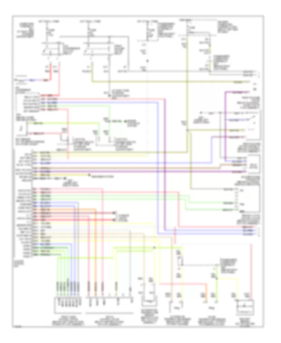
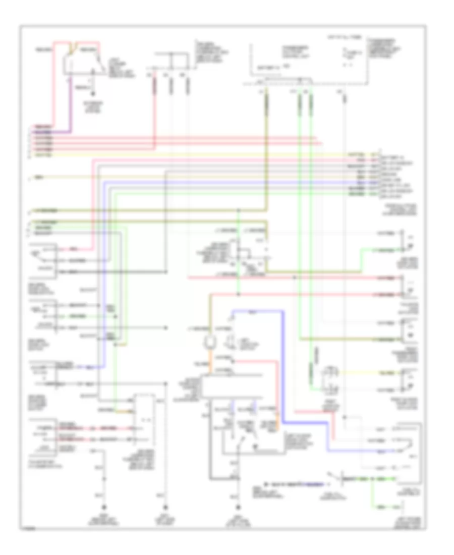
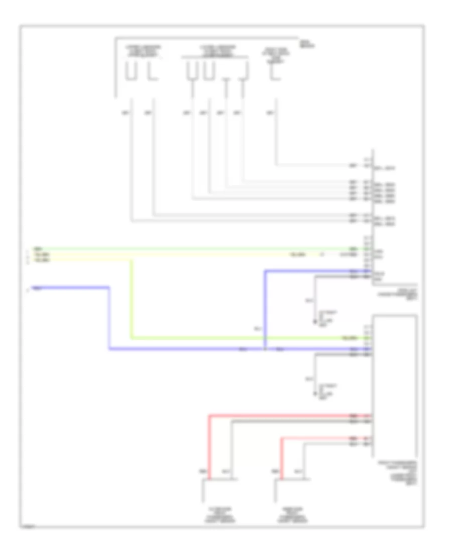
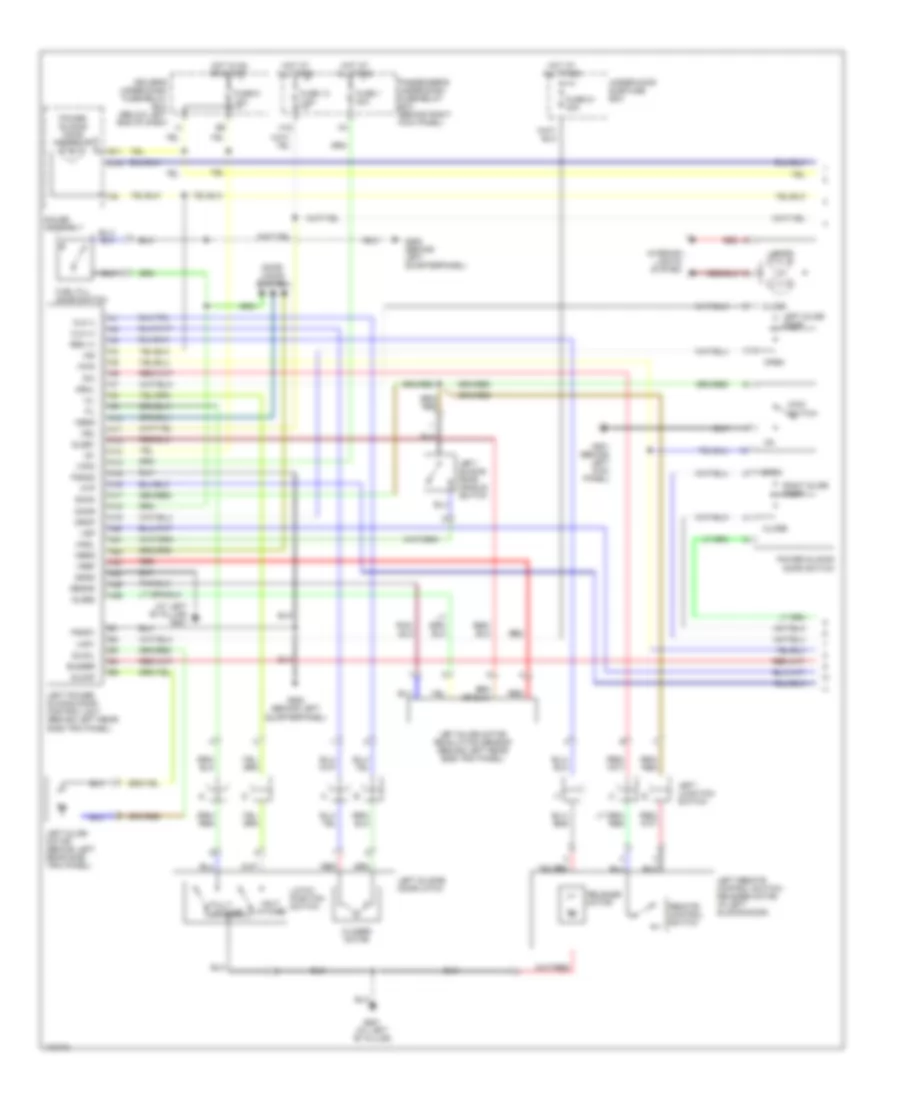
Automatic A/C Wiring Diagram, with Navigation (2 of 2) for Honda Odyssey EX 2004
List of elements for Automatic A/C Wiring Diagram, with Navigation (2 of 2) for Honda Odyssey EX 2004:
- (not used)
- A/c condenser fan motor (behind right side of radiator)
- A/c diode a
- A/c diode b (below right end of dash)
- A/c diode c (below right end of dash)
- A/c on input
- A/c pressure switch (at right side of engine compartment, on a/c receiver line)
- A17
- A20
- A27
- Auto
- C18
- C26
- Climate control panel
- Clk 1
- Condenser fan relay
- D-gnd
- D15
- D16
- Data
- Ds0
- Ds1
- Ds2
- Ect sensor
- Fan control
- Fl +
- Fuse 30a
- G101 (at left side of engine compt)
- G201 (at right side of engine compartment)
- H17
- High
- Hot at all times
- I17
- Ill +
- Ill -
- Interior lights system
- J/c c105 (at left side of engine compartment)
- K14
- Latch
- Low
- Off
- Passenger's under-dash fuse/relay box (behind right kick panel)
- Pcm (behind lower center of dash)
- Radiator fan main relay (in abs relay box, on right side of engine compartment)
- Radiator fan motor (behind left side of radiator)
- Radiator fan relay
- Radiator fan switch a (at top rear of engine, near thermostat cover)
- Radiator fan switch b (at top rear of engine, near thermostat cover)
- Red
- Relay ctrl
- Sensor gnd
- Under-hood fuse/relay box (at right side of engine compartment)
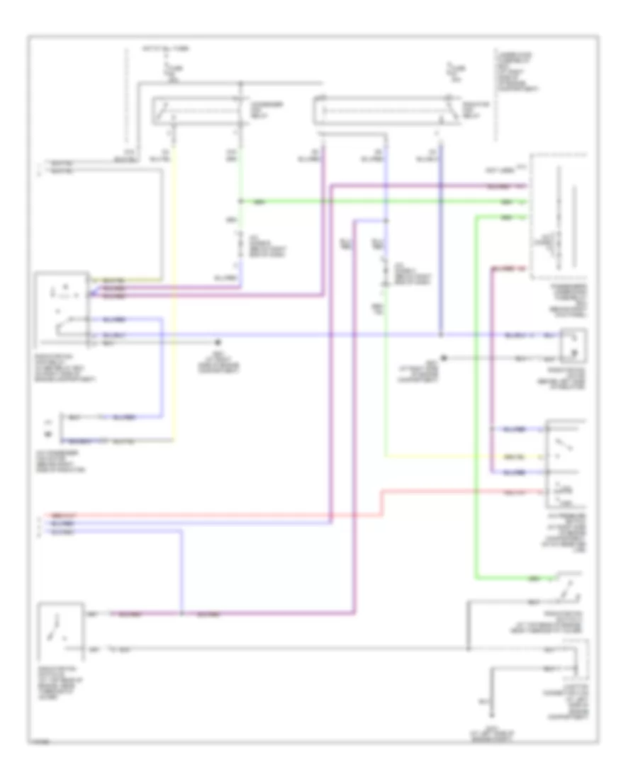
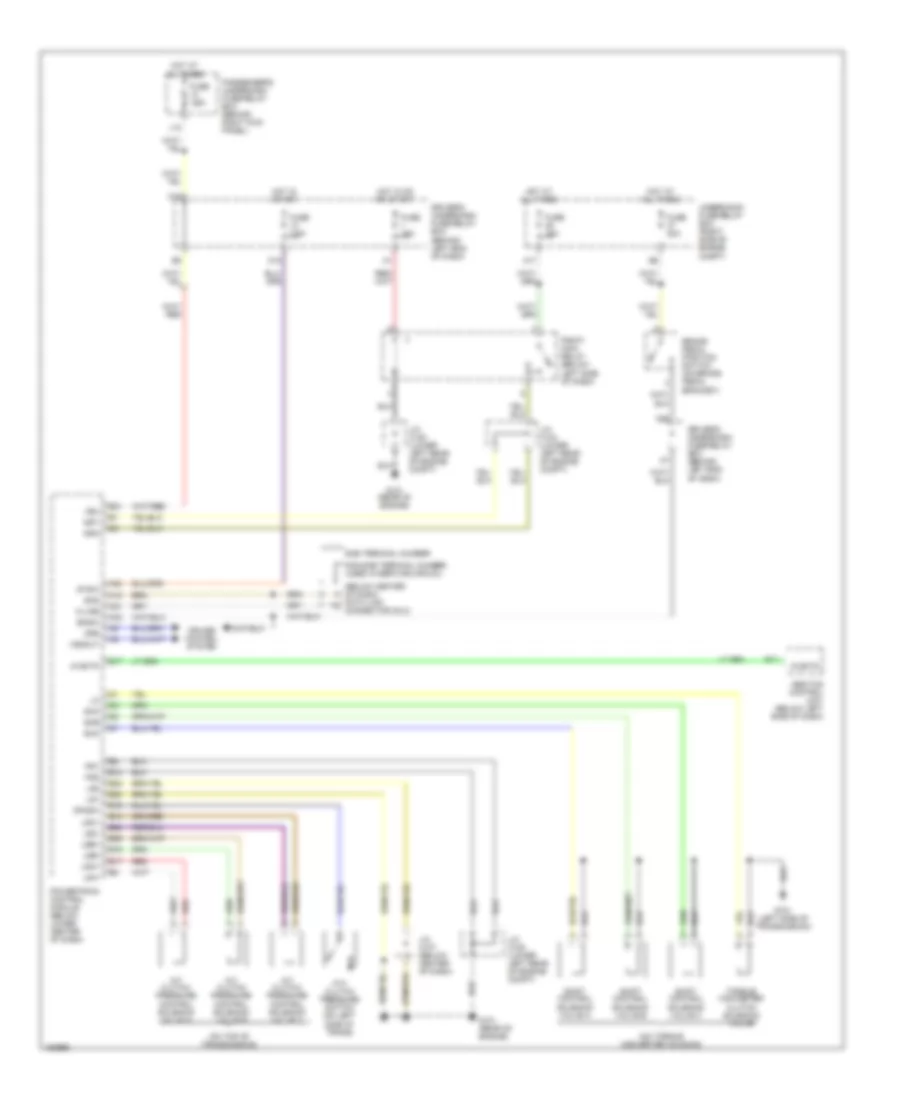
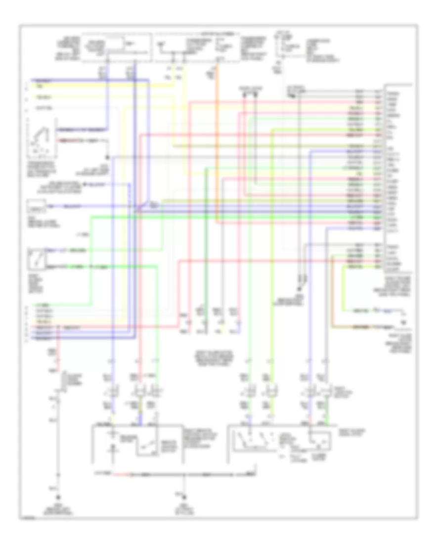
Automatic A/C Wiring Diagram, without Navigation (1 of 2) for Honda Odyssey EX 2004
List of elements for Automatic A/C Wiring Diagram, without Navigation (1 of 2) for Honda Odyssey EX 2004:
- (at right side of engine compartment) g201
- A/c compressor clutch
- A/c compressor clutch relay
- A/c on input
- A/c on out
- A17
- A20
- A27
- Air mix control motor (below center of dash, on hvac assembly)
- Air mix cool
- Air mix hot
- Air mix pot
- Amd-p
- B10
- B11
- B12
- B13
- B14
- B15
- B16
- B17
- B18
- B19
- B20
- Battery
- Bl rly ctrl
- Blower power transistor (behind glove box, near blower motor)
- Blwr mtr fb
- C18
- C26
- Climate control unit
- Connector c104 (at left side of engine compartment)
- Connector c105 (at left side of engine compartment)
- D11
- D14
- Defogger system
- Driver's under-dash fuse/relay box (below left end of dash)
- Ect input
- Ect sensor
- Ect sensor (at top rear of engine, on water jacket)
- Engine controls system
- Evap sen in
- Evaporator temperature sensor (behind glove box, on hvac assembly)
- Fan control
- Fresh ctrl
- Front blower motor (below glove box, on bottom of hvac assembly)
- Front blower motor high relay (behind glove box, on hvac assembly)
- Front blower motor relay
- Front mode control motor (behind left side of dash, on end of hvac assembly)
- Frs
- Fuse 40a
- Fuse 7.5a
- G401 (under left side of dash)
- Ground
- Hot at all times
- Hot in on
- Ig2
- Ign in
- Ill +
- Ill -
- In-car in
- In-car temperature sensor (behind dash, to right of steering column)
- Interior lights system
- J12
- Junction
- K15
- M-cool
- M-def
- M-hot
- M-vent
- Mode 1
- Mode 2
- Mode 3
- Mode 4
- Mode-def
- Mode-vent
- O13
- Out air in
- Outside air temperature sensor (behind right side of front bumper)
- Passenger's under-dash fuse/relay box (behind right kick panel)
- Pcm (behind lower center of dash)
- Prw tr ctrl
- Rec
- Recirc ctrl
- Recirculation control motor (behind glove box, on hvac assembly)
- Red
- Ref volt
- Relay ctrl
- Rr def on
- S-com
- S5v
- Sensor gnd
- Solid state
- Sun sen in
- Sunlight sensor (on top center of dash)
- Under-hood fuse/relay box (at right side of engine compartment)
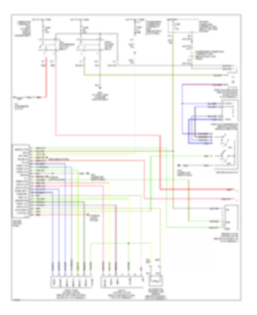
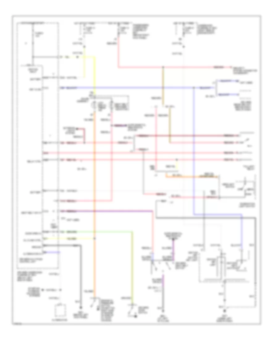
Automatic A/C Wiring Diagram, without Navigation (2 of 2) for Honda Odyssey EX 2004
List of elements for Automatic A/C Wiring Diagram, without Navigation (2 of 2) for Honda Odyssey EX 2004:
- (at left side of engine compartment)
- (not used)
- A/c condenser fan motor (behind right side of radiator)
- A/c diode a
- A/c diode b (below right end of dash)
- A/c diode c (below right end of dash)
- A/c pressure switch (at right side of engine compartment, on a/c receiver line)
- Condenser fan relay
- Connector c105
- D15
- D16
- Fuse 30a
- G101 (at left side of engine compt)
- G201 (at right side of engine compartment)
- H17
- High
- Hot at all times
- I17
- Junction
- K14
- Low
- Passenger's under-dash fuse/relay box (behind right kick panel)
- Radiator fan main relay (in abs relay box, on right side of engine compartment)
- Radiator fan motor (behind left side of radiator)
- Radiator fan relay
- Radiator fan switch a (at top rear of engine, near thermostat cover)
- Radiator fan switch b (at top rear of engine, near thermostat cover)
- Under-hood fuse/relay box (at right side of of engine compartment)
Manual A/C Wiring Diagram (1 of 2) for Honda Odyssey EX 2004
List of elements for Manual A/C Wiring Diagram (1 of 2) for Honda Odyssey EX 2004:
- (behind glove box, on hvac assembly)
- A/c compressor clutch
- A/c compressor clutch relay
- A/c on
- Air mix control motor (below center of dash, on hvac assembly)
- Air mix cool
- Air mix hot
- Air mix pot
- Amd-p
- Battery
- D11
- D14
- Defogger system
- Driver's under-dash fuse/relay box (below left end of dash)
- Evap sen in
- Evaporator temperature sensor (behind glove box, on hvac assembly)
- Fresh ctrl
- Front blower motor (below glove box, on bottom of hvac assembly)
- Front blower motor relay
- Front blower resistor (behind glove box, near blower motor)
- Front mode control motor (behind left side of dash, on end of hvac assembly)
- Frs
- Fuse 40a
- Fuse 7.5a
- G201 (at right side of engine compartment)
- G401 (under left side of dash)
- Ground
- Heater control panel
- Heater fan switch
- Hot at all times
- Hot in on
- Htr fan in
- Ig2
- Ign in
- Ill +
- Ill -
- Interior lights system
- J12
- K15
- M-cool
- M-def
- M-hot
- M-vent
- Mode 1
- Mode 1 out
- Mode 2
- Mode 2 out
- Mode 3
- Mode 3 out
- Mode 4
- Mode 4 out
- Mode-def +
- Mode-vent +
- O13
- Off
- Passenger's under-dash fuse/relay box (behind right kick panel)
- Rec
- Recirc ctrl
- Recirculation control motor
- Red
- Ref volt
- Rr def on
- S-com
- S5v
- Sensor gnd
- Under-hood fuse/relay box (at right side of engine compartment)
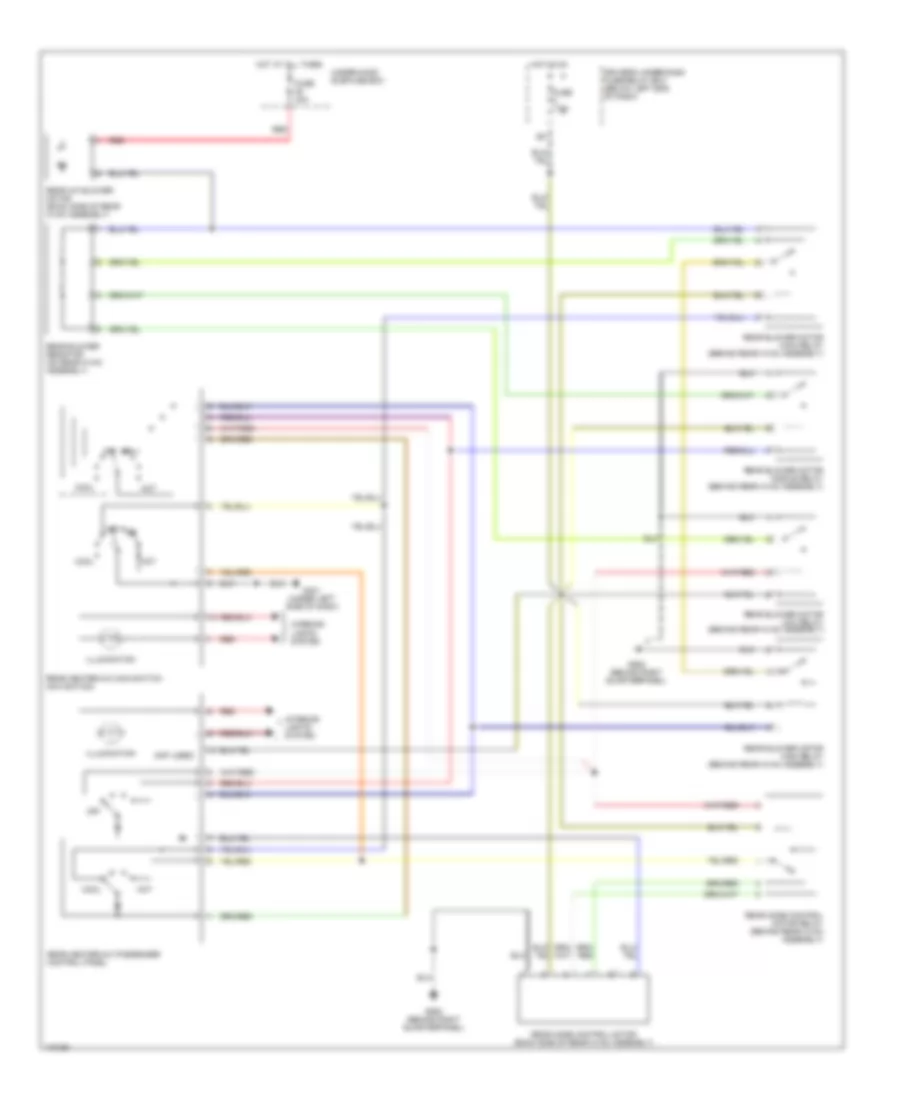
Manual A/C Wiring Diagram (2 of 2) for Honda Odyssey EX 2004
List of elements for Manual A/C Wiring Diagram (2 of 2) for Honda Odyssey EX 2004:
- (at left side of engine compt)
- (not used)
- A/c condenser fan motor (behind right side of radiator)
- A/c diode a
- A/c diode b (below right end of dash)
- A/c diode c (below right end of dash)
- A/c on in
- A/c pressure switch (at right side of engine compartment, on a/c receiver line)
- A17
- A20
- A27
- Condenser fan relay
- D15
- D16
- Fan ctrl
- Fuse 30a
- G101 (at left side of engine compt)
- G201 (at right side of engine compartment)
- G201 (at right side of engine compt)
- H17
- High
- Hot at all times
- I17
- Junction connector c105
- K14
- Low
- Passenger's under-dash fuse/relay box (behind right kick panel)
- Pcm (behind lower center of dash)
- Radiator fan main relay (in abs relay box, on right side of engine compartment)
- Radiator fan motor (behind left side of radiator)
- Radiator fan relay
- Radiator fan switch a (at top rear of engine, near thermostat cover)
- Radiator fan switch b (at top rear of engine, near thermostat cover)
- Red
- Relay control
- Under-hood fuse/relay box (at right side of of engine compartment)
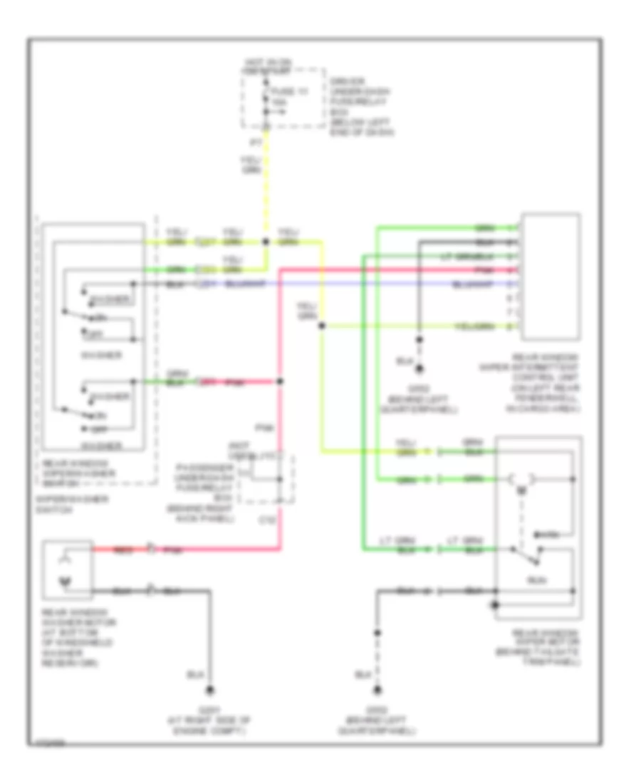
Rear A/C Wiring Diagram for Honda Odyssey EX 2004
List of elements for Rear A/C Wiring Diagram for Honda Odyssey EX 2004:
- (not used)
- Cool
- Driver's under-dash fuse/relay box (below left end of dash)
- Fuse 40a
- Fuse 7.5a
- G401 (under left side of dash)
- G582 (behind right quarterpanel)
- Hot
- Hot at all times
- Hot in on
- Illumination
- Interior lights system
- Off
- Rear a/c blower motor (back side of rear hvac assembly)
- Rear blower motor high relay (behind rear hvac assembly)
- Rear blower motor low relay (behind rear hvac assembly)
- Rear blower motor main relay (behind rear hvac assembly)
- Rear blower motor middle relay (behind rear hvac assembly)
- Rear blower resistor (on rear hvac assembly)
- Rear heater-a/c main switch (navigation)
- Rear heater-a/c passenger control panel
- Rear mode control motor (back side of rear hvac assembly)
- Rear mode control motor relay (behind rear hvac assembly)
- Red
- Under-hood sub-fuse box
ANTI-LOCK BRAKES
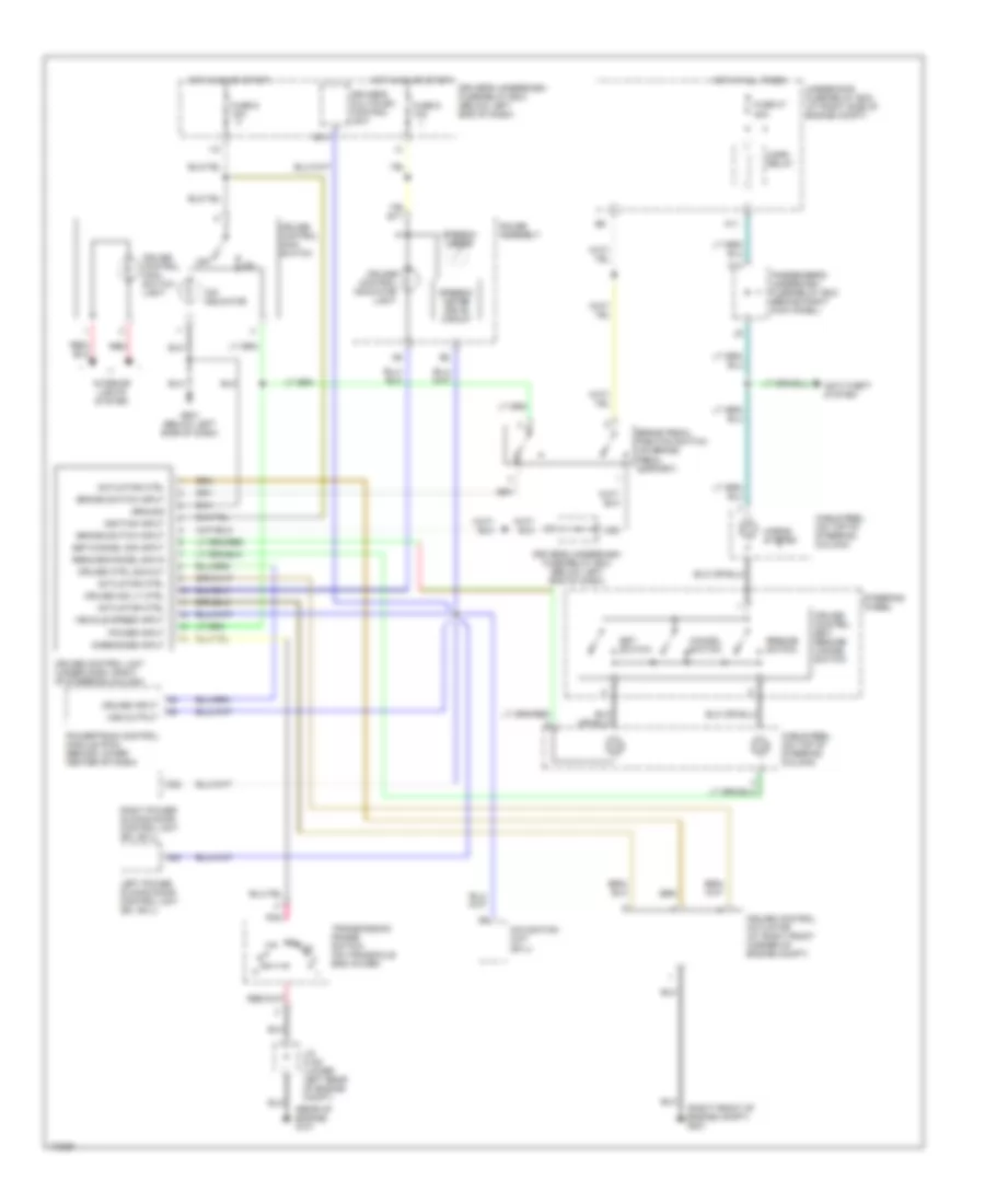
Anti-lock Brakes Wiring Diagram (1 of 2) for Honda Odyssey EX 2004
List of elements for Anti-lock Brakes Wiring Diagram (1 of 2) for Honda Odyssey EX 2004:
- (behind left kick panel) g303
- (below left side of dash) abs/tcs control unit
- (not used)
- A10
- A11
- A12
- A13
- A14
- A15
- A16
- A17
- A18
- A19
- A20
- A21
- A22
- A23
- A24
- A25
- A26
- Abs
- Abs fail- safe relay (in abs relay box, on right side of engine compt)
- Abs pump motor relay (in abs relay box, on right side of engine compt)
- Atsftp
- B10
- B11
- B12
- B13
- B14
- B15
- B16
- B4
- Brake pedal position switch (on brake pedal bracket)
- C10
- C11
- C12
- Computer data lines system
- Dlc
- Driver's under-dash fuse/relay box (below left end of dash)
- E15
- E16
- E17
- Fl-in
- Fl-out
- Flw (+)
- Flw (-)
- Fptdr
- Fr-in
- Fr-out
- Frw (+)
- Frw (-)
- Fsr
- Fuse 14 7.5a
- Fuse 3 10a
- Fuse 47 20a
- Fuse 48 20a
- Fuse 50 30a
- G101 (at left side of engine compt)
- G201 (at right side of engine compt)
- G303 (behind left kick panel) test tachometer connector (on top of brake booster)
- Gnd1
- Gnd2
- Gnd3
- H18
- Hot at all times
- Ig2
- Left front wheel speed sensor (on left steering knuckle assembly)
- Mck
- Ncl
- Ncr
- Nep
- Nor
- O20
- Park
- Passenger's under-dash fuse/relay box (behind right kick panel)
- Pfinh
- Pmr
- Powertrain control module (behind lower center of dash)
- Right rear wheel speed sensor (on right rear wheel hub assembly)
- Rl-in
- Rl-out
- Rlw (+)
- Rlw (-)
- Rr-in
- Rr-out
- Rrw (+)
- Rrw (-)
- Scs
- Stop
- Tcs relay (in multi-fuse relay box a)
- Tcs sw
- Tcs1
- Tcs2
- Tcsr
- Thlout
- Under-hood fuse/relay box (at right side of engine compt)
- Vref
Anti-lock Brakes Wiring Diagram (2 of 2) for Honda Odyssey EX 2004
List of elements for Anti-lock Brakes Wiring Diagram (2 of 2) for Honda Odyssey EX 2004:
- (behind right kick panel) passenger's under- dash fuse/relay box
- (below left end of dash) driver's under-dash fuse/relay box
- (not used)
- A17
- A18
- Abs check
- Abs indicator circuit
- Abs indicator light
- Abs pump motor
- Abs/tcs modulator unit (left side of engine compt)
- B11
- B13
- B14
- B15
- B16
- Brake fluid level switch (in brake fluid reservoir cap)
- C10
- C11
- C14
- C16
- Canada
- Cruise control main switch/ tcs switch
- Driver's multiplex control unit
- Driver's under-dash fuse/relay box (below left end of dash)
- Drl control unit (behind center of dash)
- E16
- Fuse 4 7.5a
- Fuse 6 15a
- Fuse 9 10a
- G301 (at left side of engine compt)
- G302 (at left side of engine compt)
- G503 (w/ dvd: behind right kick panel) (w/o dvd: behind right side of glove box)
- Gauge assembly
- Hot in on
- Hot in on or start
- I12
- Illum
- Interior lights system
- K10
- Left front abs solenoid (in)
- Left front abs solenoid (out)
- Left rear abs solenoid (in)
- Left rear abs solenoid (out)
- Left rear wheel speed sensor (on left rear wheel hub assembly)
- Left tcs solenoids
- O10
- Parking brake & brake system indicator light
- Parking brake switch (on parking brake pedal assembly)
- Red
- Right front abs solenoid (in)
- Right front abs solenoid (out)
- Right front wheel speed sensor (on right steering knuckle assembly)
- Right rear abs solenoid (in)
- Right rear abs solenoid (out)
- Right tcs solenoids
- Tacho- meter drive circuit
- Tcs indicator light
- Usa
ANTI-THEFT
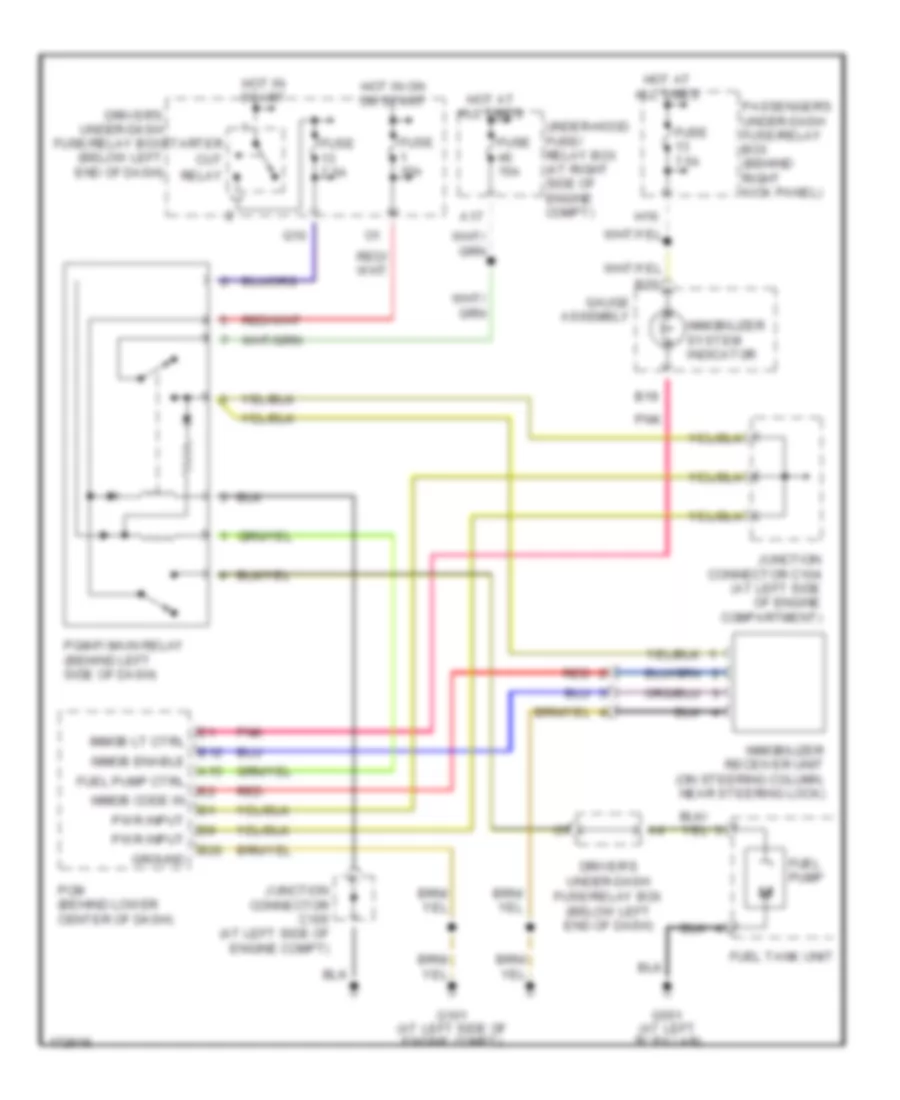
Immobilizer Wiring Diagram for Honda Odyssey EX 2004
List of elements for Immobilizer Wiring Diagram for Honda Odyssey EX 2004:
- A15
- A17
- B19
- B20
- Driver's under-dash fuse/relay box (below left end of dash)
- E12
- Fuel pump
- Fuel pump ctrl
- Fuel tank unit
- Fuse 15a
- Fuse 15a
- Fuse 7.5a
- G101 (at left side of engine compt)
- G551 (at left "b" pillar)
- Gauge assembly
- Ground
- H16
- Hot at all times
- Hot in on or start
- Hot in start
- Immob code in
- Immob enable
- Immob lt ctrl
- Immobilizer receiver unit (on steering column, near steering lock)
- Immobilizer system indicator
- Junction connector c104 (at left side of engine compartment)
- Junction connector c105 (at left side of engine compt)
- Passenger's under-dash fuse/relay box (behind right kick panel)
- Pcm (behind lower center of dash)
- Pgm-fi main relay (behind left side of dash)
- Pnk
- Pwr input
- Q10
- Red
- Starter cut relay
- Under-hood fuse/ relay box (at right side of engine compt)
Power Door Locks Wiring Diagram, Except LX (1 of 3) for Honda Odyssey EX 2004
List of elements for Power Door Locks Wiring Diagram, Except LX (1 of 3) for Honda Odyssey EX 2004:
- 10a
- 7.5a
- A10
- A12
- A13
- A14
- A15
- A16
- A17
- A18
- A20
- A22
- A24
- B11
- B16
- B22
- Battery in
- Battery input
- Combination light switch
- Comm line
- Dr door sw
- Dr lck sw
- Driver's door switch
- Driver's multiplex control unit
- Driver's under-dash fuse/relay box (below left end of dash)
- Front passenger's door switch
- Fuse 13
- Fuse 9
- G14
- G201 (right front of engine compt)
- G401 (left side of dash)
- G501 (behind left kick panel)
- G503 (behind right kick panel)
- G552 (behind left rear side quarterpanel)
- G581 (right side of "b" pillar)
- G9 (not used)
- Ground
- Hood sw
- Hood switch
- Hot at all times
- Hot in on or start
- Ign input
- Ignition input
- Ignition key switch
- Ignition key switch/ light key
- Instrument cluster system
- J11
- J12
- Key cyl sw
- Key in ign input
- Keyless receiver unit (behind right end of dash)
- Lck knob sw
- Left power sliding door control unit
- Left sliding door switch
- Lft slide dr sw
- Lock
- Lt slid dr ctrl
- O19
- Panic
- Pass dr sw
- Passenger's multiplex control unit
- Passenger's under-dash fuse/relay box (behind right kick panel)
- Pnk
- Right power sliding door control unit
- Right sliding door switch
- Rt slid dr ctrl
- Security ind
- Slid dr lck sw
- Slid dr sw
- Tailgate latch switch
- Tailgate sw
- Taillight relay
- Taillight relay (behind left side of dash)
- Transmitter
- Unlock
Power Door Locks Wiring Diagram, Except LX (2 of 3) for Honda Odyssey EX 2004
List of elements for Power Door Locks Wiring Diagram, Except LX (2 of 3) for Honda Odyssey EX 2004:
- A12
- A15
- A16
- A17
- A18
- B21
- Battery in
- Comm line
- Door multiplex control unit (in driver's door)
- Dr lck sw
- Driver's door key cylinder switch
- Driver's door lock knob switch
- Driver's door lock switch
- Front passenger's door key cylinder switch
- Front passenger's door lock knob switch
- Front passenger's door lock switch
- G401 (left side of dash)
- G552 (behind left quarterpanel)
- G581 (right side of "b" pillar)
- Gauge assembly
- Ground
- Indicators
- Key cyl sw
- Lck knob sw
- Lock
- Pnk
- Security system indicator
- Tailgate key cylinder switch
- Tailgate lock knob switch
- Unlock
Power Door Locks Wiring Diagram, Except LX (3 of 3) for Honda Odyssey EX 2004
List of elements for Power Door Locks Wiring Diagram, Except LX (3 of 3) for Honda Odyssey EX 2004:
- (not used)
- 20a
- A10
- A11 lck act
- A18
- A20
- A21
- A23
- Audio unit
- B11 dr lck act 2
- B14
- B21
- Battery in
- C14
- Driver's door lock actuator 2
- Driver's under-dash fuse/relay box (below left end of dash)
- F15
- F17
- Front passenger's door lock actuator
- Fuel fill door relay (behind left rear side trim panel)
- Fuel fill door switch
- Fuse 12
- G551 (left side of "b" pillar)
- G552 (behind left quarterpanel)
- G581 (right side of "b" pillar)
- Horn relay
- Horns system
- Hot at all times
- Int lt sw
- Interior lights system
- J14
- K13
- Kick panel)
- Lck knb act
- Lck knb sw
- Left junction switch
- Left power sliding door control unit
- Left sliding door lock knob switch/ actuator
- Passenger's multiplex control unit
- Passenger's under-dash fuse/relay box (behind right
- Passenger's under-dash fuse/relay box (behind right kick panel)
- Rear controller & screen
- Red
- Right junction switch
- Right sliding door lock knob switch/ actuator
- Sliding door lock control unit (in left sliding door)
- Tailgate lock actuator
- W/ rear enter- tainment system
- W/o rear enter- tainment system
Power Door Locks Wiring Diagram, LX with Keyless Entry (1 of 2) for Honda Odyssey EX 2004
List of elements for Power Door Locks Wiring Diagram, LX with Keyless Entry (1 of 2) for Honda Odyssey EX 2004:
- (not used)
- 10a
- 15a
- 7.5a
- A10
- A12
- A13
- A16
- A17
- A20
- A22
- A24
- B11
- B22
- Battery in
- Battery input
- Comm line
- Disarm switch
- Disarm switch (w/ security)
- Door switches output
- Dr door lck sw lck
- Dr door lck sw unlck
- Driver's door switch
- Driver's multiplex control unit
- Driver's under-dash fuse/relay box (below left end of dash)
- F15
- Front passenger's door key cylinder switch
- Front passenger's door lock switch
- Front passenger's door switch
- Fuse 10
- Fuse 13
- Fuse 9
- G14
- G201 (right front of engine compt)
- G303 (behind left kick panel)
- G401 (left side of dash)
- G501 (behind left kick panel)
- G503 (behind right kick panel)
- G552 (behind left quarterpanel)
- G581 (right side of "b" pillar)
- Gauge assembly
- Ground
- Hood switch
- Hood switch (w/ security)
- Horn system
- Horns system
- Hot at all times
- Hot in on or start
- Ign input
- Ignition input
- Ignition key switch
- Ignition key switch/key light
- In-line fuse 1 (behind left side of dash)
- In-line fuse 2 (behind left side of dash)
- In-line fuse 3 (behind left side of dash)
- Int lights sw input
- Interior lights system
- J12
- J14
- Key in ign input
- Keyless or keyless & security control unit (behind dash, right of steering column)
- Left sliding door switch
- Light flasher relay
- Lock
- O19
- Pass key sw
- Pass lck sw
- Passenger's multiplex control unit
- Passenger's under-dash fuse/relay box (behind right kick panel)
- Pnk
- Red
- Right sliding door switch
- Security indicator
- Security led (w/
- Security)
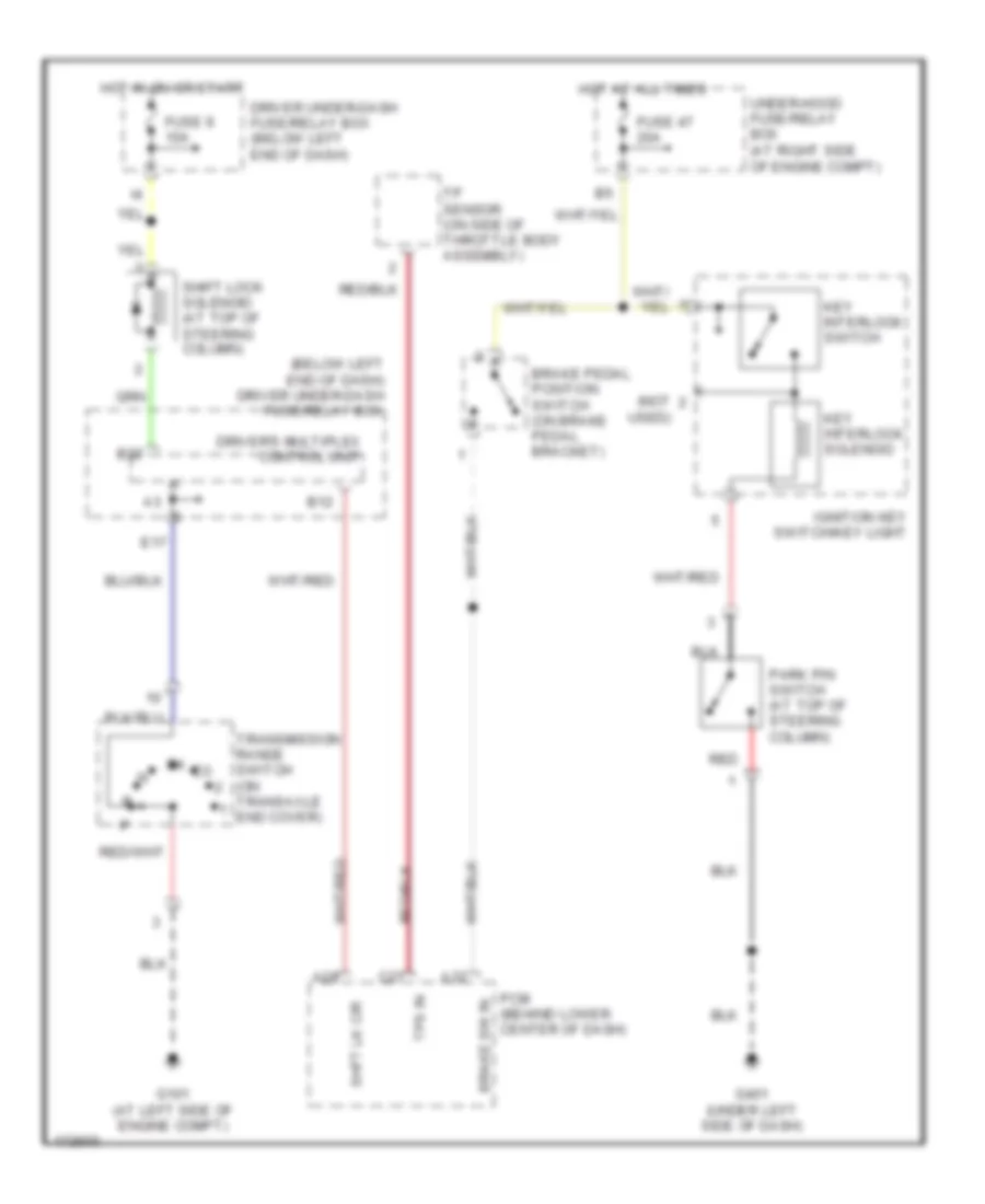
- Shift interlock system
- Tailgate latch switch
- Unlock
- Unlock relay
- Unlock relay (below left side of dash)
- W/ security
Power Door Locks Wiring Diagram, LX with Keyless Entry (2 of 2) for Honda Odyssey EX 2004
List of elements for Power Door Locks Wiring Diagram, LX with Keyless Entry (2 of 2) for Honda Odyssey EX 2004:
- (below left end of dash)
- 20a
- A11
- A12
- A15
- A16
- A17
- A18
- A23
- Battery in
- Comm line
- Door multiplex control unit (in driver's door)
- Dr key cyl sw
- Dr lck knob sw
- Dr lck sw
- Driver's door key cylinder switch
- Driver's door lock actuator
- Driver's door lock knob switch
- Driver's door lock switch
- Driver's under-dash fuse/relay box
- Driver's under-dash fuse/relay box (below left end of dash)
- Exterior lights system
- F17
- Front passenger's door lock actuator
- Fuel fill door relay
- Fuel fill door switch
- Fuse 12
- G401 (left side of dash)
- G551 (left side of "b" pillar)
- G552 (behind left quarterpanel)
- G6 (not used)
- Ground
- Hot at all times
- I18
- K13
- Left junction switch
- Left power sliding door control unit
- Left sliding door lock knob switch/ actuator
- Light flasher relay (below left side of dash)
- Lock
- Passenger's multiplex control unit
- Passenger's under-dash fuse/relay box (behind right kick panel)
- Pnk
- Right junction switch
- Right sliding door lock actuator
- Sliding door lock control unit (in left sliding door)
- Tailgate key cylinder switch
- Tailgate lock actuator
- Unlock
BODY CONTROL MODULES
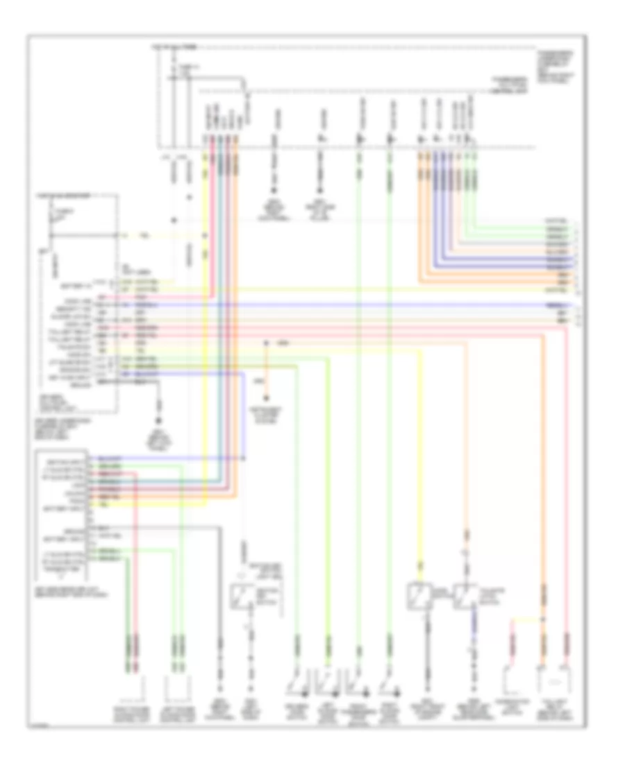
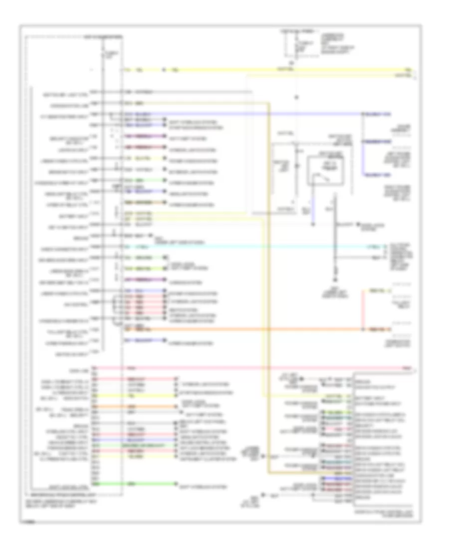
Multiplex Control Wiring Diagram (1 of 2) for Honda Odyssey EX 2004
List of elements for Multiplex Control Wiring Diagram (1 of 2) for Honda Odyssey EX 2004:
- (at left ``b" pillar) g551
- (at right side of engine compt)
- (below left kick panel)
- (ex, ex-l)
- (not used)
- (not used) q7
- (under left side of dash) g401
- A/t gear pos park input
- A10
- A11
- A12
- A13
- A14
- A15
- A16
- A17
- A18
- A19
- A20
- A21
- A22
- A23
- A24
- Alternator input
- Anti-lock brakes system
- Anti-theft system
- B10
- B11
- B12
- B13
- B14
- B15
- B16
- B17
- B18
- B19
- B20
- B21
- B22
- Battery input
- Brake switch input
- C15
- Check connector input
- Combination light switch
- Comm line
- Communication line
- Cruise control system
- Dash lts bright ctrl in
- Dim control
- Door locks system
- Door locks, anti-theft system
- Door multiplex control unit (in driver door)
- Dr door key cly sw-unlk
- Dr door knob sw-lck
- Dr door knob sw-unlck
- Dr door lock sw-unlck
- Dr window mtr pulser in
- Driver's door open input
- Driver's multiplex control unit
- Driver's seat belt sw in
- Driver's underdash fuse/relay box (below left end of dash)
- Drv's win unit relay coil
- Drv's window mtr ctrl
- Drv's window unit relay
- E12
- E17
- E19
- E20
- Exterior lights system
- Fuse 47 20a
- Fuse 9 10a
- G14
- G401 (under left side of dash)
- G501
- G551 (at left ``b" pillar)
- Gauge assembly
- Ground
- Hdlght rly ctrl
- Headlight relay ctrl
- Headlights system
- Hood switch
- Hot al all times
- Hot in on or start
- Ignition key light
- Ignition key light ctrl
- Ignition key switch
- Ignition key switch/ key light
- Ignition on input
- Instrument cluster system
- Interior lights system
- Interlock ctrl input
- K10
- K15
- Key in ignition
- Key in ignition input
- L/rear door open in
- L/rear window mtr ctrl
- Left power sliding door control unit (ex, ex-l)
- Lights on input
- Main switch output
- Multiplex control inspection connector (below left side of dash)
- O19
- O20
- Oil press ind flash ctrl
- Parking brake input
- Pnk
- Power windows system
- Q15
- Q18
- Red
- Right power sliding door control unit (ex, ex-l)
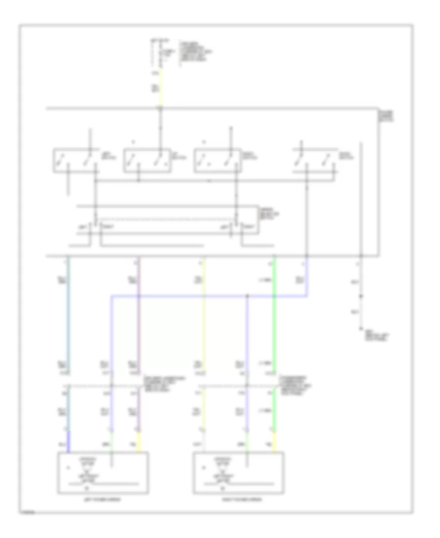
- Seats system
- Security
- Security indicator
- Shift interlock system
- Shift lock sol ctrl
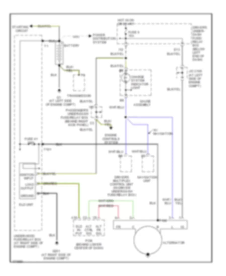
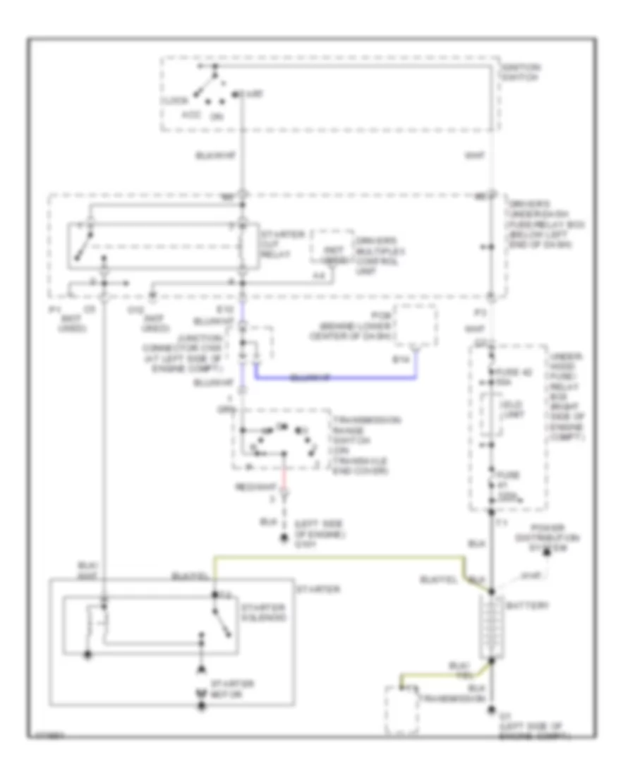
- Starting/charging system
- Switched power input
- Taillight relay
- Taillight relay ctrl
- Tlght rly ctrl
- Trunk open in
- Underhood fuse/relay box
- Vehicle speed input
- Warning system
- Windshield washer on in
- Windshield wiper int input
- Wiper int relay ctrl
- Wiper park/run input
- Wiper/washer system
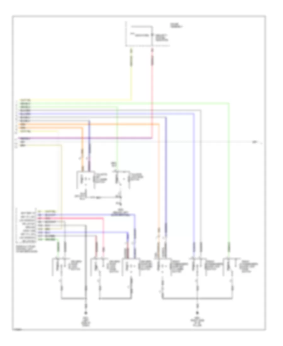
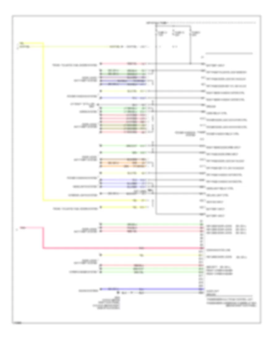
Multiplex Control Wiring Diagram (2 of 2) for Honda Odyssey EX 2004
List of elements for Multiplex Control Wiring Diagram (2 of 2) for Honda Odyssey EX 2004:
- (at right ``b" pillar) g581
- (ex, ex-l)
- (not used)
- (w/o dvd: behind right side of glove box)
- A10
- A11
- A12
- A13
- A14
- A15
- A16
- A17
- A18
- A19
- A20
- A21
- A22
- A23
- A24
- Audio unit
- B10
- B11
- B12
- B13
- B14
- B15
- B16
- B17
- B18
- B19
- B20
- B21
- B22
- Battery input
- C13
- C14
- Ceiling light ctrl
- Communication line
- Door locks, anti-theft system
- F15
- F17
- F18
- F3 (or g2)
- F7 (or g3)
- Front wiper/washer
- Frt pass door key cyl sw in-lck
- Frt pass door lock sw in-lock
- Frt pass door lock sw in-unlck
- Frt pass door open input
- Frt pass key cyl sw in-unlock
- Frt pass window motor ctrl
- Frt pass/tailgate lock knob sw
- Fuse 12 20a
- Fuse 13 7.5a
- Fuse 5 20a
- G503 (w/dvd: behind right kick panel)
- Ground
- Headlight relay ctrl
- Headlights system
- Horn relay ctrl
- Horns system
- Hot at all times
- I18
- Ignition input
- Interior lights system
- J11
- J12
- J14
- Keyless door locks
- Passenger's multiplex control unit
- Passenger's underdash fuse/relay box (behind right kick panel)
- Pnk
- Power door lock actuator ctrl
- Power window relay ctrl
- Power windows system
- Right rear door open input
- Right rear window motor ctrl
- Security
- Sound systems
- Trunk, tailgate, fuel doors system
- Wiper/washer system
COMPUTER DATA LINES
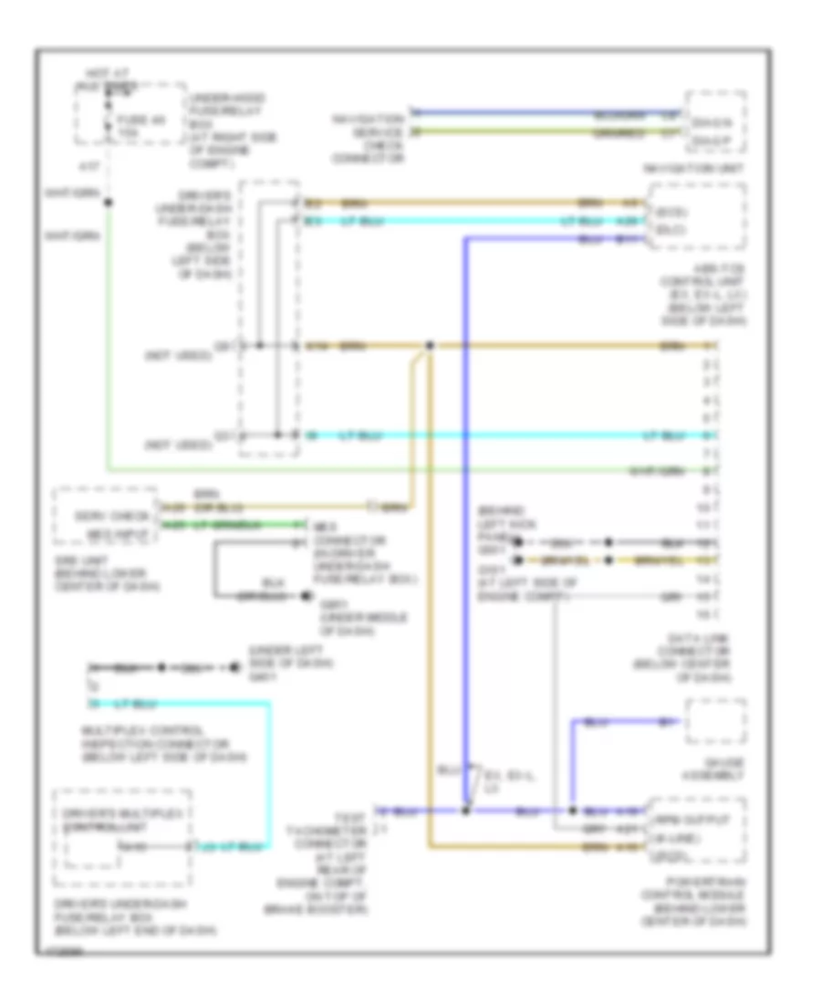
Computer Data Lines Wiring Diagram for Honda Odyssey EX 2004
List of elements for Computer Data Lines Wiring Diagram for Honda Odyssey EX 2004:
- (behind left kick panel) g501
- (dlc)
- (in driver under-dash fuse/relay box)
- (k-line)
- (not used)
- (scs)
- (under left side of dash) g401
- A10
- A15
- A17
- A19
- A21
- A25
- A26
- Abs-tcs control unit (ex, ex-l, lx) (below left side of dash)
- B11
- Data link connector (below center of dash)
- Diag n
- Diag p
- Driver's multiplex control unit
- Driver's under-dash fuse/relay box (below left end of dash)
- Driver's under-dash fuse/relay box (below left side of dash)
- Ex, ex-l, lx
- Fuse 46 15a
- G101 (at left side of engine compt)
- G851 (under middle of dash)
- Gauge assembly
- Hot at all times
- K14
- Mes connector
- Mes input
- Multiplex control inspection connector (below left side of dash)
- Navigation service check connector
- Navigation unit
- Powertrain control module (behind lower center of dash)
- Rpm output
- Serv check
- Srs unit (behind lower center of dash)
- Test tachometer connector (at left rear of engine compt, on top of brake booster)
- Under-hood fuse/relay box (at right side of engine compt)
COOLING FAN
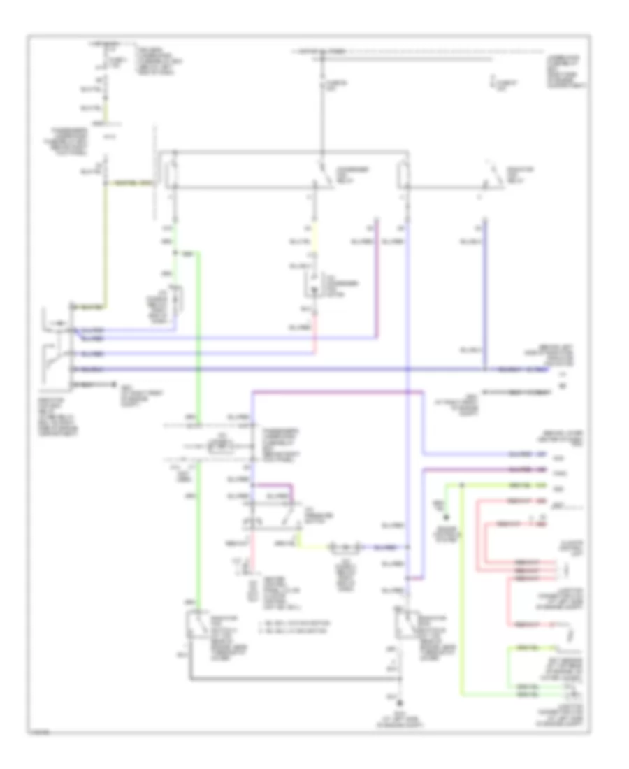
Cooling Fan Wiring Diagram for Honda Odyssey EX 2004
List of elements for Cooling Fan Wiring Diagram for Honda Odyssey EX 2004:
- (behind left side of radiator) radiator fan motor
- (behind lower center of dash) pcm
- (lx)
- (not used)
- A/c condenser fan motor
- A/c diode a
- A/c diode b (below right end of dash)
- A/c diode c (below right end of dash)
- A/c on out- put
- A/c pressure switch
- A20
- A27
- Acs
- B22
- C18
- C26
- Climate control unit
- Condenser fan relay
- D15
- D16
- Driver's under-dash fuse/relay box (below left end of dash)
- Ect
- Ect sensor (at top rear of engine, on water jacket)
- Engine controls system
- Ex, ex-l w/ navigation
- Ex, ex-l w/o navigation
- Fanc
- Fuse 3 7.5a
- Fuse 57 30a
- Fuse 58 30a
- G101 (at left side of engine compt)
- G201 (at right front of engine compt)
- H17
- Heater control panel (lx) or climate control unit (ex, ex-l)
- Hot at all times
- Hot in on
- I17
- Junction connector c104 (at left side of engine compt)
- Junction connector c105 (at left side of engine compt)
- K14
- K15
- Lo hi
- Passenger's under-dash fuse/relay box (behind right kick panel)
- Radiator fan main relay (in abs relay box, on right side of engine compartment)
- Radiator fan relay
- Radiator fan switch a (at top rear of engine, near thermostat cover)
- Radiator fan switch b (at top rear of engine, near thermostat cover)
- Sg2
- Under-hood fuse/relay box (right side of engine compartment)
CRUISE CONTROL
Cruise Control Wiring Diagram for Honda Odyssey EX 2004
List of elements for Cruise Control Wiring Diagram for Honda Odyssey EX 2004:
- "on" indicator
- (rear of engine) g101
- (right front of engine compt) g201
- A11
- A20
- A22
- Actuator ctrl
- Anti-theft system
- B14
- Brake pedal position switch (on brake pedal support)
- Brake switch input
- C14
- Cable reel (on top of steering column)
- Cancel switch
- Cruise control actuator (at right front corner of engine compt)
- Cruise control indicator light
- Cruise control main switch
- Cruise control main switch light
- Cruise control set/ resume cancel switch
- Cruise control unit (under dash, right of steering column)
- Cruise ctrl sig out
- Cruise ind lt ctrl
- Cruise input
- Disengage input
- Driver's multiplex control unit
- Driver's underdash fuse/relay box (below left end of dash)
- Fuse 47 20a
- Fuse 6 15a
- Fuse 9 10a
- G501 (below left side of dash)
- Gauge assembly
- Ground
- Horn relay
- Horns system
- Hot at all times
- Hot in on or start
- I12
- Ignition input
- Interior lights system
- J/c c105 (lower left rear of engine compt)
- Left power sliding door control unit (ex, ex-l)
- Navigation unit (ex-l)
- O20
- Off
- Passenger's underdash fuse/relay box (behind right kick panel)
- Pnk
- Power input
- Powertrain control module (pcm) (behind lower center of dash)
- Red
- Resume switch
- Resume/cancel sig in
- Right power sliding door control unit (ex, ex-l)
- Set switch
- Set/cancel sig input
- Speedo- meter
- Speedo- meter drive circuit
- Steering wheel
- Transmission range switch (on transaxle end cover)
- Underhood fuse/relay box (at right side of engine compt)
- Vehicle speed input
- Vss output
DEFOGGERS
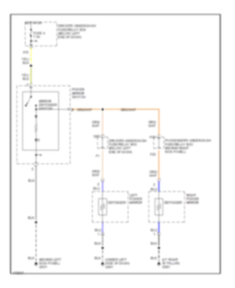
Heated Mirrors Wiring Diagram for Honda Odyssey EX 2004
List of elements for Heated Mirrors Wiring Diagram for Honda Odyssey EX 2004:
- (at right "b" pillar) g581
- (behind left kick panel) g501
- (under left side of dash) g401
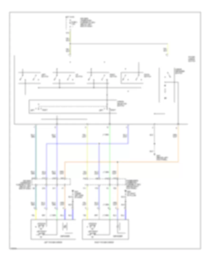
- Defogger
- Driver's under-dash fuse/relay box (below left end of dash)
- F20
- Fuse 4 7.5a
- H12
- Hot in on
- Left power mirror
- Mirror defogger switch
- Passenger's under-dash fuse/relay box (behind right kick panel)
- Power mirror switch
- Q20
- Right power mirror
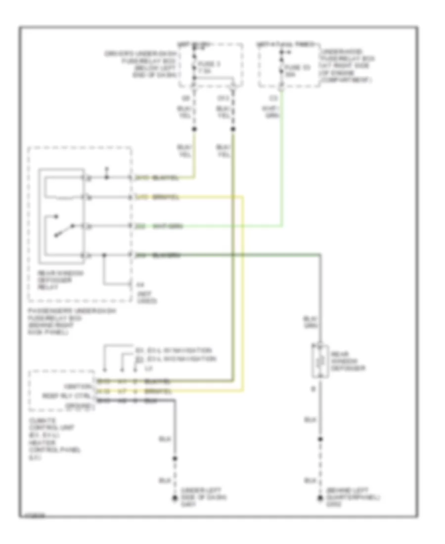
Rear Defogger Wiring Diagram for Honda Odyssey EX 2004
List of elements for Rear Defogger Wiring Diagram for Honda Odyssey EX 2004:
- (behind left quarterpanel) g552
- (not used)
- (under left side of dash) g401
- A10
- B13
- B15
- Climate control unit (ex, ex-l)
- Driver's under-dash fuse/relay box (below left end of dash)
- Ex, ex-l w/ navigation
- Ex, ex-l w/o navigation
- Fuse 3 7.5a
- Fuse 53 30a
- Ground
- Heater control panel (lx)
- Hot at all times
- Hot in on
- Ignition
- J15
- K15
- O13
- Passenger's under-dash fuse/relay box (behind right kick panel)
- Rdef rly ctrl
- Rear window defogger
- Rear window defogger relay
- Under-hood fuse/relay box (at right side of engine compartment)
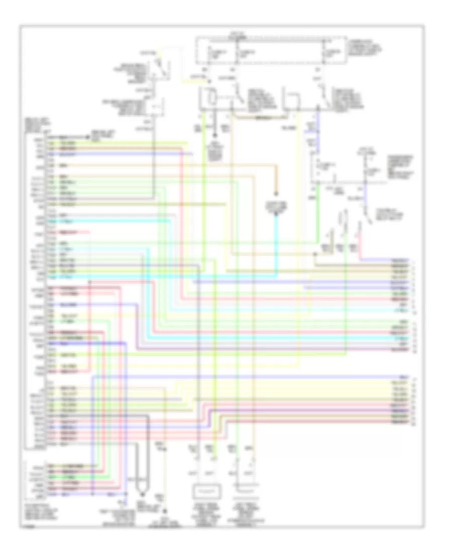
ENGINE PERFORMANCE
3.5L
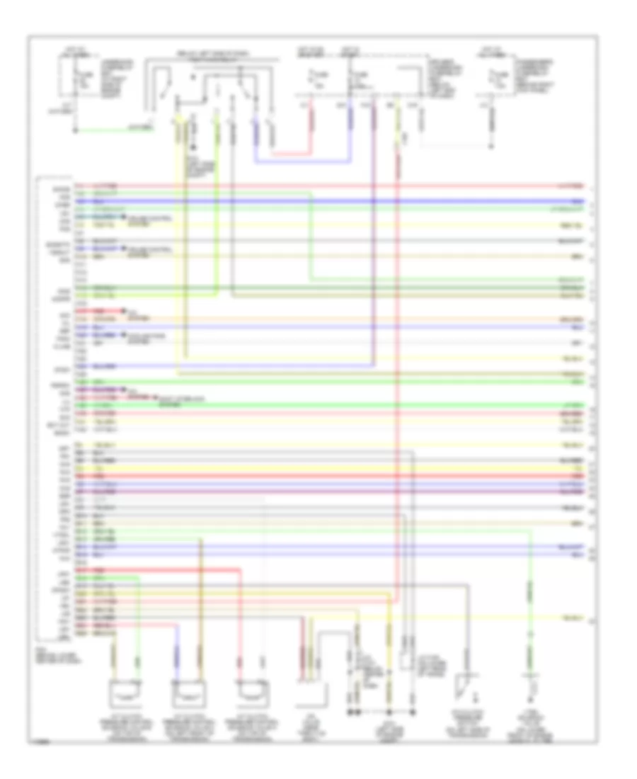
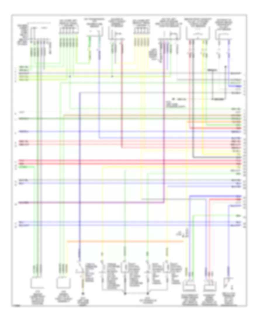
3.5L, Engine Performance Wiring Diagram (1 of 6) for Honda Odyssey EX 2004
List of elements for 3.5L, Engine Performance Wiring Diagram (1 of 6) for Honda Odyssey EX 2004:
- (below left side of dash) pgm-fi main relay
- 2wbs
- 4th clutch pressure switch (on left side of transmission)
- A/c system
- A/t clutch pressure control solenoid valve a (on top of transmission)
- A/t clutch pressure control solenoid valve b (on top of transmission)
- A/t clutch pressure control solenoid valve c (on left front of transmission)
- A10
- A11
- A12
- A13
- A14
- A15
- A16
- A17
- A18
- A19
- A20
- A21
- A22
- A23
- A24
- A25
- A26
- A27
- A28
- A29
- A30
- A31
- A32
- Acc
- Acs
- Atpnp
- B10
- B11
- B12
- B13
- B14
- B15
- B16
- B17
- B18
- B19
- B20
- B21
- B22
- B23
- B24
- B25
- Bksw
- C101
- Ccs
- Cooling fans system
- Cruise control system
- Dind
- Driver's underdash fuse/relay box (below left end of dash)
- Ect out
- Egr
- Eld
- Fanc
- Ftp
- Fuse 15a
- Fuse 7.5a
- G101 (left side of engine compt)
- Hot at all times
- Hot in on or start
- Hot in start
- Iac valve (near throttle body)
- Iacv
- Igp1
- Igp2
- Ilu
- Imofpr
- Inj1
- Inj2
- Inj3
- Inj4
- Inj5
- Inj6
- J/c c105 (on lower left rear of trans)
- J/c c107 (below center of dash)
- K-line
- Lg1
- Lg2
- Lsa+
- Lsa-
- Lsb+
- Lsb-
- Lsc+
- Lsc-
- Mcs
- Mil
- Nep
- Op4sw
- Passenger's underdash fuse/relay box (behind right kick panel)
- Pcm (behind lower center of dash)
- Pcs
- Pg1
- Pg2
- Pspsw
- Red
- Scs
- Shift interlock system
- Sho2s
- So2shtc
- Stsw
- Underhood fuse/relay box (at right side of engine compt)
- Vbu
- Vssout
- Vsv
- Vtec solenoid valve (on lower front of engine, near oil filter)
- Vtsol
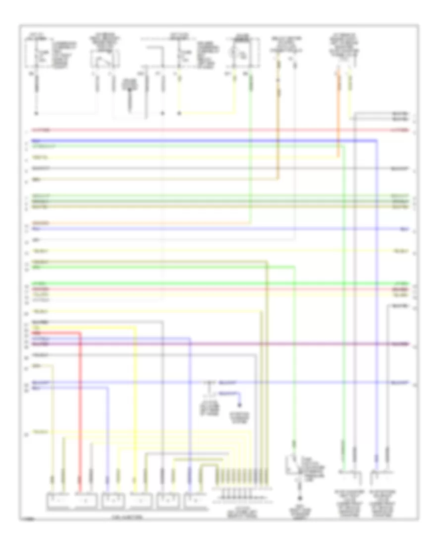
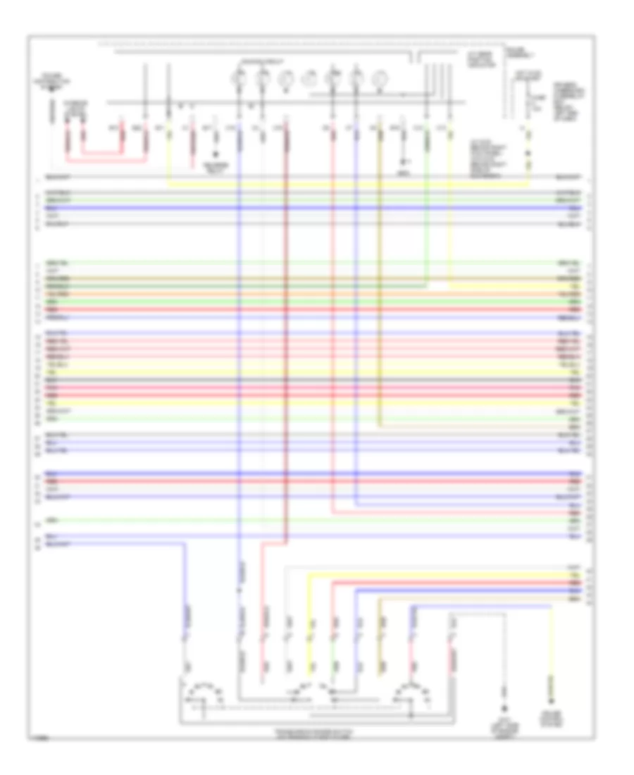
3.5L, Engine Performance Wiring Diagram (2 of 6) for Honda Odyssey EX 2004
List of elements for 3.5L, Engine Performance Wiring Diagram (2 of 6) for Honda Odyssey EX 2004:
- (at rear of engine compt, left of brake booster) evap canister purge valve
- (below center of dash) data link connector (dlc)
- (on brake pedal bracket) brake pedal position switch
- Cruise control system
- Driver's underdash fuse/relay box (below left end of dash)
- Evap bypass solenoid valve (under front of vehicle, near evap canister)
- Evap canister vent shut valve (under front of vehicle, near evap canister)
- Fuel injectors
- Fuse 10a
- Fuse 20a
- G201 (right side of engine compt)
- Gauge assembly
- Hot at all times
- Hot in on or start
- J/c c104 (on lower left rear of trans)
- J/c c105 (on lower left rear of trans)
- Mil ind
- Psp switch (on power steering pressure line)
- Red
- Starting/ charging system
- Underhood fuse/relay box (at right side of engine compt)
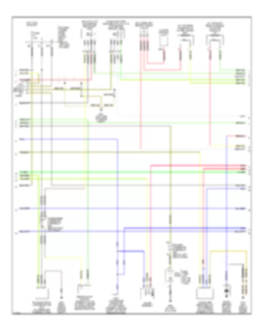
3.5L, Engine Performance Wiring Diagram (3 of 6) for Honda Odyssey EX 2004
List of elements for 3.5L, Engine Performance Wiring Diagram (3 of 6) for Honda Odyssey EX 2004:
- (at top rear of engine, on water jacket) ect sensor
- (at top right rear of engine, on intake manifold) iat sensor
- (in exhaust pipe, forward of catalytic converter) primary ho2s
- (on catalytic converter) secondary ho2s
- (on lower left rear of trans) j/c c104
- B19
- Braided
- C10
- Climate control unit
- Driver's under- dash fuse/ relay box (below left end of dash)
- Driver's underdash fuse/relay box (below left end of dash)
- Ect
- Eld (electrical load detector) unit (in underhood fuse/relay box)
- Engine mount control solenoid valve (at front center of engine compt, behind radiator)
- Fuel pump
- Fuel tank unit (on top of fuel tank)
- Fuse 15a
- G101 (left side of engine compt)
- G201 (right side of engine compt)
- G551 (at left "b" pillar)
- Gauge assembly
- Hot in on or start
- I12
- Immob
- Immobilizer receiver unit (on steering column, near steering lock)
- J/c c107 (below center of dash)
- Knock sensor (on left side of engine)
- Passenger's underdash fuse/relay box (behind right kick panel)
- Pnk
- Red
- Tach
- Test tachometer connector (at left rear corner of engine compt, on top of brake booster)
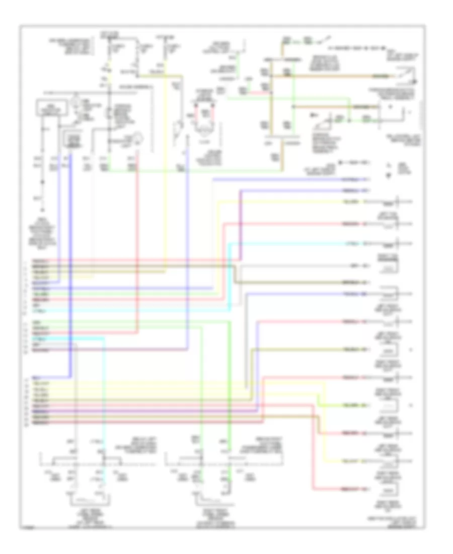
3.5L, Engine Performance Wiring Diagram (4 of 6) for Honda Odyssey EX 2004
List of elements for 3.5L, Engine Performance Wiring Diagram (4 of 6) for Honda Odyssey EX 2004:
- (behind front camshaft pulley, attached to back cover) tdc sensors
- (left side of engine compt)
- (not used)
- (on front of engine, behind crankshaft pulley) ckp sensor
- (on lower left rear of trans) j/c c104
- (on lower left rear of trans) j/c c105
- (on side of throttle body assembly) tp sensor
- (on top left rear of engine) egr valve & egr valve position sensor
- (on transmission) atf temperature sensor
- 3rd clutch pressure switch (on left side of transmission)
- Braided
- Countershaft speed sensor (on lower left rear of transmission)
- Driver's under- dash fuse/ relay box (below left end of dash)
- E14
- Ftp sensor (under front of vehicle, near evap canister)
- G101
- G101 (left side of engine compt)
- G151 (on transaxle housing)
- I17
- J/c c105
- Mainshaft speed sensor (on front of transmission)
- Map sensor (on top of throttle body assembly)
- Pnk
- Red
- Shift control solenoid valve a (on front of trans- mission)
- Shift control solenoid valve b (on top of trans- mission torque converter housing)
- Shift control solenoid valve c (on front of trans- mission)
- Torque converter clutch solenoid valve (on top of trans- mission torque converter housing)
- Vtec oil pressure switch (on bottom right side of engine)
3.5L, Engine Performance Wiring Diagram (5 of 6) for Honda Odyssey EX 2004
List of elements for 3.5L, Engine Performance Wiring Diagram (5 of 6) for Honda Odyssey EX 2004:
- (w/ dvd: behind right kick panel) (w/o dvd: behind right side of glove box)
- A/t gear position indicator
- B10 red
- C6 red
- Cruise control system
- Dimming circuit
- Driver's underdash fuse/relay box (below left end of dash)
- Fuse 10a
- G101 (left side of engine compt)
- G503
- Gauge assembly
- Hot in on or start
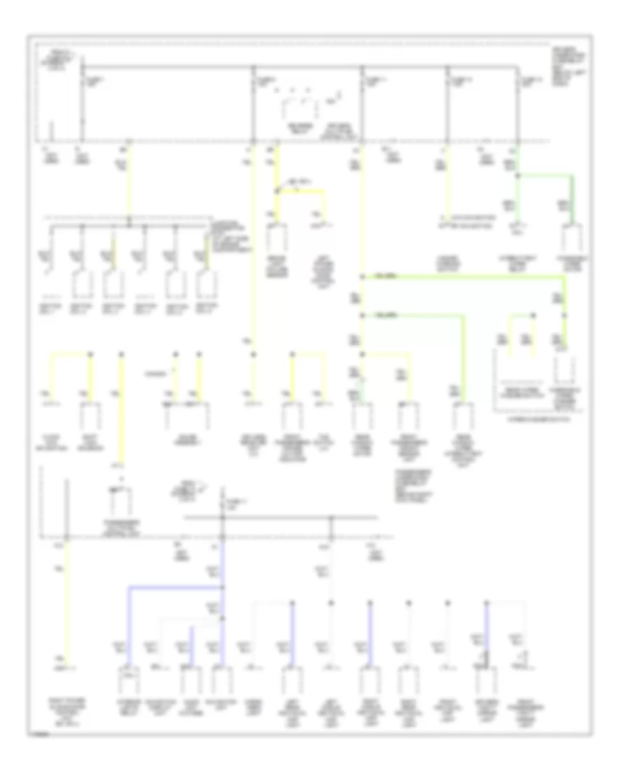
- Interior lights system
- Pnk
- Power distribution system
- Red
- Reverse relay
- Transmission range switch (on transaxle end cover)
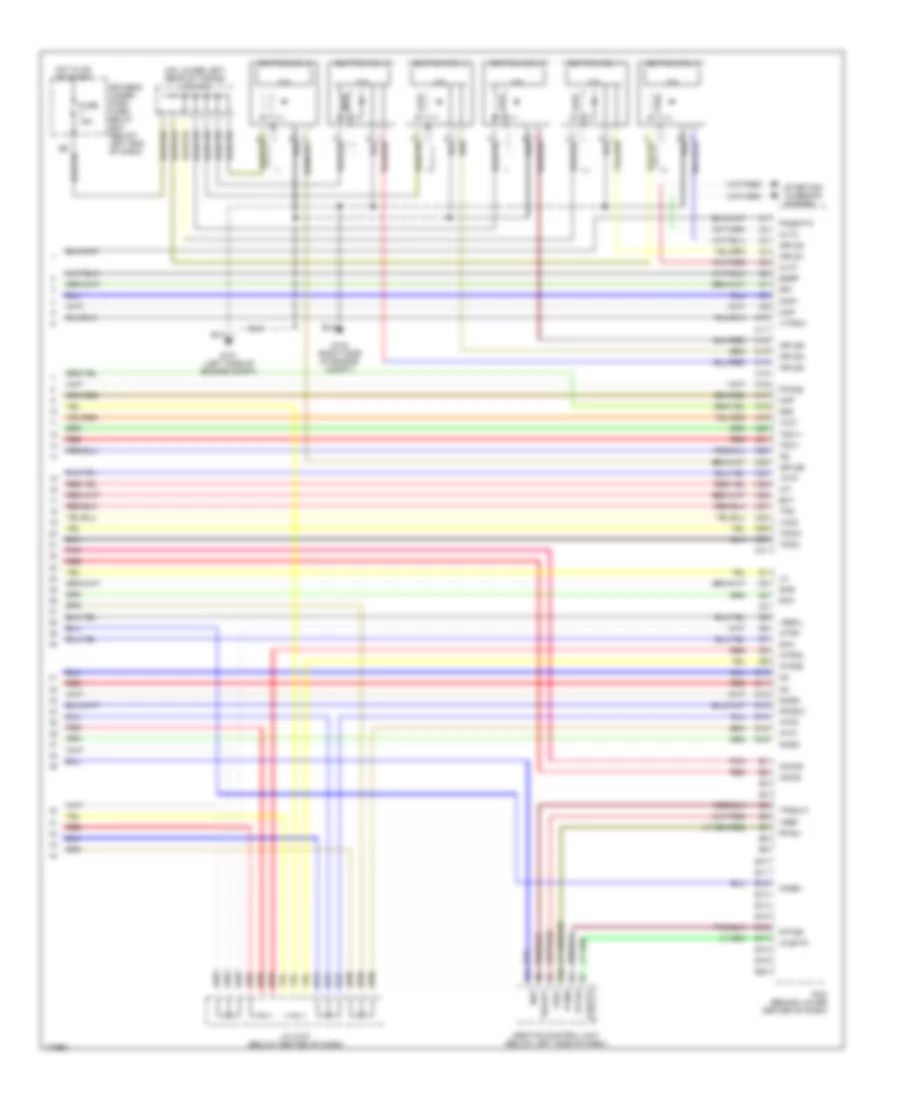
3.5L, Engine Performance Wiring Diagram (6 of 6) for Honda Odyssey EX 2004
List of elements for 3.5L, Engine Performance Wiring Diagram (6 of 6) for Honda Odyssey EX 2004:
- (on lower left rear of trans) j/c c104
- Abs/tcs control unit (below left side of dash)
- Altc
- Altf
- Atp1
- Atp2
- Atpd3
- Atpd5
- Atpr
- Atsftp
- B10
- B11
- C10
- C11
- C12
- C13
- C14
- C15
- C16
- C17
- C18
- C19
- C20
- C21
- C22
- C23
- C24
- C25
- C26
- C27
- C28
- C29
- C30
- C31
- Ckp+
- Ckp-
- D10
- D11
- D12
- D13
- D14
- D15
- D16
- Driver's under- dash fuse/ relay box (below left end of dash)
- E10
- E11
- E12
- E13
- E14
- E15
- E16
- E17
- E18
- E19
- E20
- Ect
- Egrp
- Fptdr
- Fuse 15a
- G101 (left side of engine compt)
- G102 (right side of engine compt)
- Hot in on or start
- Iat
- Icm
- Ignition coil 1
- Ignition coil 2
- Ignition coil 3
- Ignition coil 4
- Ignition coil 5
- Ignition coil 6
- Igpls1
- Igpls2
- Igpls3
- Igpls4
- Igpls5
- Igpls6
- Imocd
- Imoen
- Imoind
- J/c c107 (below center of dash)
- Map
- Ncsg
- Nep
- Nmsg
- Op3sw
- Pcm (behind lower center of dash)
- Pfinh
- Pho2s
- Pnk
- Po2shtc
- Red
- Sg1
- Sg2
- Sha
- Shb
- Shc
- Starting/ charging system
- Tatf
- Tdc1+
- Tdc1-
- Tdc2+
- Tdc2-
- Thlout
- Tps
- Tpsout
- Vbsol
- Vcc1
- Vcc2
- Vref
- Vtpsw
EXTERIOR LIGHTS
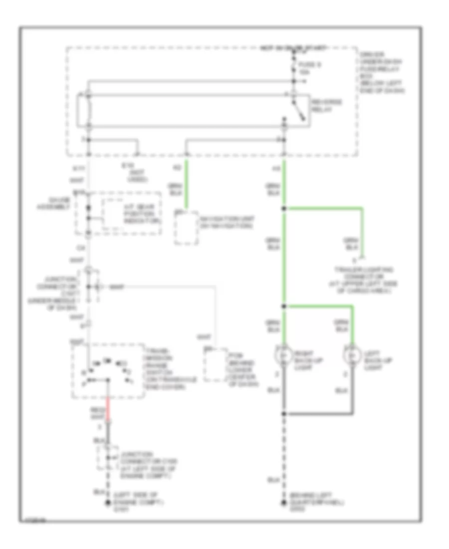
Back-up Lamps Wiring Diagram for Honda Odyssey EX 2004
List of elements for Back-up Lamps Wiring Diagram for Honda Odyssey EX 2004:
- (behind left quarterpanel) g552
- (left side of engine compt) g101
- A/t gear position indicator
- B17
- Driver under-dash fuse/relay box (below left end of dash)
- E10 (not used)
- Fuse 9 10a
- Gauge assembly
- Hot in on or start
- Junction connector c105 (at left side of engine compt)
- Junction connector c107 (under middle of dash)
- K11
- Left back-up light
- Navigation unit (w/ navigation)
- Pcm (behind lower center of dash)
- Reverse relay
- Right back-up light
- Trailer lighting connector (at upper left side of cargo area)
- Trans- mission range switch (on transaxle end cover)
Exterior Lamps Wiring Diagram (1 of 2) for Honda Odyssey EX 2004
List of elements for Exterior Lamps Wiring Diagram (1 of 2) for Honda Odyssey EX 2004:
- (at left side of engine compt) g301
- (at right side of engine compt) g201
- (behind left quarterpanel) g552
- (behind right quarterpanel) g582
- (under left side of dash) g401
- A11
- A22
- B16
- Brake light failure sensor (at left rear of cargo area)
- Brake light/ outer taillight
- Brake pedal position switch (on brake pedal bracket)
- C17
- C403
- Combination light switch
- Driver under-dash fuse/relay box (below left end of dash)
- Driver's multiplex control unit
- E18
- Ex, ex-l
- Fuse 10 15a
- Fuse 47 20a
- Fuse 9 10a
- G552 (behind left quarterpanel)
- Gauge assembly
- Headlight switch head
- High mount brake light
- Hot at all times
- Hot in on or start
- Interior lights system, air conditioning system
- Left front turn signal/ side marker light
- Left inner taillight
- Left taillight assembly
- License plate light
- O20
- Off
- Park
- Passenger under-dash fuse/relay box (behind right kick panel)
- Right front turn signal/ side marker light
- Right inner taillight
- Right taillight assembly
- Safety indicator
- Security system connector (accessory)
- Taillight relay (behind left side of dash)
- To combination light switch (diagram 2 of 2)
- To driver's underdash fuse/relay box (diagram 2 of 2)
- To trailer lighting connector (diagram 2 of 2)
- Turn signal light
- Under-hood fuse/relay box (at right side of engine compartment)
Exterior Lamps Wiring Diagram (2 of 2) for Honda Odyssey EX 2004
List of elements for Exterior Lamps Wiring Diagram (2 of 2) for Honda Odyssey EX 2004:
- (not used)
- (w/o dvd: behind right side of glove box)
- A14
- B16
- Back-up lamps circuit
- Combination light switch
- Driver under-dash fuse/relay box (below left end of dash)
- From driver's underdash fuse/relay box (diagram 1 of 2)
- From front side marker/ turn signal lights (diagram 1 of 2)
- From rear turn signal lights (diagram 1 of 2)
- Fuse 10 7.5a
- Fuse 49 15a
- G401 (under left side of dash)
- G503 (w/dvd: behind right kick panel)
- G552 (behind left quarterpanel)
- Gauge assembly
- Hazard warning switch
- Hazard warning switch light
- Hot at all times
- Hot in on or start
- I15
- I16
- Interior lights system
- K11
- Left
- Left turn signal indicator
- Off
- Passenger under-dash fuse/relay box (behind right kick panel)
- Q15
- Q17
- Q21
- Red
- Right
- Right turn signal indicator
- Trailer lighting connector (at upper left side of cargo area)
- Turn signal switch
- Turn signal/ hazard relay
- Under-hood fuse/relay box (at right side of engine compartment)
- W/ navigation
- W/o navigation
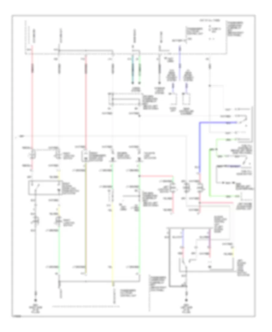
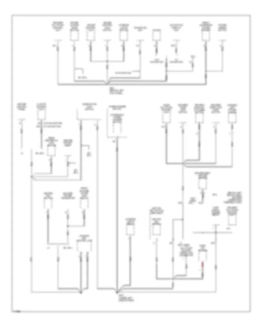
GROUND DISTRIBUTION
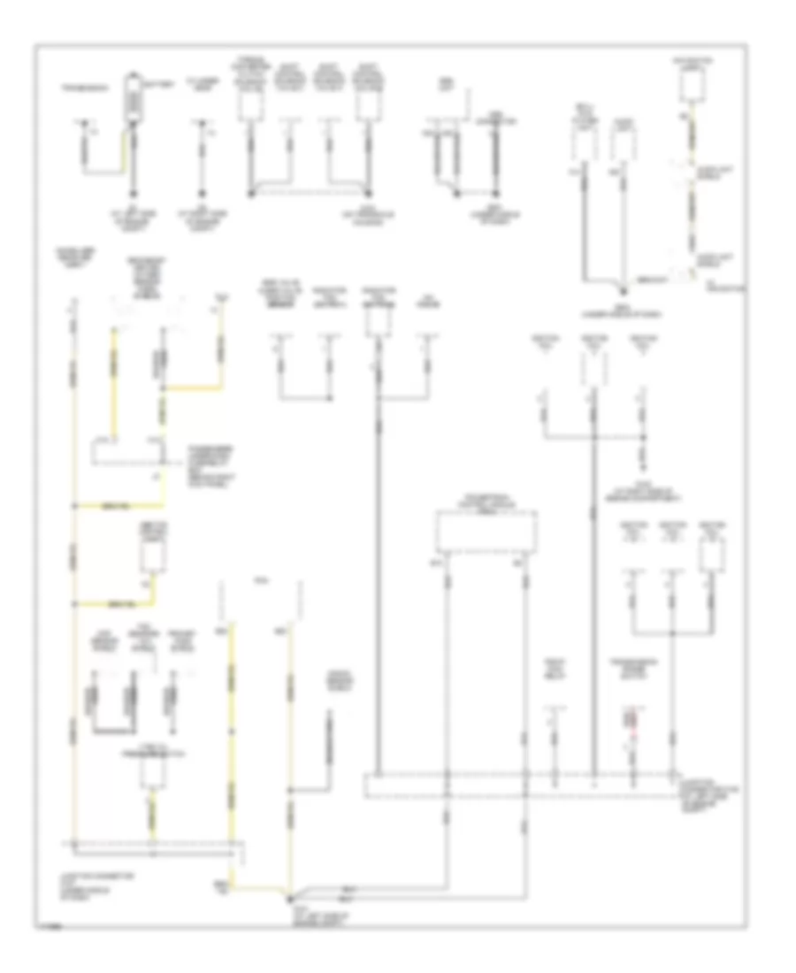
Ground Distribution Wiring Diagram (1 of 4) for Honda Odyssey EX 2004
List of elements for Ground Distribution Wiring Diagram (1 of 4) for Honda Odyssey EX 2004:
- (ex-l) dvd player unit
- Abs/tcs control unit
- Audio unit
- Audio unit shield
- B10
- B20
- B22
- Battery
- Braided wire
- C18
- Ckp sensor shield
- Cylinder head
- Dlc
- Egr valve & egr valve position sensor
- G1 (at left side of engine compt)
- G101 (at left side of engine compt)
- G102 (at right side of engine compartment)
- G151 (on transaxle housing)
- G2 (at right side of engine compt)
- G502 (under middle of dash)
- G851 (under middle of dash)
- H14
- Iac valve
- Ignition coil
- Immobilizer receiver unit
- Junction connector c105 (at left side of engine compt)
- Junction connector c107 (under middle of dash)
- Knock sensor shield
- Mes connector
- Navigation unit
- Passenger's under-dash fuse/relay box (behind right kick panel)
- Pcm
- Pgm-fi main relay
- Powertrain control module (pcm)
- Primary ho2s shield
- Radiator fan switch a
- Radiator fan switch b
- Secondary heated oxygen sensor (ho2s) shields
- Shift control solenoid valve a
- Shift control solenoid valve b
- Shift control solenoid valve c
- Srs unit
- Tdc sensors 1 & 2 shield
- Torque converter clutch solenoid valve
- Transmission
- Transmission range switch
- Vtec oil pressure switch
- W/ navigation
- Wire braided
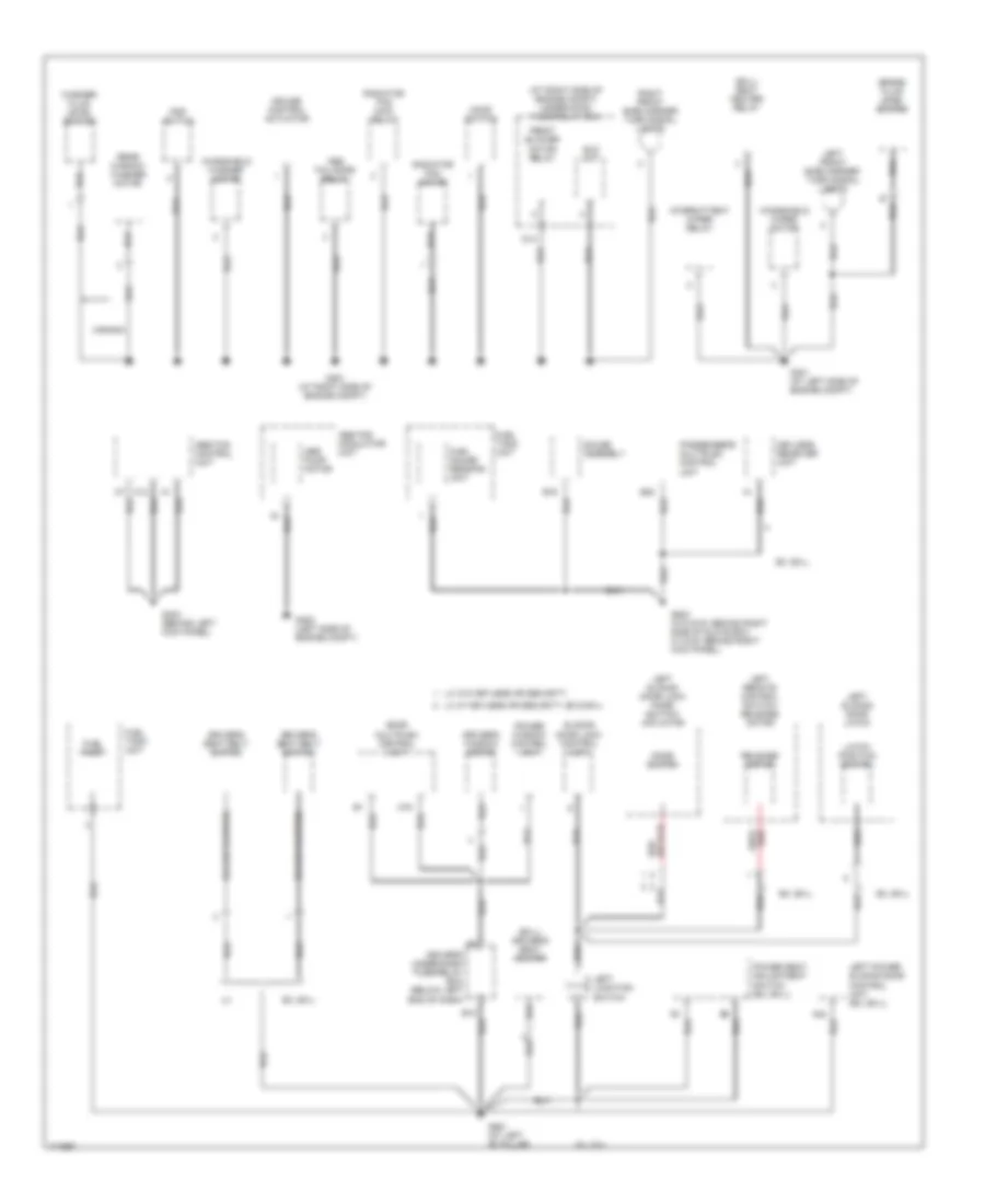
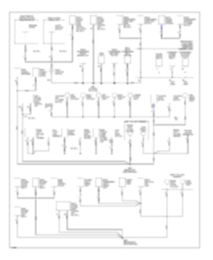
Ground Distribution Wiring Diagram (2 of 4) for Honda Odyssey EX 2004
List of elements for Ground Distribution Wiring Diagram (2 of 4) for Honda Odyssey EX 2004:
- (at right side of engine compt) under-hood fuse/relay box
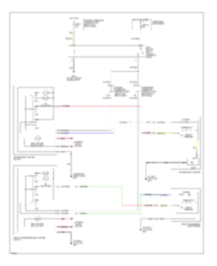
- (ex-l) driver's seat heater
- (ex-l) seat heater relay
- A19
- Abs fail-safe relay
- Abs pump motor
- Abs-tcs modulator unit
- Abs/tcs control unit
- B16
- B22
- Brake fluid level switch
- Canada
- Cruise control actuator
- D14
- Door multiplex control unit
- Driver's seat belt switch
- Driver's under-dash fuse/relay box (below left end of dash)
- Driver's window motor
- Eld unit
- Ex, ex-l
- Front blower motor relay
- Fuel gauge sending unit
- Fuel pump
- Fuel tank unit
- G201 (at right side of engine compt)
- G301 (at left side of engine compt)
- G302 (left side of engine compt)
- G303 (behind left kick panel)
- G503 (w/o dvd: behind right side of glove box, w/ dvd: behind right kick panel)
- G551 (at left "b" pillar)
- Gauge assembly
- Hood switch
- Intermittent wiper relay
- Keyless receiver unit
- Knob switch
- Latch position switch
- Left front side marker/ turn signal lights
- Left junction switch
- Left power sliding door control unit (ex, ex-l)
- Left remote control switch/ release motor
- Left sliding door latch
- Left sliding door lock knob switch/ actuator
- Lx w/ keyless or security, ex & ex-l
- Lx w/o keyless or security
- Passenger's multiplex control unit
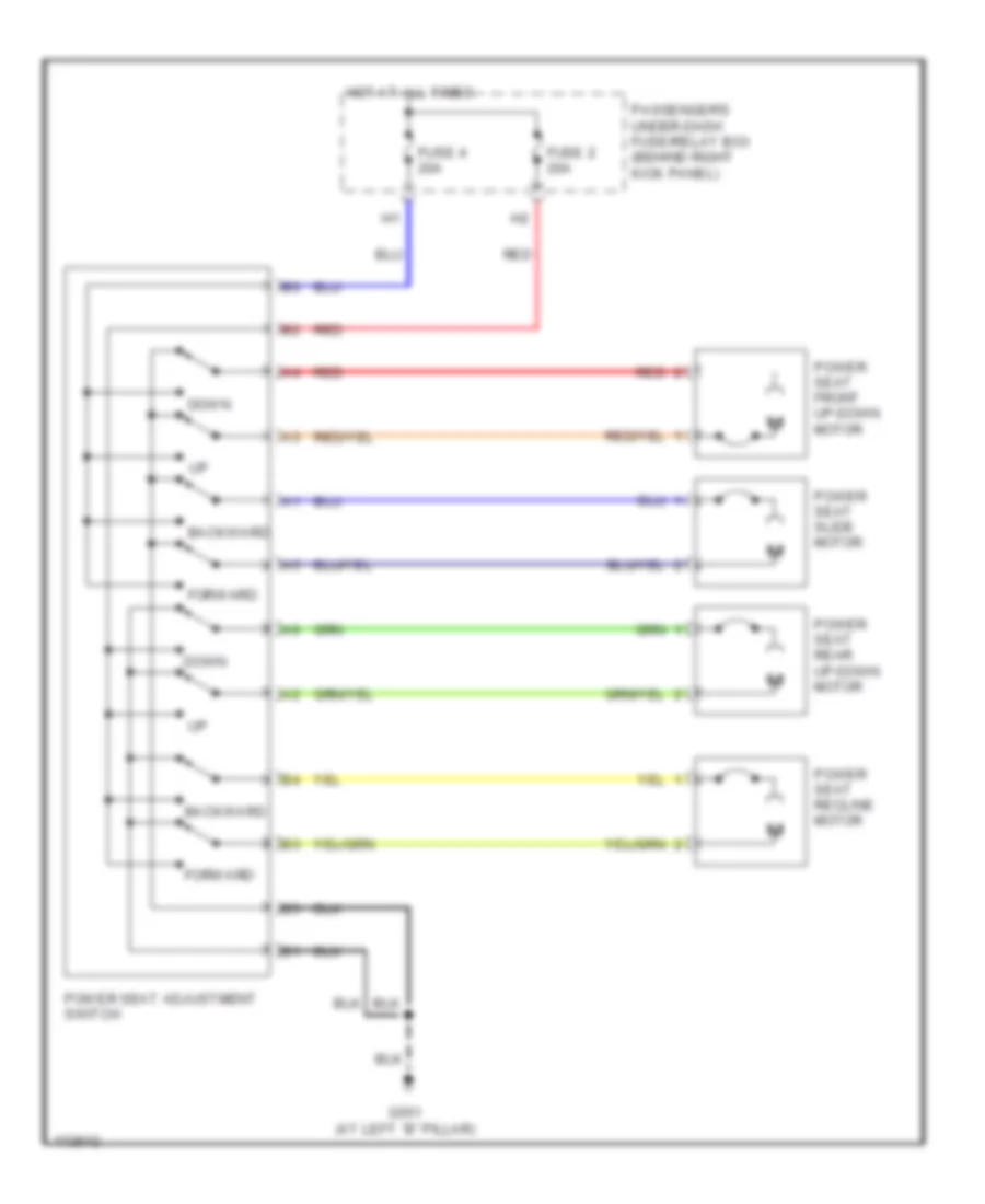
- Power seat adjustment switch (ex, ex-l)
- Power window control unit
- Psp switch
- Radiator fan main relay
- Radiator fan motor
- Rear window washer motor
- Release motor
- Right front side marker/ turn signal lights
- Sliding door lock control unit
- Washer fluid level switch
- Windshield washer motor
- Windshield wiper motor
Ground Distribution Wiring Diagram (3 of 4) for Honda Odyssey EX 2004
List of elements for Ground Distribution Wiring Diagram (3 of 4) for Honda Odyssey EX 2004:
- (below left end of dash) driver's under-dash fuse/relay box
- (canada) drl control unit
- (canada) left power mirror
- (not used)
- (w/ navigation)
- (w/o navigation)
- A12
- A14
- B10
- B15
- Blower power transistor
- Center pocket light
- Climate control unit
- Clock
- Combination light switch
- Cruise control main switch
- Cruise control unit
- Dlc
- Door multiplex control unit
- Driver's door key cylinder switch
- Driver's door lock knob switch
- Driver's door lock switch
- Driver's multiplex control unit
- Driver's seat heater switch
- Ex, ex-l
- Ex-l
- Front accessory power socket
- Front blower motor high relay
- G16
- G401 (under left side of dash)
- G501 (behind left kick panel)
- Heater control panel
- Heater fan switch
- Ignition key switch
- Ignition key switch/ key light
- Interior lights relay
- Interior lights switch
- Multiplex control inspection connector
- Navigation display unit
- Navigation unit
- Park pin switch
- Power mirror switch
- Power sliding door switch
- Q15
- Rear heater-a/c main switch
- Red
- Turn signal hazard relay
- W/ navigation
- W/o navigation
- Windshield wiper/ washer switch
- Wiper/washer switch
Ground Distribution Wiring Diagram (4 of 4) for Honda Odyssey EX 2004
List of elements for Ground Distribution Wiring Diagram (4 of 4) for Honda Odyssey EX 2004:
- (behind right kick panel) passenger's under-dash fuse/relay box
- (ex-l) front passenger's seat heater
- (not used)
- Accessory power socket relay
- Aux- iliary jack assembly
- Brake light failure sensor
- Brake light/ outer taillight
- Cargo area light
- Driver's vanity mirror light
- Ex, ex-l
- Ex-l, ex
- Front individual map light
- Front passenger's door key cylinder switch
- Front passenger's door lock knob switch (ex, ex-l)
- Front passenger's door lock switch
- Front passenger's seat belt switch
- Front passenger's vanity mirror light
- Front passenger's weight sensor unit
- Fuel fill door switch
- G552 (behind left quarterpanel)
- G581 (at right "b" pillar)
- G582 (behind right quarterpanel)
- High mount brake light
- Latch position switch
- Left back-up light
- Left inner taillight
- Left power sliding door control unit
- Left taillight assembly
- License plate light
- Opds unit
- Passenger's multiplex control unit
- Power window relay
- Rear acces- sory power socket
- Rear blower motor high relay
- Rear blower motor low relay
- Rear blower motor middle relay
- Rear cont- roller & screen
- Rear mode control motor
- Rear window defogger
- Rear window wiper inter- mittent control unit
- Rear window wiper motor
- Release motor
- Right back-up light
- Right inner taillight
- Right junction switch
- Right power mirror (canada)
- Right power sliding door control unit (ex, ex-l)
- Right remote control switch/ release motor
- Right sliding door latch
- Right sliding door lock knob switch/ actuator (ex, ex-l)
- Right taillight assembly
- Sliding door buzzer
- Tailgate key cylinder switch
- Tailgate knob switch
- Tailgate latch switch
- Trailer lighting connector
- Turn signal light
HEADLIGHTS
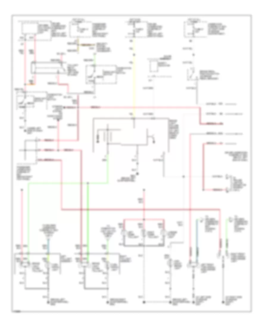
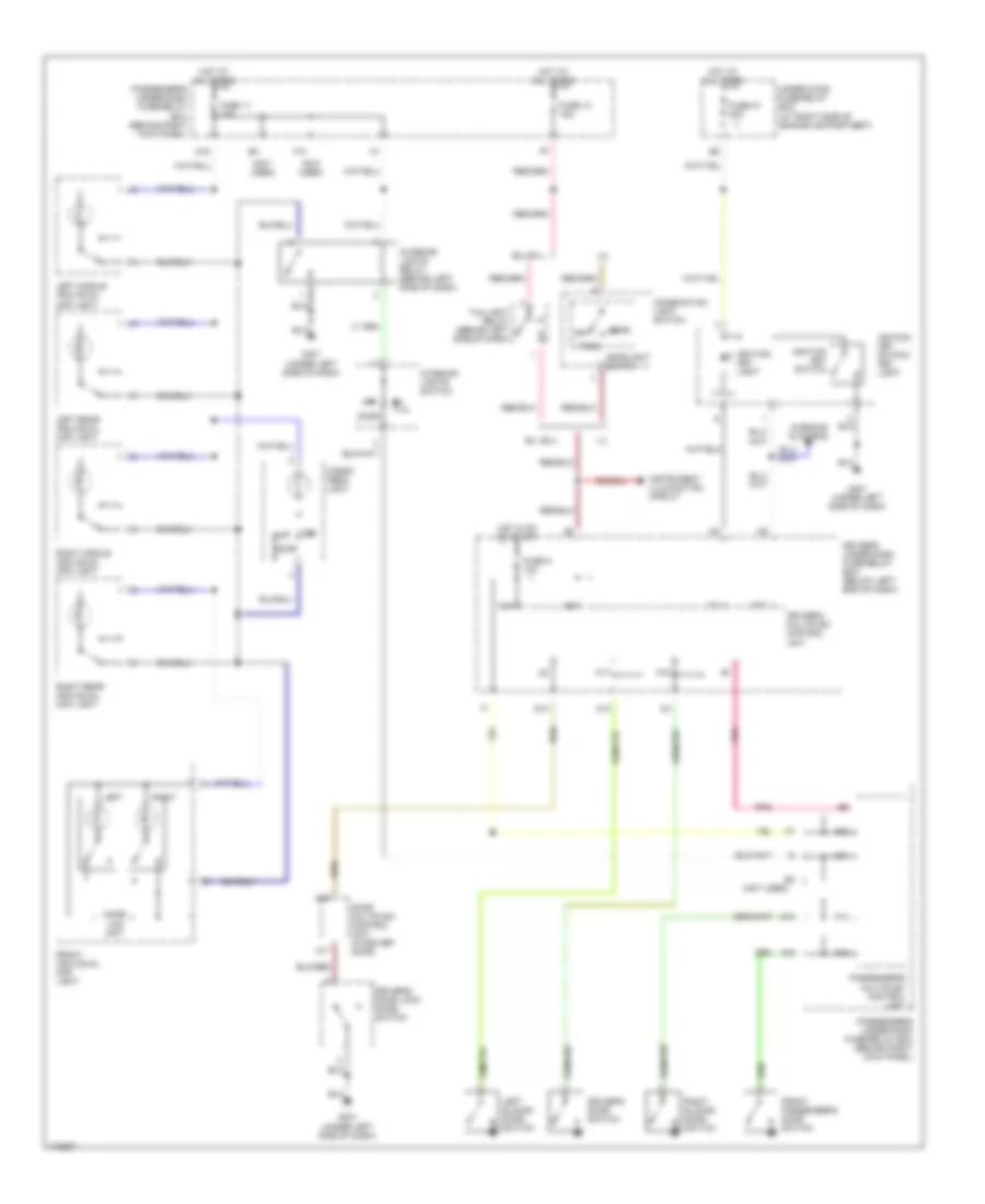
Headlights Wiring Diagram, with DRL (1 of 2) for Honda Odyssey EX 2004
List of elements for Headlights Wiring Diagram, with DRL (1 of 2) for Honda Odyssey EX 2004:
- (behind right kick panel)
- (behind right kick panel) passenger under-dash fuse/relay box
- (below left end of dash) driver under-dash fuse/relay box
- (ex ,ex-l)
- (not used)
- A10
- A12
- A13
- A14
- A15
- A16
- A17
- A2 (not used)
- A20
- A5 (not used)
- B11
- B13
- B15
- B18
- Brake system ind
- C13
- C14
- Combination light switch
- Dimmer switch
- Door locks system
- Door multiplex control unit
- Driver under-dash fuse/relay box (below left end of dash)
- Driver's door lock knob switch
- Driver's door switch
- Driver's multiplex control unit
- Drl control unit (behind glove box)
- Drl ind
- Drl relay (behind left side of dash)
- E19
- Ex, ex-l
- Flash- to-pass switch
- Fuse 10a
- Fuse 43 15a
- Fuse 44
- Fuse 45 15a
- Fuse 7.5a
- G14
- G401 (under left
- G401 (under left side of dash)
- Gauge assembly
- H8 (not used)
- Head
- Head park
- Headlight relay 1
- Headlight relay 2
- Headlight switch
- High
- High beam ind
- Hot at all times
- Hot in on
- Hot in on or start
- I13
- Ignition key switch
- Ignition key switch/ key light
- Instrument cluster system
- Interior lights system
- Left headlight
- Low
- Low beam cut relay (behind left side of dash)
- Off
- Park
- Parking brake switch (on parking brake pedal assembly)
- Passenger under-dash fuse/relay box
- Passenger under-dash fuse/relay box (behind right kick panel)
- Passenger's multiplex control unit
- Q12
- Q14
- Q15
- Red
- Right headlight
- Side of dash)
- To fog- light diode (diagram 2 of 2)
- Under-hood fuse/relay box (at right side of engine compt)
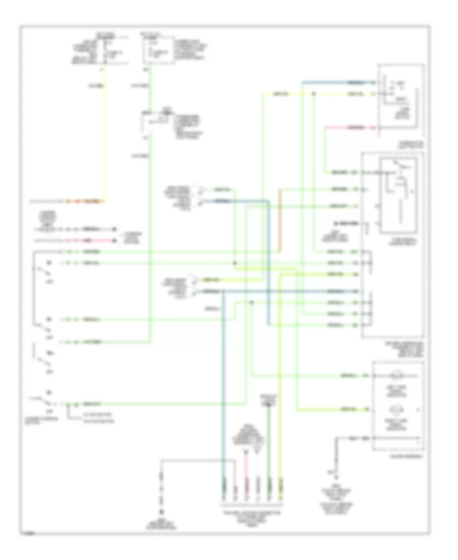
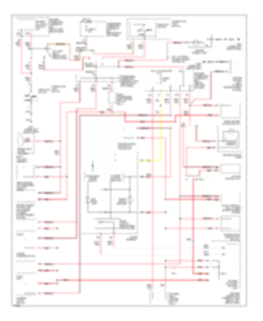
Headlights Wiring Diagram, with DRL (2 of 2) for Honda Odyssey EX 2004
List of elements for Headlights Wiring Diagram, with DRL (2 of 2) for Honda Odyssey EX 2004:
- (below left end of dash)
- A20
- Battery
- Combination light switch
- Dim ctrl
- Driver's multiplex control unit
- Driver's under-dash fuse/relay box
- Fog light diode (below steering column)
- Fog light in-line fuse a 20a (at left side of engine compt, near battery)
- Fog light in-line fuse b
- Fog light relay 1 (below left side of dash)
- Fog light relay 2 (at right front corner of engine compt)
- Fog light switch
- Fog light switch light
- From combination light switch (diagram 1 of 2)
- G1 (at left side of engine compt)
- G201 (at right side of engine compt)
- G401 (under left side of dash)
- Head
- Headlight switch
- Hot w/ headlight switch in park of head
- Left fog light
- Off
- On ind
- Park
- Red
- Right fog light
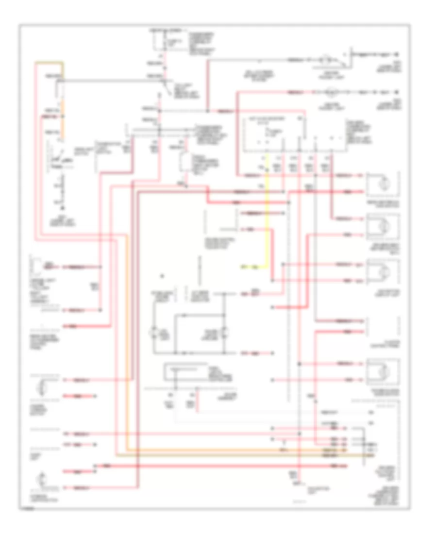
Headlights Wiring Diagram, without DRL for Honda Odyssey EX 2004
List of elements for Headlights Wiring Diagram, without DRL for Honda Odyssey EX 2004:
- (below left end of dash)
- (not used)
- A10
- A12
- A13
- A14
- A15
- A16
- A17
- A20
- B13
- Battery
- C13
- Combination light switch
- Dim control
- Dimmer switch
- Door locks system
- Door multiplex control unit
- Driver's door lock knob switch
- Driver's door switch
- Driver's multiplex control unit
- Driver's under-dash fuse/relay box
- Driver's under-dash fuse/relay box (below left end of dash)
- Driver's under-dash fuse/relay box (ex, ex-l)
- E19
- Ex, ex-l
- Flash- to-pass switch
- Fog light diode (below steering column)
- Fog light in-line fuse a 20a (at left side of engine compt, near battery)
- Fog light in-line fuse b
- Fog light relay 1 (below left side of dash)
- Fog light relay 2 (at right front corner of engine compt)
- Fog light switch
- Fog light switch light
- Fuse 43 15a
- Fuse 44
- Fuse 45 15a
- G1 (at left side of engine compt)
- G14
- G201 (at right side of engine compt)
- G401 (under left side of dash)
- Gauge assembly
- Head
- Headlight relay 1
- Headlight relay 2
- Headlight switch
- High
- High beam ind
- Hot at all times
- Hot w/ headlight switch in park or head
- I13
- Ignition key switch
- Ignition key switch/ key light
- Interior lights system
- Left fog light
- Left headlight
- Low
- Off
- On ind
- Park
- Passenger's multiplex control unit
- Passenger's under-dash fuse/relay box (behind right kick panel)
- Q12
- Q15
- Red
- Right fog light
- Right headlight
- Under-hood fuse/relay box (at right side of engine compt)
HORN
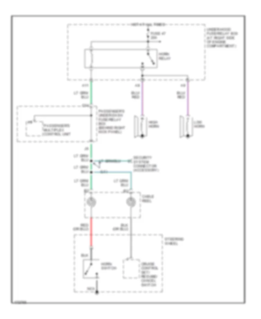
Horn Wiring Diagram for Honda Odyssey EX 2004
List of elements for Horn Wiring Diagram for Honda Odyssey EX 2004:
- (lx)
- A11
- C14
- Cable reel
- Cruise control set/ resume/ cancel switch
- Fuse 47 20a
- High horn
- Horn relay
- Horn switch
- Hot at all times
- Low horn
- Nca
- Passenger's multiplex control unit
- Passenger's under-dash fuse/relay box (behind right kick panel)
- Security system connector (accessory)
- Steering wheel
- Under-hood fuse/relay box (at right side of engine compartment)
INSTRUMENT CLUSTER
Instrument Cluster Wiring Diagram (1 of 2) for Honda Odyssey EX 2004
List of elements for Instrument Cluster Wiring Diagram (1 of 2) for Honda Odyssey EX 2004:
- (behind right kick panel) g503
- (canada)
- (not used)
- (under left rear of vehicle)
- (under left side of dash)
- (w/o dvd: behind right side of glove box) (w/dvd: behind right kick panel) g503
- A10
- A11
- A12
- A13
- A14
- A18
- A19
- A31
- Abs check
- Abs indicator circuit
- Abs indicator light
- Anti-lock brakes system
- Anti-theft system
- B10
- B11
- B12
- B13
- B14
- B15
- B16
- B17
- B18
- B19
- B20
- B21
- B22
- Brake system indicator light
- C10
- C11
- C12
- C13
- C14
- C15
- C16
- Charging system indicator light
- Clock (except navigation)
- Coolant temp circuit
- Cruise control indicator light
- Cruise control system
- Door locks system
- Driver ckt
- Driver's underdash fuse/relay box (below left end of dash)
- E15
- Ect out
- Engine controls system
- Engine coolant temperature gauge
- Exterior lights system
- Exterior lights systems
- Fuel gauge
- Fuel gauge drive circuit
- Fuel gauge sending unit
- Fuel tank unit
- Fuse 13 7.5a
- Fuse 6 15a
- Fuse 9 10a
- G501
- Gauge assembly
- H15
- H16
- Headlights system
- High beam indicator light
- Hot at all times
- Hot in on or start
- I12
- Ilu
- Immob ind ctrl
- Immobilizer indicator light
- Interior lights system
- Interior lights systems
- Lcd back light
- Lcd display
- Low engine oil pressure indicator light
- Low fuel indicator light
- Maintenance required indicator light
- Malfunction indicator light
- Mil ctrl
- Odo/trip display
- Odometer/ trip/ maintenance/ washer circuit
- Passenger's underdash fuse/relay box (behind right kick panel)
- Pnk
- Powertrain control module (pcm) (behind lower center of dash)
- Red
- Rpm output
- Seat belt reminder light
- Security indicator
- Sliding door indicator light
- Speedo- meter
- Speedo- meter drive circuit
- Srs indicator circuit
- Srs indicator light
- Starting/charging system
- Tacho- meter
- Tacho- meter drive circuit
- To safety indicator circuit
- To stabilizing power circuit (diagram 2 of 2)
- To turn signal indicators (diagram 2 of 2)
- Trip/ maintenance reset switch
- Trunk, tailgate, fuel doors system
- Vss out
- Washer indicator light (canada)
Instrument Cluster Wiring Diagram (2 of 2) for Honda Odyssey EX 2004
List of elements for Instrument Cluster Wiring Diagram (2 of 2) for Honda Odyssey EX 2004:
- (at left side of engine compt) g301
- (below left end of dash)
- (in driver's seat belt buckle)
- (left side "b" pillar) g551
- A/t gear position indicator
- A10
- A11
- A14
- A16
- A18
- A20
- B10
- B11
- B13
- B15
- B17
- B18
- B22
- Brake fluid level switch (in brake fluid reservoir cap)
- C12
- C13
- C15
- C16
- Canada
- Dash lights brightness controller
- Daytime running lights (drl) control unit (behind glove box)
- Dimming circuit
- Driver's door switch
- Driver's multiplex control unit
- Driver's seat belt switch
- Driver's underdash fuse/relay box
- Drl indicator (canada)
- Engine oil pressure switch (on bottom right side of engine, on side of oil pump housing)
- From pin b11 (diagram 1 of 2)
- From pin b16 (diagram 1 of 2)
- Front passenger's door switch
- G201 (right front of engine compt)
- Gauge assembly
- Gauge lights (6 bulbs)
- I14
- I15
- I16
- Indicators
- Interior lights system
- K12
- Lcd back light
- Left sliding door switch
- Left turn signal indicator light
- Nca
- Parking brake switch (on parking brake pedal assembly)
- Passenger's underdash fuse/relay box (behind right kick panel)
- Pnk
- Power sliding door indicator
- Red
- Right sliding door switch
- Right turn signal indicator light
- Safety indicator circuit
- Side airbag cutoff indicator
- Solid state
- Sound systems
- Stabilizing power circuit
- Tcs indicator light
- Usa
- Washer fluid level switch (at washer fluid reservoir)
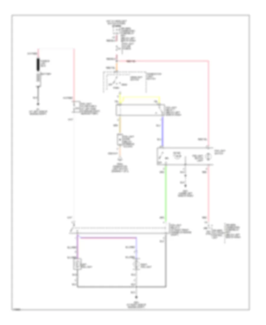
INTERIOR LIGHTS
Courtesy Lamps Wiring Diagram for Honda Odyssey EX 2004
List of elements for Courtesy Lamps Wiring Diagram for Honda Odyssey EX 2004:
- (behind left kick panel) g501
- (not used)
- A10
- A14
- A15
- A16
- A17
- A19
- A21
- Cargo area light
- Door
- Driver's door switch
- Driver's multiplex control unit
- Driver's under-dash fuse/relay box (below left end of dash)
- Driver's vanity mirror light
- Ex, ex-l
- F10
- Front individual map light
- Front passenger's door switch
- Front passenger's vanity mirror light
- Fuse 11 10a
- G401 (under left side of dash)
- G552 (behind left quarterpanel)
- G582 (behind right quarterpanel)
- Gauge assembly
- Home- link unit
- Hot at all times
- I14
- I15
- I16
- Instrument illumination circuit
- Interior lights relay (behind left side of dash)
- Interior lights switch
- Interior lights switch light
- Left
- Left middle individual map light
- Left rear individual map light
- Left sliding door switch
- Off
- Off door
- Passenger's multiplex control unit
- Passenger's under-dash fuse/relay box (behind right kick panel)
- Pnk
- Red
- Right
- Right middle individual map light
- Right rear individual map light
- Right sliding door switch
- Tailgate latch switch
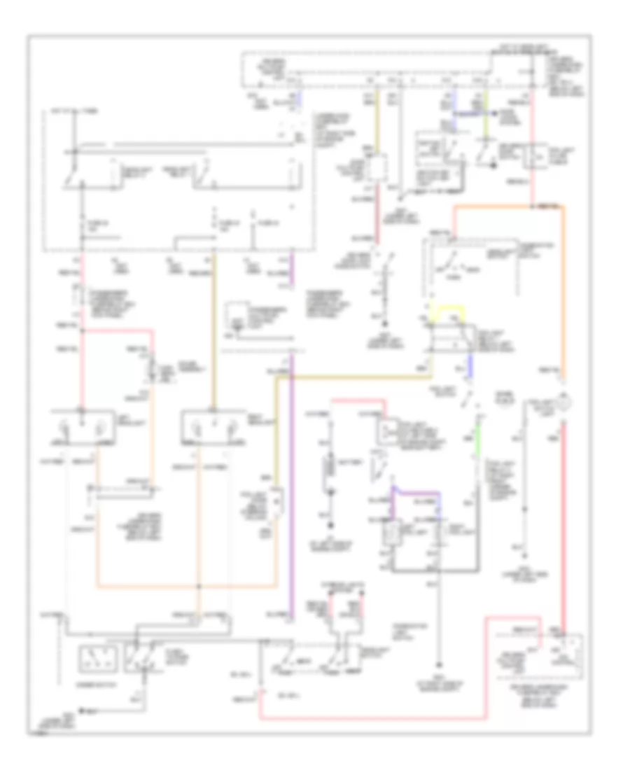
Entry Light Timer Wiring Diagram for Honda Odyssey EX 2004
List of elements for Entry Light Timer Wiring Diagram for Honda Odyssey EX 2004:
- (not used)
- A10
- A13
- A14
- A15
- A16
- A17
- A19
- A21
- A22
- A24
- Cargo area light
- Combination light switch
- Door
- Door multiplex control unit (in driver door)
- Driver's door lock knob switch
- Driver's door switch
- Driver's multiplex control unit
- Driver's under-dash fuse/relay box (below left end of dash)
- Ex, ex-l
- F10
- Front individual map light
- Front passenger's door switch
- Fuse 10 15a
- Fuse 11 10a
- Fuse 47 20a
- Fuse 9 10a
- G14
- G401 (under left side of dash)
- Head
- Headlight switch
- Home- link unit
- Hot at all times
- Hot in on or start
- Ignition key light
- Ignition key switch
- Ignition key switch/ key light
- Instrument illumination circuit
- Interior lights relay (behind left side of dash)
- Interior lights switch
- Left
- Left middle individual map light
- Left rear individual map light
- Left sliding door switch
- Off
- Park
- Passenger's multiplex control unit
- Passenger's under-dash fuse/relay box (behind right kick panel)
- Pnk
- Right
- Right middle individual map light
- Right rear individual map light
- Right sliding door switch
- Taillight relay (behind left side of dash)
- Under-hood fuse/relay box (at right side of engine compartment)
- Warning systems
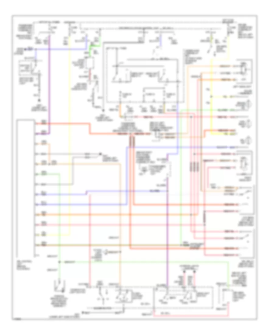
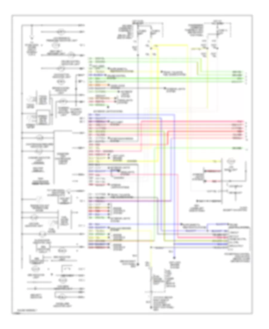
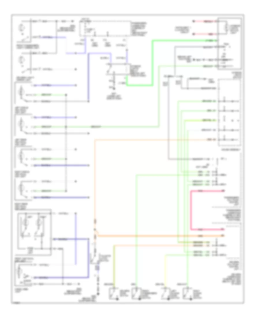
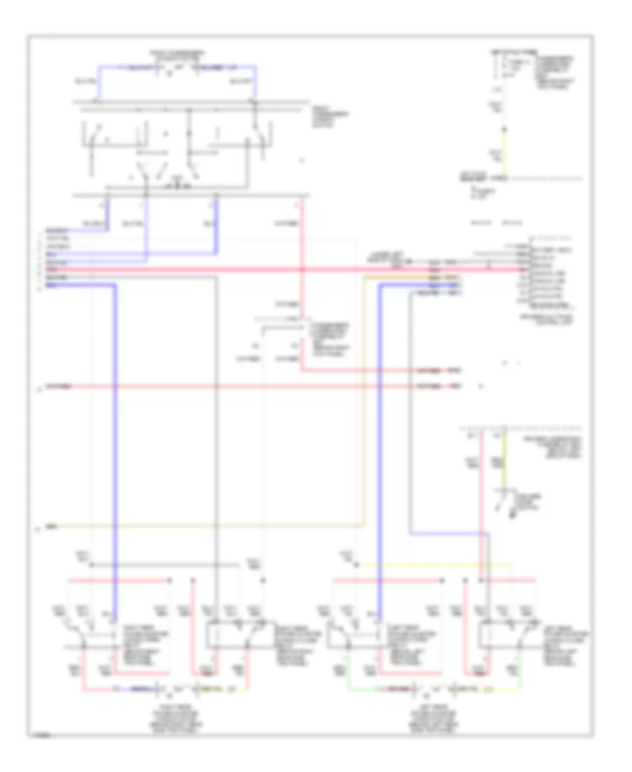
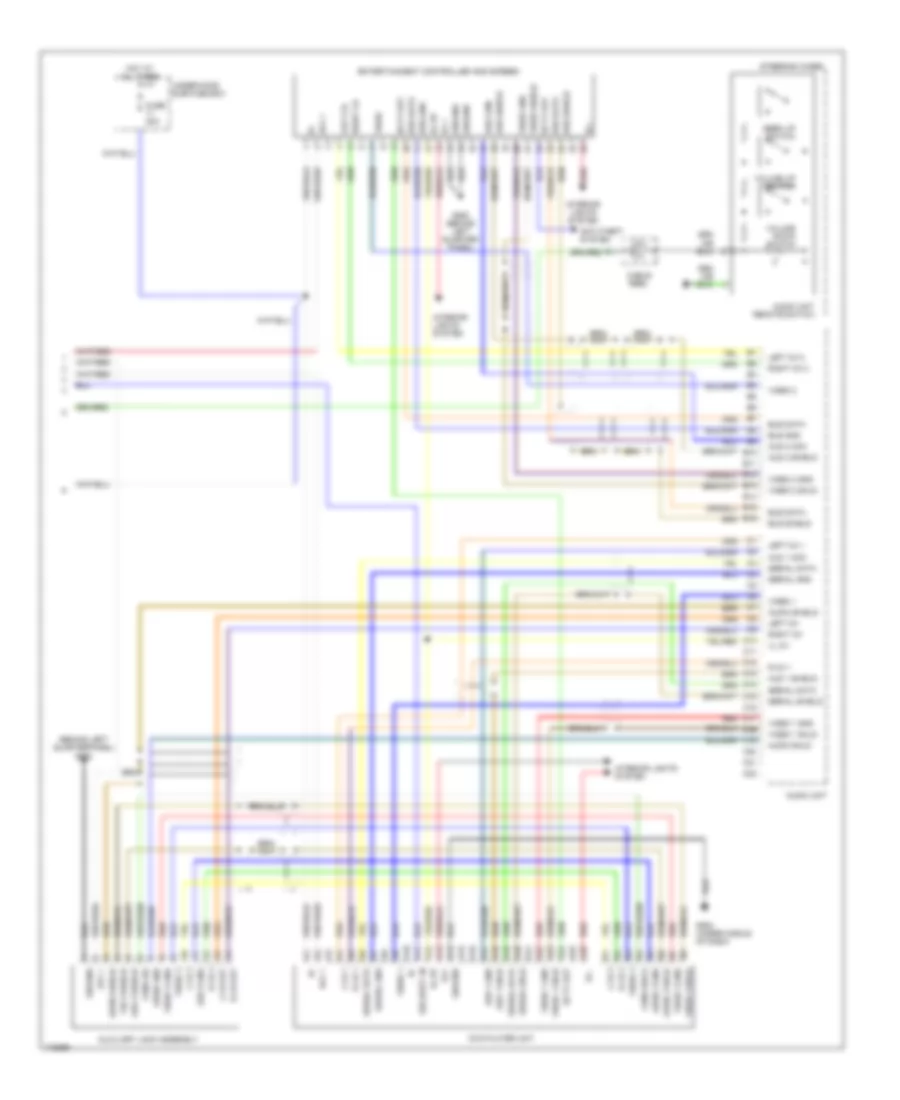
Instrument Illumination Wiring Diagram, with Navigation for Honda Odyssey EX 2004
List of elements for Instrument Illumination Wiring Diagram, with Navigation for Honda Odyssey EX 2004:
- A/t gear position indicator
- A19
- A20
- A22
- Audio unit
- B10
- B11
- B12
- B16
- B22
- Brake light/ outer taillight
- Center pocket light
- Climate control panel
- Combination light switch
- Cruise control main switch/ tcs switch
- Dash lights brightness controller
- Driver's multiplex control unit
- Driver's seat heater switch (ex-l)
- Driver's under-dash fuse/relay box (below left end of dash)
- Ex-l
- Ex-l w/o rear entertainment system
- Front passenger's seat heater switch (ex-l)
- Fuse 10 15a
- Fuse 9 10a
- G401 (under left side of dash)
- G401 (under left side of dash)
- Gauge assembly
- Gauge lights (6 bulbs)
- Hazard warning switch
- Head
- Headlight switch
- Hot at all times
- Hot in on or start
- I13
- Interior lights switch
- K15
- K16
- Lcd back light
- Navigation display unit
- Navigation unit
- Off
- Park
- Passenger's under-dash fuse/relay box (behind right kick panel)
- Power sliding door switch
- Rear heater- a/c passenger control panel
- Rear heater-a/c main switch
- Red
- Right taillight assembly
- Stabilizing power circuit
- Taillight relay (behind left side of dash)
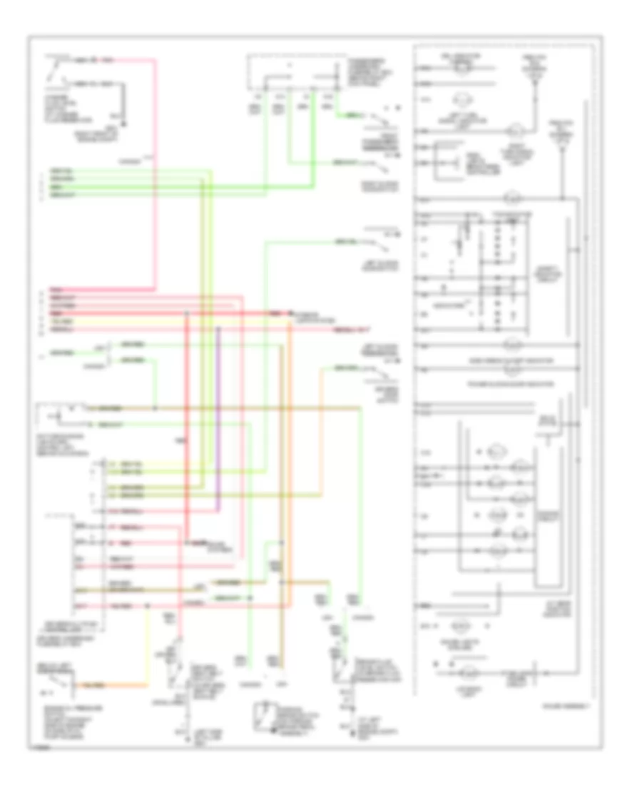
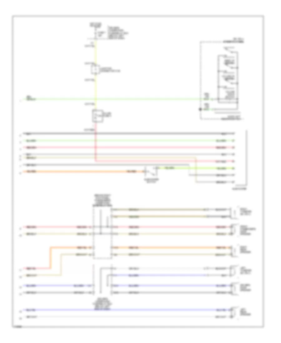
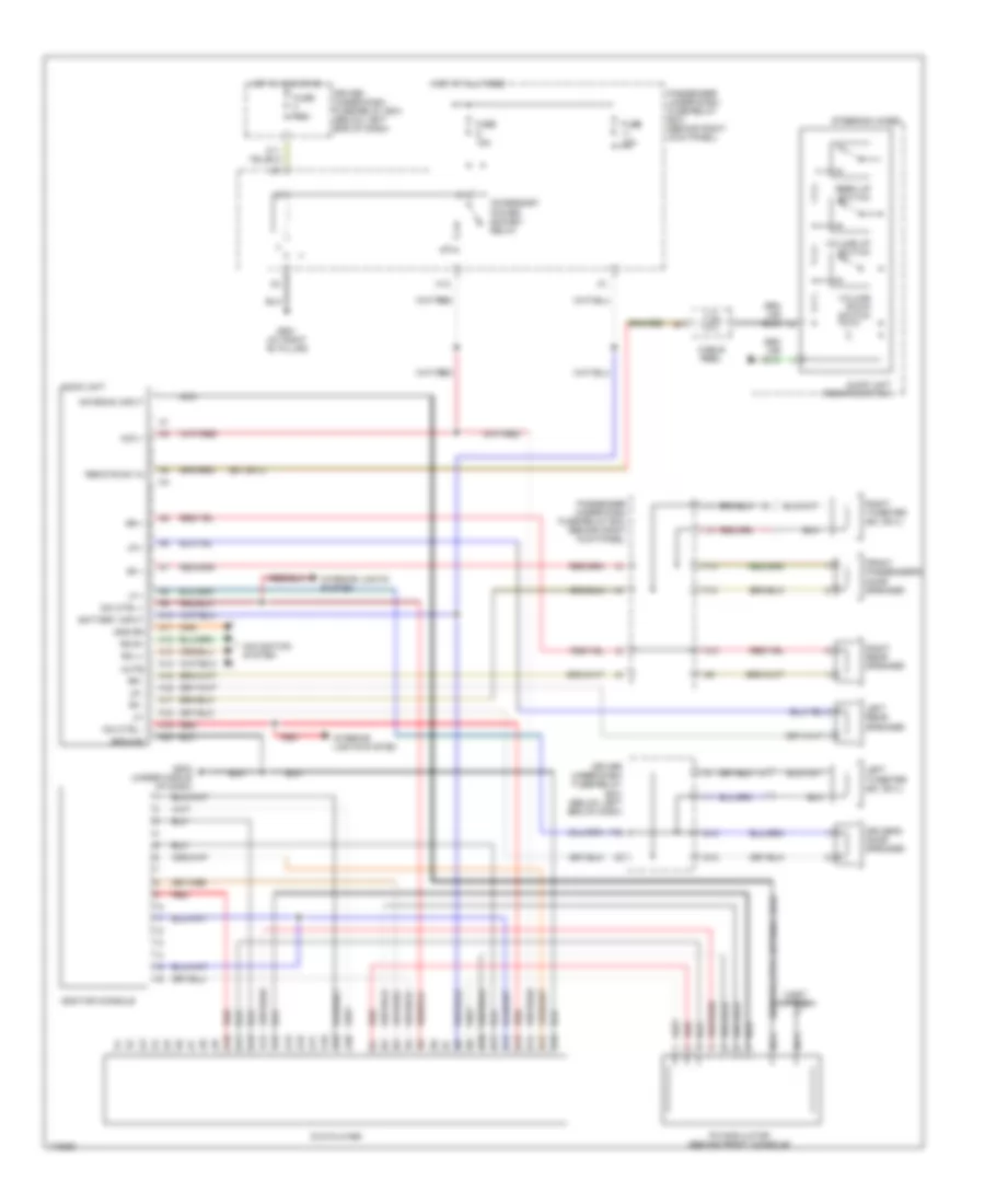
Instrument Illumination Wiring Diagram, without Navigation for Honda Odyssey EX 2004
List of elements for Instrument Illumination Wiring Diagram, without Navigation for Honda Odyssey EX 2004:
- A/t gear position indicator
- A13
- A19
- A20
- A22
- A26
- Audio unit
- B10
- B11
- B16
- B22
- Brake light/ outer taillight
- Center pocket light
- Center pocket light (w/ rear entertainment system)
- Climate control unit
- Clock
- Combination light switch
- Cruise control main switch/ tcs switch
- Dash lights brightness controller
- Dimming circuit
- Driver's multiplex control unit
- Driver's seat heater switch (ex-l)
- Driver's under-dash fuse/relay box (below left end of dash)
- Dvd player unit (ex-l w/ rear entertainment system
- Entertainment controller and screen (w/ rear entertainment system)
- Ex, ex-l
- Ex-l
- Ex-l w/o rear entertainment system, ex
- Front passenger's seat heater switch (ex-l)
- Fuse 10 15a
- Fuse 9 10a
- G401 (under left side of dash)
- Gauge assembly
- Gauge lights (6 bulbs)
- Hazard warning switch
- Head
- Headlight switch
- Heater control panel
- Hot at all times
- Hot in on or start
- I13
- Interior lights switch
- K15
- K16
- Lcd back light
- Off
- Park
- Passenger's under-dash fuse/relay box (behind right kick panel)
- Power sliding door switch (ex, ex-l)
- Rear heater- a/c main switch
- Rear heater- a/c passenger control panel
- Red
- Right taillight assembly
- Stabilizing power circuit
- Taillight relay (behind left side of dash)
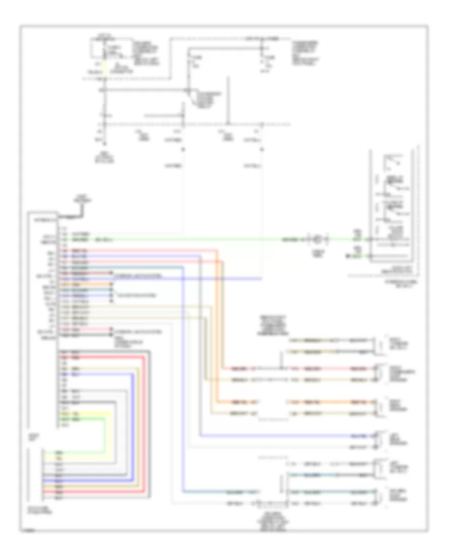
NAVIGATION
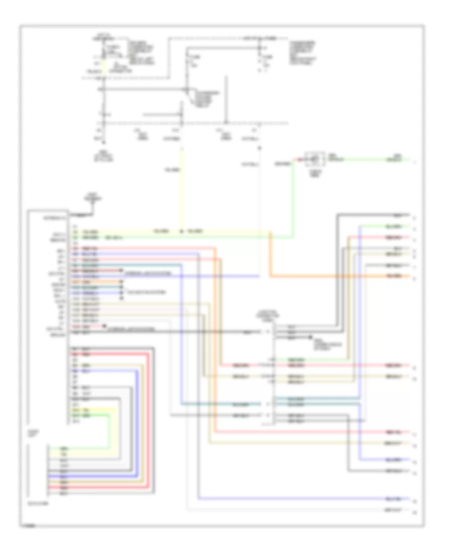
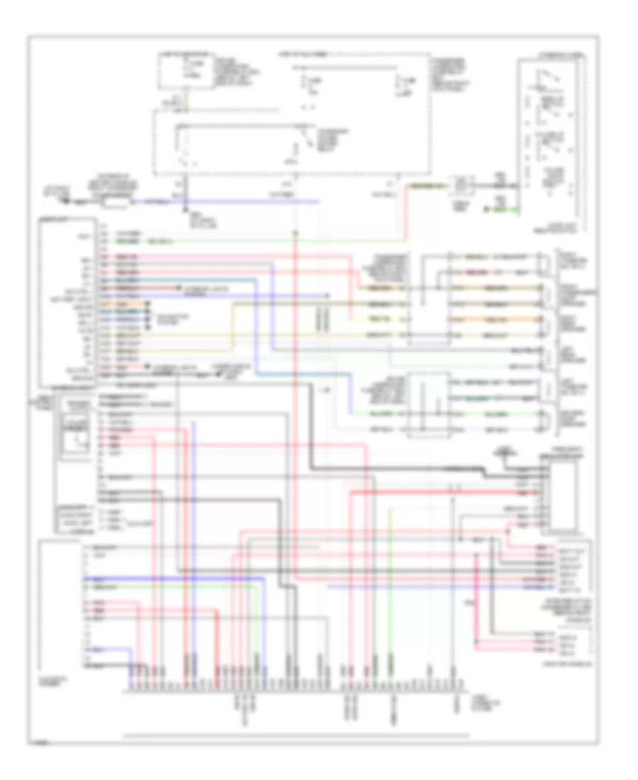
Navigation Wiring Diagram for Honda Odyssey EX 2004
List of elements for Navigation Wiring Diagram for Honda Odyssey EX 2004:
- (behind left kick panel) g501
- A10
- A11
- A12
- A13
- A14
- A15
- A16
- Acc
- Accessory power socket relay
- Aci
- Aco
- Audio unit
- B sig
- B10
- B11
- B12
- B13
- B14
- B15
- B16
- B17
- B18
- B19
- B20
- Back lt
- C sig
- Chg
- Climate control unit
- Clk 2
- Cruise control system
- Diag n
- Diag p
- Disp bus(+)
- Disp bus(-)
- Driver under- dash fuse/ relay box (below left end of dash)
- Fuse 10a
- Fuse 11 10a
- Fuse 7.5a
- Fuse 9 15a
- G sig
- G101 (at left side of engine compartment)
- G501 (behind left kick panel)
- G502 (under middle of dash)
- G581 (at right "b" pillar)
- Gauge assembly
- Gnd
- Gnd gps
- Gnd rg
- Gnd sig
- Gps
- Gps antenna
- H13
- Hot at all times
- Hot in acc or on
- Hot in on or start
- Ill+
- Ill-
- Interior lights system
- Junction connector c107 (under middle of dash)
- K11
- Mute
- Navigation display unit
- Navigation service check connector
- Navigation unit
- Nca
- O11
- Passenger under-dash fuse/relay box (behind right kick panel)
- Pcm
- Pcm (behind lower center of dash)
- R sig
- Red
- Reverse relay
- Rg l+
- Rg r+
- Sh disp bus
- Sh rg
- Sh sig
- Staring/ charging system
- Trans- mission range switch (on transaxle end cover)
- Vss
- Vss output
POWER DISTRIBUTION
Power Distribution Wiring Diagram (1 of 4) for Honda Odyssey EX 2004
List of elements for Power Distribution Wiring Diagram (1 of 4) for Honda Odyssey EX 2004:
- (not used)
- A10
- A13
- A17
- Abs/tcs control unit
- Acc
- Alternator
- Audio unit
- Battery
- Canada
- Data link connector
- Driver's under-dash fuse/relay box (below left end of dash)
- Drl unit (canada)
- Dvd player unit
- E16
- Eld unit
- Ex, ex-l
- Ex-l
- Fuse 4 7.5a
- Fuse 41 120a
- Fuse 42 50a
- Fuse 46 15a
- Fuse 5 7.5a (canada)
- Fuse 52 30a
- Fuse 53 30a
- Fuse 71 20a
- Fuse 78 20a
- Fuse 79 20a
- Fuse 80 40a
- Fuse 81 30a
- Fusible link
- G17
- Ignition switch
- Left power sliding door control unit
- Lock
- O15
- Option connector
- Passenger's under-dash fuse/relay box (behind right kick panel)
- Pgm-fi main relay
- Power mirror switch
- Power window control unit
- Q14
- Rear blower motor
- Rear controller & screen
- Rear window defogger relay
- Red
- Right power sliding door control unit
- Seat heater relay
- Start
- Starter
- Starter cut relay
- Starter solenoid
- T option connector
- T101
- To cigarette lighter in-line fuse (diagram 3 of 4)
- To fuse 3 (diagram 2 of 4)
- To fuse 47 (diagram 2 of 4)
- To fuse 56 (diagram 2 of 4)
- To fuse 6 (diagram 2 of 4)
- To fuse 8 (diagram 3 of 4)
- Under-hood fuse/relay box (right side of engine compt)
- Under-hood sub-fuse box
Power Distribution Wiring Diagram (2 of 4) for Honda Odyssey EX 2004
List of elements for Power Distribution Wiring Diagram (2 of 4) for Honda Odyssey EX 2004:
- (behind right kick panel) passenger's under-dash fuse/relay box
- (not used)
- (right side of engine compt) under-hood fuse/relay box
- (w/ nav)
- (w/o nav)
- A/c compressor clutch relay
- A17
- A18
- Abs fail-safe relay
- Abs pump motor relay
- Alternator
- B13
- Brake pedal position switch
- C10
- Climate control panel
- Climate control unit
- Coil
- Condenser fan relay
- Cruise control main switch/ tcs switch
- Cruise control unit
- D15
- Driver's under-dash fuse/relay box (below left end of dash)
- E13
- Eld unit
- Engine mount control solenoid valve
- Evap bypass solenoid valve
- Evap canister purge valve
- Evap canister vent shut valve
- Ex, ex-l
- From fuse 4 e (diagram 1 of 4)
- From fuse 41 a (diagram 1 of 4)
- From fuse 42 b (diagram 1 of 4)
- From ignition switch (diagram 1 of 4)
- Front blower motor high relay
- Front blower motor relay
- Fuse 1 15a
- Fuse 2 10a
- Fuse 3 7.5a
- Fuse 47 20a
- Fuse 48 20a
- Fuse 49 15a
- Fuse 50 30a
- Fuse 56 40a
- Fuse 57 30a
- Fuse 58 30a
- Fuse 59 7.5a
- Fuse 6 15a
- Gauge assembly
- Hazard warning switch
- Heater control panel
- Horn relay
- I12
- I15
- Ignition key light
- Ignition key switch/ key light
- Junction connector c107 (under middle of dash)
- K11 (not used)
- K15
- Key interlock switch
- O13
- O14
- Passenger's under-dash fuse/relay box (behind right kick panel)
- Pcm
- Pgm-fi main relay
- Primary ho2s
- Radiator fan main relay
- Radiator fan relay
- Rear blower motor high relay
- Rear blower motor low relay
- Rear blower motor main relay
- Rear blower motor middle relay
- Rear heater-a/c passenger control panel
- Rear mode control motor
- Rear mode control motor relay
- Rear window defogger relay
- Recirculation control motor
- Secondary ho2s
- Srs unit
- To fuse 51 (diagram 3 of 4)
- To fuse 7 (diagram 4 of 4)
- Under-hood fuse/relay box (right side of engine compt)
- W/ nav
Power Distribution Wiring Diagram (3 of 4) for Honda Odyssey EX 2004
List of elements for Power Distribution Wiring Diagram (3 of 4) for Honda Odyssey EX 2004:
- (behind right kick panel) passenger's under-dash fuse/relay box
- (below left end of dash) driver's under-dash fuse/ relay box
- (not used)
- (w/ navigation system) navigation display unit
- (w/ navigation system) navigation unit
- 15a
- 20a
- 40a
- A11
- A12
- A14
- A23
- A24
- A25
- Accessory power socket relay
- Ashtray light
- Audio unit
- Auxiliary jack assembly (w/ rse)
- B20
- B21
- C15
- Cigarette lighter
- Cigarette lighter in-line fuse (behind dash, right of steering column)
- Cigarette lighter relay
- Climate control unit
- Clock (w/o navigation)
- Combination light switch
- Door multiplex control unit
- Driver's multiplex control unit
- Driver's under-dash fuse/relay box (below left end of dash)
- Drl control unit (canada)
- Dvd player unit (w/ rse)
- Ex, ex-l
- Ex, ex-l w/o navigation
- From fuse 59 (diagram 2 of 4)
- From fuse 9 (diagram 3 of 4)
- From fusible link (diagram 1 of 4)
- From ignition switch (diagram 1 of 4)
- Front accessory power socket
- Front ashtray
- Fuel fill door relay
- Fuse 1
- Fuse 10 15a
- Fuse 12 20a
- Fuse 13 7.5a
- Fuse 2 20a
- Fuse 3 10a
- Fuse 4 20a
- Fuse 5 20a
- Fuse 51
- Fuse 54 40a
- Fuse 55 40a
- Fuse 6 10a (canada)
- Fuse 8 7.5a
- Fuse 9 15a
- G501 (behind left kick panel)
- G52
- G552 (behind left quarterpanel)
- G581 (right side of "b" pillar)
- Gauge assembly
- Gauge assembly (w/ rse)
- H11
- H13
- H15
- H16
- Headlight relay 1
- Headlight relay 2
- Heater control panel
- I18
- Interior lights system
- J12
- J16
- Keyless receiver unit (ex, ex-l)
- Left power sliding door control unit
- Left power sliding door control unit (ex, ex-l)
- O11
- O19
- Option connector
- Passenger's multiplex control unit
- Pcm
- Power seat adjustment switch (ex, ex-l)
- Power window relay
- Rear accessory power socket
- Rear controller & screen (w/ rse)
- Red
- Right power sliding door control unit
- Right power sliding door control unit (ex, ex-l)
- Security system connector (accessory)
- Taillight relay
- Tcs relay (lx)
- To accessory power socket relay (diagram 3 of 4)
- To fuse 11 (diagram 4 of 4)
- Under-hood fuse/relay box (right side of engine compt)
- W/ rse
Power Distribution Wiring Diagram (4 of 4) for Honda Odyssey EX 2004
List of elements for Power Distribution Wiring Diagram (4 of 4) for Honda Odyssey EX 2004:
- (not used)
- (w/ navigation)
- (w/o navigation)
- A10
- A13
- A16
- A19
- A22
- A24
- Audio unit (w/o rse)
- B11
- B15
- Brake light failure sensor
- Canada
- Cargo area light
- Clock (w/o navigation)
- Coil
- Driver's multiplex control unit
- Driver's under-dash fuse/relay box (below left end of dash)
- Driver's vanity mirror light
- E11
- Ex, ex-l
- F10
- From fuse 10 k (diagram 3 of 4)
- From fuse 6 j (diagram 2 of 4)
- Front individual map light
- Front passenger's air bag cut-off indicator
- Front passenger's vanity mirror light
- Front passenger's weight sensor unit
- Fuse 10 7.5a
- Fuse 11 10a
- Fuse 12 30a
- Fuse 7 15a
- Fuse 9 10a
- Gauge assembly
- Hazard warning switch
- Ignition coil 1
- Ignition coil 2
- Ignition coil 3
- Ignition coil 4
- Ignition coil 5
- Ignition coil 6
- Interior lights relay
- Intermittent wiper relay
- Junction connector c104 (at left side of engine compartment)
- Keyless receiver unit (lx)
- Left middle individual map light
- Left power sliding door control unit
- Left rear individual map light
- Navigation display unit
- Navigation unit
- Nca
- Passenger's multiplex control unit
- Passenger's under-dash fuse/relay box (behind right kick panel)
- Rear window wiper intermittent control unit
- Rear window wiper motor
- Rear wiper/ washer switch
- Reverse relay
- Right middle individual map light
- Right power sliding door control unit (ex, ex-l)
- Right rear individual map light
- Shift lock solenoid
- Tcs switch (lx)
- Windshield wiper motor
- Windshield wiper/ washer switch
- Wiper/washer switch
POWER DOOR LOCKS
Power Door Locks Wiring Diagram, LX without Keyless Entry (1 of 2) for Honda Odyssey EX 2004
List of elements for Power Door Locks Wiring Diagram, LX without Keyless Entry (1 of 2) for Honda Odyssey EX 2004:
- (not used)
- 10a
- 7.5a
- A10
- A12
- A13
- A16
- A17
- A20
- A22
- A24
- B11
- B22
- Battery in
- Battery input
- Comm line
- Door lock
- Driver's multiplex control unit
- Driver's under-dash fuse/relay box (below left end of dash)
- F15
- Front
- Front passenger's door key cylinder switch
- Fuse 13
- Fuse 9
- G14
- G401 (left side of dash)
- G501 (behind left kick panel)
- G503 (behind right kick panel)
- G581 (right side of "b" pillar)
- Ground
- Hot at all times
- Hot in on or start
- Ign input
- Ignition key switch
- Ignition key switch/key light
- J12
- J14
- Key in ign input
- Lock
- O19
- Pass key sw
- Pass lck sw
- Passenger's
- Passenger's multiplex control unit
- Passenger's under-dash fuse/relay box (behind right kick panel)
- Pnk
- Switch
- Unlock
Power Door Locks Wiring Diagram, LX without Keyless Entry (2 of 2) for Honda Odyssey EX 2004
List of elements for Power Door Locks Wiring Diagram, LX without Keyless Entry (2 of 2) for Honda Odyssey EX 2004:
- (not used)
- 20a
- A11
- A12
- A15
- A16
- A17
- A18
- Battery in
- Comm line
- Cylinder switch
- Door multiplex control unit (in driver's door)
- Dr key cyl sw
- Dr lck knob sw
- Dr lck sw
- Driver's door key cylinder switch
- Driver's door lock actuator
- Driver's door lock knob switch
- Driver's door lock switch
- Driver's under-dash fuse/relay box (below left end of dash)
- Driver's underdash fuse/relay box (below left end of dash)
- F17
- Front passenger's door lock actuator
- Fuel fill door relay
- Fuel fill door switch
- Fuse 12
- G401 (left side of dash)
- G551 (left side of "b" pillar)
- G552 (behind left quarterpanel)
- Ground
- Hot at all times
- I18
- K13
- Left junction switch
- Left power sliding door control unit
- Left sliding door lock knob switch/actuator
- Lock
- Passenger's multiplex control unit
- Passenger's under-dash fuse/relay box (behind right kick panel)
- Pnk
- Right junction switch
- Right sliding door lock actuator
- Sliding door lock control unit (in left sliding door)
- Tailgate key
- Tailgate lock actuator
- Unlock
POWER MIRRORS
Power Mirrors Wiring Diagram, Canada for Honda Odyssey EX 2004
List of elements for Power Mirrors Wiring Diagram, Canada for Honda Odyssey EX 2004:
- Defogger
- Down switch
- Driver's under-dash fuse/relay box (below left end of dash)
- Driver's underdash fuse/relay box (below left end of dash)
- F11
- F19
- F20
- Fuse 4 7.5a
- G11
- G15
- G401 (under left side of dash)
- G501 (behind left kick panel)
- G581 (at right "b" pillar)
- H12
- Hot in on
- K12
- K13
- Left
- Left power mirror
- Left switch
- Left/right motor
- Mirror defogger switch
- Mirror selector switch
- O15
- O16
- O17
- O18
- Passenger's underdash fuse/relay box (behind right kick panel)
- Power mirror switch
- Q20
- Right
- Right power mirror
- Right switch
- Up switch
- Up/down motor
Power Mirrors Wiring Diagram, USA for Honda Odyssey EX 2004
List of elements for Power Mirrors Wiring Diagram, USA for Honda Odyssey EX 2004:
- Down switch
- Driver's under-dash fuse/relay box (below left end of dash)
- Driver's underdash fuse/relay box (below left end of dash)
- F11
- F19
- Fuse 4 7.5a
- G11
- G15
- G501 (behind left kick panel)
- Hot in on
- K12
- K13
- Left
- Left power mirror
- Left switch
- Left/right
- Mirror selector switch
- Motor
- O15
- O16
- O17
- O18
- Passenger's under-dash fuse/relay box (behind right kick panel)
- Power mirror switch
- Right
- Right power mirror
- Right switch
- Up switch
- Up/down
POWER SEATS
Heater Wiring Diagram for Honda Odyssey EX 2004
List of elements for Heater Wiring Diagram for Honda Odyssey EX 2004:
- (at left ``b" pillar) g551
- (at right ``b" pillar) g581
- (under left side of dash) g401
- Back
- Circuit breaker
- Cushion
- Driver's seat heater
- Driver's seat heater switch
- Driver's under-dash fuse/relay box (below left end of dash)
- E16
- Front passenger's seat heater
- Front passenger's seat heater switch
- Fuse 4 7.5a
- Fuse 78 20a
- G18
- G301 (at left side of engine compt)
- High
- Hot at all times
- Hot in on
- Interior lights system
- K16
- Low
- Nca
- On indicators
- Passenger's under-dash fuse/relay box (behind right kick panel)
- Red
- Seat heater relay (in multi- fuse/relay box b)
- Seat heater switch light
- Thermostat
- Under-hood sub-fuse box
Power Seat Wiring Diagram for Honda Odyssey EX 2004
List of elements for Power Seat Wiring Diagram for Honda Odyssey EX 2004:
- Backward
- Down
- Forward
- Fuse 2 20a
- Fuse 4 20a
- G551 (at left `b" pillar)
- Hot at all times
- Passenger's under-dash fuse/relay box (behind right kick panel)
- Power seat adjustment switch
- Power seat front up-down motor
- Power seat rear up-down motor
- Power seat recline motor
- Power seat slide motor
- Red
POWER WINDOWS
Power Windows Wiring Diagram (1 of 2) for Honda Odyssey EX 2004
List of elements for Power Windows Wiring Diagram (1 of 2) for Honda Odyssey EX 2004:
- (behind right kick panel)
- (ex, ex-l)
- (lx)
- A10
- A11
- A12
- A13
- A14
- A15
- A16
- A18
- A19
- A20
- A22
- A24
- Anti-trap p/w circuit
- Battery input
- Commun line
- Door multiplex control unit (in driver door)
- Driver's switch
- Driver's under-dash fuse/relay box (below left end of dash)
- Driver's window motor
- F16
- F18
- Front passenger's door switch
- Frt pass ctrl
- Frt pass dr
- Fuse 13 7.5a
- Fuse 15 20a
- Fuse 16 7.5a
- Fuse 20a
- Fuse 7 7.5a
- Fuse 8 20a
- Fuse 9 10a
- G401 (under left side of dash)
- G551 (at left "b" pillar)
- G581 (at right "b" pillar)
- Ground
- H10
- Hie sensor
- Hot at all times
- Hot in on or start
- Ign input
- J10
- J12
- Left rear switch
- Main switch
- O19
- Passenger's multiplex control unit
- Passenger's under-dash fuse/relay box
- Pnk
- Power window control unit
- Power window master switch 0 = off 1 = up 2 = down 3 = auto down 4 = on 5 = auto
- Power window relay
- Q13
- Right front switch
- Right rear switch
- Rr win ctrl
- Sensing unit
- Under-hood sub-fuse box
Power Windows Wiring Diagram (2 of 2) for Honda Odyssey EX 2004
List of elements for Power Windows Wiring Diagram (2 of 2) for Honda Odyssey EX 2004:
- (under left side of dash) g401
- A12
- A14
- A16
- A19
- A24
- B11
- Battery input
- Commun line
- Dr door open
- Driver's door switch
- Driver's multiplex control unit
- Driver's under-dash fuse/relay box (below left end of dash)
- F14
- Front passenger's window motor
- Front passenger's window switch
- Fuse 13 7.5a
- Fuse 9 10a
- G14
- Ground
- Hot at all times
- Hot in on or start
- Ign on in
- J12
- Left rear power quarter window close relay (behind left rear side trim panel)
- Left rear power quarter window motor (behind left rear side trim panel)
- Left rear power quarter window open relay (behind left rear side trim panel)
- Lr win ctrl
- O19
- Passenger's under-dash fuse/relay box (behind right kick panel)
- Pnk
- Q15
- Q16
- Right rear power quarter window close relay (behind right rear side trim panel)
- Right rear power quarter window motor (behind right rear side trim panel)
- Right rear power quarter window open relay (behind right rear side trim panel)
RADIO
Radio Wiring Diagram, with CD for Honda Odyssey EX 2004
List of elements for Radio Wiring Diagram, with CD for Honda Odyssey EX 2004:
- a1
- a10
- a11
- a12
- a13
- a15
- a16
- a17
- a19
- a20
- a3
- a7
- a9
- b10
- b12
- b14
- b9
- (behind right kick panel) passenger's under-dash fuse/relay box
- (ex, ex-l)
- (not used)
- A10
- A14
- A18
- Acc (+)
- Accessory power socket relay
- Antenna in
- Audio unit
- Audio unit remote switch
- B +
- B11
- B13
- Cable reel
- Cd player (if equipped)
- Dim ctrl +
- Dim ctrl -
- Driver's door speaker
- Driver's under-dash fuse/relay box (below left end of dash)
- F12
- F13
- Front passenger's door speaker
- Fuse 10a
- Fuse 15a
- Fuse 8 7.5a
- G12
- G13
- G502 (under middle of dash)
- G581 (at right "b" pillar)
- Gnd rg
- Ground
- H11
- H13
- Hot at all times
- Hot in acc or on
- I10
- I11
- I1o
- Interior lights system
- J16
- Left rear speaker
- Left tweeter (ex, ex-l)
- Lf +
- Lf -
- Lr +
- Lr -
- Mast antenna
- Mute
- Navigation system
- Nca
- O11
- Option connector
- Passenger's under-dash fuse/relay box (behind right kick panel)
- Red
- Remote
- Rf +
- Rf -
- Rg l +
- Rg r +
- Right rear speaker
- Right tweeter (ex, ex-l)
- Rr +
- Rr -
- Seek up switch
- Steering wheel
- Volume down switch
- Volume up switch
Radio Wiring Diagram, with Cassette Deck for Honda Odyssey EX 2004
List of elements for Radio Wiring Diagram, with Cassette Deck for Honda Odyssey EX 2004:
- a11
- a12
- a13
- a14
- a15
- a17
- a3
- a4
- a5
- a8
- a9
- b10
- b12
- b13
- b14
- b2
- b3
- b4
- b5
- b6
- b8
- b9
- (+)
- (-)
- (behind right kick panel) passenger's under-dash fuse/relay box
- (ex, ex-l)
- (not used)
- A10
- A16
- A18
- A19
- A20
- Acc (+)
- Accessory power socket relay
- Antenna in
- Audio unit
- Audio unit remote switch
- B11
- Battery in
- Cable reel
- Cassette player
- Cd changer (if equipped)
- Dim ctrl+
- Dim ctrl-
- Driver's door speaker
- Driver's under-dash fuse/relay box (below left end of dash)
- F12
- F13
- Front passenger's door speaker
- Fuse 10a
- Fuse 15a
- Fuse 8 7.5a
- G12
- G13
- G502 (under middle of dash)
- G581 (at right "b" pillar)
- Gnd rg
- Ground
- H11
- H13
- Hot at all times
- Hot in acc or on
- I10
- I11
- I1o
- Interior lights system
- J16
- Left rear speaker
- Left tweeter (ex, ex-l)
- Mast antenna
- Mute
- Navigation system
- Nca
- O11
- Option connector
- Passenger's under-dash fuse/relay box (behind right kick panel)
- Red
- Remote
- Rg l+
- Rg r+
- Right rear speaker
- Right tweeter (ex, ex-l)
- Seek up switch
- Steering wheel (ex, ex-l)
- Volume down switch
- Volume up switch
Radio Wiring Diagram, with DVD (1 of 2) for Honda Odyssey EX 2004
List of elements for Radio Wiring Diagram, with DVD (1 of 2) for Honda Odyssey EX 2004:
- (behind right kick panel) passenger's under-dash fuse/relay box
- (not used)
- A10
- A11
- A12
- A13
- A14
- A15
- A16
- A17
- A18
- A19
- A20
- Acc +
- Accessory power socket relay
- Antenna in
- Antenna lead
- Audio unit
- Dim ctrl +
- Dim ctrl -
- Driver's door speaker
- Driver's under-dash fuse/relay box (below left end of dash)
- F12
- F13
- Front passenger's door speaker
- Fuse 15a
- Fuse 7.5a
- G12
- G13
- G502 (under middle of dash)
- G581 (at right "b" pillar)
- Gnd rg
- Ground
- H11
- H13
- Hot at all times
- Hot in acc or on
- I10
- I11
- I1o
- Interior lights system
- J16
- Left rear speaker
- Left tweeter
- Lf +
- Lf-
- Lr +
- Lr -
- Mast antenna
- Mute
- Navigation system
- Option connector
- Passenger's under-dash fuse/relay box (behind right kick panel)
- Red
- Remote sw in
- Rf +
- Rf -
- Rg l+
- Rg r+
- Right rear speaker
- Right tweeter
- Rr +
- Rr -
- Scty in
Radio Wiring Diagram, with DVD (2 of 2) for Honda Odyssey EX 2004
List of elements for Radio Wiring Diagram, with DVD (2 of 2) for Honda Odyssey EX 2004:
- (behind left quarterpanel) g552
- A10
- A11
- A12
- A13
- A14
- A15
- A16
- A17
- A18
- A19
- A20
- A21
- A22
- A23
- A24
- A25
- A26
- Acc +
- Anti-theft system
- Aud 1 com
- Aud 1 gnd
- Aud 1 shield
- Aud 1 shld
- Aud 2 com
- Aud 2 shield
- Aud 3 gnd
- Aud 3 shield
- Aud com
- Aud shield
- Audio 3 gnd
- Audio 3 shld
- Audio gnd
- Audio shield
- Audio shld
- Audio unit
- Audio unit remote switch
- Auxiliary jack assembly
- B10
- B11
- B12
- B13
- B14
- B15
- B16
- Bus data
- Bus gnd
- Bus shield
- C10
- C11
- C12
- C13
- C14
- C15
- C16
- C17
- C18 c18 c18 c18
- C19
- C20
- C21
- C22
- Cable reel
- Com check
- Com chk
- Dvd player unit
- Entertainment controller and screen
- Fuse 20a
- G502 (under middle of dash)
- G552 (behind left quarter- panel)
- Ground
- Hot at all times
- Ill +
- Ill -
- Ill 8v
- Ill+
- Interior lights system
- L ch 1
- L ch 3
- L ch out
- Left ch
- Left ch 1
- Left ch 2
- R ch 1
- R ch 3
- R ch out
- Red
- Right ch
- Right ch 2
- Scty out
- Security in
- Seek up switch
- Serial data
- Serial gnd
- Serial shield
- Serial shld
- Steering wheel
- Under-hood sub-fuse box
- Vid 3 shield
- Video
- Video 1
- Video 1 gnd
- Video 1 shld
- Video 2
- Video 2 gnd
- Video 2 shld
- Video 3
- Video 3 gnd
- Video 3 shld
- Video gnd
- Video shield
- Volume down switch
- Volume up switch
Radio Wiring Diagram, with Subwoofer (1 of 2) for Honda Odyssey EX 2004
List of elements for Radio Wiring Diagram, with Subwoofer (1 of 2) for Honda Odyssey EX 2004:
- (ex, ex-l)
- (not used)
- 7.5a
- A10
- A11
- A12
- A13
- A14
- A15
- A16
- A17
- A18
- A19
- A20
- Acc (+)
- Accessory power socket relay
- Antenna in
- Audio unit
- B +
- B10
- B11
- B12
- B13
- B14
- Cable reel
- Cd player
- Dim ctrl
- Dim ctrl -
- Driver's under-dash fuse/relay box (below left end of dash)
- Fuse 10a
- Fuse 15a
- Fuse 8
- G502 (under middle of dash)
- G581 (at right "b" pillar)
- Gnd rg
- Ground
- H11
- H13
- Hot at all times
- Hot in acc or on
- Interior lights system
- J16
- Junction connector c120
- Lf +
- Lf -
- Lr +
- Lr -
- Mast antenna
- Mute
- Navigation system
- Nca
- O11
- Option connector
- Passenger's under-dash fuse/relay box (behind right kick panel)
- Red
- Remote
- Rf +
- Rf -
- Rg l +
- Rg r +
- Rr +
- Rr -
Radio Wiring Diagram, with Subwoofer (2 of 2) for Honda Odyssey EX 2004
List of elements for Radio Wiring Diagram, with Subwoofer (2 of 2) for Honda Odyssey EX 2004:
- (behind right kick panel) passenger's under-dash fuse/relay box
- (ex, ex-l) steering wheel
- 7.5a
- A10
- Audio unit remote switch
- Driver's door speaker
- Driver's under-dash fuse/relay box (below left end of dash)
- F12
- F13
- Front passenger's door speaker
- Fuse 7 15a
- G12
- G13
- Hot in on or start
- I10
- I11
- I1o
- In-line fuse a
- Junction connector c120
- Left rear speaker
- Left tweeter (ex, ex-l)
- Right rear speaker
- Right tweeter (ex, ex-l)
- Seek up switch
- Subwoofer
- Subwoofer switch
- Volume down switch
- Volume up switch
Rear Seat Entertainment Wiring Diagram, with DVD for Honda Odyssey EX 2004
List of elements for Rear Seat Entertainment Wiring Diagram, with DVD for Honda Odyssey EX 2004:
- (ex, ex-l)
- A10
- A11
- A12
- A13
- A14
- A15
- A16
- A17
- A18
- A19
- A20
- Acc +
- Accessory power socket relay
- Antenna input
- Audio unit
- Audio unit remote switch
- B10
- B11
- B12
- B13
- B14
- B15
- B16
- Battery input
- Cable reel
- Dim ctrl +
- Dim ctrl -
- Driver under-dash fuse/relay box (below left end of dash)
- Driver's door speaker
- Dvd player
- F12
- F13
- Fm modulator (behind front console)
- Fm modulator antenna lead
- Front passenger's door speaker
- Fuse 10a
- Fuse 15a
- Fuse 7.5a
- G12
- G13
- G502 (under middle of dash)
- G581 (at right "b" pillar)
- Gnd rg
- Ground
- H13
- Hot at all times
- Hot in acc or on
- I10
- I11
- I1o
- Interior lights system
- Left rear speaker
- Left tweeter (ex, ex-l)
- Lf +
- Lf-
- Lr +
- Lr -
- Mast antenna
- Monitor console
- Mute
- Navigation system
- Nca
- Passenger under-dash fuse/relay box (behind right kick panel)
- Red
- Remote sw in
- Rf +
- Rf -
- Rg l+
- Rg r+
- Right rear speaker
- Right tweeter (ex, ex-l)
- Rr +
- Rr -
- Seek up switch
- Steering wheel
- Volume down switch
- Volume up switch
Rear Seat Entertainment Wiring Diagram, with VHS for Honda Odyssey EX 2004
List of elements for Rear Seat Entertainment Wiring Diagram, with VHS for Honda Odyssey EX 2004:
- (at right "b" pillar) g581
- (ex, ex-l)
- (on rear of center console) front accessory
- (under middle of dash) g502
- A10
- A11
- A12
- A13
- A14
- A15
- A16
- A17
- A18
- A19
- A20
- A21
- A22
- A23
- A24
- A25
- A26
- Acc +
- Accessory power socket relay
- Antenna input
- Antenna lead
- Audio left
- Audio right
- Audio sig
- Audio unit
- Audio unit remote switch
- Auxiliary
- B10
- B11
- B12
- B13
- B14
- B15
- B16
- Batt in
- Batt out
- Battery in
- Battery input
- Cable reel
- Condenser filter (behind front
- Console)
- Dim ctrl +
- Dim ctrl -
- Driver under-dash fuse/relay box (below left end of dash)
- Driver's door speaker
- F12
- F13
- Flip down screen
- Frequency
- Front passenger's door speaker
- Fuse 10a
- Fuse 15a
- Fuse 7.5a
- G12
- G13
- G581 (at right "b" pillar)
- Gnd in
- Gnd out
- Gnd rg
- Ground
- H13
- Headset
- Headset output
- Hot at all times
- Hot in acc or on
- I10
- I11
- I1o
- Ign in
- Ign out
- Interior lights system
- Left rear speaker
- Left tweeter (ex, ex-l)
- Lf +
- Lf-
- Lr +
- Lr -
- Mast antenna
- Media control panel
- Modulator unit
- Monitor console
- Mute
- Navigation system
- Nca
- Noise reduction
- Passenger under-dash fuse/relay box (behind right kick panel)
- Pnk
- Power socket
- Red
- Remote sig
- Rf +
- Rf -
- Rg l+
- Rg r+
- Right rear speaker
- Right tweeter (ex, ex-l)
- Rr +
- Rr -
- Seek up switch
- Shield
- Steering wheel
- Video cassette player
- Video in
- Volume control
- Volume down switch
- Volume up switch
SHIFT INTERLOCK
Shift Interlock Wiring Diagram for Honda Odyssey EX 2004
List of elements for Shift Interlock Wiring Diagram for Honda Odyssey EX 2004:
- (below left end of dash) driver under-dash fuse/relay box
- (not
- A28
- A32
- B12
- B22
- Brake pedal position switch (on brake pedal bracket)
- Brake sw in
- C27
- Driver under-dash fuse/relay box (below left end of dash)
- Driver's multiplex control unit
- E17
- Fuse 47 20a
- Fuse 9 10a
- G101 (at left side of engine compt)
- G401 (under left side of dash)
- Hot at all times
- Hot in on or start
- Ignition key switch/key light
- Key interlock solenoid
- Key interlock switch
- Park pin switch (at top of steering column)
- Pcm (behind lower center of dash)
- Red
- Shft lk cir
- Shift lock solenoid (at top of steering column)
- Tp sensor (on side of throttle body assembly)
- Tps in
- Transmission range switch (on transaxle end cover)
- Under-hood fuse/relay box (at right side of engine compt)
- Used)
STARTING/CHARGING
Charging Wiring Diagram for Honda Odyssey EX 2004
List of elements for Charging Wiring Diagram for Honda Odyssey EX 2004:
- A30
- Alt ctrl sig
- Alt fr sig
- Alternator
- Battery
- Charge system indicator light
- Driver's multiplex control unit (in driver under-dash fuse/relay box)
- Driver's under- dash fuse/ relay box (below left end of dash)
- E13
- Eld in- put
- Eld unit
- Engine controls system
- Fuse 41 120a
- Fuse 6 15a
- G1 (at left side of engine compt)
- G201 (at right side of engine compt)
- Gauge assembly
- Ground
- Hot in on or start
- I12
- Ignition input
- J/c c105 (at left side of engine compt)
- Load output
- Navigation unit
- Passenger's under-dash fuse/relay box (behind right kick panel)
- Pcm (behind lower center of dash)
- Power distribution system
- Starting circuit
- T101
- T102
- Transmission
- Under-hood fuse/relay box (at right side of engine compt)
- W/ navigation
Starting Wiring Diagram for Honda Odyssey EX 2004
List of elements for Starting Wiring Diagram for Honda Odyssey EX 2004:
- (left side of engine) g101
- (not used)
- Acc
- B14
- Battery
- Driver's multiplex control unit
- Driver's under-dash fuse/relay box (below left end of dash)
- E12
- Eld unit
- Fuse 120a
- Fuse 42 50a
- G1 (left side of engine compt)
- Ignition switch
- Junction connector c105 (at left side of engine compt)
- Lock
- O12
- Pcm (behind lower center of dash)
- Power distribution system
- Start
- Starter
- Starter cut relay
- Starter motor
- Starter solenoid
- Transmission
- Transmission range switch (on transaxle end cover)
- Under- hood fuse/ relay box (right side of engine compt)
SUPPLEMENTAL RESTRAINTS
Supplemental Restraints Wiring Diagram (1 of 3) for Honda Odyssey EX 2004
List of elements for Supplemental Restraints Wiring Diagram (1 of 3) for Honda Odyssey EX 2004:
- (at left "b" pillar) g551
- (at right "b" pillar) g581
- (left side of engine compartment) left front impact sensor
- (right side of engine compartment) right front impact sensor
- (under middle of dash) g851
- 1 (or 5)
- 2 (or 12)
- A10
- A11
- A12
- A13
- A14
- A15
- A16
- A17
- A18
- A19
- A20
- A21
- A22
- A23
- A24
- A25
- A26
- A27
- A28
- B10
- B11
- B12
- B13
- B14
- B15
- B16
- B17
- B18
- B19
- B20
- B21
- B22
- B23
- B24
- B25
- B26
- B27
- B28
- Bsdc
- Bsdh
- Bspc
- Bsph
- Caution: when ignition switch is on, or has been turned off for less than three minutes, srs control unit if bumped, could deploy air bags
- Driver's multiplex control unit
- Driver's seat belt switch (in driver's seat belt buckle)
- Driver's seat position sensor (under driver's seat)
- Driver's side airbag inflator
- Driver's side impact sensor (behind left "b" pillar)
- Driver's underdash fuse/relay box (below left end of dash)
- Front passenger's air bag first inflator
- Front passenger's air bag second inflator
- Front passenger's seat belt switch (in passenger's seat belt buckle)
- Front passenger's side airbag inflator
- Front passenger's side impact sensor (behind right "b" pillar)
- Fuse 10a
- Fuse 15a
- Gnd 1
- Gnd 2
- Hot in on or start
- K12
- Mes
- Odus
- Pnk
- Red
- Sadc1
- Sadc2
- Sadh1
- Sadh2
- Sapc1
- Sapc2
- Saph1
- Saph2
- Scs
- Sdg
- Sdv
- Seat belt buckled
- Seat belt unbuckled
- Spg
- Splc
- Splh
- Sprc
- Sprh
- Spv
- Srs unit (behind lower center of dash)
- Srs warn
- Ssdc
- Ssdh
- Sspc
- Ssph
Supplemental Restraints Wiring Diagram (2 of 3) for Honda Odyssey EX 2004
List of elements for Supplemental Restraints Wiring Diagram (2 of 3) for Honda Odyssey EX 2004:
- (behind right side of glove box) g503 (w/o dvd) g503 (w/dvd) (behind right kick panel)
- A21
- B11
- B16
- Cable reel
- Dlc (partial) (below center of dash)
- Driver's air bag first inflator
- Driver's air bag second inflator
- Driver's seat belt tensioner
- Front passenger's cut-off indicator
- Front passenger's seat belt tensioner
- G851 (under middle of dash)
- Gauge assembly
- Interior lights system
- Mes connector (below left end of dash)
- Pcm (behind lower center of dash)
- Red
- Seat belt reminder indicator
- Short contact
- Side air bag cut-off indicator
- Srs indicator
- Srs indicator circuit
- Steering wheel
- Warning: to avoid accidental deployment & possible injury, always disconnect driver's air bag, front passenger's air bag & seat belt tensioner connectors (which automatically shorts them) before working near any srs wiring
Supplemental Restraints Wiring Diagram (3 of 3) for Honda Odyssey EX 2004
List of elements for Supplemental Restraints Wiring Diagram (3 of 3) for Honda Odyssey EX 2004:
- (at right "b" pillar) g581
- (lower 4 sensors (in seat back) lower element
- (right side of seat back) side element
- (upper 2 sensors in seat back) upper element
- Front passenger's weight sensor unit (under front passenger's seat)
- Gnd
- Inner side front passenger's weight sensor
- Odus
- Opds sensor
- Opds unit (inside passenger's seat)
- Outer side front passenger's weight sensor
- Pow
- Red
- Sb1l, sb1s
- Sb2l, sb2s
- Sb3l, sb3s
- Sb4l, sb4s
- Sb5l, sb5s
- Sb6l, sb6s
- Ss1l, ss1s
- Wrn
TRANSMISSION
A/T Wiring Diagram (1 of 2) for Honda Odyssey EX 2004
List of elements for A/T Wiring Diagram (1 of 2) for Honda Odyssey EX 2004:
- (below center of dash)
- (on top of transmission)
- (on torque converter housing)
- 4th clutch pressure switch (on left side of trans)
- A/t clutch pressure control solenoid valve a
- A/t clutch pressure control solenoid valve b
- A/t clutch pressure control solenoid valve c
- A10
- A17
- A21
- A24
- A32
- Abs/tcs control unit (below left side of dash)
- Atsftp
- B10
- B13
- B17
- B18
- B19
- B20
- B21
- B22
- B24
- B25
- Bksw
- Brake pedal position switch (on brake pedal bracket)
- Crs
- Cruise control system
- Data link connector (dlc)
- Driver's underdash fuse/relay box (behind left end of dash)
- E17
- Fuse 15a
- Fuse 20a
- Fuse 7.5a
- G101 (rear of engine)
- G151 (left side of transmission)
- Hot at all times
- Hot in on or start
- Hot in start
- Igp1
- Igp2
- J/c c104 (lower left rear of engine compt)
- J/c c105 (lower left rear of engine compt)
- J/c c107 (below center of dash)
- J12
- K-line
- K18
- Lg1
- Lg2
- Lsa+
- Lsa-
- Lsb+
- Lsb-
- Lsc+
- Lsc-
- Non-sae terminal number (used in service manual)
- O19
- O20
- Op4sw
- Passenger's underdash fuse/relay box (behind right kick panel)
- Pg1
- Pg2
- Pgm-fi main relay (below left side of dash)
- Powertrain control module (below lower center of dash)
- Red
- Sae terminal number
- Scs
- Sha
- Shb
- Shc
- Shift control solenoid valve a
- Shift control solenoid valve b
- Shift control solenoid valve c
- Stsw
- Torque converter clutch solenoid valve
- Underhood fuse/relay box (right side of engine compt)
- Vbu
- Vssout
A/T Wiring Diagram (2 of 2) for Honda Odyssey EX 2004
List of elements for A/T Wiring Diagram (2 of 2) for Honda Odyssey EX 2004:
- (left rear of engine compt) j/c c105
- 3rd clutch pressure switch (left side of transmission)
- A/t fluid temperature sensor (left end of transmission)
- A14
- Atp1
- Atp2
- Atpd3
- Atpd5
- Atpnp
- Atpr
- B11
- B14
- B16
- C12
- C13
- C15
- C16
- C17
- C18
- C19
- C24
- C26
- C27
- C28
- Countershaft speed sensor (lower left rear of transmission)
- D10
- D11
- D12
- D13
- D14
- D15
- D16
- D5ind
- Driver's underdash fuse/relay box (behind left end of dash)
- E17
- Ect
- Engine controls system
- Engine coolant temperature sensor (top rear of engine)
- Fuse 10a
- Fuse 15a
- G101 (rear of engine)
- G503 (behind right side of dash)
- Gauge assembly
- Hot in on or start
- J/c c104 (lower left rear of engine compt)
- J/c c105 (lower left rear of engine compt)
- J/c c107 (below center of dash)
- K10
- Mainshaft speed sensor (front of transmission)
- Manifold absolute pressure sensor (top of throttle body)
- Map
- Ncsg
- Nmsg
- Op3sw
- P r
- Powertrain control module (behind lower center of dash)
- Red
- Sg1
- Sg2
- Tatf
- Throttle position sensor (left side of throttle body)
- Tps
- Transmission range switch (on transaxle end cover)
- Vbsol
- Vcc1
- Vcc2
TRUNK, TAILGATE, FUEL DOOR
Power Sliding Door Wiring Diagram (1 of 2) for Honda Odyssey EX 2004
List of elements for Power Sliding Door Wiring Diagram (1 of 2) for Honda Odyssey EX 2004:
- (at left "b" pillar) g551
- A10
- A11
- A12
- A13
- A14
- A15
- A16
- A17
- A18
- A19
- A20
- A21
- A22
- A23
- A24
- A25
- A26
- Atp
- B11
- Buzzer
- C15
- Clm (+)
- Clm (-)
- Close
- Closer motor
- Door
- Door locks system
- Drcl
- Driver's under-dash fuse/relay box (below left end of dash)
- Drop
- F/l
- Fuel fill door switch
- Fully latched
- Fuse 1 20a
- Fuse 13 7.5a
- Fuse 81 30a
- Fuse 9 10a
- G501 (behind left kick panel)
- G551 (at left "b" pillar)
- G552 (behind left quarterpanel)
- Gauge assembly
- H/l
- H15
- Half latched
- Hndl
- Hot at all times
- Hot in on or start
- Ig1
- Ind
- Interior lights system
- Kerq
- Kesg
- Latch position switch
- Left junction switch
- Left power sliding door control unit (behind left rear side trim panel)
- Left remote control switch/ release motor (in left sliding door)
- Left slide door
- Left slide motor (behind left rear side trim panel)
- Left slide motor revolution sensor (behind left rear side trim panel)
- Left sliding door handle switch
- Left sliding door latch
- Lights
- Main
- Main switch
- Open
- Passenger's under-dash fuse/relay box (behind right kick panel)
- Pgnd1
- Pgnd2
- Power sliding door indicator
- Power sliding door switch
- R/c
- Red
- Release motor
- Rem (+)
- Remote control switch
- Right slide door
- Scom
- Segnd
- Sgnd
- Slmcl
- Slmop
- Slse1
- Slse2
- Under-hood sub-fuse box
- Vbu
- Vmp1
- Vmp2
- Vref
- Vsp
Power Sliding Door Wiring Diagram (2 of 2) for Honda Odyssey EX 2004
List of elements for Power Sliding Door Wiring Diagram (2 of 2) for Honda Odyssey EX 2004:
- (at right "b" pillar) g581
- 2 =
- A10
- A11
- A12
- A13
- A14
- A15
- A16
- A17
- A18
- A19
- A20
- A21
- A22
- A23
- A24
- A25
- A26
- Atp
- Buzzer
- Clm (+)
- Clm (-)
- Closer motor
- Cruise control, instrument cluster & navigation systems
- Door locks system
- Drcl
- Driver's multiplex control unit
- Driver's under-dash fuse/relay box (below left end of dash)
- Drop
- E17
- F/l
- Fully latched
- Fuse 5 20a
- Fuse 52 30a
- G101 (at left side of engine compt)
- G552 (behind left quarterpanel)
- G581 (at right "b" pillar)
- G582 (behind right quarterpanel)
- H/l
- Half latched
- Hndl
- Hot at all times
- I18
- Ig1
- Ind
- K10
- Kerq
- Kesg
- Latch position switch 1 =
- Main
- Passenger's multiplex control unit
- Passenger's under-dash fuse/relay box (behind right kick panel)
- Pcm (behind lower center of dash)
- Pgnd1
- Pgnd2
- R/c
- Red
- Release motor
- Rem (+)
- Remote control switch
- Right junction switch
- Right power sliding door control unit (behind right rear side trim panel)
- Right remote control switch/ release motor (in right sliding door)
- Right slide motor (behind right rear side trim panel)
- Right slide motor revolution sensor (behind right rear side trim panel)
- Right sliding door handle switch
- Right sliding door latch
- Scom
- Segnd
- Sgnd
- Sliding door buzzer
- Slmcl
- Slmop
- Slse1
- Slse2
- Transmission range switch (on transaxle end cover)
- Under-hood fuse/ relay box (at right side of engine compt)
- Vbu
- Vmp1
- Vmp2
- Vref
- Vsp
- Vssout
WARNING SYSTEMS
Warning Systems Wiring Diagram for Honda Odyssey EX 2004
List of elements for Warning Systems Wiring Diagram for Honda Odyssey EX 2004:
- (ex, ex-l)
- (lx)
- (not used)
- 10a
- A12
- A13
- A16
- A18
- A22
- A24
- Alternator
- Alternator in
- B11
- B16
- B17
- Battery
- Combination light switch
- Door open in
- Driver's door switch
- Driver's multiplex control unit
- Driver's seat belt switch
- Driver's under-dash fuse/relay box (below left end of dash)
- Engine oil pressure switch (on bottom right side of engine, on side of oil pump housing)
- Ex, ex-l
- Exterior lights system
- Fuse 10 15a
- Fuse 13 7.5a
- Fuse 47 20a
- Fuse 9
- G10
- G401 (under left side of dash)
- G501 (behind left kick panel)
- G551 (at left ``b" pillar)
- Gauge assembly
- Ground
- Head
- Headlight switch
- Hot at all times
- Hot in on or start
- Ignition input
- Ignition key light
- Ignition key switch
- Ignition key switch/ key light
- J12
- K12
- Key in ign
- Keyless receiver unit (behind right end of dash)
- Low eng oil press ind
- O19
- Off
- Oil flash ctrl
- Park
- Passenger's under-dash fuse/relay box (behind right kick panel)
- Relay ctrl
- Seat belt reminder indicator
- Seat belt sw in
- Security system connector (accessory)
- Starting/ charging, navigation systems
- Taillight relay
- Under-hood fuse/relay box (right side of engine compt)
WIPER/WASHER
Front Wiper/Washer Wiring Diagram for Honda Odyssey EX 2004
List of elements for Front Wiper/Washer Wiring Diagram for Honda Odyssey EX 2004:
- (behind left kick panel) g501
- (not used)
- (under left side of dash) g401
- (w/ dvd: behind right kick panel) g503 (w/o dvd: behind right side of glove box)
- A11
- A13
- A21
- A22
- A23
- A24
- Anti-lock brakes system
- B11
- B14
- B15
- B16
- B22
- Brake pedal position switch (on brake pedal bracket)
- Cruise control system
- Driver under-dash fuse/relay box (below left end of dash)
- Driver's multiplex control unit
- E11
- E17
- E20
- Fuse 11 10a
- Fuse 12 30a
- Fuse 20a
- Fuse 9 10a
- G101 (at left side of engine compt)
- G201 (at right side of engine compartment)
- G301 (at left side of engine compt)
- Hot at all times
- Hot in on or start
- Int
- Intermittent dwell time controller
- Intermittent wiper relay (in multi- fuse/relay box a)
- Mist
- O20
- Off
- Park
- Parking brake switch (on parking brake pedal assembly)
- Passenger under-dash fuse/relay box (behind right kick panel)
- Passenger's multiplex control unit
- Pcm (behind lower center of dash)
- Pnk
- Q18
- Run
- Transmission range switch (on transaxle end cover)
- Under-hood fuse/relay box (at right side of engine compartment)
- Vss out
- Wash
- Windshield washer motor (at bottom of windshield washer reservoir)
- Windshield wiper motor (behind brake master cylinder booster, beneath cover)
- Windshield wiper/ washer switch
- Wiper/ washer switch
Rear Wiper/Washer Wiring Diagram for Honda Odyssey EX 2004
List of elements for Rear Wiper/Washer Wiring Diagram for Honda Odyssey EX 2004:
- (not used)
- C12
- Driver under-dash fuse/relay box (below left end of dash)
- Fuse 11 10a
- G201 (at right side of engine compt)
- G552 (behind left quarterpanel)
- Hot in on or start
- J13
- Off
- Park
- Passenger i1 under-dash fuse/relay box (behind right kick panel)
- Pnk
- Rear window washer motor (at bottom of windshield washer reservoir)
- Rear window wiper intermittent control unit (on left rear fenderwell, in cargo area)
- Rear window wiper motor (behind tailgate trim panel)
- Rear window wiper/washer switch
- Red
- Run
- Washer
- Wiper/washer switch