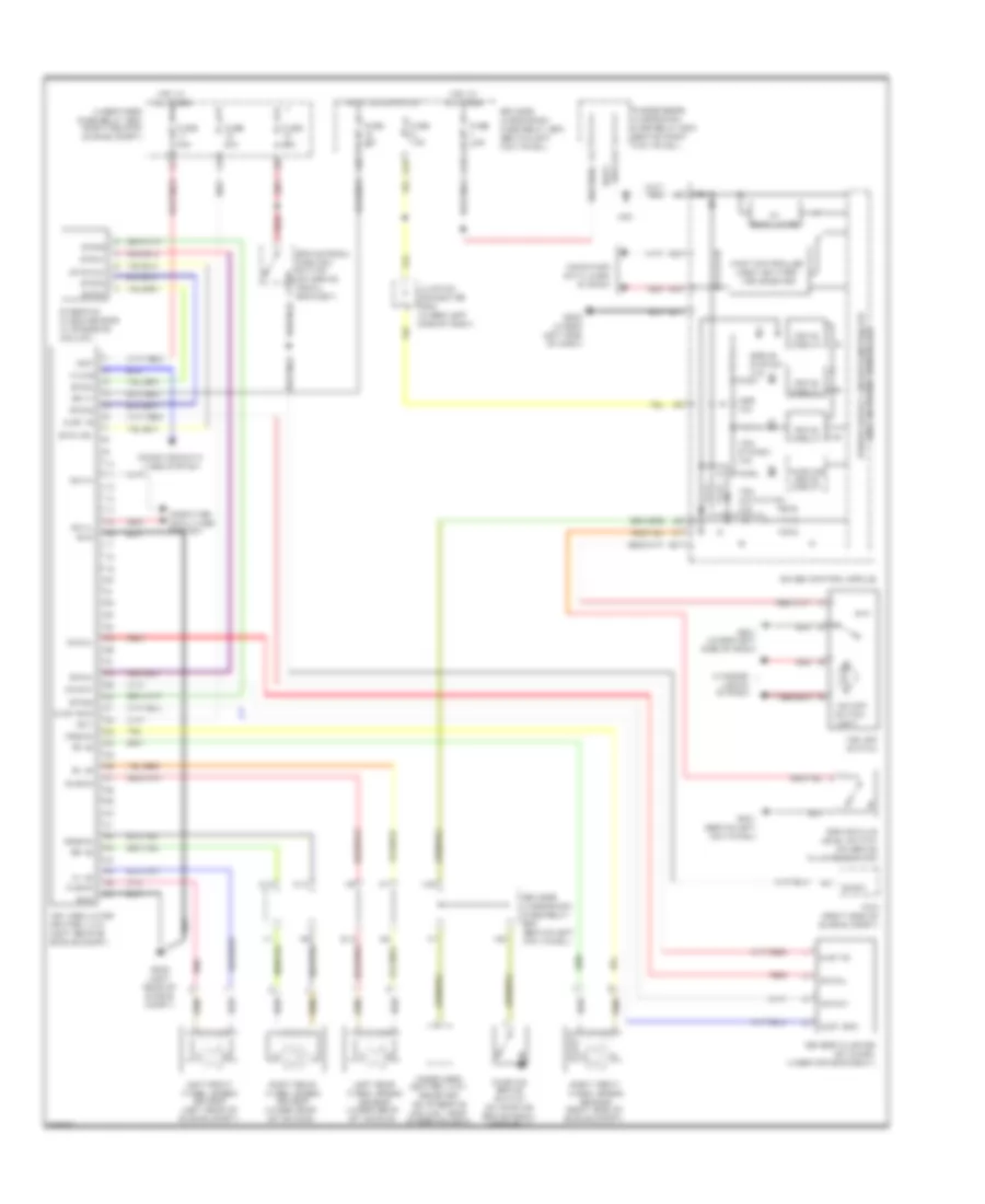
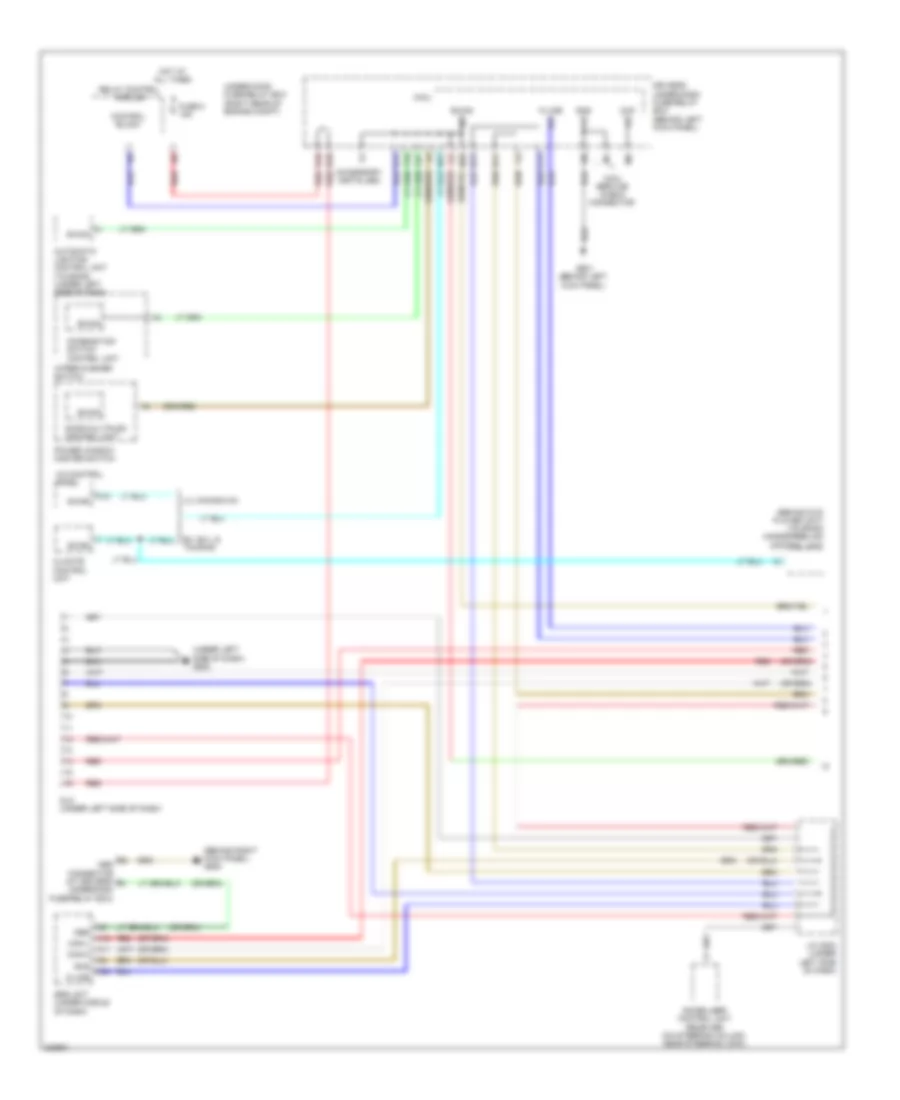
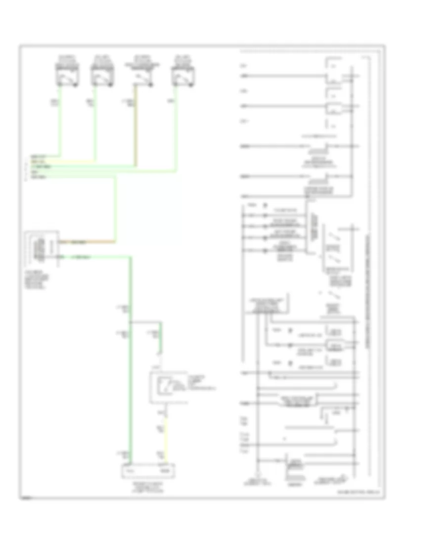
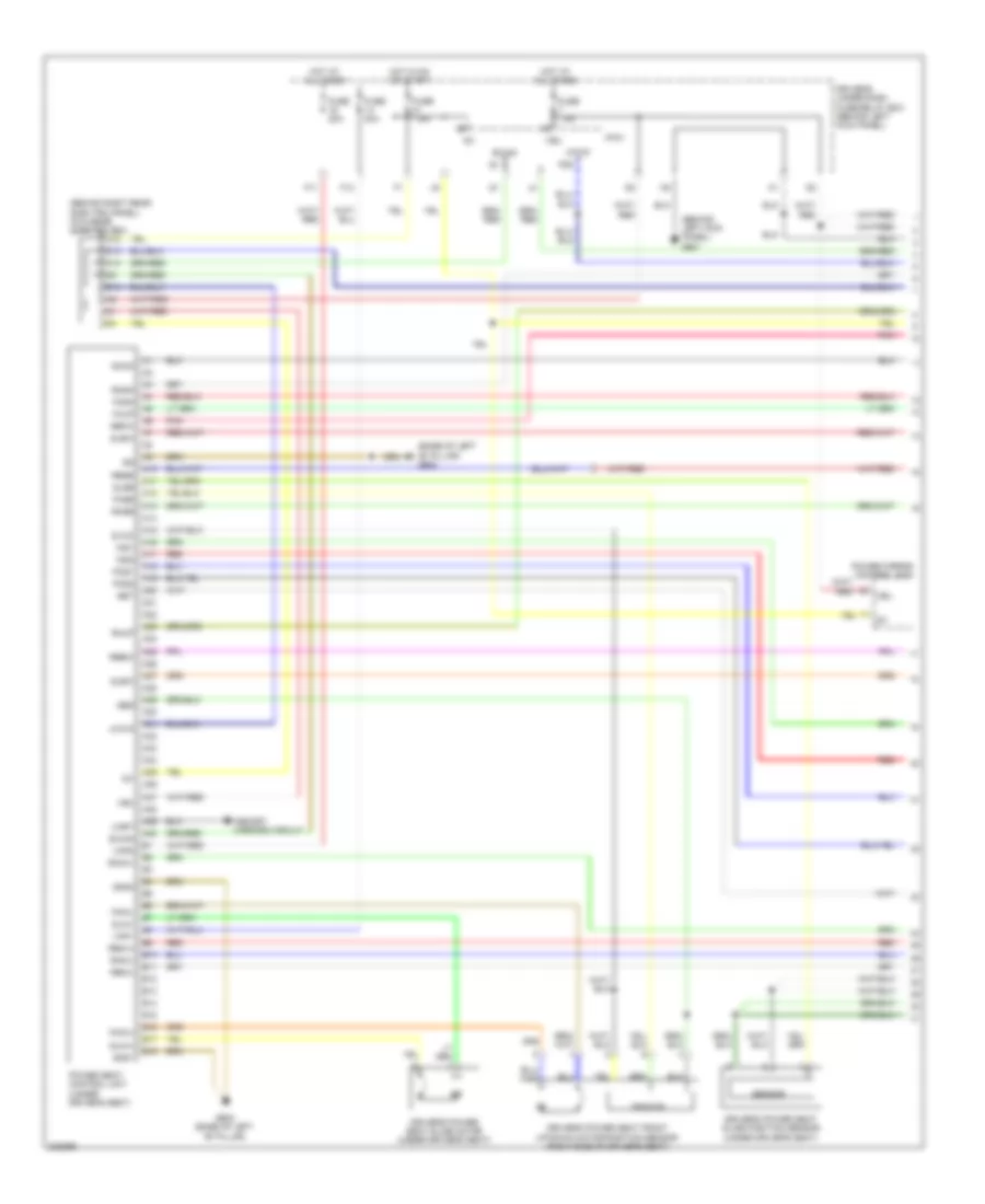
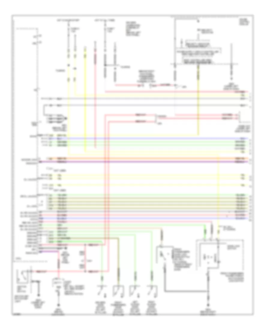
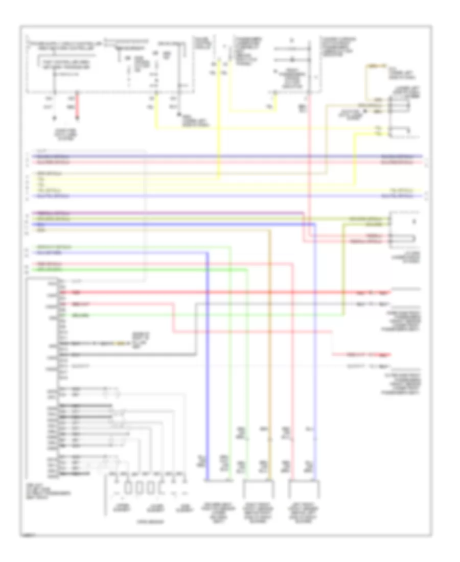
AIR CONDITIONING
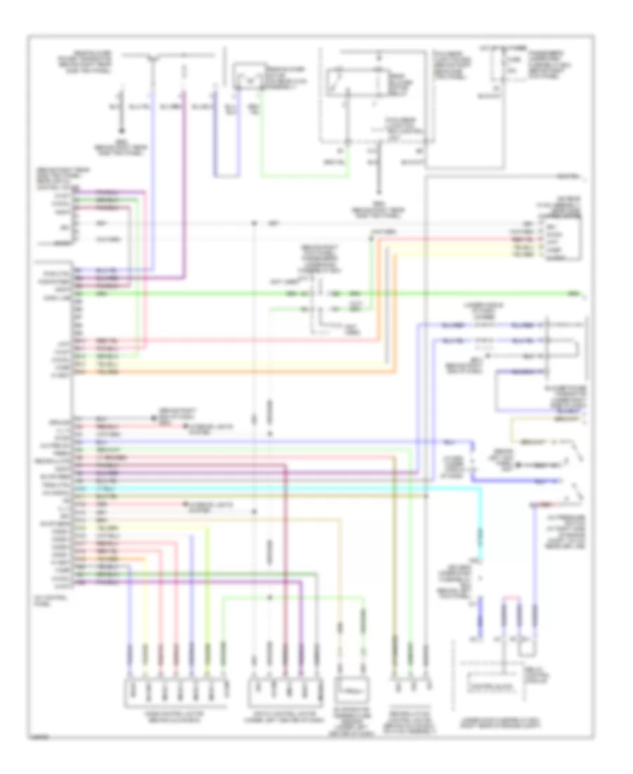
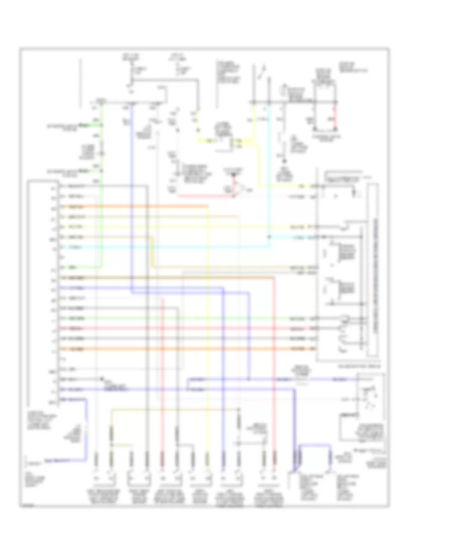
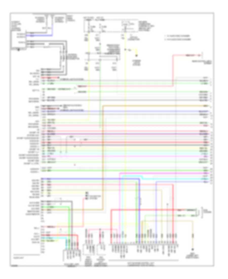
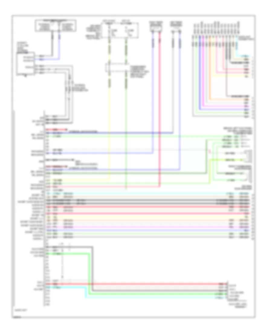
Automatic A/C Wiring Diagram (1 of 3) for Honda Odyssey EX 2010

List of elements for Automatic A/C Wiring Diagram (1 of 3) for Honda Odyssey EX 2010:
- (behind left side of front bumper) outside air temperature sensor
- (on rear hvac assembly) rear blower motor
- (top center of dash) automatic lighting sensor/sunlight sensor
- (under left side of dash) in-car temperature sensor
- A/c pre sw
- A/c pressure switch (at right side of engine compt, on a/c receiver line)
- A/c sig
- A13
- A20
- A21
- Ac-ck
- Ac-si
- Ac-so
- Air temp sens
- Amd-p
- Amd-p as
- Amd-p dr
- Bus data
- Bwr feedback
- Climate control panel
- Climate control unit
- Clk
- Computer data n22 lines system
- Control block
- D11
- Driver's air mix control motor
- Driver's under-dash fuse/relay box (behind left kick panel)
- E11
- E12
- Evap temp sens
- Evaporator temperature sensor (under left center of dash)
- Ex & ex-l
- Fresh
- Front mode control motor (behind glove box)
- Front passenger's air mix control motor (under right side of dash)
- Frs
- Fuse 30a
- G401 (behind left kick panel)
- G504 (behind right end of dash)
- G652 (behind right rear side trim panel)
- Gnd
- Hot at all times
- Ig2
- Ill (+)
- Ill (-)
- Interior lights system
- J/c c506 (under middle of dash)
- J/c c507 (behind right end of dash)
- J12
- M-cool
- M-cool as
- M-cool dr
- M-def
- M-hot
- M-hot as
- M-hot dr
- M-vent
- Micu-rear junction box (behind right rear side trim panel)
- Micu-rear junction box control unit
- Mode 1
- Mode 2
- Mode 3
- Mode 4
- Navigation unit (usa ex-l: res/ navigation touring) (under driver's seat)
- Passenger's under-dash fuse/relay box (behind right kick panel)
- Pnk
- Pwr trns ctrl
- Rear blower motor relay
- Rec
- Recirculate
- Recirculation control motor (behind glove box, on hvac assembly)
- Red
- Relay control module
- S-com
- S5v
- Sunlight sens
- Sunlight sensor
- Sunlight sensor (top center of dash)
- Temp sens
- Touring
- Under-hood fuse/relay box (right rear of engine compt)
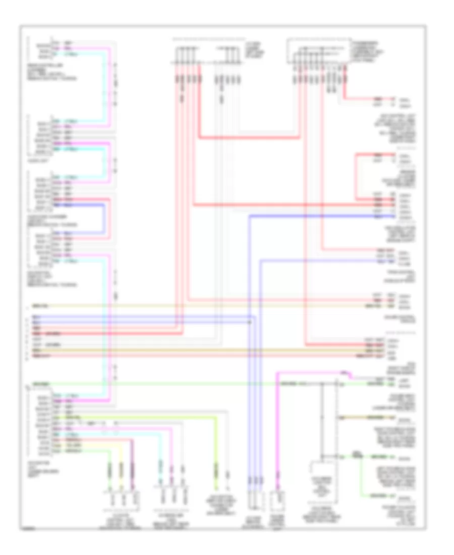
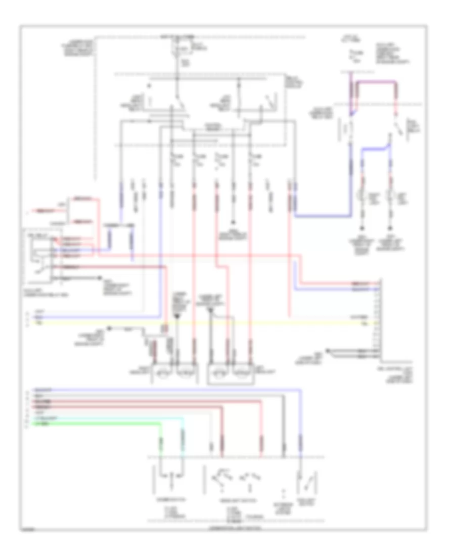
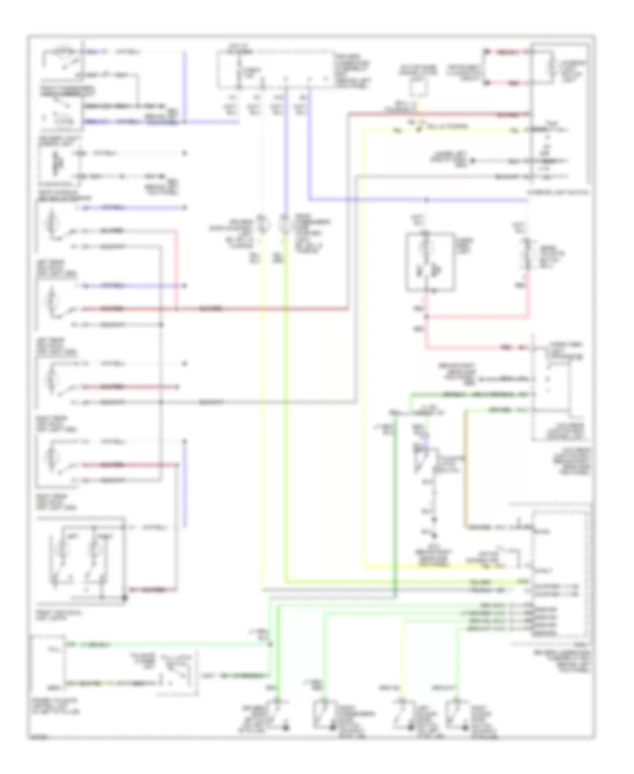
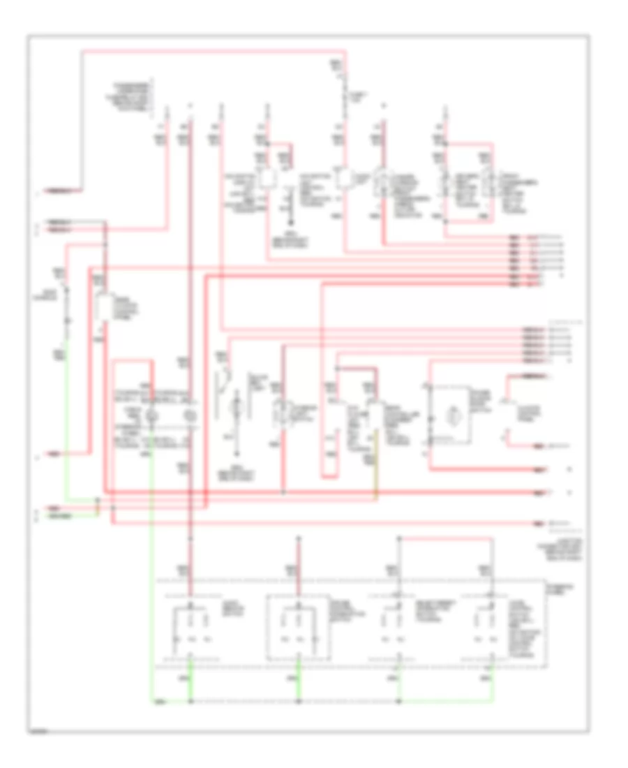
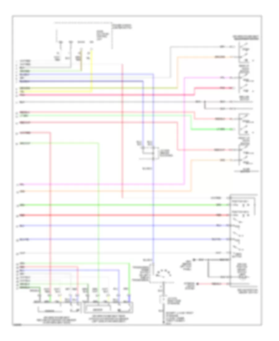
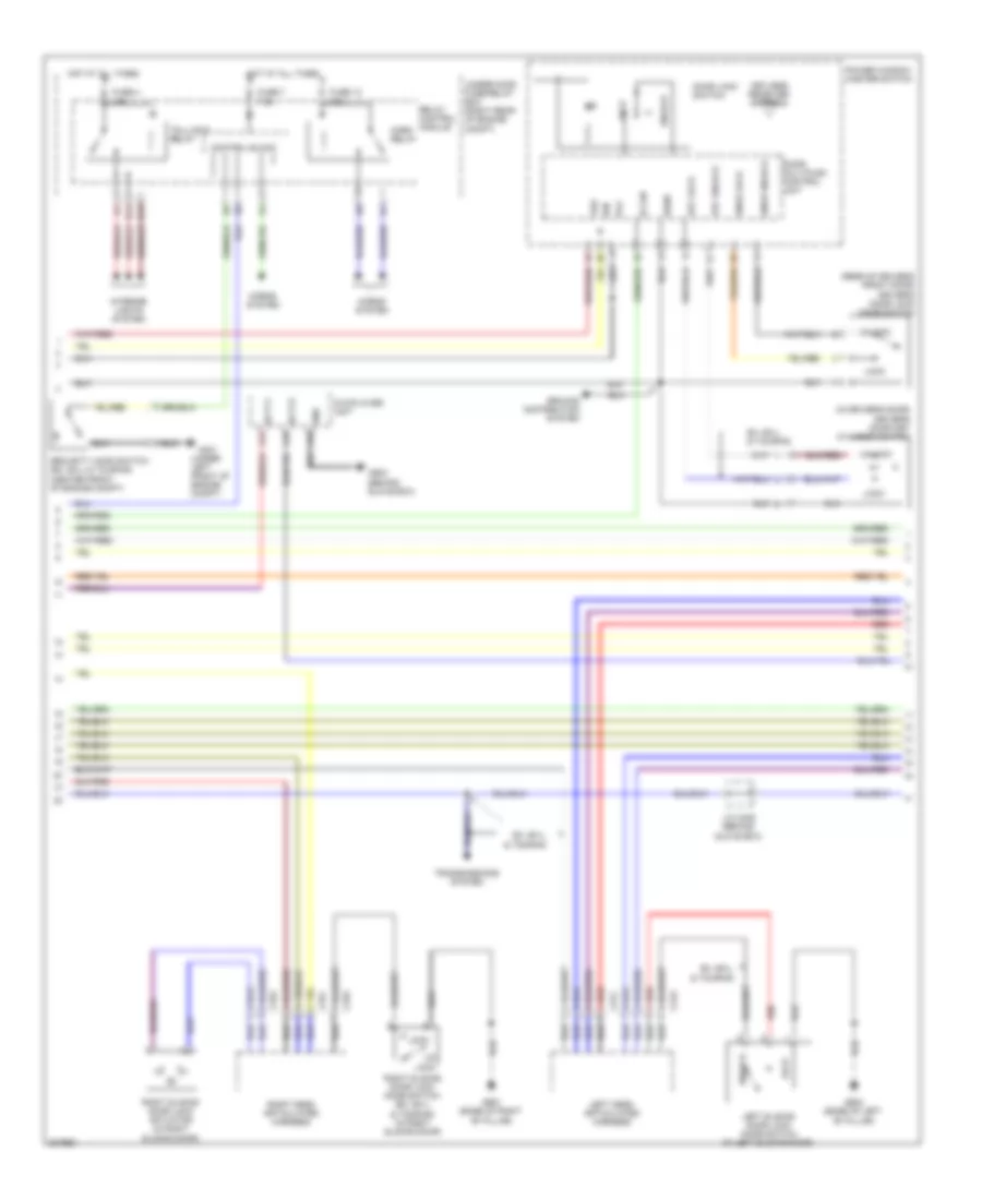
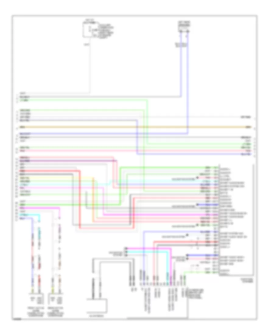
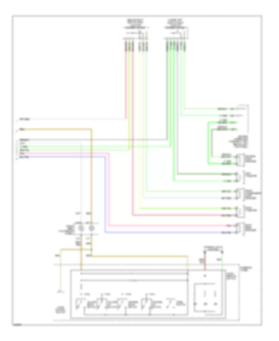
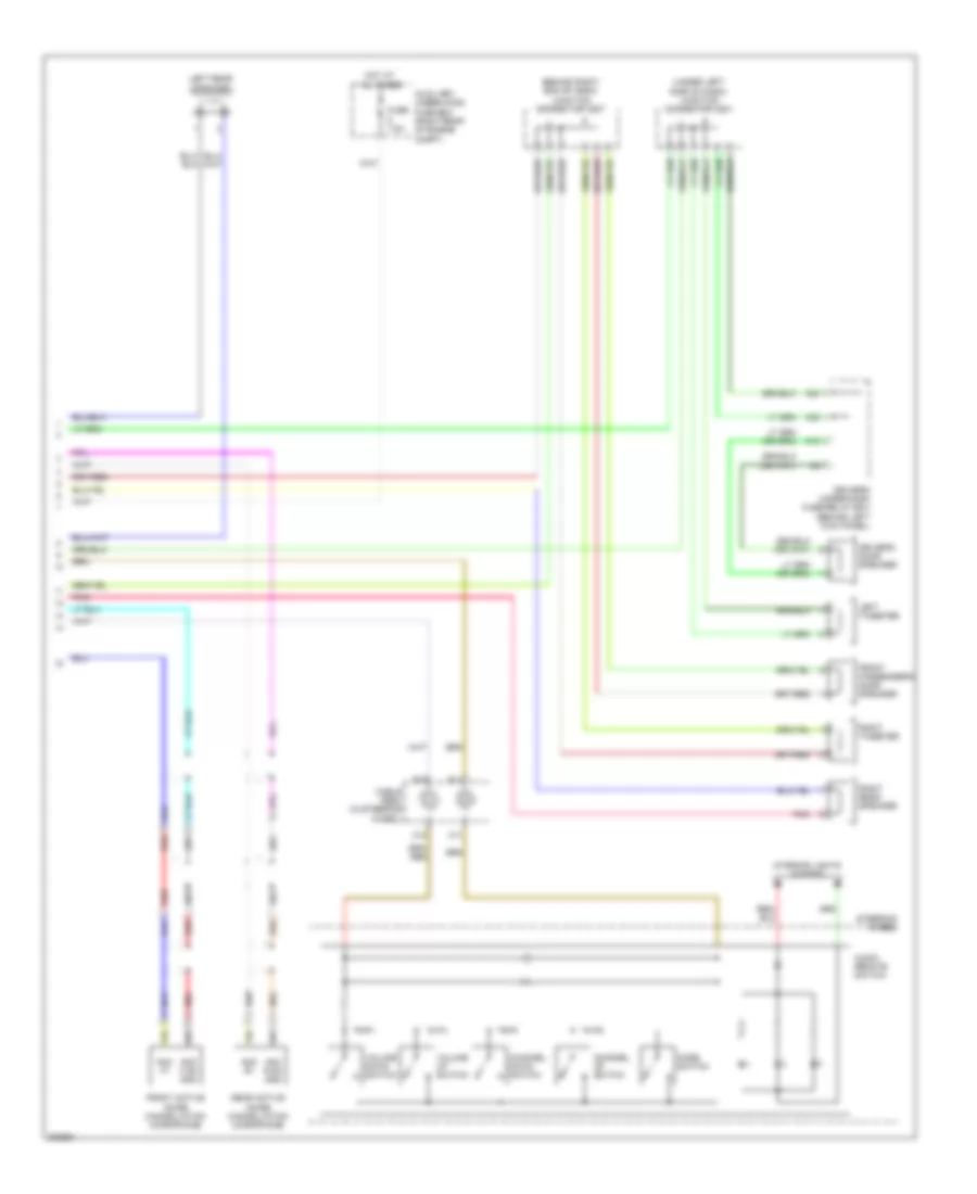
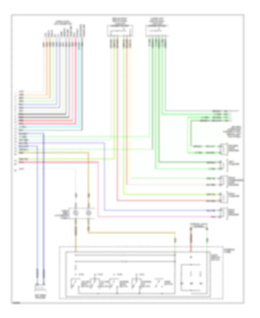
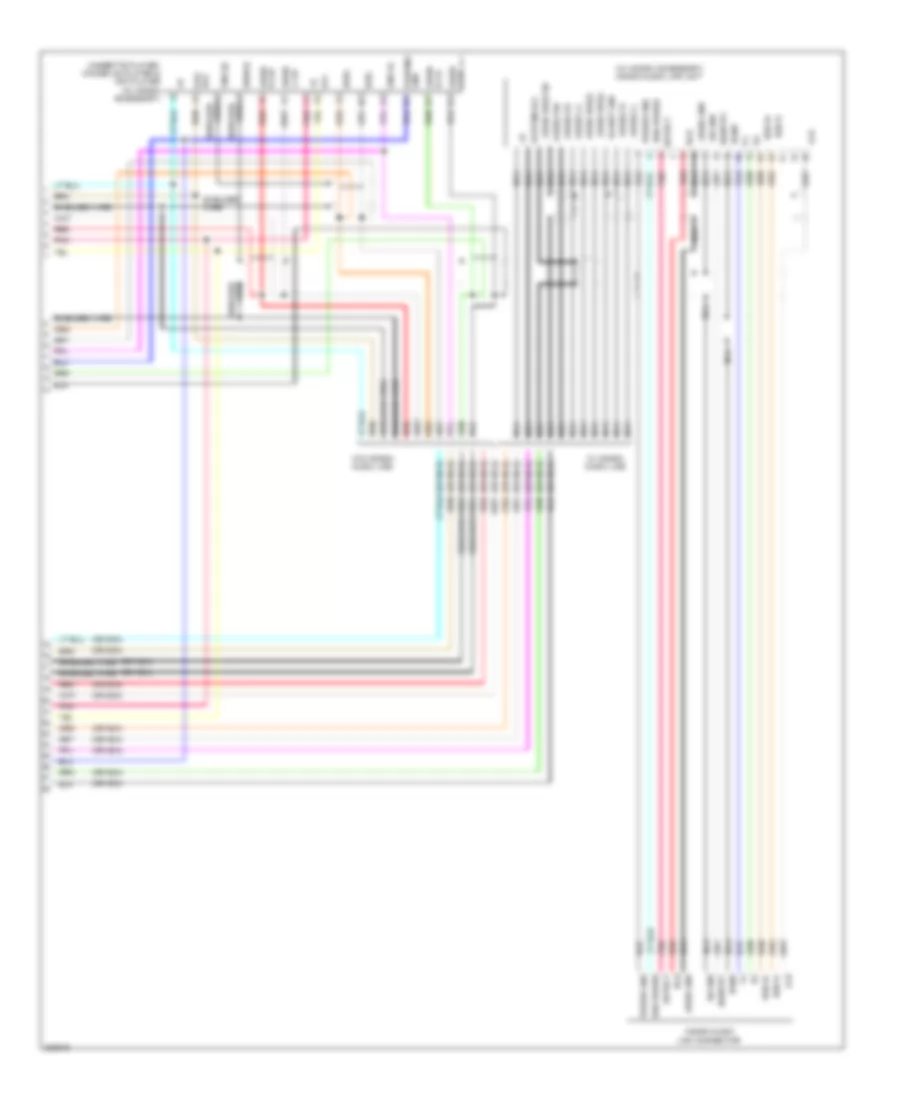
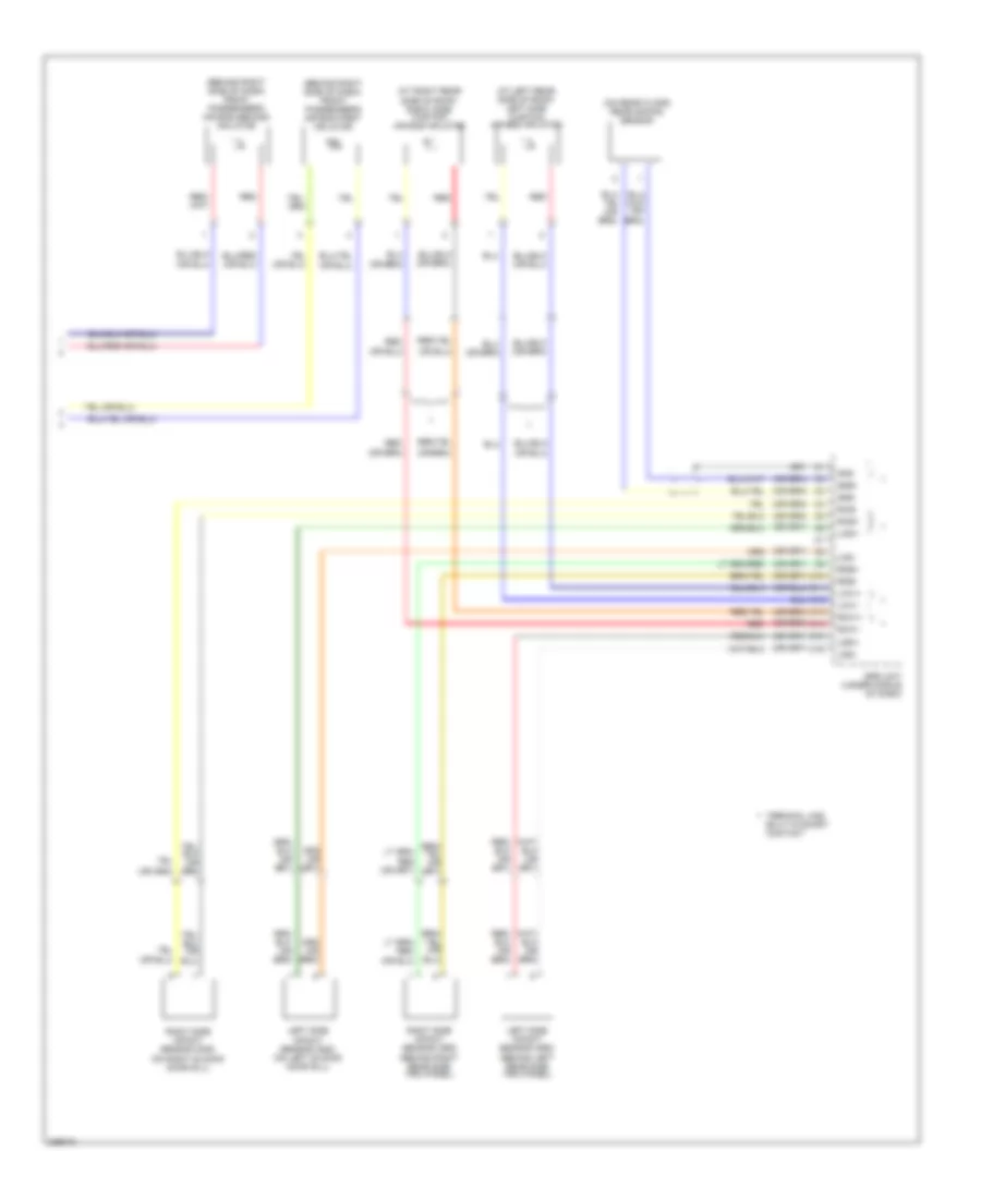
Automatic A/C Wiring Diagram (2 of 3) for Honda Odyssey EX 2010
List of elements for Automatic A/C Wiring Diagram (2 of 3) for Honda Odyssey EX 2010:
- (under middle of dash) j/c c506
- Amd-p
- Bus data
- Front blower motor
- Front blower power transistor (under right side of dash)
- G12
- G504 (behind right end of dash)
- G601 (behind left kick panel)
- G652 (behind right rear side trim panel)
- Gnd
- Headlights system
- Ig2
- Ill (+)
- Ill (-)
- Interior lights system
- M-cool
- M-def
- M-hot
- M-pt
- M-vent
- Mirrors system
- Passenger's under-dash fuse/relay box (behind right kick panel)
- Pwr ctrl
- R air m- pot
- R bwr fd bk
- R m-cool
- R m-def
- R m-hot
- R m-pt
- R m-vent
- Rear air mix control motor (behind right rear side trim panel)
- Rear blower power transistor (behind right rear side trim panel)
- Rear climate control panel
- Rear climate control unit (behind right rear side trim panel)
- Rear ctrl m-pt
- Rear in-car temperature sensor (touring) (behind right rear side trim panel)
- Rear mode control motor (on rear hvac assembly)
- Red
- S-com
- S5v
- Sens com gnd
- Temp sens
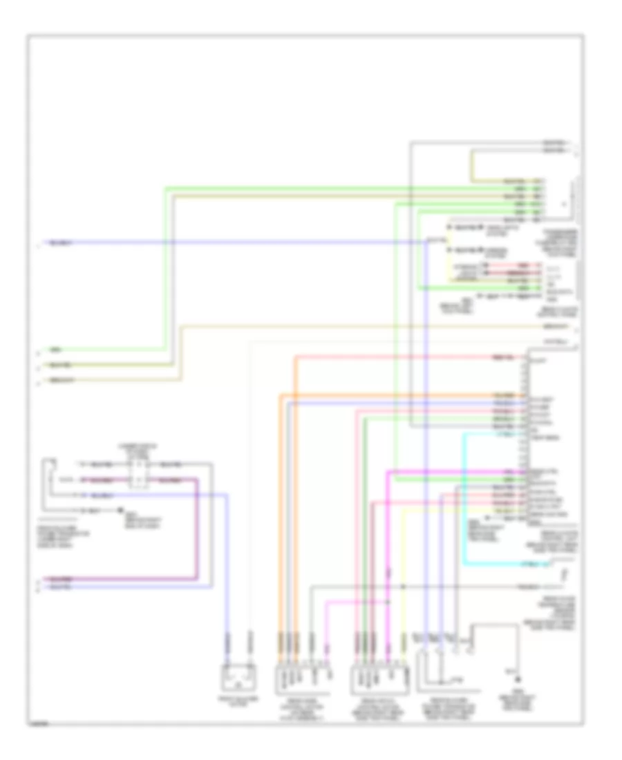
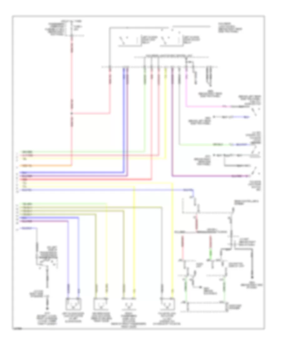
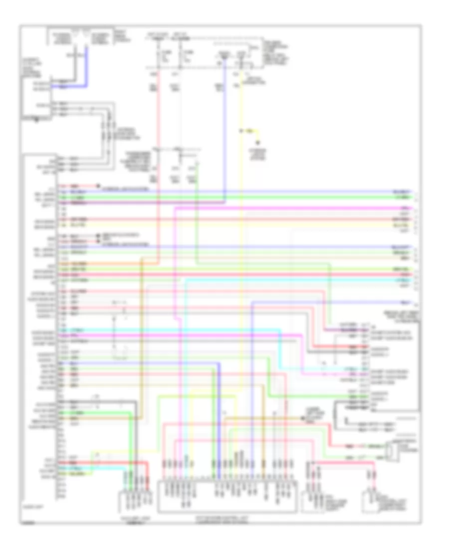
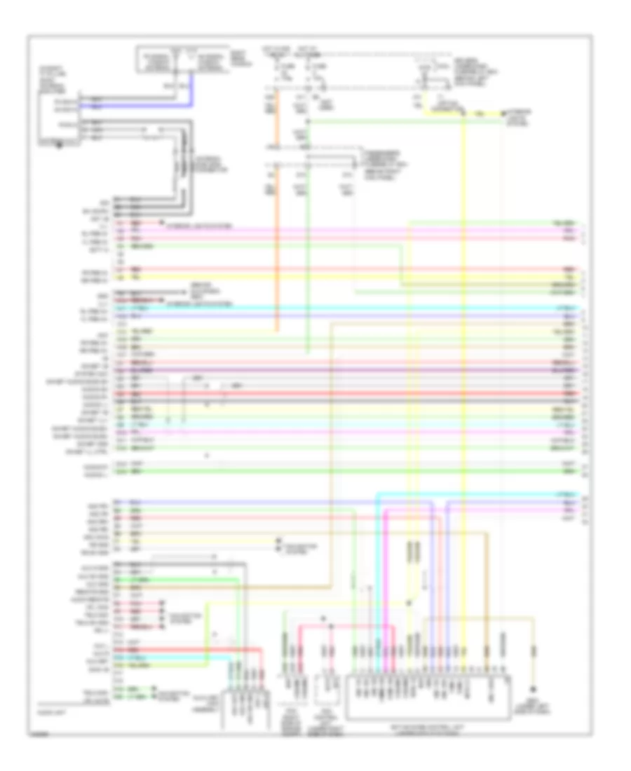
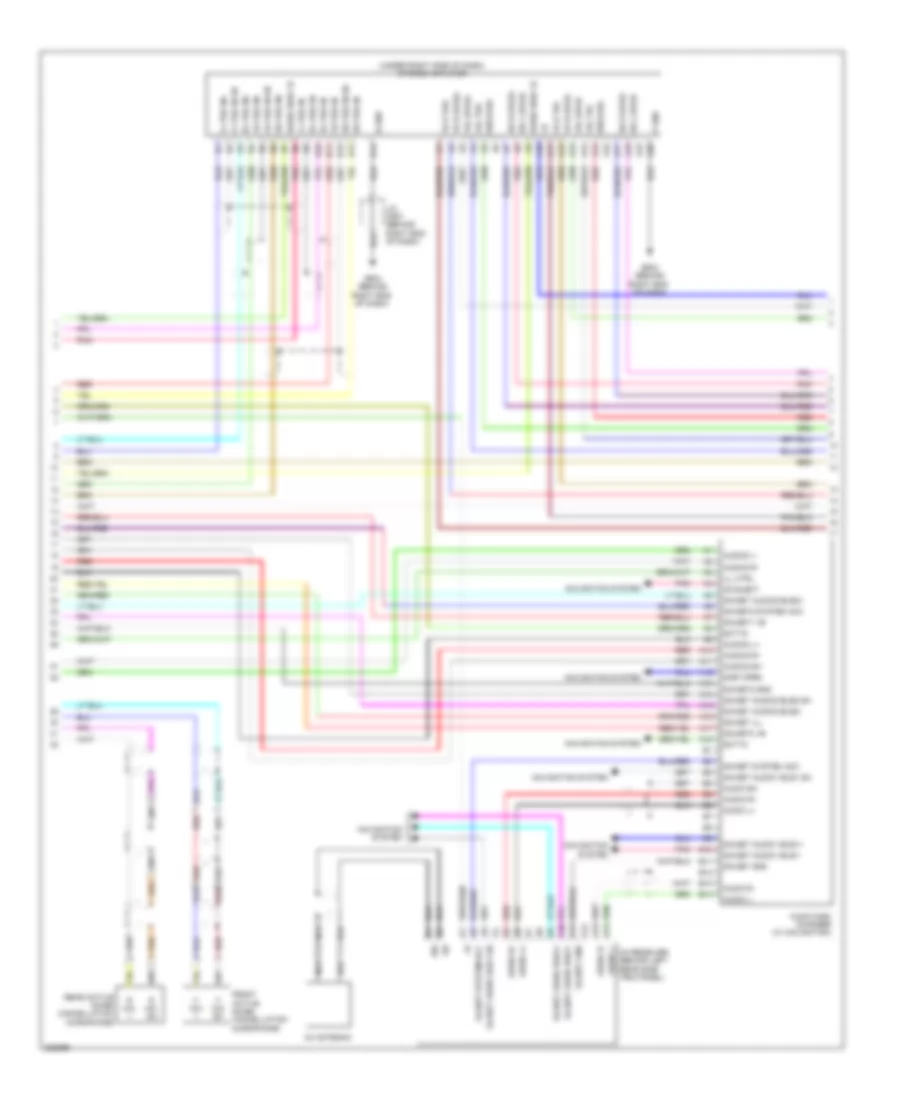
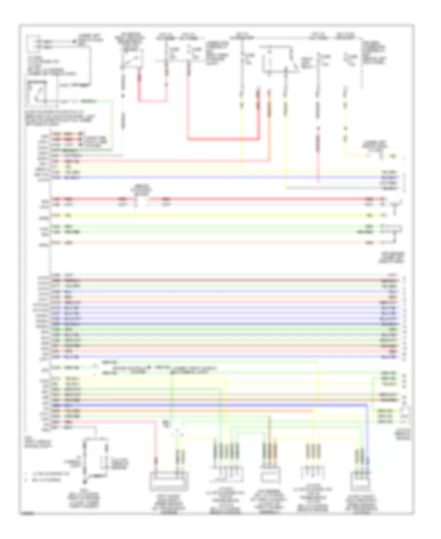
Automatic A/C Wiring Diagram (3 of 3) for Honda Odyssey EX 2010
List of elements for Automatic A/C Wiring Diagram (3 of 3) for Honda Odyssey EX 2010:
- (rear of engine) j/c c104
- A/c
- A/c compressor
- A/c compressor clutch relay
- A/c condenser fan motor (behind right side of radiator)
- A/c condenser fan relay
- A/c diode a
- A/c pressure switch
- A13
- A47
- A48
- A49
- Auxiliary under-hood fuse box (right rear of engine compt)
- C16
- C31
- C32
- C41
- Can-h
- Compressor clutch
- Computer data lines system
- D16
- Driver's under-dash fuse/relay box (behind left kick panel)
- E10
- E14
- E15
- Ect sensor 1 (top rear of engine)
- Ect sensor 2 (below throttle body)
- F10
- F14
- F15
- F17
- F19
- Fan control relay
- Front blower motor relay
- Fuse 10a
- Fuse 11 30a
- Fuse 40a
- Fuse 7.5a
- Fuse 9 30a
- G101 (under throttle body)
- G201 (under right front of engine compt)
- G202 (right side of engine compt)
- G301 (under left front of engine compt)
- Ground
- High fan control
- Hot at all times
- Hot in on
- J/c c102 (right side of engine)
- J/c c103 (rear of engine)
- Low fan control can-l
- N20
- Pcm (right side of engine compt)
- Pgm-f1 main relay 1
- Radiator fan motor (behind left side of radiator)
- Radiator fan relay
- Red
- Relay control
- Sensor ground
- Sensor input
- Under-hood fuse/relay box (right rear of engine compt)
- Usa :ex-l res/ navigation; ex-l res; touring & ex: res
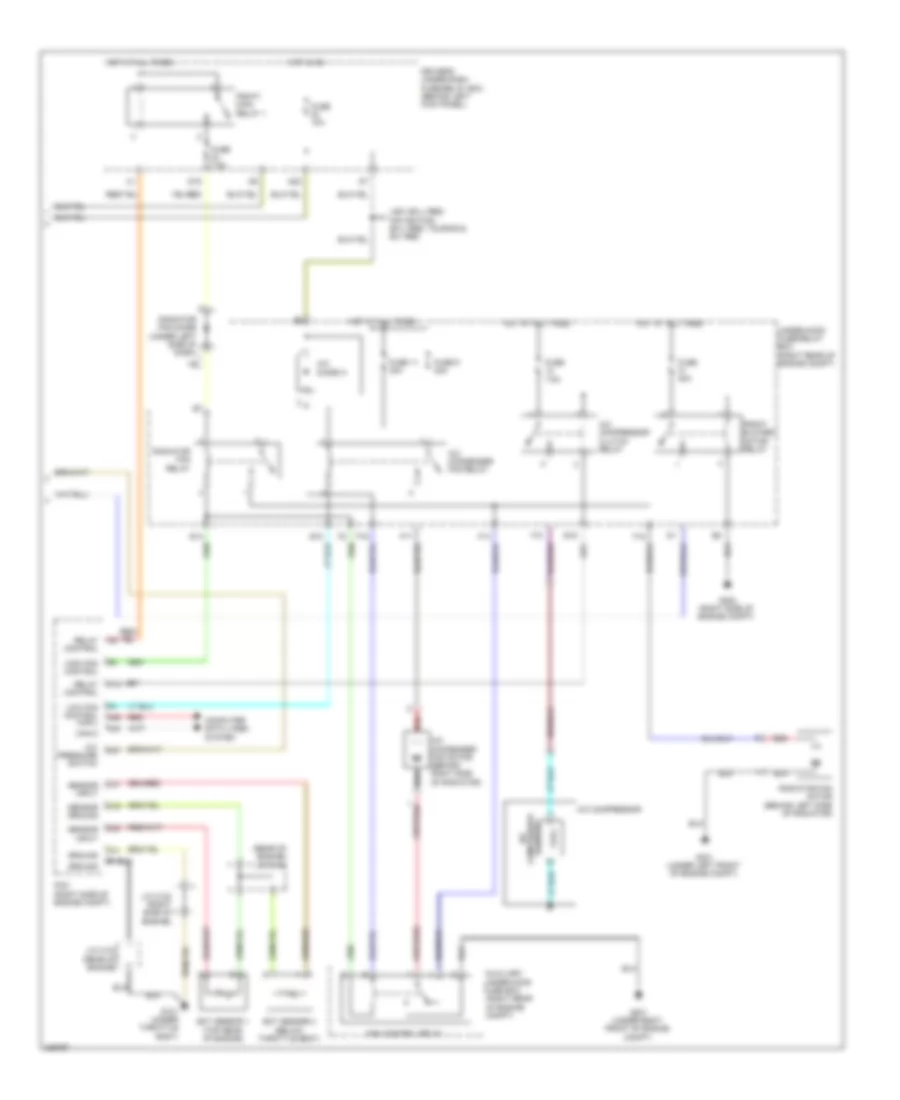
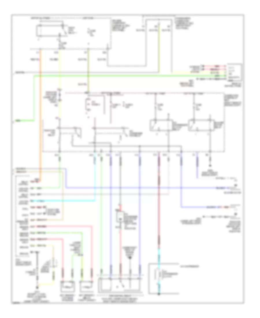
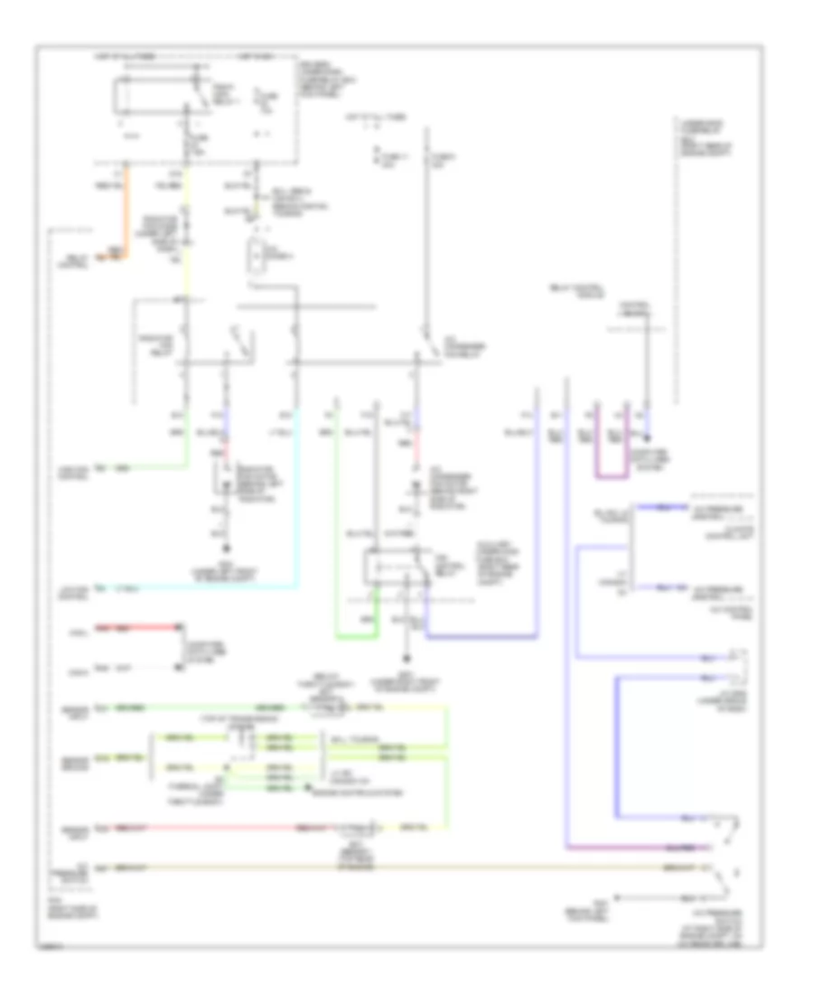
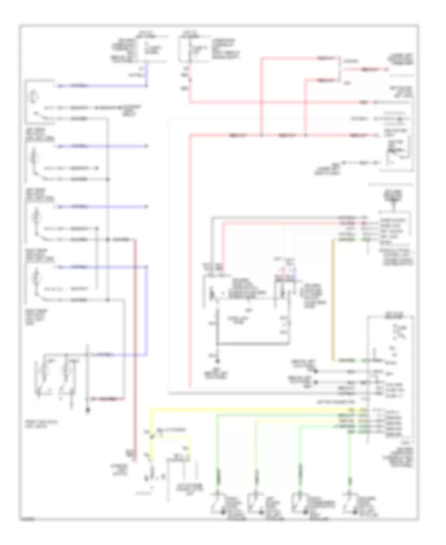
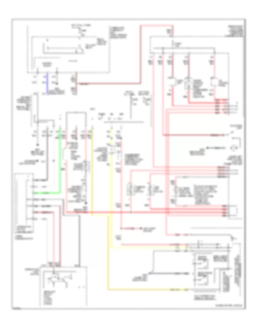
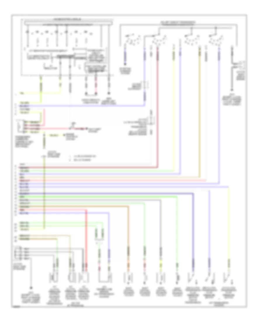
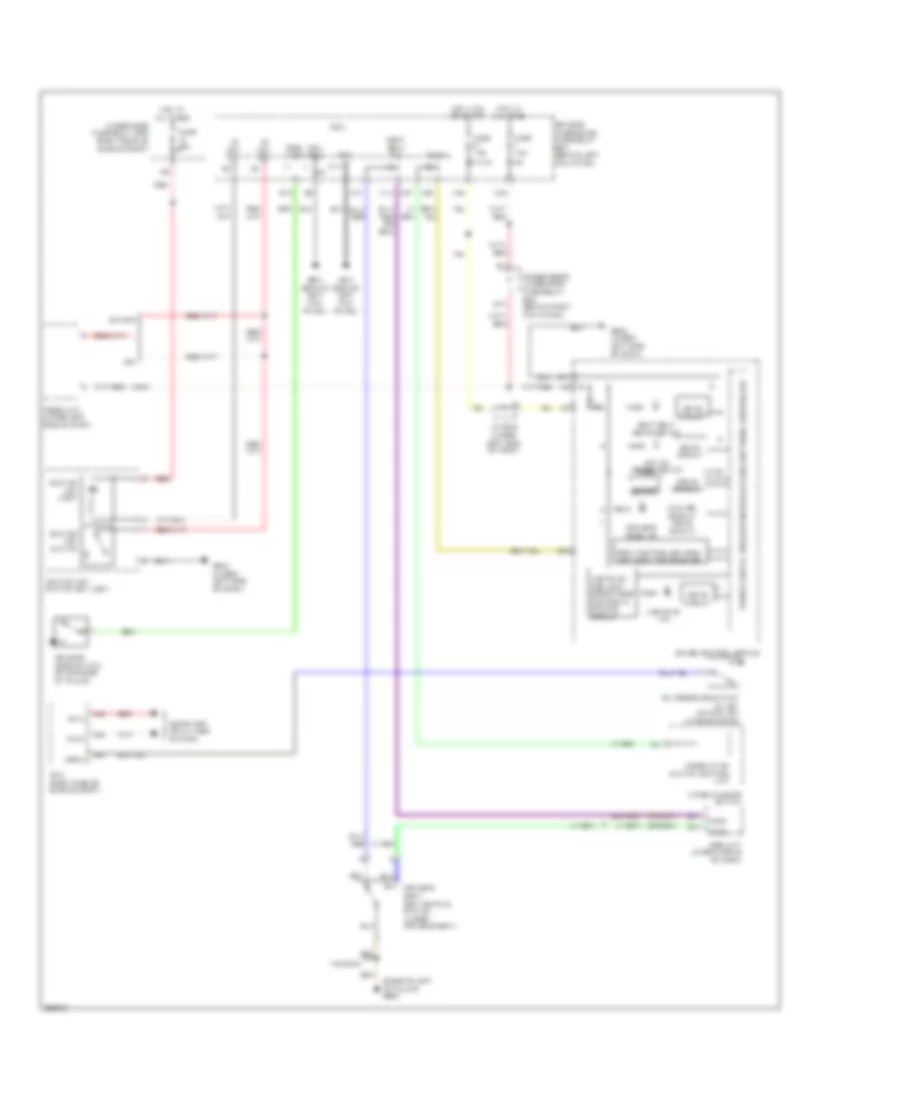
Manual A/C Wiring Diagram (1 of 2) for Honda Odyssey EX 2010
List of elements for Manual A/C Wiring Diagram (1 of 2) for Honda Odyssey EX 2010:
- (behind left kick panel) g401
- (behind right end of dash) g504
- (behind right kick panel) passenger's under-dash fuse/relay box
- (behind right rear side trim panel)
- (behind right rear side trim panel) rear air mix control motor
- (not used)
- (on rear hvac assembly) rear mode control motor
- (under middle of dash) j/c c506
- A/c control panel
- A/c pre sw
- A/c pressure switch (at right side of engine compt, on a/c receiver line)
- A/c signal
- A10
- A11
- A12
- A13
- A14
- A15
- A16
- A17
- A18
- A19
- A20
- A21
- A22
- Air mix control motor (under left center of dash)
- Amd-p
- B10
- B11
- B12
- B13
- B14
- Blower power transistor (under right side of dash)
- Blwr feed
- Comm line
- Control block
- D11
- Driver's under-dash fuse/relay box (behind left kick panel)
- E11
- Evap sens
- Evaporator temperature sensor (under left center of dash)
- Fresh
- Frs
- Fuse 30a
- G12
- G504 (behind right end of dash)
- G652
- G652 (behind right rear side trim panel)
- Ground
- Hot at all times
- Ig2
- Ill (+)
- Ill (-)
- Interior lights system
- J/c c506 (under middle of dash)
- J12
- M-cool
- M-def
- M-hot
- M-pt
- M-vent
- Micu-rear junction box (behind right rear side trim panel)
- Micu-rear junction box control unit
- Mode 1
- Mode 2
- Mode 3
- Mode 4
- Mode control motor (behind glove box)
- N22
- Passenger's under-dash fuse/relay box (behind right kick panel)
- Pwr ctrl
- R bwr fdbk
- Rear blower motor (on rear hvac assembly)
- Rear blower motor relay
- Rear blower power transistor (behind right rear side trim panel)
- Rec
- Recirculate
- Recirculation control motor (behind glove box, on hvac assembly)
- Red
- Relay control module
- S-com
- S5v
- Trns ctrl
- Under-hood fuse/relay box (right rear of engine compt)
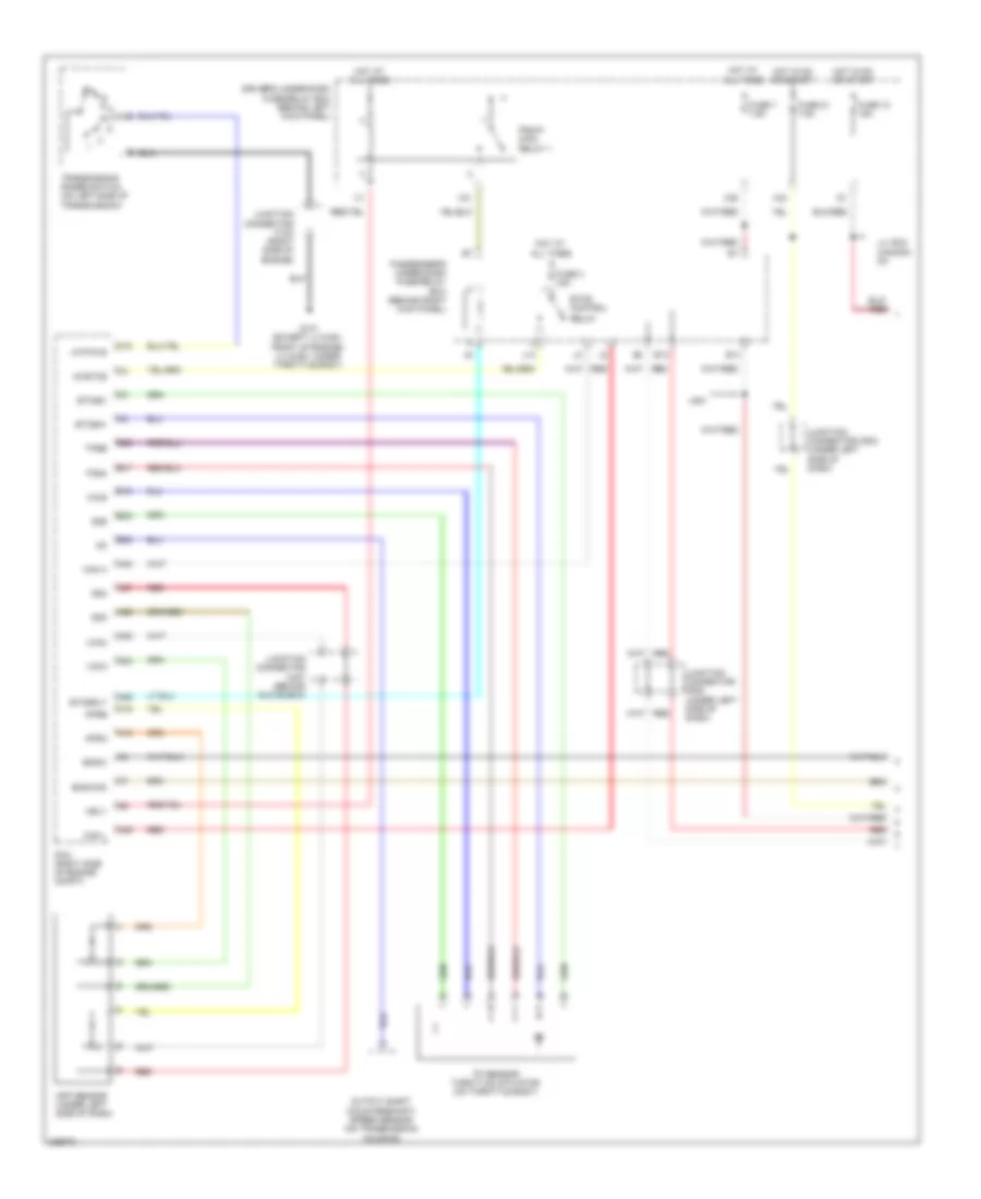
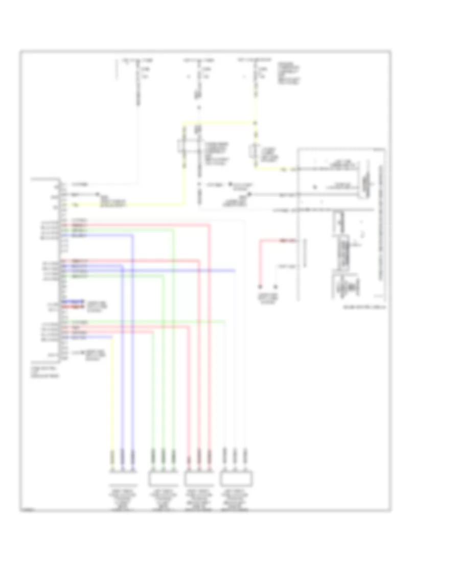
Manual A/C Wiring Diagram (2 of 2) for Honda Odyssey EX 2010
List of elements for Manual A/C Wiring Diagram (2 of 2) for Honda Odyssey EX 2010:
- (under right front of engine compt) g201
- (under throttle body) (thermal joint) s2
- A/c compressor
- A/c compressor clutch
- A/c compressor clutch relay
- A/c condenser fan motor (behind right side of radiator)
- A/c condenser fan relay
- A/c diode a
- A/c pressure switch
- A13
- A47
- A48
- A49
- Auxiliary under-hood fuse box (right rear of engine compt)
- Blower motor
- Blower motor relay
- Bus data
- C16
- C31
- C32
- C41
- Can-h
- Can-l
- Computer data lines system
- D16
- Driver's under-dash fuse/relay box (behind left kick panel)
- E10
- E14
- E15
- Ect sensor 1 (top rear of engine)
- Ect sensor 2 (below throttle body)
- F10
- F14
- F15
- F17
- F19
- Fan control relay
- Fuse 10a
- Fuse 11 30a
- Fuse 40a
- Fuse 7.5a
- Fuse 9 30a
- G101 (except lx & ex: front of engine) (lx & ex: under throttle body)
- G202 (right side of engine compt)
- G301 (under left front of engine compt)
- G601 (behind left kick panel)
- Gnd
- Ground
- High fan control
- Hot at all times
- Hot in on
- Ig2
- Ill (+)
- Ill (-)
- Interior lights system
- J/c c102 (right side of engine)
- Low fan control
- N20
- Passenger's under-dash fuse/relay box (behind right kick panel)
- Pcm (right side of engine compt)
- Pgm-fi main relay 1
- Radiator fan motor (behind left side of radiator)
- Radiator fan relay
- Rear a/c control panel
- Red
- Relay control
- S1 (thermal joint)
- Sensor ground
- Sensor input
- Under-hood fuse/relay box (right rear of engine compt)
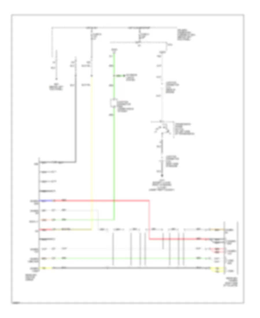
ANTI-LOCK BRAKES
Anti-lock Brakes Wiring Diagram for Honda Odyssey EX 2010
List of elements for Anti-lock Brakes Wiring Diagram for Honda Odyssey EX 2010:
- +b-p
- +b-v
- 5v regulator
- A21
- A23
- A24
- A27
- Abs ind
- Area network controller
- Bksw
- Brake fluid level switch (on brake fluid reservoir)
- Brake pedal position switch (on brake pedal bracket)
- Brake system ind
- C10
- C12
- Can-h
- Can-l
- Can2-h
- Can2-l
- Clst gnd
- Clst ig
- Computer data lines system
- Drive circuit
- Driver's under-dash fuse/relay box (behind left kick panel)
- E12
- E14
- Fast controller area network transceiver
- Fl +b
- Fl-gnd
- Fr +b
- Fr-gnd
- Fuse 15a
- Fuse 20a
- Fuse 30a
- Fuse 7.5a
- G302 (left rear of engine compt)
- G401 (behind left kick panel)
- G501 (under left side of dash)
- G502 (under left side of dash)
- Gauge control module
- Gnd
- Hot at all times
- Hot in on or start
- Ign in
- Immobilizer control unit- receiver (on steering column, near steering lock)
- Interior lights system
- Junction connector c503 (under left side of dash)
- K-line
- Left front wheel speed sensor (left rear of engine compt)
- Left rear wheel speed sensor (under rear of vehicle)
- N30
- N34
- Parking brake switch (on parking brake pedal assembly)
- Passenger's under-dash fuse/relay box (behind right kick panel)
- Pcm (right side of engine compt)
- Pnk
- Red
- Right front wheel speed sensor (right side of engine compt)
- Right rear wheel speed sensor (under rear of vehicle)
- Rl +b
- Rl-gnd
- Rr +b
- Rr-gnd
- Sensor cluster (on floor, under driver's seat)
- Steering angle sensor (in steering column)
- Str-a
- Str-b
- Str-g
- Str-vcc
- Str-z
- Under-hood fuse/relay box (right rear of engine compt)
- Usa
- Vsa activation ind
- Vsa modulator control unit (left rear of engine compt)
- Vsa off switch
- Vsa off switch light
- Vsa system ind
- Warning drive circuit
- X34
- X35
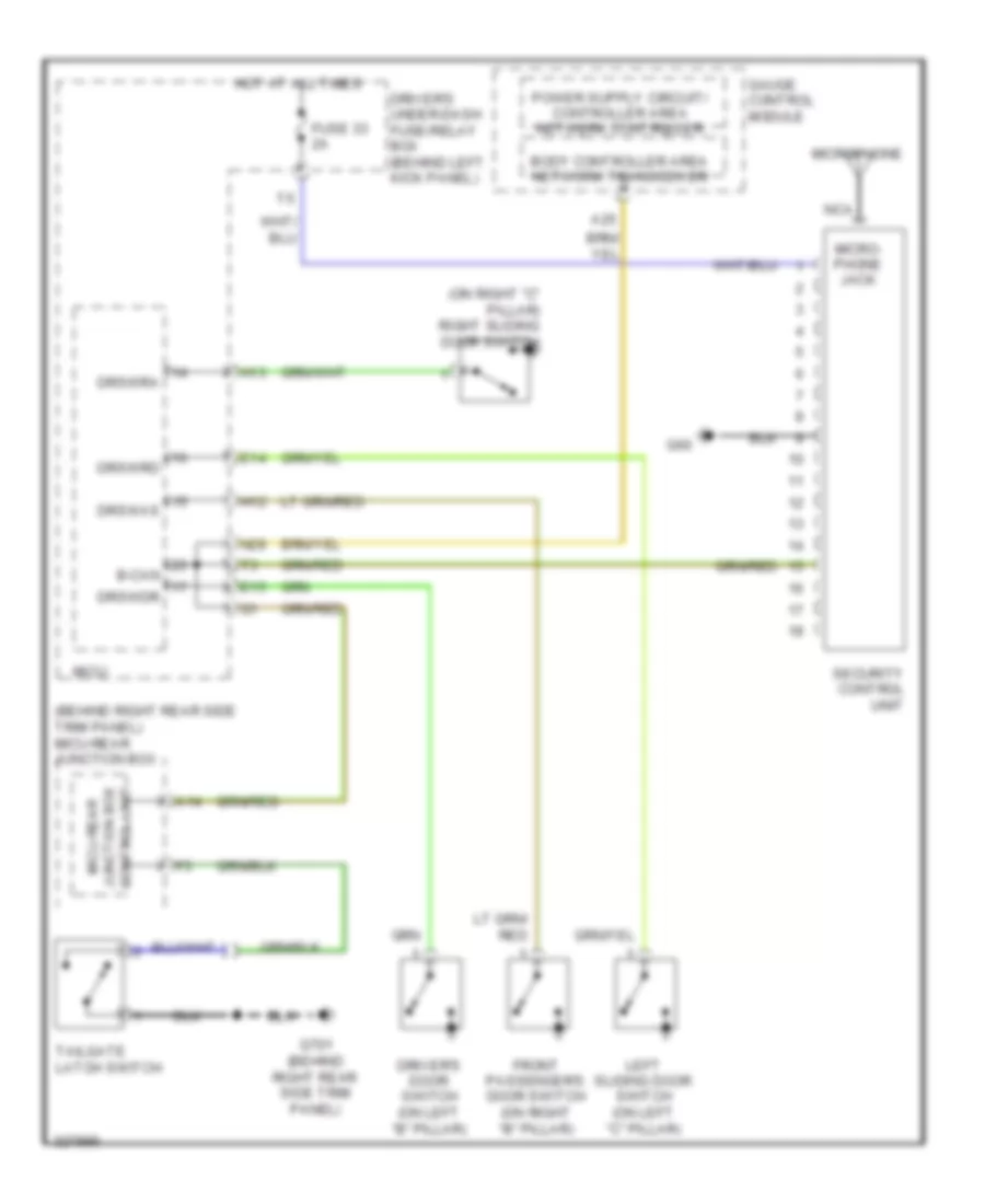
ANTI-THEFT
Forced Entry Wiring Diagram for Honda Odyssey EX 2010
List of elements for Forced Entry Wiring Diagram for Honda Odyssey EX 2010:
- (behind right rear side trim panel) micu-rear junction box
- (on right "c" pillar) right sliding door switch
- A14
- A25
- B-can drswdr
- Body controller area network transceiver
- Driver's door switch (on left "b" pillar)
- Driver's under-dash fuse/relay box (behind left kick panel)
- Drswas
- Drswra
- Drswrd
- E14
- E15
- Front passenger's door switch (on right "b" pillar)
- Fuse 33 2a
- G60
- G701 (behind right rear side trim panel)
- Gauge control module
- H12
- H13
- Hot at all times
- Left sliding door switch (on left "c" pillar)
- Micro- phone jack
- Microphone
- Micu
- Micu-rear junction box control unit
- N28
- Nca
- Security control unit
- Tailgate latch switch
Immobilizer Wiring Diagram for Honda Odyssey EX 2010
List of elements for Immobilizer Wiring Diagram for Honda Odyssey EX 2010:
- (behind right kick panel)
- (on parking brake pedal assembly) parking brake switch
- (right side of engine)
- (top of fuel tank) fuel tank unit
- (under left side of dash)
- (under left side of dash) junction connector c503
- 1=key in ignition
- A11
- A16
- A41
- A46
- B40
- B41
- B42
- C41
- Canada
- D12
- Data link connector (dlc) (under left side of dash)
- Diag-h
- Driver's under-dash fuse/relay box (behind left kick panel)
- Driver's underdash fuse/relay box (behind left kick panel)
- E13
- E14
- Engine controls system
- Fuel pump
- Fuel pump ctrl
- Fuse 19 15a
- Fuse 7 7.5a
- G101 (except lx & ex: front of engine) (lx & ex: under throttle body)
- G102 (lx, ex; canada: dx) (front of engine)
- G502
- G603 (behind left rear side trim panel)
- Gauge control module
- Gnd
- H/brake sw
- Hot at all times
- Hot in on or start
- Ig key sw
- Ig1
- Ign in (ig1)
- Ignition
- Ignition key switch
- Immobi code
- Immobi code in
- Immobilizer control unit-receiver (on steering column, near steering lock)
- Immobilizer indicator
- Imoes unit (under left side of dash)
- Imolmp
- J/c c102
- Junction connector c101 (right side of engine)
- Junction connector c503 (under left
- Key light
- Key switch/
- Lg3
- Logic gnd
- Micu
- N30
- N34
- Passenger's under-dash fuse/relay box
- Pcm (right side of engine compt)
- Pg2
- Pgm-fi main relay 1
- Pgm-fi main relay 2
- Pwr in (igp)
- Rly ctrl
- S1 (thermal joint)
- Side of dash)
- Usa
- X31
- X35
- X38
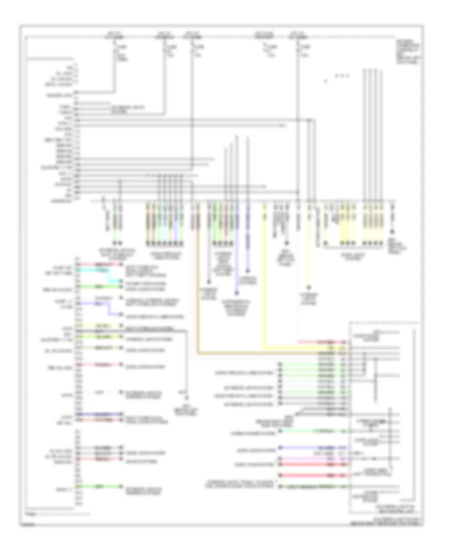
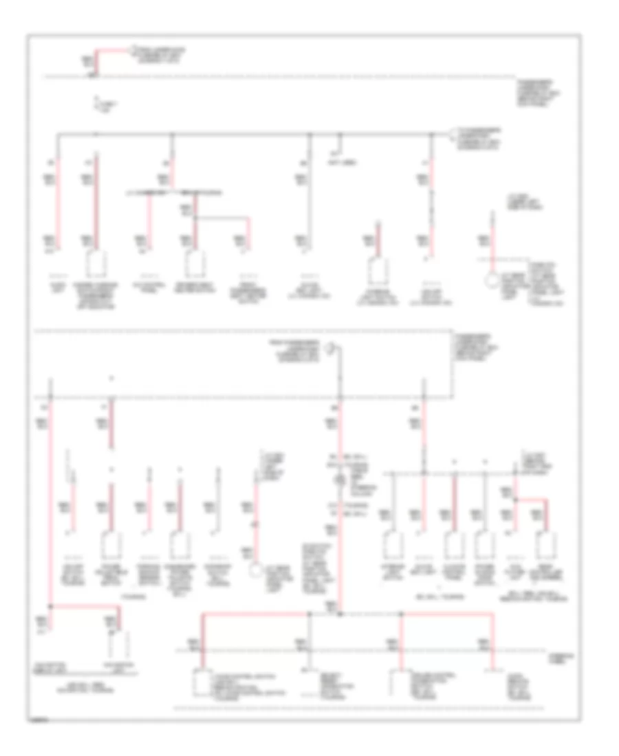
BODY CONTROL MODULES
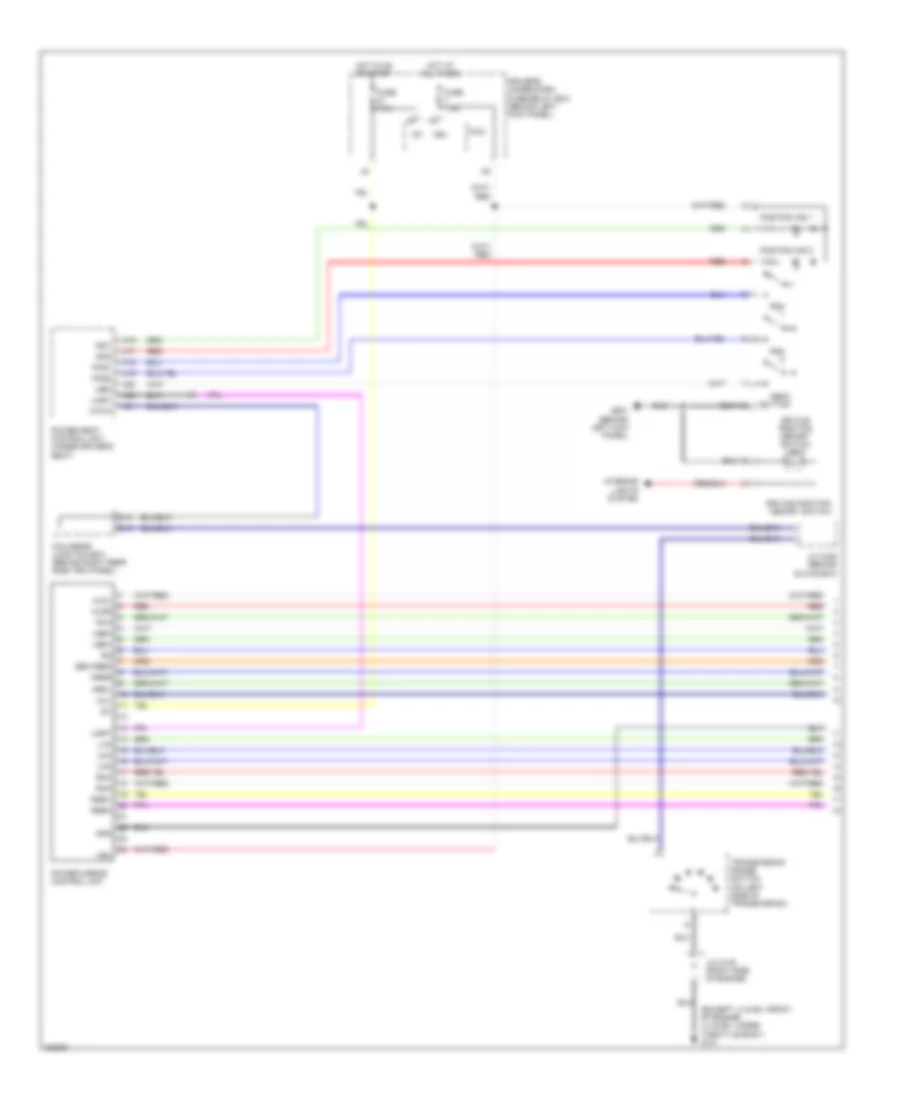
Body Control Modules Wiring Diagram for Honda Odyssey EX 2010
List of elements for Body Control Modules Wiring Diagram for Honda Odyssey EX 2010:
- (behind
- (behind left kick panel)
- (not used)
- +b door lock
- A12
- A13
- A14
- Acc
- Air conditioning system
- Atp-p
- Atp-r
- B-can
- Back lt
- Cargo area light transistor
- Chk
- Computer data lines system
- Courtesy lt as
- Courtesy lt dr
- D/l lock
- D/l unlock
- D11
- Day lt
- Door locks system
- Dr d/l unlock
- Driver's under-dash fuse/relay box (behind left kick panel)
- Drswas
- Drswdr
- Drswra
- Drswrd
- E10
- E14
- E15
- Exterior lights & mirrors systems
- Exterior lights & shift interlock systems
- Exterior lights system
- F10
- F12
- F14
- Fuse (not used)
- Fuse 10a
- Fuse 7.5a
- G401 (behind left kick panel)
- G601
- G652 (behind right rear side trim panel)
- H10
- H12
- H13
- H14
- Hazard sw
- Hot at all times
- Hot in acc or on
- Hot in on or start
- Ig key lt
- Ig key sw
- Ig1
- Interior lights system
- Interior lights, door locks & anti-theft system
- Interior lights, trunk, tailgate, fuel doors & door locks systems
- Intr lt
- K-line
- K11
- K12
- Key off timer
- Key sol
- Left kick
- Micu
- Micu gnd
- Micu-rear junction box (behind right rear side trim panel)
- Micu-rear junction box control unit
- N22
- N26
- N28
- P-pin
- P10
- P11
- P12
- P13
- P14
- P15
- P16
- P17
- P18
- P19
- P20
- P21
- P22
- P23
- P24
- P25
- P26
- P27
- P28
- P29
- P30
- Panel)
- Power distribution system
- Power tops system
- Q10
- Q11
- Q12
- Q13
- Q14
- Radio sw
- Red
- Rem as lock
- Rem as unlock
- Seat belt sw
- Sg-1
- Shift interlock & door locks systems
- Shift interlock system
- Shift interlock, door locks & anti-theft systems
- Sil as unlock
- Sil ra lock
- Sil rd unlock
- Sound systems
- Stop sw
- T1 (option connector)
- Turn l
- Turn r
- Vbu
- Warning systems
- Warning, interior lights & shift interlock systems
- Wiper/washer system
- X13
- X18
- X27
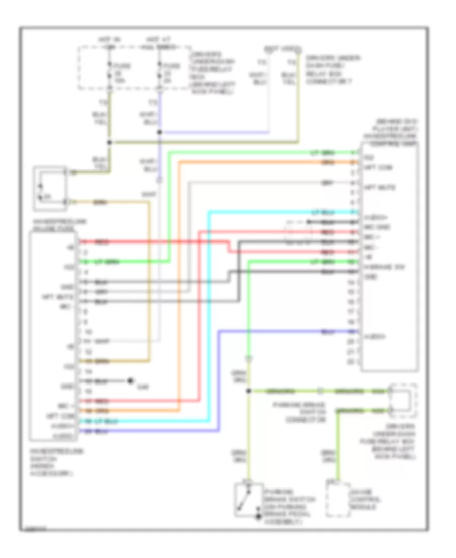
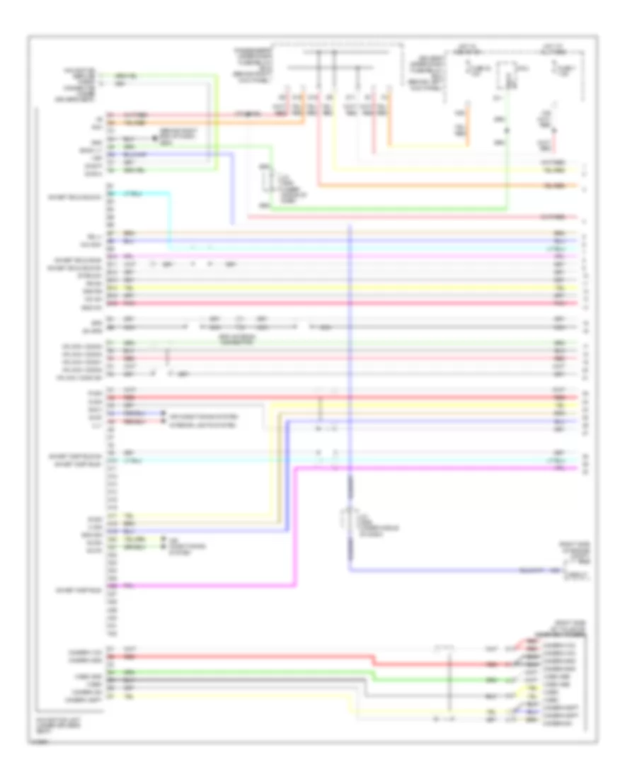
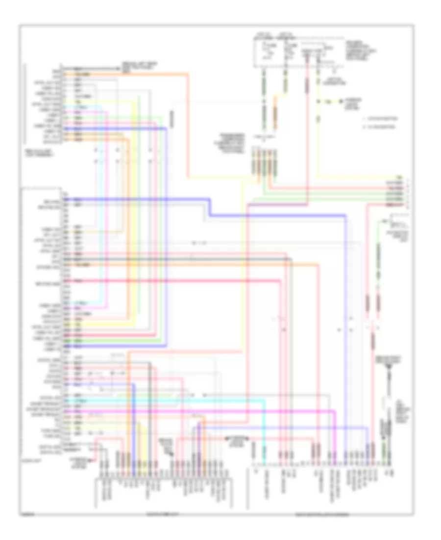
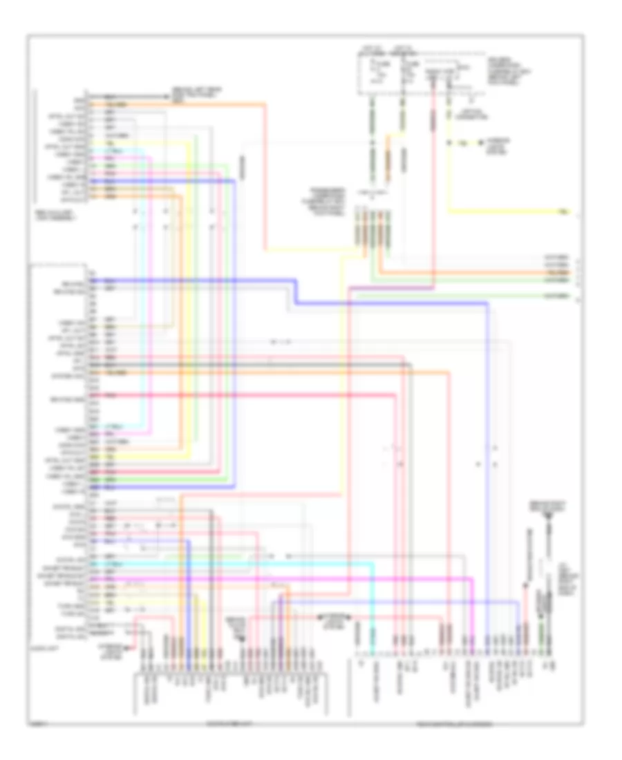
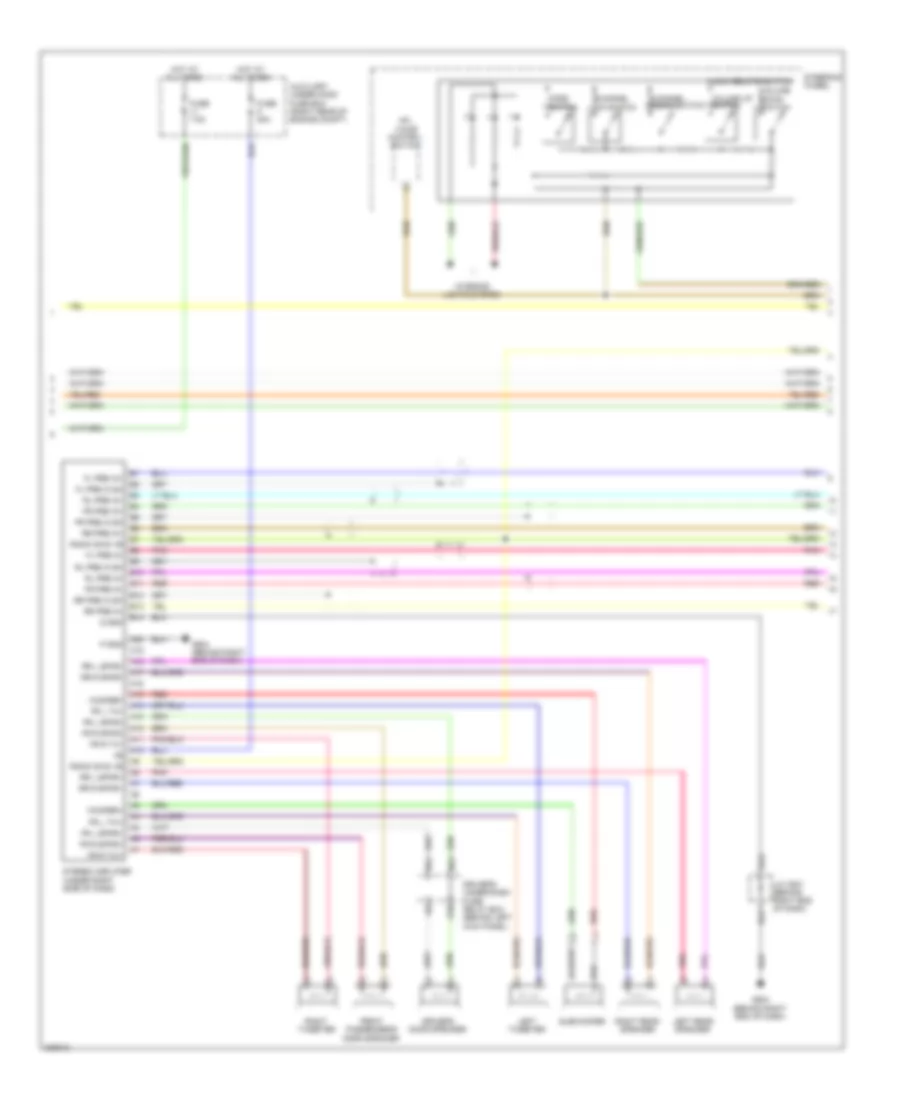
COMPUTER DATA LINES
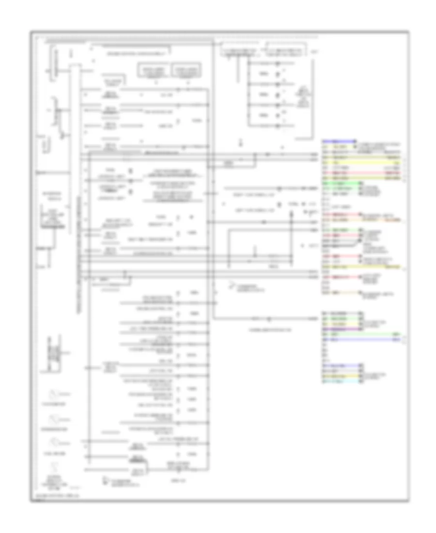
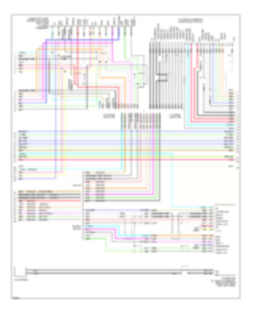
Computer Data Lines Wiring Diagram (1 of 2) for Honda Odyssey EX 2010
List of elements for Computer Data Lines Wiring Diagram (1 of 2) for Honda Odyssey EX 2010:
- (accessory installed)
- (behind dvd player unit) (touring) handsfreelink control unit
- (behind right kick panel) g505
- (under left side of dash) g502
- A/c control panel
- A10
- A11
- A12
- A24
- Automatic lighting control unit (touring) (under left side of dash)
- B-can
- C11
- Can-h
- Can-l
- Chk
- Climate control unit
- Combination switch control unit
- Control block
- D10
- D11
- Dlc (under left side of dash)
- Door multiplex control unit
- Driver's under-dash fuse/relay box (behind left kick panel)
- Ex, ex-l & touring
- Fuse 8 15a
- G601 (behind left kick panel)
- Gnd
- Hot at all times
- Immobilizer control unit receiver (on steering column, near steering lock)
- J/c c503 (under left side of dash)
- K-line
- Lx; canada dx
- Mes
- Micu
- Micu service check connector
- N10
- N13
- N14
- N22
- N28
- Power window master switch
- R2 mes connector (at driver's r1 underdash fuse/relay box)
- Red
- Relay control module
- Scs
- Srs unit (under middle of dash)
- Under-hood fuse/relay box (right rear of engine compt)
- Wiper/washer switch
- X18
- X27
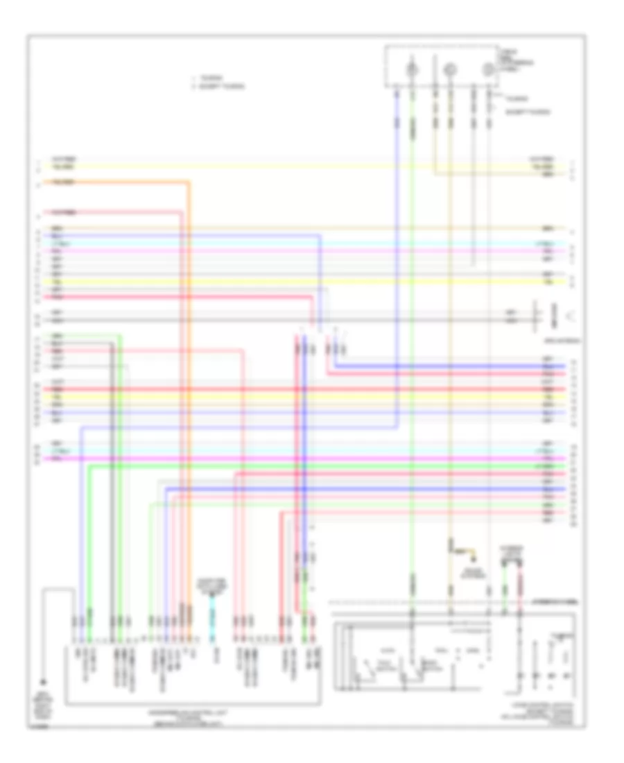
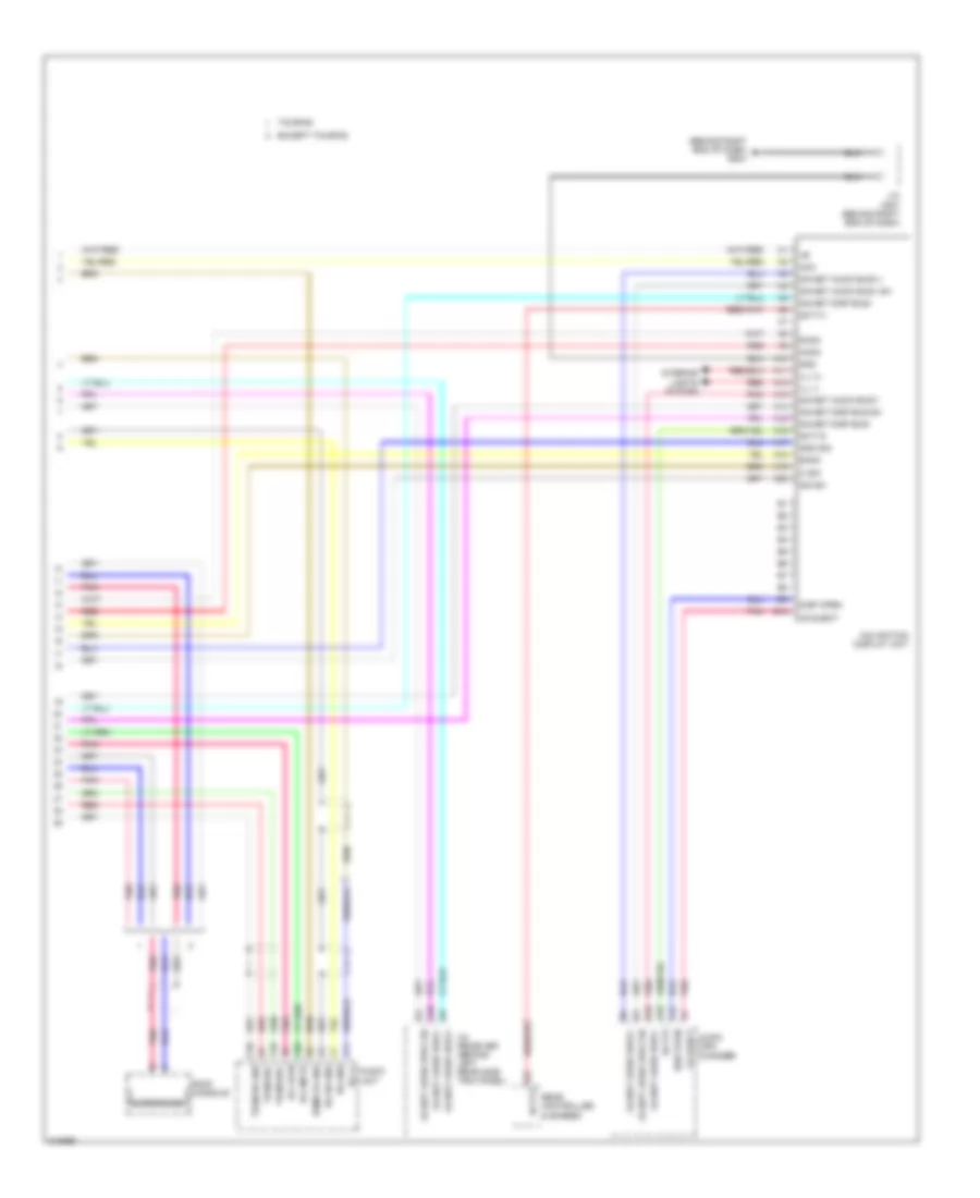
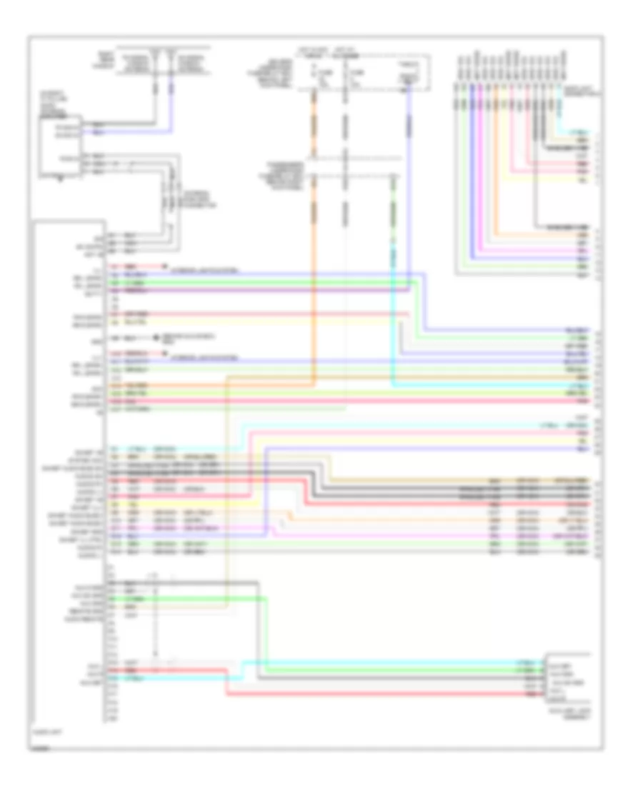
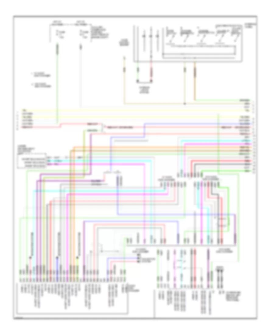
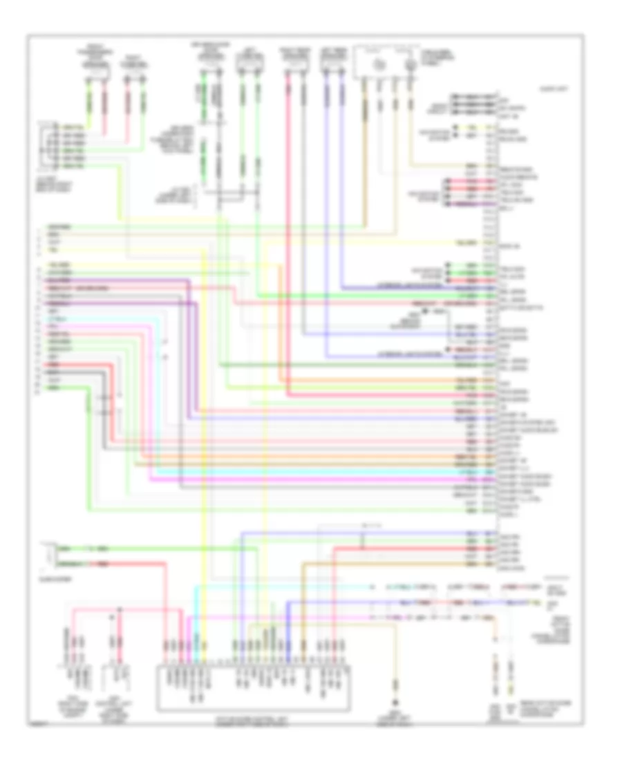
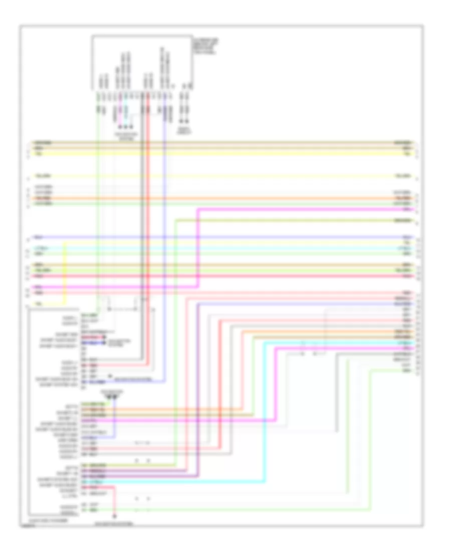
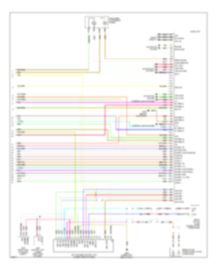
Computer Data Lines Wiring Diagram (2 of 2) for Honda Odyssey EX 2010
List of elements for Computer Data Lines Wiring Diagram (2 of 2) for Honda Odyssey EX 2010:
- (not used)
- A10
- A13
- A14
- A15
- A20
- A21
- A23
- A24
- A25
- A26
- A32
- A39
- A40
- A44
- A48
- A49
- Ac-ck
- Ac-si
- Ac-so
- Acm control unit (usa: ex-l, ex-l res, ex-l res/navigation, canada: ex-l, ex-l res, touring) (under right side of dash)
- Audio disc changer (usa ex-l: res/navigation, touring)
- Audio unit
- B-can
- B10
- B11
- B19
- Bus (+)
- Bus (-)
- Bus sh
- Bus(+)
- Bus(-)
- Bus1 (+)
- Bus1 (-)
- Bus1 sh
- Bus2 (+)
- Bus2 (-)
- Bus2 sh
- C10
- C11
- Can-h
- Can-l
- Climate control unit (usa ex-l: res/ navigation, touring)
- D10
- Diag n
- Diag p
- Diag-k
- E13
- Gauge control module
- J/c c405 (behind glove box)
- J/c c508 (under left side of dash)
- K-line
- Left power sliding door control unit (ex, ex-l & touring) (behind left rear side trim panel)
- Micu-rear junction box (behind right rear side trim panel)
- Micu-rear junction box control unit
- Navigation display unit (usa ex-l: res/navigation, touring)
- Navigation service check connector (under driver's seat)
- Navigation unit (under driver's seat)
- Passenger's under-dash fuse/relay box (behind right kick panel)
- Pcm (right side of engine compt)
- Pnk
- Power mirror control unit
- Power seat control unit (touring) (under driver's seat)
- Power tailgate control unit (touring, ex-l) (in left "d" pillar)
- Rear controller & screen (ex-l: res; usa ex-l:
- Red
- Res/navigation, touring)
- Right power sliding door control unit (ex, ex-l & touring) (behind right rear side trim panel)
- Scs
- Sensor cluster (on floor, under driver's seat)
- Tpms control unit (middle of roof)
- Uart
- Vsa modulator control unit (left rear of engine compt)
- Wen
- Xm receiver (usa) (behind left rear side trim panel)
COOLING FAN
Cooling Fan Wiring Diagram for Honda Odyssey EX 2010
List of elements for Cooling Fan Wiring Diagram for Honda Odyssey EX 2010:
- (below throttle body) ect sensor 2
- (top of transmission) j/c c104
- A/c condenser fan motor (behind right side of radiator)
- A/c condenser fan relay
- A/c control panel
- A/c diode a
- A/c pressure switch
- A/c pressure switch (at right side of engine compt, on a/c receiver line)
- A47
- A48
- A49
- Auxiliary under-hood fuse box (right rear of engine compt)
- Box (right rear of engine compt)
- C16
- C31
- C32
- Can-h
- Can-l
- Canada:
- Canada: dx
- Climate control unit
- Computer data lines
- Computer data lines system
- Control block
- D16
- Driver's under-dash fuse/relay box (behind left kick panel)
- E10
- E11
- E14
- Ect sensor 1 (top rear of engine)
- Engine controls system
- Ex, ex-l & touring
- Ex-l, res & usa ex-l: res/navigation, touring
- Ex-l, touring
- F14
- F15
- F19
- Fan control relay
- Fuse 10a
- Fuse 11 30a
- Fuse 7.5a
- Fuse 9 30a
- G201 (under right front of engine compt)
- G301 (under left front of engine compt)
- G401 (behind left kick panel)
- High fan control
- Hot at all times
- Hot in on
- J/c c506 (under middle of dash)
- Low fan control
- Lx, ex;
- Lx;
- Pcm (right side of engine compt)
- Pgm-fi main relay 1
- Radiator fan motor (behind left side of radiator)
- Radiator fan relay
- Red
- Relay control
- Relay control module
- S2 (thermal joint) (under throttle body)
- Sensor ground
- Sensor input
- System
- Under-hood fuse/relay
CRUISE CONTROL
Cruise Control Wiring Diagram (1 of 2) for Honda Odyssey EX 2010
List of elements for Cruise Control Wiring Diagram (1 of 2) for Honda Odyssey EX 2010:
- A18
- A19
- A24
- A25
- A26
- A27
- A29
- A48
- A49
- App sensor (under left side of dash)
- Apsa
- Apsb
- Atp-fwd
- B17
- B18
- B26
- B33
- B38
- Bksw
- Bkswnc
- C18
- Can h
- Can l
- Driver's under-dash fuse/relay box (behind left kick panel)
- E13
- E14
- Etcs control
- Etcsm+
- Etcsm-
- Etcsrly
- Fuse 18 15a
- Fuse 21 7.5a
- Fuse 3 15a
- Fuse 7 7.5a
- G101 (except lx & ex: front of engine) (lx & ex: under throttle body)
- Hot at all times
- Hot in on or start
- Ig1etcs
- J13
- Junction connector c102 (right side of engine)
- Junction connector c407 (behind glove box)
- Junction connector c503 (under left side of dash)
- Junction connector c508 (under left side of dash)
- Lx, ex2 canada: dx
- Mrly
- Output shaft (countershaft) speed sensor (on transmission housing)
- Passenger's under-dash fuse/relay box (behind right kick panel)
- Pcm (right side of engine compt)
- Pgm-fi main relay 1
- Red
- Relay
- Sg3
- Sg4
- Sg5
- Tp sensor/ throttle actuator (on throttle body)
- Tpsa
- Tpsb
- Transmission range switch (on left side of transmission)
- Usa
- Vcc3
- Vcc4
- Vcc5
- X31
- X34
- X35
Cruise Control Wiring Diagram (2 of 2) for Honda Odyssey EX 2010
List of elements for Cruise Control Wiring Diagram (2 of 2) for Honda Odyssey EX 2010:
- (touring) (ex, ex-l)
- 10v regulator
- 5v regulator
- A10
- A11
- A21
- A23
- A24
- B11 b1
- Brake pedal position switch (on brake pedal bracket)
- C11 c6
- C12 c7
- C13 c8
- C14 c9
- C3 c1
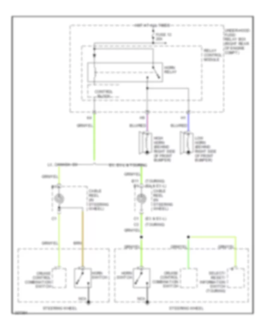
- Cable reel (in steering wheel)
- Cancel switch
- Control block
- Cruise control combination switch
- Cruise control dimming circuit
- Cruise control indicator
- Cruise control main switch indicator
- Ex, ex-l & touring
- Fast controller area network transceiver
- Fuse 13 20a
- Fuse 7 7.5a
- G502 (under left side of dash)
- Gauge control module
- Horn relay
- Horns system
- Hot at all times
- Interior lights system
- Lx2, canada: dx
- Main switch
- Pnk
- Red
- Relay control module
- Resume switch
- Set switch
- Steering wheel
- Under-hood fuse/relay box (right rear of engine compt)
- Warning drive circuit
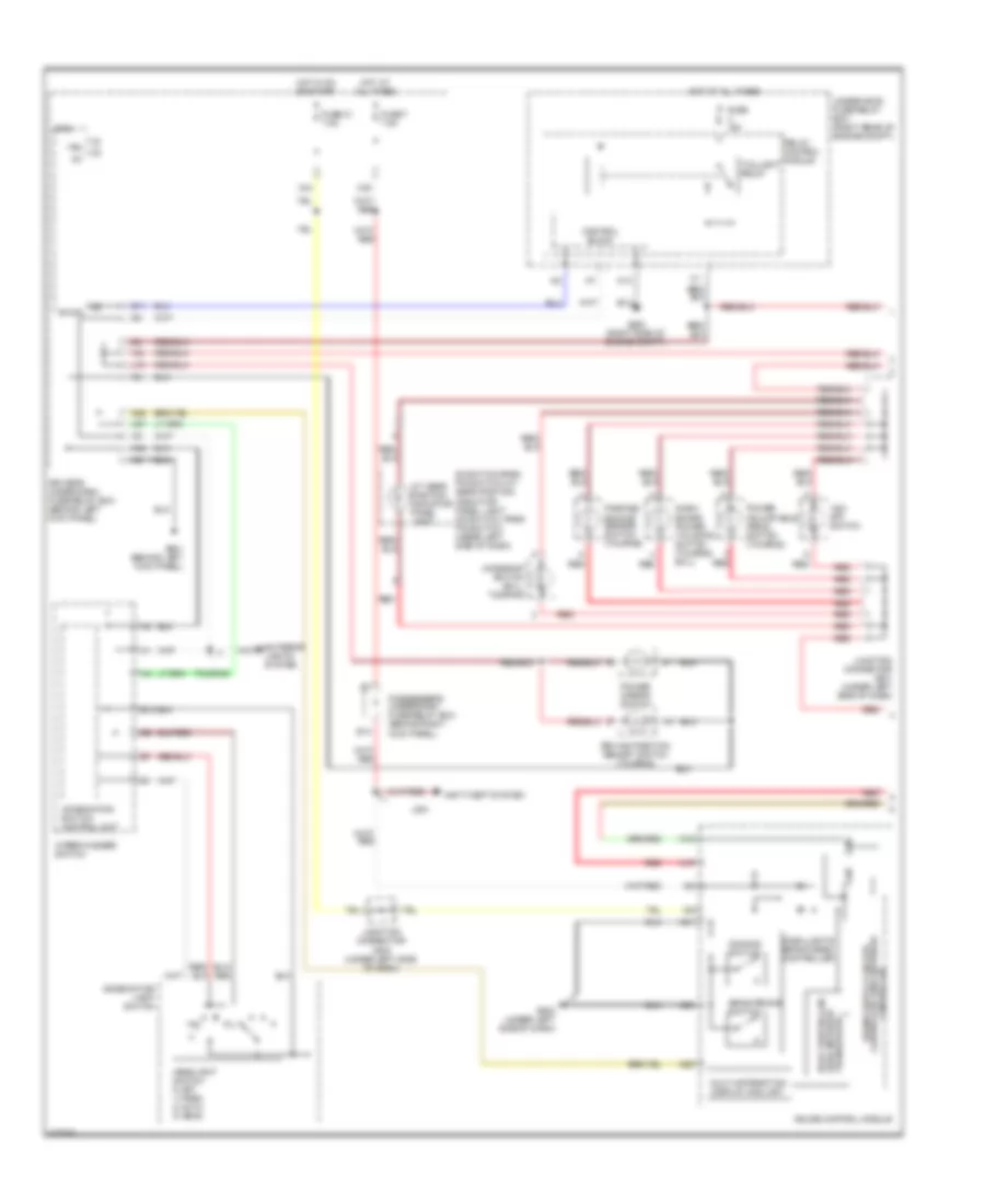
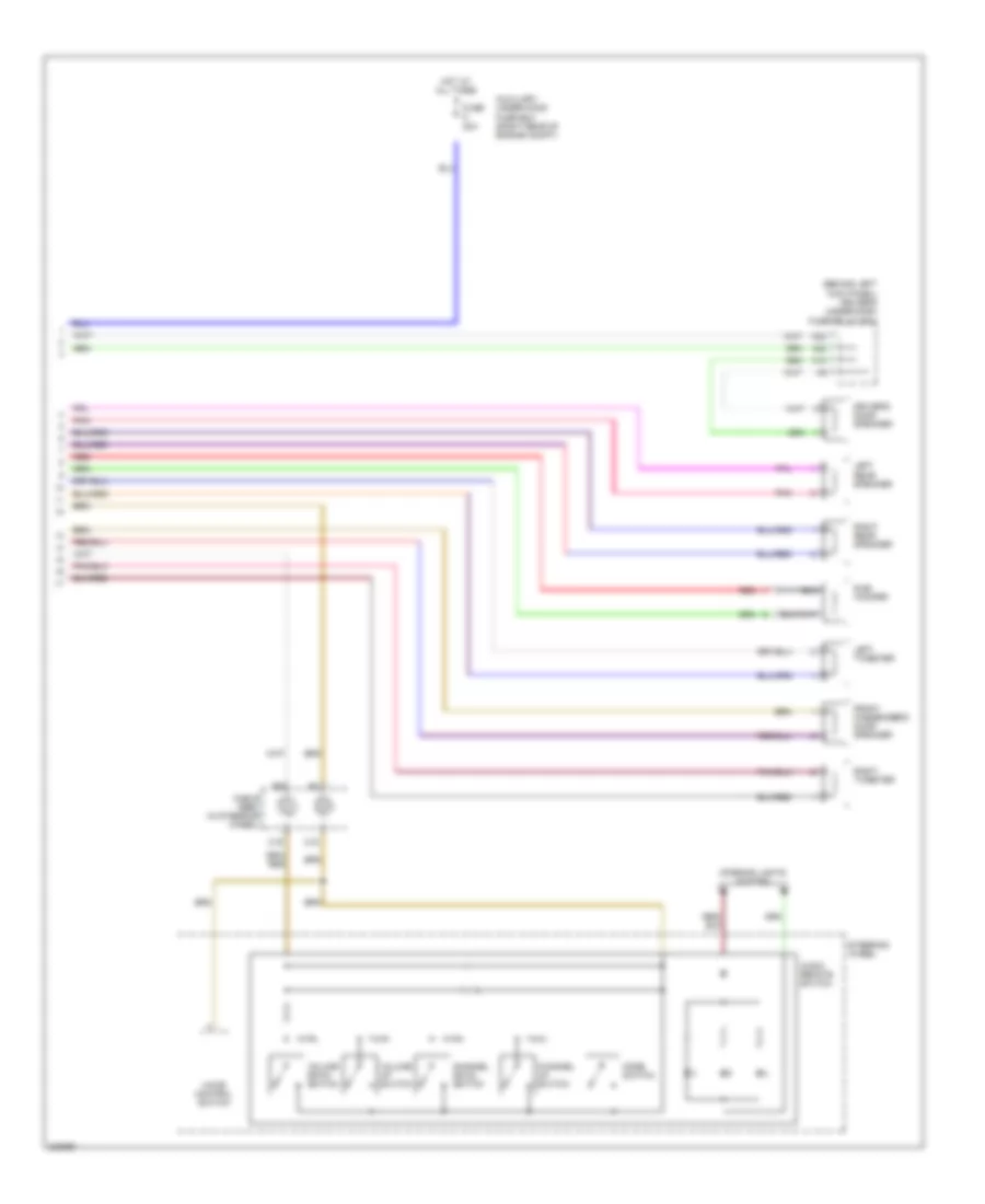
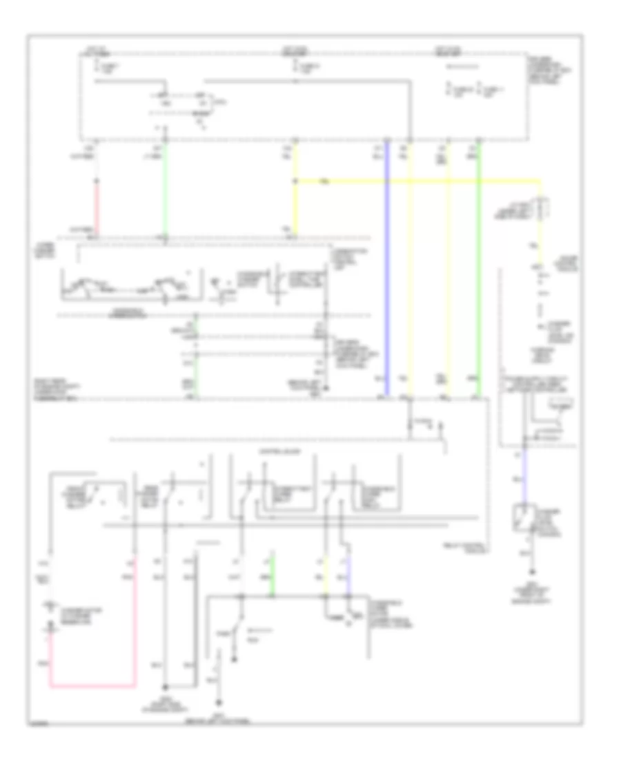
DEFOGGERS
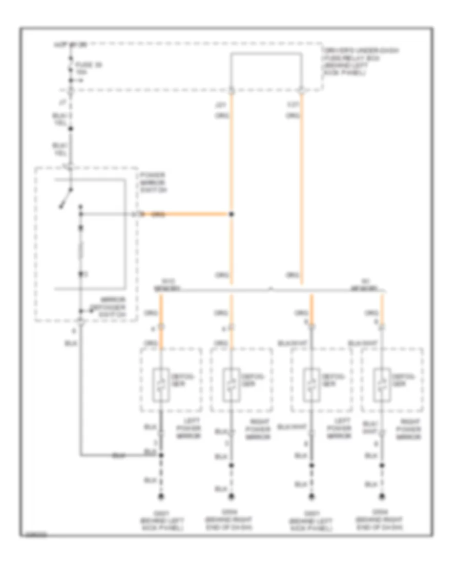
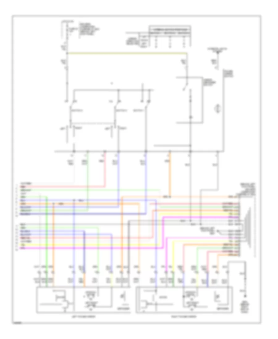
Heated Mirrors Wiring Diagram for Honda Odyssey EX 2010
List of elements for Heated Mirrors Wiring Diagram for Honda Odyssey EX 2010:
- Defog- ger
- Driver's under-dash fuse/relay box (behind left kick panel)
- Fuse 30 10a
- G504 (behind right end of dash)
- G601 (behind left kick panel)
- Hot in on
- J21
- Left power mirror
- Mirror defogger switch
- Power mirror switch
- Right power mirror
- W/ memory
- W/o memory
- X21
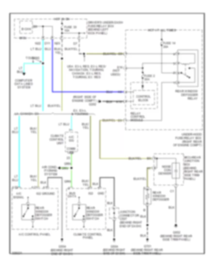
Rear Defogger Wiring Diagram for Honda Odyssey EX 2010
List of elements for Rear Defogger Wiring Diagram for Honda Odyssey EX 2010:
- (not
- (right side of engine compt) g202
- A/c
- A/c control panel
- A/c sig
- A10
- A11
- Air cond- itioning system
- B-can
- Bus
- Climate control panel
- Climate control unit
- Comm line
- Computer data lines system
- Control block
- D11
- Data
- Driver's under-dash fuse/relay box (behind left kick panel)
- E16
- Ex, ex-l & touring
- Fuse 14 30a
- Fuse 2 30a
- Fuse 30 10a
- G504 (behind right end of dash)
- G652 (behind right rear side trim panel)
- G701 (behind right rear side trim panel)
- Gnd
- Ground
- Hot at all times
- Hot in on
- Ig2
- Junction connector c507 (behind right end of dash)
- K10
- Lx, canada: dx
- Micu
- Micu-rear junction box (behind right rear side trim panel)
- N20
- N22
- Noise con- denser
- Rear window defogger
- Rear window defogger relay
- Rear window defogger switch
- Relay control module
- Signal
- Touring
- Under-hood fuse/relay box (right rear of engine compt)
- Usa: ex-l res, ex-l res/ navigation, touring; canada: ex-l res, touring, ex: res
- Used)
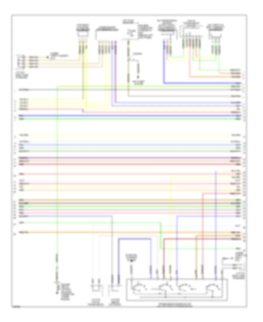
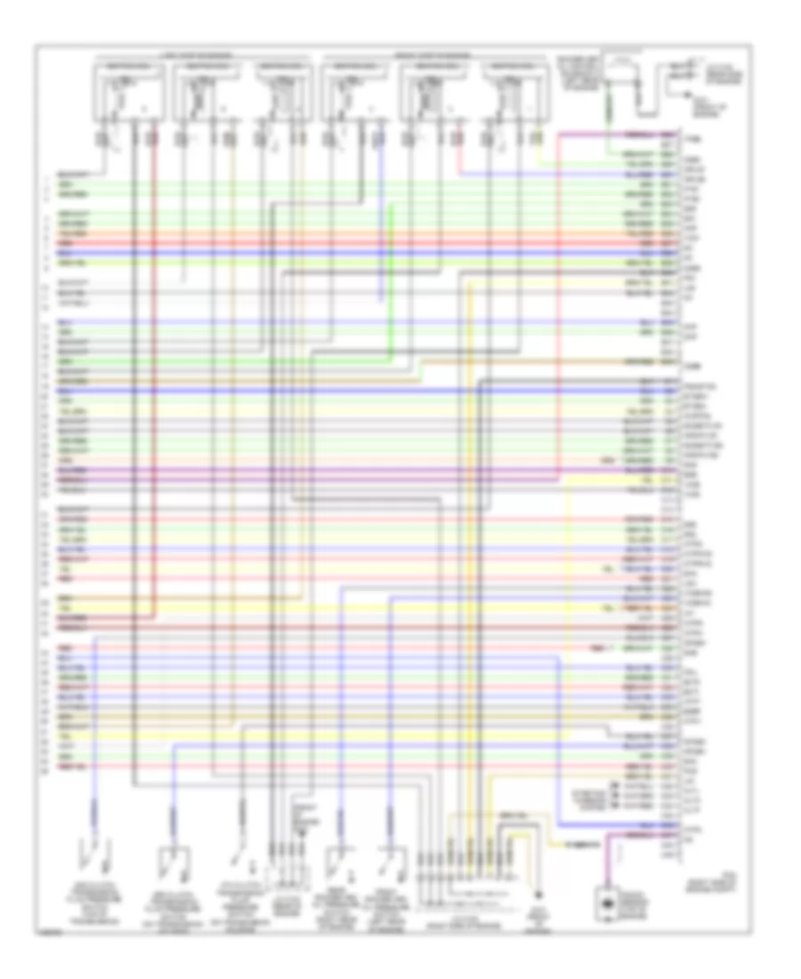
ENGINE PERFORMANCE
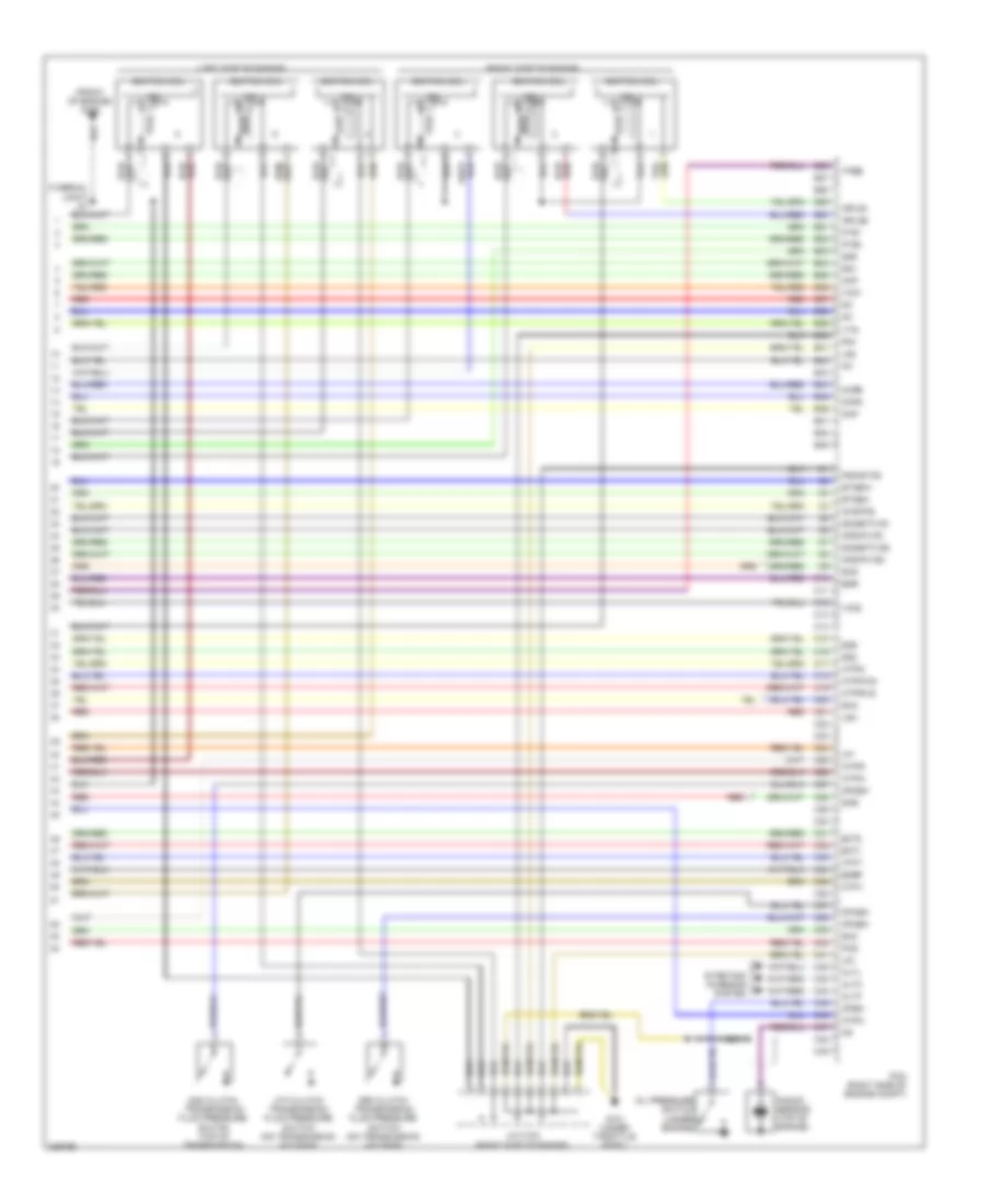
3.5L
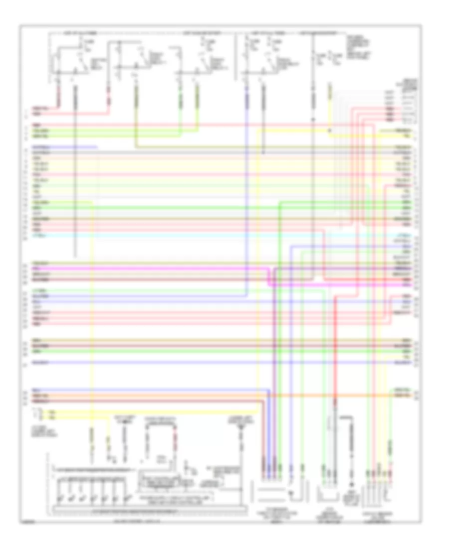
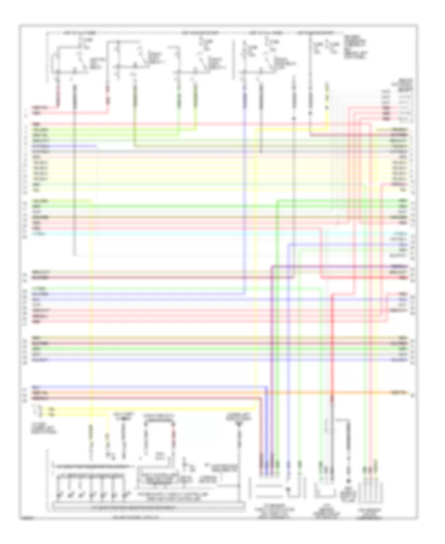
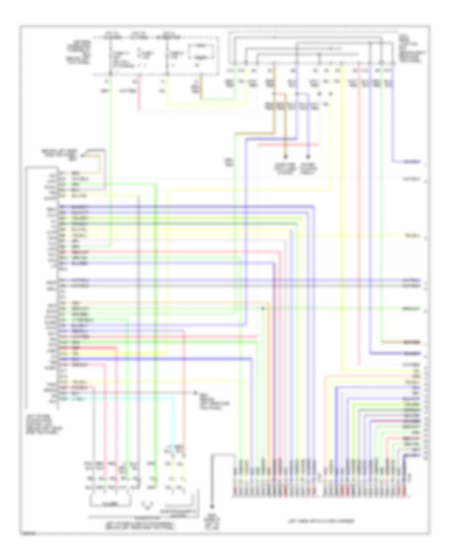
3.5L, Engine Performance Wiring Diagram, EX-L (1 of 7) for Honda Odyssey EX 2010
List of elements for 3.5L, Engine Performance Wiring Diagram, EX-L (1 of 7) for Honda Odyssey EX 2010:
- (front of engine) g101
- (on brake pedal bracket) brake pedal position switch
- (under left side of dash) j/c c501
- (under middle of vehicle) evap canister vent shut valve
- A10
- A11
- A12
- A13
- A14
- A15
- A16
- A17
- A18
- A19
- A20
- A21
- A22
- A23
- A24
- A25
- A26
- A27
- A28
- A29
- A30
- A31
- A32
- A33
- A34
- A35
- A36
- A37
- A38
- A39
- A40
- A41
- A42
- A43
- A44
- A45
- A46
- A47
- A48
- A49
- Acc
- Air conditioning system
- Air conditioning system computer data lines system
- Anti-theft system
- Apsa
- Apsb
- Atp-p
- B10
- B11
- B12
- B13
- B14
- B15
- B16
- B17
- B18
- B19
- B20
- B21
- B22
- B23
- B24
- B25
- Barometer sensor
- Bksw
- Bkswnc
- Can-h
- Can-l
- Ckpout
- Cmpout
- Computer data lines system
- Cruise control system
- Cssama
- Cssamc
- D3 switch
- D3 switch/ park pin switch/ a/t gear position indicator panel light (d3 switch/ park pin switch: under left side of dash)
- D3sw
- Driver's under-dash fuse/relay box (behind left kick panel)
- Eld
- Etcsrly
- Fanh
- Fanl
- Ftp
- Fuse 15a
- Fuse 20a
- G501 (under left side of dash)
- Hot at all times
- Hot in on or start
- Igp
- Igpls3
- Igpls4
- Igpls5
- Igpls6
- Imo fpr
- Imocd
- Inj1
- Inj2
- Inj3
- Inj4
- Inj5
- Inj6
- Injectors (injectors 1, 2 & 3: top right side of engine) (injectors 4, 5 & 6: top left side of engine)
- J/c c102 (right side of engine)
- J/c c103 (rear of engine)
- Lg3
- Lsb
- Lsc
- Met-inh
- Mrly
- Navigation system
- Nca
- Nep
- Pcm (right side of engine compt)
- Pdsw
- Pg2
- Pnk
- Psp sw
- Red
- Scs
- Sg3
- Sg4
- Shift interlock system
- Sho2s b1
- Sho2s b2
- Sls
- Sound systems
- Starting/charging system
- Sts
- Sub rly
- Tpsa
- Under-hood fuse/relay box (right rear of engine compt)
- Vbsol1
- Vbsol2
- Vcc3
- Vcc4
- Vcc5
- Vcent b1
- Vcent b2
- Vg+
- Vg-
- Vs b1
- Vs b2
- Vssout
- Vsv
- Wen
- X16
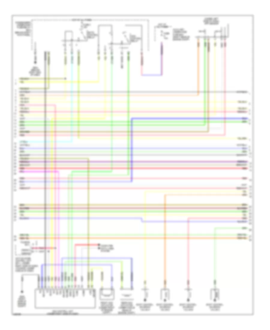
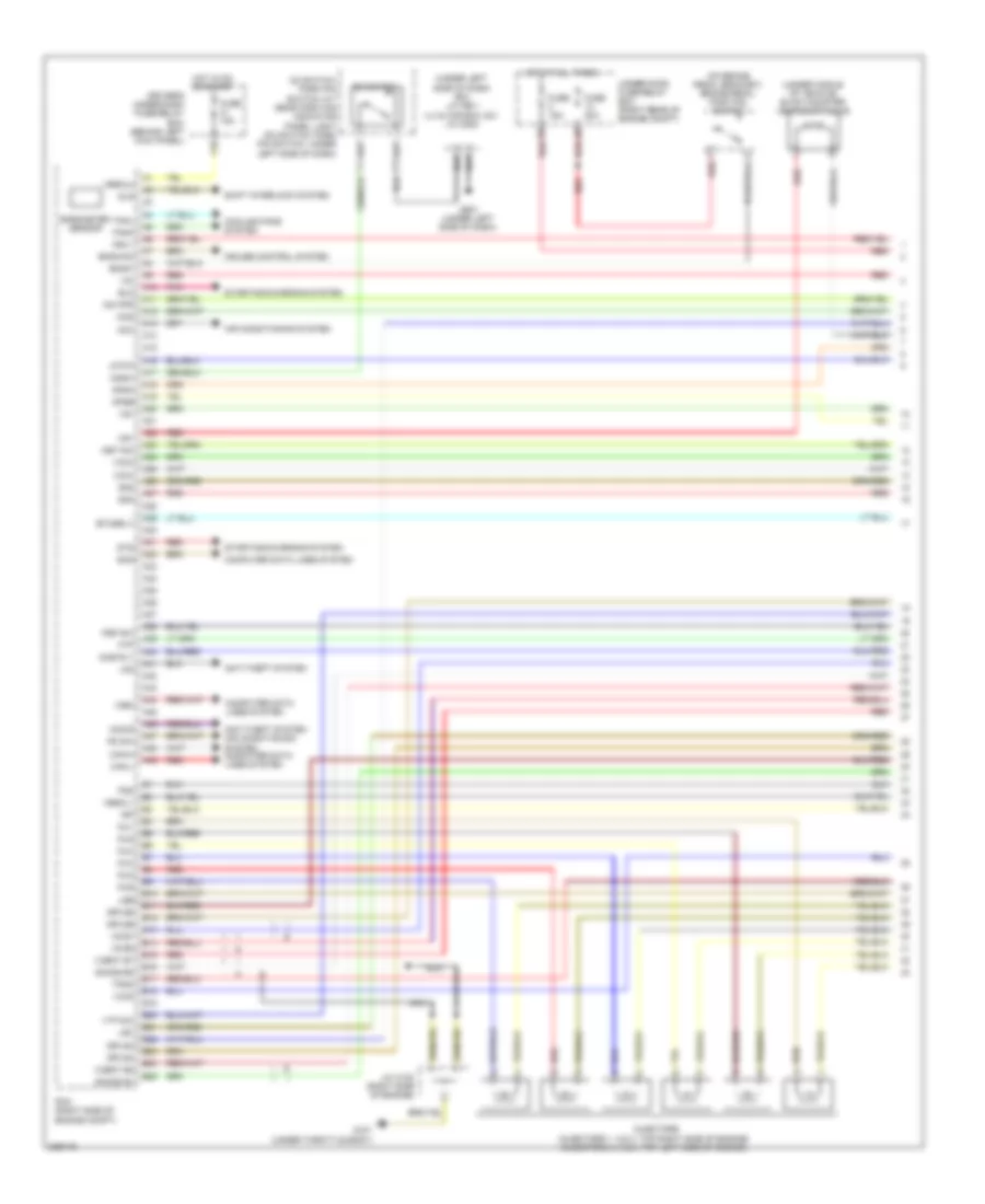
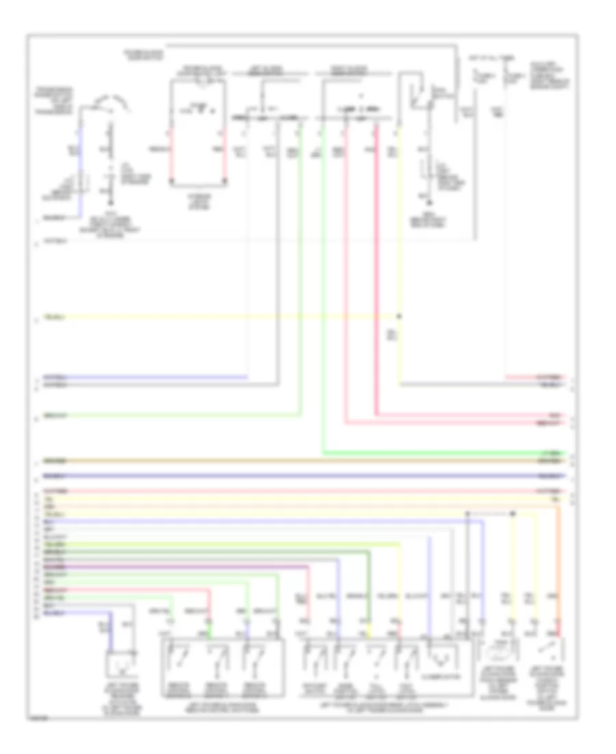
3.5L, Engine Performance Wiring Diagram, EX-L (2 of 7) for Honda Odyssey EX 2010
List of elements for 3.5L, Engine Performance Wiring Diagram, EX-L (2 of 7) for Honda Odyssey EX 2010:
- A/t clutch pressure control solenoid valve a (on top of transaxle)
- A/t clutch pressure control solenoid valve b (on top of transaxle)
- A/t clutch pressure control solenoid valve c (on top of transmission)
- Evap canister purge valve (right rear of engine)
- Fuel gauge sending unit
- Fuel pump
- Fuel tank unit (top of fuel tank)
- G101 (front of engine)
- G401 (behind left kick panel)
- G603 (behind left rear side trim panel)
- Instrument cluster system
- J/c c101 (right side of engine)
- J/c c102 (right side of engine)
- J/c c103 (rear of engine)
- Pnk
- Psp switch (on power steering pressure line)
- Red
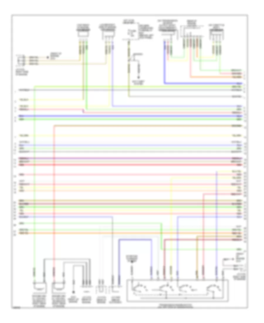
3.5L, Engine Performance Wiring Diagram, EX-L (3 of 7) for Honda Odyssey EX 2010
List of elements for 3.5L, Engine Performance Wiring Diagram, EX-L (3 of 7) for Honda Odyssey EX 2010:
- (behind glove box) j/c c407
- (under left side of dash) g502
- A/t gear position detection circuit
- A/t gear position dimming circuit
- A/t gear position indicator driver circuit
- A21
- A23
- A24
- Anti-theft system
- Braided wire
- Computer data lines system
- D10
- Drive circuit
- Driver's underdash fuse/relay box (behind left kick panel)
- E13
- Fast controller area network transceiver
- Ftp sensor (under middle of vehicle)
- Fuse 15a
- Fuse 7.5a
- G651 (base of right "b" pillar)
- Gauge control module
- Hot at all times
- Hot in on or start
- Ignition coil relay
- J/c c503 (under left side of dash)
- Maf/iat sensor (on air cleaner box)
- Maintenance required ind (ex-l)
- Mil ind
- Pgm-fi main relay 1
- Pgm-fi main relay 2
- Pgm-fi sub relay (laf)
- Pnk
- Red
- Tp sensor/ throttle actuator (on throttle body)
- Warning drive ind
- X31
- X32
- X34
- X36
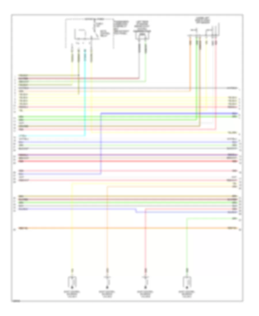
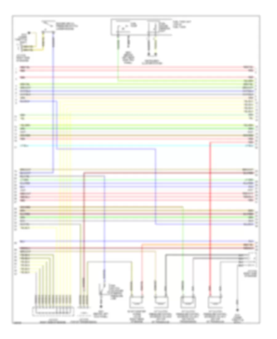
3.5L, Engine Performance Wiring Diagram, EX-L (4 of 7) for Honda Odyssey EX 2010
List of elements for 3.5L, Engine Performance Wiring Diagram, EX-L (4 of 7) for Honda Odyssey EX 2010:
- (not used)
- (under left side of dash) app sensor
- Acm control relay
- Acm control unit (under right side of dash)
- Active noise control unit (ex-l: under right side of dash) (touring: under middle of dash)
- Auxiliary under-hood fuse box (right rear of engine compt)
- B10
- Canh
- Canl
- Computer data lines system
- Crk
- Cssam1
- Cssam2
- Ects control relay
- Front acm actuator (under front of engine compt)
- Fuse 10a
- Fuse 3 15a
- G202 (right side of engine compt)
- G504 (behind right end of dash)
- Hot at all times
- Ig1
- Igsol
- J13
- Passenger's under-dash fuse/relay box (behind right kick panel)
- Pnk
- Rear acm actuator (under middle rear of engine compt)
- Red
- Scp
- Scp2
- Shift control solenoid valve a
- Shift control solenoid valve b
- Shift control solenoid valve c
- Shift control solenoid valve d
- Solfm
- Solfp
- Solrm
- Solrp
- Solry
- Tdc
- Touring ex-l
3.5L, Engine Performance Wiring Diagram, EX-L (5 of 7) for Honda Odyssey EX 2010
List of elements for 3.5L, Engine Performance Wiring Diagram, EX-L (5 of 7) for Honda Odyssey EX 2010:
- (front of engine) g101
- (lower right side of engine) ckp sensor
- (on throttle body) map sensor
- (on transmission housing) output shaft (countershaft) speed sensor
- (rear of engine) j/c c104
- (top front of engine) cmp sensor
- Anti-theft system
- Canada
- Driver's under-dash fuse/relay box (behind left kick panel)
- Fuse 15a
- G101 (front of engine)
- Hot in on or start
- J/c c102 (right side of engine)
- J/c c103 (rear of engine)
- J/c c104 (rear of engine)
- J/c c405 (behind glove box)
- Red
- Rocker arm oil control solenoid a (right rear of engine)
- Rocker arm oil control solenoid b (right rear of engine)
- Starting/ charging system
- Transmission range switch (on left side of transmission)
- X38
3.5L, Engine Performance Wiring Diagram, EX-L (6 of 7) for Honda Odyssey EX 2010
List of elements for 3.5L, Engine Performance Wiring Diagram, EX-L (6 of 7) for Honda Odyssey EX 2010:
- (left rear of engine) front a/f sensor (b2, s1)
- (left rear of engine) front secondary ho2s (b2, s2)
- (lower right side of engine) rear a/f sensor (b1, s1)
- (lower right side of engine) rear secondary ho2s (b1, s2)
- (rear of engine) j/c c104
- (right side of engine) j/c c101
- Atf temperature sensor connector (on transmission housing)
- Ect sensor 1 (top rear of engine)
- Ect sensor 2 (below throttle body)
- Egr valve & egr valve position sensor (top rear of engine)
- G101 (front of engine)
- Input shaft (main shaft) speed sensor (on transmission housing)
- J/c c102 (right side of engine)
- J/c c104 (rear of engine)
- Pnk
- Red
- Rocker arm oil pressure sensor (under engine)
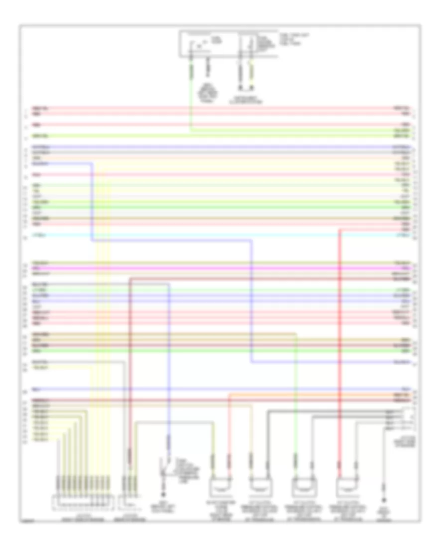
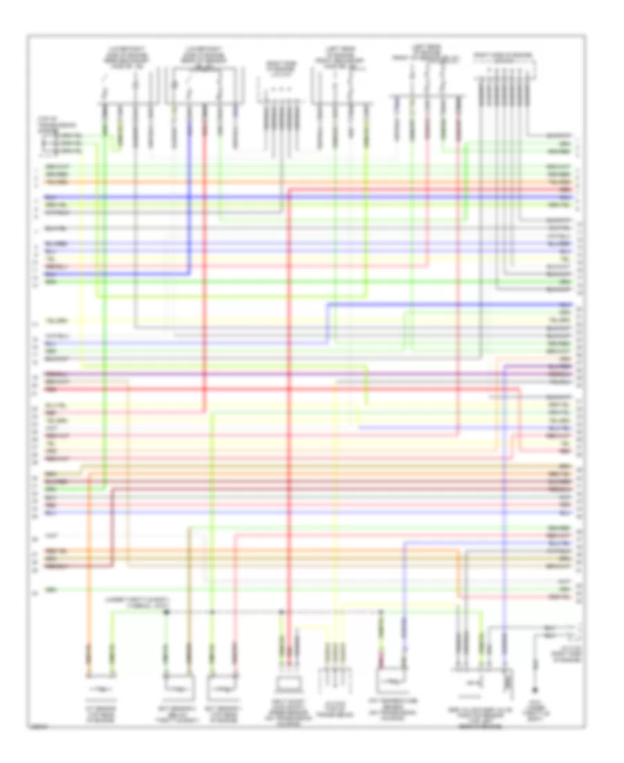
3.5L, Engine Performance Wiring Diagram, EX-L (7 of 7) for Honda Odyssey EX 2010
List of elements for 3.5L, Engine Performance Wiring Diagram, EX-L (7 of 7) for Honda Odyssey EX 2010:
- (front of engine) g101
- (left side of engine)
- (right side of engine)
- 2nd clutch transmission fluid pressure switch (top of transmission)
- 3rd clutch transmission fluid pressure switch (on transmission housing)
- 4th clutch transmission fluid pressure switch (on transmission housing)
- Afshtc b1
- Afshtc b2
- Altc
- Altf
- Altl
- Atft
- Atp-1
- Atp-2
- Atp-d
- Atp-fwd
- Atp-n
- Atp-r
- Atp-rvs
- B26
- B27
- B28
- B29
- B30
- B31
- B32
- B33
- B34
- B35
- B36
- B37
- B38
- B39
- B40
- B41
- B42
- B43
- B44
- B45
- B46
- B47
- B48
- B49
- C10
- C11
- C12
- C13
- C14
- C15
- C16
- C17
- C18
- C19
- C20
- C21
- C22
- C23
- C24
- C25
- C26
- C27
- C28
- C29
- C30
- C31
- C32
- C33
- C34
- C35
- C36
- C37
- C38
- C39
- C40
- C41
- C42
- C43
- C44
- C45
- C46
- C47
- C48
- C49
- Ckp
- Cmp
- Cssa
- Cssb
- Cssc
- Ect1
- Ect2
- Egr
- Egrp
- Etcsm+
- Etcsm-
- Front rocker arm oil pressure switch (left rear of engine)
- G101 (front of engine)
- Iat
- Icm
- Ig1
- Ig1etcs
- Ignition coil
- Igpls1
- Igpls2
- Ip b1
- Ip b2
- J/c c102 (rear side of engine)
- J/c c102 (right side of engine)
- J/c c103 (rear of engine)
- Knock sensor (top of engine)
- Lg1
- Lg2
- Lsa
- Map
- Nca
- Op2sw
- Op3sw
- Op4sw
- Pcm (right side of engine compt)
- Pcs
- Pg1
- Pgm etcs
- Poil
- Rear rocker arm oil pressure switch (right rear of engine)
- Red
- Sg1
- Sg2
- Sg5
- Sg6
- Sha
- Shb
- Shc
- Shd
- So2shtc b1
- So2shtc b2
- Starting/ charging system
- Tpsb
- Vcc1
- Vcc2
- Vcc6
- Vcmswb
- Vcmswc
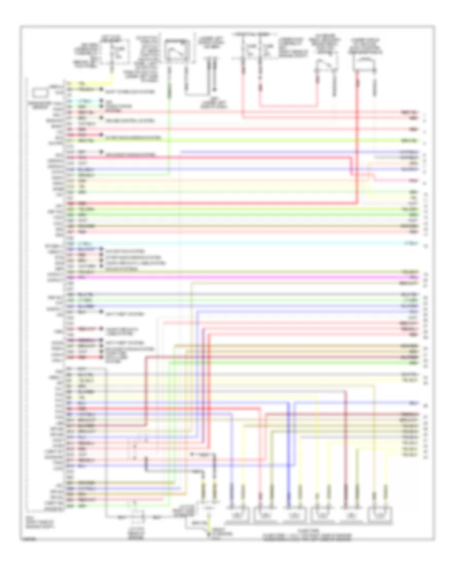
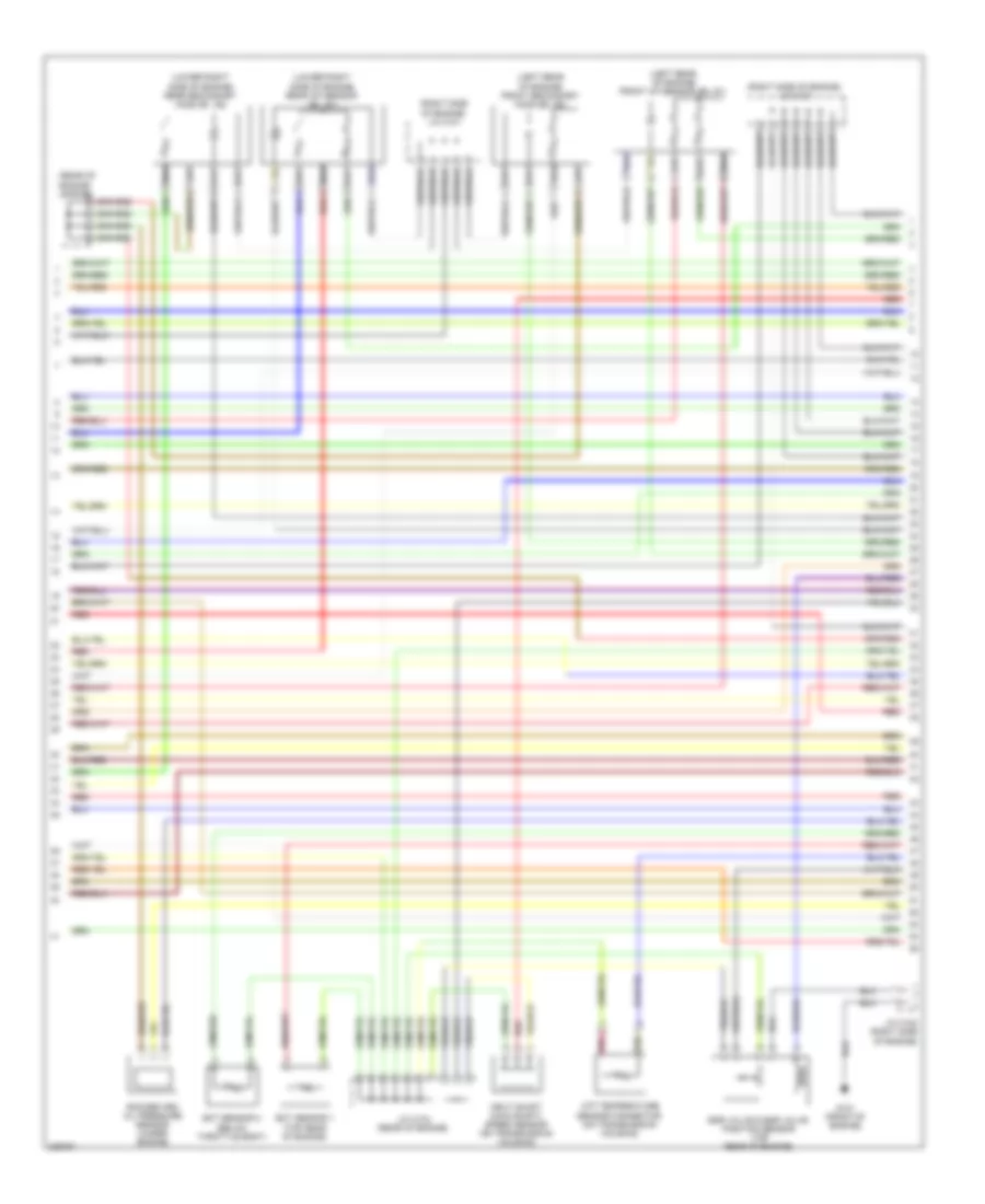
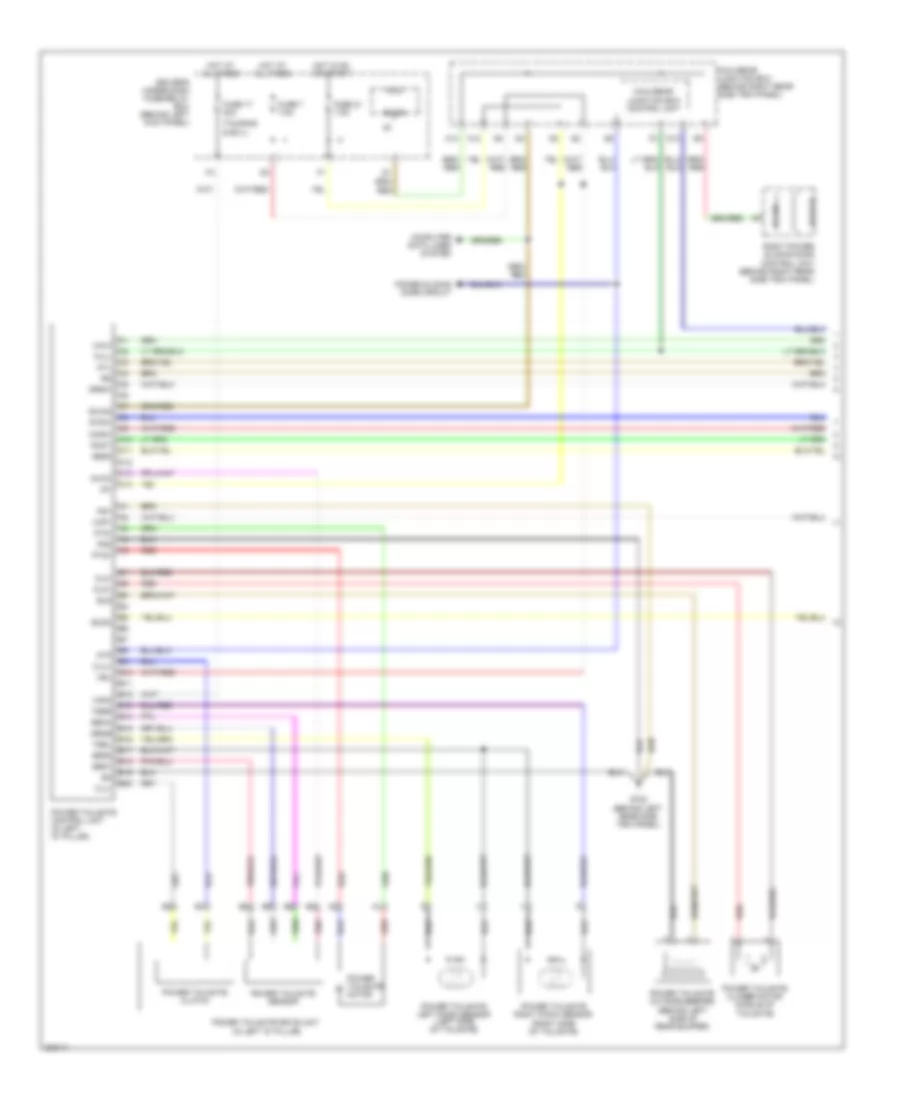
3.5L, Engine Performance Wiring Diagram, EX (1 of 7) for Honda Odyssey EX 2010
List of elements for 3.5L, Engine Performance Wiring Diagram, EX (1 of 7) for Honda Odyssey EX 2010:
- (on brake pedal bracket) brake pedal position switch
- (under left side of dash) (ex) j/c c501 (lx & canada: dx) j/c c502
- (under middle of vehicle) evap canister vent shut valve
- A10
- A11
- A12
- A13
- A14
- A15
- A16
- A17
- A18
- A19
- A20
- A21
- A22
- A23
- A24
- A25
- A26
- A27
- A28
- A29
- A30
- A31
- A32
- A33
- A34
- A35
- A36
- A37
- A38
- A39
- A40
- A41
- A42
- A43
- A44
- A45
- A46
- A47
- A48
- A49
- Acc
- Air conditioning system
- Anti-theft system
- Anti-theft system air conditioning system computer data lines system
- Apsa
- Apsb
- Atp-p
- B10
- B11
- B12
- B13
- B14
- B15
- B16
- B17
- B18
- B19
- B20
- B21
- B22
- B23
- B24
- B25
- Barometer sensor
- Bksw
- Bkswnc
- Can-h
- Can-l
- Computer data lines system
- Cooling fans system
- Cruise control system
- D3 switch
- D3 switch/ park pin switch/ a/t gear position indicator panel light (d3 switch/ park pin switch: under left side of dash)
- D3sw
- Driver's under-dash fuse/relay box (behind left kick panel)
- Eld
- Etcsrly
- Fanh
- Fanl
- Ftp
- Fuse 15a
- Fuse 20a
- G101 (under throttle body)
- G501 (under left side of dash)
- Hot at all times
- Hot in on or start
- Igp
- Igpls3
- Igpls4
- Igpls5
- Igpls6
- Imo fpr
- Imocd
- Inj1
- Inj2
- Inj3
- Inj4
- Inj5
- Inj6
- Injectors (injectors 1, 2 & 3: top right side of engine) (injectors 4, 5 & 6: top left side of engine)
- J/c c102 (right side of engine)
- Lg3
- Lsb
- Lsc
- Mcs
- Met-inh
- Mrly
- Nca
- Pcm (right side of engine compt)
- Pd sw
- Pg2
- Pnk
- Psp sw
- Red
- Scs
- Sg3
- Sg4
- Shift interlock system
- Sho2s b1
- Sho2s b2
- Sls
- Starting/charging system
- Sts
- Sub rly
- Tpsa
- Under-hood fuse/relay box (right rear of engine compt)
- Vbsol1
- Vbsol2
- Vcc3
- Vcc4
- Vcc5
- Vcent b1
- Vcent b2
- Vg+
- Vg-
- Vs b1
- Vs b2
- Vsv
- Vtp sw
- Wen
- X16
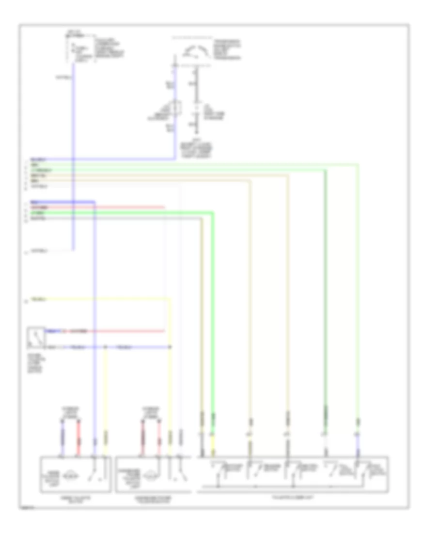
3.5L, Engine Performance Wiring Diagram, EX (2 of 7) for Honda Odyssey EX 2010
List of elements for 3.5L, Engine Performance Wiring Diagram, EX (2 of 7) for Honda Odyssey EX 2010:
- A/t clutch pressure control solenoid valve a (on top of transaxle)
- A/t clutch pressure control solenoid valve b (on top of transaxle)
- A/t clutch pressure control solenoid valve c (on top of transmission)
- Evap canister purge valve (right rear of engine)
- Fuel gauge sending unit
- Fuel pump
- Fuel tank unit (top of fuel tank)
- G101 (under throttle body)
- G401 (behind left kick panel)
- G603 (behind left rear side trim panel)
- Instrument cluster system
- J/c c101 (right side of engine)
- J/c c102 (right side of engine)
- J/c c103 (top of transmission)
- Psp switch (on power steering pressure line)
- Red
- Rocker arm oil pressure switch (under engine)
3.5L, Engine Performance Wiring Diagram, EX (3 of 7) for Honda Odyssey EX 2010
List of elements for 3.5L, Engine Performance Wiring Diagram, EX (3 of 7) for Honda Odyssey EX 2010:
- (behind glove box) j/c c407
- (under left side of dash) g502
- A/t gear position detection circuit
- A/t gear position dimming circuit
- A/t gear position indicator driver circuit
- A21
- A23
- A24
- Anti-theft system
- Braided wire
- Computer data lines system
- D10
- Drive circuit
- Driver's underdash fuse/relay box (behind left kick panel)
- E13
- Fast controller area network transceiver
- Ftp sensor (under middle of vehicle)
- Fuse 15a
- Fuse 7.5a
- G651 (base of right "b" pillar)
- Gauge control module
- Hot at all times
- Hot in on or start
- Ignition coil relay
- J/c c503 (under left side of dash)
- Maf sensor (on air cleaner box)
- Maintenance required ind
- Mil ind
- Pgm-fi main relay 1
- Pgm-fi main relay 2
- Pgm-fi sub relay (laf)
- Red
- Tp sensor/ throttle actuator (on throttle body assembly)
- Warning drive ind
- X31
- X32
- X34
- X36
3.5L, Engine Performance Wiring Diagram, EX (4 of 7) for Honda Odyssey EX 2010
List of elements for 3.5L, Engine Performance Wiring Diagram, EX (4 of 7) for Honda Odyssey EX 2010:
- (left rear of engine) engine mount control solenoid valve
- (under left side of dash) app sensor
- Ects control relay
- Fuse 3 15a
- Hot at all times
- J13
- Passenger's under-dash fuse/relay box (behind right kick panel)
- Red
- Shift control solenoid valve a
- Shift control solenoid valve b
- Shift control solenoid valve c
- Shift control solenoid valve d
3.5L, Engine Performance Wiring Diagram, EX (5 of 7) for Honda Odyssey EX 2010
List of elements for 3.5L, Engine Performance Wiring Diagram, EX (5 of 7) for Honda Odyssey EX 2010:
- (on throttle body assembly) map sensor
- (on transmission housing) output shaft (countershaft) speed sensor
- (top front of engine) cmp sensor
- (top of transmission) j/c c103
- (under engine) ckp sensors a & b
- (under throttle body) g101
- Anti-theft system
- Canada
- Driver's under-dash fuse/relay box (behind left kick panel)
- Fuse 15a
- Hot in on or start
- J/c c102 (right side of engine)
- J/c c103 (top of transmission)
- J/c c405 (behind glove box)
- Red
- Rocker arm oil control solenoid connector (under engine)
- Starting/ charging system
- Transmission range switch (on left side of transmission)
- X38
3.5L, Engine Performance Wiring Diagram, EX (6 of 7) for Honda Odyssey EX 2010
List of elements for 3.5L, Engine Performance Wiring Diagram, EX (6 of 7) for Honda Odyssey EX 2010:
- (left rear of engine) front a/f sensor (b2, s1)
- (left rear of engine) front secondary ho2s (b2, s2)
- (lower right side of engine) rear a/f sensor (b1, s1)
- (lower right side of engine) rear secondary ho2s (b1, s2)
- (right side of engine) j/c c101
- (thermal joint) s2
- (top of transmission) j/c c103
- (under throttle body)
- Atf temperature sensor (on transmission housing)
- Ect sensor 1 (top rear of engine)
- Ect sensor 2 (below throttle body)
- Egr valve & egr valve position sensor (top left rear of engine)
- G101 (under throttle body)
- Iat sensor (top rear of engine)
- Input shaft (main shaft) speed sensor (on transmission housing)
- J/c c102 (right side of engine)
- J/c c103 (top of transmission)
- Pnk
- Red
3.5L, Engine Performance Wiring Diagram, EX (7 of 7) for Honda Odyssey EX 2010
List of elements for 3.5L, Engine Performance Wiring Diagram, EX (7 of 7) for Honda Odyssey EX 2010:
- (front of engine) g102
- (left side of engine)
- (right side of engine)
- (thermal joint) s1
- 2nd clutch transmission fluid pressure switch (top of transmission)
- 3rd clutch transmission fluid pressure switch (on transmission housing)
- 4th clutch transmission fluid pressure switch (on transmission housing)
- Afshtc b1
- Afshtc b2
- Altc
- Altf
- Altl
- Atft
- Atp-1
- Atp-2
- Atp-d
- Atp-fwd
- Atp-n
- Atp-r
- Atp-rvs
- B26
- B27
- B28
- B29
- B30
- B31
- B32
- B33
- B34
- B35
- B36
- B37
- B38
- B39
- B40
- B41
- B42
- B43
- B44
- B45
- B46
- B47
- B48
- B49
- C10
- C11
- C12
- C13
- C14
- C15
- C16
- C17
- C18
- C19
- C20
- C21
- C22
- C23
- C24
- C25
- C26
- C27
- C28
- C29
- C30
- C31
- C32
- C33
- C34
- C35
- C36
- C37
- C38
- C39
- C40
- C41
- C42
- C43
- C44
- C45
- C46
- C47
- C48
- C49
- Ckpa
- Ckpb
- Cmp
- Ect1
- Ect2
- Egr
- Egrp
- Etcsm+
- Etcsm-
- G101 (under throttle body)
- Iat
- Icm
- Ig1
- Ig1etcs
- Ignition coil
- Igpls1
- Igpls2
- Ip b1
- Ip b2
- J/c c102 (right side of engine)
- Knock sensor (top of engine)
- Lg1
- Lg2
- Lsa
- Map
- Nca
- Oil pressure switch (under engine)
- Op2sw
- Op3sw
- Op4sw
- Opsw
- Pcm (right side of engine compt)
- Pcs
- Pg1
- Pgm etcs
- Red
- Sg1
- Sg2
- Sg5
- Sg6
- Sha
- Shb
- Shc
- Shd
- So2shtc b1
- So2shtc b2
- Starting/ charging system
- Tpsb
- Vcc1
- Vcc2
- Vts
3.5L, Engine Performance Wiring Diagram, LX (1 of 7) for Honda Odyssey EX 2010
List of elements for 3.5L, Engine Performance Wiring Diagram, LX (1 of 7) for Honda Odyssey EX 2010:
- (on brake pedal bracket) brake pedal position switch
- (under left side of dash) (ex) j/c c501 (lx & canada: dx) j/c c502
- (under middle of vehicle) evap canister vent shut valve
- A10
- A11
- A12
- A13
- A14
- A15
- A16
- A17
- A18
- A19
- A20
- A21
- A22
- A23
- A24
- A25
- A26
- A27
- A28
- A29
- A30
- A31
- A32
- A33
- A34
- A35
- A36
- A37
- A38
- A39
- A40
- A41
- A42
- A43
- A44
- A45
- A46
- A47
- A48
- A49
- Acc
- Air conditioning system
- Anti-theft system
- Anti-theft system air conditioning system computer data lines system
- Apsa
- Apsb
- Atp-p
- B10
- B11
- B12
- B13
- B14
- B15
- B16
- B17
- B18
- B19
- B20
- B21
- B22
- B23
- B24
- B25
- Barometer sensor
- Bksw
- Bkswnc
- Can-h
- Can-l
- Computer data lines system
- Cooling fans system
- Cruise control system
- D3 switch
- D3 switch/ park pin switch/ a/t gear position indicator panel light (d3 switch/ park pin switch: under left side of dash)
- D3sw
- Driver's under-dash fuse/relay box (behind left kick panel)
- Eld
- Etcsrly
- Fanh
- Fanl
- Ftp
- Fuse 15a
- Fuse 20a
- G101 (under throttle body)
- G501 (under left side of dash)
- Hot at all times
- Hot in on or start
- Igp
- Igpls3
- Igpls4
- Igpls5
- Igpls6
- Imo fpr
- Imocd
- Inj1
- Inj2
- Inj3
- Inj4
- Inj5
- Inj6
- Injectors (injectors 1, 2 & 3: top right side of engine) (injectors 4, 5 & 6: top left side of engine)
- J/c c102 (right side of engine)
- Lg3
- Lsb
- Lsc
- Mcs
- Met-inh
- Mrly
- Nca
- Pcm (right side of engine compt)
- Pd sw
- Pg2
- Pnk
- Psp sw
- Red
- Scs
- Sg3
- Sg4
- Shift interlock system
- Sho2s b1
- Sho2s b2
- Sls
- Starting/charging system
- Sts
- Sub rly
- Tpsa
- Under-hood fuse/relay box (right rear of engine compt)
- Vbsol1
- Vbsol2
- Vcc3
- Vcc4
- Vcc5
- Vcent b1
- Vcent b2
- Vg+
- Vg-
- Vs b1
- Vs b2
- Vsv
- Vtp sw
- Wen
- X16
3.5L, Engine Performance Wiring Diagram, LX (2 of 7) for Honda Odyssey EX 2010
List of elements for 3.5L, Engine Performance Wiring Diagram, LX (2 of 7) for Honda Odyssey EX 2010:
- A/t clutch pressure control solenoid valve a (on top of transaxle)
- A/t clutch pressure control solenoid valve b (on top of transaxle)
- A/t clutch pressure control solenoid valve c (on top of transmission)
- Evap canister purge valve (right rear of engine)
- Fuel gauge sending unit
- Fuel pump
- Fuel tank unit (top of fuel tank)
- G101 (under throttle body)
- G401 (behind left kick panel)
- G603 (behind left rear side trim panel)
- Instrument cluster system
- J/c c101 (right side of engine)
- J/c c102 (right side of engine)
- J/c c103 (top of transmission)
- Psp switch (on power steering pressure line)
- Red
- Rocker arm oil pressure switch (under engine)
3.5L, Engine Performance Wiring Diagram, LX (3 of 7) for Honda Odyssey EX 2010
List of elements for 3.5L, Engine Performance Wiring Diagram, LX (3 of 7) for Honda Odyssey EX 2010:
- (behind glove box) j/c c407
- (under left side of dash) g502
- A/t gear position detection circuit
- A/t gear position dimming circuit
- A/t gear position indicator driver circuit
- A21
- A23
- A24
- Anti-theft system
- Braided wire
- Computer data lines system
- D10
- Drive circuit
- Driver's underdash fuse/relay box (behind left kick panel)
- E13
- Fast controller area network transceiver
- Ftp sensor (under middle of vehicle)
- Fuse 15a
- Fuse 7.5a
- G651 (base of right "b" pillar)
- Gauge control module
- Hot at all times
- Hot in on or start
- Ignition coil relay
- J/c c503 (under left side of dash)
- Maf sensor (on air cleaner box)
- Maintenance required ind
- Mil ind
- Pgm-fi main relay 1
- Pgm-fi main relay 2
- Pgm-fi sub relay (laf)
- Red
- Tp sensor/ throttle actuator (on throttle body assembly)
- Warning drive ind
- X31
- X32
- X34
- X36
3.5L, Engine Performance Wiring Diagram, LX (4 of 7) for Honda Odyssey EX 2010
List of elements for 3.5L, Engine Performance Wiring Diagram, LX (4 of 7) for Honda Odyssey EX 2010:
- (left rear of engine) engine mount control solenoid valve
- (under left side of dash) app sensor
- Ects control relay
- Fuse 3 15a
- Hot at all times
- J13
- Passenger's under-dash fuse/relay box (behind right kick panel)
- Red
- Shift control solenoid valve a
- Shift control solenoid valve b
- Shift control solenoid valve c
- Shift control solenoid valve d
3.5L, Engine Performance Wiring Diagram, LX (5 of 7) for Honda Odyssey EX 2010
List of elements for 3.5L, Engine Performance Wiring Diagram, LX (5 of 7) for Honda Odyssey EX 2010:
- (on throttle body assembly) map sensor
- (on transmission housing) output shaft (countershaft) speed sensor
- (top front of engine) cmp sensor
- (top of transmission) j/c c103
- (under engine) ckp sensors a & b
- (under throttle body) g101
- Anti-theft system
- Canada
- Driver's under-dash fuse/relay box (behind left kick panel)
- Fuse 15a
- Hot in on or start
- J/c c102 (right side of engine)
- J/c c103 (top of transmission)
- J/c c405 (behind glove box)
- Red
- Rocker arm oil control solenoid connector (under engine)
- Starting/ charging system
- Transmission range switch (on left side of transmission)
- X38
3.5L, Engine Performance Wiring Diagram, LX (6 of 7) for Honda Odyssey EX 2010
List of elements for 3.5L, Engine Performance Wiring Diagram, LX (6 of 7) for Honda Odyssey EX 2010:
- (left rear of engine) front a/f sensor (b2, s1)
- (left rear of engine) front secondary ho2s (b2, s2)
- (lower right side of engine) rear a/f sensor (b1, s1)
- (lower right side of engine) rear secondary ho2s (b1, s2)
- (right side of engine) j/c c101
- (thermal joint) s2
- (top of transmission) j/c c103
- (under throttle body)
- Atf temperature sensor (on transmission housing)
- Ect sensor 1 (top rear of engine)
- Ect sensor 2 (below throttle body)
- Egr valve & egr valve position sensor (top left rear of engine)
- G101 (under throttle body)
- Iat sensor (top rear of engine)
- Input shaft (main shaft) speed sensor (on transmission housing)
- J/c c102 (right side of engine)
- J/c c103 (top of transmission)
- Pnk
- Red
3.5L, Engine Performance Wiring Diagram, LX (7 of 7) for Honda Odyssey EX 2010
List of elements for 3.5L, Engine Performance Wiring Diagram, LX (7 of 7) for Honda Odyssey EX 2010:
- (front of engine) g102
- (left side of engine)
- (right side of engine)
- (thermal joint) s1
- 2nd clutch transmission fluid pressure switch (top of transmission)
- 3rd clutch transmission fluid pressure switch (on transmission housing)
- 4th clutch transmission fluid pressure switch (on transmission housing)
- Afshtc b1
- Afshtc b2
- Altc
- Altf
- Altl
- Atft
- Atp-1
- Atp-2
- Atp-d
- Atp-fwd
- Atp-n
- Atp-r
- Atp-rvs
- B26
- B27
- B28
- B29
- B30
- B31
- B32
- B33
- B34
- B35
- B36
- B37
- B38
- B39
- B40
- B41
- B42
- B43
- B44
- B45
- B46
- B47
- B48
- B49
- C10
- C11
- C12
- C13
- C14
- C15
- C16
- C17
- C18
- C19
- C20
- C21
- C22
- C23
- C24
- C25
- C26
- C27
- C28
- C29
- C30
- C31
- C32
- C33
- C34
- C35
- C36
- C37
- C38
- C39
- C40
- C41
- C42
- C43
- C44
- C45
- C46
- C47
- C48
- C49
- Ckpa
- Ckpb
- Cmp
- Ect1
- Ect2
- Egr
- Egrp
- Etcsm+
- Etcsm-
- G101 (under throttle body)
- Iat
- Icm
- Ig1
- Ig1etcs
- Ignition coil
- Igpls1
- Igpls2
- Ip b1
- Ip b2
- J/c c102 (right side of engine)
- Knock sensor (top of engine)
- Lg1
- Lg2
- Lsa
- Map
- Nca
- Oil pressure switch (under engine)
- Op2sw
- Op3sw
- Op4sw
- Opsw
- Pcm (right side of engine compt)
- Pcs
- Pg1
- Pgm etcs
- Red
- Sg1
- Sg2
- Sg5
- Sg6
- Sha
- Shb
- Shc
- Shd
- So2shtc b1
- So2shtc b2
- Starting/ charging system
- Tpsb
- Vcc1
- Vcc2
- Vts
3.5L, Engine Performance Wiring Diagram, Touring (1 of 7) for Honda Odyssey EX 2010
List of elements for 3.5L, Engine Performance Wiring Diagram, Touring (1 of 7) for Honda Odyssey EX 2010:
- (front of engine) g101
- (on brake pedal bracket) brake pedal position switch
- (under left side of dash) j/c c501
- (under middle of vehicle) evap canister vent shut valve
- A10
- A11
- A12
- A13
- A14
- A15
- A16
- A17
- A18
- A19
- A20
- A21
- A22
- A23
- A24
- A25
- A26
- A27
- A28
- A29
- A30
- A31
- A32
- A33
- A34
- A35
- A36
- A37
- A38
- A39
- A40
- A41
- A42
- A43
- A44
- A45
- A46
- A47
- A48
- A49
- Acc
- Air conditioning system
- Air conditioning system computer data lines system
- Anti-theft system
- Apsa
- Apsb
- Atp-p
- B10
- B11
- B12
- B13
- B14
- B15
- B16
- B17
- B18
- B19
- B20
- B21
- B22
- B23
- B24
- B25
- Barometer sensor
- Bksw
- Bkswnc
- Can-h
- Can-l
- Ckpout
- Cmpout
- Computer data lines system
- Cruise control system
- Cssama
- Cssamc
- D3 switch
- D3 switch/ park pin switch/ a/t gear position indicator panel light (d3 switch/ park pin switch: under left side of dash)
- D3sw
- Driver's under-dash fuse/relay box (behind left kick panel)
- Eld
- Etcsrly
- Fanh
- Fanl
- Ftp
- Fuse 15a
- Fuse 20a
- G501 (under left side of dash)
- Hot at all times
- Hot in on or start
- Igp
- Igpls3
- Igpls4
- Igpls5
- Igpls6
- Imo fpr
- Imocd
- Inj1
- Inj2
- Inj3
- Inj4
- Inj5
- Inj6
- Injectors (injectors 1, 2 & 3: top right side of engine) (injectors 4, 5 & 6: top left side of engine)
- J/c c102 (right side of engine)
- J/c c103 (rear of engine)
- Lg3
- Lsb
- Lsc
- Met-inh
- Mrly
- Navigation system
- Nca
- Nep
- Pcm (right side of engine compt)
- Pdsw
- Pg2
- Pnk
- Psp sw
- Red
- Scs
- Sg3
- Sg4
- Shift interlock system
- Sho2s b1
- Sho2s b2
- Sls
- Sound systems
- Starting/charging system
- Sts
- Sub rly
- Tpsa
- Under-hood fuse/relay box (right rear of engine compt)
- Vbsol1
- Vbsol2
- Vcc3
- Vcc4
- Vcc5
- Vcent b1
- Vcent b2
- Vg+
- Vg-
- Vs b1
- Vs b2
- Vssout
- Vsv
- Wen
- X16
3.5L, Engine Performance Wiring Diagram, Touring (2 of 7) for Honda Odyssey EX 2010
List of elements for 3.5L, Engine Performance Wiring Diagram, Touring (2 of 7) for Honda Odyssey EX 2010:
- A/t clutch pressure control solenoid valve a (on top of transaxle)
- A/t clutch pressure control solenoid valve b (on top of transaxle)
- A/t clutch pressure control solenoid valve c (on top of transmission)
- Evap canister purge valve (right rear of engine)
- Fuel gauge sending unit
- Fuel pump
- Fuel tank unit (top of fuel tank)
- G101 (front of engine)
- G401 (behind left kick panel)
- G603 (behind left rear side trim panel)
- Instrument cluster system
- J/c c101 (right side of engine)
- J/c c102 (right side of engine)
- J/c c103 (rear of engine)
- Pnk
- Psp switch (on power steering pressure line)
- Red
3.5L, Engine Performance Wiring Diagram, Touring (3 of 7) for Honda Odyssey EX 2010
List of elements for 3.5L, Engine Performance Wiring Diagram, Touring (3 of 7) for Honda Odyssey EX 2010:
- (behind glove box) j/c c407
- (under left side of dash) g502
- A/t gear position detection circuit
- A/t gear position dimming circuit
- A/t gear position indicator driver circuit
- A21
- A23
- A24
- Anti-theft system
- Braided wire
- Computer data lines system
- D10
- Drive circuit
- Driver's underdash fuse/relay box (behind left kick panel)
- E13
- Fast controller area network transceiver
- Ftp sensor (under middle of vehicle)
- Fuse 15a
- Fuse 7.5a
- G651 (base of right "b" pillar)
- Gauge control module
- Hot at all times
- Hot in on or start
- Ignition coil relay
- J/c c503 (under left side of dash)
- Maf/iat sensor (on air cleaner box)
- Maintenance required ind (ex-l)
- Mil ind
- Pgm-fi main relay 1
- Pgm-fi main relay 2
- Pgm-fi sub relay (laf)
- Pnk
- Red
- Tp sensor/ throttle actuator (on throttle body)
- Warning drive ind
- X31
- X32
- X34
- X36
3.5L, Engine Performance Wiring Diagram, Touring (4 of 7) for Honda Odyssey EX 2010
List of elements for 3.5L, Engine Performance Wiring Diagram, Touring (4 of 7) for Honda Odyssey EX 2010:
- (not used)
- (under left side of dash) app sensor
- Acm control relay
- Acm control unit (under right side of dash)
- Active noise control unit (ex-l: under right side of dash) (touring: under middle of dash)
- Auxiliary under-hood fuse box (right rear of engine compt)
- B10
- Canh
- Canl
- Computer data lines system
- Crk
- Cssam1
- Cssam2
- Ects control relay
- Front acm actuator (under front of engine compt)
- Fuse 10a
- Fuse 3 15a
- G202 (right side of engine compt)
- G504 (behind right end of dash)
- Hot at all times
- Ig1
- Igsol
- J13
- Passenger's under-dash fuse/relay box (behind right kick panel)
- Pnk
- Rear acm actuator (under middle rear of engine compt)
- Red
- Scp
- Scp2
- Shift control solenoid valve a
- Shift control solenoid valve b
- Shift control solenoid valve c
- Shift control solenoid valve d
- Solfm
- Solfp
- Solrm
- Solrp
- Solry
- Tdc
- Touring ex-l
3.5L, Engine Performance Wiring Diagram, Touring (5 of 7) for Honda Odyssey EX 2010
List of elements for 3.5L, Engine Performance Wiring Diagram, Touring (5 of 7) for Honda Odyssey EX 2010:
- (front of engine) g101
- (lower right side of engine) ckp sensor
- (on throttle body) map sensor
- (on transmission housing) output shaft (countershaft) speed sensor
- (rear of engine) j/c c104
- (top front of engine) cmp sensor
- Anti-theft system
- Canada
- Driver's under-dash fuse/relay box (behind left kick panel)
- Fuse 15a
- G101 (front of engine)
- Hot in on or start
- J/c c102 (right side of engine)
- J/c c103 (rear of engine)
- J/c c104 (rear of engine)
- J/c c405 (behind glove box)
- Red
- Rocker arm oil control solenoid a (right rear of engine)
- Rocker arm oil control solenoid b (right rear of engine)
- Starting/ charging system
- Transmission range switch (on left side of transmission)
- X38
3.5L, Engine Performance Wiring Diagram, Touring (6 of 7) for Honda Odyssey EX 2010
List of elements for 3.5L, Engine Performance Wiring Diagram, Touring (6 of 7) for Honda Odyssey EX 2010:
- (left rear of engine) front a/f sensor (b2, s1)
- (left rear of engine) front secondary ho2s (b2, s2)
- (lower right side of engine) rear a/f sensor (b1, s1)
- (lower right side of engine) rear secondary ho2s (b1, s2)
- (rear of engine) j/c c104
- (right side of engine) j/c c101
- Atf temperature sensor connector (on transmission housing)
- Ect sensor 1 (top rear of engine)
- Ect sensor 2 (below throttle body)
- Egr valve & egr valve position sensor (top rear of engine)
- G101 (front of engine)
- Input shaft (main shaft) speed sensor (on transmission housing)
- J/c c102 (right side of engine)
- J/c c104 (rear of engine)
- Pnk
- Red
- Rocker arm oil pressure sensor (under engine)
3.5L, Engine Performance Wiring Diagram, Touring (7 of 7) for Honda Odyssey EX 2010
List of elements for 3.5L, Engine Performance Wiring Diagram, Touring (7 of 7) for Honda Odyssey EX 2010:
- (front of engine) g101
- (left side of engine)
- (right side of engine)
- 2nd clutch transmission fluid pressure switch (top of transmission)
- 3rd clutch transmission fluid pressure switch (on transmission housing)
- 4th clutch transmission fluid pressure switch (on transmission housing)
- Afshtc b1
- Afshtc b2
- Altc
- Altf
- Altl
- Atft
- Atp-1
- Atp-2
- Atp-d
- Atp-fwd
- Atp-n
- Atp-r
- Atp-rvs
- B26
- B27
- B28
- B29
- B30
- B31
- B32
- B33
- B34
- B35
- B36
- B37
- B38
- B39
- B40
- B41
- B42
- B43
- B44
- B45
- B46
- B47
- B48
- B49
- C10
- C11
- C12
- C13
- C14
- C15
- C16
- C17
- C18
- C19
- C20
- C21
- C22
- C23
- C24
- C25
- C26
- C27
- C28
- C29
- C30
- C31
- C32
- C33
- C34
- C35
- C36
- C37
- C38
- C39
- C40
- C41
- C42
- C43
- C44
- C45
- C46
- C47
- C48
- C49
- Ckp
- Cmp
- Cssa
- Cssb
- Cssc
- Ect1
- Ect2
- Egr
- Egrp
- Etcsm+
- Etcsm-
- Front rocker arm oil pressure switch (left rear of engine)
- G101 (front of engine)
- Iat
- Icm
- Ig1
- Ig1etcs
- Ignition coil
- Igpls1
- Igpls2
- Ip b1
- Ip b2
- J/c c102 (rear side of engine)
- J/c c102 (right side of engine)
- J/c c103 (rear of engine)
- Knock sensor (top of engine)
- Lg1
- Lg2
- Lsa
- Map
- Nca
- Op2sw
- Op3sw
- Op4sw
- Pcm (right side of engine compt)
- Pcs
- Pg1
- Pgm etcs
- Poil
- Rear rocker arm oil pressure switch (right rear of engine)
- Red
- Sg1
- Sg2
- Sg5
- Sg6
- Sha
- Shb
- Shc
- Shd
- So2shtc b1
- So2shtc b2
- Starting/ charging system
- Tpsb
- Vcc1
- Vcc2
- Vcc6
- Vcmswb
- Vcmswc
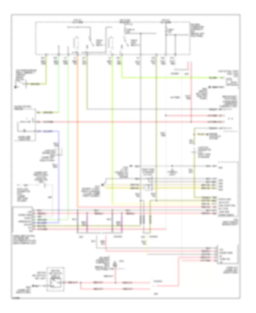
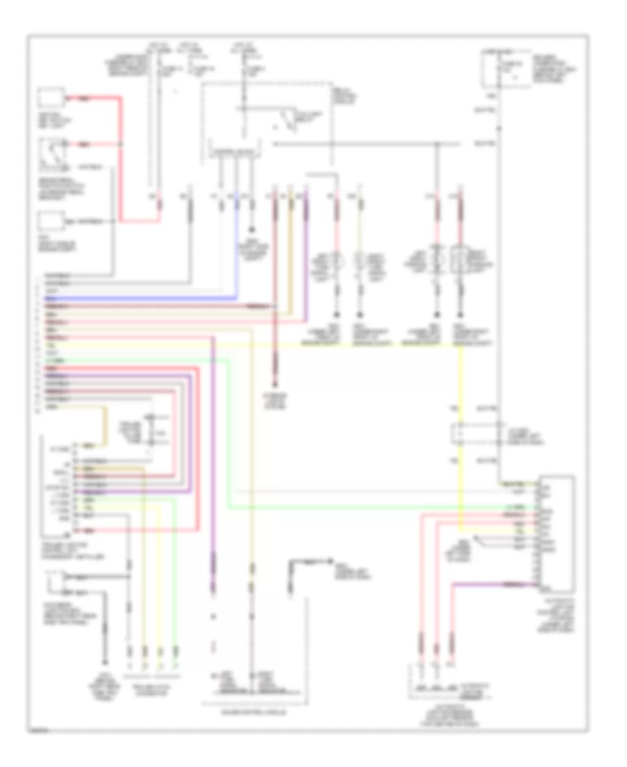
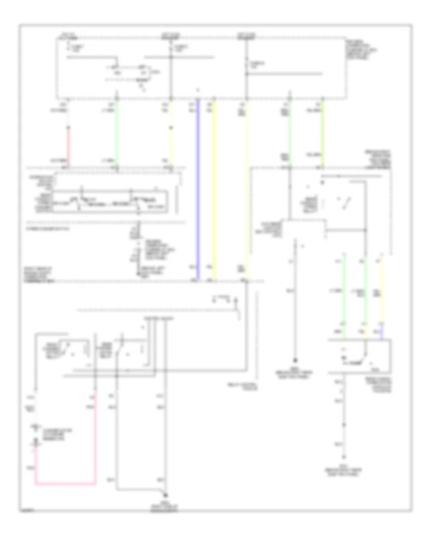
EXTERIOR LIGHTS
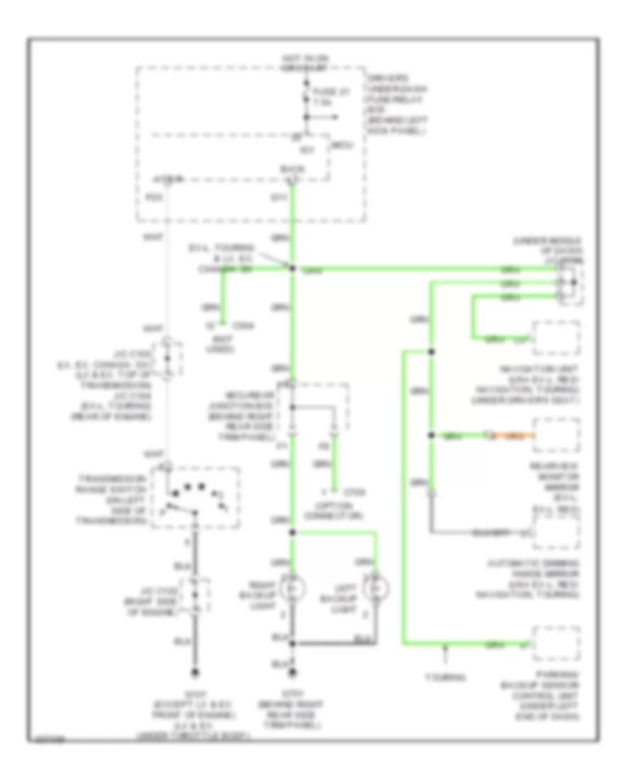
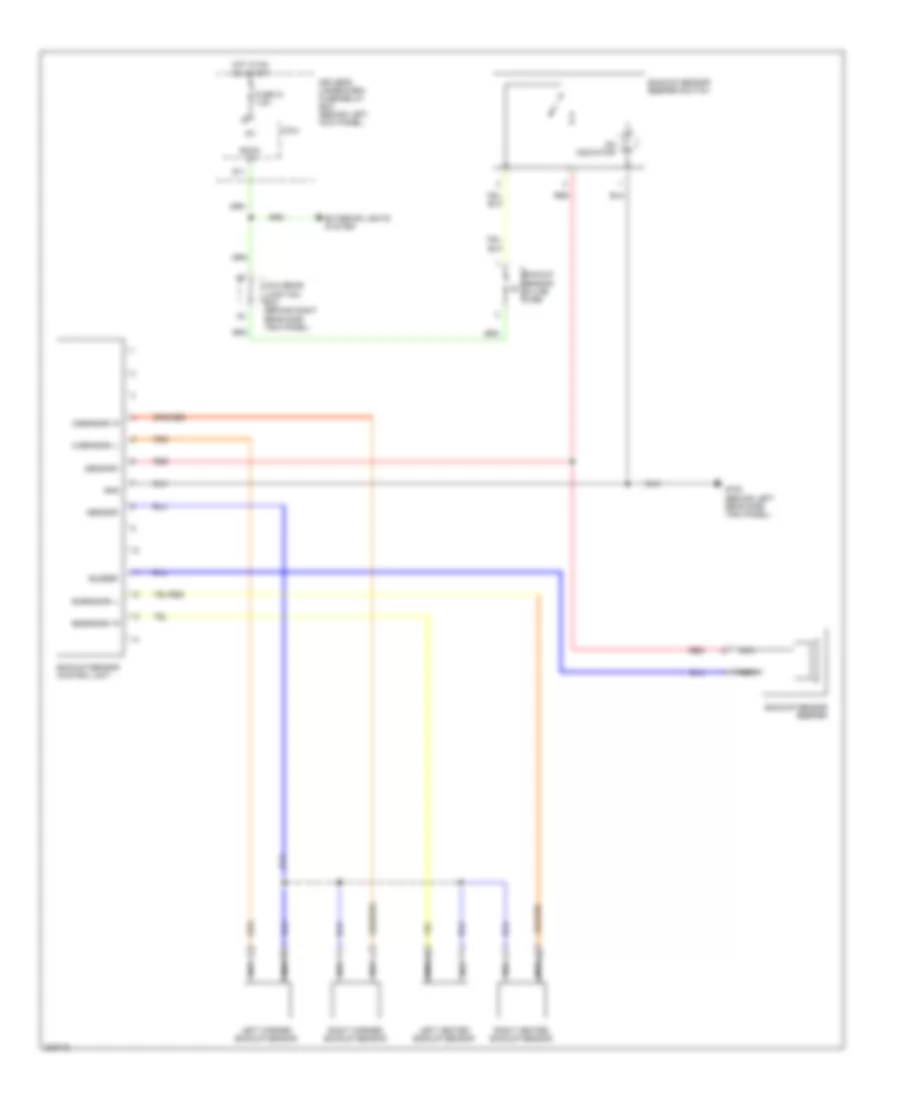
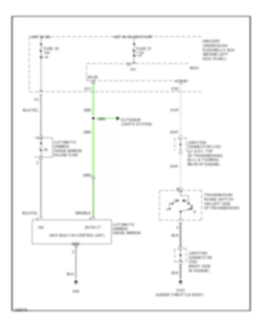
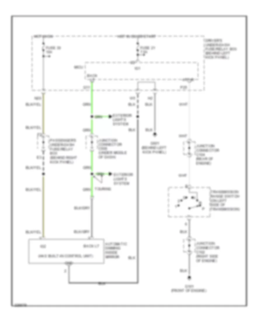
Backup Lamps Wiring Diagram for Honda Odyssey EX 2010
List of elements for Backup Lamps Wiring Diagram for Honda Odyssey EX 2010:
- (not used)
- (option connector)
- (under middle of dash) j/c c506
- Atp-r
- Automatic dimming inside mirror (usa ex-l: res/ navigation, touring)
- Back lt
- C504
- C709
- Canada: dx
- Driver's under-dash fuse/relay box (behind left kick panel)
- Ex-l, touring & lx, ex;
- Ex-l: res)
- Fuse 21 7.5a
- G101 (except lx & ex: front of engine) (lx & ex: under throttle body)
- G701 (behind right rear side trim panel)
- Hot in on or start
- Ig1
- J/c c102 (right side of engine)
- J/c c103 (lx, ex; canada: dx) (lx & ex: top of transmission) j/c c104 (ex-l, touring) (rear of engine)
- Left backup light
- Micu
- Micu-rear junction box (behind right rear side trim panel)
- Navigation unit (usa ex-l: res/ navigation, touring) (under driver's seat)
- P25
- Parking/ backup sensor control unit (under left end of dash)
- Q11
- Rearview monitor mirror (ex-l;
- Right backup light
- Touring
- Transmission range switch (on left side of transmission)
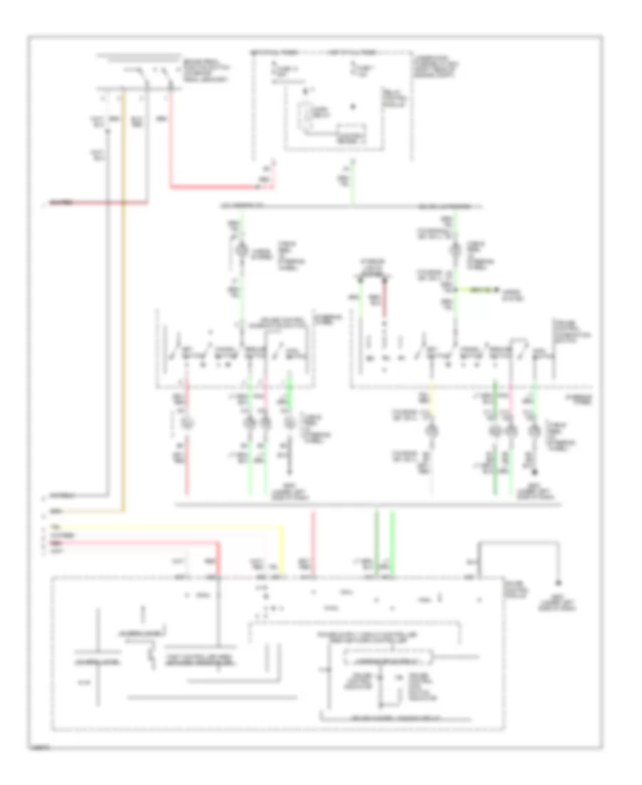
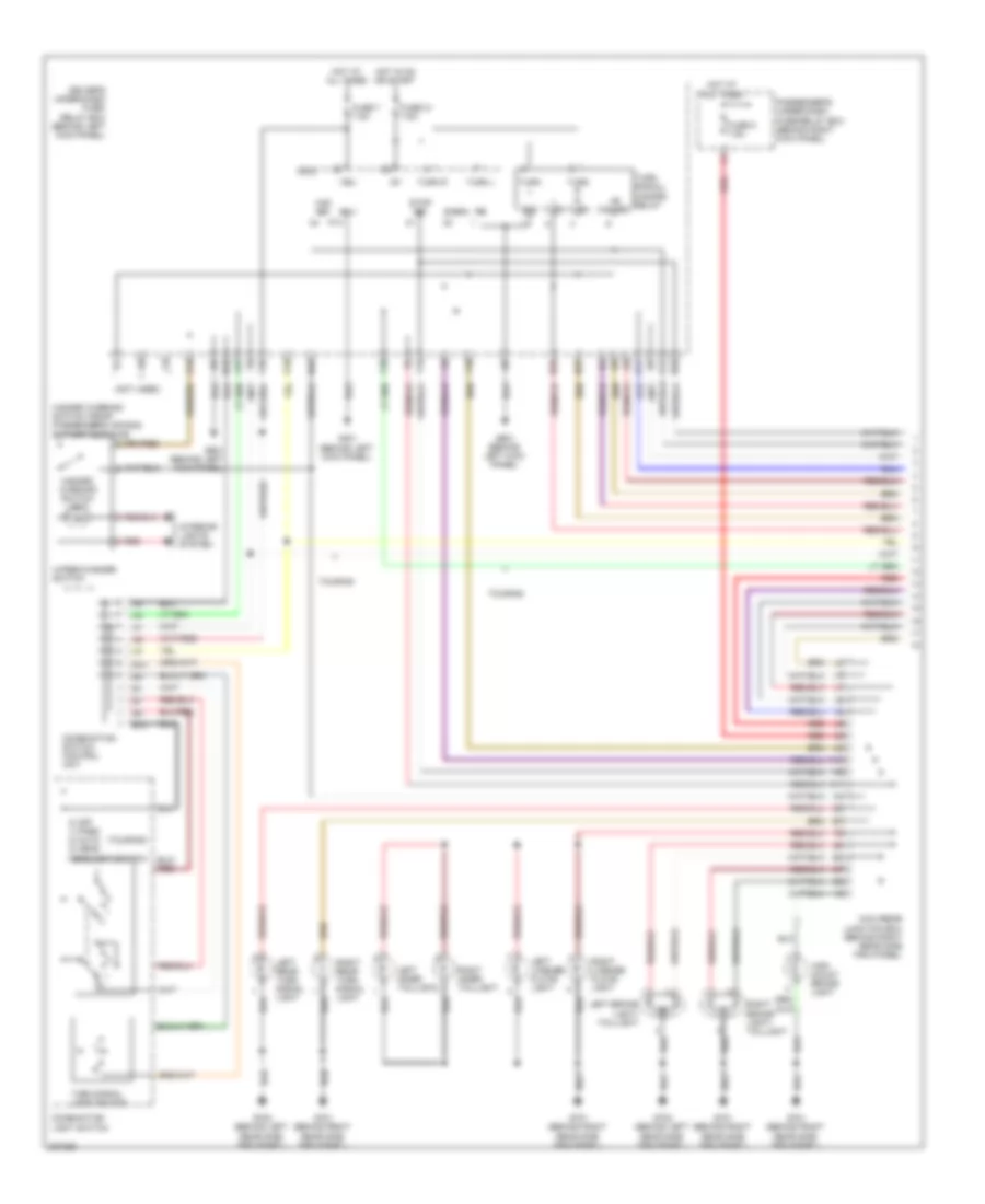
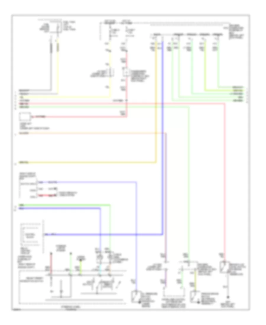
Exterior Lamps Wiring Diagram (1 of 2) for Honda Odyssey EX 2010
List of elements for Exterior Lamps Wiring Diagram (1 of 2) for Honda Odyssey EX 2010:
- (not used)
- (touring)
- +b hazard
- 0) off 1) park 2) auto 3) head headlight switch
- A10
- A11
- B-can
- B10
- B12
- Combination light switch
- Combination switch control unit
- D11
- D17
- Driver's under-dash fuse/ relay box (behind left kick panel)
- F10
- F12
- Fuse 21 7.5a
- Fuse 5 7.5a
- Fuse 7 7.5a
- G401 (behind left kick panel)
- G601 (behind left kick panel)
- G701 (behind right rear side trim panel)
- G702 (behind left rear side trim panel)
- Gnd
- Haz sw
- Hazard warning switch light
- Hazard warning switch/ front passenger's air bag cut-off indicator
- High mount brake light
- Hot at all times
- Hot in on or start
- Ig1
- Interior lights system
- L turn
- Left brake light/ taillight
- Left inner taillight
- Left license plate light
- Left rear turn signal light
- Micu
- Micu-rear junction box (behind right rear side trim panel)
- N26
- N27
- N33
- N42
- N45
- P14
- Passenger's under-dash fuse/relay box (behind right kick panel)
- R turn
- Red
- Right brake light/ taillight
- Right inner taillight
- Right license plate light
- Right rear turn signal light
- Sg-1
- Stop sw
- Touring
- Turn l
- Turn r
- Turn signal light switch
- Turn signal/ hazard relay
- Vbu
- Wiper/washer switch
- X13
- X18
- X27
- X34
- X35
Exterior Lamps Wiring Diagram (2 of 2) for Honda Odyssey EX 2010
List of elements for Exterior Lamps Wiring Diagram (2 of 2) for Honda Odyssey EX 2010:
- +b small ill+ stop sw l turn r turn l turn gnd
- 7.5a
- A15
- A21
- A30
- Automatic lighting control unit (touring) (under left side of dash)
- Automatic lighting sensor
- Automatic lighting sensor/ sunlight sensor (top center of dash)
- B/u
- Brake pedal position switch (on brake pedal bracket)
- Bus
- Control block
- D9 red
- Driver's under-dash fuse/relay box (behind left kick panel)
- Fuse 13 20a
- Fuse 16 15a
- Fuse 30 10a
- Fuse 4 15a
- G201 (under right front of engine compt)
- G202 (right side of engine compt)
- G301 (under left front of engine compt)
- G501 (under left side of dash)
- G502 (under left side of dash)
- G701 (behind right rear side trim panel)
- Gauge control module
- Gnd1
- Gnd2
- Hot at all times
- Hot in on
- Ig1
- Ig2
- Ignition key switch/ key light
- Interior lights system
- J/c c503 (under left side of dash)
- Left front parking light
- Left front turn signal
- Left turn signal indicator
- Light
- Micu-rear junction box (behind right rear side trim panel)
- N20
- Pcm (right side of engine compt)
- R turn
- Red
- Relay control module
- Right front parking light
- Right front turn signal light
- Right turn signal indicator
- Sig
- Sio
- Sip
- Taillight relay
- Trailer hitch connector
- Trailer lighting control unit (accessory installed)
- Trailer lighting in-line fuse
- Under-hood fuse/relay box (right rear of engine compt)
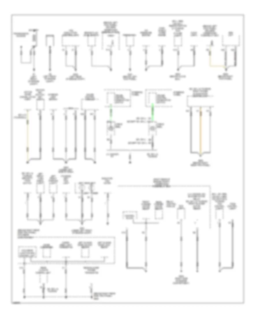
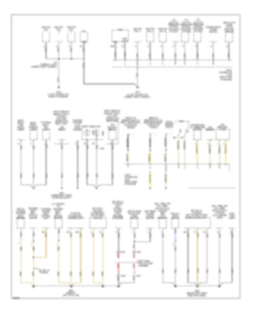
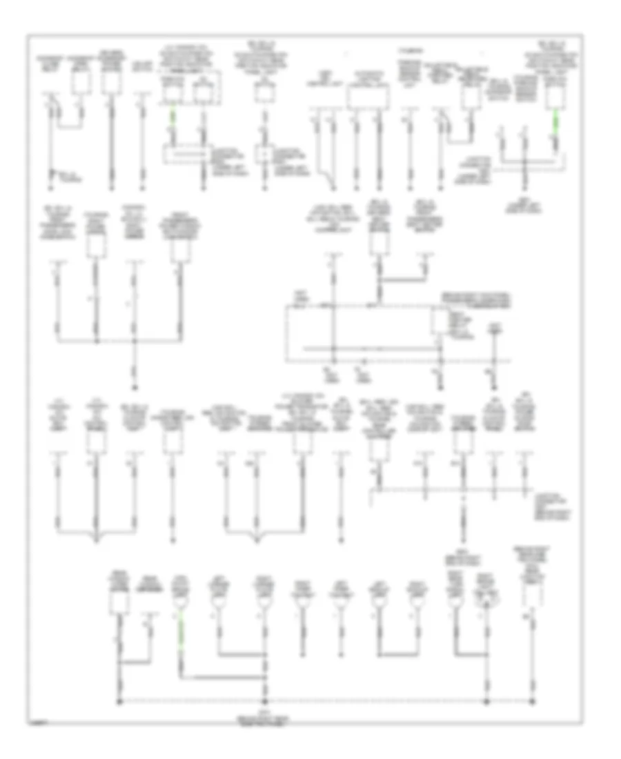
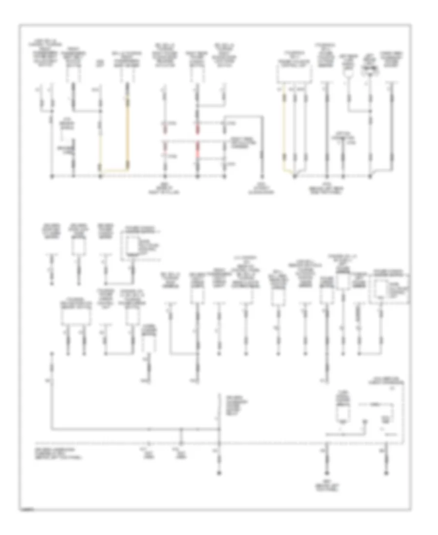
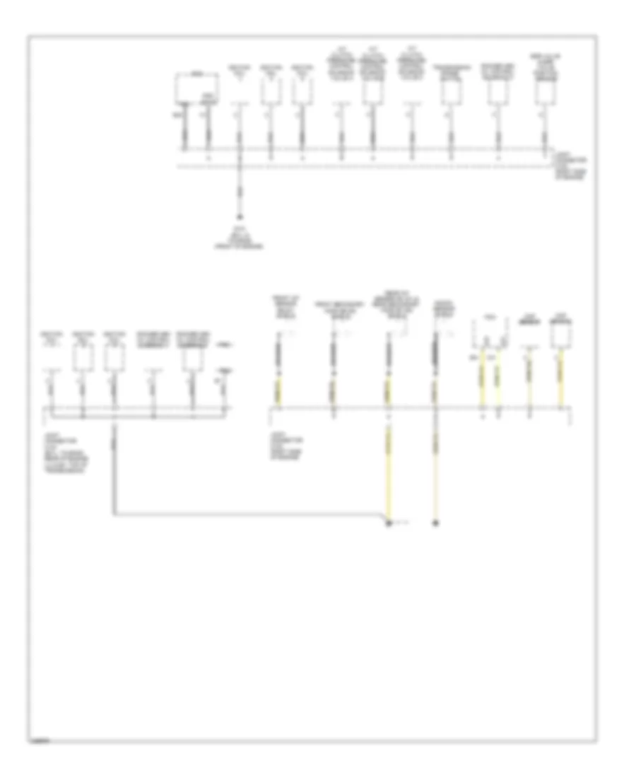
GROUND DISTRIBUTION
Ground Distribution Wiring Diagram (1 of 5) for Honda Odyssey EX 2010
List of elements for Ground Distribution Wiring Diagram (1 of 5) for Honda Odyssey EX 2010:
- (behind left kick panel) driver's under-dash fuse/relay box
- (behind right rear side trim panel)
- (behind right rear side trim panel) micu-rear junction box
- (ex, ex-l & touring) right power sliding door control unit
- (ex, ex-l & touring) security hood switch
- (ex, ex-l)
- (ex-l)
- (ex-l, ex: res, usa ex-l res/ navigation & touring) acm control unit
- (ex-l: res; usa ex-l, res/navigation & touring) dvd player unit
- (except ex, ex-l)
- (lx; canada: dx) blower motor relay (ex, ex-l & touring) front blower motor relay
- (right rear of engine compt) under-hood fuse/relay box
- (touring)
- (touring) left fog light
- A/c pressure switch
- A12
- A13
- A20
- A21
- A22
- A23
- Active noise cancellation unit
- Audio unit
- Battery
- Brake fluid level switch
- C14
- Cable reel
- Cargo area light transistor
- Control block
- Cruise control combination switch
- Dlc
- Eld unit
- Engine
- Ex, ex-l & touring
- Front washer motor relay
- G1 (left front of engine compt)
- G2 (left front of engine compt)
- G202 (right side of engine compartment)
- G301 (under left front of engine compt)
- G302 (left rear of engine compt)
- G401 (behind left kick panel)
- G502 (under left side of dash)
- G503 (behind glove box)
- G505 (behind right kick panel)
- G652
- G653 (behind right rear trim panel)
- Gauge control module
- High
- Ignition key switch/ key light
- Interior light switch
- Junction box control unit
- K10
- Left front parking light
- Left front turn signal light
- Left headlight
- Left sliding door lock relay
- Left sliding door unlock relay
- Low
- Lx; canada: dx
- Mes
- Micu
- Micu-rear
- Noise condenser
- P14
- Psp switch
- Radiator fan motor
- Rear blower power transistor
- Rear climate control unit
- Rear washer motor relay
- Relay control module
- Sg-1
- Srs unit
- Steering wheel
- Tpms control unit
- Transmission housing
- Vsa modulator- control unit
- Wind- shield wiper motor
Ground Distribution Wiring Diagram (2 of 5) for Honda Odyssey EX 2010
List of elements for Ground Distribution Wiring Diagram (2 of 5) for Honda Odyssey EX 2010:
- (canada) washer fluid level switch
- (ex & ex-l) driver's power seat adjustment switch
- (ex, ex-l & touring) left power sliding door control unit
- (ex, ex-l & touring) left power sliding door release actuator
- (ex-l & touring) driver's seat heater
- (ex-l: res, usa ex-l: res/ navigation & touring) res jack assembly
- (ex-l: res; usa ex-l: res/ navigation & touring) ac inverter unit
- (lx; canada: dx)
- (right rear of
- (touring) power seat control unit
- (touring) right fog light
- A/t clutch pressure control solenoid valve a
- A/t clutch pressure control solenoid valve b
- A/t clutch pressure control solenoid valve c
- A21
- Auxiliary under-hood relay box
- B18
- B40
- B41
- Braided
- C41
- C751
- C752
- C753
- C754
- Ckp sensors (a & b)
- Cmp sensor
- Driver's seat belt buckle switch
- Drl relay
- Egr valve & egr valve position sensor
- Engine compt)
- Engine compt) (canada) auxiliary under-hood relay box
- Etcs
- Ex, ex-l & touring
- Fan control relay
- Front a/f sensor (b2,s1) & front secondary ho2s (b2,s2) shield
- Fuel fill door switch
- Fuel tank unit
- G101 (lx, ex; canada: dx) (under throttle body)
- G102 (lx, ex; canada: dx) (front of engine)
- G201 (under right front of engine compt)
- G602 (base of left "b" pillar)
- G603 (behind left rear side trim panel)
- High
- Ignition coil
- Ignition coil 4
- Ignition coil 5
- Ignition coil 6
- Joint connector c102 (right side of engine)
- Knock sensor shield
- Left cess articulated harness
- Left rear power window switch
- Left sliding door lock knob switch
- Lg1
- Lg2
- Low
- Pcm
- Pg1
- Pg2
- Pgm
- Rear a/f sensor (b1,s1) & rear secondary ho2s (b1,s2) shield
- Red
- Right front parking light
- Right front turn signal light
- Right headlight
- Rocker arm oil pressure switch
- S1 (thermal joint) (under throttle body)
- Transmission range switch
- Usa
Ground Distribution Wiring Diagram (3 of 5) for Honda Odyssey EX 2010
List of elements for Ground Distribution Wiring Diagram (3 of 5) for Honda Odyssey EX 2010:
- (behind right kick panel) passenger's under-dash fuse/relay box
- (behind right rear side trim panel)
- (behind right rear side trim panel) micu- rear junction box
- (canada:
- (ex,
- (ex, ex-l & touring) climate control unit
- (ex, ex-l & touring) d3 switch/park pin switch/a/t gear position indicator panel light
- (ex, ex-l & touring) front passenger's door lock knob switch
- (ex-l & touring) driver's seat heater switch
- (ex-l & touring) front passenger's seat heater switch
- (ex-l & touring) moonroof switch
- (ex-l: res, usa ex-l: res/ navigation & touring) rear controller & screen
- (lx;
- (lx; canada: dx) blower power transistor (ex, ex-l & touring) front blower power transistor
- (lx; canada: dx) d3 switch/park pin switch/a/t gear position indicator panel light
- (not
- (not used)
- (touring)
- (touring) hands free link control unit
- (touring) parking/ backup sensor switch
- (touring) right power mirror
- (touring) stereo amplifier
- (usa ex-l: res, navigation & touring) navigation unit
- (usa ex-l: res/ navigation & touring) navigation display unit
- (usa) drl control unit
- (usa: ex-l res/ navigation, ex-l, ex-l res & touring) acm control unit
- A/c control panel
- A10
- A20
- Adjustable pedal forward relay
- Adjustable pedal rearward relay
- Automatic lighting control unit
- B10
- B14
- B4 (not used)
- Canada: dx)
- Canada: dx) glove box light
- D3 switch
- Driver's accessory power socket
- Dx, lx; ex & ex-l) right power mirror
- Ex-l & touring
- Ex-l & touring)
- Ex-l & touring) climate control panel
- Ex-l & touring) power sliding door switch
- F8 (not used)
- Front passenger's power window switch/door lock switch
- G501 (under left side of dash)
- G504 (behind right end of dash)
- G701
- Glove box light
- High mount brake light
- Junction connector c501 (under left side of dash)
- Junction connector c502 (under left side of dash)
- Junction connector c507 (behind right end of dash)
- Left backup light
- Left inner taillight
- Left license plate light
- Moonroof close relay
- Moonroof open relay
- Park pin switch
- Parking/ backup sensor control unit
- Rear window defogger
- Rear window wiper motor
- Right backup light
- Right brake light/ taillight
- Right inner taillight
- Right license plate light
- Right rear turn signal light
- Seat heater relay (ex-l & touring)
- Used)
- Vsa off switch
Ground Distribution Wiring Diagram (4 of 5) for Honda Odyssey EX 2010
List of elements for Ground Distribution Wiring Diagram (4 of 5) for Honda Odyssey EX 2010:
- (behind left kick panel)
- (canada: dx, lx, ex, ex-l & touring) power mirror switch
- (canada: dx, lx; ex & ex-l) left power mirror
- (ex, ex-l & touring) right power sliding door release actuator
- (ex, ex-l & touring) right sliding door lock knob switch
- (ex, ex-l & touring) roof console
- (ex-l & touring) front passenger's seat heater
- (ex-l; ex-l: res) rearview monitor mirror
- (lx; canada: dx) rear a/c control panel (ex, ex-l & touring) rear climate control panel
- (not used)
- (option connector)
- (touring & ex-l)
- (touring & ex-l) power tailgate outside beeper
- (touring) driving position memory switch
- (touring) left power mirror
- (touring) power mirror control unit
- (usa ex-l: res/navigation & touring) automatic dimming inside mirror
- (usa: ex-l & canada: touring) front passenger's power seat adjustment switch
- B19
- Braided
- C709
- C781
- C782
- C783
- C784
- Cargo area accessory power socket
- D12
- Door multiplex control unit
- Driver's accessory power socket relay
- Driver's door key cylinder switch
- Driver's door lock knob switch
- Driver's power window motor
- Driver's under-dash fuse/relay box (behind left kick panel)
- Driver's vanity mirror light
- Front passenger's seat belt buckle
- Front passenger's vanity mirror light
- Ftp sensor shield
- G601
- G651 (base of right "b" pillar)
- G702 (behind left rear side trim panel)
- G751 (in right sliding door)
- Gnd
- Left brake light/ taillight
- Left rear turn signal light
- Micu
- Micu gnd
- Micu service check connector
- N17
- N18
- N42
- Ods unit
- Pg1
- Power mirror switch
- Power tailgate control unit
- Power window master switch
- Red
- Right cess articulated harness
- Right rear power window switch
- Sgnd
- Switch
- Turn signal/ hazard relay
- Wiper/ washer switch
- Wire
Ground Distribution Wiring Diagram (5 of 5) for Honda Odyssey EX 2010
List of elements for Ground Distribution Wiring Diagram (5 of 5) for Honda Odyssey EX 2010:
- A/t clutch pressure control solenoid valve a
- A/t clutch pressure control solenoid valve b
- A/t clutch pressure control solenoid valve c
- B40
- B41
- Braided
- C41
- Ckp sensor
- Cmp sensor
- Egr valve & egr valve position sensor
- Etcs
- Front a/f sensor (b2,s1) shield
- Front secondary ho2s (b2,s2) shield
- G101 (ex-l & touring) (front of engine)
- Ignition coil
- Joint connector c102 (right side of engine)
- Joint connector c103 (ex-l, touring: rear of engine) (lx & ex: top of transmission)
- Knock sensor shield
- Lg1
- Lg2
- Pcm
- Pg1
- Pg2
- Pgm
- Rear a/f sensor (b1,s1) & rear secondary ho2s (b1,s2) shield
- Rocker arm oil control solenoid a
- Rocker arm oil control solenoid b
- Rocker arm oil control solenoid c
- Transmission range switch
HEADLIGHTS
Headlights Wiring Diagram, Except Touring (1 of 2) for Honda Odyssey EX 2010
List of elements for Headlights Wiring Diagram, Except Touring (1 of 2) for Honda Odyssey EX 2010:
- 0) low 1) high 2) passing
- 0) off 1) park 2) head
- A21
- A25
- B-can
- B12
- Body controller area network transceiver
- Combination light switch
- Combination switch control unit
- D11
- D14
- Day lt
- Dimmer switch
- Drive circuit
- Driver's under-dash fuse/relay box (behind left kick panel)
- Drl indicator
- E14
- Exterior lights system
- Fog light switch
- Fuse 10a
- Fuse 7.5a
- G401 (behind left kick panel)
- G502 (under left side of dash)
- G601 (behind left kick panel)
- Gauge control module
- Headlight switch
- High beam indicator
- Hot at all times
- Hot in on or start
- Ig1
- J/c c503 (under left side of dash)
- Micu
- Micu gnd
- N28
- N30
- N34
- N42
- P14
- Parking brake switch (on parking brake pedal assembly)
- Passenger's under-dash fuse/relay box (behind right kick panel)
- Sg-1
- Usa
- Vbu
- Warning drive circuit
- Wiper/washer switch
- X27
- X34
- X35
Headlights Wiring Diagram, Except Touring (2 of 2) for Honda Odyssey EX 2010
List of elements for Headlights Wiring Diagram, Except Touring (2 of 2) for Honda Odyssey EX 2010:
- (not used)
- (under
- (under left front of engine compt) g301
- (under right front of
- 120a
- Auxiliary under-hood fuse box (right rear
- Auxiliary under-hood relay box (canada)
- Canada
- Canada: dx
- Control block
- Drl relay
- Eld unit
- Engine compt) g201
- Ex, ex-l
- F13
- Fog light relay (if equipped) (in auxiliary underhood relay box)
- Fuse 10a
- Fuse 20a
- G201
- G201 (under right front of engine compt)
- G202 (right side of engine compt)
- G30
- H10
- H11
- H13
- H16
- H17
- H18
- Headlight
- High beam headlight relay
- Hot at all times
- K10
- Left
- Left fog light (if equipped)
- Low beam headlight relay
- Lx;
- Multi fuse 22
- Of engine compt)
- Relay control module
- Right
- Right fog light (if equipped)
- Right front of engine compt)
- Under-hood fuse/relay box (right rear of engine compt)
- Usa
Headlights Wiring Diagram, Touring (1 of 2) for Honda Odyssey EX 2010
List of elements for Headlights Wiring Diagram, Touring (1 of 2) for Honda Odyssey EX 2010:
- (behind left kick panel)
- (top center of dash)
- (touring)
- A21
- A25
- Automatic lighting control unit (under left side of dash)
- Automatic lighting sensor
- Automatic lighting sensor/sunlight sensor
- B-can
- B/u
- Body controller area network transceiver
- Bus
- Combination switch control unit
- D11
- D14
- Day lt
- Drive circuit
- Driver's under-dash fuse/relay box (behind left kick panel)
- Drl indicator
- E14
- Fog light indicator
- Fuse 10a
- Fuse 7.5a
- G401 (behind left kick panel)
- G501 (under left side of dash)
- G502 (under left side of dash)
- G601
- G601 (behind left kick panel)
- Gauge control module
- Gnd1
- Gnd2
- High beam indicator
- Hot at all times
- Hot in on
- Hot in on or start
- Ig1
- Ig2
- J/c c503 (under left side of dash)
- Lights on/fog light brightness control & dimming circuit
- Micu
- Micu gnd
- N20
- N28
- N30
- N34
- N42
- P14
- Parking brake switch (on parking brake pedal assembly)
- Passenger's under-dash fuse/relay box (behind right kick panel)
- Red
- Sg-1
- Sig
- Sio
- Sip
- Usa
- Vbu
- Warning
- Wiper/washer switch
- X18
- X27
- X34
- X35
Headlights Wiring Diagram, Touring (2 of 2) for Honda Odyssey EX 2010
List of elements for Headlights Wiring Diagram, Touring (2 of 2) for Honda Odyssey EX 2010:
- (not used)
- (touring)
- (under
- (under left
- (under left front of engine compt) g301
- (under right
- 0) low 1) high 2) passing
- 0) off 1) park 2) auto 3) head
- 120a
- Auxiliary under-hood fuse box (right rear of engine compt)
- Auxiliary under-hood relay box
- Canada
- Combination light switch
- Control block
- Dimmer switch
- Drl control unit (usa) (under left side of dash)
- Drl relay
- Eld unit
- Engine compt)
- Exterior lights system
- Fog light
- Fog light switch
- Front of
- Fuse 10a
- Fuse 20a
- G201
- G201 (under right front of engine compt)
- G202 (right side of engine compt)
- G301 (under left front of engine compt)
- G501
- H10
- H11
- H13
- H16
- H17
- H18
- Headlight
- Headlight switch
- High beam headlight relay
- Hot at all times
- K10
- Left
- Left fog light
- Low beam headlight relay
- Multi fuse 22
- Red
- Relay
- Relay control module
- Right
- Right fog light
- Right front of engine compt)
- Side of dash)
- Under-hood fuse/relay box (right rear of engine compt)
- Usa
HORN
Horn Wiring Diagram for Honda Odyssey EX 2010
List of elements for Horn Wiring Diagram for Honda Odyssey EX 2010:
- (ex & ex-l)
- (touring)
- B11
- Cable reel (in steering wheel)
- Control block
- Cruise control combination switch
- Ex, ex-l & touring
- Fuse 13 20a
- High horn (behind right side of front bumper)
- Horn relay
- Horn switch
- Hot at all times
- Low horn (behind right side of front bumper)
- Lx, canada: dx
- Nca
- Relay control module
- Select/ reset/ information switch (touring)
- Steering wheel
- Under-hood fuse/ relay box (right rear of engine compt)
INSTRUMENT CLUSTER
Instrument Cluster Wiring Diagram (1 of 3) for Honda Odyssey EX 2010
List of elements for Instrument Cluster Wiring Diagram (1 of 3) for Honda Odyssey EX 2010:
- (mid) unit
- (not used)
- (touring)
- 10v regulator
- 5v regulator
- A/t gear position
- A/t gear position dimming circuit
- A/t gear position ind drive circuit
- A10
- A11
- A12
- A13
- A14
- A15
- A16
- A17
- A18
- A19
- A20
- A21
- A22
- A23
- A24
- A25
- A26
- A27
- A28
- A29
- A30
- Abs ind
- Anti-lock brakes system
- B10
- B11
- B12
- B13
- B14
- Brake system ind
- Canada:dx)
- Charging system ind
- Compulsory turning-off circuit
- Compulsory turning-on circuit
- Computer data lines system
- Cruise control dimming circuit
- Cruise control ind
- Cruise control main switch ind
- Cruise control system
- Detection circuit
- Dial/car graphic/lcd brightness control & dimming circuit
- Display multi-information
- Drive circuit
- Drl ind
- Eco ind (ex-l & touring)
- Engine coolant temperature gauge
- Exterior lights system
- Fail safe circuit
- Fast controller area network transceiver
- Fuel gauge
- G502 (under left side of dash)
- Gauge control module
- Immobilizer system ind
- Interior lights system
- Lcd back light
- Left turn signal ind
- Low fuel ind
- Low oil pressure ind
- Low tire pressure ind
- Maintenance required ind (lx, ex & ex-l;
- Mid brightness control & dimming circuit
- Mil ind
- Navigation system
- Pointer brightness control & dimming circuit
- Power sliding door ind (ex & ex-l)
- Red
- Right turn signal ind
- Seat belt reminder ind
- Security ind
- Security ind blinking circuit
- Side air bag cut-off ind
- Speedometer
- Srs ind
- System message ind (touring)
- Tachometer
- To beeper (diagram 3 of 3)
- Tpms ind (usa:lx, ex & ex-l; canada:dx)
- Vsa activation ind
- Vsa system ind
- Warning drive circuit
- Washer fluid level ind (canada)
- Wiper/washer system transmissions system
Instrument Cluster Wiring Diagram (2 of 3) for Honda Odyssey EX 2010
List of elements for Instrument Cluster Wiring Diagram (2 of 3) for Honda Odyssey EX 2010:
- (right rear of
- (right side of engine compt) pcm
- A48
- A49
- B-can
- B14
- B15
- Block
- Box
- Brake fluid level switch (on brake fluid reservoir)
- C45
- Cable reel (in steering wheel)
- Canh
- Canl
- Computer data lines system
- Control
- D11
- Driver's under-dash fuse/relay box (behind left kick panel)
- Drswas
- Drswdr
- Drswra
- Drswrd
- E14
- E15
- Engine compt)
- Fuel gauge sending unit
- Fuel tank unit (top of fuel tank)
- Fuse 21 7.5a
- Fuse 7 7.5a
- G401 (behind left kick panel)
- H12
- H13
- Horns system
- Hot at all times
- Hot in on or start
- Immobilizer control unit-receiver (on steering column, near steering lock)
- Imoes unit (usa) (under left side of dash)
- Info switch
- Information switch
- Interior lights system
- J/c c503 (under left side of dash)
- Micu
- N28
- N30
- N34
- Oil pressure switch (lx & ex; canada:dx) (under engine)
- Parking brake switch (on parking brake pedal assembly)
- Passenger's under-dash fuse/relay box (behind right kick panel)
- Red
- Relay control module
- Select/ reset switch
- Select/reset/
- Steering wheel (touring)
- Switch input
- Under-hood fuse/relay
- X34
- X35
Instrument Cluster Wiring Diagram (3 of 3) for Honda Odyssey EX 2010
List of elements for Instrument Cluster Wiring Diagram (3 of 3) for Honda Odyssey EX 2010:
- (on left "b" pillar) driver's door switch
- (on left "c" pillar) left sliding door switch
- (on right "b" pillar) front passenger's door switch
- (on right "c" pillar) right sliding door switch
- (touring)
- A14
- A18
- A19
- A20
- A21
- A25
- B11
- B12
- B13
- B14
- Backup sensor beeper
- Beeper
- Body controller area network transceiver
- Brightening switch
- C11
- Control unit junction box micu-rear
- Corner parking sensor beeper
- Dash lights brightness controller
- Dimming switch
- Drive circuit
- Driver's door ind
- Failure display drive circuit
- Fog light ind
- From pin 6 (diagram 1 of 3)
- From srs ind b (diagram 1 of 3)
- Front passenger's door ind
- Full
- Full latch switch
- Gauge control module
- High beam ind
- I/f
- Left power sliding door ind
- Lights on ind
- Lights on/fog light brightness control and dimming circuit
- Micu-rear junction box (behind right rear side trim panel)
- Power tailgate control unit (in left "d" pillar)
- Rihgt power sliding door ind
- Seg3
- Select/ reset switch
- Tailgate closer unit (touring & ex-l)
- Tailgate ind
INTERIOR LIGHTS
Courtesy Lamps Wiring Diagram for Honda Odyssey EX 2010
List of elements for Courtesy Lamps Wiring Diagram for Honda Odyssey EX 2010:
- (behind right rear side trim panel) g652
- (ex-l)
- (option
- (touring)
- (under left side of dash) g502
- A14
- Active noise cancellation unit
- B-can
- C11
- Cargo area light
- Cargo area light transistor
- Connector)
- Courtesy lt as
- Courtesy lt dr
- Door
- Driver's door courtesy light (ex, ex-l & touring)
- Driver's door switch (on left "b" pillar)
- Driver's under-dash fuse/relay box (behind left kick panel)
- Driver's vanity mirror light
- Drswas
- Drswdr
- Drswra
- Drswrd
- E14
- E15
- Ex-l
- Ex-l & touring
- Front individual map lights
- Front passenger's door courtesy light (ex, ex-l & touring)
- Front passenger's door switch (on right "b" pillar)
- Front passenger's vanity mirror light
- Full
- Full latch switch
- Fuse 6 7.5a
- G601 (behind left kick panel)
- G701 (behind right rear side trim panel)
- H12
- H13
- Homelink unit
- Hot at all times
- Inside tailgate switch (ex-l)
- Instrument illumination circuit
- Interior light switch
- Interior light switch light
- Intrlt
- Left
- Left rear individual map light (2nd)
- Left rear individual map light (3rd)
- Left sliding door switch (on left "c" pillar)
- Lx, ex, canada: dx
- Micu
- Micu-rear junction box (behind right rear side trim panel)
- Micu-rear junction box control unit
- N15
- Off
- Off door
- On door
- P15
- Power tailgate control unit (in left "d" pillar)
- Red
- Right
- Right rear individual map light (2nd)
- Right rear individual map light (3rd)
- Right sliding door switch (on right "c" pillar)
- Roof console (ex, ex-l & touring)
- Seg3
- Tailgate closer unit
- Tailgate latch switch
Entry Light Timer Wiring Diagram for Honda Odyssey EX 2010
List of elements for Entry Light Timer Wiring Diagram for Honda Odyssey EX 2010:
- (behind left kick panel) g401
- (behind left kick panel) g601
- (ex-l)
- (option connector)
- (touring)
- (under left side of dash) imoes unit
- Active noise cancellation unit
- B-can
- Canada
- Courtesy lamps circuit
- Door
- Door lock knob
- Door multiplex control unit
- Driver's door key cylinder switch (in driver's door)
- Driver's door lock knob switch (rear of driver's front door)
- Driver's door switch (on left "b" pillar)
- Driver's under-dash fuse/relay box (behind left kick panel)
- Drswas
- Drswdr
- Drswra
- Drswrd
- E14
- E15
- Ex-l & touring
- Front individual map lights
- Front passenger's door switch (on right "b" pillar)
- Fuse 13 20a
- Fuse 6 7.5a
- Fuse 7.5a
- G502 (under left side of dash)
- G601 (behind left kick panel)
- H12
- H13
- Hot at all times
- Hot in on or start
- Ig key lt
- Ig key sw
- Ig1
- Ignition key light
- Ignition key switch
- Ignition key switch/ key light
- Interior light switch
- Intr lt
- Key
- Key lock
- Key unlock
- Keyless receiver antenna
- Knob lock
- Knob unlock
- Left
- Left rear individual map light (2nd)
- Left rear individual map light (3rd)
- Left sliding door switch (on left "c" pillar)
- Lock
- Micu
- Micu gnd
- Off
- P14
- Power window master switch
- Red
- Right
- Right rear individual map light (2nd)
- Right rear individual map light (3rd)
- Right sliding door switch (on right "c" pillar)
- Sg-1
- Under-hood fuse/relay box (right rear of engine compt)
- Unlock
- Usa
Instrument Illumination Wiring Diagram, Except LX (1 of 2) for Honda Odyssey EX 2010
List of elements for Instrument Illumination Wiring Diagram, Except LX (1 of 2) for Honda Odyssey EX 2010:
- A/t gear position indicator panel light
- A18
- A19
- A20
- A21
- A25
- Anti-theft system
- B-can
- B12
- Brightening switch
- Combination light switch
- Combination switch control unit
- Control block
- Controller
- D11
- D3 switch/park pin switch/ a/t gear position indicator panel light (d3 switch /park pin switch: under left side of dash)
- Dash lights brightness controller
- Dash- board power tailgate switch (touring; ex-l)
- Dimming switch
- Driver's under-dash fuse/relay box (behind left kick panel)
- Driving position memory switch (touring)
- E14
- Exterior lights system
- Fuse 15a
- Fuse 21 7.5a
- Fuse 7 7.5a
- G202 (right side of engine compt)
- G502 (under left side of dash)
- G601 (behind left kick panel)
- Gauge control module
- Headlight switch 0) off 1) park 2) auto 3) head
- Hot at all times
- Hot in on or start
- Ig1
- J19
- Junction connector c501 (under left side of dash)
- Junction connector c503 (under left side of dash)
- K10
- Micu
- Moonroof switch (ex-l, touring)
- Multi-information display (mid) unit
- N28
- N42
- Parking/ backup sensor switch (touring)
- Passenger's under-dash fuse/relay box (behind right kick panel)
- Power adjustable pedal switch (touring)
- Power mirror switch
- Red
- Relay control module
- Taillight relay
- Touring
- Transceiver area network body controller
- Under-hood fuse/relay box (right rear of engine compt)
- Usa
- Vbu
- Vsa off switch
- Wiper/washer switch
- X27
- X34
- X35
Instrument Illumination Wiring Diagram, Except LX (2 of 2) for Honda Odyssey EX 2010
List of elements for Instrument Illumination Wiring Diagram, Except LX (2 of 2) for Honda Odyssey EX 2010:
- (ex,ex-l)
- (ex,ex-l) b10
- (ex,ex-l) c10
- (touring)
- (touring) b17
- (touring) c9
- A10
- A11
- A12
- A13
- Audio remote switch
- Audio unit
- B18
- C10
- Cable reel (in steering wheel)
- Climate control panel
- Cruise control combination switch
- Driver's seat heater switch (ex-l & touring)
- Dvd player unit (res; ex-l: usa ex-l, touring)
- E11
- E12
- Front passenger's seat heater switch (ex-l & touring)
- Fuse 7 7.5a
- G10
- G504 (behind right end of dash)
- Glove box light
- Hazard warning switch/ front passenger's airbag cut-off indicator
- Interior light switch
- Junction connector c507 (behind right end of dash)
- Navigation display unit (usa ex-l: res/ navigation, touring)
- Navigation unit (usa ex-l: res/ navigation, touring)
- Passenger's under-dash fuse/relay box (behind right kick panel)
- Power sliding door switch
- Rear climate control panel
- Rear controller & screen (res; ex-l: usa ex-l: touring)
- Red
- Roof console
- Select/reset/ information switch (touring)
- Steering wheel
- Voice control switch (usa ex-l: res/ navigation) hfl-voice control switch (touring)
Instrument Illumination Wiring Diagram, LX for Honda Odyssey EX 2010
List of elements for Instrument Illumination Wiring Diagram, LX for Honda Odyssey EX 2010:
- (behind right kick panel) passenger's under-dash fuse/relay box
- (under left side of dash) junction connector c502
- A/c control panel
- A/t gear position indicator panel light
- A10
- A12
- A19
- A20
- A21
- A25
- Anti-theft system
- Audio unit
- B-can
- B12
- Brightening switch
- Combination light switch
- Combination switch control unit
- Control block
- Controller
- D11
- D3 switch/park pin switch/ a/t gear position indicator panel light (d3 switch/park pin switch: under left side of dash)
- Dash lights brightness controller
- Dimming switch
- Driver's under-dash fuse/relay box (behind left kick panel)
- E12
- E14
- Exterior lights system
- Fuse 15a
- Fuse 7 7.5a
- Fuse 7.5a
- G10
- G202 (right side of engine compt)
- G502 (under left side of dash)
- G504 (behind right end of dash)
- G601 (behind left kick panel)
- Gauge control module
- Glove box light
- Hazard warning switch/ front passenger's air bag cut-off indicator
- Headlight switch 0) off 1) park 2) auto 3) head
- Hot at all times
- Hot in on or start
- Ig1
- Interior light switch
- J19
- Junction connector c503 (under left side of dash)
- K10
- Micu
- Multi-information display (mid) unit
- N28
- N42
- Passenger's under-dash fuse/relay box (behind right kick panel)
- Power mirror switch
- Rear a/c control panel
- Red
- Relay control module
- Taillight relay
- Transceiver area network body controller
- Under-hood fuse/relay box (right rear of engine compt)
- Vbu
- Vsa off switch
- Wiper/ washer switch
- X27
- X34
- X35
MEMORY SYSTEMS
Memory Mirrors Wiring Diagram (1 of 2) for Honda Odyssey EX 2010
List of elements for Memory Mirrors Wiring Diagram (1 of 2) for Honda Odyssey EX 2010:
- (except lx & ex: front of engine) (lx & ex: under throttle body) g101
- A16
- A17
- A18
- A19
- A20
- A31
- A39
- Atp-p
- D13
- D14
- Driver's under-dash fuse/relay box (behind left kick panel)
- Driving position memory switch
- Driving position memory switch light
- Fuse 7.5a
- G601 (behind left kick panel)
- Gnd
- Hot at all times
- Hot in on or start
- Ig1
- Ind1
- Ind2
- Interior lights system
- J/c c102 (right side of engine)
- J/c c405 (behind glove box)
- Lhm
- Lmc
- Lseh
- Lsev
- Lvm
- Mem
- Memo button
- Micu
- Micu-rear junction box (behind right rear side trim panel)
- Mldl
- Mldr
- Mrdl
- Mrdr
- Mul
- Pos
- Pos1
- Pos2
- Position ind 1
- Position ind 2
- Power mirror control unit
- Power seat control unit (under driver's seat)
- Red
- Rhm
- Rmc
- Rseh
- Rsev
- Rvm
- Sen feed
- Transmission range switch (on left side of transmission)
- Uart
- Vbu
Memory Mirrors Wiring Diagram (2 of 2) for Honda Odyssey EX 2010
List of elements for Memory Mirrors Wiring Diagram (2 of 2) for Honda Odyssey EX 2010:
- (behind left kick panel) driver's under-dash fuse/relay box
- (behind left kick panel) g601
- Defogger
- Down
- Driver's under-dash fuse/relay box (behind left kick panel)
- Fuse 30 10a
- G504 (behind right end of dash)
- Hot in on
- Interior lights system
- Internal switch positions
- J10
- J11
- J12
- J13
- J14
- J21
- Left
- Left power mirror
- Left/right motor
- Mirror defogger switch
- Mirror direction selected
- Power mirror switch
- Red
- Right
- Right power mirror
- Swing
- Switch 1
- Switch 2
- Switch 3
- Tilt
- Up/down motor
- X21
Memory Seat Wiring Diagram (1 of 2) for Honda Odyssey EX 2010
List of elements for Memory Seat Wiring Diagram (1 of 2) for Honda Odyssey EX 2010:
- (base of left "b" pillar) g602
- (behind left kick panel) g601
- (behind right rear side trim panel) micu-rear junction box
- A10
- A11
- A12
- A13
- A14
- A15
- A16
- A17
- A18
- A19
- A20
- A21
- A22
- A23
- A24
- A25
- A26
- A27
- A28
- A29
- A30
- A31
- A32
- A33
- A34
- A35
- A36
- A37
- A38
- A39
- A40
- Atp-p
- B-can
- B10
- B11
- B12
- B13
- B14
- B15
- B16
- B17
- B18
- D13
- D14
- Driver's power seat front up-down motor/position sensor (right side of driver's seat)
- Driver's power seat slide motor (under driver's seat)
- Driver's power seat slide position sensor (under driver's seat)
- Driver's under-dash fuse/relay box (behind left kick panel)
- F11
- F13
- Fhdn
- Fhm(+)
- Fhm(-)
- Fhse
- Fhup
- Fuse 20a
- Fuse 7.5a
- G602 (base of left "b" pillar)
- Gnd1
- Gnd2
- Hot at all times
- Hot in on or start
- Ig1
- Ind1
- Ind2
- Memory mirrors circuit
- Micu
- P29
- Pnk
- Pos1
- Pos2
- Power mirror control unit
- Power seat control unit (under driver's seat)
- Rebw
- Red
- Refw
- Rem(+)
- Rem(-)
- Rese
- Rhdn
- Rhm(+)
- Rhm(-)
- Rhse
- Rhup
- Scom
- Seg
- Sensor
- Set
- Slbw
- Slm(+)
- Slm(-)
- Slse
- Svcc
- Uart
- Vbu
- Vmp1
- Vmp2
Memory Seat Wiring Diagram (2 of 2) for Honda Odyssey EX 2010
List of elements for Memory Seat Wiring Diagram (2 of 2) for Honda Odyssey EX 2010:
- (except lx & ex: front of engine) (lx & ex: under throttle body) g101
- B-can
- Bwd
- Door multiplex control unit
- Down
- Driver's power seat adjustment switch
- Driver's power seat rear up-down motor/position sensor (left side of driver's seat)
- Driver's power seat recline motor/position sensor (in driver's seat back)
- Driving position memory switch
- Driving position memory switch light
- Front up down switch
- Fwd
- G601 (behind left kick panel)
- Ign
- Interior lights system
- J/c c102 (right side of engine)
- J/c c405 (behind glove box)
- Memo button
- Pg1
- Pnk
- Pos
- Position ind 1
- Position ind 2
- Power window master switch
- Rear up down switch
- Recline switch
- Red
- Sensor
- Slide switch
- Transmission range switch (on left side of transmission)
- Vbu
NAVIGATION
Hands Free Module Wiring Diagram for Honda Odyssey EX 2010
List of elements for Hands Free Module Wiring Diagram for Honda Odyssey EX 2010:
- (behind dvd player unit) handsfreelink control unit
- (not used)
- Audio+
- Audio-
- Driver's under- dash fuse/
- Driver's under-dash fuse/relay box (behind left kick panel)
- Fuse 10a
- Fuse 2a
- G40
- Gauge control module
- Gnd
- H brake sw
- Handsfreelink in line fuse
- Handsfreelink switch (honda accessory)
- Hft com
- Hft mute
- Hot at all times
- Hot in on
- Ig2
- Mic +
- Mic -
- Mic gnd
- N30
- N34
- Parking brake switch (on parking brake pedal assembly)
- Parking brake switch connector
- Red
- Relay box connector t
Home Link Remote Control Wiring Diagram for Honda Odyssey EX 2010
List of elements for Home Link Remote Control Wiring Diagram for Honda Odyssey EX 2010:
- Driver's under-dash fuse/relay box (behind left kick panel)
- Fuse 7.5a
- G601 (behind left kick panel)
- Home- link ind
- Home- link unit
- Hot at all times
- Roof console
- Sw 1
- Sw 2
- Sw 3
Navigation Wiring Diagram (1 of 3) for Honda Odyssey EX 2010
List of elements for Navigation Wiring Diagram (1 of 3) for Honda Odyssey EX 2010:
- (behind right end of dash) g504
- (right side of engine compt) pcm
- (right side of tailgate) rearview camera
- (touring)
- A10
- A11
- A12
- A13
- A14
- A15
- A16
- A17
- A18
- A19
- A20
- A21
- A22
- A23
- A24
- A25
- A26
- A27
- A28
- A29
- A30
- A31
- A32
- Ac-ck
- Ac-si
- Ac-so
- Acc
- Air conditioning system
- B sig
- B10
- B11
- B12
- B13
- B14
- B15
- B16
- Back lt
- C sig
- Camera adpt
- Camera gnd
- Camera sh
- Camera vcc
- Connector (under driver's seat)
- D11
- D15
- D16
- Diag n
- Diag p
- Driver's under-dash fuse/relay box (behind left kick panel)
- Fuse 32 10a
- Fuse 7 7.5a
- G sig
- Ga-net disp bus sh
- Ga-net disp bus+
- Ga-net disp bus-
- Ga-net ecu2 bus s+
- Ga-net ecu2 bus sh
- Ga-net ecu2 bus-
- Gnd
- Gnd mic
- Gnd rg
- Gnd sig
- Gps
- Gps antenna connector
- Hfl/nav comm sh
- Hfl/nav comm1
- Hfl/nav comm2
- Hfl/nav comm3
- Hfl/nav comm4
- Hot at all times
- Hot in acc or on
- Ill+
- Interior lights system
- J/c c506 (under middle of dash)
- Mic sh
- Mic sig+
- Micu
- N36
- Navigation service check
- Navigation unit (under driver's seat)
- Nca
- Passenger's under-dash fuse/relay box (behind right kick panel)
- Pnk
- Q11
- R sig
- Red
- Rg l+
- Rg sh
- Sh gps
- Sig h
- Strg sw
- Video
- Video gnd
- Vsp
- Vssout
- X35
Navigation Wiring Diagram (2 of 3) for Honda Odyssey EX 2010
List of elements for Navigation Wiring Diagram (2 of 3) for Honda Odyssey EX 2010:
- Acc
- Amplifier
- B-can
- B10
- B11
- B13
- Back
- C11
- C13
- C17
- C18
- C20
- Cable reel (in steering
- Computer data lines system
- Except touring
- G504 (behind right end of dash)
- Gnd
- Gps antenna
- Handsfreelink control unit (touring) (behind dvd player unit)
- Hfl icon
- Hfl mute
- Hfl strg sw
- Hfl/nav comm sh
- Hfl/nav comm1
- Hfl/nav comm2
- Hfl/nav comm3
- Hfl/nav comm4
- Interior lights system
- Mic gnd
- Mic out+
- Mic out-
- Mic sig+
- Nca
- Pnk
- Red
- Sound systems
- Steering wheel
- Switch
- Talk
- Telm sh gnd
- Telm sig+
- Telm sig-
- Touring
- Voice control switch (except touring) hfl-voice control switch (touring)
- Wheel)
Navigation Wiring Diagram (3 of 3) for Honda Odyssey EX 2010
List of elements for Navigation Wiring Diagram (3 of 3) for Honda Odyssey EX 2010:
- (behind right end of dash) g504
- A10
- A11
- A12
- A13
- A14
- A15
- A16
- A17
- A18
- A19
- A20
- Acc
- Audio disc changer
- Audio unit
- B-sig
- B10
- C sig
- Cd eject
- Disp open
- Except touring
- F10
- F11
- F19
- F20
- G-sig
- Ga-net audio bus1 sh
- Ga-net audio bus1+
- Ga-net audio bus1-
- Ga-net disp bus sh
- Ga-net disp bus+
- Ga-net disp bus-
- Gnd
- Gnd sig
- Hfl icon
- Hfl mute
- Ill (+)
- Ill (-)
- Interior lights system
- J/c c507 (behind right end of dash)
- Microphone
- Navigation display unit
- Pnk
- R-sig
- Rear controller & screen
- Red
- Remote gnd
- Rg gnd
- Rg l+
- Rg sh gnd
- Roof console
- Scty3
- Scty4
- Scty5
- Sig sh
- Telm sh gnd
- Telm sig+
- Telm sig-
- Touring
- Xm receiver (behind left rear side trim panel)
Parking Assistant Wiring Diagram, Except Touring for Honda Odyssey EX 2010
List of elements for Parking Assistant Wiring Diagram, Except Touring for Honda Odyssey EX 2010:
- B/sensor+ l
- B/sensor+ r
- Back lt
- Backup sensor beeper
- Backup sensor beeper switch
- Backup sensor control unit
- Backup sensor in-line fuse
- Buzzer-
- C/sensor+ l
- C/sensor+ r
- Driver's under-dash fuse/relay box (behind left kick panel)
- Exterior lights system
- Fuse 21 7.5a
- G702 (behind left rear side trim panel)
- Gnd
- Hot in on or start
- Ig1
- Left center backup sensor
- Left corner backup sensor
- Micu
- Micu-rear junction box (behind right rear side trim panel)
- Nca
- On indicator
- Q11
- Red
- Right center backup sensor
- Right corner backup sensor
- Sensor+
- Sensor-
Parking Assistant Wiring Diagram, Touring for Honda Odyssey EX 2010
List of elements for Parking Assistant Wiring Diagram, Touring for Honda Odyssey EX 2010:
- (behind glove box) j/c c405
- (under left side of dash) j/c c503
- A30
- Adjustable pedal forward relay (under left end of dash)
- Adjustable pedal rearward relay (under left end of dash)
- Anti-theft system
- Atp-p
- Atp-r
- B11
- B12
- B13
- B14
- Back lt
- Backup sensor beeper
- Bbz
- Cbz
- Corner parking sensor beeper
- Driver's under-dash fuse/relay box (behind left kick panel)
- E14
- Exterior lights system
- Fuse 21 7.5a
- Fuse 7 7.5a
- G101 (front of engine)
- G501 (under left side of dash)
- Gauge control module
- Hot at all times
- Hot in on or start
- I/f
- Ig1
- Interior lights system
- J/c c102 (right side of engine)
- J/c c104 (rear of engine)
- J/c c501 (under left side of dash)
- J/c c506 (under middle of dash)
- Left front corner parking sensor (in left side of front bumper)
- Left parking/ backup sensor (behind left side of rear bumper)
- Left rear corner parking sensor (left corner of rear bumper)
- Micu
- Multi-information display (mid) unit
- P25
- P29
- Parking/ backup sensor control unit (under left end of dash)
- Parking/ backup sensor on indicator
- Parking/ backup sensor switch
- Parking/ backup sensor switch light
- Passenger's under-dash fuse/relay box (behind right kick panel)
- Pcm (right side of engine compt)
- Q11
- Red
- Right front corner parking sensor (in right side of front bumper)
- Right parking/ backup sensor
- Right rear corner parking sensor
- Spd
- Transmission range switch (on left side of transmission)
- Usa
- Vss out
- X34
- X35
Rear Camera Wiring Diagram for Honda Odyssey EX 2010
List of elements for Rear Camera Wiring Diagram for Honda Odyssey EX 2010:
- Acc
- Back lt
- Camera adpt
- Camera gnd
- Camera sh
- Camera vcc
- Camera video
- D15
- Driver's under-dash fuse/relay box (behind left kick panel)
- Fuse 10a
- Fuse 7.5a
- G504 (behind right end of dash)
- G601 (behind left kick panel)
- Gnd
- Hot in acc or on
- Hot in on
- Hot in on or start
- Ig1
- Ig2
- J/c c506 (under middle of dash)
- Micu
- N20
- N36
- Navigation unit (under driver's seat)
- Passenger's under-dash fuse/relay box (behind right kick panel)
- Q11
- Rearview camera
- Rearview monitor mirror
- Red
- Video
- Video gnd
- W/ navigation
- W/o navigation
POWER DISTRIBUTION
Power Distribution Wiring Diagram (1 of 8) for Honda Odyssey EX 2010
List of elements for Power Distribution Wiring Diagram (1 of 8) for Honda Odyssey EX 2010:
- (left front
- (not used)
- (touring) (ex-l)
- 120a
- 70a
- A/c compressor clutch relay
- A/c condenser fan relay
- A10
- Ac inverter unit (ex-l, res & usa ex-l: res/navigation, touring)
- Acm control relay
- Active noise cancellation unit
- Alternator
- Auxiliary under-hood fuse box (right rear of engine compt)
- Auxiliary under-hood relay box
- Battery
- Eld unit
- Etcs control relay
- Ex,
- Ex-l
- Ex-l & touring
- Fog light relay (touring)
- Front passenger's power seat adjustment switch (ex-l & touring)
- Fuse 1 (not used)
- Fuse 1 30a
- Fuse 10 20a (ex-l & touring)
- Fuse 11 30a
- Fuse 11 7.5a (ex-l: res & usa ex-l: res/navigation, touring)
- Fuse 12 7.5a
- Fuse 19 30a
- Fuse 2 (not used)
- Fuse 2 40a
- Fuse 20 40a
- Fuse 3 15a
- Fuse 3 40a
- Fuse 4 20a
- Fuse 4 40a (touring & ex-l)
- Fuse 5 20a 7.5a
- Fuse 5 7.5a (honda accessory)
- Fuse 6 15a (ex-l & touring)
- Fuse 6 20a (ex-l, res & usa ex-l: res/navigation, touring)
- Fuse 7 20a (touring)
- Fuse 8 10a (ex-l & touring)
- Fuse 8 20a (ex, ex-l & touring)
- Fuse 9 (not used)
- Fuse 9 20a (ex-l & touring)
- Fuse 9 30a
- Left power sliding door control unit
- Left sliding door lock relay
- Left sliding door unlock relay
- Micu-rear junction box (behind right rear side trim panel)
- Multi-fuse
- Of engine compt)
- Passenger's under-dash fuse/relay box (behind right kick panel)
- Passenger's under-dash fuse/relay box (ex-l & touring) (behind right kick panel)
- Power tailgate control unit (touring)
- Radiator fan relay
- Rear blower motor relay
- Rear controller & screen (ex-l: res & usa ex-l: res/navigation, touring)
- Red
- Right power sliding door control unit
- Right power sliding door control unit (ex, ex-l & touring)
- Seat heater relay (ex-l & touring)
- Starter
- Starter solenoid
- Stereo amplifier
- T101
- T102
- To driver's under-dash fuse/relay box (diagram 3 of 8)
- To driver's under-dash fuse/relay box (diagram 6 of 8)
- To fuse 15 (diagram 2 of 8)
- To fuse 17 (diagram 5 of 8)
- To fuse 4 (diagram 7 of 8)
- To multi- fuse 23 (diagram 2 of 8)
- Touring
- Trailer lighting control unit (accessory installed)
- Transmission housing
- Under-hood fuse/relay box (right rear of engine compt)
Power Distribution Wiring Diagram (2 of 8) for Honda Odyssey EX 2010
List of elements for Power Distribution Wiring Diagram (2 of 8) for Honda Odyssey EX 2010:
- (behind left
- (diagram 3 of 8)
- (ex, ex-l & touring)
- (lx;
- (not
- (not used)
- (right rear
- (right rear of engine compt) under-hood fuse/ relay box
- 50a
- 7.5a
- A/c compressor clutch relay
- A/c condenser fan relay
- A/c diode a
- A31
- Ac inverter unit (ex-l: res & usa ex-l: res/navigation, touring)
- Acc
- Automatic dimming inside mirror (accessory installed)
- Automatic dimming inside mirror in-line fuse
- Auxiliary fuse holder (under left side of dash)
- Auxiliary under-hood relay box
- Blower motor relay (lx, canada: dx) front blower motor relay (ex, ex-l & touring)
- Canada: dx)
- Canada: dx, lx;
- Control block
- Control module
- D15
- Driver's
- Driver's under-dash fuse/relay box (behind left kick panel)
- E16
- Ex, ex-l, touring
- F13
- F19
- Fan control relay
- From driver's under-dash m fuse/relay box (diagram 2 of 8)
- From fuse 20 (diagram 1 of 8)
- Front passenger's power window switch/door lock switch
- Fuse 10 (not used)
- Fuse 15 40a
- Fuse 2 30a
- Fuse 20a
- Fuse 21 40a
- Fuse 30 10a
- Fuse 30a
- Fuse 33 7.5a (honda accessory)
- Fuse 7 7.5a
- Fuse 8 15a
- Fuse/relay box
- H11
- Ignition switch
- Kick panel)
- Left cess articu- lated harness
- Left rear power window switch
- Lock
- Multi- fuse 50a
- Multi-fuse 23 40a
- N12
- N20
- Of engine compartment)
- Pcm
- Power mirror switch (usa: lx) (canada: lx, dx ex, ex-l & touring)
- Power window master switch
- Power window relay
- Rear climate control unit (ex, ex-l & touring)
- Rear window defogger relay
- Red
- Red x11
- Relay
- Relay control module
- Right cess articu- lated harness
- Right rear power window switch
- Security control unit (accessory installed)
- Start
- Starter
- Starter cut relay
- Starter solenoid
- To driver's under-dash fuse/relay box
- To driver's under-dash fuse/relay box (diagram 4 of 8)
- To driver's under-dash fuse/relay box (diagram 5 of 8)
- To driver's under-dash fuse/relay box (diagram 6 of 8)
- To fuse 27 (diagram 5 of 8)
- To passenger's under-dash fuse/relay box (diagram 5 of 8)
- To under- hood fuse/ relay box (diagram 2 of 8)
- Transmission range switch
- Under-dash
- Used)
- X33
- X37
Power Distribution Wiring Diagram (3 of 8) for Honda Odyssey EX 2010
List of elements for Power Distribution Wiring Diagram (3 of 8) for Honda Odyssey EX 2010:
- (behind left kick panel) driver's under-dash fuse/relay box
- (behind right kick panel) passenger's under-dash fuse/relay box
- (diagram 1 of 8)
- (not used)
- (usa ex-l: res/navigation, touring)
- +b door lock
- 10a
- 7.5a
- A11
- A17
- A37
- Active noise cancellation unit (touring)
- Audio unit
- B10
- C607
- Cargo area light
- Combination switch control unit
- D10
- D11
- D12
- D13
- Driver's door courtesy light (ex, ex-l & touring)
- Driver's vanity mirror light
- Driving position memory switch (touring)
- Dvd player unit (ex-l: res & usa ex-l: res/navigation, touring)
- E14
- Ex-l &
- From passenger's under-dash fuse/relay box f
- From under-hood fuse/ q relay box (diagram 2 of 8)
- Front individual map lights
- Front passenger's door courtesy light (ex, ex-l & touring)
- Front passenger's vanity mirror light
- Fuse 5
- Fuse 6
- Fuse 7
- Fuse 8
- Gauge control module
- Hands freelink control unit (touring)
- Immobilizer control unit- receiver
- Imoes unit (canada)
- Imoes unit (usa)
- Inside tailgate switch (touring)
- J11
- Left power sliding door control unit (ex, ex-l & touring)
- Left rear individual map light (second)
- Left rear individual map light (third)
- Micu
- Micu-rear junction box (behind right rear side trim panel)
- Micu-rear junction box control unit
- N11
- N15
- Navigation display unit
- Navigation unit
- Option connector (accessory installed)
- Passenger's under-dash fuse/relay box (behind right kick panel)
- Power mirror control unit (touring)
- Power seat control unit (touring)
- Power tailgate control unit (touring)
- Power window master switch
- Right power sliding door control unit (ex, ex-l & touring)
- Right rear individual map light (second)
- Right rear individual map light (third)
- Roof console (ex, ex-l & touring)
- To fuse 9 (diagram 5 of 8)
- Touring
- Usa: ex
- Vbu
- Wiper/washer switch
- X22
- X35
- Xm receiver
Power Distribution Wiring Diagram (4 of 8) for Honda Odyssey EX 2010
List of elements for Power Distribution Wiring Diagram (4 of 8) for Honda Odyssey EX 2010:
- (behind left kick panel) driver's under-dash fuse/relay box
- (not
- (not used)
- 10a
- 15a
- 30a
- 7.5a
- A12
- A14
- A17
- A18
- A35
- Acm control relay (ex-l & touring)
- Acm control unit (ex-l & touring)
- Alternator
- Automatic lighting control unit (touring)
- B42
- Brake pedal position switch
- C14
- Canada
- Combination switch control unit
- Control block
- Driver's under-dash fuse/relay box (behind left kick panel)
- Drl control unit (usa)
- Eld unit
- Engine mount control solenoid valve (lx, ex, & canada: dx)
- Evap canister purge valve
- From driver's under-dash fuse/relay box (diagram 4 of 8)
- From fuse 20 (diagram 4 of 8)
- From j ignition switch (diagram 2 of 8)
- Front passenger's power window switch/door lock switch (ex, ex-l & touring)
- Front washer motor relay
- Fuse
- Fuse 10
- Fuse 19
- Fuse 21
- Gauge control module
- Hazard warning switch/front passenger's air bag cut- off indicator
- Ig1
- Immobilizer control unit- receiver
- Imoes unit
- Intermi- ttent wiper relay
- J/c c103 (ex-l & touring: rear of engine) (ex & lx: top of transmission)
- J/c c503 (under left side of dash)
- J10
- Left power sliding door control unit (ex, ex-l & touring)
- Lx, ex, canada: dx
- Micu
- Micu-rear junction box (behind right rear side trim panel)
- Micu-rear junction box control unit
- N29
- N41
- Ods unit
- Parking/ backup sensor switch (touring)
- Passenger's under-dash fuse/relay box (behind right kick panel)
- Pcm
- Pgm-fi main relay 2
- Power mirror control unit (touring)
- Power seat control unit (touring)
- Power tailgate control unit (touring)
- Power window master switch
- Rear washer motor relay
- Rear window wiper motor
- Rear window wiper relay
- Red
- Relay control module
- Right power sliding door control unit (ex, ex-l & touring)
- Shift lock solenoid
- Srs unit
- To fuse 21 (diagram 4 of 8)
- To micu-rear junction box (diagram 4 of 8)
- Touring
- Tpms control unit
- Under-hood fuse/relay box (right rear of engine compt)
- Usa
- Used)
- Vsa modulator control unit
- Windshield wiper motor
- Wiper/washer switch
- X16
- X17
- X20
- X34
- X38
Power Distribution Wiring Diagram (5 of 8) for Honda Odyssey EX 2010
List of elements for Power Distribution Wiring Diagram (5 of 8) for Honda Odyssey EX 2010:
- (behind left kick panel) driver's under-dash fuse/relay box
- (behind right kick panel) passenger's under-dash fuse/relay box
- (diagram 2 of 8)
- (ex-l, touring)
- (ex-l: res; usa ex-l: res/navigation & touring)
- (not used)
- (option connector)
- (usa ex-l: res/navigation,
- +b hazard
- 10a
- 15a
- 20a
- 30a
- 7.5a
- A/c control panel (lx; canada: dx)
- A11
- A14
- Acc
- Audio unit
- Automatic dimming inside mirror (usa ex-l: res/navigation, touring)
- Automatic lighting control unit (touring)
- Brake pedal position switch
- Climate control panel
- Climate control unit
- D14
- D15
- D16
- D17
- Driver's accessory power socket
- Driver's accessory power socket relay
- Driver's under-dash fuse/relay box (behind left kick panel)
- Dvd player unit
- Ex, ex-l & touring
- From battery (diagram 1 of 8)
- From driver's under-dash fuse/relay box (diagram 2 of 8)
- From fuse 6 (diagram 3 of 8)
- From ignition switch (diagram 2 of 8)
- From multi-fuse 23 (diagram 2 of 8)
- Fuse 13 20a
- Fuse 16
- Fuse 17
- Fuse 18
- Fuse 27
- Fuse 28 (ex-l & touring) 20a
- Fuse 32
- Fuse 9
- G501 (under left side of dash)
- G601 (behind left kick panel)
- Handsfreelink control unit (touring)
- Hazard warning switch/front passenger's airbag cut-off indicator
- Horn relay
- Ignition key switch/key light
- J/c c503 (under left side of dash)
- Micu
- Micu-rear junction box (behind right rear side trim panel)
- Moonroof close relay
- Moonroof open relay
- N36
- N39
- N45
- Navigation display unit
- Navigation unit
- Power window master switch
- Rear a/c control panel (lx; canada: dx) rear climate control panel (ex, ex-l & touring)
- Rearview monitor mirror (ex-l; ex-l: res)
- Recirculation control motor
- Red
- Relay control module
- Res auxiliary headphone jack assembly
- Seat heater relay (ex-l & touring)
- To power window relay s
- Touring
- Touring)
- Trailer lighting control unit (accessory installed)
- Trailer lighting in-line fuse
- Turn signal/ hazard relay
- Under-hood fuse/relay box (right rear of engine compt)
- Vsa modulator control unit
- X14
- X24
- X39
Power Distribution Wiring Diagram (6 of 8) for Honda Odyssey EX 2010
List of elements for Power Distribution Wiring Diagram (6 of 8) for Honda Odyssey EX 2010:
- (ex-l & touring)
- (not used)
- (touring)
- 15a
- 7.5a
- Adjustable pedal forward relay (touring)
- Adjustable pedal rearward relay (touring)
- Auxiliary under-hood relay box
- B12
- Canada
- Cargo area accessory power socket
- Cargo area accessory power socket relay
- Ckp sensor
- Ckp sensors (a & b) (lx, ex & canada;dx)
- Cmp sensor
- D10
- D14
- D16
- Data link connector (dlc)
- Day lt
- Driver's power seat adjustment switch
- Driver's under-dash fuse/relay box (behind left kick panel)
- Drl control unit
- Drl relay
- Etcs control relay
- Ex & ex-l
- F11
- F13
- From under-hood fuse/relay box (diagram 1 of 8)
- From under-hood fuse/relay box (diagram 2 of 8)
- Fuel injector
- Fuse 1 7.5a
- Fuse 12
- Fuse 13 (ex, ex-l & touring) 20a
- Fuse 14 (ex, ex-l & touring) 20a
- Fuse 15 (touring) 20a
- Fuse 16 (ex, ex-l & touring) 20a
- Fuse 17 (touring) 20a
- Fuse 2
- Fuse 23
- Fuse 3 10a
- Fuse 4
- G652 (behind right rear side trim panel)
- G702 (behind left rear side trim panel)
- Ignition coil relay
- J/c c101 (right side of engine)
- Left power sliding door control unit (ex, ex-l & touring)
- Maf sensor (lx, ex & canada: dx) maf/iat sensor (ex-l, touring)
- Micu
- Micu-rear junction box (behind right rear side trim panel)
- Micu-rear junction box control unit
- N10
- N40
- Passenger's under-dash fuse/relay box (behind right kick panel)
- Pcm
- Pgm-fi main relay 1
- Pgm-fi sub- relay (laf)
- Power adjustable pedal switch (touring)
- Power seat control unit
- Power tailgate control unit
- Radiator fan diode (under left side of dash)
- Radiator fan relay
- Red
- Touring
- Tpms control unit
- Under-hood fuse/relay box (right rear of engine compt)
- Usa
- X12
- X15
- X23
- X26
- X31
Power Distribution Wiring Diagram (7 of 8) for Honda Odyssey EX 2010
List of elements for Power Distribution Wiring Diagram (7 of 8) for Honda Odyssey EX 2010:
- (canada: dx, lx;
- (not
- (not used)
- A11
- Connector
- Control block
- Driver's under-dash fuse/relay box (behind left kick panel)
- Driving position memory switch
- Drl control unit (usa)
- Ex, ex-l, touring)
- F12
- F13
- From fuse 12 (diagram 1 of 8)
- Fuse 10a
- Fuse 4 15a
- Fuse. 10a
- H10
- H11
- H14
- H15
- H16
- H17
- H18
- High beam headlight relay
- J19
- Left brake light/taillight
- Left front parking light
- Left headlight
- Left inner taillight
- Left license plate light
- Low beam headlight relay
- Micu-rear junction box (behind right rear side trim panel)
- N31
- Option
- Power mirror switch
- Rear a/c control panel (lx; canada: dx) rear climate control panel (ex, ex-l, touring)
- Relay control module
- Right brake light/taillight
- Right front parking light
- Right headlight
- Right inner taillight
- Right license plate light
- Roof console (ex, ex-l, touring)
- Taillight relay
- To fuse 7 (diagram 8 of 8)
- Trailer lighting control unit
- Under-hood fuse/relay box (right rear of engine compt)
- Used)
Power Distribution Wiring Diagram (8 of 8) for Honda Odyssey EX 2010
List of elements for Power Distribution Wiring Diagram (8 of 8) for Honda Odyssey EX 2010:
- (ex, ex-l)
- (ex, ex-l, touring)
- (ex-l: res; usa ex-l: res/navigation, touring)
- (not used)
- (touring)
- (usa ex-l: res/ navigation, touring)
- 7.5a
- A/c control panel
- A/t gear position indicator panel light
- A10
- A11
- Audio remote switch (ex, ex-l, touring)
- Audio unit
- B18
- C10
- Cable reel (in steering column)
- Climate control panel
- Cruise control combination switch (ex, ex-l, touring)
- D3 switch/ park pin switch/ a/t gear position indicator panel light (ex, ex-l, touring)
- Dashboard power tailgate switch (touring, ex-l)
- Driver's seat heater switch
- Dvd player unit
- Ex-l & touring
- From passenger's under-dash fuse/relay box (diagram 8 of 8)
- From under-hood fuse/relay box (diagram 7 of 8)
- Front passenger's seat heater switch
- Fuse 7
- Glove box light
- Glove box light (lx; canada: dx)
- Hazard warning switch/front passenger's air bag cut- off indicator
- Interior light switch
- Interior light switch (lx; canada: dx)
- J/c c501 (under left side of dash)
- J/c c502 (under left side of dash)
- J/c c507 (behind right end of dash)
- Lx; canada: dx
- Moonroof switch (ex-l, touring)
- Navigation display unit
- Navigation unit
- Park pin switch/ a/t gear position indicator panel light (lx; canada: dx)
- Parking/ backup sensor switch
- Passenger's under-dash fuse/relay box (behind right kick panel)
- Power adjustable pedal switch
- Power sliding door switch
- Rear controller and screen
- Select/ reset/ information switch (touring)
- Steering wheel
- To passenger's under-dash fuse/relay box (diagram 8 of 8)
- Voice control switch (usa ex-l: res/navigation) hfl-voice control switch (touring)
- Vsa off switch (ex, ex-l, touring)
- Vsa off switch (lx; canada: dx)
POWER DOOR LOCKS
Power Door Locks Wiring Diagram (1 of 3) for Honda Odyssey EX 2010
List of elements for Power Door Locks Wiring Diagram (1 of 3) for Honda Odyssey EX 2010:
- (behind left kick panel)
- (behind right kick panel) passenger's under-dash fuse/relay box
- (not used)
- +b door lock
- 7.5a
- A21
- A25
- Audio unit (ex, ex-l: except ex-l res; except usa ex-l: res/navigation)
- B-can
- Body controller area network transceiver
- C401
- Canada
- D/l lock
- D/l unlock
- D11
- Door lock switch
- Dr d/l unlock
- Driver's door switch (on left "b" pillar)
- Driver's under-dash fuse/relay box (behind left kick panel)
- Drswas
- Drswdr
- Drswra
- Drswrd
- E10
- E14
- E15
- Ex, ex-l & touring
- Front passenger's door lock knob switch (ex, ex-l & touring) (rear of front passenger's door)
- Front passenger's door switch (on right "b" pillar)
- Front passenger's power window switch/door lock switch
- Fuse 21
- Fuse 7
- G401 (behind left kick panel)
- G502 (under left side of dash)
- G503 (behind glove box)
- G504 (behind right end of dash)
- G601
- Gauge control module
- Gnd
- H10
- H12
- H13
- Hot at all times
- Hot in on or start
- Ig1
- Ignition key switch
- Ignition key switch/key light
- Imoes unit (under left side of dash)
- K11
- K12
- Left sliding door switch (on left "c" pillar)
- Lock
- Micu
- Micu gnd
- N28
- P14 sg-1
- P17 sil as unlock
- P2 ig key sw
- P20 rem as lock
- P29 atp-p
- P6 rem as unlock
- Q4 sil ra unlock
- Q5 sil rd unlock
- Q6 radio sw
- Right sliding door switch (on right "c" pillar)
- Scty1
- Security indicator
- Security indicator blinking circuit
- Touring
- Unlock
- Usa
- Vbu
- X34
- X35
Power Door Locks Wiring Diagram (2 of 3) for Honda Odyssey EX 2010
List of elements for Power Door Locks Wiring Diagram (2 of 3) for Honda Odyssey EX 2010:
- (behind glove box)
- (in driver's door) driver's door key cylinder switch
- (rear of driver's front door) driver's door lock knob switch
- (under left front of engine compt)
- 15a
- 20a
- 7.5a
- B-can
- C751
- C753
- C781
- C783
- Control block
- Door lock switch
- Door multiplex control unit
- Dvd player unit
- Ex, ex-l & touring
- Fuse 13
- Fuse 4
- Fuse 7
- G301
- G503
- G602 (base of left "b" pillar)
- G651 (base of right "b" pillar)
- Gnd a12
- Ground distribution system
- H14
- H15
- Horn relay
- Horns system
- Hot at all times
- Ign
- Interior lights system
- J/c c405 (behind glove box)
- Key lock
- Key unlock
- Keyless receiver antenna
- Knob lock
- Knob unlock
- Left cess articulated harness
- Left sliding door lock knob switch (in left sliding door)
- Lock
- Pg1
- Power window master switch
- Red
- Relay control module
- Right cess articulated harness
- Right sliding door lock actuator (in right sliding door)
- Right sliding door lock knob switch (ex, ex-l & touring) (in right sliding door)
- Scty1 a17
- Scty2 a16
- Security hood switch (ex, ex-l & touring) (center front of engine compt)
- Sgnd
- Taillight relay
- Transmissions system
- Un lock
- Under-hood fuse/relay box (right rear of engine compt)
- Unlock
- Vbu
Power Door Locks Wiring Diagram (3 of 3) for Honda Odyssey EX 2010
List of elements for Power Door Locks Wiring Diagram (3 of 3) for Honda Odyssey EX 2010:
- (behind left rear side trim panel) fuel fill door switch
- (behind right end of dash)
- (lx, ex) (canada: dx) tailgate latch switch
- (not used)
- (on left side of transmission) transmission range switch
- 20a
- A10
- A12
- A13
- A14
- A16
- A18
- Audio disc changer
- Audio unit
- D11
- Driver's door lock actuator (rear of driver's front door)
- Ex-l:res
- F10
- Front passenger's door lock actuator (rear of front passenger's front door)
- Fuse 4
- G101 (except lx & ex: front of engine) (lx & ex: under throttle body)
- G503 (behind glove box)
- G504 (behind right end of dash)
- G603 (behind left rear side trim panel)
- G652 (behind right rear side trim panel)
- G701 (behind right rear side trim panel)
- Gnd
- Hot at all times
- J/c c102 (right side of engine)
- J/c c507
- Left sliding door lock actuator (in left sliding door)
- Left sliding door lock relay
- Left sliding door unlock relay
- Micu-rear junction box (behind right rear side trim panel)
- Micu-rear junction box control unit
- Navigation display unit
- Passenger's under-dash fuse/relay box (behind right kick panel)
- Rear controller & screen
- Red
- Scty2
- Scty3
- Scty4
- Scty5
- Scty6
- Tailgate lock actuator (lx, ex) (canada: dx) (in middle of tailgate)
- Tailgate lock knob switch (ex)
- Usa ex-l: res/navigation,touring
POWER MIRRORS
Automatic Day/Night Mirror Wiring Diagram, EX, LX for Honda Odyssey EX 2010
List of elements for Automatic Day/Night Mirror Wiring Diagram, EX, LX for Honda Odyssey EX 2010:
- (has built-in control unit)
- Atp-r
- Automatic dimming inside mirror
- Automatic dimming inside mirror in-line fuse
- Back lt
- Driver's under-dash fuse/relay box (behind left kick panel)
- Exterior lights system
- Fuse 21 7.5a
- Fuse 30 10a
- G101 (under throttle body)
- G40
- Gnd
- Hot in on
- Hot in on or start
- Ig1
- Ig2
- Junction connector c102 (right side of engine)
- Junction connector c103 (lx & ex: top of transmission) (ex-l & touring: rear of engine)
- Micu
- P25
- Q11
- Transmission range switch (on left side of transmission)
Automatic Day/Night Mirror Wiring Diagram, EX-L, Touring for Honda Odyssey EX 2010
List of elements for Automatic Day/Night Mirror Wiring Diagram, EX-L, Touring for Honda Odyssey EX 2010:
- (has built-in control unit)
- Atp-r
- Automatic dimming inside mirror
- Back lt
- Driver's under-dash fuse/relay box (behind left kick panel)
- Exterior lights system
- Fuse 21 7.5a
- Fuse 30 10a
- G101 (front of engine)
- G601 (behind left kick panel)
- Gnd
- Hot in on
- Hot in on or start
- Ig1
- Ig2
- Junction connector c102 (right side of engine)
- Junction connector c104 (rear of engine)
- Junction connector c506 (under middle of dash)
- Micu
- N20
- P25
- Passenger's under-dash fuse/relay box (behind right kick panel)
- Q11
- Touring
- Transmission range switch (on left side of transmission)
Power Mirrors Wiring Diagram, Canada for Honda Odyssey EX 2010
List of elements for Power Mirrors Wiring Diagram, Canada for Honda Odyssey EX 2010:
- Defogger
- Down
- Driver's under-dash fuse/relay box (behind left kick panel)
- Fuse 30 10a
- G504 (behind right end of dash)
- G601 (behind left kick panel)
- Hot in on
- Interior lights system
- Internal switch positions
- J10
- J11
- J12
- J21
- Left
- Left power mirror
- Left/right motor
- Mirror defogger switch
- Mirror direction selected
- Off
- Power mirror switch
- Right
- Right power mirror
- Switch 1
- Switch 2
- Switch 3
- Up/down motor
- X21
Power Mirrors Wiring Diagram, USA for Honda Odyssey EX 2010
List of elements for Power Mirrors Wiring Diagram, USA for Honda Odyssey EX 2010:
- Down
- Driver's under-dash fuse/relay box (behind left kick panel)
- Fuse 30 10a
- G601 (behind left kick panel)
- Hot in on
- Internal switch positions
- J10
- J11
- J12
- Left
- Left power mirror
- Left/right motor
- Mirror direction selected
- Power mirror switch
- Power windows system
- Right
- Right power mirror
- Switch 1
- Switch 2
- Switch 3
- Up/down motor
Rearview Monitor Mirror Wiring Diagram for Honda Odyssey EX 2010
List of elements for Rearview Monitor Mirror Wiring Diagram for Honda Odyssey EX 2010:
- Atp-r
- Back lt
- Camera gnd
- Camera sh
- Camera vcc
- Camera video
- Camera video gnd
- Driver's under-dash fuse/relay box (behind left kick panel)
- Exterior lights system
- Fuse 21 7.5a
- Fuse 30 10a
- G101 (except lx & ex: front of engine) (lx & ex: under throttle body)
- G601 (behind left kick panel)
- Gnd
- Hot in on
- Hot in on or start
- Ig1
- Ig2
- Junction connector c102 (right side of engine)
- Junction connector c104 (rear of engine)
- Junction connector c506 (under middle of dash)
- Micu
- N20
- Nca
- P25
- Q11
- Rearview camera (right side of tailgate)
- Rearview monitor mirror
- Red
- Transmission range switch (on left side of transmission)
- Video
- Video gnd
POWER SEATS
Adjustable Pedal Wiring Diagram for Honda Odyssey EX 2010
List of elements for Adjustable Pedal Wiring Diagram for Honda Odyssey EX 2010:
- (under left side of dash) accelerator/ brake pedal adjuster motor
- Adjustable pedal forward relay (under left end of dash)
- Adjustable pedal rearward relay (under left end of dash)
- Driver's under-dash fuse/relay box (behind left kick panel)
- For- ward
- Fuse 15 20a
- G101 (except lx & ex: front of engine) (lx & ex: under throttle body)
- G501 (under left side of dash)
- Hot at all times
- Interior lights system
- J/c c102 (right side of engine)
- J/c c405 (behind glove box)
- Navigation system
- Power adjustable pedal switch
- Rear- ward
- Red
- Transmission range switch (on left side of transmission)
- X12
Driver Power Seat Wiring Diagram for Honda Odyssey EX 2010
List of elements for Driver Power Seat Wiring Diagram for Honda Odyssey EX 2010:
- Backward
- Down
- Driver's power seat adjustment switch
- Driver's power seat front up-down motor (right side of driver's seat)
- Driver's power seat rear up-down motor (left side of driver's seat)
- Driver's power seat recline motor (in driver's seat back)
- Driver's power seat slide motor (under driver's seat)
- Driver's under-dash fuse/relay box (behind left kick panel)
- F11
- F13
- Forward
- Fuse 14 20a
- Fuse 16 20a
- G602 (base of left "b" pillar)
- Hot at all times
- Red
Heated Seats Wiring Diagram for Honda Odyssey EX 2010
List of elements for Heated Seats Wiring Diagram for Honda Odyssey EX 2010:
- Circuit breaker
- Cushion
- Driver's seat heater
- Driver's seat heater switch
- Driver's under-dash fuse/relay box (behind left kick panel)
- Front passenger's seat heater
- Front passenger's seat heater switch
- Fuse 30 10a
- Fuse 6 15a
- G11
- G13
- G14
- G504 (behind right end of dash)
- G602 (base of left ``b" pillar)
- G651 (base of right ``b" pillar)
- High
- Hot at all times
- Hot in on
- Interior lights system
- Low
- N20
- On indicators
- Passenger's under-dash fuse/relay box (behind right kick panel)
- Red
- Seat back
- Seat heater relay
- Seat heater switch light
- Thermostat
Passenger Power Seat Wiring Diagram for Honda Odyssey EX 2010
List of elements for Passenger Power Seat Wiring Diagram for Honda Odyssey EX 2010:
- Auxiliary under-hood fuse box (right rear of engine compt)
- Back- ward
- For- ward
- Front passenger's power seat adjustment switch
- Front passenger's power seat recline motor (right side of front passenger's seat back)
- Front passenger's power seat slide motor (under front passenger's seat)
- Fuse 10 20a
- Fuse 9 20a
- G651 (base of right "b" pillar)
- Hot at all times
- Recline switch
- Red
- Slide switch
POWER TOP/SUNROOF
Power Top/Sunroof Wiring Diagram for Honda Odyssey EX 2010
List of elements for Power Top/Sunroof Wiring Diagram for Honda Odyssey EX 2010:
- (under left side of dash) g501
- (under left side of dash) moonroof close relay
- Close
- Driver's door switch (on driver's "b" pillar)
- Driver's under-dash fuse/relay box (behind left kick panel)
- Drswas
- Drswdr
- E15
- Front passenger's door switch (on front passenger's "b" pillar)
- Fuse 21 7.5a
- Fuse 28 20a
- Fuse 7 7.5a
- G501 (under left side of dash)
- G601 (behind left kick panel)
- H12
- Hot at all times
- Hot in on or start
- Ig1
- Interior lights system
- Junction connector c501 (under left side of dash)
- Key off timer
- Micu
- Moonroof motor/ limit switch (ex-l & touring) (middle of roof)
- Moonroof open relay (under left side of dash)
- Moonroof switch
- Moonroof switch lights
- Open
- Red
- Tilt
- Tilt or close
- Vbu
- X14
POWER WINDOWS
Power Windows Wiring Diagram (1 of 2) for Honda Odyssey EX 2010
List of elements for Power Windows Wiring Diagram (1 of 2) for Honda Odyssey EX 2010:
- (in driver's door) driver's door key cylinder switch
- (in driver's front door)
- 5) auto up
- B-can
- Computer data lines system
- Door lock knob
- Door multiplex control unit
- Down
- Down+
- Driver's power window motor
- Driver's switch 0) off 1) up 2) down 3) auto down
- Driver's switch light
- Driver's under-dash fuse/relay box (behind left kick panel)
- E11
- Ex, ex-l & touring
- Fp down
- Fp up
- Front passenger's switch
- Front passenger's switch light
- Fuse 20a
- Fuse 21 7.5a
- Fuse 24 20a
- Fuse 25 20a
- Fuse 26 20a
- Fuse 7 7.5a
- G601 (behind left kick panel)
- H11
- Hot at all times
- Hot in on or start
- Ig1
- Ign
- J15
- J16
- J18
- Key
- Key lock
- Keyless receiver antenna
- Left rear switch
- Left rear switch light
- Lr down
- Lr up
- Main switch
- Micu
- N12
- N19
- Off
- Pg1
- Pls a
- Pls b
- Power window master switch
- Power window relay
- Pulser
- Right rear switch
- Right rear switch light
- Rly-
- Rr down
- Rr up
- Sgnd
- Svcc
- Touring
- Unlock
- Up+
- Vbu
- Vmp1
Power Windows Wiring Diagram (2 of 2) for Honda Odyssey EX 2010
List of elements for Power Windows Wiring Diagram (2 of 2) for Honda Odyssey EX 2010:
- C751
- C753
- C781
- C783
- Down
- Front passenger's power window motor (in passenger's front door)
- Front passenger's power window switch/ door lock switch
- G504 (behind right end of dash)
- G602 (base of left "b" pillar)
- G651 (base of right "b" pillar)
- Left cess articulated harness
- Left rear power window motor (in left sliding door)
- Left rear power window switch
- Off
- Red
- Right cess articulated harness
- Right rear power window motor (in right sliding door)
- Right rear power window switch
RADIO
Radio Wiring Diagram, EX-L with Navigation (1 of 3) for Honda Odyssey EX 2010
List of elements for Radio Wiring Diagram, EX-L with Navigation (1 of 3) for Honda Odyssey EX 2010:
- (behind glove box) g503
- (behind right kick panel)
- (in right "c" pillar) am/fm antenna amplifier
- (option connector)
- A10
- A11
- A12
- A13
- A14
- A15
- A16
- A17
- A33
- Acc
- Acm control unit (under right side of dash)
- Active noise control unit (under right side of dash)
- Am sig in
- Am signal window antenna
- Anc chk2
- Anc f sh gnd
- Anc f+
- Anc fr+
- Anc fr-
- Anc r sh gnd
- Anc r+
- Anc rr+
- Anc rr-
- Anc sh gnd
- Ant +b
- Antenna out
- Antenna sub-lead connector
- Audio remote
- Audio unit
- Audio2 l+
- Audio2 l-
- Audio2 r+
- Audio2 r-
- Audio2 sh
- Aux det
- Aux gnd
- Aux l
- Aux r
- Aux s gnd
- Aux sh gnd
- Auxiliary jack assembly
- Cssam1
- Cssam2
- Cssama
- Cssamc
- D10
- D11
- D12
- D13
- D14
- Driver's under-dash fuse/relay box (behind left kick panel)
- F10
- F11
- F12
- F13
- F14
- F15
- F16
- F17
- F18
- F19
- F20
- Fm sig in
- Fm signal window antenna
- Fr l spkr+
- Fr l spkr-
- Fr r spkr+
- Fr r spkr-
- Fuse 10a
- G502 (under left side of dash)
- Ga-net +b
- Ga-net audio2 bus2 sh
- Ga-net audio2 bus2+
- Ga-net audio2 bus2-
- Ga-net gnd
- Ga-net ill ctrl
- Ga-net ill+
- Gnd
- Hot at all times
- Hot in acc or on
- Ill+
- Ill-
- Interior lights system
- Intr lt
- Intr lt-
- Micu
- N11
- N36
- Navigation system
- Nca
- Nep
- Passenger's under-dash fuse/relay box
- Pcm (right side of engine compt)
- Pnk
- Pwr in
- Rear controller & screen
- Red
- Remote gnd
- Rg gnd
- Rg l+
- Rg sh gnd
- Right rear window
- Rr l spkr+
- Rr l spkr-
- Rr r spkr+
- Rr r spkr-
- Scp
- Scp2
- Scty 6
- Sh (am/fm)
- Sh gnd
- Sig
- Sub w-
- Sub woofer
- Subw+
- Swd +b
- System acc
- W/ audio disc changer
- W/o audio disc changer
Radio Wiring Diagram, EX-L with Navigation (2 of 3) for Honda Odyssey EX 2010
List of elements for Radio Wiring Diagram, EX-L with Navigation (2 of 3) for Honda Odyssey EX 2010:
- A10
- A11
- A12
- A13
- A14
- A15
- A16
- A17
- A18
- Anc f sh gnd
- Anc f+
- Anc r sh gnd
- Anc r+
- Audio disc changer
- Audio l+
- Audio l-
- Audio r+
- Audio r-
- Audio sh
- Audio2 l+
- Audio2 l-
- Audio2 r+
- Audio2 r-
- Audio2 sh
- Auxiliary under-hood fuse box (right rear of engine compt)
- B10
- B11
- B12
- B13
- B14
- Cd eject
- Disp open
- Front active noise cancellation microphone
- Fuse 7.5a
- Ga-net audio bus1 sh
- Ga-net audio bus1+
- Ga-net audio bus1-
- Ga-net audio1 bus1 sh
- Ga-net audio1 bus1+
- Ga-net audio1 bus1-
- Ga-net audio2 bus2 sh
- Ga-net audio2 bus2+
- Ga-net audio2 bus2-
- Ga-net gnd
- Ga-net ill
- Ga-net system acc
- Ga-net1 +b
- Ga-net2 +b
- Ga-net2 gnd
- Ga-net2 system acc
- Hot at all times
- Ill ctrl
- Left rear speaker
- Navigation system
- Nca
- Pnk
- Rear active noise cancellation microphone
- Red
- Scty5
- Scty6
- Sig
- Xm antenna
- Xm receiver (behind left rear side trim panel)
Radio Wiring Diagram, EX-L with Navigation (3 of 3) for Honda Odyssey EX 2010
List of elements for Radio Wiring Diagram, EX-L with Navigation (3 of 3) for Honda Odyssey EX 2010:
- (behind right end of dash) junction connector c507
- (under left side of dash) junction connector c501
- Audio remote switch
- B11
- B12
- C11
- C12
- Cable reel (in steering wheel)
- Channel down switch
- Channel up switch
- Driver's door speaker
- Driver's under-dash fuse/relay box (behind left kick panel)
- Front passenger's door speaker
- Interior lights system
- K10
- Left tweeter
- Mode switch
- N23
- N24
- Pnk
- Right rear speaker
- Right tweeter
- Steering wheel
- Voice control switch
- Volume down switch
- Volume up switch
Radio Wiring Diagram, EX-L without Navigation (1 of 2) for Honda Odyssey EX 2010
List of elements for Radio Wiring Diagram, EX-L without Navigation (1 of 2) for Honda Odyssey EX 2010:
- (behind glove box) g503
- (behind left rear side trim panel) xm receiver
- (in right "c" pillar) am/fm antenna amplifier
- (option connector)
- (under left side of dash) g502
- A10
- A11
- A12
- A13
- A14
- A15
- A16
- A17
- A33
- Acc
- Acm control unit (under right side of dash)
- Active noise control unit (under right side of dash)
- Am sig in
- Am signal window antenna
- Anc chk2
- Anc f sh gnd
- Anc f+
- Anc fr+
- Anc fr-
- Anc r sh gnd
- Anc r+
- Anc rr+
- Anc rr-
- Anc sh gnd
- Ant +b
- Antenna out
- Antenna sub-lead connector
- Audio bus2 sh
- Audio bus2+
- Audio bus2-
- Audio remote
- Audio unit
- Audio2 l+
- Audio2 l-
- Audio2 r+
- Audio2 r-
- Audio2 sh
- Aux det
- Aux gnd
- Aux l
- Aux r
- Aux s gnd
- Aux sh gnd
- Auxiliary jack assembly
- Cssam1
- Cssam2
- Cssama
- Cssamc
- D10
- D11
- D12
- D13
- D14
- Driver's under-dash fuse/ relay box (behind left kick panel)
- F10
- F11
- F12
- F13
- F14
- F15
- F16
- F17
- F18
- F19
- F20
- Fm sig in
- Fm signal window antenna
- Fr l spkr+
- Fr l spkr-
- Fr r spkr+
- Fr r spkr-
- Fuse 10a
- Ga-net audio bus2 sh
- Ga-net audio bus2+
- Ga-net audio bus2-
- Ga-net gnd
- Ga-net2 gnd
- Ga-net2 system acc
- Gnd
- Hot at all times
- Hot in acc or on
- Ill+
- Ill-
- Interior lights system
- Intr lt
- Intr lt-
- Micu
- N11
- N36
- Nca
- Nep
- Passenger's under-dash fuse/relay box (behind right kick panel)
- Pcm (right side of engine compt)
- Pnk
- Pwr in
- Radio sw
- Red
- Remote gnd
- Right rear window
- Rr l spkr+
- Rr l spkr-
- Rr r spkr+
- Rr r spkr-
- Scp
- Scp2
- Scty 1
- Sh (am/fm)
- Sh gnd
- Sig
- Sub w-
- Sub- wooffer
- Subw+
- Swd +b
- System acc
- Xm antenna
Radio Wiring Diagram, EX-L without Navigation (2 of 2) for Honda Odyssey EX 2010
List of elements for Radio Wiring Diagram, EX-L without Navigation (2 of 2) for Honda Odyssey EX 2010:
- (behind right end of dash) junction connector c507
- (under left side of dash) junction connector c501
- Anc f sh gnd
- Anc f+
- Anc r sh gnd
- Anc r+
- Audio remote switch
- Auxiliary under-hood fuse box (right rear of engine compt)
- B11
- B12
- C11
- C12
- Cable reel (in steering wheel)
- Channel down switch
- Channel up switch
- Driver's door speaker
- Driver's under-dash fuse/relay box (behind left kick panel)
- Front active noise cancellation microphone
- Front passenger's door speaker
- Fuse 7.5a
- Hot at all times
- Interior lights system
- K10
- Left rear speaker
- Left tweeter
- Mode switch
- N23
- N24
- Pnk
- Rear active noise cancellation microphone
- Red
- Right rear speaker
- Right tweeter
- Steering wheel
- Volume down switch
- Volume up switch
Radio Wiring Diagram, EX (1 of 3) for Honda Odyssey EX 2010
List of elements for Radio Wiring Diagram, EX (1 of 3) for Honda Odyssey EX 2010:
- (behind glove box) g503
- (in right "c" pillar) am/fm antenna amplifier
- (not used)
- (or nca)
- (usa: ex)
- A10
- A11
- A12
- A13
- A14
- A15
- A16
- A17
- Acc
- Am sig in
- Am signal window antenna
- Ant +b
- Antenna out
- Antenna sub-lead connector
- Audio remote
- Audio unit
- Audio unit connector d
- Audio2 l+
- Audio2 l-
- Audio2 r+
- Audio2 r-
- Audio2 sh
- Aux det
- Aux gnd
- Aux l
- Aux r
- Aux s gnd
- Aux sh gnd
- Auxiliary jack assembly
- D10
- D11
- D12
- D13
- D14
- Driver's under-dash fuse/relay box (behind left kick panel)
- F10
- F11
- F12
- F13
- F14
- F15
- F16
- F17
- F18
- F19
- F20
- Fm sig in
- Fm signal window antenna
- Fr l spkr+
- Fr l spkr-
- Fr r spkr+
- Fr r spkr-
- Fuse 10a
- Ga-net +b
- Ga-net audio bus2 sh
- Ga-net audio bus2+
- Ga-net audio bus2-
- Ga-net gnd
- Ga-net ill ctrl
- Ga-net ill+
- Gnd
- Hot at all times
- Hot in acc or on
- Ill+
- Ill-
- Interior lights system
- Micu
- N11
- N36
- Nca
- Passenger's under-dash fuse/relay box (behind right kick panel)
- Pnk
- Pwr in
- Radio sw
- Red
- Remote gnd
- Right rear window
- Rr l spkr+
- Rr l spkr-
- Rr r spkr+
- Rr r spkr-
- Scty1
- Sh (am/fm)
- Shielded wire
- Sig
- System acc
Radio Wiring Diagram, EX (2 of 3) for Honda Odyssey EX 2010
List of elements for Radio Wiring Diagram, EX (2 of 3) for Honda Odyssey EX 2010:
- (not used)
- (or nca)
- (or nca) red
- (or nca) shielded wire
- (w/ honda accessory) honda music link unit
- A10
- A11
- A12
- A13
- A14
- Audio bus2 sh
- Audio bus2+
- Audio bus2-
- Audio gnd
- Audio l ch+
- Audio l ch-
- Audio r ch+
- Audio r ch-
- Audio2 l+
- Audio2 l-
- Audio2 r+
- Audio2 r-
- Audio2 sh
- Bus+
- Bus-
- Cassette player, in-dash cd player & mp3 player (w/ honda accessory)
- Detect
- Dgnd
- Except usa: ex
- Ga-net gnd
- Gnd (1)
- Gnd (2)
- Identify
- Ill (+)
- Ill+
- Lch
- Nca
- Parking gnd
- Pnk
- Power gnd
- Rch
- Red
- Sh gnd
- Shield
- Shielded wire
- Sig
- Sys acc
- System acc
- Usa: ex
- Usb d+
- Usb d-
- Usb power
- W/ honda music line
- W/o honda music line
- Wire shielded
- Xm antenna
- Xm receiver (w/ honda accessory) (behind left rear side trim panel)
Radio Wiring Diagram, EX (3 of 3) for Honda Odyssey EX 2010
List of elements for Radio Wiring Diagram, EX (3 of 3) for Honda Odyssey EX 2010:
- (behind right end of dash) junction connector c507
- (under left side of dash) junction connector c501
- Audio gnd
- Audio remote switch
- B11
- B12
- Cable reel (in steering wheel)
- Channel down switch
- Channel up switch
- Detect
- Dgnd
- Driver's door speaker
- Driver's under-dash fuse/relay box (behind left kick panel)
- Front passenger's door speaker
- Honda music link connector
- Identify
- Interior lights system
- K10
- Lch
- Left rear speaker
- Left tweeter
- Mode switch
- N23
- N24
- Nca
- Pnk
- Power gnd
- Rch
- Red
- Right rear speaker
- Right tweeter
- Sh gnd
- Steering wheel
- Usb d+
- Usb d-
- Usb power
- Volume down switch
- Volume up switch
Radio Wiring Diagram, LX, Canada DX (1 of 2) for Honda Odyssey EX 2010
List of elements for Radio Wiring Diagram, LX, Canada DX (1 of 2) for Honda Odyssey EX 2010:
- (behind left kick panel) driver's under-dash fuse/relay box
- (in right "c" pillar) am/fm antenna amplifier
- (not used)
- (not used) audio unit connector d
- (or nca)
- (usa: ex)
- A10
- A11
- A12
- A13
- A14
- A15
- A16
- A17
- Acc
- Am sig in
- Am signal window antenna
- Ant +b
- Antenna out
- Antenna sub-lead connector
- Audio unit
- Audio2 l+
- Audio2 l-
- Audio2 r+
- Audio2 r-
- Audio2 sh
- Aux det
- Aux gnd
- Aux l
- Aux r
- Aux s gnd
- Aux sh gnd
- Auxiliary jack assembly
- D10
- D11
- D12
- D13
- D14
- Driver's door speaker
- Driver's under-dash fuse/relay box (behind left kick panel)
- F10
- F11
- F12
- F13
- F14
- F15
- F16
- F17
- F18
- F19
- F20
- Fm sig in
- Fm signal window antenna
- Fr r spkr+
- Fr r spkr-
- Frl spkr+
- Frl spkr-
- Front passenger's door speaker
- Fuse 10a
- G503 (behind glove box)
- Ga-net +b
- Ga-net audio bus2 sh
- Ga-net audio bus2+
- Ga-net audio bus2-
- Ga-net gnd
- Ga-net ill ctrl
- Ga-net ill+
- Gnd
- Hot at all times
- Hot in acc or on
- Ill+
- Ill-
- Interior lights system
- K10
- Left rear speaker
- N11
- N23
- N24
- N36
- Nca
- Passenger's under-dash fuse/relay box (behind right kick panel)
- Pnk
- Pwr in
- Red
- Right rear speaker
- Right rear window
- Rr l spkr+
- Rr l spkr-
- Rr r spkr+
- Rr r spkr-
- Sh (am/fm)
- Shielded wire
- Sig
- System acc
Radio Wiring Diagram, LX, Canada DX (2 of 2) for Honda Odyssey EX 2010
List of elements for Radio Wiring Diagram, LX, Canada DX (2 of 2) for Honda Odyssey EX 2010:
- (or nca)
- (or nca) red
- (or nca) shielded wire
- (w/ honda accessory) honda music link unit
- Audio bus2 sh
- Audio bus2+
- Audio bus2-
- Audio gnd
- Audio l ch+
- Audio l ch-
- Audio r ch+
- Audio r ch-
- Audio2 l+
- Audio2 l-
- Audio2 r+
- Audio2 r-
- Audio2 sh
- Bus+
- Bus-
- Cassette player, in-dash cd player & mp3 player (w/ honda accessory)
- Detect
- Dgnd
- Ga-net gnd
- Gnd (1)
- Gnd (2)
- Honda music link connector
- Identify
- Ill+
- Lch
- Nca
- Parking gnd
- Pnk
- Power gnd
- Rch
- Red
- Sh gnd
- Shield
- Shielded wire
- Sys acc
- System acc
- Usb d+
- Usb d-
- Usb power
- W/ honda music line
- W/o honda music line
- Wire shielded
Radio Wiring Diagram, Touring (1 of 3) for Honda Odyssey EX 2010
List of elements for Radio Wiring Diagram, Touring (1 of 3) for Honda Odyssey EX 2010:
- (behind glove box) g503
- (behind right kick panel)
- (in right "c" pillar) am/fm antenna amplifier
- (not used)
- (option connector)
- A10
- A11
- A12
- A13
- A14
- A15
- A16
- A17
- A33
- Acc
- Acm control unit (under right side of dash)
- Active noise control unit (under middle of dash)
- Am sig in
- Am signal window antenna
- Anc chk2
- Anc fr+
- Anc fr-
- Anc rr+
- Anc rr-
- Anc sh
- Ant +b
- Antenna out
- Antenna sub-lead connector
- Audio remote
- Audio unit
- Audio2 l+
- Audio2 l-
- Audio2 r+
- Audio2 r-
- Audio2 sh
- Aux det
- Aux gnd
- Aux l
- Aux r
- Aux s gnd
- Aux sh gnd
- Auxiliary jack assembly
- Cssam1
- Cssam2
- Cssama
- Cssamc
- D10
- D11
- D12
- D13
- D14
- Driver's under-dash fuse/relay box (behind left kick panel)
- F mic+
- F mmic sh
- F10
- F11
- F12
- F13
- F14
- F15
- F16
- F17
- F18
- F19
- F20
- Fl pre in+
- Fl pre in-
- Fm sig in
- Fm signal window antenna
- Fr pre in+
- Fr pre in-
- Fuse 10a
- G502 (under left side of dash)
- Ga-net +b
- Ga-net audio2 bus2 sh
- Ga-net audio2 bus2+
- Ga-net audio2 bus2-
- Ga-net gnd
- Ga-net ill ctrl
- Ga-net ill+
- Gnd
- Hfl icon
- Hfl mute
- Hot at all times
- Hot in acc or on
- Ill+
- Ill-
- Interior lights system
- Intr lt
- Intr lt-
- Micu
- N11
- N36
- Navigation system
- Nca
- Nep
- Passenger's under-dash fuse/relay box
- Pcm (right side of engine compt)
- Pnk
- Pwr in
- R mic sh
- R mic+
- Red
- Remote gnd
- Rg gnd
- Rg l+
- Rg sh gnd
- Right rear window
- Rl pre in+
- Rl pre in-
- Rr pre in+
- Rr pre in-
- Scp
- Scp2
- Scty 6
- Sh (am/fm)
- Sig
- Swd +b
- System acc
- Telm sh gnd
- Telm sig+
- Telm sig-
Radio Wiring Diagram, Touring (2 of 3) for Honda Odyssey EX 2010
List of elements for Radio Wiring Diagram, Touring (2 of 3) for Honda Odyssey EX 2010:
- (under right side of dash) stereo amplifier
- A10
- A11
- A12
- A13
- A14
- A15
- A16
- A17
- A18
- A19
- A20
- Audio disc changer (w/ navigation)
- Audio l+
- Audio l-
- Audio r+
- Audio r-
- Audio sh
- Audio2 l+
- Audio2 l-
- Audio2 r+
- Audio2 r-
- Audio2 sh
- B10
- B11
- B12
- B13
- B14
- Cd eject
- Disp open
- F mic +
- F mic sh
- Fl pre in sh
- Fl pre in+
- Fl pre in-
- Fr pre in sh
- Fr pre in+
- Fr pre in-
- Fr r spkr+
- Fr r spkr-
- Fr r tw+
- Fr r tw-
- Frl spkr+
- Frl spkr-
- Frl tw+
- Frl tw-
- Front active noise cancellation microphone
- G504 (behind right end of dash)
- Ga-net audio bus1 sh
- Ga-net audio bus1+
- Ga-net audio bus1-
- Ga-net audio1 bus1 sh
- Ga-net audio1 bus1+
- Ga-net audio1 bus1-
- Ga-net audio2 bus2 sh
- Ga-net audio2 bus2+
- Ga-net audio2 bus2-
- Ga-net gnd
- Ga-net ill
- Ga-net system acc
- Ga-net1 +b
- Ga-net2 +b
- Ga-net2 gnd
- Ga-net2 system acc
- Ill ctrl
- J/c c507 (behind right end of dash)
- Navigation system
- Nca
- P gnd
- Pnk
- R mic +
- R mic sh
- Radio swd +b
- Rear active noise cancellation microphone
- Red
- Rl pre in+
- Rl pre in-
- Rl pre sh
- Rr l spkr+
- Rr l spkr-
- Rr pre in sh
- Rr pre in+
- Rr pre in-
- Rr r spkr+
- Rr r spkr-
- S gnd
- Scty5
- Scty6
- Sig
- Woofer+
- Woofer-
- Xm antenna
- Xm receiver (behind left rear side trim panel)
Radio Wiring Diagram, Touring (3 of 3) for Honda Odyssey EX 2010
List of elements for Radio Wiring Diagram, Touring (3 of 3) for Honda Odyssey EX 2010:
- (behind left kick panel) driver's under-dash fuse/relay box
- Audio remote switch
- Auxiliary under-hood fuse box (right rear of engine compt)
- C18
- C19
- Cable reel (in steering wheel)
- Channel down switch
- Channel up switch
- Driver's door speaker
- Front passenger's door speaker
- Fuse 20a
- Hot at all times
- Interior lights system
- K10
- Left rear speaker
- Left tweeter
- Mode switch
- N23
- N24
- Pnk
- Red
- Right rear speaker
- Right tweeter
- Steering wheel
- Sub- woofer
- Voice control switch
- Volume down switch
- Volume up switch
Rear Seat Entertainment Wiring Diagram, EX-L (1 of 3) for Honda Odyssey EX 2010
List of elements for Rear Seat Entertainment Wiring Diagram, EX-L (1 of 3) for Honda Odyssey EX 2010:
- (behind glove box) g503
- (behind left rear side trim panel) g603
- (behind right end of dash) g504
- (option connector)
- A10
- A11
- A12
- A13
- A14
- A15
- A16
- A17
- A18
- A19
- A20
- A21
- A22
- Acc
- Audio unit
- B10
- B11
- B12
- B13
- B14
- B15
- B16
- B17
- B18
- B19
- B20
- B21
- B22
- B23
- B24
- B25
- B26
- B27
- B28
- B29
- B30
- C10
- C11
- C12
- C13
- C14
- C15
- C16
- Comn chk
- D10
- D13
- D14
- D17
- Digital sh
- Digital sig
- Driver's under-dash fuse/relay box (behind left kick panel)
- Dvd
- Dvd gnd
- Dvd l
- Dvd player unit
- Dvd r
- Dvd r/l gnd
- Dvd r/l sh
- Dvd sh
- Fuse 10a
- Ga-net rr bus sh
- Ga-net rr bus+
- Ga-net rr bus-
- Gnd
- Hot at all times
- Hot in acc or on
- Hp l
- Hp l out
- Hp r
- Hp r out
- Hp r/l gnd
- Hp r/l out gnd
- Hp r/l out sh
- Hp r/l sh
- Ill+
- Ill-
- Interior lights system
- Intr lt
- J/c c507 (behind right end of dash)
- Micu
- N11
- N36
- Navigation display unit
- Nca
- Passenger's under-dash fuse/relay box (behind right kick panel)
- Pnk
- Radio sw
- Rear controller & screen
- Red
- Res auxiliary jack assembly
- Rr ntsc
- Rr ntsc gnd
- Rr ntsc sh
- Scty 4
- Scty1
- Scty2
- Scty3
- System acc
- System lights interior
- Tx/rx gnd
- Tx/rx sh
- Video1
- Video1 gnd
- Video1 l
- Video1 r
- Video1 r/l gnd
- Video1 r/l sh
- Video1 sh
- W/ navigation
- W/o navigation
Rear Seat Entertainment Wiring Diagram, EX-L (2 of 3) for Honda Odyssey EX 2010
List of elements for Rear Seat Entertainment Wiring Diagram, EX-L (2 of 3) for Honda Odyssey EX 2010:
- (under driver's seat) navigation unit
- A10
- A10 ga-net aud bus2- ga-net aud bus1-
- A11
- A11 ga-net 2gnd
- A12
- A13
- A14
- A15
- A16
- A17
- A18
- A3 ga-net aud bus2 sh
- A8 ga-net aud bus1+
- A9 ga-net aud bus2+
- Audio disc changer
- Audio l+
- Audio l-
- Audio r+
- Audio r-
- Audio remote switch
- Audio sh
- Auxiliary under-hood fuse box (right rear of engine compt)
- B10
- B11
- B12
- B13
- B14
- Cd eject
- Channel down switch
- Channel up switch
- Disc changer
- Disp open
- Fuse 7.5a
- Ga-net aud bus1 sh
- Ga-net audio bus1 sh
- Ga-net audio bus1+
- Ga-net audio bus1-
- Ga-net audio bus2 sh
- Ga-net audio bus2+
- Ga-net audio bus2-
- Ga-net ecu2 bus sh
- Ga-net ecu2 bus+
- Ga-net ecu2 bus-
- Ga-net gnd
- Ga-net ill
- Ga-net system acc
- Ga-net1 +b
- Ga-net2 +b
- Ga-net2 gnd
- Ga-net2 system acc
- Hot at all times
- Ill ctrl
- Interior lights system
- Mode switch
- Navigation system
- Pnk
- Radio circuit
- Red
- Scty5
- Scty6
- Sig
- Steering wheel
- Voice control switch
- Volume down switch
- Volume up switch
- W/ audio
- W/ audio disc changer
- W/o audio
- W/o audio disc changer
- Xm receiver (behind left rear side trim panel)
Rear Seat Entertainment Wiring Diagram, EX-L (3 of 3) for Honda Odyssey EX 2010
List of elements for Rear Seat Entertainment Wiring Diagram, EX-L (3 of 3) for Honda Odyssey EX 2010:
- A10
- A11
- A12
- A13
- A14
- A15
- A16
- A17
- A33
- Acc
- Acm control unit (under right side of dash)
- Active noise control unit (under right side of dash)
- Anc chk2
- Anc f sh gnd
- Anc f+
- Anc fr+
- Anc fr-
- Anc r sh gnd
- Anc r+
- Anc rr+
- Anc rr-
- Anc sh gnd
- Ant +b
- Aud2 l+
- Aud2 l-
- Aud2 r+
- Aud2 r-
- Aud2 sh
- Audio remote
- Audio unit
- B11
- B12
- C11
- C12
- Cable reel (in steering wheel)
- Cssam1
- Cssam2
- Cssama
- Cssamc
- D10
- D11
- D12
- D13
- D14
- Driver's door door speaker
- Driver's under-dash fuse/relay box (behind left kick panel)
- F10
- F11
- F12
- F13
- F14
- F15
- F16
- F17
- F18
- F19
- F20
- Fr l spkr+
- Fr l spkr-
- Fr r spkr+
- Fr r spkr-
- Front active noise cancellation microphone
- Front passenger's door speaker
- G502 (under left side of dash)
- G503 (behind glove box)
- Ga-net +b
- Ga-net audio bus2 sh
- Ga-net audio bus2+
- Ga-net audio bus2-
- Ga-net ill ctrl
- Ga-net ill+
- Ga-net2 gnd
- Ga-net2 system acc
- Gnd
- Hfl icon
- Hfl mute
- Ill+
- Ill-
- Interior lights system
- Intr lt-
- J/c c501 (under left side of dash)
- J/c c507 (behind right end of dash)
- K10
- Left rear speaker
- Left tweeter
- N23
- N24
- Navigation system
- Nca
- Nep
- Pcm (right side of engine compt)
- Pnk
- Radio circuit
- Rear active noise cancellation microphone
- Red
- Remote gnd
- Rg gnd
- Rg l+
- Rg sh gnd
- Right rear speaker
- Right tweeter
- Rr l spkr+
- Rr r spkr+
- Rr r spkr-
- Rrl spkr-
- Scp
- Scp2
- Scty3 or scty6
- Sh (am/fm)
- Sig
- Subw+
- Subw-
- Subwoofer
- Swd +b
- Telm sh gnd
- Telm sig+
- Telm sig-
Rear Seat Entertainment Wiring Diagram, Touring (1 of 4) for Honda Odyssey EX 2010
List of elements for Rear Seat Entertainment Wiring Diagram, Touring (1 of 4) for Honda Odyssey EX 2010:
- (behind glove box) g503
- (behind left rear side trim panel) g603
- (behind right end of dash) g504
- (option connector)
- A10
- A11
- A12
- A13
- A14
- A15
- A16
- A17
- A18
- A19
- A20
- A21
- A22
- Acc
- Audio unit
- B10
- B11
- B12
- B13
- B14
- B15
- B16
- B17
- B18
- B19
- B20
- B21
- B22
- B23
- B24
- B25
- B26
- B27
- B28
- B29
- B30
- C10
- C11
- C12
- C13
- C14
- C15
- C16
- Comn chk
- D10
- D13
- D14
- D17
- Digital sh
- Digital sig
- Driver's under-dash fuse/relay box (behind left kick panel)
- Dvd
- Dvd gnd
- Dvd l
- Dvd player unit
- Dvd r
- Dvd r/l gnd
- Dvd r/l sh
- Dvd sh
- Fuse 10a
- Ga-net rr bus sh
- Ga-net rr bus+
- Ga-net rr bus-
- Gnd
- Hot at all times
- Hot in acc or on
- Hp l
- Hp l out
- Hp r
- Hp r out
- Hp r/l gnd
- Hp r/l out gnd
- Hp r/l out sh
- Hp r/l sh
- Ill+
- Ill-
- Interior lights system
- Intr lt
- J/c c507 (behind right end of dash)
- Micu
- N11
- N36
- Navigation system
- Nca
- Passenger's under-dash fuse/relay box (behind right kick panel)
- Pnk
- Radio sw
- Rear controller & screen
- Red
- Res auxiliary jack assembly
- Rr ntsc
- Rr ntsc gnd
- Rr ntsc sh
- Scty1
- Scty2
- Scty3
- System acc
- System lights interior
- Tx/rx gnd
- Tx/rx sh
- Video1
- Video1 gnd
- Video1 l
- Video1 r
- Video1 r/l gnd
- Video1 r/l sh
- Video1 sh
Rear Seat Entertainment Wiring Diagram, Touring (2 of 4) for Honda Odyssey EX 2010
List of elements for Rear Seat Entertainment Wiring Diagram, Touring (2 of 4) for Honda Odyssey EX 2010:
- A10
- A11
- A12
- A13
- A14
- A15
- A16
- A17
- A18
- A19
- A20
- Audio remote switch
- Auxiliary under-hood fuse box (right rear of engine compt)
- B10
- B11
- B12
- B13
- B14
- Channel down switch
- Channel up switch
- Driver's door speaker
- Driver's under-dash fuse/ relay box (behind left kick panel)
- Fl pre in sh
- Fl pre in+
- Fl pre in-
- Fr l spkr+
- Fr l spkr-
- Fr l tw+
- Fr l tw-
- Fr pre in sh
- Fr pre in+
- Fr pre in-
- Fr r spkr+
- Fr r spkr-
- Fr r tw+
- Fr r tw-
- Front passenger's door speaker
- Fuse 20a
- Fuse 7.5a
- G504 (behind right end of dash)
- Hfl voice control switch
- Hot at all times
- Interior lights system
- J/c c507 (behind right end of dash)
- K10
- Left rear speaker
- Left tweeter
- Mode switch
- N23
- N24
- P gnd
- Pnk
- Radio swd +b
- Red
- Right rear speaker
- Right tweeter
- Rl pre in sh
- Rl pre in+
- Rl pre in-
- Rr l spkr+
- Rr l spkr-
- Rr pre in sh
- Rr pre in+
- Rr pre in-
- Rr r spkr+
- Rr r spkr-
- S gnd
- Steering wheel
- Stereo amplifier (under right side of dash)
- Subwoofer
- Volume down switch
- Volume up switch
- Woofer+
- Woofer-
Rear Seat Entertainment Wiring Diagram, Touring (3 of 4) for Honda Odyssey EX 2010
List of elements for Rear Seat Entertainment Wiring Diagram, Touring (3 of 4) for Honda Odyssey EX 2010:
- A10
- A11
- A12
- A13
- A14
- A15
- A16
- A17
- A18
- Audio disc changer
- Audio l+
- Audio l-
- Audio r+
- Audio r-
- Audio sh
- Audio2 l+
- Audio2 l-
- Audio2 r+
- Audio2 r-
- Audio2 sh
- B10
- B11
- B12
- B13
- B14
- Cd eject
- Disp open
- Ga-net audio bus1 sh
- Ga-net audio bus1+
- Ga-net audio bus1-
- Ga-net audio bus2 sh
- Ga-net audio bus2+
- Ga-net audio bus2-
- Ga-net gnd
- Ga-net ill
- Ga-net system acc
- Ga-net1 +b
- Ga-net2 +b
- Ga-net2 gnd
- Ga-net2 system acc
- Ill ctrl
- Navigation system
- Pnk
- Radio circuit
- Red
- Scty5
- Scty6
- Sig
- Xm receiver (behind left rear side trim panel)
Rear Seat Entertainment Wiring Diagram, Touring (4 of 4) for Honda Odyssey EX 2010
List of elements for Rear Seat Entertainment Wiring Diagram, Touring (4 of 4) for Honda Odyssey EX 2010:
- A10
- A11
- A12
- A13
- A14
- A15
- A16
- A17
- A33
- Acc
- Acm control unit (under right side of dash)
- Active noise control unit (under middle of dash)
- Anc chk2
- Anc fr+
- Anc fr-
- Anc rr+
- Anc rr-
- Anc sh
- Ant +b
- Aud2 l+
- Aud2 l-
- Aud2 r+
- Aud2 r-
- Aud2 sh
- Audio remote
- Audio unit
- C18
- C19
- Cable reel (in steering wheel)
- Cssam1
- Cssam2
- Cssama
- Cssamc
- D10
- D11
- D12
- D13
- D14
- F mic +
- F mic sh
- F mic+
- F10
- F11
- F12
- F13
- F14
- F15
- F16
- F17
- F18
- F19
- F20
- Fl pre in+
- Fr pre in+
- Fr pre in-
- Front active noise cancellation microphone
- G502 (under left side of dash)
- G503 (behind glove box)
- Ga-net +b
- Ga-net audio bus2 sh
- Ga-net audio bus2+
- Ga-net audio bus2-
- Ga-net gnd
- Ga-net ill ctrl
- Ga-net ill+
- Gnd
- Hfl icon
- Hfl mute
- Ill+
- Ill-
- Interior lights system
- Intr lt-
- Navigation system
- Nca
- Nep
- Pcm (right side of engine compt)
- Pnk
- R mic +
- R mic sh
- R mic+
- Radio circuit
- Rear active noise cancellation microphone
- Red
- Remote gnd
- Rg gnd
- Rg l+
- Rg sh gnd
- Rl pre in+
- Rl pre in-
- Rr pre in+
- Rr pre in-
- Scp
- Scp2
- Scty6
- Sh (am/fm)
- Sig
- Swd +b
- System acc
- Telm sh gnd
- Telm sig+
- Telm sig-
SHIFT INTERLOCK
Shift Interlock Wiring Diagram for Honda Odyssey EX 2010
List of elements for Shift Interlock Wiring Diagram for Honda Odyssey EX 2010:
- (behind glove box)
- (behind left kick panel)
- (not used)
- A16
- A18
- A19
- A24
- A25
- A26
- A27
- App sensor (under left side of dash)
- Apsa
- Apsb
- Atp-p
- Bksw
- Brake pedal position switch (on brake pedal bracket)
- D3 switch/park pin switch/a/t gear position indicator panel light (under left side of dash)
- Driver's under-dash fuse/relay box
- Driver's under-dash fuse/relay box (behind left kick panel)
- E16
- Ex, ex-l & touring
- Fuse 13 20a
- Fuse 21 7.5a
- Fuse 32 10a
- G101 (lx & ex: under throttle body) (except lx & ex: front of engine)
- G501 (under left side of dash)
- G502 (under left side of dash)
- Hot at all times
- Hot in acc or on
- Hot in on or start
- Ig key sw
- Ignition key switch
- Ignition key switch/key light
- Imoes unit (under left side of dash)
- J/c c102 (right side of engine)
- J/c c405 (behind glove box)
- J/c c407
- J/c c502 (lx; canada; dx) j/c c501 (ex, ex-l & touring) (under left side of dash)
- Key interlock solenoid
- Key sol
- Micu
- N26
- N36
- Of engine compt)
- P-pin
- P13
- P29
- P30
- Park pin switch
- Passenger's under-dash fuse/relay box (behind right kick panel)
- Pcm (right side of engine compt)
- Red
- Sg3
- Sg4
- Shift lock solenoid (under left side of dash)
- Sls
- Stop sw
- Transmission range switch (on left side of transmission)
- Under-hood fuse/relay box (right rear
- Vcc3
- Vcc4
- X34
STARTING/CHARGING
Charging Wiring Diagram for Honda Odyssey EX 2010
List of elements for Charging Wiring Diagram for Honda Odyssey EX 2010:
- A10
- A21
- A23
- A24
- A48
- A49
- Alt c sig
- Alt fr sig
- Alt l sig
- Alternator
- Battery
- C42
- C43
- C44
- Can h
- Can l
- Charging system indicator
- Computer data lines system
- Drive circuit
- Driver's under-dash fuse/relay box (behind left kick panel)
- Eld in- put
- Eld unit
- Fast controller area network transceiver
- Fuse 18 15a
- Fuse 21 7.5a
- G1 (left front of engine compt)
- G202 (right side of engine compt)
- G502 (under left side of dash)
- Gauge control module
- Hot in on or start
- J/c c103 (ex-l, touring: rear of engine) (lx, ex: top of transmission)
- J/c c503 (under left side of dash)
- Multi- fuse 22 120a
- Pcm (right side of engine compt)
- Pnk
- Power distribution system
- Red
- Sol in- put
- Starting circuit
- T101
- T102
- Transmission
- Under-hood fuse/relay box (right rear of engine compt)
- X34
Starting Wiring Diagram for Honda Odyssey EX 2010
List of elements for Starting Wiring Diagram for Honda Odyssey EX 2010:
- 7.5a
- A31
- Acc
- Auxiliary fuse holder (under left side of dash)
- Battery
- D15
- Driver's under-dash fuse/relay box (behind left kick panel)
- Eld unit
- G1 (left front of engine compt)
- G101 (except lx, ex: front of engine) (lx, ex: under throttle body)
- Ignition switch
- J/c c102 (right side of engine)
- Lock
- Multi- fuse 22 120a
- Multi- fuse 23 50a
- Pcm (right side of engine compt)
- Power distribution system
- Red
- Start
- Starter
- Starter cut relay
- Starter motor
- Starter solenoid
- Sw sig starter
- T101
- Transmission
- Transmission range switch (on left side of transmission)
- Under- hood fuse/ relay box (right rear of engine compt)
- X11
- X33
SUPPLEMENTAL RESTRAINTS
Supplemental Restraints Wiring Diagram (1 of 3) for Honda Odyssey EX 2010
List of elements for Supplemental Restraints Wiring Diagram (1 of 3) for Honda Odyssey EX 2010:
- (base of left "b" pillar) g602
- (base of right "b" pillar) g651
- (behind right kick panel)
- A10
- A11
- A12
- A13
- A14
- A15
- A16
- A17
- A18
- A19
- A20
- A21
- A22
- A23
- A24
- A25
- A26
- A27
- A28
- B10
- B11
- B12
- B13
- B14
- B15
- B16
- B17
- B18
- B19
- B20
- B21
- B22
- B23
- B24
- B25
- B26
- B27
- B28
- Buck- led
- Built-in short contact
- Cable reel (in steering wheel)
- Check in
- Computer data lines
- Computer data lines system
- Connector
- Driver's air bag first inflator
- Driver's air bag second inflator
- Driver's seat belt buckle switch (under driver's seat)
- Driver's seat belt tensioner (base of driver's "b" pillar)
- Driver's side air bag inflator (under driver's seat)
- Driver's under-dash fuse/relay box (behind left kick panel)
- Ex, ex-l & touring
- F-can+
- F-can-
- F14
- Flbc
- Flbo
- Frbc
- Frbo
- Front passenger's seat belt buckle switch (under front passenger's seat)
- Front passenger's seat belt tensioner (base of front passenger's "b" pillar)
- Front passenger's side air bag inflator (under front passenger's seat)
- Fuse 10a
- Fuse 7.5a
- G505
- G505 (behind right kick panel)
- Gnda
- Gndb
- H14
- Hot in on or start
- K-line
- La1+
- La1-
- La2+
- La2-
- Lbsi+
- Lbsi-
- Left side impact sensor (1st) (base of left "b" pillar)
- Lfs+
- Lfs-
- Lrp+
- Lrp-
- Lsa+
- Lsa-
- Mes
- Mes conn
- Micu
- N41
- Ods
- Ptt
- Ra1+
- Ra1-
- Ra2+
- Ra2-
- Rbsi+
- Rbsi-
- Red
- Rfs+
- Rfs-
- Right side impact sensor (1st) (base of right "b" pillar)
- Rrp+
- Rrp-
- Rsa+
- Rsa-
- Seat belt sw
- Srs unit (under middle of dash)
- Ss+
- Ss-
- Steering wheel
- System
- Terminal has
- Un-
- X34
Supplemental Restraints Wiring Diagram (2 of 3) for Honda Odyssey EX 2010
List of elements for Supplemental Restraints Wiring Diagram (2 of 3) for Honda Odyssey EX 2010:
- (base of right "b" pillar) g651
- (under front
- (under left side of dash) j/c c503
- 0s2s
- A21
- A23
- A24
- Area network controller
- Computer data lines
- Computer data lines system
- D10
- D11
- D12
- D13
- D14
- D15
- D16
- D17
- D18
- Dlc (under left side of dash)
- Drive circuit
- Driver's seat position sensor (under driver's seat)
- Fast controller area
- Front passenger's air bag cut-off indicator
- G502 (under left side of dash)
- Gauge control module
- Gnd
- Hazard warning switch/front passenger's airbag cut-off indicator
- Inner side front passenger's weight sensor
- J/c c506 (under middle of dash)
- Left front impact sensor (behind left side of front bumper)
- Lower element
- Nca
- Network transceiver
- Ods
- Ods unit (in left side of front passenger's seat back)
- Opds sensor
- Os1l
- Os1s
- Os2l
- Os3l
- Os3s
- Os4l
- Os4s
- Os5l
- Os5s
- Os6l
- Os6s
- Os7l
- Os7s
- Outer side front passenger's weight sensor
- Passenger's seat)
- Passenger's under-dash fuse/relay box (behind right kick pannel)
- Pow
- Red
- Right front impact sensor (behind right side of front bumper)
- Side air bag cut-off ind
- Side element
- Srs ind
- System
- Upper element
- Wsig
- Wsip
- Wsog
- Wsop
Supplemental Restraints Wiring Diagram (3 of 3) for Honda Odyssey EX 2010
List of elements for Supplemental Restraints Wiring Diagram (3 of 3) for Honda Odyssey EX 2010:
- (at left rear side of roof) left side curtain air bag inflator
- (at right rear side of roof) right side curtain air bag inflator
- (behind right side of dash) front passenger's air bag first inflator
- (behind right side of dash) front passenger's air bag second inflator
- (on rear floor) rear safing sensor
- Built-in short contact
- C10
- C11
- C12
- C13
- C14
- C15
- C16
- Gnd
- Lca1+
- Lca1-
- Lcsi+
- Lcsi-
- Ldsi+
- Ldsi-
- Left side impact sensor (2nd) (on left sliding door sill)
- Left side impact sensor (3rd) (behind left rear side trim panel)
- Rca1+
- Rca1-
- Rcsi+
- Rcsi-
- Rdsi+
- Rdsi-
- Red
- Right side impact sensor (2nd) (on right sliding door sill)
- Right side impact sensor (3rd) (behind right rear side trim panel)
- Srs unit (under middle of dash)
- Sss+
- Sss-
- Terminal has
TRANSMISSION
Transmission Wiring Diagram (1 of 2) for Honda Odyssey EX 2010
List of elements for Transmission Wiring Diagram (1 of 2) for Honda Odyssey EX 2010:
- (behind glove box) j/c c407
- (on brake pedal bracket) brake pedal position switch
- (thermal joint)
- (under left side of dash) g501
- (under left side of dash) j/c c503
- A16
- A17
- A18
- A19
- A23
- A24
- A25
- A26
- A27
- A32
- A48
- A49
- App sensor (under left side of dash)
- Apsa
- Apsb
- Atft
- Atp fwd
- Atp rvs
- Atp-1
- Atp-2
- Atp-d
- Atp-n
- Atp-p
- Atp-r
- B10
- B21
- B34
- B35
- B36
- B37
- B38
- Bksw
- C12
- C16
- C17
- C18
- C19
- C20
- C21
- C25
- C26
- C27
- C28
- C33
- C35
- C37
- C38
- C39
- C46
- Can-h
- Can-l
- Computer data lines system
- D10
- D3 switch
- D3 switch/park pin switch/ a/t gear position indicator panel light (d3 switch/park pin switch: under left side of dash)
- D3sw
- Driver's underdash fuse/relay box (behind left kick panel)
- Engine controls system
- Ex-l & touring
- Fuse 15a
- Fuse 20a
- Fuse 7.5a
- G101 (ex-l & touring: front of engine) (lx & ex: under throttle body)
- Hot at all times
- Hot in on or start
- Igp
- Input shaft (main shaft) speed sensor (on transmission housing)
- J/c c103 (lx ,ex & canada: dx) (top of transmission) j/c c104 (ex-l & touring) (rear of engine)
- J/c c103 (lx, ex & canada: dx) (top of transmission) j/c c104 (ex-l & touring) (rear of engine)
- J/c c103 (rear of engine)
- J/c c104 (rear of engine)
- J/c c502 (lx & canada: dx) j/c c501 (ex, ex-l & touring) (under left side of dash)
- Lsa
- Lsb
- Lsc
- Lx, ex & canada: dx
- Map
- Map sensor (ex-l & touring: on throttle body) (lx & ex: on throttle body) assembly)
- Met-inh
- Mrly
- Op2sw
- Op3sw
- Op4sw
- Output shaft (counter shaft) speed sensor (on transmission housing)
- Pcm (right side of engine compt)
- Pg2
- Pgm-fi main relay 1
- Red
- S1 (thermal joint)
- Sc2
- Scs
- Sg1
- Sg3
- Sg4
- Sha
- Shb
- Shc
- Shd
- Under-hood fuse/relay box (right rear of engine compt)
- Vbsol2
- Vcc1
- Vcc2
- Vcc3
- Vcc4
- X16
- X31
- X34
- X35
Transmission Wiring Diagram (2 of 2) for Honda Odyssey EX 2010
List of elements for Transmission Wiring Diagram (2 of 2) for Honda Odyssey EX 2010:
- (on left side of transmission) transmission range switch
- (on top of transaxle)
- (on transmission housing)
- 10v regulator
- 2nd clutch transmission fluid pressure switch (top of transmission)
- 3rd clutch transmission fluid pressure switch
- 4th clutch transmission fluid pressure switch
- 5v regulator
- A/t clutch pressure control solenoid valve a
- A/t clutch pressure control solenoid valve b
- A/t clutch pressure control solenoid valve c (on top of transmission)
- A/t gear position detection circuit
- A/t gear position dimming circuit
- A/t gear position indicator driver circuit
- A21
- A23
- A24
- Anti-theft system
- Atf temperature sensor (on transmission housing)
- Computer data lines system
- E14
- Engine controls system
- Ex-l & touring
- Fast controller area network transceiver
- G101 (except lx & ex: front of engine) (lx & ex: under throttle body)
- G502 (under left side of dash)
- Gauge control module
- J/c c101 (right side of engine)
- J/c c102 (right side of engine)
- J/c c103 (lx, ex & canada: dx) (top of transmission) j/c c104 (ex-l & touring) (rear of engine)
- J/c c405 (behind glove box)
- Lx, ex & canada: dx
- Passenger's underdash fuse/relay box (behind right kick panel)
- Pnk
- Red
- Shift control solenoid valve a
- Shift control solenoid valve b
- Shift control solenoid valve c
- Shift control solenoid valve d
- Starting/ charging system
- Usa
TRUNK, TAILGATE, FUEL DOOR
Power Sliding Door Wiring Diagram, Except LX (1 of 3) for Honda Odyssey EX 2010
List of elements for Power Sliding Door Wiring Diagram, Except LX (1 of 3) for Honda Odyssey EX 2010:
- (behind left rear side trim panel) g603
- A10
- A11
- A12
- A13
- A14
- A15
- A16
- A17
- A18
- A19
- A20
- A21
- A22
- Atp-p
- B-can
- B10
- B11
- B12
- C752
- C754
- Clm+
- Clm-
- Clmp
- Computer data lines system
- D12
- D13
- Drcl
- Driver's under-dash fuse/relay box (behind left kick panel)
- Drop
- E/c+
- E/c-
- Electromagnetic clutch
- F/l
- Fgnd
- Fuse 13 20a (ex, ex-l & touring)
- Fuse 21 7.5a
- Fuse 7 7.5a
- G602 (base of left "b" pillar)
- G603 (behind left rear side trim panel)
- H/l
- Hot at all times
- Hot in on or start
- Ig1
- L/p
- Left cess articulated harness
- Left power slide motor assembly (behind left rear side trim panel)
- Left power sliding door control unit (behind left rear side trim panel)
- Main
- Micu
- Micu- rear junction box (behind right rear side trim panel)
- Pg1
- Pg2
- Pnk
- Power tailgate circuit
- Pulser
- R/c1
- R/c2
- R/c3
- Red
- Rem+
- Scom
- Sdw
- Segnd
- Slide motor
- Slmcl
- Slmop
- Slse1
- Slse2
- Tse
- Vbu
- Vmp1
- Vmp2
- Vref
Power Sliding Door Wiring Diagram, Except LX (2 of 3) for Honda Odyssey EX 2010
List of elements for Power Sliding Door Wiring Diagram, Except LX (2 of 3) for Honda Odyssey EX 2010:
- Auxiliary under-hood fuse box (right rear of engine compt)
- Base position switch
- Close
- Closer motor
- Full latch switch
- Fuse 2 40a
- Fuse 3 40a
- G101 (ex & lx: under throttle body) (except ex & lx: front of engine)
- G504 (behind right end of dash)
- Half latch switch
- Hot at all times
- Interior lights system
- J/c c102 (right side of engine)
- J/c c405 (behind glove box)
- J/c c507 (behind right end of dash)
- Left power sliding door pinch sensor (in left power sliding door)
- Left power sliding door rear latch assembly (in left power sliding door)
- Left power sliding door release actuator (in left power sliding door)
- Left power sliding door remote control switches
- Left power sliding door window position switch (in left power sliding door)
- Left sliding door switch
- Main switch
- Off
- On ind
- Open
- Pnk
- Power sliding door switch
- Power sliding door switch light
- Ratchet switch
- Red
- Remote control switch 1
- Remote control switch 2
- Remote control switch 3
- Right sliding door switch
- Transmission range switch (on left side of transmission)
Power Sliding Door Wiring Diagram, Except LX (3 of 3) for Honda Odyssey EX 2010
List of elements for Power Sliding Door Wiring Diagram, Except LX (3 of 3) for Honda Odyssey EX 2010:
- (in right power sliding door) right power sliding door pinch sensor
- (in right power sliding door) right power sliding door rear latch assembly
- (in right power sliding door) right power sliding door window position switch
- A10
- A11
- A12
- A13
- A14
- A15
- A16
- A17
- A18
- A19
- A20
- A21
- A22
- Atp-p
- B-can
- B10
- B11
- B12
- Base position switch
- Beeper
- C782
- C784
- Clm+
- Clm-
- Clmp
- Closer motor
- Drcl
- Drop
- E/c+
- E/c-
- Electromagnetic clutch
- F/l
- Fgnd
- Full latch switch
- Fuse 8 20a (ex,ex-l & touring)
- G651 (base of right "b" pillar)
- G653 (behind right rear trim panel)
- H/l
- Half latch switch
- Hot at all times
- Ig1
- L/p
- Main
- Passenger's under-dash fuse/relay box (behind right kick panel)
- Pg1
- Pg2
- Pnk
- Pulser
- R/c1
- R/c2
- R/c3
- Ratchet switch
- Red
- Rem+
- Remote control switch 1
- Remote control switch 2
- Remote control switch 3
- Right cess articulated harness
- Right power slide motor assembly (behind right rear side trim panel)
- Right power sliding door control unit (behind right rear side trim panel)
- Right power sliding door release actuator (in right power sliding door)
- Right power sliding door remote control switches
- Scom
- Sdw
- Segnd
- Slide motor
- Slmcl
- Slmop
- Slse1
- Slse2
- Tse
- Vbu
- Vmp1
- Vmp2
- Vref
Power Tailgate Wiring Diagram, Touring (1 of 2) for Honda Odyssey EX 2010
List of elements for Power Tailgate Wiring Diagram, Touring (1 of 2) for Honda Odyssey EX 2010:
- & ex-l)
- (touring
- A12
- A14
- Atp
- B-can
- B10
- B11
- B12
- B13
- B14
- B15
- B16
- B17
- B18
- B19
- B20
- Beeper
- Buz
- C10
- C11
- C12
- C13
- C14
- Clm+
- Clm-
- Clu+
- Clu-
- Computer data lines system
- D13
- Driver's under-dash fuse/relay box (behind left kick panel)
- Drsw
- Full
- Fuse 17 20a
- Fuse 21 7.5a
- Fuse 7 7.5a
- G702 (behind left rear side trim panel)
- Gtsw
- Half
- Hot at all times
- Hot in on or start
- Ig1
- Micu
- Micu-rear junction box (behind right rear side trim panel)
- Micu-rear junction box control unit
- Motor
- Ntl
- Ohsw
- Pg1
- Pg2
- Pnk
- Power sliding door circuit
- Power tailgate closer motor (middle of tailgate)
- Power tailgate clutch
- Power tailgate control unit (in left "d" pillar)
- Power tailgate drive unit (in left "d" pillar)
- Power tailgate left pinch sensor (left side of tailgate)
- Power tailgate m
- Power tailgate outside beeper (behind left side of rear bumper)
- Power tailgate right pinch sensor (right side of tailgate)
- Power tailgate sensor
- Ptg+
- Ptg-
- Ract
- Red
- Right power sliding door control unit (behind right rear side trim panel)
- Scom
- Seg1
- Seg2
- Seg3
- Sena
- Senb
- Svcc
- Tsel
- Tser
- Vbu
- Vmp1
- Vmp2
Power Tailgate Wiring Diagram, Touring (2 of 2) for Honda Odyssey EX 2010
List of elements for Power Tailgate Wiring Diagram, Touring (2 of 2) for Honda Odyssey EX 2010:
- Auxiliary under-hood fuse box (right rear of engine compt)
- Dashboard power tailgate switch
- Dashboard power tailgate switch light
- Full latch switch
- Fuse 4 40a (touring & ex-l)
- G101 (except lx & ex; front of engine) (lx & ex; under throttle body)
- Half latch switch
- Hot at all times
- Inside tailgate switch
- Inside tailgate switch light
- Interior lights system
- J/c c102 (right side of engine)
- J/c c405 (behind glove box)
- Neutral switch
- Power tailgate outer handle switch
- Ratchet switch
- Red
- Release switch
- Tailgate closer unit
- Transmission range switch (on left side of transmission)
WARNING SYSTEMS
Chime Wiring Diagram for Honda Odyssey EX 2010
List of elements for Chime Wiring Diagram for Honda Odyssey EX 2010:
- (base of left "b" pillar) g602
- (usa)
- A21
- A25
- A48
- A49
- B-can
- B11
- B12
- Beeper
- Body controller area network transceiver
- C45
- Canada
- Canh
- Canl
- Combination switch control unit
- Computer data lines system
- Drive circuit
- Driver's door ind
- Driver's door switch (on driver's "b" pillar)
- Driver's seat belt buckle switch (under driver's seat)
- Driver's under-dash fuse/relay box (behind left kick panel)
- Drs- wdr
- E14
- E15
- F14
- Failure display drive circuit
- Flbc
- Flbo
- Fuse 20a
- Fuse 7.5a
- G401 (behind left kick panel)
- G502 (under left side of dash)
- G601 (behind left kick panel)
- Gauge control module
- H14
- Hot at all times
- Hot in on or start
- Ig key lt
- Ig key sw
- Ignition key light
- Ignition key switch
- Ignition key switch/key light
- Imoes unit (under left side of dash)
- J/c c503 (under left side of dash)
- Lights on ind
- Lights on/ fog light brightness control & dimming circuit
- Low oil pressure ind
- Micu
- Micu gnd
- N28
- Oil pressure switch (lx, ex; canada: dx) (under engine)
- Opsw
- P14
- Passenger's under-dash fuse/relay box (behind right kick panel)
- Pcm (right side of engine compt)
- Red
- Seat belt reminder ind
- Seat belt sw
- Sg-1
- Srs unit (under middle of dash)
- Touring
- Under-hood fuse/relay box (right rear of engine compt)
- Usa
- Wiper/washer switch
- X27
- X34
- X35
Tire Pressure Monitoring Wiring Diagram for Honda Odyssey EX 2010
List of elements for Tire Pressure Monitoring Wiring Diagram for Honda Odyssey EX 2010:
- (touring) unit (mid) display information multi-
- A10
- A11
- A12
- A13
- A14
- A21
- A23
- A24
- Anti-theft system
- Area network fast controller
- B10
- B11
- B12
- B13
- B14
- B15
- B16
- B17
- B18
- B19
- B20
- Can h
- Can l
- Computer data lines system
- Driver's under-dash fuse/relay box (behind left kick panel)
- E14
- Fr lf gnd
- Fr lf pwr
- Fuse 7.5a
- G202 (right side of engine compt)
- G502 (under left side of dash)
- Gauge control module
- Gnd
- Hot at all times
- Hot in on or start
- Ig1
- J/c c503 (under left side of dash)
- J10
- K-line
- Left front tpms initiator (touring) (behind left side of front bumper)
- Left rear tpms initiator (touring) (in left rear wheelwell)
- Lf lf gnd
- Lf lf pwr
- Lf lf sig
- Low tire pressure ind
- Lr lf pwr
- Lr lf sig
- Passenger's under-dash fuse/relay box (behind right kick panel)
- Red
- Regulator 5v
- Rf lf sig
- Right front tpms initiator (touring) (behind right side of front bumper)
- Right rear tpms initiator (touring) (in right rear wheelwell)
- Rl lf gnd
- Rr lf gnd
- Rr lf pwr
- Rr lf sig
- Tpms control unit (middle of roof)
- Tpms ind
- Transceiver
- Warning drive circuit
- X23
- X34
- X35
WIPER/WASHER
Front Wiper/Washer Wiring Diagram for Honda Odyssey EX 2010
List of elements for Front Wiper/Washer Wiring Diagram for Honda Odyssey EX 2010:
- (behind left kick panel) g601
- (right rear of engine compt) under-hood fuse/relay box
- 5v reg
- B-can
- Combination switch control unit
- Control block
- D11
- D13
- Driver's under-dash fuse/relay box (behind left kick panel)
- Front washer motor relay
- Fuse 11 30a
- Fuse 20 10a
- Fuse 21 7.5a
- Fuse 7 7.5a
- G201 (under right front of engine compt)
- G202 (right side of engine compt)
- G401 (behind left kick panel)
- Gauge control module
- H12
- High
- Hot at all times
- Hot in on or start
- Ig1
- Int
- Int off
- Intermittent dwell time controller
- Intermittent wiper relay
- J/c c503 (under left side of dash)
- K10
- Low
- Micu
- Mist
- N42
- Off
- Park
- Pnk
- Rear washer motor relay
- Relay control module
- Run
- Vbu
- Warning drive circuit
- Wash
- Washer fluid level ind (canada)
- Washer fluid level switch (canada)
- Washer motor (in washer reservoir)
- Windshield washer switch
- Windshield wiper high relay
- Windshield wiper motor (under middle of cowl cover)
- Windshield wiper switch
- Wiper/ washer switch
- X10
- X27
- X34
- X35
Rear Wiper/Washer Wiring Diagram for Honda Odyssey EX 2010
List of elements for Rear Wiper/Washer Wiring Diagram for Honda Odyssey EX 2010:
- (behind left kick panel) g601
- (behind right rear side trim panel) micu-rear junction box
- (right rear of engine compt) under-hood fuse/relay box
- A14
- B-can
- Combination switch control unit
- Control block
- D11
- Driver's under-dash fuse/relay box (behind left kick panel)
- F11
- Front washer motor relay
- Fuse 20 10a
- Fuse 21 7.5a
- Fuse 7 7.5a
- G202 (right side of engine compt)
- G652 (behind right rear side trim panel)
- G701 (behind right rear side trim panel)
- H12
- Hot at all times
- Hot in on or start
- Ig1
- K10
- Micu
- Micu-rear junction box control unit
- N42
- Off
- Off rr wip
- Park
- Pnk
- Rear washer motor relay
- Rear window wiper motor (middle of tailgate)
- Rear window wiper relay
- Rear window wiper/
- Relay control module
- Rr wash
- Rr wip
- Run
- Vbu
- Washer motor (in washer reservoir)
- Washer switch
- Wiper/washer switch
- X27
- X34
- X35