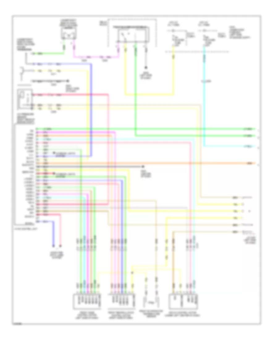
AIR CONDITIONING
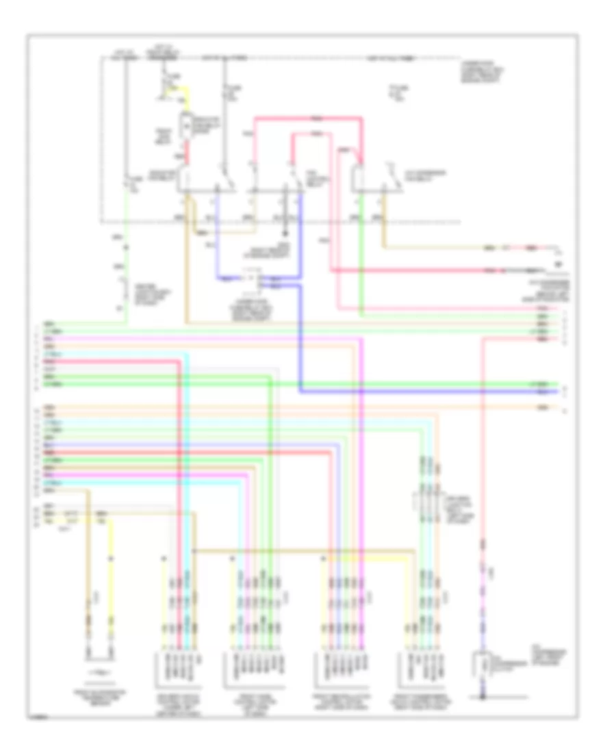
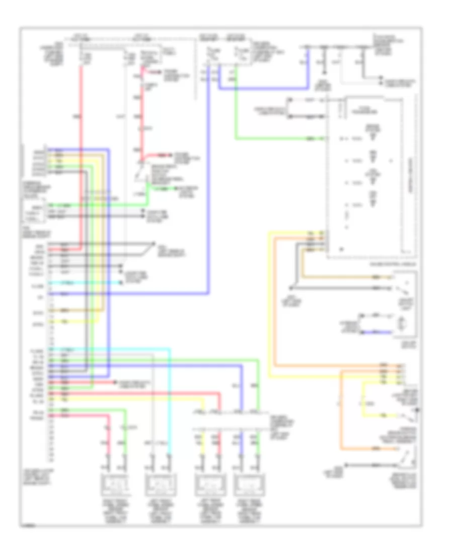
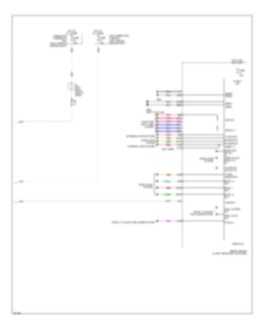
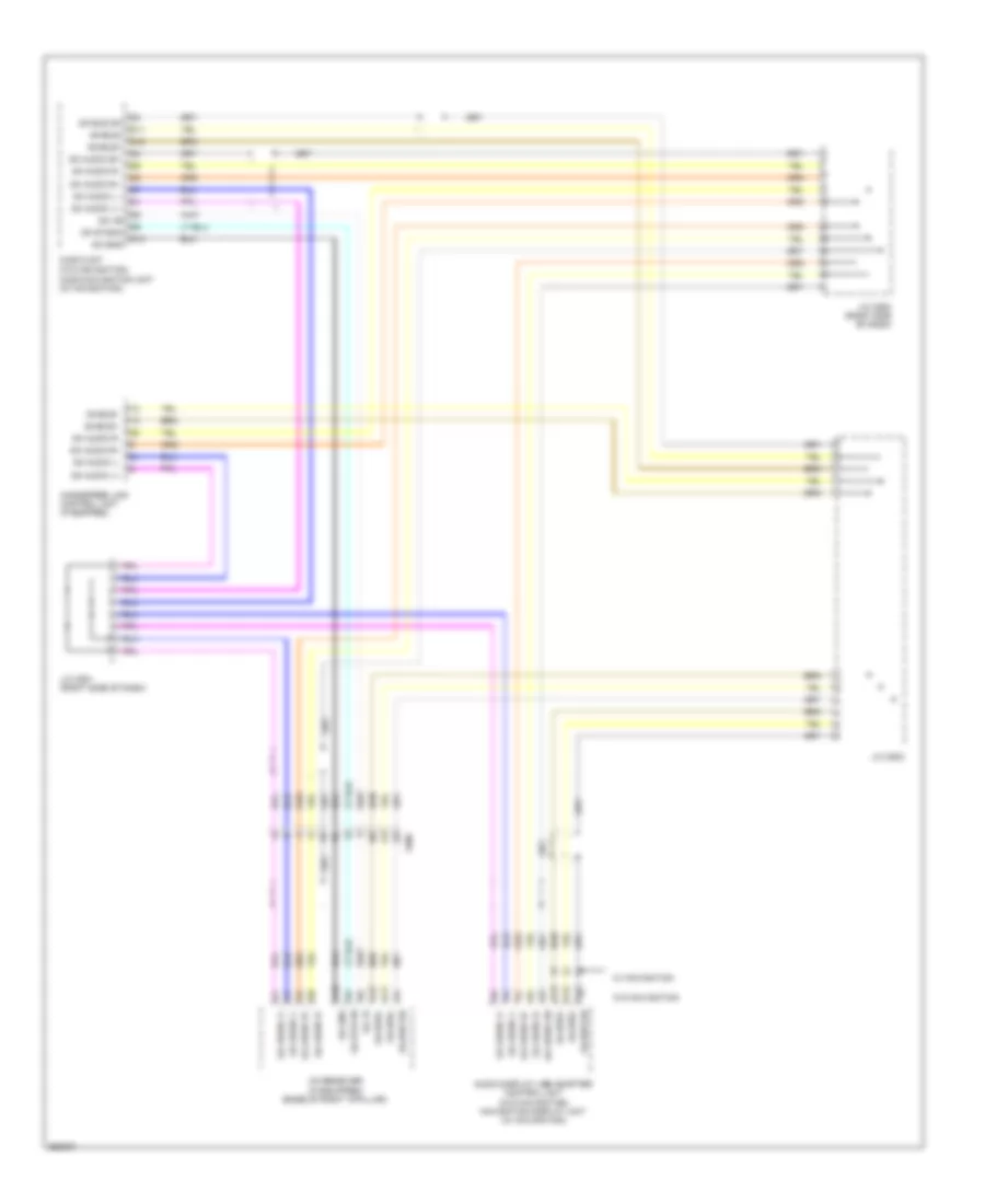
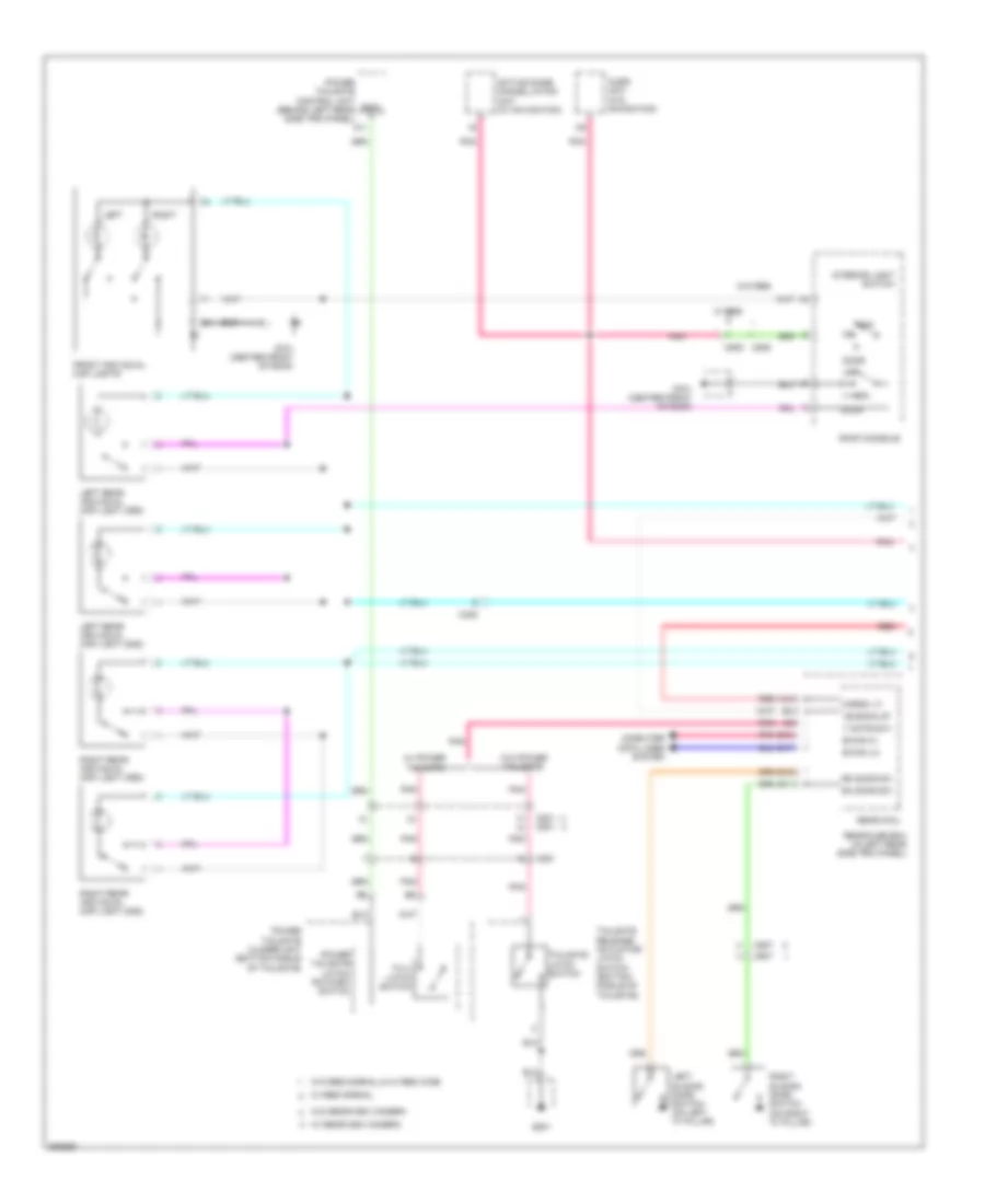
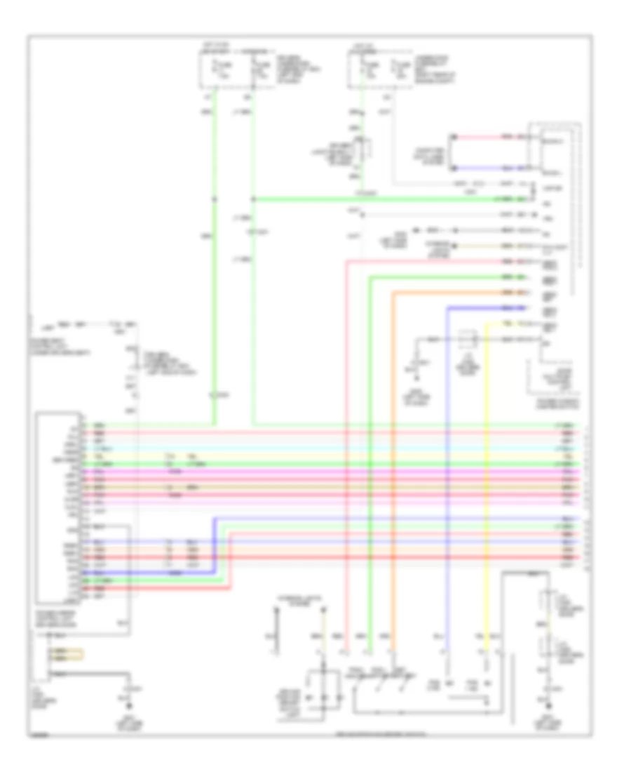
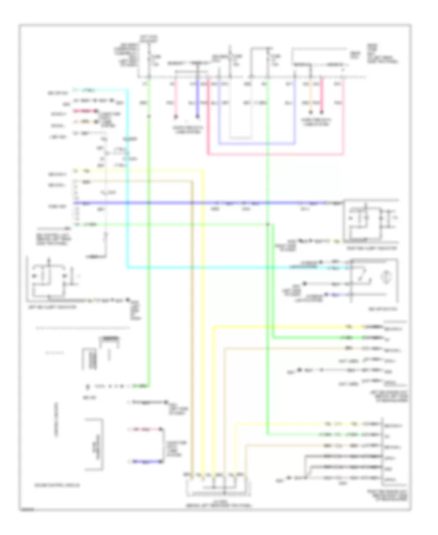
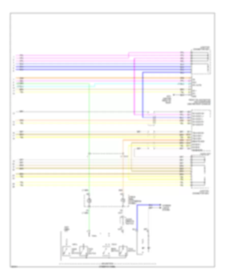
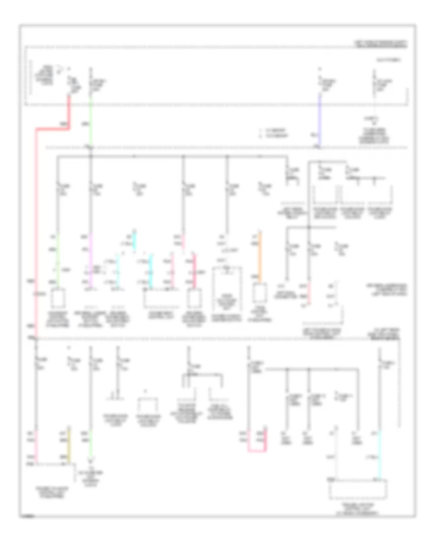
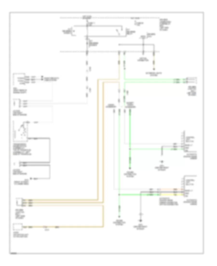
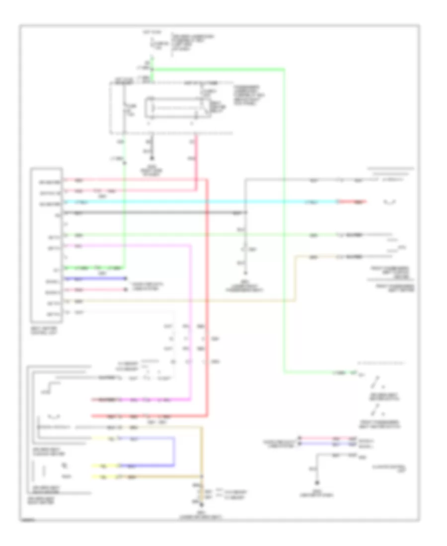
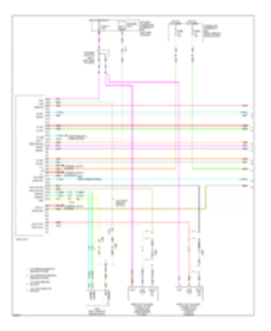
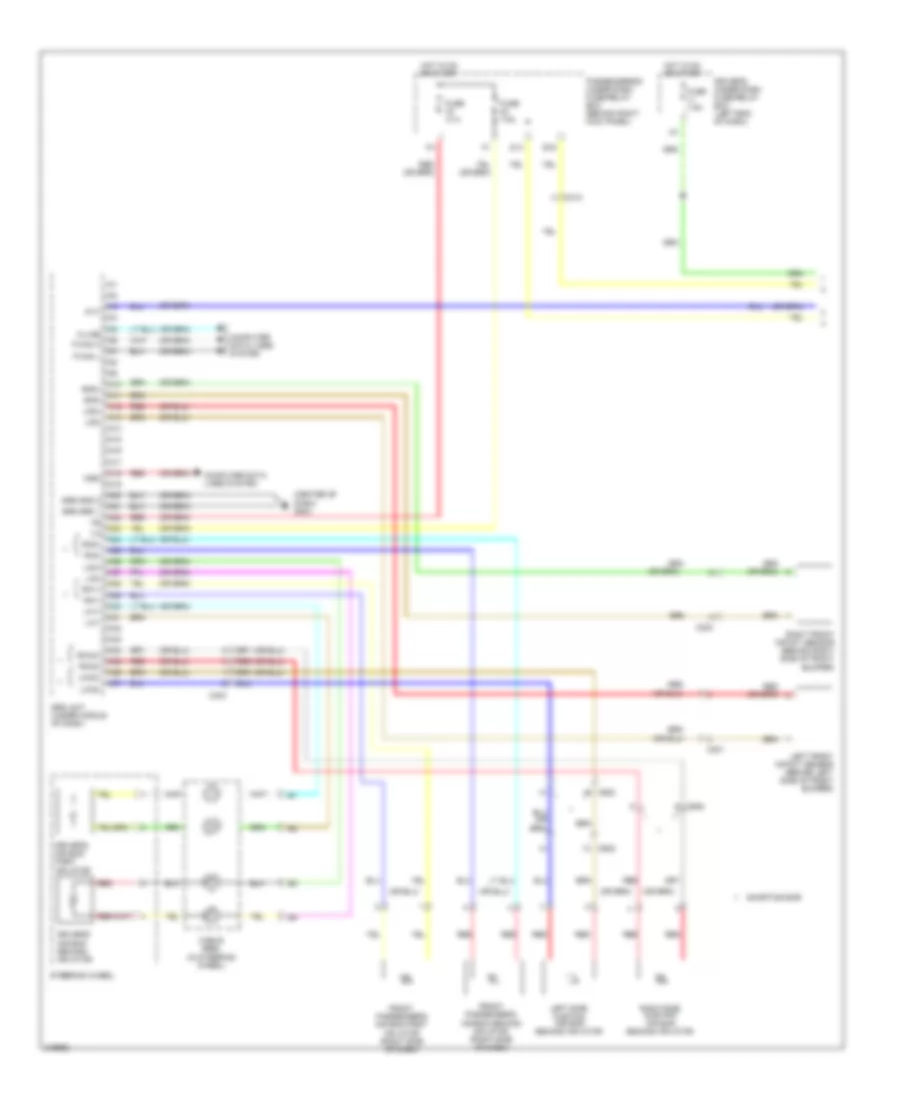
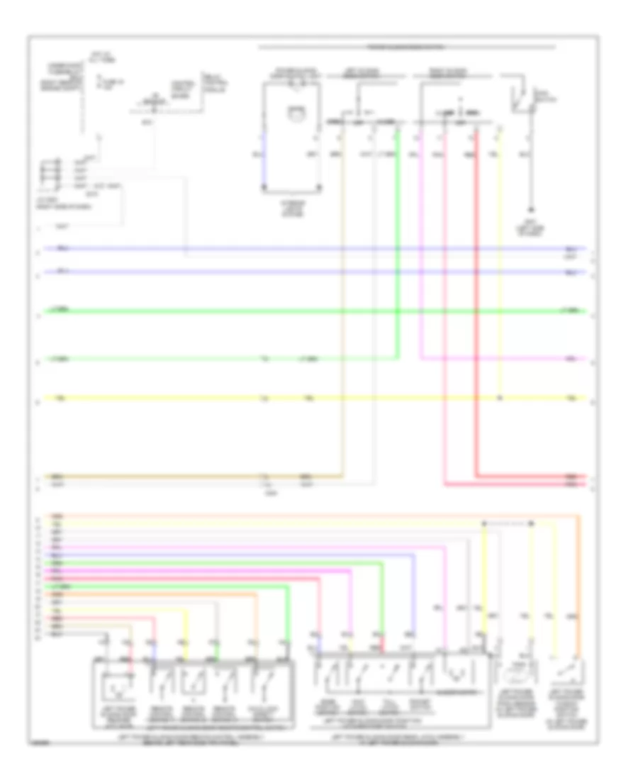
Automatic A/C Wiring Diagram, with Memory (1 of 3) for Honda Odyssey EX 2012

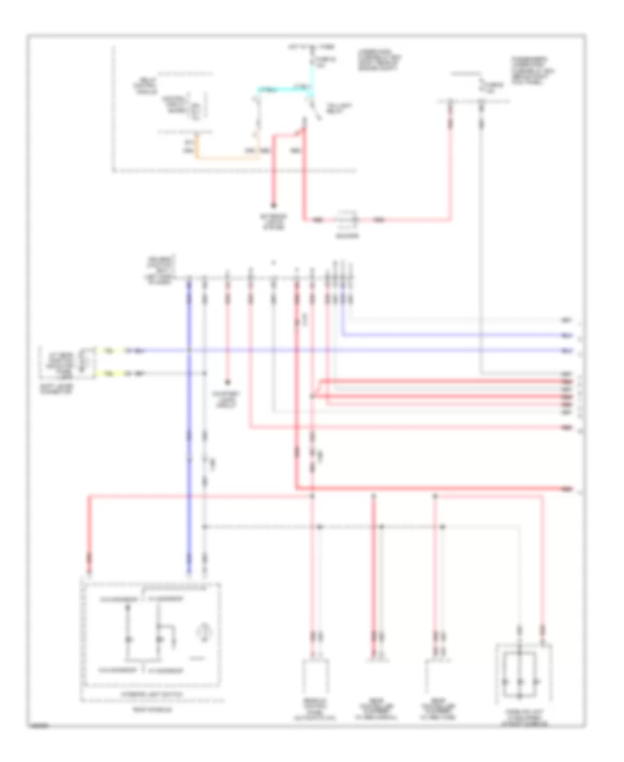
List of elements for Automatic A/C Wiring Diagram, with Memory (1 of 3) for Honda Odyssey EX 2012:
- (left side of dash) driver's junction box 2
- (right side of dash) (w/ cool box) cool box control motor
- (w/ cool box) cool box control switch
- A/c pressure sensor (right rear of engine compt)
- A10
- A11
- A12
- A13
- A14
- A15
- A16
- A17
- A18
- A19
- A20
- A21
- A22
- A23
- A24
- A25
- A26
- A27
- A28
- Amd-p-as
- Amd-p-dr
- Automatic lighting sensor/sunlight sensor (top center of dash)
- B-can h
- B-can hi
- B-can l
- B-can lo
- B10
- B11
- B12
- B13
- B14
- B15
- B16
- Batt
- Blw-g
- Blw-v
- Bus-data
- C/b bulb
- C/b open
- C/b sht
- C/b sw
- C202
- C205
- C208
- C410
- C411
- C413
- Climate control unit
- Computer data lines system
- Driver's junction box 2 (left side of dash)
- Driver's micu
- Driver's under-dash fuse/relay box (left end of dash)
- F17
- Fr blower fuse 40a
- Front blower motor (under right side of dash)
- Front blower motor relay
- Front blower power transistor (under right side of dash)
- Fuse 7.5a
- G204 (right side of dash)
- G302 (left side of dash)
- G403 (center of dash)
- Gnd
- H10
- Hot at all times
- Hot in on
- Hum (hum-data)
- Humidity sensor
- Humidity/in-car temperature sensor (lower left side of dash)
- Ig2
- Ill+
- Ill-
- In-car temperature sensor
- Interior lights system
- K10
- L-mode 1
- L-mode 2
- L-mode 3
- M-cool-as
- M-cool-dr
- M-def
- M-frs
- M-hot-as
- M-hot-dr
- M-rec
- M-vent
- Main under-hood fuse box (left side of engine compt)
- Mode 1
- Mode 2
- Mode 3
- Mode 4
- Multi- fuse 3
- Outside air temperature sensor (behind left side of front bumper)
- Pnk
- Red
- Relay block (left rear of engine compt)
- S5v
- Sens-com
- Sunlight sensor
- Tam
- Teva
- Tr (hum-clk)
- Tsun
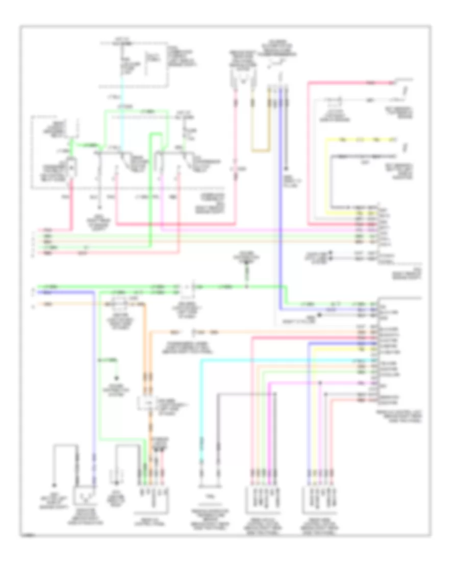
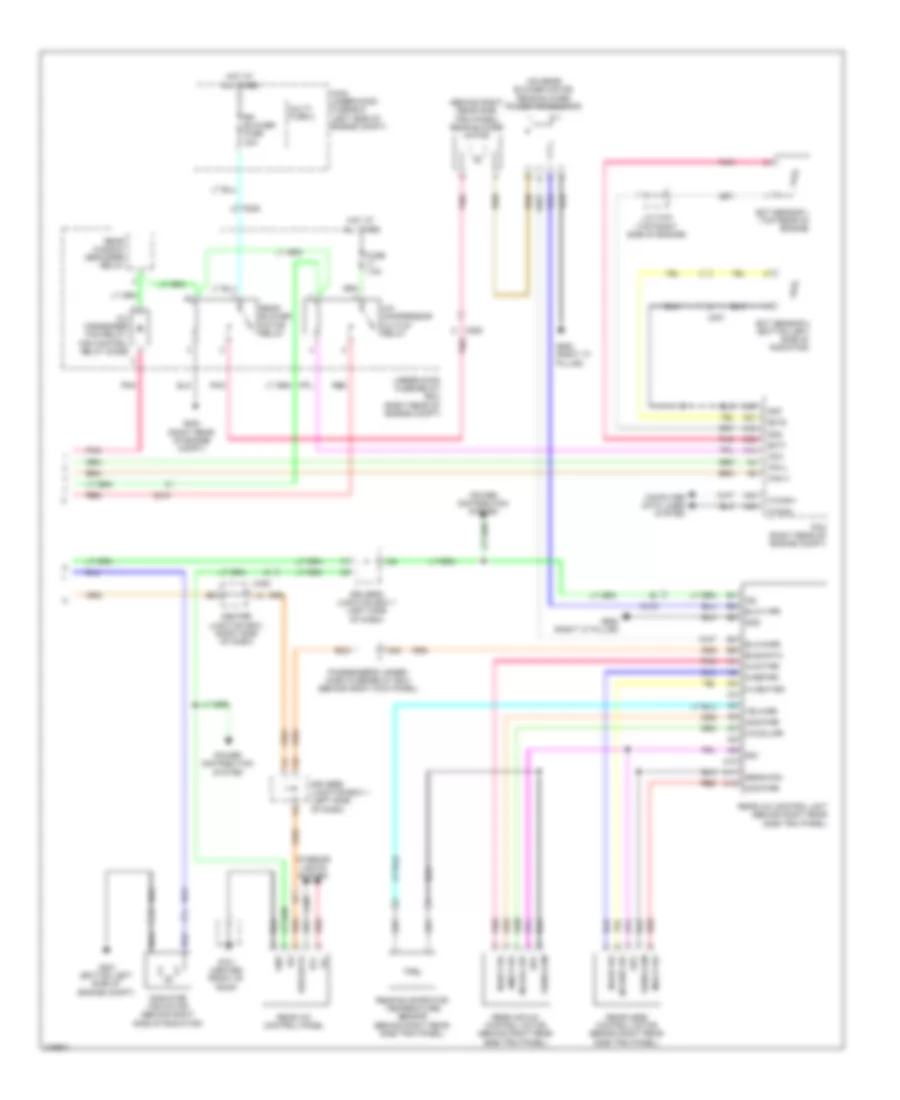
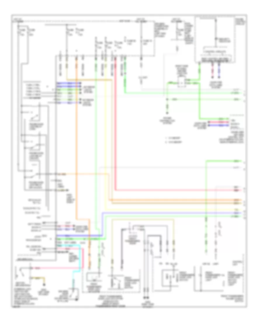
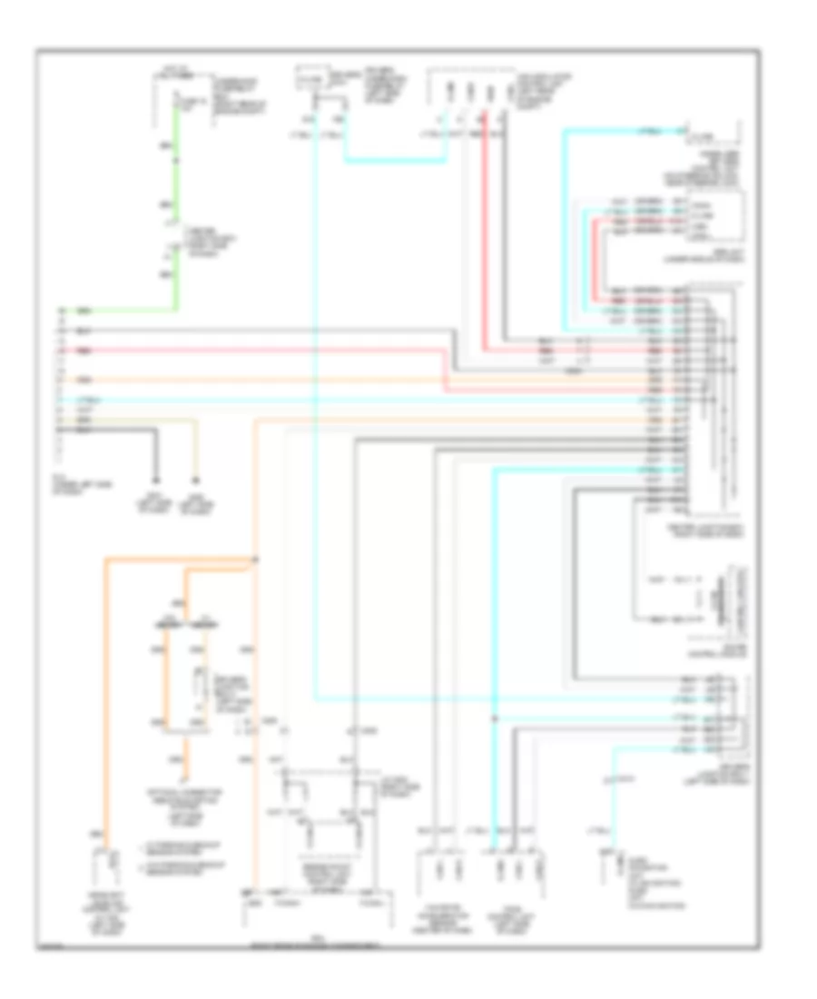
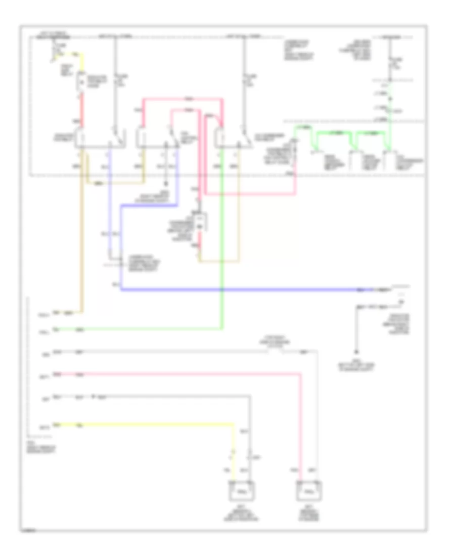
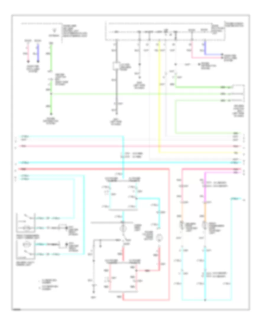
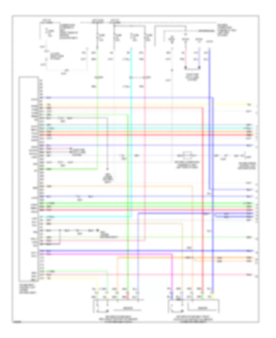
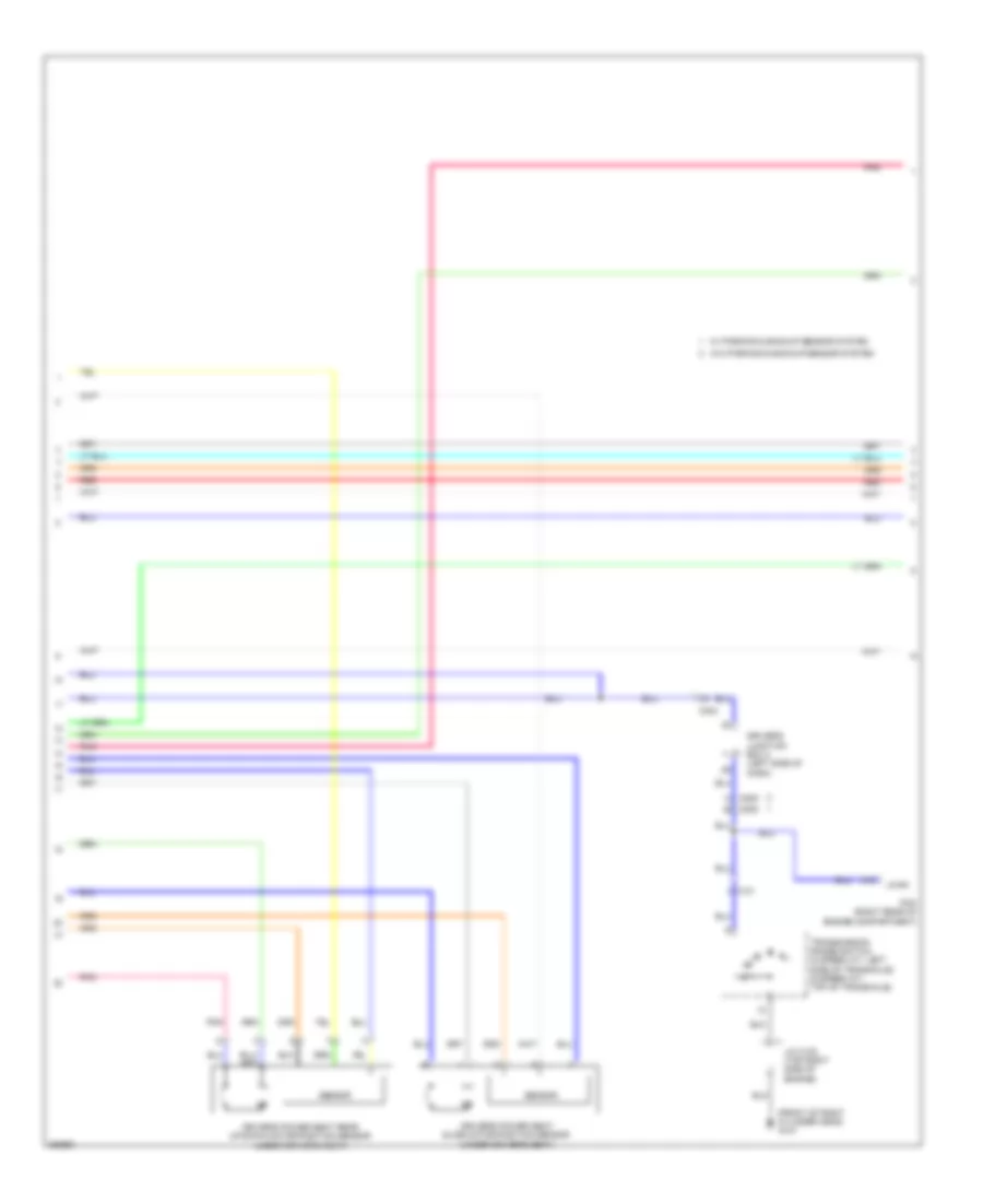
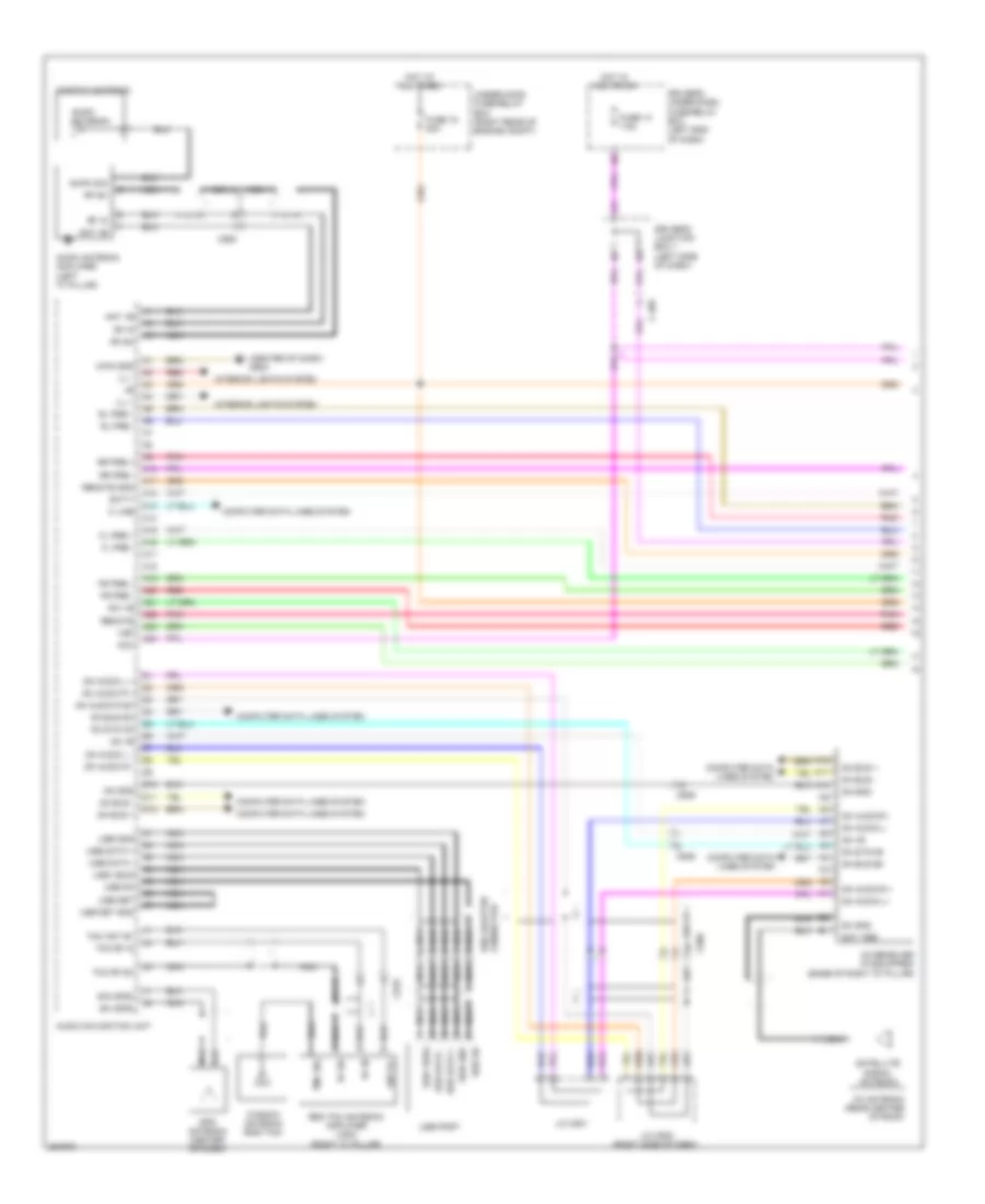
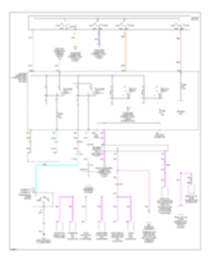
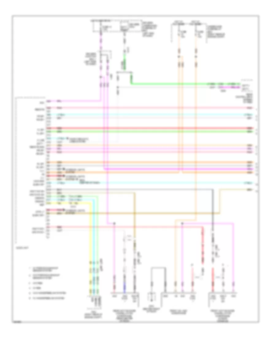
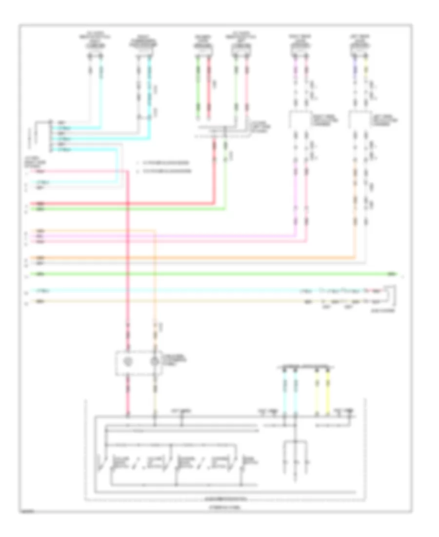
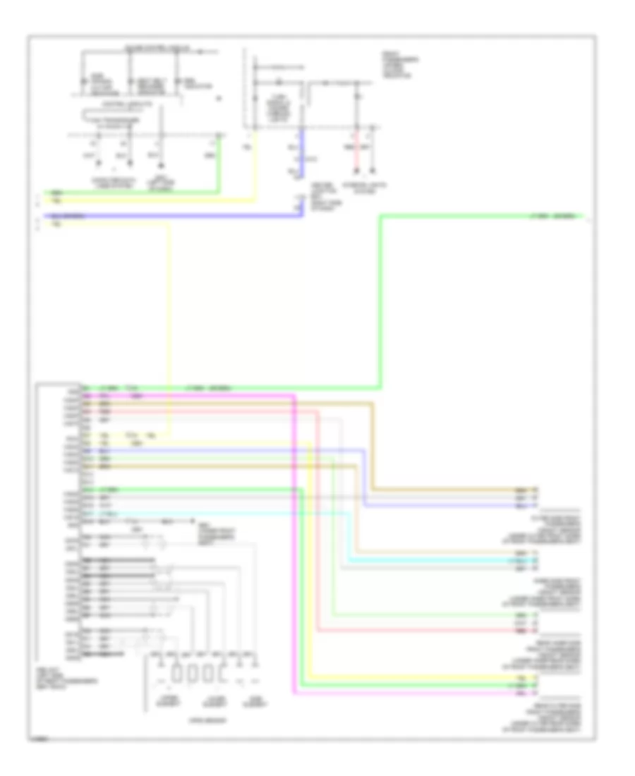
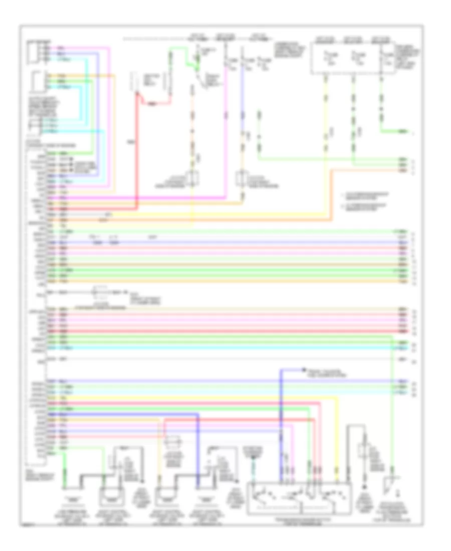
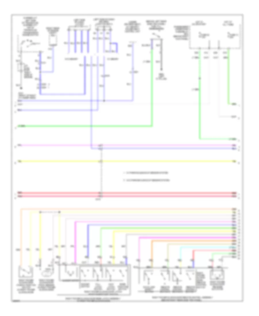
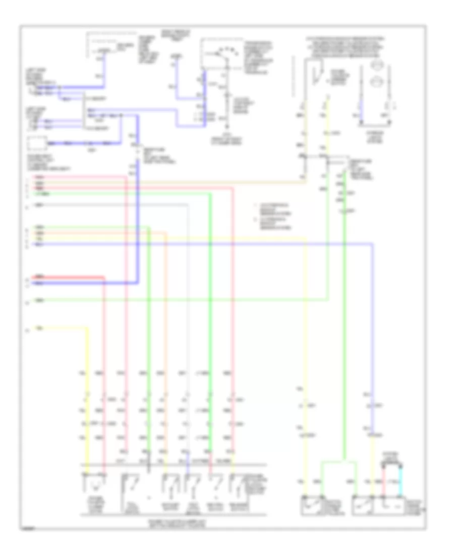
Automatic A/C Wiring Diagram, with Memory (2 of 3) for Honda Odyssey EX 2012
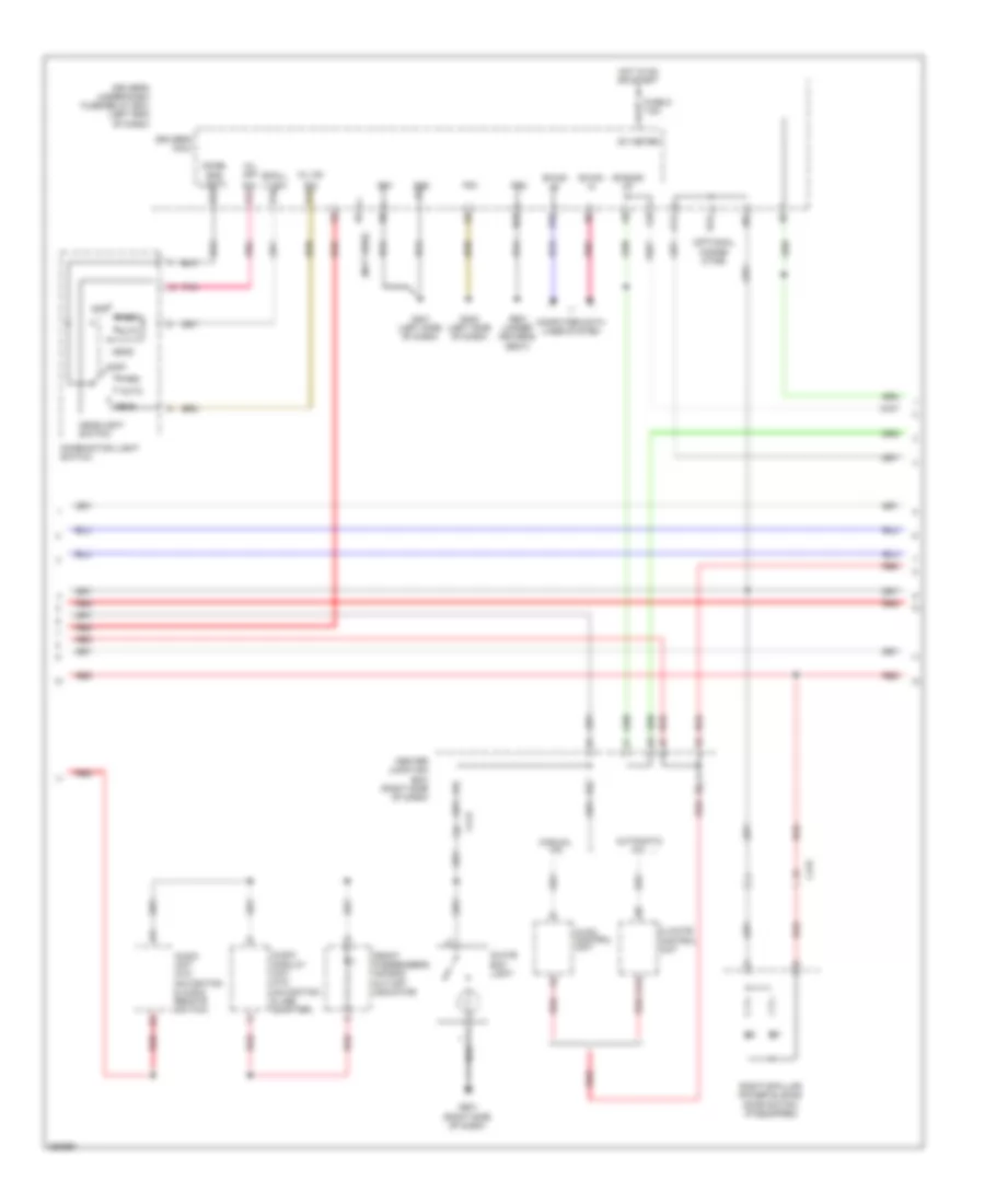
List of elements for Automatic A/C Wiring Diagram, with Memory (2 of 3) for Honda Odyssey EX 2012:
- A/c compressor (left front of engine)
- A/c compressor clutch
- A/c condenser fan motor (behind left side of radiator)
- A/c condensor fan relay
- Amd-p-as
- Amd-p-dr
- C101
- C411
- Center junction box (right side of dash)
- Driver's air mix control motor (under left center of dash)
- Driver's junction box 2 (left side of dash)
- Fan control relay
- Front evaporator temperature sensor
- Front mode control motor (left side of dash)
- Front passenger's air mix control motor (right side of dash)
- Front recirculation control motor (right side of dash)
- Fuse 10a
- Fuse 30a
- Fuse 7.5a
- G203 (right rear of of engine compt)
- Hot at all times
- Hot w/ pgm-fi relay energized
- L-mode 1
- L-mode 2
- L-mode 3
- M-cool-as
- M-cool-dr
- M-def
- M-frs
- M-hot-as
- M-hot-dr
- M-rec
- M-vent
- Mode 1
- Mode 2
- Mode 3
- Mode 4
- Pgm-fi sub relay
- Pnk
- Radiator fan relay
- Radiator fan relay diode
- Red
- S5v
- Sens-com
- Under-hood fuse/relay box (right rear of engine compt)
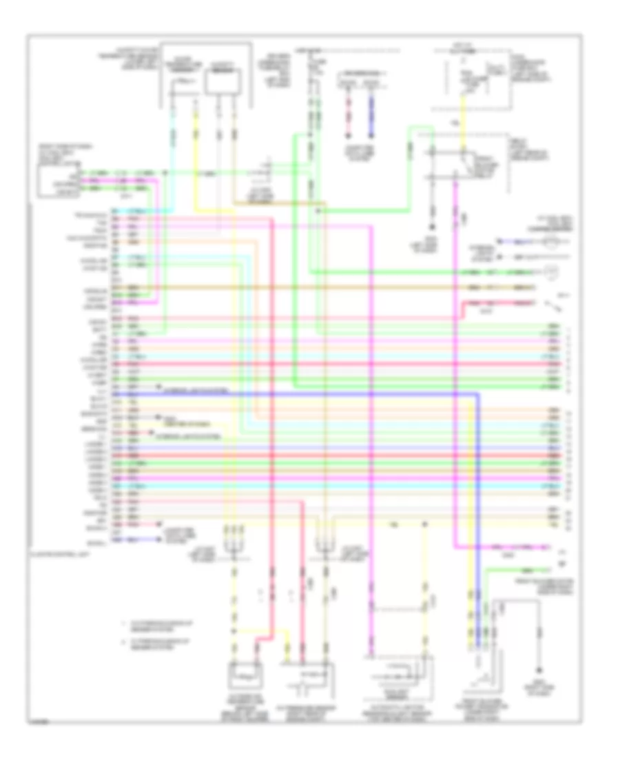
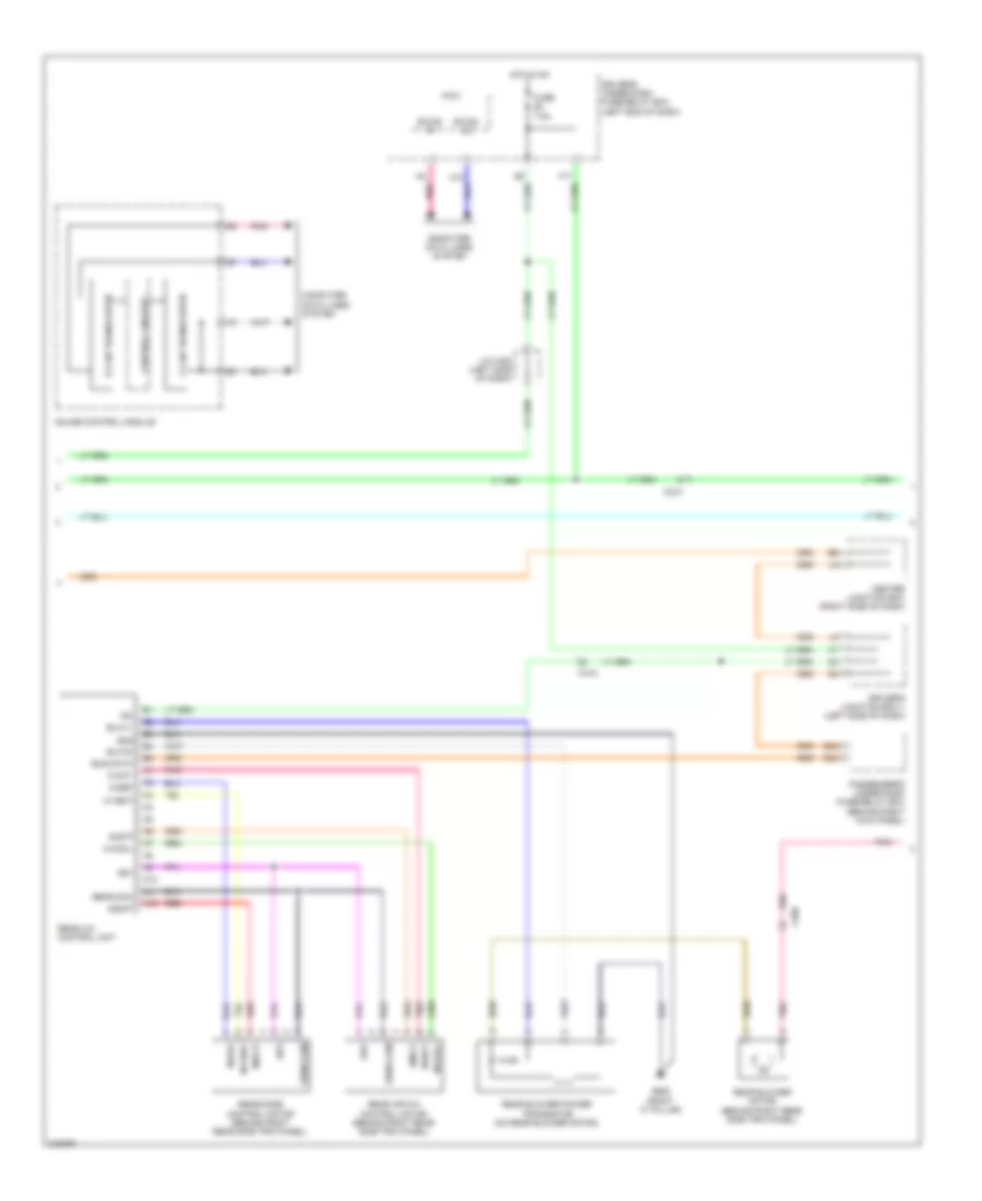
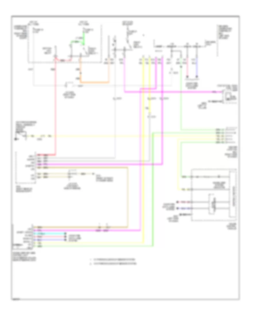
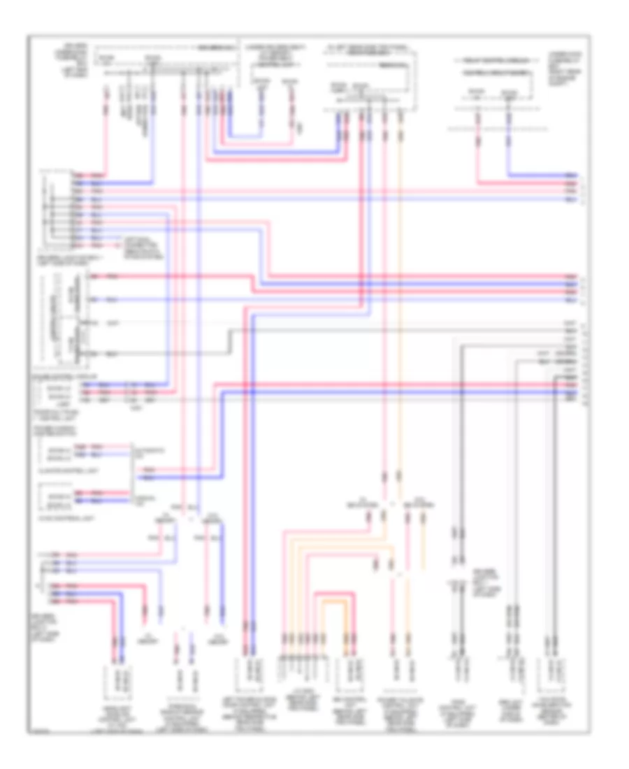
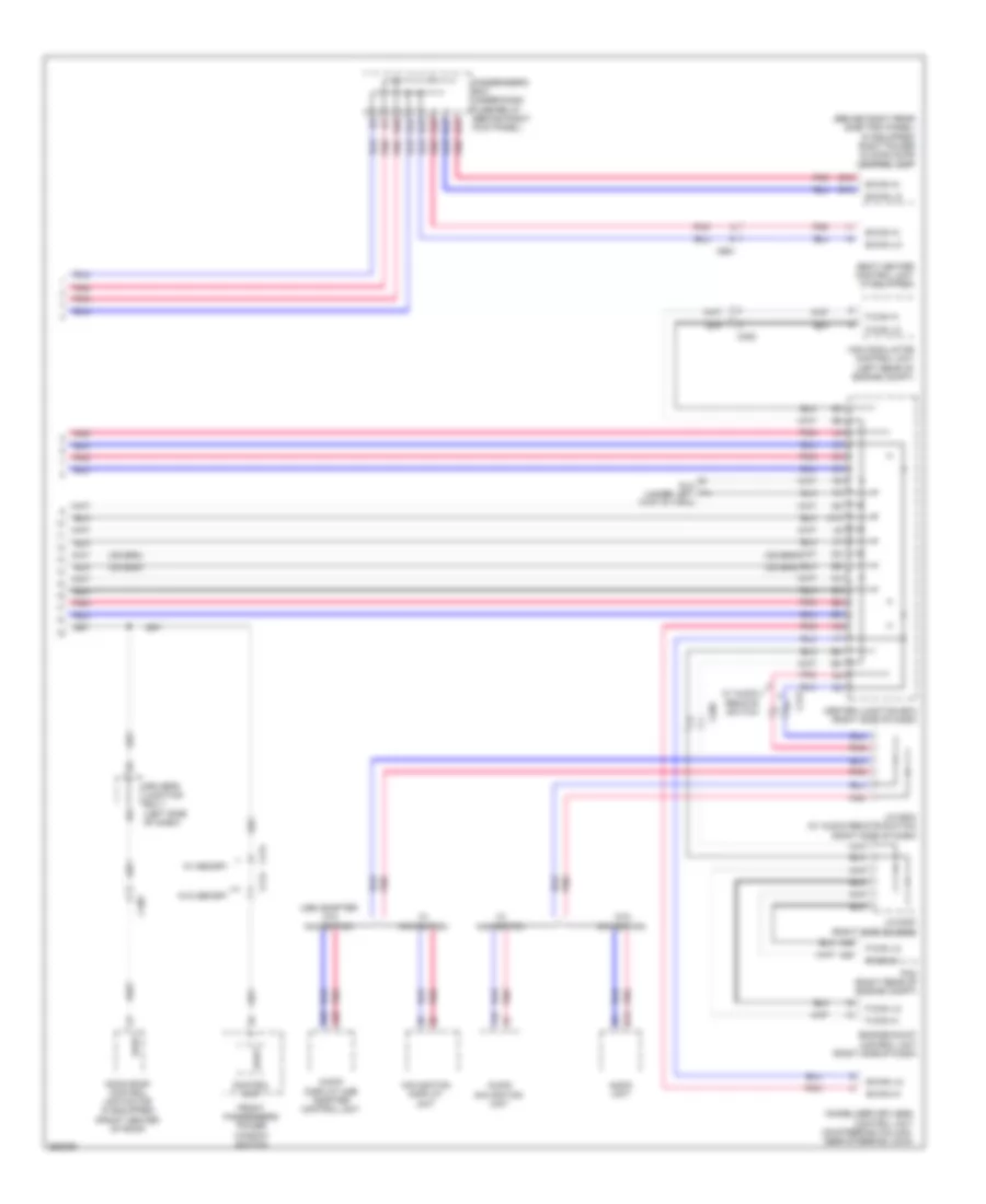
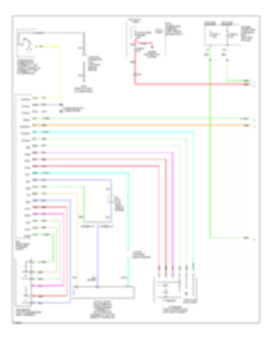
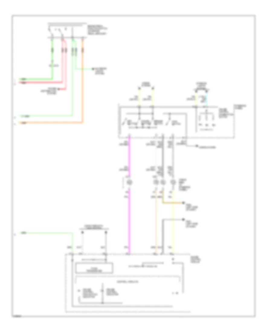
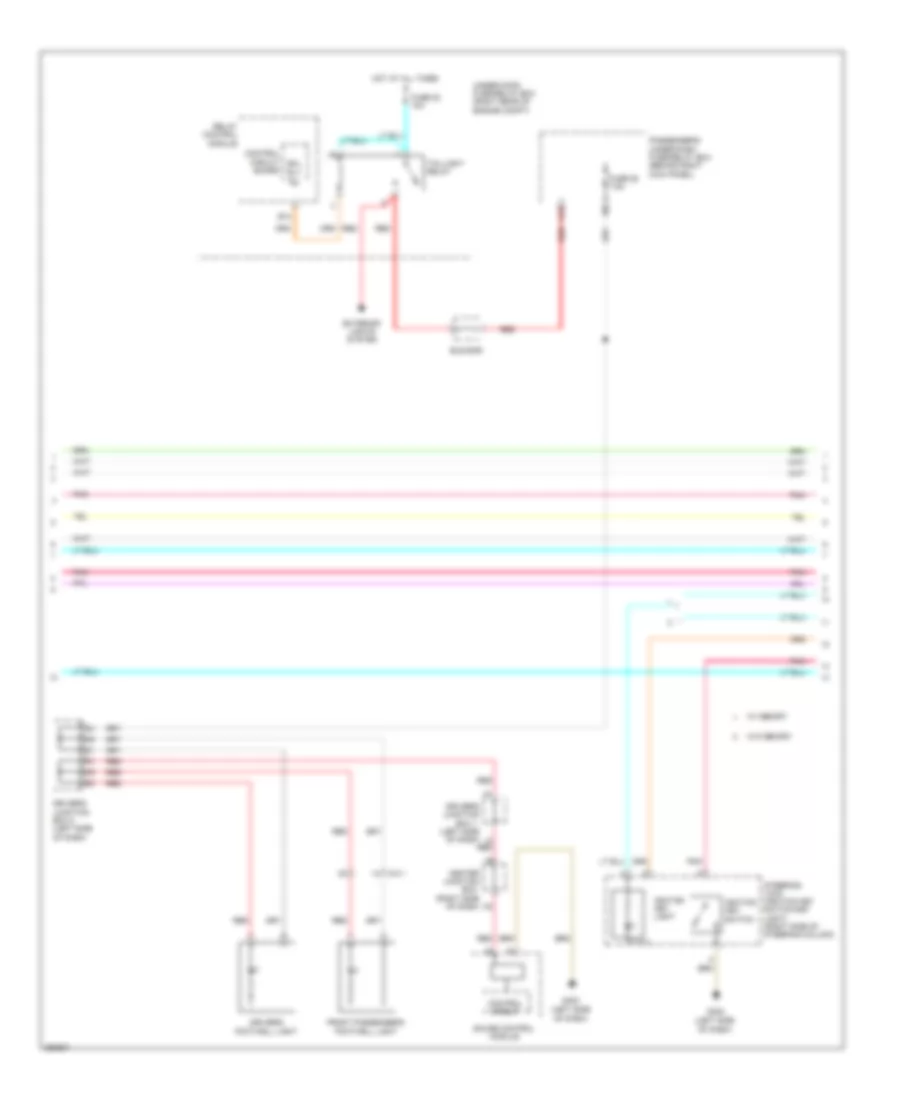
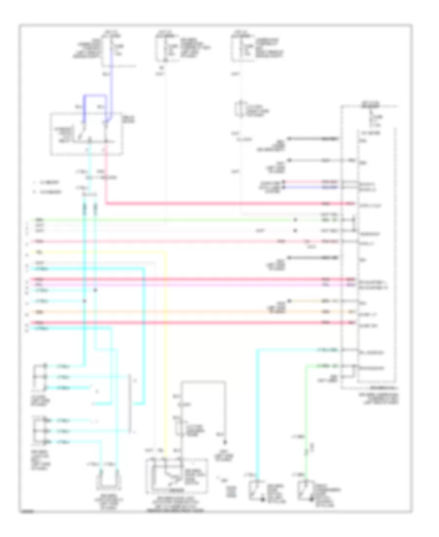
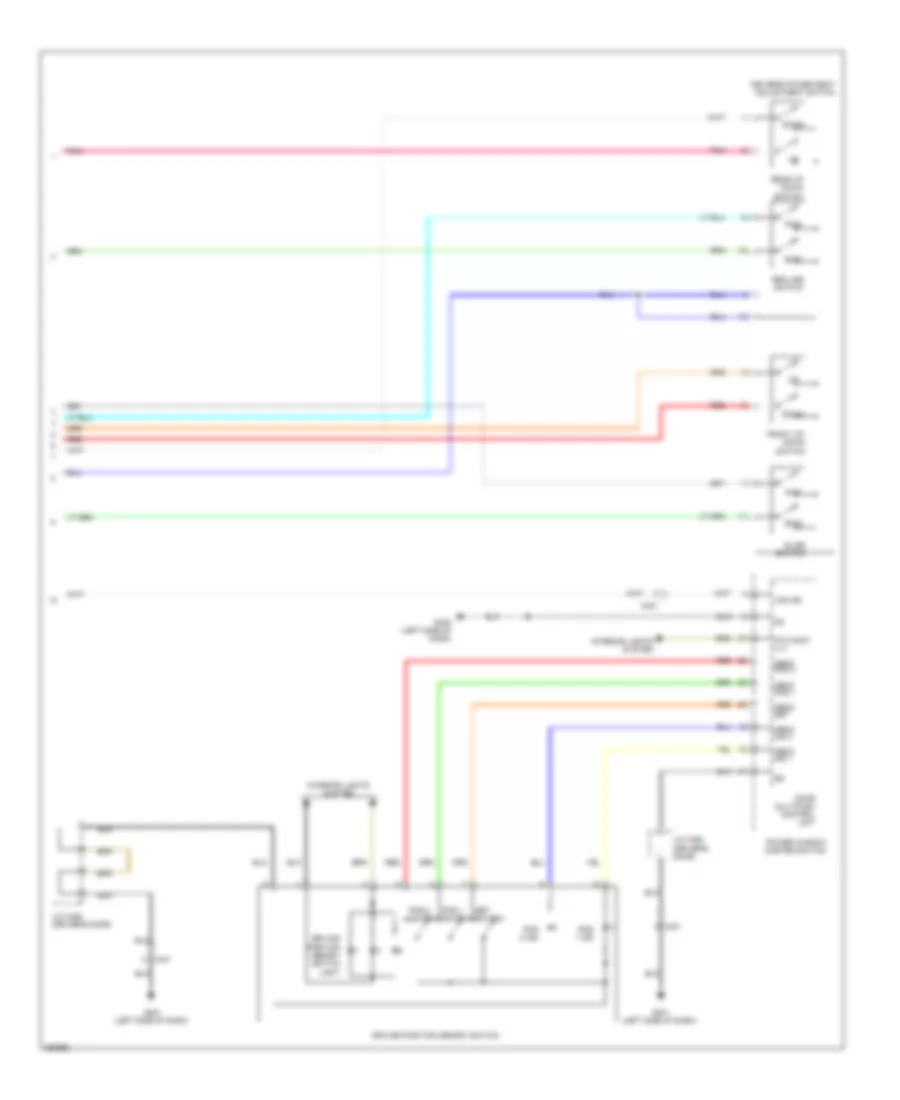
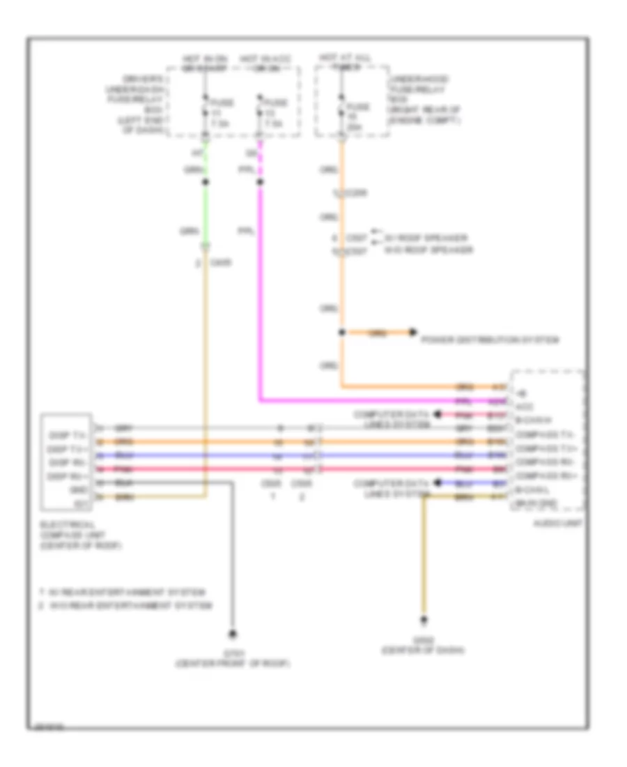
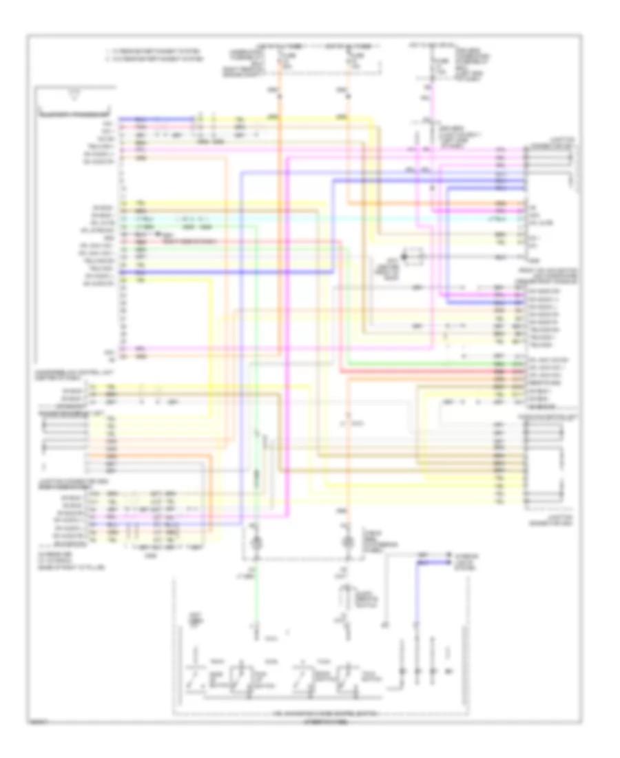
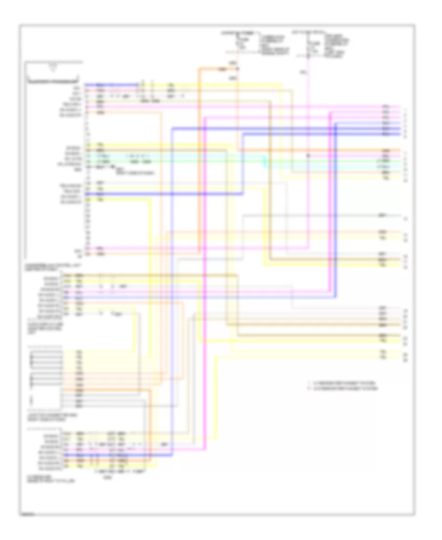
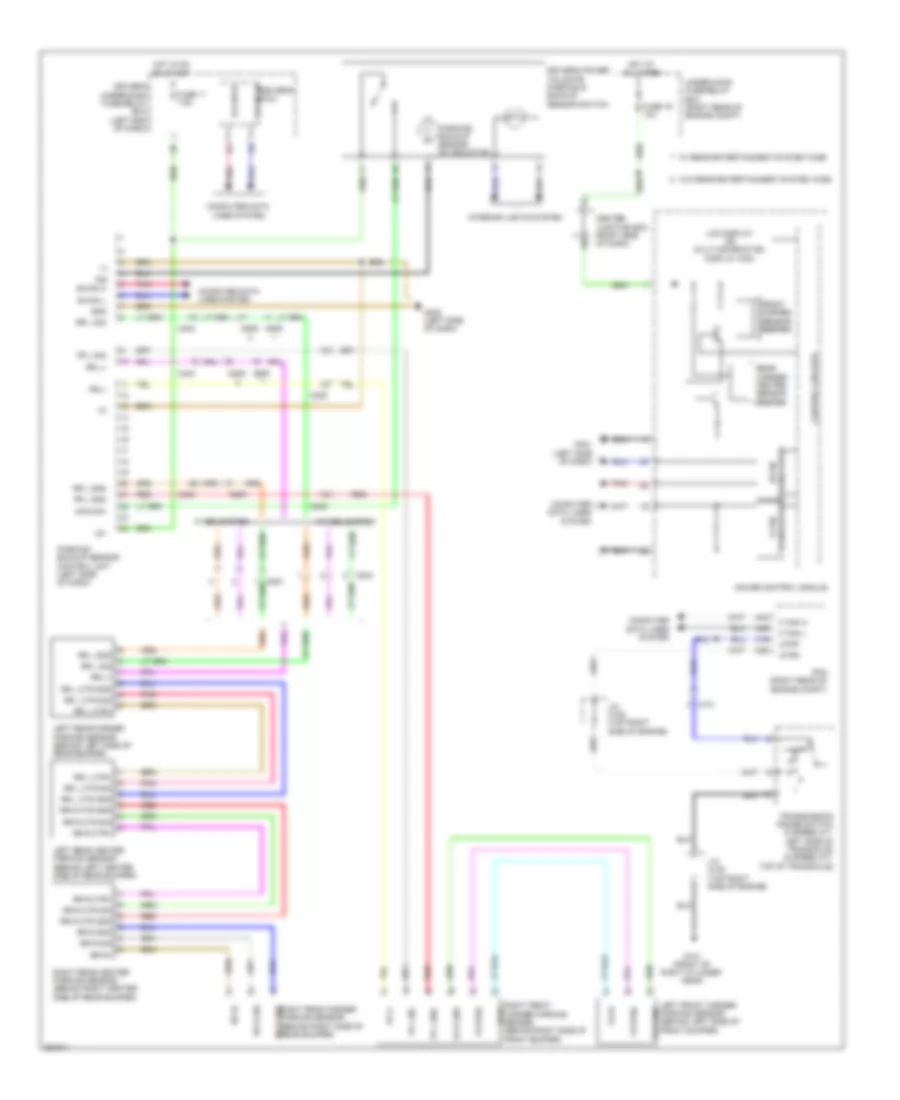
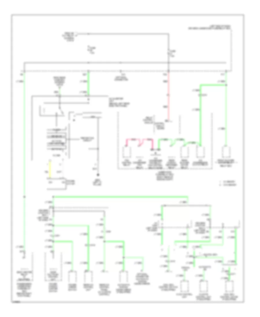
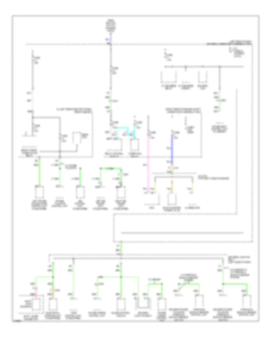
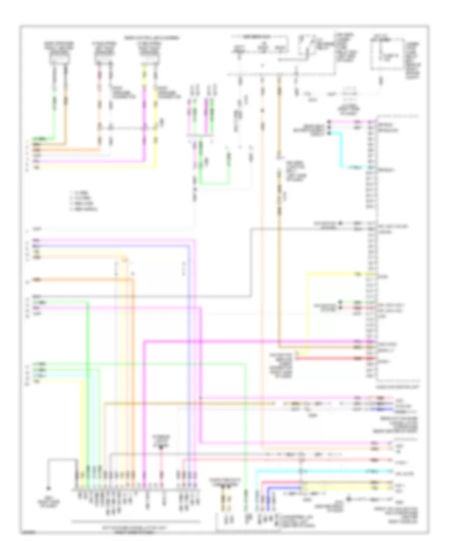
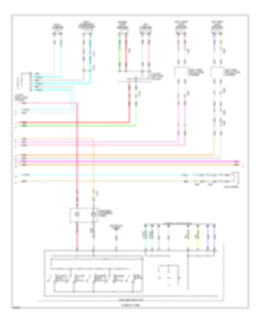
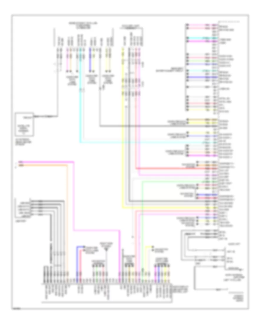
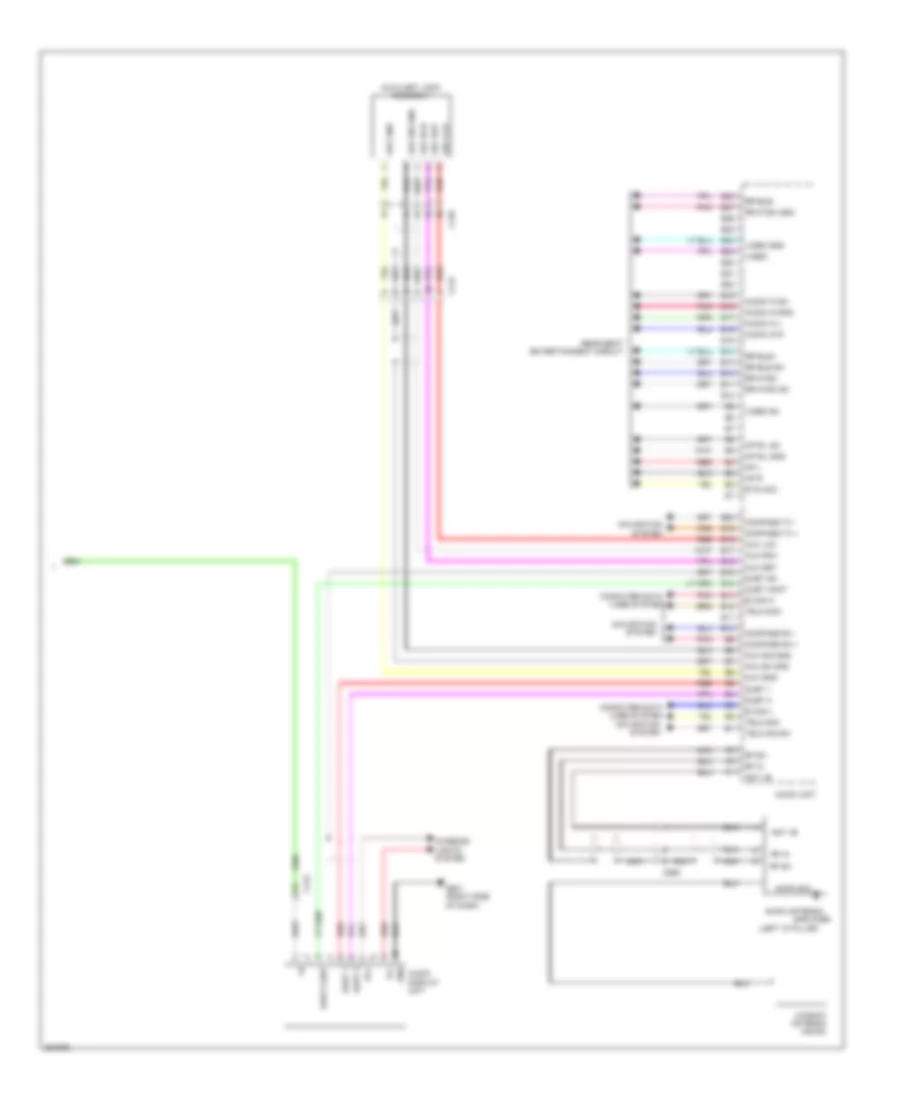
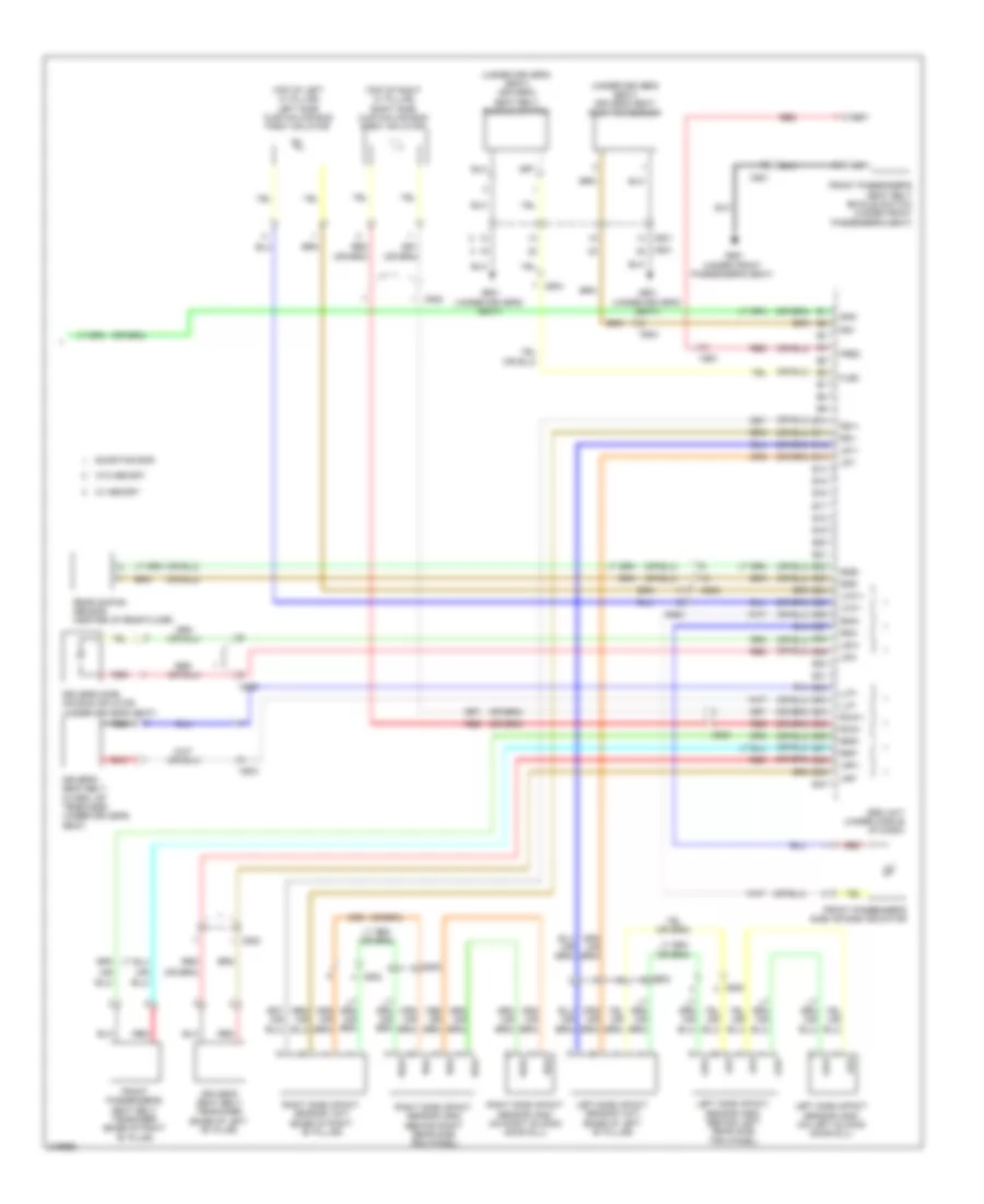
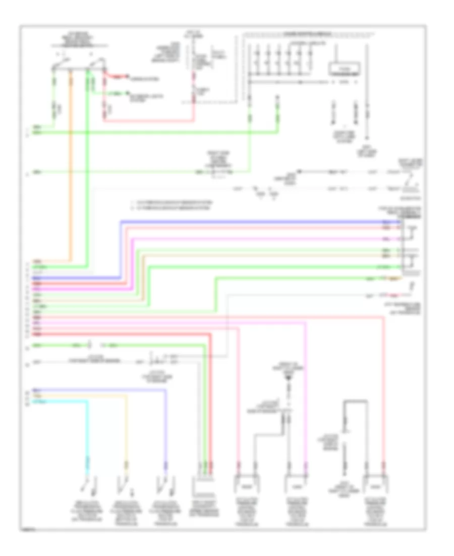
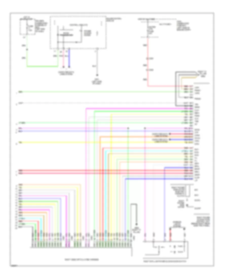
Automatic A/C Wiring Diagram, with Memory (3 of 3) for Honda Odyssey EX 2012
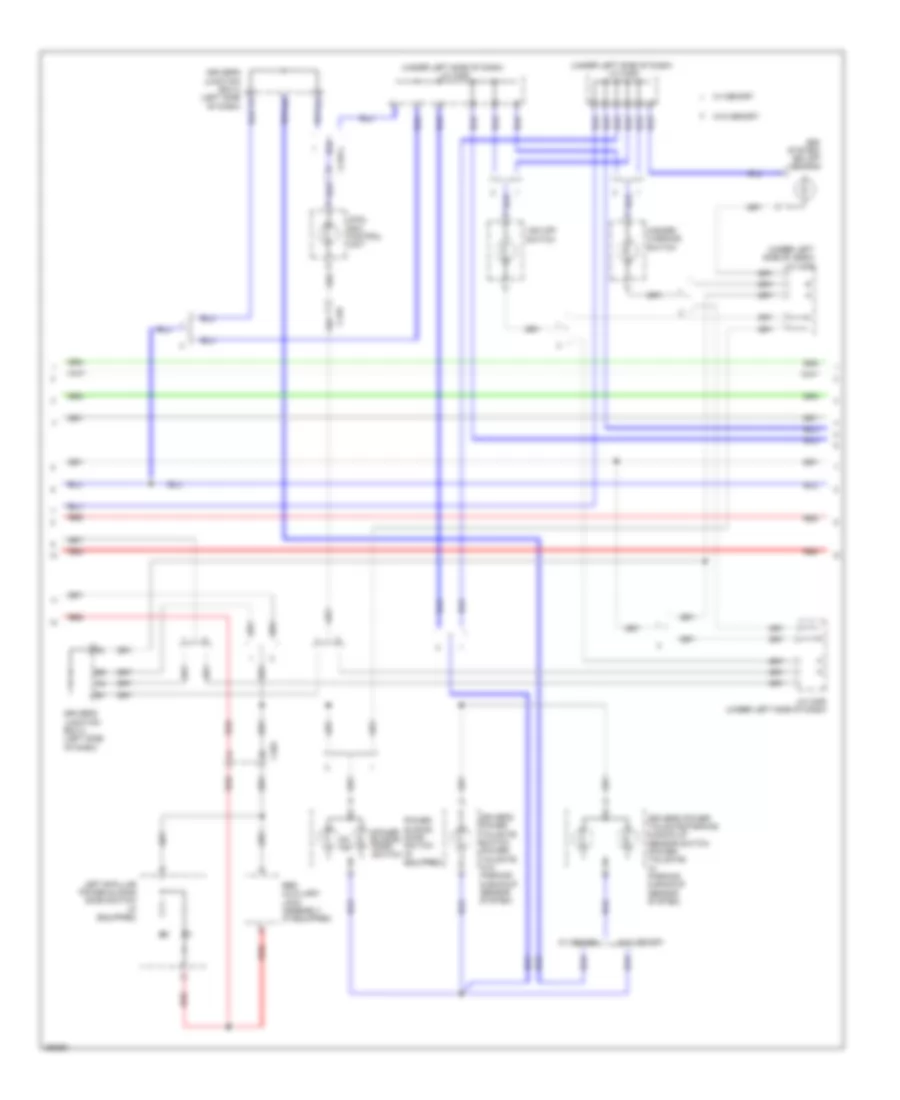
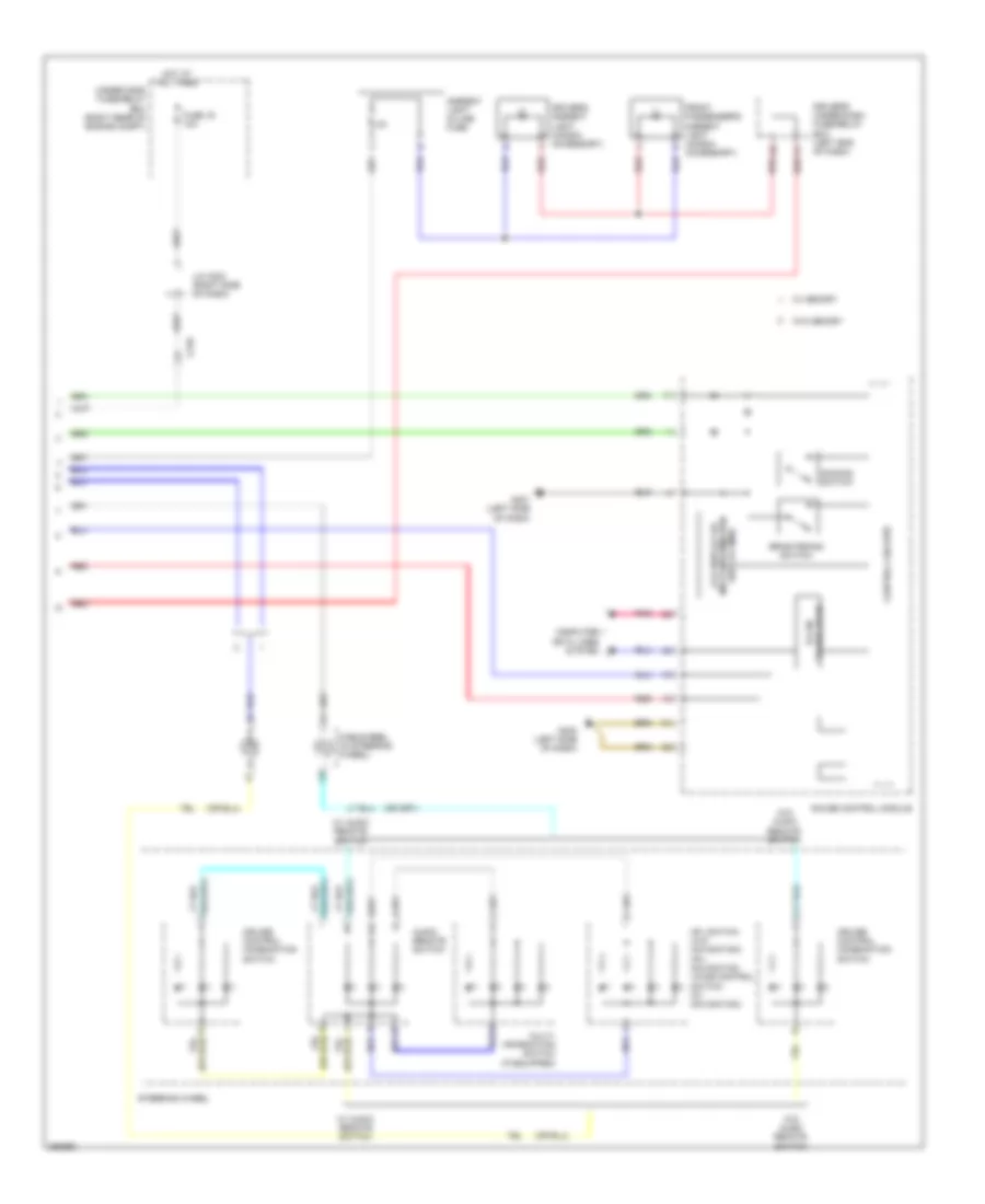
List of elements for Automatic A/C Wiring Diagram, with Memory (3 of 3) for Honda Odyssey EX 2012:
- (behind right rear side trim panel) rear blower motor
- (on rear blower motor) rear blower power transistor
- A/c compressor clutch relay
- A/c condenser fan relay/ fan control relay diode
- A10
- A11
- A12
- A13
- A21
- A37
- A48
- A49
- Acc
- Amd-p-rr
- Blw-g-rr
- Blw-v-rr
- Bus-data
- C16
- C201
- C206
- C208
- C210
- C32
- C405
- C415
- Center junction box (right side of dash)
- Computer data lines system
- D40
- Driver's junction box 1 (left side of dash)
- E32
- Ect sensor 1 (top rear of engine)
- Ect sensor 2 (bottom left side of radiator)
- Ect1
- Ect2
- F-can-h
- F-can-l
- Fan h
- Fan l
- Fuse 7.5a
- G201 (bottom left side of engine compt)
- G203 (right rear of engine compt)
- G652 (right "c" pillar)
- G701 (center front of roof)
- Gnd
- Hot at all times
- Ig2
- Ill+
- Ill-
- Interior lights system
- J/c c104 (top right side of engine)
- M-cool-rr
- M-def-rr
- M-hot-rr
- M-vent-rr
- Main under-hood fuse box (left side of engine compt)
- Mdd-p-rr
- Multi- fuse 2
- Passenger's under- dash fuse/relay box (behind right kick panel)
- Pcm (right rear of engine compt)
- Pnk
- Power distribution system
- Radiator fan motor (behind right side of radiator)
- Rear a/c control panel
- Rear a/c control unit (behind right rear side trim panel)
- Rear air mix control motor (behind right rear side trim panel)
- Rear blower motor relay
- Rear evaporator temperature sensor (behind right rear side trim panel)
- Rear mode control motor (behind right rear side trim panel)
- Rear window defogger relay
- Red
- Rr blower fuse 30a
- S5v
- Sens-com
- Sg2
- Sg7
- Teva-rr
- Under-hood fuse/relay box (right rear of engine compt)
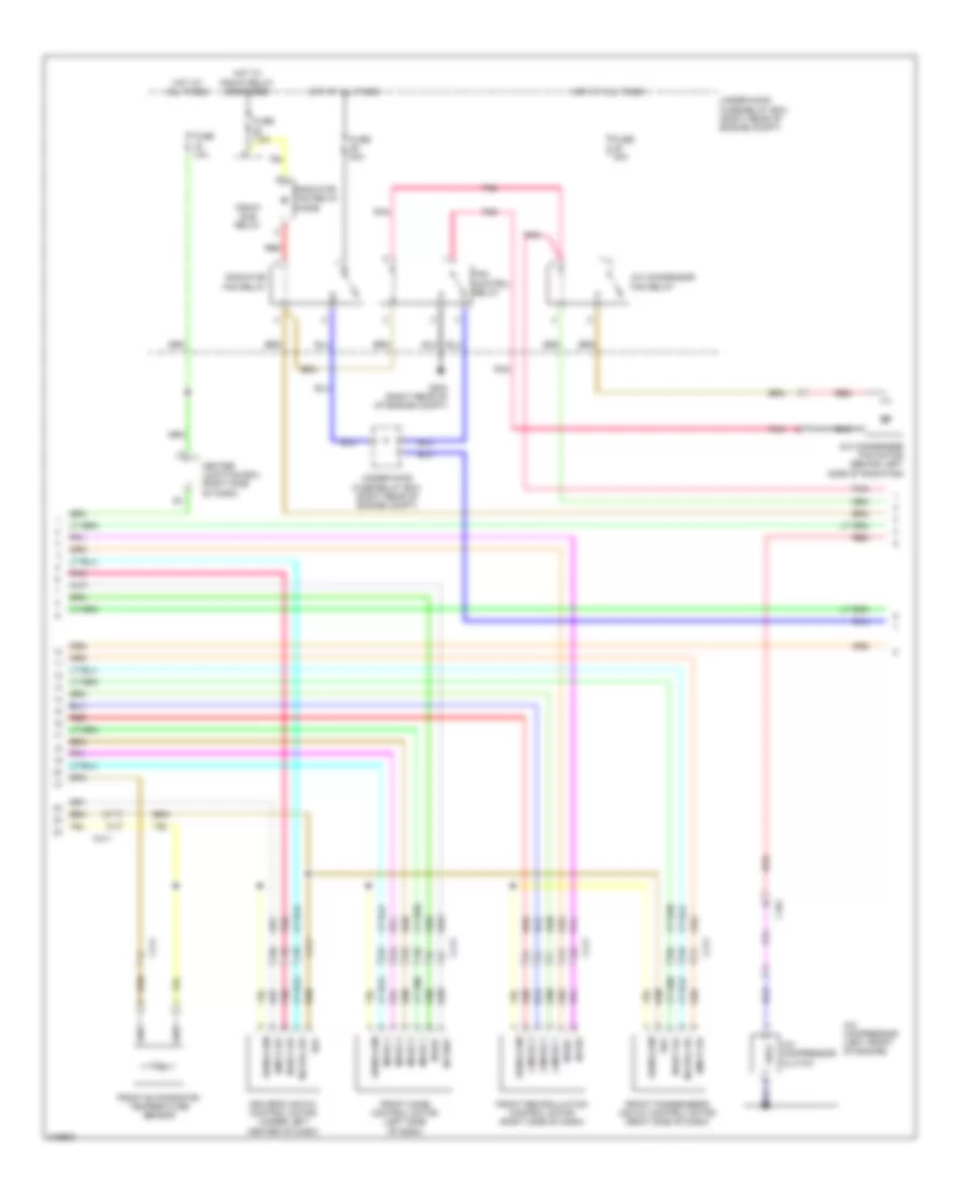
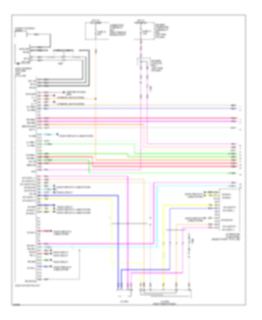
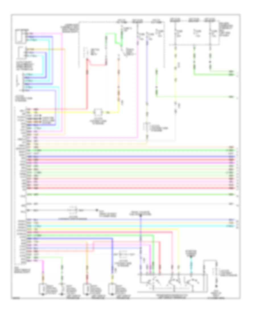
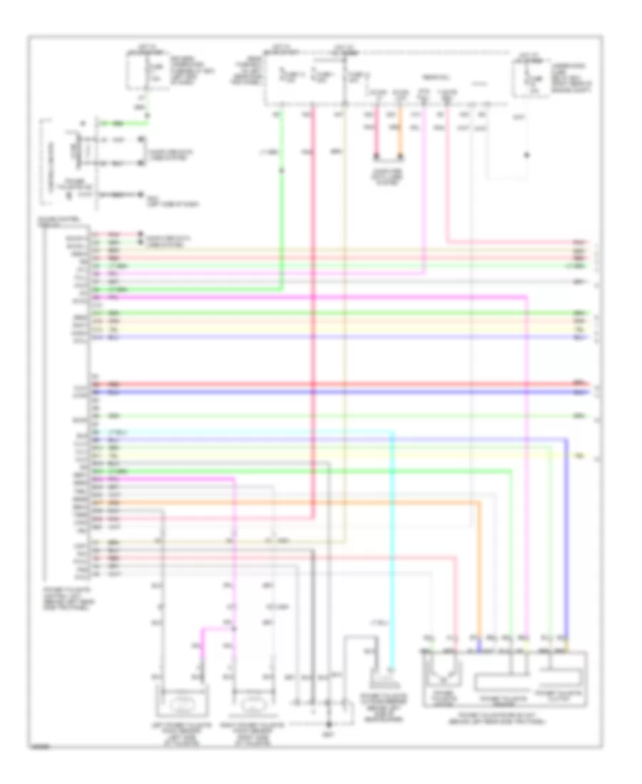
Automatic A/C Wiring Diagram, without Memory (1 of 3) for Honda Odyssey EX 2012
List of elements for Automatic A/C Wiring Diagram, without Memory (1 of 3) for Honda Odyssey EX 2012:
- (right side of dash) (w/ cool box) cool box control motor
- (w/ cool box) cool box control switch
- A/c pressure sensor (right rear of engine compt)
- A10
- A11
- A12
- A13
- A14
- A15
- A16
- A17
- A18
- A19
- A20
- A21
- A22
- A23
- A24
- A25
- A26
- A27
- A28
- Amd-p-as
- Amd-p-dr
- Automatic lighting sensor/sunlight sensor (top center of dash)
- B-can h
- B-can hi
- B-can l
- B-can lo
- B10
- B11
- B12
- B13
- B14
- B15
- B16
- Batt
- Blw-g
- Blw-v
- Bus-data
- C/b bulb
- C/b open
- C/b sht
- C/b sw
- C202
- C205
- C208
- C410
- C411
- C413
- Climate control unit
- Computer data lines system
- Driver's micu
- Driver's under-dash fuse/relay box (left end of dash)
- F17
- Fr blower fuse 40a
- Front blower motor (under right side of dash)
- Front blower motor relay
- Front blower power transistor (under right side of dash)
- Fuse 7.5a
- G204 (right side of dash)
- G302 (left side of dash)
- G403 (center of dash)
- Gnd
- H10
- Hot at all times
- Hot in on
- Hum (hum-data)
- Humidity sensor
- Humidity/in-car temperature sensor (lower left side of dash)
- Ig2
- Ill+
- Ill-
- In-car temperature sensor
- Interior lights system
- J/c c407 (left side of dash)
- J/c c408 (left side of dash)
- L-mode 1
- L-mode 2
- L-mode 3
- M-cool-as
- M-cool-dr
- M-def
- M-frs
- M-hot-as
- M-hot-dr
- M-rec
- M-vent
- Main under-hood fuse box (left side of engine compt)
- Mode 1
- Mode 2
- Mode 3
- Mode 4
- Multi- fuse 3
- Outside air temperature sensor (behind left side of front bumper)
- Pnk
- Red
- Relay block (left rear of engine compt)
- S5v
- Sens-com
- Sunlight sensor
- Tam
- Teva
- Tr (hum-clk)
- Tsun
- W/ parking & back-up senser system
- W/o parking & back-up senser system
Automatic A/C Wiring Diagram, without Memory (2 of 3) for Honda Odyssey EX 2012
List of elements for Automatic A/C Wiring Diagram, without Memory (2 of 3) for Honda Odyssey EX 2012:
- A/c compressor (left front of engine)
- A/c compressor clutch
- A/c condenser fan motor (behind left side of radiator)
- A/c condensor fan relay
- Amd-p-as
- Amd-p-dr
- C101
- C411
- Center junction box (right side of dash)
- Driver's air mix control motor (under left center of dash)
- Fan control relay
- Front evaporator temperature sensor
- Front mode control motor (left side of dash)
- Front passenger's air mix control motor (right side of dash)
- Front recirculation control motor (right side of dash)
- Fuse 10a
- Fuse 30a
- Fuse 7.5a
- G203 (right rear of of engine compt)
- Hot at all times
- Hot w/ pgm-fi relay energized
- L-mode 1
- L-mode 2
- L-mode 3
- M-cool-as
- M-cool-dr
- M-def
- M-frs
- M-hot-as
- M-hot-dr
- M-rec
- M-vent
- Mode 1
- Mode 2
- Mode 3
- Mode 4
- Pgm-fi sub relay
- Pnk
- Radiator fan relay
- Radiator fan relay diode
- Red
- S5v
- Sens-com
- Under-hood fuse/relay box (right rear of engine compt)
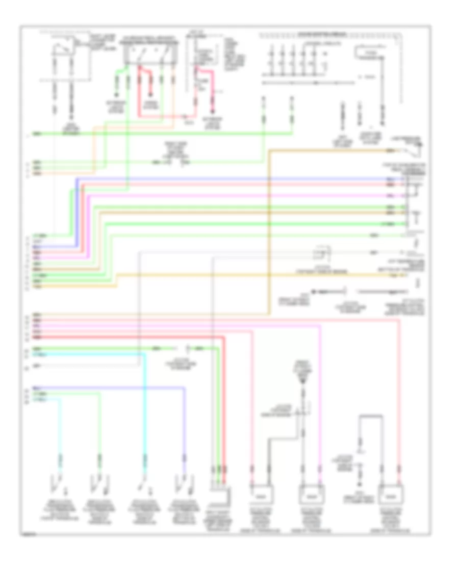
Automatic A/C Wiring Diagram, without Memory (3 of 3) for Honda Odyssey EX 2012
List of elements for Automatic A/C Wiring Diagram, without Memory (3 of 3) for Honda Odyssey EX 2012:
- (behind right rear side trim panel) rear blower motor
- (on rear blower motor) rear blower power transistor
- A/c compressor clutch relay
- A/c condenser fan relay/ fan control relay diode
- A10
- A11
- A12
- A13
- A21
- A37
- A48
- A49
- Acc
- Amd-p-rr
- Blw-g-rr
- Blw-v-rr
- Bus-data
- C16
- C201
- C206
- C208
- C210
- C32
- C405
- C415
- Center junction box (right side of dash)
- Computer data lines system
- D40
- Driver's junction box 1 (left side of dash)
- E32
- Ect sensor 1 (top rear of engine)
- Ect sensor 2 (bottom left side of radiator)
- Ect1
- Ect2
- F-can-h
- F-can-l
- Fan h
- Fan l
- Fuse 7.5a
- G201 (bottom left side of engine compt)
- G203 (right rear of engine compt)
- G652 (right "c" pillar)
- G701 (center front of roof)
- Gnd
- Hot at all times
- Ig2
- Ill+
- Ill-
- Interior lights system
- J/c c104 (top right side of engine)
- M-cool-rr
- M-def-rr
- M-hot-rr
- M-vent-rr
- Main under-hood fuse box (left side of engine compt)
- Mod-p-rr
- Multi- fuse 2
- Passenger's under- dash fuse/relay box (behind right kick panel)
- Pcm (right rear of engine compt)
- Pnk
- Power distribution system
- Radiator fan motor (behind right side of radiator)
- Rear a/c control panel
- Rear a/c control unit (behind right rear side trim panel)
- Rear air mix control motor (behind right rear side trim panel)
- Rear blower motor relay
- Rear evaporator temperature sensor (behind right rear side trim panel)
- Rear mode control motor (behind right rear side trim panel)
- Rear window defogger relay
- Red
- Rr blower fuse 30a
- S5v
- Sens-com
- Sg2
- Sg7
- Teva-rr
- Under-hood fuse/relay box (right rear of engine compt)
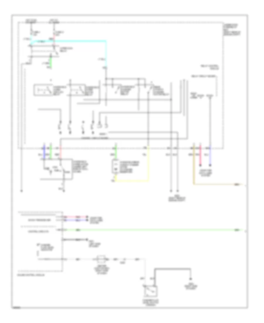
Manual A/C Wiring Diagram (1 of 3) for Honda Odyssey EX 2012
List of elements for Manual A/C Wiring Diagram (1 of 3) for Honda Odyssey EX 2012:
- (under right side of dash) front blower motor
- (under right side of dash) front blower power transistor
- A/c pressure sensor (right rear of engine compt)
- Air mix control motor (under left center of dash)
- Amd-p
- B-can h
- B-can l
- Blw-g
- Blw-v
- Bus data
- C202
- C205
- C208
- C411
- Computer data lines system
- Fr blower fuse 40a
- Front blower motor relay
- Front evaporator temperature sensor
- Front mode control motor (left side of dash)
- Front recirculation control motor (right side of dash)
- G204 (right side of dash)
- G302 (left side of dash)
- G403 (center of dash)
- Gnd
- Hot at all times
- Hvac control unit
- Ig2
- Ill+
- Ill-
- Interior lights system
- J/c c407 (left side of dash)
- L-mode 1
- L-mode 2
- L-mode 3
- M-cool
- M-def
- M-frs
- M-hot
- M-rec
- M-vent
- Main under-hood fuse box (left side of engine compt)
- Mode 1
- Mode 2
- Mode 3
- Mode 4
- Multi- fuse 2
- Multi- fuse 3
- Pnk
- Red
- Relay block
- Rr blower fuse 30a
- S5v
- Sens com
- Sens-com
- Teva
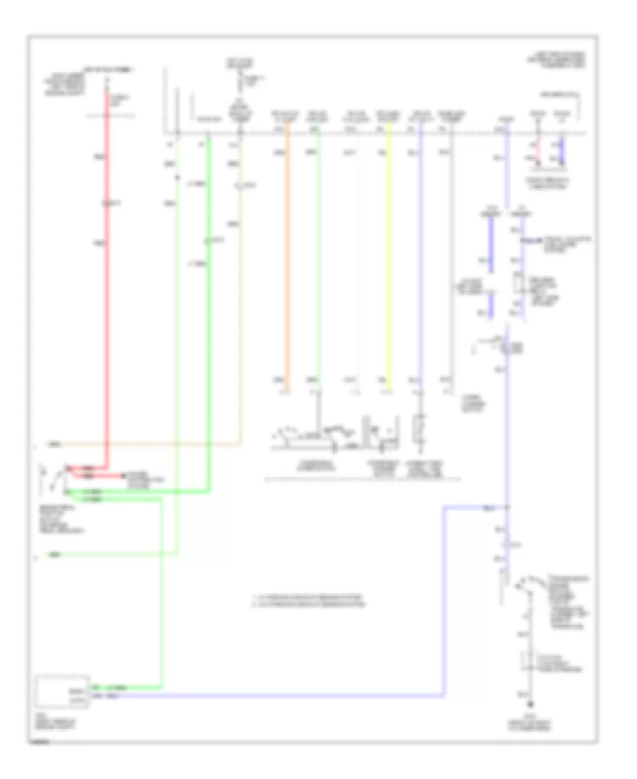
Manual A/C Wiring Diagram (2 of 3) for Honda Odyssey EX 2012
List of elements for Manual A/C Wiring Diagram (2 of 3) for Honda Odyssey EX 2012:
- A10
- A11
- A12
- Amd-p
- B can transceiver
- B-can hi
- B-can lo
- Blw-g
- Blw-v
- Bus data
- C206
- C210
- C415
- Center junction box (right side of dash)
- Computer data lines system
- Control circuits
- D40
- Driver's junction box 1 (left side of dash)
- Driver's under-dash fuse/relay box (left end of dash)
- E32
- F can transceiver
- F17
- Fuse 7.5a
- G652 (right "c" pillar)
- Gauge control module
- Gnd
- H10
- Hot in on
- Ig2
- J/c c408 (left side of dash)
- M-cool
- M-def
- M-hot
- M-vent
- Mdd-p
- Micu
- Passenger's under-dash fuse/relay box (behind right kick panel)
- Pnk
- Rear a/c control unit
- Rear air mix control motor (behind right rear side trim panel)
- Rear blower motor (behind right rear side trim panel)
- Rear blower power transistor (on rear blower motor)
- Rear mode control motor (behind right rear side trim panel)
- Red
- S5v
- Sens-com
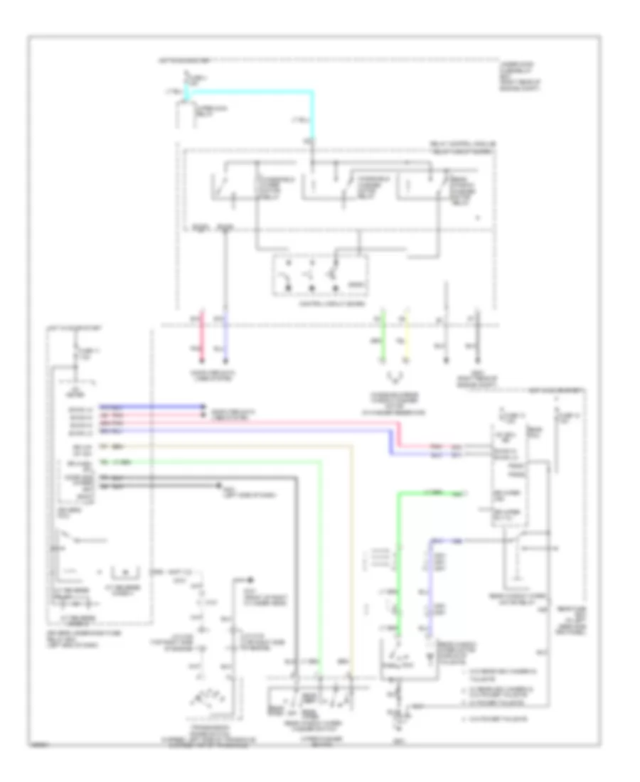
Manual A/C Wiring Diagram (3 of 3) for Honda Odyssey EX 2012
List of elements for Manual A/C Wiring Diagram (3 of 3) for Honda Odyssey EX 2012:
- A/c compressor clutch
- A/c compressor clutch case ground (rear of a/c compressor)
- A/c compressor clutch relay
- A/c condenser fan motor (behind left side of radiator)
- A/c condenser fan relay
- A/c condenser fan relay/ fan control relay diode
- A13
- A21
- A37
- A48
- A49
- A5 fan h
- Acc
- C101
- C16
- C201
- C32
- Computer data lines system
- Ect sensor 1 (top rear of engine)
- Ect sensor 2 (bottom left side of radiator)
- Ect1
- Ect2
- F-can h
- F-can l
- Fan control relay
- Fan l
- Fuse 30a
- Fuse 7.5a
- G201 (bottom left side of engine compt)
- G203 (right rear of of engine compt)
- Hot at all times
- J/c c104 (top right side of engine)
- Pcm (right rear of engine compt)
- Pgm-fi sub- relay
- Pnk
- Radiator fan motor (behind right side of radiator)
- Radiator fan relay
- Radiator fan relay diode
- Rear blower motor relay
- Rear window defogger relay
- Red
- Sg2
- Sg7
- Under-hood fuse/relay box (right rear of engine compt)
ANTI-LOCK BRAKES
Anti-lock Brakes Wiring Diagram for Honda Odyssey EX 2012
List of elements for Anti-lock Brakes Wiring Diagram for Honda Odyssey EX 2012:
- A48
- A49
- Abs ind
- Bksw
- Brake fluid level switch (brake fluid reservoir)
- Brake pedal position switch (on brake pedal bracket)
- Brake system ind
- C210
- C212
- C302
- Center junction box (right side of dash)
- Computer data lines system
- Control circuits
- Driver's under-dash fuse/relay box (left end of dash)
- E35
- E36
- E38
- E39
- Exterior lights system
- F-can h
- F-can l
- F-can transceiver
- F15
- F16
- F18
- F19
- F31
- Fl +b
- Fl-gnd
- Fr +b
- Fr-gnd
- Fsr +b
- Fuse 7.5a
- Fuse 9 20a
- G13
- G301 (left rear of engine compt)
- G302 (left side of dash)
- G401 (left side of dash)
- G403 (center of dash)
- Gauge control module
- Gnd
- Hot at all times
- Hot in on or start
- Ig 1
- Ig1
- Interior lights system
- K-line
- Left front wheel speed sensor (left front wheel hub assembly)
- Left rear wheel speed sensor (left rear wheel hub assembly)
- Main under-hood fuse box (left side of engine compt)
- Mr+b
- Mr-gnd
- Multi- fuse 2
- Parking brake switch (on parking brake pedal assembly)
- Pcm (right rear of engine compt)
- Pnk
- Power distribution system
- Red
- Right front wheel speed sensor (right front wheel hub assembly)
- Right rear wheel speed sensor (right rear wheel hub assembly)
- Rl +b
- Rl-gnd
- Rr +b
- Rr-gnd
- Sgnd
- Steering angle sensor (in steering column)
- Stop & horn hazard 30a
- Str-a
- Str-b
- Str-z
- Svcc
- Vsa fsr 30a
- Vsa modulator control unit (left rear of engine compt)
- Vsa mtr 40a
- Vsa off ind
- Vsa off switch
- Vsa off switch light
- Vsa system ind
- Wen
- Yaw rate acceleration sensor (center of dash)
ANTI-THEFT
Forced Entry Wiring Diagram (1 of 3) for Honda Odyssey EX 2012
List of elements for Forced Entry Wiring Diagram (1 of 3) for Honda Odyssey EX 2012:
- (not used)
- (right side of dash) center junction box
- +b hazard
- 20a
- 7.5a
- B-can h
- B-can hi
- B-can l
- B-can lo
- Body controller area network transceiver
- C401
- C414
- C415
- Computer data lines system
- Control circuits
- Control unit
- D/lck rly cl-
- D/unlck rly cl-
- Dr d/unlck rly cl-
- Driver's door switch (on driver's "b" pillar)
- Driver's micu
- Driver's under-dash fuse/relay box (left end of dash)
- E10
- E11
- E13
- E14
- E15
- E21
- E22
- E25
- E33
- Exterior lights system
- F11
- F12
- Fr l door sw
- Fr r door sw
- Front passenger's door lock actuator
- Front passenger's door lock actuator/ knob switch (rear of front passenger's front door)
- Front passenger's door lock knob switch
- Front passenger's door lock light
- Front passenger's door lock switch
- Front passenger's door lock switch unlock light
- Front passenger's power window switch
- Fuse 15a
- Fuse 19
- Fuse 20a
- Fuse 26
- Fuse 7.5a
- G402 (left side of dash)
- G405 (right side of dash)
- G601 (under driver's seat)
- Gauge control module
- H10
- H12
- H13
- Hot at all times
- Hot in on
- Ignition key switch
- Immobilizer keyless control unit (on steering column, near steering lock)
- J/c c472 (front passenger's door)
- Lock
- Main under- hood fuse box (left side of engine compt)
- Pg1
- Pg2
- Pnk
- Power distribution system
- Power door lock relay (dr unlock)
- Power door lock relay (lock)
- Power door lock relay (unlock)
- Q18 atp-p
- Q4 ig key sw
- Q7 scty radio
- Red
- Security indicator
- Sil as ul
- Steering lock (ignition key light/ignition key switch/key interlock solenoid) (right side of steering column)
- Turn lt fr l
- Turn lt fr r
- Turn lt rr l
- Turn lt rr r
- Uart
- Unlock
- Vbu
- Vmp as
- W/ memory
- W/o memory
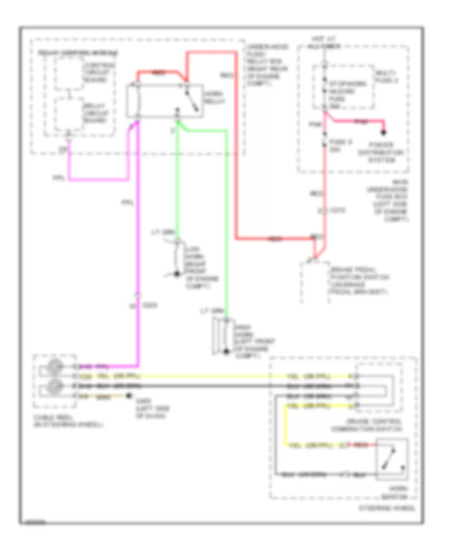
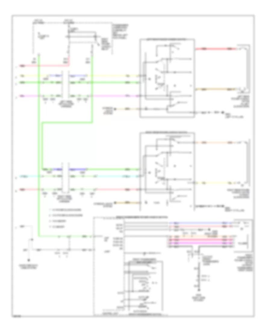
Forced Entry Wiring Diagram (2 of 3) for Honda Odyssey EX 2012
List of elements for Forced Entry Wiring Diagram (2 of 3) for Honda Odyssey EX 2012:
- (dri- ver's door) j/c c452
- (left side of dash) driver's junction box 2
- (rear of driver's front door) driver's door lock actuator/ knob switch/ key cylinder switch
- 10a
- B-can h
- B-can l
- C401
- C415
- C605
- C606
- C652
- C653
- C681
- C682
- C691
- C692
- Close
- Computer data lines system
- Control circuit board
- Door multiplex control unit
- Driver's door key cylinder switch
- Driver's door lock actuator
- Driver's door lock knob switch
- Driver's door lock switch
- Driver's door lock switch lock light
- Driver's door lock switch unlock light
- Driver's junction box 1 (left side of dash)
- Eng hood sw
- Front passenger's door switch (on front passenger's "b" pillar)
- Fuse 16
- G204 (right side of dash)
- G401 (left side of dash)
- G402 (left side of dash)
- G602 (left "c" pillar)
- G671 (right sliding door)
- High horn (left front of engine compartment)
- Horn relay
- Horns system
- Hot at all times
- Ig2
- J/c c407 (left side of dash)
- Kc dr lock
- Kc dr ul
- Left cess articulated harness
- Left sliding door lock actuator
- Left sliding door lock knob switch
- Left sliding door remote control assembly (behind left rear side trim panel)
- Lock
- Low horn (right front of engine compartment)
- Open
- Pnk
- Power distribution system
- Power tops system
- Power window master switch
- Red
- Relay circuit board
- Relay control module
- Right cess articulated harness
- Right sliding door lock actuator
- Right sliding door lock knob switch
- Right sliding door remote control assembly (behind right rear side trim panel)
- Security hood switch (if equipped) (center front of engine compt)
- Sil dr lock
- Trunk, tailgate, fuel doors system
- Uart
- Under-hood fuse/relay box (right rear of engine compt)
- Unlock
- Vbu
- Vmp dr
- W/ memory
- W/ power sliding door
- W/o memory
- W/o power sliding door
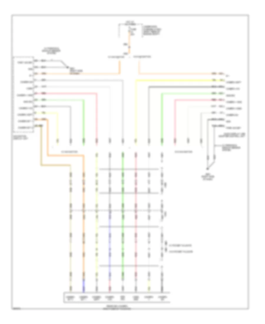
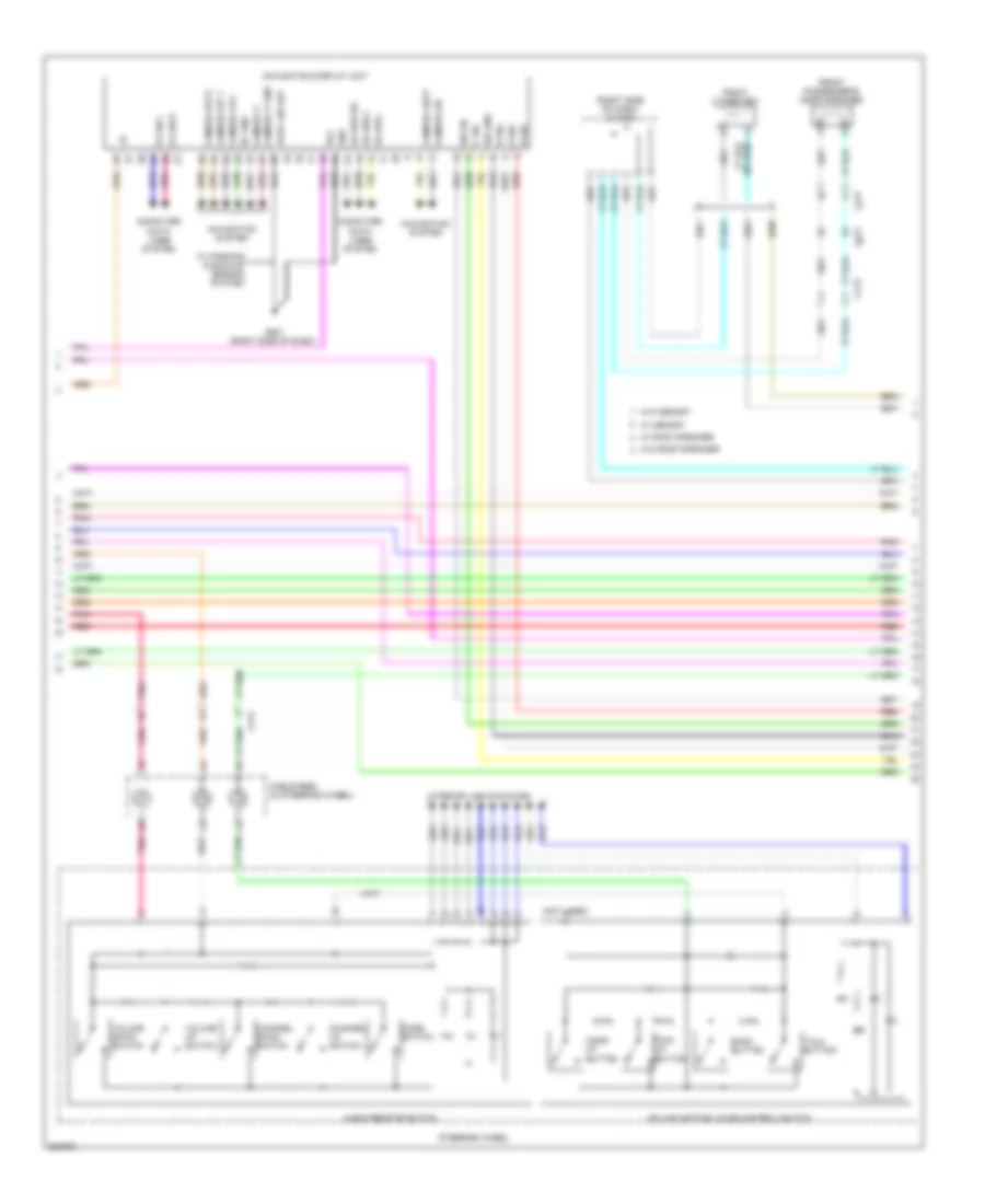
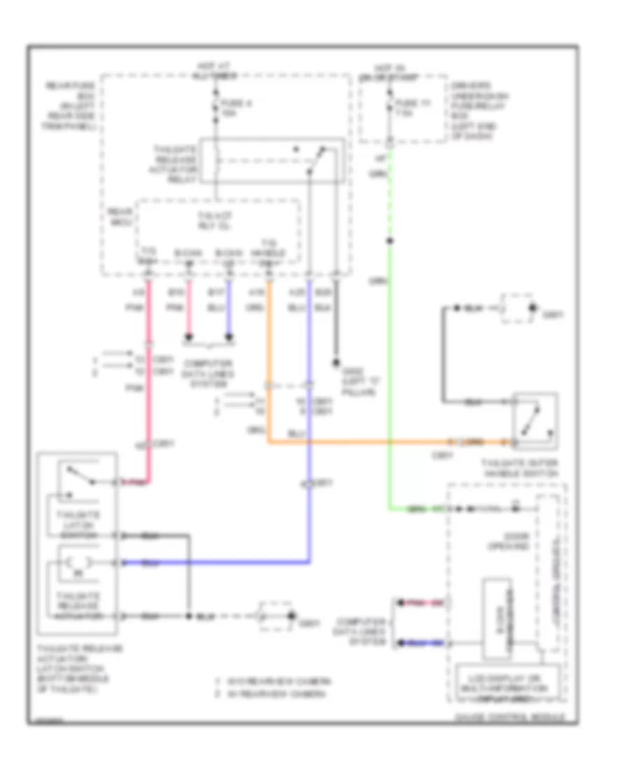
Forced Entry Wiring Diagram (3 of 3) for Honda Odyssey EX 2012
List of elements for Forced Entry Wiring Diagram (3 of 3) for Honda Odyssey EX 2012:
- (bottom middle of tailgate) power tailgate closer unit
- 10a
- 20a
- 7.5a
- A12
- A13
- A16
- A25
- A29
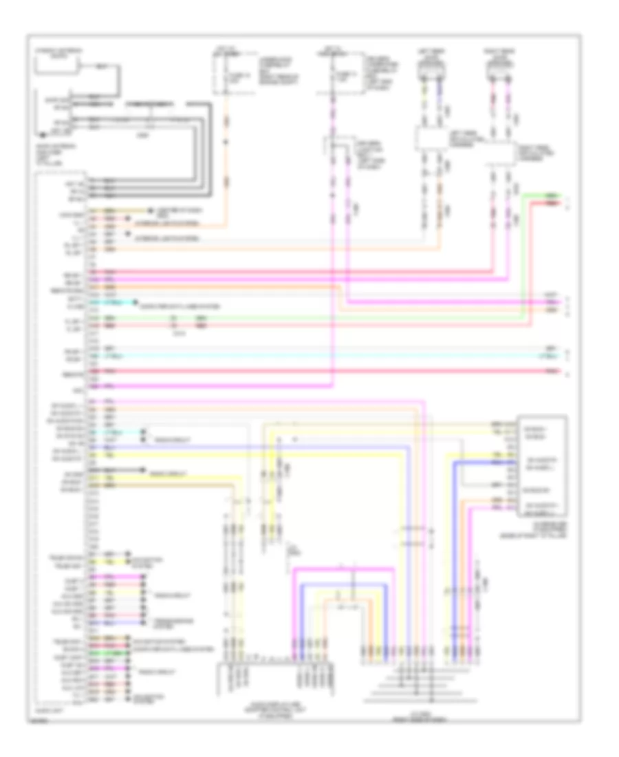
- Audio navig- ation unit (w/ navigation) audio unit (w/o navigation)
- B-can hi
- B-can lo
- B10
- B11
- B12
- B15
- B17
- B21
- B26
- B27
- B28
- C101
- C11
- C205
- C413
- C505
- C604
- C607
- C801
- C851
- Computer data lines system
- Controls system
- Door lock rd rly cl-
- Door unlock rd rly cl-
- Engine
- Full latch switch
- Fuse 18
- Fuse 4
- Fuse 5
- G101 (front of right cylinder head)
- G602 (left "c" pillar)
- G801
- Hot at all times
- J/c c102 (top right side of engine)
- Left sliding door switch (on left "c" pillar)
- Passenger's under-dash fuse/relay box (behind right kick panel)
- Pgnd1
- Pgnd2
- Pnk
- Power door lock relay (unlock)
- Power door relay (lock)
- Power tailgate control unit (behind left rear side trim panel)
- Power tailgate latch/ratchet
- Ra door sw
- Ra sil ul sw+
- Rd door sw
- Rd sil l sw+
- Rd sil ul sw+
- Rear controller & screen
- Rear fuse box (in left rear side trim panel)
- Rear micu
- Red
- Right sliding door switch (on right "c" pillar)
- Scty+
- Scty-
- Seg3
- Sensor system
- Switch
- T gate handle sw+
- T gate sw+
- T/g (trunk) act rly cl-
- Tailgate latch switch
- Tailgate outer handle switch (w/o power tailgate)
- Tailgate release actuator
- Tailgate release actuator relay
- Tailgate release actuator/latch switch (w/o power tailgate) (bottom middle of tailgate)
- Transmission range switch (6 speed a/t: top of transaxle) (5 speed a/t: left side of transaxle)
- W/ normal rear entertrainment system
- W/ parking & backup
- W/ power tailgate
- W/ rear entertrainment system
- W/ rearview camera
- W/ wide rear entertrainment system
- W/o parking & backup
- W/o power tailgate
- W/o rear entertrainment system
- W/o rearview camera
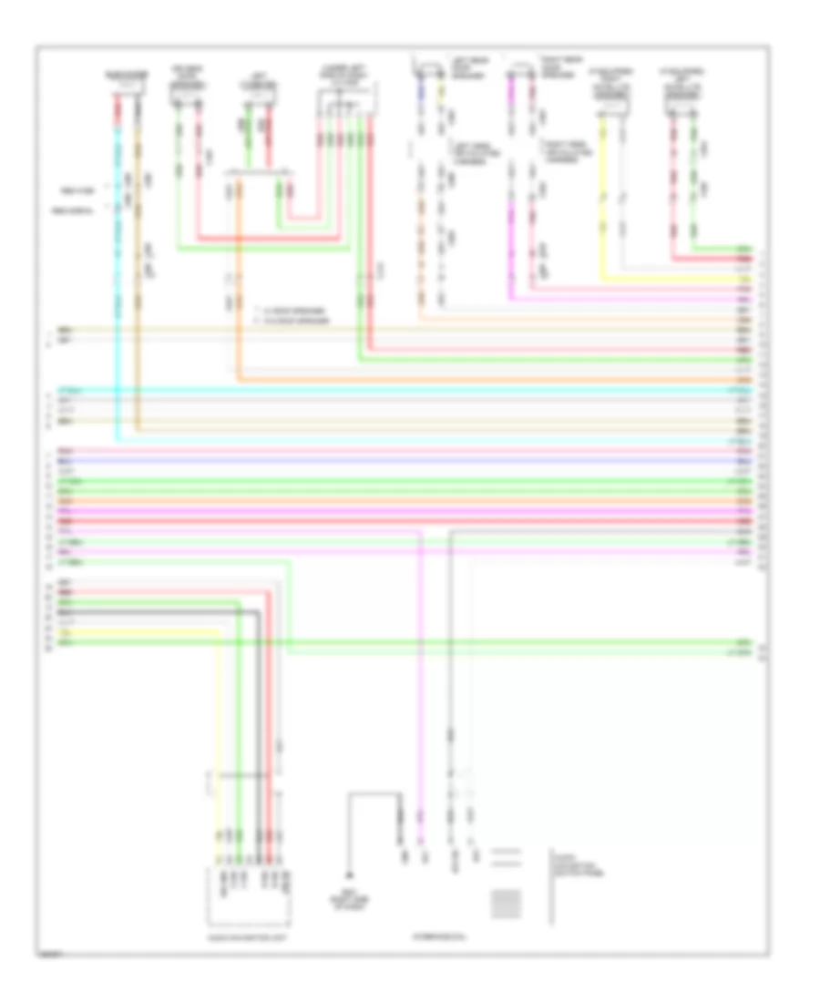
Immobilizer Wiring Diagram for Honda Odyssey EX 2012
List of elements for Immobilizer Wiring Diagram for Honda Odyssey EX 2012:
- (on parking brake pedal assembly) parking brake switch
- (s-net)
- (top of fuel tank) fuel tank unit
- + b backup
- A11
- A41
- A46
- Antenna
- B- can hi
- B- can lo
- B-can h
- B-can l
- B-can transceiver
- B41
- B42
- C101
- C205
- C210
- C212
- C302
- C41
- Center junction box (right side of dash)
- Computer data lines system
- Control circuits
- Driver's micu
- Driver's under-dash fuse/relay box (left end of dash)
- E16
- F10
- F20
- F24
- F26
- Fuel pump
- Fuse 10 15a
- Fuse 16 10a
- Fuse 21 20a
- G101 (front of right cylinder head)
- G12
- G401 (left side of dash)
- G602 (left "c" pillar)
- Gauge control module
- H10
- Hot at all times
- Hot in on or start
- Ig1
- Ign
- Ignition coil relay
- Immobilizer keyless control unit (on steering column, near steering lock)
- Immobilizer system indicator
- Imocd
- Imofpr
- J/c c103 (top right side of engine)
- J/c c203 (right side of dash)
- K-line
- Lg1
- Lg2
- Lg3
- Mrly
- Pcm (right rear of engine compt)
- Pgm-fi main relay 1
- Pgm-fi main relay 2
- Pnk
- Red
- S-net
- S-net5v
- Under-hood fuse/relay box (right rear of engine compt)
- Vbu
- W/ parking & backup sensor system
- W/o parking & backup sensor system
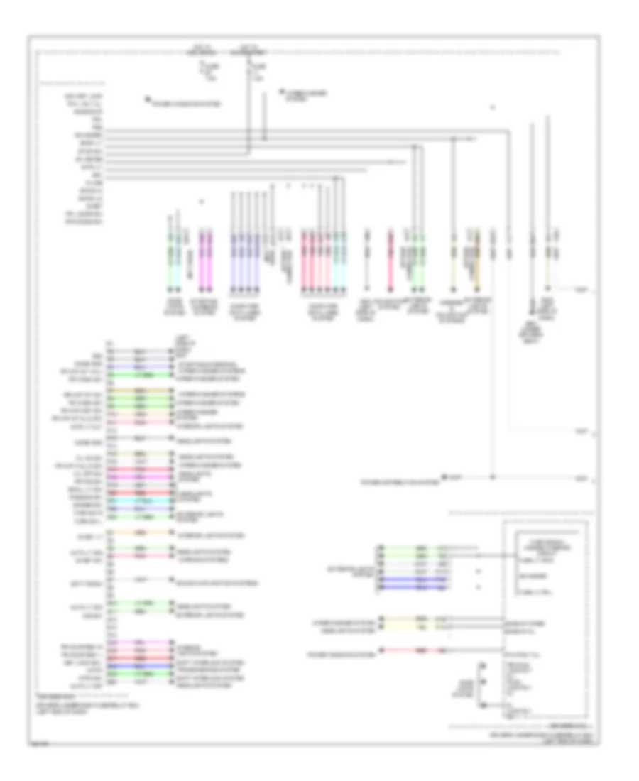
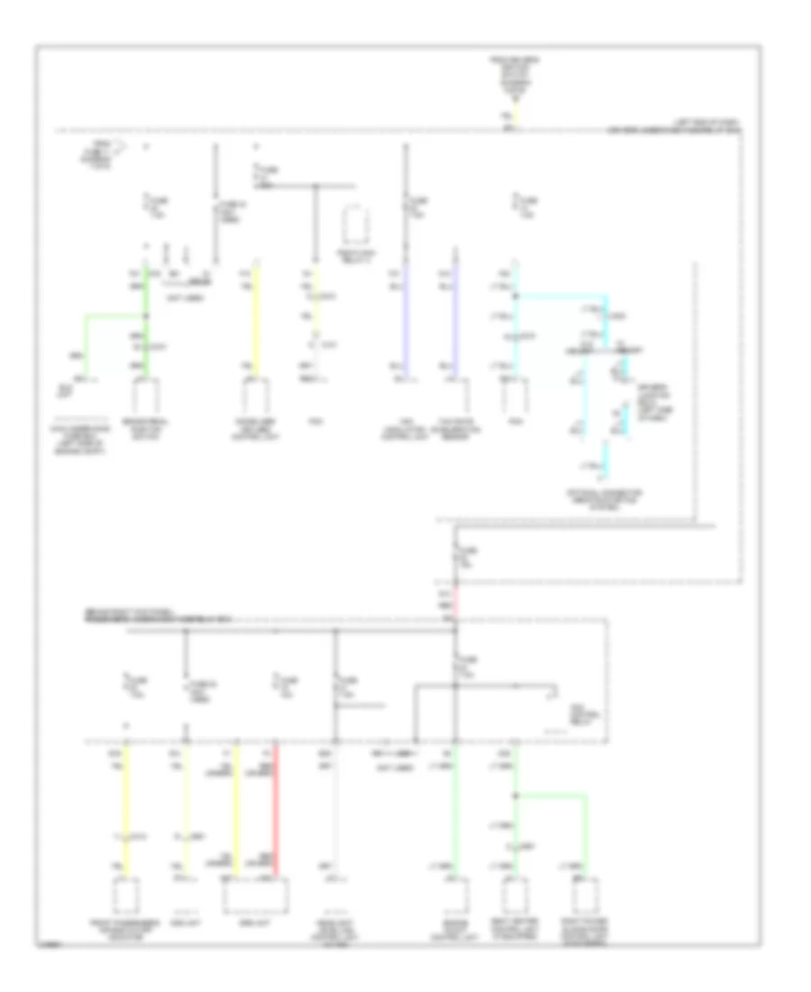
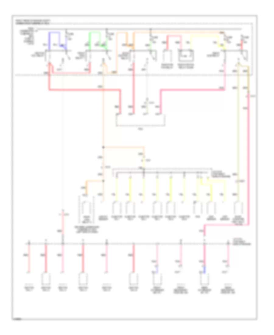
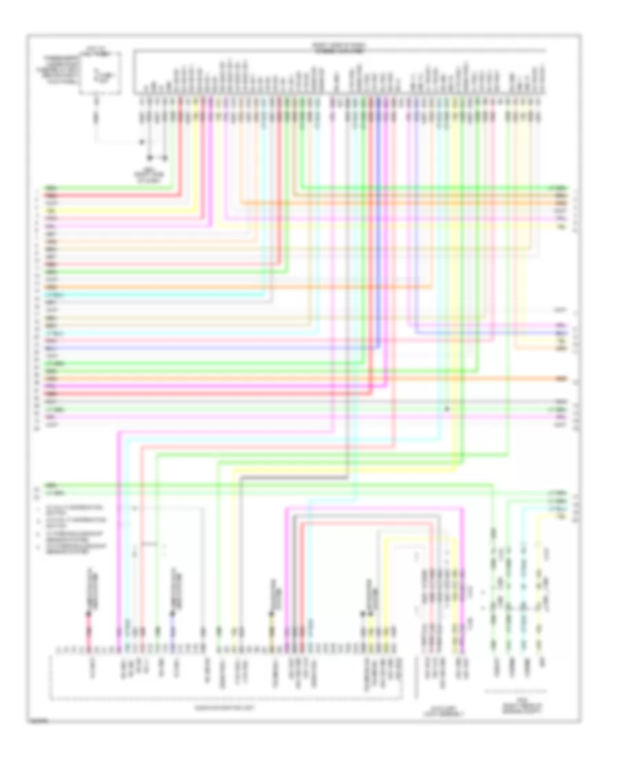
BODY CONTROL MODULES
Body Control Modules Wiring Diagram (1 of 2) for Honda Odyssey EX 2012
List of elements for Body Control Modules Wiring Diagram (1 of 2) for Honda Odyssey EX 2012:
- (left side of dash) g401
- (not used)
- +b backup
- +b hazard
- Acc key lock
- Atp-p
- Auto lt sig
- Auto lt sio
- Auto lt sip
- B-can hi
- B-can lo
- Back lt
- Backup h/l
- Backup wiper
- Combi gnd
- Computer data lines system
- Connector) (option
- D/ lock rly cl-
- Dimmer sw
- Door locks system
- Dr d/unl lock rly cl- d/unl lock rly cl-
- Driver's micu
- Driver's under-dash fuse/relay box (left end of dash)
- E15
- E16
- E21
- E22
- E23
- E25
- E29
- E31
- E32
- E43
- E44
- Exterior lights system
- F11
- F12
- F13
- F14
- F24
- F25
- F26
- Fr courtesy l
- Fr courtesy r
- Fr fog sw
- Fr l door sw
- Fr r door sw
- Fr wash sw
- Fr wip hi & lo sw
- Fr wip int & lo sw
- Fr wip int vol+
- Fr wip mist sw
- Fuse 7.5a
- G10
- G12
- G15
- G401 (left side of dash)
- G402 (left side of dash)
- G601 (under driver's seat)
- H/l off sw
- H/l on sw
- H10
- Haz sw
- Headlights system
- Hot in acc or on
- Hot in on or start
- Ig key lt
- Ig key sw
- Ig1 meter
- Interior lights system
- Intr lt cut
- Intr lt-
- K-line
- Key lock sol-
- Mirrors & navigation systems
- Navigation system
- P-pin sw
- P/w l rly cl-
- P/w r rly cl-
- P10
- P11
- P12
- P13
- P14
- P15
- P16
- P17
- P18
- P19
- P20
- P21
- P22
- P23
- Passing sw
- Pg1
- Pg2
- Pnk
- Power distribution system
- Power windows system
- Q10
- Q11
- Q12
- Q13
- Q14
- Q15
- Q16
- Q17
- Q18
- Q19
- Q20
- Red
- Rr wip int sw
- S-net
- Scty radio
- Sg1
- Sg2
- Shift interlock system
- Small lt sw
- Sound & navigation systems
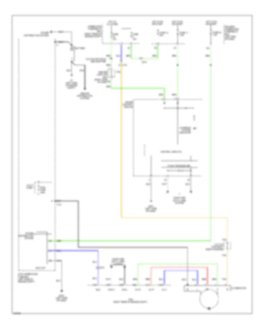
- Starting/ charging system
- Starting/charging & wiper/washer systems
- Stop sw
- Transmissions system
- Turn lt fr l
- Turn lt fr r
- Turn signal/ hazard warning circuit
- Turn sw l
- Turn sw r
- Used) (not
- Warning systems
- Wiper/washer system
- Wiper/washer systems
Body Control Modules Wiring Diagram (2 of 2) for Honda Odyssey EX 2012
List of elements for Body Control Modules Wiring Diagram (2 of 2) for Honda Odyssey EX 2012:
- (not used)
- + backup
- A10
- A13
- A16
- A18
- A23
- A24
- A29
- B-can hi
- B-can lo
- B10
- B11
- B12
- B14
- B15
- B16
- B17
- B21
- B26
- C210
- Cargo lt -
- Computer data lines system
- Door lock rd rly cl- door unlock rd rly cl- cl-
- Door locks system
- Exterior lights system
- Fuel lid open rly
- Fuel lid sw rly
- Fuse 10a
- Fuse 15a
- Fuse 7.5a
- G602 (left "c" pillar)
- G801
- Hot at all times
- Hot in on or start
- Ig1 ecu rr
- Interior lights system
- J/c c203 (right side of dash)
- Main under-hood fuse box (left side of engine compt)
- Pgnd1
- Pnk
- Ptg full
- Ra door sw
- Ra sil ul sw+
- Rd door sw
- Rd sil l sw+
- Rd sil ul sw+
- Rear fuse box (in left rear side trim panel)
- Rear micu
- Red
- Sgnd1
- Sgnd2 pgnd2
- T gate handle sw+
- T gate sw+
- T/g (trunk) act rly cl-
- Trunk, tailgate, fuel doors system
- Under-hood fuse/relay box (right rear of engine compt)
COMPUTER DATA LINES
Data Link Connector Wiring Diagram for Honda Odyssey EX 2012
List of elements for Data Link Connector Wiring Diagram for Honda Odyssey EX 2012:
- (left side of dash)
- A13
- A18
- A32
- A48
- A49
- Audio navigation unit (w/ navigation) audio unit (w/o navigation)
- C205
- C302
- C413
- Can h
- Can l
- Can-h
- Can-l
- Center junction box (right side of dash)
- Control circuits
- Dlc (under left side of dash)
- Driver's junction box 1 (left side of dash)
- Driver's junction box 2 (left side of dash)
- Driver's micu
- Driver's under-dash fuse/relay (left side of dash)
- Engine mount control unit (right side of dash)
- F-can transceiver
- F-can-h
- F-can-l
- F25
- Fuse 16 10a
- G15
- G401 (left side of dash)
- G402 (left side of dash)
- Gauge control module
- Headlight leveling control unit (w/ hid) (left side of dash)
- Hot at all times
- Immobilizer keyless control unit (on steering column, near steering lock)
- J/c c203 (right side of dash)
- K-line
- K10
- Optional connector (remote starting system)
- Pcm (right rear of engine compartment)
- Red
- Scs
- Srs unit (under middle of dash)
- Tpms control unit (left side of dash)
- Under-hood fuse/relay box (right rear of engine compt)
- Vsa modulator control unit (left rear of engine compt)
- W/ memory
- W/ parking & backup sensor system
- W/o memory
- W/o parking & backup sensor system
- Wen
- Yaw rate- acceleration sensor (center of dash)
F-CAN & B-CAN Wiring Diagram (1 of 2) for Honda Odyssey EX 2012
List of elements for F-CAN & B-CAN Wiring Diagram (1 of 2) for Honda Odyssey EX 2012:
- (in left rear side trim panel) rear fuse box
- (not used)
- (option connector)
- (optional connector)
- (remote sta- rting system)
- (under driver's seat) (w/ memory) power seat control unit
- A23
- A24
- A26
- A28
- Automatic a/c
- B-can hi
- B-can lo
- B-can low
- B10
- B12
- B14
- B15
- B16
- B17
- B21
- B22
- Bcan-hi
- Bcan-lo
- Bsi control unit (behind left rear side trim panel)
- C401
- C601
- Climate control unit
- Control circuit
- Control circuit board
- Door multiplex control unit
- Driver's junction box 1 (left side of dash)
- Driver's junction box 2 (left side of dash)
- Driver's micu
- Driver's under-dash fuse/relay box (left end of dash)
- E15
- E16
- E31
- E32
- E43
- E44
- F-can hi
- F-can lo
- Gauge control module
- H10
- Headlight leveling control unit (w/ hid) (left side of dash)
- Hvac controal unit
- J/c c803 (behind left rear side trim panel)
- Left power sliding door control unit (if equipped) (behind respective rear side trim panel)
- Manual a/c
- Parking & backup sensor control unit (if equipped) (left side of dash)
- Pnk
- Power tailgate control unit (if equipped) (behind left rear side trim panel)
- Power window master switch
- Rear micu
- Relay control module
- Srs unit (under middle of dash)
- Tpms control unit (if equipped) (left side of dash)
- Transceiver b-can
- Transceiver f-can
- Uart
- Under-hood fuse/relay box (right rear of engine compt)
- W/ bsi system
- W/ memory
- W/o bsi system
- W/o memory
- Yaw rate acceleration sensor (center of dash)
F-CAN & B-CAN Wiring Diagram (2 of 2) for Honda Odyssey EX 2012
List of elements for F-CAN & B-CAN Wiring Diagram (2 of 2) for Honda Odyssey EX 2012:
- (behind right rear side trim panel) (if equipped) right power sliding door control unit
- A28
- A29
- A48
- A49
- Audio display-usb adapter control unit
- Audio navigation unit
- Audio unit
- B-can hi
- B-can lo
- B12
- B13
- B14
- C205
- C302
- C405
- C412
- C414
- C651
- Center junction box (right side of dash)
- Control unit
- D22
- D24
- D34
- D36
- Dlc (under left side of dash)
- Driver's junction box 1 (left side of dash)
- E40
- E42
- Engine mount control unit (right side of dash)
- F-can hi
- F-can lo
- F16
- Front passenger's power window switch
- Immobilizer keyless control unit (on steering column, near steering lock)
- J/c c203 (right side of dash)
- J/c c504 (w/ audio remote switch) (right side of dash)
- K10
- Moon roof control unit/motor (if equipped) (front center of roof)
- Navigation display unit
- Passenger's box under-dash fuse/relay (behind right kick panel)
- Pcm (right rear of engine compt)
- Pnk
- Seat heater control unit (if equipped)
- Uart
- Usb adapter w/o navigation
- Vsa modulator control unit (left rear of engine compt)
- W/ audio remote switch
- W/ memory
- W/ navigation
- W/o memory
- W/o navigation
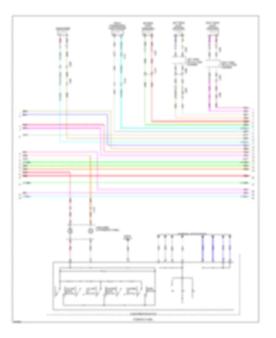
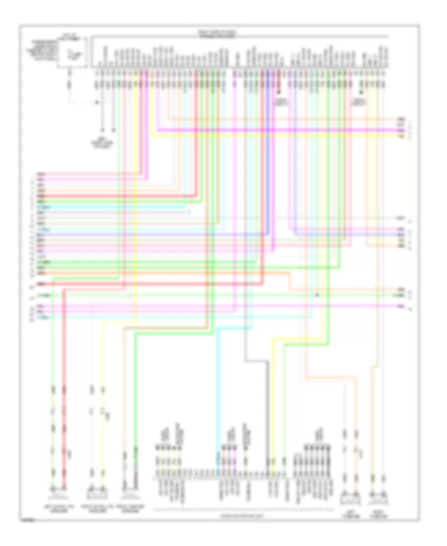
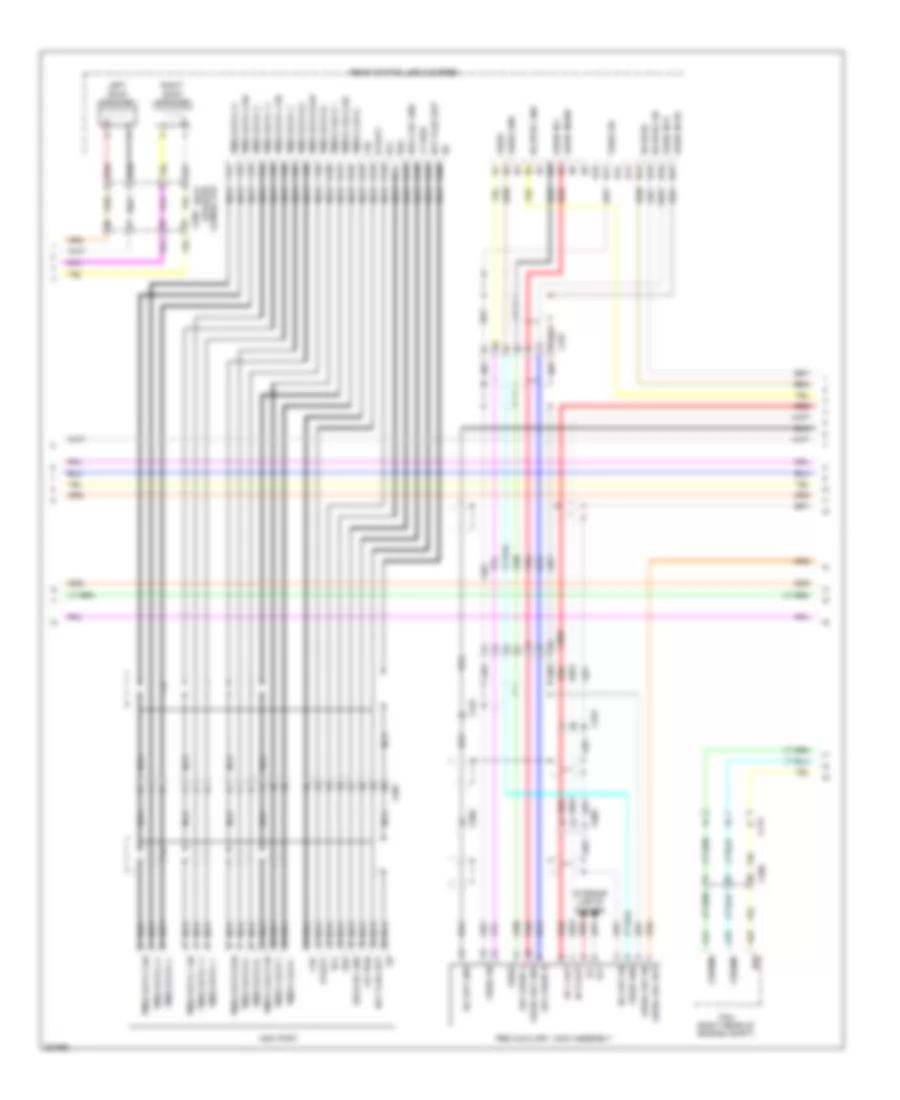
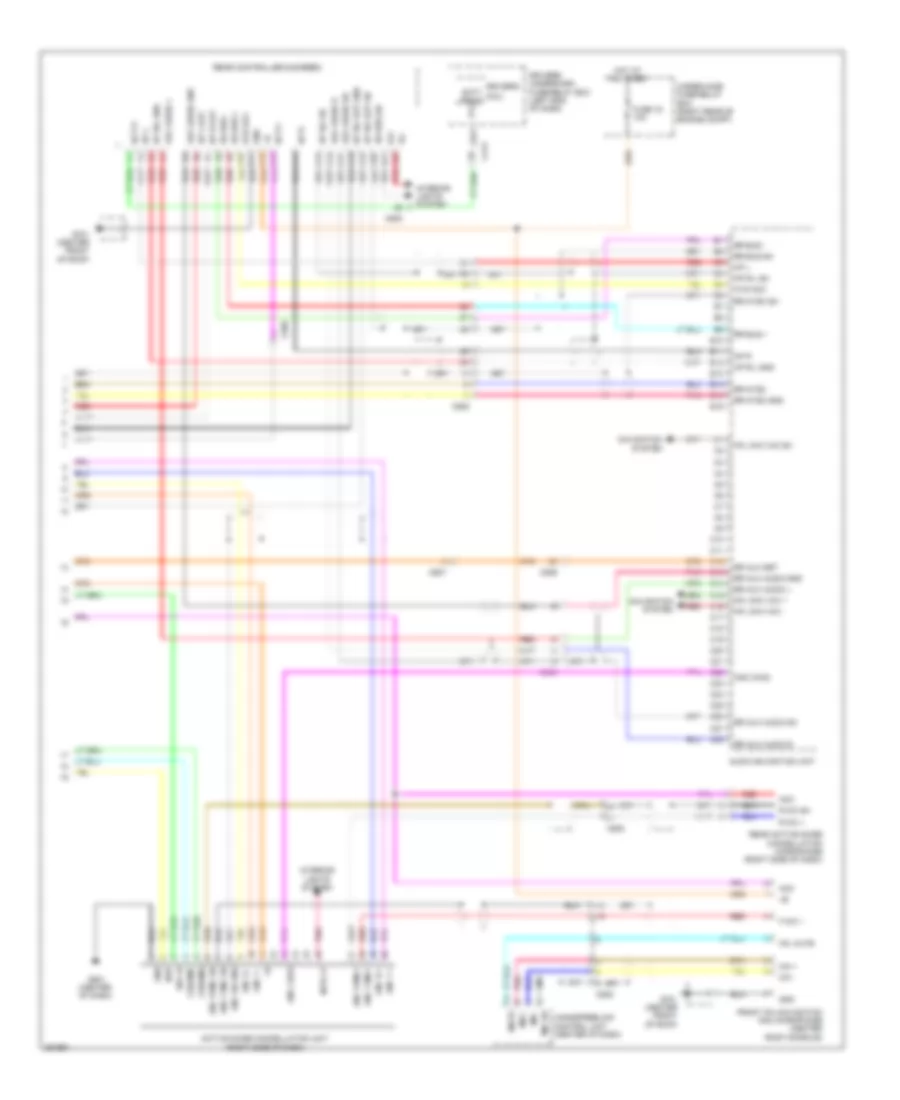
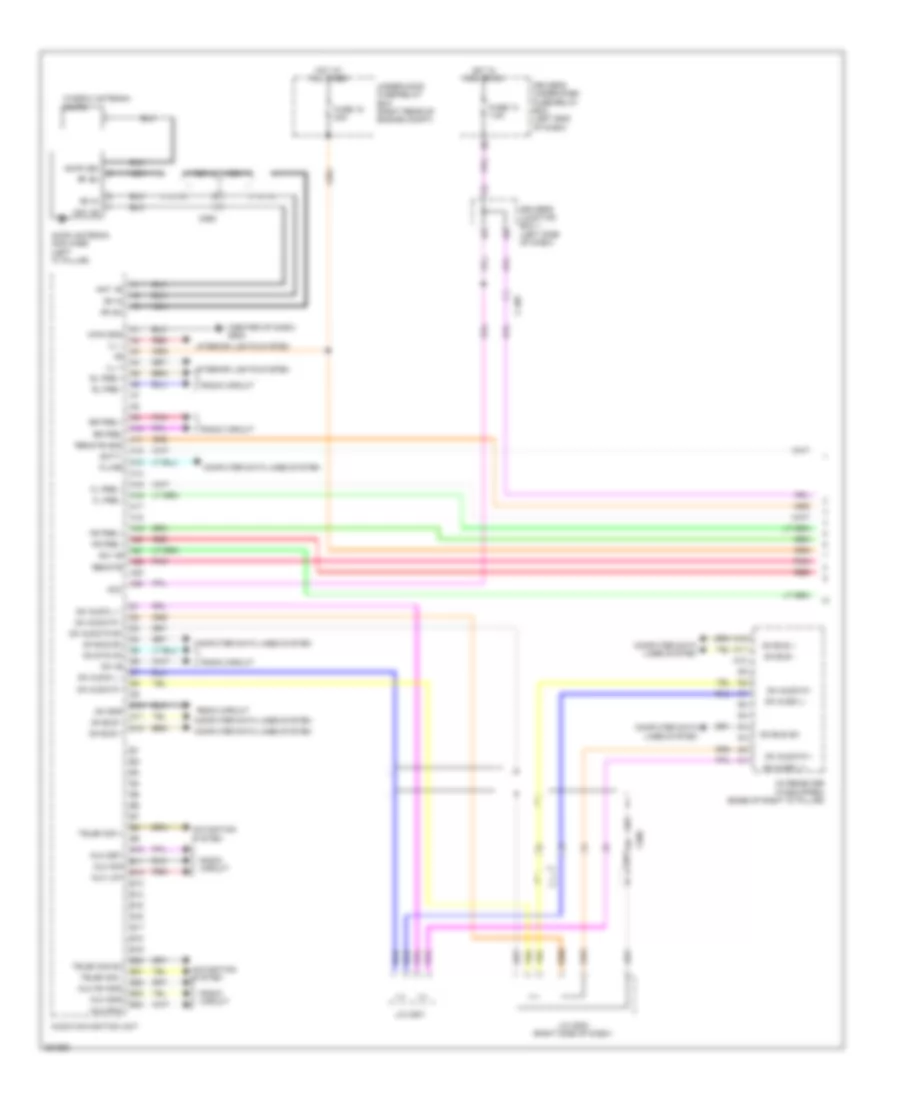
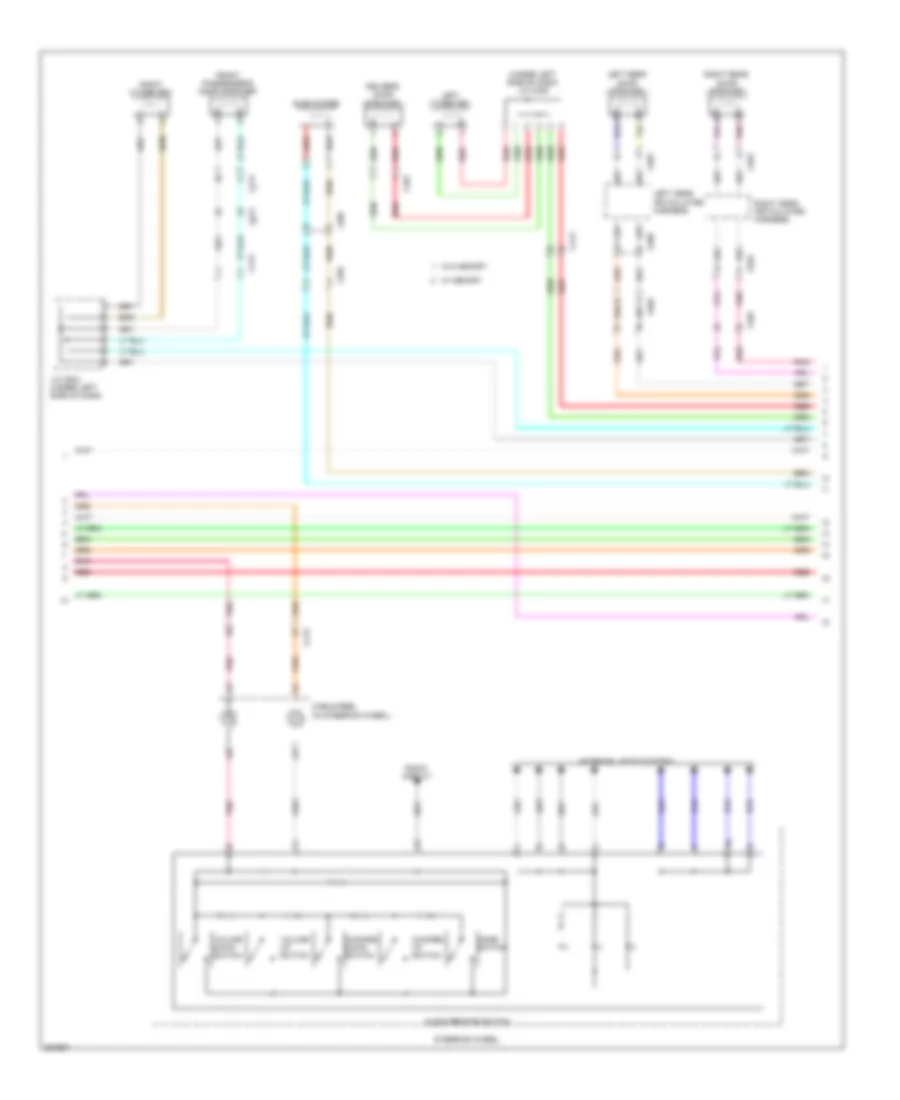
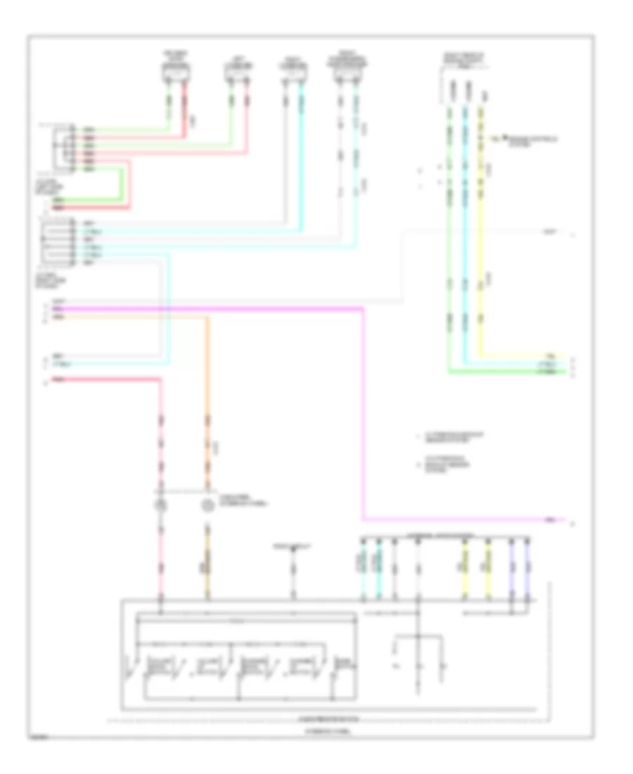
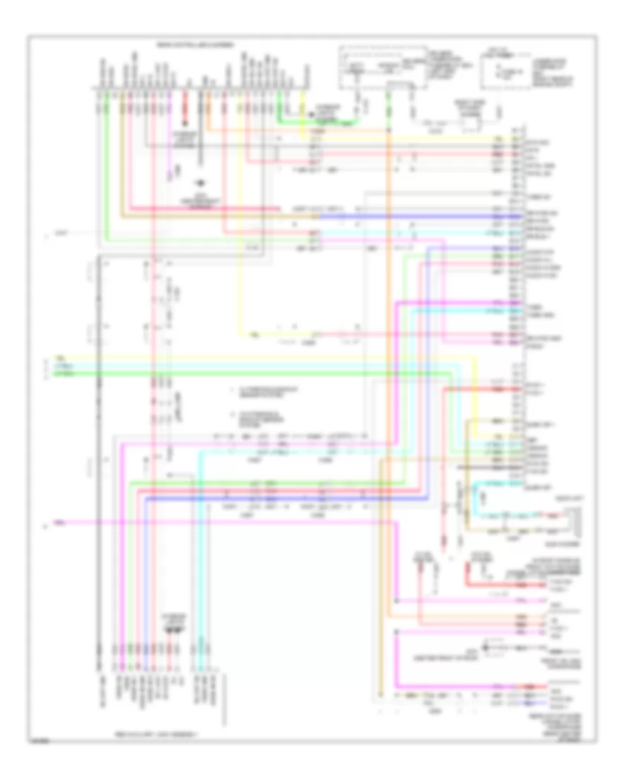
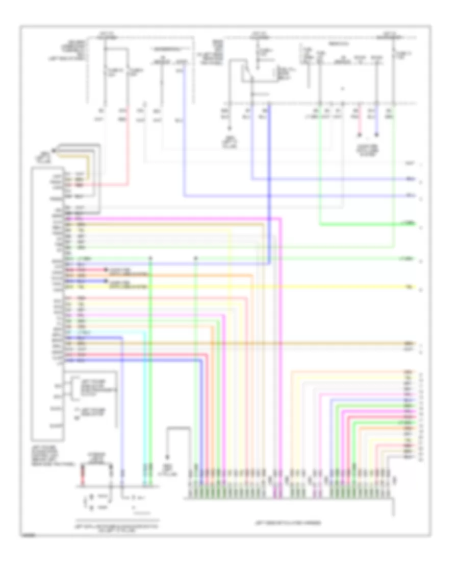
GA-NET Bus/GA-NET Audio Wiring Diagram for Honda Odyssey EX 2012
List of elements for GA-NET Bus/GA-NET Audio Wiring Diagram for Honda Odyssey EX 2012:
- A10
- A11
- A12
- A13
- A14
- Audio display usb adapter control unit (w/o navigation) navigation display unit (w/ navigation)
- Audio navigation unit (w/ navigation)
- Audio uint (w/o navigation)
- C506
- D10
- D11
- D12
- Ga +b
- Ga audio l+
- Ga audio l-
- Ga audio r+
- Ga audio r-
- Ga audio sh
- Ga bus sh
- Ga gnd
- Ga sys on
- Ga syson
- Ga-bus sh
- Ga-bus+
- Ga-bus-
- Handsfree link control unit (if eqipped)
- J/c c501 (right side of dash)
- J/c c502 (right side of dash)
- J/c c503
- W/ navigation
- W/o navigation
- Xm receiver (if equipped) (base of right "d"pillar)
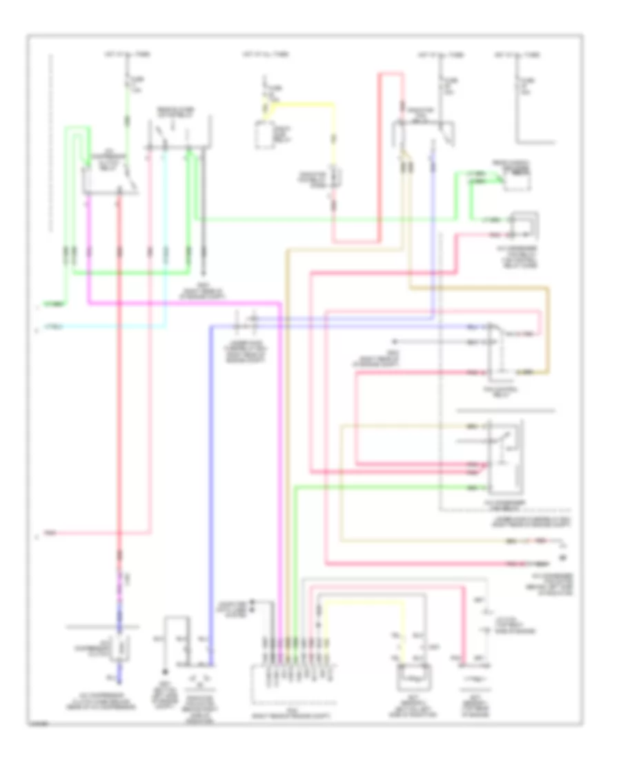
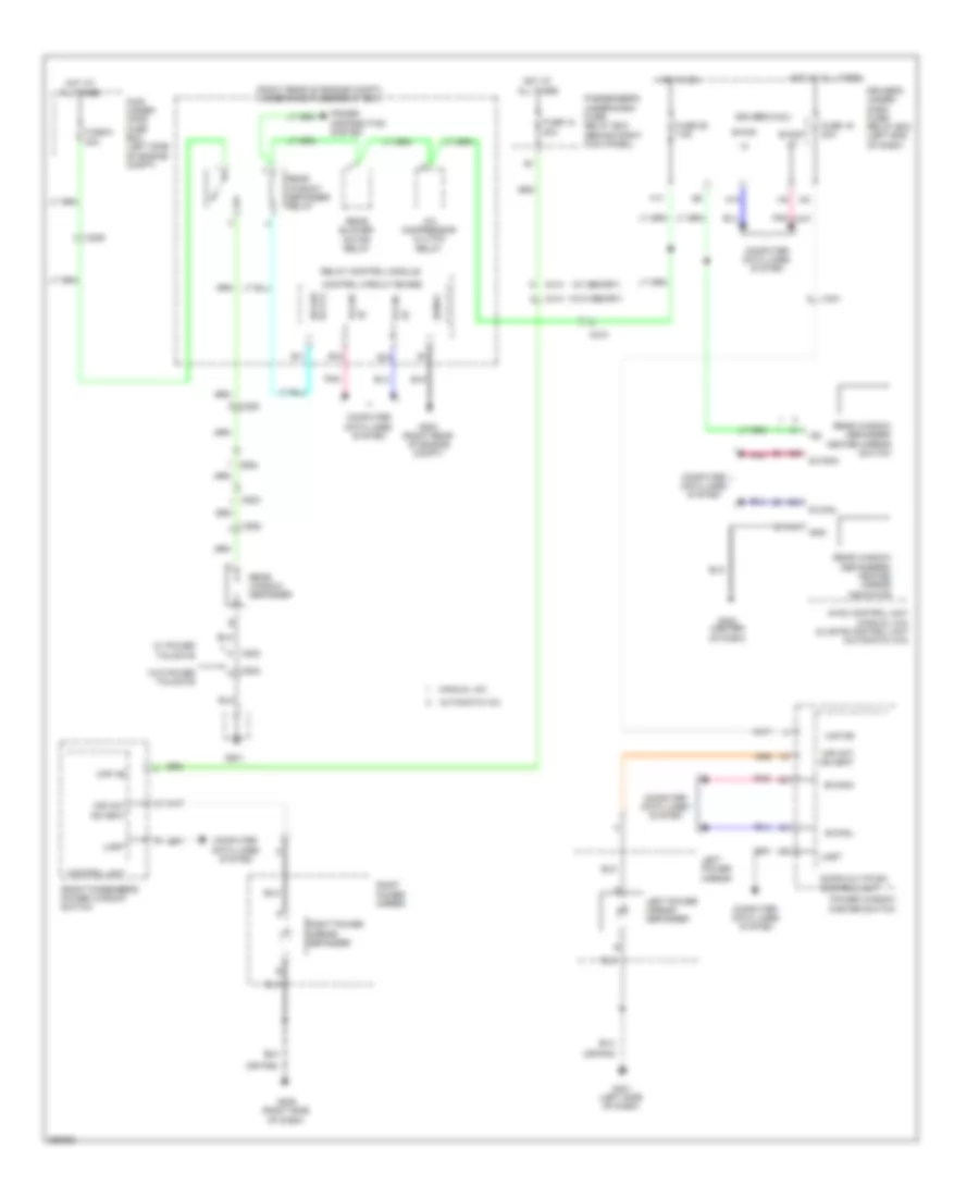
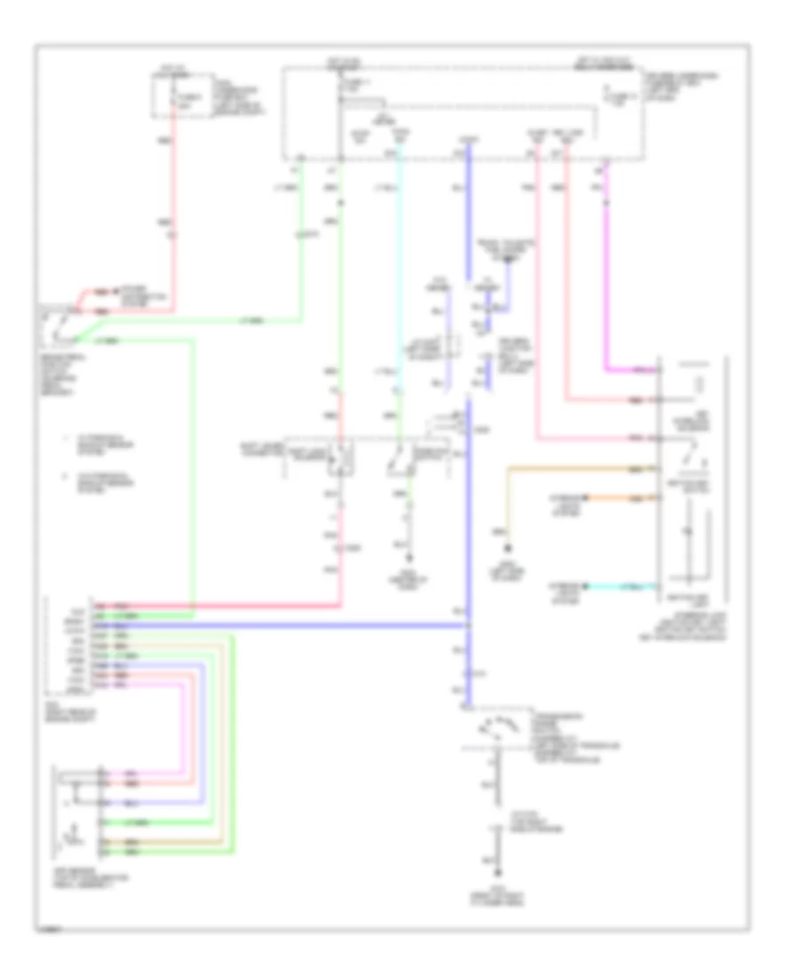
COOLING FAN
Cooling Fan Wiring Diagram for Honda Odyssey EX 2012
List of elements for Cooling Fan Wiring Diagram for Honda Odyssey EX 2012:
- (top right side of engine) j/c c104
- A/c compressor clutch relay
- A/c condenser fan motor (behind left side of radiator)
- A/c condenser fan relay
- A/c condenser fan relay/ fan control relay diode
- A21
- A37
- C16
- C201
- C210
- C32
- Driver's under-dash fuse/relay box (left end of dash)
- Ect sensor 1 (top rear of engine)
- Ect sensor 2 (bottom left side of radiator)
- Ect1
- Ect2
- F17
- Fan control relay
- Fan h
- Fan l
- Fuse 30a
- Fuse 7.5a
- G201 (bottom left side of engine compt)
- G203 (right rear of of engine compt)
- Hot at all times
- Hot in on
- Hot w/ pgm-fi relay energized
- Pcm (right rear of engine compt)
- Pgm-fi sub relay
- Pnk
- Radiator fan motor (behind right side of radiator)
- Radiator fan relay
- Radiator fan relay diode
- Rear blower motor relay
- Rear window defogger relay
- Red
- Sg2
- Sg7
- Under-hood fuse/relay box (right rear of engine compt)
CRUISE CONTROL
Cruise Control Wiring Diagram (1 of 2) for Honda Odyssey EX 2012
List of elements for Cruise Control Wiring Diagram (1 of 2) for Honda Odyssey EX 2012:
- 5-speed a/t
- 6-speed a/t
- A18
- A19
- A24
- A25
- A26
- A27
- A48
- A49
- App sensor (top of accelerator pedal assembly)
- Apsa
- Apsb
- Atpfwd
- B17
- B18
- B26
- B33
- B34
- B36
- B38
- Bksw
- Bkswnc
- C15
- C18
- C212
- Computer data lines system
- Driver's under-dash fuse/relay box (left end of dash)
- Etcsm+
- Etcsm-
- F-can-h
- F-can-l
- F21
- Fuse 11 7.5a
- Fuse 24 7.5a
- Fuse 9 20a
- G101 (front of right cylinder head)
- Hot at all times
- Hot in on or start
- J/c c105 (top right side of engine)
- Junction connector c102 (top right side of engine)
- Main under-hood fuse box (left side of engine compt)
- Multi- fuse 2
- Output shaft (countershaft) speed sensor (5 speed a/t: on transaxle) (6 speed a/t: bottom rear of transaxle)
- Pcm (right rear of engine compt)
- Pnk
- Power distribution system
- Red
- Sg1
- Sg3
- Sg4
- Sg5
- Sg6
- Stop & horn hazard 30a
- Tan
- Throttle actuator
- Tp sensor
- Tp sensor/ throttle actuator (on throttle body)
- Tpsa
- Tpsb
- Transmission range switch (5 speed a/t: left side of transaxle) (6 speed a/t: top of transaxle)
- Vcc1
- Vcc3
- Vcc4
- Vcc5
Cruise Control Wiring Diagram (2 of 2) for Honda Odyssey EX 2012
List of elements for Cruise Control Wiring Diagram (2 of 2) for Honda Odyssey EX 2012:
- Brake pedal position switch (on brake pedal bracket)
- C210
- Cable reel (in steering wheel)
- Cancel switch
- Computer data lines system
- Control circuits
- Cruise control combination switch
- Cruise control indicator
- Cruise control main switch indicator
- Exterior lights system
- F-can transceiver
- G401 (left side of dash)
- G402 (left side of dash)
- Gauge control module
- Horns system
- Interior lights system
- Main switch
- Power distribution system
- Red
- Resume switch
- Set switch
- Steering wheel
DEFOGGERS
Defoggers Wiring Diagram for Honda Odyssey EX 2012
List of elements for Defoggers Wiring Diagram for Honda Odyssey EX 2012:
- (or pnk)
- (right rear of engine compt) under-hood fuse/relay box
- A/c compressor clutch relay
- A12
- A26
- A28
- All times
- Automatic a/c
- B canh
- B canl
- B-can
- B-can lo
- B-canh
- B-canl
- B11
- B15
- B16
- C206
- C209
- C210
- C401
- C414 (w/ memory)
- C414 (w/o memory)
- C654
- C802
- C852
- Computer data lines system
- Control circuit board
- Control unit
- Door multiplex control unit
- Driver's micu
- Driver's under- dash fuse/ relay box (left end of dash)
- F17
- Front pasenger's power window switch
- Fuse 18 20a
- Fuse 19 20a
- Fuse 26 7.5a
- Fuse 6 40a
- G203 (right rear of engine compt)
- G401 (left side of dash)
- G403 (center of dash)
- G405 (right side of dash)
- G801
- Gnd
- H10
- Hi b-can
- Hot at
- Hot at all times
- Hot in on
- Hvac control unit (manual a/c) climate control unit (automatic a/c)
- Ig2
- Left power mirror
- Left power mirror defogger
- Lo b-can
- Main under- hood fuse box (left side of engine compt)
- Manual a/c
- Mir act as heat
- Passenger's under-dash fuse/ relay box (behind right kick panel)
- Pnk
- Power distribution system
- Power window master switch
- Rear blower motor relay
- Rear window defogger
- Rear window defogger relay
- Rear window defogger/ heated mirror switch
- Rear window defoggers/ heated mirror indicator
- Relay control module
- Right power mirror
- Right power mirror defogger
- Rr def rly-cl
- Sgnd1
- Uart
- Vmp as
- Vmp dr
- W/ power tailgate
- W/o power tailgate
ENGINE PERFORMANCE
3.5L
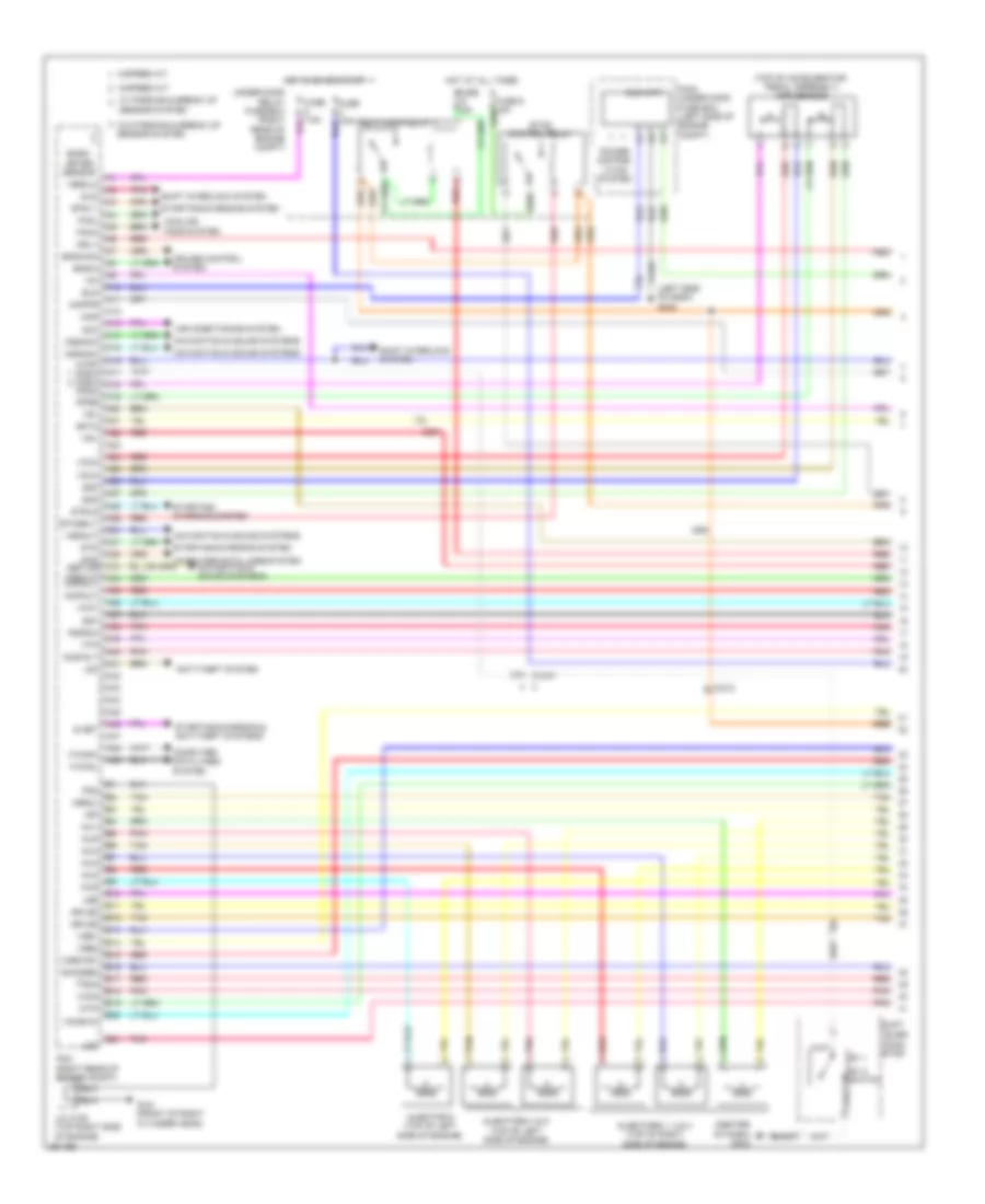
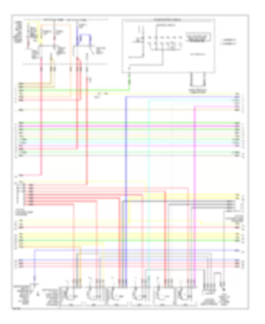
3.5L, Engine Performance Wiring Diagram (1 of 7) for Honda Odyssey EX 2012
List of elements for 3.5L, Engine Performance Wiring Diagram (1 of 7) for Honda Odyssey EX 2012:
- (center of dash) g403
- (left side of dash) g302
- (top of accelerator pedal assembly) app sensor
- 5-speed a/t
- 6-speed a/t
- A10
- A11
- A12
- A13
- A14
- A15
- A16
- A17
- A19
- A20
- A21
- A22
- A23
- A24
- A25
- A26
- A27
- A28
- A29
- A30
- A31
- A32
- A33
- A35
- A36
- A37
- A38
- A39
- A40
- A41
- A42
- A43
- A44
- A45
- A46
- A47
- A48
- A49
- Acc
- Air conditioning system
- Anti-theft system
- Apsa
- Apsb
- Atpp d3sw d4sw a18
- B10
- B11
- B12
- B13
- B14
- B15
- B16
- B17
- B18
- B19
- B20
- B21
- Baro- meter sensor
- Bksw
- Bkswnc
- C201
- C210
- C212
- Ckpout
- Cmpout
- Computer data lines system
- Cooling fans system
- Cruise control system
- Cssama
- Cssamc
- D4 switch
- Ect2
- Eld
- Eld unit
- Etcs control relay
- Etcsrly
- F-canh
- F-canl
- Fanh
- Fanl
- Ftp
- Fuse 15a
- G101 (front of right cylinder head)
- Hot at all times
- Hot in on or start
- Igp
- Igpls5
- Igpls6
- Imofpr
- Imtm
- Inj1
- Inj2
- Inj3
- Inj4
- Inj5
- Inj6
- Injector 6 (top of left side of engine)
- Injectors 1, 2 & 3 (top of right side of engine)
- Injectors 4 & 5 (top of left side of engine)
- J/c c105 (top right side of engine)
- Lever conn- etor
- Lg3
- Lsb
- Lsc
- Main under-hood fuse box (left side of engine compt)
- Mcs
- Mrly
- Navigation & sound systems
- Pcm (right rear of engine compt)
- Pg2
- Pgm fi main relay 1
- Pnk
- Power distrib- ution system
- Pspsw
- Red
- S net
- Scs nep (or vssout) a34
- Sensor system
- Sg3
- Sg4
- Sg7
- Shift
- Shift interlock system
- Sho2sb2
- Sls
- Starting/ charging system
- Starting/charging & anti-theft systems
- Starting/charging system
- Strld
- Strly
- Sts
- Sub rly
- Tan
- Tpsa
- Under-hood relay fuse/box (right rear of engine compt)
- Vbsol
- Vbsol2
- Vcc3
- Vcc4
- Vcc5
- Vcc7
- Vcentb1
- Vcmswc
- Vg+
- Vg-
- Vsb1
- Vsb2
- Vssout
- Vsv
- W/ parking & break up
- W/o parking & break up sensor system
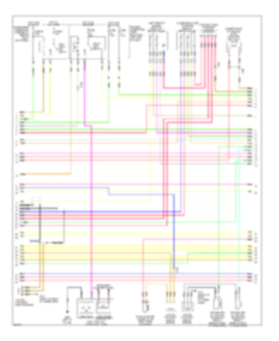
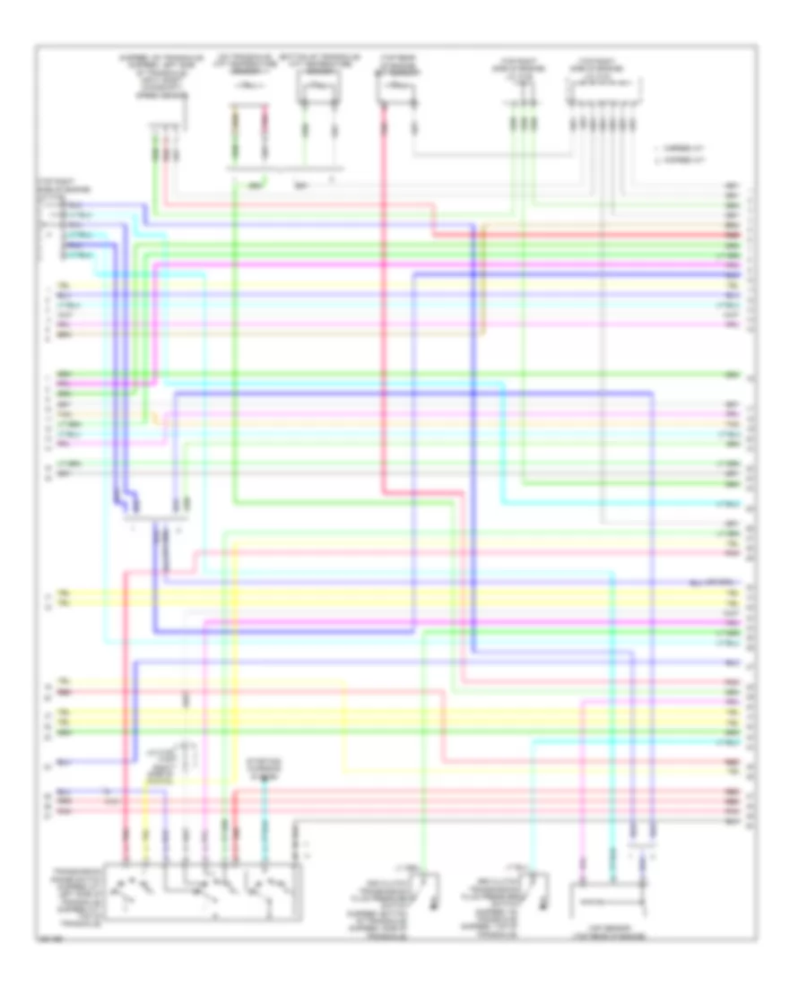
3.5L, Engine Performance Wiring Diagram (2 of 7) for Honda Odyssey EX 2012
List of elements for 3.5L, Engine Performance Wiring Diagram (2 of 7) for Honda Odyssey EX 2012:
- (bottom left side of radiator) ect sensor 2
- (on power steering pressure line) psp switch
- (right side of dash) engine mount control unit
- (top right side of engine) j/c c102
- (under middle of vehicle) ftp sensor
- A/t clutch pressure control solenoid valve b (5-speed a/t: top of transaxle) (6-speed a/t: side of transaxle)
- A/t clutch pressure control solenoid valve c (5-speed a/t: top of transaxle) (6-speed a/t: side of transaxle)
- Braided
- C101
- C201
- C207
- C210
- Ckp
- Cmp
- Computer data lines system
- Dash)
- F-can h
- F-can l
- Front engine mount actuator (lower left front of engine compt)
- Front rocker arm oil pressure switch (front of left cylinder bank)
- Front secondary ho2s (b2, s2) (left rear of engine)
- G101 (front of right cylinder head)
- G204 (right side of
- G204 (right side of dash)
- Iat
- Ig1
- Igsol
- J/c c105 (top right side of engine)
- Maf
- Maf/iat sensor (engine air intake duct)
- Pnk
- Rear engine mount actuator (lower right rear of engine compt)
- Rear secondary ho2s (b1, s2) (lower right side of engine)
- Red
- Solfm
- Solfp
- Solrly
- Solrm
- Solrp
- Tan
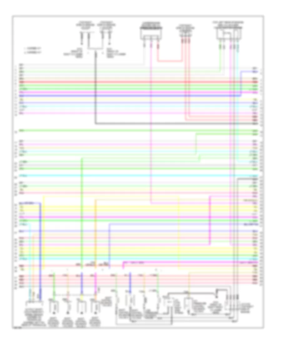
3.5L, Engine Performance Wiring Diagram (3 of 7) for Honda Odyssey EX 2012
List of elements for 3.5L, Engine Performance Wiring Diagram (3 of 7) for Honda Odyssey EX 2012:
- (left rear of engine) front a/f sensor (b2, s1)
- (lower right side of engine) rear a/f sensor (b1, s1)
- (top right side of engine) j/c c104
- (under middle of vehicle) evap canister vent shut valve
- Acm cont- rol relay
- Braided
- C101
- C207
- C210
- Driver's under dash fuse/ relay box (left end of dash)
- E16
- Evap canister purge valve (right rear of engine)
- F10
- F20
- F21
- Fuel gauge sending unit
- Fuel pump
- Fuel tank unit (top of fuel tank)
- Fuse 20 7.5a
- Fuse 20a
- Fuse 3 10a
- Fuse 7.5a
- G101 (front of right cylinder head)
- G602 (left "c" pillar)
- Hot at all times
- Hot in on or start
- Instrument cluster system
- J/c c104 (top right side of engine)
- J/c c105 (top right side of engine)
- Passenger's under-dash fuse/relay (behind right kick panel)
- Pgm-fi main relay 2
- Pnk
- Red
- Rocker arm oil control solenoid a (bank 1) (rear of right cylinder bank)
- Rocker arm oil control solenoid b (bank 1) (rear of right cylinder bank)
- Tan
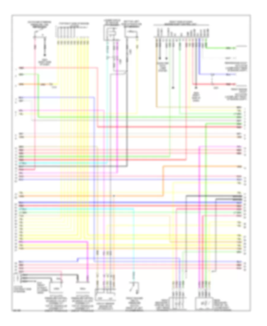
3.5L, Engine Performance Wiring Diagram (4 of 7) for Honda Odyssey EX 2012
List of elements for 3.5L, Engine Performance Wiring Diagram (4 of 7) for Honda Odyssey EX 2012:
- 5-speed a/t
- 6-speed a/t
- C101
- C212
- Computer data lines system
- Control circuit
- Fast controller area network transceiver
- Fuse 11 15a
- Fuse 28 7.5a
- Fuse 8 15a
- G101 (front of right cylinder head)
- Gauge control module
- Hot at all times
- Icm
- Ignition coil relay
- Ignition coils (1, 2 & 3: right side of engine) (4, 5 & 6: left side of engine)
- J/c c102 (top right side of engine)
- J/c c104 (top right side of engine)
- J/c c105 (top right side of engine)
- Mil ind
- Pgm fi sub relay
- Pnk
- Radi- ator fan relay
- Radi- ator fan relay diode
- Rear rocker arm oil pressure switch (rear of right cylinder bank)
- Red
- Tan
- Under- hood fuse/ relay box (right rear of engine compt)
3.5L, Engine Performance Wiring Diagram (5 of 7) for Honda Odyssey EX 2012
List of elements for 3.5L, Engine Performance Wiring Diagram (5 of 7) for Honda Odyssey EX 2012:
- (5-speed: on transaxle) (6-speed: left side of transaxle) input shaft (mainshaft) speed sensor
- (bottom of transaxle) atf temperature sensor
- (on transaxle) atf temperature sensor
- (top rear of engine) ect sensor 1
- (top right side of engine) j/c c104
- (top right side of engine) j/c c105
- 2nd clutch transmission fluid pressure switch (5-speed: bottom of transaxle) (6-speed: side of transaxle)
- 3rd clutch transmission fluid pressure switch (5-speed: on transaxle) (6-speed: top of transaxle)
- 5-speed a/t
- 6-speed a/t
- C101
- J/c c105 (top right side of engine)
- Maf sensor (top rear of engine)
- Pnk
- Red
- Starting/ charging system
- Tan
- Transmission range switch (5-speed a/t: left side of transaxle) (6-speed a/t: top of transaxle)
3.5L, Engine Performance Wiring Diagram (6 of 7) for Honda Odyssey EX 2012
List of elements for 3.5L, Engine Performance Wiring Diagram (6 of 7) for Honda Odyssey EX 2012:
- (top left rear of engine) egr valve & egr valve position sensor
- (top right side of engine) j/c c102
- (top right side of engine) j/c c103
- (top right side of engine) j/c c105
- (under engine) rocker arm oil pressure sensor
- 5-speed a/t
- 6-speed a/t
- A/t pressure control solenoid valve d
- C107
- G101 (front of right cylinder head)
- G101 (front of right front cylinder head)
- J/c c102 (top right side of engine)
- J/c c105 (top right side of eng)
- Line pressure solenoid valve
- Output shaft (countershaft) speed sensor (5-speed: on transaxle) (6-speed: bottom rear of transaxle)
- Pnk
- Red
- Shift control solenoid valve a
- Shift control solenoid valve b
- Shift control solenoid valve c
- Shift control solenoid valve d
- Tan
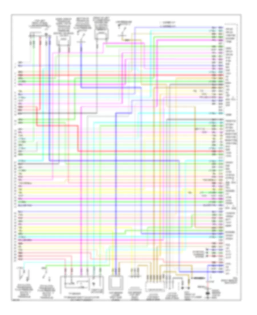
3.5L, Engine Performance Wiring Diagram (7 of 7) for Honda Odyssey EX 2012
List of elements for 3.5L, Engine Performance Wiring Diagram (7 of 7) for Honda Odyssey EX 2012:
- (6-spd: side of transaxle) (5-spd: top of transaxle) a/t clutch pressure control solenoid valve a
- (bottom of transaxle) 4th clutch transmission fluid pressure switch
- (front of left cylinder bank) rocker arm oil control solenoid a (bank 2)
- (top left front of eng) imt actuator
- 5-speed a/t
- 5th clutch transmission fluid pressure switch (side of transaxle)
- 6-speed a/t
- 6th clutch transmission fluid pressure switch (top of transaxle)
- Afshtcb1
- Afshtcb2
- Altc
- Altf
- Altl
- Atpd
- Atpfwd
- Atpl
- Atpn
- Atpr
- Atprvs
- B22
- B23
- B24
- B25
- B26
- B27
- B28
- B29
- B30
- B31
- B32
- B33
- B34
- B35
- B36
- B37
- B38
- B39
- B40
- B41
- B42
- B43
- B44
- B45
- B46
- B47
- B48
- B49
- Braided
- C10
- C101
- C106
- C11
- C12
- C13
- C14
- C15
- C16
- C17
- C18
- C19
- C20
- C21
- C22
- C23
- C24
- C25
- C26
- C27
- C28
- C29
- C30
- C31
- C32
- C33
- C34
- C35
- C36
- C37
- C38
- C39
- C40
- C41
- C42
- C43
- C44
- C45
- C46
- C47
- C48
- C49
- Ckp
- Ckp sensor (lower right side of eng)
- Cmp
- Cmp sensor (top left front of eng)
- Cssa
- Cssb
- Cssc
- Ect1
- Egr
- Egrp
- Etcsm+
- Etcsm-
- G101 (front of right cylinder head)
- Iat
- Ig1
- Ig1etcs
- Igpls1
- Igpls2
- Igpls3
- Igpls4
- Imt+
- Imt-
- Ip b1
- Ip b2
- J/c c102 (top right side of eng)
- J/c c103 (top right side of eng)
- Knock sensor (top of eng)
- Lg1
- Lg2
- Line pressure switch
- Lsd
- Map
- Op2sw
- Op3sw
- Op4sw
- Op6sw
- Pcm (right rear of eng compt)
- Pcs
- Pg1
- Pgmetcs
- Pla
- Pnk
- Poil
- Red
- Sg1
- Sg2
- Sg5
- Sg6
- Sha
- Shb
- Shb lsa
- Shc
- Shd
- Sho2sb1
- So2sgb1
- So2sgb2
- So2shtcb1
- So2shtcb2
- Starting/ charging system
- Tan
- Tatf
- Throttle actuator
- Tp sensor
- Tp sensor/throttle actuator (on throttle body)
- Tpsb
- Vcc1
- Vcc2
- Vcc6
- Vcentb2
- Vcmswb
EXTERIOR LIGHTS
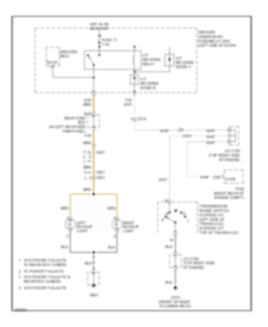
Backup Lamps Wiring Diagram for Honda Odyssey EX 2012
List of elements for Backup Lamps Wiring Diagram for Honda Odyssey EX 2012:
- A/t reverse diode a
- A/t reverse diode b
- A/t reverse relay
- A34
- Atpr
- B30
- Back lt
- C101
- C210
- C25
- C801
- C851
- Driver's micu
- Driver's under-dash fuse/relay box (left end of dash)
- Fuse 11 7.5a
- G101 (front of right cylinder head)
- G801
- Hot in on or start
- J/c c102 (top right side of engine)
- J/c c105 (top right side of engine)
- Left backup light
- Pcm (right rear of engine compt)
- Rear fuse box (in left rear side trim panel)
- Right backup light
- Transmission range switch (5 speed a/t: left side of transaxle) (6 speed a/t: top of transaxle)
- W/ power tailgate
- W/o power tailgate
- W/o power tailgate & rearview camera
- W/o power tailgate w/ rearview camera
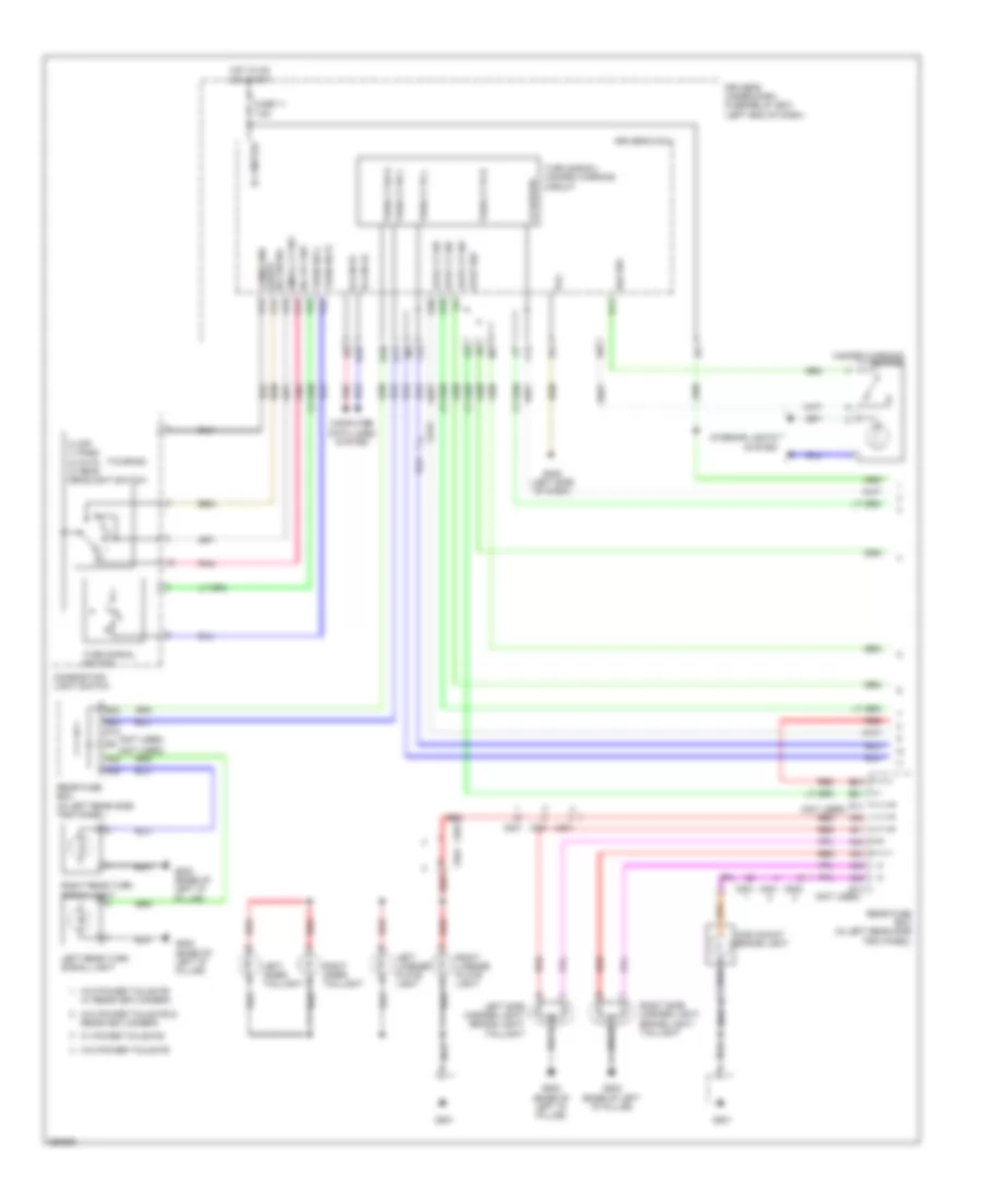
Exterior Lamps Wiring Diagram (1 of 2) for Honda Odyssey EX 2012
List of elements for Exterior Lamps Wiring Diagram (1 of 2) for Honda Odyssey EX 2012:
- (not used)
- (touring)
- +b hazard
- 0) off 1) park 2) auto 3) head headlight switch
- A30
- A31
- A32
- A36
- A38
- A39
- A42
- A45
- Auto lt sig
- Auto lt sio
- Auto lt sip
- B-can hi
- B-can lo
- B22
- B23 d10
- B24
- B31
- C212
- C801
- C802
- C851
- Combi gnd (light) h/l on sw
- Combination light switch
- Computer data lines system
- D13 (not used)
- D14
- Driver's micu
- Driver's under-dash fuse/relay box (left end of dash)
- E10
- E11
- F11
- F12
- Fuse 11 7.5a
- G402 (left side of dash)
- G801
- G802 (base of left "d" pillar)
- H/l off sw
- H10
- Haz sw
- Hazard warning switch
- High mount brake light
- Hot in on or start
- Ig 1 meter
- Interior lights system
- Left inner taillight
- Left license plate light
- Left rear turn signal light
- Left side marker light/ brake light/ taillight
- P13
- P15
- P17
- P19
- P22
- P23
- Pg1
- Pnk
- Q10
- Q11
- Q20
- Rear fuse box (in left rear side trim panel)
- Rearview camera
- Red
- Right inner taillight
- Right license plate light
- Right rear turn signal light
- Right side marker light/ brake light/ taillight
- Small lt sw
- Stop sw
- Turn lt fr l
- Turn lt fr r
- Turn lt rr l
- Turn lt rr r
- Turn signal switch
- Turn signal/ hazard warning circuit
- Turn sw l
- Turn sw r
- W/ power tailgate
- W/ rearview camera
- W/o power tailgate
- W/o power tailgate &
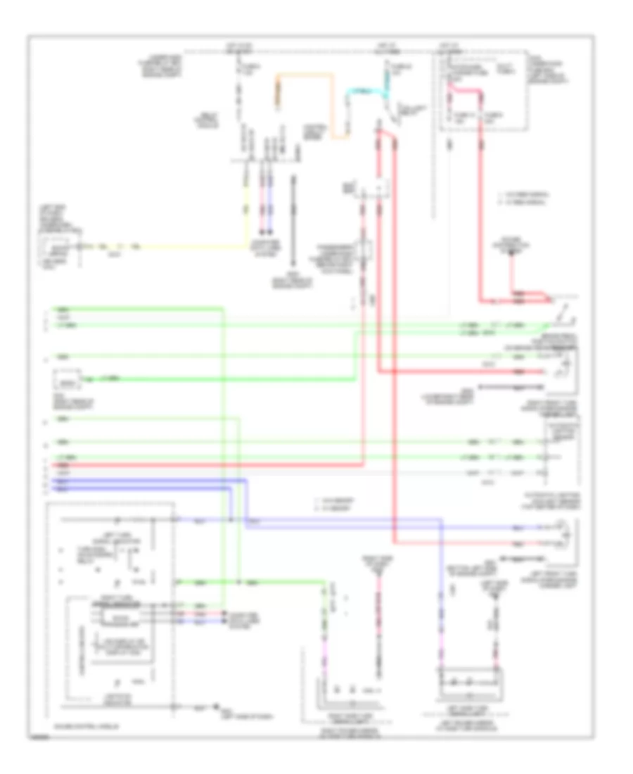
Exterior Lamps Wiring Diagram (2 of 2) for Honda Odyssey EX 2012
List of elements for Exterior Lamps Wiring Diagram (2 of 2) for Honda Odyssey EX 2012:
- (left end of dash) driver's under-dash fuse/relay box
- (left side of dash) g401
- (right side of dash) g405
- A13
- Automatic lighting sensor
- Automatic lighting/ sunlight sensor (top center of dash)
- B-can hi
- B-can lo
- B-can transceiver
- B13
- B14
- B15
- B16
- Back up h/l
- Bksw
- Brake pedal position switch (on brake pedal bracket)
- Bus bar
- C210
- C212
- C401
- C413
- C414
- C607
- Computer data lines system
- Control circuit board
- Control circuits
- D30
- Driver's micu
- F14
- Fuse 10 15a
- Fuse 22 10a
- Fuse 6 7.5a
- Fuse 9 20a
- G201 (bottom left side of engine compt)
- G202 (lower right rear of engine compt)
- G203 (right rear of engine compt)
- G401 (left side of dash)
- Gauge control module
- H/l back up
- Hot at all times
- Hot in on or start
- Ig1 ecu fr
- Lcd display or multi-information display (mid)
- Left front turn signal/parking/side marker light
- Left power mirror (w/ side turn signals)
- Left side turn signal light
- Left turn signal indicator
- Lights on indicator
- Main under-hood fuse box (left side of engine compt)
- Multi fuse 2
- Passenger's under-dash fuse/relay box (behind right kick panel)
- Pcm (right rear of engine compt)
- Pnk
- Power distribution system
- Red
- Relay control module
- Right front turn signal/parking/side marker light
- Right power mirror (w/ side turn signals)
- Right side turn signal light
- Right turn signal indicator
- Sgnd1
- Sml rly cl-
- Stop/horn hazard fuse 20a
- Taillight relay
- Turn sign- anls/hazard relay
- Under-hood fuse/relay box (right rear of engine compt)
- W/ memory
- W/ res normal
- W/o memory
- W/o res normal
Trailer Tow Wiring Diagram for Honda Odyssey EX 2012
List of elements for Trailer Tow Wiring Diagram for Honda Odyssey EX 2012:
- (right rear of engine compt) pcm
- +b dr small lt
- +b hazard
- +b small
- A13
- A48 bksw
- B13
- B22
- B23
- B24
- B31
- Brake pedal position switch (on brake pedal bracket)
- Bus bar
- C212
- C507
- C80
- Combi gnd (light)
- Combination light switch
- Control circuit board
- D10
- D11
- D13
- D14
- D30
- Driver's micu
- Driver's under-dash fuse/relay box (left end of dash)
- E10
- E11
- Exterior lights circuit
- F11
- Fuse 10 15a
- Fuse 11 7.5a
- Fuse 2 7.5a
- Fuse 22 10a
- Fuse 9 20a
- G203 (right rear of engine compt)
- G802 (base of left "d" pillar)
- Gnd
- Haz sw
- Hazard warning switch
- Hot at all times
- Interior lights system
- Kick panel)
- L turn lt
- L turn stop
- Main under- hood fuse box (left side of engine compt)
- P13
- P22
- P23
- Passenger's under-dash fuse/relay box (behind right
- Power distribution system
- Q11
- R turn lt
- R turn stop
- Rear fuse box (in left rear side trim panel)
- Red
- Relay control module
- Sgnd1
- Sml rly cl-
- Stop sw
- Taillight relay
- Trailer hitch connector
- Trailer lighting control unit
- Trailer small
- Turn lt rr l
- Turn lt rr r
- Turn signal switch
- Turn signal/ hazard warning circuit
- Turn sw l
- Turn sw r
- Under-dash fuse/relay box (right rear of engine compt)
- W/ res normal
- W/o res normal
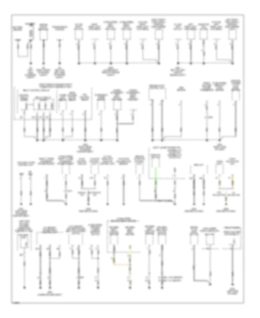
GROUND DISTRIBUTION
Ground Distribution Wiring Diagram (1 of 4) for Honda Odyssey EX 2012
List of elements for Ground Distribution Wiring Diagram (1 of 4) for Honda Odyssey EX 2012:
- (5-speed a/t) d3 switch (6-speed a/t) d4 switch
- (canada) washer fluid level switch
- (honda accessory) left front fog light
- (honda accessory) right front fog light
- (if equipped) driver's lumbar support switch
- (if equipped) driver's seat heater
- (if equipped) front lower accessory power socket
- (if equipped) left front fog light
- (if equipped) right front fog light
- (if equipped) security hood switch
- (left end of dash) driver's under-dash fuse/relay box
- (right rear of engine compt) under-hood fuse/relay box
- (w/ hid) headlight leveling control unit
- (w/ hid) left hid unit
- (w/ hid) right hid unit
- (w/ memory)
- (w/ memory) power seat control unit
- (w/o hid) left head light (low beam)
- (w/o hid) right head light (low beam)
- (w/o memory)
- (w/o memory) driver's power seat adjustment switch
- A12
- A20
- A21
- Audio navigation unit
- Audio unit
- Automatic a/c
- B12
- Battery
- Battery sensor
- Brake fluid level switch
- C202
- C410
- C601
- Climate control unit
- Control circuit board
- D12
- Driver's micu
- Driver's seat back heater
- Driver's seat belt buckle switch
- Driver's seat cushion heater
- Driver's seat position sensor
- E21
- Eld unit
- Engine mount bracket
- Engine mount control unit
- Fan control relay
- Front blower motor relay
- Front blower power transistor
- Front upper accessory power socket
- G1 (left side of engine compt)
- G2 (right front of engine compt)
- G201 (bottom left side of engine compt)
- G202 (lower right rear of engine compt)
- G203 (right rear of engine compartment)
- G204 (right side of dash)
- G3 (bottom left side of engine compt)
- G301 (left rear of engine compartment)
- G302 (left side of dash)
- G403 (center of dash)
- G404 (center of dash)
- G502 (center of dash)
- G601 (under driver's seat)
- Gnd
- Hvac control module
- Left front turn signal/ parking/ side marker light
- Left head light (high beam)
- Main under- hood fuse block
- Manual a/c
- Mr gnd
- Park pin switch
- Pg2
- Pgnd1
- Psp switch
- Radiator fan motor
- Rear blower motor relay
- Relay block
- Relay circuit board
- Relay control module
- Remote starting control unit
- Right front turn signal/ parking/ side marker light
- Right head light (high beam)
- Sg-1
- Sgnd1
- Shift lever connector
- Srs unit
- Transmission housing
- Vsa modulator control unit
- W/ navigation
- W/o navigation
- Windshield wiper motor
- Wiper main relay
- Yaw rate accleration sensor
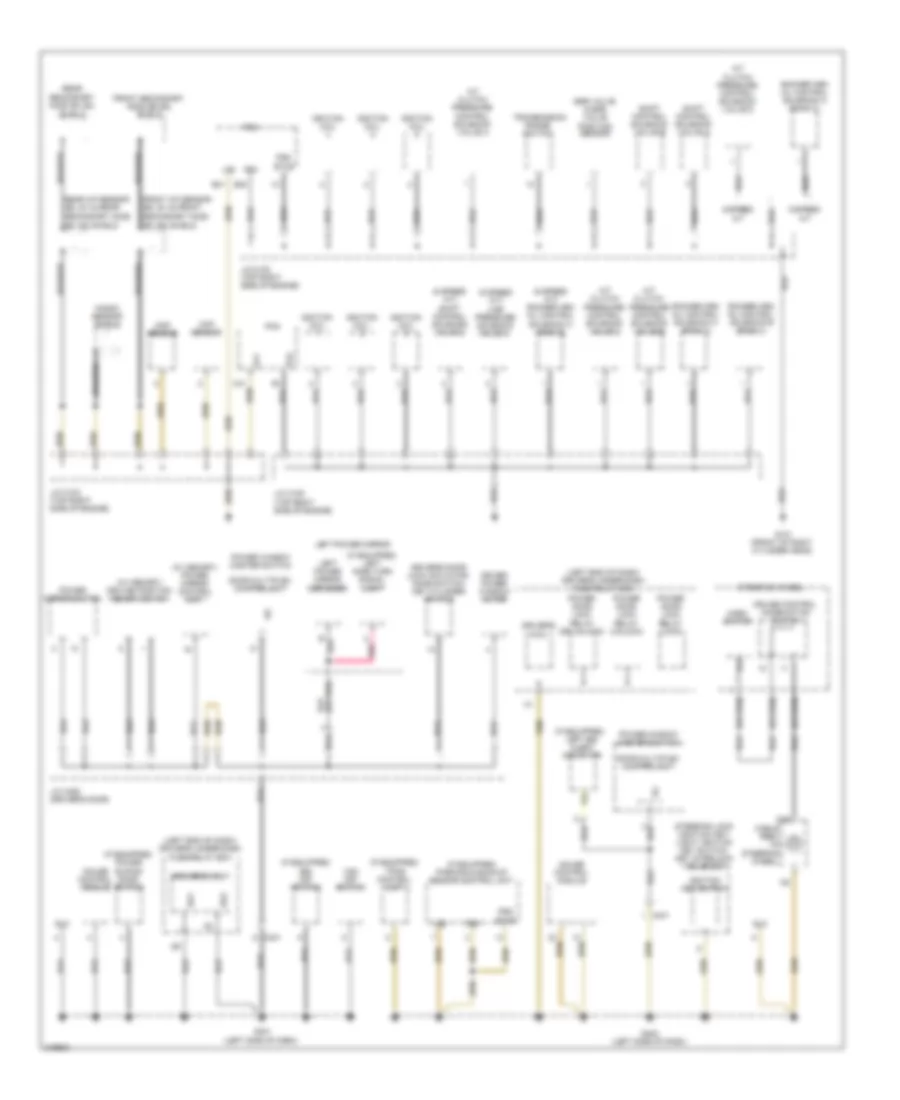
Ground Distribution Wiring Diagram (2 of 4) for Honda Odyssey EX 2012
List of elements for Ground Distribution Wiring Diagram (2 of 4) for Honda Odyssey EX 2012:
- (6 speed a/t) line pressure solenoid valve a
- (6 speed a/t) rocker arm oil control solenoid a (bank 2)
- (6 speed a/t) shift control solenoid valve c
- (if equipped) bsi off switch
- (if equipped) left bsi alert indicator
- (if equipped) left side turn signal light
- (if equipped) parking & backup sensor control unit
- (if equipped) power sliding door switch
- (if equipped) tpms control unit
- (left end of dash) driver's under-dash fuse/relay box
- (w/ memory) driving position memory switch
- (w/ memory) power mirror control unit
- 5-speed a/t
- 6-speed a/t
- A/t clutch pressure control solenoid valve a
- A/t clutch pressure control solenoid valve b
- A/t clutch pressure control solenoid valve c
- A/t clutch pressure control solenoid valve d
- B40
- B41
- Braided
- C19
- C401
- C41
- Cable reel (in steering wheel)
- Ckp sensor
- Cmp sensor
- Cruise control combination switch
- Dlc
- Door multiplex control unit
- Driver power window motor
- Driver's door lock actuator/ knob switch/ key cylinder switch
- Driver's micu
- Egr valve & egr valve position sensor
- Etcs
- Front a/f sensor (b2, s1) & front secondary ho2s (b2, s2) shield
- Front secondary ho2s (b2,s2) shield
- G101 (front of right cylinder head)
- G401 (left side of dash)
- G402 (left side of dash)
- Gauge control module
- Horn switch
- Ignition coil
- Ignition key switch
- J/c c102 (top right side of engine)
- J/c c103 (top right side of engine)
- J/c c105 (top right side of engine)
- J/c c452 (driver's door)
- Knock sensor shield
- Left power mirror
- Left power mirror defogger
- Lg1
- Lg2
- Pcm
- Pg1
- Pg2
- Pgm
- Pnk
- Power door lock relay (dr unlock)
- Power door lock relay (lock)
- Power door lock relay (unlock)
- Power mirror switch
- Power window master switch
- Rear a/f sensor (b2, s1) & rear secondary ho2s (b2, s2) shield
- Rear secondary ho2s (b1,s2) shield
- Rocker arm oil control solenoid a (bank 1)
- Rocker arm oil control solenoid a (bank 2)
- Rocker arm oil control solenoid b (bank 1)
- Sg1
- Sg2
- Shift control solenoid valve a
- Shift control solenoid valve b
- Steering lock (ignition key/ light/ ignition key switch/ key interlock solenoid
- Steering wheel
- Transmission range switch
- Vsa off switch
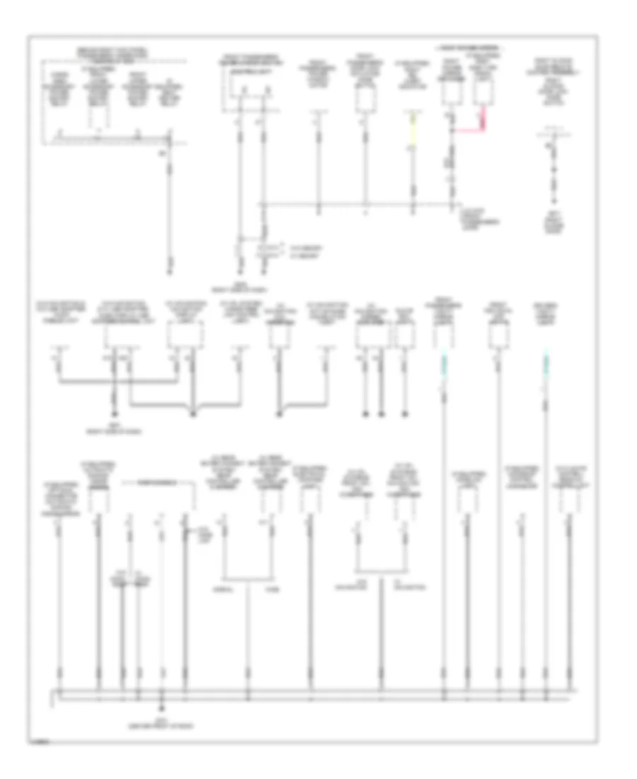
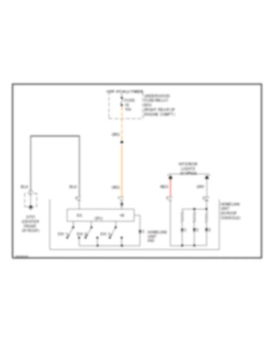
Ground Distribution Wiring Diagram (3 of 4) for Honda Odyssey EX 2012
List of elements for Ground Distribution Wiring Diagram (3 of 4) for Honda Odyssey EX 2012:
- (behind right kick panel) passenger's under-dash fuse/relay box
- (if equipped) automatic dimming inside mirror
- (if equipped) electrical compass unit
- (if equipped) front lower accessory power socket relay
- (if equipped) homelink unit
- (if equipped) moonroof control unit/motor
- (if equipped) optional connector (automatic dimming inside mirror)
- (if equipped) right bsi alert indicator
- (if equipped) right side turn signal light
- (if equipped) seat heater relay
- (w/ climate control) rear a/c control unit
- (w/ hfl system) hands free link control unit
- (w/ hfl systems) front hfl- anc microphone
- (w/ hfl systems) front hfl- navigation- anc microphone
- (w/ navigation) active noise cancelation unit
- (w/ navigation) dial interface
- (w/ navigation) navigation display unit
- (w/ navigation) stereo amplifier
- (w/ rear entertainment system) rear controller & screen
- (w/o navigation & w/ usb adapter) audio display-usb adapter control unit
- (w/o navigation & w/o usb adapter) audio display unit
- A11
- A15
- A20
- C414
- Cargo area accessory power socket relay
- Control unit
- Driver's vanity mirror light
- Front individual map lights
- Front passenger's door lock actuator/ knob switch
- Front passenger's power window motor
- Front passenger's power window switch
- Front passenger's vanity mirror light
- Front upper accessory power socket relay
- G405 (right side of dash)
- G501 (right side of dash)
- G671 (right sliding door)
- G701 (center front of roof)
- Glove box light
- J/c c472 (front passenger's door)
- Normal
- Pnk
- Right power mirror
- Right power mirror defogger
- Right sliding door lock knob switch
- Right sliding door remote control assembly
- Roof console
- W/ memory
- W/ moon- roof
- W/ navigation
- W/o home link
- W/o memory
- W/o moon- roof
- W/o navigation
- Wide
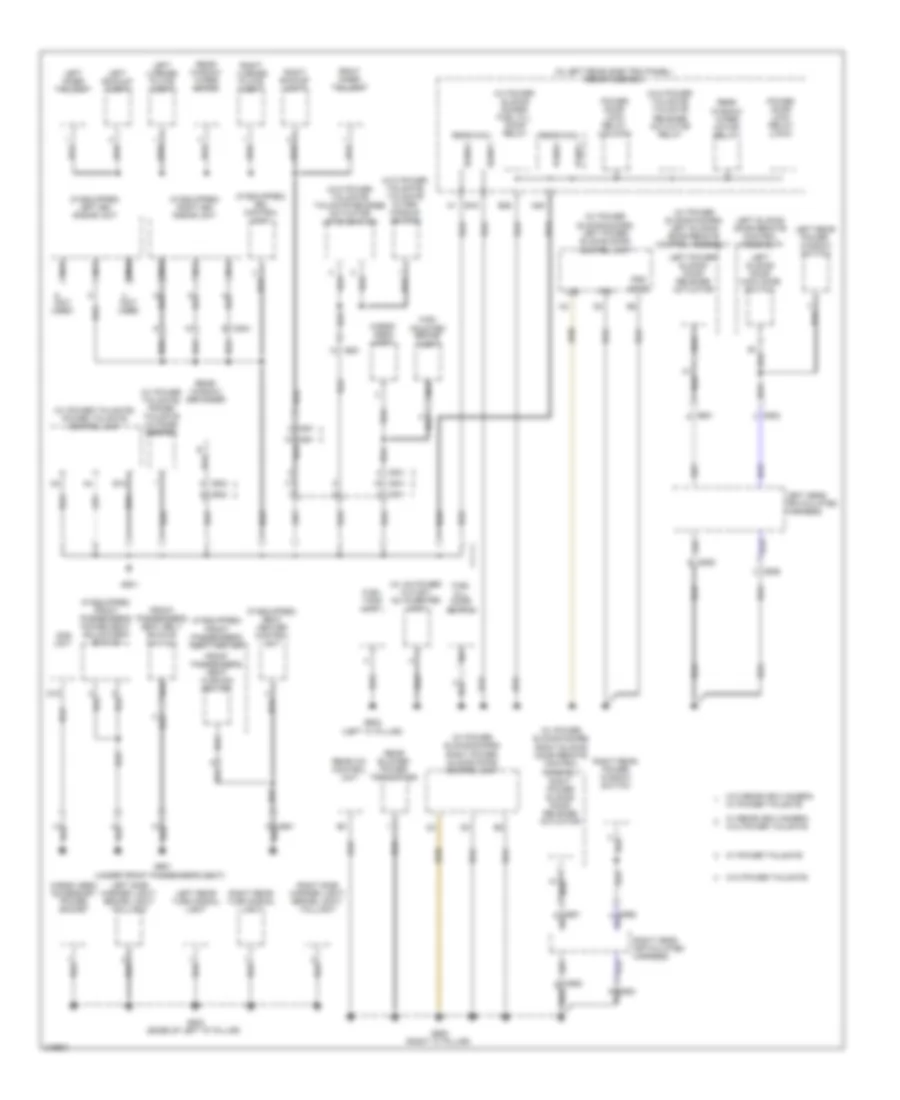
Ground Distribution Wiring Diagram (4 of 4) for Honda Odyssey EX 2012
List of elements for Ground Distribution Wiring Diagram (4 of 4) for Honda Odyssey EX 2012:
- (if equipped) bsi control unit
- (if equipped) front passenger's power seat adjustment switch
- (if equipped) front passenger's seat heater
- (if equipped) left bsi radar unit
- (if equipped) right bsi radar unit
- (if equipped) seat heater control unit
- (in left rear side trim panel) rear fuse box
- (not used)
- (under front passenger's seat)
- (w/ ac power outlet) ac inverter unit
- (w/ power sliding doors) fuel fill door relay
- (w/ power sliding doors) left power sliding door control unit
- (w/ power sliding doors) left sliding door remote control assembly
- (w/ power sliding doors) right power sliding door control unit
- (w/ power sliding doors) right sliding door remote control assembly
- (w/ power tailgate) power tailgate control unit
- (w/ power tailgate) power tailgate outside beeper
- (w/o power tailgate) tailgate outer handle switch
- (w/o power tailgate) tailgate release actuator relay
- (w/o power tailgate) tailgate release actuator/ latch switch
- A29
- B12
- B16
- B26
- C606
- C651
- C653
- C681
- C682
- C691
- C692
- C801
- C802
- C804
- C851
- Cargo area accessory power socket
- Cargo area light
- D18
- Etcs
- Front passenger's seat belt buckle switch
- Front passenger's seat cushion heater
- Fuel fill door switch
- Fuel tank unit
- G602 (left "c" pillar)
- G651
- G652 (right "c" pillar)
- G801
- G802 (base of left "d" pillar)
- High mounted brake light
- Left backup light
- Left cess articulated harness
- Left inner taillight
- Left license plate light
- Left power sliding door release actuator
- Left rear power window switch
- Left rear turn signal light
- Left side marker light/ brake light/ taillight
- Left sliding door lock knob switch
- Left sliding door remote control assembly
- Lg2
- Nca
- Ods unit
- Pg1
- Pgm
- Pgnd1
- Pgnd2
- Power door lock relay (lock)
- Power door lock relay (unlock)
- Rear a/c control unit
- Rear blower power transistor
- Rear micu
- Rear window defogger
- Rear window wiper motor
- Rear window wiper motor relay
- Right backup light
- Right cess articulated harness
- Right inner taillight
- Right license plate light
- Right power sliding door release actuator
- Right rear power window switch
- Right rear turn signal light
- Right side marker light/ brake light/ taillight
- Sgnd1
- Sgnd2
- W/ power tailgate
- W/ rearview camera w/o power tailgate
- W/o power tailgate
- W/o rearview camera w/ power tailgate
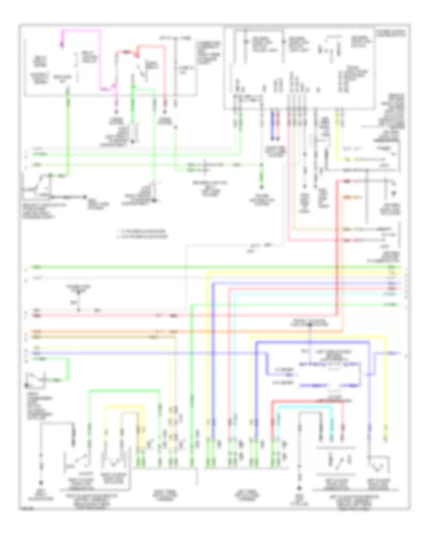
HEADLIGHTS
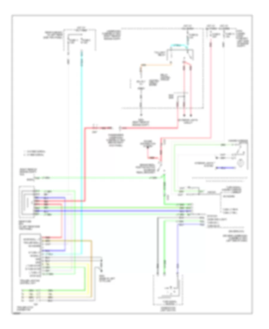
Fog Lamp Wiring Diagram for Honda Odyssey EX 2012
List of elements for Fog Lamp Wiring Diagram for Honda Odyssey EX 2012:
- B- can hi
- B- can lo
- B-can transceiver
- B14
- B15
- B16
- C210
- Combi gnd (light)
- Combination light switch
- Computer data lines system
- Control circuit board
- Control circuits
- D12
- Driver's micu
- Driver's under-dash fuse/relay box (left end of dash)
- F14
- Factory
- Fog light indicator
- Fr fog rly cl-
- Fr fog sw
- Front fog light relay
- Front fog light switch
- Front fog lights optional connector
- Fuse 20a
- Fuse 7.5a
- G202 (lower right rear of engine compt)
- G203 (right rear of engine compt)
- G401 (left side of dash)
- Gauge control module
- H/l back up
- H10
- Honda accessory
- Hot at all times
- Hot in on or start
- Ig1 ecu fr
- Ig1 meter
- Lcd display or mult-information display (mid)
- Left front fog
- Left front fog light
- Light
- Off
- P13
- P18
- Pnk
- Relay circuit board
- Relay control module
- Right front fog light
- Sg1
- Sgnd
- Under- hood fuse/ relay box (right rear of engine compt)
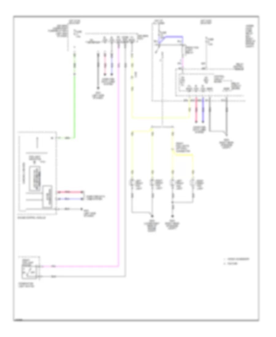
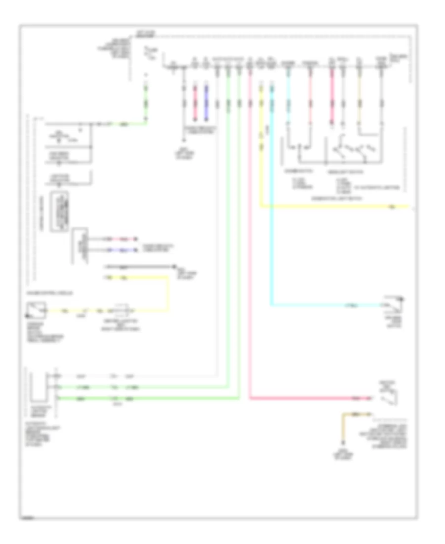
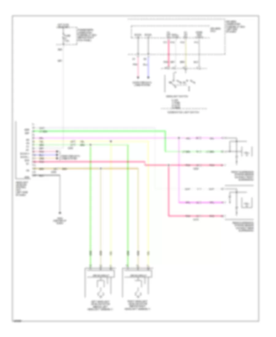
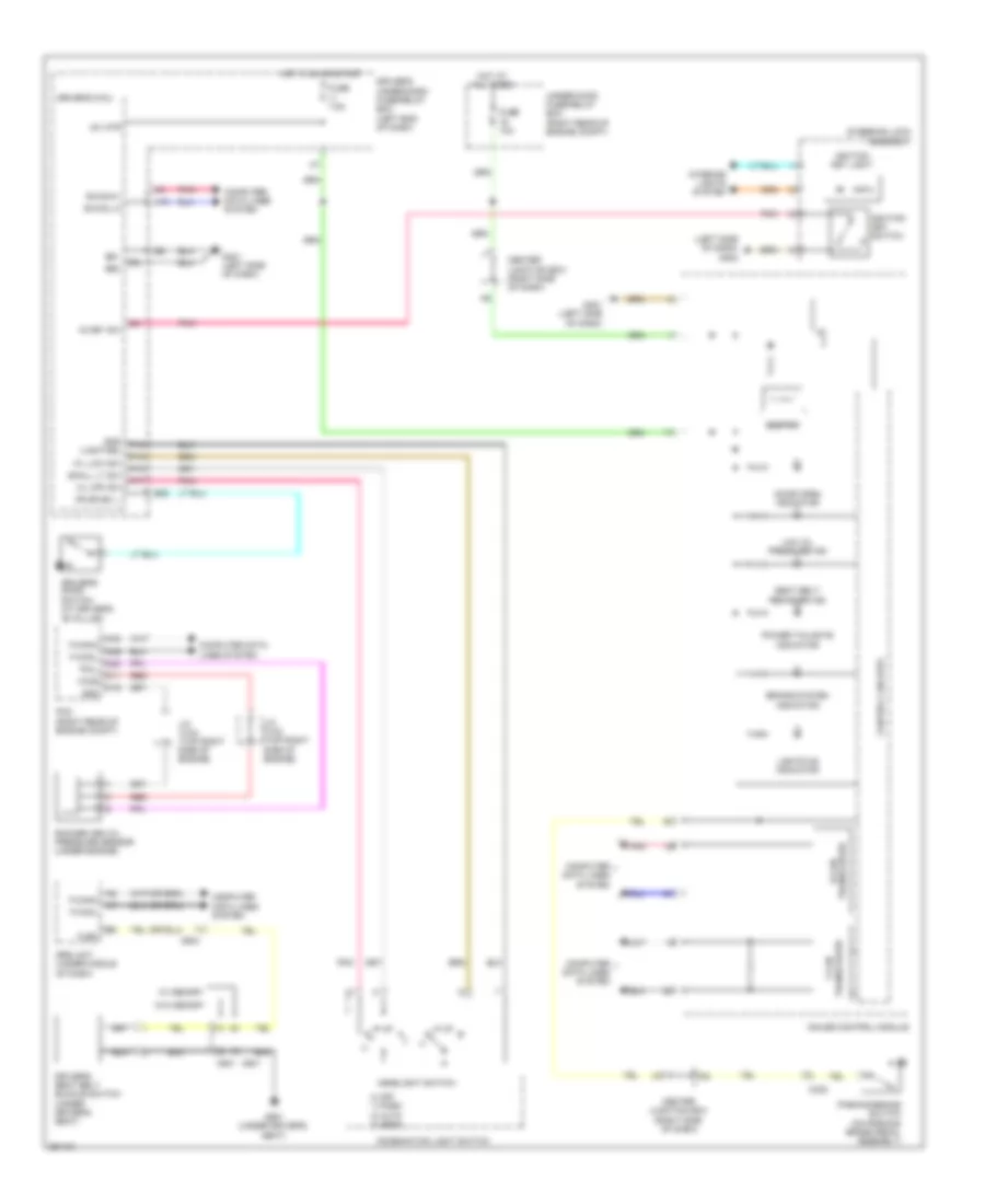
Headlamps Wiring Diagram (1 of 2) for Honda Odyssey EX 2012
List of elements for Headlamps Wiring Diagram (1 of 2) for Honda Odyssey EX 2012:
- (w/ automatic lighting)
- 0) low 1) high 2) passing
- 0) off 1) park 2) auto 3) head
- Auto lt sig
- Auto lt sio
- Auto lt sip
- Automatic lighting sensor
- Automatic lighting/sunlight sensor (if equipped) (top center of dash)
- B- can hi
- B- can lo
- B-can transceiver
- C210
- C302
- C413
- Center junction box (right side of dash)
- Combi gnd (light)
- Combination light switch
- Computer data lines system
- Control circuits
- Dimmer sw
- Dimmer switch
- Driver's door switch
- Driver's micu
- Driver's under-dash fuse/relay box (left end of dash)
- Drl indicator
- E22
- F14
- Fr l door sw
- Fuse 7.5a
- G401 (left side of dash)
- G402 (left side of dash)
- Gauge control module
- H/l back up
- H/l off sw
- H/l on sw
- H10
- Headlight switch
- High beam indicator
- Hot in on or start
- Ig key sw
- Ig1 meter
- Ignition key switch
- Lcd display or mult-information display (mid)
- Lights on indicator
- P13
- P15
- P17
- P19
- P20
- P21
- Parking brake switch (on parking brake pedal assembly)
- Passing sw
- Pnk
- Q10
- Q20
- Red
- Sg1
- Small lt sw
- Steering lock (ignition key light/ ignition key switch/key interlock solenoid) (right side of steering column)
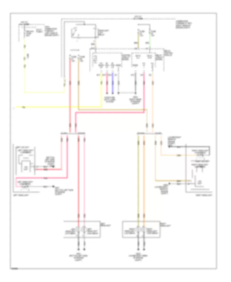
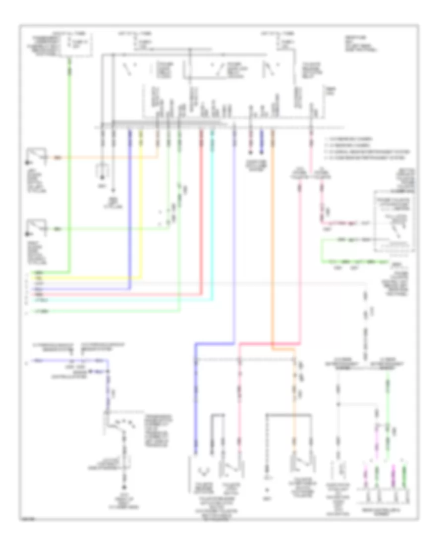
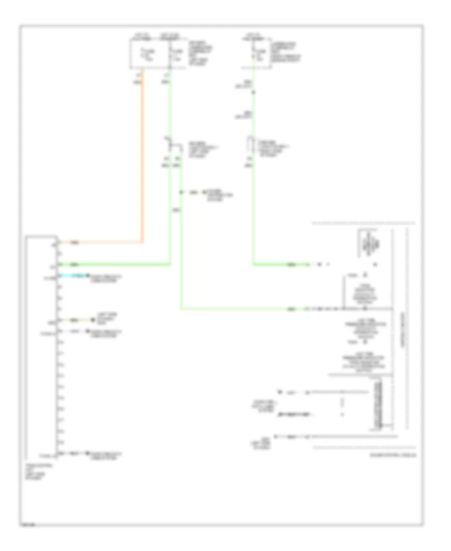
Headlamps Wiring Diagram (2 of 2) for Honda Odyssey EX 2012
List of elements for Headlamps Wiring Diagram (2 of 2) for Honda Odyssey EX 2012:
- (bottom left side of engine compt) g201
- (lower right rear of engine compt) g202
- +b h/l hi l
- +b h/l hi r
- B- can hi
- B- can lo
- B12
- B14
- B15
- B16
- C209
- Computer data lines system
- Control circuit baord
- D12
- Fuse 10a
- Fuse 15a
- G201 (bottom left side of engine compt)
- G202 (lower right rear of engine compt)
- G203 (right rear of engine compt)
- H/l back up
- H/l hi l
- H/l hi r
- H/l lo rly cl-
- Headlight low relay
- Hid unit
- Hot at all times
- Left headlight
- Left headlight (high beam)
- Left headlight (low beam)
- Left hid unit
- Main under-hood fuse box (left side of engine compt)
- Multi- fuse 3
- Pnk
- Rb main fuse 60a
- Red
- Relay circuit baord
- Relay control module
- Right headlight
- Right headlight (high beam)
- Right headlight (low beam)
- Right hid unit
- Sgnd
- Under-hood fuse/relay box (right rear of engine compt)
- W/ hid
- W/o hid
Headlamps Leveling Wiring Diagram for Honda Odyssey EX 2012
List of elements for Headlamps Leveling Wiring Diagram for Honda Odyssey EX 2012:
- 0) off 1) park 2) auto 3) head
- B-can h
- B-can hi
- B-can l
- B-can lo
- C205
- C415
- Combi gnd (light)
- Combination light switch
- Computer data lines system
- Drive circuit
- Driver's micu
- Driver's under-dash fuse/relay box (left end of dash)
- E25
- Front suspension stroke sensor (on right front suspension)
- Fuse 7.5a
- G403 (center of dash)
- Gnd
- H/l off sw
- H/l on sw
- Hall ic
- Headlight leveling control unit (left side of dash)
- Headlight switch
- Hot in on or start
- Ig1
- Left headlight leveling motor (behind left headlight assembly)
- P13
- P15
- P17
- P19
- Passenger's under-dash fuse/relay box (behind right kick panel)
- Pnk
- Rear suspension stroke sensor (on right rear suspension)
- Right headlight leveling motor (behind right headlight assembly)
- Scs
- Small lt sw
- Ssf
- Ssr
HORN
Horn Wiring Diagram for Honda Odyssey EX 2012
List of elements for Horn Wiring Diagram for Honda Odyssey EX 2012:
- A10
- Brake pedal position switch (on brake pedal bracket)
- C19
- C20
- C205
- C212
- Cable reel (in steering wheel)
- Control circuit board
- Cruise control combination switch
- Fuse 9 20a
- G402 (left side of dash)
- High horn (left front of engine compt)
- Horn
- Horn relay
- Hot at all times
- Low horn (right front of engine compt)
- Main under-hood fuse box (left side of engine compt)
- Multi- fuse 2
- Pnk
- Power distribution system
- Red
- Relay circuit board
- Relay control module
- Steering wheel
- Stop/horn hazard fuse 30a
- Switch
- Under-hood fuse/ relay box (right rear of engine compt)
INSTRUMENT CLUSTER
Instrument Cluster Wiring Diagram (1 of 3) for Honda Odyssey EX 2012
List of elements for Instrument Cluster Wiring Diagram (1 of 3) for Honda Odyssey EX 2012:
- (left side of dash) g401
- Abs ind
- B can hi
- B can lo
- B-can transceiver
- B10
- B11
- B12
- B17
- Brake system ind
- Bsi ind (if equipped)
- C607
- Center junction box (right side of dash)
- Charging system ind
- Computer data lines system
- Control circuits
- Cruise control ind
- Cruise control main switch ind
- Cruise control system
- Dial illumination (white)
- Door open ind
- Drl ind (w/o multi information switch)
- Eco ind
- Engine coolant temperature gauge
- Exterior lights system
- F-can transceiver
- Fog light ind (if equipped)
- Fuel gauge
- Fuse 16 10a
- G402 (left side of dash)
- Gauge control module
- Hot at all times
- Interior lights system
- Lcd display or multi- information display (md)
- Lcd illumination (white)
- Led light
- Left sliding door switch (on left "c" pillar)
- Lights on ind
- Lin transceiver
- Low fuel ind
- Low oil pressure ind
- Low tire pressure ind (w/o multi information switch)
- Low tire pressure ind/tpms ind (w/o multi information switch)
- Maintenance required ind (w/o multi information switch)
- Message ind (w/ multi information switch)
- Mid illumination (white)
- Mil ind
- Parking & back-up sensor ind (if equipped)
- Pnk
- Pointers illumination (white)
- Power sliding door ind (if equipped)
- Power tailgate ind (if equipped)
- Ra door sw
- Rd door sw
- Rear fuse box (in left rear side trim panel)
- Rear micu
- Red
- Right sliding door switch (on right "c" pillar)
- Seat belt remainder
- Side air bag cut off ind
- Speedometer
- Srs ind
- Starter system ind (w/o multi information switch)
- Tachometer
- To dimming switch (diagram 3 of 3)
- To front corner sensor beeper (diagram 3 of 3)
- To security ind (diagram 3 of 3)
- Tpms ind (w/o multi information switch)
- Under-hood fuse/relay box (right rear of engine compt)
- Vsa off ind
- Vsa system ind
- W/ wide rear entertainment system w/ normal rear entertainment system
- Washer fluid level ind
Instrument Cluster Wiring Diagram (2 of 3) for Honda Odyssey EX 2012
List of elements for Instrument Cluster Wiring Diagram (2 of 3) for Honda Odyssey EX 2012:
- (not used)
- (on left "b" pillar) driver's door switch
- (on right "b" pillar) front passenger's door switch
- A14
- A15
- B-can hi
- B-can lo
- C14
- C15
- C415
- Cable reel (in steering column)
- Computer data lines system
- Driver's micu
- Driver's under-dash fuse/relay box (left end of dash)
- E22
- E25
- Fr l door
- Fr r door
- Fuse 11 7.5a
- H10
- Hot in on or start
- Interior lights system
- Multi-information switch
- Next button
- Pnk
- Sel/ reset button
- Steering wheel (w/ multi-information switch)
Instrument Cluster Wiring Diagram (3 of 3) for Honda Odyssey EX 2012
List of elements for Instrument Cluster Wiring Diagram (3 of 3) for Honda Odyssey EX 2012:
- (brake fluid reservoir) brake fluid level switch
- (if equipped) audio navigation unit
- (left side of dash)
- 5 speed a/t
- 6 speed a/t
- Battery sensor
- Beeper
- Brightening switch
- C11
- C205
- C302
- C404
- C412
- Center junction box (right side of dash)
- Control circuits
- D3 d4
- Dimming switch
- Driver's junction box 1 (left side of dash)
- From pin 1 (diagram 1 of 3)
- From pin 25 a (diagram 1 of 3)
- From pin 26 (diagram 1 of 3)
- Front corner
- Fuel gauge sending unit
- Fuel tank unit (top of fuel tank)
- G204 (right side of dash)
- G302
- G401
- Gauge control module
- High beam ind
- Immobilizer system ind
- Left turn signal ind
- Odometer/ trip/ meter/ select/ reset switch
- Parking brake switch (on parking brake pedal assembly)
- Pnk
- Rear corner/center
- Right turn signal ind
- Security ind (if equipped)
- Sensor beeper
- Turn signal/ hazard relay
- Vsa off switch
- Washer fluid level switch (canada)
INTERIOR LIGHTS
Courtesy Lamps Wiring Diagram (1 of 4) for Honda Odyssey EX 2012
List of elements for Courtesy Lamps Wiring Diagram (1 of 4) for Honda Odyssey EX 2012:
- +b back-up
- A18
- Active noise cancellation
- Audio unit (w/o navigation)
- B-can hi
- B-can lo
- B10
- B11
- B12
- B17
- C11
- C405
- C505
- C607
- C801 c801
- C851
- Cargo lt-
- Computer data lines system
- Door
- Front individual map lights
- Full latch switch
- G701 (center front of roof)
- G801
- Interior light switch
- Left
- Left rear individual map light (2nd)
- Left rear individual map light (3rd)
- Left sliding door switch (on left "c" pillar)
- Off
- Off on
- Pnk
- Power tailgate closer unit (bottom middle of tailgate)
- Power tailgate control unit (behind left rear side trim panel)
- Power tailgate latch/ ratchet switch
- Ra door sw
- Rd door sw
- Rear fuse box (in left rear side trim panel)
- Rear micu
- Red
- Right
- Right rear individual map light (2nd)
- Right rear individual map light (3rd)
- Right sliding door switch (on right "c" pillar)
- Roof console
- Seg3
- T gate sw+
- Tailgate latch switch
- Tailgate release actuator/ latch switch (bottom middle of tailgate)
- Unit (w/ navigation)
- W/ power tailgate
- W/ rearview camera
- W/ res
- W/ res normal
- W/o power tailgate
- W/o rearview camera
- W/o res
- W/o res normal & w/ res wide
Courtesy Lamps Wiring Diagram (2 of 4) for Honda Odyssey EX 2012
List of elements for Courtesy Lamps Wiring Diagram (2 of 4) for Honda Odyssey EX 2012:
- (left side
- (w/ memory)
- (w/ res)
- (w/o memory)
- (w/o res)
- Antenna
- B-can h
- B-can l
- C401
- C414
- C451
- C471
- C701
- C801
- C851
- Cargo area light
- Center junction box (right side of dash)
- Computer data lines system
- Door
- Door multiplex control unit
- Driver's door courtesy light
- Driver's junction box 1 (left side of dash)
- Driver's vanity mirror light
- Front passenger's door courtesy light
- Front passenger's vanity mirror light
- G401
- G402 (left side
- G701 (center front of roof)
- G801
- Immobilizer- keyless control unit (on steering column, near steering lock)
- J/c c452 (driver's door)
- Lock
- Of dash)
- Off
- Pnk
- Power distribution system
- Power tailgate inside switch
- Power window master switch
- Red
- Unlock
- Vbu
- Vmp dr
- W/ power tailgate
- W/ rearview camera
- W/o power tailgate
- W/o rearview camera
Courtesy Lamps Wiring Diagram (3 of 4) for Honda Odyssey EX 2012
List of elements for Courtesy Lamps Wiring Diagram (3 of 4) for Honda Odyssey EX 2012:
- A13
- B13
- Bus bar
- C411
- Center junction box (right side of dash)
- Control circuit
- Control circuit board
- Driver's footwell light
- Driver's junction box 1 (left side of dash)
- Driver's junction box 2 (left side of dash)
- Exterior lights system
- Front passenger's footwell light
- Fuse 22 10a
- Fuse 25 7.5a
- G402 (left side
- Gauge control module
- Hot at all times
- Ignition key light
- Ignition key switch
- J3 red
- Of dash)
- Passenger's under-dash fuse/relay box (behind right kick panel)
- Pnk
- Red
- Relay control module
- Sml rly cl-
- Steering lock (ignition key switch/key light) (right side of steering column)
- Taillight relay
- Under-hood fuse/relay box (right rear of engine compt)
- W/ memory
- W/o memory
Courtesy Lamps Wiring Diagram (4 of 4) for Honda Odyssey EX 2012
List of elements for Courtesy Lamps Wiring Diagram (4 of 4) for Honda Odyssey EX 2012:
- +b backup
- B-can hi
- B-can lo
- C210
- C302
- C401
- C413
- C415
- Computer data lines system
- Door lock knob
- Driver's door lock actuator/ knob switch/ key cylinder switch (rear of driver's front door)
- Driver's door lock knob switch
- Driver's door switch (on left "b" pillar)
- Driver's junction box 1 (left side of dash)
- Driver's junction box 2 (left side of dash)
- Driver's micu
- Driver's under-dash fuse/relay box (left end of dash)
- E21
- E22
- E23
- E25 (not used)
- E43
- E44
- F24
- Fr courtesy l
- Fr courtesy r
- Fr l door sw
- Fr r door sw
- Front passenger's door switch (on right "b" pillar)
- Fuse 10a
- Fuse 20a
- Fuse 7.5a
- G10
- G401 (left side of dash)
- G402 (left side of dash)
- G601 (under driver's seat)
- Hot at all times
- Hot in on or start
- Ig key lt-
- Ig key sw
- Ig1 meter
- Interior lights cut relay
- Intr lt cut
- Intr lt-
- J/c c203 (right side of dash)
- J/c c408 (left side of dash)
- J/c c452 (driver's door)
- Key
- Lock
- Main under-hood fuse box (left side of engine compt)
- P11
- Pg1
- Pg2
- Pnk
- Q15
- Q16
- Relay block
- Sg1
- Sg2
- Under-hood fuse/relay box (right rear of engine compt)
- Unlock
- W/ memory
- W/o memory
Instrument Illumination Wiring Diagram (1 of 4) for Honda Odyssey EX 2012
List of elements for Instrument Illumination Wiring Diagram (1 of 4) for Honda Odyssey EX 2012:
- (w/ res normal)
- (w/ res wide)
- A/t gear position indicator panel light
- A13
- A21
- A22
- B13
- Bus bar
- C405
- C413
- Control circuit board
- Courtesy lamps circuit
- Driver's junction box 1 (left side of dash)
- Exterior lights system
- Fuse 22 10a
- Fuse 25 7.5a
- Homelink unit (if equipped) (in roof console)
- Hot at all times
- Interior light switch
- Passenger's under-dash fuse/relay box (behind right kick panel)
- Rear a/c control panel (automatic a/c)
- Rear controller & screen
- Red
- Relay control module
- Roof console
- Shift lever connector
- Sml rly cl-
- Taillight relay
- Under-hood fuse/relay box (right rear of engine compt)
- W/ moonroof
- W/o moonroof
Instrument Illumination Wiring Diagram (2 of 4) for Honda Odyssey EX 2012
List of elements for Instrument Illumination Wiring Diagram (2 of 4) for Honda Odyssey EX 2012:
- (not used)
- (optional conne- ctor)
- +b back up
- A11
- A14
- Audio display unit (w/o navigation & usb adapter)
- Audio unit (w/o navigation & audio remote switch)
- Auto
- Automatic a/c
- B-can hi
- B-can lo
- C412
- C415
- Center junction box (right side of dash)
- Climate control unit
- Combi gnd (light)
- Combination light switch
- Computer data lines system
- Driver's micu
- Driver's under-dash fuse/relay box (left end of dash)
- E21
- E42
- F24
- Front passenger's air bag cut-off indicator
- Fuse 5 7.5a
- G401 (left side of dash)
- G402 (left side of dash)
- G501 (right side of dash)
- G601 (under driver's seat)
- Glove box light
- H/l off
- H/l on
- H10
- Head
- Headlight switch
- Hot in on or start
- Hvac control unit
- Ig1 meter
- Manual a/c
- Off
- P13
- Park
- Pg1
- Pg2
- Pnk
- Red
- Right b-pillar power sliding door switch (if equipped)
- Sg1
- Sg2
- Small lt sw p19
- Sw p15
- Sw p17
Instrument Illumination Wiring Diagram (3 of 4) for Honda Odyssey EX 2012
List of elements for Instrument Illumination Wiring Diagram (3 of 4) for Honda Odyssey EX 2012:
- (bsi system) bsi off switch
- (under left side of dash) j/c c406
- C404
- C410
- Cool box control unit
- Driver's junction box 2 (left side of dash)
- Driver's power tailgate switch (power tailgate w/o parking & backup sensor system)
- Driver's power tailgate/parking & back-up sensor switch (power tailgate) w/ parking & backup sensor system)
- Hazard warning switch
- J/c c406 (under left side of dash)
- Left b-pillar power sliding door switch (if equipped)
- On ind
- Power sliding door switch
- Power sliding door switch (if equipped)
- Red
- Res auxiliary jack assembly (if equipped)
- Vsa off switch
- W/ memory
- W/o memory
Instrument Illumination Wiring Diagram (4 of 4) for Honda Odyssey EX 2012
List of elements for Instrument Illumination Wiring Diagram (4 of 4) for Honda Odyssey EX 2012:
- Ambient light in-line fuse
- Audio remote switch
- Brightening switch
- C210
- Cable reel (in steering wheel)
- Computer data lines system
- Control circuits
- Cruise control combination switch
- Dimming switch
- Display (mid) multi-information lcd display or
- Driver's ambient light (honda accessory)
- Driver's under-dash fuse/relay box (left end of dash)
- Front passenger's ambient light (honda accessory)
- Fuse 16 10a
- G401 (left side of dash)
- G402 (left side of dash)
- Gauge control module
- Hfl switch (w/o navigation) hfl- navigation voice control switch (w/ navigation)
- Hot at all times
- J/c c203 (right side of dash)
- Multi- information switch (if equipped)
- Pnk
- Red
- Steering wheel
- Transceiver b-can
- Under-hood fuse/relay box (right rear of engine compt)
- W/ audio remote switch
- W/ memory
- W/o audio remote switch
- W/o memory
MEMORY SYSTEMS
Memory Mirrors Wiring Diagram (1 of 2) for Honda Odyssey EX 2012
List of elements for Memory Mirrors Wiring Diagram (1 of 2) for Honda Odyssey EX 2012:
- (driver's door)
- B-can h
- B-can l
- B23
- C401
- C402
- C601
- Computer data lines system
- Door multiplex control unit
- Driver's junction box 1 (left side of dash)
- Driver's under-dash fuse/relay box (left end of dash)
- Driving position memory switch
- Driving position memory switch light
- E24
- Fuse 10a
- Fuse 20a
- Fuse 7.5a
- G401 (left side of dash)
- G402 (left side of dash)
- Gnd
- H11
- Hot at all times
- Hot in on
- Ig1
- Ig2
- Interior lights system
- J/c c452 (driver's door)
- Lhm
- Lmc
- Lseh
- Lsev
- Lvm
- Memo ind 1
- Memo ind 2
- Memo pos 1
- Memo pos 2
- Memo set
- Mldl
- Mldr
- Mrdl
- Mrdr
- Mul
- Or start
- P/w cont ill+
- Pnk
- Pos 1 ind
- Pos 1 switch
- Pos 2 ind
- Pos 2 switch
- Power mirror control unit
- Power seat control unit (under driver's seat)
- Power window master switch
- Red
- Rhm
- Rmc
- Rseh
- Rsev
- Rvm
- Sen feed
- Set switch
- Uart
- Under-hood fuse/relay box (right rear of engine compt)
- Vbu
- Vmp dr
Memory Mirrors Wiring Diagram (2 of 2) for Honda Odyssey EX 2012
List of elements for Memory Mirrors Wiring Diagram (2 of 2) for Honda Odyssey EX 2012:
- (on steering column, near steering lock)
- Antenna
- B-can h
- B-can l
- C401
- C402
- C414
- Computer data lines system
- Down
- G401 (left side of dash)
- Immobilizer keyless control unit
- Interior lights system
- Internal switch positions
- J/c c452 (driver's door)
- Left
- Left power mirror
- Left power mirror actuator
- Left/right motor
- Mirror direction selected
- Pnk
- Position sensor
- Power mirror switch
- Red
- Right
- Right power mirror
- Right power mirror actuator
- Swing
- Switch 1
- Switch 2
- Switch 3
- Tilt
- Transmitter
- Up/down motor
Memory Seat Wiring Diagram (1 of 3) for Honda Odyssey EX 2012
List of elements for Memory Seat Wiring Diagram (1 of 3) for Honda Odyssey EX 2012:
- +b back up
- A10
- A11
- A12
- A13
- A14
- A15
- A16
- A17
- A18
- Atp-p
- Atpp
- B-can hi
- B-can lo
- B-canh
- B-canl
- B10
- B11
- B12
- B13
- B14
- B15
- B16
- B17
- B18
- B19
- B20
- B21
- B22
- B23
- B24
- B25
- B26
- B27
- B28
- B29
- B30
- B31
- B32
- B33
- B34
- B35
- B36
- B37
- B38
- B39
- C210
- C402
- C601
- Computer data lines system
- Driver's micu
- Driver's power seat front up-down motor/position sensor (under driver's seat)
- Driver's power seat recline motor/position sensor (in driver's seat back)
- Driver's under-dash fuse/relay box (left end of dash)
- E12
- E23
- E24
- E34
- F24
- Fhdn
- Fhm +
- Fhm -
- Fhse
- Fhup
- Fuse 10a
- Fuse 20a
- Fuse 7.5a
- G601 (under driver's seat)
- H10
- H11
- Hot at all times
- Hot in on or start
- Ig1
- J/c c203 (right side of dash)
- Pg1
- Pg2
- Pnk
- Power mirror control unit (driver's door)
- Power seat control unit (under driver's seat)
- Q18
- Rebw
- Red
- Refw
- Rem +
- Rem -
- Rese
- Rhdn
- Rhm +
- Rhm -
- Rhse
- Rhup
- Scom
- Seg
- Sensor
- Slbw
- Slfw
- Slm +
- Slm -
- Slse
- Svcc
- Uart
- Under-hood fuse/relay box (right rear of engine compartment)
- Vbu
- Vmp1
- Vmp2
Memory Seat Wiring Diagram (2 of 3) for Honda Odyssey EX 2012
List of elements for Memory Seat Wiring Diagram (2 of 3) for Honda Odyssey EX 2012:
- (front of right cylinder head)
- A16
- Atpp
- C101
- C205
- C404
- Driver's junction box 2 (left side of dash)
- Driver's power seat rear up-down motor/position sensor (under driver's seat)
- Driver's power seat slide motor/position sensor (under driver's seat)
- G101
- J/c c102 (top right side of engine)
- Pcm (right rear of engine compartment)
- Pnk
- Red
- Sensor
- Transmission range switch (5 speed a/t: left side of transaxle) (6 speed a/t: top of transaxle)
- W/ parking & backup sensor system
- W/o parking & backup sensor system
Memory Seat Wiring Diagram (3 of 3) for Honda Odyssey EX 2012
List of elements for Memory Seat Wiring Diagram (3 of 3) for Honda Odyssey EX 2012:
- Bwd
- C401
- Door multiplex control unit
- Down
- Driver's power seat adjustment switch
- Driving position memory switch
- Driving position memory switch light
- Front up- down switch
- Fwd
- G401 (left side of dash)
- G402 (left side of dash)
- Interior lights system
- J/c c452 (driver's door)
- Memo ind 1
- Memo ind 2
- Memo pos 1
- Memo pos 2
- Memo set
- P/w cont ill+
- Pnk
- Pos 1 ind
- Pos 1 switch
- Pos 2 ind
- Pos 2 switch
- Power window master switch
- Rear up down switch
- Recline switch
- Red
- Set switch
- Slide switch
- Vmp dr
NAVIGATION
Blind Spot Information System Wiring Diagram for Honda Odyssey EX 2012
List of elements for Blind Spot Information System Wiring Diagram for Honda Odyssey EX 2012:
- (not used)
- A23
- A24
- B-can h
- B-can hi
- B-can l
- B-can lo
- B10
- B17
- B29
- Beeper
- Bsi control unit (behind left rear side trim panel)
- Bsi ind
- Bsi off sw
- Bsi off switch
- Bsi-can h
- Bsi-can l
- C401
- C404
- C414
- C609
- C804
- Computer data lines system
- Control circuits
- Control speaker
- Driver's micu
- Driver's under-dash fuse/relay box (left end of dash)
- E18
- E43
- E44
- Fuse 15a
- Fuse 7.5a
- G401 (left side of dash)
- G402 (left side of dash)
- G405 (right side of dash)
- G801
- Gauge control module
- Gnd
- H10
- Hot in on or start
- Ig1
- Interior lights system
- J/c c803 (behind left rear side trim panel)
- L bsi ind+
- Left bsi alert indicator
- Left bsi radar unit (behind left side of rear bumper)
- Mpio-0
- Mpio-1
- Nca
- Pnk
- R bsi ind+
- Rear fuse box (in left rear side trim panel)
- Rear micu
- Right bsi alert indicator
- Right bsi radar unit (behind right side of rear bumper)
- Transceiver b-can
Compass Wiring Diagram for Honda Odyssey EX 2012
List of elements for Compass Wiring Diagram for Honda Odyssey EX 2012:
- A24
- Acc
- Audio unit
- B-can h
- B-can l
- B10
- B13
- B19
- B20
- C206
- C405
- C505
- C507
- Compass rx+
- Compass rx-
- Compass tx+
- Compass tx-
- Computer data lines system
- Disp rx+
- Disp rx-
- Disp tx+
- Disp tx-
- Driver's under-dash fuse/relay box (left end of dash)
- Electrical compass unit (center of roof)
- Fuse 20a
- Fuse 7.5a
- G502 (center of dash)
- G701 (center front of roof)
- Gnd
- Hot at all times
- Hot in acc or on
- Hot in on or start
- Ig1
- Main gnd
- Pnk
- Power distribution system
- Under-hood fuse/relay box (right rear of engine compt)
- W/ rear entertainment system
- W/ roof speaker
- W/o rear entertainment system
- W/o roof speaker
Hands Free Module Wiring Diagram, with Navigation for Honda Odyssey EX 2012
List of elements for Hands Free Module Wiring Diagram, with Navigation for Honda Odyssey EX 2012:
- (base of right "d" pillar)
- (not used)
- A11
- A12
- Acc
- Audio navigation unit
- Audio remote switch
- B20
- B21
- Back switch
- C15
- C16
- C413
- C505
- C506
- Cable reel (in steering wheel)
- D11
- D12
- Driver's junction box 1 (left side of dash)
- Driver's under-dash fuse/relay box (left end of dash)
- Front hfl-navigation anc microphone (center roof console)
- Fuse 10a
- Fuse 20a
- Fuse 7.5a
- G501 (right side of dash)
- G701 (center front of roof)
- Ga audio l+
- Ga audio l-
- Ga audio r+
- Ga audio r-
- Ga audio sh
- Ga bus +
- Ga bus -
- Ga bus sh
- Gnd
- Handsfreelink control unit (center of dash)
- Hang up switch
- Hfl mute
- Hfl navi mic +
- Hfl navi mic -
- Hfl navi mic sh
- Hfl navigation voice control switch
- Hfl strg sw
- Hot at all times
- Hot in acc or on
- Interior lights system
- Junction connector c501
- Junction connector c502 (right side of dash)
- Junction connector c503
- Mc +
- Mc -
- Mic +
- Mic -
- Mic sh
- Navigation display unit
- Pick up switch
- Pnk
- Red
- Remote gnd
- Steering wheel
- Talk switch
- Telm sig +
- Telm sig -
- Telm sig sh
- Under-hood fuse/relay box (right rear of engine compt)
- W/ rear entertainment system
- W/o rear entertainment system
- Xm receiver (w/ xm radio)
Hands Free Module Wiring Diagram, without Navigation (1 of 2) for Honda Odyssey EX 2012
List of elements for Hands Free Module Wiring Diagram, without Navigation (1 of 2) for Honda Odyssey EX 2012:
- A11
- A12
- A13
- A14
- Acc
- Audio display-usb adapter control unit
- C505
- C506
- Driver's under-dash fuse/relay box (left end of dash)
- Fuse 20a
- Fuse 7.5a
- G501 (right side of dash)
- Ga audio l+
- Ga audio l-
- Ga audio r+
- Ga audio r-
- Ga audio sh
- Ga bus +
- Ga bus -
- Ga bus sh
- Gnd
- Handsfreelink control unit (center of dash)
- Hfl mute
- Hfl strg sw
- Hot at all times
- Hot in acc or on
- Junction connector c502 (right side of dash)
- Mic +
- Mic -
- Mic sh
- Pnk
- Telm sig +
- Telm sig -
- Telm sig sh
- Under-hood fuse/relay box (right rear of engine compt)
- W/ rear entertainment system
- W/o rear entertainment system
- Xm receiver (base of right "d" pillar)
Hands Free Module Wiring Diagram, without Navigation (2 of 2) for Honda Odyssey EX 2012
List of elements for Hands Free Module Wiring Diagram, without Navigation (2 of 2) for Honda Odyssey EX 2012:
- (not used)
- A11
- Acc
- Audio remote switch
- Audio unit
- B12
- Back switch
- C413
- Cable reel (in steering wheel)
- D11
- D12
- Front hfl-navigation anc microphone (center roof console)
- G701 (center front of roof)
- Ga audio l+
- Ga audio l-
- Ga audio r+
- Ga audio r-
- Ga audio sh
- Ga bus +
- Ga bus -
- Ga bus sh
- Gnd
- Hang up switch
- Hfl mute
- Hfl switch
- Interior lights system
- Junction connector c501
- Junction connector c503
- Mc +
- Mc -
- Pick up switch
- Remote gnd
- Steering wheel
- Talk switch
- Telm sig +
- Telm sig -
- Telm sig sh
Home Link Remote Control Wiring Diagram for Honda Odyssey EX 2012
List of elements for Home Link Remote Control Wiring Diagram for Honda Odyssey EX 2012:
- Cpu
- Fuse 10a
- G701 (center front of roof)
- Homelink unit (in roof console)
- Homelink unit ind
- Hot at all times
- Interior lights system
- Red
- Sw 1
- Sw 2
- Sw 3
- Under-hood fuse/relay box (right rear of engine compt)
Navigation Wiring Diagram (1 of 5) for Honda Odyssey EX 2012
List of elements for Navigation Wiring Diagram (1 of 5) for Honda Odyssey EX 2012:
- (center of dash) g502
- A10
- A11
- A12
- A13
- A14
- A15
- A16
- A17
- A18
- A19
- A20
- A21
- A22
- A23
- A24
- Acc
- Am/fm antenna
- Am/fm antenna amplifier (left "c" pillar)
- Am/fm sig
- Ant +b
- Ant b+
- Audio navigation unit
- C-405
- C506
- C550
- C570
- Computer data lines system
- Connector usb adapter
- D10
- D11
- D12
- Driver's junction box 1 (left side of dash)
- Driver's under-dash fuse/relay box (left end of dash)
- Fl pre +
- Fl pre -
- Fr pre +
- Fr pre -
- Fuse 13 7.5a
- Fuse 15 20a
- Ga +b
- Ga audio l +
- Ga audio l -
- Ga audio l+
- Ga audio l-
- Ga audio r +
- Ga audio r -
- Ga audio r sh
- Ga bus +
- Ga bus -
- Ga bus sh
- Ga gnd
- Ga sys on
- Gps antenna (center of dash)
- Hot at all times
- Hot in acc or on
- Ill +
- Ill -
- Interior lights system
- J/c c501
- J/c c502 (right side of dash)
- K line
- Main gnd
- Nca
- Pnk
- Rds tmc antenna amplifier (usa) (right "c" pillar)
- Red
- Remote
- Remote gnd
- Rf in
- Rf sh
- Rl pre +
- Rl pre -
- Rr pre +
- Rr pre -
- Sat ter-
- Satellite signal antenna
- Scty-
- Sh (gps)
- Sh gnd
- Sig (gps)
- Sw +b
- Tmc ant b+
- Tmc rf in
- Tmc rf sh
- Tmc sig
- Under-hood fuse/relay box (right rear of engine compt)
- Usb data +
- Usb data -
- Usb det
- Usb det gnd
- Usb gnd
- Usb port
- Usb sh
- Usb vbus
- Vsp
- Window antenna
- Window antenna (rds tmc)
- Xm antenna (rear center of roof)
- Xm receiver (if equipped) (base of right "d" pillar)
Navigation Wiring Diagram (2 of 5) for Honda Odyssey EX 2012
List of elements for Navigation Wiring Diagram (2 of 5) for Honda Odyssey EX 2012:
- (not used)
- (right side of dash) j/c c504
- Acc
- Audio remote switch
- B can h
- B can l
- B sig
- Back button
- C sig
- C413
- C414
- Cable reel (in steering wheel)
- Camera adpt
- Camera bit 0
- Camera bit 1
- Camera sh
- Camera v
- Camera v gnd
- Camera vcc
- Channel down switch
- Channel up switch
- Computer data lines system
- Front passenger's door speaker
- G sig
- G501 (right side of dash)
- Ga bus +
- Ga bus -
- Ga bus sh
- Gnd
- Hang- up button
- Hfl-navigation voice control switch
- Interior lights system
- Mode switch
- Navigation display unit
- Navigation system
- Part aid det
- Pick- up button
- Pnk
- R sig
- Rc gnd
- Red
- Right tweeter
- Sig gnd
- Sig sh
- Steering wheel
- Talk button
- Volume down switch
- Volume up switch
- W/ memory
- W/ parking & backup sensor system
- W/ roof speaker
- W/o memory
- W/o roof speaker
Navigation Wiring Diagram (3 of 5) for Honda Odyssey EX 2012
List of elements for Navigation Wiring Diagram (3 of 5) for Honda Odyssey EX 2012:
- (if equipped) left satellite speaker
- (if equipped) right satellite speaker
- (under left side of dash) j/c c409
- Acc
- Audio navigation switch panel
- Audio navigation unit
- B sig
- C sig
- C401
- C413
- C507
- C604
- C605
- C607
- C652
- C654
- C681
- C691
- Driver's door speaker
- G sig
- G501 (right side of dash)
- Gnd
- Interface dial
- Jog
- Jog sh
- Left cess articulated harness
- Left rear door speaker
- Left tweeter
- Pnk
- R sig
- Red
- Res normal
- Res wide
- Right cess articulated harness
- Right rear door speaker
- Sig gnd
- Sig sh
- Subwoofer
- W/ roof speaker
- W/o roof speaker
Navigation Wiring Diagram (4 of 5) for Honda Odyssey EX 2012
List of elements for Navigation Wiring Diagram (4 of 5) for Honda Odyssey EX 2012:
- (right side of dash) stereo amplifier
- A10
- A11
- A12
- A13
- A14
- A15
- A16
- A17
- A18
- A19
- A20
- A21
- A22
- A23
- A24
- A30
- A33
- Anc f +
- Anc f -
- Anc r +
- Anc r -
- Audio navigation unit
- Aux det
- Aux gnd
- Aux lch
- Aux rch
- Aux sh gnd
- Aux sig gnd
- Auxiliary jack assembly
- B can h
- B can l
- B10
- B11
- B11 aux sig gnd
- B12
- B12 aux lch
- B13
- B14
- B15
- B16
- B17
- B18
- B19
- B20
- B21
- B22
- B23
- B24
- B25
- B26
- B27
- B28
- C205
- C410
- C412
- C413
- Cssama
- Cssamc
- Ctr pre +
- Ctr pre -
- Ctr sp+
- Ctr sp-
- F10
- F11
- F12
- F13
- F14
- F15
- F16
- F17
- F18
- F19
- F20
- Fl pre +
- Fl pre -
- Fl sp +
- Fl sp -
- Fl tw sp +
- Fl tw sp -
- Fr pre +
- Fr pre -
- Fr sp+
- Fr sp-
- Fr tw sp +
- Fr tw sp -
- Fuse 1 30a
- G501 (right side of dash)
- Gnd
- Hot at all times
- Lh roof sp +
- Lh roof sp -
- Lines system computer data
- Nep
- Passenger's under-dash fuse/relay box (behind right kick panel)
- Pcm (right rear of engine compt)
- Pnk
- Red
- Rg gnd
- Rg l +
- Rg l+
- Rg sh
- Rh roof sp +
- Rh roof sp -
- Rl pre +
- Rl pre -
- Rl sp +
- Rl sp -
- Rl sr sp +
- Rl sr sp -
- Rr pre +
- Rr pre -
- Rr sp +
- Rr sp -
- Rr sr sp +
- Rr sr sp -
- Rs 485 +
- Rs 485 -
- Rs 485 sh
- Subw pre +
- Subw pre -
- Subw sp+
- Subw sp-
- Sw +b
- System navigation
- Telem sig +
- Telem sig -
- Telem sig sh
- Vssout
- W/ multi-information switch
- W/ parking & backup sensor system
- W/o multi-information switch
- W/o parking & backup sensor system
Navigation Wiring Diagram (5 of 5) for Honda Odyssey EX 2012
List of elements for Navigation Wiring Diagram (5 of 5) for Honda Odyssey EX 2012:
- (if equipped) left roof speaker
- (if equipped) right roof speaker
- (roof speaker) front center speaker
- +b back- up
- A/t reverse relay
- A13
- Acc
- Active noise cancellation unit (right side of dash)
- Anc chk2
- Anc f +
- Anc f -
- Anc f mic sh
- Anc f mic+
- Anc r +
- Anc r -
- Anc r mic sh
- Anc r mic+
- Anc sh gnd
- Audio navigation unit
- Back lt
- Bus +
- Bus -
- C10
- C11
- C12
- C13
- C14
- C15
- C16
- C17
- C18
- C19
- C20
- C21
- C210
- C22
- C23
- C24
- C25
- C26
- C27
- C28
- C413
- C505
- Computer data lines system
- Cssama
- Cssamc
- Diag +
- Diag -
- Driver's junction box 1 (left side of dash)
- Driver's micu
- Driver's under- dash fuse/ relay box (left end of dash)
- E10
- E11
- E12
- E13
- E14
- E15
- E16
- F mic +
- F24
- Front hfl-navigation anc microphone (center roof console)
- Fuse 16 10a
- G501 (right side of dash)
- G701 (center front of roof)
- Gnd
- Handsfree link control unit (center of dash)
- Hfl mute
- Hfl navi mic +
- Hfl navi mic -
- Hfl navi mic sh
- Hot at all times
- Interior lights system
- Intr lt
- J/c c203 (right side of dash)
- Jog
- Jog sh
- Mic +
- Mic -
- Mic sh
- Mic+
- Mic-
- Mute
- Navigation service check connector (right side of dash)
- Navigation system
- Nep
- Pnk
- R mic +
- R mic sh
- Rear active noise cancellation microphone (rear center of roof)
- Rear controller & screen
- Rear seat entertainment circuit
- Red
- Res normal
- Res wide
- Roof speaker connector
- Rr bus +
- Rr bus -
- Rr bus sh
- Scty radio
- Scty+
- Scty-
- Strg sw
- Sw +b
- Under- hood fuse/ relay box rear of (right engine compt)
- W/ res
- W/o res
Parking Assistant Wiring Diagram for Honda Odyssey EX 2012
List of elements for Parking Assistant Wiring Diagram for Honda Odyssey EX 2012:
- A16
- A48
- A49
- Atpp
- Atpr
- B-can h
- B-can hi
- B-can l
- B-can lo driver's micu
- C101
- C205
- C25
- C404
- C609
- C804
- Center junction box (right side of dash)
- Computer data lines system
- Control circuits
- Driver's power tailgate/ parking & backup sensor switch
- Driver's under-dash fuse/relay box (left end of dash)
- F can h
- F can l
- Fr l gnd
- Fr l sig
- Fr l+
- Fr r gnd
- Fr r sig
- Fr r+
- Frl+
- Front corner sensor beeper
- Fuse 11 7.5a
- Fuse 16 10a
- G101 (front of right cylinder head)
- G401 (left side of dash)
- G402 (left side of dash)
- Gauge control module
- Gnd
- Hot at all times
- Hot in on or start
- Ig1
- Ind
- Interior lights system
- J/c c102 (top right side of engine)
- J/c c105 (top right side of engine)
- Lcd display or multi-information display (mid)
- Left front corner parking sensor (behind left side of front bumper)
- Left rear center parking sensor (behind left center side of rear bumper)
- Left rear corner parking sensor (behind left side of rear bumper)
- Main sw
- Parking/ backup sensor control unit (left side of dash)
- Parking/ backup sensor on indicator
- Pcm (right rear of engine compt)
- Pnk
- Rear corner/ center sensor beeper
- Red
- Right front corner parking sensor fr r+ (behind right side of front bumper)
- Right rear center parking sensor (behind right center side of rear bumper)
- Right rear corner parking sensor (behind right side of rear bumper)
- Rr l ctr gnd
- Rr l ctr sig
- Rr l ctr+
- Rr l gnd
- Rr l sig
- Rr l+
- Rr r ctr gnd
- Rr r ctr sig
- Rr r ctr+
- Rr r gnd
- Rr r sig
- Rr r+
- Transceiver b-can
- Transceiver f-can
- Transmission range switch (5 speed a/t: left side of transaxle) (6 speed a/t: top of transaxle)
- Under-hood fuse/relay box (right rear of engine compt)
- W/ bsi system
- W/ rear entertainment system wide
- W/o bsi system
- W/o rear entertainment system wide
Rear Camera Wiring Diagram for Honda Odyssey EX 2012
List of elements for Rear Camera Wiring Diagram for Honda Odyssey EX 2012:
- A15
- A20
- A21
- A22
- A23
- A24
- A32
- Audio display usb adapter control unit
- B +
- C506
- C654
- C801
- Camera adpt
- Camera bit 0
- Camera bit 1
- Camera sh
- Camera v
- Camera v gnd
- Camera vcc
- Camera video
- Fuse 20a
- G501 (right side of dash)
- Gnd
- Gnd (rc)
- Hot at all times
- Navigation display unit
- Park aid det
- Part aid det
- Rearview camera (right side of tailgate)
- Red
- Under-hood fuse/relay box (right rear of engine compt)
- Video
- Video gnd
- W/ navigation
- W/ parking & backup sensor system
- W/ power tailgate
- W/o navigation
- W/o power tailgate
POWER DISTRIBUTION
Power Distribution Wiring Diagram (1 of 9) for Honda Odyssey EX 2012
List of elements for Power Distribution Wiring Diagram (1 of 9) for Honda Odyssey EX 2012:
- (left side of engine compt) main under-hood fuse box
- (not used)
- (right rear of engine compt) under-hood fuse/relay box
- +b back up
- A10
- A12
- A32
- Active noise cancellation unit (w/ navigation)
- Audio display usb adapter control unit (if equipped w/o navigation)
- Audio navigation unit (if equipped)
- Audio unit (w/o navigation)
- B10
- B20
- B25
- Battery
- Battery sensor
- Bms fuse 30a
- Brake pedal position switch
- C206
- C208
- C210
- C212
- C507
- C601
- Control circuit board
- D29
- Driver's micu
- Driver's under-dash fuse/relay box (left end of dash)
- E23
- E31
- F11
- F24
- Fi main fuse 30a
- Fuse
- Fuse 10a
- Fuse 15a
- Fuse 20a
- Fuse 7.5a
- Handsfree link control unit (if equipped)
- Hazard warning switch
- Horn relay
- Interior lights cut relay
- J/c c203 (right side of dash)
- Left power sliding door control unit (if equipped
- Multi- fuse 2
- Navigation display unit (if equipped)
- Passenger's under-dash fuse/relay box (behind right kick panel)
- Pnk
- Power seat control unit (w/ memory)
- Power tailgate control unit (if equipped
- Rear blower fuse 30a
- Rear blower motor relay
- Rear fuse box (in left rear side trim panel)
- Rear micu
- Red
- Relay block
- Relay control module
- Right power sliding door control unit (if equipped
- Starter
- Starter solenoid
- Stop/horn hazard fuse 30a
- To driver's junction box 1 (diagram 2 of 9)
- To fan main fuse (diagram 2 of 9)
- To fuse 11 (diagram 9 of 9)
- To multi- fuse 1 (diagram 3 of 9)
- Turn signal/ hazard warning
- Under-hood fuse/relay box (right rear of engine compt)
- Vsa fsr fuse 30a
- Vsa modulator control unit
- Vsa mtr fuse 40a
- W/ memory
- W/ roof speaker
- W/o roof speaker
Power Distribution Wiring Diagram (2 of 9) for Honda Odyssey EX 2012
List of elements for Power Distribution Wiring Diagram (2 of 9) for Honda Odyssey EX 2012:
- (base of left "d" pillar)
- (behind right kick panel) passenger's under-dash fuse/relay box
- (left side of engine compt) main under-hood fuse box
- A/c compressor clutch relay
- A/c condenser fan relay
- A12
- Abs fb-2 fuse 50a
- Audio display unit (w/o navigation & usb adapter)
- B16
- C211
- C401
- C405
- C410
- C412
- C654
- Cargo area accessory power socket
- Cargo area accessory power socket relay
- Center junction box (right side of dash)
- Climate control unit (if equipped)
- D10
- D15
- Dlc
- Door multiplex control unit
- Driver's junction box 1 (left side of dash)
- Driver's junction box 2 (left side of dash)
- E11
- E19
- Fan main fuse 60a
- From driver's under-dash fuse/relay box (diagram 1 of 9)
- From fi main b fuse (diagram 1 of 9)
- Front fog light relay
- Front hfl-anc microphone (w/o navigation if equipped) front hfl-navigation anc microphone (w/ navigation if equipped)
- Front lower accessory power socket
- Front lower accessory power socket relay (if equipped)
- Front upper accessory power socket
- Front upper accessory power socket relay
- Fuse (not used)
- Fuse 15a
- Fuse 20a
- Fuse 30a
- Fuse 7.5a
- G403 (center of dash)
- G405 (right side of dash)
- G802
- Gauge control module
- Homelink unit (if equipped)
- Immobilizer keyless control unit
- Multi-fuse 2
- Optional connector (automatic dimming inside mirror)
- Power mirror control unit (w/ memory)
- Power window master switch
- Radiator fan relay
- Rear controller & screen
- Right power sliding door control unit (if equipped)
- To driver's junction box 1 (diagram 5 of 9)
- Under-hood fuse/relay box (right rear of engine compt)
- W/ memory
- W/ res normal
- W/ res wide
- W/o memory
Power Distribution Wiring Diagram (3 of 9) for Honda Odyssey EX 2012
List of elements for Power Distribution Wiring Diagram (3 of 9) for Honda Odyssey EX 2012:
- Acm control relay
- Alternator
- As fb-1 fuse 50a
- As psd mtr fuse 40a
- C206
- C208
- C209
- C211
- C414
- C651
- Control unit
- D13
- Eld unit
- Fr blower fuse 40a
- From multi-fuse 2 (diagram 1 of 9)
- Front blower motor relay
- Front passenger's power seat adjustment switch (if equipped)
- Front passenger's power window switch
- Fuse 10 (not used)
- Fuse 10a
- Fuse 11 (not used)
- Fuse 19 (not used)
- Fuse 20a
- Fuse 21 (not used)
- Fuse 23 (not used)
- Fuse 25 (not used)
- Fuse 30a
- Fuse 4 (not used)
- Fuse 5 (not used)
- Fuse 6 (not used)
- Fuse 6 40a
- Fuse 7 (not used)
- Fuse 9 (not used)
- Headlight low relay
- Main fuse 125a
- Main under-hood fuse box (left side of engine compt)
- Multi- fuse 1
- Multi-fuse 3
- Passenger's under-dash fuse/relay box (behind right kick panel)
- Rb main fuse 60a
- Rear window defogger relay
- Red
- Relay box
- Relay circuit board
- Relay control module
- Right power sliding door control unit (if equipped)
- Right rear power window relay
- Seat heater relay (if equipped)
- Stereo amplifier (w/ navigation)
- T101
- Taillight relay
- To dr fb-1 fuse (diagram 4 of 9)
- Under-hood fuse/relay box (right rear of engine compt)
- W/ memory
- W/o memory
- Wiper main relay
Power Distribution Wiring Diagram (4 of 9) for Honda Odyssey EX 2012
List of elements for Power Distribution Wiring Diagram (4 of 9) for Honda Odyssey EX 2012:
- (in left rear side trim panel) rear fuse box
- (left side of engine compt) main under-hood fuse box
- (not used)
- (optional connector)
- A12
- A33
- A47
- B19
- B25
- B35
- B36
- C303
- C401
- C405
- C601
- D11
- Door multiplex control unit
- Dr fb-1 fuse 50a
- Dr fb-2 fuse 50a
- Driver's lumbar support switch (if equipped)
- Driver's power seat adjustment switch
- Driver's under-dash fuse/relay box (left end of dash)
- E12
- E19
- E30
- From as psd mtr fuse (diagram 3 of 9)
- Fuel fill door relay (w/ power sliding doos)
- Fuse 10 (not used)
- Fuse 10a
- Fuse 11 7.5a
- Fuse 2 7.5a
- Fuse 20a
- Fuse 30a
- Fuse 40a
- Fuse 7.5a
- Fuse 8 (not used)
- Fuse 9 (not used)
- Ig1 main fuse 50a
- Left power sliding door control unit (if equipped)
- Left rear power window relay
- Moonroof control unit/motor (if equipped)
- Multi-fuse 3
- Pnk
- Power door lock relay (dr unlock)
- Power door lock relay (lock)
- Power door lock relay (unlock)
- Power seat control unit
- Power tailgate control unit (if equipped)
- Power window master switch
- Red
- Rr fb-1 fuse 60a
- Tailgate release actuator relay (w/o power tailgate)
- To ac inverter unit (diagram 6 of 9)
- To driver's under-dash fuse/relay box (diagram 5 of 9)
- Tpms control unit (if equipped)
- Trailer lighting control unit (w/ honda accessory)
- W/ memory
- W/o memory
Power Distribution Wiring Diagram (5 of 9) for Honda Odyssey EX 2012
List of elements for Power Distribution Wiring Diagram (5 of 9) for Honda Odyssey EX 2012:
- (if equipped)
- (not used)
- (optional connector)
- 5 speed a/t
- 6 speed a/t
- A16
- A24
- A28
- Acc
- Acc cut relay
- Audio display usb adapter control unit (w/o navigation)
- Audio navigation unit (if equipped)
- Audio unit (w/o navigation)
- C101
- C208
- C210
- C405
- C413
- Driver's junction box 1 (left side of dash)
- Driver's micu
- Driver's under-dash fuse/relay box (left end of dash)
- E40
- F27
- F28
- F29
- From main under-hood fuse box (diagram 4 of 9)
- From passenger's under-dash fuse/relay box (diagram 2 of 9)
- Front active noise cancellation microphone (w/o hfl system)
- Front hfl- anc microphone (w/o navigation) front hfl navigation anc microphone (w/ navigation)
- Fuse 7.5a
- G101 (front of right cylinder head)
- Hands free link control unit (if equipped)
- Ig2 cut relay
- Ignition switch
- Interface dial (w/ navigation)
- Key interlock solenoid
- Lock
- Navigation display unit (if equipped)
- Pcm
- Pnk
- Rear active noise cancellation microphone
- Red
- Start
- Starter
- Starter cut relay 1
- Starter cut relay 2
- Starter solenoid
- Steering lock (ignition key light/ignition key switch/key interlock solenoid)
- To driver's under-dash fuse/relay box (diagram 7 of 9)
- To driver's under-dash fuse/relay box (diagram 8 of 9)
- To driver's under-dash fuse/relay box fuse 26 (diagram 6 of 9)
- Transmission range switch
Power Distribution Wiring Diagram (6 of 9) for Honda Odyssey EX 2012
List of elements for Power Distribution Wiring Diagram (6 of 9) for Honda Odyssey EX 2012:
- (left end of dash) driver's under-dash fuse/relay box
- (optional connector)
- A/c compressor clutch relay
- A/c condenser fan relay
- A/c condenser fan relay/ fan control relay diode
- A10
- Ac inverter unit (behind left rear side trim panel)
- Ac to dc high voltage
- Ac+
- Ac-
- Automatic a/c
- Automatic dimming inside mirror (if equipped)
- C210
- C401
- C405
- C410
- C411
- C415
- Climate control unit (if equipped)
- Control circuit board
- Cool box control motor (if equipped)
- Cool box control switch (if equipped)
- Cpc
- Dc to ac
- Door multiplex control unit
- Driver's junction box 1 (left side of dash)
- Driver's junction box 2 (left side of dash)
- E17
- E37
- F17
- F32
- Fan control relay
- Filter
- From ig2 cut relay (diagram 5 of 9)
- From rear fuse box (diagram 4 of 9)
- Front blower motor relay
- Fuse 7.5a
- G602 (left "c" pillar)
- Hvac control unit
- J/c c408 (left side of dash)
- K10
- Manual a/c
- Optional connector (automatic dimming inside mirror)
- Passenger's under-dash fuse/relay box (behind right kick panel)
- Pnk
- Power mirror switch
- Power outlet
- Power window master switch
- Protection circuit
- Rear a/c control panel (w/ climate control)
- Rear a/c control unit
- Rear blower motor relay
- Rear window defogger relay
- Red
- Relay box
- Relay control module
- Seat heater relay (if equipped)
- Under-hood fuse/relay box (right rear of engine compt)
- W/ cool box
- W/ memory
- W/o memory
Power Distribution Wiring Diagram (7 of 9) for Honda Odyssey EX 2012
List of elements for Power Distribution Wiring Diagram (7 of 9) for Honda Odyssey EX 2012:
- (in left rear side trim panel) rear fuse box
- (left end of dash) driver's under-dash fuse/relay box
- (right rear of engine compt) under-hood fuse/relay box
- A/t reverse diode a
- A/t reverse relay
- Alternator
- B27
- B29
- Bsi control unit (if equipped)
- C101
- C212
- C402
- C405
- C601
- C804
- Driver's junction box 1 (left side of dash)
- Driver's junction box 2
- Driver's micu
- Driver's power tailgate/ parking & backup sensor switch
- E18
- E34
- Electrical compass unit (if equipped)
- Evap canister purge valve
- From ignition switch (diagram 5 of 9)
- Fuse 10a
- Fuse 15a
- Fuse 20a
- Fuse 7 (not used)
- Fuse 7.5a
- Guage control module
- J/c c104 (top right side of engine)
- Left bsi radar unit (if equipped)
- Left power sliding door control unit (if equipped)
- Nca
- Parking & backup sensor control unit
- Pcm
- Power mirror control unit
- Power seat control unit (w/ memory)
- Power tailgate control unit
- Rear micu
- Rear window wiper motor relay
- Red
- Relay control module
- Right bsi radar unit (if equipped)
- Shift lever connector
- Shift lock solenoid
- Tan
- To fuse 24 (diagram 8 of 9)
- Tpms control unit (if equipped)
- W/ memory
- W/ parking & backup sensor system
- W/ power tailgate
- W/o memory & w/ parking & backup sensor system
- Wiper main relay
Power Distribution Wiring Diagram (8 of 9) for Honda Odyssey EX 2012
List of elements for Power Distribution Wiring Diagram (8 of 9) for Honda Odyssey EX 2012:
- (behind right kick panel) passenger's under-dash fuse/relay box
- (left end of dash)
- (not used)
- A22
- A23
- A31
- Acm control relay
- B42
- Brake pedal position switch
- C1 (or c2)
- C101
- C210
- C212
- C302
- C412
- C651
- D14
- D35
- Driver's junction box 2 (left side of dash)
- Driver's under-dash fuse/relay box
- E16
- E25
- E29
- E41
- Eld unit
- Engine mount control unit
- F10
- F21
- F23
- F31
- From driver's ignition switch (diagram 5 of 9)
- From fuse 11 (diagram 7 of 9)
- Front passenger's air bag cutoff indicator
- Fuse 10a
- Fuse 15a
- Fuse 20a
- Fuse 22 (not used)
- Fuse 34 (not used)
- Fuse 7.5a
- G13
- G14
- G16
- Headlight levelling control unit (w/ hid)
- Immobilizer keyless control unit
- Main under-hood fuse box (left side of engine compt)
- Ods unit
- Optional connector (remote starting system)
- Pcm
- Pgm-fi main relay 2
- Red
- Right power sliding door control unit (if equipped)
- Seat heater control unit (if equipped)
- Srs unit
- Vsa modulator control unit
- W/ memory
- W/o memory
- Yaw rate acceleration sensor
Power Distribution Wiring Diagram (9 of 9) for Honda Odyssey EX 2012
List of elements for Power Distribution Wiring Diagram (9 of 9) for Honda Odyssey EX 2012:
- (right rear of engine compt) under-hood fuse/relay box
- A29
- A40
- C101
- C207
- C212
- Ckp sensor
- Cmp sensor
- Drivers under-dash fuse/relay box (left end of dash)
- Etcs control relay
- Evap canister vent shut valve
- From under-hood fuse/relay box fuse 15 (diagram 1 of 9)
- Front a/f sensor (b2, s1)
- Front secondary ho2s (b2, s2)
- Fuse 15a
- Fuse 7.5a
- Ignition coil 1
- Ignition coil 2
- Ignition coil 3
- Ignition coil 4
- Ignition coil 5
- Ignition coil 6
- Ignition coil relay
- Injector no 1
- Injector no 2
- Injector no 3
- Injector no 4
- Injector no 5
- Injector no 6
- J/c c102 (top right side of engine)
- J/c c104 (top right side of engine)
- Maf/iat sensor
- Pcm
- Pgm-fi main relay 1
- Pgm-fi main relay 2
- Pgm-fi sub relay
- Pnk
- Radiator fan relay
- Radiator fan relay diode
- Rear a/f sensor (b1, s1)
- Rear secondary ho2s (b1, s2)
- Red
POWER DOOR LOCKS
Power Door Locks Wiring Diagram (1 of 3) for Honda Odyssey EX 2012
List of elements for Power Door Locks Wiring Diagram (1 of 3) for Honda Odyssey EX 2012:
- (not used)
- (right side of dash) center junction box
- +b hazard
- 20a
- 7.5a
- B-can h
- B-can hi
- B-can l
- B-can lo
- Body controller area network transceiver
- C401
- C414
- C415
- Computer data lines system
- Control circuits
- Control unit
- D/lck rly cl-
- D/unlck rly cl-
- Dr d/unlck rly cl-
- Driver's door switch (on driver's "b" pillar)
- Driver's micu
- Driver's under-dash fuse/relay box (left end of dash)
- E10
- E11
- E13
- E14
- E15
- E21
- E22
- E25
- E33
- Exterior lights system
- F11
- F12
- Fr l door sw
- Fr r door sw
- Front passenger's door lock actuator
- Front passenger's door lock actuator/ knob switch (rear of front passenger's front door)
- Front passenger's door lock knob switch
- Front passenger's door lock light
- Front passenger's door lock switch
- Front passenger's door lock switch unlock light
- Front passenger's power window switch
- Fuse 15a
- Fuse 19
- Fuse 20a
- Fuse 26
- Fuse 7.5a
- G402 (left side of dash)
- G405 (right side of dash)
- G601 (under driver's seat)
- Gauge control module
- H10
- H12
- H13
- Hot at all times
- Hot in on
- Ignition key switch
- Immobilizer keyless control unit (on steering column, near steering lock)
- J/c c472 (front passenger's door)
- Lock
- Main under- hood fuse box (left side of engine compt)
- Pg1
- Pg2
- Pnk
- Power distribution system
- Power door lock relay (dr unlock)
- Power door lock relay (lock)
- Power door lock relay (unlock)
- Q18 atp-p
- Q4 ig key sw
- Q7 scty radio
- Red
- Security indicator
- Sil as ul
- Steering lock (ignition key light/ignition key switch/key interlock solenoid) (right side of steering column)
- Turn lt fr l
- Turn lt fr r
- Turn lt rr l
- Turn lt rr r
- Uart
- Unlock
- Vbu
- Vmp as
- W/ memory
- W/o memory
Power Door Locks Wiring Diagram (2 of 3) for Honda Odyssey EX 2012
List of elements for Power Door Locks Wiring Diagram (2 of 3) for Honda Odyssey EX 2012:
- (dri- ver's door) j/c c452
- (left side of dash) driver's junction box 2
- (rear of driver's front door) driver's door lock actuator/ knob switch/ key cylinder switch
- 10a
- B-can h
- B-can l
- C401
- C415
- C605
- C606
- C652
- C653
- C681
- C682
- C691
- C692
- Close
- Computer data lines system
- Control circuit board
- Door multiplex control unit
- Driver's door key cylinder switch
- Driver's door lock actuator
- Driver's door lock knob switch
- Driver's door lock switch
- Driver's door lock switch lock light
- Driver's door lock switch unlock light
- Driver's junction box 1 (left side of dash)
- Eng hood sw
- Front passenger's door switch (on front passenger's "b" pillar)
- Fuse 16
- G204 (right side of dash)
- G401 (left side of dash)
- G402 (left side of dash)
- G602 (left "c" pillar)
- G671 (right sliding door)
- High horn (left front of engine compartment)
- Horn relay
- Horns system
- Hot at all times
- Ig2
- J/c c407 (left side of dash)
- Kc dr lock
- Kc dr ul
- Left cess articulated harness
- Left sliding door lock actuator
- Left sliding door lock knob switch
- Left sliding door remote control assembly (behind left rear side trim panel)
- Lock
- Low horn (right front of engine compartment)
- Open
- Pnk
- Power distribution system
- Power tops system
- Power window master switch
- Red
- Relay circuit board
- Relay control module
- Right cess articulated harness
- Right sliding door lock actuator
- Right sliding door lock knob switch
- Right sliding door remote control assembly (behind right rear side trim panel)
- Security hood switch (if equipped) (center front of engine compt)
- Sil dr lock
- Trunk, tailgate, fuel doors system
- Uart
- Under-hood fuse/relay box (right rear of engine compt)
- Unlock
- Vbu
- Vmp dr
- W/ memory
- W/ power sliding door
- W/o memory
- W/o power sliding door
Power Door Locks Wiring Diagram (3 of 3) for Honda Odyssey EX 2012
List of elements for Power Door Locks Wiring Diagram (3 of 3) for Honda Odyssey EX 2012:
- (bottom middle of tailgate) power tailgate closer unit
- 10a
- 20a
- 7.5a
- A12
- A13
- A16
- A25
- A29
- Audio navig- ation unit (w/ navigation) audio unit (w/o navigation)
- B-can hi
- B-can lo
- B10
- B11
- B12
- B15
- B17
- B21
- B26
- B27
- B28
- C101
- C11
- C205
- C413
- C505
- C604
- C607
- C801
- C851
- Computer data lines system
- Controls system
- Door lock rd rly cl-
- Door unlock rd rly cl-
- Engine
- Full latch switch
- Fuse 18
- Fuse 4
- Fuse 5
- G101 (front of right cylinder head)
- G602 (left "c" pillar)
- G801
- Hot at all times
- J/c c102 (top right side of engine)
- Left sliding door switch (on left "c" pillar)
- Passenger's under-dash fuse/relay box (behind right kick panel)
- Pgnd1
- Pgnd2
- Pnk
- Power door lock relay (unlock)
- Power door relay (lock)
- Power tailgate control unit (behind left rear side trim panel)
- Power tailgate latch/ratchet
- Ra door sw
- Ra sil ul sw+
- Rd door sw
- Rd sil l sw+
- Rd sil ul sw+
- Rear controller & screen
- Rear fuse box (in left rear side trim panel)
- Rear micu
- Red
- Right sliding door switch (on right "c" pillar)
- Scty+
- Scty-
- Seg3
- Sensor system
- Switch
- T gate handle sw+
- T gate sw+
- T/g (trunk) act rly cl-
- Tailgate latch switch
- Tailgate outer handle switch (w/o power tailgate)
- Tailgate release actuator
- Tailgate release actuator relay
- Tailgate release actuator/latch switch (w/o power tailgate) (bottom middle of tailgate)
- Transmission range switch (6 speed a/t: top of transaxle) (5 speed a/t: left side of transaxle)
- W/ normal rear entertrainment system
- W/ parking & backup
- W/ power tailgate
- W/ rear entertrainment system
- W/ rearview camera
- W/ wide rear entertrainment system
- W/o parking & backup
- W/o power tailgate
- W/o rear entertrainment system
- W/o rearview camera
POWER MIRRORS
Automatic Day/Night Mirror Wiring Diagram for Honda Odyssey EX 2012
List of elements for Automatic Day/Night Mirror Wiring Diagram for Honda Odyssey EX 2012:
- (control unit built-in)
- (option connector)
- A/t reverse diode a
- A/t reverse diode b
- A/t reverse relay
- A48
- A49
- Atpr
- Audio navigation unit (w/ navigation)
- Automatic dimming inside mirror
- Automatic dimming inside mirror connector (option connector)
- Back lt
- Back lt-
- C101
- C210
- C23
- C25
- C405
- C413
- Computer data lines system
- Driver's junction box 1 (left side of dash)
- Driver's micu
- Driver's under-dash fuse/relay box (left end of dash)
- E29
- Except honda accessory
- Exterior lights system
- F-can-h
- F-can-l
- F30
- Fuse 11 7.5a
- Fuse 26 7.5a
- G101 (front of right cylinder head)
- G701 (center front of roof)
- Gnd
- Honda accessory
- Hot in on
- Hot in on or start
- Ig2
- J/c c102 (top right side of engine)
- J/c c105 (top right side of engine)
- K10
- Pcm (right rear of engine compt)
- Power distribution system
- Transmission range switch (6 speed a/t: top of transaxle) (5 speed a/t: left side of transaxle)
Power Mirrors Wiring Diagram for Honda Odyssey EX 2012
List of elements for Power Mirrors Wiring Diagram for Honda Odyssey EX 2012:
- C401
- C414
- Control unit
- Defogger
- Defogger system
- Door multiplex control unit
- Down
- Driver's under-dash fuse/relay box (left end of dash)
- Exterior lights system
- Front passenger's power window switch
- Fuse 18 20a
- Fuse 26 7.5a
- G401 (left side of dash)
- G402 (left side of dash)
- G405 (right side of dash)
- Hot at all times
- Hot in on
- Ig2
- Interior lights system
- Internal switch positions
- J/c c452 (driver's door)
- Left
- Left power mirror
- Left power mirror actuator
- Left/right motor
- Mir act as com
- Mir act as lr
- Mir act as ud
- Mir sw as com
- Mir sw as lr
- Mirror direction selected
- Passenger's under-dash fuse/relay box (behind right kick panel)
- Pnk
- Power mirror switch
- Power tops system
- Power window master switch
- Red
- Right
- Right power mirror
- Right power mirror actuator
- Side turn signal light
- Switch 1
- Switch 2
- Switch 3
- Uart
- Up/down motor
- Vmp as
POWER SEATS
Driver Power Seat Wiring Diagram for Honda Odyssey EX 2012
List of elements for Driver Power Seat Wiring Diagram for Honda Odyssey EX 2012:
- Backward
- C601
- Down
- Driver's power seat adjustment switch
- Driver's power seat front up-down motor (under driver's seat)
- Driver's power seat rear up-down motor (under driver's seat)
- Driver's power seat recline motor (in driver's seat back)
- Driver's power seat slide motor (under driver's seat)
- Driver's under-dash fuse/relay box (left end of dash)
- E12
- Forward
- Fuse 15 20a
- Fuse 32 20a
- G601 (under driver's seat)
- Hot at all times
- Pnk
- Red
Driver"s Lumbar Wiring Diagram for Honda Odyssey EX 2012
List of elements for Driver"s Lumbar Wiring Diagram for Honda Odyssey EX 2012:
- (w/ memory)
- (w/o memory)
- Backward
- C601
- Driver's lumbar support motor (in driver's seat back)
- Driver's lumbar support switch
- Driver's under-dash fuse/relay box (left end of dash)
- E30
- Forward
- Fuse 29 7.5a
- G601 (under driver's seat)
- Hot at all times
- W/ memory
- W/o memory
Heated Seats Wiring Diagram for Honda Odyssey EX 2012
List of elements for Heated Seats Wiring Diagram for Honda Odyssey EX 2012:
- A1 ig 1
- A12 gnd
- A26
- A28
- As heater
- As th+
- As th-
- B-can h
- B-can l
- C601
- C604
- C651
- Climate control unit
- Computer data lines system
- D35
- Dr heater
- Dr th+
- Dr th-
- Driver's seat back heater
- Driver's seat cushion heater
- Driver's seat heater switch
- Driver's under-dash fuse/relay box (left end of dash)
- Front passenger's seat cushion heater
- Front passenger's seat heater
- Front passenger's seat heater switch
- Fuse 26 7.5a
- Fuse 5 20a
- Fuse 7.5a
- G403 (center of dash)
- G405 (right side of dash)
- G601 (under driver's seat)
- G651 (under front passenger's seat)
- Hot at all times
- Hot in on
- Hot in on or start
- Ig 1
- Ntc
- Passenger's under-dash fuse/relay box (behind right kick panel)
- Pnk
- Red
- Seat heater control unit
- Seat heater relay
- Switch +b
- W/ memory
- W/o memory
Passenger Power Seat Wiring Diagram for Honda Odyssey EX 2012
List of elements for Passenger Power Seat Wiring Diagram for Honda Odyssey EX 2012:
- Back- ward
- C51
- D13
- For ward
- Front passenger's power seat adjustment switch
- Front passenger's power seat recline motor (front passenger's seat back)
- Front passenger's power seat slide motor (under front passenger's seat)
- Fuse 7 20a
- Fuse 8 20a
- G651 (under front passenger's seat)
- Hot at all times
- Passenger's under-dash fuse/relay box (behind right kick panel)
- Recline switch
- Red
- Slide switch
POWER TOP/SUNROOF
Power Top/Sunroof Wiring Diagram for Honda Odyssey EX 2012
List of elements for Power Top/Sunroof Wiring Diagram for Honda Odyssey EX 2012:
- Auto
- Auto close
- Auto open
- B-can hi
- B-can lo
- C405
- C415
- Close
- Close auto close
- Computer
- Computer data lines system
- Cpu
- Data lines
- Driver's door switch (on driver's "b" pillar)
- Driver's micu
- Driver's under-dash fuse/relay box (left end of dash)
- E22
- Fr l door sw
- Fr r door sw
- Front passenger's door switch (on front passenger's "b" pillar)
- Fuse 11 7.5a
- Fuse 16 20a
- G701 (center front of roof)
- H10
- Hall sensor
- Hot at all times
- Hot in on or start
- Ig1
- Input circuit
- Interior lights system
- Lin
- Moonroof close relay
- Moonroof control unit (front center of roof)
- Moonroof motor
- Moonroof open relay
- Moonroof switch
- Moonroof switch light
- Off
- Open
- Plsa
- Plsb
- Pnk
- Reg
- Roof console
- Svcc
- System
- Tilt
- Vdd
POWER WINDOWS
Power Windows Wiring Diagram (1 of 2) for Honda Odyssey EX 2012
List of elements for Power Windows Wiring Diagram (1 of 2) for Honda Odyssey EX 2012:
- (in driver's front door)
- Auto
- B-can h
- B-can l
- C401
- C404
- C415
- Computer data lines system
- Door lock knob
- Door multiplex control unit
- Down
- Dr dn
- Dr up
- Driver's door key cylinder switch
- Driver's door lock actuator/knob switch/key cylinder switch (rear of driver's front door)
- Driver's power window motor
- Driver's switch 0) off 1) up 2) down 3) auto down 5) auto up
- Driver's switch light
- Driver's under-dash fuse/relay box (left end of dash)
- E20
- Front passenger's switch
- Front passenger's switch light
- Fuse 16 10a
- Fuse 17 20a
- Fuse 19 20a
- Fuse 26 7.5a
- G401 (left side of dash)
- G402 (left side of dash)
- H10
- Hot at all times
- Hot in on
- Ig 2
- Interior lights system
- J/c c452 (driver's door)
- Kc dr
- Kc dr lock
- Key
- Left rear power window relay
- Left rear switch
- Left rear switch light
- Main switch
- Main switch light
- Off
- P/w cont ill+
- P/w l rly cl-
- P/w r rly cl-
- Plsa dr
- Plsb dr
- Pnk
- Power window master switch
- Power window master switch llumination
- Pulser
- Red
- Right rear switch
- Right rear switch light
- Rl rly dn
- Rl rly up
- Rr rly dn
- Rr rly up
- Svcc dr
- Uart
- Under-hood fuse/relay box (right rear of engine compt)
- Vbu
- Vmp dr
Power Windows Wiring Diagram (2 of 2) for Honda Odyssey EX 2012
List of elements for Power Windows Wiring Diagram (2 of 2) for Honda Odyssey EX 2012:
- As dn
- As up
- Auto
- Auto down
- Auto up
- C414
- C605
- C606
- C652
- C653
- C681
- C682
- C691
- C692
- Computer data lines system
- Control unit
- D11
- Down
- E14
- Front passenger's power window motor (in front passenger's front door)
- Front passenger's power window switch
- Front passenger's switch
- Front passenger's switch light
- Fuse 18 20a
- Fuse 2 20a
- G405 (right side of dash)
- G602 (left "c" pillar)
- G652 (right "c" pillar)
- Hot at all times
- Interior lights system
- J/c c472 (front passenger's door)
- Left cess articulated harness
- Left rear power window motor (in left sliding door)
- Left rear power window switch
- Off
- Off down
- Passenger's under-dash fuse/relay box (behind left kick panel)
- Plsa as
- Plsb as
- Pnk
- Pulser
- Red
- Right cess articulated harness
- Right rear power window motor (in right sliding door)
- Right rear power window relay
- Right rear power window switch
- Svcc as
- Uart
- Vmp as
- W/ memory
- W/ power sliding doors
- W/o memory
- W/o power sliding doors
RADIO
Radio Wiring Diagram, with Navigation (1 of 5) for Honda Odyssey EX 2012
List of elements for Radio Wiring Diagram, with Navigation (1 of 5) for Honda Odyssey EX 2012:
- (center of dash) g502
- A10
- A11
- A12
- A13
- A14
- A15
- A16
- A17
- A18
- A19
- A20
- A21
- A22
- A23
- A24
- Acc
- Am/fm antenna
- Am/fm antenna amplifier (left "c" pillar)
- Am/fm sig
- Ant +b
- Ant b+
- Audio navigation unit
- C-405
- C506
- C550
- C570
- Computer data lines system
- Connector usb adapter
- D10
- D11
- D12
- Driver's junction box 1 (left side of dash)
- Driver's under-dash fuse/relay box (left end of dash)
- Fl pre +
- Fl pre -
- Fr pre +
- Fr pre -
- Fuse 13 7.5a
- Fuse 15 20a
- Ga +b
- Ga audio l +
- Ga audio l -
- Ga audio l+
- Ga audio l-
- Ga audio r +
- Ga audio r -
- Ga audio r sh
- Ga bus +
- Ga bus -
- Ga bus sh
- Ga gnd
- Ga sys on
- Gps antenna (center of dash)
- Hot at all times
- Hot in acc or on
- Ill +
- Ill -
- Interior lights system
- J/c c501
- J/c c502 (right side of dash)
- K line
- Main gnd
- Nca
- Pnk
- Rds tmc antenna amplifier (usa) (right "c" pillar)
- Red
- Remote
- Remote gnd
- Rf in
- Rf sh
- Rl pre +
- Rl pre -
- Rr pre +
- Rr pre -
- Sat ter-
- Satellite signal antenna
- Scty-
- Sh (gps)
- Sh gnd
- Sig (gps)
- Sw +b
- Tmc ant b+
- Tmc rf in
- Tmc rf sh
- Tmc sig
- Under-hood fuse/relay box (right rear of engine compt)
- Usb data +
- Usb data -
- Usb det
- Usb det gnd
- Usb gnd
- Usb port
- Usb sh
- Usb vbus
- Vsp
- Window antenna
- Window antenna (rds tmc)
- Xm antenna (rear center of roof)
- Xm receiver (if equipped) (base of right "d" pillar)
Radio Wiring Diagram, with Navigation (2 of 5) for Honda Odyssey EX 2012
List of elements for Radio Wiring Diagram, with Navigation (2 of 5) for Honda Odyssey EX 2012:
- (not used)
- (right side of dash) j/c c504
- Acc
- Audio remote switch
- B can h
- B can l
- B sig
- Back button
- C sig
- C413
- C414
- Cable reel (in steering wheel)
- Camera adpt
- Camera bit 0
- Camera bit 1
- Camera sh
- Camera v
- Camera v gnd
- Camera vcc
- Channel down switch
- Channel up switch
- Computer data lines system
- Front passenger's door speaker
- G sig
- G501 (right side of dash)
- Ga bus +
- Ga bus -
- Ga bus sh
- Gnd
- Hang- up button
- Hfl-navigation voice control switch
- Interior lights system
- Mode switch
- Navigation display unit
- Navigation system
- Part aid det
- Pick- up button
- Pnk
- R sig
- Rc gnd
- Red
- Right tweeter
- Sig gnd
- Sig sh
- Steering wheel
- Talk button
- Volume down switch
- Volume up switch
- W/ memory
- W/ parking & backup sensor system
- W/ roof speaker
- W/o memory
- W/o roof speaker
Radio Wiring Diagram, with Navigation (3 of 5) for Honda Odyssey EX 2012
List of elements for Radio Wiring Diagram, with Navigation (3 of 5) for Honda Odyssey EX 2012:
- (if equipped) left satellite speaker
- (if equipped) right satellite speaker
- (under left side of dash) j/c c409
- Acc
- Audio navigation switch panel
- Audio navigation unit
- B sig
- C sig
- C401
- C413
- C507
- C604
- C605
- C607
- C652
- C654
- C681
- C691
- Driver's door speaker
- G sig
- G501 (right side of dash)
- Gnd
- Interface dial
- Jog
- Jog sh
- Left cess articulated harness
- Left rear door speaker
- Left tweeter
- Pnk
- R sig
- Red
- Res normal
- Res wide
- Right cess articulated harness
- Right rear door speaker
- Sig gnd
- Sig sh
- Subwoofer
- W/ roof speaker
- W/o roof speaker
Radio Wiring Diagram, with Navigation (4 of 5) for Honda Odyssey EX 2012
List of elements for Radio Wiring Diagram, with Navigation (4 of 5) for Honda Odyssey EX 2012:
- (right side of dash) stereo amplifier
- A10
- A11
- A12
- A13
- A14
- A15
- A16
- A17
- A18
- A19
- A20
- A21
- A22
- A23
- A24
- A30
- A33
- Anc f +
- Anc f -
- Anc r +
- Anc r -
- Audio navigation unit
- Aux det
- Aux gnd
- Aux lch
- Aux rch
- Aux sh gnd
- Aux sig gnd
- Auxiliary jack assembly
- B can h
- B can l
- B10
- B11
- B11 aux sig gnd
- B12
- B12 aux lch
- B13
- B14
- B15
- B16
- B17
- B18
- B19
- B20
- B21
- B22
- B23
- B24
- B25
- B26
- B27
- B28
- C205
- C410
- C412
- C413
- Cssama
- Cssamc
- Ctr pre +
- Ctr pre -
- Ctr sp+
- Ctr sp-
- F10
- F11
- F12
- F13
- F14
- F15
- F16
- F17
- F18
- F19
- F20
- Fl pre +
- Fl pre -
- Fl sp +
- Fl sp -
- Fl tw sp +
- Fl tw sp -
- Fr pre +
- Fr pre -
- Fr sp+
- Fr sp-
- Fr tw sp +
- Fr tw sp -
- Fuse 1 30a
- G501 (right side of dash)
- Gnd
- Hot at all times
- Lh roof sp +
- Lh roof sp -
- Lines system computer data
- Nep
- Passenger's under-dash fuse/relay box (behind right kick panel)
- Pcm (right rear of engine compt)
- Pnk
- Red
- Rg gnd
- Rg l +
- Rg l+
- Rg sh
- Rh roof sp +
- Rh roof sp -
- Rl pre +
- Rl pre -
- Rl sp +
- Rl sp -
- Rl sr sp +
- Rl sr sp -
- Rr pre +
- Rr pre -
- Rr sp +
- Rr sp -
- Rr sr sp +
- Rr sr sp -
- Rs 485 +
- Rs 485 -
- Rs 485 sh
- Subw pre +
- Subw pre -
- Subw sp+
- Subw sp-
- Sw +b
- System navigation
- Telem sig +
- Telem sig -
- Telem sig sh
- Vssout
- W/ multi-information switch
- W/ parking & backup sensor system
- W/o multi-information switch
- W/o parking & backup sensor system
Radio Wiring Diagram, with Navigation (5 of 5) for Honda Odyssey EX 2012
List of elements for Radio Wiring Diagram, with Navigation (5 of 5) for Honda Odyssey EX 2012:
- (if equipped) left roof speaker
- (if equipped) right roof speaker
- (roof speaker) front center speaker
- +b back- up
- A/t reverse relay
- A13
- Acc
- Active noise cancellation unit (right side of dash)
- Anc chk2
- Anc f +
- Anc f -
- Anc f mic sh
- Anc f mic+
- Anc r +
- Anc r -
- Anc r mic sh
- Anc r mic+
- Anc sh gnd
- Audio navigation unit
- Back lt
- Bus +
- Bus -
- C10
- C11
- C12
- C13
- C14
- C15
- C16
- C17
- C18
- C19
- C20
- C21
- C210
- C22
- C23
- C24
- C25
- C26
- C27
- C28
- C413
- C505
- Computer data lines system
- Cssama
- Cssamc
- Diag +
- Diag -
- Driver's junction box 1 (left side of dash)
- Driver's micu
- Driver's under- dash fuse/ relay box (left end of dash)
- E10
- E11
- E12
- E13
- E14
- E15
- E16
- F mic +
- F24
- Front hfl-navigation anc microphone (center roof console)
- Fuse 16 10a
- G501 (right side of dash)
- G701 (center front of roof)
- Gnd
- Handsfree link control unit (center of dash)
- Hfl mute
- Hfl navi mic +
- Hfl navi mic -
- Hfl navi mic sh
- Hot at all times
- Interior lights system
- Intr lt
- J/c c203 (right side of dash)
- Jog
- Jog sh
- Mic +
- Mic -
- Mic sh
- Mic+
- Mic-
- Mute
- Navigation service check connector (right side of dash)
- Navigation system
- Nep
- Pnk
- R mic +
- R mic sh
- Rear active noise cancellation microphone (rear center of roof)
- Rear controller & screen
- Rear seat entertainment circuit
- Red
- Res normal
- Res wide
- Roof speaker connector
- Rr bus +
- Rr bus -
- Rr bus sh
- Scty radio
- Scty+
- Scty-
- Strg sw
- Sw +b
- Under- hood fuse/ relay box rear of (right engine compt)
- W/ res
- W/o res
Radio Wiring Diagram, without Navigation with USB Adapter (1 of 3) for Honda Odyssey EX 2012
List of elements for Radio Wiring Diagram, without Navigation with USB Adapter (1 of 3) for Honda Odyssey EX 2012:
- A10
- A11
- A12
- A13
- A14
- A15
- A16
- A17
- A18
- A19
- A20
- A21
- A22
- A24
- A33
- Acc
- Anc f mic +
- Anc f mic sh
- Anc f mic+
- Anc r mic +
- Anc r mic sh
- Anc r mic+
- Audio unit
- C10
- C11
- C12
- C13
- C14
- C15
- C16
- C205
- C405
- C413
- C505
- Computer data lines system
- Cssama
- Cssamc
- Driver's junction box 1 (left side of dash)
- Driver's micu
- Driver's under-dash fuse/relay box (left end of dash)
- Fl sp+
- Fl sp-
- Fr sp+
- Fr sp-
- Front active noise cancellation microphone (in roof console)
- Front hfl anc microphone
- Fuse 10a
- Fuse 13 7.5a
- G502 (center of dash)
- G701 (center front of roof)
- Gnd
- Hot at all times
- Hot in acc or on
- Ill+
- Ill-
- Interior lights system
- Intr lt
- K line
- Main gnd
- Nep
- Pcm (right rear of engine compt)
- Pnk
- Rear active noise cancellation microphone (rear center of roof)
- Rear controller & screen (w/ res)
- Red
- Remote
- Remote gnd
- Rl sp+
- Rl sp-
- Rr sp+
- Rr sp-
- Scty -
- Scty radio
- Scty+
- Scty-
- Subw sp+
- Subw sp-
- Under-hood fuse/relay box (right rear of engine compt)
- W/ handsfreelink system
- W/ parking & backup sensor system
- W/ res
- W/o handsfreelink system
- W/o parking & backup sensor system
- W/o res
Radio Wiring Diagram, without Navigation with USB Adapter (2 of 3) for Honda Odyssey EX 2012
List of elements for Radio Wiring Diagram, without Navigation with USB Adapter (2 of 3) for Honda Odyssey EX 2012:
- Audio remote switch
- C401
- C413
- C414
- C507
- C604
- C605
- C607
- C652
- C681
- C691
- Cable reel (in steering wheel)
- Channel down switch
- Channel up switch
- Driver's door speaker
- Front passenger's door speaker
- Interior lights system
- J/c c408 (left side of dash)
- J/c c504 (right side of dash)
- Left cess articulated harness
- Left rear door speaker
- Left tweeter
- Mode switch
- Navigation system
- Pnk
- Red
- Right cess articulated harness
- Right rear door speaker
- Right tweeter
- Steering wheel
- Sub woofer
- Volume down switch
- Volume up switch
Radio Wiring Diagram, without Navigation with USB Adapter (3 of 3) for Honda Odyssey EX 2012
List of elements for Radio Wiring Diagram, without Navigation with USB Adapter (3 of 3) for Honda Odyssey EX 2012:
- (base of right "d" pillar) (if equipped) xm receiver
- (left "c" pillar)
- (right side of dash) g501
- A10
- A11
- A12
- A13
- A14
- A15
- A16
- A17
- A18
- A19
- A20
- A21
- A22
- A23
- A24
- A25
- A26
- A27
- A28
- A29
- A30
- A31
- A32
- Acc
- Am/fm antenna
- Am/fm sig
- Amplifier
- Ant +b
- Audio display usb adapter control unit
- Audio in gnd
- Audio in l
- Audio in r
- Audio in sh
- Audio l+
- Audio l-
- Audio r+
- Audio r-
- Audio unit
- Aux det
- Aux gnd
- Aux lch
- Aux rch
- Aux sh gnd
- Aux sig gnd
- Auxiliary jack assembly
- B can h
- B can l
- B-can h
- B-can l
- B10
- B11
- B12
- B13
- B14
- B15
- B16
- B17
- B18
- B19
- B20
- C410
- C412
- C506
- C550
- Cam adpt
- Cam sh
- Cam v
- Cam v gnd
- Cam vcc
- Compass rx +
- Compass rx -
- Compass tx +
- Compass tx -
- Computer data lines system
- D10
- D11
- D12
- Duet 1
- Duet 2
- Duet cont
- Duet sh
- E10
- E11
- E12
- E13
- E14
- E15
- E16
- E17
- E18
- E19
- E20
- E21
- E22
- E23
- E24
- E25
- E26
- E27
- E28
- Ga +b
- Ga audio l+
- Ga audio l-
- Ga audio r+
- Ga audio r-
- Ga audio sh
- Ga bus sh
- Ga bus+
- Ga bus-
- Ga gnd
- Ga sys on
- Gnd
- Gnd (rc)
- Hp l
- Hp r
- Hp r/l gnd
- Hp r/l sh
- Navigation system
- Nca
- Park aid det
- Pnk
- Rear seat entertainment circuit
- Red
- Rf in
- Rf sh
- Rr bus sh
- Rr bus+
- Rr bus-
- Rr ntsc
- Rr ntsc gnd
- Rr ntsc sh
- Satellite signal antenna
- Sh gnd
- Sys acc
- Telm sig sh
- Telm sig+
- Telm sig-
- Ter sat
- Usb data+
- Usb data-
- Usb det
- Usb det gnd
- Usb gnd
- Usb port
- Usb sh
- Usb vbus
- Video
- Video gnd
- Video sh
- Window antenna (am/fm)
- Xm antenna (rear center of roof)
Radio Wiring Diagram, without Navigation without USB Adapter (1 of 3) for Honda Odyssey EX 2012
List of elements for Radio Wiring Diagram, without Navigation without USB Adapter (1 of 3) for Honda Odyssey EX 2012:
- A10
- A11
- A12
- A13
- A14
- A15
- A16
- A17
- A18
- A19
- A20
- A21
- A22
- A23
- A24
- A33
- Acc
- Anc f mic +
- Anc f mic sh
- Anc f mic+
- Anc r mic +
- Anc r mic sh
- Anc r mic+
- Audio unit
- C10
- C11
- C12
- C13
- C14
- C15
- C16
- C205
- C412
- C413
- C414
- C505
- Computer data lines system
- Cssama
- Cssamc
- Driver's junction box 1 (left side of dash)
- Driver's micu
- Driver's under-dash fuse/relay box (left end of dash)
- Fl sp+
- Fl sp-
- Fr sp+
- Fr sp-
- Front active noise cancellation microphone (in roof console)
- Fuse 10a
- Fuse 13 7.5a
- G501 (right side of dash)
- Hot at all times
- Hot in acc or on
- Ill+
- Ill-
- Interior lights system
- Intr lt
- K line
- Main gnd
- Nep
- Pcm (right rear of engine compt)
- Pnk
- Rear active noise cancellation microphone (rear center of roof)
- Red
- Remote
- Remote gnd
- Rl sp+
- Rl sp-
- Rr sp+
- Rr sp-
- Scty -
- Scty radio
- Subw sp+
- Subw sp-
- Under-hood fuse/relay box (right rear of engine compt)
- Vsp
- Vssout
- W/ audio remote switch
- W/ parking & backup sensor system
- W/o audio remote switch
- W/o parking & backup sensor system
Radio Wiring Diagram, without Navigation without USB Adapter (2 of 3) for Honda Odyssey EX 2012
List of elements for Radio Wiring Diagram, without Navigation without USB Adapter (2 of 3) for Honda Odyssey EX 2012:
- (not used)
- (w/ audio remote switch) left tweeter
- (w/ audio remote switch) right tweeter
- Audio remote switch
- C401
- C413
- C414
- C507
- C604
- C605
- C607
- C652
- C681
- C691
- Cable reel (in steering wheel)
- Channel down switch
- Channel up switch
- Driver's door speaker
- Front passenger's door speaker
- Interior lights system
- J/c c408 (left side of dash)
- J/c c504 (right side of dash)
- Left cess articulated harness
- Left rear door speaker
- Mode switch
- Pnk
- Red
- Right cess articulated harness
- Right rear door speaker
- Steering wheel
- Sub woofer
- Volume down switch
- Volume up switch
- W/ power sliding doors
- W/o power sliding doors
Radio Wiring Diagram, without Navigation without USB Adapter (3 of 3) for Honda Odyssey EX 2012
List of elements for Radio Wiring Diagram, without Navigation without USB Adapter (3 of 3) for Honda Odyssey EX 2012:
- (left "c" pillar)
- Am/fm antenna
- Am/fm sig
- Amplifier
- Ant +b
- Audio display unit
- Audio in gnd
- Audio in l
- Audio in r
- Audio in sh
- Audio unit
- Aux det
- Aux gnd
- Aux lch
- Aux rch
- Aux sh gnd
- Aux sig gnd
- Auxiliary jack assembly
- B can h
- B can l
- B10
- B11
- B12
- B13
- B14
- B15
- B16
- B17
- B18
- B19
- B20
- C410
- C412
- C550
- Compass rx +
- Compass rx -
- Compass tx +
- Compass tx -
- Computer data lines system
- Duet 1
- Duet 2
- Duet cont
- Duet sh
- E10
- E11
- E12
- E13
- E14
- E15
- E16
- E17
- E18
- E19
- E20
- E21
- E22
- E23
- E24
- E25
- E26
- E27
- E28
- G501 (right side of dash)
- Gnd
- Hp l
- Hp r
- Hp r/l gnd
- Hp r/l sh
- Ill+
- Ill-
- Interior lights system
- Navigation system
- Nca
- Pnk
- Rear seat entertainment circuit
- Red
- Rf in
- Rf sh
- Rr bus sh
- Rr bus+
- Rr bus-
- Rr ntsc
- Rr ntsc gnd
- Rr ntsc sh
- Sys acc
- Telm sig sh
- Telm sig+
- Telm sig-
- Video
- Video gnd
- Video sh
- Window antenna (am/fm)
Rear Seat Entertainment Wiring Diagram, with Ultrawide Rear Entertainment System (1 of 5) for Honda Odyssey EX 2012
List of elements for Rear Seat Entertainment Wiring Diagram, with Ultrawide Rear Entertainment System (1 of 5) for Honda Odyssey EX 2012:
- (center of dash) g502
- A10
- A11
- A12
- A13
- A14
- A15
- A16
- A17
- A18
- A19
- A20
- A21
- A22
- A23
- A24
- Acc
- Am/fm antenna amplifier (left "c" pillar)
- Am/fm sig
- Ant +b
- Audio navigation unit
- B can h
- B can l
- C405
- C506
- C550
- Computer data lines system
- D10
- D11
- D12
- Driver's junction box 1 (left side of dash)
- Driver's under-dash fuse/relay box (left end of dash)
- F10
- F11
- F12
- F13
- F14
- F15
- F16
- F17
- F18
- F19
- F20
- Fl pre +
- Fl pre -
- Fr pre +
- Fr pre -
- Fuse 13 7.5a
- Fuse 15 20a
- Ga +b
- Ga audio l +
- Ga audio l -
- Ga audio l+
- Ga audio l-
- Ga audio r +
- Ga audio r -
- Ga audio r sh
- Ga bus +
- Ga bus -
- Ga bus sh
- Ga gnd
- Ga sys on
- Hot at all times
- Hot in acc or on
- Ill +
- Ill -
- Interior lights system
- J/c c501
- J/c c502 (right side of dash)
- K-line
- Main gnd
- Nca
- Pnk
- Radio circuit
- Red
- Remote
- Remote gnd
- Rf in
- Rf sh
- Rg gnd
- Rg l+
- Rg sh
- Rl pre+
- Rl pre-
- Rr pre+
- Rr pre-
- Rs 485 +
- Rs 485 -
- Rs 485 sh
- Scty-
- Sw +b
- Under-hood fuse/relay box (right rear of engine compt)
- Window antenna (am/fm)
- Xm receiver (if equipped) (base of right "d" pillar)
Rear Seat Entertainment Wiring Diagram, with Ultrawide Rear Entertainment System (2 of 5) for Honda Odyssey EX 2012
List of elements for Rear Seat Entertainment Wiring Diagram, with Ultrawide Rear Entertainment System (2 of 5) for Honda Odyssey EX 2012:
- Audio remote switch
- C401
- C413
- C414
- C507
- C604
- C605
- C607
- C652
- C681
- C691
- Cable reel (in steering wheel)
- Channel down switch
- Channel up switch
- Driver's door speaker
- Front passenger's door speaker
- Interior lights system
- Left cess articulated harness
- Left rear door speaker
- Mode switch
- Pnk
- Radio circuit
- Red
- Right cess articulated harness
- Right rear door speaker
- Steering wheel
- Subwoofer
- Volume down switch
- Volume up switch
Rear Seat Entertainment Wiring Diagram, with Ultrawide Rear Entertainment System (3 of 5) for Honda Odyssey EX 2012
List of elements for Rear Seat Entertainment Wiring Diagram, with Ultrawide Rear Entertainment System (3 of 5) for Honda Odyssey EX 2012:
- (right side of dash) stereo amplifier
- A10
- A11
- A12
- A13
- A14
- A15
- A16
- A17
- A18
- A19
- A20
- A21
- A22
- A23
- A24
- Anc f +
- Anc f -
- Anc r +
- Anc r -
- Audio navigation unit
- Aux det
- Aux gnd
- Aux lch
- Aux rch
- Aux sh gnd
- Aux sig
- B10
- B11
- B12
- B13
- B14
- B15
- B16
- B17
- B18
- B19
- B20
- B21
- B22
- B23
- B24
- B25
- B26
- B27
- B28
- C413
- C507
- C654
- Circuit radio
- Ctr pre+
- Ctr pre-
- Ctr sp+
- Ctr sp-
- Fl pre +
- Fl pre -
- Fl sp +
- Fl sp -
- Fl tw sp+
- Fl tw sp-
- Fr l tw+
- Fr pre +
- Fr pre -
- Fr r spkr+
- Fr sp+
- Fr sp-
- Fr tw pre-
- Fr tw sp+
- Front center speaker
- Fuse 1 30a
- G501 (right side of dash)
- Hot at all times
- Left satellite speaker
- Left tweeter
- Nca
- Passenger's under-dash fuse/relay box (behind right kick panel)
- Pnk
- Radio circuit
- Red
- Rg gnd
- Rg l+
- Right satellite speaker
- Right tweeter
- Rl pre+
- Rl pre-
- Rl sp +
- Rl sp -
- Rl sr sp+
- Rl sr sp-
- Roof l sp+
- Roof l sp-
- Roof r sp+
- Roof r sp-
- Rr pre+
- Rr pre-
- Rr sp +
- Rr sp -
- Rr sr sp+
- Rr sr sp-
- Rs 485 +
- Rs 485 -
- Subw pre+
- Subw pre-
- Subw sp+
- Subw sp-
- Sw +b
- System navigation
- Telem sig +
- Telem sig -
- Telem sig sh
- Usb data+
- Usb data-
- Usb dct gnd
- Usb det
- Usb gnd
- Usb sh
- Usb vbus
Rear Seat Entertainment Wiring Diagram, with Ultrawide Rear Entertainment System (4 of 5) for Honda Odyssey EX 2012
List of elements for Rear Seat Entertainment Wiring Diagram, with Ultrawide Rear Entertainment System (4 of 5) for Honda Odyssey EX 2012:
- +5v pwr
- +v pwr
- A14
- A15
- A33
- Audio aux det
- Audio aux gnd
- Audio aux sh
- Audio in l
- Audio in r
- Audio in sh
- Audio ingnd
- Aux audio l
- Aux audio r
- B10
- B11
- B12
- B13
- B14
- B15
- B16
- B17
- C10
- C11
- C12
- C13
- C14
- C15
- C16
- C17
- C18
- C19
- C20
- C205
- C413
- C505
- C609
- C701
- C901
- Cec
- Cssama
- Cssamc
- Ddc/ cec gnd
- Ddc/cec gnd
- Hdmi port
- Hot plug det
- Hp l out
- Hp r out
- Ill+
- Ill-
- Interior lights system
- Left roof speaker
- Nca
- Nep
- Pcm (right rear of engine compt)
- Pnk
- R/l out gnd
- R/l out sh
- Rear controller & screen
- Red
- Res auxiliary jack assembly
- Right roof speaker
- Roof
- Rr ntsc
- Rr ntsc gnd
- Rr ntsc sh
- Scl
- Sda
- Speaker connector
- Tmds clock +
- Tmds clock -
- Tmds clock sh
- Tmds data 0 +
- Tmds data 0 -
- Tmds data 0 sh
- Tmds data 1 +
- Tmds data 1 -
- Tmds data 1 sh
- Tmds data 2 +
- Tmds data 2 -
- Tmds data 2 sh
- Utility
- Video
- Video gnd
- Video sh
Rear Seat Entertainment Wiring Diagram, with Ultrawide Rear Entertainment System (5 of 5) for Honda Odyssey EX 2012
List of elements for Rear Seat Entertainment Wiring Diagram, with Ultrawide Rear Entertainment System (5 of 5) for Honda Odyssey EX 2012:
- A10
- A11
- A12
- A13
- A14
- A15
- A16
- A17
- A18
- A19
- A20
- A21
- A22
- Acc
- Active noise cancellation unit (right side of dash)
- Anc chk2
- Anc f +
- Anc f -
- Anc f mic sh
- Anc f mic+
- Anc r +
- Anc r -
- Anc r mic sh
- Anc r mic+
- Anc sh gnd
- Audio navigation unit
- Aux audio gnd
- Aux audio l
- Aux audio r
- Aux audio sh
- Ays acc
- C10
- C11
- C12
- C13
- C14
- C15
- C16
- C17
- C18
- C19
- C20
- C21
- C22
- C23
- C24
- C25
- C26
- C27
- C28
- C413
- C505
- C506
- C607
- Cssama
- Cssamc
- Driver's
- Driver's under-dash fuse/relay box (left end of dash)
- E10
- E11
- E12
- E13
- E14
- E15
- E16
- F mic +
- Front hfl-navigation anc microphone (center roof console)
- Fuse 16 10a
- G501 (center of dash)
- G701 (center front of roof)
- Gnd
- Handsfreelink control unit (center of dash)
- Hfl mute
- Hfl navi mic +
- Hfl navi mic -
- Hfl navi mic sh
- Hot at all times
- Hp l
- Hp l out
- Hp r
- Hp r out
- Hp r/l gnd
- Hp r/l out gnd
- Hp r/l out sh
- Hp r/l sh
- Ill+
- Ill-
- Interior lights system
- Intr lt
- Mic +
- Mic -
- Mic sh
- Mic+
- Mic-
- Micu
- Mute
- Navigation system
- Nep
- Pnk
- R mic +
- R mic sh
- Rear active noise cancellation microphone (right side of dash)
- Rear controller & screen
- Red
- Rr aux audio gnd
- Rr aux audio l
- Rr aux audio r
- Rr aux audio sh
- Rr aux det
- Rr bus +
- Rr bus -
- Rr bus sh
- Rr ntsc
- Rr ntsc gnd
- Rr ntsc sh
- Scty radio
- Scty+
- Scty-
- Sw +b
- Sys acc
- Under-hood fuse/relay box (right rear of engine compt)
Rear Seat Entertainment Wiring Diagram, without Ultrawide Rear Entertainment System with Navigation (1 of 4) for Honda Odyssey EX 2012
List of elements for Rear Seat Entertainment Wiring Diagram, without Ultrawide Rear Entertainment System with Navigation (1 of 4) for Honda Odyssey EX 2012:
- (center of dash) g502
- A10
- A11
- A12
- A13
- A14
- A15
- A16
- A17
- A18
- A19
- A20
- A21
- A22
- A23
- A24
- Acc
- Am/fm antenna amplifier (left "c" pillar)
- Am/fm sig
- Ant +b
- Audio navigation unit
- Aux det
- Aux gnd
- Aux lch
- Aux rch
- Aux sh gnd
- Aux sig
- B10
- B11
- B12
- B13
- B14
- B15
- B16
- B17
- B18
- B19
- B20
- B21
- B22
- B23
- B24
- C-405
- C506
- C550
- Computer data lines system
- D10
- D11
- D12
- Driver's junction box 1 (left side of dash)
- Driver's under-dash fuse/relay box (left end of dash)
- Fl pre +
- Fl pre -
- Fr pre +
- Fr pre -
- Fuse 13 7.5a
- Fuse 15 20a
- Ga +b
- Ga audio l +
- Ga audio l -
- Ga audio l+
- Ga audio l-
- Ga audio r +
- Ga audio r -
- Ga audio r sh
- Ga bus +
- Ga bus -
- Ga bus sh
- Ga gnd
- Ga sys on
- Hot at all times
- Hot in acc or on
- Ill +
- Ill -
- Interior lights system
- J/c c501
- J/c c502 (right side of dash)
- K-line
- Main gnd
- Navigation system
- Nca
- Pnk
- Radio circuit
- Red
- Remote
- Remote gnd
- Rf in
- Rf sh
- Rl pre +
- Rl pre -
- Rr pre +
- Rr pre-
- Scty-
- Sw +b
- Telem sig +
- Telem sig -
- Telem sig sh
- Under-hood fuse/relay box (right rear of engine compt)
- Window antenna (am/fm)
- Xm receiver (if equipped) (base of right "d" pillar)
Rear Seat Entertainment Wiring Diagram, without Ultrawide Rear Entertainment System with Navigation (2 of 4) for Honda Odyssey EX 2012
List of elements for Rear Seat Entertainment Wiring Diagram, without Ultrawide Rear Entertainment System with Navigation (2 of 4) for Honda Odyssey EX 2012:
- (under left side of dash) j/c c409
- Audio remote switch
- C401
- C413
- C414
- C507
- C604
- C605
- C607
- C652
- C681
- C691
- Cable reel (in steering wheel)
- Channel down switch
- Channel up switch
- Driver's door speaker
- Front passenger's door speaker
- Interior lights system
- J/c c504 (under left side of dash)
- Left cess articulated harness
- Left rear door speaker
- Left tweeter
- Mode switch
- Pnk
- Radio circuit
- Red
- Right cess articulated harness
- Right rear door speaker
- Right tweeter
- Steering wheel
- Subwoofer
- Volume down switch
- Volume up switch
- W/ memory
- W/o memory
Rear Seat Entertainment Wiring Diagram, without Ultrawide Rear Entertainment System with Navigation (3 of 4) for Honda Odyssey EX 2012
List of elements for Rear Seat Entertainment Wiring Diagram, without Ultrawide Rear Entertainment System with Navigation (3 of 4) for Honda Odyssey EX 2012:
- (right side of dash) stereo amplifier
- A10
- A11
- A12
- A13
- A14
- A15
- A16
- A17
- A18
- A19
- A20
- A21
- A22
- A23
- A24
- A33
- Anc f +
- Anc f -
- Anc r +
- Anc r -
- Audio aux det
- Audio aux gnd
- Audio aux sh
- Audio navigation unit
- Aux audio l
- Aux audio r
- B can h
- B can l
- B10
- B11
- B12
- B13
- B14
- B15
- B16
- B17
- B18
- B19
- B20
- B21
- B22
- B23
- B24
- B25
- B26
- B27
- B28
- C205
- C413
- C609
- C701
- Computer data lines system
- Cssama
- Cssamc
- Ctr pre+
- Ctr pre-
- Ctr sp+
- Ctr sp-
- F10
- F11
- F12
- F13
- F14
- F15
- F16
- F17
- F18
- F19
- F20
- Fl pre +
- Fl pre -
- Fl sp +
- Fl sp -
- Fl tw sp+
- Fl tw sp-
- Fr l tw+
- Fr pre +
- Fr pre -
- Fr r spkr+
- Fr sp+
- Fr sp-
- Fr tw pre-
- Fr tw sp+
- Fuse 1 30a
- G501 (right side of dash)
- Hot at all times
- Hp l out
- Hp r out
- Ill+
- Ill-
- Interior lights system
- Nep
- Passenger's under-dash fuse/relay box (behind right kick panel)
- Pcm (right rear of engine compt)
- Pnk
- R/l out gnd
- R/l out sh
- Radio circuit
- Red
- Res auxiliary jack assembly
- Rg gnd
- Rg l+
- Rg sh
- Rl sp +
- Rl sp -
- Rl sr sp+
- Rl sr sp-
- Rr sp +
- Rr sp -
- Rr sr sp+
- Rr sr sp-
- Rs 485 +
- Rs 485 -
- Rs 485 sh
- Subw sp+
- Subw sp-
- Sw +b
- Video
- Video gnd
- Video sh
- W/ parking & backup sensor system
- W/o parking & backup sensor system
Rear Seat Entertainment Wiring Diagram, without Ultrawide Rear Entertainment System with Navigation (4 of 4) for Honda Odyssey EX 2012
List of elements for Rear Seat Entertainment Wiring Diagram, without Ultrawide Rear Entertainment System with Navigation (4 of 4) for Honda Odyssey EX 2012:
- (right side of dash) j/c c203
- +b back up
- Acc
- Active noise cancellation unit (right side of dash)
- Anc chk2
- Anc f +
- Anc f -
- Anc f mic sh
- Anc f mic+
- Anc r +
- Anc r -
- Anc r mic sh
- Anc r mic+
- Anc sh gnd
- Audio navigation unit
- Ays acc
- C-210
- C10
- C11
- C12
- C13
- C14
- C15
- C16
- C17
- C18
- C19
- C20
- C21
- C22
- C23
- C24
- C25
- C26
- C27
- C28
- C413
- C505
- C506
- C607
- Cssama
- Cssamc
- Driver's under-dash fuse/relay box (left end of dash)
- E10
- E11
- E12
- E13
- E14
- E15
- E16
- F mic +
- F24
- Front hfl-navigation anc microphone (center roof console)
- Fuse 16 10a
- G501 (right side of dash)
- G701 (center front of roof)
- Gnd
- Handsfreelink control unit (center of dash)
- Hfl mute
- Hfl navi mic +
- Hfl navi mic -
- Hfl navi mic sh
- Hot at all times
- Hp l
- Hp l out
- Hp r
- Hp r out
- Hp r/l gnd
- Hp r/l sh
- Ill+
- Ill-
- Interior lights system
- Intr lt
- Mic +
- Mic -
- Mic sh
- Mic+
- Mic-
- Micu
- Mute
- Navigation system
- Nep
- Pnk
- R mic +
- R mic sh
- R/l out sh
- Rear active noise cancellation microphone (right side of dash)
- Rear controller & screen
- Red
- Rr aux audio gnd
- Rr aux audio l
- Rr aux audio r
- Rr aux audio sh
- Rr aux det
- Rr bus +
- Rr bus -
- Rr bus sh
- Rr ntsc
- Rr ntsc gnd
- Rr ntsc sh
- Scty radio
- Scty+
- Scty-
- Sw +b
- Sys acc
- Under-hood fuse/relay box (right rear of engine compt)
- Video
- Video gnd
- Video sh
Rear Seat Entertainment Wiring Diagram, without Ultrawide Rear Entertainment System without Navigation (1 of 3) for Honda Odyssey EX 2012
List of elements for Rear Seat Entertainment Wiring Diagram, without Ultrawide Rear Entertainment System without Navigation (1 of 3) for Honda Odyssey EX 2012:
- (center of dash) g502
- A1 audio r -
- A10
- A11
- A12
- A12 ga bus +
- A13
- A13 ga bus sh
- A14
- A15
- A16
- A17
- A18
- A19
- A2 audio sh
- A20
- A21
- A22
- A23
- A24
- A3 audio l -
- A4 audio l +
- Acc
- Am/fm antenna amplifier (left "c" pillar)
- Am/fm sig
- Ant +b
- Audio display-usb adapter control unit (if equipped)
- Audio r+
- Audio unit
- Aux det
- Aux gnd
- Aux lch
- Aux rch
- Aux sh gnd
- Aux sig gnd
- B-can h
- B10
- B11
- B12
- B13
- B14
- B15
- B16
- B17
- B18
- B19
- B20
- C-506
- C405
- C413
- C507
- C550
- C604
- C605
- C652
- C681
- C691
- Computer data lines system
- D10
- D11
- D12
- D13
- D14
- D15
- D16
- D17
- D18
- D19
- D20
- Driver's junction box 1 (left side of dash)
- Driver's under-dash fuse/relay box (left end of dash)
- Duet 1
- Duet 2
- Duet cont
- Duet sh
- Fl sp +
- Fl sp -
- Fr sp +
- Fr sp -
- Fuse 13 7.5a
- Fuse 15 20a
- Ga +b
- Ga audio l +
- Ga audio l -
- Ga audio l+
- Ga audio l-
- Ga audio r +
- Ga audio r -
- Ga audio r sh
- Ga bus +
- Ga bus -
- Ga bus sh
- Ga gnd
- Ga sys on
- Hot at all times
- Hot in acc or on
- Ill +
- Ill -
- Interior lights system
- J/c c502 (right side of dash)
- J/c c503
- K-line
- Left cess articulated harness
- Left rear door speaker
- Main gnd
- Navigation system
- Nca
- Pnk
- Radio circuit
- Red
- Remote
- Remote gnd
- Rf in
- Rf sa
- Rf sh
- Right cess articulated harness
- Right rear door speaker
- Rl sp +
- Rl sp -
- Rr sp +
- Rr sp -
- Rx +
- Rx -
- Scty-
- Telem sig +
- Telem sig -
- Telem sig sh
- Transmissions system
- Tx +
- Tx -
- Under-hood fuse/relay box (right rear of engine compt)
- Window antenna (am/fm)
- Xm receiver (if equipped) (base of right "d" pillar)
Rear Seat Entertainment Wiring Diagram, without Ultrawide Rear Entertainment System without Navigation (2 of 3) for Honda Odyssey EX 2012
List of elements for Rear Seat Entertainment Wiring Diagram, without Ultrawide Rear Entertainment System without Navigation (2 of 3) for Honda Odyssey EX 2012:
- (right rear of engine compt) pcm
- A14
- A15
- A33
- Audio remote switch
- C401
- C413
- C414
- Cable reel (steering wheel)
- Channel down switch
- Channel up switch
- Cssama
- Cssamc
- Driver's door speaker
- Engine controls system
- Front passenger's door speaker
- Interior lights system
- J/c c408 (left side of dash)
- J/c c504 (right side of dash)
- Left tweeter
- Mode switch
- Nep
- Pnk
- Radio circuit
- Red
- Right tweeter
- Steering wheel
- Volume down switch
- Volume up switch
- W/ parking & backup sensor system
- W/o parking & backup sensor system
Rear Seat Entertainment Wiring Diagram, without Ultrawide Rear Entertainment System without Navigation (3 of 3) for Honda Odyssey EX 2012
List of elements for Rear Seat Entertainment Wiring Diagram, without Ultrawide Rear Entertainment System without Navigation (3 of 3) for Honda Odyssey EX 2012:
- (center front of roof)
- (in roof console) front active noise cancellation microphone
- (right side of dash) j/c c203
- +b back up
- Acc
- Audio in gnd
- Audio in l
- Audio in r
- Audio in sh
- Audio unit
- C-210
- C-413
- C-505
- C-506
- C-507
- C-607
- C-701
- C10
- C11
- C12
- C13
- C14
- C15
- C16
- C505
- C609
- Cssama
- Cssamc
- Driver's micu
- Driver's under-dash fuse/relay box (left end of dash)
- E10
- E11
- E12
- E13
- E14
- E15
- E16
- E17
- E18
- E19
- E20
- E21
- E22
- E23
- E24
- E25
- E26
- E27
- E28
- F mic +
- F mic sh
- F24
- Front hfl-anc microphone
- Fuse 16 10a
- G701
- G701 (center front of roof)
- Gnd
- Hot at all times
- Hp l
- Hp l out
- Hp r
- Hp r out
- Hp r/l gnd
- Hp r/l sh
- Ill+
- Ill-
- Interior lights system
- Nep
- Pnk
- R bus -
- R mic +
- R mic sh
- R/l out gnd
- R/l out sh
- Rear active noise cancellation microphone (rear center of roof)
- Rear controller & screen
- Red
- Res auxiliary jack assembly
- Rr bus +
- Rr bus -
- Rr bus sh
- Rr ntsc
- Rr ntsc gnd
- Rr ntsc sh
- Scty radio
- Scty+
- Scty-
- Sub woofer
- Subw sp +
- Subw sp -
- Sys acc
- Under-hood fuse/relay box (right rear of engine compt)
- Video
- Video dh
- Video gnd
- Video sh
- W/ hfl system
- W/ parking & backup sensor system
- W/o parking & backup sensor system
SHIFT INTERLOCK
Shift Interlock Wiring Diagram for Honda Odyssey EX 2012
List of elements for Shift Interlock Wiring Diagram for Honda Odyssey EX 2012:
- 20a
- A16
- A18
- A19
- A24
- A25
- A26
- A27
- App sensor (top of accelerator pedal assembly)
- Apsa
- Apsb
- Atp-p
- Bksw
- Brake pedal position switch (on brake pedal bracket)
- C101
- C205
- C212
- Driver's junction box 2 (left side of dash)
- Driver's under-dash fuse/relay box (left end of dash)
- Fuse 11 7.5a
- Fuse 13 7.5a
- Fuse 9
- G101 (front of right cylinder head)
- G402 (left side of dash)
- G403 (center of dash)
- Hot at all times
- Hot in on or start
- Hot w/ acc cut relay energized
- Ig 1 meter
- Ig key sw
- Ignition key light
- Ignition key switch
- Interior lights system
- J/c c102 (top right side of engine)
- J/c c407 (left side of dash)
- Key interlock solenoid
- Key lock sol-
- Main under-hood fuse box (left side of engine compt)
- Memory
- P-pin sw
- Park pin switch
- Pcm (right rear of engine compt)
- Pnk
- Power distribution system
- Q17
- Q18
- Q19
- Red
- Sg3
- Sg4
- Shift lever connector
- Shift lock solenoid
- Sls
- Steering lock (ignition key light/ ignition key switch/ key interlock solenoid)
- Stop sw
- Transmission range switch (5-speed a/t: left side of transaxle) (6-speed a/t: top of transaxle)
- Trunk, tailgate, fuel doors system
- Vcc3
- Vcc4
- W/ parking & backup sensor system
- W/o
- W/o parking & backup sensor system
STARTING/CHARGING
Charging Wiring Diagram for Honda Odyssey EX 2012
List of elements for Charging Wiring Diagram for Honda Odyssey EX 2012:
- A10
- A48
- A49
- Altc
- Alternator
- Altf
- Altl
- Battery
- C101
- C210
- C212
- C42
- C43
- C44
- Can h
- Can l
- Center junction box (right side of dash)
- Charging system indicator
- Computer data lines system
- Control circuits
- Driver's under-dash fuse/relay box (left end of dash)
- Eld
- Eld unit
- F-can transceiver
- F21
- Fuse 10a
- Fuse 11 7.5a
- Fuse 12 20a
- Fuse 15a
- Fuse 24 7.5a
- G1 (left side of engine compt)
- G302 (left side of dash)
- G401 (left side of dash)
- Gauge control module
- Ground distribution system
- Hot at all times
- Hot in on or start
- J/c c104 (top right side of engine)
- Main fuse 125a
- Main under-hood fuse box (left side of engine compt)
- Multi- fuse 1
- Nca
- Pcm (right rear of engine compt)
- Power distribution system
- Red
- T101
- Tan
- Under-hood fuse/relay box (right rear of engine compt)
- W/o navigation & usb adapter
Remote Starting Wiring Diagram (1 of 2) for Honda Odyssey EX 2012
List of elements for Remote Starting Wiring Diagram (1 of 2) for Honda Odyssey EX 2012:
- (on steering column, near steering lock) immobilizer keyless control unit
- (right rear of engine compt)
- (right side of dash) center junction box
- (under left side of dash) dlc
- 40a
- Antenna input
- B-can hi
- B-can lo
- Center junction box (right side of dash)
- Combi gnd
- Combination light switch
- Combination light switch connector
- Computer data lines system
- Driver's junction box 1 (left side of dash)
- Driver's junction box 2 (w/ memory) (left side of dash)
- Driver's micu
- Driver's under-dash fuse/relay box (left end of dash)
- F26
- Fr wip int
- Fuse 10a
- Fuse 7.5a
- G12
- G403 (center of dash)
- Gnd
- H/l 0n sw
- H/l off cut
- H/l off sw
- Headlight switch 0) off 1) park 2) auto 3) head
- Hot at all times
- Hot in on or start
- Ig1
- Ig1 meter
- Ig1 relay
- Ig1/ig2 fuse
- Ig2
- Ig2 relay
- Immobilizer keyless control unit connector
- Imocd
- Int vr+
- Intermittent dwell time controller
- K-line
- Option connector (remote starting) (left side of dash)
- P13
- P15
- P17
- P19
- Park pin switch
- Pnk
- Red
- Remote starting control unit
- Remote starting in-line fuse
- Remote starting system antenna
- Rly-gnd
- S-net
- Scs
- Shift lever connector
- Shift lock
- Shift lock solenoid
- Small lt sw
- Sts
- Under-hood fuse/ relay box
- Vbu
- Vol+
- Wip cut gnd
- Wiper gnd
- Wiper/washer switch
- Wiper/washer switch connector
Remote Starting Wiring Diagram (2 of 2) for Honda Odyssey EX 2012
List of elements for Remote Starting Wiring Diagram (2 of 2) for Honda Odyssey EX 2012:
- (left end of dash) driver's under-dash fuse/relay box
- 5-speed a/t
- 6-speed a/t
- A28
- A31
- A32
- A46
- Acc
- Acc cut relay
- Battery
- C101
- C205
- C208
- C210
- Eld unit
- F23
- F27
- F28
- F29
- Fuse 14 7.5a
- Fuse 25 7.5a
- G1 (left side of engine compt)
- G101 (front of right cylinder head)
- Ground distribution system
- Hot at all times
- Ig1 main 50a
- Ig2 cut relay
- Ignition switch
- J/c c102 (top right side of engine)
- Lock
- Main fuse 125a
- Multi- fuse 1
- Multi- fuse 3
- Nca
- Option connector (remote starting) (left side of dash)
- Pcm (right rear of engine compt)
- Pnk
- Power distribution system
- Red
- S-net5v
- Scs
- Sensor system
- Shift lever connector
- Sls
- Start
- Starter
- Starter cut relay 1
- Starter cut relay 2
- Starter motor
- Starter solenoid
- Strld
- Strly
- Sts
- Transmission range switch (6 speed a/t: top of transaxle) (5 speed a/t: left side of transaxle)
- Under- hood fuse/ relay box (right rear of engine compt)
- W/ parking & backup
- W/o parking & backup
Starting Wiring Diagram for Honda Odyssey EX 2012
List of elements for Starting Wiring Diagram for Honda Odyssey EX 2012:
- (left end of dash) driver's under-dash fuse/relay box
- 5-speed a/t 6-speed a/t
- A28
- A31
- Acc
- Acc cut relay
- Battery
- C101
- C208
- C210
- C302
- Driver's junction box 2 (left side of dash)
- Eld unit
- F23
- F27
- F28
- F29
- Fuse 14 7.5a
- Fuse 25 7.5a
- G1 (left side of engine compt)
- G101 (front of right cylinder head)
- Ground distribution system
- Hot at all times
- Ig1 main 50a
- Ig2 cut relay
- Ignition switch
- J/c c102 (top right side of engine)
- Lock
- Main fuse 125a
- Multi- fuse 1
- Multi- fuse 3
- Nca
- Option connector (remote starting) (left side of dash)
- Pcm (right rear of engine compt)
- Pnk
- Power distribution system
- Red
- Start
- Starter
- Starter cut relay 1
- Starter cut relay 2
- Starter motor
- Starter solenoid
- Strld
- Strly
- Sts
- Transmission range switch (6 speed a/t: top of transaxle) (5 speed a/t: left side of transaxle)
- Under- hood fuse/ relay box (right rear of engine compt)
- W/ memory
- W/o memory
SUPPLEMENTAL RESTRAINTS
Supplemental Restraints Wiring Diagram (1 of 3) for Honda Odyssey EX 2012
List of elements for Supplemental Restraints Wiring Diagram (1 of 3) for Honda Odyssey EX 2012:
- (center of dash) g404
- A10
- A11
- A12
- A13
- A14
- A15
- A16
- A17
- A18
- A19
- A20
- A21
- A22
- A23
- A24
- A25
- A26
- A27
- A28
- A29
- A30
- A31
- A32
- A33
- A34
- A35
- A36
- A37
- C204
- C301
- C403
- C412
- C602
- C608
- Cable reel (in steering wheel)
- Computer data lines system
- D14
- Driver's air bag first inflator
- Driver's air bag second inflator
- Driver's under-dash fuse/relay box (left end of dash)
- E16
- F-can h
- F-can l
- Front passenger's air bag first inflator (right side of dash)
- Front passenger's air bag second inflator (right side of dash)
- Fuse 10 a
- Fuse 7.5a
- Hot in on or start
- K-line
- La1+
- La1-
- La2+
- La2-
- Lca2+
- Lca2-
- Left front impact sensor (behind left side of front bumper)
- Left side curtain air bag second inflator
- Lfs+
- Lfs-
- Passengers's under-dash fuse/relay box (behind right kick panel)
- Ptt
- Ra1+
- Ra1-
- Ra2+
- Ra2-
- Rca2+
- Rca2-
- Red
- Rfs+
- Rfs-
- Right front impact sensor (behind right side of front bumper)
- Right side curtain air bag second inflator
- Shorting bar
- Srs gnd 2
- Srs grd 1
- Srs unit (under middle of dash)
- Steering wheel
- Wen
Supplemental Restraints Wiring Diagram (2 of 3) for Honda Odyssey EX 2012
List of elements for Supplemental Restraints Wiring Diagram (2 of 3) for Honda Odyssey EX 2012:
- 0s2s
- C412
- C651
- Center junction box (right side of dash)
- Computer data lines system
- Control circuits
- D10
- D11
- D12
- D13
- D14
- D15
- D16
- D17
- D18
- F can transceiver
- Front passenger's air bag cut-off indicator
- G401 (left side of dash)
- G651 (under front passenger's seat)
- Gauge control module
- Gnd
- Inner side front passenger's weight sensor (under inner front sides of front passenger's seat)
- Interior lights
- Lower element
- Nca
- Ods
- Ods unit (left side of front passenger's seat back)
- Opds sensor
- Os1l
- Os1s
- Os2l
- Os3l
- Os3s
- Os4l
- Os4s
- Os5l
- Os5s
- Os6l
- Os6s
- Os7l
- Os7s
- Outer side front passenger's weight sensor (under outer front sides of front passenger's seat)
- Pow
- Rear inner side front passenger's weight sensor (under inner rear sides of front passenger's seat)
- Rear outer side front passenger's weight sensor (under outer rear sides of front passenger's seat)
- Red
- Seat belt reminder indicator
- Side air bag cut-off indicator
- Side element
- Srs indicator
- System
- Turn signal & hazard warning lights
- Upper element
- Ws1g
- Ws1o
- Ws1p
- Ws2g
- Ws2o
- Ws2p
- Ws3g
- Ws3o
- Ws3p
- Ws4g
- Ws4o
- Ws4p
Supplemental Restraints Wiring Diagram (3 of 3) for Honda Odyssey EX 2012
List of elements for Supplemental Restraints Wiring Diagram (3 of 3) for Honda Odyssey EX 2012:
- (top of left "c" pillar) left side curtain air bag first inflator
- (top of right "c" pillar) right side curtain air bag first inflator
- (under driver's seat)
- (under driver's seat) driver's seat belt buckle switch
- (under driver's seat) driver's seat position sensor
- B10
- B11
- B12
- B13
- B14
- B15
- B16
- B17
- B18
- B19
- B20
- B21
- B22
- B23
- B24
- B25
- B26
- B27
- B28
- B29
- B30
- B31
- B32
- B33
- B34
- B35
- B36
- B37
- B38
- B39
- B40
- C601
- C602
- C603
- C604
- C608
- C651
- Driver's seat belt outer lap tensioner (under driver's seat)
- Driver's seat belt tensioner (base of left "b" pilar)
- Driver's side air bag inflator (under driver's seat)
- Flbc
- Frbc
- Front passenger's seat belt buckle switch (under front passenger's seat)
- Front passenger's seat belt tensioner (base of right "b" pilar)
- Front passenger's side air bag indicator
- G601
- G601 (under driver's seat)
- G651 (under front passenger's seat)
- Gnd
- Lca1+
- Lca1-
- Left side impact sensor (1st) (base of left "b" pillar)
- Left side impact sensor (2nd) (on left sliding door sill)
- Left side impact sensor (3rd) (behind left rear side trim panel)
- Llp+
- Llp-
- Lrp+
- Lrp-
- Ls1+
- Ls1-
- Ls2+
- Ls2-
- Ls3+
- Ls3-
- Lsa+
- Lsa-
- Rca1+
- Rca1-
- Rear safing sensor (center of rear floor)
- Red
- Right side impact sensor (1st) (base of right "b" pillar)
- Right side impact sensor (2nd) (on right sliding door sill)
- Right side impact sensor (3rd) (behind right rear side trim panel)
- Rrp+
- Rrp-
- Rs1+
- Rs1-
- Rs2+
- Rs2-
- Rs3+
- Rs3-
- Rsa+
- Rsa-
- Shorting bar
- Srs unit (under middle of dash)
- Ss+
- Sss+
- Sss-
- W/ memory
- W/o memory
TRANSMISSION
A/T Wiring Diagram, 5 Speed (1 of 2) for Honda Odyssey EX 2012
List of elements for A/T Wiring Diagram, 5 Speed (1 of 2) for Honda Odyssey EX 2012:
- A16
- A17
- A18
- A19
- A24
- A25
- A26
- A27
- A32
- A48
- A49
- Apsa
- Apsb
- Atpd
- Atpfwd
- Atpl
- Atpn
- Atpp
- Atpr
- Atprvs
- B10
- B21
- B34
- B35
- B36
- B37
- B38
- B42
- B44
- Bksw
- Bkswnc
- C101
- C107
- C12
- C16
- C17
- C18
- C19
- C20
- C21
- C212
- C25
- C26
- C27
- C28
- C33
- C37
- C38
- C46
- Computer data lines system
- D3sw
- Driver's under-dash fuse/relay box (left end of dash)
- F-can-h
- F-can-l
- F10
- F21
- Fuse 10 15a
- Fuse 10a
- Fuse 15a
- Fuse 20a
- Fuse 7.5a
- G101 (front of right cylinder head)
- Hot at all times
- Hot in on or start
- Ig1
- Ignition coil relay
- Igp
- J/c c102 (top right side of engine)
- J/c c104 (top right side of engine)
- J/c c105 (top right side of engine)
- Lsa
- Lsb
- Lsc
- Map
- Map sensor
- Mrly
- Op2sw
- Op3sw
- Op4sw
- Output shaft (countershaft) speed sensor (on transaxle)
- Pcm (right rear of engine compt)
- Pg 2
- Pgm-fi main relay 1
- Pnk
- Red
- Scs
- Sg1
- Sg2
- Sg3
- Sg4
- Sha
- Shb
- Shc
- Shd
- Shift control solenoid valve a (left side of transaxle)
- Shift control solenoid valve b (left side of transaxle)
- Shift control solenoid valve c (left side of transaxle)
- Shift control solenoid valve d
- Starting/ charging system
- Tan
- Tatf
- Transmission range switch (left side of transaxle)
- Trunk, tailgate, fuel doors system
- Under-hood fuse/relay box (right rear of engine compt)
- Vbsol
- Vbsol2
- Vcc1
- Vcc2
- Vcc3
- Vcc4
A/T Wiring Diagram, 5 Speed (2 of 2) for Honda Odyssey EX 2012
List of elements for A/T Wiring Diagram, 5 Speed (2 of 2) for Honda Odyssey EX 2012:
- (front of right cylinder head) g101
- (on brake pedal bracket) brake pedal position switch
- (right side of dash) center junction box
- (top of accelerator pedal assembly) app sensor
- 2nd clutch transmission fluid pressure switch a (bottom of transaxle)
- 3rd clutch transmission fluid pressure switch b (on transaxle)
- 4th clutch transmission fluid pressure switch (top of transaxle)
- A/t clutch pressure control solenoid valve a (top of transaxle)
- A/t clutch pressure control solenoid valve b (top of transaxle)
- A/t clutch pressure control solenoid valve c (top of transaxle)
- Atf temperature sensor (on transaxle)
- C205
- C210
- C212
- Computer data lines system
- Control circuits
- D3 switch
- Exterior lights system
- F-can
- Fuse 2
- Fuse 9 7.5a
- G101 (front of right cylinder head)
- G401 (left side of dash)
- G403 (center of dash)
- Gauge control module
- Horns system
- Hot at all times
- Input shaft (mainshaft) speed sensor (on transaxle)
- J/c c102 (top right side of engine)
- J/c c104 (top right side of engine)
- J/c c105 (top right side of engine)
- Main under-hood fuse box (left side of engine compt)
- Multi-
- Pnk
- Red
- Shift lever connector
- Stop/ horn hazard 30a
- Tan
- Transceiver
- W/ parking & backup sensor system
- W/o parking & backup sensor system
A/T Wiring Diagram, 6 Speed (1 of 2) for Honda Odyssey EX 2012
List of elements for A/T Wiring Diagram, 6 Speed (1 of 2) for Honda Odyssey EX 2012:
- 6th clutch transmission fluid pressure switch e (top of transaxle)
- A16
- A17
- A18
- A19
- A24
- A25
- A26
- A27
- A32
- A48
- A49
- Apsa
- Apsb
- Atpd
- Atpfwd
- Atpl
- Atpn
- Atpp
- Atpr
- Atprvs
- B10
- B21
- B34
- B35
- B36
- B37
- B38
- B42
- B44
- Bksw
- Bkswnc
- C101
- C12
- C14
- C15
- C16
- C17
- C18
- C19
- C20
- C205
- C21
- C210
- C212
- C25
- C26
- C27
- C28
- C31
- C33
- C35
- C37
- C38
- C43
- C46
- Computer data lines system
- D4sw
- Driver's under-dash fuse/relay relay (left end of dash)
- F-can-h
- F-can-l
- F10
- F21
- Fuse 10 15a
- Fuse 10a
- Fuse 15a
- Fuse 20a
- Fuse 7.5a
- G101 (front of right cylinder head)
- Hot at all times
- Hot in on or start
- Ig1
- Ignition coil relay
- Igp
- J/c c102 (top right side of engine)
- J/c c104 (top right side of engine)
- J/c c105 (top right side of engine)
- Line pressure solenoid valve a (left side of transaxle)
- Lsa
- Lsb
- Lsc
- Lsd
- Map
- Map sensor
- Mrly
- Op2sw
- Op3sw
- Op4sw
- Op5sw
- Op6sw
- Output shaft (countershaft) speed sensor (bottom rear of transaxle)
- Pcm (right rear of engine compt)
- Pg 2
- Pgm-fi main relay 1
- Pla
- Pnk
- R p
- Red
- Scs
- Sensor system
- Sg1
- Sg2
- Sg3
- Sg4
- Sg6
- Sha
- Shb
- Shc
- Shift control solenoid valve a (left side of transaxle)
- Shift control solenoid valve b (left side of transaxle)
- Shift control solenoid valve c (left side of transaxle)
- Starting/ charging system
- Tan
- Tatf
- Transmission range switch (top of transaxle)
- Trunk, tailgate, fuel doors system
- Under-hood fuse/relay box (right rear of engine compt)
- Vbsol
- Vbsol2
- Vcc1
- Vcc2
- Vcc3
- Vcc4
- W/ parkinkg backup
- W/o parkinkg backup
A/T Wiring Diagram, 6 Speed (2 of 2) for Honda Odyssey EX 2012
List of elements for A/T Wiring Diagram, 6 Speed (2 of 2) for Honda Odyssey EX 2012:
- (front of right cylinder head) g101
- (on brake pedal bracket) brake pedal position switch
- (right side of dash) center junction box
- (top of accelerator pedal assembly) app sensor
- 2nd clutch transmission fluid pressure switch a (side of transaxle)
- 3rd clutch transmission fluid pressure switch b (top of transaxle)
- 4th clutch transmission fluid pressure switch c (bottom of transaxle)
- 5th clutch transmission fluid pressure switch d (side of transaxle)
- A/t clutch pressure control solenoid valve a (side of transaxle)
- A/t clutch pressure control solenoid valve b (side of transaxle)
- A/t clutch pressure control solenoid valve c (side of transaxle)
- A/t clutch pressure control solenoid valve d (side of transaxle)
- Atf temperature sensor (bottom of transaxle)
- C212
- Computer data lines system
- Control circuits
- D4 switch
- Exterior lights system
- F-can
- Fuse 20a
- G101 (front of right cylinder head)
- G401 (left side of dash)
- G403 (center of dash)
- Gauge control module
- Horns system
- Hot at all times
- Input shaft (mainshaft) speed sensor (left side of transaxle)
- J/c c102 (top right side of engine)
- J/c c104 (top right side of engine)
- J/c c105 (top right side of engine)
- Line pressure switch
- Main under- hood fuse/ relay box (left side of engine compt)
- Pnk
- Red
- Shift lever connector (under shift lever)
- Stop & horn hazard 30a
- Tan
- Transceiver
TRUNK, TAILGATE, FUEL DOOR
Power Sliding Door Wiring Diagram (1 of 4) for Honda Odyssey EX 2012
List of elements for Power Sliding Door Wiring Diagram (1 of 4) for Honda Odyssey EX 2012:
- (in left rear rear side trim panel)
- (left "c" pillar)
- +b backup
- A10
- A11
- A12
- Atp
- Atp-p
- B-can hi
- B-can lo
- B10
- B11
- B12
- B13
- B14
- B15
- B26
- Bpcl
- Bpop
- C605
- C606
- C681
- C682
- Canh
- Canl
- Child
- Clm+
- Clmp
- Computer data lines system
- Drcl
- Driver's micu
- Driver's under-dash fuse/relay box (left end of dash)
- Drop
- E/c+
- E/c-
- E19
- E23
- F/l
- F24
- Fgnd
- Fuel fill door relay
- Fuel lid open rly
- Fuel lid sw
- Fuse 13 7.5a
- Fuse 33 40a
- Fuse 4 10a
- Fuse 9 20a
- G602
- G602 (left "c" pillar)
- H/l
- Hot at all times
- Hot in on or start
- Ig1
- Interior lights system
- L/p
- Left b-pillar power sliding door switch (on left "c" pillar)
- Left cess articulated harness
- Left power side motor
- Left power side motor electromagnetic clutch
- Left power sliding door control unit (behind left rear side trim panel)
- Main
- Pgnd1
- Pgnd2
- Pnk
- Q18
- R/c1
- R/c2
- R/c3
- Rear fuse box
- Rear micu
- Red
- Rem+
- Scom
- Sdw
- Sgnd
- Slmcl
- Slmop
- Tse
- Vbu
- Vmp1
- Vmp2
Power Sliding Door Wiring Diagram (2 of 4) for Honda Odyssey EX 2012
List of elements for Power Sliding Door Wiring Diagram (2 of 4) for Honda Odyssey EX 2012:
- (right side of dash)
- +b backup
- B10
- Base position switch
- Board
- C210
- C404
- Child lock safety switch
- Close
- Closer motor
- Control circuit
- Full latch switch
- Fuse 16 10a
- G401 (left side of dash)
- Half latch switch
- Hot at all times
- Interior lights system
- J/c c203
- Left power sliding door /position/ latch/ratchet switch
- Left power sliding door pinch sensor (in left power sliding door)
- Left power sliding door rear latch assembly (in left power sliding door)
- Left power sliding door release actuator
- Left power sliding door remote control assembly (behind left rear side trim panel)
- Left power sliding door remote control switch
- Left power sliding door window position switch (in left power sliding door)
- Left sliding door switch
- Main switch
- Module
- Off
- On ind
- Open
- Pnk
- Power sliding door switch
- Power sliding door switch light
- Rachet switch
- Red
- Relay control
- Remote control switch 1
- Remote control switch 2
- Remote control switch 3
- Right sliding door switch
- Under-hood fuse/relay box (right rear of engine compt)
Power Sliding Door Wiring Diagram (3 of 4) for Honda Odyssey EX 2012
List of elements for Power Sliding Door Wiring Diagram (3 of 4) for Honda Odyssey EX 2012:
- (5 speed a/t: left side of transaxle) (6 speed a/t: top of transaxle)
- (behind left rear side trim panel) fuel fill door switch
- (behind right rear side trim panel)
- (front of right cylinder head)
- (left side of dash) driver's junction box 2
- (left side of dash) j/c c407
- (right rear of engine compt) pcm
- (under driver's seat) (w/ memory) power seat control unit
- A12
- A16
- Atpp
- B35
- Base position switch
- C101
- C205
- C404
- C415
- C601
- Child lock safety switch
- Closer motor
- D15
- D29
- D35
- Full latch switch
- Fuse 13 20a
- Fuse 20 7.5a
- G101
- G602 (left "c" pillar)
- Half latch switch
- Hot at all times
- Hot in on or start
- J/c c102 (top right side of engine)
- Passenger's under-dash fuse/relay box (behind right kick panel)
- Pnk
- Rachet switch
- Red
- Remote control switch 1
- Remote control switch 2
- Remote control switch 3
- Right power sliding door latch/ position/ratchet switch
- Right power sliding door pinch sensor (in right power sliding door)
- Right power sliding door rear latch assembly (in right power sliding door)
- Right power sliding door release actuator
- Right power sliding door remote control assembly
- Right power sliding door remote control switch
- Right power sliding door window position switch (in right power sliding door)
- Transmission range switch
- W/ memory
- W/ parking & backup sensor system
- W/o memory
- W/o parking & backup sensor system
Power Sliding Door Wiring Diagram (4 of 4) for Honda Odyssey EX 2012
List of elements for Power Sliding Door Wiring Diagram (4 of 4) for Honda Odyssey EX 2012:
- (left side of dash)
- (right "c" pillar)
- A10
- A11
- A12
- As psd mtr fuse 40a
- Atp
- B-can transceiver
- B10
- B11
- B12
- B13
- B14
- B15
- Bpcl
- Bpop
- C206
- C208
- C652
- C653
- C691
- C692
- Canh
- Canl
- Child
- Clm+
- Clm-
- Clmp
- Computer data lines system
- Control circuits
- Drcl
- Driver's under-dash fuse/relay box (left end of dash)
- Drop
- E/c+
- E/c-
- F/l
- Fgnd
- Fuse 7.5a
- G401
- G652
- G652 (right "c" pillar)
- Gauge control module
- H/l
- Hot at all times
- Hot in on or start
- Ig1
- Interior lights system
- L/p
- Main
- Main under-hood fuse box (left side of engine compt)
- Multi-fuse 3
- Pgnd1
- Pgnd2
- Pnk
- Power sliding doors
- R/c1
- R/c2
- R/c3
- Red
- Rem+
- Right b-pillar power sliding door switch
- Right cess articulated harness
- Right power side motor
- Right power side motor electro- magnetic clutch
- Right power sliding door control unit (behind right rear side trim panel)
- Scom
- Sdw
- Sgnd
- Slmcl
- Slmop
- Tse
- Vbu
- Vmp1
- Vmp2
Power Tailgate Wiring Diagram (1 of 2) for Honda Odyssey EX 2012
List of elements for Power Tailgate Wiring Diagram (1 of 2) for Honda Odyssey EX 2012:
- A13
- A23
- A24
- A33
- A40
- A47
- Atpp
- B can hi
- B can low
- B-can h
- B-can l
- B10
- B11
- B12
- B13
- B14
- B15
- B16
- B17
- B18
- B19
- B20
- Buz
- C10
- C11
- C12
- C13
- C14
- C801
- C851
- Clm+
- Clm-
- Clu+
- Clu-
- Computer data lines system
- Control circuits
- Driver's under-dash fuse/relay box (left end of dash)
- Drsw
- F-can transceiver
- Full
- Fuse 1 20a
- Fuse 10a
- Fuse 13 7.5a
- Fuse 14 40a
- Fuse 7.5a
- G401 (left side of dash)
- G801
- Gauge control module
- Gtcl
- Half
- Hot at all times
- Hot in on or start
- Ig1
- Left power tailgate pinch sensor (left side of tailgate)
- Ntl
- Ohsw
- Pg1
- Pg2
- Pnk
- Power tailgate clutch
- Power tailgate control unit (behind left rear side trim panel)
- Power tailgate drive unit (behind left rear side trim panel)
- Power tailgate ind
- Power tailgate motor
- Power tailgate outside beeper (behind left side of rear bumper)
- Power tailgate sensor
- Ptg full
- Ptm+
- Ptm-
- Ract
- Rear fuse box (in left rear side trim panel)
- Rear mcu
- Red
- Right power tailgate pinch sensor (right side of tailgate)
- Scom
- Seg1
- Seg2
- Seg3
- Sena
- Senb
- Svcc
- T gate sw+
- Tsel
- Tser
- Under-hood fuse/ relay box (right rear of engine compt)
- Vbu
- Vmp1
- Vmp2
Power Tailgate Wiring Diagram (2 of 2) for Honda Odyssey EX 2012
List of elements for Power Tailgate Wiring Diagram (2 of 2) for Honda Odyssey EX 2012:
- (left side of dash) driver's junction box 2
- (left side of dash) j/c c407
- (right rear of engine compt) pcm
- (w/o parking & backup sensor system) driver's power tailgate switch (w/ parking & backup sensor system) driver's power tailgate switch parking & backup sensor system
- A15
- A27
- Atp-p
- Atpp
- B18
- B35
- C101
- C205
- C404
- C601
- C801
- C802
- C851
- C852
- Closer motor
- Driver's micu
- Driver's under- dash fuse/ relay box (left end of dash)
- Full latch switch
- G101 (front of right cylinder head)
- Half latch switch
- Interior lights system
- J/c c102 (top right side of engine)
- N d
- Neutral switch
- Pnk
- Power seat control unit w/ memory (under driver's seat)
- Power tailgate
- Power tailgate closer unit (bottom middle of tailgate)
- Power tailgate latch/ ratchet switch
- Power tailgate opener switch
- Q18
- Ratchet switch
- Rear fuse box (in left rear side trim panel)
- Red
- Release switch
- Switch handle outer tailgate
- Switch inside tailgate power
- System lights interior
- Transmission range switch (5 speed a/t: left side of transaxle) (6 speed a/t: top of transaxle)
- W/ memory
- W/ parking & backup sensor system
- W/o memory
- W/o parking & backup sensor system
Tailgate Release Wiring Diagram for Honda Odyssey EX 2012
List of elements for Tailgate Release Wiring Diagram for Honda Odyssey EX 2012:
- A16
- A25
- B-can hi
- B-can lo
- B10
- B17
- B26
- C801
- C801 c801
- C851
- Computer data lines system
- Control circuits
- Door open ind
- Driver's under-dash fuse/relay box (left end of dash)
- Fuse 11 7.5a
- Fuse 4 10a
- G602 (left "c"
- G801
- Gauge control module
- Hot at all times
- Hot in on or start
- Lcd display or multi-information diplay (mid)
- Pillar)
- Pnk
- Rear fuse box (in left rear side trim panel)
- Rear micu
- T/g act rly cl-
- T/g handle sw+
- T/g sw+
- Tailgate latch switch
- Tailgate outer handle switch
- Tailgate release actuator
- Tailgate release actuator relay
- Tailgate release actuator/ latch switch (bottom middle of tailgate)
- Transceiver b-can
- W/ rearview camera
- W/o rearview camera
WARNING SYSTEMS
Chime Wiring Diagram for Honda Odyssey EX 2012
List of elements for Chime Wiring Diagram for Honda Odyssey EX 2012:
- "b" pillar)
- (left side of dash) g402
- 0) off 1) park 2) auto 3) head
- A48
- A49
- B-can hi
- B-can lo
- B-can transceiver
- Beeper
- Brake system indicator
- C11
- C16
- C22
- C302
- C601
- C604
- Center junction box (right side of dash)
- Combination light switch
- Computer data lines system
- Control circuits
- Door open indicator
- Driver's door switch (at driver's
- Driver's micu
- Driver's seat belt buckle switch (under driver's seat)
- Driver's under-dash fuse/relay box (left end of dash)
- E22
- F-canh
- F-canl
- Flbc
- Fr dr sw l
- Fuse 10a
- Fuse 7.5a
- G401 (left side of dash)
- G601 (under driver's seat)
- Gauge control module
- Gnd (lighting)
- H/l low sw
- H/l off sw
- H10
- Headlight switch
- Hot at all times
- Hot in on or start
- Ig key sw
- Ig1 mtr
- Ignition key light
- Ignition key switch
- Interior lights system
- J/c c103 (top right side of engine)
- J/c c104 (top right side of engine)
- Lights on indicator
- Low oil pressure ind
- P13
- P15
- P17
- P19
- Parking brake switch (on parking brake pedal assembly)
- Pcm (right rear of engine compt)
- Pnk
- Poil
- Power tailgate indicator
- Red
- Rocker arm oil pressure sensor (under engine)
- Seat belt reminder ind
- Sg1
- Sg2
- Small lt sw
- Srs unit (under middle of dash)
- Steering lock assembly
- Transceiver f-can
- Under-hood fuse/relay box (right rear of engine compt)
- Vcc6
- W/ memory
- W/o memory
Tire Pressure Monitoring Wiring Diagram for Honda Odyssey EX 2012
List of elements for Tire Pressure Monitoring Wiring Diagram for Honda Odyssey EX 2012:
- (left side of dash) g402
- Center junction box 1 (right side of dash)
- Computer data lines system
- Control circuits
- Driver's junction box 1 (left side of dash)
- Driver's under-dash fuse/relay box (left end of dash)
- F-can hi
- F-can lo
- Fast controller area network transceiver
- Fuse 10a
- Fuse 7.5a
- G401 (left side of dash)
- Gauge control module
- Gnd
- Hot at all times
- Hot in on or start
- Ig1
- Information display (mid)
- K-line
- Low tire pressure indicator (w/o multi- information switch)
- Low tire pressure indicator/ tpms indicator (w/ multi-information switch)
- Multi-
- Power distribution system
- Tpms control unit (left side of dash)
- Tpms indicator (w/o multi- information switch)
- Under-hood fuse/relay box (right rear of engine compt)
WIPER/WASHER
Front Wiper/Washer Wiring Diagram (1 of 2) for Honda Odyssey EX 2012
List of elements for Front Wiper/Washer Wiring Diagram (1 of 2) for Honda Odyssey EX 2012:
- B-can hi
- B-can lo
- B-can transceiver
- B15
- B16
- Back up wiper
- C205
- Center junction box (right side of dash)
- Computer data lines system
- Control circuit board
- Control circuits
- Fuse 31 30a
- Fuse 4 15a
- G203 (right rear of engine compt)
- G204 (right side of dash)
- G401 (left side of dash)
- Gauge control module
- High
- Hot at all times
- Hot in on or start
- Low
- Park
- Pnk
- Rear window washer motor relay
- Red
- Relay circuit board
- Relay control module
- Run
- Sgnd 1
- Under-hood fuse/relay box (right rear of engine compt)
- Washer fluid level indicator
- Washer fluid level switch (canada)
- Windshield washer motor relay
- Windshield wiper high/low relay
- Windshield wiper motor (under left side of cowl cover)
- Windshield wiper motor relay
- Windshield/rear window washer motor (in washer reservoir)
- Wiper main relay
Front Wiper/Washer Wiring Diagram (2 of 2) for Honda Odyssey EX 2012
List of elements for Front Wiper/Washer Wiring Diagram (2 of 2) for Honda Odyssey EX 2012:
- (left end of dash) driver's under dash fuse/relay box
- A16
- Atp-p
- B-can hi
- B-can lo
- Back up wiper
- Bksw
- Brake pedal position switch (on brake pedal bracket)
- C101
- C205
- C210
- C212
- Combi gnd (wiper)
- Computer data lines system
- Driver's junction box 2 (left side of dash)
- Driver's micu
- F13
- Fr wash switch
- Fr wip hi & lo sw
- Fr wip int & lo sw
- Fr wip int volt+
- Fr wip mist sw
- Fuse 11 7.5a
- Fuse 9 20a
- G101 (front of right cylinder head)
- H10
- High
- Hot at all times
- Hot in on or start
- Ig1 meter
- Int
- Intermittent dwell time controller
- J/c c102 (top right side of engine)
- J/c c407 (left side of dash)
- Low
- Main under- hood fuse box (left side of engine compt)
- Memory
- Mist
- Off
- P10
- P16
- Pcm (right rear of engine compt)
- Pnk
- Power distribution system
- Q18
- Red
- Stop sw
- Transmission range l switch (6 speed: top of transaxle) (5 speed: left side of transaxle)
- Trunk, tailgate, fuel doors system
- W/ parking & backup sensor system
- W/o
- W/o parking & backup sensor system
- Wash
- Windshield washer switch
- Windshield wiper switch
- Wiper/ washer switch
Rear Wiper/Washer Wiring Diagram for Honda Odyssey EX 2012
List of elements for Rear Wiper/Washer Wiring Diagram for Honda Odyssey EX 2012:
- A/t reverse diode a
- A/t reverse diode b
- A/t reverse relay
- A29
- A35
- A44
- B-can hi
- B-can lo
- B10
- B15
- B16
- B17
- Back lt
- C101
- C210
- C801
- C801 c801
- C851 c851
- Combi gnd (wiper) sg1
- Computer data lines system
- Control circuit board
- Driver's micu
- Driver's under-dash fuse/ relay box (left end of dash)
- E43
- E44
- F30
- Fuse 11 7.5a
- Fuse 12 10a
- Fuse 13 7.5a
- Fuse 4 15a
- G101 (front of right cylinder head)
- G203 (right rear of engine compt)
- G401 (left side of dash)
- G801
- H10
- Hot in on or start
- Ig1 ecu rr
- Ig1 meter
- J/c c102 (top right side of engine)
- J/c c105 (top right side of engine)
- Park
- Pgnd1
- Pgnd2
- Pnk
- Rear fuse box (in left rear side trim panel)
- Rear micu
- Rear off wiper
- Rear wash
- Rear window washer motor relay
- Rear window wiper motor (middle of tailgate)
- Rear window wiper motor relay
- Rear window wiper/ washer switch
- Relay circuit board
- Relay control module
- Rr wash sw
- Rr wip int sw
- Rr wiper (as)
- Rr wiper rly cl-
- Run
- Sgnd1
- Tailgate
- Transmission range switch (5 speed: left side of transaxle) (6 speed: top of transaxle)
- Under-hood fuse/relay box (right rear of engine compt)
- W/ power tailgate
- W/ rearview camera &
- W/o power tailgate
- W/o rearview camera &
- Windshield washer motor relay
- Windshield wiper motor relay
- Windshield/rear window washer motor (in washer reservoir)
- Wiper main relay
- Wiper/washer switch