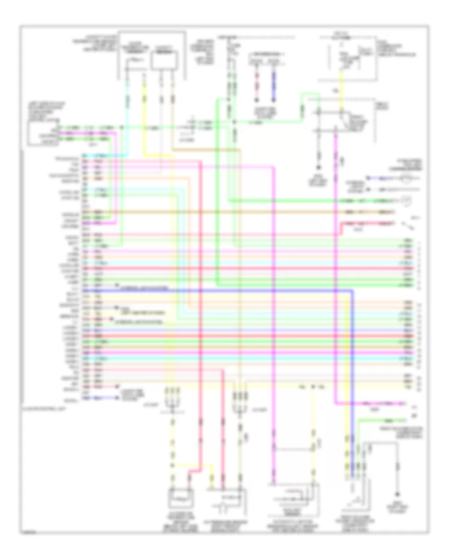
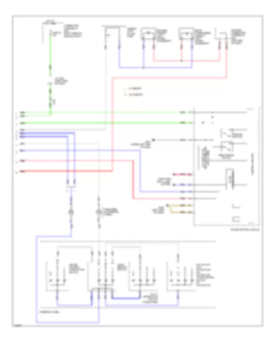
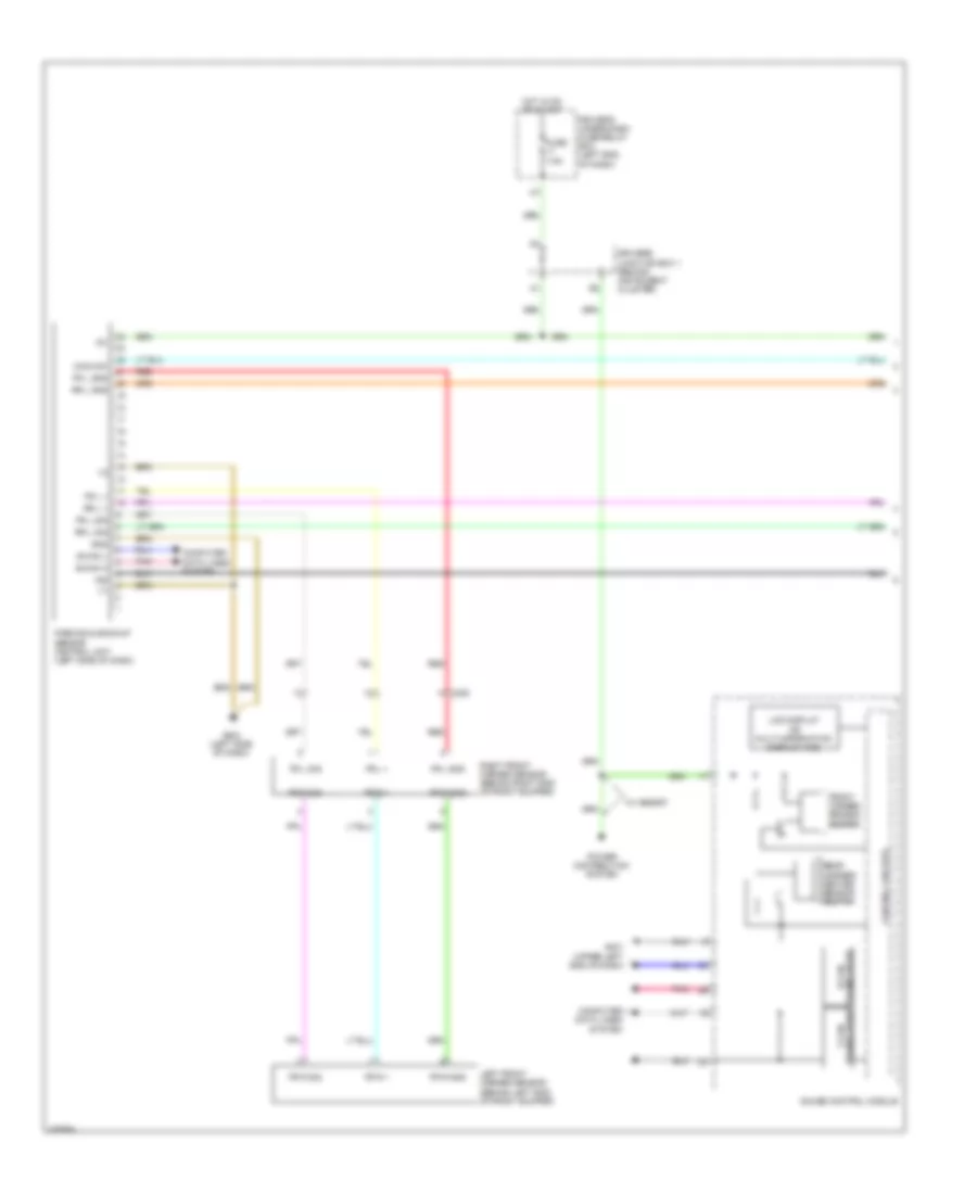
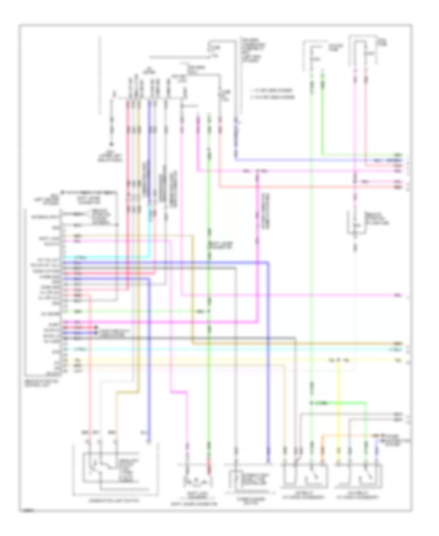
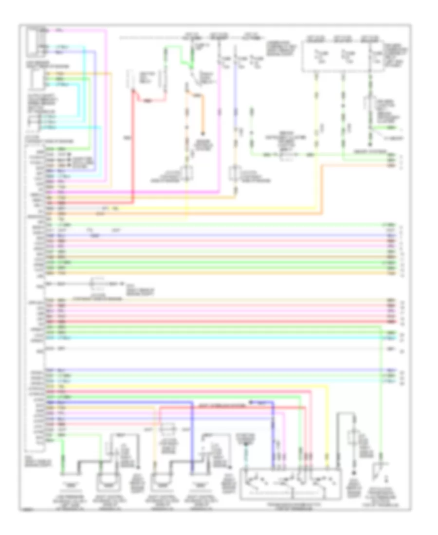
AIR CONDITIONING
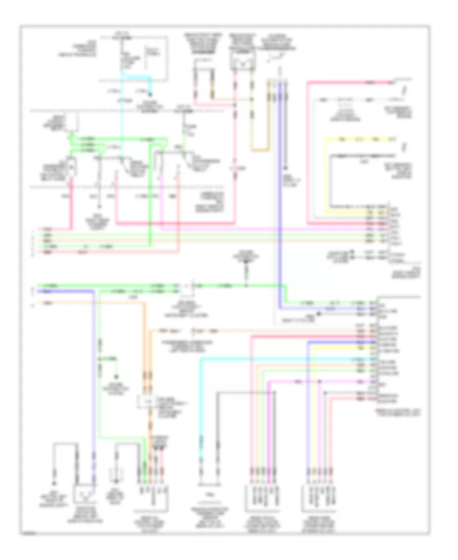
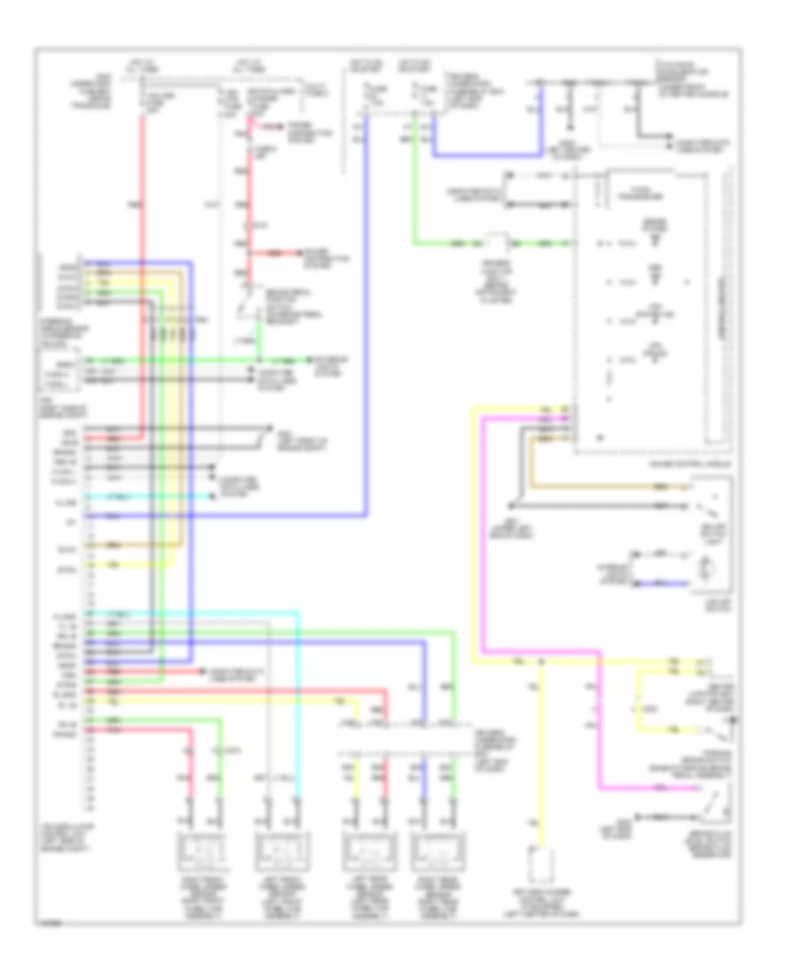
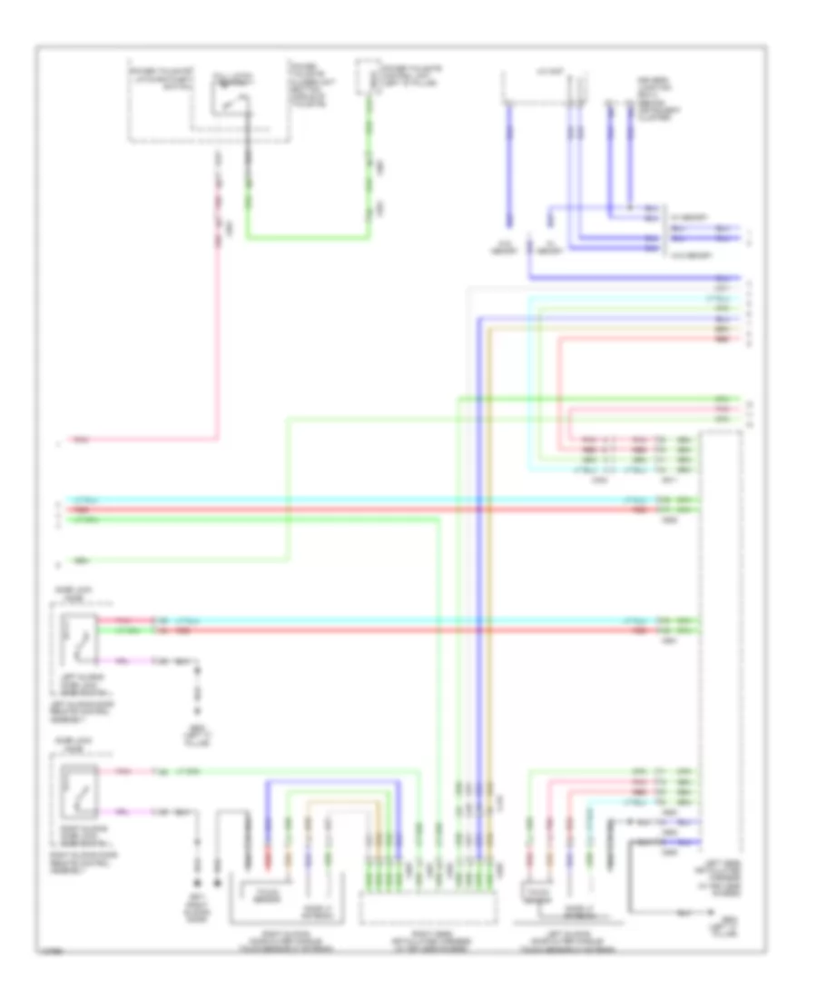
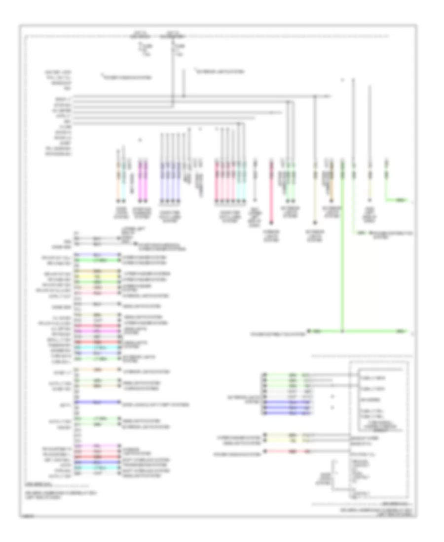
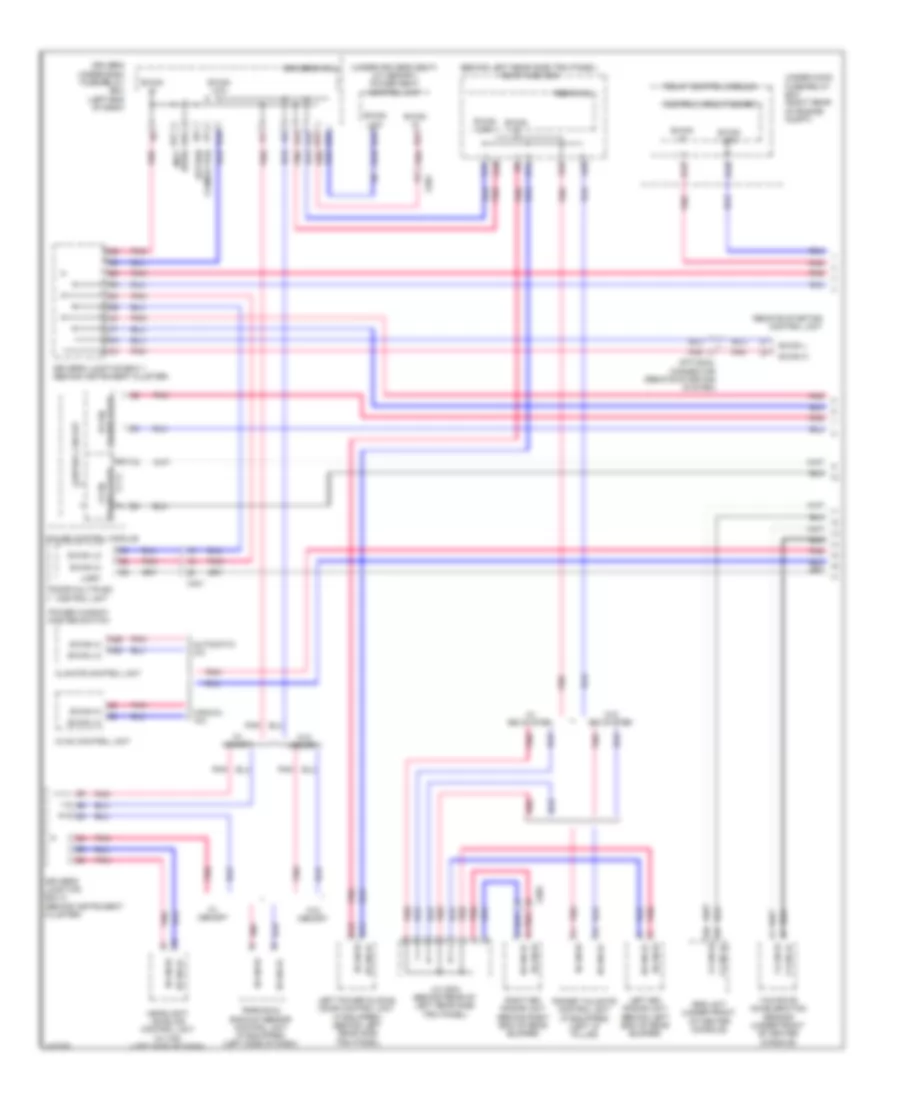
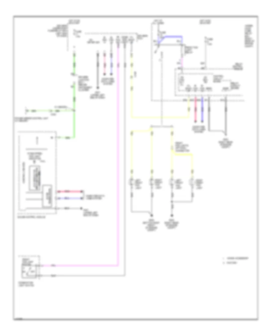
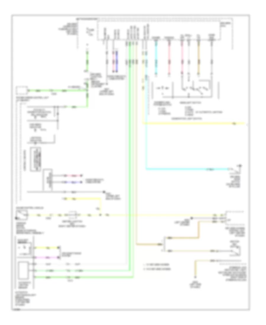
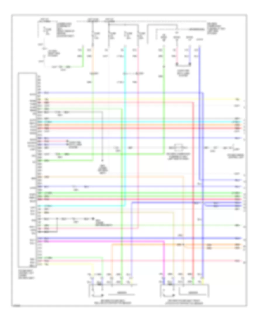
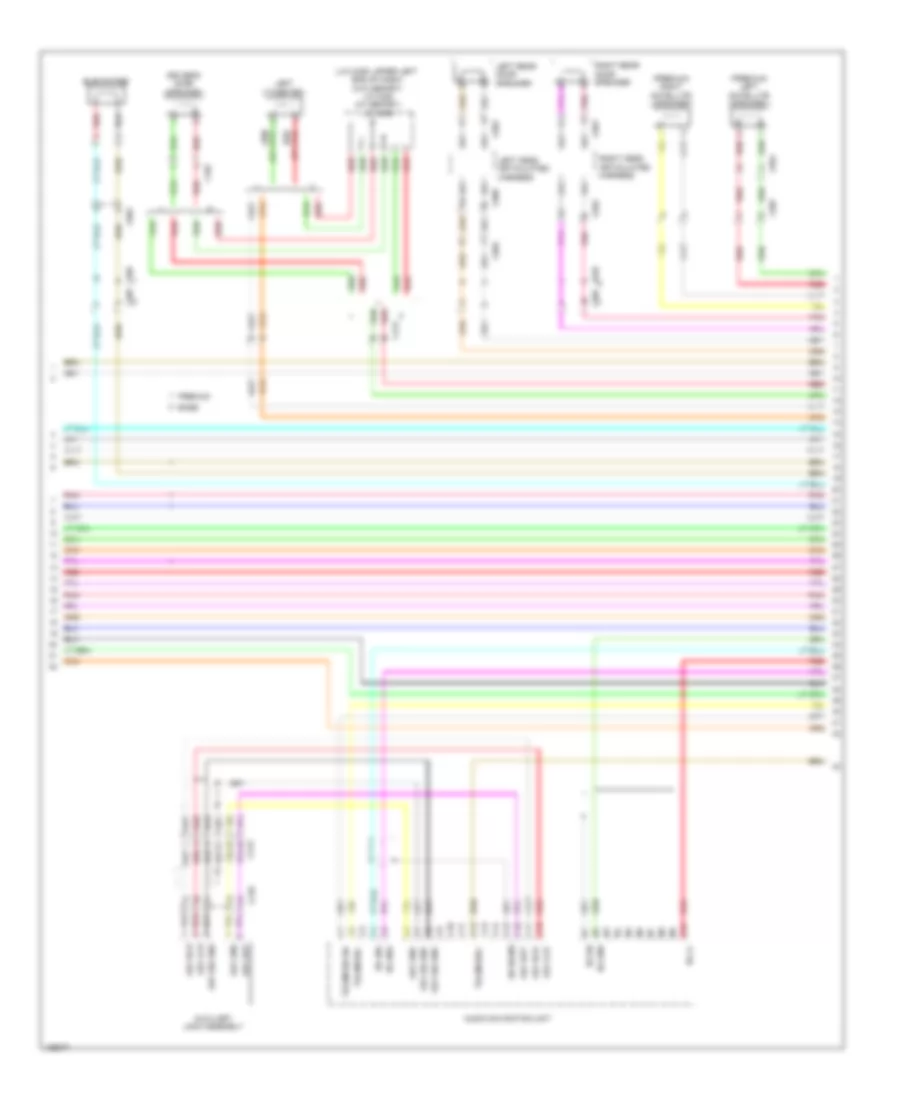
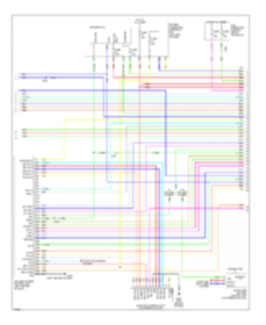
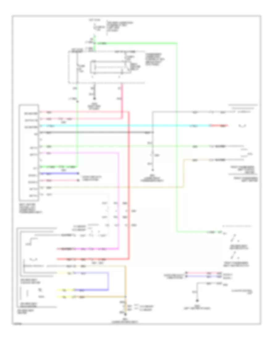
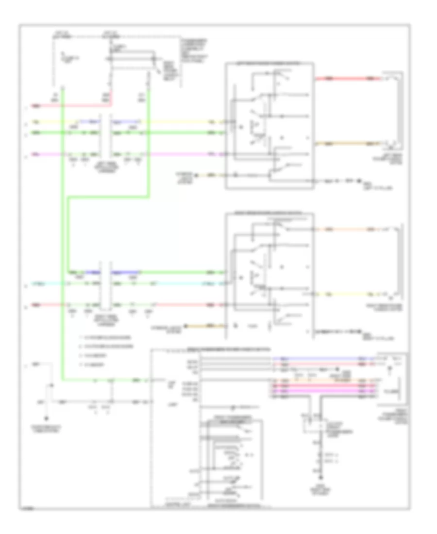
Automatic A/C Wiring Diagram, with Memory (1 of 3) for Honda Odyssey EX-L 2014

List of elements for Automatic A/C Wiring Diagram, with Memory (1 of 3) for Honda Odyssey EX-L 2014:
- (behind instrument cluster) driver's junction box 2
- (if equipped) cool box control switch
- A/c pressure sensor (right rear of engine compt)
- A10
- A11
- A12
- A13
- A14
- A15
- A16
- A17
- A18
- A19
- A20
- A21
- A22
- A23
- A24
- A25
- A26
- A27
- A28
- Amd-p-as
- Amd-p-dr
- Automatic lighting sensor/sunlight sensor (top center of dash)
- B-can h
- B-can hi
- B-can l
- B-can lo
- B10
- B11
- B12
- B13
- B14
- B15
- B16
- Batt
- Blw-g
- Blw-v
- Bus-data
- C/b bulb
- C/b open
- C/b sht
- C/b sw
- C202
- C205
- C208
- C410
- C411
- C413
- Climate control unit
- Computer data lines system
- Cool box control motor (if equipped) (left side of hvac blower housing)
- Driver's junction box 2 (behind instrument cluster)
- Driver's micu
- Driver's under-dash fuse/relay box (left end of dash)
- F17
- Fr blower fuse 40a
- Front blower motor (under right side of dash)
- Front blower motor relay
- Front blower power transistor (near front blower motor)
- Fuse 7.5a
- G204 (right end of dash)
- G302 (left end of dash)
- G403 (left center of dash)
- Gnd
- H10
- Hot at all times
- Hot in on
- Hum (hum-data)
- Humidity sensor
- Humidity/in-car temperature sensor (lower left center of dash)
- Ig2
- Ill+
- Ill-
- In-car temperature sensor
- Interior lights system
- K10
- L-mode 1
- L-mode 2
- L-mode 3
- M-cool-as
- M-cool-dr
- M-def
- M-frs
- M-hot-as
- M-hot-dr
- M-rec
- M-vent
- Main under-hood fuse box (above transaxle)
- Mode 1
- Mode 2
- Mode 3
- Mode 4
- Multi- fuse 3
- Outside air temperature sensor (behind left side of front bumper)
- Pnk
- Red
- Relay block
- S5v
- Sens-com
- Sunlight sensor
- Tam
- Teva
- Tr (hum-clk)
- Tsun
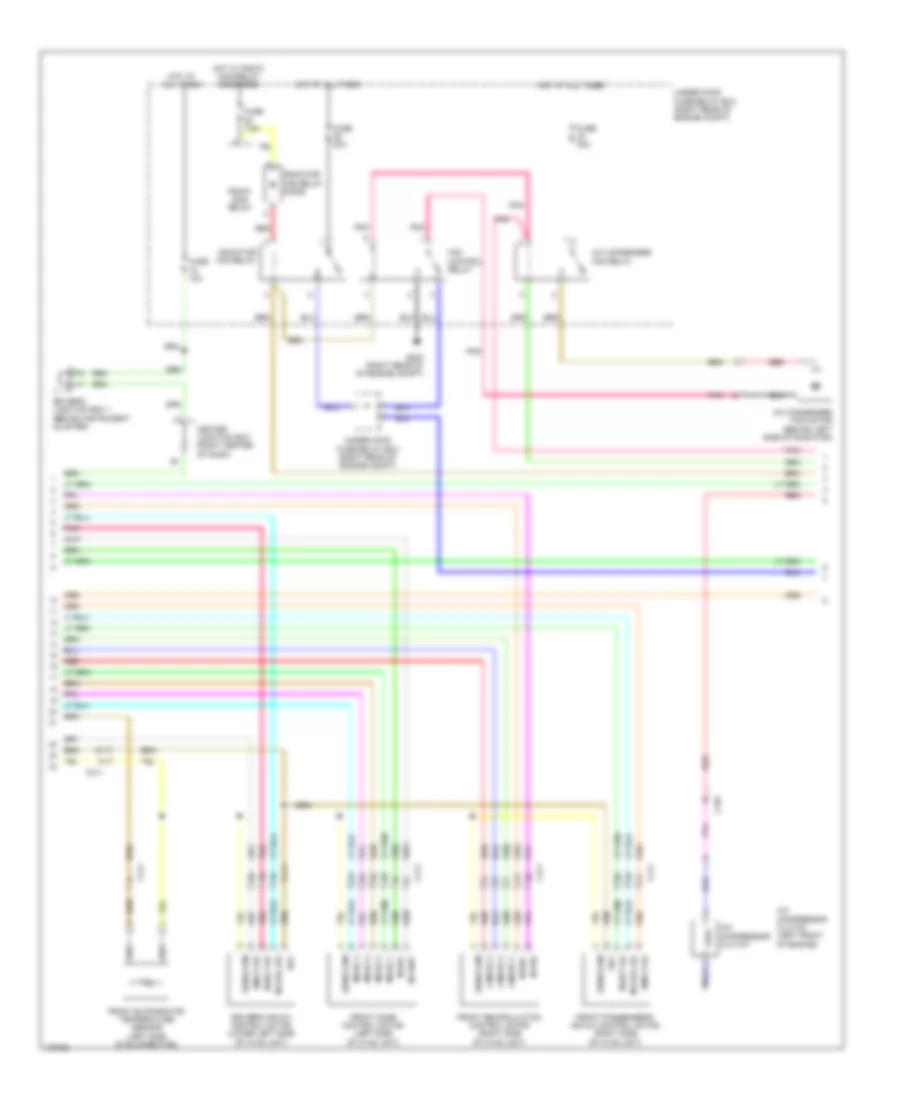
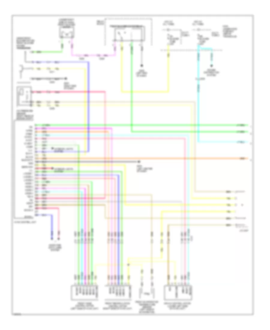
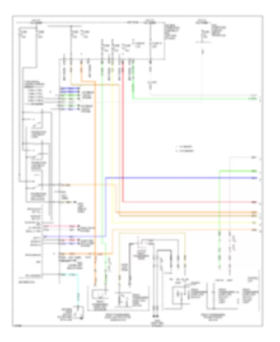
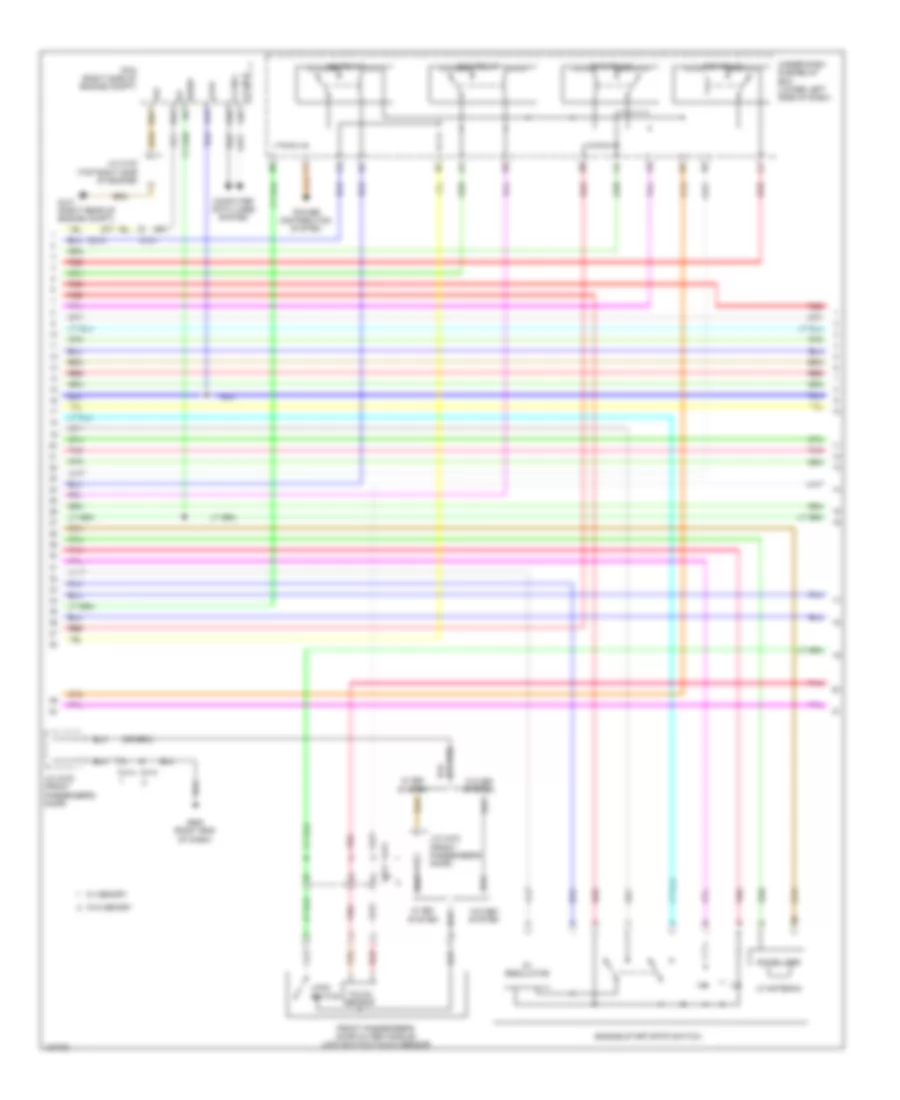
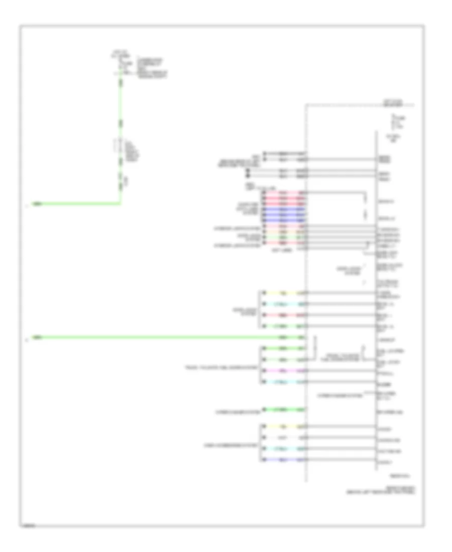
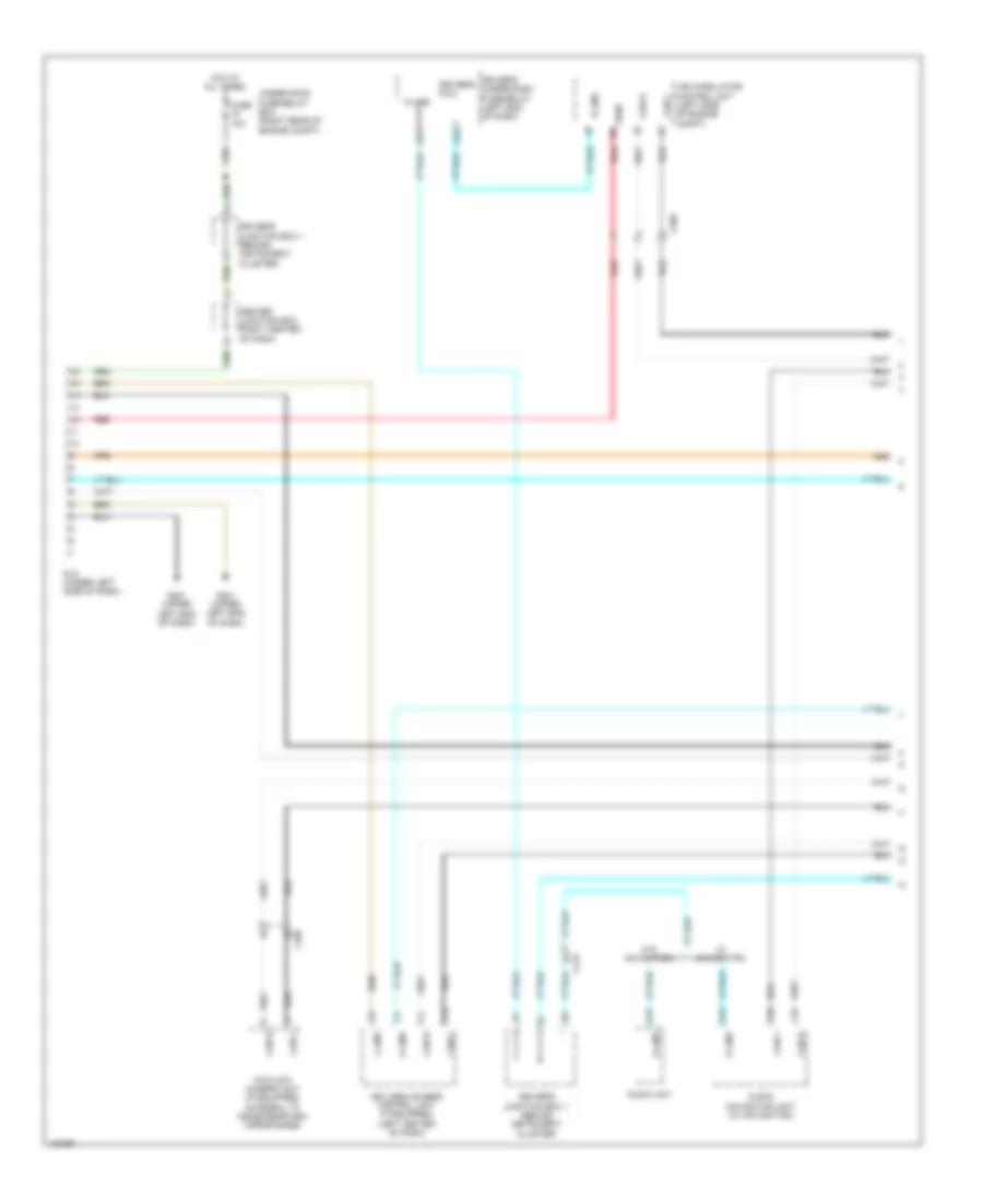
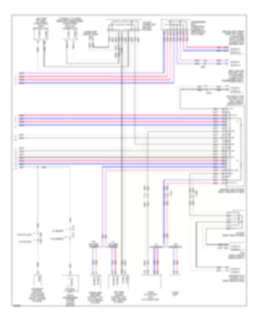
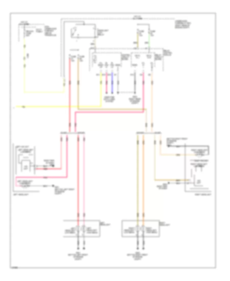
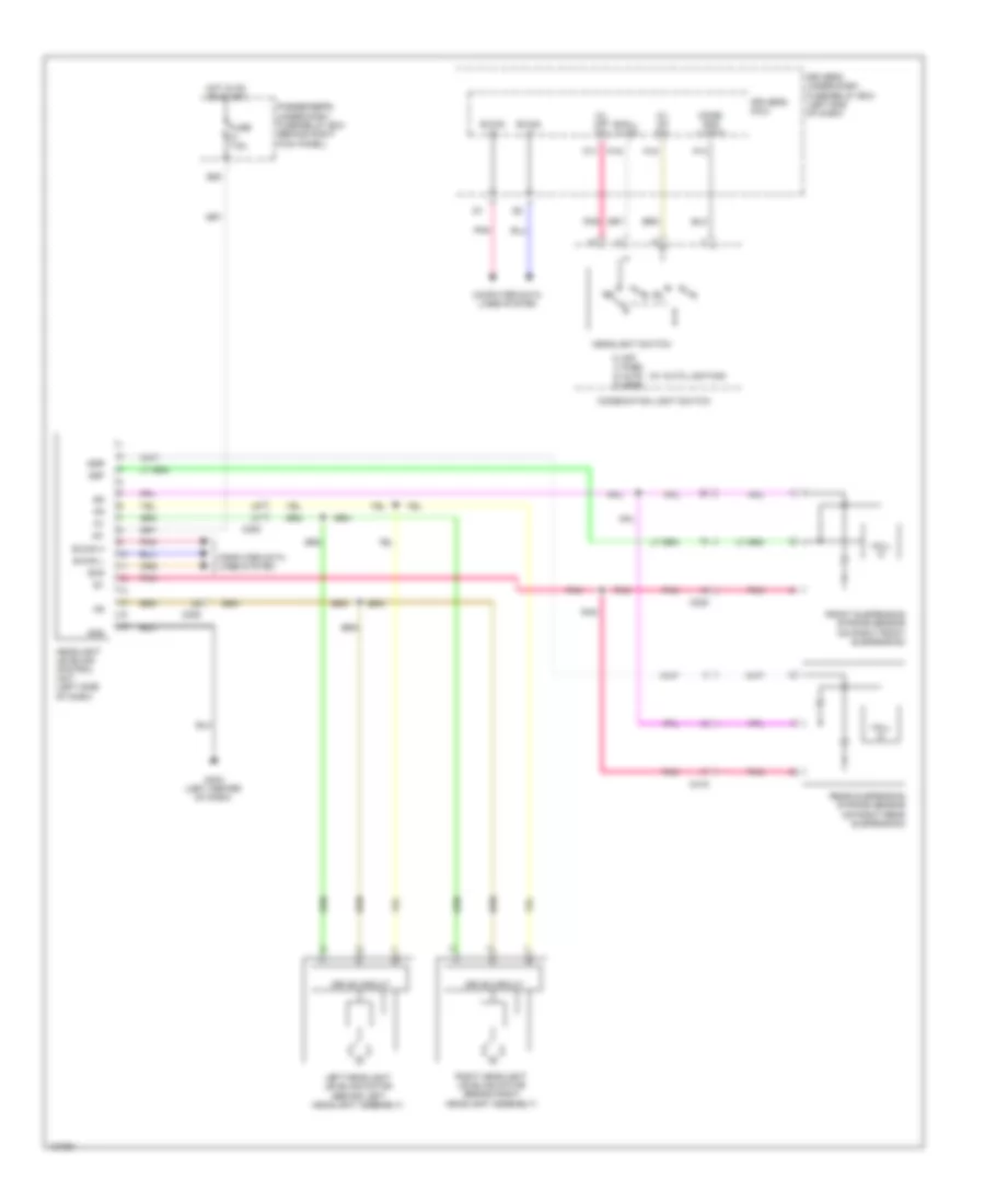
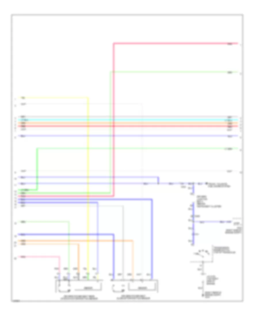
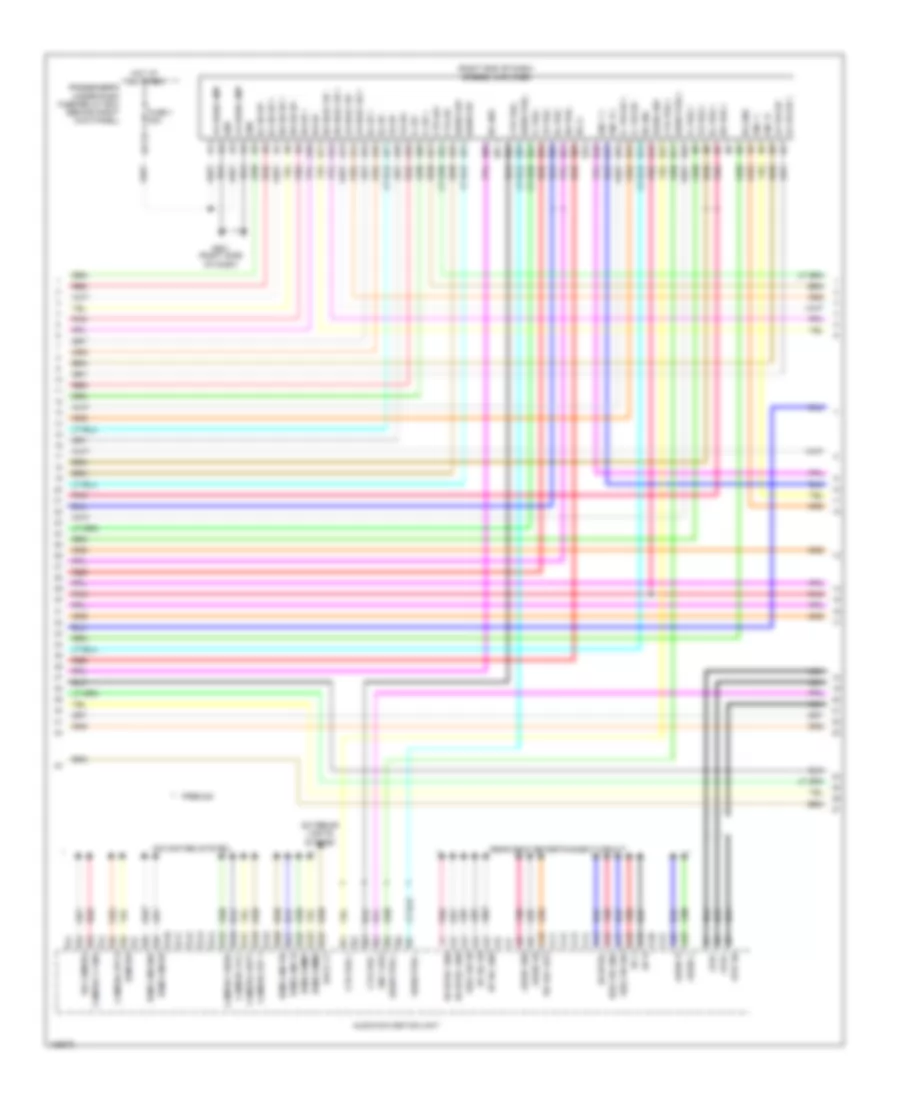
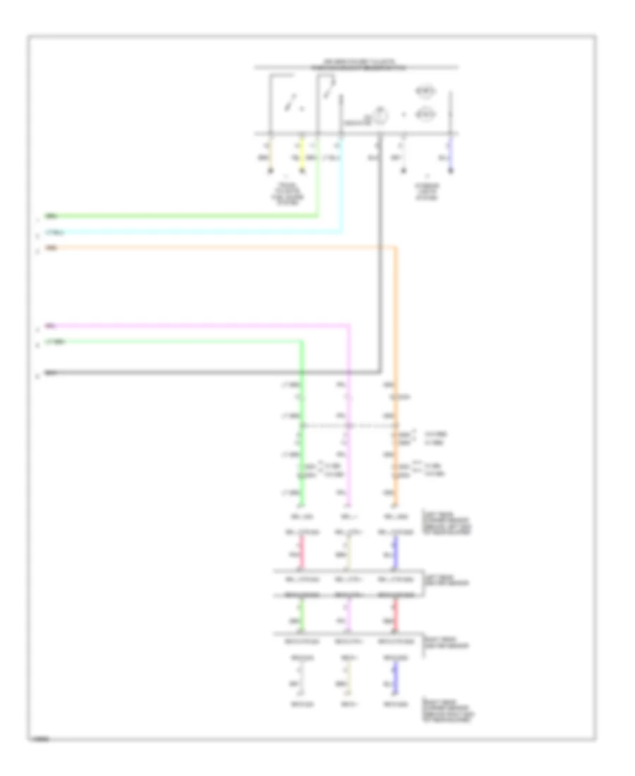
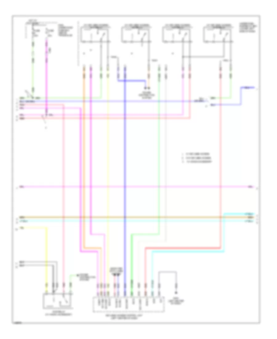
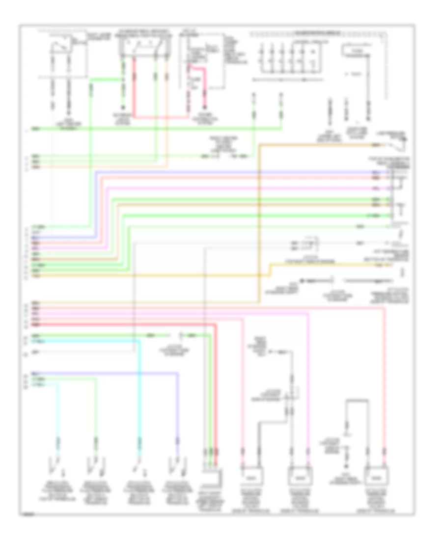
Automatic A/C Wiring Diagram, with Memory (2 of 3) for Honda Odyssey EX-L 2014
List of elements for Automatic A/C Wiring Diagram, with Memory (2 of 3) for Honda Odyssey EX-L 2014:
- A/c compressor clutch
- A/c compressor clutch (left front of engine)
- A/c condenser fan motor (behind left side of radiator)
- A/c condenser fan relay
- Amd-p-as
- Amd-p-dr
- C101
- C411
- Center junction box (right center of dash)
- Driver's air mix control motor (lower left side of hvac unit)
- Driver's junction box 1 (behind instrument cluster)
- Fan control relay
- Front evaporator temperature sensor (left side of evaporator)
- Front mode control motor (left side of hvac unit)
- Front passenger's air mix control motor (right side of hvac unit)
- Front recirculation control motor (right side of hvac unit)
- Fuse 10a
- Fuse 30a
- Fuse 7.5a
- G203 (right rear of of engine compt)
- Hot at all times
- Hot w/ pgm-fi main relay energized
- L-mode 1
- L-mode 2
- L-mode 3
- M-cool-as
- M-cool-dr
- M-def
- M-frs
- M-hot-as
- M-hot-dr
- M-rec
- M-vent
- Mode 1
- Mode 2
- Mode 3
- Mode 4
- Pgm-fi sub relay
- Pnk
- Radiator fan relay
- Radiator fan relay diode
- Red
- S5v
- Sens-com
- Under-hood fuse/relay box (right rear of engine compt)
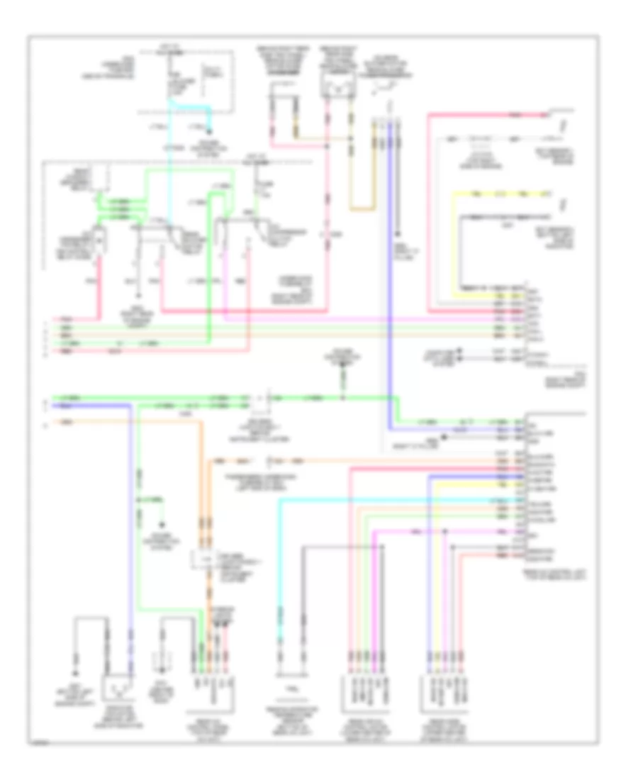
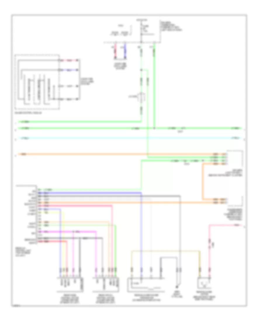
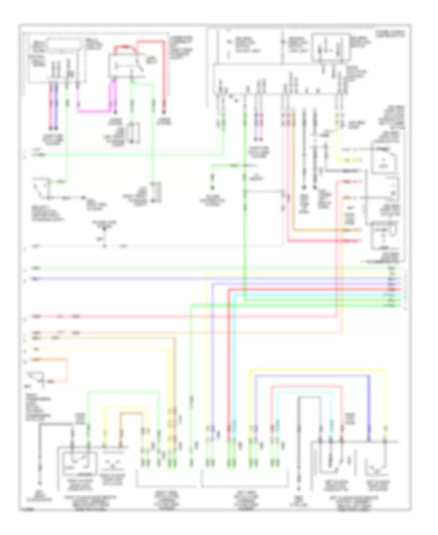
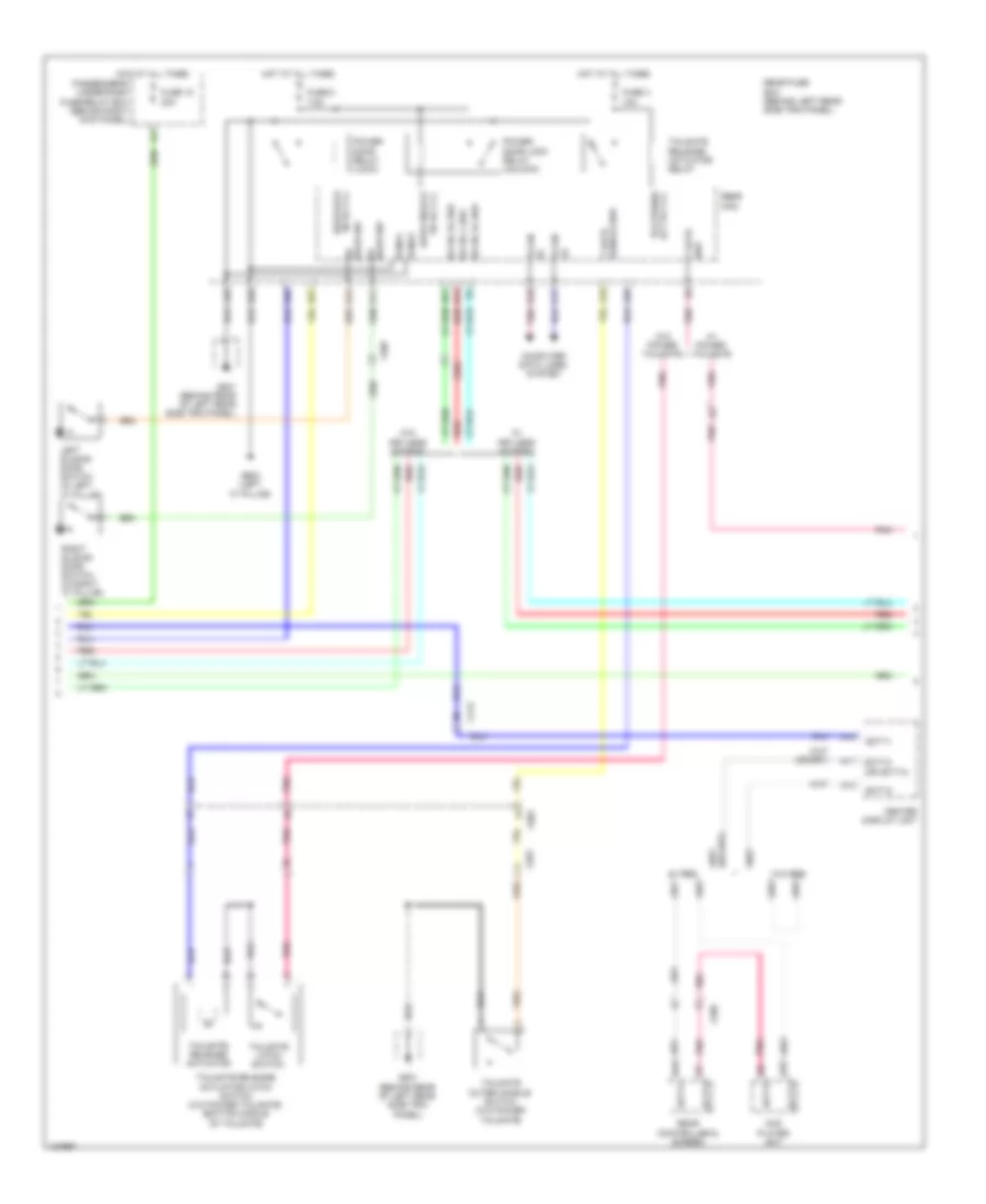
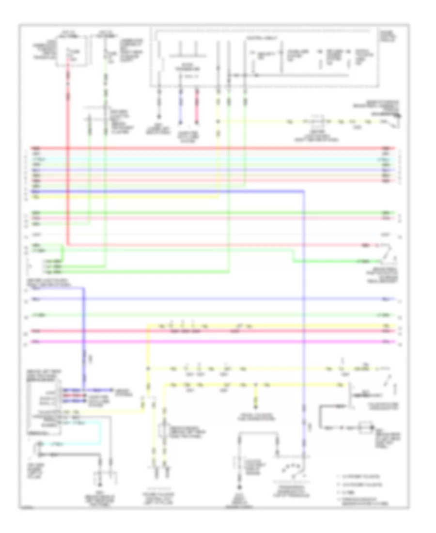
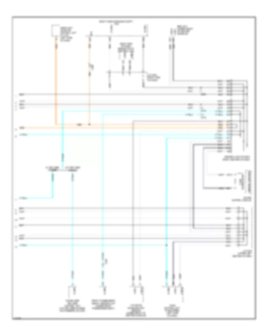
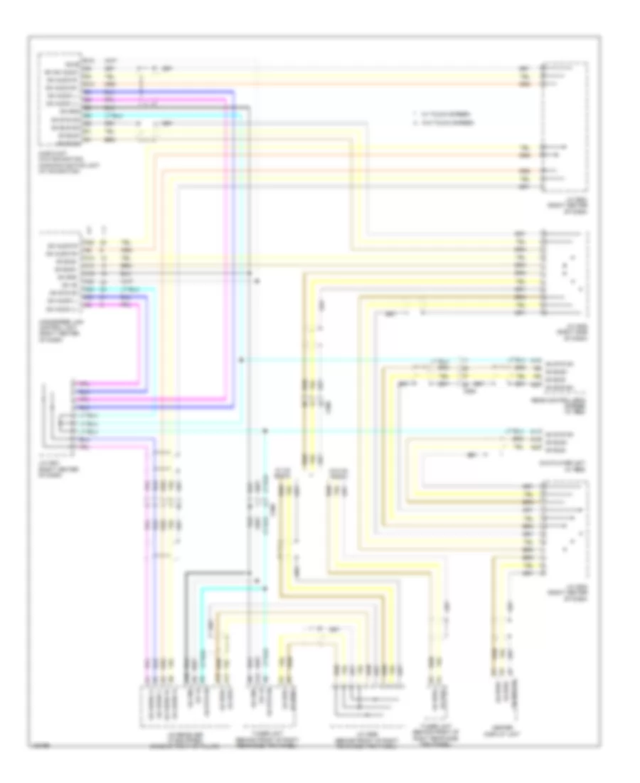
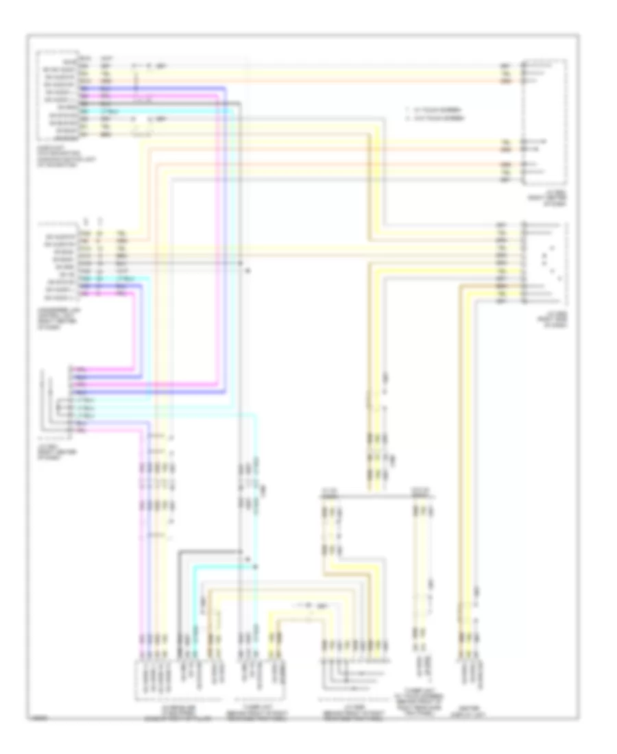
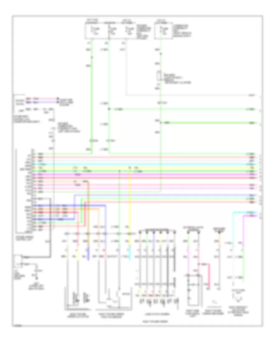
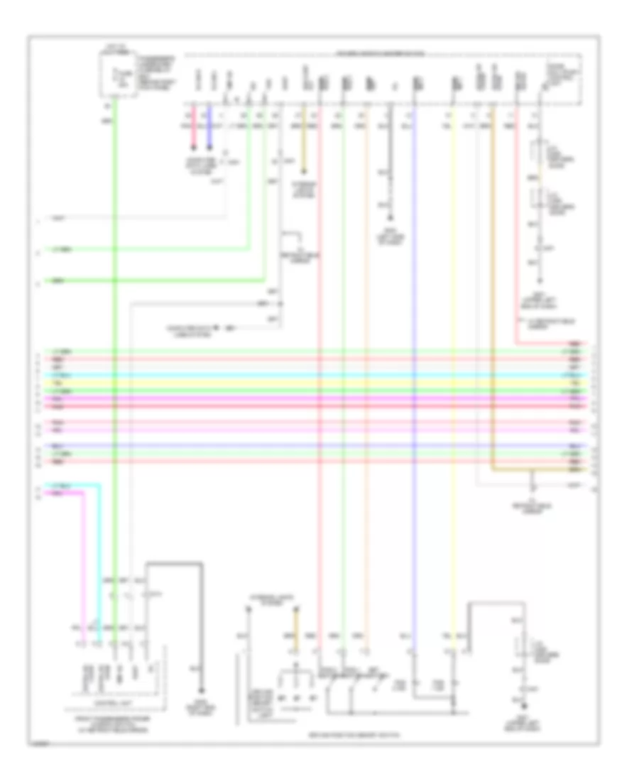
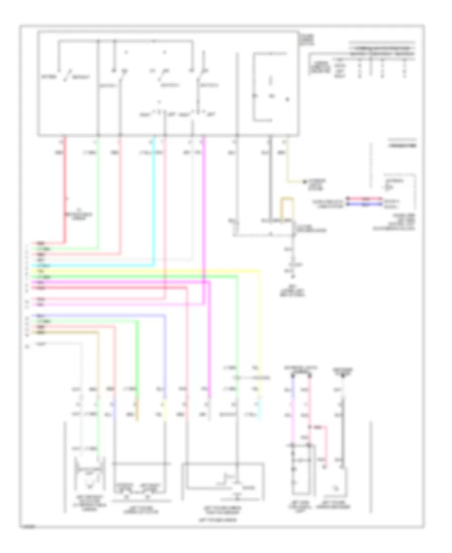
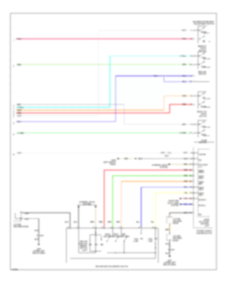
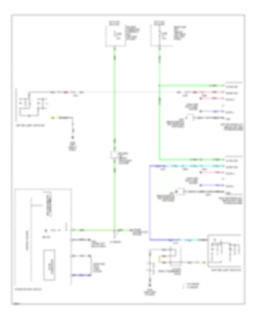
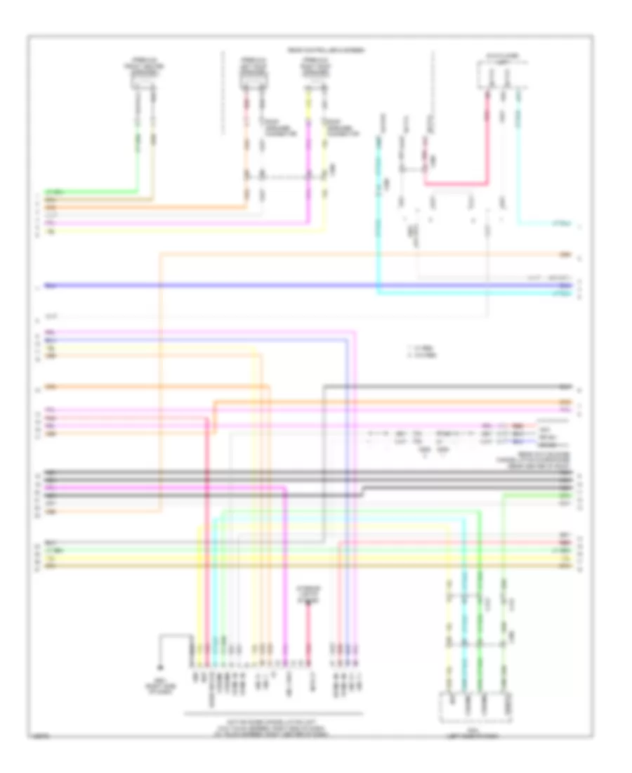
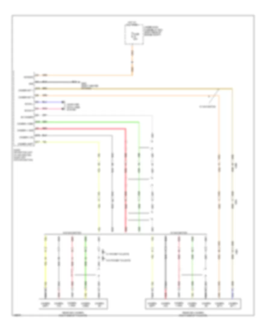
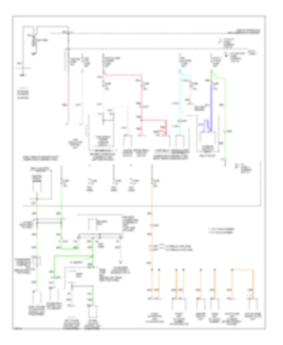
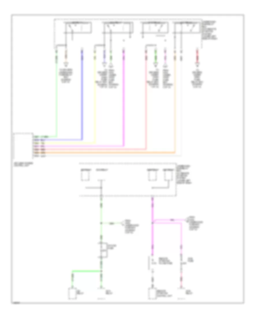
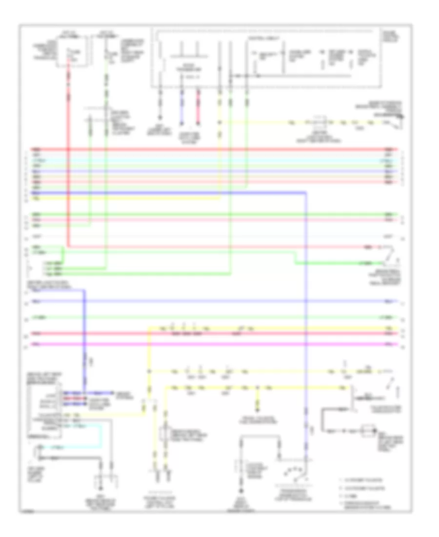
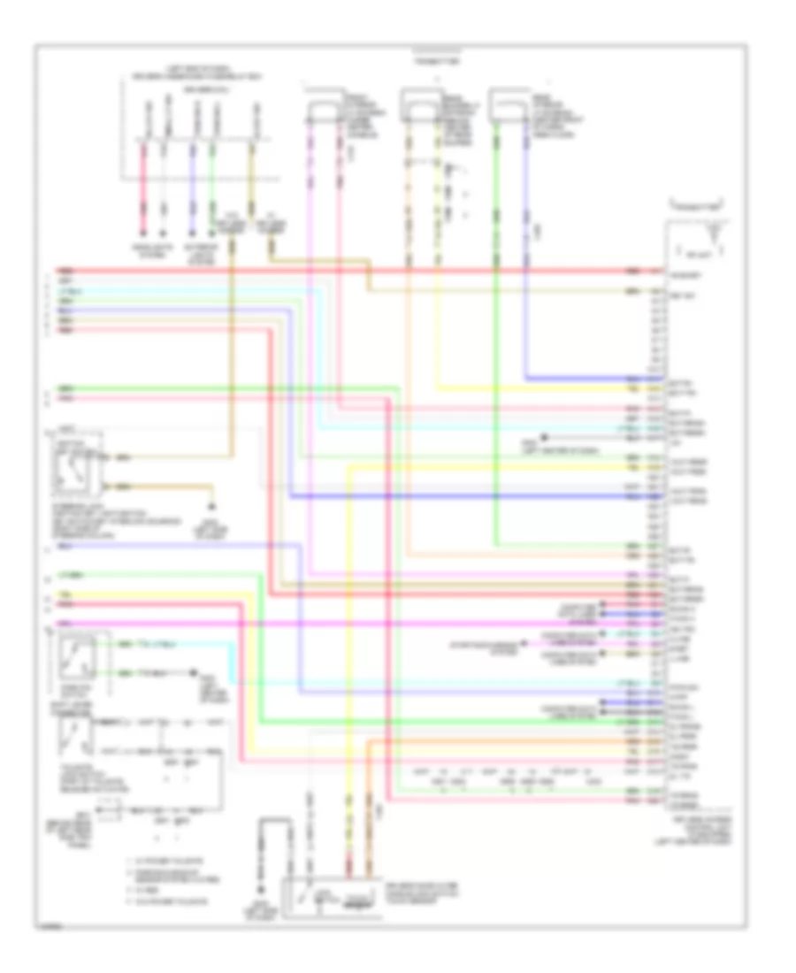
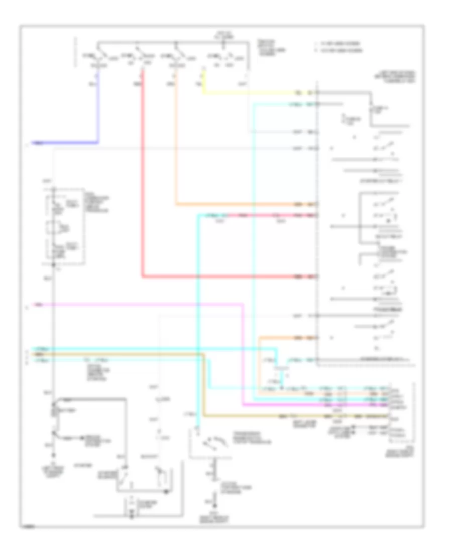
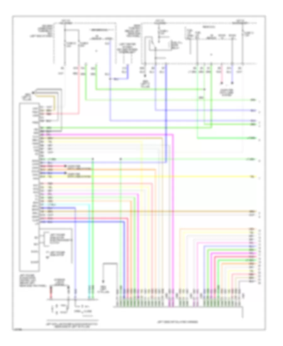
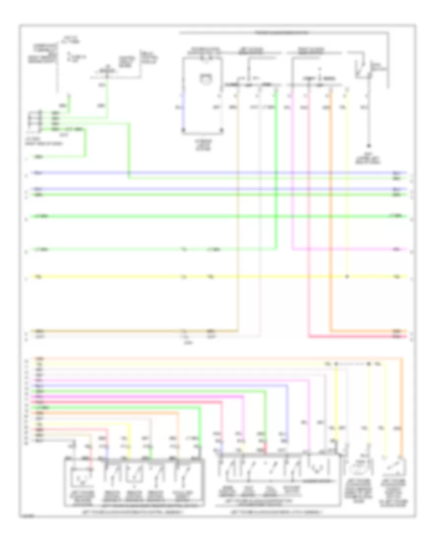
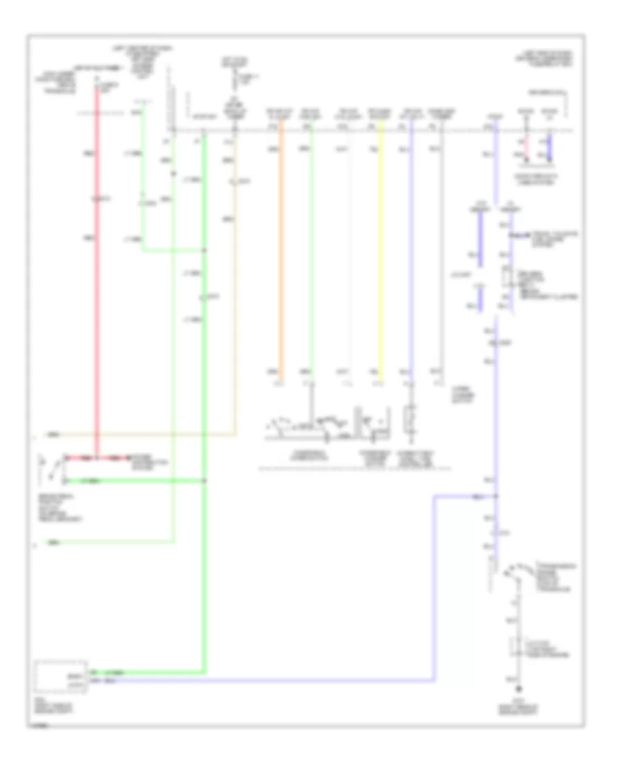
Automatic A/C Wiring Diagram, with Memory (3 of 3) for Honda Odyssey EX-L 2014
List of elements for Automatic A/C Wiring Diagram, with Memory (3 of 3) for Honda Odyssey EX-L 2014:
- (behind right rear side trim panel) rear blower motor
- (behind right rear side trim panel) rear blower motor noise condenser
- (on rear blower motor) rear blower power transistor
- A/c compressor clutch relay
- A/c condenser fan relay/ fan control relay diode
- A10
- A11
- A12
- A13
- A21
- A37
- A48
- A49
- Acc
- Amd-p-rr
- Blw-g-rr
- Blw-v-rr
- Bus-data
- C16
- C201
- C206
- C208
- C210
- C32
- C405
- C415
- Computer data lines system
- D31
- Driver's junction box 1 (behind instrument cluster)
- E42
- Ect sensor 1 (top rear of engine)
- Ect sensor 2 (bottom left side of radiator)
- Ect1
- Ect2
- F-can-h
- F-can-l
- Fan h
- Fan l
- Fuse 7.5a
- G201 (bottom left side of engine compt)
- G203 (right rear of engine compt)
- G652 (right "c" pillar)
- G701 (center front of roof)
- Gnd
- Hot at all times
- Ig2
- Ill+
- Ill-
- Interior lights system
- J/c c104 (top right side of engine)
- M-cool-rr
- M-def-rr
- M-hot-rr
- M-vent-rr
- Main under-hood fuse box (above transaxle)
- Mdd-p-rr
- Multi- fuse 2
- Passenger's under-dash fuse/relay box (left end of dash)
- Pcm (right rear of engine compt)
- Pnk
- Power distribution system
- Radiator fan motor (behind left side of radiator)
- Rear a/c control panel (top of rear a/c unit)
- Rear a/c control unit (top of rear a/c unit)
- Rear air mix control motor (lower center of rear a/c unit)
- Rear blower motor relay
- Rear evaporator temperature sensor (bottom of rear a/c unit)
- Rear mode control motor (upper center of rear a/c unit)
- Rear window defogger relay
- Red
- Rr blower fuse 30a
- S5v
- Sens-com
- Sg2
- Sg7
- Teva-rr
- Under-hood fuse/relay box (right rear of engine compt)
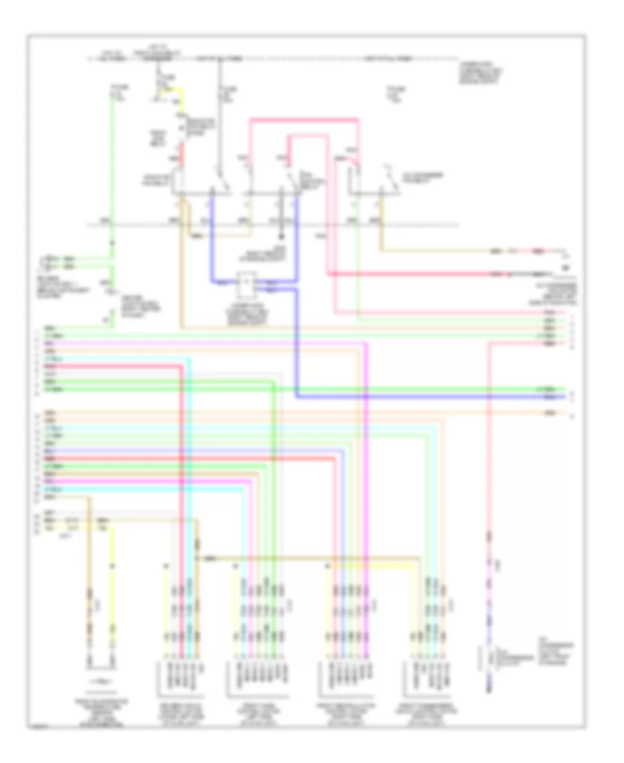
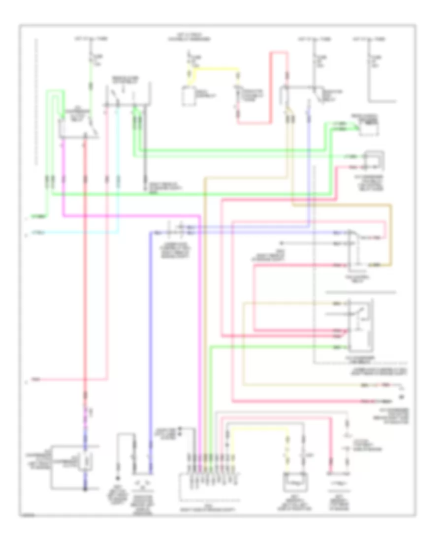
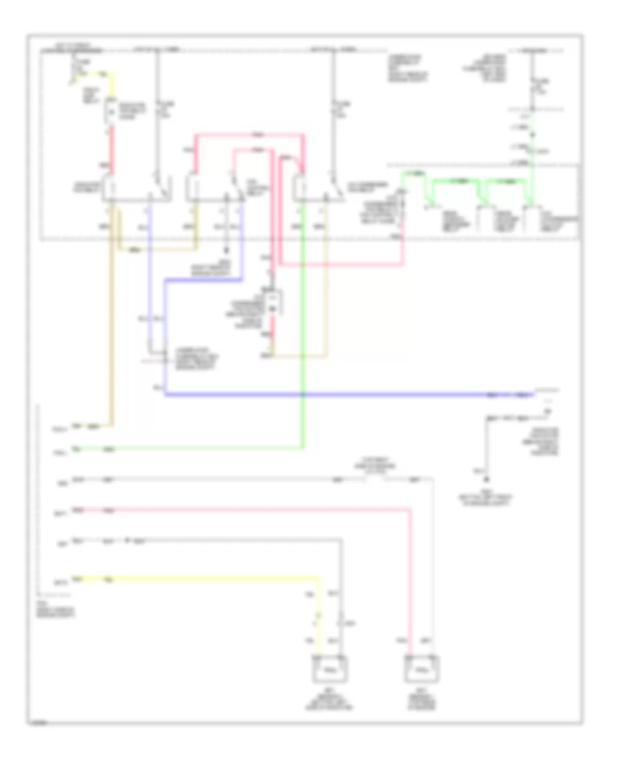
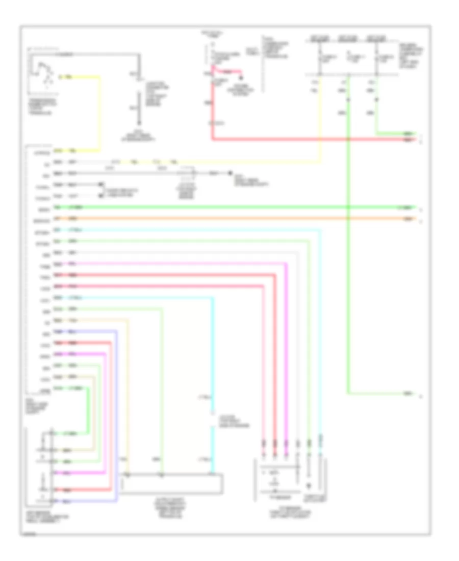
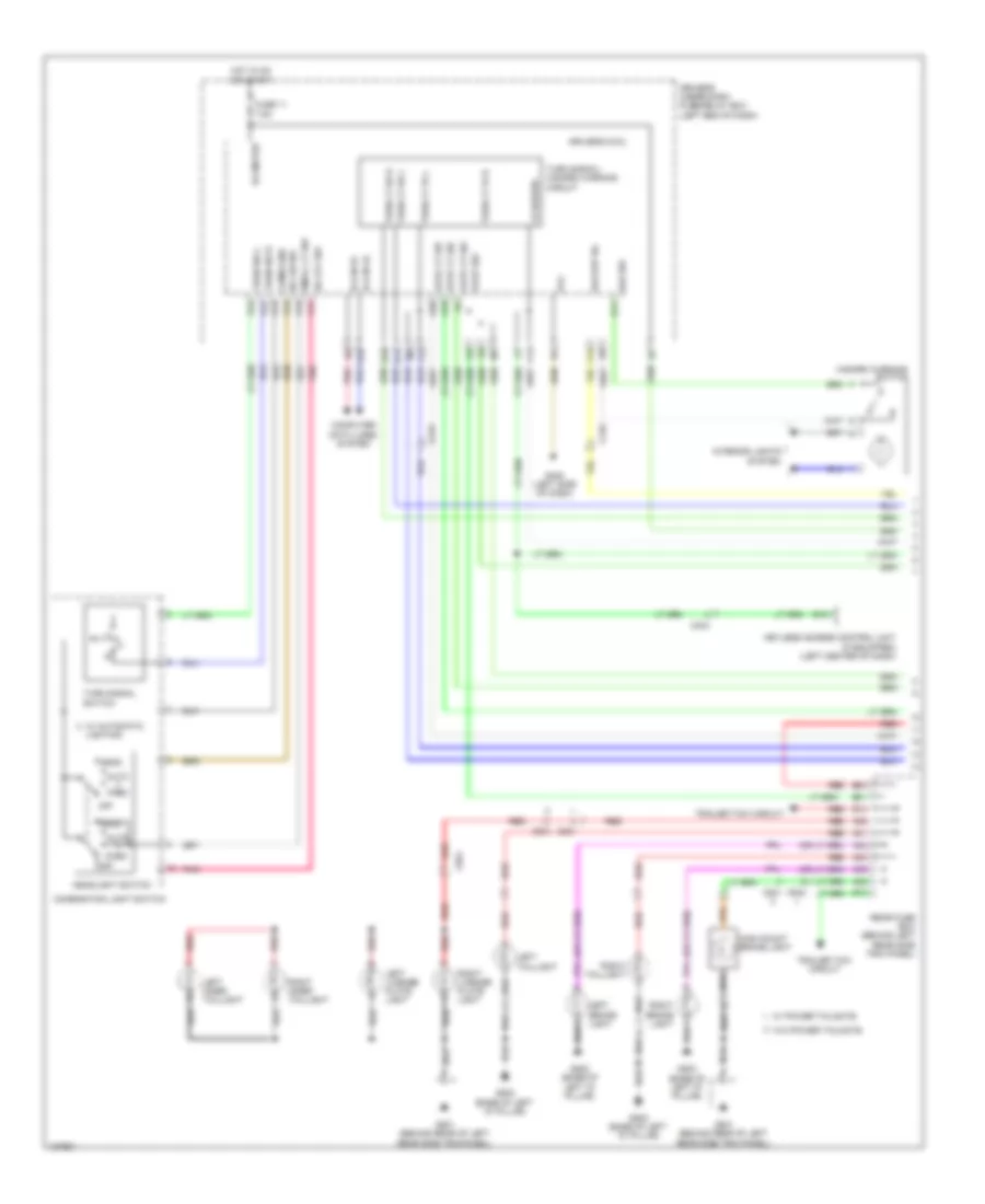
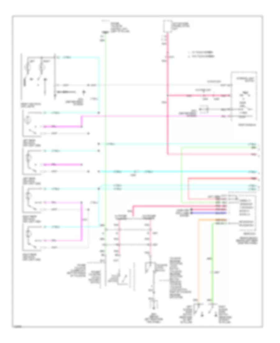
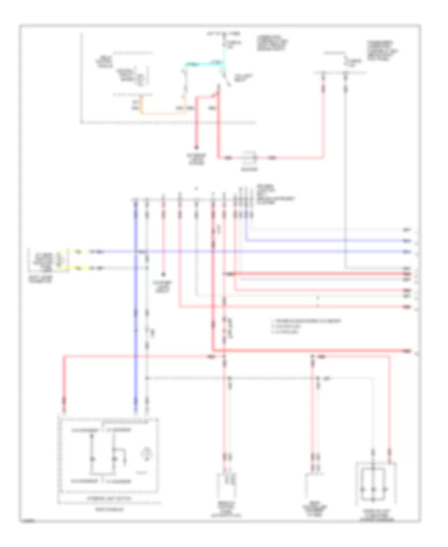
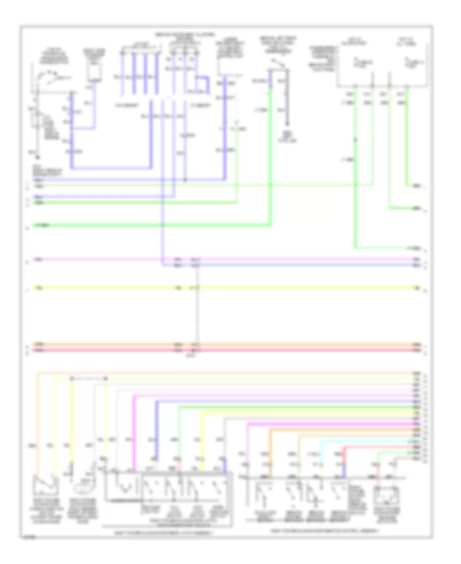
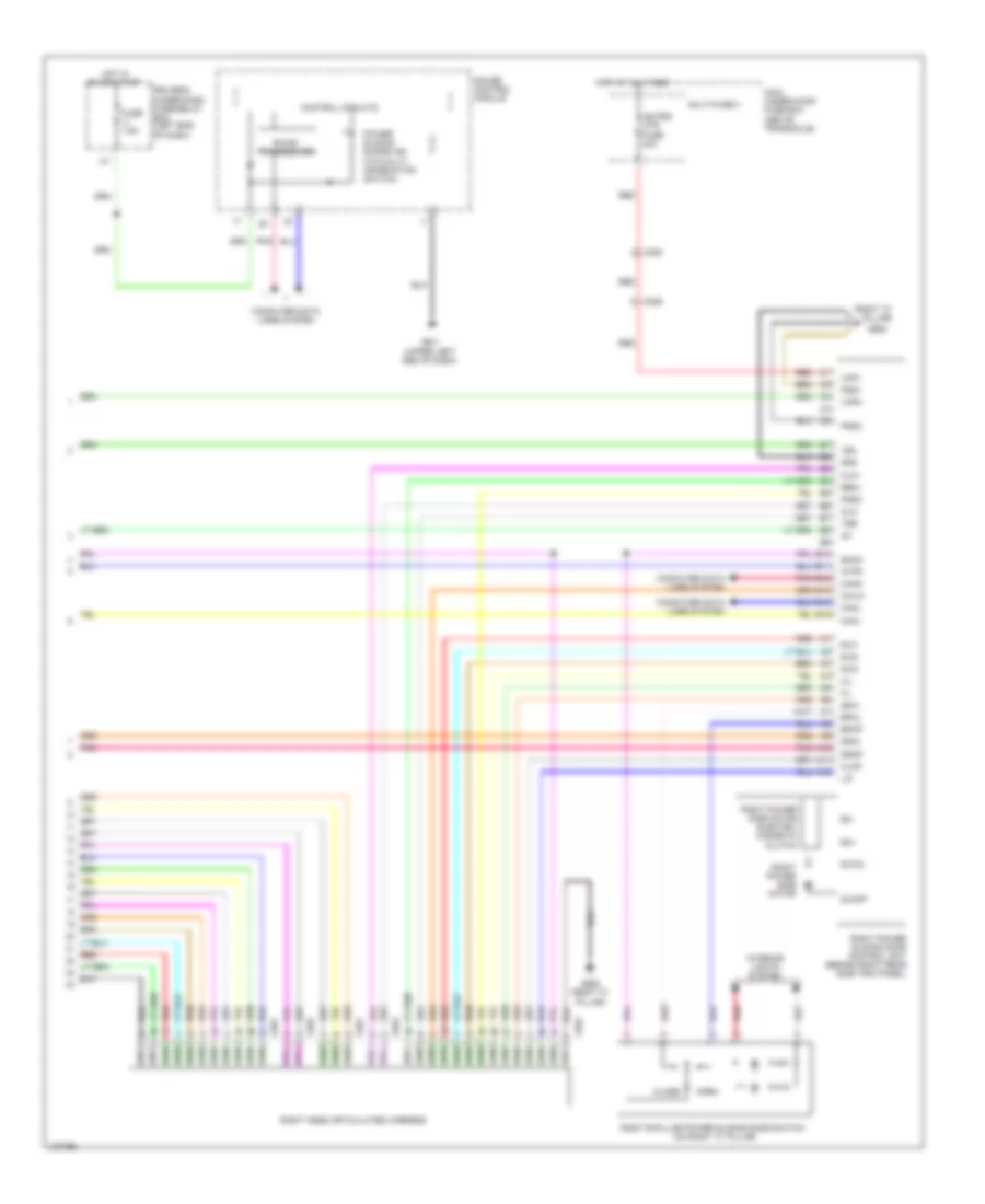
Automatic A/C Wiring Diagram, without Memory (1 of 3) for Honda Odyssey EX-L 2014
List of elements for Automatic A/C Wiring Diagram, without Memory (1 of 3) for Honda Odyssey EX-L 2014:
- (if equipped) cool box control switch
- (left side of hvac blower housing) (if equipped) cool box control motor
- A/c pressure sensor (right rear of engine compt)
- A10
- A11
- A12
- A13
- A14
- A15
- A16
- A17
- A18
- A19
- A20
- A21
- A22
- A23
- A24
- A25
- A26
- A27
- A28
- Amd-p-as
- Amd-p-dr
- Automatic lighting sensor/sunlight sensor (top center of dash)
- B-can h
- B-can hi
- B-can l
- B-can lo
- B10
- B11
- B12
- B13
- B14
- B15
- B16
- Batt
- Blw-g
- Blw-v
- Bus-data
- C/b bulb
- C/b open
- C/b sht
- C/b sw
- C202
- C205
- C208
- C410
- C411
- C413
- Climate control unit
- Computer data lines system
- Driver's micu
- Driver's under-dash fuse/relay box (left end of dash)
- F17
- Fr blower fuse 40a
- Front blower motor (under right side of dash)
- Front blower motor relay
- Front blower power transistor (under right side of dash)
- Fuse 7.5a
- G204 (right end of dash)
- G302 (left end of dash)
- G403 (left center of dash)
- Gnd
- H10
- Hot at all times
- Hot in on
- Hum (hum-data)
- Humidity sensor
- Humidity/in-car temperature sensor (lower left center of dash)
- Ig2
- Ill+
- Ill-
- In-car temperature sensor
- Interior lights system
- J/c c407
- J/c c408
- L-mode 1
- L-mode 2
- L-mode 3
- M-cool-as
- M-cool-dr
- M-def
- M-frs
- M-hot-as
- M-hot-dr
- M-rec
- M-vent
- Main under-hood fuse box (above transaxle)
- Mode 1
- Mode 2
- Mode 3
- Mode 4
- Multi- fuse 3
- Outside air temperature sensor (behind left side of front bumper)
- Pnk
- Red
- Relay block
- S5v
- Sens-com
- Sunlight sensor
- Tam
- Teva
- Tr (hum-clk)
- Tsun
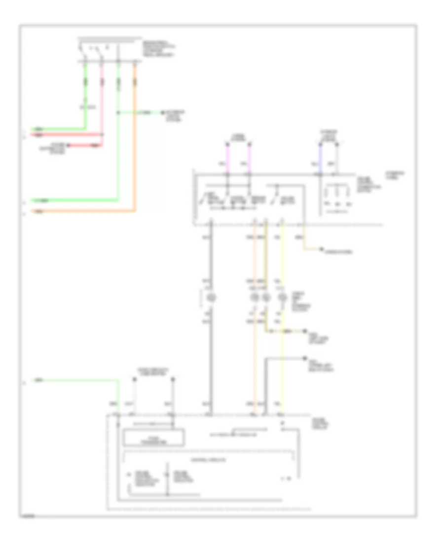
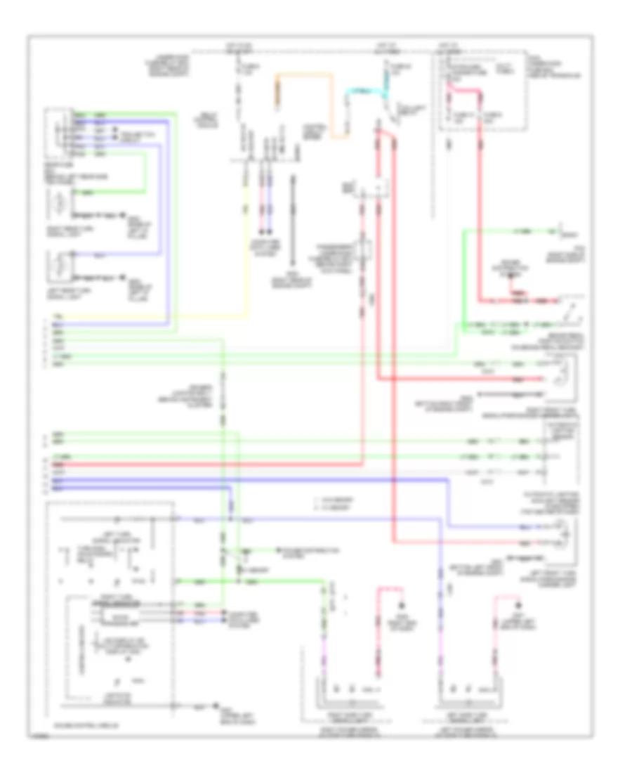
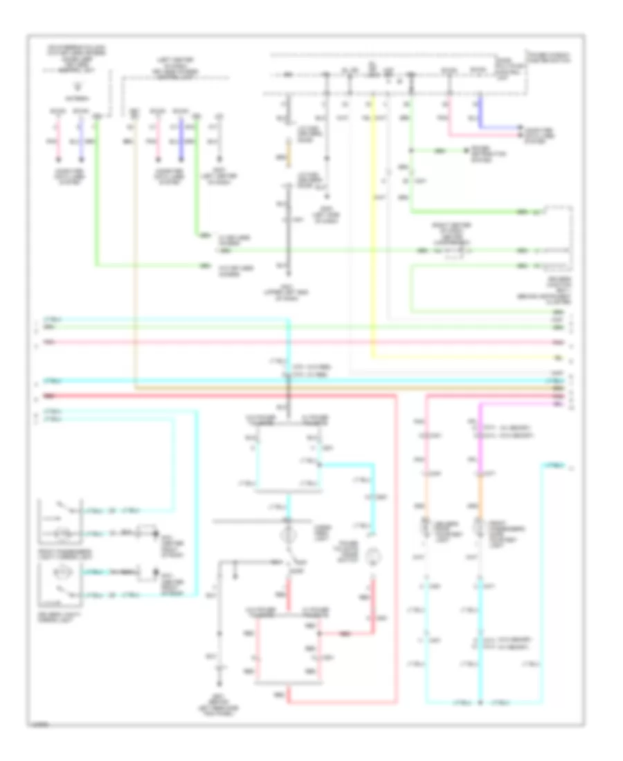
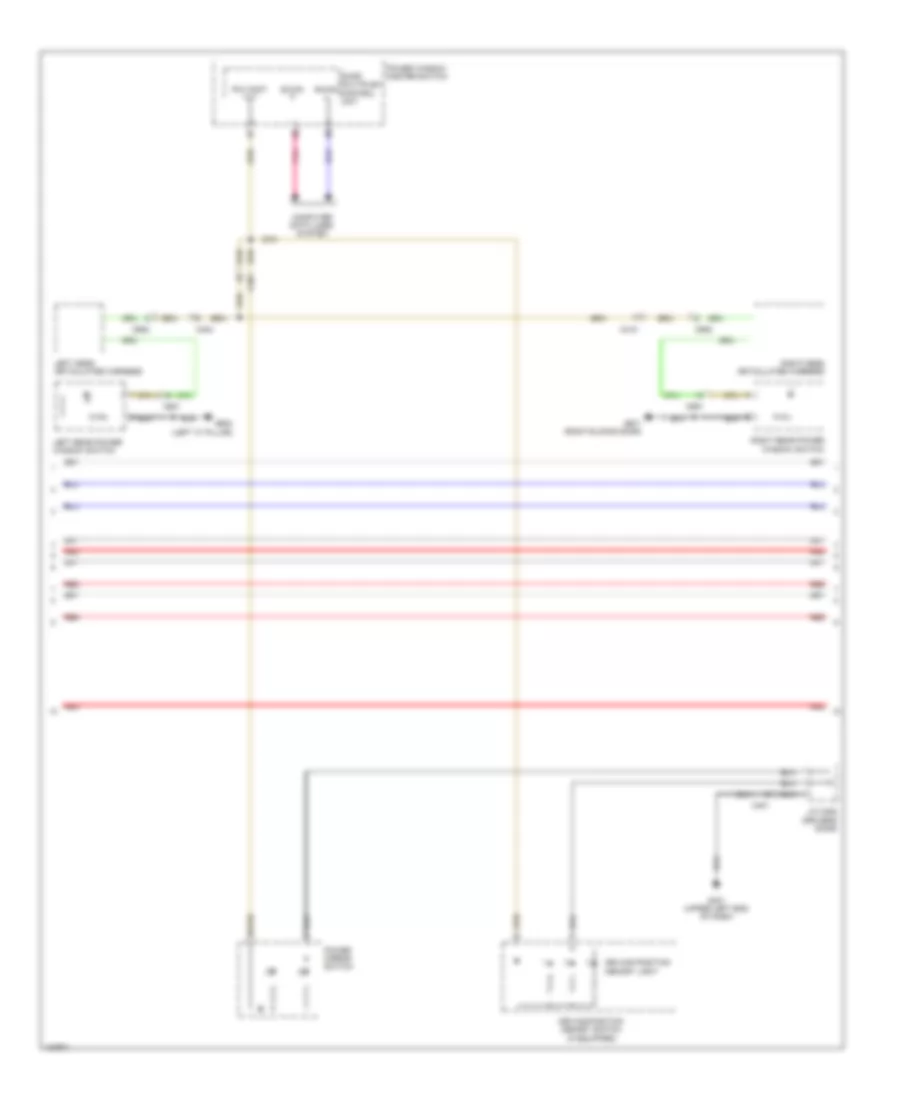
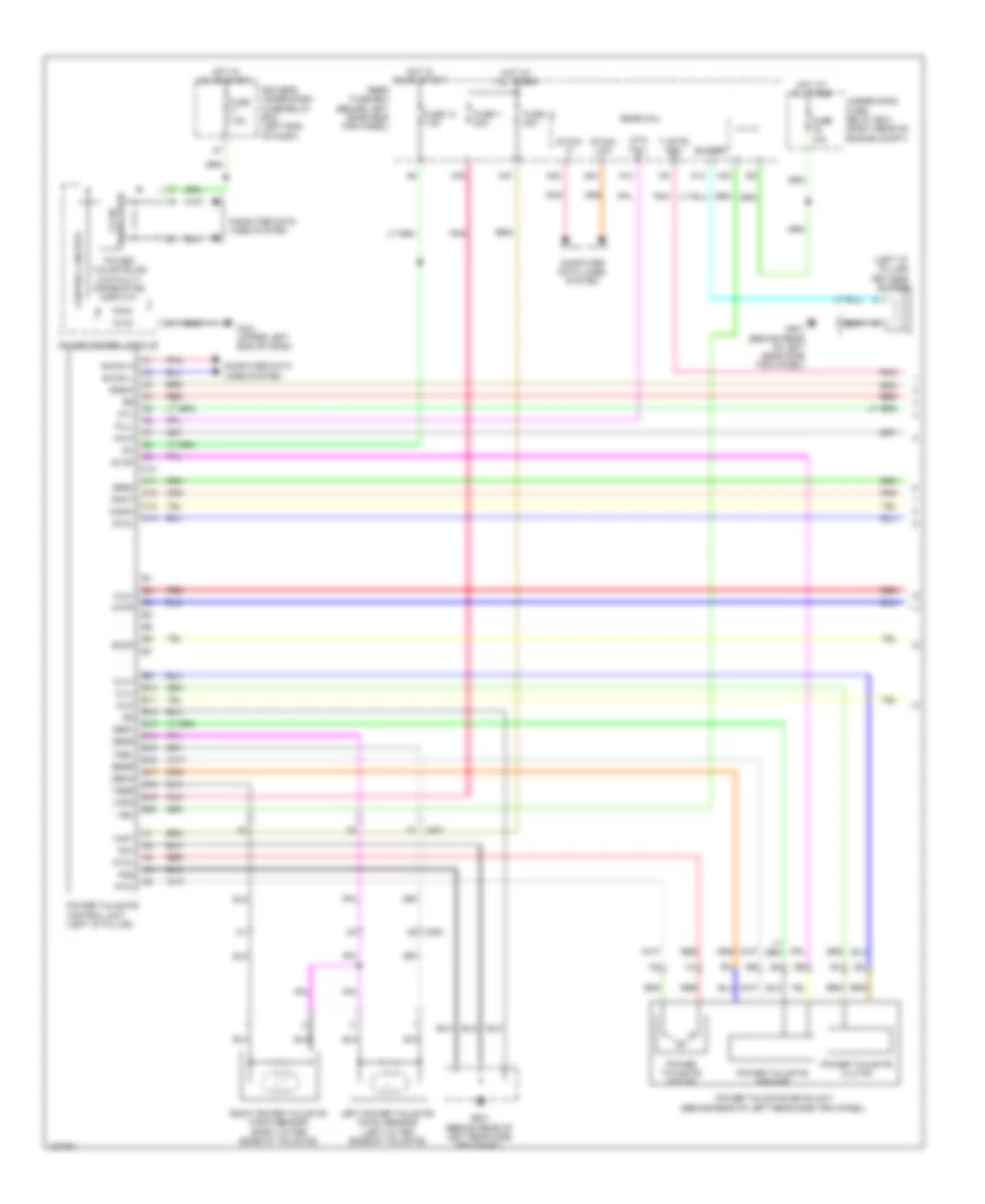
Automatic A/C Wiring Diagram, without Memory (2 of 3) for Honda Odyssey EX-L 2014
List of elements for Automatic A/C Wiring Diagram, without Memory (2 of 3) for Honda Odyssey EX-L 2014:
- A/c compressor clutch
- A/c compressor clutch (left front of engine)
- A/c condenser fan motor (behind left side of radiator)
- A/c condenser fan relay
- Amd-p-as
- Amd-p-dr
- C101
- C411
- Center junction box (right center of dash)
- Driver's air mix control motor (lower left side of hvac unit)
- Driver's junction box 1 (behind instrument cluster)
- Fan control relay
- Front evaporator temperature sensor (left side of evaporator)
- Front mode control motor (left side of hvac unit)
- Front passenger's air mix control motor (right side of hvac unit)
- Front recirculation control motor (right side of hvac unit)
- Fuse 10a
- Fuse 30a
- Fuse 7.5a
- G203 (right rear of of engine compt)
- Hot at all times
- Hot w/ pgm-fi main relay energized
- L-mode 1
- L-mode 2
- L-mode 3
- M-cool-as
- M-cool-dr
- M-def
- M-frs
- M-hot-as
- M-hot-dr
- M-rec
- M-vent
- Mode 1
- Mode 2
- Mode 3
- Mode 4
- Pgm-fi sub relay
- Pnk
- Radiator fan relay
- Radiator fan relay diode
- Red
- S5v
- Sens-com
- Under-hood fuse/relay box (right rear of engine compt)
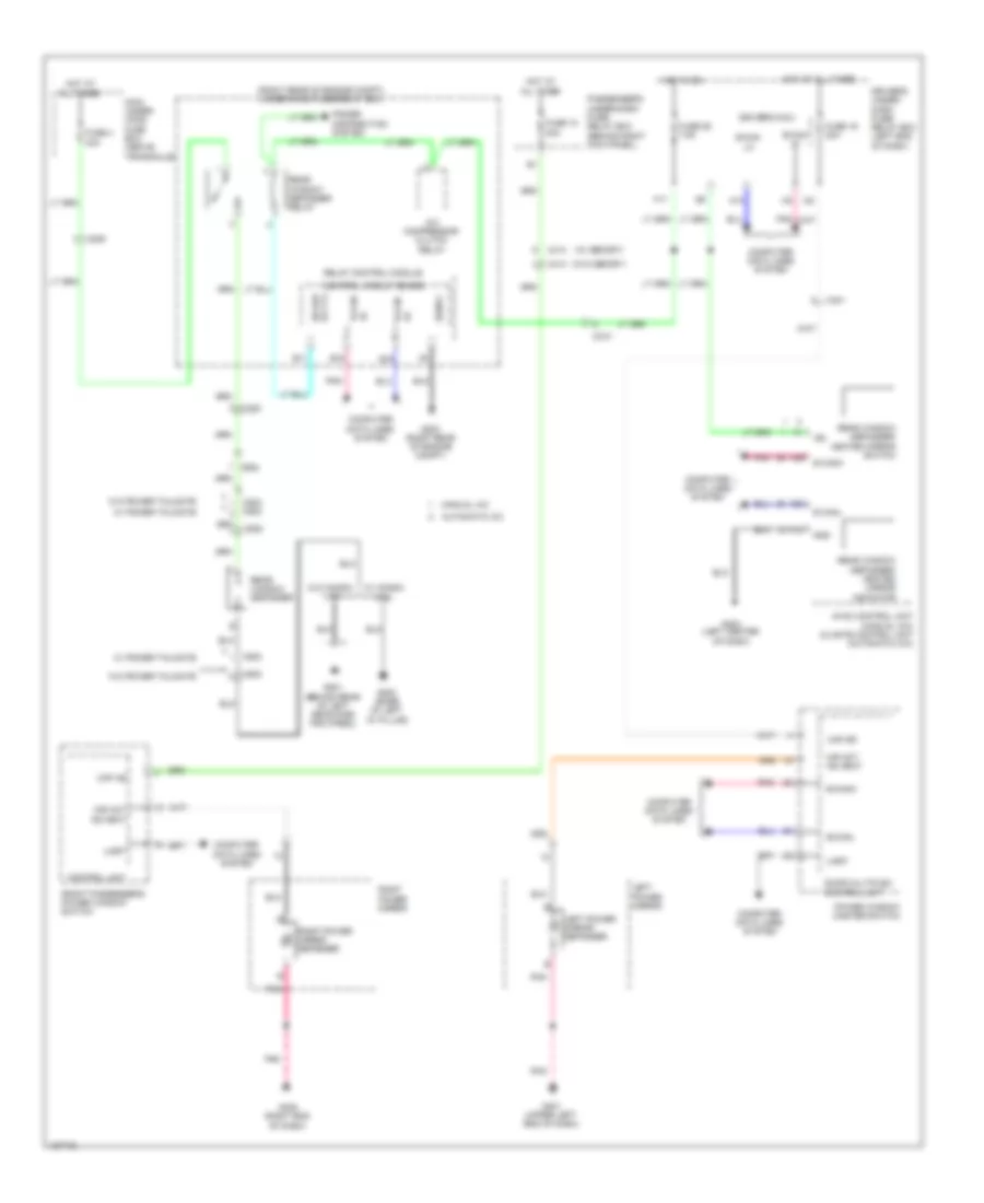
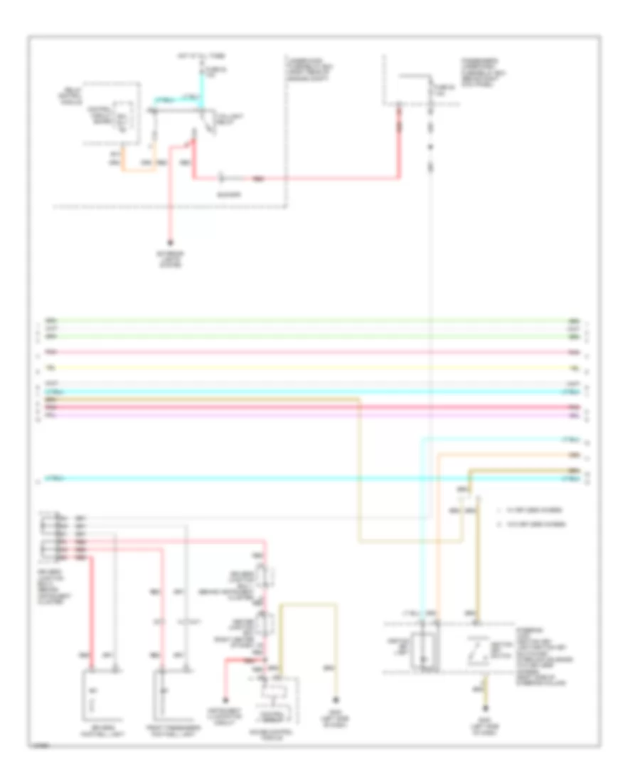
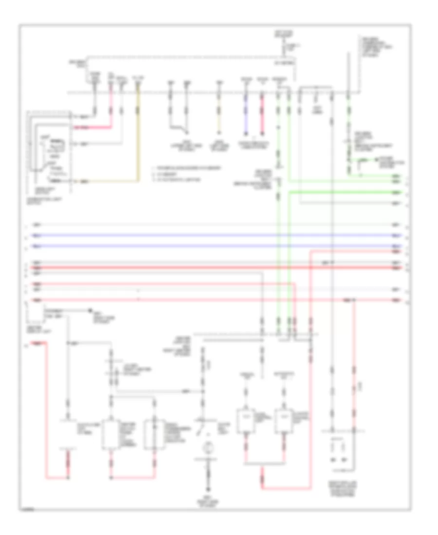
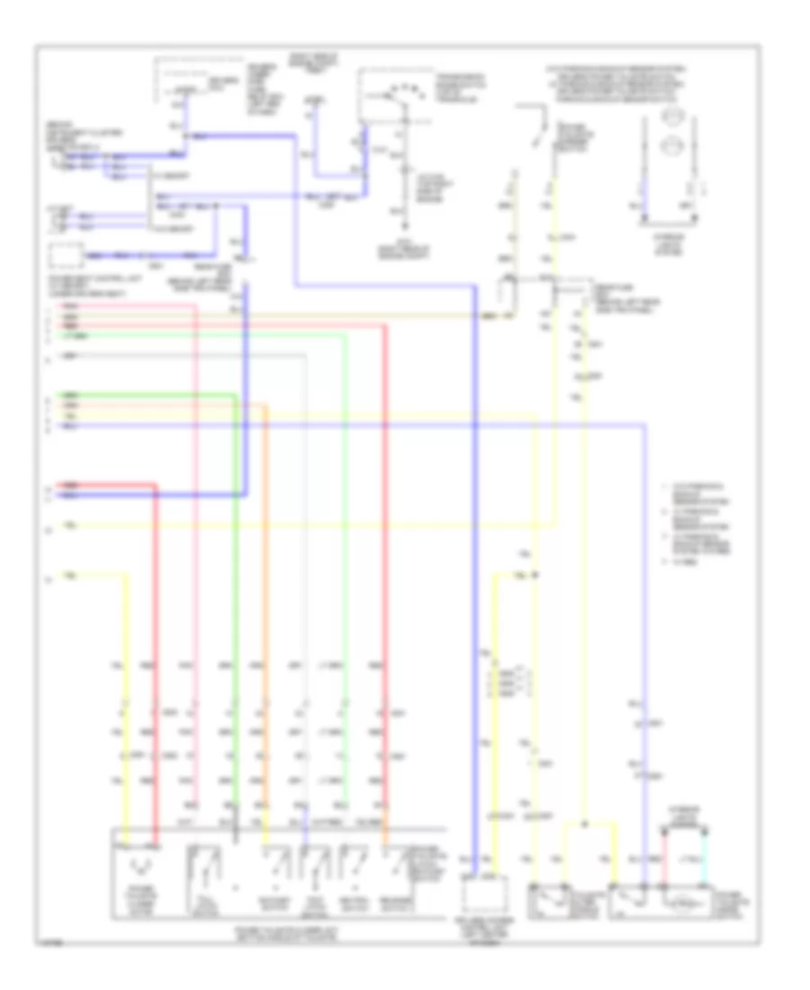
Automatic A/C Wiring Diagram, without Memory (3 of 3) for Honda Odyssey EX-L 2014
List of elements for Automatic A/C Wiring Diagram, without Memory (3 of 3) for Honda Odyssey EX-L 2014:
- (behind right rear side trim panel) rear blower motor
- (behind right rear side trim panel) rear blower motor noise condenser
- (on rear blower motor) rear blower power transistor
- A/c compressor clutch relay
- A/c condenser fan relay/ fan control relay diode
- A10
- A11
- A12
- A13
- A21
- A37
- A48
- A49
- Acc
- Amd-p-rr
- Blw-g-rr
- Blw-v-rr
- Bus-data
- C16
- C201
- C206
- C208
- C210
- C32
- C405
- C415
- Computer data lines system
- D31
- Driver's junction box 1 (behind instrument cluster)
- E42
- Ect sensor 1 (top rear of engine)
- Ect sensor 2 (bottom left side of radiator)
- Ect1
- Ect2
- F-can-h
- F-can-l
- Fan h
- Fan l
- Fuse 7.5a
- G201 (bottom left front of engine compt)
- G203 (right rear of engine compt)
- G652 (right "c" pillar)
- G701 (center front of roof)
- Gnd
- Hot at all times
- Ig2
- Ill+
- Ill-
- Interior lights system
- J/c c104 (top right side of engine)
- M-cool-rr
- M-def-rr
- M-hot-rr
- M-vent-rr
- Main under-hood fuse box (above transaxle)
- Mod-p-rr
- Multi- fuse 2
- Passenger's under-dash fuse/relay box (left end of dash)
- Pcm (right side of engine compt)
- Pnk
- Power distribution system
- Radiator fan motor (behind left side of radiator)
- Rear a/c control panel (top of rear a/c unit)
- Rear a/c control unit (top of rear a/c unit)
- Rear air mix control motor (lower center of rear a/c unit)
- Rear blower motor relay
- Rear evaporator temperature sensor (bottom of rear a/c unit)
- Rear mode control motor (upper center of rear a/c unit)
- Rear window defogger relay
- Red
- Rr blower fuse 30a
- S5v
- Sens-com
- Sg2
- Sg7
- Teva-rr
- Under-hood fuse/relay box (right rear of engine compt)
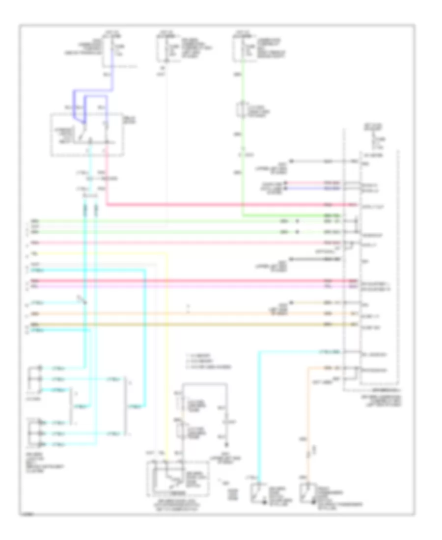
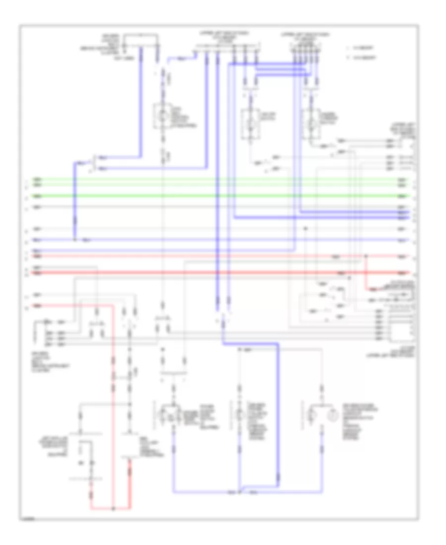
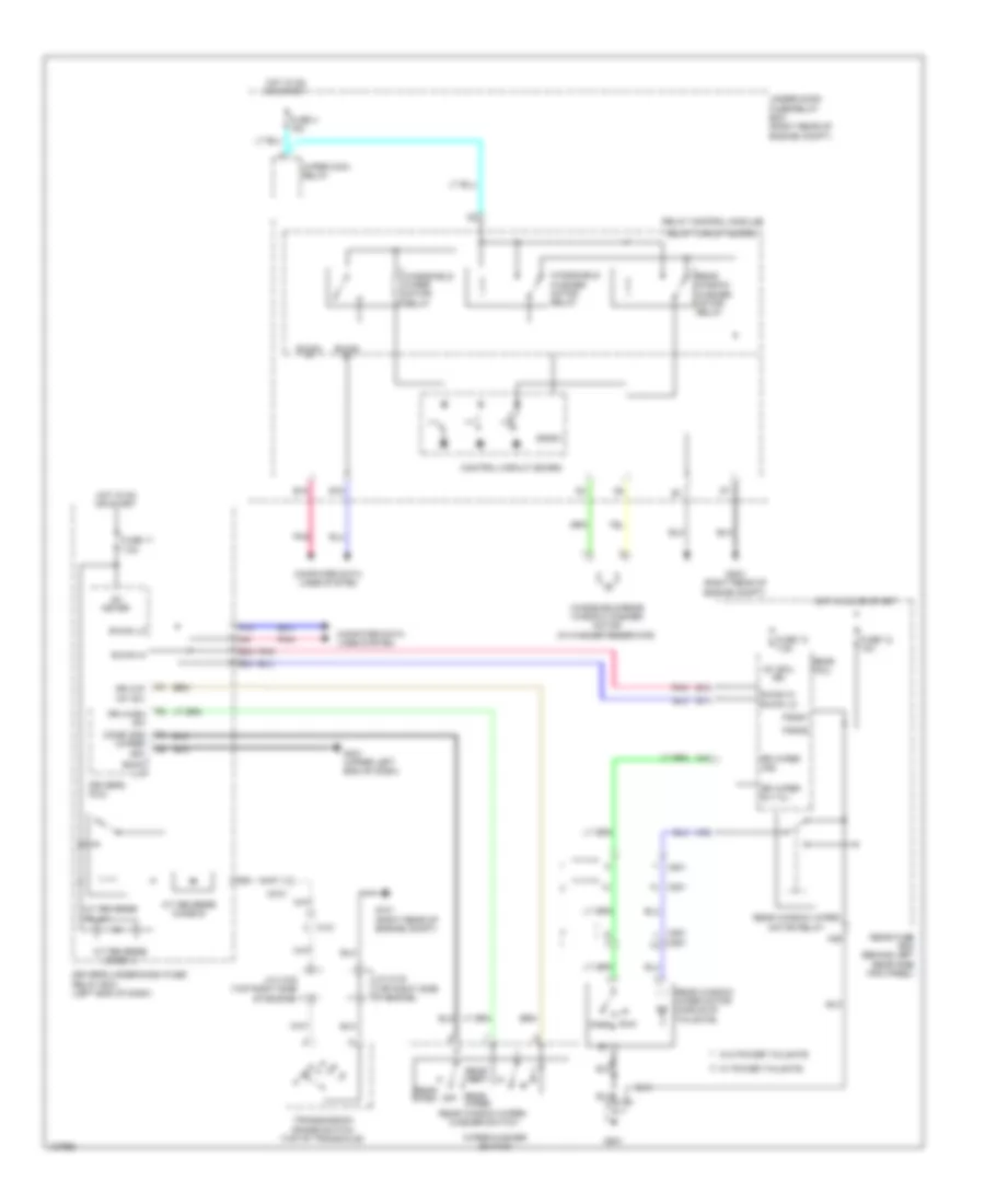
Manual A/C Wiring Diagram (1 of 3) for Honda Odyssey EX-L 2014
List of elements for Manual A/C Wiring Diagram (1 of 3) for Honda Odyssey EX-L 2014:
- (near front blower motor) front blower power transistor
- (under right side of dash) front blower motor
- A/c pressure sensor (right rear of engine compt)
- Air mix control motor (lower left side of hvac unit)
- Amd-p
- B-can h
- B-can l
- Blw-g
- Blw-v
- Bus data
- C202
- C205
- C208
- C411
- Computer data lines system
- Fr blower fuse 40a
- Front blower motor relay
- Front evaporator temperature sensor (left side of evaporator)
- Front mode control motor (left side of hvac unit)
- Front recirculation control motor (right side of hvac unit)
- G204 (right end of dash)
- G302 (left end of dash)
- G403 (left center of dash)
- Gnd
- Hot at all times
- Hvac control unit
- Ig2
- Ill+
- Ill-
- Interior lights system
- J/c c407
- L-mode 1
- L-mode 2
- L-mode 3
- M-cool
- M-def
- M-frs
- M-hot
- M-rec
- M-vent
- Main under-hood fuse box (above transaxle)
- Mode 1
- Mode 2
- Mode 3
- Mode 4
- Multi- fuse 2
- Multi- fuse 3
- Pnk
- Power distribution system
- Red
- Relay block
- Rr blower fuse 30a
- S5v
- Sens com
- Sens-com
- Teva
Manual A/C Wiring Diagram (2 of 3) for Honda Odyssey EX-L 2014
List of elements for Manual A/C Wiring Diagram (2 of 3) for Honda Odyssey EX-L 2014:
- A10
- A11
- A12
- Amd-p
- B can transceiver
- B-can hi
- B-can lo
- Blw-g
- Blw-v
- Bus data
- C206
- C210
- C415
- Computer data lines system
- Control circuits
- D31
- Driver's junction box 1 (behind instrument cluster)
- Driver's under-dash fuse/relay box (left end of dash)
- E42
- F can transceiver
- F17
- Fuse 7.5a
- G652 (right "c" pillar)
- Gauge control module
- Gnd
- H10
- Hot in on
- Ig2
- J/c c408
- M-cool
- M-def
- M-hot
- M-vent
- Mdd-p
- Micu
- Passenger's under-dash fuse/relay box (behind right kick panel)
- Pnk
- Rear a/c control unit (top of rear a/c unit)
- Rear air mix control motor (lower center of rear a/c unit)
- Rear blower motor (behind right rear side trim panel)
- Rear blower power transistor (on rear blower motor)
- Rear mode control motor (upper center of rear a/c unit)
- Red
- S5v
- Sens-com
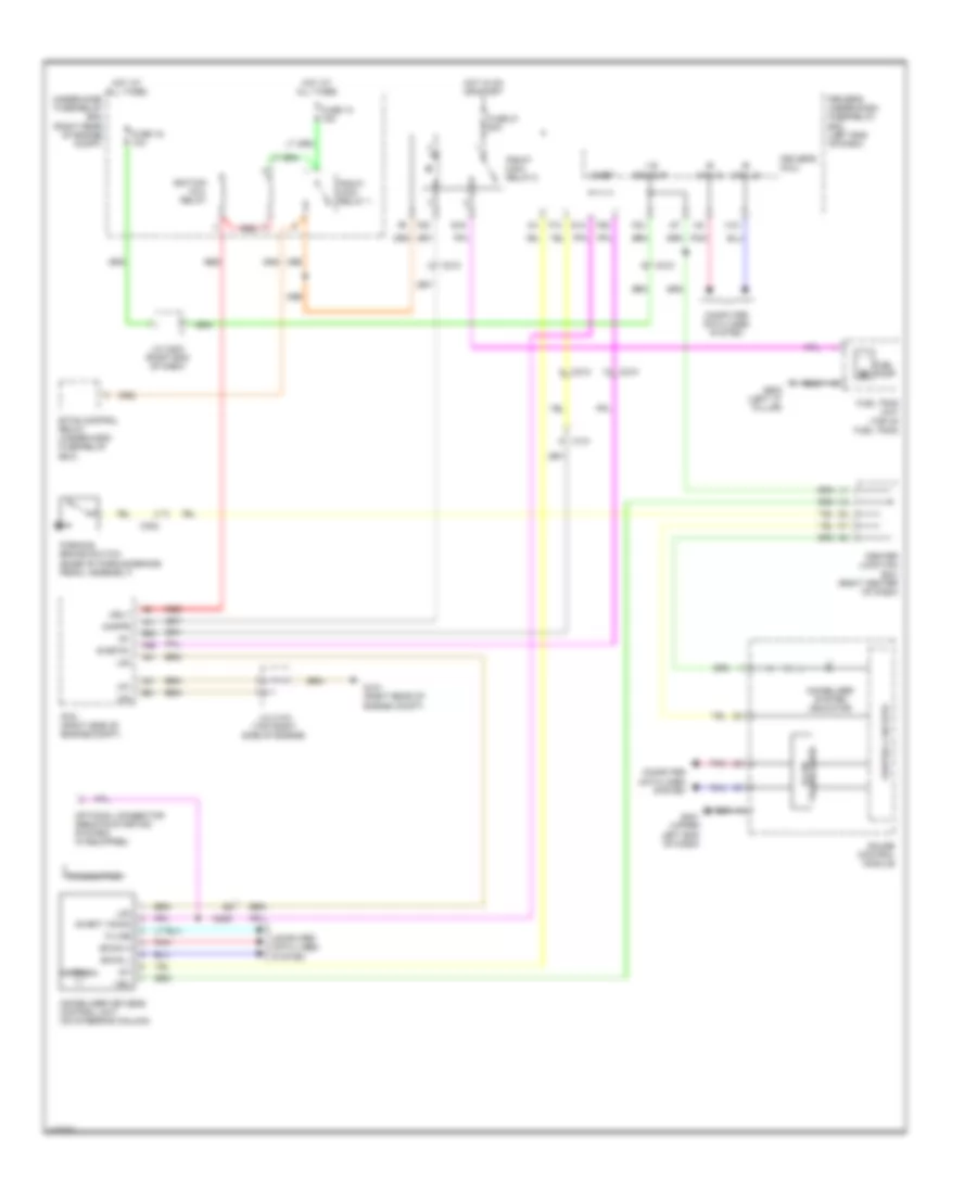
Manual A/C Wiring Diagram (3 of 3) for Honda Odyssey EX-L 2014
List of elements for Manual A/C Wiring Diagram (3 of 3) for Honda Odyssey EX-L 2014:
- (right rear of of engine compt) g203
- A/c compressor clutch
- A/c compressor clutch (left front of engine)
- A/c compressor clutch relay
- A/c condenser fan motor (behind right side of radiator)
- A/c condenser fan relay
- A/c condenser fan relay/ fan control relay diode
- A13
- A21
- A37
- A48
- A49
- A5 fan h
- Acc
- C101
- C16
- C32
- Computer data lines system
- Ect sensor 1 (top rear of engine)
- Ect sensor 2 (bottom left side of radiator)
- Ect1
- Ect2
- F-can h
- F-can l
- Fan control relay
- Fan l
- Fuse 30a
- Fuse 7.5a
- G201 (bottom left front of engine compt)
- G203 (right rear of of engine compt)
- Hot at all times
- Hot w/ pgm-fi main relay energized
- J/c c104 (top right side of engine)
- Pcm (right side of engine compt)
- Pgm-fi sub-relay
- Pnk
- Radiator fan motor (behind left side of radiator)
- Radiator fan relay
- Radiator fan relay diode
- Rear blower motor relay
- Rear window defogger relay
- Red
- Sg2
- Sg7
- Under-hood fuse/relay box (right rear of engine compt)
ANTI-LOCK BRAKES
Anti-lock Brakes Wiring Diagram for Honda Odyssey EX-L 2014
List of elements for Anti-lock Brakes Wiring Diagram for Honda Odyssey EX-L 2014:
- A48
- A49
- Abs ind
- Bksw
- Brake fluid level switch (brake fluid reservoir)
- Brake pedal position switch (on brake pedal bracket)
- Brake system ind
- C210
- C212
- C302
- Center junction box (right center of dash)
- Computer data lines system
- Control circuits
- Driver's junction box 1 (behind instrument cluster)
- Driver's under-dash fuse/relay box (left end of dash)
- E35
- E36
- E38
- E39
- Exterior lights system
- F-can h
- F-can l
- F-can transceiver
- F15
- F16
- F18
- F19
- F31
- Fl +b
- Fl-gnd
- Fr +b
- Fr-gnd
- Fsr +b
- Fuse 7.5a
- Fuse 9 20a
- G13
- G301 (left front of engine compt)
- G302 (left end of dash)
- G401 (upper left end of dash)
- G403 (left center of dash)
- Gauge control module
- Gnd
- Hot at all times
- Hot in on or start
- Ig 1
- Ig1
- Interior lights system
- K-line
- Keyless access control unit (if equipped) (left center of dash)
- Left front wheel speed sensor (left front wheel hub assembly)
- Left rear wheel speed sensor (left rear wheel hub assembly)
- Main under-hood fuse box (above transaxle)
- Mr+b
- Mr-gnd
- Multi- fuse 2
- Parking brake switch (base of parking brake pedal assembly)
- Pcm (right side of engine compt)
- Pnk
- Power distribution system
- Red
- Right front wheel speed sensor (right front wheel hub assembly)
- Right rear wheel speed sensor (right rear wheel hub assembly)
- Rl +b
- Rl-gnd
- Rr +b
- Rr-gnd
- Sgnd
- Steering angle sensor (in steering column)
- Stop & horn hazard fuse 30a
- Str-a
- Str-b
- Str-z
- Svcc
- Vsa fsr fuse 30a
- Vsa modulator control unit (left side of engine compt)
- Vsa mtr fuse 40a
- Vsa off ind
- Vsa off switch
- Vsa off switch light
- Vsa system ind
- Wen
- Yaw rate acceleration sensor (under front of center console)
ANTI-THEFT
Forced Entry Wiring Diagram (1 of 8) for Honda Odyssey EX-L 2014
List of elements for Forced Entry Wiring Diagram (1 of 8) for Honda Odyssey EX-L 2014:
- (not used)
- +b hazard
- 20a
- 7.5a
- B-can hi
- B-can lo
- C401
- C414
- C415
- Computer data lines system
- Control unit
- D/lck rly cl- pg1
- D/unlck rly cl-
- Door lock knob
- Dr d/unlck rly cl-
- Driver's door switch (on driver's "b" pillar)
- Driver's micu
- Driver's under-dash fuse/relay box (left end of dash)
- E10
- E11
- E13
- E14
- E15
- E22
- E25
- E33
- Exterior lights system
- F11
- F12
- Fr l door sw
- Fr r door sw
- Front passenger's door lock actuator
- Front passenger's door lock actuator/ knob switch
- Front passenger's door lock knob switch
- Front passenger's door lock switch
- Front passenger's door lock switch lock light
- Front passenger's door lock switch unlock light
- Front passenger's power window switch
- Fuse 15a
- Fuse 19
- Fuse 20a
- Fuse 26
- Fuse 7.5a
- G401 (upper left end of dash)
- G402 (left side of dash)
- G405 (right end of dash)
- H/l off sw
- H10
- H12
- H13
- Headlights system
- Hot at all times
- Hot in on
- J/c c472 (front passenger's door)
- Lock
- Main under-hood fuse box (above transaxle)
- P17
- P19
- Pnk
- Power door lock relay (dr unlock)
- Power door lock relay (lock)
- Power door lock relay (unlock)
- Red
- Scty1
- Sg1
- Sil as ul
- Small lt sw
- Turn lt fr l
- Turn lt fr r
- Turn lt rr l
- Turn lt rr r
- Turn signal/ hazard warning circuit
- Uart
- Unlock
- Vmp as
- W/ memory
- W/o memory
Forced Entry Wiring Diagram (2 of 8) for Honda Odyssey EX-L 2014
List of elements for Forced Entry Wiring Diagram (2 of 8) for Honda Odyssey EX-L 2014:
- (driver's door)
- B-can h
- B-can hi
- B-can l
- B-can lo
- B15
- B16
- C401
- C415
- C605
- C606
- C652
- C653
- C681
- C682
- C691
- C692
- Computer data lines system
- Control circuit board
- Door lock knob
- Door multiplex control unit
- Driver's door key cylinder switch
- Driver's door lock actuator
- Driver's door lock actuator/ knob switch/ key cylinder switch
- Driver's door lock knob switch
- Driver's door lock switch
- Driver's door lock switch lock light
- Driver's door lock switch unlock light
- Eng hood sw
- Front passenger's door switch (on front passenger's "b" pillar)
- G204 (right end of dash)
- G401 (upper left end of dash)
- G402 (left side of dash)
- G602 (left "c" pillar)
- G671 (right sliding door)
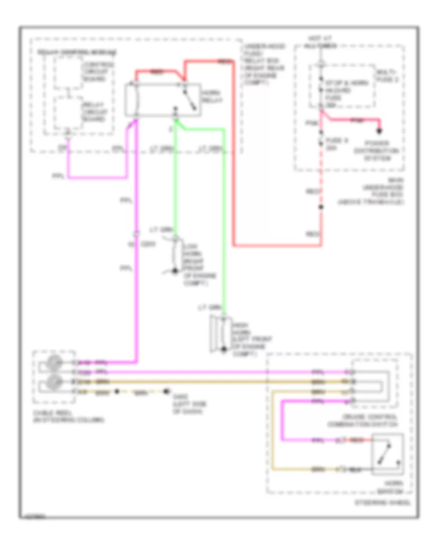
- High horn (left front of engine compt)
- Horn relay
- Horns system
- Ig2
- J/c c452
- Kc dr lock
- Kc dr ul
- Key
- Left cess articulated harness (w/o keyless access)
- Left sliding door lock actuator
- Left sliding door lock knob switch
- Left sliding door remote control assembly (behind left rear side trim panel)
- Lock
- Low horn (right front of engine compt)
- Pnk
- Power distribution system
- Power tops system
- Power window master switch
- Red
- Relay circuit board
- Relay control module
- Right cess articulated harness (w/o keyless access)
- Right sliding door lock actuator
- Right sliding door lock knob switch
- Right sliding door remote control assembly (behind right rear side trim panel)
- Security hood switch (center front of engine compt)
- Sil dr lock
- Sil dr ul
- Uart
- Under-hood fuse/relay box (right rear of engine compt)
- Unlock
- Vbu
- Vmp dr
- W/ memory
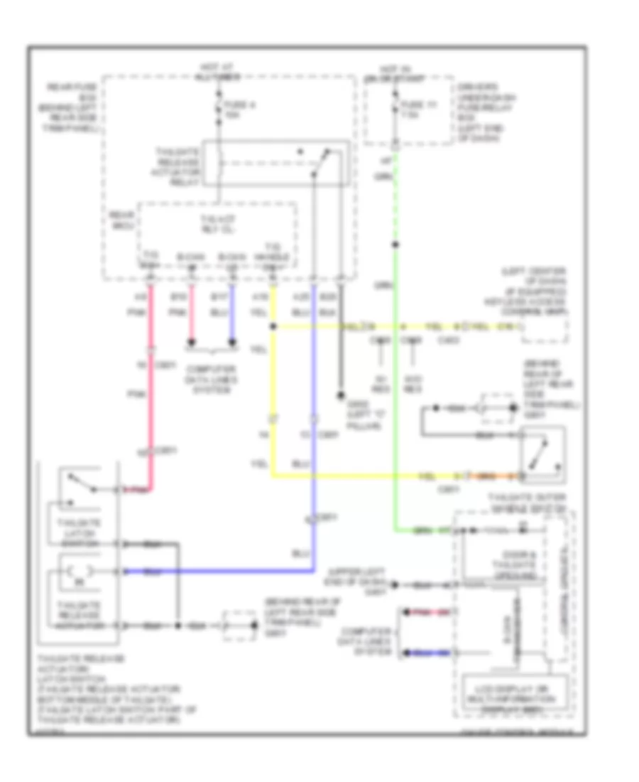
Forced Entry Wiring Diagram (3 of 8) for Honda Odyssey EX-L 2014
List of elements for Forced Entry Wiring Diagram (3 of 8) for Honda Odyssey EX-L 2014:
- 10a
- 20a
- 7.5a
- A10
- A11
- A12
- A13
- A16
- A22
- A25
- A29
- B-can hi
- B-can lo
- B10
- B11
- B12
- B15
- B17
- B21
- B26
- B27
- B28
- C413
- C505
- C604
- C607
- C801
- C851
- Center display unit
- Computer data lines system
- Door lock rd rly cl-
- Door unlock rd rly cl-
- Dvd player unit
- Fuse 18
- Fuse 4
- Fuse 5
- G602 (left "c" pillar)
- G801 (behind rear of left rear side trim panel)
- Hot at all times
- Left sliding door switch (in left "c" pillar)
- Passenger's under-dash fuse/relay box (behind right kick panel)
- Pgnd1
- Pgnd2
- Pnk
- Power door lock relay (unlock)
- Power door relay (lock)
- Ra door sw
- Ra sil ul sw+
- Rd door sw
- Rd sil l sw+
- Rd sil ul sw+
- Rear controller & screen
- Rear fuse box (behind left rear side trim panel)
- Rear micu
- Red
- Right sliding door switch (in right "c" pillar)
- Scty1
- Scty2
- Scty2 (or scty4)
- Scty3
- Scty4
- T gate handle sw+
- T gate sw+
- T/g (trunk) act rly cl-
- Tailgate latch switch
- Tailgate outer handle switch (w/o power tailgate)
- Tailgate release actuator
- Tailgate release actuator relay
- Tailgate release actuator/latch switch (w/o power tailgate) (bottom middle of tailgate)
- W/ keyless access
- W/ power tailgate
- W/ res
- W/o keyless access
- W/o power tailgate
- W/o res
Forced Entry Wiring Diagram (4 of 8) for Honda Odyssey EX-L 2014
List of elements for Forced Entry Wiring Diagram (4 of 8) for Honda Odyssey EX-L 2014:
- C11
- C403
- C415
- C605
- C606
- C611
- C652
- C655
- C681
- C682
- C683
- C691
- C693
- C801
- C851
- Door lf antenna
- Door lock knob
- Driver's junction box 2 (behind instrument cluster)
- Full latch switch
- G602 (left "c" pillar)
- G671 (right sliding door)
- J/c c407
- Left cess articulated harness (w/ keyless access)
- Left sliding door lock knob switch
- Left sliding door outer handle/ touch sensor/lf antenna
- Left sliding door remote control assembly
- Pnk
- Power tailgate closer unit (bottom middle of tailgate)
- Power tailgate control unit (left "d" pillar)
- Power tailgate latch/ratchet switch
- Red
- Right cess articulated harness (w/ keyless access)
- Right sliding door lock knob switch
- Right sliding door outer handle/ touch sensor/lf antenna
- Right sliding door remote control assembly
- Seg3
- Touch sensor
- W/ memory
- W/o memory
Forced Entry Wiring Diagram (5 of 8) for Honda Odyssey EX-L 2014
List of elements for Forced Entry Wiring Diagram (5 of 8) for Honda Odyssey EX-L 2014:
- +b smart
- Acc cont
- Acc key lock
- Antenna
- Atpp
- B-can h
- B-can l
- B10
- B11
- B12
- B13
- B14
- B15
- B16
- B17
- B18
- B19
- B20
- B21
- B22
- B23
- B24
- B25
- B26
- B27
- B28
- B29
- B30
- B31
- B32
- B33
- B34
- B35
- B36
- Bksw
- C205
- C212
- C304
- Computer data lines system
- Dck
- Din/dout
- Driver's micu
- Driver's under-dash fuse/relay box (left end of dash)
- Electric steering lock (in steering column)
- Esl pwr
- Esl sw b
- Esl sw c
- Esl sw d
- F10
- Fuse 10a
- Fuse 20a
- Fuse 30a
- Fuse 7.5a
- G403 (left center of dash)
- Gnd
- Hot at all times
- Ig1 cont
- Ig1 fuel
- Ig1 fuel pump
- Ig1 meter
- Ig1a s
- Ig1b s
- Ig2 cont
- Ig2 s
- Ign trx
- Immobilizer keyless control unit (on steering column)
- Ind-1
- Keyless access
- Keyless access control unit (left center of dash)
- Lg2
- Main under-hood fuse box (above transaxle)
- Mtr cont
- Mtr cut1
- Mtr cut2
- Parking sw
- Pnk
- Pump
- Q18
- Red
- Relay gnd
- Ss1 (+)
- Ss2 (-)
- Ssb gnd
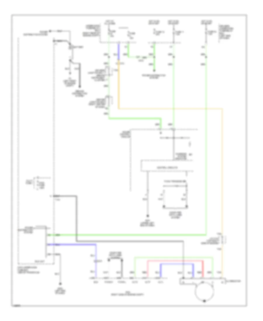
- Starting/charging system
- Stop sw
- Sts
- Swill
- Transmitter
- Vbu
- Vcont
- W/o
Forced Entry Wiring Diagram (6 of 8) for Honda Odyssey EX-L 2014
List of elements for Forced Entry Wiring Diagram (6 of 8) for Honda Odyssey EX-L 2014:
- 5v regulator
- A16
- A48
- A49
- Acc relay
- Atpp
- B41
- B42
- Bksw
- C101
- C212
- C414
- Computer data lines system
- Engine start/stop switch
- F-can-h
- F-can-l
- Front passenger's door outer handle/ lock switch/touch sensor
- G101 (right rear of engine compt)
- G405 (right end of dash)
- Ig1
- Ig1a relay
- Ig1b relay
- Ig2 relay
- Immobilizer
- J/c c103 (top right side of engine)
- J/c c472 (front passenger's door)
- Lf antenna
- Lg2
- Lock switch
- Pcm (right side of engine compt)
- Pnk
- Power distribution system
- Red
- Touch sensor
- Under-dash sub-relay box (lower left side of dash)
- W/ bsi system
- W/ memory
- W/o bsi system
- W/o memory
Forced Entry Wiring Diagram (7 of 8) for Honda Odyssey EX-L 2014
List of elements for Forced Entry Wiring Diagram (7 of 8) for Honda Odyssey EX-L 2014:
- (base of parking brake pedal assembly) parking brake switch
- (behind left rear side trim panel) rear fuse box
- A14
- A16
- A27
- Atpp
- B-cal lo
- B-can hi
- B-can transceiver
- B10
- B17
- Brake pedal position switch (on brake pedal bracket)
- Buzzer
- C101
- C13
- C302
- C403
- C404
- C609
- C801
- C851
- Center junction box (right center of dash)
- Computer data lines system
- Control circuit
- Door & tailgate open ind
- Driver's junction box 1 (behind instrument cluster)
- Fuse 10a
- Fuse 20a
- G101 (right rear of engine compt)
- G401 (under left end of dash)
- G801 (behind rear of left rear side trim panel)
- Gauge control module
- Hot at all times
- Immobilizer system ind
- J/c c102 (top right side of engine)
- Keyless access system ind
- Keyless buzzer (left "d" pillar)
- Main under-hood fuse box (above transaxle)
- Memory systems
- Ohsw
- Parking & backup sensor system w/o res
- Pnk
- Power tailgate control unit (left "d" pillar)
- Rear fuse box (behind left rear side trim panel)
- Rear micu
- Red
- Scom
- Security ind
- Tailgate handle sw+ sgnd2
- Tailgate outer handle switch
- Transmission range switch (top of transaxle)
- Trunk, tailgate, fuel doors system
- Under-hood fuse/relay box (right rear of engine compt)
- W/ power tailgate
- W/ res
- W/o power tailgate
Forced Entry Wiring Diagram (8 of 8) for Honda Odyssey EX-L 2014
List of elements for Forced Entry Wiring Diagram (8 of 8) for Honda Odyssey EX-L 2014:
- (left end of dash) driver's under-dash fuse/relay box
- +b smart
- A10
- A11
- A12
- A13
- A14
- A15
- A16
- A17
- A18
- A19
- A20
- A21
- A22
- A23
- A24
- A25
- A26
- A27
- A28
- A29
- A30
- A31
- A32
- Atpp
- B-can h
- B-can l
- C10
- C11
- C12
- C13
- C14
- C15
- C16
- C17
- C18
- C19
- C20
- C401
- C403
- C415
- C609
- C801
- C802
- C851
- Computer data lines system
- Dl frans
- Dl frdr
- Dl t/g
- Driver's door outer handle/lock switch/ touch sensor
- Driver's micu
- Ext-f+
- Ext-f-
- Ext-r+
- Ext-r-
- Ext-rras+
- Ext-rras-
- Ext-rrdr+
- Ext-rrdr-
- Ext-tr+
- Ext-tr-
- Exterior lights system
- F-can h
- F-can l
- Front interior lf antenna (under center console)
- G402 (left side of dash)
- G403 (left center of dash)
- G801 (behind rear of left rear side trim panel)
- H/l off sw
- Headlights system
- Ig key sw
- Ign trx
- Ignition key switch
- K-line
- Key sw
- Keyless access
- Keyless access control unit (if equipped) (left center of dash)
- L-line
- Lg1
- Lock switch
- Ohsw
- P-pin sw
- P17
- P19
- P22
- P23
- Park pin switch
- Parking & backup sensor system w/o res
- Pnk
- Rear bumper lf antenna (behind center of rear bumper)
- Rear interior lf antenna (center front of cargo area floor)
- Red
- Rf unit
- S-net
- Shift lever connector
- Small lt sw
- Starting/charging system
- Steering lock (ignition key light/ignition key switch/key interlock solenoid) (right side of steering column)
- Tailgate lock switch (part of tailgate release actuator)
- Touch sensor
- Transmitter
- Ts fras
- Ts frdr
- Ts rras
- Ts rrdr
- Turn sw l
- Turn sw r
- Vout fras
- Vout frdr
- Vout rras
- Vout rrdr
- W/ power tailgate
- W/ res
- W/o
- W/o power tailgate
Immobilizer Wiring Diagram for Honda Odyssey EX-L 2014
List of elements for Immobilizer Wiring Diagram for Honda Odyssey EX-L 2014:
- (s-net)
- + b backup
- A11
- A41
- A46
- Antenna
- B- can hi
- B- can lo
- B-can h
- B-can l
- B-can transceiver
- B41
- B42
- C101
- C205
- C210
- C212
- C302
- C41
- Center junction box (right center of dash)
- Computer data lines system
- Control circuits
- Driver's micu
- Driver's under-dash fuse/relay box (left end of dash)
- E16
- Etcs control relay (under-hood fuse/relay box)
- F10
- F20
- F24
- F26
- Fuel pump
- Fuel tank unit (top of fuel tank)
- Fuse 10 15a
- Fuse 16 10a
- Fuse 21 20a
- G101 (right rear of engine compt)
- G12
- G401 (upper left end of dash)
- G602 (left "c" pillar)
- Gauge control module
- H10
- Hot at all times
- Hot in on or start
- Ig1
- Ignition coil relay
- Immobilizer keyless control unit (on steering column)
- Immobilizer system indicator
- Imocd
- Imofpr
- J/c c103 (top right side of engine)
- J/c c203 (right end of dash)
- K-line
- Lg1
- Lg2
- Lg3
- Mrly
- Optional connector (remote starting system) (if equipped)
- Parking brake switch (base of parking brake pedal assembly)
- Pcm (right side of engine compt)
- Pgm-fi main relay 1
- Pgm-fi main relay 2
- Pnk
- Red
- S-net
- S-net5v
- Transmitter
- Under-hood fuse/relay box (right rear of engine compt)
- Vbu
BODY CONTROL MODULES
Body Control Modules Wiring Diagram (1 of 2) for Honda Odyssey EX-L 2014
List of elements for Body Control Modules Wiring Diagram (1 of 2) for Honda Odyssey EX-L 2014:
- (not used)
- (upper left end of dash) g401
- +b backup
- +b hazard
- Acc key lock
- Atp-p
- Auto lt sig
- Auto lt sio
- Auto lt sip
- B-can hi
- B-can lo
- Back lt
- Backup h/l
- Backup wiper
- Combi gnd
- Computer data lines system
- Connector) (option
- D/ lock rly cl-
- Dimmer sw
- Door locks & anti-theft systems
- Door locks system
- Dr d/unl lock rly cl- d/unl lock rly cl-
- Driver's micu
- Driver's under-dash fuse/relay box (left end of dash)
- E10
- E11
- E22
- E23
- E25
- E26
- E27
- E29
- E31
- E32
- E43
- E44
- Exterior lights system
- F11
- F12
- F13
- F14
- F24
- F25
- F26
- Fr courtesy l
- Fr courtesy r
- Fr fog sw
- Fr l door sw
- Fr r door sw
- Fr wash sw
- Fr wip hi & lo sw
- Fr wip int & lo sw
- Fr wip int vol+
- Fr wip mist sw
- Fuse 7.5a
- G10
- G12
- G15
- G401 (upper left end of dash)
- G402 (left side of dash)
- H/l off sw
- H/l on sw
- H10
- Haz sw
- Headlights system
- Hot in acc or on
- Hot in on or start
- Ig key lt
- Ig key sw
- Ig1 meter
- Interior lights system
- Intr lt cut
- Intr lt-
- K-line
- Key lock sol-
- P-pin sw
- P/w l rly cl-
- P/w r rly cl-
- P10
- P11
- P12
- P13
- P14
- P15
- P16
- P17
- P18
- P19
- P20
- P21
- P22
- P23
- Passing sw
- Pg1
- Pnk
- Power distribution system
- Power windows system
- Q10
- Q11
- Q12
- Q13
- Q14
- Q15
- Q16
- Q17
- Q18
- Q19
- Q20
- Red
- Rr wash sw
- Rr wip int sw
- S-net
- Sctyi
- Sg1
- Sg2
- Shift interlock system
- Small lt sw
- Starting/ charging system
- Starting/charging & wiper/washer systems
- Stop sw
- Transmissions system
- Turn lt fr l
- Turn lt fr r
- Turn lt rr l
- Turn lt rr r
- Turn signal/ hazard warning circuit
- Turn sw l
- Turn sw r
- Used) (not
- Warning systems
- Wiper/washer system
- Wiper/washer systems
Body Control Modules Wiring Diagram (2 of 2) for Honda Odyssey EX-L 2014
List of elements for Body Control Modules Wiring Diagram (2 of 2) for Honda Odyssey EX-L 2014:
- (not used)
- + backup
- A10
- A13
- A14
- A16
- A18
- A20
- A21
- A22
- A23
- A24
- A29
- A40
- A44
- B-can hi
- B-can lo
- B10
- B11
- B12
- B14
- B15
- B16
- B17
- B21
- B26
- Buzzer
- C210
- Cabin accessories system
- Cargo lt -
- Computer data lines system
- Door lock rd rly cl-
- Door locks system
- Door unlock rd rly cl-
- Fuel lid open rly
- Fuel lid sw rly
- Fuse 10a
- Fuse 7.5a
- G602 (left "c" pillar)
- G801 (behind rear of left rear side trim panel)
- Hot at all times
- Hot in on or start
- Ig1 ecu rr
- Interior lights system
- J/c c203 (right end of dash)
- Pgnd1
- Pnk
- Ptg full
- Ra door sw
- Ra sil ul sw+
- Rd door sw
- Rd sil l sw+
- Rd sil ul sw+
- Rear fuse box (behind left rear side trim panel)
- Rear micu
- Red
- Rr wiper (as)
- Rr wiper rly cl-
- Sgnd1
- Sgnd2 pgnd2
- T gate handle sw+
- T gate sw+
- T/g (trunk) act rly cl-
- Trunk, tailgate, fuel doors system
- Under-hood fuse/relay box (right rear of engine compt)
- Vac rly
- Vac run ind
- Vac sw
- Vac time ind
- Wiper/washer system
COMPUTER DATA LINES
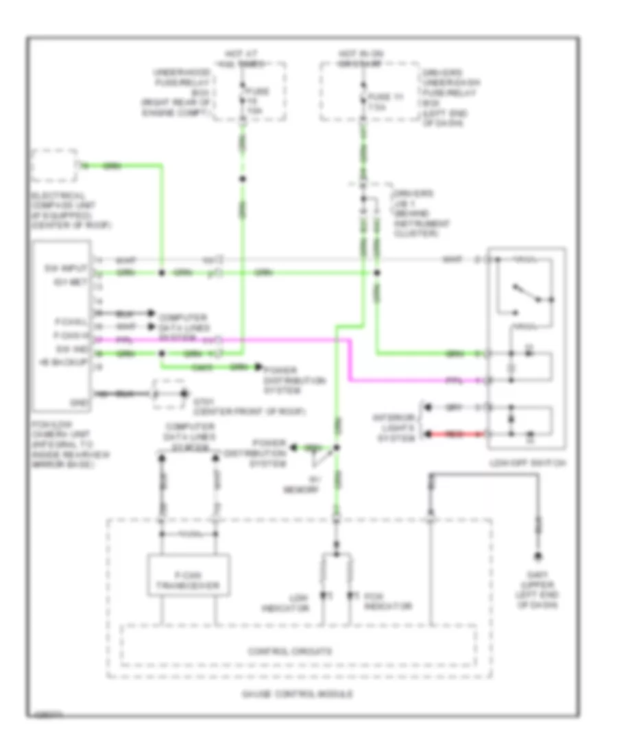
Data Link Connector Wiring Diagram (1 of 2) for Honda Odyssey EX-L 2014
List of elements for Data Link Connector Wiring Diagram (1 of 2) for Honda Odyssey EX-L 2014:
- Audio unit
- Audio- navigation unit (w/ navigation)
- C12
- C302
- C405
- C413
- Can h
- Can l
- Center junction box (right center of dash)
- Dlc (under left side of dash)
- Driver's junction box 1 (behind instrument cluster)
- Driver's micu
- Driver's under-dash fuse/relay (left end of dash)
- F25
- Fcw/ldw camera unit (if equipped) (integral to inside rearview mirror base)
- Fuse 10a
- G15
- G401 (upper left end of dash)
- Hot at all times
- K-line
- Keyless access control unit (if equipped) (left center of dash)
- L-line
- Red
- Under-hood fuse/relay box (right rear of engine compt)
- Vsa modulator control unit (left side of engine compt)
- W/ navigation
- W/o navigation
- Wen
Data Link Connector Wiring Diagram (2 of 2) for Honda Odyssey EX-L 2014
List of elements for Data Link Connector Wiring Diagram (2 of 2) for Honda Odyssey EX-L 2014:
- (right end of dash) engine mount control unit
- (right side of engine compt) pcm
- A32
- A48
- A49
- C205
- C412
- C415
- C651
- Can h
- Can l
- Center junction box (right center of dash)
- Control circuits
- F-can transceiver
- F-can-h
- F-can-l
- Front passenger's weight sensor unit (under front passenger's seat)
- Gauge control module
- Headlight leveling control unit (w/ hid) (left side of dash)
- Immobilizer keyless control unit (w/o keyless access) (on steering column)
- J/c c203 (right end of dash)
- J/c c416 (upper left center of dash)
- K-line
- K10
- Scs
- Srs unit (under front of center console)
- Tpms control unit (if equipped) (left side of dash)
- W/ keyless access
- W/o keyless access
- Yaw rate acceleration sensor (under front of center console)
F-CAN & B-CAN Wiring Diagram (1 of 2) for Honda Odyssey EX-L 2014
List of elements for F-CAN & B-CAN Wiring Diagram (1 of 2) for Honda Odyssey EX-L 2014:
- (behind left rear side trim panel) rear fuse box
- (not used)
- (option connector)
- (under driver's seat) (w/ memory) power seat control unit
- A23
- A24
- A26
- A28
- Automatic a/c
- B-can h
- B-can hi
- B-can l
- B-can lo
- B-can low
- B10
- B12
- B14
- B15
- B16
- B17
- B21
- B22
- Bcan-hi
- Bcan-lo
- C401
- C601
- C804
- Climate control unit
- Control circuit
- Control circuit board
- Door multiplex control unit
- Driver's junction box 1 (behind instrument cluster)
- Driver's junction box 2 (behind instrument cluster)
- Driver's micu
- Driver's under-dash fuse/relay box (left end of dash)
- E26
- E27
- E31
- E32
- E43
- E44
- F-can hi
- F-can lo
- Gauge control module
- H10
- Headlight leveling control unit (w/ hid) (left side of dash)
- Hvac control unit
- J/c c803 (behind rear of left rear side trim panel)
- Left bsi radar unit (behind left end of rear bumper)
- Left power sliding door control unit (if equipped) (behind left rear side trim panel)
- Manual a/c
- Optional connector (remote starting system)
- Parking & backup sensor control unit (if equipped) (left side of dash)
- Pnk
- Power tailgate control unit (if equipped) (left "d" pillar)
- Power window master switch
- Rear micu
- Relay control module
- Remote starting control unit
- Right bsi radar unit (behind right end of rear bumper)
- Srs unit (under front of center console)
- Transceiver b-can
- Transceiver f-can
- Uart
- Under-hood fuse/relay box (right rear of engine compt)
- W/ bsi system
- W/ memory
- W/o bsi system
- W/o memory
- Yaw rate acceleration sensor (under front of center console)
F-CAN & B-CAN Wiring Diagram (2 of 2) for Honda Odyssey EX-L 2014
List of elements for F-CAN & B-CAN Wiring Diagram (2 of 2) for Honda Odyssey EX-L 2014:
- (behind right rear side trim panel) (if equipped) right power sliding door control unit
- (integral to inside rearview mirror base) (if equipped) fcw/ldw camera unit
- (left side of dash) (if equipped) tpms control unit
- (under left side of dash) dlc
- A11
- A48
- A49
- Audio navigation unit (w/ navigation)
- Audio unit
- B-can hi
- B-can lo
- B12
- B14
- C11
- C12
- C205
- C302
- C405
- C412
- C414
- C651
- Center junction box (right center of dash)
- Control unit
- D23
- D24
- D35
- D36
- E37
- E41
- Engine mount control unit (right end of dash)
- F-can h
- F-can hi
- F-can l
- F-can lo
- F17
- F18
- Front passenger's power window switch
- Immobilizer keyless control unit (on steering column)
- J/c c203 (right end of dash)
- J/c c416 (upper left center of dash)
- K10
- Keyless access control unit (left center of dash)
- Moonroof control unit/motor (if equipped) (front center of roof)
- Passenger's box under-dash fuse/relay (behind right kick panel)
- Pcm (right side of engine compt)
- Pnk
- Seat heater control unit (if equipped) (under front passenger's seat)
- Uart
- Vsa modulator control unit (left side of engine compt)
- W/ fcw/ldw
- W/ keyless access
- W/ memory
- W/ navigation
- W/o fcw/ldw
- W/o keyless access
- W/o memory
- W/o navigation
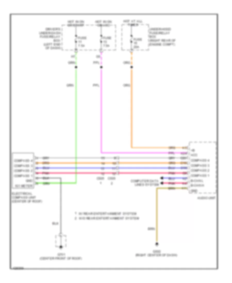
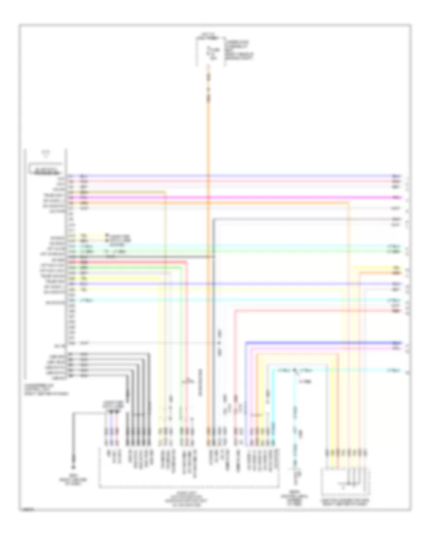
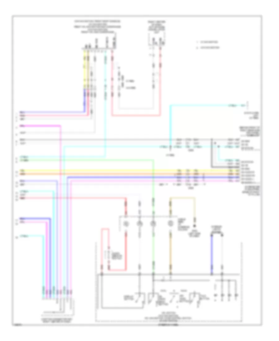
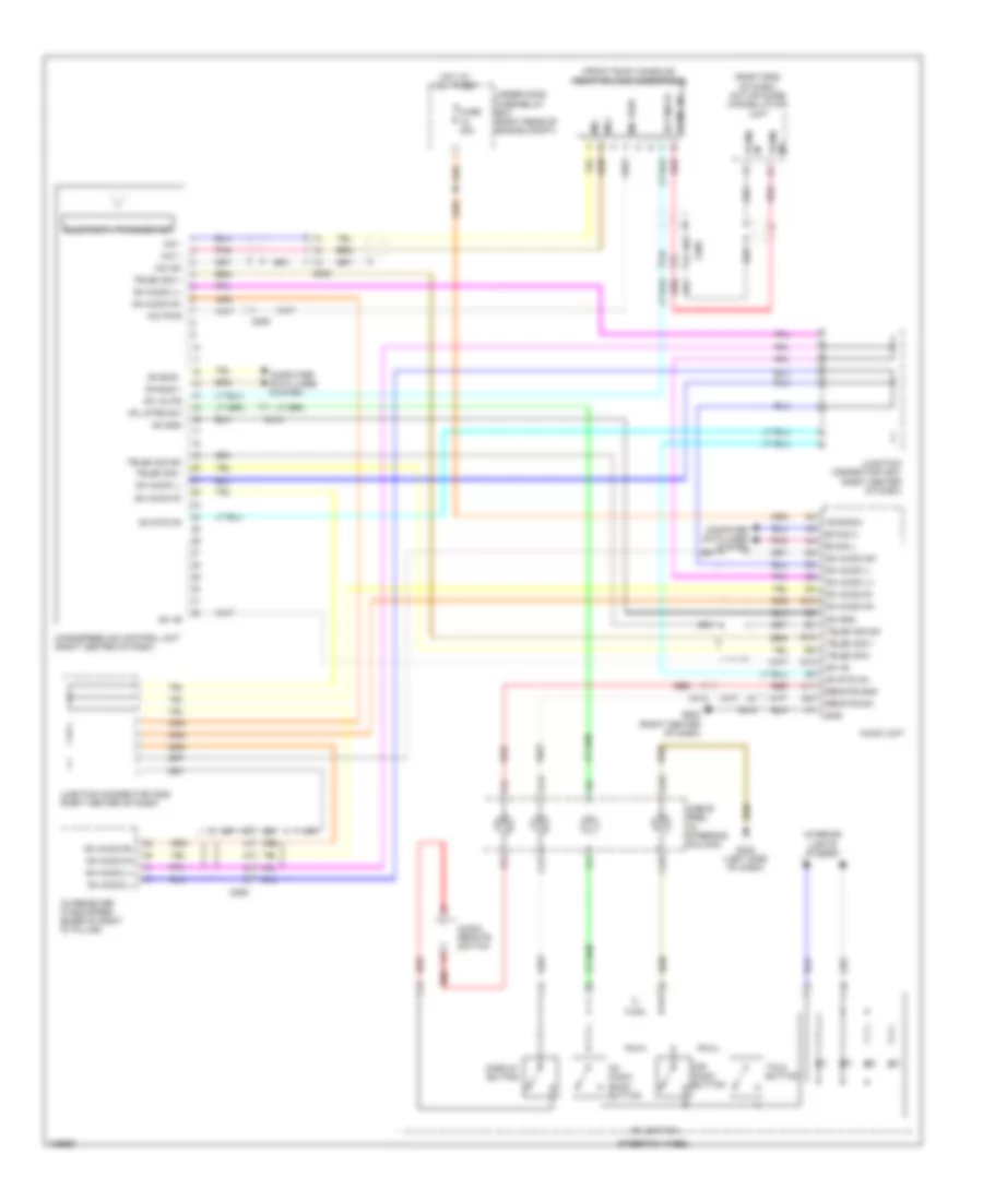
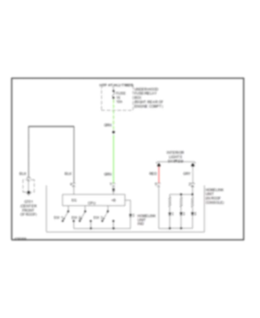
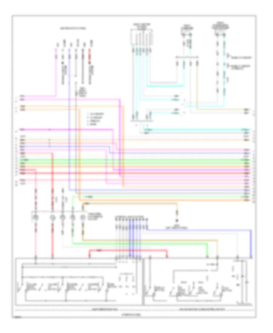
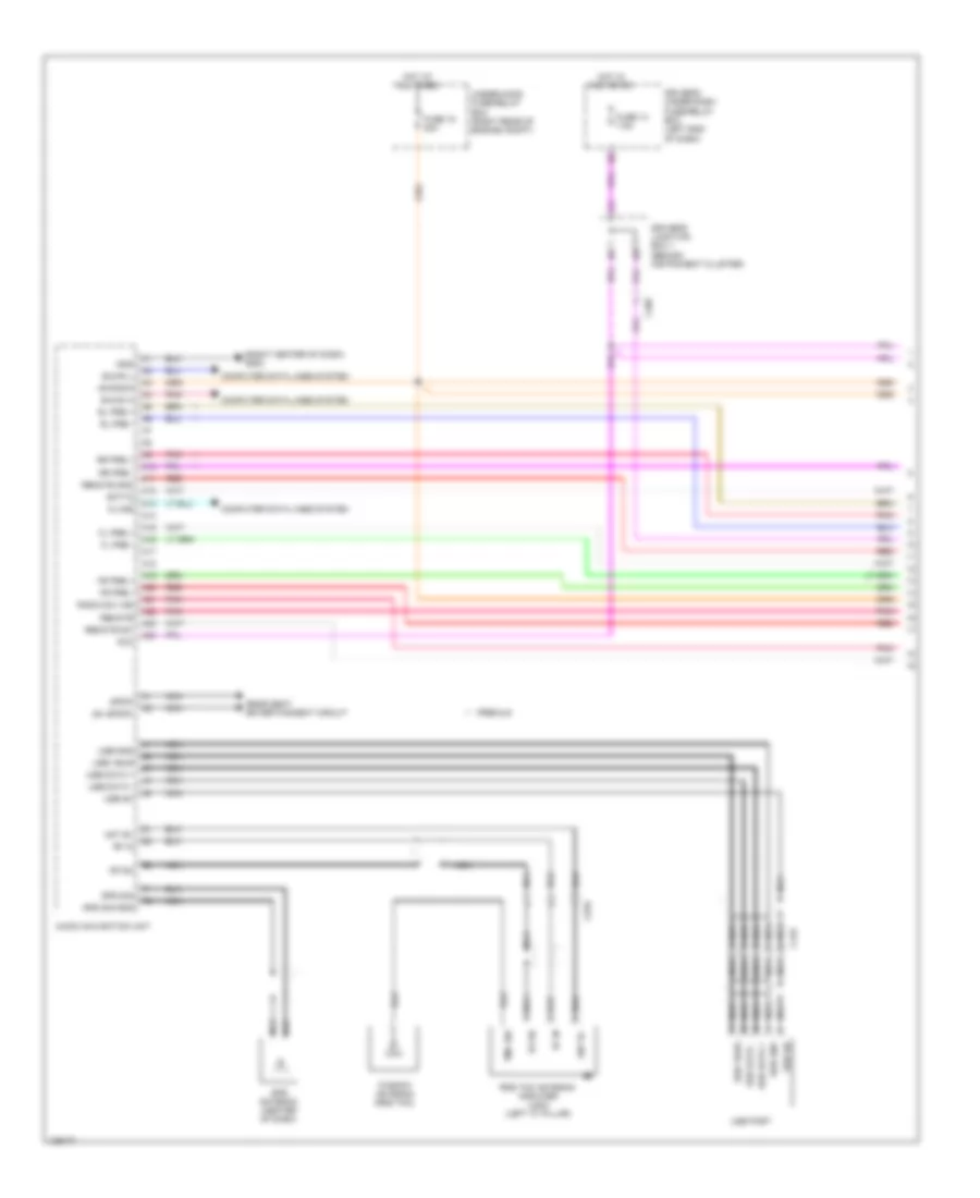
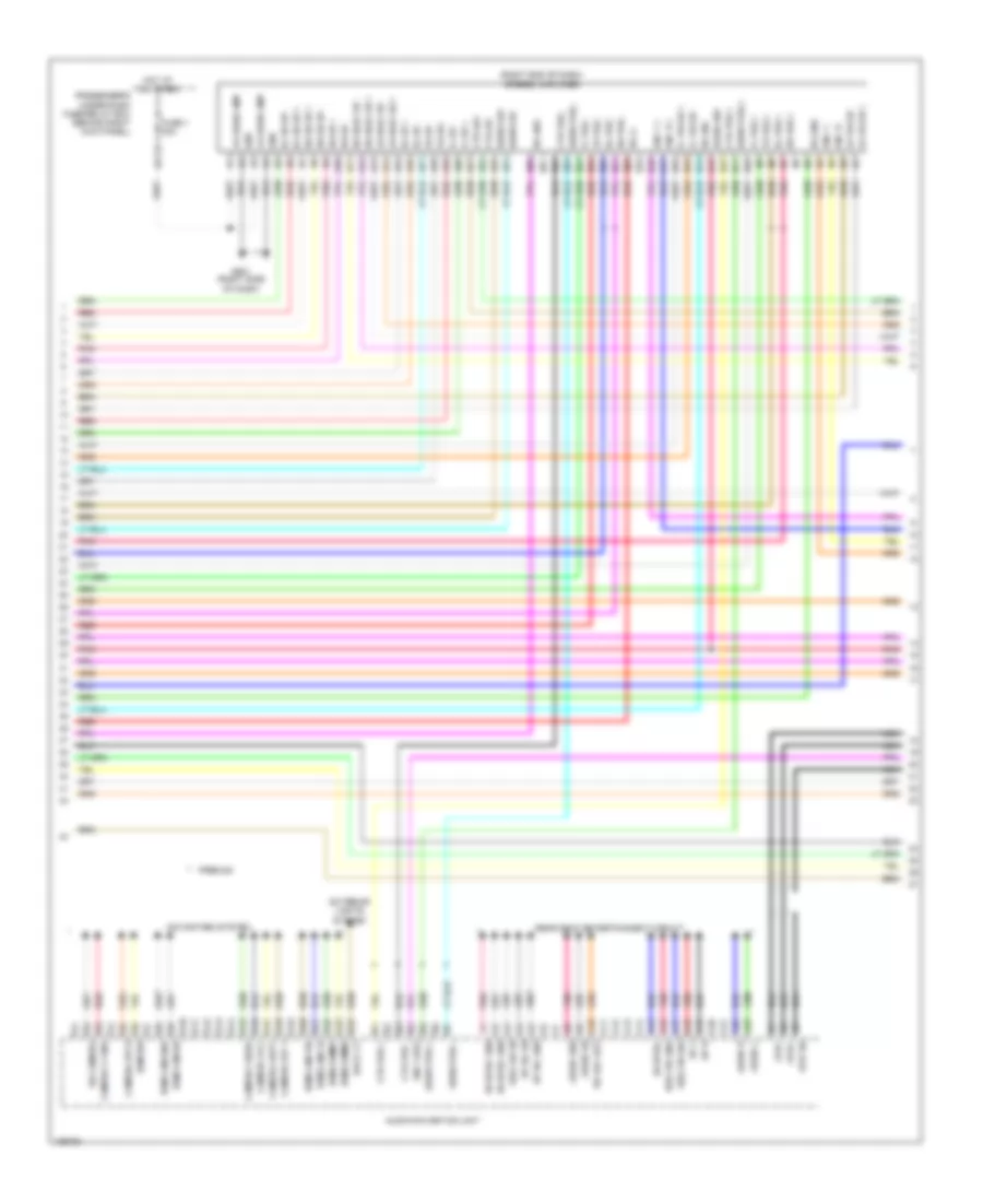
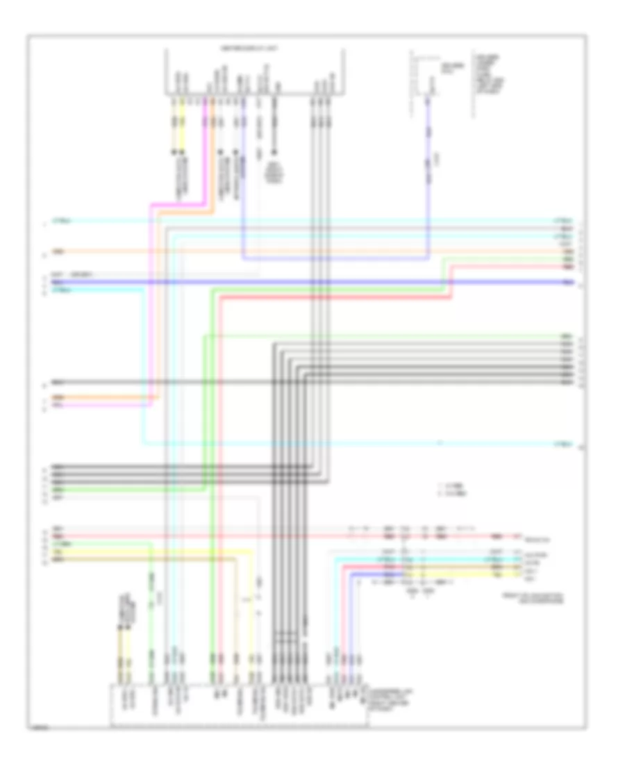
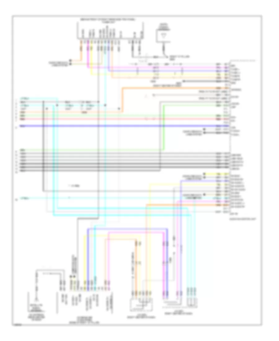
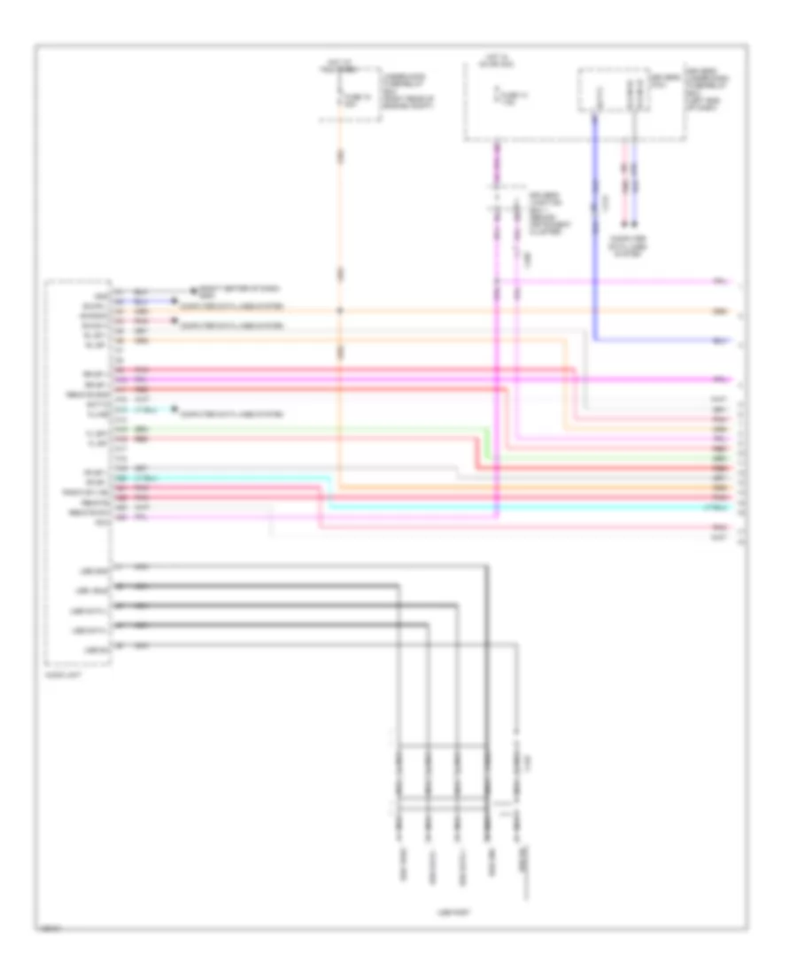
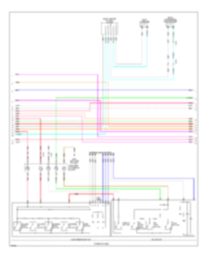
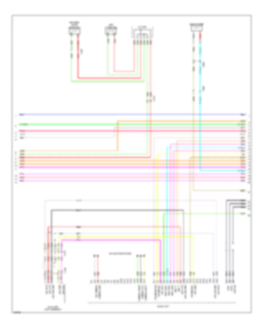
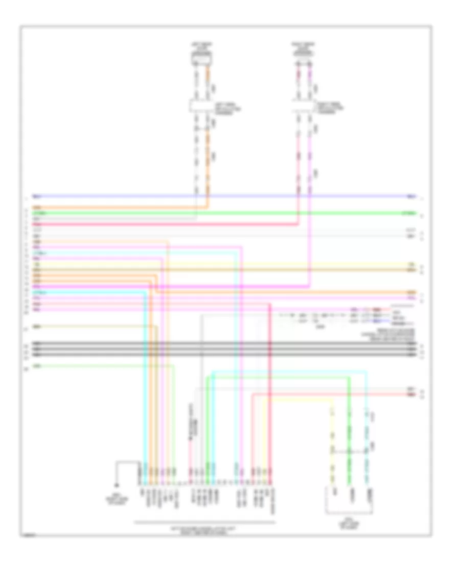
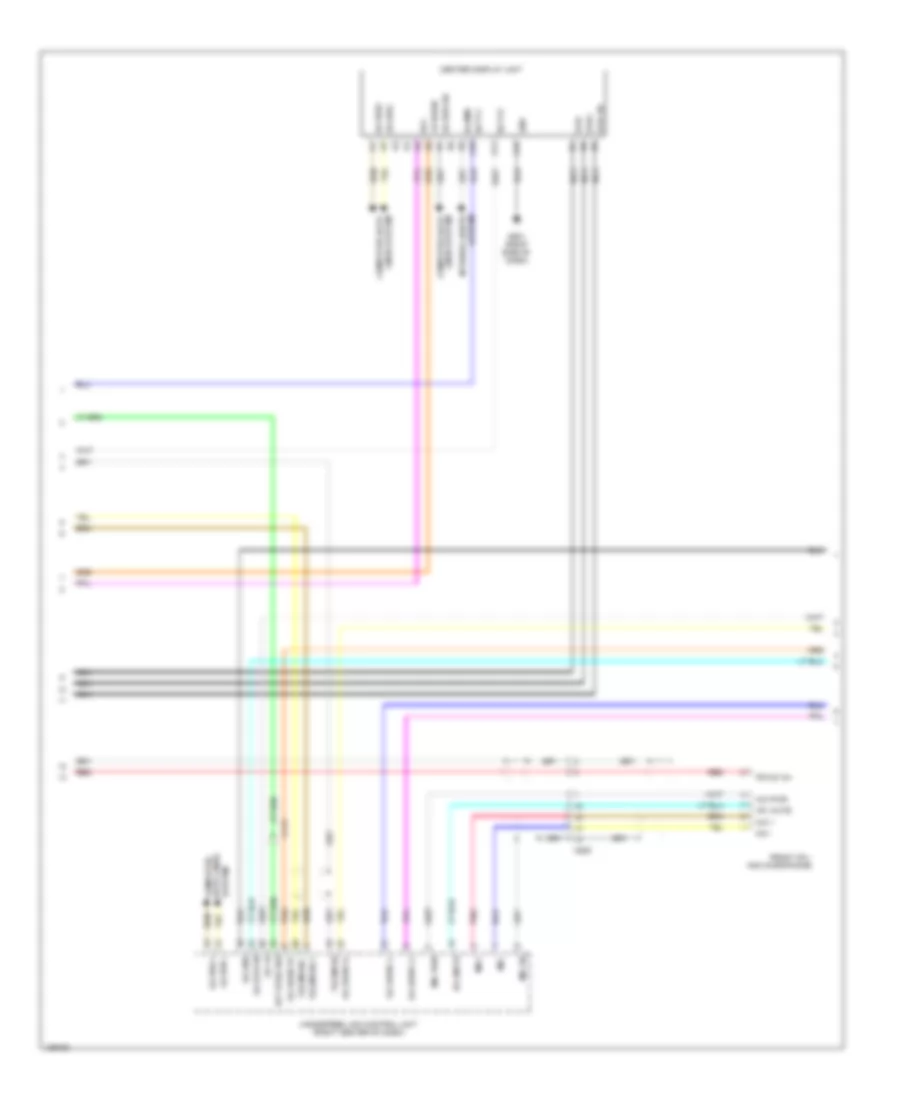
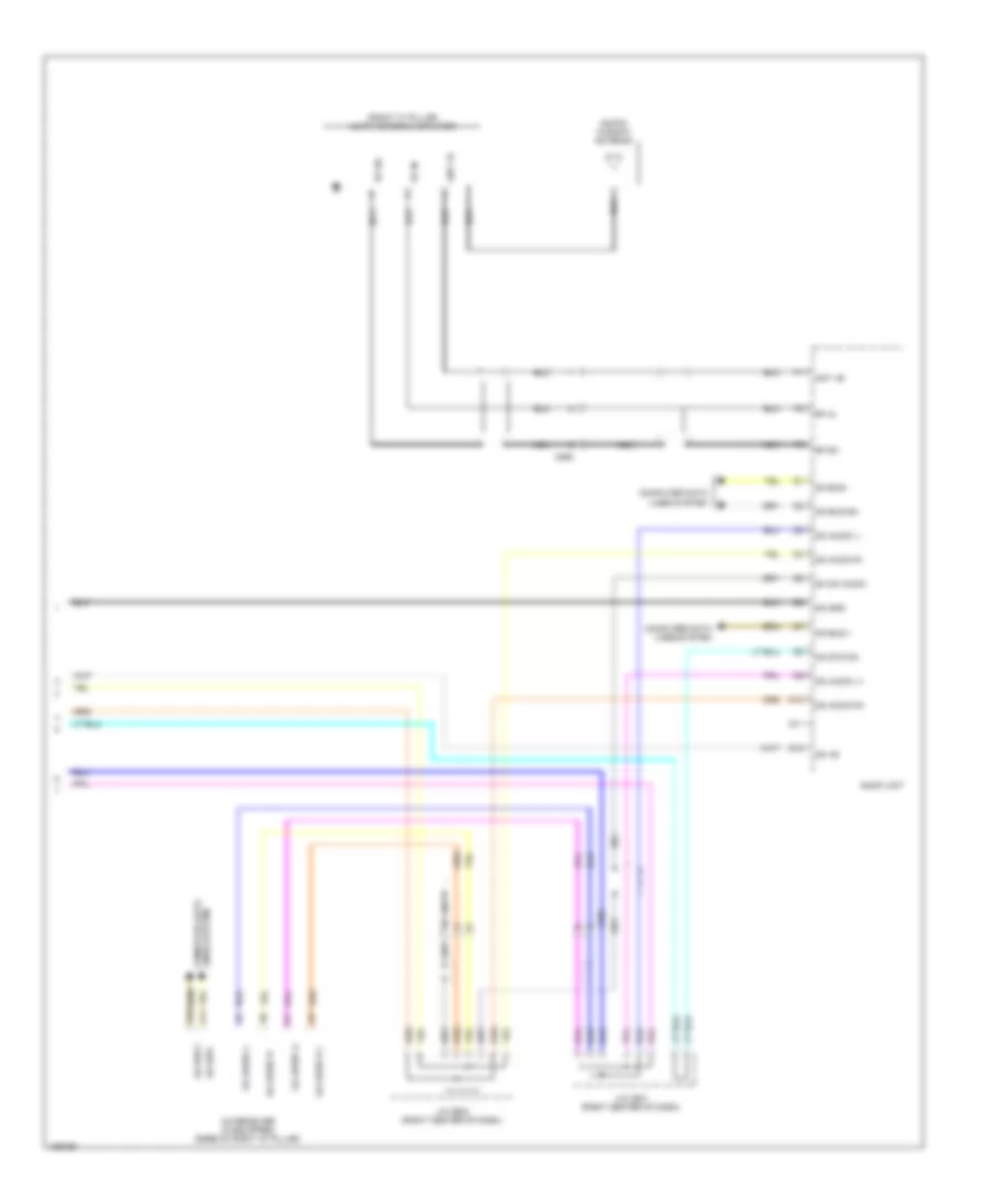
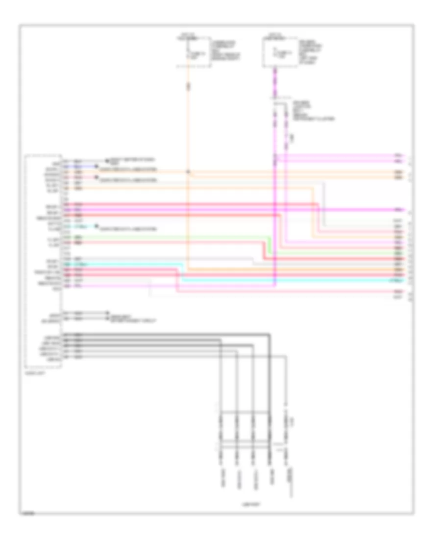
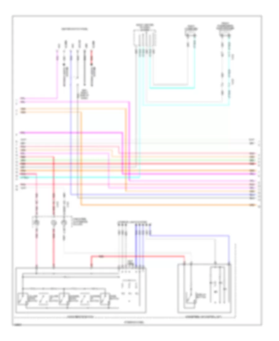
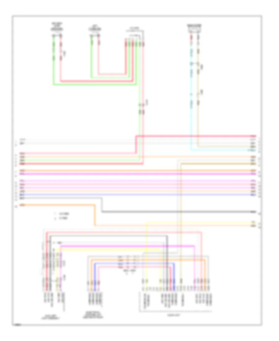
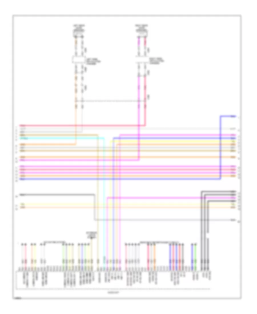
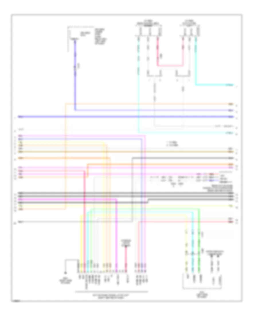
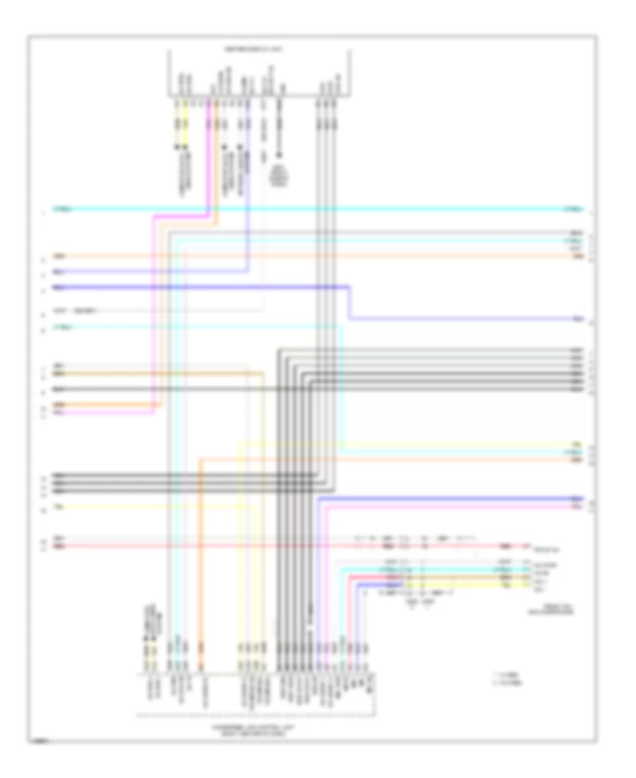
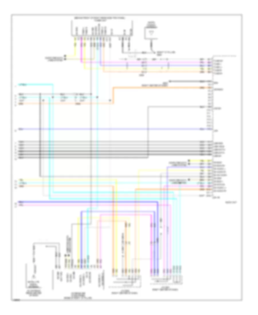
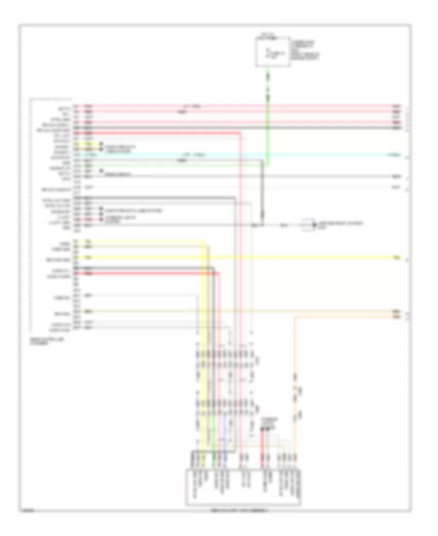
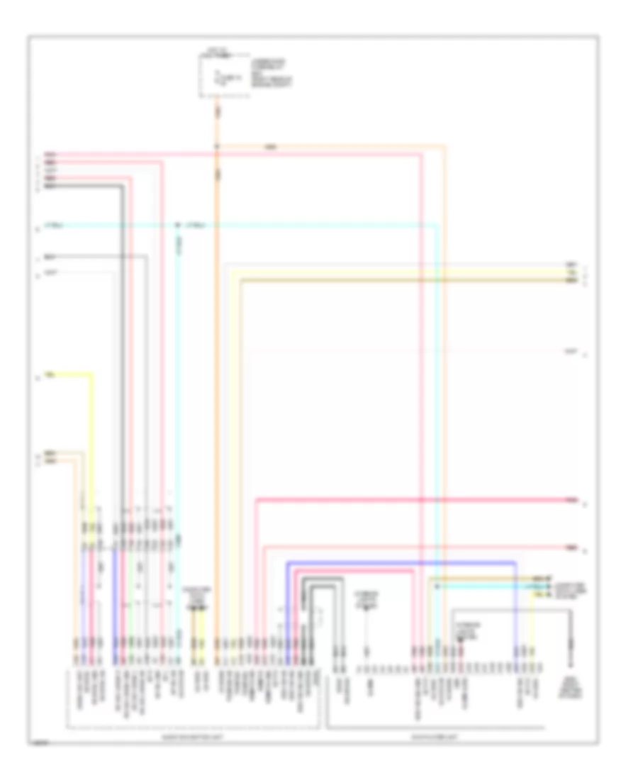
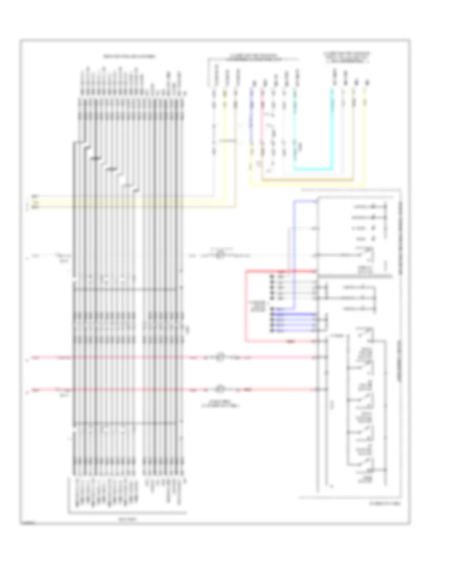
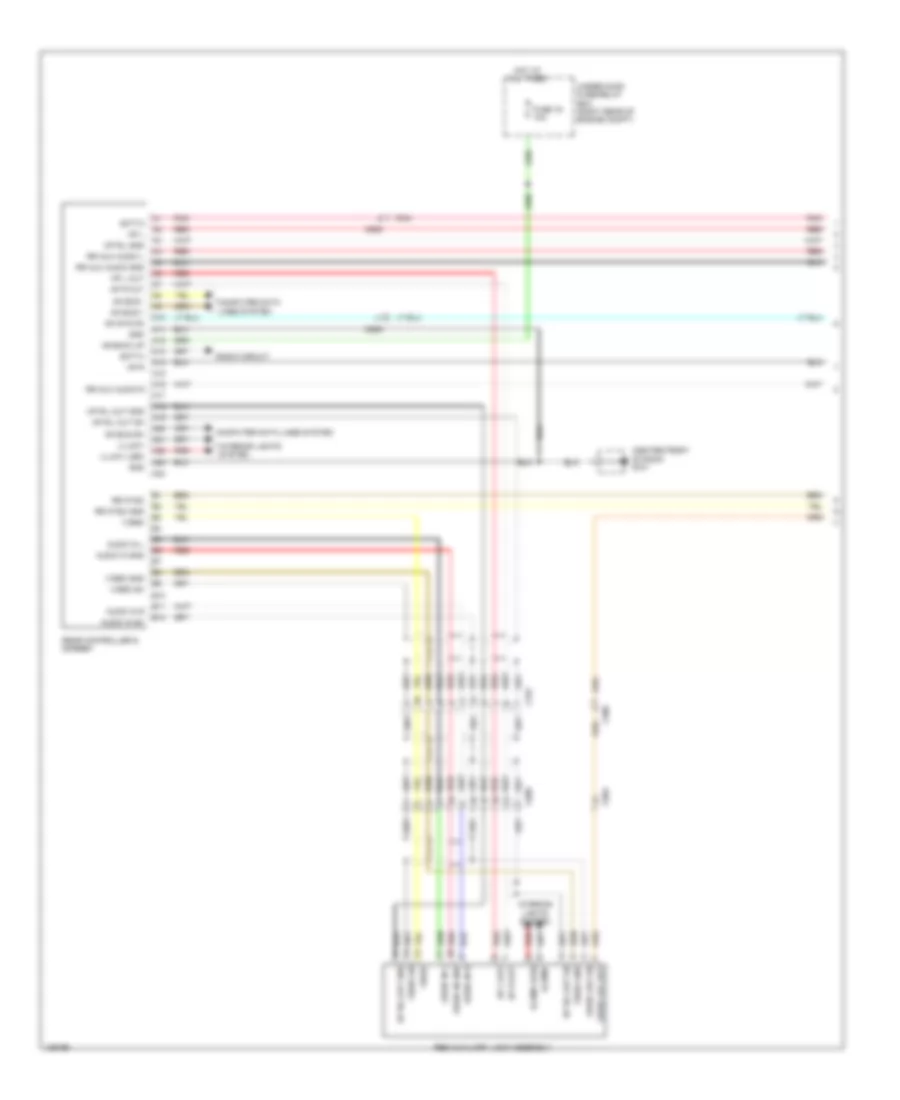
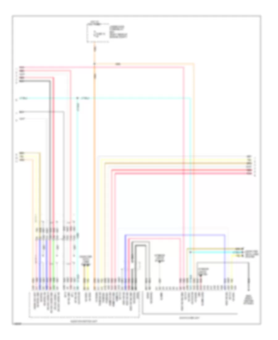
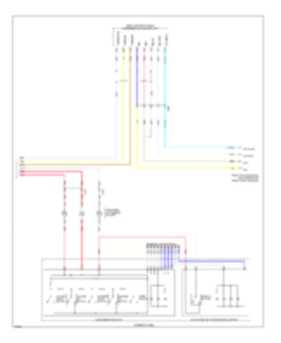
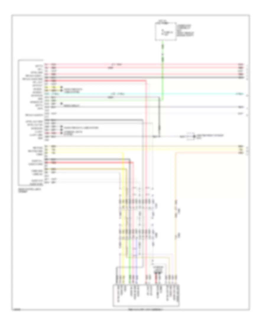
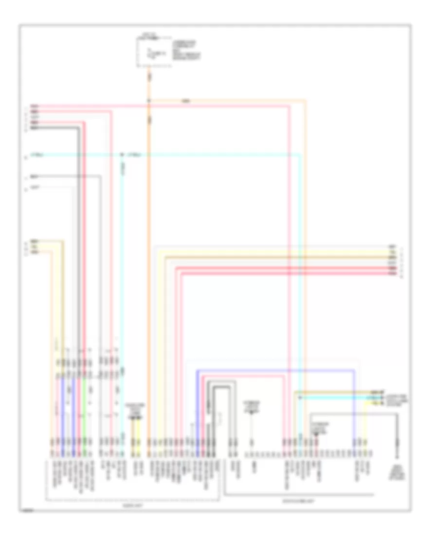
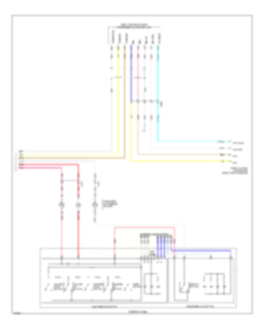
GA-NET Bus/GA-NET Audio Wiring Diagram, with RES for Honda Odyssey EX-L 2014
List of elements for GA-NET Bus/GA-NET Audio Wiring Diagram, with RES for Honda Odyssey EX-L 2014:
- A10
- A11
- A12
- A13
- A16
- A20
- A21
- A22
- A23
- A24
- A32
- Audio unit (w/o navigation)
- Audio-navigation unit (w/ navigation)
- C505
- C506
- Center display unit
- D10
- D12
- Dvd player unit (w/ res)
- Ga +b
- Ga audio l+
- Ga audio l-
- Ga audio r+
- Ga audio r-
- Ga bus sh
- Ga bus+
- Ga bus-
- Ga gnd
- Ga sys on
- Ga+b
- Ga-bus sh
- Ga-bus+
- Ga-bus-
- Handsfree link control unit (right center of dash)
- J/c c501 (right center of dash)
- J/c c502 (right center of dash)
- J/c c503 (right center of dash)
- J/c c508 (right side of dash)
- J/c c656 (behind front of right rear side trim panel)
- Rear controller & screen (w/ res)
- Sh ga audio
- Tuner unit (behind front of right rear side trim panel)
- W/ touch screen
- W/ xm radio
- W/o touch screen
- W/o xm radio
- Xm receiver (if equipped) (base of right "d" pillar)
GA-NET Bus/GA-NET Audio Wiring Diagram, without RES for Honda Odyssey EX-L 2014
List of elements for GA-NET Bus/GA-NET Audio Wiring Diagram, without RES for Honda Odyssey EX-L 2014:
- A10
- A11
- A12
- A13
- A16
- A21
- A22
- A24
- A32
- Audio unit (w/o navigation)
- Audio-navigation unit (w/ navigation)
- C506
- Center display unit
- D10
- D12
- Ga +b
- Ga audio l+
- Ga audio l-
- Ga audio r+
- Ga audio r-
- Ga bus sh
- Ga bus+
- Ga bus-
- Ga gnd
- Ga sys on
- Ga+b
- Ga-bus sh
- Ga-bus+
- Ga-bus-
- Handsfree link control unit (right center of dash)
- J/c c501 (right center of dash)
- J/c c502 (right center of dash)
- J/c c508 (right side of dash)
- J/c c656 (behind front of right rear side trim panel)
- Sh ga audio
- Tuner unit (behind front of right rear side trim panel)
- Tuner unit (w/ touch screen) (behind front of right rear side trim panel)
- W/ touch screen
- W/ xm radio
- W/o touch screen
- W/o xm radio
- Xm receiver (if equipped) (base of right "d" pillar)
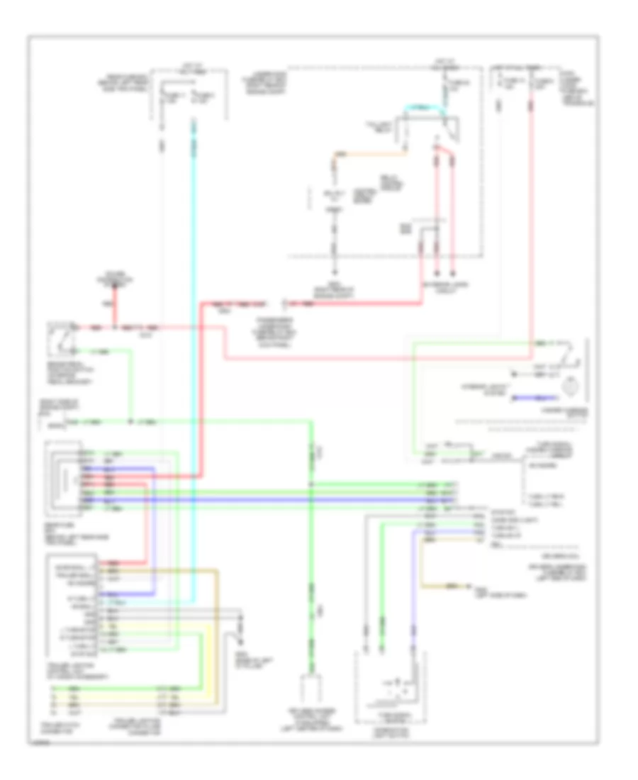
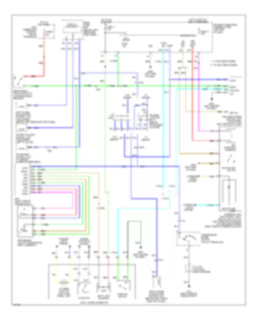
COOLING FAN
Cooling Fan Wiring Diagram for Honda Odyssey EX-L 2014
List of elements for Cooling Fan Wiring Diagram for Honda Odyssey EX-L 2014:
- (top right side of engine) j/c c104
- A/c compressor clutch relay
- A/c condenser fan motor (behind right side of radiator)
- A/c condenser fan relay
- A/c condenser fan relay/ fan control relay diode
- A21
- A37
- C16
- C201
- C210
- C32
- Driver's under-dash fuse/relay box (left end of dash)
- Ect sensor 1 (top rear of engine)
- Ect sensor 2 (bottom left side of radiator)
- Ect1
- Ect2
- F17
- Fan control relay
- Fan h
- Fan l
- Fuse 30a
- Fuse 7.5a
- G201 (bottom left front of engine compt)
- G203 (right rear of engine compt)
- Hot at all times
- Hot in on
- Hot w/ pgm-fi main relay energized
- Pcm (right side of engine compt)
- Pgm-fi sub relay
- Pnk
- Radiator fan motor (behind right side of radiator)
- Radiator fan relay
- Radiator fan relay diode
- Rear blower motor relay
- Rear window defogger relay
- Red
- Sg2
- Sg7
- Under-hood fuse/relay box (right rear of engine compt)
CRUISE CONTROL
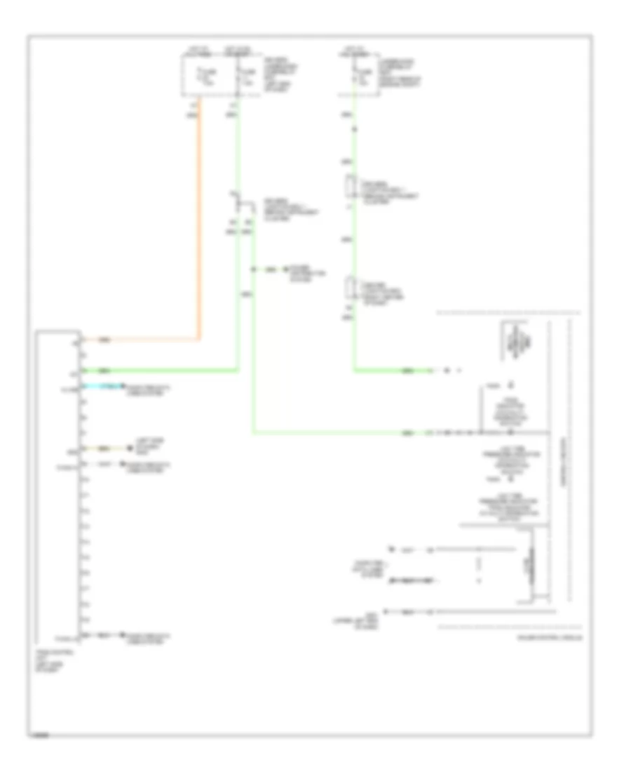
Cruise Control Wiring Diagram (1 of 2) for Honda Odyssey EX-L 2014
List of elements for Cruise Control Wiring Diagram (1 of 2) for Honda Odyssey EX-L 2014:
- A18
- A19
- A24
- A25
- A26
- A27
- A48
- A49
- App sensor (top of accelerator pedal assembly)
- Apsa
- Apsb
- Atpfwd
- B17
- B18
- B26
- B33
- B36
- B38
- B40
- B42
- Bksw
- Bkswnc
- C101
- C15
- C18
- C212
- Computer data lines system
- Driver's under-dash fuse/relay box (left end of dash)
- Etcsm+
- Etcsm-
- F-can-h
- F-can-l
- F10
- F21
- Fuse 11 7.5a
- Fuse 21 20a
- Fuse 24 7.5a
- Fuse 9 20a
- G101 (right rear of engine compt)
- Hot at all times
- Hot in on or start
- Ig1
- J/c c102 (top right side of engine)
- J/c c105 (top right side of engine)
- Junction connector c102 (top right side of engine)
- Main under-hood fuse box (above transaxle)
- Multi- fuse 2
- Output shaft (countershaft) speed sensor (bottom of transaxle)
- Pcm (right side of engine compt)
- Pg1
- Pnk
- Power distribution system
- Red
- Sg3
- Sg4
- Sg5
- Sg6
- Stop & horn hazard 30a
- Tan
- Throttle actuator
- Tp sensor
- Tp sensor/ throttle actuator (on throttle body)
- Tpsa
- Tpsb
- Transmission range switch (top of transaxle)
- Vcc1
- Vcc3
- Vcc4
- Vcc5
Cruise Control Wiring Diagram (2 of 2) for Honda Odyssey EX-L 2014
List of elements for Cruise Control Wiring Diagram (2 of 2) for Honda Odyssey EX-L 2014:
- Brake pedal position switch (on brake pedal bracket)
- C19
- C210
- Cable reel (in steering column)
- Cancel switch
- Computer data lines system
- Control circuits
- Cruise control combination switch
- Cruise control indicator
- Cruise control main switch indicator
- Cruise switch
- Exterior lights system
- F-can transceiver
- G401 (upper left end of dash)
- G402 (left side of dash)
- Gauge control module
- Horns system
- Interior lights system
- Power distribution system
- Red
- Resume switch
- Set decel switch
- Steering wheel
DEFOGGERS
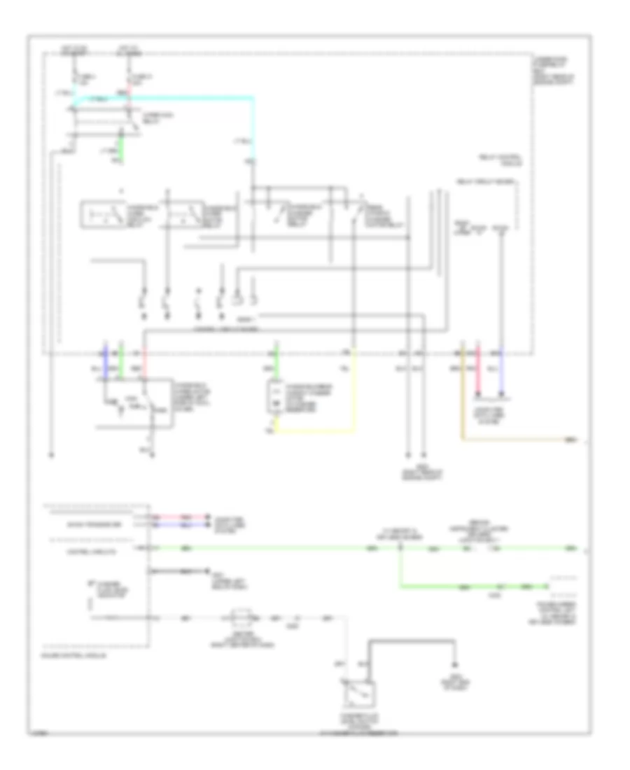
Defoggers Wiring Diagram for Honda Odyssey EX-L 2014
List of elements for Defoggers Wiring Diagram for Honda Odyssey EX-L 2014:
- (right rear of engine compt) under-hood fuse/relay box
- A/c compressor clutch relay
- A12
- A26
- A28
- All times
- Automatic a/c
- B canh
- B canl
- B-can hi
- B-can lo
- B-canh
- B-canl
- B11
- B15
- B16
- C206
- C209
- C210
- C401
- C414 (w/ memory)
- C414 (w/o memory)
- C654
- C802
- C852
- Computer data lines system
- Control circuit board
- Control unit
- Door multiplex control unit
- Driver's micu
- Driver's under- dash fuse/ relay box (left end of dash)
- F17
- Front passenger's power window switch
- Fuse 18 20a
- Fuse 19 20a
- Fuse 26 7.5a
- Fuse 4 40a
- G203 (right rear of engine compt)
- G401 (upper left end of dash)
- G403 (left center of dash)
- G405 (right end of dash)
- G801 (behind rear of left rear side trim panel)
- G802 (base of left "d" pillar)
- Gnd
- H10
- Hi b-can
- Hot at
- Hot at all times
- Hot in on
- Hvac control unit (manual a/c) climate control unit (automatic a/c)
- Ig2
- Left power mirror
- Left power mirror defogger
- Lo b-can
- Main under- hood fuse box (above transaxle)
- Manual a/c
- Mir act as heat
- Passenger's under-dash fuse/ relay box (behind right kick panel)
- Pnk
- Power distribution system
- Power window master switch
- Rear window defogger
- Rear window defogger relay
- Rear window defogger/ heated mirror indicator
- Rear window defogger/ heated mirror switch
- Relay control module
- Right power mirror
- Right power mirror defogger
- Rr def rly cl-
- Sgnd1
- Uart
- Vmp as
- Vmp dr
- W/ honda vac
- W/ power tailgate
- W/o honda vac
- W/o power tailgate
ENGINE PERFORMANCE
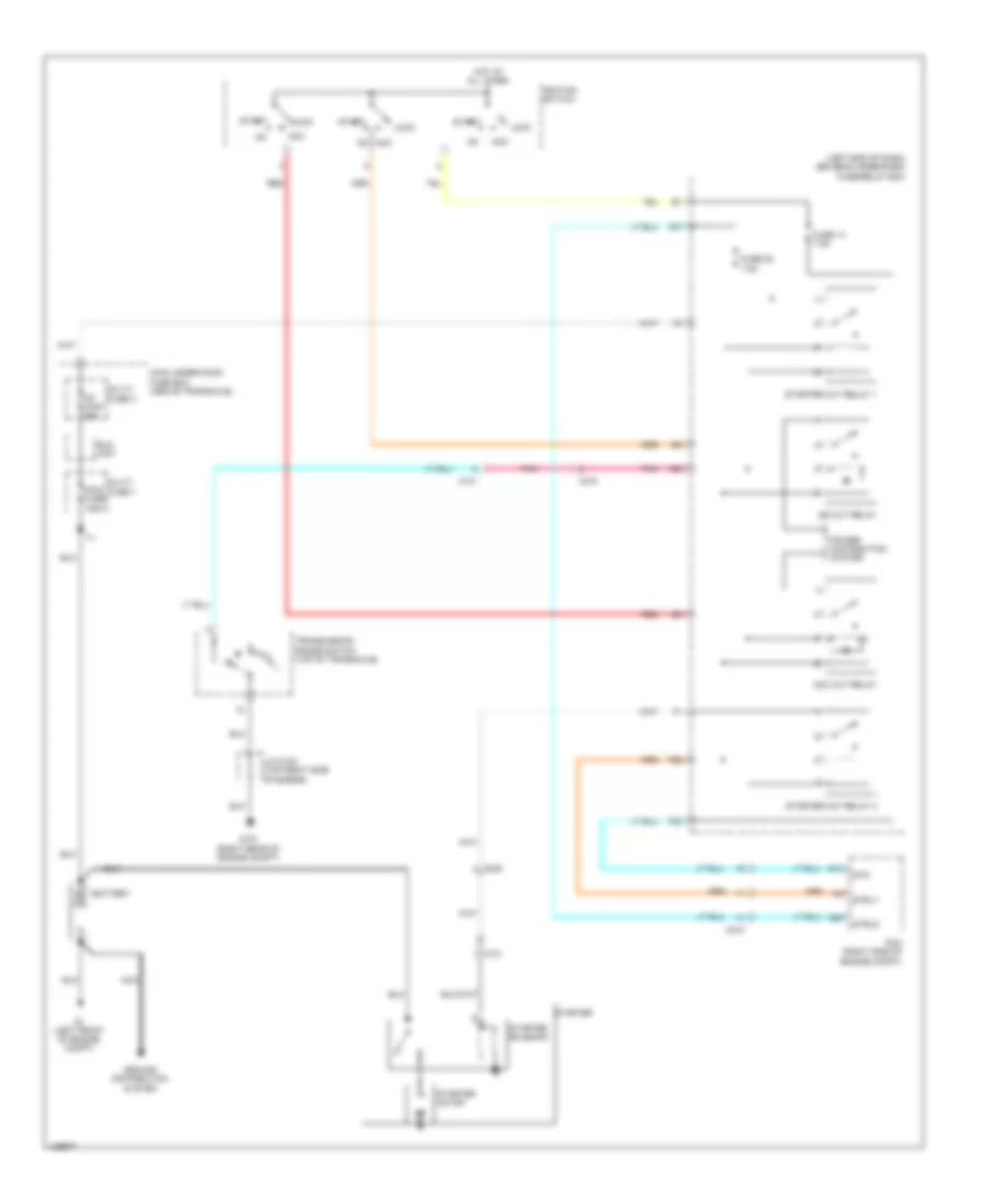
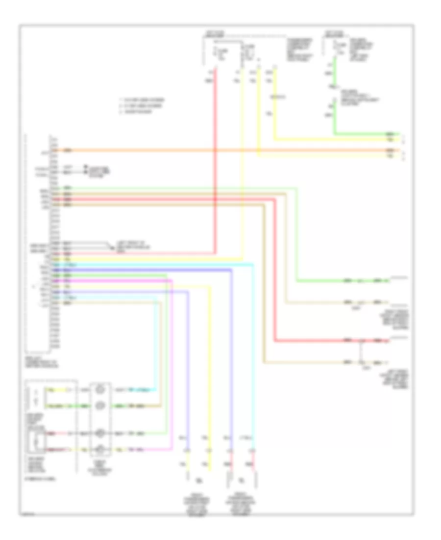
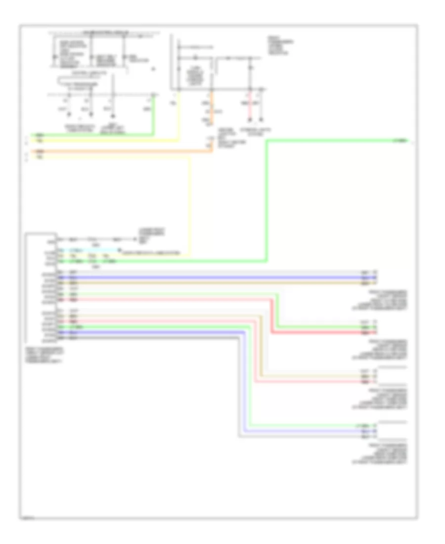
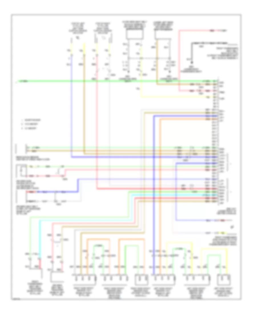
3.5L
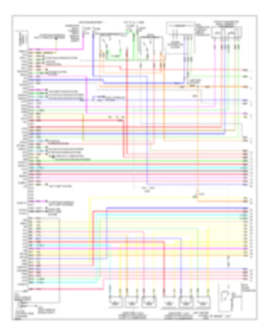
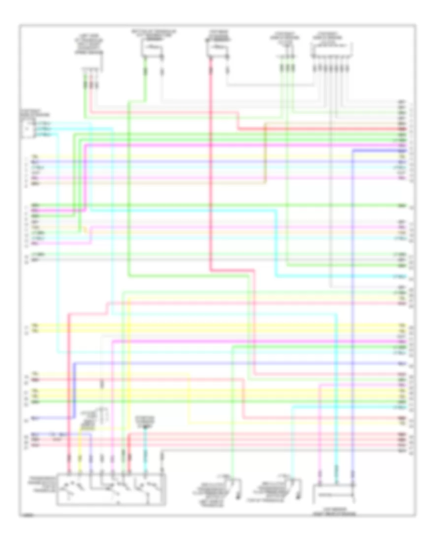
3.5L, Engine Performance Wiring Diagram (1 of 7) for Honda Odyssey EX-L 2014
List of elements for 3.5L, Engine Performance Wiring Diagram (1 of 7) for Honda Odyssey EX-L 2014:
- (left center of dash) g403
- (left end of dash) g302
- (top of accelerator pedal assembly) app sensor
- A10
- A11
- A12
- A13
- A14
- A15
- A16
- A17
- A18
- A19
- A20
- A21
- A22
- A23
- A24
- A25
- A26
- A27
- A28
- A29
- A30
- A31
- A32
- A33
- A35
- A36
- A37
- A38
- A39
- A40
- A41
- A42
- A43
- A44
- A45
- A46
- A47
- A48
- A49
- Acc
- Air conditioning system
- Anti-theft system
- Apsa
- Apsb
- Atpp
- B10
- B11
- B12
- B13
- B14
- B15
- B16
- B17
- B18
- B19
- B20
- B21
- Bksw
- Bkswnc
- C201
- C205
- C210
- C212
- Ckpout
- Cmpout
- Computer data lines system
- Cooling fans system
- Cruise control system
- Cssama
- Cssamc
- D4 switch
- D4sw
- Ect2
- Eld
- Eld unit
- Etcs control relay
- Etcsrly
- F-can-h
- F-can-l
- Fanh
- Fanl
- Ftp
- Fuse 15a
- G101 (right rear of engine compt)
- Hot at all times
- Hot in on or start
- Igp
- Igpls5
- Igpls6
- Imofpr
- Imtm
- Inj1
- Inj2
- Inj3
- Inj4
- Inj5
- Inj6
- Injectors 1, 2 & 3 (under intake manifold, in right cylinder bank)
- Injectors 4, 5 & 6 (under intake manifold, in left cylinder bank)
- J/c c105 (top right side of engine)
- Lever connector
- Lg3
- Lsb
- Lsc
- Main under-hood fuse box (above transaxle)
- Mcs
- Mrly
- Navigation & sound systems
- Nep a34
- Pcm (right side of engine compt)
- Pg2
- Pgm fi main relay 1
- Pnk
- Power distribution system
- Pspsw
- Red
- S-net 5v
- Scs
- Sensor barometer
- Sg3
- Sg4
- Sg7
- Shift
- Shift interlock system
- Sho2sb2
- Sls
- Starting/ charging system
- Starting/charging & anti-theft systems
- Starting/charging & shift interlock systems
- Starting/charging system
- Strld
- Strly
- Sts
- Subrly
- Tan
- Tpsa
- Under-hood relay fuse/box (right rear of engine compt)
- Vbsol
- Vbsol2
- Vcc3
- Vcc4
- Vcc5
- Vcc7
- Vcentb1
- Vcmswc
- Vg+
- Vg-
- Vsb1
- Vsb2
- Vssout
- Vsv
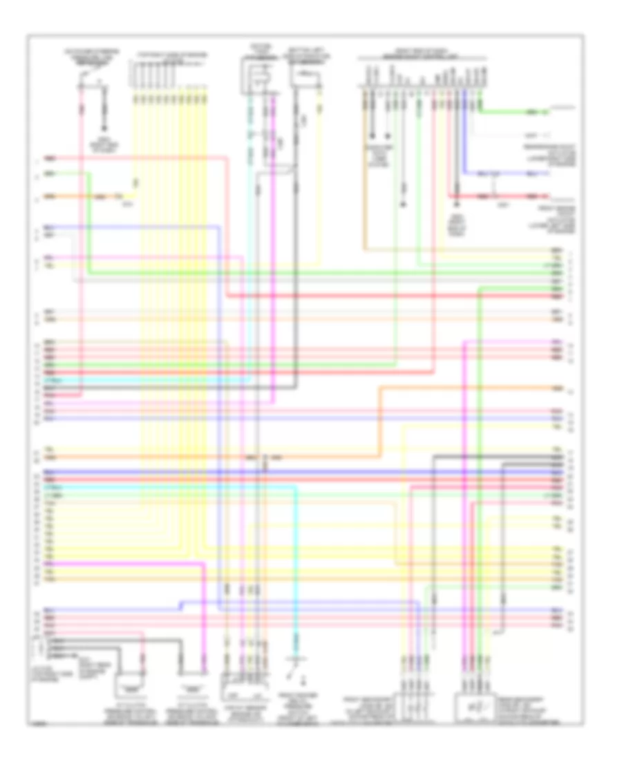
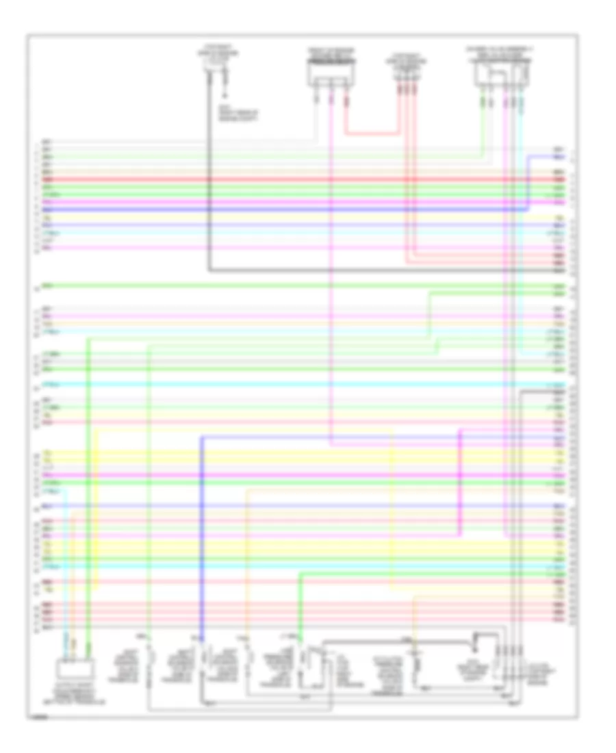
3.5L, Engine Performance Wiring Diagram (2 of 7) for Honda Odyssey EX-L 2014
List of elements for 3.5L, Engine Performance Wiring Diagram (2 of 7) for Honda Odyssey EX-L 2014:
- (bottom left side of radiator) ect sensor 2
- (on fuel tank) ftp sensor
- (on power steering pressure line) psp switch
- (right end of dash) engine mount control unit
- (top right side of engine) j/c c102
- A/t clutch pressure control solenoid valve b (side of transaxle)
- A/t clutch pressure control solenoid valve c (side of transaxle)
- C101
- C201
- C207
- C210
- Ckp
- Cmp
- Computer data lines system
- F-can h
- F-can l
- Front engine mount actuator (lower left side of engine)
- Front rocker arm oil pressure switch (front of left cylinder bank)
- Front secondary ho2s (b2, s2) (in left exhaust, downstream of catalytic converter)
- G101 (right rear of engine compt)
- G204 (right end of dash)
- Iat
- Ig1
- Igsol
- J/c c105 (top right side of engine)
- Maf
- Maf/iat sensor (engine air intake duct)
- Nca
- Pnk
- Rear engine mount actuator (lower right side of engine)
- Rear secondary ho2s (b1, s2) (in right exhaust, downstream of catalytic converter)
- Red
- Solfm
- Solfp
- Solrly
- Solrm
- Solrp
- Tan
3.5L, Engine Performance Wiring Diagram (3 of 7) for Honda Odyssey EX-L 2014
List of elements for 3.5L, Engine Performance Wiring Diagram (3 of 7) for Honda Odyssey EX-L 2014:
- (in left exhaust manifold) front a/f sensor (b2, s1)
- (in right exhaust manifold) rear a/f sensor (b1, s1)
- (top right side of engine) j/c c104
- (under middle of vehicle) evap canister vent shut valve
- Acm control relay
- C101
- C207
- C210
- Driver's under dash fuse/ relay box (left end of dash)
- E16
- Evap canister purge valve (right rear of engine)
- F10
- F20
- F21
- Fuel gauge sending unit
- Fuel pump
- Fuel tank unit (top of fuel tank)
- Fuse 20 7.5a
- Fuse 20a
- Fuse 3 10a
- Fuse 7.5a
- G101 (right rear of engine compt)
- G602 (left "c" pillar)
- Hot at all times
- Hot in on or start
- Instrument cluster system
- J/c c103 (top right side of engine)
- J/c c104 (top right side of engine)
- J/c c105 (top right side of engine)
- Nca
- Passenger's under-dash fuse/relay box (left end of dash)
- Pgm-fi main relay 2
- Pnk
- Red
- Rocker arm oil control solenoid a (bank 1) (rear of right cylinder bank)
- Rocker arm oil control solenoid b (bank 1) (rear of right cylinder bank)
- Tan
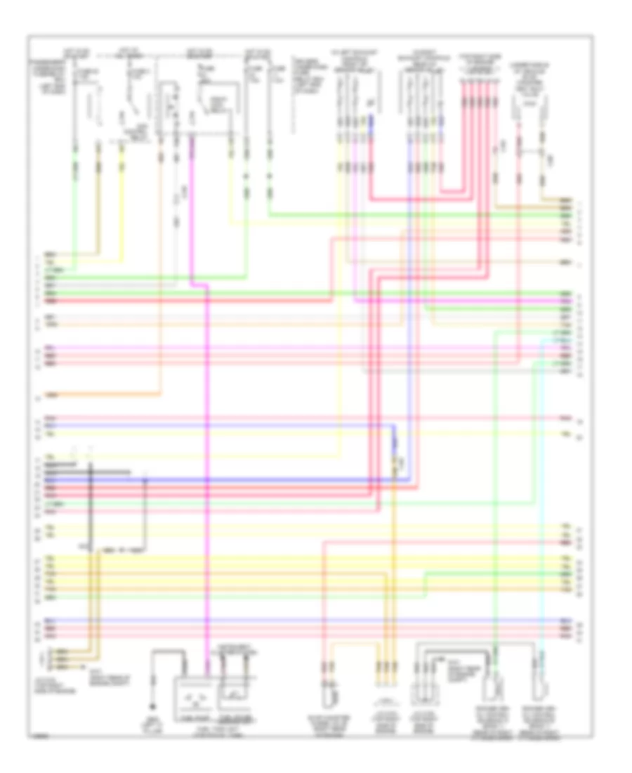
3.5L, Engine Performance Wiring Diagram (4 of 7) for Honda Odyssey EX-L 2014
List of elements for 3.5L, Engine Performance Wiring Diagram (4 of 7) for Honda Odyssey EX-L 2014:
- (upper left end of dash) g401
- C101
- C212
- Computer data lines system
- Control circuits
- Fast controller area network transceiver
- Fuse 11 15a
- Fuse 28 7.5a
- Fuse 8 15a
- G101 (right rear of engine compt)
- Gauge control module
- Hot at all times
- Icm
- Ignition coil relay
- Ignition coils (1, 2 & 3: top of right cylinder bank) (4, 5 & 6: top of left cylinder bank)
- J/c c102 (top right side of engine)
- J/c c104 (top right side of engine)
- J/c c105 (top right side of engine)
- Mil ind
- Pgm fi sub relay
- Pnk
- Radiator fan relay
- Radiator fan relay diode
- Rear rocker arm oil pressure switch (rear of right cylinder bank)
- Red
- Tan
- Under- hood fuse/ relay box (right rear of engine compt)
3.5L, Engine Performance Wiring Diagram (5 of 7) for Honda Odyssey EX-L 2014
List of elements for 3.5L, Engine Performance Wiring Diagram (5 of 7) for Honda Odyssey EX-L 2014:
- (bottom of transaxle) atf temperature sensor
- (left side of transaxle) input shaft (mainshaft) speed sensor
- (top rear of engine) ect sensor 1
- (top right side of engine) j/c c104
- (top right side of engine) j/c c105
- 2nd clutch transmission fluid pressure switch a (left side of transaxle)
- 3rd clutch transmission fluid pressure switch b (top of transaxle)
- C101
- J/c c105 (top right side of engine)
- Map sensor (right rear of engine)
- Pnk
- Red
- Starting/ charging system
- Tan
- Transmission range switch (top of transaxle)
3.5L, Engine Performance Wiring Diagram (6 of 7) for Honda Odyssey EX-L 2014
List of elements for 3.5L, Engine Performance Wiring Diagram (6 of 7) for Honda Odyssey EX-L 2014:
- (front of engine) rocker arm oil pressure sensor
- (on egr valve assembly) egr valve & egr valve position sensor
- (top right side of engine) j/c c103
- (top right side of engine) j/c c105
- A/t clutch pressure control solenoid valve d (side of transaxle)
- G101 (right rear of engine compt)
- J/c c102 (top right side of engine)
- J/c c105 (top right side of engine)
- Line pressure solenoid valve a (left side of transaxle)
- Output shaft (countershaft) speed sensor (bottom of transaxle)
- Pnk
- Red
- Shift control solenoid valve a (side of transaxle)
- Shift control solenoid valve b (side of transaxle)
- Shift control solenoid valve c (side of transaxle)
- Tan
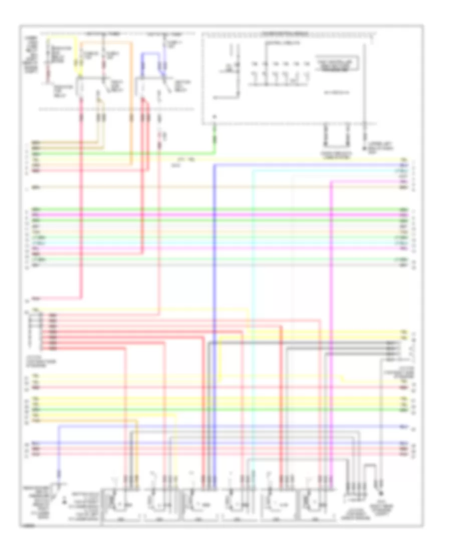
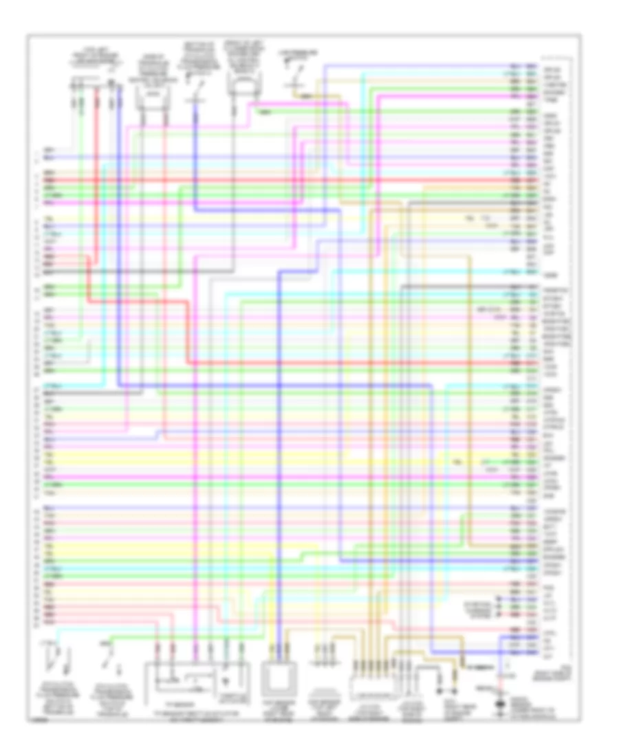
3.5L, Engine Performance Wiring Diagram (7 of 7) for Honda Odyssey EX-L 2014
List of elements for 3.5L, Engine Performance Wiring Diagram (7 of 7) for Honda Odyssey EX-L 2014:
- (bottom of transaxle) 4th clutch transmission fluid pressure switch c
- (front of left cylinder bank) rocker arm oil control solenoid a (bank 2)
- (side of transaxle) a/t clutch pressure control solenoid valve a
- (top left front of engine) imt actuator
- 5th clutch transmission fluid pressure switch d (bottom of transaxle)
- 6th clutch transmission fluid pressure switch e (top of transaxle)
- Afshtcb1
- Afshtcb2
- Altc
- Altf
- Altl
- Atpd
- Atpfwd
- Atpl
- Atpn
- Atpr
- Atprvs
- B22
- B23
- B24
- B25
- B26
- B27
- B28
- B29
- B30
- B31
- B32
- B33
- B34
- B35
- B36
- B37
- B38
- B39
- B40
- B41
- B42
- B43
- B44
- B45
- B46
- B47
- B48
- B49
- C10
- C101
- C106
- C11
- C12
- C13
- C14
- C15
- C16
- C17
- C18
- C19
- C20
- C21
- C22
- C23
- C24
- C25
- C26
- C27
- C28
- C29
- C30
- C31
- C32
- C33
- C34
- C35
- C36
- C37
- C38
- C39
- C40
- C41
- C42
- C43
- C44
- C45
- C46
- C47
- C48
- C49
- Ckp
- Ckp sensor (lower right rear of engine)
- Cmp
- Cmp sensor (top left front of engine)
- Cssa
- Cssb
- Cssc
- Ect1
- Egr
- Egrp
- Etcsm+
- Etcsm-
- G101 (right rear of engine compt)
- Iat
- Ig1
- Ig1etcs
- Igpls1
- Igpls2
- Igpls3
- Igpls4
- Imt+
- Imt-
- Ipb1
- Ipb2
- J/c c102 (top right side of engine)
- J/c c103 (top right side of engine)
- Knock sensor (under front of intake manifold)
- Lg1
- Lg2
- Line pressure switch
- Lsa
- Lsd
- Map
- Nca
- Op2sw
- Op3sw
- Op4sw
- Op5sw
- Op6sw
- Pcm (right side of engine compt)
- Pcs
- Pg1
- Pgmetcs
- Pla
- Pnk
- Poil
- Red
- Sg1
- Sg2
- Sg5
- Sg6
- Sha
- Shb
- Shc
- Sho2sb1
- So2sgb1
- So2sgb2
- So2shtcb1
- So2shtcb2
- Starting/ charging system
- Tan
- Tatf
- Throttle actuator
- Tp sensor
- Tp sensor/throttle actuator (on throttle body)
- Tpsb
- Vcc1
- Vcc2
- Vcc6
- Vcentb2
- Vcmswb
EXTERIOR LIGHTS
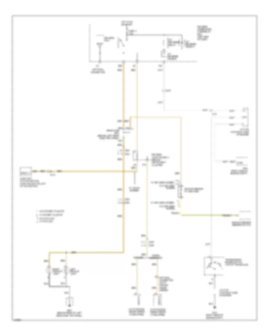
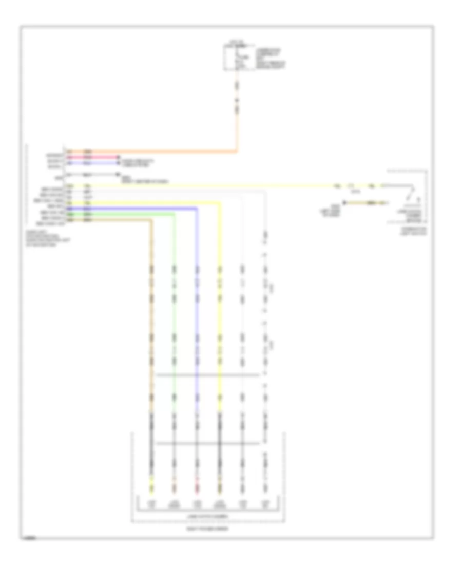
Backup Lamps Wiring Diagram for Honda Odyssey EX-L 2014
List of elements for Backup Lamps Wiring Diagram for Honda Odyssey EX-L 2014:
- (optional connector)
- A/t reverse diode a
- A/t reverse diode b
- A/t reverse relay
- A34
- Atpr
- Audio unit (w/o navigation) audio navigation unit (w/ navigation)
- Auto dimming inside mirror (if equipped)
- B30
- Back lt
- Backup sensor beeper switch
- Backup sensor in line fuse
- C101
- C210
- C25
- C405
- C413
- C801
- C851
- Driver's junction box 1 (behind instrument cluster)
- Driver's micu
- Driver's under-dash fuse/relay box (left end of dash)
- E29
- F30
- Factory
- Fuse 11 7.5a
- G101 (right rear of engine compt)
- G24
- G801 (behind rear of left rear side trim panel)
- Honda accessory
- Hot in on or start
- J/c c102 (top right side of engine)
- J/c c105 (top right side of engine)
- K10
- Left backup light
- Optional connector (auto dimming inside mirror)
- Pcm (right side of engine compt)
- Rear fuse box (behind left rear side trim panel)
- Right backup light
- Transmission range switch (top of transaxle)
- W/ fcw/ldw
- W/ keyless access
- W/ power tailgate
- W/ touch screen
- W/o fcw/ldw
- W/o keyless access
- W/o power tailgate
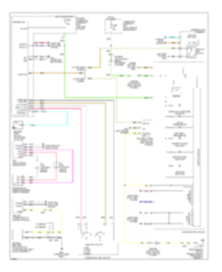
Exterior Lamps Wiring Diagram (1 of 2) for Honda Odyssey EX-L 2014
List of elements for Exterior Lamps Wiring Diagram (1 of 2) for Honda Odyssey EX-L 2014:
- +b hazard
- A30
- A31
- A36
- A39
- A42
- A45
- Auto
- Auto lt sig
- Auto lt sio
- Auto lt sip
- B-can hi
- B-can lo
- B19
- B24
- B31
- Backup h/l
- C210
- C212
- C304
- C801
- C802
- C851
- Combi gnd
- Combination light switch
- Computer data lines system
- D13
- D14
- Driver's micu
- Driver's under-dash fuse/relay box (left end of dash)
- E10
- E11
- F11
- F12
- F14
- Fuse 11 7.5a
- G402 (left side of dash)
- G801 (behind rear of left rear side trim panel)
- G802 (base of left "d" pillar)
- H/l off sw
- H/l on sw
- H10
- Haz sw
- Hazard warning switch
- Head
- Headlight switch
- High mount brake light
- Hot in on or start
- Ig1 meter
- Interior lights system
- Keyless access control unit (if equipped) (left center of dash)
- Left brake light
- Left inner taillight
- Left license plate light
- Left taillight
- Off
- P13
- P15
- P17
- P19
- P22
- P23
- Park
- Pg1
- Pnk
- Q10
- Q11
- Q20
- Rear fuse box (behind left rear side trim panel)
- Red
- Right brake light
- Right inner taillight
- Right license plate light
- Right taillight
- Small lt sw
- Stop sw
- Trailer tow circuit
- Turn lt fr l
- Turn lt fr r
- Turn lt rr l
- Turn lt rr r
- Turn signal switch
- Turn signal/ hazard warning circuit
- Turn sw l
- Turn sw r
- W/ automatic lighting
- W/ power tailgate
- W/o power tailgate
Exterior Lamps Wiring Diagram (2 of 2) for Honda Odyssey EX-L 2014
List of elements for Exterior Lamps Wiring Diagram (2 of 2) for Honda Odyssey EX-L 2014:
- A32
- A38
- Automatic lighting sensor
- Automatic lighting/ sunlight sensor (if equipped) (top center of dash)
- B-can hi
- B-can lo
- B-can transceiver
- B13
- B14
- B15
- B16
- B22
- B23 d10
- Bksw
- Brake pedal position switch (on brake pedal bracket)
- Bus bar
- C212
- C401
- C413
- C414
- C604
- Computer data lines system
- Control circuit board
- Control circuits
- D19
- Driver's junction box 1 (behind instrument cluster)
- Fuse 10 15a
- Fuse 22 10a
- Fuse 6 7.5a
- Fuse 9 20a
- G201 (bottom left front of engine compt)
- G202 (bottom right front of engine compt)
- G203 (right rear of engine compt)
- G401 (upper left end of dash)
- G405 (right end of dash)
- G802 (base of left "d" pillar)
- Gauge control module
- H/l backup
- Hot at all times
- Hot in on or start
- Ig1 ecu fr
- Lcd display or multi-information display (mid)
- Left front turn signal/parking/side marker light
- Left power mirror (w/ side turn signals)
- Left rear turn signal light
- Left side turn signal light
- Left turn signal indicator
- Lights on indicator
- Main under-hood fuse box (above transaxle)
- Multi fuse 2
- Passenger's under-dash fuse/relay box (behind right kick panel)
- Pcm (right side of engine compt)
- Pnk
- Power distribution system
- Rear fuse box (behind left rear side trim panel)
- Red
- Relay control module
- Right front turn signal/parking/side marker light
- Right power mirror (w/ side turn signals)
- Right rear turn signal light
- Right side turn signal light
- Right turn signal indicator
- Sgnd1
- Sml rly cl-
- Stop/horn hazard fuse 30a
- Taillight relay
- Trailer tow circuit
- Turn sign- anls/hazard relay
- Under-hood fuse/relay box (right rear of engine compt)
- W/ memory
- W/o memory
Trailer Tow Wiring Diagram for Honda Odyssey EX-L 2014
List of elements for Trailer Tow Wiring Diagram for Honda Odyssey EX-L 2014:
- (right side of engine compt) pcm
- +b dr small lt
- +b hazard
- +b small
- A48 bksw
- B13
- B19
- B22
- B23
- B24
- B31
- Brake pedal position switch (on brake pedal bracket)
- Bus bar
- C212
- C304
- C604
- Combi gnd (light)
- Combination light switch
- Control circuit board
- D10
- D11
- D13
- D14
- D19
- Driver's micu
- Driver's under-dash fuse/relay box (left end of dash)
- E10
- E11
- Exterior lamps circuit
- F11
- Fuse 10 15a
- Fuse 11 7.5a
- Fuse 2 7.5a
- Fuse 22 10a
- Fuse 9 20a
- G203 (right rear of engine compt)
- G402 (left side of dash)
- G802 (base of left "d" pillar)
- Gnd
- Haz sw
- Hazard warning switch
- Hot at all times
- Interior lights system
- Keyless access control unit (if equipped) (left center of dash)
- Kick panel)
- L turn lt
- L turn/stop
- Main under- hood fuse box (above transaxle)
- P13
- P22
- P23
- Passenger's under-dash fuse/relay box (behind right
- Pg1
- Power distribution system
- Q11
- R turn lt
- R turn/stop
- Rear fuse box (behind left rear side trim panel)
- Red
- Relay control module
- Sgnd1
- Sml rly cl-
- Stop sw
- Taillight relay
- Trailer hitch connector
- Trailer lighting connector in-line connector
- Trailer lighting control unit (w/ honda accessory)
- Trailer small
- Turn lt rr l
- Turn lt rr r
- Turn signal switch
- Turn signal/ hazard warning circuit
- Turn sw l
- Turn sw r
- Under-hood fuse/relay box (right rear of engine compt)
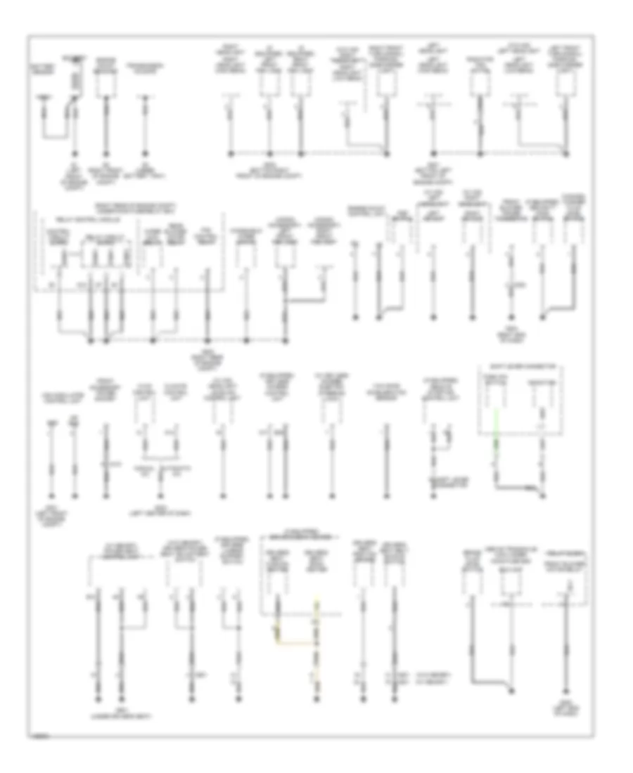
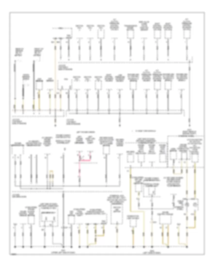
GROUND DISTRIBUTION
Ground Distribution Wiring Diagram (1 of 5) for Honda Odyssey EX-L 2014
List of elements for Ground Distribution Wiring Diagram (1 of 5) for Honda Odyssey EX-L 2014:
- (above transaxle) main under- hood fuse box
- (canada) washer fluid level switch
- (honda accessory) left front fog light
- (honda accessory) right front fog light
- (if equipped) driver's lumbar support switch
- (if equipped) driver's seat heater
- (if equipped) keyless access control unit
- (if equipped) left front fog light
- (if equipped) remote starting control unit
- (if equipped) right front fog light
- (if equipped) security hood switch
- (right rear of engine compt) under-hood fuse/relay box
- (w/ hid) headlight leveling control unit
- (w/ hid) left headlight
- (w/ hid) right headlight
- (w/ keyless access) electric steering lock
- (w/ memory)
- (w/ memory) power seat control unit
- (w/o hid) left headlight
- (w/o hid) right headlight
- (w/o memory)
- (w/o memory) driver's power seat adjustment switch
- A12
- A17
- Automatic a/c
- B12
- B36
- Battery
- Battery sensor
- Brake fluid level switch
- C202
- C410
- C601
- Climate control unit
- Control circuit board
- D12
- D4 switch
- Driver's seat back heater
- Driver's seat belt buckle switch
- Driver's seat cushion heater
- Driver's seat position sensor
- Eld unit
- Engine mount bracket
- Engine mount control unit
- Fan control relay
- Front accessory power socket
- Front blower motor relay
- Front blower power transistor
- G1 (left front of engine compt)
- G2 (right front of engine compt)
- G201 (bottom left front of engine compt)
- G202 (bottom right front of engine compt)
- G203 (right rear of engine compt)
- G204 (right end of dash)
- G3 (under battery tray)
- G301 (left front of engine compt)
- G302 (left end of dash)
- G403 (left center of dash)
- G601 (under driver's seat)
- Gnd
- Hvac control unit
- Left front turn signal/ parking/ side marker light
- Left headlight
- Left headlight (high beam)
- Left headlight (low beam)
- Left hid unit
- Manual a/c
- Mr gnd
- Nca
- Park pin switch
- Pgnd1
- Psp switch
- Radiator fan motor
- Rear blower motor relay
- Relay block
- Relay circuit board
- Relay control module
- Right front turn signal/ parking/ side marker light
- Right headlight
- Right headlight (high beam)
- Right headlight (low beam)
- Right hid unit
- Sg-1
- Sgnd1
- Shift lever connector
- Transmission housing
- Vsa modulator control unit
- Windshield wiper motor
- Wiper main relay
- Yaw rate acceleration sensor
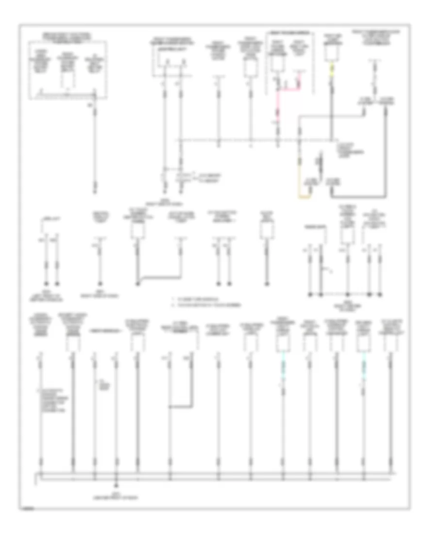
Ground Distribution Wiring Diagram (2 of 5) for Honda Odyssey EX-L 2014
List of elements for Ground Distribution Wiring Diagram (2 of 5) for Honda Odyssey EX-L 2014:
- (if equipped) left bsi alert indicator
- (if equipped) parking & backup sensor control unit
- (if equipped) power sliding door switch
- (if equipped) tpms control unit
- (left end of dash) driver's under-dash fuse/relay box
- (w/ keyless access) driver's door outer handle/ lock switch/ touch sensor
- (w/ memory) driving position memory switch
- (w/ memory) power mirror control unit
- (w/o navigation) hfl switch (w/ navigation) hfl- navigation voice control switch
- A/t clutch pressure control solenoid valve a
- A/t clutch pressure control solenoid valve b
- A/t clutch pressure control solenoid valve c
- A/t clutch pressure control solenoid valve d
- A18
- B40
- B41
- Braided
- C18
- C19
- C401
- C41
- Cable reel (in steering wheel)
- Ckp sensor
- Cmp sensor
- Combination light switch
- Cruise control combination switch
- Dlc
- Door multiplex control unit
- Driver's door lock actuator/ knob switch/ key cylinder switch
- Driver's micu
- Driver's power window motor
- Egr valve & egr valve position sensor
- Etcs
- Front a/f sensor (b2, s1) shield
- G101 (right rear of engine compt)
- G401 (upper left end of dash)
- G402 (left side of dash)
- Gauge control module
- Horn switch
- Ignition coil
- Ignition key switch
- J/c c102 (top right side of engine)
- J/c c103 (top right side of engine)
- J/c c105 (top right side of engine)
- J/c c452 (driver's door)
- Knock sensor shield
- Left power mirror
- Left power mirror defogger
- Left side turn signal light
- Lg1
- Lg2
- Line pressure solenoid valve a
- Pcm
- Pg1
- Pg2
- Pgm
- Pnk
- Power door lock relay (dr unlock)
- Power door lock relay (lock)
- Power door lock relay (unlock)
- Power mirror switch
- Power window master switch
- Rear a/f sensor (b2, s1) shield
- Rocker arm oil control solenoid a (bank 1)
- Rocker arm oil control solenoid a (bank 2)
- Rocker arm oil control solenoid b (bank 1)
- Sg1
- Sg2
- Shift control solenoid valve a
- Shift control solenoid valve b
- Shift control solenoid valve c
- Steering lock (ignition key light/ ignition key switch/ key interlock solenoid)
- Steering wheel
- Transmission range switch
- Vsa off switch
- W/ side turn signals
Ground Distribution Wiring Diagram (3 of 5) for Honda Odyssey EX-L 2014
List of elements for Ground Distribution Wiring Diagram (3 of 5) for Honda Odyssey EX-L 2014:
- (behind right kick panel) passenger's under-dash fuse/relay box
- (except honda accessory) automatic dimming inside mirror
- (honda accessory) automatic dimming inside mirror
- (if equipped) electrical compass unit
- (if equipped) fcw/ldw camera unit
- (if equipped) homelink unit
- (if equipped) moonroof control unit/motor
- (if equipped) seat heater relay
- (w/ climate control) rear a/c control unit
- (w/ navigation) audio- navigation unit
- (w/ navigation) stereo amplifier
- (w/ res & touch screen) dvd player unit
- (w/ res) rear controller & screen
- (w/ touch screen) center switch panel
- A11
- A12
- A13
- A20
- A21
- A23
- Active noise cancellation unit
- Audio unit
- Automatic
- C414
- Cargo area accessory power socket relay
- Central display unit
- Control unit
- Dimming inside mirror connector (option connector)
- Driver's vanity mirror light
- Front accessory power socket relay
- Front individual map lights
- Front passenger's door lock actuator/ knob switch
- Front passenger's door outer handle/ lock switch/ touch sensor
- Front passenger's power window motor
- Front passenger's power window switch
- Front passenger's vanity mirror light
- G404 (left front of center console)
- G405 (right end of dash)
- G501 (right side of dash)
- G502 (right center of dash)
- G701 (center front of roof)
- Glove box light
- J/c c472 (front passenger's door)
- Pnk
- Right bsi alert indicator
- Right power mirror
- Right power mirror defogger
- Right side turn signal light
- Roof console
- Srs unit
- W/ bsi system
- W/ memory
- W/ moon- roof
- W/ side turn signals
- W/o bsi system
- W/o memory
- W/o navigation w/ touch screen
Ground Distribution Wiring Diagram (4 of 5) for Honda Odyssey EX-L 2014
List of elements for Ground Distribution Wiring Diagram (4 of 5) for Honda Odyssey EX-L 2014:
- (behind left rear side trim panel) rear fuse box
- (if equipped) hondavac motor
- (if equipped) hondavac switch
- (if equipped) left bsi radar unit
- (if equipped) right bsi radar unit
- (w/ ac power outlet) ac inverter unit
- (w/ keyless access) keyless buzzer
- (w/ keyless access) left sliding door lock knob switch
- (w/ keyless access) left sliding door outer handle/ touch sensor/lf antenna
- (w/ keyless access) tailgate lock switch
- (w/ power sliding doors) fuel fill door relay
- (w/ power sliding doors) left power sliding door control unit
- (w/ power sliding doors) left sliding door remote control assembly
- (w/ power tailgate) power tailgate control unit
- (w/o hondavac) rear window defogger
- (w/o power tailgate) tailgate outer handle switch
- (w/o power tailgate) tailgate release actuator/ latch switch
- A29
- B12
- B16
- B26
- C605
- C606
- C682
- C801
- C802
- C804
- C851
- Cargo area light
- Etcs
- Fuel fill door switch
- Fuel tank unit
- G602 (left "c" pillar)
- G801 (behind rear of left rear side trim panel)
- High mount brake light
- Left backup light
- Left cess articulated harness
- Left inner taillight
- Left license plate light
- Left rear power window switch
- Left sliding door lock knob switch
- Left sliding door remote control assembly
- Lg2
- Pg1
- Pgm
- Pgnd1
- Pgnd2
- Power door lock relay (lock)
- Power door lock relay (unlock)
- Rear micu
- Rear window wiper motor
- Rear window wiper motor relay
- Right backup light
- Right inner taillight
- Right license plate light
- Sgnd1
- Sgnd2
- Tailgate release actuator relay
- W/ power tailgate
- W/o power tailgate
Ground Distribution Wiring Diagram (5 of 5) for Honda Odyssey EX-L 2014
List of elements for Ground Distribution Wiring Diagram (5 of 5) for Honda Odyssey EX-L 2014:
- (if equipped) front passenger's seat heater
- (if equipped) seat heater control unit
- (w/ honda accessory) trailer lighting control unit
- (w/ hondavac) rear window defogger
- (w/ keyless access) right sliding door lock knob switch
- (w/ keyless access) right sliding door outer handle/ touch sensor/lf antenna
- (w/ power sliding doors) right power sliding door control unit
- (w/ power sliding doors) right sliding door remote control assembly
- (w/o keyless access) right sliding door remote control assembly
- Backup sensor beeper
- Backup sensor beeper switch
- Backup sensor control unit
- C651
- C653
- C692
- C802
- Cargo area accessory power socket
- Front passenger's power seat adjustment switch
- Front passenger's seat belt buckle switch
- Front passenger's seat cushion heater
- Front passenger's weight sensor unit
- G651 (under front passenger's seat)
- G652 (right "c" pillar)
- G671 (right sliding door)
- G802 (base of left "d" pillar)
- Honda accessory
- Left brake light
- Left rear turn signal light
- Left taillight
- Nca
- Rear a/c control unit
- Rear blower power transistor
- Right brake light
- Right cess articulated harness
- Right rear power window switch
- Right rear turn signal light
- Right sliding door lock knob switch
- Right taillight
- Trailer hitch connector
- W/ power tailgate
- W/o power tailgate
HEADLIGHTS
Fog Lamp Wiring Diagram for Honda Odyssey EX-L 2014
List of elements for Fog Lamp Wiring Diagram for Honda Odyssey EX-L 2014:
- (if equipped) fog light indicator
- B- can hi
- B- can lo
- B-can transceiver
- B14
- B15
- B16
- C210
- C402
- Combi gnd (light)
- Combination light switch
- Computer data lines system
- Control circuit board
- Control circuits
- D12
- Driver's junction box 1 (behind instrument cluster)
- Driver's micu
- Driver's under-dash fuse/relay box (left end of dash)
- F14
- Factory
- Fr fog rly cl-
- Fr fog sw
- Front fog light relay
- Front fog light switch
- Front fog lights optional connector
- Fuse 20a
- Fuse 7.5a
- G202 (bottom right front of engine compt)
- G203 (right rear of engine compt)
- G401 (upper left end of dash)
- Gauge control module
- H/l back up
- H10
- Honda accessory
- Hot at all times
- Hot in on or start
- Ig1 ecu fr
- Ig1 meter
- Lcd display or multi-information display (mid)
- Left front fog
- Left front fog light
- Light
- Off
- P13
- P18
- Pnk
- Power mirror control unit (w/ memory)
- Relay circuit board
- Relay control module
- Right front fog light
- Sg1
- Sgnd
- Under- hood fuse/ relay box (right rear of engine compt)
- W/ memory
Headlamps Wiring Diagram (1 of 2) for Honda Odyssey EX-L 2014
List of elements for Headlamps Wiring Diagram (1 of 2) for Honda Odyssey EX-L 2014:
- (w/ automatic lighting)
- (w/o multi- information switch) drl indicator
- 0) low 1) high 2) passing
- 0) off 1) park 2) auto 3) head
- A17
- Air conditioning system
- Auto lt sig
- Auto lt sip
- Automatic lighting sensor
- Automatic lighting/sunlight sensor (if equipped) (top center of dash)
- B-can hi
- B-can lo
- B-can transceiver
- C210
- C302
- C402
- C413
- Center junction box (right center of dash)
- Combi gnd (light)
- Combination light switch
- Computer data lines system
- Control circuits
- Dimmer sw
- Dimmer/flash- to-pass switch
- Driver's door switch (on driver's "b" pillar)
- Driver's junction box 1 (behind instrument cluster)
- Driver's micu
- Driver's under-dash fuse/relay box (left end of dash)
- E22
- F14
- Fr l door sw
- Fuse 7.5a
- G401 (upper left end of dash)
- G402 (left side of dash)
- G403 (left center of dash)
- Gauge control module
- H/l back up
- H/l off sw
- H/l on sw
- H10
- Headlight switch
- High beam indicator
- Hot in on or start
- Ig key sw
- Ig1 meter
- Ignition key switch
- Keyless access control unit (left center of dash)
- Lcd display or multi-information display (mid)
- Lg1
- Lights on indicator
- P13
- P15
- P17
- P19
- P20
- P21
- Parking brake switch (base of parking brake pedal assembly)
- Passing sw
- Pnk
- Power mirror control unit (w/ memory)
- Q10
- Q20
- Red
- Sg1
- Small lt sw
- Steering lock (ignition key light/ ignition key switch/key interlock solenoid) (right side of steering column)
- Sunlight sensor
- W/ keyless access
- W/ memory
- W/o keyless access
Headlamps Wiring Diagram (2 of 2) for Honda Odyssey EX-L 2014
List of elements for Headlamps Wiring Diagram (2 of 2) for Honda Odyssey EX-L 2014:
- (bottom right front of engine compt) g202
- (right end of dash) g204
- +b h/l hi l
- +b h/l hi r
- B- can hi
- B- can lo
- B12
- B14
- B15
- B16
- C209
- Computer data lines system
- Control circuit board
- D12
- Fuse 10a
- Fuse 15a
- G201 (bottom left front of engine compt)
- G202 (bottom right front of engine compt)
- G203 (right rear of engine compt)
- G204 (right end of dash)
- H/l back up
- H/l hi l
- H/l hi r
- H/l lo rly cl-
- Headlight low relay
- Hid unit
- Hot at all times
- Left headlight
- Left headlight (high beam)
- Left headlight (low beam)
- Left hid unit
- Main under-hood fuse box (above transaxle)
- Multi- fuse 3
- Pnk
- Rb main fuse 60a
- Red
- Relay circuit board
- Relay control module
- Right headlight
- Right headlight (high beam)
- Right headlight (low beam)
- Right hid unit
- Sgnd
- Under-hood fuse/relay box (right rear of engine compt)
- W/ hid
- W/o hid
Headlamps Leveling Wiring Diagram for Honda Odyssey EX-L 2014
List of elements for Headlamps Leveling Wiring Diagram for Honda Odyssey EX-L 2014:
- (w/ auto lighting)
- 0) off 1) park 2) auto 3) head
- B-can h
- B-can hi
- B-can l
- B-can lo
- C205
- C415
- Combi gnd (light)
- Combination light switch
- Computer data lines system
- Drive circuit
- Driver's micu
- Driver's under-dash fuse/relay box (left end of dash)
- E28
- Front suspension stroke sensor (on right front suspension)
- Fuse 7.5a
- G403 (left center of dash)
- Gnd
- H/l off sw
- H/l on sw
- Hall ic
- Headlight leveling control unit (left side of dash)
- Headlight switch
- Hot in on or start
- Ig1
- Left headlight leveling motor (behind left headlight assembly)
- P13
- P15
- P17
- P19
- Passenger's under-dash fuse/relay box (behind right kick panel)
- Pnk
- Rear suspension stroke sensor (on right rear suspension)
- Right headlight leveling motor (behind right headlight assembly)
- Scs
- Small lt sw
- Ssf
- Ssr
HORN
Horn Wiring Diagram for Honda Odyssey EX-L 2014
List of elements for Horn Wiring Diagram for Honda Odyssey EX-L 2014:
- A10
- C19
- C20
- C205
- Cable reel (in steering column)
- Control circuit board
- Cruise control combination switch
- Fuse 9 20a
- G402 (left side of dash)
- High horn (left front of engine compt)
- Horn
- Horn relay
- Hot at all times
- Low horn (right front of engine compt)
- Main under-hood fuse box (above transaxle)
- Multi- fuse 2
- Pnk
- Power distribution system
- Red
- Relay circuit board
- Relay control module
- Steering wheel
- Stop & horn hazard fuse 30a
- Switch
- Under-hood fuse/ relay box (right rear of engine compt)
INSTRUMENT CLUSTER
Instrument Cluster Wiring Diagram (1 of 3) for Honda Odyssey EX-L 2014
List of elements for Instrument Cluster Wiring Diagram (1 of 3) for Honda Odyssey EX-L 2014:
- (upper left end of dash) g401
- (w/o multi-information switch)
- Abs ind
- B can hi
- B can lo
- B-can transceiver
- B10
- B11
- B12
- B17
- Brake system ind
- Bsi ind (if equipped)
- C607
- Center junction box (right center of dash)
- Charging system ind
- Computer data lines system
- Control circuits
- Cruise control ind
- Cruise control main switch ind
- Cruise control system
- Dial illumination (white)
- Door & tailgate open ind
- Driver's junction box 1 (behind instrument cluster)
- Drl ind (w/o multi- information switch)
- Eco ind
- Engine coolant temperature gauge
- Exterior lights system
- F-can transceiver
- Fcw ind (if equipped)
- Fog light ind (if equipped)
- Fuel gauge
- Fuse 16 10a
- G402 (left side of dash)
- Gauge control module
- Hot at all times
- Interior lights system
- Lcd display or multi- information display (md)
- Lcd illumination (white)
- Ldw ind (if equipped)
- Led light
- Left sliding door switch (in left "c" pillar)
- Light control ind
- Lights on ind
- Lin transceiver
- Low fuel ind
- Low oil pressure ind
- Low tire pressure ind (w/o multi-information switch)
- Low tire pressure ind/tpms ind (w/o multi-information switch)
- Maintenance required ind (w/o multi- information switch)
- Message ind (w/ multi-information switch)
- Mid illumination (white)
- Mil ind
- Parking & back-up sensor ind (if equipped)
- Pnk
- Pointers illumination (white)
- Power sliding door ind (if equipped)
- Power tailgate ind (if equipped)
- Ra door sw
- Rd door sw
- Rear fuse box (behind left rear side trim panel)
- Rear micu
- Red
- Right sliding door switch (in right "c" pillar)
- Seat belt remainder
- Side air bag cut off ind
- Speedometer
- Srs ind
- Starter system ind (w/o multi-information switch)
- Tachometer
- To dimming switch (diagram 3 of 3)
- To front corner sensor beeper (diagram 3 of 3)
- To security ind (diagram 3 of 3)
- Tpms ind (w/o multi-information switch)
- Under-hood fuse/relay box (right rear of engine compt)
- Vsa off ind
- Vsa system ind
- Washer fluid level ind (w/o multi-information switch)
Instrument Cluster Wiring Diagram (2 of 3) for Honda Odyssey EX-L 2014
List of elements for Instrument Cluster Wiring Diagram (2 of 3) for Honda Odyssey EX-L 2014:
- (not used)
- (on driver's "b" pillar) driver's door switch
- (on front passenger's "b" pillar) front passenger's door switch
- A14
- A15
- A48
- A49
- B-can hi
- B-can lo
- C11
- C14
- C15
- C16
- C22
- C415
- Cable reel (in steering column)
- Computer data lines system
- Driver's junction box 1 (behind instrument cluster)
- Driver's micu
- Driver's under-dash fuse/relay box (left end of dash)
- E22
- E25
- F-can h
- F-can l
- Fr l door
- Fr r door
- Fuse 11 7.5a
- H10
- Hot in on or start
- Interior lights system
- J/c c103 (top right side of engine)
- J/c c104 (top right side of engine)
- Multi-information switch
- Next button
- Pcm (right side of engine compt)
- Pnk
- Poil
- Red
- Rocker arm oil pressure sensor (front of engine)
- Sel/ reset button
- Sg2
- Steering wheel (w/ multi-information switch)
- Vcc6
Instrument Cluster Wiring Diagram (3 of 3) for Honda Odyssey EX-L 2014
List of elements for Instrument Cluster Wiring Diagram (3 of 3) for Honda Odyssey EX-L 2014:
- (brake fluid reservoir) brake fluid level switch
- (left end of dash)
- (not used)
- (upper left end of dash)
- Beeper
- Brightening switch
- C205
- C302
- C404
- C405
- Center junction box (right center of dash)
- Control circuits
- Dimming switch
- Driver's junction box 1 (behind instrument cluster)
- From pin 1 (diagram 1 of 3)
- From pin 25 a (diagram 1 of 3)
- From pin 26 (diagram 1 of 3)
- Front corner sensor beeper
- Fuel gauge sending unit
- Fuel tank unit (top of fuel tank)
- G204 (right end of dash)
- G302
- G401
- Gauge control module
- High beam ind
- Honda accessory
- Immobilizer system ind
- Keyless access control unit (if equipped) (left center of dash)
- Keyless access system ind (if equipped)
- Left turn signal ind
- Odometer/ trip/ meter/ select/ reset switch
- Optional connector (automatic dimming inside mirror)
- Parking brake switch (base of parking brake pedal assembly)
- Pnk
- Rear corner/center sensor beeper
- Right turn signal ind
- Security ind (if equipped)
- Turn signal/ hazard relay
- Vsa off switch
- Washer fluid level switch (canada) (in washer fluid reservoir)
INTERIOR LIGHTS
Courtesy Lamps Wiring Diagram (1 of 4) for Honda Odyssey EX-L 2014
List of elements for Courtesy Lamps Wiring Diagram (1 of 4) for Honda Odyssey EX-L 2014:
- (not used) red
- +b backup
- A10
- A18
- Active noise cancellation
- B-can hi
- B-can lo
- B10
- B11
- B12
- B17
- C11
- C405
- C413
- C607
- C801
- C851
- Cargo lt-
- Computer data lines system
- Door
- Front individual map lights
- Full latch switch
- G701 (center front of roof)
- G801 (behind left rear side trim panel)
- Interior light switch
- Left
- Left rear individual map light (2nd)
- Left rear individual map light (3rd)
- Left sliding door switch (rear side of left "b" pillar)
- Off
- Off on
- Pnk
- Power tailgate closer unit (bottom middle of tailgate)
- Power tailgate control unit (left "d" pillar) seg3
- Power tailgate latch/ ratchet switch
- Ra door sw
- Rd door sw
- Rear fuse box (behind left rear side trim panel)
- Rear micu
- Red
- Right
- Right rear individual map light (2nd)
- Right rear individual map light (3rd)
- Right sliding door switch (rear side of right "b" pillar)
- Roof console
- T gate sw+
- Tailgate latch switch
- Tailgate release actuator/ latch switch (tailgate release actuator: bottom middle of tailgate) (tailgate latch switch: part of tailgate release actuator)
- Unit
- W/ fcw/ldw
- W/ power tailgate
- W/ touch screen
- W/o fcw/ldw
- W/o power tailgate
- W/o touch screen
Courtesy Lamps Wiring Diagram (2 of 4) for Honda Odyssey EX-L 2014
List of elements for Courtesy Lamps Wiring Diagram (2 of 4) for Honda Odyssey EX-L 2014:
- (left center of dash) keyless access control unit
- (on steering column) (w/o keyless access) immobilizer keyless control unit
- (right center of dash) center junction box
- (upper left end
- (w/ memory)
- (w/ res)
- (w/o memory)
- (w/o res)
- A17
- Antenna
- B-can h
- B-can l
- B18
- C11
- C401
- C414
- C451
- C471
- C701
- C801
- C851
- Cargo area light
- Computer data lines system
- Door
- Door multiplex control unit
- Driver's door courtesy light
- Driver's junction box 1 (behind instrument cluster)
- Driver's vanity mirror light
- Front passenger's door courtesy light
- Front passenger's vanity mirror light
- G401
- G402 (left side
- G403 (left center
- G701 (center front of roof)
- G801 (behind left rear side trim panel)
- J/c c452 (driver's door)
- Key sw
- Lg1
- Of dash)
- Off
- Pnk
- Power distribution system
- Power tailgate inside switch
- Power window master switch
- Red
- Sil dr lock
- Sil dr ul
- Vbu
- Vmp dr
- W/ keyless access
- W/ power tailgate
- W/o keyless access
- W/o power tailgate
Courtesy Lamps Wiring Diagram (3 of 4) for Honda Odyssey EX-L 2014
List of elements for Courtesy Lamps Wiring Diagram (3 of 4) for Honda Odyssey EX-L 2014:
- B13
- Bus bar
- C411
- Center junction box (right center of dash)
- Control circuit
- Control circuit board
- Driver's footwell light
- Driver's junction box 1 (behind instrument cluster)
- Driver's junction box 2 (behind instrument cluster)
- Exterior lights system
- Front passenger's footwell light
- Fuse 22 10a
- Fuse 25 7.5a
- G402 (left side
- Gauge control module
- Hot at all times
- Ignition key light
- Ignition key switch
- Instrument illumination circuit
- J3 red
- Of dash)
- Passenger's under-dash fuse/relay box (behind right kick panel)
- Pnk
- Red
- Relay control module
- Sml rly cl-
- Steering lock (ignition key light/ignition key switch/key interlock solenoid) (w/o keyless access) (right side of steering column)
- Taillight relay
- Under-hood fuse/relay box (right rear of engine compt)
- W/ keyless access
- W/o keyless access
Courtesy Lamps Wiring Diagram (4 of 4) for Honda Odyssey EX-L 2014
List of elements for Courtesy Lamps Wiring Diagram (4 of 4) for Honda Odyssey EX-L 2014:
- (not used)
- (optional)
- +b backup
- B-can hi
- B-can lo
- C210
- C302
- C401
- C415
- Computer data lines system
- Door lock knob
- Driver's door lock actuator/knob switch/ key cylinder switch
- Driver's door lock knob switch
- Driver's door switch (on driver's "b" pillar)
- Driver's junction box 1 (behind instrument cluster)
- Driver's micu
- Driver's under-dash fuse/relay box (left end of dash)
- E22
- E23
- E25
- E43
- E44
- F24
- Fr courtesy l
- Fr courtesy r
- Fr l door sw
- Fr r door sw
- Front passenger's door switch (on front passenger's "b" pillar)
- Fuse 10a
- Fuse 20a
- Fuse 7.5a
- G10
- G401 (upper left end of dash)
- G402 (left side of dash)
- Hot at all times
- Hot in on or start
- Ig key lt-
- Ig key sw
- Ig1 meter
- Interior lights cut relay
- Intr lt cut
- Intr lt-
- J/c c203 (right end of dash)
- J/c c408
- J/c c452 (driver's door)
- Key
- Lock
- Main under-hood fuse box (above transaxle)
- P11
- Pg1
- Pnk
- Q15
- Q16
- Relay block
- Sg1
- Sg2
- Under-hood fuse/relay box (right rear of engine compt)
- Unlock
- W/ memory
- W/o keyless access
- W/o memory
Instrument Illumination Wiring Diagram (1 of 5) for Honda Odyssey EX-L 2014
List of elements for Instrument Illumination Wiring Diagram (1 of 5) for Honda Odyssey EX-L 2014:
- (w/ res)
- A/t gear position indicator panel light
- A21
- A22
- B13
- Bus bar
- C405
- C413
- Control circuit board
- Courtesy lamps circuit
- Driver's junction box 1 (behind instrument cluster)
- Exterior lights system
- Fuse 22 10a
- Fuse 25 7.5a
- Homelink unit (if equipped) (in roof console)
- Hot at all times
- Illu+
- Illu-
- Interior light switch
- Passenger's under-dash fuse/relay box (behind right kick panel)
- Power sliding doors w/o memory
- Rear a/c control panel (automatic a/c)
- Rear controller & screen
- Red
- Relay control module
- Roof console
- Shift lever connector
- Sml rly cl-
- Taillight relay
- Under-hood fuse/relay box (right rear of engine compt)
- W/ fcw/ldw
- W/ moonroof
- W/o fcw/ldw
- W/o moonroof
Instrument Illumination Wiring Diagram (2 of 5) for Honda Odyssey EX-L 2014
List of elements for Instrument Illumination Wiring Diagram (2 of 5) for Honda Odyssey EX-L 2014:
- (if equipped)
- B-can h
- B-can l
- C401
- C404
- C415
- C605
- C652
- C681
- C691
- Computer data lines system
- Door multiplex control unit
- Driving position memory light
- Driving position memory switch
- G401 (upper left end of dash)
- G602 (left "c" pillar)
- G671 (right sliding door)
- J/c c452 (driver's door)
- Left cess articulated harness
- Left rear power window switch
- P/w cont ill+
- Pnk
- Power mirror switch
- Power window master switch
- Red
- Right cess articulated harness
- Right rear power window switch
Instrument Illumination Wiring Diagram (3 of 5) for Honda Odyssey EX-L 2014
List of elements for Instrument Illumination Wiring Diagram (3 of 5) for Honda Odyssey EX-L 2014:
- (not used)
- +b back up
- A11
- A12
- A14
- Auto
- Automatic a/c
- B-can hi
- B-can lo
- C412
- C415
- Center display unit
- Center junction box (right center of dash)
- Center switch panel (w/ touch screen)
- Climate control unit
- Combi gnd (light)
- Combination light switch
- Computer data lines system
- Driver's junction box 1 (behind instrument cluster)
- Driver's micu
- Driver's under-dash fuse/relay box (left end of dash)
- Dvd player unit (w/ res)
- E42
- F24
- Front passenger's air bag cut-off indicator
- Fuse 11 7.5a
- G401 (upper left end of dash)
- G402 (left side of dash)
- G501 (right side of dash)
- Glove box light
- H/l off
- H/l on
- H10
- Head
- Headlight switch
- Hot in on or start
- Hvac control unit
- Ig1 meter
- Ill+
- Ill-
- J/c c501 (right center of dash)
- Manual a/c
- Off
- P13
- Park
- Pg1
- Pnk
- Power distribution system
- Power sliding doors w/o memory
- Red
- Right b-pillar power sliding door switch (if equipped)
- Sg1
- Sg2
- Small lt sw p19
- Sw p15
- Sw p17
- W/ automatic lighting
- W/ memory
Instrument Illumination Wiring Diagram (4 of 5) for Honda Odyssey EX-L 2014
List of elements for Instrument Illumination Wiring Diagram (4 of 5) for Honda Odyssey EX-L 2014:
- (not used)
- (upper left end of dash) (w/ memory) j/c c406
- (upper left end of dash) (w/o memory) j/c c406
- (w/ fcw/ldw) ldw off switch
- C404
- C410
- Cool box control switch (if equipped)
- Driver's junction box 2 (behind instrument cluster)
- Driver's power tailgate switch (w/o parking & backup sensor system)
- Driver's power tailgate/parking & backup sensor switch (w/ parking & backup sensor system)
- Hazard warning switch
- J/c c406 (w/o memory) (upper left end of dash)
- Left b-pillar power sliding door switch (if equipped)
- On ind
- Power sliding door switch
- Power sliding door switch (if equipped)
- Red
- Res auxiliary jack assembly (if equipped)
- Vsa off switch
- W/ memory
- W/o memory
Instrument Illumination Wiring Diagram (5 of 5) for Honda Odyssey EX-L 2014
List of elements for Instrument Illumination Wiring Diagram (5 of 5) for Honda Odyssey EX-L 2014:
- Ambient light in-line fuse
- Audio remote switch
- Brightening switch
- C210
- Cable reel (in steering wheel)
- Computer data lines system
- Control circuits
- Cruise control combination switch
- Dimming switch
- Display (mid) multi-information lcd display or
- Driver's ambient light (honda accessory)
- Driver's under-dash fuse/relay box (left end of dash)
- Front passenger's ambient light (honda accessory)
- Fuse 16 10a
- G401 (upper left end of dash)
- G402 (left side of dash)
- Gauge control module
- Hfl switch (w/o navigation) hfl- navigation voice control switch (w/ navigation)
- Hot at all times
- J/c c203 (right end of dash)
- Multi- information switch (if equipped)
- Pnk
- Red
- Steering wheel
- Transceiver b-can
- Under-hood fuse/relay box (right rear of engine compt)
- W/ memory
- W/o memory
MEMORY SYSTEMS
Memory Mirrors Wiring Diagram (1 of 3) for Honda Odyssey EX-L 2014
List of elements for Memory Mirrors Wiring Diagram (1 of 3) for Honda Odyssey EX-L 2014:
- Auto turn unit
- B-canh
- B-canl
- B21
- B22
- B23
- C401
- C402
- C414
- C601
- Comm 1 lwc
- Comm 2 lwc
- Computer data lines system
- Defogger system
- Driver's junction box 1 (behind instrument cluster)
- Driver's under-dash fuse/relay box (left end of dash)
- E24
- Exterior lights system
- Fuse 10a
- Fuse 20a
- Fuse 7.5a
- G401 (upper left end of dash)
- Gnd
- H11
- Hot at all times
- Hot in on
- Ig1
- J/c c452 (driver's door)
- Lane watch camera
- Lhm
- Lmc
- Lseh
- Lsev
- Lvm
- Mirror defogger
- Mldl
- Mldr
- Motor left/right
- Motor up/down
- Mrdl
- Mrdr
- Mul
- Navigation system
- Nca
- Or start
- Pnk
- Position sensor
- Power mirror control unit
- Power seat control unit (under driver's seat)
- Red
- Rhm
- Right power
- Right power mirror
- Right power mirror actuator
- Right retract actuator (w/ retractable mirror)
- Right side
- Rmc
- Rseh
- Rsev
- Rvm
- Sen feed
- Sw lwc
- Swing
- Tilt
- Turn signal light
- Uart
- Under-hood fuse/relay box (right rear of engine compt)
- Vbu
- Vcc lwc
- Vid lwc
Memory Mirrors Wiring Diagram (2 of 3) for Honda Odyssey EX-L 2014
List of elements for Memory Mirrors Wiring Diagram (2 of 3) for Honda Odyssey EX-L 2014:
- B-can h
- B-can l
- C401
- C414
- Close retra dr
- Computer data lines system
- Control unit
- Door multiplex control unit
- Driving position memory switch
- Driving position memory switch light
- Front passenger's power window switch (w/ retractable mirror)
- Fuse 20a
- G401 (upper left end of dash)
- G402 (left side of dash)
- G405 (right end of dash)
- Hot at all times
- Ig2
- Ill+ p/w cont
- Ind 1 memo
- Ind 2 memo
- Interior lights system
- J/c c452 (driver's door)
- Open retra dr
- Passenger's under-dash fuse/relay box (behind right kick panel)
- Pnk
- Pos 1 ind
- Pos 1 memo
- Pos 1 switch
- Pos 2 ind
- Pos 2 memo
- Pos 2 switch
- Power window master switch
- Red
- Retra as close
- Retra as open
- Retra mir sw
- Set memo
- Set switch
- Uart
- Vbu
- Vmp as
- Vmp dr
- W/ retractable mirror
Memory Mirrors Wiring Diagram (3 of 3) for Honda Odyssey EX-L 2014
List of elements for Memory Mirrors Wiring Diagram (3 of 3) for Honda Odyssey EX-L 2014:
- (on steering column)
- Antenna
- Auto turn unit
- B-can h
- B-can l
- C401
- C402
- Computer data lines system
- Defogger system
- Down
- Extend
- Exterior lights system
- G401 (upper left end of dash)
- Immobilizer keyless control unit
- Interior lights system
- Internal switch positions
- J/c c452 (driver's door)
- Left
- Left power
- Left power mirror
- Left power mirror actuator
- Left retract actuator (w/ retractable mirror)
- Left side
- Left/right motor
- Mirror defogger
- Mirror direction selected
- Pnk
- Position sensor
- Power mirror switch
- Red
- Retract
- Right
- Swing
- Switch 1
- Switch 2
- Switch 3
- Tilt
- Transmitter
- Turn signal light
- Up/down motor
- W/ retractable mirror
Memory Seat Wiring Diagram (1 of 3) for Honda Odyssey EX-L 2014
List of elements for Memory Seat Wiring Diagram (1 of 3) for Honda Odyssey EX-L 2014:
- +b back up
- A10
- A11
- A12
- A13
- A14
- A15
- A16
- A17
- A18
- Atp-p
- Atpp
- B-can hi
- B-can lo
- B-canh
- B-canl
- B10
- B11
- B12
- B13
- B14
- B15
- B16
- B17
- B18
- B19
- B20
- B21
- B22
- B23
- B24
- B25
- B26
- B27
- B28
- B29
- B30
- B31
- B32
- B33
- B34
- B35
- B36
- B37
- B38
- B39
- C210
- C402
- C601
- Computer data lines system
- Driver's micu
- Driver's power seat front up-down motor/position sensor
- Driver's power seat recline motor/position sensor
- Driver's under-dash fuse/relay box (left end of dash)
- E12
- E23
- E24
- E34
- F24
- Fhdn
- Fhm +
- Fhm -
- Fhse
- Fhup
- Fuse 10a
- Fuse 20a
- Fuse 7.5a
- G601 (under driver's seat)
- H10
- H11
- Hot at all times
- Hot in on or start
- Ig1
- J/c c203 (right end of dash)
- Pg1
- Pg2
- Pnk
- Power mirror control unit
- Power seat control unit (under driver's seat)
- Q18
- Rebw
- Red
- Refw
- Rem +
- Rem -
- Rese
- Rhdn
- Rhm +
- Rhm -
- Rhse
- Rhup
- Scom
- Seg
- Sensor
- Slbw
- Slfw
- Slm +
- Slm -
- Slse
- Svcc
- Uart
- Under-hood fuse/relay box (right rear of engine compartment)
- Vbu
- Vmp1
- Vmp2
Memory Seat Wiring Diagram (2 of 3) for Honda Odyssey EX-L 2014
List of elements for Memory Seat Wiring Diagram (2 of 3) for Honda Odyssey EX-L 2014:
- (right rear of engine compt)
- A16
- Atpp
- C101
- C205
- C404
- Driver's junction box 2 (behind instrument cluster)
- Driver's power seat rear up-down motor/position sensor
- Driver's power seat slide motor/position sensor
- G101
- J/c c102 (top right side of engine)
- Pcm (right side of engine compt)
- Pnk
- Red
- Sensor
- Transmission range switch (top of transaxle)
- Trunk, tailgate, fuel doors system
Memory Seat Wiring Diagram (3 of 3) for Honda Odyssey EX-L 2014
List of elements for Memory Seat Wiring Diagram (3 of 3) for Honda Odyssey EX-L 2014:
- B-can h
- B-can l
- Bwd
- C401
- Computer data lines system
- Door multiplex control unit
- Down
- Driver's power seat adjustment switch
- Driving position memory switch
- Driving position memory switch light
- Front up- down switch
- Fwd
- G401 (upper left end of dash)
- G402 (left side of dash)
- Interior lights system
- J/c c452 (driver's door)
- Memo ind 1
- Memo ind 2
- Memo pos 1
- Memo pos 2
- Memo set
- P/w cont ill+
- Pnk
- Pos 1 ind
- Pos 1 switch
- Pos 2 ind
- Pos 2 switch
- Power window master switch
- Rear up down switch
- Recline switch
- Red
- Set switch
- Slide switch
- Vmp dr
NAVIGATION
Blind Spot Information System Wiring Diagram for Honda Odyssey EX-L 2014
List of elements for Blind Spot Information System Wiring Diagram for Honda Odyssey EX-L 2014:
- As bsi ind+
- B-can h
- B-can l
- Bsi ind
- C401
- C404
- C414
- C609
- C804
- Computer data lines system
- Control circuits
- Dr bsi ind+
- Driver's j/b 1 (behind instrument cluster)
- Driver's under-dash fuse/relay box (left end of dash)
- Fuse 7.5a
- G401 (upper left end of dash)
- G402 (left side of dash)
- G405 (right end of dash)
- G801 (behind rear of left rear side trim panel)
- Gauge control module
- Gnd
- Hot in on or start
- Ig1 ecu rr
- J/c c472 (front passenger's door)
- Left bsi alert indicator
- Left bsi radar unit (behind left end of rear bumper)
- Multi-information display (mid)
- Pnk
- Power distribution system
- Rear fuse box (behind left rear side trim panel)
- Red
- Right bsi alert indicator
- Right bsi radar unit (behind right end of rear bumper)
- Transceiver b-can
- W/ memory
- W/o memory
Compass Wiring Diagram for Honda Odyssey EX-L 2014
List of elements for Compass Wiring Diagram for Honda Odyssey EX-L 2014:
- A24
- Acc
- Audio unit
- B-can h
- B-can l
- C10
- C19
- C20
- C505
- Compass 1
- Compass 2
- Compass 3
- Compass 4
- Computer data lines system
- Driver's under-dash fuse/relay box (left end of dash)
- Electrical compass unit (center of roof)
- Fuse 20a
- Fuse 7.5a
- G502 (right center of dash)
- G701 (center front of roof)
- Gnd
- Hot at all times
- Hot in on or acc
- Hot in on or start
- Ig1 meter
- Pnk
- Under-hood fuse/relay box (right rear of engine compt)
- W/ rear entertainment system
- W/o rear entertainment system
Hands Free Module Wiring Diagram, with Touch Screen (1 of 2) for Honda Odyssey EX-L 2014
List of elements for Hands Free Module Wiring Diagram, with Touch Screen (1 of 2) for Honda Odyssey EX-L 2014:
- +b radio
- A10
- A11
- A12
- A13
- A14
- A15
- A16
- A17
- A18
- A19
- A20
- A21
- A22
- A23
- A24
- A25
- A26
- A27
- A28
- A29
- A30
- A31
- A32
- Audio unit (w/o navigation) audio-navigation unit (w/ navigation)
- B-can h
- B-can l
- C12
- C412
- C413
- C505
- Computer data lines system
- D10
- D12
- F13
- F14
- Fuse 20a
- G502 (right center of dash)
- Ga +b
- Ga audio l+
- Ga audio l-
- Ga audio r+
- Ga audio r-
- Ga bus+
- Ga bus-
- Ga gnd
- Ga sys on
- Gnd
- Handsfreelink control unit (right center of dash)
- Hft mute
- Hft strg sw
- Hft-navi mic sh
- Hft-navi mic+
- Hft-navi mic-
- Hot at all times
- Junction connector c502 (right center of dash)
- Mic pwr
- Mic sh
- Mic+
- Mic-
- Nca
- On ga sys
- Pnk
- Rear controller & screen (w/ res)
- Red
- Remote gnd
- Remote sw
- Sh ga audio
- Telem sig +
- Telem sig sh
- Telem sig+
- Telem sig-
- Under-hood fuse/relay box (right rear of engine compt)
- Usb data+
- Usb data-
- Usb gnd
- Usb sh
- Usb vbus
- W/ navigation
- W/ res
Hands Free Module Wiring Diagram, with Touch Screen (2 of 2) for Honda Odyssey EX-L 2014
List of elements for Hands Free Module Wiring Diagram, with Touch Screen (2 of 2) for Honda Odyssey EX-L 2014:
- (behind front of right rear side trim panel) tuner unit
- (right center of dash) active noise cancellation unit
- (w/ navigation) front hfl-navigation-anc microphone (w/o navigation) front hfl-anc microphone
- (w/o navigation: front roof console)
- A10
- A11
- A12
- A13
- A18
- Audio remote switch
- C13
- C18
- C505
- C506
- Cable reel (in steering column)
- Display button
- Dvd player unit (w/ res)
- Fr mic in+
- Fr mic in-
- G402 (left side of dash)
- Ga +b
- Ga audio l+
- Ga audio l-
- Ga audio r+
- Ga audio r-
- Ga gnd
- Ga sys on
- Hfl switch (w/o navigation) hfl navigation voice control switch (w/ navigation)
- Hft mute
- Interior lights system
- Junction connector c501 (right center of dash)
- Mic pwr
- Mic+
- Mic-
- Off hook button
- On hook/ back button
- Pnk
- Red
- Steering wheel
- Talk button
- W/ navigation
- W/ res
- W/o navigation
- W/o res
- Xm receiver (if equipped) (base of right "d" pillar)
Hands Free Module Wiring Diagram, without Touch Screen for Honda Odyssey EX-L 2014
List of elements for Hands Free Module Wiring Diagram, without Touch Screen for Honda Odyssey EX-L 2014:
- (front roof console) front hfl-anc microphone
- (right end of dash) active noise cancellation unit
- +b radio
- A11
- A13
- A18
- A23
- Audio remote switch
- Audio unit
- B-can h
- B-can l
- B12
- C13
- C18
- C412
- C413
- C505
- C506
- Cable reel (in steering column)
- Computer data lines system
- D10
- D12
- Display button
- Fr mic in+
- Fr mic in-
- Fuse 20a
- G402 (left side of dash)
- G502 (right center of dash)
- Ga +b
- Ga audio l+
- Ga audio l-
- Ga audio r+
- Ga audio r-
- Ga audio sh
- Ga bus +
- Ga bus -
- Ga gnd
- Ga sys on
- Gnd
- Handsfreelink control unit (right center of dash)
- Hfl mute
- Hfl strg sw
- Hfl switch
- Hft mute
- Hot at all times
- Interior lights system
- Junction connector c501 (right center of dash)
- Junction connector c502 (right center of dash)
- Mic +
- Mic -
- Mic pwr
- Mic sh
- Mic+
- Mic-
- Off hook button
- On hook/ back button
- Pnk
- Red
- Remote gnd
- Remote sw
- Steering wheel
- Talk button
- Telem sig +
- Telem sig -
- Telem sig sh
- Under-hood fuse/relay box (right rear of engine compt)
- Xm receiver (if equipped) (base of right "d" pillar)
Home Link Remote Control Wiring Diagram for Honda Odyssey EX-L 2014
List of elements for Home Link Remote Control Wiring Diagram for Honda Odyssey EX-L 2014:
- Cpu
- Fuse 10a
- G701 (center front of roof)
- Homelink unit (in roof console)
- Homelink unit ind
- Hot at all times
- Interior lights system
- Red
- Sw 1
- Sw 2
- Sw 3
- Under-hood fuse/relay box (right rear of engine compt)
Lane Departure Warning Wiring Diagram for Honda Odyssey EX-L 2014
List of elements for Lane Departure Warning Wiring Diagram for Honda Odyssey EX-L 2014:
- +b backup
- C405
- Computer data lines system
- Control circuits
- Driver's j/b 1 (behind instrument cluster)
- Driver's under-dash fuse/relay box (left end of dash)
- Electrical compass unit (if equipped) (center of roof)
- F-can h
- F-can l
- F-can transceiver
- Fcw indicator
- Fcw/ldw camera unit (integral to inside rearview mirror base)
- Fuse 10a
- Fuse 11 7.5a
- G401 (upper left end of dash)
- G701 (center front of roof)
- Gauge control module
- Gnd
- Hot at all times
- Hot in on or start
- Ig1 met
- Interior lights system
- Ldw indicator
- Ldw/off switch
- Power distribution system
- Red
- Sw ind
- Sw input
- Under-hood fuse/relay box (right rear of engine compt)
- W/ memory
Lane Watch Camera Wiring Diagram for Honda Odyssey EX-L 2014
List of elements for Lane Watch Camera Wiring Diagram for Honda Odyssey EX-L 2014:
- +b radio
- Audio unit (w/o navigation) audio navigation unit (w/ navigation)
- B-can h
- B-can l
- Bsm cam +b
- Bsm cam sh
- Bsm cam v gnd
- Bsm camm vid
- Bsm comm1
- Bsm comm2
- Bsn sw
- C412
- C417
- Combination light switch
- Computer data lines system
- Fuse 20a
- G20
- G21
- G22
- G23
- G402 (left side of dash)
- G502 (right center of dash)
- Gnd
- Hot at all times
- Lane watch camera
- Lane watch camera switch
- Lwc comm1
- Lwc comm2
- Lwc sh
- Lwc vcc
- Lwc vid
- Nca
- Pnk
- Red
- Right power mirror
- Under-hood fuse/relay box (right rear of engine compt)
Navigation Wiring Diagram (1 of 7) for Honda Odyssey EX-L 2014
List of elements for Navigation Wiring Diagram (1 of 7) for Honda Odyssey EX-L 2014:
- (right center of dash) g502
- +b radio
- A10
- A11
- A12
- A13
- A14
- A15
- A16
- A17
- A18
- A19
- A20
- A21
- A22
- A23
- A24
- Acc
- Ant b+
- Audio navigation unit
- B-can h
- B-can l
- C405
- C418
- C570
- Computer data lines system
- Driver's junction box 1 (behind instrument cluster)
- Driver's under-dash fuse/relay box (left end of dash)
- Fl pre +
- Fl pre -
- Fr pre +
- Fr pre -
- Fuse 13 7.5a
- Fuse 15 20a
- Gnd
- Gps antenna (center of dash)
- Gps sig
- Gps sig gnd
- Hot at all times
- Hot in acc or on
- K-line
- Nca
- Pnk
- Premium
- Radio sw (+b)
- Rds tmc antenna amplifier (usa) (left "c" pillar)
- Rear seat entertainment circuit
- Red
- Remote
- Remote gnd
- Remote sw
- Rf in
- Rf sh
- Rl pre +
- Rl pre -
- Rr pre +
- Rr pre -
- Scty2
- Sh (spdif)
- Spdif
- Tmc sig
- Under-hood fuse/relay box (right rear of engine compt)
- Usb data +
- Usb data -
- Usb gnd
- Usb port
- Usb sh
- Usb vbus
- Window antenna (rds tmc)
Navigation Wiring Diagram (2 of 7) for Honda Odyssey EX-L 2014
List of elements for Navigation Wiring Diagram (2 of 7) for Honda Odyssey EX-L 2014:
- (right center of dash) j/c c504
- A13
- A18
- Acc
- Audio remote switch
- Base
- Base w/ memory & premium
- Base w/o memory
- C13
- C18
- C412
- C413
- C414
- Cable reel (in steering column)
- Center switch panel
- Channel down switch
- Channel up switch
- Display button
- Front passenger's door speaker
- G402 (left side of dash)
- G501 (right side of dash)
- Gnd
- Hfl-navigation voice control switch
- Illumi+
- Illumi-
- Interior lights system
- Jog
- Jog sh
- Mode switch
- Off hook button
- On hook/ back button
- Pnk
- Premium
- Red
- Right tweeter
- Steering wheel
- Talk button
- Volume down switch
- Volume up switch
- W/ memory
- W/o memory
Navigation Wiring Diagram (3 of 7) for Honda Odyssey EX-L 2014
List of elements for Navigation Wiring Diagram (3 of 7) for Honda Odyssey EX-L 2014:
- (j/c c409: upper left end of dash) (w/o memory) j/c c408 (w/ memory) j/c c409
- (premium) left satellite speaker
- (premium) right satellite speaker
- Audio navigation unit
- Aux det
- Aux gnd
- Aux lch
- Aux rch
- Aux sh gnd
- Aux sig gnd
- Auxiliary jack assembly
- Base
- C10
- C11
- C12
- C13
- C14
- C15
- C16
- C17
- C18
- C401
- C410
- C412
- C413
- C507
- C604
- C605
- C652
- C654
- C681
- C691
- Driver's door speaker
- Left cess articulated harness
- Left rear door speaker
- Left tweeter
- N10
- Pnk
- Premium
- Red
- Rg gnd
- Rg l+
- Rg sh
- Right cess articulated harness
- Right rear door speaker
- Rs 485+
- Rs 485-
- Sh rs485
- Subwoofer
- Telem sig sh
- Telem sig+
- Telem sig-
Navigation Wiring Diagram (4 of 7) for Honda Odyssey EX-L 2014
List of elements for Navigation Wiring Diagram (4 of 7) for Honda Odyssey EX-L 2014:
- (right end of dash) stereo amplifier
- +b audio amp
- A10
- A11
- A12
- A13
- A14
- A15
- A16
- A17
- A18
- A19
- A20
- A21
- A22
- A23
- A24
- Anc chk2
- Anc f +
- Anc f -
- Anc r +
- Anc r -
- Audio l
- Audio r
- Audio-navigation unit
- B10
- B11
- B12
- B13
- B14
- B15
- B16
- B17
- B18
- B19
- B20
- B21
- B22
- B23
- B24
- B25
- B26
- B27
- B28
- Back lt
- Bsm cam +b
- Bsm cam gnd
- Bsm cam sh
- Bsm cam vid
- Bsm comm1
- Bsm comm2
- Bsm sw
- Camera adpt
- Camera bit 0
- Camera bit 1
- Camera v gnd
- Camera vcc
- Camera video
- Ctr pre +
- Ctr pre -
- Ctr sp+
- Ctr sp-
- Exterior lights system
- Fl pre +
- Fl pre -
- Fl sp +
- Fl sp -
- Fl tw sp +
- Fl tw sp -
- Fr pre +
- Fr pre -
- Fr sp+
- Fr sp-
- Fr tw sp +
- Fr tw sp -
- Fuse 1 30a
- G10
- G11
- G12
- G13
- G14
- G15
- G16
- G17
- G18
- G19
- G20
- G21
- G22
- G23
- G24
- G501 (right side of dash)
- Gnd
- Gvif sh
- Gvif+
- Gvif-
- Hot at all times
- Hp l
- Hp r
- L10 rr aux det
- L11
- L12
- L13
- L14
- L15
- L16
- L17
- L18
- L19
- L20
- L21
- L22
- L23
- L3 res vid sh
- L4 hp r/l sh
- L5 hp r/l gnd
- L8 audio gnd
- L9 audio sh
- Lh roof sp +
- Lh roof sp -
- Navigation system
- Nca
- Passenger's under-dash fuse/relay box (behind right kick panel)
- Pnk
- Premium
- Radio sw
- Rear seat entertainment circuit
- Red
- Res vid gnd
- Res vid sig
- Rg gnd
- Rg l+
- Rh roof sp +
- Rh roof sp -
- Rl pre +
- Rl pre -
- Rl sp +
- Rl sp -
- Rl sr sp +
- Rl sr sp -
- Rr ntsc
- Rr ntsc gnd
- Rr pre +
- Rr pre -
- Rr sp +
- Rr sp -
- Rr sr sp +
- Rr sr sp -
- Rs 485+
- Rs 485-
- Sh camera
- Subw pre +
- Subw pre -
- Subw sp+
- Subw sp-
Navigation Wiring Diagram (5 of 7) for Honda Odyssey EX-L 2014
List of elements for Navigation Wiring Diagram (5 of 7) for Honda Odyssey EX-L 2014:
- (premium) front center speaker
- (premium) left roof speaker
- (premium) right roof speaker
- A10
- A11
- A13
- A22
- Acc
- Active noise cancellation unit (w/o touch screen: right end of dash) (w/ touch screen: right center of dash)
- Anc chk2
- Anc f +
- Anc f -
- Anc r +
- Anc r -
- C205
- C412
- C413
- C505
- Cssama
- Cssamc
- Dvd player unit
- Fr mic in+
- Fr mic in-
- G501 (right side of dash)
- Ga sys
- Gnd
- Interior lights system
- Intr lt
- Nca
- Nep
- Pcm (left side of dash)
- Pnk
- Radio sw (+b)
- Rear active noise cancellation microphone (rear center of roof)
- Rear controller & screen
- Red
- Roof speaker connector
- Rr mic +
- Rr mic -
- Rr mic in+
- Scty2
- Scty3
- Scty4
- Vssout
- W/ res
- W/o res
Navigation Wiring Diagram (6 of 7) for Honda Odyssey EX-L 2014
List of elements for Navigation Wiring Diagram (6 of 7) for Honda Odyssey EX-L 2014:
- (or scty4)
- +b radio
- A10
- A11
- A12
- A13
- A14
- A15
- A16
- A17
- A18
- A19
- A20
- A24
- A32
- Acc
- C413
- C505
- Center display unit
- Driver's micu
- Driver's under- dash fuse/ relay box (left end of dash)
- Fr mic in+
- Front hfl-navigation- anc microphone
- G501 (right side of dash)
- Ga +b
- Ga bus +
- Ga bus -
- Ga bus sh
- Ga bus+
- Ga bus-
- Ga gnd
- Ga sys on
- Gnd
- Gvif sh
- Gvif+
- Gvif-
- Handsfree link control unit (right center of dash)
- Illumi+
- Interior lights system
- Lines system computer data
- Mic +
- Mic -
- Mic pwr
- Mic sh
- Mic+
- Mic-
- Mute
- Nca
- Pnk
- Red
- Scty1
- Scty2
- Strwg sw
- System data lines computer
- Telem sig sh
- Telem sig+
- Telem sig-
- Usb data+
- Usb data-
- Usb gnd
- Usb sh
- Usb vbus
- W/ res
- W/o res
Navigation Wiring Diagram (7 of 7) for Honda Odyssey EX-L 2014
List of elements for Navigation Wiring Diagram (7 of 7) for Honda Odyssey EX-L 2014:
- (am/fm) window antenna
- (behind front of right rear side trim panel) tuner unit
- (pins: f4 to f5 not used)
- (pins: f7 to f8 not used)
- (right "c" pillar) g653
- +b radio
- A10
- A11
- A12
- Audio navigation unit
- C506
- Computer data
- Computer data lines system
- D10
- D11
- D12
- F can-h
- F can-l
- F10
- F11
- F12
- F13
- F14
- F15
- F16
- F17
- F18
- G502 (right center of dash)
- Ga +b
- Ga audio l+
- Ga audio l-
- Ga audio r +
- Ga audio r -
- Ga audio r+
- Ga audio r-
- Ga bus +
- Ga bus -
- Ga bus sh
- Ga bus+
- Ga bus-
- Ga gnd
- Ga sys on
- Gnd
- J/c c501 (right center of dash)
- J/c c502 (right center of dash)
- Jog
- Jog sh
- Lines system
- Mic sh
- Mic+
- Mic-
- Nca
- Red
- Rf in
- Rf sh
- Sat ter-
- Satellite signal antenna
- Sh ga audio
- Sh gnd
- Tune l+
- Tune l-
- Tune r+
- Tune r-
- Usb data+
- Usb data-
- Usb gnd
- Usb sh
- Usb vbus
- Vsp
- W/ res
- Xm antenna (rear center of roof)
- Xm receiver (if equipped) (base of right "d" pillar)
Parking Assistant Wiring Diagram, with Honda Accessory for Honda Odyssey EX-L 2014
List of elements for Parking Assistant Wiring Diagram, with Honda Accessory for Honda Odyssey EX-L 2014:
- A/t reverse diode a
- A/t reverse diode b
- A/t reverse relay
- B30
- Back lt
- Backup sensor beeper
- Backup sensor beeper switch
- Backup sensor control unit (left side of dash)
- Backup sensor in-line fuse
- Backup sensor system in-line connector
- C101
- C210
- Driver's micu
- Driver's under-dash fuse/relay box (left end of dash)
- E29
- F30
- Fuse 11 7.5a
- G101 (right rear of engine compt)
- G802 (base of left "d" pillar)
- Gnd
- Hot in on or start
- J/c c102 (top right side of engine)
- J/c c105 (top right side of engine)
- Left center backup sensor
- Left corner backup sensor
- Nca
- On indicator
- Rear fuse box (behind left rear side trim panel)
- Red
- Right center backup sensor
- Right corner backup sensor
- Rr cor sens l
- Rr cor sens r
- Rr ctr sens l
- Rr ctr sens r
- Rr sens-
- Sens buz +
- Sensor+
- Transmission range switch (top of transaxle)
- W/ keyless access
- W/o keyless access
Parking Assistant Wiring Diagram, without Honda Accessory (1 of 2) for Honda Odyssey EX-L 2014
List of elements for Parking Assistant Wiring Diagram, without Honda Accessory (1 of 2) for Honda Odyssey EX-L 2014:
- B-can h
- B-can l
- C205
- Computer data lines system
- Control circuits
- Driver's junction box 1 (behind instrument cluster)
- Driver's under-dash fuse/relay box (left end of dash)
- Fr l +
- Fr l gnd
- Fr l sig
- Fr r +
- Fr r gnd
- Fr r sig
- Front corner sensor beeper
- Fuse 7.5a
- G401 (upper left end of dash)
- G402 (left side of dash)
- Gauge control module
- Gnd
- Hot in on or start
- Ig1
- Ind
- Lcd display or multi-information display (mid)
- Left front corner sensor (behind left end of front bumper)
- Main sw
- Parking & backup sensor control unit (left side of dash)
- Pnk
- Power distribution system
- Rear corner/ center sensor beeper
- Red
- Right front corner sensor (behind right end of front bumper)
- Rr l +
- Rr l gnd
- Rr l sig
- Transceiver b-can
- Transceiver f-can
- W/ memory
Parking Assistant Wiring Diagram, without Honda Accessory (2 of 2) for Honda Odyssey EX-L 2014
List of elements for Parking Assistant Wiring Diagram, without Honda Accessory (2 of 2) for Honda Odyssey EX-L 2014:
- C404
- C609
- C804
- Driver's power tailgate parking & backup sensor switch
- Interior lights system
- Left rear center sensor
- Left rear corner sensor (behind left end of rear bumper)
- On indicator
- Pnk
- Red
- Right rear center sensor
- Right rear corner sensor (behind right end of rear bumper)
- Rr l +
- Rr l ctr +
- Rr l ctr gnd
- Rr l ctr sig
- Rr l gnd
- Rr l sig
- Rr r +
- Rr r ctr +
- Rr r ctr gnd
- Rr r ctr sig
- Rr r gnd
- Rr r sig
- Trunk, tailgate, fuel doors system
- W/ bsi
- W/ res
- W/o bsi
- W/o res
Rear Camera Wiring Diagram for Honda Odyssey EX-L 2014
List of elements for Rear Camera Wiring Diagram for Honda Odyssey EX-L 2014:
- +b radio
- Audio navigation unit (w/ navigation) audio unit (w/o navigation)
- B-can h
- B-can l
- C506
- C654
- C801
- Camera adpt
- Camera bit 0
- Camera bit 1
- Camera sh
- Camera v gnd
- Camera vcc
- Camera video
- Computer data lines system
- Fuse 20a
- G15
- G16
- G17
- G18
- G502 (right center of dash)
- Gnd
- Hot at all times
- Pnk
- Rearview camera (right side of tailgate)
- Red
- Sh camera
- Under-hood fuse/relay box (right rear of engine compt)
- W/ navigation
- W/ power tailgate
- W/o navigation
- W/o power tailgate
POWER DISTRIBUTION
Power Distribution Wiring Diagram (1 of 10) for Honda Odyssey EX-L 2014
List of elements for Power Distribution Wiring Diagram (1 of 10) for Honda Odyssey EX-L 2014:
- (above transaxle) main under-hood fuse box
- (not used)
- (right rear of engine compt) under-hood fuse/relay box
- A12
- A13
- A40
- Active noise cancellation unit
- Audio 1 unit (w/ touch screen, w/o navigation)
- Audio unit (w/ touch screen)
- Audio- navigation unit (w/ navigation)
- B10
- B20
- B25
- Battery
- Battery sensor
- Brake pedal position switch
- C206
- C208
- C210
- C212
- C507
- C601
- Center display unit
- Control circuit board
- D21
- Driver's micu
- Driver's under-dash fuse/relay box (left end of dash)
- Dvd player unit (w/ rear entertainment system)
- E23
- F11
- F24
- Fuse
- Fuse 10a
- Fuse 15a
- Fuse 20a
- Fuse 7.5a
- Hazard warning switch
- Horn relay
- Interior lights cut relay
- Intr lt fi main fuse 30a
- J/c c203 (right end of dash)
- Left power sliding door control unit (if equipped)
- Multi- fuse 2
- Passenger's under-dash fuse/relay box (behind right kick panel)
- Pnk
- Power seat control unit (w/ memory)
- Power tailgate control unit (if equipped)
- Rear blower motor relay
- Rear fuse box (behind left rear side trim panel)
- Rear micu
- Red
- Relay block
- Relay control module
- Right power sliding door control unit (if equipped)
- Rr blower fuse 30a
- Starter
- Starter solenoid
- Stop & horn hazard fuse 30a
- To driver's junction box 1 (diagram 2 of 10)
- To fan main fuse (diagram 2 of 10)
- To fuse 11 (diagram 9 of 10)
- To multi- fuse 1 (diagram 3 of 10)
- Turn signal/ hazard warning circuit
- Under-hood fuse/relay box (right rear of engine compt)
- Vsa fsr fuse 30a
- Vsa modulator control unit
- Vsa mtr fuse 40a
- W/ memory
- W/ premium amplifier
- W/ touch screen
- W/o premium amplifier
- W/o touch screen
Power Distribution Wiring Diagram (2 of 10) for Honda Odyssey EX-L 2014
List of elements for Power Distribution Wiring Diagram (2 of 10) for Honda Odyssey EX-L 2014:
- (above transaxle) main under-hood fuse box
- (behind right kick panel) passenger's under-dash fuse/relay box
- (not used)
- A/c compressor clutch relay
- A/c condenser fan relay
- A12
- Abs fb-2 fuse 50a
- B16
- B18
- C211
- C303
- C401
- C405
- C410
- C610
- C654
- Cargo area accessory power socket
- Cargo area accessory power socket relay
- Center junction box (right center of dash)
- Climate control unit (if equipped)
- D12
- Dlc
- Door multiplex control unit
- Driver's junction box 1 (behind instrument cluster)
- E10
- E26
- Fan main fuse 60a
- Fcw/ldw camera unit (if equipped)
- From driver's junction box 1 (diagram 5 of 10)
- From driver's under-dash fuse/relay box (diagram 1 of 10)
- From intr lt b fi main fuse (diagram 1 of 10)
- Front accessory power socket
- Front accessory power socket relay
- Front fog light relay
- Fuse (not used)
- Fuse 15a
- Fuse 20a
- Fuse 30a
- Fuse 7.5a
- G403 (left center of dash)
- G405 (right end of dash)
- G802 (base of left "d" pillar)
- Gauge control module
- Homelink unit (if equipped)
- Hondavac motor relay (if equipped)
- Immobilizer keyless control unit
- Inside mirror (optional connector)
- Keyless access control unit
- Multi-fuse 2
- Power mirror control unit (w/ memory)
- Power window master switch
- Radiator fan relay
- Rear controller & screen (w/ rear entertainment system)
- Right power sliding door control unit (if equipped)
- Under-hood fuse/relay box (right rear of engine compt)
- Vacuum fuse 60a
- W/ keyless access
- W/ memory
- W/o keyless access
Power Distribution Wiring Diagram (3 of 10) for Honda Odyssey EX-L 2014
List of elements for Power Distribution Wiring Diagram (3 of 10) for Honda Odyssey EX-L 2014:
- Acm control relay
- Alternator
- As fb-1 fuse 50a
- As psd mtr fuse 40a
- C206
- C208
- C209
- C211
- C304
- C414
- C651
- Control unit
- D13
- Eld unit
- Fr blower fuse 40a
- From multi-fuse 2 (diagram 1 of 10)
- Front blower motor relay
- Front passenger's power seat adjustment switch
- Front passenger's power window switch
- Fuse 10 (not used)
- Fuse 10a
- Fuse 11 (not used)
- Fuse 15a
- Fuse 19 (not used)
- Fuse 20a
- Fuse 21 (not used)
- Fuse 23 (not used)
- Fuse 25 (not used)
- Fuse 30a
- Fuse 4 (not used)
- Fuse 4 40a
- Fuse 5 (not used)
- Fuse 6 (not used)
- Fuse 6 30a
- Fuse 7 30a
- Fuse 9 (not used)
- Headlight low relay
- Main fuse 125a
- Main under-hood fuse box (above transaxle)
- Multi- fuse 1
- Multi-fuse 3
- Passenger's under-dash fuse/relay box (behind right kick panel)
- Rb main fuse 60a
- Rear window defogger relay
- Red
- Relay box
- Relay circuit board
- Relay control module
- Right power sliding door control unit (if equipped)
- Right rear power window relay
- Seat heater relay (if equipped)
- Stereo amplifier (w/ base amplifier & premium amplifier)
- T101
- Taillight relay
- To ig1a/ ig2 fuse (diagram 10 of 10)
- To ig1b fuse (diagram 10 of 10)
- To rr fb-1 fuse (diagram 4 of 10)
- To under- dash sub- relay box (diagram 10 of 10)
- To under-dash sub-relay box (diagram 10 of 10)
- Under-hood fuse/relay box (right rear of engine compt)
- W/ memory
- W/ remote starting system
- W/o memory
- W/o remote starting system
- Wiper main relay
Power Distribution Wiring Diagram (4 of 10) for Honda Odyssey EX-L 2014
List of elements for Power Distribution Wiring Diagram (4 of 10) for Honda Odyssey EX-L 2014:
- (above transaxle) main under-hood fuse box
- (behind left rear side trim panel) rear fuse box
- (not used)
- (optional connector)
- A12
- A33
- A41
- A47
- A48
- B19
- B20 (or b33)
- B25
- B34
- B35
- B36
- C303
- C401
- C405
- C601
- D11
- Door multiplex control unit
- Dr fb-1 fuse 50a
- Dr fb-2 fuse 50a
- Driver's lumbar support switch (if equipped)
- Driver's power seat adjustment switch
- Driver's under-dash fuse/relay box (left end of dash)
- E12
- E19
- E30
- From as psd mtr fuse (diagram 3 of 10)
- Fuel fill door relay (w/ power sliding door)
- Fuse (not used)
- Fuse 10a
- Fuse 2 7.5a
- Fuse 20a
- Fuse 30a
- Fuse 40a
- Fuse 7.5a
- Fuse 8 10a
- Ig1 main fuse (w/o keyless access) 50a st mtr fuse (w/ keyless access) 40a
- Left power sliding door control unit (if equipped)
- Left rear power window relay
- Moonroof control unit/motor (if equipped)
- Multi-fuse 3
- Pnk
- Power door lock relay (dr unlock)
- Power door lock relay (lock)
- Power door lock relay (unlock)
- Power seat control unit
- Power tailgate control unit (if equipped)
- Power window master switch
- Red
- Rr fb-1 fuse 60a
- Tailgate release actuator relay
- To ac inverter unit (diagram 6 of 10)
- To driver's under-dash fuse/relay box (diagram 5 of 10)
- To keyless access control unit (diagram 9 of 10)
- Tpms control unit (if equipped)
- Trailer lighting control unit (w/ honda accessory)
- W/ memory
- W/o memory
Power Distribution Wiring Diagram (5 of 10) for Honda Odyssey EX-L 2014
List of elements for Power Distribution Wiring Diagram (5 of 10) for Honda Odyssey EX-L 2014:
- (optional connector)
- A24
- A28
- Acc
- Acc cut relay
- Audio navigation unit (w/ navigation & keyless access)
- Audio unit (w/o navigation)
- C101
- C208
- C210
- C405
- C413
- C609
- Center display unit
- Center switch panel (w/ touch screen & keyless access)
- Driver's junction box 1 (behind instrument cluster)
- Driver's micu
- Driver's under-dash fuse/relay box (left end of dash)
- E40
- F27
- F28
- F29
- From main under-hood fuse box (diagram 4 of 10)
- From under-dash sub-relay box (diagram 10 of 10)
- Fuse 7.5a
- Hondavac motor relay (if equipped)
- Hondavac switch (if equipped)
- Ig2 cut relay
- Ignition switch (w/o keyless access)
- Key interlock solenoid
- Lock
- Pcm
- Pnk
- Rear active noise cancellation microphone
- Red
- Start
- Starter
- Starter cut relay 1
- Starter cut relay 2
- Starter solenoid
- Steering lock (ignition key light/ignition key switch/key interlock solenoid)
- To driver's under-dash fuse/relay box (diagram 7 of 10)
- To driver's under-dash fuse/relay box (diagram 8 of 10)
- To fuse 26 (diagram 6 of 10)
- To passenger's under-dash fuse/relay box (diagram 2 of 10)
- Transmission range switch
- W/ keyless access
- W/o keyless access
Power Distribution Wiring Diagram (6 of 10) for Honda Odyssey EX-L 2014
List of elements for Power Distribution Wiring Diagram (6 of 10) for Honda Odyssey EX-L 2014:
- (left end of dash) driver's under-dash fuse/relay box
- (optional connector)
- A/c compressor clutch relay
- A/c condenser fan relay
- A/c condenser fan relay/ fan control relay diode
- A/c inverter unit (behind left rear side trim panel)
- A10
- Ac to dc high voltage
- Ac+
- Ac-
- Automatic dimming
- Automatic dimming inside mirror (if equipped)
- Automatic dimming inside mirror (optional connector)
- C210
- C401
- C405
- C410
- C411
- C415
- Climate control unit (if equipped)
- Control circuit board
- Cool box control motor (if equipped)
- Cool box control switch (if equipped)
- Cpc
- Dc to ac
- Door multiplex control unit
- Driver's junction box 1 (behind instrument of dash)
- Driver's junction box 2 (behind instrument of dash)
- E17
- E37
- F17
- F32
- Fan control relay
- Filter
- From ig2 cut relay (diagram 5 of 10)
- From rear fuse box (diagram 4 of 10)
- Front blower motor relay
- Fuse 7.5a
- G602 (left "c" pillar)
- Hvac control unit
- Inside mirror (optional connector)
- J/c c408
- K10
- Passenger's under-dash fuse/relay box (behind right kick panel)
- Pnk
- Power mirror switch
- Power outlet
- Power window master switch
- Protection circuit
- Rear a/c control panel (w/ climate control)
- Rear a/c control unit
- Rear blower motor relay
- Rear window defogger relay
- Red
- Relay box
- Relay control module
- Seat heater relay (if equipped)
- Under-hood fuse/relay box (right rear of engine compt)
- W/ cool box
- W/ fcw/ldw
- W/ honda accessory
- W/ keyless access
- W/ memory
- W/o fcw/ldw
- W/o honda accessory
- W/o keyless access
- W/o memory
Power Distribution Wiring Diagram (7 of 10) for Honda Odyssey EX-L 2014
List of elements for Power Distribution Wiring Diagram (7 of 10) for Honda Odyssey EX-L 2014:
- (behind left rear side trim panel) rear fuse box
- (left end of dash) driver's under-dash fuse/relay box
- (right rear of engine compt) under-hood fuse/relay box
- A/t reverse diode a
- A/t reverse relay
- Alternator
- B27
- B29
- C101
- C212
- C402
- C405
- C601
- C804
- Driver's junction box 1 (behind instrument cluster)
- Driver's micu
- Driver's power tailgate/ parking & backup sensor switch
- E18
- E34
- Electrical compass unit (if equipped)
- Evap canister purge valve
- Fcw/ldw camera unit (if equipped)
- From ignition switch (diagram 5 of 10)
- From under-dash sub-relay box (diagram 10 of 10)
- Fuse 10a
- Fuse 15a
- Fuse 20a
- Fuse 7 (not used)
- Fuse 7.5a
- Gauge control module
- J/c c104 (top right side of engine)
- Ldw off switch (if equipped)
- Left bsi radar unit (if equipped)
- Left power sliding door control unit (if equipped)
- Parking & backup sensor control unit
- Pcm
- Power mirror control unit
- Power seat control unit (w/ memory)
- Power tailgate control unit
- Rear micu
- Rear window wiper motor relay
- Red
- Relay control module
- Right bsi radar unit (if equipped)
- Shift lever connector
- Shift lock solenoid
- Tan
- To fuse 24 (diagram 8 of 10)
- To passenger's under-dash fuse/relay box (diagram 8 of 10)
- Tpms control unit (if equipped)
- W/ keyless access
- W/ keyless access, parking & backup sensor system
- W/ power tailgate & keyless access
- W/o keyless access
- Wiper main relay
Power Distribution Wiring Diagram (8 of 10) for Honda Odyssey EX-L 2014
List of elements for Power Distribution Wiring Diagram (8 of 10) for Honda Odyssey EX-L 2014:
- (behind right kick panel) passenger's under-dash fuse/relay box
- (diagram 7 of 10)
- (left end of dash)
- (not used)
- A22
- A23
- A31
- Acm control relay
- B34
- B42
- Brake pedal position switch
- C1 (or c2)
- C101
- C210
- C212
- C302
- C304
- C412
- C651
- D14
- D32
- D35
- Driver's junction box 2 (behind instrument cluster)
- Driver's under-dash fuse/relay box
- E16
- E25
- E28
- E29
- E41
- Eld unit
- Electric steering lock
- Engine mount control unit
- F10
- F21
- F23
- F31
- From driver's under-dash fuse/ relay box (diagram 7 of 10)
- From fuse 11 l
- From ignition switch (diagram 5 of 10)
- Front passenger's air bag cutoff indicator
- Front passenger's weight sensor unit
- Fuse 10a
- Fuse 15a
- Fuse 20a
- Fuse 22 (not used)
- Fuse 34 (not used)
- Fuse 7.5a
- G13
- G14
- G16
- Headlight leveling control unit (w/ hid)
- Immobilizer keyless control unit
- Keyless access control unit
- Main under-hood fuse box (above transaxle)
- Optional connector (remote starting system)
- Pcm
- Pgm-fi main relay 2
- Red
- Right power sliding door control unit
- Seat heater control unit (if equipped)
- Srs unit
- Vsa modulator control unit
- W/ keyless access
- W/ memory
- W/ power sliding door
- W/o keyless access
- W/o memory
- Yaw rate acceleration sensor
Power Distribution Wiring Diagram (9 of 10) for Honda Odyssey EX-L 2014
List of elements for Power Distribution Wiring Diagram (9 of 10) for Honda Odyssey EX-L 2014:
- (right rear of engine compt) under-hood fuse/relay box
- A29
- A40
- C101
- C207
- C212
- Ckp sensor
- Cmp sensor
- Driver's under-dash fuse/relay box (left end of dash)
- Electric steering lock
- Engine start/stop switch
- Etcs control relay
- Evap canister vent shut valve
- From driver's under-dash fuse/relay box (diagram 4 of 10)
- From fuse 15 (diagram 1 of 10)
- Front a/f sensor (b2, s1)
- Front secondary ho2s (b2, s2)
- Fuse 15a
- Fuse 7.5a
- Ignition coil 1
- Ignition coil 2
- Ignition coil 3
- Ignition coil 4
- Ignition coil 5
- Ignition coil 6
- Ignition coil relay
- Injector no 1
- Injector no 2
- Injector no 3
- Injector no 4
- Injector no 5
- Injector no 6
- J/c c102 (top right side of engine)
- J/c c104 (top right side of engine)
- Keyless access control unit
- Maf/iat sensor
- Pcm
- Pgm-fi main relay 1
- Pgm-fi main relay 2
- Pgm-fi sub relay
- Pnk
- Radiator fan relay
- Radiator fan relay diode
- Rear a/f sensor (b1, s1)
- Rear secondary ho2s (b1, s2)
- Red
- W/ keyless access
Power Distribution Wiring Diagram (10 of 10) for Honda Odyssey EX-L 2014
List of elements for Power Distribution Wiring Diagram (10 of 10) for Honda Odyssey EX-L 2014:
- 20a
- Acc relay
- B15
- B16
- B17
- B27
- B29
- B30
- B35
- From main under- hood fuse box (diagram 3 of 10)
- From main under-hood fuse box (diagram 3 of 10)
- Ig1a relay
- Ig1a/ig2 fuse
- Ig1b fuse
- Ig1b relay
- Ig2 relay
- Keyless access control unit
- Pnk
- Red
- Remote starting control unit
- Remote starting in-line fuse
- To driver's under- dash fuse/ relay box (diagram 5 of 10)
- To driver's under- dash fuse/ relay box (diagram 7 of 10)
- To driver's under-dash fuse/relay box (diagram 5 of 10)
- To from driver's main under- under- dash hood fuse/ fuse relay box box (diagram (diagram 7 of 10) 3 of 10)
- Under-dash sub-relay box (w/ remote starting system) (lower left side of dash)
- Under-dash sub-relay box (w/o remote starting system) (lower left side of dash)
POWER DOOR LOCKS
Power Door Locks Wiring Diagram (1 of 8) for Honda Odyssey EX-L 2014
List of elements for Power Door Locks Wiring Diagram (1 of 8) for Honda Odyssey EX-L 2014:
- (not used)
- +b hazard
- 20a
- 7.5a
- B-can hi
- B-can lo
- C401
- C414
- C415
- Computer data lines system
- Control unit
- D/lck rly cl- pg1
- D/unlck rly cl-
- Door lock knob
- Dr d/unlck rly cl-
- Driver's door switch (on driver's "b" pillar)
- Driver's micu
- Driver's under-dash fuse/relay box (left end of dash)
- E10
- E11
- E13
- E14
- E15
- E22
- E25
- E33
- Exterior lights system
- F11
- F12
- Fr l door sw
- Fr r door sw
- Front passenger's door lock actuator
- Front passenger's door lock actuator/ knob switch
- Front passenger's door lock knob switch
- Front passenger's door lock switch
- Front passenger's door lock switch lock light
- Front passenger's door lock switch unlock light
- Front passenger's power window switch
- Fuse 15a
- Fuse 19
- Fuse 20a
- Fuse 26
- Fuse 7.5a
- G401 (upper left end of dash)
- G402 (left side of dash)
- G405 (right end of dash)
- H/l off sw
- H10
- H12
- H13
- Headlights system
- Hot at all times
- Hot in on
- J/c c472 (front passenger's door)
- Lock
- Main under-hood fuse box (above transaxle)
- P17
- P19
- Pnk
- Power door lock relay (dr unlock)
- Power door lock relay (lock)
- Power door lock relay (unlock)
- Red
- Scty1
- Sg1
- Sil as ul
- Small lt sw
- Turn lt fr l
- Turn lt fr r
- Turn lt rr l
- Turn lt rr r
- Turn signal/ hazard warning circuit
- Uart
- Unlock
- Vmp as
- W/ memory
- W/o memory
Power Door Locks Wiring Diagram (2 of 8) for Honda Odyssey EX-L 2014
List of elements for Power Door Locks Wiring Diagram (2 of 8) for Honda Odyssey EX-L 2014:
- (driver's door)
- B-can h
- B-can hi
- B-can l
- B-can lo
- B15
- B16
- C401
- C415
- C605
- C606
- C652
- C653
- C681
- C682
- C691
- C692
- Computer data lines system
- Control circuit board
- Door lock knob
- Door multiplex control unit
- Driver's door key cylinder switch
- Driver's door lock actuator
- Driver's door lock actuator/ knob switch/ key cylinder switch
- Driver's door lock knob switch
- Driver's door lock switch
- Driver's door lock switch lock light
- Driver's door lock switch unlock light
- Eng hood sw
- Front passenger's door switch (on front passenger's "b" pillar)
- G204 (right end of dash)
- G401 (upper left end of dash)
- G402 (left side of dash)
- G602 (left "c" pillar)
- G671 (right sliding door)
- High horn (left front of engine compt)
- Horn relay
- Horns system
- Ig2
- J/c c452
- Kc dr lock
- Kc dr ul
- Key
- Left cess articulated harness (w/o keyless access)
- Left sliding door lock actuator
- Left sliding door lock knob switch
- Left sliding door remote control assembly (behind left rear side trim panel)
- Lock
- Low horn (right front of engine compt)
- Pnk
- Power distribution system
- Power tops system
- Power window master switch
- Red
- Relay circuit board
- Relay control module
- Right cess articulated harness (w/o keyless access)
- Right sliding door lock actuator
- Right sliding door lock knob switch
- Right sliding door remote control assembly (behind right rear side trim panel)
- Security hood switch (center front of engine compt)
- Sil dr lock
- Sil dr ul
- Uart
- Under-hood fuse/relay box (right rear of engine compt)
- Unlock
- Vbu
- Vmp dr
- W/ memory
Power Door Locks Wiring Diagram (3 of 8) for Honda Odyssey EX-L 2014
List of elements for Power Door Locks Wiring Diagram (3 of 8) for Honda Odyssey EX-L 2014:
- 10a
- 20a
- 7.5a
- A10
- A11
- A12
- A13
- A16
- A22
- A25
- A29
- B-can hi
- B-can lo
- B10
- B11
- B12
- B15
- B17
- B21
- B26
- B27
- B28
- C413
- C505
- C604
- C607
- C801
- C851
- Center display unit
- Computer data lines system
- Door lock rd rly cl-
- Door unlock rd rly cl-
- Dvd player unit
- Fuse 18
- Fuse 4
- Fuse 5
- G602 (left "c" pillar)
- G801 (behind rear of left rear side trim panel)
- Hot at all times
- Left sliding door switch (in left "c" pillar)
- Passenger's under-dash fuse/relay box (behind right kick panel)
- Pgnd1
- Pgnd2
- Pnk
- Power door lock relay (unlock)
- Power door relay (lock)
- Ra door sw
- Ra sil ul sw+
- Rd door sw
- Rd sil l sw+
- Rd sil ul sw+
- Rear controller & screen
- Rear fuse box (behind left rear side trim panel)
- Rear micu
- Red
- Right sliding door switch (in right "c" pillar)
- Scty1
- Scty2
- Scty2 (or scty4)
- Scty3
- Scty4
- T gate handle sw+
- T gate sw+
- T/g (trunk) act rly cl-
- Tailgate latch switch
- Tailgate outer handle switch (w/o power tailgate)
- Tailgate release actuator
- Tailgate release actuator relay
- Tailgate release actuator/latch switch (w/o power tailgate) (bottom middle of tailgate)
- W/ keyless access
- W/ power tailgate
- W/ res
- W/o keyless access
- W/o power tailgate
- W/o res
Power Door Locks Wiring Diagram (4 of 8) for Honda Odyssey EX-L 2014
List of elements for Power Door Locks Wiring Diagram (4 of 8) for Honda Odyssey EX-L 2014:
- C11
- C403
- C415
- C605
- C606
- C611
- C652
- C655
- C681
- C682
- C683
- C691
- C693
- C801
- C851
- Door lf antenna
- Door lock knob
- Driver's junction box 2 (behind instrument cluster)
- Full latch switch
- G602 (left "c" pillar)
- G671 (right sliding door)
- J/c c407
- Left cess articulated harness (w/ keyless access)
- Left sliding door lock knob switch
- Left sliding door outer handle/ touch sensor/lf antenna
- Left sliding door remote control assembly
- Pnk
- Power tailgate closer unit (bottom middle of tailgate)
- Power tailgate control unit (left "d" pillar)
- Power tailgate latch/ratchet switch
- Red
- Right cess articulated harness (w/ keyless access)
- Right sliding door lock knob switch
- Right sliding door outer handle/ touch sensor/lf antenna
- Right sliding door remote control assembly
- Seg3
- Touch sensor
- W/ memory
- W/o memory
Power Door Locks Wiring Diagram (5 of 8) for Honda Odyssey EX-L 2014
List of elements for Power Door Locks Wiring Diagram (5 of 8) for Honda Odyssey EX-L 2014:
- +b smart
- Acc cont
- Acc key lock
- Antenna
- Atpp
- B-can h
- B-can l
- B10
- B11
- B12
- B13
- B14
- B15
- B16
- B17
- B18
- B19
- B20
- B21
- B22
- B23
- B24
- B25
- B26
- B27
- B28
- B29
- B30
- B31
- B32
- B33
- B34
- B35
- B36
- Bksw
- C205
- C212
- C304
- Computer data lines system
- Dck
- Din/dout
- Driver's micu
- Driver's under-dash fuse/relay box (left end of dash)
- Electric steering lock (in steering column)
- Esl pwr
- Esl sw b
- Esl sw c
- Esl sw d
- F10
- Fuse 10a
- Fuse 20a
- Fuse 30a
- Fuse 7.5a
- G403 (left center of dash)
- Gnd
- Hot at all times
- Ig1 cont
- Ig1 fuel
- Ig1 fuel pump
- Ig1 meter
- Ig1a s
- Ig1b s
- Ig2 cont
- Ig2 s
- Ign trx
- Immobilizer keyless control unit (on steering column)
- Ind-1
- Keyless access
- Keyless access control unit (left center of dash)
- Lg2
- Main under-hood fuse box (above transaxle)
- Mtr cont
- Mtr cut1
- Mtr cut2
- Parking sw
- Pnk
- Pump
- Q18
- Red
- Relay gnd
- Ss1 (+)
- Ss2 (-)
- Ssb gnd
- Starting/charging system
- Stop sw
- Sts
- Swill
- Transmitter
- Vbu
- Vcont
- W/o
Power Door Locks Wiring Diagram (6 of 8) for Honda Odyssey EX-L 2014
List of elements for Power Door Locks Wiring Diagram (6 of 8) for Honda Odyssey EX-L 2014:
- 5v regulator
- A16
- A48
- A49
- Acc relay
- Atpp
- B41
- B42
- Bksw
- C101
- C212
- C414
- Computer data lines system
- Engine start/stop switch
- F-can-h
- F-can-l
- Front passenger's door outer handle/ lock switch/touch sensor
- G101 (right rear of engine compt)
- G405 (right end of dash)
- Ig1
- Ig1a relay
- Ig1b relay
- Ig2 relay
- Immobilizer
- J/c c103 (top right side of engine)
- J/c c472 (front passenger's door)
- Lf antenna
- Lg2
- Lock switch
- Pcm (right side of engine compt)
- Pnk
- Power distribution system
- Red
- Touch sensor
- Under-dash sub-relay box (lower left side of dash)
- W/ bsi system
- W/ memory
- W/o bsi system
- W/o memory
Power Door Locks Wiring Diagram (7 of 8) for Honda Odyssey EX-L 2014
List of elements for Power Door Locks Wiring Diagram (7 of 8) for Honda Odyssey EX-L 2014:
- (base of parking brake pedal assembly) parking brake switch
- (behind left rear side trim panel) rear fuse box
- A14
- A16
- A27
- Atpp
- B-cal lo
- B-can hi
- B-can transceiver
- B10
- B17
- Brake pedal position switch (on brake pedal bracket)
- Buzzer
- C101
- C13
- C302
- C403
- C404
- C609
- C801
- C851
- Center junction box (right center of dash)
- Computer data lines system
- Control circuit
- Door & tailgate open ind
- Driver's junction box 1 (behind instrument cluster)
- Fuse 10a
- Fuse 20a
- G101 (right rear of engine compt)
- G401 (under left end of dash)
- G801 (behind rear of left rear side trim panel)
- Gauge control module
- Hot at all times
- Immobilizer system ind
- J/c c102 (top right side of engine)
- Keyless access system ind
- Keyless buzzer (left "d" pillar)
- Main under-hood fuse box (above transaxle)
- Memory systems
- Ohsw
- Parking & backup sensor system w/o res
- Pnk
- Power tailgate control unit (left "d" pillar)
- Rear fuse box (behind left rear side trim panel)
- Rear micu
- Red
- Scom
- Security ind
- Tailgate handle sw+ sgnd2
- Tailgate outer handle switch
- Transmission range switch (top of transaxle)
- Trunk, tailgate, fuel doors system
- Under-hood fuse/relay box (right rear of engine compt)
- W/ power tailgate
- W/ res
- W/o power tailgate
Power Door Locks Wiring Diagram (8 of 8) for Honda Odyssey EX-L 2014
List of elements for Power Door Locks Wiring Diagram (8 of 8) for Honda Odyssey EX-L 2014:
- (left end of dash) driver's under-dash fuse/relay box
- +b smart
- A10
- A11
- A12
- A13
- A14
- A15
- A16
- A17
- A18
- A19
- A20
- A21
- A22
- A23
- A24
- A25
- A26
- A27
- A28
- A29
- A30
- A31
- A32
- Atpp
- B-can h
- B-can l
- C10
- C11
- C12
- C13
- C14
- C15
- C16
- C17
- C18
- C19
- C20
- C401
- C403
- C415
- C609
- C801
- C802
- C851
- Computer data lines system
- Dl frans
- Dl frdr
- Dl t/g
- Driver's door outer handle/lock switch/ touch sensor
- Driver's micu
- Ext-f+
- Ext-f-
- Ext-r+
- Ext-r-
- Ext-rras+
- Ext-rras-
- Ext-rrdr+
- Ext-rrdr-
- Ext-tr+
- Ext-tr-
- Exterior lights system
- F-can h
- F-can l
- Front interior lf antenna (under center console)
- G402 (left side of dash)
- G403 (left center of dash)
- G801 (behind rear of left rear side trim panel)
- H/l off sw
- Headlights system
- Ig key sw
- Ign trx
- Ignition key switch
- K-line
- Key sw
- Keyless access
- Keyless access control unit (if equipped) (left center of dash)
- L-line
- Lg1
- Lock switch
- Ohsw
- P-pin sw
- P17
- P19
- P22
- P23
- Park pin switch
- Parking & backup sensor system w/o res
- Pnk
- Rear bumper lf antenna (behind center of rear bumper)
- Rear interior lf antenna (center front of cargo area floor)
- Red
- Rf unit
- S-net
- Shift lever connector
- Small lt sw
- Starting/charging system
- Steering lock (ignition key light/ignition key switch/key interlock solenoid) (right side of steering column)
- Tailgate lock switch (part of tailgate release actuator)
- Touch sensor
- Transmitter
- Ts fras
- Ts frdr
- Ts rras
- Ts rrdr
- Turn sw l
- Turn sw r
- Vout fras
- Vout frdr
- Vout rras
- Vout rrdr
- W/ power tailgate
- W/ res
- W/o
- W/o power tailgate
POWER MIRRORS
Automatic Day/Night Mirror Wiring Diagram for Honda Odyssey EX-L 2014
List of elements for Automatic Day/Night Mirror Wiring Diagram for Honda Odyssey EX-L 2014:
- (control unit built-in)
- (option connector)
- A/t reverse diode a
- A/t reverse diode b
- A/t reverse relay
- A48
- A49
- Atpr
- Audio navigation unit (w/ navigation) audio unit (w/o navigation)
- Automatic dimming inside mirror
- Automatic dimming inside mirror connector (option connector)
- Back lt
- Back lt-
- C101
- C210
- C25
- C405
- C413
- Computer data lines system
- Driver's junction box 1 (behind instrument cluster)
- Driver's micu
- Driver's under-dash fuse/relay box (left end of dash)
- E29
- Except honda accessory
- Exterior lights system
- F-can-h
- F-can-l
- F30
- Fuse 11 7.5a
- Fuse 26 7.5a
- G101 (right rear of engine compt)
- G24
- G701 (center front of roof)
- Gnd
- Honda accessory
- Hot in on
- Hot in on or start
- Ig2
- J/c c102 (top right side of engine)
- J/c c105 (top right side of engine)
- K10
- Pcm (right side of engine compt)
- Power distribution system
- Transmission range switch (top of transaxle)
- W/ fcw/ldw
- W/ touch screen
- W/o fcw/ldw
Power Mirrors Wiring Diagram for Honda Odyssey EX-L 2014
List of elements for Power Mirrors Wiring Diagram for Honda Odyssey EX-L 2014:
- C401
- C414
- Control unit
- Defogger
- Defogger system
- Door multiplex control unit
- Down
- Driver's under-dash fuse/relay box (left end of dash)
- Exterior lights system
- Front passenger's power window switch
- Fuse 18 20a
- Fuse 26 7.5a
- G401 (upper left end of dash)
- G402 (left side of dash)
- G405 (right end of dash)
- Hot at all times
- Hot in on
- Ig2
- Interior lights system
- Internal switch positions
- J/c c452 (driver's door)
- Left
- Left power mirror
- Left power mirror actuator
- Left/right motor
- Mir act as com
- Mir act as lr
- Mir act as ud
- Mir sw as com
- Mir sw as lr
- Mirror direction selected
- Passenger's under-dash fuse/relay box (behind right kick panel)
- Pnk
- Power mirror switch
- Power tops system
- Power window master switch
- Red
- Right
- Right power mirror
- Right power mirror actuator
- Side turn signal light
- Switch 1
- Switch 2
- Switch 3
- Uart
- Up/down motor
- Vmp as
POWER SEATS
Driver Power Seat Wiring Diagram for Honda Odyssey EX-L 2014
List of elements for Driver Power Seat Wiring Diagram for Honda Odyssey EX-L 2014:
- Backward
- C601
- Down
- Driver's power seat adjustment switch
- Driver's power seat front up-down motor
- Driver's power seat rear up-down motor
- Driver's power seat recline motor
- Driver's power seat slide motor
- Driver's under-dash fuse/relay box (left end of dash)
- E12
- Forward
- Fuse 15 20a
- Fuse 32 20a
- G601 (under driver's seat)
- Hot at all times
- Pnk
- Red
Driver"s Lumbar Wiring Diagram for Honda Odyssey EX-L 2014
List of elements for Driver"s Lumbar Wiring Diagram for Honda Odyssey EX-L 2014:
- (w/ memory)
- (w/o memory)
- Backward
- C601
- Driver's lumbar support motor
- Driver's lumbar support switch
- Driver's under-dash fuse/relay box (left end of dash)
- E30
- Forward
- Fuse 29 7.5a
- G601 (under driver's seat)
- Hot at all times
- W/ memory
- W/o memory
Heated Seats Wiring Diagram for Honda Odyssey EX-L 2014
List of elements for Heated Seats Wiring Diagram for Honda Odyssey EX-L 2014:
- A1 ig 1
- A12 gnd
- A26
- A28
- As heater
- As th+
- As th-
- B-can h
- B-can l
- C601
- C604
- C651
- Climate control unit
- Computer data lines system
- D32
- Dr heater
- Dr th+
- Dr th-
- Driver's seat back heater
- Driver's seat cushion heater
- Driver's seat heater
- Driver's seat heater switch
- Driver's under-dash fuse/relay box (left end of dash)
- Front passenger's seat cushion heater
- Front passenger's seat heater
- Front passenger's seat heater switch
- Fuse 26 7.5a
- Fuse 5 20a
- Fuse 7.5a
- G403 (left center of dash)
- G405 (right end of dash)
- G601 (under driver's seat)
- G651 (under front passenger's seat)
- Hot at all times
- Hot in on
- Hot in on or start
- Ig 1
- Ntc
- Passenger's under-dash fuse/relay box (behind right kick panel)
- Pnk
- Red
- Seat heater control unit (under front passenger's seat)
- Seat heater relay
- Switch +b
- W/ memory
- W/o memory
Passenger Power Seat Wiring Diagram for Honda Odyssey EX-L 2014
List of elements for Passenger Power Seat Wiring Diagram for Honda Odyssey EX-L 2014:
- Back- ward
- C651
- D13
- For ward
- Front passenger's power seat adjustment switch
- Front passenger's power seat recline motor
- Front passenger's power seat slide motor
- Fuse 7 20a
- Fuse 8 20a
- G651 (under front passenger's seat)
- Hot at all times
- Passenger's under-dash fuse/relay box (behind right kick panel)
- Recline switch
- Red
- Slide switch
POWER TOP/SUNROOF
Power Top/Sunroof Wiring Diagram for Honda Odyssey EX-L 2014
List of elements for Power Top/Sunroof Wiring Diagram for Honda Odyssey EX-L 2014:
- Auto
- Auto close
- Auto open
- B-can hi
- B-can lo
- C405
- C415
- Close
- Close auto close
- Computer
- Computer data lines system
- Cpu
- Data lines
- Driver's door switch (on driver's "b" pillar)
- Driver's micu
- Driver's under-dash fuse/relay box (left end of dash)
- E22
- Fr l door sw
- Fr r door sw
- Front passenger's door switch (on front passenger's "b" pillar)
- Fuse 11 7.5a
- Fuse 16 20a
- G701 (center front of roof)
- H10
- Hall sensor
- Hot at all times
- Hot in on or start
- Input circuit
- Interior lights system
- Lin
- Meter ig1
- Moonroof close relay
- Moonroof control unit (front center of roof)
- Moonroof motor
- Moonroof open relay
- Moonroof switch
- Moonroof switch light
- Off
- Open
- Plsa
- Plsb
- Pnk
- Reg
- Roof console
- Svcc
- System
- Tilt
- Vdd
POWER WINDOWS
Power Windows Wiring Diagram (1 of 2) for Honda Odyssey EX-L 2014
List of elements for Power Windows Wiring Diagram (1 of 2) for Honda Odyssey EX-L 2014:
- Auto
- B-can h
- B-can l
- C401
- C404
- C415
- Computer data lines system
- Door lock knob
- Door multiplex control unit
- Down
- Dr dn
- Dr up
- Driver's door key cylinder switch
- Driver's door lock actuator/knob switch/key cylinder switch
- Driver's junction box 1 (behind instrument cluster)
- Driver's micu
- Driver's power window motor
- Driver's switch 0) off 1) up 2) down 3) auto down 5) auto up
- Driver's switch light
- Driver's under-dash fuse/relay box (left end of dash)
- E20
- Front passenger's switch
- Front passenger's switch light
- Fuse 16 10a
- Fuse 17 20a
- Fuse 19 20a
- Fuse 26 7.5a
- G401 (upper left end of dash)
- G402 (left side of dash)
- H10
- Hot at all times
- Hot in on
- Ig2
- Interior lights system
- J/c c452 (driver's door)
- Kc dr
- Kc dr lock
- Key
- Left rear power window relay
- Left rear switch
- Left rear switch light
- Main switch
- Main switch light
- Off
- P/w cont ill+
- P/w l rly cl-
- P/w r rly cl-
- Plsa dr
- Plsb dr
- Pnk
- Power window master switch
- Power window master switch illumination
- Pulser
- Red
- Right rear switch
- Right rear switch light
- Rl rly dn
- Rl rly up
- Rr rly dn
- Rr rly up
- Svcc dr
- Uart
- Under-hood fuse/relay box (right rear of engine compt)
- Unlock lock
- Vbu
- Vmp dr
- W/ memory
- W/o memory
Power Windows Wiring Diagram (2 of 2) for Honda Odyssey EX-L 2014
List of elements for Power Windows Wiring Diagram (2 of 2) for Honda Odyssey EX-L 2014:
- As dn
- As up
- Auto
- Auto down
- Auto up
- C414
- C605
- C606
- C652
- C653
- C681
- C682
- C691
- C692
- Computer data lines system
- Control unit
- D11
- Down
- E29
- Front passenger's power window motor
- Front passenger's power window switch
- Front passenger's switch
- Front passenger's switch light
- Fuse 18 20a
- Fuse 2 20a
- G405 (right end of dash)
- G405 (right side of dash)
- G602 (left "c" pillar)
- G652 (right "c" pillar)
- Hot at all times
- Interior lights system
- J/c c472 (front passenger's door)
- Left cess articulated harness
- Left rear power window motor
- Left rear power window switch
- Off
- Off down
- Passenger's under-dash fuse/relay box (behind right kick panel)
- Plsa as
- Plsb as
- Pnk
- Pulser
- Red
- Right cess articulated harness
- Right rear power window motor
- Right rear power window relay
- Right rear power window switch
- Svcc as
- Uart
- Vmp as
- W/ memory
- W/ power sliding doors
- W/o memory
- W/o power sliding doors
RADIO
Radio Wiring Diagram, with Navigation (1 of 7) for Honda Odyssey EX-L 2014
List of elements for Radio Wiring Diagram, with Navigation (1 of 7) for Honda Odyssey EX-L 2014:
- (right center of dash) g502
- +b radio
- A10
- A11
- A12
- A13
- A14
- A15
- A16
- A17
- A18
- A19
- A20
- A21
- A22
- A23
- A24
- Acc
- Ant b+
- Audio navigation unit
- B-can h
- B-can l
- C405
- C418
- C570
- Computer data lines system
- Driver's junction box 1 (behind instrument cluster)
- Driver's under-dash fuse/relay box (left end of dash)
- Fl pre +
- Fl pre -
- Fr pre +
- Fr pre -
- Fuse 13 7.5a
- Fuse 15 20a
- Gnd
- Gps antenna (center of dash)
- Gps sig
- Gps sig gnd
- Hot at all times
- Hot in acc or on
- K-line
- Nca
- Pnk
- Premium
- Radio sw (+b)
- Rds tmc antenna amplifier (usa) (left "c" pillar)
- Rear seat entertainment circuit
- Red
- Remote
- Remote gnd
- Remote sw
- Rf in
- Rf sh
- Rl pre +
- Rl pre -
- Rr pre +
- Rr pre -
- Scty2
- Sh (spdif)
- Spdif
- Tmc sig
- Under-hood fuse/relay box (right rear of engine compt)
- Usb data +
- Usb data -
- Usb gnd
- Usb port
- Usb sh
- Usb vbus
- Window antenna (rds tmc)
Radio Wiring Diagram, with Navigation (2 of 7) for Honda Odyssey EX-L 2014
List of elements for Radio Wiring Diagram, with Navigation (2 of 7) for Honda Odyssey EX-L 2014:
- (right center of dash) j/c c504
- A13
- A18
- Acc
- Audio remote switch
- Base
- Base w/ memory & premium
- Base w/o memory
- C13
- C18
- C412
- C413
- C414
- Cable reel (in steering column)
- Center switch panel
- Channel down switch
- Channel up switch
- Display button
- Front passenger's door speaker
- G402 (left side of dash)
- G501 (right side of dash)
- Gnd
- Hfl-navigation voice control switch
- Illumi+
- Illumi-
- Interior lights system
- Jog
- Jog sh
- Mode switch
- Off hook button
- On hook/ back button
- Pnk
- Premium
- Red
- Right tweeter
- Steering wheel
- Talk button
- Volume down switch
- Volume up switch
- W/ memory
- W/o memory
Radio Wiring Diagram, with Navigation (3 of 7) for Honda Odyssey EX-L 2014
List of elements for Radio Wiring Diagram, with Navigation (3 of 7) for Honda Odyssey EX-L 2014:
- (j/c c409: upper left end of dash) (w/o memory) j/c c408 (w/ memory) j/c c409
- (premium) left satellite speaker
- (premium) right satellite speaker
- Audio navigation unit
- Aux det
- Aux gnd
- Aux lch
- Aux rch
- Aux sh gnd
- Aux sig gnd
- Auxiliary jack assembly
- Base
- C10
- C11
- C12
- C13
- C14
- C15
- C16
- C17
- C18
- C401
- C410
- C412
- C413
- C507
- C604
- C605
- C652
- C654
- C681
- C691
- Driver's door speaker
- Left cess articulated harness
- Left rear door speaker
- Left tweeter
- N10
- Pnk
- Premium
- Red
- Rg gnd
- Rg l+
- Rg sh
- Right cess articulated harness
- Right rear door speaker
- Rs 485+
- Rs 485-
- Sh rs485
- Subwoofer
- Telem sig sh
- Telem sig+
- Telem sig-
Radio Wiring Diagram, with Navigation (4 of 7) for Honda Odyssey EX-L 2014
List of elements for Radio Wiring Diagram, with Navigation (4 of 7) for Honda Odyssey EX-L 2014:
- (right end of dash) stereo amplifier
- +b audio amp
- A10
- A11
- A12
- A13
- A14
- A15
- A16
- A17
- A18
- A19
- A20
- A21
- A22
- A23
- A24
- Anc chk2
- Anc f +
- Anc f -
- Anc r +
- Anc r -
- Audio l
- Audio r
- Audio-navigation unit
- B10
- B11
- B12
- B13
- B14
- B15
- B16
- B17
- B18
- B19
- B20
- B21
- B22
- B23
- B24
- B25
- B26
- B27
- B28
- Back lt
- Bsm cam +b
- Bsm cam gnd
- Bsm cam sh
- Bsm cam vid
- Bsm comm1
- Bsm comm2
- Bsm sw
- Camera adpt
- Camera bit 0
- Camera bit 1
- Camera v gnd
- Camera vcc
- Camera video
- Ctr pre +
- Ctr pre -
- Ctr sp+
- Ctr sp-
- Exterior lights system
- Fl pre +
- Fl pre -
- Fl sp +
- Fl sp -
- Fl tw sp +
- Fl tw sp -
- Fr pre +
- Fr pre -
- Fr sp+
- Fr sp-
- Fr tw sp +
- Fr tw sp -
- Fuse 1 30a
- G10
- G11
- G12
- G13
- G14
- G15
- G16
- G17
- G18
- G19
- G20
- G21
- G22
- G23
- G24
- G501 (right side of dash)
- Gnd
- Gvif sh
- Gvif+
- Gvif-
- Hot at all times
- Hp l
- Hp r
- L10 rr aux det
- L11
- L12
- L13
- L14
- L15
- L16
- L17
- L18
- L19
- L20
- L21
- L22
- L23
- L3 res vid sh
- L4 hp r/l sh
- L5 hp r/l gnd
- L8 audio gnd
- L9 audio sh
- Lh roof sp +
- Lh roof sp -
- Navigation system
- Nca
- Passenger's under-dash fuse/relay box (behind right kick panel)
- Pnk
- Premium
- Radio sw
- Rear seat entertainment circuit
- Red
- Res vid gnd
- Res vid sig
- Rg gnd
- Rg l+
- Rh roof sp +
- Rh roof sp -
- Rl pre +
- Rl pre -
- Rl sp +
- Rl sp -
- Rl sr sp +
- Rl sr sp -
- Rr ntsc
- Rr ntsc gnd
- Rr pre +
- Rr pre -
- Rr sp +
- Rr sp -
- Rr sr sp +
- Rr sr sp -
- Rs 485+
- Rs 485-
- Sh camera
- Subw pre +
- Subw pre -
- Subw sp+
- Subw sp-
Radio Wiring Diagram, with Navigation (5 of 7) for Honda Odyssey EX-L 2014
List of elements for Radio Wiring Diagram, with Navigation (5 of 7) for Honda Odyssey EX-L 2014:
- (premium) front center speaker
- (premium) left roof speaker
- (premium) right roof speaker
- A10
- A11
- A13
- A22
- Acc
- Active noise cancellation unit (w/o touch screen: right end of dash) (w/ touch screen: right center of dash)
- Anc chk2
- Anc f +
- Anc f -
- Anc r +
- Anc r -
- C205
- C412
- C413
- C505
- Cssama
- Cssamc
- Dvd player unit
- Fr mic in+
- Fr mic in-
- G501 (right side of dash)
- Ga sys
- Gnd
- Interior lights system
- Intr lt
- Nca
- Nep
- Pcm (left side of dash)
- Pnk
- Radio sw (+b)
- Rear active noise cancellation microphone (rear center of roof)
- Rear controller & screen
- Red
- Roof speaker connector
- Rr mic +
- Rr mic -
- Rr mic in+
- Scty2
- Scty3
- Scty4
- Vssout
- W/ res
- W/o res
Radio Wiring Diagram, with Navigation (6 of 7) for Honda Odyssey EX-L 2014
List of elements for Radio Wiring Diagram, with Navigation (6 of 7) for Honda Odyssey EX-L 2014:
- (or scty4)
- +b radio
- A10
- A11
- A12
- A13
- A14
- A15
- A16
- A17
- A18
- A19
- A20
- A24
- A32
- Acc
- C413
- C505
- Center display unit
- Driver's micu
- Driver's under- dash fuse/ relay box (left end of dash)
- Fr mic in+
- Front hfl-navigation- anc microphone
- G501 (right side of dash)
- Ga +b
- Ga bus +
- Ga bus -
- Ga bus sh
- Ga bus+
- Ga bus-
- Ga gnd
- Ga sys on
- Gnd
- Gvif sh
- Gvif+
- Gvif-
- Handsfree link control unit (right center of dash)
- Illumi+
- Interior lights system
- Lines system computer data
- Mic +
- Mic -
- Mic pwr
- Mic sh
- Mic+
- Mic-
- Mute
- Nca
- Pnk
- Red
- Scty1
- Scty2
- Strwg sw
- System data lines computer
- Telem sig sh
- Telem sig+
- Telem sig-
- Usb data+
- Usb data-
- Usb gnd
- Usb sh
- Usb vbus
- W/ res
- W/o res
Radio Wiring Diagram, with Navigation (7 of 7) for Honda Odyssey EX-L 2014
List of elements for Radio Wiring Diagram, with Navigation (7 of 7) for Honda Odyssey EX-L 2014:
- (am/fm) window antenna
- (behind front of right rear side trim panel) tuner unit
- (pins: f4 to f5 not used)
- (pins: f7 to f8 not used)
- (right "c" pillar) g653
- +b radio
- A10
- A11
- A12
- Audio navigation unit
- C506
- Computer data
- Computer data lines system
- D10
- D11
- D12
- F can-h
- F can-l
- F10
- F11
- F12
- F13
- F14
- F15
- F16
- F17
- F18
- G502 (right center of dash)
- Ga +b
- Ga audio l+
- Ga audio l-
- Ga audio r +
- Ga audio r -
- Ga audio r+
- Ga audio r-
- Ga bus +
- Ga bus -
- Ga bus sh
- Ga bus+
- Ga bus-
- Ga gnd
- Ga sys on
- Gnd
- J/c c501 (right center of dash)
- J/c c502 (right center of dash)
- Jog
- Jog sh
- Lines system
- Mic sh
- Mic+
- Mic-
- Nca
- Red
- Rf in
- Rf sh
- Sat ter-
- Satellite signal antenna
- Sh ga audio
- Sh gnd
- Tune l+
- Tune l-
- Tune r+
- Tune r-
- Usb data+
- Usb data-
- Usb gnd
- Usb sh
- Usb vbus
- Vsp
- W/ res
- Xm antenna (rear center of roof)
- Xm receiver (if equipped) (base of right "d" pillar)
Radio Wiring Diagram, without Navigation & Touch Screen (1 of 6) for Honda Odyssey EX-L 2014
List of elements for Radio Wiring Diagram, without Navigation & Touch Screen (1 of 6) for Honda Odyssey EX-L 2014:
- (right center of dash) g502
- +b radio
- A10
- A11
- A12
- A13
- A14
- A15
- A16
- A17
- A18
- A19
- A20
- A21
- A22
- A23
- A24
- Acc
- Audio unit
- B-can h
- B-can hi
- B-can l
- B-can lo
- C405
- C413
- C418
- Computer data lines system
- Driver's junction box 1 (behind instrument cluster)
- Driver's micu
- Driver's under-dash fuse/relay box (left end of dash)
- Fl sp+
- Fl sp-
- Fr sp +
- Fr sp -
- Fuse 13 7.5a
- Fuse 15 20a
- Gnd
- H10
- Hot at all times
- Hot in on or acc
- K-line
- Nca
- Pnk
- Radio sw (+b)
- Red
- Remote
- Remote gnd
- Remote sw
- Rl sp +
- Rl sp -
- Rr sp +
- Rr sp -
- Scty1
- Scty2
- Under-hood fuse/relay box (right rear of engine compt)
- Usb data +
- Usb data -
- Usb gnd
- Usb port
- Usb sh
- Usb vbus
Radio Wiring Diagram, without Navigation & Touch Screen (2 of 6) for Honda Odyssey EX-L 2014
List of elements for Radio Wiring Diagram, without Navigation & Touch Screen (2 of 6) for Honda Odyssey EX-L 2014:
- (not used)
- (right center of dash) j/c c504
- A13
- A18
- Audio remote switch
- C13
- C18
- C412
- C413
- C414
- Cable reel (in steering column)
- Channel down switch
- Channel up switch
- Display button
- Front passenger's door speaker
- G402 (left side of dash)
- Hfl switch
- Interior lights system
- Mode switch
- Off hook button
- On hook/ back button
- Pnk
- Red
- Right tweeter
- Steering wheel
- Talk button
- Volume down switch
- Volume up switch
Radio Wiring Diagram, without Navigation & Touch Screen (3 of 6) for Honda Odyssey EX-L 2014
List of elements for Radio Wiring Diagram, without Navigation & Touch Screen (3 of 6) for Honda Odyssey EX-L 2014:
- Anc chk2
- Anc f+
- Anc f-
- Audio unit
- Aux det
- Aux gnd
- Aux lch
- Aux rch
- Aux sh gnd
- Aux sig gnd
- Auxiliary jack assembly
- B10
- B11
- B12
- B13
- B14
- B15
- B16
- B17
- B18
- B19
- B20
- C401
- C410
- C412
- C413
- C507
- C604
- Camera adpt
- Camera gnd
- Camera vcc
- Camera video
- Driver's door speaker
- G10
- G11
- G12
- G13
- G14
- G15
- G16
- G17
- Gvif sh
- Gvif+
- Gvif-
- J/c c408
- Left tweeter
- Navigation system
- Nca
- Pnk
- Red
- Sh camera
- Subwoofer
- Swf pre+
- Swf pre-
- Telem sig sh
- Telem sig+
- Telem sig-
Radio Wiring Diagram, without Navigation & Touch Screen (4 of 6) for Honda Odyssey EX-L 2014
List of elements for Radio Wiring Diagram, without Navigation & Touch Screen (4 of 6) for Honda Odyssey EX-L 2014:
- +b radio
- Acc
- Active noise cancellation unit (right center of dash)
- Anc chk2
- Anc f +
- Anc f -
- C205
- C413
- C505
- C507
- C604
- C605
- C652
- C681
- C691
- Cssama
- Cssamc
- Fr mic in+
- Fr mic in-
- G501 (right side of dash)
- Gnd
- Intr lt
- Left cess articulated harness
- Left rear door speaker
- Nca
- Nep
- Pcm (left side of dash)
- Pnk
- Radio sw (+b)
- Rear active noise cancellation microphone (rear center of roof)
- Red
- Right cess articulated harness
- Right rear door speaker
- Rr mic +
- Rr mic -
- Rr mic in+
- Rr mic in-
- Subw sp+
- Subw sp-
- Swf pre +
- Swf pre -
- System interior lights
Radio Wiring Diagram, without Navigation & Touch Screen (5 of 6) for Honda Odyssey EX-L 2014
List of elements for Radio Wiring Diagram, without Navigation & Touch Screen (5 of 6) for Honda Odyssey EX-L 2014:
- +b radio
- A10
- A11
- A12
- Acc
- C413
- C505
- Center display unit
- Fr mic in+
- Front hfl- anc microphone
- G501 (right side of dash)
- Ga +b
- Ga audio l+
- Ga audio l-
- Ga audio r+
- Ga audio r-
- Ga bus +
- Ga bus -
- Ga bus sh
- Ga bus+
- Ga bus-
- Ga gnd
- Ga sys on
- Gnd
- Gvif sh
- Gvif+
- Gvif-
- Handsfree link control unit (right center of dash)
- Hfl mute
- Hft strg sw
- Illumi+
- Interior lights system
- Lines system computer data
- Mic +
- Mic -
- Mic pwr
- Mic sh
- Mic+
- Mic-
- Nca
- Pnk
- Red
- Scty1
- Scty2
- System data lines computer
- Telem sh
- Telem sig +
- Telem sig -
Radio Wiring Diagram, without Navigation & Touch Screen (6 of 6) for Honda Odyssey EX-L 2014
List of elements for Radio Wiring Diagram, without Navigation & Touch Screen (6 of 6) for Honda Odyssey EX-L 2014:
- (am/fm) window antenna
- (right "c" pillar) am/fm antenna amplifier
- A11
- A12
- Ant +b
- Audio unit
- C506
- C550
- Computer data
- Computer data lines system
- D10
- D11
- D12
- Ga +b
- Ga audio l+
- Ga audio l-
- Ga audio r +
- Ga audio r -
- Ga audio r+
- Ga audio r-
- Ga bus +
- Ga bus -
- Ga bus sh
- Ga gnd
- Ga sys on
- J/c c501 (right center of dash)
- J/c c502 (right center of dash)
- Lines system
- Nca
- Rf in
- Rf sh
- Sh ga audio
- Xm receiver (if equipped) (base of right "d" pillar)
Radio Wiring Diagram, without Navigation with Touch Screen (1 of 7) for Honda Odyssey EX-L 2014
List of elements for Radio Wiring Diagram, without Navigation with Touch Screen (1 of 7) for Honda Odyssey EX-L 2014:
- (right center of dash) g502
- +b radio
- A10
- A11
- A12
- A13
- A14
- A15
- A16
- A17
- A18
- A19
- A20
- A21
- A22
- A23
- A24
- Acc
- Audio unit
- B-can h
- B-can l
- C405
- C418
- Computer data lines system
- Driver's junction box 1 (behind instrument cluster)
- Driver's under-dash fuse/relay box (left end of dash)
- Fl sp+
- Fl sp-
- Fr sp +
- Fr sp -
- Fuse 13 7.5a
- Fuse 15 20a
- Gnd
- Hot at all times
- Hot in acc or on
- K-line
- Nca
- Pnk
- Radio sw (+b)
- Rear seat entertainment circuit
- Red
- Remote
- Remote gnd
- Remote sw
- Rl sp +
- Rl sp -
- Rr sp +
- Rr sp -
- Scty2
- Sg (spdif)
- Spdif
- Under-hood fuse/relay box (right rear of engine compt)
- Usb data +
- Usb data -
- Usb gnd
- Usb port
- Usb sh
- Usb vbus
Radio Wiring Diagram, without Navigation with Touch Screen (2 of 7) for Honda Odyssey EX-L 2014
List of elements for Radio Wiring Diagram, without Navigation with Touch Screen (2 of 7) for Honda Odyssey EX-L 2014:
- (not used)
- (right center of dash) j/c c504
- A13
- Acc
- Audio remote switch
- C13
- C412
- C413
- C414
- Cable reel (in steering column)
- Center switch panel
- Channel down switch
- Channel up switch
- Display button
- Front passenger's door speaker
- G501 (right side of dash)
- Gnd
- Handsfree link control unit
- Illumi+
- Illumi-
- Interior lights system
- Jog
- Jog sh
- Mode switch
- Pnk
- Red
- Right tweeter
- Steering wheel
- Volume down switch
- Volume up switch
Radio Wiring Diagram, without Navigation with Touch Screen (3 of 7) for Honda Odyssey EX-L 2014
List of elements for Radio Wiring Diagram, without Navigation with Touch Screen (3 of 7) for Honda Odyssey EX-L 2014:
- Audio unit
- Aux det
- Aux gnd
- Aux lch
- Aux rch
- Aux sh gnd
- Aux sig gnd
- Auxiliary jack assembly
- C10
- C11
- C12
- C13
- C14
- C15
- C16
- C17
- C18
- C19
- C20
- C401
- C410
- C412
- C413
- C505
- C507
- C604
- Compass1
- Compass2
- Compass3
- Compass4
- Driver's door speaker
- Electrical compass unit (center of roof)
- J/c c408
- Left tweeter
- Pnk
- Red
- Subwoofer
- Telem sig +
- Telem sig -
- Telem sig sh
- W/ res
- W/o res
Radio Wiring Diagram, without Navigation with Touch Screen (4 of 7) for Honda Odyssey EX-L 2014
List of elements for Radio Wiring Diagram, without Navigation with Touch Screen (4 of 7) for Honda Odyssey EX-L 2014:
- Anc chk2
- Anc f +
- Anc f -
- Anc r +
- Anc r -
- Audio l
- Audio r
- Audio unit
- Back lt
- Bsm cam +b
- Bsm cam gnd
- Bsm cam sh
- Bsm cam vid
- Bsm comm1
- Bsm comm2
- Bsm sw
- C507
- C604
- C605
- C652
- C681
- C691
- Camera adpt
- Camera bit 0
- Camera bit 1
- Camera v gnd
- Camera vcc
- Camera video
- Exterior lights system
- G10
- G11
- G12
- G13
- G14
- G15
- G16
- G17
- G18
- G19
- G20
- G21
- G22
- G23
- G24
- Gvif sh
- Gvif+
- Gvif-
- Hp l
- Hp r
- L10 rr aux det
- L11
- L12
- L13
- L14
- L15
- L16
- L17
- L18
- L19
- L20
- L21
- L22
- L23
- L3 res vid sh
- L4 hp r/l sh
- L5 hp r/l gnd
- L8 audio gnd
- L9 audio sh
- Left cess articulated harness
- Left rear door speaker
- Navigation system
- Nca
- Pnk
- Rear seat entertainment circuit
- Red
- Res vid gnd
- Res vid sig
- Right cess articulated harness
- Right rear door speaker
- Rr ntsc
- Rr ntsc gnd
- Sh camera
- Subw sp+
- Subw sp-
Radio Wiring Diagram, without Navigation with Touch Screen (5 of 7) for Honda Odyssey EX-L 2014
List of elements for Radio Wiring Diagram, without Navigation with Touch Screen (5 of 7) for Honda Odyssey EX-L 2014:
- (w/ res) dvd player unit
- (w/ res) rear controller & screen
- A10
- A11
- A13
- A22
- Acc
- Active noise cancellation unit (right center of dash)
- Anc chk2
- Anc f +
- Anc f -
- Anc r +
- Anc r -
- C205
- C413
- C505
- Computer data lines system
- Cssama
- Cssamc
- Driver's micu
- Driver's under- dash fuse/ relay box (left end of dash)
- F can h
- F can l
- Fr mic in+
- Fr mic in-
- G501 (right side of dash)
- Ga sys
- Gnd
- Interior lights system
- Intr lt
- Nca
- Nep
- Pcm (left side of dash)
- Pnk
- Radio sw (+b)
- Rear active noise cancellation microphone (rear center of roof)
- Red
- Rr mic +
- Rr mic -
- Rr mic in+
- Scty1
- Scty2
- Scty3
- Scty4
- W/ res
- W/o res
Radio Wiring Diagram, without Navigation with Touch Screen (6 of 7) for Honda Odyssey EX-L 2014
List of elements for Radio Wiring Diagram, without Navigation with Touch Screen (6 of 7) for Honda Odyssey EX-L 2014:
- (or scty4)
- +b radio
- A10
- A11
- A12
- A13
- A14
- A16
- A19
- A20
- A21
- A22
- A24
- A32
- Acc
- C505
- Center display unit
- Fr mic in+
- Front hfl- anc microphone
- G501 (right side of dash)
- Ga +b
- Ga audio l+
- Ga audio l-
- Ga audio r+
- Ga audio r-
- Ga bus +
- Ga bus -
- Ga bus sh
- Ga bus+
- Ga bus-
- Ga gnd
- Ga sys on
- Gnd
- Gvif sh
- Gvif+
- Gvif-
- Handsfree link control unit (right center of dash)
- Illumi+
- Interior lights system
- Lines system computer data
- Mic +
- Mic -
- Mic pwr
- Mic sh
- Mic+
- Mic-
- Mute
- Nca
- Pnk
- Red
- Scty1
- Scty2
- System data lines computer
- Telem sig sh
- Telem sig+
- Telem sig-
- Usb data+
- Usb data-
- Usb gnd
- Usb sh
- Usb vbus
- W/ res
- W/o res
Radio Wiring Diagram, without Navigation with Touch Screen (7 of 7) for Honda Odyssey EX-L 2014
List of elements for Radio Wiring Diagram, without Navigation with Touch Screen (7 of 7) for Honda Odyssey EX-L 2014:
- (am/fm) window antenna
- (behind front of right rear side trim panel) tuner unit
- (right "c" pillar) g653
- +b radio
- A10
- A11
- A12
- Audio unit
- C506
- Computer data
- Computer data lines system
- D10
- D11
- D12
- F10
- F11
- F12
- F13
- F14
- F15
- F16
- G502 (right center of dash)
- Ga +b
- Ga audio l+
- Ga audio l-
- Ga audio r +
- Ga audio r -
- Ga audio r+
- Ga audio r-
- Ga bus +
- Ga bus -
- Ga bus sh
- Ga bus+
- Ga bus-
- Ga gnd
- Ga sys on
- Gnd
- J/c c501 (right center of dash)
- J/c c502 (right center of dash)
- Jog
- Jog sh
- Lines system
- Nca
- Rf in
- Rf sh
- Sat ter-
- Satellite signal antenna
- Sh ga audio
- Sh gnd
- Ter-sat
- Tune l+
- Tune l-
- Tune r+
- Tune r-
- Tune sh
- Usb data+
- Usb data-
- Usb gnd
- Usb sh
- Usb vbus
- Xm antenna (rear center of roof)
- Xm receiver (if equipped) (base of right "d" pillar)
Rear Seat Entertainment Wiring Diagram, with Navigation & RES Wide (1 of 3) for Honda Odyssey EX-L 2014
List of elements for Rear Seat Entertainment Wiring Diagram, with Navigation & RES Wide (1 of 3) for Honda Odyssey EX-L 2014:
- (center front of roof) g701
- +b back up
- A10
- A11
- A12
- A13
- A14
- A15
- A16
- A17
- A18
- A19
- A20
- A21
- A22
- A23
- A24
- Audio aux det
- Audio aux sh
- Audio in gnd
- Audio in l
- Audio in r
- Audio in sh
- B10
- B11
- B12
- B13
- B14
- B15
- B16
- B17
- C505
- C506
- C604
- C609
- C701
- Computer data lines system
- Fuse 16 10a
- Ga bus +
- Ga bus -
- Ga bus sh
- Ga sys on
- Gnd
- Hot at all times
- Hp l
- Hp l out
- Hp r
- Hp r out
- Hp r/l gnd
- Hp r/l out gnd
- Hp r/l out sh
- Illumi+
- Illumi- (led)
- Interior lights system
- Pnk
- Radio circuit
- Rear controller & screen
- Red
- Res auxiliary jack assembly
- Rr aux audio gnd
- Rr aux audio l
- Rr aux audio r
- Rr ntsc
- Rr ntsc gnd
- Scty3
- Scty4
- Under-hood fuse/relay box (right rear of engine compt)
- Video
- Video gnd
- Video sh
Rear Seat Entertainment Wiring Diagram, with Navigation & RES Wide (2 of 3) for Honda Odyssey EX-L 2014
List of elements for Rear Seat Entertainment Wiring Diagram, with Navigation & RES Wide (2 of 3) for Honda Odyssey EX-L 2014:
- +b radio
- A10
- A11
- A12
- A13
- A14
- A15
- A16
- A17
- A18
- A19
- A20
- A21
- A22
- A23
- A24
- Audio aux det
- Audio navigation unit
- C12
- C505
- Computer data lines system
- Dvd player unit
- Fuse 15
- G502 (right center of dash)
- Ga bus+
- Ga bus-
- Ga sys on
- Gnd
- Hot at all times
- Hp l
- Hp r
- Hp r/l gnd
- Hp r/l sh
- Illumi+
- Illumi- (led)
- Interior lights system
- L10
- L15
- L16
- L17
- L18
- L19
- L22
- L23
- Nca
- Pnk
- Red
- Remote
- Remote gnd
- Remote sw
- Res vid sh
- Res vid sig
- Res vid sig gnd
- Rr aux audio gnd
- Rr aux audio l
- Rr aux audio r
- Rr aux audio sh
- Rr ntsc
- Rr ntsc gnd
- Rr ntsc sh
- Scty2
- Scty3
- Sh (spdif)
- Spdif
- Telm sig sh
- Telm sig+
- Telm sig-
- Under-hood fuse/relay box (right rear of engine compt)
Rear Seat Entertainment Wiring Diagram, with Navigation & RES Wide (3 of 3) for Honda Odyssey EX-L 2014
List of elements for Rear Seat Entertainment Wiring Diagram, with Navigation & RES Wide (3 of 3) for Honda Odyssey EX-L 2014:
- (under center console) front hfl-navigation- anc microphone
- (under center console) handsfree link control unit
- +5v pwr
- +v pwr
- A13
- A14
- A19
- A20
- Audio remote switch
- C10
- C11
- C12
- C13
- C14
- C15
- C16
- C17
- C18
- C19
- C20
- C412
- C413
- C505
- C901
- Cable reel (in steering wheel)
- Cec
- Ddc/ cec gnd
- Ddc/cec gnd
- Display button
- Down channel switch
- Down volume switch
- Hdmi port
- Hfl-navigation voice control switch
- Hft mute
- Hot plug det
- Interior lights system
- Mic pwr
- Mic sh
- Mic+
- Mic-
- Mode switch
- Nca
- Pnk
- Rear controller & screen
- Red
- Scl
- Sda
- Steering wheel
- Telm sig sh
- Telm sig+
- Telm sig-
- Tmds clock +
- Tmds clock -
- Tmds clock sh
- Tmds data 0 +
- Tmds data 0 -
- Tmds data 0 sh
- Tmds data 1 +
- Tmds data 1 -
- Tmds data 1 sh
- Tmds data 2 +
- Tmds data 2 -
- Tmds data 2 sh
- Up channel switch
- Up volume switch
- Utility
Rear Seat Entertainment Wiring Diagram, with Navigation & without RES Wide (1 of 3) for Honda Odyssey EX-L 2014
List of elements for Rear Seat Entertainment Wiring Diagram, with Navigation & without RES Wide (1 of 3) for Honda Odyssey EX-L 2014:
- (center front of roof) g701
- +b back up
- A10
- A11
- A12
- A13
- A14
- A15
- A16
- A17
- A18
- A19
- A20
- A21
- A22
- A23
- A24
- Audio aux det
- Audio aux sh
- Audio in gnd
- Audio in l
- Audio in r
- Audio in sh
- B10
- B11
- B12
- C505
- C506
- C604
- C609
- C701
- Computer data lines system
- Fuse 16 10a
- Ga bus +
- Ga bus -
- Ga bus sh
- Ga sys on
- Gnd
- Hot at all times
- Hp l
- Hp l out
- Hp r
- Hp r out
- Hp r/l gnd
- Hp r/l out gnd
- Hp r/l out sh
- Illumi+
- Illumi- (led)
- Interior lights system
- Pnk
- Radio circuit
- Rear controller & screen
- Red
- Res auxiliary jack assembly
- Rr aux audio gnd
- Rr aux audio l
- Rr aux audio r
- Rr ntsc
- Rr ntsc gnd
- Scty3
- Scty4
- Under-hood fuse/relay box (right rear of engine compt)
- Video
- Video gnd
- Video sh
Rear Seat Entertainment Wiring Diagram, with Navigation & without RES Wide (2 of 3) for Honda Odyssey EX-L 2014
List of elements for Rear Seat Entertainment Wiring Diagram, with Navigation & without RES Wide (2 of 3) for Honda Odyssey EX-L 2014:
- +b radio
- A10
- A11
- A12
- A13
- A14
- A15
- A16
- A17
- A18
- A19
- A20
- A21
- A22
- A23
- A24
- Audio aux det
- Audio navigation unit
- C12
- C505
- Computer data lines system
- Dvd player unit
- Fuse 15
- G502 (right center of dash)
- Ga bus+
- Ga bus-
- Ga sys on
- Gnd
- Hot at all times
- Hp l
- Hp r
- Hp r/l gnd
- Hp r/l sh
- Illumi+
- Illumi- (led)
- Interior lights system
- L10
- L15
- L16
- L17
- L18
- L19
- L22
- L23
- Nca
- Pnk
- Red
- Remote
- Remote gnd
- Remote sw
- Res vid sh
- Res vid sig
- Res vid sig gnd
- Rr aux audio gnd
- Rr aux audio l
- Rr aux audio r
- Rr aux audio sh
- Rr ntsc
- Rr ntsc gnd
- Rr ntsc sh
- Scty2
- Scty3
- Sh (spdif)
- Spdif
- Telm sig sh
- Telm sig+
- Telm sig-
- Under-hood fuse/relay box (right rear of engine compt)
Rear Seat Entertainment Wiring Diagram, with Navigation & without RES Wide (3 of 3) for Honda Odyssey EX-L 2014
List of elements for Rear Seat Entertainment Wiring Diagram, with Navigation & without RES Wide (3 of 3) for Honda Odyssey EX-L 2014:
- (right center of dash) handsfree link control unit
- A13
- A14
- A19
- A20
- Audio remote switch
- C13
- C412
- C413
- C505
- Cable reel (in steering column)
- Channel down switch
- Channel up switch
- Display button
- Front hfl-navigation anc microphone (front roof console)
- Hfl-navigation voice control switch
- Hft mute
- Interior lights system
- Mic pwr
- Mic sh
- Mic+
- Mic-
- Mode switch
- Pnk
- Red
- Steering wheel
- Telm sig sh
- Telm sig+
- Telm sig-
- Volume down switch
- Volume up switch
Rear Seat Entertainment Wiring Diagram, without Navigation (1 of 3) for Honda Odyssey EX-L 2014
List of elements for Rear Seat Entertainment Wiring Diagram, without Navigation (1 of 3) for Honda Odyssey EX-L 2014:
- (center front of roof) g701
- +b back up
- A10
- A11
- A12
- A13
- A14
- A15
- A16
- A17
- A18
- A19
- A20
- A21
- A22
- A23
- A24
- Audio aux det
- Audio aux sh
- Audio in gnd
- Audio in l
- Audio in r
- Audio in sh
- B10
- B11
- B12
- C505
- C506
- C604
- C609
- C701
- Computer data lines system
- Fuse 16 10a
- Ga bus +
- Ga bus -
- Ga bus sh
- Ga sys on
- Gnd
- Hot at all times
- Hp l
- Hp l out
- Hp r
- Hp r out
- Hp r/l gnd
- Hp r/l out gnd
- Hp r/l out sh
- Illumi+
- Illumi- (led)
- Interior lights system
- Pnk
- Radio circuit
- Rear controller & screen
- Red
- Res auxiliary jack assembly
- Rr aux audio gnd
- Rr aux audio l
- Rr aux audio r
- Rr ntsc
- Rr ntsc gnd
- Scty3
- Scty4
- Under-hood fuse/relay box (right rear of engine compt)
- Video
- Video gnd
- Video sh
Rear Seat Entertainment Wiring Diagram, without Navigation (2 of 3) for Honda Odyssey EX-L 2014
List of elements for Rear Seat Entertainment Wiring Diagram, without Navigation (2 of 3) for Honda Odyssey EX-L 2014:
- +b radio
- A10
- A11
- A12
- A13
- A14
- A15
- A16
- A17
- A18
- A19
- A20
- A21
- A22
- A23
- A24
- Audio aux det
- Audio unit
- C12
- C505
- Computer data lines system
- Dvd player unit
- Fuse 15
- G502 (right center of dash)
- Ga bus+
- Ga bus-
- Ga sys on
- Gnd
- Hot at all times
- Hp l
- Hp r
- Hp r/l gnd
- Hp r/l sh
- Illumi+
- Illumi- (led)
- Interior lights system
- L10
- L15
- L16
- L17
- L18
- L19
- L22
- L23
- Nca
- Pnk
- Red
- Remote
- Remote gnd
- Remote sw
- Res vid sh
- Res vid sig
- Res vid sig gnd
- Rr aux audio gnd
- Rr aux audio l
- Rr aux audio r
- Rr aux audio sh
- Rr ntsc
- Rr ntsc gnd
- Rr ntsc sh
- Scty2
- Scty3
- Sh (spdif)
- Spdif
- Telm sig sh
- Telm sig+
- Telm sig-
- Under-hood fuse/relay box (right rear of engine compt)
Rear Seat Entertainment Wiring Diagram, without Navigation (3 of 3) for Honda Odyssey EX-L 2014
List of elements for Rear Seat Entertainment Wiring Diagram, without Navigation (3 of 3) for Honda Odyssey EX-L 2014:
- (not used)
- (right center of dash) handsfree link control unit
- A13
- A14
- A19
- A20
- Audio remote switch
- C13
- C412
- C413
- C505
- Cable reel (in steering column)
- Channel down switch
- Channel up switch
- Display button
- Front hlf-anc microphone (front roof console)
- Handsfree link switch
- Hft mute
- Interior lights system
- Mic pwr
- Mic sh
- Mic+
- Mic-
- Mode switch
- Pnk
- Red
- Steering wheel
- Telm sig sh
- Telm sig+
- Telm sig-
- Volume down switch
- Volume up switch
SHIFT INTERLOCK
Shift Interlock Wiring Diagram for Honda Odyssey EX-L 2014
List of elements for Shift Interlock Wiring Diagram for Honda Odyssey EX-L 2014:
- 20a
- A/t gear position indicator panel light
- A15
- A16
- A17
- A18
- A19
- A24
- A25
- A26
- A27
- App sensor (top of accelerator pedal assembly)
- Apsa
- Apsb
- Atpp
- B11
- B19
- B35
- Bksw
- Brake pedal position switch (on brake pedal bracket)
- C10
- C101
- C205
- C212
- C304
- C404
- C415
- C601
- D4 switch
- Driver's junction box 2 (behind instrument cluster)
- Driver's micu
- Driver's under-dash fuse/relay box (left end of dash)
- Engine controls system
- Fuel fill door relay
- Fuse 11 7.5a
- Fuse 13 7.5a
- Fuse 9
- G101 (right rear of engine compt)
- G402 (left side of dash)
- G403 (left center of dash)
- Hot at all times
- Hot in on or start
- Hot w/ acc cut relay energized
- Ig 1 meter
- Ig key sw
- Ignition key light
- Ignition key switch
- Interior lights system
- J/c c102 (top right side of engine)
- J/c c407
- Key interlock solenoid
- Key lock sol-
- Key sw
- Keyless access control unit (if equipped) (left center of dash)
- Left power sliding door control unit (if equipped) (behind left rear side trim panel)
- Lg1
- Main under-hood fuse box (above transaxle)
- Memory
- P-pin sw
- Park pin switch
- Pcm (right side of engine compt)
- Pg1
- Power seat control unit (w/ memory) (under driver's seat)
- Power tailgate control unit (if equipped) (left "d" pillar)
- Q17
- Q18
- Q19
- Rear fuse box (behind left rear side trim panel)
- Red
- Right power sliding door control unit (behind right rear side trim panel)
- Sg3
- Sg4
- Shift lever connector
- Shift lock solenoid
- Sls
- Steering lock (ignition key light/ ignition key switch/ key interlock solenoid) (w/o keyless access) (right side of steering column)
- Stop sw
- Transmission range switch (top of transaxle)
- Vcc3
- Vcc4
- W/ keyless access
- W/o
- W/o keyless access
STARTING/CHARGING
Charging Wiring Diagram for Honda Odyssey EX-L 2014
List of elements for Charging Wiring Diagram for Honda Odyssey EX-L 2014:
- A10
- A48
- A49
- Altc
- Alternator
- Altf
- Altl
- Battery
- C101
- C210
- C212
- C42
- C43
- C44
- Center junction box (right center of dash)
- Charging system indicator
- Computer data lines system
- Control circuits
- Driver's junction box 1 (behind instrument cluster)
- Driver's under-dash fuse/relay box (left end of dash)
- Eld
- Eld unit
- F-can transceiver
- F-can-h
- F-can-l
- F21
- Fuse 10a
- Fuse 11 7.5a
- Fuse 12 20a
- Fuse 15a
- Fuse 24 7.5a
- G1 (left front of engine compt)
- G302 (left end of dash)
- G401 (upper left end of dash)
- Gauge control module
- Ground distribution system
- Hot at all times
- Hot in on or start
- J/c c104 (top right side of engine)
- Main fuse 125a
- Main under-hood fuse box (above transaxle)
- Multi- fuse 1
- Nca
- Pcm (right side of engine compt)
- Power distribution system
- Red
- T101
- Tan
- Under-hood fuse/relay box (right rear of engine compt)
Remote Starting Wiring Diagram (1 of 3) for Honda Odyssey EX-L 2014
List of elements for Remote Starting Wiring Diagram (1 of 3) for Honda Odyssey EX-L 2014:
- (remote starting) option connector
- +b unit
- 20a
- Acc key lock
- Antenna input
- B-can hi
- B-can lo
- Combi gnd
- Combi wip gnd
- Combination light switch
- Combination light switch connector
- Computer data lines system
- Driver's micu
- Driver's under-dash fuse/relay box (left end of dash)
- F26
- Fr wip int
- Fr wip int vol+
- Fuse 7.5a
- G12
- G401 (upper left end of dash)
- G403 (left center of dash)
- Gnd
- H/l 0n sw
- H/l off cut
- H/l off sw
- Headlight switch 0) off 1) park 2) auto 3) head
- Ig1
- Ig1 meter
- Ig1a relay (w/ honda accessory)
- Ig1a/ig2 fuse
- Ig1b fuse
- Ig2
- Ig2 relay (w/ honda accessory)
- Int vol cut
- Intermittent dwell time controller
- P13
- P15
- P17
- P19
- Pnk
- Power distribution system
- Red
- Remote starting control unit
- Remote starting in-line fuse
- Remote starting system antenna
- Rly-gnd
- S-net
- Sg1
- Shift lever connector
- Shift lock
- Shift lock solenoid
- Sls cut
- Small lt sw
- Sts
- W/ keyless access
- W/o keyless access
- Wiper gnd
- Wiper/washer switch
- Wiper/washer switch connector
Remote Starting Wiring Diagram (2 of 3) for Honda Odyssey EX-L 2014
List of elements for Remote Starting Wiring Diagram (2 of 3) for Honda Odyssey EX-L 2014:
- (w/ keyless access) acc relay
- (w/ keyless access) ig1a relay
- (w/ keyless access) ig1b relay
- (w/ keyless access) ig2 relay
- A17
- Acc cont
- B-can h
- B-can l
- B15
- B16
- B17
- B27
- B29
- B30
- B32
- B35
- C11
- C304
- Computer data lines system
- Fuse 30a
- G403 (left center of dash)
- Hot at all times
- Ig1 cont
- Ig1a s
- Ig1b relay (w/ honda accessory)
- Ig1b s
- Ig2 cont
- Ig2 s
- Keyless access control unit (left center of dash)
- Lg1
- Main under-hood fuse box (above transaxle)
- Pnk
- Power distribution system
- Red
- Rly gnd
- S-net
- Sts
- Under-dash sub-relay box (lower left side of dash)
- W/ honda accessory
- W/ keyless access
- W/o keyless access
Remote Starting Wiring Diagram (3 of 3) for Honda Odyssey EX-L 2014
List of elements for Remote Starting Wiring Diagram (3 of 3) for Honda Odyssey EX-L 2014:
- (left end of dash) driver's under-dash fuse/relay box
- A28
- A31
- A46
- A48
- A49
- Acc
- Acc cut relay
- Battery
- C101
- C205
- C208
- C210
- C302
- Computer data lines system
- Eld unit
- F-can-h
- F-can-l
- F23
- F27
- F28
- F29
- Fuse 14 7.5a
- Fuse 25 7.5a
- G1 (left front of engine compt)
- G101 (right rear of engine compt)
- Ground distribution system
- Hot at all times
- Ig1 main 50a
- Ig2 cut relay
- Ignition switch (w/o keyless access)
- J/c c102 (top right side of engine)
- Lock
- Main fuse 125a
- Main under-hood fuse box (above transaxle)
- Multi- fuse 1
- Multi- fuse 3
- Nca
- Option connector (remote starting)
- Pcm (right side of engine compt)
- Pnk
- Power distribution system
- Red
- S-net5v
- Shift lever connector
- Sls
- Start
- Starter
- Starter cut relay 1
- Starter cut relay 2
- Starter motor
- Starter solenoid
- Strld
- Strly
- Sts
- Transmission range switch (top of transaxle)
- W/ keyless access
- W/o keyless access
Starting Wiring Diagram for Honda Odyssey EX-L 2014
List of elements for Starting Wiring Diagram for Honda Odyssey EX-L 2014:
- (left end of dash) driver's under-dash fuse/relay box
- A28
- A31
- Acc
- Acc cut relay
- Battery
- C101
- C208
- C210
- Eld unit
- F23
- F27
- F28
- F29
- Fuse 14 7.5a
- Fuse 25 7.5a
- G1 (left front of engine compt)
- G101 (right rear of engine compt)
- Ground distribution system
- Hot at all times
- Ig1 main 50a
- Ig2 cut relay
- Ignition switch
- J/c c102 (top right side of engine)
- Lock
- Main fuse 125a
- Main under-hood fuse box (above transaxle)
- Multi- fuse 1
- Multi- fuse 3
- Nca
- Pcm (right side of engine compt)
- Pnk
- Power distribution system
- Red
- Start
- Starter
- Starter cut relay 1
- Starter cut relay 2
- Starter motor
- Starter solenoid
- Strld
- Strly
- Sts
- Transmission range switch (top of transaxle)
SUPPLEMENTAL RESTRAINTS
Supplemental Restraints Wiring Diagram (1 of 3) for Honda Odyssey EX-L 2014
List of elements for Supplemental Restraints Wiring Diagram (1 of 3) for Honda Odyssey EX-L 2014:
- (left front of center console) g404
- A10
- A11
- A12
- A13
- A14
- A15
- A16
- A17
- A18
- A19
- A20
- A21
- A22
- A23
- A24
- A25
- A26
- A27
- A28
- A29
- A30
- A31
- A32
- A33
- A34
- A35
- A36
- A37
- A38
- A39
- C204
- C301
- C412
- Cable reel (in steering column)
- Computer data lines system
- D14
- Driver's air bag first inflator
- Driver's air bag second inflator
- Driver's junction box 1 (behind instrument cluster)
- Driver's under-dash fuse/relay box (left end of dash)
- E16
- F-can h
- F-can l
- Front passenger's air bag first inflator (right side of dash)
- Front passenger's air bag second inflator (right side of dash)
- Fuse 10a
- Fuse 7.5a
- Hot in on or start
- La1+
- La1-
- La2+
- La2-
- Left front impact sensor (behind left end of front bumper)
- Lfs+
- Lfs-
- Passenger's under-dash fuse/relay box (behind right kick panel)
- Ptt
- Ra1+
- Ra1-
- Ra2+
- Ra2-
- Red
- Rfs+
- Rfs-
- Right front impact sensor (behind right end of front bumper)
- Shorting bar
- Srs gnd 2
- Srs grd 1
- Srs unit (under front of center console)
- Steering wheel
- W/ keyless access
- W/o keyless access
Supplemental Restraints Wiring Diagram (2 of 3) for Honda Odyssey EX-L 2014
List of elements for Supplemental Restraints Wiring Diagram (2 of 3) for Honda Odyssey EX-L 2014:
- (under front passenger's seat) g651
- C412
- C651
- Center junction box (right center of dash)
- Computer data lines system
- Control circuits
- F can transceiver
- Front passenger's air bag cut-off indicator
- Front passenger's weight sensor (front inner side) (under front inner side of front passenger's seat)
- Front passenger's weight sensor (front outer side) (under front outer side of front passenger's seat)
- Front passenger's weight sensor (rear inner side) (under rear inner side of front passenger's seat)
- Front passenger's weight sensor (rear outer side) (under rear outer side of front passenger's seat)
- Front passenger's weight sensor unit (under front passenger's seat)
- G401 (upper left end of dash)
- Gauge control module
- Gnd
- Interior lights
- Kline
- Odus
- Pow
- Red
- Seat belt reminder indicator
- Side air bag off indicator (usa) side air bag cut-off indicator (canada)
- Srs indicator
- Sws1
- Sws1g
- Sws2
- Sws2g
- Sws3
- Sws3g
- Sws4
- Sws4g
- Swsp1
- Swsp2
- Swsp3
- Swsp4
- System
- Turn signal & hazard warning lights
Supplemental Restraints Wiring Diagram (3 of 3) for Honda Odyssey EX-L 2014
List of elements for Supplemental Restraints Wiring Diagram (3 of 3) for Honda Odyssey EX-L 2014:
- (in driver's seat belt buckle assembly) driver's seat belt buckle switch
- (outer edge of front passenger's seat back)
- (top of left "c" pillar) left side curtain air bag inflator
- (top of right "c" pillar) right side curtain air bag inflator
- (under driver's seat)
- (under left rear of driver's seat) driver's seat position sensor
- B10
- B11
- B12
- B13
- B14
- B15
- B16
- B17
- B18
- B19
- B20
- B21
- B22
- B23
- B24
- B25
- B26
- B27
- B28
- B29
- B30
- B31
- B32
- B33
- B34
- B35
- B36
- B37
- B38
- B39
- C403
- C601
- C602
- C603
- C604
- C608
- C651
- Driver's seat belt outer lap tensioner (base of left "b" pillar)
- Driver's seat belt tensioner (base of left "b" pillar)
- Driver's side air bag inflator (outer edge of driver's seat back)
- Flbc
- Frbc
- Front passenger's seat belt buckle switch (in front passenger's seat belt buckle assembly)
- Front passenger's seat belt tensioner (base of right "b" pillar)
- Front passenger's side air bag inflator
- G601
- G601 (under driver's seat)
- G651 (under front passenger's seat)
- Lca1+
- Lca1-
- Left side impact sensor (1st) (base of left "b" pillar)
- Left side impact sensor (2nd) (on left sliding door sill)
- Left side impact sensor (3rd) (behind left rear side trim panel)
- Llp+
- Llp-
- Lrp+
- Lrp-
- Ls1+
- Ls1-
- Ls2+
- Ls2-
- Ls3+
- Ls3-
- Lsa+
- Lsa-
- Ods
- Rca1+
- Rca1-
- Rear safing sensor (center of cargo area floor)
- Red
- Right side impact sensor (1st) (base of right "b" pillar)
- Right side impact sensor (2nd) (on right sliding door sill)
- Right side impact sensor (3rd) (behind right rear side trim panel)
- Rrp+
- Rrp-
- Rs1+
- Rs1-
- Rs2+
- Rs2-
- Rs3+
- Rs3-
- Rsa+
- Rsa-
- Shorting bar
- Srs unit (under front of center console)
- Ss+
- Sss+
- Sss-
- W/ memory
- W/o memory
TRANSMISSION
Transmission Wiring Diagram (1 of 2) for Honda Odyssey EX-L 2014
List of elements for Transmission Wiring Diagram (1 of 2) for Honda Odyssey EX-L 2014:
- (behind instrument cluster) driver's junction box 1
- 6th clutch transmission fluid pressure switch e (top of transaxle)
- A16
- A17
- A18
- A19
- A24
- A25
- A26
- A27
- A32
- A48
- A49
- Apsa
- Apsb
- Atpd
- Atpfwd
- Atpl
- Atpn
- Atpp
- Atpr
- Atprvs
- B10
- B21
- B34
- B35
- B36
- B37
- B38
- B42
- B43
- B44
- Bksw
- Bkswnc
- C101
- C12
- C14
- C15
- C16
- C17
- C18
- C19
- C20
- C205
- C21
- C210
- C212
- C25
- C26
- C27
- C28
- C31
- C33
- C35
- C37
- C38
- C46
- Computer data lines system
- D4sw
- Driver's junction box 1 (behind instrument cluster)
- Driver's under-dash fuse/relay relay (left end of dash)
- Engine controls system
- F-can-h
- F-can-l
- F10
- F21
- Fuse 10 15a
- Fuse 10a
- Fuse 15a
- Fuse 20a
- Fuse 7.5a
- G101 (right rear of engine compt)
- Hot at all times
- Hot in on or start
- Ig1
- Ignition coil relay
- Igp
- J/c c102 (top right side of engine)
- J/c c104 (top right side of engine)
- J/c c105 (top right side of engine)
- Line pressure solenoid valve a (left side of transaxle)
- Lsa
- Lsb
- Lsc
- Lsd
- Map
- Map sensor (right rear of engine)
- Memory systems
- Mrly
- Op2sw
- Op3sw
- Op4sw
- Op5sw
- Op6sw
- Output shaft (countershaft) speed sensor (bottom of transaxle)
- Pcm (right side of engine compt)
- Pg2
- Pgm-fi main relay 1
- Pla
- Pnk
- R p
- Red
- Scs
- Sg1
- Sg2
- Sg3
- Sg4
- Sg6
- Sha
- Shb
- Shc
- Shift control solenoid valve a (side of transaxle)
- Shift control solenoid valve b (side of transaxle)
- Shift control solenoid valve c (side of transaxle)
- Shift interlock system
- Starting/ charging system
- Tan
- Tatf
- Transmission range switch (top of transaxle)
- Under-hood fuse/relay box (right rear of engine compt)
- Vbsol
- Vbsol2
- Vcc1
- Vcc2
- Vcc3
- Vcc4
- W/ memory
Transmission Wiring Diagram (2 of 2) for Honda Odyssey EX-L 2014
List of elements for Transmission Wiring Diagram (2 of 2) for Honda Odyssey EX-L 2014:
- (on brake pedal bracket) brake pedal position switch
- (right center of dash) center junction box
- (right rear of engine compt) g101
- (top of accelerator pedal assembly) app sensor
- 2nd clutch transmission fluid pressure switch a (left side of transaxle)
- 3rd clutch transmission fluid pressure switch b (top of transaxle)
- 4th clutch transmission fluid pressure switch c (bottom of transaxle)
- 5th clutch transmission fluid pressure switch d (bottom of transaxle)
- A/t clutch pressure control solenoid valve a (side of transaxle)
- A/t clutch pressure control solenoid valve b (side of transaxle)
- A/t clutch pressure control solenoid valve c (side of transaxle)
- A/t clutch pressure control solenoid valve d (side of transaxle)
- Atf temperature sensor (bottom of transaxle)
- Computer data lines system
- Control circuits
- D4 switch
- Exterior lights system
- F-can
- Fuse 20a
- G101 (right rear of engine compt)
- G401 (upper left end of dash)
- G403 (left center of dash)
- Gauge control module
- Hot at all times
- Input shaft (mainshaft) speed sensor (left side of transaxle)
- J/c c102 (top right side of engine)
- J/c c104 (top right side of engine)
- J/c c105 (top right side of engine)
- Line pressure switch
- Main under- hood fuse/ relay box (above transaxle)
- Multi- fuse 2
- Pnk
- Power distribution system
- Red
- Shift lever connector
- Stop & horn hazard 30a
- Tan
- Transceiver
TRUNK, TAILGATE, FUEL DOOR
Power Sliding Door Wiring Diagram (1 of 4) for Honda Odyssey EX-L 2014
List of elements for Power Sliding Door Wiring Diagram (1 of 4) for Honda Odyssey EX-L 2014:
- (left "c" pillar)
- (left center of dash) keyless access control unit
- +b backup
- A10
- A11
- A12
- Atp-p
- Atpp
- B-can hi
- B-can lo
- B10
- B11
- B12
- B13
- B14
- B15
- B26
- Bpcl
- Bpop
- C10
- C605
- C606
- C681
- C682
- Canh
- Canl
- Child
- Clm+
- Clm-
- Clmp
- Close
- Computer data lines system
- Drcl
- Driver's micu
- Driver's under-dash fuse/relay box (left end of dash)
- Drop
- E19
- E23
- Ec+
- Ec-
- F/l
- F24
- Fgnd
- Fuel fill door relay
- Fuel lid open rly
- Fuel lid sw
- Fuse 13 7.5a
- Fuse 33 40a
- Fuse 4 10a
- Fuse 9 20a
- G602
- G602 (left "c" pillar)
- H/l
- Hot at all times
- Hot in on or start
- Ig1
- Interior lights system
- L/p
- Left b-pillar power sliding door switch (rear side of left "b" pillar)
- Left cess articulated harness
- Left power side motor
- Left power side motor electromagnetic clutch
- Left power sliding door control unit (behind left rear side trim panel)
- Main
- Open
- Pgd1
- Pgd2
- Pnk
- Q18
- R/c1
- R/c2
- R/c3
- Rear fuse box (behind left rear side trim panel)
- Rear micu
- Red
- Rem+
- Scom
- Sdw
- Sgd
- Slmcl
- Slmop
- Tse
- Vbu
- Vmp1
- Vmp2
Power Sliding Door Wiring Diagram (2 of 4) for Honda Odyssey EX-L 2014
List of elements for Power Sliding Door Wiring Diagram (2 of 4) for Honda Odyssey EX-L 2014:
- (right end of dash)
- +b backup
- A10
- A11
- A12
- A13
- B10
- Base position switch
- C210
- C404
- Child lock safety switch
- Close
- Closer motor
- Control circuit board
- Full latch switch
- Fuse 16 10a
- G401 (upper left end of dash)
- Half latch switch
- Hot at all times
- Interior lights system
- J/c c203
- Left power sliding door pinch sensor (front of left power sliding door)
- Left power sliding door rear latch assembly
- Left power sliding door release actuator
- Left power sliding door remote control assembly
- Left power sliding door remote control switch
- Left power sliding door window position switch (in left power sliding door)
- Left power sliding door/position/ latch/ratchet switch
- Left sliding door switch
- Main switch
- Off
- On ind
- Open
- Pnk
- Power sliding door switch
- Power sliding door switch light
- Ratchet switch
- Red
- Relay control module
- Remote control switch 1
- Remote control switch 2
- Remote control switch 3
- Right sliding door switch
- Under-hood fuse/relay box (right rear of engine compt)
Power Sliding Door Wiring Diagram (3 of 4) for Honda Odyssey EX-L 2014
List of elements for Power Sliding Door Wiring Diagram (3 of 4) for Honda Odyssey EX-L 2014:
- (behind instrument cluster) driver's junction box 2
- (behind left rear side trim panel) fuel fill door switch
- (right rear of engine compt)
- (right side of engine compt) pcm
- (top of transaxle)
- (under driver's seat) (w/ memory) power seat control unit
- A10
- A11
- A12
- A13
- A16
- Atpp
- B25
- B35
- Base position switch
- C101
- C205
- C404
- C415
- C601
- Child lock safety switch
- Closer motor
- D12
- D21
- D32
- Full latch switch
- Fuse 13 20a
- Fuse 20 7.5a
- G101
- G602 (left "c" pillar)
- Half latch switch
- Hot at all times
- Hot in on or start
- J/c c102 (top right side of engine)
- J/c c407
- Passenger's under-dash fuse/relay box (behind right kick panel)
- Pnk
- Ratchet switch
- Red
- Remote control switch 1
- Remote control switch 2
- Remote control switch 3
- Right power sliding door latch/ position/ratchet switch
- Right power sliding door pinch sensor (front of right power sliding door)
- Right power sliding door rear latch assembly
- Right power sliding door release actuator
- Right power sliding door remote control assembly
- Right power sliding door remote control switch
- Right power sliding door window position switch (in right power sliding door)
- Transmission range switch
- W/ memory
- W/o memory
Power Sliding Door Wiring Diagram (4 of 4) for Honda Odyssey EX-L 2014
List of elements for Power Sliding Door Wiring Diagram (4 of 4) for Honda Odyssey EX-L 2014:
- (right "c" pillar)
- (upper left end of dash)
- A10
- A11
- A12
- As psd mtr fuse 40a
- Atpp
- B-can transceiver
- B10
- B11
- B12
- B13
- B14
- B15
- Bpcl
- Bpop
- C206
- C208
- C652
- C653
- C691
- C692
- Canh
- Canl
- Child
- Clm+
- Clm-
- Clmp
- Close
- Computer data lines system
- Control circuits
- Drcl
- Driver's under-dash fuse/relay box (left end of dash)
- Drop
- Ec+
- Ec-
- F/l
- Fgnd
- Fuse 7.5a
- G401
- G652
- G652 (right "c" pillar)
- Gauge control module
- H/l
- Hot at all times
- Hot in on or start
- Ig1
- Interior lights system
- L/p
- Main
- Main under-hood fuse box (above transaxle)
- Multi-fuse 3
- Open
- Pgd1
- Pgd2
- Pnk
- Power sliding doors ind (w/o multi- information switch)
- R/c1
- R/c2
- R/c3
- Red
- Rem+
- Right b-pillar power sliding door switch (on right "c" pillar)
- Right cess articulated harness
- Right power side motor
- Right power side motor electro- magnetic clutch
- Right power sliding door control unit (behind right rear side trim panel)
- Scom
- Sdw
- Sgd
- Slmcl
- Slmop
- Tse
- Vbu
- Vmp1
- Vmp2
Power Tailgate Wiring Diagram (1 of 2) for Honda Odyssey EX-L 2014
List of elements for Power Tailgate Wiring Diagram (1 of 2) for Honda Odyssey EX-L 2014:
- (left "d" pillar) keyless buzzer
- A13
- A14
- A23
- A24
- A33
- A40
- A47
- Atpp
- B can hi
- B can low
- B-can h
- B-can l
- B10
- B11
- B12
- B13
- B14
- B15
- B16
- B17
- B18
- B19
- B20
- Buzzer
- C10
- C11
- C12
- C13
- C14
- C801
- C851
- Clm+
- Clm-
- Clu+
- Clu-
- Computer data lines system
- Control circuits
- Driver's under-dash fuse/relay box (left end of dash)
- Drsw
- F-can transceiver
- Full
- Fuse 1 20a
- Fuse 10a
- Fuse 13 7.5a
- Fuse 14 40a
- Fuse 7.5a
- G401 (upper left end of dash)
- G801 (behind rear of left rear side trim panel)
- Gauge control module
- Gtcl
- Half
- Hot at all times
- Hot in on or start
- Ig1
- Left power tailgate pinch sensor (left outer edge of tailgate)
- Ntl
- Ohsw
- Pg1
- Pg2
- Pnk
- Power tailgate clutch
- Power tailgate control unit (left "d" pillar)
- Power tailgate drive unit (behind rear of left rear side trim panel)
- Power tailgate ind (w/o multi- information display)
- Power tailgate motor
- Power tailgate sensor
- Ptg full
- Ptm+
- Ptm-
- Ract
- Rear fuse box (behind left rear side trim panel)
- Rear mcu
- Red
- Right power tailgate pinch sensor (right outer edge of tailgate)
- Scom
- Seg1
- Seg2
- Seg3
- Sena
- Senb
- Svcc
- T gate sw+
- Tsel
- Tser
- Under-hood fuse/ relay box (right rear of engine compt)
- Vbu
- Vmp1
- Vmp2
Power Tailgate Wiring Diagram (2 of 2) for Honda Odyssey EX-L 2014
List of elements for Power Tailgate Wiring Diagram (2 of 2) for Honda Odyssey EX-L 2014:
- (behind instrument cluster) driver's junction box 2
- (right side of engine compt) pcm
- (w/o parking & backup sensor system) driver's power tailgate switch (w/ parking & backup sensor system) driver's power tailgate switch/ parking & backup sensor switch
- A15
- A27
- Atp-p
- Atpp
- B18
- B35
- C10
- C101
- C16
- C205
- C403
- C404
- C601
- C609
- C801
- C802
- C851
- C852
- Closer motor
- Driver's micu
- Driver's under- dash fuse/ relay box (left end of dash)
- Full latch switch
- G101 (right rear of engine compt)
- Half latch switch
- Interior lights system
- J/c c102 (top right side of engine)
- J/c c407
- Keyless access control unit (left center of dash)
- N d
- Neutral switch
- Pnk
- Power seat control unit (w/ memory) (under driver's seat)
- Power tailgate
- Power tailgate closer unit (bottom middle of tailgate)
- Power tailgate inside switch
- Power tailgate latch/ ratchet switch
- Power tailgate opener switch
- Q18
- Ratchet switch
- Rear fuse box (behind left rear side trim panel)
- Red
- Release switch
- Tailgate outer handle switch
- Transmission range switch (top of transaxle)
- W/ memory
- W/ parking & backup sensor system
- W/ parking & backup sensor system w/o res
- W/ res
- W/o memory
- W/o parking & backup sensor system
Tailgate Release Wiring Diagram for Honda Odyssey EX-L 2014
List of elements for Tailgate Release Wiring Diagram for Honda Odyssey EX-L 2014:
- (behind rear of left rear side trim panel) g801
- (left center of dash) (if equipped) keyless access control unit
- (upper left end of dash) g401
- A16
- A25
- B-can hi
- B-can lo
- B10
- B17
- B26
- C16
- C403
- C609
- C801
- C851
- Computer data lines system
- Control circuits
- Door & tailgate open ind
- Driver's under-dash fuse/relay box (left end of dash)
- Fuse 11 7.5a
- Fuse 4 10a
- G602 (left "c"
- Gauge control module
- Hot at all times
- Hot in on or start
- Lcd display or multi-information display (mid)
- Pillar)
- Pnk
- Rear fuse box (behind left rear side trim panel)
- Rear micu
- T/g act rly cl-
- T/g handle sw+
- T/g sw+
- Tailgate latch switch
- Tailgate outer handle switch
- Tailgate release actuator
- Tailgate release actuator relay
- Tailgate release actuator/ latch switch (tailgate release actuator: bottom middle of tailgate) (tailgate latch switch: part of tailgate release actuator)
- Transceiver b-can
- W/ res
- W/o res
WARNING SYSTEMS
Chime Wiring Diagram for Honda Odyssey EX-L 2014
List of elements for Chime Wiring Diagram for Honda Odyssey EX-L 2014:
- "b" pillar)
- (left side of dash) g402
- (upper left end of dash) g401
- 0) off 1) park 2) auto 3) head
- A17 lg1
- A2 key sw
- A48
- A49
- Access
- B-can hi
- B-can lo
- B-can transceiver
- B1 parking sw
- Beeper
- Brake system indicator
- C11
- C16
- C22
- C302
- C601
- C604
- Center junction box (right center of dash)
- Comb1 gnd (lighting)
- Combination light switch
- Computer data lines system
- Control circuits
- Door & tail gate open indicator
- Driver's door switch (on driver's
- Driver's junction box 1 (behind instrument cluster)
- Driver's micu
- Driver's seat belt buckle switch (in driver's seat belt buckle assembly)
- Driver's under-dash fuse/relay box (left end of dash)
- E22
- F-canh
- F-canl
- Flbc
- Fr dr sw l
- Fuse 10a
- Fuse 7.5a
- G401 (upper left end of dash)
- G403 (left center of dash)
- G601 (under driver's seat)
- Gauge control module
- H/l low sw
- H/l off sw
- H10
- Headlight switch
- Hot at all times
- Hot in on or start
- Ig key sw
- Ig1 mtr
- Ignition key light
- Ignition key switch
- Interior lights system
- J/c c103 (top right side of engine)
- J/c c104 (top right side of engine)
- Keyless access control unit (left center of dash)
- Lights on indicator
- Low oil pressure ind
- P13
- P15
- P17
- P19
- Parking brake switch (base of parking brake pedal assembly)
- Pcm (right side of engine compt)
- Pnk
- Poil
- Power tailgate indicator
- Red
- Rocker arm oil pressure sensor (front of engine)
- Seat belt reminder ind
- Sg1
- Sg2
- Small lt sw
- Srs unit (under front of center console)
- Steering lock assembly
- Transceiver f-can
- Under-hood fuse/relay box (right rear of engine compt)
- Vcc6
- W/ keyless
- W/ memory
- W/o keyless
- W/o memory
Tire Pressure Monitoring Wiring Diagram for Honda Odyssey EX-L 2014
List of elements for Tire Pressure Monitoring Wiring Diagram for Honda Odyssey EX-L 2014:
- (left side of dash) g402
- Center junction box (right center of dash)
- Computer data lines system
- Control circuits
- Driver's junction box 1 (behind instrument cluster)
- Driver's under-dash fuse/relay box (left end of dash)
- F-can hi
- F-can lo
- F-can transceiver
- Fuse 10a
- Fuse 7.5a
- G401 (upper left end of dash)
- Gauge control module
- Gnd
- Hot at all times
- Hot in on or start
- Ig1
- Information display (mid)
- K-line
- Low tire pressure indicator (w/o multi- information switch)
- Low tire pressure indicator/ tpms indicator (w/ multi-information switch)
- Multi-
- Power distribution system
- Tpms control unit (left side of dash)
- Tpms indicator (w/o multi- information switch)
- Under-hood fuse/relay box (right rear of engine compt)
WIPER/WASHER
Front Wiper/Washer Wiring Diagram (1 of 2) for Honda Odyssey EX-L 2014
List of elements for Front Wiper/Washer Wiring Diagram (1 of 2) for Honda Odyssey EX-L 2014:
- (behind instrument cluster) driver's junction box 1
- B-can hi
- B-can lo
- B-can transceiver
- B15
- B16
- Back up wiper
- C205
- C402
- Center junction box (right center of dash)
- Computer data lines system
- Control circuit board
- Control circuits
- Fuse 31 30a
- Fuse 4 15a
- G203 (right rear of engine compt)
- G204 (right end of dash)
- G401 (upper left end of dash)
- Gauge control module
- High
- Hot at all times
- Hot in on or start
- Low
- Park
- Pnk
- Power mirror control unit (w/ memory & keyless access)
- Rear window washer motor relay
- Red
- Relay circuit board
- Relay control module
- Run
- Sgnd 1
- Under-hood fuse/relay box (right rear of engine compt)
- W/ memory & keyless access
- Washer fluid level indicator
- Washer fluid level switch (canada) (in washer fluid reservoir)
- Windshield washer motor relay
- Windshield wiper high/low relay
- Windshield wiper motor (under left side of cowl cover)
- Windshield wiper motor relay
- Windshield/rear window washer motor (in washer reservoir)
- Wiper main relay
Front Wiper/Washer Wiring Diagram (2 of 2) for Honda Odyssey EX-L 2014
List of elements for Front Wiper/Washer Wiring Diagram (2 of 2) for Honda Odyssey EX-L 2014:
- (left center of dash) (if equipped) keyless access control unit
- (left end of dash) driver's under-dash fuse/relay box
- A16
- Atp-p
- B-can hi
- B-can lo
- B19
- Back up wiper
- Bksw
- Brake pedal position switch (on brake pedal bracket)
- C101
- C205
- C210
- C212
- C304
- Combi gnd (wiper)
- Computer data lines system
- Driver's junction box 2 (behind instrument cluster)
- Driver's micu
- F13
- Fr wash switch
- Fr wip hi & lo sw
- Fr wip int & lo sw
- Fr wip int volt+
- Fr wip mist sw
- Fuse 11 7.5a
- Fuse 9 20a
- G101 (right rear of engine compt)
- H10
- High
- Hot at all times
- Hot in on or start
- Ig1 meter
- Int
- Intermittent dwell time controller
- J/c c102 (top right side of engine)
- J/c c407
- Low
- Main under- hood fuse box (above transaxle)
- Memory
- Mist
- Off
- P10
- P16
- Pcm (right side of engine compt)
- Pnk
- Power distribution system
- Q18
- Red
- Stop sw
- Transmission range l switch (top of transaxle)
- Trunk, tailgate, fuel doors system
- W/o
- Wash
- Windshield washer switch
- Windshield wiper switch
- Wiper/ washer switch
Rear Wiper/Washer Wiring Diagram for Honda Odyssey EX-L 2014
List of elements for Rear Wiper/Washer Wiring Diagram for Honda Odyssey EX-L 2014:
- A/t reverse diode a
- A/t reverse diode b
- A/t reverse relay
- A29
- A35
- A44
- B-can hi
- B-can lo
- B10
- B15
- B16
- B17
- Back lt
- C101
- C210
- C801
- C851 c851
- Combi gnd (wiper) sg1
- Computer data lines system
- Control circuit board
- Driver's micu
- Driver's under-dash fuse/ relay box (left end of dash)
- E43
- E44
- F30
- Fuse 11 7.5a
- Fuse 12 10a
- Fuse 13 7.5a
- Fuse 4 15a
- G101 (right rear of engine compt)
- G203 (right rear of engine compt)
- G401 (upper left end of dash)
- G801
- H10
- Hot in on or start
- Ig1 ecu rr
- Ig1 meter
- J/c c102 (top right side of engine)
- J/c c105 (top right side of engine)
- Park
- Pgnd1
- Pgnd2
- Pnk
- Rear fuse box (behind left rear side trim panel)
- Rear micu
- Rear off wiper
- Rear wash
- Rear window washer motor relay
- Rear window wiper motor (middle of tailgate)
- Rear window wiper motor relay
- Rear window wiper/ washer switch
- Relay circuit board
- Relay control module
- Rr wash sw
- Rr wip int sw
- Rr wiper (as)
- Rr wiper rly cl-
- Run
- Sgnd1
- Transmission range switch (top of transaxle)
- Under-hood fuse/relay box (right rear of engine compt)
- W/ power tailgate
- W/o power tailgate
- Windshield washer motor relay
- Windshield wiper motor relay
- Windshield/rear window washer motor (in washer reservoir)
- Wiper main relay
- Wiper/washer switch