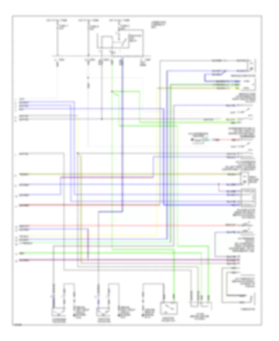
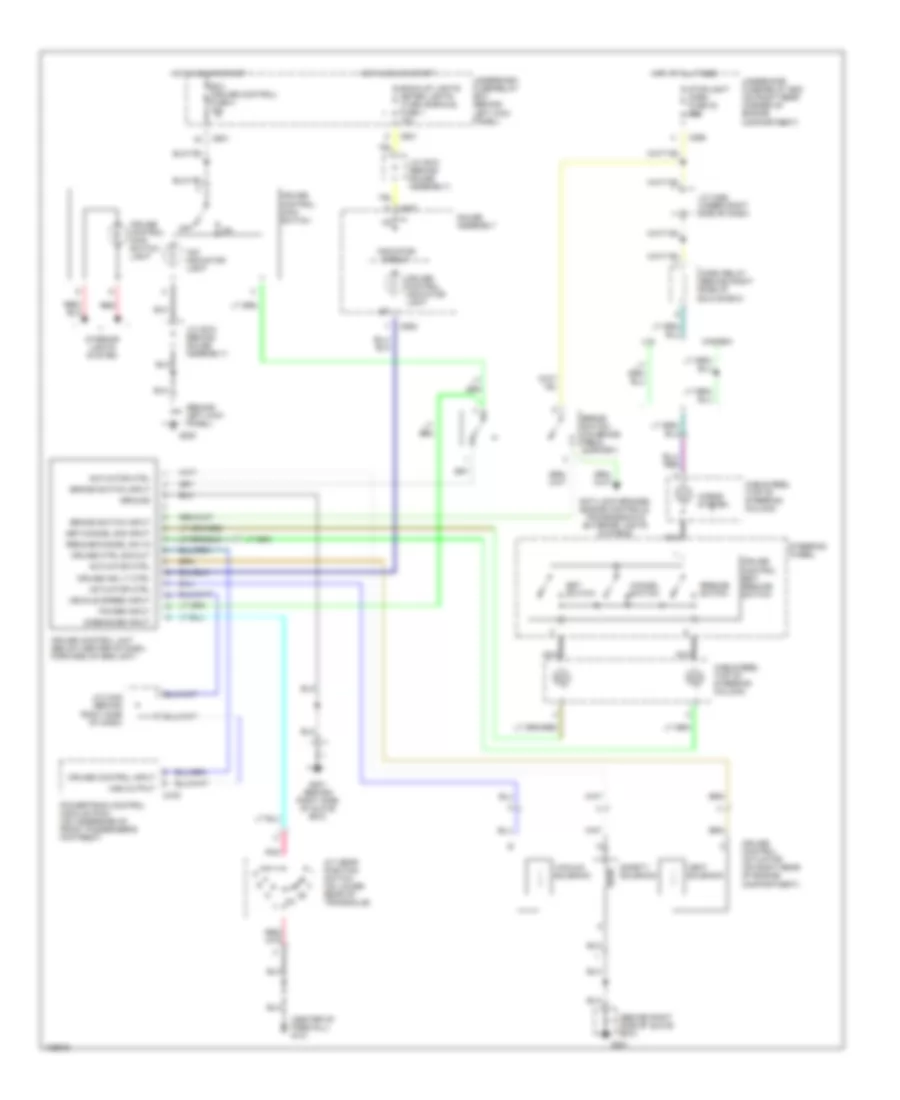
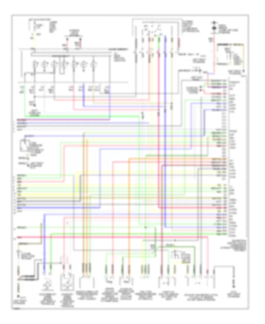
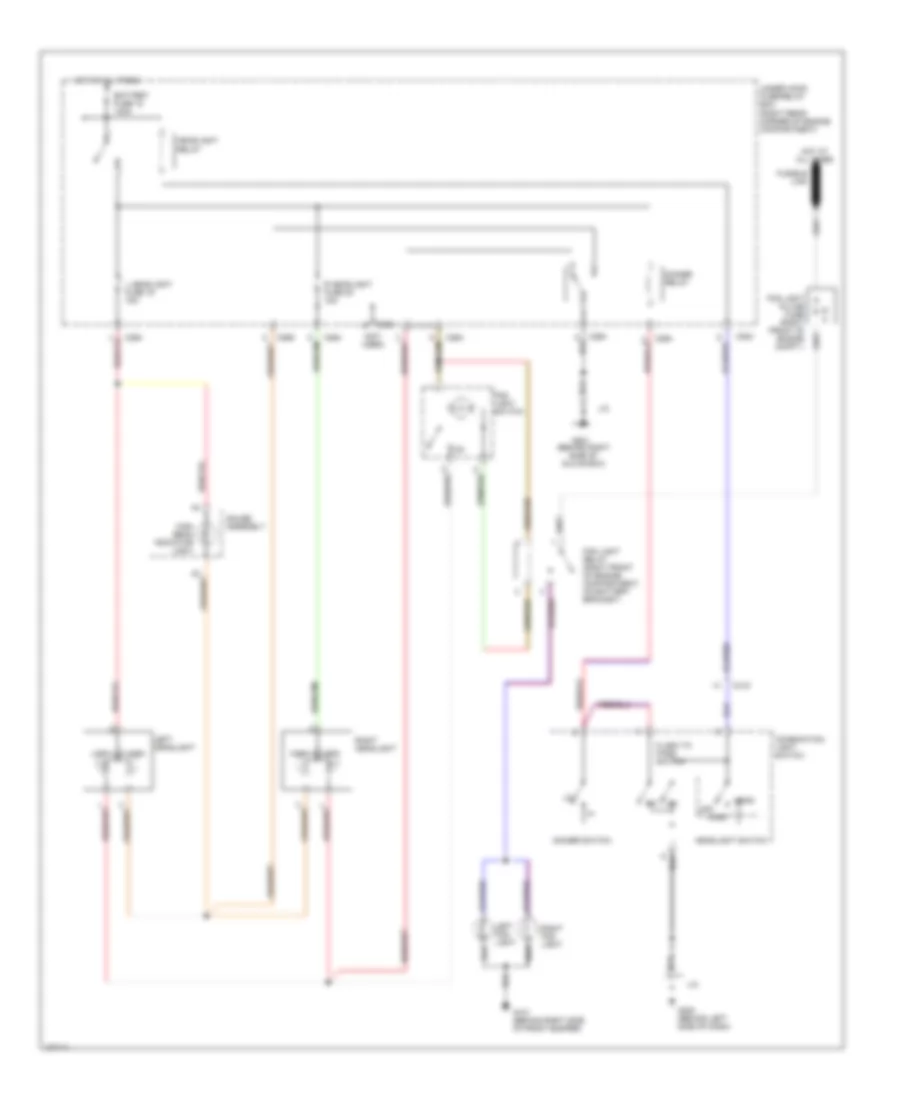
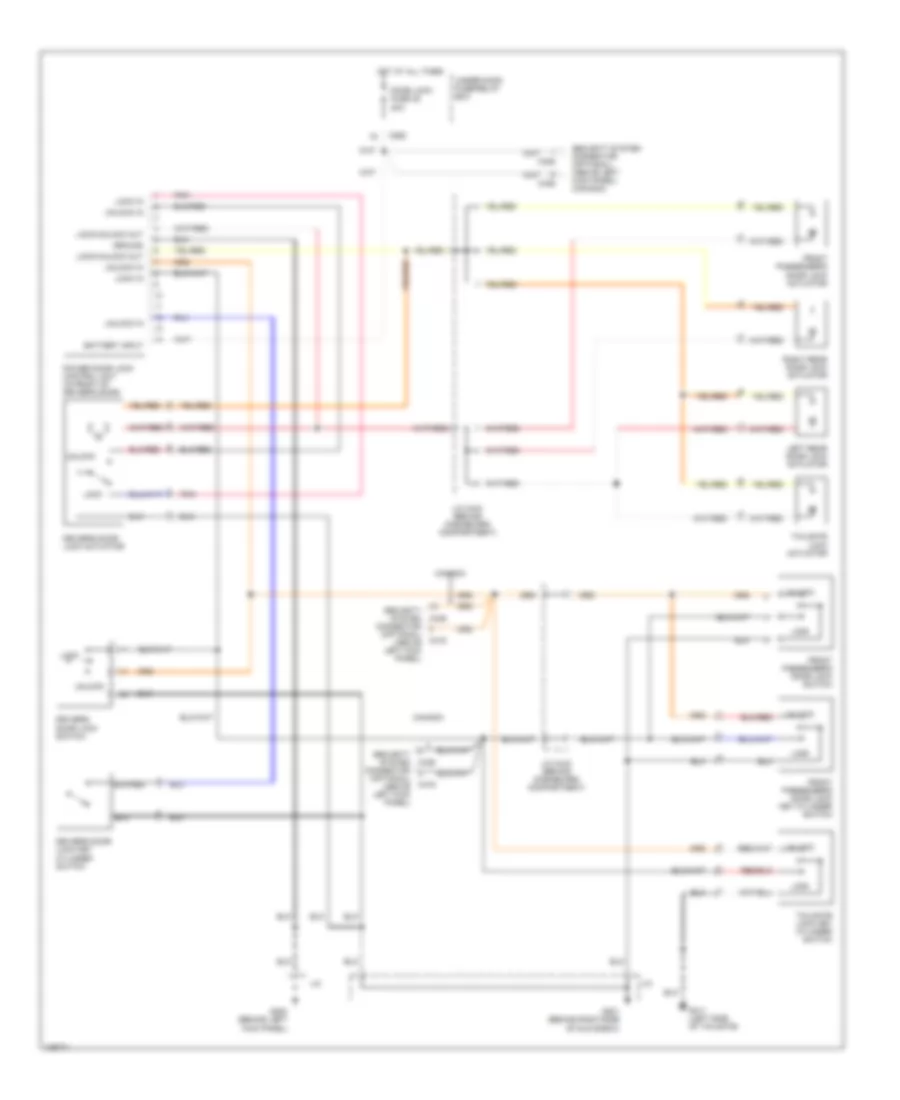
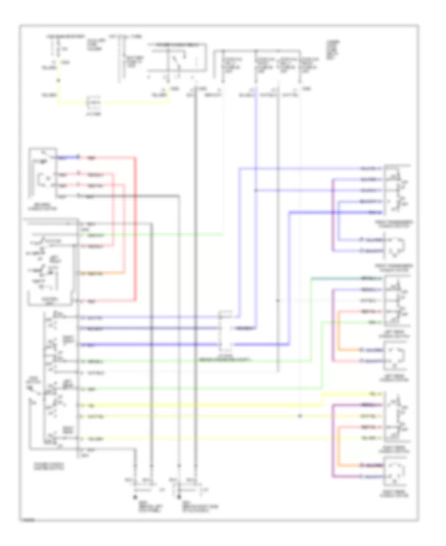
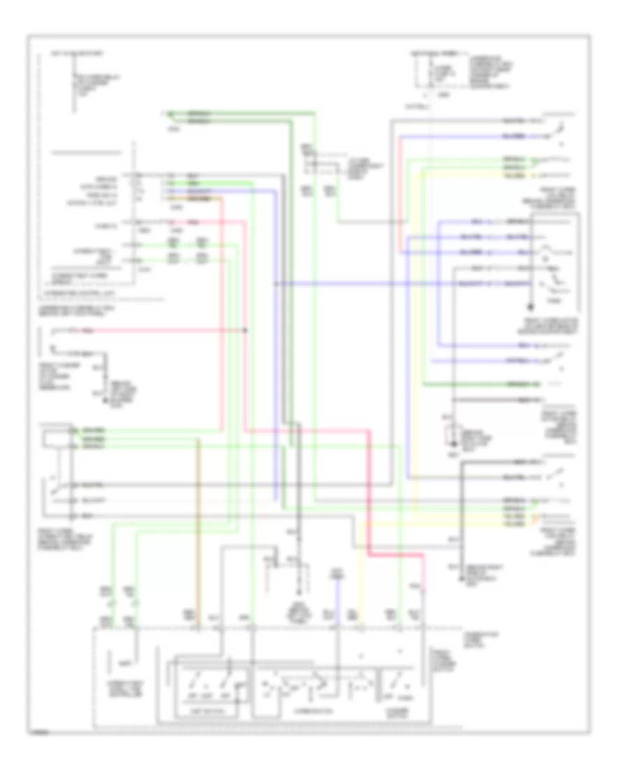
AIR CONDITIONING
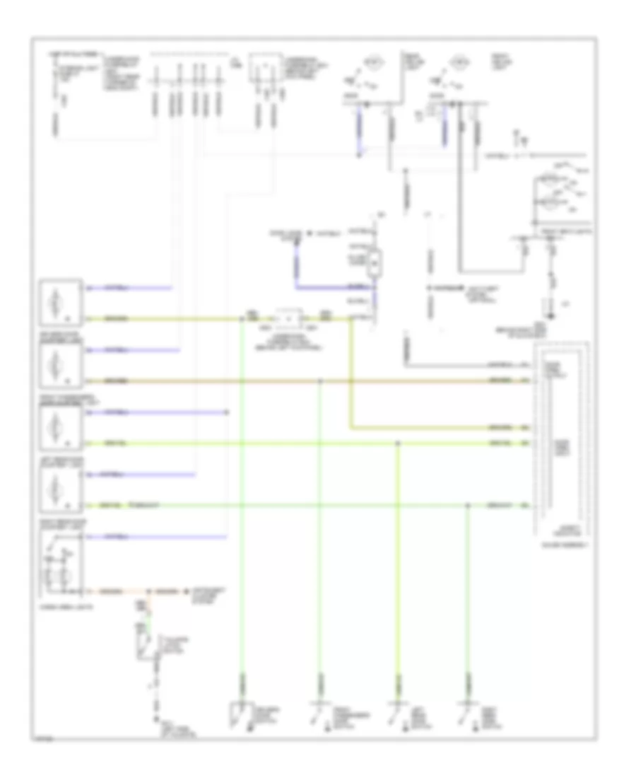
Air Conditioning Wiring Diagrams (1 of 2) for Honda Odyssey LX 1998

List of elements for Air Conditioning Wiring Diagrams (1 of 2) for Honda Odyssey LX 1998:
- "a/c on" indic- ator
- "a/c on" indicator
- (behind left kick panel)
- (behind right side of glove box)
- (under right side of dash) j/c 468
- A/c switch
- Bi-lev switch
- Blower motor relay
- C401
- C402
- C403
- C404
- C476
- Defrost switch
- Dimming control circuit
- Fresh
- Fresh/ recirc switch
- Fuse 8 7.5a
- G200
- G201
- G203 (behind bottom right side of kick panel)
- H/def switch
- Heat switch
- Heater control panel
- Heater control panel light
- Heater fan switch
- Hot in on
- Interior lights system
- Med
- Mode control motor (behind dash, on left side of plenum)
- Off
- Powertrain control module (pcm) (on underside of front passenger's footrest)
- Rear a/c unit switch
- Rear blower motor in-line fuse (on underside of ceiling, right side of rear a/c unit)
- Rec
- Recirc
- Recirculation control motor (behind glove box, on plenum)
- Red
- Slide fan switch
- Suction line solenoid valve (on center rear of engine compartment)
- Under-dash fuse/relay box
- Vent switch
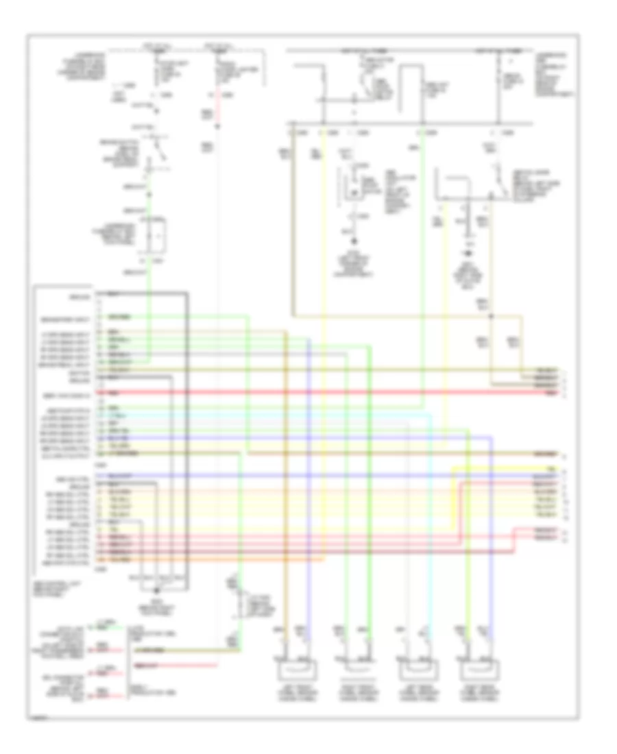
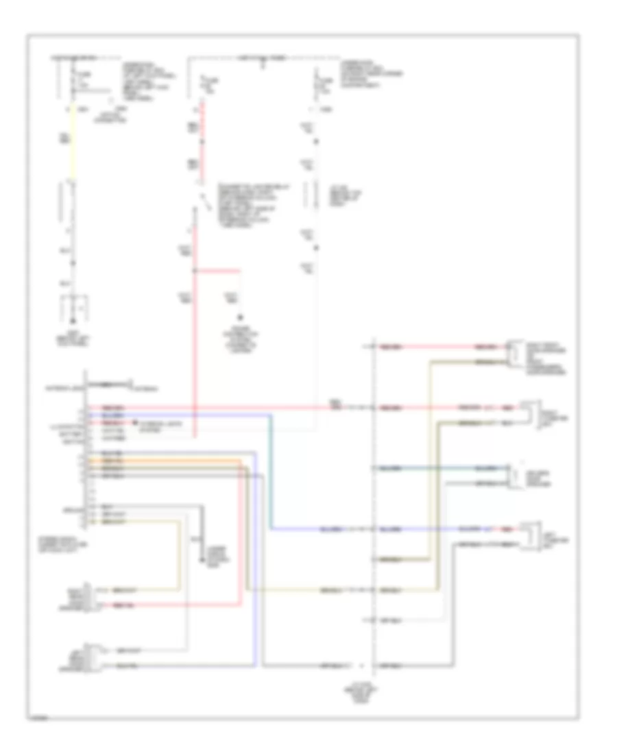
Air Conditioning Wiring Diagrams (2 of 2) for Honda Odyssey LX 1998
List of elements for Air Conditioning Wiring Diagrams (2 of 2) for Honda Odyssey LX 1998:
- (behind left front side of bumper) g100
- (behind right front side of bumper) g101
- (center rear of engine) g115
- (not used)
- A/c compressor clutch
- A/c compressor clutch relay (on left front of engine compartment, on bracket)
- A/c pressure switch (on lower right front of engine compartment, on a/c refrigerant line)
- A/c thermostat (behind glove box, on front of plenum)
- Blower motor resistor (front) (behind glove box, on plenum)
- C262
- C263
- C264
- C265
- Condenser fan motor
- Condenser fan relay (on left front of engine compartment, on bracket)
- Front blower motor
- Fuse 17 40a
- Fuse 21 20a
- Fuse 34 20a
- High
- Hot at all times
- J/c 445 (behind center of dash)
- Low
- Nca
- Radiator fan motor
- Radiator fan relay
- Radiator fan switch
- Rear blower motor
- Rear blower motor resistor (right side of rear a/c unit)
- Red
- Thermistor
- Under-hood fuse/relay box
ANTI-LOCK BRAKES
Anti-lock Brake Wiring Diagrams (1 of 2) for Honda Odyssey LX 1998
List of elements for Anti-lock Brake Wiring Diagrams (1 of 2) for Honda Odyssey LX 1998:
- (not used)
- 4
- Abs b1 fuse 43 20a
- Abs control unit (behind right kick panel)
- Abs fail-safe ctrl
- Abs fail-safe relay (behind left side of dash, right of steering column)
- Abs ind ctrl
- Abs modulator unit (on left front of engine compart- ment)
- Abs motor fuse 41 30a
- Abs pmp mtr ctrl
- Abs pump motor
- Abs pump motor relay
- Abs pump mtr in
- Abs unit fuse 42 7.5a
- Box)
- Brake pedal input
- Brake switch (behind dash, on brake pedal support)
- Brake/park input
- C259
- C260
- C262
- C265
- C353
- C401
- C464
- C465
- Data link connector (dlc) (partial) (on left side of front passenger's footwell area)
- Dlc input/output
- Early production 1998
- G100 (left front corner of engine compartment)
- G201 (behind right side of glove box)
- G203 (behind right kick panel)
- Ground
- Hot at all times
- Ignition
- J/c c423 (behind left side of dash)
- Late production 1998,
- Left front wheel sensor (inside wheel)
- Left rear wheel sensor (inside wheel)
- Lf abs sol ctrl
- Lf spd sens input
- Lr abs sol ctrl
- Lr spd sens input
- Radio cigar lighter fuse 36 15a
- Red
- Rf abs sol ctrl
- Rf spd sens input
- Right front wheel sensor (inside wheel)
- Right rear wheel sensor (inside wheel)
- Rr abs sol ctrl
- Rr spd sens input
- Sdl connector (partial) (behind left side of glove
- Serv chk conn in
- Stoplight horn fuse 30 15a
- Underdash fuse/relay box (behind left kick panel)
- Underhood abs fuse/relay box (on right rear of engine compartment)
- Underhood fuse/relay box (on right rear corner of engine compartment)
Anti-lock Brake Wiring Diagrams (2 of 2) for Honda Odyssey LX 1998
List of elements for Anti-lock Brake Wiring Diagrams (2 of 2) for Honda Odyssey LX 1998:
- (option connector)
- Abs indicator circuit
- Abs indicator light
- Abs inspection connector (left side of engine compartment)
- Abs modulator unit (on left front of engine compartment)
- Back-up lights, meter lights (turn signals) fuse 1 10a
- Brake fluid level switch (in brake fluid reservoir cap)
- Brake ind out
- C352
- C401
- C601
- C607
- C609
- C909
- Canadian models
- D10
- Daytime running lights (drl) control unit (behind left side of dash, above left kick panel)
- G200 (behind left kick panel)
- Gauge assembly
- Hot in on
- Hot in on or start
- Instrument cluster system (brake system indicator)
- J/c c445 (behind right side of dash)
- J/c c468 (behind right side of dash)
- J/c c469 (under right side of dash)
- J/c c610 (behind gauge assembly)
- Left front abs solenoid (in)
- Left front abs solenoid (out)
- Left rear abs solenoid (in)
- Left rear abs solenoid (out)
- Park brake sw in
- Parking brake switch (at base of park brake lever)
- R/c mirror fuse 7 7.5a
- Red
- Right front abs solenoid (in)
- Right front abs solenoid (out)
- Right rear abs solenoid (in)
- Right rear abs solenoid (out)
- Service check connector (partial) (fastened below left side of glove box)
- Underdash fuse/relay box (behind left kick panel)
- Us models
ANTI-THEFT
Anti-theft Wiring Diagram for Honda Odyssey LX 1998
List of elements for Anti-theft Wiring Diagram for Honda Odyssey LX 1998:
- (on center front of engine compartment, forward of radiator) hood switch
- 10a
- Antenna
- Auxiliary fuse holder (on left side of underdash fuse/relay box)
- C262
- C263
- C402
- C403
- C405
- C503
- C57
- C601
- C911 (option connector)
- Disarm/valet switch
- Door locks system
- Door locks system (w/ keyless)
- Door locks system (w/keyless entry) (ex models)
- Driver's door switch (in left front "b" pillar)
- Exterior & interior lights systems
- Front passenger's door switch (in right front "b" pillar)
- G108 (center of radiator support)
- G200 (behind left kick panel)
- G411 (left side of tailgate)
- Gauge assembly
- Glass breakage microphone
- Horns system
- Hot at all times
- Hot in on or start
- Ign. sw fuse 16 50a
- Ignition key switch (closed with key in ignition)
- Instrument cluster system
- Interior lights system
- Interior lights system (ceiling light)
- J/c
- J/c c469 (under right side of dash)
- Left rear door switch (on left rear quarter panel)
- Light flasher relay
- Red
- Right rear door switch (on right rear quarter panel)
- Safety indicator
- Security control unit (below driver's seat)
- Security in-line fuse holder (above left kick panel)
- Security indicator
- Siren (optional)
- Small light fuse 32 15a
- Steering lock
- Tailgate latch switch (closed w/tailgate open)
- Underdash fuse/relay box (behind left kick panel)
- Underhood fuse/relay box (on right rear corner of engine compartment)
- Warning systems
Immobilizer Wiring Diagram for Honda Odyssey LX 1998
List of elements for Immobilizer Wiring Diagram for Honda Odyssey LX 1998:
- (behind right rear side trim panel) g403
- (center of firewall) g121
- A12
- A13
- A15
- A25
- B20
- Back up (radio) fuse 39 7.5a
- C10
- C262
- C401
- C405
- Ecu fuse 33 10a
- Engine controls system
- Fuel pump (on center of floor, through access hole, in top of fuel tank)
- Fuel pump fuse 2 15a
- Fuel pump in
- Gauge assembly
- Ground
- Hot at all times
- Hot in on or start
- Hot in start
- Immob code in
- Immob enable
- Immob lt ctrl
- Immobilizer indicator light
- Immobilizer unit (on steering lock)
- J/c c469 (under right side of dash)
- Pgm-fi main relay (behind dash, left of steering column)
- Pnk
- Powertrain control module (pcm) (on underside of front passenger's footrest)
- Pwr input
- Red
- Starter signal fuse 9 7.5a
- Under dash fuse/relay box (behind left kick panel)
- Underhood fuse/relay box (on right rear corner of engine compartment)
BODY COMPUTER
Integrated Control Unit Wiring Diagram for Honda Odyssey LX 1998
List of elements for Integrated Control Unit Wiring Diagram for Honda Odyssey LX 1998:
- Back-up lights meter lights turn signals fuse 1 10a
- Battery input
- C262
- C401
- C402
- C405
- C410
- C503
- C601
- C904
- Combination light switch
- Defogger system
- Door switch input
- Driver's door switch
- Driver's seat belt sw in
- Engine oil pressure indicator flasher circuit
- Fr wiper relay fr washer fuse 6 10a
- G200 (behind left kick panel)
- Ground
- Head
- Headlight switch
- Headlight switch input
- Hot at all times
- Hot in on or start
- Ignition key light ctrl
- Ignition key switch input
- Instrument cluster system
- Integrated control unit (rear of under- dash fuse/relay box)
- Interior light fuse 37 7.5a
- Interior lights system
- Intermittent rly ctrl out
- Intermittent time input
- Intermittent wiper input
- J/c
- J/c c468
- Not used
- Off
- Park
- Park switch input
- Pnk
- Underdash fuse/relay box (behind left side of dash)
- Underhood fuse/relay box
- Warning systems
- Wash input
- Wiper/washer system
COMPUTER DATA LINES
Computer Data Lines for Honda Odyssey LX 1998
List of elements for Computer Data Lines for Honda Odyssey LX 1998:
- (k-line)
- (left side of front passenger footwell) data link connector (dlc)
- (lg2)
- (scs)
- A10
- A21
- Abs control unit (below left side of dash)
- B22
- C262
- C464
- Cigar lighter fuse 36 15a
- Dlc in/out
- Dlc input/ output
- Early prod 1998
- G121 (center of firewall)
- G201
- Hot at all times
- J/c (behind right side of glove box)
- J/c c423 (behind left side of dash)
- J/c c469
- Late prod 1998 & 1999
- Powertrain control module (behind lower center of dash)
- Radio
- Red
- Sdl connector (behind left side of glove box) (early prod)
- Service check connector (below left side of glove box)
- Service chk conn input
- Srs unit (below center of dash)
- Under-hood fuse/relay box
COOLING FAN
Cooling Fan Wiring Diagram for Honda Odyssey LX 1998
List of elements for Cooling Fan Wiring Diagram for Honda Odyssey LX 1998:
- (behind left side of front bumper) g100
- (behind right side of front bumper)
- (center of firewall) g121
- (not used)
- A20
- C262
- C264
- C265
- C302
- C401
- C922
- Cond. fan fuse 20a
- Condenser fan motor
- Condenser fan relay (left front of engine compartment)
- Cool. fan fuse 20a
- Fanc
- G101
- Hot at all times
- Hot in on
- Htr ctrl rly a/c cl rly rr cool fan fuse 8 7.5a
- J/c c445 (behind dashboard compartment)
- J/c c468
- Powertrain or engine control module (underside of front passenger's footrest)
- Radiator fan motor
- Radiator fan relay
- Radiator fan switch (on thermostat cover)
- Under- dash fuse/ relay box
- Under-hood fuse/relay box
CRUISE CONTROL
Cruise Control Wiring Diagram for Honda Odyssey LX 1998
List of elements for Cruise Control Wiring Diagram for Honda Odyssey LX 1998:
- "on" indicator light
- (behind left kick panel)
- (behind right side of glove box)
- (center of firewall) g121
- A/t gear position switch (on lower rear of transaxle)
- Actuator ctrl
- Anti-lock brakes, engine controls, transmission & exterior lights systems
- Back-up lights meter lights (turn signals) fuse 1 10a
- Brake switch (on brake pedal support)
- Brake switch input
- C262
- C476
- C601
- C607
- C608
- Cable reel (top of steering column)
- Canada
- Cancel switch
- Cruise control actuator (on right rear of engine compartment)
- Cruise control indicator light
- Cruise control input
- Cruise control main switch
- Cruise control main switch light
- Cruise control set/ resume switch
- Cruise control unit (below center of dash, forward of srs unit)
- Cruise ctrl sig out
- Cruise ind lt ctrl
- Disengage input
- Ecu (cruise control) fuse 4 15a
- G200
- G201
- G201 (behind right side of glove box)
- Gauge assembly
- Ground
- Horn relay (behind right side of glove box)
- Horns system
- Hot at all times
- Hot in on or start
- Indicator circuit
- Interior lights system
- J/c c445 (behind right side of dash)
- J/c c468 (under right side of dash)
- J/c c610 (behind gauge assembly)
- Nca
- Off
- Pnk
- Power input
- Powertrain control module (pcm) (on underside of front passenger's footrest)
- Red
- Resume switch
- Resume/cancel sw in
- Safety solenoid
- Set switch
- Set/cancel sig input
- Steering wheel
- Stoplight horn fuse 30 15a
- U.s.
- Underdash fuse/relay box (behind left kick panel)
- Underhood fuse/relay box (on right rear corner of engine compartment)
- Vacuum solenoid
- Vehicle speed input
- Vent solenoid
- Vss output
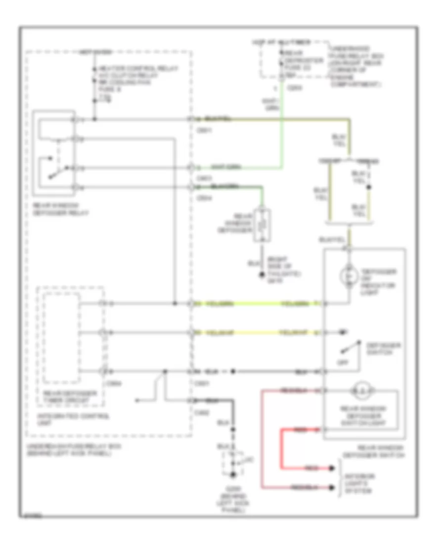
DEFOGGERS
Defogger Wiring Diagram for Honda Odyssey LX 1998
List of elements for Defogger Wiring Diagram for Honda Odyssey LX 1998:
- "defogger on" indicator light
- (right side of tailgate) g410
- 1995-97
- 1998-99
- C266
- C402
- C403
- C504
- C601
- C904
- Defogger switch
- G200 (behind left kick panel)
- Heater control relay a/c clutch relay rr cooling fan fuse 8 7.5a
- Hot at all times
- Hot in on
- Integrated control unit
- Interior lights system
- J/c
- Off
- Rear defogger timer circuit
- Rear defroster fuse 22 30a
- Rear window defogger relay
- Rear window defogger
- Rear window defogger switch
- Rear window defogger switch light
- Red
- Underdash fuse/relay box (behind left kick panel)
- Underhood fuse/relay box (on right rear corner of engine compartment)
ENGINE PERFORMANCE
2.3L
2.3L, Engine Performance Wiring Diagrams (1 of 3) for Honda Odyssey LX 1998
List of elements for 2.3L, Engine Performance Wiring Diagrams (1 of 3) for Honda Odyssey LX 1998:
- (behind right rear side trim panel)
- (center rear of engine compt) engine mount control solenoid valve
- (left front of engine)
- (right rear of engine compt) evaporative emission (evap) purge control solenoid valve
- (top of fuel tank) fuel pump
- 2nd clutch pressure switch (on left front of transaxle)
- 2wbs
- 3rd clutch pressure switch (on right rear of transaxle)
- A10
- A11
- A12
- A13
- A14
- A15
- A16
- A17
- A18
- A19
- A20
- A21
- A22
- A23
- A24
- A25
- A26
- A27
- A28
- A29
- A30
- A31
- A32
- Acc
- Acs
- Air conditioning system
- Anti- theft system
- Anti-theft system
- B10
- B11
- B12
- B13
- B14
- B15
- B16
- B17
- B18
- B19
- B20
- B21
- B22
- B23
- B24
- B25
- Bksw
- C262
- C402
- C405
- C406
- C601
- Cooling fans system
- Crs
- Cruise control system
- Cylinder position sensor
- Cyp
- D4ind
- Distributor
- Distributor assembly
- E-egr
- Fanc
- Flr
- Fuel injectors
- Fuse 2 15a
- Fuse 33 10a
- Fuse 39 7.5a
- Fuse 5 15a
- Fuse 9 15a
- G110
- G110 (left front of engine)
- G405
- Gauge assembly
- Grd
- Ground
- Hot at all times
- Hot in on or start
- Hot in start
- Iacv
- Icm
- Idle air control valve (left side of intake manifold)
- Ign input signal
- Ignition coil
- Ignition control module
- Igp1
- Igp2
- Ilu
- Immobilizer unit
- Imocd
- Imoen
- Imolmp
- Inj1
- Inj2
- Inj3
- Inj4
- J/c c122%% (lower rear of engine)
- J/c c469 (right side of dash)
- K-line
- Lg1
- Lg2
- Lsa+
- Lsa-
- Lsb+
- Lsb-
- Mcs
- Mil
- Nep
- Op2sw
- Op3sw
- Pcs
- Pg1
- Pg2
- Pgm-fi main relay (left of steering column)
- Pnk
- Powertrain control module (underside of passenger's front footrest)
- Pri
- Primary output control
- Pspsw
- Ptank
- Pwr
- Red
- Scs
- Sec
- Shift interlock system
- Sho2s
- Sig
- So2shtc
- Starting/ charging system
- Sts
- Tach
- Test tachometer connector (right rear of eng compt)
- Under- dash fuse/ relay box
- Under- hood fuse/ relay box
- Vbu
- Vssout
- Vsv
- Vtec solenoid valve (left rear of cylinder head)
- Vts
2.3L, Engine Performance Wiring Diagrams (2 of 3) for Honda Odyssey LX 1998
List of elements for 2.3L, Engine Performance Wiring Diagrams (2 of 3) for Honda Odyssey LX 1998:
- (left front
- (left front of engine)
- (left side of engine)
- (on top of control canister) evaporative emission control canister vent shut valve
- (right rear of engine compt) evaporative emission bypass solenoid valve
- (top right of transaxle) a/t clutch pressure control solenoid valve "a"
- (top right of transaxle) a/t clutch pressure control solenoid valve "b"
- Abs control unit (behind right kick panel)
- Braided
- Brake switch (on brake pedal support)
- C262
- C263
- C265
- C401
- C464
- C601
- Ckp
- Crankshaft position/top dead center (ckp/tdc) sensor (behind crankshaft pulley, on oil pump)
- Cruise control system
- Cruise control unit (below center of dash)
- Data link connector (left side of front passenger's footwell)
- Exterior lights system
- Fuse 1 10a
- Fuse 30 15a
- Fuse 36 15a
- Fuse 4 15a
- G110
- G112 (lower left side of engine)
- G200 (left kick panel)
- G201 (right side of dash)
- Gauge assembly
- Hot at all times
- Hot in on or start
- J/c c137
- J/c c445 (center of dash)
- J/c c468 (right side of dash)
- J/c c468%%
- J/c c469 (right side of dash)
- J/c c610%% (back of cluster)
- Lock-up control solenoid valve (top right of transaxle)
- Malfunction indicator light (mil)
- Of engine)
- Pnk
- Power steering pressure switch (lower rear of eng compt)
- Primary heated oxygen sensor (forward of twc converter)
- Red
- Scs
- Secondary heated oxygen sensor (rear of twc converter)
- Service check connector (left side of glove box)
- Shift control solenoid valve "a" (top right of transaxle)
- Shift control solenoid valve "b" (right side of transaxle)
- Shift control solenoid valve "c" (right side of transaxle)
- Srs unit (below center of dash)
- Tdc
- Under- dash fuse/ relay box
- Under- hood fuse/ relay box
- Underdash fuse/relay box
- Vss in
2.3L, Engine Performance Wiring Diagrams (3 of 3) for Honda Odyssey LX 1998
List of elements for 2.3L, Engine Performance Wiring Diagrams (3 of 3) for Honda Odyssey LX 1998:
- (left front of engine)
- (left front of engine) g110
- (left kick panel)
- A/t gear position indicator
- A/t gear position switch (lower rear of transaxle)
- A10
- Altc
- Altf
- Atp1
- Atp2
- Atpd3
- Atpd4
- Atpnp
- Atpr
- Braided
- C11
- C12
- C13
- C14
- C15
- C16
- C19
- C22
- C23
- C24
- C31
- C601
- Ckpm
- Ckpp
- Countershaft speed sensor (left rear of transaxle)
- Cypm
- Cypp
- D10
- D11
- D12
- D13
- D14
- D15
- D16
- Dimming circuit
- Ect
- Egrl
- Engine coolant temperature sensor (right rear of cylinder head)
- Exhaust gas recirculation valve & lift sensor (on left rear of engine)
- Fuel tank pressure sensor (right side of firewall)
- Fuse 1 10a
- G110
- G110 (left front of engine)
- G200
- Gauge assembly
- Hot in on or start
- Iat
- Intake air temperature sensor (in intake manifold)
- Interior lights system
- J/c c137%% (lower left of engine)
- J/c c469 (right side of dash)
- Knock sensor (lower left side of engine)
- Mainshaft speed sensor (lower right rear of transaxle)
- Manifold absolute pressure sensor (on top of throttle body)
- Map
- Ncsg
- Nmsg
- Pho2s
- Pnk
- Po2shtc
- Powertrain control module (underside of of front passenger's footrest)
- Red
- Red c21
- Sg1
- Sg2
- Sha
- Shb
- Shift interlock system
- Snc
- Starting/ charging system
- Tdcm
- Tdcp
- Throttle position sensor (on throttle body)
- Tps
- Under- dash fuse/ relay box
- Vbsol
- Vcc1
- Vcc2
- Vtec pressure switch (on rear of cylinder head)
- Vtm
EXTERIOR LIGHTS
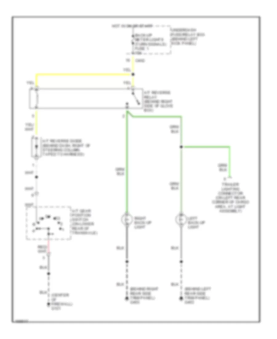
Back-up Lamps Wiring Diagram for Honda Odyssey LX 1998
List of elements for Back-up Lamps Wiring Diagram for Honda Odyssey LX 1998:
- (behind left rear side trim panel) g403
- (behind right rear side trim panel) g403
- (center of firewall) g121
- A/t gear position switch (on lower rear of transaxle)
- A/t reverse diode (behind dash, right of steering column, taped to harness)
- A/t reverse relay (behind right side of glove box)
- Back-up meter lights (turn signals) fuse 1 10a
- C402
- Hot in on or start
- Left back-up light
- Right back-up light
- Trailer lighting connector (on left rear corner of cargo area, at light assembly)
- Underdash fuse/relay box (behind left kick panel)
Exterior Lamps Wiring Diagram (1 of 2) for Honda Odyssey LX 1998
List of elements for Exterior Lamps Wiring Diagram (1 of 2) for Honda Odyssey LX 1998:
- (behind left rear side trim panel) g402
- (behind left side of front bumper) g100
- (behind right rear side trim panel) g403
- (behind right side of front bumper) g101
- (left side of tailgate) g411
- (not used)
- Brake switch (behind dash, on brake pedal support)
- C262
- C265
- C401
- C402
- C503
- C504
- Combination light switch
- Cruise control system
- Engine controls system
- G403 (behind right rear side trim panel)
- Head
- Headlight switch
- High mount brake light
- Hot at all times
- Instrument cluster system
- Interior lights system
- J/c c468 (under right side of dash)
- Left brake light failure sensor (left rear corner of cargo area, at light assembly)
- Left brake light/ taillight
- Left front parking/turn signal light
- Left rear turn signal light
- License plate lights
- Off
- Park
- Right brake light failure sensor (right rear corner of cargo area, at light assembly)
- Right brake light/ taillight
- Right front parking/ turn signal light
- Right rear turn signal light
- Small light fuse 32 15a
- Stop light horn fuse 30 15a
- To combination light switch (diagram 2 of 2)
- To j/c c445 (diagram 2 of 2)
- To trailer lighting connector (diagram 2 of 2)
- To underdash fuse/relay box (diagram 2 of 2)
- Underdash fuse/relay box (behind left kick panel)
- Underhood fuse/relay box (on right rear corner of engine compartment)
Exterior Lamps Wiring Diagram (2 of 2) for Honda Odyssey LX 1998
List of elements for Exterior Lamps Wiring Diagram (2 of 2) for Honda Odyssey LX 1998:
- (behind left rear side trim panel) g402
- (not used)
- Back-up lights meter lights (turn signals) fuse 1 10a
- Back-up lights system
- C262
- C401
- C402
- C503
- C601
- C901
- Combination light switch
- From front parking/ turn signal lights (diagram 1 of 2)
- From rear turn signal lights (diagram 1 of 2)
- From underdash fuse/relay box (diagram 1 of 2)
- G200 (behind left kick panel)
- Gauge assembly
- Ground
- Hazard fuse 35 10a
- Hazard warning switch
- Hazard warning switch light
- Hot at all times
- Hot in on or start
- Ignition
- Interior lights system
- J/c
- J/c c445 (behind center of dash)
- J/c c610 (behind gauge assembly)
- Left
- Left turn signal indicator light
- Off
- Red
- Relay out
- Right
- Right turn signal indicator light
- Trailer lighting connector (on left rear corner of cargo area, at light assembly)
- Turn signal switch
- Turn signal/ hazard relay
- Underdash fuse/relay box (behind left kick panel)
- Underhood fuse/relay box (on right rear corner of engine compartment)
GROUND DISTRIBUTION
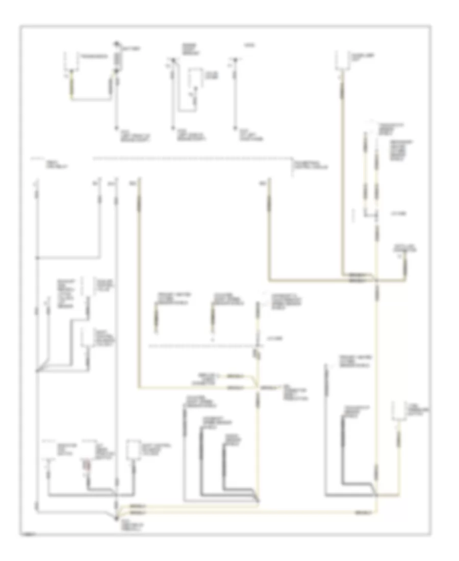
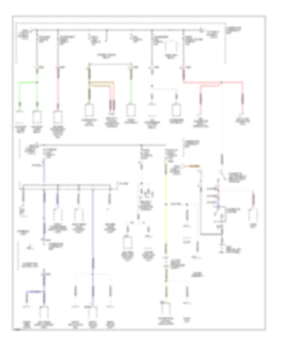
Ground Distribution Wiring Diagram (1 of 3) for Honda Odyssey LX 1998
List of elements for Ground Distribution Wiring Diagram (1 of 3) for Honda Odyssey LX 1998:
- A/t gear position switch
- B10
- B20
- B22
- Battery
- Braided wire
- Connector (early production)
- Counter- shaft speed sensor shield
- Data link connector
- Engine mount bracket
- Exhaust gas recircu- lation valve & lift sensor
- G100 (left side of engine compt)
- G101 (left front of engine compt.)
- G121 (center of firewall)
- G127 (at left hood hinge)
- Hood
- Idle air control valve
- Immobilizer unit
- J/c c468
- J/c c469
- Knock sensor shield
- Mainshaft & countershaft speed sensor shield
- Mainshaft speed sensor shield
- Pgm-fi main relay
- Powertrain control module
- Primary heated oxygen sensor shield
- Radiator fan switch
- Sdl
- Secondary heated oxygen sensor shield
- Service check connector
- Shift control solenoid valve b
- Shift control solenoid valve c
- Tdc/ckp/cyp sensor shield
- Transmission
- Valve cover
- Vtec pressure switch
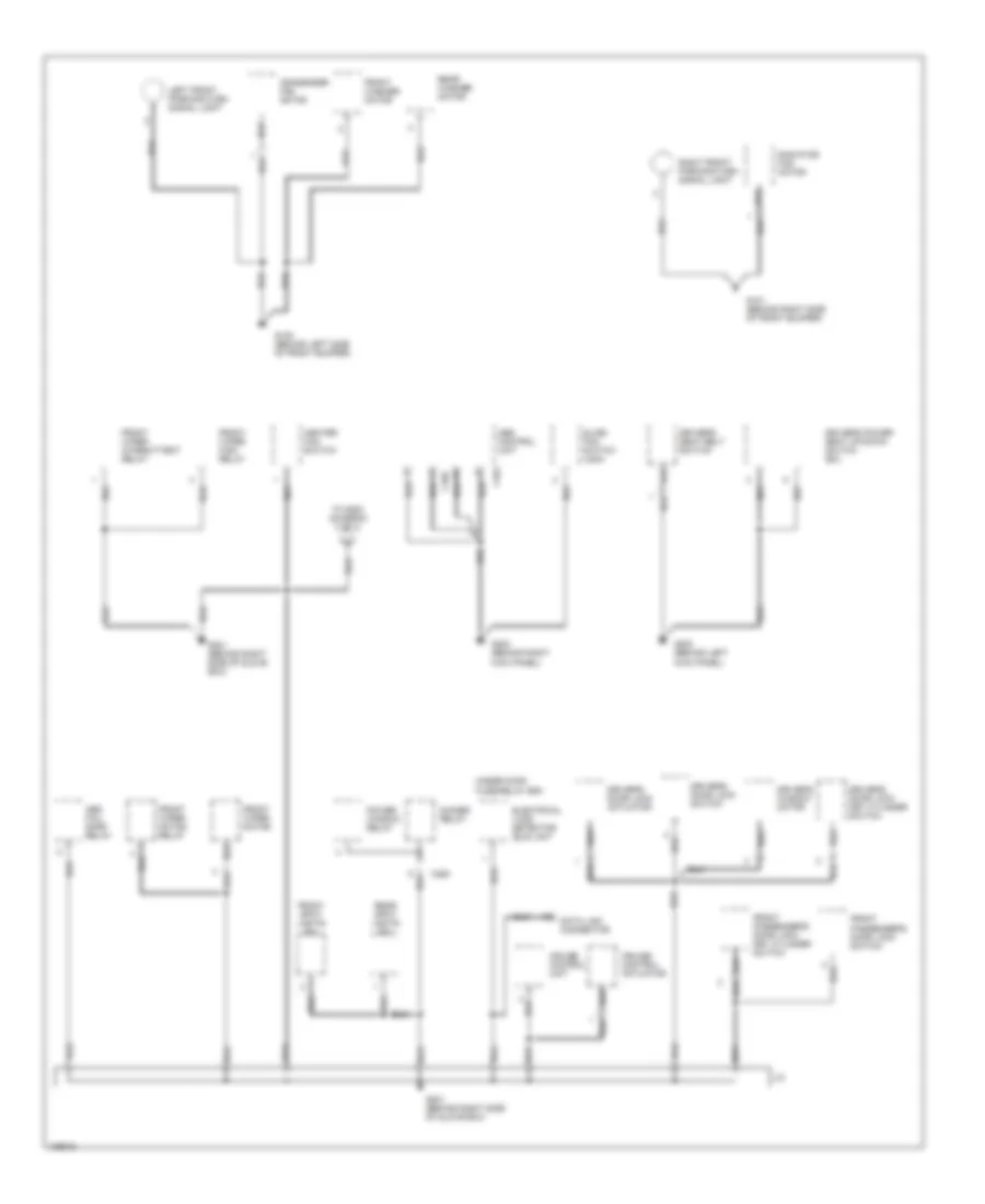
Ground Distribution Wiring Diagram (2 of 3) for Honda Odyssey LX 1998
List of elements for Ground Distribution Wiring Diagram (2 of 3) for Honda Odyssey LX 1998:
- Abs control unit
- Abs fail- safe relay
- C263
- C464
- C465
- Condenser fan motor
- Cruise control actuator
- Cruise control unit
- Data link connector
- Dimmer relay
- Driver's door lock actuator
- Driver's door lock key cylinder switch
- Driver's door lock switch
- Driver's power seat up-down switch (ex)
- Driver's seat belt switch
- Driver's window motor
- Electrical load detector (eld) unit
- Front passenger's door lock key cylinder switch
- Front passenger's door lock switch
- Front spot lights (ex)
- Front washer motor
- Front wiper high relay
- Front wiper intermittent relay
- Front wiper motor
- Front wiper motor relay
- G100 (behind left side of front bumper)
- G101 (behind right side of front bumper)
- G200 (behind left kick panel)
- G201 (behind right side of glove box)
- G203 (behind right kick panel)
- Heater fan switch
- J/c
- Left front parking/turn signal light
- Power window relay
- Radiator fan motor
- Rear spot lights (ex)
- Rear washer motor
- Right front parking/turn signal light
- Slide fan switch (usa)
- To g200 (diagram 3 of 3)
- Under-hood fuse/relay box
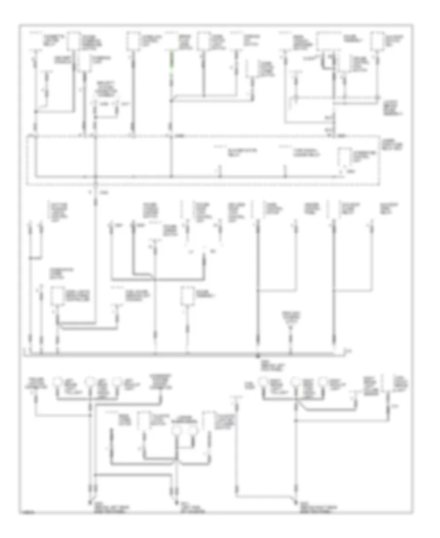
Ground Distribution Wiring Diagram (3 of 3) for Honda Odyssey LX 1998
List of elements for Ground Distribution Wiring Diagram (3 of 3) for Honda Odyssey LX 1998:
- Accessory poower socket connector
- Blower motor relay
- Brake fluid level switch
- C13
- C402
- C405
- C417
- C436
- C601
- C641
- C904
- Center console
- Cigarette lighter relay
- Clock
- Combi- nation light switch
- Combi- nation wiper switch
- Combination wiper switch
- Cruise control main switch
- Dash lights brightness controller
- Daytime running lights control unit
- From g201 (diagram 2 of 3)
- Fuel gauge sending unit (canada)
- Fuel pump
- G200 (behind left kick panel)
- G402 (behind left rear side trim panel)
- G403 (behind right rear side trim panel)
- G411 (left side of tailgate)
- Gauge assembly
- Heater control panel
- High mount brake light
- Integrated control unit
- Interlock control unit
- J/c
- J/c c610 (behind gauge assembly)
- Keyless door lock control unit
- Left back-up light
- Left brake light/ taillight
- Left rear turn signal light
- License plate lights
- Mode control motor
- Parking pin switch
- Power door lock control unit
- Power mirror switch
- Power steering pressure switch
- Power window master switch
- Rear window defogger switch
- Rear wiper motor
- Right back-up light
- Right brake light failure sensor
- Right brake light/ taillight
- Right rear turn signal light
- Security system connector (canada)
- Steering lock
- Sun roof close relay
- Sun roof open relay
- Sun roof switch (ex)
- Tailgate latch switch
- Tailgate lock key cylinder switch
- Trailer lighting connector
- Turn signal/ hazard relay
- Under- dash fuse/ relay box
HEADLIGHTS
Headlight Wiring Diagram, with DRL for Honda Odyssey LX 1998
List of elements for Headlight Wiring Diagram, with DRL for Honda Odyssey LX 1998:
- (not used)
- 15a
- B12
- Battery fuse 15 100a
- Battery input
- Brake indicator control
- C263
- C264
- C265
- C401
- Combination light switch
- Day lights fuse 10 7.5a
- Daytime running lights control unit (above left kick panel)
- Daytime running lights indicator
- Dimmer relay
- Dimmer relay input
- Dimmer switch
- Drl indicator control
- Drl output
- Flash to pass switch
- Fog light in-line fuse (right front of engine compartment)
- Fog light relay (right front of engine compt., on battery bracket)
- Fog light switch
- Fusible link
- G101 (behind right side of front bumper)
- G200 (behind left kick panel)
- G201 (behind right side of glove box)
- Gauge assembly
- Ground
- Head
- Headlight relay
- Headlight switch
- Headlights on input
- Hi beam control/ drl mode output
- Hi beam/ drl mode control
- High
- High beam indicator light
- Hot at all times
- Hot in on
- Ignition input
- Instrument cluster system
- J/c
- Left fog light
- Left headlight assembly
- Left headlight fuse 19 15a
- Low
- Low beam cut relay (above left kick panel)
- Off
- Park
- Parking brake sw input
- Parking brake switch
- Right fog light
- Right headlight assembly
- Right headlight fuse 20 15a
- Running light fuse 27 10a
- Under dash fuse/ relay box (behind left kick panel)
- Under hood fuse/relay box (right rear corner of engine compartment)
Headlight Wiring Diagram, without DRL for Honda Odyssey LX 1998
List of elements for Headlight Wiring Diagram, without DRL for Honda Odyssey LX 1998:
- (behind right side of glove box)
- (not used)
- Battery fuse 15 100a
- C254
- C263
- C264
- C265
- C418
- Combination light switch
- Dimmer relay
- Dimmer switch
- Flash to pass switch
- Fog light in-line fuse (right front of engine compt.)
- Fog light relay (right front of engine compartment, on battery bracket)
- Fog light switch
- Fusible link
- G101 (behind right side of front bumper)
- G200 (behind left side of dash)
- G201
- Gauge assembly
- Head
- Headlight relay
- Headlight switch
- High
- High beam indicator light
- Hot at all times
- J/c
- L headlight fuse 19 15a
- Left fog light
- Left headlight
- Low
- Off
- Park
- R headlight fuse 20 15a
- Right fog light
- Right headlight
- Under hood fuse/relay box (right rear corner of engine compartment)
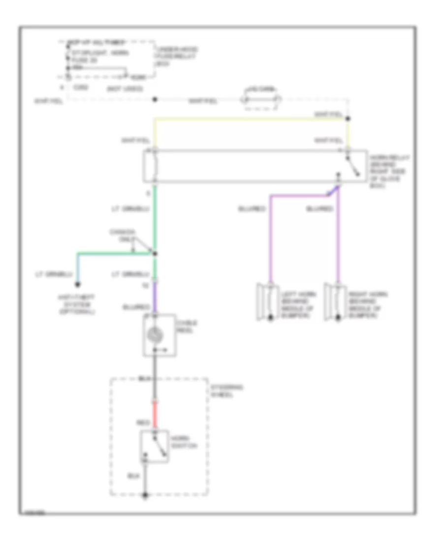
HORN
Horn Wiring Diagram for Honda Odyssey LX 1998
List of elements for Horn Wiring Diagram for Honda Odyssey LX 1998:
- (not used)
- Anti-theft system (optional)
- C262
- C265
- Cable reel
- Canada only
- Horn relay (behind right side of glove box)
- Horn switch
- Hot at all times
- J/c c468
- Left horn (behiind middle of bumper)
- Red
- Right horn (behiind middle of bumper)
- Steering wheel
- Stoplight, horn fuse 20 15a
- Under-hood fuse/relay box
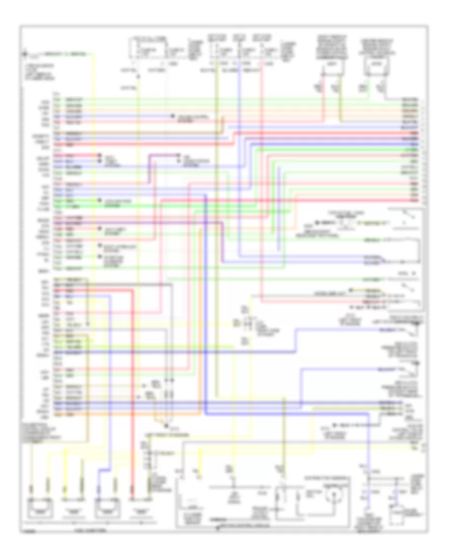
INSTRUMENT CLUSTER
Instrument Cluster Wiring Diagram (1 of 2) for Honda Odyssey LX 1998
List of elements for Instrument Cluster Wiring Diagram (1 of 2) for Honda Odyssey LX 1998:
- A/t gear position switch (on lower rear of transaxle)
- A10
- Abs indicator circuit
- Abs indicator light
- Anti-lock brakes system
- Anti-theft system
- At gear position indicator
- B10
- B11
- B12
- B13
- Back-up lights meter lights (turn signals) fuse 1 10a
- Brake system indicator light
- C10
- C11
- C12
- C13
- C14
- C15
- C16
- C17
- C18
- C19
- C20
- C21
- C22
- C601
- C610 (behind gauge assembly)
- Charging system light
- Cpu
- Cruise control system
- Cruise indicator light
- D10
- Drive circuit
- Ecu cruise control fuse 4 15a
- Engine controls system
- Engine coolant temperature gauge
- Exterior lights system
- Front passenger's door switch (on right front "b" pillar)
- Fuel gauge
- G121 (center of firewall)
- G200 (behind left kick panel)
- Gauge assembly
- Gauge lights (6 bulbs)
- Headlights system
- Heater control relay a/c clutch relay rr cooling fan fuse 8 7.5a
- Hot in on
- Hot in on or start
- I/f
- Immobilizer indicator light
- Indicator circuit
- Interior lights system
- J/c
- Lcd
- Lcd back- up light
- Lcd dimming circuit
- Low fuel indicator light
- Maintenance reminder light
- Pnk
- Red
- Select/ reset switch
- Speedometer
- Srs indicator circuit
- Srs indicator light
- Starting/charging system
- Tachometer
- To drl indicator (diagram 2 of 2)
- To turn signal indicators (diagram 2 of 2)
- Transmissions systems
- Underdash fuse/relay box (behind left kick panel)
- Warning systems
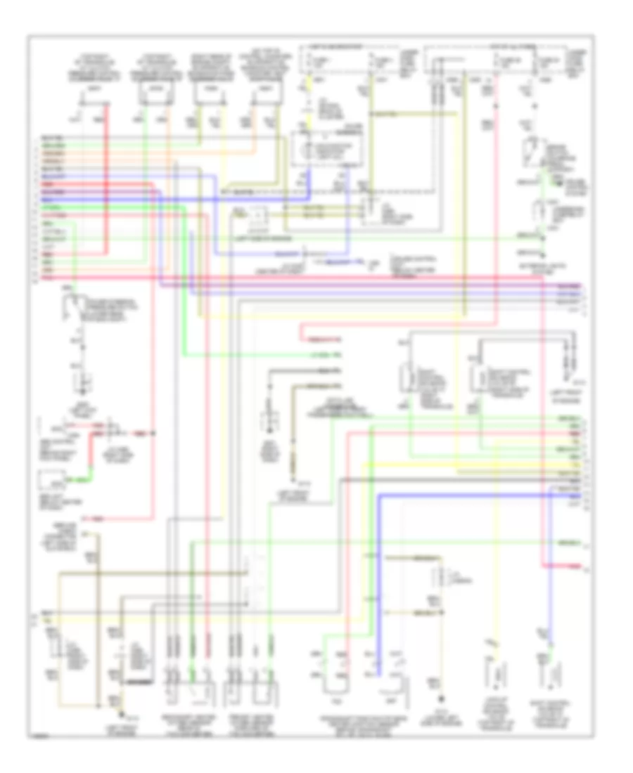
Instrument Cluster Wiring Diagram (2 of 2) for Honda Odyssey LX 1998
List of elements for Instrument Cluster Wiring Diagram (2 of 2) for Honda Odyssey LX 1998:
- "brake lamp" indicator light
- (left side of tailgate) g411
- 1 indicator
- 2 indicator
- A/t gear position/ cruise control indicator circuit
- A10
- Abs control unit (behind right kick panel)
- Anti-theft system
- B10
- B11
- B12
- B21
- Back-up radio fuse 39 7.5a
- Brake fluid level switch (in brake fluid reservoir cap)
- Brake ind ctrl
- Brake/park input
- C10
- C11
- C13
- C14
- C15
- C16
- C19
- C20
- C262
- C465
- C503
- C601
- Canada
- Canadian models
- Circuit
- D3 indicator
- D4 indicator
- Daytime running lights (drl) control unit (behind left side of dash, above kick panel)
- Driver's door indicator light
- Driver's door switch (on left front "b" pillar)
- Drl indicator light
- Engine coolant temperature (ect) gauge sending unit (on right rear of cylinder head)
- Engine oil pressure indicator flasher c410
- Engine oil pressure switch (on lower left side of engine)
- From abs a indicator circuit (diagram 1 of 2)
- From abs indicator circuit b (diagram 1 of 2)
- Front passenger's door indicator light
- Fuel gauge sending unit
- G200 (behind left kick panel)
- Gauge assembly
- High beam indicator light
- Hot at all times
- Integrated control unit
- Interior lights system
- J/c
- J/c c468 (under right side of dash)
- Left rear door indicator light
- Left rear door switch (left rear quarter panel)
- Left turn signal indicator light
- Low engine oil pressure indicator light
- Malfunction indicator light
- N indicator
- P indicator
- Parking brake switch (between front seats, at base of park brake lever)
- Parking brake switch input
- Power door locks system
- R indicator
- Right rear door indicator light
- Right rear door switch (right rear quarter panel)
- Right turn signal indicator light
- Safety indicator circuit
- Seat belt reminder light
- Tailgate indicator light
- Tailgate latch switch (part of talgate latch assembly)
- Underdash fuse/relay box (behind left kick panel)
- Underhood fuse/relay box (on right rear corner of engine compartment)
- Us models
INTERIOR LIGHTS
Courtesy Lamps Wiring Diagram for Honda Odyssey LX 1998
List of elements for Courtesy Lamps Wiring Diagram for Honda Odyssey LX 1998:
- (optional)
- Anti-theft
- C262
- C401
- C503
- C601
- Cargo area lights
- Door
- Door locks system
- Door open input
- Door open output
- Driver's door courtesy light
- Driver's door switch
- Ex lx
- Front ceiling light
- Front passenger's door courtesy light
- Front passenger's door switch
- Front spotlights
- G201 (behind right side of glove box)
- G411 (left side of tailgate)
- Gauge assembly
- Hot at all times
- In-line diode
- Instrument cluster system
- Interior light fuse 37 7.5a
- J/c
- J/c c468
- Left rear door courtesy light
- Left rear door switch
- Off
- Rear ceiling light
- Right rear door courtesy light
- Right rear door switch
- Safety indicator
- System
- Tailgate latch switch
- Under-dash fuse/relay box (behind left kick panel)
- Under-hood fuse/relay box (right rear corner of eng compt)
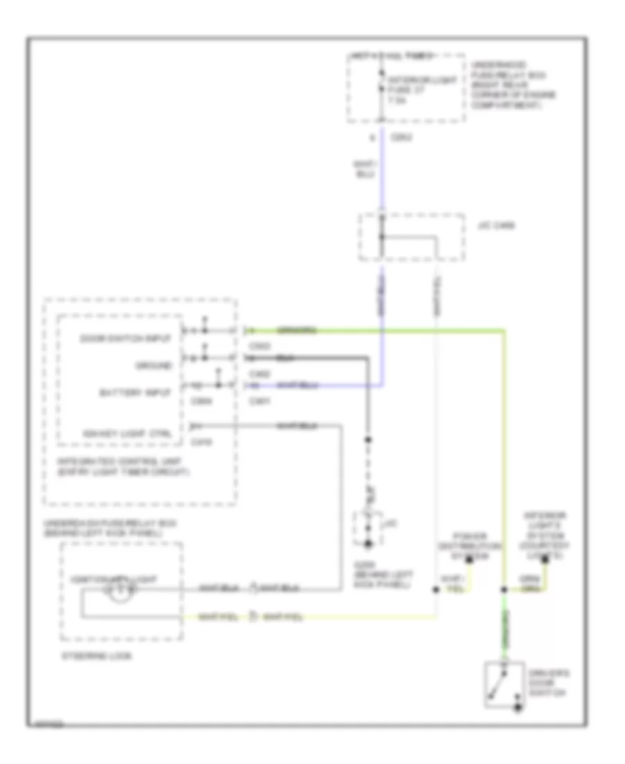
Entry Light Timer Wiring Diagram for Honda Odyssey LX 1998
List of elements for Entry Light Timer Wiring Diagram for Honda Odyssey LX 1998:
- Battery input
- C262
- C401
- C402
- C410
- C503
- C904
- Door switch input
- Driver's door switch
- G200 (behind left kick panel)
- Ground
- Hot at all times
- Ign key light ctrl
- Ignition key light
- Integrated control unit (entry light timer circuit)
- Interior light fuse 37 7.5a
- Interior lights system (courtesy lights)
- J/c
- J/c c468
- Power distribution system
- Steering lock
- Underdash fuse/relay box (behind left kick panel)
- Underhood fuse/relay box (right rear corner of engine compartment)
Instrument Illumination Wiring Diagram for Honda Odyssey LX 1998
List of elements for Instrument Illumination Wiring Diagram for Honda Odyssey LX 1998:
- (behind right side of glove box)
- A/t gear position/ cruise control indicator circuit
- A10
- Anti-theft system (optional)
- Ashtray light
- C262
- C401
- C402
- C601
- Center console
- Center pocket light
- Cigarette lighter light
- Clock
- Combination light switch
- Cruise control main switch
- Dash lights brightness controller
- Dimmer
- Dimming input
- Driver's vanity mirror light
- Exterior lights system
- G200 (behind left kick panel)
- G201
- Gauge assembly
- Gauge lights (8 bulbs)
- Hazard warning switch
- Head
- Headlight switch
- Heater control panel
- Hot at all times
- J/c
- J/c c423 (behind left side of dash)
- J/c c468
- J/c c610 (behind gauge assembly)
- Off
- Park
- Passenger's vanity mirror light
- Rear a/c unit switch
- Rear spot- lights
- Rear window defogger switch
- Red
- Small light fuse 32 15a
- Stereo radio/ cassette player
- Sunroof switch (ex model)
- Underdash fuse/relay box (behind left kick panel)
- Underhood fuse/relay box (right rear corner of engine compartment)
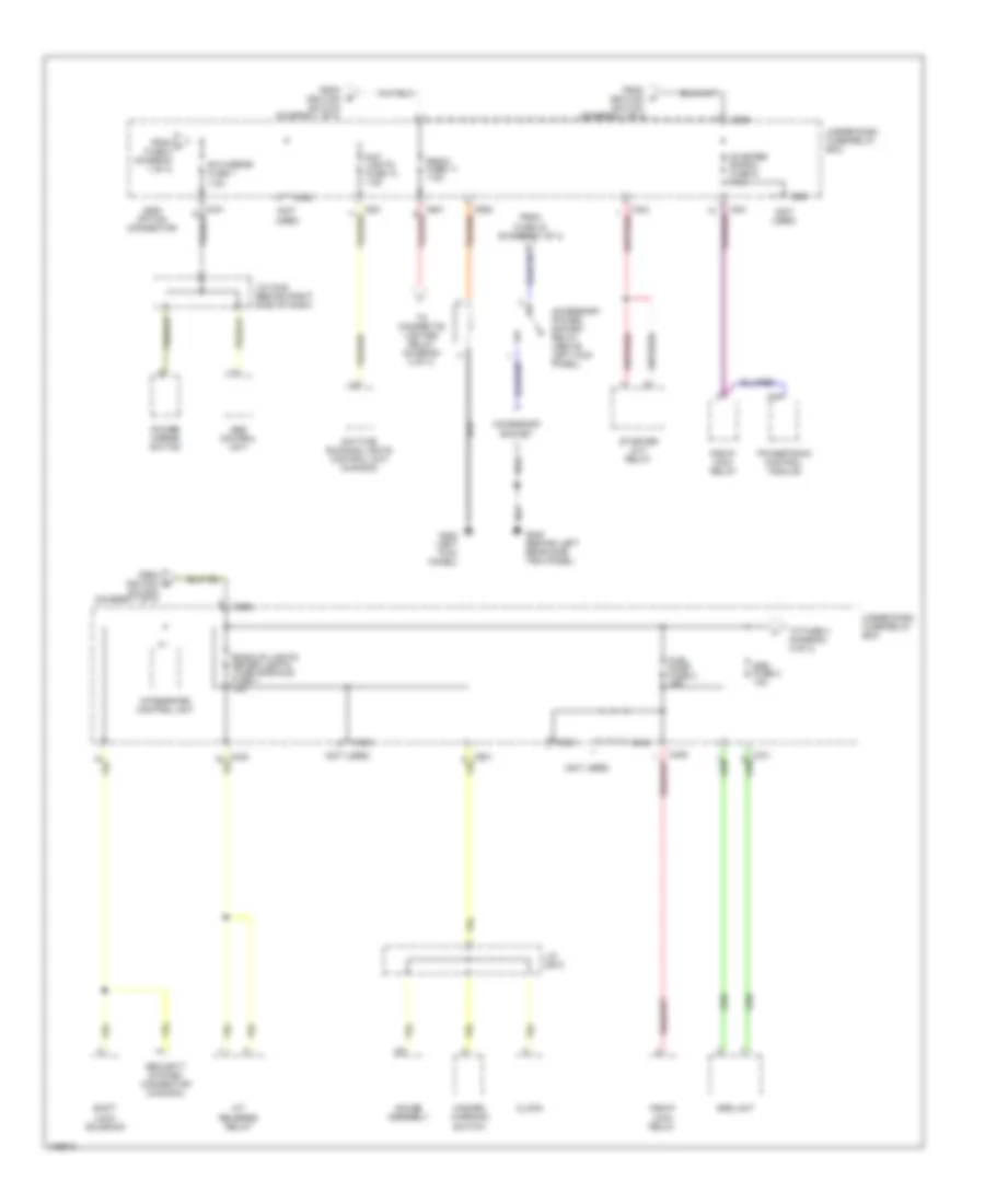
POWER DISTRIBUTION
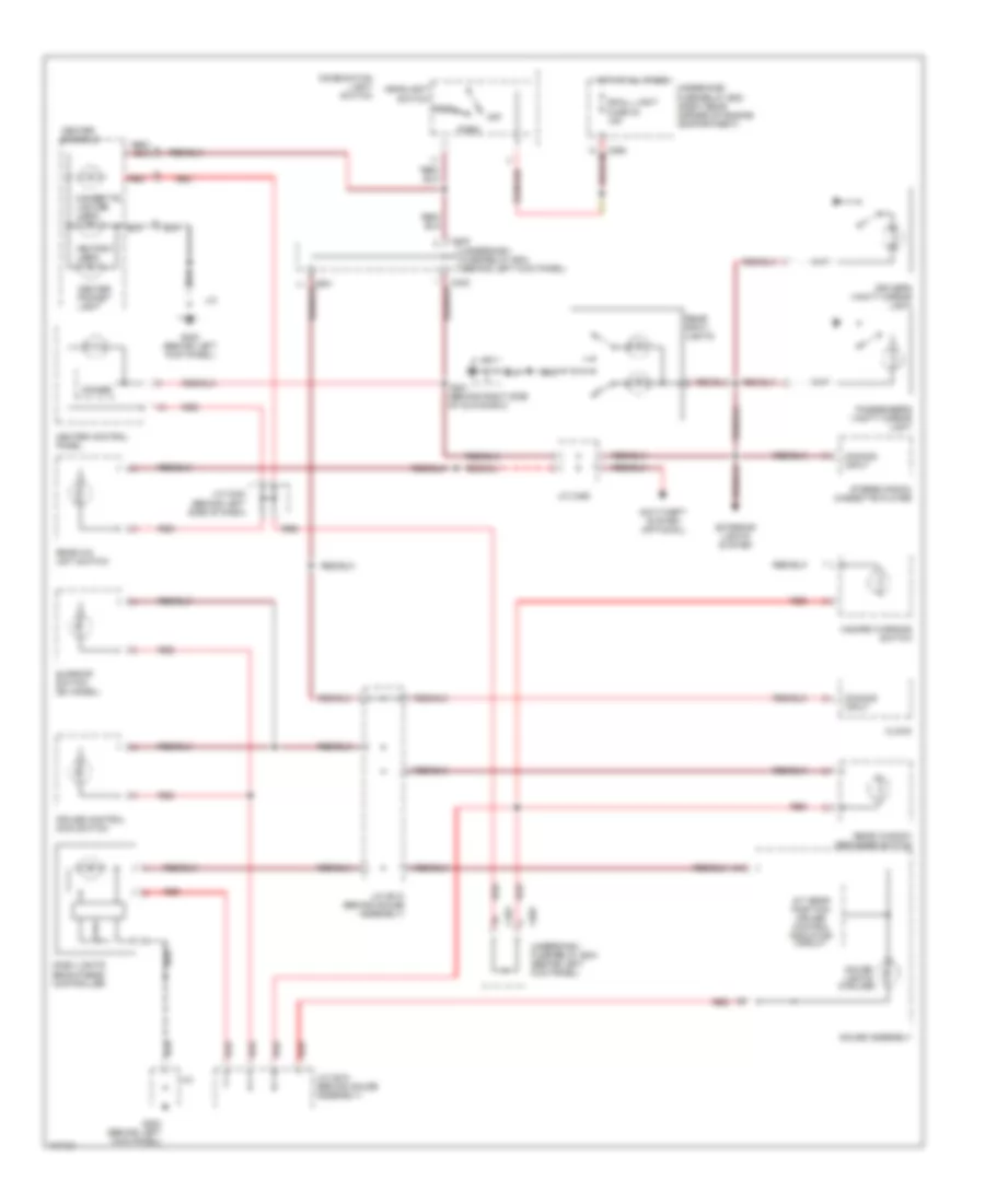
Power Distribution Wiring Diagram (1 of 4) for Honda Odyssey LX 1998
List of elements for Power Distribution Wiring Diagram (1 of 4) for Honda Odyssey LX 1998:
- (not used)
- A/c compressor clutch relay
- A/c thermostat
- Abs b1 fuse 43 20a
- Abs fail-safe relay
- Abs motor fuse 41 30a
- Abs pump motor relay
- Acc
- Acc socket fuse 23 10a
- Alternator
- Battery
- Battery fuse 15 100a
- Blower motor relay
- Brake switch
- C22
- C259
- C265
- C266
- C401
- C403
- C503
- C906
- C911 option connector
- Condenser fan relay
- Cooling fan fuse 21 20a
- Daytime running lights control unit (canada)
- Electrical load detector (eld) unit
- From a fuse 22 (diagram 1 of 4)
- Front wiper motor relay
- Gauge assembly
- Hazard fuse 35 10a
- Hazard warning switch
- Heater blower fuse 17 40a
- Heater control panel
- Heater control relay a/c clutch relay rr cooling fan fuse 8 7.5a
- Horn relay
- Ign. sw fuse 16 50a
- Ignition switch
- J/c c445
- J/c c468
- Lock
- Mode control motor
- Radiator fan relay
- Rear a/c unit switch (usa)
- Rear blower motor (usa)
- Rear blower motor in-line fuse 5a
- Rear def fuse 22 30a
- Rear window defogger relay
- Rear window defogger switch
- Recirculation control motor
- Running light fuse 27 10a
- Start
- Starter
- Starter solenoid
- Steering lock assembly
- Stop light horn fuse 30 15a
- Suction line solenoid valve (usa)
- T101
- T102
- To accessory power socket relay (diagram 3 of 4)
- To fuse 1 (under-dash fuse/relay box) (diagram 3 of 4)
- To fuse 11 (under-dash fuse/relay box) (diagram 3 of 4)
- To fuse 21 (diagram 1 of 4)
- To fuse 29 (diagram 2 of 4)
- To fuse 7 (diagram 3 of 4)
- To fuse 9 (under-dash fuse/relay box) (diagram 3 of 4)
- Under-dash fuse/relay box
- Under-hood abs fuse/relay box
- Under-hood fuse/relay box
- Wiper fuse 18 40a
Power Distribution Wiring Diagram (2 of 4) for Honda Odyssey LX 1998
List of elements for Power Distribution Wiring Diagram (2 of 4) for Honda Odyssey LX 1998:
- (diagram 2 of 4)
- (ex)
- A/c compressor clutch relay
- Audio unit
- B21
- Back-up radio fuse 39 7.5a
- C10
- C262
- C263
- C264
- C401
- C425
- C436
- Cargo area lights
- Cigarette lighter
- Cigarette lighter relay (behind front console)
- Clock
- Combination light switch
- Condenser fan fuse 34 20a
- Condenser fan relay
- Data link connector (dlc)
- Door lock fuse 38 20a
- Driver's power seat up/down switch (ex)
- Drivers door courtesy light
- Ecu fuse 33 10a
- From b fuse 22 (diagram 1 of 4)
- From g fuse 36 (diagram 2 of 4)
- From i fuse 11 (diagram 3 of 4)
- Front ceiling light
- Front passenger's door courtesy light
- Front spotlights (ex)
- G200 (behind left kick panel)
- Gauge assembly
- Headlight relay
- Integrated control unit
- Interior light fuse 37 7.5a
- J/c c445 (behind dashboard compt.)
- J/c c468
- Keyless door lock control unit
- Left rear door courtesy light
- Pgm-fi main relay
- Power door lock control unit
- Power seat height fuse 31 20a
- Power window relay
- Powertrain control module (pcm)
- Radio cigar lighter fuse 36 15a
- Rear ceiling light
- Red
- Right rear door courtesy light
- Sdl connector (early production)
- Security system connector (canada)
- Small light fuse 32 15a
- Steering lock
- Sun roof close relay
- Sun roof fuse 29 30a
- Sun roof open relay
- To fuse 37
- Under-dash fuse/relay box
- Under-hood fuse/relay box
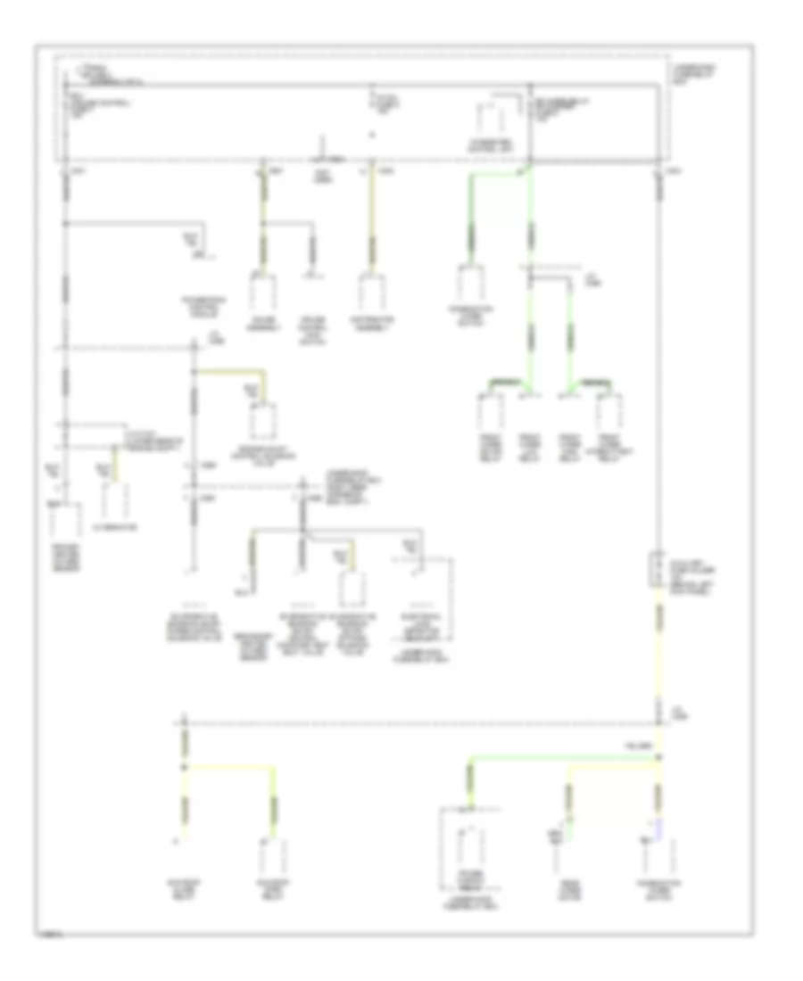
Power Distribution Wiring Diagram (3 of 4) for Honda Odyssey LX 1998
List of elements for Power Distribution Wiring Diagram (3 of 4) for Honda Odyssey LX 1998:
- (not used)
- 7.5a
- A/t reverse relay
- A24
- Abs control unit
- Accessory power socket relay (above left kick panel)
- Accessory socket
- Back-up lights meter lights (turn signals) fuse 1 10a
- C401
- C402
- C404
- C405
- C503
- C601
- C906
- C908
- C909 option connector
- Clock
- Day lights fuse 10 7.5a
- Daytime running lights control unit (canada)
- From f fuse 8 (diagram 1 of 4)
- From fuse 23 (diagram 1 of 4)
- From ignition switch (diagram 1 of 4)
- Fuel pump fuse 2 15a
- G200 (left kick panel)
- G402 (behind left rear side trim panel)
- Gauge assembly
- Hazard warning switch
- Integrated control unit
- J/c c445 (behind right side of dash)
- J/c c610
- Pgm-fi main relay
- Power mirror switch
- Powertrain control module
- R/c mirror fuse 7
- Radio fuse 11 7.5a
- Security system connector (canada)
- Shift lock solenoid
- Srs fuse 3 10a
- Srs unit
- Starter cut relay
- Starter signal fuse 9 7.5a
- To cigarette lighter relay (diagram 2 of 4)
- To fuse 4 (diagram 4 of 4)
- Under-dash fuse/relay box
Power Distribution Wiring Diagram (4 of 4) for Honda Odyssey LX 1998
List of elements for Power Distribution Wiring Diagram (4 of 4) for Honda Odyssey LX 1998:
- (not used)
- Alternator
- Auxiliary fuse holder 10a (behind left kick panel)
- C263
- C265
- C401
- C402
- C404
- C503
- C601
- Combination wiper switch
- Cruise control main switch
- Distributor assembly
- Ecu (cruise control) fuse 4 15a
- Electrical load detector (eld) unit
- Engine mount control solenoid valve
- Evaporative emission (evap) bypass solenoid valve
- Evaporative emission (evap) control canister vent shut valve
- Evaporative emission (evap) purge control solenoid valve
- Fr wiper relay fr washer fuse 6 10a
- From fuse 3 (diagram 3 of 4)
- Front wiper high relay
- Front wiper intermittent relay
- Front wiper low relay
- Front wiper motor relay
- Gauge assembly
- Ig coil fuse 5 15a
- Integrated control unit
- J/c c137 (lower rear of engine compt.)
- J/c c469
- Power window relay
- Powertrain control module
- Primary heated oxygen sensor
- Rear wiper motor
- Secondary heated oxygen sensor
- Sun roof close relay
- Sun roof open relay
- Under-dash fuse/relay box
- Under-hood fuse/relay box
- Under-hood fuse/relay box (right rear corner of eng. compt.)
POWER DOOR LOCKS
Power Door Lock Wiring Diagram, with Keyless Entry for Honda Odyssey LX 1998
List of elements for Power Door Lock Wiring Diagram, with Keyless Entry for Honda Odyssey LX 1998:
- (above left kick panel) security system connector (optional)
- (behind dashboard compartment j/c c443
- 20a
- Battery input
- C262
- C402
- C405
- C416
- C503
- C601
- Door lock fuse 38
- Door open input
- Dr opn in
- Dr opn o
- Driver's door lock actuator
- Driver's door lock key cylinder switch
- Driver's door lock switch
- Driver's door switch
- Front passenger's door lock actuator
- Front passenger's door lock key cylinder switch
- Front passenger's door lock switch
- Front passenger's door switch
- G200 (behind left kick panel)
- G201 (behind right side of glove box)
- G411 (left side of tailgate)
- Gauge assembly
- Ground
- Hot at all times
- Ign key sw in
- Ignition key switch
- In-line diode (under left side of dash)
- Instrument cluster system
- Interior lights system
- J/c c443 (behind dashboard compartment)
- J/c c445 (behind dashboard compartment)
- Keyless door lock control unit (in front of driver's door)
- Left rear door lock actuator
- Left rear door switch
- Lock
- Lock input
- M m
- Pnk
- Right rear door lock actuator
- Right rear door switch
- Safety indicator
- Security system connector (optional) (above left kick panel)
- Security system connector c416 (optional) (above left kick panel)
- Steering lock
- Tailgate latch switch
- Tailgate lock actuator
- Tailgate lock key cylinder switch
- Tailgate open
- Under-dash fuse/relay box
- Under-hood fuse/relay box
- Unlock
- Unlock input
- Unlock/lock out
- Warning systems
Power Door Lock Wiring Diagram, without Keyless Entry for Honda Odyssey LX 1998
List of elements for Power Door Lock Wiring Diagram, without Keyless Entry for Honda Odyssey LX 1998:
- (optional) (above left kick panel)
- 20a
- Battery input
- C262
- C416
- C425
- C436
- Canada
- Door lock fuse 38
- Driver's door lock actuator
- Driver's door lock key cylinder switch
- Driver's door lock switch
- Front passenger's door lock actuator
- Front passenger's door lock key cylinder switch
- Front passenger's door lock switch
- G200 (behind left kick panel)
- G201 (behind right side of glove box)
- G411 (left side of tailgate)
- Ground
- Hot at all times
- J/c
- J/c c443 (behind dashboard compartment)
- Left rear door lock actuator
- Lock
- Lock in
- Lock/unlock out
- Pnk
- Power door lock control unit (in front of driver's door)
- Right rear door lock actuator
- Security system connector
- Security system connector (optional) (above left kick panel) (canada)
- Tailgate lock actuator
- Tailgate lock key cylinder switch
- Under-hood fuse/relay box
- Unlock
- Unlock in
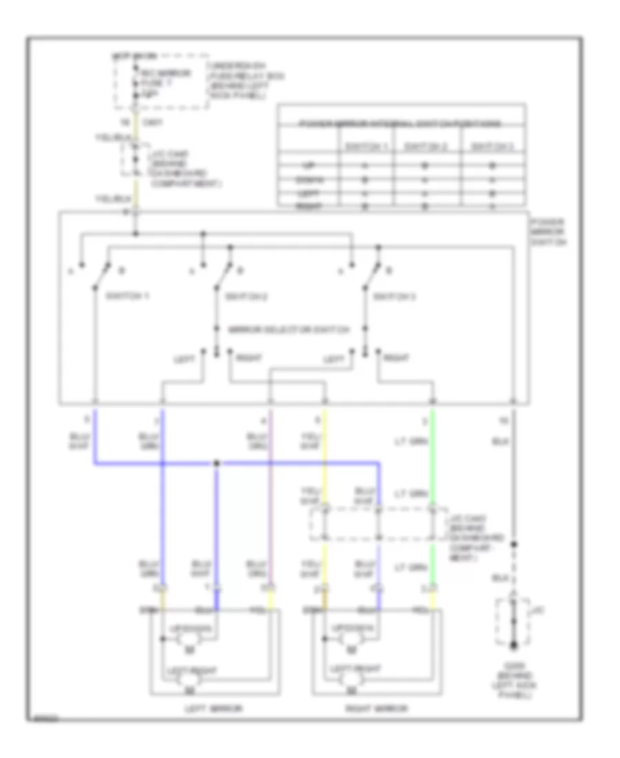
POWER MIRRORS
Power Mirror Wiring Diagram for Honda Odyssey LX 1998
List of elements for Power Mirror Wiring Diagram for Honda Odyssey LX 1998:
- C401
- Down
- G200 (behind left kick panel)
- Hot in on
- J/c
- J/c c443 (behind dashboard compart- ment)
- J/c c445 (behind dashboard compartment)
- Left
- Left mirror
- Left/right
- Mirror selector switch
- Power mirror internal switch positions
- Power mirror switch
- R/c mirror fuse 7 7.5a
- Right
- Right mirror
- Switch 1
- Switch 2
- Switch 3
- Underdash fuse/relay box (behind left kick panel)
- Up/down
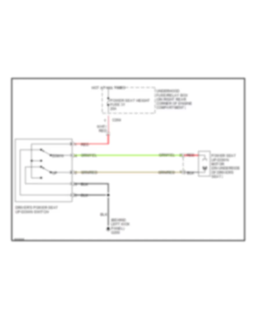
POWER SEATS
Power Seat Wiring Diagrams for Honda Odyssey LX 1998
List of elements for Power Seat Wiring Diagrams for Honda Odyssey LX 1998:
- (behind left kick panel) g200
- C264
- Down
- Driver's power seat up-down switch
- Hot at all times
- Power seat height fuse 31 20a
- Power seat up-down motor (on underside of driver's seat)
- Red
- Underhood fuse/relay box (on right rear corner of engine compartment)
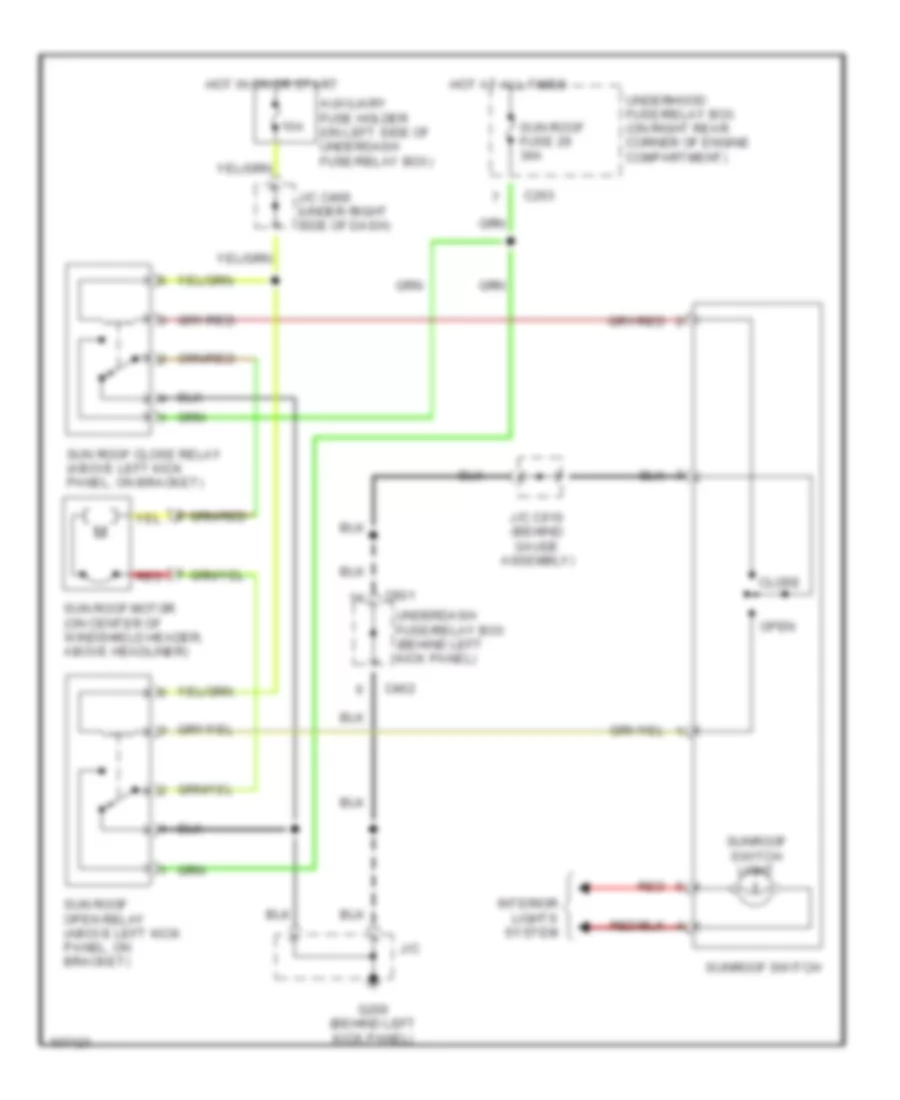
POWER TOP/SUNROOF
Power Top/Sunroof Wiring Diagrams for Honda Odyssey LX 1998
List of elements for Power Top/Sunroof Wiring Diagrams for Honda Odyssey LX 1998:
- 10a
- Auxiliary fuse holder (on left side of underdash fuse/relay box)
- C263
- C402
- C601
- Close
- G200 (behind left kick panel)
- Hot at all times
- Hot in on or start
- Interior lights system
- J/c
- J/c c469 (under right side of dash)
- J/c c610 (behind gauge assembly)
- Open
- Red
- Sun roof close relay (above left kick panel, on bracket)
- Sun roof fuse 29 30a
- Sun roof motor (on center of windshield header, above headliner)
- Sun roof open relay (above left kick panel, on bracket)
- Sunroof switch
- Sunroof switch light
- Underdash fuse/relay box (behind left kick panel)
- Underhood fuse/relay box (on right rear corner of engine compartment)
POWER WINDOWS
Power Window Wiring Diagram for Honda Odyssey LX 1998
List of elements for Power Window Wiring Diagram for Honda Odyssey LX 1998:
- 10a
- Auto dn
- Auxiliary fuse holder
- Battery fuse 15 100a
- C262
- C263
- C402
- C640
- C641
- Control unit
- Driver's window motor
- Front passenger's window motor
- Front passenger's window switch
- G200 (behind left kick panel)
- G201 (behind right side of glove box)
- Hot at all times
- Hot in on or start
- J/c
- J/c c443 (behind dashboard compt.)
- J/c c469
- Left front
- Left rear
- Left rear window motor
- Left rear window switch
- Main switch
- Off
- Power window master switch
- Power window relay
- Pulser
- Pwr win fr lt fuse 28 20a
- Pwr win fr rt fuse 26
- Pwr win rr lt fuse 25 20a
- Pwr win rr rt fuse 24 20a
- Red
- Right front
- Right rear
- Right rear window motor
- Right rear window switch
- Under- hood fuse/ relay box
RADIO
Radio Wiring Diagrams for Honda Odyssey LX 1998
List of elements for Radio Wiring Diagrams for Honda Odyssey LX 1998:
- (+) (+)
- antenna lead
- left rear door speaker
- (+) (+) illumination battery
- (-)
- (option connector)
- (under middle of dash) g206
- Antenna
- C262
- C601
- C908
- Cigarette lighter relay (behind dash, right of steering column) (1997 model) (behind left side of dash, right of steering column) (1998 model)
- Driver's door speaker
- Fuse 15a
- Fuse 7.5a
- G200 (behind left kick panel)
- Ground
- Hot at all times
- Hot in acc or on
- Ignition
- Interior lights system
- J/c 445 (behind top center of dash)
- J/c c423 (behind left side of dash)
- Left tweeter (ex)
- Nca
- Power distribution system (cigarette lighter)
- Red
- Right front door speaker or front passenger's door speaker
- Right rear door speaker
- Right tweeter (ex)
- Stereo radio/ cassette player (or audio unit)
- Under-dash fuse relay box (at left kick panel) (1997 model) (behind left kick panel) (1998 model)
- Under-hood fuse/relay box (on right rear corner of engine compartment)
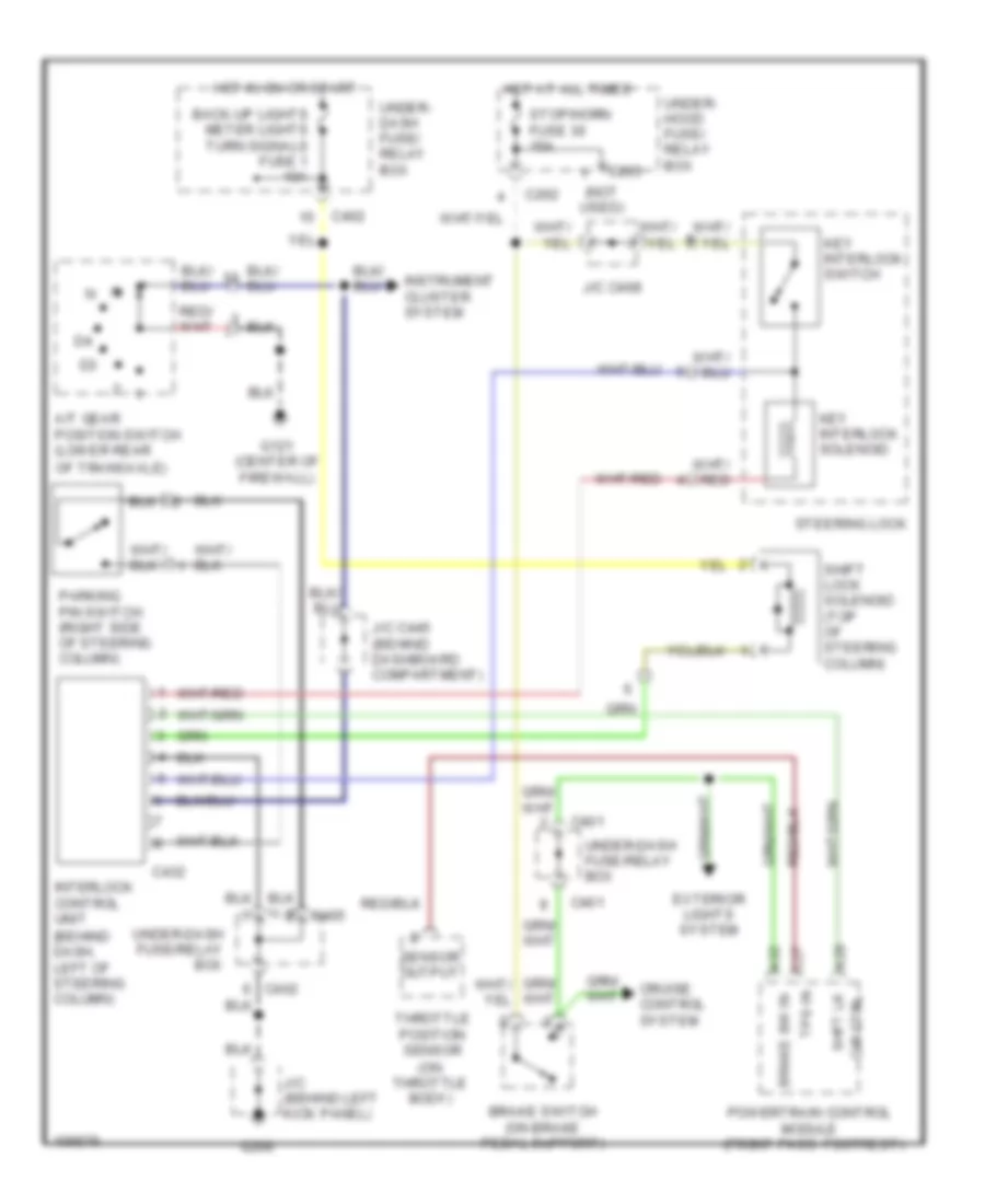
SHIFT INTERLOCKS
Shift Interlock Wiring Diagram for Honda Odyssey LX 1998
List of elements for Shift Interlock Wiring Diagram for Honda Odyssey LX 1998:
- (behind dash, left of steering column)
- (not used)
- (on throttle body)
- A/t gear position switch (lower rear
- A28
- A32
- Back-up lights meter lights turn signals fuse 1 10a
- Brake sw in
- Brake switch (on brake pedal support)
- C262
- C265
- C27
- C401
- C402
- C405
- C432
- Cir ctrl
- Cruise control system
- Exterior lights system
- G121 (center of firewall)
- G200
- Hot at all times
- Hot in on or start
- Instrument cluster system
- Interlock control unit
- J/c (behind left kick panel)
- J/c c445 (behind dashboard compartment)
- J/c c468
- Key interlock solenoid
- Key interlock switch
- Of transaxle)
- Parking pin switch (right side of steering column)
- Powertrain control module (front pass. footrest)
- Sensor output
- Shft lk
- Shift lock solenoid (top of steering column)
- Steering lock
- Stop/horn fuse 30 15a
- Throttle position sensor
- Tps in
- Under- dash fuse/ relay box
- Under- hood fuse/ relay box
- Under-dash fuse/relay box
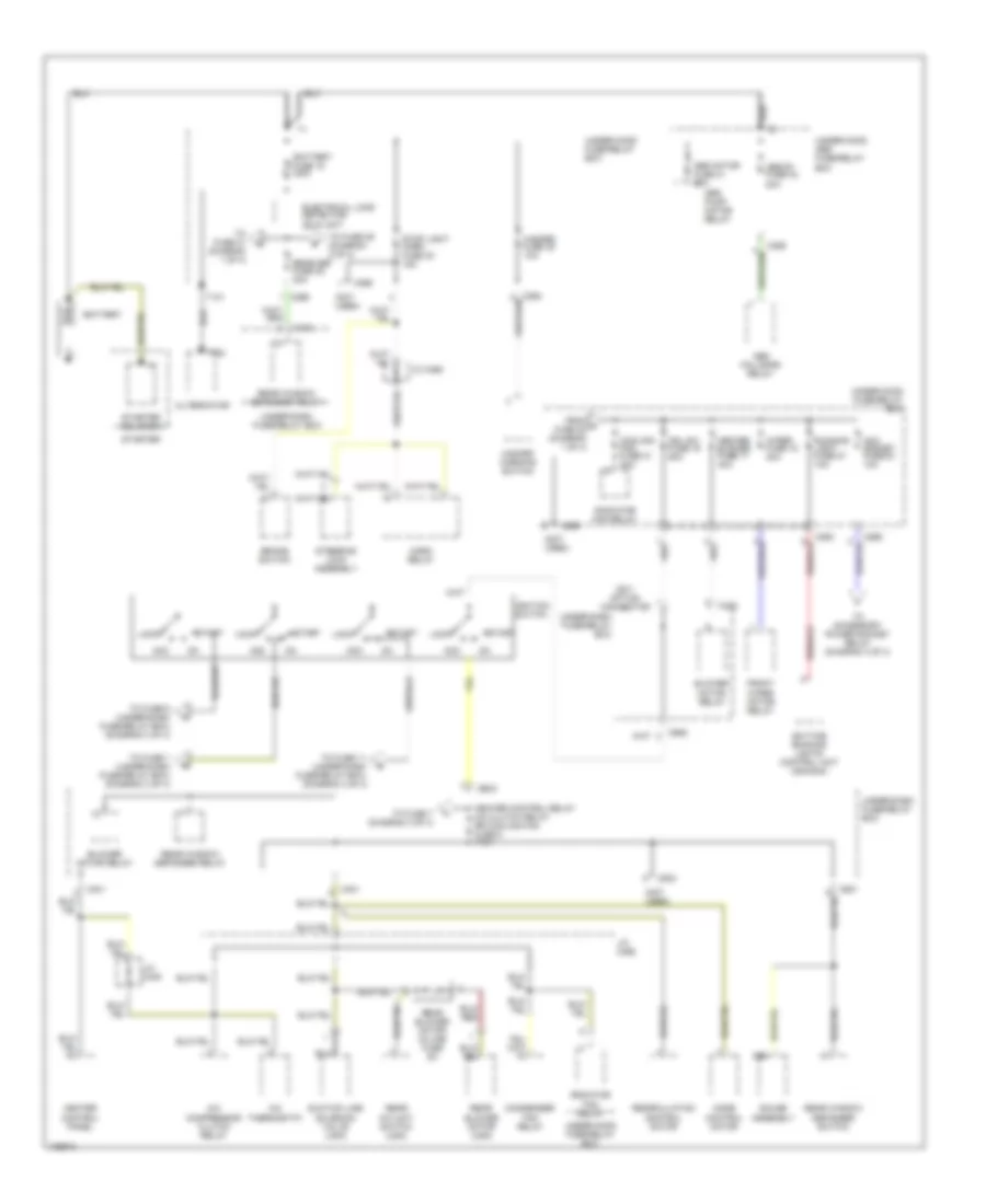
STARTING/CHARGING
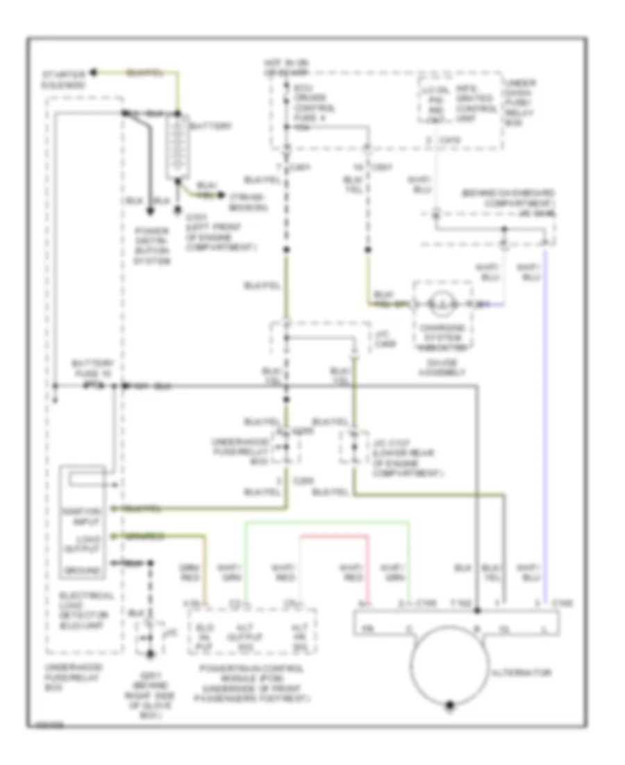
Charging Wiring Diagram for Honda Odyssey LX 1998
List of elements for Charging Wiring Diagram for Honda Odyssey LX 1998:
- (behind dashboard compartment) j/c c445
- (trans- mission)
- A30
- Alt fr sig
- Alt output sig
- Alternator
- Battery
- Battery fuse 15 100a
- C105
- C265
- C401
- C410
- C601
- Charging system indicator
- Ecu cruise control fuse 4 15a
- Eld in- put
- Electrical load detector (eld) unit
- G101 (left front of engine compartment)
- G201 (behind right side of glove box)
- Gauge assembly
- Ground
- Hot in on or start
- Ignition input
- Inte- grated control unit
- J/c
- J/c c137 (lower rear of engine compartment)
- J/c c469
- Lo oil psi ind ckt
- Load output
- Power distri- bution system
- Powertrain control module (pcm) (underside of front passenger's footrest)
- Starter solenoid
- T101
- T102
- Under dash- fuse/ relay box
- Under-hood fuse/relay box
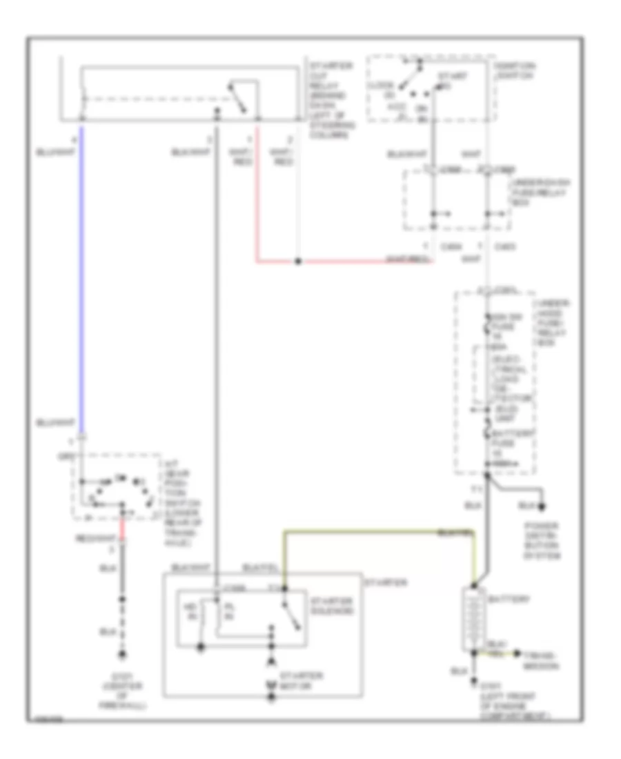
Starting Wiring Diagram for Honda Odyssey LX 1998
List of elements for Starting Wiring Diagram for Honda Odyssey LX 1998:
- A/t gear posi- tion switch (lower rear of trans- axle)
- Acc (i)
- Battery
- Battery fuse 100a
- C109
- C263
- C403
- C404
- C906
- Elec- trical load de- tector (eld) unit
- G101 (left front of engine compartment)
- G121 (center of firewall)
- Hd in
- Ign sw fuse 50a
- Ignition switch
- Lock (0)
- On (ii)
- Pl in
- Power distri- bution system
- Start (iii)
- Starter
- Starter cut relay (behind dash, left of steering column)
- Starter motor
- Starter solenoid
- Trans- mission
- Under- hood fuse/ relay box
- Under-dash fuse/relay box
SUPPLEMENTAL RESTRAINTS
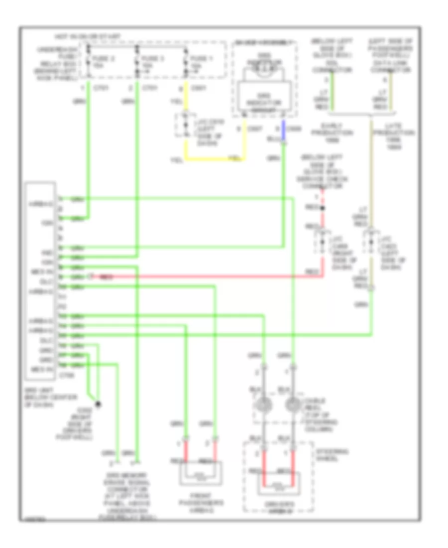
Supplemental Restraint Wiring Diagram for Honda Odyssey LX 1998
List of elements for Supplemental Restraint Wiring Diagram for Honda Odyssey LX 1998:
- (below left side of glove box) sdl connector
- (below left side of glove box) service check connector
- (left side of passenger's footwell) data link connector
- Airbag
- C601
- C607
- C609
- C701
- C706
- Cable reel (top of steering column)
- Dlc
- Driver's airbag
- Early production
- Front passenger's airbag
- Fuse 1 10a
- Fuse 2 15a
- Fuse 3 10a
- G302 (right side of driver's footwell)
- Gauge assembly
- Grd
- Hot in on or start
- Ign
- Ind
- J/c c423 (left side of dash)
- J/c c469 (right side of dash)
- J/c c610 (left side of dash)
- Late production 1998,
- Mes in
- Red
- Srs indicator
- Srs indicator circuit
- Srs memory erase signal connector (at left kick panel, above underdash fuse/relay box)
- Srs unit (below center of dash)
- Steering wheel
- Underdash fuse/ relay box (behind left kick panel)
TRANSMISSION
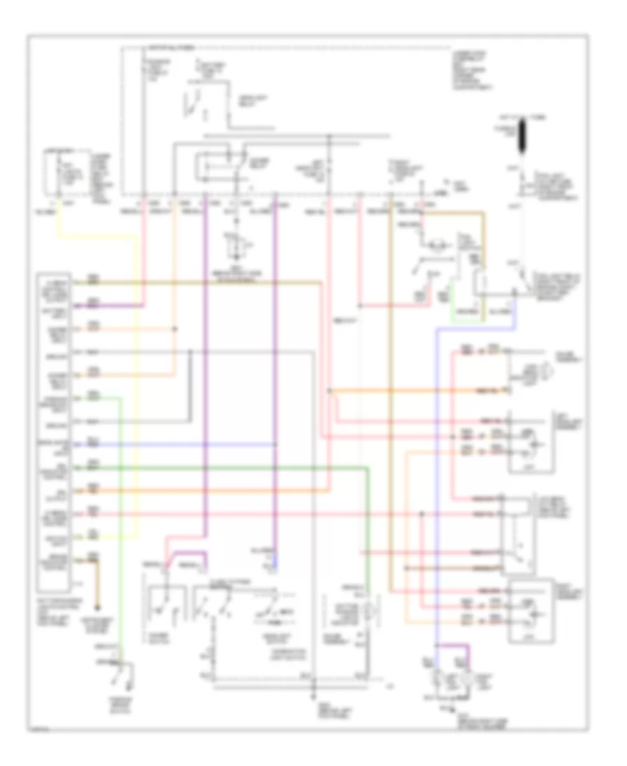
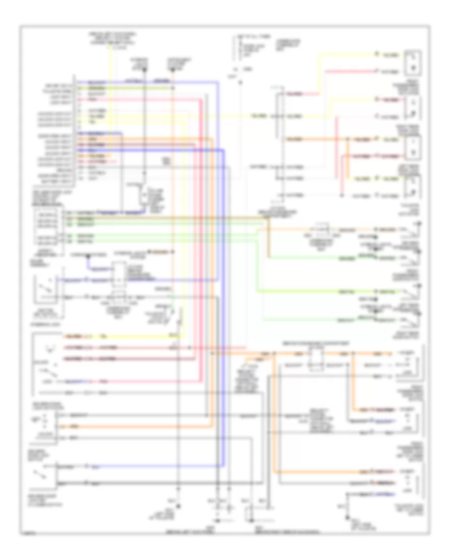
A/T Wiring Diagram for Honda Odyssey LX 1998
List of elements for A/T Wiring Diagram for Honda Odyssey LX 1998:
- (left front of eng)
- (left kick panel)
- (top right of transaxle)
- 2nd clutch pressure switch (left front of transaxle)
- 3rd clutch pressure switch (right rear of transaxle)
- A/t clutch pressure control solenoid valves (top right of transaxle)
- A/t gear position indicator
- A/t gear position switch (lower rear of transaxle)
- A10
- A14
- A21
- A28
- A32
- Atp1
- Atp2
- Atpd3
- Atpd4
- Atpnp
- Atpr
- B10
- B14
- B17
- B18
- B20
- B21
- B22
- B24
- B25
- Bksw
- Box
- Braided
- Brake switch (on brake pedal support)
- C11
- C13
- C14
- C15
- C16
- C19
- C20
- C262
- C401
- C405
- C601
- Countershaft speed sensor (left rear of transaxle)
- Crs
- Cruise control system
- D10
- D11
- D12
- D13
- D14
- D15
- D16
- D4 ind
- Data link connector (left side of front passenger's footwell area)
- Dimming circuit
- Ect
- Engine coolant temperature sensor (right rear of cylinder head)
- Fuel tank pressure sensor
- Fuse 1 10a
- Fuse 10a
- Fuse 15a
- Fuse 7.5a
- G110
- G110 (left front of eng)
- G200
- Gauge assembly
- Hot at all times
- Hot in on or start
- Igp1
- Igp2
- Ilu
- Interior lights system
- Interlock control unit
- J/c c137%% (lower left of engine)
- J/c c469
- J/c c469 (right side of dash)
- K-line
- Lg1
- Lg2
- Ls a+
- Ls a-
- Ls b+
- Ls b-
- Mainshaft speed sensor (lower right rear of transaxle)
- Ncsg
- Nmsg
- Op2sw
- Op3sw
- Pg1
- Pg2
- Pgm-fi main relay (behind dash, left of steering column)
- Pnk
- Powertrain control module (underside of front passenger's footrest)
- Red
- Relay box
- Sg2
- Sh "b"
- Sh "c"
- Sha
- Shift control solenoid valve "a"
- Shift control solenoid valve "b"
- Shift control solenoid valves (right side of transaxle)
- Shift interlock system
- Throttle position sensor (on throttle body)
- Tps
- Under- dash fuse/
- Under- dash fuse/ relay box
- Under- hood fuse/ relay
- Vbsol
- Vbu
- Vcc2
WARNING SYSTEMS
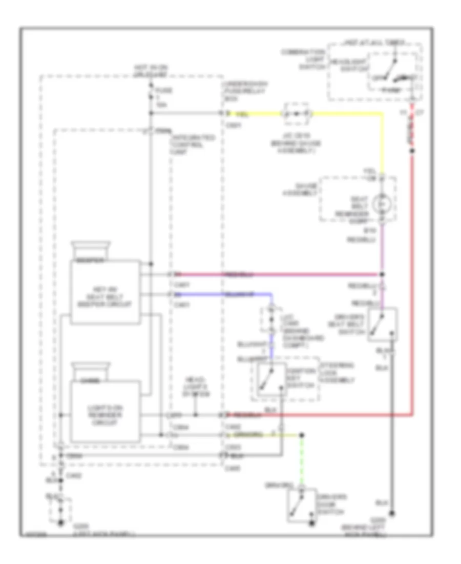
Warning System Wiring Diagrams for Honda Odyssey LX 1998
List of elements for Warning System Wiring Diagrams for Honda Odyssey LX 1998:
- B10
- Beeper
- C401
- C402
- C405
- C503
- C601
- C904
- Chime
- Combination light switch
- Driver's door switch
- Driver's seat belt switch
- Fuse 10a
- G200 (behind left kick panel)
- G200 (left kick panel)
- Gauge assembly
- Head
- Head- lights system
- Headlight switch
- Hot at all times
- Hot in on or start
- Ignition key switch
- Integrated control unit
- J/c c445 (behind dashboard compt)
- J/c c610 (behind gauge assembly)
- Key-in/ seat belt beeper circuit
- Lights-on reminder circuit
- Off
- Park
- Seat belt reminder light
- Steering lock assembly
- Under-dash fuse/relay box
WIPER/WASHER
Front Wiper/Washer Wiring Diagram for Honda Odyssey LX 1998
List of elements for Front Wiper/Washer Wiring Diagram for Honda Odyssey LX 1998:
- (behind left side of front bumper) g100
- (behind right side of glove box)
- (behind right side of glove box) g201
- (not used)
- C263
- C402
- C404
- C405
- C410
- C904
- Combination wiper switch
- Fr wiper relay fr washer fuse 6 10a
- Front washer motor (in washer fluid reservoir)
- Front wiper high relay (behind underhood fuse/relay box)
- Front wiper intermittent relay (behind underhood fuse/relay box)
- Front wiper low relay (behind underhood fuse/relay box)
- Front wiper motor (on center rear of engine compartment)
- Front wiper motor relay (behind underhood fuse/relay box)
- Front wiper/ washer switch
- G200 (behind left kick panel)
- G201
- Ground
- Hot at all times
- Hot in on or start
- Int
- Integrated control unit
- Intermittent dwell time controller
- Intermittent time input
- Intermittent wiper circuit
- Intr rly ctrl out
- Intr wiper in
- J/c c469 (under right side of dash)
- Mist
- Mist switch
- Off
- Park
- Park sw in
- Pnk
- Run
- Underdash fuse/relay box (behind left kick panel)
- Underhood fuse/relay box (on right rear corner of engine compartment)
- Wash
- Wash in
- Washer switch
- Wiper fuse 18 40a
- Wiper switch
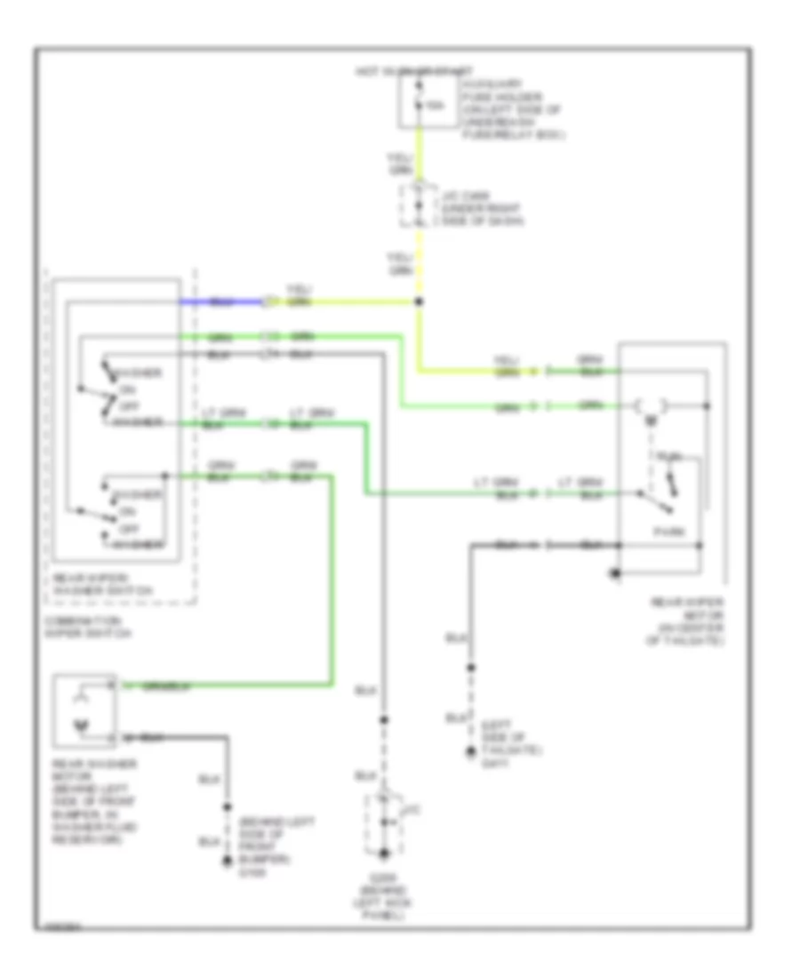
Rear Wiper/Washer Wiring Diagram for Honda Odyssey LX 1998
List of elements for Rear Wiper/Washer Wiring Diagram for Honda Odyssey LX 1998:
- (behind left side of front bumper) g100
- (left side of tailgate) g411
- 10a
- Auxiliary fuse holder (on left side of underdash fuse/relay box)
- Combination wiper switch
- G200 (behind left kick panel)
- Hot in on or start
- J/c
- J/c c469 (under right side of dash)
- Off
- Park
- Rear washer motor (behind left side of front bumper, in washer fluid reservoir)
- Rear wiper motor (in center of tailgate)
- Rear wiper/ washer switch
- Run
- Washer