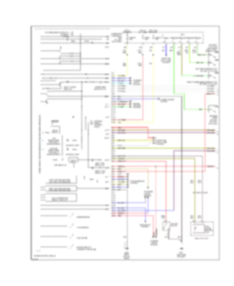
AIR CONDITIONING
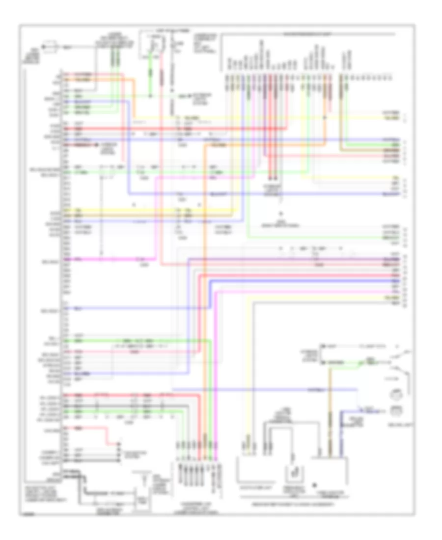
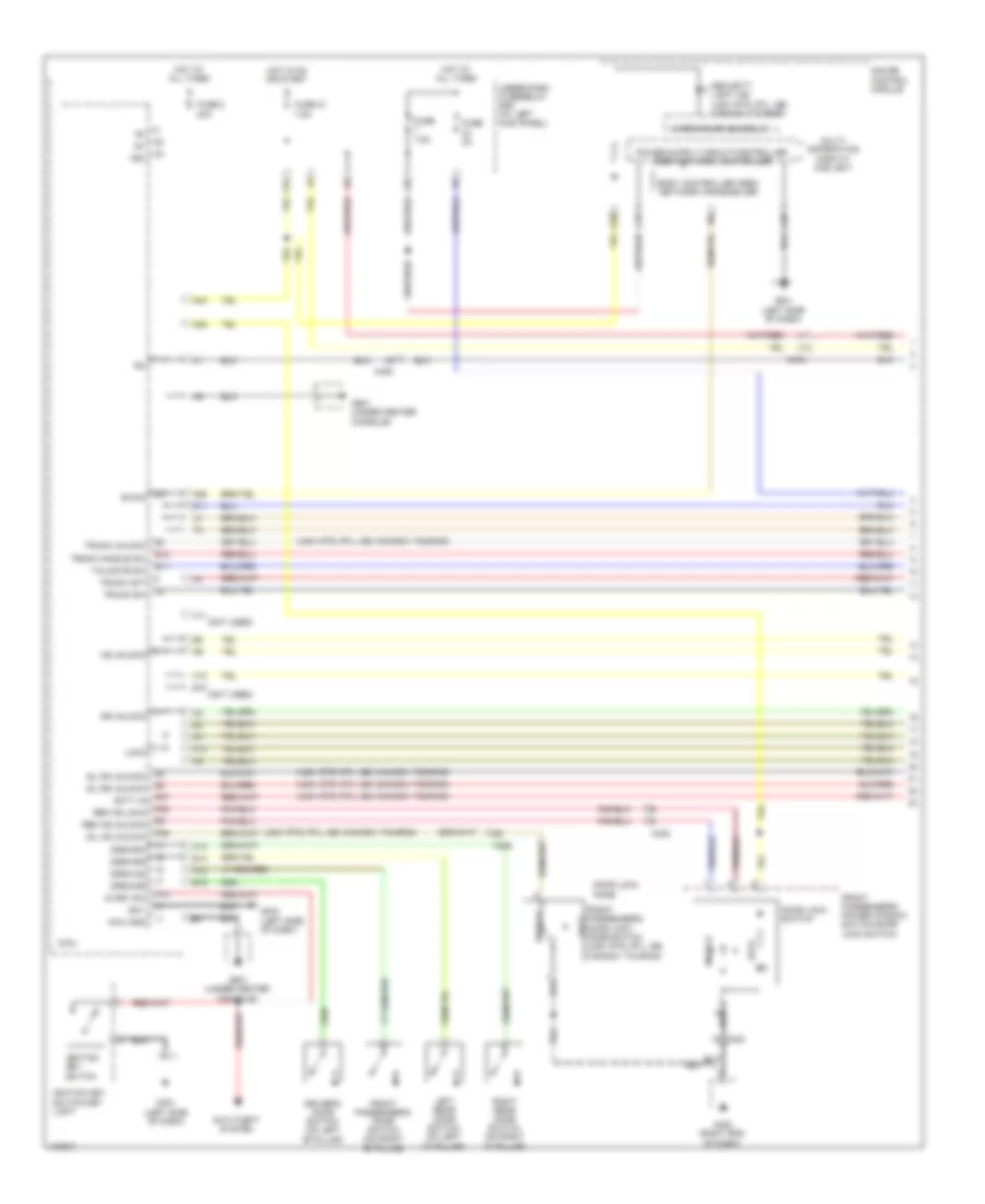
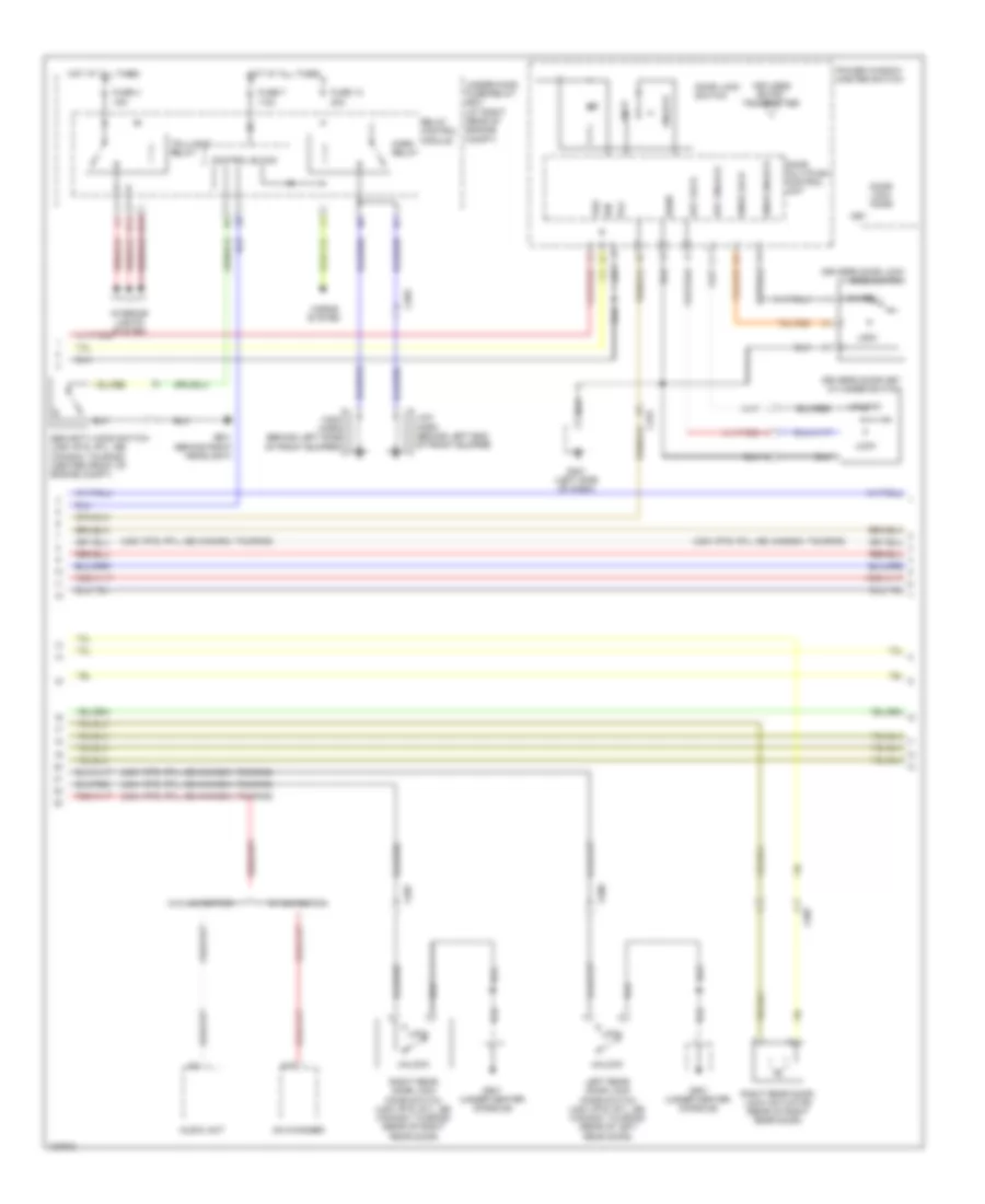
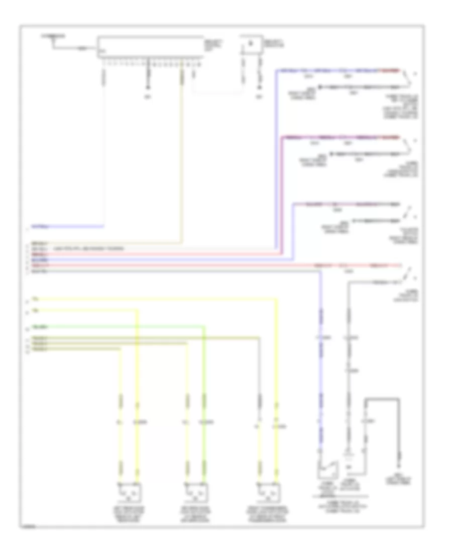
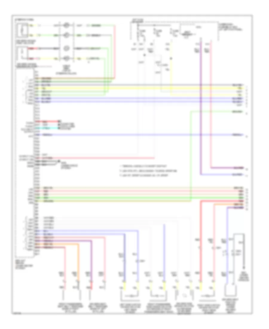
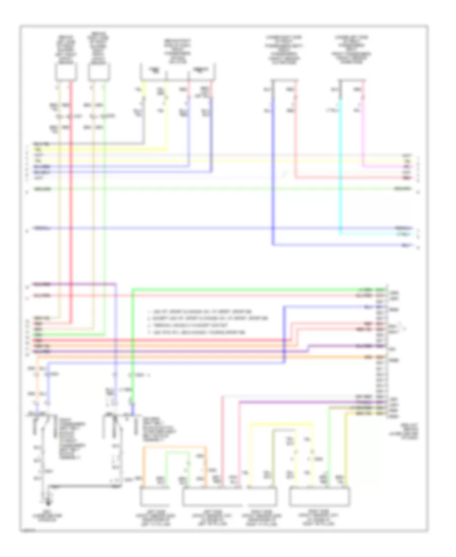
Automatic A/C Wiring Diagram (1 of 2) for Honda Ridgeline RTS 2014

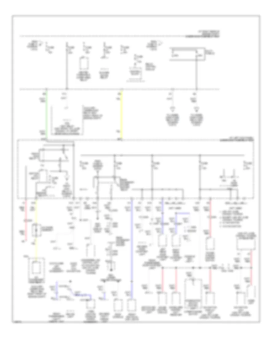
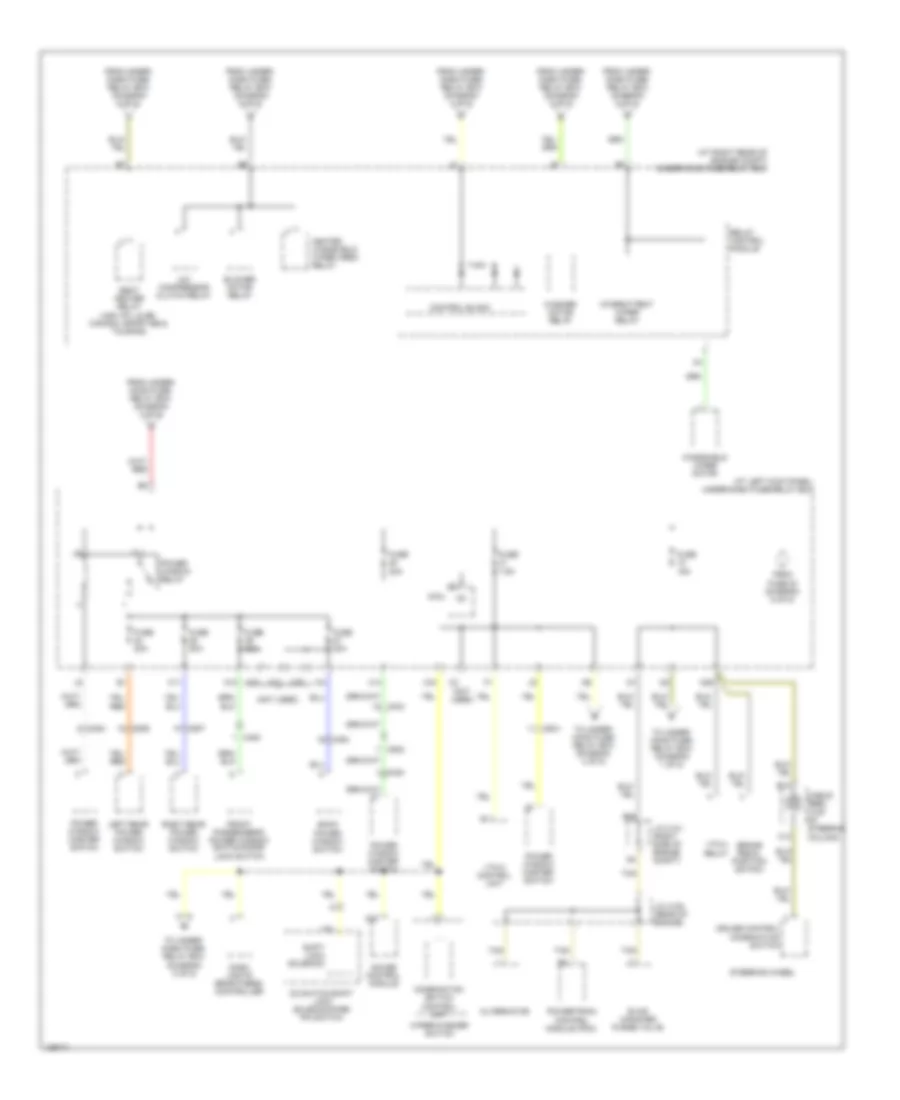
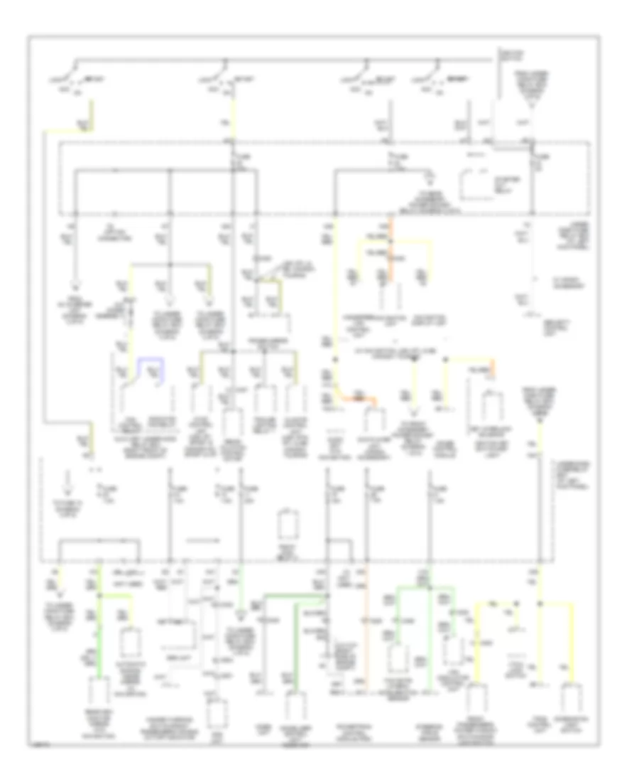
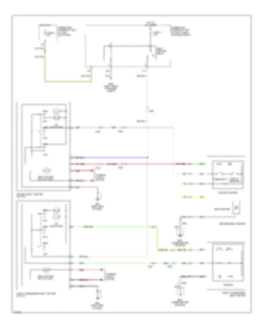
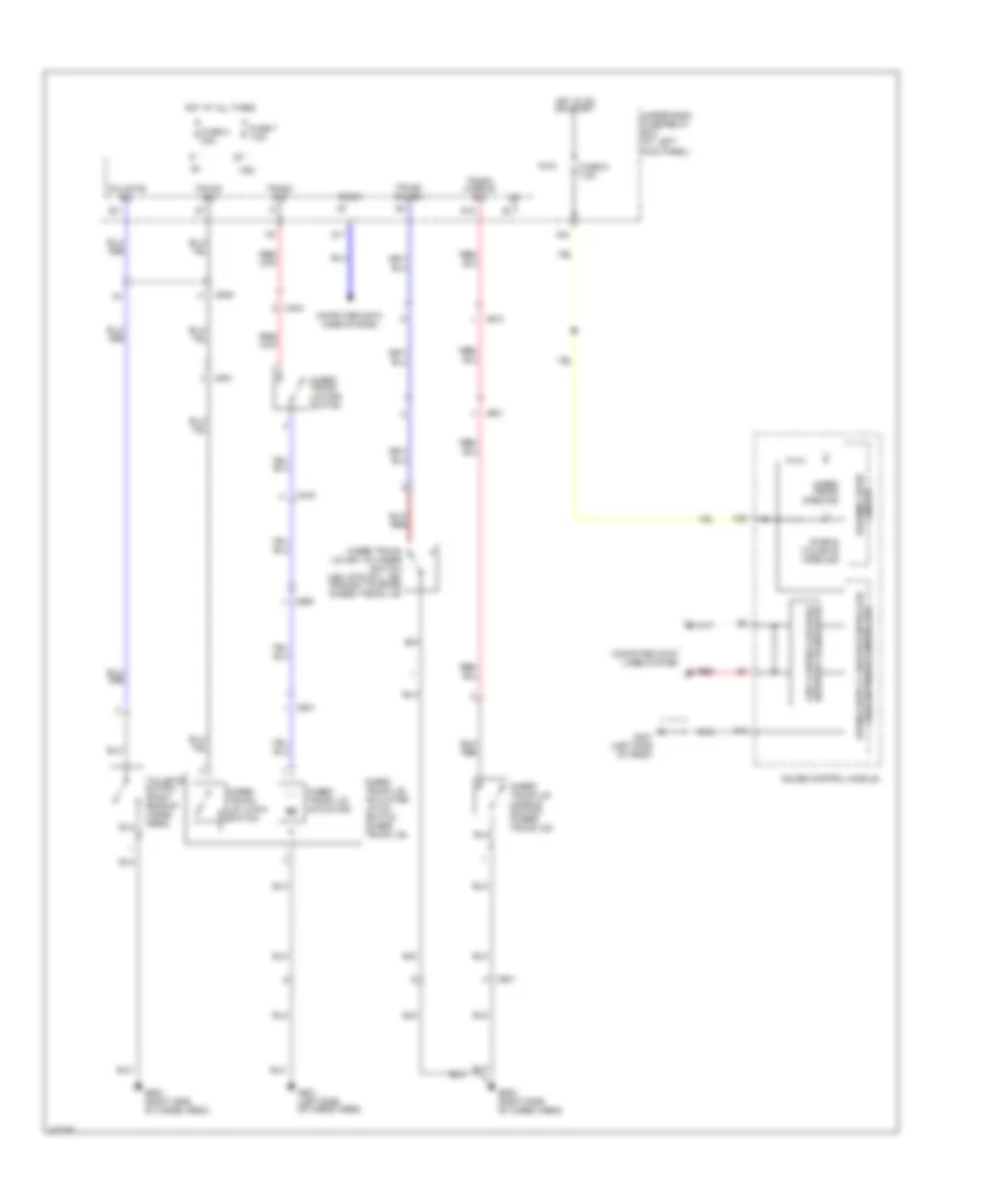
List of elements for Automatic A/C Wiring Diagram (1 of 2) for Honda Ridgeline RTS 2014:
- (right rear of engine compt)
- (right side of hvac unit)
- (right side of hvac unit) mode control motor
- 5v(+)
- A/c pres sw
- A/c pressure switch (right side of engine compt)
- Ac-ck
- Ac-si
- Ac-so
- Amd-p
- Amd-p as
- Amd-p dr
- B-can
- B20
- B21
- Blwr fdbk
- C204
- C405
- C407
- Climate control unit
- Computer data
- Computer data lines system
- Control block
- Driver's air mix control motor (left side of hvac unit)
- Evap sens
- Evaporator temperature sensor (bottom left of hvac unit)
- Fresh
- Front passenger's air mix control motor
- Frs
- G202
- G401 (left side of dash)
- Gnd
- Ig2
- Illum(+)
- Illum(-)
- In-car
- In-car temperature sensor (lower left side of dash)
- Interior lights system
- Lines system
- M-cool
- M-cool as
- M-cool dr
- M-def
- M-hot
- M-hot as
- M-hot dr
- M-vent
- Mode 1
- Mode 2
- Mode 3
- Navigation unit (usa: rtl) (canada: touring) (under driver's seat)
- Outside air
- Outside air temperature sensor (behind front grille)
- Pnk
- Pwr trns ctl
- Rec
- Recirculate
- Recirculation control motor (left side of blower unit)
- Red
- Relay control module
- S-com
- S5v
- Sun sens
- Sunlight sensor (top center of dash)
- Under-hood fuse/relay box (at right rear of engine compt)
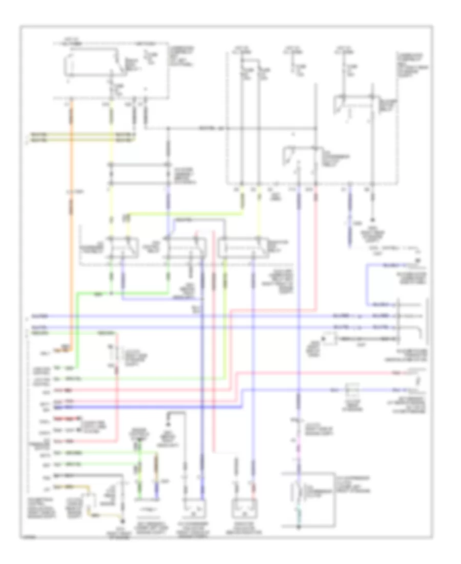
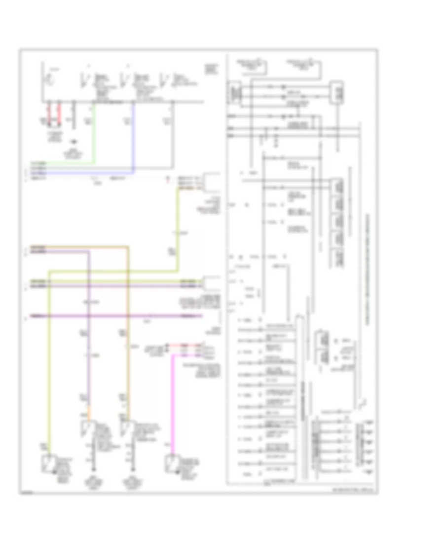
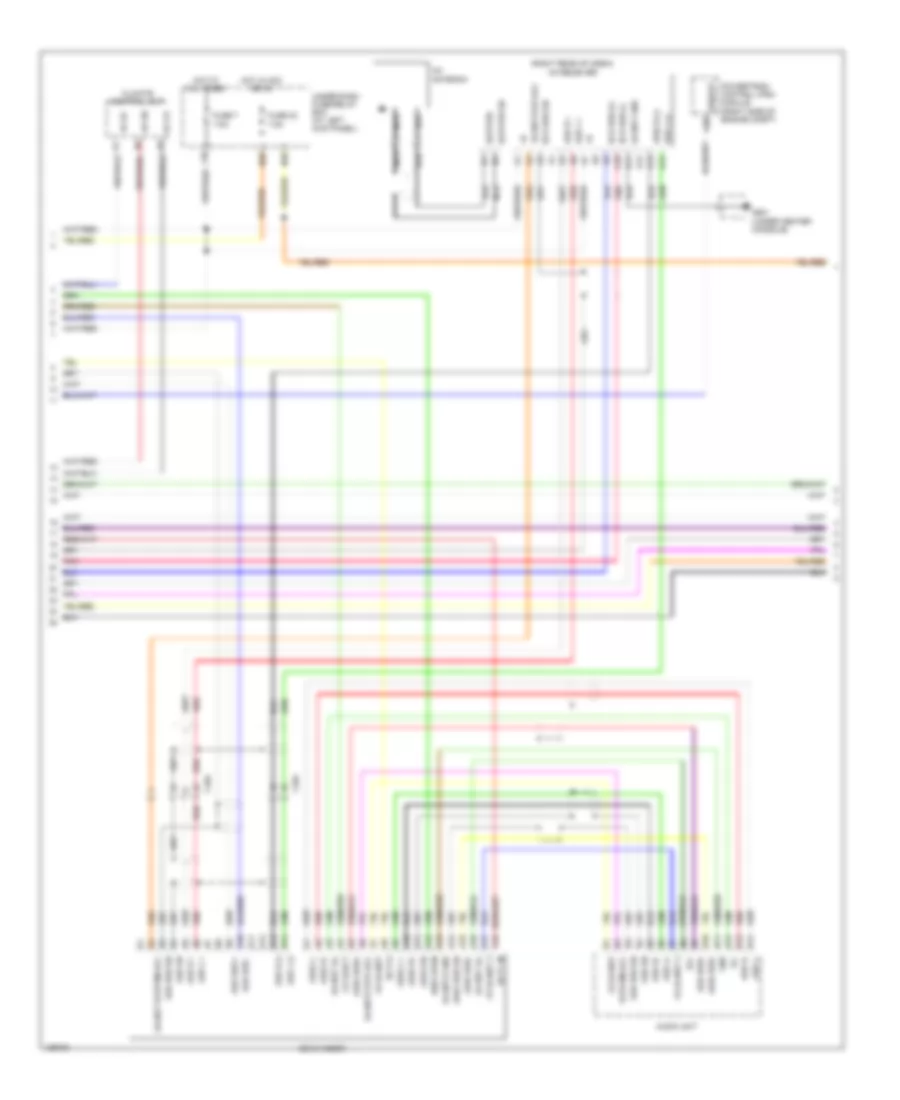
Automatic A/C Wiring Diagram (2 of 2) for Honda Ridgeline RTS 2014
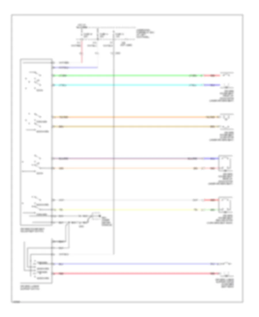
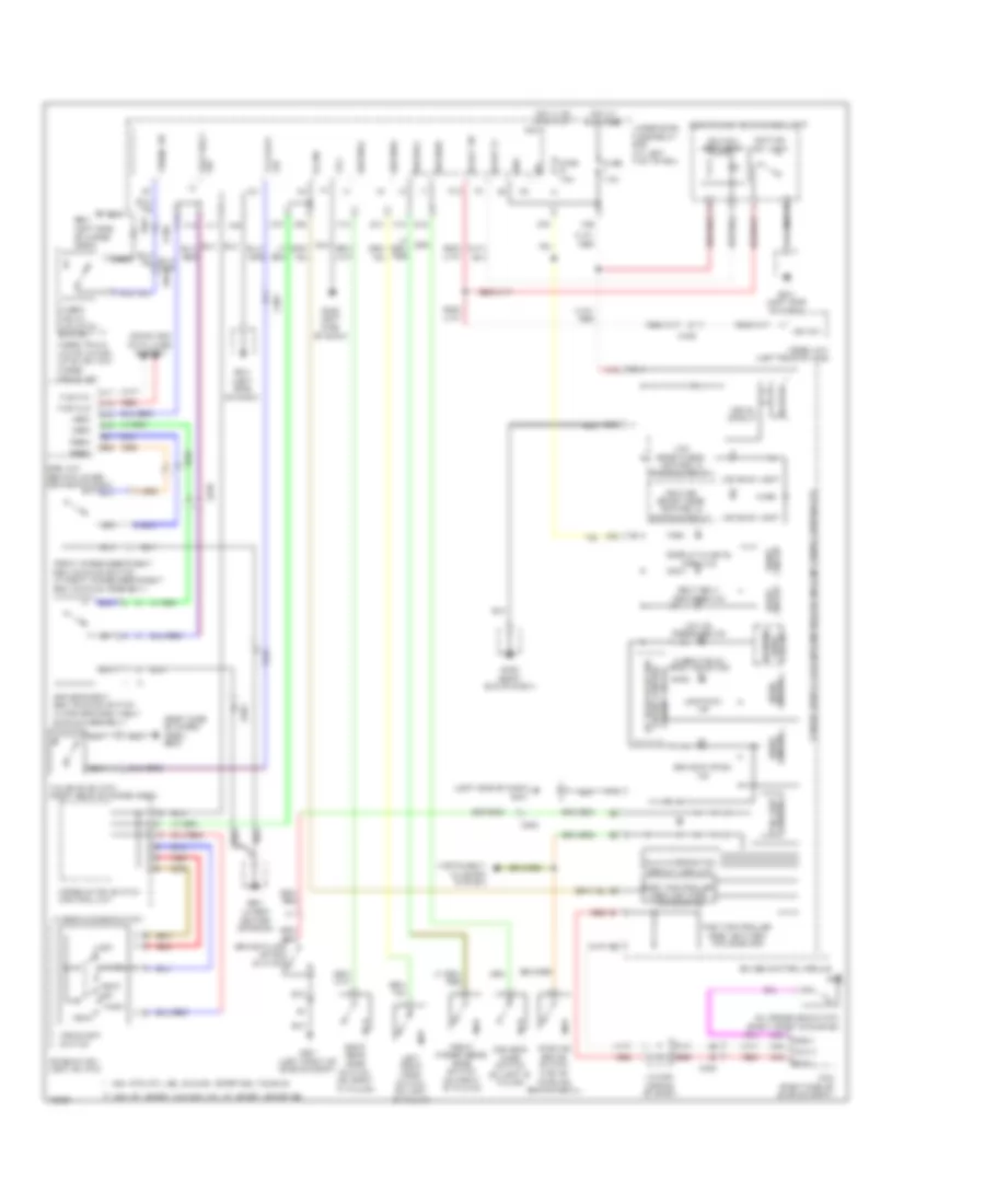
List of elements for Automatic A/C Wiring Diagram (2 of 2) for Honda Ridgeline RTS 2014:
- (not used)
- A/c compressor clutch
- A/c compressor clutch (lower left front of engine)
- A/c compressor clutch relay
- A/c condenser fan motor (front middle of engine compt)
- A/c condenser fan relay
- A/c diode assembly (behind glove box)
- A/c pressure switch
- A13
- A20
- A21
- A37
- A48
- A49
- Acc
- Auxiliary under-hood relay box (right front of engine compt)
- B19
- B34
- Blower motor (under right side of dash)
- Blower motor relay
- Blower power transistor (near blower motor)
- Box (at right rear of engine compt)
- C14
- C204
- C206
- C251
- C32
- C407
- C41
- Can-h
- Can-l
- Computer data lines system
- D16
- E15
- Ect sensor 1 (at rear of engine, on top of water passage)
- Ect sensor 2 (under left side engine compt)
- Ect1
- Ect2
- Engine controls system
- F10
- Fan control relay
- Fuse 10a
- Fuse 30a
- Fuse 40a
- Fuse 7.5a
- G101 (right front of engine)
- G201 (behind right headlight)
- G202 (right rear of engine compt)
- G402 (right end of dash)
- High fan control
- Hot at all times
- Hot in on
- J/c c101 (right side of engine compt)
- J/c c104 (middle rear of engine compt)
- J/c c105 (rear of engine)
- Lg1
- Low fan control
- Mrly
- N20
- Pg2
- Pgm-fi main relay 1
- Pnk
- Powertrain control module (pcm) (right side of engine compt)
- Radiator fan motor (behind radiator)
- Radiator fan relay
- Red
- Sg1
- Sg7
- Under-dash fuse/relay box (at left kick panel)
- Under-hood fuse/relay
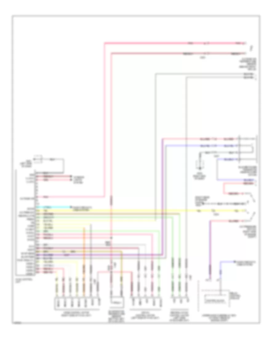
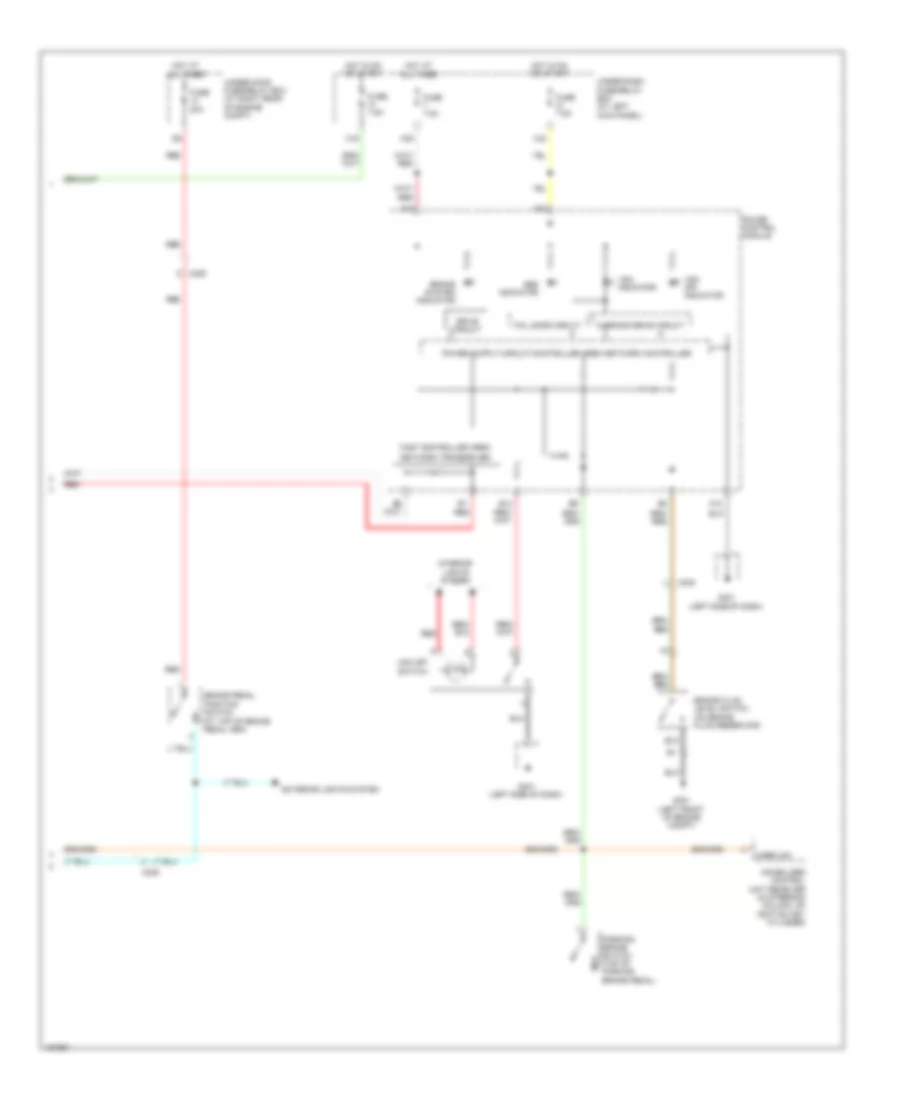
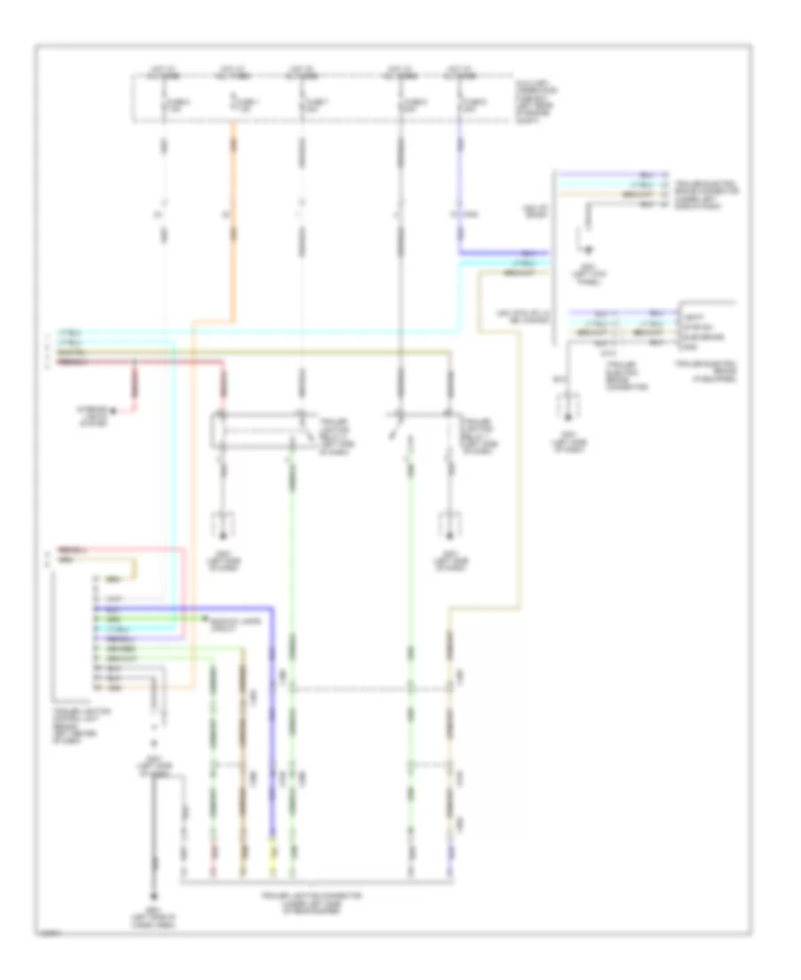
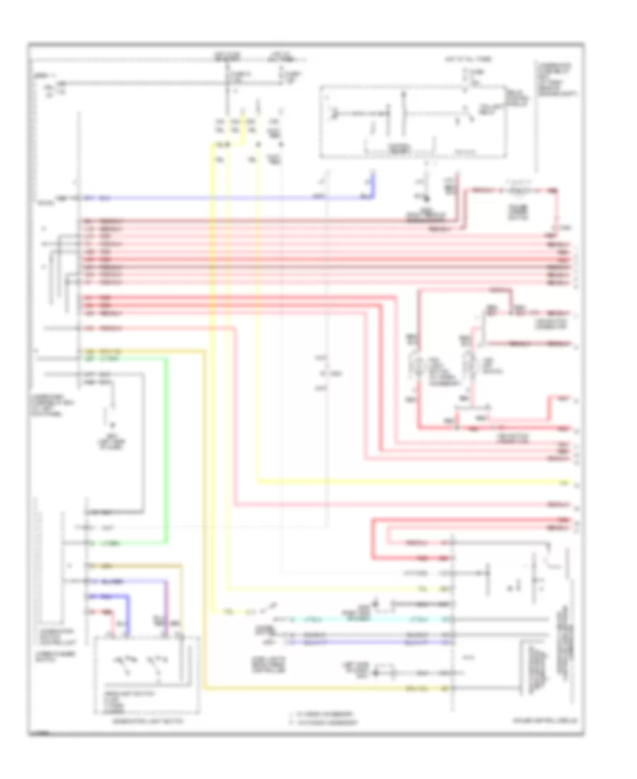
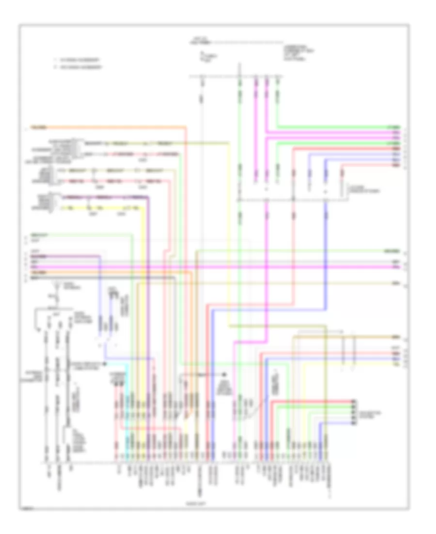
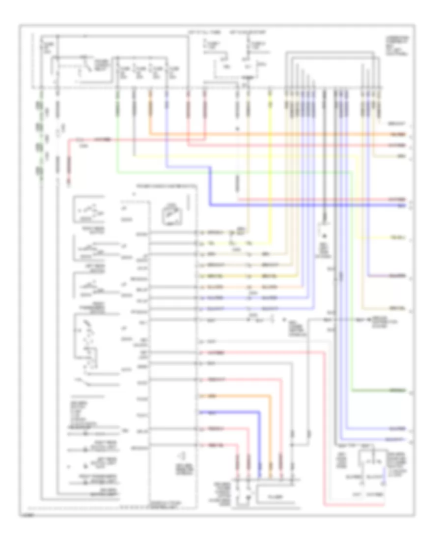
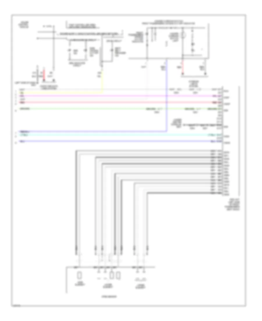
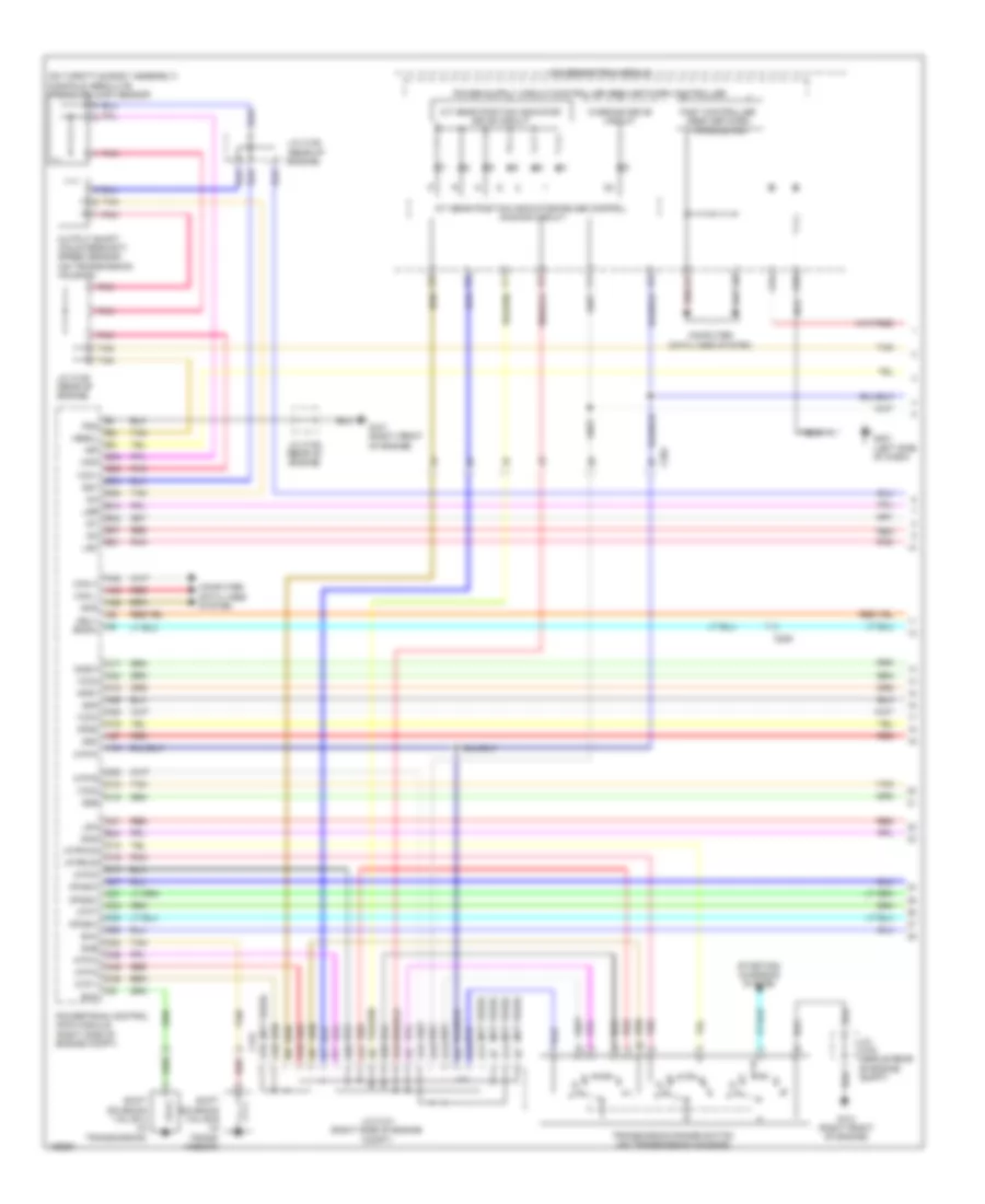
Manual A/C Wiring Diagram (1 of 2) for Honda Ridgeline RTS 2014
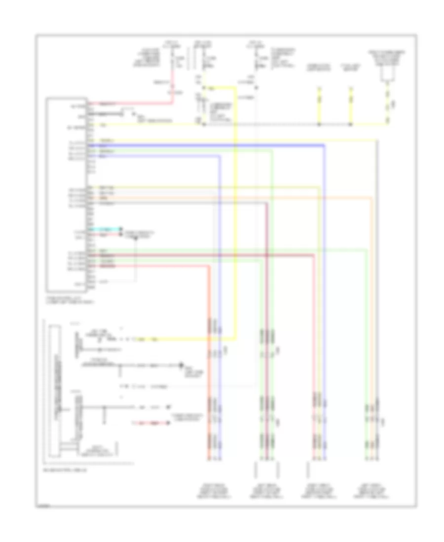
List of elements for Manual A/C Wiring Diagram (1 of 2) for Honda Ridgeline RTS 2014:
- (right rear of engine compt)
- 5v(+)
- A/c pres sw
- A/c pressure switch (right side of engine compt)
- Air mix control motor (left side of hvac unit)
- Amd-p
- B-can
- Blower power transistor (near blower motor)
- Blwr fdbk
- C204
- C407
- Computer data lines system
- Control block
- Evap sens
- Evaporator temperature sensor (bottom left of hvac unit)
- Fresh
- Frs
- G202
- G401 (left side of dash)
- G402 (right end of dash)
- Gnd
- Hvac control unit
- Ig2
- Illum(+)
- Illum(-)
- Interior lights system
- M-cool
- M-def
- M-hot
- M-vent
- Mode 1
- Mode 2
- Mode 3
- Mode 4
- Mode control motor (right side of hvac unit)
- Outside air
- Outside air temperature sensor (behind front grille)
- Pnk
- Pwr trns ctl
- Rec
- Recirculate
- Recirculation control motor (left side of blower unit)
- Red
- Relay control module
- S-com
- S5v
- Under-hood fuse/relay box (at right rear of engine compt)
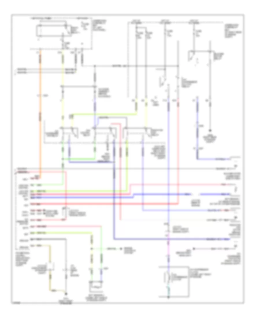
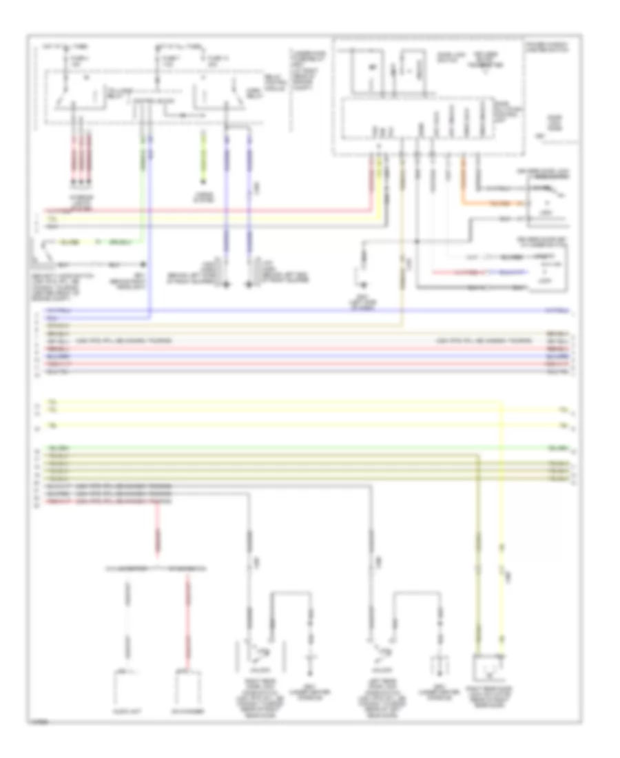
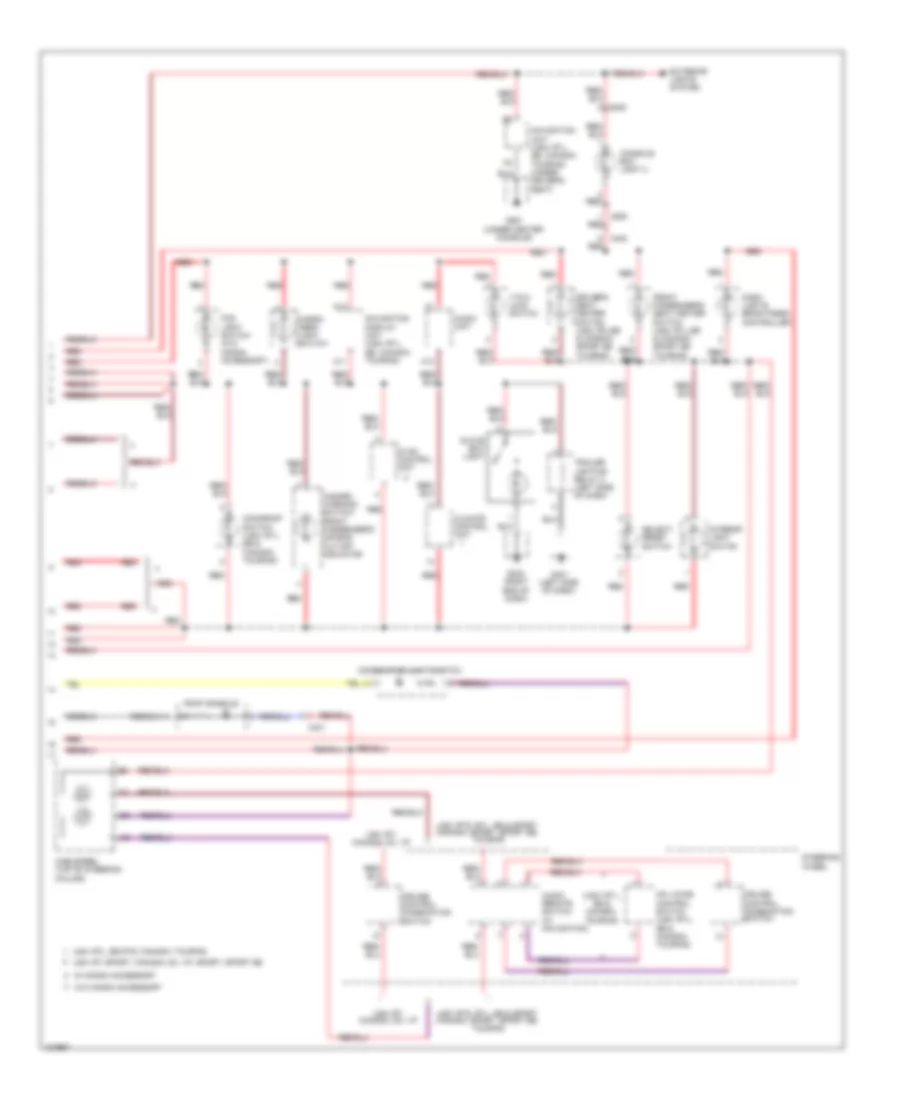
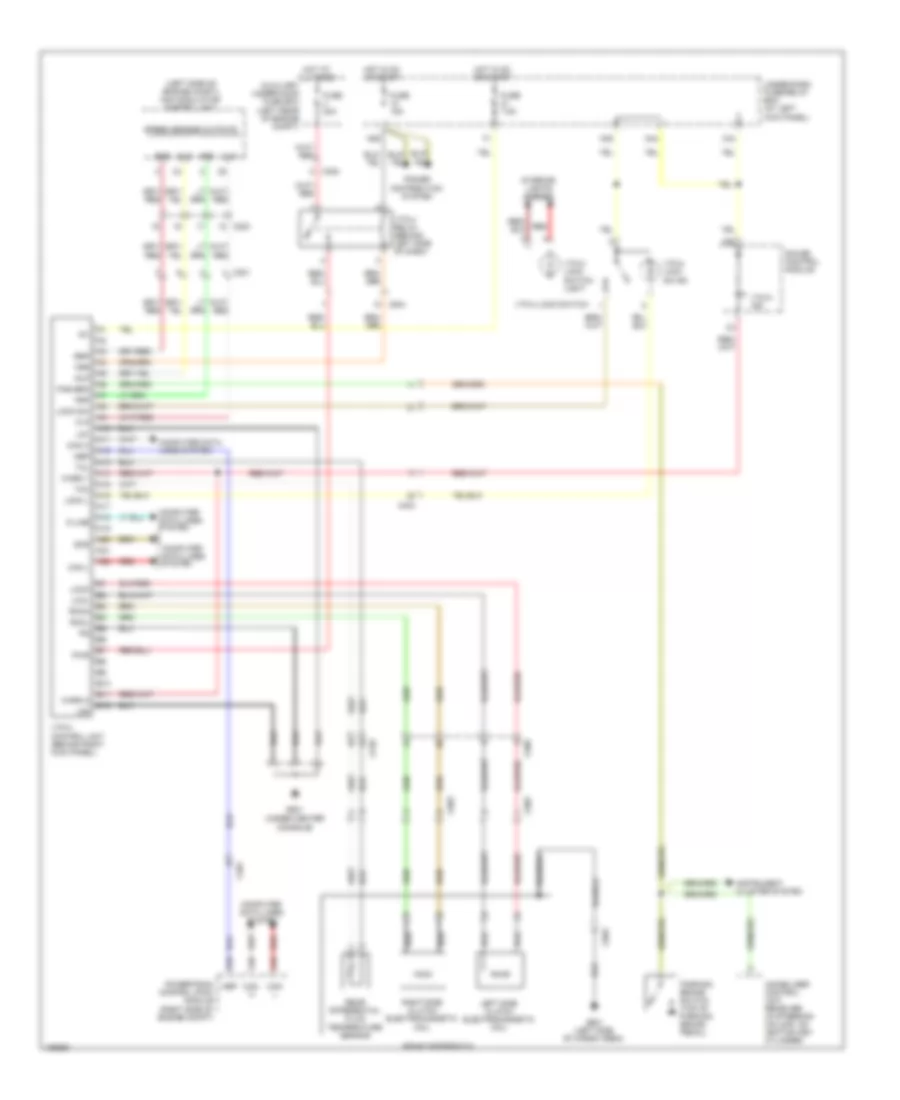
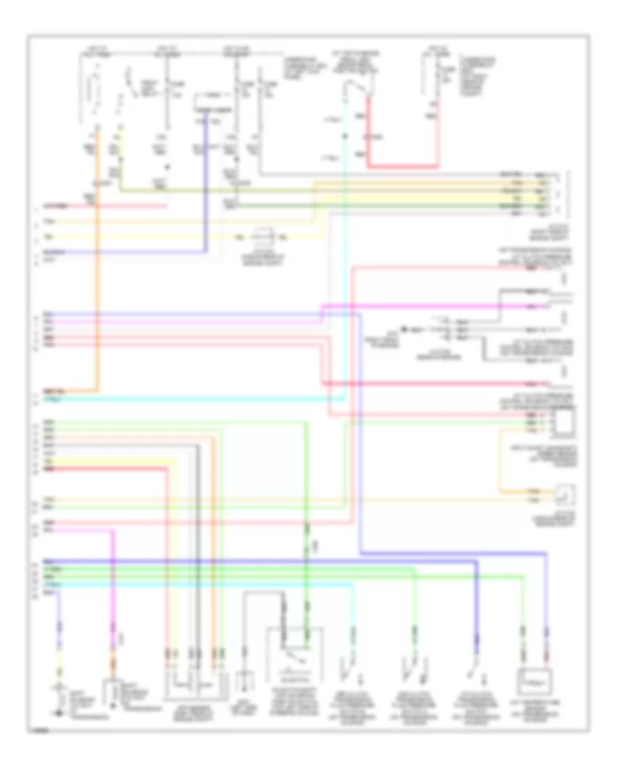
Manual A/C Wiring Diagram (2 of 2) for Honda Ridgeline RTS 2014
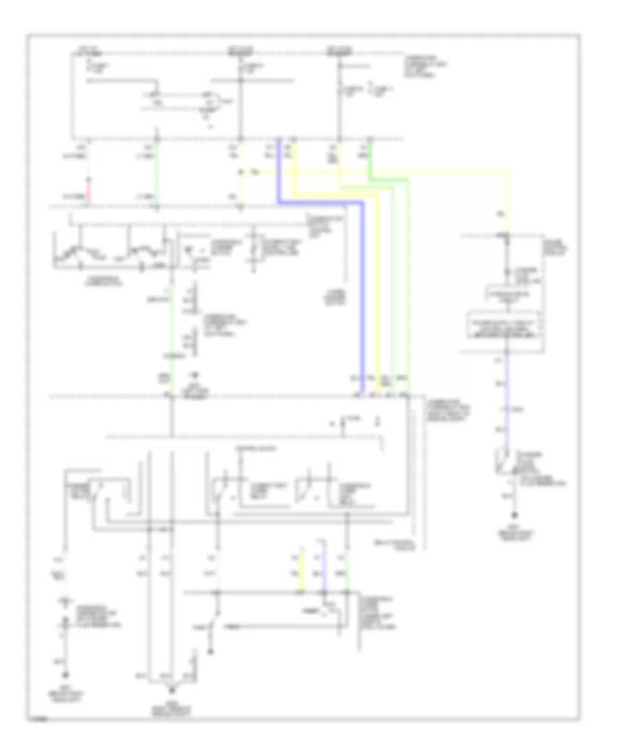
List of elements for Manual A/C Wiring Diagram (2 of 2) for Honda Ridgeline RTS 2014:
- (not used)
- A/c compressor clutch
- A/c compressor clutch (lower left front of engine)
- A/c compressor clutch relay
- A/c condenser fan motor (front middle of engine compt)
- A/c condenser fan relay
- A/c diode assembly (behind glove box)
- A/c pressure switch
- A13
- A20
- A21
- A37
- A48
- A49
- Acc
- Auxiliary under-hood relay box (right front of engine compt)
- B19
- B34
- Blower motor (under right side of dash)
- Blower motor relay
- C14
- C204
- C206
- C207
- C251
- C32
- C41
- Can-h
- Can-l
- Computer data lines system
- D16
- E15
- Ect sensor 1 (at rear of engine, on top of water passage)
- Ect sensor 2 (under left side of of engine compt)
- Ect1
- Ect2
- Engine controls system
- F10
- Fan control relay
- Fuse 10a
- Fuse 30a
- Fuse 40a
- Fuse 7.5a
- G101 (right front of engine)
- G201 (behind right headlight)
- G202 (right rear of engine compt)
- Ground
- High fan control
- Hot at all times
- Hot in on
- J/c c101 (right side of engine compt)
- J/c c104 (middle rear of engine compt)
- J/c c105 (rear of engine)
- Low fan control
- Mrly
- N20
- Pgm-fi main relay 1
- Pnk
- Powertrain control module (pcm) (right side of engine compt)
- Radiator fan motor (behind radiator)
- Radiator fan relay
- Red
- Sg1
- Sg7
- Under-dash fuse/relay box (at left kick panel)
- Under-hood fuse/relay box (at right rear of engine compt)
ANTI-LOCK BRAKES
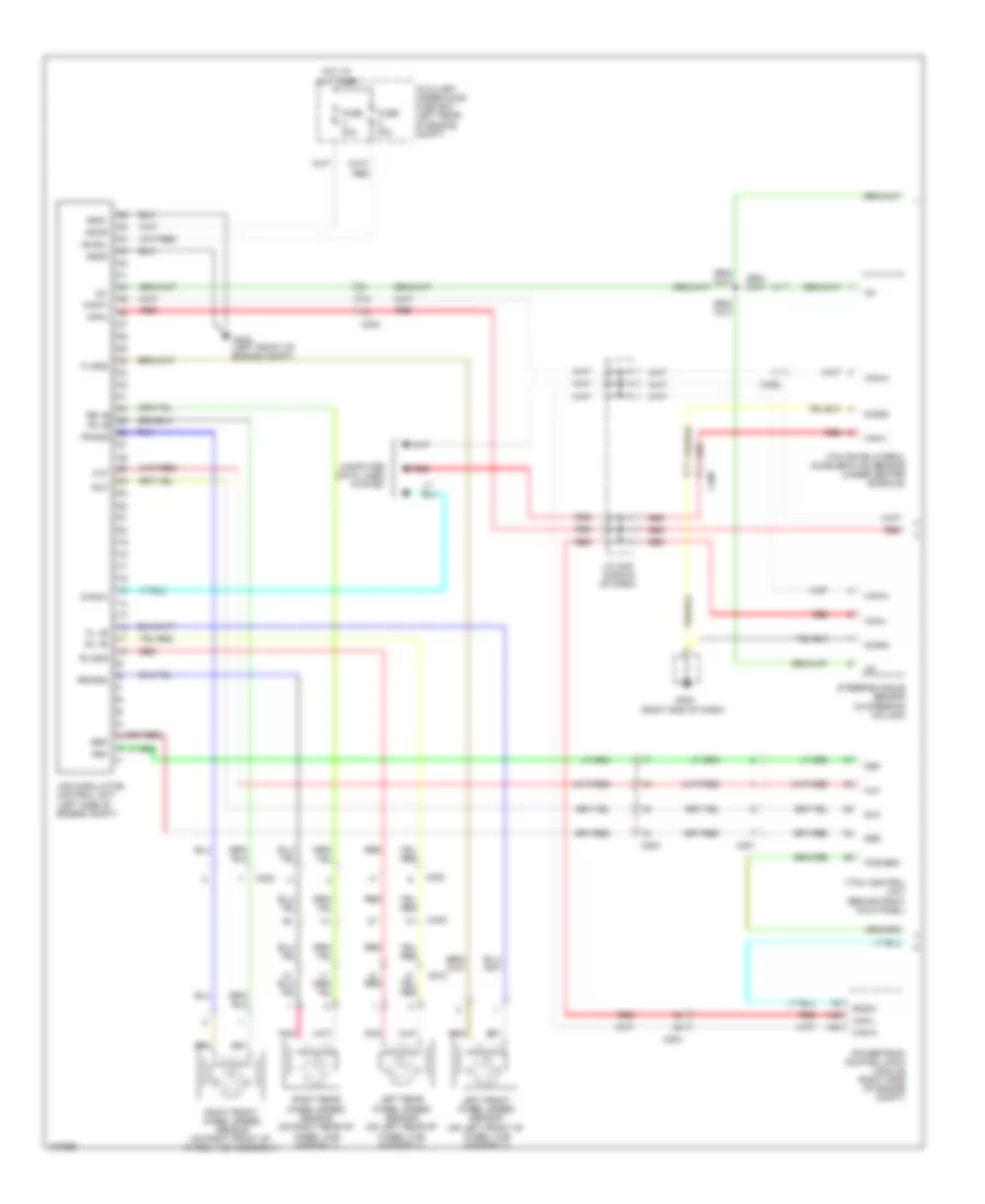
Anti-lock Brakes Wiring Diagram (1 of 2) for Honda Ridgeline RTS 2014
List of elements for Anti-lock Brakes Wiring Diagram (1 of 2) for Honda Ridgeline RTS 2014:
- (behind right kick panel)
- (left side of engine compt)
- (right end of dash)
- +b sol
- +b-mr
- A48
- A49
- Auxiliary under-hood fuse box (left rear of engine compt)
- Bksw
- C201
- C203
- C204
- C302
- C402
- C406
- C510
- Can-h
- Can-l
- Computer data lines system
- Diag-k
- Fl +b
- Fl-gnd
- Flp
- Fr +b
- Fr-gnd
- Frp
- Fuse 20a
- Fuse 40a
- G302 (left front of engine compt)
- G402
- Gnd1
- Gnd2
- Hot at all times
- Ig1
- J/c c451 (middle of dash)
- Left front wheel speed sensor (on left front of wheel hub assembly)
- Left rear wheel speed sensor (on left rear of wheel hub assembly)
- Par brk
- Pnk
- Powertrain control (pcm) module (right side of engine compt)
- Red
- Right front wheel speed sensor (on right front of wheel hub assembly)
- Right rear wheel speed sensor (on right rear of wheel hub assembly)
- Rl +b
- Rl-gnd
- Rlp
- Rr +b
- Rr-gnd
- Rrp
- S-gnd
- Steering angle sensor (in steering column)
- Vsa modulator control unit
- Vtm-4 control unit
- Yaw rate-lateral acceleration sensor (under center console)
Anti-lock Brakes Wiring Diagram (2 of 2) for Honda Ridgeline RTS 2014
List of elements for Anti-lock Brakes Wiring Diagram (2 of 2) for Honda Ridgeline RTS 2014:
- A10
- A19
- A20
- Abs indicator
- B14
- Brake fluid level switch (on brake fluid reservoir)
- Brake pedal position switch (at top of brake pedal arm)
- Brake system indicator
- C205
- C302
- Drive circuit
- Exterior lights system
- Fail safe circuit
- Fast controller area
- Fuse 20a
- Fuse 7.5a
- G301 (left front of engine compt)
- G401 (left side of dash)
- Gauge control module
- H/brk sw
- Hot at all times
- Hot in on or start
- Immobilizer control unit receiver (in steering column, on ignition key cylinder)
- Interior lights system
- Network transceiver
- Parking brake switch (top of parking brake pedal)
- Red
- Under-dash fuse/relay box (at left kick panel)
- Under-hood fuse/relay box (at right rear of engine compt)
- Vsa indicator
- Vsa off indicator
- Vsa off switch
- Warning drive circuit
- X16
- X34
- X35
ANTI-THEFT
Forced Entry Wiring Diagram (1 of 3) for Honda Ridgeline RTS 2014
List of elements for Forced Entry Wiring Diagram (1 of 3) for Honda Ridgeline RTS 2014:
- (not used)
- (usa: rts, rtl, se; canada: touring)
- 20a
- 7.5a
- A10
- A19
- A20
- Anti-theft system
- As unlock
- B-can
- Body controller area network transceiver
- C408
- C453
- C454
- D11
- Door lock knob
- Door lock switch
- Dr unlock
- Driver's door switch (on left "b" pillar)
- Drswas
- Drswdr
- Drswra
- Drswrd
- E10
- E14
- E15
- Front passenger's door lock knob switch (usa: rts, rtl, se; canada: touring)
- Front passenger's door switch (on right "b" pillar)
- Front passenger's power window switch/door lock switch
- Fuse 21
- Fuse 2a
- Fuse 7.5a
- Fuse 8
- G401 (left side of dash)
- G402 (right end of dash)
- G403 (left side of dash)
- G501 (under center console)
- Gauge control module
- H10
- H12
- H13
- Hot at all times
- Hot in on or start
- Ig1
- Ignition key switch
- Ignition key switch/key light
- K11
- K12
- Left rear door switch (on left "c" pillar)
- Lock
- Micu
- Micu gnd
- Multi- information display (mid) unit
- N28
- N38
- N44
- P1 sg-1
- P13 ig key sw
- P25 rem as lock
- P27 scty in
- P29 sil as unlock
- P9 rem as unlock
- Q11 tailgate sw
- Q12 trunk handle sw
- Q2 sil ra unlock
- Q3 sil rd unlock
- Q4 trunk unlock
- Right rear door switch (on right "c" pillar)
- Security light ind (usa: rts, rtl, se; canada: touring)
- Trunk act
- Trunk sw
- Under-dash fuse/relay box (at left kick panel)
- Unlock
- Vbu
- Warning drive circuit
- X34
- X35
Forced Entry Wiring Diagram (2 of 3) for Honda Ridgeline RTS 2014
List of elements for Forced Entry Wiring Diagram (2 of 3) for Honda Ridgeline RTS 2014:
- (usa: rts, rtl, se; canada: touring)
- 15a
- 20a
- 7.5a
- A18
- Audio unit
- C203
- C454
- C506
- C507
- Cd changer
- Control block
- Door lock knob
- Door lock switch
- Door multiplex control unit
- Driver's door key cylinder switch
- Driver's door lock knob switch
- Fuse 13
- Fuse 4
- Fuse 7
- G201 (behind right headlight)
- G401 (left side of dash)
- G501 (under center console)
- H14
- H15
- High horn (behind left side of front bumper)
- Horn relay
- Horns system
- Hot at all times
- Ign
- Interior lights system
- Key
- Key lock
- Key unlock
- Keyless entry transmitter
- Knob lock
- Knob unlock
- Left rear door lock knob switch (usa: rts, rtl, se; canada: touring) (rear of left rear door)
- Lock
- Low horn (behind left end of front bumper)
- Pg1
- Power window master switch
- Relay control module
- Right rear door lock actuator (rear of right rear door)
- Right rear door lock knob switch (usa: rts, rtl, se; canada: touring) (rear of right rear door)
- Security hood switch (usa: rts, rtl, se; canada: touring) (center front of engine compt)
- Sgnd
- Taillight relay
- Under-hood fuse/relay box (at right rear of engine compt)
- Unlock
- Vbu
- W/ navigation
- W/o navigation
Forced Entry Wiring Diagram (3 of 3) for Honda Ridgeline RTS 2014
List of elements for Forced Entry Wiring Diagram (3 of 3) for Honda Ridgeline RTS 2014:
- (usa: rts, rtl, se; canada: touring)
- C403
- C408
- C453
- C506
- C509
- C510
- C601
- Driver's door lock actuator (at rear of driver's door)
- Front passenger's door lock actuator (at rear of front passenger's door)
- G51
- G601 (left side of cargo area)
- G602 (right side of cargo area)
- In-bed trunk lid actuator
- In-bed trunk lid actuator/latch switch (in-bed trunk lid)
- In-bed trunk lid handle switch (in-bed trunk lid)
- In-bed trunk lid key cylinder switch (usa: rts, rtl, se; canada: touring) (in-bed trunk lid)
- In-bed trunk lid latch switch
- In-bed trunk lid main switch
- Left rear door lock actuator (rear of left rear door)
- Mic
- Microphone
- Nca
- Security control unit
- Security indicator
- Tailgate switch (right rear of cargo area)
Immobilizer Wiring Diagram for Honda Ridgeline RTS 2014
List of elements for Immobilizer Wiring Diagram for Honda Ridgeline RTS 2014:
- (lower left side of dash)
- (right side of engine compt) j/c c101
- +b backup
- A11
- A19
- A41
- A46
- B21
- B23
- B40
- B41
- B42
- C18
- C204
- C205
- C402
- C41
- Data link (dlc) connector
- Diag-h
- E12
- E13
- Fuel pump
- Fuel pump ctrl
- Fuel tank unit
- Fuse 19 15a
- Fuse 7 7.5a
- G101 (right front of engine)
- G401 (left side of dash)
- G502 (left rear of cabin)
- Gauge control module
- Gnd
- H/brake sw
- Hot at all times
- Hot in on or start
- Ig key sw
- Ig1
- Ig1 fuel pump
- Ign in
- Ignition key switch
- Ignition key switch/key light
- Immobi alarm
- Immobi code
- Immobi code in
- Immobilizer control unit receiver (in steering column, on ignition key cylinder)
- Immobilizer system indicator
- Imocd
- Imoes unit (left rear of cab)
- J/c c101 (right side of engine compt)
- J/c c103 (middle rear of engine compt)
- J/c c104 (middle rear of engine compt)
- J/c c105 (rear of engine)
- Key sw
- Lg1
- Lg3
- Logic gnd
- Micu
- P13
- Parking brake switch (top of parking brake pedal)
- Pgm-fi main relay 1
- Pgm-fi main relay 2
- Powertrain control (pcm) module (right side of engine compt)
- Pwr in
- Rly ctrl
- Transmissions system
- Under-dash fuse/relay box (at left kick panel)
- X35
- X38
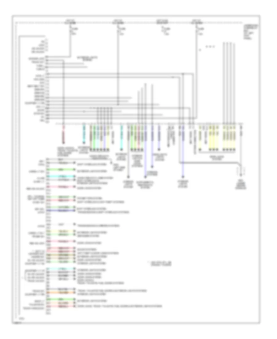
BODY CONTROL MODULES
Body Control Modules Wiring Diagram for Honda Ridgeline RTS 2014
List of elements for Body Control Modules Wiring Diagram for Honda Ridgeline RTS 2014:
- (not used)
- (option connector)
- (rtl, touring) p12
- (under center console)
- +b door lock
- Anti-theft & door locks systems
- As unlock
- Atp-p
- Atp-r
- B-can
- Back lt
- Cargo lt rly
- Cargo lt sw
- Chk
- Computer data lines system
- Computer data lines system shift interlock & interior lights systems
- Courtesy lt as
- Courtesy lt dr
- Courtesy lt lr
- Courtesy lt rr
- D11
- D14
- Day lt
- Defogger system
- Door locks & trunk, tailgate, fuel doors systems
- Door locks system
- Door locks, trunk, tailgate, fuel doors & exterior lights systems
- Dr unlock
- Drswas
- Drswdr
- Drswra
- Drswrd
- E10
- E14
- E15
- Exterior lights system
- F12
- F14
- Fr def sw
- Fuse 10a
- Fuse 20a
- Fuse 7.5a
- G403 (left side of dash)
- G501
- H10
- H12
- H13
- H14
- Hazard sw
- Headlights lights system
- Hot at all times
- Hot in on or start
- Ig key lt
- Ig key sw
- Ig1
- Interior lights & door locks systems
- Interior lights system
- Intr lt
- K-line
- K11
- K12
- Key off timer
- Key sol
- Lock
- Micu
- Micu gnd
- Micu service check connector
- N22
- N26
- N28
- P-pin
- P10
- P11
- P13
- P14
- P15
- P16
- P17
- P18
- P19
- P20
- P21
- P22
- P23
- P24
- P25
- P26
- P27
- P29
- P30
- Power tops system
- Q10
- Q11
- Q12
- Q13
- Q14
- Rem as lock
- Rem as unlock
- Scty in (ur radio sw) p28
- Seat belt sw
- Sg-1
- Shift interlock & anti-theft systems
- Shift interlock system
- Sil as unlock
- Sil ra unlock
- Sil rd unlock
- Sound systems
- Stop sw
- Tailgate sw
- Transmissions & mirrors systems
- Transmissions & shift interlock systems
- Trunk act
- Trunk handle sw
- Trunk sw
- Trunk unlock
- Trunk, tailgate, fuel doors & exterior lights systems
- Turn l
- Turn r
- Under-dash fuse/relay box (at left kick panel)
- Usa: rts, rtl, se canada: touring
- Vbu
- Warning systems
- X18
- X27
COMPUTER DATA LINES
Computer Data Lines Wiring Diagram for Honda Ridgeline RTS 2014
List of elements for Computer Data Lines Wiring Diagram for Honda Ridgeline RTS 2014:
- (at left kick panel) under-dash fuse/relay box
- (not used)
- (right end of dash) g402
- A16
- A17
- A18
- A3 k-line
- A32
- A48
- A49
- Audio unit (w/o navigation) (navigation: usa: rtl, se; canada: touring)
- B-can
- B10
- B19
- C11
- C203
- C204
- C302
- C404
- C406
- C454
- Can-h
- Can-l
- Chk
- Climate control unit
- Combination switch control unit
- Control block
- D10
- D11
- Data link (dlc) connector (lower left side of dash)
- Diag (+)
- Diag (-)
- Diag-h
- Diag-k
- Door multiplex control unit
- Fuse 8 15a
- G501 (under center console)
- Gauge control module
- Gnd
- Handsfreelink control unit (navigation: usa rtl, se, canada touring) (under middle of dash)
- Hot at all times
- Hvac control unit
- Immobilizer control unit-receiver (in steering column, on ignition key cylinder)
- J/c c451 (middle of dash)
- J/c c452 (middle of dash)
- K-line
- Micu
- Micu service check connector
- N10
- N13
- N14
- N22
- N28
- Navigation service check connector (usa: rtl, se; canada: touring) (under driver's seat)
- Navigation unit (under driver's seat)
- Power window master switch
- Powertrain control (pcm) module (right side of engine compt)
- Red
- Red a22
- Relay control module
- Scs
- Srs unit (behind lower center of dash)
- Steering angle sensor (in steering column)
- Tpms control unit (under left side of dash)
- Under-hood fuse/relay box (at right rear of engine compt)
- Usa: rt, sport; canada: dx, vp, sport, sport-se
- Usa: rts, rtl, se; canada: touring
- Vsa modulator control unit (left side of engine compt)
- Vtm-4 control unit (behind right kick panel)
- Wiper/washer switch
- X18
- X27
- Yaw rate-lateral acceleration sensor (under center console)
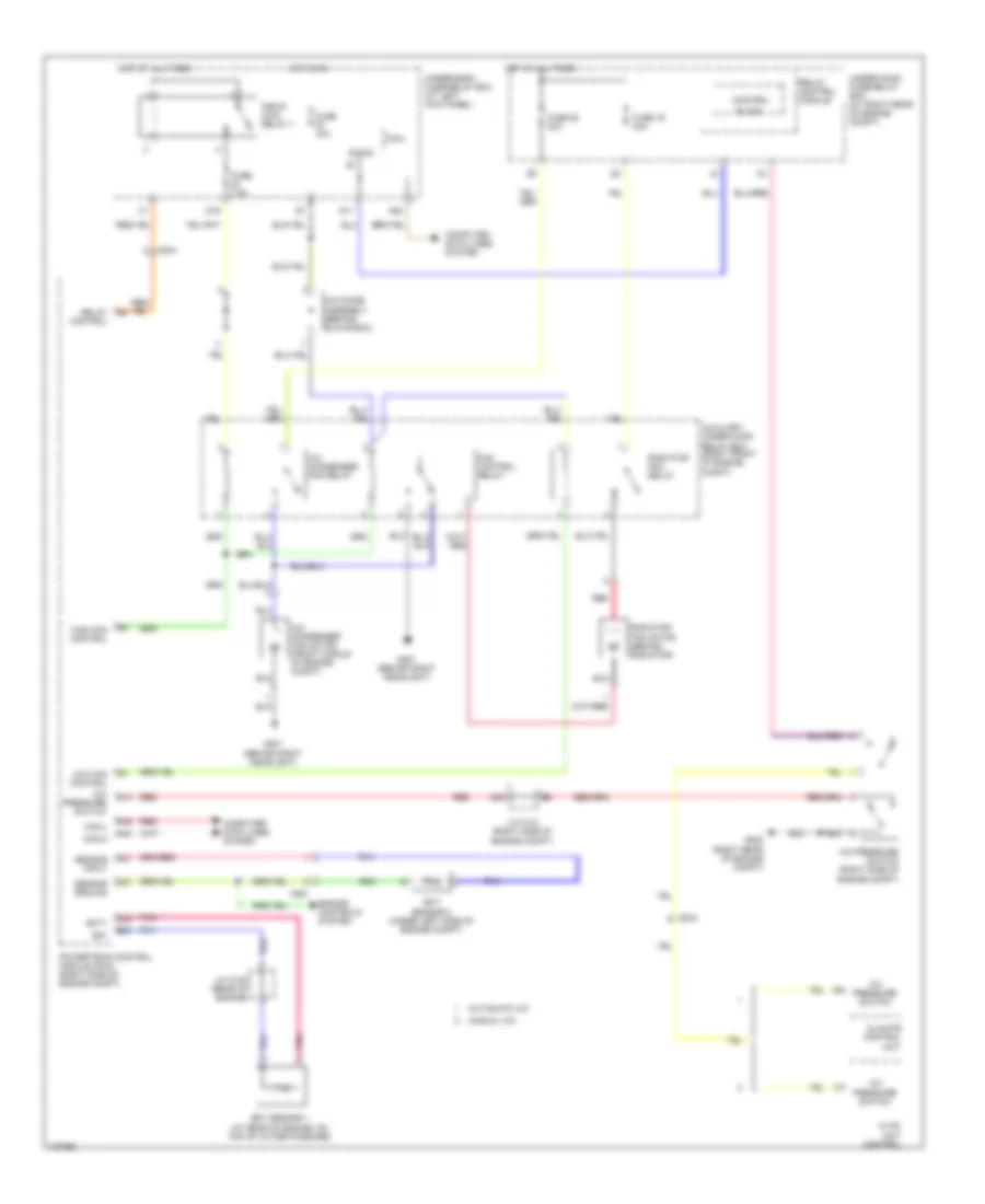
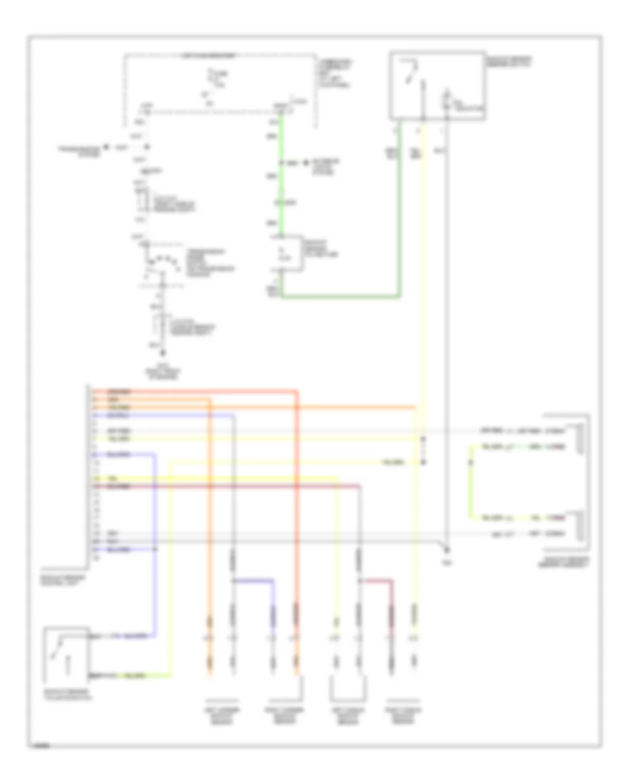
COOLING FAN
Cooling Fan Wiring Diagram for Honda Ridgeline RTS 2014
List of elements for Cooling Fan Wiring Diagram for Honda Ridgeline RTS 2014:
- (right rear of engine compt)
- A/c condenser fan motor (front middle of engine compt)
- A/c condenser fan relay
- A/c diode assembly (behind glove box)
- A/c pressure switch
- A/c pressure switch (right side of engine compt)
- A20
- A21
- A37
- A48
- A49
- Automatic a/c
- Auxiliary under-hood relay box (right front of engine compt)
- B-can
- B34
- Block
- C14
- C204
- C251
- C32
- Can-h
- Can-l
- Climate control unit
- Computer data lines system
- Control
- D11
- D16
- Ect sensor 1 (at rear of engine, on top of water passage)
- Ect sensor 2 (under left side of engine compt)
- Ect1
- Engine controls system
- Fan control relay
- Fuse 10a
- Fuse 19 30a
- Fuse 20 30a
- Fuse 7.5a
- G201 (behind right headlight)
- G202
- High fan control
- Hot at all times
- Hot in on
- Hvac unit control
- J/c c101 (right side of engine compt)
- J/c c105 (rear of engine)
- Low fan control
- Manual a/c
- Micu
- N28
- Pgm-fi main relay 1
- Pnk
- Powertrain control module (pcm) (right side of engine compt)
- Radiator fan motor (behind radiator)
- Radiator fan relay
- Red
- Relay control
- Relay control module
- Sensor ground
- Sensor input
- Sg1
- Under-dash fuse/relay box (at left kick panel)
- Under-hood fuse/relay box (at right rear of engine compt)
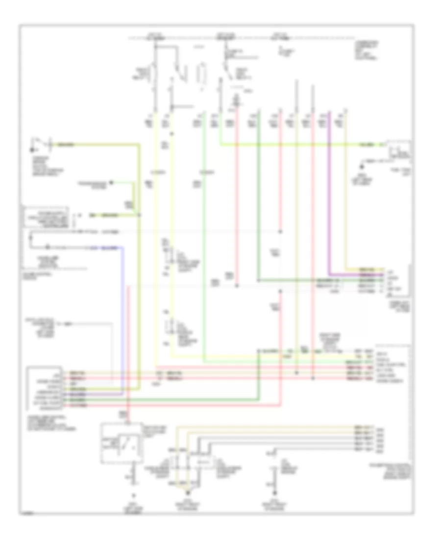
CRUISE CONTROL
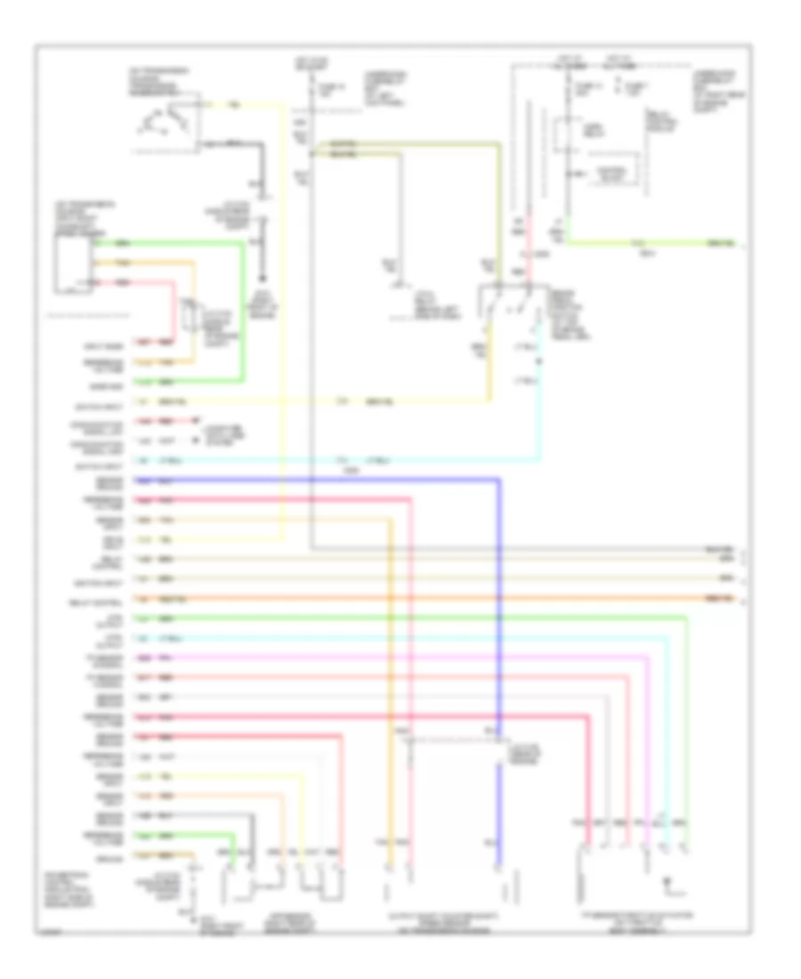
Cruise Control Wiring Diagram (1 of 2) for Honda Ridgeline RTS 2014
List of elements for Cruise Control Wiring Diagram (1 of 2) for Honda Ridgeline RTS 2014:
- (on transmission housing) input shaft (mainshaft) speed sensor
- (on transmission housing) transmission range switch
- A18
- A19
- A24
- A25
- A26
- A27
- A29
- A48
- A49
- App sensor (right rear of engine compt)
- B17
- B18
- B26
- B33
- B34
- B36
- B37
- B38
- Brake pedal position switch (at top of brake pedal arm)
- C12
- C15
- C18
- C204
- C205
- C41
- Communication signal high
- Communication signal low
- Computer data lines system
- Control block
- Drive input
- Fuse 13 20a
- Fuse 18 15a
- Fuse 7 7.5a
- G101 (right front of engine)
- Ground
- Horn relay
- Hot at all times
- Hot in on or start
- Ignition input
- Input snsr
- J/c c103 (middle rear of engine compt)
- J/c c104 (middle rear of engine compt)
- J/c c105 (rear of engine)
- Mtr+ output
- Mtr- output
- N29
- Output shaft (counter shaft) speed sensor (on transmission housing)
- Pnk
- Powertrain control module (pcm) (right side of engine compt)
- Red
- Reference voltage
- Relay control
- Relay control module
- Sensor ground
- Sensor input
- Snsr gnd
- Switch input
- Tan
- Tp sensor a signal
- Tp sensor b signal
- Tp sensor/throttle actuator (on throttle body assembly)
- Under-dash fuse/relay box (at left kick panel)
- Under-hood fuse/relay box (at right rear of engine compt)
- Vtm-4 relay (behind left side of dash)
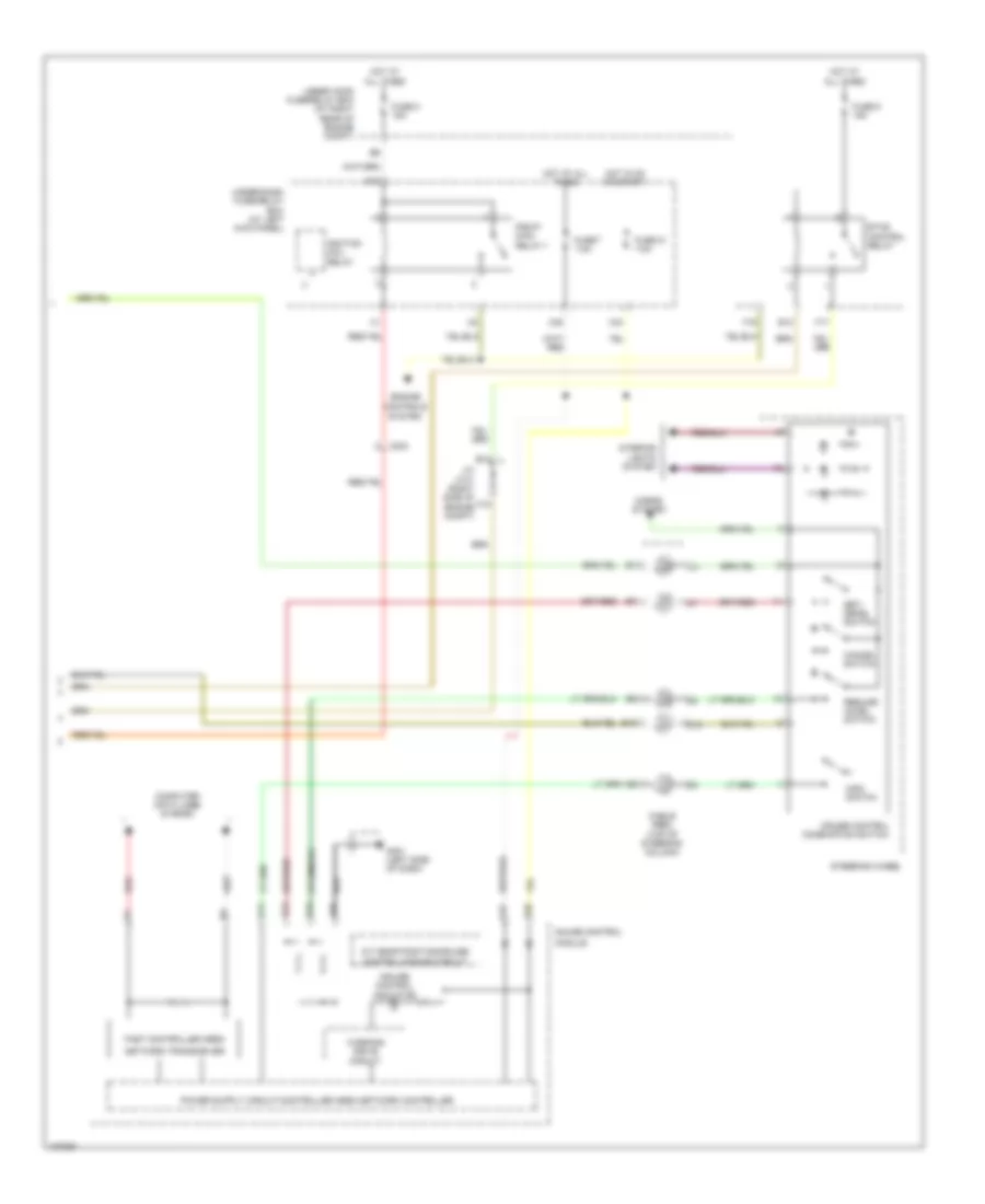
Cruise Control Wiring Diagram (2 of 2) for Honda Ridgeline RTS 2014
List of elements for Cruise Control Wiring Diagram (2 of 2) for Honda Ridgeline RTS 2014:
- A/t gear position/cruise control dimming circuit
- A10
- A12
- A13
- A14
- A19
- A20
- B12
- B13
- C13
- C204
- Cable reel (top of steering column)
- Cancel switch
- Computer data lines system
- Cruise control combination switch
- Cruise control indicator
- D10
- E10
- Engine controls
- Etcs control relay
- F17
- F19
- Fast controller area
- Fuse 21 7.5a
- Fuse 7 7.5a
- Fuse 8 15a
- Fuse 9 15a
- G401 (left side of dash)
- Gauge control
- Horns system
- Hot at all times
- Hot in on or start
- Ignition coil relay
- Interior lights system
- J/c c101 (right side of engine compt)
- Main switch
- Module
- Network transceiver
- Pgm-fi main relay 1
- Red
- Resume/ accel switch
- Set/ decel switch
- Steering wheel
- System
- Under hood fuse/relay box (at right rear of engine compt)
- Under-dash fuse/relay box (at left kick panel)
- Warning drive circuit
- X34
- X35
DEFOGGERS
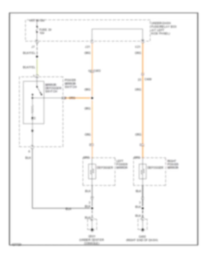
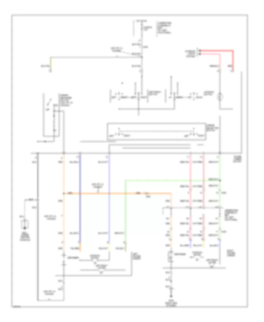
Heated Mirrors Wiring Diagram for Honda Ridgeline RTS 2014
List of elements for Heated Mirrors Wiring Diagram for Honda Ridgeline RTS 2014:
- C408
- C453
- Defogger
- Fuse 30 10a
- G402 (right end of dash)
- G501 (under center console)
- Hot in on
- J21
- Left power mirror
- Mirror defogger switch
- Power mirror switch
- Right power mirror
- Under-dash fuse/relay box (at left kick panel)
- X21
Heated Windshield Wiring Diagram for Honda Ridgeline RTS 2014
List of elements for Heated Windshield Wiring Diagram for Honda Ridgeline RTS 2014:
- (right rear of engine compt) g202
- Air conditioning system
- Automatic a/c
- B-can
- C204
- C205
- Climate control unit
- Control block
- D11
- E16
- Fr def sw
- Fuse 14 20a
- Fuse 2 (not used)
- Fuse 30 10a
- G401 (left side of dash)
- G402 (right end of dash)
- Gnd
- Heated windshield wiper area defogger
- Heated windshield wiper area relay
- Hot at all times
- Hot in on
- Hvac control unit
- Ig2
- J10
- Manual a/c
- Micu
- N20
- N22
- Outside air temp sens
- Outside air temperature sensor (behind front grille)
- P23
- Pnk
- Relay control module
- S-com
- Under-dash fuse/relay box (at left kick panel)
- Under-hood fuse/relay box (at right rear of engine compt)
ENGINE PERFORMANCE
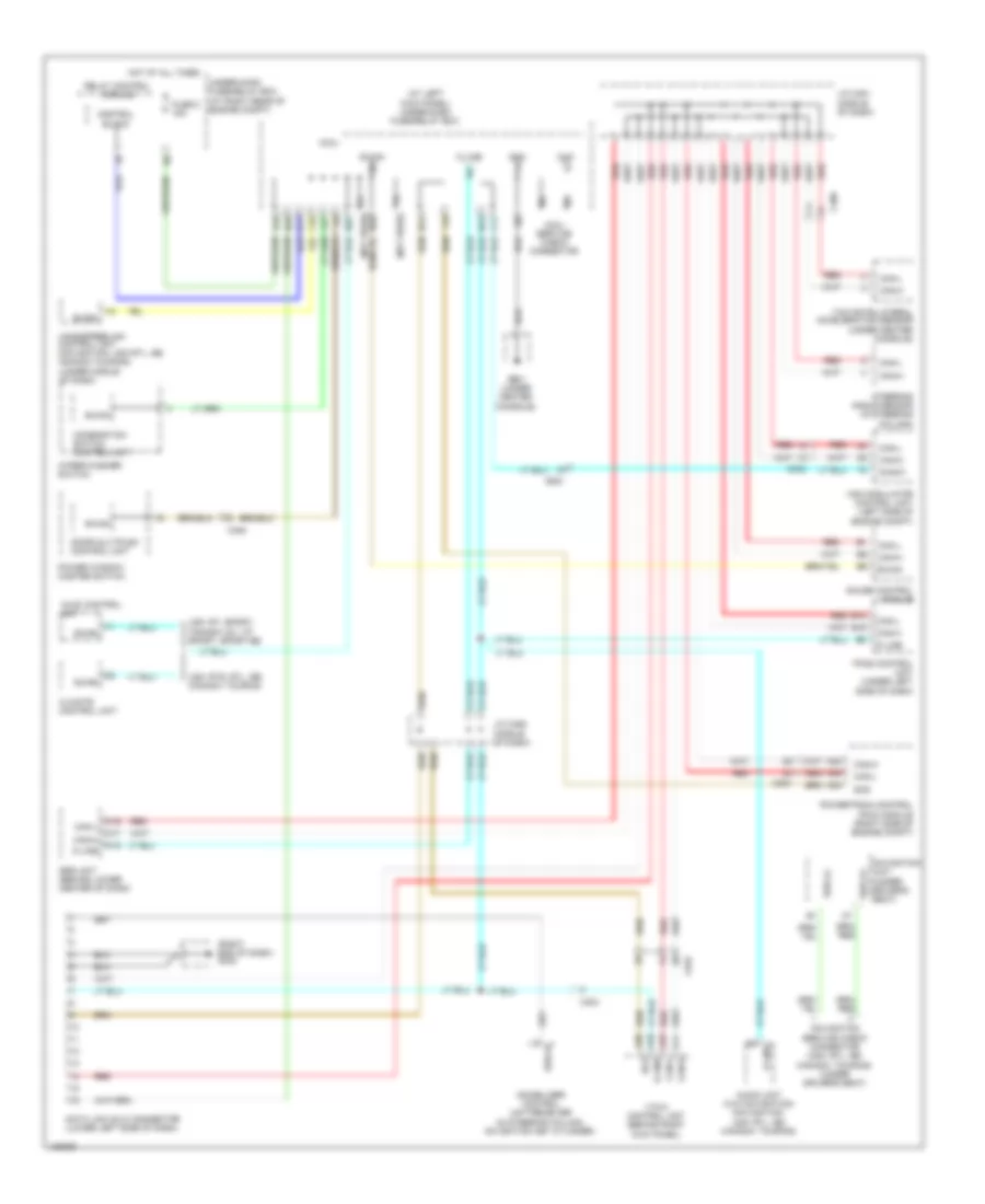
3.5L
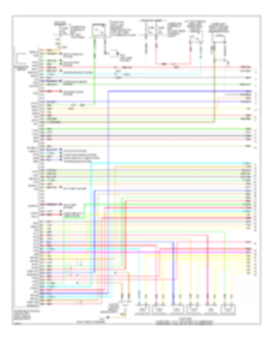
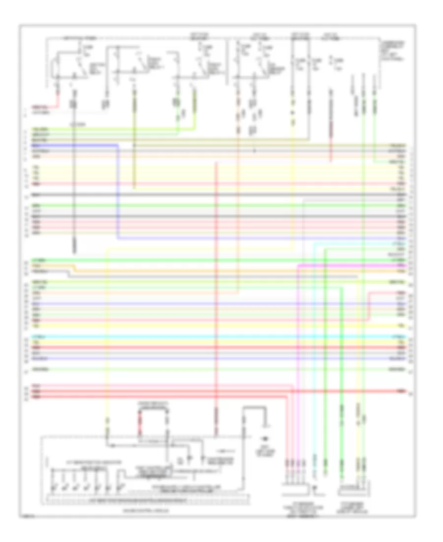
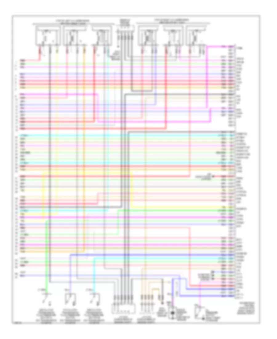
3.5L, Engine Performance Wiring Diagram (1 of 7) for Honda Ridgeline RTS 2014
List of elements for 3.5L, Engine Performance Wiring Diagram (1 of 7) for Honda Ridgeline RTS 2014:
- (at top of brake pedal arm) brake pedal position switch
- (under left side of vehicle) evap canister vent shut valve
- A10
- A11
- A12
- A13
- A14
- A15
- A16
- A17
- A18
- A19
- A20
- A21
- A22
- A23
- A24
- A25
- A26
- A27
- A28
- A29
- A30
- A31
- A32
- A33
- A34
- A35
- A36
- A37
- A38
- A39
- A40
- A41
- A42
- A43
- A44
- A45
- A46
- A47
- A48
- A49
- Acc
- Air conditioning system
- Anti-theft system
- Aps1
- Aps2
- Atp-p
- B10
- B11
- B12
- B13
- B14
- B15
- B16
- B17
- B18
- B19
- B20
- B21
- B22
- B23
- B24
- B25
- Barometer sensor
- Bksw
- Bkswnc
- C201
- C204
- C205
- Can-h
- Can-l
- Computer data lines system
- Cooling fans system
- Cruise control system
- D3 switch
- D3 switch/ shift lock solenoid/ park pin switch (top left side of steering column)
- D3sw
- Ect2
- Eld
- Etcsrly
- Fanh
- Fanl
- Ftp
- Fuse 15a
- Fuse 20a
- Fuse 7.5a
- G101 (right front of engine)
- G401 (left side of dash)
- Hot at all times
- Hot in on or start
- Igp
- Igpls3
- Igpls4
- Igpls5
- Igpls6
- Imo fpr
- Imtm
- Inj1
- Inj2
- Inj3
- Inj4
- Inj5
- Inj6
- Injectors (injectors 1, 2 & 3: top of right cylinder bank) (injectors 4, 5 & 6: top of left cylinder bank)
- J/c c104 (middle rear of engine compt)
- Lg3
- Lsb
- Lsc
- Mrly
- Navigation system
- Nep
- Pg2
- Pnk
- Powertrain control module (pcm) (right side of engine compt)
- Psp sw
- Red
- S-net5v
- Scs
- Sg3
- Sg4
- Sg7
- Shift interlock system
- Sho2s b1
- Sho2s b2
- Sls
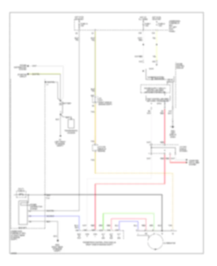
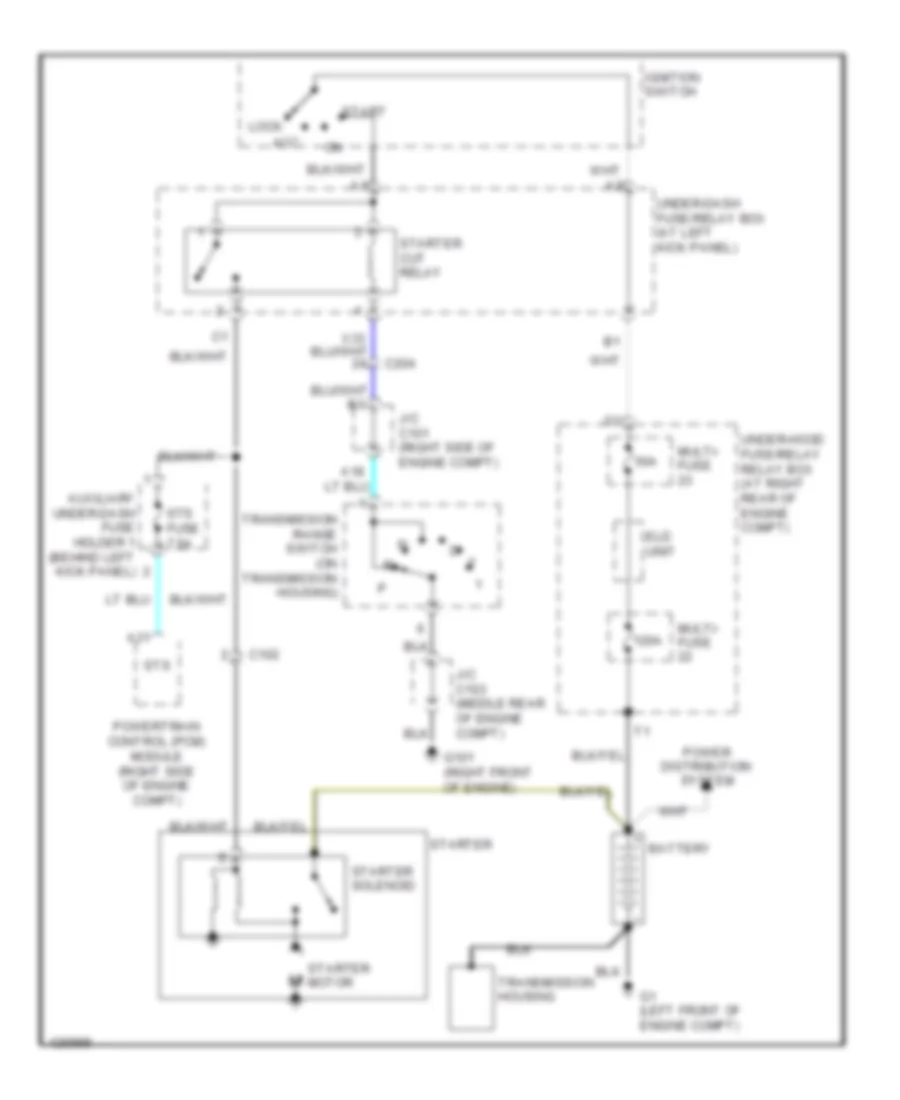
- Starting/charging system
- Sts
- Sub rly
- Tan
- Tpsa
- Transmissions system
- Under-dash fuse/relay box (at left kick panel)
- Under-hood fuse/relay box (at right rear of engine compt)
- Vbsol
- Vbsol2
- Vcc3
- Vcc4
- Vcc5
- Vcc7
- Vcent b1
- Vcent b2
- Vg+
- Vg-
- Vs b1
- Vs b2
- Vssout
- Vsv
- Vtpsw
- X20
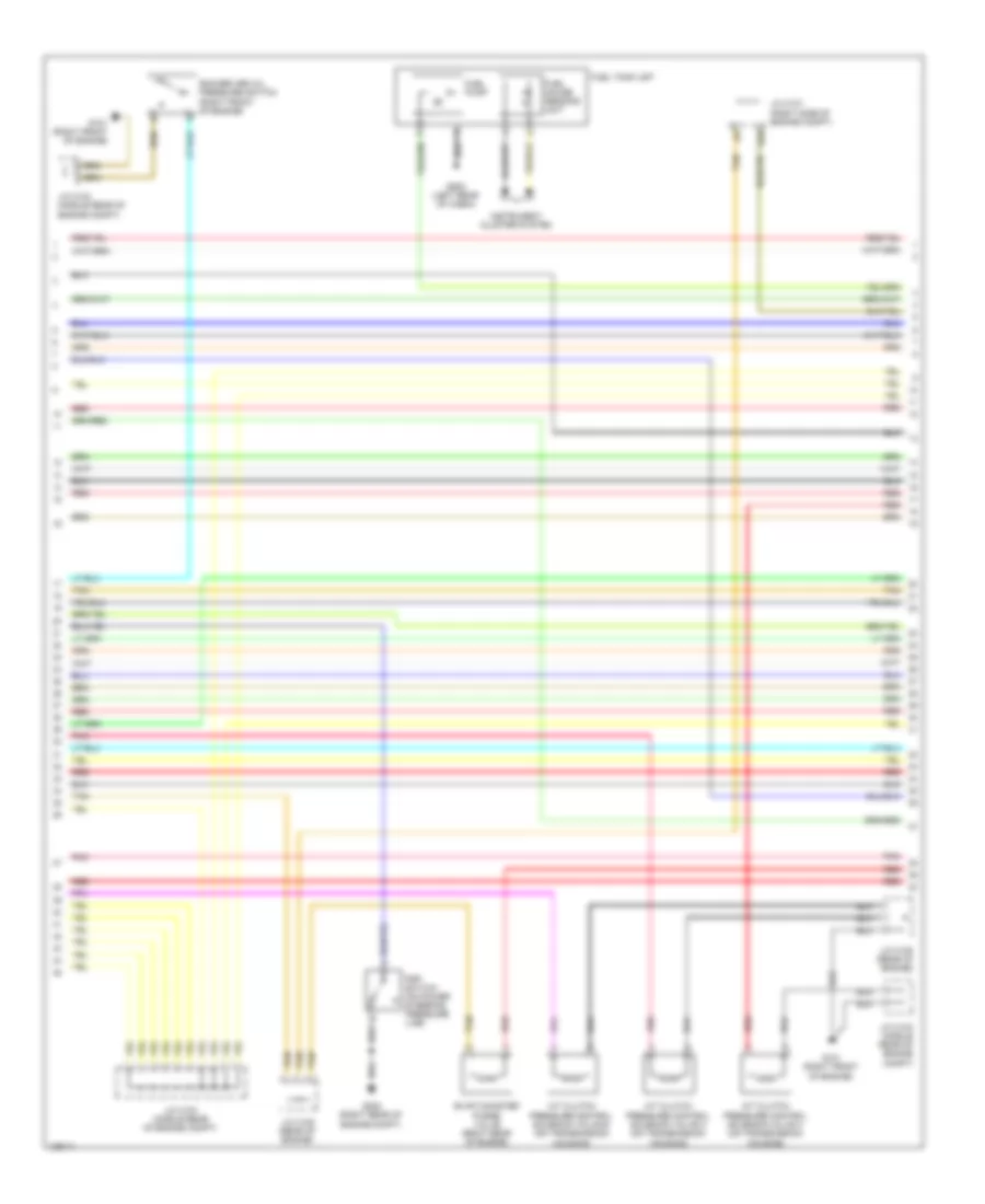
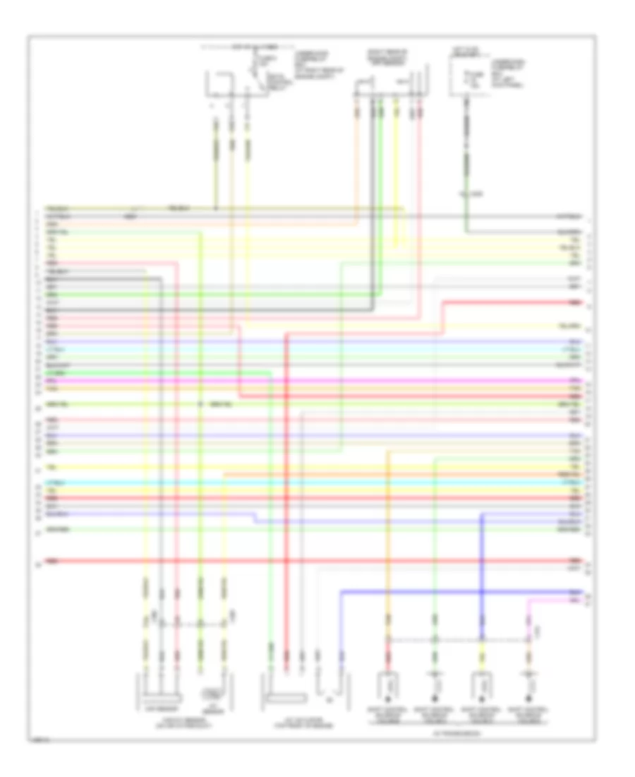
3.5L, Engine Performance Wiring Diagram (2 of 7) for Honda Ridgeline RTS 2014
List of elements for 3.5L, Engine Performance Wiring Diagram (2 of 7) for Honda Ridgeline RTS 2014:
- A/t clutch pressure control solenoid valve a (on transmission housing)
- A/t clutch pressure control solenoid valve b (on transmission housing)
- A/t clutch pressure control solenoid valve c (on transmission housing)
- B20
- Evap canister purge valve (right rear of engine)
- Fuel gauge sending unit
- Fuel pump
- Fuel tank unit
- G101 (right front of engine)
- G202 (right rear of engine compt)
- G502 (left rear of cabin)
- Instrument cluster system
- J/c c101 (right side of engine compt)
- J/c c103 (middle rear of engine compt)
- J/c c104 (middle rear of engine compt)
- J/c c105 (rear of engine)
- Pnk
- Psp switch (on power steering pressure line)
- Red
- Rocker arm oil pressure switch (right front of engine)
- Tan
3.5L, Engine Performance Wiring Diagram (3 of 7) for Honda Ridgeline RTS 2014
List of elements for 3.5L, Engine Performance Wiring Diagram (3 of 7) for Honda Ridgeline RTS 2014:
- (not used)
- A/f sensor relay
- A/t gear position indicator
- A/t gear position/cruise control dimming circuit
- A10
- A19
- A20
- C201
- C204
- C205
- Computer data lines system
- D10
- Drive circuit
- E13
- E16
- Fast controller area network transceiver
- Ftp sensor (under left side of vehicle)
- Fuse 15a
- Fuse 7.5a
- G401 (left side of dash)
- Gauge control module
- Hot at all times
- Hot in on or start
- Ignition coil relay
- Maintenance required ind
- Mil ind
- Pgm-fi main relay 1
- Pgm-fi main relay 2
- Pnk
- Red
- Tan
- Tp sensor/ throttle actuator (on throttle body assembly)
- Under-dash fuse/relay box (at left kick panel)
- Warning drive circuit
- X32
- X34
- X35
- X36
3.5L, Engine Performance Wiring Diagram (4 of 7) for Honda Ridgeline RTS 2014
List of elements for 3.5L, Engine Performance Wiring Diagram (4 of 7) for Honda Ridgeline RTS 2014:
- (in transmission)
- (right rear of engine compt) app sensor
- C151
- C203
- C205
- C302
- E10
- Ects control relay
- F17
- F19
- Fuse 15a
- Fuse 9 15a
- Hot at all times
- Hot in on or start
- Iat sensor
- Imt actuator (top front of engine)
- Maf sensor
- Maf/iat sensor (on air intake duct)
- Red
- Shift control solenoid valve a
- Shift control solenoid valve b
- Shift control solenoid valve c
- Shift control solenoid valve d
- Tan
- Under-dash fuse/relay box (at left kick panel)
- Under-hood fuse/relay box (at right rear of engine compt)
- X38
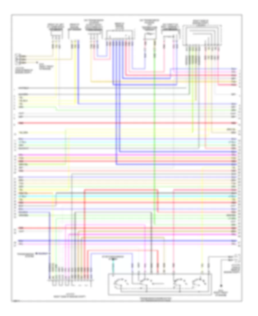
3.5L, Engine Performance Wiring Diagram (5 of 7) for Honda Ridgeline RTS 2014
List of elements for 3.5L, Engine Performance Wiring Diagram (5 of 7) for Honda Ridgeline RTS 2014:
- (front of left cylinder bank) cmp sensor
- (on throttle body assembly) map sensor
- (on transmission housing) atf temperature sensor
- (on transmission housing) output shaft (countershaft) speed sensor
- (rear of engine) ckp sensor
- (rear of engine) j/c c105
- (right side of engine compt) j/c c101
- A10
- A11
- A12
- A13
- A14
- A15
- A16
- A17
- A19
- A21
- A22
- A23
- B11
- B12
- B13
- B21
- B23
- G101 (right front of engine)
- J/c c101 (right side of engine compt)
- J/c c103 (middle rear of engine compt)
- J/c c104 (middle rear of engine compt)
- N r
- Pnk
- Red
- Starting/charging system
- Tan
- Transmission range switch (on transmission housing)
- Transmissions system
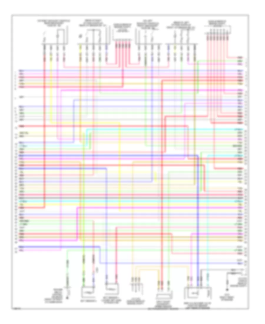
3.5L, Engine Performance Wiring Diagram (6 of 7) for Honda Ridgeline RTS 2014
List of elements for 3.5L, Engine Performance Wiring Diagram (6 of 7) for Honda Ridgeline RTS 2014:
- (middle rear of engine compt) j/c c104
- (on left exhaust manifold) front secondary ho2s (b2, s2)
- (on right exhaust manifold) rear secondary ho2s (b1, s2)
- (rear of left intake manifold) front a/f sensor (b2, s1)
- (rear of right intake manifold) rear a/f sensor (b1, s1)
- C251
- Ect sensor 1 (lower left side of radiator)
- Ect sensor 2
- Egr valve & egr valve position sensor (left rear of engine)
- G101 (right front of engine)
- Input shaft (mainshaft) speed sensor (on transmission housing)
- J/c c103 (middle rear of engine compt)
- Pnk
- Red
- Rocker arm oil control solenoid (front of right cylinder bank)
- Tan
3.5L, Engine Performance Wiring Diagram (7 of 7) for Honda Ridgeline RTS 2014
List of elements for 3.5L, Engine Performance Wiring Diagram (7 of 7) for Honda Ridgeline RTS 2014:
- (rear of engine) j/c c105
- (top of left cylinder bank) ignition coils 4, 5 & 6
- (top of right cylinder bank) ignition coils 1, 2 & 3
- 2nd clutch transmission fluid pressure switch a (on transmission housing)
- 3rd clutch transmission fluid pressure switch b (on transmission housing)
- 4th clutch transmission fluid pressure switch (on transmission housing)
- Afshtc b1
- Afshtc b2
- Air conditioning system
- Altc
- Altf
- Altl
- Atft
- Atp-1
- Atp-2
- Atp-d
- Atp-fwd
- Atp-n
- Atp-r
- Atp-rvs
- B26
- B27
- B28
- B29
- B30
- B31
- B32
- B33
- B34
- B35
- B36
- B37
- B38
- B39
- B40
- B41
- B42
- B43
- B44
- B45
- B46
- B47
- B48
- B49
- C10
- C11
- C12
- C13
- C14
- C15
- C152
- C16
- C17
- C18
- C19
- C20
- C21
- C22
- C23
- C24
- C25
- C26
- C27
- C28
- C29
- C30
- C31
- C32
- C33
- C34
- C35
- C36
- C37
- C38
- C39
- C40
- C41
- C42
- C43
- C44
- C45
- C46
- C47
- C48
- C49
- Ckpa
- Cmp
- Ect1
- Egr
- Egrp
- Etcsm+
- Etcsm-
- G101 (right front of engine)
- Iat
- Icm
- Ig1
- Ig1etcs
- Igpls1
- Igpls2
- Imt (+)
- Imt (-)
- Ip b1
- Ip b2
- J/c c103 (middle rear of engine compt)
- J/c c104 (middle rear of engine compt)
- Knock sensor (top center of engine)
- Lg1
- Lg2
- Lsa
- Map
- Oil pressure switch (right front of engine)
- Op2sw
- Op3sw
- Op4sw
- Opsw
- Pcs
- Pdsw
- Pg1
- Pgmetcs
- Pnk
- Powertrain control module (pcm) (right side of engine compt)
- Red
- Sg1
- Sg2
- Sg5
- Sg6
- Sha
- Shb
- Shc
- Shd
- So2sg b1
- So2sg b2
- So2shtc b1
- So2shtc b2
- Starting/ charging system
- Tan
- Tpsb
- Vcc1
- Vcc2
- Vcc6
- Vts
EXTERIOR LIGHTS
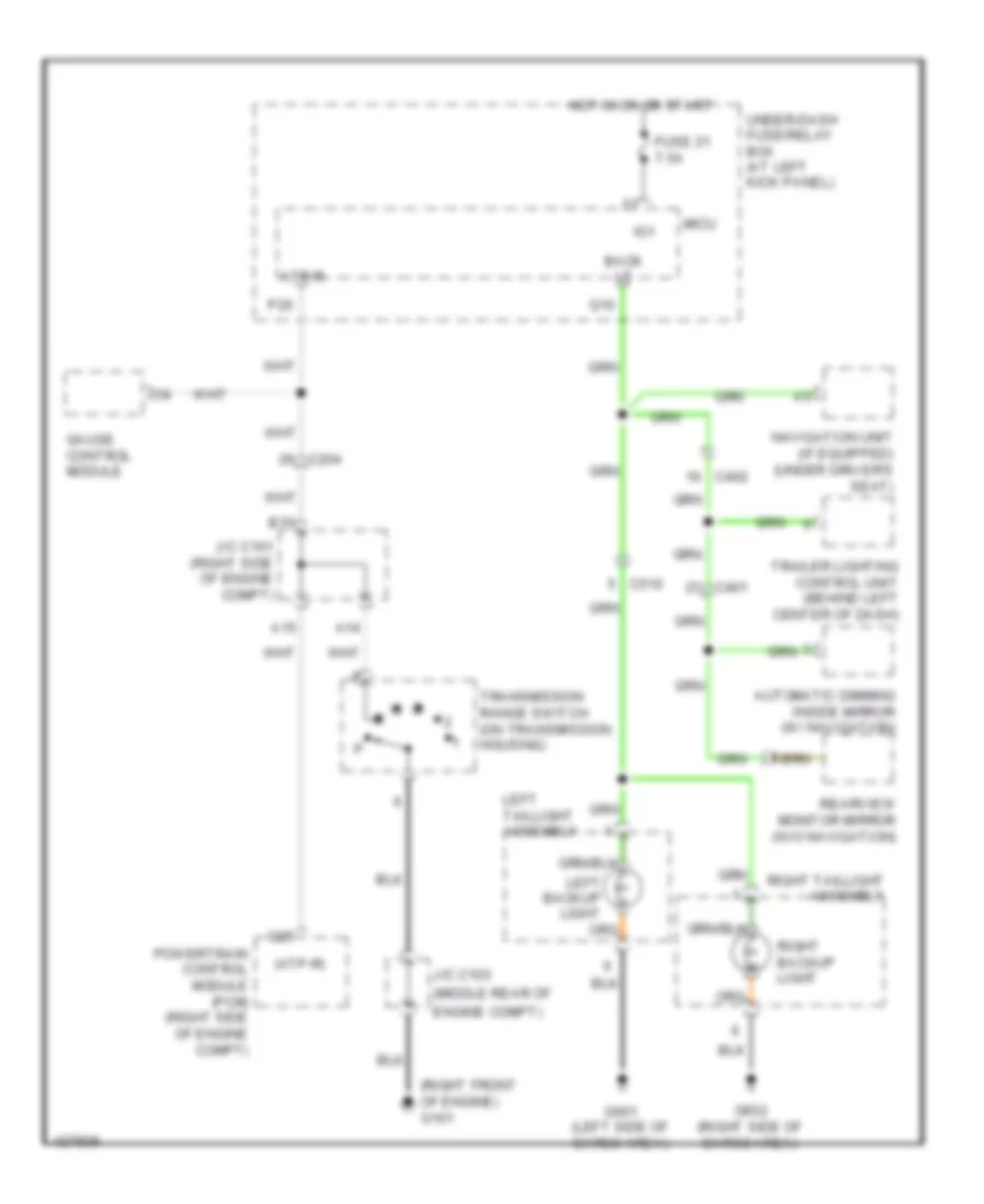
Backup Lamps Wiring Diagram for Honda Ridgeline RTS 2014
List of elements for Backup Lamps Wiring Diagram for Honda Ridgeline RTS 2014:
- (atp-r)
- (middle rear of
- (right front of engine) g101
- A14
- A15
- Atp-r
- Automatic dimming inside mirror (w/ navigation)
- B15
- Back lt
- C204
- C25
- C401
- C402
- C510
- Engine compt)
- Fuse 21 7.5a
- G601 (left side of cargo area)
- G602 (right side of cargo area)
- Gauge control module
- Hot in on or start
- Ig1
- J/c c101 (right side of engine compt)
- J/c c103
- Left backup light
- Left taillight assembly
- Micu
- Navigation unit (if equipped) (under driver's seat)
- P20
- Powertrain control module (pcm) (right side of engine compt)
- Q10
- Rearview monitor mirror (w/o navigation)
- Right backup light
- Right taillight assembly
- Trailer lighting control unit (behind left center of dash)
- Transmission range switch (on transmission housing)
- Under-dash fuse/relay box (at left kick panel)
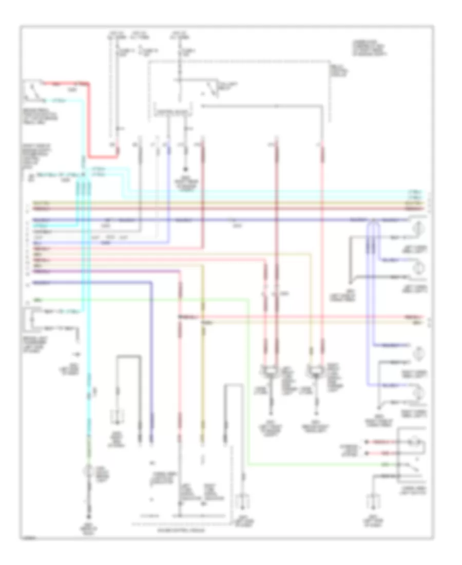
Exterior Lamps & Trailer Connector Wiring Diagram (1 of 3) for Honda Ridgeline RTS 2014
List of elements for Exterior Lamps & Trailer Connector Wiring Diagram (1 of 3) for Honda Ridgeline RTS 2014:
- +b haz
- 0) off 1) park 2) head
- B-can
- C509
- C510
- C601
- Cargo area light relay (behind left side of dash)
- Cargo lt rly
- Combination light switch
- Combination switch control unit
- D11
- D17
- F10
- F12
- Fuse 1 7.5a
- Fuse 21 7.5a
- Fuse 30 10a
- Fuse 7 7.5a
- G401 (left side of dash)
- G403 (left side of dash)
- G501 (under center console)
- G601 (left side of cargo area)
- G602 (right side of cargo area)
- Gnd
- Haz sw
- Hazard warning switch light
- Hazard warning switch/front passenger's air bag cut-off indicator
- Headlight switch
- Hot at all times
- Hot in on
- Hot in on or start
- Ig1
- In-bed trunk lid actuator/ latch switch (in-bed trunk lid)
- In-bed trunk lid latch switch
- Interior lights system
- L turn
- Left brake light/ taillight
- Left license plate light
- Left rear turn signal light
- Left taillight assembly
- Lt sw cargo p4
- Micu
- N17
- N20
- N26
- N27
- N31
- N33
- N42
- N45
- Not used
- P22
- P28
- R turn
- Red
- Right brake light/ taillight
- Right license plate light
- Right rear turn signal light
- Right taillight assembly
- Sg-1
- Stop sw
- Sw tailgate q11
- Sw trunk q7
- Tailgate switch (right rear of cargo area)
- Turn l
- Turn r
- Turn signal light switch
- Turn signal/ hazard relay
- Turn sw l
- Turn sw r
- Under-dash fuse/ relay box (at left kick panel)
- Vbu
- Wiper/washer switch
- X23
- X27
- X34
- X35
Exterior Lamps & Trailer Connector Wiring Diagram (2 of 3) for Honda Ridgeline RTS 2014
List of elements for Exterior Lamps & Trailer Connector Wiring Diagram (2 of 3) for Honda Ridgeline RTS 2014:
- (right end of dash)
- (right side of engine compt) powertrain control module (pcm)
- 1-side 2-turn
- A10
- A8 bk sw
- Brake light condenser (left side of dash)
- Brake pedal position switch (at top of brake pedal arm)
- C10
- C15
- C19
- C203
- C205
- C401
- C402
- C510
- Cargo area light switch
- Cargo area lights on indicator
- Control block
- D9 red
- Fuse 13 20a
- Fuse 16 15a
- Fuse 4 15a
- G201 (behind right headlight)
- G202 (right rear of engine compt)
- G301 (left front of engine compt)
- G401 (left side of dash)
- G402
- G551 (rear of roof)
- G601 (left side of cargo area)
- G602 (right side of cargo area)
- Gauge control module
- High mount brake light
- Hot at all times
- Interior lights system
- Left cargo area light 1
- Left cargo area light 2
- Left front turn signal/ side marker light
- Left turn signal indicator
- Red
- Relay control module
- Right cargo area light 1
- Right cargo area light 2
- Right front turn signal/ side marker light
- Right turn signal indicator
- Taillight relay
- Under-hood fuse/relay box (at right rear of engine compt)
Exterior Lamps & Trailer Connector Wiring Diagram (3 of 3) for Honda Ridgeline RTS 2014
List of elements for Exterior Lamps & Trailer Connector Wiring Diagram (3 of 3) for Honda Ridgeline RTS 2014:
- (if equipped)
- (trailer electric brake connector)
- +batt
- Auxiliary under-hood fuse box (left rear of engine compt)
- Backup lamps circuit
- C302
- C403
- C406
- C410
- C509
- C510
- C604
- Elec brake
- Fuse 1 7.5a
- Fuse 6 20a
- Fuse 7 20a
- Fuse 8 7.5a
- Fuse 9 20a
- G401 (left kick panel)
- G401 (left side of dash)
- G601 (left side of cargo area)
- Gnd
- Hot at all times
- Interior lights system
- Red
- Stop sw
- Trailer electric brake
- Trailer electric brake connector (under left side of dash)
- Trailer lighting connector (under left side of rear bumper)
- Trailer lighting control unit (behind left center of dash)
- Trailer lighting relay 1 (left side of dash)
- Trailer lighting relay 2 (left side of dash)
- Usa: rt sport
- Usa: rts, rtl & se; canada
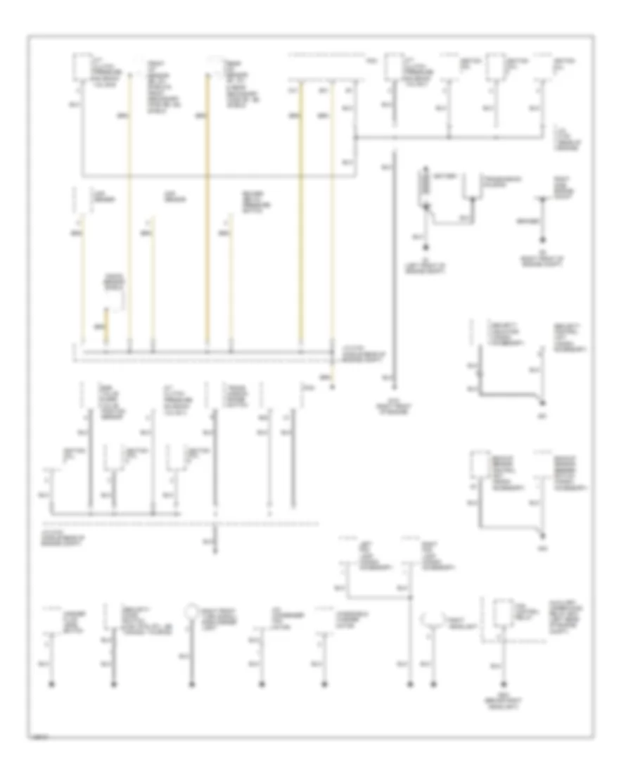
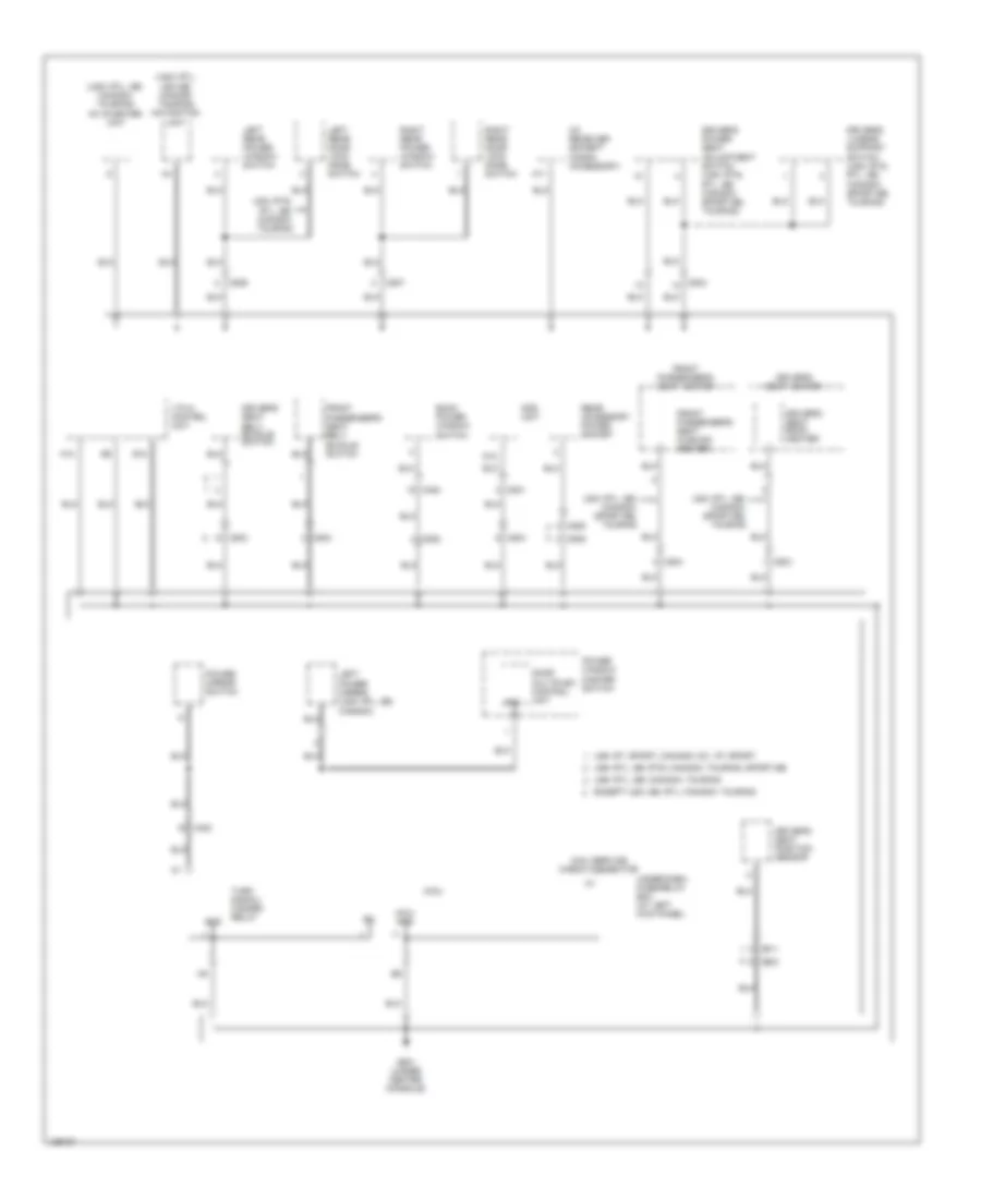
GROUND DISTRIBUTION
Ground Distribution Wiring Diagram (1 of 5) for Honda Ridgeline RTS 2014
List of elements for Ground Distribution Wiring Diagram (1 of 5) for Honda Ridgeline RTS 2014:
- & rear secondary ho2s (b1, s2) shield
- A/c condenser fan motor
- A/t clutch pressure solenoid valve a
- A/t clutch pressure solenoid valve b
- A/t clutch pressure solenoid valve c
- Accessory)
- Auxiliary under-hood relay box (left rear of engine compt)
- B40
- B41
- Backup sensor beeper switch (honda accessory)
- Backup sensor control unit (honda accessory)
- Battery
- Braided
- C41
- Ckp sensor
- Cmp sensor
- Coil
- Egr valve & egr valve position sensor
- Fan control relay
- Front a/f sensor (b2, s1) shield & front secondary ho2s (b2, s2) shield
- G1 (left front of engine compt)
- G101 (right front of engine)
- G2 (right front of engine compt)
- G201 (behind right headlight)
- G40
- G51
- Ignition
- Ignition coil
- J/c c103 (middle rear of engine compt)
- J/c c104 (middle rear of engine compt)
- J/c c105 (rear of engine)
- Knock sensor shield
- Left fog lamp (honda accessory)
- Pcm
- Rear a/f sensor (b1, s1)
- Right fog lamp (honda accessory)
- Right front turn signal/ side marker light
- Right headlight
- Right side engine mount
- Rocker arm oil pressure switch
- Security control unit (honda
- Security hood switch (usa: rts, rtl, se canada: touring)
- Security indicator (honda accessory)
- Trans- mission range switch
- Transmission housing
- Washer fluid level switch
- Windshield washer motor
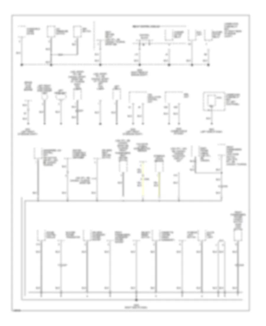
Ground Distribution Wiring Diagram (2 of 5) for Honda Ridgeline RTS 2014
List of elements for Ground Distribution Wiring Diagram (2 of 5) for Honda Ridgeline RTS 2014:
- (usa: rtl, se; canada: sport-se, touring) front passenger's seat heater switch
- (usa: rtl, usa, se; canada: touring) navigation display unit
- (usa: sport, rtl se; canada: sport, sport-se, vp, touring) right fog light
- (usa: sport, rtl, se; canada: sport, vp, touring) left fog light
- A/c pressure switch
- A10
- A28
- A29
- Block
- Blower motor relay
- Blower power transistor
- Brake fluid level switch
- C10
- C207
- C406
- C407
- C408
- Cigarette lighter (honda accessory)
- Control
- Dlc
- Driver's accessory power socket
- Driver's seat heater switch
- E14
- Eld unit
- Front passenger's accessory power socket
- Front passenger's door lock knob switch (usa: rts, rtl, se; canada: touring)
- Front passenger's power window switch/ door lock switch
- G202 (right rear of engine compt)
- G301 (left front of engine compt)
- G302 (left front of engine compt)
- G402 (right end of dash)
- G403 (left side of dash)
- G405 (under middle of dash)
- Gauge control module
- Glove box light
- Handsfree link control unit (navigation: usa rtl, usa, se; canada: touring)
- Heated windshield wiper area defogger
- Interior light switch
- J10
- Left drl
- Left front turn signal/ side marker light
- Left headlight
- Micu
- Psp switch
- Relay control module
- Right power mirror (usa: rtl, se; canada)
- Seat heater relay (usa: rtl, se canada: touring, sport-se)
- Select/ reset switch
- Sg-1
- Srs unit
- Steering angle sensor
- Under-dash fuse/relay box (at left kick panel)
- Under-hood fuse/relay box (at right rear of engine compt)
- Usa: rtl, se; canada: touring, sp0rt-se
- Vsa modulator- control unit
- Washer motor relay
- Windshield wiper motor
- Yaw rate- lateral acceleration sensor
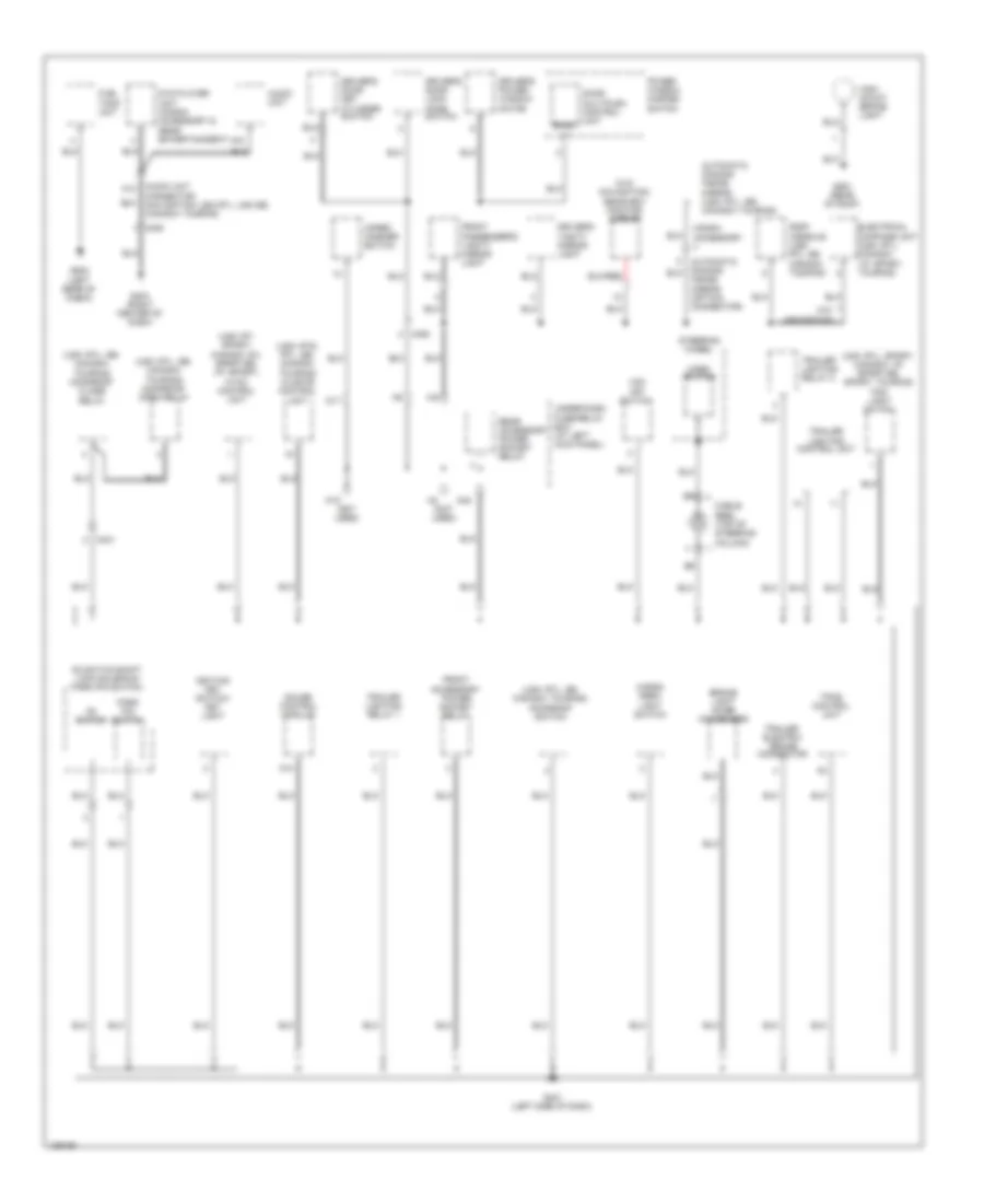
Ground Distribution Wiring Diagram (3 of 5) for Honda Ridgeline RTS 2014
List of elements for Ground Distribution Wiring Diagram (3 of 5) for Honda Ridgeline RTS 2014:
- (not used)
- (usa: rt, sport; canada: dx, sport-se, vp, sport) hvac control unit
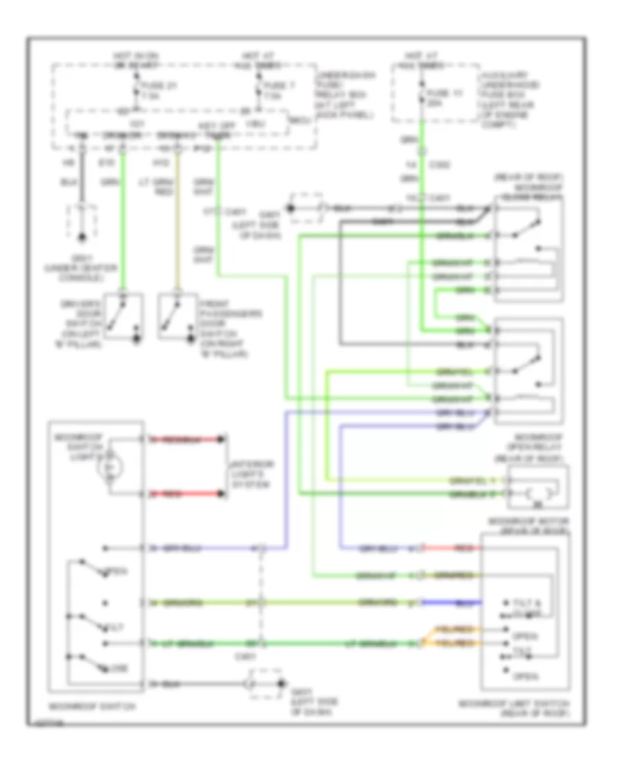
- (usa: rtl, se; canada: touring) moonroof close relay
- (usa: rtl, se; canada: touring) moonroof open relay
- (usa: rtl, se; canada: touring) moonroof switch
- (usa: rtl, sport; canada: vp, sport-se, sport, touring) fog light switch
- (usa: rts, rtl, se; canada: touring) climate control unit
- (w/o navigation) rearview monitor mirror
- A10
- A12
- Audio unit
- Audio unit connector (navigation: usa rtl, usa se; canada: touring)
- Automatic dimming inside mirror (usa: rtl, se; canada: touring)
- Brake light noise condenser
- C401
- C409
- C453
- Cable reel (top of steering column)
- Cargo area light switch
- D3 switch
- D3 switch/shift lock solenoid/ park pin switch
- Door multiplex control unit
- Driver's door key cylinder switch
- Driver's door lock knob switch
- Driver's power window motor
- Driver's vanity mirror light
- Dvd player unit (honda accessory & rear entertainment)
- Electrical compass unit (usa: rtl; canada: vp, sport, touring)
- Front accessory power socket relay
- Front passenger's vanity mirror light
- Fuel tank unit
- G401 (left side of dash)
- G404 (right center of dash)
- G502 (left rear of cabin)
- G551 (rear of roof)
- Gauge control module
- High mount brake light
- Honda accessory
- Horn switch
- Ignition key switch/ key light
- Inside mirror (option connector)
- N17
- N18
- N42
- Park pin switch
- Power window master switch
- Rear accessory power socket relay
- Roof console (usa: rtl, se; canada: touring)
- Sgnd
- Steering
- Tpms control unit
- Trailer electric brake connector
- Trailer lighting control unit
- Trailer lighting relay 1
- Trailer lighting relay 2
- Under-dash fuse/relay box (at left kick panel)
- Vsa off switch
- W/o navigation
- Wheel
- Wiper/ washer switch
Ground Distribution Wiring Diagram (4 of 5) for Honda Ridgeline RTS 2014
List of elements for Ground Distribution Wiring Diagram (4 of 5) for Honda Ridgeline RTS 2014:
- (usa: rtl, se; canada: touring) ac inventer unit
- (usa: rtl, usa se; canada: touring) navigation unit
- A10
- A11
- B12
- Back power window switch
- C453
- C454
- C502
- C503
- C504
- C505
- C506
- C507
- C511
- C801
- D12
- Door multiplex control unit
- Driver's lumbar support switch (usa: rts, rtl, se; canada: sport-se, touring)
- Driver's power seat adjustment switch (usa: rts, rtl, se; canada: sport-se, touring)
- Driver's seat back heater
- Driver's seat belt buckle switch
- Driver's seat heater
- Driver's seat position sensor
- Except usa: se, rtl; canada: touring
- Front passenger's seat belt buckle switch
- Front passenger's seat cushion heater
- Front passenger's seat heater
- G501 (under center console)
- Gnd
- Left power mirror (usa: rtl, se; canada)
- Left rear door lock knob switch
- Left rear power window switch
- Micu
- Micu gnd
- Micu service check connector
- Ods unit
- Pg1
- Power mirror switch
- Power window master switch
- Rear accessory power socket
- Right rear door lock knob switch
- Right rear power window switch
- Turn signal/ hazard relay
- Under-dash fuse/relay box (at left kick panel)
- Usa: rt, sport; canada: dx, vp, sport
- Usa: rtl, se, rts; canada: touring, sport-se
- Usa: rtl, se; canada: sport-se, touring
- Usa: rtl, se; canada: touring
- Usa: rts, rtl, se; canada: touring
- Vtm-4 control unit
- Xm receiver (except honda accessory)
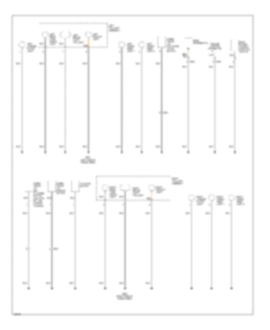
Ground Distribution Wiring Diagram (5 of 5) for Honda Ridgeline RTS 2014
List of elements for Ground Distribution Wiring Diagram (5 of 5) for Honda Ridgeline RTS 2014:
- Back power window position switch
- C601
- C603
- C604
- G601 (left side of cargo area)
- G602 (right side of cargo area)
- In-bed trunk lid actuator/ latch switch
- In-bed trunk lid handle switch
- In-bed trunk lid key cylinder switch (usa: rts, rtl, se; canada: touring)
- Left backup light
- Left brake light/ taillight
- Left cargo area light 1
- Left cargo area light 2
- Left license plate light
- Left rear turn signal light
- Left taillight assembly
- Rear differential
- Right backup light
- Right brake light/ taillight
- Right cargo area light 1
- Right cargo area light 2
- Right license plate light
- Right rear turn signal light
- Right taillight assembly
- Tailgate switch
- Trailer lighting connector
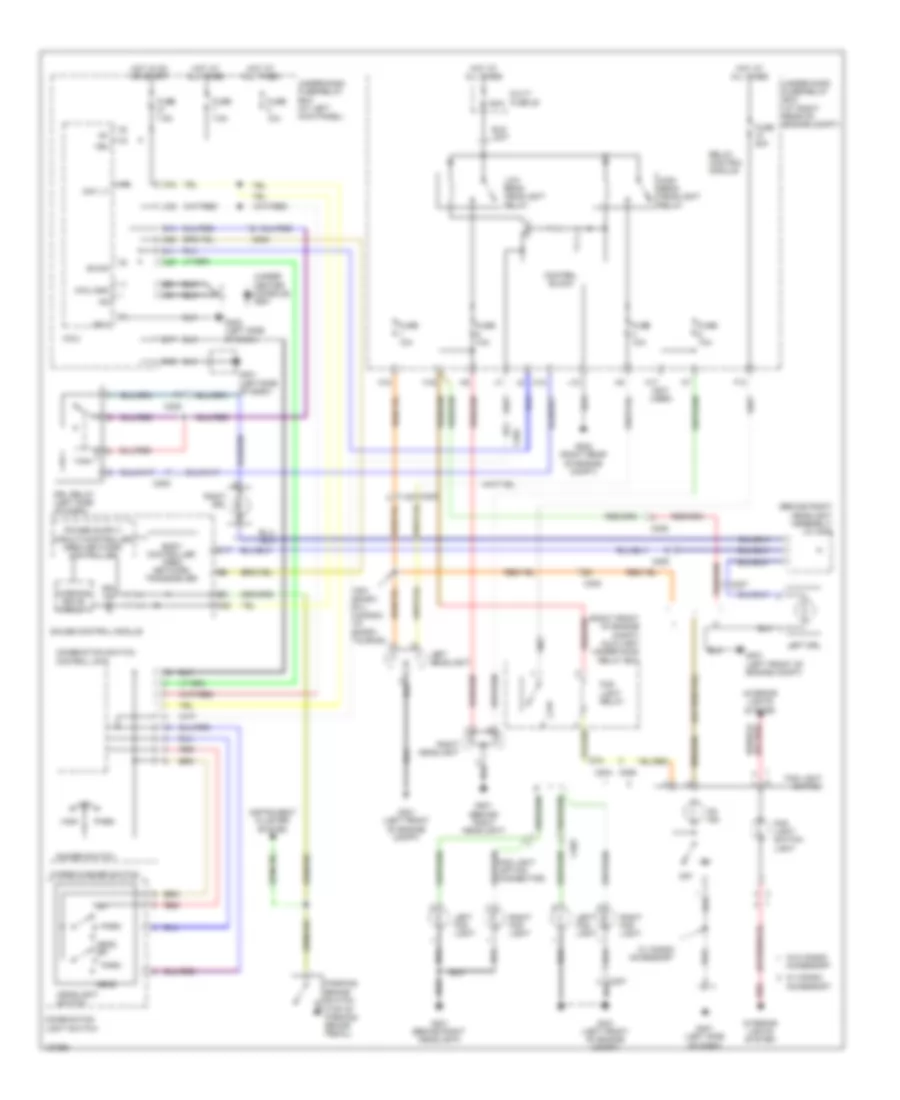
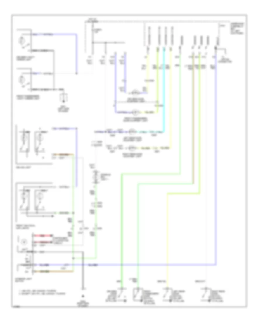
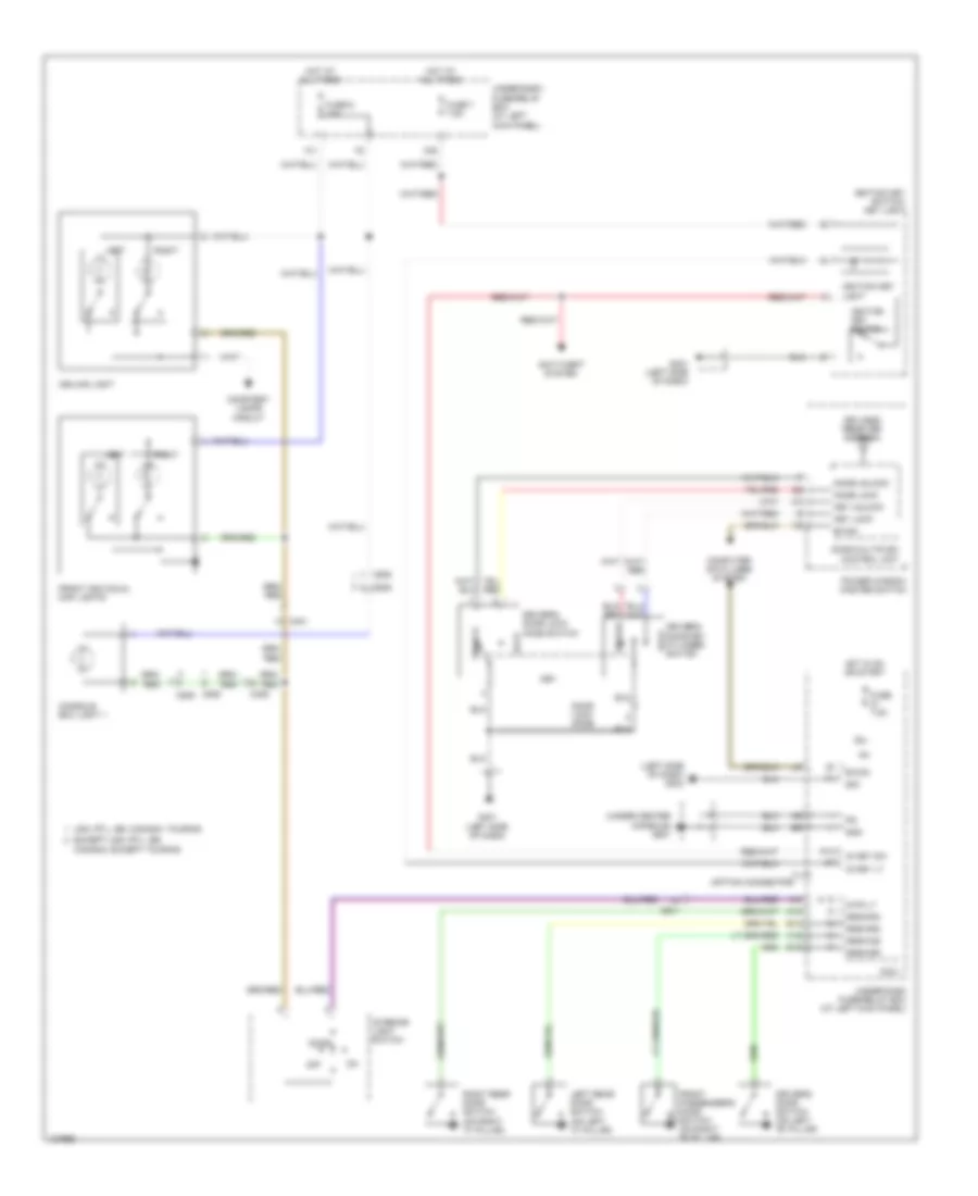
HEADLIGHTS
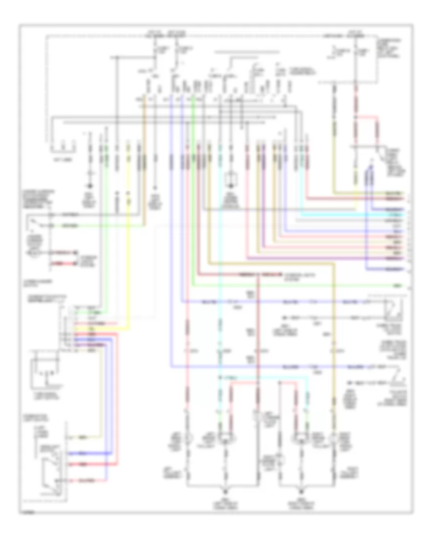
Headlights Wiring Diagram for Honda Ridgeline RTS 2014
List of elements for Headlights Wiring Diagram for Honda Ridgeline RTS 2014:
- (behind right headlight assembly) j/c c208
- (right front of engine compt) auxiliary under-hood relay box
- (under center console) g501
- 120a
- A20
- Accessory
- B-can
- Body controller area network transceiver
- C17
- C203
- C204
- C205
- C206
- C207
- C302
- Combination light switch
- Combination switch control unit
- Control block
- D11
- D14
- Day lt
- Dimmer switch
- Drl ind
- Drl relay (left side of dash)
- Eld unit
- F13
- Fog light (option connector)
- Fog light relay
- Fog light switch
- Fog light switch light
- Fuse 10a
- Fuse 20a
- Fuse 7.5a
- G201 (behind right headlight)
- G202 (right rear of engine compt)
- G301 (left front of engine compt)
- G401 (left side of dash)
- G403 (left side of dash)
- Gauge control module
- H10
- H16
- H17 (not used)
- H18
- Head
- Head off
- Headlight switch
- High
- High beam headlight relay
- Hot at all times
- Hot in on or start
- Ig1
- Instrument cluster system
- Interior lights system
- J10
- Left drl
- Left fog light
- Left headlight
- Low
- Low beam headlight relay
- Micu
- Micu gnd
- Multi fuse 22
- N17
- N28
- N42
- Off
- On ind
- Park
- Parking brake switch (top of parking brake pedal)
- Pass
- Red
- Relay control module
- Right drl
- Right fog light
- Right headlight
- Sg-1
- Under-dash fuse/relay box (at left kick panel)
- Under-hood fuse/relay box (at right rear of engine compt)
- Usa: sport, rtl; canada: vp, sport, touring;
- Vbu
- W/ honda
- W/ honda accessory
- W/o honda
- Warning drive circuit
- Wiper/washer switch
- X27
- X34
- X35
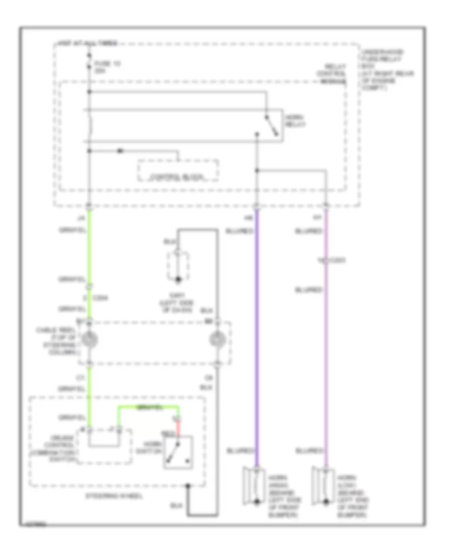
HORN
Horn Wiring Diagram for Honda Ridgeline RTS 2014
List of elements for Horn Wiring Diagram for Honda Ridgeline RTS 2014:
- C203
- C204
- Cable reel (top of steering column)
- Control block
- Cruise control combination switch
- Fuse 13 20a
- G401 (left side of dash)
- Horn (high) (behind left side of front bumper)
- Horn (low) (behind left end of front bumper)
- Horn relay
- Horn switch
- Hot at all times
- Red
- Relay control module
- Steering wheel
- Under-hood fuse/relay box (at right rear of engine compt)
INSTRUMENT CLUSTER
Instrument Cluster Wiring Diagram (1 of 2) for Honda Ridgeline RTS 2014
List of elements for Instrument Cluster Wiring Diagram (1 of 2) for Honda Ridgeline RTS 2014:
- (on right "c" pillar) right rear door switch
- A10
- A11
- A12
- A13
- A14
- A15
- A16
- A17
- A18
- A19
- A20
- B-can
- B10
- B11
- B12
- B13
- B14
- Back window open ind
- Beeper
- Body controller area network transceiver
- C10
- C11
- C12
- C13
- C14
- C15
- C16
- C17
- C18
- C19
- C20
- C402
- C403
- Cargo area lights on ind
- Computer data lines system
- Cruise control system
- D11
- Drive circuit
- Driver's door switch (on left "b" pillar)
- Drswas
- Drswdr
- Drswra
- Drswrd
- E14
- E15
- Engine coolant temperature gauge
- Exterior lights system
- Fast controller area network transceiver
- Front passenger's door switch (on right "b" pillar)
- Fuel gauge
- Fuel gauge sending unit
- Fuel tank unit
- Fuse 21 7.5a
- Fuse 32 7.5a
- Fuse 7 7.5a
- G401 (left side of dash)
- G402 (right end of dash)
- Gauge control module
- H12
- H13
- Headlights system
- High beam ind
- Hot at all times
- Hot in acc or on
- Hot in on or start
- Interior lights system
- Lcd back light
- Lcd brightness control & dimming circuit
- Left rear door switch (on left "c" pillar)
- Left turn signal ind
- Micu
- Multi-information display (mid) unit
- N36
- Pointer brightness control & dimming circuit
- Red
- Right turn signal ind
- Speedometer
- Tachometer
- To drive circuit (diagram 2 of 2)
- To immobilizer system ind (diagram 2 of 2)
- Transmissions system
- Under-dash fuse/relay box (at left kick panel)
- Vsa off switch
- Wiper/washer system
- X34
- X35
Instrument Cluster Wiring Diagram (2 of 2) for Honda Ridgeline RTS 2014
List of elements for Instrument Cluster Wiring Diagram (2 of 2) for Honda Ridgeline RTS 2014:
- A/t gear position indicator
- A/t gear position/cruise
- A/t temperature ind
- A12
- A13
- A14
- A20
- A48
- A49
- Abs ind
- B11
- Back power window position switch (bottom left of rear window)
- Brake fluid level switch (on brake fluid reservoir)
- Brake system ind
- C17
- C18
- C302
- C401
- C402
- C404
- C45
- C509
- Can-h
- Can-l
- Charging system ind
- Circuit
- Circuit drive
- Computer data lines system
- Control dimming circuit
- Control ind
- Cruise
- Cruise main ind
- Door & tailgate open ind
- Drive circuit
- Drl ind
- Engine oil pressure switch (right front of engine)
- Fail safe circuit
- From pin a10 (diagram 1 of 2)
- From pin a8 (diagram 1 of 2)
- G301 (left front of engine compt)
- G402 (right end of dash)
- G601 (left side of cargo area)
- Gauge control module
- Immobilizer control unit receiver (in steering column, on ignition key cylinder)
- Immobilizer system ind
- In-bed trunk open ind
- Information ind (w/ navigation)
- Interior lights system
- Lights on ind
- Low fuel ind
- Low oil pressure ind
- Low tire pressure ind
- Maintenance required ind
- Mil ind
- Next switch (navigation)
- Opsw
- Parking brake switch (top of parking brake pedal)
- Powertrain control (pcm) module (right side of engine compt)
- Red
- Reset switch (w/o navigation) select/ reset switch (w/ navigation)
- Roof console
- Seat belt reminder ind
- Security light ind
- Select/ reset switch
- Side air bag cut-off ind
- Srs ind
- Srs ind circuit
- Tpms ind (w/o navigation)
- Vsa off ind
- Vsa system ind
- Vtm-4 control unit (behind right kick panel)
- Vtm-4 ind
- Warning drive
- Warning drive circuit
- Washer fluid level ind
INTERIOR LIGHTS
Courtesy Lamps Wiring Diagram for Honda Ridgeline RTS 2014
List of elements for Courtesy Lamps Wiring Diagram for Honda Ridgeline RTS 2014:
- C401
- C406
- C408
- C453
- C505
- C506
- C507
- Ceiling light
- Console box light 1
- Courtesy lt as
- Courtesy lt dr
- Courtesy lt lr
- Courtesy lt rr
- Door
- Driver's door courtesy light
- Driver's door switch (on left "b" pillar)
- Driver's vanity mirror light
- Drswas
- Drswdr
- Drswra
- Drswrd
- E14
- E15
- Except usa: rtl, se; canada: touring
- Front individual map lights
- Front passenger's door courtesy light
- Front passenger's door switch (on right "b" pillar)
- Front passenger's vanity mirror light
- Fuse 6 10a
- G401 (left side of dash)
- G402 (right end of dash)
- H12
- H13
- Hot at all times
- Instrument illumination circuit
- Interior light switch
- Intr lt
- Left
- Left rear door courtesy light
- Left rear door switch (on left "c" pillar)
- Micu
- N15
- Off
- P30
- Red
- Right
- Right rear door courtesy light
- Right rear door switch (on right "c" pillar)
- T1 (option connector)
- Under-dash fuse/relay box (at left kick panel)
- Usa: rtl, se; canada: touring
Entry Light Timer Wiring Diagram for Honda Ridgeline RTS 2014
List of elements for Entry Light Timer Wiring Diagram for Honda Ridgeline RTS 2014:
- (left side of dash) g403
- (under center console) g501
- Anti-theft system
- B-can
- C401
- C406
- C505
- Ceiling light
- Computer data lines system
- Console box light 1
- Courtesy lamps circuit
- Door
- Door lock knob
- Door multiplex control unit
- Driver's door key cylinder switch
- Driver's door lock knob switch
- Driver's door switch (on left "b" pillar)
- Drswas
- Drswdr
- Drswra
- Drswrd
- E14
- E15
- Except usa: rtl, se; canada: except touring
- Front individual map lights
- Front passenger's door switch (on right "b" pillar)
- Fuse 6 10a
- Fuse 7 7.5a
- Fuse 7.5a
- G401 (left side of dash)
- Gnd
- H12
- H13
- Hot at all times
- Hot in on or start
- Ig key lt
- Ig key sw
- Ig1
- Ignition key light
- Ignition key switch
- Ignition key switch/ key light
- Interior light switch
- Intr lt
- Key
- Key lock
- Key unlock
- Keyless receiver antenna
- Knob lock
- Knob unlock
- Left
- Left rear door switch (on left "c" pillar)
- Lock
- Micu
- Off
- P13
- Power window master switch
- Right
- Right rear door switch (on right "c" pillar)
- Sg1
- T1 (option connector)
- Under-dash fuse/relay box (at left kick panel)
- Unlock
- Usa: rtl, se; canada: touring
- X35
Instrument Illumination Wiring Diagram (1 of 2) for Honda Ridgeline RTS 2014
List of elements for Instrument Illumination Wiring Diagram (1 of 2) for Honda Ridgeline RTS 2014:
- (left side of dash) g401
- A10
- A19
- A20
- B-can
- C10
- C20
- C204
- C453
- Cancel switch
- Combination light switch
- Combination switch control unit
- Control block
- Controller
- D11
- Dash lights brightness controller
- Fog light switch (w/ honda accessory)
- Fuse 15a
- Fuse 21 7.5a
- Fuse 7 7.5a
- G202 (right rear of engine compt)
- G401 (left side of dash)
- G402 (right end of dash)
- Gauge control module
- H15
- Headlight switch 0) off 1) park 2) head
- Hot at all times
- Hot in on or start
- Ig1
- J10
- J13
- J19
- Micu
- N17
- N21
- N28
- N30
- N31
- N34
- N37
- N38
- N42
- N44
- Power mirror switch
- Red
- Relay control module
- Taillight relay
- Transceiver area network body controller
- Under-dash fuse/relay box (at left kick panel)
- Under-hood fuse relay box (at right rear of engine compt)
- Vbu
- Vsa off switch
- Vsa switch connector
- W/ honda accessory
- W/o honda accessory
- Wiper/washer switch
- X27
- X28
- X34
- X35
Instrument Illumination Wiring Diagram (2 of 2) for Honda Ridgeline RTS 2014
List of elements for Instrument Illumination Wiring Diagram (2 of 2) for Honda Ridgeline RTS 2014:
- (usa: rtl, se & canada, touring)
- A11
- A12
- A13
- Audio remote switch (w/ navigation)
- Audio unit
- C401
- C402
- C505
- Cable reel (top of steering column)
- Cargo area light switch
- Climate control unit
- Combination light switch
- Console box light 2
- Cruise control combination switch
- Dash lights brightness controller
- Driver's seat heater switch (usa: rtlse & canada: sport se touring)
- Exterior lights system
- Fog light switch (w/o honda accessory)
- Front passenger's seat heater switch (usa: rtl,se & canada: sport se touring)
- G401 (left side of dash)
- G402 (right end of dash)
- G501 (under center console)
- Glove box light
- Hazard warning switch/ front passenger's air bag cut-off indicator
- Hfl-voice control switch (usa: rtl; se & canada: touring)
- Hvac control unit
- Interior light switch
- Moonroof switch (usa: rtl, se & canada: touring)
- Navigation display unit (usa: rtl, se, canada: touring)
- Navigation unit (usa: rtl, se, canada: touring) (under driver's seat)
- Red
- Roof console
- Select/ reset switch
- Steering wheel
- Trailer lighting relay 2 (left side of dash)
- Usa: rt, sport; canada: dx, vp, sport, sport se
- Usa: rt; canada: dx, vp
- Usa: rtl, se rts; canada: touring
- Usa: rts, rtl, se & sport canada: sport, sport se; touring
- Vtm-4 lock switch
- W/ honda accessory
- W/o honda accessory
NAVIGATION
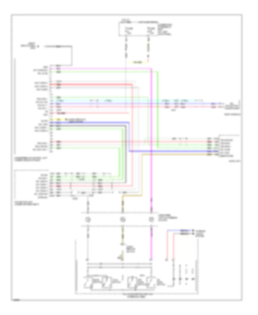
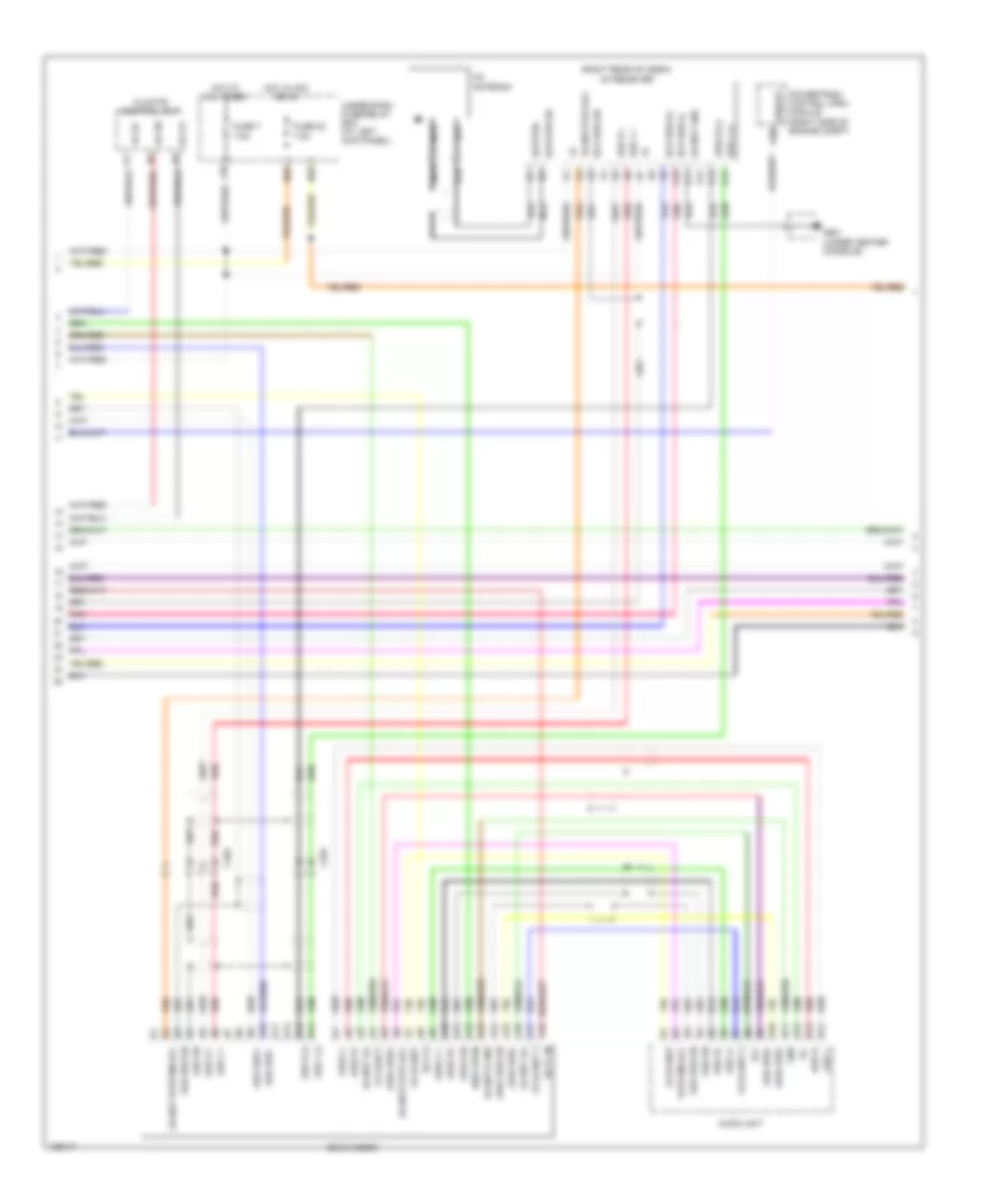
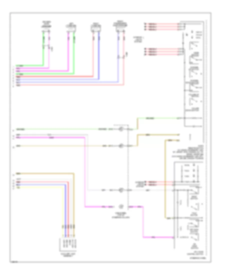
Hands Free Module Wiring Diagram for Honda Ridgeline RTS 2014
List of elements for Hands Free Module Wiring Diagram for Honda Ridgeline RTS 2014:
- (right end of dash) g402
- Acc
- Audio remote switch
- Audio unit
- B can
- B10
- B11
- Back switch
- C10
- C11
- C12
- C13
- C15
- C401
- C402
- C405
- C406
- Cable reel (top of steering column)
- Computer data lines system
- Fuse 20a
- Fuse 7.5a
- Gnd
- Handsfreelink control unit (under middle of dash)
- Hfl comm 1
- Hfl comm 2
- Hfl comm 3
- Hfl comm 4
- Hfl comm sh
- Hfl icon
- Hfl mute
- Hfl navi mic +
- Hfl navigation microphone
- Hfl-voice control switch
- Hft strg sw
- Hot at all times
- Hot in acc or on
- Interior lights system
- Mic out +
- Mic out -
- Mic out sh
- Mic sh
- Mic sig +
- N11
- N39
- Navi comm
- Navi comm 1
- Navi comm 2
- Navi comm 3
- Navi comm 4
- Navigation unit (under driver's seat)
- Off hook switch
- On hook switch
- Pnk
- Red
- Remote gnd
- Roof console
- Steering wheel
- Strg sw
- Talk switch
- Telm sig +
- Telm sig -
- Telm sig sh
- Under-dash fuse/relay box (at left kick panel)
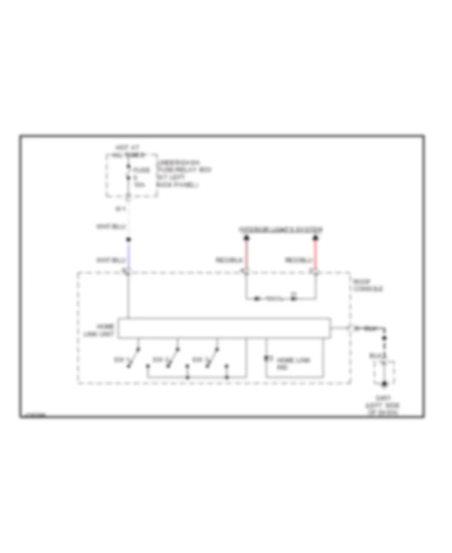
Home Link Remote Control Wiring Diagram for Honda Ridgeline RTS 2014
List of elements for Home Link Remote Control Wiring Diagram for Honda Ridgeline RTS 2014:
- Fuse 10a
- G401 (left side of dash)
- Home link ind
- Home link unit
- Hot at all times
- Interior lights system
- Roof console
- Sw 1
- Sw 2
- Sw 3
- Under-dash fuse/relay box (at left kick panel)
Navigation Wiring Diagram (1 of 4) for Honda Ridgeline RTS 2014
List of elements for Navigation Wiring Diagram (1 of 4) for Honda Ridgeline RTS 2014:
- (rear entertainment & honda accessory)
- A10
- A11
- A12
- A13
- A14
- A15
- A16
- A17
- A18
- A19
- A20
- Ac-ck
- Ac-si
- Ac-so
- Acc
- Ampli- fier
- Audio bus -
- Audio bus sh
- Audio bus(+)
- B sig
- B10
- B11
- B12
- B13
- B14
- B15
- B16
- B17
- B18
- B19
- B20
- B21
- B22
- B23
- B24
- B25
- B26
- B27
- B28
- B29
- B30
- B31
- B32
- Back lt
- C sig
- C10
- C11
- C12
- C13
- C14
- C15
- C16
- C201
- C402
- C405
- C406
- Cam adpt
- Cam gnd
- Camera sh
- Camera v
- Cd eject
- Ceiling light
- Ceiling light connector
- Diag +
- Diag -
- Disp open
- Dvd player unit
- Ecu bus +
- Ecu bus -
- Ecu bus sg gnd
- Ecu bus sh
- Ens bus sg gnd
- Exterior lights system
- Frequency modulator unit
- Fuse 10a
- G sig
- G402 (right end of dash)
- G501 (under center console)
- Gnd
- Gnd sig
- Gps
- Gps antenna (under middle of dash)
- Gps antenna connector
- Gps sh
- Handsfree link control unit (under middle of dash)
- Hfl comm 2
- Hfl comm 3
- Hfl comm 4
- Hfl comm sh
- Hfl comm1
- Hfl navi mic int
- Hft strg sw
- Hot at all times
- I-ves/ monitor terminal connector
- Ill +
- Ill+
- Ill-
- Interior lights system
- Left
- Lt back
- Mic sh
- Mic sig +
- Micu
- Navi comm
- Navi comm 1
- Navi comm 2
- Navi comm 3
- Navi comm 4
- Navigation display unit
- Navigation system
- Navigation unit (usa rtl, usa se; canada touring) (under driver's seat)
- Nca
- P27
- Pnk
- Q10
- R sig
- Rd sw
- Red
- Rg gnd
- Rg l +
- Rg sh
- Right
- Scty 5
- Scty2
- Shd gnd
- Sig gnd
- Sig sh
- Strg sw
- Term din
- Under-dash fuse/relay box (at left kick panel)
- Video monitor console
- Vsp
Navigation Wiring Diagram (2 of 4) for Honda Ridgeline RTS 2014
List of elements for Navigation Wiring Diagram (2 of 4) for Honda Ridgeline RTS 2014:
- (right rear of cabin) xm receiver
- +b ga-net
- +b ga-net 2
- A10
- A11
- A12
- A13
- A14
- A15
- A16
- A17
- A18
- A30
- Ac-ck
- Ac-si
- Ac-so
- Aud bus +
- Aud bus -
- Aud bus sh
- Aud bus+
- Aud l (-)
- Aud l +
- Aud l+
- Aud l-
- Aud r (-)
- Aud r +
- Aud r+
- Aud r-
- Aud sh
- Aud2 bus sh
- Aud2 bus+
- Aud2 bus-
- Aud2 l +
- Aud2 l-
- Aud2 r (-)
- Aud2 r+
- Aud2 r-
- Aud2 sh
- Audio unit
- B10
- B11
- B12
- B13
- B14
- C404
- Cd changer
- Cd eject
- Climate control unit
- Disp open
- Ecu bus (+)
- Ecu bus (-)
- Ecu bus sh
- Fuse 32 7.5a
- Fuse 7 7.5a
- G501 (under center console)
- Ga net ill
- Ga-net gnd
- Ga-net ill
- Ga-net sys acc
- Ga-net system acc
- Ga-net2 gnd
- Ga-net2 sys acc
- Gnd
- Hot at all times
- Hot in acc or on
- Ill+
- Ill-
- N36
- N39
- Nca
- Pnk
- Powertrain control (pcm) module (right side of engine compt)
- Red
- Sat/ter
- Sat/ter sh
- Scty in
- Scty2
- System acc
- Under-dash fuse/relay box (at left kick panel)
- Vssout
- X35
- Xm antenna
Navigation Wiring Diagram (3 of 4) for Honda Ridgeline RTS 2014
List of elements for Navigation Wiring Diagram (3 of 4) for Honda Ridgeline RTS 2014:
- (not used)
- A10
- A11
- A12
- A13
- A14
- A15
- A16
- A17
- A18
- A19
- A20
- A21
- A22
- A23
- A24
- Acc
- Am/fm antenna
- Am/fm antenna amplifier
- Ant
- Ant +b
- Ant in
- Audio unit
- Audio unit connector
- Audio unit connector d
- Aux det
- Aux gnd
- C10
- C11
- C12
- C13
- C14
- C403
- C404
- C409
- C506
- C507
- Computer data lines system
- Connector
- Fm modu- lator (honda acce- ssory)
- Fr l spkr+
- Fr l spkr-
- Fr r spkr+
- Fr r spkr-
- Fuse 5 20a
- G404 (right center of dash)
- Gnd
- Hfl icon
- Hfl mute
- Hot at all times
- Ill (+)
- Ill (-)
- Interior lights system
- J/c c452 (middle of dash)
- K-line
- K10
- L ch
- Left rear door speaker
- N11
- N23
- N24
- Navigation system
- Nca
- R ch
- Red
- Remote control
- Remote gnd
- Rg gnd
- Rg l +
- Right rear door speaker
- Rr l spkr -
- Rr l spkr+
- Rr r spkr+
- Rr r spkr-
- Rr woofer+
- Rr woofer-
- S gnd
- Scty
- Shd gnd
- Shield (am/fm)
- Sig
- Subwoofer (w/ honda accessory usa: rts) (w/o honda accessory usa rtl, usa se; canada touring)
- Telm sig sh
- Telm sig+
- Telm sig-
- Under-dash fuse/relay box (at left kick panel)
- W/ honda accessory
- W/o honda accessory
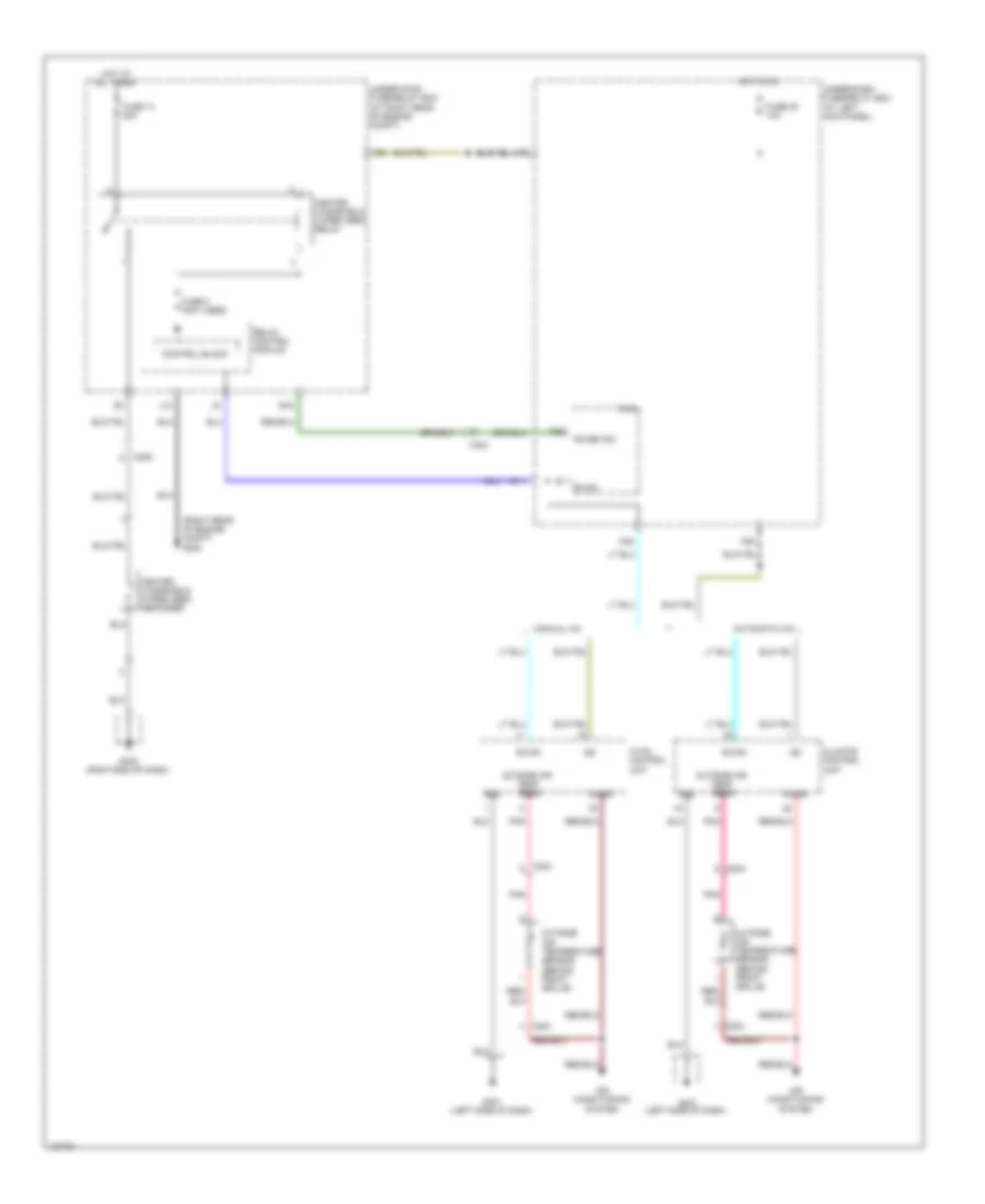
Navigation Wiring Diagram (4 of 4) for Honda Ridgeline RTS 2014
List of elements for Navigation Wiring Diagram (4 of 4) for Honda Ridgeline RTS 2014:
- Audio remote switch (w/ honda accessory usa: rt, sport, rts; canada: dx, vp, sport, sport-se) (w/o honda accessory usa: rtl, usa se; canada touring)
- Aux det
- Aux gnd
- Aux l ch
- Aux r ch
- Auxiliary jack assembly
- B10
- B11
- B12
- Back switch
- C10
- C11
- C12
- C405
- C408
- C453
- Cable reel (top of steering column)
- Channel down switch
- Channel up switch
- Driver's door speaker
- Front passenger's door speaker
- Hfl-voice control switch
- Interior lights system
- Left tweeter
- Mode switch
- Off hook switch
- On hook switch
- Red
- Right tweeter
- S gnd
- Steering wheel
- Talk switch
- Volume down switch
- Volume up switch
Parking Assistant Wiring Diagram for Honda Ridgeline RTS 2014
List of elements for Parking Assistant Wiring Diagram for Honda Ridgeline RTS 2014:
- A14
- Atp- r
- B15
- Back lt
- Backup sensor beeper assembly
- Backup sensor beeper switch
- Backup sensor control unit
- Backup sensor in-line fuse
- Backup sensor tailgate switch
- C204
- C509
- Exterior lights system
- Fuse 7.5a
- G101 (right front of engine)
- G40
- Hot in on or start
- Ig1
- J/c c101 (right side of engine compt)
- J/c c103 (middle rear of engine compt)
- Left corner backup sensor
- Left middle backup sensor
- Micu
- On indicator
- P20
- Q10
- Red
- Right corner backup sensor
- Right middle backup sensor
- Transmission range switch (on transmission housing)
- Transmissions system
- Under-dash fuse/relay box (at left kick panel)
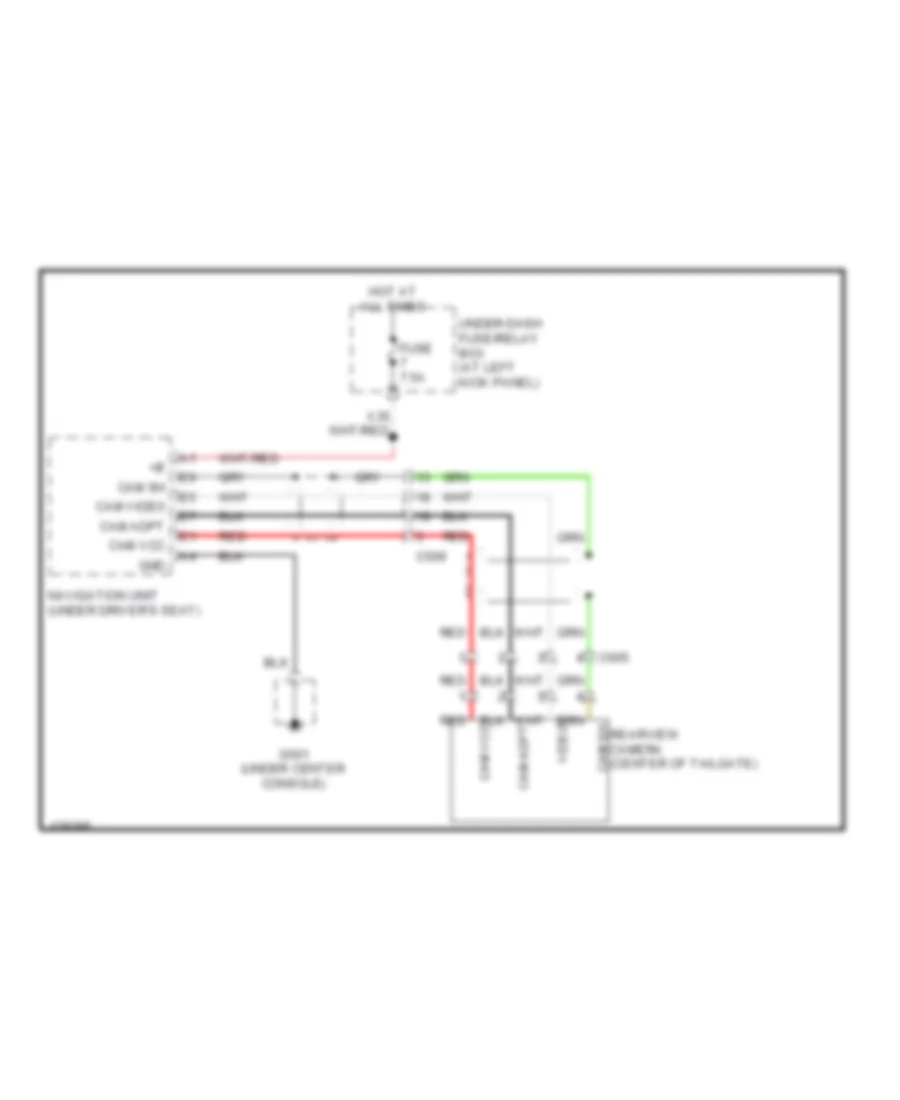
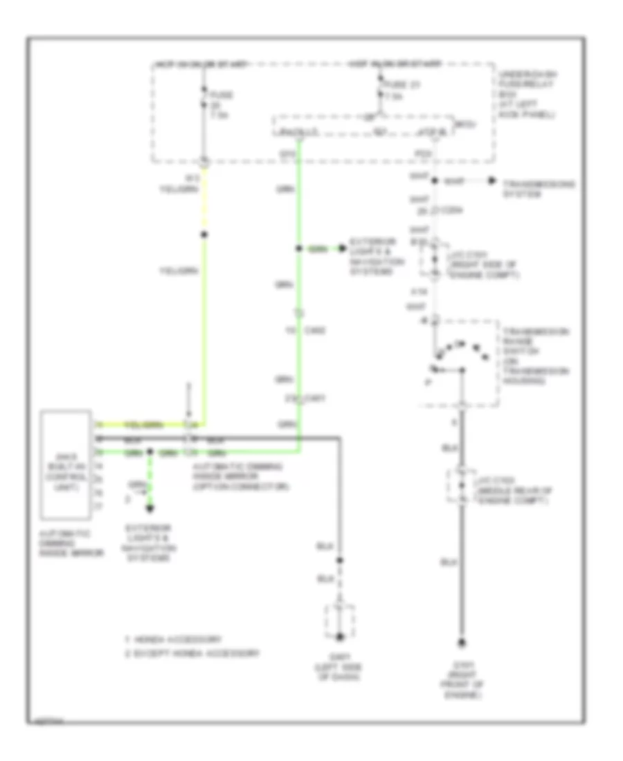
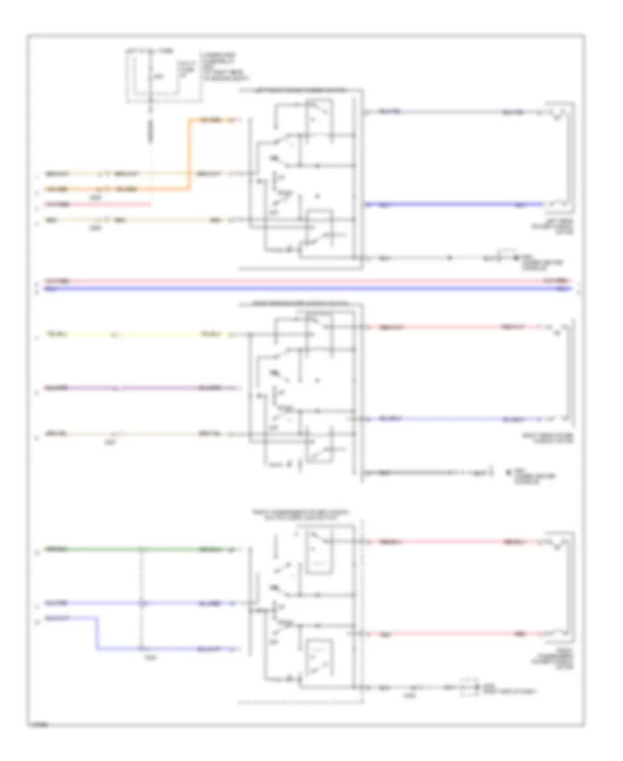
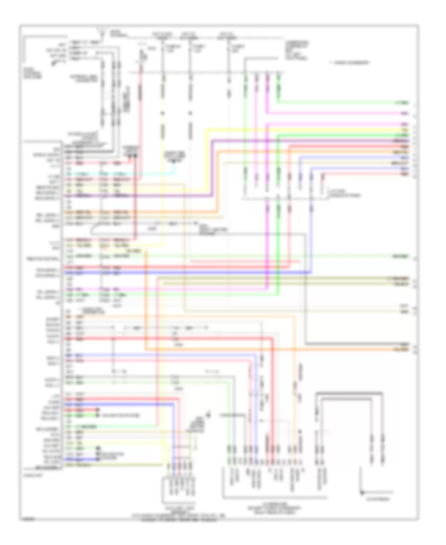
Rear Camera Wiring Diagram, with Navigation for Honda Ridgeline RTS 2014
List of elements for Rear Camera Wiring Diagram, with Navigation for Honda Ridgeline RTS 2014:
- C509
- C605
- Cam adpt
- Cam sh
- Cam sh rearview camera (center of tailgate)
- Cam vcc
- Cam video
- Fuse 7.5a
- G501 (under center console)
- Gnd
- Hot at all times
- Navigation unit (under driver's seat)
- Red
- Under-dash fuse/relay box (at left kick panel)
- Video
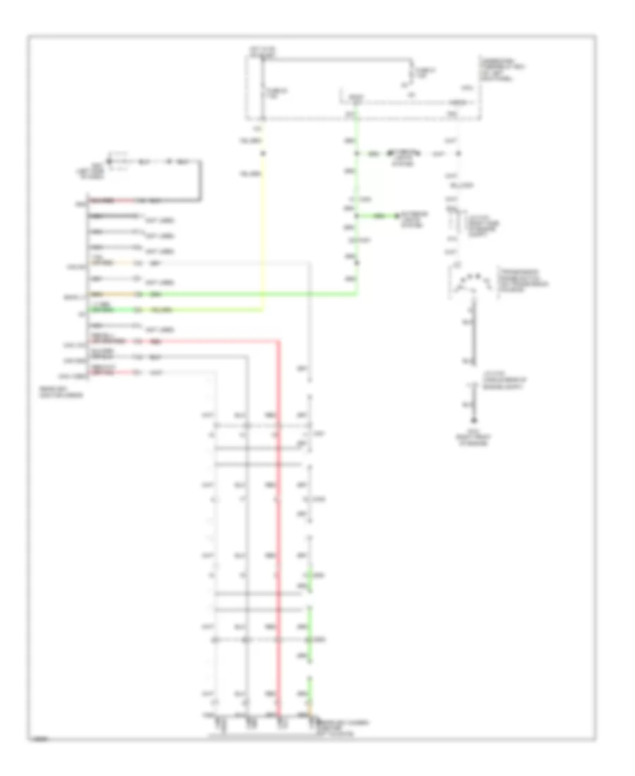
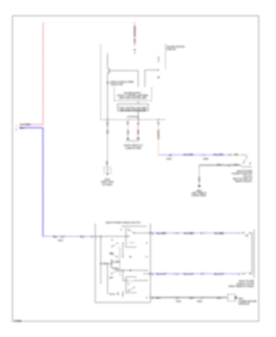
Rear Camera Wiring Diagram, without Navigation for Honda Ridgeline RTS 2014
List of elements for Rear Camera Wiring Diagram, without Navigation for Honda Ridgeline RTS 2014:
- (middle rear of
- (not used)
- A14
- Atp-r
- B15
- Back lt
- C204
- C401
- C402
- C509
- C605
- Cam gnd
- Cam sh
- Cam vcc
- Cam video
- Engine compt)
- Exterior lights system
- Fuse 20 7.5a
- Fuse 21 7.5a
- G101 (right front of engine)
- G401 (left side of dash)
- Gnd
- Hot in on or start
- Ig1
- J/c c101 (right side of engine compt)
- J/c c103
- Micu
- Nca
- P20
- Q10
- Rearview monitor mirror
- Red
- Red cam
- Sh rearview camera (center of tailgate)
- Tan (or red)
- Transmission range switch (on transmission housing)
- Under-dash fuse/relay box (at left kick panel)
- Vcc
POWER DISTRIBUTION
Power Distribution Wiring Diagram (1 of 5) for Honda Ridgeline RTS 2014
List of elements for Power Distribution Wiring Diagram (1 of 5) for Honda Ridgeline RTS 2014:
- (at right rear of engine compt) under-hood fuse/relay box
- (not used)
- (trailer electric brake connector)
- 120a
- 40a
- A/c compressor clutch relay
- A/c condenser fan relay
- Alternator
- Auxiliary under-hood relay box (right front of engine compt)
- Battery
- C302
- C401
- C410
- Cigarette lighter (honda accessory)
- Driver's accessory power socket (except honda accessory)
- Eld unit
- Etcs control
- From under- dash fuse/ d
- From under-dash fuse/relay box (diagram 5 of 5)
- Front accessory power socket relay (left side of dash)
- Front passenger's accessory power socket
- Fuse 15a
- Fuse 20a
- Fuse 30a
- Fuse 40a
- Fuse 7.5a
- G1 (left front of engine compt)
- G401 (left side of dash)
- G402 (right end of dash)
- Moonroof close relay (usa: rtl & se; canada: touring)
- Moonroof open relay (usa: rtl & se; canada: touring)
- Multi- fuse 22
- Radiator fan relay
- Relay
- Relay box (diagram 4 of 5)
- Seat heater relay (usa: rtl & se; canada: sport- se & touring)
- Starter
- Starter solenoid
- T101
- To fuse 16 (diagram 2 of 5)
- To fuse 8 (diagram 3 of 5)
- To low beam headlight relay (diagram 2 of 5)
- To multi- fuse 23 (diagram 3 of 5)
- To under- dash fuse/ relay box (diagram 2 of 5)
- Tpms control unit
- Trailer electric brake (if equipped)
- Trailer lighting control unit
- Trailer lighting relay 1
- Trailer lighting relay 2
- Transmission housing
- Usa: rt sport
- Usa: rts, rtl & se; canada
- Vsa modulator control unit
- Vtm-4 relay
Power Distribution Wiring Diagram (2 of 5) for Honda Ridgeline RTS 2014
List of elements for Power Distribution Wiring Diagram (2 of 5) for Honda Ridgeline RTS 2014:
- (at left kick panel) under-dash fuse/relay box
- (at right rear of engine compt) under-hood fuse/relay box
- (diagram 1 of 5)
- (not used)
- (usa: rts, rtl & se; canada: sport-se & touring)
- +b hazard
- A/c inverter unit (usa: rtl & se; canada: touring) (under front passenger's seat)
- A/f sensor relay
- Ac power outlet
- Ac+
- Ac-
- B21
- Brake pedal position switch
- C201
- C205
- C302
- C503
- C505
- Cargo area light relay
- Ckp sensor
- Cmp sensor
- Cpu
- D14
- D17
- Day lt
- Driver's lumbar support switch
- Driver's power seat adjustment switch
- Drl relay
- Etcs control relay
- F11
- F13
- F19
- From fuse 20 g
- From multi- c
- From pgm-fi main relay 1 s (diagram 3 of 5)
- From under- dash fuse/ relay box (diagram 5 of 5)
- From under-hood fuse/relay box (diagram 1 of 5)
- Fuse (not used)
- Fuse 10a
- Fuse 15a
- Fuse 20a
- Fuse 22 (diagram 1 of 5)
- Fuse 40a
- Fuse 7.5a
- G501 (under center console)
- Hazard warning switch/front passenger's air bag cut-off indicator
- High beam headlight relay
- Horn relay
- Ignition coil relay
- Injector 1
- Injector 2
- Injector 3
- Injector 4
- Injector 5
- Injector 6
- Inverter
- J/c c101 (right side of engine compt)
- J/c c103 (middle rear of engine compt)
- Low beam headlight relay
- Maf/iat sensor
- Micu
- N40
- N45
- Pgm-fi main relay 2
- Powertrain control module (pcm)
- Red
- Relay control module
- Taillight relay
- Turn signal/ hazard relay
- X12
- X23
- X26
- X31
Power Distribution Wiring Diagram (3 of 5) for Honda Ridgeline RTS 2014
List of elements for Power Distribution Wiring Diagram (3 of 5) for Honda Ridgeline RTS 2014:
- (at left kick panel) under-dash fuse/relay box
- (at right rear of engine compt) under-hood fuse/relay box
- (diagram 1 of 5)
- (not used)
- (usa: rtl & se, canada: touring) xm receiver
- +b door lock
- 20a
- 50a
- 60a
- A/c condenser fan relay
- A/c diode assembly
- A/f sensor relay
- A19
- A24
- Audio unit (w/o navigation)
- Auxiliary under-hood relay box (right front of engine compt)
- Blower motor relay
- C402
- C405
- C408
- C453
- C454
- C505
- C505 c505
- C506
- C507
- Canada: touring
- Ceiling light
- Combination switch control unit
- Console box light 1
- Control block
- D10
- D12
- D16
- Dlc
- Driver's door courtesy light
- Driver's vanity mirror light
- Dvd player unit (honda accessory)
- Except usa: rtl & se
- F13
- Fog light relay (usa: sport, rtl & se canada: vp, sport, sport-se & touring)
- From fuse 12 e
- From fuse 19 f
- From fuse 32 (diagram 5 of 5)
- Front individual map lights
- Front passenger's door courtesy light
- Front passenger's vanity mirror light
- Fuse
- Fuse 10a
- Fuse 15a
- Fuse 20a
- Fuse 40a
- Fuse 7.5a
- G401 (left side of dash)
- G501 (under center console)
- Gauge control module
- Handsfree link control unit (w/ navigation: usa: rtl & se; canada: touring)
- Heated windshield
- Ignition coil relay
- Ignition key switch/key light
- Immobilizer control unit- receiver
- Imoes unit
- Left rear door courtesy light
- Micu
- Multi- fuse 23
- N10
- N11
- N15
- N42
- Navigation display unit (usa: rtl & se, canada: touring)
- Navigation unit (usa: rtl & se, canada: touring)
- Pcm
- Pgm-fi main relay 1
- Power window master switch
- Rear accessory power socket
- Rear accessory power socket relay
- Relay control module
- Right rear door courtesy light
- Roof console
- To pgm-fi main relay 2 (diagram 2 of 5)
- To under- dash fuse/ relay box (diagram 4 of 5)
- To under- dash fuse/ relay box (diagram 5 of 5)
- Usa: rtl & se;
- Vbu
- Video monitor console (honda accessory)
- W/ navigation
- W/o navigation
- Wiper area relay
- Wiper/washer switch
- X204
- X22
- X35
Power Distribution Wiring Diagram (4 of 5) for Honda Ridgeline RTS 2014
List of elements for Power Distribution Wiring Diagram (4 of 5) for Honda Ridgeline RTS 2014:
- (at left kick panel) under-dash fuse/relay box
- (at right rear of engine compt) under-hood fuse/relay box
- (not used)
- A/c compressor clutch relay
- A20
- Alternator
- B13
- B20
- Back power window switch
- Blower motor relay
- Brake pedal position switch
- C13
- C403
- C408
- C454
- C502
- C506
- C507
- Cable reel (top of steering column)
- Combination switch control unit
- Control block
- Cruise control combination switch
- D3 switch/shift lock solenoid/park pin switch
- Dash lights brightness controller
- Evap canister purge valve
- From fuse 20 (diagram 5 of 5)
- From under- dash fuse/ relay box (diagram 4 of 5)
- From under- dash fuse/ relay box (diagram 5 of 5)
- From under- hood fuse/ relay box (diagram 3 of 5)
- Front passenger's power window switch/door lock switch
- Fuse 15a
- Fuse 20a
- Fuse 7.5a
- Gauge control module
- H11
- Heated windshield wiper area relay
- Ig1
- Intermittent wiper relay
- J/c c101 (right side of engine compt)
- J/c c105 (rear of engine)
- Left rear power window switch
- Micu
- N12
- N29
- Power window master switch
- Power window relay
- Powertrain control module (pcm)
- Relay control module
- Right rear power window switch
- Seat heater relay (usa: rtl & se; canada: sport-se & touring)
- Shift lock solenoid
- Steering wheel
- Tan
- To under- dash fuse/ relay box (diagram 5 of 5)
- To under- hood fuse/ relay box (diagram 1 of 5)
- To under- hood fuse/ relay box (diagram 4 of 5)
- Vtm-4 control unit
- Vtm-4 relay
- Washer motor relay
- Windshield wiper motor
- Wiper/washer switch
- X14
- X24
- X34
- X37
- X39
Power Distribution Wiring Diagram (5 of 5) for Honda Ridgeline RTS 2014
List of elements for Power Distribution Wiring Diagram (5 of 5) for Honda Ridgeline RTS 2014:
- (not
- (not used)
- (option connector)
- (w/ navigation, usa: rtl & se; canada: touring)
- A/c diode assembly
- A14
- A26
- A27
- Acc
- Audio unit (w/o navigation)
- Automatic dimming inside mirror (w/ navigation)
- Auxiliary under-hood relay box (right front of engine compt)
- B42
- C205
- C302
- C402
- C406
- C408
- C453
- C504
- Climate control unit (usa: rts, rtl & se; canada: touring)
- Combination light switch
- Dvd player unit (honda accessory)
- Fan control relay
- From ac inverter unit (diagram 2 of 5)
- From under- dash fuse/ relay box (diagram 4 of 5)
- From under- hood fuse/ relay box (diagram 3 of 5)
- Front passenger's power window switch/door lock switch
- Fuse 10a
- Fuse 15a
- Fuse 2a
- Fuse 30a
- Fuse 7.5a
- Gauge control module
- Handsfree link control unit
- Hazard warning switch/front passenger's air bag cut-off indicator
- Hvac control unit (usa: rt, sport & canada: dx, sport & vp)
- Ignition key switch/key light
- Ignition switch
- Immobilizer control unit- receiver
- Imoes unit
- J/c c101 (right side of engine compt)
- Key interlock solenoid
- Lock
- N20
- N36
- N38
- N39
- N41
- N44
- Navigation display unit
- Navigation unit
- Ods unit
- Pgm-fi main relay 2
- Power mirror switch
- Powertrain control module (pcm)
- Radiator fan relay
- Rearview monitor mirror (w/o navigation)
- Recir- culation control motor
- Security control unit
- Srs unit
- Start
- Starter cut relay
- Steering angle sensor
- To front accessory power socket relay (diagram 1 of 5)
- To fuse 18 (diagram 4 of 5)
- To rear accessory power socket relay (diagram 3 of 5)
- To under- hood fuse/ relay box (diagram 4 of 5)
- Tpms control unit
- Trailer lighting relay 1
- Under- dash fuse/ relay box (at left kick panel)
- Under-dash fuse/relay box (at left kick panel)
- Usa: rtl & se; canada: touring
- Used)
- Vsa modulator control unit
- Vtm-4 lock switch
- W/ honda accessory
- X16
- X17
- X20
- X38
- Yaw rate- lateral acceleration sensor
POWER DOOR LOCKS
Power Door Locks Wiring Diagram (1 of 3) for Honda Ridgeline RTS 2014
List of elements for Power Door Locks Wiring Diagram (1 of 3) for Honda Ridgeline RTS 2014:
- (not used)
- (usa: rts, rtl, se; canada: touring)
- 20a
- 7.5a
- A10
- A19
- A20
- Anti-theft system
- As unlock
- B-can
- Body controller area network transceiver
- C408
- C453
- C454
- D11
- Door lock knob
- Door lock switch
- Dr unlock
- Driver's door switch (on left "b" pillar)
- Drswas
- Drswdr
- Drswra
- Drswrd
- E10
- E14
- E15
- Front passenger's door lock knob switch (usa: rts, rtl, se; canada: touring)
- Front passenger's door switch (on right "b" pillar)
- Front passenger's power window switch/door lock switch
- Fuse 21
- Fuse 2a
- Fuse 7.5a
- Fuse 8
- G401 (left side of dash)
- G402 (right end of dash)
- G403 (left side of dash)
- G501 (under center console)
- Gauge control module
- H10
- H12
- H13
- Hot at all times
- Hot in on or start
- Ig1
- Ignition key switch
- Ignition key switch/key light
- K11
- K12
- Left rear door switch (on left "c" pillar)
- Lock
- Micu
- Micu gnd
- Multi- information display (mid) unit
- N28
- N38
- N44
- P1 sg-1
- P13 ig key sw
- P25 rem as lock
- P27 scty in
- P29 sil as unlock
- P9 rem as unlock
- Q11 tailgate sw
- Q12 trunk handle sw
- Q2 sil ra unlock
- Q3 sil rd unlock
- Q4 trunk unlock
- Right rear door switch (on right "c" pillar)
- Security light ind (usa: rts, rtl, se; canada: touring)
- Trunk act
- Trunk sw
- Under-dash fuse/relay box (at left kick panel)
- Unlock
- Vbu
- Warning drive circuit
- X34
- X35
Power Door Locks Wiring Diagram (2 of 3) for Honda Ridgeline RTS 2014
List of elements for Power Door Locks Wiring Diagram (2 of 3) for Honda Ridgeline RTS 2014:
- (usa: rts, rtl, se; canada: touring)
- 15a
- 20a
- 7.5a
- A18
- Audio unit
- C203
- C454
- C506
- C507
- Cd changer
- Control block
- Door lock knob
- Door lock switch
- Door multiplex control unit
- Driver's door key cylinder switch
- Driver's door lock knob switch
- Fuse 13
- Fuse 4
- Fuse 7
- G201 (behind right headlight)
- G401 (left side of dash)
- G501 (under center console)
- H14
- H15
- High horn (behind left side of front bumper)
- Horn relay
- Horns system
- Hot at all times
- Ign
- Interior lights system
- Key
- Key lock
- Key unlock
- Keyless entry transmitter
- Knob lock
- Knob unlock
- Left rear door lock knob switch (usa: rts, rtl, se; canada: touring) (rear of left rear door)
- Lock
- Low horn (behind left end of front bumper)
- Pg1
- Power window master switch
- Relay control module
- Right rear door lock actuator (rear of right rear door)
- Right rear door lock knob switch (usa: rts, rtl, se; canada: touring) (rear of right rear door)
- Security hood switch (usa: rts, rtl, se; canada: touring) (center front of engine compt)
- Sgnd
- Taillight relay
- Under-hood fuse/relay box (at right rear of engine compt)
- Unlock
- Vbu
- W/ navigation
- W/o navigation
Power Door Locks Wiring Diagram (3 of 3) for Honda Ridgeline RTS 2014
List of elements for Power Door Locks Wiring Diagram (3 of 3) for Honda Ridgeline RTS 2014:
- (usa: rts, rtl, se; canada: touring)
- C403
- C408
- C453
- C506
- C509
- C510
- C601
- Driver's door lock actuator (at rear of driver's door)
- Front passenger's door lock actuator (at rear of front passenger's door)
- G51
- G601 (left side of cargo area)
- G602 (right side of cargo area)
- In-bed trunk lid actuator
- In-bed trunk lid actuator/latch switch (in-bed trunk lid)
- In-bed trunk lid handle switch (in-bed trunk lid)
- In-bed trunk lid key cylinder switch (usa: rts, rtl, se; canada: touring) (in-bed trunk lid)
- In-bed trunk lid latch switch
- In-bed trunk lid main switch
- Left rear door lock actuator (rear of left rear door)
- Mic
- Microphone
- Nca
- Security control unit
- Security indicator
- Tailgate switch (right rear of cargo area)
POWER MIRRORS
Automatic Day/Night Mirror Wiring Diagram for Honda Ridgeline RTS 2014
List of elements for Automatic Day/Night Mirror Wiring Diagram for Honda Ridgeline RTS 2014:
- (has built-in control unit)
- 7.5a
- A14
- Atp-r
- Automatic dimming inside mirror
- Automatic dimming inside mirror (option connector)
- B15
- Back lt
- C204
- C401
- C402
- Except honda accessory
- Exterior lights & navigation systems
- Fuse 21
- Fuse 7.5a
- G101 (right front of engine)
- G401 (left side of dash)
- Honda accessory
- Hot in on or start
- Ig1
- J/c c101 (right side of engine compt)
- J/c c103 (middle rear of engine compt)
- Micu
- P20
- Q10
- Transmission range switch (on transmission housing)
- Transmissions system
- Under-dash fuse/relay box (at left kick panel)
Power Mirrors Wiring Diagram for Honda Ridgeline RTS 2014
List of elements for Power Mirrors Wiring Diagram for Honda Ridgeline RTS 2014:
- (under center console)
- C408
- C453
- Canada
- Defogger
- Down
- Fuse 30 10a
- G402 (right end of dash)
- G501
- Hot in on
- Interior lights system
- J10
- J11
- J12
- J21
- Left
- Left power mirror
- Left/right motor
- Left/right switch
- Mirror defogger switch (usa: rtl & canada)
- Mirror selection switch
- Off
- Power mirror switch
- Red
- Right
- Right power mirror
- Under-dash fuse/relay box (at left kick panel)
- Up/down motor
- Up/down switch
- Usa: rtl &
- X21
POWER SEATS
Heated Seats Wiring Diagram for Honda Ridgeline RTS 2014
List of elements for Heated Seats Wiring Diagram for Honda Ridgeline RTS 2014:
- Back heater
- C205
- C402
- C404
- C503
- C504
- Circuit breaker
- Cushion
- Cushion heater
- Driver's seat heater
- Driver's seat heater switch
- E14
- F14
- Front passenger's seat heater
- Front passenger's seat heater switch
- Fuse 11 15a
- Fuse 30 10a
- G202 (right rear of engine compt)
- G402 (right end of dash)
- G501 (under center console)
- High
- Hot at all times
- Hot in on
- Interior lights system
- Low
- On indicators
- Red
- Seat heater relay
- Seat heater switch light
- Thermostat
- Under-dash fuse/relay box (at left kick panel)
- Under-hood fuse/relay box (at right rear of engine compt)
Power Seat Wiring Diagram for Honda Ridgeline RTS 2014
List of elements for Power Seat Wiring Diagram for Honda Ridgeline RTS 2014:
- Backward
- C503
- Down
- Driver's lumbar support motor (in driver's seat back)
- Driver's lumbar support switch
- Driver's power seat adjustment switch
- Driver's power seat front up- down motor (under driver's seat)
- Driver's power seat rear up- down motor (under driver's seat)
- Driver's power seat recline motor (in driver's seat back)
- Driver's power seat slide motor (under driver's seat)
- F11
- F13
- Forward
- Fuse 13 10a
- Fuse 14 20a
- Fuse 16 20a
- G501 (under center console)
- Hot at all times
- Red
- Under-dash fuse/relay box (at left kick panel)
- X26 (not used)
POWER TOP/SUNROOF
Power Top/Sunroof Wiring Diagram for Honda Ridgeline RTS 2014
List of elements for Power Top/Sunroof Wiring Diagram for Honda Ridgeline RTS 2014:
- (rear of roof)
- (rear of roof) moonroof close relay
- Auxiliary under-hood fuse box (left rear of engine compt)
- C302
- C401
- Close
- Driver's door switch (on left "b" pillar)
- Drswas
- Drswdr
- E15
- Front passenger's door switch (on right "b" pillar)
- Fuse 11 20a
- Fuse 21 7.5a
- Fuse 7 7.5a
- G401 (left side of dash)
- G501 (under center console)
- H12
- Hot at all times
- Hot in on or start
- Ig1
- Interior lights system
- Key off timer
- Micu
- Moonroof limit switch (rear of roof)
- Moonroof motor (rear of roof)
- Moonroof open relay
- Moonroof switch
- Moonroof switch lights
- Open
- P12
- Red
- Tilt
- Tilt & close
- Under-dash fuse/ relay box (at left kick panel)
- Vbu
POWER WINDOWS
Power Windows Wiring Diagram (1 of 3) for Honda Ridgeline RTS 2014
List of elements for Power Windows Wiring Diagram (1 of 3) for Honda Ridgeline RTS 2014:
- (in driver's door)
- Auto
- B-can
- C403
- C453
- C454
- C502
- Door multiplex control unit
- Down
- Dr down
- Dr up
- Driver's door key cylinder switch 1) unlock 2) lock
- Driver's power window motor
- Driver's switch 0) off 1) up 2) down 3) auto down 5) auto up
- Driver's switch light
- E11
- Fp down
- Fp up
- Front passenger's switch
- Front passenger's switch light
- Fuse 20a
- Fuse 21 7.5a
- Fuse 7 7.5a
- G401 (left side of dash)
- G501 (under center console)
- Ground distribution system
- H11
- Hot at all times
- Hot in on or start
- Ig 1
- J15
- J16
- J18
- Key
- Key/ door lock knob
- Keyless receiver antenna
- Left rear switch
- Left rear switch light
- Lock
- Lr down
- Lr up
- Main switch
- Micu
- N12
- N19
- N42
- Off
- Pg 1
- Pls a
- Pls b
- Power window master switch
- Power window relay
- Pulser
- Right rear switch
- Right rear switch light
- Rr down
- Rr up
- Sgnd
- Svcc
- Under-dash fuse/relay box (at left kick panel)
- Unlock
- Vbu
- X14
- X35
Power Windows Wiring Diagram (2 of 3) for Honda Ridgeline RTS 2014
List of elements for Power Windows Wiring Diagram (2 of 3) for Honda Ridgeline RTS 2014:
- 50a
- C408
- C506
- C507
- Down
- Front passenger's power window motor
- Front passenger's power window switch/ door lock switch
- G402 (right end of dash )
- G501 (under center console)
- Hot at all times
- Left rear power window motor
- Left rear power window switch
- Multi- fuse
- Off
- Red
- Right rear power window motor
- Right rear power window switch
- Under-hood fuse/relay box (at right rear of engine compt)
Power Windows Wiring Diagram (3 of 3) for Honda Ridgeline RTS 2014
List of elements for Power Windows Wiring Diagram (3 of 3) for Honda Ridgeline RTS 2014:
- A19
- Back power window motor (right rear of cabin)
- Back power window position switch (bottom left of rear window)
- Back power window switch
- Back window open indicator
- C10
- C402
- C454
- C502
- C509
- Close
- Computer data lines system
- Fast controller area network tranceiver
- G402 (right end of dash)
- G501 (under center console)
- G601 (left side of cargo area)
- Gauge control module
- Off
- Open
- Red
RADIO
Radio Wiring Diagram, with Navigation (1 of 4) for Honda Ridgeline RTS 2014
List of elements for Radio Wiring Diagram, with Navigation (1 of 4) for Honda Ridgeline RTS 2014:
- (rear entertainment & honda accessory)
- A10
- A11
- A12
- A13
- A14
- A15
- A16
- A17
- A18
- A19
- A20
- Ac-ck
- Ac-si
- Ac-so
- Acc
- Ampli- fier
- Audio bus -
- Audio bus sh
- Audio bus(+)
- B sig
- B10
- B11
- B12
- B13
- B14
- B15
- B16
- B17
- B18
- B19
- B20
- B21
- B22
- B23
- B24
- B25
- B26
- B27
- B28
- B29
- B30
- B31
- B32
- Back lt
- C sig
- C10
- C11
- C12
- C13
- C14
- C15
- C16
- C201
- C402
- C405
- C406
- Cam adpt
- Cam gnd
- Camera sh
- Camera v
- Cd eject
- Ceiling light
- Ceiling light connector
- Diag +
- Diag -
- Disp open
- Dvd player unit
- Ecu bus +
- Ecu bus -
- Ecu bus sg gnd
- Ecu bus sh
- Ens bus sg gnd
- Exterior lights system
- Frequency modulator unit
- Fuse 10a
- G sig
- G402 (right end of dash)
- G501 (under center console)
- Gnd
- Gnd sig
- Gps
- Gps antenna (under middle of dash)
- Gps antenna connector
- Gps sh
- Handsfree link control unit (under middle of dash)
- Hfl comm 2
- Hfl comm 3
- Hfl comm 4
- Hfl comm sh
- Hfl comm1
- Hfl navi mic int
- Hft strg sw
- Hot at all times
- I-ves/ monitor terminal connector
- Ill +
- Ill+
- Ill-
- Interior lights system
- Left
- Lt back
- Mic sh
- Mic sig +
- Micu
- Navi comm
- Navi comm 1
- Navi comm 2
- Navi comm 3
- Navi comm 4
- Navigation display unit
- Navigation system
- Navigation unit (usa rtl, usa se; canada touring) (under driver's seat)
- Nca
- P27
- Pnk
- Q10
- R sig
- Rd sw
- Red
- Rg gnd
- Rg l +
- Rg sh
- Right
- Scty 5
- Scty2
- Shd gnd
- Sig gnd
- Sig sh
- Strg sw
- Term din
- Under-dash fuse/relay box (at left kick panel)
- Video monitor console
- Vsp
Radio Wiring Diagram, with Navigation (2 of 4) for Honda Ridgeline RTS 2014
List of elements for Radio Wiring Diagram, with Navigation (2 of 4) for Honda Ridgeline RTS 2014:
- (right rear of cabin) xm receiver
- +b ga-net
- +b ga-net 2
- A10
- A11
- A12
- A13
- A14
- A15
- A16
- A17
- A18
- A30
- Ac-ck
- Ac-si
- Ac-so
- Aud bus +
- Aud bus -
- Aud bus sh
- Aud bus+
- Aud l (-)
- Aud l +
- Aud l+
- Aud l-
- Aud r (-)
- Aud r +
- Aud r+
- Aud r-
- Aud sh
- Aud2 bus sh
- Aud2 bus+
- Aud2 bus-
- Aud2 l +
- Aud2 l-
- Aud2 r (-)
- Aud2 r+
- Aud2 r-
- Aud2 sh
- Audio unit
- B10
- B11
- B12
- B13
- B14
- C404
- Cd changer
- Cd eject
- Climate control unit
- Disp open
- Ecu bus (+)
- Ecu bus (-)
- Ecu bus sh
- Fuse 32 7.5a
- Fuse 7 7.5a
- G501 (under center console)
- Ga net ill
- Ga-net gnd
- Ga-net ill
- Ga-net sys acc
- Ga-net system acc
- Ga-net2 gnd
- Ga-net2 sys acc
- Gnd
- Hot at all times
- Hot in acc or on
- Ill+
- Ill-
- N36
- N39
- Nca
- Pnk
- Powertrain control (pcm) module (right side of engine compt)
- Red
- Sat/ter
- Sat/ter sh
- Scty in
- Scty2
- System acc
- Under-dash fuse/relay box (at left kick panel)
- Vssout
- X35
- Xm antenna
Radio Wiring Diagram, with Navigation (3 of 4) for Honda Ridgeline RTS 2014
List of elements for Radio Wiring Diagram, with Navigation (3 of 4) for Honda Ridgeline RTS 2014:
- (not used)
- A10
- A11
- A12
- A13
- A14
- A15
- A16
- A17
- A18
- A19
- A20
- A21
- A22
- A23
- A24
- Acc
- Am/fm antenna
- Am/fm antenna amplifier
- Ant
- Ant +b
- Ant in
- Audio unit
- Audio unit connector
- Audio unit connector d
- Aux det
- Aux gnd
- C10
- C11
- C12
- C13
- C14
- C403
- C404
- C409
- C506
- C507
- Computer data lines system
- Connector
- Fm modu- lator (honda acce- ssory)
- Fr l spkr+
- Fr l spkr-
- Fr r spkr+
- Fr r spkr-
- Fuse 5 20a
- G404 (right center of dash)
- Gnd
- Hfl icon
- Hfl mute
- Hot at all times
- Ill (+)
- Ill (-)
- Interior lights system
- J/c c452 (middle of dash)
- K-line
- K10
- L ch
- Left rear door speaker
- N11
- N23
- N24
- Navigation system
- Nca
- R ch
- Red
- Remote control
- Remote gnd
- Rg gnd
- Rg l +
- Right rear door speaker
- Rr l spkr -
- Rr l spkr+
- Rr r spkr+
- Rr r spkr-
- Rr woofer+
- Rr woofer-
- S gnd
- Scty
- Shd gnd
- Shield (am/fm)
- Sig
- Subwoofer (w/ honda accessory usa: rts) (w/o honda accessory usa rtl, usa se; canada touring)
- Telm sig sh
- Telm sig+
- Telm sig-
- Under-dash fuse/relay box (at left kick panel)
- W/ honda accessory
- W/o honda accessory
Radio Wiring Diagram, with Navigation (4 of 4) for Honda Ridgeline RTS 2014
List of elements for Radio Wiring Diagram, with Navigation (4 of 4) for Honda Ridgeline RTS 2014:
- Audio remote switch (w/ honda accessory usa: rt, sport, rts; canada: dx, vp, sport, sport-se) (w/o honda accessory usa: rtl, usa se; canada touring)
- Aux det
- Aux gnd
- Aux l ch
- Aux r ch
- Auxiliary jack assembly
- B10
- B11
- B12
- Back switch
- C10
- C11
- C12
- C405
- C408
- C453
- Cable reel (top of steering column)
- Channel down switch
- Channel up switch
- Driver's door speaker
- Front passenger's door speaker
- Hfl-voice control switch
- Interior lights system
- Left tweeter
- Mode switch
- Off hook switch
- On hook switch
- Red
- Right tweeter
- S gnd
- Steering wheel
- Talk switch
- Volume down switch
- Volume up switch
Radio Wiring Diagram, without Navigation (1 of 2) for Honda Ridgeline RTS 2014
List of elements for Radio Wiring Diagram, without Navigation (1 of 2) for Honda Ridgeline RTS 2014:
- (middle of dash)
- A10
- A11
- A12
- A13
- A14
- A15
- A16
- A17
- A18
- A19
- A20
- A21
- A22
- A23
- A24
- Acc
- Am/fm antenna
- Am/fm antenna amplifier
- Ant
- Ant +b
- Ant gnd
- Ant in
- Aud 2 l (-)
- Aud l (-)
- Aud l+
- Aud r (-)
- Aud r+
- Aud sh
- Aud2 bus +
- Aud2 bus -
- Aud2 bus sh
- Aud2 r-
- Audio unit
- Audio unit connector d
- Aux det
- Aux gnd
- Aux l ch
- Aux r ch
- Auxiliary jack assembly (w/o honda accessory usa: sport, rts, rtl, se; canada: vp, sport, sport-se, touring)
- B10
- B11
- B12
- B13
- B14
- Bus (+)
- Bus (-)
- Bus sh
- C10
- C11
- C12
- C13
- C14
- C404
- C409
- Computer data lines system
- Connector
- Fm modulator (honda accessory)
- Fr l spkr (+)
- Fr l spkr (-)
- Fr r spkr (+)
- Fr r spkr (-)
- Fuse 32 7.5a
- Fuse 5 20a
- Fuse 7 7.5a
- G404 (right center of dash)
- G501 (under center console)
- Ga-net
- Gnd
- Hfl icon
- Hfl mute
- Honda accessory
- Hot at all times
- Hot in acc or on
- Ill (+)
- Ill (-)
- Interior lights system
- J/c c452
- K line
- K10
- L ch
- Micu
- N11
- N23
- N24
- N36
- Navigation system
- Nca
- P27
- Pnk
- R ch
- Radio sw
- Red
- Remote control
- Remote gnd
- Rr l spkr (+)
- Rr l spkr (-)
- Rr r spkr (+)
- Rr r spkr (-)
- Rr woofer +
- Rr woofer -
- S gnd
- Sat/ter
- Sat/ter sh
- Scty
- Shd gnd
- Shield (am/fm)
- Sig
- Telm shd
- Telm sig +
- Telm sig -
- Under-dash fuse/relay box (at left kick panel)
- X35
- Xm antenna
- Xm receiver (except honda accessory) (right rear of cabin)
Radio Wiring Diagram, without Navigation (2 of 2) for Honda Ridgeline RTS 2014
List of elements for Radio Wiring Diagram, without Navigation (2 of 2) for Honda Ridgeline RTS 2014:
- (not used)
- (rear entertainment & honda accessory)
- (w/ honda accessory usa: rts) (w/o honda accessory usa: rts, rtl, se; canada touring) sub woofer
- Audio remote switch (w/ honda accessory usa: rt, sports, rts; canada: dx, vp, sport-se, sport) (w/o honda accessory usa: sport, se, rts, rtl; canada: sport, sport-se, touring)
- B11
- B12
- C11
- C12
- C403
- C404
- C408
- C453
- C506
- C507
- Cable reel (top of steering column)
- Ceiling light
- Ceiling light connector
- Channel down switch
- Channel up switch
- Driver's door speaker
- Dvd player unit
- Frequency modulator unit
- Front passenger's door speaker
- Fuse 10a
- Hot at all times
- I-ves/monitor terminal connector
- Interior lights system
- Left
- Left rear door speaker
- Left tweeter
- Mode switch
- Red
- Right
- Right rear door speaker
- Right tweeter
- Steering wheel
- Term din
- Under-dash fuse/relay box (at left kick panel)
- Video monitor console
- Volume down switch
- Volume up switch
XM Receiver Wiring Diagram for Honda Ridgeline RTS 2014
List of elements for XM Receiver Wiring Diagram for Honda Ridgeline RTS 2014:
- +b (1)
- +b (2)
- A10
- A11
- A12
- A13
- A14
- A24
- Audio lch+
- Audio lch-
- Audio rch+
- Audio rch-
- Audio unit
- B10
- B11
- B12
- B13
- B14
- Bus +
- Bus -
- C409
- Fuse 5 20a
- G404 (right center of dash)
- Gnd
- Gnd (2)
- Hot at all times
- Ill +
- N11
- Nca
- Parking gnd
- Pnk
- Red
- Sat/ter
- Sat/ter sh
- Shield
- Sys acc
- Under-dash fuse/relay box (at left kick panel)
- Xm antenna
- Xm receiver (honda accessory) (right rear of cabin)
SHIFT INTERLOCK
Shift Interlock Wiring Diagram for Honda Ridgeline RTS 2014
List of elements for Shift Interlock Wiring Diagram for Honda Ridgeline RTS 2014:
- (at left kick panel)
- (middle rear of engine compt) j/c c103
- (right front of engine) g101
- A16
- A18
- A19
- A24
- A25
- A26
- A27
- Anti-theft system
- App sensor (right rear of engine compt)
- Apsa
- Apsb
- Atp-p
- Bksw
- Brake pedal position switch (at top of brake pedal arm)
- C204
- C205
- D3 switch/shift lock solenoid/ park pin switch (shift lock solenoid: in steering column) (park pin switch: top left side of steering column)
- Fuse 13 20a
- Fuse 21 7.5a
- Fuse 29 7.5a
- Fuse 32 7.5a
- Fuse 7 7.5a
- G101 (right front of engine)
- G401 (left side of dash)
- Gauge control module
- Gnd
- Hot at all times
- Hot in acc or on
- Hot in on or start
- Ig key lt
- Ig key sw
- Ignition key
- Ignition key light
- Ignition key switch
- J/c c101 (right side of engine compt)
- J/c c103 (middle rear of engine compt)
- Key interlock solenoid
- Key sol
- Micu
- N26
- N36
- P-pin
- P13
- P15
- P16
- Park pin switch
- Powertrain control (pcm) module (right side of engine compt)
- Red
- Sg3
- Sg4
- Shift lock solenoid
- Sls
- Stop sw
- Switch/key light
- Transmission range switch (on transmission housing)
- Under-dash fuse/relay box
- Under-dash fuse/relay box (at left kick panel)
- Under-hood fuse/relay box (at right rear of engine compt)
- Vbsol2
- Vcc3
- Vccb
- X20
- X34
- X35
STARTING/CHARGING
Charging Wiring Diagram for Honda Ridgeline RTS 2014
List of elements for Charging Wiring Diagram for Honda Ridgeline RTS 2014:
- 120a
- A10
- A19
- A20
- A48
- A49
- Alt c sig
- Alt fr sig
- Alt l sig
- Alternator
- B20
- Battery
- C42
- C43
- C44
- Can h
- Can l
- Charging system indicator
- Computer data lines system
- Drive circuit
- Eld in- put
- Eld unit
- Fast controller area network transceiver
- Fuse 18 15a
- Fuse 21 7.5a
- Fuse 7 7.5a
- G1 (left front of engine compt)
- G202 (right rear of engine compt)
- G401 (left side of dash)
- Gauge control module
- Hot at all times
- Hot in on or start
- J/c c101 (right side of engine compt)
- J/c c105 (rear of engine)
- J/c c451 (middle of dash)
- Multi- fuse 22
- Power distribution system
- Powertrain control (pcm) module (right side of engine compt)
- Red
- Starting circuit
- T101
- Tan
- Transmission housing
- Under-dash fuse/relay box (at left kick panel)
- Under-hood fuse/relay box (at right rear of engine compt)
- X34
- X35
Starting Wiring Diagram for Honda Ridgeline RTS 2014
List of elements for Starting Wiring Diagram for Honda Ridgeline RTS 2014:
- 120a
- 50a
- A31
- Acc
- Auxiliary under-dash fuse holder 1 (behind left kick panel)
- Battery
- C102
- C204
- Eld unit
- G1 (left front of engine compt)
- G101 (right front of engine)
- Ignition switch
- J/c c101 (right side of engine compt)
- J/c c103 (middle rear of engine compt)
- Lock
- Multi- fuse
- Power distribution system
- Powertrain control (pcm) module (right side of engine compt)
- Start
- Starter
- Starter cut relay
- Starter motor
- Starter solenoid
- Sts
- Sts fuse 7.5a
- Transmission housing
- Transmission range switch (on transmission housing)
- Under-dash fuse/relay box (at left kick panel)
- Under-hood fuse/relay relay box (at right rear of engine compt)
SUPPLEMENTAL RESTRAINTS
Supplemental Restraints Wiring Diagram (1 of 3) for Honda Ridgeline RTS 2014
List of elements for Supplemental Restraints Wiring Diagram (1 of 3) for Honda Ridgeline RTS 2014:
- A10
- A11
- A12
- A13
- A14
- A15
- A16
- A17
- A18
- A19
- A20
- A21
- A22
- A23
- A24
- A25
- A26
- A27
- A28
- A29
- A30
- A31
- A32
- A33
- A34
- A35
- A36
- A37
- A38
- A39
- B10
- B11
- B12
- B13
- B14
- B15
- B16
- B17
- C402
- C501
- C503
- C511
- Cable reel (top of steering column)
- Computer data lines system
- Dlc input/ output
- Driver's air bag first inflator
- Driver's air bag second inflator
- Driver's seat belt tensioner (base of left "b" pillar)
- Driver's seat position sensor (under driver's seat)
- Driver's side air bag inflator (outer edge of driver's seat back)
- F-can+
- F-can-
- F14
- Front passenger's seat belt tensioner (base of right "b" pillar)
- Front passenger's side air bag inflator (outer side of front passenger's seat back)
- Fuse 10a
- Fuse 7.5a
- G405 (under middle of dash)
- G501 (under center console)
- Gnda
- Gndb
- H14
- Hot in on or start
- Ig input (va)
- Ig input (vb)
- La1+
- La1-
- La2+
- La2-
- Lca+
- Lca-
- Left side curtain air bag inflator (left rear of roof)
- Lfs+
- Lfs-
- Lrp+
- Lrp-
- Lsa+
- Lsa-
- Micu
- N41
- Ods
- Ptt
- Ra2+
- Ra2-
- Red
- Rfs+
- Rfs-
- Right side curtain air bag inflator (right rear of roof)
- Rrp+
- Rrp-
- Rsa+
- Rsa-
- Seat belt sw
- Srs unit (behind lower center of dash)
- Steering wheel
- Terminal has built-in short contact
- Under-dash fuse/relay box (at left kick panel)
- Usa: rt, sport & canada: dx, vp, sport
- Usa: rts, rtl, se & canada: touring, sport-se
- X34
Supplemental Restraints Wiring Diagram (2 of 3) for Honda Ridgeline RTS 2014
List of elements for Supplemental Restraints Wiring Diagram (2 of 3) for Honda Ridgeline RTS 2014:
- (behind left side of front bumper) left front impact sensor
- (behind right side of dash) front passenger's air bag inflator
- (behind right side of front bumper) right front impact sensor
- (under left side of front passenger's seat) front passenger's weight sensor (inner side)
- (under right side of front passenger's seat) front passenger's weight sensor (outer side)
- B18
- B19
- B20
- B21
- B22
- B23
- B24
- B25
- B26
- B27
- B28
- B29
- B30
- B31
- B32
- B33
- B34
- B35
- B36
- B37
- B38
- B39
- Buckled
- C202
- C301
- C503
- C504
- C508
- Driver's seat belt buckle switch (in driver's seat belt buckle assembly)
- Except usa: rt, sport & canada: dx, vp, sport, sport-se
- First
- Front passenger's seat belt buckle switch (in front passenger's seat belt buckle assembly)
- G501 (under center console)
- Lbsc
- Lbsd
- Lbsi+
- Lbsi-
- Left side impact sensor (1st) (at base of left "b" pillar)
- Left side impact sensor (2nd) (near base of left "c" pillar)
- Rbsc
- Rbsd
- Rbsi+
- Rbsi-
- Red
- Right side impact sensor (1st) (at base of right "b" pillar)
- Right side impact sensor (2nd) (near base of right "c" pillar)
- Rsa+
- Rsa-
- Second
- Srs unit (behind lower center of dash)
- Ss+
- Terminal has built-in short contact
- Unbuckled
- Usa: rt, sport & canada: dx, vp, sport, sport-se
- Usa: rts, rtl, se & canada: touring, sport-se
Supplemental Restraints Wiring Diagram (3 of 3) for Honda Ridgeline RTS 2014
List of elements for Supplemental Restraints Wiring Diagram (3 of 3) for Honda Ridgeline RTS 2014:
- (left side of dash) g401
- (under center console) g501
- A10
- A20
- C504
- C801
- Computer data lines system
- D10
- D11
- D12
- D13
- D14
- D15
- D16
- Drive circuit
- Fast controller area network transceiver
- Front passenger's air bag cut-off indicator
- Gauge control module
- Gnd
- Hazard warning switch light
- Hazard warning switch/ front passenger's air bag cut-off indicator
- Interior lights system
- Lower element
- Nca
- Ods
- Ods unit (left side of front passenger's seat back)
- Opds sensor
- Os1l
- Os1s
- Os2l
- Os2s
- Os3l
- Os3s
- Os4l
- Os4s
- Os5l
- Os5s
- Os6l
- Os6s
- Os7l
- Os7s
- Pow
- Red
- Seat belt reminder ind
- Side air bag cut-off ind
- Side element
- Srs ind
- Srs indicator circuit
- Upper element
- Warning drive circuit
- Wsig
- Wsip
- Wsog
- Wsop
TRANSMISSION
4WD Wiring Diagram for Honda Ridgeline RTS 2014
List of elements for 4WD Wiring Diagram for Honda Ridgeline RTS 2014:
- (left side of engine compt) vsa modulator control unit
- (under center console)
- A10
- A11
- A12
- A13
- A14
- A15
- A16
- A17
- A18
- A19
- A20
- A21
- A22
- A33
- A48
- A49
- Auxiliary under-hood fuse box (left rear of engine compt)
- B10
- B11
- B12
- C201
- C203
- C302
- C404
- C509
- C510
- C602
- C603
- Can h
- Can l
- Computer data lines system
- Flp
- Frp
- Fsr
- Fuse 15a
- Fuse 20a
- Fuse 7.5a
- G501
- G601 (left side of cargo area)
- Gauge control module
- Hot at all times
- Hot in on or start
- Ig1
- Immobilizer control unit receiver (in steering column, on ignition key cylinder)
- Instrument cluster system
- Interior lights system
- K-line
- Lcoh
- Lcol
- Left side clutch electromagnetic coil
- Lg1
- Lg2
- Lock l
- Lock sw
- N29
- N38
- N44
- Nep
- Par brk
- Parking brake switch (top of parking brake pedal)
- Power distribution system
- Powertrain control (pcm) module (right side of engine compt)
- Pwr
- Rcoh
- Rcol
- Rear differential
- Rear differential fluid temperature sensor
- Red
- Right side clutch electromagnetic coil
- Rlp
- Rrp
- Scs
- Speed sensor outputs
- Tch
- Tcl
- Under-dash fuse/relay box (at left kick panel)
- Vtm-4 control unit (behind right kick panel)
- Vtm-4 ind
- Vtm-4 lock on ind
- Vtm-4 lock switch
- Vtm-4 lock switch light
- Vtm-4 relay (behind left side of dash)
- Warn 1
- Warn 2
- X34
A/T Wiring Diagram (1 of 2) for Honda Ridgeline RTS 2014
List of elements for A/T Wiring Diagram (1 of 2) for Honda Ridgeline RTS 2014:
- (not used)
- (on throttle body assembly) manifold absolute pressure (map) sensor
- A/t gear position indicator drive circuit
- A/t gear position indicator/cruise control dimming circuit
- A10
- A14
- A15
- A16
- A17
- A18
- A19
- A22
- A23
- A24
- A25
- A26
- A27
- A32
- A48
- A49
- Aps1
- Aps2
- Atft
- Atp-1
- Atp-2
- Atp-d
- Atp-n
- Atp-p
- Atp-r
- Atpfwd
- Atprvs
- B1 red
- B10
- B14
- B15
- B16
- B17
- B21
- B34
- B35
- B36
- B37
- B38
- B42
- B44
- C12
- C15
- C151
- C17
- C18
- C19
- C20
- C204
- C205
- C21
- C25
- C26
- C27
- C28
- C33
- C35
- C37
- C38
- C46
- Can h
- Can l
- Computer data lines system
- D3sw
- Fast controller area network transceiver
- G101 (right front of engine)
- G401 (left side of dash)
- Gauge control module
- Ig1
- Igp
- J/c c101 (right side of engine compt)
- J/c c103 (middle rear of engine compt)
- J/c c105 (rear of engine)
- Lsa
- Lsb
- Lsc
- Map
- Mrly bksw
- Op2sw
- Op3sw
- Op4sw
- Output shaft (countershaft) speed sensor (on transmission housing)
- Pg2
- Pnk
- Powertrain control (pcm) module (right side of engine compt)
- Red
- Scs
- Sg1
- Sg3
- Sg4
- Sg6
- Sha
- Shb
- Shc
- Shd
- Shift solenoid valve b (in trans- mission)
- Shift solenoid valve c (in transmission)
- Starting/ charging system
- Tan
- Transmission range switch (on transmission housing)
- Vbsol
- Vcc1
- Vcc2
- Vcc3
- Vcc4
- Warning drive circuit
A/T Wiring Diagram (2 of 2) for Honda Ridgeline RTS 2014
List of elements for A/T Wiring Diagram (2 of 2) for Honda Ridgeline RTS 2014:
- (at top of brake pedal arm) brake pedal position switch
- (on transmission housing)
- 2nd clutch transmission fluid pressure switch a (on transmission housing)
- 3rd clutch transmission fluid pressure switch b (on transmission housing)
- 4th clutch transmission fluid pressure switch (on transmission housing)
- A/t clutch pressure control solenoid valve a
- A/t clutch pressure control solenoid valve b (on transmission housing)
- A/t clutch pressure control solenoid valve c (on transmission housing)
- App sensor (right rear of engine compt)
- Atf temperature sensor (on transmission housing)
- Atp-p
- Atp-r
- B20
- B21
- B23
- C151
- C204
- C205
- D3 switch
- D3 switch/shift lock solenoid/ park pin switch (top left side of steering column)
- Fuse 15a
- Fuse 20a
- Fuse 7.5a
- G101 (right front of engine)
- G401 (left side of dash)
- Hot at all times
- Hot in on or start
- Input shaft (mainshaft) speed sensor (on transmission housing)
- J/c c101 (right side of engine compt)
- J/c c103 (middle rear of engine compt)
- J/c c105 (rear of engine)
- Micu
- P16
- P20
- Pgm-fi main relay 1
- Pnk
- Red
- Shift solenoid valve a (in transmission)
- Shift solenoid valve d (in transmission)
- Tan
- Under-dash fuse/relay box (at left kick panel)
- Under-hood fuse/relay box (at right rear of engine compt)
- X35
- X38
TRUNK, TAILGATE, FUEL DOOR
Trunk Release Wiring Diagram for Honda Ridgeline RTS 2014
List of elements for Trunk Release Wiring Diagram for Honda Ridgeline RTS 2014:
- A10
- A20
- B-can
- C403
- C509
- C510
- C601
- Circuit warning drive
- Computer data lines system
- D11
- Door & tailgate open ind
- Fast controller area
- Fuse 21 7.5a
- Fuse 7 7.5a
- Fuse 8 20a
- G401 (left side of dash)
- G601 (left side of cargo area)
- G602 (right side of cargo area)
- Gauge control module
- Hot at all times
- Hot in on or start
- Ig1
- In bed trunk open ind
- In-bed trunk lid actuator
- In-bed trunk lid actuator/ latch switch (in-bed trunk lid)
- In-bed trunk lid handle switch (in-bed trunk lid)
- In-bed trunk lid key cylinder switch (usa: rts, rtl, se: canada: touring) (in-bed trunk lid)
- In-bed trunk lid latch switch
- In-bed trunk lid main switch
- Micu
- Network transceiver
- Q11
- Q12
- Red
- Tailgate sw
- Tailgate switch (right rear of cargo area)
- Trunk act
- Trunk handle sw
- Trunk sw
- Trunk unlock
- Under-dash fuse/relay box (at left kick panel)
- Vbu
- X34
WARNING SYSTEMS
Chime Wiring Diagram for Honda Ridgeline RTS 2014
List of elements for Chime Wiring Diagram for Honda Ridgeline RTS 2014:
- (left side of dash)
- (right side of cargo area) g602
- A10
- A16
- A17
- A19
- A20
- A48
- A49
- B-can
- B18
- B19
- B21
- B29
- Beeper
- Body controller area network transceiver
- Brake fluid level switch
- Brake system ind
- C10
- C204
- C302
- C402
- C45
- C503
- C504
- C509
- C601
- Can-h
- Can-l
- Combination light switch
- Combination switch control unit
- Computer data lines system
- Dimming circuit cruise control a/t gear position/
- Door & tailgate open ind
- Drive circuit
- Driver's door switch (on left "b" pillar)
- Driver's seat belt buckle switch (in driver's seat belt buckle assembly)
- Drswas
- Drswdr
- Drswra
- Drswrd
- E14
- E15
- F-can-hi
- F-can-lo
- F14
- Fail-safe circuit
- Fast controller area network transceiver
- Front passenger's door switch (on right "b" pillar)
- Front passenger's seat belt buckle switch (in front passenger's seat belt buckle assembly)
- Fuse 7.5a
- G301 (left front of engine compt)
- G401
- G401 (left side of dash)
- G402 (right end of dash)
- G403 (left side of dash)
- G501 (under center console)
- G601 (left side of cargo area)
- Gauge control module
- H12
- H13
- H14
- Head
- Headlight switch
- Hot at all times
- Hot in on or start
- Ig key lt
- Ig key sw
- Ig1
- Ignition key light
- Ignition key switch/key light
- Imoes unit (left rear of cab)
- In-bed trunk lid actuator/ latch switch (in-bed trunk lid)
- In-bed trunk lid latch switch
- In-bed trunk open indicator
- Instrument cluster system
- J/c c451 (middle of dash)
- Key sw
- Lbsc
- Lbsd
- Lcd back light
- Lcd brightness control & dimming circuit
- Left rear door switch (on left "c" pillar)
- Lights on ind
- Low oil pressure ind
- Micu
- Multi-information display (mid) unit
- N17
- N28
- N42
- Off
- Oil pressure switch (right front of engine)
- Opsw
- P13
- Park
- Parking brake switch (top of parking brake pedal)
- Pcm (right side of engine compt)
- Pointer brightness control & dimming circuit
- Q11
- Rbsc
- Rbsd
- Red
- Right rear door switch (on right "c" pillar)
- Seat belt reminder ind
- Seat belt sw
- Sg-1
- Srs unit (behind lower center of dash)
- Sw tailgate
- Tailgate switch (right rear of cargo area)
- Trunk sw
- Under-dash fuse/relay box (at left kick panel)
- Usa: rt, sport; canada: dx, vp, sport, sport-se
- Usa: rts, rtl, se, canada: sport-se, touring
- Vbu
- Warning
- Wiper/washer switch
- X27
- X34
- X35
Tire Pressure Monitoring Wiring Diagram for Honda Ridgeline RTS 2014
List of elements for Tire Pressure Monitoring Wiring Diagram for Honda Ridgeline RTS 2014:
- (w/o navigation)
- +b tpms
- A10
- A11
- A12
- A13
- A14
- A19
- A20
- Auxiliary under-hood fuse box (left rear of engine compt)
- B10
- B11
- B12
- B13
- B14
- B15
- B16
- B17
- B18
- B19
- B20
- C204
- C302
- C402
- C408
- C509
- Can h
- Can l
- Combination light switch
- Computer data lines system
- Fast controller area network transceiver
- Fl ini sig
- Fl lf gnd
- Fl lf ini+
- Fr ini sig
- Fr lf gnd
- Fr lf ini+
- Front passenger's power window switch/door lock switch
- Fuse 7.5a
- G401 (left side of dash)
- Gauge control module
- Gnd
- Hot at all times
- Hot in on or start
- Ig1 meter
- K-line
- Left front tpms initiator (rear of left front wheelwell)
- Left rear tpms initiator (front of left rear wheelwell)
- Low tire pressure ind
- Multi- information display (mid) unit
- Red
- Right front tpms initiator (rear of right front wheelwell)
- Right rear tpms initiator (front of right rear wheelwell)
- Rl ini sig
- Rl lf gnd
- Rl lf ini+
- Rr ini sig
- Rr lf gnd
- Rr lf ini+
- Tpms control unit (under left side of dash)
- Tpms ind
- Under-dash fuse/relay box (at left kick panel)
- Vtm-4 lock switch
- Warning drive circuit
- X34
- X35
WIPER/WASHER
Wiper/Washer Wiring Diagram for Honda Ridgeline RTS 2014
List of elements for Wiper/Washer Wiring Diagram for Honda Ridgeline RTS 2014:
- (behind right headlight)
- A11
- A20
- B-can
- C204
- Combination switch control unit
- Control block
- D11
- Fuse 11 30a
- Fuse 20 7.5a
- Fuse 21 7.5a
- Fuse 7 7.5a
- G201
- G202 (right rear of engine compt)
- G401 (left side of dash)
- Gauge control module
- H12
- High
- Hot at all times
- Hot in on or start
- Ig1
- Int
- Int off
- Intermittent dwell time controller
- Intermittent wiper relay
- J10
- Low
- Micu
- Mist
- N17
- N42
- Off
- Park
- Relay control module
- Run
- Under-dash fuse/relay box (at left kick panel)
- Under-hood fuse/relay box (right front of engine compt)
- Vbu
- Warning drive circuit
- Wash
- Washer fluid level ind
- Washer fluid level switch (on washer fluid reservoir)
- Washer motor relay
- Windshield washer motor (on washer fluid reservoir)
- Windshield washer switch
- Windshield wiper high relay
- Windshield wiper motor (under left side of cowl cover)
- Windshield wiper switch
- Wiper/ washer switch
- X27
- X34
- X35