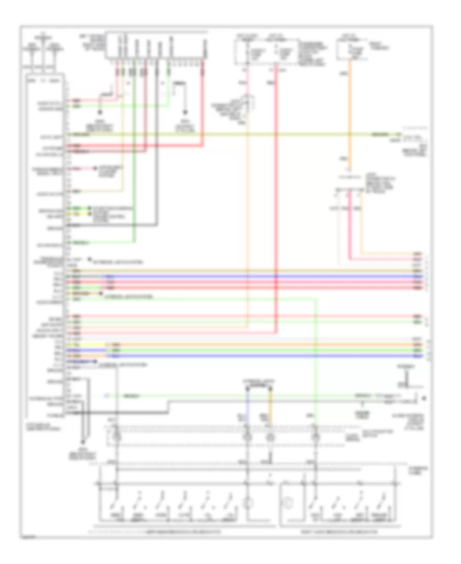
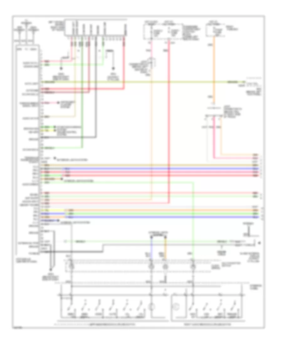
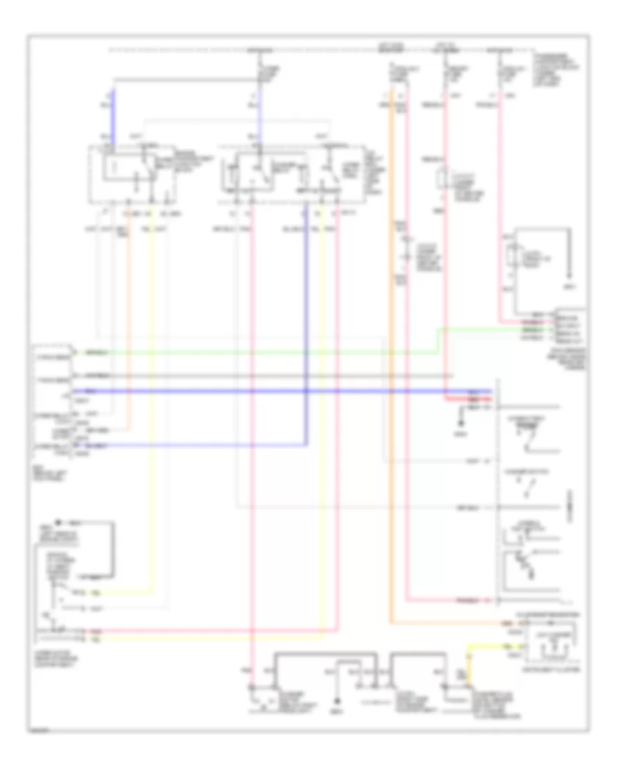
AIR CONDITIONING
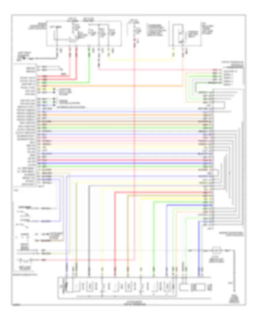
Automatic A/C Wiring Diagram (1 of 2) for Hyundai Azera GLS 2010

List of elements for Automatic A/C Wiring Diagram (1 of 2) for Hyundai Azera GLS 2010:
- (behind left side of dash) joint connector m-5
- (below left side of dash) data link connector
- (under center console) gm02
- A/c control module
- A/c output (hi)
- A/c select sig(hi)
- A/con fuse 10a
- A/con sw fuse 10a
- Amb sens(+)
- Auto light & photo sensor (top center of dash)
- Blower motor (under right side of dash)
- Blower relay
- Blower rly on in
- Computer data lines system
- Cool
- Cruise control system
- Def
- Defogger ind
- Defogger sw
- Defogger system
- Driver
- Driver temperature actuator (under left center of dash)
- Evap sens(+)
- Evaporator sensor (under right center of dash, on hvac assembly)
- F/b
- Fet(d)
- Fet(g)
- Field effect transister (under right side of dash)
- Fre
- Gm01 (under front of center console)
- Gm02 (under center console)
- Ground
- Hot at all times
- Hot in on
- Humidity sens(+)
- I/p-a
- I/p-d
- I/p-e
- I/p-f
- Ill(+)
- Ill(-)
- Incar sens(+)
- Instrument cluster
- Instrument cluster system
- Intake actuator (behind right side of dash, on hvac assembly)
- Interior lights system
- Joint connector m-1 (behind right side of dash)
- Joint connector m-11 (behind right kick panel)
- Joint connector m-12 (behind right kick panel)
- Joint connector m-17 (under front of center console)
- K-line
- M32-a
- M50-a
- M50-b
- Memory fuse 15a
- Memory pwr
- Motor(-)
- On input
- Passenger
- Passenger compartment junction block (under left end of dash)
- Passenger temperature actuator (under right side of dash)
- Photo sensor
- Pnk
- Rec
- Red
- Sens ground
- Sens ref (5v)
- Temp in
- Vent
- Vss sens
- Warm
- Wts(+)
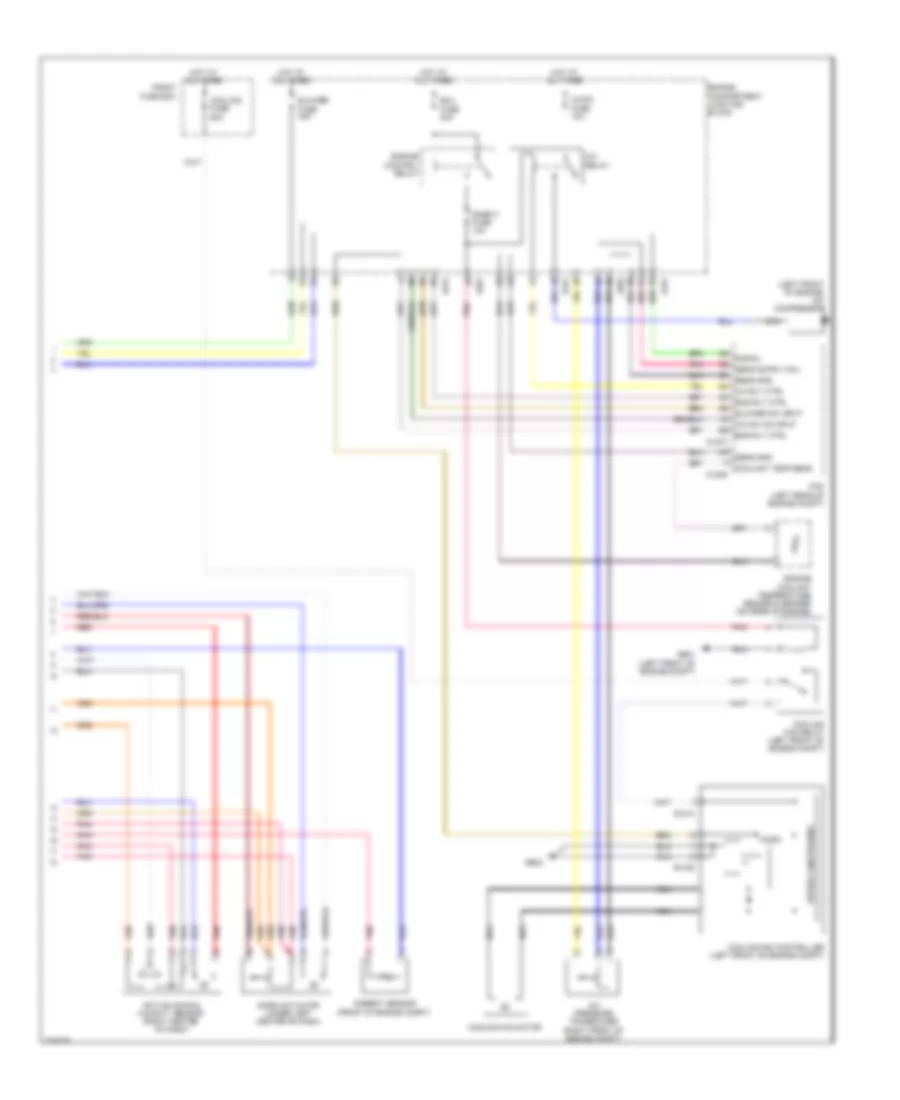
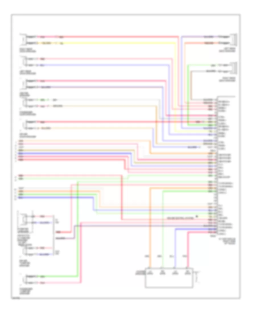
Automatic A/C Wiring Diagram (2 of 2) for Hyundai Azera GLS 2010
List of elements for Automatic A/C Wiring Diagram (2 of 2) for Hyundai Azera GLS 2010:
- (left front of engine) a/c compressor
- A/c pressure transducer (right front of engine compt)
- A/c relay
- A/c rly ctrl
- A/c sw on input
- A/con fuse 10a
- Active incar & humidity sensor (right center of dash)
- Ambient sensor (front of engine compt)
- Blower fuse 40a
- Blower sw input
- Clg-a
- Clg-b
- Coolant temp sens
- Cooling fan controller (left front of engine compt)
- Cooling fan motor
- Cooling fan relay (left front of engine compt)
- Cooling fuse 60a
- E12-a
- E12-b
- Ecu fuse 30a
- Eng rly ctrl
- Engine compartment junction block
- Engine control relay
- Engine coolant temperature sensor & sender (on rear of engine)
- Front fuse box
- Ge01 (left front of engine compt)
- Ge02
- Hot at all times
- Jc01
- Je01
- Je02
- Micom
- Mode actuator (under left center of dash)
- Nca
- Pcm (left rear of engine compt)
- Pnk
- Power conditioning
- Red
- Sens gnd
- Signal
- Snsr 3 fuse 10a
ANTI-LOCK BRAKES
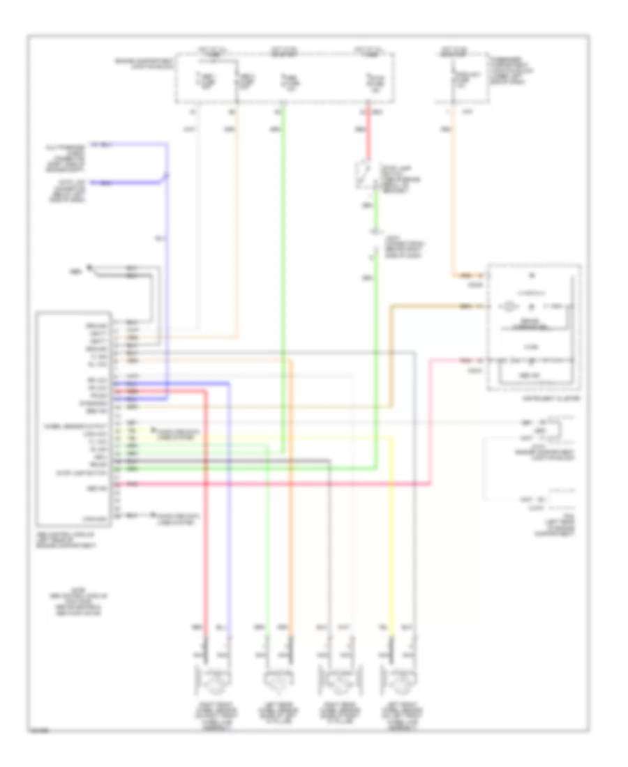
Anti-lock Brakes Wiring Diagram, with ESP for Hyundai Azera GLS 2010
List of elements for Anti-lock Brakes Wiring Diagram, with ESP for Hyundai Azera GLS 2010:
- +ecu
- Abs 1 fuse 40a
- Abs 2 fuse 20a
- Abs fuse 10a
- Abs ind
- Brake warning ind
- Can high
- Can low
- Can-high
- Can-low
- Clg-a
- Computer data lines system
- Data link connector (below left side of dash)
- Diagnosis
- Diode
- Ebd
- Ebd ind
- Engine compartment junction block
- Esc control module (left rear of engine compt)
- Esc control switch
- Esc ind
- Esc off ind
- Esc switch
- Fl sig
- Fl vcc
- Fr sig
- Fr vcc
- Ge05
- Gf03
- Gm02 (under center console)
- Ground
- Hot at all times
- Hot in on or start
- I/p-e
- I/p-f
- I/p-g
- Illum
- Instrument cluster
- Interior lights system
- J/c m-10 (under front of center console)
- Jc01
- Je02
- Joint connector e-1 (behind right side of dash)
- Joint connector m-1 (behind right side of dash)
- Joint connector m-5 (behind left side of dash)
- Left front wheel sensor (on left front wheel hub assembly)
- Left rear wheel sensor (base of left "c" pillar)
- M32-a
- M32-b
- M32-c
- Module 2 fuse 10a
- Multipurpose check connector (right side of engine compt)
- Nca
- Note: esc control module contains: esc solenoids, esc pump motor
- Off
- On/start
- Parking brake sig
- Parking brake switch (above parking brake pedal, on bracket)
- Passenger compartment junction block (under left end of dash)
- Pcm (left rear of engine compartment)
- Pnk
- Red
- Right front wheel sensor (on right front wheel hub assembly)
- Right rear wheel sensor (base of right "c" pillar)
- Rl sig
- Rl vcc
- Rr sig
- Rr vcc
- Steering angle sensor (on steering column)
- Stop fuse 15a
- Stop lamp switch
- Stop lamp switch (above brake pedal, on bracket)
- Vbatt
- Wheel spd out (vr)
- Yaw rate sensor (under rear console)
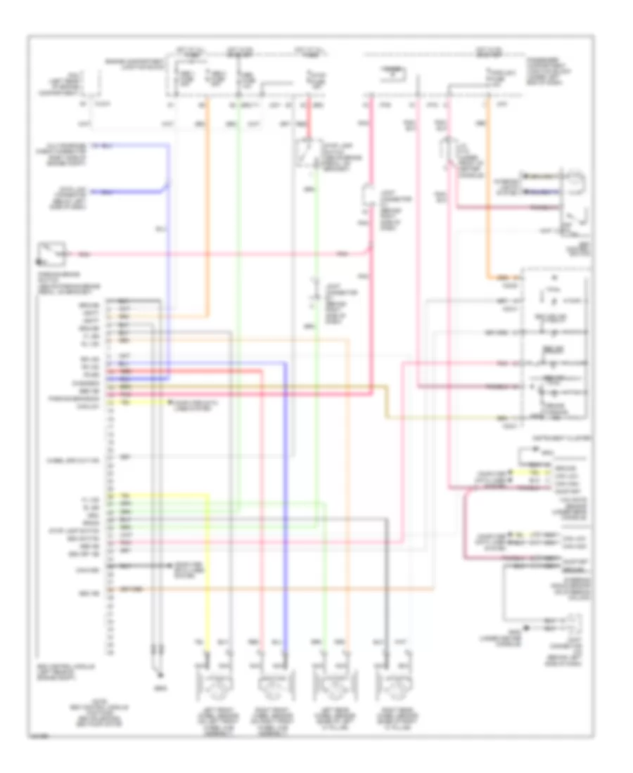
Anti-lock Brakes Wiring Diagram, without ESP for Hyundai Azera GLS 2010
List of elements for Anti-lock Brakes Wiring Diagram, without ESP for Hyundai Azera GLS 2010:
- +ecu
- Abs 1 fuse 40a
- Abs 2 fuse 20a
- Abs control module (left rear of engine compartment)
- Abs fuse 10a
- Abs ind
- Abs pump motor
- Brake warning ind
- Can-high
- Can-low
- Clg-a
- Computer data lines system
- Data link connector (below left side of dash)
- Diagnosis
- Ebd ind
- Engine compartment junction block
- Fl sig
- Fl vcc
- Fr sig
- Fr vcc
- Ge05
- Ground
- Hot at all times
- Hot in on or start
- I/p-f
- Instrument cluster
- Jc101
- Je02
- Joint connector e-1 (behind right side of dash)
- Left front wheel sensor (on left front wheel hub assembly)
- Left rear wheel sensor (base of left "c" pillar)
- M32-b
- M32-c
- Module 2 fuse 10a
- Multipurpose check connector (right side of engine compt)
- Nca
- Note: abs control module contains: abs solenoids &
- Passenger compartment junction block (under left end of dash)
- Pcm (left rear of engine compartment)
- Pnk
- Red
- Right front wheel sensor (on right front wheel hub assembly)
- Right rear wheel sensor (base of right "c" pillar)
- Rl sig
- Rl vcc
- Rr sig
- Rr vcc
- Stop fuse 15a
- Stop lamp switch
- Stop lamp switch (above brake pedal, on bracket)
- Vbatt
- Wheel sensor output
ANTI-THEFT
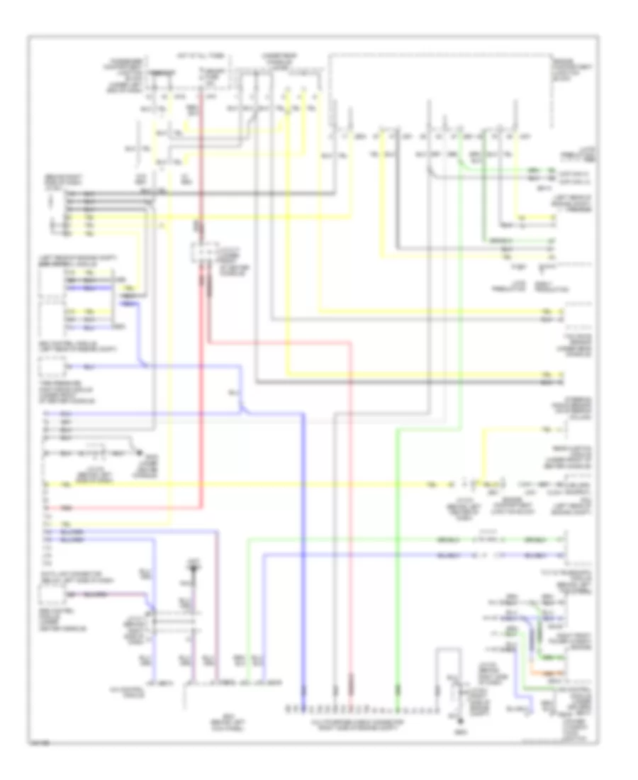
Forced Entry Wiring Diagram for Hyundai Azera GLS 2010
List of elements for Forced Entry Wiring Diagram for Hyundai Azera GLS 2010:
- (on right "c" pillar)
- (rear of left front door)
- 2 turn unlock relay
- Bcm (behind left kick panel)
- Do3-a
- Do3-b
- Do4-a
- Do4-b
- Door lock relay
- Door unlock relay
- Ge04 (left rear of engine compt)
- Gf01
- Gf03
- Gf04
- Ground
- Hood sw
- Hood switch (right front of engine compt)
- Hot at all times
- Hot in on
- I/p-f
- I/p-j
- I/p-k
- Interior lights system
- J/c d-1 (in left front door)
- J/c d-2 (in right front door)
- J/c f-1 (on left "c" pillar)
- J/c f-4 (base of right "c" pillar)
- J/c m-17 (under front of center console)
- J/c m-9 (behind right side of dash)
- Key sol fuse 20a
- Left front door lock actuator
- Left rear door lock actuator (rear of left rear door)
- Lock
- M28-a
- M28-c
- M28-d
- Mcu
- Memory
- Memory fuse 15a
- Memory power
- Module 1 fuse 10a
- Passenger compartment junction block (under left end of dash)
- Pnk
- Power door lock switch
- Power window main switch
- Red
- Rf com
- Rf receiver
- Right front door lock actuator (rear of right front door)
- Right front power window switch
- Right rear door lock actuator (rear of right rear door)
- Security ind
- Security indicator
- Signal
- Un- lock
- Unlk
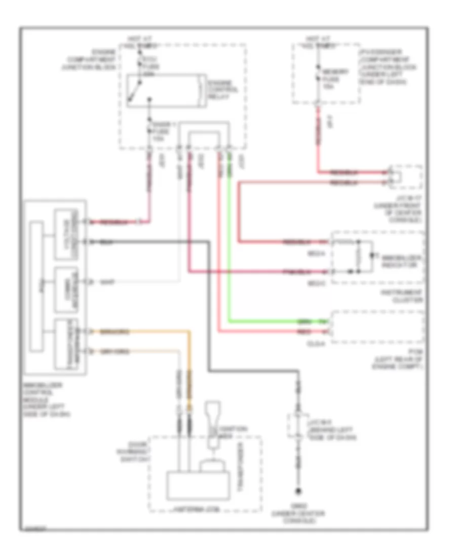
Immobilizer Wiring Diagram for Hyundai Azera GLS 2010
List of elements for Immobilizer Wiring Diagram for Hyundai Azera GLS 2010:
- Antenna coil
- Clg-a
- Comms interface
- Door warning switch
- Ecu fuse 30a
- Engine compartment junction block
- Engine control relay
- Gm02 (under center console)
- Hot at all times
- I/p-f
- Ignition key
- Immobilizer control module (under left side of dash)
- Immobilizer indicator
- Instrument cluster
- J/c m-17 (under front of center console)
- J/c m-5 (behind left side of dash)
- Jc01
- Je01
- Je02
- M32-a
- M32-c
- Memory fuse 15a
- Nca
- Passenger compartment junction block (under left end of dash)
- Pcm (left rear of engine compt)
- Pcu
- Red
- Snsr 1 fuse 15a
- Transponder
- Transponder interface
- Voltage conditioning
BODY CONTROL MODULES
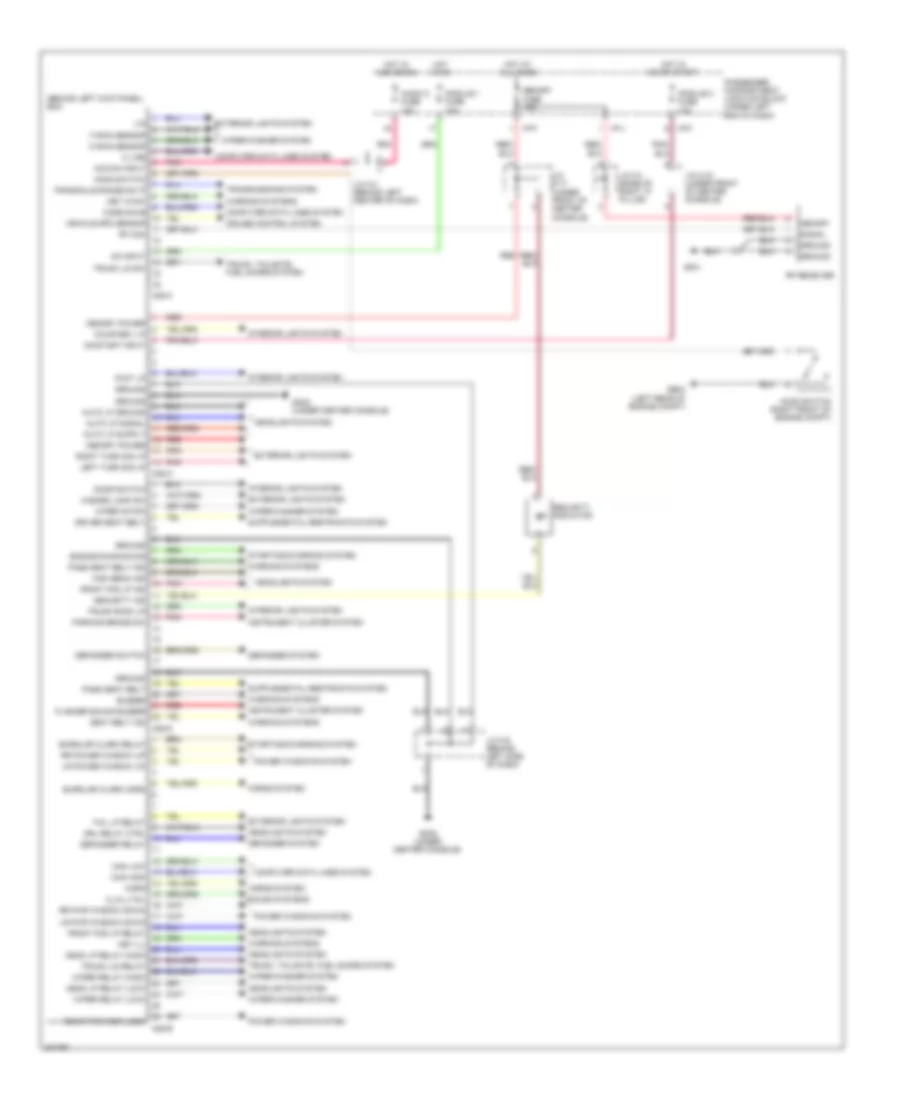
Body Control Modules Wiring Diagram for Hyundai Azera GLS 2010
List of elements for Body Control Modules Wiring Diagram for Hyundai Azera GLS 2010:
- (behind left kick panel) bcm
- Acc/on input
- Audio 2 fuse 10a
- Auto lp ground
- Auto lp signal
- Burglar alarm horn
- Burglar alarm relay
- Buzzer
- Can high
- Can low
- Code save
- Computer data lines system
- Courtesy lp
- Cruise control system
- Defogger relay
- Defogger switch
- Defogger system
- Door switch
- Driver seat belt
- Drl relay ctrl
- Engine running sig
- Exterior lights system
- F rain sensor
- Flasher sound buzzer
- Foot lp
- Front fog lp ind
- Front fog lp relay
- Ge04 (left rear of engine compt)
- Gf01
- Gm02 (under center console)
- Ground
- Hazard lamp sw
- Head lp relay (high)
- Head lp relay (low)
- Headlights system
- High beam ind
- Hood switch
- Hood switch (right front of engine compt)
- Horn
- Horns system
- Hot at all times
- Hot in acc or on
- Hot in on
- Hot in on or start
- I/p-f
- I/p-j
- Instrument cluster system
- Interior lights system
- J/c f-4 (base of right "c" pillar)
- J/c m-10 (under front of center console)
- J/c m-17 (under front of center console)
- J/c m-3 (behind left center of dash)
- J/c m-5 (behind left side of dash)
- K line
- Key ill
- Key in sw
- Left turn sig lp
- Lin
- Lr power window up
- Lr pwr window down
- M28-a
- M28-b
- M28-c
- M28-d
- Memory
- Memory fuse 15a
- Memory power
- Module 1 fuse 10a
- Module 2 fuse 10a
- O rain sensor
- On input
- On/start input
- O_av_tail
- Parking brake sw
- Pass seat belt
- Pass seat belt ind
- Passenger compartment junction block (under left end of dash)
- Pnk
- Power windows system
- Rear pwr wdw lock
- Red
- Rf com
- Rf receiver
- Right turn sig lp
- Rr power window up
- Rr pwr window down
- Seat belt ind
- Security ind
- Security indicator
- Signal
- Sound systems
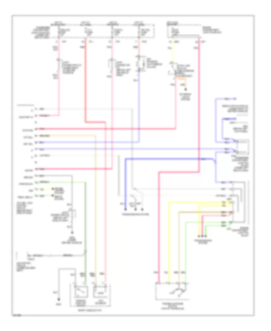
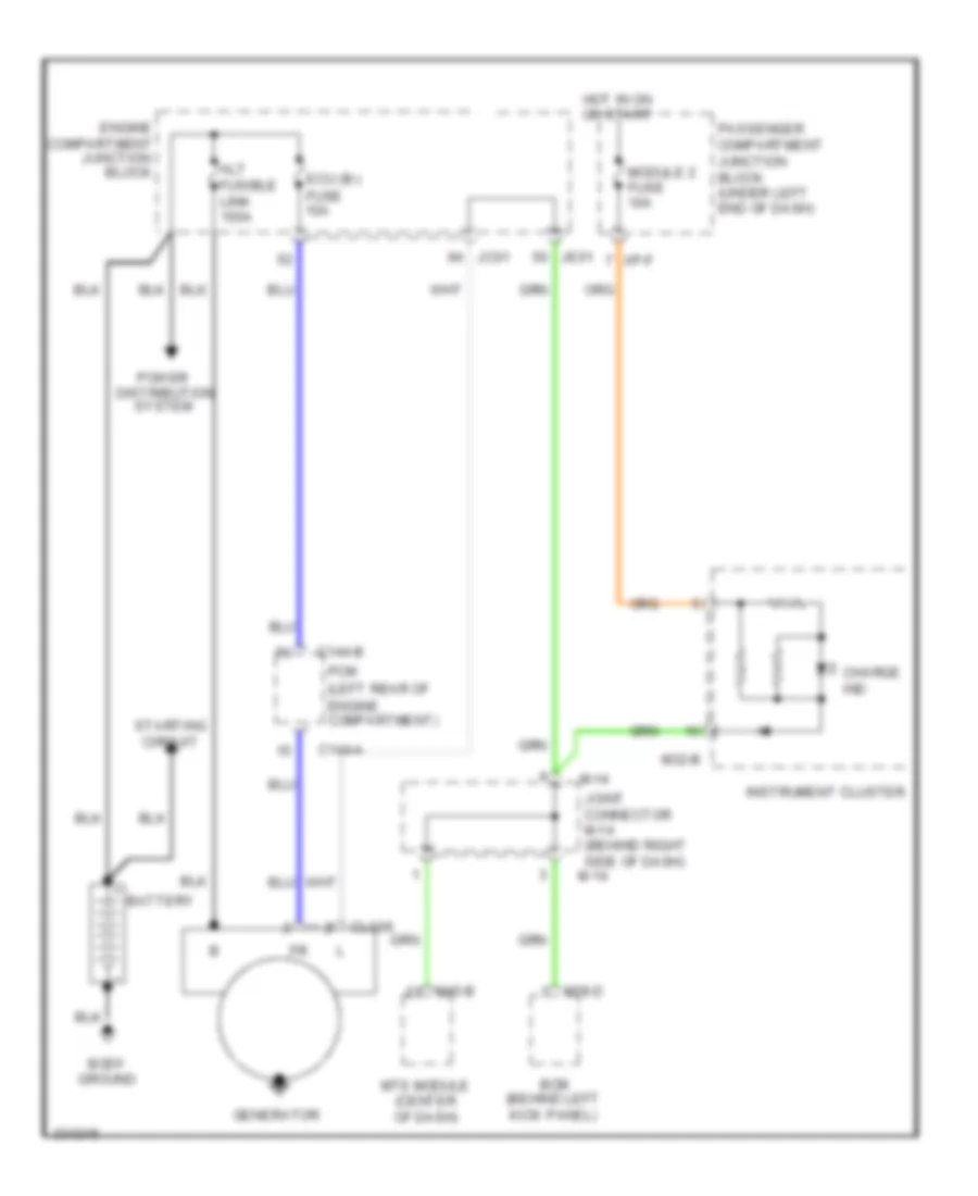
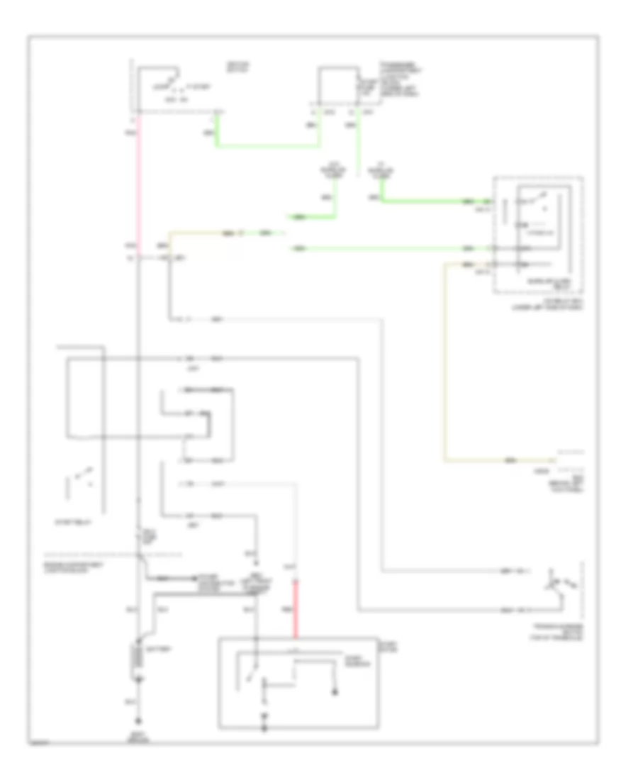
- Starting/charging system
- Tail lp relay
- Transaxle range sw p
- Transmissions system
- Trunk lid relay
- Trunk lid sw
- Trunk room lp
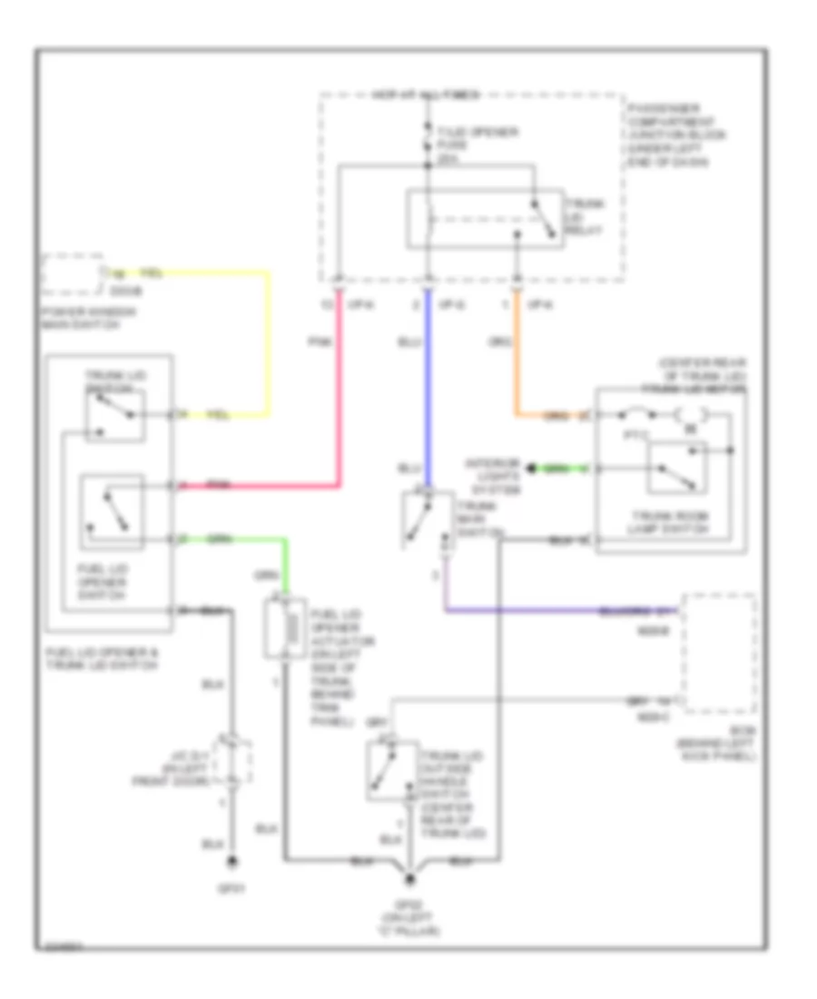
- Trunk, tailgate, fuel doors system
- Vehicle spd sensor
- Warning systems
- Wiper (stop)
- Wiper relay (high)
- Wiper relay (low)
- Wiper/washer system
COMPUTER DATA LINES
Computer Data Lines Wiring Diagram for Hyundai Azera GLS 2010
List of elements for Computer Data Lines Wiring Diagram for Hyundai Azera GLS 2010:
- (behind right side of dash) j/c e-3
- (late preduction) tcm
- (left rear of engine compt) abs control module
- (left rear of engine compt) pcm/ecm
- (not used)
- (under center console)
- (under rear console) j/c f-6
- A/c control module
- Asb
- Bcm (behind left kick panel)
- C144-a
- Ccp can hi
- Ccp can lo
- Clg-a
- D04-b
- Data link connector (below left side of dash)
- E91-k
- Early production
- Engine compartment junction block
- Esc
- Esc control module (left rear of engine compt)
- Ge03
- Gm02
- Hot at all times
- I/p-f
- I/p-g
- Ims control module (under driver's seat)
- J/c e-4 (right side of engine compt)
- J/c m-1 (behind right side of dash)
- J/c m-17 (under front
- J/c m-2 (behind left center of dash)
- J/c m-5 (behind left side of dash)
- J/c m-9 (behind right side of dash)
- Jc01
- Je01
- Je02
- Late preduction
- M28-b
- M28-c
- M50-a
- Memory fuse 15a
- Multipurpose check connector (right side of engine compt)
- Nca
- Of center console)
- Passenger compartment junction block (under left end of dash)
- Pcm (left rear of engine compt)
- Power window main switch
- Rear curtain module (under front of center console)
- Red
- Red/
- Resistor
- Right front power window switch
- S08-c
- Srs control module (under center console)
- Steering angle sensor (on steering column)
- Tilt & telescopic module (behind left kick panel)
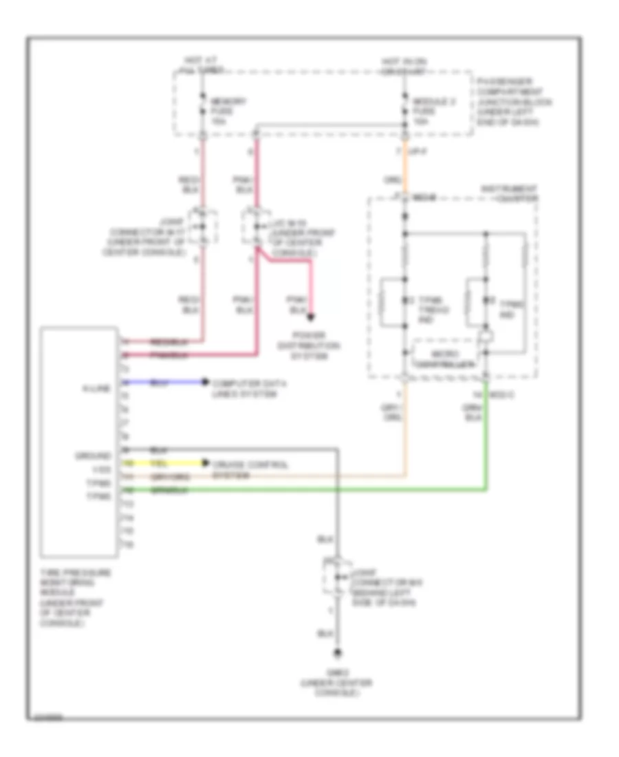
- Tire pressure monitoring module (under front of center console)
- Veh spd output
- W/ esc
- W/o esc
- Yaw rate sensor (under rear console)
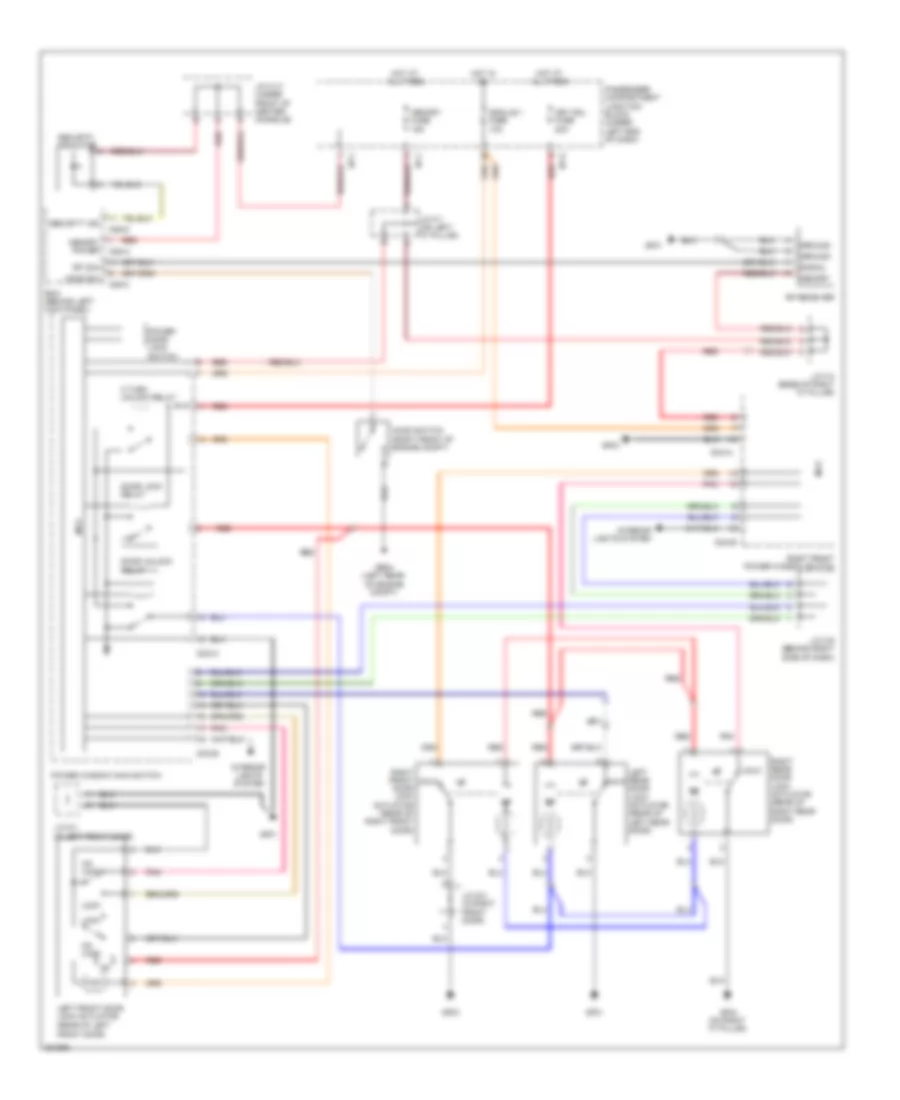
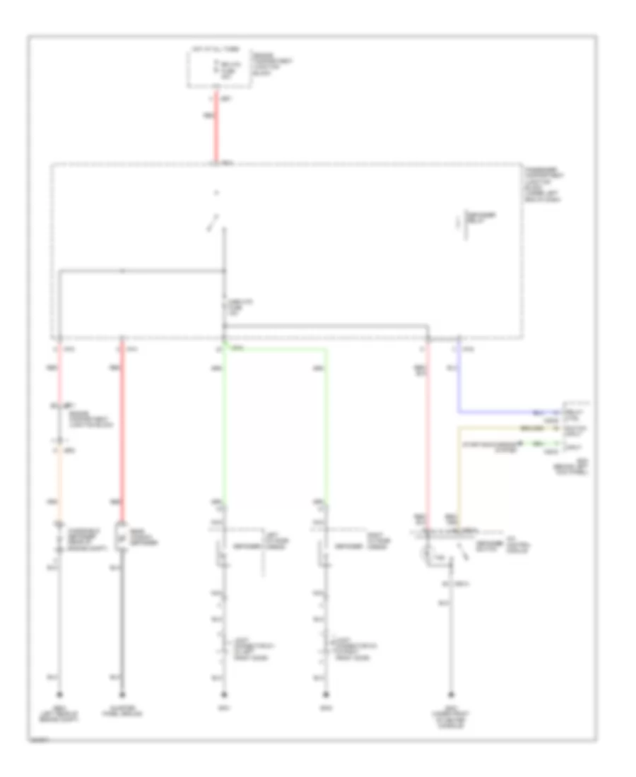
COOLING FAN
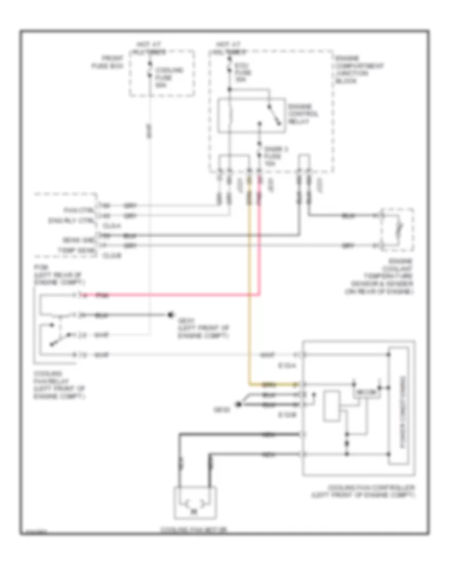
Cooling Fan Wiring Diagram for Hyundai Azera GLS 2010
List of elements for Cooling Fan Wiring Diagram for Hyundai Azera GLS 2010:
- Clg-a
- Clg-b
- Cooling fan controller (left front of engine compt)
- Cooling fan motor
- Cooling fan relay (left front of engine compt)
- Cooling fuse 60a
- E12-a
- E12-b
- Ecu fuse 30a
- Eng rly ctrl
- Engine compartment junction block
- Engine control relay
- Engine coolant temperature sensor & sender (on rear of engine)
- Fan ctrl
- Front fuse box
- Ge01 (left front of engine compt)
- Ge02
- Hot at all times
- Jco1
- Je01
- Micom
- Nca
- Pcm (left rear of engine compt)
- Pnk
- Power conditioning
- Sens gnd
- Snsr 3 fuse 10a
- Temp sens
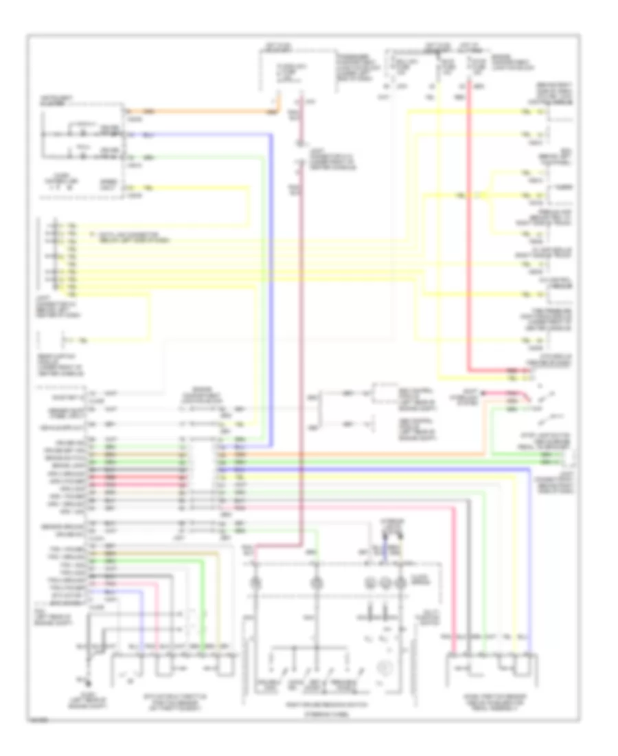
CRUISE CONTROL
Cruise Control Wiring Diagram for Hyundai Azera GLS 2010
List of elements for Cruise Control Wiring Diagram for Hyundai Azera GLS 2010:
- (+)
- (-)
- (behind right side of dash) atm key lock control module
- (left rear of engine compt)
- A/c control module
- Abs
- Abs control module (left rear of engine compt)
- Abs/esc buff wheel input
- Accel position sensor (above accelerator pedal assembly)
- Aps 1 ground
- Aps 1 power
- Aps 1 sig
- Aps 2 ground
- Aps 2 power
- Aps 2 sig
- Audio
- Av amp module (right side of trunk)
- B/up fuse 10a
- Bcm (behind left kick panel)
- Brake lamp
- Brake switch
- Can- cel
- Clg-a
- Clg-b
- Clock spring
- Cruise ind
- Cruise main
- Cruise set ind
- Cruise sw
- Data link connector (below left side of dash)
- Ecu (ig1) fuse 10a
- Engine compartment junction block
- Esc
- Esc control module
- Etc motor & throttle position sensor (on throttle body)
- Etc motor +
- Etc motor -
- F55-b
- F57-b
- Glg01 (left rear of engine compt)
- Hot at all times
- Hot in on or start
- I/p-f
- Ill
- Instrument cluster
- Interior lights system
- Jc01
- Je01
- Je02
- Joint connector e-1 (behind right side of dash)
- Joint connector m-10 (under front of center console)
- Joint connector m-2 (behind left center of dash)
- M14
- M28-c
- M32-a
- M32-b
- M45-b
- M50-b
- M58-a
- Micro controller
- Module 2 fuse 10a
- Mts module (center of dash)
- Multi- function switch
- Nca
- On/start in
- Passenger compartment junction block (under left end of dash)
- Pcm (left rear of engine compt)
- Pnk
- Premium amp (behind trim, at right side of trunk)
- Rear curtain module (under front of center console)
- Red
- Resume/ accel
- Right cruise remocon switch
- Sensor ground
- Set/ coast
- Shift interlock system
- Speed input
- Steering wheel
- Stop fuse 15a
- Stop lamp switch (above brake pedal, on bracket)
- Tire pressure monitoring module (under front of center console)
- Tps 1 ground
- Tps 1 power
- Tps 1 sig
- Tps 2 ground
- Tps 2 power
- Tps 2 sig
- Vehicle spd out
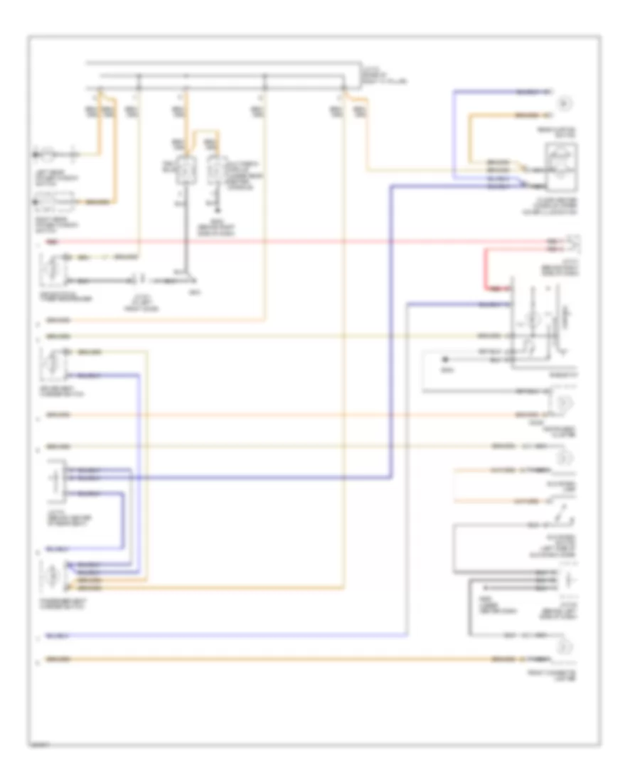
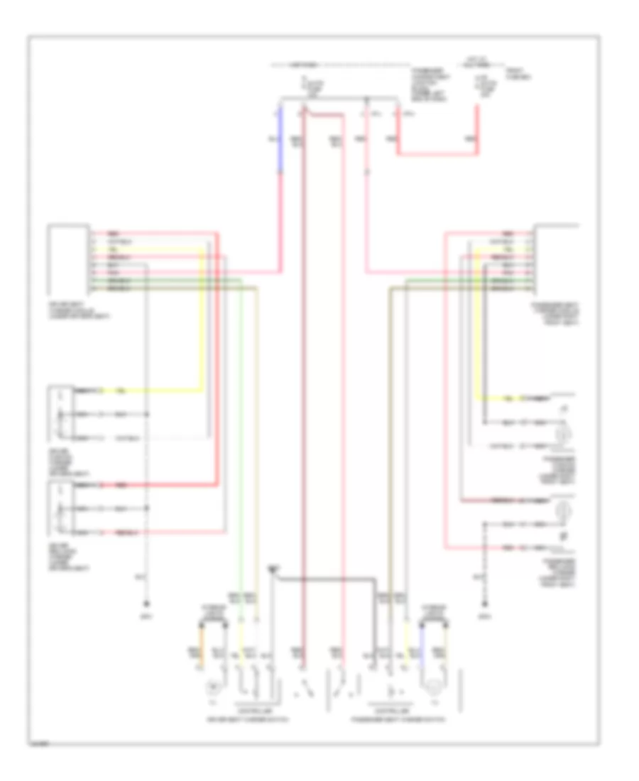
DEFOGGERS
Defoggers Wiring Diagram for Hyundai Azera GLS 2010
List of elements for Defoggers Wiring Diagram for Hyundai Azera GLS 2010:
- A/c control module
- Bcm (behind left kick panel)
- Defogger
- Defogger relay
- Defogger switch
- Engine compartment junction block
- Ge04 (left rear of engine compt)
- Gf01
- Gf03
- Gm01 (under front of center console)
- Hot at all times
- I/p-a
- I/p-d
- I/p-g
- I/p-h
- I/p-k
- Ind
- Input
- Je01
- Je02
- Joint connector d-1 (in left front door)
- Joint connector d-2 (in right front door)
- Left outside mirror
- M28-b
- M28-d
- M50-a
- Mirr htd fuse 10a
- Nca
- Passenger compartment junction block (under left end of dash)
- Quarter panel ground
- Rear window defogger
- Red
- Relay ctrl
- Right outside mirror
- Rr htd fuse 40a
- Starting/charging system
- Switch input
- Windshield defogger (rear of engine compt)
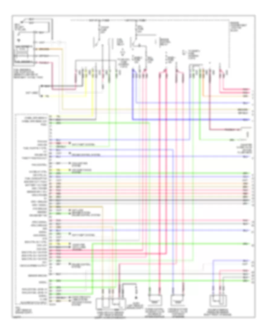
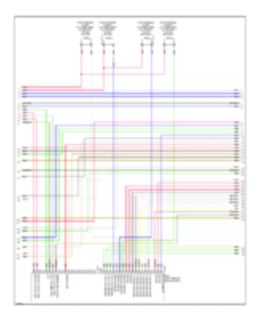
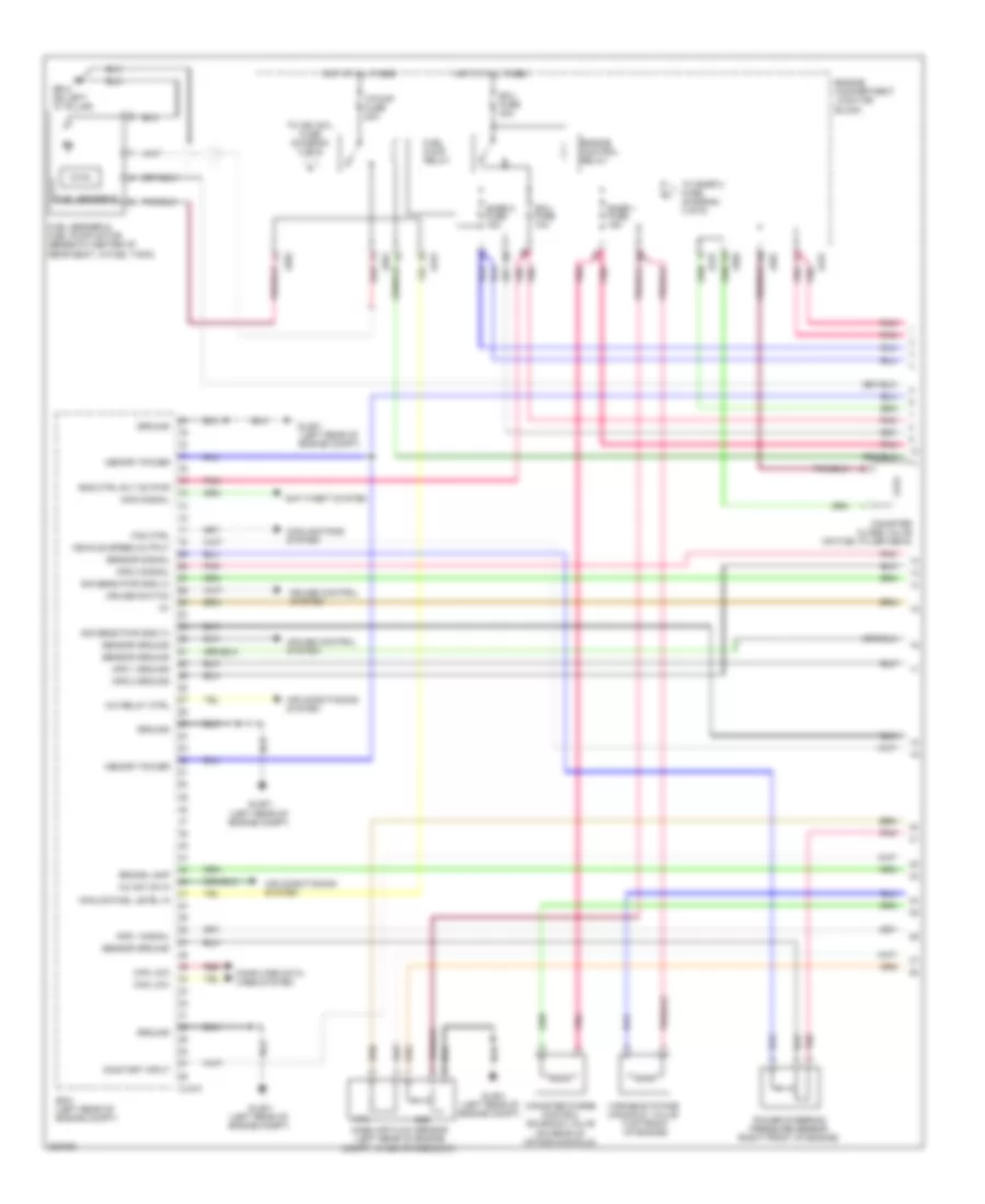
ENGINE PERFORMANCE
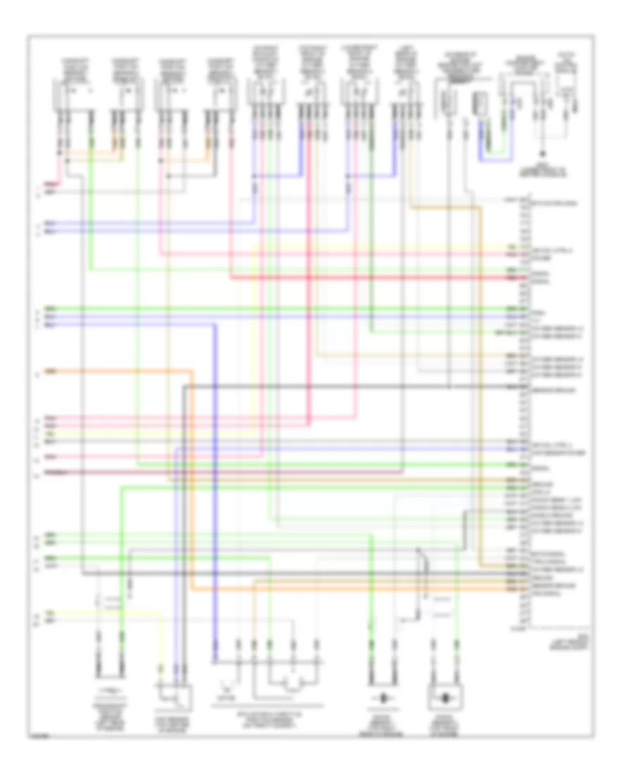
3.3L
3.3L, Engine Performance Wiring Diagram, Early Production (1 of 5) for Hyundai Azera GLS 2010
List of elements for 3.3L, Engine Performance Wiring Diagram, Early Production (1 of 5) for Hyundai Azera GLS 2010:
- (not used)
- (on fuel filler neck)
- A/c relay ctrl
- Abs/esc
- Afs
- Air conditioning system
- Analog fuel level in
- Anti-lock brakes system cruise control system
- Anti-theft system
- Aps 1 ground
- Aps 1 power
- Aps 1 signal
- Aps 2 ground
- Aps 2 power
- Aps 2 signal
- Ats
- Ats ground
- Battery voltage
- Blower switch input
- Can high
- Can low
- Canister close valve
- Ccv
- Computer data lines system
- Computer data lines system air conditioning system
- Cooling fans system
- Cruise control system
- Cruise ind
- Cruise set ind
- Ecu fuse 10a
- Ecu fuse 30a
- Eng ctrl rly ctrl
- Eng ctrl rly on pwr
- Eng spd out (tach)
- Engine compartment junction block
- Engine control relay
- F/pump fuse 20a
- Fan control
- Fuel consumption
- Fuel pump relay
- Fuel pump rly ctrl
- Fuel sender & fuel pump motor (beneath center of rear seat, in fuel tank)
- Fuel sender a
- Fuel sender b
- Gf02 (on left "c" pillar)
- Glg-a
- Glg01 (left rear of engine compt)
- Hot at all times
- Immo ind
- Immo signal
- Ind ctrl mil
- Jc01
- Je01
- Je02
- K line
- Mass air flow sensor (left rear of engine compt, in air intake duct)
- Pcm (left rear of engine compt)
- Pcsv
- Pnk
- Power steering pressure sensor (right front of engine)
- Purge control solenoid valve (on rear of intake manifold)
- Pwm sig
- Red
- Sensor ground
- Sensor sply (5v)
- Signal
- Snsr 1 fuse 15a
- Snsr 2 fuse 15a
- Thrott pos pwm out
- To ign coil fuse (diagram 4 of 5)
- To snsr 3 fuse (diagram 4 of 5)
- Variable intake manifold valve (top front of engine)
- Vehicle speed output
- Viv
- Wheel spd sens hi
- Wheel spd sens low
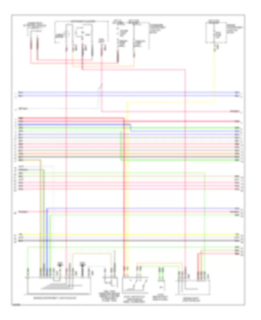
3.3L, Engine Performance Wiring Diagram, Early Production (2 of 5) for Hyundai Azera GLS 2010
List of elements for 3.3L, Engine Performance Wiring Diagram, Early Production (2 of 5) for Hyundai Azera GLS 2010:
- (not used)
- (top of engine, in left cylinder head) oil control valve 2
- (top of engine, in right cylinder head) oil control valve 1
- (top of transaxle) transaxle range switch
- A/c pressure transducer (right front of engine compt)
- Accel position sensor (above accelerator pedal assembly)
- Down shift
- Engine compartment junction block
- Engine coolant temperature sensor & sender (on rear of engine)
- Hot in on or start
- I/p-f
- Instrument cluster system
- Jc01
- Je01
- Je02
- Manual
- Module 2 fuse 10a
- Nca
- Normal
- Passenger compartment junction block (under left end of dash)
- Pnk
- Red
- Select switch
- Sender
- Sensor
- Sport mode switch
- Starting/ charging system
- Up shift
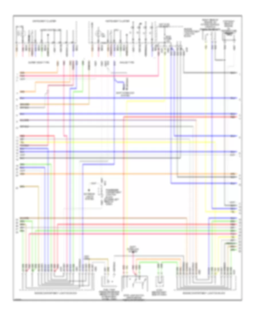
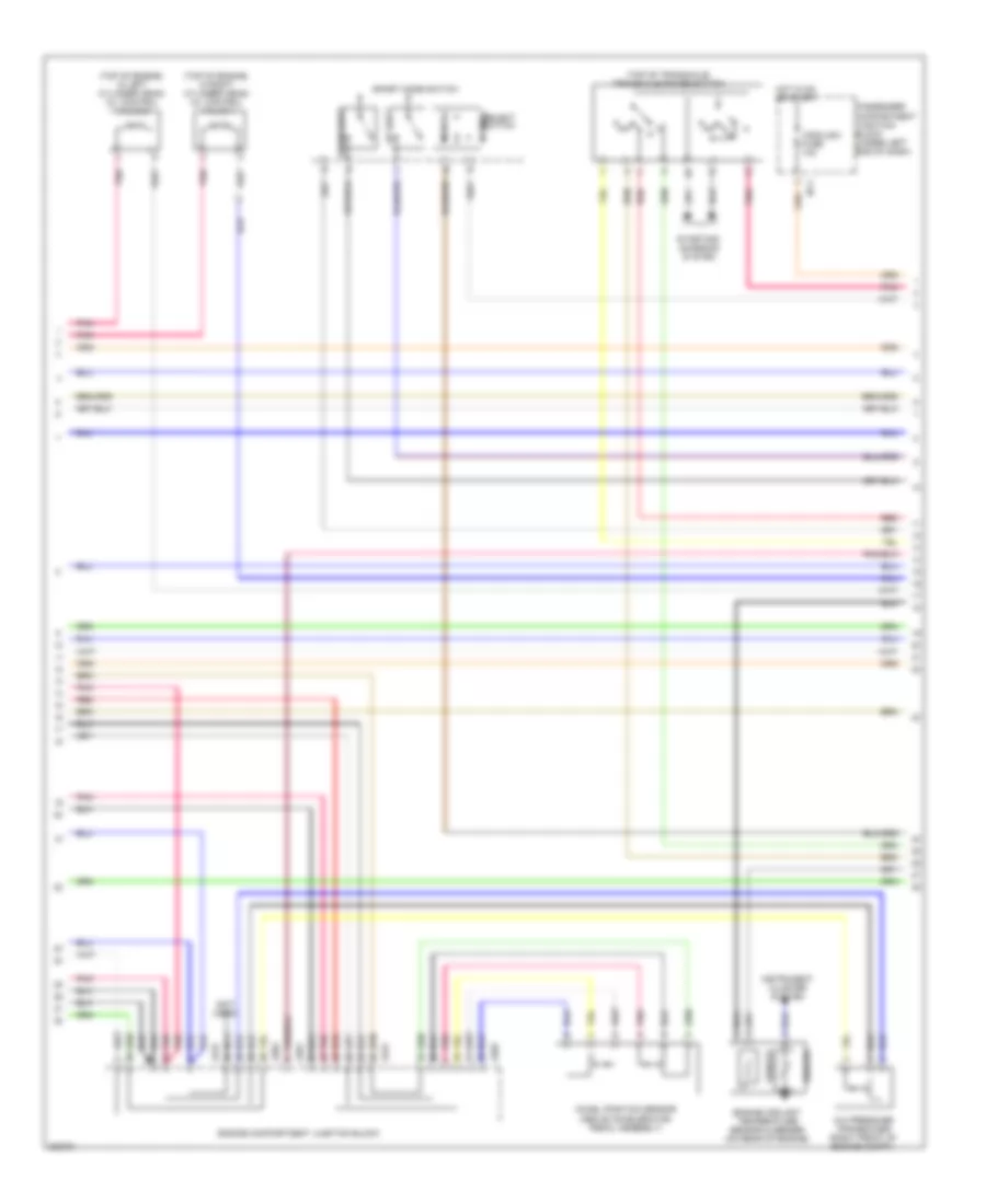
3.3L, Engine Performance Wiring Diagram, Early Production (3 of 5) for Hyundai Azera GLS 2010
List of elements for 3.3L, Engine Performance Wiring Diagram, Early Production (3 of 5) for Hyundai Azera GLS 2010:
- (not used)
- (right rear of engine, on intake manifold) manifold pressure sensor
- (top right rear of engine) oil temperature sensor
- Analog type
- B/up fuse 10a
- Engine compartment junction block
- Exterior lights system
- Fuel tank pressure sensor (beneath center of rear seat, in fuel tank)
- Hot in on or start
- I/p-g
- Instrument cluster
- J/c e-1 (behind right side of dash)
- Jc01
- Je01
- Je02
- M32-a
- M32-b
- Mcu
- Micro controller
- Mil ind
- Passenger compartment junction block (under left end of dash)
- Pnk
- Pwm
- Red
- Shift interlock system
- Stop lamp switch (above brake pedal, on bracket)
- Super vision type
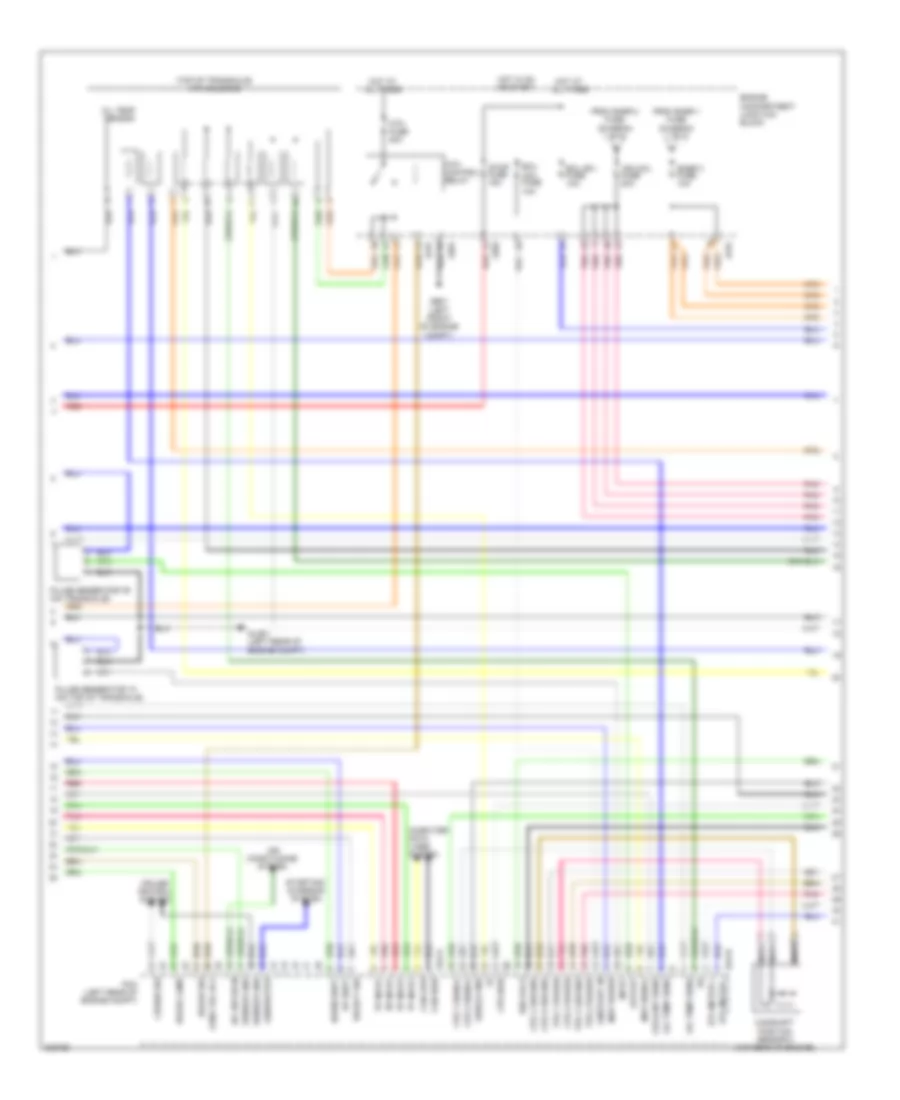
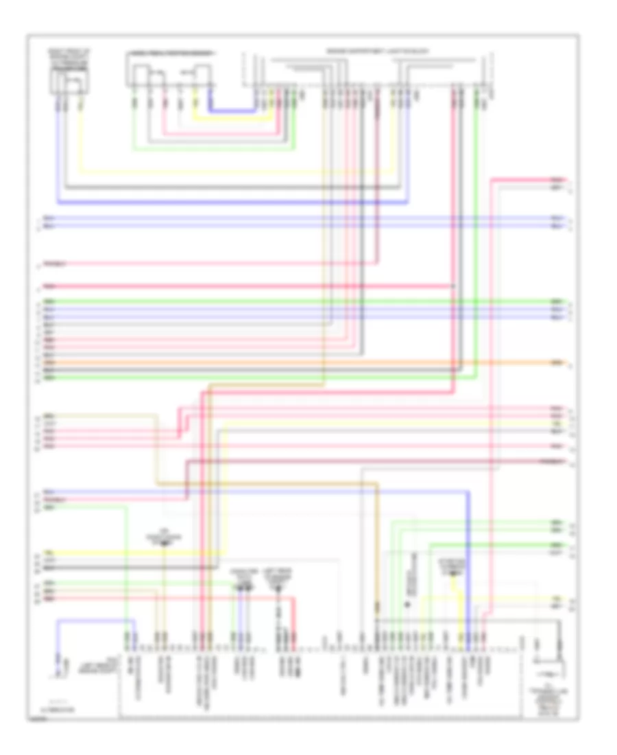
3.3L, Engine Performance Wiring Diagram, Early Production (4 of 5) for Hyundai Azera GLS 2010
List of elements for 3.3L, Engine Performance Wiring Diagram, Early Production (4 of 5) for Hyundai Azera GLS 2010:
- "d" input
- "n" input
- "p" input
- "r" input
- (ig1) fuse 10a
- (top of transaxle) atm solenoid
- A/c sw on in
- Air conditioning system
- Atm control relay
- Atm ctrl rly
- Atm fuse 20a
- Brake lamp
- Brake sw
- Camshaft position sensor 2 (top rear of engine)
- Can high
- Can low
- Computer data lines system
- Coolant sens
- Cps 1 ground
- Cps 1 signal
- Cps 2 ground
- Cps 2 power
- Cps 2 signal
- Cps high
- Cruise control system
- Cruise sw
- Down shift
- Ecu
- Ecu (b+) fuse 10a
- Engine compartment junction block
- Etc motor +
- Etc motor -
- From snsr 1 fuse (diagram 1 of 5)
- From snsr 2 fuse (diagram 1 of 5)
- Ge01 (left front of engine compt)
- Generator
- Glg-a
- Glg-b
- Glg01 (left rear of engine compt)
- Hot at all times
- Hot in on or start
- Ign coil 6
- Ign coil fuse 20a
- Input
- Jc01
- Je01
- Je02
- Map power
- Map signal
- Nca
- Oil temp sens
- Oil temp sensor
- On/start in
- Output
- Pcm (left rear of engine compt)
- Pnk
- Pulse generator "a" (on top of transaxle)
- Pulse generator "b" (on transaxle)
- Red
- Select sw
- Sensor gnd
- Shield gnd
- Snsr 3 fuse 10a
- Starting/ charging system
- Stop fuse 15a
- Tps 1 ground
- Tps 1 power
- Tps 2 power
- Up shift
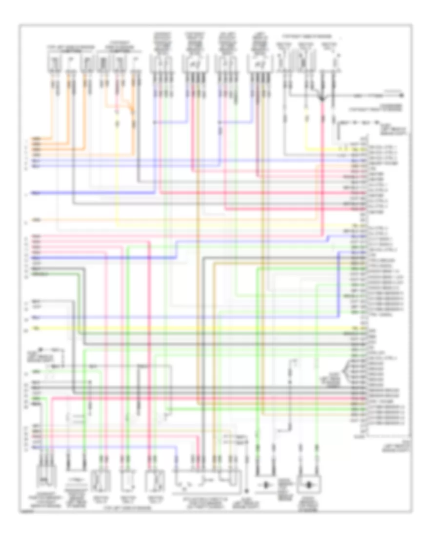
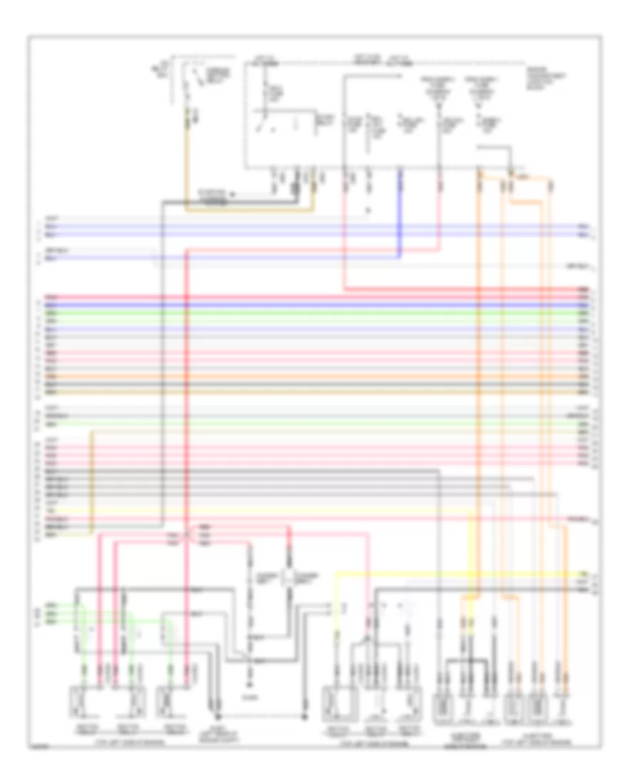
3.3L, Engine Performance Wiring Diagram, Early Production (5 of 5) for Hyundai Azera GLS 2010
List of elements for 3.3L, Engine Performance Wiring Diagram, Early Production (5 of 5) for Hyundai Azera GLS 2010:
- (left rear of engine) oxygen sensor 4 (b2/s2)
- (on left exhaust manifold) oxygen sensor 2 (b2/s1)
- (on right exhaust manifold) oxygen sensor 1 (b1/s1)
- (top left side of engine)
- (top left side of engine) injectors
- (top right front of engine) oxygen sensor 3 (b1/s2)
- (top right side of engine)
- (top right side of engine) injectors
- 2nd
- Camshaft position sensor 1 (top right rear of engine)
- Condenser (top right front of engine)
- Cps 1 power
- Cps low
- Crankshaft position sensor (left rear of engine)
- Cvvt bank 1
- Cvvt bank 2
- Dcc
- Etc motor & throttle position sensor (on throttle body)
- Glg-b
- Glg01 (left rear of engine compt)
- Ground
- Heater
- Ign coil ctrl 1
- Ign coil ctrl 2
- Ign coil ctrl 3
- Ign coil ctrl 4
- Ign coil ctrl 5
- Ignition coil 1
- Ignition coil 2
- Ignition coil 3
- Ignition coil 4
- Ignition coil 5
- Ignition coil 6
- Inj ctrl 1
- Inj ctrl 2
- Inj ctrl 3
- Inj ctrl 4
- Inj ctrl 5
- Inj ctrl 6
- Knock sens 1 hi
- Knock sens 1 low
- Knock sens 2 hi
- Knock sens 2 low
- Knock sensor 1 (top right rear of engine)
- Knock sensor 2 (top front of engine)
- Memory power
- Nca
- Oxygen sensor hi
- Oxygen sensor lo
- Pcm (left rear of engine compt)
- Pnk
- Red
- Sensor ground
- Tps 1 signal
- Tps 2 ground
- Tps 2 signal
- Vfs
3.3L, Engine Performance Wiring Diagram, Late Production (1 of 6) for Hyundai Azera GLS 2010
List of elements for 3.3L, Engine Performance Wiring Diagram, Late Production (1 of 6) for Hyundai Azera GLS 2010:
- (left rear of engine compt)
- (on rear of intake manifold)
- A/c relay ctrl
- A/c sw on in
- Afs
- Air conditioning system
- Analog fuel level in
- Anti-theft system
- Aps 1 ground
- Aps 1 signal
- Aps 2 ground
- Aps 2 signal
- Ats
- Brake lamp
- Can low
- Canister close valve (on fuel filler neck)
- Canister purge control solenoid valve
- Clg-a
- Computer data lines system
- Cooling fans system
- Cruise control system
- Cruise switch
- Ecm (left rear of engine compt)
- Ecu fuse 10a
- Ecu fuse 30a
- Eng ctrl rly on pwr
- Engine compartment junction block
- Engine control relay
- F/pump fuse 20a
- Fan ctrl
- Fuel pump relay
- Fuel sender & fuel pump motor (beneath center of rear seat, in fuel tank)
- Fuel sender b
- Gf02 (on left "c" pillar)
- Glg01
- Glg01 (left rear of engine compt)
- Ground
- Hot at all times
- Immo signal
- Jc01
- Je01
- Je02
- Mass air flow sensor (left rear of engine compt, in air intake duct)
- Memory power
- On/start input
- Pnk
- Power steering pressure sensor (right front of engine)
- Red
- Sensor ground
- Sensor signal
- Sig sens pwr gnd (v)
- Snsr 1 fuse 15a
- Snsr 2 fuse 15a
- To ign coil fuse (diagram 3 of 6)
- To snsr 3 fuse (diagram 3 of 6)
- Variable intake manifold valve (top front of engine)
- Vehicle speed output
3.3L, Engine Performance Wiring Diagram, Late Production (2 of 6) for Hyundai Azera GLS 2010
List of elements for 3.3L, Engine Performance Wiring Diagram, Late Production (2 of 6) for Hyundai Azera GLS 2010:
- (top of engine, in left cylinder head) oil control valve 1 (exhaust)
- (top of engine, in left cylinder head) oil control valve 2 (intake)
- (top of engine, in right cylinder head) oil control valve 1 (intake)
- (top of engine, in right cylinder head) oil control valve 2 (exhaust)
- Aps 2 power
- Ccv
- Clg-a
- Clg-b
- Ecm (left rear of engine compt)
- Eng ctrl rly ctrl
- Eng ctrl rly on pwr
- Etc motor (low)
- Exhaust lh bank
- Exhaust rh bank
- Fuel pump rly ctrl
- Heater
- Ignition coil ctrl 2
- Ignition coil ctrl 4
- Ignition coil ctrl 6
- Injector control 1
- Injector control 2
- Injector control 3
- Injector control 4
- Injector control 5
- Injector control 6
- Intake lh bank
- Intake rh bank
- Pnk
- Red
- Start over running
3.3L, Engine Performance Wiring Diagram, Late Production (3 of 6) for Hyundai Azera GLS 2010
List of elements for 3.3L, Engine Performance Wiring Diagram, Late Production (3 of 6) for Hyundai Azera GLS 2010:
- (top left side of engine)
- Clg18-1
- Clg18-2
- Clg18-3
- Clg18-4
- Clg18-5
- Clg18-6
- Conden- ser 1
- Conden- ser 2
- Ecu (b+) fuse 10a
- Ecu (ig1) fuse 10a
- Engine compartment junction block
- Engine compt)
- From snsr 1 fuse (diagram 1 of 6)
- From snsr 2 fuse (diagram 1 of 6)
- Glg01 (left rear of
- Glg02
- Hot at all times
- Hot in on or start
- Icm relay box
- Ign 2 fuse 40a
- Ign coil fuse 20a
- Ignition coil 1
- Ignition coil 2
- Ignition coil 3
- Ignition coil 4
- Ignition coil 5
- Ignition coil 6
- Injectors
- Injectors (top right side of engine)
- Jc01
- Je01
- Je02
- M01-b
- Nca
- Parking/ neutral relay
- Pnk
- Red
- Snsr 3 fuse 10a
- Start relay
- Starting/ charging system
- Stop fuse 15a
3.3L, Engine Performance Wiring Diagram, Late Production (4 of 6) for Hyundai Azera GLS 2010
List of elements for 3.3L, Engine Performance Wiring Diagram, Late Production (4 of 6) for Hyundai Azera GLS 2010:
- (not used)
- (under front of center console) j/c m-17
- B/up fuse 10a
- Check engine
- Engine compartment junction block
- Engine compt junction block
- Fuel input
- Fuel tank pressure sensor (beneath center of rear seat, in fuel tank)
- Hot at all times
- Hot in on or start
- Immo
- Instrument cluster
- J/c e-1 (behind right side of dash)
- Jc01
- Je01
- Je02
- M32-a
- M32-b
- M32-c
- Memory fuse 15a
- Module 2 fuse 10a
- Nca
- Passenger compartment junction block
- Pnk
- Power conn 30a
- Red
- Stop lamp switch (above brake pedal, on bracket)
3.3L, Engine Performance Wiring Diagram, Late Production (5 of 6) for Hyundai Azera GLS 2010
List of elements for 3.3L, Engine Performance Wiring Diagram, Late Production (5 of 6) for Hyundai Azera GLS 2010:
- (left rear of engine compt)
- (right front of engine compt)
- A/c pressure transducer
- Accel pedal position sensor
- Air conditioning system
- Alternator
- Alternator (fr)
- Analog fuel lvl in
- Anti-lock brakes system
- Aps1 power
- Ats signal
- Blower sw in
- Brake sw
- Can high
- Clg-a
- Clg-b
- Clg06
- Computer data lines system
- Cps hi
- Crank request
- Engine compartment junction block
- Glg01
- Ground
- Ign coil ctrl 1
- Immo ind
- Jc01
- Je02
- Knock sensor 2 hi
- Map sensor sig
- Mil ind
- Oil temp sens gnd
- Oil temp sens sig
- Oil temperature sensor (top right rear of engine)
- Pcm (left rear of engine compt)
- Pnk
- Power
- Pwm
- Red
- Sig sens pwr gnd(v)
- Signal
- Starting/ charging system
- Tps 1 signal
- Tps power
- Vehicle spd in
3.3L, Engine Performance Wiring Diagram, Late Production (6 of 6) for Hyundai Azera GLS 2010
List of elements for 3.3L, Engine Performance Wiring Diagram, Late Production (6 of 6) for Hyundai Azera GLS 2010:
- (auto) a/c control module
- (left rear of engine) oxygen sensor 4 (b2/s2)
- (lower right front of engine) oxygen sensor 2 (b2/s1)
- (on rear of engine) engine coolant temperature sensor & sender
- (on right exhaust manifold) oxygen sensor 1 (b1/s1)
- (top right front of engine) oxygen sensor 3 (b1/s2)
- Afs signal
- Camshaft position sensor 1 (exhaust)
- Camshaft position sensor 1 (intake)
- Camshaft position sensor 2 (exhaust)
- Camshaft position sensor 2 (intake)
- Clg-b
- Cps lo
- Crankshaft position sensor (left rear of engine)
- Ecm (left rear of engine compt)
- Ects signal
- Engine compartment junction block
- Etc motor & throttle position sensor (on throttle body)
- Etc motor (high)
- Gm01 (under front of center console)
- Ground
- Ign coil ctrl 3
- Ign coil ctrl 5
- Jc01
- Je01
- Knock sens 1 low
- Knock sens 2 low
- Knock sensor 1 (top right rear of engine)
- Knock sensor 2 (top front of engine)
- M50-b
- Map sensor (top center of engine)
- Map sensor power
- Motor
- Nca
- Oxygen sensor hi
- Oxygen sensor lo
- Pcsv
- Pnk
- Power
- Red
- Sender
- Sensor
- Sensor ground
- Shield ground
- Signal
- Tps 2 signal
- Viv
- Wts (+)
3.8L
3.8L, Engine Performance Wiring Diagram, Early Production (1 of 5) for Hyundai Azera GLS 2010
List of elements for 3.8L, Engine Performance Wiring Diagram, Early Production (1 of 5) for Hyundai Azera GLS 2010:
- (not used)
- (on fuel filler neck)
- A/c relay ctrl
- Abs/esc
- Afs
- Air conditioning system
- Analog fuel level in
- Anti-lock brakes system cruise control system
- Anti-theft system
- Aps 1 ground
- Aps 1 power
- Aps 1 signal
- Aps 2 ground
- Aps 2 power
- Aps 2 signal
- Ats
- Ats ground
- Battery voltage
- Blower switch input
- Can high
- Can low
- Canister close valve
- Ccv
- Computer data lines system
- Computer data lines system air conditioning system
- Cooling fans system
- Cruise control system
- Cruise ind
- Cruise set ind
- Ecu fuse 10a
- Ecu fuse 30a
- Eng ctrl rly ctrl
- Eng ctrl rly on pwr
- Eng spd out (tach)
- Engine compartment junction block
- Engine control relay
- F/pump fuse 20a
- Fan control
- Fuel consumption
- Fuel pump relay
- Fuel pump rly ctrl
- Fuel sender & fuel pump motor (beneath center of rear seat, in fuel tank)
- Fuel sender a
- Fuel sender b
- Gf02 (on left "c" pillar)
- Glg-a
- Glg01 (left rear of engine compt)
- Hot at all times
- Immo ind
- Immo signal
- Ind ctrl mil
- Jc01
- Je01
- Je02
- K line
- Mass air flow sensor (left rear of engine compt, in air intake duct)
- Pcm (left rear of engine compt)
- Pcsv
- Pnk
- Power steering pressure sensor (right front of engine)
- Purge control solenoid valve (on rear of intake manifold)
- Pwm sig
- Red
- Sensor ground
- Sensor sply (5v)
- Signal
- Snsr 1 fuse 15a
- Snsr 2 fuse 15a
- Thrott pos pwm out
- To ign coil fuse (diagram 4 of 5)
- To snsr 3 fuse (diagram 4 of 5)
- Variable intake manifold valve (top front of engine)
- Vehicle speed output
- Viv
- Wheel spd sens hi
- Wheel spd sens low
3.8L, Engine Performance Wiring Diagram, Early Production (2 of 5) for Hyundai Azera GLS 2010
List of elements for 3.8L, Engine Performance Wiring Diagram, Early Production (2 of 5) for Hyundai Azera GLS 2010:
- (not used)
- (top of engine, in left cylinder head) oil control valve 2
- (top of engine, in right cylinder head) oil control valve 1
- (top of transaxle) transaxle range switch
- A/c pressure transducer (right front of engine compt)
- Accel position sensor (above accelerator pedal assembly)
- Down shift
- Engine compartment junction block
- Engine coolant temperature sensor & sender (on rear of engine)
- Hot in on or start
- I/p-f
- Instrument cluster system
- Jc01
- Je01
- Je02
- Manual
- Module 2 fuse 10a
- Nca
- Normal
- Passenger compartment junction block (under left end of dash)
- Pnk
- Red
- Select switch
- Sender
- Sensor
- Sport mode switch
- Starting/ charging system
- Up shift
3.8L, Engine Performance Wiring Diagram, Early Production (3 of 5) for Hyundai Azera GLS 2010
List of elements for 3.8L, Engine Performance Wiring Diagram, Early Production (3 of 5) for Hyundai Azera GLS 2010:
- (not used)
- (right rear of engine, on intake manifold) manifold pressure sensor
- (top right rear of engine) oil temperature sensor
- Analog type
- B/up fuse 10a
- Engine compartment junction block
- Exterior lights system
- Fuel tank pressure sensor (beneath center of rear seat, in fuel tank)
- Hot in on or start
- I/p-g
- Instrument cluster
- J/c e-1 (behind right side of dash)
- Jc01
- Je01
- Je02
- M32-a
- M32-b
- Mcu
- Micro controller
- Mil ind
- Passenger compartment junction block (under left end of dash)
- Pnk
- Pwm
- Red
- Shift interlock system
- Stop lamp switch (above brake pedal, on bracket)
- Super vision type
3.8L, Engine Performance Wiring Diagram, Early Production (4 of 5) for Hyundai Azera GLS 2010
List of elements for 3.8L, Engine Performance Wiring Diagram, Early Production (4 of 5) for Hyundai Azera GLS 2010:
- "d" input
- "n" input
- "p" input
- "r" input
- (ig1) fuse 10a
- (top of transaxle) atm solenoid
- A/c sw on in
- Air conditioning system
- Atm control relay
- Atm ctrl rly
- Atm fuse 20a
- Brake lamp
- Brake sw
- Camshaft position sensor 2 (top rear of engine)
- Can high
- Can low
- Computer data lines system
- Coolant sens
- Cps 1 ground
- Cps 1 signal
- Cps 2 ground
- Cps 2 power
- Cps 2 signal
- Cps high
- Cruise control system
- Cruise sw
- Down shift
- Ecu
- Ecu (b+) fuse 10a
- Engine compartment junction block
- Etc motor +
- Etc motor -
- From snsr 1 fuse (diagram 1 of 5)
- From snsr 2 fuse (diagram 1 of 5)
- Ge01 (left front of engine compt)
- Generator
- Glg-a
- Glg-b
- Glg01 (left rear of engine compt)
- Hot at all times
- Hot in on or start
- Ign coil 6
- Ign coil fuse 20a
- Input
- Jc01
- Je01
- Je02
- Map power
- Map signal
- Nca
- Oil temp sens
- Oil temp sensor
- On/start in
- Output
- Pcm (left rear of engine compt)
- Pnk
- Pulse generator "a" (on top of transaxle)
- Pulse generator "b" (on transaxle)
- Red
- Select sw
- Sensor gnd
- Shield gnd
- Snsr 3 fuse 10a
- Starting/ charging system
- Stop fuse 15a
- Tps 1 ground
- Tps 1 power
- Tps 2 power
- Up shift
3.8L, Engine Performance Wiring Diagram, Early Production (5 of 5) for Hyundai Azera GLS 2010
List of elements for 3.8L, Engine Performance Wiring Diagram, Early Production (5 of 5) for Hyundai Azera GLS 2010:
- (left rear of engine) oxygen sensor 4 (b2/s2)
- (on left exhaust manifold) oxygen sensor 2 (b2/s1)
- (on right exhaust manifold) oxygen sensor 1 (b1/s1)
- (top left side of engine)
- (top left side of engine) injectors
- (top right front of engine) oxygen sensor 3 (b1/s2)
- (top right side of engine)
- (top right side of engine) injectors
- 2nd
- Camshaft position sensor 1 (top right rear of engine)
- Condenser (top right front of engine)
- Cps 1 power
- Cps low
- Crankshaft position sensor (left rear of engine)
- Cvvt bank 1
- Cvvt bank 2
- Dcc
- Etc motor & throttle position sensor (on throttle body)
- Glg-b
- Glg01 (left rear of engine compt)
- Ground
- Heater
- Ign coil ctrl 1
- Ign coil ctrl 2
- Ign coil ctrl 3
- Ign coil ctrl 4
- Ign coil ctrl 5
- Ignition coil 1
- Ignition coil 2
- Ignition coil 3
- Ignition coil 4
- Ignition coil 5
- Ignition coil 6
- Inj ctrl 1
- Inj ctrl 2
- Inj ctrl 3
- Inj ctrl 4
- Inj ctrl 5
- Inj ctrl 6
- Knock sens 1 hi
- Knock sens 1 low
- Knock sens 2 hi
- Knock sens 2 low
- Knock sensor 1 (top right rear of engine)
- Knock sensor 2 (top front of engine)
- Memory power
- Nca
- Oxygen sensor hi
- Oxygen sensor lo
- Pcm (left rear of engine compt)
- Pnk
- Red
- Sensor ground
- Tps 1 signal
- Tps 2 ground
- Tps 2 signal
- Vfs
3.8L, Engine Performance Wiring Diagram, Late Production (1 of 6) for Hyundai Azera GLS 2010
List of elements for 3.8L, Engine Performance Wiring Diagram, Late Production (1 of 6) for Hyundai Azera GLS 2010:
- (left rear of engine compt)
- (on rear of intake manifold)
- A/c relay ctrl
- A/c sw on in
- Afs
- Air conditioning system
- Analog fuel level in
- Anti-theft system
- Aps 1 ground
- Aps 1 signal
- Aps 2 ground
- Aps 2 signal
- Ats
- Brake lamp
- Can low
- Canister close valve (on fuel filler neck)
- Canister purge control solenoid valve
- Clg-a
- Computer data lines system
- Cooling fans system
- Cruise control system
- Cruise switch
- Ecm (left rear of engine compt)
- Ecu fuse 10a
- Ecu fuse 30a
- Eng ctrl rly on pwr
- Engine compartment junction block
- Engine control relay
- F/pump fuse 20a
- Fan ctrl
- Fuel pump relay
- Fuel sender & fuel pump motor (beneath center of rear seat, in fuel tank)
- Fuel sender b
- Gf02 (on left "c" pillar)
- Glg01
- Glg01 (left rear of engine compt)
- Ground
- Hot at all times
- Immo signal
- Jc01
- Je01
- Je02
- Mass air flow sensor (left rear of engine compt, in air intake duct)
- Memory power
- On/start input
- Pnk
- Power steering pressure sensor (right front of engine)
- Red
- Sensor ground
- Sensor signal
- Sig sens pwr gnd (v)
- Snsr 1 fuse 15a
- Snsr 2 fuse 15a
- To ign coil fuse (diagram 3 of 6)
- To snsr 3 fuse (diagram 3 of 6)
- Variable intake manifold valve (top front of engine)
- Vehicle speed output
3.8L, Engine Performance Wiring Diagram, Late Production (2 of 6) for Hyundai Azera GLS 2010
List of elements for 3.8L, Engine Performance Wiring Diagram, Late Production (2 of 6) for Hyundai Azera GLS 2010:
- (top of engine, in left cylinder head) oil control valve 1 (exhaust)
- (top of engine, in left cylinder head) oil control valve 2 (intake)
- (top of engine, in right cylinder head) oil control valve 1 (intake)
- (top of engine, in right cylinder head) oil control valve 2 (exhaust)
- Aps 2 power
- Ccv
- Clg-a
- Clg-b
- Ecm (left rear of engine compt)
- Eng ctrl rly ctrl
- Eng ctrl rly on pwr
- Etc motor (low)
- Exhaust lh bank
- Exhaust rh bank
- Fuel pump rly ctrl
- Heater
- Ignition coil ctrl 2
- Ignition coil ctrl 4
- Ignition coil ctrl 6
- Injector control 1
- Injector control 2
- Injector control 3
- Injector control 4
- Injector control 5
- Injector control 6
- Intake lh bank
- Intake rh bank
- Pnk
- Red
- Start over running
3.8L, Engine Performance Wiring Diagram, Late Production (3 of 6) for Hyundai Azera GLS 2010
List of elements for 3.8L, Engine Performance Wiring Diagram, Late Production (3 of 6) for Hyundai Azera GLS 2010:
- (top left side of engine)
- Clg18-1
- Clg18-2
- Clg18-3
- Clg18-4
- Clg18-5
- Clg18-6
- Conden- ser 1
- Conden- ser 2
- Ecu (b+) fuse 10a
- Ecu (ig1) fuse 10a
- Engine compartment junction block
- Engine compt)
- From snsr 1 fuse (diagram 1 of 6)
- From snsr 2 fuse (diagram 1 of 6)
- Glg01 (left rear of
- Glg02
- Hot at all times
- Hot in on or start
- Icm relay box
- Ign 2 fuse 40a
- Ign coil fuse 20a
- Ignition coil 1
- Ignition coil 2
- Ignition coil 3
- Ignition coil 4
- Ignition coil 5
- Ignition coil 6
- Injectors
- Injectors (top right side of engine)
- Jc01
- Je01
- Je02
- M01-b
- Nca
- Parking/ neutral relay
- Pnk
- Red
- Snsr 3 fuse 10a
- Start relay
- Starting/ charging system
- Stop fuse 15a
3.8L, Engine Performance Wiring Diagram, Late Production (4 of 6) for Hyundai Azera GLS 2010
List of elements for 3.8L, Engine Performance Wiring Diagram, Late Production (4 of 6) for Hyundai Azera GLS 2010:
- (not used)
- (under front of center console) j/c m-17
- B/up fuse 10a
- Check engine
- Engine compartment junction block
- Engine compt junction block
- Fuel input
- Fuel tank pressure sensor (beneath center of rear seat, in fuel tank)
- Hot at all times
- Hot in on or start
- Immo
- Instrument cluster
- J/c e-1 (behind right side of dash)
- Jc01
- Je01
- Je02
- M32-a
- M32-b
- M32-c
- Memory fuse 15a
- Module 2 fuse 10a
- Nca
- Passenger compartment junction block
- Pnk
- Power conn 30a
- Red
- Stop lamp switch (above brake pedal, on bracket)
3.8L, Engine Performance Wiring Diagram, Late Production (5 of 6) for Hyundai Azera GLS 2010
List of elements for 3.8L, Engine Performance Wiring Diagram, Late Production (5 of 6) for Hyundai Azera GLS 2010:
- (left rear of engine compt)
- (right front of engine compt)
- A/c pressure transducer
- Accel pedal position sensor
- Air conditioning system
- Alternator
- Alternator (fr)
- Analog fuel lvl in
- Anti-lock brakes system
- Aps1 power
- Ats signal
- Blower sw in
- Brake sw
- Can high
- Clg-a
- Clg-b
- Clg06
- Computer data lines system
- Cps hi
- Crank request
- Engine compartment junction block
- Glg01
- Ground
- Ign coil ctrl 1
- Immo ind
- Jc01
- Je02
- Knock sensor 2 hi
- Map sensor sig
- Mil ind
- Oil temp sens gnd
- Oil temp sens sig
- Oil temperature sensor (top right rear of engine)
- Pcm (left rear of engine compt)
- Pnk
- Power
- Pwm
- Red
- Sig sens pwr gnd(v)
- Signal
- Starting/ charging system
- Tps 1 signal
- Tps power
- Vehicle spd in
3.8L, Engine Performance Wiring Diagram, Late Production (6 of 6) for Hyundai Azera GLS 2010
List of elements for 3.8L, Engine Performance Wiring Diagram, Late Production (6 of 6) for Hyundai Azera GLS 2010:
- (auto) a/c control module
- (left rear of engine) oxygen sensor 4 (b2/s2)
- (lower right front of engine) oxygen sensor 2 (b2/s1)
- (on rear of engine) engine coolant temperature sensor & sender
- (on right exhaust manifold) oxygen sensor 1 (b1/s1)
- (top right front of engine) oxygen sensor 3 (b1/s2)
- Afs signal
- Camshaft position sensor 1 (exhaust)
- Camshaft position sensor 1 (intake)
- Camshaft position sensor 2 (exhaust)
- Camshaft position sensor 2 (intake)
- Clg-b
- Cps lo
- Crankshaft position sensor (left rear of engine)
- Ecm (left rear of engine compt)
- Ects signal
- Engine compartment junction block
- Etc motor & throttle position sensor (on throttle body)
- Etc motor (high)
- Gm01 (under front of center console)
- Ground
- Ign coil ctrl 3
- Ign coil ctrl 5
- Jc01
- Je01
- Knock sens 1 low
- Knock sens 2 low
- Knock sensor 1 (top right rear of engine)
- Knock sensor 2 (top front of engine)
- M50-b
- Map sensor (top center of engine)
- Map sensor power
- Motor
- Nca
- Oxygen sensor hi
- Oxygen sensor lo
- Pcsv
- Pnk
- Power
- Red
- Sender
- Sensor
- Sensor ground
- Shield ground
- Signal
- Tps 2 signal
- Viv
- Wts (+)
EXTERIOR LIGHTS
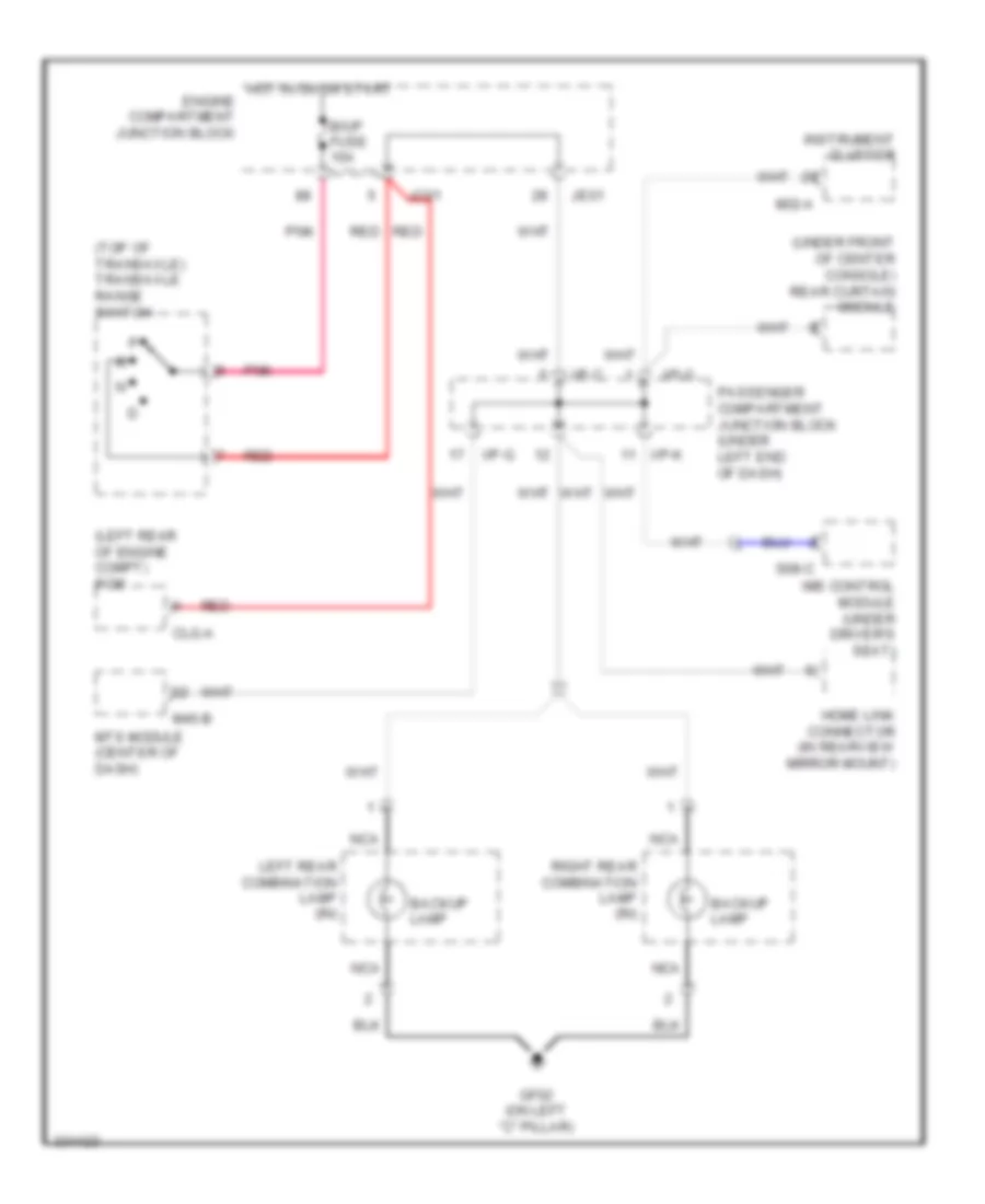
Backup Lamps Wiring Diagram for Hyundai Azera GLS 2010
List of elements for Backup Lamps Wiring Diagram for Hyundai Azera GLS 2010:
- (left rear of engine compt) pcm
- (top of transaxle) transaxle range switch
- (under front of center console) rear curtain module
- B/up fuse 10a
- Backup lamp
- Clg-a
- Engine compartment junction block
- Gf02 (on left "c" pillar)
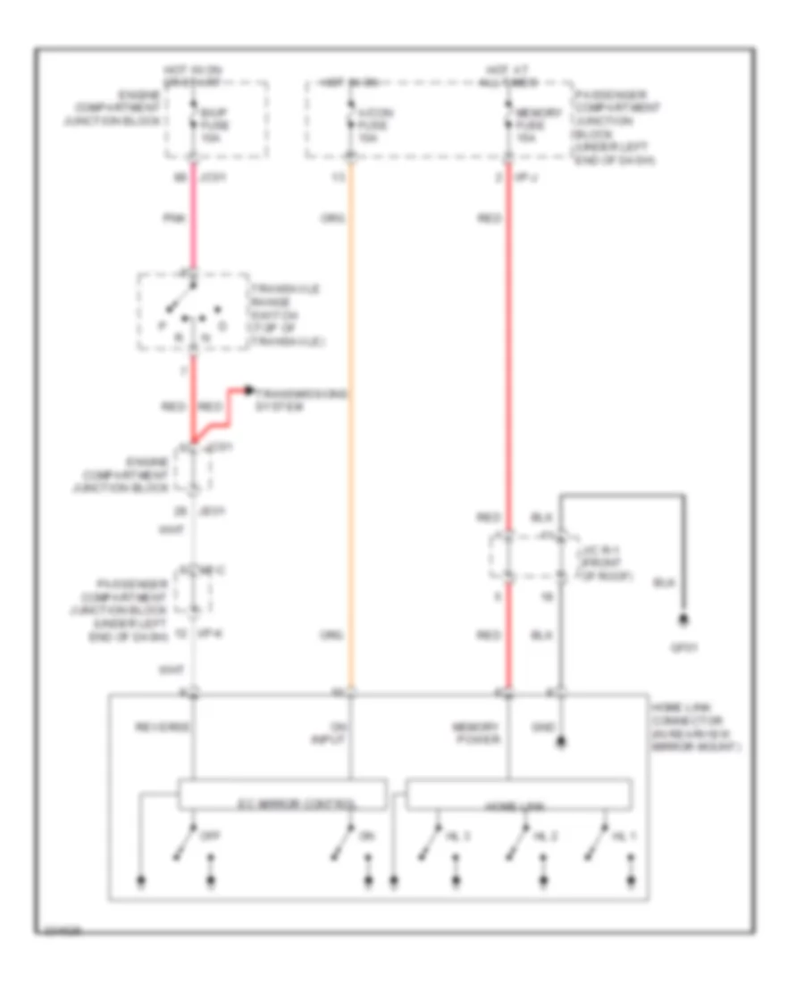
- Home link connector (in rearview mirror mount)
- Hot in on or start
- I/p-c
- I/p-g
- I/p-k
- Ims control module (under driver's seat)
- Instrument cluster
- Jc01
- Je01
- Left rear combination lamp (in)
- M32-a
- M45-b
- Mts module (center of dash)
- Nca
- Passenger compartment junction block (under left end of dash)
- Pnk
- Red
- Right rear combination lamp (in)
- S08-c
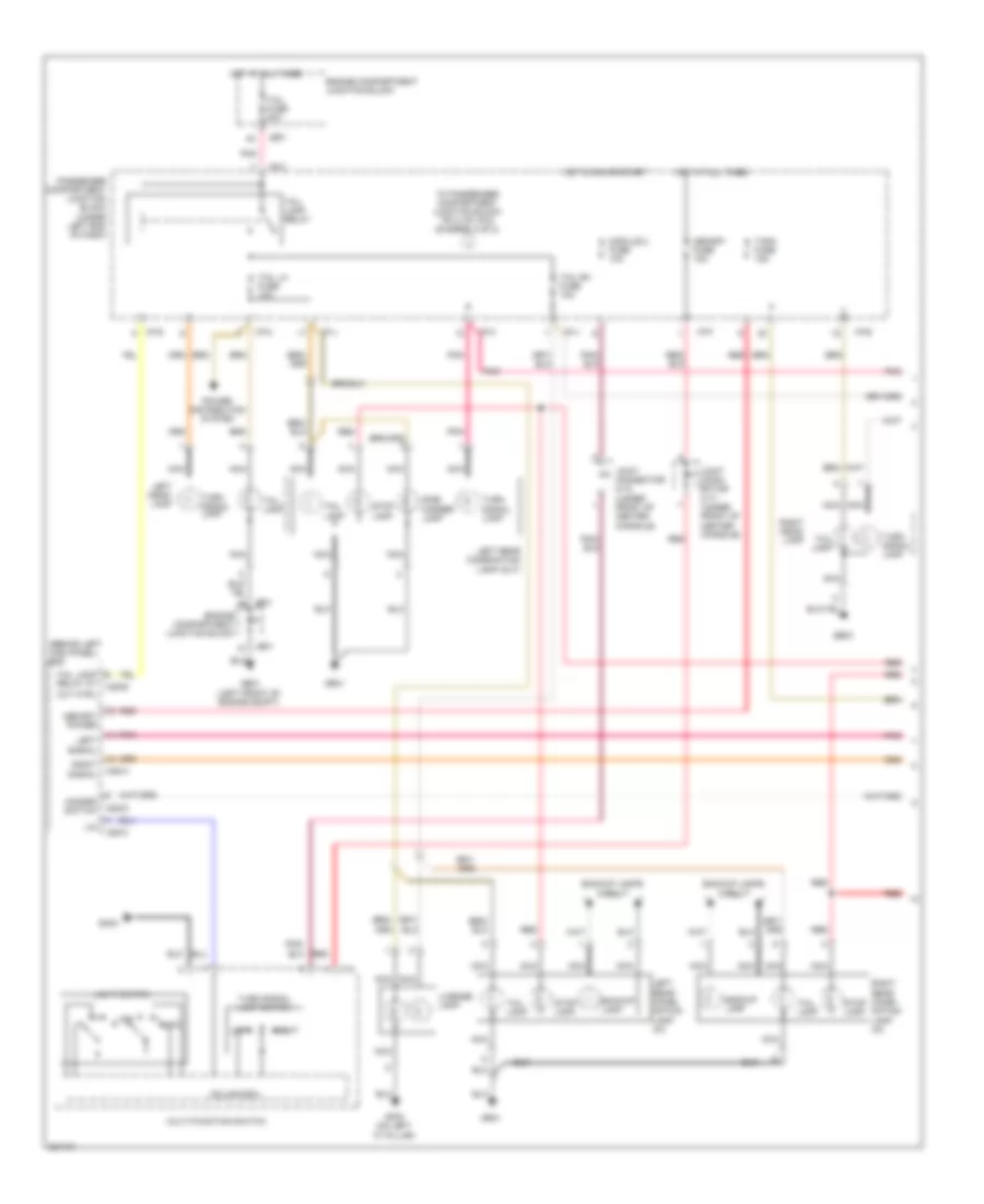
Exterior Lamps Wiring Diagram (1 of 2) for Hyundai Azera GLS 2010
List of elements for Exterior Lamps Wiring Diagram (1 of 2) for Hyundai Azera GLS 2010:
- (behind left kick panel) bcm
- Auto
- Backup lamp
- Backup lamps circuit
- Column ecu
- Cut ctrl
- Engine compartment junction block
- Ge01 (left front of engine compt)
- Ge03
- Gf02 (on left "c" pillar)
- Gm04
- Gr01
- Hazard switch
- Hot at all times
- Hot in on or start
- I/p-c
- I/p-e
- I/p-f
- I/p-g
- I/p-j
- I/p-k
- Je01
- Joint conn- ector m-17 (under front of center console)
- Joint connector m-10 (under front of center console)
- Left
- Left head- lamp
- Left rear combi- nation lamp (in)
- Left rear combination lamp (out)
- Left signal
- License lamp
- Light switch
- Lin
- M12
- M28-a
- M28-b
- M28-c
- M28-d
- Memory fuse 15a
- Memory power
- Module 2 fuse 10a
- Multi-function switch
- Nca
- Off
- Passenger compartment junction block (under left end of dash)
- Pnk
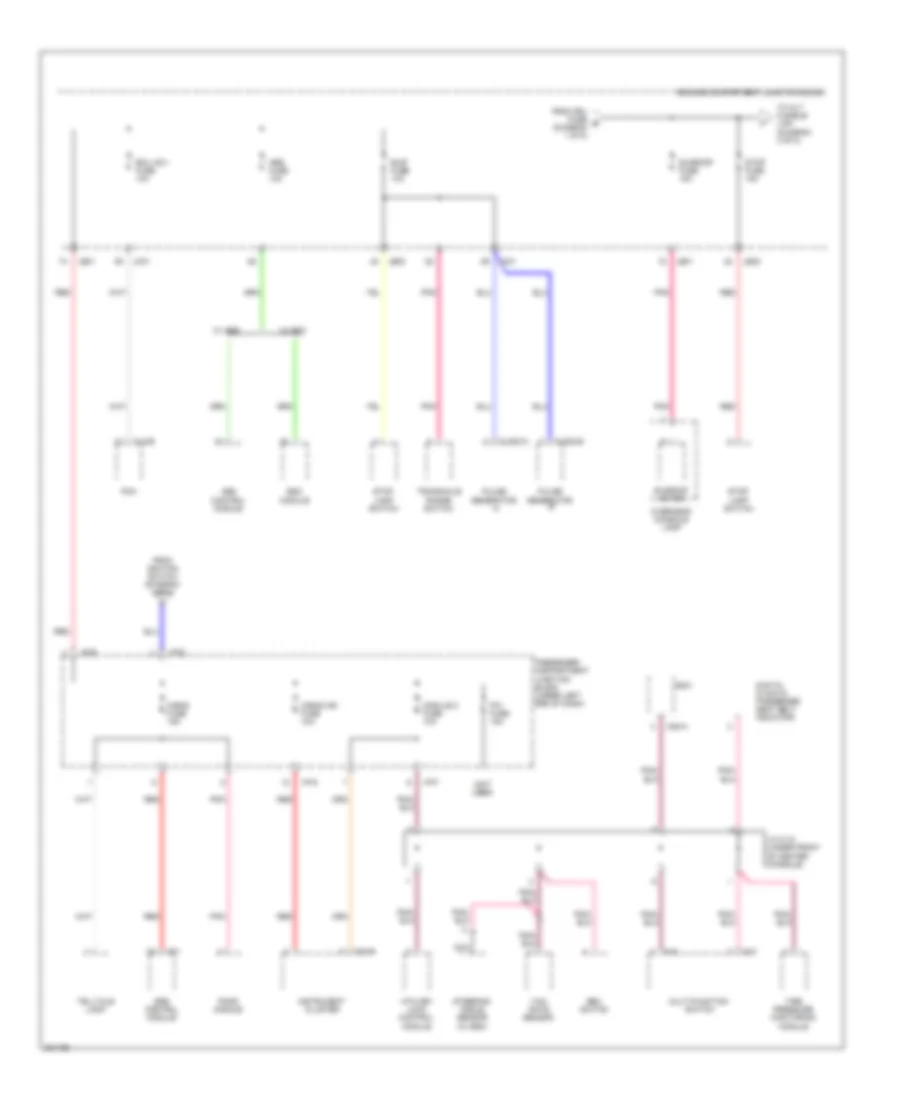
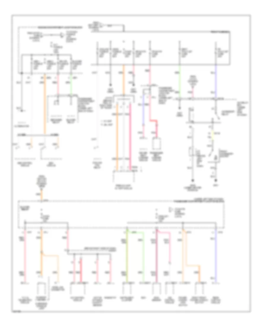
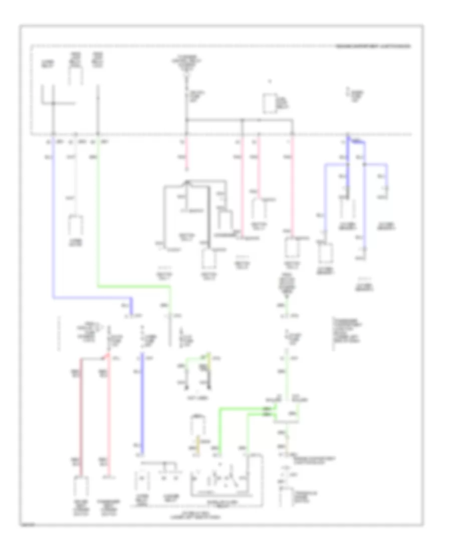
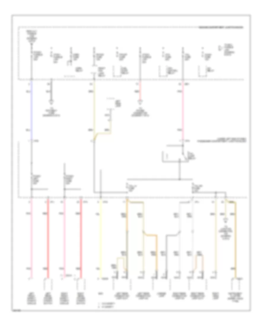
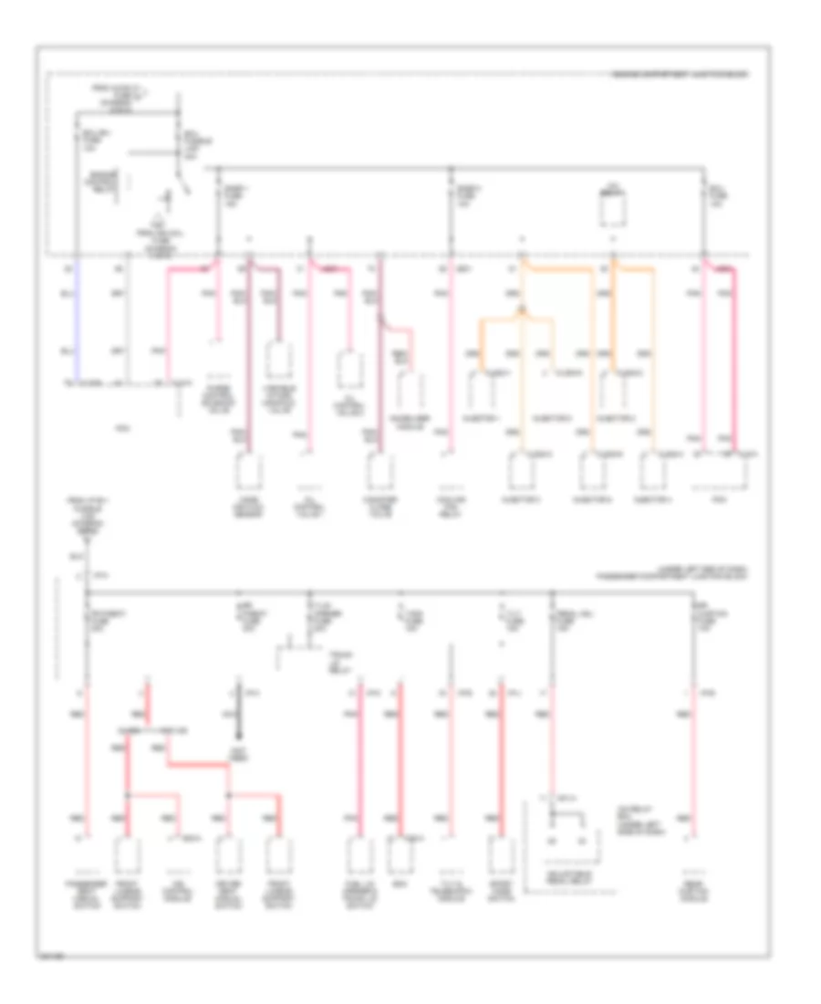
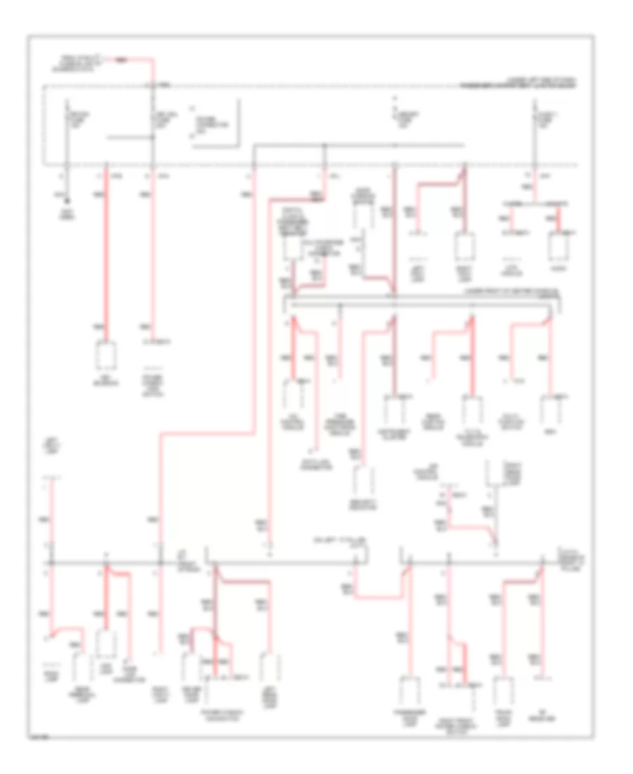
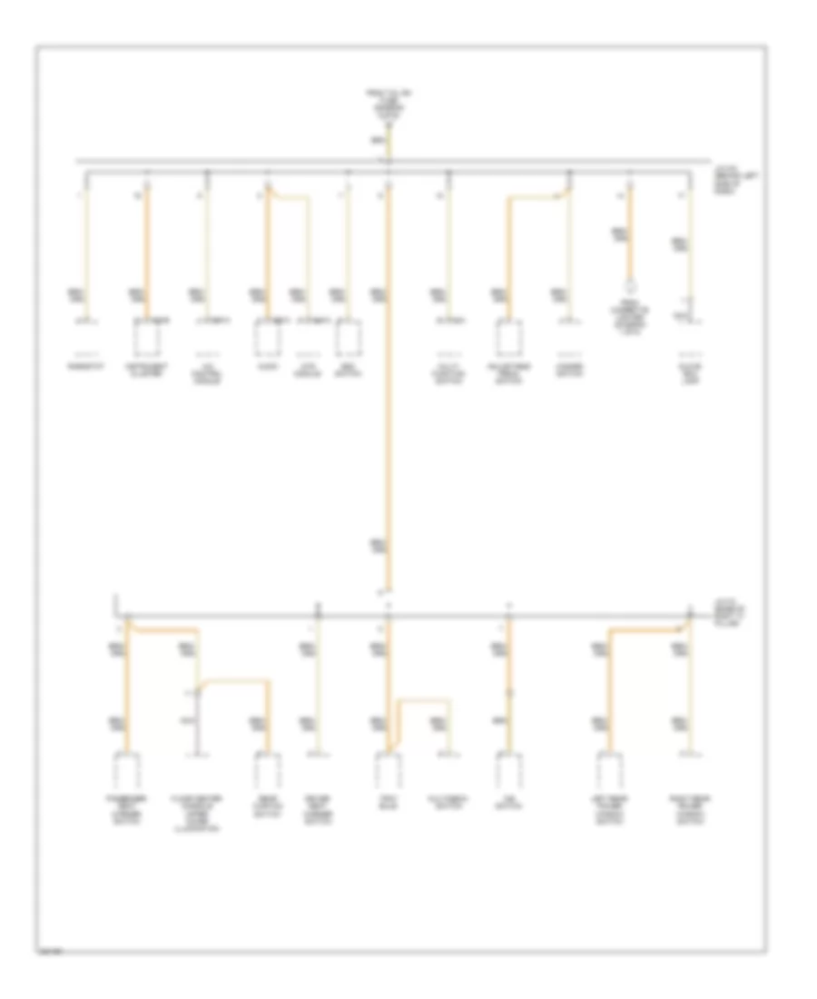
- Power distribution system
- Red
- Right
- Right head- lamp
- Right rear combi- nation lamp (in)
- Right signal
- Side marker lamp
- Stop lamp
- T/sig fuse 15a
- Tail fuse 20a
- Tail lamp
- Tail lamp relay
- Tail lamp relay at
- Tail lh fuse 10a
- Tail rh fuse 10a
- To passenger compartment junction block pin 4 of i/p-g (diagram 2 of 2)
- Turn signal lamp
- Turn signal lamp switch
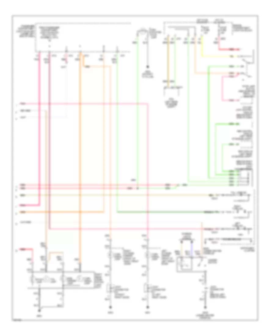
Exterior Lamps Wiring Diagram (2 of 2) for Hyundai Azera GLS 2010
List of elements for Exterior Lamps Wiring Diagram (2 of 2) for Hyundai Azera GLS 2010:
- (behind right side of dash) joint connector e-1
- (front of left front door)
- (front of right front door)
- Abs control module (left rear of engine compt)
- Atm key lock control module (behind right side of dash)
- B/up fuse 10a
- Clg-a
- Engine compartment junction block
- Esc module (left rear of engine compt)
- From passenger compartment junction block pin 6 of i/p-c (diagram 1 of 2)
- Gf01
- Gf03
- Gf04 (on right "c" pillar)
- Gm02 (under center console)
- Gr01
- Hazard switch
- High mounted stop lamp
- Hot at all times
- Hot in on or start
- I/p-c
- I/p-f
- I/p-g
- I/p-k
- Ill
- Instrument cluster
- Interior lights system
- Jc01
- Jeo2
- Joint connector d-1 (in left front door)
- Joint connector d-2 (in right front door)
- Joint connector m-5 (behind left side of dash)
- Left outside mirror
- Left turn ind
- M32-a
- M32-c
- Nca
- Passenger compartment junction block (under left end of dash)
- Pcm (left rear of engine compt)
- Pnk
- Power ground
- Red
- Right outside mirror
- Right rear combi- nation lamp (out)
- Right turn ind
- Side marker lamp
- Stop fuse 15a
- Stop lamp
- Stop lamp switch (above brake pedal, on bracket)
- Tail lamp
- Tail lamp ind
- Turn signal lamp
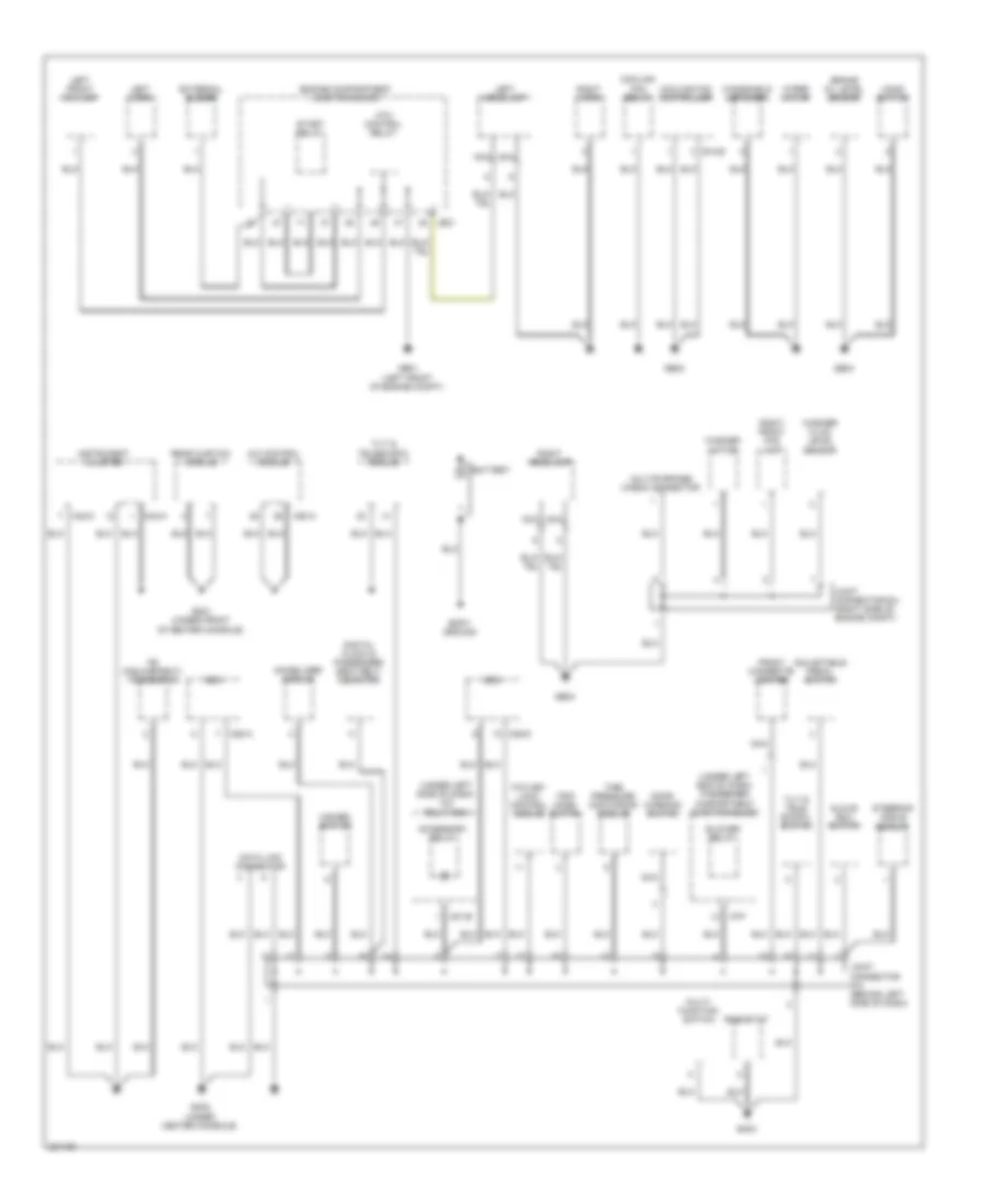
GROUND DISTRIBUTION
Ground Distribution Wiring Diagram (1 of 3) for Hyundai Azera GLS 2010
List of elements for Ground Distribution Wiring Diagram (1 of 3) for Hyundai Azera GLS 2010:
- (under left end of dash) passenger compartment junction block
- (under left side of dash) icm relay box
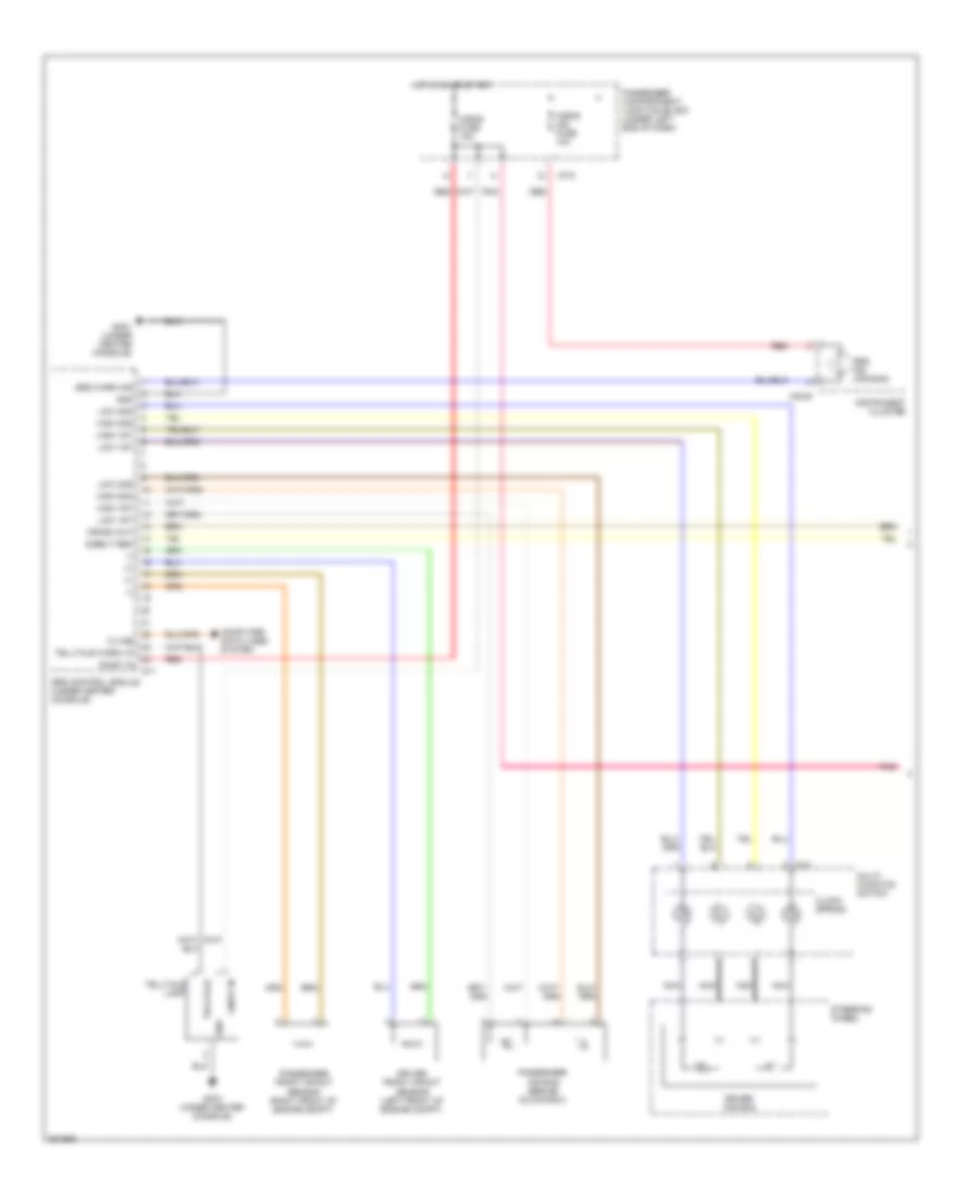
- A/c control module
- Accessory relay
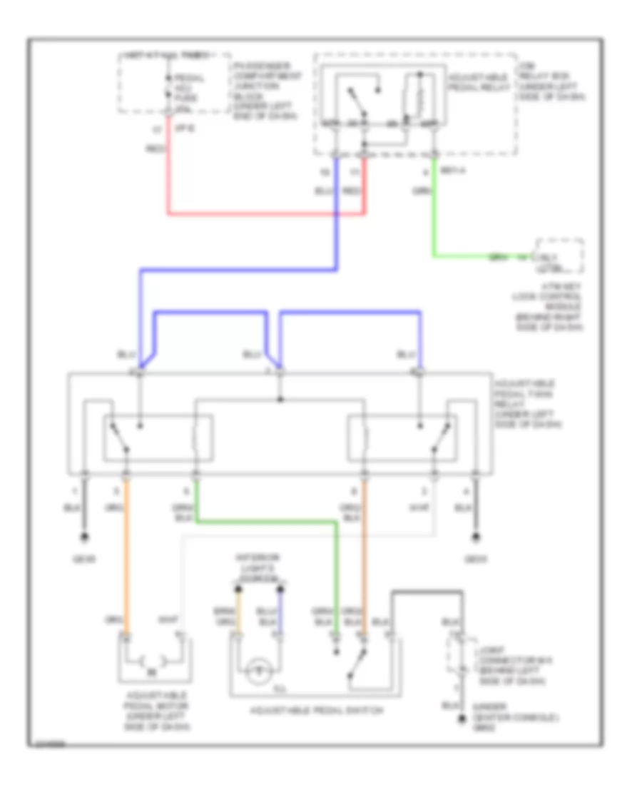
- Adjustable pedal switch
- Atm control relay
- Atm key lock control module
- Battery
- Bcm
- Blower relay
- Body ground
- Brake oil level sensor
- Cooling fan controller
- Cooling fan relay
- Data link connector
- Digital clock & passenger seat belt indicator
- Door warning switch
- E12-b
- Engine compartment junction block
- External buzzer
- Fe (field-effect) transistor
- Front cigarette lighter
- Ge01 (left front of engine compt)
- Ge02
- Ge03
- Ge04
- Glove box switch
- Gm01 (under front of center console)
- Gm02 (under center console)
- Gm04
- Hazard switch
- Hood switch
- I/p-f
- Immobilizer module
- Instrument cluster
- Je01
- Joint connector e-4 (right side of engine compt)
- Joint connector m-5 (behind left side of dash)
- Left front fog lamp
- Left headlamp
- Left horn
- M01-b
- M28-a
- M28-d
- M32-a
- M32-c
- M50-a
- Multi- function switch
- Multipurpose check connector
- Nca
- Rear curtain module
- Rheostat
- Right front fog lamp
- Right headlamp
- Right horn
- Start relay
- Steering angle sensor
- Tilt & tele- scopic switch
- Tilt & telescopic module
- Tire pressure monitoring module
- Trip mode switch
- Washer fluid level sensor
- Washer motor
- Windshield defogger
- Wiper motor
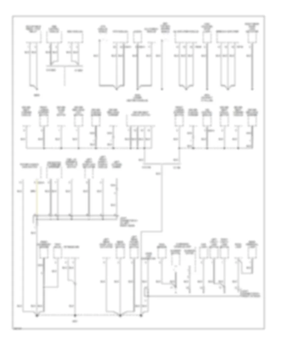
Ground Distribution Wiring Diagram (2 of 3) for Hyundai Azera GLS 2010
List of elements for Ground Distribution Wiring Diagram (2 of 3) for Hyundai Azera GLS 2010:
- Abs control module
- Adjustable pedal twin relay
- Audio
- Av amplifier module
- D03-a
- Driver cushion warmer
- Driver reclining limit switch
- Driver reclining warmer
- Driver seat manual switch
- Driver seat warmer module
- Driver slide limit switch
- Esc module
- F55-b
- F57-b
- Front accessory socket
- Front lumbar support switch
- Fuel lid opener & trunk lid switch
- Ge05
- Gf01
- Gf04 (on right "c" pillar)
- Gm03 (under center console)
- High mounted stop lamp
- Home link connector
- Ims control module
- Ims switch & tweeter speaker
- Joint connector d-1 (in left front door)
- Joint connector r-1 (front of roof)
- Left front door lock actuator
- Left front safety window module
- Left outside mirror
- Left rear door lock actuator
- Left rear power window switch
- Left vanity lamp switch
- M45-a
- M58-a
- Map lamp
- Mts module
- Mts module shield
- Multimedia module
- Nca
- Overhead console lamp
- Power window main switch
- Premium amplifier
- Rain sensor
- Rear curtain switch
- Rear personal lamp
- Rf receiver
- Right rear door lock actuator
- Right vanity lamp switch
- Room lamp
- S08-a
- Set top box (sdars)
- Shield
- Sunroof motor
- Sunroof switch
- Tray bulb
- W/ esc
- W/ ims
- W/o esc
- W/o ims
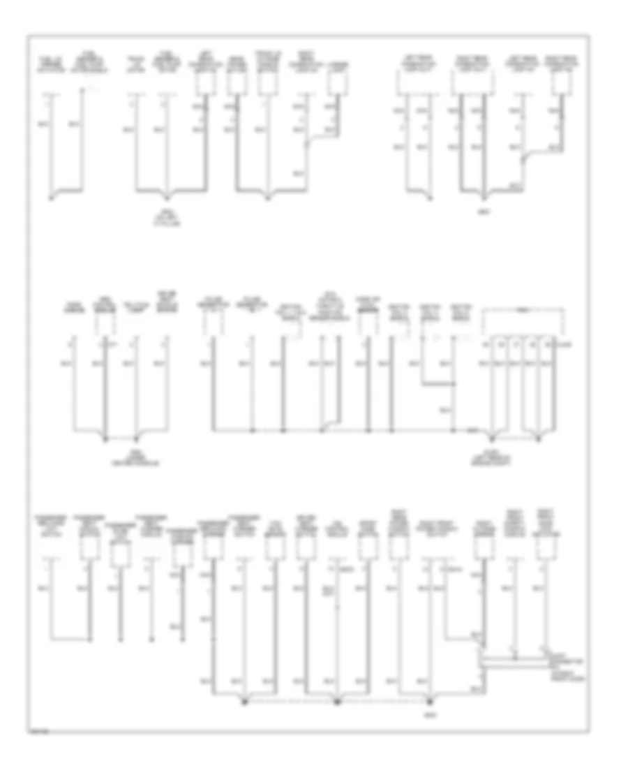
Ground Distribution Wiring Diagram (3 of 3) for Hyundai Azera GLS 2010
List of elements for Ground Distribution Wiring Diagram (3 of 3) for Hyundai Azera GLS 2010:
- Clg-b
- D04-a
- Driver seat buckle switch
- Driver seat warmer switch
- Etc motor &
- Fuel lid opener actuator
- Fuel sender & fuel pump motor
- Fuel sender & fuel pump motor shield
- Ga01 (under center console)
- Gf02 (on left "c" pillar)
- Gf03
- Glg01 (left rear of engine compt)
- Gr01
- Ignition coil 1, 3 & 5 shield
- Ignition coil 2 shield
- Ignition coil 4 shield
- Ignition coil 6 shield
- Ims control module
- Joint connector d-2 (in right front door)
- Left rear combination lamp (in)
- Left rear combination lamp (out)
- License lamp
- M71
- Mass air flow sensor
- Nca
- Passenger cushion warmer
- Passenger reclining limit switch
- Passenger reclining warmer
- Passenger seat manual switch
- Passenger seat warmer module
- Passenger seat warmer switch
- Passenger slide limit switch
- Pcm
- Pods module
- Pulse generator a
- Pulse generator b
- Rear power outlet
- Right front door lock actuator
- Right front power window switch
- Right front safety window module
- Right outside mirror
- Right rear combination lamp (in)
- Right rear combination lamp (out)
- Right rear power window switch
- S08-d
- Sport mode switch
- Srs control module
- Telltale lamp
- Throttle position sensor shield
- Trunk lid motor
- Trunk lid outside handle switch
- Yaw rate sensor
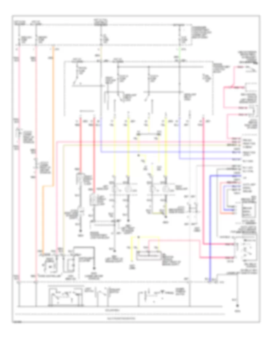
HEADLIGHTS
Headlights Wiring Diagram for Hyundai Azera GLS 2010
List of elements for Headlights Wiring Diagram for Hyundai Azera GLS 2010:
- (above parking brake pedal, on bracket) parking brake switch
- (not used)
- Auto
- Auto light
- Auto light & photo sensor (top center of dash)
- Auto light sensor
- Bcm (behind left kick panel)
- Column ecu
- Dim
- Dimmer/ passing switch
- Drl fuse 15a
- Drl relay (canada)
- Drl resistor (canada) (right front of engine compt)
- Engine compartment junction block
- Esc control module (left rear of engine compt)
- Foglamp switch
- Fr fog fuse 15a
- Front fog
- Front fog ind
- Front fog lp rly
- Front foglamp relay
- Ge01 (left front of engine compt)
- Ge03
- Gm02 (under center console)
- Gm04
- Ground
- H/lp fuse 10a
- H/lp hi fuse 20a
- H/lp lo fuse 20a
- Headlamp relay (high)
- Headlamp relay (low)
- Hi beam
- High beam ind
- Hot at all times
- Hot in on
- Hot in on or start
- Hot w/ tail lamp relay energized
- I/p-c
- I/p-f
- Icm relay box (under left side of dash)
- Instrument cluster
- J/c e-4 (right side of engine compt)
- J/c m-1 (behind right side of dash)
- J/c m-10 (under front of center console)
- J/c m-17 (under front of center console)
- Je01
- Je02
- Left front fog lamp
- Left headlamp
- Lh tail fuse 10a
- Light switch
- Lin
- Low
- M01-b
- M12
- M28-a
- M28-b
- M28-c
- M28-d
- M32-a
- M32-b
- Memory fuse 15a
- Micro controller
- Module 2 fuse 10a
- Multi-function switch
- Nca
- Off
- Pass
- Passenger compartment junction block (under left end of dash)
- Pnk
- Prk sw
- Red
- Right front fog lamp
- Right headlamp
- Rly ctrl
- Rly high
- Rly low
- Signal
- W/ drl
- W/o drl
HORN
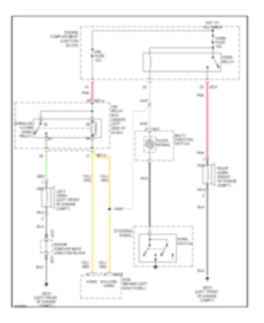
Horn Wiring Diagram for Hyundai Azera GLS 2010
List of elements for Horn Wiring Diagram for Hyundai Azera GLS 2010:
- B/alarm horn
- Bcm (behind left kick panel)
- Burglar alarm horn relay
- Clock spring
- Drl fuse 15a
- Engine compartment junction block
- Ge01 (left front of engine compt)
- Horn
- Horn fuse 15a
- Horn relay
- Horn switch
- Hot at all times
- Icm relay box (under left side of dash)
- Je01
- Left horn (left front of engine compt)
- M01-a
- M14
- M28-b
- Multi- function switch
- Nca
- Pnk
- Right horn (front of engine compt)
- Steering wheel
INSTRUMENT CLUSTER
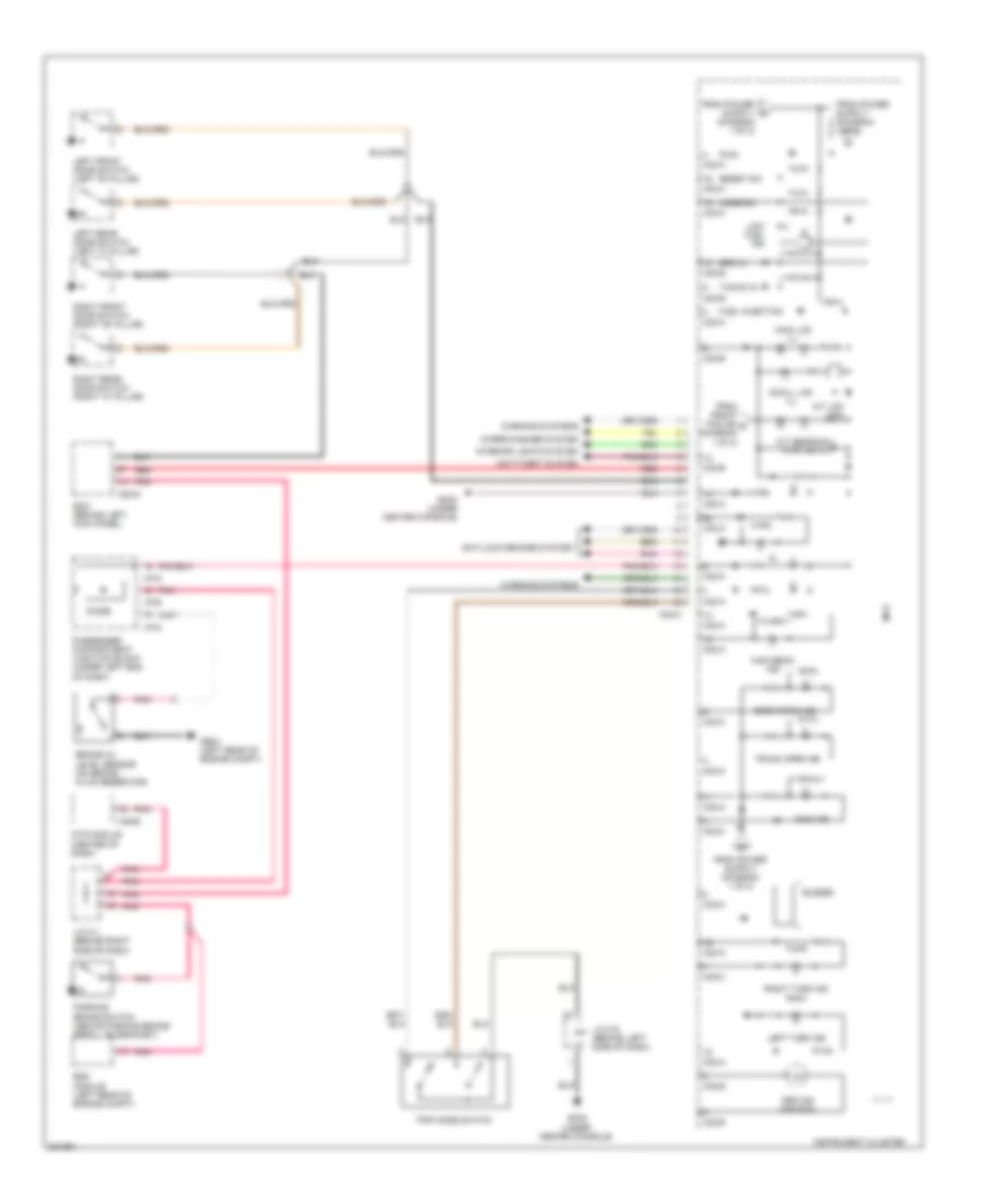
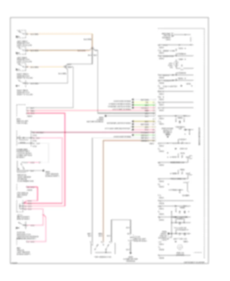
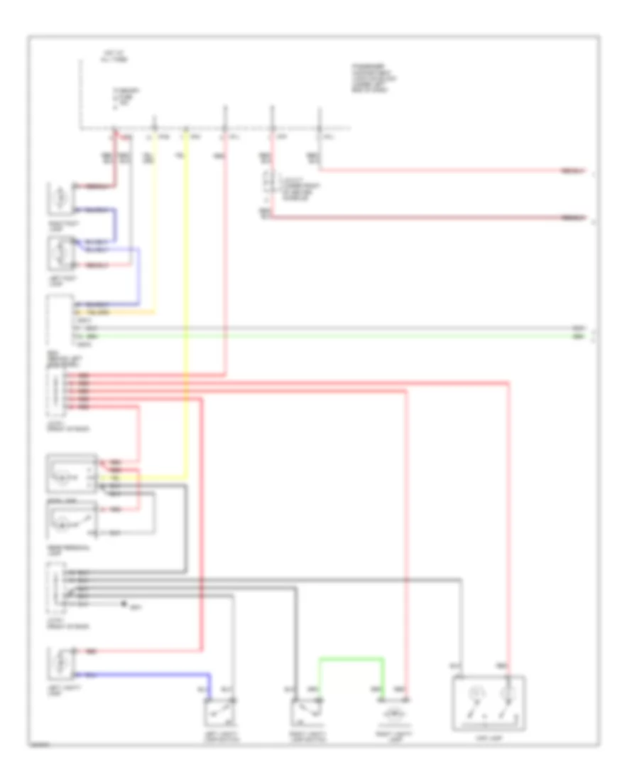
Instrument Cluster Wiring Diagram, with Analog Cluster (1 of 2) for Hyundai Azera GLS 2010
List of elements for Instrument Cluster Wiring Diagram, with Analog Cluster (1 of 2) for Hyundai Azera GLS 2010:
- (center of dash)
- (under center console gm02
- A/c control module
- A/t lcd con
- Abs ind
- Acc/on in
- Anti-lock brakes system
- Audio 2 fuse 10a
- Bcm (behind left kick panel)
- Brake warning ind
- Charge ind
- Clg-a
- Cruise control system
- Cruise ind
- Cruise set ind
- Digital clock
- Digital clock & passenger seat belt indicator
- Display
- Ebd
- Engine compartment junction block
- Engine controls system
- Engine coolant temperature sensor & sender (on rear of engine)
- Esc ind
- Esc off ind
- Exterior lights system
- Front fog ind
- Fuel gauge
- Fuel gnd
- Fuel in
- Fuel sen- der a
- Fuel sen- der b
- Fuel sender & fuel pump motor (beneath center of rear seat, in fuel tank)
- Gm01 (under front of center console)
- Gm02 (under center console)
- Gnd
- Headlights system
- Hot at all times
- Hot in acc or on
- Hot in on or start
- I/p-f
- Ill
- Input b
- Instrument cluster
- Interior lights system
- J/c m-17 (under front of center console)
- J/c m-3 (behind left center of dash)
- J/c m-5 (behind left side of dash)
- Jc01
- Je01
- Low washer ind
- M28-d
- M32-a
- M32-b
- M32-c
- M50-b
- Mcu
- Memory fuse 15a
- Memory pwr
- Mil ind
- Module 2 fuse 10a
- Oil pressure ind
- Oil pressure switch (top left rear of engine)
- Parking brake
- Passenger compartment junction block (under left end of dash)
- Pcm (left rear of engine compt)
- Pnk
- Red
- Seat belt ind
- Sender
- Speedometer
- Starting/ charging system
- Tachometer
- Tail (-)
- Temp gauge
- Temp in
- To immo ind (diagram 2 of 2)
- To low fuel ind (diagram 2 of 2)
- To main lcd ill (diagram 2 of 2)
- To small lcd ind (diagram 2 of 2)
- Tpms ind
- Tpms tread ind
- Transmissions & shift interlock systems headlights system
- Transmissions system
- Trip/ odo
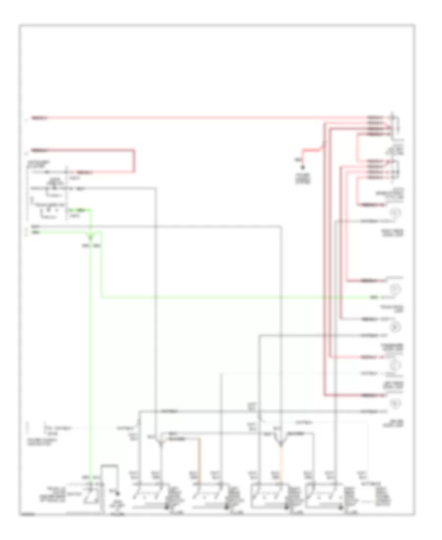
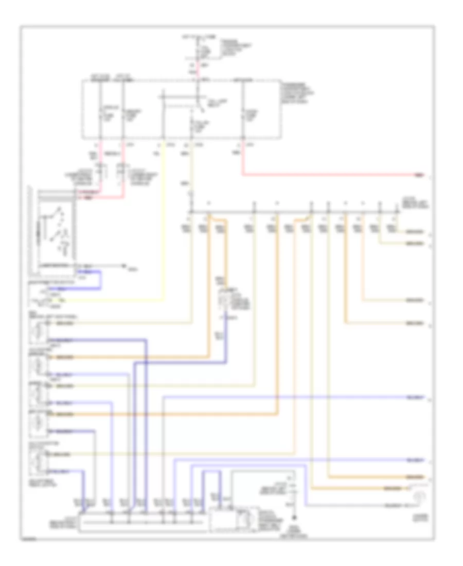
Instrument Cluster Wiring Diagram, with Analog Cluster (2 of 2) for Hyundai Azera GLS 2010
List of elements for Instrument Cluster Wiring Diagram, with Analog Cluster (2 of 2) for Hyundai Azera GLS 2010:
- (diagram 1 of 2)
- A/t gear/dial/ pointer ill
- A/t lcd con
- Anti-lock brakes system
- Anti-theft system
- Bcm (behind left kick panel)
- Brake oil level sensor (on brake fluid reservoir)
- Buzzer
- Diode
- Door open ind
- Esc module (left rear of engine compt)
- From front fog ind c (diagram 1 of 2)
- Fuel injection
- Ge04 (left rear of engine compt)
- Gm02 (under center console)
- High beam ind
- I/p-e
- I/p-g
- Immo ind
- Instrument cluster
- Interior lights system
- J/c m-1 (behind right side of dash)
- J/c m-5 (behind left side of dash)
- Left front door switch (left "b" pillar)
- Left rear door switch (left "c" pillar)
- Left turn ind
- Low fuel ind
- M28-d
- M32-a
- M32-b
- M32-c
- M45-b
- Main lcd ill
- Mcu
- Mode sw
- Mts module (center of dash)
- Parking brake switch (above parking brake pedal, on bracket)
- Passenger compartment junction block (under left end of dash)
- Pnk
- Pwm
- Red
- Reset sw
- Right front door switch (right "b" pillar)
- Right rear door switch (right "c" pillar)
- Right turn ind
- Small lcd ill
- Spd in
- Srs ind (air bag)
- Tacho in
- Trip mode switch
- Trunk open ind
- Warning systems
- Wiper/washer system
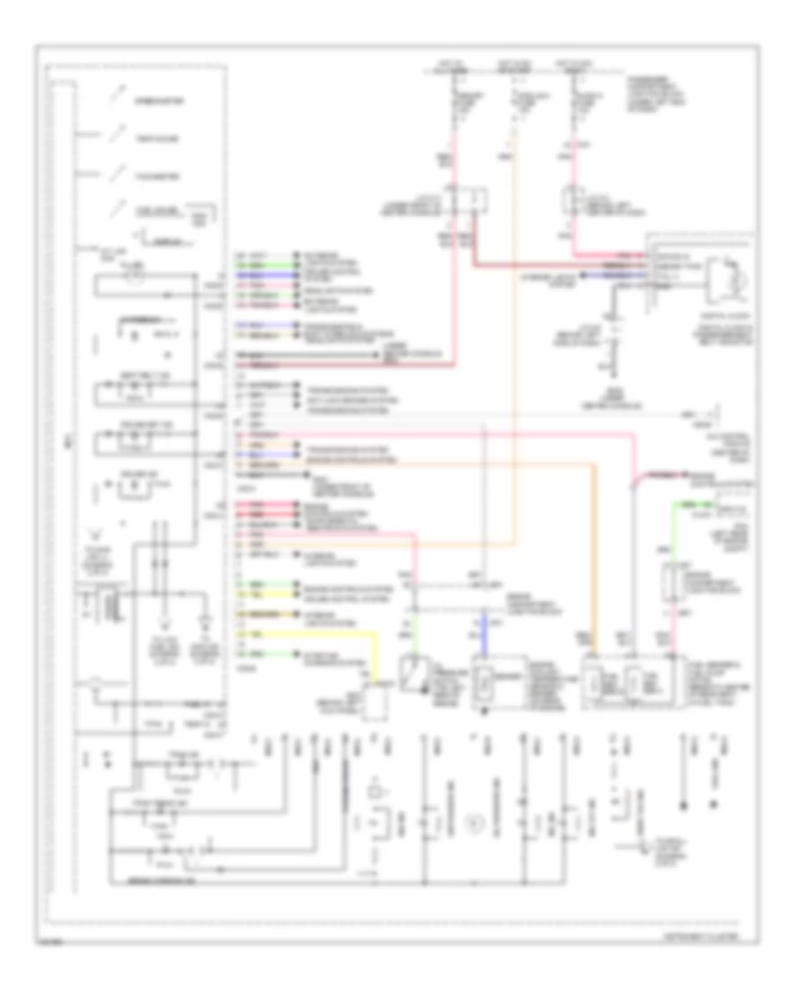
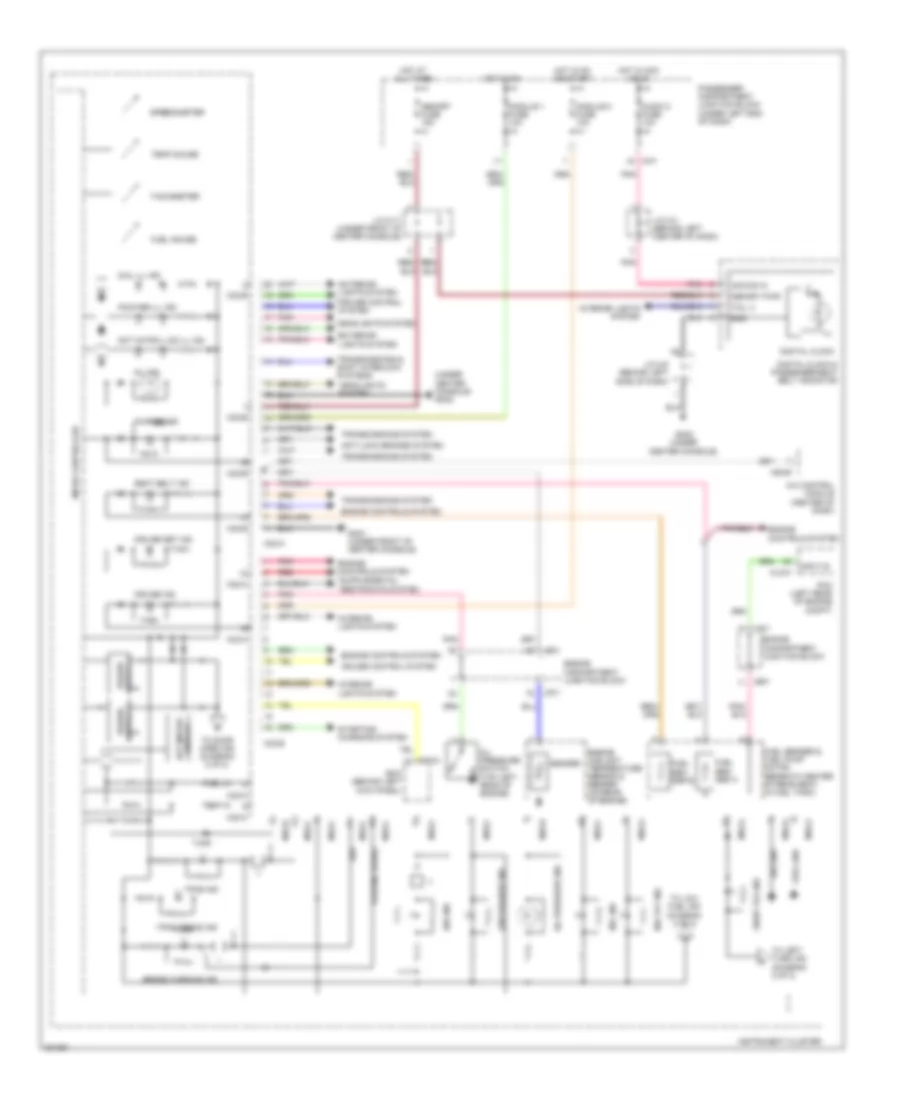
Instrument Cluster Wiring Diagram, with Super Vision (1 of 2) for Hyundai Azera GLS 2010
List of elements for Instrument Cluster Wiring Diagram, with Super Vision (1 of 2) for Hyundai Azera GLS 2010:
- (under center console) gm02
- A/c control module (center of dash)
- Abs ind
- Acc/on in
- Anti-lock brakes system
- Audio 2 fuse 10a
- Bcm (behind left kick panel)
- Brake warning ind
- Charge ind
- Clg-a
- Cruise control system
- Cruise ind
- Cruise set ind
- Dial ill ind
- Digital clock
- Digital clock & passenger seat belt indicator
- Display dot matrix
- Dot matrix lcd ill ind
- Ebd
- Engine compartment junction block
- Engine controls system
- Engine coolant temperature sensor & sender (on rear of engine)
- Esc ind
- Esc off ind
- Exterior lights system
- Front fog ind
- Fuel gauge
- Fuel gnd
- Fuel in
- Fuel sen- der a
- Fuel sen- der b
- Fuel sender & fuel pump motor (beneath center of rear seat, in fuel tank)
- Gm01 (under front of center console)
- Gm02 (under center console)
- Gnd
- Headlights system
- Hot at all times
- Hot in acc or on
- Hot in on
- Hot in on or start
- I/p-f
- Ill
- Input b
- Instrument cluster
- Interior lights system
- J/c m-17 (under front of center console)
- J/c m-3 (behind left center of dash)
- J/c m-5 (behind left side of dash)
- Jc01
- Je01
- Low washer ind
- M28-d
- M32-a
- M32-b
- M32-c
- M50-b
- Memory fuse 15a
- Memory pwr
- Micro controller
- Mil ind
- Module 1 fuse 10a
- Module 2 fuse 10a
- Oil pressure ind
- Oil pressure switch (top left rear of engine)
- Parking brake
- Passenger compartment junction block (under left end of dash)
- Pcm (left rear of engine compt)
- Pnk
- Pointer ill ind
- Red
- Seat belt ind
- Sender
- Sig gnd
- Speedometer
- Starting/ charging system
- Tachometer
- Tail (-)
- Temp gauge
- Temp in
- To door open ind (diagram 2 of 2)
- To left turn ind (diagram 2 of 2)
- To low fuel ind (diagram 2 of 2)
- Tpms ind
- Tpms tread ind
- Transmissions & shift interlock systems
- Transmissions system
Instrument Cluster Wiring Diagram, with Super Vision (2 of 2) for Hyundai Azera GLS 2010
List of elements for Instrument Cluster Wiring Diagram, with Super Vision (2 of 2) for Hyundai Azera GLS 2010:
- (diagram 1 of 2)
- Anti-lock brakes system
- Anti-theft system
- Bcm (behind left kick panel)
- Brake oil level sensor (on brake fluid reservoir)
- Buzzer
- Diode
- Door open ind
- Esc module (left rear of engine compt)
- Exterior lights system
- From esc off ind a
- From front fog ind (diagram c 1 of 2)
- Fuel injection
- Ge04 (left rear of engine compt)
- Gm02 (under center console)
- High beam ind
- I/p-e
- I/p-g
- Immo ind
- Instrument cluster
- Interior lights system
- J/c m-1 (behind right side of dash)
- J/c m-5 (behind left side of dash)
- Left front door switch (left "b" pillar)
- Left rear door switch (left "c" pillar)
- Left turn ind
- Low fuel ind
- M28-d
- M32-a
- M32-b
- M32-c
- M45-b
- Micro controller
- Mode knob
- Mts module (center of dash)
- Parking brake switch (above parking brake pedal, on bracket)
- Passenger compartment junction block (under left end of dash)
- Pnk
- Pwm
- Red
- Reset knob
- Right front door switch (right "b" pillar)
- Right rear door switch (right "c" pillar)
- Right turn ind
- Spd in
- Srs ind (air bag)
- Tacho in
- Tail lamp ind
- Trip mode switch
- Trunk open ind
- Warning systems
- Wiper/washer system
INTERIOR LIGHTS
Courtesy Lamps Wiring Diagram (1 of 2) for Hyundai Azera GLS 2010
List of elements for Courtesy Lamps Wiring Diagram (1 of 2) for Hyundai Azera GLS 2010:
- Bcm (behind left kick panel)
- Gf01
- Hot at all times
- I/p-e
- I/p-f
- I/p-j
- I/p-k
- J/c m-17 (under front of center console)
- J/c r-1 (front of roof)
- Left foot lamp
- Left vanity lamp
- Left vanity lamp switch
- M28-a
- M28-d
- Map lamp
- Memory fuse 15a
- Passenger compartment junction block (under left end of dash)
- Rear personal lamp
- Red
- Right foot lamp
- Right vanity lamp
- Right vanity lamp switch
- Room lamp
Courtesy Lamps Wiring Diagram (2 of 2) for Hyundai Azera GLS 2010
List of elements for Courtesy Lamps Wiring Diagram (2 of 2) for Hyundai Azera GLS 2010:
- D03-b
- D04-b
- Door open ind
- Driver door lamp
- Gf02 (on left "c" pillar)
- Instrument cluster
- J/c f-1 (on left "c" pillar)
- J/c f-4 (base of right "c" pillar)
- Left front door switch (left "b" pillar)
- Left rear door lamp
- Left rear door switch (left "c" pillar)
- M32-a
- M32-c
- Passenger door lamp
- Power window main switch
- Power window system
- Red
- Right front door switch (right "b" pillar)
- Right front power window switch
- Right rear door lamp
- Right rear door switch (right "c" pillar)
- Switch
- Trunk lid motor (center rear of trunk lid)
- Trunk open ind
- Trunk room lamp
Instrument Illumination Wiring Diagram (1 of 2) for Hyundai Azera GLS 2010
List of elements for Instrument Illumination Wiring Diagram (1 of 2) for Hyundai Azera GLS 2010:
- A/c control module
- A/con fuse 10a
- Adjustable pedal switch
- Audio
- Auto
- Bcm (behind left kick panel)
- Column ecu
- Digital clock & passenger seat belt indicator
- Engine compartment junction block
- Esc switch
- Gm02 (under center dash)
- Gm04
- Hazard switch
- Hot at all times
- Hot in on
- Hot in on or start
- I/p-c
- I/p-e
- I/p-f
- I/p-g
- Ill
- J/c m-10 (under front of center console)
- J/c m-17 (under front of center console)
- J/c m-5 (behind left side of dash)
- J/c m-6 (behind left side of dash)
- J/c m-7 (behind right side of dash)
- Je01
- Light switch
- Lin
- M12
- M28-b
- M28-c
- M45-a
- M50-a
- M58-a
- Memory fuse 15a
- Module fuse 10a
- Mts module (center of dash)
- Multi-function switch
- Off i
- Passenger compartment junction block (under left end of dash)
- Pnk
- Red
- Tail fuse 20a
- Tail lamp relay
- Tail lp rly
- Tail rh fuse 10a
Instrument Illumination Wiring Diagram (2 of 2) for Hyundai Azera GLS 2010
List of elements for Instrument Illumination Wiring Diagram (2 of 2) for Hyundai Azera GLS 2010:
- Control
- Driver seat warmer switch
- Floor center console upper cover illumination
- Front cigarette lighter
- Gf01
- Glove box lamp
- Glove box switch (left side of glove box door)
- Gm02 (under center dash)
- Gm03 (behind right side of dash)
- Gm04
- Ill
- Ims switch & tweeter speaker
- Instrument cluster
- J/c d-1 (in left front door)
- J/c f-2 (base of right "c" pillar)
- J/c f-3 (behind center of rear seat)
- J/c m-1 (behind right side of dash)
- J/c m-5 (behind left side of dash)
- Left rear power window switch
- M32-b
- Multimedia module (under rear center console)
- Nca
- Passenger seat warmer switch
- Rear curtain switch
- Red
- Rheostat
- Right rear power window switch
- Tray bulb
MEMORY SYSTEMS
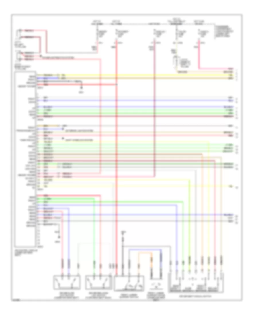
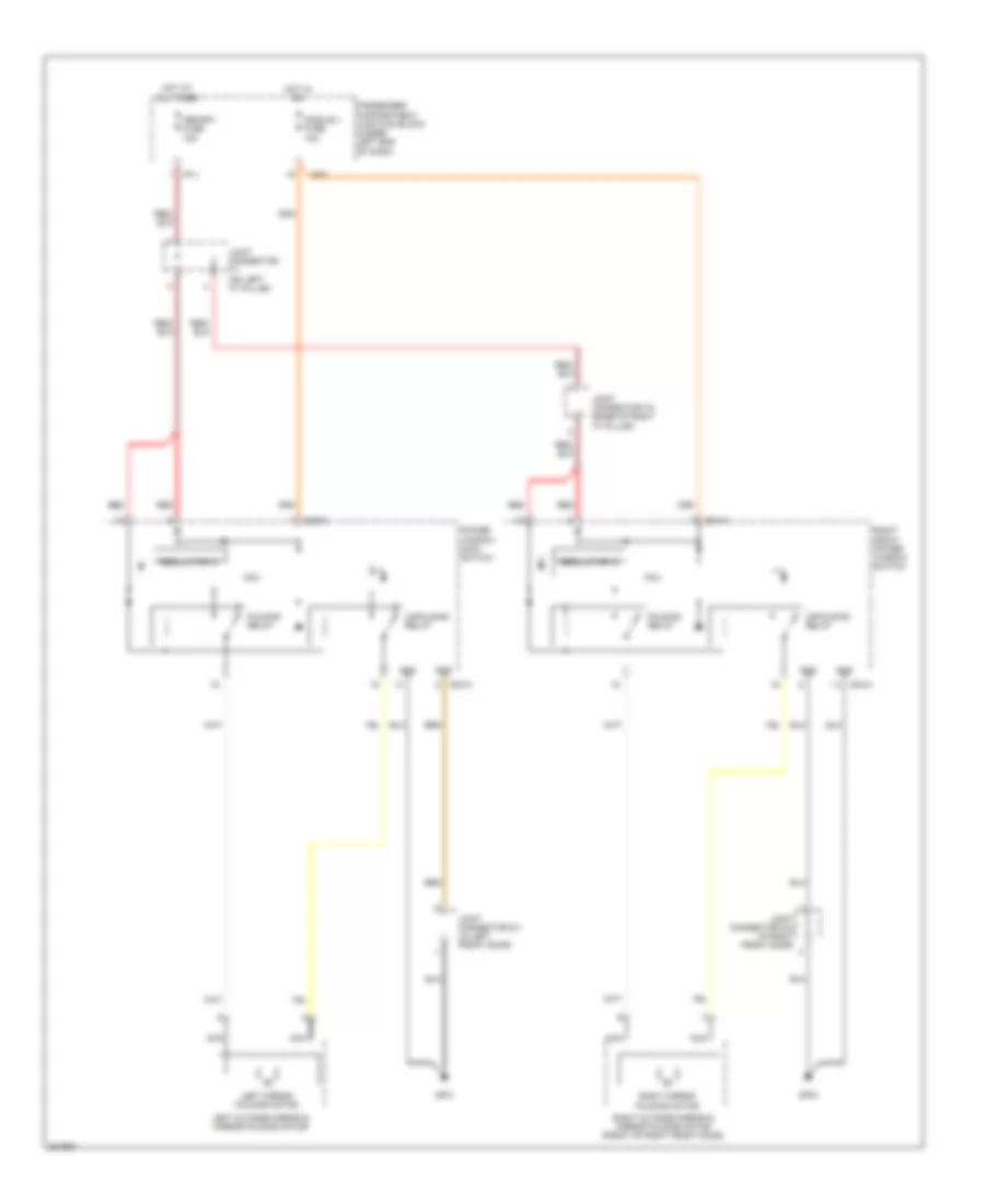
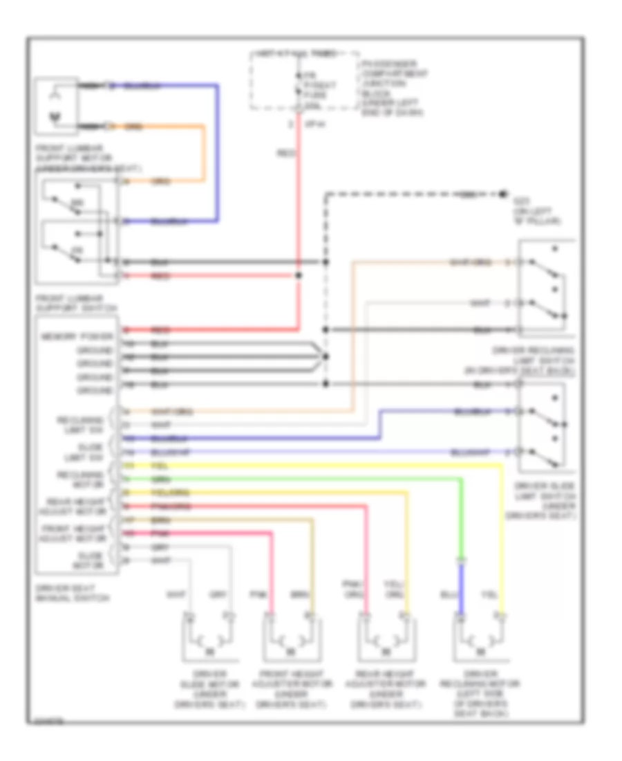
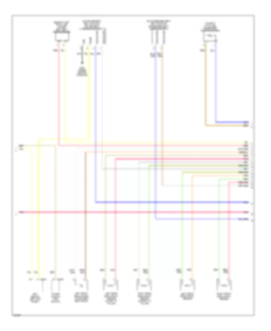
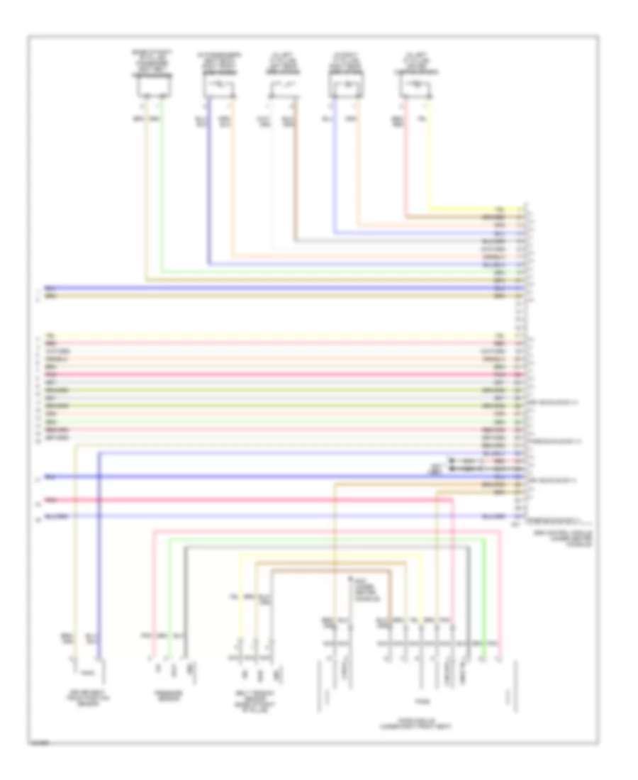
Driver"s Memory Seat Wiring Diagram (1 of 2) for Hyundai Azera GLS 2010
List of elements for Driver"s Memory Seat Wiring Diagram (1 of 2) for Hyundai Azera GLS 2010:
- Audio 2 fuse 10a
- Can high
- Can low
- Down
- Driver reclining limit switch (in driver's seat back)
- Driver seat manual switch
- Driver slide limit switch (under driver's seat)
- Exterior lights system
- Fr p/seat fuse 30a
- Front
- Front height switch
- Front lumbar support motor (under driver's seat)
- Front lumbar support switch
- Gf01
- Gf03
- Ground
- Hot at all times
- Hot in on
- Hot in on or acc
- Hot w/ tail lamp relay energized
- I/p-e
- I/p-h
- I/p-j
- I/p-k
- Ims control module (under driver's seat)
- J/c f-1 (on left ``c" pillar)
- J/c f-2 (base of right ``c" pillar)
- J/c f-4 (base of right ``c" pillar)
- Memory fuse 15a
- Memory power
- Module 1 fuse 10a
- Nca
- On input
- Park pos sw
- Passenger compartment junction block (under left end of dash)
- Pnk
- Power distribution system
- Rear
- Rear height switch
- Recline switch
- Red
- S08-a
- S08-b
- S08-c
- S08-d
- Shift interlock system
- Slide switch
- Tail rh fuse 10a
- Trans range sw
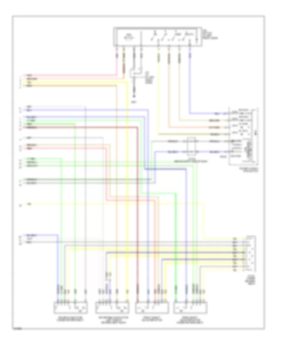
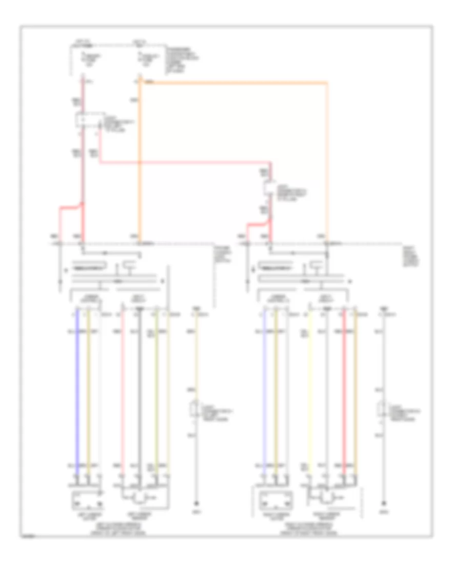
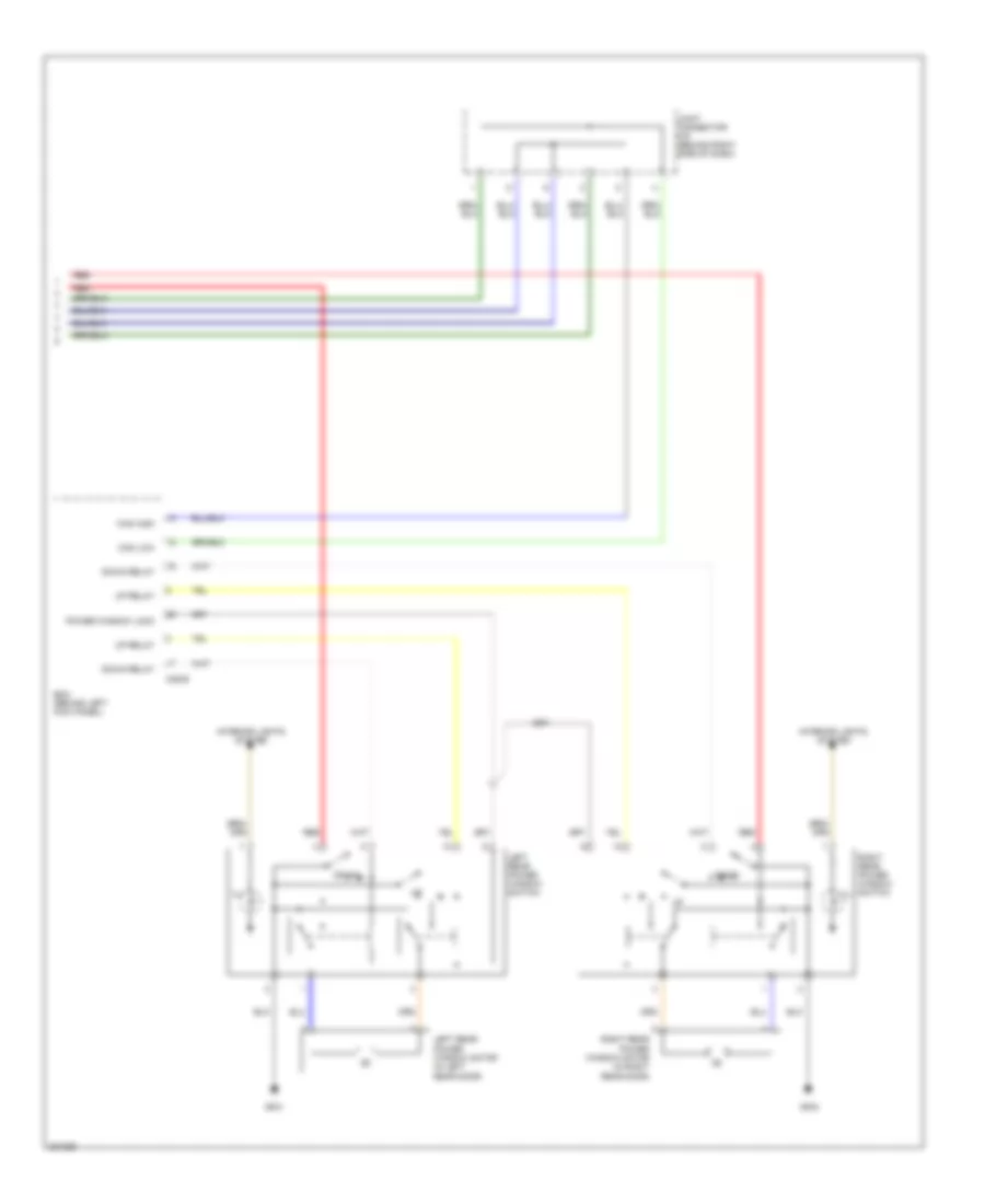
Driver"s Memory Seat Wiring Diagram (2 of 2) for Hyundai Azera GLS 2010
List of elements for Driver"s Memory Seat Wiring Diagram (2 of 2) for Hyundai Azera GLS 2010:
- +5va
- Auto
- Can
- Can high
- Can low
- D03-b
- Driver reclining motor (left side of driver's seat back)
- Driver slide motor (under driver's seat)
- Front height adjuster motor
- Gf01
- Illu
- Ims switch (in left front door)
- J/c d-1 (in left front door)
- J/c m-9 (behind right side of dash)
- J/c s-1 (under driver's seat)
- Mcu
- Pnk
- Power window main switch
- Rear height adjuster motor (under driver's seat)
- Red
- Set
- Transceiver ic
Memory Power Tilt & Power Telescopic Wiring Diagram for Hyundai Azera GLS 2010
List of elements for Memory Power Tilt & Power Telescopic Wiring Diagram for Hyundai Azera GLS 2010:
- +5va
- A/con fuse 10a
- Audio 2 fuse 10a
- Auto
- Back
- Back(s2)
- Can high
- Can low
- Can transceiver ic
- Computer data lines system
- D03-b
- Down
- Down(s2)
- Fwd
- Fwd(s1)
- Gf01
- Gm01 (under front of center console)
- Gm02 (under center console)
- Hot at all times
- Hot in on
- Hot in on or acc
- Illu
- Ims switch (in left front door)
- Interior lights system
- J/c d-1 (in left front door)
- Joint connector m-17 (under front of center console)
- Joint connector m-5 (behind left side of dash)
- Limit switch
- Mcu
- Memory fuse 15a
- Motor
- Passenger compartment junction block (under left end of dash)
- Pnk
- Power window main switch
- Red
- Set
- Telescopic motor (on steering column)
- Tilt & telescopic module (behind left kick panel)
- Tilt & telescopic switch
- Tilt fuse 15a
- Tilt motor (on steering column)
- Up(s1)
- Vcc
NAVIGATION
Navigation Wiring Diagram, with AV Amplifier (1 of 2) for Hyundai Azera GLS 2010
List of elements for Navigation Wiring Diagram, with AV Amplifier (1 of 2) for Hyundai Azera GLS 2010:
- (on right "c" pillar)
- Acc/on input
- Accel
- Amp on/off
- Antenna
- Antenna b+ pwr
- Audio 1 fuse 15a
- Audio 2 fuse 10a
- Audio com
- Audio left
- Audio right
- Audio s/remo
- Audio xm in l
- Audio xm in r
- Auto light
- Bcm (behind left kick panel)
- Can high
- Can low
- Can-
- Cdma
- Cdma antenna
- Cel
- Circuit
- Clock spring
- Coast
- Common gnd
- Down
- Eng run sig
- Eq sel
- Exterior lights system
- F/cable
- Feeder cable
- Fl(+)
- Fl(-)
- Fr(+)
- Fr(-)
- Front
- Fuse box
- Gf04
- Glass antenna module (in right "c" pillar)
- Gm03 (behind right side of dash)
- Gps
- Gps antenna
- Ground
- Hot at all times
- Hot in acc or on
- I/p-f
- Ill (+)
- Ill (-)
- Instrument cluster system
- Interior lights system
- Joint connector f-5 (behind trim, at right side of trunk)
- Joint connector m-3 (behind left center of dash)
- Left audio remocon & cruise switch
- M28-b
- M45-a
- M45-b
- Main
- Mem pwr
- Memory power
- Mode
- Mts module (center of dash)
- Multi-function switch
- Mute
- Nca
- O av tail
- P/amp fuse 30a
- Parking break signal input
- Passenger compartment junction block (under left end of dash)
- Pnk
- Range switch r input
- Red
- Resume/
- Right audio remocon & cruise switch
- Rl(+)
- Rl(-)
- Rr(+)
- Rr(-)
- Seek
- Set top box (sdars) (right side of trunk)
- Set/
- Starting/charging system cruise control system
- Steering wheel
- Transaxle
- Tv antenna
- Veh spd
- Vol
- Xm can sig hi
- Xm can sig lo
- Xm power
Navigation Wiring Diagram, with AV Amplifier (2 of 2) for Hyundai Azera GLS 2010
List of elements for Navigation Wiring Diagram, with AV Amplifier (2 of 2) for Hyundai Azera GLS 2010:
- (in left
- Av amp module (right side of trunk)
- Center speaker
- Cruise control system
- Ctr(+)
- Ctr(-)
- Driver door speaker
- Driver tweeter speaker
- Eq sel
- F55-a
- F55-b
- Fl(+)
- Fl(-)
- Fldr(+)
- Fldr(-)
- Fr(+)
- Fr(-)
- Frdr(+)
- Frdr(-)
- Front door)
- Ims switch & tweeter speaker
- Left rear deck speaker
- Left rear door speaker
- Lh spkr
- Mem power
- Nca
- Passenger door speaker
- Passenger tweeter speaker
- Pnk
- Red
- Rem on/off
- Rh spkr
- Right rear deck speaker
- Right rear door speaker
- Rl deck(+)
- Rl deck(-)
- Rl(+)
- Rl(-)
- Rldr(+)
- Rldr(-)
- Rr deck(+)
- Rr deck(-)
- Rr(+)
- Rr(-)
- Rrdr(+)
- Rrdr(-)
- Tweeter speaker
- Twtr spkr(+)
- Twtr spkr(-)
- Veh spd
- W/ ims
- W/o ims
- Wfr1(+)
- Wfr1(-)
- Wfr2(+)
- Wfr2(-)
- Woofer speaker
Navigation Wiring Diagram, with JBL Amplifier (1 of 2) for Hyundai Azera GLS 2010
List of elements for Navigation Wiring Diagram, with JBL Amplifier (1 of 2) for Hyundai Azera GLS 2010:
- (on right "c" pillar)
- Acc/on input
- Accel
- Amp on/off
- Antenna
- Antenna b+ pwr
- Audio 1 fuse 15a
- Audio 2 fuse 10a
- Audio com
- Audio left
- Audio right
- Audio s/remo
- Audio xm in l
- Audio xm in r
- Auto light
- Bcm (behind left kick panel)
- Can high
- Can low
- Can-
- Cdma
- Cdma antenna
- Cel
- Circuit
- Clock spring
- Coast
- Common gnd
- Down
- Eng run sig
- Eq sel
- Exterior lights system
- F/cable
- Feeder cable
- Fl(+)
- Fl(-)
- Fr(+)
- Fr(-)
- Front
- Fuse box
- Gf04
- Glass antenna module (in right "c" pillar)
- Gm03 (behind right side of dash)
- Gps
- Gps antenna
- Ground
- Hot at all times
- Hot in acc or on
- I/p-f
- Ill (+)
- Ill (-)
- Instrument cluster system
- Interior lights system
- Joint connector f-5 (behind trim, at right side of trunk)
- Joint connector m-3 (behind left center of dash)
- Left audio remocon & cruise switch
- M28-b
- M45-a
- M45-b
- Main
- Mem pwr
- Memory power
- Mode
- Mts module (center of dash)
- Multi-function switch
- Mute
- Nca
- O av tail
- P/amp fuse 30a
- Parking break signal input
- Passenger compartment junction block (under left end of dash)
- Pnk
- Range switch r input
- Red
- Resume/
- Right audio remocon & cruise switch
- Rl(+)
- Rl(-)
- Rr(+)
- Rr(-)
- Seek
- Set top box (sdars) (right side of trunk)
- Set/
- Starting/charging system cruise control system
- Steering wheel
- Transaxle
- Tv antenna
- Veh spd
- Vol
- Xm can sig hi
- Xm can sig lo
- Xm power
Navigation Wiring Diagram, with JBL Amplifier (2 of 2) for Hyundai Azera GLS 2010
List of elements for Navigation Wiring Diagram, with JBL Amplifier (2 of 2) for Hyundai Azera GLS 2010:
- (in left
- (on right "c" pillar)
- Center speaker
- Cruise control system
- Ctr(+)
- Ctr(-)
- Driver door speaker
- Driver tweeter speaker
- Eq sel
- F57-a
- F57-b
- Fl(+)
- Fl(-)
- Fldr(+)
- Fldr(-)
- Fr(+)
- Fr(-)
- Frdr(+)
- Frdr(-)
- Front door)
- Gf04
- Ground
- Ims switch & tweeter speaker
- Left rear door speaker
- Lh spkr
- Mem power
- Nca
- Of trunk)
- Passenger door speaker
- Passenger tweeter speaker
- Pnk
- Premium amp (behind trim, at right side
- Red
- Rem on/off
- Rh spkr
- Right rear door speaker
- Rl(+)
- Rl(-)
- Rldr(+)
- Rldr(-)
- Rr(+)
- Rr(-)
- Rrdr(+)
- Rrdr(-)
- Tweeter speaker
- Veh spd
- W/ ims
- W/o ims
- Wfr1 (+)
- Wfr1 (-)
- Wfr2 (+)
- Wfr2 (-)
- Woofer speaker
POWER DISTRIBUTION
Power Distribution Wiring Diagram (1 of 8) for Hyundai Azera GLS 2010
List of elements for Power Distribution Wiring Diagram (1 of 8) for Hyundai Azera GLS 2010:
- (not used)
- Acc
- Acc socket fuse 15a
- Ashtray illumination
- Atm key lock control module
- Audio
- Audio 2 fuse 10a
- Battery
- Bcm
- Body ground
- Burglar alarm horn relay
- C/lighter fuse 15a
- Digital clock & passenger seat belt indicator
- Drl fuse 15a
- Drl relay (canada)
- Engine compartment junction block
- Front cigarette lighter
- Gf02 (on left "c" pillar)
- Gm02 (under center console)
- H/lp hi fuse 20a
- H/lp lo fuse 20a
- H/lp lo right fuse 15a
- H/lp washer fuse 20a
- Head lamp relay (high)
- Head lamp relay (low)
- I/p-d
- I/p-e
- I/p-f
- I/p-j
- I/p-k
- Icm relay box (under left side of dash)
- Ign 1 fusible link 30a
- Ign 2 fusible link 2 40a
- Ignition switch
- Ill
- Ims switch & tweeter speaker
- J/c m-3 (behind left center of dash)
- J/c m-5 (behind left side of dash)
- Je01
- Je02
- Lock
- M01-a
- M01-b
- M28-c
- M45-a
- M58-a
- Mts module
- Nca
- Passenger compartment junction block (under left end of dash)
- Pnk
- Rear power outlet
- Red
- Start
- Start motor
- Start relay
- To a/bag fuse (diagram 2 of 8)
- To a/con fuse (diagram 3 of 8)
- To front fuse box (diagram 3 of 8)
- To icm relay box (diagram 3 of 8)
- To joint connector m-6 (diagram 8 of 8)
- To start fuse (diagram 4 of 8)
- To sunroof fuse (diagram 2 of 8)
Power Distribution Wiring Diagram (2 of 8) for Hyundai Azera GLS 2010
List of elements for Power Distribution Wiring Diagram (2 of 8) for Hyundai Azera GLS 2010:
- (not used)
- A/bag fuse 15a
- A/bag ind fuse 10a
- Abs control module
- Abs fuse 10a
- Atm key lock control module
- B/up fuse 10a
- Bcm
- Clg-b
- Clg02-a
- Clg02-b
- Digital clock & passenger seat belt indicator
- Ecu (ig1) fuse 10a
- Engine compartment junction block
- Esc module
- Esc switch
- From drl fuse b (diagram 1 of 8)
- From ignition switch (diagram 1 of 8)
- I/p-b
- I/p-d
- I/p-f
- I/p-g
- Instrument cluster
- J/c m-10 (under front of center console)
- Jc01
- Je01
- Je02
- M12
- M14
- M28-a
- M32-b
- M71
- Module 2 fuse 10a
- Multi-function switch
- Nca
- Overhead console lamp
- Passenger compartment junction block (under left end of dash)
- Pcm
- Pic fuse 15a
- Pnk
- Pods module
- Pulse generator `a'
- Pulse generator `b'
- Red
- Srs control module
- Steering angle sensor (w/ esc)
- Stop fuse 15a
- Stop lamp switch
- Sunroof fuse 15a
- Sunroof motor
- Telltale lamp
- Tire pressure monitoring module
- To alt fusible link (diagram 3 of 8)
- Transaxle range switch
- W/ abs
- W/ esc
- Yaw rate sensor
Power Distribution Wiring Diagram (3 of 8) for Hyundai Azera GLS 2010
List of elements for Power Distribution Wiring Diagram (3 of 8) for Hyundai Azera GLS 2010:
- (behind right side of dash) j/c m-1
- (not used)
- (under left end of dash) passenger compartment junction block
- A/c control module
- A/con fuse 10a
- Abs 1 fusible link 40a
- Abs 2 fusible link 20a
- Abs control module
- Accessory relay
- Active intake & humidity sensor
- Agcs fusible link 60a
- Alt fusible link 150a
- Alternator
- Av amp
- Bcm
- Blower fusible link 40a
- Blower relay
- Cooling fan relay
- Cooling fusible link 60a
- D03-a
- D04-a
- Defogger relay
- Driver seat warmer module
- Engine compartment junction block
- Esc module
- F55-b
- F57-b
- Fr p/outlet fuse 20a
- Fr s/htr fuse 30a
- From battery a (diagram 1 of 8)
- From ignition switch (diagram 1 of 8)
- From j/c m-3 (diagram 1 of 8)
- From stop fuse f (diagram 2 of 8)
- Front accessory socket
- Front fuse box
- Gf01
- Gm02 (under center console)
- Home link connector
- I/p-a
- I/p-d
- I/p-f
- I/p-g
- I/p-h
- I/p-j
- I/p-k
- Icm relay box (under left side of dash)
- Ims control module
- Instrument cluster
- J/c f-5 (behind trim, at right side of trunk)
- J/c m-5 (behind left side of dash)
- Jbl amp
- Je01
- Je02
- M01-b
- M28-c
- M32-a
- M50-a
- Module 1 fuse 10a
- Nca
- Overhead console lamp
- P/amp fuse 30a
- Passenger compartment junction block (under left end of dash)
- Passenger seat warmer module
- Pnk
- Power window main switch
- Premium amp/ av amp module
- Rain sensor
- Rear curtain module
- Red
- Rheostat
- Right front power window switch
- Rr htd fusible link 40a
- Rr s/htr fuse 30a
- S08-c
- Seat p/outlet fuse 20a
- Sunroof motor
- Tilt & telescopic module
- To p/wdw fusible link (diagram 5 of 8)
- To s/htr fuse (diagram 4 of 8)
- W/ abs
- W/ esc
Power Distribution Wiring Diagram (4 of 8) for Hyundai Azera GLS 2010
List of elements for Power Distribution Wiring Diagram (4 of 8) for Hyundai Azera GLS 2010:
- (not used)
- 87a
- Bcm
- Burglar alarm relay
- Clg18-1
- Clg18-2
- Clg18-3
- Clg18-4
- Clg18-5
- Clg18-6
- Condenser
- Driver seat warmer switch
- Engine compartment junction block
- From ignition switch (diagram 1 of 8)
- From module 1 i fuse (diagram 3 of 8)
- Fuel pump relay
- H/lp fuse 10a
- Head lamp relay (high)
- Head lamp relay (low)
- I/p-c
- I/p-d
- I/p-f
- I/p-g
- I/p-j
- Icm relay box (under left side of dash)
- Ign coil fuse 20a
- Ignition coil 1
- Ignition coil 2
- Ignition coil 3
- Ignition coil 4
- Ignition coil 5
- Ignition coil 6
- Jc01
- Je01
- Je02
- M01-a
- M28-b
- Nca
- Oxygen sensor 1
- Oxygen sensor 2
- Oxygen sensor 3
- Oxygen sensor 4
- Passenger compartment junction block (under left end of dash)
- Passenger seat warmer switch
- Pnk
- S/htr fuse 10a
- Snsr2 fuse 15a
- Start fuse 10a
- To engine control relay (diagram 6 of 8)
- Transaxle range switch
- W/ b/alarm
- W/o b/alarm
- Washer relay
- Wiper fuse 25a
- Wiper motor
- Wiper relay
- Wiper relay (high)
Power Distribution Wiring Diagram (5 of 8) for Hyundai Azera GLS 2010
List of elements for Power Distribution Wiring Diagram (5 of 8) for Hyundai Azera GLS 2010:
- (under left end of dash) passenger compartment junction block
- A/c relay
- A/con fuse 10a
- Atm control relay
- Atm fuse 20a
- Bcm
- D04-a
- Engine compartment junction block
- F/pump fuse 20a
- Fr fog fuse 15a
- From alt fusible link (diagram 3 of 8)
- Front fog lamp relay
- Fuel pump relay
- Horn fuse 15a
- Horn relay
- I/p b+1 fusible link 40a
- I/p b+2 fusible link 30a
- I/p-b
- I/p-c
- I/p-e
- I/p-g
- I/p-j
- I/p-k
- Instrument cluster (super vision
- Je01
- Left front safety window module
- Left head lamp
- Left rear combination lamp (in)
- Left rear combination lamp (out)
- Left rear power window switch
- License lamp
- M28-b
- M32-c
- Nca
- P/wdw fusible link 40a
- P/wdw left fuse 30a
- P/wdw right fuse 30a
- Pnk
- Red
- Right front safety window module
- Right head lamp
- Right rear combination lamp (in)
- Right rear combination lamp (out)
- Right rear power window switch
- Tail fuse 20a
- Tail lamp relay
- Tail lh fuse 10a
- Tail rh fuse 10a
- To ecu fusible link (diagram 6 of 8)
- To fr p/seat fuse (diagram 6 of 8)
- To junction connector, m-6 (diagram 8 of 8)
- To power connector (diagram 7 of 8)
- Type)
- W/ safety
- W/o safety
Power Distribution Wiring Diagram (6 of 8) for Hyundai Azera GLS 2010
List of elements for Power Distribution Wiring Diagram (6 of 8) for Hyundai Azera GLS 2010:
- (not used)
- (under left end of dash) passenger compartment junction block
- A/c relay
- Adjustable pedal relay
- Bcm
- Canister close valve
- Clg-a
- Clg-b
- Clg24-1
- Clg24-2
- Clg24-3
- Clg24-4
- Clg24-5
- Clg24-6
- Cooling fan relay
- Driver seat manual switch
- Ecu (b+) fuse 10a
- Ecu fuse 10a
- Ecu fusible link 30a
- Engine compartment junction block
- Engine control relay
- Fr p/seat fuse 30a
- From a/con fuse j (diagram 5 of 8)
- From i/p b+1 fusible link (diagram 5 of 8)
- From ign coil fuse (diagram 4 of 8)
- Front lumbar support switch
- Fuel lid opener & trunk lid switch
- I/p-a
- I/p-e
- I/p-h
- I/p-j
- I/p-k
- Icm relay box (under left side of dash)
- Immobilizer module
- Ims control module
- Injector 1
- Injector 2
- Injector 3
- Injector 4
- Injector 5
- Injector 6
- Jc01
- Jeo1
- M01-a
- M28-a
- Mass air flow sensor
- Nca
- Oil control valve 1
- Oil control valve 2
- Passenger seat manual switch
- Pcm
- Pedal adj fuse 15a
- Pnk
- Purge control solenoid valve
- Rear curtain module
- Red
- Rr curtain fuse 10a
- Rr p/seat fuse 30a
- S08-a
- Snsr 1 fuse 15a
- Snsr 3 fuse 10a
- Sport mode switch
- T/lid opener fuse 20a
- T/sig fuse 15a
- Tilt & telescopic module
- Tilt fuse 15a
- Trunk lid relay
- Variable intake manifold valve
- W/ ims
- W/o ims
Power Distribution Wiring Diagram (7 of 8) for Hyundai Azera GLS 2010
List of elements for Power Distribution Wiring Diagram (7 of 8) for Hyundai Azera GLS 2010:
- (not used)
- (on left ``c" pillar) j/c f-1
- (under front of center console) j/c m-17
- (under left end of dash) passenger compartment junction block
- A/c control module
- Audio
- Audio 1 fuse 15a
- Bcm
- D03-a
- D04-a
- Data link connector
- Digital clock & passenger seat belt indicator
- Door warning switch
- Driver door lamp
- From i/p b+2 fusible link (diagram 5 of 8)
- Home link connector
- I/p-b
- I/p-e
- I/p-f
- I/p-j
- I/p-k
- Ims control module
- Instrument cluster
- J/c f-4 (base of right "c" pillar)
- J/c r-1 (front of roof)
- Key sol fuse 20a
- Key solenoid
- Left foot lamp
- Left rear door lamp
- Left vanity lamp
- M12
- M28-a
- M32-a
- M45-a
- M50-a
- M58-a
- Map lamp
- Memory fuse 15a
- Mts module
- Multi- function switch
- Multipurpose check connector
- Nca
- Passenger door lamp
- Pnk
- Power connector 30a
- Power window main switch
- Rear curtain module
- Rear personal lamp
- Red
- Rf receiver
- Right foot lamp
- Right front power window switch
- Right rear door lamp
- Right vanity lamp
- Room lamp
- Rr fog fuse 15a
- S08-c
- Security indicator
- Tilt & telescopic module
- Tire pressure monitoring module
- Trunk room lamp
- W/ mts
- W/o mts
Power Distribution Wiring Diagram (8 of 8) for Hyundai Azera GLS 2010
List of elements for Power Distribution Wiring Diagram (8 of 8) for Hyundai Azera GLS 2010:
- A/c control module
- Adjustable pedal switch
- Audio
- Driver seat warmer switch
- Esc switch
- Floor center console upper cover illumination
- From cigarette lighter (diagram 1 of 8)
- From tail rh fuse (diagram 5 of 8)
- Glove box lamp
- Hazard switch
- Ims switch
- Instrument cluster
- J/c f-2 (base of right "c" pillar)
- J/c m-6 (behind left side of dash)
- Left rear power window switch
- M14
- M32-b
- M45-a
- M50-a
- M58-a
- Mts module
- Multi- function switch
- Multimedia switch
- Nca
- Passenger seat warmer switch
- Rear curtain switch
- Rheostat
- Right rear power window switch
- Tray bulb
POWER DOOR LOCKS
Power Door Locks Wiring Diagram for Hyundai Azera GLS 2010
List of elements for Power Door Locks Wiring Diagram for Hyundai Azera GLS 2010:
- (on right "c" pillar)
- (rear of left front door)
- 2 turn unlock relay
- Bcm (behind left kick panel)
- Do3-a
- Do3-b
- Do4-a
- Do4-b
- Door lock relay
- Door unlock relay
- Ge04 (left rear of engine compt)
- Gf01
- Gf03
- Gf04
- Ground
- Hood sw
- Hood switch (right front of engine compt)
- Hot at all times
- Hot in on
- I/p-f
- I/p-j
- I/p-k
- Interior lights system
- J/c d-1 (in left front door)
- J/c d-2 (in right front door)
- J/c f-1 (on left "c" pillar)
- J/c f-4 (base of right "c" pillar)
- J/c m-17 (under front of center console)
- J/c m-9 (behind right side of dash)
- Key sol fuse 20a
- Left front door lock actuator
- Left rear door lock actuator (rear of left rear door)
- Lock
- M28-a
- M28-c
- M28-d
- Mcu
- Memory
- Memory fuse 15a
- Memory power
- Module 1 fuse 10a
- Passenger compartment junction block (under left end of dash)
- Pnk
- Power door lock switch
- Power window main switch
- Red
- Rf com
- Rf receiver
- Right front door lock actuator (rear of right front door)
- Right front power window switch
- Right rear door lock actuator (rear of right rear door)
- Security ind
- Security indicator
- Signal
- Un- lock
- Unlk
POWER MIRRORS
Electrochromic Mirror Wiring Diagram for Hyundai Azera GLS 2010
List of elements for Electrochromic Mirror Wiring Diagram for Hyundai Azera GLS 2010:
- A/con fuse 10a
- B/up fuse 10a
- Ec mirror control
- Engine compartment junction block
- Gf01
- Gnd
- Hl 1
- Hl 2
- Hl 3
- Home link
- Home link connector (in rearview mirror mount)
- Hot at all times
- Hot in on
- Hot in on or start
- I/p-c
- I/p-j
- I/p-k
- J/c r-1 (front of roof)
- Jc01
- Je01
- Memory fuse 15a
- Memory power
- Off
- On input
- Passenger compartment junction block (under left end of dash)
- Pnk
- Red
- Reverse
- Transaxle range switch (top of transaxle)
- Transmissions system
Power Mirrors Wiring Diagram, with Fold-Back Mirrors for Hyundai Azera GLS 2010
List of elements for Power Mirrors Wiring Diagram, with Fold-Back Mirrors for Hyundai Azera GLS 2010:
- D03-a
- D04-a
- Folding relay
- Gf01
- Gf03
- Gnd
- Hot at all times
- Hot in on
- I/p-j
- I/p-k
- Joint connector d-1 (in left front door)
- Joint connector d-2 (in right front door)
- Joint connector f-1 (on left "c" pillar)
- Joint connector f-4 (base of right "c" pillar)
- Left mirror folding motor
- Left outside mirror & mirror folding motor
- Mcu
- Memory fuse 15a
- Module 1 fuse 10a
- Nca
- Passenger compartment junction block (under left end of dash)
- Power window main switch
- Red
- Regulator ic
- Right front power window switch
- Right mirror folding motor
- Right outside mirror & mirror folding motor (front of right front door)
- Unfolding relay
Power Mirrors Wiring Diagram, without Fold-Back Mirrors for Hyundai Azera GLS 2010
List of elements for Power Mirrors Wiring Diagram, without Fold-Back Mirrors for Hyundai Azera GLS 2010:
- D03-a
- D03-b
- D04-a
- D04-b
- Gf01
- Gf03
- Gnd
- Hot at all times
- Hot in on
- I/p-j
- I/p-k
- Input circuit
- Joint connector d-1 (in left front door)
- Joint connector d-2 (in right front door)
- Joint connector f-1 (on left "c" pillar)
- Joint connector f-4 (base of right "c" pillar)
- Left mirror motor
- Left mirror sensor
- Left outside mirror & mirror folding motor (front of left front door)
- Mcu
- Memory fuse 15a
- Mirror control ic
- Module 1 fuse 10a
- Nca
- Passenger compartment junction block (under left end of dash)
- Power window main switch
- Red
- Regulator ic
- Right front power window switch
- Right mirror motor
- Right mirror sensor
- Right outside mirror & mirror folding motor (front of right front door)
POWER SEATS
Adjustable Pedal Wiring Diagram for Hyundai Azera GLS 2010
List of elements for Adjustable Pedal Wiring Diagram for Hyundai Azera GLS 2010:
- (under center console) gm02
- Adjustable pedal motor (under left side of dash)
- Adjustable pedal relay
- Adjustable pedal switch
- Adjustable pedal twin relay (under left side of dash)
- Atm key lock control module (behind right side of dash)
- Ge05
- Hot at all times
- I/p-e
- Icm relay box (under left side of dash)
- Ill
- Interior lights system
- Joint connector m-5 (behind left side of dash)
- M01-a
- Passenger compartment junction block (under left end of dash)
- Pedal adj fuse 15a
- Red
- Rly ctrl
Driver Power Seat Wiring Diagram for Hyundai Azera GLS 2010
List of elements for Driver Power Seat Wiring Diagram for Hyundai Azera GLS 2010:
- Driver reclining limit switch (in driver's seat back)
- Driver reclining motor (left side of driver's seat back)
- Driver seat manual switch
- Driver slide limit switch (under driver's seat)
- Driver slide motor (under driver's seat)
- Fr p/seat fuse 30a
- Front height adjust motor
- Front height adjuster motor (under driver's seat)
- Front lumbar support motor (under driver's seat)
- Front lumbar support switch
- G23 (on left "b" pillar)
- Ground
- Hot at all times
- I/p-h
- Memory power
- Nca
- Passenger compartment junction block (under left end of dash)
- Pnk
- Rear height adjust motor
- Rear height adjuster motor (under driver's seat)
- Reclining limit sw
- Reclining motor
- Red
- Slide limit sw
- Slide motor
Heated Seats Wiring Diagram for Hyundai Azera GLS 2010
List of elements for Heated Seats Wiring Diagram for Hyundai Azera GLS 2010:
- Controller
- Driver cushion warmer (under driver's seat)
- Driver reclining warmer (under driver's seat)
- Driver seat warmer module (under driver's seat)
- Driver seat warmer switch
- Fr s/htr fuse 30a
- Front fuse box
- Gf01
- Gf03
- Hot at all times
- Hot in on
- I/p-h
- I/p-j
- Ill
- Interior lights system
- Nca
- Passenger compartment junction block (under left end of dash)
- Passenger cushion warmer (under right front seat)
- Passenger reclining warmer (under right front seat)
- Passenger seat warmer module (under right front seat)
- Passenger seat warmer switch
- Pnk
- Red
- S/htr fuse 10a
Passenger Power Seat Wiring Diagram for Hyundai Azera GLS 2010
List of elements for Passenger Power Seat Wiring Diagram for Hyundai Azera GLS 2010:
- Back
- For- ward
- Fr p/seat fuse 30a
- Gf03
- Gnd
- Hot at all times
- I/p-h
- Passenger compartment junction block (under left end of dash)
- Passenger reclining limit switch (under right front seat)
- Passenger reclining motor (under right front seat)
- Passenger seat manual switch
- Passenger slide limit switch (under right front seat)
- Passenger slide motor (under right front seat)
- Reclining
- Red
- Slide
POWER TOP/SUNROOF
Power Top/Sunroof Wiring Diagram for Hyundai Azera GLS 2010
List of elements for Power Top/Sunroof Wiring Diagram for Hyundai Azera GLS 2010:
- A/con fuse 10a
- Close/ down
- Engine compartment junction block
- Gf01
- Home link connector (in rearview mirror mount)
- Hot at all times
- Hot in on
- I/p-j
- Je01
- Joint connector r-1 (front of roof)
- Overhead console lamp
- Passenger compartment junction block (under left end of dash)
- Pnk
- Slide open
- Sunroof fuse 15a
- Sunroof motor
- Sunroof switch
- Tilt up
POWER WINDOWS
Power Windows Wiring Diagram (1 of 2) for Hyundai Azera GLS 2010
List of elements for Power Windows Wiring Diagram (1 of 2) for Hyundai Azera GLS 2010:
- Can high
- Can low
- Cpu
- Crash input
- D03-a
- D03-b
- D04-a
- D04-b
- Down
- Driver side door switch
- Engine compartment junction
- Gf01
- Gf03
- Gnd
- Hot at all times
- Hot in on
- I/p-b
- I/p-j
- I/p-k
- Ign power
- Interior lights system
- Je01
- Joint connector d-1 (in left front door)
- Joint connector d-2 (in right front door)
- Joint connector f-1 (on left "c" pillar)
- Joint connector f-4 (base of right "c" pillar)
- Left front safety window module (in left front door)
- Left p/wdw fuse 30a
- Memory fuse 15a
- Module 1 fuse 10a
- Nca
- P/wdw fuse 40a
- P/wdw lock
- Passenger compartment junction block (under left end of dash)
- Passenger side door switch
- Pnk
- Power window main switch
- Red
- Right front power window motor (w/o safety
- Right front power window switch
- Right front safety window module (in right front door)
- Right p/wdw fuse 30a
- Trunk lid switch
- Trunk, tailgate, fuel doors system
- V bat
- W/ safety window
- W/o safety window
- Window)
Power Windows Wiring Diagram (2 of 2) for Hyundai Azera GLS 2010
List of elements for Power Windows Wiring Diagram (2 of 2) for Hyundai Azera GLS 2010:
- Bcm (behind left kick panel)
- Can high
- Can low
- Down
- Down relay
- Gf01
- Gf03
- Ill
- Interior lights system
- Joint connector m-9 (behind right side of dash)
- Left rear power window motor (in left rear door)
- Left rear power window switch
- M28-b
- Power window lock
- Red
- Right rear power window motor (in right rear door)
- Right rear power window switch
- Up relay
Rear Curtain Wiring Diagram for Hyundai Azera GLS 2010
List of elements for Rear Curtain Wiring Diagram for Hyundai Azera GLS 2010:
- (under front of center console) gm01
- Atm key lock control module (behind right side of dash)
- Bcm (behind left kick panel)
- Cruise control system
- Down motor
- Exterior lights system
- Gf01
- Gm01 (under front of center console)
- Gnd
- Hot at all times
- Hot in on
- I/p-e
- I/p-f
- I/p-g
- Instrument cluster
- Interior lights system
- J/c m-17 (under front of center console)
- M28-c
- M32-a
- Memory fuse 15a
- Memory pwr
- Module 1 fuse 10a
- On input
- P tran range sw
- Passenger compartment junction block (under left end of dash)
- R tran range sw
- Rear curtain module (under front of center console)
- Rear curtain motor (center of rear window)
- Rear curtain switch
- Red
- Rr curtain fuse 10a
- Rr curtain sw
- Transmissions system
- Up motor
- Vehicle speed sen
RADIO
Radio Wiring Diagram, with Navigation & with AV Amplifier (1 of 2) for Hyundai Azera GLS 2010
List of elements for Radio Wiring Diagram, with Navigation & with AV Amplifier (1 of 2) for Hyundai Azera GLS 2010:
- (on right "c" pillar)
- Acc/on input
- Accel
- Amp on/off
- Antenna
- Antenna b+ pwr
- Audio 1 fuse 15a
- Audio 2 fuse 10a
- Audio com
- Audio left
- Audio right
- Audio s/remo
- Audio xm in l
- Audio xm in r
- Auto light
- Bcm (behind left kick panel)
- Can high
- Can low
- Can-
- Cdma
- Cdma antenna
- Cel
- Circuit
- Clock spring
- Coast
- Common gnd
- Down
- Eng run sig
- Eq sel
- Exterior lights system
- F/cable
- Feeder cable
- Fl(+)
- Fl(-)
- Fr(+)
- Fr(-)
- Front
- Fuse box
- Gf04
- Glass antenna module (in right "c" pillar)
- Gm03 (behind right side of dash)
- Gps
- Gps antenna
- Ground
- Hot at all times
- Hot in acc or on
- I/p-f
- Ill (+)
- Ill (-)
- Instrument cluster system
- Interior lights system
- Joint connector f-5 (behind trim, at right side of trunk)
- Joint connector m-3 (behind left center of dash)
- Left audio remocon & cruise switch
- M28-b
- M45-a
- M45-b
- Main
- Mem pwr
- Memory power
- Mode
- Mts module (center of dash)
- Multi-function switch
- Mute
- Nca
- O av tail
- P/amp fuse 30a
- Parking break signal input
- Passenger compartment junction block (under left end of dash)
- Pnk
- Range switch r input
- Red
- Resume/
- Right audio remocon & cruise switch
- Rl(+)
- Rl(-)
- Rr(+)
- Rr(-)
- Seek
- Set top box (sdars) (right side of trunk)
- Set/
- Starting/charging system cruise control system
- Steering wheel
- Transaxle
- Tv antenna
- Veh spd
- Vol
- Xm can sig hi
- Xm can sig lo
- Xm power
Radio Wiring Diagram, with Navigation & with AV Amplifier (2 of 2) for Hyundai Azera GLS 2010
List of elements for Radio Wiring Diagram, with Navigation & with AV Amplifier (2 of 2) for Hyundai Azera GLS 2010:
- (in left
- Av amp module (right side of trunk)
- Center speaker
- Cruise control system
- Ctr(+)
- Ctr(-)
- Driver door speaker
- Driver tweeter speaker
- Eq sel
- F55-a
- F55-b
- Fl(+)
- Fl(-)
- Fldr(+)
- Fldr(-)
- Fr(+)
- Fr(-)
- Frdr(+)
- Frdr(-)
- Front door)
- Ims switch & tweeter speaker
- Left rear deck speaker
- Left rear door speaker
- Lh spkr
- Mem power
- Nca
- Passenger door speaker
- Passenger tweeter speaker
- Pnk
- Red
- Rem on/off
- Rh spkr
- Right rear deck speaker
- Right rear door speaker
- Rl deck(+)
- Rl deck(-)
- Rl(+)
- Rl(-)
- Rldr(+)
- Rldr(-)
- Rr deck(+)
- Rr deck(-)
- Rr(+)
- Rr(-)
- Rrdr(+)
- Rrdr(-)
- Tweeter speaker
- Twtr spkr(+)
- Twtr spkr(-)
- Veh spd
- W/ ims
- W/o ims
- Wfr1(+)
- Wfr1(-)
- Wfr2(+)
- Wfr2(-)
- Woofer speaker
Radio Wiring Diagram, with Navigation & with JBL Amplifier (1 of 2) for Hyundai Azera GLS 2010
List of elements for Radio Wiring Diagram, with Navigation & with JBL Amplifier (1 of 2) for Hyundai Azera GLS 2010:
- (on right "c" pillar)
- Acc/on input
- Accel
- Amp on/off
- Antenna
- Antenna b+ pwr
- Audio 1 fuse 15a
- Audio 2 fuse 10a
- Audio com
- Audio left
- Audio right
- Audio s/remo
- Audio xm in l
- Audio xm in r
- Auto light
- Bcm (behind left kick panel)
- Can high
- Can low
- Can-
- Cdma
- Cdma antenna
- Cel
- Circuit
- Clock spring
- Coast
- Common gnd
- Down
- Eng run sig
- Eq sel
- Exterior lights system
- F/cable
- Feeder cable
- Fl(+)
- Fl(-)
- Fr(+)
- Fr(-)
- Front
- Fuse box
- Gf04
- Glass antenna module (in right "c" pillar)
- Gm03 (behind right side of dash)
- Gps
- Gps antenna
- Ground
- Hot at all times
- Hot in acc or on
- I/p-f
- Ill (+)
- Ill (-)
- Instrument cluster system
- Interior lights system
- Joint connector f-5 (behind trim, at right side of trunk)
- Joint connector m-3 (behind left center of dash)
- Left audio remocon & cruise switch
- M28-b
- M45-a
- M45-b
- Main
- Mem pwr
- Memory power
- Mode
- Mts module (center of dash)
- Multi-function switch
- Mute
- Nca
- O av tail
- P/amp fuse 30a
- Parking break signal input
- Passenger compartment junction block (under left end of dash)
- Pnk
- Range switch r input
- Red
- Resume/
- Right audio remocon & cruise switch
- Rl(+)
- Rl(-)
- Rr(+)
- Rr(-)
- Seek
- Set top box (sdars) (right side of trunk)
- Set/
- Starting/charging system cruise control system
- Steering wheel
- Transaxle
- Tv antenna
- Veh spd
- Vol
- Xm can sig hi
- Xm can sig lo
- Xm power
Radio Wiring Diagram, with Navigation & with JBL Amplifier (2 of 2) for Hyundai Azera GLS 2010
List of elements for Radio Wiring Diagram, with Navigation & with JBL Amplifier (2 of 2) for Hyundai Azera GLS 2010:
- (in left
- (on right "c" pillar)
- Center speaker
- Cruise control system
- Ctr(+)
- Ctr(-)
- Driver door speaker
- Driver tweeter speaker
- Eq sel
- F57-a
- F57-b
- Fl(+)
- Fl(-)
- Fldr(+)
- Fldr(-)
- Fr(+)
- Fr(-)
- Frdr(+)
- Frdr(-)
- Front door)
- Gf04
- Ground
- Ims switch & tweeter speaker
- Left rear door speaker
- Lh spkr
- Mem power
- Nca
- Of trunk)
- Passenger door speaker
- Passenger tweeter speaker
- Pnk
- Premium amp (behind trim, at right side
- Red
- Rem on/off
- Rh spkr
- Right rear door speaker
- Rl(+)
- Rl(-)
- Rldr(+)
- Rldr(-)
- Rr(+)
- Rr(-)
- Rrdr(+)
- Rrdr(-)
- Tweeter speaker
- Veh spd
- W/ ims
- W/o ims
- Wfr1 (+)
- Wfr1 (-)
- Wfr2 (+)
- Wfr2 (-)
- Woofer speaker
Radio Wiring Diagram, without Navigation & with AV Amplifier (1 of 2) for Hyundai Azera GLS 2010
List of elements for Radio Wiring Diagram, without Navigation & with AV Amplifier (1 of 2) for Hyundai Azera GLS 2010:
- (+)
- (-)
- (not used)
- Acc/on input
- Antenna
- Audio
- Audio 1 fuse 15a
- Audio 2 fuse 10a
- Aux 1 def
- Aux 1 ref
- Aux def
- Aux l in
- Aux r in
- Aux ref
- Circuit
- Clock spring
- Eq sel
- F/cable
- Feeder cable
- Fl(+)
- Fl(-)
- Fr(+)
- Fr(-)
- Glass antenna amplifier (in right "c" pillar)
- Gm03 (behind right side of dash)
- Gnd aux shld
- Gnd m/media
- Ground
- Hot at all times
- Hot in acc or on
- I/p-f
- Ill (+)
- Ill (-)
- Illu
- Illum
- Interior lights system
- Joint connector m-3 (behind left center of dash)
- Left audio remocon switch
- M14
- M58-a
- M58-b
- M58-c1
- M58-c2
- M58-c3
- Memory pwr
- Mode
- Multi-function switch
- Multimedia module (under rear center console)
- Mute
- Nca
- Passenger compartment junction block (under left end of dash)
- Pnk
- Rear remocon
- Red
- Rem gnd
- Rem sig
- Remote
- Right audio remocon switch
- Rl(+)
- Rl(-)
- Rr(+)
- Rr(-)
- Seek down
- Seek up
- Steering wheel (audio remocon)
- Usb d(+)
- Usb d(+)/ipod rx
- Usb d(-)
- Usb d(-)/ipod tx
- Usb/ipod 5v
- Usb/ipod gnd
- Usb/ipod vdd
- Vol down
- Vol up
- W/ audio remocon
Radio Wiring Diagram, without Navigation & with AV Amplifier (2 of 2) for Hyundai Azera GLS 2010
List of elements for Radio Wiring Diagram, without Navigation & with AV Amplifier (2 of 2) for Hyundai Azera GLS 2010:
- (in left
- (on right "c" pillar)
- Av amp module (right side of trunk)
- Center speaker
- Cruise control system
- Ctr(+)
- Ctr(-)
- Driver door speaker
- Driver tweeter speaker
- Eq sel
- F55-a
- F55-b
- Fl(+)
- Fl(-)
- Fldr(+)
- Fldr(-)
- Fr(+)
- Fr(-)
- Frdr(+)
- Frdr(-)
- Front
- Front door)
- Fuse box
- Gf04
- Ground
- Hot at all times
- Ims switch & tweeter speaker
- Joint connector f-5 (behind trim, at right side of trunk)
- Left rear deck speaker
- Left rear door speaker
- Lh spkr
- Mem power
- Nca
- P/amp fuse 30a
- Passenger door speaker
- Passenger tweeter speaker
- Pnk
- Red
- Rem on/off
- Rh spkr
- Right rear deck speaker
- Right rear door speaker
- Rl deck(+)
- Rl deck(-)
- Rl(+)
- Rl(-)
- Rldr(+)
- Rldr(-)
- Rr deck(+)
- Rr deck(-)
- Rr(+)
- Rr(-)
- Rrdr(+)
- Rrdr(-)
- Tweeter speaker
- Twtr spkr(+)
- Twtr spkr(-)
- Veh spd
- W/ ims
- W/o ims
- Wfr1(+)
- Wfr1(-)
- Wfr2(+)
- Wfr2(-)
- Woofer speaker
Radio Wiring Diagram, without Navigation & with JBL Amplifier for Hyundai Azera GLS 2010
List of elements for Radio Wiring Diagram, without Navigation & with JBL Amplifier for Hyundai Azera GLS 2010:
- (+)
- (-)
- (not used)
- Acc/on input
- Antenna
- Audio
- Audio 1 fuse 15a
- Audio 2 fuse 10a
- Aux 1 def
- Aux 1 ref
- Aux def
- Aux l in
- Aux r in
- Aux ref
- Circuit
- Clock spring
- Cruise control system
- Driver door speaker
- Driver tweeter speaker
- F/cable
- Feeder cable
- Fl(+)
- Fl(-)
- Fr(+)
- Fr(-)
- G19 (behind right side of dash)
- Glass antenna amplifier (base of right "c" pillar)
- Gnd aux shld
- Gnd m/media
- Gnd usb shld
- Ground
- Hot at all times
- Hot in acc or on
- I/p-f
- Ill (+)
- Ill (-)
- Illu
- Illum
- Ims switch (in left front door)
- Interior lights system
- Ipod 5v
- Ipod rx
- Ipod tx
- Joint connector m-3 (behind left center of dash)
- Left audio remocon switch
- Left rear door speaker
- M14
- M58-a
- M58-b
- M58-c1
- M58-c2
- M58-c3
- Memory pwr
- Mode
- Multi-function switch
- Multimedia module (under rear center console)
- Mute
- Nca
- Passenger compartment junction block (under left end of dash)
- Passenger door speaker
- Passenger tweeter speaker
- Pnk
- Rear rem
- Red
- Rem gnd
- Rem sig
- Right audio remocon switch
- Right rear door speaker
- Rl(+)
- Rl(-)
- Rr(+)
- Rr(-)
- Seek down
- Seek up
- Steering wheel (audio remocon)
- Tweeter speaker
- Usb d(+)
- Usb d(-)
- Usb/ipod gnd
- Usb/ipod vdd
- Veh spd
- Vol down
- Vol up
- W/ audio remocon
- W/ ims
- W/o ims
SHIFT INTERLOCK
Shift Interlock Wiring Diagram for Hyundai Azera GLS 2010
List of elements for Shift Interlock Wiring Diagram for Hyundai Azera GLS 2010:
- (behind left side of dash)
- (on steering column)
- (under front of center console)
- Acc/on
- Atm key lock control module (behind right side of dash)
- Atm sol
- Atm solenoid
- Audio 2 fuse 10a
- B/up fuse 10a
- Bcm (behind left kick panel)
- Cruise control system
- Engine compartment junction block
- Exterior lights system
- Gf03
- Gm02 (under center console)
- Ground
- Hot at all times
- Hot in acc or on
- Hot in on or start
- I/p-e
- I/p-f
- I/p-j
- Ims control module (under driver's seat)
- Jc01
- Je02
- Joint connector m-10
- Joint connector m-3 (behind left center of dash)
- Joint connector m-5
- Key sol
- Key sol fuse 20a
- Key solenoid
- M28-a
- Module 2 fuse 10a
- On/start in
- Parking position switch
- Parking sw
- Passenger compartment junction block (under left end of dash)
- Pedal relay
- Pnk
- R p
- Rear curtain module (under front of center console)
- Red
- S08-c
- Seats system
- Sport mode switch
- Stop lamp switch (above brake pedal, on bracket)
- Stop sig
- Tilt fuse 15a
- Transaxle range switch (top of transaxle)
- Transmissions system
- Vss
STARTING/CHARGING
Charging Wiring Diagram for Hyundai Azera GLS 2010
List of elements for Charging Wiring Diagram for Hyundai Azera GLS 2010:
- (left rear of engine compartment)
- Alt fusible link 150a
- Battery
- Bcm (behind left kick panel)
- Block
- Body ground
- C144-a
- C144-b
- Charge ind
- Clg06
- Compartment
- Distribution
- Ecu (b-) fuse 10a
- Engine
- Generator
- Hot in on or start
- I/p-f
- Instrument cluster
- Jc01
- Je01
- Joint connector m-14 (behind right side of dash)
- Junction
- M-14
- M28-d
- M32-b
- M45-b
- Module 2 fuse 10a
- Mts module (center of dash)
- Passenger compartment junction block (under left end of dash)
- Pcm
- Power
- Starting circuit
- System
Starting Wiring Diagram for Hyundai Azera GLS 2010
List of elements for Starting Wiring Diagram for Hyundai Azera GLS 2010:
- 87a
- Acc
- Battery
- Bcm (behind left kick panel)
- Body ground
- Burglar alarm relay
- Engine compartment junction block
- Ge01 (left front of engine compt)
- I/p-d
- I/p-f
- Icm relay box (under left side of dash)
- Ign 2 fuse 40a
- Ignition switch
- Jc01
- Je01
- Lock
- M01-a
- M28-b
- N d
- Passenger compartment junction block (under left end of dash)
- Pnk
- Power distribution system
- Red
- Start
- Start fuse 10a
- Start motor
- Start relay
- Start solenoid
- Transaxle range switch (top of transaxle)
- W/ burglar alarm
- W/o burglar alarm
SUPPLEMENTAL RESTRAINTS
Supplemental Restraints Wiring Diagram (1 of 3) for Hyundai Azera GLS 2010
List of elements for Supplemental Restraints Wiring Diagram (1 of 3) for Hyundai Azera GLS 2010:
- (+)
- (-)
- A/bag fuse 15a
- A/bag ind fuse 10a
- Clock spring
- Computer data lines system
- Crash out
- Driver air bag
- Driver front impact sensor (left front of engine compt)
- Ga01 (under center console)
- Gnd
- High 1st
- High 2nd
- Hot in on or start
- I/p-g
- Instrument cluster
- K-line
- Low 1st
- Low 2nd
- M13
- M32-b
- M71
- Multi- function switch
- Nca
- On/st in
- Passenger air bag (behind glove box)
- Passenger compartment junction block (under left end of dash)
- Passenger front impact sensor (right front of engine compt)
- Pnk
- Red
- S/belt rem
- Srs control module (under center console)
- Srs ind (air bag)
- Srs warn ind
- Steering wheel
- Telltale
- Telltale lamp
- Telltale warn lp
Supplemental Restraints Wiring Diagram (2 of 3) for Hyundai Azera GLS 2010
List of elements for Supplemental Restraints Wiring Diagram (2 of 3) for Hyundai Azera GLS 2010:
- (base of left "b" pillar) driver seat belt pretensioner
- (in right "c" pillar) passenger curtain air bag
- (on driver seat belt buckle) driver seat buckle switch
- (on passenger seat belt buckle) passenger seat buckle switch
- Bcm (behind left kick panel)
- Buckle sw
- D03-b
- Ga01 (under center console)
- Gnd
- Left front side air bag (in driver's seat back)
- Left front side impact sensor
- Left rear side impact sensor (in left "c" pillar)
- M28-d
- Pnk
- Power window main switch
- Red
- Right front side impact sensor
- Right rear side impact sensor (in right "c" pillar)
- Warn
Supplemental Restraints Wiring Diagram (3 of 3) for Hyundai Azera GLS 2010
List of elements for Supplemental Restraints Wiring Diagram (3 of 3) for Hyundai Azera GLS 2010:
- (+)
- (-)
- (base of right "b" pillar) passenger seat belt pretensioner
- (in left "c" pillar) driver curtain air bag
- (in left "c" pillar) left rear side air bag
- (in passenger's seat back) right front side air bag
- (in right "c" pillar) right rear side air bag
- (not used)
- +5v
- A01
- Belt tension sensor (base of right "b" pillar)
- Can-hi
- Can-low
- Driver seat track position sensor
- Drv buckle sw (+)
- Drv buckle sw (-)
- Ga01 (under center console)
- Gnd
- Nca
- On/st in
- Pass buckle sw (+)
- Pass buckle sw (-)
- Pnk
- Pods
- Pods module (under right front seat)
- Pressure sensor
- Pwr
- Red
- Sig
- Srs control module (under center console)
- Volt
TRANSMISSION
Transmission Wiring Diagram, Early Production (1 of 2) for Hyundai Azera GLS 2010
List of elements for Transmission Wiring Diagram, Early Production (1 of 2) for Hyundai Azera GLS 2010:
- (behind right side of dash) atm key lock control module
- 2nd
- Atm control relay
- B/up fuse 10a
- Battery volt
- C144-a
- D input
- Dcc
- Down shift
- Engine compartment junction block
- Exterior lights system
- Glg-b
- Glg01 (left rear of engine compartment)
- Ground
- Hot in on or start
- I/p-c
- I/p-g
- Jc01
- Je01
- Je02
- N input
- Oil temp sensor
- P input
- Passenger compartment junction block (under left end of dash)
- Pcm (left rear of engine compartment)
- Pnk
- Pulse generator "a" (on top of transaxle)
- Pulse generator "a" in
- Pulse generator "b" (on transaxle)
- Pulse generator "b" out
- Pwm signal
- R input
- Red
- Select switch
- Sensor ground
- Starting/ charging
- System
- Transaxle range switch (top of transaxle)
- Up shift
- Vfs
Transmission Wiring Diagram, Early Production (2 of 2) for Hyundai Azera GLS 2010
List of elements for Transmission Wiring Diagram, Early Production (2 of 2) for Hyundai Azera GLS 2010:
- Analog type
- Atm control relay
- Atm fuse 20a
- Atm solenoid (top of transaxle)
- Down shift switch
- Engine compartment junction block
- Ge01 (left front of engine compartment)
- Hot at all times
- Instrument cluster
- Jc01
- Je01
- Je02
- M32-a
- Manual
- Mcu
- Micro controller
- Normal
- Oil temperature sensor
- Pwm
- Select switch
- Shift interlock system
- Sport mode switch
- Supervision type
- Up shift switch
Transmission Wiring Diagram, Late Production for Hyundai Azera GLS 2010
List of elements for Transmission Wiring Diagram, Late Production for Hyundai Azera GLS 2010:
- (behind left side of dash)
- (left front
- (not used)
- (top of transaxle)
- (under left side of dash)
- 26-vfs
- 35r-vfs
- Atm control relay
- Atm fuse 20a
- Atm rly on in
- Atm solenoid (top of transaxle)
- B/up fuse 10a
- Back-up lp rly
- C91-k
- Can high
- Can low
- Ccp can high
- Ccp can low
- Compt)
- Computer data lines system
- Dc-vfs
- Down shift
- Ecu (ig1) fuse 10a
- Engine compartment junction block
- Engine controls system
- Exterior lights system
- Ge01
- Ge05
- Gm02 (under center console)
- Ground
- Hot at all times
- Hot in on or start
- I/p-j
- Icm relay box
- Ig1 fuse 10a
- Input spd pwr
- Input spd sig
- Input speed
- Instrument cluster system
- J/c m-5
- Jc01
- Je01
- Je02
- Lp-vfs
- M01-b
- Normal
- Od-vfs
- Of engine
- Oil temp sens +
- Oil temp sens -
- On/start in
- Output spd pwr
- Output spd sig
- P/n rly ctrl
- Parking/ neutral relay
- Passenger compartment junction block (under left end of dash)
- Pnk
- Pos sw code s1
- Pos sw code s2
- Pos sw code s3
- Pos sw code s4
- Red
- Select
- Select sw
- Select switch
- Sensor temperature oil
- Shift lock solenoid
- Signal 1
- Signal 2
- Signal 3
- Signal 4
- Solenoid
- Solenoid pwr 1
- Solenoid pwr 2
- Speed output
- Sports mode switch
- Ss-a
- Ss-b
- Tcm
- Tilt fuse 15a
- Transaxle range switch
- Ud-vfs
- Up shift
TRUNK, TAILGATE, FUEL DOOR
Trunk & Fuel Door Release Wiring Diagram for Hyundai Azera GLS 2010
List of elements for Trunk & Fuel Door Release Wiring Diagram for Hyundai Azera GLS 2010:
- (center rear of trunk lid) trunk lid motor
- Bcm (behind left kick panel)
- D03-b
- Fuel lid opener & trunk lid switch
- Fuel lid opener actuator (on left side of trunk, behind trim panel)
- Fuel lid opener switch
- Gf01
- Gf02 (on left "c" pillar)
- Hot at all times
- I/p-g
- I/p-k
- Interior lights system
- J/c d-1 (in left front door)
- M28-b
- M28-c
- Passenger compartment junction block (under left end of dash)
- Pnk
- Power window main switch
- Ptc
- T/lid opener fuse 20a
- Trunk lid outside handle switch (center rear of trunk lid)
- Trunk lid relay
- Trunk lid switch
- Trunk main switch
- Trunk room lamp switch
WARNING SYSTEMS
Chime Wiring Diagram for Hyundai Azera GLS 2010
List of elements for Chime Wiring Diagram for Hyundai Azera GLS 2010:
- (+)
- (-)
- (not used)
- Bcm (behind left kick panel)
- Belt
- Buckle sw
- Buzzer
- Column ecu
- D03-b
- Digital clock & passenger seat belt indicator
- Door
- Door warning switch
- Driver door lamp
- Driver seat buckle switch (on driver seat belt buckle)
- Drv seat belt
- Engine compartment junction block
- External buzzer (behind left headlight)
- Flash buzzer
- Ga01 (under center console)
- Ge01 (left front of engine compt)
- Gm02 (under center console)
- Gm04
- Ground
- Hot at all times
- Hot in on or start
- I/p-f
- Ind
- Instrument cluster
- Interior lights system
- Joint connector m-10 (under front of center console)
- Joint connector m-17 (under front of center console)
- Joint connector m-5 (behind left side of dash)
- Key ill
- Key in sw
- Key switch
- Left front door switch (left ``b" pillar)
- Light switch
- Lin
- M28-b
- M28-c
- M28-d
- M32-a
- M32-b
- M32-c
- Memory fuse 15a
- Module 2 fuse 10a
- Multi-function switch
- Nca
- Open
- Passenger compartment junction block (under left end of dash)
- Passenger seat belt ind
- Passenger seat belt indicator
- Power window main switch
- Red
- Seat
- Seat belt ind
- Srs control module (under center console)
- Warning
Tire Pressure Monitoring Wiring Diagram for Hyundai Azera GLS 2010
List of elements for Tire Pressure Monitoring Wiring Diagram for Hyundai Azera GLS 2010:
- Cluster
- Computer data lines system
- Cruise control system
- Gm02 (under center console)
- Ground
- Hot at all times
- Hot in on or start
- I/p-f
- Instrument
- J/c m-10 (under front of center console)
- Joint connector m-17 (under front of center console)
- Joint connector m-5 (behind left side of dash)
- K-line
- M32-b
- M32-c
- Memory fuse 15a
- Micro controller
- Module 2 fuse 10a
- Passenger compartment junction block (under left end of dash)
- Power distribution system
- Tire pressure monitoring module (under front of center console)
- Tpms
- Tpms ind
- Tpms tread ind
- Vss
WIPER/WASHER
Wiper/Washer Wiring Diagram for Hyundai Azera GLS 2010
List of elements for Wiper/Washer Wiring Diagram for Hyundai Azera GLS 2010:
- (left rear of engine compt)
- (shown w/ wipers at rest)
- 87a
- Bcm (behind left kick panel)
- Column ecu
- Engine compartment junction block
- F rain sens
- Ge03
- Ge04
- Gf01
- Gm04
- Ground on input sens (in) sens out
- Hot at all times
- Hot in on
- Hot in on or start
- I/p-f
- I/p-k
- Icm relay box (under left side of dash)
- Instrument cluster
- Int
- Intermittent switch
- J/c e-4 (right side of engine compartment)
- J/c m-10 (under front of center console)
- J/c m-17 (under front of center console)
- J/c r-1 (front of roof)
- Je01
- Je02
- Lin
- Low washer ind
- M01-a
- M28-c
- M32-b
- M32-c
- Memory fuse 15a
- Mist
- Module 1 fuse 10a
- Module 2 fuse 10a
- Multi-function switch
- O rain sens
- Off
- Parking switch
- Passenger compartment junction block (under left end of dash)
- Pnk
- Rain sensor (behind inside rearview mirror)
- Red
- Washer fluid level sensor (on bottom of washer fluid reservoir)
- Washer motor (below right headlight)
- Washer relay
- Washer switch
- Wiper & mist switch
- Wiper (stop) m28-d
- Wiper fuse 25a
- Wiper motor (rear of engine compartment)
- Wiper relay
- Wiper relay (high)
- Wiper relay (high) m28-b
- Wiper relay (low) m28-b