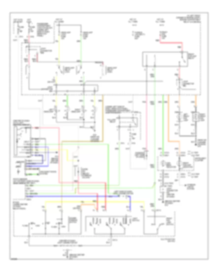
AIR CONDITIONING
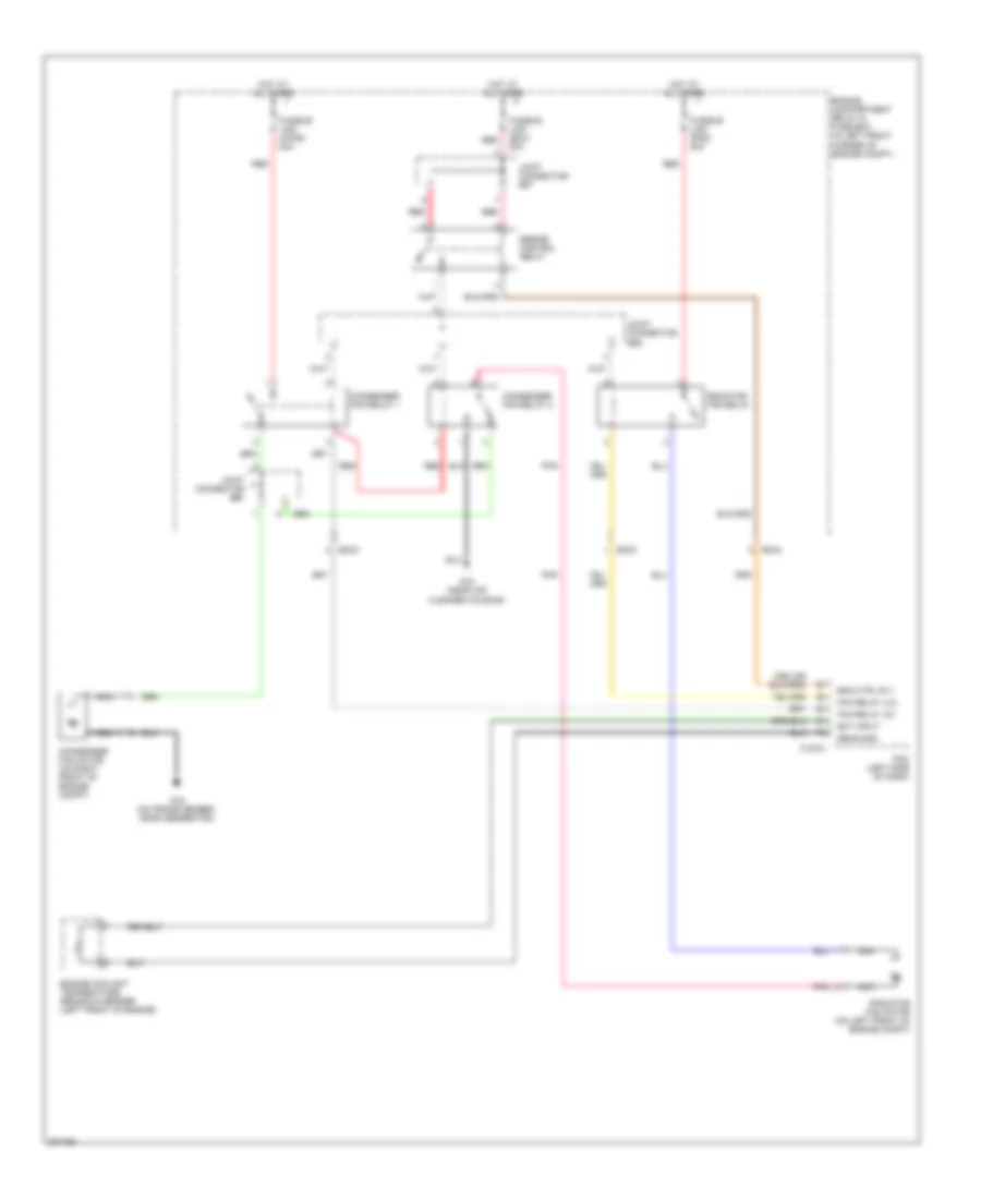
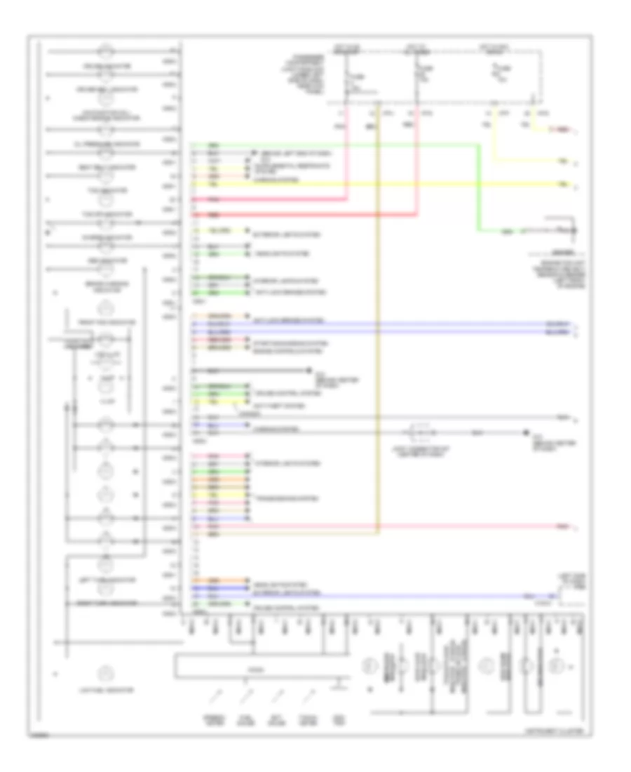
Automatic A/C Wiring Diagram (1 of 2) for Hyundai Elantra GT 2005

List of elements for Automatic A/C Wiring Diagram (1 of 2) for Hyundai Elantra GT 2005:
- (behind left center of dash) mode actuator
- (beside blower motor, below right side of dash) blower relay
- A/c control module (below center of dash, forward of shift lever)
- A/c output
- A/c select
- Actuator cool
- Actuator warm
- Amb temp sens
- Ambient sensor (behind center of front bumper)
- Aqs sensor
- Aqs sensor (behind center of front bumper, on cross support)
- Blower motor (under right side of dash)
- Blr feed back
- Def
- Defogger
- Defogger sw
- Engine compartment relay & fuse box (in left front corner of engine compartment)
- Feed back sig
- Fre
- Fuse 10a
- Fuse 15a
- Fusible link (blower) 30a
- G11 (behind center of dash)
- G11 (behind center of dash)
- G15 (near air cleaner housing)
- Ground
- Hi blwr ctrl
- High blower relay (beside blower motor, below right side of dash)
- Hot at all times
- Hot in on
- Humidity sensor
- Humidity sensor (4 door: left center of rear package shelf) (5 door: right rear shock tower)
- I/p-b
- I/p-g
- I/p-h
- I/p-j
- Ill+
- Ill-
- In-car sens in
- In-car sens out
- Interior lights system
- Joint connector e56
- Joint connector m33 (left side of dash)
- Joint connector m36 (left side of dash)
- M19-1
- M19-2
- Memory power
- On input
- Passenger compartment junction block (under left side of dash, near kick panel)
- Photo sens +
- Pnk
- Power (5v)
- Power transistor (under right side of dash, in blower motor housing)
- Pwr trans
- Rec
- Red
- Sensor ground
- Sensor signal
- System
- Temperature actuator (behind lower right center of dash)
- Vent
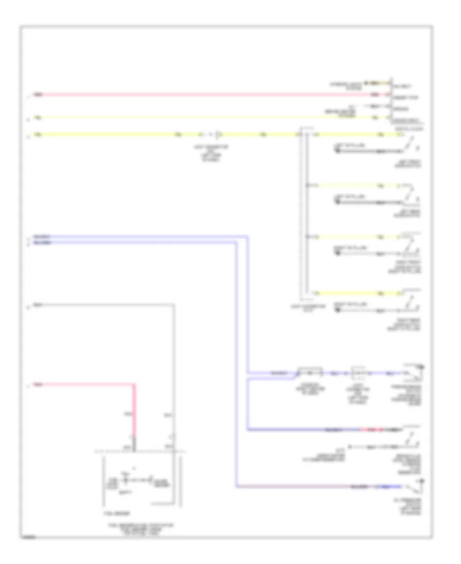
Automatic A/C Wiring Diagram (2 of 2) for Hyundai Elantra GT 2005
List of elements for Automatic A/C Wiring Diagram (2 of 2) for Hyundai Elantra GT 2005:
- (on frame member, near generator) g16
- A/c compressor (right front of engine)
- A/c relay
- A/c relay ctrl
- A/c sig input
- A/c sw on
- C fan sig
- C183-3
- Condenser fan motor (on right front of engine compt)
- Condenser fan relay 1
- Condenser fan relay 2
- Ec03
- Ec04
- Ect input
- Engine compartment relay & fuse box (in left front corner of engine compartment)
- Engine control relay
- Engine coolant temperature sensor & sender (left front of engine)
- Engine ctrl rly
- Evaporator temperature sensor (behind lower left center of dash)
- Fan relay (hi)
- Fan relay (lo)
- Fusible link (cond) 20a
- Fusible link (ecu) 20a
- Fusible link (rad) 20a
- G15 (near air cleaner housing)
- High
- Horn & a/c fuse 15a
- Hot at all times
- Intake actuator
- Joint connector e57
- Joint connector e58
- Joint connector e59
- Low
- Mid
- Nca
- Pcm (left side of dash)
- Photo sensor (on top right side of dash, near defroster vent)
- Pnk
- Radiator fan motor (on left front of engine compt)
- Radiator fan relay
- Red
- Sens gnd
- Triple pressure switch (on a/c line, near right front strut tower)
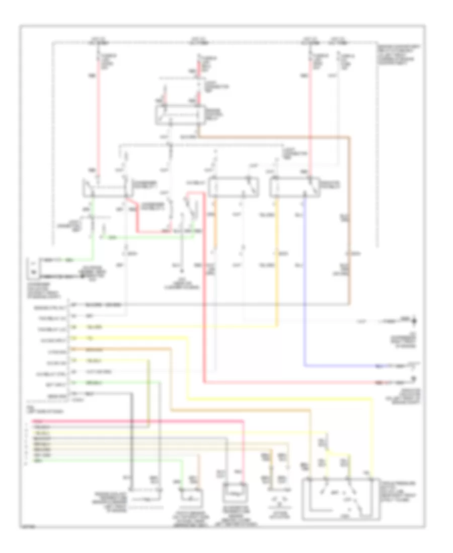
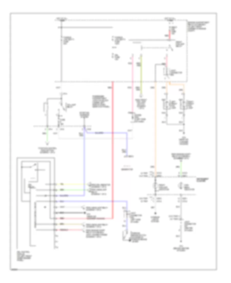
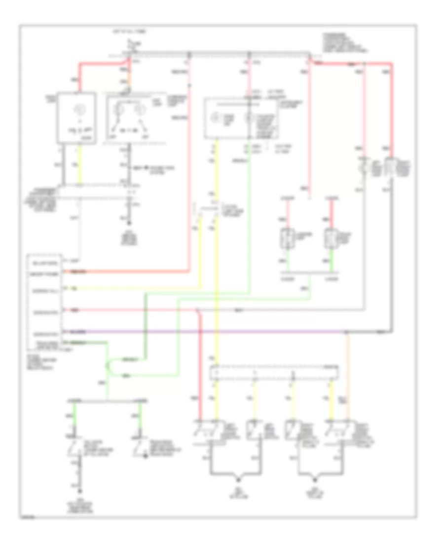
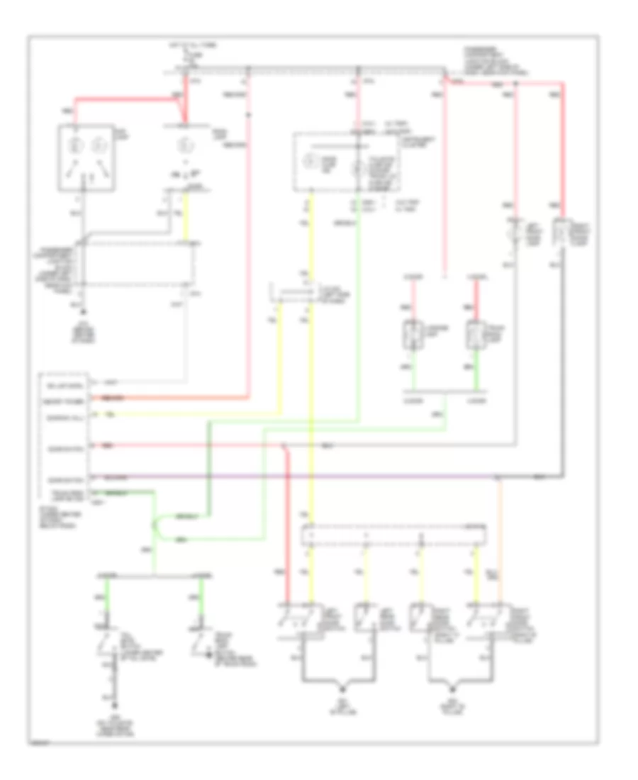
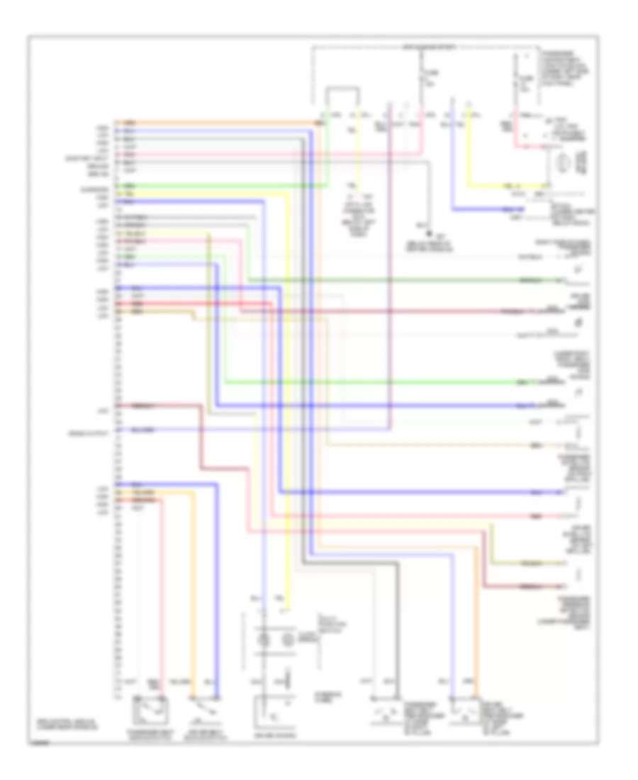
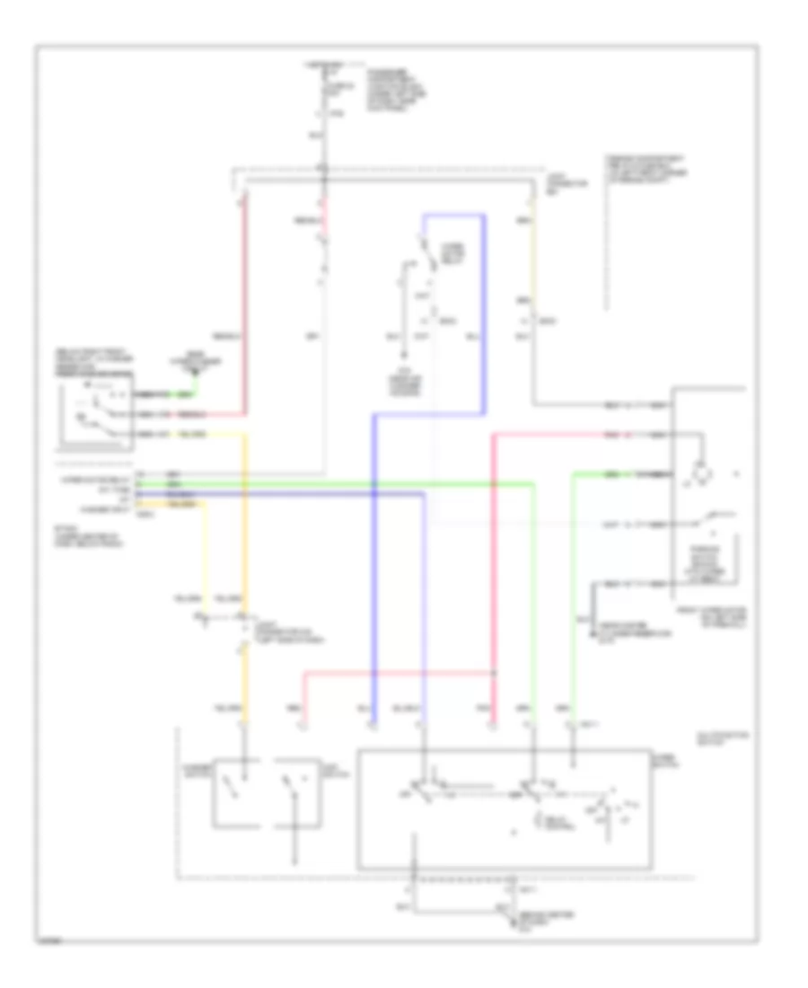
Manual A/C Wiring Diagram (1 of 2) for Hyundai Elantra GT 2005
List of elements for Manual A/C Wiring Diagram (1 of 2) for Hyundai Elantra GT 2005:
- (beside blower motor, below right side of dash) blower relay
- A/c compressor (right front of engine)
- A/c control module (below center of dash, forward of shift lever)
- A/c on sig
- A/c relay
- Actuator
- Blower motor (under right side of dash)
- Blower resistor (under right side of dash, in blower motor housing)
- Blower switch
- Blr on sig
- Cool
- Defog switch
- Defogger system
- Ec03
- Engine compartment relay & fuse box (in left front corner of engine compt)
- F/b
- F/b ground
- Fre
- Fuse 10a
- Fuse 15a
- Fusible link (blower) 30a
- G11 (behind center of dash)
- Ground
- High
- Horn & a/c fuse 15a
- Hot at all times
- Hot in on
- I/p-g
- I/p-h
- I/p-j
- Iii
- Iiii
- Illum +
- Illum -
- Intake actuator (behind upper right side of dash)
- Interior lights system
- Joint connector m36 (left side of dash)
- Low
- Mem pwr
- Mid
- Mode actuator (behind left center of dash)
- Nca
- Off
- On input
- Passenger compartment junction block (under left side of dash, near kick panel)
- Pnk
- Rec
- Red
- Temperature actuator (behind lower left center of dash)
- Thermistor
- Thermostatic switch (behind right side of dash)
- To joint connector e58 (diagram 2 of 2)
- Triple pressure switch (on a/c line, near right front strut tower)
- Vcc
- Warm
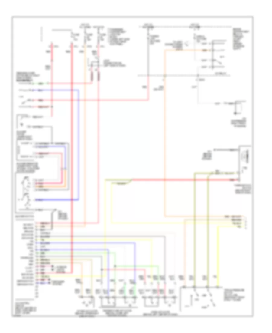
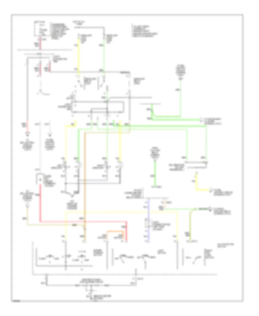
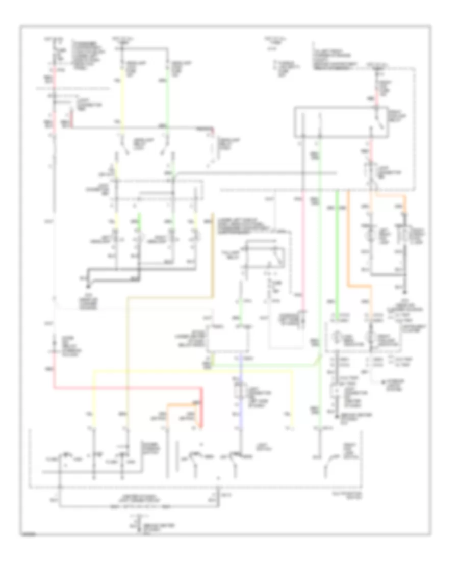
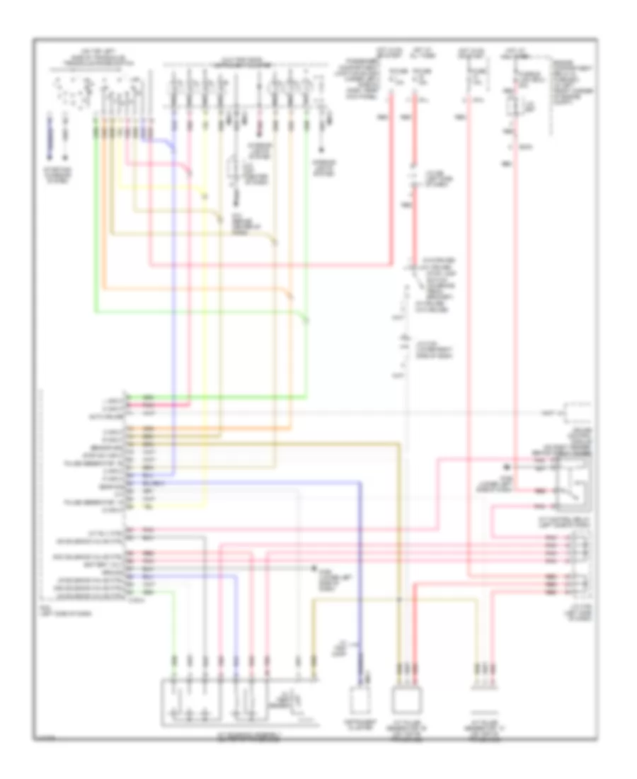
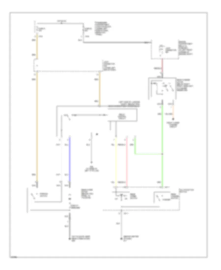
Manual A/C Wiring Diagram (2 of 2) for Hyundai Elantra GT 2005
List of elements for Manual A/C Wiring Diagram (2 of 2) for Hyundai Elantra GT 2005:
- A/c rly ctrl
- A/c sig input
- A/c sw on
- C fan sig
- C183-3
- Condenser fan motor (on right front of engine compt)
- Condenser fan relay 1
- Condenser fan relay 2
- Ec03
- Ec04
- Ect input
- Eng ctrl relay
- Engine compartment relay & fuse box (in left front corner of engine compt)
- Engine control relay
- Engine coolant temperature sensor & sender (left front of engine)
- Fan relay (hi)
- Fan relay (lo)
- From a/c relay (diagram 1 of 2)
- Fusible link (cond) 20a
- Fusible link (ecu) 20a
- Fusible link (rad) 20a
- G15 (near air cleaner housing)
- G16 (on frame member, near generator)
- Hot at all times
- Joint connector e57
- Joint connector e58
- Joint connector e59
- Nca
- Pcm (left side of dash)
- Pnk
- Radiator fan motor (on left front of engine compt)
- Radiator fan relay
- Red
- Sens gnd
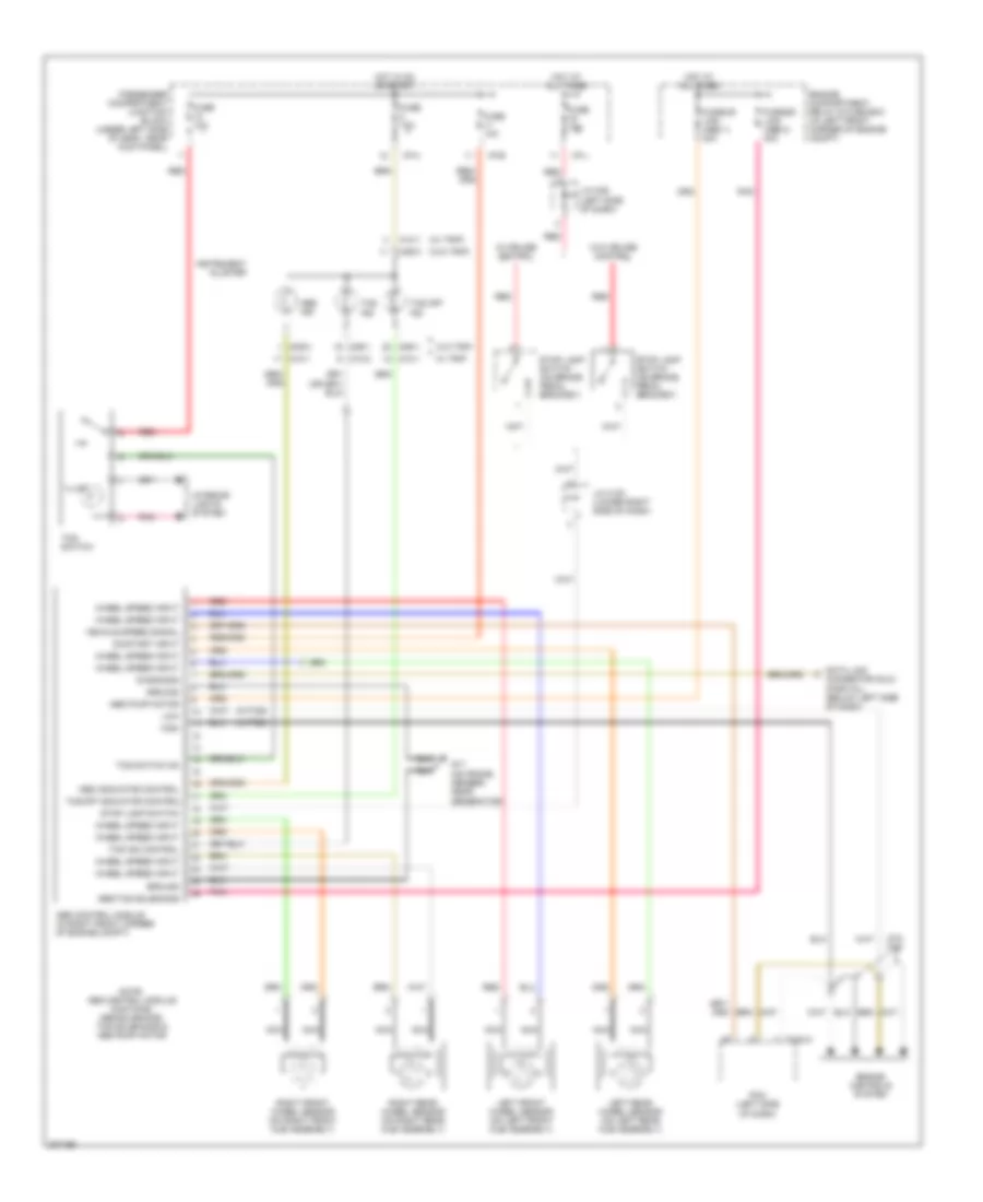
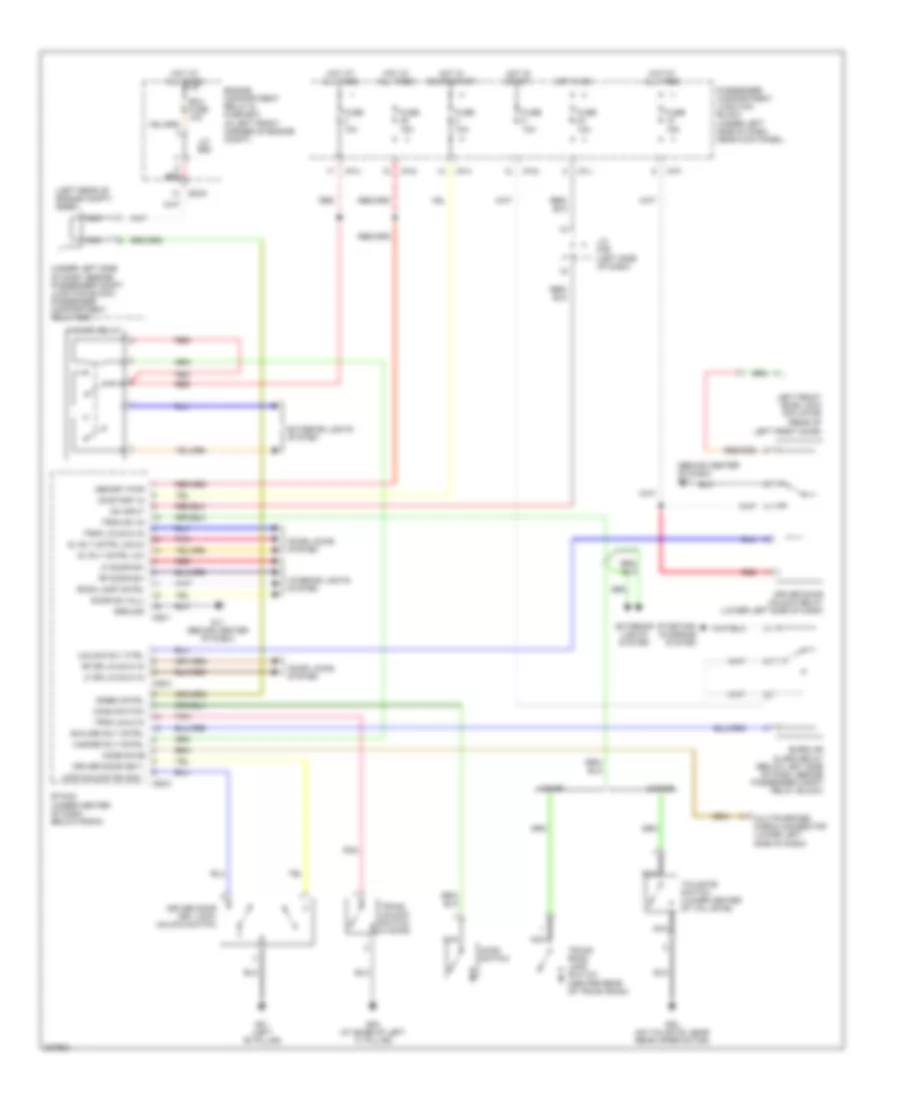
ANTI-LOCK BRAKES
Anti-lock Brakes Wiring Diagram for Hyundai Elantra GT 2005
List of elements for Anti-lock Brakes Wiring Diagram for Hyundai Elantra GT 2005:
- (w/ trip)
- (w/o trip)
- (w/tcs)
- Abs control module (in right front corner of engine compt)
- Abs ind
- Abs indicator control
- Abs pump motor
- Abs/tcs solenoids
- C183-3
- Connector (dlc) (partial) (below left side of dash)
- Data link
- Diagnosis
- Engine compartment relay & fuse box (in left front corner of engine compt)
- Engine controls system
- Fuse 10a
- Fuse 15a
- Fusible link (abs 1) 30a
- Fusible link (abs 2) 30a
- G17 (on frame member, near generator)
- Ground
- High
- Hot at all times
- Hot in on or start
- I/p-b
- I/p-h
- I/p-j
- Illum
- Instrument cluster
- Interior lights system
- J/c c191 (lower right side of dash)
- J/c m36 (left side of dash)
- Left front wheel sensor (on left front hub assembly)
- Left rear wheel sensor (on left rear hub assembly)
- Low
- M09-1
- M09-2
- M09-3
- M10-1
- M10-2
- Nca
- Note: abs control module contains: abs solenoids, tcs solenoids & abs pump motor
- On/start input
- Passenger compartment junction block (under left side of dash, near kick panel)
- Pcm (left side of dash)
- Pnk
- Red
- Right front wheel sensor (on right front hub assembly)
- Right rear wheel sensor (on right rear hub assembly)
- Stop lamp switch
- Stop lamp switch (on brake pedal bracket)
- Tcs ind
- Tcs ind control
- Tcs off ind
- Tcs off indicator control
- Tcs switch
- Tcs switch on
- Vehicle speed signal
- W/ cruise control
- W/ trip
- W/o cruise control
- W/o tcs
- W/o trip
- Wheel speed input
ANTI-THEFT
Forced Entry Wiring Diagram for Hyundai Elantra GT 2005
List of elements for Forced Entry Wiring Diagram for Hyundai Elantra GT 2005:
- (behind center of dash) g11
- (left rear of engine compt) siren
- (rear of left front door)
- (under left side of dash, beside passenger compt junction block) passenger compartment relay box
- 4 door
- 5 door
- B/alarm rly cntrl
- Burglar alarm relay (below left side of dash, beside passenger compt relay block)
- Code save
- Dl rly cntrl (lk)
- Dl rly cntrl (unlk)
- Door locks system
- Door sw (all)
- Driver door key
- Driver door key lock/ unlock switch
- Driver door unlock relay (lower left side of dash)
- Ec04
- Ecu fuse 10a
- Engine compartment relay & fuse box (in left front corner of engine compt)
- Etacm (under center of dash, below radio)
- Exterior lights system
- Fuse 10a
- Fuse 15a
- G01 (left "b" pillar)
- G05 (at base of left "c" pillar)
- G11 (behind center of dash)
- G28 (on tailgate, near rear wiper motor)
- Ground
- Hazard relay
- Hazard rly cntrl
- Hood switch
- Hot at all times
- Hot in on
- Hot in on or start
- Hot in start
- I/p-f
- I/p-g
- I/p-h
- I/p-j
- Interior lights system
- J/c e62
- J/c m36 (left side of dash)
- Left front door lock actuator
- Lf door sw
- Lf dr lk/unlk in
- Lock/unlock sw sig
- M25-1
- M25-2
- M25-3
- Memory pwr
- Multipurpose check connector (lower left side of dash)
- Nca
- On input
- On/start in
- Passenger compartment junction block (under left side of dash, near kick panel)
- Pnk
- Red
- Rf door sw
- Rf dr lk/unlk in
- Room lamp cntrl
- Siren cntrl
- Starting/ charging system
- Tailgate switch (lower center of tail gate)
- Trnk lk/unlk in
- Trnk sw in
- Trnk unlk in
- Trunk room lamp switch (center rear of trunk room)
- Trunk unlock switch (4 door)
- Unlock rly ctrl
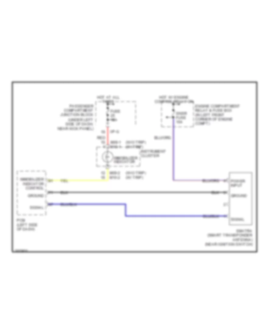
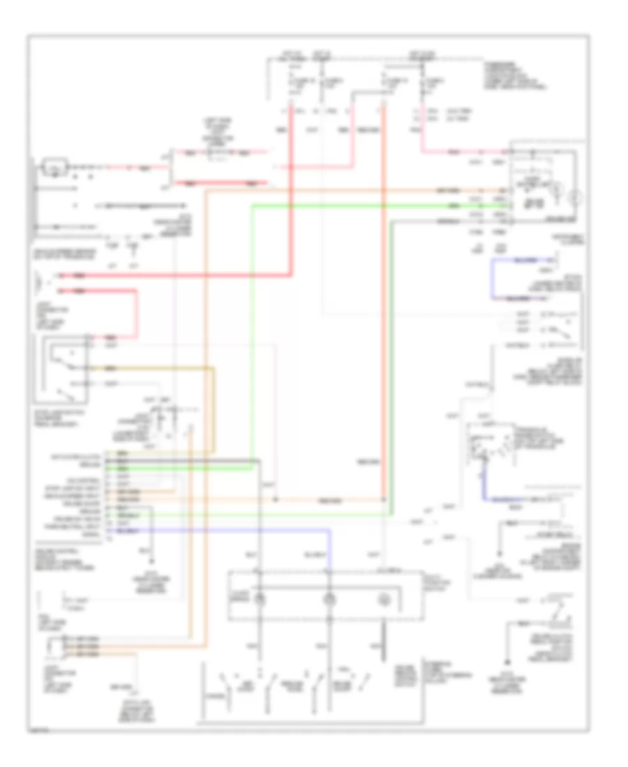
Immobilizer Wiring Diagram for Hyundai Elantra GT 2005
List of elements for Immobilizer Wiring Diagram for Hyundai Elantra GT 2005:
- (under left side of dash, near kick panel)
- (w/o trip) (w/ trip)
- Engine compartment relay & fuse box (in left front corner of engine compt)
- Fuse 15a
- Ground
- Hot at all times
- Hot w/ engine control relay on
- I/p-g
- Immobilizer indicator
- Immobilizer indicator control
- Instrument cluster
- M09-1 m10-1
- M09-2 m10-2
- Passenger compartment junction block
- Pcm (left side of dash)
- Power input
- Red
- Signal
- Smatra (smart transponder antenna) (near ignition switch)
- Snsr fuse 10a
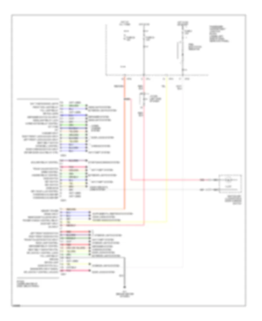
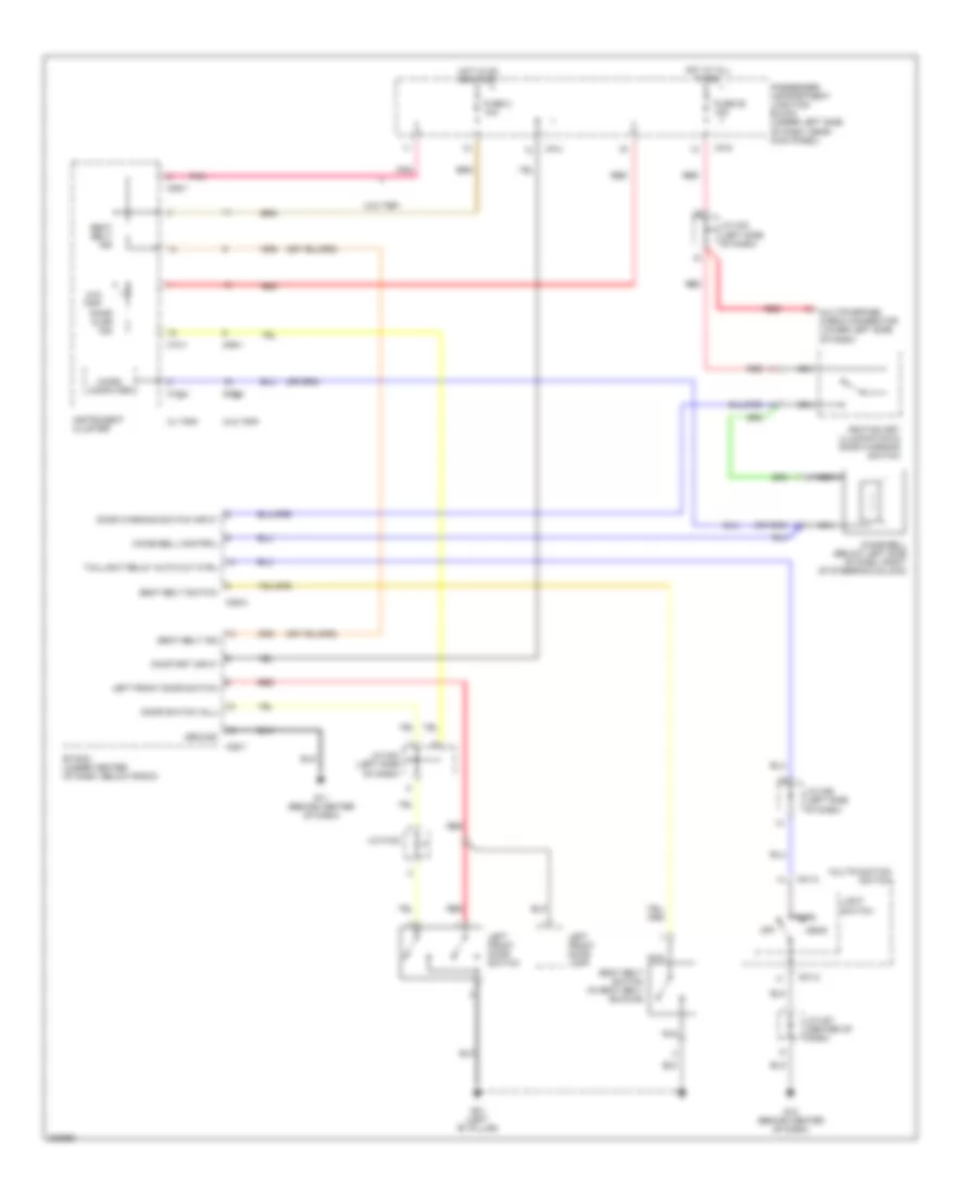
BODY CONTROL MODULES
Body Control Modules Wiring Diagram for Hyundai Elantra GT 2005
List of elements for Body Control Modules Wiring Diagram for Hyundai Elantra GT 2005:
- (not used)
- Anti-theft system
- B/alarm relay control
- Chime bell control
- Code save
- Computer data lines system
- Crash input
- Day time running lights
- Defogger relay control
- Defogger switch on input
- Defogger system
- Door locks system
- Door switch (all)
- Door warning switch input
- Dr lock rly control (lock)
- Dr lock rly control (unlock)
- Driver door unlk relay ctrl
- Engine rpm input signal
- Etacm (under center of dash, below radio)
- Exterior lights system
- Front fog lamp relay
- Fuse 2 10a
- Fuse 24 10a
- Fuse 25 15a
- G11 (behind center of dash)
- Ground
- Hazard relay control
- Headlamp relay (low)
- Headlights system
- Hood switch
- Hot at all times
- Hot in on
- Hot in on or start
- I/p-g
- I/p-h
- I/p-j
- Ignition key illumination & door warning switch
- Illum
- Int
- Int (time)
- Interior lights system
- J/c m36 (left side of dash)
- Key hole illum control
- Key switch
- Left front door switch
- Left front lock/unlock input
- M25-1
- M25-2
- M25-3
- Memory power
- Nca
- On input
- On/start input
- Passenger compartment junction block (under left side of dash, near kick panel)
- Pnk
- Power window control relay
- Power windows system
- Pre- excitation resistor
- Rear door/tailgate input
- Red
- Right front door switch
- Right front lock/unlock input
- Room lamp control
- Rr fog lamp
- Rr fog lamps
- Seat belt indicator ctrl
- Seat belt switch
- Siren control
- Starting/charging system
- Tail lamp relay
- Trunk unlock switch
- Trunk/tailgate switch input
- Warning system
- Washer input
- Windshield glass def
- Wiper motor relay control
- Wiper/ washer system
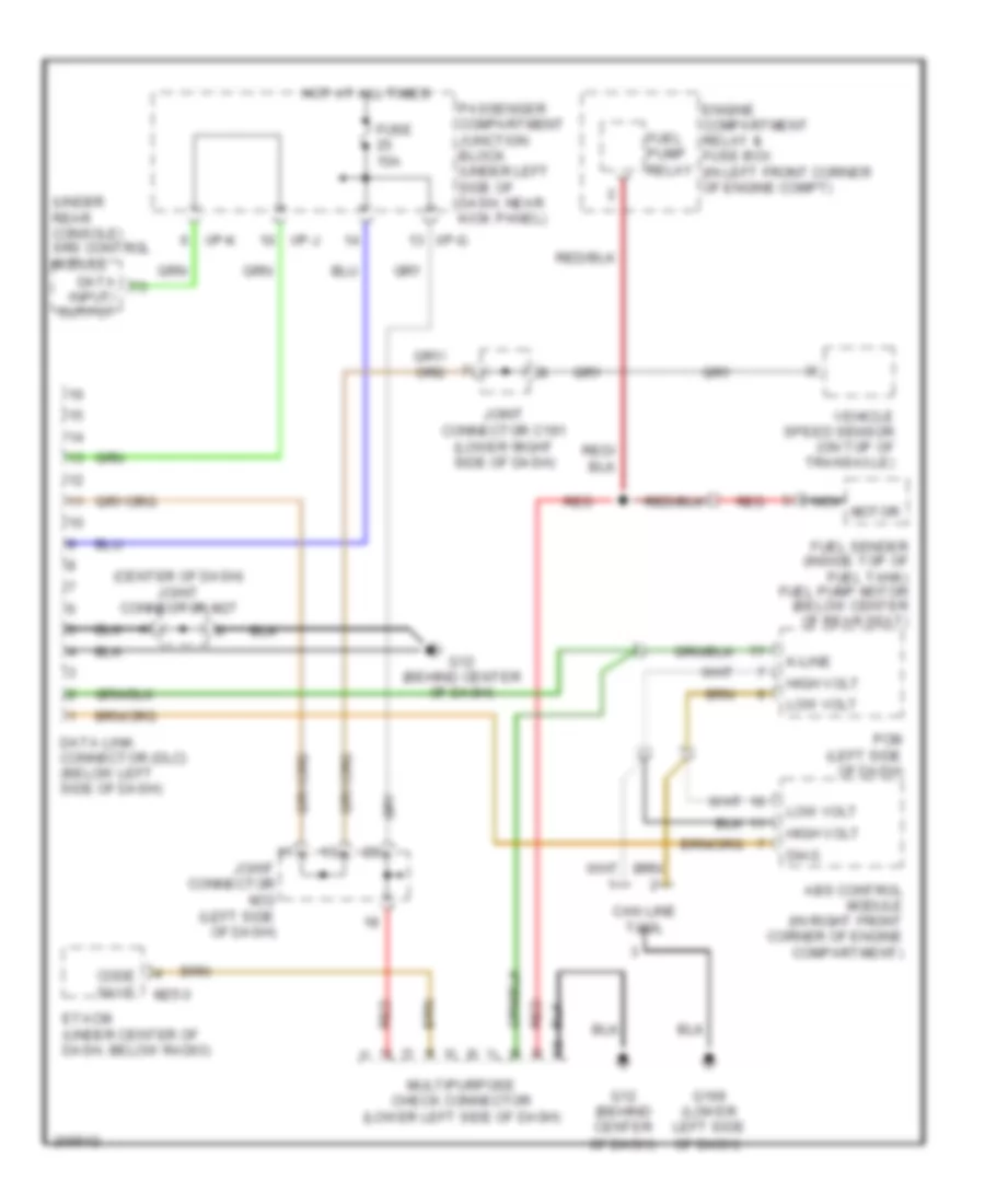
COMPUTER DATA LINES
Computer Data Lines Wiring Diagram for Hyundai Elantra GT 2005
List of elements for Computer Data Lines Wiring Diagram for Hyundai Elantra GT 2005:
- (center of dash) joint connector m27
- (under rear console) srs control module
- Abs control module (in right front corner of engine compartment)
- Can line tool
- Code save
- Data
- Data link connector (dlc) (below left side of dash)
- Diag
- Engine compartment relay & fuse box (in left front corner of engine compt)
- Etacm (under center of dash, below radio)
- Fuel pump relay
- Fuel sender (inside top of fuel tank) fuel pump motor (below center of rear seat)
- Fuse 15a
- G12 (behind center of dash)
- G169 (lower left side of dash)
- High volt
- Hot at all times
- I/p-g
- I/p-j
- I/p-k
- Input/ output
- Joint connector c191 (lower right side of dash)
- Joint connector m33 (left side of dash)
- K-line
- Low volt
- M25-3
- Multipurpose check connector (lower left side of dash)
- Nca motor
- Passenger compartment junction block (under left side of dash, near kick panel)
- Pcm (left side of dash)
- Red
- Vehicle speed sensor (on top of transaxle)
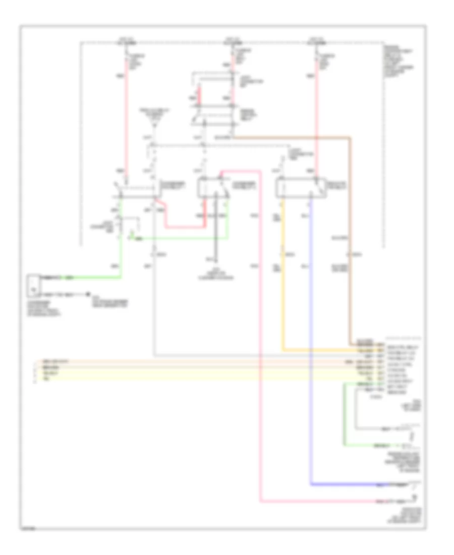
COOLING FAN
Cooling Fan Wiring Diagram for Hyundai Elantra GT 2005
List of elements for Cooling Fan Wiring Diagram for Hyundai Elantra GT 2005:
- C183-3
- Condenser fan motor (on right front of engine compt)
- Condenser fan relay 1
- Condenser fan relay 2
- Ec03
- Ec04
- Ect input
- Eng ctrl rly
- Engine compartment relay & fuse box (in left front corner of engine compt)
- Engine control relay
- Engine coolant temperature sensor & sender (left front of engine)
- Fan relay (hi)
- Fan relay (lo)
- Fusible link (cond) 20a
- Fusible link (ecu) 20a
- Fusible link (rad) 20a
- G15 (near air cleaner housing)
- G16 (on frame member, near generator)
- Hot at all times
- Joint connector e57
- Joint connector e58
- Joint connector e59
- Nca
- Pcm (left side of dash)
- Pnk
- Radiator fan motor (on left front of engine compt)
- Radiator fan relay
- Red
- Sens gnd
CRUISE CONTROL
Cruise Control Wiring Diagram for Hyundai Elantra GT 2005
List of elements for Cruise Control Wiring Diagram for Hyundai Elantra GT 2005:
- (left side of dash) joint connector c192
- (w/ trip)
- (w/o trip)
- A/t
- Actuator clutch
- Burglar alarm relay (below left side of dash, beside passenger compt relay block)
- C159
- C160
- C183-4
- Cancel
- Clock spring
- Cruise clutch pedal position switch (near clutch pedal bracket)
- Cruise control module (on right fender, behind strut tower)
- Cruise ind
- Cruise on/off
- Cruise remote control switch
- Cruise set ind
- Cruise sw ind on
- Data link connector (below left side of dash)
- Ec03
- Engine compartment relay & fuse box (in left front corner of engine compt)
- Etacm (under center of dash, below radio)
- Fuse 10 10a
- Fuse 16 15a
- Fuse 2 10a
- Fuse 8 10a
- G15 (near air cleaner housing)
- G170 (near master cylinder reservoir)
- Ground
- Hall ic
- Hot at all times
- Hot in on or start
- Hot in start
- I/p-g
- I/p-h
- I/p-j
- Instrument cluster
- Joint connector c191 (lower right side of dash)
- Joint connector m33 (left side of dash)
- Joint connector m36 (left side of dash)
- M/t
- M01-4
- M09-1
- M09-2
- M09-3
- M10-1
- M10-2
- M25-3
- Micro controller
- Multi- function switch
- Nca
- O/d control
- Park/neutral input
- Passenger compartment junction block (under left side of dash, near kick panel)
- Pcm (left side of dash)
- Pnk
- Red
- Resume/ accel
- Set/ coast
- Signal
- Start relay
- Steering wheel (top of steering column)
- Stop lamp sw input
- Stop lamp switch (on brake pedal bracket)
- Transaxle range switch (on top left side l of transaxle)
- Vehicle speed input
- Vehicle speed sensor (on top of transaxle)
- W/ trip
- W/o trip
DEFOGGERS
Defoggers Wiring Diagram for Hyundai Elantra GT 2005
List of elements for Defoggers Wiring Diagram for Hyundai Elantra GT 2005:
- 4 door
- 5 door
- A/c control module (below center of dash, forward of shift lever)
- Automatic a/c manual a/c
- Defogger
- Defogger ctrl
- Defogger input
- Defogger relay
- Defogger switch
- Engine input
- Etacm (under center of dash, below radio)
- Fuse 10a
- Fuse 17 10a
- Fuse 30a
- G01 (left "b" pillar)
- G03 (under right "b" pillar)
- G10 (at base of right "c" pillar)
- G11 (behind center of dash)
- G28 (on tailgate, near rear wiper motor)
- G29 (under left "c" pillar trim)
- Glass antenna (above right end of package shelf)
- Hot at all times
- Hot in on or start
- I/p-d
- I/p-f
- I/p-g
- I/p-h
- Indicator
- Left outside mirror motor & defogger
- M19-1
- M19-1 m20
- M20
- M25-1
- M25-2
- M66-1
- M69
- M75
- Manual a/c automatic a/c
- Mirror defogger
- Nca
- Off
- On/start in
- Passenger compartment junction block (under left side of dash, near kick panel)
- Pre- excitation resistor
- R06
- R15
- Rear
- Red
- Right outside mirror motor & defogger
- W/ glass antenna
- W/ power windows
- W/o glass antenna
- Window
ENGINE PERFORMANCE
2.0L
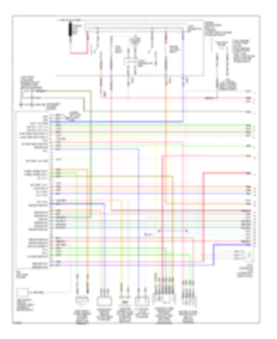
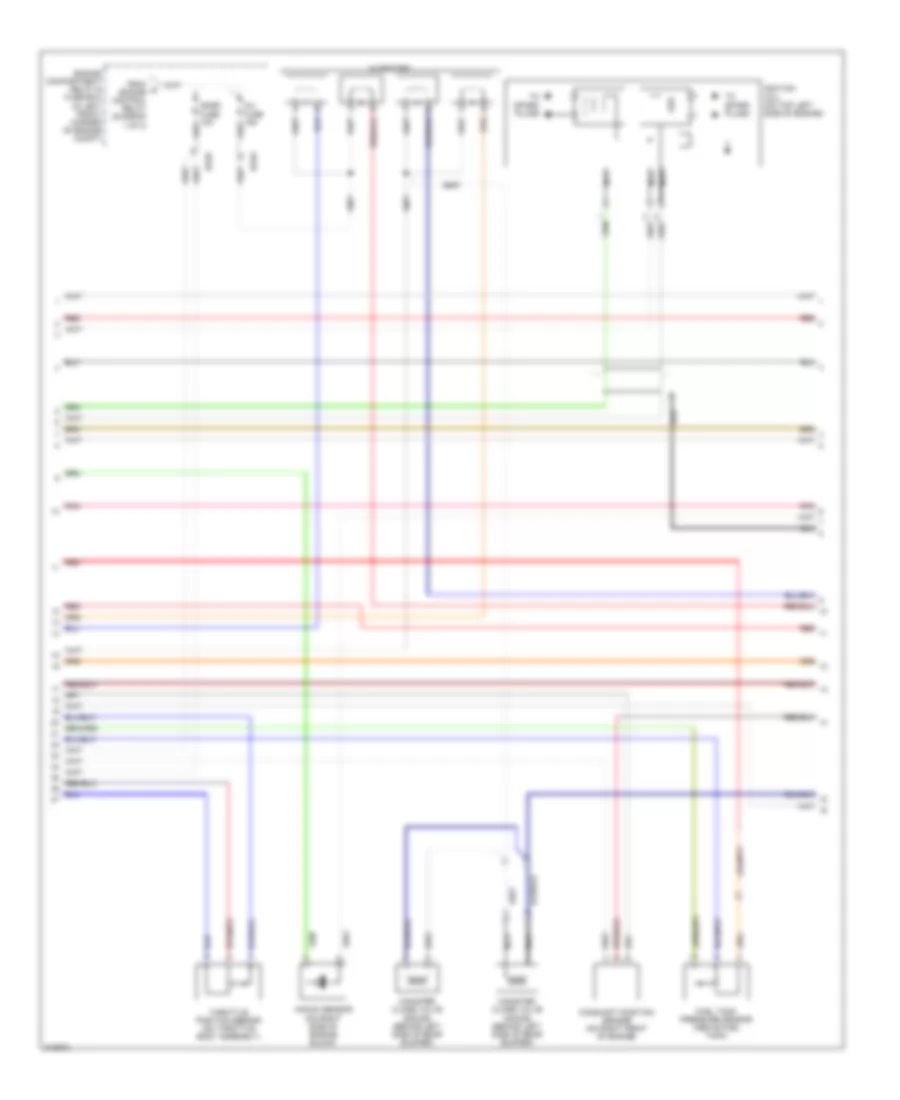
2.0L, Engine Performance Wiring Diagram (1 of 3) for Hyundai Elantra GT 2005
List of elements for 2.0L, Engine Performance Wiring Diagram (1 of 3) for Hyundai Elantra GT 2005:
- (left front of engine) engine coolant temperature sensor & sender
- (lower left side of dash) g169
- Abs control module (in right front corner of engine compt)
- Batt voltage
- Battery volt
- Battery voltage
- Canister purge valve (on left rear of engine compt, on bracket)
- Comm area network hi
- Comm area network lo
- Cpv ctrl
- Crankshaft position sensor (on left rear of engine)
- Ec03
- Ec04
- Emo2
- Engine compartment relay & fuse box (in left front corner of engine compt)
- Engine control relay
- Fuel pump motor
- Fuel pump relay
- Fuel sender & fuel pump motor (fuel sender: inside top of fuel tank) (fuel pump motor: below center of rear seat)
- Fusible link (ecu) 20a
- G04 (at middle front of rear seat cushion, under carpet)
- Gnd
- Ground
- Heated oxygen sensor (down) (below exhaust manifold)
- Heated oxygen sensor (up) (on front exhaust pipe, between catalytic converters)
- Hot at all times
- Htr
- Ign coil 1 (cyl 1,4)
- Ign coil 2 (cyl 2,3)
- Inj 1 ctrl
- Inj 4 ctrl
- Instrument cluster system
- Ip (+)
- Joint connector c191 (lower right side of dash)
- Joint connector e57
- Joint connector e58
- Nca
- Ocv
- Oil control valve (left front of engine)
- On/start in
- Oxygen sens heating
- Oxygen sens sig
- Pcm (left side of dash)
- Pnk
- Red
- Right front wheel sensor (w/o abs) (on right front hub assembly)
- Sensor ground
- Sensor pwr
- Sensor sig
- To inj fuse (diagram 2 of 3)
- Vehicle speed in
- Vs (+)
- Vs (-) ip (-)
- Wheel speed input
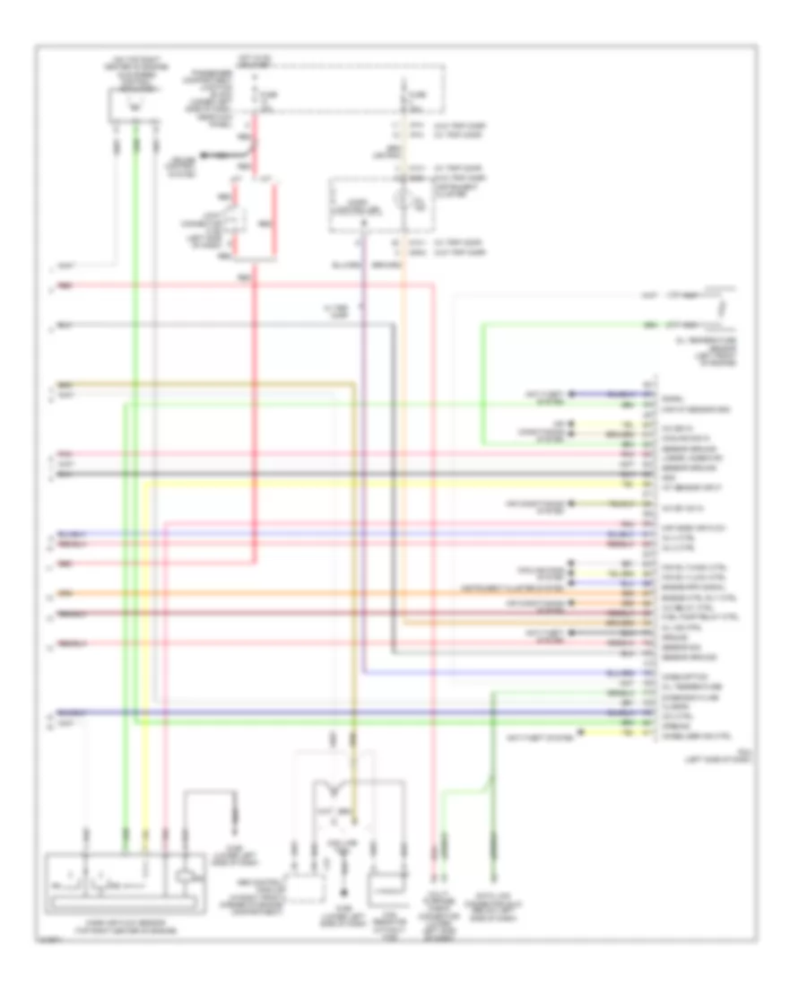
2.0L, Engine Performance Wiring Diagram (2 of 3) for Hyundai Elantra GT 2005
List of elements for 2.0L, Engine Performance Wiring Diagram (2 of 3) for Hyundai Elantra GT 2005:
- Camshaft position sensor (on right front of engine)
- Canister close valve (4door) (behind left side of rear bumper)
- Canister close valve (5door) (behind left side of rear bumper)
- Ec03
- Ec05
- Engine compartment relay & fuse box (in left front corner of engine compt)
- From a engine control relay (diagram 1 of 3)
- Fuel tank pressure sensor (above fuel tank)
- Ignition coil (on top left side of engine)
- Inj fuse 15a
- Injectors
- Knock sensor (on right side of engine block)
- Nca
- Pnk
- Red
- Snsr fuse 10a
- Throttle position sensor (on throttle body assembly)
- To spark plugs
2.0L, Engine Performance Wiring Diagram (3 of 3) for Hyundai Elantra GT 2005
List of elements for 2.0L, Engine Performance Wiring Diagram (3 of 3) for Hyundai Elantra GT 2005:
- (on top right center of engine) idle speed control actuator
- (w/ trip comp)
- (w/o trip comp)
- A/c relay ctrl
- A/c sig in
- A/c sw on in
- A/t
- Abs control module (in right front corner of engine compartment)
- Air conditioning system
- Anti-theft system
- Can line tool
- Can resistor (without tcs)
- Ccv ctrl
- Closing
- Consumption
- Cooling fans system
- Cooling sig in
- Cruise control system
- Data link connector (dlc) (below left side of dash)
- Diagnosis k-line
- E37
- Engine ctrl rly ctrl
- Engine rpm signal
- Fan rly (high) ctrl
- Fan rly (low) ctrl
- Fuel pump relay ctrl
- Fuse 10a
- G169 (lower left side of dash)
- Gnd
- Ground
- Hot in on or start
- I/p-h
- Iat sensor input
- Immobilizer ind ctrl
- Inj 2 ctrl
- Inj 3 ctrl
- Instrument cluster
- Instrument cluster system
- Joint connector c192 (left side of dash)
- Linear lambda rc
- M/t
- M09-1
- M09-2
- M10-1
- Maf mass air flow
- Maf/iat sensor gnd
- Mass air flow sensor (top right center of engine)
- Micro controller
- Mil ind
- Mil ind ctrl
- Multi- purpose check connector (lower left side of dash)
- Nca
- Oil temperature
- Oil temperature sensor (left front of engine)
- Opening
- Passenger compartment junction block (under left side of dash, near kick panel)
- Pcm (left side of dash)
- Pnk
- Red
- Sensor ground
- Sensor sig
- Signal
- W/ trip comp
EXTERIOR LIGHTS
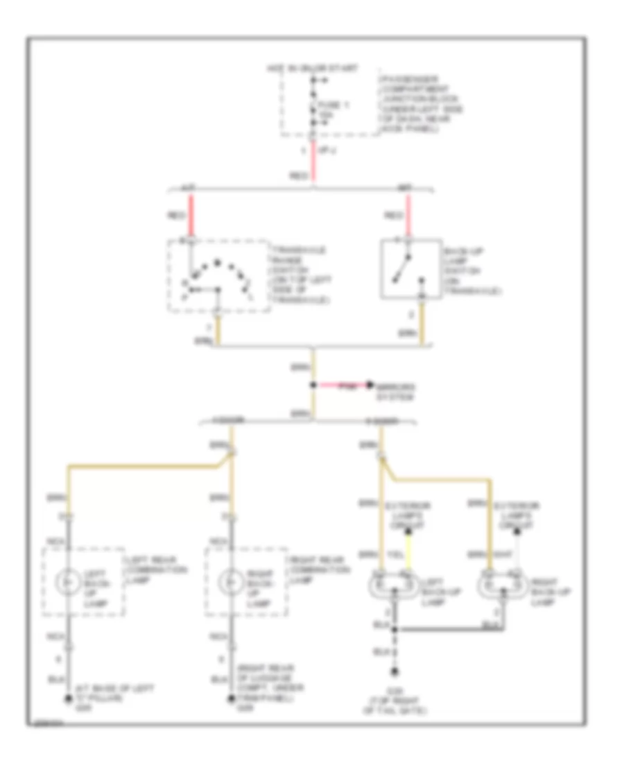
Backup Lamps Wiring Diagram for Hyundai Elantra GT 2005
List of elements for Backup Lamps Wiring Diagram for Hyundai Elantra GT 2005:
- (at base of left "c" pillar) g05
- 4 door
- 5 door
- A/t
- Back-up lamp switch (on transaxle)
- Compt, under trim panel) g09
- Exterior lamps circuit
- Fuse 1 10a
- G30 (top right of tail gate)
- Hot in on or start
- I/p-j
- Left back- up lamp
- Left back-up lamp
- Left rear combination lamp
- M/t
- Mirrors system
- Nca
- Passenger compartment junction block (under left side of dash, near kick panel)
- Pnk
- Red
- Right back- up lamp
- Right back-up lamp
- Right rear combination lamp
- Transaxle range switch (on top left side of transaxle)
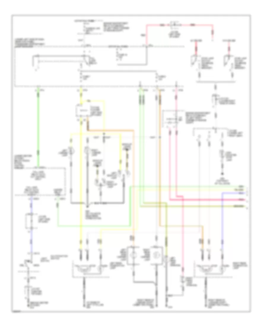
Exterior Lamps Wiring Diagram, 4 Door (1 of 2) for Hyundai Elantra GT 2005
List of elements for Exterior Lamps Wiring Diagram, 4 Door (1 of 2) for Hyundai Elantra GT 2005:
- (under left side of dash, near kick panel) passenger compartment junction block
- Engine compartment relay & fuse box (in left front corner of engine compt)
- Etacs control module (under center of dash, below radio)
- Fuse 16 15a
- Fuse 6 10a
- Fuse 7 10a
- Fusible link (batt) 50a
- G05 (at base of left "c" pillar)
- G09 (right rear of luggage compt, under trim panel)
- G12 (behind center of dash)
- G15 (near air cleaner housing)
- G16 (on frame member, near generator)
- Hazard relay ctrl
- Head
- High mounted stop lamp
- Hot at all times
- I/p-a
- I/p-b
- I/p-d
- I/p-h
- I/p-j
- J/c c191 (lower right side of dash)
- J/c e61
- J/c m27 (center of dash)
- J/c m36 (left side of dash)
- J/c m45 (lower left end of dash)
- J/c m46 (under left front seat)
- Left front side marker lamp
- Left head lamp (parking)
- Left rear combin- ation lamp
- License lamp
- Light switch
- M01-2
- M25-1
- M25-2
- M25-3
- Marker
- Multifunction
- Nca
- Nca nca
- Off
- Park
- Pnk
- Red
- Right front side marker lamp
- Right head lamp (parking)
- Right rear combination lamp
- Stop
- Stoplamp switch (on brake pedal bracket)
- Switch
- Tail
- Tail lamp relay
- Tail lamp relay auto cut control input
- Tail lamp relay auto cut control output
- Turn
- W/ cruise
- W/ glass
- W/ spoiler
- W/o cruise
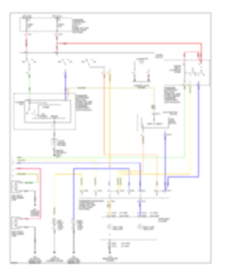
Exterior Lamps Wiring Diagram, 4 Door (2 of 2) for Hyundai Elantra GT 2005
List of elements for Exterior Lamps Wiring Diagram, 4 Door (2 of 2) for Hyundai Elantra GT 2005:
- (behind center of dash) g12
- (near air cleaner housing)
- (w/ trip)
- (w/o trip)
- Coil control
- Flasher unit
- Fuse 1 10a
- Fuse 4 10a
- G12 (behind center of dash)
- G15
- G16 (on frame member, near generator)
- Ground
- Hazard relay (w/ burglar alarm)
- Hazard switch
- Hot at all times
- Hot in on or start
- I/p-b
- I/p-d
- I/p-g
- I/p-h
- I/p-j
- Illumination
- Instrument cluster
- Interior lights system
- J/c m27 (center of dash)
- Left
- Left front turn signal lamp
- Left turn indicator
- M01-2
- M09-1
- M09-2
- M09-3
- M10-2
- Multifunction switch
- Off
- Passenger compartment junction block (under left side of dash, near kick panel)
- Passenger compartment relay box (under left side of dash, beside passenger compartment junction block)
- Pnk
- Power
- Red
- Right
- Right front turn signal lamp
- Right turn indicator
- Turn signal switch
Exterior Lamps Wiring Diagram, 5 Door (1 of 2) for Hyundai Elantra GT 2005
List of elements for Exterior Lamps Wiring Diagram, 5 Door (1 of 2) for Hyundai Elantra GT 2005:
- (at base of left "c" pillar) g06
- (right rear of luggage compt, under trim panel) g08
- (under center of dash, below radio) etacs control module
- (under left side of dash, near kick panel) passenger compartment junction block
- Back-up lamps circuit
- Engine compartment relay & fuse box (in left front corner of engine compt)
- Fuse 16 15a
- Fuse 6 10a
- Fuse 7 10a
- Fusible link (batt) 50a
- G15
- G28 (on tailgate, near rear wiper motor)
- G30 (top right of tail gate)
- Hazard relay ctrl
- Head
- High mounted stop lamp
- Hot at all times
- I/p-a
- I/p-b
- I/p-d
- I/p-h
- I/p-j
- J/c c191 (lower right side of dash)
- J/c e61
- J/c m27 (center of dash)
- J/c m36 (left side of dash)
- J/c m45 (lower left end of dash)
- J/c m46 (under left front seat)
- Left back-up lamp
- Left head lamp (parking)
- Left license lamp
- Left rear combination lamp
- Left rear side marker lamp
- Light switch
- M01-2
- M25-1
- M25-2
- M25-3
- Multifunction switch
- Nca
- Nca nca
- Of dash) g12
- Off
- Park
- Pnk
- Red
- Right back-up lamp
- Right head lamp (parking)
- Right license lamp
- Right rear combination lamp
- Right rear side marker lamp
- Stop
- Stop lamp switch (on brake pedal bracket)
- Tail
- Tail lamp relay
- Tail lamp relay auto cut control input
- Tail lamp relay auto cut control output
- Turn
- W/ cruise
- W/o cruise
Exterior Lamps Wiring Diagram, 5 Door (2 of 2) for Hyundai Elantra GT 2005
List of elements for Exterior Lamps Wiring Diagram, 5 Door (2 of 2) for Hyundai Elantra GT 2005:
- (behind center of dash) g12
- (w/ trip)
- (w/o trip)
- Coil control
- Flasher unit
- Fuse 1 10a
- Fuse 4 10a
- G12 (behind center of dash)
- G15 (near air cleaner housing)
- G16 (on frame member, near generator)
- Ground
- Hazard relay (w/ burglar alarm)
- Hazard switch
- Hot at all times
- Hot in on or start
- I/p-b
- I/p-d
- I/p-g
- I/p-h
- I/p-j
- Illumination
- Instrument cluster
- Interior lights system
- J/c m27 (center of dash)
- Left
- Left front side marker lamp
- Left front turn signal lamp
- Left turn indicator
- M01-2
- M09-1
- M09-2
- M09-3
- M10-2
- Multifunction switch
- Off
- Passenger compartment junction block (under left side of dash, near kick panel)
- Passenger compartment relay box (under left side of dash, beside passenger compartment, junction block)
- Pnk
- Power
- Red
- Right
- Right front side marker lamp
- Right front turn signal lamp
- Right turn indicator
- Turn signal switch
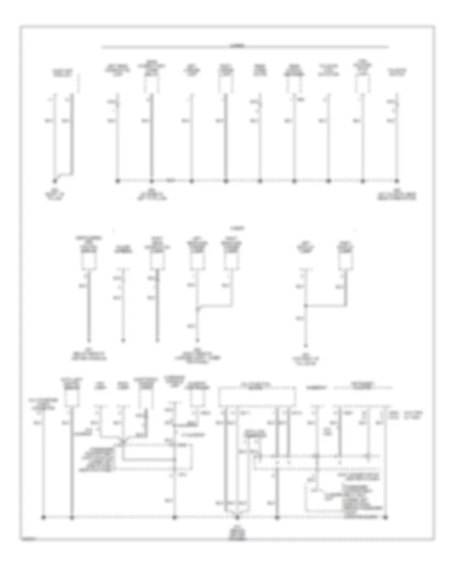
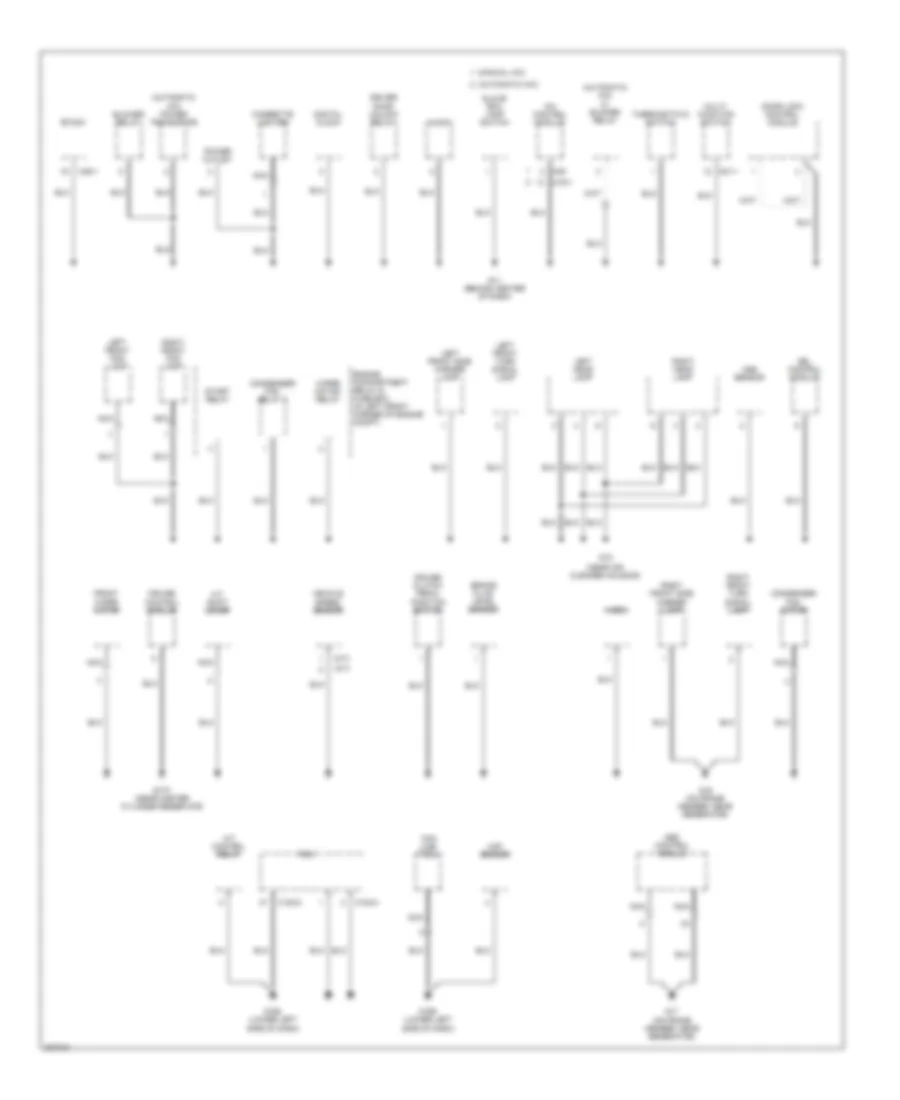
GROUND DISTRIBUTION
Ground Distribution Wiring Diagram (1 of 3) for Hyundai Elantra GT 2005
List of elements for Ground Distribution Wiring Diagram (1 of 3) for Hyundai Elantra GT 2005:
- (advanced) srs control module
- (fr)
- (fr+rr)
- (glass) high mounted stop lamp
- (spoiler) high mounted stop lamp
- (w/ glass ant) rear window defogger
- (w/ trip)
- (w/o glass ant) rear window defogger
- (w/o trip)
- 4 door
- D29
- D30
- D39
- D40
- Driver door key lock/unlock switch
- Driver seat buckle switch
- Driver seat track position sensor
- Fuel sender & fuel pump motor
- G01 (left ``b" pillar)
- G03 (right ``b" pillar)
- G04 (at middle front of rear seat cushion, under carpet)
- G05 (at base of left ``c" pillar)
- G09 (right rear of luggage compt, under trim panel)
- G10 (at base of right ``c" pillar)
- G13 (behind left end of dash)
- G27 (below rear of center console)
- G29 (under left ``c" pillar trim)
- Instrument cluster
- Left front door lock actuator
- Left front door switch
- Left front seat warmer
- Left outside mirror motor & defogger
- Left rear combination lamp
- Left rear door lock actuator
- Left rear door switch
- Left rear power window switch
- License lamp
- M09-1
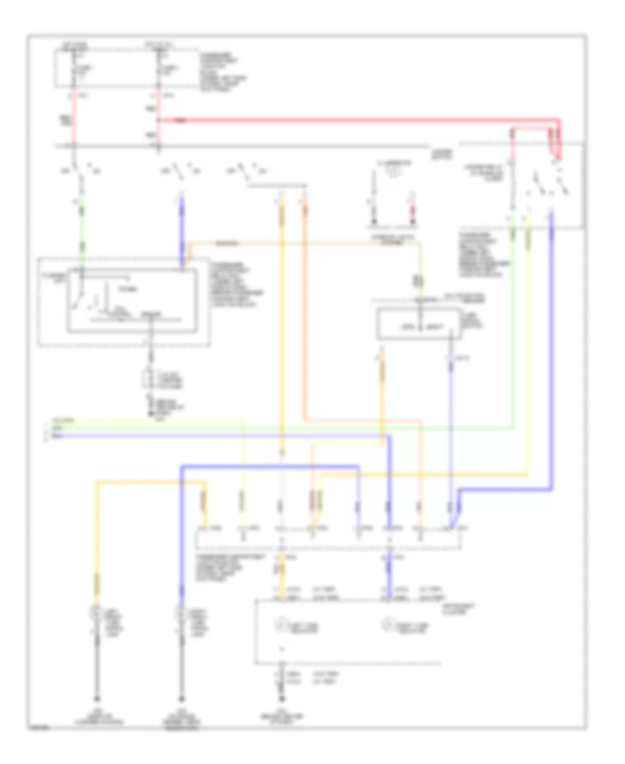
- M10-1
- M66-1
- M69
- Nca
- Nca nca
- Oc sensor
- Passenger seat buckle switch
- Passenger seat track position sensor
- Power outside mirror switch
- Power window main switch
- Right front door lock actuator
- Right front door switch
- Right front power window switch
- Right front seat warmer
- Right outside mirror motor & defogger
- Right rear combination lamp
- Right rear door lock actuator
- Right rear door switch
- Right rear power window switch
- Seat belt switch
- Telltale
- Trunk unlock switch
- W/ power window
- W/o power window
Ground Distribution Wiring Diagram (2 of 3) for Hyundai Elantra GT 2005
List of elements for Ground Distribution Wiring Diagram (2 of 3) for Hyundai Elantra GT 2005:
- (depowered) srs control module
- (w/o trip) (w/ trip)
- 5 door
- Audio amp module 2
- Auto light control module
- Data link connector
- Electronic chrome mirror
- Flasher unit
- G02 (right ``b" pillar)
- G06 (at base of left "c" pillar)
- G08 (right rear of luggage compt, under trim panel)
- G12 (behind center of dash)
- G28 (on tailgate, near rear wiper motor)
- G30 (top right of tail gate)
- G37 (below rear of center console)
- High mounted stop lamp
- I/p-c
- I/p-h
- Instrument cluster
- Joint connector m27 (center of dash)
- Left back-up lamp
- Left license lamp
- Left rear combination lamp
- Left rear side marker lamp
- M01-1
- M01-2
- M09-1
- M09-2 m10-2
- M94-2
- Map lamp
- Multifunction switch
- Multipurpose check connector
- Nca
- Overhead console lamp
- Passenger compartment junction block (under left side of dash, near kick panel)
- Passenger compartment relay box (under left side of dash, beside passenger compt junction block)
- Power antenna
- R06
- Rear intermittent wiper relay
- Rear window defogger
- Rear wiper motor
- Rheostat
- Right back-up lamp
- Right license lamp
- Right rear combination lamp
- Right rear side marker lamp
- Room lamp
- Sunroof controller
- Tailgate lock actuator
- Tailgate switch
- W/ sunroof
- W/o trip
- W/o sunroof
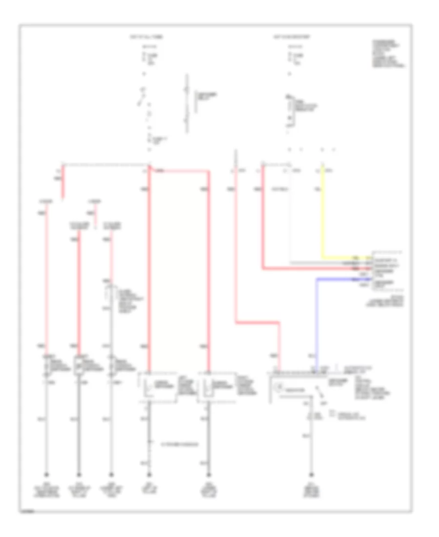
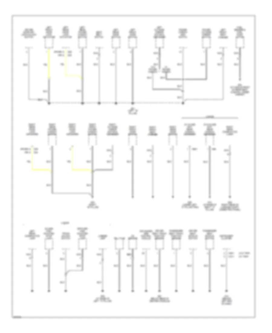
Ground Distribution Wiring Diagram (3 of 3) for Hyundai Elantra GT 2005
List of elements for Ground Distribution Wiring Diagram (3 of 3) for Hyundai Elantra GT 2005:
- (a/t)
- (automatic a/c)
- (automatic a/c) hi blower relay
- (automatic a/c) power transistor
- (m/t)
- (manual a/c)
- (near air cleaner housing)
- A/c control module
- A/t control relay
- A/t shift lever
- Abs control module
- Aqs sensor
- Audio
- Blower relay
- Brake fluid level sensor
- C183-2
- C183-3
- Can line tool
- Cigarette lighter
- Condenser fan motor
- Condenser fan relay 2
- Cruise clutch pedal position switch
- Cruise control module
- Digital clock
- Door lock control module
- Driver door unlock relay
- Drl control module
- Engine compartment relay & fuse box (in left front corner of engine compt)
- Etacm
- Front wiper motor
- G11 (behind center of dash)
- G15
- G16 (on frame member, near generator)
- G168 (lower left side of dash)
- G169 (lower left side of dash)
- G17 (on frame member, near generator)
- G170 (near master cylinder reservoir)
- Glove box lamp switch
- Horn
- Left front fog lamp
- Left front side marker lamp
- Left front turn signal lamp
- Left head lamp
- M01-1
- M19-1
- M20
- M25-1
- Maf sensor
- Multi- function switch
- Nca
- Pcm
- Power outlet
- Right front fog lamp
- Right front side marker lamp
- Right front turn signal lamp
- Right head lamp
- Start relay
- Thermostatic switch
- Vehicle speed sensor
- Wiper motor relay
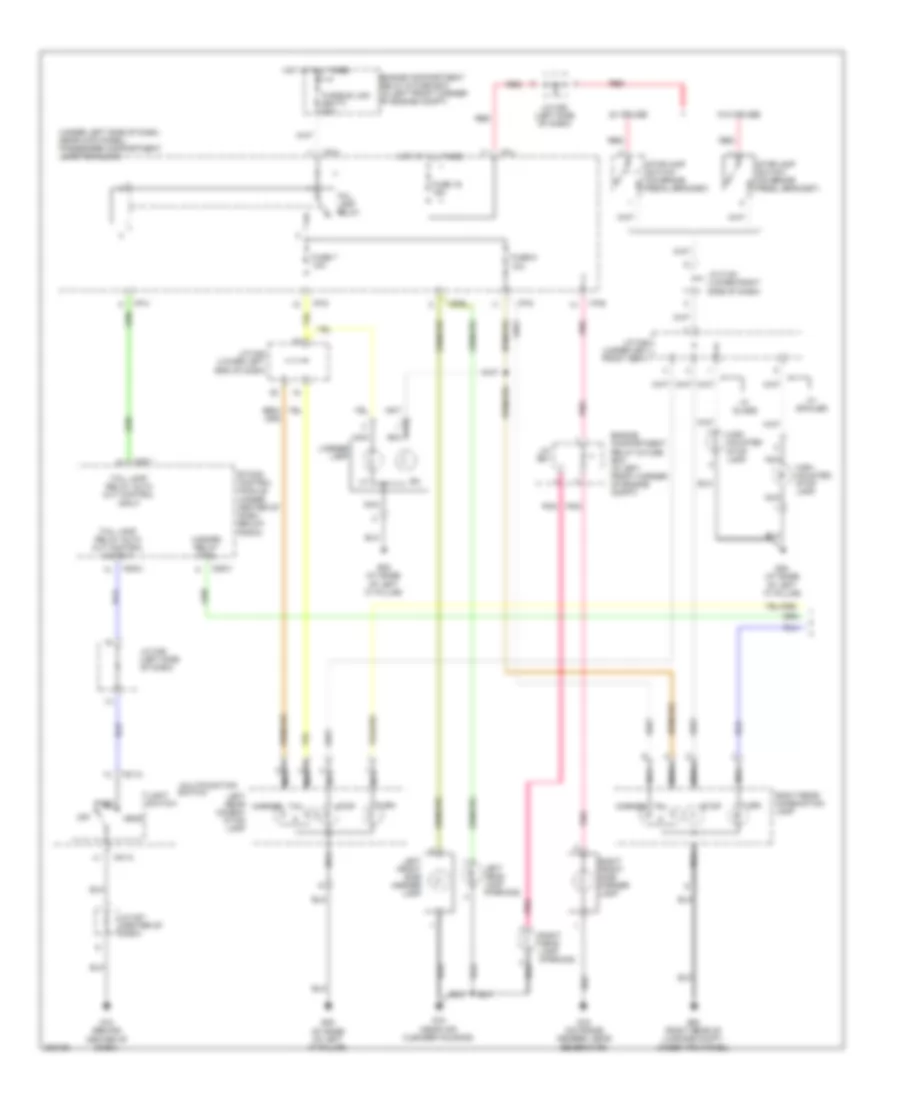
HEADLIGHTS
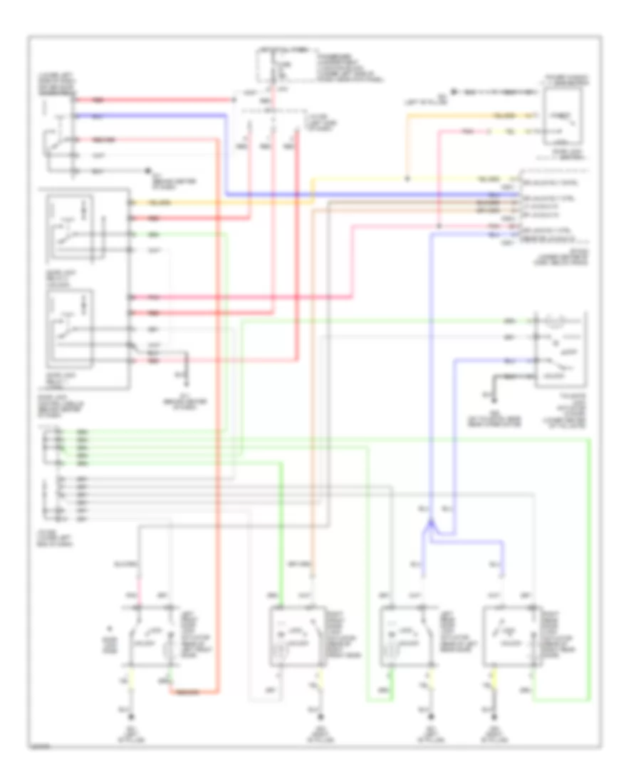
Headlights Wiring Diagram, with Autolamps for Hyundai Elantra GT 2005
List of elements for Headlights Wiring Diagram, with Autolamps for Hyundai Elantra GT 2005:
- (behind center of dash) g12
- (center of dash) auto light control module
- (center of dash) joint connector m27
- (in left front corner of engine compt) engine compartment relay & fuse box
- (left side of dash) joint connector m36
- (near air cleaner housing)
- (under left side of dash, near kick panel) passenger compartment junction block
- (w/ trip)
- (w/o trip)
- +5v
- Air conditioning system
- Amp
- Auto
- Dimmer/ passing switch
- Diode z02 (left side of dash)
- Diode z04 (below steering column)
- Etacm (under center of dash, below radio)
- Flash
- Front fog fuse 15a
- Front fog lamp switch
- Front foglamp indicator
- Front foglamp relay
- Fuse 10a
- Fusible link (batt) fuse 50a
- G12 (behind center of dash)
- G15
- G15 (near air cleaner housing)
- Gnd
- H/l
- Head
- Headlamp (high) fuse 15a
- Headlamp (low) fuse 15a
- Headlamp relay (high)
- Headlamp relay (low)
- High
- High beam indicator
- Hot at all times
- Hot in on
- Hot in on or start
- I/p-a
- I/p-b
- I/p-g
- I/p-h
- Input
- Instrument cluster
- Interior lights system
- Joint connector e56
- Joint connector e60
- Joint connector e62
- Joint connector m27 (center of dash)
- Left front fog lamp
- Left headlamp
- Light switch
- Low
- M01-2
- M09-1
- M09-3
- M10-2
- M10-3
- M25-1
- M25-2
- Mcu
- Multifunction switch
- Nca
- Off
- Park
- Passenger compartment junction block (under left side of dash, near kick panel)
- Photo sensor (on top right side of dash, near defroster vent)
- Pnk
- Red
- Right front fog lamp
- Right headlamp
- Sig in
- T/l
- Taillamp relay
- W/ trip
- W/o trip
Headlights Wiring Diagram, with DRL (1 of 2) for Hyundai Elantra GT 2005
List of elements for Headlights Wiring Diagram, with DRL (1 of 2) for Hyundai Elantra GT 2005:
- (behind center of dash) g12
- (center of dash) joint connector m27
- (in left front corner of engine compt) engine compartment relay & fuse box
- Dimmer/ passing switch
- Diode z04 (below steering column)
- Drl resistor (on left fenderwell)
- Etacm (under center of dash, below radio)
- Flash
- From taillamp relay (diagram 2 of 2)
- Front fog lamp switch
- Fuse 10a
- G15 (near air cleaner housing)
- Head
- Headlamp (high) fuse 15a
- Headlamp (low) fuse 15a
- Headlamp relay (high)
- Headlamp relay (low)
- High
- Hot at all times
- Hot in on
- I/p-b
- Joint connector e56
- Joint connector e60
- Joint connector m36 (left side of dash)
- Left headlamp
- Light switch
- Low
- M01-2
- M25-1
- M25-2
- Multifunction switch
- Off
- Park
- Passenger compartment junction block (under left side of dash, near kick panel)
- Red
- Right headlamp
- To drl control module (diagram 2 of 2)
- To front foglamp relay (diagram 2 of 2)
- To instrument cluster (diagram 2 of 2)
Headlights Wiring Diagram, with DRL (2 of 2) for Hyundai Elantra GT 2005
List of elements for Headlights Wiring Diagram, with DRL (2 of 2) for Hyundai Elantra GT 2005:
- (near air cleaner housing)
- (w/ trip)
- (w/o trip)
- Diode z02 (left side of dash)
- Drl control module (on left front inner fender panel)
- Drl fuse 15a
- Drl relay
- E20-2
- Engine compartment relay & fuse box (in left front corner of engine compt)
- From drl resistor (diagram 1 of 2)
- From engine compt relay & fuse box, (diagram 1 of 2)
- From engine compt relay & fuse box, joint connector e56 (diagram 1 of 2)
- From front fog lamp switch (diagram 1 of 2)
- From headlamp relay (diagram 1 of 2)
- Front fog fuse 15a
- Front foglamp indicator
- Front foglamp relay
- Fuse 10a
- Fusible link (batt) fuse 120a
- Fusible link (batt) fuse 50a
- G12 (behind center of dash)
- G15
- G15 (near air cleaner housing)
- Generator
- High beam indicator
- Hot at all times
- I/p-a
- I/p-b
- I/p-g
- I/p-h
- Instrument instrument cluster cluster
- Interior lights system
- Joint connector e62
- Joint connector m27 (center of dash)
- Joint connector m36 (left side of dash)
- Left front fog lamp
- M09-1
- M09-3
- M10-2
- M10-3
- Nca
- Parking brake switch (on base of parking brake lever)
- Passenger compartment junction block (under left side of dash, near kick panel)
- Pnk
- Power & control circuit
- Red
- Right front fog lamp
- Starting/ charging system
- Taillamp relay
- To etacs control module/tacm (diagram 1 of 2)
- W/ trip
- W/o trip
Headlights Wiring Diagram, without DRL for Hyundai Elantra GT 2005
List of elements for Headlights Wiring Diagram, without DRL for Hyundai Elantra GT 2005:
- (behind center of dash) g12
- (center of dash) joint connector m27
- (in left front corner of engine compt) engine compartment relay & fuse box
- (under left side of dash, near kick panel) passenger compartment junction block
- (w/ trip)
- (w/o trip)
- Dimmer/ passing switch
- Diode z02 (left side of dash)
- Diode z04 (below steering column)
- Etacm (under center of dash, below radio)
- Flash
- Front fog fuse 15a
- Front fog lamp switch
- Front foglamp indicator
- Front foglamp relay
- Fuse 10a
- Fusible link (batt) fuse 50a
- G15 (near air cleaner housing)
- Head
- Headlamp (high) fuse 15a
- Headlamp (low) fuse 15a
- Headlamp relay (high)
- Headlamp relay (low)
- High
- High beam indicator
- Hot at all times
- Hot in on
- I/p-a
- I/p-b
- I/p-g
- I/p-h
- Instrument cluster
- Interior lights system
- Joint connector e56
- Joint connector e60
- Joint connector e62
- Joint connector m27 (center of dash)
- Joint connector m36 (left side of dash)
- Left front fog lamp
- Left headlamp
- Light switch
- Low
- M01-2
- M09-1
- M09-3
- M10-2
- M10-3
- M25-1
- M25-2
- Multifunction switch
- Nca
- Off
- Park
- Passenger compartment junction block (under left side of dash, near kick panel)
- Pnk
- Red
- Right front fog lamp
- Right headlamp
- Taillamp relay
- W/ trip
- W/o trip
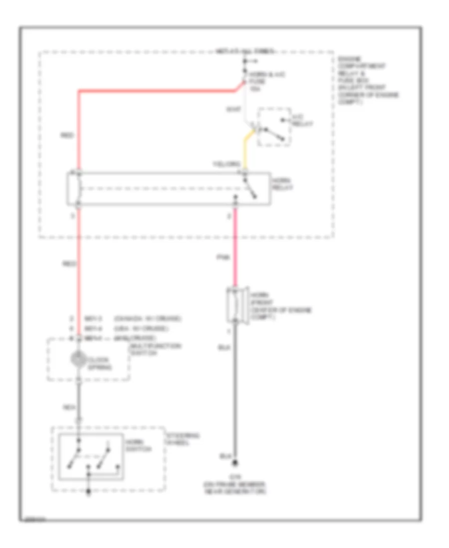
HORN
Horn Wiring Diagram for Hyundai Elantra GT 2005
List of elements for Horn Wiring Diagram for Hyundai Elantra GT 2005:
- (canada: w/ cruise)
- (usa: w/ cruise)
- (w/o cruise)
- A/c relay
- Clock spring
- Engine compartment relay & fuse box (in left front corner of engine compt)
- G16 (on frame member, near generator)
- Horn & a/c fuse 15a
- Horn (front center of engine compt)
- Horn relay
- Horn switch
- Hot at all times
- M01-1
- M01-3
- M01-4
- Multifunction switch
- Nca
- Pnk
- Red
- Steering wheel
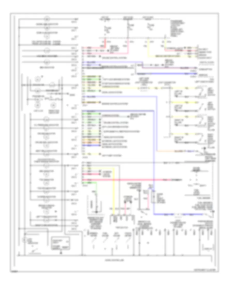
INSTRUMENT CLUSTER
Instrument Cluster Wiring Diagram, with TRIP COMPUTER for Hyundai Elantra GT 2005
List of elements for Instrument Cluster Wiring Diagram, with TRIP COMPUTER for Hyundai Elantra GT 2005:
- (5 door) (4 door)
- (behind center of dash) g12
- (behind left end of dash) g13
- (left "b" pillar) g01
- (left side of dash) joint connector m33
- (near master cylinder reservoir) g170
- (right "b" pillar) g03
- A/t
- Abs indicator
- Acc/on input
- Anti-lock brakes system
- Anti-theft system
- Brake fluid level sensor (in brake fluid reservoir)
- Brake warning indicator
- C183-3
- C183-4
- Charge indicator
- Consumption
- Cruise control system
- Cruise indicator
- Cruise set indicator
- Dial(x8) ind
- Digital clock
- Dim input
- Diode z01 (right center of dash)
- Display
- Door ajar indicator
- Door locks system
- Ect gauge
- Empty
- Engine controls system
- Engine coolant temperature (ect) sensor & sender (left front of engine)
- Exterior lights system
- Front fog indicator
- Fuel gauge
- Fuel level float
- Fuel sender
- Fuel sender & fuel pump motor (fuel sender: inside top of fuel tank)
- Full
- Fuse 10a
- Fuse 15a
- G11 (behind center of dash)
- Gauge sender
- Gear sig
- Gnd
- Ground
- Headlights system
- High beam indicator
- Hot at all times
- Hot in acc or on
- Hot in on or start
- I/p-f
- I/p-g
- I/p-h
- Ill(+)
- Ill(-)
- Immobilizer indicator
- Instrument cluster
- Interior lights system
- Joint connector m112
- Joint connector m36 (left side of dash)
- Lcd illum
- Left front door switch
- Left rear door switch
- Left turn indicator
- Low fuel indicator
- M/t
- M10-1
- M10-2
- M10-3
- Malfunction (mil) check engine indicator
- Memory pwr
- Micro controller
- Mode/ reset
- Nca
- Oil pressure indicator
- Oil pressure switch (left rear of engine)
- On/start input
- Parking brake switch (on base of parking brake lever)
- Passenger compartment junction block (under left side of dash, near kick panel)
- Pcm (left side of dash)
- Pnk
- Pointer ind
- Red
- Reset
- Right front door switch (right "b" pillar)
- Right rear door switch (right "c" pillar)
- Right turn indicator
- Seat belt indicator
- Sender
- Sgnd
- Speedo- meter
- Srs indicator
- Starting/charging system
- Tacho- meter
- Tail gate ajar ind trunk lid ajar ind
- Tcs indicator
- Tcs off indicator
- Trip switch
- Warning system
Instrument Cluster Wiring Diagram, without Trip Computer (1 of 2) for Hyundai Elantra GT 2005
List of elements for Instrument Cluster Wiring Diagram, without Trip Computer (1 of 2) for Hyundai Elantra GT 2005:
- (4 door)
- (5 door)
- (behind left end of dash) g13
- (left side of dash) pcm
- Abs indicator
- Anti-lock brakes system
- Anti-theft system
- Brake warning indicator
- C183-3
- Canada
- Charge indicator
- Constant voltage
- Cruise control system
- Cruise indicator
- Cruise set indicator
- Door ajar indicator
- Ect gauge
- Engine controls system
- Engine coolant temperature (ect) sensor & sender (left front of engine)
- Exterior lights system
- Front fog indicator
- Fuel gauge
- Fuse 10a
- Fuse 15a
- G12 (behind center of dash)
- Headlights system
- Hot at all times
- Hot in acc or on
- Hot in on or start
- I/p-f
- I/p-g
- I/p-h
- Illum
- Immobilizer indicator
- Indicator
- Indicator high beam
- Instrument cluster
- Interior lights system
- Joint connector m27 (center of dash)
- Lcd illum
- Left turn indicator
- Low fuel indicator
- M09-1
- M09-2
- M09-3
- Malfunction (mil) check engine indicator
- Micom
- Mo9-1
- Mo9-2
- Mo9-3
- Odo/ trip
- Oil pressure indicator
- Passenger compartment junction block (under left side of dash, near kick panel)
- Pnk
- Red
- Right turn indicator
- Seat belt indicator
- Sender
- Speedo- meter
- Srs indicator
- Starting/charging system
- Tacho- meter
- Tailgate ajar
- Tcs indicator
- Tcs off indicator
- Transmissions system
- Trunk lid ajar
- Warning system
Instrument Cluster Wiring Diagram, without Trip Computer (2 of 2) for Hyundai Elantra GT 2005
List of elements for Instrument Cluster Wiring Diagram, without Trip Computer (2 of 2) for Hyundai Elantra GT 2005:
- (left "b" pillar) g01
- (near master cylinder reservoir)
- (right "b" pillar) g03
- Acc/on input
- Brake fluid level sensor (in brake fluid reservoir)
- Digital clock
- Dim input
- Diode z01 (right center of dash)
- Door switch (right "b" pillar)
- Empty
- Fuel level float
- Fuel sender
- Fuel sender & fuel pump motor (fuel sender: inside top of fuel tank)
- Full
- G11 (behind center of dash)
- G170
- Gauge sender
- Ground
- Interior lights system
- Joint connector m112
- Joint connector m33 (left side of dash)
- Joint connector m36 (left side of dash)
- Left front door switch
- Left rear door switch
- Memory pwr
- Nca
- Oil pressure switch (left rear of engine)
- Parking brake switch (on base of parking brake lever)
- Pnk
- Red
- Right front
- Right rear door switch (right "c" pillar)
INTERIOR LIGHTS
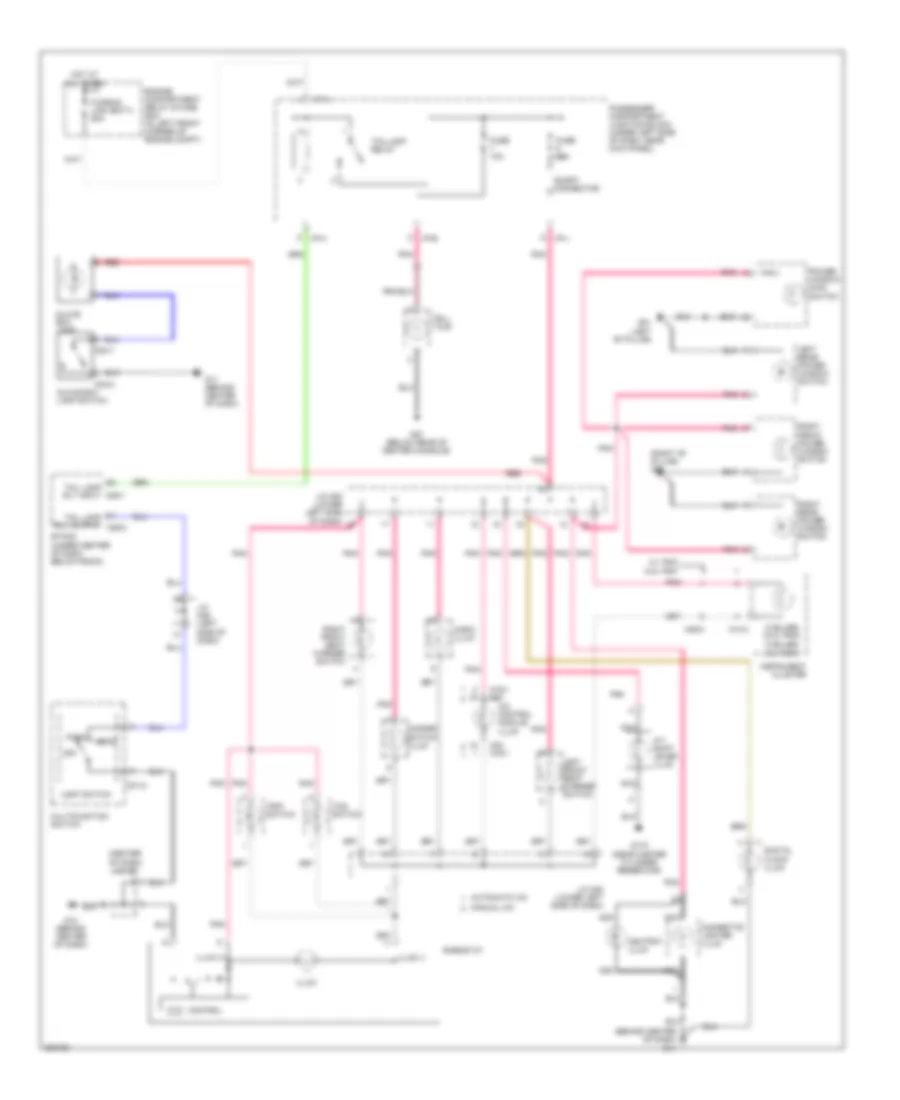
Courtesy Lamps Wiring Diagram, with Sunroof for Hyundai Elantra GT 2005
List of elements for Courtesy Lamps Wiring Diagram, with Sunroof for Hyundai Elantra GT 2005:
- (w/ trip)
- (w/o trip)
- 4 door
- 5 door
- Door
- Door ajar ind
- Door sw (all)
- Door switch
- Etacm (under center of dash, below radio)
- Fuse 15a
- G01 (left "b" pillar)
- G03 (right "b" pillar)
- G12 (behind center of dash)
- G28 (on tailgate, near rear wiper motor)
- Hot at all times
- I/p-c
- I/p-d
- I/p-g
- I/p-h
- Instrument cluster
- J/c m112
- J/c m33 (left side of dash)
- Left front door lamp
- Left front door switch
- Left rear door switch
- Luggage lamp
- M09-1
- M10-1
- M25-1
- Map lamp
- Memory power
- Nca
- Off
- Overhead console lamp
- Passenger compartment junction block (under left side of dash, near kick panel)
- Power tops system
- Red
- Right front door lamp
- Right front door switch (right "b" pillar)
- Right rear door switch (right "c" pillar)
- Rm lmp cntrl
- Room lamp
- Tail gate switch (lower center of tail gate)
- Tailgate ajar ind (5 door) trunk lid ajar ind (4 door)
- Trunk room lamp
- Trunk room lamp sw sig
- Trunk room lamp switch (center rear of trunk room)
- W/ trip
- W/o trip
Courtesy Lamps Wiring Diagram, without Sunroof for Hyundai Elantra GT 2005
List of elements for Courtesy Lamps Wiring Diagram, without Sunroof for Hyundai Elantra GT 2005:
- (w/ trip)
- (w/o trip)
- 4 door
- 5 door
- Door
- Door ajar ind
- Door sw (all)
- Door switch
- Etacm (under center of dash, below radio)
- Fuse 15a
- G01 (left "b" pillar)
- G03 (right "b" pillar)
- G12 (behind center of dash)
- G28 (on tailgate, near rear wiper motor)
- Hot at all times
- I/p-c
- I/p-d
- I/p-g
- I/p-h
- Instrument cluster
- J/c m112
- J/c m33 (left side of dash)
- Left front door lamp
- Left front door switch
- Left rear door switch
- Luggage lamp
- M09-1
- M10-1
- M25-1
- Map lamp
- Memory power
- Nca
- Off
- Passenger compartment junction block (under left side of dash, near kick panel)
- Red
- Right front door lamp
- Right front door switch (right b" pillar)
- Right rear door switch (right "c" pillar)
- Rm lmp cntrl
- Room lamp
- Tail gate switch (lower center of tail gate)
- Tailgate ajar ind (5 door) trunk lid ajar ind (4 door)
- Trunk room lamp
- Trunk room lamp sw sig
- Trunk room lamp switch (center rear of trunk room)
- W/ trip
- W/o trip
Instrument Illumination Wiring Diagram for Hyundai Elantra GT 2005
List of elements for Instrument Illumination Wiring Diagram for Hyundai Elantra GT 2005:
- (3 bulbs) (w/ trip)
- (3 bulbs) (w/o trip)
- (behind center of dash) g11
- (center of dash) j/c m27
- (right "b" pillar) g03
- A/c control module illum
- A/t shift lever illum
- Ashtray illum
- Audio illum
- Automatic a/c
- Cigarette lighter illum
- Control
- Digital clock illum
- Engine compartment relay & fuse box (in left front corner of engine compt)
- Etacm (under center of dash, below radio)
- Fuse 10a
- Fusible link (batt) 50a
- G01 (left "b" pillar)
- G11 (behind center of dash)
- G12 (behind center of dash)
- G170 (near master cylinder reservoir)
- G27 (below rear of center console)
- Glove box lamp
- Glove box lamp switch
- Hazard switch illum
- Head
- Hot at all times
- I/p-a
- I/p-b
- I/p-h
- I/p-j
- Illum
- Illum (+)
- Illum (-)
- Instrument cluster
- J/c m08 (lower left side of dash)
- J/c m36 (left side of dash)
- Left front seat warmer switch
- Left rear power window switch
- Light switch
- M01-2
- M03-1
- M03-2
- M09-3
- M10-3
- M19-1 m20
- M20 m19-1
- M25-1
- Manual a/c
- Multifunction switch
- Nca
- Off
- Park
- Passenger compartment junction block (under left side of dash, near kick panel)
- Pnk
- Power window main switch
- Red
- Rheostat
- Right front power window switch
- Right front seat warmer switch
- Right rear power window switch
- Short connector
- Tail lamp rly input
- Tail lamp rly output m25-2
- Taillamp relay
- Tcs switch
- Tell tale
- Trip switch
- W/ trip
- W/o trip
POWER ANTENNA
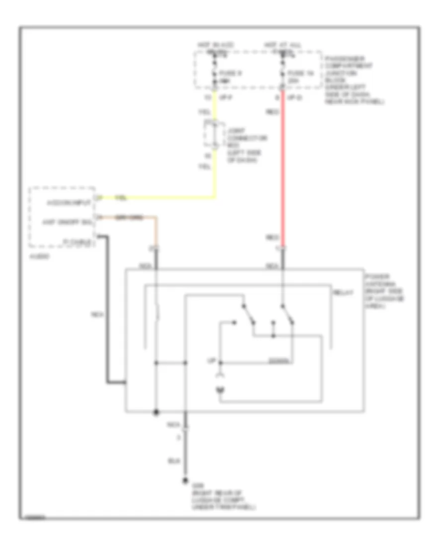
Power Antenna Wiring Diagram for Hyundai Elantra GT 2005
List of elements for Power Antenna Wiring Diagram for Hyundai Elantra GT 2005:
- Acc/on input
- Ant on/off sig
- Audio
- Down
- F/ cable
- Fuse 14 20a
- Fuse 9 10a
- G08 (right rear of luggage compt, under trim panel)
- Hot at all times
- Hot in acc or on
- I/p-d
- I/p-f
- Joint connector m33 (left side of dash)
- Nca
- Passenger compartment junction block (under left side of dash, near kick panel)
- Power antenna (right side of luggage area)
- Red
- Relay
POWER DISTRIBUTION
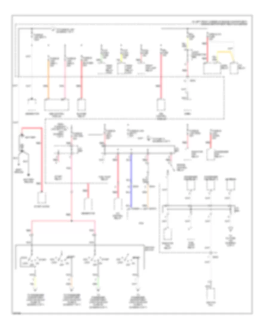
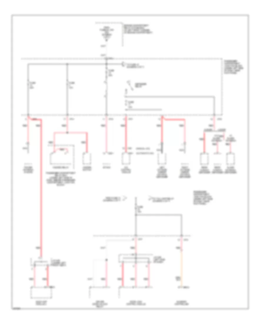
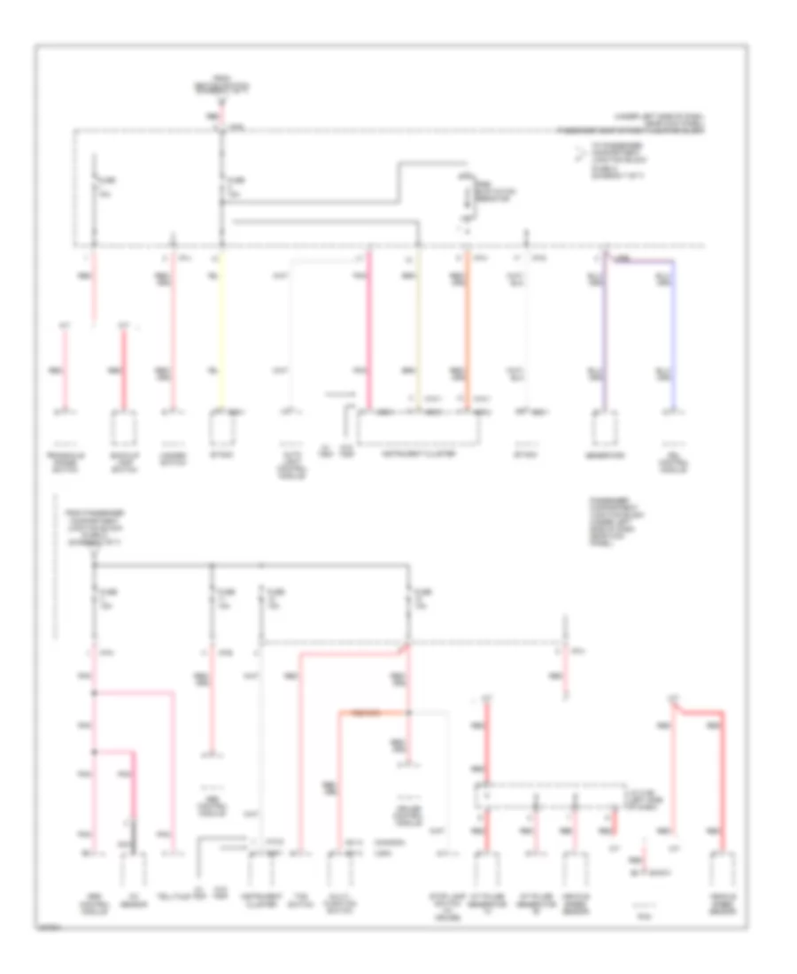
Power Distribution Wiring Diagram (1 of 7) for Hyundai Elantra GT 2005
List of elements for Power Distribution Wiring Diagram (1 of 7) for Hyundai Elantra GT 2005:
- (in left front corner of engine compartment) engine compartment relay & fuse box
- A/c relay
- A/t control relay
- Abs control module
- Acc
- Battery
- Battery ground
- Blower relay
- Body ground
- C183-1
- C183-3
- Condenser fan relay 1
- Condenser fan relay 2
- Drl control module
- Drl fuse 15a
- Ec03
- Ec04
- Ecu fuse 10a
- Engine control relay
- F/fog fuse 15a
- From fusible link (batt) a 120a (diagram 1 of 7)
- Front fog lamp relay
- Fuel pump relay
- Fusible link (abs 1) 30a
- Fusible link (abs 2) 30a
- Fusible link (batt) 120a
- Fusible link (batt) 50a
- Fusible link (blower) 30a
- Fusible link (cond) 20a
- Fusible link (ecu) 20a
- Fusible link (ign) 40a
- Fusible link (rad) 20a
- Generator
- H/lp (high) fuse 15a
- H/lp (low) fuse 15a
- Head- lamp relay (high)
- Head- lamp relay (low)
- Horn & a/c fuse 15a
- Horn relay
- Ignition coil
- Ignition switch
- J/c e55
- J/c e57
- J/c e58
- Joint connector e62
- Lock
- Nca
- Off
- Pcm
- Pnk
- Radiator fan relay
- Red
- Siren
- Start
- Start motor
- Start relay
- To fuse 13 (diagram 3 of 7)
- To fusible link (diagram 1 0f 7)
- To inj fuse 15a (diagram 2 of 7)
- To passenger compartment junction block (fuse 18) (diagram 2 of 7)
- To passenger compartment junction block (fuse 2) (diagram 7 of 7)
- To passenger compartment junction block (fuse 20) (diagram 6 of 7)
- To passenger compartment junction block (fuse 8) (diagram 2 of 7)
Power Distribution Wiring Diagram (2 of 7) for Hyundai Elantra GT 2005
List of elements for Power Distribution Wiring Diagram (2 of 7) for Hyundai Elantra GT 2005:
- (behind center of dash) g11
- (not used)
- 4 door
- 5 door
- Ashtray illumination
- Audio
- Burglar alarm relay
- C183-3
- Camshaft position sensor
- Canister close valve
- Canister purge solenoid valve
- Cigarette lighter
- Crankshaft position sensor
- Cvvt
- Digital clock
- Ec05
- Engine compartment relay & fuse box (in left front corner of engine compartment)
- From ignition switch (diagram 1 of 7)
- From j/c e58 (diagram 1 of 7)
- Fuse 10a
- Fuse 18 15a
- Fuse 9 10a
- Heated oxygen sensor (down)
- Heated oxygen sensor (up)
- I/p-d
- I/p-e
- I/p-f
- I/p-g
- Idle speed control actuator
- Illumination
- Inj fuse 15a
- Injector 1
- Injector 2
- Injector 3
- Injector 4
- Interior lights system
- J/c c191 (lower right side of dash)
- J/c m33 (left side of dash)
- Maf sensor
- Nca
- Passenger compartment junction block (under left side of dash, near kick panel)
- Pcm
- Pnk
- Power outlet
- Power outside mirror switch
- Smatra
- Snsr fuse 1oa
- W/ immobilizer
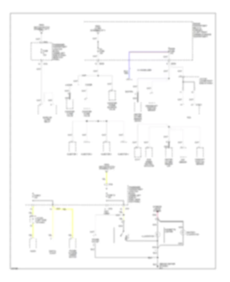
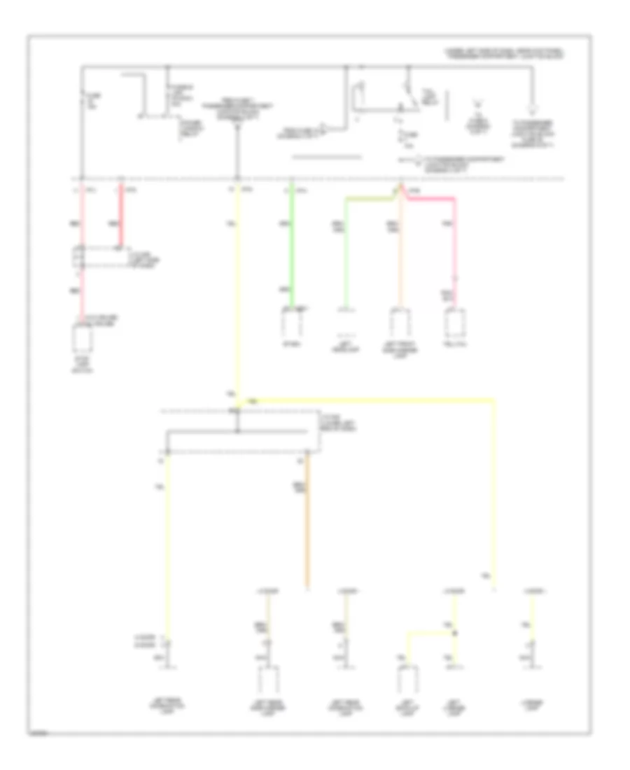
Power Distribution Wiring Diagram (3 of 7) for Hyundai Elantra GT 2005
List of elements for Power Distribution Wiring Diagram (3 of 7) for Hyundai Elantra GT 2005:
- (automatic a/c)
- (manual a/c)
- 4 door
- 5 door
- A/c control module
- Audio amp module 2
- Defogger relay
- Door lock control module
- Driver door unlock relay
- Engine compartment relay & fuse box (in left front corner of engine compartment)
- Etacm
- From fuse 13 (diagram 3 of 7)
- From fusible link 50a (diagram 1 of 7)
- Fuse 10a
- Fuse 15a
- Fuse 20a
- Fuse 30a
- Glass antenna (defogger)
- Hazard relay
- Hazard switch
- I/p-a
- I/p-c
- I/p-d
- I/p-f
- I/p-g
- I/p-h
- J/c m36 (left side of dash)
- J/c m49 (under left front seat)
- Left outside mirror motor & defogger
- M19-1
- M20
- M25-1
- M52-2
- M94-2
- Nca
- Passenger compartment junction block (under left side of dash, near kick panel)
- Passenger compartment relay box (under left side of dash, beside passenger compartment junction block)
- Power antenna (5 door)
- Rear window defogger
- Red
- Right outside mirror motor & defogger
- Sunroof controller
- To fuse 15 (diagram 3 of 7)
- To taillamp relay (diagram 4 of 7)
- W/ glass antenna
- W/o glass antenna
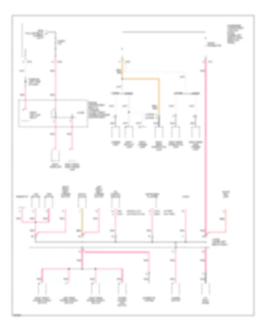
Power Distribution Wiring Diagram (4 of 7) for Hyundai Elantra GT 2005
List of elements for Power Distribution Wiring Diagram (4 of 7) for Hyundai Elantra GT 2005:
- (4 door)
- (5 door)
- (under left side of dash, near kick panel) passenger compartment junction block
- (w/ cruise)
- (w/o cruise)
- 4 door
- 5 door
- Etacm
- From fuse 15 f (diagram 3 of 7)
- From fuse 7 passenger compartment junction block (diagram 4 of 7)
- Fuse 10a
- Fuse 15a
- Fusible link (p/wdw) 30a
- I/p-b
- I/p-d
- I/p-g
- I/p-h
- I/p-j
- J/c m36 (left side of dash)
- J/c m45 (lower left end of dash)
- Left back-up lamp
- Left front side marker lamp
- Left headlamp
- Left license lamp
- Left rear combination lamp
- Left rear side marker lamp
- License lamp
- M25-1
- Nca
- Pnk
- Power window relay
- Red
- Stop lamp switch
- Tail- lamp relay
- Telltail
- To fuse 6 (diagram 5 of 7)
- To passenger compartment junction block (diagram 4 of 7)
- To passenger compartment junction block fuse 25 (diagram 6 of 7)
Power Distribution Wiring Diagram (5 of 7) for Hyundai Elantra GT 2005
List of elements for Power Distribution Wiring Diagram (5 of 7) for Hyundai Elantra GT 2005:
- (4 door)
- (5 door)
- (automatic a/c)
- (manual a/c)
- (w/o trip)
- (w/trip)
- 4 door
- 5 door
- A/c control module
- A/t shift lever
- Audio
- Cigarette lighter
- Digital clock
- Diode z02 (left side of dash)
- Engine compartment relay & fuse box (in left front corner of engine compartment)
- From taillamp relay h (diagram 4 of 7)
- Front fog lamp relay
- Fuse 6 10a
- Glove box lamp
- Hazard switch
- I/p-b
- I/p-d
- I/p-g
- I/p-j
- Instrument cluster
- J/c e61
- J/c m08 (lower left side of dash)
- Left front seat warmer switch
- Left rear power window switch
- License lamp
- M09-3
- M10-3
- M19-1
- M20
- Nca
- Passenger compartment junction block (under left side of dash, near kick panel)
- Pnk
- Power window main switch
- Red
- Rheostat
- Right back-up lamp
- Right front power window switch
- Right front seat warmer switch
- Right front side marker lamp
- Right headlamp
- Right license lamp
- Right rear combination lamp
- Right rear power window switch
- Right rear side marker lamp
- Short connector
- Tcs switch
- Trip switch
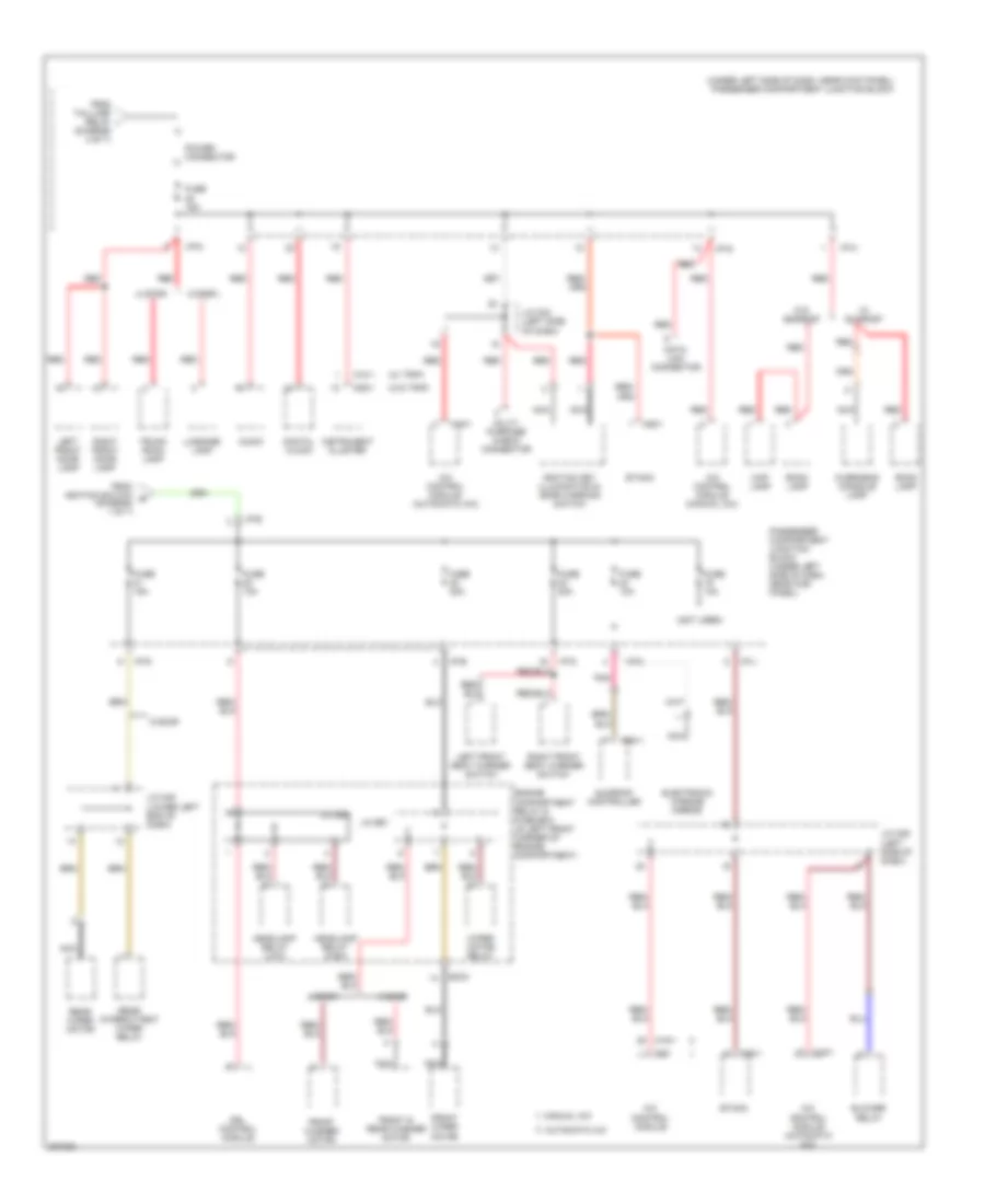
Power Distribution Wiring Diagram (6 of 7) for Hyundai Elantra GT 2005
List of elements for Power Distribution Wiring Diagram (6 of 7) for Hyundai Elantra GT 2005:
- (diagram 4 of 7)
- (not used)
- (under left side of dash, near kick panel) passenger compartment junction block
- (w/ trip)
- (w/o trip)
- 4 door
- 5 door
- A/c control module
- A/c control module (automatic a/c)
- A/c control module (manual a/c)
- Audio
- Automatic a/c
- Blower relay
- Data link connector
- Digital clock
- Drl control module
- Ec03
- Electronic chrome mirror
- Engine compartment relay & fuse box (in left front corner of engine compartment)
- Etacm
- From ignition switch e (diagram 1 of 7)
- From taillamp relay i
- Front & rear washer motor
- Front washer motor
- Front wiper motor
- Fuse 10a
- Fuse 15a
- Fuse 20a
- Headlamp relay (high)
- Headlamp relay (low)
- I/p-b
- I/p-c
- I/p-d
- I/p-e
- I/p-g
- I/p-j
- Ignition key illumination & door warning switch
- Instrument cluster
- J/c e56
- J/c e61
- J/c m33 (left side of dash)
- J/c m36 (left side of dash)
- J/c m45 (lower left end of dash)
- Left front door lamp
- Left front seat warmer switch
- Luggage lamp
- M09-1
- M10-1
- M19-1
- M20
- M25-1
- M94-1
- Manual a/c
- Map lamp
- Multi- purpose check connector
- Nca
- Overhead console lamp
- Passenger compartment junction block (under left side of dash, near kick panel)
- Pnk
- Power connector
- Rear intermittent wiper relay
- Rear wiper motor
- Red
- Right front door lamp
- Right front seat warmer switch
- Room lamp
- Sunroof controller
- Trunk room lamp
- W/ sunroof
- W/o sunroof
- Wiper motor relay
Power Distribution Wiring Diagram (7 of 7) for Hyundai Elantra GT 2005
List of elements for Power Distribution Wiring Diagram (7 of 7) for Hyundai Elantra GT 2005:
- (canada)
- (fuse 3) (diagram 7 of 7)
- (under left side of dash, near kick panel) passenger compartment junction block
- (usa)
- A/t
- A/t pulse generator "a"
- A/t pulse generator "b"
- Abs control module
- Auto light control module
- Back-up lamp switch
- C183-3
- Cruise control module
- Drl control module
- Etacm
- From ignition switch (diagram 1 of 7)
- From passenger compartment junction block (fuse 2) (diagram 7 of 7)
- Fuse 10a
- Fuse 15a
- Generator
- Hazard switch
- I/p-b
- I/p-e
- I/p-g
- I/p-h
- I/p-j
- I/p-k
- Instrument cluster
- J/c c192 (left side of dash)
- M/t
- M01-3
- M01-4
- M09-1
- M09-2
- M09-3
- M10-1
- M10-2
- M25-1
- Multi- function switch
- Nca
- Oc sensor
- Passenger compartment junction block (under left side of dash, near kick panel)
- Pcm
- Pnk
- Pre- excitation resistor
- Red
- Srs control module
- Stop lamp switch (w/ cruise)
- Tcs switch
- Telltale
- To passenger compartment junction block
- Transaxle range switch
- Vehicle speed sensor
- W/ trip
- W/o trip
POWER DOOR LOCKS
Power Door Locks Wiring Diagram for Hyundai Elantra GT 2005
List of elements for Power Door Locks Wiring Diagram for Hyundai Elantra GT 2005:
- (lower left side of dash) driver door unlock relay
- (rear of left front door)
- (rear of left rear door)
- Door lock control module (behind center of dash)
- Door lock knob
- Door lock relay 1 (lock)
- Door lock relay 2 (unlock)
- Door lock switch
- Dr lock rly ctrl
- Dr unlck rly cntrl
- Dr unlck rly ctrl
- Etacm (under center of dash, below radio)
- Fuse 15a
- G01 (left "b" pillar)
- G03 (right "b" pillar)
- G11 (behind center of dash)
- G28 (on tailgate, near rear wiper motor)
- Hot at all times
- I/p-f
- J/c m36 (left side of dash)
- J/c m45 (lower left end of dash)
- Left front door lock actuator
- Left rear door lock actuator
- Lf lk/unlk in
- Lock
- M25-1
- M25-2
- Passenger compartment junction block (under left side of dash, near kick panel)
- Pnk
- Power window main switch
- Rear dr lk/unlk in
- Red
- Rf lk/unlk in
- Right front door lock actuator (rear of right front door)
- Right rear door lock actuator (rear of right rear door)
- Tailgate lock actuator (5 door) (lower center of tail gate)
- Unlock
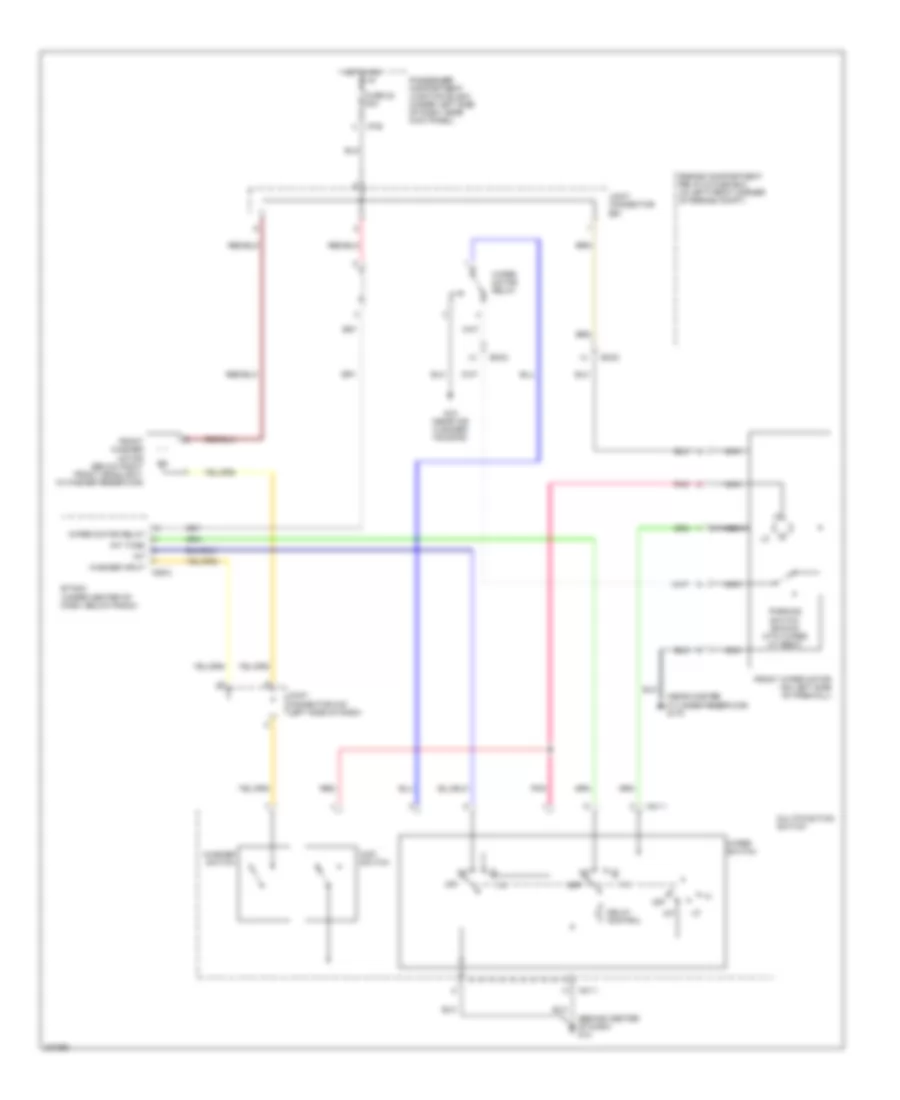
POWER MIRRORS
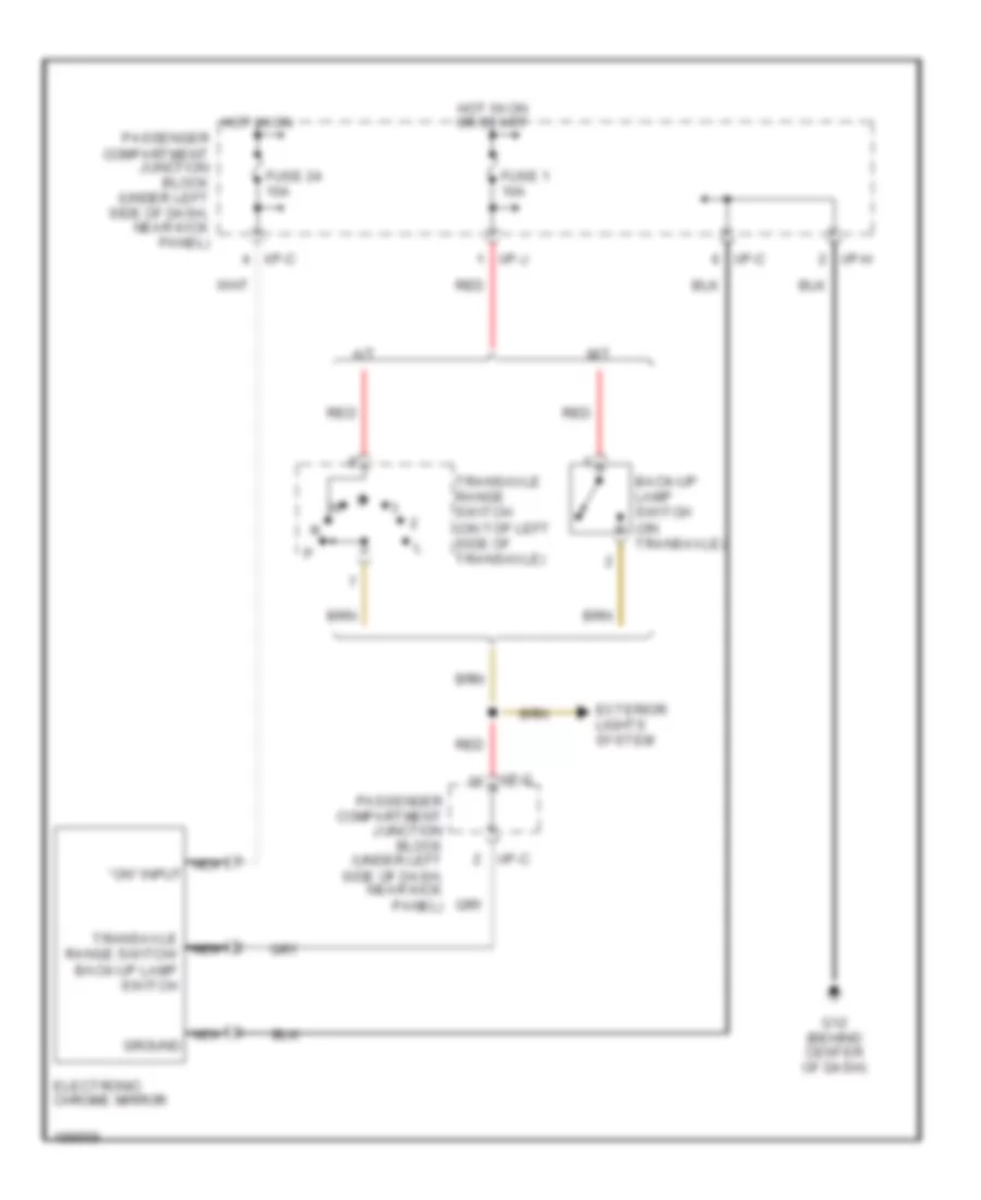
Electrochromic Mirror Wiring Diagram for Hyundai Elantra GT 2005
List of elements for Electrochromic Mirror Wiring Diagram for Hyundai Elantra GT 2005:
- A/t
- Back-up lamp switch (on transaxle)
- Electronic chrome mirror
- Exterior lights system
- Fuse 1 10a
- Fuse 24 10a
- G12 (behind center of dash)
- Ground
- Hot in on
- Hot in on or start
- I/p-c
- I/p-g
- I/p-h
- I/p-j
- M/t
- Nca
- Passenger compartment junction block (under left side of dash, near kick panel)
- Red
- Transaxle range switch (on top left side of transaxle)
- Transaxle range switch/ back-up lamp switch
- ``on" input
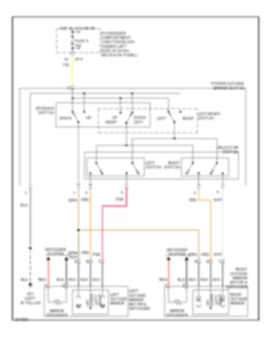
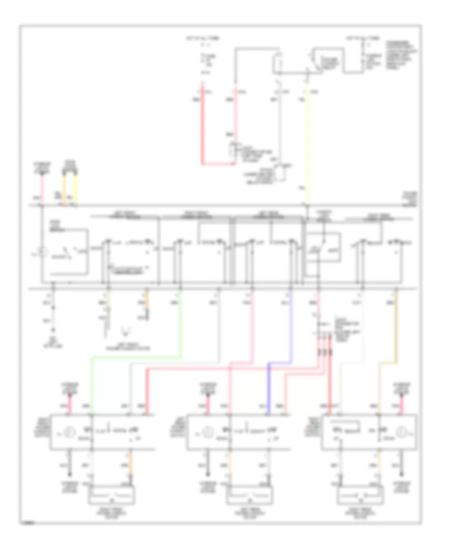
Power Mirrors Wiring Diagram for Hyundai Elantra GT 2005
List of elements for Power Mirrors Wiring Diagram for Hyundai Elantra GT 2005:
- Defogger system
- Down
- Down left
- Down up/
- Fuse 9 10a
- G01 (left "b" pillar)
- Hot in acc or on
- I/p-f
- Left
- Left outside mirror
- Left outside mirror motor & defogger
- Left switch
- Left/
- Left/right switch
- M right
- Mirror defogger
- Nca
- Passenger compartment junction block (under left side of dash, near kick panel)
- Pnk
- Power outside mirror switch
- Red
- Right
- Right outside mirror
- Right outside mirror motor & defogger
- Right switch
- Selector switch
- Up right
- Up/ down
- Up/down switch
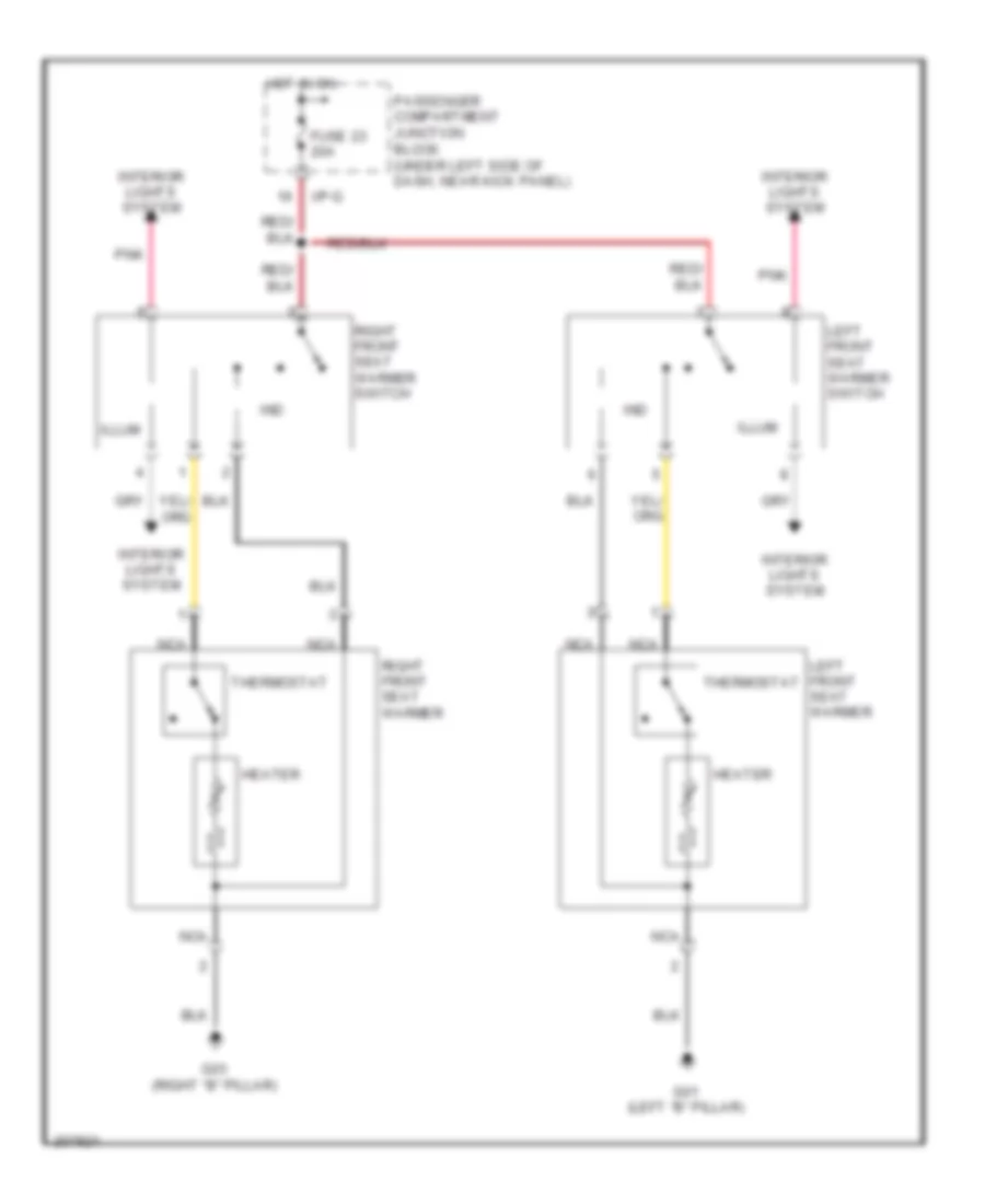
POWER SEATS
Heated Seats Wiring Diagram for Hyundai Elantra GT 2005
List of elements for Heated Seats Wiring Diagram for Hyundai Elantra GT 2005:
- Fuse 23 20a
- G01 (left "b" pillar)
- G03 (right "b" pillar)
- Heater
- Hot in on
- I/p-g
- Illum
- Ind
- Interior lights system
- Left front seat warmer
- Left front seat warmer switch
- Nca
- Passenger compartment junction block (under left side of dash, near kick panel)
- Pnk
- Right front seat warmer
- Right front seat warmer switch
- Thermostat
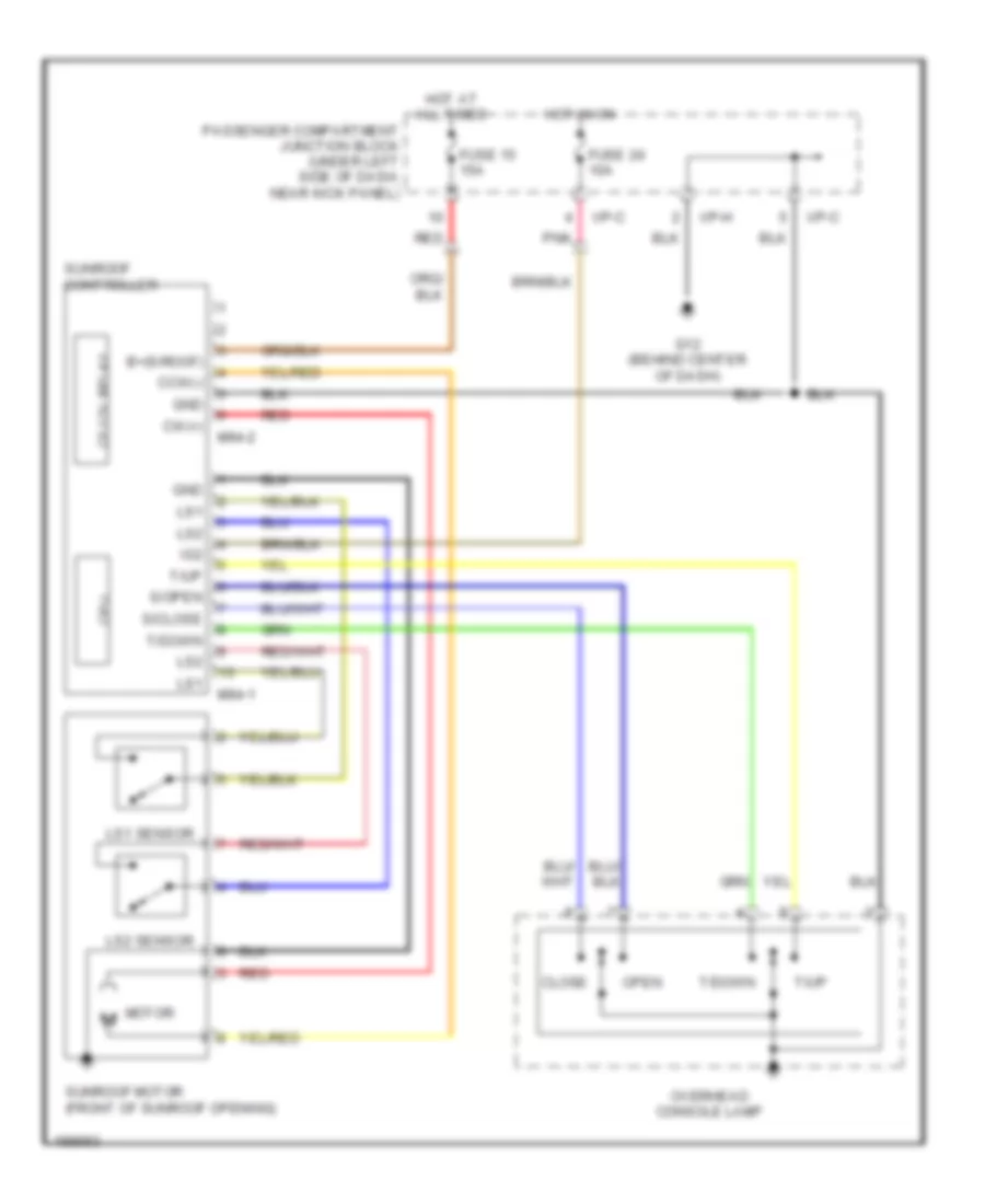
POWER TOP/SUNROOF
Power Top/Sunroof Wiring Diagram for Hyundai Elantra GT 2005
List of elements for Power Top/Sunroof Wiring Diagram for Hyundai Elantra GT 2005:
- B+(s/roof)
- Ccw(-)
- Cf-12v relay
- Close
- Cpu
- Cw(+)
- Fuse 15 15a
- Fuse 24 10a
- G12 (behind center of dash)
- Gnd
- Hot at all times
- Hot in on
- I/p-c
- I/p-h
- Ig2
- Ls1
- Ls1 sensor
- Ls2
- Ls2 sensor
- M94-1
- M94-2
- Motor
- Open
- Overhead console lamp
- Passenger compartment junction block (under left side of dash, near kick panel)
- Pnk
- Red
- S/close
- S/open
- Sunroof controller
- Sunroof motor (front of sunroof opening)
- T/down
- T/up
POWER WINDOWS
Power Windows Wiring Diagram for Hyundai Elantra GT 2005
List of elements for Power Windows Wiring Diagram for Hyundai Elantra GT 2005:
- Auto d0wn/up control unit
- Door lock switch
- Door locks system
- Down
- Etacm (under center of dash, below radio)
- Fuse 15a
- Fusible link (p/wdw) 30a
- G01 (left "b" pillar)
- Hot at all times
- I/p-d
- I/p-f
- I/p-g
- I/p-j
- Ill
- Interior lights system
- Joint connector m36 (left side of dash)
- Joint connector m45 (lower left end of dash)
- Left front power window motor
- Left front window switch
- Left rear power window motor
- Left rear power window switch
- Left rear window switch
- Lock
- M25-1
- Nca
- Off
- Off down
- Off up
- Passenger compartment junction block (under left side of dash, near kick panel)
- Pnk
- Power window main switch
- Power window relay
- Red
- Right front power window motor
- Right front power window switch
- Right front window switch
- Right rear power window motor
- Right rear power window switch
- Right rear window switch
- Un- lock
- Unlock
- Window lock switch
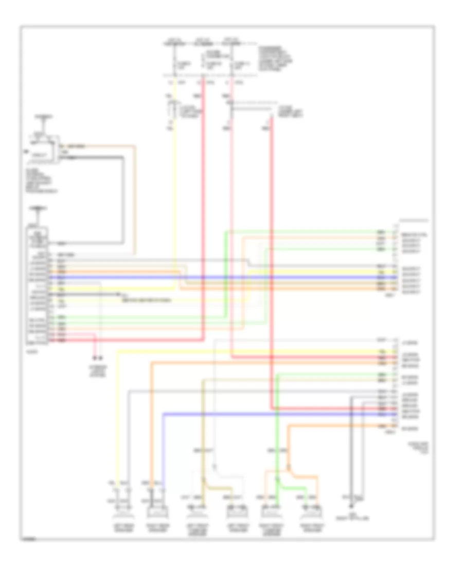
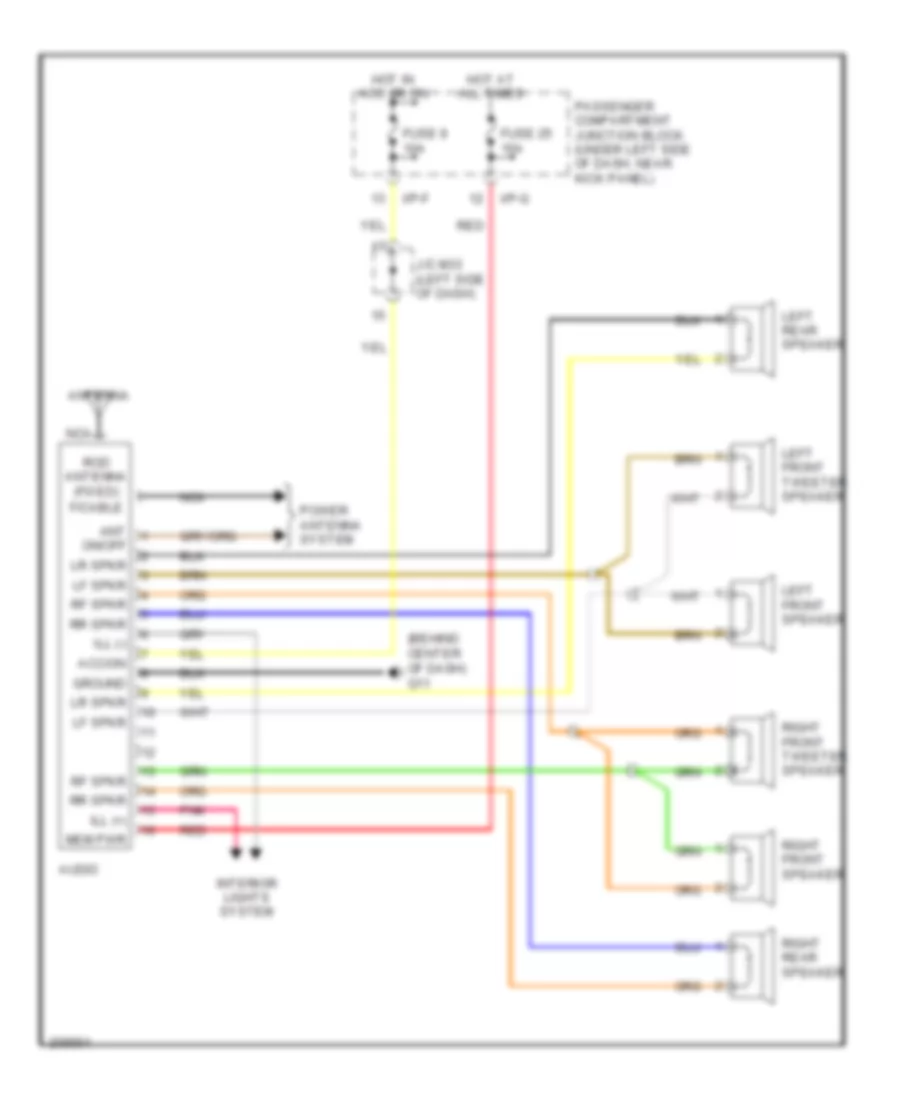
RADIO
Radio Wiring Diagram, 4 Door for Hyundai Elantra GT 2005
List of elements for Radio Wiring Diagram, 4 Door for Hyundai Elantra GT 2005:
- Acc/on
- Ant on/off
- Antenna
- Audio
- Audio amp module 1 & 2
- Circuit
- F/cable
- Fuse 14 20a
- Fuse 25 15a
- Fuse 9 10a
- G02 (right "b" pillar)
- G11 (behind center of dash)
- Glass antenna (if equipped) (above right end of package shelf)
- Ground
- Hot at all times
- Hot in acc or on
- I/p-d
- I/p-f
- I/p-g
- Ill (+)
- Ill (-)
- Interior lights system
- J/c m33 (left side of dash)
- J/c m49 (under left front seat)
- Left front speaker
- Left front tweeter speaker
- Left rear speaker
- Lf spkr
- Lr spkr
- M52-1
- M52-2
- M66
- Mem pwr
- Nca
- Passenger compartment junction block (under left side of dash, near kick panel)
- Pnk
- Power connector
- Red
- Remote ctrl
- Rf spkr
- Right front speaker
- Right front tweeter speaker
- Right rear speaker
- Rm ctrl
- Rod antenna (fixed)
- Rr spkr
- Sig input
Radio Wiring Diagram, 5 Door for Hyundai Elantra GT 2005
List of elements for Radio Wiring Diagram, 5 Door for Hyundai Elantra GT 2005:
- (behind center of dash) g11
- Acc/on
- Ant
- Antenna
- Audio
- F/cable
- Fuse 25 15a
- Fuse 9 10a
- Ground
- Hot at all times
- Hot in acc or on
- I/p-f
- I/p-g
- Ill (+)
- Ill (-)
- Interior lights system
- J/c m33 (left side of dash)
- Left front speaker
- Left front tweeter speaker
- Left rear speaker
- Lf spkr
- Lr spkr
- Mem pwr
- Nca
- On/off
- Passenger compartment junction block (under left side of dash, near kick panel)
- Pnk
- Power antenna system
- Red
- Rf spkr
- Right front speaker
- Right front tweeter speaker
- Right rear speaker
- Rod antenna (fixed)
- Rr spkr
STARTING/CHARGING
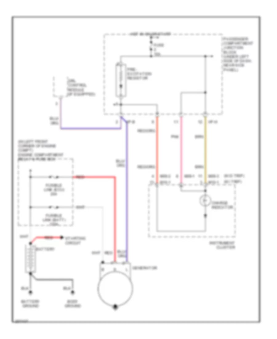
Charging Wiring Diagram for Hyundai Elantra GT 2005
List of elements for Charging Wiring Diagram for Hyundai Elantra GT 2005:
- (in left front corner of engine compt) engine compartment relay & fuse box
- (w/ trip)
- (w/o trip)
- Battery
- Battery ground
- Body ground
- Charge indicator
- Drl control module (if equipped)
- Fuse 10a
- Fusible link (batt) 120a
- Fusible link (ecu) 20a
- Generator
- Hot in on or start
- I/p-b
- I/p-h
- Instrument cluster
- M09-1
- M09-2
- M09-3
- M10-1
- Passenger compartment junction block (under left side of dash, near kick panel)
- Pnk
- Pre- excitation resistor
- Red
- Starting circuit
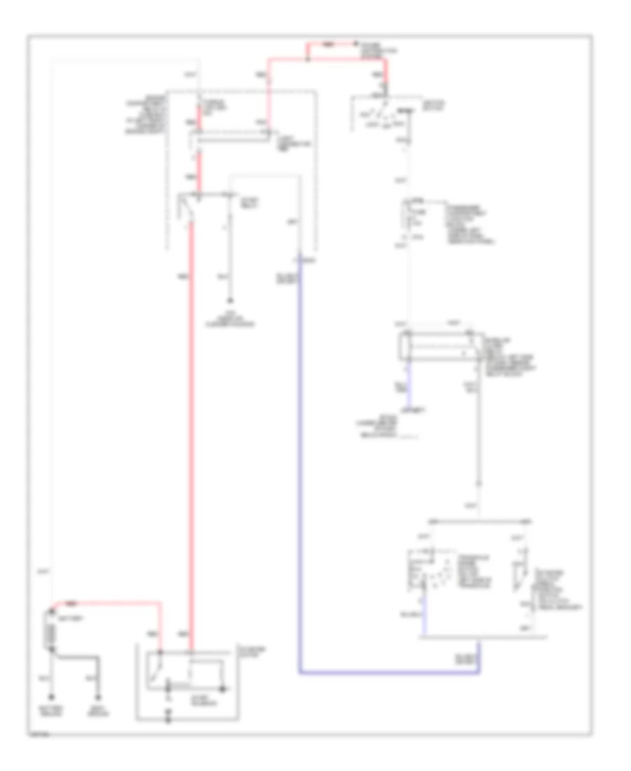
Starting Wiring Diagram for Hyundai Elantra GT 2005
List of elements for Starting Wiring Diagram for Hyundai Elantra GT 2005:
- A/t
- Acc
- Battery
- Battery ground
- Body ground
- Burglar alarm relay (below left side of dash, beside passenger compt relay block)
- Ec03
- Engine compartment relay & fuse box (in left front corner of engine compt)
- Etacm (under center of dash, below radio)
- Fuse 10a
- Fusible link (ign) 40a
- G15 (near air cleaner housing)
- I/p-e
- I/p-g
- Ignition switch
- Joint connector e55
- Lock
- M/t
- M25-3
- Nca
- Passenger compartment junction block (under left side of dash, near kick panel)
- Pnk
- Power distribution system
- Red
- Run off
- Start
- Start relay
- Start solenoid
- Starter clutch pedal position switch (on clutch pedal bracket)
- Starter motor
- Transaxle range switch (on top left side of transaxle)
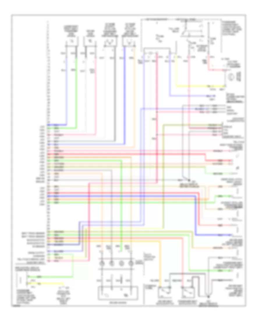
SUPPLEMENTAL RESTRAINTS
Supplemental Restraints Wiring Diagram, Advanced for Hyundai Elantra GT 2005
List of elements for Supplemental Restraints Wiring Diagram, Advanced for Hyundai Elantra GT 2005:
- (at base of left "b" pillar) driver seat belt pretensioner
- (at base of right "b" pillar) passenger seat belt pretensioner
- (below rear of center console)
- (near hood latch) front impact sensor
- (on right "b" pillar) passenger side impact sensor
- (right side of dash) passenger air bag
- (under right front seat) passenger side air bag
- Air bag ind (srs)
- Buckle switch
- Clock spring
- Crash output
- Data link connector (dlc) (below left side of dash)
- Diagnosis
- Driver air bag
- Driver seat buckle switch
- Driver seat track position sensor (under left front seat)
- Driver side air bag
- Driver side impact sensor (on left "b" pillar)
- Etacm (under center of dash, below radio)
- Exterior lights system
- Fuse 10a
- Fuse 15a
- G27
- G27 (below rear of center console)
- Gnd
- Ground
- High
- Hot at all times
- Hot in on or start
- I/p-b
- I/p-h
- I/p-j
- I/p-k
- Instrument cluster
- Low
- M07
- M09-1
- M10-2
- M25-1
- Module
- Multi- function switch
- Nca
- Oc sensor
- Occupant classification
- On/start
- On/start input
- Passenger compartment junction block (under left side of dash, near kick panel)
- Passenger seat buckle switch
- Passenger seat track position sensor (under right front seat)
- Pnk
- Red
- Seat track sensor
- Signal
- Srs control module (under rear console)
- Srs ind
- Steering wheel
- Tail
- Tail lamp relay
- Telltale
- Telltale warning lamp
- W/ trip
- W/o trip
Supplemental Restraints Wiring Diagram, Depowered for Hyundai Elantra GT 2005
List of elements for Supplemental Restraints Wiring Diagram, Depowered for Hyundai Elantra GT 2005:
- "b"pillar)
- (below rear of center console)
- (on left
- (on right
- (right side of dash) passenger air bag
- (under right front seat) passenger side air bag
- Air bag ind (srs)
- Clock spring
- Crash output
- Data link connector (dlc) (below left side of dash)
- Diagnosis
- Driver air bag
- Driver satellite sensor
- Driver seat belt pretensioner (at base of left "b" pillar)
- Driver seat buckle switch
- Driver side air bag
- Etacm (under center of dash, below radio)
- Fuse 10a
- Fuse 15a
- G27
- Ground
- High
- Hot in on or start
- I/p-h
- I/p-j
- I/p-k
- Instrument cluster
- Low
- M07
- M09-1
- M10-2
- M25-1
- Multi- function switch
- Nca
- On/start input
- Passenger compartment junction block (under left side of dash, near kick panel)
- Passenger presence detection sensor (under passenger seat)
- Passenger satellite sensor
- Passenger seat belt pretensioner (at base of right "b" pillar)
- Passenger seat buckle switch
- Pnk
- Red
- Srs control module (under rear console)
- Srs ind
- Steering wheel
- W/ trip
- W/o trip
TRANSMISSION
A/T Wiring Diagram for Hyundai Elantra GT 2005
List of elements for A/T Wiring Diagram for Hyundai Elantra GT 2005:
- (on top left side of transaxle) transaxle range switch
- (w/ cruise)
- (w/o cruise)
- (w/o trip comp) instrument cluster
- 2 input r input sensor gnd stop sw input pulse generator ``b" 3 input p input gear sig o/t pulse generator ``a" d input
- A/t control relay (left side of dash)
- A/t pulse generator ``a" (on top of transaxle)
- A/t pulse generator ``b" (on top of transaxle)
- A/t rly ctrl od solenoid valve ctrl
- A/t solenoid assembly (on top of transaxle)
- C183-4
- Cruise control module (on right fender, behind strut tower)
- Dcc solenoid valve ctrl battery volt ground lr solenoid valve ctrl 2nd solenoid valve ctrl ud solenoid valve ctrl
- Ec03
- Engine compartment relay & fuse box (in left front corner of engine compt)
- Fuse 10a
- Fuse 15a
- Fusible link (ecu) 20a
- G12 (behind center of dash)
- G168 (lower left side of dash)
- Hot at all times
- Hot in on or start
- I/p-h
- I/p-j
- Instrument cluster
- Interior lights system
- J/c c191 (lower right side of dash)
- J/c c192 (left side of dash)
- J/c e57
- J/c m27 (center of dash)
- J/c m36 (left side of dash)
- L input n input auto cruise
- M09-2
- M09-3
- M10-1
- Oil temp sensor
- Passenger compartment junction block (under left side of dash, near kick panel)
- Pcm (left side of dash)
- Pnk
- Red
- Starting/ charging system
- Stop lamp switch (on brake pedal bracket)
- W/ trip comp
WARNING SYSTEMS
Warning Systems Wiring Diagram for Hyundai Elantra GT 2005
List of elements for Warning Systems Wiring Diagram for Hyundai Elantra GT 2005:
- Chime bell (below left side of dash, right of steering column)
- Chime bell control
- Door ajar ind
- Door switch (all)
- Door warning switch input
- Etacm (under center of dash, below radio)
- Fuse 2 10a
- Fuse 25 15a
- G01 (left "b" pillar)
- G11 (behind center of dash)
- G12 (behind center of dash)
- Ground
- Head
- Hot at all times
- Hot in on or start
- I/p-g
- I/p-h
- Ignition key illumination & door warning switch
- Instrument cluster
- J/c m122
- J/c m27 (center of dash)
- J/c m33 (left side of dash)
- J/c m36 (left side of dash)
- Left front door lamp
- Left front door switch
- Light switch
- M01-2
- M09-1
- M09-2
- M10-1
- M10-2
- M25-1
- M25-2
- Micro computer
- Multifunction switch
- Multipurpose check connector (lower left side of dash)
- Nca
- Off
- On/start input
- Park
- Passenger compartment junction block (under left side of dash, near kick panel)
- Pnk
- Red
- Seat belt ind
- Seat belt switch
- Seat belt switch (in seat belt buckle)
- Taillight relay auto cut ctrl
- W/ trip
- W/o trip
WIPER/WASHER
Front Wiper/Washer Wiring Diagram, 4 Door for Hyundai Elantra GT 2005
List of elements for Front Wiper/Washer Wiring Diagram, 4 Door for Hyundai Elantra GT 2005:
- (behind center of dash) g12
- (near master cylinder reservoir) g170
- Delay control
- Ec03
- Engine compartment relay & fuse box (in left front corner of engine compt)
- Etacm (under center of dash, below radio)
- Front washer motor (below right front headlight, in washer reservoir)
- Front wiper motor (on left side of firewall)
- Fuse 22 20a
- G15 (near air cleaner housing)
- Hot in on
- I/p-b
- Int
- Int (time)
- Joint connector e61
- Joint connector m33 (left side of dash)
- M01-1
- M25-2
- Mist switch
- Multifunction switch
- Nca
- Off
- Parking switch (shown with wiper at rest)
- Passenger compartment junction block (under left side of dash, near kick panel)
- Pnk
- Red
- Washer input
- Washer switch
- Wiper motor relay
- Wiper switch
Front Wiper/Washer Wiring Diagram, 5 Door for Hyundai Elantra GT 2005
List of elements for Front Wiper/Washer Wiring Diagram, 5 Door for Hyundai Elantra GT 2005:
- (behind center of dash) g12
- (below right front headlight, in washer reservoir) front washer motor
- (near master cylinder reservoir) g170
- Delay control
- Ec03
- Engine compartment relay & fuse box (in left front corner of engine compt)
- Etacm (under center of dash, below radio)
- Front wiper motor (on left side of firewall)
- Fuse 22 20a
- G15 (near air cleaner housing)
- Hot in on
- I/p-b
- Int
- Int (time)
- Joint connector e61
- Joint connector m33 (left side of dash)
- M01-1
- M25-2
- Mist switch
- Multifunction switch
- Nca
- Off
- Parking switch (shown with wiper at rest)
- Passenger compartment junction block (under left side of dash, near kick panel)
- Pnk
- Rear wiper/washer circuit
- Red
- Washer input
- Washer switch
- Wiper motor relay
- Wiper switch
Rear Washer/Wiper Wiring Diagram for Hyundai Elantra GT 2005
List of elements for Rear Washer/Wiper Wiring Diagram for Hyundai Elantra GT 2005:
- (behind center of dash) g11
- (left side of luggage compt, behind trim) rear intermittent wiper relay
- (on tailgate, near rear wiper motor) g28
- Circuit breaker
- Engine compartment relay & fuse box (in left front corner of engine compt)
- Front wiper/ washer circuit
- Fuse 21 15a
- Fuse 22 20a
- G06 (at base of left "c" pillar)
- Hot in on
- I/p-b
- I/p-d
- Int
- Joint connector e61
- Joint connector m45 (lower left end of dash)
- M01-1
- Multifunction switch
- Nca
- Off
- Parking switch
- Passenger compartment junction block (under left side of dash, near kick panel)
- Rear washer motor (below right front headlight, in washer reservoir)
- Rear washer switch
- Rear wiper motor (behind trim panel, in tailgate)
- Rear wiper switch
- Relay control circuit
- Washer