AIR CONDITIONING
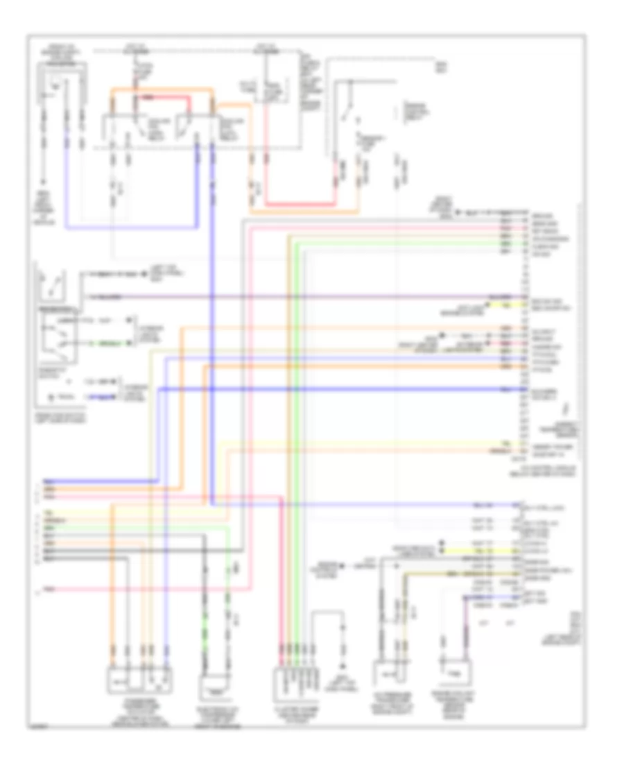
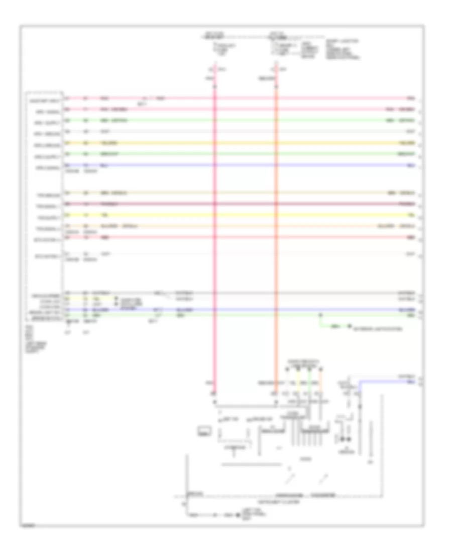
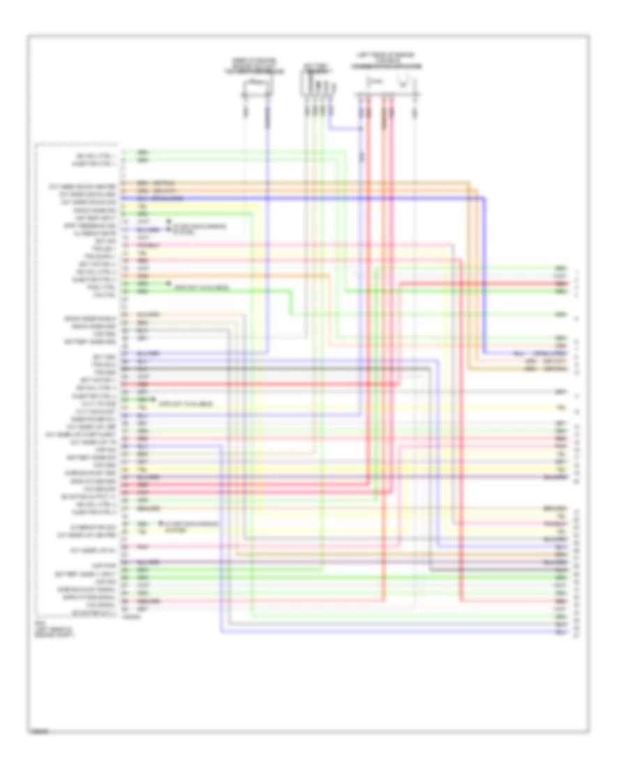
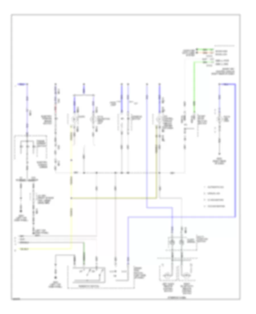
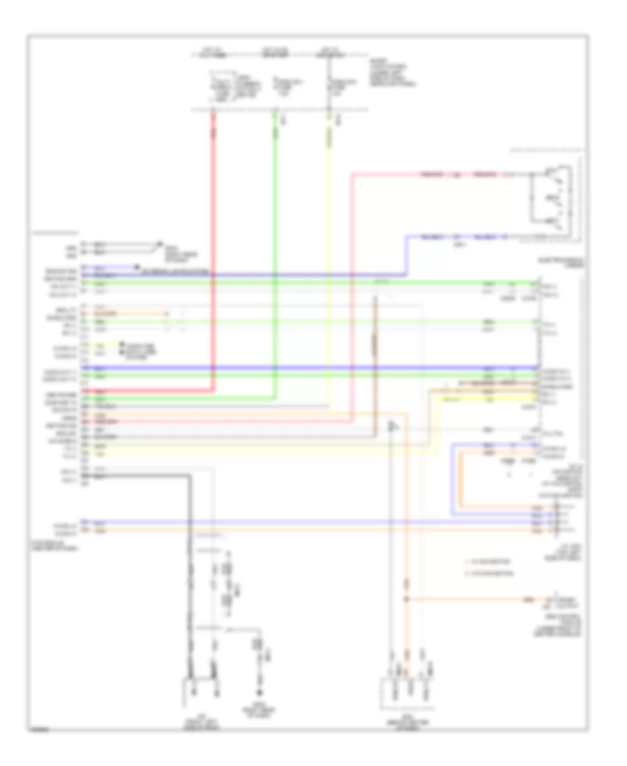
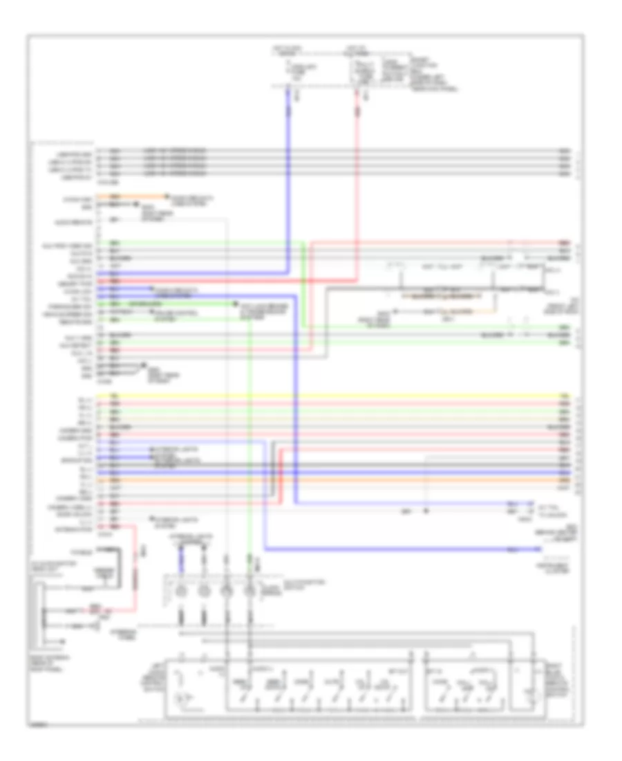
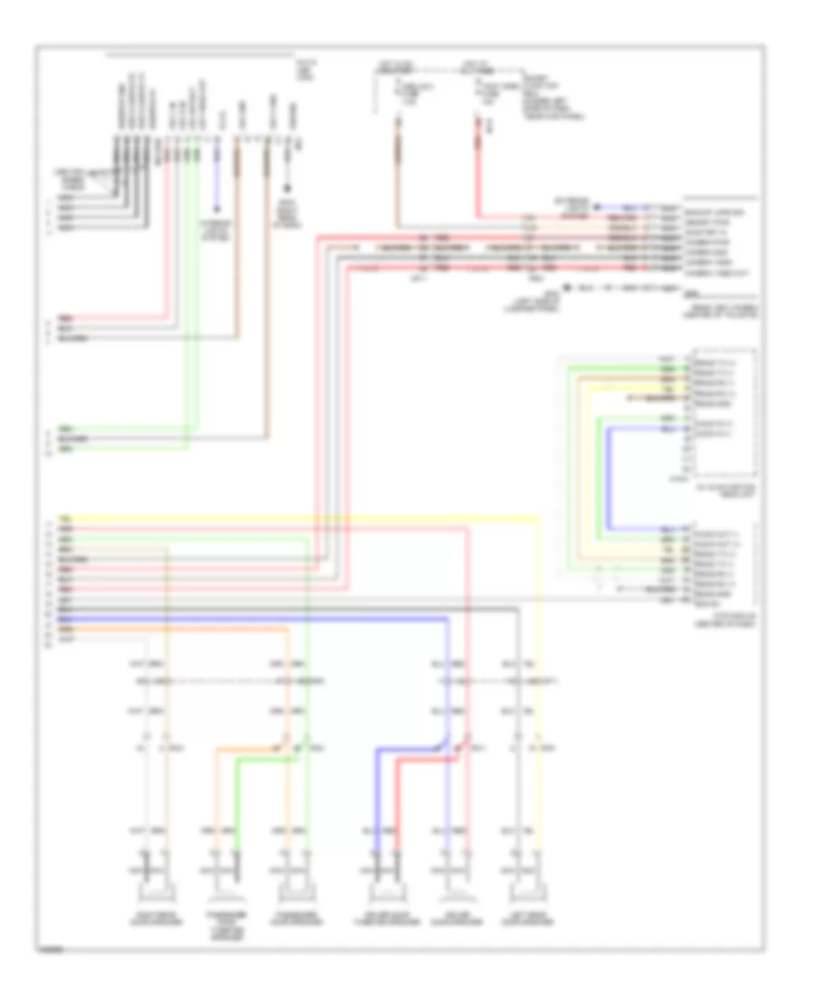
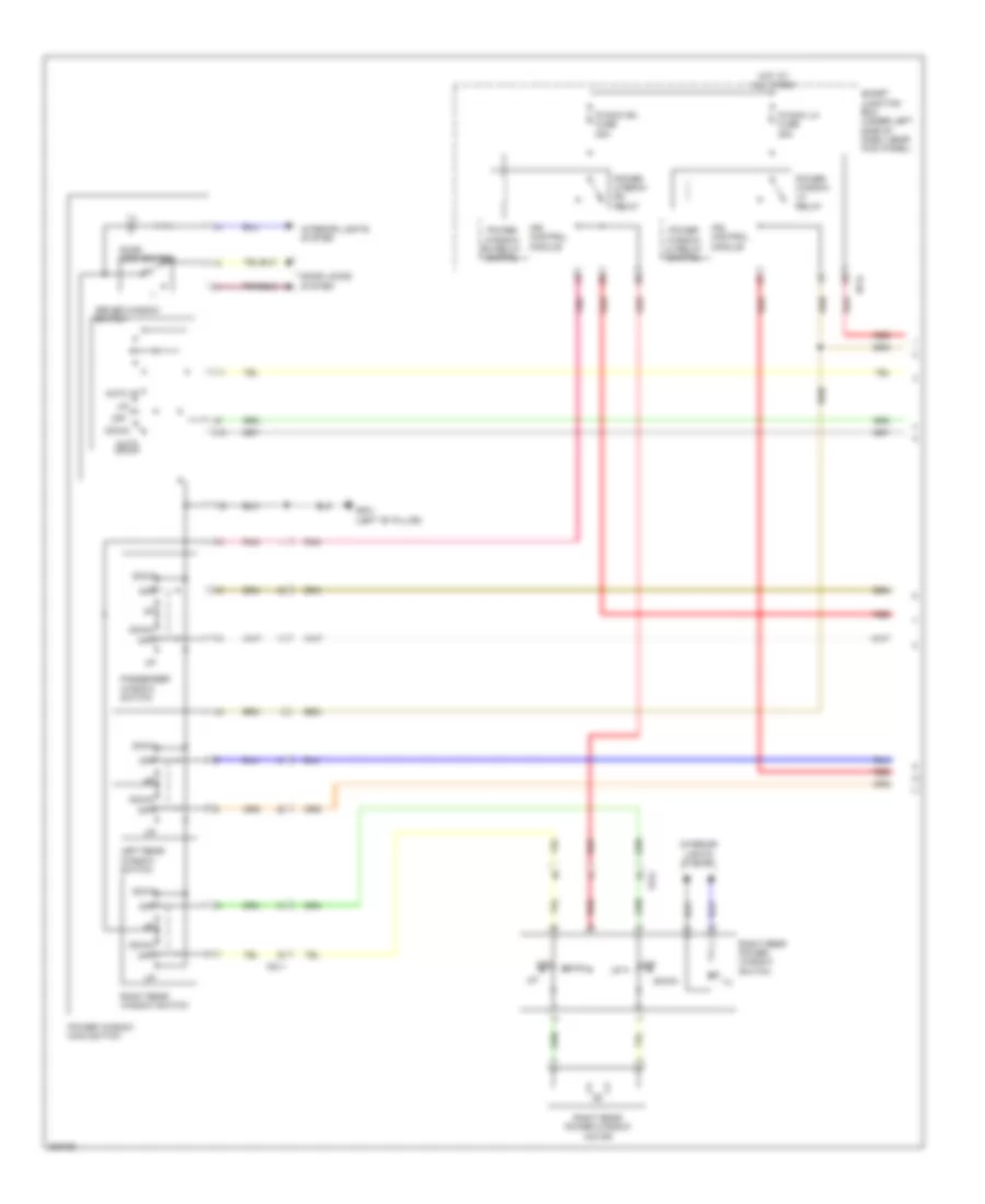
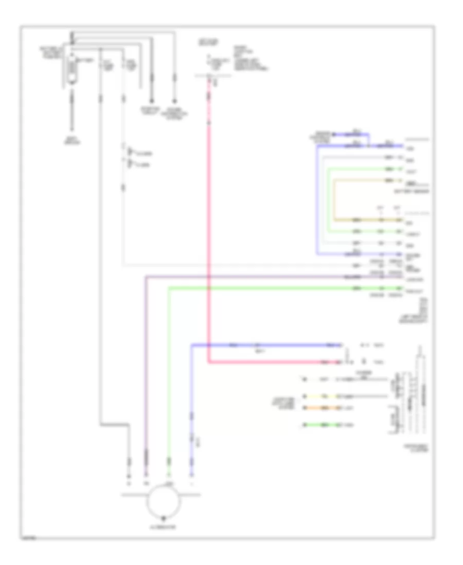
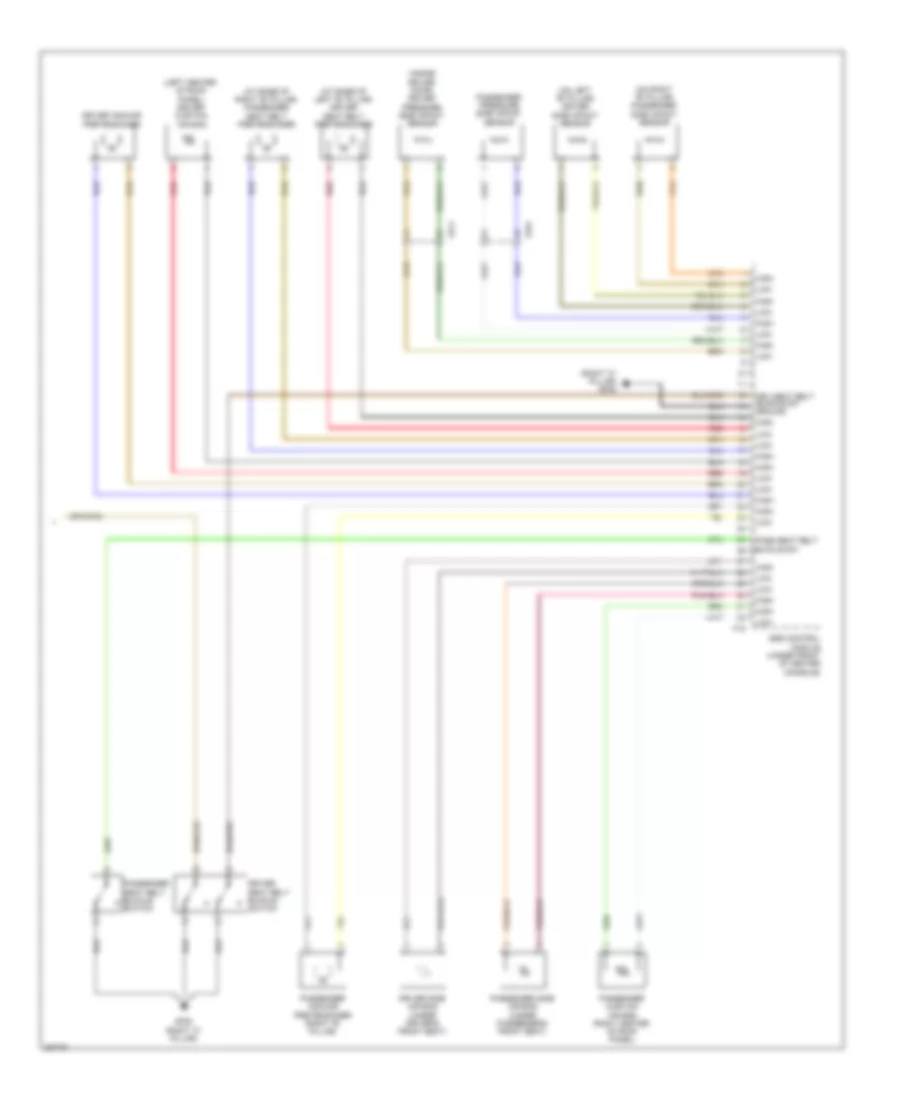
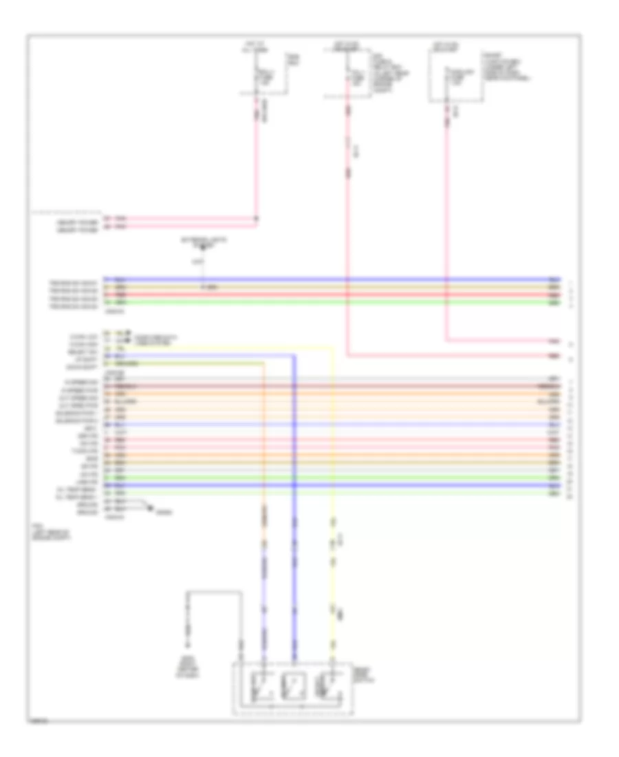
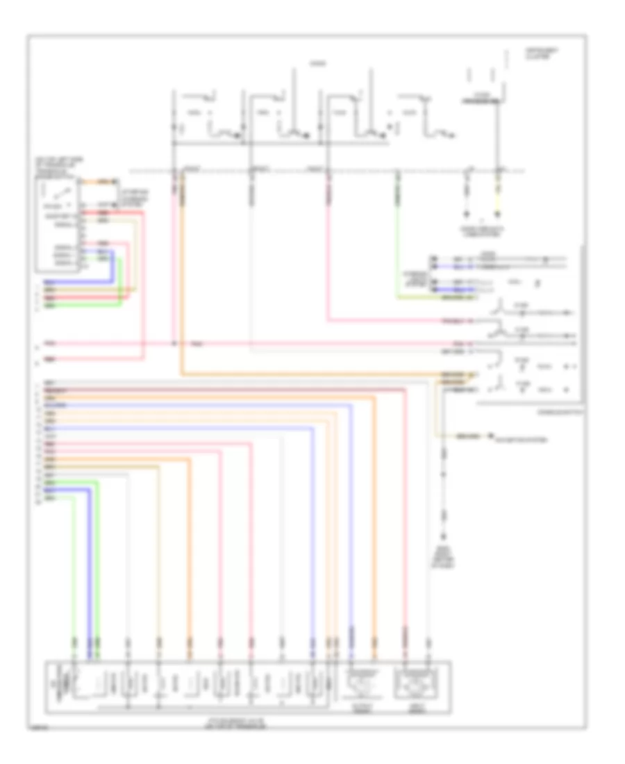
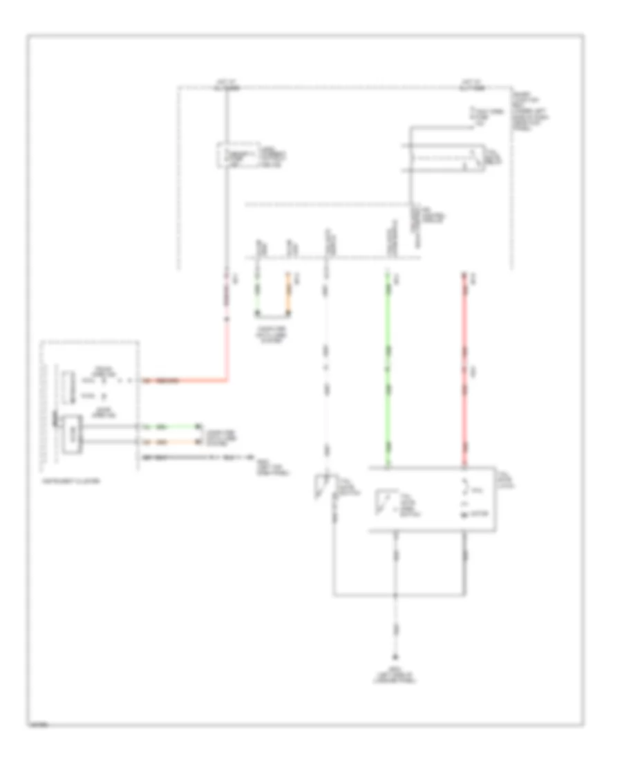
Automatic A/C Wiring Diagram (1 of 2) for Hyundai Elantra GT 2013

List of elements for Automatic A/C Wiring Diagram (1 of 2) for Hyundai Elantra GT 2013:
- A/bag fuse 15a
- A/c control module (below center of dash)
- A/con fuse 7.5a
- A/con sw fuse 7.5a
- Ambient temperature sensor (behind center of front bumper)
- Ambit temp sensor (+)
- Auto defog sensor (+)
- Auto defogger sensor (top front of windshield)
- Auto light & photo sensor (top center of dash)
- Blower fuse 40a red
- Blower motor (under right side of dash)
- Blower relay
- C-can hi
- C-can lo
- Close
- Computer data lines system
- Computer data lines system defogger system
- Defog actr close
- Defog actr f/b
- Defog actr open
- Defogger actuator (center rear of dash)
- Detent out (+)
- Driver temp actr cool
- Driver temp actr f/b
- Driver temp actr warm
- Driver temperature actuator (center of dash)
- E/r fuse & relay box (in left rear corner of engine compt)
- Ecv gnd
- Ecv power
- Ee11
- Em61
- Evap sensor (+)
- Evaporator sensor (center of dash, near blower motor)
- F/b
- Fet (field effect transistor) (center of dash, near blower motor)
- Fet gate
- Ge01 (left front corner of vehicle)
- Ge09 (center of dash)
- Gm04 (right center of dash)
- Ground
- Gsl ptc fuse 60a red
- Hot at all times
- Hot in on
- Hot in on or start
- Htd ind
- I/p-e
- I/p-f
- I/p-h
- Ill (+)
- Ill (-)
- In actr f/b
- In actr fre
- In actr rec
- Intake actuator (center rear of dash)
- Interior lights system
- K-line
- Leak current autocut device
- M21-a
- Memory 2 fuse 10a
- Mode actr def
- Mode actr f/b
- Mode actr vent
- Mode actuator (center of dash)
- Module 4 fuse 7.5a
- Module 5 fuse 7.5a
- Mr11
- Multi fuse
- Multi- fuse
- Open
- Pab on/start in
- Pab sig off
- Photo sensor
- Photo sensor (-) lh
- Photo sensor (-) rh
- Pnk
- Ptc heater (center of dash)
- Ptc relay
- Ptc rly ctrl
- Rear defogger sw
- Red
- Ref (5v)
- Seat warm ind lh-hi
- Seat warm ind lh-lo
- Seat warm ind rh-hi
- Seat warm ind rh-lo
- Seat warm sw sig lh
- Seat warm sw sig rh
- Seats system
- Sensor ref (+5v)
- Smart junction box (under left side of dash, near kick panel)
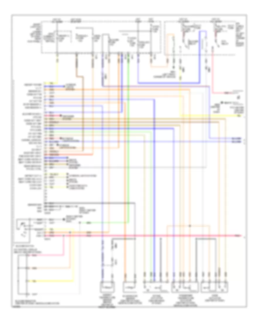
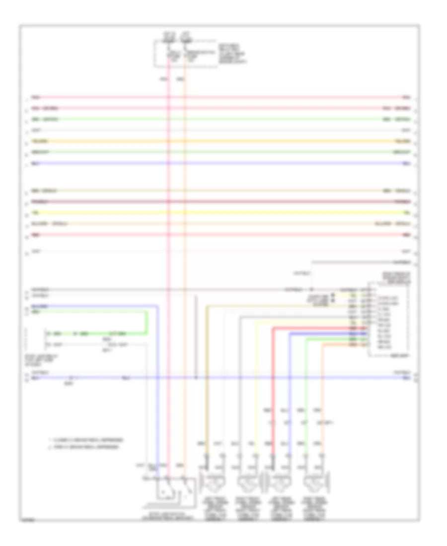
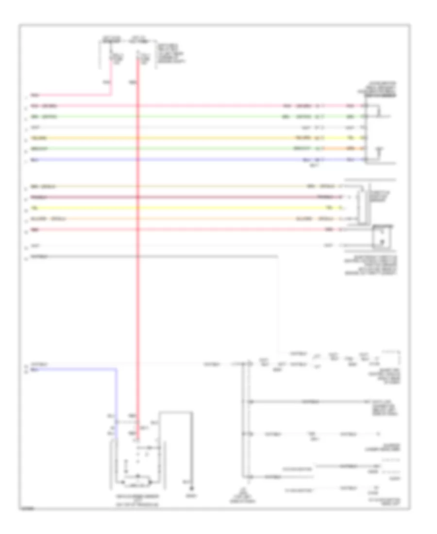
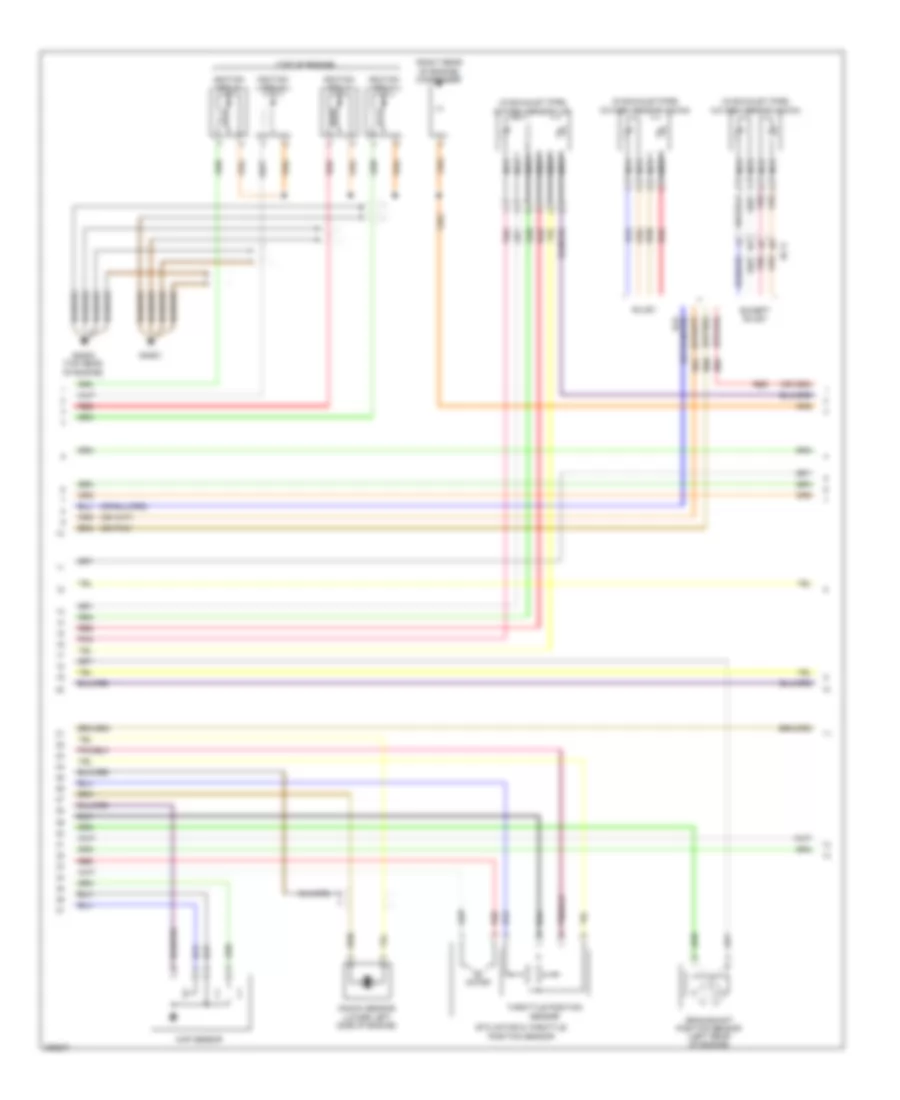
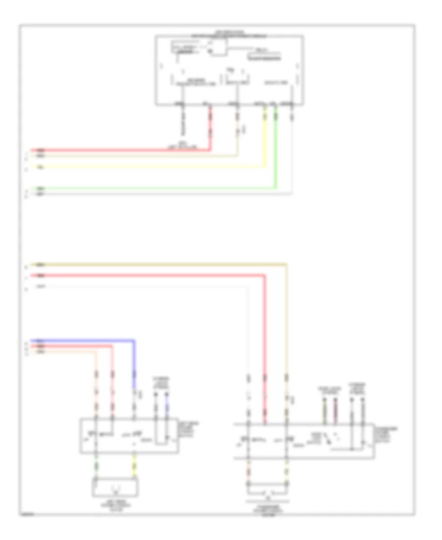
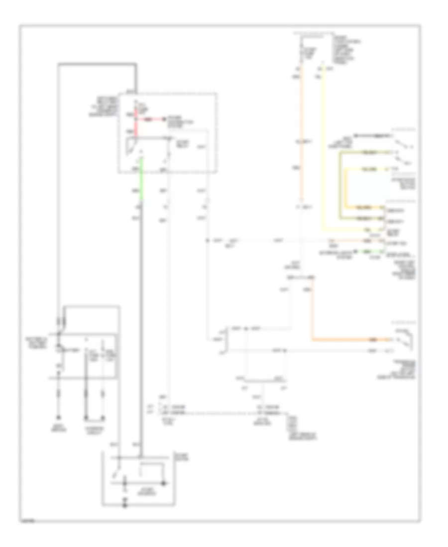
Automatic A/C Wiring Diagram (2 of 2) for Hyundai Elantra GT 2013
List of elements for Automatic A/C Wiring Diagram (2 of 2) for Hyundai Elantra GT 2013:
- (front of engine compt) cooling fan motor
- (left top dash panel) gm01
- (right center of dash) gm02
- A/c control module (below center of dash)
- A/c pressure transducer (right front of engine compt)
- A/t
- Ambient temperature sensor
- Anti-lock brakes system
- Blowers motor (+)
- C-can hi
- C-can lo
- C/fan fuse 40a
- Clean sig
- Cluster ionizer (center rear of dash)
- Cng-aa
- Cng-ab
- Cng-ma
- Cng-mk
- Computer data lines system
- Cooling fan (high) relay
- Cooling fan (low) relay
- Crash pad switch (left side of dash)
- Diag
- Down
- E/r fuse & relay box (in left rear corner of engine compt)
- E/r-cnga
- E/r-cngb
- E/r-ems
- Ec11
- Eco sw sig
- Eco switch
- Ect gnd
- Ect sig
- Electronic a/c compressor (lower left front of engine)
- Em11
- Ems box
- Ems fuse 60a
- Eng ctrl rly ctrl
- Engine control relay
- Engine controls system
- Engine coolant temperature sensor (rear of engine)
- Esc on/off sw
- Exterior lights system
- Fet drain
- Ge02 (left front corner of vehicle)
- Gm01 (left top dash panel)
- Gm02 (right center of dash)
- Ground
- Hazard sw
- Hot at all times
- Ill
- Interior lights system
- Ion diagnosis
- Ion sig
- M/t
- M21-b
- Memory power
- Multi fuse
- Nca
- On input
- On/start in
- Passenger temperature actuator (center of dash, near blower motor)
- Pcm (a/t) ecm (m/t) (left rear of engine compt)
- Pnk
- Pta cool
- Pta f/b
- Pta warm
- Red
- Rheostat switch
- Rly ctrl (hi)
- Rly ctrl (low)
- Sens gnd
- Sensor 1 fuse 10a
- Snsr gnd
- Snsr power (+5v)
- Snsr sig
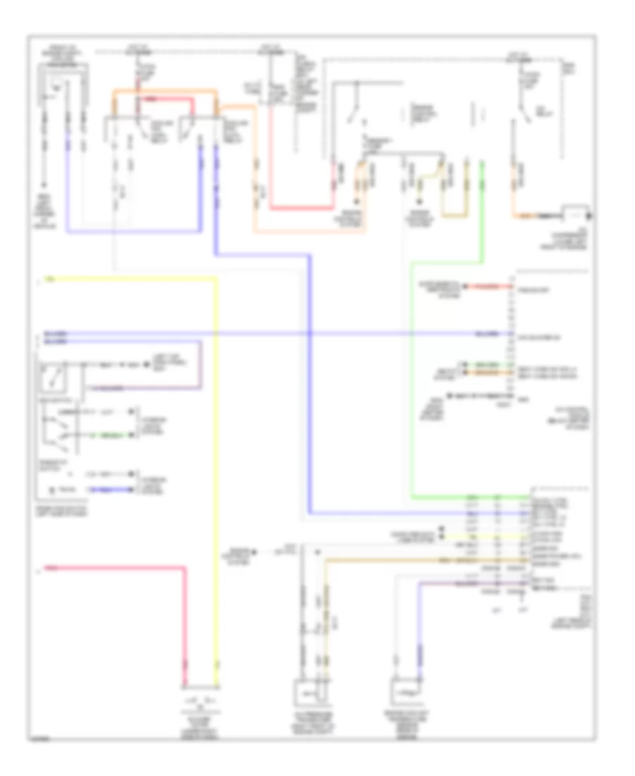
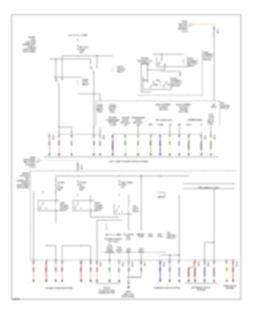
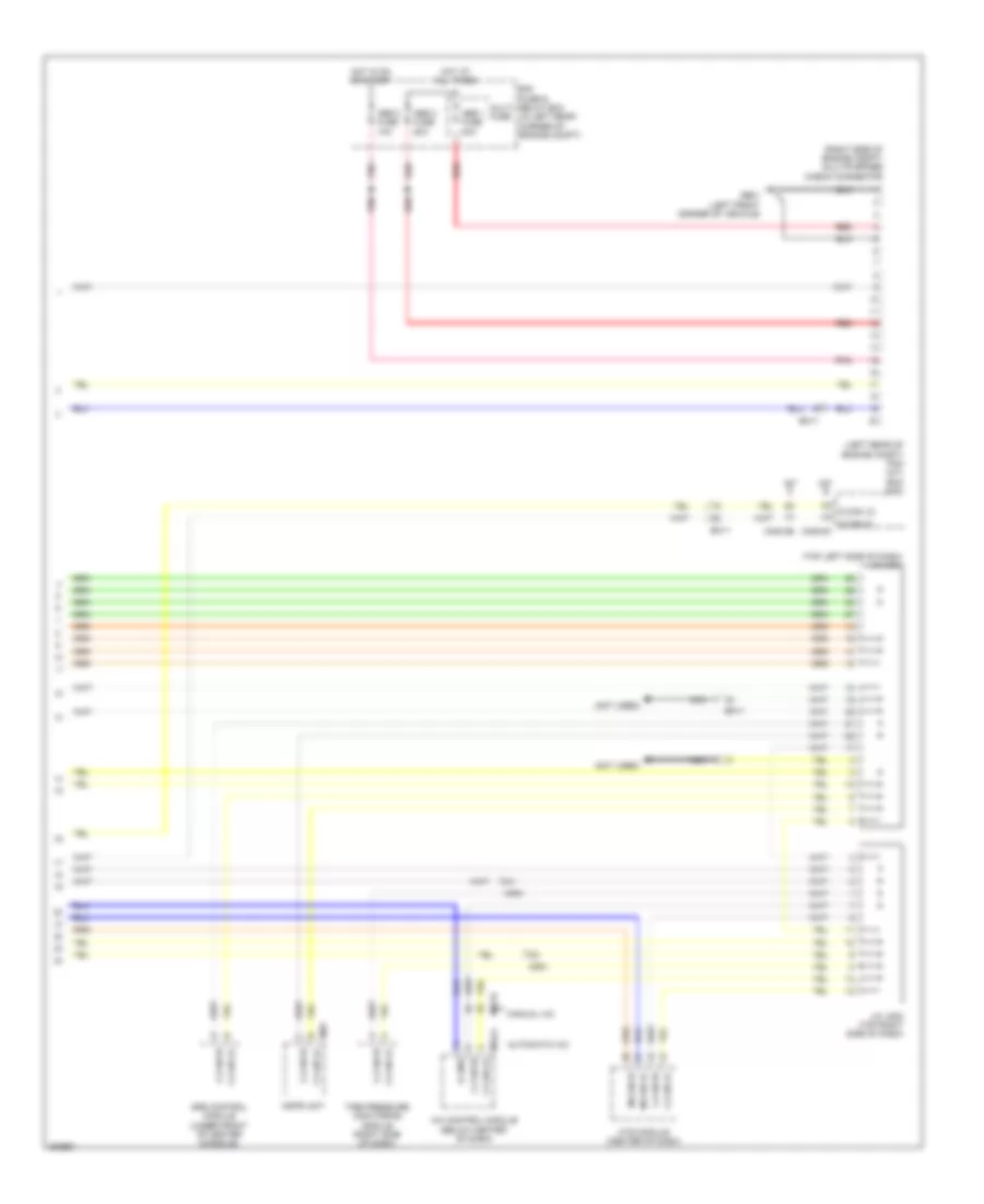
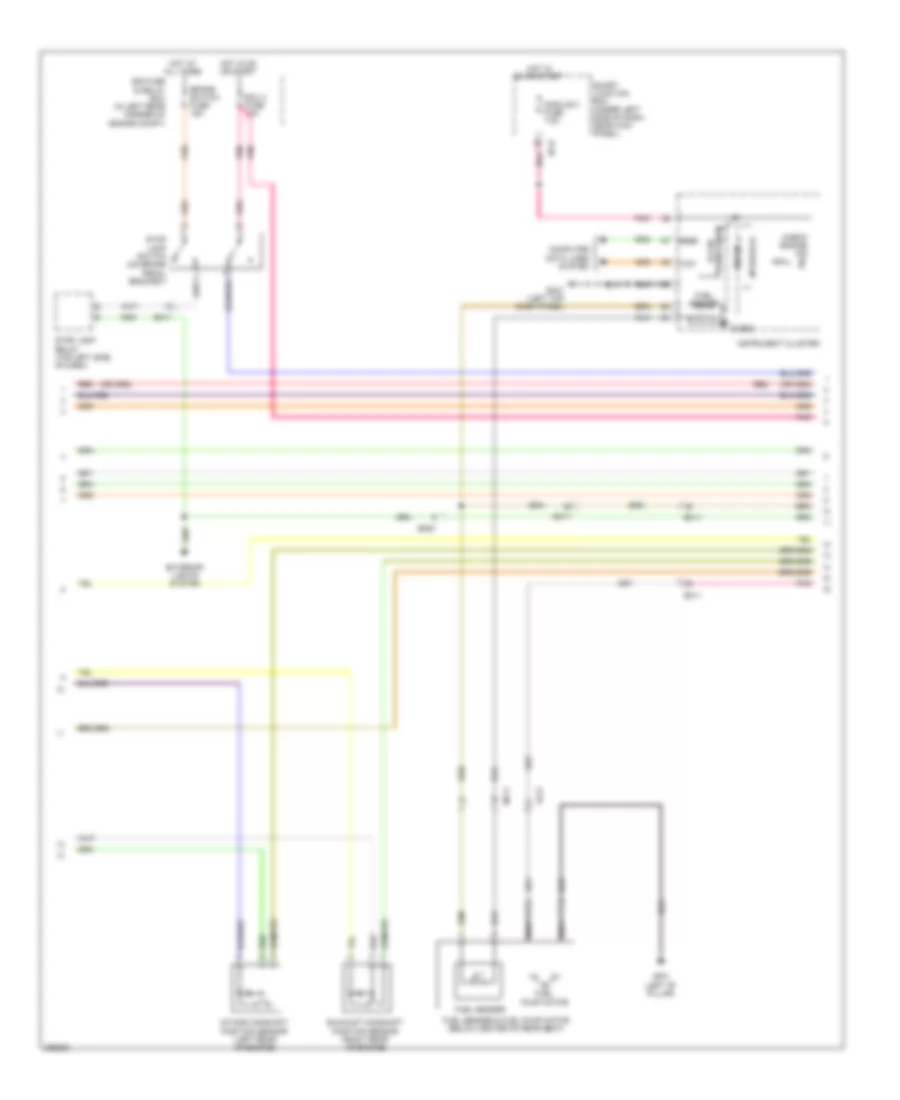
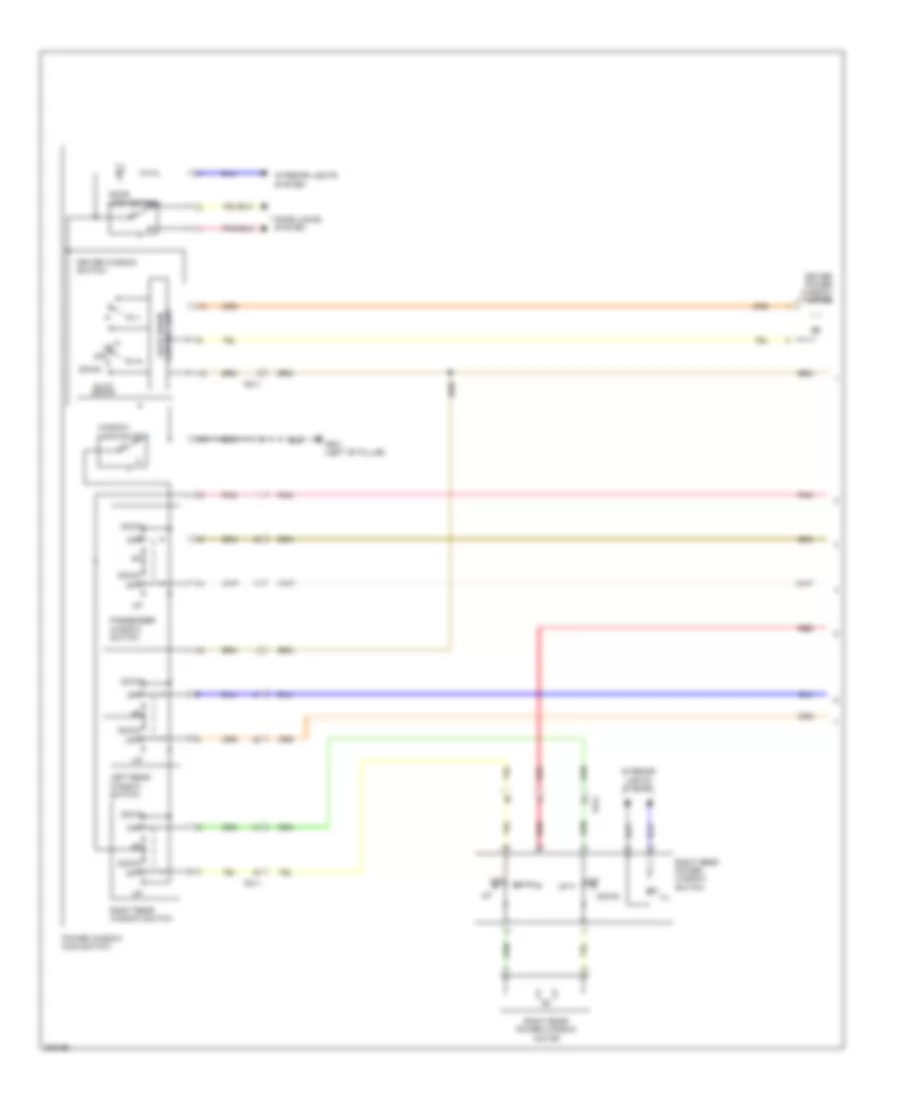
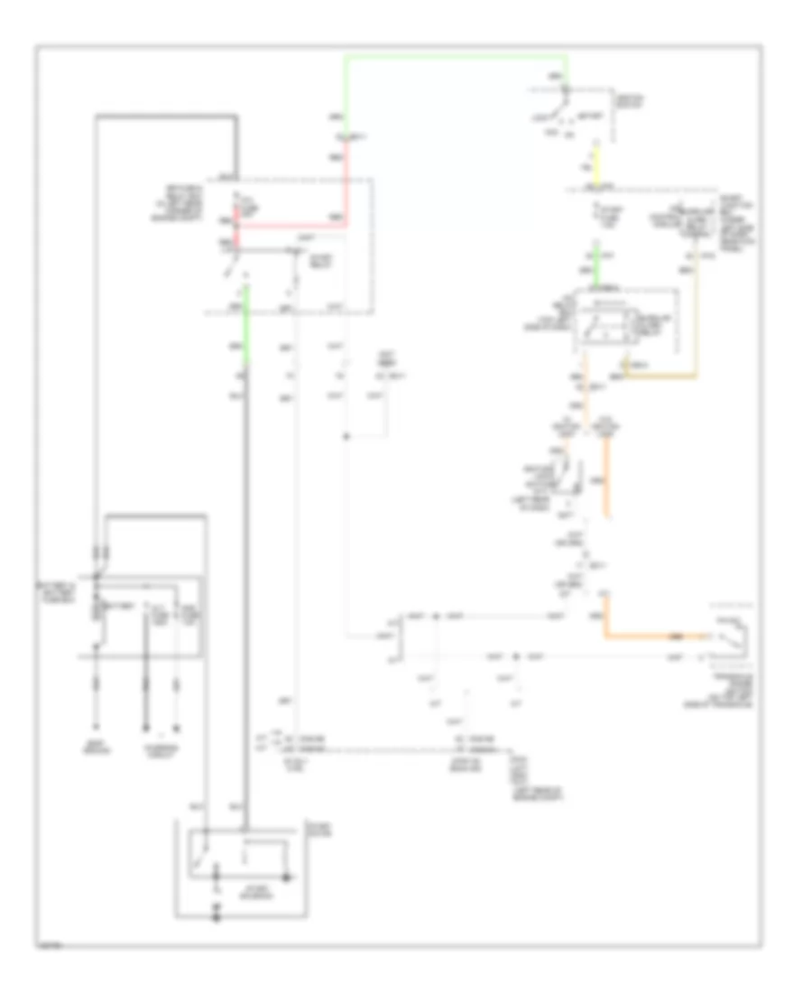
Manual A/C Wiring Diagram (1 of 2) for Hyundai Elantra GT 2013
List of elements for Manual A/C Wiring Diagram (1 of 2) for Hyundai Elantra GT 2013:
- (right center of dash) gm04
- A/bag fuse 15a
- A/c control module (below center of dash)
- A/con fuse 7.5a
- A/con sw fuse 7.5a
- Amb sensor (+)
- Ambient temperature sensor (behind center of front bumper)
- Blower fuse 10a
- Blower fuse 40a red
- Blower on sig (-)
- Blower relay
- Blower resistor (center of dash, near blower motor)
- Blower switch
- C-can high
- C-can low
- Computer data lines system
- Defogger system
- Detent out (+)
- E/r fuse & relay box (in left rear corner of engine compt)
- Eco sw sig
- Ee11
- Em11
- Em61
- Evap sensor (+)
- Evaporator sensor (center of dash, near blower motor)
- Exterior lights system
- Ge01 (left front corner of vehicle)
- Ge09 (center of dash)
- Gm02 (right center of dash)
- Gnd
- Gsl ptc fuse 60a red
- Hazard lamps sw
- High
- Hot at all times
- Hot in on
- Hot in on or start
- Htd ind
- I/p-e
- I/p-f
- I/p-h
- Iii
- Iiii
- Ill (+)
- Ill (-)
- Int act f/b
- Int act fre
- Int act rec
- Intake actuator (center rear of dash)
- Interior lights system
- Leak current autocut device
- Low
- M/hi
- M/low
- M22-a
- M22-b
- Memory 2 fuse 10a
- Memory power
- Mode act def
- Mode act f/b
- Mode act vent
- Mode actuator (center of dash)
- Module 4 fuse 7.5a
- Module 5 fuse 7.5a
- Multi fuse
- Off
- On input
- On/start input
- Pab on/start input
- Passenger temperature actuator (center of dash, near blower motor)
- Pnk
- Pta cool
- Pta f/b
- Pta warm
- Ptc heater (center of dash)
- Ptc relay
- Ptc rly ctrl
- Rear defog sw
- Red
- Seat warm ind lh-hi
- Seat warm ind lh-lo
- Seat warm ind rh-hi
- Seat warm ind rh-lo
- Seats system
- Sensor (5v)
- Sensor gnd
- Smart junction box (under left side of dash, near kick panel)
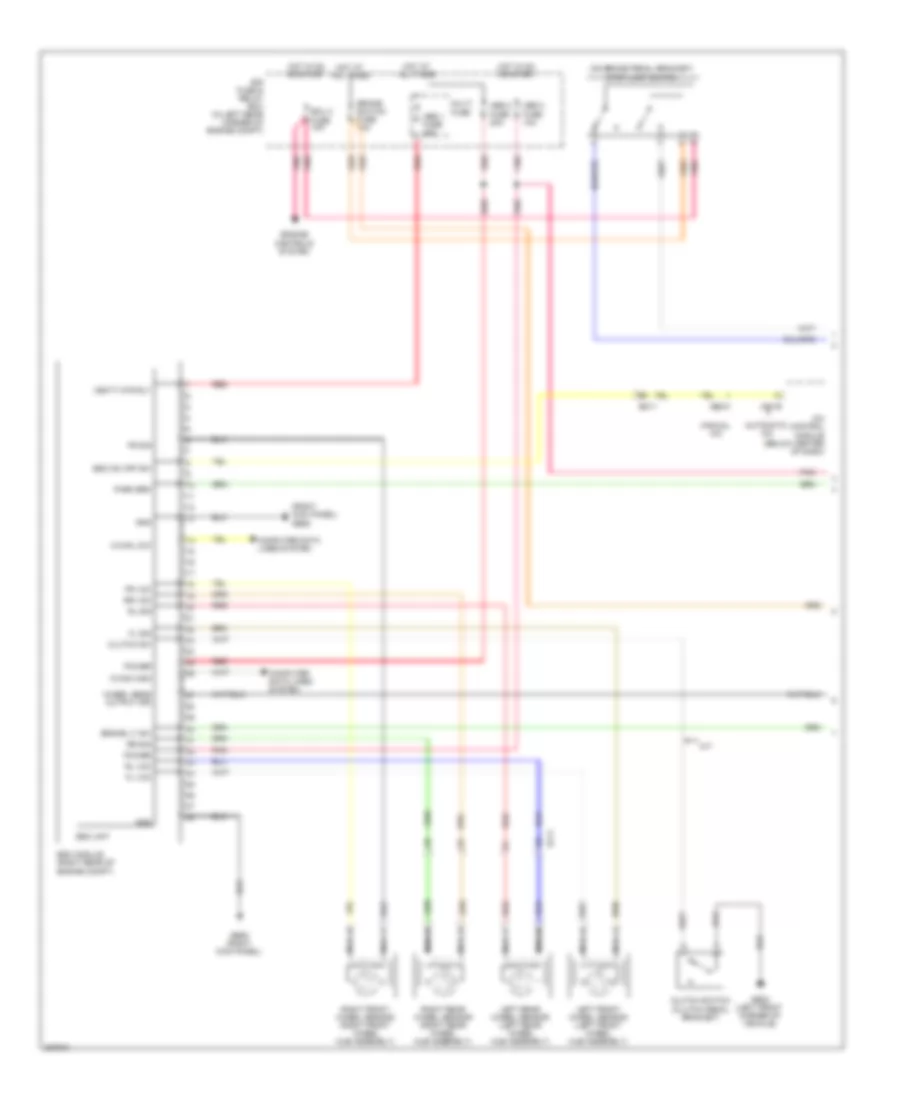
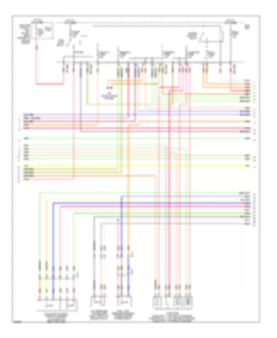
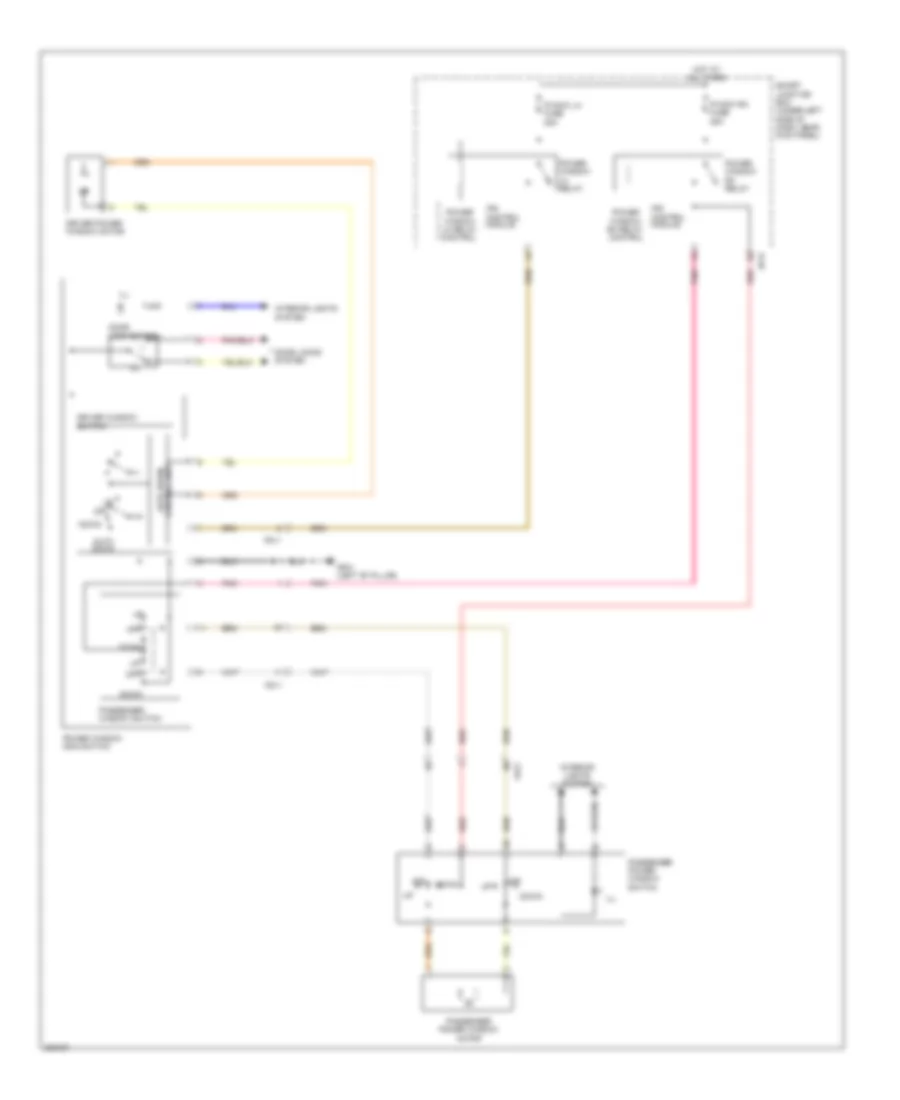
Manual A/C Wiring Diagram (2 of 2) for Hyundai Elantra GT 2013
List of elements for Manual A/C Wiring Diagram (2 of 2) for Hyundai Elantra GT 2013:
- (front of engine compt) cooling fan motor
- (left top dash panel) gm01
- A/c compressor (lower left front of engine)
- A/c control module (below center of dash)
- A/c pressure transducer (right front of engine compt)
- A/c relay
- A/c rly ctrl engine ctrl/ rly ctrl rly ctrl lo
- A/con fuse 30a
- A/t
- Blower motor (under right side of dash)
- C-can high
- C-can low
- C/fan fuse 40a
- Cng-aa
- Cng-ab
- Cng-ma
- Cng-mk
- Computer data lines system
- Cooling fan (high) relay
- Cooling fan (low) relay
- Crash pad switch (left side of dash)
- Down
- E/r fuse & relay box (in left rear corner of engine compt)
- E/r-cnga
- E/r-cngb
- E/r-ems
- Ec11
- Eco switch
- Ect gnd
- Ect sig
- Ems box
- Ems fuse 60a
- Engine control relay
- Engine controls system
- Engine coolant temperature sensor (rear of engine)
- Ge02 (left front corner of vehicle)
- Gm02 (right center of dash)
- Gnd
- Hot at all times
- Ill
- Interior lights system
- M/t
- M22-c
- Max blower on
- Multi fuse
- Nca
- Pab sig off
- Pcm (a/t) ecm (m/t) (left rear of engine compt)
- Pnk
- Red
- Rheostat switch
- Rly ctrl hi
- Seat warm sw sig lh
- Seat warm sw sig rh
- Seats system
- Sensor 1 fuse 10a
- Snsr gnd
- Snsr power (+5v)
- Snsr sig
ANTI-LOCK BRAKES
Anti-lock Brakes Wiring Diagram (1 of 2) for Hyundai Elantra GT 2013
List of elements for Anti-lock Brakes Wiring Diagram (1 of 2) for Hyundai Elantra GT 2013:
- (on brake pedal bracket) stop lamp switch
- (right kick panel) ge06
- A/c control module (below center of dash)
- Abs 1 fuse 40a
- Abs 2 fuse 20a
- Abs 3 fuse 10a
- Automatic a/c
- Brake lt sw
- Brake switch fuse 10a
- C-can high
- C-can low
- Clutch sw
- Clutch switch (clutch pedal bracket)
- Computer data lines system
- E/r fuse & relay box (in left rear corner of engine compt)
- Ecu 3 fuse 10a
- Ef11
- Em11
- Engine controls system
- Esc module (right rear of engine compt)
- Esc on/ off sw
- Esc unit
- Fl sig
- Fl vcc
- Fr sig
- Fr vcc
- Ge02 (left front corner of vehicle)
- Ge06 (right kick panel)
- Gnd
- Hot at all times
- Hot in on or start
- Left front wheel sensor (left front wheel hub assembly)
- Left rear wheel sensor (left rear wheel hub assembly)
- M/t
- M21-b
- M22-c
- Manual a/c
- Multi fuse
- Nca
- Park brk
- Pnk
- Power
- Red
- Right front wheel sensor (right front wheel hub assembly)
- Right rear wheel sensor (right rear wheel hub assembly)
- Rl sig
- Rl vcc
- Rr sig
- Rr vcc
- Vbatt mtr rly
- Wheel sens output (fr)
Anti-lock Brakes Wiring Diagram (2 of 2) for Hyundai Elantra GT 2013
List of elements for Anti-lock Brakes Wiring Diagram (2 of 2) for Hyundai Elantra GT 2013:
- (top left side of dash) stop lamp relay
- A/t
- Abs ind
- Av & navigation
- B-can high
- B-can low
- B-can transceiver
- Bcm (behind center of dash)
- Brake fluid level sensor (in brake fluid reservoir)
- Brake ind
- Brk flu
- C-can high
- C-can low
- C-can transceiver
- Can high
- Can low
- Cng-ab
- Cng-mk
- Computer data lines system
- Cruise control system
- Ec11
- Ec61
- Ecm/pcm (left rear of engine compt)
- Ef11
- Em11
- Em61
- Esc ind
- Esc off ind
- Exterior lights system
- Ge01 (left front corner of vehicle)
- Gf02 (right "b" pillar)
- Gm01 (left top dash panel)
- Ground
- High
- Hot at all times
- Hot in on or start
- I/p-c
- I/p-e
- I/p-f
- I/p-g
- I/p-h
- Instrument cluster
- Inter face
- Ips control module
- J/c jm04 (top left side of dash)
- Le sen
- Low
- M/t
- M13-b
- M15-b
- Micom
- Module 3 fuse 7.5a
- Parking brake switch
- Parking brk sw
- Pnk
- Power
- S-ground
- Smart junction box (under left side of dash, near kick panel)
- Smart key control module (right rear of dash)
- Stop lp fuse 15a
- Yaw rate sensor (front passenger's floor area under seat)
ANTI-THEFT
Forced Entry Wiring Diagram (1 of 2) for Hyundai Elantra GT 2013
List of elements for Forced Entry Wiring Diagram (1 of 2) for Hyundai Elantra GT 2013:
- B-can
- Burglar alarm relay control
- Computer data lines system
- Door lock relay
- Door lock relay control
- Door unlock relay
- Door unlock relay control
- Dr lk
- Dr lock fuse 20a
- Dr unlk
- Driver door key unlock signal
- Driver door lock actuator
- Driver door lock/ unlock signal
- Fd11
- Fd31
- Fd41
- Fuel filler actuator (left side of luggage panel)
- Gf01 (left "b" pillar)
- Gf02 (right "b" pillar)
- Gm01 (left top dash panel)
- High
- Hot at all times
- I/p-b
- I/p-c
- I/p-g
- I/p-h
- Ips control module
- Key lk
- Key unlk
- Left rear door lock actuator
- Left rear door lock/ unlock signal
- Low
- Pnk
- Red
- Right rear door lock actuator
- Right rear door lock/ unlock signal
- Smart junction box (under left side of dash, near kick panel)
- Starting/ charging system
Forced Entry Wiring Diagram (2 of 2) for Hyundai Elantra GT 2013
List of elements for Forced Entry Wiring Diagram (2 of 2) for Hyundai Elantra GT 2013:
- (right front of engine compt) burglar alarm horn
- (top left side of dash)
- Auto light & photo sensor (top center of dash)
- B/alarm horn relay
- B/alarm horn relay control
- Bcm (behind center of dash)
- Can h
- Can l
- Computer data lines system
- Door lock
- Door lock switch
- Door unlock
- Dr lk
- Dr unlk
- Driver/ passenger door key lock signal
- E/r fuse & relay box (in left rear corner of engine compt)
- Em11
- Em61
- Fd11
- Fd21
- Ge04 (right front corner of vehicle)
- Gf01 (left "b" pillar)
- Gf02 (right "b" pillar)
- Gm02 (right center of dash)
- Hood switch
- Hood switch (right front of engine compt)
- Horn fuse 15a red
- Horns system
- Hot at all times
- I/p-c
- I/p-e
- I/p-g
- I/p-h
- Icm relay box
- Icm relay box (top left side of dash)
- Ips control module
- J/c jd02 (in front passenger's door)
- Key lk
- Key unlk
- Leak current auto cut device
- Lock
- M02-b
- M02-c
- M06-a
- Memory 2 fuse 10a
- Mf11
- Nca
- Passenger door key unlock signal
- Passenger door lock actuator
- Passenger door lock/ unlock signal
- Passenger power window switch
- Pnk
- Power window main switch
- Red
- Sec ind
- Smart junction box (under left side of dash, near kick panel)
- Two turn un lock relay
- Two turn unlock relay control
- Unlock
- W/ safety power windows
- W/o safety power windows
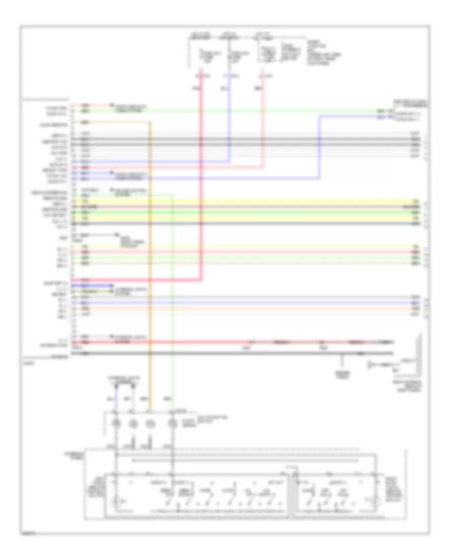
Immobilizer Wiring Diagram, with Smart Key System (1 of 3) for Hyundai Elantra GT 2013
List of elements for Immobilizer Wiring Diagram, with Smart Key System (1 of 3) for Hyundai Elantra GT 2013:
- (left front corner of vehicle)
- A/t
- Acc/in input
- B-can high
- B-can low
- Bat
- Bcm fuse 7.5a
- Cng-aa
- Cng-ab
- Cng-mk
- Com
- Computer data lines system
- E/r fuse & relay box (in left rear corner of engine compt)
- Ec11
- Ecm (m/t) pcm (a/t) (left rear of engine compt)
- Electronic steering column lock (top of steering column)
- Em11
- Em61
- Ems com
- Enable
- Ge01
- Ge02
- Ge02 (left front corner of vehicle)
- Gm01 (left top dash panel)
- Gnd
- Ground
- Hot at all times
- I/p-f
- I/p-h
- Ig 1 fuse 40a
- Ig 2 fuse 40a
- M/t
- M13-a
- Memory power
- Module 7 fuse 7.5a
- On input
- On/start input
- Passenger toggle button
- Pdm 1 fuse 25a
- Pdm 2 (acc) relay
- Pdm 2 fuse 7.5a
- Pdm 3 (ig1) relay
- Pdm 3 fuse 7.5a
- Pdm 4 (ig2) relay
- Pnk
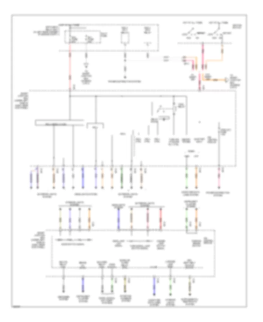
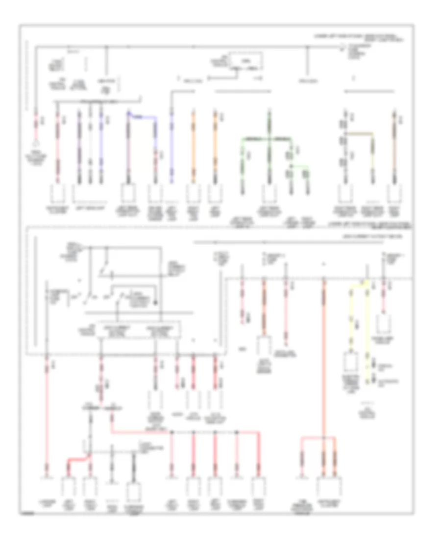
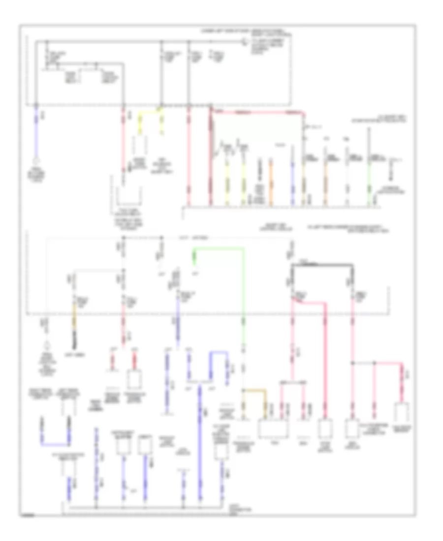
- Power distribution system
- Red
- Rpm
- Smart junction box (under left side of dash, near kick panel)
- Smart key control module (right rear of dash)
- Ssb sw1
- Ssb sw2
- Starting/ charging system
- Switch unlock
- Terminal control acc relay
- Terminal control ig1 relay
- Terminal control ig2 relay
- Terminal ctrl st relay
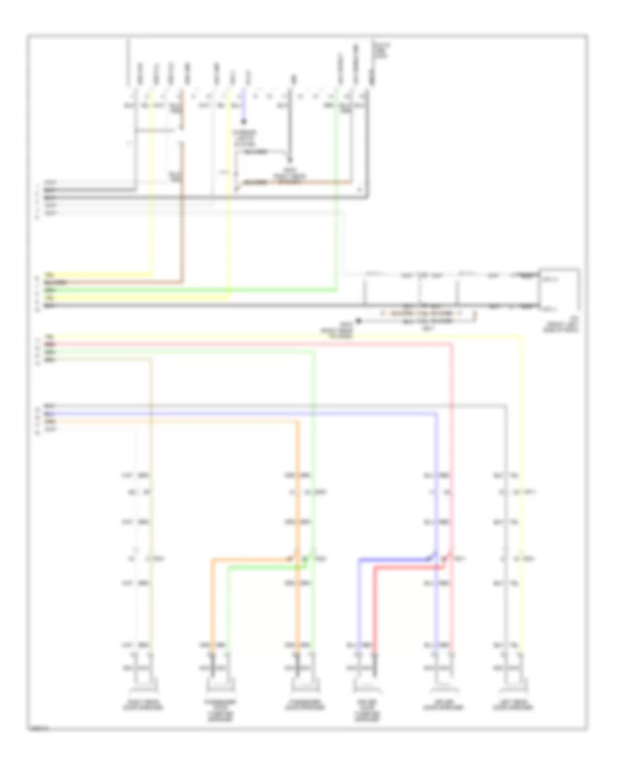
Immobilizer Wiring Diagram, with Smart Key System (2 of 3) for Hyundai Elantra GT 2013
List of elements for Immobilizer Wiring Diagram, with Smart Key System (2 of 3) for Hyundai Elantra GT 2013:
- (ill -)
- A/t
- B+ (ill +)
- Brake light switch
- Brake switch fuse 10a
- C-can high
- C-can low
- Computer data lines system
- Driver lock/unlock sw
- E/r fuse & relay box (in left rear corner of engine compt)
- Em11
- Em61
- Enable
- Exterior lights system
- External buzzer
- Ge02 (left front corner of vehicle)
- Gm01 (left top dash panel)
- Gm02 (right center of dash)
- Hot at all times
- Ignition lock switch (left rear of dash)
- Immo antenna ground
- Immo antenna power
- Interior lights system
- K-line
- Lines system computer data
- M/t
- M13-b
- P position ignition lock sw
- P position switch
- Smart key control module (right rear of dash)
- Sport mode switch
- Ssb amber
- Ssb green
- Ssb ill ground
- Ssb ill power
- Ssb sw 1
- Ssb sw 2
- Start feedback signal (m/t) (a/t)
- Start stop button switch
- Starting/ charging system
- Stop lamp power
- System cruise control
- Unlock switch
- Wheel sen output (fr)
Immobilizer Wiring Diagram, with Smart Key System (3 of 3) for Hyundai Elantra GT 2013
List of elements for Immobilizer Wiring Diagram, with Smart Key System (3 of 3) for Hyundai Elantra GT 2013:
- (behind center of rear bumper) smart key bumper antenna
- (center of floor console) smart key antenna (interior 1)
- (center rear of trunk area) smart key trunk antenna
- (under rear of floor console) smart key antenna (interior 2)
- Antenna gnd
- Antenna power
- Computer data lines system
- Driver smart key outside handle
- Ee11
- External buzzer (left front corner of vehicle)
- Fd11
- Fd21
- Fr11
- Ge01 (left front corner of vehicle)
- Gf01 (left "b" pillar)
- Gf02 (right "b" pillar)
- Gm01 (left top dash panel)
- Ground
- High
- Hot at all times
- I/p-f
- Immo ind
- Instrument cluster
- Interface
- J/c jd02 (in front passenger door)
- Leak current autocut device
- Lock
- Low
- M13-c
- Memory 2 fuse 10a
- Mf61
- Micom
- Nca
- Passenger smart key outside handle
- Power
- Red
- Smart junction box (under left side of dash, near kick panel)
- Smart key control module (right rear of dash)
- Ssb green
- Ssb ill ground
- Ssb ill power
- Transceiver b-can
- Transceiver c-can
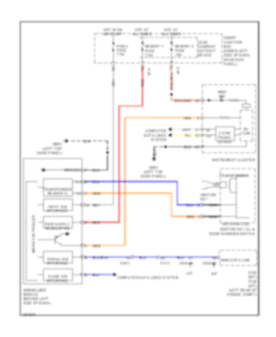
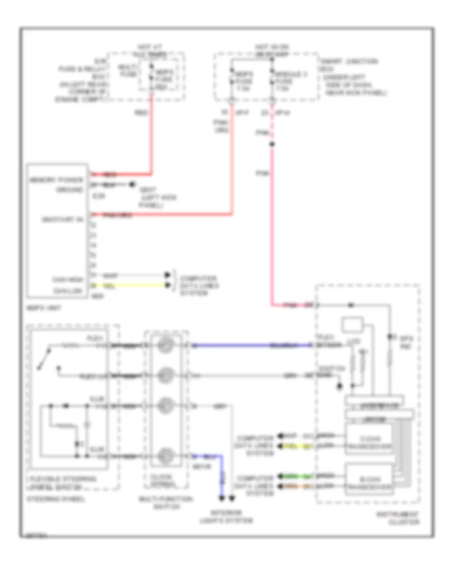
Immobilizer Wiring Diagram, without Smart Key System for Hyundai Elantra GT 2013
List of elements for Immobilizer Wiring Diagram, without Smart Key System for Hyundai Elantra GT 2013:
- (+)
- (-)
- A/t
- Antenna coil
- C-can trans- ceiver
- Cng-aa
- Cng-mk
- Computer data lines system
- Ec11
- Ecm (m/t) pcm (a/t) (left rear of engine compt)
- Em11
- Gm01 (left top dash panel)
- Ground
- Hot at all times
- Hot in on or start
- I/p-f
- I/p-h
- Ignition key
- Ignition key ill & door warning switch
- Immo data line
- Immo ind
- Immobilizer module (behind left side of dash)
- Input sig interface
- Instrument cluster
- K-line sig interface
- Leak current autocut device
- M/t
- Memory 1 fuse 7.5a
- Memory 2 fuse 10a
- Mi- com
- Micro controller
- Nca
- Pdm 3 fuse 7.5a
- Red
- Serial sig interface
- Smart junction box (under left side of dash, near kick panel)
- Transponder
- Transponder reader ic
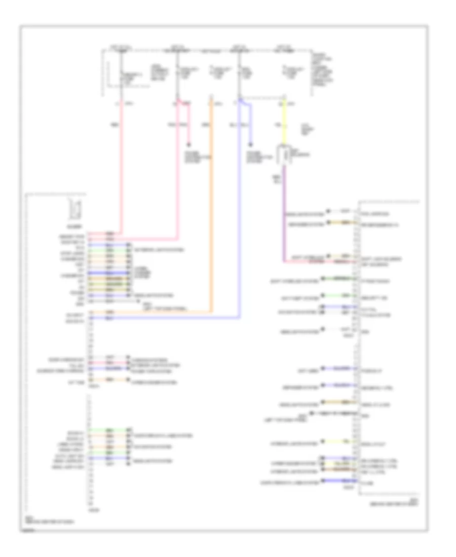
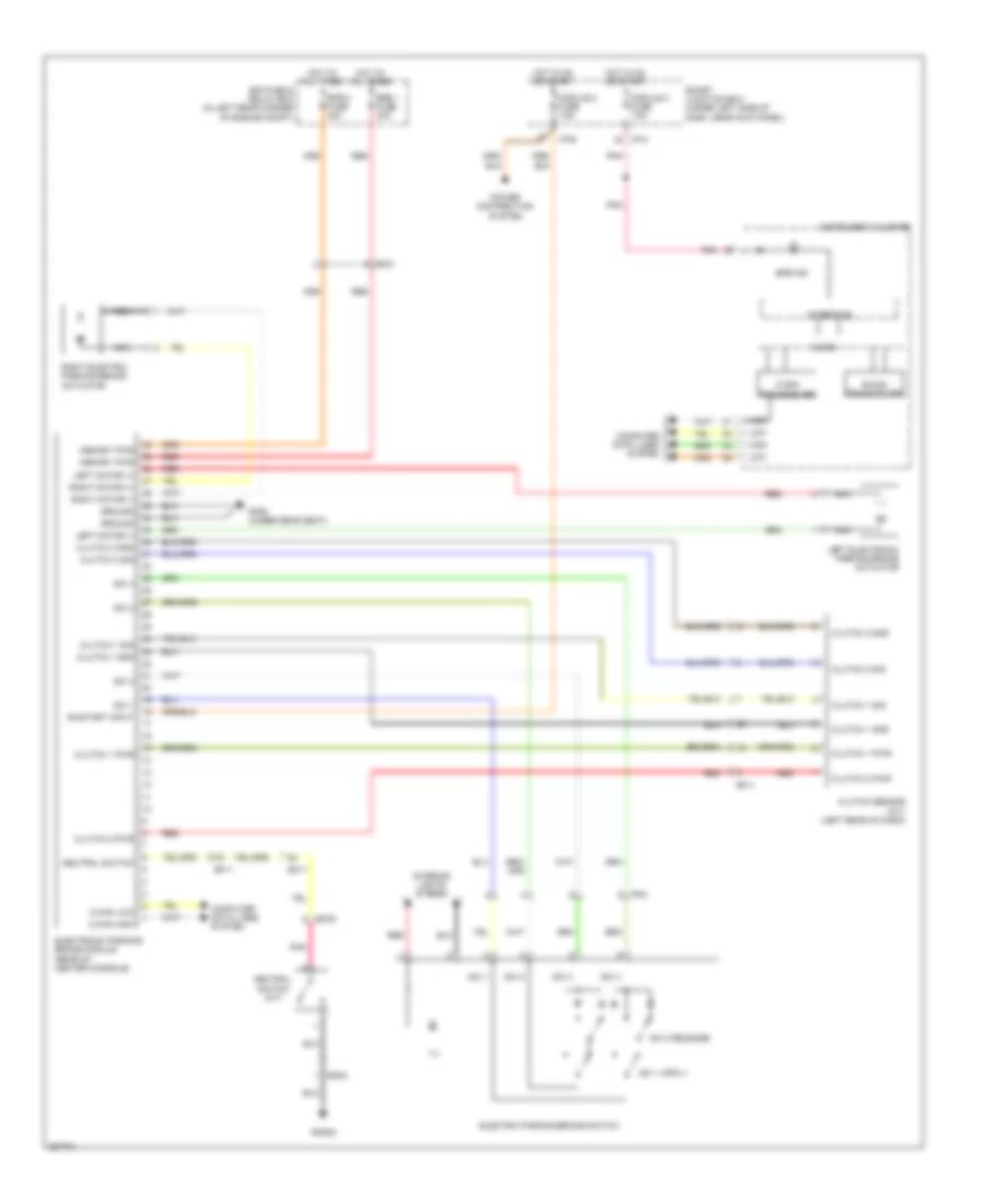
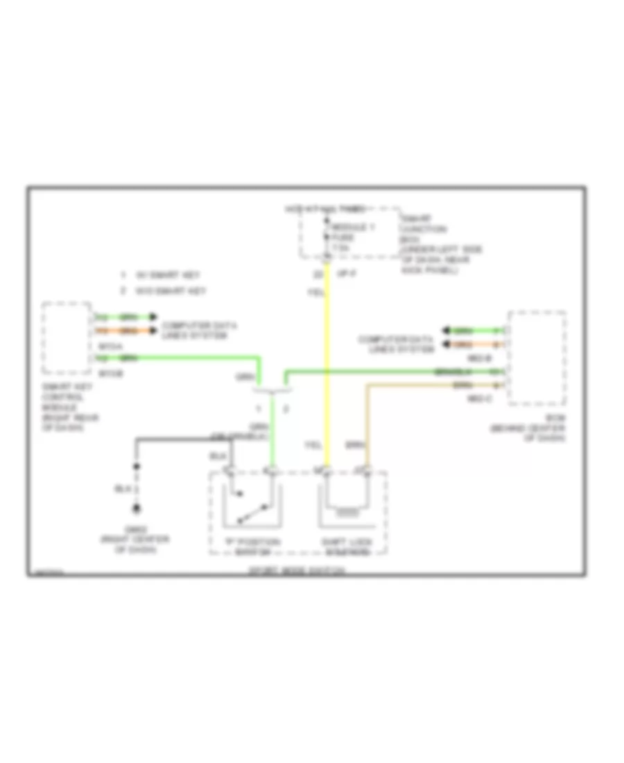
BODY CONTROL MODULES
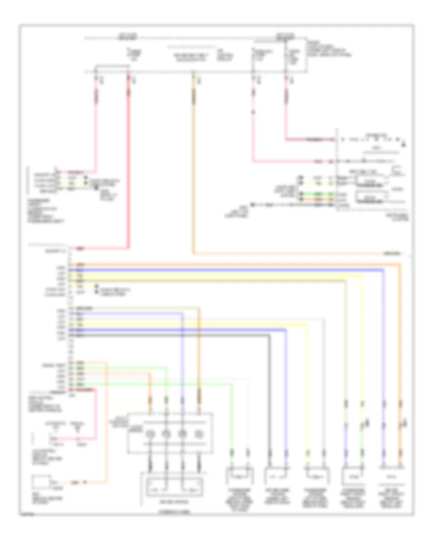
Body Control Module Wiring Diagram for Hyundai Elantra GT 2013
List of elements for Body Control Module Wiring Diagram for Hyundai Elantra GT 2013:
- 'p' position sw
- 'r' in
- (not used)
- A/v-tail
- Acc/on in
- Anti-theft system
- Auto light sw
- B-can hi
- B-can lo
- Bcm (behind center of dash)
- Bcm fuse 7.5a
- Buzzer
- Computer data lines system
- Crash input
- Defogger system
- Deicer rly ctrl
- Door warning sw
- Exterior lights system
- Fog lamps sig
- Fr wiper rly ctrl
- Gm01 (left top dash panel)
- Gnd
- Head lamp hi sw
- Head lamps sw
- Head lp lo sig
- Headlights system
- Hot at all times
- Hot in acc or on
- Hot in on
- Hot in on or start
- I/p-f
- I/p-h
- Int
- Int time
- Interior lights system
- K-line
- Key ill ctrl
- Key solenoid
- L-res- mts-rx
- Leak current autocut device
- M02-a
- M02-b
- M02-c
- M02-d
- Memory 2 fuse 10a
- Memory pwr
- Mist
- Module 1 fuse 7.5a
- Module 3 fuse 7.5a
- Module 7 fuse 7.5a
- Navigation system
- On input
- On/start in
- Pnk
- Power
- Power distribution system
- Power tops system
- Puddle lp
- Red
- Room lp out
- Rr defogger sw in
- Rr wiper rly ctrl
- Security ind
- Shift interlock system
- Shift lock solenoid
- Sig
- Smart junction box (under left side of dash, near kick panel)
- Stop lamps
- Sunroof open warning
- Tail sw
- Tx-unlk state
- W/o smart key
- Warning systems
- Washer sig
- Washer sw
- Wiper/ washer system
- Wiper/washer system
IPS Control Module Wiring Diagram (1 of 2) for Hyundai Elantra GT 2013
List of elements for IPS Control Module Wiring Diagram (1 of 2) for Hyundai Elantra GT 2013:
- Acc
- B+1 fuse 60a
- B+2 fuse 60a
- B-can
- B/a horn relay ctrl
- Brake oil level
- Burglar alarm relay ctrl
- Computer data lines system
- Defogger system
- Door locks & anti-theft systems
- Door switch signal
- Drv
- Drv seat belt buckle switch
- E/r fuse & relay box (in left rear corner of engine compt)
- Em11
- Exterior lights system
- Hazard lamp switch signal
- Head lamp low signal
- Headlights system
- High
- Hood switch
- Hot at all times
- I/p-b
- I/p-c
- I/p-d
- I/p-e
- I/p-f
- I/p-g
- I/p-h
- Ignition switch
- Instrument cluster system
- Interior lights system
- Ips 3
- Ips 3 ctrl
- Ips 4 (arisu-lt,4ch)
- Ips 4 ctrl
- Ips 8
- Ips 8 ctrl
- Ips control module
- K-line
- Key
- Lock
- Low
- Luggage lamp (gnd)
- Memory power
- Module 3 fuse 7.5a
- Multi fuse
- On/start input
- Parking brake switch
- Pas
- Pdm 3 (ig 1) relay
- Pdm 4 (ig 2) relay
- Pnk
- Power distribution system
- Red
- Relay sound
- Rr htd relay ctrl
- Smart
- Smart junction box (under left side of dash, near kick panel)
- Start
- Starting/ charging system
- T/sig relay
- To smart junction box (diagram 2 of 2)
- Turn sig lp sound rly ctrl
- Turn signal lamp switch signal
- W/o
IPS Control Module Wiring Diagram (2 of 2) for Hyundai Elantra GT 2013
List of elements for IPS Control Module Wiring Diagram (2 of 2) for Hyundai Elantra GT 2013:
- Anti-theft & door locks systems
- Distribution
- Door lk sw
- Door lock relay
- Door lock relay ctrl
- Door unlock relay
- Door unlock relay ctrl
- Dr lk/unlk sig
- Dr lock fuse 20a
- Driver door key unlk sig
- Driver/ passenger dr key lk sig
- Drv
- Exterior lights system
- From e/r fuse & relay box (diagram 1 of 2)
- From ignition a switch (diagram 1 of 2)
- Gm01 (left top dash panel)
- Gnd (drl)
- Gnd (ecu)
- Headlights system
- Hot at all times
- I/p-b
- I/p-c
- I/p-d
- I/p-e
- I/p-f
- I/p-g
- I/p-h
- Interior lights system
- Ips 1 ctrl
- Ips 7
- Ips 7 ctrl
- Ips control module
- Ips1 (arisu-lt, 4ch)
- Leak current autocut device
- Leak current autocut device rly ctrl
- Leak current autocut relay
- Leak current autocut switch
- Left power window relay
- Memory pwr
- Off
- On input
- P/wdw lh fuse 25a
- P/wdw rh fuse 25a
- Pass
- Passenger door key unlk sig
- Pnk
- Power
- Power window rly ctrl
- Power windows system
- Red
- Right power window relay
- Smart box junction (under left side of dash, near kick panel)
- Smart junction box (under left side of dash, near kick panel)
- System
- Tail gate open switch
- Tail gate relay
- Tail gate rly ctrl
- Tail gate sw
- Tgat open fuse 10a
- Trunk, tailgate, fuel doors system
- Two turn un lk relay ctrl
- Unlk
COMPUTER DATA LINES
Computer Data Lines Wiring Diagram (1 of 2) for Hyundai Elantra GT 2013
List of elements for Computer Data Lines Wiring Diagram (1 of 2) for Hyundai Elantra GT 2013:
- (behind left side of dash) immobilizer module
- (left top dash panel)
- 4p pulse
- A/v & navigation headunit
- Audio
- B-can hi
- B-can lo
- Bcm (behind center of dash)
- C-can hi
- C-can lo
- Data link connector (dlc) (below left side of dash)
- Electronic parking brake module (rear of center console)
- Em61
- Esc module (right rear of engine compt)
- Gm01
- Hot at all times
- I/p-g
- I/p-h
- Instrument cluster
- Ips control module
- J/c je01 (front passenger's footwell)
- J/c jf01 (under front passenger's seat)
- J/c jm03 (top left side of dash)
- J/c jm04 (top left side of dash)
- K-line
- Leak current autocut device
- M-can hi
- M-can lo
- M02-b
- M02-d
- M09-b
- M13-a
- M13-b
- M15-b
- Memory 2 fuse 10a
- Mf61
- Mr11
- Passenger weight classification sensor (under front passenger's seat)
- Red
- Smart junction box (under left side of dash, near kick panel)
- Smart key control module (w/ smart key) (right rear of dash)
- Sunroof control module (under headliner)
- Vech spd
- W/ navigation
- W/ smart key
- W/o navigation
- W/o smart key
- Wheel start
- Yaw rate sensor (front passenger's floor area under seat)
Computer Data Lines Wiring Diagram (2 of 2) for Hyundai Elantra GT 2013
List of elements for Computer Data Lines Wiring Diagram (2 of 2) for Hyundai Elantra GT 2013:
- (left rear of engine compt) pcm (a/t) ecm (m/t)
- (not used)
- (right side of engine compt) multipurpose check connector
- (top left side of dash) j/c jm01
- A/c control module (below center of dash)
- A/t
- Abs 1 fuse 40a
- Abs 2 fuse 20a
- Abs 3 fuse 10a
- Automatic a/c
- C-can hi
- C-can lo
- Cng-ab
- Cng-mk
- E/r fuse & relay box (in left rear corner of engine compt)
- Ec11
- Em11
- Ge01 (left front corner of vehicle)
- Hot at all times
- Hot in on or start
- J/c jm02 (top right side of dash)
- K-line
- M-can hi
- M-can lo
- M/t
- M21-a
- M22-b
- M26
- Manual a/c
- Mdps unit
- Mf61
- Mts module (center of dash)
- Multi fuse
- Nca
- Pnk
- Red
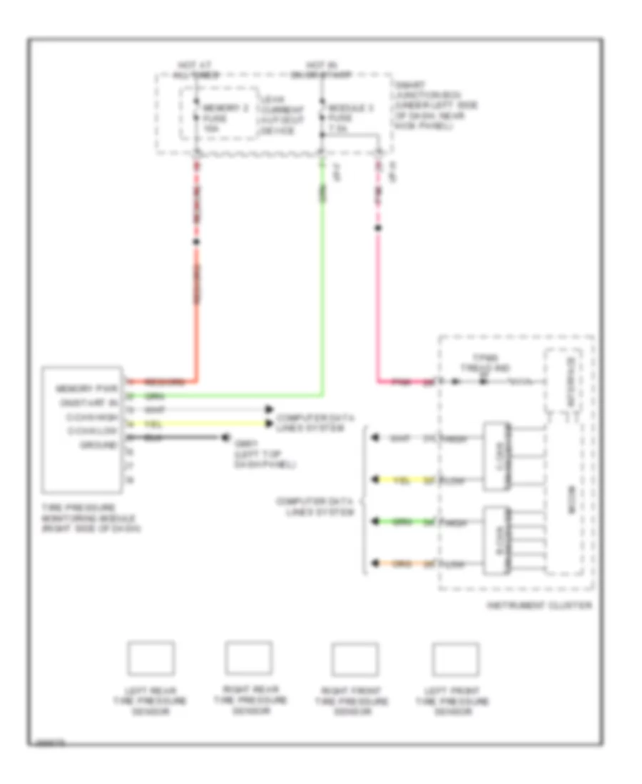
- Srs control module (under front of center console)
- Tire pressure monitoring module (right side of dash)
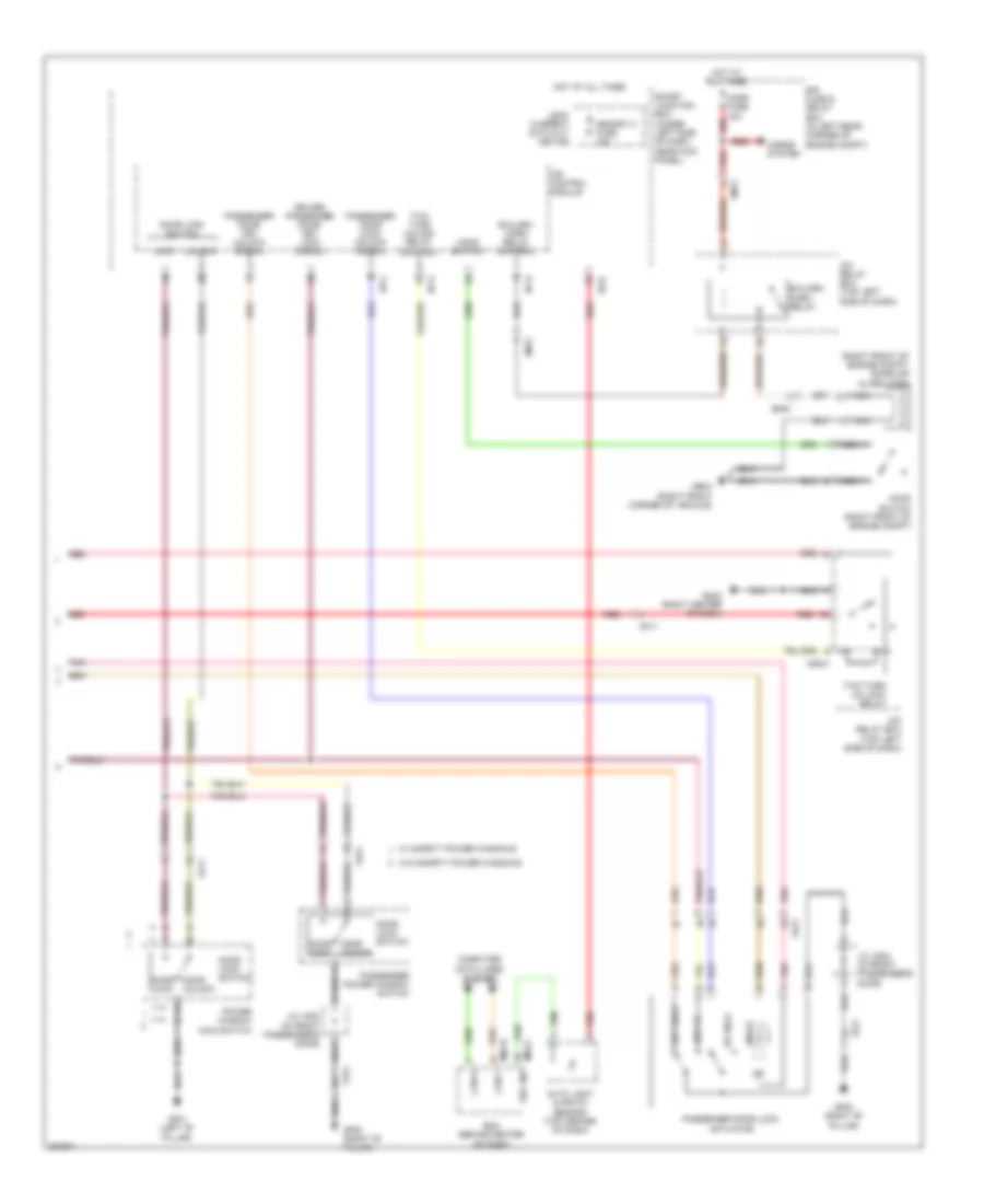
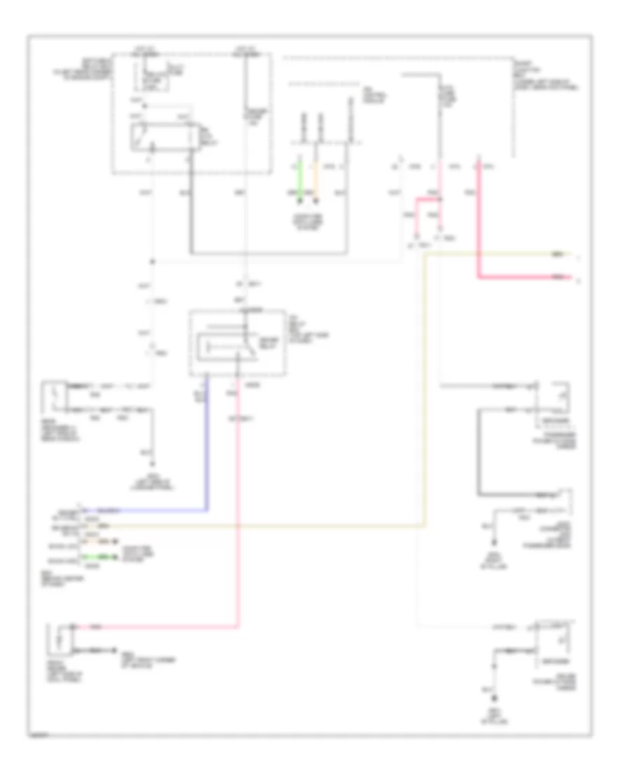
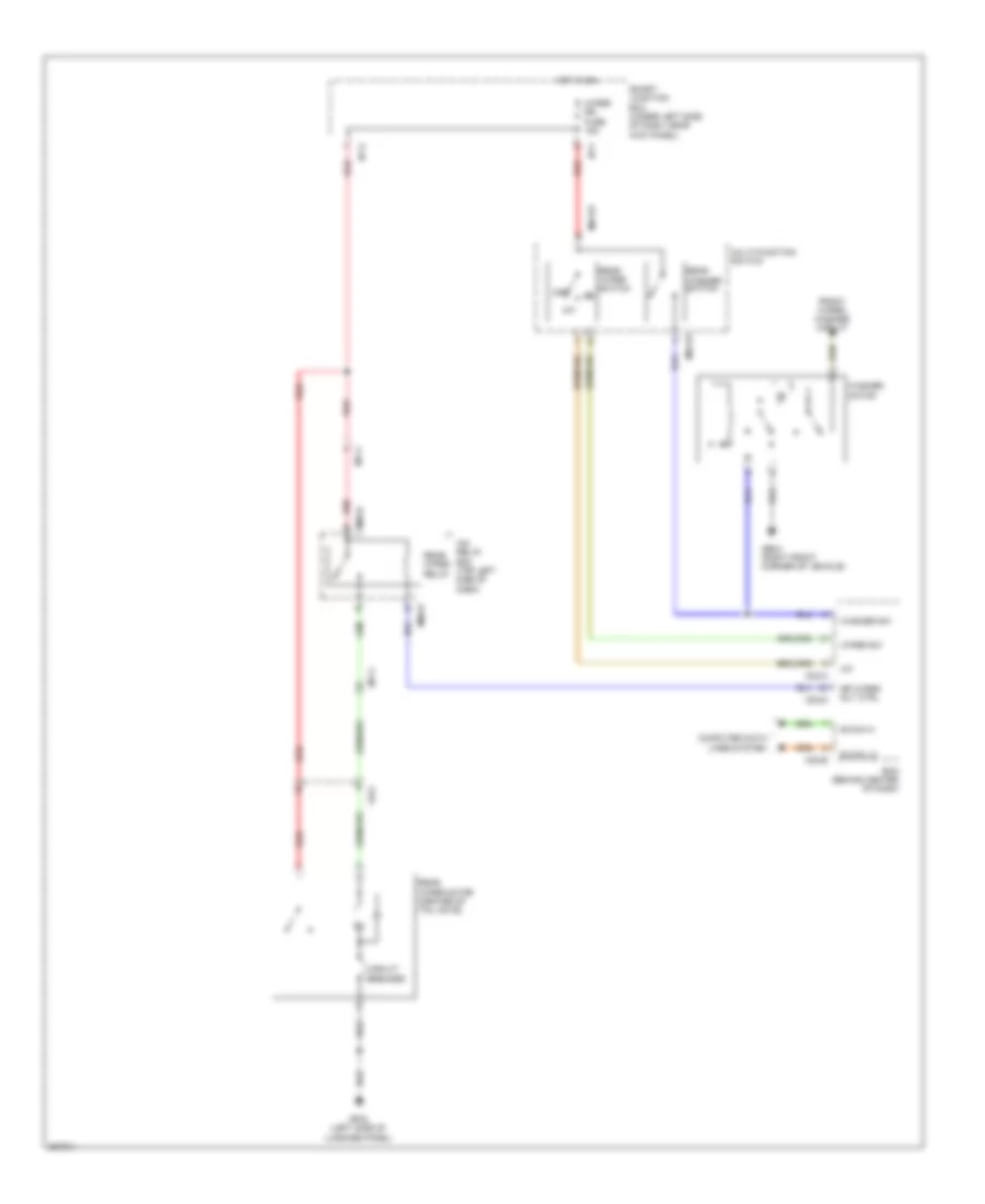
COOLING FAN
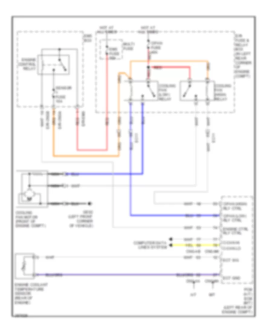
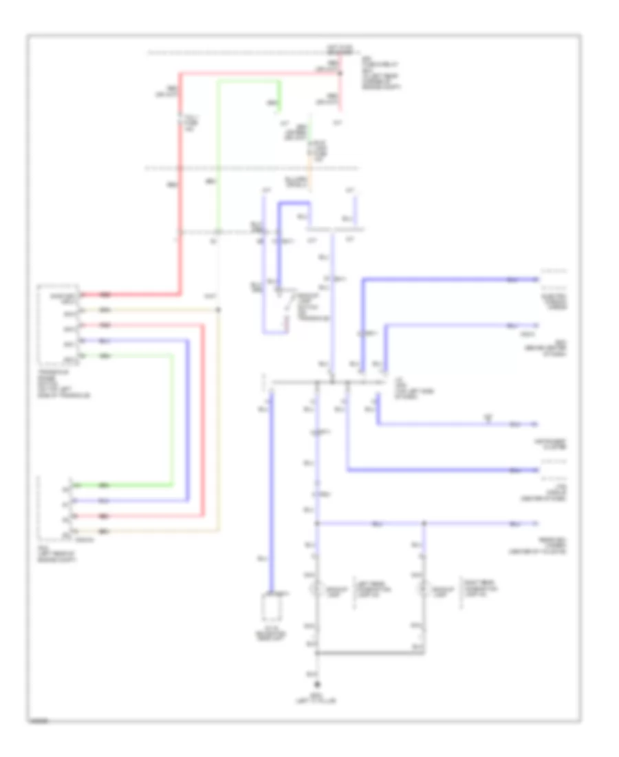
Cooling Fan Wiring Diagram for Hyundai Elantra GT 2013
List of elements for Cooling Fan Wiring Diagram for Hyundai Elantra GT 2013:
- A/t
- C-can hi
- C-can lo
- C/fan (high) rly ctrl
- C/fan (low) rly ctrl
- C/fan fuse 40a red
- Cng-aa
- Cng-ab
- Cng-ma
- Cng-mk
- Computer data lines system
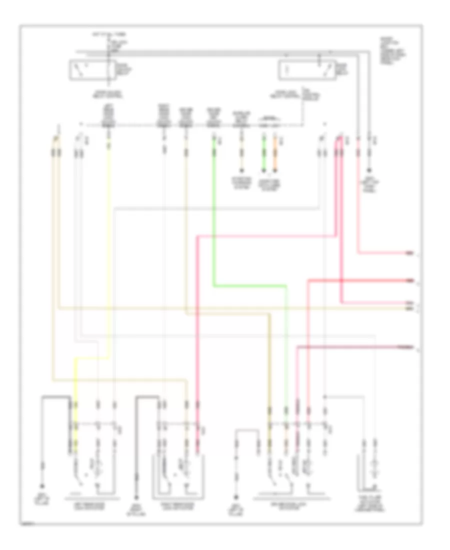
- Cooling fan (high) relay
- Cooling fan (low) relay
- Cooling fan motor (front of engine compt)
- E/r fuse & relay box (in left rear corner of engine compt)
- E/r-cnga
- E/r-cngb
- E/r-ems
- Ec11
- Ect gnd
- Ect sig
- Ems box
- Ems fuse 60a
- Engine control relay
- Engine coolant temperature sensor (rear of engine)
- Engine ctrl rly ctrl
- Ge02 (left front corner of vehicle)
- Hot at all times
- M/t
- Multi fuse
- Nca
- Pcm (a/t) ecm (m/t) (left rear of engine compt)
- Red
- Sensor fuse 10a
CRUISE CONTROL
Cruise Control Wiring Diagram (1 of 3) for Hyundai Elantra GT 2013
List of elements for Cruise Control Wiring Diagram (1 of 3) for Hyundai Elantra GT 2013:
- (left top dash panel) gm01
- (or pnk)
- 5v regulator
- A/t
- Aps 1 ground
- Aps 1 signal
- Aps 2 ground
- Aps 2 signal
- B-can transceiver
- Brake light sw
- Brake switch
- C-can high
- C-can low
- C-can transceiver
- Cng-aa
- Cng-ab
- Cng-ma
- Cng-mk
- Computer data lines system
- Cruise ind
- Ec11
- Etc motor (+)
- Etc motor (-)
- Exterior lights system
- Ground
- High
- Hot at all times
- Hot in on or start
- I/p-f
- I/p-h
- Ig+
- Ig/b+
- Instrument cluster
- Interface
- Leak current autocut device
- Low
- M/t
- Memory 2 fuse 10a
- Micom
- Module 3 fuse 7.5a
- On/start input
- Pcm (a/t) ecm (m/t) (left rear of engine compt)
- Pnk
- Red
- S- ground
- Set ind
- Smart junction box (under left side of dash, near kick panel)
- Speedometer
- Tachometer
- Tps ground
- Tps signal 1
- Tps signal 2
- Vehicle speed
Cruise Control Wiring Diagram (2 of 3) for Hyundai Elantra GT 2013
List of elements for Cruise Control Wiring Diagram (2 of 3) for Hyundai Elantra GT 2013:
- (or pnk)
- (right rear of engine compt) esc module
- Brake switch fuse 10a
- C-can high
- C-can low
- Closed w/ brake pedal depressed
- Computer data lines system
- E/r fuse & relay box (in left rear corner of engine compt)
- Ecu 3 fuse 10a
- Ef11
- Em11
- Em61
- Esc unit
- Fl sig
- Fl vcc
- Fr sig
- Fr vcc
- Hot at all times
- Hot in on or start
- Left front wheel speed sensor (left front wheel hub assembly)
- Left rear wheel speed sensor (left rear wheel hub assembly)
- Nca
- Open w/ brake pedal depressed
- Pnk
- Red
- Right front wheel speed sensor (right front wheel hub assembly)
- Right rear wheel speed sensor (right rear wheel hub assembly)
- Rl sig
- Rl vcc
- Rr sig
- Rr vcc
- Stop lamp relay (top left side of dash)
- Stop lamp switch (on brake pedal bracket)
Cruise Control Wiring Diagram (3 of 3) for Hyundai Elantra GT 2013
List of elements for Cruise Control Wiring Diagram (3 of 3) for Hyundai Elantra GT 2013:
- (accelerator pedal bracket) accelerator pedal position sensor
- (or pnk)
- + hall ic
- A/t
- A/v & navigation head unit
- Audio
- Data link connector (below left side of dash)
- E/r fuse & relay box (in left rear corner of engine compt)
- Ec11
- Ecu 3 fuse 10a
- Electronic throttle control motor & throttle position sensor (etc motor: rear of engine, on throttle body)
- Em61
- Etc motor
- Gng01
- Hot at all times
- Hot in on or start
- J/c jm04 (top left side of dash)
- M/t
- M09-b
- M13-b
- M15-b
- Mr11
- Pnk
- Red
- Smart key control module (right rear of dash)
- Sunroof (under headliner)
- Tcu 1 fuse 15a
- Throttle position sensor
- Vehicle speed sensor (m/t) (on top of transaxle)
- W/ navigation
- W/o navigation
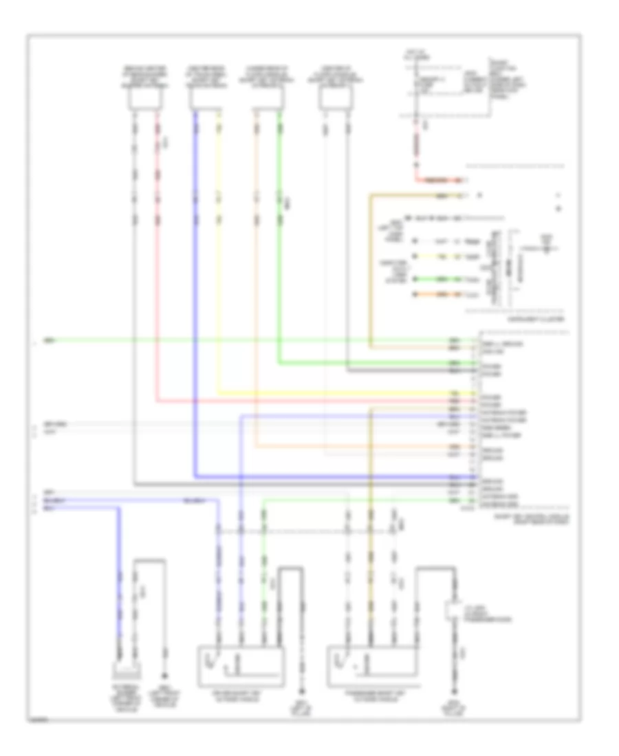
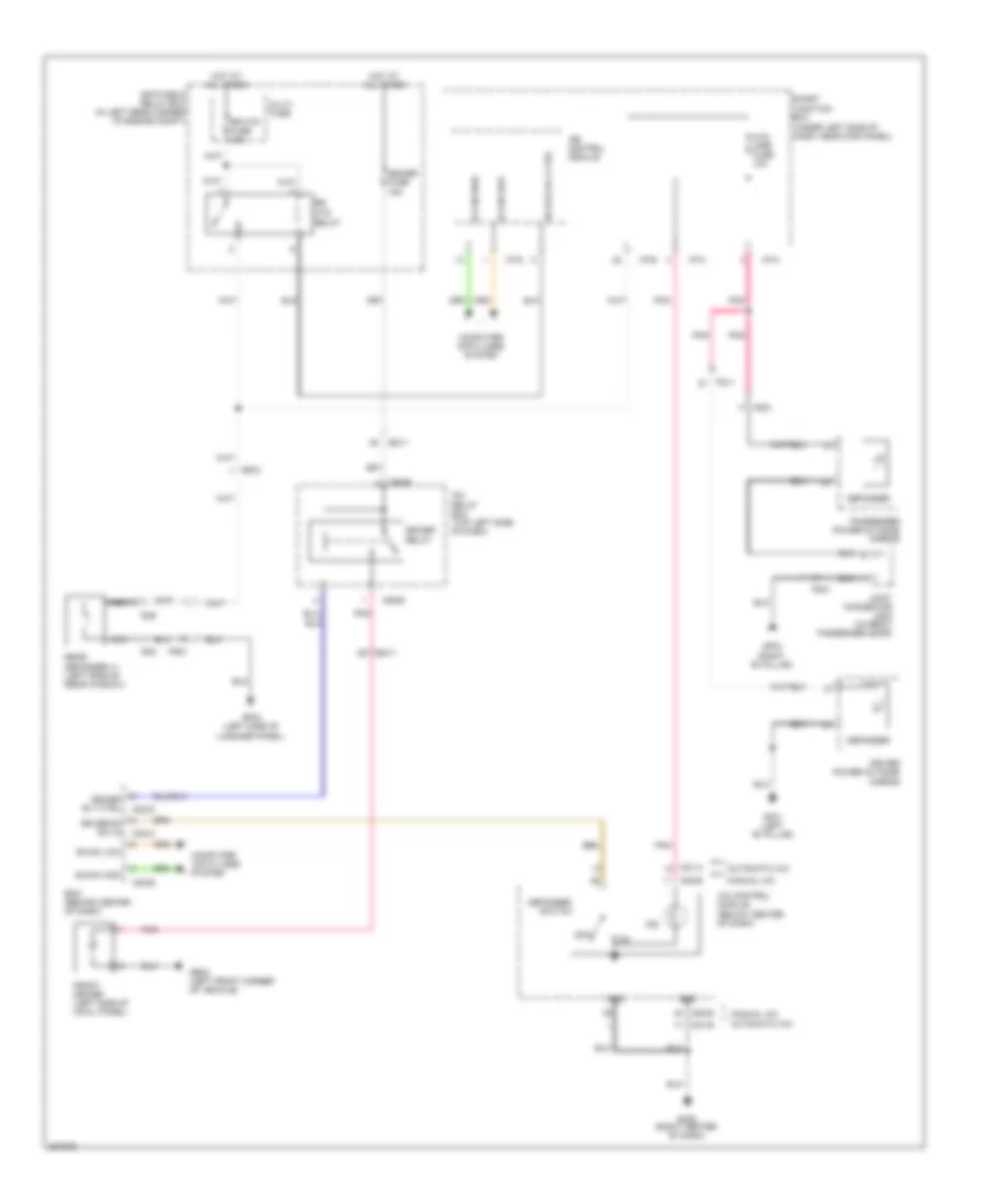
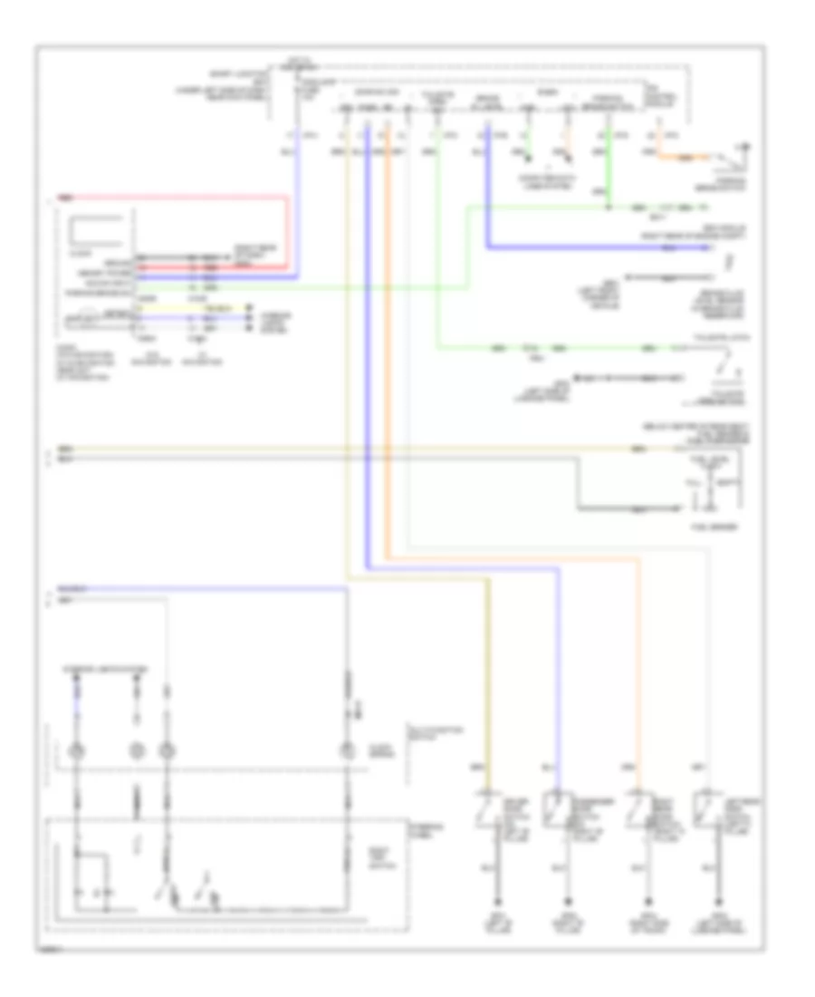
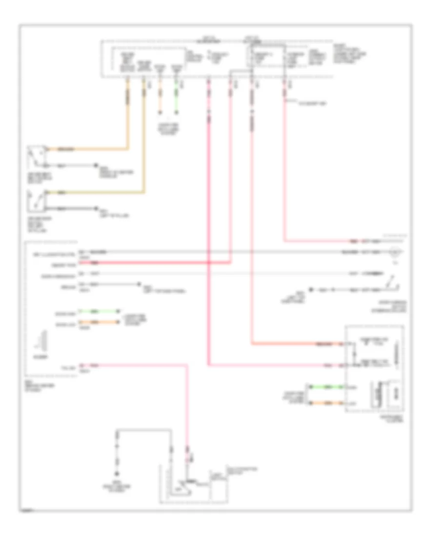
DEFOGGERS
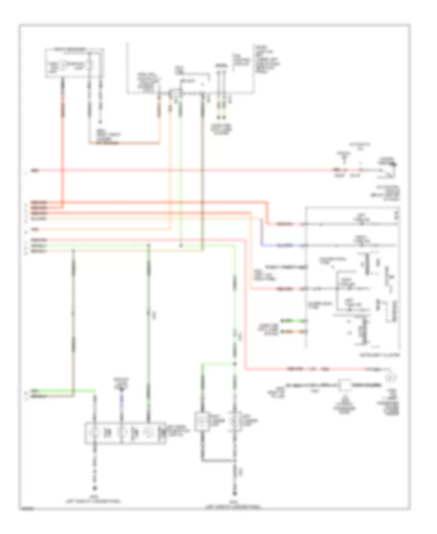
Defoggers Wiring Diagram, with Auto Defogger (1 of 2) for Hyundai Elantra GT 2013
List of elements for Defoggers Wiring Diagram, with Auto Defogger (1 of 2) for Hyundai Elantra GT 2013:
- B-can high
- B-can low
- Bcm (behind center of dash)
- Computer data lines
- Computer data lines system
- Defogger
- Deicer fuse 15a
- Deicer relay
- Deicer rly ctrl
- Driver power outside mirror
- E/r fuse & relay box (in left rear corner of engine compt)
- Ef21
- Em11
- Fd11
- Fd21
- Fr21
- Front deicer (left side of cowl panel)
- Ge02 (left front corner of vehicle)
- Gf01 (left "b" pillar)
- Gf02 (right "b" pillar)
- Gf03 (left side of luggage panel)
- Hot at all times
- Htd mirr fuse 10a
- I/p-a
- I/p-e
- I/p-g
- I/p-h
- Icm relay box (top left side of dash)
- Ips control module
- Joint connector jd02 (in front passenger door)
- M02-b
- M02-c
- M02-d
- M06-b
- Multi fuse
- Nca
- Passenger power outside mirror
- Pnk
- R35
- R39
- Rear defogger (+) (left side of rear window)
- Relay
- Rr defog sw in
- Rr htd
- Rr htd fuse 40a
- Rr htd rly ctrl
- Smart junction box (under left side of dash, near kick panel)
- System
Defoggers Wiring Diagram, with Auto Defogger (2 of 2) for Hyundai Elantra GT 2013
List of elements for Defoggers Wiring Diagram, with Auto Defogger (2 of 2) for Hyundai Elantra GT 2013:
- A/c control module (below center of dash)
- A/con fuse 7.5a
- Air conditioning system
- Auto defogger actuator
- Auto defogger sensor (top front of windshield)
- Auto defogger snsr
- Blower motor (+)
- Close
- Def
- Defogger actuator
- Defogger actuator (center rear of dash)
- Defogger switch
- Drain
- F/b
- Fet
- Gate
- Gm02 (right center
- Ground
- Hot at all times
- Hot in on
- Hot in on or start
- I/p-f
- I/p-h
- Ill
- Leak current autocut device
- M21-a
- M21-b
- Memory power
- Mode actuator (center of dash)
- Module 2 fuse 10a
- Module 4 fuse 7.5a
- Mr11
- Of dash)
- Off
- On input
- On/start input
- Open
- Pnk
- Red
- Ref (5v)
- Smart junction box (under left side of dash, near kick panel)
- Snsr gnd
- Snsr ref (+5v)
- Vent
Defoggers Wiring Diagram, without Auto Defogger for Hyundai Elantra GT 2013
List of elements for Defoggers Wiring Diagram, without Auto Defogger for Hyundai Elantra GT 2013:
- (right center of dash)
- A/c control module (below center of dash)
- Automatic a/c
- B-can high
- B-can low
- Bcm (behind center of dash)
- Computer data lines
- Computer data lines system
- Defogger
- Deicer fuse 15a
- Deicer relay
- Deicer rly ctrl
- Driver power outside mirror
- E/r fuse & relay box (in left rear corner of engine compt)
- Ef21
- Em11
- Fd11
- Fd21
- Fr21
- Front deicer (left side of cowl panel)
- Ge02 (left front corner of vehicle)
- Gf01 (left "b" pillar)
- Gf02 (right "b" pillar)
- Gf03 (left side of luggage panel)
- Gm02
- Gnd
- Hot at all times
- Htd mirr fuse 10a
- I/p-a
- I/p-e
- I/p-g
- I/p-h
- Icm relay box (top left side of dash)
- Ind
- Ips control module
- Joint connector jd02 (in front passenger door)
- M02-b
- M02-c
- M02-d
- M06-b
- M21-a
- M21-b
- M22-b
- Manual a/c
- Multi fuse
- Nca
- Off
- Passenger power outside mirror
- Pnk
- R35
- R39
- Rear defogger (+) (left side of rear window)
- Relay
- Rr defog sw in
- Rr htd
- Rr htd fuse 40a
- Rr htd rly ctrl
- Smart junction box (under left side of dash, near kick panel)
- Switch
- System
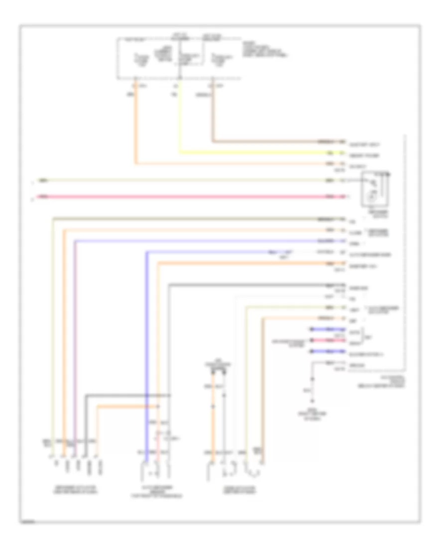
ELECTRONIC POWER STEERING
Electronic Power Steering Wiring Diagram for Hyundai Elantra GT 2013
List of elements for Electronic Power Steering Wiring Diagram for Hyundai Elantra GT 2013:
- (left kick
- (under left
- B-can
- C-can
- Can high
- Can low
- Clock spring
- Computer data lines system
- E/r fuse & relay box (in left rear corner of engine compt)
- E29
- Eps ind
- Flex (+)
- Flex (-)
- Flex steer
- Flexible steering wheel switch
- Ge07
- Ground
- High
- Hot at all times
- Hot in on or start
- I/p-f
- I/p-h
- Ig+
- Illm (+)
- Illm (-)
- Instrument cluster
- Interface
- Interior lights system
- Lcd
- Low
- M01-r
- M26
- Mdps fuse 7.5a
- Mdps fuse 80a
- Mdps unit
- Memory power
- Micom
- Module 3 fuse 7.5a
- Multi fuse
- Multi-function switch
- Nca
- Near kick panel)
- On/start in
- Panel)
- Pnk
- Red
- Side of dash,
- Smart junction box
- Steering wheel
- Switch gnd
- Transceiver
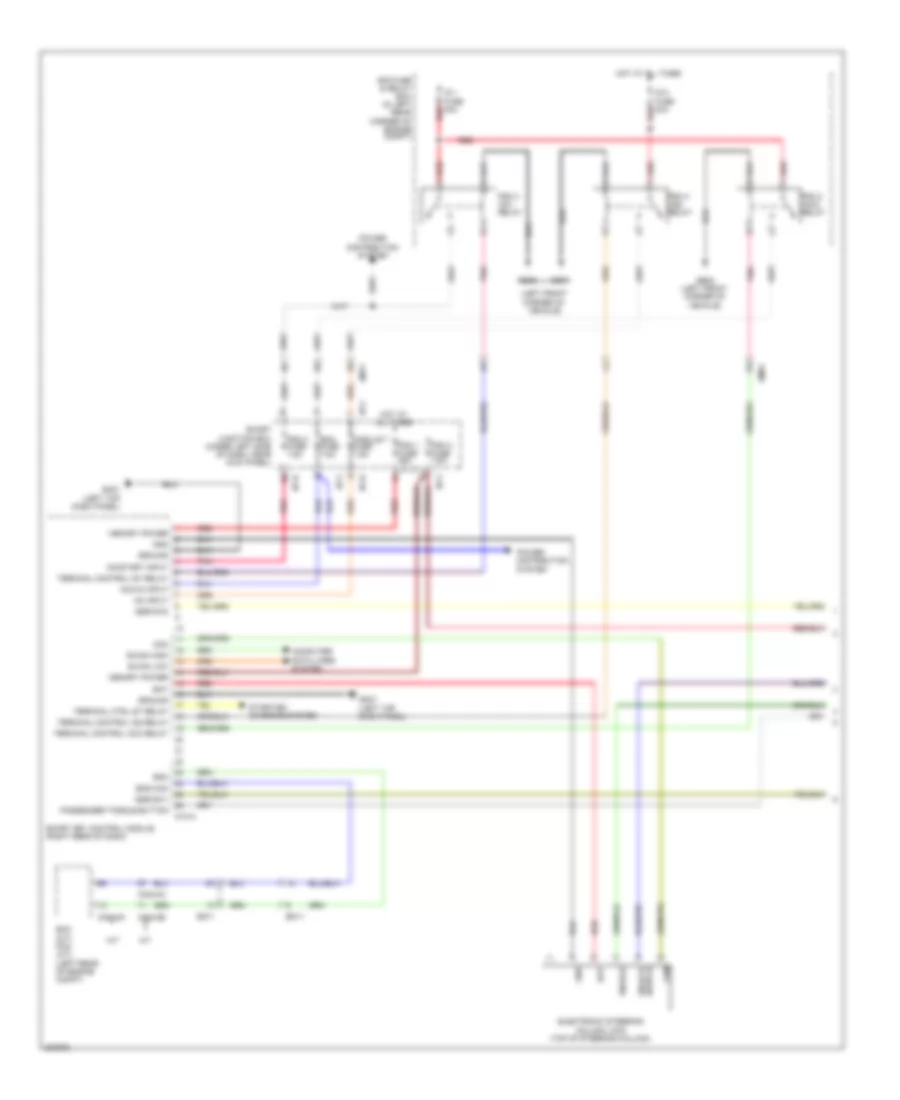
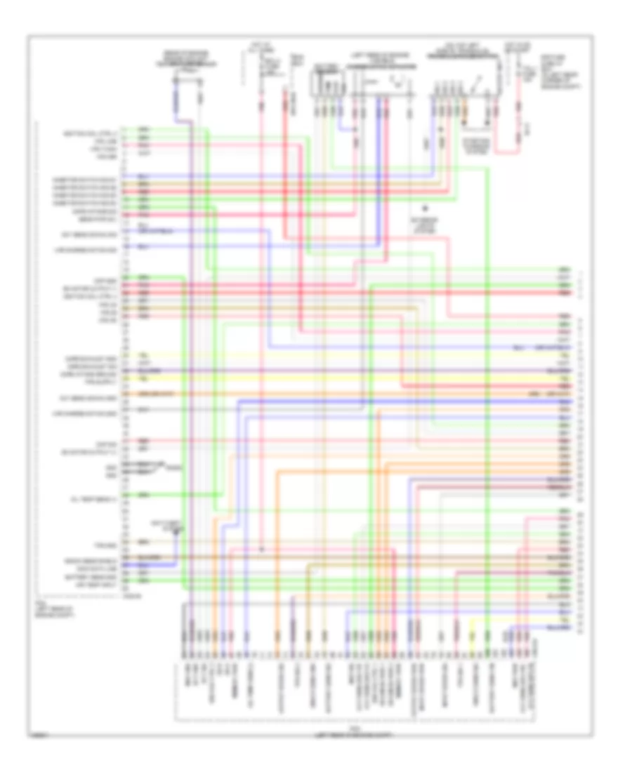
ENGINE PERFORMANCE
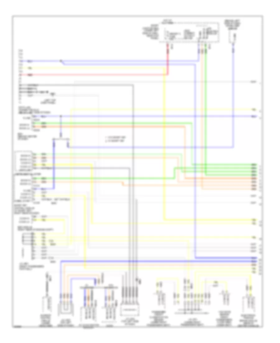
1.8L
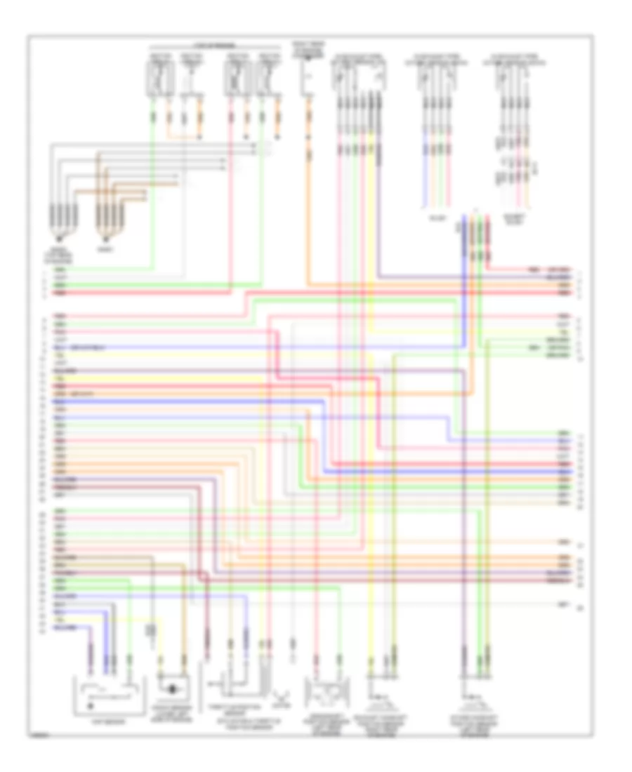
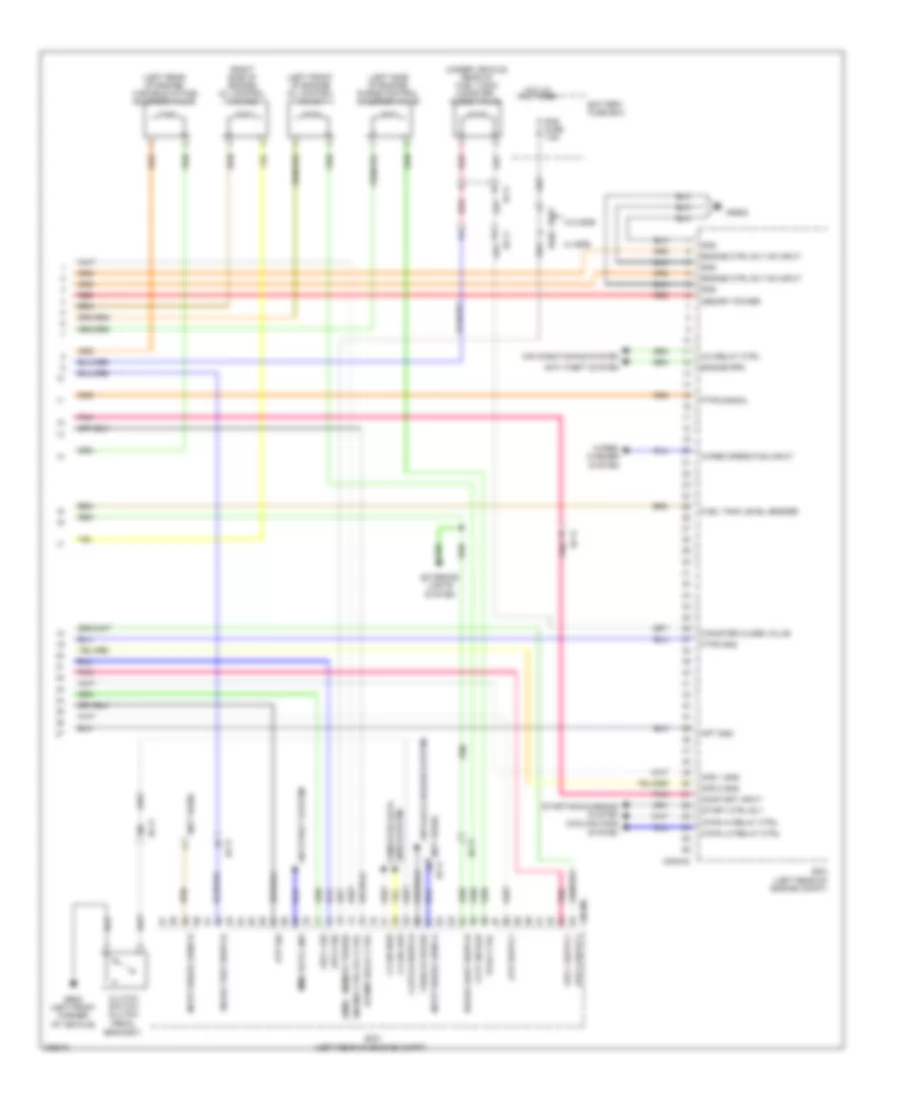
1.8L, Engine Performance Wiring Diagram, A/T (1 of 5) for Hyundai Elantra GT 2013
List of elements for 1.8L, Engine Performance Wiring Diagram, A/T (1 of 5) for Hyundai Elantra GT 2013:
- (left rear of engine) variable charge motion actuator
- (on top left side of transaxle) transaxle range switch
- (rear of engine) engine coolant temperature sensor
- Air temp input
- Anti-theft
- Battery sens gnd
- Battery sens sig
- Battery sens vin
- Battery sensor
- Ckp gnd
- Ckp sig
- Cmps exhaust gnd
- Cmps exhaust sig
- Cmps intake ground
- Cmps intake sig
- Cng-aa
- Dc motor output (+)
- Dc motor output (-)
- E/r fuse & relay box (in left rear corner of engine compt)
- E/r-cngb
- Ec11
- Ect gnd
- Ect sig
- Ecu 4 fuse 15a
- Ems box
- Exterior lights system
- Gnd
- Gng02
- Ground
- Hot at all times
- Hot in on or start
- Ign coil ctrl 1
- Ign coil ctrl 3
- Ignition coil ctrl 2
- Ignition coil ctrl 4
- Immo data line
- Inhibitor switch sig s1
- Inhibitor switch sig s2
- Inhibitor switch sig s3
- Inhibitor switch sig s4
- Input speed pwr
- Input speed sig
- Knock sens gnd
- Knock sens shield
- Knock sens sig
- Map gnd
- Map pwr
- Map sig
- Memory pwr
- Oil temp sens (+)
- Oil temp sens (-)
- On strt inpt
- Output speed pwr
- Output speed sig
- Oxy sens (down) gnd
- Oxy sens (down) sig
- Oxy sens (up) vg
- Oxy sens (up) vip
- Oxy sens (up) vn
- Oxy sens (up) vrc
- Pcm (left rear of engine compt)
- Pnk
- Red
- Sens pwr (5v)
- Sig 1
- Sig 2
- Sig 3
- Sig 4
- Solenoid pwr 1
- Solenoid pwr 2
- Ss a
- Ss b
- Starting/ charging system
- System
- Tcu 1 fuse 15a
- Temp
- Tps gnd
- Tps sig 1
- Tps sig 2
- Var charge motion gnd
- Var charge motion sig
- Vdd
- Vfs 26
- Vfs 35r
- Vfs line
- Vfs od
- Vfs t/con
- Vfs ud
- Vout
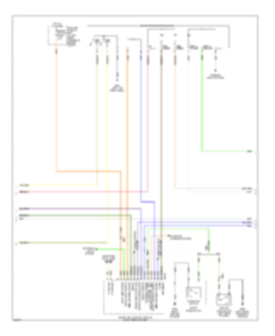
1.8L, Engine Performance Wiring Diagram, A/T (2 of 5) for Hyundai Elantra GT 2013
List of elements for 1.8L, Engine Performance Wiring Diagram, A/T (2 of 5) for Hyundai Elantra GT 2013:
- (in exhaust pipe) oxygen sensor (down)
- (in exhaust pipe) oxygen sensor (up)
- (or pnk)
- (right rear of engine) condenser
- (top of engine)
- Crankshaft position sensor (left rear of engine)
- Ec11
- Etc motor & throttle position sensor
- Except sulev
- Exhaust camshaft position sensor (right rear of engine)
- Gng01
- Gng03 (top rear of engine)
- Ignition coil 1
- Ignition coil 2
- Ignition coil 3
- Ignition coil 4
- Intake camshaft position sensor (left rear of engine)
- Knock sensor (lower left side of engine)
- Map sensor
- Motor
- Nca
- Pnk
- Red
- Sulev
- Throttle position sensor
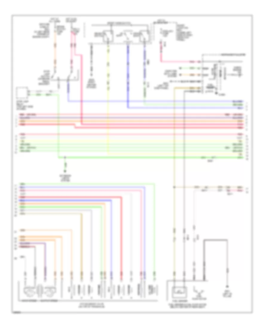
1.8L, Engine Performance Wiring Diagram, A/T (3 of 5) for Hyundai Elantra GT 2013
List of elements for 1.8L, Engine Performance Wiring Diagram, A/T (3 of 5) for Hyundai Elantra GT 2013:
- (or pnk)
- Atm solenoid valve (on top of transaxle)
- Brake switch fuse 15a
- Check engine ind
- Computer data lines system
- Down shift
- E/r fuse & relay box (in left rear corner of engine compt)
- Ec11
- Ecu 3 fuse 10a
- Ef21
- Em11
- Em61
- Exterior lights system
- Fuel
- Fuel sender
- Fuel sender & fuel pump motor (below center of rear seat)
- Gf01 (left "b" pillar)
- Gm01 (left top dash panel)
- Gm02 (right center of dash)
- High
- Hot at all times
- Hot in on or start
- I/p-h
- Input speed
- Instrument cluster
- Interface
- Low
- Mf11
- Micom
- Module 3 fuse 7.5a
- Nca
- Oil temp sensor
- Output speed
- Pnk
- Pump motor
- Red
- S gnd
- Select switch
- Shift
- Smart junction box (under left side of dash, near kick panel)
- Sport mode switch
- Ss a
- Ss b
- Stop lamp relay (top left side of dash)
- Stop lamp switch (on brake pedal bracket)
- Transceiver b-can
- Vfs 26b
- Vfs 35r
- Vfs line
- Vfs od
- Vfs t/con
- Vfs ud
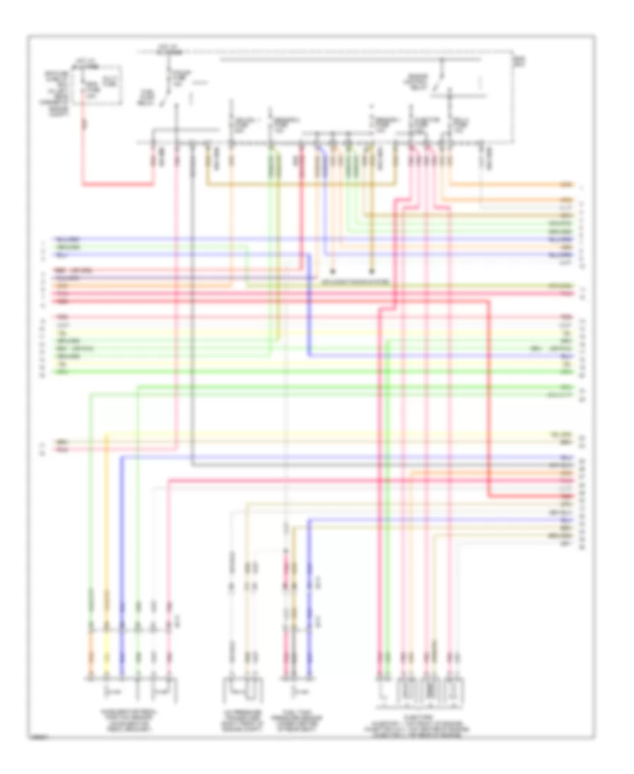
1.8L, Engine Performance Wiring Diagram, A/T (4 of 5) for Hyundai Elantra GT 2013
List of elements for 1.8L, Engine Performance Wiring Diagram, A/T (4 of 5) for Hyundai Elantra GT 2013:
- (or pnk)
- A/c pressure transducer (right front of engine compt)
- Accelerator pedal position sensor (accelerator pedal bracket)
- Air conditioning system
- E/r fuse & relay box (in left rear corner of engine compt)
- E/r-cnga
- E/r-cngb
- E/r-ems
- Ec11
- Ecu 2 fuse 10a
- Ef11
- Ems box
- Ems fuse 40a
- Engine control relay
- F/pump fuse 15a
- Fuel pump relay
- Fuel tank pressure sensor (under center of rear seat)
- Hot at all times
- Ign coil 1 fuse 20a
- Injector fuse 10a
- Injectors (injector 1: top front of engine) (injector 2 & 3: top center of engine) (injector 4: top rear of engine)
- Multi fuse
- Pnk
- Red
- Sensor 1 fuse 10a
- Sensor 2 fuse 10a
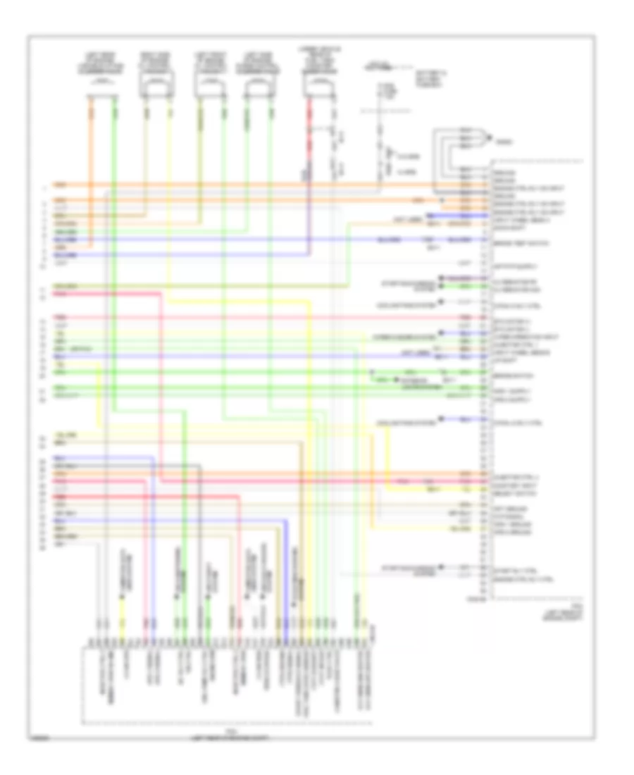
1.8L, Engine Performance Wiring Diagram, A/T (5 of 5) for Hyundai Elantra GT 2013
List of elements for 1.8L, Engine Performance Wiring Diagram, A/T (5 of 5) for Hyundai Elantra GT 2013:
- (left front of engine) oil control valve 1
- (left rear of engine) variable intake solenoid valve
- (left side of engine) purge control solenoid valve
- (not used)
- (or pnk)
- (right side of engine) oil control valve 2
- (under vehicle, rear of fuel tank) canister close valve
- A/c rly ctrl
- Alternator com
- Alternator fr
- Ams fuse 7.5a
- Aps 1 ground
- Aps 1 signal
- Aps 2 ground
- Aps 2 signal
- Apt ground
- Atp signal
- Battery & battery fuse box
- Brake switch
- Brake test switch
- C-can high
- C-can low
- C/fan hi rly ctrl
- C/fan lo rly ctrl
- Canister close valve
- Cng-ab
- Cooling fans system
- Cvvt exhaust
- Cvvt intake
- Down shift
- Ec01
- Ec02
- Ec11
- Ef11
- Engine ctrl rly ctrl
- Engine ctrl rly on input
- Engine rpm
- Etc motor (+)
- Etc motor (-)
- Exterior lights system
- Ftps ground
- Ftps signal
- Fuel pump rly ctrl
- Fuel tank level sender
- Gng02
- Ground
- Hot at all times
- Injector ctrl 1
- Injector ctrl 2
- Injector ctrl 3
- Injector ctrl 4
- Input wheel sens a
- Input wheel sens b
- Lines system computer data
- Memory pwr
- Memory pwr w/ ams
- On/start input
- Oxy snsr (dn) heater
- Oxy snsr (up) heater
- Pcm (left rear of engine compt)
- Pcsv ctrl
- Pnk
- Red
- Select switch
- Start feedback signal
- Start rly ctrl
- Starting/charging system
- System air conditioning
- System anti-lock brakes
- System anti-theft
- System starting/charging
- Up shift
- Vehicle speed
- Vis ctrl
- W/ epb
- W/o epb
- Wiper operation input
- Wiper/washer system
1.8L, Engine Performance Wiring Diagram, M/T (1 of 5) for Hyundai Elantra GT 2013
List of elements for 1.8L, Engine Performance Wiring Diagram, M/T (1 of 5) for Hyundai Elantra GT 2013:
- (info not available)
- (left rear of engine) variable charge motion actuator
- (or pnk)
- (rear of engine) engine coolant temperature sensor
- Air temp input
- Alternator com
- Alternator fr
- Battery sensor
- Battery snsr gnd
- Battery snsr sig
- Battery snsr v input
- Ckp gnd
- Ckp sig
- Cmps exhaust gnd
- Cmps exhaust signal
- Cmps intake gnd
- Cmps intake signal
- Cng-ma
- Cvvt exhaust
- Cvvt intake
- Dc motor out (-)
- Dc motor output (+)
- Ecm (left rear of engine compt)
- Ect gnd
- Ect motor (+)
- Ect motor (-)
- Ect sig
- Ground
- Ign coil ctrl 1
- Ign coil ctrl 2
- Ign coil ctrl 3
- Ign coil ctrl 4
- Injector ctrl 1
- Injector ctrl 2
- Injector ctrl 3
- Injector ctrl 4
- Knock snsr gnd
- Knock snsr shield
- Knock snsr sig
- Map gnd
- Map pwr
- Map sig
- Oxy snsr (down) gnd
- Oxy snsr (down) heater
- Oxy snsr (down) sig
- Oxy snsr (up) heater
- Oxy snsr (up) nv
- Oxy snsr (up) purp curnt
- Oxy snsr (up) tr
- Oxy snsr (up) ver
- Pcsv ctrl
- Pnk
- Red
- Snsr power (5v)
- Starting/charging system
- Strt feedback sig
- Temp
- Tps gnd
- Tps sig 1
- Tps sig 2
- Vcm ground
- Vcm signal
- Vdd
- Vis ctrl
- Vout
1.8L, Engine Performance Wiring Diagram, M/T (2 of 5) for Hyundai Elantra GT 2013
List of elements for 1.8L, Engine Performance Wiring Diagram, M/T (2 of 5) for Hyundai Elantra GT 2013:
- (in exhaust pipe) oxygen sensor (down)
- (in exhaust pipe) oxygen sensor (up)
- (or pnk)
- (right rear of engine) condenser
- (top of engine)
- Crankshaft position sensor (left rear of engine)
- Ec11
- Etc motor & throttle position sensor
- Except sulev
- Gng01
- Gng03 (top rear of engine)
- Ignition coil 1
- Ignition coil 2
- Ignition coil 3
- Ignition coil 4
- Knock sensor (lower left side of engine)
- Map sensor
- Motor
- Nca
- Pnk
- Red
- Sulev
- Throttle position sensor
1.8L, Engine Performance Wiring Diagram, M/T (3 of 5) for Hyundai Elantra GT 2013
List of elements for 1.8L, Engine Performance Wiring Diagram, M/T (3 of 5) for Hyundai Elantra GT 2013:
- Brake switch fuse 15a
- Check engine ind
- Computer data lines system
- E/r fuse & relay box (in left rear corner of engine compt)
- Ec11
- Ecu 3 fuse 10a
- Ef21
- Em11
- Em61
- Exhaust camshaft position sensor (right rear of engine)
- Exterior lights system
- Fuel
- Fuel sender
- Fuel sender & fuel pump motor (below center of rear seat)
- Gf01 (left "b" pillar)
- Gm01 (left top dash panel)
- High
- Hot at all times
- Hot in on or start
- I/p-h
- Instrument cluster
- Intake camshaft position sensor (left rear of engine)
- Interface
- Low
- Mf11
- Micom
- Module 3 fuse 7.5a
- Nca
- Pnk
- Pump motor
- Red
- S gnd
- Smart junction box (under left side of dash, near kick panel)
- Stop lamp relay (top left side of dash)
- Stop lamp switch (on brake pedal bracket)
- Transceiver b-can
1.8L, Engine Performance Wiring Diagram, M/T (4 of 5) for Hyundai Elantra GT 2013
List of elements for 1.8L, Engine Performance Wiring Diagram, M/T (4 of 5) for Hyundai Elantra GT 2013:
- A/c pressure transducer (right front of engine compt)
- Accelerator pedal position sensor (accelerator pedal bracket)
- Air conditioning system
- E/r fuse & relay box (in left rear corner of engine compt)
- E/r-cnga
- E/r-cngb
- E/r-ems
- Ec11
- Ecu 2 fuse 10a
- Ecu 4 fuse 15a
- Ef11
- Ems box
- Ems fuse 40a
- Engine control relay
- F/pump fuse 15a
- Fuel pump relay
- Fuel tank pressure sensor (under center of rear seat)
- Hot at all times
- Ign coil 1 fuse 20a
- Injector fuse 10a
- Injectors (injector 1: top front of engine) (injector 2 & 3: top center of engine) (injector 4: top rear of engine)
- Multi fuse
- Pnk
- Red
- Sensor 1 fuse 10a
- Sensor 2 fuse 10a
1.8L, Engine Performance Wiring Diagram, M/T (5 of 5) for Hyundai Elantra GT 2013
List of elements for 1.8L, Engine Performance Wiring Diagram, M/T (5 of 5) for Hyundai Elantra GT 2013:
- (ams)
- (left front of engine) oil control valve 1
- (left rear of engine) variable intake solenoid valve
- (left side of engine) purge control solenoid valve
- (not used)
- (not used) ec11
- (right side of engine) oil control valve 2
- (under vehicle, rear of fuel tank) canister close valve
- A/c relay ctrl
- Air conditioning system
- Ams fuse 7.5a
- Anti-lock brakes system
- Anti-theft system
- Aps 1 gnd
- Aps 1 sig
- Aps 2 gnd
- Aps 2 sig
- Apt gnd
- Atp sig
- Battery fuse box
- Bracket)
- Brake light switch
- Brake test switch
- C-can high
- C-can low
- C/fan hi relay ctrl
- C/fan lo relay ctrl
- Canister close valve
- Clutch switch
- Clutch switch (clutch pedal
- Cng-mk
- Cooling fans system
- Cvvt intake
- Ec01
- Ec02
- Ec11
- Ecm (left rear of engine compt)
- Ef11
- Engine ctrl rly ctrl
- Engine ctrl rly on input
- Engine rpm
- Exterior lights system
- F/pump relay ctrl
- Ftps gnd
- Ftps signal
- Fuel tank level sender
- Ge02 (left front corner of vehicle)
- Gnd
- Gng02
- Hot at all times
- Immo data line
- Input wheel sens a
- Input wheel sens b
- Lines system computer data
- Memory power
- On/start input
- Pcsv ctrl
- Pnk
- Red
- Start ctrl rly
- Starting/charging system
- Vehicle speed
- W/ epb
- W/o epb
- Wiper operation input
- Wiper/ washer system
EXTERIOR LIGHTS
Backup Lamps Wiring Diagram for Hyundai Elantra GT 2013
List of elements for Backup Lamps Wiring Diagram for Hyundai Elantra GT 2013:
- A/t
- A/v & navigation head unit
- B/up lamp fuse 10a
- Backup lamp
- Backup lamp switch (on transaxle)
- Bcm (behind center of dash)
- Cng-aa
- E/r fuse & relay box (in left rear corner of engine compt)
- Ec11
- Electro- chromic mirror
- Em11
- Fr21
- Gf03 (left "c" pillar
- Hot in on or start
- Instrument cluster
- J/c jm04 (top left side of dash)
- Left rear combination lamp (in)
- M/t
- M02-a
- M15-a
- Mf11
- Mr11
- Mts module (center of dash)
- Nca
- On/start input
- Pcm (left rear of engine compt)
- Rearview camera (center of tailgate)
- Red
- Right rear combination lamp (in)
- Sig 1
- Sig 2
- Sig 3
- Sig 4
- Tcu 1 fuse 15a
- Transaxle range switch (on top left side of transaxle)
Exterior Lamps Wiring Diagram (1 of 3) for Hyundai Elantra GT 2013
List of elements for Exterior Lamps Wiring Diagram (1 of 3) for Hyundai Elantra GT 2013:
- A/t
- Auto
- B+1 fuse 60a
- B+2 fuse 60a
- B-can hi
- B-can lo
- Bcm (behind center of dash)
- Brake switch fuse 10a
- C-can hi
- C-can lo
- Circuit
- Close w/ brake
- Cng-ab
- Cng-mk
- Computer data lines system
- E/r fuse & relay box (in left rear corner of engine compt)
- Ec11
- Ecm (m/t) pcm (a/t) (left rear of engine compt)
- Ecu 3 fuse 10a
- Ef11
- Em11
- Em61
- Esc module (right rear of engine compt)
- Ge02 (left front corner of vehicle)
- Gm01 (left top dash panel)
- Gm02 (left top dash panel)
- Gm02 (right center of dash)
- Head
- Hot at all times
- Hot in on or start
- Left headlamp
- Light switch
- M/t
- M01-l
- M02-a
- M02-b
- M13-b
- Multi fuse
- Multi-function switch
- Nca
- Off
- Open w/ brake
- Parking lamp
- Pedal depressed
- Pnk
- Red
- Smart key control module (right rear of dash)
- Stop lamp relay (top left side of dash)
- Stop lamp switch (on brake pedal bracket)
- Stop lp sw
- Stop lp switch
- Tail
- Taillight sw
- Turn lamp switch
- Turn sig lamp
Exterior Lamps Wiring Diagram (2 of 3) for Hyundai Elantra GT 2013
List of elements for Exterior Lamps Wiring Diagram (2 of 3) for Hyundai Elantra GT 2013:
- Backup lamp
- Backup lamps circuit
- Control module
- Driver power outside mirror
- Fd11
- Fr21
- Gf01 (left "b" pillar)
- Gf03 (left side of luggage panel)
- Gf04 (right side of trunk)
- Hazard lamp sw sig
- High- mounted stop lamp
- Hot at all times
- I/p-b
- I/p-d
- I/p-e
- I/p-f
- I/p-g
- Ips
- Ips 1 (arisu-lt, 4ch)
- Ips 4(arisu- lt,4ch)
- Ips ctrl
- Ips4 ctrl
- Leak current autocut device
- Left rear combination lamp (out)
- Mem
- Mem power
- Memory 2 fuse 10a
- Nca
- Par- king lamp
- Parking lamp
- Power
- Red
- Relay sound
- Right rear combination lamp (in)
- Right rear combination lamp (out)
- Smart junction box (under left side of dash, near kick panel)
- Stop lamp
- Stop lamp fuse 15a
- T/sig sound relay
- To ips (2ch) (diagram 3 of 3)
- Turn lamp switch sig
- Turn sig lamp
- Turn sig lp sound relay ctrl
- W/ led
- W/o led
Exterior Lamps Wiring Diagram (3 of 3) for Hyundai Elantra GT 2013
List of elements for Exterior Lamps Wiring Diagram (3 of 3) for Hyundai Elantra GT 2013:
- A/c control module (below center of dash)
- Automatic a/c
- B-can
- Backup lamp
- Backup lamps circuit
- Combination
- Computer data lines system
- Conventional type
- Fd21
- Fr11
- Fr21
- From ips control a module (diagram 2 of 3)
- Ge04 (right front corner of vehicle)
- Gf02 (right "b" pillar)
- Gf03 (left side of luggage panel)
- Gm01 (left top dash panel)
- Hazard switch
- I/p-b
- I/p-e
- I/p-g
- Ig/b+
- Instrument cluster
- Interface
- Ips (2ch)
- Ips 8 ctrl
- Ips control module
- J/c jd02 (in front passenger door)
- Lamp (in)
- Left license lamp
- Left rear
- Left turn ind
- M21-b
- M22-b
- Manual a/c
- Micom
- Nca
- Parking lamp
- Passenger
- Power outside mirror
- Red
- Regulator 5v
- Right headlamp
- Right license lamp
- Right turn ind
- Smart junction box (under left side of dash, near kick panel)
- Stop lamp
- Supervision type
- Tail on ind
- Transceiver b-can
- Turn sig lamp
GROUND DISTRIBUTION
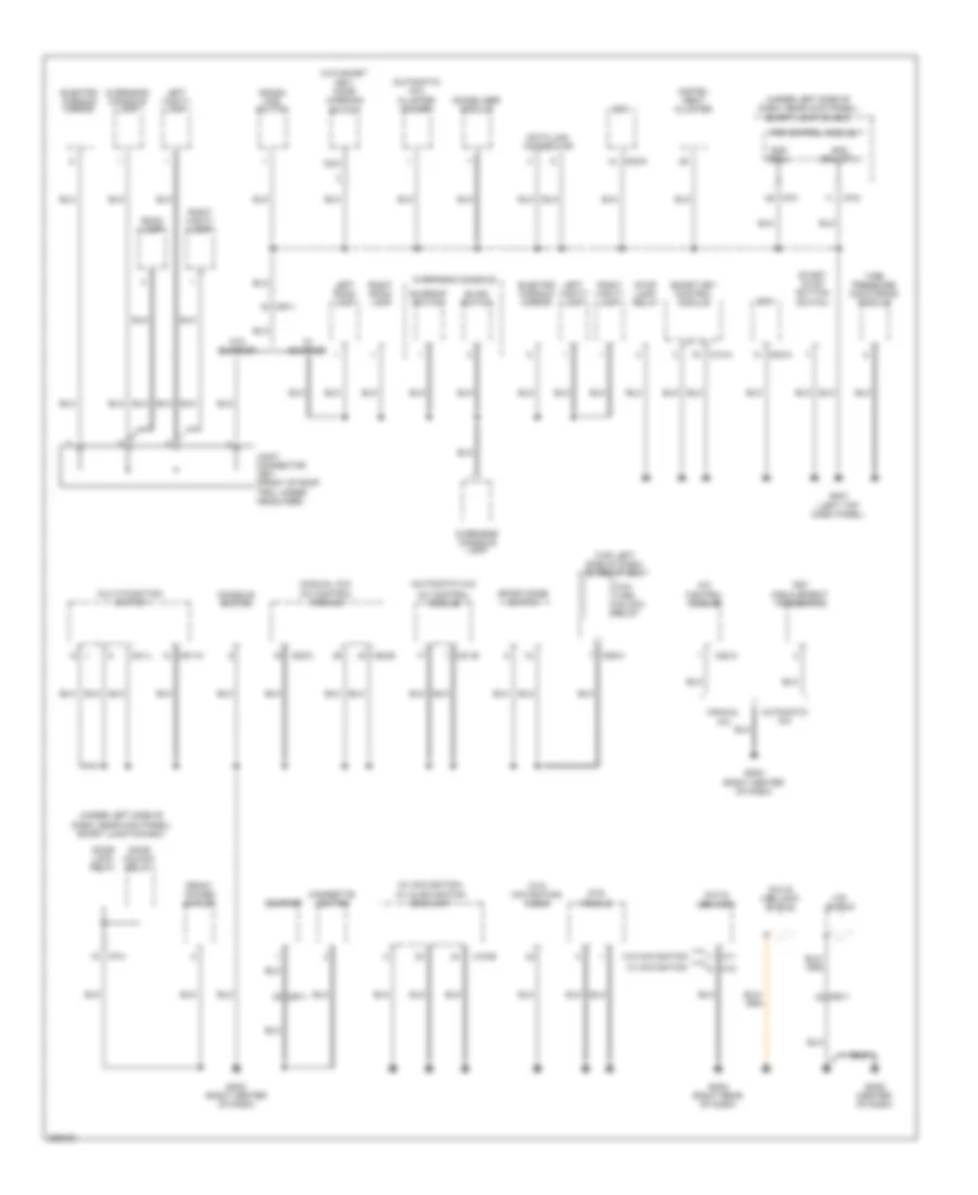
Ground Distribution Wiring Diagram (1 of 3) for Hyundai Elantra GT 2013
List of elements for Ground Distribution Wiring Diagram (1 of 3) for Hyundai Elantra GT 2013:
- (automatic a/c)
- (automatic a/c) cluster ionizer
- (manual a/c) a/c control module
- (top left side of dash) icm relay box
- (under left side of dash, near kick panel) smart junction box
- (w/ navigation) a/v & navigation head unit
- (w/o navigation) audio
- (w/o smart key) door warning switch
- A/c control module
- Automatic a/c
- Aux & usb jack
- Aux & usb jack shield
- Bcm
- Blind switch
- Cigarette lighter
- Console switch
- Crash pad switch
- Data link connector
- Door lock relay
- Door unlock relay
- Electro chromic mirror
- Fet (field effect transistor)
- Front power outlet
- Gm01 (left top dash panel)
- Gm02 (right center of dash)
- Gm03 (right rear of dash)
- Gm04 (right center of dash)
- Gm05 (center of dash)
- Gnd (drl opt)
- Gnd (ecu)
- I/p-f
- I/p-g
- I/p-h
- Immobilizer module
- Instru- ment cluster
- Ips control module
- Joint connector jr01 (front of roof trim, under headliner)
- Left room lamp
- Left vanity lamp
- M01-l
- M01-w
- M02-a
- M02-d
- M06-a
- M11
- M12
- M13-a
- M15-b
- M21-b
- M22-a
- M22-b
- M22-c
- Manual a/c
- Mic shield
- Mr11
- Mts module
- Multi-function switch
- Nca
- Overhead console
- Overhead console lamp
- Right room lamp
- Right vanity lamp
- Room lamp
- Smart key control module
- Sport mode switch
- Start stop button switch
- Stop lamp relay
- Sunroof
- Sunroof switch
- Tire pressure monitoring module
- Two turn unlock relay
- W/ navigation
- W/ sunroof
- W/o navigation
- W/o sunroof
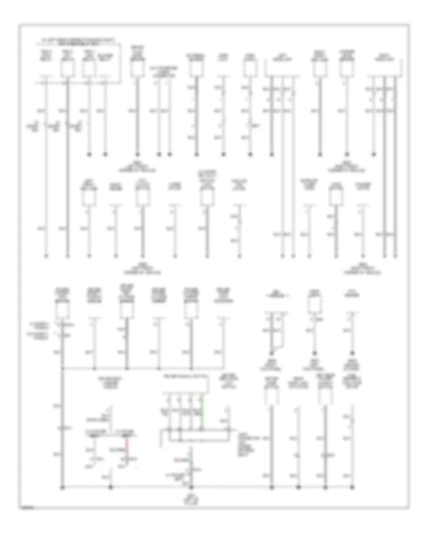
Ground Distribution Wiring Diagram (2 of 3) for Hyundai Elantra GT 2013
List of elements for Ground Distribution Wiring Diagram (2 of 3) for Hyundai Elantra GT 2013:
- (center of dash)
- (in left rear corner of engine compt) e/r fuse & relay box
- (left kick panel)
- (m/t) clutch switch
- (right kick panel)
- (w/ smart key & m/t)
- Blower relay
- Brake fluid level sensor
- Burglar alarm horn
- Cooling fan motor
- D02-a
- D08
- Driver door lock actuator
- Driver door switch
- Driver manual switch
- Driver power outside mirror
- Driver reclining limit switch
- Driver safety window module
- Driver seat warmer module
- Driver smart key outside handle
- E29
- Ee11
- Esc module
- External buzzer
- Fd11
- Fd31
- Front deicer
- Fs11
- Fs12
- Fuel sender & fuel pump motor
- Ge01 (left front corner of vehicle)
- Ge02 (left front corner of vehicle)
- Ge03 (right front corner of vehicle)
- Ge04 (right front corner of vehicle)
- Ge06
- Ge07
- Ge09
- Gf01 (left "b" pillar)
- Hood switch
- Horn (high)
- Horn (low)
- Ignition lock switch
- Joint connector js01 (under driver's seat)
- Left front fog lamp
- Left headlamp
- Left rear power window switch
- Mdps unit
- Multipurpose check connector
- Nca
- Pdm 2 (acc) relay
- Pdm 3 (ig1) relay
- Pdm 4 (ig2) relay
- Power outside mirror switch
- Power window main switch
- Ptc heater
- Rear door lock actuator
- Right front fog lamp
- Right headlamp
- Seat
- W/ power
- W/ power seat
- W/ safety window
- W/ smart key
- W/o power
- W/o safety window
- Washer level sensor
- Washer motor
- Wiper motor
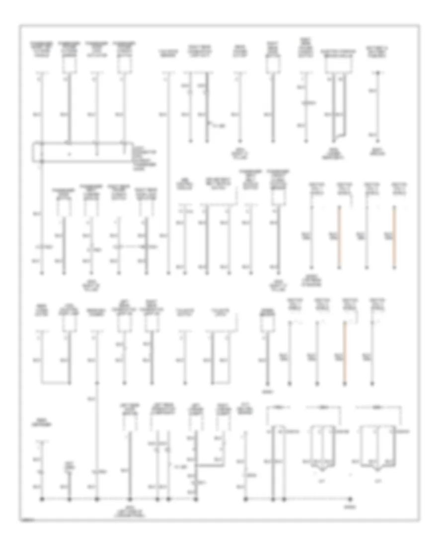
Ground Distribution Wiring Diagram (3 of 3) for Hyundai Elantra GT 2013
List of elements for Ground Distribution Wiring Diagram (3 of 3) for Hyundai Elantra GT 2013:
- (m/t) neutral switch
- (not used)
- A/t
- Battery & battery fuse box
- Body ground
- Cng-aa
- Cng-ab
- Cng-mk
- Driver seat belt buckle switch
- Ec02
- Ecm
- Electric parking brake module
- F15
- Fd21
- Fd41
- Fr11
- Fr21
- Fs21
- Gf02 (right "b" pillar)
- Gf03 (left side of luggage panel)
- Gf04 (right "c" pillar)
- Gf05 (right "c" pillar)
- Gf06 (under rear seat)
- Gng01
- Gng02
- Gng03 (top rear of engine)
- High mounted stop lamp
- Ignition coil 1 shield
- Ignition coil 2 shield
- Ignition coil 3 shield
- Ignition coil 4 shield
- Joint connector jd02 (in front passenger door)
- Left license lamp
- Left rear combination lamp (in)
- Left rear combination lamp (out)
- Left rear door switch
- M/t
- Nca
- Passenger door lock actuator
- Passenger door switch
- Passenger power outside mirror
- Passenger power window switch
- Passenger seat belt buckle switch
- Passenger seat warmer module
- Passenger smart key outside handle
- Passenger weight classi- fication sensor
- Pcm
- Rear defogger
- Rear power outlet
- Rear wiper motor
- Rearview camera
- Right license lamp
- Right rear combination lamp (in)
- Right rear combination lamp (out)
- Right rear door lock actuator
- Right rear door switch
- Right rear power window switch
- Speed sensor
- Srs control module
- Tailgate latch
- Tailgate switch
- W/ led
- Yaw rate sensor
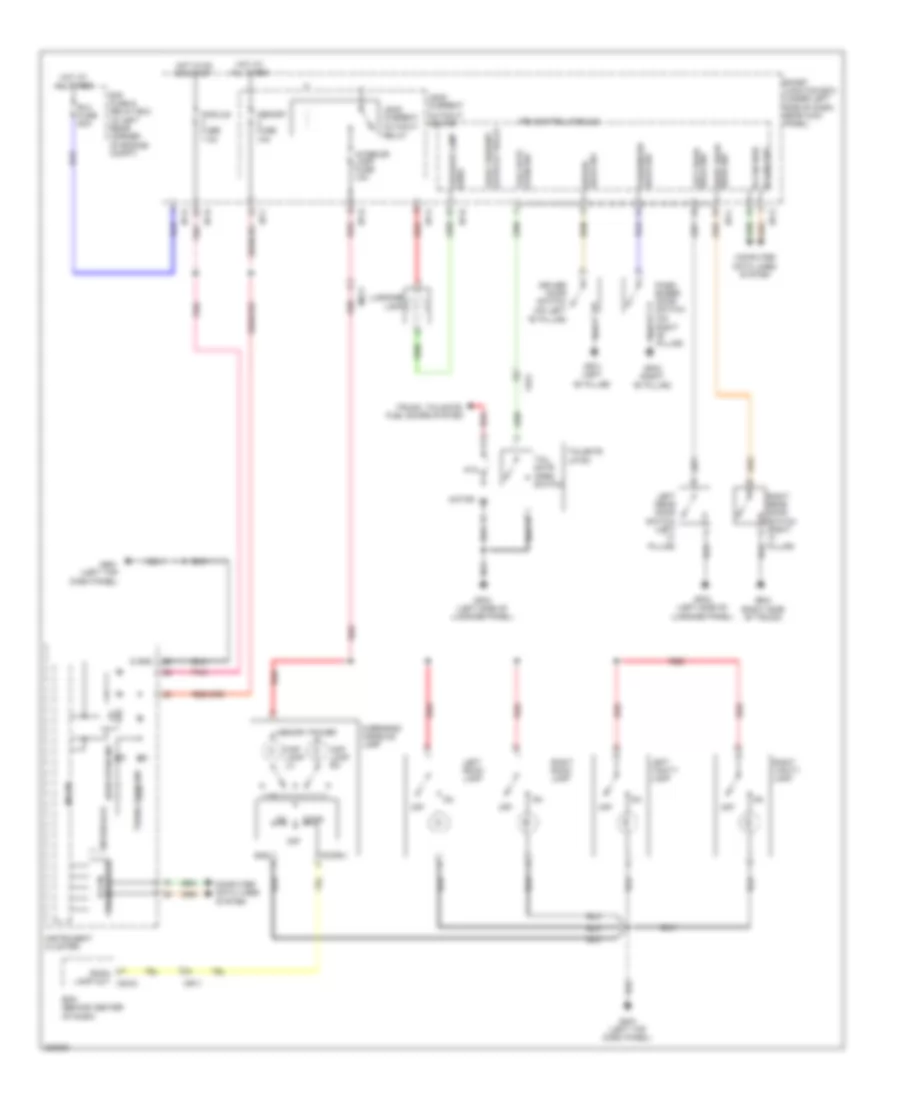
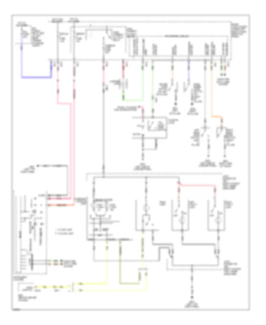
HEADLIGHTS
Autolamps Wiring Diagram for Hyundai Elantra GT 2013
List of elements for Autolamps Wiring Diagram for Hyundai Elantra GT 2013:
- Auto
- Auto lamp switch
- Auto light & photo sensor (top center of dash)
- Auto light sensor gnd
- Auto light sensor pwr
- Auto light sensor sig
- B+1 fuse 60a
- B+2 fuse 60a
- B-can
- B-can high
- B-can low
- Bcm (behind center of dash)
- Computer data lines system
- Corner of engine compt)
- Dimmer/ passing switch
- E/r fuse & relay box (in left rear
- Fog lamp switch
- Front fog lamp ind
- Ge01 (left front corner of vehicle)
- Ge02 (left front corner of vehicle)
- Ge03 (right front corner of vehicle)
- Ge04 (right front corner of vehicle)
- Gm01 (left top dash panel)
- Gm02 (right center of dash)
- Ground (drl)
- Head
- Headlamp hi switch
- Headlamp lo signal
- Headlamps switch
- High
- High beam ind
- Hot at all times
- I/p-d
- I/p-e
- I/p-f
- I/p-g
- Instrument cluster
- Interface
- Ips 1 (arisu-lt 4ch)
- Ips 3
- Ips 3 ctrl
- Ips 4 (arisu-lt 4ch)
- Ips 5
- Ips 6
- Ips control module
- Leak current autocut device
- Left front fog lamp
- Left headlamp
- Light switch
- Low
- Low pass
- M01-l
- M02-a
- M02-b
- M02-c
- M02-d
- Memory 2 fuse 10a
- Memory pwr
- Micom
- Multi fuse
- Multi-function switch
- Nca
- Off
- Pass
- Pnk
- Red
- Right front fog lamp
- Right headlamp
- Smart junction box (under left side of dash, near kick panel)
- Static lamp
- Tail
- Tail lamp switch
- Transceiver
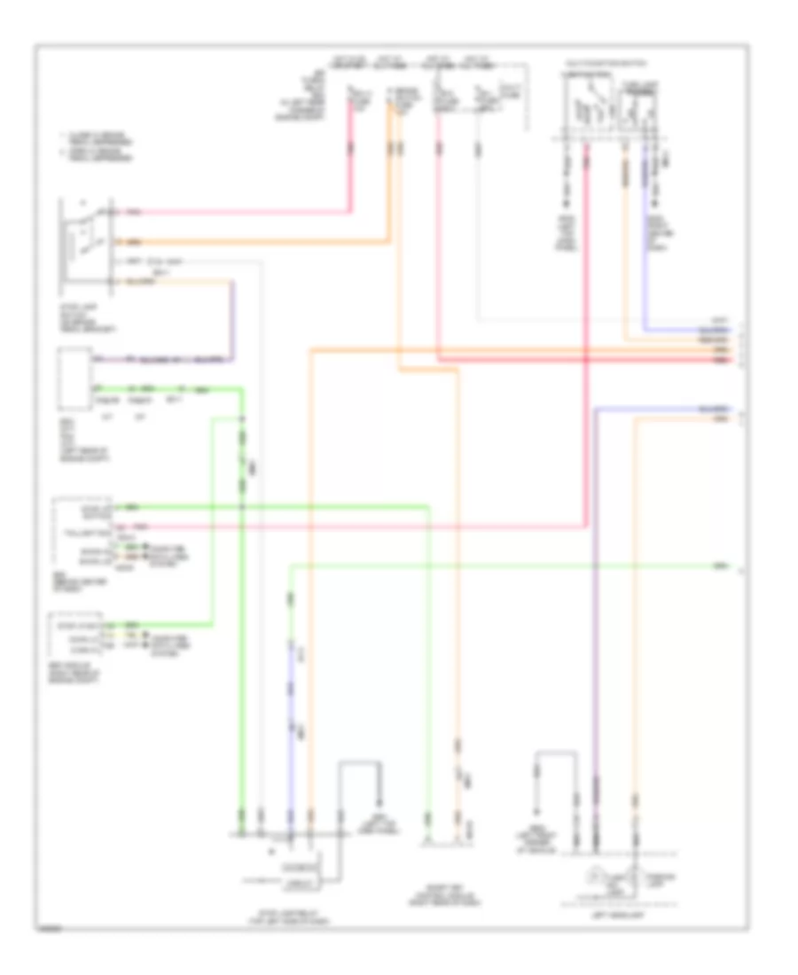
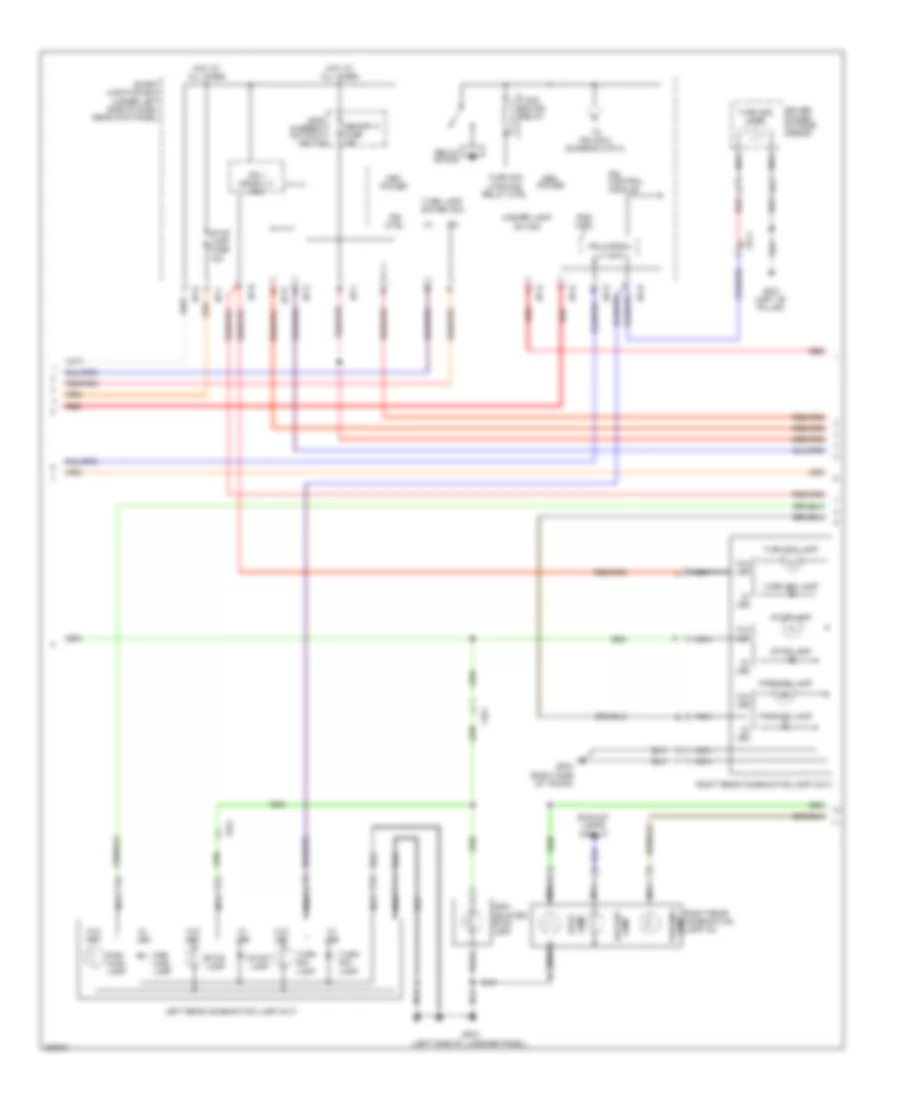
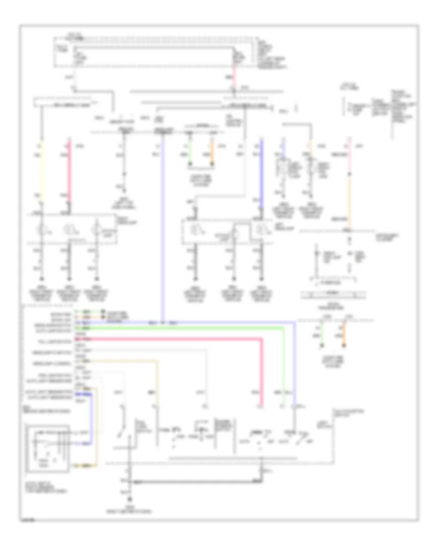
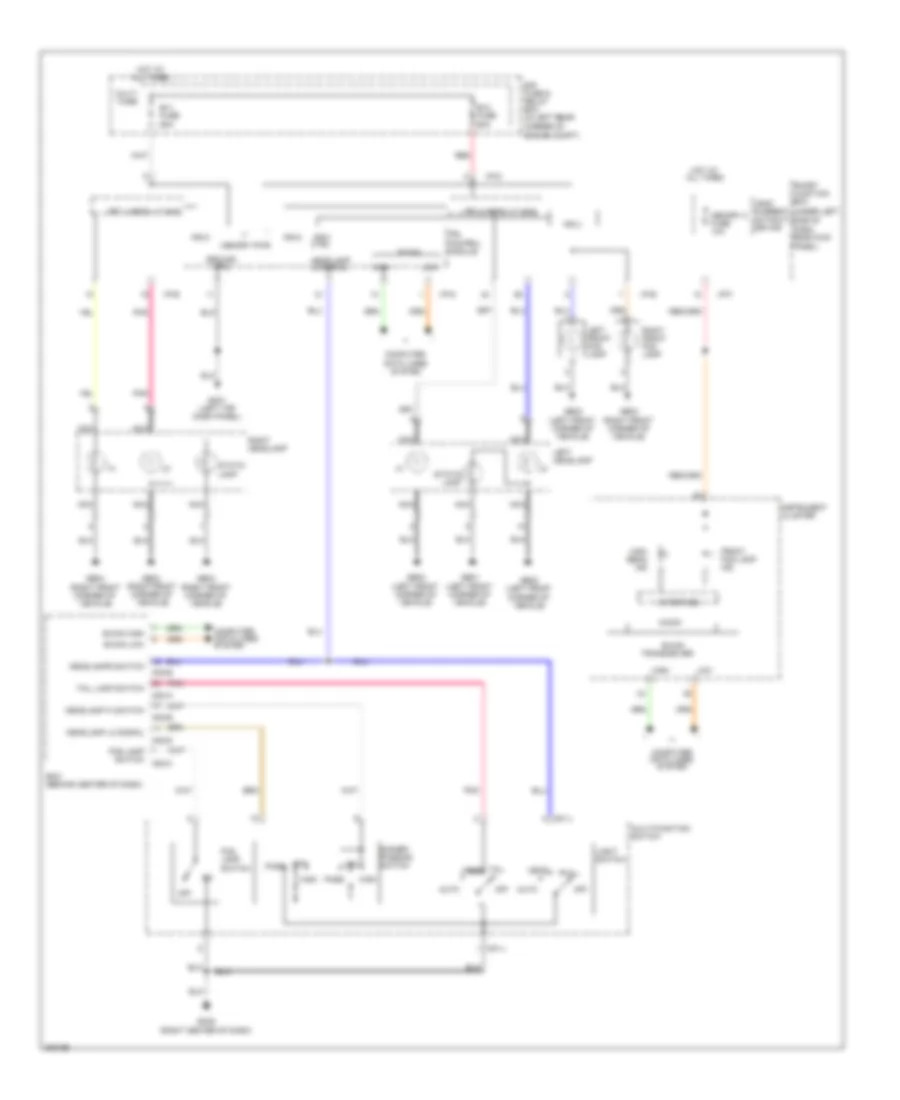
Headlamps Wiring Diagram for Hyundai Elantra GT 2013
List of elements for Headlamps Wiring Diagram for Hyundai Elantra GT 2013:
- (under left
- Auto
- B+1 fuse 60a
- B+2 fuse 60a
- B-can
- B-can high
- B-can low
- Bcm (behind center of dash)
- Computer data lines
- Computer data lines system
- Corner of engine compt)
- Dimmer/ passing switch
- E/r fuse & relay box (in left rear
- Fog lamp switch
- Front fog lamp ind
- Ge01 (left front corner of vehicle)
- Ge02 (left front corner of vehicle)
- Ge03 (right front corner of vehicle)
- Ge04 (right front corner of vehicle)
- Gm01 (left top dash panel)
- Gm02 (right center of dash)
- Ground (drl)
- Head
- Headlamp hi switch
- Headlamp lo signal
- Headlamps switch
- High
- High beam ind
- Hot at all times
- I/p-d
- I/p-e
- I/p-f
- I/p-g
- Instrument cluster
- Interface
- Ips 1 (arisu-lt 4ch)
- Ips 3
- Ips 3 ctrl
- Ips 4 (arisu-lt 4ch)
- Ips 5
- Ips 6
- Ips control module
- Leak current autocut device
- Left front fog lamp
- Left headlamp
- Light switch
- Low
- Low pass
- M01-l
- M02-a
- M02-b
- M02-c
- M02-d
- Memory 2 fuse 10a
- Memory pwr
- Micom
- Multi fuse
- Multi-function switch
- Nca
- Off
- Panel)
- Pass
- Pnk
- Red
- Right front fog lamp
- Right headlamp
- Side of dash, near kick
- Smart junction box
- Static lamp
- System
- Tail
- Tail lamp switch
- Transceiver
HORN
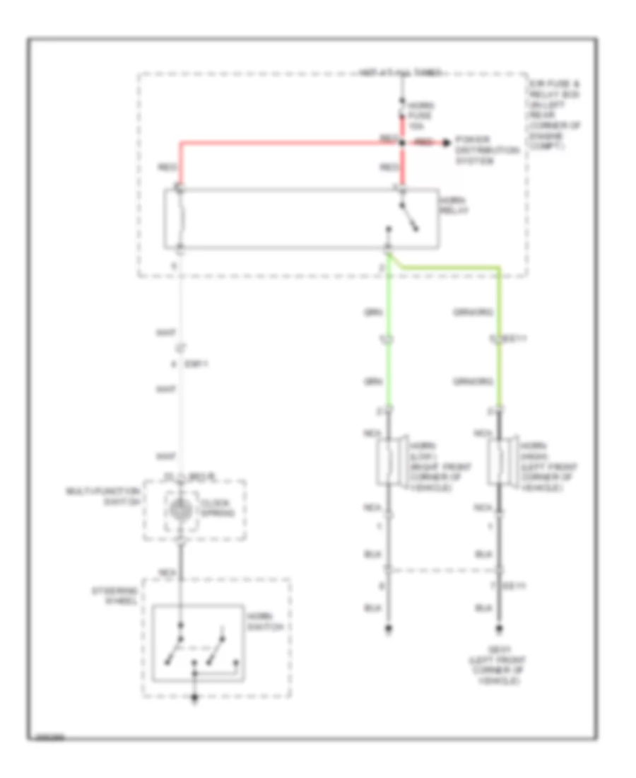
Horn Wiring Diagram for Hyundai Elantra GT 2013
List of elements for Horn Wiring Diagram for Hyundai Elantra GT 2013:
- Clock spring
- E/r fuse & relay box (in left rear corner of engine compt)
- Ee11
- Em11
- Ge01 (left front corner of vehicle)
- Horn (high) (left front corner of vehicle)
- Horn (low) (right front corner of vehicle)
- Horn fuse 15a
- Horn relay
- Horn switch
- Hot at all times
- M01-r
- Multi-function switch
- Nca
- Power distribution system
- Red
- Steering wheel
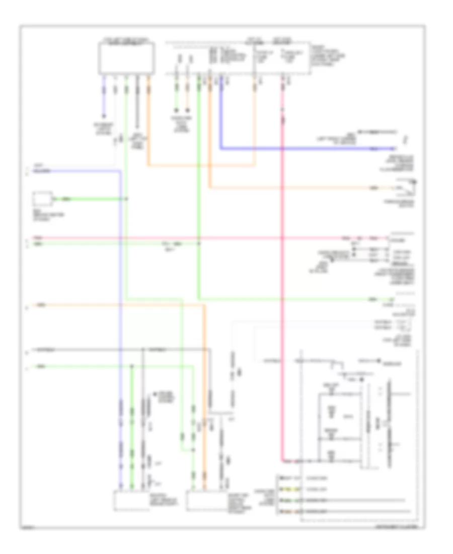
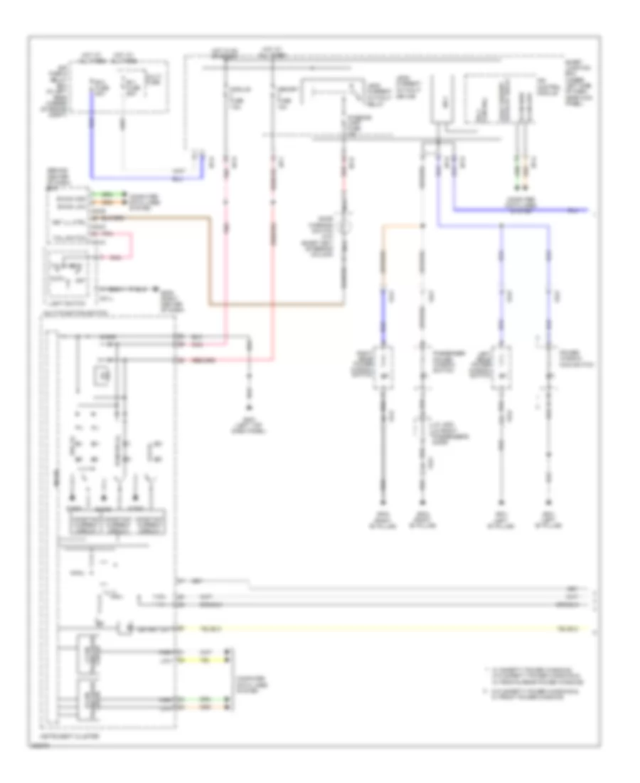
INSTRUMENT CLUSTER
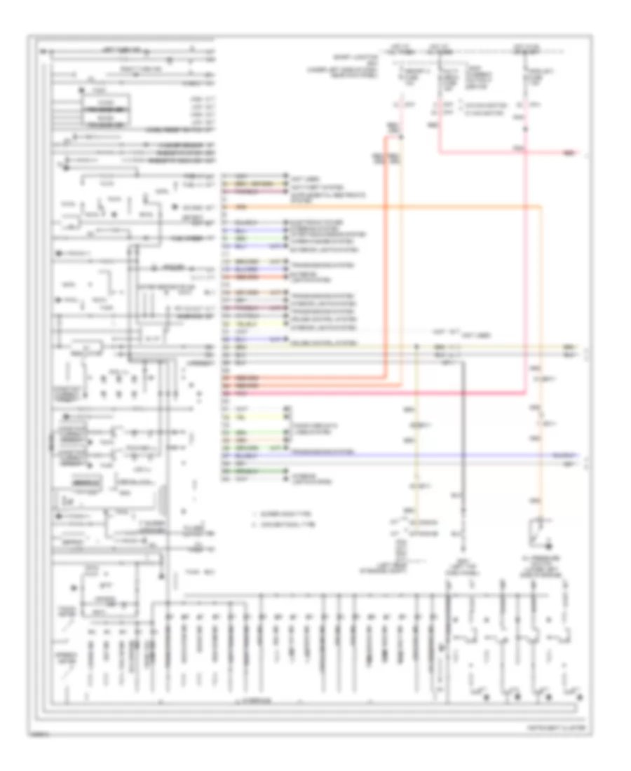
Instrument Cluster Wiring Diagram (1 of 2) for Hyundai Elantra GT 2013
List of elements for Instrument Cluster Wiring Diagram (1 of 2) for Hyundai Elantra GT 2013:
- (a/t)
- (m/t)
- (not used)
- (under left side of dash, near kick panel)
- 4ch i/c
- 5v i/f
- 5v regulator
- A/t
- Abs ind
- Air bag ind
- Anti-theft system
- B-can
- Brake ind
- Buzzer
- C-can
- Charge
- Charge ind
- Check engine ind
- Cng-ab
- Cng-mk
- Computer data lines system
- Constant current circuit
- Conventional type
- Cruise control system
- Cruise ind
- D out
- Detent out
- Dial ill
- Door open ind
- Ec11
- Eeprom
- Electronic power steering system starting/charging system
- Em11
- Epb ind
- Eps ind
- Esc ind
- Esc off ind
- Exterior lights system
- Ffv 5v out
- Flex steer
- Fuel (+)
- Fuel (-)
- Gm01 (left top dash panel)
- Grafic ic
- High
- High beam ind
- Hot at all times
- Hot in on or start
- I/f
- I/p-f
- I/p-h
- Ig+
- Ill (-)
- Immo ind
- Ind eco (green)
- Instrument cluster
- Interface
- Interior lights system
- Lamp ind front fog
- Lcd ill
- Leak current autocut device
- Left turn ind
- Low
- Low fuel ind
- M/t
- Memory 2 fuse 10a
- Mf11
- Micom
- Model/reset switch
- Module 3 fuse 7.5a
- Multi- media fuse 15a
- N out
- Nca
- Oil pres
- Oil pressure ind
- Oil pressure switch (lower left side of engine)
- P out
- Pcm (a/t) ecm (m/t) (left rear of engine compt)
- Pnk
- Pointer ill
- Pulses output
- R input
- R out
- Red
- Rheostat down sw
- Rheostat up sw
- Right turn ind
- Rom
- Seat belt ind
- Set ind
- Smart junction box
- Snsr gnd
- Speaker
- Speedo- meter
- Supervision type
- Sw gnd
- Tacho- meter
- Tail on ind
- Temp high ind
- Tft 5v, 3.3v
- Tft lcd
- Tpms tread ind
- Transceiver
- Transmissions system
- Trunk open ind
- Vehicle speed
- W/ navigation
- W/o navigation
- Washer sensor
- Water separate ind
- Wiper/washer system
Instrument Cluster Wiring Diagram (2 of 2) for Hyundai Elantra GT 2013
List of elements for Instrument Cluster Wiring Diagram (2 of 2) for Hyundai Elantra GT 2013:
- (+)
- (-)
- (below center of rear seat) fuel sender & fuel pump motor
- (right rear of dash) gm03
- (under left side of dash, near kick panel)
- Acc/on input
- Audio (w/o navigation) a/v & navigation head unit (w/ navigation)
- B-can
- Brake fluid level sensor (in brake fluid reservoir)
- Brake oil level
- Clock
- Clock spring
- Computer data lines system
- Detent
- Door sw sig
- Driver door switch (on left "b" pillar)
- Drv
- Em11
- Empty
- Esc module (right rear of engine compt)
- Fr21
- Fuel level float
- Fuel sender
- Full
- Ge01 (left front corner of vehicle)
- Gf01 (left "b" pillar)
- Gf02 (right "b" pillar)
- Gf03 (left side of luggage panel)
- Gf04 (right side of trunk)
- Ground
- High
- Hot in acc or on
- I/p-c
- I/p-e
- I/p-g
- I/p-h
- Ill
- Interior lights system
- Ips control module
- Left rear door switch (left "c" pillar)
- Low
- M01-r
- M09-a
- M09-b
- M15-a
- M15-b
- Memory power
- Module 6 fuse 10a
- Multi-function switch
- Nca
- Parking brake sw
- Parking brake switch
- Pass
- Passenger door switch (on right "b" pillar)
- Red
- Reset
- Right rear door switch (right "c" pillar)
- Right trip switch
- Smart junction box
- Steering wheel
- Tailgate latch
- Tailgate open sw
- Tailgate open switch
- Trip
- Trip (+)
- Trip (-)
- W/ navigation
- W/o navigation
INTERIOR LIGHTS
Courtesy Lamps Wiring Diagram, with Sunroof for Hyundai Elantra GT 2013
List of elements for Courtesy Lamps Wiring Diagram, with Sunroof for Hyundai Elantra GT 2013:
- "b" pillar)
- Autocut device
- Autocut relay
- B+3 fuse 50a
- B-can high
- B-can low
- Bcm (behind center of dash)
- Computer data lines system
- Door
- Door open ind
- Door sw driver
- Door sw left rear
- Door sw passenger
- Door sw right rear
- Door(-)
- Driver door switch (on left
- E/r fuse & relay box (in left rear corner of engine compt)
- Fr21
- Gf01 (left
- Gf02 (right
- Gf03 (left side of luggage panel)
- Gf04 (right side of trunk)
- Gm01 (left top dash panel)
- Gnd
- Hot at all times
- Hot in on or start
- I/p-a
- I/p-b
- I/p-c
- I/p-d
- I/p-f
- I/p-g
- I/p-h
- Instrument cluster
- Interface
- Interior lamp fuse 10a
- Ips control module
- Leak current
- Leak current autocut relay
- Left rear door switch (left "c" pillar)
- Left room lamp
- Left vanity lamp
- Luggage lamp
- Luggage lamp (gnd)
- Map lamp lh
- Map lamp rh
- Memory fuse 10a
- Memory power
- Micom
- Module fuse 7.5a
- Motor
- Mr11
- Off
- Overhead console lamp
- Pass- enger door switch (on
- Pnk
- Ptc
- Red
- Reg 5v
- Right
- Right rear door switch (right "c" pillar)
- Right room lamp
- Right vanity lamp
- Room lamp out m02-d
- S gnd
- Smart junction box (under left side of dash, near kick panel)
- Tail gate open sw
- Tail gate open switch
- Tailgate latch
- Transceiver b-can
- Trunk open ind
- Trunk, tailgate, fuel doors system
Courtesy Lamps Wiring Diagram, without Sunroof for Hyundai Elantra GT 2013
List of elements for Courtesy Lamps Wiring Diagram, without Sunroof for Hyundai Elantra GT 2013:
- "b" pillar)
- Autocut device
- Autocut relay
- Autocut relay leak current
- B+3 fuse 50a
- B-can high
- B-can low
- Bcm (behind center of dash)
- Computer data lines system
- Door
- Door sw driver
- Door sw left rear
- Door sw passenger
- Door sw right rear
- Door(-)
- Driver door switch (on left
- E/r fuse & relay box (in left rear corner of engine compt)
- Fr21
- Gf01 (left
- Gf02 (right
- Gf03 (left side of luggage panel)
- Gf04 (right side of trunk)
- Gm01 (left top dash panel)
- Gnd
- Hot at all times
- Hot in on or start
- I/p-a
- I/p-b
- I/p-c
- I/p-d
- I/p-f
- I/p-g
- I/p-h
- Ind door open
- Instrument cluster
- Interface
- Interior lamp fuse 10a
- Ips control module
- Joint connector jr01 (front of roof trim, under headliner)
- Leak current
- Left rear door switch (left "c" pillar)
- Left vanity lamp
- Luggage lamp
- Luggage lamp (gnd)
- Map lamp lh
- Map lamp rh
- Memory fuse 10a
- Memory power
- Micom
- Module fuse 7.5a
- Motor
- Mr11
- Nca
- Off
- Overhead console lamp
- Pass- enger door switch (on
- Pnk
- Ptc
- Red
- Reg 5v
- Right
- Right rear door switch (right "c" pillar)
- Right vanity lamp
- Room lamp
- Room lamp out m02-d
- Room(+)
- S gnd
- Smart junction box (under left side of dash, near kick panel)
- Tail gate open sw
- Tail gate open switch
- Tailgate latch
- Transceiver c-can
- Trunk open ind
- Trunk, tailgate, fuel doors system
- W/ map lamp
- W/o map lamp
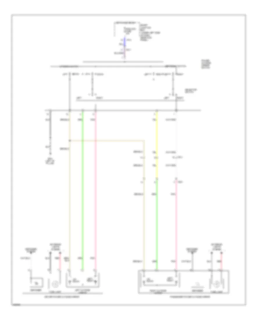
Instrument Illumination Wiring Diagram (1 of 2) for Hyundai Elantra GT 2013
List of elements for Instrument Illumination Wiring Diagram (1 of 2) for Hyundai Elantra GT 2013:
- (behind center of dash) bcm
- 5v reg
- Auto
- Autocut device
- Autocut relay
- Autocut relay leak current
- B+1 fuse 60a
- B+3 fuse 50a
- B-can
- B-can high
- B-can low
- C-can
- Computer data lines system
- Constant current circuit
- Detent out
- Dial ill
- Door warning switch (w/o smart key) (steering column)
- E/r fuse & relay box (in left rear corner of engine compt)
- Fd21
- Fd31
- Fd41
- Gf01 (left "b" pillar)
- Gf02 (right "b" pillar)
- Gm01 (left top dash panel)
- Gm02 (right center of dash)
- Head
- High
- Hot at all times
- Hot in on or start
- I/f
- I/p-b
- I/p-d
- I/p-f
- I/p-g
- I/p-h
- Ill (-)
- Instrument cluster
- Interior lamp fuse 10a
- Ips 7
- Ips 7 control
- Ips control module
- J/c jd02 (in front passenger's door)
- Key ill ctrl
- Lcd ill
- Leak current
- Left rear power window switch
- Light switch
- Low
- M01-l
- M02-a
- M02-b
- M02-d
- Memory fuse 10a
- Micom
- Module fuse 7.5a
- Multi fuse
- Multi-function switch
- Nca
- Off
- Passenger power window switch
- Pnk
- Pointer ill
- Power window main switch
- Red
- Right rear power window switch
- S gnd
- S-gnd
- Smart junction box (under left side of dash, near kick panel)
- Tail
- Tail switch
- Transceiver ceiver
- W/ safefty power windows, w/o safefty power windows & w/ front& rear power windows
- W/o safefty power windows & w/ front power windows
Instrument Illumination Wiring Diagram (2 of 2) for Hyundai Elantra GT 2013
List of elements for Instrument Illumination Wiring Diagram (2 of 2) for Hyundai Elantra GT 2013:
- (ill-)
- (left top dash panel) gm01
- A/c control module (below center m21-a of dash)
- A/t
- A/v & navigation head unit
- Audio
- Automatic a/c
- Aux & usb jack
- B-can high
- B-can low
- Clock spring
- Computer data lines system
- Console switch
- Crash pad switch (left side of dash)
- Electric parking brake switch
- Electro- chromic mirror
- Ff01
- Gm01 (left top dash panel)
- Gm03 (right rear of dash)
- Ill(+)
- Ill(-)
- Inside mirror switch
- J/c jr01 (front of roof trim, under headliner)
- Left audio remote control switch
- M01-r
- M09-a
- M13-a
- M13-c
- M15-a
- M21-a
- M22-b
- Manual a/c
- Mf11
- Mood lamp
- Mr11
- Multi- function switch
- Nca
- Pwr ssb ill
- Red
- Rheostat switch
- Smart key control module (right rear of dash)
- Ssb ill gnd
- Ssb ill pwr
- Start stop button switch
- Steering wheel
- W/ navigation
- W/ sunroof
- W/o navigation
- W/o sunroof
NAVIGATION
Mobile Telematic System Wiring Diagram for Hyundai Elantra GT 2013
List of elements for Mobile Telematic System Wiring Diagram for Hyundai Elantra GT 2013:
- A/bag
- A/v & navigation head unit (w/ navigation) audio (w/o navigation)
- Acc/on in
- Audio in (+)
- Audio in (-)
- Audio out (+)
- Audio out (-)
- Av_tail
- Backup sig
- Bcm (behind center of dash)
- Bcm_rx
- Bcm_tx
- C-can hi
- C-can lo
- Computer data lines system
- Crash output
- Electrochromic mirror
- Exterior lights system
- Gm03 (right rear of dash)
- Gnd
- Hot at all times
- Hot in acc or on
- Hot in on or start
- I/p-f
- I/p-h
- J/c jm03 (top left side of dash)
- Keypad gnd
- Keypad sig
- Leak current autocut device
- M-can hi
- M-can lo
- M02-b
- M02-c
- M09-b
- M15-a
- M15-b
- M15-c
- M51
- Mem power
- Mic (+)
- Mic (-)
- Mic (front left side of roof)
- Mic out (+)
- Mic out (-)
- Mic shield
- Module 3 fuse 7.5a
- Module 6 fuse 10a
- Mr11
- Mts module (center of dash)
- Multi media fuse 10a
- Nca mic (+)
- Nca mic (-)
- On/start in
- Red
- Rx (+)
- Rx (-)
- Shield gnd
- Smart junction box (under left side of dash, near kick panel)
- Srs control module (under front of center console)
- Sw1
- Sw2
- Sw3
- Tx (+)
- Tx (-)
- W/ navigation
- W/o navigation
Navigation Wiring Diagram (1 of 2) for Hyundai Elantra GT 2013
List of elements for Navigation Wiring Diagram (1 of 2) for Hyundai Elantra GT 2013:
- (+)
- (-)
- (usb high speed cable)
- A/v & navigation head unit
- A/v tail
- Acc/on in
- Alt l
- Antenna pwr
- Anti-lock brakes & transmissions systems
- Audio (+)
- Audio (-)
- Audio remote
- Aux detect
- Aux gnd
- Aux ipod video sig
- Aux l in
- Aux r in
- Aux v gnd
- B/t in
- B/t out
- Backup sig
- Bcm (behind center of dash)
- Call/ off
- Call/ on
- Camera gnd
- Camera pwr
- Camera vgnd
- Camera video (+)
- Circuit
- Clock spring
- Computer data lines system
- Cruise control system
- Door unlock
- F/cable
- Feeder cable
- Fl (+)
- Fl (-)
- Fr (+)
- Fr (-)
- Fr21
- Gm03 (right rear of dash)
- Gnd
- Hot at all times
- Hot in acc or on
- I/p-f
- I/p-h
- Ill
- Ill (+)
- Ill (-)
- Instrument cluster
- Interior lights system
- Interior lights system exterior lights system
- Leak current autocut device
- Left audio remote control switch
- M-can high
- M-can low
- M01-r
- M02-c
- M15-a
- M15-b
- M15-usb
- Memory pwr
- Mf61
- Mic (+)
- Mic (-)
- Mic (front left side of roof)
- Mode
- Module 6 fuse 10a
- Mr11
- Multi media fuse 15a
- Multi-function switch
- Mute
- Nca
- Parking brk sw
- Red
- Remote gnd
- Rl (+)
- Rl (-)
- Roof antenna (rear of roof panel)
- Rr (+)
- Rr (-)
- Seek down
- Seek up
- Smart junction box (under left side of dash, near kick panel)
- Steering wheel
- Tx unlock
- Usb d (+)/ipod rx
- Usb d (+)/ipod tx
- Usb/ipod 5v
- Usb/ipod gnd
- Vehicle speed sig
- Voice
- Vol down
- Vol up
Navigation Wiring Diagram (2 of 2) for Hyundai Elantra GT 2013
List of elements for Navigation Wiring Diagram (2 of 2) for Hyundai Elantra GT 2013:
- A/v & navigation head unit
- Audio in (+)
- Audio in (-)
- Audio out (+)
- Audio out (-)
- Aux & usb jack
- Aux detect
- Aux gnd
- Aux l in
- Aux r in
- Aux v gnd
- Aux video out
- Backup lmps sig
- Bcm rx
- Camera gnd
- Camera pwr
- Camera vgnd
- Camera video out
- Driver door speaker
- Driver door tweeter speaker
- Exterior lights system
- Fd11
- Fd21
- Fd31
- Fd41
- Fr21
- Gf03 (left side of luggage panel)
- Gm03 (right rear of dash)
- Gnd
- Ground
- Hot at all times
- Hot in on or start
- I/p-b
- Ill (+)
- Interior lights system
- Left rear door speaker
- M12
- M12-usb
- M15-c
- Memory pwr
- Mf11
- Mf61
- Module 2 fuse 7.5a
- Mts module (center of dash)
- Nca
- On/start in
- Passenger door speaker
- Passenger door tweeter speaker
- Rear view camera (center of tailgate)
- Red
- Right rear door speaker
- Rs422 gnd
- Rs422 rx (+)
- Rs422 rx (-)
- Rs422 tx (+)
- Rs422 tx (-)
- Smart junction box (under left side of dash, near kick panel)
- Tgat open fuse 10a
- Usb d (+)/ipod rx
- Usb d (+)/ipod tx
- Usb high speed cable
- Usb/ipod 5v
- Usb/ipod gnd
POWER DISTRIBUTION
Power Distribution Wiring Diagram (1 of 6) for Hyundai Elantra GT 2013
List of elements for Power Distribution Wiring Diagram (1 of 6) for Hyundai Elantra GT 2013:
- (in left rear corner of engine compt)
- (in left rear corner of engine compt) e/r fuse & relay box
- A/c relay (manual a/c)
- A/con fuse 30a
- A/t
- Abs 1 fuse 40a
- Abs 2 fuse 20a
- Alt fuse 150a
- Alternator
- Ams fuse 7.5a
- B+1 fuse 60a
- B+2 fuse 60a
- B+3 fuse 50a
- B/alarm horn relay
- Battery
- Battery & battery fuse box
- Blower fuse 40a
- Blower relay
- Body ground
- Brake switch fuse 10a
- C/fan fuse 40a
- Chg-mk
- Cng-aa
- Cng-ab
- Cng-mk
- Cooling fan (high) relay
- Cooling fan (low) relay
- Deicer fuse 15a
- Deicer relay
- Driver seat warmer module
- E/r fuse & relay box
- E/r-cngb
- E/r-ems
- E29
- Ec01
- Ec02
- Ecm
- Ecu 4 fuse 15a
- Ef31
- Electric parking brake module
- Em11
- Ems box
- Ems fuse 60a
- Engine control relay
- Epb 1 fuse 30a
- Epb 2 fuse 30a
- Esc module
- F/pump fuse 15a
- F/pump relay
- From mdps fuse (diagram 1 of 6)
- From multi fuse (diagram 1 of 6)
- Fs11
- Fs12
- Fs21
- Fuse (diagram 1 of 6)
- Gsl ptc fuse 60a
- Horn fuse 15a
- Horn relay
- Icm relay box (top left side of dash)
- M/t
- M06-b
- M13-b
- Mdps fuse 80a
- Mdps unit
- Mf11
- Mf61
- Multi fuse
- Multipurpose check connector
- Passenger seat warmer module
- Pcm
- Pcm (a/t) ecm (m/t)
- Pnk
- Power
- Ptc relay
- Red
- Rr htd fuse 40a
- Rr htd relay
- S/heater frt fuse 20a
- Seat
- Smart key control module
- Start motor
- Stop lamp switch
- To ems box (diagram 1 of 6)
- To horn
- To ig 1 fuse (diagram 2 of 6)
- To smart junction box (diagram 4 of 6)
- To smart junction box (diagram 5 of 6)
- To smart junction box (diagram 6 of 6)
- W/o
- W/o epb
Power Distribution Wiring Diagram (2 of 6) for Hyundai Elantra GT 2013
List of elements for Power Distribution Wiring Diagram (2 of 6) for Hyundai Elantra GT 2013:
- (in left rear corner of engine compt) e/r fuse & relay box
- (or pnk)
- (under left side of dash, near kick panel) smart junction box
- A/bag fuse 15a
- A/bag ind fuse 7.5a
- A/c control module
- Acc
- Automatic a/c
- Bcm
- Bcm fuse 7.5a
- C/lighter fuse 20a
- Cigarette lighter
- Em11
- Em61
- Fr21
- From epb 1 c fuse (diagram 1 of 6)
- From ig 1 fuse (diagram 2 of 6)
- From ig 2 fuse (diagram 2 of 6)
- From pdm 2 (acc) relay (diagram 2 of 6)
- From pdm 3 (ig1) relay (diagram 2 of 6)
- From pdm 4 (ig2) relay (diagram 2 of 6)
- Front power outlet
- Ge01 (left front corner of vehicle)
- Ge02 (left front corner of vehicle)
- Gf04 (right side of trunk)
- Gm02 (right center of dash)
- I/p-a
- I/p-b
- I/p-e
- I/p-f
- I/p-h
- Icm relay box (top left side of dash)
- Ig 1 fuse 20a
- Ig 1 fuse 40a
- Ig 2 fuse 40a
- Ignition switch (w/o smart key)
- Instrument cluster
- Key
- Lock
- M01-w
- M02-a
- M06-b
- M13-a
- M21-a
- M22-b
- Manual a/c
- Mf11
- Module 7 fuse 7.5a
- Multi- function switch
- Nca
- Passenger weight classification sensor
- Pdm 2 (acc) relay
- Pdm 3 (ig1) relay
- Pdm 4 (ig2) relay
- Pnk
- Power outlet frt fuse 15a
- Rear power outlet
- Rear wiper motor
- Rear wiper relay
- Red
- Smart
- Smart key control module
- Srs control module
- Start
- Starter relay
- Starting/ charging system
- To e/r fuse & relay box (diagram 6 of 6)
- To ignition switch (diagram 2 of 6)
- To module 2 fuse (diagram 3 of 6)
- To module 6 fuse (diagram 3 of 6)
- To smart junction box (diagram 2 of 6)
- To wiper frt fuse (diagram 3 of 6)
- W/ smart key
- W/o
- W/o smart key
- Wiper rr fuse 15a
Power Distribution Wiring Diagram (3 of 6) for Hyundai Elantra GT 2013
List of elements for Power Distribution Wiring Diagram (3 of 6) for Hyundai Elantra GT 2013:
- (not used)
- (under left side of dash, near kick panel)
- (under left side of dash, near kick panel) smart junction box
- A/c control module
- A/con fuse 7.5a
- A/v & navigation head unit
- Audio
- Automatic a/c
- Bcm
- Blower relay
- Cluster ionizer
- Console switch
- Driver seat manual switch
- Driver seat warmer module
- E/r fuse & relay box
- E/r fuse & relay box (in left rear corner of engine compt)
- Electric parking brake module
- Electro chromic mirror (w/ home link)
- Em11
- Fd11
- Fd21
- Fr21
- From a/bag ind fuse k (diagram 2 of 6)
- From ips 8 (2ch) r (diagram 5 of 6)
- From module 4 fuse l (diagram 3 of 6)
- From module 7 fuse m (diagram 2 of 6)
- From power outlet frt j fuse (diagram 2 of 6)
- Fs11
- Fs12
- Fs21
- I/p-a
- I/p-b
- I/p-e
- I/p-f
- I/p-h
- Immobilizer module
- Instrument cluster
- Ips control input module
- Ips control start module input
- M01-w
- M02-a
- M09-a
- M09-b
- M13-a
- M15-b
- M21-b
- M22-b
- M26
- Manual a/c
- Mdps fuse 7.5a
- Mdps unit
- Module 2 fuse 7.5a
- Module 3 fuse 7.5a
- Module 4 fuse 7.5a
- Module 5 fuse 7.5a
- Module 6 fuse 10a
- Mr11
- Mts module
- Multi- function switch
- Nca
- On/
- P/seat drv fuse 30a
- Passenger seat warmer module
- Pdm 3 fuse 7.5a
- Pnk
- Power outside mirror switch
- Ptc relay
- Puddle lamp fuse 10a
- Rear view camera
- Red
- Smart junction box
- Smart junction box (under left side of dash, near kick panel)
- Smart key control module
- Stop lamp relay
- Stop lp fuse 15a
- Sunroof
- Sunroof fuse 20a
- Tire pressure monitoring module
- To mdps fuse (diagram 3 of 6)
- W/ navigation
- W/ power seat
- W/ smart key
- W/o navigation
- W/o power seat
- W/o smart key
- Wiper frt fuse 25a
- Wiper motor
- Wiper relay
Power Distribution Wiring Diagram (4 of 6) for Hyundai Elantra GT 2013
List of elements for Power Distribution Wiring Diagram (4 of 6) for Hyundai Elantra GT 2013:
- (under left side of dash, near kick panel)
- A/c control module
- A/t
- A/v & navigation head unit
- Audio
- Automatic a/c
- Aux & usb jack
- Console switch
- Crash pad switch
- Driver safety window module
- Electric chromic mirror (w/o home link)
- Electric parking brake switch
- Fd11
- Fd21
- Fd31
- Fd41
- Ff01
- Fr21
- From ips control module s (diagram 4 of 6)
- From multi fuse (diagram 1 of 6)
- I/p-b
- I/p-d
- I/p-e
- I/p-g
- I/p-h
- Instrument cluster
- Ips 1 (arisu lt, 4ch)
- Ips 1 ctrl
- Ips 7
- Ips 7 ctrl
- Ips control module
- Left rear power window switch
- M01-r
- M09-a
- M15-a
- M21-a
- M22-b
- Manual a/c
- Mem pwr
- Mf11
- Mood lamp
- Mr11
- Multi- function switch
- Nca
- P/wdw lh fuse 25a
- P/wdw rh fuse 25a
- Passenger power outside mirror
- Passenger power window switch
- Pnk
- Power window lh relay
- Power window main switch (w/ safety power window & w/o safety power window & w/ front & rear power windows)
- Power window main switch (w/o safety power window & w/ front power windows)
- Power window rh relay
- Rear view camera
- Red
- Right headlamp
- Right rear combination lamp (out)
- Right rear power window switch
- Smart junction box
- Tail gate relay
- Tgate open fuse 10a
- To ips 7 (diagram 4 of 6)
- W/ navigation
- W/o navigation
Power Distribution Wiring Diagram (5 of 6) for Hyundai Elantra GT 2013
List of elements for Power Distribution Wiring Diagram (5 of 6) for Hyundai Elantra GT 2013:
- (or nca)
- (under left side of dash, near kick panel)
- (under left side of dash, near kick panel) smart junction box
- (w/o
- A/c control module
- A/v & navigation head unit
- Audio
- Auto light & photo sensor
- Automatic a/c
- Bcm
- Ctrl
- Data link connector
- Door warning switch
- Driver power outside mirror
- Electro chromic mirror (w/ home link)
- Fd11
- Fr11
- Fr21
- From multi fuse (diagram 1 of 6)
- From pdm 2 p fuse (diagram 6 of 6)
- I/p-a
- I/p-b
- I/p-d
- I/p-e
- I/p-f
- I/p-g
- I/p-h
- Immobilizer module
- Instrument cluster
- Interior lamp fuse 10a
- Ips 3
- Ips 3 (1ch)
- Ips 4 (arisu lt, 4ch)
- Ips 8
- Ips 8 (2ch)
- Ips control module
- Ips4 ctrl
- Joint connector jr01
- Leak current autocut device
- Leak current autocut relay
- Leak current autocut rly ctrl
- Leak current autocut sw ctrl
- Leak current autocut switch
- Left front fog lamp
- Left head- lamp
- Left headlamp
- Left license lamp
- Left rear combination lamp (in)
- Left rear combination lamp (out)
- Left room lamp
- Left vanity lamp
- Luggage lamp
- M02-a
- M09-b
- M15-b
- M21-b
- M22-b
- Manual a/c
- Mem pwr
- Memory 1 fuse 7.5a
- Memory 2 fuse 10a
- Mr11
- Mts module
- Multi media fuse 15a
- Nca
- Off
- Overhead console lamp
- Red
- Right front fog lamp
- Right head- lamp
- Right license lamp
- Right rear combination lamp (in)
- Right rear combination lamp (out)
- Right room lamp
- Right vanity lamp
- Room lamp
- Smart junction box
- Smart key)
- Sunroof
- T/ sig sound rly ctrl
- T/sig sound relay
- Tire pressure monitoring module
- To sunroof fuse (diagram 3 of 6)
- W/o
Power Distribution Wiring Diagram (6 of 6) for Hyundai Elantra GT 2013
List of elements for Power Distribution Wiring Diagram (6 of 6) for Hyundai Elantra GT 2013:
- (ill +)
- (ill -)
- (in left rear corner of engine compt)
- (not used)
- (or pnk)
- (or red)
- (under left side of dash, near kick panel)
- (w/ home link) electro chromic mirror
- (w/ smart key) start/stop button switch
- A/t
- A/v & navigation head unit
- Abs 3 fuse 10a
- B/up lp fuse 10a
- Backup lamp switch
- Bcm
- Cng-aa
- Cng-ab
- Cng-mk
- Door lock relay
- Door unlock relay
- Dr lock fuse 20a
- E/r fuse & relay box
- Ec11
- Ecm
- Ecu 3 fuse 10a
- Ecu 6 fuse 15a
- Ef11
- Em11
- Esc module
- Fr21
- From b+3 fuse (diagram 1 of 6)
- From smart junction box (diagram 2 of 6)
- Gm01 (left top dash) panel)
- I/p-d
- I/p-f
- I/p-h
- Icm relay box (top left side of dash)
- Instrument cluster
- Interior lights system
- Joint connector jm04
- Key solenoid (w/o smart key)
- Left rear combination lamp (in)
- M/t
- M02-a
- M06-a
- M13-a
- M13-b
- M13-c
- M15-a
- Mf11
- Module 1 fuse 7.5a
- Mr11
- Mts module
- Multipurpose check connector
- Nca
- Pcm
- Pdm 1 fuse 25a
- Pdm 2 fuse 7.5a
- Pnk
- Rear view camera
- Red
- Right rear combination lamp (in)
- Smart junction box
- Smart key control module
- Sport mode switch
- Ssb amber
- Ssb green
- Ssb ill ground
- Ssb ill power
- Ssb sw 1
- Ssb sw 2
- Stop lamp switch
- Tcu 1 fuse 15a
- To leak current autocut device (diagram 5 of 6)
- Transaxle range switch
- Two turn unlock relay
- Vehicle speed sensor
- Yaw rate sensor
POWER DOOR LOCKS
Power Door Locks Wiring Diagram (1 of 2) for Hyundai Elantra GT 2013
List of elements for Power Door Locks Wiring Diagram (1 of 2) for Hyundai Elantra GT 2013:
- B-can
- Burglar alarm relay control
- Computer data lines system
- Door lock relay
- Door lock relay control
- Door unlock relay
- Door unlock relay control
- Dr lk
- Dr lock fuse 20a
- Dr unlk
- Driver door key unlock signal
- Driver door lock actuator
- Driver door lock/ unlock signal
- Fd11
- Fd31
- Fd41
- Fuel filler actuator (left side of luggage panel)
- Gf01 (left "b" pillar)
- Gf02 (right "b" pillar)
- Gm01 (left top dash panel)
- High
- Hot at all times
- I/p-b
- I/p-c
- I/p-g
- I/p-h
- Ips control module
- Key lk
- Key unlk
- Left rear door lock actuator
- Left rear door lock/ unlock signal
- Low
- Pnk
- Red
- Right rear door lock actuator
- Right rear door lock/ unlock signal
- Smart junction box (under left side of dash, near kick panel)
- Starting/ charging system
Power Door Locks Wiring Diagram (2 of 2) for Hyundai Elantra GT 2013
List of elements for Power Door Locks Wiring Diagram (2 of 2) for Hyundai Elantra GT 2013:
- (right rear of engine compt) burglar alarm horn
- (top left side of dash)
- Auto light & photo sensor (top center of dash)
- B/alarm horn relay
- B/alarm horn relay control
- Bcm (behind center of dash)
- Can h
- Can l
- Computer data lines system
- Door lock
- Door lock switch
- Door unlock
- Dr lk
- Dr unlk
- Driver/ passenger door key lock signal
- E/r fuse & relay box (in left rear corner of engine compt)
- Em11
- Em61
- Fd11
- Fd21
- Ge04 (right front corner of vehicle)
- Gf01 (left "b" pillar)
- Gf02 (right "b" pillar)
- Gm02 (right center of dash)
- Hood switch
- Hood switch (right front of engine compt)
- Horn fuse 15a red
- Horns system
- Hot at all times
- I/p-c
- I/p-e
- I/p-g
- I/p-h
- Icm relay box
- Icm relay box (top left side of dash)
- Ips control module
- J/c jd02 (in front passenger's door)
- Key lk
- Key unlk
- Leak current auto cut device
- Lock
- M02-b
- M02-c
- M06-a
- Memory 2 fuse 10a
- Mf11
- Nca
- Passenger door key unlock signal
- Passenger door lock actuator
- Passenger door lock/ unlock signal
- Passenger power window switch
- Pnk
- Power window main switch
- Red
- Sec ind
- Smart junction box (under left side of dash, near kick panel)
- Two turn un lock relay
- Two turn unlock relay control
- Unlock
- W/ safety power windows
- W/o safety power windows
POWER MIRRORS
Electrochromic Mirror Wiring Diagram, with Home Link for Hyundai Elantra GT 2013
List of elements for Electrochromic Mirror Wiring Diagram, with Home Link for Hyundai Elantra GT 2013:
- Backup signal
- Compass
- Ec mirror control
- Electrochromic mirror
- Exterior lights system
- Gm01 (left top dash panel)
- Gnd
- Hl 1
- Hl 2
- Hl 3
- Home link
- Hot at all times
- Hot in on
- I/p-f
- I/p-h
- J/c jr01 (front of roof trim, under headliner)
- Leak current autocut device
- Memory 2 fuse 10a
- Memory power
- Module 5 fuse 7.5a
- Mr11
- Off
- On input
- Pnk
- Power distribution system
- Smart junction box (under left side of dash, near kick panel)
- W/ sunroof
- W/o sunroof
Electrochromic Mirror Wiring Diagram, without Home Link for Hyundai Elantra GT 2013
List of elements for Electrochromic Mirror Wiring Diagram, without Home Link for Hyundai Elantra GT 2013:
- B+ 1 fuse 60a
- E/r fuse & relay box (in left rear corner of engine compt)
- Electrochromic mirror
- Gm01 (left top dash panel)
- Gm05 (center of dash)
- Gnd
- Hot at all times
- Hot in on or start
- I/p-d
- I/p-f
- I/p-h
- Ill (+)
- Input
- Inside mirror switch
- Ips 7
- Ips 7 control
- Ips control module
- J/c jr01 (front of roof trim, under headliner)
- Keypad
- Keypad gnd
- Keypad sig
- Module 3 fuse 7.5a
- Mr11
- Mts module (center of dash)
- Multi fuse
- On/st
- Sig
- Smart junction box (under left side of dash, near kick panel)
- Sw1
- Sw2
- Sw3
- W/ sunroof
- W/o sunroof
Power Mirrors Wiring Diagram for Hyundai Elantra GT 2013
List of elements for Power Mirrors Wiring Diagram for Hyundai Elantra GT 2013:
- (under left side
- Defogger
- Defogger system
- Down
- Driver power outside mirror
- Exterior lights system
- Fd11
- Fd21
- Gf01 (left "b" pillar)
- Hot in acc or on
- I/p-a
- Left
- Left outside mirror
- Left/ right
- Left/right switch
- Module 6 fuse 10a
- Of dash, near kick
- Panel)
- Passenger power outside mirror
- Pnk
- Power outside mirror switch
- Red
- Right
- Right outside mirror
- Selector switch
- Smart junction box
- Turn lamp
- Up/ down
- Up/down switch
POWER SEATS
Heated Seats Wiring Diagram for Hyundai Elantra GT 2013
List of elements for Heated Seats Wiring Diagram for Hyundai Elantra GT 2013:
- A/c control module (below center of dash)
- Automatic a/c
- Driver cushion warmer
- Driver seat warmer module
- E/r fuse & relay box (in left rear corner of engine compt)
- Em11
- Fs11
- Fs12
- Fs21
- Gf01 (left "b" pillar)
- Gf02 (right "b" pillar)
- Gnd
- High
- High ind
- Hot at all times
- Hot in on
- Hot in on or start
- Htd (+)
- Htd (-)
- I/p-b
- Left seat heater switch
- Low
- Low ind
- M21-a
- M22-b
- M22-c
- Manual a/c
- Memory pwr
- Mf11
- Mf61
- Module 3 fuse 7.5a
- Module 5 fuse 7.5a
- Nca
- Nca htd (+)
- Nca htd (-)
- Nca ntc (+)
- Nca ntc (-)
- Ntc (+)
- Ntc (-)
- On input
- On/st in
- Passenger cushion warmer
- Passenger seat warmer module
- Pnk
- Right seat heater switch
- S/heater frt fuse 20a
- Smart junction box (under left side of dash, near kick panel)
- Sw sig
- Switch
- W/ power seat
- W/o power seat
Power Seats Wiring Diagram for Hyundai Elantra GT 2013
List of elements for Power Seats Wiring Diagram for Hyundai Elantra GT 2013:
- (under driver's seat)
- Bwd
- Driver front height adjuster motor
- Driver front height adjuster switch
- Driver lumbar support motor
- Driver lumbar support switch
- Driver rear height adjuster motor
- Driver rear height adjuster switch
- Driver reclining limit switch
- Driver reclining motor
- Driver reclining switch
- Driver seat manual switch
- Driver slide motor
- Driver slide switch fwd
- Fs12
- Fwd
- Gf01 (left "b" pillar)
- Hot at all times
- I/p-b
- J/c js01
- Nca
- P/seat drv fuse 30a
- Red
- Smart junction box (under left side of dash, near kick panel)
POWER TOP/SUNROOF
Power Top/Sunroof Wiring Diagram for Hyundai Elantra GT 2013
List of elements for Power Top/Sunroof Wiring Diagram for Hyundai Elantra GT 2013:
- (right center of dash) gm02
- Bcm (behind center of dash)
- Blind closed sw
- Blind open sw
- Blind switch
- Closed sw
- Cruise control system
- Gm01 (left top dash panel)
- Ground
- Hot at all times
- Hot in on
- I/p-f
- I/p-h
- M02-a
- Memory pwr
- Mirrors system
- Module 5 fuse 7.5a
- Mr-11
- Mr11
- On input
- Open sw
- Open warming
- Overhead console
- Pnk
- Red
- Sig a
- Sig b
- Sig c
- Smart junction box (under left side of dash, near kick panel)
- Sunroof control module (under headliner)
- Sunroof fuse 20a
- Sunroof switch
- Vehicle speed
POWER WINDOWS
Power Windows Wiring Diagram, with Safety Power Windows (1 of 2) for Hyundai Elantra GT 2013
List of elements for Power Windows Wiring Diagram, with Safety Power Windows (1 of 2) for Hyundai Elantra GT 2013:
- Auto down
- Auto up
- Door lock switch
- Door locks system
- Down
- Driver window switch
- Fd11
- Fd41
- Gf01 (left "b" pillar)
- Hot at all times
- I/p-b
- Ill
- Interior lights system
- Ips control module
- Left rear window switch
- Off
- P/wdw lh fuse 25a
- P/wdw rh fuse 25a
- Passenger window switch
- Pnk
- Power window lh relay
- Power window lh relay control
- Power window main switch
- Power window rh relay
- Power window rh relay control
- Red
- Right rear power window motor
- Right rear power window switch
- Right rear window switch
- Smart junction box (under left side of dash, near kick panel)
Power Windows Wiring Diagram, with Safety Power Windows (2 of 2) for Hyundai Elantra GT 2013
List of elements for Power Windows Wiring Diagram, with Safety Power Windows (2 of 2) for Hyundai Elantra GT 2013:
- (driver's door) driver safety power window module
- Auto
- Com
- Door lock switch
- Door locks system
- Down
- Ecu
- Fd11
- Fd21
- Fd31
- Gf01 (left "b" pillar)
- Gnd
- Hall effect sensor
- Ill
- Interior lights system
- Left rear power window motor
- Left rear power window switch
- Off
- Passenger power window motor
- Passenger power window switch
- Red
- Relay
- Reverse protection & filter
- Shunt resistor
- Sig & filter
- Sig filter
Power Windows Wiring Diagram, without Safety Power Windows with Front & Rear Power Windows (1 of 2) for Hyundai Elantra GT 2013
List of elements for Power Windows Wiring Diagram, without Safety Power Windows with Front & Rear Power Windows (1 of 2) for Hyundai Elantra GT 2013:
- Auto down
- Auto down control unit
- Door lock switch
- Door locks system
- Down
- Driver power window motor
- Driver window switch
- Fd11
- Fd41
- Gf01 (left "b" pillar)
- Ill
- Interior lights system
- Left rear window switch
- Off
- Passenger window switch
- Pnk
- Power window main switch
- Red
- Right rear power window motor
- Right rear power window switch
- Right rear window switch
- Window lock switch
Power Windows Wiring Diagram, without Safety Power Windows with Front & Rear Power Windows (2 of 2) for Hyundai Elantra GT 2013
List of elements for Power Windows Wiring Diagram, without Safety Power Windows with Front & Rear Power Windows (2 of 2) for Hyundai Elantra GT 2013:
- Door lock switch
- Door locks system
- Down
- Fd21
- Fd31
- Hot at all times
- I/p-b
- Ill
- Interior lights system
- Ips control module
- Left rear power window motor
- Left rear power window switch
- Off
- P/wdw lh fuse 25a
- P/wdw rh fuse 25a
- Passenger power window motor
- Passenger power window switch
- Pnk
- Power window lh relay
- Power window lh relay control
- Power window rh relay
- Power window rh relay control
- Red
- Smart junction box (under left side of dash, near kick panel)
Power Windows Wiring Diagram, without Safety Power Windows with Front Power Windows for Hyundai Elantra GT 2013
List of elements for Power Windows Wiring Diagram, without Safety Power Windows with Front Power Windows for Hyundai Elantra GT 2013:
- Auto down
- Control unit auto down
- Door lock switch
- Door locks system
- Down
- Driver power window motor
- Driver window switch
- Fd11
- Fd21
- Gf01 (left "b" pillar)
- Hot at all times
- I/p-b
- Ill
- Interior lights system
- Ips control module
- Off
- P/wdw lh fuse 25a
- P/wdw rh fuse 25a
- Passenger power window motor
- Passenger power window switch
- Passenger window switch
- Pnk
- Power window lh relay
- Power window lh relay control
- Power window main switch
- Power window rh relay
- Power window rh relay control
- Red
- Smart junction box (under left side of dash, near kick panel)
RADIO
Radio Wiring Diagram, with Navigation (1 of 2) for Hyundai Elantra GT 2013
List of elements for Radio Wiring Diagram, with Navigation (1 of 2) for Hyundai Elantra GT 2013:
- (+)
- (-)
- (usb high speed cable)
- A/v & navigation head unit
- A/v tail
- Acc/on in
- Alt l
- Antenna pwr
- Anti-lock brakes & transmissions systems
- Audio (+)
- Audio (-)
- Audio remote
- Aux detect
- Aux gnd
- Aux ipod video sig
- Aux l in
- Aux r in
- Aux v gnd
- B/t in
- B/t out
- Backup sig
- Bcm (behind center of dash)
- Call/ off
- Call/ on
- Camera gnd
- Camera pwr
- Camera vgnd
- Camera video (+)
- Circuit
- Clock spring
- Computer data lines system
- Cruise control system
- Door unlock
- F/cable
- Feeder cable
- Fl (+)
- Fl (-)
- Fr (+)
- Fr (-)
- Fr21
- Gm03 (right rear of dash)
- Gnd
- Hot at all times
- Hot in acc or on
- I/p-f
- I/p-h
- Ill
- Ill (+)
- Ill (-)
- Instrument cluster
- Interior lights system
- Interior lights system exterior lights system
- Leak current autocut device
- Left audio remote control switch
- M-can high
- M-can low
- M01-r
- M02-c
- M15-a
- M15-b
- M15-usb
- Memory pwr
- Mf61
- Mic (+)
- Mic (-)
- Mic (front left side of roof)
- Mode
- Module 6 fuse 10a
- Mr11
- Multi media fuse 15a
- Multi-function switch
- Mute
- Nca
- Parking brk sw
- Red
- Remote gnd
- Rl (+)
- Rl (-)
- Roof antenna (rear of roof panel)
- Rr (+)
- Rr (-)
- Seek down
- Seek up
- Smart junction box (under left side of dash, near kick panel)
- Steering wheel
- Tx unlock
- Usb d (+)/ipod rx
- Usb d (+)/ipod tx
- Usb/ipod 5v
- Usb/ipod gnd
- Vehicle speed sig
- Voice
- Vol down
- Vol up
Radio Wiring Diagram, with Navigation (2 of 2) for Hyundai Elantra GT 2013
List of elements for Radio Wiring Diagram, with Navigation (2 of 2) for Hyundai Elantra GT 2013:
- A/v & navigation head unit
- Audio in (+)
- Audio in (-)
- Audio out (+)
- Audio out (-)
- Aux & usb jack
- Aux detect
- Aux gnd
- Aux l in
- Aux r in
- Aux v gnd
- Aux video out
- Backup lmps sig
- Bcm rx
- Camera gnd
- Camera pwr
- Camera vgnd
- Camera video out
- Driver door speaker
- Driver door tweeter speaker
- Exterior lights system
- Fd11
- Fd21
- Fd31
- Fd41
- Fr21
- Gf03 (left side of luggage panel)
- Gm03 (right rear of dash)
- Gnd
- Ground
- Hot at all times
- Hot in on or start
- I/p-b
- Ill (+)
- Interior lights system
- Left rear door speaker
- M12
- M12-usb
- M15-c
- Memory pwr
- Mf11
- Mf61
- Module 2 fuse 7.5a
- Mts module (center of dash)
- Nca
- On/start in
- Passenger door speaker
- Passenger door tweeter speaker
- Rear view camera (center of tailgate)
- Red
- Right rear door speaker
- Rs422 gnd
- Rs422 rx (+)
- Rs422 rx (-)
- Rs422 tx (+)
- Rs422 tx (-)
- Smart junction box (under left side of dash, near kick panel)
- Tgat open fuse 10a
- Usb d (+)/ipod rx
- Usb d (+)/ipod tx
- Usb high speed cable
- Usb/ipod 5v
- Usb/ipod gnd
Radio Wiring Diagram, without Navigation (1 of 2) for Hyundai Elantra GT 2013
List of elements for Radio Wiring Diagram, without Navigation (1 of 2) for Hyundai Elantra GT 2013:
- (+)
- (-)
- (center of dash) mts module
- Acc/on in
- Antenna pwr
- Audio
- Audio (+)
- Audio (-)
- Audio in (+)
- Audio in (-)
- Audio out (+)
- Audio out (-)
- Audio remote
- Aux detect
- Aux gnd
- Aux l in
- Aux r in
- B/t in
- B/t out
- Circuit
- Clock spring
- Computer data lines system
- Cruise control system
- Detent
- F/cable
- Feeder cable
- Fl (+)
- Fl (-)
- Fr (+)
- Fr (-)
- Fr21
- Gm03 (right rear of dash)
- Gnd
- Hot at all times
- Hot in acc or on
- Hot in on or start
- I/p-f
- I/p-h
- Ill
- Ill (+)
- Ill (-)
- Interior lights system
- Leak current autocut device
- Left audio remote control switch
- M-can high
- M-can low
- M01-r
- M09-a
- M09-b
- Memory pwr
- Mf61
- Mic (+)
- Mic (-)
- Mode
- Module 3 fuse 7.5a
- Module 6 fuse 10a
- Multi media fuse 15a
- Multi-function switch
- Mute
- Nca
- Off/ call
- On/ call
- On/start in
- Pnk
- Red
- Remote gnd
- Rl (+)
- Rl (-)
- Roof antenna (rear of roof panel)
- Rr (+)
- Rr (-)
- Seek down
- Seek up
- Smart junction box (under left side of dash, near kick panel)
- Steering wheel
- Usb d (+)
- Usb d (-)
- Usb/ipod gnd
- Usb/ipod vod
- Vehicle speed sig
- Voice
- Vol down
- Vol up
Radio Wiring Diagram, without Navigation (2 of 2) for Hyundai Elantra GT 2013
List of elements for Radio Wiring Diagram, without Navigation (2 of 2) for Hyundai Elantra GT 2013:
- Aux & usb jack
- Aux detect
- Aux gnd
- Aux l
- Aux r
- Aux shield gnd
- Driver door speaker
- Driver door tweeter speaker
- Fd11
- Fd21
- Fd31
- Fd41
- Gm03 (right rear of dash)
- Gnd
- Ill (+)
- Interior lights system
- Left rear door speaker
- Mf11
- Mf61
- Mic (+)
- Mic (-)
- Mic (front left side of roof)
- Mr11
- Nca
- Passenger door speaker
- Passenger door tweeter speaker
- Red
- Right rear door speaker
- Usb d (+)
- Usb d (-)
- Usb gnd
- Usb vod
SHIFT INTERLOCK
Electric Parking Brake Wiring Diagram for Hyundai Elantra GT 2013
List of elements for Electric Parking Brake Wiring Diagram for Hyundai Elantra GT 2013:
- B-can transceiver
- C-can high
- C-can low
- C-can transceiver
- Clutch 1 gnd
- Clutch 1 pwr
- Clutch 1 sig
- Clutch 2 gnd
- Clutch 2 pwr
- Clutch 2 sig
- Clutch sensor (m/t) (left rear of dash)
- Computer data lines system
- E/r fuse & relay box (in left rear corner of engine compt)
- Ec02
- Ec11
- Ef11
- Ef31
- Electric parking brake switch
- Electronic parking brake module (rear of center console)
- Epb 1 fuse 30a
- Epb 2 fuse 30a
- Epb ind
- Ff01
- Gf06 (under rear seat)
- Gng02
- Ground
- High
- Hot at all times
- Hot in on or start
- I/p-b
- I/p-h
- Ill
- Instrument cluster
- Interface
- Interior lights system
- Left electronic parking brake actuator
- Left motor (+)
- Left motor (-)
- Low
- Memory pwr
- Micom
- Module 2 fuse 7.5a
- Module 3 fuse 7.5a
- Nca
- Neutral switch
- Neutral switch (m/t)
- On/start input
- Pnk
- Power distribution system
- Red
- Right electric parking brake actuator
- Right motor (+)
- Right motor (-)
- Smart junction box (under left side of dash, near kick panel)
- Sw 1
- Sw 2
- Sw 2 release
- Sw 3
- Sw 4
Shift & Key Lock Wiring Diagram for Hyundai Elantra GT 2013
List of elements for Shift & Key Lock Wiring Diagram for Hyundai Elantra GT 2013:
- "p" position switch
- Bcm (behind center of dash)
- Computer data lines system
- Gm02 (right center of dash)
- Hot at all times
- I/p-f
- M02-b
- M02-c
- M13-a
- M13-b
- Module 1 fuse 7.5a
- Shift lock solenoid
- Smart junction box (under left side of dash, near kick panel)
- Smart key control module (right rear of dash)
- Sport mode switch
- W/ smart key
- W/o smart key
STARTING/CHARGING
Charging Wiring Diagram for Hyundai Elantra GT 2013
List of elements for Charging Wiring Diagram for Hyundai Elantra GT 2013:
- A/t
- Alt fuse 150a
- Alternator
- Ams fuse 7.5a
- Battery
- Battery & battery fuse box
- Battery sensor
- Body ground
- Charge
- Cng-aa
- Cng-ab
- Cng-ma
- Com
- Computer data lines system
- Ec01
- Ec02
- Ec11
- Em11
- Engine controls system
- Gnd
- High
- Hot in on or start
- I/p-h
- Ind
- Instrument cluster
- Interface
- Load sig
- Low
- M/t
- Mem power cng-mk
- Micom
- Module 3 fuse 7.5a
- Pcm (a/t) ecm (m/t) (left rear of engine compt)
- Pnk
- Power (5v) cng-ma
- Power distribution system
- Pwm out
- Sig
- Smart junction box (under left side of dash, near kick panel)
- Starting circuit
- Temp
- Transceiver b-can
- Transceiver c-can
- Vdd
- Vinput
- Vout
- W/ epb
- W/o epb
Starting Wiring Diagram, with Smart Key for Hyundai Elantra GT 2013
List of elements for Starting Wiring Diagram, with Smart Key for Hyundai Elantra GT 2013:
- A/t
- Alt fuse 150a
- Ams fuse 7.5a
- Battery
- Battery & battery fuse box
- Body ground
- Charging circuit
- Cng-ab
- Cng-ma
- Cng-mk
- E/r fuse & relay box (in left rear corner of engine compt)
- Ec11
- Em11
- Em61
- Exterior lights system
- Gm01 (left top dash panel)
- I/p-f
- Ig 2 fuse 40a
- M/t
- M13-a
- M13-b
- P/n sw
- Pcm (a/t) ecm (m/t) (left rear of engine compt)
- Power distribution system
- Red
- Smart junction box (under left side of dash, near kick panel)
- Smart key control module (right rear of dash)
- Solenoid
- Ssb sw1
- Ssb sw2
- St fd back sig
- St rly ctrl
- Start
- Start fuse 7.5a
- Start motor
- Start relay
- Start sig
- Start/stop button switch
- Stop lp sig
- Transaxle range switch (on top left side of transaxle)
Starting Wiring Diagram, without Smart Key for Hyundai Elantra GT 2013
List of elements for Starting Wiring Diagram, without Smart Key for Hyundai Elantra GT 2013:
- (left rear of dash)
- (m/t)
- (not used)
- (top left side of dash)
- A/t
- Acc
- Alt fuse 150a
- Ams fuse 7.5a
- Battery
- Battery & battery fuse box
- Body ground
- Box
- Burglar alarm relay
- Burglar alarm relay control
- Charging circuit
- Cng-ab
- Cng-ma
- Cng-mk
- Control
- E/r fuse & relay box (in left rear corner of engine compt)
- Ec11
- Em11
- I/p-f
- I/p-g
- Icm
- Ig 2 fuse 40a
- Ignition
- Ignition switch
- Ips
- Lock
- M/t
- M06-a
- Module
- P/n sw
- Pcm (a/t) ecm (m/t) (left rear of engine compt)
- Red
- Relay
- Smart junction box (under left side of dash, near kick panel)
- Solenoid
- St rly ctrl
- Start
- Start fuse 7.5a
- Start motor
- Start relay
- Strt fd back sig
- Switch
- Transaxle range switch (on top left side of transaxle)
- W/ ignition lock
- W/o ignition lock
SUPPLEMENTAL RESTRAINTS
Supplemental Restraints Wiring Diagram (1 of 2) for Hyundai Elantra GT 2013
List of elements for Supplemental Restraints Wiring Diagram (1 of 2) for Hyundai Elantra GT 2013:
- A/bag fuse 15a
- A/bag ind fuse 7.5a
- A/c control module (below center of dash)
- Air bag ind
- Automatic a/c
- B-can transceiver
- Bcm (behind center of dash)
- Buckle switch
- C-can high
- C-can low
- C-can transceiver
- Clock spring
- Computer data lines system
- Crash temp
- Driver air bag
- Driver front impact sensor (below left headlamp)
- Driver knee air bag (under left side of dash)
- Driver seat belt
- Em11
- Em61
- Gf05 (right "c" pillar)
- Gm01 (left top dash panel)
- Ground
- High
- Hot in on or start
- I/p-b
- I/p-c
- I/p-f
- I/p-h
- Instrument cluster
- Ips control module
- Low
- M02-b
- M21-a
- M22-c
- M51
- Manual a/c
- Micom
- Module 3 fuse 7.5a
- Multi- function switch
- Nca
- On/strt in
- Pab off
- Passenger air bag (1st stage) (behind right side of dash)
- Passenger air bag (2nd stage) (behind upper right side of dash)
- Passenger front impact sensor (below right headlamp)
- Passenger weight classification sensor (under front passenger's seat)
- Pnk
- Red
- S-gnd
- Seat belt ind
- Smart junction box (under left side of dash, near kick panel)
- Srs control module (under front of center console)
- Steering wheel
Supplemental Restraints Wiring Diagram (2 of 2) for Hyundai Elantra GT 2013
List of elements for Supplemental Restraints Wiring Diagram (2 of 2) for Hyundai Elantra GT 2013:
- (at base of left "b" pillar) driver seat belt pretensioner
- (at base of right "b" pillar) passenger seat belt pretensioner
- (inside driver door) driver pressure side impact sensor
- (left center of roof panel) driver curtain air bag
- (on left "b" pillar) driver side impact sensor
- (on right "b" pillar) passenger side impact sensor
- (right "c" pillar) gf05
- Driver anchor pretensioner
- Driver seat belt buckle switch
- Driver side air bag (under driver's front seat)
- Drv seat belt buckle sw ground
- F15
- Fd11
- Fd21
- Gf05 (right "c" pillar)
- High
- Low
- Pass seat belt buckle sw
- Passenger anchor pretensioner (right "b" pillar)
- Passenger curtain air bag (right center of roof panel)
- Passenger pressure side impact sensor
- Passenger seat belt buckle switch
- Passenger side air bag (under passenger's front seat)
- Red
- Srs control module (under front of center console)
TRANSMISSION
Transmission Wiring Diagram (1 of 2) for Hyundai Elantra GT 2013
List of elements for Transmission Wiring Diagram (1 of 2) for Hyundai Elantra GT 2013:
- 26-vfs
- 35r-vfs
- C-can high
- C-can low
- Cng-aa
- Cng-ab
- Computer data lines system
- Down shift
- E/r fuse & relay box (in left rear corner of engine compt)
- E/r-cngb
- Ec11
- Ecu 4 fuse 15a
- Em61
- Ems box
- Exterior lights
- Gm02 (right center of dash)
- Gng02
- Ground
- Hot at all times
- Hot in on or start
- I/p-h
- In speed pwr
- In speed sig
- Line-vfs
- Memory power
- Module 3 fuse 7.5a
- Od-vfs
- Oil temp sens +
- Oil temp sens -
- Out sped pwr
- Out speed sig
- Pcm (left rear of engine compt)
- Pnk
- Red
- Select sw
- Select switch
- Smart junction box (under left side of dash, near kick panel)
- Solenoid pwr 1
- Solenoid pwr 2
- Sport mode switch
- Ss-a
- Ss-b
- System
- T/con-vfs
- Tcu 1 fuse 15a
- Trs rng sw sig s1
- Trs rng sw sig s2
- Trs rng sw sig s3
- Trs rng sw sig s4
- Ud-vfs
- Up shift
Transmission Wiring Diagram (2 of 2) for Hyundai Elantra GT 2013
List of elements for Transmission Wiring Diagram (2 of 2) for Hyundai Elantra GT 2013:
- (on top left side of transaxle) transaxle range switch
- 26-vfs
- 35r-vfs
- Atm solenoid valve (on top of transaxle)
- C-can
- Charging system
- Computer data lines system
- Console switch
- D ind
- Gm02 (right center of dash)
- Ill (+)
- Ill (-)
- Input speed
- Instrument cluster
- Interior lights system
- Line-vfs
- Micom
- Mood ill (+)
- Mood ill (-)
- N ind
- N-out
- Navigation system
- Od-vfs
- On/start in
- Output speed
- P ind
- P-out
- P/n sw
- Pnk
- R ind
- R-out
- Red
- Sensor
- Signal 1
- Signal 2
- Signal 3
- Signal 4
- Ss-a
- Ss-b
- Starting/
- T/con-vfs
- Temperature oil
- Transceiver
- Ud-vfs
TRUNK, TAILGATE, FUEL DOOR
Tailgate Release Wiring Diagram for Hyundai Elantra GT 2013
List of elements for Tailgate Release Wiring Diagram for Hyundai Elantra GT 2013:
- B-can
- B-can high
- B-can low
- Computer data lines system
- Door open ind
- Fr21
- Gate open switch
- Gf03 (left side of luggage panel)
- Gm01 (left top dash panel)
- Hot at all times
- I/p-b
- I/p-c
- I/p-f
- I/p-g
- Instrument cluster
- Interface
- Ips control module
- Leak current autocut device
- Memory 2 fuse 10a
- Micom
- Motor m
- Ptc
- Red
- Relay control tail gate
- Smart junction box (under left side of dash, near kick panel)
- Tail
- Tail gate latch
- Tail gate open switch
- Tail gate relay
- Tail gate switch
- Tgat open fuse 10a
- Transceiver
- Trunk open ind
WARNING SYSTEMS
Chime Wiring Diagram for Hyundai Elantra GT 2013
List of elements for Chime Wiring Diagram for Hyundai Elantra GT 2013:
- Auto
- B-can high
- B-can low
- B-can transceiver
- Bcm (behind center of dash)
- Buzzer
- Computer data lines system
- Door open ind
- Door warning sw
- Door warning switch (steering column)
- Driver door switch
- Driver door switch (on left "b" pillar)
- Driver seat belt buckle switch
- Gf01 (left "b" pillar)
- Gf05 (front of center console)
- Gm01 (left top dash panel)
- Gm02 (right center of dash)
- Ground
- Head
- High
- Hot at all times
- Hot in on or start
- I/p-c
- I/p-f
- I/p-g
- I/p-h
- Ill
- Instrument cluster
- Interface
- Interior lamp fuse 10a
- Ips control module
- Key illumination ctrl
- Leak current autocut device
- Light switch
- Low
- M01-l
- M02-a
- M02-b
- M02-d
- Memory 2 fuse 10a
- Memory pwr
- Micom
- Module 3 fuse 7.5a
- Multi-function switch
- Nca
- Off
- Pnk
- Red
- Seat belt ind
- Smart junction box (under left side of dash, near kick panel)
- Tail
- Tail sw
- W/o smart key
Tire Pressure Monitoring Wiring Diagram for Hyundai Elantra GT 2013
List of elements for Tire Pressure Monitoring Wiring Diagram for Hyundai Elantra GT 2013:
- B-can transceiver
- C-can high
- C-can low
- C-can transceiver
- Computer data lines system
- Gm01 (left top dash panel)
- Ground
- High
- Hot at all times
- Hot in on or start
- I/p-f
- I/p-h
- Instrument cluster
- Interface
- Leak current autocut device
- Left front tire pressure sensor
- Left rear tire pressure sensor
- Low
- Memory 2 fuse 10a
- Memory pwr
- Micom
- Module 3 fuse 7.5a
- On/start in
- Pnk
- Right front tire pressure sensor
- Right rear tire pressure sensor
- Smart junction box (under left side of dash, near kick panel)
- Tire pressure monitoring module (right side of dash)
- Tpms tread ind
WIPER/WASHER
Front Wiper/Washer Wiring Diagram for Hyundai Elantra GT 2013
List of elements for Front Wiper/Washer Wiring Diagram for Hyundai Elantra GT 2013:
- (in left rear corner of engine compt)
- 5v regulator
- A/t
- B can transceiver
- B can-hi
- B can-lo
- Bcm (behind center of dash)
- Cng-ab
- Cng-mk
- Computer data linessystem
- Delay control
- E/r fuse & relay box
- Ec11
- Em11
- Em61
- Front wiper motor (on left side of firewall)
- Ge02 (left front corner of vehicle)
- Ge03 (right front corner of vehicle)
- Ge04 (right front corner of vehicle)
- Gm01 (left top dash panel)
- Gm02 (right center of dash)
- Gnd
- Hot in on
- Hot in on or start
- I/p-e
- I/p-f
- I/p-h
- Ig+
- Instrument cluster
- Int
- Int time
- M/t
- M01-w
- M02-a
- M02-b
- M02-d
- Micom
- Mist
- Mist switch
- Module 3 fuse 7.5a
- Multi-function switch
- Off
- Parking switch (shown w/ wipers at rest)
- Pcm (a/t) ecm (m/t) (left rear of engine compt)
- Pnk
- Rear wiper/ washer circuit
- Smart junction box (under left side of dash, near kick panel)
- Washer level sensor (at base of reservoir)
- Washer motor
- Washer sig
- Washer switch
- Wiper frt fuse 25a
- Wiper fuse 10a
- Wiper relay
- Wiper rly ctrl
- Wiper switch
Rear Wiper/Washer Wiring Diagram for Hyundai Elantra GT 2013
List of elements for Rear Wiper/Washer Wiring Diagram for Hyundai Elantra GT 2013:
- B-can hi
- B-can lo
- Bcm (behind center of dash)
- Circuit breaker
- Computer data lines system
- Fr21
- Front wiper/ washer circuit
- Ge04 (right front corner of vehicle)
- Gf03 (left side of luggage panel)
- Hot in on
- I/p-a
- I/p-f
- Icm relay box (top left side of dash)
- Int
- M01-w
- M02-a
- M02-b
- M02-d
- M06-b
- Mf11
- Multi-function switch
- Off
- Rear washer switch
- Rear wiper motor (center of tail gate)
- Rear wiper relay
- Rear wiper switch
- Red
- Rr wiper rly ctrl
- Smart junction box (under left side of dash, near kick panel)
- Washer motor
- Washer sw
- Wiper rr fuse 15a
- Wiper sw