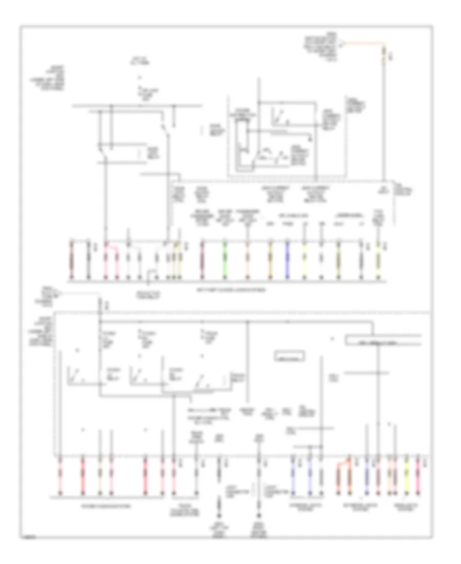
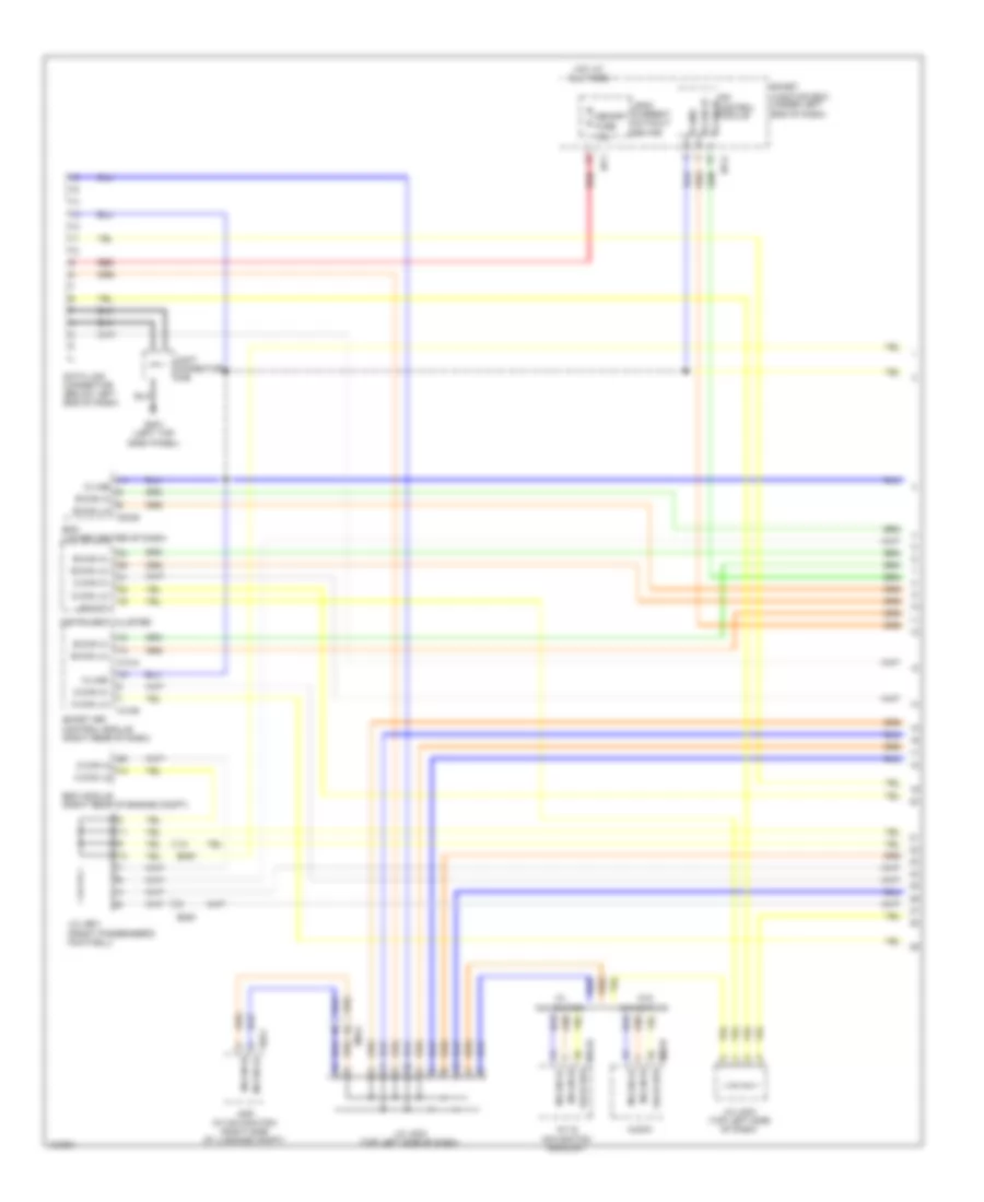
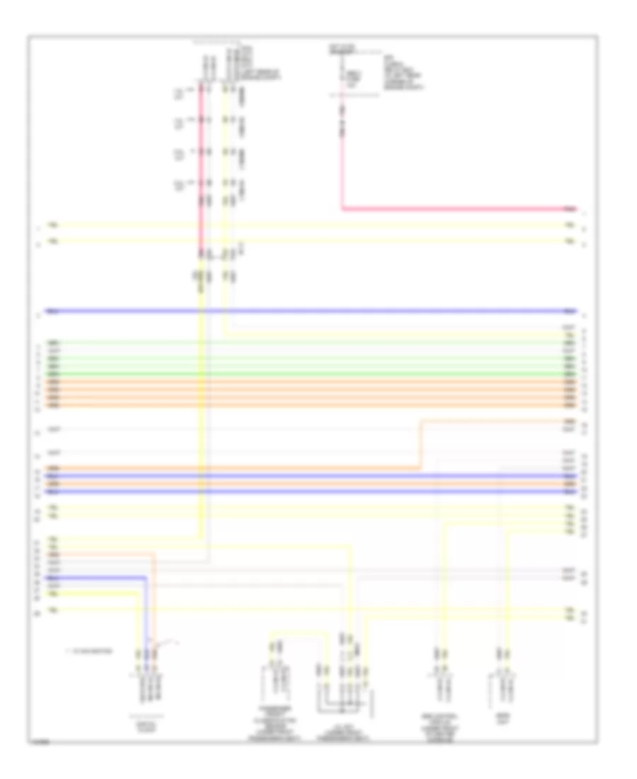
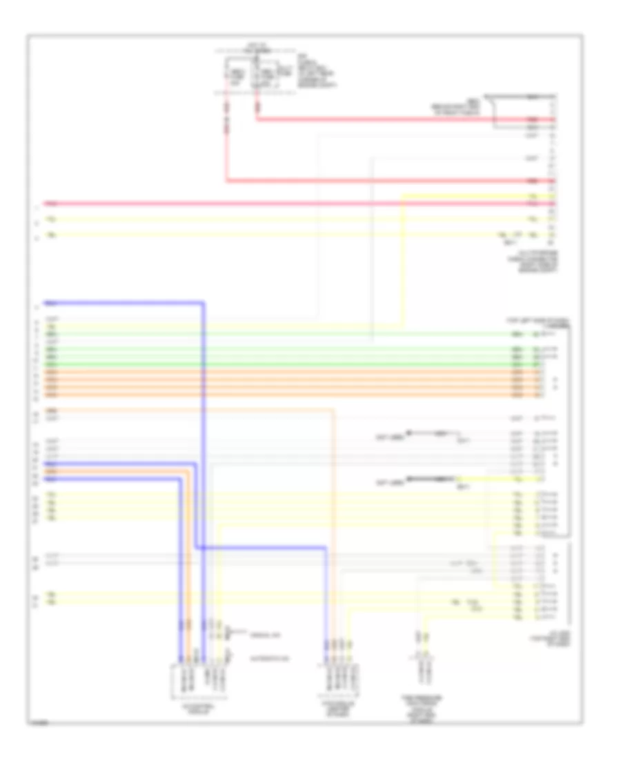
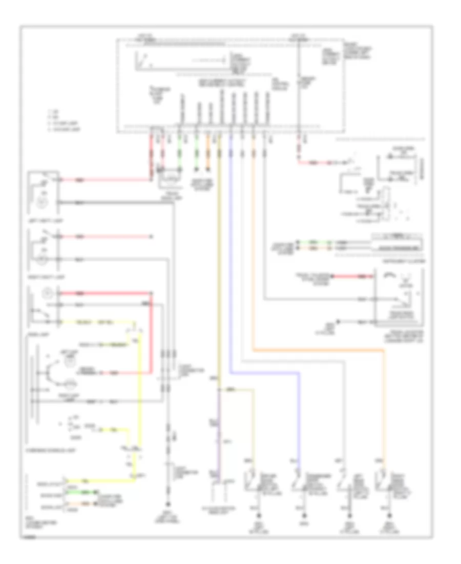
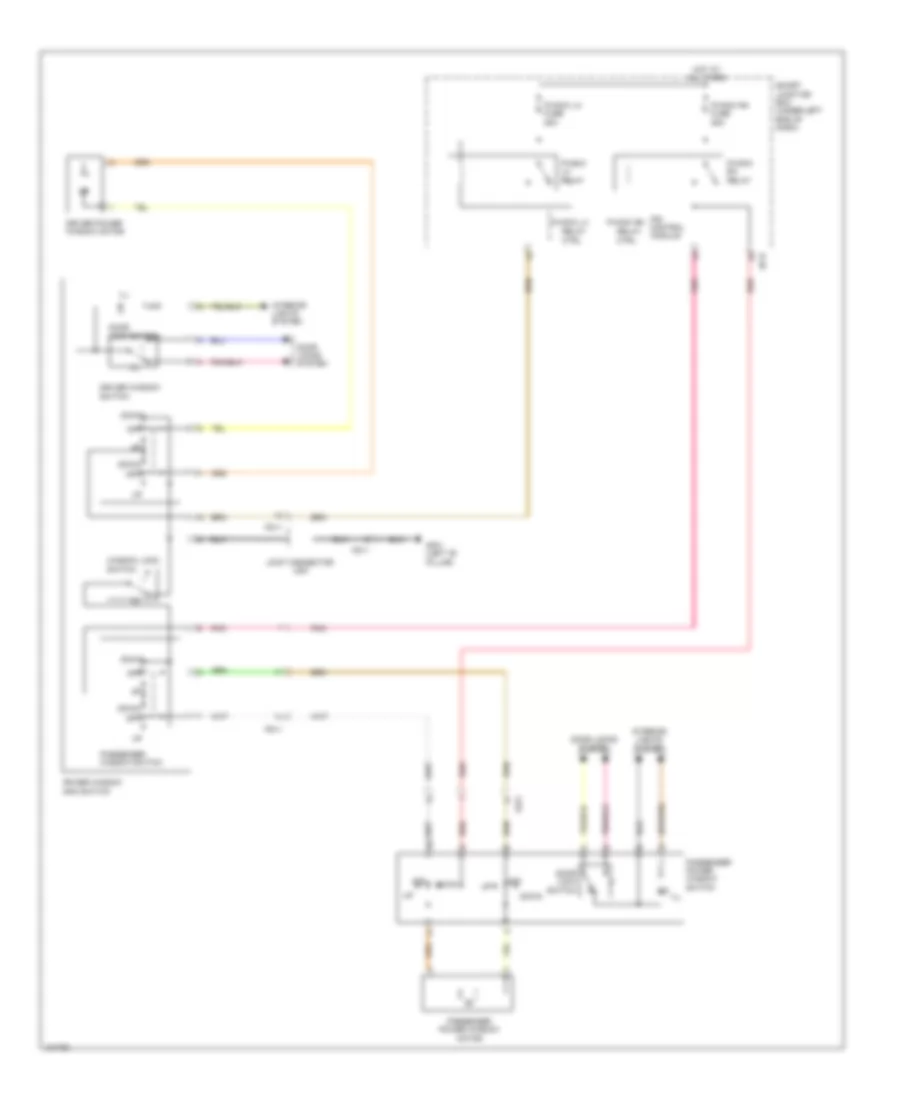
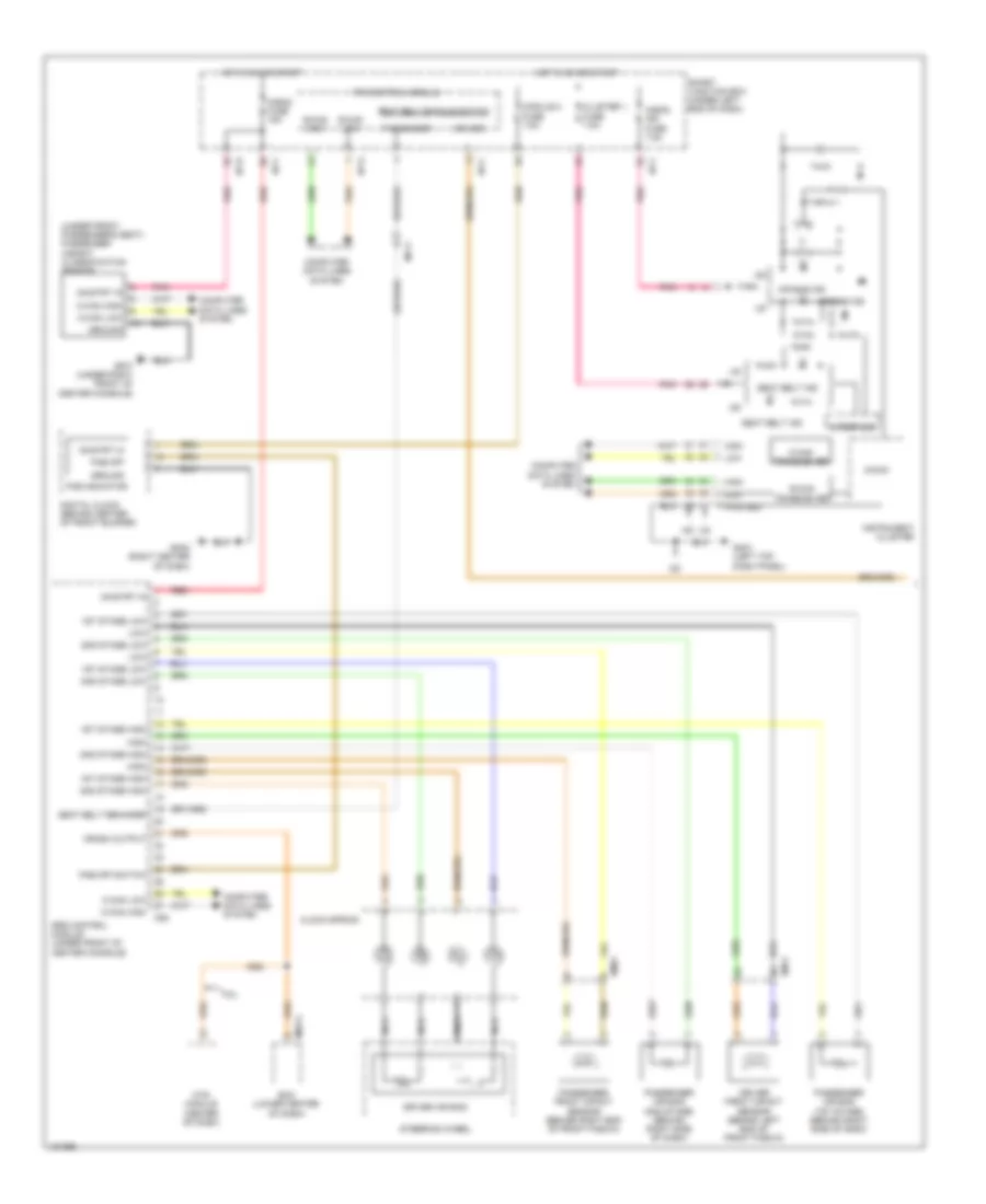
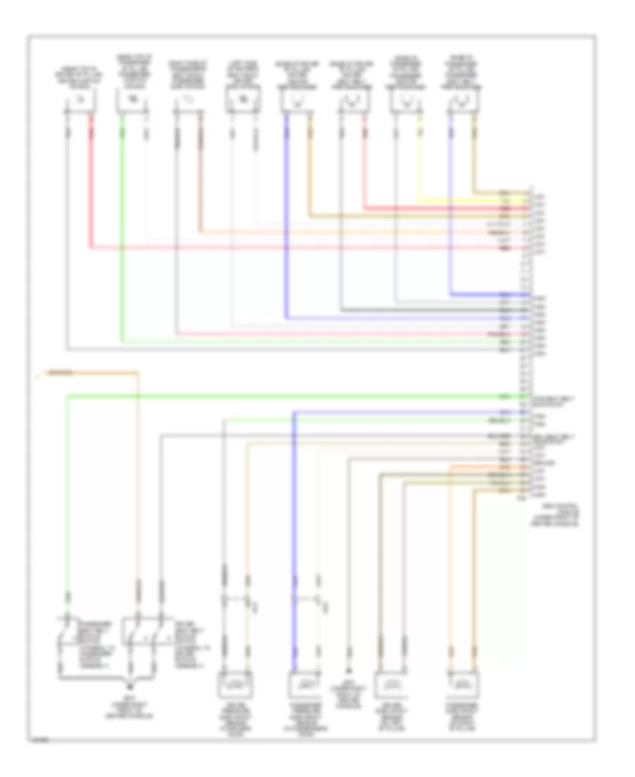
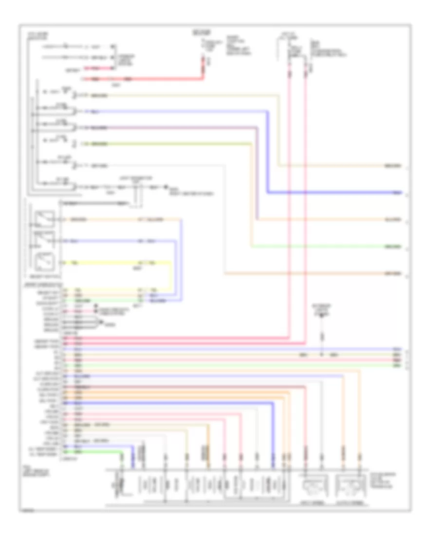
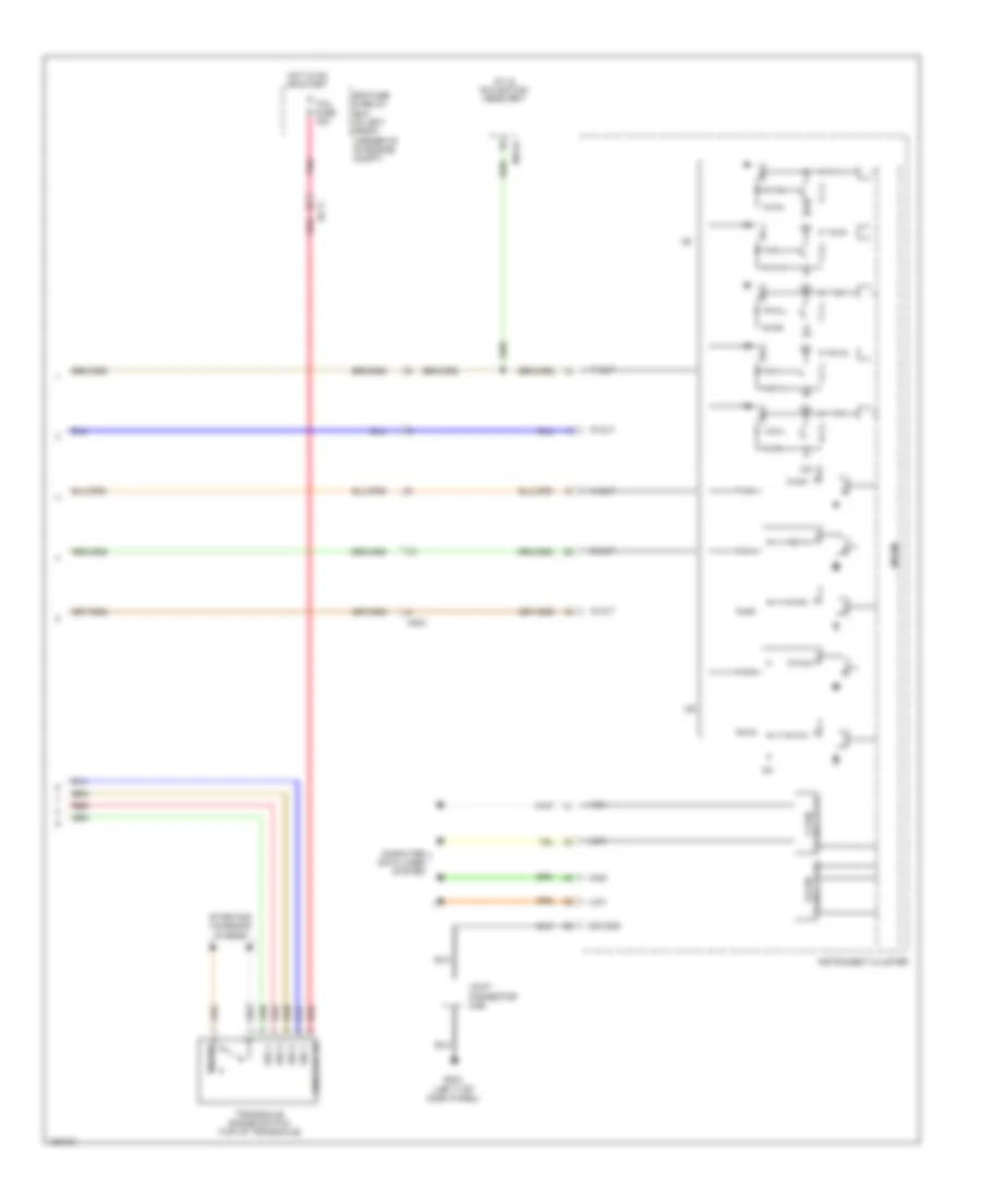
AIR CONDITIONING
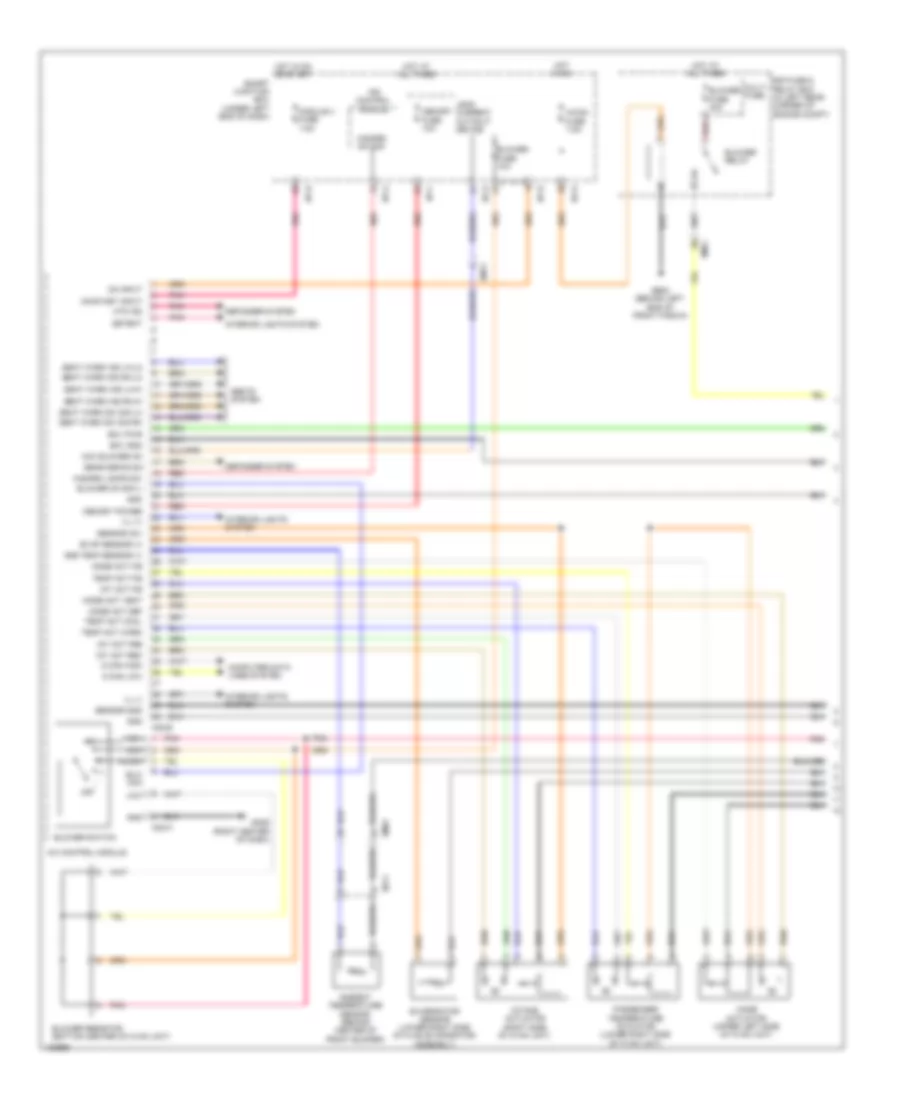
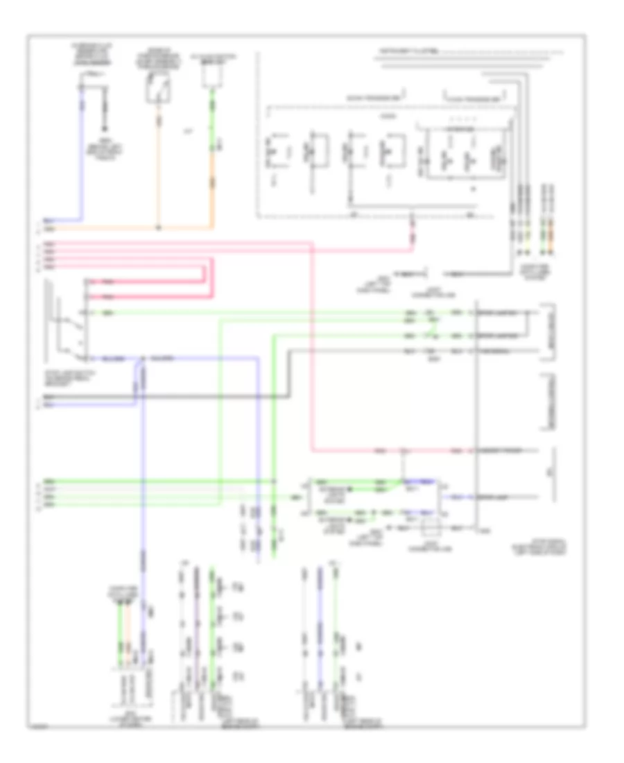
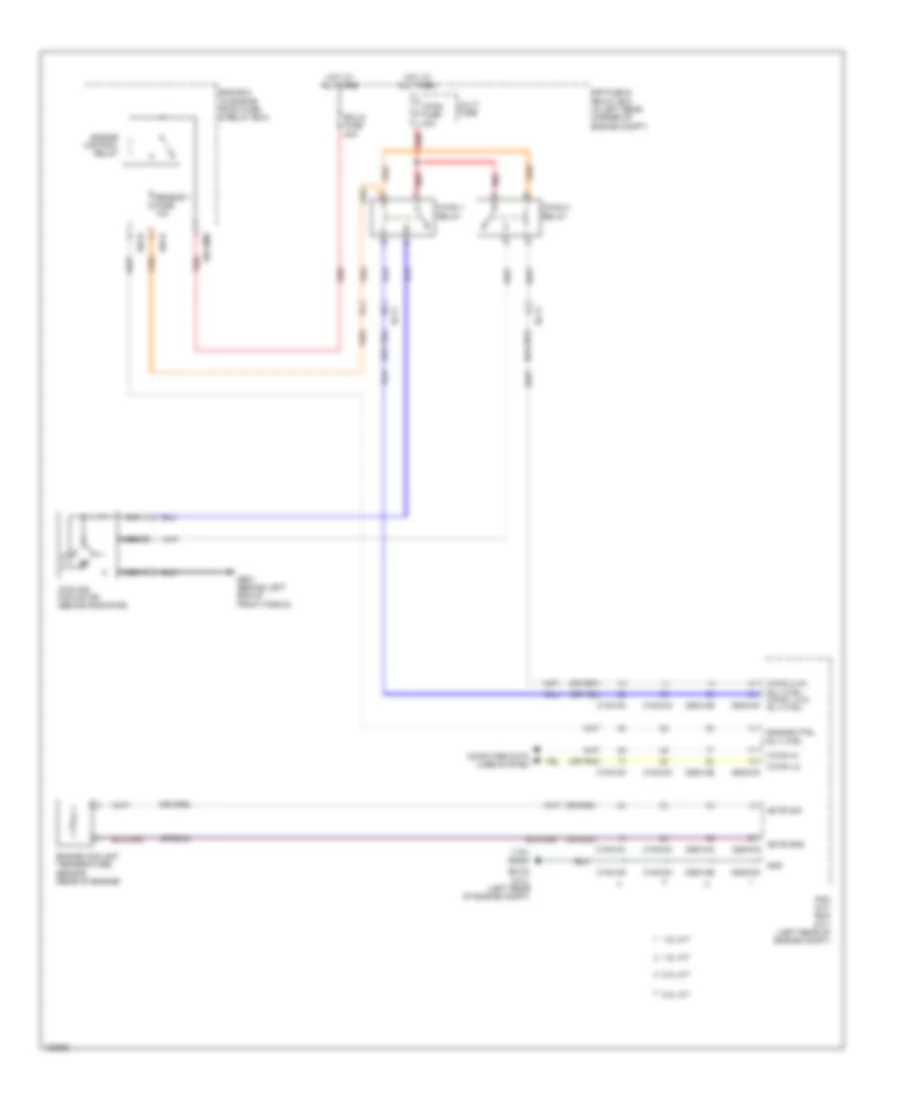
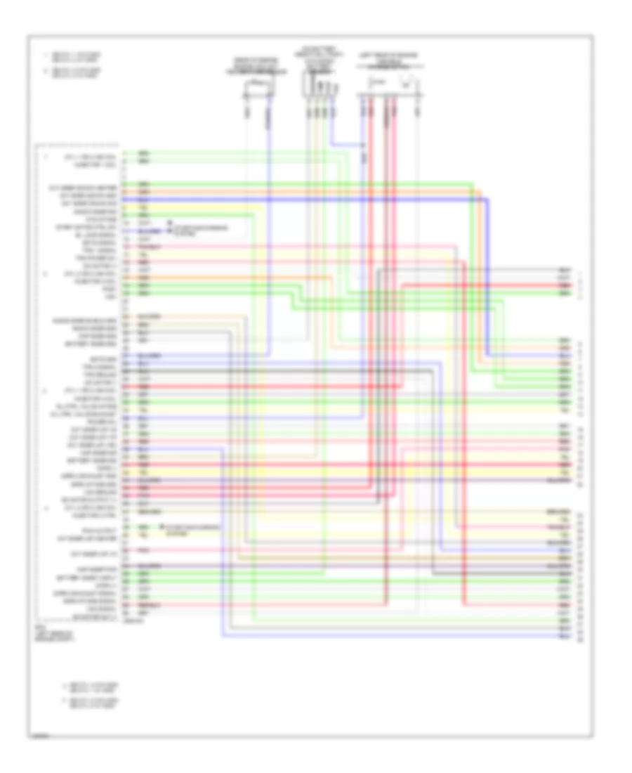
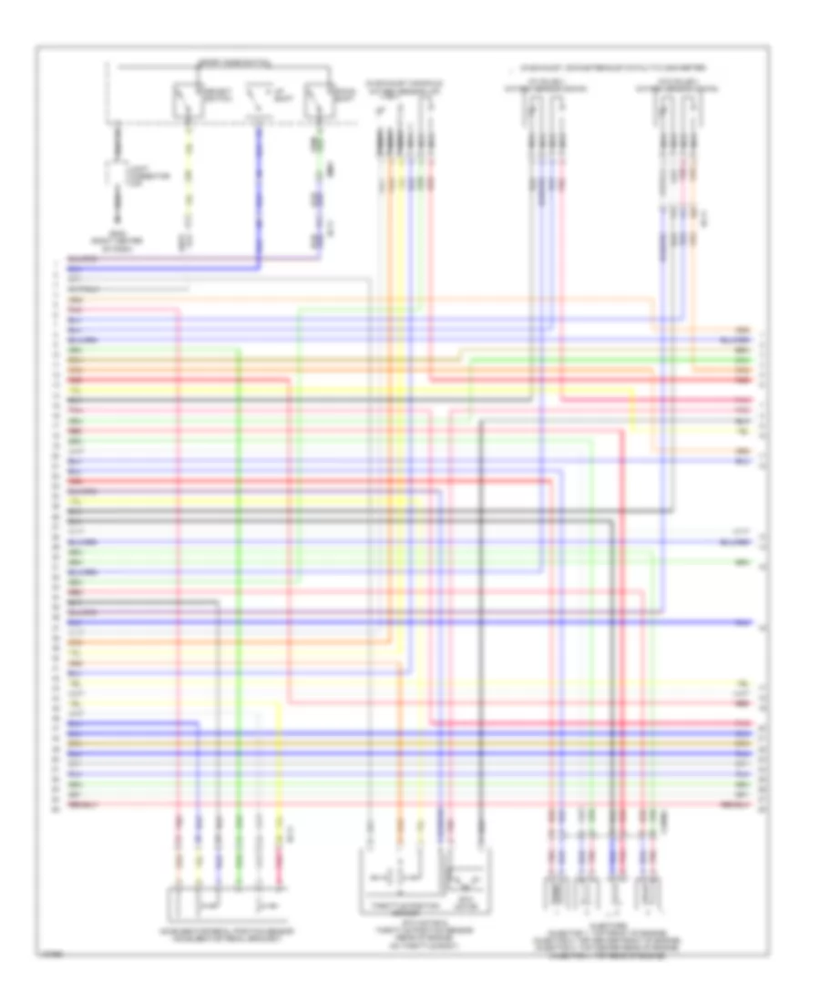
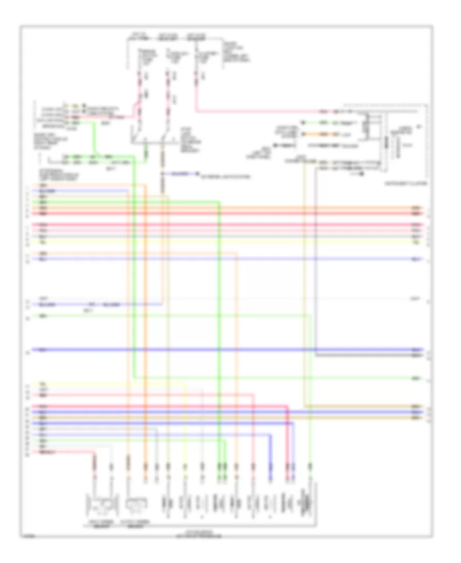
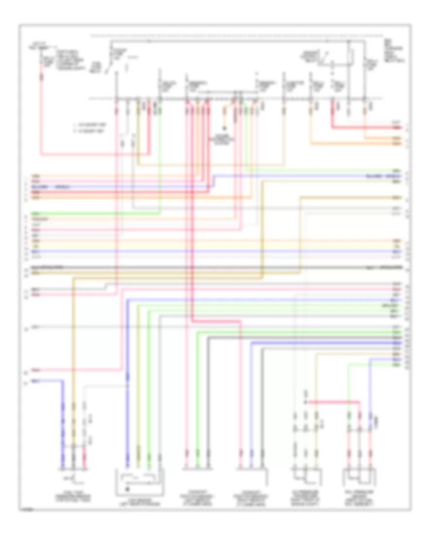
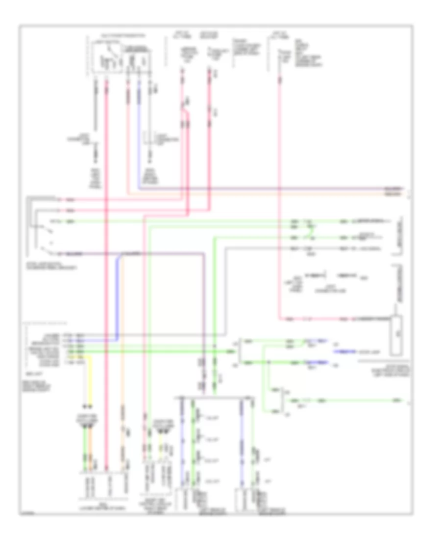
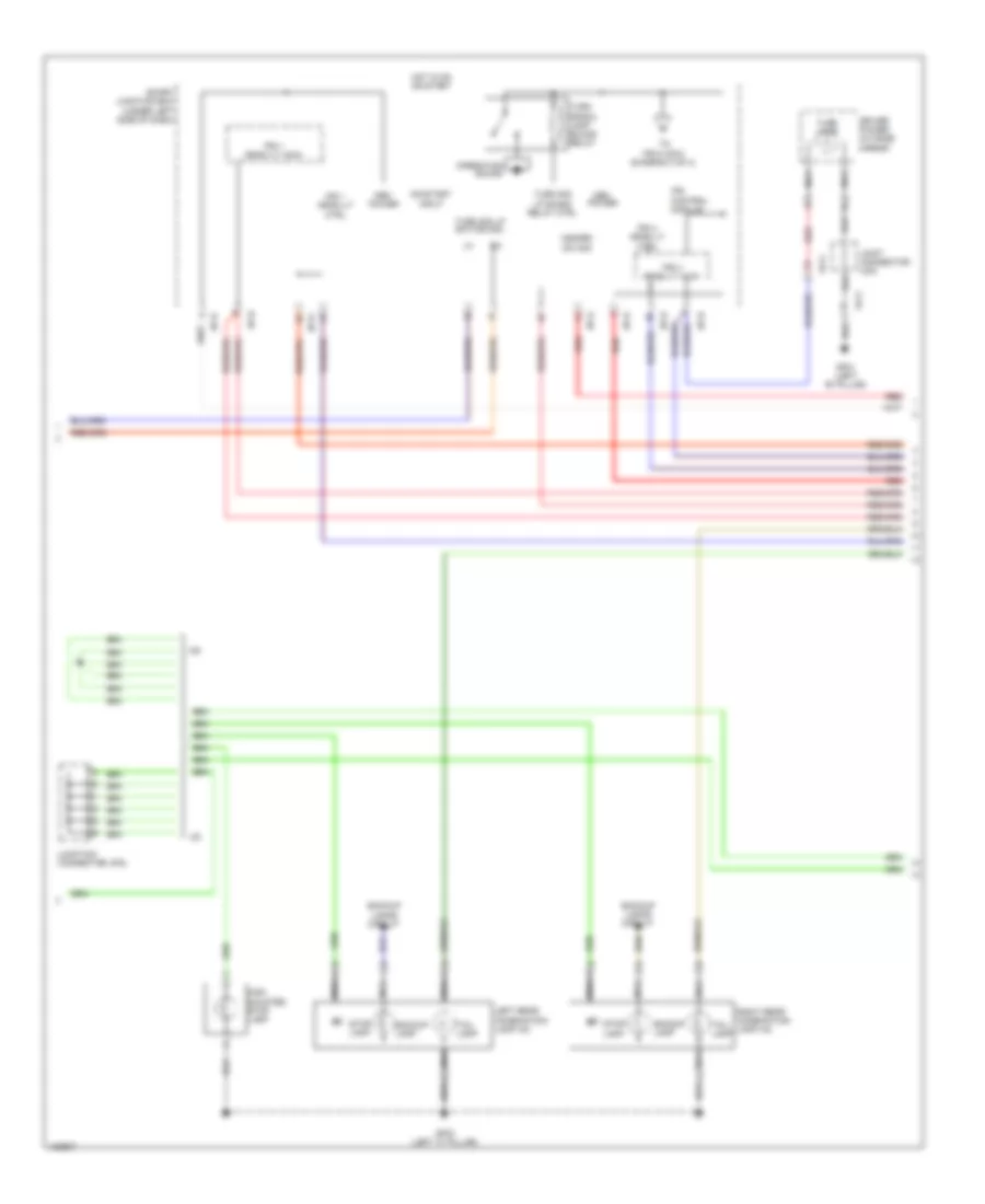
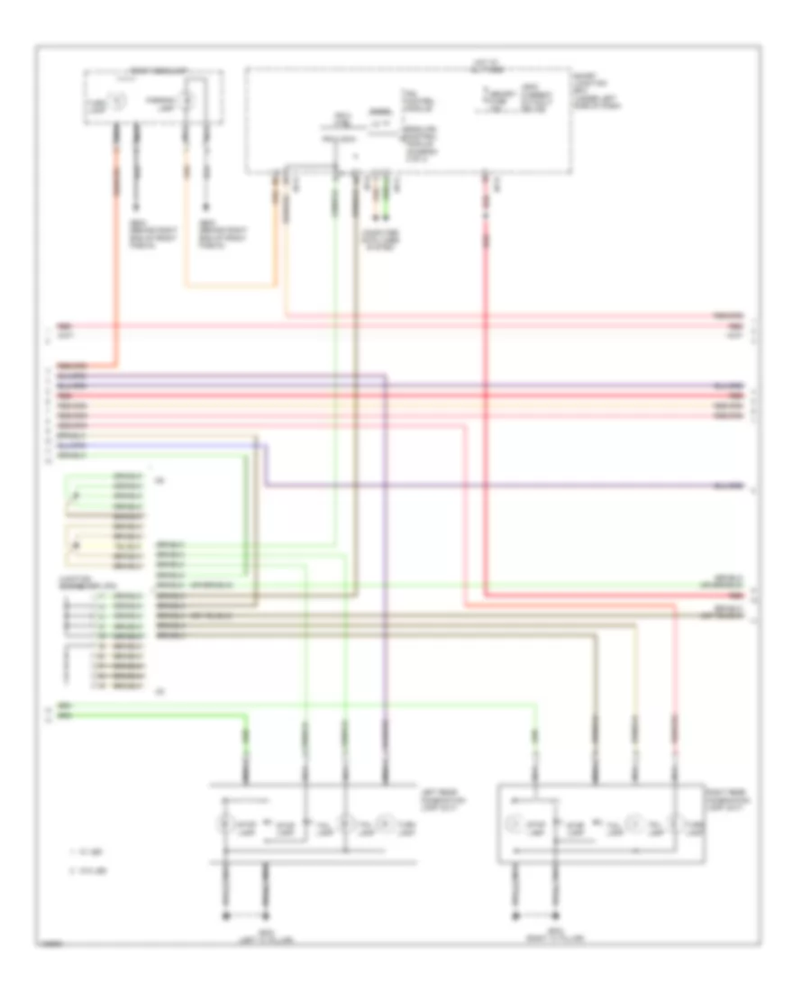
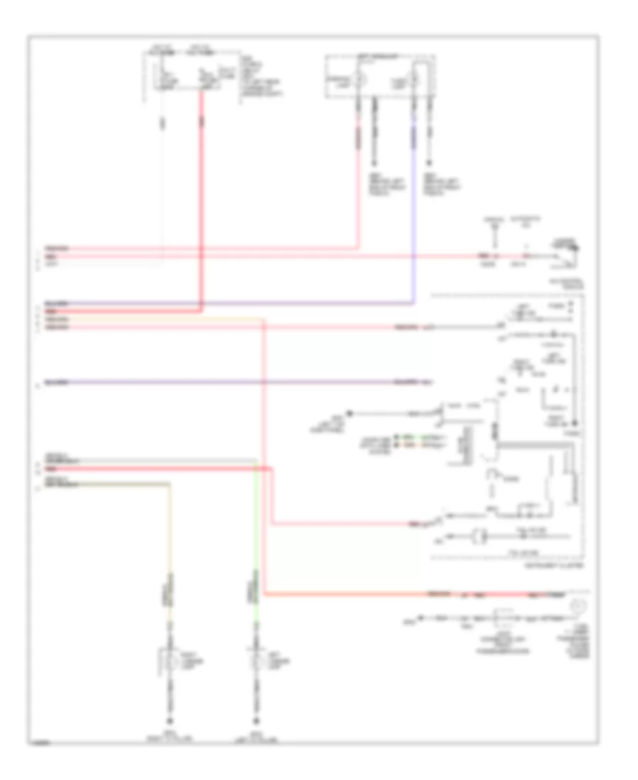
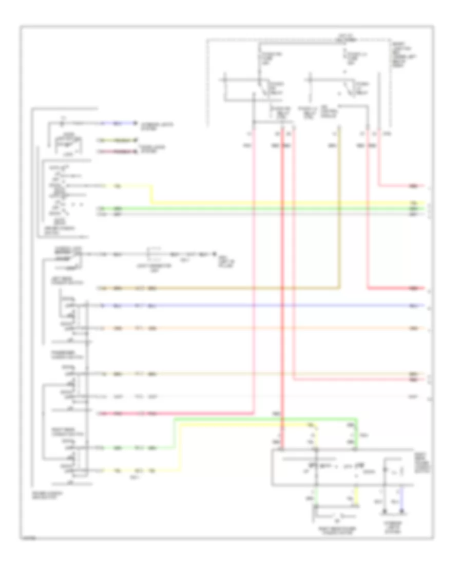
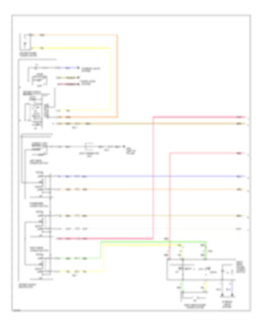
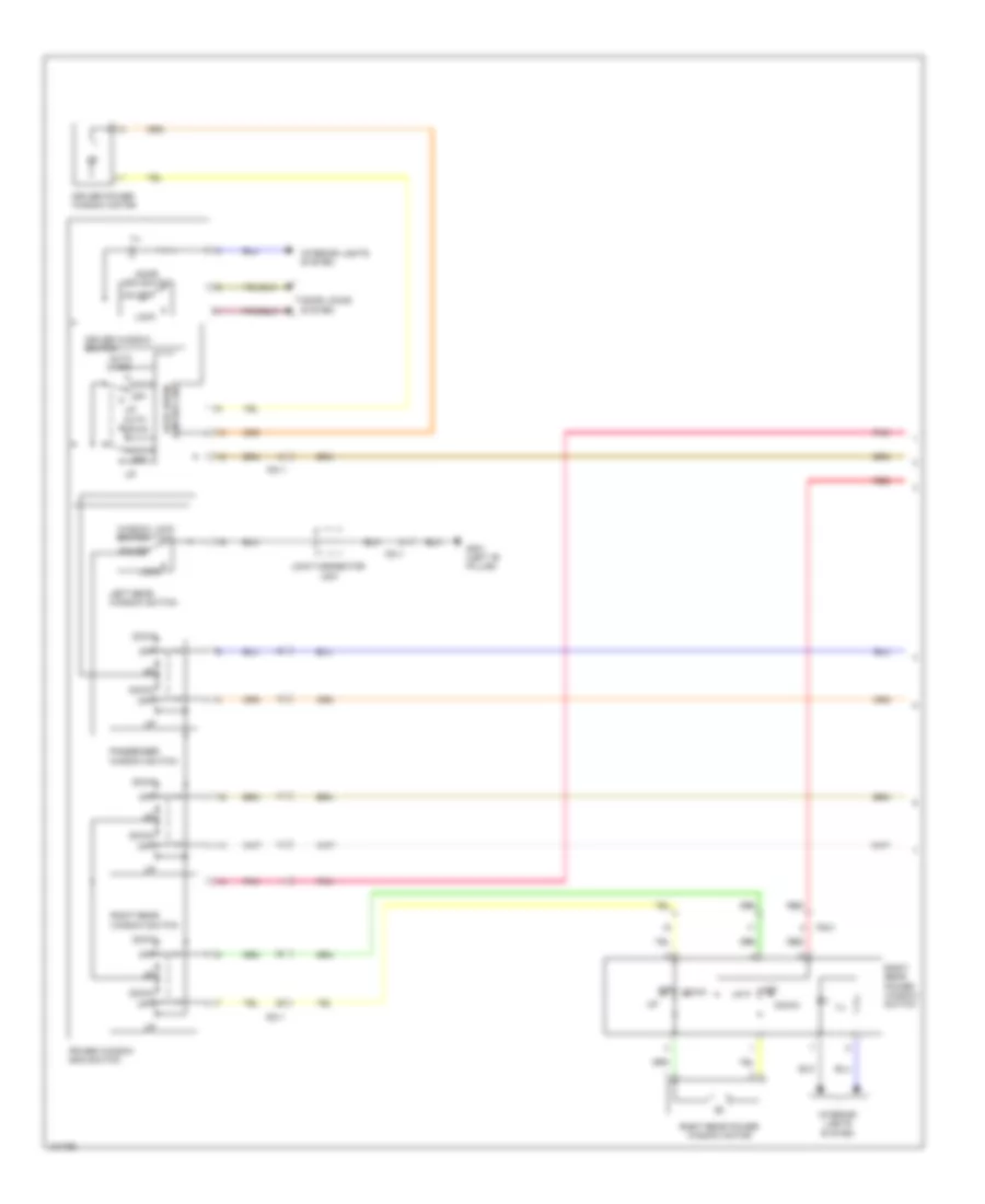
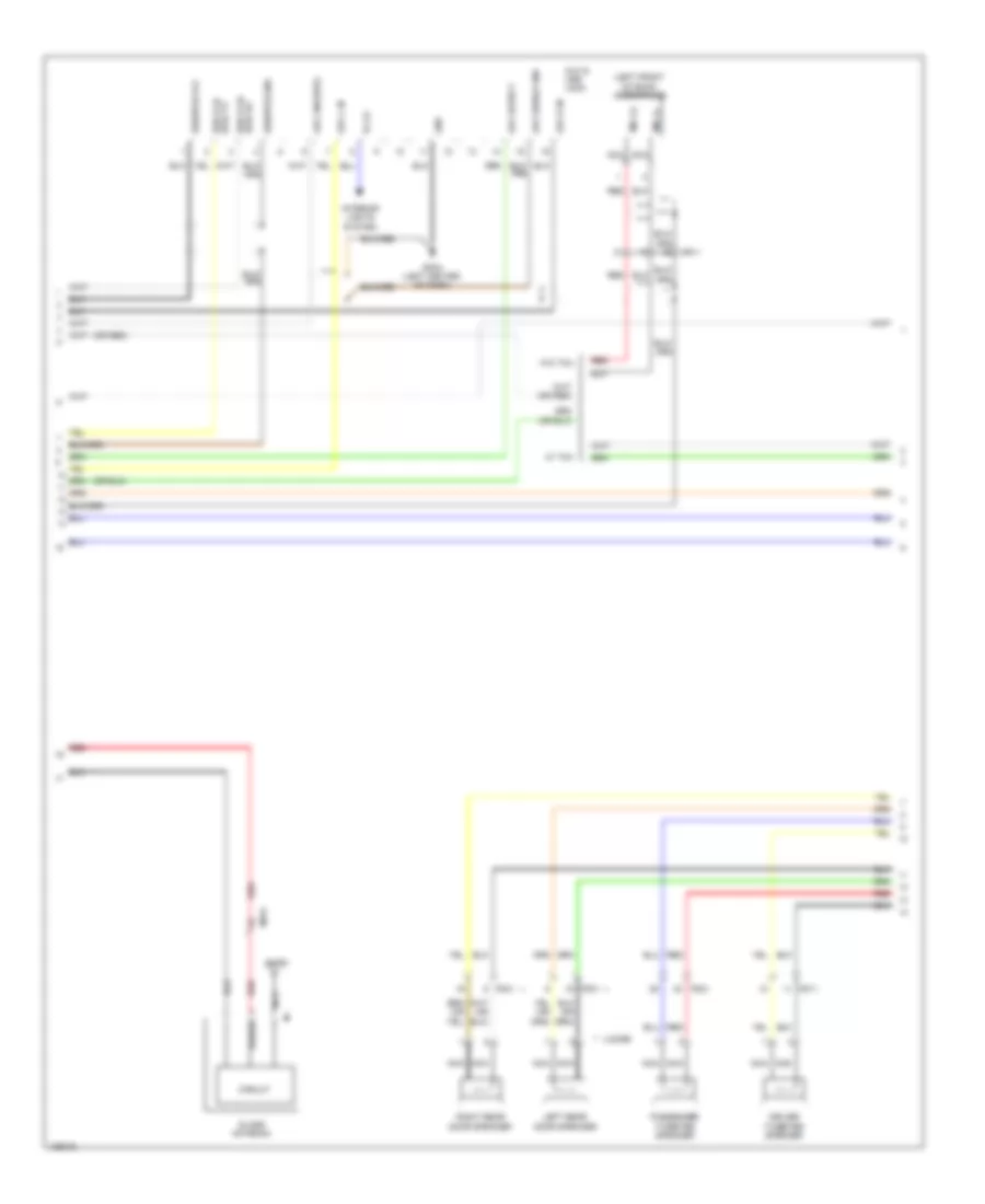
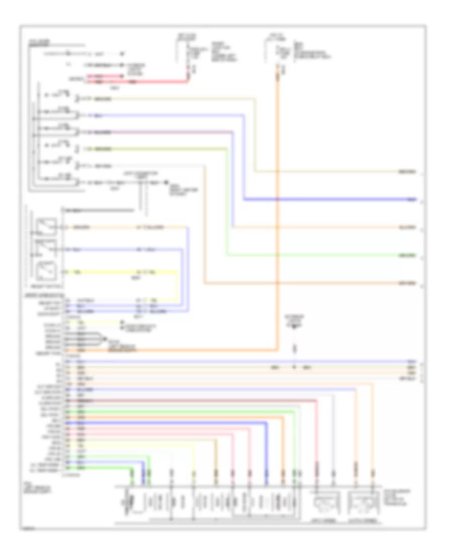
Automatic A/C Wiring Diagram (1 of 2) for Hyundai Elantra Sport 2014

List of elements for Automatic A/C Wiring Diagram (1 of 2) for Hyundai Elantra Sport 2014:
- A/c control module
- A/con fuse 7.5a
- A/con sw fuse 7.5a
- Ambient temperature sensor (behind center of front bumper)
- Ambit temp sens (+)
- Auto defog sens (+)
- Auto defogger actuator (upper right side of hvac unit)
- Auto defogger sensor (integral to inside rearview mirror assembly)
- Auto light & photo sensor (top center of dash)
- Blower fuse 40a
- Blower motor (under right side of dash)
- Blower relay
- Body k-line
- C-can hi
- C-can lo
- Close
- Computer data lines system
- Computer data lines system defogger system
- Detent
- Dr temp actr cool
- Dr temp actr f/b
- Dr temp actr warm
- Driver temperature actuator (lower left side of hvac unit)
- E/r fuse & relay box (in left rear corner of engine compt)
- Ecv gnd
- Ecv power
- Ee11
- Em61
- Evap sensor (+)
- Evaporator sensor (lower right side of hvac evaporator assembly)
- F/b
- Fet (field effect transistor) (bottom center of hvac unit)
- Fet gate
- Ge02 (behind left end of front fascia)
- Gm06 (right center of dash)
- Ground
- Hazard sw
- Hot at all times
- Hot in on
- Hot in on or start
- Htd ind
- I/p-e
- I/p-f
- I/p-h
- Ill (+)
- Ill (-)
- In actr f/b
- In actr fre
- In actr rec
- Incar sensor (built inside module)
- Intake actuator (right side of hvac unit)
- Interior lights system
- Interior lights system exterior lights system
- Joint connector uma
- Joint connector umb
- Leak current autocut device
- M21-a
- Memory fuse 10a
- Mode actr def
- Mode actr f/b
- Mode actr vent
- Mode actuator (upper left side of hvac unit)
- Module 4 fuse 7.5a
- Mr11
- Multi fuse
- Open
- Photo sensor
- Photo sensor lh
- Photo sensor rh
- Pnk
- Power
- Rear defogger sw
- Red
- Seat warm ind lh-hi
- Seat warm ind lh-lo
- Seat warm ind rh-hi
- Seat warm ind rh-lo
- Seat warm sw lh
- Seat warm sw rh
- Seats system
- Sensor 5v
- Signal
- Smart junction box (under left end of dash)
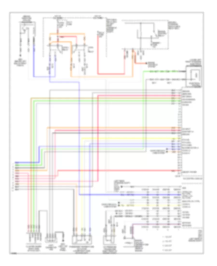
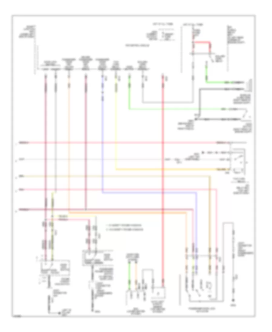
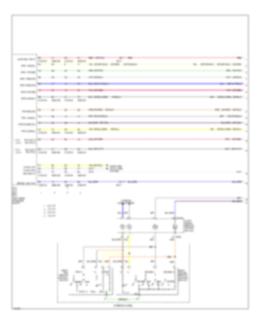
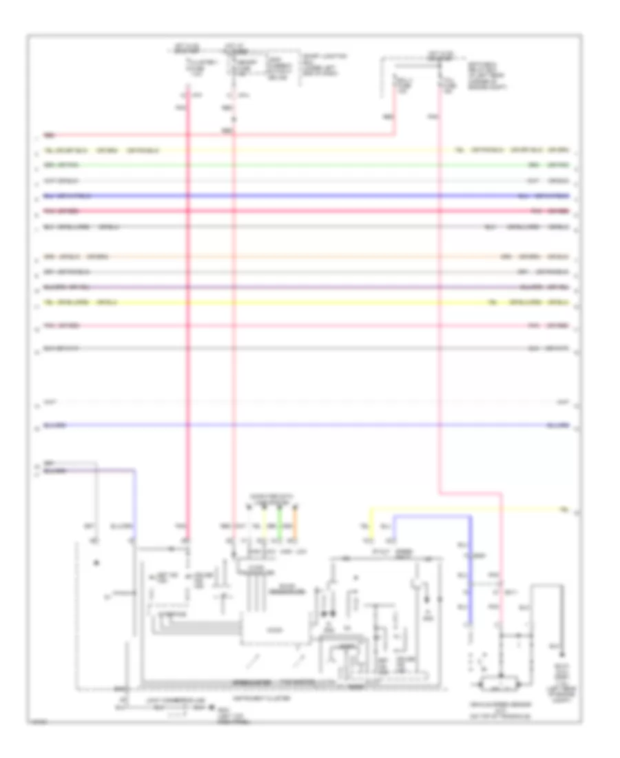
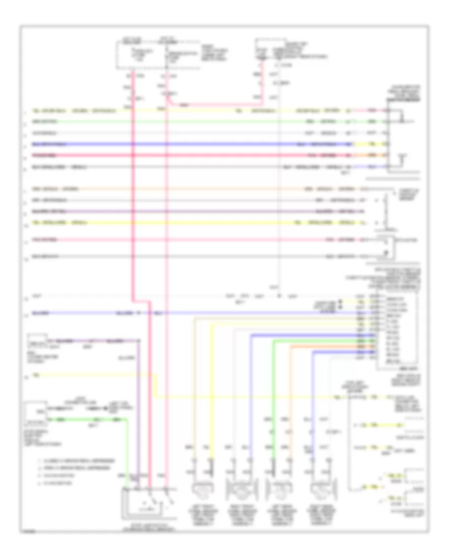
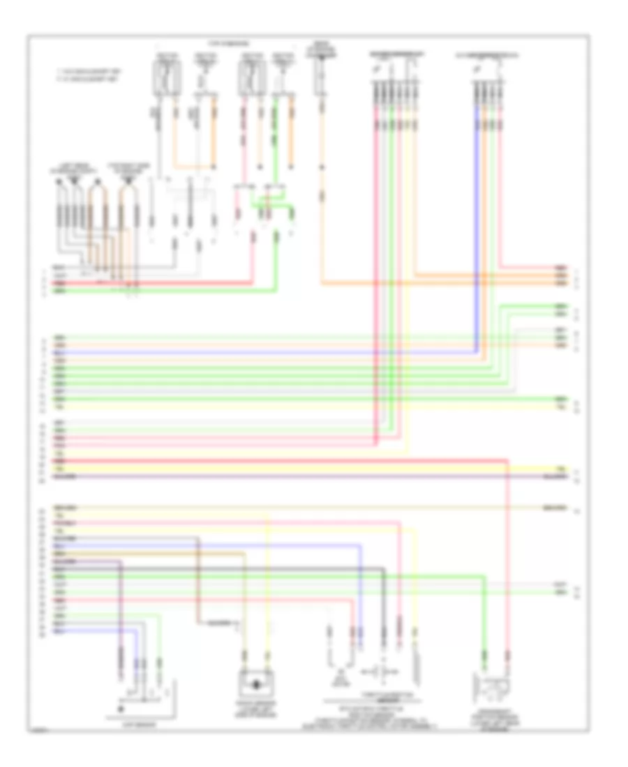
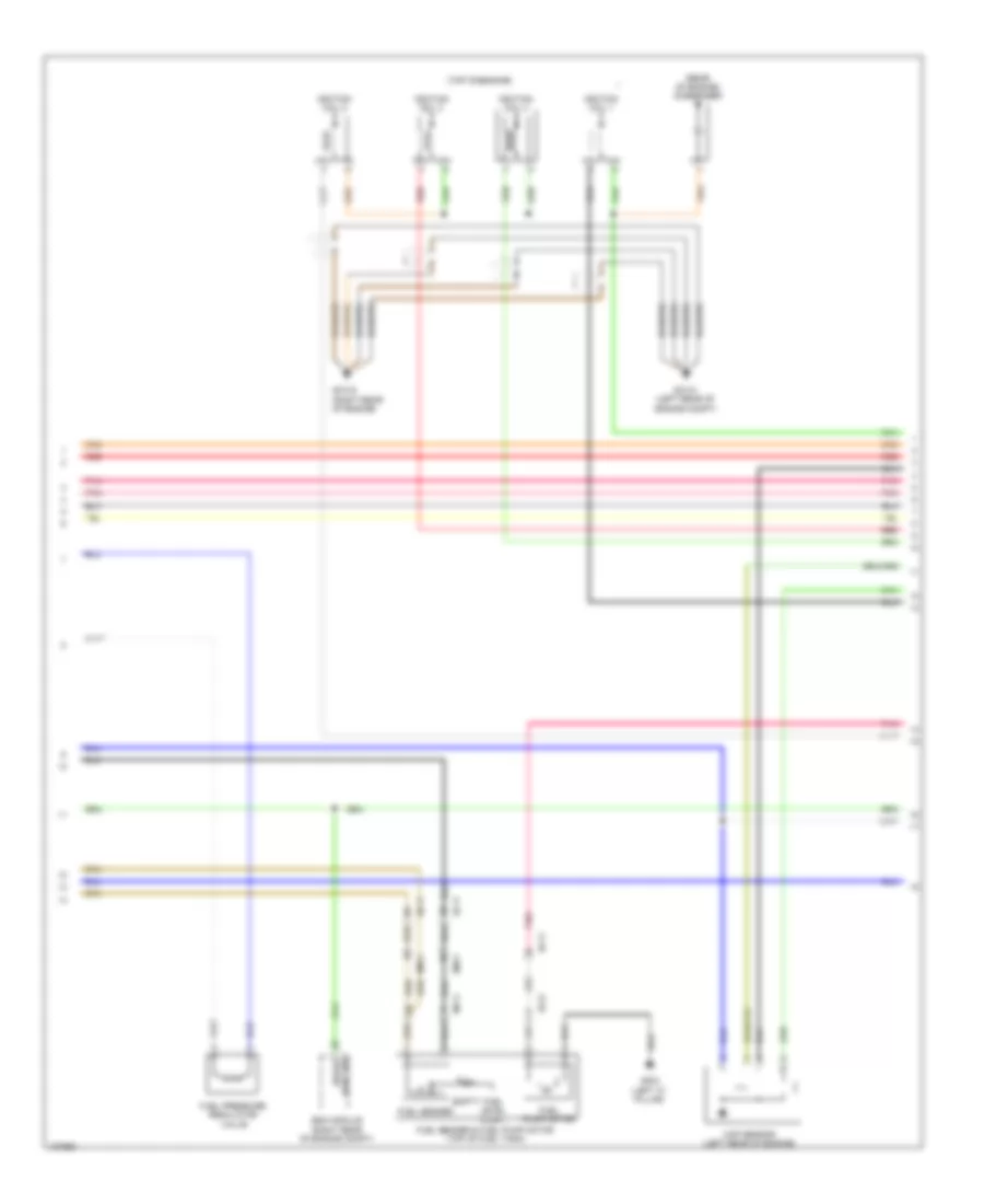
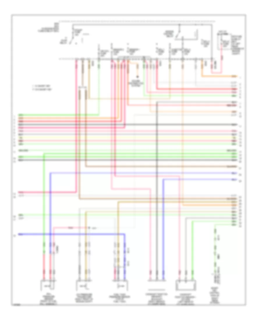
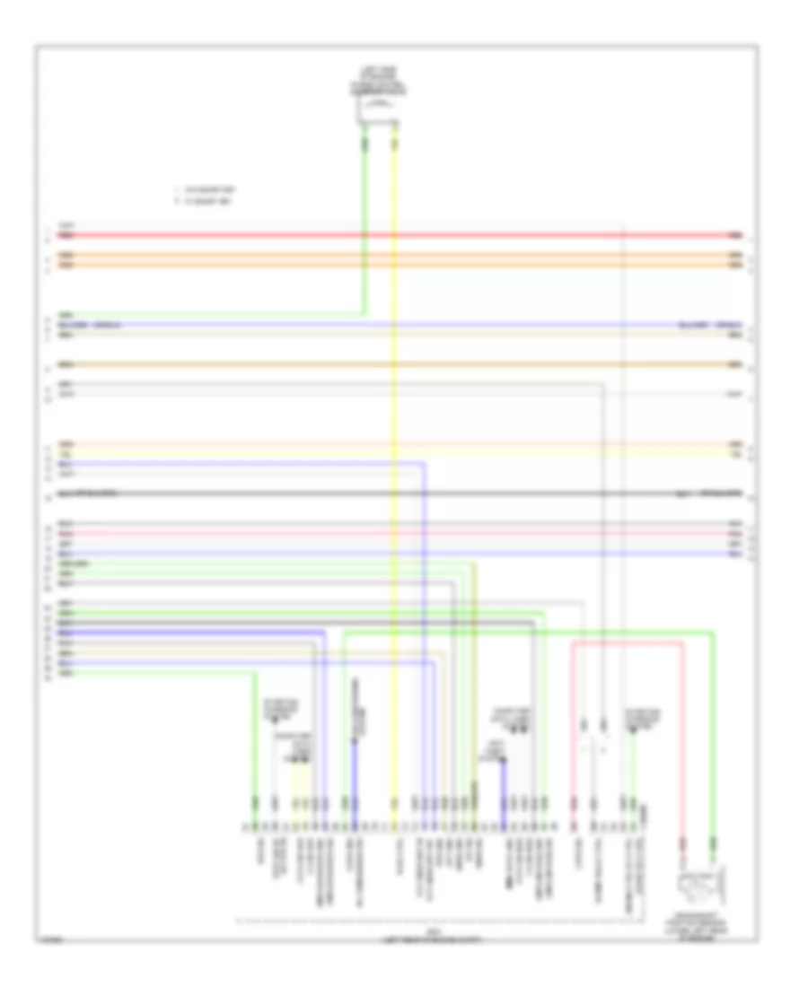
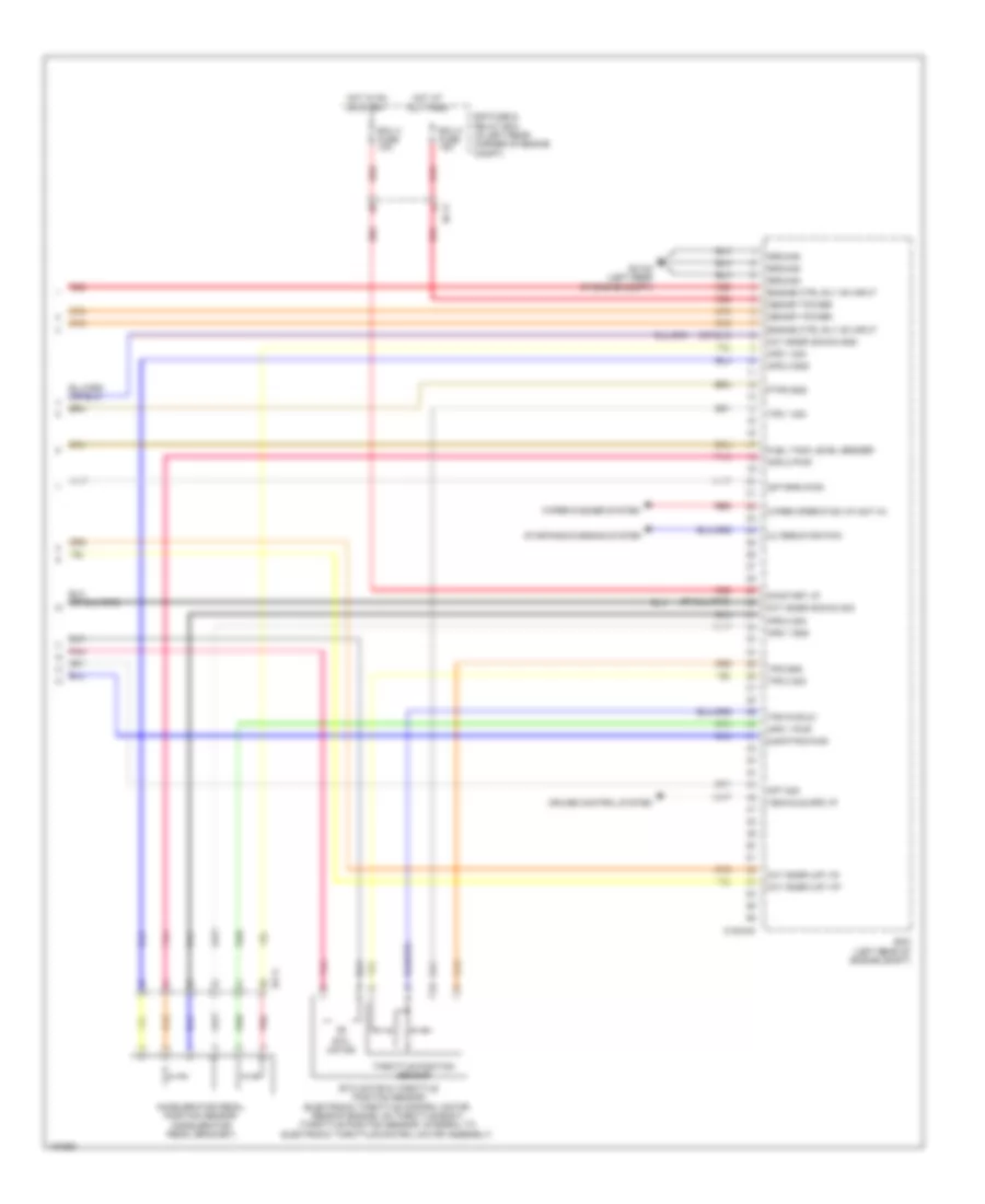
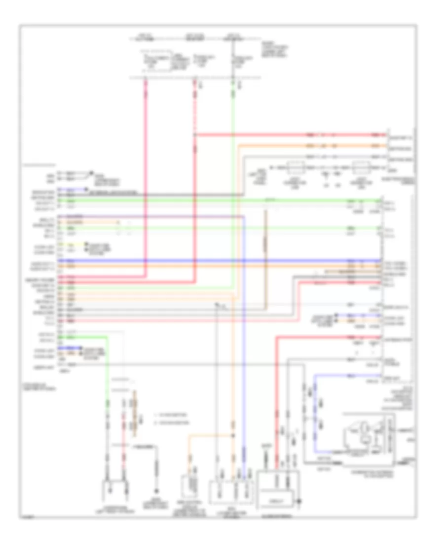
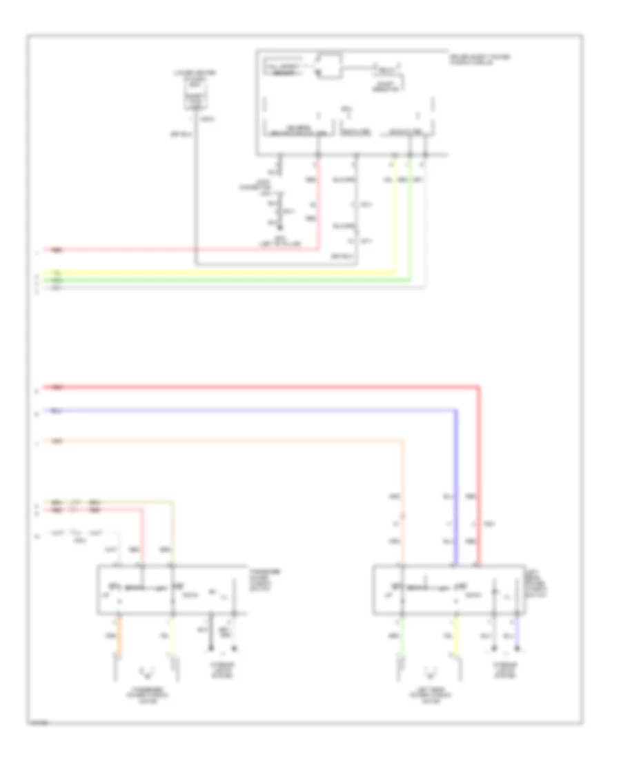
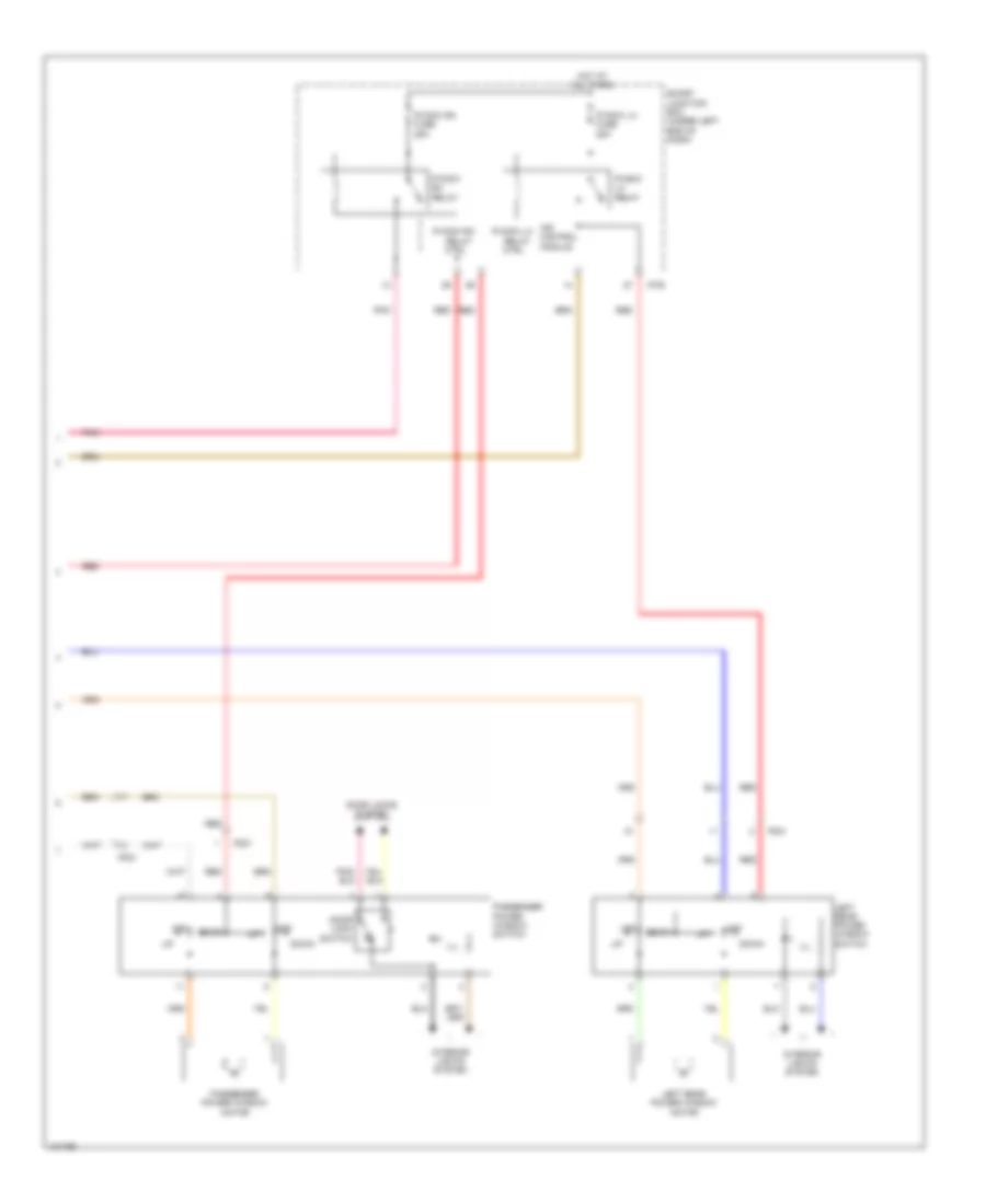
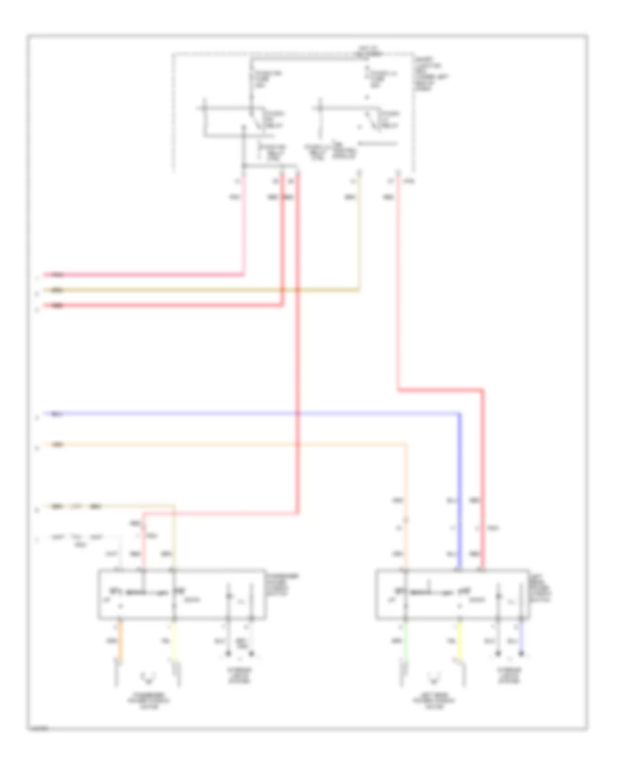
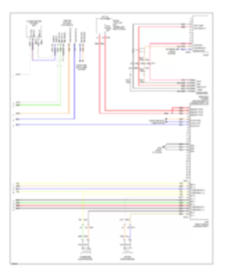
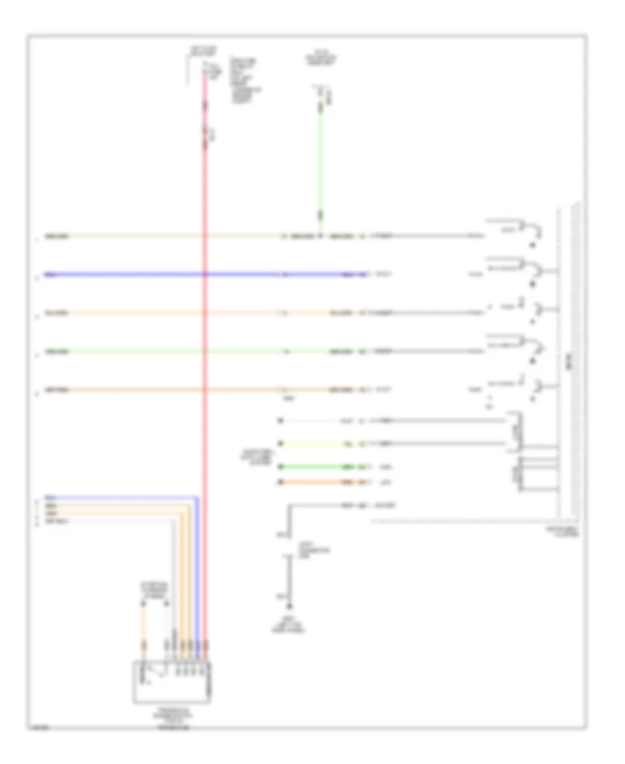
Automatic A/C Wiring Diagram (2 of 2) for Hyundai Elantra Sport 2014
List of elements for Automatic A/C Wiring Diagram (2 of 2) for Hyundai Elantra Sport 2014:
- (behind radiator) cooling fan motor
- (left rear of engine compt) (2.0l) gc102 gc602 (1.8l)
- (lower left front of engine) electronic a/c compressor
- (or pnk)
- 1.8l a/t
- 1.8l m/t
- 2.0l a/t
- 2.0l m/t
- A/c control module
- A/c gnd
- A/c pressure transducer (right front of engine compt)
- A/c pwr
- A/c sig
- Blower motor (+)
- C-can hi
- C-can lo
- C/fan 1 relay
- C/fan 2 (hi) rly ctrl c/fan 1 (lo) rly ctrl
- C/fan fuse 40a
- C/fan relay
- C100-aa
- C100-ak
- C100-ma
- C100-mk
- C600-aa
- C600-ab
- C600-ma
- C600-mk
- Clean sig
- Cluster ionizer (right side of hvac unit)
- Computer data lines system
- Diag
- E/r fuse & relay box (in left rear corner of engine compt)
- E/r-a
- E/r-b
- E/r-ems
- Ec11
- Ects gnd
- Ects sig
- Ecu 6 fuse 40a
- Electrical control valve
- Em11
- Ems box (in engine room fuse & relay box)
- Eng ctrl rly ctrl
- Engine control relay
- Engine controls system
- Engine coolant temperature sensor (rear of engine)
- Fet drain
- Ge01 (behind left end of front fascia)
- Gm01 (left top dash panel)
- Gnd
- Ground
- Hot at all times
- Ion diagnosis
- Ion sig
- Joint connector ume
- M-can hi
- M-can lo
- M21-b
- Memory power
- Multi fuse
- Nca
- On input
- On/start in
- Passenger temperature actuator (lower right side of hvac unit)
- Pcm (a/t) ecm (m/t) (left rear of engine compt)
- Pnk
- Pta cool
- Pta f/b
- Pta warm
- Red
- Sens gnd
- Sensor 1 fuse 10a
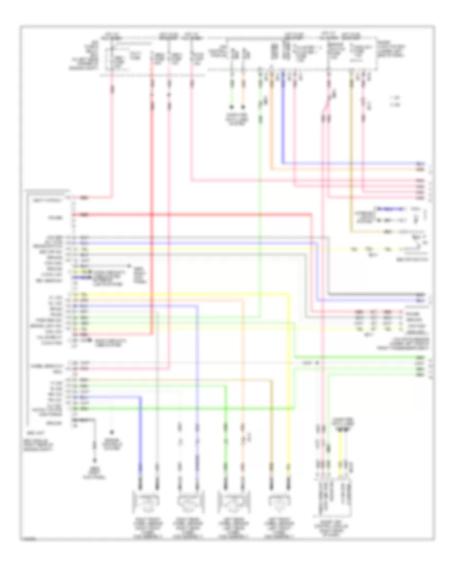
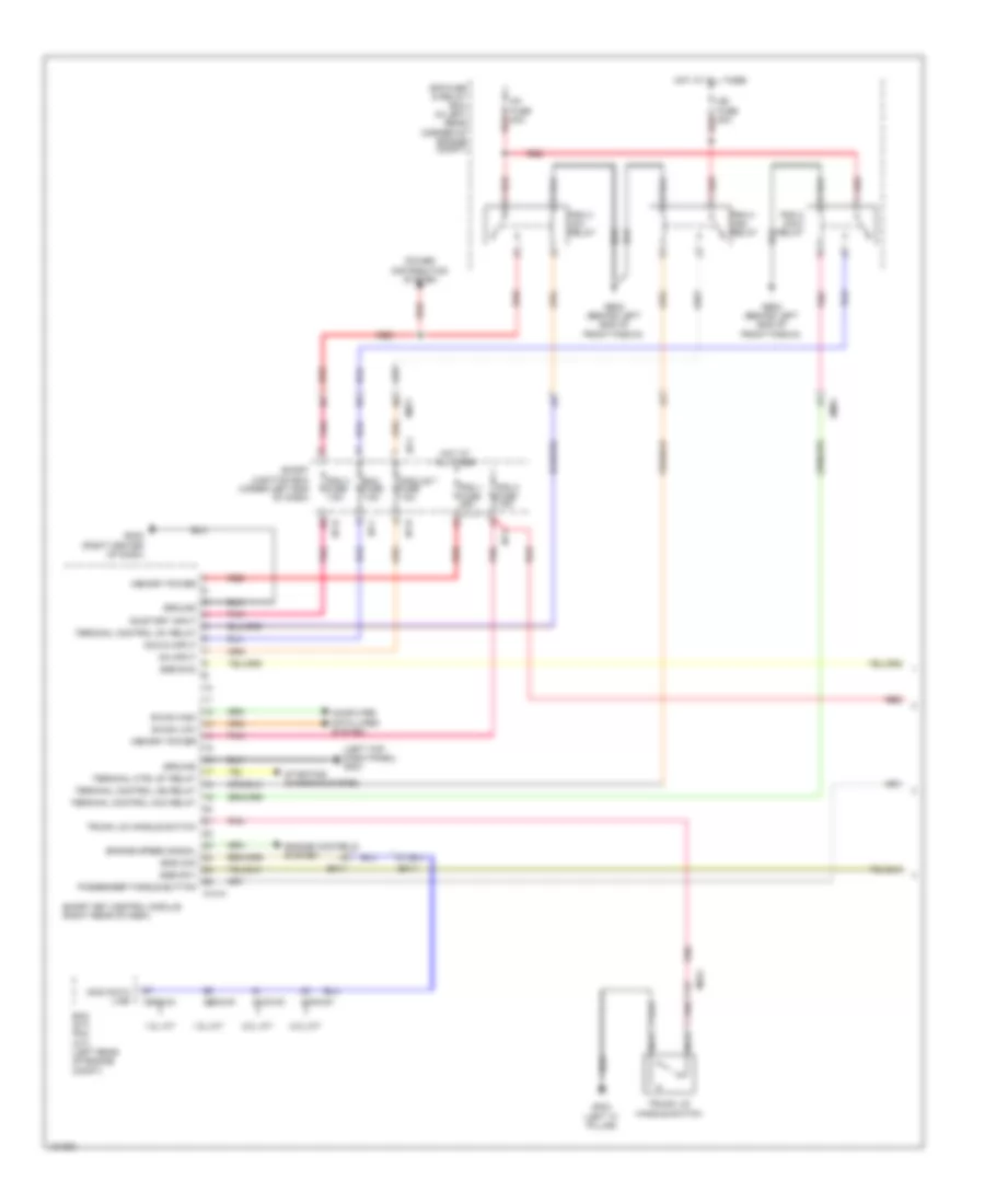
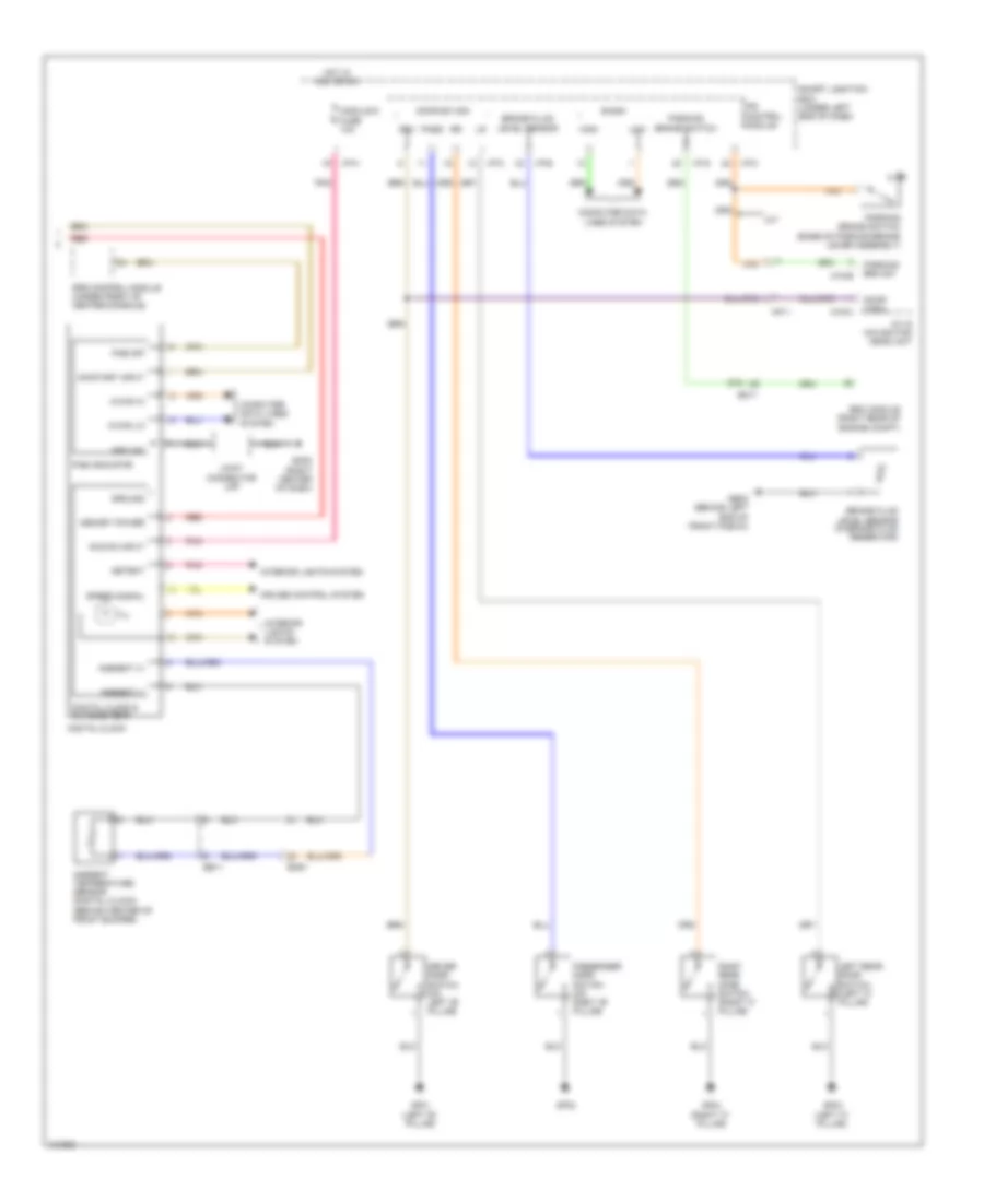
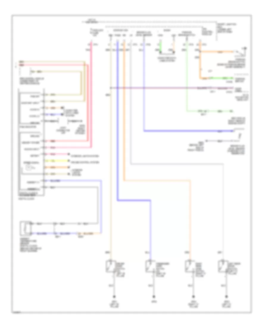
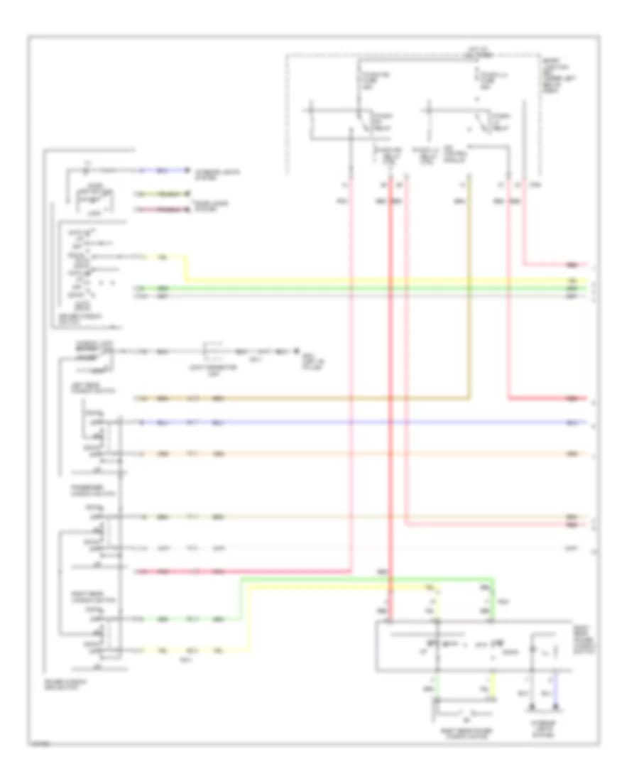
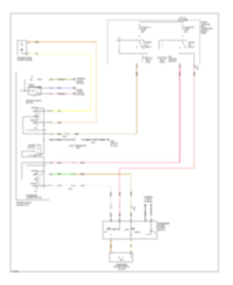
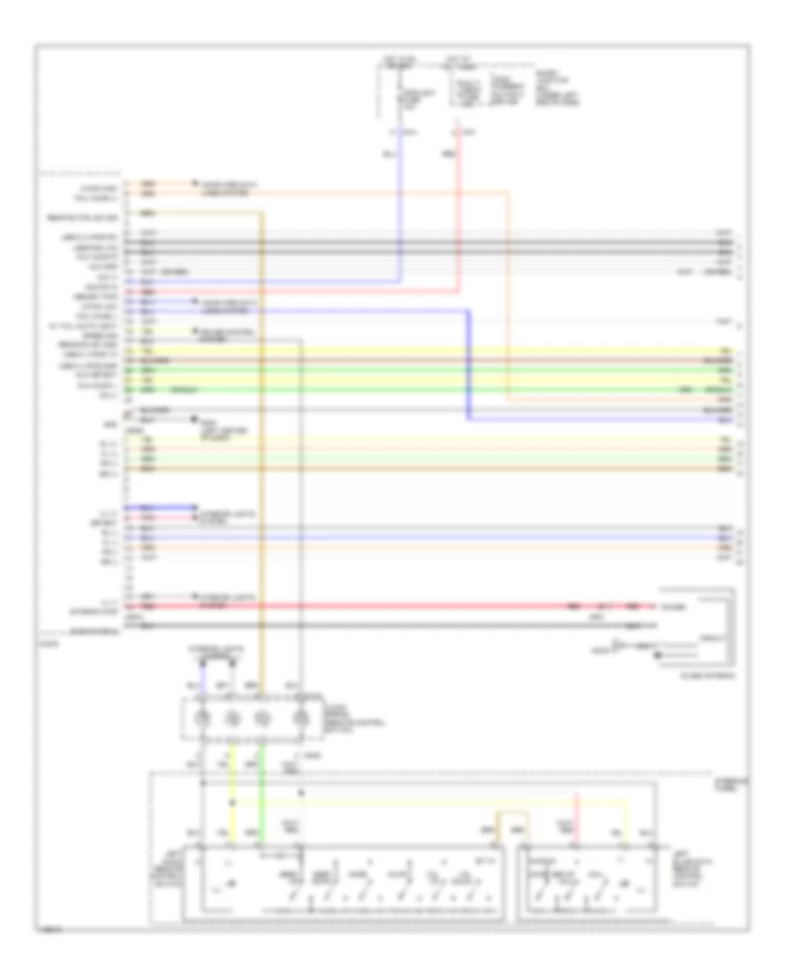
Manual A/C Wiring Diagram (1 of 2) for Hyundai Elantra Sport 2014
List of elements for Manual A/C Wiring Diagram (1 of 2) for Hyundai Elantra Sport 2014:
- A/c control module
- A/con fuse 7.5a
- Amb temp sensor (+)
- Ambient temperature sensor (behind center of front bumper)
- Blower fuse 10a
- Blower fuse 40a
- Blower on sig (-)
- Blower relay
- Blower resistor (bottom center of hvac unit)
- Blower switch
- Blw com
- C-can high
- C-can low
- Computer data lines system
- Defogger system
- Detent
- E/r fuse & relay box (in left rear corner of engine compt)
- Ecv gnd
- Ecv pwr
- Ee11
- Em11
- Em61
- Evap sensor (+)
- Evaporator sensor (lower right side of hvac evaporator assembly)
- Ge02 (behind left end of front fascia)
- Gm06 (right center of dash)
- Gnd
- Hazard lamps sw
- Hazard sw sig
- High
- Hot at all times
- Hot in on
- Hot in on or start
- Htd ind
- I off
- I/p-e
- I/p-f
- I/p-g
- I/p-h
- Iii
- Iiii
- Ill (+)
- Ill (-)
- Int act f/b
- Int act fre
- Int act rec
- Intake actuator (right side of hvac unit)
- Interior lights system
- Ips control module
- Leak current autocut device
- Low
- M/hi
- M/low
- M22-a
- M22-b
- Max blower on
- Memory fuse 10a
- Memory power
- Mode act def
- Mode act f/b
- Mode act vent
- Mode actuator (upper left side of hvac unit)
- Module 4 fuse 7.5a
- Multi fuse
- On input
- On/start input
- Passenger temperature actuator (lower right side of hvac unit)
- Pnk
- Rear defog sw
- Red
- Seat warm ind lh-hi
- Seat warm ind lh-lo
- Seat warm ind rh-hi
- Seat warm ind rh-lo
- Seat warm sw sig lh
- Seat warm sw sig rh
- Seats system
- Sensor (5v)
- Sensor gnd
- Smart junction box (under left end of dash)
- Temp act cool
- Temp act f/b
- Temp act warm
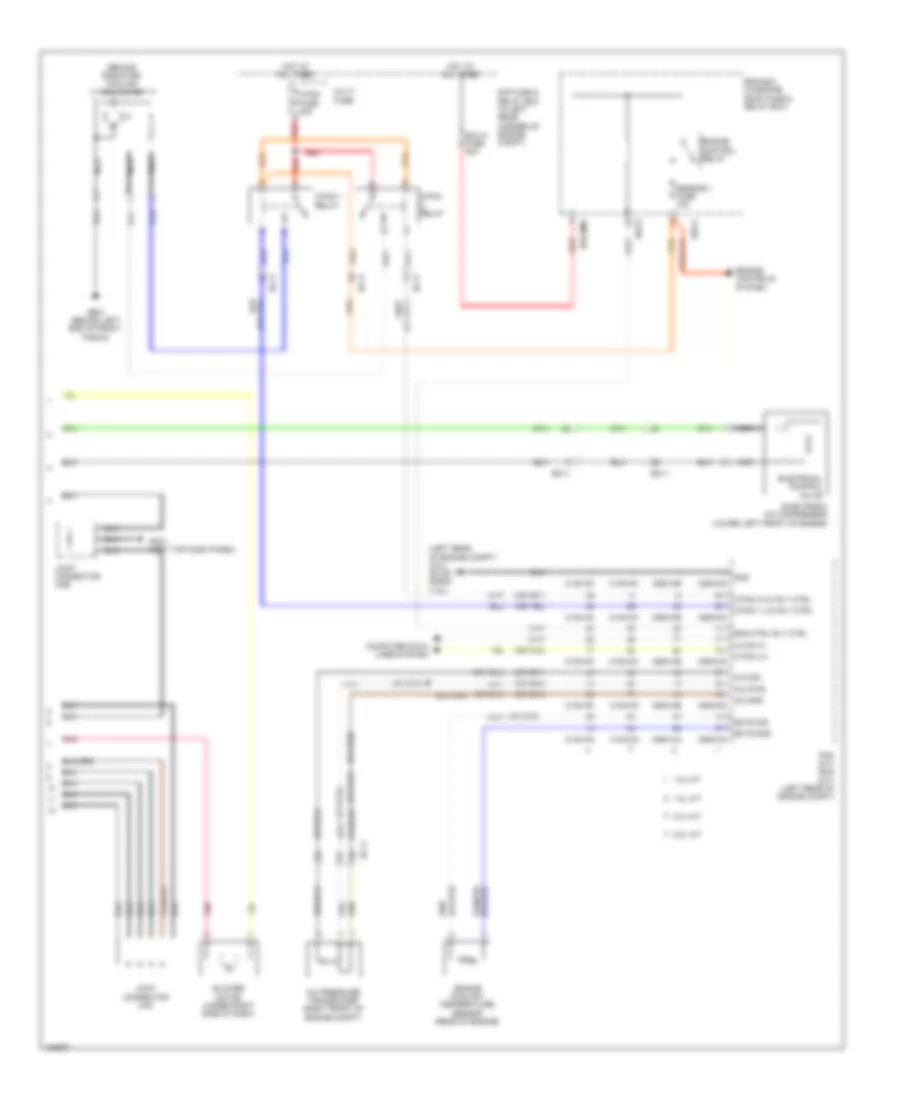
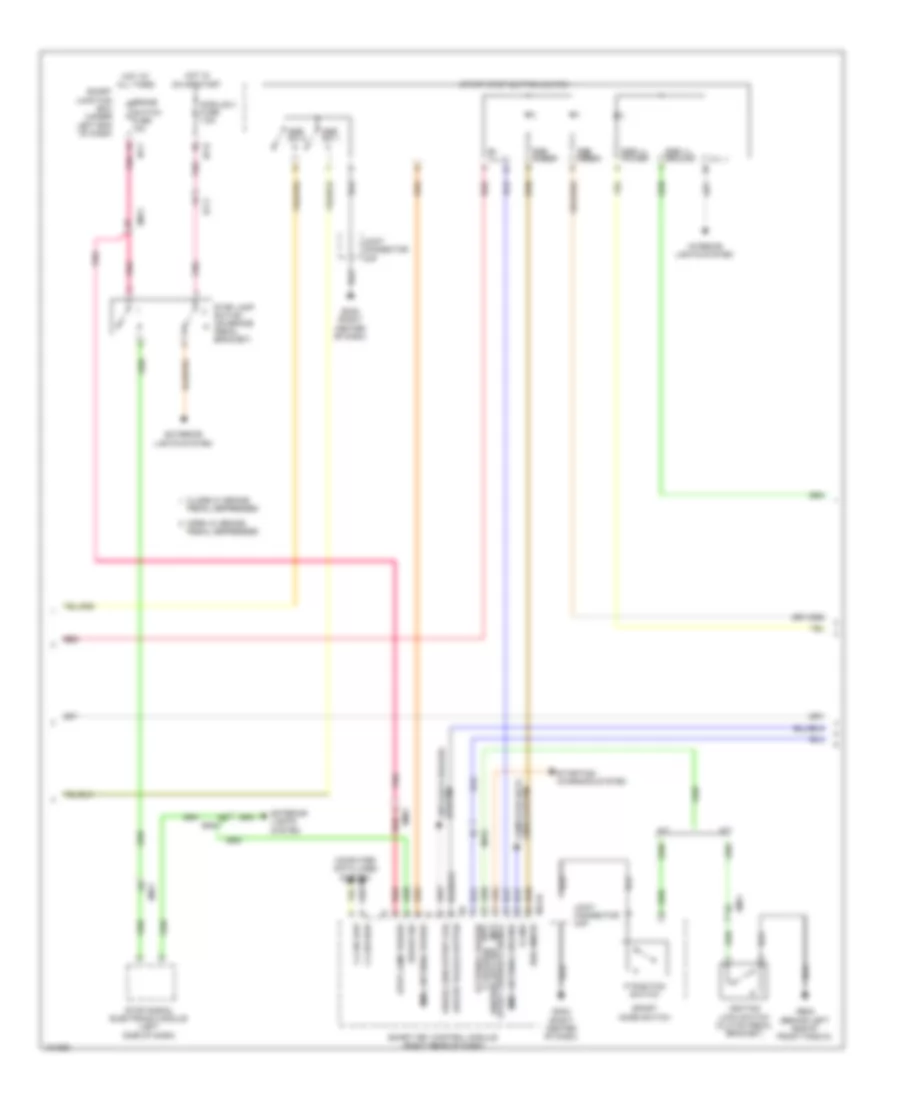
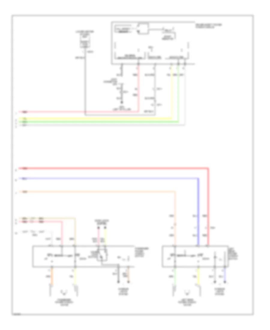
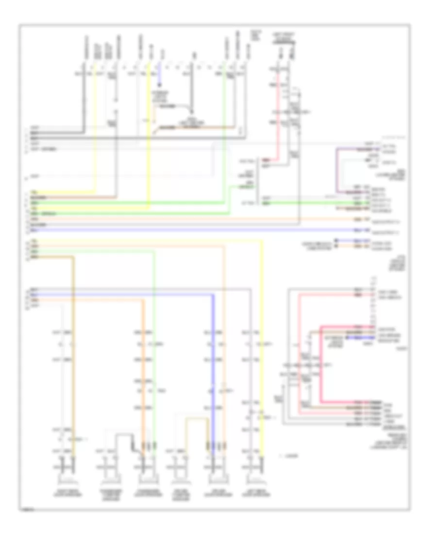
Manual A/C Wiring Diagram (2 of 2) for Hyundai Elantra Sport 2014
List of elements for Manual A/C Wiring Diagram (2 of 2) for Hyundai Elantra Sport 2014:
- (behind radiator) cooling fan motor
- (left rear of engine compt) (2.0l) gc102 gc602 (1.8l)
- (or pnk)
- 1.8l a/t
- 1.8l m/t
- 2.0l a/t
- 2.0l m/t
- A/c gnd
- A/c pressure transducer (right front of engine compt)
- A/c pwr
- A/c sig
- Blower motor (under right side of dash)
- C-can hi
- C-can lo
- C/fan 1 (lo) rly ctrl
- C/fan 1 relay
- C/fan 2 (hi) rly ctrl
- C/fan fuse 40a
- C/fan relay
- C100-aa
- C100-ak
- C100-ma
- C100-mk
- C600-aa
- C600-ab
- C600-ma
- C600-mk
- Computer data lines system
- E/r fuse & relay box (in left rear corner of engine compt)
- E/r-a
- E/r-b
- E/r-ems
- Ec11
- Ects gnd
- Ects sig
- Ecu 6 fuse 40a
- Electrical control valve
- Electronic a/c compressor (lower left front of engine)
- Em11
- Ems box (in engine room fuse & relay box)
- Eng ctrl rly ctrl
- Engine control relay
- Engine controls system
- Engine coolant temperature sensor (rear of engine)
- Ge01 (behind left end of front fascia)
- Gm01 (left top dash panel)
- Gnd
- Hot at all times
- Joint connector uma
- Joint connector ume
- Multi fuse
- Nca
- Pcm (a/t) ecm (m/t) (left rear of engine compt)
- Pnk
- Red
- Sensor 1 fuse 10a
ANTI-LOCK BRAKES
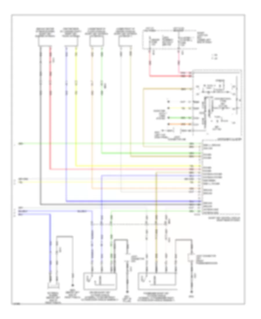
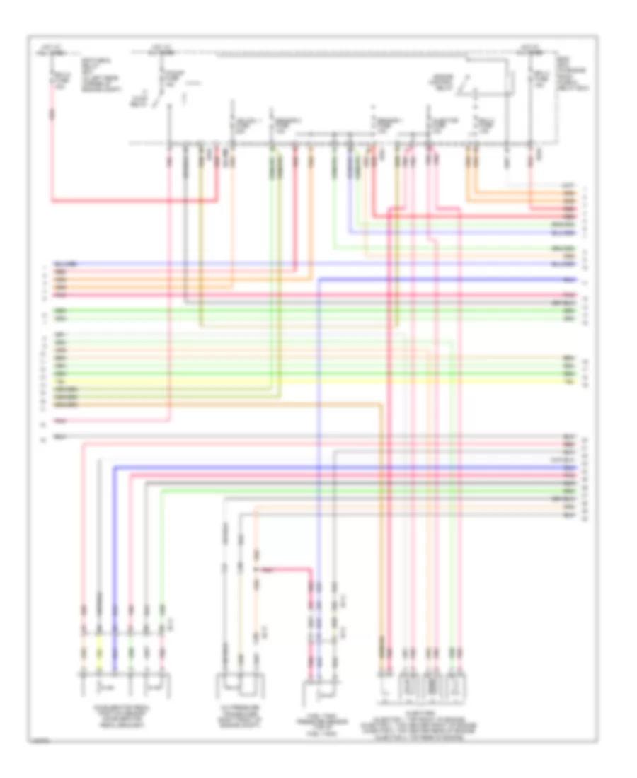
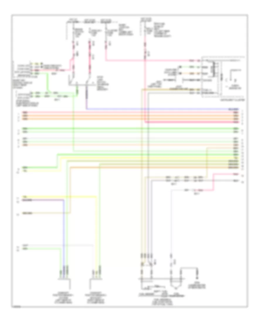
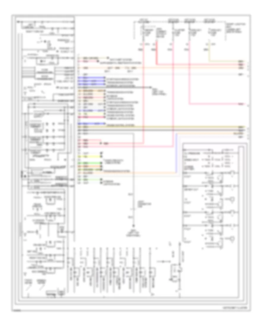
Anti-lock Brakes Wiring Diagram (1 of 2) for Hyundai Elantra Sport 2014
List of elements for Anti-lock Brakes Wiring Diagram (1 of 2) for Hyundai Elantra Sport 2014:
- +ecu
- Abs 1 fuse 40a
- Abs 2 fuse 30a
- Abs 3 fuse 10a
- Brake light sw
- Brake sig
- Brake switch fuse 10a
- Brk fluid
- C-can high
- C-can low
- Can high
- Can low
- Clt sw hac rly state monitoring
- Cluster 1 cluster fuse 7.5a
- Computer data lines system
- Computer data lines system exterior lights system
- E/r fuse & relay box (in left rear corner of engine compt)
- Ef11
- Em11
- Em61
- Engine controls system
- Esc module (right rear of engine compt)
- Esc off sw
- Esc off switch
- Esc unit
- Fl sig
- Fl vcc
- Fr sig
- Fr vcc
- Ge06 (right kick panel)
- Ground
- Hac brk rly ctrl brake switch
- High b-can
- Hot at all times
- Hot in on or start
- I/p-b
- I/p-c
- I/p-e
- I/p-f
- I/p-g
- Ill
- Interior lights system
- Ips control module
- Left front wheel sensor (left front wheel hub assembly)
- Left rear wheel sensor (left rear wheel hub assembly)
- Lev sen
- Low b-can
- M13-b
- Module 3 fuse 7.5a
- Multi fuse
- Nca
- Off
- Park brk sw
- Parking brk sw
- Pnk
- Power
- Red
- Rev gear sw
- Right front wheel sensor (right front wheel hub assembly)
- Right rear wheel sensor (right rear wheel hub assembly)
- Rl sig
- Rl vcc
- Rr sig
- Rr vcc
- Smart junction box (under left end of dash)
- Smart key control module (right rear of dash)
- Stop lamp 15a
- Stop lmp pwr
- Valve relay
- Vbatt mtr rly
- Wheel sens out
- Yaw rate sensor (under left side of front passenger's seat)
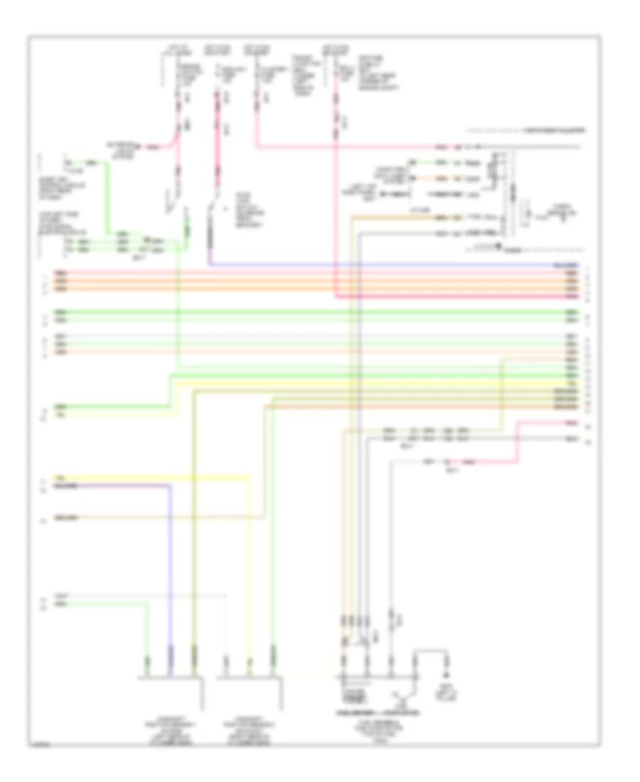
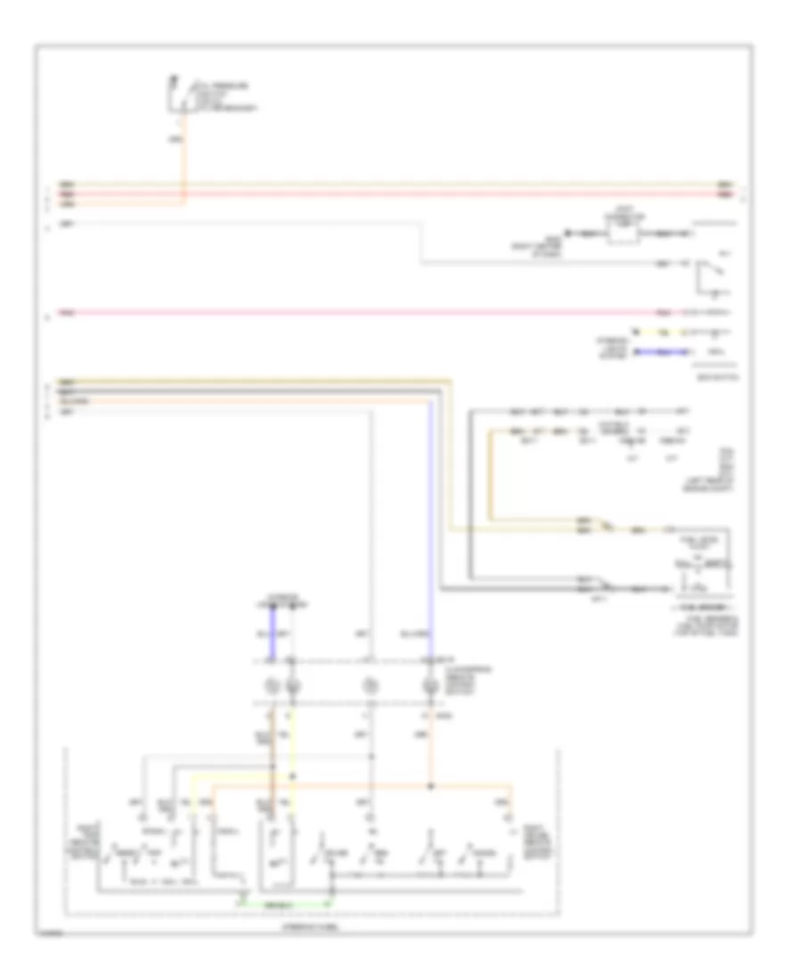
Anti-lock Brakes Wiring Diagram (2 of 2) for Hyundai Elantra Sport 2014
List of elements for Anti-lock Brakes Wiring Diagram (2 of 2) for Hyundai Elantra Sport 2014:
- (base of parking brake lever assembly) parking brake switch
- (in brake fluid reservoir) brake fluid level sensor
- A/t
- A/t 1.8l
- A/t 2.0l
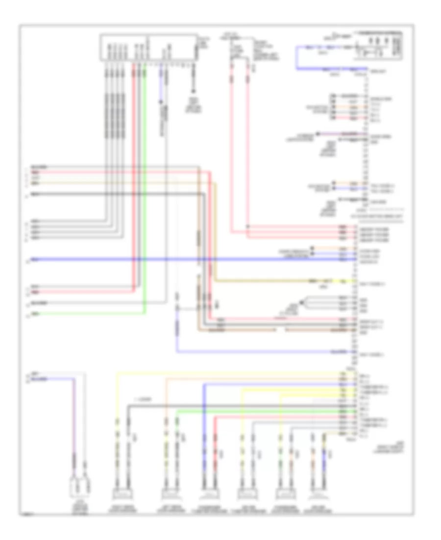
- A/v & navigation head unit
- Abs ind
- B-can high
- B-can low
- B-can transceiver
- Bcm (lower center of dash)
- Brake ind
- Brake ind parking
- Brake sw
- C-can high
- C-can low
- C-can transceiver
- C100-aa
- C100-ak
- C100-ma
- C100-mk
- C600-ab
- C600-mk
- Computer data lines system
- Ec11
- Ecm (m/t) pcm (a/t) (left rear of engine compt)
- Em11
- Em61
- Esc ind
- Esc off ind
- Exterior lights system
- Ge02 (behind left end of front fascia)
- Gm01 (left top dash panel)
- Gnd
- Hac signal
- Input
- Input circuit
- Input vecle spd
- Instrument cluster
- Interface
- Internal control
- Ips
- Joint connector ume
- Light sw brake
- M/t
- M/t 1.8l
- M/t 2.0l
- M02-a
- M02-b
- Memory power
- Mf11
- Micom
- Pnk
- Stop lamp
- Stop lamp sig
- Stop lamp sw
- Stop lamp switch (on brake pedal bracket)
- Stop signal electronic module (left side of dash)
- Vecle spd
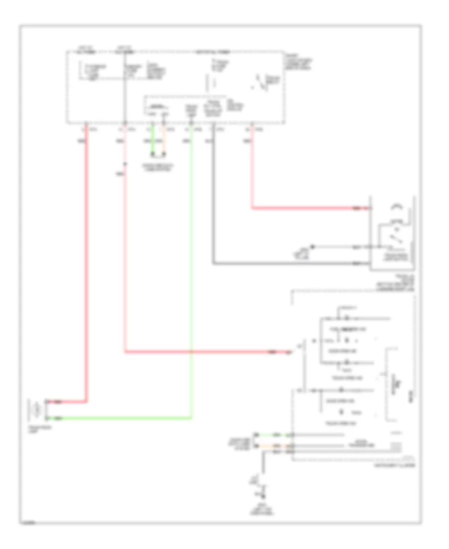
ANTI-THEFT
Forced Entry Wiring Diagram (1 of 2) for Hyundai Elantra Sport 2014
List of elements for Forced Entry Wiring Diagram (1 of 2) for Hyundai Elantra Sport 2014:
- B-can
- Burglar alarm relay control
- Computer data lines system
- Door lock relay
- Door lock relay control
- Door unlock relay
- Door unlock relay control
- Dr lk
- Dr lock fuse 20a
- Dr unlk
- Driver door key unlock signal
- Driver door lock actuator
- Driver door lock/ unlock signal
- Fd11
- Fd31
- Fd41
- Gf01 (left "b" pillar)
- Gf03 (left "c" pillar)
- Gf04 (right "c" pillar)
- Gm01 (left top dash panel)
- High
- Hot at all times
- I/p-b
- I/p-c
- I/p-g
- I/p-h
- Ips control module
- Joint connector uda
- Key lk
- Key unlk
- Left rear door lock actuator
- Left rear door lock/ unlock signal
- Low
- Pnk
- Right rear door lock actuator
- Right rear door lock/ unlock signal
- Smart junction box (under left end of dash)
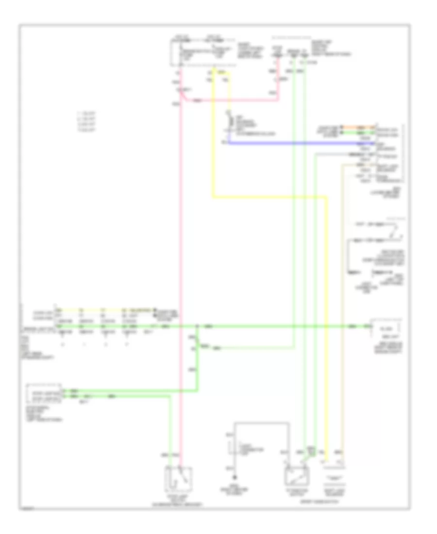
- Starting/ charging system
- W/ two turn relay
- W/o two turn relay
Forced Entry Wiring Diagram (2 of 2) for Hyundai Elantra Sport 2014
List of elements for Forced Entry Wiring Diagram (2 of 2) for Hyundai Elantra Sport 2014:
- (behind right end of front fascia)
- (left "b" pillar) gf01
- (top left side of dash)
- Auto light & photo sensor (top center of dash)
- B/alarm horn relay
- B/alarm horn relay control
- Bcm (lower center of dash)
- Burglar alarm horn (right rear of engine compt)
- Can h
- Can l
- Computer data lines system
- Door lock
- Door lock switch
- Door unlock
- Dr lk
- Dr unlk
- Driver/ passenger door key lock signal
- E/r fuse & relay box (in left rear corner of engine compt)
- Fd11
- Fd21
- Ge04
- Gf02
- Gm01 (left top dash panel)
- Hood switch
- Hood switch (right front of engine compt)
- Horn fuse 15a
- Hot at all times
- I/p-c
- I/p-e
- I/p-g
- I/p-h
- Icm relay box
- Ips control module
- Joint connector jd01 (front passenger's door)
- Joint connector uda
- Key lk
- Key unlk
- Leak current autocut device
- Lock
- M02-b
- M02-c
- M06
- Memory fuse 10a
- Mf11
- Nca
- Passenger door key unlock signal
- Passenger door lock actuator
- Passenger door lock/ unlock signal
- Passenger power window switch (w/ central door lock)
- Pnk
- Power window main switch
- Red
- Sec ind
- Smart junction box (under left end of dash)
- Two turn relay
- Two turn relay control
- Unlock
- W/ safety power windows
- W/o safety power windows
Immobilizer Wiring Diagram, with Smart Key System (1 of 3) for Hyundai Elantra Sport 2014
List of elements for Immobilizer Wiring Diagram, with Smart Key System (1 of 3) for Hyundai Elantra Sport 2014:
- (left top dash panel) gm01
- 1.8l a/t
- 1.8l m/t
- 2.0l a/t
- 2.0l m/t
- Acc/in input
- B-can high
- B-can low
- Bcm fuse 7.5a
- C100-ak
- C100-mk
- C600-aa
- C600-mk
- Computer data lines system
- E/r fuse & relay box (in left rear corner of engine compt)
- Ec11
- Ecm (m/t) pcm (a/t) (left rear of engine compt)
- Em11
- Em61
- Ems com
- Engine controls system
- Engine speed signal
- Ge02 (behind left end of front fascia)
- Gf03 (left "c" pillar)
- Gm02 (right center of dash)
- Ground
- Hot at all times
- I/p-f
- I/p-h
- Ig1 fuse 40a
- Ig2 fuse 40a
- Immo data line
- M13-a
- Memory power
- Mf61
- Module 7 fuse 7.5a
- Nca
- On input
- On/start input
- Passenger toggle button
- Pdm 1 fuse 25a
- Pdm 2 (acc) relay
- Pdm 2 fuse 7.5a
- Pdm 3 (ig1) relay
- Pdm 3 fuse 7.5a
- Pdm 4 (ig2) relay
- Pnk
- Power distribution system
- Red
- Smart junction box (under left end of dash)
- Smart key control module (right rear of dash)
- Ssb sw1
- Ssb sw2
- Starting/ charging system
- Terminal control acc relay
- Terminal control ig1 relay
- Terminal control ig2 relay
- Terminal ctrl st relay
- Trunk lid handle switch
Immobilizer Wiring Diagram, with Smart Key System (2 of 3) for Hyundai Elantra Sport 2014
List of elements for Immobilizer Wiring Diagram, with Smart Key System (2 of 3) for Hyundai Elantra Sport 2014:
- (ill -)
- A/t
- B+ (ill +)
- Brake
- Brake sig
- C-can high
- C-can low
- Close w/ brake
- Computer data lines system
- Driver toggle button
- Ef11
- Em11
- Em61
- Exterior lights system
- External buzzer
- Ge02 (behind left end of front fascia)
- Gm02 (right center of dash)
- Hot at all times
- Hot in on or start
- I/p-b
- I/p-f
- Ignition lock switch (clutch pedal bracket)
- Immo antenna ground
- Immo antenna power
- Interior lights system
- Joint connector umf
- K-line
- Lines system computer data
- M/t
- M13-b
- Mf61
- Module 3 fuse 7.5a
- Open w/ brake
- P position ignition lock sw
- P position switch
- Pedal depressed
- Pnk
- Red
- Smart junction box (under left end of dash)
- Smart key control module (right rear of dash)
- Sport mode switch
- Ssb amber
- Ssb green
- Ssb ill ground
- Ssb ill power
- Ssb sw 1
- Ssb sw 2
- Start feedback signal (m/t) (a/t)
- Start stop button switch
- Starting/ charging system
- Stop lamp power
- Stop lamp switch (on brake pedal bracket)
- Stop signal electronic module (left side of dash)
- Switch fuse 10a
- System anti-lock brakes
- Wheel sen output (fr)
Immobilizer Wiring Diagram, with Smart Key System (3 of 3) for Hyundai Elantra Sport 2014
List of elements for Immobilizer Wiring Diagram, with Smart Key System (3 of 3) for Hyundai Elantra Sport 2014:
- (behind center of rear bumper) smart key bumper antenna
- (center rear of luggage compt) smart key trunk antenna
- (conventional type) key out ind
- (under front of center console) smart key antenna (interior 1)
- (under rear of floor console) smart key antenna (interior 2)
- Antenna gnd
- Antenna power
- Cluster 1 cluster fuse 7.5a
- Computer data lines system
- Driver smart key outside handle (integral to driver front outside door handle assembly)
- Ee11
- External buzzer (behind left end of front fascia)
- Fd11
- Fd21
- Fr11
- Ge02 (behind left end of front fascia)
- Gf01 (left "b" pillar)
- Gf02
- Gm01 (left top dash panel)
- Ground
- High
- Hot at all times
- Hot in on or start
- I/p-f
- I/p-h
- Immo ind
- Instrument cluster
- Interface
- Joint connector jd01 (front passenger's door)
- Joint connector uda
- Joint connector ume
- Key out ind
- Leak current autocut device
- Lock
- Low
- M13-c
- Memory fuse 10a
- Mf61
- Micom
- Nca
- Passenger smart key outside handle (integral to passenger front outside door handle assembly)
- Pnk
- Power
- Red
- Smart junction box (under left end of dash)
- Smart key control module (right rear of dash)
- Ssb green
- Ssb ill ground
- Ssb ill power
- Transceiver b-can
- Transceiver c-can
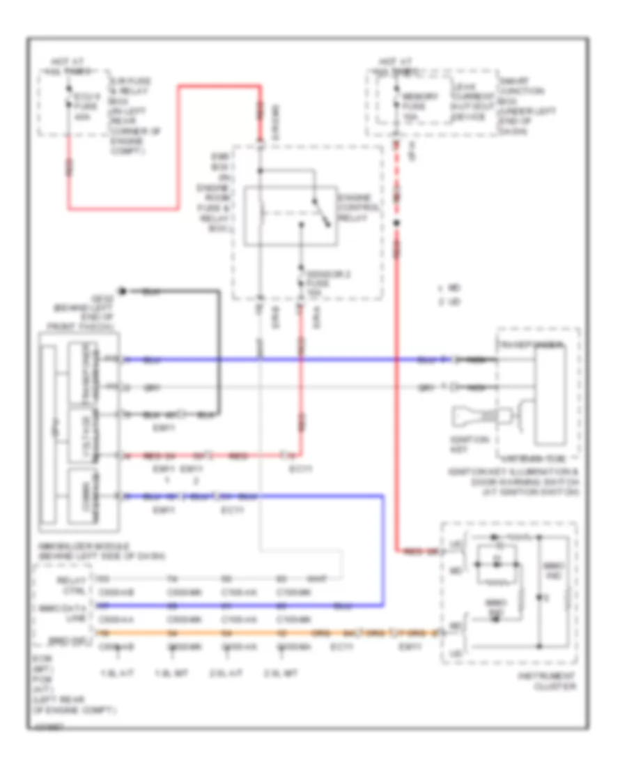
Immobilizer Wiring Diagram, without Smart Key System for Hyundai Elantra Sport 2014
List of elements for Immobilizer Wiring Diagram, without Smart Key System for Hyundai Elantra Sport 2014:
- (+)
- (-)
- 1.8l a/t
- 1.8l m/t
- 2.0l a/t
- 2.0l m/t
- Antenna coil
- C100-ak
- C100-ma
- C100-mk
- C600-aa
- C600-ab
- C600-mk
- Cpu
- E/r fuse & relay box (in left rear corner of engine compt)
- E/r-a
- E/r-b
- E/r-ems
- Ec11
- Ecm (m/t) pcm (a/t) (left rear of engine compt)
- Ecu 6 fuse 40a
- Em11
- Ems box (in engine room fuse & relay box)
- Engine control relay
- Ge02 (behind left end of front fascia)
- Hot at all times
- I/p-h
- Ignition key
- Ignition key illumination & door warning switch (at ignition switch)
- Immo data line
- Immo ind
- Immobilizer module (behind left side of dash)
- Instrument cluster
- Interface comms
- Interface transponer
- Leak current autocut device
- Memory fuse 10a
- Nca
- Red
- Regulator voltage
- Relay ctrl
- Sensor 2 fuse 10a
- Smart junction box (under left end of dash)
- Transponder
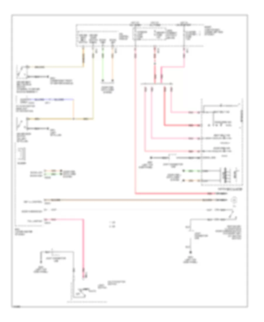
BODY CONTROL MODULES
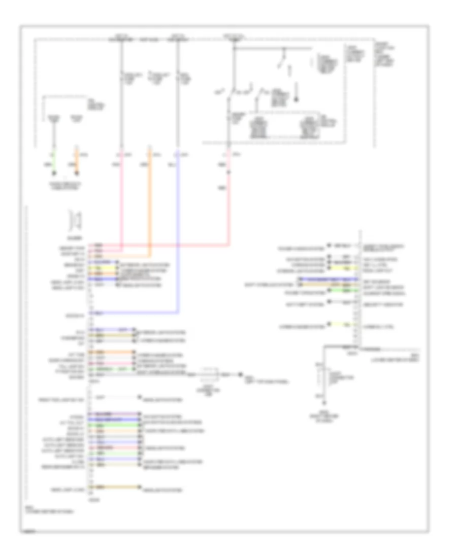
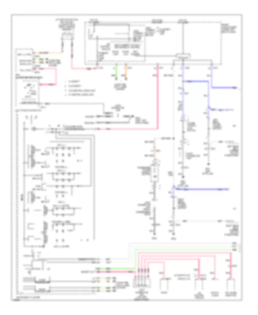
Body Control Module Wiring Diagram for Hyundai Elantra Sport 2014
List of elements for Body Control Module Wiring Diagram for Hyundai Elantra Sport 2014:
- 'p' position sw
- 'r' in
- (a/t)
- (m/t)
- (w/o smart key)
- A/v tail out
- Acc/on in
- Anti-theft system
- Auto light sens gnd
- Auto light sens pwr
- Auto light sens sig
- Auto light sw
- B-can hi
- B-can high
- B-can lo
- B-can low
- Bcm (lower center of dash)
- Bcm fuse 7.5a
- Brake sw
- Buzzer
- Computer data lines system
- Crash in
- Defogger system
- Door warning sw
- Exterior lights system
- Front fog lamp sw 'on'
- Gm01 (left top dash panel)
- Gm02 (right center of dash)
- Head lamp hi sw
- Head lamp lo sig
- Head lamp lo sw
- Headlights system
- Hot at all times
- Hot in acc or on
- Hot in on
- Hot in on or start
- I/p-f
- I/p-g
- I/p-h
- Int
- Int time
- Interior lights system
- Ips control module
- Joint connector ume
- Joint connector umf
- K-line
- Key ill ctrl
- Key solenoid
- Leak current autocut device
- Leak current autocut device relay
- Leak current autocut device relay control
- Leak current autocut device switch
- Leak current autocut device switch control
- M02-a
- M02-b
- M02-c
- Memory fuse 10a
- Memory pwr
- Mist
- Module 2 fuse 7.5a
- Module 7 fuse 7.5a
- Mts-rx
- Navi wake-up sig
- Navigation & sound systems
- Navigation system
- Off
- On in
- On/start in
- Pnk
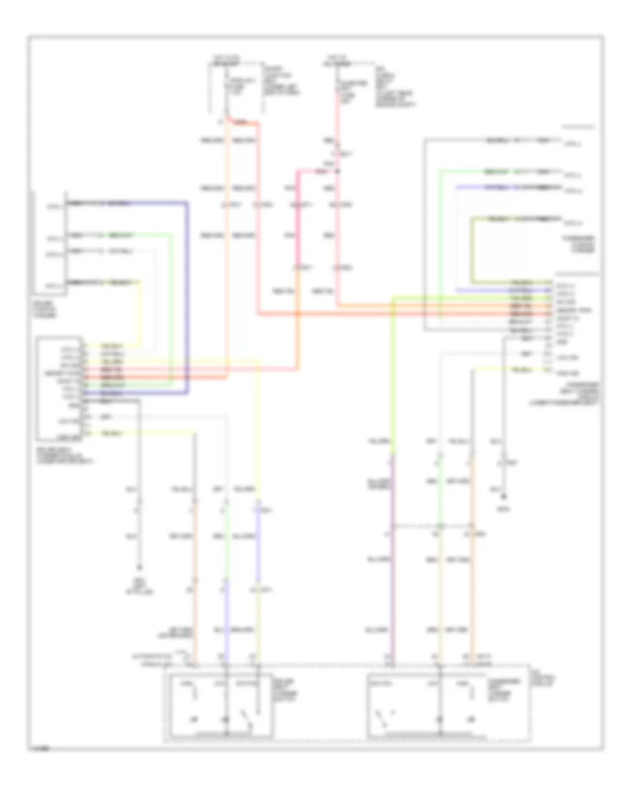
- Power tops system
- Power window system
- Pwr gnd
- Rear defogger sw in
- Red
- Room lamp out
- Safety pwr window enable output
- Security indicator
- Shift interlock system
- Shift lock solenoid
- Sig gnd
- Smart junction box (under left end of dash)
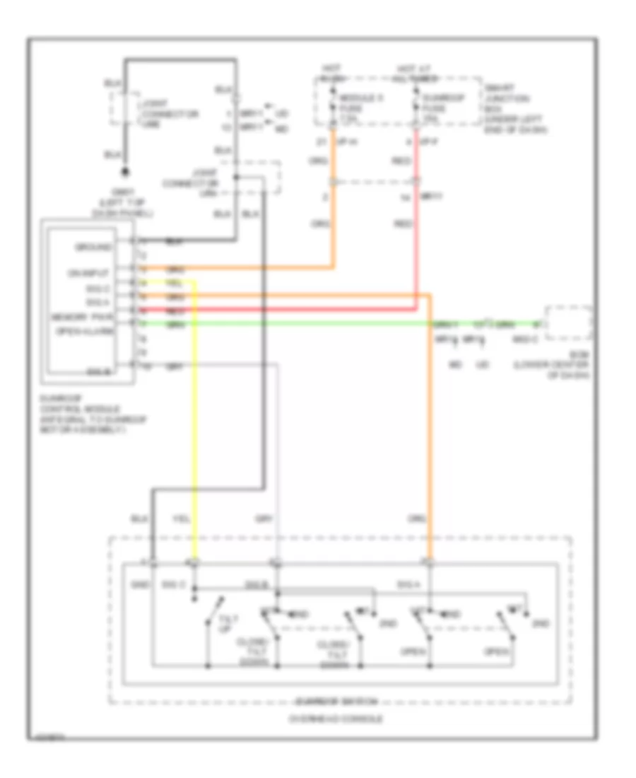
- Sunroof open signal
- Tail lamp sw
- Warning system
- Warning systems
- Washer sig
- Wiper rly ctrl
- Wiper/washer system
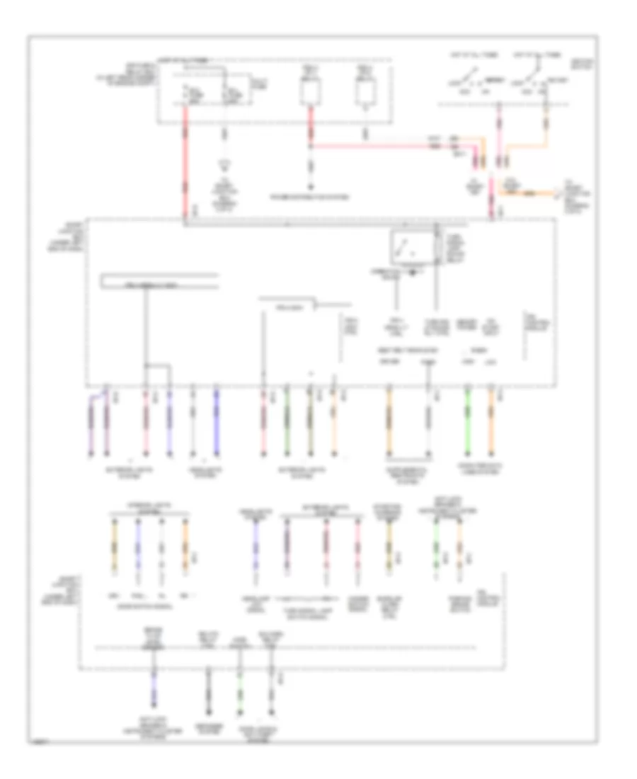
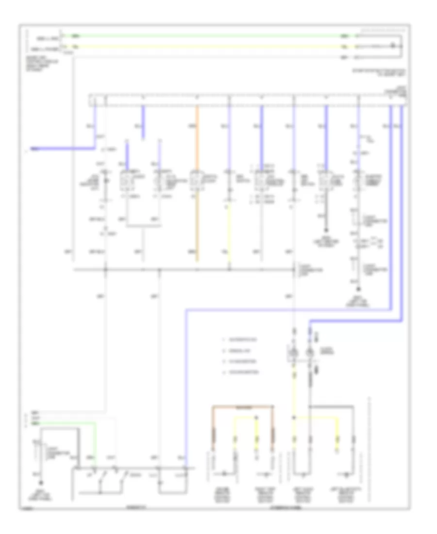
IPS Control Module Wiring Diagram (1 of 2) for Hyundai Elantra Sport 2014
List of elements for IPS Control Module Wiring Diagram (1 of 2) for Hyundai Elantra Sport 2014:
- Acc
- Anti-lock brakes & instrument cluster systems
- Arisu-lt
- B+1 fuse 60a
- B+2 fuse 60a
- B-can
- B/a horn relay ctrl
- Brake fluid level sensor
- Burglar alarm relay ctrl
- Computer data lines system
- Ctrl
- Defogger system
- Door locks & anti-theft system
- Door switch signal
- Driver
- Drv
- E/r fuse & relay box (in left rear corner of engine compt)
- Em11
- Exterior lights system
- Hazard switch signal
- Headlamp low signal
- Headlights system
- High
- Hood switch
- Hot at all times
- I/p-b
- I/p-c
- I/p-d
- I/p-e
- I/p-f
- I/p-g
- Ignition switch
- Interior lights system
- Ips 4
- Ips 4 arisu-lt (4ch)
- Ips 8 (2ch)
- Ips 8 (2ch) ctrl
- Ips control module
- Key
- Lock
- Low
- Memory power
- Multi fuse
- On/ start input
- Operation sound
- Parking brake switch
- Pas
- Pass
- Pdm 3 (ig 1) relay
- Pdm 4 (ig 2) relay
- Pnk
- Power distribution system
- Red
- Rr htd relay ctrl
- Seat belt buckle sw
- Smart
- Smart junction box (under left end of dash)
- Start
- Starting/ charging system
- To smart junction box (diagram 2 of 2)
- Turn sig lp sound rly ctrl
- Turn signal lamp sound relay
- Turn signal lamp switch signal
- W/o
IPS Control Module Wiring Diagram (2 of 2) for Hyundai Elantra Sport 2014
List of elements for IPS Control Module Wiring Diagram (2 of 2) for Hyundai Elantra Sport 2014:
- Anti-theft & door locks systems
- Distribution
- Door lk sw
- Door lock relay
- Door lock relay ctrl
- Door unlock relay
- Door unlock relay ctrl
- Dr lk/unlk sig
- Dr lock fuse 20a
- Driver door key unlk sig
- Driver/ passenger dr key lk sig
- Drv
- Exterior lights system
- From ignition switch (w/o smart key) pdm 4 (ig2) relay (w/ smart key) (diagram 1 of 2)
- From multi fuse (diagram 1 of 2)
- Gm01 (left top dash panel)
- Gm02 (right center of dash)
- Gnd (drl)
- Gnd (mcu)
- Headlights system
- Hot at all times
- I/p-b
- I/p-c
- I/p-d
- I/p-e
- I/p-f
- I/p-g
- I/p-h
- Interior lights system
- Ips 1 arisu-lt (4ch)
- Ips 1 arisu-lt ctrl
- Ips 3 (1ch)
- Ips 3 ctrl
- Ips 7 (1ch)
- Ips 7 ctrl
- Ips control module
- Joint connector ume
- Joint connector umf
- Leak current autocut device
- Leak current autocut device relay
- Leak current autocut device relay ctrl
- Leak current autocut device sw ctrl
- Leak current autocut device switch
- Md w/o two turn relay
- Memory pwr
- Off
- On input
- P/wdw lh fuse 25a
- P/wdw lh relay
- P/wdw rh fuse 25a
- P/wdw rh relay
- Pass
- Passenger door key unlk sig
- Pnk
- Power
- Power window rly ctrl
- Power windows system
- Red
- Smart junction box (under left side of dash, near kick panel)
- System
- Trunk fuse 10a
- Trunk open switch
- Trunk relay
- Trunk rly ctrl
- Trunk, tailgate, fuel doors system
- Two turn relay ctrl
- Unlk
COMPUTER DATA LINES
Computer Data Lines Wiring Diagram (1 of 3) for Hyundai Elantra Sport 2014
List of elements for Computer Data Lines Wiring Diagram (1 of 3) for Hyundai Elantra Sport 2014:
- 10a
- 4p out
- A/v & navigation headunit
- Amp (w/ navigation) (right side of luggage compt)
- Audio
- B-can hi
- B-can lo
- Bcm (lower center of dash)
- C-can hi
- C-can lo
- Data link connector (below left end of dash)
- Em61
- Esc module (right rear of engine compt)
- F02-c
- Gm01 (left top dash panel)
- Hot at all times
- I/p-f
- I/p-g
- Instrument cluster
- Ips control module
- J/c je01 (front passenger's footwell)
- J/c jm03 (top left side of dash)
- J/c jm04 (top left side of dash)
- Joint connector ume
- K-line
- Leak current autocut device
- M-can hi
- M-can lo
- M02-b
- M09-b
- M13-a
- M13-b
- M15-b
- Memory fuse
- Mf61
- Red
- Smart junction box (under left end of dash)
- Smart key control module (right rear of dash)
- Vech spd
- W/ navigation
- W/o navigation
Computer Data Lines Wiring Diagram (2 of 3) for Hyundai Elantra Sport 2014
List of elements for Computer Data Lines Wiring Diagram (2 of 3) for Hyundai Elantra Sport 2014:
- 1.8l a/t
- 1.8l m/t
- 2.0l a/t
- 2.0l m/t
- Abs 3 fuse 10a
- C-can hi
- C-can lo
- C100-ak
- C100-mk
- C600-ab
- C600-mk
- Ccp can hi
- Ccp can lo
- Digital clock
- E/r fuse & relay box (in left rear corner of engine compt)
- Ec11
- Hot in on or start
- J/c jf01 (under front passenger's seat)
- M-can hi
- M-can lo
- Mdps unit
- Mf61
- Passenger weight classification sensor (under front passenger's seat)
- Pcm (a/t) ecm (m/t) (left rear of engine compt)
- Pnk
- Srs control module (under front of center console)
- Vech spd
- W/ navigation
Computer Data Lines Wiring Diagram (3 of 3) for Hyundai Elantra Sport 2014
List of elements for Computer Data Lines Wiring Diagram (3 of 3) for Hyundai Elantra Sport 2014:
- (not used)
- (top left side of dash) j/c jm01
- A/c control module
- Abs 1 fuse 40a
- Abs 2 fuse 30a
- Automatic a/c
- C-can hi
- C-can lo
- E/r fuse & relay box (in left rear corner of engine compt)
- Em11
- Ge04 (behind right end of front fascia)
- Hot at all times
- J/c jm02 (top right end of dash)
- K-line
- M-can hi
- M-can lo
- M21-a
- M21-b
- M22-b
- Manual a/c
- Mf61
- Mts module (center of dash)
- Multi fuse
- Multipurpose check connector (right side of engine compt)
- Nca
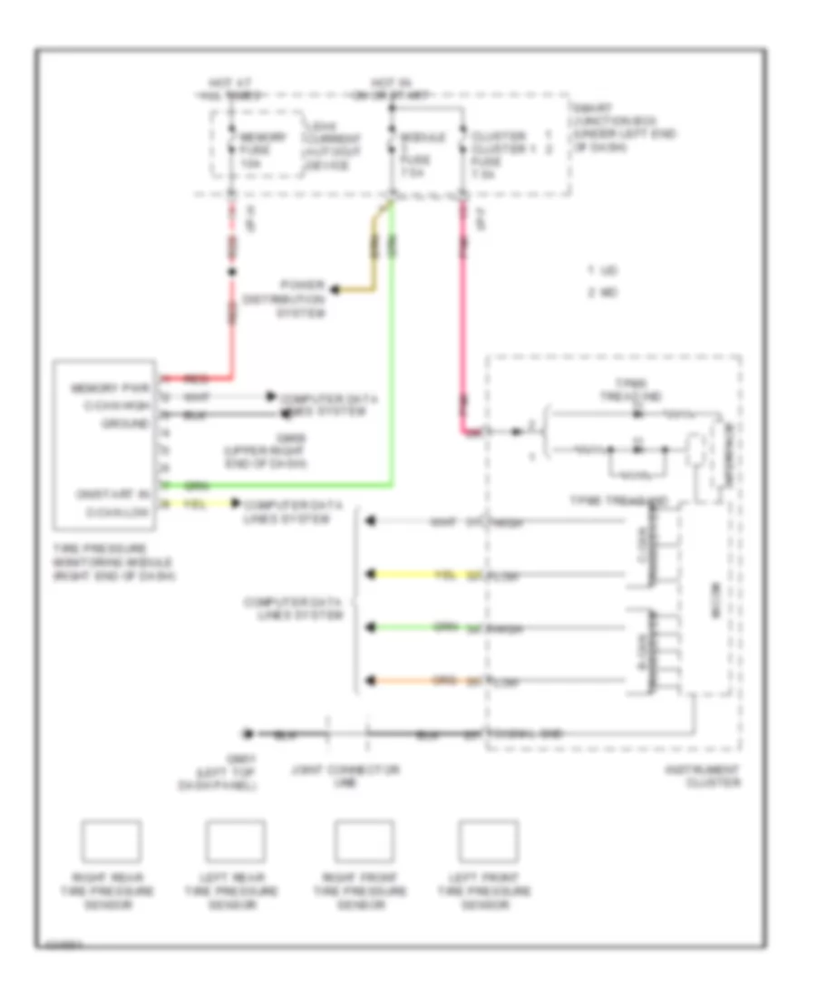
- Pnk
- Red
- Tire pressure monitoring module (right end of dash)
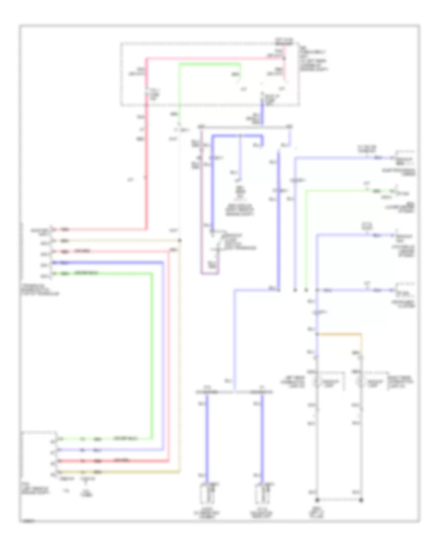
COOLING FAN
Cooling Fan Wiring Diagram for Hyundai Elantra Sport 2014
List of elements for Cooling Fan Wiring Diagram for Hyundai Elantra Sport 2014:
- (1.8l) gc602
- (or pnk)
- 1.8l a/t
- 1.8l m/t
- 2.0l a/t
- 2.0l m/t
- C-can hi
- C-can lo
- C/fan 1 relay
- C/fan 2 (hi) rly ctrl c/fan 1 (lo) rly ctrl
- C/fan 2 relay
- C/fan fuse 40a
- C100-aa
- C100-ak
- C100-ma
- C100-mk
- C600-aa
- C600-ab
- C600-ma
- C600-mk
- Computer data lines system
- Cooling fan motor (behind radiator)
- E/r fuse & relay box (in left rear corner of engine compt)
- E/r-a
- E/r-b
- E/r-ems
- Ec11
- Ects gnd
- Ects sig
- Ecu 6 fuse 40a
- Ems box (in engine room fuse & relay box)
- Engine control relay
- Engine coolant temperature sensor (rear of engine)
- Engine ctrl rly ctrl
- Gc102 (2.0l) (left rear of engine compt)
- Ge01 (behind left end of front fascia)
- Gnd
- Hot at all times
- Multi fuse
- Nca
- Pcm (a/t) ecm (m/t) (left rear of engine compt)
- Red
- Sensor 1 fuse 10a
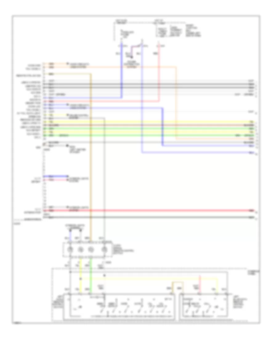
CRUISE CONTROL
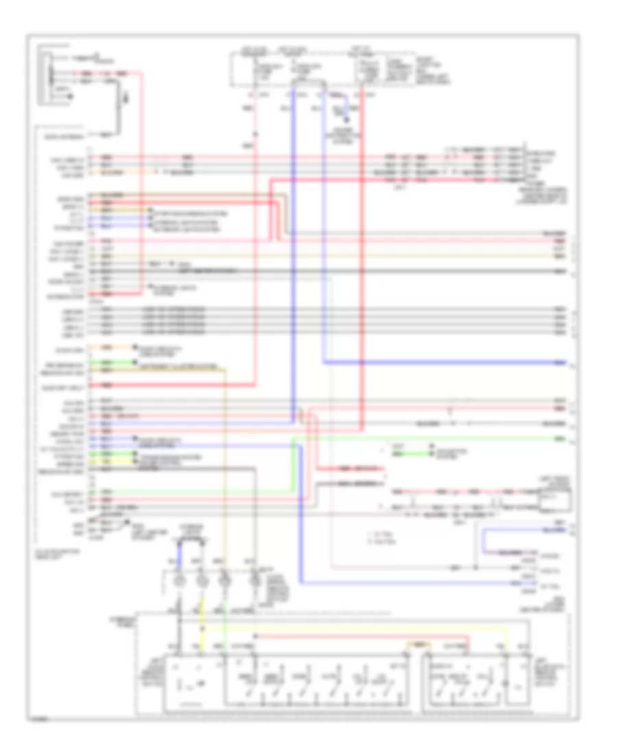
Cruise Control Wiring Diagram (1 of 3) for Hyundai Elantra Sport 2014
List of elements for Cruise Control Wiring Diagram (1 of 3) for Hyundai Elantra Sport 2014:
- & &
- (+)
- (-)
- (or pnk)
- (or red)
- 1.8l a/t
- 1.8l m/t
- 2.0l a/t
- 2.0l m/t
- Aps 1 ground
- Aps 1 power
- Aps 1 signal
- Aps 2 ground
- Aps 2 power
- Aps 2 signal
- Brake light sw
- C-can high
- C-can low
- C100-aa
- C100-ak
- C100-ma
- C100-mk
- C600-aa
- C600-ab
- C600-ma
- C600-mk
- Cancel
- Clock spring (remote control switch)
- Computer data lines system
- Cruise
- Cruise (+)
- Cruise (-)
- Ec11
- Etc o/p (+) dc mtr (+)
- Etc o/p (-) dc mtr (-) c100-ak
- Ill
- Interior lights system
- M01-r
- Mm02
- On/start input
- Pcm (a/t) ecm (m/t) (left rear of engine compt)
- Pnk
- Red
- Res (+)
- Reset
- Right cruise remote control switch
- Right trip remote control switch
- Set (-)
- Sig
- Steering wheel
- Tps 1 signal
- Tps 2 signal
- Tps ground
- Tps power (5v)
- Trip
- Trip (+)
- Trip (-)
- Veh spd i/p
Cruise Control Wiring Diagram (2 of 3) for Hyundai Elantra Sport 2014
List of elements for Cruise Control Wiring Diagram (2 of 3) for Hyundai Elantra Sport 2014:
- (or pnk)
- (or red)
- + hall ic
- 4p out
- B-can transceiver
- C-can transceiver
- Cluster 1 fuse 7.5a
- Computer data lines system
- Cruise ind (md)
- Cruise ind (ud)
- E/r fuse & relay box (in left rear corner of engine compt)
- Ec11
- Ecu 3 fuse 10a
- Em61
- Gc101 (2.0l) gc601 (1.8l) (left rear of engine compt)
- Gm01 (left top dash panel)
- Gnd
- High
- Hot at all times
- Hot in on or start
- I/f
- I/p-f
- I/p-h
- Ig+
- Instrument cluster
- Interface
- Joint connector ume
- Leak current autocut device
- Low
- Memory fuse 10a
- Micom
- P- gnd
- Pnk
- Red
- S- gnd
- S-gnd
- Set ind (md)
- Set ind (ud)
- Smart junction box (under left end of dash)
- Speed input
- Speedometer
- Tachometer
- Tcu fuse 15a
- Vehicle speed sensor (m/t) (on top of transaxle)
Cruise Control Wiring Diagram (3 of 3) for Hyundai Elantra Sport 2014
List of elements for Cruise Control Wiring Diagram (3 of 3) for Hyundai Elantra Sport 2014:
- (accelerator pedal bracket) accel pedal position sensor
- (left top dash panel) gm01
- (not used) em61
- (or pnk)
- (or red)
- (top left side of dash) j/c jm04
- A/v & navigation head unit
- Audio
- Bcm (lower center of dash)
- Brake switch fuse 10a
- Brk sw
- C-can high
- C-can low
- Closed w/ brake pedal depressed
- Computer data lines system
- Data link connector (below left side of dash)
- Digital clock
- Ec11
- Ef11
- Em11
- Em61
- Esc module (right rear of engine compt)
- Esc unit
- Etc motor
- Etc motor & throttle position sensor (throttle position sensor: integral to electronic throttle control motor assembly)
- Fl sig
- Fl vcc
- Fr sig
- Fr vcc
- Gnd
- Hot at all times
- Hot in on or start
- I/p-b
- I/p-f
- Joint connector ume
- Left front wheel sensor (left front wheel hub assembly)
- Left rear wheel sensor (left rear wheel hub assembly)
- M02-a
- M09-b
- M13-b
- M15-b
- Module 3 fuse 7.5a
- Nca
- Open w/ brake pedal depressed
- Pnk
- Red
- Right front wheel sensor (right front wheel hub assembly)
- Right rear wheel sensor (right rear wheel hub assembly)
- Rl sig
- Rl vcc
- Rr sig
- Rr vcc
- Sens o/p
- Smart junction box (under left end of dash)
- Smart key control module (right rear of dash)
- Stlp sw
- Stop lamp switch (on brake pedal bracket)
- Stop lmp pwr
- Stop signal electric module (left side of dash)
- Throttle position sensor
- W/ navigation
- W/o navigation
- Wheel sens o/p
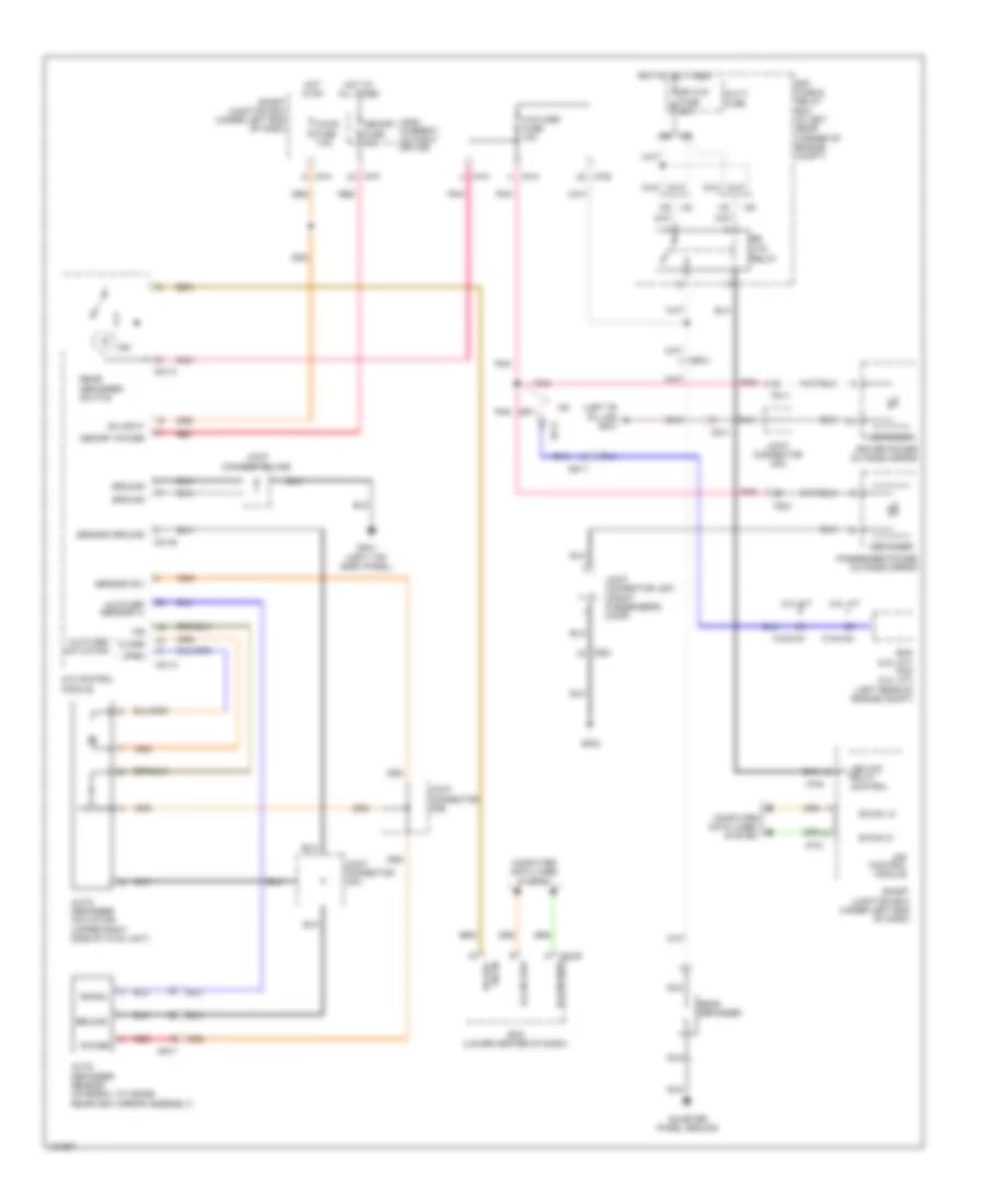
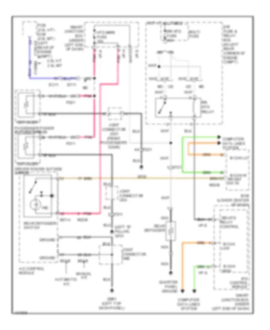
DEFOGGERS
Defoggers Wiring Diagram, with Auto Defogger for Hyundai Elantra Sport 2014
List of elements for Defoggers Wiring Diagram, with Auto Defogger for Hyundai Elantra Sport 2014:
- (left "b" pillar) gf01
- 2.0l a/t
- 2.0l m/t
- A/c control module
- A/con fuse 7.5a
- Auto def actuator
- Auto def sensor (+)
- Auto defogger actuator (upper right side of hvac unit)
- Auto defogger sensor (integral to inside rearview mirror assembly)
- B-can hi
- B-can high
- B-can lo
- B-can low
- Bcm (lower center of dash)
- C100-ak
- C100-ma
- Close
- Computer data lines
- Computer data lines system
- Control
- Control module
- Defogger
- Driver power outside mirror
- E/r fuse & relay box (in left rear corner of engine compt)
- Ec11
- Ecm (2.0l m/t) pcm (2.0l a/t) (left rear of engine compt)
- Ef11
- Ef21
- F/b
- Fd11
- Fd21
- Gf02
- Gm01 (left top dash panel)
- Ground
- Hot at all times
- Hot in on
- Htd mirr fuse 10a
- I/p-a
- I/p-e
- I/p-f
- I/p-g
- I/p-h
- Ind
- Ips
- Joint connector jd01 (front passenger's door)
- Joint connector uda
- Joint connector uma
- Joint connector umb
- Joint connector ume
- Leak current autocut device
- M02-b
- M21-a
- M21-b
- Memory fuse 10a
- Memory power
- Mr11
- Multi fuse
- Nca
- On input
- Open
- Passenger power outside mirror
- Pnk
- Power
- Quarter panel ground
- Rear defogger
- Rear defogger switch
- Red
- Relay
- Rr def sw in
- Rr htd
- Rr htd fuse 40a
- Sensor (5v)
- Sensor ground
- Signal
- Smart junction box (under left end of dash)
- System
Defoggers Wiring Diagram, without Auto Defogger for Hyundai Elantra Sport 2014
List of elements for Defoggers Wiring Diagram, without Auto Defogger for Hyundai Elantra Sport 2014:
- (left "b" pillar) gf01
- 2.0l a/t
- 2.0l m/t
- A/c control module
- Automatic a/c
- B-can
- B-can hi
- B-can lo
- Bcm (lower center of dash)
- C100-ak
- C100ma
- Computer data lines system
- Control
- Control module
- Defogger
- Driver power outside mirror
- E/r fuse & relay box (in left rear corner of engine compt)
- Ec11
- Ef11
- Ef21
- Fd11
- Fd21
- Gf02
- Gm01 (left top dash panel)
- Ground
- High
- Hot at all times
- Htd mirr fuse 10a
- I/p-a
- I/p-e
- I/p-g
- I/p-h
- Ind
- Ips
- Joint connector jd01 (front passenger's door)
- Joint connector uda
- Joint connector ume
- Low
- M02-b
- M21-a
- M21-b
- M22-b
- Manual a/c
- Multi fuse
- Nca
- Passenger power outside mirror
- Pcm (2.0l a/t) ecm (2.0l m/t) (left rear of engine compt)
- Pnk
- Quarter panel ground
- Rear defogger
- Rear defogger switch
- Relay
- Rr def
- Rr htd
- Rr htd fuse 40a
- Smart junction box (under left end of dash)
- Sw in
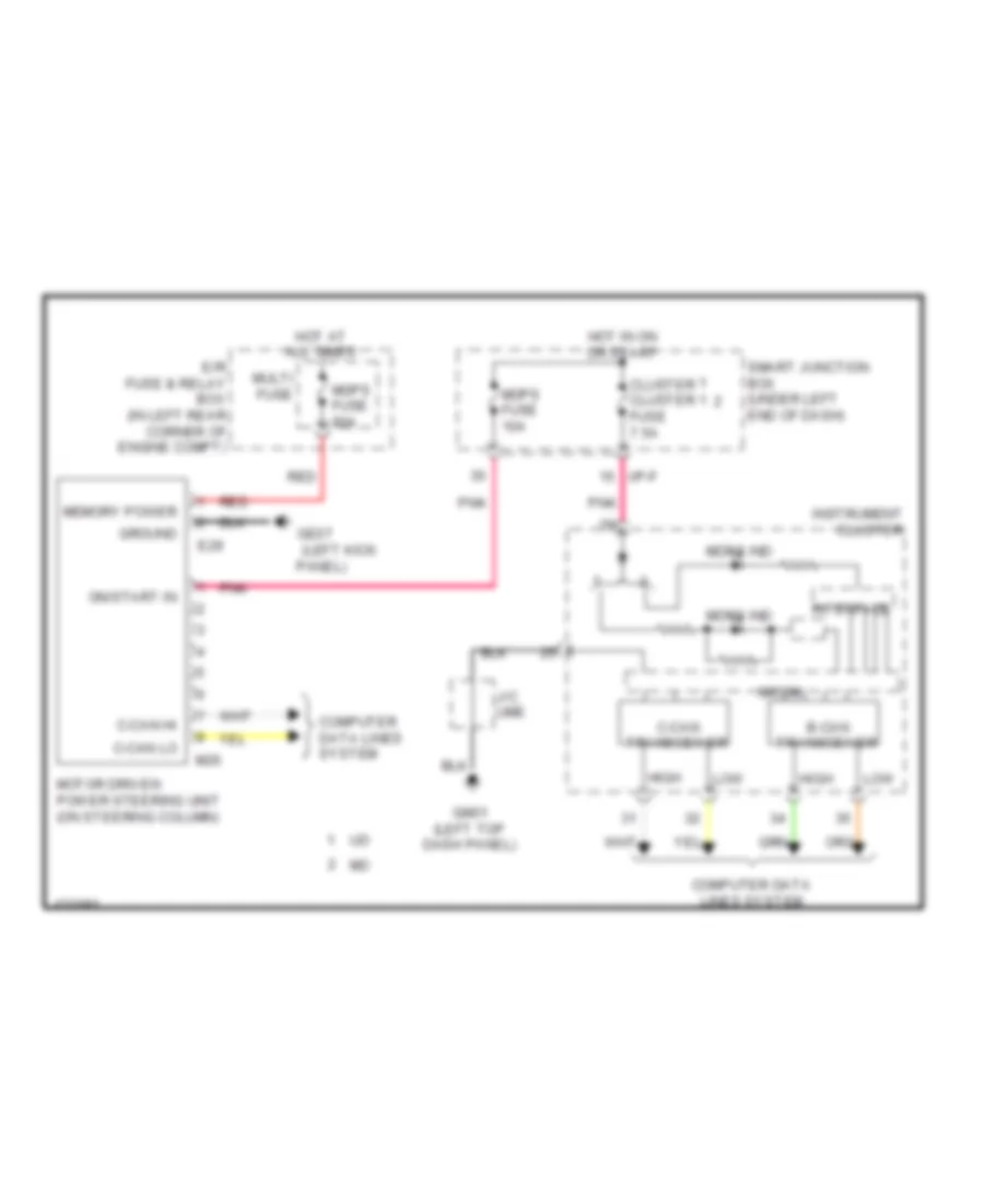
ELECTRONIC POWER STEERING
Electronic Power Steering Wiring Diagram for Hyundai Elantra Sport 2014
List of elements for Electronic Power Steering Wiring Diagram for Hyundai Elantra Sport 2014:
- (left kick
- B-can
- C-can
- C-can hi
- C-can lo
- Cluster cluster 1 fuse 7.5a
- Computer data lines system
- E/r fuse & relay box (in left rear corner of engine compt)
- E29
- Ge07
- Gm01 (left top dash panel)
- Ground
- High
- Hot at all times
- Hot in on or start
- I/p-f
- Instrument cluster
- Interface
- J/c ume
- Low
- M26
- Mdps fuse 10a
- Mdps fuse 80a
- Mdps ind
- Memory power
- Micom
- Motor driven power steering unit (on steering column)
- Multi fuse
- On/start in
- Panel)
- Pnk
- Red
- Smart junction box (under left end of dash)
- Transceiver
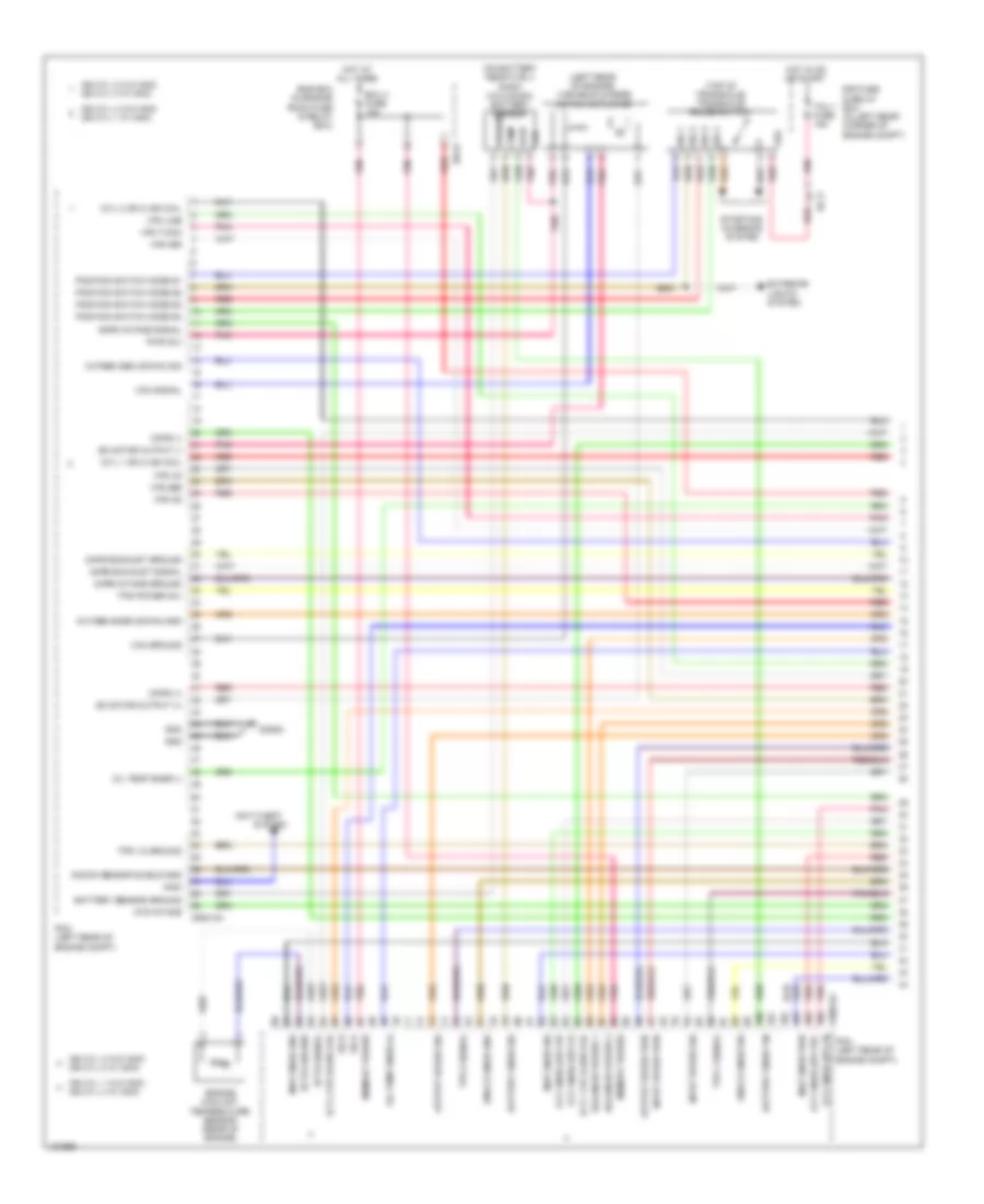
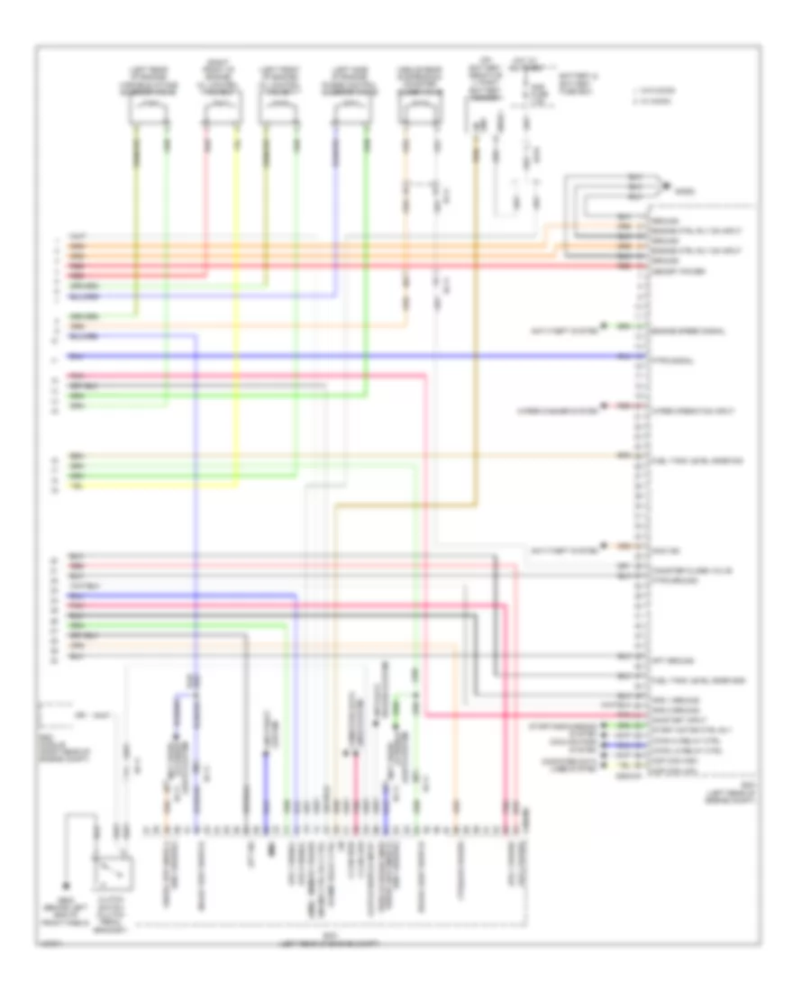
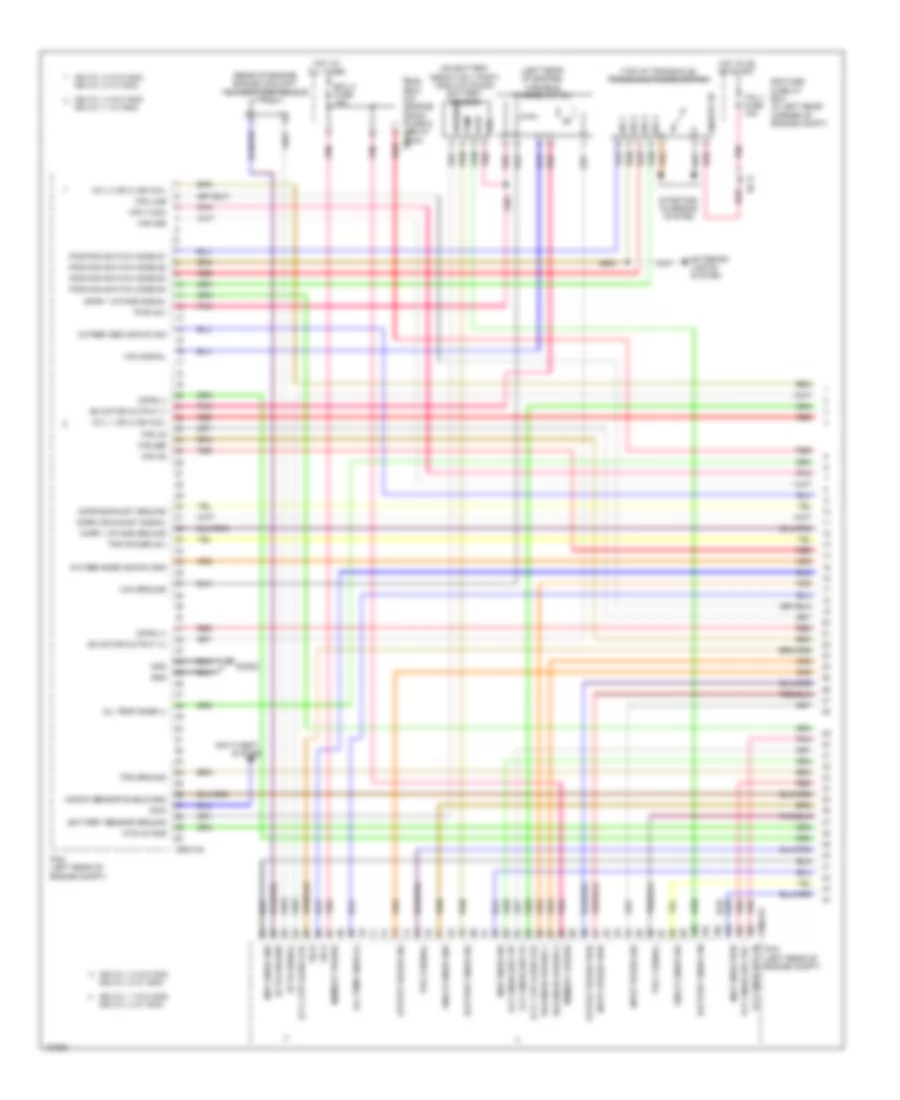
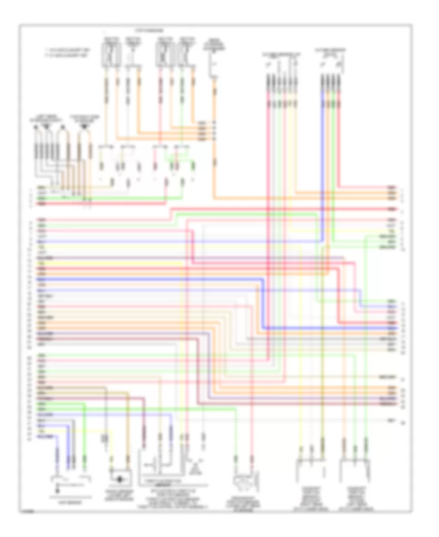
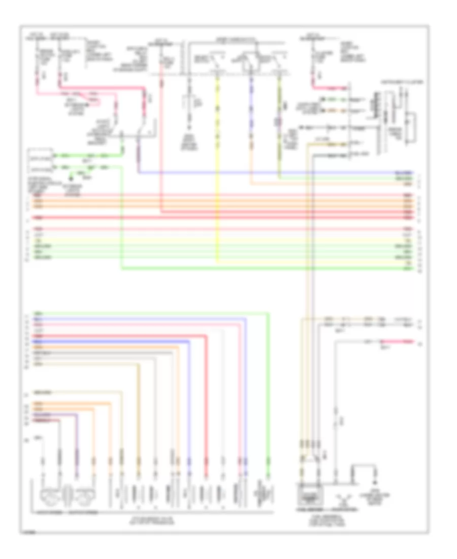
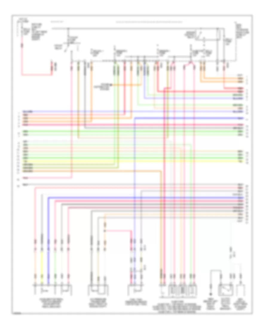
ENGINE PERFORMANCE
1.8L
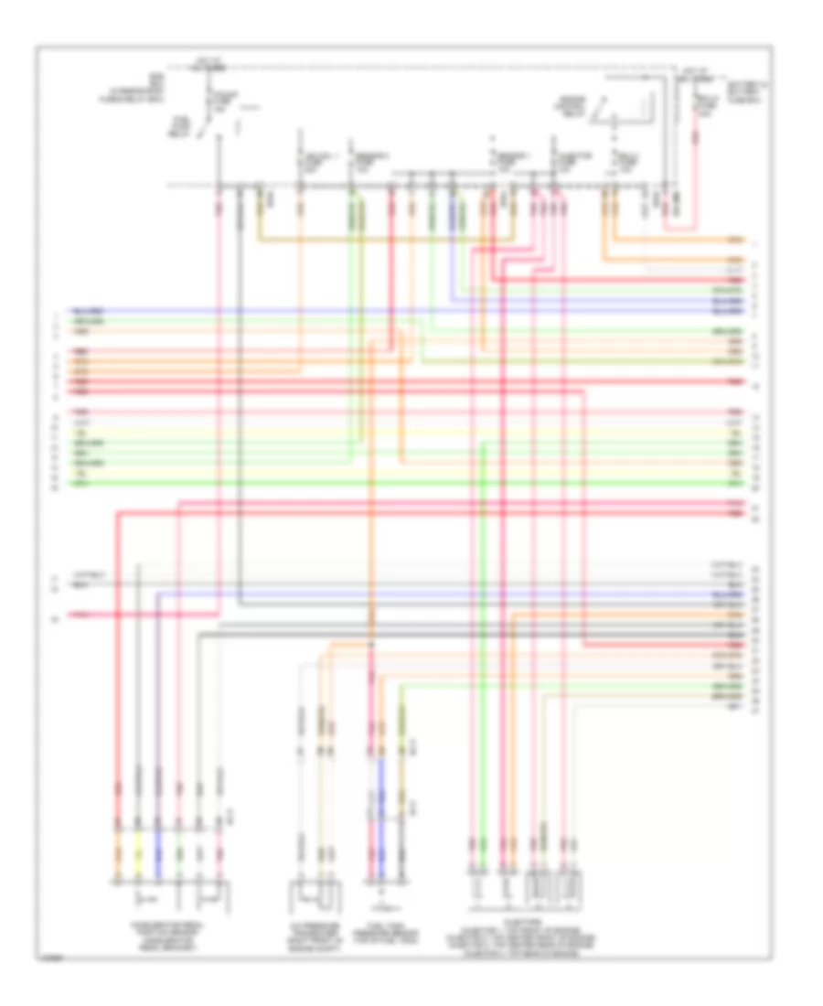
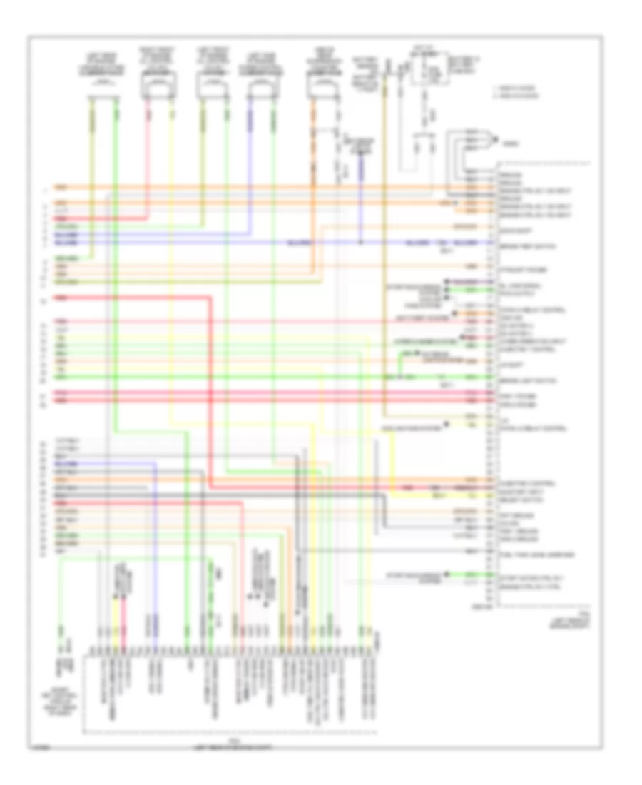
1.8L, Engine Performance Wiring Diagram, MD A/T (1 of 5) for Hyundai Elantra Sport 2014
List of elements for 1.8L, Engine Performance Wiring Diagram, MD A/T (1 of 5) for Hyundai Elantra Sport 2014:
- (cyl 1 or 4) ign coil
- (cyl 2 or 3) ign coil
- (left rear of engine) variable charge motion actuator
- (top of transaxle) transaxle range switch
- Anti-theft
- Ats intake
- Battery sensor ground
- Battery snsr sig
- Battery snsr vin
- C600-aa
- Ckps (+)
- Ckps (-)
- Cmps exhaust ground
- Cmps exhaust signal
- Cmps intake ground
- Cmps intake signal
- Dc motor output (+)
- Dc motor output (-)
- E/r fuse & relay box (in left rear corner of engine compt)
- E/r-b
- Ec11
- Ects ground
- Ects signal
- Ecu 4 fuse 15a
- Ems box (in engine room fuse & relay box)
- Engine coolant temperature sensor (rear of engine)
- Exterior lights system
- Gc602
- Gnd
- Ground
- Hot at all times
- Hot in on or start
- Ign cyl 1 w/o immo ign cyl 4 w/ immo
- Ign cyl 2 w/o immo ign cyl 3 w/ immo
- Ign cyl 3 w/o immo ign cyl 2 w/ immo
- Ign cyl 4 w/o immo ign cyl 1 w/ immo
- Immo
- Input speed pwr
- Input speed sig
- Knock sensor shield gnd
- Knock snsr gnd
- Knock snsr sig
- Map snsr gnd
- Map snsr pwr
- Map snsr sig
- Memory power
- Oil temp snsr (+)
- Oil temp snsr (-)
- Output speed pwr
- Output speed sig
- Oxy snsr (up) vg
- Oxy snsr (up) vip
- Oxy snsr (up) vn
- Oxy snsr (up) vrc
- Oxygen sen (down) sig
- Oxygen snsr (down) gnd
- Pcm (left rear of engine compt)
- Pnk
- Position switch code s1
- Position switch code s2
- Position switch code s3
- Position switch code s4
- Pwr (5v)
- Red
- Sig 1
- Sig 2
- Sig 3
- Sig 4
- Solenoid power 1
- Solenoid power 2
- Ss a
- Ss b
- Starting/ charging system
- System
- Tcu 1 fuse 15a
- Temp
- Tps 1 signal
- Tps 1/2 ground
- Tps 2 signal
- Tps power (5v)
- Vcm ground
- Vcm signal
- Vdd
- Vfs 26b
- Vfs 35r
- Vfs line
- Vfs od
- Vfs t/con
- Vfs ud
- Vout
1.8L, Engine Performance Wiring Diagram, MD A/T (2 of 5) for Hyundai Elantra Sport 2014
List of elements for 1.8L, Engine Performance Wiring Diagram, MD A/T (2 of 5) for Hyundai Elantra Sport 2014:
- (or red)
- (rear of engine) condenser
- (top of engine)
- (top right side of engine) gc603
- Camshaft position sensor 1 (intake) (left rear of cylinder head)
- Camshaft position sensor 2 (exhaust) (right rear of cylinder head)
- Crankshaft position sensor (lower left rear of engine)
- Etc motor & throttle position sensor (throttle position sensor: integral to electronic throttle control motor assembly)
- Gc601 (left rear of engine compt)
- Ignition coil 1
- Ignition coil 2
- Ignition coil 3
- Ignition coil 4
- Knock sensor (lower left side of engine)
- Map sensor
- Motor
- Nca
- Oxygen sensor (down)
- Oxygen sensor (up)
- Pnk
- Red
- Throttle position sensor
- W/ immo & smart key
- W/o immo & smart key
1.8L, Engine Performance Wiring Diagram, MD A/T (3 of 5) for Hyundai Elantra Sport 2014
List of elements for 1.8L, Engine Performance Wiring Diagram, MD A/T (3 of 5) for Hyundai Elantra Sport 2014:
- (left side of dash) stop signal electronic module
- Atm solenoid (on top of transaxle)
- Brake switch fuse 10a
- Check engine ind
- Cluster 1 fuse 7.5a
- Computer data lines system
- Down shift
- E/r fuse & relay box (in left rear corner of engine compt)
- Ec11
- Ecu 3 fuse 10a
- Ef11
- Ef21
- Em11
- Em61
- Exterior lights system
- Fuel
- Fuel (+)
- Fuel (-)
- Fuel sender
- Fuel sender & fuel pump motor (top of fuel tank)
- Gauge sender
- Gf03 (left "c" pillar)
- Gm01 (left top dash panel)
- Gm02 (right center of dash)
- High
- Hot at all times
- Hot in on or start
- I/f
- I/p-b
- I/p-f
- Input speed sensor
- Instrument cluster
- Low
- M13b
- Mf11
- Micom
- Module fuse 7.5a
- Oil temp sensor
- Output speed sensor
- Pnk
- Pump motor
- Red
- S gnd
- Select switch
- Shift
- Smart junction box (under left end of dash)
- Smart key control module (right rear of dash)
- Sport mode switch
- Ss a
- Ss b
- Stop lamp switch (on brake pedal bracket)
- Transceiver b-can
- Vfs 26b
- Vfs 35r
- Vfs line
- Vfs od
- Vfs t/con
- Vfs ud
1.8L, Engine Performance Wiring Diagram, MD A/T (4 of 5) for Hyundai Elantra Sport 2014
List of elements for 1.8L, Engine Performance Wiring Diagram, MD A/T (4 of 5) for Hyundai Elantra Sport 2014:
- A/c pressure transducer (right front of engine compt)
- Accelerator pedal position sensor (accelerator pedal bracket)
- Compt)
- E/r fuse & relay box (in left rear corner of engine
- E/r-a
- E/r-b
- E/r-ems
- Ec11
- Ecu 2 fuse 10a
- Ecu 6 fuse 40a
- Ef11
- Ems box (in engine room fuse & relay box)
- Engine control relay
- F/pump fuse 15a
- F/pump relay
- Fuel tank pressure sensor (top of fuel tank)
- Hot at all times
- Ign coil fuse 20a
- Injector fuse 10a
- Injectors (injector 1: top front of engine) (injector 2 & 3: top center of engine) (injector 4: top rear of engine)
- Pnk
- Red
- Sensor 1 fuse 10a
- Sensor 2 fuse 10a
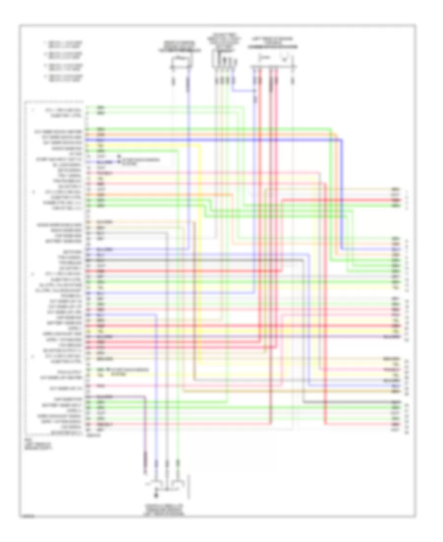
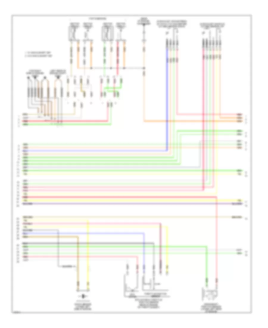
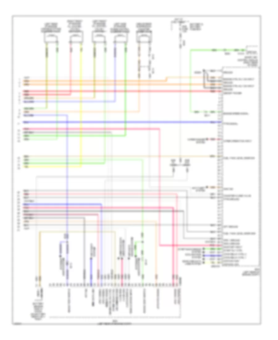
1.8L, Engine Performance Wiring Diagram, MD A/T (5 of 5) for Hyundai Elantra Sport 2014
List of elements for 1.8L, Engine Performance Wiring Diagram, MD A/T (5 of 5) for Hyundai Elantra Sport 2014:
- (above rear suspension) canister close valve
- (left front of engine) oil control valve 1
- (left rear of engine) variable intake solenoid valve
- (left side of engine) purge control solenoid valve
- (not used)
- (right front of engine) oil control valve 2
- (right rear of dash)
- Anti-theft system
- Aps 1 ground
- Aps 1 power
- Aps 1 signal
- Aps 2 ground
- Aps 2 power
- Aps 2 signal
- Apt ground
- Apt sig
- Brake light switch
- Brake test switch
- C-can high
- C-can low
- C/fan hi relay control
- C/fan lo relay control
- C600-ab
- Canister close valve
- Ccp can high
- Ccp can low
- Cooling fans system
- Dc motor (+)
- Dc motor (-)
- Down shift
- Ec11
- Ef11
- El load signal
- Em61
- Engine ctrl rly ctrl
- Engine ctrl rly on input
- Engine speed signal
- Exterior lights system
- F/pump rly ctrl
- Ftps ground
- Ftps signal
- Ftps/apt power
- Fuel tank level snsr gnd
- Fuel tank lvl snsr sig
- Gc602
- Ground
- Immo ind
- Injector 1 control
- Injector 2 ctrl
- Injector 3 control
- Injector 4 ctrl
- Lin communication
- Lines system computer data
- M13-a
- Memory power
- Memory pwr (w/ micom)
- Module
- Oil ctrl valve exhaust
- Oil ctrl valve intake
- On/start input
- Oxy snsr (dn) heater
- Oxy snsr (up) heater
- Pcm (left rear of engine compt)
- Pcsv
- Pnk
- Pwm output
- Red
- Select switch
- Smart key control
- Spd sig engine
- Start motor ctrl rly
- Start motor ctrl sw
- Starting/charging system
- System anti-lock brakes
- System starting/charging
- Up shift
- Vehicle speed sensor
- Visv
- Wheel spd sens +
- Wheel spd sens -
- Wiper operation input
- Wiper/washer system
1.8L, Engine Performance Wiring Diagram, MD M/T (1 of 5) for Hyundai Elantra Sport 2014
List of elements for 1.8L, Engine Performance Wiring Diagram, MD M/T (1 of 5) for Hyundai Elantra Sport 2014:
- (cyl 1 or 4) ign coil
- (cyl 2 or 3) ign coil
- (left rear of engine) variable charge motion
- (rear of engine) engine coolant temperature sensor
- Ats intake
- Battery snsr gnd
- Battery snsr sig
- Battery snsr vinput
- C600-ma
- Ckps (+)
- Ckps (-)
- Cmps 2 exhaust gnd
- Cmps 2 exhaust signal
- Cmps intake gnd
- Cmps intake signal
- Dc motor (+)
- Dc motor (-)
- Dc motor out (-)
- Dc motor output (+)
- Ecm (left rear of engine compt)
- Ects gnd
- Ects signal
- El load signal
- Ground
- Ign cyl 1 w/ immo
- Ign cyl 1 w/o immo ign cyl 4 w/ immo
- Ign cyl 2 w/o immo
- Ign cyl 2 w/o immo ign cyl 3 w/ immo
- Ign cyl 3 w/ immo
- Ign cyl 4 w/o immo
- Injector 1 coil
- Injector 2 ctrl
- Injector 3 coil
- Injector 4 coil
- Knock snsr gnd
- Knock snsr shield gnd
- Knock snsr sig
- Map snsr gnd
- Map snsr pwr
- Map snsr sig
- Oil ctrl valve exhaust
- Oil ctrl valve intake
- Oxy snsr (down) gnd
- Oxy snsr (down) heater
- Oxy snsr (down) sig
- Oxy snsr (up) heater
- Oxy snsr (up) vg
- Oxy snsr (up) vip
- Oxy snsr (up) vn
- Oxy snsr (up) vrc
- Pcsv
- Pnk
- Power (5v)
- Pwm output
- Red
- Start motor ctrl sw
- Starting/charging system
- Temp
- Tps 1 signal
- Tps 2 signal
- Tps ground
- Tps power (5v)
- Vcm ground
- Vcm signal
- Vdd
- Visv
- Vout
1.8L, Engine Performance Wiring Diagram, MD M/T (2 of 5) for Hyundai Elantra Sport 2014
List of elements for 1.8L, Engine Performance Wiring Diagram, MD M/T (2 of 5) for Hyundai Elantra Sport 2014:
- (left rear of engine compt) gc601
- (or red)
- (rear of engine) condenser
- (top of engine)
- (top right side of engine) gc603
- Crankshaft position sensor (lower left rear of engine)
- Etc motor
- Etc motor & throttle position sensor (throttle position sensor: integral to electronic throttle control motor assembly)
- Ignition coil 1
- Ignition coil 2
- Ignition coil 3
- Ignition coil 4
- Knock sensor (lower left side of engine)
- Map sensor
- Nca
- Oxygen sensor (down)
- Oxygen sensor (up)
- Pnk
- Red
- Throttle position sensor
- W/ immo & smart key
- W/o immo & smart key
1.8L, Engine Performance Wiring Diagram, MD M/T (3 of 5) for Hyundai Elantra Sport 2014
List of elements for 1.8L, Engine Performance Wiring Diagram, MD M/T (3 of 5) for Hyundai Elantra Sport 2014:
- (left top dash panel) gm01
- (top left side of dash) stop signal electric module
- Brake switch fuse 10a
- Camshaft position sensor 1 (intake) (left rear of cylinder head)
- Camshaft position sensor 2 (exhaust) (right rear of cylinder head)
- Check engine ind
- Cluster 1 fuse 7.5a
- Computer data lines system
- E/r fuse & relay box (in left rear corner of engine compt)
- Ec11
- Ecu 3 fuse 10a
- Ef11
- Ef21
- Em11
- Exterior lights system
- Fuel (+)
- Fuel gnd
- Fuel pump motor
- Fuel sender
- Fuel sender & fuel pump motor (top of fuel tank)
- Gauge sender
- Gf03 (left "c" pillar)
- Gnd
- High
- Hot at all times
- Hot in on or start
- I/f
- I/p-b
- I/p-f
- Instrument cluster
- J/c ume
- Low
- M13-b
- Mf11
- Micom
- Module 3 fuse 10a
- Pnk
- Red
- S gnd
- Smart junction box (under left end of dash)
- Smart key control module (right rear of dash)
- Stop lamp switch (on brake pedal bracket)
- Transceiver b-can
1.8L, Engine Performance Wiring Diagram, MD M/T (4 of 5) for Hyundai Elantra Sport 2014
List of elements for 1.8L, Engine Performance Wiring Diagram, MD M/T (4 of 5) for Hyundai Elantra Sport 2014:
- A/c pressure transducer (right front of engine compt)
- Accelerator pedal position sensor (accelerator pedal bracket)
- E/r fuse & relay box (in left rear corner of engine compt)
- E/r-a
- E/r-b
- E/r-ems
- Ec11
- Ecu 2 fuse 10a
- Ecu 4 fuse 15a
- Ecu 6 fuse 40a
- Ef11
- Ems box (in engine room fuse & relay box)
- Engine control relay
- F/ pump relay
- F/pump fuse 15a
- Fuel tank pressure sensor (top of fuel tank)
- Hot at all times
- Ign coil 1 fuse 20a
- Injector fuse 10a
- Injectors (injector 1: top front of engine) (injector 2 : top center front of engine) (injector 3: top center rear of engine) (injector 4: top rear of engine)
- Pnk
- Red
- Sensor 1 fuse 10a
- Sensor 2 fuse 10a
1.8L, Engine Performance Wiring Diagram, MD M/T (5 of 5) for Hyundai Elantra Sport 2014
List of elements for 1.8L, Engine Performance Wiring Diagram, MD M/T (5 of 5) for Hyundai Elantra Sport 2014:
- (above rear suspension) canister close valve
- (ams)
- (left front of engine) oil control valve 1
- (left rear of engine) variable intake solenoid valve
- (left side of engine) purge control solenoid valve
- (not used)
- (right front of engine) oil control valve 2
- (w/o abs/esc)
- (w/o abs/esc) wheel spd snsr (+)
- Ams fuse 7.5a
- Anti-theft system
- Aps 1 ground
- Aps 1 power
- Aps 1 signal
- Aps 2 ground
- Aps 2 power
- Aps 2 signal
- Apt ground
- Apt sig
- Battery & battery fuse box
- Brake light switch
- Brake test switch
- Brakes system anti-lock
- C-can high
- C-can low
- C/fan hi relay ctrl
- C/fan lo relay ctrl
- C600-mk
- Canister close valve
- Ccp can high
- Ccp can low
- Clutch switch (clutch pedal bracket)
- Clutch switch input
- Computer data lines system
- Cooling fans system
- Ec01
- Ec11
- Ecm (left rear of engine compt)
- Ef11
- Engine ctrl rly ctrl
- Engine ctrl rly on input
- Engine speed signal
- Esc module (right rear of engine compt)
- F/pump relay ctrl
- Ftps ground
- Ftps signal
- Ftps/aps power
- Fuel tank level snsr gnd
- Fuel tank level snsr sig
- Gc602
- Ge02 (behind left end of front fascia)
- Ground
- Hot at all times
- Immo
- Immo ind
- Lights system exterior
- Lin
- Line lin
- Lines system computer data
- Memory power
- On/start input
- Pnk
- Red
- Snsr +
- Start motor ctrl rly
- Starting/charging system
- System anti-theft
- Vehicle speed snsr
- W/ micom
- W/o micom
- Wheel spd snsr (-)
- Wiper operation input
- Wiper/washer system
1.8L, Engine Performance Wiring Diagram, UD A/T (1 of 5) for Hyundai Elantra Sport 2014
List of elements for 1.8L, Engine Performance Wiring Diagram, UD A/T (1 of 5) for Hyundai Elantra Sport 2014:
- (cyl 1 or 4) ign coil
- (cyl 2 or 3) ign coil
- (left rear of engine) variable charge motion
- (rear of engine) engine coolant temperature sensor
- (top of transaxle) transaxle range switch
- Anti-theft
- Ats intake
- Battery sensor ground
- Battery snsr sig
- Battery snsr vin
- C600-aa
- Ckps (+)
- Ckps (-)
- Cmps 1 intake ground
- Cmps 1 intake signal
- Cmps 2 exhaust signal
- Cmps exhaust ground
- Dc motor output (+)
- Dc motor output (-)
- E/r fuse & relay box (in left rear corner of engine compt)
- Ec11
- Ects ground
- Ects signal
- Ecu 4 fuse 15a
- Ems box (in engine room fuse & relay e/r-b box)
- Exterior lights system
- Gc602
- Gnd
- Ground
- Hot at all times
- Hot in on or start
- Ign cyl 1 w/ immo
- Ign cyl 1 w/o immo ign cyl 4 w/ immo
- Ign cyl 2 w/ immo
- Ign cyl 2 w/o immo
- Ign cyl 3 w/ immo
- Ign cyl 3 w/o immo
- Ign cyl 4 w/o immo
- Immo
- Input speed pwr
- Input speed sig
- Knock sensor shield gnd
- Knock snsr gnd
- Knock snsr sig
- Map snsr gnd
- Map snsr pwr
- Map snsr sig
- Memory power
- Oil temp snsr (+)
- Oil temp snsr (-)
- On/strt i/p
- Output speed pwr
- Output speed sig
- Oxy snsr (up) vg
- Oxy snsr (up) vip
- Oxy snsr (up) vn
- Oxy snsr (up) vrc
- Oxygen sen (down) sig
- Oxygen snsr (down) gnd
- Pcm (left rear of engine compt)
- Pnk
- Position switch code s1
- Position switch code s2
- Position switch code s3
- Position switch code s4
- Pwr (5v)
- Red
- Sig 1
- Sig 2
- Sig 3
- Sig 4
- Solenoid power 1
- Solenoid power 2
- Ss a
- Ss b
- Starting/ charging system
- System
- Tcu 1 fuse 15a
- Temp
- Tps 1 signal
- Tps 2 signal
- Tps ground
- Tps power (5v)
- Vcm ground
- Vcm signal
- Vdd
- Vfs 26b
- Vfs 35r
- Vfs line
- Vfs od
- Vfs t/con
- Vfs ud
- Vout
1.8L, Engine Performance Wiring Diagram, UD A/T (2 of 5) for Hyundai Elantra Sport 2014
List of elements for 1.8L, Engine Performance Wiring Diagram, UD A/T (2 of 5) for Hyundai Elantra Sport 2014:
- (left rear of engine compt) gc601
- (or red)
- (rear of engine) condenser
- (top of engine)
- (top right side of engine) gc603
- Camshaft position sensor 1 (intake) (left rear of cylinder head)
- Camshaft position sensor 2 (exhaust) (right rear of cylinder head)
- Crankshaft position sensor (lower left rear of engine)
- Etc motor
- Etc motor & throttle position sensor (throttle position sensor: electronic integral to throttle control motor assembly)
- Ignition coil 1
- Ignition coil 2
- Ignition coil 3
- Ignition coil 4
- Knock sensor (lower left side of engine)
- Map sensor
- Nca
- Oxygen sensor (down)
- Oxygen sensor (up)
- Pnk
- Red
- Throttle position sensor
- W/ immo & smart key
- W/o immo & smart key
1.8L, Engine Performance Wiring Diagram, UD A/T (3 of 5) for Hyundai Elantra Sport 2014
List of elements for 1.8L, Engine Performance Wiring Diagram, UD A/T (3 of 5) for Hyundai Elantra Sport 2014:
- Atm solenoid valve (on top of transaxle)
- Brake switch fuse 10a
- Cluster fuse 7.5a
- Computer data lines system
- Down shift
- E/r fuse & relay box (in left rear corner of engine compt)
- Ec11
- Ecu 3 fuse 10a
- Ef11
- Ef21
- Em11
- Em61
- Engine check ind
- Exterior lights system
- Fuel
- Fuel +
- Fuel gnd
- Fuel sender
- Fuel sender & fuel pump motor (top of fuel tank)
- Gauge sender
- Gf06 (under center of rear seats)
- Gm01 (left top dash panel)
- Gm02 (right center of dash)
- High
- Hot at all times
- Hot in on or start
- I/p-b
- I/p-f
- Input speed
- Instrument cluster
- J/c ume
- J/c umf
- Low
- Mf11
- Micom
- Module 3 fuse 7.5a
- Oil
- Output speed
- Pnk
- Pump motor
- Red
- S gnd
- Select switch
- Shift
- Smart junction box (under left end of dash)
- Sport mode switch
- Ss a
- Ss b
- Stop lamp switch (on brake pedal bracket)
- Stop signal electric module (left side of dash)
- Stp ip sig
- Stp lp sw
- Temperature sensor
- Transceiver b-can
- Vfs 26b
- Vfs 35r
- Vfs line
- Vfs od
- Vfs t/con
- Vfs ud
1.8L, Engine Performance Wiring Diagram, UD A/T (4 of 5) for Hyundai Elantra Sport 2014
List of elements for 1.8L, Engine Performance Wiring Diagram, UD A/T (4 of 5) for Hyundai Elantra Sport 2014:
- A/c pressure transducer (right front of engine compt)
- Accelerator pedal position sensor (accelerator pedal bracket)
- Battery & battery fuse box
- E/r-a
- E/r-b
- E/r-ems
- Ec11
- Ecu 2 fuse 10a
- Ecu 6 fuse 40a
- Ef11
- Ems box (in engine room fuse & relay box)
- Engine control relay
- F/pump fuse 15a
- Fuel pump relay
- Fuel tank pressure sensor (top of fuel tank)
- Hot at all times
- Ign coil 1 fuse 20a
- Injector fuse 10a
- Injectors (injector 1: top front of engine) (injector 2: top center front of engine) (injector 3: top center rear of engine) (injector 4: top rear of engine)
- Pnk
- Red
- Sensor 1 fuse 10a
- Sensor 2 fuse 10a
1.8L, Engine Performance Wiring Diagram, UD A/T (5 of 5) for Hyundai Elantra Sport 2014
List of elements for 1.8L, Engine Performance Wiring Diagram, UD A/T (5 of 5) for Hyundai Elantra Sport 2014:
- (above rear suspension) canister close valve
- (left front of engine) oil control valve 1 (intake)
- (left rear of engine) variable intake solenoid valve
- (left side of engine) purge control solenoid valve
- (right front of engine) oil control valve 2 (exhaust)
- A/c sig
- Ams fuse 7.5a
- Ams w/ micom
- Ams w/o micom
- Anti-theft system
- Aps 1 ground
- Aps 1 power
- Aps 1 signal
- Aps 2 ground
- Aps 2 power
- Aps 2 signal
- Apt ground
- Battery & battery fuse box
- Brake light switch
- Brake test switch
- C-can high
- C-can low
- C/fan hi relay control
- C/fan lo relay control
- C600-ab
- Canister close valve
- Ccp can high
- Ccp can low
- Computer data lines system
- Cooling fans system
- Dc motor (+)
- Dc motor (-)
- Down shift
- Ec01
- Ec11
- Ef11
- El load signal
- Em61
- Engine
- Engine ctrl rly ctrl
- Engine ctrl rly on input
- Engine speed sensor
- Exterior lights system
- F/pump rly ctrl
- Ftps ground
- Ftps signal
- Ftps/apt power
- Fuel tank level snsr gnd
- Fuel tank lvl snsr sig
- Gc602
- Ground
- Hot at all times
- Immo ind
- Injector 1 control
- Injector 2 ctrl
- Injector 3 control
- Injector 4 ctrl
- Lin
- Line lin
- Lines system computer data
- M13-a snsr spd
- Memory power
- Memory pwr (ams/bem)
- Oil ctrl valve exhaust
- Oil ctrl valve intake
- On/start input
- Oxy snsr (dn) heater
- Oxy snsr (up) heater
- Pcm (left rear of engine compt)
- Pcsv
- Pnk
- Pwm output
- Red
- Select switch
- Smart key control module (right rear of dash)
- Snsr
- Start motor ctrl rly
- Start sig i/p
- Starting/charging system
- System anti-lock brakes
- System starting/charging
- Up shift
- Vehicle speed i/p
- Visv
- Wiper operation input
- Wiper/washer system
1.8L, Engine Performance Wiring Diagram, UD M/T (1 of 5) for Hyundai Elantra Sport 2014
List of elements for 1.8L, Engine Performance Wiring Diagram, UD M/T (1 of 5) for Hyundai Elantra Sport 2014:
- (cyl 1 or 4) ign coil
- (cyl 2 or 3) ign coil
- (left rear of engine) variable charge motion actuator
- (rear of engine) engine coolant temperature sensor
- Battery snsr gnd
- Battery snsr input
- Battery snsr sig
- C600-ma
- Ckps (+)
- Ckps (-)
- Cmps 1 intake gnd
- Cmps 1 intake signal
- Cmps 2 exhaust gnd
- Cmps 2 exhaust signal
- Dc motor (+)
- Dc motor (-)
- Dc motor out (-)
- Dc motor output (+)
- Ecm (left rear of engine compt)
- Ects gnd
- Ects signal
- El load signal
- Ground
- Iat sig
- Ign cyl 1 w/ immo
- Ign cyl 1 w/o immo
- Ign cyl 2 w/ immo
- Ign cyl 2 w/o immo ign cyl 3 w/ immo
- Ign cyl 3 w/o immo
- Ign cyl 4 w/ immo
- Ign cyl 4 w/o immo
- Injector 1 ctrl
- Injector 2 ctrl
- Injector 3 ctrl
- Injector 4 ctrl
- Knock snsr gnd
- Knock snsr shield gnd
- Knock snsr sig
- Manifold absolute pressure sensor (left rear of engine)
- Map snsr gnd
- Map snsr pwr
- Map snsr sig
- Oil ctrl valve exhaust
- Oil ctrl valve intake
- Oxy snsr (down) gnd
- Oxy snsr (down) heater
- Oxy snsr (down) sig
- Oxy snsr (up) heater
- Oxy snsr (up) vg
- Oxy snsr (up) vip
- Oxy snsr (up) vn
- Oxy snsr (up) vrc
- Pnk
- Power (5v)
- Purge ctrl sol vlv
- Pwm output
- Red
- Start sig input (act hi)
- Starting/charging system
- Temp
- Tps 1 signal
- Tps 2 signal
- Tps ground
- Tps power (5v)
- Var int sol vlv
- Vcm ground
- Vcm signal
- Vdd
- Vout
1.8L, Engine Performance Wiring Diagram, UD M/T (2 of 5) for Hyundai Elantra Sport 2014
List of elements for 1.8L, Engine Performance Wiring Diagram, UD M/T (2 of 5) for Hyundai Elantra Sport 2014:
- (in exhaust manifold) oxygen sensor (up)
- (in exhaust, downstream of catalytic converter) oxygen sensor (down)
- (left rear of engine compt) gc601
- (or red)
- (rear of engine) condenser
- (top of engine)
- (top right side of engine) gc603
- Crankshaft position sensor (lower left rear of engine)
- Etc motor
- Etc motor & throttle position sensor (rear of engine, on throttle body)
- Ignition coil 1
- Ignition coil 2
- Ignition coil 3
- Ignition coil 4
- Knock sensor (lower left side of engine)
- Nca
- Pnk
- Red
- Throttle position sensor
- W/ immo & smart key
- W/o immo & smart key
1.8L, Engine Performance Wiring Diagram, UD M/T (3 of 5) for Hyundai Elantra Sport 2014
List of elements for 1.8L, Engine Performance Wiring Diagram, UD M/T (3 of 5) for Hyundai Elantra Sport 2014:
- Brake sig
- Brake switch fuse 10a
- C-can high
- C-can low
- Camshaft position sensor 1 (intake) (left rear of cylinder head)
- Camshaft position sensor 2 (exhaust) (right rear of cylinder head)
- Check engine ind
- Cluster fuse 7.5a
- Computer data lines system
- E/r fuse & relay box (in left rear corner of engine compt)
- Ec11
- Ecu 3 fuse 10a
- Ef11
- Ef21
- Em11
- Em61
- Empty
- Fuel (+)
- Fuel gnd
- Fuel level float
- Fuel pump motor
- Fuel sender
- Fuel sender & fuel pump motor (top of fuel tank)
- Full
- Gf06 (under center of rear seats)
- Gm01 (left top dash panel)
- High
- Hot at all times
- Hot in on or start
- I/p-b
- I/p-f
- Instrument cluster
- Joint connector ume
- Low
- M13-b
- Mf11
- Micom
- Module 3 fuse 7.5a
- Pnk
- Red
- Sig gnd
- Smart junction box (under left end of dash)
- Smart key control module (right rear of dash)
- Stop lamp switch (on brake pedal bracket)
- Stop signal electronic module (left side of dash)
- Stp ip sig
- Stp lmp pwr
- Stp lp sw
- Transceiver b-can
1.8L, Engine Performance Wiring Diagram, UD M/T (4 of 5) for Hyundai Elantra Sport 2014
List of elements for 1.8L, Engine Performance Wiring Diagram, UD M/T (4 of 5) for Hyundai Elantra Sport 2014:
- A/c pressure transducer (right front of engine compt)
- Accelerator pedal position sensor (accelerator pedal bracket)
- Bracket)
- Clutch switch (clutch pedal
- E/r fuse & relay box (in left rear corner of engine compt)
- E/r-a
- E/r-b
- E/r-ems
- Ec11
- Ecu 2 fuse 10a
- Ecu 4 fuse 15a
- Ecu 6 fuse 40a
- Ef11
- Ems box (in engine room fuse & relay box)
- Engine control relay
- Esc module (right rear of engine compt)
- F/pump fuse 15a
- F/pump relay
- Fuel tank pressure sensor (top of fuel tank)
- Ge02 (behind left end of front fascia)
- Hot at all times
- Ign coil 1 fuse 20a
- Injector fuse 10a
- Injectors (injector 1: top front of engine) (injector 2: top center front of engine) (injector 3: top center rear of engine) (injector 4: top rear of engine)
- Pnk
- Power distribution system
- Red
- Sensor 1 fuse 10a
- Sensor 2 fuse 10a
1.8L, Engine Performance Wiring Diagram, UD M/T (5 of 5) for Hyundai Elantra Sport 2014
List of elements for 1.8L, Engine Performance Wiring Diagram, UD M/T (5 of 5) for Hyundai Elantra Sport 2014:
- (above rear suspension) canister close valve
- (left front of engine) oil control valve 1 (intake)
- (left rear of engine) variable intake solenoid valve
- (left side of engine) purge control solenoid valve
- (right front of engine) oil control valve 2 (exhaust)
- Ams fuse 7.5a
- Ams w/ micom
- Ams w/o micom
- Anti-theft system
- Aps 1 ground
- Aps 1 power
- Aps 1 signal
- Aps 2 ground
- Aps 2 power
- Aps 2 signal
- Apt ground
- Apt sig
- Apt/ftps power
- Battery & battery fuse box
- Brake light switch
- Brake test switch
- Brakes system anti-lock
- C-can high
- C-can low
- C/fan relay ctrl 1
- C/fan relay ctrl 2
- C600-mk
- Canister close valve
- Ccp-can high
- Ccp-can low
- Clutch switch
- Computer data lines system
- Cooling fans system
- Ec01
- Ec11
- Ecm (left rear of engine compt)
- Ef11
- Em61
- Engine ctrl rly ctrl
- Engine ctrl rly on input
- Engine speed signal
- F/pump relay ctrl
- Ftps ground
- Ftps signal
- Fuel tank level sndr gnd
- Fuel tank level sndr sig
- Gc602
- Ground
- Hot at all times
- Immo data line
- Immo ind
- Lights system exterior
- Lin communication
- Lin line
- Lines system computer data
- M13-a
- Memory power
- On/start input
- Pnk
- Red
- Smart key control module (right rear of dash)
- Snsr +
- Spd sig
- Start rly ctrl
- Starting/charging system
- System anti-theft
- Vehicle speed input
- Wiper operation input
- Wiper/washer system
2.0L
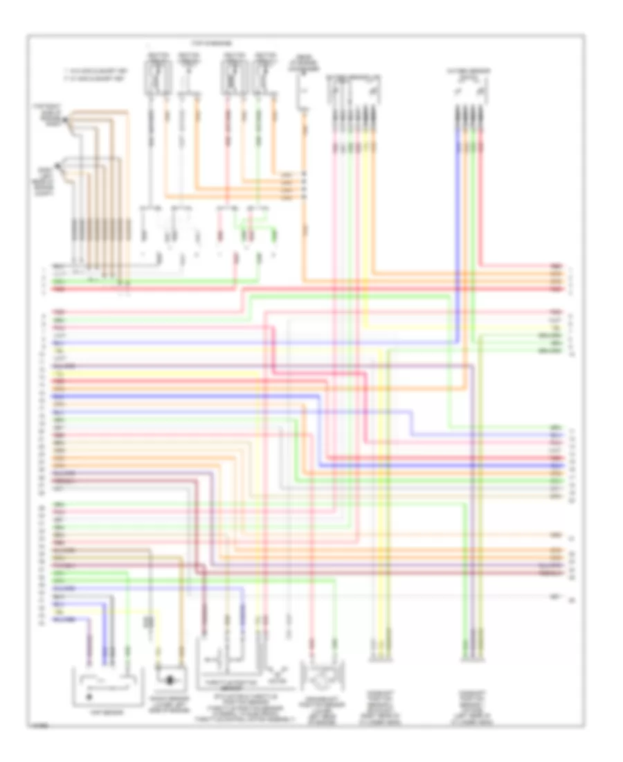
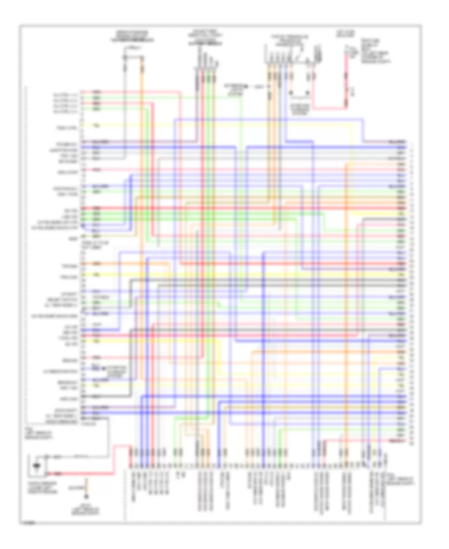
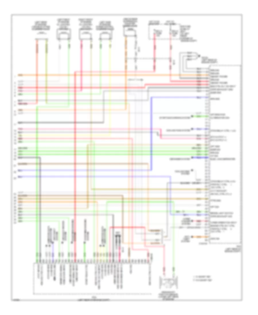
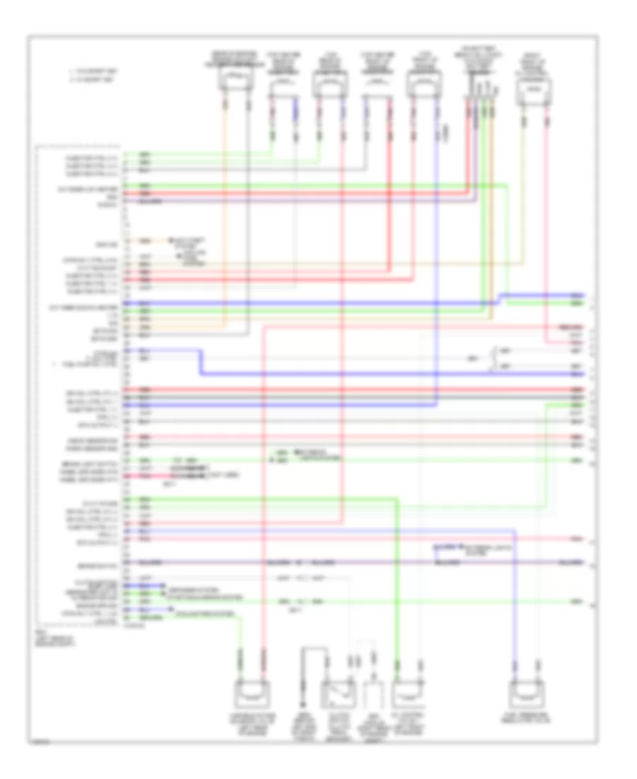
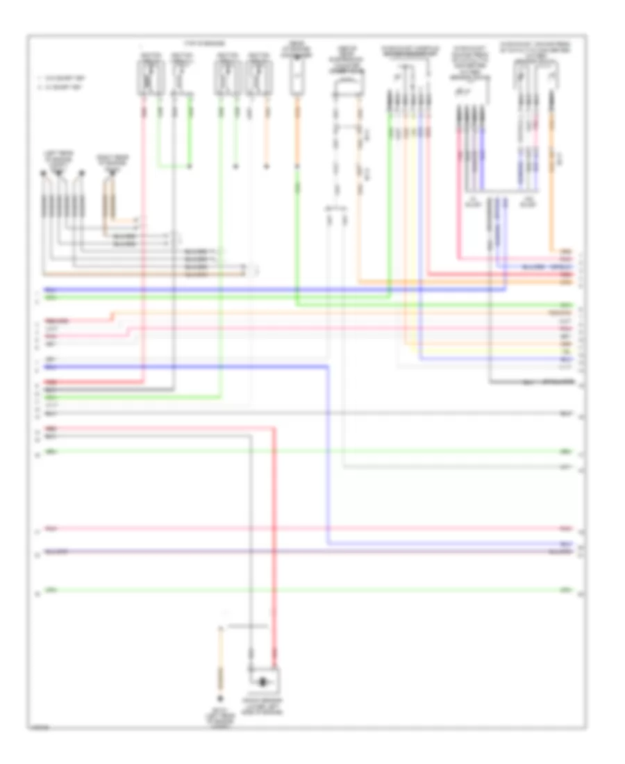
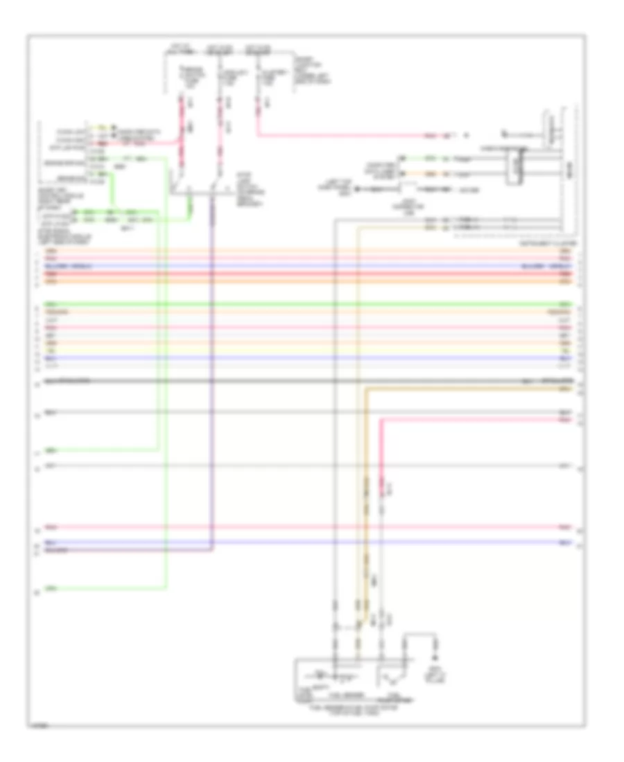
2.0L, Engine Performance Wiring Diagram, A/T (1 of 6) for Hyundai Elantra Sport 2014
List of elements for 2.0L, Engine Performance Wiring Diagram, A/T (1 of 6) for Hyundai Elantra Sport 2014:
- (pins: 27 to 29 not used)
- (rear of engine) engine coolant temperature sensor
- (top of transaxle) transaxle range switch
- 26 vfs
- 35r vfs
- Alternator pwm
- Aps 1 gnd
- Aps 1 pwr
- Aps 1 sig
- Aps 2 gnd
- Aps 2 pwr
- Aps 2 sig
- Brake sw
- C100-aa
- Down shift
- E/r fuse & relay box (in left rear corner of engine compt)
- Ec11
- Ects gnd
- Ects sig
- Exterior lights system
- Fpcv (+)
- Fpcv (-)
- Ftps sig
- Fuel tank lvl sndr
- Gc101 (left rear of engine compt)
- Ground
- Hot in on or start
- Inj ctrl 1 (+)
- Inj ctrl 1 (-)
- Inj ctrl 2 (+)
- Inj ctrl 2 (-)
- Inj ctrl 3 (+)
- Inj ctrl 3 (-)
- Inj ctrl 4 (+)
- Inj ctrl 4 (-)
- Input speed power
- Input speed signal
- Knock sens gnd
- Knock sens sig
- Knock sensor (lower left side of engine)
- Line vfs
- Map/ftps pwr
- Od vfs
- Oil temp snsr (+)
- Oil temp snsr (-)
- On/strt input
- Output speed power
- Output speed signal
- Oxy snsr (up) vg
- Oxy snsr (up) vip
- Oxy snsr (up) vn
- Oxy snsr (up) vrc
- Oxygn snsr (down) gnd
- Oxygn snsr (down) htr
- Oxygn snsr (dwn) sig
- Oxygn snsr (up) htr
- Pcm (left rear of engine compt)
- Pcsv ctrl
- Pnk
- Pos switch code s1
- Pos switch code s2
- Pos switch code s3
- Pos switch code s4
- Power (5v)
- Red
- Select switch
- Sig
- Sig 1
- Sig 2
- Sig 3
- Sig 4
- Solenoid power 1
- Solenoid power 2
- Ss-a
- Ss-b
- Starting/ charging system
- T/con vfs
- Tcu fuse 15a
- Tps 1 sig
- Tps 2 sig
- Tps gnd
- Tps pwr (5v)
- Ud vfs
- Up shift
- V in
- V out
2.0L, Engine Performance Wiring Diagram, A/T (2 of 6) for Hyundai Elantra Sport 2014
List of elements for 2.0L, Engine Performance Wiring Diagram, A/T (2 of 6) for Hyundai Elantra Sport 2014:
- (in exhaust manifold) oxygen sensor (up)
- (in exhaust, downstream of catalytic converter)
- (w/ sulev) oxygen sensor (down)
- (w/o sulev) oxygen sensor (down)
- Accelerator pedal position sensor (accelerator pedal bracket)
- Cgninj
- Down shift
- Ec11
- Em61
- Etc motor
- Etc motor & throttle position sensor (rear of engine, on throttle body)
- Gm02 (right center of dash)
- Injectors (injector 1: top front of engine) (injector 2: top center front of engine) (injector 3: top center rear of engine) (injector 4: top rear of engine)
- Joint connector umf
- Nca
- Pnk
- Red
- Select switch
- Sport mode switch
- Throttle position sensor
- Up shift
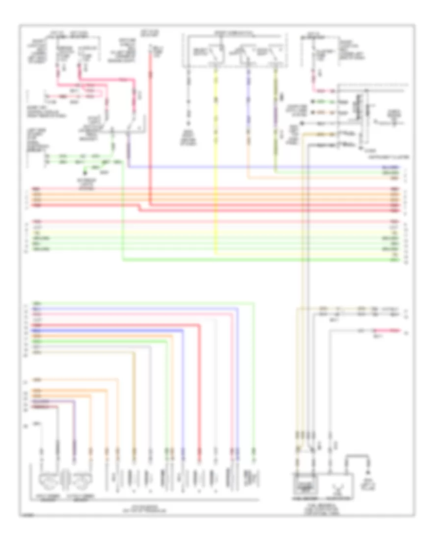
2.0L, Engine Performance Wiring Diagram, A/T (3 of 6) for Hyundai Elantra Sport 2014
List of elements for 2.0L, Engine Performance Wiring Diagram, A/T (3 of 6) for Hyundai Elantra Sport 2014:
- 26 vfs
- 35r vfs
- Atm solenoid (on top of transaxle)
- Brake sig
- Brake switch fuse 10a
- C-can high
- C-can low
- Check engine ind
- Cluster 1 fuse 7.5a
- Computer data lines system
- Ec11
- Ef11
- Em11
- Em61
- Exterior lights system
- Fuel (+)
- Fuel gnd
- Gm01 (left top dash panel)
- High
- Hot at all times
- Hot in on or start
- I/p-b
- I/p-f
- Input speed sensor
- Instrument cluster
- Interface
- Joint connector ume
- Line vfs
- Low
- M13-b
- Micom
- Module 3 fuse 7.5a
- Od vfs
- Output speed sensor
- Pnk
- Red
- Sensor temperature oil
- Sig gnd
- Smart junction box (under left end of dash)
- Smart key control module (right rear of dash)
- Ss-a
- Ss-b
- Stop lamp switch (on brake pedal bracket)
- Stop signal electronic module (left side of dash)
- Stp lmp pwr
- T/con vfs
- Transceiver b-can
- Ud vfs
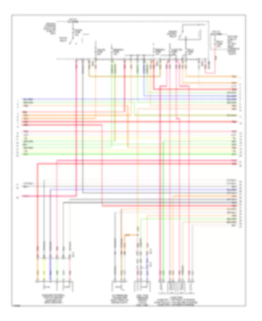
2.0L, Engine Performance Wiring Diagram, A/T (4 of 6) for Hyundai Elantra Sport 2014
List of elements for 2.0L, Engine Performance Wiring Diagram, A/T (4 of 6) for Hyundai Elantra Sport 2014:
- (rear of engine) condenser
- (top of engine)
- Brake
- Ec11
- Ef21
- Em11
- Empty
- Esc module (right rear of engine compt)
- Fuel level float
- Fuel pressure regulator valve
- Fuel pump motor
- Fuel sender
- Fuel sender & fuel pump motor (top of fuel tank)
- Full
- Gc101 (left rear of engine compt)
- Gc103 (right rear of engine)
- Gf03 (left "c" pillar)
- Ignition coil 1
- Ignition coil 2
- Ignition coil 3
- Ignition coil 4
- Light sw
- Map sensor (left rear of engine)
- Mf11
- Pnk
- Red
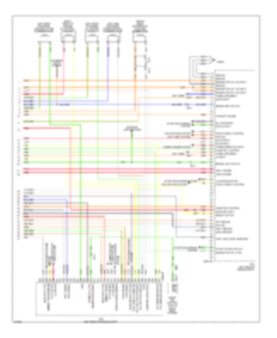
2.0L, Engine Performance Wiring Diagram, A/T (5 of 6) for Hyundai Elantra Sport 2014
List of elements for 2.0L, Engine Performance Wiring Diagram, A/T (5 of 6) for Hyundai Elantra Sport 2014:
- (right rear of dash)
- A/c pressure transducer (right front of engine compt)
- Camshaft position sensor 1 (intake) (left rear of cylinder head)
- Camshaft position sensor 2 (exhaust) (right rear of cylinder head)
- Cgninj
- E/r fuse & relay box (in left rear corner of engine compt)
- E/r-a
- E/r-b
- E/r-ems
- Ec11
- Ecu 1 fuse 20a
- Ecu 2 fuse 10a
- Ecu 4 fuse 15a
- Ecu 6 fuse 40a
- Ef11
- Em61
- Ems box (in engine room fuse & relay box)
- Engine control relay
- F/ pump relay
- F/pump fuse 15a
- Fuel tank pressure sensor (top of fuel tank)
- Hot at all times
- Ign coil fuse 20a
- Injector fuse 10a
- M13-a
- Module
- Pnk
- Power distribution system
- Rail pressure sensor (front of fuel rail assembly)
- Red
- Sensor 1 fuse 10a
- Sensor 2 fuse 10a
- Smart key control
- Spd sig engine
- W/ smart key
- W/o smart key
2.0L, Engine Performance Wiring Diagram, A/T (6 of 6) for Hyundai Elantra Sport 2014
List of elements for 2.0L, Engine Performance Wiring Diagram, A/T (6 of 6) for Hyundai Elantra Sport 2014:
- (above rear suspension) canister close valve
- (left front of engine) oil control valve 1 (intake)
- (left rear of engine) variable intake solenoid valve
- (left side of engine) purge control solenoid valve
- (not used)
- (right front of engine) oil control valve 2 (exhaust)
- Alternator com
- Anti- theft system
- Apt gnd
- Apt sig
- Apt/rps pwr
- Brake light switch
- C-can high
- C-can low
- C/fan relay ctrl 1 (lo)
- C/fan relay ctrl 2 (hi)
- C100-ak
- Ccp-can high
- Ccp-can low
- Ccv ctrl
- Ckps gnd
- Ckps sig
- Cmps (exhaust) gnd
- Cmps (exhaust) sig
- Cmps (intake) gnd
- Cmps (intake) sig
- Cooling fans system
- Crankshaft position sensor (lower left rear of engine)
- Cvvt exhaust
- Cvvt intake
- Defogger system
- E/r fuse & relay box (in left rear corner of engine compt)
- Ec11
- Ecu 3 fuse 10a
- Ecu 5 fuse 15a
- Ef11
- Elec load defroster
- Eng ctrl rly on input
- Engine ctrl rly ctrl
- Engine spd signal
- Etc output (+)
- Etc output (-)
- F/pmp rly ctrl
- Ftps gnd
- Gc102 (left rear of engine compt)
- Ground
- Hot at all times
- Hot in on or start
- Iat sig
- Ign coil ctrl cyl 1
- Ign coil ctrl cyl 2
- Ign coil ctrl cyl 3
- Ign coil ctrl cyl 4
- Immo data line
- Immo ind
- Lines system computer data
- Memory power
- Nca
- On/start input
- Pcm (left rear of engine compt)
- Pnk
- Red
- Rps gnd
- Rps sig
- Snsr gnd
- Snsr sig
- Start relay ctrl
- Start signal input
- Starting/charging system
- System anti-lock brakes
- System anti-theft
- System starting/charging
- Vehicle spd input
- Vis ctrl
- W/ smart key
- W/o smart key
- Whl spd snsr input a
- Whl spd snsr input b
- Wiper operation input
- Wiper/ washer system
2.0L, Engine Performance Wiring Diagram, M/T (1 of 6) for Hyundai Elantra Sport 2014
List of elements for 2.0L, Engine Performance Wiring Diagram, M/T (1 of 6) for Hyundai Elantra Sport 2014:
- (left rear of engine)
- (not used)
- (rear of engine) engine coolant temperature sensor
- (right front of engine) oil control valve 2
- (top center front of engine) injector 2
- (top center rear of engine) injector 3
- (top front of engine) injector 1
- (top rear of engine) injector 4
- Alternator com
- Anti-theft system
- Bracket)
- Brake light switch
- Brake switch
- C/fan rly ctrl 1 (lo)
- C/fan rly ctrl 2 (hi)
- C100-ma
- Cgninj
- Clutch switch (clutch pedal
- Clutch switch elec load- defroster (act hi)
- Cooling fans system
- Cvvt exhaust
- Cvvt intake
- Defogger system
- Ec11
- Ecm (left rear of engine compt)
- Ects gnd
- Ects sig
- Engine spd sig
- Esc module (right rear of engine compt)
- Etc output (+)
- Etc output (-)
- Exterior lights system
- Fpcv (+)
- Fpcv (-)
- Ftps sig ccv ctrl fuel pump rly ctrl
- Fuel pressure regulator valve
- Ge02 (behind left end of front fascia)
- Gnd
- Ground
- Ign coil ctrl cyl 1
- Ign coil ctrl cyl 2
- Ign coil ctrl cyl 3
- Ign coil ctrl cyl 4
- Immo ind
- Injector ctrl 1 (+)
- Injector ctrl 1 (-)
- Injector ctrl 2 (+)
- Injector ctrl 3 (+)
- Injector ctrl 3 (-)
- Injector ctrl 4 (+)
- Injector ctrl 4 (-)
- Knock sensor gnd
- Knock sensor sig
- Nca
- Oil control valve 1 (left front of engine)
- Oxy snsr (down) heater
- Oxy snsr (up) heater
- Pnk
- Pwr
- Pwr 5v
- Red
- Sig
- Starting/charging system
- V in
- V out
- Variable intake solenoid valve
- Vis ctrl
- W/ smart key
- W/o smart key
- Wheel spd snsr i/p a
- Wheel spd snsr i/p b
2.0L, Engine Performance Wiring Diagram, M/T (2 of 6) for Hyundai Elantra Sport 2014
List of elements for 2.0L, Engine Performance Wiring Diagram, M/T (2 of 6) for Hyundai Elantra Sport 2014:
- (above rear suspension) canister close valve
- (in exhaust manifold) oxygen sensor (up)
- (in exhaust, downstream of catalytic converter) oxygen sensor (down)
- (left rear of engine compt) gc101
- (rear of engine) condenser
- (right rear of engine) gc103
- (top of engine)
- Ec11
- Ef11
- Gc101 (left rear of engine compt)
- Ignition coil 1
- Ignition coil 2
- Ignition coil 3
- Ignition coil 4
- Knock sensor (lower left side of engine)
- Nca
- Pnk
- Red
- W/ smart key
- W/ sulev
- W/o smart key
- W/o sulev
2.0L, Engine Performance Wiring Diagram, M/T (3 of 6) for Hyundai Elantra Sport 2014
List of elements for 2.0L, Engine Performance Wiring Diagram, M/T (3 of 6) for Hyundai Elantra Sport 2014:
- (left top dash panel) gm01
- Brake sig
- Brake switch fuse 10a
- C-can high
- C-can low
- Check engine ind
- Cluster 1 fuse 7.5a
- Computer data lines system
- Ec11
- Ef11
- Ef21
- Em11
- Em61
- Empty
- Engine spd sig
- Fuel (+)
- Fuel (-)
- Fuel level float
- Fuel pump motor
- Fuel sender
- Fuel sender & fuel pump motor (top of fuel tank)
- Full
- Gf03 (left "c" pillar)
- High
- Hot at all times
- Hot in on or start
- I/p-b
- I/p-f
- Instrument cluster
- Interface
- Joint connector ume
- Low
- M13-a
- M13-b
- Mf11
- Micom
- Module 3 fuse 7.5a
- Pnk
- Red
- Sig gnd
- Smart junction box (under left end of dash)
- Smart key control module (right rear of dash)
- Stop lamp switch (on brake pedal bracket)
- Stop signal electronic module (left side of dash)
- Stp ip sig
- Stp lmp pwr
- Stp lp sw
- Transceiver b-can
2.0L, Engine Performance Wiring Diagram, M/T (4 of 6) for Hyundai Elantra Sport 2014
List of elements for 2.0L, Engine Performance Wiring Diagram, M/T (4 of 6) for Hyundai Elantra Sport 2014:
- A/c pressure transducer (right front of engine compt)
- Camshaft position sensor 1 (left rear of cylinder head)
- Camshaft position sensor 2 (right rear of cylinder head)
- Cgninj
- E/r fuse & relay box (in left rear corner of engine compt)
- E/r-a
- E/r-b
- E/r-ems
- Ec11
- Ecu 1 fuse 20a
- Ecu 2 fuse 10a
- Ecu 4 fuse 15a
- Ecu 6 fuse 40a
- Ef11
- Ems box (in engine room fuse & relay box)
- Engine control relay
- F/pump fuse 15a
- Fuel pump relay
- Fuel tank pressure sensor (top of fuel tank)
- Hot at all times
- Ign coil fuse 20a
- Injector fuse 10a
- Map sensor (left rear of engine)
- Pnk
- Power distribution system
- Rail pressure sensor (front of fuel rail assembly)
- Red
- Sensor 1 fuse 10a
- Sensor 2 fuse 10a
- W/ smart key
- W/o smart key
2.0L, Engine Performance Wiring Diagram, M/T (5 of 6) for Hyundai Elantra Sport 2014
List of elements for 2.0L, Engine Performance Wiring Diagram, M/T (5 of 6) for Hyundai Elantra Sport 2014:
- (active hi)
- (left side of engine) purge control solenoid valve
- A/c comeressor sw
- Anti- theft system
- Apt gnd
- C-can high
- C-can low
- C100-mk
- Ccp-can high
- Ccp-can low
- Ckps gnd
- Ckps sig
- Cmps (exhaust) gnd
- Cmps (exhaust) sig
- Cmps (intake) gnd
- Cmps (intake) sig
- Computer data lines system
- Crankshaft position sensor (lower left rear of engine)
- Ecm (left rear of engine compt)
- Engine ctrl rly ctrl
- F/pump relay ctrl
- Iat sig
- Immo data line
- Oxy snsr (up) vn
- Oxy snsr (up) vrc
- Pcsv ctrl
- Pnk
- Red
- Rps gnd
- Rps sig
- Snsr gnd
- Snsr sig
- Start rly ctrl
- Starting/ charging system
- Strt sig i/p
- System air conditioning
- W/ smart key
- W/o smart key
2.0L, Engine Performance Wiring Diagram, M/T (6 of 6) for Hyundai Elantra Sport 2014
List of elements for 2.0L, Engine Performance Wiring Diagram, M/T (6 of 6) for Hyundai Elantra Sport 2014:
- Accelerator pedal position sensor (accelerator pedal bracket)
- Alternator pwm
- Aps 1 gnd
- Aps 1 pwr
- Aps 1 sig
- Aps 2 gnd
- Aps 2 pwr
- Aps 2 sig
- Apt sig
- Apt/rps pwr
- C100-mk
- Cruise control system
- E/r fuse & relay box (in left rear corner of engine compt)
- Ec11
- Ecm (left rear of engine compt)
- Ecu 3 fuse 10a
- Ecu 5 fuse 15a
- Engine ctrl rly on input
- Etc motor
- Etc motor & throttle position sensor (electronic throttle control motor: rear of engine, on throttle body) (throttle position sensor: integral to electronic throttle control motor assembly)
- Ftps gnd
- Fuel tank level sender
- Gc102 (left rear of engine compt)
- Ground
- Hot at all times
- Hot in on or start
- Map/ftps pwr
- Memory power
- On/start i/p
- Oxy snsr (down) gnd
- Oxy snsr (down) sig
- Oxy snsr (up) vg
- Oxy snsr (up) vip
- Pnk
- Red
- Starting/charging system
- Throttle position sensor
- Tpd 1 sig
- Tps 2 sig
- Tps gnd
- Tps pwr 5v
- Vechicle spd i/p
- Wiper operation i/p (act hi)
- Wiper/washer system
EXTERIOR LIGHTS
Backup Lamps Wiring Diagram for Hyundai Elantra Sport 2014
List of elements for Backup Lamps Wiring Diagram for Hyundai Elantra Sport 2014:
- "r" sig
- (in left rear corner of engine compt)
- 1.8l
- 2.0l turbo
- A/t
- A/v & navigation head unit
- Audio (w/ rearview camera)
- B/up lp fuse 10a
- Backup lamp
- Backup lamp switch (on transaxle)
- Backup sig
- Bcm (lower center of dash)
- C100-aa
- C600-aa
- E/r fuse & realy box
- Ec11
- Electrochromic mirror
- Em11
- Esc module (right rear of engine compt)
- Gf03 (left "c" pillar)
- Hot in on or start
- Instrument cluster
- Left rear combination lamp (in)
- M/t
- M/t & audio
- M02-a
- M09-c
- M15-a
- Mf11
- Mr11
- Mts module (center of dash)
- Navigation
- Nca
- On/start input
- Pcm (left rear of engine compt)
- Pnk
- Red
- Rev gear sw
- Right rear combination lamp (in)
- Sig 1
- Sig 2
- Sig 3
- Sig 4
- Sig backup
- Tcu 1 fuse 15a
- Transaxle range switch (top of transaxle)
- W/ tmu or homelink
- W/o
Exterior Lamps Wiring Diagram (1 of 4) for Hyundai Elantra Sport 2014
List of elements for Exterior Lamps Wiring Diagram (1 of 4) for Hyundai Elantra Sport 2014:
- 1.8l a/t
- 1.8l m/t
- 2.0l a/t
- 2.0l m/t
- A/t
- Auto
- B-can high
- B-can low
- Bcm (lower center of dash)
- Brake light sw hac rly state monitoring c-can low c-can high
- Brake sig
- Brake sw
- Brake switch fuse 10a
- C-can high
- C-can low
- C100-aa
- C100-ak
- C100-ma
- C600-ab
- C600-mk
- Computer data lines system
- E/r fuse & relay box (in left rear corner of engine compt)
- Ec11
- Ecm (m/t) pcm (a/t) (left rear of engine compt)
- Ef11
- Em11
- Em61
- Esc module (right rear of engine compt)
- Esc unit
- Gm01 (left top dash panel)
- Gm02 (right center of dash)
- Gnd
- Hac brk rly ctrl brake switch
- Hac signal
- Head
- Hot at all times
- Hot in on or start
- I/p-b
- Input circuit
- Internal control
- Ips
- Joint connector ume
- Joint connector umf
- Left
- Light sw brake
- Light switch
- M/t
- M01-l
- M02-a
- M02-b
- M13-b
- Memory power
- Module 3 fuse 7.5a
- Multi-function switch
- Off
- Pnk
- Red
- Right
- Smart junction box (under left end of dash)
- Smart key control module (right rear of dash)
- Stop lamp
- Stop lamp 15a
- Stop lamp switch (on brake pedal bracket)
- Stop lmp pwr
- Stop lp sw
- Stop signal electronic module (left side of dash)
- Stop lp sig
- Tail
- Tail lp sw
- Turn signal lamp switch
Exterior Lamps Wiring Diagram (2 of 4) for Hyundai Elantra Sport 2014
List of elements for Exterior Lamps Wiring Diagram (2 of 4) for Hyundai Elantra Sport 2014:
- Backup lamp
- Backup lamps circuit
- Driver power outside mirror
- Fd11
- Gf01 (left "b" pillar)
- Gf03 (left "c" pillar)
- Hazard sw sig
- High mounted stop lamp
- Hot in on or start
- I/p-b
- I/p-d
- I/p-e
- I/p-g
- Ips 1 arisu-lt (4ch)
- Ips 1 arisu-lt ctrl
- Ips 4 arisu-lt (4ch)
- Ips 4 arisu-lt ctrl
- Ips control module
- Joint connector uda
- Junction connector jf02
- Left rear combination lamp (in)
- Mem
- Nca
- On/start input
- Operation sound
- Power
- Red
- Right rear combination lamp (in)
- Smart junction box (under left side of dash)
- Stop lamp
- Tail lamp
- To ips 8 (2ch) (diagram 3 of 4)
- Turn lamp
- Turn sig lp sound relay ctrl
- Turn sig lp switch sig
- Turn signal lamp sound relay
Exterior Lamps Wiring Diagram (3 of 4) for Hyundai Elantra Sport 2014
List of elements for Exterior Lamps Wiring Diagram (3 of 4) for Hyundai Elantra Sport 2014:
- B-can
- Computer data lines system
- From ips control a
- Ge03 (behind right end of front fascia)
- Gf03 (left "c" pillar)
- Gf04 (right "c" pillar)
- Hot at all times
- I/p-b
- I/p-e
- I/p-g
- I/p-h
- Ips 8 (2ch)
- Ips 8 ctrl
- Ips control module
- Junction connector jf02
- Leak current autocut device
- Left rear combination lamp (out)
- Memory fuse 10a
- Module (diagram 2 of 4)
- Nca
- Parking lamp
- Red
- Right headlamp
- Right rear combination lamp (out)
- Smart junction box (under left side of dash)
- Stop lamp
- Tail lamp
- Turn lamp
- W/ led
- W/o led
Exterior Lamps Wiring Diagram (4 of 4) for Hyundai Elantra Sport 2014
List of elements for Exterior Lamps Wiring Diagram (4 of 4) for Hyundai Elantra Sport 2014:
- A/c control module
- Automatic a/c
- B+1 fuse 60a
- B+2 fuse 60a
- Computer data lines system
- E/r fuse & relay box (in left rear corner of engine compt)
- Fd21
- Ge01 (behind left end of front fascia)
- Gf02
- Gf03 (left "c" pillar)
- Gf04 (right "c" pillar)
- Gm01 (left top dash panel)
- Hazard switch
- Hot at all times
- I/f
- Instrument cluster
- Interface
- Joint connector jd01 (front passenger's door)
- Left headlamp
- Left license lamp
- Left turn ind
- M21-a
- M22-b
- Manual a/c
- Micom
- Multi fuse
- Nca
- P-gnd
- Parking lamp
- Passenger power outside mirror
- Red
- Right license lamp
- Right turn ind
- S-gnd
- Tail on ind
- Transceiver b-can
- Turn lamp
GROUND DISTRIBUTION
Ground Distribution Wiring Diagram (1 of 3) for Hyundai Elantra Sport 2014
List of elements for Ground Distribution Wiring Diagram (1 of 3) for Hyundai Elantra Sport 2014:
- (a/t) atm lever indicator
- (a/t) sport mode switch
- (automatic a/c) cluster ionizer
- (right center of dash)
- (under left end of dash) smart junction box
- (w/ burglar alarm) hood switch
- A/c control module
- A/v & navigation head unit
- Audio
- Automatic a/c
- Aux & usb jack
- Aux & usb jack shield
- Bcm
- Burglar alarm horn
- Console power outlet
- Cooling fan motor
- Data link connector
- Digital clock
- Door lock relay
- Door unlock relay
- Eco switch
- Ee11
- Electro- chromic mirror
- Esc module
- Fet (field effect transistor)
- Front power outlet
- Ge01 (behind left end of front fascia)
- Ge03 (behind right end of front fascia)
- Ge04 (behind right end of front fascia)
- Ge06 (right kick panel)
- Ge07 (left kick panel)
- Gm01 (left top dash panel)
- Gm02 (right center of dash)
- Gm04 (left center of dash) left horn
- Gm06
- Gm08 (upper right end of dash)
- Gnd (drl)
- I/p-f
- I/p-g
- I/p-h
- Icm relay box (top left side of dash)
- Ignition key illumination & door warning switch (w/o smart key)
- Instrument cluster
- Ips control module
- Joint connector ume
- Joint connector umf
- Joint connector ura
- Left front fog lamp
- Left headlamp
- Left vanity lamp
- M01-l
- M01-w
- M02-a
- M02-c
- M09-b
- M13-a
- M15-a
- M15-b
- M15-c
- M21-b
- M22-a
- M22-b
- Manual a/c
- Mdps unit
- Mic shield
- Mm01
- Mr11
- Multi-function switch
- Multi-purpose check connector
- Nca
- Overhead console
- Overhead console lamp
- Rheostat
- Right front fog lamp
- Right headlamp
- Right horn
- Right vanity lamp
- Room lamp
- S gnd (mcu)
- Smart key control module
- Start stop button switch
- Stop signal electronic module
- Sunroof
- Sunroof switch
- Tire pressure monitoring module
- Two turn relay
- Ud md
- W/ navigation
- W/o navigation
- W/o rearview camera
- Washer motor
Ground Distribution Wiring Diagram (2 of 3) for Hyundai Elantra Sport 2014
List of elements for Ground Distribution Wiring Diagram (2 of 3) for Hyundai Elantra Sport 2014:
- (in left rear corner of engine compt) e/r fuse & relay box
- (m/t) clutch switch
- (md) fuel sender & fuel pump motor
- (ud) fuel sender & fuel pump motor
- (w/ smart key & m/t)
- (w/ smart key)
- (w/ smart key) driver smart key outside handle
- (w/ smart key) external buzzer
- (w/o smart key) immobilizer module
- 2-way
- 8-way
- Blower relay
- Brake fluid level sensor
- Driver door lock actuator
- Driver door switch
- Driver power outside mirror
- Driver reclining limit switch
- Driver safety power window module
- Driver seat belt buckle switch
- Driver seat manual switch
- Driver seat warmer module
- Ee11
- Em11
- F49
- Fd11
- Fd31
- Fs11
- Fs12
- Ge02 (behind left end of front fascia)
- Gf01 (left "b" pillar)
- Gf03 (left "c" pillar)
- Gf06 (under center of rear seats)
- Gf07 (under right front of center console)
- High mounted stop lamp
- Ignition lock switch
- Joint connector js01 (under driver's seat)
- Joint connector uda
- Left license lamp
- Left rear combination lamp (in)
- Left rear combination lamp (out)
- Left rear door lock actuator
- Left rear door switch
- Left rear power window switch
- Left rear seat warmer
- Left rear seat warmer switch
- Nca
- Passenger seat belt buckle switch
- Passenger weight classification sensor
- Pdm 2 (acc) relay
- Pdm 3 (ig1) relay
- Pdm 4 (ig2) relay
- Power outside mirror switch
- Power window main switch
- Right license lamp
- Right rear combination lamp (in)
- Seat
- Srs control module
- Trunk lid handle switch
- Trunk lid motor
- W/ power
- W/ power seat
- W/ safety power windows
- W/ smart key
- W/o power
- W/o safety power windows
- Wiper motor
Ground Distribution Wiring Diagram (3 of 3) for Hyundai Elantra Sport 2014
List of elements for Ground Distribution Wiring Diagram (3 of 3) for Hyundai Elantra Sport 2014:
- (2.0l) knock sensor shield
- (m/t) vehicle speed sensor
- (upper right end of dash)
- (w/ smart key) passenger smart key outside handle
- 1.8l
- 2.0l
- A/t
- Amp
- Battery & battery fuse box
- Body ground
- C100-ak
- C100-mk
- C600-aa
- C600-ab
- C600-mk
- Ecm
- F02-c
- Fd21
- Fd41
- Fs21
- Gc601 (1.8l) gc101 (2.0l) (left rear of engine compt)
- Gc602 (1.8l) gc102 (2.0l) (2.0l: left rear of engine compt)
- Gc603 (1.8l) gc103 (2.0l) (1.8l: top right side of engine) (2.0l: right rear of engine)
- Gf02
- Gf04 (right "c" pillar)
- Gf05 (right "c" pillar)
- Gm09
- Ignition coil 1 shield
- Ignition coil 2 shield
- Ignition coil 3 shield
- Ignition coil 4 shield
- Joint connector jd01 (front passenger's door)
- M/t
- Mic shield
- Mts module
- Nca
- Passenger door lock actuator
- Passenger door switch
- Passenger power outside mirror
- Passenger power window switch
- Passenger seat warmer module
- Pcm
- Quarter panel ground
- Rear defogger
- Right rear combination lamp (out)
- Right rear door lock actuator
- Right rear door switch
- Right rear power window switch
- Right rear seat warmer
- Right rear seat warmer switch
- W/ central door lock
- W/o central door lock
HEADLIGHTS
Autolamps Wiring Diagram for Hyundai Elantra Sport 2014
List of elements for Autolamps Wiring Diagram for Hyundai Elantra Sport 2014:
- (under left end of dash) smart junction box
- Auto
- Auto lamp switch
- Auto light sens gnd
- Auto light sens pwr
- Auto light sens sig
- Autolight & photo sensor (top center of dash)
- Autolight sensor
- B+1 fuse 60a
- B+2 fuse 60a
- B-can
- B-can high
- B-can low
- Bcm (lower center of dash)
- Computer data lines system
- Dimmer/ passing switch
- E/r fuse & relay box (in left rear corner of engine compt)
- Front fog ind
- Front fog lamp switch
- Ge01 (behind left end of front fascia)
- Ge03 (behind right end of front fascia)
- Gm01 (left top dash panel)
- Gm02 (right center of dash)
- Head
- Headlamp
- Headlamp hi switch
- Headlamp lo signal
- Headlamp lo signal front fog lamp switch 'on'
- Headlamp lo switch
- High
- High beam ind
- Hot at all times
- I/f
- I/p-d
- I/p-e
- I/p-f
- I/p-g
- I/p-h
- Instrument cluster
- Interface
- Ips 1 arisu-lt (4ch)
- Ips 1 ctrl
- Ips 3 (1ch)
- Ips 3 ctrl
- Ips 4 arisu-lt (4ch)
- Ips 4 ctrl
- Ips control module
- Joint connector ume
- Joint connector umf
- Leak current autocut device
- Left front fog lamp
- Left headlamp
- Light switch
- Low
- Low pass
- M01-l
- M02-a
- M02-b
- Mcu gnd
- Memory fuse 10a
- Memory pwr
- Micom
- Multi fuse
- Multi-function switch
- Nca
- Off
- Pass
- Pnk
- Power distribution system
- Red
- Right
- Right front fog lamp
- Tail
- Tail lamp switch
- Transceiver
- W/ dimming control
Headlamps Wiring Diagram for Hyundai Elantra Sport 2014
List of elements for Headlamps Wiring Diagram for Hyundai Elantra Sport 2014:
- (under left end of dash) smart junction box
- A/v & navigation headunit
- Auto
- B+1 fuse 60a
- B+2 fuse 60a
- B-can
- B-can high
- B-can low
- Bcm (lower center of dash)
- Computer data lines system
- Corner of engine compt)
- Dimmer/ passing switch
- Drl switch
- E/r fuse & relay box (in left rear
- Front fog ind
- Front fog lamp switch
- Front fog lamp switch 'on'
- Ge01 (behind left end of front fascia)
- Ge03 (behind right end of front fascia)
- Gm01 (left top dash panel)
- Gm02 (right center of dash)
- Ground mcu
- Head
- Headlamp
- Headlamp hi switch
- Headlamp lo signal
- Headlamp lo switch
- High
- High beam ind
- Hot at all times
- I/f
- I/p-c
- I/p-d
- I/p-e
- I/p-f
- I/p-g
- I/p-h
- Instrument cluster
- Interface
- Ips 1 arisu-lt (4ch)
- Ips 1 ctrl
- Ips 3 (1ch)
- Ips 4 arisu-lt (4ch)
- Ips 4 ctrl
- Ips control module
- Joint connector ume
- Joint connector umf
- Leak current autocut device
- Left front fog lamp
- Left headlamp
- Light switch
- Low
- Low pass
- M01-l
- M02-a
- M02-b
- M15-b
- Memory fuse 10a
- Memory pwr
- Mf11
- Micom
- Multi fuse
- Multi-function switch
- Nca
- Off
- Parking brake
- Parking brake switch (base of parking brake lever assembly)
- Pass
- Pnk
- Power distribution system
- Red
- Right
- Right front fog lamp
- Switch
- Tail
- Tail lamp switch
- Transceiver
- W/ dimming control
HORN
Horn Wiring Diagram for Hyundai Elantra Sport 2014
List of elements for Horn Wiring Diagram for Hyundai Elantra Sport 2014:
- Clock spring
- E/r fuse & relay box (in left rear corner of engine compt)
- Ee11
- Em11
- Ge01 (behind left end of front fascia)
- Horn fuse 15a
- Horn relay
- Horn switch
- Hot at all times
- Left horn (behind left side of front fascia)
- M01-r
- Mm02
- Nca
- Red
- Right horn (behind right side of front fascia)
- Steering wheel
INSTRUMENT CLUSTER
Instrument Cluster Wiring Diagram, MD (1 of 3) for Hyundai Elantra Sport 2014
List of elements for Instrument Cluster Wiring Diagram, MD (1 of 3) for Hyundai Elantra Sport 2014:
- (a/t)
- (m/t)
- (w/ conventional)
- (w/ conventional) key out ind
- 5v regulator
- Abs ind
- Active eco sw
- Air bag ind
- Altl output
- Anti-theft system
- Auto stop (green) ind
- B-can
- Battery charger
- Buzzer
- C-can
- Charge ind
- Check engine ind
- Cluster 1 fuse 7.5a
- Computer data lines system
- Constant current circuit
- Cruise control system
- Cruise ind
- D out
- Dc-dc
- Dc/d power
- Detent out
- Dial ill
- Door open ind
- Ec11
- Eco (green) ind
- Eeprom
- Em11
- Esc ind
- Esc off ind
- Exterior lights system
- Front fog ind
- Fuel (+)
- Fuel (-)
- Gm01 (left top dash panel)
- High
- High beam ind
- Hot at all times
- Hot in on or start
- I/f
- I/p-f
- I/p-h
- Immo ind
- Input switch
- Instrument cluster
- Interface
- Interior lights system
- Joint connector ume
- Lcd ill
- Leak current autocut device
- Left turn ind
- Low
- Low fuel ind
- Mdps ind
- Memory fuse 10a
- Micom
- Module 2 fuse 7.5a
- Module 3 fuse 7.5a
- N out
- Oil press
- Oil pressure ind
- Oled
- Output
- Output 4 pulses
- P out
- Parking brake ind
- Pnk
- Pointer ill
- Pwr gnd
- R input
- R out
- Red
- Rheostat down switch
- Rheostat out
- Rheostat up switch
- Right turn ind
- S out
- Seat belt ind
- Seg lcd
- Set ind
- Sig gnd
- Smart junction box (under left end of dash)
- Speed input
- Speedo- meter
- Starting/charging system
- Sw gnd
- Tacho- meter
- Tail on ind
- Temp high ind
- Tpms tread ind
- Transceiver
- Transmissions system
- Trunk open ind
- Vision) (w/ super oled lcd
- W/ conventional
- W/ super vision
Instrument Cluster Wiring Diagram, MD (2 of 3) for Hyundai Elantra Sport 2014
List of elements for Instrument Cluster Wiring Diagram, MD (2 of 3) for Hyundai Elantra Sport 2014:
- (+)
- (-)
- (remote control switch)
- 1.8l a/t
- 1.8l m/t
- 2.0l a/t
- 2.0l m/t
- C100-aa
- C100-mk
- C600-ab
- C600-mk
- Cancel
- Clock spring
- Cruise
- Ec11
- Eco switch
- Em11
- Empty
- Fuel level float
- Fuel sender
- Fuel sender & fuel pump motor (top of fuel tank)
- Full
- Gm02 (right center of dash)
- Ill
- Interior lights system
- Joint connector umf
- M01-r
- Mf11
- Mm02
- Oil pressure switch (on oil filter bracket)
- Pcm (a/t) ecm (m/t) (left rear of engine compt)
- Pnk
- Red
- Res (+)
- Reset
- Right cruise remote control switch
- Right trip remote control switch
- Set (-)
- Steering wheel
- Trip
- Trip(+)
- Trip(-)
Instrument Cluster Wiring Diagram, MD (3 of 3) for Hyundai Elantra Sport 2014
List of elements for Instrument Cluster Wiring Diagram, MD (3 of 3) for Hyundai Elantra Sport 2014:
- A/v & navigation head unit
- Acc/on input
- Ambient (+)
- Ambient (-)
- Ambient temperature sensor (digital clock) (behind center of front bumper)
- B-can
- Brake fluid level sensor
- Brake fluid level sensor (in brake fluid reservoir)
- Computer data lines system
- Cruise control system
- Detent
- Digital clock
- Digital clock & outside temp
- Door open
- Door sw sig
- Driver door switch (on left "b" pillar)
- Drv
- Ee11
- Em11
- Em61
- Esc module (right rear of engine compt)
- Ge02 (behind left end of front fascia)
- Gf01 (left "b" pillar)
- Gf02
- Gf03 (left "c" pillar)
- Gf04 (right "c" pillar)
- Gm02 (right center of dash)
- Ground
- High
- Hot in acc or on
- I/p-c
- I/p-e
- I/p-g
- I/p-h
- Ill
- Interior lights system
- Ips control module
- Joint connector umf
- Left rear door switch (left "c" pillar)
- Low
- M-can hi
- M-can lo
- M/t
- M15-b
- M15-c
- Memory power
- Mf11
- Module 6 fuse 10a
- On/start input
- Pab indicator
- Pab off
- Parking brake switch
- Parking brake switch (base of parking brake lever assembly)
- Parking brk sw
- Pass
- Passenger door switch (on right "b" pillar)
- Pnk
- Red
- Right rear door switch (right "c" pillar)
- Smart junction box (under left end of dash)
- Speed signal
- Srs control module (under front of center console)
Instrument Cluster Wiring Diagram, UD (1 of 3) for Hyundai Elantra Sport 2014
List of elements for Instrument Cluster Wiring Diagram, UD (1 of 3) for Hyundai Elantra Sport 2014:
- (a/t)
- (m/t)
- (under left end of dash)
- 4p out
- Abs ind
- Air bag ind
- Alt l out
- Anti-theft system
- B-can
- Brake ind
- Buzzer
- C-can
- Charge battery
- Charge ind
- Check engine ind
- Cluster fuse 7.5a
- Computer data lines system
- Constant current
- Cruise control system
- Cruise ind
- D out
- Dc-dc
- Detent out
- Dial ill (white)
- Door open ind
- Ec11
- Eco (green) ind
- Eeprom
- Em11
- Esc ind
- Esc off ind
- Exterior lights system
- Front fog ind
- Fuel cap open ind
- Fuel input
- Fuel low
- Gm01 (left top dash panel)
- High
- High beam ind
- Hot at all times
- Hot in on or start
- I/p-f
- I/p-h
- Immo ind
- Instrument cluster
- Interior lights system
- Joint connector ume
- Key out ind
- Lcd ill (white)
- Leak current autocut device
- Left turn ind
- Low
- Low fuel ind
- Mdps ind
- Memory fuse 10a
- Micom
- Module 2 fuse 7.5a
- Module 3 fuse 7.5a
- N out
- Oil pressure
- Oil pressure ind
- P out
- Pnk
- Pointer ill (red)
- Pwr gnd
- R input
- R out
- Red
- Rheostat down switch
- Rheostat out
- Rheostat up switch
- Right turn ind
- S out
- Seat belt ind
- Seg lcd
- Set ind
- Smart junction box
- Snsr gnd
- Speed input
- Speedo- meter
- Starting/charging system
- Sw gnd
- Switch input
- Tacho- meter
- Tail on ind
- Temp high ind
- Tpms tread ind
- Transceiver
- Transmissions system
- Trunk open ind
- W/ dimming control
Instrument Cluster Wiring Diagram, UD (2 of 3) for Hyundai Elantra Sport 2014
List of elements for Instrument Cluster Wiring Diagram, UD (2 of 3) for Hyundai Elantra Sport 2014:
- (+)
- (-)
- (remote control switch)
- A/t
- C600-ab
- C600-mk
- Cancel
- Clockspring
- Cruise (+)
- Ec11
- Eco switch
- Em11
- Empty
- Fuel level float
- Fuel sender
- Fuel sender & fuel pump motor (top of fuel tank)
- Full
- Gm02 (right center of dash)
- Ill
- Interior lights system
- Joint connector umf
- M/t
- M01-r
- Mf11
- Mm02
- Oil pressure switch (on oil filter bracket)
- Pcm (a/t) ecm (m/t) (left rear of engine compt)
- Pnk
- Red
- Res (+)
- Reset
- Right cruise remote control switch
- Right trip remote control switch
- Set (-)
- Steering wheel
- Trip
- Trip(+)
- Trip(-)
Instrument Cluster Wiring Diagram, UD (3 of 3) for Hyundai Elantra Sport 2014
List of elements for Instrument Cluster Wiring Diagram, UD (3 of 3) for Hyundai Elantra Sport 2014:
- A/v & navigation head unit
- Acc/on input
- Ambient (+)
- Ambient (-)
- Ambient temperature sensor (digital clock) (behind center of front bumper)
- B-can
- Brake fluid level sensor
- Brake fluid level sensor (in brake fluid reservoir)
- Computer data lines system
- Cruise control system
- Detent
- Digital clock
- Digital clock & outside temp
- Door open
- Door sw sig
- Driver door switch (on left "b" pillar)
- Drv
- Ee11
- Em11
- Em61
- Esc module (right rear of engine compt)
- Ge02 (behind left end of front fascia)
- Gf01 (left "b" pillar)
- Gf02
- Gf03 (left "c" pillar)
- Gf04 (right "c" pillar)
- Gm02 (right center of dash)
- Ground
- High
- Hot in acc or on
- I/p-c
- I/p-e
- I/p-g
- I/p-h
- Ill
- Interior lights system
- Ips control module
- Joint connector umf
- Left rear door switch (left "c" pillar)
- Low
- M-can hi
- M-can lo
- M/t
- M15-b
- M15-c
- Memory power
- Mf11
- Module 6 fuse 10a
- On/start input
- Pab indicator
- Pab off
- Parking brake switch
- Parking brake switch (base of parking brake lever assembly)
- Parking brk sw
- Pass
- Passenger door switch (on right "b" pillar)
- Pnk
- Red
- Right rear door switch (right "c" pillar)
- Smart junction box (under left end of dash)
- Speed signal
- Srs control module (under front of center console)
INTERIOR LIGHTS
Courtesy Lamps Wiring Diagram for Hyundai Elantra Sport 2014
List of elements for Courtesy Lamps Wiring Diagram for Hyundai Elantra Sport 2014:
- A/v & navigation head unit
- B-can high
- B-can low
- B-can transceiver
- Bcm (lower center of dash)
- Computer data lines system
- Door
- Door (-)
- Door open ind
- Driver door switch (on left "b" pillar)
- Driver dr sw sig
- Gf01 (left "b" pillar)
- Gf02
- Gf03 (left "c" pillar)
- Gf04 (right "c" pillar)
- Gm01 (left top dash panel)
- Gnd
- High
- Hot at all times
- I/p-a
- I/p-b
- I/p-c
- I/p-g
- I/p-h
- Instrument cluster
- Interface
- Interior lamp fuse 10a
- Ips control module
- Joint connector ume
- Joint connector ura
- Leak current autocut device
- Leak current autocut device relay
- Leak current autocut device relay control
- Left map lamp
- Left rear door switch (left "c" pillar)
- Left vanity lamp
- Lh rr dr sw sig
- Low
- M02-b
- M02-c
- M15-c
- Memory fuse 10a
- Memory power
- Mf11
- Micom
- Motor
- Mr11
- Off
- Overhead console lamp
- Pass dr sw sig
- Passenger door switch (on right "b" pillar)
- Ptc
- Red
- Rh rr dr sw sig
- Right map lamp
- Right rear door switch (right "c" pillar)
- Right vanity lamp
- Room (+)
- Room lamp
- Room lp out
- Smart junction box (under left end of dash)
- Trunk lid motor (bottom center of luggage compt lid)
- Trunk open ind
- Trunk open sw
- Trunk room lamp
- Trunk room lamp switch
- Trunk room lp
- Trunk, tailgate & fuel doors system
- W/ map lamp
- W/o map lamp
Instrument Illumination Wiring Diagram (1 of 2) for Hyundai Elantra Sport 2014
List of elements for Instrument Illumination Wiring Diagram (1 of 2) for Hyundai Elantra Sport 2014:
- (at ignition switch) ignition key illumination & door warning switch
- 5v reg
- A/c control module
- Atm lever indicator
- Audio
- Auto
- Automatic a/c
- B-can high
- B-can low
- B-can transceiver
- Bcm (lower center of dash)
- C-can transceiver
- Cluster 1 fuse 7.5a
- Computer data lines system
- Constant power
- Detent out
- Dial ill
- Dial ill (white)
- Digital clock
- Fd11
- Fd21
- Fd31
- Fd41
- Gf01 (left "b" pillar)
- Gf02
- Gm01 (left top dash panel)
- Head
- Hot at all times
- Hot in on or start
- I/f
- I/p-b
- I/p-f
- I/p-g
- I/p-h
- Instrument cluster
- Interior lamp fuse 10a
- Ips 7 control
- Ips 7(1ch)
- Ips control module
- Joint connector jd01 (front passenger's door)
- Joint connector jm04 (top left side of dash)
- Joint connector uda
- Joint connector ume
- Key ill ctrl
- Lcd ill
- Lcd ill (white)
- Leak current autocut device
- Leak current autocut device relay
- Leak current autocut device relay control
- Left rear power window switch
- Left rear seat warmer switch (if equipped)
- Light switch
- M01-l
- M02-a
- M02-b
- M02-c
- M09-a
- M21-a
- M22-b
- Manual a/c
- Md conventional
- Md supervision
- Micom
- Mm01
- Multi-function switch
- Nca
- Off
- Passenger power window switch
- Pnk
- Pointer ill
- Pointer ill (red)
- Power constant
- Power window main switch
- Pwr gnd
- Red
- Rheostat out
- Right rear power window switch
- Right rear seat warmer switch (if equipped)
- Sig gnd
- Smart junction box (under left end of dash)
- Tail
- Tail lp sw
- W/ central door lock
- W/ safety
- W/o central door lock
- W/o safety
Instrument Illumination Wiring Diagram (2 of 2) for Hyundai Elantra Sport 2014
List of elements for Instrument Illumination Wiring Diagram (2 of 2) for Hyundai Elantra Sport 2014:
- (+)
- (-)
- A/c control module
- A/v & navigation head unit
- Atm lever indicator (a/t)
- Audio
- Automatic a/c
- Aux & usb jack
- Clock spring
- Cruise remote control switch
- Digital clock
- Down
- Eco switch
- Electro chromic mirror
- Esc off switch
- Gm01 (left top dash panel)
- Gm04 (left center of dash)
- Ill(+)
- Ill(-)
- Joint connector umc
- Joint connector umd
- Joint connector ume
- Joint connector ura
- Left audio remote control switch
- M01-r
- M09-a
- M13-c
- M15-a
- M21-a
- M22-b
- Manual a/c
- Mm01
- Mm02
- Mr11
- Rheostat
- Right trip remote control switch
- Smart key control module (right rear of dash)
- Ssb ill gnd
- Ssb ill power
- Start stop button switch (w/ smart key)
- Steering wheel
- W/ navigation
- W/ tmu
- W/o navigation
NAVIGATION
Navigation Wiring Diagram (1 of 2) for Hyundai Elantra Sport 2014
List of elements for Navigation Wiring Diagram (1 of 2) for Hyundai Elantra Sport 2014:
- 'p' position
- 'r' position
- (+)
- (-)
- (left front of roof) microphone
- (usb high speed cable)
- A/v & navigation head unit
- Acc/on in
- Alt l
- Am/fm
- Am/fm antenna
- Antenna pwr
- Audio in
- Aux detect
- Aux gnd
- Aux lin
- Aux rin
- Av tail
- Av tail(auto lt)
- B/t in
- Bcm (lower center of dash)
- Call
- Cam gnd
- Cam power
- Cam v-gnd
- Cam video in
- Circuit
- Clock spring (remote control switch)
- Cmm02
- Computer data lines system
- Door unlock
- End of call
- Exterior lights system
- Gm04 (left center of dash)
- Gnd
- Hot at all times
- Hot in acc or on
- Hot in on or start
- I/p-a
- I/p-f
- I/p-h
- Ill
- Ill (+)
- Ill (-)
- Instrument cluster system
- Interior lights system
- Leak current autocut device
- Left audio remote control switch
- M-can high
- M-can low
- M01-r
- M02-b
- M02-c
- M15-a
- M15-b
- Memory pwr
- Mf11
- Mf61
- Mic (+)
- Mic (-)
- Mm11
- Mode
- Module 4 fuse 7.5a
- Module 6 fuse 10a
- Mr11
- Mts rx
- Mts tx
- Multi media fuse 15a
- Mute
- Navi voice (+)
- Navi voice (-)
- Navigation system
- Nca
- Nca mic (-)
- On/start input
- Pnk
- Power
- Power distribution system
- Prk brake sw
- Rearview camera (center rear of luggage compt lid)
- Red
- Remocon sw gnd
- Remocon sw sig
- Seek down
- Seek up
- Shield gnd
- Smart junction box (under left end of dash)
- Spdif (+)
- Spdif (-)
- Spdif gnd
- Speed sig
- Starting/charging system
- Steering wheel
- Transmissions system cruise control system
- Usb d (+)
- Usb d (-)
- Usb gnd
- Usb vcc
- V gnd
- Video out
- Voice
- Vol down
- Vol up
- W/ tmu
- W/o tmu
Navigation Wiring Diagram (2 of 2) for Hyundai Elantra Sport 2014
List of elements for Navigation Wiring Diagram (2 of 2) for Hyundai Elantra Sport 2014:
- (usb high speed cable)
- 4 door
- A/v & navigation head unit
- Acc/on in
- Amp (right side of luggage compt)
- Amp fuse 25a
- Aux & usb jack
- Aux detect
- Aux gnd
- Aux l in
- Aux r in
- Bcm rx
- Bcm tx
- Bpf
- Cam gnd
- Combination antenna
- Computer data lines system
- Door open
- Driver door speaker
- Driver tweeter speaker
- F02-a
- F02-c
- Fd11
- Fd21
- Fd31
- Fd41
- Fl (+)
- Fl (-)
- Fr (+)
- Fr (-)
- Gf05 (right "c" pillar)
- Gm04 (left center of dash)
- Gnd
- Gps
- Gps ant
- Ground
- Hot at all times
- I/p-b
- Ill (+)
- Interior lights system
- Left rear door speaker
- Lna
- M-can high
- M-can low
- M15-c
- M15-lg
- Matching circuit
- Memory power
- Mf61
- Mm12
- Mm13
- Mts module (center of dash)
- Navi voice (+)
- Navi voice (-)
- Navigation system
- Nca
- Passenger door speaker
- Passenger tweeter speaker
- Red
- Rfc
- Right rear door speaker
- Rl (+)
- Rl (-)
- Rr (+)
- Rr (-)
- Rx (+)
- Rx (-)
- Shield gnd
- Smart junction box (under left end of dash)
- Spdif out (+)
- Spdif out (-)
- System interior lights
- Tmu voice (+)
- Tmu voice (-)
- Tweeter fl (+)
- Tweeter fl (-)
- Tweeter fr (+)
- Tweeter fr (-)
- Tx (+)
- Tx (-)
- Usb d (+)
- Usb d (-)
- Usb gnd
- Usb vcc
Telematics Wiring Diagram for Hyundai Elantra Sport 2014
List of elements for Telematics Wiring Diagram for Hyundai Elantra Sport 2014:
- A/bag
- A/v & navigation head unit (w/ navigation) audio (w/o navigation)
- Acc/on in
- Am/fm
- Am/fm f/cable
- Ant-cg
- Ant-ch
- Ant-gr
- Antenna pwr
- Audio out (+)
- Audio out (-)
- Backup sig
- Bcm (lower center of dash)
- Bcm_rx
- Bcm_tx
- Bpf
- C-can high
- C-can low
- Circuit
- Combination antenna (w/ navigation)
- Computer data lines system
- Crash in
- Door unlk in
- Electrochromic mirror
- Exterior lights system
- F38
- Glass antenna
- Gm01 (left top dash panel)
- Gm09 (upper right end of dash)
- Gnd
- Gps
- Gps ant
- Hot at all times
- Hot in acc or on
- Hot in on or start
- Hsdpa
- Hsdpa ant
- I/p-f
- I/p-h
- Joint connector ume
- Joint connector ura
- Keypad gnd
- Keypad in
- Keypad sig
- Leak current autocut device
- Lna
- M-can high
- M-can low
- M02-a
- M02-b
- M02-c
- M09-a
- M09-b
- M15-a
- M15-b
- M15-c
- M15-lg
- M15-lr
- M52
- M65
- M65-h
- Matching circuit
- Memory power
- Mf61
- Mic (+)
- Mic (-)
- Mic in (+)
- Mic in (-)
- Mic out (+)
- Mic out (-)
- Microphone (left front of roof)
- Mm11
- Mm12
- Mm13
- Module 4 fuse 7.5a
- Module 6 fuse 10a
- Mr11
- Mts module (center of dash)
- Mts_rx
- Mts_tx
- Multimedia fuse 15a
- Nca
- Nca mic (+)
- Nca mic (-)
- On/start in
- Output crash
- Pnk
- Power
- Red
- Rfc
- Rx (+)
- Rx (-)
- Shield gnd
- Smart junction box (under left end of dash)
- Srs control module (under front of center console)
- Tmu voice(+)
- Tmu voice(-)
- Tx (+)
- Tx (-)
- W/ navigation
- W/o navigation
POWER DISTRIBUTION
Power Distribution Wiring Diagram, MD (1 of 7) for Hyundai Elantra Sport 2014
List of elements for Power Distribution Wiring Diagram, MD (1 of 7) for Hyundai Elantra Sport 2014:
- (in left rear corner of engine compt) e/r fuse & relay box
- 1.8l a/t
- 1.8l m/t
- 2.0l a/t
- 2.0l m/t
- A/t
- Abs 1 fuse 40a
- Abs 2 fuse 30a
- Alt fuse 150a
- Alternator
- Ams fuse 7.5a (1.8l)
- B+1 fuse 60a
- B+2 fuse 60a
- B+3 fuse 50a
- B/a horn relay
- Battery
- Battery & battery fuse box
- Battery sensor
- Blower fuse 40a
- Blower relay
- Body ground
- C/fan 1 relay
- C/fan 2 relay
- C/fan fuse 40a
- C100-ak
- C100-mk
- C600-aa
- C600-ab
- C600-mk
- Driver seat warmer module
- E/r fuse & relay box (in left rear corner of engine compt)
- E/r-b
- E/r-ems
- E29
- Ec01
- Ec11
- Ecu 4 fuse 15a
- Ecu 5 fuse 15a
- Ecu 6 fuse 40a
- Em11
- Ems box (in engine room fuse & relay box)
- Esc module
- F/pump fuse 15a
- F/pump relay
- From mdps fuse a (diagram 1 of 7)
- Fs11
- Fs12
- Fs21
- Horn fuse 15a
- Horn relay
- M/t
- Mdps fuse 80a
- Mdps unit
- Mf11
- Mf61
- Multi fuse
- Multipurpose check connector
- Passenger seat warmer module
- Pcm (a/t) ecm (m/t)
- Pnk
- Red
- Rr htd fuse 40a
- Rr htd relay
- S/heater frt fuse 20a
- Start motor
- Stop lamp fuse 15a
- Stop signal electronic module
- To engine control relay (diagram 7 of 7)
- To ig 1 fuse (diagram 2 of 7)
- To smart junction box (diagram 4 of 7)
- To smart junction box (diagram 5 of 7)
- To smart junction box (diagram 6 of 7)
- To stop lamp fuse (diagram 1 of 7)
- W/ micom
- W/ power seat
- W/o micom
- W/o power seat
Power Distribution Wiring Diagram, MD (2 of 7) for Hyundai Elantra Sport 2014
List of elements for Power Distribution Wiring Diagram, MD (2 of 7) for Hyundai Elantra Sport 2014:
- (in left rear corner of engine compt) e/r fuse & relay box
- (or pnk)
- (under left end of dash) smart junction box
- A/bag fuse 15a
- A/bag ind fuse 7.5a
- Acc
- Bcm
- Bcm fuse 7.5a
- C/lighter fuse 15a
- Console power outlet
- Em11
- Em61
- Fd31
- Fd41
- From ig 1 fuse (diagram 2 of 7)
- From ig 2 fuse (diagram 2 of 7)
- From p s/heater frt fuse (diagram 1 of 7)
- From pdm 2 (acc) relay (diagram 2 of 7)
- From pdm 3 (ig1) relay (diagram 2 of 7)
- From pdm 4 (ig2) relay (diagram 2 of 7)
- Front power outlet
- Ge02 (behind left end of front fascia)
- Gm02 (right center of dash)
- I/p-b
- I/p-e
- I/p-f
- I/p-h
- Ig 1 fuse 20a
- Ig 1 fuse 40a
- Ig 2 fuse 40a
- Ignition switch (w/o smart key)
- Instrument cluster
- Left rear seat warmer switch
- Lock
- M02-a
- M13-a
- M52
- Mm01
- Module 7 fuse 7.5a
- Nca
- Passenger weight classification sensor
- Pdm 2 (acc) relay
- Pdm 3 (ig1) relay
- Pdm 4 (ig2) relay
- Pnk
- Power outlet frt fuse 20a
- Red
- Right rear seat warmer switch
- S/heater rr fuse 15a
- Smart key control module
- Smart key control module (if equipped)
- Srs control module
- Start
- Start 1 relay
- Starting/ charging system
- To e/r fuse & relay box (diagram 6 of 7)
- To ignition switch (diagram 2 of 7)
- To module 2 fuse (diagram 3 of 7)
- To module 6 fuse (diagram 3 of 7)
- To smart junction box (diagram 2 of 7)
- To wiper frt fuse (diagram 3 of 7)
- W/ smart key
- W/o smart key
Power Distribution Wiring Diagram, MD (3 of 7) for Hyundai Elantra Sport 2014
List of elements for Power Distribution Wiring Diagram, MD (3 of 7) for Hyundai Elantra Sport 2014:
- (not used)
- (under left end of dash) smart junction box
- A/c control module
- A/con fuse 7.5a
- A/v & navigation head unit
- A/v & navigation head unit (w/ navigation)
- Amp
- Atm lever indicator (a/t)
- Audio
- Automatic a/c
- Bcm
- Blower relay
- Cluster ionizer
- Digital clock
- Driver seat warmer module
- E/r fuse & relay box (in left rear corner of engine compt)
- Eco switch
- Ef11
- Electrochromic mirror
- Esc off switch
- F02-c
- Fd11
- From a/bag f ind fuse (diagram 2 of 7)
- From bcm fuse e (diagram 2 of 7)
- From module 7 fuse g (diagram 2 of 7)
- Fs11
- Fs12
- Fs21
- I/p-a
- I/p-b
- I/p-e
- I/p-f
- I/p-h
- Input
- Ips control module
- M01-w
- M02-a
- M09-b
- M15-b
- M21-b
- M22-b
- Manual a/c
- Mm01
- Module 2 fuse 7.5a
- Module 3 fuse 7.5a
- Module 4 fuse 7.5a
- Module 5 fuse 7.5a
- Module 6 fuse 10a
- Mr11
- Mts module
- Multi- function switch
- Nca
- On/ start input
- Passenger seat warmer module
- Pnk
- Power outside mirror switch
- Red
- Stop lamp switch
- Sunroof
- Tire pressure monitoring module
- To mdps fuse (diagram 7 of 7)
- W/ navigation
- W/ power seat
- W/o navigation
- W/o power seat
- Wiper frt fuse 25a
- Wiper motor
- Wiper relay
Power Distribution Wiring Diagram, MD (4 of 7) for Hyundai Elantra Sport 2014
List of elements for Power Distribution Wiring Diagram, MD (4 of 7) for Hyundai Elantra Sport 2014:
- (under left end of dash) smart junction box
- A/c control module
- A/t
- A/v & navigation head unit
- Amp
- Amp fuse 25a
- Atm lever indicator
- Audio
- Automatic a/c
- Aux & usb jack
- Brake switch fuse 10a
- Clock spring (remote control switch)
- Digital clock
- Driver safety power window module (w/ auto up/down & safety power window)
- Eco switch
- Electrochromic mirror (w/ tmu)
- Em11
- Em61
- Esc off switch
- F02-c
- Fd11
- Fd21
- Fd31
- Fd41
- From brake switch fuse j (diagram 4 of 7)
- From multi fuse (diagram 1 of 7)
- I/p-b
- I/p-d
- I/p-e
- I/p-f
- I/p-g
- I/p-h
- Instrument cluster
- Ips 1 arisu-lt (4ch)
- Ips 1 arisu-lt ctrl
- Ips 3 (1ch)
- Ips 3 ctrl
- Ips 7 (1ch)
- Ips 7 ctrl
- Ips control module
- Joint connector umc
- Left audio remote control switch
- Left front fog lamp
- Left rear power window switch
- Left rear seat warmer switch
- M01-r
- M09-a
- M13-b
- M15-a
- M21-a
- M22-b
- Manual a/c
- Mem pwr
- Mm01
- Mm02
- Mr11
- Nca
- P/wdw lh fuse 25a
- P/wdw lh relay
- P/wdw rh fuse 25a
- P/wdw rh relay
- Passenger power outside mirror
- Passenger power window switch
- Pnk
- Power window main switch
- Red
- Rheostat
- Right front fog lamp
- Right headlamp
- Right rear combination lamp (out)
- Right rear power window switch
- Right rear seat warmer switch
- Smart key control module
- Steering wheel
- Stop lamp switch
- To ips 7 (1ch) (diagram 4 of 7)
- Trunk fuse 10a
- Trunk relay
- W/ central door lock
- W/ navigation
- W/ safety power windows
- W/o central door lock
- W/o navigation
- W/o safety power windows
Power Distribution Wiring Diagram, MD (5 of 7) for Hyundai Elantra Sport 2014
List of elements for Power Distribution Wiring Diagram, MD (5 of 7) for Hyundai Elantra Sport 2014:
- (under left end of dash) smart junction box
- A/c control module
- A/v & navigation head unit (w/ navigation)
- Audio (w/o navigation)
- Auto light & photo sensor
- Automatic a/c
- Bcm
- Data link connector
- Digital clock
- Driver power outside mirror
- Electrochromic mirror (w/ home link)
- Fd11
- From multi fuse (diagram 1 of 7)
- From pdm 2 fuse n (diagram 6 of 7)
- I/p-a
- I/p-b
- I/p-d
- I/p-e
- I/p-f
- I/p-g
- I/p-h
- Ignition key illumination & door warning switch (w/o smart key)
- Instrument cluster
- Interior lamp fuse 10a
- Ips 4 arisu-lt (4ch)
- Ips 4 arisu-lt ctrl
- Ips 8 (2ch)
- Ips 8 ctrl
- Ips control module
- Leak current autocut device
- Leak current autocut device relay
- Leak current autocut device rly ctrl
- Leak current autocut device sw ctrl
- Leak current autocut device switch
- Left headlamp
- Left license lamp
- Left rear combination lamp (in)
- Left rear combination lamp (out)
- Left vanity lamp
- M02-a
- M09-b
- M15-b
- M21-b
- M22-b
- Manual a/c
- Mem pwr
- Memory fuse 10a
- Mr11
- Mts module
- Multimedia fuse 15a
- Nca
- Off
- Overhead console lamp
- Pnk
- Red
- Right headlamp
- Right license lamp
- Right rear combination lamp (in)
- Right rear combination lamp (out)
- Right vanity lamp
- Room lamp
- Tire pressure monitoring module
- To sunroof fuse (diagram 7 of 7)
- Trunk room lamp
- Turn signal lamp sound relay
- W/ led
Power Distribution Wiring Diagram, MD (6 of 7) for Hyundai Elantra Sport 2014
List of elements for Power Distribution Wiring Diagram, MD (6 of 7) for Hyundai Elantra Sport 2014:
- (ill +)
- (ill -)
- (or red)
- (or red) pnk
- (w/ smart key) start stop button switch
- 1.8l
- 2.0l
- A/t
- Abs 3 fuse 10a
- B/up lamp fuse 10a (m/t)
- Backup lamp switch
- C100-ak
- C100-mk
- C600-ab
- C600-mk
- Door lock relay
- Door unlock relay
- Dr lock fuse 20a
- E/r fuse & relay box (in left rear corner of engine compt)
- Ec11
- Ecm (m/t)
- Ecu 3 fuse 10a
- Esc module
- From b+3 fuse (diagram 1 of 7)
- From smart junction box (diagram 2 of 7)
- Gm02 (right center of dash)
- I/p-d
- I/p-f
- I/p-h
- Icm relay box (top left side of dash)
- Interior lights system
- Joint connector umf
- Key solenoid (w/o smart key)
- M/t
- M13-a
- M13-b
- M13-c
- Module 1 fuse 7.5a
- Multipurpose check connector
- Pcm (a/t)
- Pdm 1 fuse 25a
- Pdm 2 fuse 7.5a
- Pnk
- Red
- Smart junction box (under left end of dash)
- Smart key control module (if equipped)
- Sport mode switch (a/t)
- Ssb amber
- Ssb green
- Ssb ill ground
- Ssb ill power
- Ssb sw 1
- Ssb sw 2
- Tcu fuse 15a
- To leak current autocut device relay (diagram 5 of 7)
- Transaxle range switch
- Two turn relay
- Vehicle speed sensor
Power Distribution Wiring Diagram, MD (7 of 7) for Hyundai Elantra Sport 2014
List of elements for Power Distribution Wiring Diagram, MD (7 of 7) for Hyundai Elantra Sport 2014:
- (not used)
- (or pnk) red
- (under left end of dash) smart junction box
- 1.8l
- 1.8l a/t
- 1.8l m/t
- 2-way
- 2.0l
- 2.0l a/t
- 2.0l m/t
- 8-way
- C/fan 1 relay
- C/fan 2 relay
- C100-ak
- C100-mk
- C600-ab
- C600-mk
- Camshaft position sensor 1 (intake)
- Camshaft position sensor 2 (exhaust)
- Canister close valve
- Cluster 1 fuse 7.5a
- Condenser
- Driver seat manual switch
- E/r fuse & relay box (in left rear corner of engine compt)
- E/r-a
- E/r-b
- Ec11
- Ecu 1 fuse 20a
- Ecu 2 fuse 10a
- Ef11
- Em11
- Ems box (in engine room fuse & relay box)
- Engine control relay
- F/pump relay
- Fd11
- From ecu 2 fuse (diagram 7 of 7)
- From ecu 4 fuse (diagram 1 of 7)
- From ips 8 (2ch) (diagram 5 of 7)
- From module 4 fuse h (diagram 3 of 7)
- Fs12
- I/p-b
- I/p-f
- I/p-h
- Ign coil fuse 20a
- Ignition coil 1
- Ignition coil 2
- Ignition coil 3
- Ignition coil 4
- Immobilizer module (w/o smart key)
- Injector 1 (1.8l)
- Injector 2 (1.8l)
- Injector 3 (1.8l)
- Injector 4 (1.8l)
- Injector fuse 10a
- Instrument cluster
- M13-a
- M26
- Mdps fuse 10a
- Mdps unit
- Mr11
- Nca
- Oil control valve 1 (intake) (1.8l) oil control valve 2 (exhaust) (2.0l)
- Oil control valve 1 (intake) (2.0l) oil control valve 2 (exhaust) (1.8l)
- Oxygen sensor (down)
- Oxygen sensor (down) (w/o sulev)
- Oxygen sensor (up)
- P/seat drv fuse 30a
- Pcm (a/t) ecm (m/t)
- Pdm 3 fuse 7.5a
- Pnk
- Purge control solenoid valve
- Red
- Sensor 1 fuse 10a
- Sensor 2 fuse 10a
- Smart key control module
- Sunroof
- Sunroof fuse 15a
- To sensor 2 (diagram 7 of 7)
- Variable intake solenoid valve
- W/ sulev
Power Distribution Wiring Diagram, UD (1 of 7) for Hyundai Elantra Sport 2014
List of elements for Power Distribution Wiring Diagram, UD (1 of 7) for Hyundai Elantra Sport 2014:
- (in left rear corner of engine compt) e/r fuse & relay box
- A/t
- Abs 1 fuse 40a
- Abs 2 fuse 30a red
- Alt fuse 150a
- Alternator
- Ams fuse 7.5a
- Ams w/ micom
- Ams w/o micom
- B+1 fuse 60a
- B+2 fuse 60a
- B+3 fuse 50a
- B/a horn relay
- Battery
- Battery & battery fuse box
- Battery sensor
- Blower fuse 40a
- Blower relay
- Body ground
- C/fan 1 relay
- C/fan 2 relay
- C/fan fuse 40a
- C600-ab
- C600-mk
- Driver seat warmer module
- E29
- Ec01
- Ecu 6 fuse 40a
- Em11
- Esc module
- From mdps fuse (diagram 1 of 7)
- Fs11
- Fs12
- Fs21
- Horn fuse 15a
- Horn relay
- M/t
- Mdps fuse 80a
- Mdps unit
- Mf11
- Mf61
- Multi fuse
- Multipurpose check connector
- Passenger seat warmer module
- Pcm (a/t) ecm (m/t)
- Pnk
- Red
- Rr htd fuse 40a
- Rr htd relay
- S/heater frt fuse 20a
- Start motor
- Stop lamp fuse 15a pnk
- Stop signal electronic module
- To ems box (diagram 2 of 7)
- To ig 1 fuse (diagram 3 of 7)
- To smart junction box (diagram 5 of 7)
- To smart junction box (diagram 6 of 7)
- To smart junction box (diagram 7 of 7)
- To stop lamp fuse (diagram 1 of 7)
- W/ power seat
- W/o power seat
Power Distribution Wiring Diagram, UD (2 of 7) for Hyundai Elantra Sport 2014
List of elements for Power Distribution Wiring Diagram, UD (2 of 7) for Hyundai Elantra Sport 2014:
- (in engine room fuse & relay box) ems box
- A/t
- C/fan 1 relay
- C/fan 2 relay
- C600-aa
- C600-ab
- C600-mk
- Camshaft position sensor 1 (intake)
- Camshaft position sensor 2 (exhaust)
- Canister close valve
- Condenser
- E/r-a
- E/r-b
- E/r-ems
- Ec11
- Ecu 2 fuse 10a
- Ecu 4 fuse 15a
- Ef11
- Em11
- Engine control relay
- F/pump fuse 15a
- F/pump relay
- From ecu 6 fuse (diagram 1 of 7)
- Ign coil 1 fuse 20a
- Ignition coil 1
- Ignition coil 2
- Ignition coil 3
- Ignition coil 4
- Immobilizer module
- Injector
- Injector fuse 10a
- M/t
- Nca
- Oil control valve 1 (intake)
- Oil control valve 2 (exhaust)
- Oxygen sensor (down)
- Oxygen sensor (up)
- Pcm (a/t) ecm (m/t)
- Pnk
- Purge control solenoid valve
- Red
- Sensor 1 fuse 10a
- Sensor 2 fuse 10a
- Variable intake solenoid valve
- W/o smart key
Power Distribution Wiring Diagram, UD (3 of 7) for Hyundai Elantra Sport 2014
List of elements for Power Distribution Wiring Diagram, UD (3 of 7) for Hyundai Elantra Sport 2014:
- (in left rear corner of engine compt) e/r fuse & relay box
- (or pnk)
- (under left end of dash) smart junction box
- A/bag fuse 15a
- A/bag ind fuse 7.5a
- Acc
- Bcm
- Bcm fuse 7.5a
- C/lighter fuse 15a
- Console power outlet
- Em11
- Em61
- Fd31
- Fd41
- From ecu 6 p fuse (diagram 1 of 7)
- From ig 1 fuse (diagram 3 of 7)
- From ig 2 fuse (diagram 3 of 7)
- From pdm 2 (acc) relay (diagram 3 of 7)
- From pdm 3 (ig1) relay (diagram 3 of 7)
- From pdm 4 (ig2) relay (diagram 3 of 7)
- Front power outlet
- Ge02 (behind left end of front fascia)
- Gm02 (right center of dash)
- I/p-b
- I/p-e
- I/p-f
- I/p-h
- Ig 1 fuse 20a
- Ig 1 fuse 40a
- Ig 2 fuse 40a
- Ignition switch (w/o smart key) lock
- Instrument cluster
- Key
- Left rear seat warmer switch
- Lock
- M02-a
- M13-a
- M52
- Mm01
- Module 7 fuse 7.5a
- Nca
- Passenger weight classification sensor
- Pdm 2 (acc) relay
- Pdm 3 (ig1) relay
- Pdm 4 (ig2) relay
- Pnk
- Power outlet frt fuse 20a
- Red
- Right rear seat warmer switch
- S/heater rr fuse 15a
- Smart
- Smart key control module
- Srs control module
- Start
- Start 1 relay
- Starting/ charging system
- To e/r fuse & relay box (diagram 7 of 7)
- To ignition switch (diagram 3 of 7)
- To module 2 fuse (diagram 4 of 7)
- To module 6 fuse (diagram 4 of 7)
- To smart junction box (diagram 3 of 7)
- To wiper frt fuse (diagram 4 of 7)
- W/ smart key
- W/o
- W/o smart key
Power Distribution Wiring Diagram, UD (4 of 7) for Hyundai Elantra Sport 2014
List of elements for Power Distribution Wiring Diagram, UD (4 of 7) for Hyundai Elantra Sport 2014:
- (a/t)
- (not used)
- (under left end of dash) smart junction box
- 2-way
- 8-way
- A/c control module
- A/con fuse 7.5a
- A/v & navigation head unit
- A/v & navigation head unit (w/ navigation)
- Amp
- Atm lever indicator
- Audio
- Automatic a/c
- Bcm
- Blower relay
- Cluster fuse 7.5a
- Cluster ionizer
- Digital clock
- Driver seat manual switch
- Driver seat warmer module
- E/r fuse & relay box (in left rear corner of engine compt)
- Eco switch
- Ef11
- Electro- chromic mirror
- Esc off switch
- F02-c
- Fd11
- From a/bag ind fuse f (diagram 3 of 7)
- From bcm fuse e (diagram 3 of 7)
- From ips 8 (2ch) l (diagram 6 of 7)
- From module 4 fuse h (diagram 4 of 7)
- From module 7 fuse g (diagram 3 of 7)
- Fs11
- Fs12
- Fs21
- I/p-a
- I/p-b
- I/p-e
- I/p-f
- I/p-h
- Input
- Instrument cluster
- Ips control module
- M01-w
- M02-a
- M09-b
- M13-a
- M15-b
- M21-b
- M22-b
- M26
- Manual a/c
- Mdps fuse 7.5a
- Mdps unit
- Mm01
- Module 2 fuse 7.5a
- Module 3 fuse 7.5a
- Module 4 fuse 7.5a
- Module 5 fuse 7.5a
- Module 6 fuse 10a
- Mr11
- Mts module
- Multi- function switch
- Nca
- On/ start input
- P/seat drv fuse 30a
- Passenger seat warmer module
- Pdm 3 fuse 7.5a
- Pnk
- Power outside mirror switch
- Red
- Smart junction box (under left end of dash)
- Smart key control module
- Stop lamp switch
- Sunroof
- Sunroof fuse 15a
- Tire pressure monitoring module
- To mdps fuse (diagram 4 of 7)
- W/ navigation
- W/ power seat
- W/o navigation
- W/o power seat
- Wiper frt fuse 25a
- Wiper motor
- Wiper relay
Power Distribution Wiring Diagram, UD (5 of 7) for Hyundai Elantra Sport 2014
List of elements for Power Distribution Wiring Diagram, UD (5 of 7) for Hyundai Elantra Sport 2014:
- (under left end of dash) smart junction box
- A/c control module
- A/t
- A/v & navigation head unit
- Amp
- Amp fuse 25a
- Atm lever indicator
- Audio
- Automatic a/c
- Aux & usb jack
- Brake switch fuse 10a
- Clock spring (remote control switch)
- Digital clock
- Driver safety power window module (w/ auto up/down & safety power window)
- Eco switch
- Electrochromic mirror
- Em11
- Em61
- Esc off switch
- F02-c
- Fd11
- Fd21
- Fd31
- Fd41
- From brake switch fuse j (diagram 5 of 7)
- From multi fuse (diagram 1 of 7)
- I/p-b
- I/p-d
- I/p-e
- I/p-f
- I/p-g
- I/p-h
- Instrument cluster
- Ips 1 arisu-lt (4ch)
- Ips 1 arisu-lt ctrl
- Ips 3 (1ch)
- Ips 3 ctrl
- Ips 7 (1ch)
- Ips 7 ctrl
- Ips control module
- Joint connector umc
- Left front fog lamp
- Left rear power window switch
- Left rear seat warmer switch
- M01-r
- M09-a
- M13-b
- M15-a
- M21-a
- M22-b
- Manual a/c
- Mem pwr
- Mm01
- Mr11
- Nca
- P/wdw lh fuse 25a
- P/wdw lh relay
- P/wdw rh fuse 25a
- P/wdw rh relay
- Passenger power outside mirror
- Passenger power window switch
- Pnk
- Power window main switch
- Red
- Rheostat
- Right front fog lamp
- Right headlamp
- Right rear combination lamp (out)
- Right rear power window switch
- Right rear seat warmer switch
- Smart key control module
- Stop lamp switch
- Tmu
- To ips 7 (1ch) (diagram 5 of 7)
- Trunk fuse 10a
- Trunk relay
- W/ central door lock
- W/ navigation
- W/ safety
- W/o central door lock
- W/o navigation
- W/o safety
Power Distribution Wiring Diagram, UD (6 of 7) for Hyundai Elantra Sport 2014
List of elements for Power Distribution Wiring Diagram, UD (6 of 7) for Hyundai Elantra Sport 2014:
- (under left end of dash) smart junction box
- A/c control module
- A/v & navigation head unit (w/ navigation)
- Atomatic a/c
- Audio (w/o navigation)
- Auto light & photo sensor
- Bcm
- Data link connector
- Digital clock
- Driver power outside mirror
- Electrochromic mirror (w/ homelink)
- Fd11
- From multi fuse (diagram 1 of 7)
- From pdm 2 fuse n (diagram 7 of 7)
- I/p-a
- I/p-b
- I/p-d
- I/p-e
- I/p-f
- I/p-g
- I/p-h
- Ignition key illumination & door warning switch (w/o smart key)
- Instrument cluster
- Interior lamp fuse 10a
- Ips 4 arisu ctrl
- Ips 4 arisu-lt (4ch)
- Ips 8 (2ch)
- Ips 8 ctrl
- Ips control module
- J/c jf02
- Leak current autocut device
- Leak current autocut device relay
- Leak current autocut device switch
- Left headlamp
- Left license lamp
- Left rear combination lamp (in)
- Left rear combination lamp (out)
- Left vanity lamp
- M02-a
- M09-b
- M15-b
- M21-b
- M22-b
- Manual a/c
- Mem pwr
- Memory fuse 10a
- Mr11
- Mts module
- Multi media fuse 15a
- Nca
- Off
- Overhead console lamp
- Pnk
- Red
- Right head lamp
- Right license lamp
- Right rear combination lamp (in)
- Right rear combination lamp (out)
- Right vanity lamp
- Rly ctrl
- Room lamp
- Sw ctrl
- Tire pressure monitoring module
- To sunroof fuse (diagram 4 of 7)
- Trunk room lamp
- Turn signal lamp sound relay
- W/ led
Power Distribution Wiring Diagram, UD (7 of 7) for Hyundai Elantra Sport 2014
List of elements for Power Distribution Wiring Diagram, UD (7 of 7) for Hyundai Elantra Sport 2014:
- (a/t)
- (ill +)
- (ill -)
- (in left rear corner of engine compt) e/r fuse & relay box
- (or pnk)
- (or red)
- (under left end of dash) smart junction box
- (w/ smart key) start stop button switch
- (w/o
- A/t
- Abs 3 fuse 10a
- Audio (w/o navigation)
- Av & navigation head unit (w/ navigation)
- B/up lamp fuse 10a
- Backup lamp switch
- C600-aa
- C600-ab
- C600-mk
- Door lock relay
- Door unlock relay
- Dr lock fuse 20a
- Ec11
- Ecm
- Ecu 3 fuse 10a
- Electrochromic mirror
- Em11
- Esc module
- From b+3 fuse (diagram 1 of 7)
- From smart junction box/ pdm 3 (ig1) relay (diagram 3 of 7)
- Gm02 (right center of dash)
- I/p-d
- I/p-f
- I/p-h
- Icm relay box (top left side of dash)
- Interior lights system
- Key solenoid
- Left rear combination lamp (in)
- M/t
- M06-a
- M09-c
- M13-a
- M13-b
- M13-c
- Mf11
- Mi5-a
- Module 1 fuse 7.5a
- Mr11
- Multipurpose check connector
- Nca
- Pcm
- Pdm 1 fuse 25a
- Pdm 2 fuse 7.5a
- Pnk
- Red
- Right rear combination lamp (in)
- Smart key control module
- Smart key)
- Sport mode switch
- Ssb amber
- Ssb green
- Ssb ill ground
- Ssb ill power
- Ssb sw 1
- Ssb sw 2
- Tcu fuse 15a
- To leak current autocut device relay (diagram 6 of 7)
- Transaxle range switch
- Two turn relay
- Vehicle speed sensor
POWER DOOR LOCKS
Power Door Locks Wiring Diagram (1 of 2) for Hyundai Elantra Sport 2014
List of elements for Power Door Locks Wiring Diagram (1 of 2) for Hyundai Elantra Sport 2014:
- B-can
- Burglar alarm relay control
- Computer data lines system
- Door lock relay
- Door lock relay control
- Door unlock relay
- Door unlock relay control
- Dr lk
- Dr lock fuse 20a
- Dr unlk
- Driver door key unlock signal
- Driver door lock actuator
- Driver door lock/ unlock signal
- Fd11
- Fd31
- Fd41
- Gf01 (left "b" pillar)
- Gf03 (left "c" pillar)
- Gf04 (right "c" pillar)
- Gm01 (left top dash panel)
- High
- Hot at all times
- I/p-b
- I/p-c
- I/p-g
- I/p-h
- Ips control module
- Joint connector uda
- Key lk
- Key unlk
- Left rear door lock actuator
- Left rear door lock/ unlock signal
- Low
- Pnk
- Right rear door lock actuator
- Right rear door lock/ unlock signal
- Smart junction box (under left end of dash)
- Starting/ charging system
- W/ two turn relay
- W/o two turn relay
Power Door Locks Wiring Diagram (2 of 2) for Hyundai Elantra Sport 2014
List of elements for Power Door Locks Wiring Diagram (2 of 2) for Hyundai Elantra Sport 2014:
- (behind right end of front fascia)
- (left "b" pillar) gf01
- (top left side of dash)
- Auto light & photo sensor (top center of dash)
- B/alarm horn relay
- B/alarm horn relay control
- Bcm (lower center of dash)
- Burglar alarm horn (right rear of engine compt)
- Can h
- Can l
- Computer data lines system
- Door lock
- Door lock switch
- Door unlock
- Dr lk
- Dr unlk
- Driver/ passenger door key lock signal
- E/r fuse & relay box (in left rear corner of engine compt)
- Fd11
- Fd21
- Ge04
- Gf02
- Gm01 (left top dash panel)
- Hood switch
- Hood switch (right front of engine compt)
- Horn fuse 15a
- Hot at all times
- I/p-c
- I/p-e
- I/p-g
- I/p-h
- Icm relay box
- Ips control module
- Joint connector jd01 (front passenger's door)
- Joint connector uda
- Key lk
- Key unlk
- Leak current autocut device
- Lock
- M02-b
- M02-c
- M06
- Memory fuse 10a
- Mf11
- Nca
- Passenger door key unlock signal
- Passenger door lock actuator
- Passenger door lock/ unlock signal
- Passenger power window switch (w/ central door lock)
- Pnk
- Power window main switch
- Red
- Sec ind
- Smart junction box (under left end of dash)
- Two turn relay
- Two turn relay control
- Unlock
- W/ safety power windows
- W/o safety power windows
POWER MIRRORS
Electrochromic Mirror Wiring Diagram, with Home Link for Hyundai Elantra Sport 2014
List of elements for Electrochromic Mirror Wiring Diagram, with Home Link for Hyundai Elantra Sport 2014:
- (md)
- (ud)
- Backup signal
- Compass
- Ec mirror control
- Electro- chromic mirror
- Exterior lights system
- Gm01 (left top dash panel)
- Gnd
- Hl 1
- Hl 2
- Hl 3
- Home link
- Hot at all times
- Hot in on or start
- I/p-f
- J/c ume
- J/c ura
- Leak current autocut device
- Memory fuse 10a
- Memory power
- Module 4 fuse 7.5a
- Mr11
- On/ off
- On/ start input
- Power distribution system
- Red
- Smart junction box (under left end of dash)
Electrochromic Mirror Wiring Diagram, with TMU for Hyundai Elantra Sport 2014
List of elements for Electrochromic Mirror Wiring Diagram, with TMU for Hyundai Elantra Sport 2014:
- Backup lamp sig
- Electrochromic mirror
- Exterior lights system
- Gm01 (left top dash panel)
- Gnd
- Gnd keypad
- Hot in on or start
- I/p-f
- Ill+
- Interior lights system
- Joint connector ume
- Joint connector ura
- Keypad gnd
- Keypad sig
- Keypad switch
- Module 4 fuse 7.5a
- Mr11
- Mts module (center of dash)
- On/start input
- Red
- Sig input keypad
- Smart junction box (under left end of dash)
- Sw1
- Sw2
- Sw3
Power Mirrors Wiring Diagram for Hyundai Elantra Sport 2014
List of elements for Power Mirrors Wiring Diagram for Hyundai Elantra Sport 2014:
- Defogger
- Defogger system
- Down
- Driver power outside mirror
- Exterior lights system
- Fd11
- Fd21
- Gf01 (left "b" pillar)
- Hot in acc or on
- I/p-a
- J/c uda
- Left
- Left outside mirror
- Left/ right
- Left/right switch
- Module 6 fuse 10a
- Passenger power outside mirror
- Pnk
- Power distribution system
- Power outside mirror switch
- Red
- Right
- Right outside mirror
- Selector switch
- Smart junction box (under left end of dash)
- Turn lamp
- Up/ down
- Up/down switch
POWER SEATS
Front Heated Seats Wiring Diagram, with Power Seats for Hyundai Elantra Sport 2014
List of elements for Front Heated Seats Wiring Diagram, with Power Seats for Hyundai Elantra Sport 2014:
- A/c control module
- Automatic a/c
- Driver cushion warmer
- Driver seat warmer module (under driver seat)
- Driver seat warmer switch
- E/r fuse & relay box (in left rear corner of engine compt)
- Em11
- Fs12
- Fs21
- Gf01 (left "b" pillar)
- Gf02
- Gnd
- High
- High ind
- Hot at all times
- Hot in on or start
- Htd (+)
- Htd (-)
- I/p-b
- Low
- Low ind
- M21-a
- M22-b
- Manual a/c
- Memory pwr
- Mf11
- Mf61
- Module 4 fuse 7.5a
- Nca
- Ntc (+)
- Ntc (-)
- On/st in
- Passenger cushion warmer
- Passenger seat warmer module (under passenger seat)
- Passenger seat warmer switch
- Pnk
- Red
- S/heater frt fuse 20a
- Smart junction box (under left end of dash)
- Sw sig
- Switch
Front Heated Seats Wiring Diagram, without Power Seats for Hyundai Elantra Sport 2014
List of elements for Front Heated Seats Wiring Diagram, without Power Seats for Hyundai Elantra Sport 2014:
- A/c control module
- Automatic a/c
- Driver cushion warmer
- Driver seat warmer module (under driver seat)
- Driver seat warmer switch
- E/r fuse & relay box (in left rear corner of engine compt)
- Em11
- Fs11
- Fs21
- Gf01 (left "b" pillar)
- Gf02
- Gnd
- High
- High ind
- Hot at all times
- Hot in on or start
- Htd (+)
- Htd (-)
- I/p-b
- Low
- Low ind
- M21-a
- M22-b
- Manual a/c
- Memory pwr
- Mf11
- Mf61
- Module 4 fuse 7.5a
- Nca
- Ntc (+)
- Ntc (-)
- On/st in
- Passenger cushion warmer
- Passenger seat warmer module (under passenger seat)
- Passenger seat warmer switch
- Pnk
- Red
- S/heater frt fuse 20a
- Smart junction box (under left end of dash)
- Sw sig
- Switch
Power Seats Wiring Diagram for Hyundai Elantra Sport 2014
List of elements for Power Seats Wiring Diagram for Hyundai Elantra Sport 2014:
- 2 way
- 8 way
- Bwd
- Driver front height adjuster motor
- Driver front height adjuster switch
- Driver lumbar support motor
- Driver lumbar support switch
- Driver rear height adjuster motor
- Driver rear height adjuster switch
- Driver reclining limit switch
- Driver reclining motor
- Driver reclining switch
- Driver seat manual switch
- Driver slide motor
- Driver slide switch fwd
- Fs12
- Fwd
- Gf01 (left "b" pillar)
- Hot at all times
- I/p-b
- J/c js01 (under driver's seat)
- Nca
- P/seat drv fuse 30a
- Red
- Smart junction box (under left end of dash)
Rear Heated Seats Wiring Diagram for Hyundai Elantra Sport 2014
List of elements for Rear Heated Seats Wiring Diagram for Hyundai Elantra Sport 2014:
- Back heater
- Cushion heater
- Fd31
- Fd41
- Gf01 (left "b" pillar)
- Gf02
- Gnd
- Hot in on
- I/p-b
- Ill
- Ind
- Interior lights system
- Left rear seat warmer
- Left rear seat warmer switch
- Nca
- Pnk
- Red
- Right rear seat warmer
- Right rear seat warmer switch
- S/heater rr fuse 15a
- Smart junction box (under left end of dash)
- Thermostat
POWER TOP/SUNROOF
Power Top/Sunroof Wiring Diagram for Hyundai Elantra Sport 2014
List of elements for Power Top/Sunroof Wiring Diagram for Hyundai Elantra Sport 2014:
- 1st
- 2nd
- Bcm (lower center of dash)
- Close/ tilt down
- Gm01 (left top dash panel)
- Gnd
- Ground
- Hot at all times
- Hot in on
- I/p-f
- I/p-h
- Joint connector ume
- Joint connector ura
- M02-c
- Memory pwr
- Module 5 fuse 7.5a
- Mr11
- On input
- Open
- Open alarm
- Overhead console
- Red
- Sig a
- Sig b
- Sig c
- Smart junction box (under left end of dash)
- Sunroof control module (integral to sunroof motor assembly)
- Sunroof fuse 15a
- Sunroof switch
- Tilt up
POWER WINDOWS
Power Windows Wiring Diagram, with Safety Power Windows with Auto Power Window without Central Door Locks (1 of 2) for Hyundai Elantra Sport 2014
List of elements for Power Windows Wiring Diagram, with Safety Power Windows with Auto Power Window without Central Door Locks (1 of 2) for Hyundai Elantra Sport 2014:
- Auto down
- Auto down auto up
- Auto up
- Door lock switch
- Door locks system
- Down
- Driver window switch
- Fd11
- Fd41
- Gf01 (left "b" pillar)
- Hot at all times
- I/p-b
- Ill
- Interior lights system
- Ips control module
- Joint connector uda
- Left rear window switch
- Lock
- Off
- P/wdw lh
- P/wdw lh fuse 25a
- P/wdw lh relay
- P/wdw rh
- P/wdw rh fuse 25a
- P/wdw rh relay
- Passenger window switch
- Pnk
- Power window main switch
- Red
- Relay ctrl
- Right rear power window motor
- Right rear power window switch
- Right rear window switch
- Smart junction box (under left end of dash)
- Unlock
- Window lock switch
Power Windows Wiring Diagram, with Safety Power Windows with Auto Power Window without Central Door Locks (2 of 2) for Hyundai Elantra Sport 2014
List of elements for Power Windows Wiring Diagram, with Safety Power Windows with Auto Power Window without Central Door Locks (2 of 2) for Hyundai Elantra Sport 2014:
- (lower center of dash) bcm
- Down
- Driver safety power window module
- Ecu
- Fd11
- Fd21
- Fd31
- Gf01 (left "b" pillar)
- Hall effect sensor
- Ill
- Interior lights system
- Joint connector uda
- Left rear power window motor
- Left rear power window switch
- M02-c
- Mf11
- Off
- Passenger power window motor
- Passenger power window switch
- Red
- Relay
- Reverse protection & filter
- Safety pwr wnd
- Shunt resistor
- Sig & filter
- Sig filter
Power Windows Wiring Diagram, with Safety Power Windows with Auto Power Window & Central Door Locks (1 of 2) for Hyundai Elantra Sport 2014
List of elements for Power Windows Wiring Diagram, with Safety Power Windows with Auto Power Window & Central Door Locks (1 of 2) for Hyundai Elantra Sport 2014:
- Auto down
- Auto up
- Door lock switch
- Door locks system
- Down
- Driver window switch
- Fd11
- Fd41
- Gf01 (left "b" pillar)
- Hot at all times
- I/p-b
- Ill
- Interior lights system
- Ips control module
- Joint connector uda
- Left rear window switch
- Lock
- Off
- P/wdw lh
- P/wdw lh fuse 25a
- P/wdw lh relay
- P/wdw rh
- P/wdw rh fuse 25a
- P/wdw rh relay
- Passenger window switch
- Pnk
- Power window main switch
- Red
- Relay ctrl
- Right rear power window motor
- Right rear power window switch
- Right rear window switch
- Smart junction box (under left end of dash)
- Unlock
- Window lock switch
Power Windows Wiring Diagram, with Safety Power Windows with Auto Power Window & Central Door Locks (2 of 2) for Hyundai Elantra Sport 2014
List of elements for Power Windows Wiring Diagram, with Safety Power Windows with Auto Power Window & Central Door Locks (2 of 2) for Hyundai Elantra Sport 2014:
- (lower center of dash) bcm
- Door lock switch
- Door locks system
- Down
- Driver safety power window module
- Ecu
- Fd11
- Fd21
- Fd31
- Gf01 (left "b" pillar)
- Hall effect sensor
- Ill
- Interior lights system
- Joint connector uda
- Left rear power window motor
- Left rear power window switch
- M02-c
- Mf11
- Off
- Passenger power window motor
- Passenger power window switch
- Red
- Relay
- Reverse protection & filter
- Safety pwr wnd
- Shunt resistor
- Sig & filter
- Sig filter
Power Windows Wiring Diagram, without Safety Power Windows with Auto Power Window & Central Door Locks (1 of 2) for Hyundai Elantra Sport 2014
List of elements for Power Windows Wiring Diagram, without Safety Power Windows with Auto Power Window & Central Door Locks (1 of 2) for Hyundai Elantra Sport 2014:
- Auto down
- Auto down control unit
- Door lock switch
- Door locks system
- Down
- Driver power window motor
- Driver window switch
- Fd11
- Fd41
- Gf01 (left "b" pillar)
- Ill
- Interior lights system
- Joint connector uda
- Left rear window switch
- Lock
- Off
- Passenger window switch
- Pnk
- Power window main switch
- Red
- Right rear power window motor
- Right rear power window switch
- Right rear window switch
- Unlock
- Window lock switch
Power Windows Wiring Diagram, without Safety Power Windows with Auto Power Window & Central Door Locks (2 of 2) for Hyundai Elantra Sport 2014
List of elements for Power Windows Wiring Diagram, without Safety Power Windows with Auto Power Window & Central Door Locks (2 of 2) for Hyundai Elantra Sport 2014:
- Door lock switch
- Door locks system
- Down
- Fd21
- Fd31
- Hot at all times
- I/p-b
- Ill
- Interior lights system
- Ips control module
- Left rear power window motor
- Left rear power window switch
- Off
- P/wdw lh
- P/wdw lh fuse 25a
- P/wdw lh relay
- P/wdw rh
- P/wdw rh fuse 25a
- P/wdw rh relay
- Passenger power window motor
- Passenger power window switch
- Pnk
- Red
- Relay ctrl
- Smart junction box (under left end of dash)
Power Windows Wiring Diagram, without Safety Power Windows with Auto Power Window without Central Door Locks (1 of 2) for Hyundai Elantra Sport 2014
List of elements for Power Windows Wiring Diagram, without Safety Power Windows with Auto Power Window without Central Door Locks (1 of 2) for Hyundai Elantra Sport 2014:
- Auto down
- Auto down control unit
- Door lock switch
- Door locks system
- Down
- Driver power window motor
- Driver window switch
- Fd11
- Fd41
- Gf01 (left "b" pillar)
- Ill
- Interior lights system
- Joint connector uda
- Left rear window switch
- Lock
- Off
- Passenger window switch
- Pnk
- Power window main switch
- Red
- Right rear power window motor
- Right rear power window switch
- Right rear window switch
- Unlock
- Window lock switch
Power Windows Wiring Diagram, without Safety Power Windows with Auto Power Window without Central Door Locks (2 of 2) for Hyundai Elantra Sport 2014
List of elements for Power Windows Wiring Diagram, without Safety Power Windows with Auto Power Window without Central Door Locks (2 of 2) for Hyundai Elantra Sport 2014:
- Down
- Fd21
- Fd31
- Hot at all times
- I/p-b
- Ill
- Interior lights system
- Ips control module
- Left rear power window motor
- Left rear power window switch
- Off
- P/wdw lh fuse 25a
- P/wdw lh relay
- P/wdw lh relay ctrl
- P/wdw rh
- P/wdw rh fuse 25a
- P/wdw rh relay
- Passenger power window motor
- Passenger power window switch
- Pnk
- Red
- Relay ctrl
- Smart junction box (under left end of dash)
Power Windows Wiring Diagram, without Safety Power Windows without Auto Power Window with Central Door Locks for Hyundai Elantra Sport 2014
List of elements for Power Windows Wiring Diagram, without Safety Power Windows without Auto Power Window with Central Door Locks for Hyundai Elantra Sport 2014:
- Door lock switch
- Door locks system
- Down
- Driver power window motor
- Driver window switch
- Fd11
- Fd21
- Gf01 (left "b" pillar)
- Hot at all times
- I/p-b
- Ill
- Interior lights system
- Ips control module
- Joint connector uda
- Off
- P/wdw lh
- P/wdw lh fuse 25a
- P/wdw lh relay
- P/wdw rh
- P/wdw rh fuse 25a
- P/wdw rh relay
- Passenger power window motor
- Passenger power window switch
- Passenger window switch
- Pnk
- Power window main switch
- Red
- Relay ctrl
- Smart junction box (under left end of dash)
- Window lock switch
Power Windows Wiring Diagram, without Safety Power Windows without Auto Power Window without Central Door Locks for Hyundai Elantra Sport 2014
List of elements for Power Windows Wiring Diagram, without Safety Power Windows without Auto Power Window without Central Door Locks for Hyundai Elantra Sport 2014:
- Door lock switch
- Door locks system
- Down
- Driver power window motor
- Driver window switch
- Fd11
- Fd21
- Gf01 (left "b" pillar)
- Hot at all times
- I/p-b
- Ill
- Interior lights system
- Ips control module
- Joint connector uda
- Off
- P/wdw lh
- P/wdw lh fuse 25a
- P/wdw lh relay
- P/wdw rh
- P/wdw rh fuse 25a
- P/wdw rh relay
- Passenger power window motor
- Passenger power window switch
- Passenger window switch
- Pnk
- Power window main switch
- Red
- Relay ctrl
- Smart junction box (under left end of dash)
- Window lock switch
RADIO
Radio Wiring Diagram, with Navigation (1 of 2) for Hyundai Elantra Sport 2014
List of elements for Radio Wiring Diagram, with Navigation (1 of 2) for Hyundai Elantra Sport 2014:
- 'p' position
- 'r' position
- (+)
- (-)
- (left front of roof) microphone
- (usb high speed cable)
- A/v & navigation head unit
- Acc/on in
- Alt l
- Am/fm
- Am/fm antenna
- Antenna pwr
- Audio in
- Aux detect
- Aux gnd
- Aux lin
- Aux rin
- Av tail
- Av tail(auto lt)
- B/t in
- Bcm (lower center of dash)
- Call
- Cam gnd
- Cam power
- Cam v-gnd
- Cam video in
- Circuit
- Clock spring (remote control switch)
- Cmm02
- Computer data lines system
- Door unlock
- End of call
- Exterior lights system
- Gm04 (left center of dash)
- Gnd
- Hot at all times
- Hot in acc or on
- Hot in on or start
- I/p-a
- I/p-f
- I/p-h
- Ill
- Ill (+)
- Ill (-)
- Instrument cluster system
- Interior lights system
- Leak current autocut device
- Left audio remote control switch
- M-can high
- M-can low
- M01-r
- M02-b
- M02-c
- M15-a
- M15-b
- Memory pwr
- Mf11
- Mf61
- Mic (+)
- Mic (-)
- Mm11
- Mode
- Module 4 fuse 7.5a
- Module 6 fuse 10a
- Mr11
- Mts rx
- Mts tx
- Multi media fuse 15a
- Mute
- Navi voice (+)
- Navi voice (-)
- Navigation system
- Nca
- Nca mic (-)
- On/start input
- Pnk
- Power
- Power distribution system
- Prk brake sw
- Rearview camera (center rear of luggage compt lid)
- Red
- Remocon sw gnd
- Remocon sw sig
- Seek down
- Seek up
- Shield gnd
- Smart junction box (under left end of dash)
- Spdif (+)
- Spdif (-)
- Spdif gnd
- Speed sig
- Starting/charging system
- Steering wheel
- Transmissions system cruise control system
- Usb d (+)
- Usb d (-)
- Usb gnd
- Usb vcc
- V gnd
- Video out
- Voice
- Vol down
- Vol up
- W/ tmu
- W/o tmu
Radio Wiring Diagram, with Navigation (2 of 2) for Hyundai Elantra Sport 2014
List of elements for Radio Wiring Diagram, with Navigation (2 of 2) for Hyundai Elantra Sport 2014:
- (usb high speed cable)
- 4 door
- A/v & navigation head unit
- Acc/on in
- Amp (right side of luggage compt)
- Amp fuse 25a
- Aux & usb jack
- Aux detect
- Aux gnd
- Aux l in
- Aux r in
- Bcm rx
- Bcm tx
- Bpf
- Cam gnd
- Combination antenna
- Computer data lines system
- Door open
- Driver door speaker
- Driver tweeter speaker
- F02-a
- F02-c
- Fd11
- Fd21
- Fd31
- Fd41
- Fl (+)
- Fl (-)
- Fr (+)
- Fr (-)
- Gf05 (right "c" pillar)
- Gm04 (left center of dash)
- Gnd
- Gps
- Gps ant
- Ground
- Hot at all times
- I/p-b
- Ill (+)
- Interior lights system
- Left rear door speaker
- Lna
- M-can high
- M-can low
- M15-c
- M15-lg
- Matching circuit
- Memory power
- Mf61
- Mm12
- Mm13
- Mts module (center of dash)
- Navi voice (+)
- Navi voice (-)
- Navigation system
- Nca
- Passenger door speaker
- Passenger tweeter speaker
- Red
- Rfc
- Right rear door speaker
- Rl (+)
- Rl (-)
- Rr (+)
- Rr (-)
- Rx (+)
- Rx (-)
- Shield gnd
- Smart junction box (under left end of dash)
- Spdif out (+)
- Spdif out (-)
- System interior lights
- Tmu voice (+)
- Tmu voice (-)
- Tweeter fl (+)
- Tweeter fl (-)
- Tweeter fr (+)
- Tweeter fr (-)
- Tx (+)
- Tx (-)
- Usb d (+)
- Usb d (-)
- Usb gnd
- Usb vcc
Radio Wiring Diagram, without Navigation with Amplifier (1 of 3) for Hyundai Elantra Sport 2014
List of elements for Radio Wiring Diagram, without Navigation with Amplifier (1 of 3) for Hyundai Elantra Sport 2014:
- (+)
- (-)
- (or red)
- Acc/on in
- Am/fm f/cable
- Antenna pwr
- Audio
- Audio in
- Aux audio l
- Aux audio r
- Aux detect
- Aux gnd
- Av tail (auto light)
- B/t in
- Call
- Clock spring (remote control switch)
- Computer data lines system
- Cruise control system
- Detent
- End of call
- Gm04 (left center of dash)
- Gnd
- Hot at all times
- Hot in on or acc
- I/p-a
- I/p-f
- I/p-h
- Ill
- Ill (+)
- Ill (-)
- Interior lights system
- Leak current autocut device
- Left audio remote control switch
- M-can high
- M-can low
- M01-r
- M09-a
- M09-b
- Memory pwr
- Mic (+)
- Mic (-)
- Mm02
- Mode
- Module 6 fuse 10a
- Multi media fuse 15a
- Mute
- Pnk
- Power distribution system
- Red
- Remocon sw gnd
- Remote ctrl sw sig
- Seek down
- Seek up
- Smart junction box (under left end of dash)
- Speed sig
- Steering wheel
- Tmu voice (+)
- Tmu voice (-)
- Usb d (+)/ipod rx
- Usb d (-)/ipod gnd
- Usb d (-)/ipod tx
- Usb/ipod vcc
- Voice
- Vol down
- Vol up
Radio Wiring Diagram, without Navigation with Amplifier (2 of 3) for Hyundai Elantra Sport 2014
List of elements for Radio Wiring Diagram, without Navigation with Amplifier (2 of 3) for Hyundai Elantra Sport 2014:
- (left front of roof) microphone
- (or red)
- 4 door
- Am/fm
- Aux & usb jack
- Aux detect
- Aux gnd (ref)
- Aux l in
- Aux r in
- Aux shield gnd
- Circuit
- Driver tweeter speaker
- Fd11
- Fd21
- Fd31
- Fd41
- Glass antenna
- Gm04 (left center of dash)
- Gnd
- Ill (+)
- Interior lights system
- Left rear door speaker
- Mf61
- Mic (+)
- Mic (-)
- Nca
- Passenger tweeter speaker
- Power
- Red
- Right rear door speaker
- Usb d (+)/ ipod rx
- Usb d (-)/ ipod tx
- Usb/ipod gnd
- Usb/ipod vcc
- W/ tmu
- W/o tmu
Radio Wiring Diagram, without Navigation with Amplifier (3 of 3) for Hyundai Elantra Sport 2014
List of elements for Radio Wiring Diagram, without Navigation with Amplifier (3 of 3) for Hyundai Elantra Sport 2014:
- (center of dash) mts module
- (lower center of dash) bcm
- Acc/on in
- Amp (right side of luggage compt)
- Amp fuse 25a
- Aud output (+)
- Aud output (-)
- Audio
- Av tail
- Backup sig
- Bcm rx
- Bcm tx
- Cam ground
- Cam pwr
- Cam v-gnd
- Cam vedio in
- Computer data lines system
- Driver door speaker
- Exterior lights system
- F02-a
- F02-c
- Fd11
- Fd21
- Fl (+)
- Fl (-)
- Fr (+)
- Fr (-)
- Gf05 (right "c" pillar)
- Gnd
- Hot at all times
- I/p-b
- M-can high
- M-can low
- M02-b
- M02-c
- M09-c
- Memory pwr
- Mf11
- Mic out (+)
- Mic out (-)
- Mic shield
- Mts rx
- Mts tx
- Nca
- Nca gnd
- Nca pwr
- Nca shield gnd
- Nca v-gnd
- Nca vedio out
- Passenger door speaker
- Pnk
- Rearview camera (center rear of luggage compt lid)
- Red
- Rl (+)
- Rl (-)
- Rr (+)
- Rr (-)
- Smart junction box (under left end of dash)
- Tweeter fl (+)
- Tweeter fl (-)
- Tweeter fr (+)
- Tweeter fr (-)
Radio Wiring Diagram, without Navigation without Amplifier (1 of 2) for Hyundai Elantra Sport 2014
List of elements for Radio Wiring Diagram, without Navigation without Amplifier (1 of 2) for Hyundai Elantra Sport 2014:
- (+)
- (-)
- (or red)
- Acc/on in
- Am/fm
- Am/fm f/cable
- Antenna pwr
- Audio
- Audio in
- Aux audio l
- Aux audio r
- Aux detect
- Aux gnd
- Av tail (auto light)
- B/t in
- Call
- Circuit
- Clock spring (remote control switch)
- Computer data lines system
- Cruise control system
- Detent
- End of call
- Fl (+)
- Fl (-)
- Fr (+)
- Fr (-)
- Glass antenna
- Gm04 (left center of dash)
- Gnd
- Hot at all times
- Hot in on or acc
- I/p-f
- I/p-h
- Ill
- Ill (+)
- Ill (-)
- Interior lights system
- Leak current autocut device
- Left audio remote control switch
- M-can high
- M-can low
- M01-r
- M09-a
- M09-b
- Memory pwr
- Mf61
- Mic (+)
- Mic (-)
- Mm02
- Mode
- Module 6 fuse 10a
- Multi media fuse 15a
- Mute
- Nca
- Pnk
- Power
- Red
- Remocon sw gnd
- Remote ctrl sw sig
- Rl (+)
- Rl (-)
- Rr (+)
- Rr (-)
- Seek down
- Seek up
- Smart junction box (under left end of dash)
- Speed sig
- Steering wheel
- Tmu voice (+)
- Tmu voice (-)
- Usb d (+)/ipod rx
- Usb d (-)/ipod gnd
- Usb d (-)/ipod tx
- Usb/ipod vcc
- Voice
- Vol down
- Vol up
Radio Wiring Diagram, without Navigation without Amplifier (2 of 2) for Hyundai Elantra Sport 2014
List of elements for Radio Wiring Diagram, without Navigation without Amplifier (2 of 2) for Hyundai Elantra Sport 2014:
- (left front of roof) microphone
- (or red)
- 4 door
- Aud output (+)
- Aud output (-)
- Audio
- Aux & usb jack
- Aux detect
- Aux gnd (ref)
- Aux l in
- Aux r in
- Aux shield gnd
- Av tail
- Backup sig
- Bcm (lower center of dash)
- Bcm rx
- Bcm tx
- Cam ground
- Cam pwr
- Cam v-gnd
- Cam vedio in
- Computer data lines system
- Driver door speaker
- Driver tweeter speaker
- Exterior lights system
- Fd11
- Fd21
- Fd31
- Fd41
- Gm04 (left center of dash)
- Gnd
- Ill (+)
- Interior lights system
- Left rear door speaker
- M-can high
- M-can low
- M02-b
- M02-c
- M09-c
- Mf11
- Mf61
- Mic (+)
- Mic (-)
- Mic out (+)
- Mic out (-)
- Mic shield
- Mts module (center of dash)
- Mts rx
- Mts tx
- Nca
- Nca gnd
- Nca pwr
- Nca shield gnd
- Nca v-gnd
- Nca vedio out
- Passenger door speaker
- Passenger tweeter speaker
- Pnk
- Rearview camera (center rear of luggage compt lid)
- Red
- Right rear door speaker
- Usb d (+)/ ipod rx
- Usb d (-)/ ipod tx
- Usb/ipod gnd
- Usb/ipod vcc
- W/ tmu
- W/o tmu
SHIFT INTERLOCK
Shift Interlock Wiring Diagram for Hyundai Elantra Sport 2014
List of elements for Shift Interlock Wiring Diagram for Hyundai Elantra Sport 2014:
- "p" pos
- "p" pos sw
- "p" position switch
- (lower center
- (or pnk)
- (right center of dash)
- 1.8l a/t
- 1.8l m/t
- 2.0l a/t
- 2.0l m/t
- B-can high
- B-can low
- Bcm
- Brake light sw
- Brake sig
- Brake switch fuse 10a
- C-can high
- C-can low
- C100-ak
- C100-ma
- C100-mk
- C600-ab
- C600-mk
- Computer data lines system
- Door warning sw
- Ec11
- Em11
- Em61
- Esc module (right rear of engine compt)
- Esc unit
- Gm01 (left top dash panel)
- Gm02
- Hot at all times
- I/p-f
- Ignition key illumination & door warning switch (w/o smart key)
- Joint connector ume
- Joint connector umf
- Key solenoid
- Key solenoid (w/o smart key) (in steering column)
- M02-a
- M02-b
- M02-c
- M13-b
- Module 1 fuse 7.5a
- Nca
- Of dash)
- Pcm (a/t) ecm (m/t) (left rear of engine compt)
- Pnk
- Red
- Rl sig
- Shift lock solenoid
- Smart junction box (under left end of dash)
- Smart key control module (right rear of dash)
- Sport mode switch
- Stop lamp sig
- Stop lamp sw
- Stop lamp switch (on brake pedal bracket)
- Stop lmp pwr
- Stop signal electric module (left side of dash)
STARTING/CHARGING
Charging Wiring Diagram for Hyundai Elantra Sport 2014
List of elements for Charging Wiring Diagram for Hyundai Elantra Sport 2014:
- (or pnk)
- (or red)
- 1.8l
- 1.8l a/t
- 1.8l m/t
- 2.0l a/t
- 2.0l m/t
- A/v & navigation head unit
- Alt fuse 150a
- Alt-l-out
- Alternator
- Ams fuse 7.5a (1.8l)
- Ams w/ micom
- Ams w/o micom
- Battery
- Battery & battery fuse box
- Body ground
- C-can (high)
- C-can (low)
- C100-aa
- C100-ak
- C100-ma
- C100-mk
- C600-aa
- C600-ab
- C600-ma
- C600-mk
- Charge
- Cluster cluster 1 fuse 7.5a
- Com
- Computer data lines system
- Ec01
- Ec11
- Em11
- Engine controls system
- Gm01 (left top dash panel)
- Gnd
- High
- Hot in on or start
- I/f
- I/p-f
- Ind
- Instrument cluster
- Interface
- Lamp
- Lin line
- Load sig
- Low
- M15-a
- Mem power lin
- Micom
- Pcm (a/t) ecm (m/t) (left rear of engine compt)
- Pnk
- Power (5v) c600-ma
- Pwm o/p
- S gnd
- Sig
- Sig gnd
- Smart junction box (under left end of dash)
- Snsr +
- Starting circuit
- Temp
- Transceiver b-can
- Transceiver c-can
- V input
- V out
- Vdd
Starting Wiring Diagram, with Smart Key for Hyundai Elantra Sport 2014
List of elements for Starting Wiring Diagram, with Smart Key for Hyundai Elantra Sport 2014:
- (or red)
- (right center of dash) gm02
- 1.8l a/t
- 1.8l m/t
- 2.0l a/t
- 2.0l m/t
- A/t
- Alt fuse 150a
- Ams fuse 7.5a (1.8l)
- Battery
- Battery & battery fuse box
- Body ground
- C-can (high)
- C-can (low)
- C100-aa
- C100-ak
- C100-mk
- C600-aa
- C600-ab
- C600-ma
- C600-mk
- Charging circuit
- Computer data lines system
- E/r fuse & relay box (in left rear corner of engine compt)
- Ec11
- Em11
- Em61
- Exterior lights system
- Hot in on or start
- I/p-f
- Ig 2 fuse 40a
- M/t
- M13-a
- M13-b
- On/start input
- P/n sw
- Pcm (a/t) ecm (m/t) (left rear of engine compt)
- Pnk
- Position switch code
- Red
- Sig 1
- Sig 2
- Sig 3
- Sig 4
- Smart junction box (under left end of dash)
- Smart key control module (right rear of dash)
- Ssb sw1
- Ssb sw2
- St rly ctrl
- St sig input
- Start 1 relay
- Start fuse 7.5a
- Start motor
- Start relay
- Start sig
- Start solenoid
- Start stop button switch
- Tcu fuse 15a
- Transaxle range switch (top of transaxle)
Starting Wiring Diagram, without Smart Key for Hyundai Elantra Sport 2014
List of elements for Starting Wiring Diagram, without Smart Key for Hyundai Elantra Sport 2014:
- (left rear of engine compt)
- (not used)
- (or red)
- 1.8l a/t
- 1.8l m/t
- 2.0l a/t
- 2.0l m/t
- A/t
- Acc
- Alt fuse 150a
- Ams fuse 7.5a (1.8l)
- Battery
- Battery & battery fuse box
- Body ground
- Burglar alarm relay
- Burglar alarm relay control
- C100-aa
- C100-ak
- C100-mk
- C600-aa
- C600-ab
- C600-ma
- C600-mk
- Charging circuit
- Code
- Control
- E/r fuse & relay box (in left rear corner of engine compt)
- Ec11
- Em11
- Exterior lights system
- Hot in on or start
- I/p-f
- I/p-g
- Icm relay box (top left side of dash)
- Ig 2 fuse 40a
- Ignition lock switch (clutch pedal bracket)
- Ignition switch
- Ips
- Lock
- M/t
- M/t w/ ignition lock switch
- M/t w/o ignition lock switch & a/t
- Module
- On/start input
- P/n sw
- Pcm (a/t) ecm (m/t)
- Pnk
- Position switch
- Red
- Sig 1
- Sig 2
- Sig 3
- Sig 4
- Smart junction box (under left end of dash)
- Solenoid
- St rly ctrl
- St sig i/p
- Start
- Start 1 relay
- Start fuse 7.5a
- Start motor
- Tcu fuse 15a
- Transaxle range switch (top of transaxle)
- W/ burglar alarm
- W/o burglar alarm
SUPPLEMENTAL RESTRAINTS
Supplemental Restraints Wiring Diagram (1 of 2) for Hyundai Elantra Sport 2014
List of elements for Supplemental Restraints Wiring Diagram (1 of 2) for Hyundai Elantra Sport 2014:
- (under front passenger's seat) passenger weight classification sensor
- 1st stage high
- 1st stage low
- 2nd stage high
- 2nd stage low
- A/bag fuse 15a
- A/bag ind fuse 7.5a
- Air bag ind
- B-can high
- B-can low
- B-can transceiver
- Bcm (lower center of dash)
- C-can high
- C-can low
- C-can transceiver
- Clock spring
- Cluster 1 fuse 7.5a
- Computer data lines system
- Crash output
- Digital clock (behind center of front bumper)
- Driver
- Driver air bag
- Driver front impact sensor (behind left end of front fascia)
- Em11
- Em61
- Gf07 (under right front of center console)
- Gm01 (left top dash panel)
- Gm02 (right center of dash)
- Ground
- High
- Hot in on or start
- I/p-b
- I/p-c
- I/p-f
- I/p-g
- Instrument cluster
- Interface
- Ips control module
- Low
- M02-a
- M52
- Mf11
- Micom
- Module 2 fuse 7.5a
- Mts module (center of dash)
- Nca
- On/strt in
- Pab indicator
- Pab off
- Pab off switch
- Passenger
- Passenger air bag (1st stage) (behind right side of dash)
- Passenger air bag (2nd stage) (behind right side of dash)
- Passenger front impact sensor (behind right end of front fascia)
- Pnk
- Pwr gnd
- Red
- Seat belt buckle switch
- Seat belt ind
- Seat belt reminder
- Smart junction box (under left end of dash)
- Srs control module (under front of center console)
- Steering wheel
- Tmu
Supplemental Restraints Wiring Diagram (2 of 2) for Hyundai Elantra Sport 2014
List of elements for Supplemental Restraints Wiring Diagram (2 of 2) for Hyundai Elantra Sport 2014:
- (base of driver "b" pillar) driver anchor pretensioner
- (base of driver "b" pillar) driver seat belt pretensioner
- (base of passenger "b" pillar) passenger anchor pretensioner
- (base of passenger "b" pillar) passenger seat belt pretensioner
- (left side of driver's seat back) driver side air bag
- (near top of driver "b" pillar) driver curtain air bag
- (near top of passenger "b" pillar) passenger curtain air bag
- (right side of passenger's seat back) passenger side air bag
- Driver pressure side impact sensor (in driver's door)
- Driver seat belt buckle switch (integral to driver buckle assembly)
- Driver side impact sensor (on left "b" pillar)
- Drv seat belt buckle sw low
- F49
- Fd11
- Fd21
- Gf07 (under right front of center console)
- Ground
- High
- Low
- Pas seat belt buckle sw
- Passenger pressure side impact sensor (in passenger's door)
- Passenger seat belt buckle switch (integral to passenger buckle assembly)
- Passenger side impact sensor (on right "b" pillar)
- Red
- Srs control module (under front of center console)
TRANSMISSION
1.8L
1.8L, Transmission Wiring Diagram (1 of 2) for Hyundai Elantra Sport 2014
List of elements for 1.8L, Transmission Wiring Diagram (1 of 2) for Hyundai Elantra Sport 2014:
- Atm lever indicator
- Atm solenoid valve (on top of transaxle)
- C-can hi
- C-can lo
- C600-aa
- C600-ab
- Computer data lines system
- D ind
- Detent
- Down shift
- E/r-b
- Ec11
- Ecu 4 fuse 15a
- Em61
- Ems box (in engine room fuse & relay box)
- Exterior lights system
- Gc602
- Gm02 (right center of dash)
- Ground
- Hot at all times
- Hot in on or start
- I/p-h
- Ill
- In spd pwr
- In spd sig
- Input speed
- Interior lights system
- Joint connector umf
- Memory pwr
- Mm01
- Module 4 fuse 7.5a
- N ind
- Oil temp snsr +
- Oil temp snsr -
- Out spd pwr
- Out spd sig
- Output speed
- P ind
- Pcm (left rear of engine compt)
- Pnk
- R ind
- Red
- S(+) ind
- S(-) ind
- Select sw
- Select switch
- Sensor temperature oil
- Smart junction box (under left end of dash)
- Sol pwr 1
- Sol pwr 2
- Sport mode switch
- Ss a
- Ss b
- Ss-a
- Up shift
- Vfs 26b
- Vfs 35r
- Vfs line
- Vfs od
- Vfs t/con
- Vfs ud
1.8L, Transmission Wiring Diagram (2 of 2) for Hyundai Elantra Sport 2014
List of elements for 1.8L, Transmission Wiring Diagram (2 of 2) for Hyundai Elantra Sport 2014:
- A/v & navigation head unit
- B-can transceiver
- C-can transceiver
- Computer data lines system
- D out
- E/r fuse & relay box (in left front corner of of engine compt)
- Ec11
- Gm01 (left top dash panel)
- High
- Hot in on or start
- Ig+
- Instrument cluster
- Joint connector ume
- Low
- M15-b
- Micom
- Mm01
- N out
- On/start i/p
- P out
- P/n sw
- Pnk
- R out
- Red
- S out
- Sig 1
- Sig 2
- Sig 3
- Sig 4
- Sig gnd
- Starting/ charging system
- Tcu fuse 15a
- Transaxle range switch (top of transaxle)
2.0L
2.0L, Transmission Wiring Diagram (1 of 2) for Hyundai Elantra Sport 2014
List of elements for 2.0L, Transmission Wiring Diagram (1 of 2) for Hyundai Elantra Sport 2014:
- (right center of dash)
- Atm lever indicator
- Atm solenoid valve (on top of transaxle)
- C-can hi
- C-can lo
- C100-aa
- C100-ak
- Computer data lines system
- D ind
- Detent
- Down shift
- E/r-b
- Ec11
- Ecu 4 fuse 15a
- Em61
- Ems box (in engine room fuse & relay box)
- Exterior lights system
- Gc102 (left rear of engine compt)
- Gm02
- Ground
- Hot at all times
- Hot in on or start
- I/p-h
- Ill
- In spd pwr
- In spd sig
- Input speed
- Interior lights system
- Joint connector umf
- Memory pwr
- Mm01
- Module 4 fuse 7.5a
- N ind
- Oil temp snsr +
- Oil temp snsr -
- Out spd pwr
- Out spd sig
- Output speed
- P ind
- Pcm (left rear of engine compt)
- Pnk
- R ind
- Red
- S(+) ind
- S(-) ind
- Select sw
- Select switch
- Sensor temperature oil
- Smart junction box (under left end of dash)
- Sol pwr 1
- Sol pwr 2
- Sport mode switch
- Ss a
- Ss b
- Ss-a
- Up shift
- Vfs 26
- Vfs 35r
- Vfs line
- Vfs od
- Vfs t/con
- Vfs ud
2.0L, Transmission Wiring Diagram (2 of 2) for Hyundai Elantra Sport 2014
List of elements for 2.0L, Transmission Wiring Diagram (2 of 2) for Hyundai Elantra Sport 2014:
- A/v & navigation head unit
- B-can transceiver
- C-can transceiver
- Computer data lines system
- D out
- E/r fuse & relay box (in left rear corner of engine compt)
- Ec11
- Gm01 (left top dash panel)
- High
- Hot in on or start
- Ig+
- Instrument cluster
- Joint connector ume
- Low
- M15-b
- Micom
- Mm01
- N out
- On/start i/p
- P out
- P/n sw
- Pnk
- R out
- Red
- S out
- Sig 1
- Sig 2
- Sig 3
- Sig 4
- Sig gnd
- Starting/ charging system
- Tcu fuse 15a
- Transaxle range switch (top of transaxle)
TRUNK, TAILGATE, FUEL DOOR
Trunk Release Wiring Diagram for Hyundai Elantra Sport 2014
List of elements for Trunk Release Wiring Diagram for Hyundai Elantra Sport 2014:
- (md) interface
- B-can
- B-can transceiver
- Computer data lines system
- Door open ind
- Fuel cap open ind
- Gf03 (left "c" pillar)
- Gm01 (left top dash panel)
- High
- Hot at all times
- I/p-a
- I/p-b
- I/p-c
- I/p-g
- I/p-h
- Instrument cluster
- Interior lamp fuse 10a
- Ips control module
- J/c ume
- Leak current autocut device
- Low
- Memory fuse 10a
- Micom
- Motor
- Ptc
- Red
- Smart junction box (under left end of dash)
- Trunk fuse 10a
- Trunk lid motor (bottom center of luggage compt lid)
- Trunk op switch
- Trunk open ind
- Trunk relay
- Trunk rly ctrl
- Trunk room lamp
- Trunk room lamp switch
WARNING SYSTEMS
Chime Wiring Diagram for Hyundai Elantra Sport 2014
List of elements for Chime Wiring Diagram for Hyundai Elantra Sport 2014:
- A/v & navigation head unit (w/ navigation)
- Auto
- B-can high
- B-can low
- B-can transceiver
- Bcm (lower center of dash)
- Buzzer
- Cluster cluster 1 fuse 7.5a
- Computer data lines system
- Door open ind
- Door open m15-c
- Door warning sw
- Driver door switch (on left "b" pillar)
- Driver door switch signal
- Driver seat belt buckle switch (integral to driver buckle assembly)
- Driver seat belt switch
- Gf01 (left "b" pillar)
- Gf07 (under right front of center console)
- Gm01 (left top dash panel)
- Head
- High
- Hot at all times
- Hot in on or start
- I/p-c
- I/p-f
- I/p-g
- I/p-h
- Ignition key illumination & door warning switch (w/o smart key) (at ignition switch)
- Ill
- Instrument cluster
- Interface
- Interior lamp fuse 10a
- Ips control module
- Joint connector ume
- Key ill control
- Leak current autocut device
- Light switch
- Low
- M01-l
- M02-a
- M02-b
- M02-c
- Memory fuse 10a
- Mf11
- Micom
- Multi-function switch
- Nca
- Off
- Pnk
- Red
- Seat belt ind
- Signal gnd
- Smart junction box (under left end of dash)
- Tail
- Tail lamp sw
Tire Pressure Monitoring Wiring Diagram for Hyundai Elantra Sport 2014
List of elements for Tire Pressure Monitoring Wiring Diagram for Hyundai Elantra Sport 2014:
- B-can transceiver
- C-can high
- C-can low
- C-can transceiver
- Cluster cluster 1 fuse 7.5a
- Computer data lines system
- Distribution system
- Gm01 (left top dash panel)
- Gm08 (upper right end of dash)
- Ground
- High
- Hot at all times
- Hot in on or start
- I/p-f
- I/p-h
- Instrument cluster
- Interface
- Joint connector ume
- Leak current autocut device
- Left front tire pressure sensor
- Left rear tire pressure sensor
- Low
- Memory fuse 10a
- Memory pwr
- Micom
- Module fuse 7.5a
- On/start in
- Pnk
- Power
- Red
- Right front tire pressure sensor
- Right rear tire pressure sensor
- Signal gnd
- Smart junction box (under left end of dash)
- Tire pressure monitoring module (right end of dash)
- Tpms tread ind
WIPER/WASHER
Wiper/Washer Wiring Diagram for Hyundai Elantra Sport 2014
List of elements for Wiper/Washer Wiring Diagram for Hyundai Elantra Sport 2014:
- (in left rear corner of engine compt)
- 1.8l
- 2.0l
- A/t
- B-can high
- B-can low
- B-can transceiver
- Bcm (lower center of dash)
- C100-ak
- C100-mk
- C600-ab
- C600-mk
- Computer data lines system
- Delay control
- E/r fuse & relay box
- Ec11
- Ecm (left rear of engine compt)
- Em11
- Em61
- Ge02 (behind left end of front fascia)
- Ge04 (behind right end of front fascia)
- Gm02 (right center of dash)
- Hot in on
- I/p-e
- I/p-f
- Instrument cluster
- Int
- Int (time)
- Joint connector umf
- M/t
- M01-w
- M02-a
- M02-b
- M02-c
- Micom
- Mist
- Mist switch
- Multi-function switch
- Off
- Parking switch (shown w/ wipers at rest)
- Pcm (left rear of engine compt)
- Pnk
- Red
- Smart junction box (under left end of dash)
- Washer motor (on washer reservoir)
- Washer sig
- Washer switch
- Wiper frt fuse 25a
- Wiper fuse 10a
- Wiper i/p
- Wiper motor (under left side cowl cover)
- Wiper relay
- Wiper rly ctrl
- Wiper switch