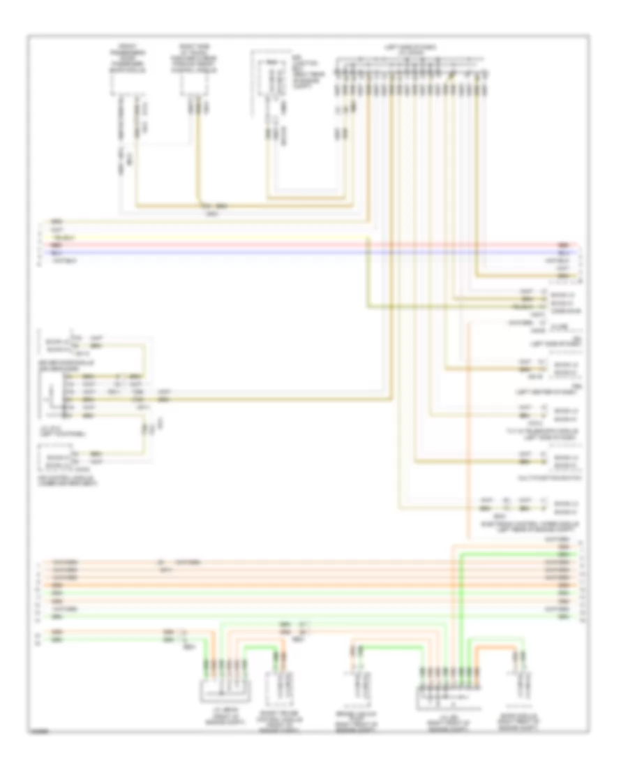
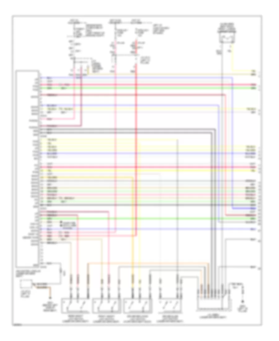
AIR CONDITIONING
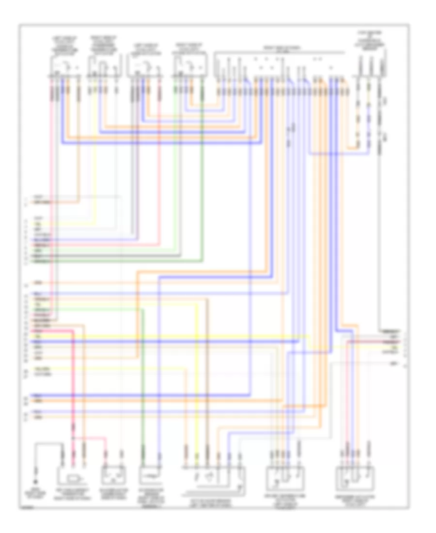
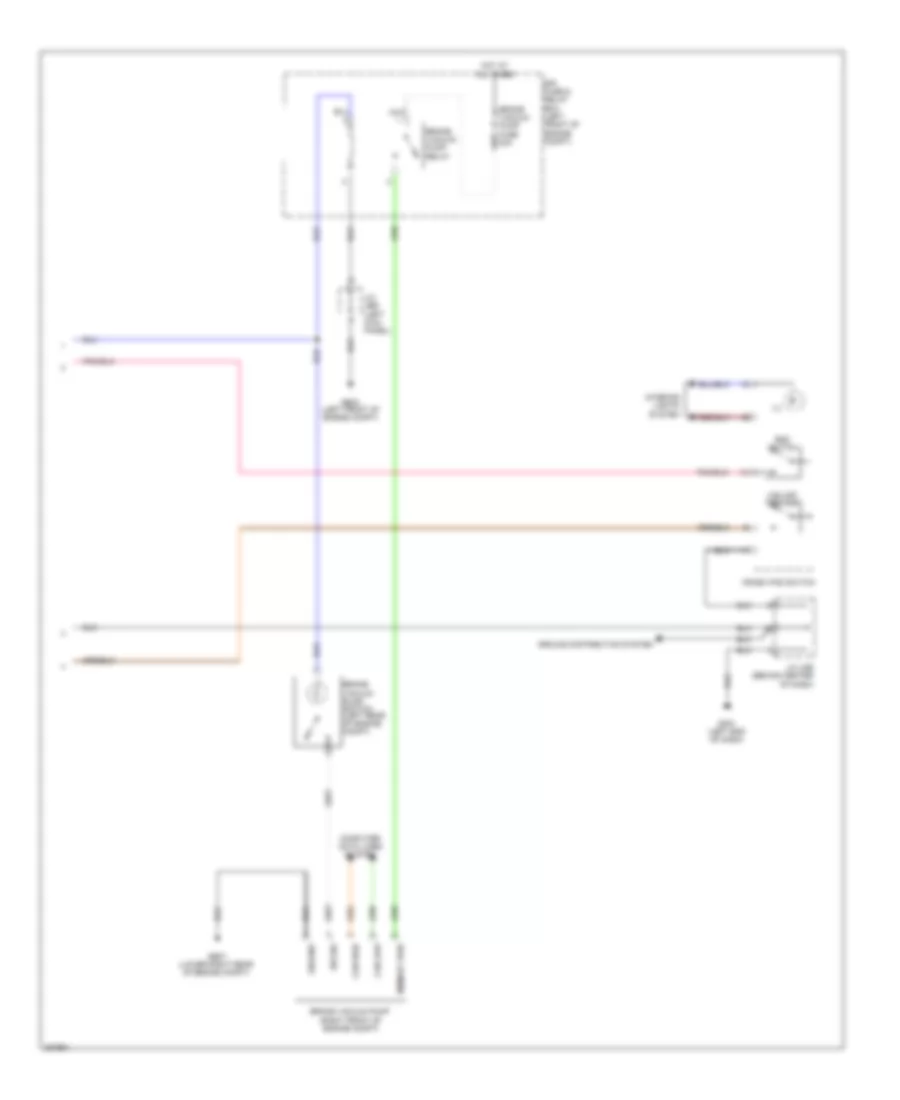
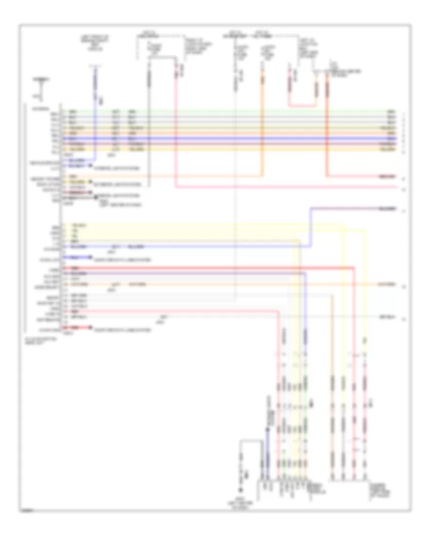
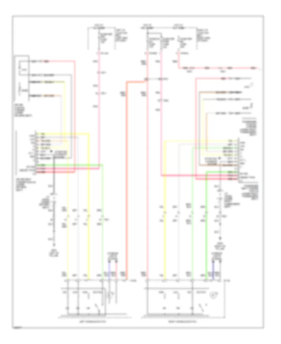
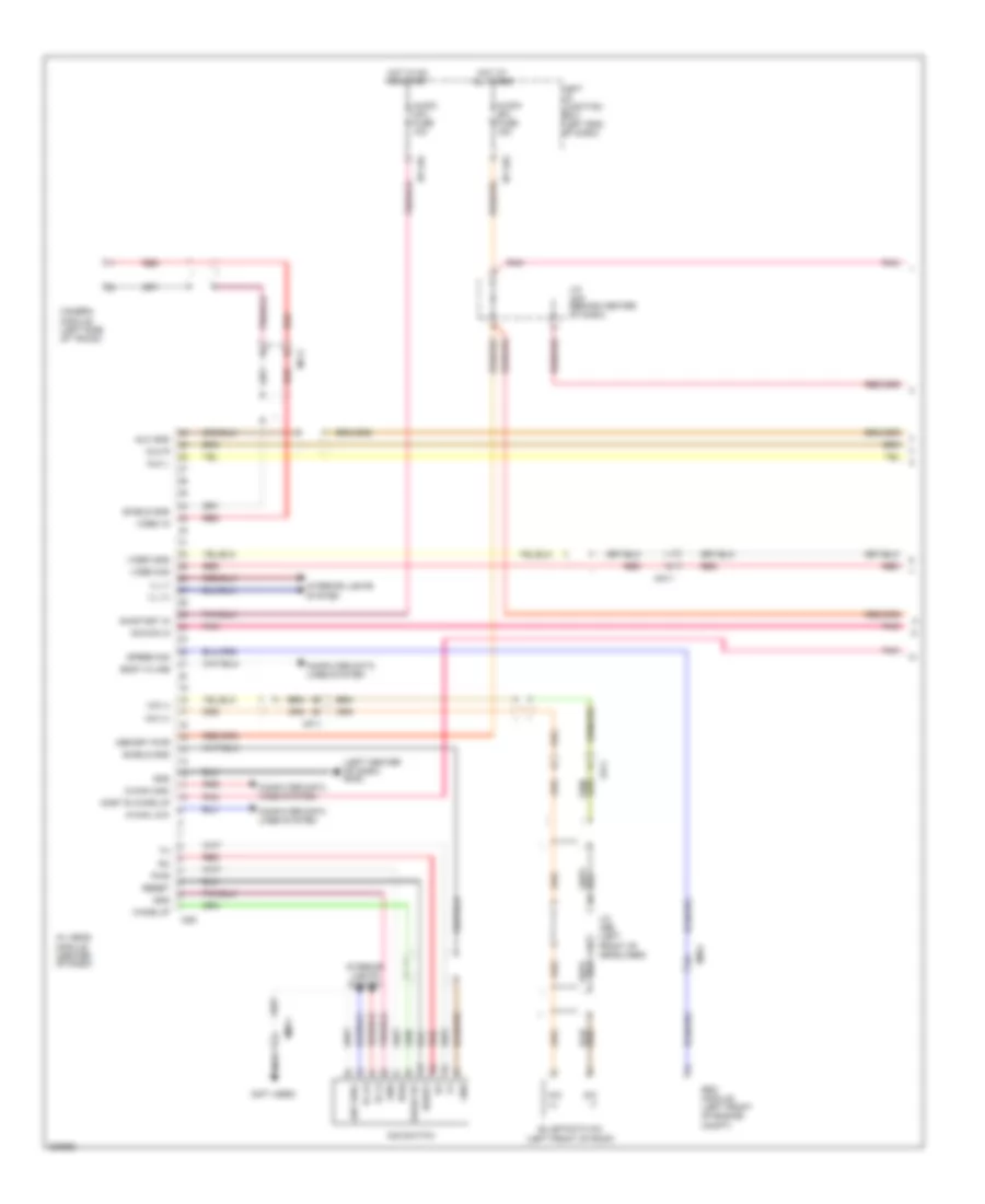
Automatic A/C Wiring Diagram (1 of 3) for Hyundai Genesis 3.8 2013

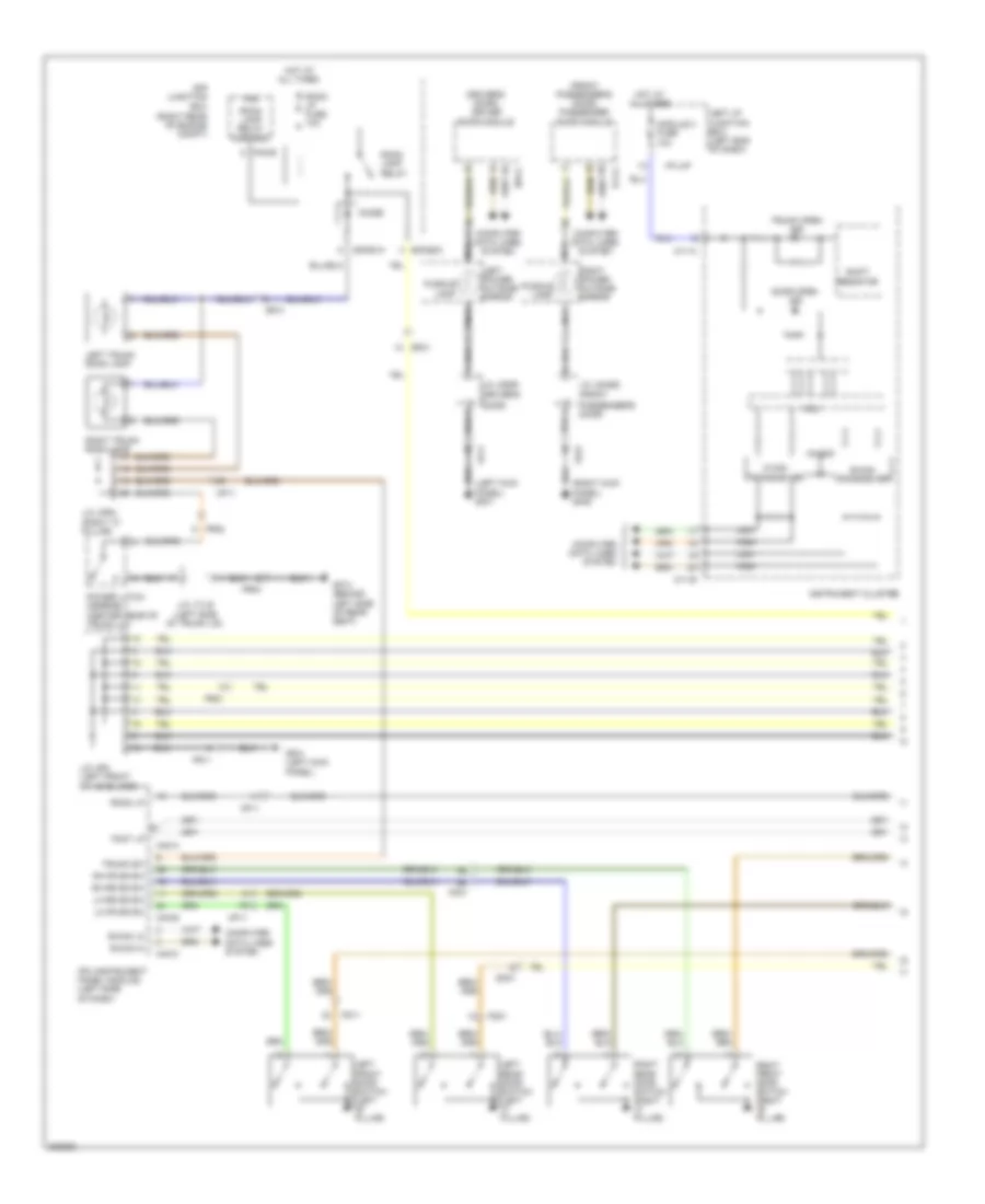
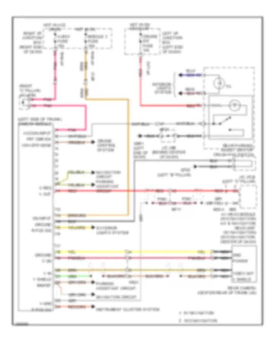
List of elements for Automatic A/C Wiring Diagram (1 of 3) for Hyundai Genesis 3.8 2013:
- (left end of dash) gm06
- (left front of engine compt) ge03
- (left kick panel) j/c jeb
- 3.8l
- 5.0l
- A/c control module (right side of dash)
- A/con (b+) fuse 10a
- A/con (ig1) fuse 10a
- A/con fuse 10a
- Ambient sensor (front of engine compt)
- Aqs fuse 10a
- Aqs sensor (front of engine compt)
- Aqs signal
- B-can high
- B-can low
- Blower
- Blower relay
- Blower relay on input
- Body k-line
- Can high
- Can low
- Computer data lines system
- Console temperature actuator "a" (left side of hvac unit)
- Console vent temperature actuator & switch
- Cool console temp actr
- Cool console temp actr a
- Cool temp actuator
- Def led output (htd)
- Def mode actuator
- Defogger system
- Drv photo sensor (-)
- E/r-e1b
- E/r-e2b
- Ec41
- Ecv (+)
- Ecv (-)
- Ee11
- Ee21
- Ee31
- Electronic a/c compressor (left front of engine)
- Em21
- Em41
- Engine room junction box (right rear of engine compt)
- Evap sensor (+)
- F/b
- F/b console temp actr a
- F/b console temp actuator
- F/b intake actuator
- F/b mode actuator
- F/b temp actuator
- Fet (d)
- Fet (g)
- Fre intake actuator
- Fuse 40a
- Ge04 (lower right rear of engine compt)
- Gm02 (right side of dash)
- Ground
- Hot at all times
- Hot in on
- Hot in on or start
- Humidity sensor (+)
- I/p-lha
- I/p-lhc
- I/p-lhg
- Ill (+)
- Ill (-)
- Incar sensor (+)
- Interior lights system
- J/c jmsex (under center console)
- Left i/p junction box (left end of dash)
- M07-a
- M07-b
- Memory power
- Mm11
- Motor (-)
- Nca
- On/start input
- Out dr temp sensor
- Pass photo sensor (-)
- Photo sensor (top right side of dash)
- Pnk
- Rec intake actuator
- Red
- Sensor ground
- Sensor ref (+5)
- Vent mode actuator
- Vent switch
- Vent switch signal
- Vent temperature actuator
- Warm console temp actr
- Warm console temp actr a
- Warm temp actuator
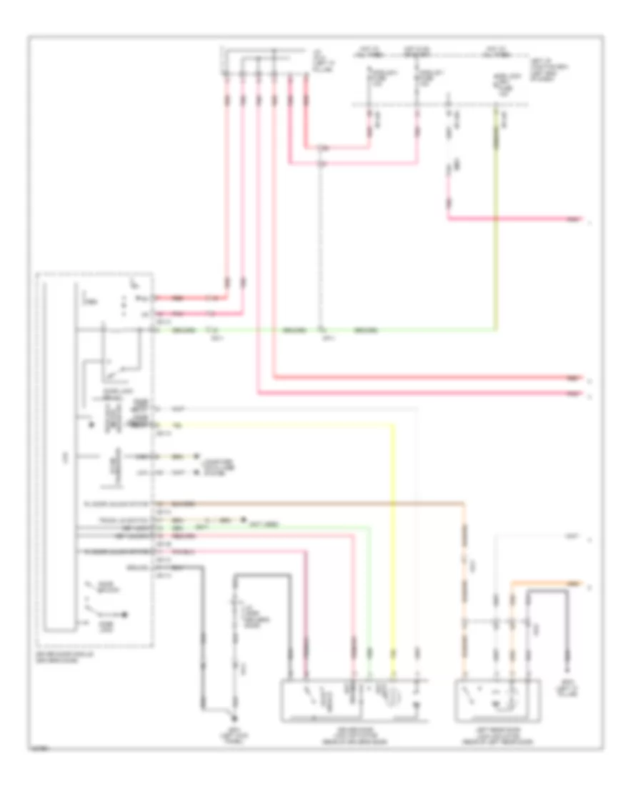
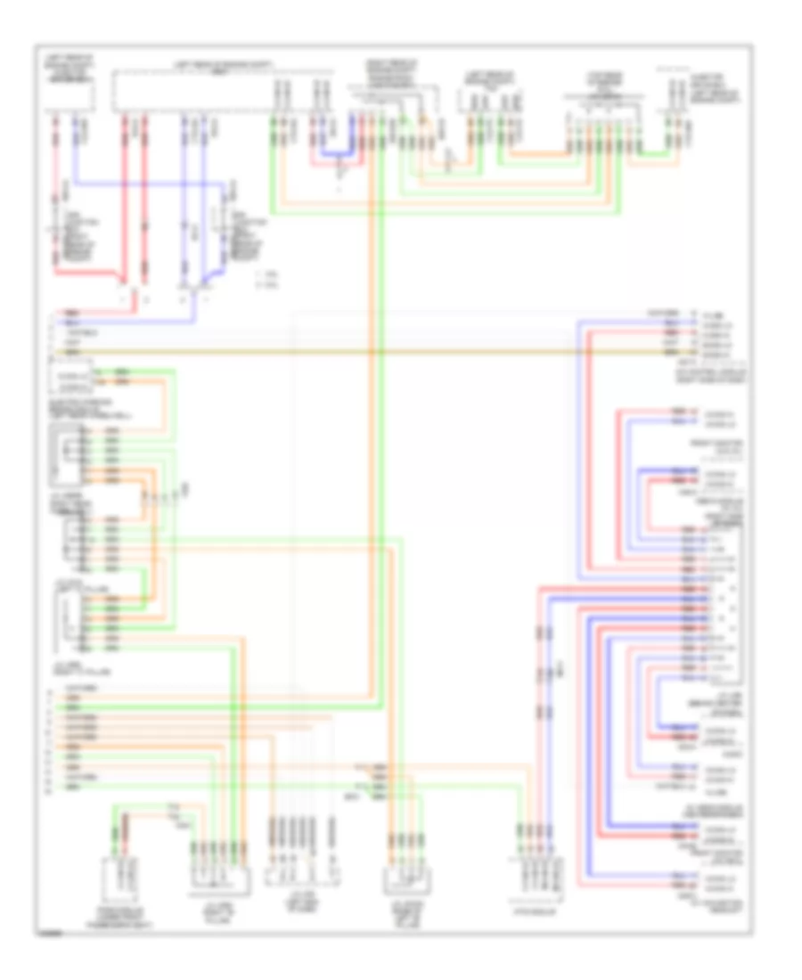
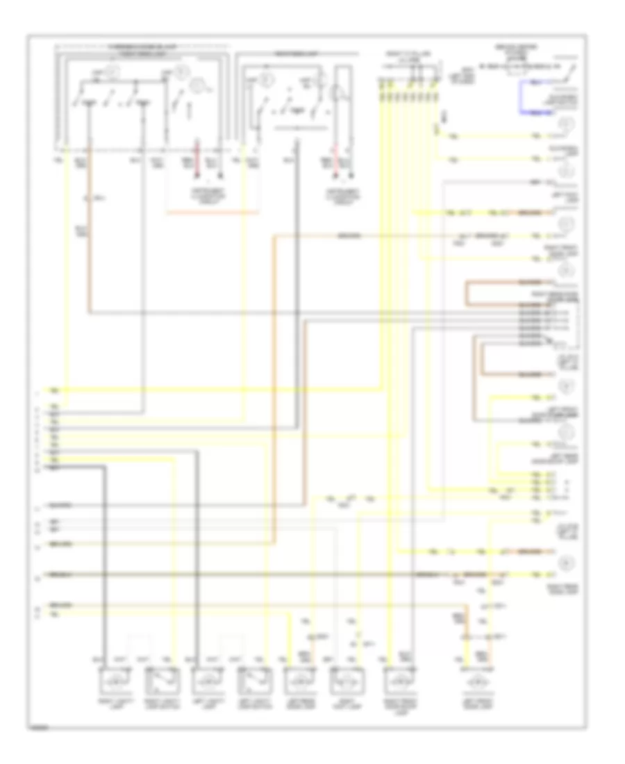
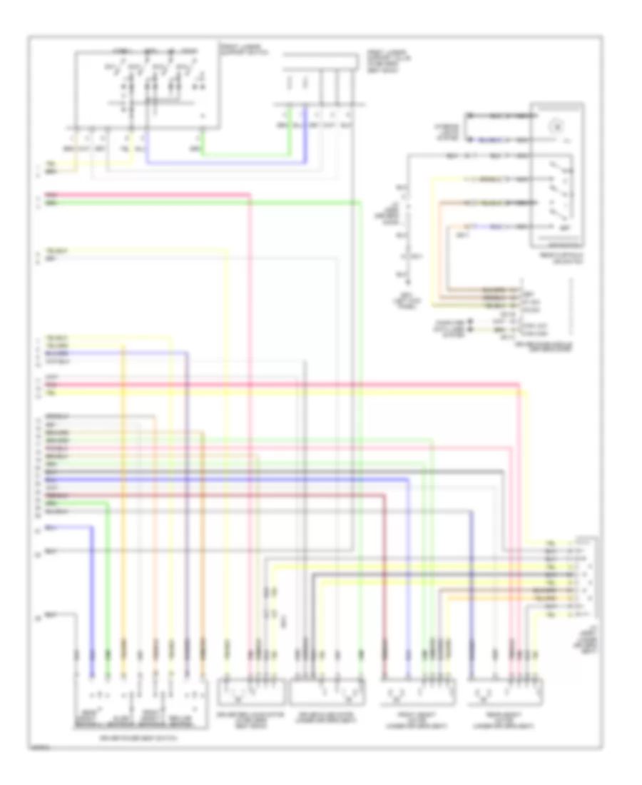
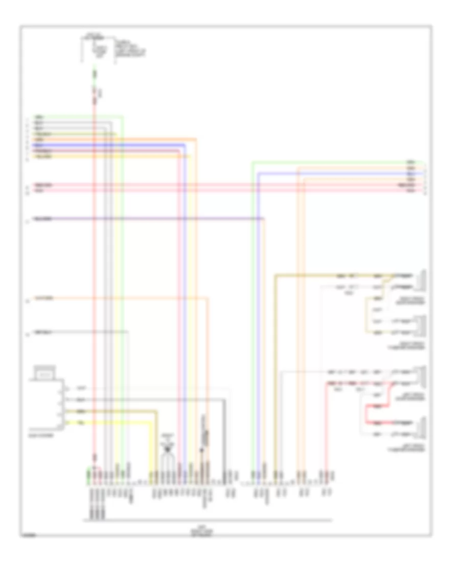
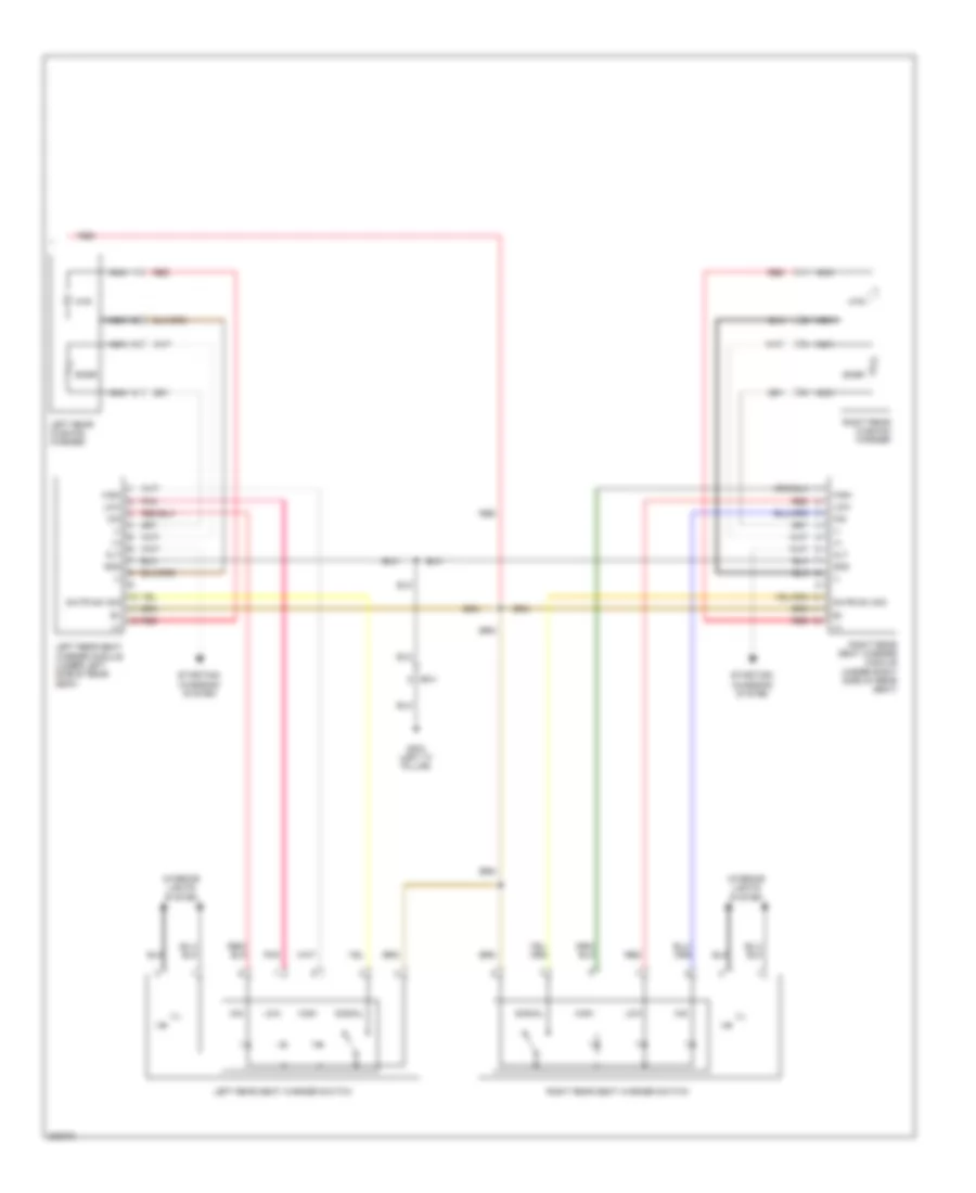
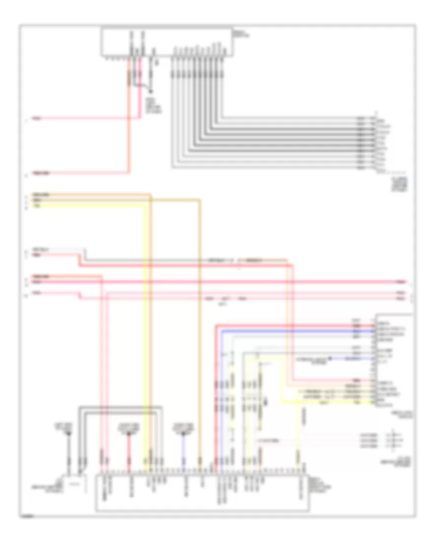
Automatic A/C Wiring Diagram (2 of 3) for Hyundai Genesis 3.8 2013
List of elements for Automatic A/C Wiring Diagram (2 of 3) for Hyundai Genesis 3.8 2013:
- (left side of hvac unit) console temperature actuator
- (left side of hvac unit) mode actuator
- (right end of dash) j/c jmg
- (right side of hvac unit) intake actuator
- (right side of hvac unit) passenger temperature actuator
- (top center of windshield) auto defogger sensor
- Active incar sensor (left center of dash)
- Blower motor (under right side of dash)
- Defogger actuator (right side of hvac unit)
- Driver temperature actuator (left side of hvac unit)
- Ee41
- Evaporator sensor (right side of dash, on hvac assembly)
- Fet (field effect transistor) (right side of dash)
- Fr21
- Gm02 (right side of dash)
- Humidity
- Mf21
- Pnk
- Sensor (+)
- Sensor (-)
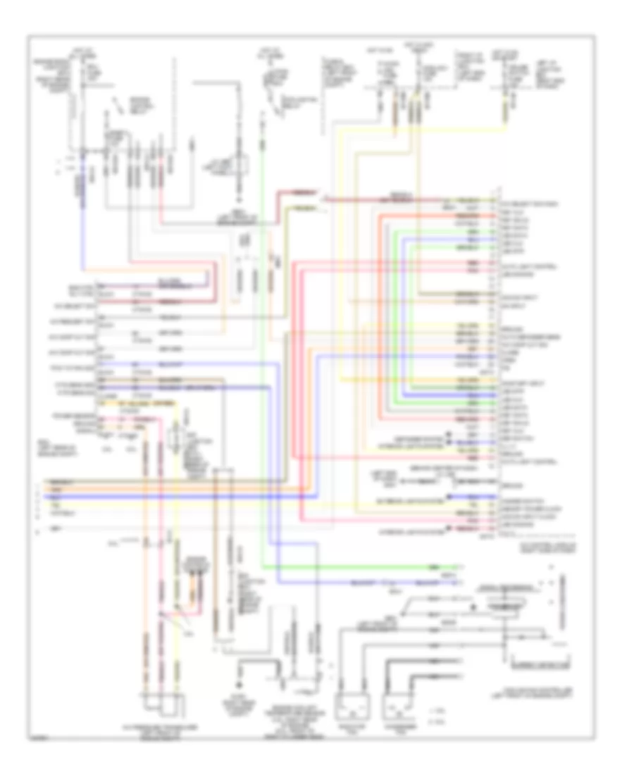
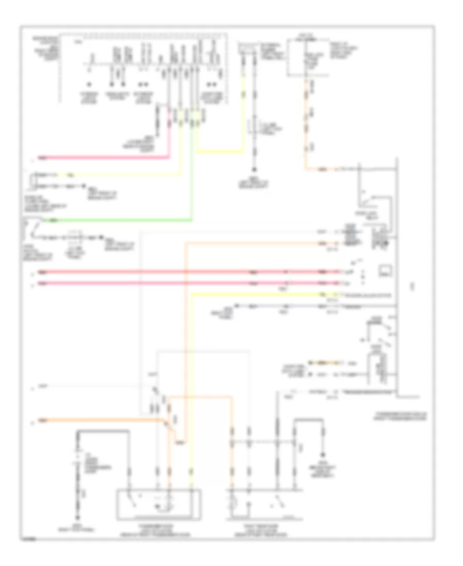
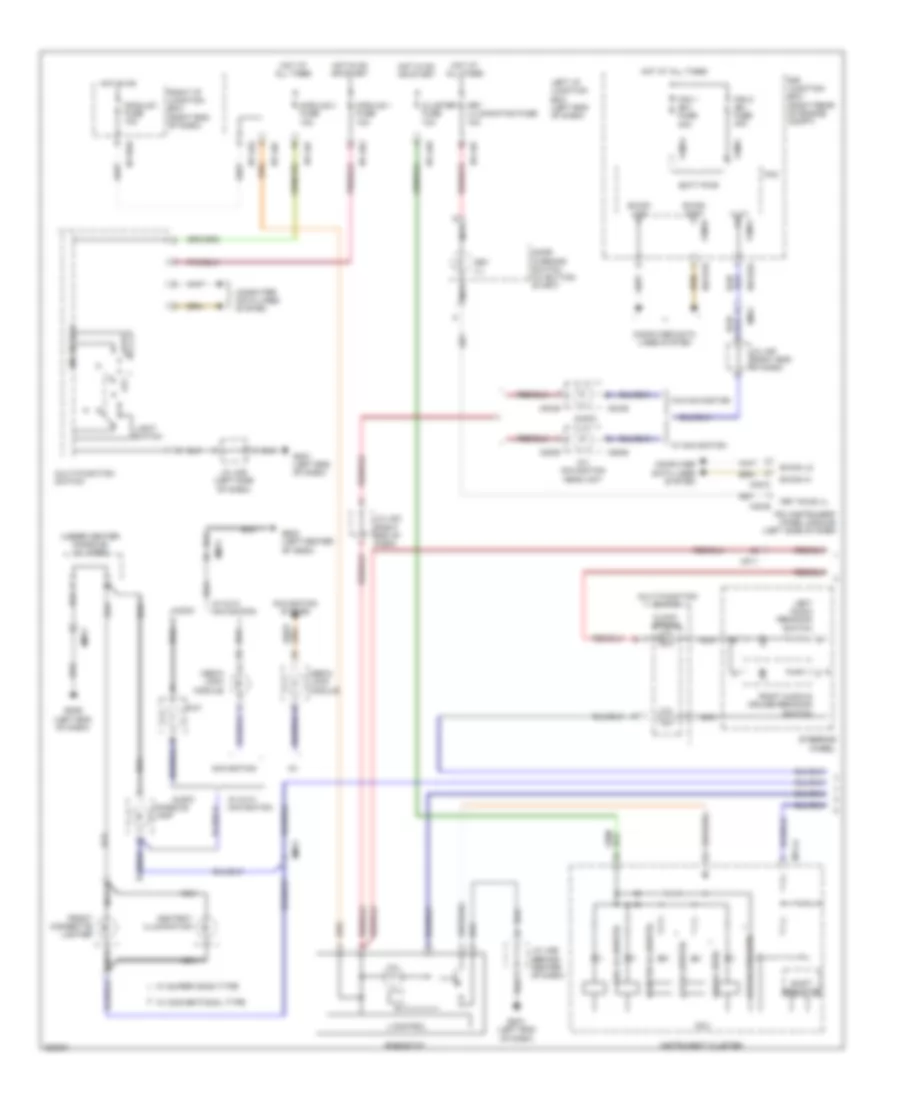
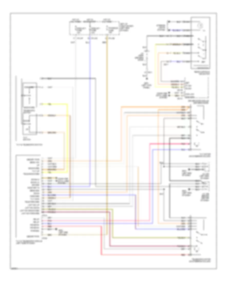
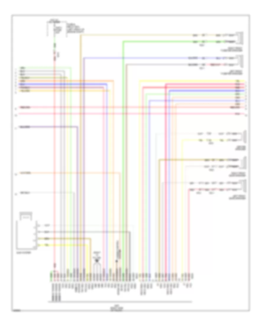
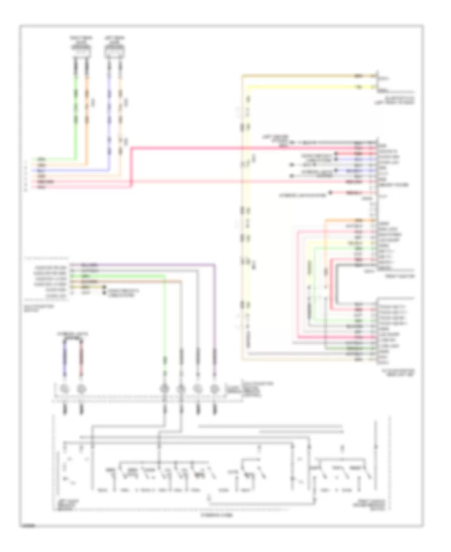
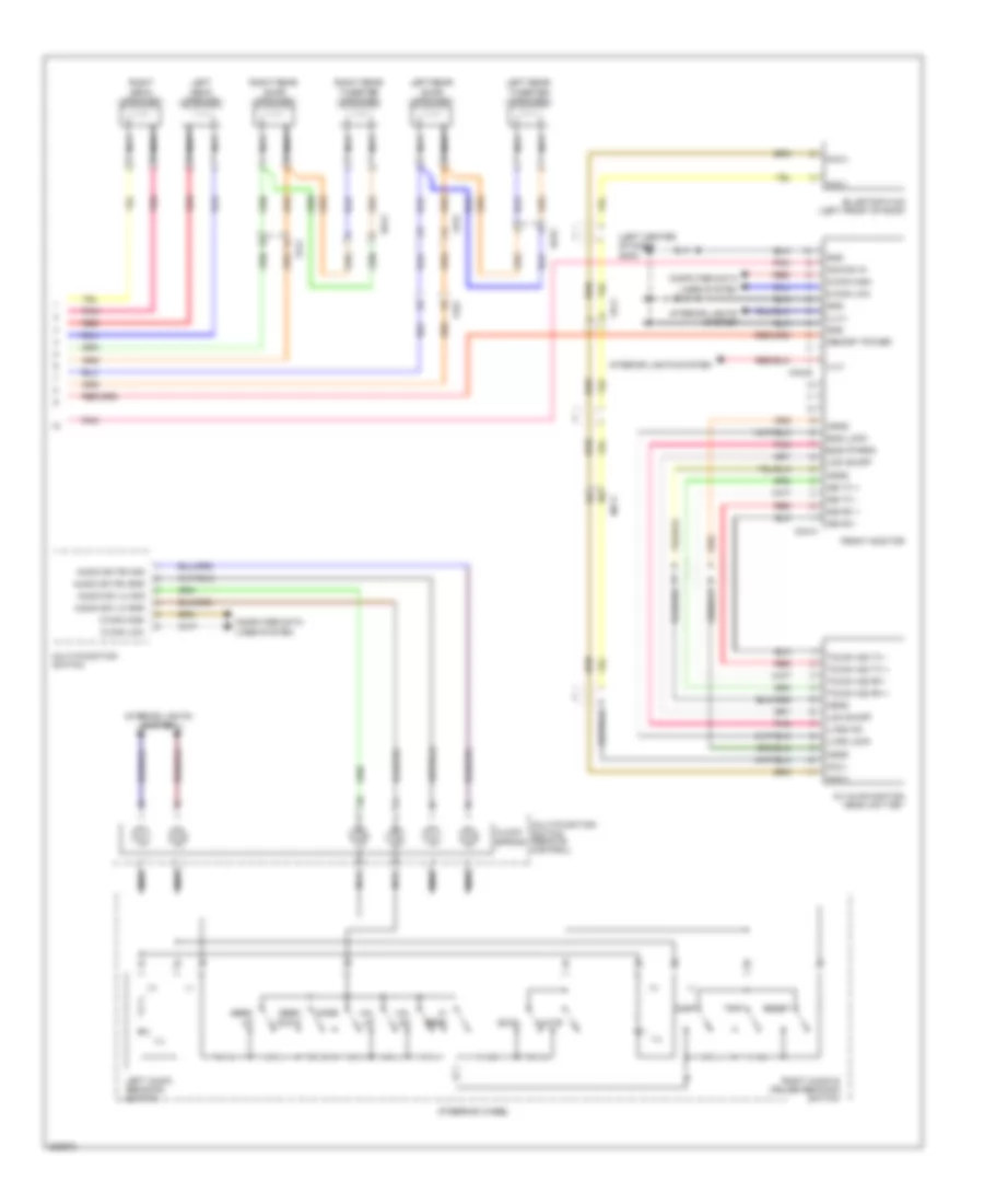
Automatic A/C Wiring Diagram (3 of 3) for Hyundai Genesis 3.8 2013
List of elements for Automatic A/C Wiring Diagram (3 of 3) for Hyundai Genesis 3.8 2013:
- (behind center of dash) j/c jme
- (left end of dash) gm01
- (or red)
- 3.8l
- 5.0l
- A/c comp cut sig
- A/c comp cut sig elg-a
- A/c control module (right side of dash)
- A/c pressure transducer (left front of engine compt)
- A/c request sw elg-a
- A/c select sig (high)
- A/c select sw
- A/con (ig2) fuse 10a
- Acc/on input
- Acc/on input clock
- Auto defogger sens
- Auto light control
- C/fan fuse 60a
- Close
- Condenser fan
- Cooling fan controller (left front of engine compt)
- Cooling fan relay
- Cruise switch fuse 10a
- Ctg-ag
- Ctg-kg
- Current detecting
- Def switch
- Defogger system
- E/r junction box (5.0l) (right rear of engine compt)
- E/r junction box (right rear of e/r-cb engine compt)
- E/r-ca
- E/r-cb
- E/r-e2a
- E05-a
- E05-b
- Ec41
- Ecm (left rear of engine compt)
- Ecu fuse 30a
- Em41
- Eng ctrl rly ctrl elg-a
- Engine control relay
- Engine controls systems
- Engine coolant temperature sensor (3.8l: right rear of engine) (5.0l: front of right cylinder head)
- Engine room junction box (right rear of engine compt)
- Exterior lights system
- F/b
- Fuse & relay box (left front of engine compt)
- Ge01 (left front of engine compt)
- Ge03 (left front of engine compt)
- Glg01 (right rear of engine compt)
- Gnd
- Ground
- Ground signal elg-a
- Hazard switch
- Hot at all times
- Hot in acc or on
- Hot in on
- Hot in on or start
- I/p-lhc
- I/p-rhb
- I/p-rhd
- Ill (+)
- Ill (-)
- Interior lights system
- J/c jeb (left kick panel)
- Key clk
- Key data
- Key sh/ld
- Led clk
- Led data
- Led dimming
- Led str
- Left i/p junction box (right end of dash)
- M07-c
- M07-d
- Memory power clock
- Module 2 fuse 10a
- Nca
- On input
- On/start input
- Open
- Pnk
- Power conditioning
- Power sensor
- Pwm to fan mod elg-a
- Pwn driver
- Radiator fan
- Red
- Right i/p junction box (left end of dash)
- Signal processing
- Snsr 2 fuse 10a
- Wts sens gnd
- Wts sens sig clg-bg
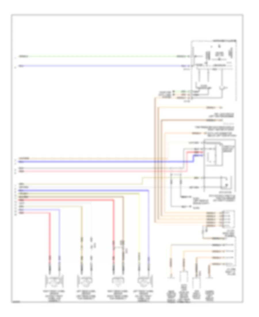
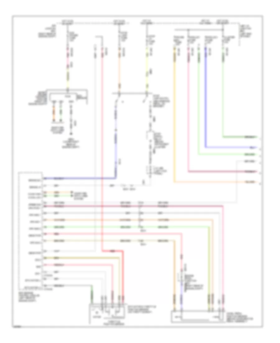
ANTI-LOCK BRAKES
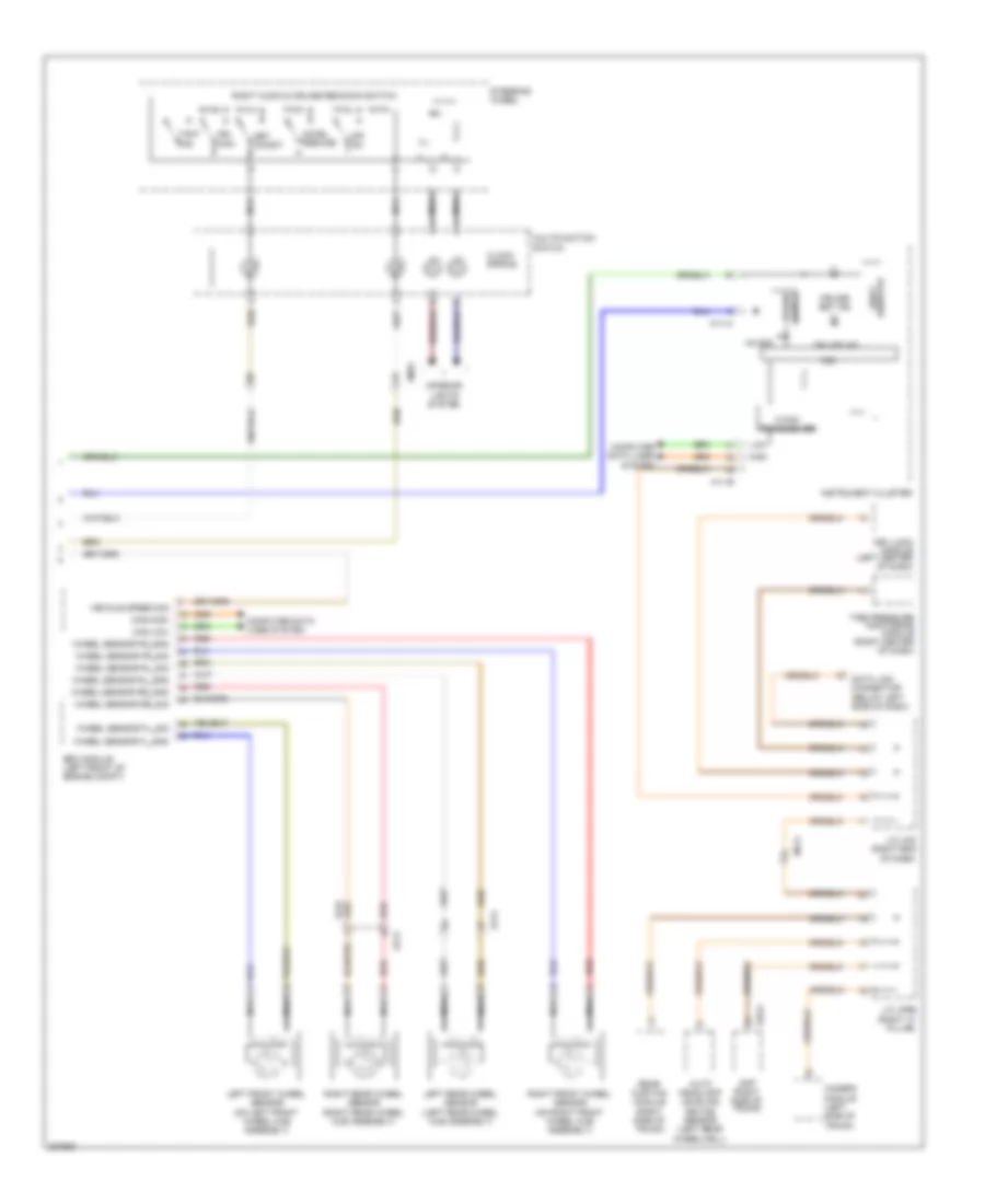
Anti-lock Brakes Wiring Diagram (1 of 3) for Hyundai Genesis 3.8 2013
List of elements for Anti-lock Brakes Wiring Diagram (1 of 3) for Hyundai Genesis 3.8 2013:
- (above
- (note: esc control module contains: esc solenoids, esc pump motor)
- (w/ epb
- Abs pump motor
- Avh sw
- Bracket)
- Brake pedal, on
- Brake sw sig
- Brk out
- Brl 1
- Can high
- Can low
- Computer data lines system
- E/r fuse & relay box (left front of engine compt)
- E/r-e1a
- E/r-e2b
- Ef21
- Ef31
- Em21
- Em31
- Engine room junction box (right rear of engine compt)
- Esc fuse 10a
- Esc module (left front of engine compt)
- Esc sw
- Esc-1 fuse 30a
- Esc-2 fuse 30a
- Exterior lights system
- Ge02 (right kick panel)
- Ground
- High
- Hot at all times
- Hot in on or start
- Ipm
- J/c jea
- J/c jeb (left kick panel)
- K-line
- Left front wheel sensor (on left front wheel hub assembly)
- Left rear wheel sensor (on left rear wheel hub assembly)
- Low
- M40-a
- Nca
- On/start input
- Pnk
- Power
- Red
- Right front wheel sensor (on right front wheel hub assembly)
- Right rear wheel sensor (on right rear wheel hub assembly)
- Smart cruise)
- Stop lamp
- Stop lamp fuse 10a
- Stop lamp relay
- Stop lamp signal relay
- Stop lp fuse 10a
- Switch
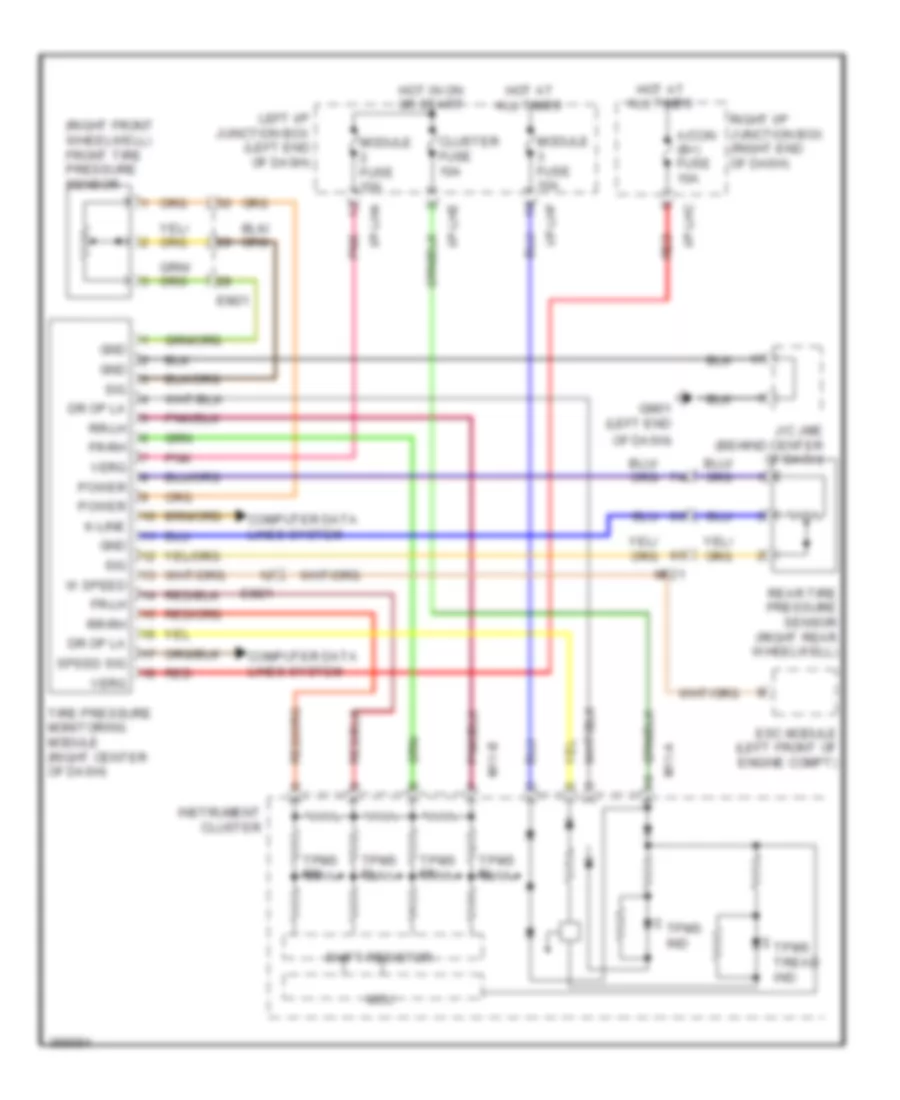
- Tire pressure monitoring module (right center of dash)
- Vsm off sw
- W/ auto cruise & epb
- W/ epb
- W/o auto cruise & epb
- Wheel sensor fl_gnd
- Wheel sensor fl_sig
- Wheel sensor fr_gnd
- Wheel sensor fr_sig
- Wheel sensor rl_gnd
- Wheel sensor rl_sig
- Wheel sensor rr_gnd
- Wheel sensor rr_sig
- Wheel spd sig fl out
- Wheel spd sig fr out
- Wheel spd sig rl out
- Wheel spd sig rr out
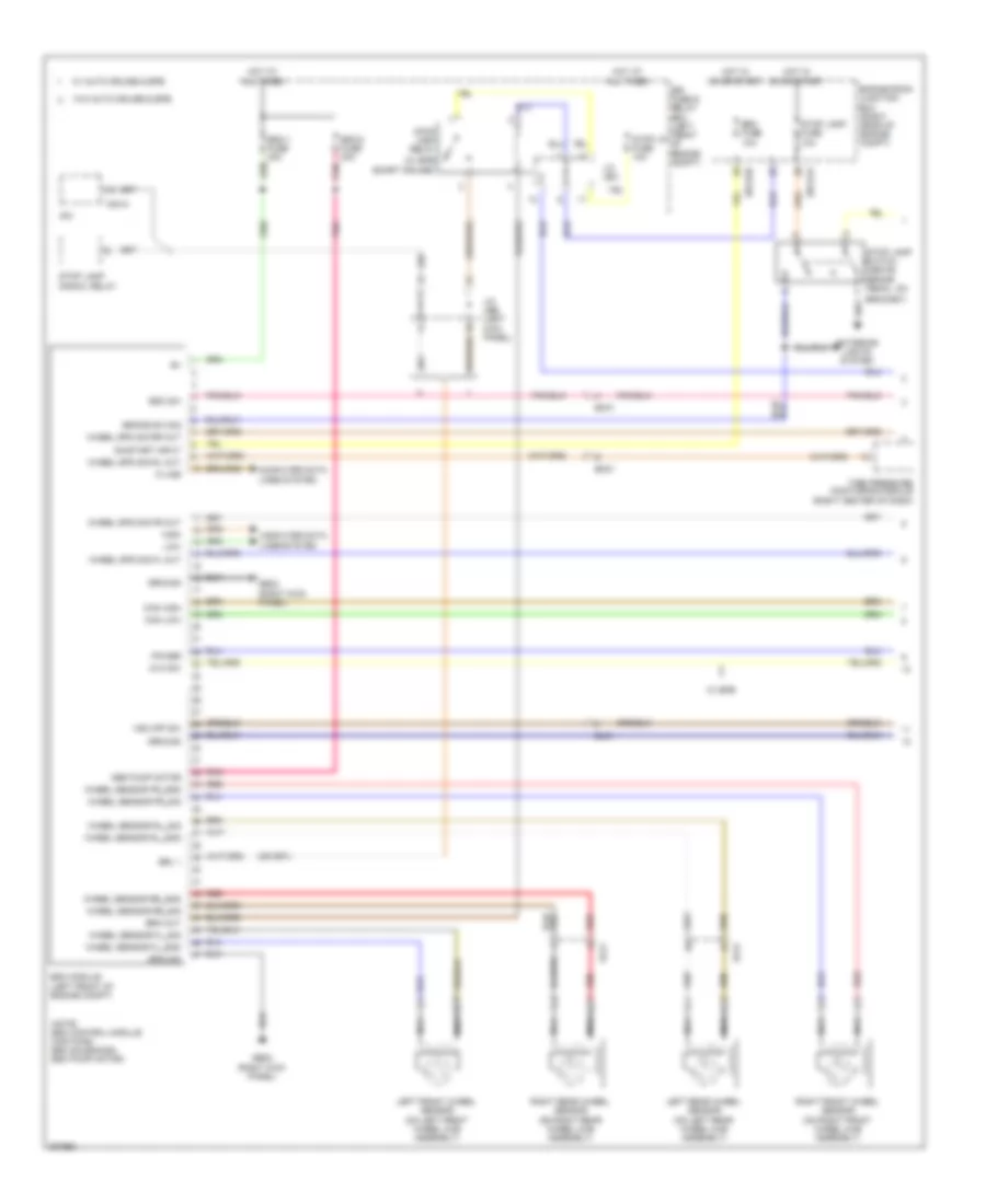
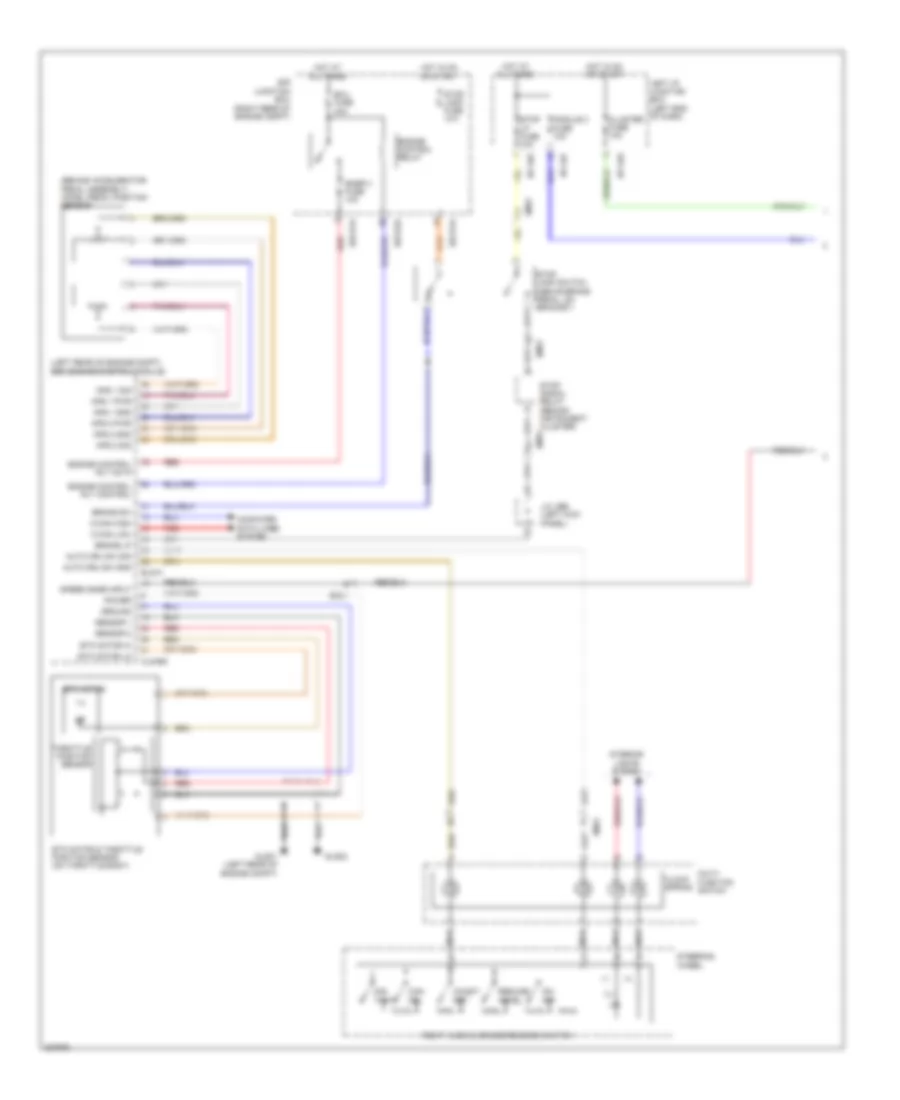
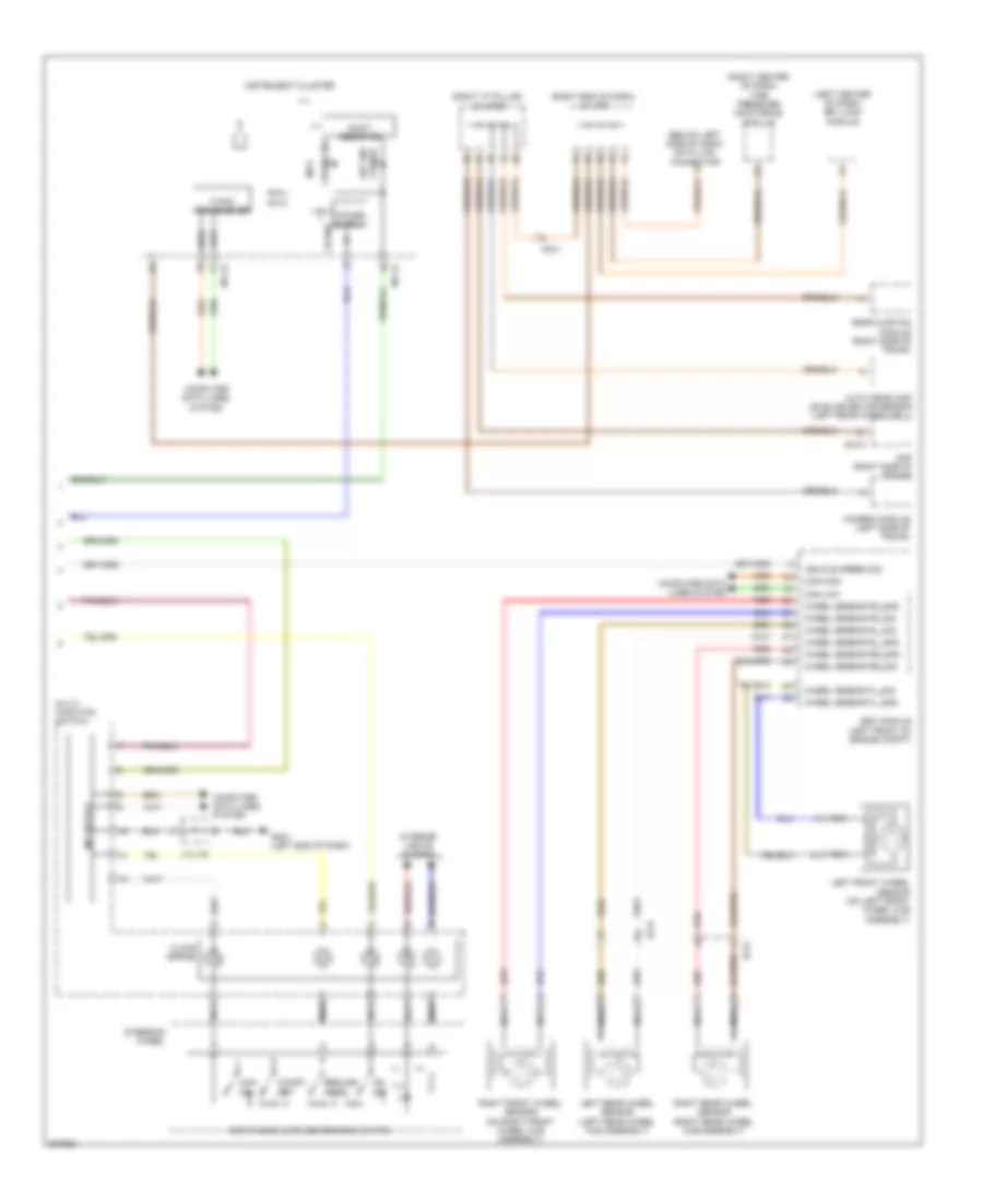
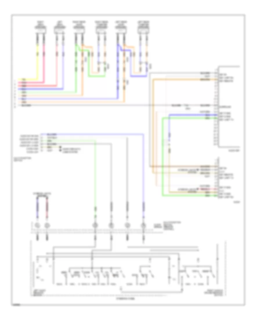
Anti-lock Brakes Wiring Diagram (2 of 3) for Hyundai Genesis 3.8 2013
List of elements for Anti-lock Brakes Wiring Diagram (2 of 3) for Hyundai Genesis 3.8 2013:
- 3.8l
- Abs ind
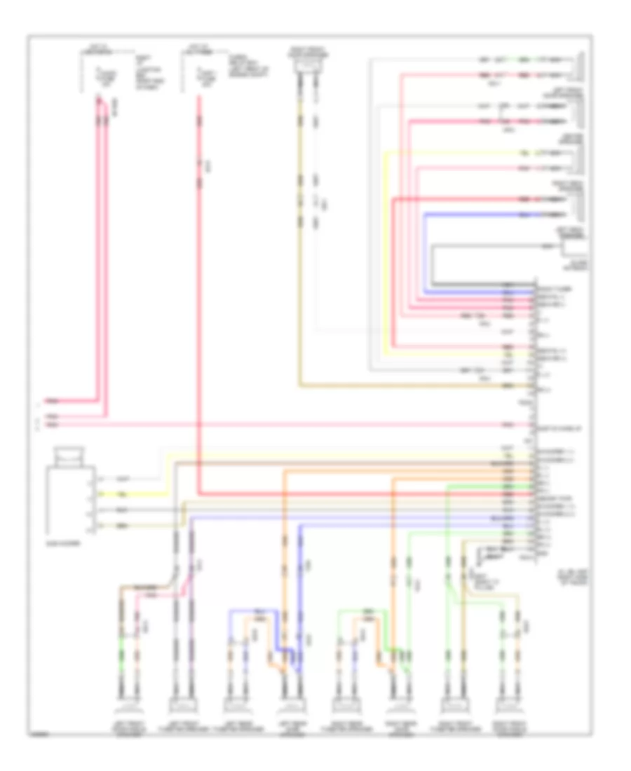
- Av & navigation head unit
- Av head module (center of dash)
- Avh
- Can high
- Can low
- Clg-bg
- Cluster fuse 10a
- Computer data lines system
- Ctg-kg
- Diode
- Ec21
- Ec41
- Ecm (left rear of engine compt)
- Ef31
- Em31
- Em41
- Epb & avh switch
- Esc ind
- Esc off ind
- Gm01 (left end of dash)
- Ground
- Hot at all times
- Hot in on or start
- I/p-lhc
- I/p-lhe
- I/p-lhf
- I/p-lhg
- Ill.
- Instrument cluster
- Instrument cluster sensor (under center console)
- Interior lights system
- J/c jme (behind center of dash)
- Left i/p junction box (left end of dash)
- M11-a
- M11-b
- M25-e
- M51-b
- Mcu
- Module 2 fuse 10a
- Navi
- Parking brake ind
- Parking brake switch (w/o epb) (above parking brake pedal, on bracket)
- Pdm (left center of dash)
- Power
- Shift resistor
- Steering angle sensor (top of steering column)
- Stop lp fuse 10a
- Switch
- Vsm off ind
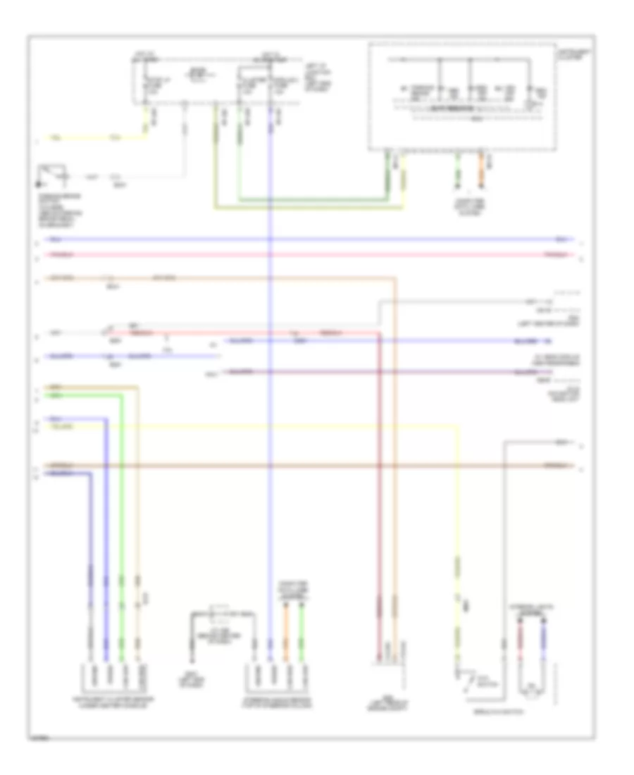
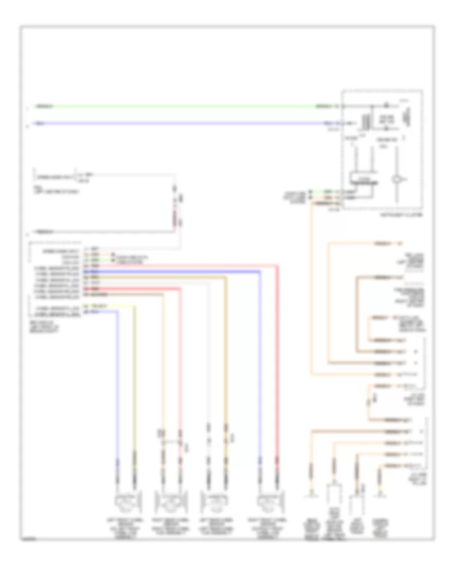
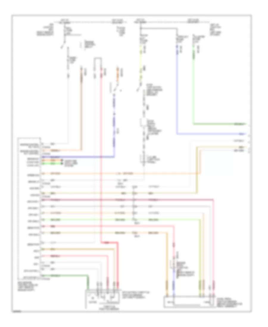
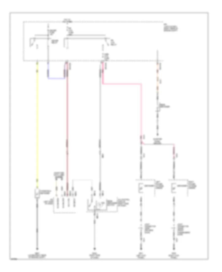
Anti-lock Brakes Wiring Diagram (3 of 3) for Hyundai Genesis 3.8 2013
List of elements for Anti-lock Brakes Wiring Diagram (3 of 3) for Hyundai Genesis 3.8 2013:
- Brake vacuum pump (right front of engine compt)
- Brake vacuum pump fuse 20a
- Brake vacuum pump relay
- Brake vacuum pump switch (left rear of engine compt)
- Can high
- Can low
- Computer data lines system
- Crash pad switch
- E/r fuse & relay box (left front of engine compt)
- Esc switch
- Ge03 (left front of engine compt)
- Ge07 (lower right rear of engine compt)
- Gm01 (left end of dash)
- Ground
- Ground distribution system
- Hot at all times
- Ill
- Interior lights system
- J/c jeb (left kick panel)
- J/c jme (behind center of dash)
- Memory pwr
- Sw sig
- Vsm off switch
ANTI-THEFT
Forced Entry Wiring Diagram (1 of 2) for Hyundai Genesis 3.8 2013
List of elements for Forced Entry Wiring Diagram (1 of 2) for Hyundai Genesis 3.8 2013:
- (not used)
- Computer data lines system
- Cpu
- D01-a
- D01-b
- D01-c
- Dd11
- Door lock
- Door lock relay
- Door unlock
- Door unlock relay
- Dr lock drv fuse 10a
- Driver door lock actuator (rear of driver's door)
- Driver door module (driver's door)
- Driver ips motor
- Em21
- Fd11
- Fd31
- Fl door unlock state
- Gf01 (left kick panel)
- Gf03 (left "c" pillar)
- Ground
- High
- Hot at all times
- Hot in on or start
- I/p-lhf
- I/p-lhg
- Ig1
- J/c jddri (driver's door)
- J/c jfla (left "c" pillar)
- Key
- Key lock
- Key unlock
- Left i/p junction box (left end of dash)
- Left rear door lock actuator (rear of left rear door)
- Lock
- Low
- Mf11
- Module 1 fuse 10a
- Module 3 fuse 10a
- Pnk
- Red
- Reg
- Rl door unlock state
- Transceiver b-can
- Trunk lid switch
- Unlock
- Unlock lock/
Forced Entry Wiring Diagram (2 of 2) for Hyundai Genesis 3.8 2013
List of elements for Forced Entry Wiring Diagram (2 of 2) for Hyundai Genesis 3.8 2013:
- B-can
- B/a horn
- Burglar alarm horn (lower left rear of engine compt)
- Computer data lines system
- Cpu
- D11-a
- D11-c
- Door
- Door lock
- Door lock relay door unlock relay
- Dr lock pass fuse 15a
- Driver ips motor
- E/r-e1a
- E/r-e1b
- Engine room junction box (right rear of engine compt)
- Ext buzzer
- Exterior lights system
- External buzzer (left front wheelwell)
- Fam
- Fam-a
- Fam-b
- Fam-c
- Fd21
- Fd41
- Fr door unlock state
- Ge03 (left front of engine compt)
- Ge04 (lower right rear of engine compt)
- Gf05 (right kick panel)
- Gf09 (behind right side of rear seat)
- Gnd
- Ground
- Headlights system
- High
- Hood sw
- Hood switch (left front of engine compt)
- Hot at all times
- I/p-rhb
- Ig1
- Ill(+)
- Interior lights system
- J/c jdass (front passenger's door)
- J/c jeb (left kick panel)
- Lh head lamp hi
- Lh tail lp
- Low
- Mf21
- Nca
- On/start input
- Passenger door lock actuator (rear of front passenger's door)
- Passenger door module (front passenger's door)
- Pnk
- Red
- Reg
- Relay
- Rh head lamp hi
- Rh tail lp
- Right i/p junction box (right end of dash)
- Right rear door lock actuator (rear of right rear door)
- Rr door unlock state
- Transceiver b-can
- Unlock
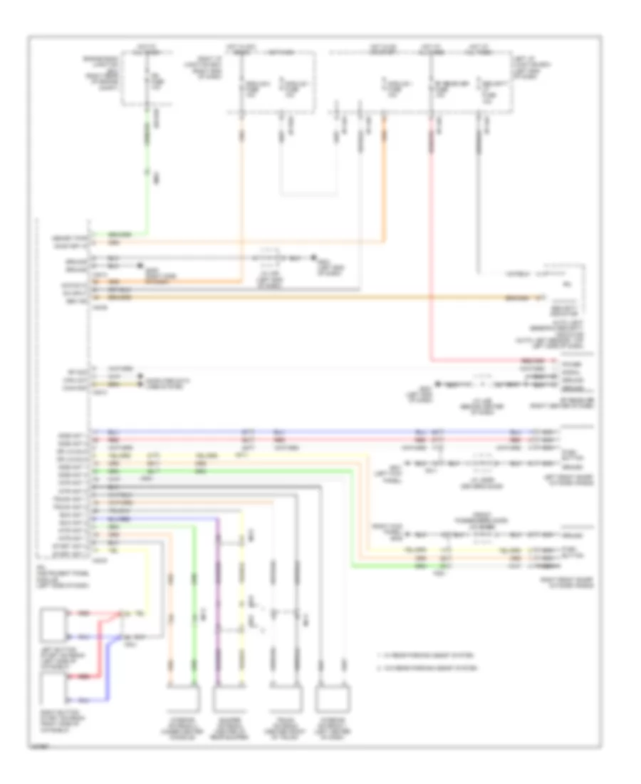
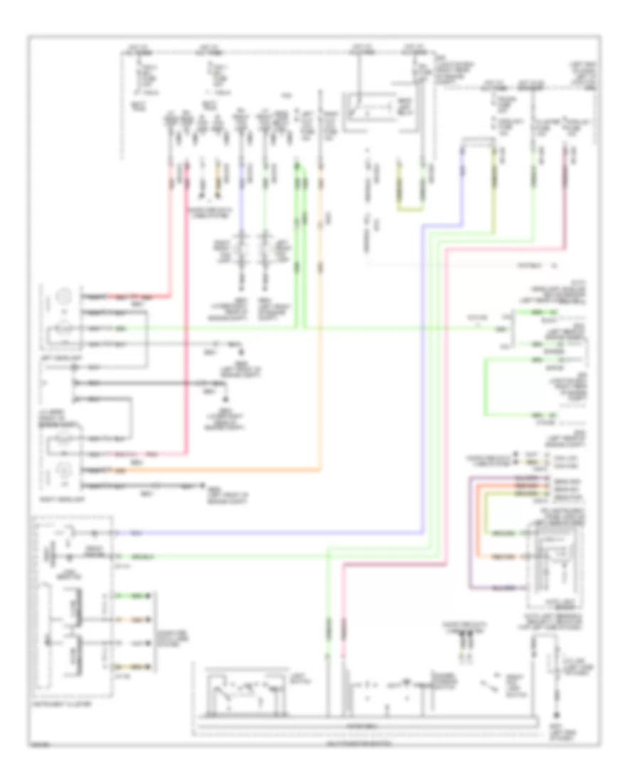
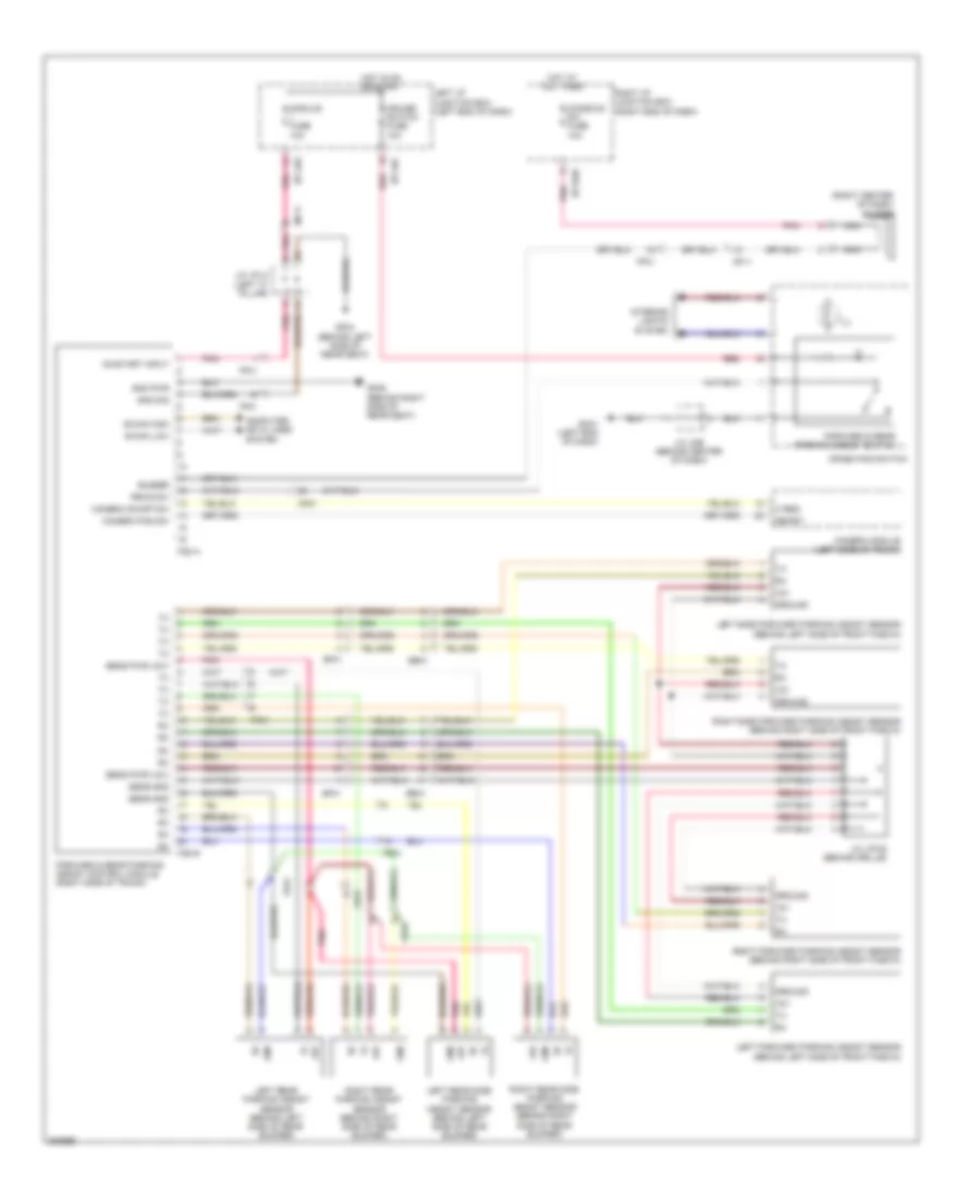
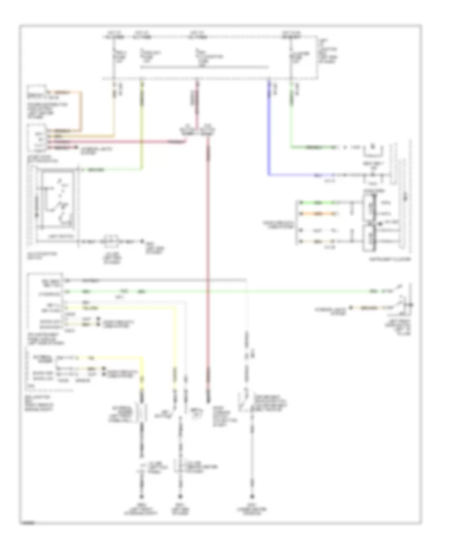
Immobilizer Wiring Diagram, with Button Start for Hyundai Genesis 3.8 2013
List of elements for Immobilizer Wiring Diagram, with Button Start for Hyundai Genesis 3.8 2013:
- (front passenger's door) j/c jdass
- (right kick panel) gf05
- Acc/on in
- Auto light sensor & security indicator (auto light sensor: top left side of dash)
- Bum ant 1
- Bum ant 2
- Bumper antenna (center of rear bumper)
- Button
- Can-high
- Can-low
- Computer data lines system
- Dr lk/unlk
- E/r-e2b
- Em31
- Engine room junction box (right rear of engine compt)
- Fd11
- Fd21
- Fr31
- Fr32
- Gf01 (left kick
- Gm01 (left end of dash)
- Gm05 (right side of dash)
- Ground
- Hot at all times
- Hot in acc or on
- Hot in on
- Hot in on or start
- I/p-lha
- I/p-lhd
- I/p-lhg
- I/p-rhd
- Interior antenna 1 (left center of dash)
- Interior antenna 2 (under center console)
- Intr ant 1
- Intr ant 2
- Ipm (instrument panel module) (left side of dash)
- Ipm fuse 10a
- J/c jddri (driver's door)
- J/c jmd (left end of dash)
- J/c jme (behind center of dash)
- Left button start antenna (left side of hatshelf)
- Left front smart outside handle
- Left i/p junction box (left end of dash)
- M40-a
- M40-b
- M40-c
- M40-d
- Memory pwr
- Mf11
- Mf21
- Module 1 fuse 10a
- Module 2 fuse 10a
- Nca
- On input
- On/start in
- Panel)
- Power
- Push
- Push button
- Red
- Rf com
- Rf receiver (right center of dash)
- Rf receiver fuse 10a
- Right button start antenna (right side of hatshelf)
- Right front smart outside handle
- Right i/p junction box (right end of dash)
- Sec ind
- Security indicator
- Security lp fuse 10a
- Side ant 1
- Side ant 2
- Signal
- Start ant 1
- Start ant 2
- Trunk ant 1
- Trunk ant 2
- Trunk antenna (center front of trunk)
- W/ rear parking assist system
- W/o rear parking assist system
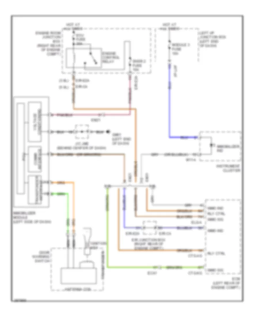
Immobilizer Wiring Diagram, without Button Start for Hyundai Genesis 3.8 2013
List of elements for Immobilizer Wiring Diagram, without Button Start for Hyundai Genesis 3.8 2013:
- (+)
- (-)
- (3.8l)
- 3.8l
- 5.0l
- Antenna coil
- Comms interface
- Ctg-ag
- Ctg-kg
- Door warning switch
- E/r junction box (right rear of engine compt)
- E/r-ca
- E/r-e2a
- Ec41
- Ecm (left rear of engine compt)
- Ecu fuse 30a
- Elg-a
- Em21
- Em31
- Engine control relay
- Engine room junction box (right rear of engine compt)
- Gm01 (left end of dash)
- Hot at all times
- I/p-lhf
- Ignition key
- Immo ind
- Immo sig
- Immobilizer ind
- Immobilizer module (left side of dash)
- Instrument cluster
- J/c jme (behind center of dash)
- Left i/p junction box (left end of dash)
- M11-a
- Module 3 fuse 10a
- Nca
- Pcu
- Rly ctrl
- Snsr 2 fuse 10a
- Transponder
- Transponder interface
- Voltage conditioning
BODY CONTROL MODULES
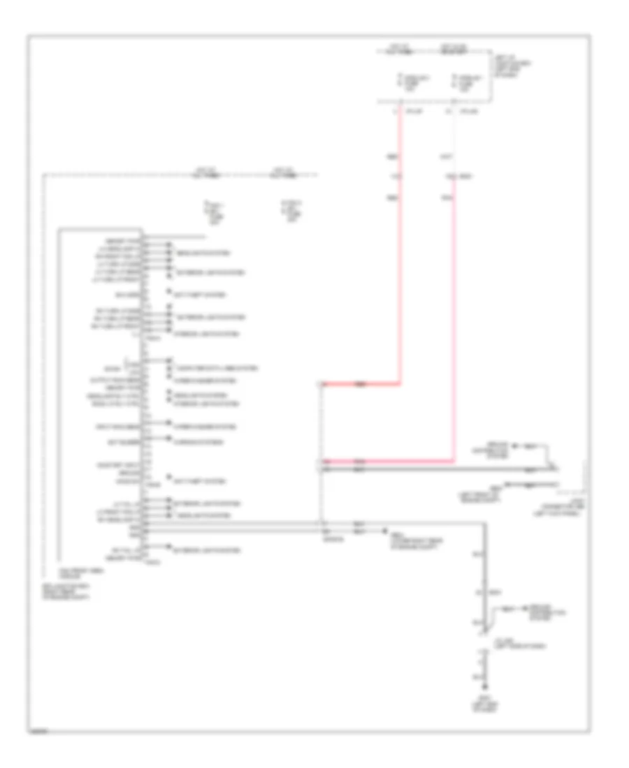
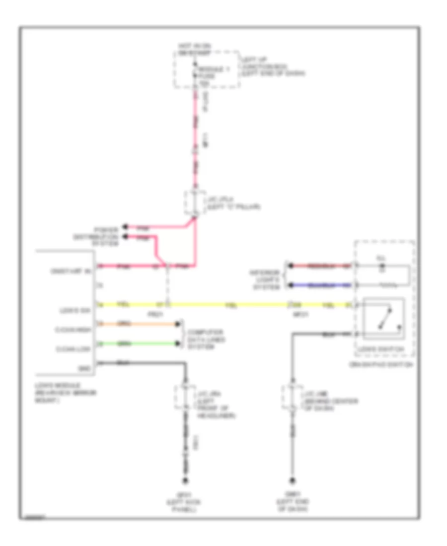
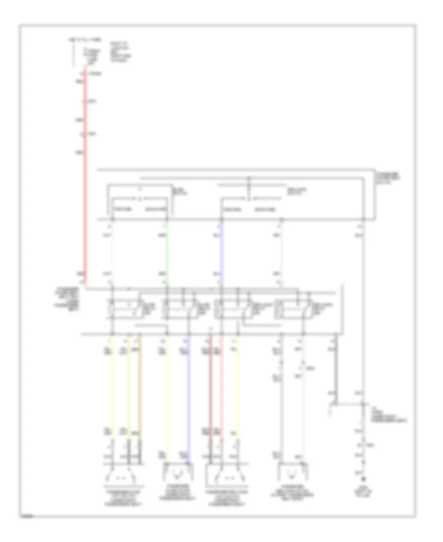
Front Area Module Wiring Diagram for Hyundai Genesis 3.8 2013
List of elements for Front Area Module Wiring Diagram for Hyundai Genesis 3.8 2013:
- (left front of
- (left kick panel)
- Anti-theft system
- B-can
- B/a horn
- Computer data lines system
- Connector jeb
- E/r junction box (right rear of engine compt)
- E/r-e1b
- Em21
- Engine compt)
- Ext buzzer
- Exterior lights system
- Fam (front area module)
- Fam 1 (b+) fuse 40a
- Fam 2 (b+) fuse 40a
- Fam-a
- Fam-b
- Fam-c
- Ge03
- Ge04 (lower right rear of engine compt)
- Gm01 (left end of dash)
- Gnd
- Ground
- Ground distribution system
- Headlamp rly ctrl
- Headlights system
- High
- Hood sw
- Hot at all times
- Hot in on or start
- I/p-lhf
- I/p-lhg
- Ill
- Input rain sens
- Interior lights system
- J/c jmd (left side of dash)
- Joint
- Left i/p junction box (left end of dash)
- Lh front fog lp
- Lh headlamp hi
- Lh tail lp
- Lh turn lp front
- Lh turn lp rear
- Lh turn lp side
- Low
- Memory pwr
- Module 1 fuse 10a
- Module 3 fuse 10a
- On/start input
- Output rain sens
- Pnk
- Red
- Rh front fog lp
- Rh headlamp hi
- Rh tail lp
- Rh turn lp front
- Rh turn lp rear
- Rh turn lp side
- Room lp rly ctrl
- Warning systems
- Wiper/washer system
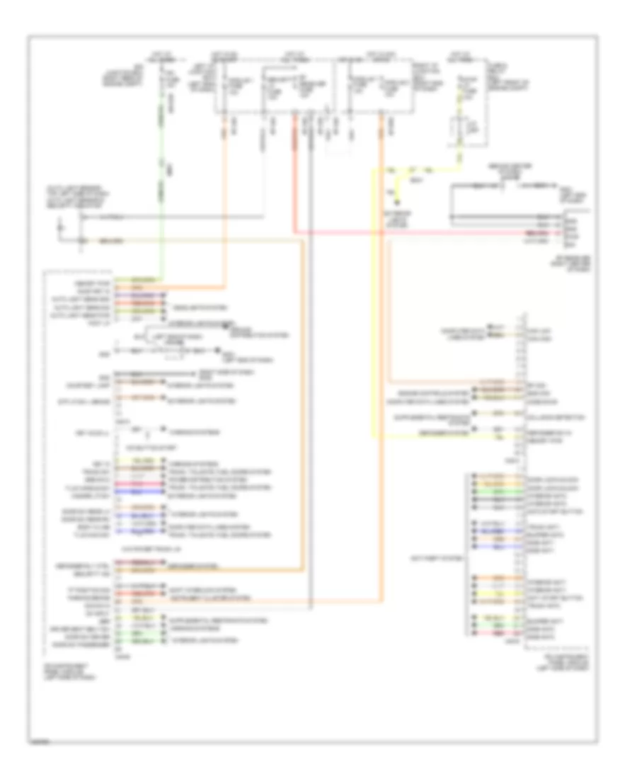
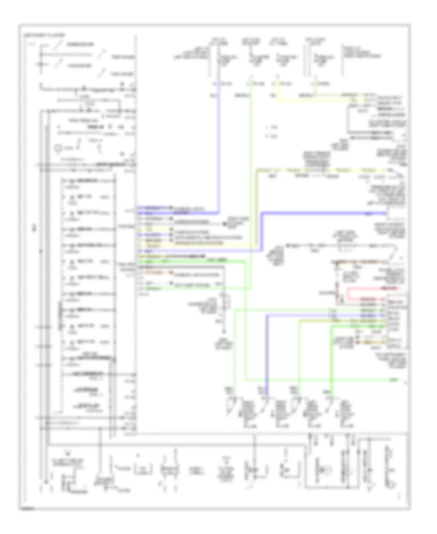
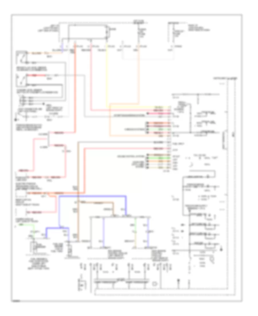
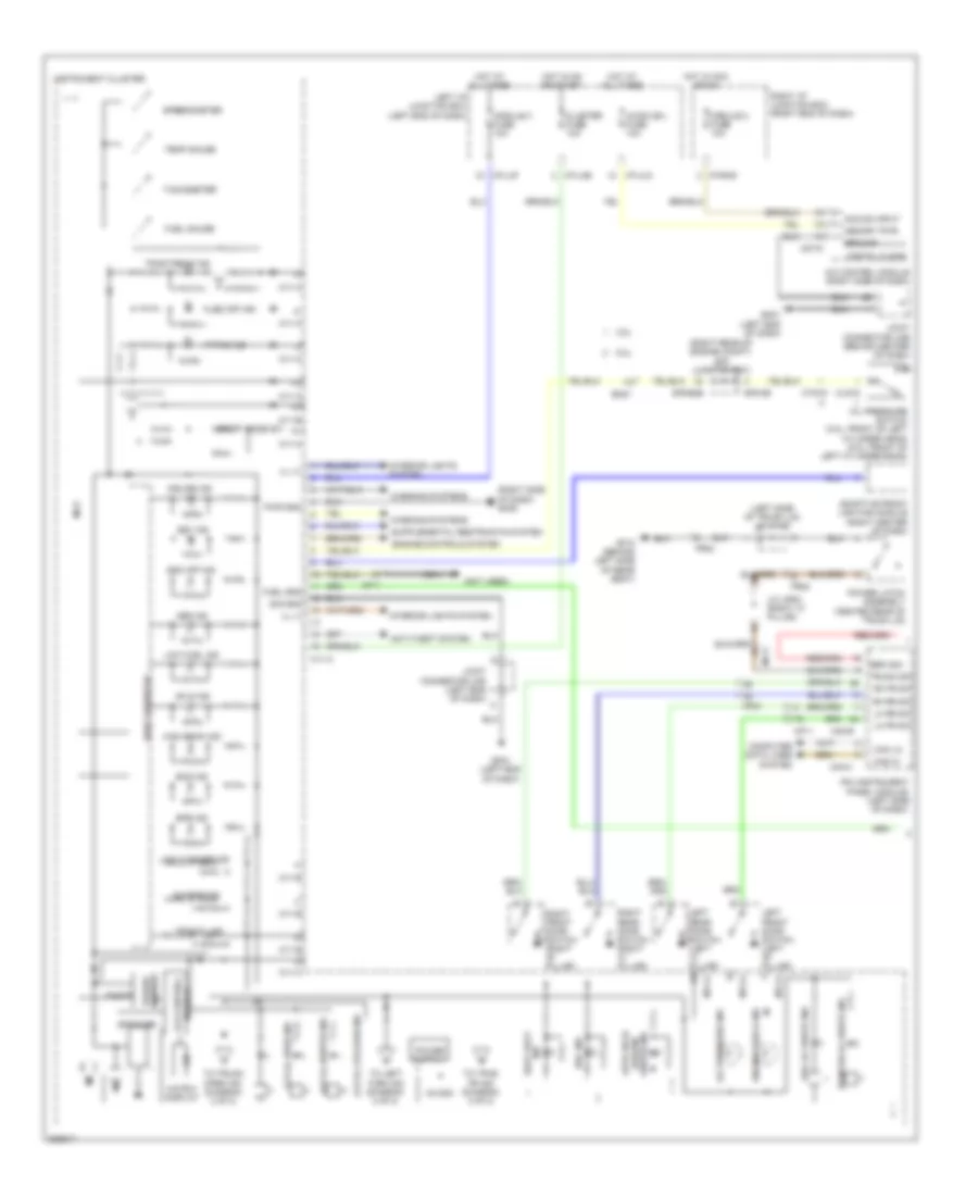
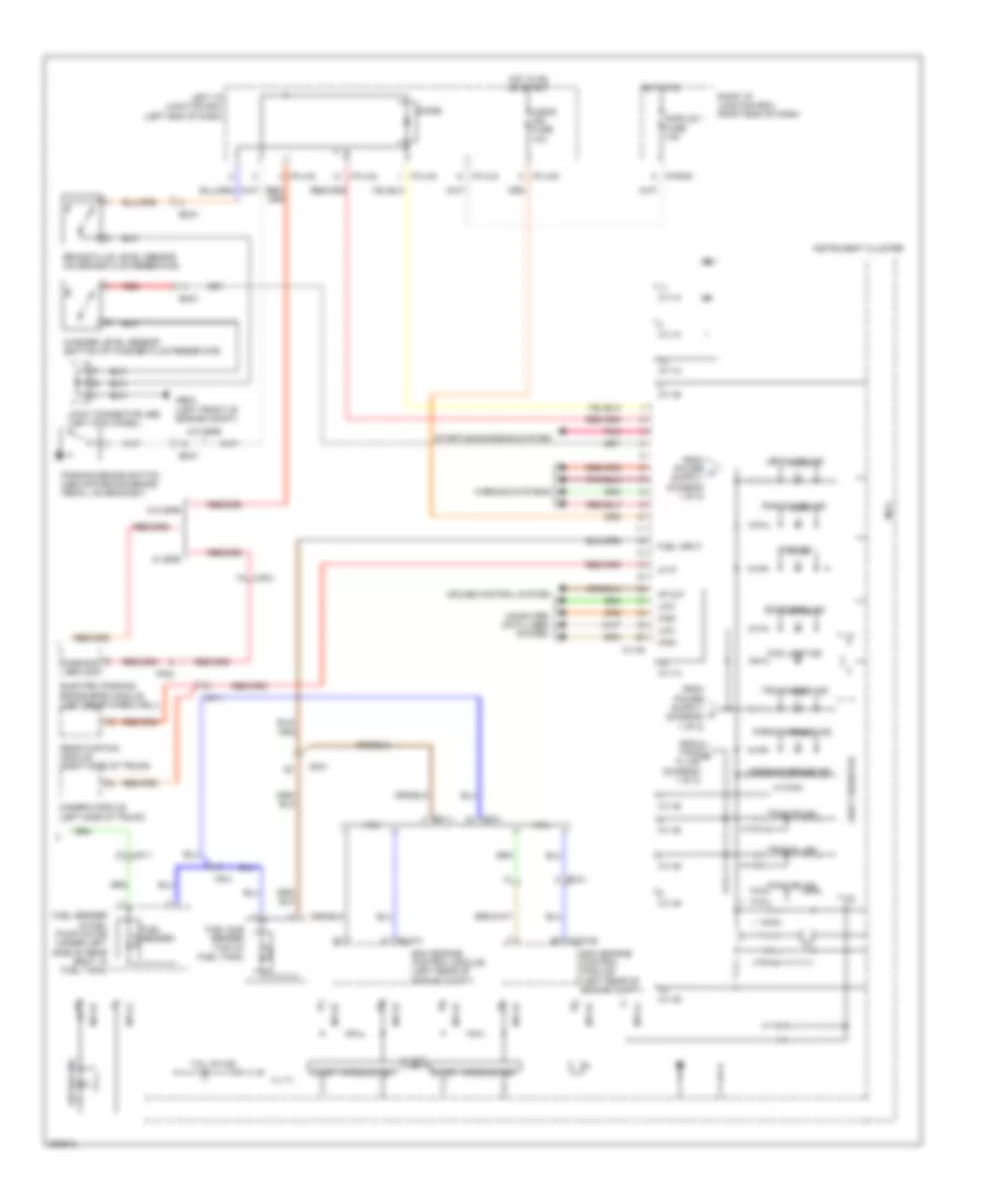
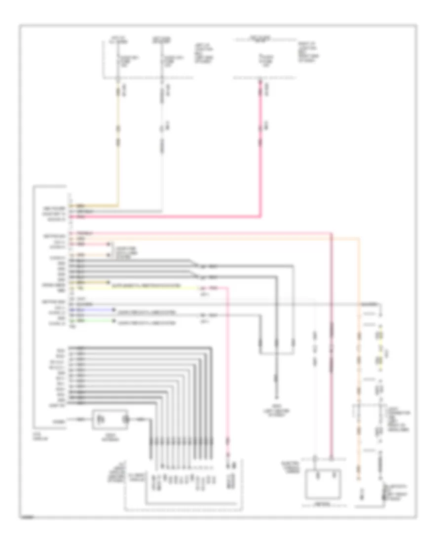
Instrument Panel Module Wiring Diagram for Hyundai Genesis 3.8 2013
List of elements for Instrument Panel Module Wiring Diagram for Hyundai Genesis 3.8 2013:
- "p" position sig
- (auto light sensor: top left side of dash) auto light sensor & security indicator
- (behind center of dash) j/c jme
- (left end of dash)
- (right side of dash) gm05
- Acc/on in
- Ant1 start button
- Ant2 start button
- Anti-theft system
- Auto light sens gnd
- Auto light sens pwr
- Auto light sens sig
- Body k-line
- Bumper ant1
- Bumper ant2
- Can high
- Can low
- Code save
- Collision detection
- Computer data lines system
- Courtesy lamp
- Defogger rly ctrl
- Defogger sw in
- Defogger system
- Door lock/unlock
- Door sw driver
- Door sw passenger
- Door sw rear lh
- Door sw rear rh
- Driver seat belt sw
- E/r junction box (right rear of engine compt)
- E/r-e2b
- Em31
- Ems com
- Engine controls system
- Exterior lights system
- Foot lp
- Fuse & relay box (left front of engine compt)
- Gm01
- Gm01 (left end of dash)
- Gnd
- Ground distribution system
- Hazard lp sw
- Headlights system
- Hot at all times
- Hot in acc or on
- Hot in on
- Hot in on or start
- I/p-lha
- I/p-lhd
- I/p-lhg
- I/p-rhd
- Instrument cluster system
- Interior ant1
- Interior ant2
- Interior lights system
- Ipm (instrument panel module) (left side of dash)
- Ipm fuse 10a
- J/c jea
- J/c jmd
- Key hole ill
- Key in
- Left i/p junction box (left end of dash)
- M40-a
- M40-b
- M40-c
- M40-d
- Memory pwr
- Module 1 fuse 10a
- Module 2 fuse 10a
- On input
- On/start in
- Parking brake
- Pnk
- Power distribution system
- Pwr
- Red
- Rf com
- Rf receiver (right center of dash)
- Rf receiver fuse 10a
- Right i/p junction box (right end of dash)
- Sbr
- Security ind
- Security lp fuse 10a
- Shift interlock system
- Side ant1
- Side ant2
- Sig
- Ssb sw-2
- Stop lp fuse 10a
- Stp lp sw l brake
- T/lid handle sw
- T/lid main sw
- Trunk ant1
- Trunk ant2
- Trunk sw
- Trunk, tailgate, fuel doors system
- W/o button start
- W/o power trunk lid
- Warning systems
COMPUTER DATA LINES
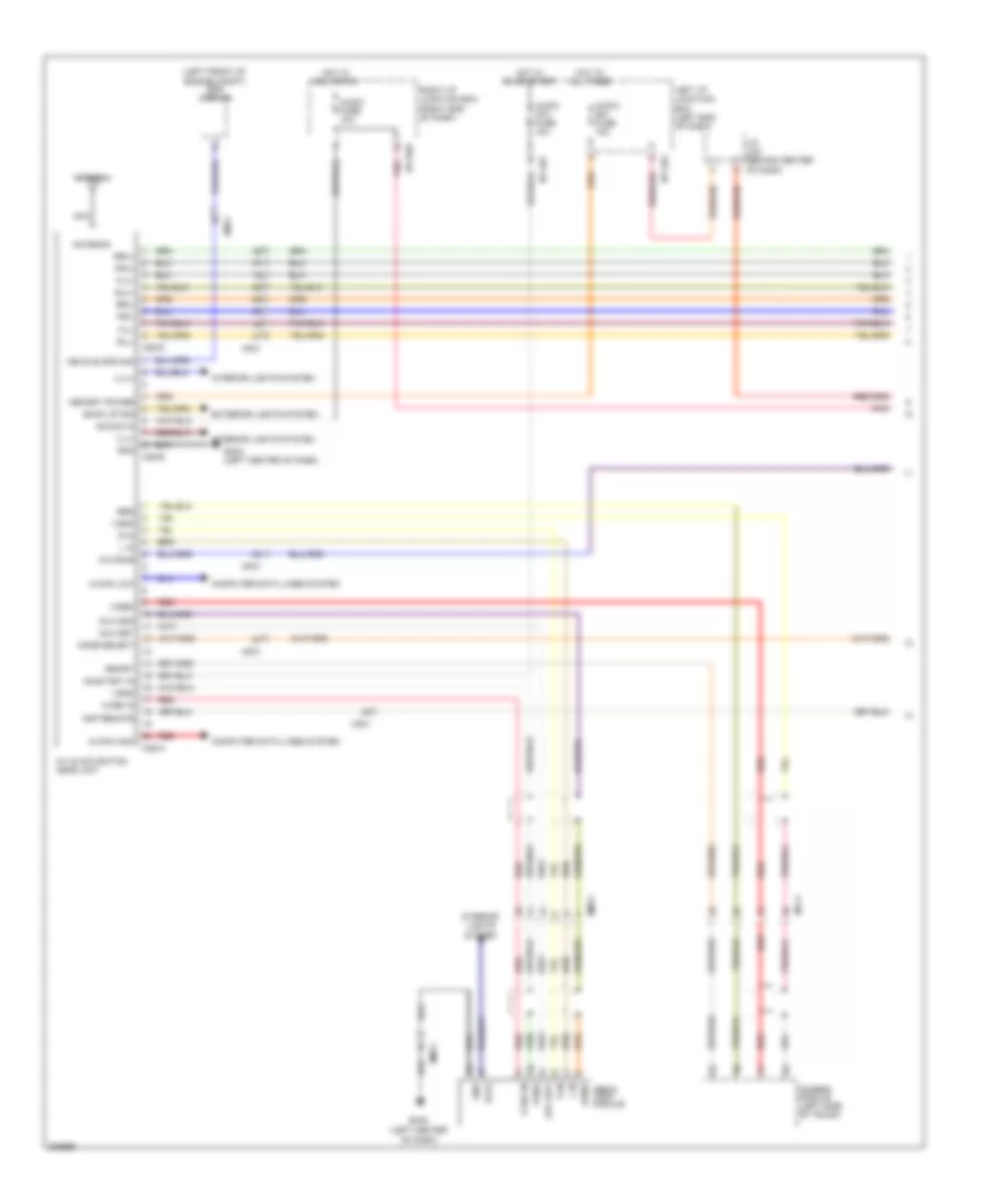
Computer Data Lines Wiring Diagram (1 of 3) for Hyundai Genesis 3.8 2013
List of elements for Computer Data Lines Wiring Diagram (1 of 3) for Hyundai Genesis 3.8 2013:
- (left "b" pillar) gf02
- (left center of dash) key lock module
- (left end of dash)
- (left end of dash) j/c jmd
- (left front of
- (left front of engine compt)
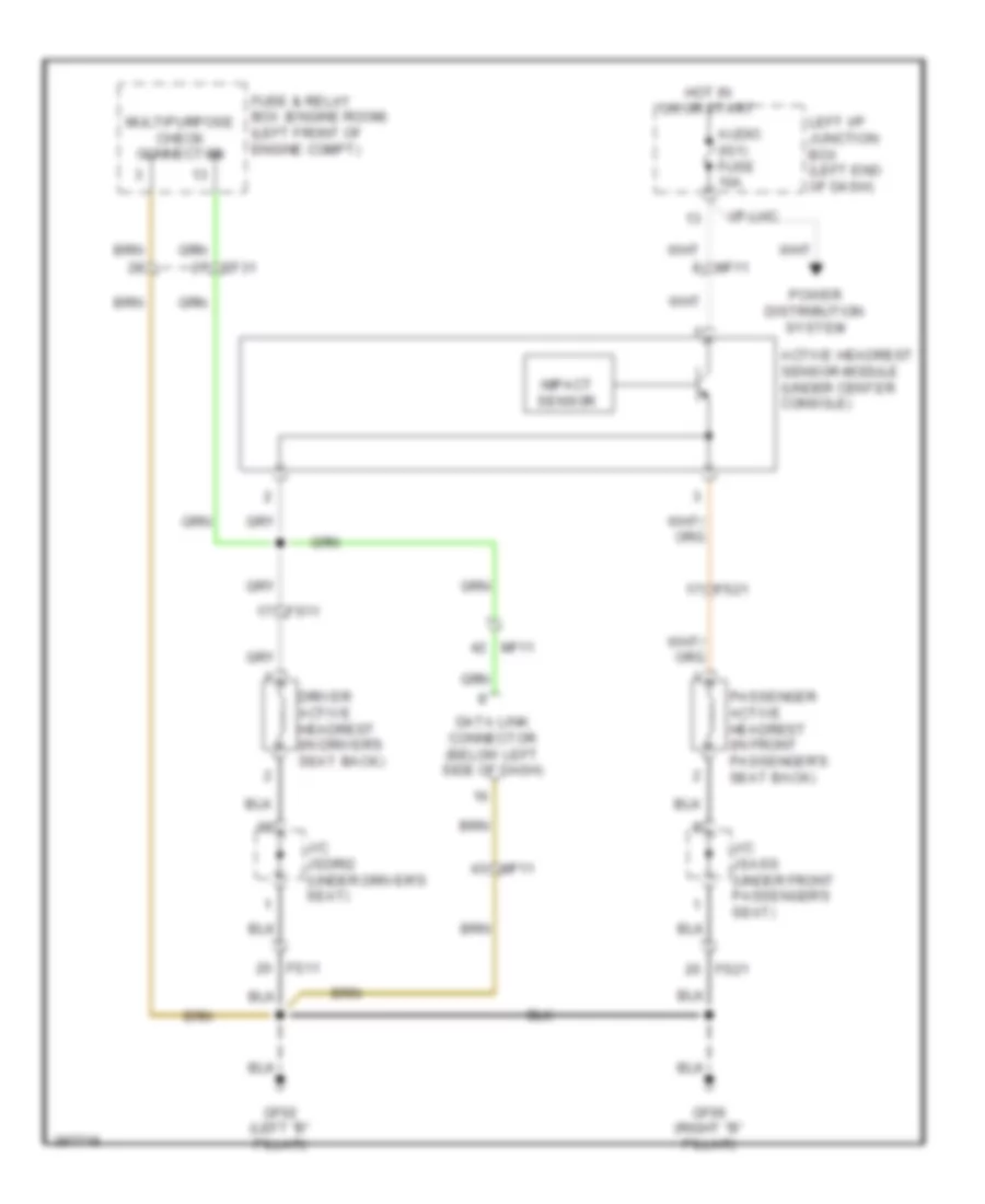
- (right kick panel)
- A01-a
- Active headrest sensor module (under center console)
- Adaptive front lighting module (right center of dash)
- Amp (right side of trunk)
- Auto headlamp leveling device sensor (left rear wheelwell)
- B-can hi
- B-can lo
- C-can hi
- C-can lo
- Camera module (left side of trunk)
- Data link connector (below left side of dash)
- Driver active headrest (in driver's seat back)
- E/r junction box (right rear of engine compt)
- E/r-e2b
- Ef31
- Em31
- Engine compt) esc module
- Engine room fuse & relay box
- Engine room fuse & relay box (left front of engine compt)
- Esc 1 fuse 30a
- Esc 2 fuse 30a
- Esc fuse 10a
- F03-a
- Fr21
- Fs11
- Ge02
- Ge02 (right kick panel)
- Gf02 (left "b" pillar)
- Gm01
- Gm05 (right side of dash)
- Hot at all times
- Hot in on or start
- I/p-lha
- Instrument cluster
- J/c jea
- J/c jfrb (right "c" pillar)
- J/c jma (behind center of dash)
- J/c jmc (right end of dash)
- J/c jrb (left front of headliner)
- K-line
- Ldws module (rearview mirror mount)
- Left i/p junction box (left end of dash)
- M11-b
- Mf11
- Mf21
- Multipurpose check connector (engine room fuse & relay box)
- Pnk
- Rear curtain module (right side of trunk)
- Red
- Security lp fuse 10a
- Sig (+)
- Sig veh spd
- Srs control module (under center console)
- Steering angle sensor (top of steering column)
- Tire pressure monitoring module (right center of dash)
- Veh spd
Computer Data Lines Wiring Diagram (2 of 3) for Hyundai Genesis 3.8 2013
List of elements for Computer Data Lines Wiring Diagram (2 of 3) for Hyundai Genesis 3.8 2013:
- (front of engine compt)
- (front passenger's door) passenger door module
- (left center of dash)
- (left rear of engine compt)
- (left side of dash)
- (left side of dash) j/c jmcan
- (right side of trunk) forward & rear parking assist control module
- B-can hi
- B-can lo
- Brake vacuum pump (right front of engine compt)
- C-can hi
- C-can lo
- Code save
- D01-c
- D11-c
- Driver door module (driver's door)
- E/r junction box (right rear of engine compt)
- E/r-e1b
- Ee21
- Ee31
- Ehps module (right front of engine compt)
- Electronic control wiper module
- Em21
- Em31
- F36-a
- Fam
- Fam-b
- Fd11
- Fd21
- Fs11
- Ims control module (under driver's seat)
- Ipm (left side of dash)
- J/c jec (right front of engine compt)
- J/c jecan
- J/c jflc (left kick panel)
- K-line
- M40-b
- M40-c
- M51-b
- M70-a
- Mf11
- Mf21
- Multi-function switch
- Pdm
- Red
- S15-d
- Smart cruise control module (front of engine compt)
- Tilt & telescopic module
Computer Data Lines Wiring Diagram (3 of 3) for Hyundai Genesis 3.8 2013
List of elements for Computer Data Lines Wiring Diagram (3 of 3) for Hyundai Genesis 3.8 2013:
- (left rear of engine compt)
- (left rear of engine compt) injector driver box
- (left rear of engine compt) tcm
- (right e/r-e2a
- (right rear of engine compt) engine room junction box
- (right rear wheelwell)
- (top rear of engine) (5.0l) j/c jccan
- 3.8l
- 5.0l
- A/c control module (right side of dash)
- A/v navigation headunit
- Aa21
- Audio
- Av head module (center of dash)
- B-can hi
- B-can lo
- Box
- C-can hi
- C-can lo
- Clg-idb
- Clg-tg
- Ctg-ag
- Ctg-idb
- Ctg-kg
- E/r
- E/r junction box (right e/r-e2a rear of engine compt)
- E/r-ca
- E/r-cb
- E/r-e2b
- Ec41
- Ecm
- Ef31
- Electric parking brake module (left rear wheelwell)
- Elg-a
- Ff02
- Front monitor (w/ navi)
- Front monitor (w/o av)
- High
- Injector drive box
- J/c jfcan (base of left "b" pillar)
- J/c jfepb
- J/c jfld (left "c" pillar)
- J/c jfrc (right "b" pillar)
- J/c jfrd (right "c" pillar)
- J/c jmb (behind center
- J/c jmd (left end of dash)
- Junction
- K-line
- Low
- M-can hi
- M-can lo
- M03-a
- M07-a
- M25-a
- M34-b
- M45-a
- Media module (w/ av) (right side of dash)
- Mf11
- Mts module
- Of dash)
- Passenger's seat)
- Pods module (under front
- Rear of engine compt)
- Red
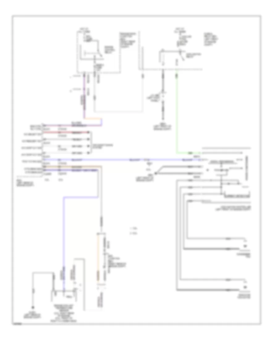
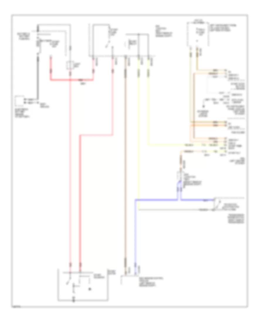
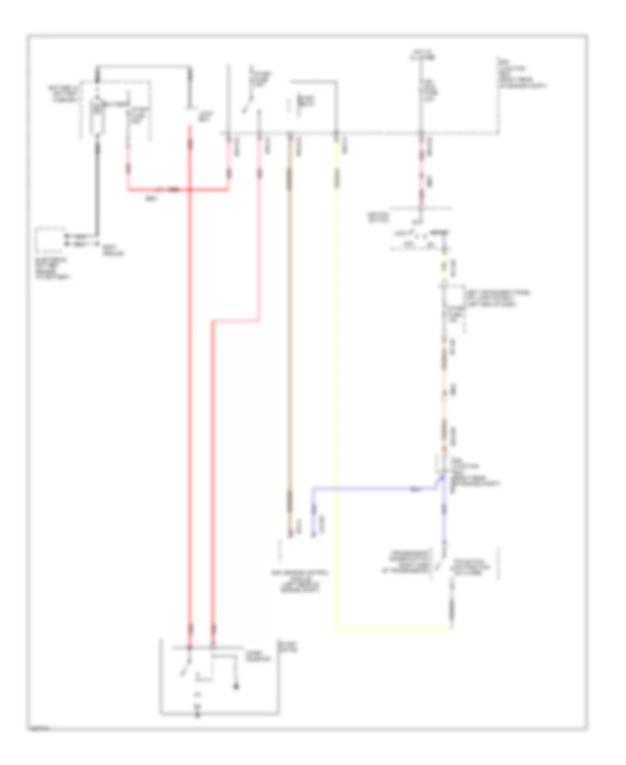
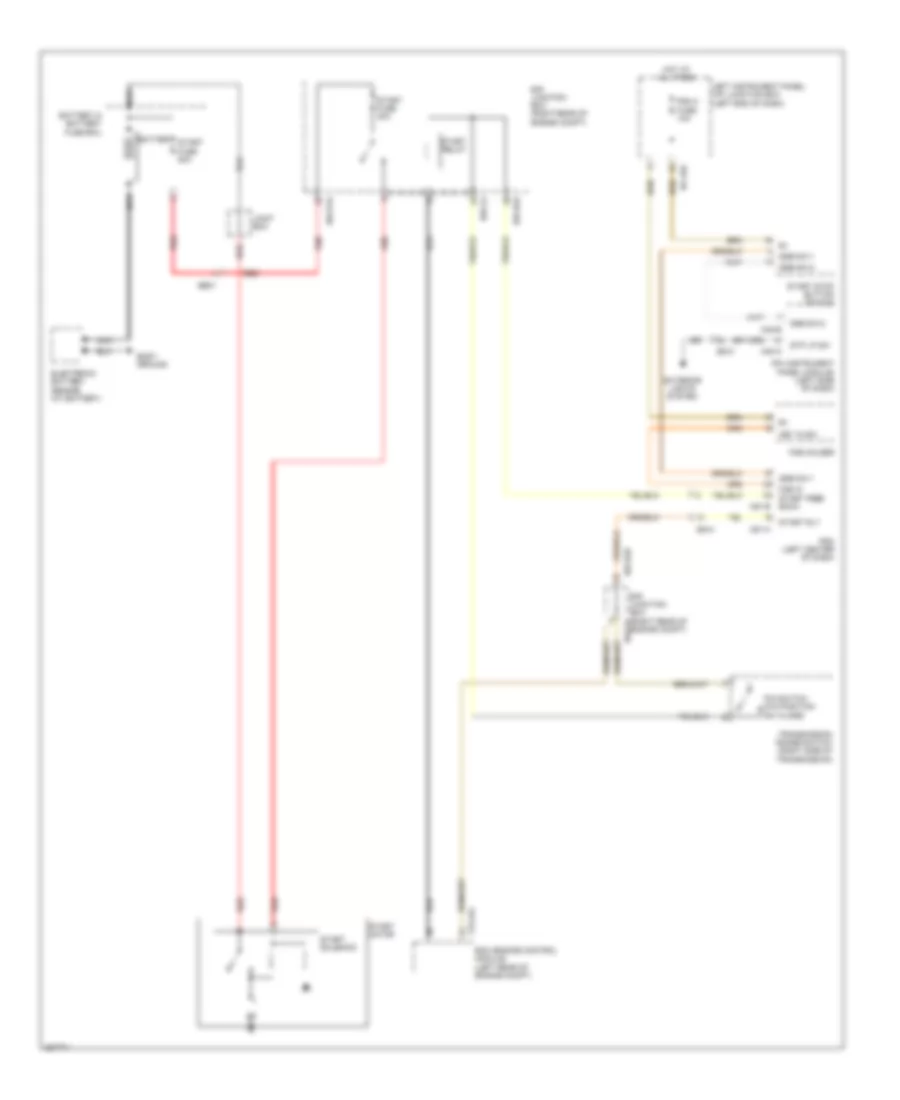
COOLING FAN
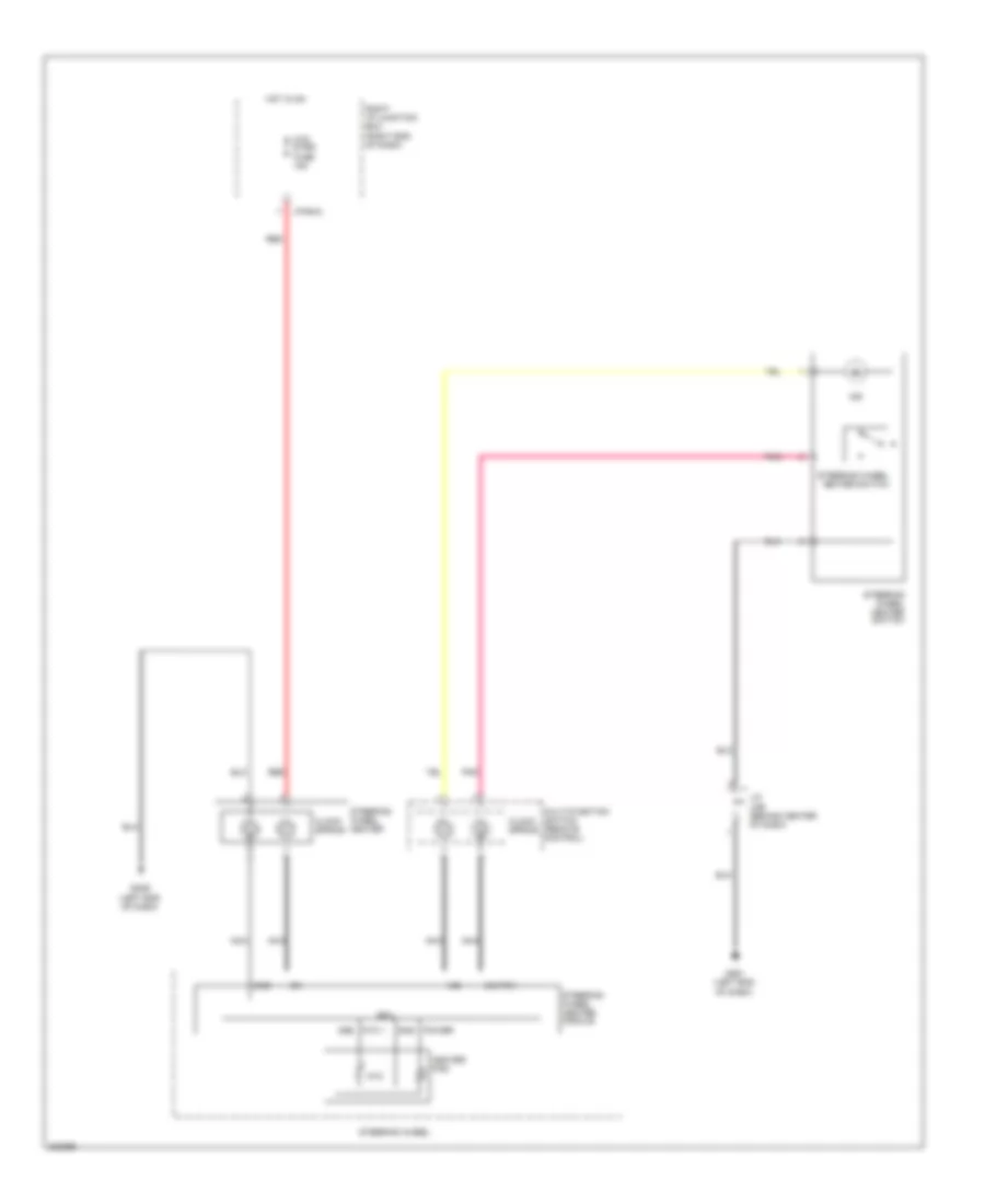
Cooling Fan Wiring Diagram for Hyundai Genesis 3.8 2013
List of elements for Cooling Fan Wiring Diagram for Hyundai Genesis 3.8 2013:
- 3.8l
- 5.0l
- 60a
- A/c comp cut sig
- A/c comp cut sig elg-a
- A/c request sw
- A/c select sw
- Air conditioning system
- Condenser fan
- Cooling fan controller (left front of engine compt)
- Cooling fan relay
- Ctg-ag
- Ctg-kg
- Current detecting
- E/r junction box (right rear of engine compt) e/r-cb
- E/r-ca
- E/r-cb
- E/r-e2a
- E05-a
- E05-b
- Ec41
- Ecm (left rear of engine compt)
- Ecu fuse 30a
- Elg-a
- Eng ctrl rly ctrl elg-a
- Engine control relay
- Engine coolant temperature sensor (3.8l: right rear of engine) (5.0l: front of right cylinder head)
- Engine room junction box (right rear of engine compt)
- Fuse & relay box (left front
- Ge01 (left front of engine compt)
- Ge03 (left front of engine compt)
- Glg01 (left rear of engine compt)
- Gnd
- Hot at all times
- J/c jeb (left kick panel)
- Nca
- Of engine compt)
- Power conditioning
- Pwm to fan mod elg-a
- Pwn driver
- Radiator fan motor
- Signal processing
- Snsr 2 fuse 10a
- Wts sens gnd
- Wts sens sig clg-bg
CRUISE CONTROL
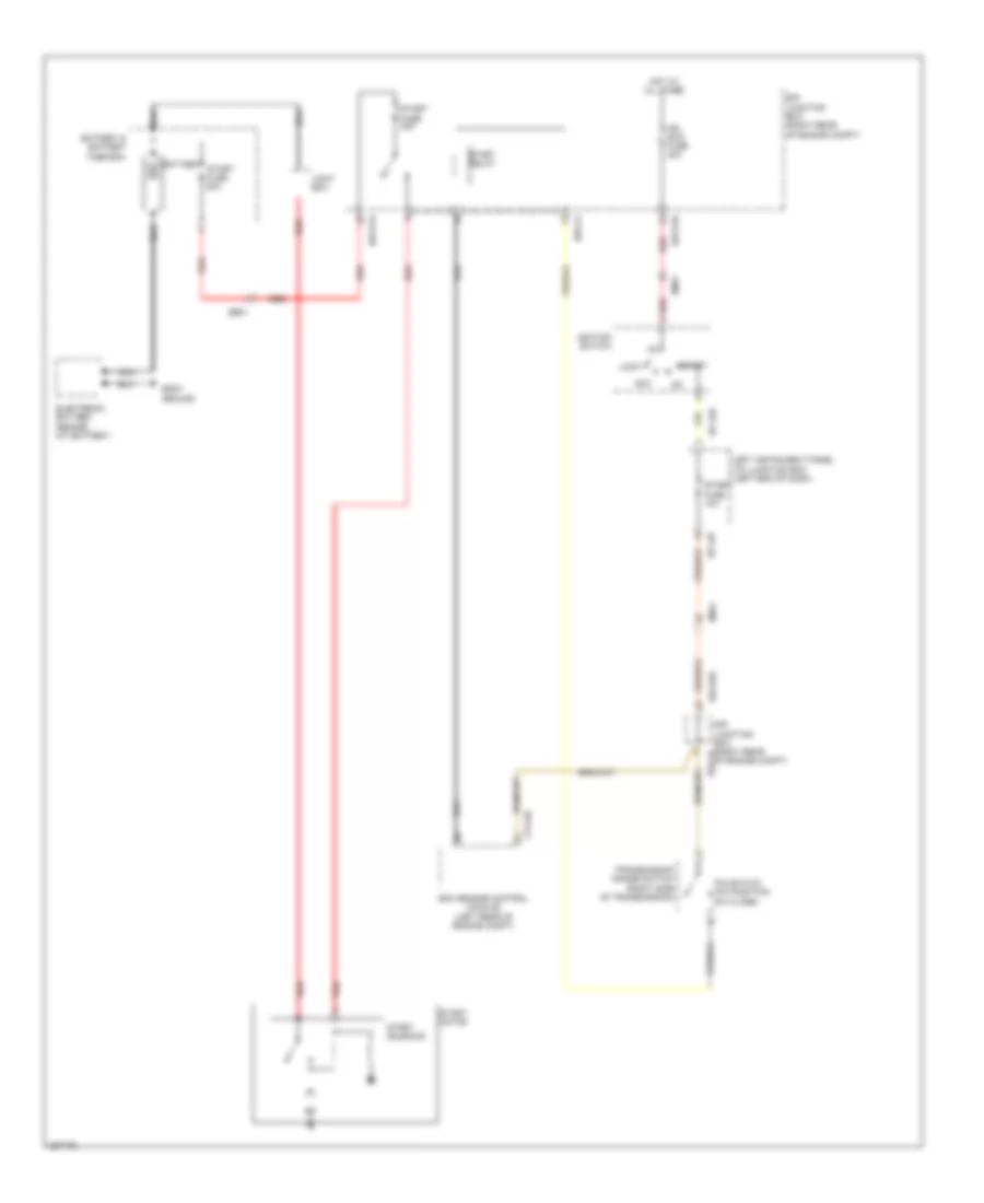
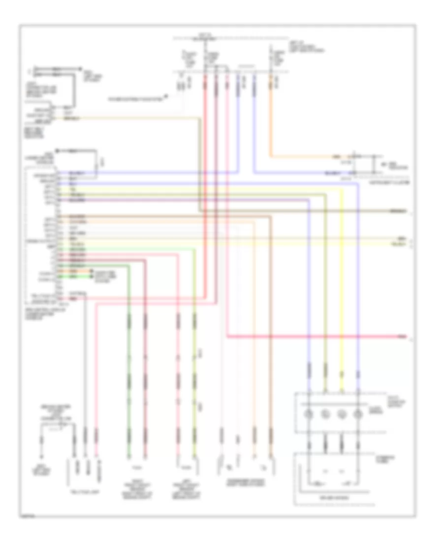
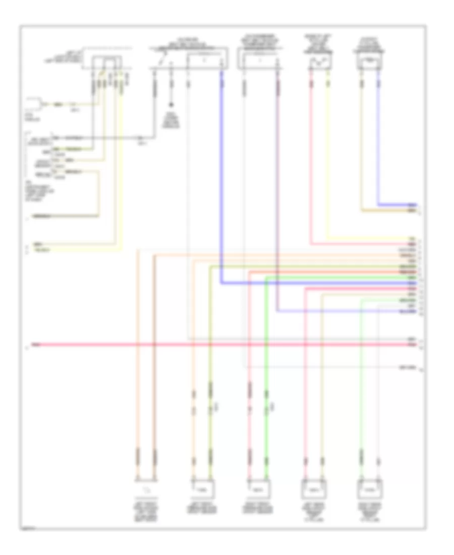
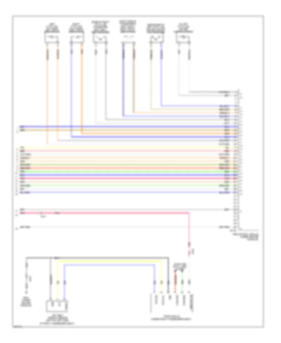
3.8L
3.8L, Cruise Control Wiring Diagram, with SCC (1 of 2) for Hyundai Genesis 3.8 2013
List of elements for 3.8L, Cruise Control Wiring Diagram, with SCC (1 of 2) for Hyundai Genesis 3.8 2013:
- (+)
- (-)
- (behind accelerator pedal assembly) accel pedal position sensor
- (front of engine compt) smart cruise control module
- (left rear of engine compt) ecm (engine control module)
- Aps 1 gnd
- Aps 1 pwr
- Aps 1 sig
- Aps 2 gnd
- Aps 2 pwr
- Aps 2 sig
- Brake lp
- Brake sw
- C-can high
- C-can low
- Can- cel
- Can-high
- Can-low
- Ccs power fuse 10a
- Clg-bg
- Clock spring
- Cluster fuse 10a
- Coast/ set
- Computer data lines system
- Cruise sw fuse 10a
- E/r junction box (right rear of engine compt)
- E/r-e1a
- E/r-e2a
- Ec21
- Ee21
- Elg-a
- Em31
- Esc module (left front of engine compt)
- Etc motor hi
- Etc motor lo
- Ge04 (lower right rear of engine compt)
- Gm01 (left end of dash)
- Gnd
- Ground
- High
- Hot at all times
- Hot in on or start
- I/p-lhc
- I/p-lhe
- I/p-lhf
- I/p-lhg
- Ill
- Interior lights system
- J/c jeb (left kick panel)
- J/c jmd (left end of dash)
- Left i/p junction box (left end of dash)
- Low
- M/f sw ecu
- M51-b
- Module 1 fuse 10a
- Module 3 fuse 10a
- Multi- function switch
- Nca
- On/ off
- Pdm (left center of dash)
- Pnk
- Power
- Pwr
- Red
- Resume/ accel
- Right audio & cruise remocon switch
- Scc sensor
- Sensor 1
- Sensor 2
- Snsr input
- Speed snsr input
- Steering wheel
- Stop lamp fuse 10a
- Stop lamp switch (above brake pedal, on bracket)
- Stop lp fuse 10a
- Stop signal relay (behind instrument cluster)
- Wheel sensor fl_gnd
- Wheel sensor fl_sig
- Wheel sensor fr_gnd
- Wheel sensor fr_sig
- Wheel sensor rl_gnd
- Wheel sensor rl_sig
- Wheel sensor rr_gnd
- Wheel sensor rr_sig
3.8L, Cruise Control Wiring Diagram, with SCC (2 of 2) for Hyundai Genesis 3.8 2013
List of elements for 3.8L, Cruise Control Wiring Diagram, with SCC (2 of 2) for Hyundai Genesis 3.8 2013:
- +5v30d
- Amp (right side of trunk)
- Auto head- lamp leveling device sensor (left rear wheelwell)
- C-can transceiver
- Camera module (left side of trunk)
- Computer data lines system
- Cruise ind
- Cruise set ind
- Data link connector (below left side of dash)
- Ef21
- Ef31
- Etc motor
- Etc motor & throttle position sensor (on throttle body)
- F03-a
- Glg01 (left rear of engine compt)
- Glg02
- High
- Instrument cluster
- J/c jfrb (right "c" pillar)
- J/c jmc (right end of dash)
- Key lock module (left center of dash)
- Left front wheel sensor (on left front wheel hub assembly)
- Left rear wheel sensor (left rear wheel hub assembly)
- Low
- M11-a
- M11-b
- Mcu
- Mf21
- Nca
- Rear curtain module (right side of trunk)
- Red
- Resistor shift
- Right front wheel sensor (on right front wheel hub assembly)
- Right rear wheel sensor (right rear wheel hub assembly)
- Throttle position sensor
- Tire pressure monitoring module (right center of dash)
3.8L, Cruise Control Wiring Diagram, without SCC (1 of 2) for Hyundai Genesis 3.8 2013
List of elements for 3.8L, Cruise Control Wiring Diagram, without SCC (1 of 2) for Hyundai Genesis 3.8 2013:
- (+)
- (-)
- (behind accelerator pedal assembly) accel pedal position sensor
- (left rear of engine compt) ecm (engine control module)
- Aps 1 gnd
- Aps 1 pwr
- Aps 1 sig
- Aps 2 gnd
- Aps 2 pwr
- Aps 2 sig
- Auto cru sw gnd
- Auto cru sw sig
- Brake lp
- Brake sw
- C-can high
- C-can low
- Can- cel
- Clg-bg
- Clock spring
- Cluster fuse 10a
- Coast/ set
- Computer data lines system
- Dis- tant
- E/r junction box (right rear of engine compt)
- E/r-e1a
- E/r-e2a
- Ec21
- Ecu fuse 30a
- Elg-a
- Em31
- Engine control relay
- Engine control rly control
- Engine control rly on in
- Etc motor
- Etc motor & throttle position sensor (on throttle body)
- Etc motor hi
- Etc motor lo
- Glg01 (left rear of engine compt)
- Glg02
- Ground
- Hot at all times
- Hot in on or start
- I/p-lhe
- I/p-lhf
- I/p-lhg
- Ill
- Interior lights system
- J/c jeb (left kick panel)
- Left i/p junction box (left end of dash)
- Module 3 fuse 10a
- Multi- function switch
- Nca
- On/ off
- Power
- Red
- Resume/ accel
- Right audio & cruise remocon switch
- Sensor 1
- Sensor 2
- Snsr 3 fuse 10a
- Speed snsr input
- Steering wheel
- Stop lamp fuse 10a
- Stop lamp switch (above brake pedal, on bracket)
- Stop lp fuse 10a
- Stop signal relay (behind instrument cluster)
- Throttle position sensor
3.8L, Cruise Control Wiring Diagram, without SCC (2 of 2) for Hyundai Genesis 3.8 2013
List of elements for 3.8L, Cruise Control Wiring Diagram, without SCC (2 of 2) for Hyundai Genesis 3.8 2013:
- +5v30d
- Amp (right side of trunk)
- Auto head- lamp leveling device sensor (left rear wheelwell)
- C-can transceiver
- Camera module (left side of trunk)
- Can-high
- Can-low
- Computer data lines system
- Cruise ind
- Cruise set ind
- Data link connector (below left side of dash)
- Ef21
- Ef31
- Em31
- Esc module (left front of engine compt)
- F03-a
- High
- Instrument cluster
- J/c jfrb (right "c" pillar)
- J/c jmc (right end of dash)
- Key lock module (left center of dash)
- Left front wheel sensor (on left front wheel hub assembly)
- Left rear wheel sensor (left rear wheel hub assembly)
- Low
- M11-a
- M11-b
- M51-b
- Mcu
- Mf21
- Nca
- Pdm (left center of dash)
- Rear curtain module (right side of trunk)
- Red
- Resistor shift
- Right front wheel sensor (on right front wheel hub assembly)
- Right rear wheel sensor (right rear wheel hub assembly)
- Speed snsr input
- Tire pressure monitoring module (right center of dash)
- Wheel sensor fl_gnd
- Wheel sensor fl_sig
- Wheel sensor fr_gnd
- Wheel sensor fr_sig
- Wheel sensor rl_gnd
- Wheel sensor rl_sig
- Wheel sensor rr_gnd
- Wheel sensor rr_sig
5.0L
5.0L, Cruise Control Wiring Diagram, with SCC (1 of 2) for Hyundai Genesis 3.8 2013
List of elements for 5.0L, Cruise Control Wiring Diagram, with SCC (1 of 2) for Hyundai Genesis 3.8 2013:
- (lower right rear of engine compt)
- Accel pedal position sensor (behind accelerator pedal assembly)
- Apm gnd 1
- Apm gnd 2
- Apm pwr 1
- Apm sig 1
- Apm sig 2
- Brake lp
- Brake sw
- C-can high
- C-can low
- Ccs power fuse 10a
- Cluster fuse 10a
- Computer data lines system
- Cruise sw fuse 10a
- Ctg-ag
- Ctg-kg
- E/r junction box (right rear of engine compt)
- E/r-ca
- E/r-cb
- E/r-e1a
- E/r-e2a
- Ec31
- Ec41
- Ecm (engine control module) (left rear of engine compt)
- Ee21
- Em31
- Engine room junction box e/r-e2a (right rear of engine compt)
- Etc motor & throttle position sensor (on throttle body)
- Etc motor (+)
- Etc motor (-)
- Ge04
- Gnd
- High
- Hot at all times
- Hot in on or start
- I/p-lhc
- I/p-lhe
- I/p-lhf
- I/p-lhg
- J/c jeb (left kick panel)
- Left i/p junction box (left end of dash)
- Low
- Module 1 fuse 10a
- Module 3 fuse 10a
- Motor
- Pnk
- Pwr
- Red
- Scc sensor
- Sens pwr
- Sig 1
- Sig 2
- Smart cruise control module (front of engine compt)
- Speed sig
- Stop lamp fuse 10a
- Stop lamp switch (above brake pedal, on bracket)
- Stop lp fuse 10a
- Stop signal relay (behind instrument cluster)
- Throttle position sensor
5.0L, Cruise Control Wiring Diagram, with SCC (2 of 2) for Hyundai Genesis 3.8 2013
List of elements for 5.0L, Cruise Control Wiring Diagram, with SCC (2 of 2) for Hyundai Genesis 3.8 2013:
- (+)
- (-)
- (below left side of dash) data link connector
- (left center of dash) key lock module
- (right "c" pillar) j/c jfrb
- (right center of dash) tire pressure monitoring module
- (right end of dash) j/c jmc
- +5v30d
- Amp (right side of trunk)
- Auto headlamp leveling device sensor (left rear wheelwell)
- C-can transceiver
- Camera module (left side of trunk)
- Can- cel
- Can-high
- Can-low
- Clock spring
- Coast/ set
- Computer data lines system
- Cruise ind
- Ef21
- Ef31
- Esc module (left front of engine compt)
- F03-a
- Gm01 (left end of dash)
- High
- Ill
- Instrument cluster
- Interior lights system
- J/c jmo
- Left front wheel sensor (on left front wheel hub assembly)
- Left rear wheel sensor (left rear wheel hub assembly)
- Low
- M/f sw ecu
- M11-a
- M11-b
- Mcu
- Mf21
- Multi- function switch
- Nca
- On/ off
- Rear curtain module (right side of trunk)
- Red
- Resume/ accel
- Right audio & cruise remocon switch
- Right front wheel sensor (on right front wheel hub assembly)
- Right rear wheel sensor (right rear wheel hub assembly)
- Set ind cruise
- Shift resistor
- Steering wheel
- Vehicle speed sig
- Wheel sensor fl_gnd
- Wheel sensor fl_sig
- Wheel sensor fr_gnd
- Wheel sensor fr_sig
- Wheel sensor rl_gnd
- Wheel sensor rl_sig
- Wheel sensor rr_gnd
- Wheel sensor rr_sig
5.0L, Cruise Control Wiring Diagram, without SCC (1 of 2) for Hyundai Genesis 3.8 2013
List of elements for 5.0L, Cruise Control Wiring Diagram, without SCC (1 of 2) for Hyundai Genesis 3.8 2013:
- Accel pedal position sensor (behind accelerator pedal assembly)
- Acs gnd
- Acs sig
- Apm gnd 1
- Apm gnd 2
- Apm pwr 1
- Apm sig 1
- Apm sig 2
- Brake lp
- Brake sw
- C-can high
- C-can low
- Cluster fuse 10a
- Computer data lines system
- Ctg-ag
- Ctg-kg
- E/r junction box (right rear of engine compt)
- E/r-ca
- E/r-cb
- E/r-e1a
- Ec41
- Ecm (engine control module) (left rear of engine compt)
- Ecu fuse 30a
- Em31
- Engine control relay
- Engine control rly control
- Engine control rly on in
- Engine room junction box e/r-e2a (right rear of engine compt)
- Etc motor & throttle position sensor (on throttle body)
- Etc motor (+)
- Etc motor (-)
- Gnd
- Hot at all times
- Hot in on or start
- I/p-lhe
- I/p-lhf
- I/p-lhg
- J/c jeb (left kick panel)
- Left i/p junction box (left end of dash)
- Module 3 fuse 10a
- Motor
- Red
- Sens pwr
- Sig 1
- Sig 2
- Snsr 1 fuse 10a
- Speed sig
- Stop lamp fuse 10a
- Stop lamp switch (above brake pedal, on bracket)
- Stop lp fuse 10a
- Stop signal relay (behind instrument cluster)
- Throttle position sensor
5.0L, Cruise Control Wiring Diagram, without SCC (2 of 2) for Hyundai Genesis 3.8 2013
List of elements for 5.0L, Cruise Control Wiring Diagram, without SCC (2 of 2) for Hyundai Genesis 3.8 2013:
- (+)
- (-)
- +5v30d
- Accel resume/
- Amp (right side of trunk)
- Auto headlamp leveling device sensor (left rear wheelwell)
- C-can transceiver
- Camera module (left side of trunk)
- Can-high
- Can-low
- Cel can-
- Clock spring
- Computer data lines system
- Cruise ind
- Cruise set ind
- Data link connector (below left side of dash)
- Ef21
- Ef31
- Em31
- Esc module (left front of engine compt)
- F03-a
- High
- Ill
- Instrument cluster
- Interior lights system
- J/c jfrb (right "c" pillar)
- J/c jmc (right end of dash)
- Key lock module (left center of dash)
- Left front wheel sensor (on left front wheel hub assembly)
- Left rear wheel sensor (left rear wheel hub assembly)
- Low
- M11-a
- M11-b
- Mcu
- Mf21
- Multifunction switch
- Nca
- Off on/
- Rear curtain module (right side of trunk)
- Red
- Resistor shift
- Right audio & cruise remocon switch
- Right front wheel sensor (on right front wheel hub assembly)
- Right rear wheel sensor (right rear wheel hub assembly)
- Set coast/
- Steering wheel
- Tant dis-
- Tire pressure monitoring module (right center of dash)
- Vehicle speed sig
- Wheel sensor fl_gnd
- Wheel sensor fl_sig
- Wheel sensor fr_gnd
- Wheel sensor fr_sig
- Wheel sensor rl_gnd
- Wheel sensor rl_sig
- Wheel sensor rr_gnd
- Wheel sensor rr_sig
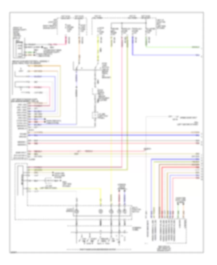
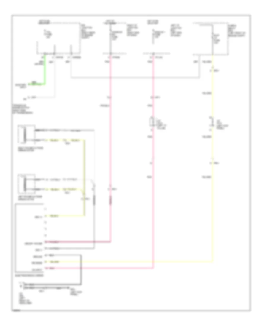
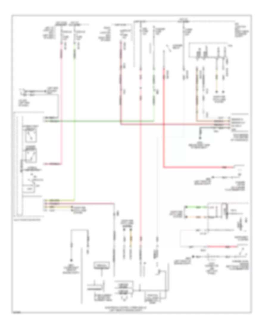
DEFOGGERS
Defoggers Wiring Diagram for Hyundai Genesis 3.8 2013
List of elements for Defoggers Wiring Diagram for Hyundai Genesis 3.8 2013:
- A/c control module (right side of dash)
- B-can high
- B-can low
- Computer data lines system
- Defogger
- Deicer fuse 15a
- Deicer relay
- E/r junction box (right rear of engine compt)
- E/r-e1b
- E/r-e2a
- E/r-e2b
- Ef21
- Em21
- Fd11
- Fd21
- Ge07 (lower right rear of engine compt)
- Gf01 (left kick panel)
- Gf05 (right kick panel)
- Gm02 (right side of dash)
- Hot at all times
- Ind
- Ipm (left side of dash)
- Joint connector jdass (front passenger's door)
- Joint connector jddri (driver's door)
- Left power outside mirror
- M07-a
- M07-d
- M40-b
- M40-c
- Mirr htd fuse 10a
- Nca
- Pnk
- Quarter panel ground
- Rear defogger
- Rear defogger switch
- Right power outside mirror
- Rly ctrl
- Rr htd fuse 40a
- Rr htd relay
- Sw input
- Windshield defogger
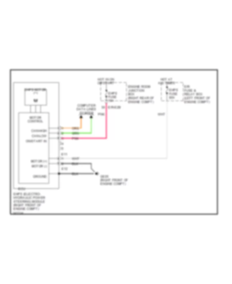
ELECTRONIC POWER STEERING
Electronic Power Steering Wiring Diagram for Hyundai Genesis 3.8 2013
List of elements for Electronic Power Steering Wiring Diagram for Hyundai Genesis 3.8 2013:
- Can-high
- Can-low
- Computer data lines system
- E/r fuse & relay box (left front of engine compt)
- E/r-e2b
- E11
- E12
- Ecu
- Ehps (electro- hydraulic power steering) module (right front of engine compt)
- Ehps fuse 10a
- Ehps fuse 80a
- Ehps motor
- Engine room junction box (right rear of engine compt)
- Ge05 (right front of engine compt)
- Ground
- Hot at all times
- Hot in on or start
- Motor (+)
- Motor (-)
- Motor control
- On/start in
- Pnk
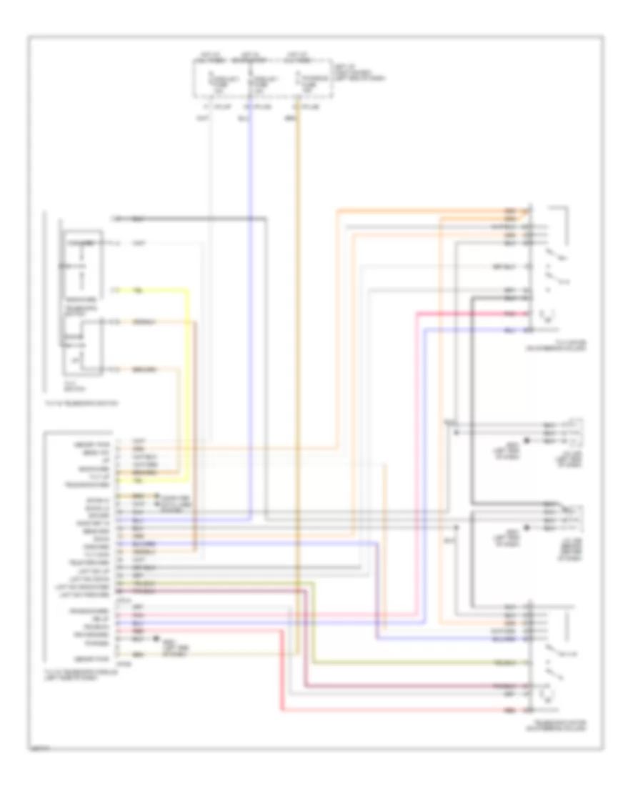
Power Tilt Steering Column Wiring Diagram for Hyundai Genesis 3.8 2013
List of elements for Power Tilt Steering Column Wiring Diagram for Hyundai Genesis 3.8 2013:
- B-can hi
- B-can lo
- Backward
- Computer data lines system
- Down
- Forward
- Gm01 (left end of dash)
- Hot at all times
- Hot in on or start
- I/p-lhe
- I/p-lhf
- I/p-lhg
- Ips backward
- Ips down
- Ips forward
- Ips up
- J/c jmd (left end of dash)
- J/c jme (behind center of dash)
- Left i/p junction box (left end of dash)
- Limit sw backward
- Limit sw down
- Limit sw forward
- Limit sw up
- M70-a
- M70-b
- Memory pwr
- Module 1 fuse 10a
- Module 3 fuse 10a
- On/start in
- P/handle fuse 15a
- Pnk
- Pwr gnd
- Red
- Sens gnd
- Sens vcc
- Sig gnd
- Tele backward
- Tele forward
- Telescopic motor (on steering column)
- Telescopic switch
- Tilt & telescopic module (left side of dash)
- Tilt & telescopic switch
- Tilt dwn
- Tilt motor (on steering column)
- Tilt switch
- Tilt up
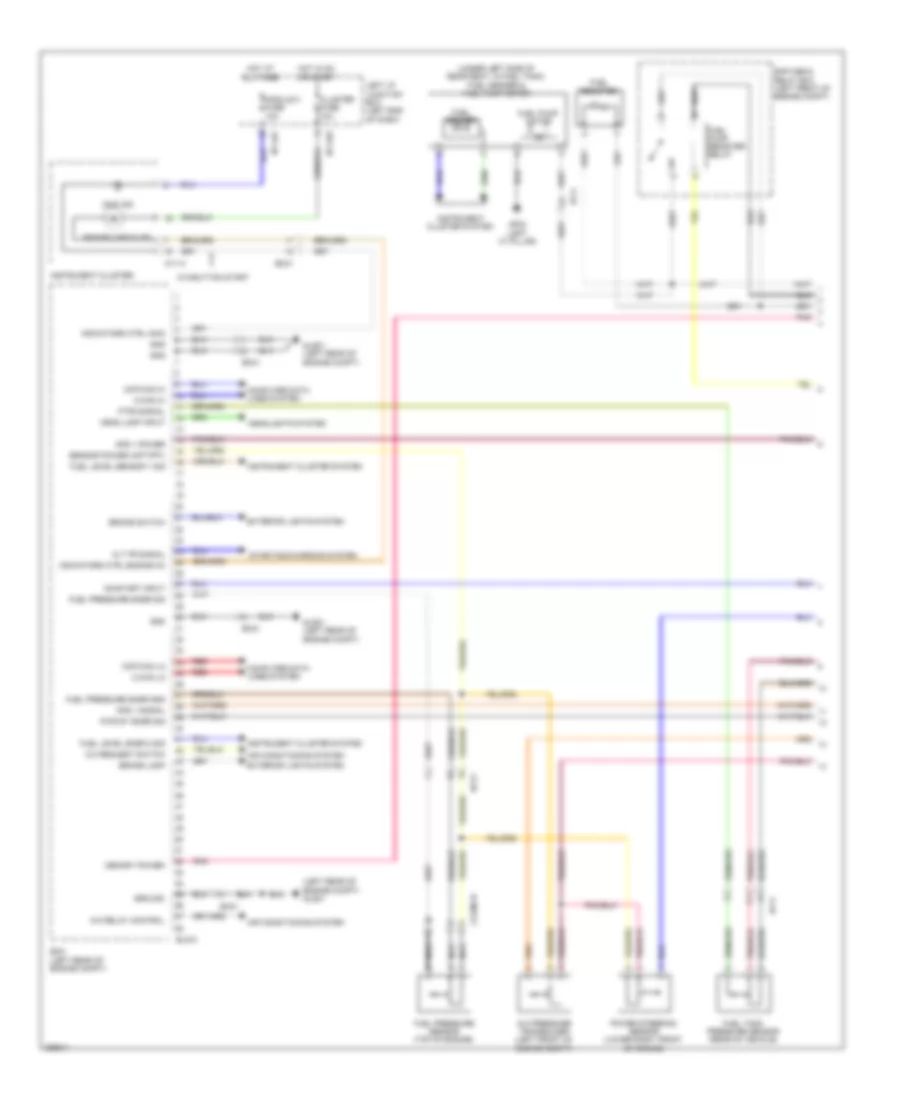
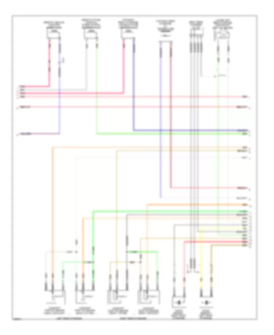
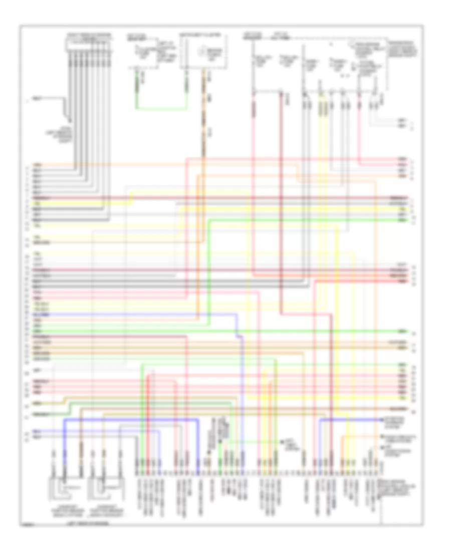
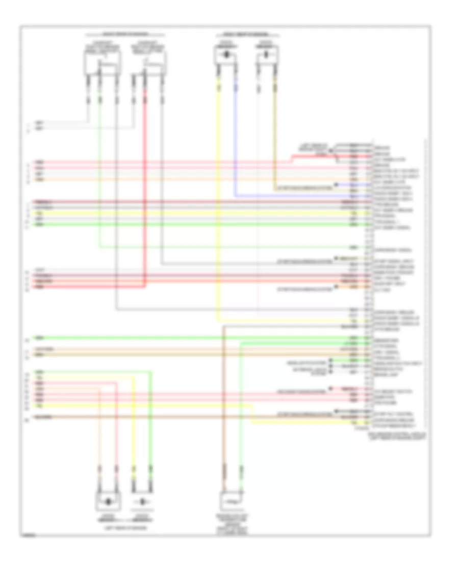
ENGINE PERFORMANCE
3.8L
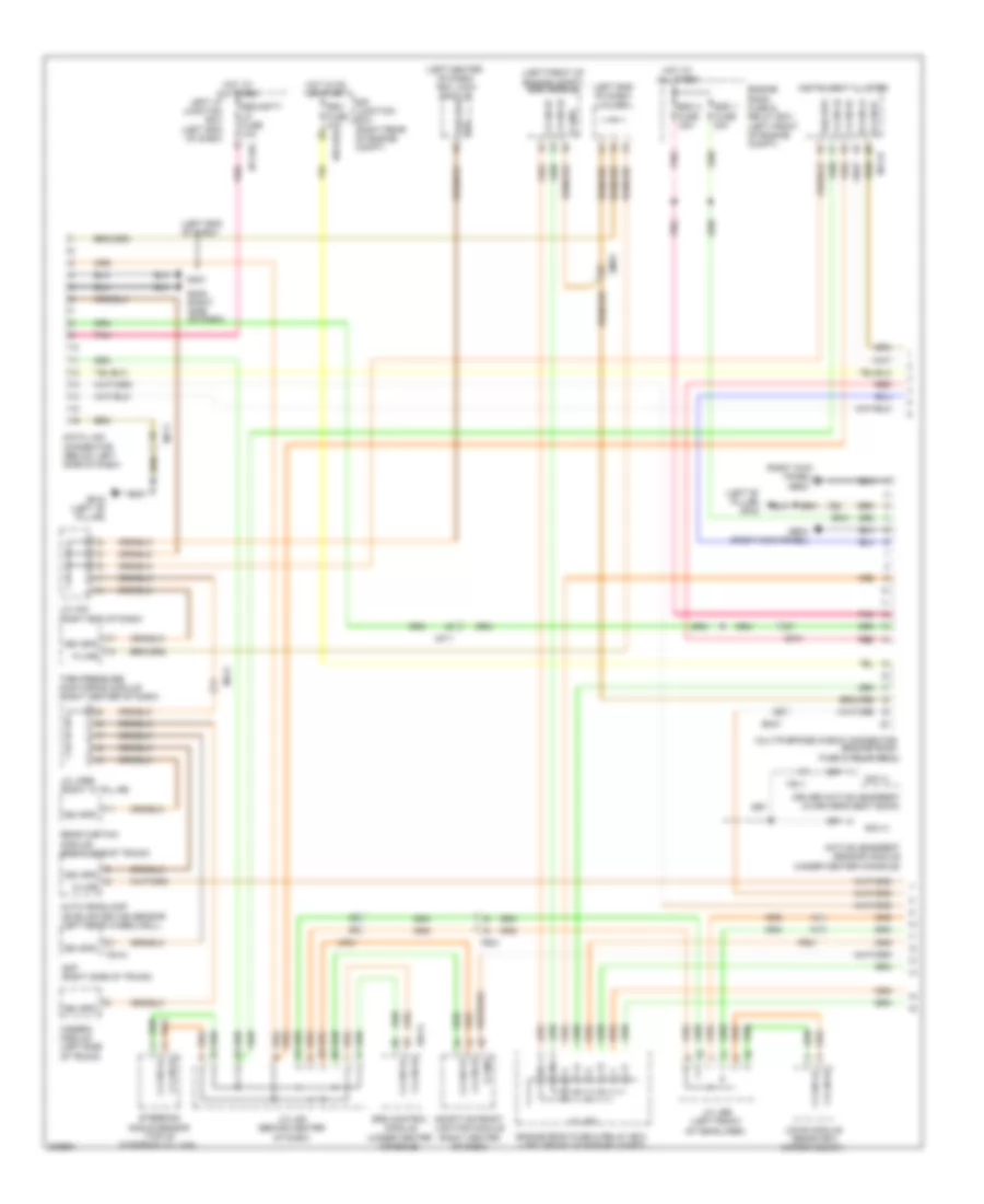
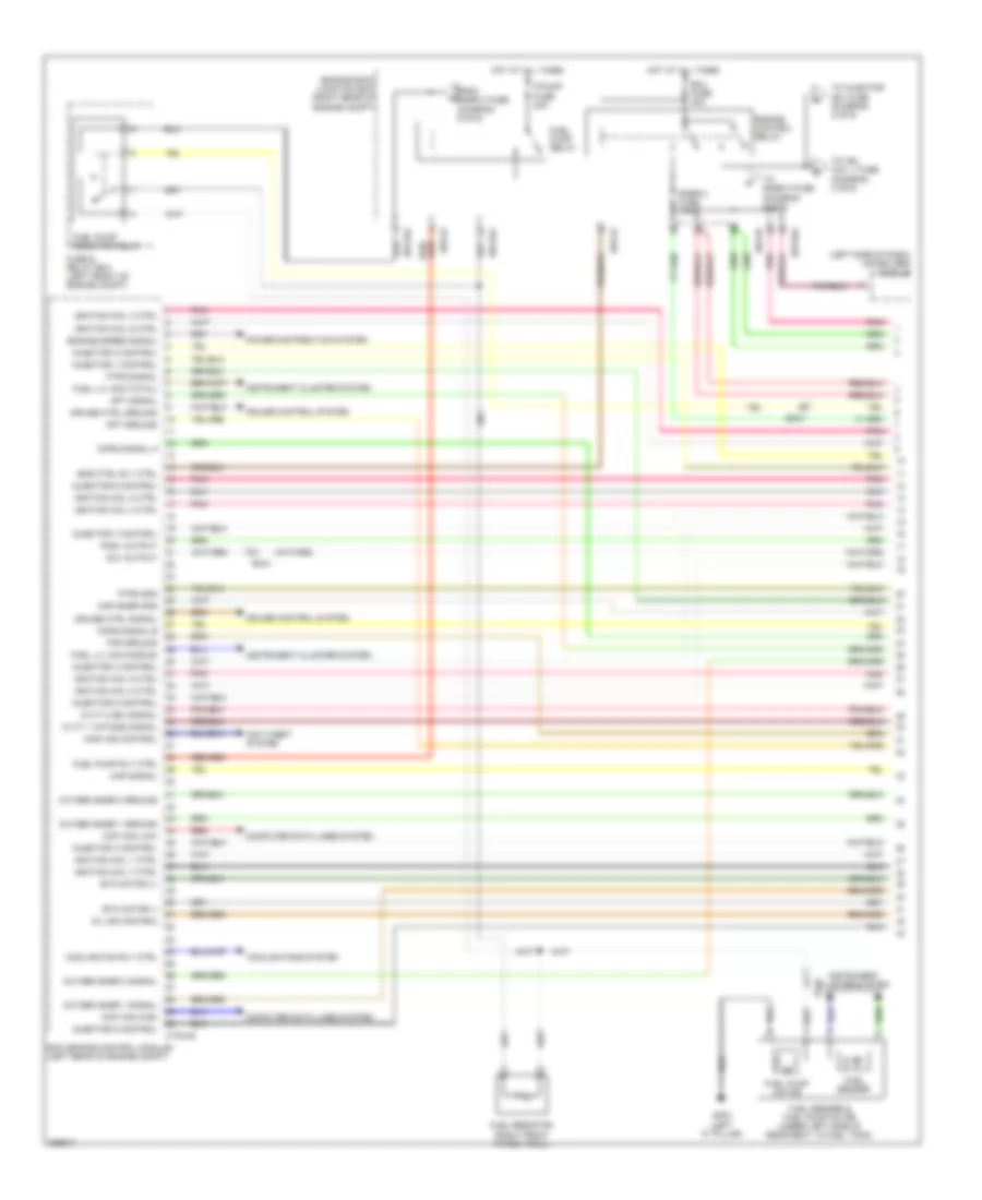
3.8L, Engine Performance Wiring Diagram (1 of 6) for Hyundai Genesis 3.8 2013
List of elements for 3.8L, Engine Performance Wiring Diagram (1 of 6) for Hyundai Genesis 3.8 2013:
- (left rear of engine compt) glg01
- (under left side of rear seat, in fuel tank)
- A/c pressure transducer (left front of engine compt)
- A/c relay control
- A/c request switch
- Air conditioning system
- Alt fr signal
- Aps 1 power
- Aps 1 signal
- Brake lamp
- Brake switch
- C-can hi
- C-can lo
- Ccp-can hi
- Ccp-can lo
- Clginj-b
- Cluster fuse 10a
- Computer data lines system
- E/r fuse & relay box (left front of engine compt)
- Ec21
- Ecm (left rear of engine compt)
- Ef11
- Elg-a
- Em31
- Engine check ind
- Exterior lights system
- Ftps signal
- Fuel level sensor 1 sig
- Fuel level snsr 2 sig
- Fuel pressure sensor (top of engine)
- Fuel pressure snsr gnd
- Fuel pressure snsr sig
- Fuel pump motor
- Fuel pump register relay
- Fuel register
- Fuel sender
- Fuel sender & fuel pump motor
- Fuel tank pressure sensor (rear of vehicle)
- Gf03 (left "c" pillar)
- Glg01 (left rear of engine compt)
- Gnd
- Ground
- Head lamp input
- Headlights system
- Hot at all times
- Hot in on or start
- I/p-lhe
- I/p-lhf
- Immo ind
- Indicators ctrl engine ck
- Indicators ctrl immo
- Instrument cluster
- Instrument cluster system
- Left i/p junction box (left end of dash)
- M11-a
- Memory power
- Module 3 fuse 10a
- Nca
- On/start input
- Pnk
- Power steering sensor (lower right front of engine)
- Pwr st snsr sig
- Red
- Sensor power (apt/fpt)
- Starting/charging system
- W/o button start
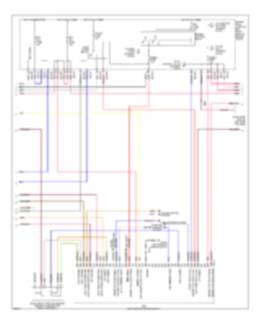
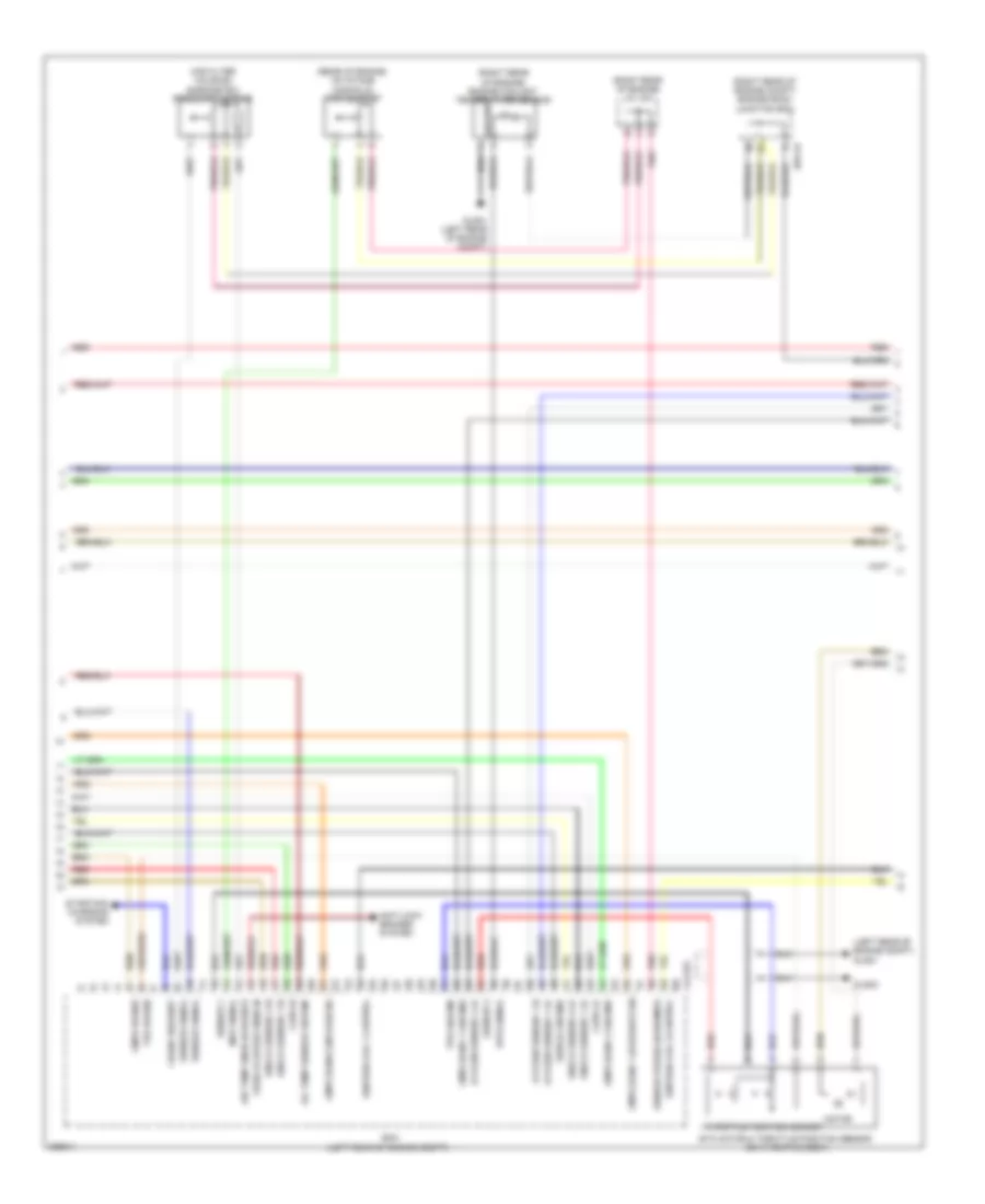
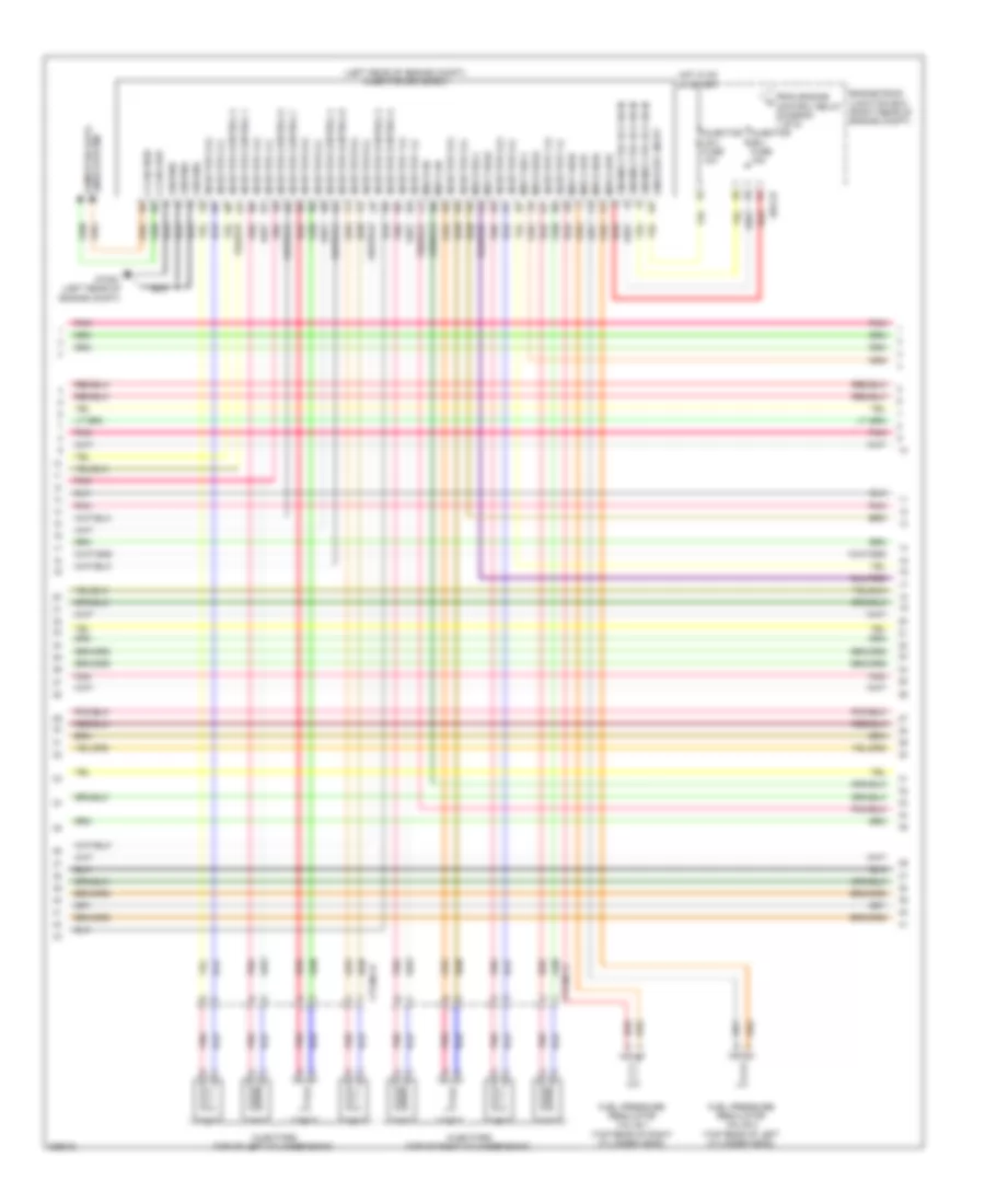
3.8L, Engine Performance Wiring Diagram (2 of 6) for Hyundai Genesis 3.8 2013
List of elements for 3.8L, Engine Performance Wiring Diagram (2 of 6) for Hyundai Genesis 3.8 2013:
- (not used)
- Accel pedal position sensor (behind accelerator pedal assembly)
- Alt c-terminal input
- Anti-theft system
- Aps 1 ground
- Aps 2 ground
- Aps 2 power
- Aps 2 signal
- Apt ground
- Apt signal
- Auto cruise switch gnd
- Auto cruise switch sig
- Ccv signal
- Cooling fan relay ctrl
- Cooling fans system
- Cruise control system
- Distribution system
- E/r-ca
- E/r-cb
- E/r-e1a
- E/r-e2a
- E/r-e2b
- Ec21
- Ecm (left rear of engine compt)
- Ecu (b+) fuse 15a
- Ecu (ig1) fuse 10a
- Ecu fuse 30a
- Elg-a
- Em21
- Engine control relay
- Engine ctrl relay 'on' in
- Engine ctrl relay ctrl
- Engine room junction box (right rear of engine compt)
- Engine rotation signal
- F/pump fuse 20a
- Fuel pump relay
- Fuel pump relay ctrl
- Fuel resistor relay ctrl
- Fuel tank pr snsr gnd
- Fuel tank pr snsr pwr
- Glg01 (left rear of engine compt)
- Ground
- Hot at all times
- Hot in on or start
- Immo signal
- Immobilizer module (left side of dash)
- Lin communication
- Memory power
- Pnk
- Power
- Red
- Snsr 2 fuse 10a
- Snsr 3 fuse 10a
- Start relay ctrl
- Starting/ charging system
- To ign coil 1 (diagram 6 of 6)
- To injector (b+) fuse (diagram 5 of 6)
- To oil control valve (diagram 6 of 6)
- To snsr 1 fuse (diagram 6 of 6)
3.8L, Engine Performance Wiring Diagram (3 of 6) for Hyundai Genesis 3.8 2013
List of elements for 3.8L, Engine Performance Wiring Diagram (3 of 6) for Hyundai Genesis 3.8 2013:
- (left rear of engine)
- (lower left rear of engine) crankshaft position sensor
- (rear of intake manifold) purge control solenoid valve
- (rear of vehicle) canister close valve
- (right rear of engine)
- (right rear of engine) j/c jca
- (top right front of engine) variable intake manifold valve
- (top right rear of engine) oil temperature sensor
- Camshaft position sensor (bank 1 exhaust)
- Camshaft position sensor (bank 1 intake)
- Camshaft position sensor (bank 2 exhaust)
- Camshaft position sensor (bank 2 intake)
- Ef11
- Knock sensor 1 (right front of engine)
- Knock sensor 2 (left front of engine)
- Nca
- Pnk
- Red
3.8L, Engine Performance Wiring Diagram (4 of 6) for Hyundai Genesis 3.8 2013
List of elements for 3.8L, Engine Performance Wiring Diagram (4 of 6) for Hyundai Genesis 3.8 2013:
- (air filter housing) barometric pressure sensor
- (left rear of engine compt) glg01
- (rear of engine, on intake manifold) map sensor
- (right rear of engine compt) engine room junction box
- (right rear of engine) engine coolant temperature sensor
- (right rear of engine) j/c jca
- Air temp snsr (exhaust)
- Anti-lock brakes system
- Ckps hi
- Ckps lo
- Clg-bg
- Cmps bank 1 (exhaust) sig
- Cmps bank 1 ground
- Cmps bank 2 ground
- Cmps bank2 (intake) sig
- Cmps power
- Crank request
- E/r-cb
- Ecm (left rear of engine compt)
- Etc motor & throttle position sensor (on throttle body)
- Glg01 (left rear of engine compt)
- Glg02
- Ground
- Ignition coil 1 control
- Ignition coil 3 control
- Knock sensor 1 hi
- Knock sensor 1 lo
- Knock sensor 2 hi
- Knock sensor 2 lo
- Map signal
- Motor
- Oil temp sensor ground
- Oxygen sensor 1 hi
- Oxygen sensor 1 lo
- Oxygen sensor 4 lo
- Pnk
- Red
- Sensor 1
- Sensor 2
- Sensor power (baro/map)
- Sensor signal
- Shield ground
- Starting/ charging system
- Throttle position sensor
- Tps ground
- Tps power
- Vehicle speed snsr in
- Wts signal
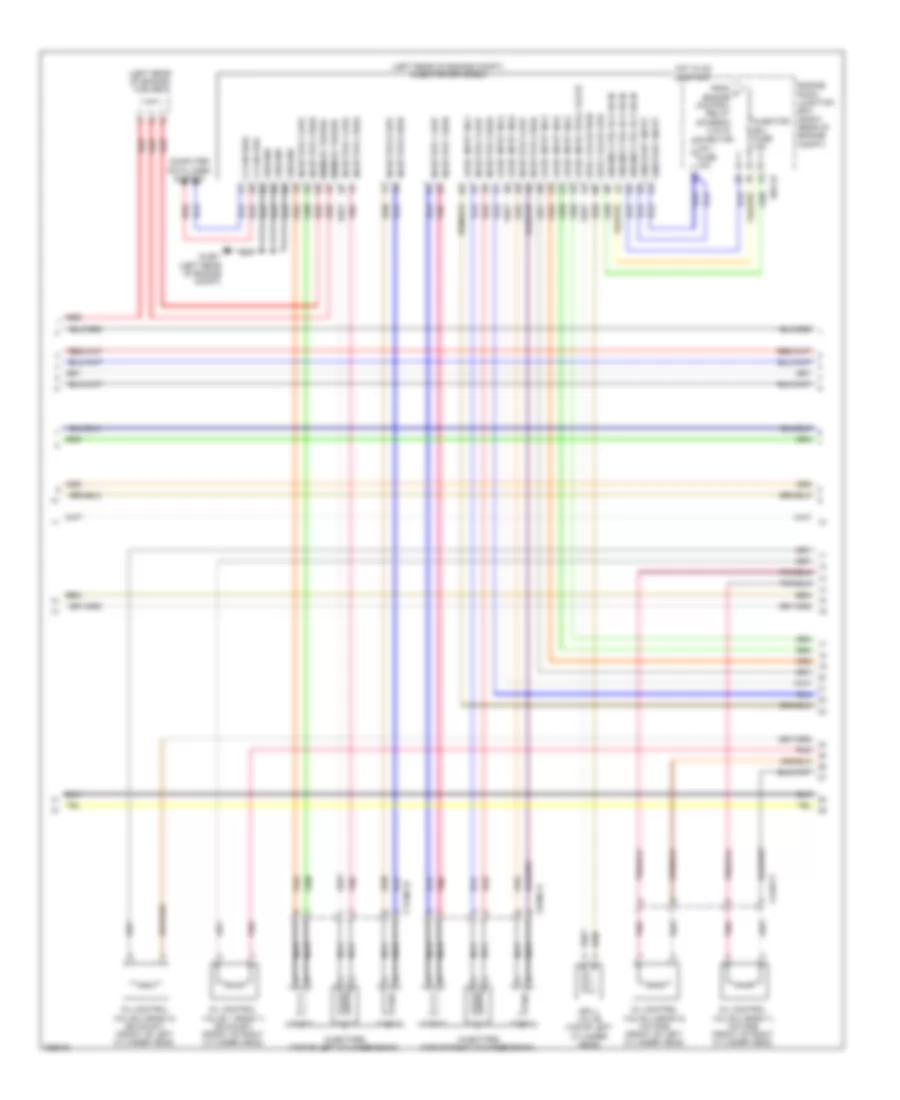
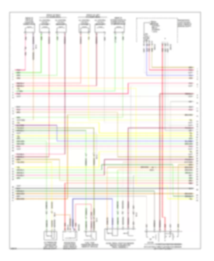
3.8L, Engine Performance Wiring Diagram (5 of 6) for Hyundai Genesis 3.8 2013
List of elements for 3.8L, Engine Performance Wiring Diagram (5 of 6) for Hyundai Genesis 3.8 2013:
- (left rear of engine compt) injector drive box
- (left rear of engine) j/c jcc
- C-can high
- C-can low
- Ciginj-a
- Clgocv
- Computer data lines system
- Ctginj-b
- E/r-cb
- Engine ctrl rly on in
- Engine room junction box (right rear of engine compt)
- From a engine control relay (diagram 2 of 6)
- Glg01 (left rear of engine compt)
- Ground
- Hot in on or start
- Injector (b+) fuse 15a
- Injector (ig1) fuse 10a
- Injector 1 high
- Injector 1 low
- Injector 2 high
- Injector 2 low
- Injector 3 high
- Injector 3 low
- Injector 4 high
- Injector 4 low
- Injector 5 high
- Injector 5 low
- Injector 6 high
- Injector 6 low
- Injectors (top of left cylinder bank)
- Injectors (top of right cylinder bank)
- Logic input inj1
- Logic input inj2
- Logic input inj3
- Logic input inj4
- Logic input inj5
- Logic input inj6
- Logic input spill valve
- Memory power
- Nca
- Oil control valve 1 (bank 1) (exhaust) (front of right cylinder head)
- Oil control valve 2 (bank 2) (exhaust) (front of left cylinder head)
- Oil control valve 3 (bank 1) (intake) (front of right cylinder head)
- Oil control valve 4 (bank 2) (intake) (front of left cylinder head)
- On/start input
- Pnk
- Red
- Spill valve (top of left cylinder head)
- Spill valve high
- Spill valve low
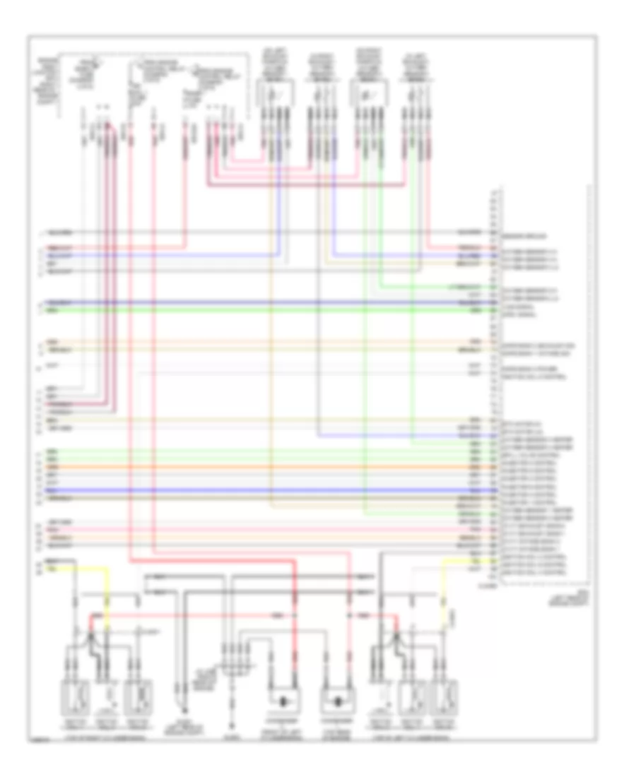
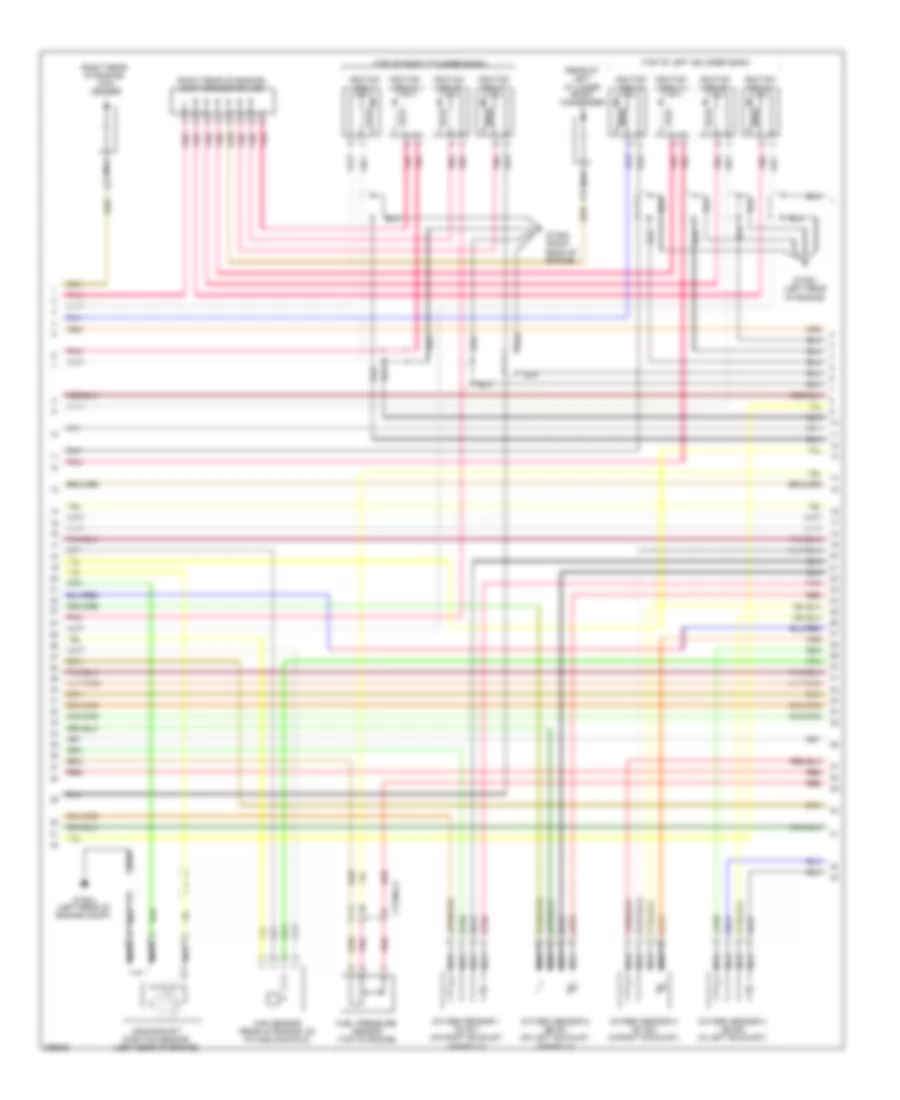
3.8L, Engine Performance Wiring Diagram (6 of 6) for Hyundai Genesis 3.8 2013
List of elements for 3.8L, Engine Performance Wiring Diagram (6 of 6) for Hyundai Genesis 3.8 2013:
- (in left exhaust) oxygen sensor 4 (b2/s2)
- (in right exhaust) oxygen sensor 3 (b1/s2)
- (on left exhaust manifold) oxygen sensor 1 (b1/s1)
- (on right exhaust manifold) oxygen sensor 2 (b2/s1)
- (right
- (top of left cylinder bank)
- (top of right cylinder bank)
- Box
- Clg-bg
- Clgig-1
- Clgig-2
- Cmps bank 1 (intake) sig
- Cmps bank 2 (exhaust) sig
- Cmps bank 2 power
- Condenser (front of left cylinder bank)
- Condenser (top rear of engine)
- Cpsv signal
- Cvvt (exhaust) bank 1
- Cvvt (exhaust) bank 2
- Cvvt (intake) bank 1
- Cvvt (intake) bank 2
- E/r-ca
- E/r-cb
- E/r-e2a
- Ecm (left rear of engine compt)
- Engine
- Engine compt)
- Etc motor (hi)
- Etc motor (lo)
- From b snsr 2 fuse (diagram 2 of 6)
- From engine control relay (diagram 2 of 6)
- Glg01 (left rear of engine compt)
- Glg02
- Ign coil 1 fuse 20a
- Ignition coil 1
- Ignition coil 2
- Ignition coil 2 control
- Ignition coil 3
- Ignition coil 4
- Ignition coil 4 control
- Ignition coil 5
- Ignition coil 5 control
- Ignition coil 6
- Ignition coil 6 control
- Inject0r 1 control
- Inject0r 2 control
- Inject0r 3 control
- Inject0r 4 control
- Inject0r 5 control
- Inject0r 6 control
- J/c jcb (right rear of engine)
- Junction
- Nca
- Oxygen sensor 1 heater
- Oxygen sensor 2 heater
- Oxygen sensor 2 hi
- Oxygen sensor 2 lo
- Oxygen sensor 3 heater
- Oxygen sensor 3 hi
- Oxygen sensor 3 lo
- Oxygen sensor 4 heater
- Oxygen sensor 4 hi
- Pnk
- Rear of
- Red
- Room
- Sensor ground
- Snsr 1 fuse 10a
- Spill valve control
- Vics signal
5.0L
5.0L, Engine Performance Wiring Diagram (1 of 6) for Hyundai Genesis 3.8 2013
List of elements for 5.0L, Engine Performance Wiring Diagram (1 of 6) for Hyundai Genesis 3.8 2013:
- (left side of dash) immobilizer module
- Anti-theft system
- Apt ground
- Apt signal
- Ccp can high
- Ccp can low
- Ccv output
- Ckps signal a
- Ckps signal b
- Computer data lines system
- Cooling fan rly ctrl
- Cooling fans system
- Cruise control system
- Cruise ctrl ground
- Cruise ctrl signal
- Ctg-ag
- Cvvt 1 (intake) signal
- Cvvt 2 (ex) signal
- E/r-ca
- E/r-cb
- E/r-e1a
- E/r-e2a
- Ec41
- Ecm (engine control module) (left rear of engine compt)
- Ecu fuse 30a
- Ef11
- Eng ctrl rly ctrl
- Engine control relay
- Engine room junction box (right rear of engine compt)
- Engine speed signal
- Etc motor (+)
- Etc motor (-)
- F/pump fuse 20a
- Fps ground
- From snsr 3 fuse (diagram 5 of 6)
- Ftps gnd
- Ftps signal
- Fuel lvl sig (middle)
- Fuel lvl sig (total)
- Fuel pump motor
- Fuel pump relay
- Fuel pump resistor relay
- Fuel pump rly ctrl
- Fuel resistor (right front wheel well)
- Fuel sender
- Fuel sender & fuel pump motor (under left side of rear seat, in fuel tank)
- Fuse & relay box (left front of engine compt)
- Gf03 (left "c" pillar)
- Hot at all times
- Ignition coil 1 ctrl
- Ignition coil 2 ctrl
- Ignition coil 3 ctrl
- Ignition coil 4 ctrl
- Ignition coil 5 ctrl
- Ignition coil 6 ctrl
- Ignition coil 7 ctrl
- Ignition coil 8 ctrl
- Immo ind control
- Injector 1 control
- Injector 2 control
- Injector 3 control
- Injector 4 control
- Injector 5 control
- Injector 6 control
- Injector 7 control
- Injector 8 control
- Instrument cluster system
- Map signal
- Map snsr gnd
- Mil ind control
- Oxygen snsr 1 ground
- Oxygen snsr 1 signal
- Oxygen snsr 2 ground
- Oxygen snsr 2 signal
- Pcsv output
- Pnk
- Power distribution system
- Red
- Snsr 2 fuse 10a
- To ign coil 1 fuse (diagram 3 of 6)
- To injector (b+) fuse (diagram 2 of 6)
- To snsr 3 fuse (diagram 5 of 6)
5.0L, Engine Performance Wiring Diagram (2 of 6) for Hyundai Genesis 3.8 2013
List of elements for 5.0L, Engine Performance Wiring Diagram (2 of 6) for Hyundai Genesis 3.8 2013:
- (left rear of engine compt) injector drive box
- C-can high
- C-can low
- Computer data lines system
- Ctginj-a
- Ctginj-b
- E/r-cb
- Engine ctrl rly on in
- Engine room junction box (right rear of engine compt)
- From engine control relay (diagram 1 of 6)
- Fuel pressure regulator valve 1 (top rear of right cylinder head)
- Fuel pressure regulator valve 2 (top rear of left cylinder head)
- Ground
- Gtg01 (left rear of engine compt)
- Hot in on or start
- Injector (b+) fuse 15a
- Injector (ig1) fuse 10a
- Injector 1 (+)
- Injector 1 (-)
- Injector 2 (+)
- Injector 2 (-)
- Injector 3 (+)
- Injector 3 (-)
- Injector 4 (+)
- Injector 4 (-)
- Injector 5 (+)
- Injector 5 (-)
- Injector 6 (+)
- Injector 6 (-)
- Injector 7 (+)
- Injector 7 (-)
- Injector 8 (+)
- Injector 8 (-)
- Injector control 1
- Injector control 2
- Injector control 3
- Injector control 4
- Injector control 5
- Injector control 6
- Injector control 7
- Injector control 8
- Injectors (top of left cylinder bank)
- Injectors (top of right cylinder bank)
- Msv1 high
- Msv1 low
- Msv1 on
- Msv1 sel0
- Msv1 sel1
- Msv2 high
- Msv2 low
- Msv2 on
- Msv2 sel0
- Msv2 sel1
- On/start input
- Pnk
- Red
5.0L, Engine Performance Wiring Diagram (3 of 6) for Hyundai Genesis 3.8 2013
List of elements for 5.0L, Engine Performance Wiring Diagram (3 of 6) for Hyundai Genesis 3.8 2013:
- (front of left cylinder head)
- (front of right cylinder head)
- (rear of intake manifold) purge control solenoid valve
- (rear of vehicle) canister close valve
- 1 of 6)
- A/c pressure transducer (left front of engine compt)
- Accel pedal position sensor (behind accelerator pedal assembly)
- Control relay (diagram
- E/r-ca
- E/r-cb
- E/r-e2a
- Ec41
- Ef11
- Engine room junction box (right rear of engine compt)
- Etc motor & throttle position sensor (on throttle body)
- From engine b
- Fuel tank pressure sensor (rear of vehicle)
- Ign coil 1 fuse 20a
- Motor
- Oil control valve 1 (intake)
- Oil control valve 2 (exhaust)
- Oil control valve 3 (intake)
- Oil control valve 4 (exhaust)
- Pnk
- Red
- Throttle position sensor
5.0L, Engine Performance Wiring Diagram (4 of 6) for Hyundai Genesis 3.8 2013
List of elements for 5.0L, Engine Performance Wiring Diagram (4 of 6) for Hyundai Genesis 3.8 2013:
- (rear of left cylinder bank) condenser
- (right rear of engine) con- denser
- (right rear of engine) joint connector jcb
- (top of left cylinder bank)
- (top of right cylinder bank)
- Crankshaft position sensor (left rear of engine)
- Ctginj-a
- Fuel pressure sensor (top of engine)
- Gtg01 (left rear of engine compt)
- Gtg02 (right rear of engine)
- Gtg03 (left rear of engine)
- Ignition coil 1
- Ignition coil 2
- Ignition coil 3
- Ignition coil 4
- Ignition coil 5
- Ignition coil 6
- Ignition coil 7
- Ignition coil 8
- Map sensor (rear of engine, on intake manifold)
- Nca
- Oxygen sensor 1 (b1/s1) (on right exhaust manifold)
- Oxygen sensor 2 (b2/s1) (on left exhaust manifold)
- Oxygen sensor 3 (b1/s2) (in right exhaust)
- Oxygen sensor 4 (b2/s2) (in left exhaust)
- Pnk
- Red
5.0L, Engine Performance Wiring Diagram (5 of 6) for Hyundai Genesis 3.8 2013
List of elements for 5.0L, Engine Performance Wiring Diagram (5 of 6) for Hyundai Genesis 3.8 2013:
- (left rear of engine)
- (right rear of engine) j/c jca
- A/c comp output
- Air conditioning system
- Alt fr
- Anti- theft system
- Apm 1 ground
- Apm 2 ground
- Apm 2 signal
- Brakes system anti-lock
- Camshaft position sensor (bank 2 exhaust)
- Camshaft position sensor (bank 2 intake)
- Can high
- Can low
- Check ind
- Cluster fuse 10a
- Cmps bank1 signal
- Cmps bank2 ground
- Cmps bank2 signal
- Computer data lines system
- Ctg-kg
- Cvvt 3 signal
- Cvvt 4 signal
- E/r-ca
- E/r-cb
- Ec41
- Ecm (engine control module) (left rear of engine compt)
- Ecu (b+) fuse 10a
- Ecu (ig1) fuse 10a
- Em31
- Engine
- Engine room junction box (right rear of engine compt)
- From engine control relay (diagram 1 of 6)
- Gtg01 (left rear of of engine compt)
- Hot at all times
- Hot in on or start
- I/p-lhe
- Immo sig
- Instrument cluster
- Knock snsr 2 sig a
- Knock snsr 2 sig b
- Knock snsr 4 sig a
- Knock snsr 4 sig b
- Left i/p junction box (left end of dash)
- M11-a
- Memory power
- Msv 1 on
- Msv 1 sel0
- Msv 1 sel1
- Msv 2 on
- Msv 2 sel0
- Msv 2 sel1
- Nca
- Oxy snsr 1 htr
- Oxy snsr 3 htr
- Oxy snsr 3 signal
- Oxy snsr 4 ground
- Pnk
- Red
- Snsr 1 fuse 10a
- Snsr 3 fuse 10a
- Starting/ charging system
- To fuel pump relay (diagram 1 of 6)
- Veh spd sig
5.0L, Engine Performance Wiring Diagram (6 of 6) for Hyundai Genesis 3.8 2013
List of elements for 5.0L, Engine Performance Wiring Diagram (6 of 6) for Hyundai Genesis 3.8 2013:
- (left rear of engine compt) gtg01
- (left rear of engine)
- (right rear of engine)
- A/c select switch
- Air conditioning system
- Alt com
- Apm 1 power
- Apm 1 signal
- Brake lamp
- Brake switch
- Camshaft position sensor (bank 1 exhaust)
- Camshaft position sensor (bank 1 intake)
- Cmps bank1 ground
- Cmps bank1 signal
- Cmps bank2 ground
- Ctg-kg
- Ecm (engine control module (left rear of engine compt)
- Eng ctrl rly on input
- Engine coolant temperature sensor (front of right cylinder head)
- Exterior lights system
- F/pump resister rly
- Fps power
- Fps signal
- Ground
- Headlamp switch input
- Headlights system
- Knock sensor 1
- Knock sensor 2
- Knock sensor 3
- Knock sensor 4
- Knock snsr 1 sig a
- Knock snsr 1 signal b
- Knock snsr 3 sig a
- Knock snsr 3 signal b
- Lin communication
- Nca
- On/start input
- Oxy snsr 2 htr
- Oxy snsr 3 ground
- Oxy snsr 3 htr
- Oxy snsr 4 signal
- Pnk
- Red
- Sensor gnd
- Snsr pwr
- Snsr pwr (tps/map)
- Start rly control
- Start signal input
- Starting/charging system
- Tps ground
- Tps signal 1
- Tps signal 2
- Wts ground
- Wts signal
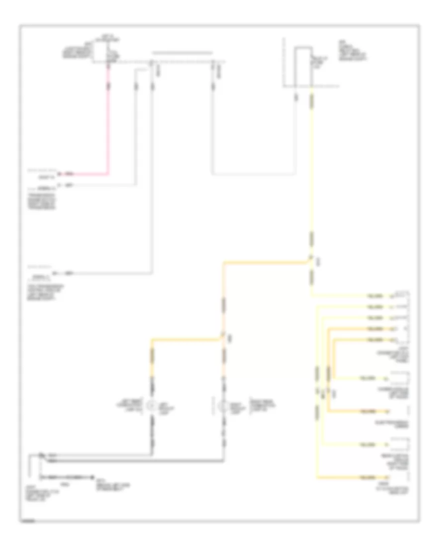
EXTERIOR LIGHTS
Backup Lamps Wiring Diagram for Hyundai Genesis 3.8 2013
List of elements for Backup Lamps Wiring Diagram for Hyundai Genesis 3.8 2013:
- A/v & navigation head unit
- B/up lp fuse 10a
- Camera module (left side of trunk)
- E/r fuse & relay box (left rear of engine compt)
- E/r junction box (right rear of engine compt)
- E/r-cb
- E/r-e2b
- Ef21
- Electrochromic mirror
- Fr02
- Fr21
- Gf10 (behind left side of rear seat)
- Hot in on or start
- Joint connector jflc (left kick panel)
- Joint connector jtlid (left side of trunk lid)
- Left backup lamp
- Left rear combination lamp (in)
- M25-e
- Mf11
- Nca
- On/st in
- Pnk
- Rear curtain module (right side of trunk)
- Right backup lamp
- Right rear combination lamp (in)
- Signal 2
- Tcm (transmission control module) (left rear of engine compt)
- Tcu fuse 15a
- Transmission range switch (right side of transmission)
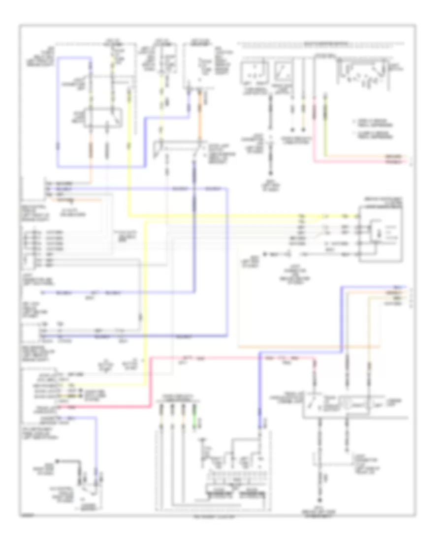
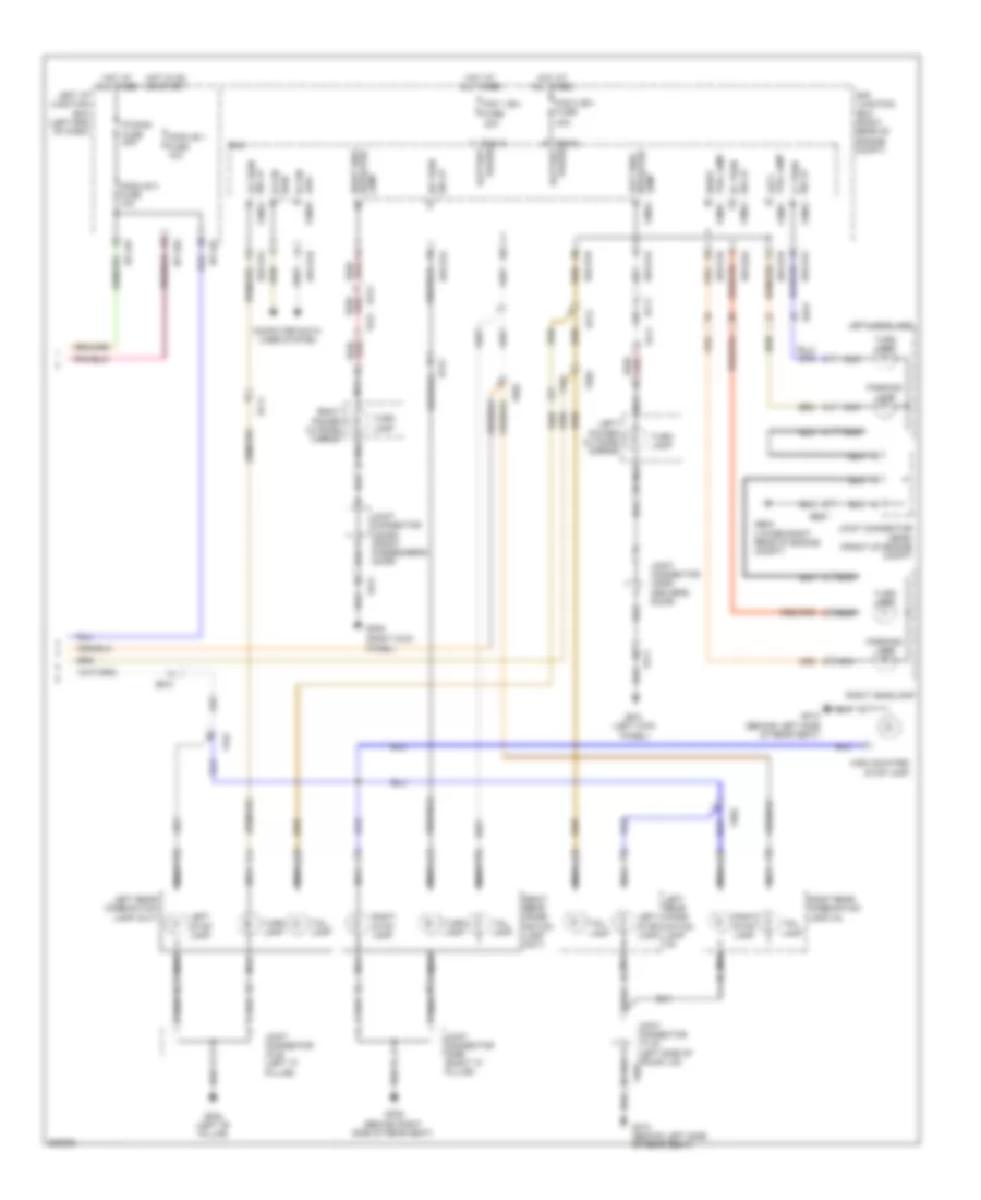
Exterior Lamps Wiring Diagram (1 of 2) for Hyundai Genesis 3.8 2013
List of elements for Exterior Lamps Wiring Diagram (1 of 2) for Hyundai Genesis 3.8 2013:
- (behind center
- (behind instrument cluster) stop signal relay
- (left end
- +5v30d
- 3.8l
- 5.0l
- A/c control module (right side of dash)
- Auto
- B-can high
- B-can low
- B-can transceiver
- C-can transceiver
- Close w/ brake
- Computer data lines system
- Cruise & epb
- Ctg-kg
- E/r fuse & relay box (left front of engine compt)
- E/r junction box (right rear of engine compt)
- E/r-e1a
- Ec41
- Ecm (engine control module) (left rear of engine compt)
- Elg-a
- Em21
- Em31
- Engine compt)
- Esc control module (left front of
- Fr02
- Front fog lamp switch
- Gf10 (behind left side of rear seat)
- Gm01
- Gm01 (left end of dash)
- Gm02 (right side of dash)
- Hazard switch
- Hazard switch m40-b
- Hot at all times
- Hot in on or start
- I/p-lhg
- Ill(+)
- Instrument cluster
- Ipm (instrument panel module) (left side of dash)
- Joint connector jea
- Joint connector jeb (left kick panel)
- Joint connector jmd (left end of dash)
- Joint connector jme
- Joint connector jtlid (left side of trunk lid)
- Key lock module (left center of dash)
- Left
- Left i/p junction box (left end of dash)
- Left turn ind
- License lamp
- Light switch
- M/f sw ecu
- M07-a
- M07-d
- M11-a
- M11-b
- M40-a
- M40-c
- Mcu
- Mem power
- Mf11
- Multi-function switch
- Nca
- Of dash)
- Off
- Open w/ brake
- Pedal depressed
- Pnk
- Right
- Right turn ind
- Stop lamp relay
- Stop lamp switch (above brake pedal, on bracket)
- Stop lp fuse 10a
- Stop lp s/wl brk
- Tail on ind
- Trunk lid handle sw
- Trunk lid handle switch
- Trunk lid handle switch & license lamp
- Turn signal lamp switch
- W/ auto
- W/ button start
- W/o auto cruise & epb
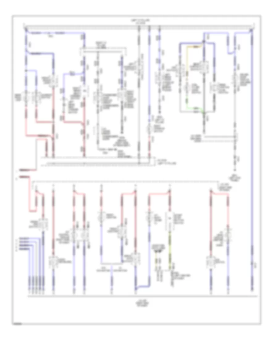
Exterior Lamps Wiring Diagram (2 of 2) for Hyundai Genesis 3.8 2013
List of elements for Exterior Lamps Wiring Diagram (2 of 2) for Hyundai Genesis 3.8 2013:
- (right kick
- 40a
- B-can high
- B-can low fam-b
- Computer data lines system
- E/r junction box (right rear of engine compt)
- E/r-e1a
- E/r-e1b
- E/r-e2a
- Ee21
- Ef11
- Ef21
- Ef31
- Fam
- Fam 1 (b+) fuse
- Fam 2 (b+) fuse
- Fam-a
- Fam-a battery power
- Fam-c
- Fam-c battery power
- Fd11
- Fd21
- Ff01
- Fr02
- Ge04 (lower right rear of engine compt)
- Gf01 (left kick panel)
- Gf02 (left "b" pillar)
- Gf05
- Gf09 (behind right side of rear seat)
- Gf10 (behind left side of rear seat)
- High mounted stop lamp
- Hot at all times
- Hot in on or start
- I/p-lhf
- I/p-lhg
- Joint connector jdass (front passenger's door)
- Joint connector jddri (driver's door)
- Joint connector jefem (front of engine compt)
- Joint connector jflb (left "c" pillar)
- Joint connector jfrb (right "c" pillar)
- Joint connector jtlid (left side of trunk lid)
- Lamp fam-a
- Left headlamp
- Left i/p junction box (left end of dash)
- Left power outside mirror
- Left rear combi- nation lamp (in)
- Left rear combination lamp (out)
- Left side repeater
- Left stop lamp
- Lr turn sig lp fam-a
- Module 1 fuse 10a
- Module 3 fuse 10a
- Nca
- P/conn fuse 30a
- Panel)
- Parking lamp
- Right headlamp
- Right power outside mirror
- Right rear combi- nation lamp (out)
- Right rear combination lamp (in)
- Right side repeater lamp
- Right stop lamp
- Right tail lamp fam-c
- Rr turn sig lp
- Sig lp lf turn
- Sig lp rf turn
- Tail lamp
- Tail lamp left
- Turn lamp
GROUND DISTRIBUTION
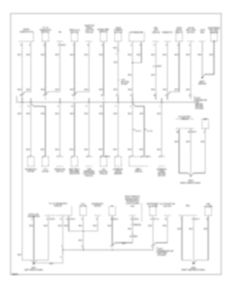
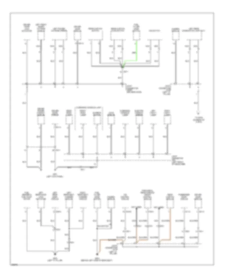
Ground Distribution Wiring Diagram (1 of 6) for Hyundai Genesis 3.8 2013
List of elements for Ground Distribution Wiring Diagram (1 of 6) for Hyundai Genesis 3.8 2013:
- (right rear of engine compt) engine room junction box
- A/c control module
- Adaptive front lighting module
- Body ground
- Crash pad switch
- Data link connector
- Door warning switch
- E/r-e1b
- Electronic battery sensor
- Em21
- Epb & avh switch
- Fam
- Fam-c
- Fet
- Fob holder
- Glove box lamp switch
- Gm01 (left end of dash)
- Gm02 (right side of dash)
- Gm04 (right center of dash)
- Immobilizer module
- Instrument cluster
- Ipm
- Joint box
- Joint connector jmd (left end of dash)
- Joint connector jme (behind center of dash)
- Key lock module
- M07-a
- M07-d
- M11-a
- M40-a
- M40-c
- M45-a
- M51-a
- M70-a
- M70-b
- Media module
- Mm01
- Multifunction switch
- Nca
- Pdm
- Rf receiver
- Rheostat
- Seat belt reminder indicator
- Sport mode switch
- Steering angle sensor
- Steering wheel heater switch
- Stop signal relay
- Telescopic motor
- Tilt & telescopic module
- Tilt & telescopic switch
- Tilt motor
- Tire pressure monitoring module
- W/ av
- W/o button start
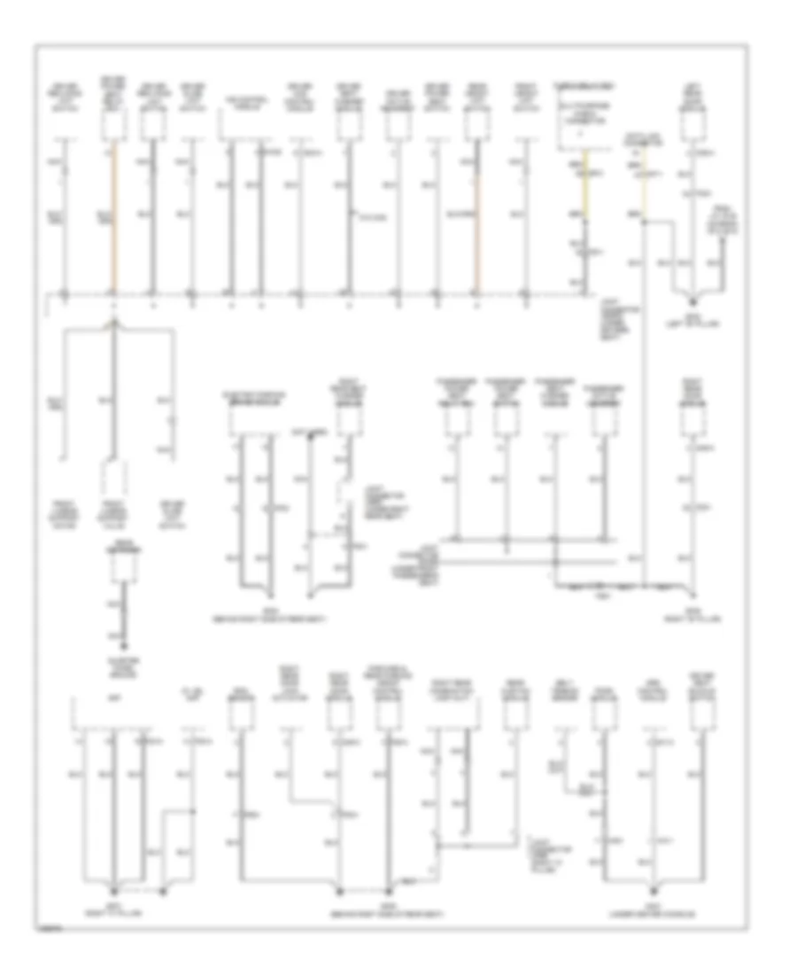
Ground Distribution Wiring Diagram (2 of 6) for Hyundai Genesis 3.8 2013
List of elements for Ground Distribution Wiring Diagram (2 of 6) for Hyundai Genesis 3.8 2013:
- A/v & navigation head unit
- Audio
- Aux
- Av head module
- Console lamp
- Console vent temperature actuator & switch
- Cooling fan controller
- D11-a
- D11-c
- Data link connector
- E05-b
- Esc module
- Fd21
- Front cigarette lighter
- Front monitor
- Front power outlet
- Fuse & relay box
- Ge01 (left front of engine compt)
- Ge02 (right kick panel)
- Gf05 (right kick panel)
- Gm03 (left center of dash)
- Gm05 (right side of dash)
- Gm06 (left end of dash)
- Instrument cluster
- Ipm
- Joint connector jdass (front passenger's door)
- Joint connector jmsex (under center door)
- M03-e
- M11-a
- M25-e
- M34-b
- M40-a
- Media jack module
- Mf11
- Mf21
- Mm11
- Mts module
- Multipurpose check connector
- Navigation
- Nca
- Passenger door lock actuator
- Passenger door module
- Passenger power window module
- Right front smart outside handle
- Right power outside mirror
- Steering wheel heater
- W/ av
- W/o av navigation
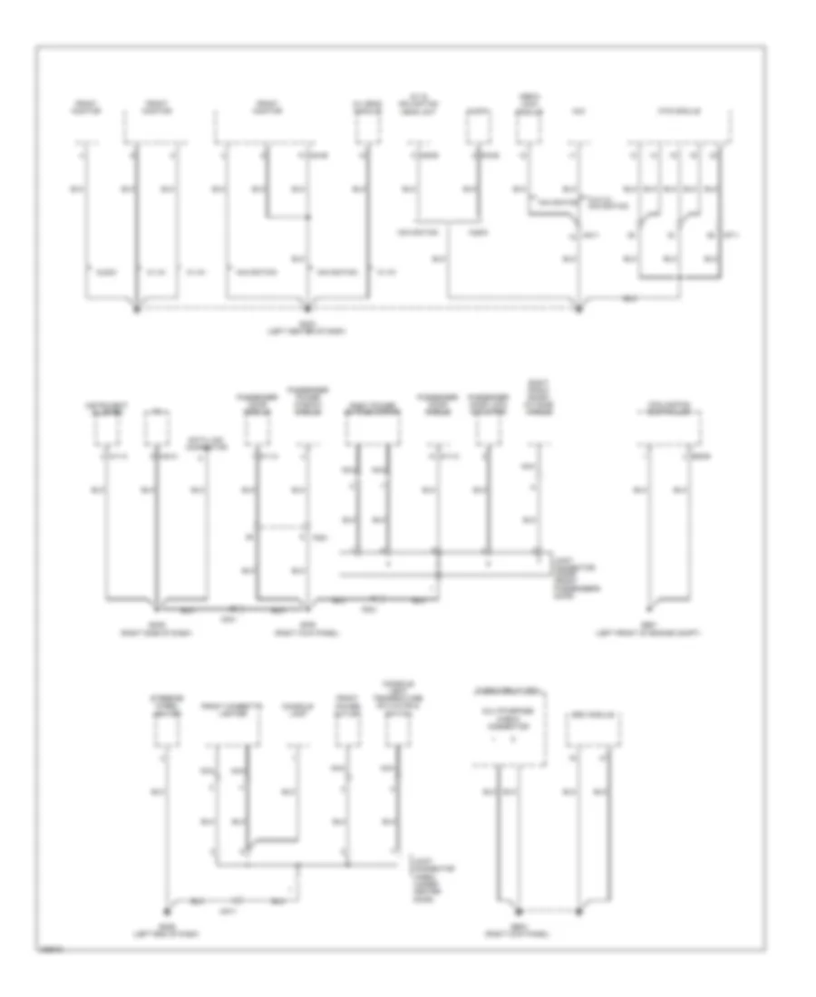
Ground Distribution Wiring Diagram (3 of 6) for Hyundai Genesis 3.8 2013
List of elements for Ground Distribution Wiring Diagram (3 of 6) for Hyundai Genesis 3.8 2013:
- (if equppied) ehps module
- (left front of engine compt) engine room fuse & relay box
- (right rear of engine compt) engine room junction box
- 3.8l
- Acc socket relay
- Active accel pedal module
- Aqs sensor
- Auto head lamp leveling device sensor
- Blower relay
- Brake fluid level sensor
- Brake vacuum pump
- Brake vacuum pump relay
- Burglar alarm horn
- Cooling fan relay
- E/r-e1b
- E/r-e2b
- E12
- Ee21
- Ee31
- Ef31
- Electronic control wiper module
- External buzzer
- Fam
- Fam-b
- Fam-c
- Ge03 (left front of engine compt)
- Ge04 (lower right rear of engine compt)
- Ge05 (right front of engine compt)
- Ge06 (left front of engine compt)
- Ge07 (lower right rear of engine compt)
- Hood switch
- J/c jefem (front of engine compt)
- Joint connector jeb (left kick panel)
- Left front fog lamp
- Left head lamp
- Left horn
- Nca
- Pdm (acc) relay
- Pdm (ign1) relay
- Pdm (ign2) relay
- Right front fog lamp
- Right head lamp
- Right horn
- Smart cruise control module
- Washer level sensor
- Washer motor
- Windshield defogger
Ground Distribution Wiring Diagram (4 of 6) for Hyundai Genesis 3.8 2013
List of elements for Ground Distribution Wiring Diagram (4 of 6) for Hyundai Genesis 3.8 2013:
- (not used)
- Camera module
- D01-a
- D01-c
- D11-c
- D39-a
- Dd11
- Driver door lock actuator
- Driver door module
- Driver power window module
- Electro chromic mirror
- F36-a
- Fd11
- Fd21
- Fd31
- Fd41
- Ff01
- Forward & rear parking assist control module
- Fr11
- Front room lamp
- Fs11
- Fs41
- Fuel filler door motor
- Fuel filler door switch
- Fuel sender & fuel pump motor
- Gf01 (left kick panel)
- Gf03 (left "c" pillar)
- Gf04 (behind left side of rear seat)
- Ims control module
- Ims switch
- Joint connector jddri (driver's door)
- Joint connector jfla (left "c" pillar)
- Joint connector jflb (left "c" pillar)
- Joint connector jra (left front of headliner)
- Ldws module
- Left front smart outside handle
- Left power outside mirror
- Left rear combination lamp (out)
- Left rear door lock actuator
- Left rear door module
- Left rear seat warmer module
- Left vanity lamp
- Navigation
- Nca
- Overhead console lamp
- Passenger door module
- Rear curtain & ims switch
- Rear curtain module
- Rear curtain switch
- Rear room lamp
- Right rear seat warmer module
- Right vanity lamp
- S15-d
- Sunroof switch
- To gfo2 (diagram of 5 of 6)
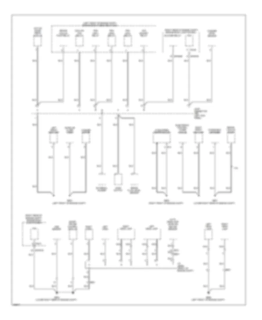
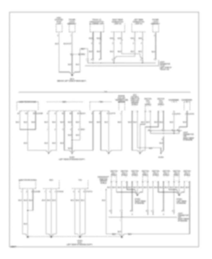
Ground Distribution Wiring Diagram (5 of 6) for Hyundai Genesis 3.8 2013
List of elements for Ground Distribution Wiring Diagram (5 of 6) for Hyundai Genesis 3.8 2013:
- (behind right side of rear seat)
- (not used)
- (under center console)
- A01-a
- Aa11
- Aa21
- Amp
- Av jbl amp
- Belt tension sensor
- D39-a
- D49-a
- Data link connector
- Driver active headrest
- Driver ccs control module
- Driver power seat relay box
- Driver power seat switch
- Driver reclining limit switch
- Driver seat buckle switch
- Driver seat warmer module
- Driver slide limit switch
- Ef31
- Electric parking brake module
- F03-a
- F08-a
- F36-a
- Fd31
- Fd41
- Ff02
- Forward & rear parking assist control module
- Fr21
- From j/c jflb (diagram of 4 of 6)
- Front height limit switch
- Front lumbar support motor
- Front lumbar support valve
- Fs11
- Fs21
- Fs41
- Fuse & relay box
- Ga01
- Gf02 (left "b" pillar)
- Gf06 (right "b" pillar)
- Gf07 (right "c" pillar)
- Gf08 (behind right side of rear seat)
- Gf09
- Ims control module
- Joint connector jfrb (right "c" pillar)
- Joint connector jsass (under front passenger's seat)
- Joint connector jsdri2 (under driver's seat)
- Joint connector jsrr (under right rear seat)
- Left rear door module
- Mf11
- Multipurpose check connector
- Nca
- Passenger active headrest
- Passenger power seat relay box
- Passenger power seat switch
- Passenger seat warmer module
- Pods module
- Quarter panel ground
- Rain sensor
- Rear curtain module
- Rear defogger
- Rear height limit switch
- Right rear combination lamp (out)
- Right rear door lock actuator
- Right rear door module
- Right rear seat warmer module
- S03-a
- S15-b
- Srs control module
- W/o ccs
Ground Distribution Wiring Diagram (6 of 6) for Hyundai Genesis 3.8 2013
List of elements for Ground Distribution Wiring Diagram (6 of 6) for Hyundai Genesis 3.8 2013:
- 3.8l
- Clg-idb
- Clg-tg
- Clg19-1
- Clg19-2
- Condenser
- Crankshaft position sensor shield
- Ctg-kg
- Ctg-tg
- Ec21
- Ecm
- Elg-a
- Engine coolant temperature sensor
- Etc motor & throttle position sensor shield
- Fr02
- Gf10 (behind left side of rear seat)
- Glg01 (left rear of engine compt)
- Glg02
- Gtg01 (5.0l) (left rear of engine compt)
- Gtg02 (right rear of engine)
- Gtg03 (left rear of engine)
- High- mounted stop lamp
- Ignition coil 1 shield
- Ignition coil 1,3,5 shield
- Ignition coil 2 shield
- Ignition coil 2,4,6 shield
- Ignition coil 3 shield
- Ignition coil 4 shield
- Ignition coil 5 shield
- Ignition coil 6 shield
- Ignition coil 7 shield
- Ignition coil 8 shield
- Injector drive box
- Joint connector jca (right rear of engine)
- Joint connector jcb (right rear of engine)
- Joint connector jtlid (left side of trunk lid)
- Left rear combination lamp (in)
- Nca
- Power latch assembly
- Right rear combination lamp (in)
- Tcm
- Trunk lid handle switch & license lamp
HEADLIGHTS
Adaptive Front Lighting Wiring Diagram for Hyundai Genesis 3.8 2013
List of elements for Adaptive Front Lighting Wiring Diagram for Hyundai Genesis 3.8 2013:
- (left end
- (left rear wheelwell)
- Adaptive front light module (right center of dash)
- Afsl fuse 10a
- Body k-line
- C-can high
- C-can low
- Cluster fuse 10a
- Computer data lines system
- Ee21
- Em21
- Em31
- Gm01
- Ground
- Hot in on or start
- I/p-lha
- I/p-lhe
- Instrument cluster
- J/c jme (behind center of dash)
- Ldm tell tale
- Led off
- Left front height sensor (in left front wheelwell)
- Left headlamp
- Left i/p junction box (left end of dash)
- Left rear height sensor
- Lin
- M11-a
- Mf11
- Nca
- Of dash)
- On/start input
- Right headlamp
- Vls (front) gnd
- Vls (front) pwr
- Vls (front) sig
- Vls (rear) gnd
- Vls (rear) pwr
- Vls (rear) sig
Headlamps Wiring Diagram for Hyundai Genesis 3.8 2013
List of elements for Headlamps Wiring Diagram for Hyundai Genesis 3.8 2013:
- (left end of dash) left i/p junction box
- 3.8l
- 5.0l
- Auto
- Auto headlamp leveling device sensor (left rear wheelwell)
- Auto light sensor
- Auto light sensor & security indicator (top left side of dash)
- B- can high
- B- can low
- Batt pwr
- Can high
- Can low
- Cluster fuse 10a
- Computer data lines system
- Ctg-kg
- Dim
- Dimmer/ passing switch
- E/r junction box (right rear of engine compt)
- E/r-cb
- E/r-e1a
- E/r-e1b
- E/r-e2a
- E/r-e2b
- Ecm (left rear of engine compt)
- Ee21
- Ee31
- Ef21
- Elg-a
- Fam
- Fam 1 (b+) fuse 40a
- Fam 2 (b+) fuse 40a
- Fam-a
- Fam-b
- Fam-c
- Front fog ind
- Front fog lamp switch
- Ge03 (left front of engine compt)
- Ge04 (lower right rear of engine compt)
- Ge06 (left front of engine compt)
- Ge07 (lower right rear of engine compt)
- Gm01 (left end of dash)
- Head lamp relay ctrl
- Head- lamp relay
- High beam ind
- Hot at all times
- Hot in on or start
- I/p-lhe
- I/p-lhf
- I/p-lhg
- Instrument cluster
- Ipm (instrument panel module) (left side of dash)
- Ipm fuse 10a
- J/c jefem (front of engine compt)
- J/c jmd (left side of dash)
- Left front fog lamp
- Left h/lp low fuse 15a
- Left headlamp
- Lh front fog lamp
- Lh head lamp hi
- Light switch
- M/f sw ecu
- M11-a
- M11-b
- M40-a
- M40-c
- Mcu
- Module 1 fuse 10a
- Module 3 fuse 10a
- Multi-function switch
- Nca
- Off
- P/conn fuse 30a
- Pass
- Pnk
- Red
- Rh front fog lamp
- Rh head lamp hi
- Right front fog lamp
- Right h/lp low fuse 15a
- Right headlamp
- Sens gnd
- Sens pwr
- Sens sig
- Shift resistor
- Transceiver b-can
- Transceiver c-can
- W/o hid
Headlamps Leveling Wiring Diagram, with AFLS for Hyundai Genesis 3.8 2013
List of elements for Headlamps Leveling Wiring Diagram, with AFLS for Hyundai Genesis 3.8 2013:
- (lower right rear of engine compt) ge04
- Adaptive front light module (right center of dash)
- Adaptive front lighting circuit
- Afls fuse 10a
- Afsl fuse 10a
- Computer data lines system
- E/r junction box (right rear of engine compt)
- E/r-e2a
- Ee21
- Em41
- Gm01 (left end of dash)
- Ground
- Headlamp
- Hot in on or start
- I/p-lha
- Ism
- J/c jefem (front of engine compt)
- J/c jme (behind center of dash)
- K-line
- Left
- Left hlld actuator
- Left i/p junction box (left end of dash)
- Nca
- On/start input
- Right
- Right hlld actuator
- Step mtr hlld actr
Headlamps Leveling Wiring Diagram, without AFLS for Hyundai Genesis 3.8 2013
List of elements for Headlamps Leveling Wiring Diagram, without AFLS for Hyundai Genesis 3.8 2013:
- (lower right rear of engine compt)
- Afsl fuse 10a
- Auto headlamp leveling device sensor (left rear wheelwell)
- Computer data lines system
- Cruise control system
- E/r junction box (right rear of engine compt)
- E/r-e2a
- E/r-e2b
- Ee21
- Ef21
- Ef31
- Em41
- Ge04
- Ground
- Head lamp relay
- Headlamp
- Headlamps circuit
- Hot at all times
- Hot in on or start
- I/p-lha
- Ipm fuse 10a
- Ism
- J/c jefem (front of engine compt)
- K-line
- Left
- Left hlld actuator
- Left i/p junction box (left end of dash)
- Mf11
- Nca
- On/off sig
- On/start input
- Right
- Right hlld actuator
- Sens output
- Speed sig
- Step mtr hlld actr
HORN
Horn Wiring Diagram for Hyundai Genesis 3.8 2013
List of elements for Horn Wiring Diagram for Hyundai Genesis 3.8 2013:
- Clock spring
- E/r junction box (right rear of engine compt)
- E/r-e1b
- E/r-e2b
- Ee21
- Em41
- Ge04 (lower right rear of engine compt)
- Horn fuse 15a
- Horn relay
- Horn switch
- Hot at all times
- Joint connector jefem (front of engine compt)
- Left horn (left front of engine compt)
- Multi-function switch (remote control)
- Nca
- Pnk
- Right horn (right front of engine compt)
- Steering wheel
INSTRUMENT CLUSTER
Instrument Cluster Wiring Diagram, with Conventional Cluster (1 of 2) for Hyundai Genesis 3.8 2013
List of elements for Instrument Cluster Wiring Diagram, with Conventional Cluster (1 of 2) for Hyundai Genesis 3.8 2013:
- (left side
- (left side of trunk lid) j/c jtlid
- (not used)
- (right rear of engine compt) engine room junction box
- (right side of dash) gm05
- (white/green/red)
- +5v30d
- +5v30g
- 3.8l
- 5.0l
- A/c control module (right side of dash)
- A/con (b+) fuse 10a
- Abs ind
- Acc/on input
- Adaptive front lighting module (right center of dash)
- Afls ind
- Anti-theft system
- Brk sig
- Can hi
- Can lo
- Charge ind
- Clg15
- Cluster fuse 10a
- Computer data lines system
- Cruise ind
- Ctg15
- Dial ill white ind
- Digital clock
- E/r-cb
- E/r-e2b
- Eco ind
- Eco-p ind
- Ecs ind
- Em21
- Engine check ind
- Engine controls system
- Epb ind
- Esc ind
- Esc off ind
- Fr02
- Fuel gauge
- Fuel gnd
- Gf10 (behind left side of rear seat)
- Gm01 (left end of dash)
- Graphic uc
- Ground
- High beam ind
- Hot at all times
- Hot in acc or on
- Hot in on or start
- I/p-lha
- I/p-lhe
- I/p-lhf
- I/p-rhd
- Ill (+)
- Ill (-)
- Ind
- Ind seat belt
- Instrument cluster
- Interior lights system
- Ipm (instrument
- J/c jfra (right "c" pillar)
- Joint connector jmd (left end of dash)
- Joint connector jme (behind center of dash)
- Ldws ind
- Led off ind
- Left front door switch (left "b" pillar)
- Left i/p junction box (left end of dash)
- Left rear door switch (left "c" pillar)
- Lf sw
- Low fuel ind
- Low washer ind
- Lr sw
- M07-d
- M11-a
- M11-b
- M40-b
- M40-c
- Mcu
- Memory pwr
- Mf11
- Mf21
- Module 2 fuse 10a
- Module 3 fuse 10a
- Mute
- Nca
- Of dash)
- Oil pressure
- Oil pressure switch (3.8l: front of left cylinder head) (5.0l: front of left cylinder bank)
- Panel module)
- Pointer ill white ind
- Power latch assembly (center rear of trunk lid)
- Pwr gnd
- Rf sw
- Right front door switch (right "b" pillar)
- Right i/p junction box (right end of dash)
- Right rear door switch (right "c" pillar)
- Rr sw
- Set ind
- Shift resistor
- Sig gnd
- Speaker
- Speedometer
- Sport mode sw
- Stand by
- Tachometer
- Temp gauge
- Tft lcd
- To left turn ind (diagram 2 of 2)
- To tpms fr ind (diagram 2 of 2)
- Tpms fl ind
- Tpms ind
- Tpms tread ind
- Trunk sw
- Warning systems
Instrument Cluster Wiring Diagram, with Conventional Cluster (2 of 2) for Hyundai Genesis 3.8 2013
List of elements for Instrument Cluster Wiring Diagram, with Conventional Cluster (2 of 2) for Hyundai Genesis 3.8 2013:
- +5v30d
- 3.8l
- 4p out
- 5.0l
- A/bag ind fuse 10a
- Air bag ind
- At-p
- B-can transceiver
- Brake fluid level sensor (on brake fluid reservoir)
- C-can transceiver
- Camera module (left side of trunk)
- Computer data lines system
- Cruise control system
- Ctg-ag
- Diode
- Door open ind
- Ec41
- Ecm (engine control module) (left rear of engine compt)
- Ef11
- Ef31
- Electric parking brake (epb) module (left rear wheelwell)
- Elg-a
- Em21
- Em31
- Ff01
- Ff02
- Fog lamp ind
- From tpms a fl ind (diagram 1 of 2)
- Fuel input
- Fuel sender
- Fuel sender & fuel pump motor (under left side of rear seat, in fuel tank)
- Fuel sub sender (top of fuel tank)
- Ge03 (left front of engine compt)
- High
- Hot in on
- Hot in on or start
- I/p-lha
- I/p-lhc
- I/p-lhg
- I/p-rhd
- Ill (+)
- Immo ind
- Instrument cluster
- Joint connector jeb (left kick panel)
- Left i/p junction box (left end of dash)
- Left turn ind
- Low
- M11-a
- M11-b
- Mcu
- Mf11
- Mf21
- Module 1 fuse 10a
- Parking brake ind
- Parking brake switch (above parking brake pedal, on bracket)
- Parking brk sig
- Pnk
- Rear curtain module (right side of trunk)
- Red
- Right i/p junction box (right end of dash)
- Right turn ind
- Shift resistor
- Starting/charging system
- Tail on ind
- Tpms fr ind
- Tpms rl ind
- Tpms rr ind
- W/ epb
- W/o epb
- Warning systems
- Washer level sensor (bottom of washer fluid reservoir)
Instrument Cluster Wiring Diagram, with Super Vision (1 of 2) for Hyundai Genesis 3.8 2013
List of elements for Instrument Cluster Wiring Diagram, with Super Vision (1 of 2) for Hyundai Genesis 3.8 2013:
- (left side
- (left side of trunk lid) j/c jtlid
- (not used)
- (right rear of engine compt) e/r junction box
- (right side of dash) gm05
- +5v30d
- +5v30g
- 3.8l
- 5.0l
- A/c control module (right side of dash)
- A/con (b+) fuse 10a
- Abs ind
- Acc/on input
- Adaptive front lighting module (right center of dash)
- Afls ind
- Anti-theft system
- Auto hold
- Brk sig
- Can hi
- Can lo
- Charge ind
- Clg15
- Cluster fuse 10a
- Computer data lines system
- Cruise ind
- Ctg15
- Dial ill white ind
- Digital clock
- E/r-cb
- E/r-e2b
- Ecs ind
- Em21
- Engine check ind
- Engine controls system
- Epb ind
- Esc ind
- Esc off ind
- Fr02
- Fuel gauge
- Fuel gnd
- Gf10 (behind left side of rear seat)
- Gia
- Gm01 (left end of dash)
- Ground
- High beam ind
- Hot at all times
- Hot in acc or on
- Hot in on or start
- I/p-lha
- I/p-lhe
- I/p-lhf
- I/p-rhd
- Ill (+)
- Ill (-)
- Ind seat belt
- Instrument cluster
- Interior lights system
- Ipm (instrument
- J/c jfra (right "c" pillar)
- Joint connector jmd (left end of dash)
- Joint connector jme (behind center of dash)
- Lcd ill (red) ind
- Lcd ill (white) ind
- Led off ind
- Left front door switch (left "b" pillar)
- Left i/p junction box (left end of dash)
- Left rear door switch (left "c" pillar)
- Lh fr sw
- Lh rr sw
- Low fuel ind
- Low washer ind
- M07-d
- M11-a
- M11-b
- M40-b
- M40-c
- Matrix display
- Mcu
- Memory pwr
- Mf11
- Mf21
- Module 2 fuse 10a
- Module 3 fuse 10a
- Module lcd control
- Nca
- Of dash)
- Oil pressure ind
- Oil pressure switch (3.8l: front of left cylinder head) (5.0l: front of left cylinder bank)
- Panel module)
- Pointer ill white ind
- Power latch assembly (center rear of trunk lid)
- Pwr gnd
- Rh fr sw
- Rh rr sw
- Right front door switch (right "b" pillar)
- Right i/p junction box (right end of dash)
- Right rear door switch (right "c" pillar)
- Set ind
- Shift resistor
- Sig gnd
- Speaker
- Speedometer
- Sport mode sw
- Tachometer
- Temp gauge
- To left turn ind (diagram 2 of 2)
- To tpms fr ind (diagram 2 of 2)
- To trunk open ind (diagram 2 of 2)
- Tpms fl ind
- Tpms ind
- Tpms tread ind
- Trunk sw
- Warning systems
- White) ind (green/
Instrument Cluster Wiring Diagram, with Super Vision (2 of 2) for Hyundai Genesis 3.8 2013
List of elements for Instrument Cluster Wiring Diagram, with Super Vision (2 of 2) for Hyundai Genesis 3.8 2013:
- +5v30d
- 3.8l
- 4p out
- 5.0l
- A/bag ind fuse 10a
- Air bag ind
- At-p
- B-can transceiver
- Brake fluid level sensor (on brake fluid reservoir)
- C-can transceiver
- Camera module (left side of trunk)
- Computer data lines system
- Cruise control system
- Ctg-ag
- Diode
- Door open ind
- Ec41
- Ecm (engine control module) (left rear of engine compt)
- Ef11
- Ef31
- Electric parking brake (epb) module (left rear wheelwell)
- Elg-a
- Em21
- Em31
- Ff01
- Ff02
- Fog lamp ind
- From tpms b fl ind (diagram 1 of 2)
- Fuel input
- Fuel sender
- Fuel sender & fuel pump motor (under left side of rear seat, in fuel tank)
- Fuel sub sender (top of fuel tank)
- Ge03 (left front of engine compt)
- High
- Hot in on
- Hot in on or start
- I/p-lha
- I/p-lhc
- I/p-lhg
- I/p-rhd
- Ill (+)
- Immo ind
- Instrument cluster
- Joint connector jeb (left kick panel)
- Left i/p junction box (left end of dash)
- Left turn ind
- Low
- M11-a
- M11-b
- Mcu
- Mf11
- Mf21
- Module 1 fuse 10a
- Parking brake ind
- Parking brake switch (above parking brake pedal, on bracket)
- Parking brk sig
- Pnk
- Rear curtain module (right side of trunk)
- Red
- Right i/p junction box (right end of dash)
- Right turn ind
- Shift resistor
- Starting/charging system
- Tail on ind
- Tpms fr ind
- Tpms rl ind
- Tpms rr ind
- Trunk open ind
- W/ epb
- W/o epb
- Warning systems
- Washer level sensor (bottom of washer fluid reservoir)
INTERIOR LIGHTS
Courtesy Lamps Wiring Diagram (1 of 2) for Hyundai Genesis 3.8 2013
List of elements for Courtesy Lamps Wiring Diagram (1 of 2) for Hyundai Genesis 3.8 2013:
- (driver's
- (driver's door) driver door module
- (front
- (front passenger's door) passenger door module
- (left kick panel) gf01
- (right kick panel) gf05
- (right rear of engine compt)
- +5v30d
- B-can hi
- B-can lo
- B-can transceiver
- C-can transceiver
- Computer data lines system
- D01-c
- D11-c
- Dd31
- Diode
- Door open ind
- Door)
- E/r junction box
- E/r-e1a
- E/r-e2a
- Ef21
- Ef31
- Fam
- Fam-b
- Fd11
- Fd21
- Fd31
- Foot lp
- Fr02
- Fr11
- Fr21
- Gf01 (left kick panel)
- Gf10 (behind left side of rear seat)
- High
- Hot at all times
- I/p-lhf
- Instrument cluster
- Ipm (instrument panel module) (left side of dash)
- J/c jdass
- J/c jddri
- J/c jfra (right "c" pillar)
- J/c jra (left front of headliner)
- J/c jtlid (left side of trunk lid)
- Left front door switch (left "b" pillar)
- Left i/p junction box (left end of dash)
- Left power outside mirror
- Left rear door switch (left "c" pillar)
- Left trunk room lamp
- Lh fr dr sw
- Lh rr dr sw
- Low
- M11-a
- M11-b
- M40-a
- M40-b
- M40-c
- Mcu
- Mf11
- Mf21
- Module 3 fuse 10a
- Nca
- Passenger's door)
- Power latch assembly (center rear of trunk lid)
- Puddle lamp
- Rh fr dr sw
- Rh rr dr sw
- Right front door switch (right "b" pillar)
- Right power outside mirror
- Right rear door switch (right "c" pillar)
- Right trunk room lamp
- Room lamp relay
- Room lamp relay control
- Room lp
- Room lp fuse 10a
- Shift resistor
- Trunk open ind
- Trunk sw
Courtesy Lamps Wiring Diagram (2 of 2) for Hyundai Genesis 3.8 2013
List of elements for Courtesy Lamps Wiring Diagram (2 of 2) for Hyundai Genesis 3.8 2013:
- (behind center of dash) j/c jme
- (right "c" pillar) j/c jfrb
- Dd11
- Dd21
- Dd31
- Dd41
- Dome
- Door
- Fd11
- Fd21
- Fd31
- Fd41
- Ff01
- Fr11
- Front room lamp
- Glove box lamp
- Glove box lamp switch
- Gm01 (left end of dash)
- Ill
- Instrument illumination circuit
- J/c jfla (left "c" pillar)
- J/c jflb (left "c" pillar)
- Left foot lamp
- Left front door lamp
- Left front door scuff lamp
- Left rear door lamp
- Left rear door scuff lamp
- Left vanity lamp
- Left vanity lamp switch
- Map lh
- Map rh
- Mf11
- Mf21
- Overhead console lamp
- Rear room lamp
- Right foot lamp
- Right front door lamp
- Right front door scuff lamp
- Right rear door lamp
- Right rear door scuff lamp
- Right vanity lamp
- Right vanity lamp switch
- Room
Instrument Illumination Wiring Diagram (1 of 2) for Hyundai Genesis 3.8 2013
List of elements for Instrument Illumination Wiring Diagram (1 of 2) for Hyundai Genesis 3.8 2013:
- (under center console) j/c jmsex
- A/v navigation head unit
- Ashtray illumination
- Audio
- Auto
- Aux
- Av & w/ navigation
- B-can hi
- B-can high
- B-can lo
- B-can low
- Batt pwr
- Clock spring
- Cluster fuse 10a
- Computer data lines system
- Console lamp
- Control
- Dial ill (white)
- Door warning switch (w/ button start)
- E/r junction box (right rear of engine compt)
- E/r-e1b
- E/r-e2a
- Em41
- Fam
- Fam 1 (b+) fuse 40a
- Fam 2 (b+) fuse 40a
- Fam-a
- Fam-b
- Fam-c
- Front cigarette lighter
- Gm01 (left end of dash)
- Gm03 (left center of dash)
- Gm06 (left end of dash)
- Hot at all times
- Hot in on
- Hot in on or start
- I/p-lha
- I/p-lhc
- I/p-lhe
- I/p-lhf
- I/p-lhg
- I/p-rhd
- Ill
- Ill(+)
- Instrument cluster
- Ipm (instrument panel module) (left side of dash)
- J/c jmc (right end of dash)
- J/c jmd (left side of dash)
- J/c jme (behind center of dash)
- J/c jmf (right end of dash)
- Key hole ill
- Key ill
- Key illumination fuse 10a
- Lcd ill (red)
- Lcd ill (white)
- Left audio remocon switch
- Left i/p junction box (left end of dash)
- Light
- M/f sw ecu
- M03-e
- M11-a
- M25-e
- M40-b
- M40-c
- Mcu
- Media jack module
- Mf11
- Mm11
- Module 1 fuse 10a
- Module 3 fuse 10a
- Multi-function switch
- Navigation
- Navigation system
- Nca
- Off
- Pointer ill (white)
- Rheostat
- Right audio & cruise remocon switch
- Right i/p junction box (right end of dash)
- Shift resistor
- Steering
- Switch
- W/ conventional type
- W/ navigation
- W/ supervision type
- W/o navigation
- Wheel
Instrument Illumination Wiring Diagram (2 of 2) for Hyundai Genesis 3.8 2013
List of elements for Instrument Illumination Wiring Diagram (2 of 2) for Hyundai Genesis 3.8 2013:
- (left "c" pillar)
- (left "c" pillar) j/c jflb
- (right "c" pillar) j/c jfra
- (right end of dash)
- A/c control module (right side of dash)
- A/t shift lever ill
- Audio (keyboard)
- Av head module (center of dash)
- B-can hi
- B-can lo
- Computer data lines system
- Crash pad switch
- D01-c
- D11-c
- D39-a
- D49-a
- Dd11
- Dis switch
- Driver door module (driver's door)
- Ef11
- Epb & avh switch
- F15-b
- F17-b
- Fd11
- Fd21
- Fd31
- Fd41
- Ff01
- Fr11
- Front monitor
- Front room lamp
- Fs41
- Fuel filler door switch
- Gf01 (left kick panel)
- Gf03 (left "c" pillar)
- Gf05 (right kick panel)
- Gf09 (behind right side of rear seat)
- Ims switch
- J/c jdass (front passenger's door)
- J/c jddri (driver's door)
- J/c jflb
- J/c jmc
- J/c jmf (right end of dash)
- Left console switch
- Left rear door module (left d39-a
- Left rear seat warmer switch
- M07-a
- M07-d
- M34-b
- M51-b
- Navigation
- Nca
- Passenger door module (front passenger's door)
- Pdm (left center of dash)
- Rear curtain & ims switch
- Rear curtain switch
- Rear door)
- Rear room lamp
- Right console switch
- Right rear door module (right rear door)
- Right rear seat warmer switch
- Ssb ill pwr
- Start stop button switch
- Sunroof switch
- W/o
MEMORY SYSTEMS
Driver"s Memory Seat Wiring Diagram (1 of 2) for Hyundai Genesis 3.8 2013
List of elements for Driver"s Memory Seat Wiring Diagram (1 of 2) for Hyundai Genesis 3.8 2013:
- (in driver's seat back) front lumbar support motor
- Back
- Can hi
- Can lo
- Computer data lines system
- Down
- Driver reclining limit switch (in driver's seat back)
- Driver slide limit switch (under driver's seat)
- Ef31
- Engine room fuse & relay box (left front of engine compt)
- Front height limit switch (under driver's seat)
- Fs11
- Fwd
- Gf02 (left ``b" pillar)
- Gf04 (behind left side of rear seat)
- Gnd
- Hot at all times
- Hot in on or start
- I/p-lhf
- I/p-lhg
- Ims control module (under driver's seat)
- J/c jfla (left "c" pillar)
- J/c jsdri2 (under driver's seat)
- Left i/p junction box (left end of dash)
- Memory pwr
- Module 1 fuse 10a
- Module 3 fuse 10a
- Nca
- On/st in
- P/seat drv fuse 30a
- Pnk
- Pwr
- Pwr b+
- Rear height limit switch (under driver's seat)
- Red
- Red mf11
- S15-a
- S15-b
- S15-c
- S15-d
- Ss11
Driver"s Memory Seat Wiring Diagram (2 of 2) for Hyundai Genesis 3.8 2013
List of elements for Driver"s Memory Seat Wiring Diagram (2 of 2) for Hyundai Genesis 3.8 2013:
- Can high
- Can low
- Computer data lines system
- D01-b
- D01-c
- Dd11
- Down
- Driver door module (driver's door)
- Driver power seat switch
- Driver reclining motor (in driver's seat back)
- Driver slide motor (under driver's seat)
- Fd11
- Front height motor (under driver's seat)
- Front height switch
- Front lumbar support switch
- Front lumbar support valve (in driver's seat back)
- Gf01 (left kick panel)
- Ill
- Ims switch
- Interior lights system
- J/c jddri (driver's door)
- J/c jsdri1 (under driver's seat)
- Less -
- More +
- Nca
- P1 sw
- P2 sw
- Pnk
- Rear curtain & ims switch
- Rear height motor (under driver's seat)
- Rear height switch
- Recline switch
- Set
- Slide switch
- Ss11
- Sw1
- Sw2
- Sw3
- Sw4
Memory Power Tilt & Power Telescopic Wiring Diagram for Hyundai Genesis 3.8 2013
List of elements for Memory Power Tilt & Power Telescopic Wiring Diagram for Hyundai Genesis 3.8 2013:
- B-can hi
- B-can lo
- Backward
- Can high
- Can low
- Computer data lines system
- D01-b
- D01-c
- Dd11
- Down
- Driver door module (driver's door)
- Fd11
- Forward
- Gf01 (left kick panel)
- Gm01 (left end of dash)
- Hot at all times
- Hot in on or start
- I/p-lhe
- I/p-lhf
- I/p-lhg
- Ill
- Ims switch
- Interior lights system
- Ips down
- Ips up
- J/c jddri (driver's door)
- J/c jmd (left end of dash)
- J/c jme (behind center of dash)
- Left i/p junction box (left end of dash)
- Limit sw backward
- Limit sw down
- Limit sw forward
- Limit sw up
- M70-a
- M70-b
- Memory pwr
- Module 1 fuse 10a
- Module 3 fuse 10a
- Nca
- On/start in
- P/handle fuse 15a
- P1 sw
- P2 sw
- Pnk
- Pwr gnd
- Rear curtain & ims switch
- Red
- Sens gnd
- Sens vcc
- Set
- Sig gnd
- Tele backward
- Tele forward
- Telescopic motor (on steering column)
- Telescopic switch
- Tilt & telescopic module (left side of dash)
- Tilt & telescopic switch
- Tilt dwn
- Tilt motor (on steering column)
- Tilt switch
- Tilt up
NAVIGATION
Driver Information System Wiring Diagram (1 of 4) for Hyundai Genesis 3.8 2013
List of elements for Driver Information System Wiring Diagram (1 of 4) for Hyundai Genesis 3.8 2013:
- (left center of dash) gm03
- (not used)
- Acc/on in
- Ant wrc
- Audio (b+) fuse 15a
- Audio (ig1) fuse 10a
- Aux gnd
- Aux l
- Aux r
- Av head module (center of dash)
- Body k-line
- Camera module (left side of trunk)
- Computer data lines system
- Dis switch
- Em41
- Esc module (left front of engine compt)
- Fr11
- Gnd
- Hot at all times
- Hot in on or start
- I/p-lhc
- I/p-lhg
- Ill (+)
- Ill (-)
- Interior lights system
- J/c jma (behind center of dash)
- J/c jrb (left front of headliner)
- Left i/p junction box (left end of dash)
- M-can high
- M-can low
- M06
- Memory pwr
- Mf11
- Mic (+)
- Mic (-)
- Mm11
- Most e wake up
- Nca
- On/start in
- Pnk
- Pwr
- Red
- Reset
- Shield gnd
- Speed sig
- Video gnd
- Video in
- Video sig
- Wake up
Driver Information System Wiring Diagram (2 of 4) for Hyundai Genesis 3.8 2013
List of elements for Driver Information System Wiring Diagram (2 of 4) for Hyundai Genesis 3.8 2013:
- (left end of dash)
- Acc/on in
- Aux detect
- Aux gnd
- Aux l
- Aux l in
- Aux r
- Aux r in
- Aux ref
- Av head module (center of dash)
- Computer data lines system
- Data
- Front monitor
- Gm01
- Gm03 (left center
- Gnd
- Ill (+)
- Interior lights system
- J/c jma (behind center of dash)
- J/c jme (behind center of dash)
- M-can high
- M-can low
- M31
- M45-a
- M45-b
- Media jack module
- Media module (right side of dash)
- Memory pwr
- Mf11
- Mm11
- Nca
- Of dash)
- Pnk
- Red
- Tx0+
- Tx0-
- Tx1+
- Tx1-
- Tx2+
- Tx2-
- Txclk+
- Txclk-
- Usb 5v
- Usb d+/ipod tx
- Usb d-/ipod rx
- Usb d-/ipod tx
- Usb gnd
- Video gnd
- Video in
Driver Information System Wiring Diagram (3 of 4) for Hyundai Genesis 3.8 2013
List of elements for Driver Information System Wiring Diagram (3 of 4) for Hyundai Genesis 3.8 2013:
- (+)
- (-)
- (mute)
- Clock spring
- Computer data lines system
- Disp
- Down
- Free
- Gm01 (left end of dash)
- Hot at all times
- Hot in on or start
- I/p-lhf
- I/p-lhg
- Ill
- Interior lights system
- J/c jmd (left end of dash)
- Left audio remocon switch
- Left i/p junction box (left end of dash)
- M/f sw ecu
- Mode
- Module 1 fuse 10a
- Module 3 fuse 10a
- Multi-function switch
- Multi-function switch (remote control)
- Nca
- Pnk
- Reset
- Right audio & cruise remocon switch
- Scan
- Sds
- Seek
- Steering wheel
- Trip
- Vol
Driver Information System Wiring Diagram (4 of 4) for Hyundai Genesis 3.8 2013
List of elements for Driver Information System Wiring Diagram (4 of 4) for Hyundai Genesis 3.8 2013:
- (+)
- (-)
- Amp 1 fuse 40a
- Audio fuse 10a
- Av jbl amp (right side of trunk)
- Center speaker
- Dd11
- Dd21
- Dd31
- Dd41
- Deck rl (+)
- Deck rl (-)
- Deck rr (+)
- Deck rr (-)
- Ef21
- F07
- F08-a
- F08-b
- Fd11
- Fd21
- Fd31
- Fd41
- Ff01
- Fl (+)
- Fl (-)
- Fr (+)
- Fr (-)
- Fuse & relay box (left front of engine compt)
- Gf07 (right "c" pillar)
- Glass antenna
- Gnd
- Hot at all times
- Hot in acc or on
- I/p-rhd
- Left deck speaker
- Left front door middle speaker
- Left front door speaker
- Left front tweeter speaker
- Left rear door speaker
- Left rear tweeter speaker
- Memory pwr
- Mf21
- Most e wake up
- Nca
- Pnk
- Radio tuner
- Red
- Right deck speaker
- Right front door middle speaker
- Right front door speaker
- Right front tweeter speaker
- Right i/p junction box (right end of dash)
- Right rear door speaker
- Right rear tweeter speaker
- Rl (+)
- Rl (-)
- Rr (+)
- Rr (-)
- S/woofer 1 (+)
- S/woofer 1 (-)
- S/woofer 2 (+)
- S/woofer 2 (-)
- Sub woofer
Lane Departure Warning Wiring Diagram for Hyundai Genesis 3.8 2013
List of elements for Lane Departure Warning Wiring Diagram for Hyundai Genesis 3.8 2013:
- C-can high
- C-can low
- Computer data lines system
- Crash pad switch
- Fr11
- Fr21
- Gf01 (left kick panel)
- Gm01 (left end of dash)
- Gnd
- Hot in on or start
- Ill
- Interior lights system
- Ip-lhg
- J/c jfla (left "c" pillar)
- J/c jme (behind center of dash)
- J/c jra (left front of headliner)
- Ldws module (rearview mirror mount)
- Ldws sw
- Ldws switch
- Left i/p junction box (left end of dash)
- Mf11
- Mf21
- Module 1 fuse 10a
- On/start in
- Pnk
- Power distribution system
Mobile Telematic System Wiring Diagram for Hyundai Genesis 3.8 2013
List of elements for Mobile Telematic System Wiring Diagram for Hyundai Genesis 3.8 2013:
- (left center of dash)
- Acc/on in
- Ant cdma
- Ant gps
- Antenna
- Audio (b+) fuse 15a
- Audio (ig1) fuse 10a
- Audio fuse 10a
- Av head
- Av head module (center of dash)
- C-can hi
- C-can lo
- Cdma
- Computer data lines system
- Crash sens
- Electro- chromic mirror
- F52
- Fr11
- Gm03
- Gnd
- Gps ant
- Hot at all times
- Hot in acc or on
- Hot in on or start
- I/p-lhc
- I/p-lhg
- I/p-rhe
- Joint connector jrb (left front of headliner)
- Keypad
- Keypad gnd
- Keypad sig
- Left i/p junction box (left end of dash)
- M-can hi
- M-can lo
- M06
- Mem power
- Mf11
- Mf21
- Mic (+)
- Mic (-)
- Modem
- Module
- Most e
- Most rx
- Most tx
- Mts
- Nca
- On/start in
- Pnk
- Rbd
- Red
- Right i/p junction box (right end of dash)
- Rx clk +
- Rx clk -
- Rx clk+
- Rx clk-
- Rx0+
- Rx0-
- Rx1+
- Rx1-
- Rx2+
- Rx2-
- Sig
- Wakeup
Navigation Wiring Diagram, with Audio Amplifier (1 of 3) for Hyundai Genesis 3.8 2013
List of elements for Navigation Wiring Diagram, with Audio Amplifier (1 of 3) for Hyundai Genesis 3.8 2013:
- (left center of dash)
- (left front of engine compt) esc module
- A/v & navigation head unit
- Acc/0n in
- Agnd
- Amp remote
- Antenna
- Audio (b+) fuse 15a
- Audio (ig1) fuse 10a
- Audio fuse 10a
- Aux det
- Aux gnd
- Avc/sur
- Back up sig
- Camera module (left side of trunk)
- Computer data lines system
- Cvbs in
- Em41
- Exterior lights system
- Fl(+)
- Fl(-)
- Fr(+)
- Fr(-)
- Gm03
- Gm03 (left center of dash)
- Gnd
- Hot at all times
- Hot in acc or on
- Hot in on or start
- I/p-lhc
- I/p-lhg
- I/p-rhd
- Ill(+)
- Ill(-)
- Interior lights system
- J/c jma (behind center of dash)
- L in
- Left i/p junction box (left end of dash)
- M-can high
- M-can low
- M25-a
- M25-d
- M25-e
- Media jack module
- Memory power
- Mf11
- Mf21
- Mm11
- Mode select
- Nca
- On/start in
- Pnk
- R in
- Red
- Req
- Right i/p junction box (right end of dash)
- Rl(+)
- Rl(-)
- Rr(+)
- Rr(-)
- Rr/frt
- Vehicle spd sig
- Vgnd
- Video
Navigation Wiring Diagram, with Audio Amplifier (2 of 3) for Hyundai Genesis 3.8 2013
List of elements for Navigation Wiring Diagram, with Audio Amplifier (2 of 3) for Hyundai Genesis 3.8 2013:
- (+)
- (-)
- (right "c" pillar) gf07
- (right side of trunk)
- Amp
- Amp 2 fuse 30a
- Avc/sur
- Ef21
- Eq scl
- F03-a
- F03-b
- Fd11
- Fd21
- Ff01
- Fl(+)
- Fl(-)
- Fr(+)
- Fr(-)
- Fuse & relay box (left front of engine compt)
- Gnd
- Hot at all times
- Left front door speaker
- Left front tweeter speaker
- Memory power
- Nca
- Pnk
- Red
- Remote
- Right front door speaker
- Right front tweeter speaker
- Rl(+)
- Rl(-)
- Rr(+)
- Rr(-)
- Speed sig
- Sub woofer
- System cruise control
- Wl(+)
- Wl(-)
- Wr(+)
- Wr(-)
Navigation Wiring Diagram, with Audio Amplifier (3 of 3) for Hyundai Genesis 3.8 2013
List of elements for Navigation Wiring Diagram, with Audio Amplifier (3 of 3) for Hyundai Genesis 3.8 2013:
- (+)
- (-)
- (left center of dash) gm03
- 458 rx +
- 458 rx -
- 458 tx +
- 458 tx -
- 9248 lock
- 9248 pwrdn
- A/v & navigation head unit key
- Acc/on in
- Agnd
- Audio sw lh gnd
- Audio sw lh sig
- Audio sw rh gnd
- Audio sw rh sig
- C-can high
- C-can low
- Clock spring
- Computer data
- Disp
- Down
- Fd31
- Fd41
- Ff01
- Fr11
- Free
- Front monitor
- Gnd
- Ill
- Ill(+)
- Ill(-)
- Interior lights system
- Lcd on/off
- Left audio remocon switch
- Left rear door speaker
- Lines system
- Lvds inh
- Lvds lock
- M-can high
- M-can low
- M34-a
- M34-b
- Memory power
- Mf11
- Mic(+)
- Mic(-)
- Mode
- Multi-function switch
- Multi-function switch (remote control)
- Mute
- Nca
- Pnk
- Red
- Reset
- Right audio & cruise remocon switch
- Right rear door speaker
- Scan
- Seek
- Steering wheel
- Touch 422 rh +
- Touch 422 rh -
- Touch 422 tx +
- Touch 422 tx -
- Trip
- Vol
Navigation Wiring Diagram, with JBL Amplifier (1 of 3) for Hyundai Genesis 3.8 2013
List of elements for Navigation Wiring Diagram, with JBL Amplifier (1 of 3) for Hyundai Genesis 3.8 2013:
- (left center of dash)
- (left front of engine compt) esc module
- A/v & navigation head unit
- Acc/0n in
- Agnd
- Amp remote
- Antenna
- Audio (b+) fuse 15a
- Audio (ig1) fuse 10a
- Audio fuse 10a
- Aux det
- Aux gnd
- Avc/sur
- Back up sig
- Camera module (left side of trunk)
- Computer data lines system
- Cvbs in
- Em41
- Exterior lights system
- Fl(+)
- Fl(-)
- Fr(+)
- Fr(-)
- Gm03
- Gm03 (left center of dash)
- Gnd
- Hot at all times
- Hot in acc or on
- Hot in on or start
- I/p-lhc
- I/p-lhg
- I/p-rhd
- Ill(+)
- Ill(-)
- Interior lights system
- J/c jma (behind center of dash)
- L in
- Left i/p junction box (left end of dash)
- M-can high
- M-can low
- M25-a
- M25-d
- M25-e
- Media jack module
- Memory power
- Mf11
- Mf21
- Mm11
- Mode select
- Nca
- On/start in
- Pnk
- R in
- Red
- Req
- Right i/p junction box (right end of dash)
- Rl(+)
- Rl(-)
- Rr(+)
- Rr(-)
- Rr/frt
- System interior lights
- Vehicle spd sig
- Vgnd
- Video
Navigation Wiring Diagram, with JBL Amplifier (2 of 3) for Hyundai Genesis 3.8 2013
List of elements for Navigation Wiring Diagram, with JBL Amplifier (2 of 3) for Hyundai Genesis 3.8 2013:
- "c" pillar) gf07
- (+)
- (-)
- (right
- (right side of trunk)
- Amp
- Amp 2 fuse 30a
- Avc/sur
- Center speaker
- Deck lh(+)
- Deck lh(-)
- Deck rh(+)
- Deck rh(-)
- Ef21
- Eq scl
- F03-a
- F03-b
- Fd11
- Fd21
- Ff01
- Fl(+)
- Fl(-)
- Fr(+)
- Fr(-)
- Fuse & relay box (left front of engine compt)
- Gnd
- Hot at all times
- Left front door speaker
- Left front tweeter speaker
- Memory power
- Mf21
- Nca
- Pnk
- Red
- Remote
- Right front door speaker
- Right front tweeter speaker
- Rl(+)
- Rl(-)
- Rr(+)
- Rr(-)
- Speed sig
- Sub woofer
- System cruise control
- Tw fl(+)
- Tw fl(-)
- Tw fr(+)
- Tw fr(-)
- Wl(+)
- Wl(-)
- Wr(+)
- Wr(-)
Navigation Wiring Diagram, with JBL Amplifier (3 of 3) for Hyundai Genesis 3.8 2013
List of elements for Navigation Wiring Diagram, with JBL Amplifier (3 of 3) for Hyundai Genesis 3.8 2013:
- (+)
- (-)
- (left center of dash) gm03
- 458 rx +
- 458 rx -
- 458 tx +
- 458 tx -
- 9248 lock
- 9248 pwrdn
- A/v & navigation head unit key
- Acc/on in
- Agnd
- Audio sw lh gnd
- Audio sw lh sig
- Audio sw rh gnd
- Audio sw rh sig
- C-can high
- C-can low
- Clock spring
- Computer data
- Dd31
- Dd41
- Disp
- Down
- Fd31
- Fd41
- Ff01
- Fr11
- Free
- Front monitor
- Gnd
- Ill
- Ill(+)
- Ill(-)
- Interior lights system
- Lcd on/off
- Left audio remocon switch
- Left deck speaker
- Left rear door speaker
- Left rear tweeter speaker
- Lines system
- Lvds inh
- Lvds lock
- M-can high
- M-can low
- M34-a
- M34-b
- Memory power
- Mf11
- Mic(+)
- Mic(-)
- Mode
- Multi-function switch
- Multi-function switch (remote control)
- Mute
- Nca
- Pnk
- Red
- Reset
- Right audio & cruise remocon switch
- Right deck speaker
- Right rear door speaker
- Right rear tweeter speaker
- Scan
- Seek
- Steering wheel
- Touch 422 rh +
- Touch 422 rh -
- Touch 422 tx +
- Touch 422 tx -
- Trip
- Vol
Parking Assistant Wiring Diagram for Hyundai Genesis 3.8 2013
List of elements for Parking Assistant Wiring Diagram for Hyundai Genesis 3.8 2013:
- (right center of dash) buzzer
- +8v
- B-can high
- B-can low
- Buzzer
- C req
- Camera module (left side of trunk)
- Camera on/off sw
- Camera pos sw
- Computer data lines system
- Console sw fuse 10a
- Crash pad switch
- Cruise switch fuse 10a
- Ee41
- Ef41
- F36-a
- F36-b
- Fbws sw
- Ff01
- Forward & rear parking assist control module (right side of trunk)
- Forward & rear parking assist switch
- Fr31
- Gf04 (behind left side of rear seat)
- Gf09 (behind right side of rear seat)
- Gm01 (left end of dash)
- Gnd
- Gnd pwr
- Gnd sig
- Ground
- Hot at all times
- Hot in on or start
- I/p-lhc
- I/p-lhg
- I/p-rhb
- Ill
- Interior lights system
- J/c jfla (left "c" pillar)
- J/c jfws (behind grille)
- J/c jme (behind center of dash)
- Left forward parking assist sensor (behind left side of front fascia)
- Left i/p junction box (left end of dash)
- Left rear parking assist sensor (behind left side of rear bumper)
- Left rear side parking assist sensor (behind left side of rear bumper)
- Left side forward parking assist sensor (behind left side of front fascia)
- Mf11
- Mf21
- Module fuse 10a
- Nca
- On/start input
- Pnk
- Red
- Right forward parking assist sensor (behind right side of front fascia)
- Right i/p junction box (right end of dash)
- Right rear parking assist sensor (behind right side of rear bumper)
- Right rear side parking assist sensor (behind right side of rear bumper)
- Right side forward parking assist sensor (behind right side of front fascia)
- Rr/frt
- Sens gnd
- Sens pwr (+8v)
Rear Camera Wiring Diagram for Hyundai Genesis 3.8 2013
List of elements for Rear Camera Wiring Diagram for Hyundai Genesis 3.8 2013:
- (left end of dash)
- (left side of trunk) camera module
- (right "c" pillar) j/c jfra
- Acc/on input
- Audio fuse 10a
- Av head module (w/o navigation) a/v & navigation head unit (w/ navigation) (w/o navigation: center of dash)
- C on
- C req
- Cruise control system
- Cruise sw fuse 10a
- Exterior lights system
- Fr01
- Frt cmr sw
- Gf02 (left "b" pillar)
- Gm01
- Ground
- Hot in acc or on
- Hot in on
- Hot in on or start
- I/p-lhc
- I/p-rha
- I/p-rhe
- Ill
- Instrument cluster system
- Interior lights system
- J/c jflb (left "c" pillar)
- J/c jme (behind center of dash)
- Left i/p junction box (left end of dash)
- M06
- M25-a
- Mf11
- Mf21
- Module 3 fuse 10a
- Navigation circuit
- Nca gnd
- Nca power
- Nca v shield
- Nca video out
- On input
- P pos sig
- Parking assistant circuit
- Pnk
- R pos sig
- Rear camera (center rear of trunk lid)
- Rear parking assist switch crash pad switch
- Red
- Right i/p junction box (right end of dash)
- Rr/frt
- V in
- V out
- V shield
- V-gnd
- Veh spd sens
- W/ navigation
- W/o navigation
POWER DISTRIBUTION
Power Distribution Wiring Diagram (1 of 7) for Hyundai Genesis 3.8 2013
List of elements for Power Distribution Wiring Diagram (1 of 7) for Hyundai Genesis 3.8 2013:
- (diagram 1 of 7)
- (left rear of engine)
- (right rear of engine compt) engine room junction box
- (w/o button start) 40a
- 3.8l
- 5.0l
- Acc
- Alternator
- Ams fuse 10a
- Battery
- Battery & battery fuse box
- Blower
- Blower relay
- Body
- Body ground
- Ctg-kg
- Deicer fuse 15a
- Deicer relay
- E/r batt 1 fuse 125a
- E/r batt 2 fuse 125a
- E/r-ca
- E/r-cb
- E/r-e1a
- E/r-e1b
- E/r-e2a
- E/r-e2b
- Ecm
- Ecu (b+) fuse 15a
- Ecu (ig1) fuse 10a
- Ecu fuse 30a
- Ee01
- Ef01
- Ef21
- Ef31
- Electric parking brake module
- Electronic battery sensor (at battery)
- Electronic control wiper module
- Elg-a
- Em31
- Engine control relay
- Epb 1 fuse 15a
- Epb 2 fuse 15a
- F/pump fuse 20a
- Fam
- Fam 1 (b+)
- Fam 2 (b+) fuse 40a
- Fam-a
- Fam-c
- Ff02
- Ff11
- From joint box a
- From tcu fuse (diagram 4 of 7)
- Fuel pump relay
- Fuse 30a
- Fuse 40a
- Ground
- Head lamp
- Head lamp relay
- Horn fuse 15a
- Horn relay
- Ign sw 1 fuse
- Ign sw 2 fuse (w/o button start) 40a
- Ignition switch
- Injector drive box
- Ipm (instrument panel module)
- Ipm fuse 10a
- J/c jcc
- Joint box
- Lin line
- Lock
- M40-a
- Nca
- Pnk
- Red
- Relay
- Room lamp relay
- Room lp fuse 10a
- Rr htd fuse 40a
- Rr htd relay
- Snsr+
- Start
- Start fuse 50a
- Start motor
- Start relay
- Starting/ charging system
- Tcm
- Terminal (-)
- To e/r junction box (diagram 1 of 7)
- To fuse & relay box (diagram 2 of 7)
- To left i/p junction box (diagram 4 of 7)
- To right i/p junction box (diagram 5 of 7)
- To right i/p junction box (diagram 6 of 7)
- Wiper fuse 30a
Power Distribution Wiring Diagram (2 of 7) for Hyundai Genesis 3.8 2013
List of elements for Power Distribution Wiring Diagram (2 of 7) for Hyundai Genesis 3.8 2013:
- (diagram 2 of 7)
- (left front of engine compt)
- (left front of engine compt) fuse & relay box
- Alt fuse 200a
- Alternator
- Amp
- Amp 1 fuse 40a
- Amp 2 fuse 30a
- Av jbl amp
- Brake vacuum pump fuse 20a
- Brake vacuum pump relay
- C/fan fuse 60a
- Cooling fan relay
- Driver power seat relay box
- Driver power seat switch
- E12
- Ef21
- Ef31
- Ehps fuse 80a
- Ehps module
- Em11
- Em31
- Em41
- Esc 2 fuse 30a pnk
- Esc module
- F03-a
- F08-a
- From alt fuse g
- From joint box (diagram 1 of 7)
- From pdm (diagram 7 of 7)
- Front lumbar support switch
- Fs11
- Fuse & relay box
- Ge03 (left front of engine compt)
- I/p power rh fuse 60a
- Ims control module
- Ipm (instrument panel module) (w/ button start)
- J/c jea
- J/c jeb (left kick panel)
- J/c jsdri2 (under driver's seat)
- M40-c
- Multipurpose check connector
- P/outlet (frt) fuse 25a
- P/seat drv fuse 30a
- Pdm (acc) fuse 30a
- Pdm (acc) relay
- Pdm (ig1) fuse 30a
- Pdm (ig1) relay
- Pdm (ig2) fuse 30a
- Pdm (ig2) relay
- Pnk
- Red
- S15-b
- Stop lamp relay
- Stop lp fuse 10a
- Stop signal relay
- To acc socket relay (diagram 6 of 7)
- To c/fan fuse (diagram 2 of 7)
- To left i/p junction box (diagram 3 of 7)
- To left i/p junction box (diagram 4 of 7)
- To right i/p junction box (diagram 5 of 7)
- To right i/p junction box (diagram 6 of 7)
- Trunk fuse 10a
- Trunk relay
- W/ ims
- W/o ims
Power Distribution Wiring Diagram (3 of 7) for Hyundai Genesis 3.8 2013
List of elements for Power Distribution Wiring Diagram (3 of 7) for Hyundai Genesis 3.8 2013:
- (left "c" pillar)
- (left end of dash) left i/p junction box
- (not used)
- 3 of 7)
- A/c control module
- A/con (b+) fuse 10a
- A/v & navigation head unit
- Audio
- Audio (b+) fuse 15a
- Av & navigation
- Av head module
- D01-c
- D11-c
- D39-a
- D49-a
- Dd11
- Driver ccs control module
- Driver door module
- Driver power window module
- Driver seat warmer module
- E/r-e1b
- Electric parking brake module
- Electro- chromic mirror
- Em21
- Engine room junction box (right rear of engine compt)
- F/lid
- Fam
- Fam-b
- Fd11
- Fd21
- Fd31
- Fd41
- Ff01
- Ff02
- Forward & rear parking assist control module f36-a
- Fr21
- From cruise switch fuse (diagram 5 of 7)
- From fuse & relay box (diagram 2 of 7)
- From power m connector fuse (diagram 3 of 7)
- Front monitor
- Fs11
- Fuse 10a
- I/p-lha
- I/p-lhb
- I/p-lhc
- I/p-lhd
- I/p-lhf
- I/p-lhg
- Ims control module
- Instrument cluster
- Ipm (instrument panel module)
- J/c jfla
- J/c jfla (left "c" pillar)
- J/c jflc (left kick panel)
- J/c jfra (right "c" pillar)
- J/c jma (behind center of dash)
- Ldws module
- Left rear door module
- M03-e
- M07-a
- M07-d
- M11-a
- M25-e
- M34-b
- M40-a
- M45-a
- M70-a
- Media module
- Mf11
- Mf21
- Mm11
- Module 1 fuse 10a
- Module 3
- Mts module
- Multi- function switch
- Navigation
- Nca
- P/wdw (lh) fuse 30a
- P/wdw (rh) fuse 30a
- Passenger door module
- Passenger power window module
- Pnk
- Power connector fuse 30a
- Rear curtain module
- Red
- Red/
- Rf receiver
- Right rear door module
- S/heater drv fuse 15a
- S03-a
- S15-d
- Tilt & telescopic module
- Tire pressure monitoring module
- To a/con (b+) fuse (diagram
- To pdm (diagram 7 of 7)
- To stop lp fuse (diagram 7 of 7)
- Trunk lid & fuel filler door switch
- W/ ccs
- W/o ccs
Power Distribution Wiring Diagram (4 of 7) for Hyundai Genesis 3.8 2013
List of elements for Power Distribution Wiring Diagram (4 of 7) for Hyundai Genesis 3.8 2013:
- (3.8l)
- (left end of dash) left i/p junction box
- (right rear of engine compt)
- 3.8l
- 5.0l
- A/bag fuse 15a
- A/bag ind fuse 10a
- A/c control module
- A/con (ig1) fuse 10a
- A01-a
- Aa11
- Aa21
- Adaptive front lighting module
- Afls fuse 10a
- Afsl fuse 10a
- Alternator (3.8l)
- Aqs fuse 10a
- Aqs sensor
- Auto head lamp leveling device sensor
- Blower relay
- Brake vacuum pump relay
- Brake vacuum pump switch (3.8l)
- Check
- Cluster fuse 10a
- Connector
- E/r-cb
- E/r-e1a
- E/r-e1b
- E/r-e2a
- E/r-e2b
- E11
- Ee11
- Ee21
- Ehps fuse 10a
- Ehps module
- Electronic control wiper module
- Em21
- Em31
- Em41
- Engine room junction box
- Esc
- Esc fuse 10a
- From ignition switch (diagram 1 of 7)
- From pdm (ig1) relay (diagram 2 of 7)
- From right i/p junction f box (diagram 5 of 7)
- Fuse & relay box (left front of engine compt)
- Fuse (diagram 1 of 7)
- Fuse 10a
- I/p-lha
- I/p-lhe
- I/p-lhf
- I/p-lhg
- I/p-lhh
- Injector (ig1) fuse 10a
- Injector drive box
- Instrument cluster
- J/c jea (engine room fuse & relay box)
- Key lock module
- Left head lamp
- M07-a
- M11-a
- M11-b
- Mf11
- Mm01
- Module
- Module 2
- Multi- purpose
- Nca
- Pnk
- Pods module
- Power fuse 10a
- Red
- Red/
- Right head lamp
- Scc
- Smart cruise control module
- Srs control module
- Steering angle sensor
- Stop lamp fuse 10a
- Stop lamp relay
- Stop lamp switch
- Tcm
- Tcu fuse 15a
- Telltale lamp
- Tire pressure monitoring module
- To audio (ig1) fuse (diagram 5 of 7)
- To ecu (ig1)
- Transmission range switch
- W/ afls
- W/ button start
- W/o afls
- W/o button start
- Washer fuse 15a
- Washer relay
Power Distribution Wiring Diagram (5 of 7) for Hyundai Genesis 3.8 2013
List of elements for Power Distribution Wiring Diagram (5 of 7) for Hyundai Genesis 3.8 2013:
- (left end of dash) left i/p junction box
- (right end of dash) right i/p junction box
- 3.8l
- 5.0l
- A/c control module
- A/con (ig2) fuse 10a
- A/v & navigation head unit
- Active headrest sensor module
- Active incar sensor
- Alternator
- Audio
- Audio (ig1)
- Av head module
- Camera module
- Clock spring
- Crash pad switch
- Cruise switch fuse 10a
- Driver ccs control module
- Driver seat warmer module
- E/r-ca
- E/r-e2a
- Ee11
- Em21
- Em31
- Engine room junction box (right rear of engine compt)
- Fr21
- From afls fuse (diagram 4 of 7)
- From ignition switch (diagram 1 of 7)
- From pdm (ig2) relay (diagram 2 of 7)
- Fs11
- Fs21
- Fs41
- Fuse 10a
- Htd strg fuse 15a
- I/p-lha
- I/p-lhc
- I/p-lhd
- I/p-rha
- I/p-rhb
- I/p-rhd
- Instrument cluster
- Ipm (instrument panel module)
- J/c jfrb (right "c" pillar) fs11
- Left rear seat warmer module
- M03-a
- M07-c
- M07-d
- M11-b
- M25-a
- M40-b
- Mf11
- Mf21
- Module 1
- Module 3 fuse 10a
- Mts module
- Multi- function switch
- Navigation
- Nca
- Overhead console lamp
- Passenger seat warmer module
- Pnk
- Rain sensor
- Rear curtain module
- Red
- Resistor diode
- Rheostat
- Right rear seat warmer module
- S03-b
- Seat belt reminder indicator
- Steering wheel
- Steering wheel heater
- To e/r junction box (diagram 4 of 7)
- To module 1 fuse (diagram 3 of 7)
- To pdm (diagram 7 of 7)
- W/ button start
- W/ ccs
- W/o button start
- W/o ccs
Power Distribution Wiring Diagram (6 of 7) for Hyundai Genesis 3.8 2013
List of elements for Power Distribution Wiring Diagram (6 of 7) for Hyundai Genesis 3.8 2013:
- (not used)
- (right end of dash) right i/p junction box
- A/c control module
- A/v & navigation heat unit
- Acc socket relay
- Ashtray illumination
- Audio
- Audio fuse 10a
- Av & navigation
- Av head module
- Buzzer
- Camera module
- Console sw fuse 10a
- Curtain
- D01-a
- D11-a
- Dr lock pass fuse 15a
- Driver door module
- Electro- chromic mirror
- Em41
- F15-b
- F17-b
- Fd11
- Fd21
- Fr11
- Fr21
- From fuse & relay box (diagram 2 of 7)
- From ignition switch (diagram 1 of 7)
- From p/outlet (frt) fuse (diagram 2 of 7)
- From pdm h (acc) relay (diagram 2 of 7)
- Front cigarette lighter
- Front monitor
- Front power outlet
- Fs21
- Fs41
- Fuse & relay box (left front of engine compt)
- Fuse 10a
- Ge03 (left front of engine compt)
- Gm06 (left end of dash)
- I/p-rha
- I/p-rhb
- I/p-rhc
- I/p-rhd
- I/p-rhe
- Ill
- Interior lights system
- Ipm (instrument panel module)
- J/c jeb (left kick panel)
- J/c jfra (right "c" pillar)
- J/c jmsex (under center console)
- Key lock module
- Left console switch
- Left rear seat warmer module
- Left rear seat warmer switch
- M03-e
- M07-c
- M07-d
- M25-e
- M34-b
- M40-b
- M45-a
- Media module
- Mf11
- Mf21
- Mirror fuse 10a
- Mm01
- Mm11
- Module 2 fuse 10a
- Mts module
- Navigation
- Nca
- Overhead console lamp
- P/outlet (frt) fuse 10a
- P/seat pass fuse 20a
- P/seat rr fuse 20a
- Passenger door module
- Passenger power seat relay box
- Passenger seat warmer module
- Pdm fuse 25a
- Pnk
- Rear curtain module
- Red
- Right console switch
- Right rear seat warmer module
- Right rear seat warmer switch
- S/heater pass fuse 15a
- S/heater rr fuse 20a
- Sunroof fuse 20a
- To pdm (diagram 7 of 7)
- W/ button start
- W/ navigation
- W/o button start
- W/o navigation
Power Distribution Wiring Diagram (7 of 7) for Hyundai Genesis 3.8 2013
List of elements for Power Distribution Wiring Diagram (7 of 7) for Hyundai Genesis 3.8 2013:
- (diagram 3 of 7)
- (left end of dash) left i/p junction box
- (not used)
- 3.8l
- 5.0l
- Abs
- Acc
- Acc rly
- Anti-lock brakes system
- Auto light sensor & security indicator
- B-can high
- B-can low
- Computer data lines system
- Ctg-ag
- D01-a
- Data link connector
- Door warning switch
- Dr lock drv fuse 10a
- Driver door module
- Ec41
- Ecm
- Elg-a
- Em31
- F-rpm
- Fd11
- Fob holder
- Fob in
- From left i/p x junction box (diagram 5 of 7)
- From left i/p y junction box (diagram 3 of 7)
- From right i/p w junction box (diagram 6 of 7)
- From right i/p z junction box (diagram 6 of 7)
- From s/heater drv fuse n
- Fuse 10a
- Gm04 (right center of dash)
- Gnd
- Green
- Ground
- Holder (ill)
- Holder ill
- I/p-lha
- I/p-lhc
- I/p-lhe
- I/p-lhf
- I/p-lhg
- Ig1
- Ig2
- Ign 1 rly
- Ign 2 rly
- Ill gnd
- Ill pwr
- Ill(+)
- Ill(-)
- Immo clock
- Immo data
- Interior lights system
- Ipm (instrument panel module)
- Key illumination fuse 10a
- Key in sw
- M40-b
- M51-a
- M51-b
- M70-b
- Mf11
- Nca
- P/ handle fuse 15a
- Pdm 1 fuse 10a
- Pdm 2
- Pnk
- Power distribution module (pdm) (left center of dash)
- Red
- Security lp fuse 10a
- Sport mode switch
- Ssb amber
- Ssb green
- Ssb sw1
- Ssb sw2
- Ssbill pwr
- Start feedback
- Start rly
- Start stop button switch
- Starting/charging system
- Stop lamp switch
- Stop lp fuse 10a
- Sw 1
- Sw 2
- Tilt & telescopic module
- To fuse & relay box (diagram 2 of 7)
- W/ button start
- W/o button start
POWER DOOR LOCKS
Power Door Locks Wiring Diagram (1 of 2) for Hyundai Genesis 3.8 2013
List of elements for Power Door Locks Wiring Diagram (1 of 2) for Hyundai Genesis 3.8 2013:
- (not used)
- Computer data lines system
- Cpu
- D01-a
- D01-b
- D01-c
- Dd11
- Door lock
- Door lock relay
- Door unlock
- Door unlock relay
- Dr lock drv fuse 10a
- Driver door lock actuator (rear of driver's door)
- Driver door module (driver's door)
- Driver ips motor
- Em21
- Fd11
- Fd31
- Fl door unlock state
- Gf01 (left kick panel)
- Gf03 (left "c" pillar)
- Ground
- High
- Hot at all times
- Hot in on or start
- I/p-lhf
- I/p-lhg
- Ig1
- J/c jddri (driver's door)
- J/c jfla (left "c" pillar)
- Key
- Key lock
- Key unlock
- Left i/p junction box (left end of dash)
- Left rear door lock actuator (rear of left rear door)
- Lock
- Low
- Mf11
- Module 1 fuse 10a
- Module 3 fuse 10a
- Pnk
- Red
- Reg
- Rl door unlock state
- Transceiver b-can
- Trunk lid switch
- Unlock
- Unlock lock/
Power Door Locks Wiring Diagram (2 of 2) for Hyundai Genesis 3.8 2013
List of elements for Power Door Locks Wiring Diagram (2 of 2) for Hyundai Genesis 3.8 2013:
- B-can
- B/a horn
- Burglar alarm horn (lower left rear of engine compt)
- Computer data lines system
- Cpu
- D11-a
- D11-c
- Door
- Door lock
- Door lock relay door unlock relay
- Dr lock pass fuse 15a
- Driver ips motor
- E/r-e1a
- E/r-e1b
- Engine room junction box (right rear of engine compt)
- Ext buzzer
- Exterior lights system
- External buzzer (left front wheelwell)
- Fam
- Fam-a
- Fam-b
- Fam-c
- Fd21
- Fd41
- Fr door unlock state
- Ge03 (left front of engine compt)
- Ge04 (lower right rear of engine compt)
- Gf05 (right kick panel)
- Gf09 (behind right side of rear seat)
- Gnd
- Ground
- Headlights system
- High
- Hood sw
- Hood switch (left front of engine compt)
- Hot at all times
- I/p-rhb
- Ig1
- Ill(+)
- Interior lights system
- J/c jdass (front passenger's door)
- J/c jeb (left kick panel)
- Lh head lamp hi
- Lh tail lp
- Low
- Mf21
- Nca
- On/start input
- Passenger door lock actuator (rear of front passenger's door)
- Passenger door module (front passenger's door)
- Pnk
- Red
- Reg
- Relay
- Rh head lamp hi
- Rh tail lp
- Right i/p junction box (right end of dash)
- Right rear door lock actuator (rear of right rear door)
- Rr door unlock state
- Transceiver b-can
- Unlock
POWER MIRRORS
Electrochromic Mirror Wiring Diagram for Hyundai Genesis 3.8 2013
List of elements for Electrochromic Mirror Wiring Diagram for Hyundai Genesis 3.8 2013:
- B/up lp fuse 10a
- Console sw fuse 10a
- E/r junction box (right rear of engine compt)
- E/r-cb
- E/r-e2b
- Ecm mirror
- Ef21
- Electrochromic mirror
- Fd11
- Fd21
- Fr11
- Fr21
- Fuse & relay box (left front of engine compt)
- Gf01 (left kick panel)
- Ground
- Hot at all times
- Hot in on or start
- I/p-lhg
- I/p-rhb
- Input
- J/c jfla (left "c" pillar)
- J/c jflc (left kick panel)
- J/c jra (left front of headliner)
- Left i/p junction box (left end of dash)
- Left power outside mirror motor
- Memory power
- Mf11
- Module 1 fuse 10a
- Nca +
- Nca -
- Oec (+)
- Oec (-)
- On input
- On/start
- Pnk
- Reverse
- Right i/p junction box (right end of dash)
- Right power outside mirror motor
- Tcu fuse 15a
- Transaxle range switch (right side of transmission)
Power Mirrors Wiring Diagram for Hyundai Genesis 3.8 2013
List of elements for Power Mirrors Wiring Diagram for Hyundai Genesis 3.8 2013:
- (not used)
- B-can transceiver
- Computer data lines system
- Cpu
- D01-a
- D01-b
- D01-c
- D11-a
- D11-b
- D11-c
- Defogger
- Defogger system
- Driver door module (driver's door)
- Exterior lghts system
- Exterior lights system
- Fd11
- Fd21
- Fold'g
- Folding switch
- Gf01 (left kick panel)
- Gf04 (behind left side of rear seat)
- Gf05 (right kick panel)
- Gnd
- Hor
- Hot at all times
- Hot in on or start
- I/p-lhf
- I/p-lhg
- I/p-rhd
- Ig1
- Interior lights system
- J/c jfla (left "c" pillar)
- Left i/p junction box (left end of dash)
- Left power outside mirror
- Lh/rh
- Limt
- Mf11
- Mf21
- Mirror fuse 10a
- Mirror position sensor i/f
- Mirror power relay
- Module fuse 10a
- Nca
- Passenger door module (front passenger's door)
- Pnk
- Power mirror folding driver ips
- Puddle lamp
- Red
- Reg
- Right i/p junction box (right end of dash)
- Right power outside mirror
- Switch
- Turn lamp
- Un- fold'g
- Up/down
- Vcc
- Ver
POWER SEATS
Climate Control Seats Wiring Diagram for Hyundai Genesis 3.8 2013
List of elements for Climate Control Seats Wiring Diagram for Hyundai Genesis 3.8 2013:
- (+)
- (-)
- (in driver's seat back) driver back thermocouple
- (under driver's seat) driver cushion thermocouple
- Alt l
- Blw electronics
- Console sw fuse 10a
- Cool
- Cool sw
- Driver ccs blower motor (under driver's seat)
- Driver ccs control module (under driver's seat)
- F15-b
- Fs11
- Gf02 (left "b" pillar)
- Gnd
- Heater
- Heater sw
- High
- Hot at all times
- Hot in on
- Htr
- I/p-lha
- I/p-lhc
- I/p-lhg
- I/p-rhb
- I/p-rhd
- Ill
- Interior lights system
- J/c jsdri2 (under driver's seat)
- Left console switch
- Left i/p junction box (left end of dash)
- Low
- Memory pwr
- Mf11
- Mf21
- Mid
- Module 1 fuse 10a
- Nca
- On in
- Pnk
- Right i/p junction box (right end of dash)
- S/heater drv fuse 15a
- S03-a
- S03-b
- S03-c
- Sens return
- Sens sig
- Snsr
- Spd ctrl
- Starting/ charging system
- Switch
Driver Power Seat Wiring Diagram for Hyundai Genesis 3.8 2013
List of elements for Driver Power Seat Wiring Diagram for Hyundai Genesis 3.8 2013:
- Backward
- Down
- Down front height relay
- Down rear height relay
- Driver power seat relay box (under driver's seat)
- Driver power seat switch
- Driver reclining limit switch (in driver's seat back)
- Driver reclining motor (in driver's seat back)
- Driver slide limit switch (under driver's seat)
- Driver slide motor (under driver's seat)
- Ef31
- Forward
- Front height limit switch (under driver's seat)
- Front height motor (under driver's seat)
- Front height switch
- Fs11
- Fuse & relay box (left front of engine compartment)
- Gf02 (left "b" pillar)
- Hot at all times
- J/c jsdri2 (under driver's seat)
- Nca
- P/seat drv fuse 30a
- Pnk
- Rear height limit switch (under driver's seat)
- Rear height motor (under driver's seat)
- Rear height switch
- Reclin- ing forward switch
- Red
- Slide switch
- Ss12
- Up front height relay
- Up rear height relay
Heated Seats Wiring Diagram (1 of 2) for Hyundai Genesis 3.8 2013
List of elements for Heated Seats Wiring Diagram (1 of 2) for Hyundai Genesis 3.8 2013:
- (+)
- (-)
- Alt l
- Console sw fuse 10a
- Driver cushion warmer (under driver's seat)
- Driver seat warmer module (under driver's seat)
- F15-b
- F17-b
- Fs11
- Fs21
- Fs41
- Fuse 15a
- Gf02 (left "b" pillar)
- Gf06 (right "b" pillar)
- Gnd
- High
- Hot at all times
- Htr
- I/p-lhg
- I/p-rha
- I/p-rhb
- Ill
- Interior lights system
- J/c jsass (under front passenger's seat)
- J/c jsdri2 (under driver's seat)
- Left console switch
- Left i/p junction box (left end of dash)
- Low
- Memory pwr
- Mf11
- Mf21
- Mid
- Nca
- Passenger cushion warmer (under front passenger's seat)
- Passenger seat warmer module (under front passenger's seat)
- Pnk
- Red
- Right console switch
- Right i/p junction box (right end of dash)
- S/heater drv fuse 15a
- S/heater pass
- S/heater rr fuse 20a
- Snsr
- Starting/ charging system
- Sw sig
- Switch
Heated Seats Wiring Diagram (2 of 2) for Hyundai Genesis 3.8 2013
List of elements for Heated Seats Wiring Diagram (2 of 2) for Hyundai Genesis 3.8 2013:
- (+)
- (-)
- Alt
- Gf03 (left "c" pillar)
- Gnd
- High
- Htr
- Ill
- Interior lights system
- Left rear cushion warmer
- Left rear seat warmer module (under left side of rear seat)
- Left rear seat warmer switch
- Low
- Mf41
- Mid
- Nca
- Pnk
- Red
- Right rear cushion warmer
- Right rear seat warmer module (under right side of rear seat)
- Right rear seat warmer switch
- S/htr sw sig
- Signal
- Snsr
- Starting/ charging system
Heated Steering Wheel Wiring Diagram for Hyundai Genesis 3.8 2013
List of elements for Heated Steering Wheel Wiring Diagram for Hyundai Genesis 3.8 2013:
- Clock spring
- Ecu
- Gm01 (left end of dash)
- Gm06 (left end of dash)
- Gnd
- Heater pad
- Hot in on
- Htd strg fuse 15a
- I/p-rha
- Ind
- J/c jme (behind center of dash)
- Multi-function switch (remote control)
- Nca
- Ntc
- Ntc +
- Pnk
- Power
- Red
- Right i/p junction box (right end of dash)
- Steering wheel
- Steering wheel heater
- Steering wheel heater module
- Steering wheel heater switch
- Switch
Passenger Power Seat Wiring Diagram for Hyundai Genesis 3.8 2013
List of elements for Passenger Power Seat Wiring Diagram for Hyundai Genesis 3.8 2013:
- Backward
- Forward
- Fs21
- Gf06 (right "b" pillar)
- Hot at all times
- I/p-rhb
- J/c jsass (under front passenger's seat)
- Mf21
- Nca
- P/seat pass fuse 20a
- Passenger power seat relay box (under passenger's seat)
- Passenger power seat switch
- Passenger reclining limit switch (under front passenger's seat)
- Passenger reclining motor (in front passenger's seat back)
- Passenger slide limit switch (under front passenger's seat)
- Passenger slide motor (under front passenger's seat)
- Reclining relay (fr)
- Reclining relay (rr)
- Reclining switch
- Red
- Right i/p junction box (right end of dash)
- Slide relay (fr)
- Slide relay (rr)
- Slide switch
- Ss21
POWER TOP/SUNROOF
Power Top/Sunroof Wiring Diagram for Hyundai Genesis 3.8 2013
List of elements for Power Top/Sunroof Wiring Diagram for Hyundai Genesis 3.8 2013:
- Fr11
- Fr21
- Gf01 (left kick panel)
- Hot at all times
- Hot in on
- I/p-rha
- I/p-rhb
- Ill
- Interior lights system
- J/c jra (left front of headliner)
- Mf21
- Module 3 fuse 10a
- Overhead console lamp
- Right i/p junction box (right end of dash)
- Sunroof fuse 20a
- Sunroof motor
- Sunroof switch
- Sw1
- Sw2
- Sw3
POWER WINDOWS
Power Windows Wiring Diagram (1 of 2) for Hyundai Genesis 3.8 2013
List of elements for Power Windows Wiring Diagram (1 of 2) for Hyundai Genesis 3.8 2013:
- B-can high
- B-can low
- Computer data lines system
- Cpu
- D01-a
- D01-b
- D01-c
- Dir
- Down
- Down relay
- Driver door module (driver's door)
- Driver power window module (driver's door)
- Enable
- Fd11
- Fd21
- Fd31
- Gf01 (left kick panel)
- Gf02 (left "b" pillar)
- Gnd
- Hot at all times
- I/p-lhd
- Ig1
- Ill (+)
- Ill (-)
- Interior lights system
- J/c jflc (left kick panel)
- J/c jfra (right "c" pillar)
- Left i/p junction box (left end of dash)
- Left p/wdw fuse 30a
- Left rear door module (left rear door)
- Left rear power window motor (in left rear door)
- Mf11
- Mf21
- Pnk
- Pulse
- Red
- Right p/wdw fuse 30a
- Rl down
- Rl up
- Rr down
- Rr up
- Safety window ecu
- Up relay
- Vcc
Power Windows Wiring Diagram (2 of 2) for Hyundai Genesis 3.8 2013
List of elements for Power Windows Wiring Diagram (2 of 2) for Hyundai Genesis 3.8 2013:
- B-can high
- B-can low
- Computer data lines system
- Cpu
- D11-a
- D11-c
- Dir
- Down
- Down relay
- Enable
- Fd11
- Fd21
- Fd41
- Gf04 (behind left side of rear seat)
- Gf05 (right kick panel)
- Gf06 (right "b" pillar)
- Gnd
- Hot at all times
- Hot in on or start
- I/p-lhf
- I/p-lhg
- Ig1
- Ill (+)
- Ill (-)
- Interior lights system
- J/c jfla (left "c" pillar)
- Left i/p junction box (left end of dash)
- Mf11
- Module 1 fuse 10a
- Module 3 fuse 10a
- Passenger door module (front passenger's door)
- Passenger power window module (front passenger's door)
- Pnk
- Pulse
- Red
- Right rear door module (right rear door)
- Right rear power window motor (in right rear door)
- Safety window ecu
- Up relay
- Vcc
Rear Curtain Wiring Diagram for Hyundai Genesis 3.8 2013
List of elements for Rear Curtain Wiring Diagram for Hyundai Genesis 3.8 2013:
- (behind left side of rear seat) gf04
- (behind right side of rear seat) gf09
- (driver's door) j/c jddri
- (not used)
- At_p
- Camera module (left side of trunk)
- Cruise control system
- Curtain fuse 10a
- D01-c
- D52
- Dd11
- Driver door module (driver's door)
- Exterior lights system
- Fd11
- Fd31
- Fs11
- Gf01 (left kick panel)
- Hot at all times
- Hot in on
- I/p-lhf
- I/p-rha
- I/p-rhb
- Ill
- Ims control module (under driver's seat)
- Instrument cluster
- Interior lights system
- J/c jfla (left "c" pillar)
- J/c jfrb (right "c" pillar)
- Left i/p junction box (left end of dash)
- M11-b
- Memory pwr b+
- Mf11
- Mf21
- Module fuse 10a
- Motor down
- Motor up
- Nca
- On input
- Pwr gnd
- Rear curtain & ims switch
- Rear curtain module (right side of trunk)
- Rear curtain motor (center of hatshelf)
- Rear curtain switch
- Red
- Right i/p junction box (right end of dash)
- S15-d
- Sig gnd
- Speed sig
- Tran range sw p
- Tran range sw r
- Up/down sw
- W/ ims
- W/o ims
RADIO
Driver Information System Wiring Diagram (1 of 4) for Hyundai Genesis 3.8 2013
List of elements for Driver Information System Wiring Diagram (1 of 4) for Hyundai Genesis 3.8 2013:
- (left center of dash) gm03
- (not used)
- Acc/on in
- Ant wrc
- Audio (b+) fuse 15a
- Audio (ig1) fuse 10a
- Aux gnd
- Aux l
- Aux r
- Av head module (center of dash)
- Body k-line
- Camera module (left side of trunk)
- Computer data lines system
- Dis switch
- Em41
- Esc module (left front of engine compt)
- Fr11
- Gnd
- Hot at all times
- Hot in on or start
- I/p-lhc
- I/p-lhg
- Ill (+)
- Ill (-)
- Interior lights system
- J/c jma (behind center of dash)
- J/c jrb (left front of headliner)
- Left i/p junction box (left end of dash)
- M-can high
- M-can low
- M06
- Memory pwr
- Mf11
- Mic (+)
- Mic (-)
- Mm11
- Most e wake up
- Nca
- On/start in
- Pnk
- Pwr
- Red
- Reset
- Shield gnd
- Speed sig
- Video gnd
- Video in
- Video sig
- Wake up
Driver Information System Wiring Diagram (2 of 4) for Hyundai Genesis 3.8 2013
List of elements for Driver Information System Wiring Diagram (2 of 4) for Hyundai Genesis 3.8 2013:
- (left end of dash)
- Acc/on in
- Aux detect
- Aux gnd
- Aux l
- Aux l in
- Aux r
- Aux r in
- Aux ref
- Av head module (center of dash)
- Computer data lines system
- Data
- Front monitor
- Gm01
- Gm03 (left center
- Gnd
- Ill (+)
- Interior lights system
- J/c jma (behind center of dash)
- J/c jme (behind center of dash)
- M-can high
- M-can low
- M31
- M45-a
- M45-b
- Media jack module
- Media module (right side of dash)
- Memory pwr
- Mf11
- Mm11
- Nca
- Of dash)
- Pnk
- Red
- Tx0+
- Tx0-
- Tx1+
- Tx1-
- Tx2+
- Tx2-
- Txclk+
- Txclk-
- Usb 5v
- Usb d+/ipod tx
- Usb d-/ipod rx
- Usb d-/ipod tx
- Usb gnd
- Video gnd
- Video in
Driver Information System Wiring Diagram (3 of 4) for Hyundai Genesis 3.8 2013
List of elements for Driver Information System Wiring Diagram (3 of 4) for Hyundai Genesis 3.8 2013:
- (+)
- (-)
- (mute)
- Clock spring
- Computer data lines system
- Disp
- Down
- Free
- Gm01 (left end of dash)
- Hot at all times
- Hot in on or start
- I/p-lhf
- I/p-lhg
- Ill
- Interior lights system
- J/c jmd (left end of dash)
- Left audio remocon switch
- Left i/p junction box (left end of dash)
- M/f sw ecu
- Mode
- Module 1 fuse 10a
- Module 3 fuse 10a
- Multi-function switch
- Multi-function switch (remote control)
- Nca
- Pnk
- Reset
- Right audio & cruise remocon switch
- Scan
- Sds
- Seek
- Steering wheel
- Trip
- Vol
Driver Information System Wiring Diagram (4 of 4) for Hyundai Genesis 3.8 2013
List of elements for Driver Information System Wiring Diagram (4 of 4) for Hyundai Genesis 3.8 2013:
- (+)
- (-)
- Amp 1 fuse 40a
- Audio fuse 10a
- Av jbl amp (right side of trunk)
- Center speaker
- Dd11
- Dd21
- Dd31
- Dd41
- Deck rl (+)
- Deck rl (-)
- Deck rr (+)
- Deck rr (-)
- Ef21
- F07
- F08-a
- F08-b
- Fd11
- Fd21
- Fd31
- Fd41
- Ff01
- Fl (+)
- Fl (-)
- Fr (+)
- Fr (-)
- Fuse & relay box (left front of engine compt)
- Gf07 (right "c" pillar)
- Glass antenna
- Gnd
- Hot at all times
- Hot in acc or on
- I/p-rhd
- Left deck speaker
- Left front door middle speaker
- Left front door speaker
- Left front tweeter speaker
- Left rear door speaker
- Left rear tweeter speaker
- Memory pwr
- Mf21
- Most e wake up
- Nca
- Pnk
- Radio tuner
- Red
- Right deck speaker
- Right front door middle speaker
- Right front door speaker
- Right front tweeter speaker
- Right i/p junction box (right end of dash)
- Right rear door speaker
- Right rear tweeter speaker
- Rl (+)
- Rl (-)
- Rr (+)
- Rr (-)
- S/woofer 1 (+)
- S/woofer 1 (-)
- S/woofer 2 (+)
- S/woofer 2 (-)
- Sub woofer
Radio Wiring Diagram, with Navigation & Audio Amplifier (1 of 3) for Hyundai Genesis 3.8 2013
List of elements for Radio Wiring Diagram, with Navigation & Audio Amplifier (1 of 3) for Hyundai Genesis 3.8 2013:
- (left center of dash)
- (left front of engine compt) esc module
- A/v & navigation head unit
- Acc/0n in
- Agnd
- Amp remote
- Antenna
- Audio (b+) fuse 15a
- Audio (ig1) fuse 10a
- Audio fuse 10a
- Aux det
- Aux gnd
- Avc/sur
- Back up sig
- Camera module (left side of trunk)
- Computer data lines system
- Cvbs in
- Em41
- Exterior lights system
- Fl(+)
- Fl(-)
- Fr(+)
- Fr(-)
- Gm03
- Gm03 (left center of dash)
- Gnd
- Hot at all times
- Hot in acc or on
- Hot in on or start
- I/p-lhc
- I/p-lhg
- I/p-rhd
- Ill(+)
- Ill(-)
- Interior lights system
- J/c jma (behind center of dash)
- L in
- Left i/p junction box (left end of dash)
- M-can high
- M-can low
- M25-a
- M25-d
- M25-e
- Media jack module
- Memory power
- Mf11
- Mf21
- Mm11
- Mode select
- Nca
- On/start in
- Pnk
- R in
- Red
- Req
- Right i/p junction box (right end of dash)
- Rl(+)
- Rl(-)
- Rr(+)
- Rr(-)
- Rr/frt
- Vehicle spd sig
- Vgnd
- Video
Radio Wiring Diagram, with Navigation & Audio Amplifier (2 of 3) for Hyundai Genesis 3.8 2013
List of elements for Radio Wiring Diagram, with Navigation & Audio Amplifier (2 of 3) for Hyundai Genesis 3.8 2013:
- (+)
- (-)
- (right "c" pillar) gf07
- (right side of trunk)
- Amp
- Amp 2 fuse 30a
- Avc/sur
- Ef21
- Eq scl
- F03-a
- F03-b
- Fd11
- Fd21
- Ff01
- Fl(+)
- Fl(-)
- Fr(+)
- Fr(-)
- Fuse & relay box (left front of engine compt)
- Gnd
- Hot at all times
- Left front door speaker
- Left front tweeter speaker
- Memory power
- Nca
- Pnk
- Red
- Remote
- Right front door speaker
- Right front tweeter speaker
- Rl(+)
- Rl(-)
- Rr(+)
- Rr(-)
- Speed sig
- Sub woofer
- System cruise control
- Wl(+)
- Wl(-)
- Wr(+)
- Wr(-)
Radio Wiring Diagram, with Navigation & Audio Amplifier (3 of 3) for Hyundai Genesis 3.8 2013
List of elements for Radio Wiring Diagram, with Navigation & Audio Amplifier (3 of 3) for Hyundai Genesis 3.8 2013:
- (+)
- (-)
- (left center of dash) gm03
- 458 rx +
- 458 rx -
- 458 tx +
- 458 tx -
- 9248 lock
- 9248 pwrdn
- A/v & navigation head unit key
- Acc/on in
- Agnd
- Audio sw lh gnd
- Audio sw lh sig
- Audio sw rh gnd
- Audio sw rh sig
- C-can high
- C-can low
- Clock spring
- Computer data
- Disp
- Down
- Fd31
- Fd41
- Ff01
- Fr11
- Free
- Front monitor
- Gnd
- Ill
- Ill(+)
- Ill(-)
- Interior lights system
- Lcd on/off
- Left audio remocon switch
- Left rear door speaker
- Lines system
- Lvds inh
- Lvds lock
- M-can high
- M-can low
- M34-a
- M34-b
- Memory power
- Mf11
- Mic(+)
- Mic(-)
- Mode
- Multi-function switch
- Multi-function switch (remote control)
- Mute
- Nca
- Pnk
- Red
- Reset
- Right audio & cruise remocon switch
- Right rear door speaker
- Scan
- Seek
- Steering wheel
- Touch 422 rh +
- Touch 422 rh -
- Touch 422 tx +
- Touch 422 tx -
- Trip
- Vol
Radio Wiring Diagram, with Navigation & with JBL Amplifier (1 of 3) for Hyundai Genesis 3.8 2013
List of elements for Radio Wiring Diagram, with Navigation & with JBL Amplifier (1 of 3) for Hyundai Genesis 3.8 2013:
- (left center of dash)
- (left front of engine compt) esc module
- A/v & navigation head unit
- Acc/0n in
- Agnd
- Amp remote
- Antenna
- Audio (b+) fuse 15a
- Audio (ig1) fuse 10a
- Audio fuse 10a
- Aux det
- Aux gnd
- Avc/sur
- Back up sig
- Camera module (left side of trunk)
- Computer data lines system
- Cvbs in
- Em41
- Exterior lights system
- Fl(+)
- Fl(-)
- Fr(+)
- Fr(-)
- Gm03
- Gm03 (left center of dash)
- Gnd
- Hot at all times
- Hot in acc or on
- Hot in on or start
- I/p-lhc
- I/p-lhg
- I/p-rhd
- Ill(+)
- Ill(-)
- Interior lights system
- J/c jma (behind center of dash)
- L in
- Left i/p junction box (left end of dash)
- M-can high
- M-can low
- M25-a
- M25-d
- M25-e
- Media jack module
- Memory power
- Mf11
- Mf21
- Mm11
- Mode select
- Nca
- On/start in
- Pnk
- R in
- Red
- Req
- Right i/p junction box (right end of dash)
- Rl(+)
- Rl(-)
- Rr(+)
- Rr(-)
- Rr/frt
- System interior lights
- Vehicle spd sig
- Vgnd
- Video
Radio Wiring Diagram, with Navigation & with JBL Amplifier (2 of 3) for Hyundai Genesis 3.8 2013
List of elements for Radio Wiring Diagram, with Navigation & with JBL Amplifier (2 of 3) for Hyundai Genesis 3.8 2013:
- "c" pillar) gf07
- (+)
- (-)
- (right
- (right side of trunk)
- Amp
- Amp 2 fuse 30a
- Avc/sur
- Center speaker
- Deck lh(+)
- Deck lh(-)
- Deck rh(+)
- Deck rh(-)
- Ef21
- Eq scl
- F03-a
- F03-b
- Fd11
- Fd21
- Ff01
- Fl(+)
- Fl(-)
- Fr(+)
- Fr(-)
- Fuse & relay box (left front of engine compt)
- Gnd
- Hot at all times
- Left front door speaker
- Left front tweeter speaker
- Memory power
- Mf21
- Nca
- Pnk
- Red
- Remote
- Right front door speaker
- Right front tweeter speaker
- Rl(+)
- Rl(-)
- Rr(+)
- Rr(-)
- Speed sig
- Sub woofer
- System cruise control
- Tw fl(+)
- Tw fl(-)
- Tw fr(+)
- Tw fr(-)
- Wl(+)
- Wl(-)
- Wr(+)
- Wr(-)
Radio Wiring Diagram, with Navigation & with JBL Amplifier (3 of 3) for Hyundai Genesis 3.8 2013
List of elements for Radio Wiring Diagram, with Navigation & with JBL Amplifier (3 of 3) for Hyundai Genesis 3.8 2013:
- (+)
- (-)
- (left center of dash) gm03
- 458 rx +
- 458 rx -
- 458 tx +
- 458 tx -
- 9248 lock
- 9248 pwrdn
- A/v & navigation head unit key
- Acc/on in
- Agnd
- Audio sw lh gnd
- Audio sw lh sig
- Audio sw rh gnd
- Audio sw rh sig
- C-can high
- C-can low
- Clock spring
- Computer data
- Dd31
- Dd41
- Disp
- Down
- Fd31
- Fd41
- Ff01
- Fr11
- Free
- Front monitor
- Gnd
- Ill
- Ill(+)
- Ill(-)
- Interior lights system
- Lcd on/off
- Left audio remocon switch
- Left deck speaker
- Left rear door speaker
- Left rear tweeter speaker
- Lines system
- Lvds inh
- Lvds lock
- M-can high
- M-can low
- M34-a
- M34-b
- Memory power
- Mf11
- Mic(+)
- Mic(-)
- Mode
- Multi-function switch
- Multi-function switch (remote control)
- Mute
- Nca
- Pnk
- Red
- Reset
- Right audio & cruise remocon switch
- Right deck speaker
- Right rear door speaker
- Right rear tweeter speaker
- Scan
- Seek
- Steering wheel
- Touch 422 rh +
- Touch 422 rh -
- Touch 422 tx +
- Touch 422 tx -
- Trip
- Vol
Radio Wiring Diagram, without Navigation & with Audio Amplifier (1 of 2) for Hyundai Genesis 3.8 2013
List of elements for Radio Wiring Diagram, without Navigation & with Audio Amplifier (1 of 2) for Hyundai Genesis 3.8 2013:
- (+)
- (-)
- Acc/0n in
- Amp mute
- Amp rem
- Antenna
- Audio
- Audio (b+) fuse 15a
- Audio (ig1) fuse 10a
- Audio fuse 10a
- Aux det
- Aux gnd
- Aux l in
- Aux r in
- Clock spring
- Computer data lines system
- Disp
- Down
- Fl(+)
- Fl(-)
- Fr(+)
- Fr(-)
- Fr11
- Free
- Gm03 (left center of dash)
- Gnd
- Hot at all times
- Hot in acc or on
- Hot in on or start
- I/p-lhc
- I/p-lhg
- I/p-rhd
- Ill
- Ill(+)
- Ill(-)
- Interior lights system
- J/c jma (behind center of dash)
- Left audio remocon switch
- Left i/p junction box (left end of dash)
- M-can high
- M-can low
- M03-a
- M03-d
- M03-e
- Memory power
- Mf11
- Mf21
- Mic (+)
- Mic (-)
- Mm11
- Mode
- Mode select
- Multi-function switch (remote control)
- Mute
- Nca
- On/start in
- Pnk
- Red
- Reset
- Right audio & cruise remocon switch
- Right i/p junction box (right end of dash)
- Rl(+)
- Rl(-)
- Rr(+)
- Rr(-)
- Scan
- Seek
- Steering wheel
- Trip
- Usb d+/ipod rx
- Usb d-/ipod tx
- Usb/ipod 5v
- Usb/ipod gnd
- Vol
Radio Wiring Diagram, without Navigation & with Audio Amplifier (2 of 2) for Hyundai Genesis 3.8 2013
List of elements for Radio Wiring Diagram, without Navigation & with Audio Amplifier (2 of 2) for Hyundai Genesis 3.8 2013:
- (right side of trunk)
- Acc/on input
- Amp
- Amp 2 fuse 30a
- Amp mute
- Audio sw lh gnd
- Audio sw lh sig
- Audio sw rh gnd
- Audio sw rh sig
- Aux
- Aux det
- Aux l
- Aux r
- Aux ref
- Aux shld
- C-can high
- C-can low
- Computer data
- Computer data lines system
- Cruise control system
- Ef21
- Eq scl
- F03-a
- F03-b
- Fd11
- Fd21
- Fd31
- Fd41
- Ff01
- Fl(+)
- Fl(-)
- Fr(+)
- Fr(-)
- Front
- Fuse & relay box (left front of engine compt)
- Gf07 (right "c" pillar)
- Gm03 (left center of dash)
- Gnd
- Hot at all times
- Ill (+)
- Ill(+)
- Ill(-)
- Interior lights
- Ipod rx
- Ipod tx
- J/c jrb (left front of headliner)
- Left front door speaker
- Left front tweeter speaker
- Left rear door speaker
- Lines system
- M-can high
- M-can low
- Memory power
- Mic(+)
- Mic(-)
- Mm11
- Monitor
- Multi-function switch
- Nca
- Pnk
- Red
- Remote
- Right front door speaker
- Right front tweeter speaker
- Right rear door speaker
- Rl(+)
- Rl(-)
- Rr(+)
- Rr(-)
- S/woof wl(+)
- S/woof wl(-)
- S/woof wr(+)
- S/woof wr(-)
- Speed sig
- Sub woofer
- System
- System interior lights
- Usb 5v
- Usb shld
Radio Wiring Diagram, without Navigation & with JBL Amplifier (1 of 3) for Hyundai Genesis 3.8 2013
List of elements for Radio Wiring Diagram, without Navigation & with JBL Amplifier (1 of 3) for Hyundai Genesis 3.8 2013:
- (left center of dash)
- Acc/0n in
- Acc/on in
- Amp mute
- Amp rem
- Antenna
- Audio
- Audio (b+) fuse 15a
- Audio (ig1) fuse 10a
- Audio fuse 10a
- Aux
- Aux det
- Aux gnd
- Aux l
- Aux l in
- Aux r
- Aux r in
- Aux ref
- Aux shld
- Computer data
- Computer data lines system
- Fl(+)
- Fl(-)
- Fr(+)
- Fr(-)
- Fr11
- Front monitor
- Gm03
- Gm03 (left center of dash)
- Gnd
- Hot at all times
- Hot in acc or on
- Hot in on or start
- I/p-lhc
- I/p-lhg
- I/p-rhd
- Ill (+)
- Ill(+)
- Ill(-)
- Interior lights system
- Ipod rx
- Ipod tx
- J/c jma (behind center of dash)
- J/c jrb (left front of headliner)
- Left i/p junction box (left end of dash)
- Lines system
- M-can high
- M-can low
- M03-a
- M03-d
- M03-e
- Memory power
- Mf11
- Mf21
- Mic (+)
- Mic (-)
- Mic(+)
- Mic(-)
- Mm11
- Mode select
- Nca
- On/start in
- Pnk
- Red
- Right i/p junction box (right end of dash)
- Rl(+)
- Rl(-)
- Rr(+)
- Rr(-)
- System interior lights
- Usb 5v
- Usb d+/ipod rx
- Usb d-/ipod tx
- Usb gnd
- Usb/ipod 5v
- Usb/ipod gnd
Radio Wiring Diagram, without Navigation & with JBL Amplifier (2 of 3) for Hyundai Genesis 3.8 2013
List of elements for Radio Wiring Diagram, without Navigation & with JBL Amplifier (2 of 3) for Hyundai Genesis 3.8 2013:
- "c" pillar) gf07
- (+)
- (-)
- (right
- Amp (right side of trunk)
- Amp 2 fuse 30a
- Amp mute
- Center speaker
- Deck lh(+)
- Deck lh(-)
- Deck rh(+)
- Deck rh(-)
- Ef21
- Eq scl
- F03-a
- F03-b
- Fd11
- Fd21
- Ff01
- Fl(+)
- Fl(-)
- Fr(+)
- Fr(-)
- Fuse & relay box (left front of engine compt)
- Gnd
- Hot at all times
- Left front door speaker
- Left front tweeter speaker
- Memory power
- Mf21
- Nca
- Pnk
- Red
- Remote
- Right front door speaker
- Right front tweeter speaker
- Rl(+)
- Rl(-)
- Rr(+)
- Rr(-)
- Speed sig
- Sub woofer
- Surr on/off
- System cruise control
- Tw fl(+)
- Tw fl(-)
- Tw fr(+)
- Tw fr(-)
- Wl(+)
- Wl(-)
- Wr(+)
- Wr(-)
Radio Wiring Diagram, without Navigation & with JBL Amplifier (3 of 3) for Hyundai Genesis 3.8 2013
List of elements for Radio Wiring Diagram, without Navigation & with JBL Amplifier (3 of 3) for Hyundai Genesis 3.8 2013:
- (+)
- (-)
- Audio
- Audio key
- Audio sw lh gnd
- Audio sw lh sig
- Audio sw rh gnd
- Audio sw rh sig
- C-can high
- C-can low
- Clock spring
- Computer data
- Dd31
- Dd41
- Disp
- Down
- Fd31
- Fd41
- Ff01
- Free
- Ill
- Ill(+)
- Ill(-)
- Interior lights
- Interior lights system
- Key b+
- Key d gnd
- Key p gnd
- Key remote
- Key uart rx
- Key uart tx
- Left audio remocon switch
- Left deck speaker
- Left rear door speaker
- Left rear tweeter speaker
- Lines system
- Mf21
- Mode
- Multi-function switch
- Multi-function switch (remote control)
- Mute
- Nca
- Pnk
- Red
- Reset
- Right audio & cruise remocon switch
- Right deck speaker
- Right rear door speaker
- Right rear tweeter speaker
- Scan
- Seek
- Steering wheel
- Surround
- System
- Trip
- Vol
SHIFT INTERLOCK
Electric Parking Brake Wiring Diagram for Hyundai Genesis 3.8 2013
List of elements for Electric Parking Brake Wiring Diagram for Hyundai Genesis 3.8 2013:
- +5v30d
- B-can transceiver
- Battery pwr
- Brake fluid level sensor (on brake fluid reservoir)
- C-can high
- C-can low
- C-can transceiver
- Cluster fuse 10a
- Computer data lines system
- E/r-e2b
- Ef31
- Electric parking brake (epb) module (left rear wheelwell)
- Em31
- Engine room junction box (right rear of engine compt)
- Epb & avh switch
- Epb 1 fuse 15a
- Epb 2 fuse 15a
- Epb ind
- Epb switch
- Ff02
- Ge03 (left front of engine compt)
- Gf08 (behind right side of rear seat)
- Gm05 (right side of dash)
- Ground
- High
- Hot at all times
- Hot in on or start
- I/p-lhc
- I/p-lhe
- I/p-lhg
- Ill
- Instrument cluster
- Interior lights system
- Ipm (instrument panel module) (left side of dash)
- Joint connector jeb (left kick panel)
- Joint connector jfla (left "c" pillar)
- Left i/p junction box (left end of dash)
- Low
- M11-a
- M11-b
- M40-b
- Mcu
- Mf11
- Mf21
- Module 1 fuse 10a
- On/start input
- Parking brake ind
- Parking brk sig
- Pnk
- Pwr gnd
- Red
- Shift resistor
- Sw 1
- Sw 2
- Sw 4
- Sw 5
Shift & Key Lock Wiring Diagram for Hyundai Genesis 3.8 2013
List of elements for Shift & Key Lock Wiring Diagram for Hyundai Genesis 3.8 2013:
- "p" pos sw
- "p" position switch
- (left center of dash) key lock module
- (left side of dash)
- Acc input
- Atm solenoid
- Cruise control system
- E/r junction box (right rear of engine compt)
- E/r-ca
- E/r-cb
- E/r-e2a
- E/r-e2b
- Em21
- Exterior lights system
- Gm01 (left end of dash)
- Ground
- Hot at all times
- Hot in acc or on
- Hot in on or start
- I/p-lha
- I/p-rhb
- Ipm
- Joint connector jmc (right end of dash)
- Joint connector jme (behind center of dash)
- Left i/p junction box (left end of dash)
- M40-b
- Mm01
- Module 2 fuse 10a
- On/start in
- Pnk
- Power distribution system
- Red
- Right i/p junction box (right end of dash)
- Security lp fuse 10a
- Spd sig
- Sport mode switch
- Stop sig
- Transmission range switch (right side of transmission)
- Transmissions system
STARTING/CHARGING
3.8L
3.8L, Charging Wiring Diagram for Hyundai Genesis 3.8 2013
List of elements for 3.8L, Charging Wiring Diagram for Hyundai Genesis 3.8 2013:
- (under left side of rear seat)
- (under right side of rear seat)
- Alt fuse 200a
- Alternator
- Ams fuse 10a
- Battery
- Battery & battery fuse box
- Body ground
- Charge
- Cluster fuse 10a
- Com
- Cruise switch fuse 10a
- Driver ccs control module (under driver's seat)
- Driver seat warmer module (under driver's seat)
- E/r junction box (right rear of engine compt)
- E/r-e1a
- Ecm (engine control module) (left rear of engine compt)
- Ee01
- Ee11
- Ef01
- Ef21
- Electronic battery sensor (at battery)
- Elg-a
- Em21
- Ff11
- Fs11
- Fs21
- Fs41
- Fuse & relay box (engine room) (left front of engine compt)
- Hot in on or start
- I/p-lhd
- I/p-lhe
- Ig1
- Ind
- Instrument cluster
- Joint box
- Joint connector jfrb (right "c" pillar)
- Lamp
- Left instrument panel (i/p) junction box (left end of dash)
- Left rear seat warmer module
- Lin line
- M11-a
- M11-b
- Mcu
- Mf21
- Nca
- Passenger seat warmer module (under front passenger's seat)
- Pnk
- Power distribution system
- Red
- Resistor diode
- Right rear seat warmer module
- S03-b
- Shift resistor
- Snsr+
- Start fuse 50a
- Stop lp fuse 10a
- W/ ccs
- W/o ccs
3.8L, Starting Wiring Diagram, with Button Start for Hyundai Genesis 3.8 2013
List of elements for 3.8L, Starting Wiring Diagram, with Button Start for Hyundai Genesis 3.8 2013:
- Battery
- Battery & battery fuse box
- Body ground
- Clg-bg
- E/r junction box (right rear of e/r-cb
- E/r junction box (right rear of engine compt)
- E/r-ca
- E/r-e1a
- E/r-e2a
- E/r-e2b
- Ecm (engine control module) (left rear of engine compt)
- Ee01
- Electronic battery sensor (at battery)
- Elg-a
- Em31
- Em41
- Engine compt)
- Exterior
- Fob holder
- Fob in start feed back
- Hot at all times
- I/p-lhe
- Ipm (instrument panel module) (left side of dash)
- Joint box
- Key in sw
- Left instrument panel (i/p) junction box (left end of dash)
- Lights system
- M40-a
- M40-b
- M51-a
- M51-b
- Nca
- P/n switch (p/n position:
- Pdm (left center of dash)
- Pdm 2 fuse 10a
- Red
- Ssb sw-1
- Ssb sw-2
- Start fuse 30a
- Start fuse 50a
- Start motor
- Start relay
- Start rly
- Start solenoid
- Start stop button switch
- Stp lp sw l brake
- Sw close)
- Transmission range switch (right side of transmission)
3.8L, Starting Wiring Diagram, without Button Start for Hyundai Genesis 3.8 2013
List of elements for 3.8L, Starting Wiring Diagram, without Button Start for Hyundai Genesis 3.8 2013:
- Acc
- Battery
- Battery & battery fuse box
- Body ground
- Clg-bg
- E/r junction box (right rear e/r-cb of engine compt)
- E/r junction box (right rear of engine compt)
- E/r-ca
- E/r-e1a
- E/r-e1b
- E/r-e2b
- Ecm (engine control module) (left rear of engine compt)
- Ee01
- Electronic battery sensor (at battery)
- Elg-a
- Em31
- Em41
- Hot at all times
- I/p-lhe
- I/p-lhf
- Ign sw2 fuse 40a
- Ignition switch
- Joint box
- Left instrument panel (i/p) junction box (left end of dash)
- Lock
- Nca
- P/n switch (p/n position: sw close)
- Red
- Start
- Start fuse 10a
- Start fuse 30a
- Start fuse 50a
- Start motor
- Start relay
- Start solenoid
- Transmission range switch (right side of transmission)
5.0L
5.0L, Charging Wiring Diagram for Hyundai Genesis 3.8 2013
List of elements for 5.0L, Charging Wiring Diagram for Hyundai Genesis 3.8 2013:
- Alt fuse 200a
- Alternator
- Ams fuse 10a
- Battery
- Battery & battery fuse box
- Body ground
- Charge ind
- Cluster fuse 10a
- Com
- Cruise switch fuse 10a
- Ctg-kg
- Driver ccs control module (under driver's seat)
- Driver seat warmer module (under driver's seat)
- E/r junction box (right rear of engine compt)
- E/r-ca
- E/r-cb
- E/r-e2a
- Ecm (engine control module) (left rear of engine compt)
- Ecu (ig1) fuse 10a
- Ee01
- Ef01
- Ef21
- Electronic battery sensor (at battery)
- Em21
- Ff11
- Fs11
- Fs21
- Fs41
- Fuse & relay box (engine room) (left front of engine compt)
- Hot in on or start
- I/p-lhd
- I/p-lhe
- Ig1
- Instrument cluster
- Joint box
- Joint connector jfrb (right "c" pillar)
- Lamp
- Left instrument panel (i/p) junction box (left end of dash)
- Left rear seat warmer module (under left side of rear seat)
- Lin line
- M11-a
- M11-b
- Mcu
- Mf21
- Nca
- Passenger seat warmer module (under front passenger's seat)
- Pnk
- Power distribution system
- Red
- Resistor diode
- Right rear seat warmer module (under right side of rear seat)
- S03-b
- Shift resistor
- Snsr+
- Start fuse 50a
- W/ ccs
- W/o ccs
5.0L, Starting Wiring Diagram, with Button Start for Hyundai Genesis 3.8 2013
List of elements for 5.0L, Starting Wiring Diagram, with Button Start for Hyundai Genesis 3.8 2013:
- Battery
- Battery & battery fuse box
- Body ground
- Ctg-kg
- E/r junction box (right rear of e/r-cb
- E/r junction box (right rear of engine compt)
- E/r-ca
- E/r-e1a
- E/r-e2a
- E/r-e2b
- Ecm (engine control module) (left rear of engine compt)
- Ee01
- Electronic battery sensor (at battery)
- Em31
- Em41
- Engine compt)
- Exterior lights system
- Fob holder
- Fob in start feed back
- Hot at all times
- I/p-lhe
- Ipm (instrument panel module) (left side of dash)
- Joint box
- Key in sw
- Left instrument panel (i/p) junction box (left end of dash)
- M40-a
- M40-b
- M51-a
- M51-b
- Nca
- P/n switch (p/n position:
- Pdm (left center of dash)
- Pdm 2 fuse 10a
- Red
- Ssb sw-1
- Ssb sw-2
- Start fuse 30a
- Start fuse 50a
- Start motor
- Start relay
- Start rly
- Start solenoid
- Start stop button switch
- Stp lp sw
- Sw close)
- Transmission range switch (right side of transmission)
5.0L, Starting Wiring Diagram, without Button Start for Hyundai Genesis 3.8 2013
List of elements for 5.0L, Starting Wiring Diagram, without Button Start for Hyundai Genesis 3.8 2013:
- Acc
- Battery
- Battery & battery fuse box
- Body ground
- Ctg-kg
- E/r junction box (right rear e/r-cb
- E/r junction box (right rear of engine compt)
- E/r-ca
- E/r-e1a
- E/r-e1b
- E/r-e2b
- Ecm (engine control module) (left rear of engine compt)
- Ee01
- Electronic battery sensor (at battery)
- Em31
- Em41
- Hot at all times
- I/p-lhe
- I/p-lhf
- Ign sw2 fuse 40a
- Ignition switch
- Joint box
- Left instrument panel (i/p) junction box (left end of dash)
- Lock
- Nca
- Of engine compt)
- P/n switch (p/n position:
- Red
- Start
- Start fuse 10a
- Start fuse 30a
- Start fuse 50a
- Start motor
- Start relay
- Start solenoid
- Sw close)
- Transmission range switch (right side of transmission)
SUPPLEMENTAL RESTRAINTS
Air Bag Wiring Diagram (1 of 3) for Hyundai Genesis 3.8 2013
List of elements for Air Bag Wiring Diagram (1 of 3) for Hyundai Genesis 3.8 2013:
- (+)
- (-)
- (behind center of dash) joint connector jme
- 1st(+)
- 1st(-)
- 2st(+)
- 2st(-)
- A/bag fuse 15a
- A/bag ind fuse 10a
- A01-a
- Aa11
- Air bag ind
- Audio (ig1) fuse 10a
- C-can hi
- C-can lo
- Clock spring
- Computer data lines system
- Crash output
- Driver air bag
- Ea11
- Ee51
- Ga01 (under center console)
- Gm01 (left end of dash)
- Ground
- Hot in on or start
- I/p-lhc
- I/p-lhg
- I/p-lhh
- Instrument cluster
- Joint connector jme (behind center of dash)
- Left front impact sensor (left front of engine compt)
- Left i/p junction box (left end of dash)
- M11-a
- M11-b
- Module
- Multi- function switch
- Nca
- On/start in
- Passenger air bag (right side of dash)
- Pnk
- Power distribution system
- Red
- Right front impact sensor (right front of engine compt)
- Sbr
- Sbr ind
- Seat belt reminder indicator
- Srs control module (under center console)
- Srs indicator
- Steering wheel
- Telltale lamp
- Telltale lp
Air Bag Wiring Diagram (2 of 3) for Hyundai Genesis 3.8 2013
List of elements for Air Bag Wiring Diagram (2 of 3) for Hyundai Genesis 3.8 2013:
- (base of left "b" pillar) driver seat belt pretensioner
- (in right "c" pillar) passenger curtain air bag
- (on driver seat belt buckle) driver seat buckle switch
- (on passenger seat belt buckle) passenger seat buckle switch
- Drv seat buckle sw
- Fd11
- Fd21
- Ga01 (under center console)
- I/p-lha
- I/p-lhh
- Impact sensor
- Ipm (instrument panel module) (left side of dash)
- Left front pressure side impact sensor
- Left front side air bag (left side
- Left i/p junction box (left end of dash)
- Left rear side impact sensor (left "c" pillar)
- M40-b
- M40-c
- Mf11
- Mts module
- Of driver's seat back)
- Pnk
- Red
- Right front pressure side impact sensor
- Right rear side impact sensor (right "c" pillar)
- Sbr
- Sbr ind
Air Bag Wiring Diagram (3 of 3) for Hyundai Genesis 3.8 2013
List of elements for Air Bag Wiring Diagram (3 of 3) for Hyundai Genesis 3.8 2013:
- (+)
- (-)
- (base of right "b" pillar) passenger seat belt pretensioner
- (in left "c" pillar) driver curtain air bag
- (left "c" pillar) left rear side air bag
- (near base of left "b" pillar) driver anchor pretensioner
- (right "c" pillar) right rear side air bag
- (right side of passenger's seat back) right front side air bag
- A01-b
- Aa11
- Aa21
- Bts sig
- Bts vcc
- Can-high
- Can-low
- Computer data lines
- Ga01 (under center console)
- Gnd
- Left belt tension sensor (bottom left side
- Of front passenger's seat)
- On/start in
- Pnk
- Pods module (under front passenger's seat)
- Red
- Signal
- Srs control module (under center console)
- System
- Vcc
Electronic Active Headrest Wiring Diagram for Hyundai Genesis 3.8 2013
List of elements for Electronic Active Headrest Wiring Diagram for Hyundai Genesis 3.8 2013:
- Active headrest sensor module (under center console)
- Audio (ig1) fuse 10a
- Data link connector (below left side of dash)
- Driver active headrest (in driver's seat back)
- Ef31
- Fs11
- Fs21
- Fuse & relay box (engine room) (left front of engine compt)
- Gf02 (left "b" pillar)
- Gf06 (right "b" pillar)
- Hot in on or start
- I/p-lhc
- Impact sensor
- J/c jsass (under front passenger's seat)
- J/c jsdri2 (under driver's seat)
- Left i/p junction box (left end of dash)
- Mf11
- Multipurpose check connector
- Passenger active headrest (in front passenger's seat back)
- Power distribution system
TRANSMISSION
Transmission Wiring Diagram (1 of 2) for Hyundai Genesis 3.8 2013
List of elements for Transmission Wiring Diagram (1 of 2) for Hyundai Genesis 3.8 2013:
- (left rear of engine) j/c jcc
- 3.8l
- 5.0l
- D-sol 27
- D-sol 35r
- D-sol 6
- D-sol 8lr
- D-sol s & od
- D-sol ud
- Down shift
- E/r junction box (right rear of engine compt)
- E/r-ca
- E/r-cb
- E/r-e2a
- E/r-e2b
- Ecu (b+) fuse 15a
- Exterior lights system
- Glg01 (left rear of engine compt)
- Ground
- Hot at all times
- Hot in on or start
- I/p speed pwr
- Input speed sensor
- Memory power
- Middle speed pwr
- Middle speed sensor
- Oil temp sens +
- Oil temp sens -
- Oil temperature sensor
- On/start i/p
- Output speed sensor
- Pnk
- Press sw gnd
- Red
- Shift interlock system
- Solenoid pwr 1
- Tcm (transmission control module) (left rear of engine compt)
- Tcu fuse 15a
- Transmission (left side of transmission)
- Up shift
- Vfs dc
- Vfs lp
Transmission Wiring Diagram (2 of 2) for Hyundai Genesis 3.8 2013
List of elements for Transmission Wiring Diagram (2 of 2) for Hyundai Genesis 3.8 2013:
- (right rear of engine compt) e/r junction box
- C-can high
- C-can low
- Computer data lines system
- Down shift
- E/r-ca
- E/r-cb
- E/r-e2a
- E/r-e2b
- E/r-ecb
- Em41
- Gm01 (left end of dash)
- In speed sig
- J/c jme (behind center of dash)
- Middle speed sig
- On/off rev
- On/off sol
- On/start i/p
- Out speed pwr
- Out speed sig
- P/n switch
- Pnk
- Red
- Select switch
- Shift interlock system
- Signal 1
- Signal 2
- Signal 3
- Signal 4
- Solenoid pwr 2
- Sport mode switch
- Starting/ charging system
- Tcm (transmission control module) (left rear engine compt)
- Transmission range switch (right side of transmission)
- Up shift
TRUNK, TAILGATE, FUEL DOOR
Trunk & Fuel Door Release Wiring Diagram for Hyundai Genesis 3.8 2013
List of elements for Trunk & Fuel Door Release Wiring Diagram for Hyundai Genesis 3.8 2013:
- "c" pillar)
- (behind left side of rear seat) gf10
- (left end of dash) gm01
- (left end of dash) j/c jmd
- Alt fuse 200a
- C-can
- Computer data lines system
- Dd11
- Door switch
- Ef21
- Em21
- Engine room fuse & relay box (left front of engine compt)
- F/lid fuse 10a
- Fd11
- Fr02
- Fuel filler
- Fuel filler door motor (left side of trunk)
- Gf04 (behind left side of
- Gf10 (behind left
- High
- Hot at all times
- I/p-lhd
- I/p-lhf
- Instrument cluster
- Ipm (left side of dash)
- J/c jfra (right
- J/c jtlid (left side of trunk lid)
- Left i/p junction box (left end of dash)
- Low
- M11-a
- M11-b
- Mcu
- Mf11
- Module 3 fuse 10a
- Nca
- Pnk
- Power latch assembly (center rear of trunk lid)
- Rear seat)
- Side of
- Transceiver
- Trunk fuse 10a
- Trunk lid & fuel filler door switch
- Trunk lid handle sw m40-b
- Trunk lid handle switch
- Trunk lid handle switch & license lamp
- Trunk lid main sw
- Trunk lid main switch
- Trunk open ind
- Trunk relay
- Trunk sw
WARNING SYSTEMS
Chime Wiring Diagram for Hyundai Genesis 3.8 2013
List of elements for Chime Wiring Diagram for Hyundai Genesis 3.8 2013:
- +5v 30d
- Auto
- B-can high
- B-can low
- B-can transceiver
- B-can-high
- B-can-low
- C-can transceiver
- Cluster fuse 10a
- Computer data lines system
- Door open ind
- Door warning switch (w/o button start)
- Driver seat buckle switch (on driver seat belt buckle)
- Drv seat belt sw
- E/r junction box (right rear of engine compt)
- E/r-e1b
- External buzzer
- External buzzer (left front wheelwell)
- Fam
- Fam-b
- Fuse 10a
- Ga01 (under center console)
- Ge03 (left front of engine compt)
- Gm01 (left end of dash)
- Hot at all times
- Hot in on or start
- I/p-lhe
- I/p-lhf
- Ill(+)
- Ill(-)
- Ind
- Instrument cluster
- Interior lights system
- Ipm (instrument panel module) (left side of dash)
- J/c jeb (left kick panel)
- J/c jmd (left end of dash)
- J/c jme (behind center of dash)
- Key ill
- Key illumination fuse 10a
- Key in sw
- Key switch
- Left front door switch (left ``b" pillar)
- Left i/p junction box (left end of dash)
- Lf door sw
- Light switch
- M/f sw ecu
- M11-a
- M11-b
- M40-b
- M40-c
- M51-b
- Mcu
- Mf11
- Module 3
- Multi-function switch
- Nca
- Off
- Pdm 2
- Power distribution module (pdm) (left center of dash)
- Seat belt
- Ssb sw1
- Start stop button switch
- Sw1
- W/ button start
- W/o button start
Tire Pressure Monitoring Wiring Diagram for Hyundai Genesis 3.8 2013
List of elements for Tire Pressure Monitoring Wiring Diagram for Hyundai Genesis 3.8 2013:
- (right front wheelwell) front tire pressure sensor
- A/con (b+) fuse 10a
- Cluster fuse 10a
- Computer data lines system
- Dr op la
- Em21
- Esc module (left front of engine compt)
- Fr-lh
- Fr-rh
- Gm01 (left end
- Gnd
- Hot at all times
- Hot in on or start
- I/p-lha
- I/p-lhc
- I/p-lhe
- I/p-lhf
- Instrument cluster
- J/c jme (behind center of dash)
- K-line
- Left i/p junction box (left end of dash)
- M11-a
- M11-b
- Mcu
- Mf21
- Module fuse 10a
- Of dash)
- Pnk
- Power
- Rear tire pressure sensor (right rear wheelwell)
- Red
- Right i/p junction box (right end of dash)
- Rr-lh
- Rr-rh
- Shift resistor
- Sig
- Speed sig
- Tire pressure monitoring module (right center of dash)
- Tpms fl
- Tpms fr
- Tpms ind
- Tpms rl
- Tpms rr
- Tpms tread ind
- Verg
- W speed
WIPER/WASHER
Wiper/Washer Wiring Diagram for Hyundai Genesis 3.8 2013
List of elements for Wiper/Washer Wiring Diagram for Hyundai Genesis 3.8 2013:
- (behind right side of rear seat)
- (left end of dash) gm01
- Aqs fuse 10a
- B-can hi
- B-can lo
- Can high
- Can low
- Computer data lines system
- E/r junction box (right rear of engine compt)
- E/r-e1a
- E/r-e1b
- E/r-e2b
- Ef21
- Electronic control wiper module (left rear of engine compt)
- Em21
- Em31
- Fam
- Fam-b
- Fr21
- Ge03 (left front of engine compt)
- Ge07 (lower right rear of engine compt)
- Gf09
- Gnd
- H-bridge driver
- High
- Hot at all times
- Hot in on
- Hot in on or start
- I/p-lhf
- I/p-lhg
- I/p-rha
- Instrument cluster
- Int (auto)
- Intermittent switch
- J/c jmd (left end of dash)
- Joint connector jeb (left kick panel)
- Left i/p junction box (left end of dash)
- Low
- M/f sw ecu
- M11-b
- Mcu
- Mf21
- Mist
- Module fuse 10a
- Multi-function switch
- Off
- On input
- Over current detection current meas
- Position hall snsr speed hall snsr
- Power memory
- Rain sens in
- Rain sens out
- Rain sensor (top center of windshield)
- Red
- Reg
- Resistor shift
- Right i/p junction box (right end of dash)
- Sensor in
- Sensor out
- Terminal protection
- Transceiver c-can
- Washer fuse 15a
- Washer level sensor (bottom of washer fluid reservoir)
- Washer motor (on washer fluid reservoir)
- Washer relay
- Washer switch
- Watch-dog
- Wiper & mist switch
- Wiper fuse 30a
- Wiper low