AIR CONDITIONING
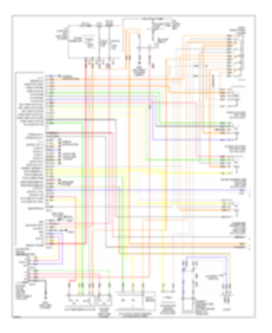
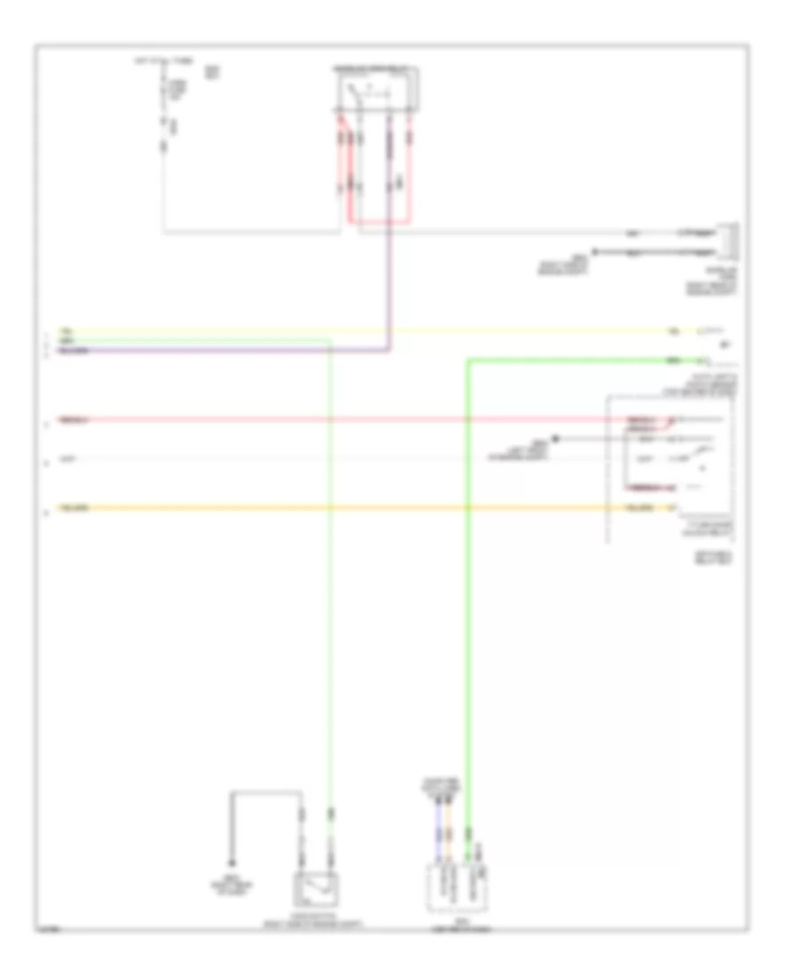
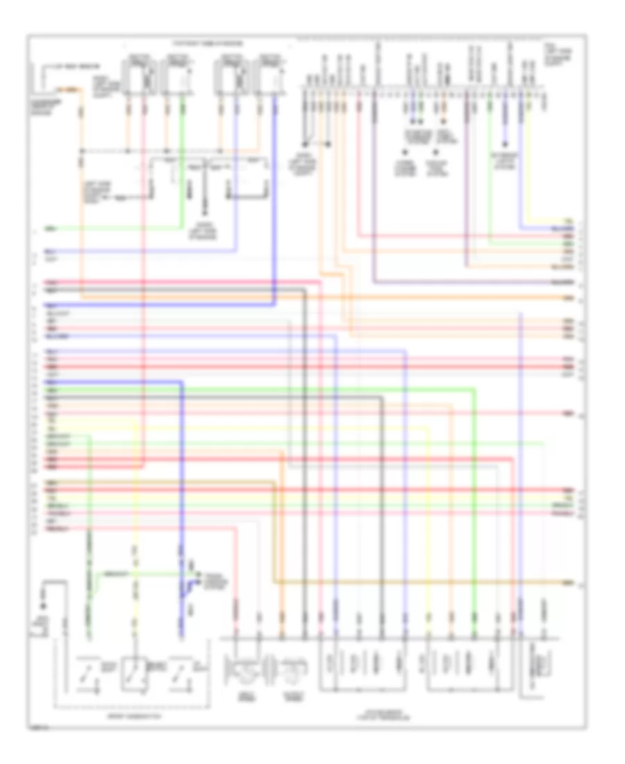
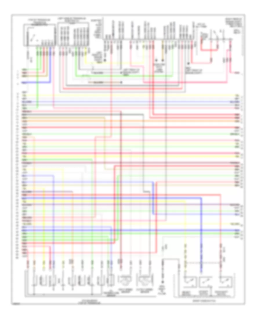
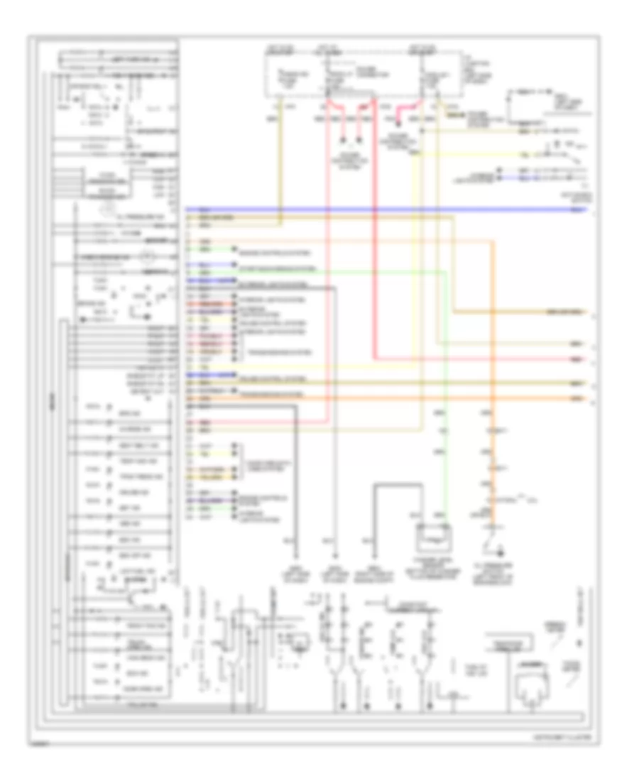
2.0L
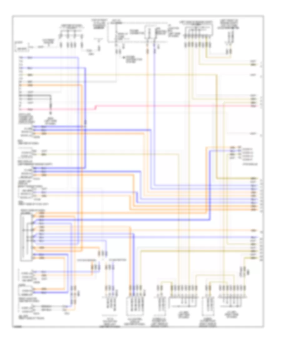
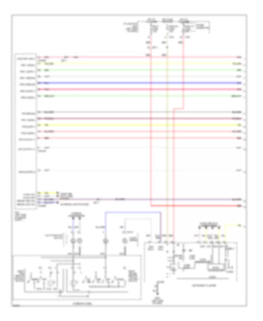
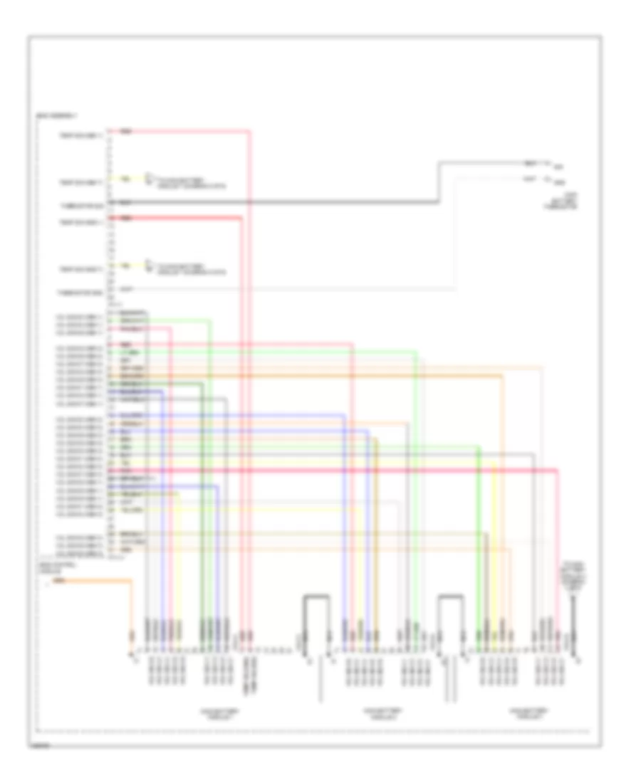
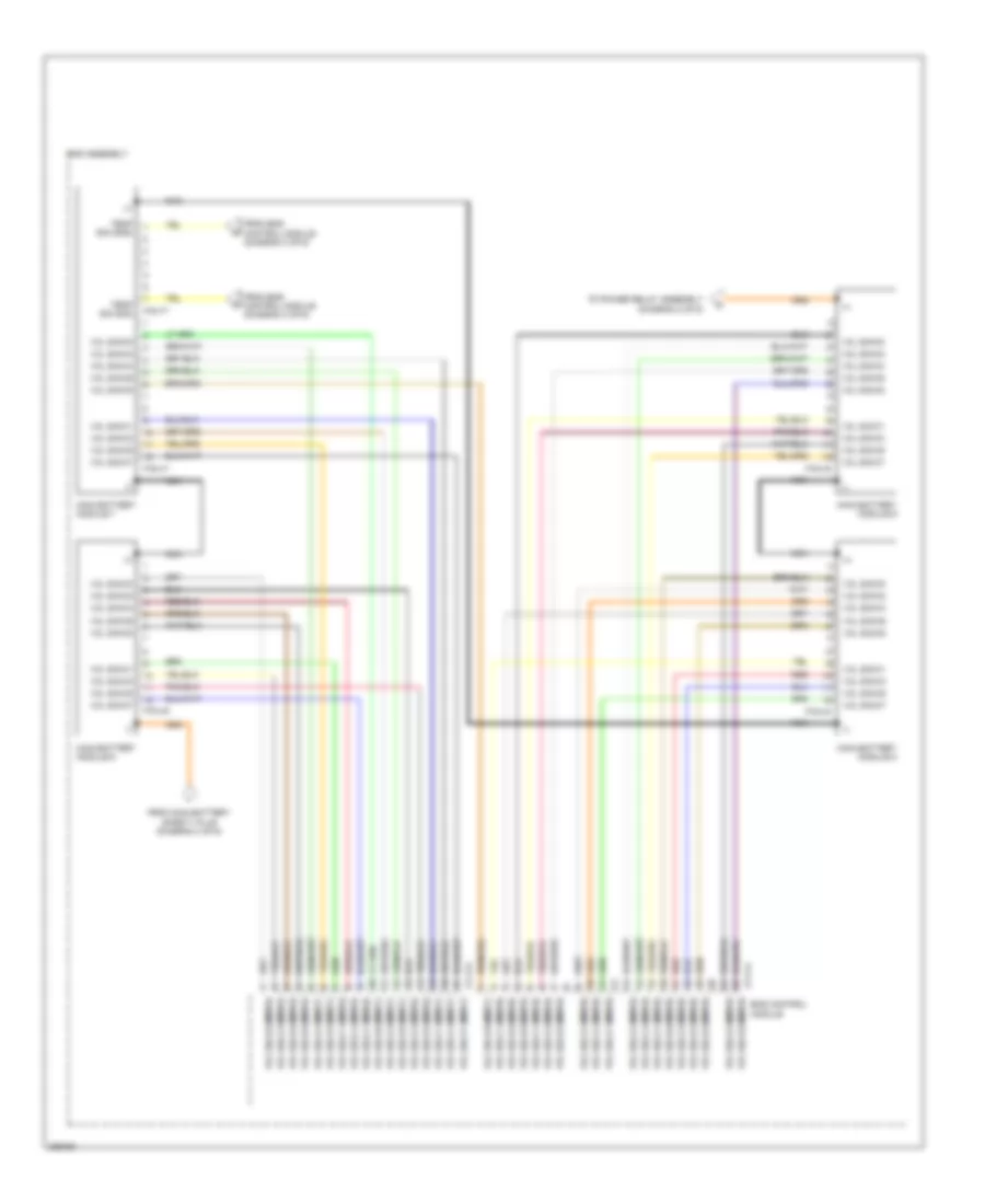
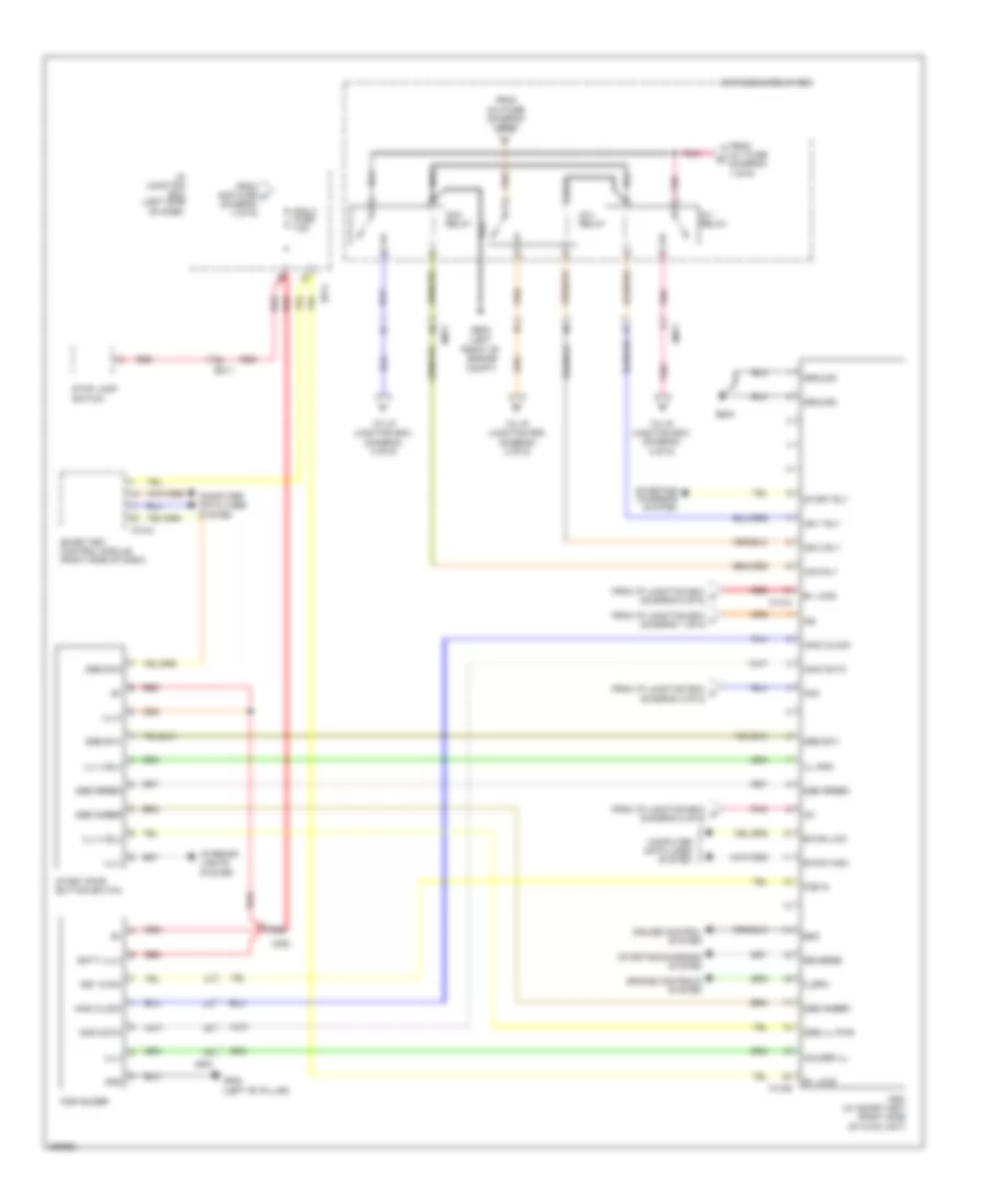
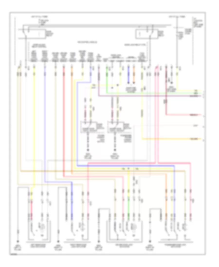
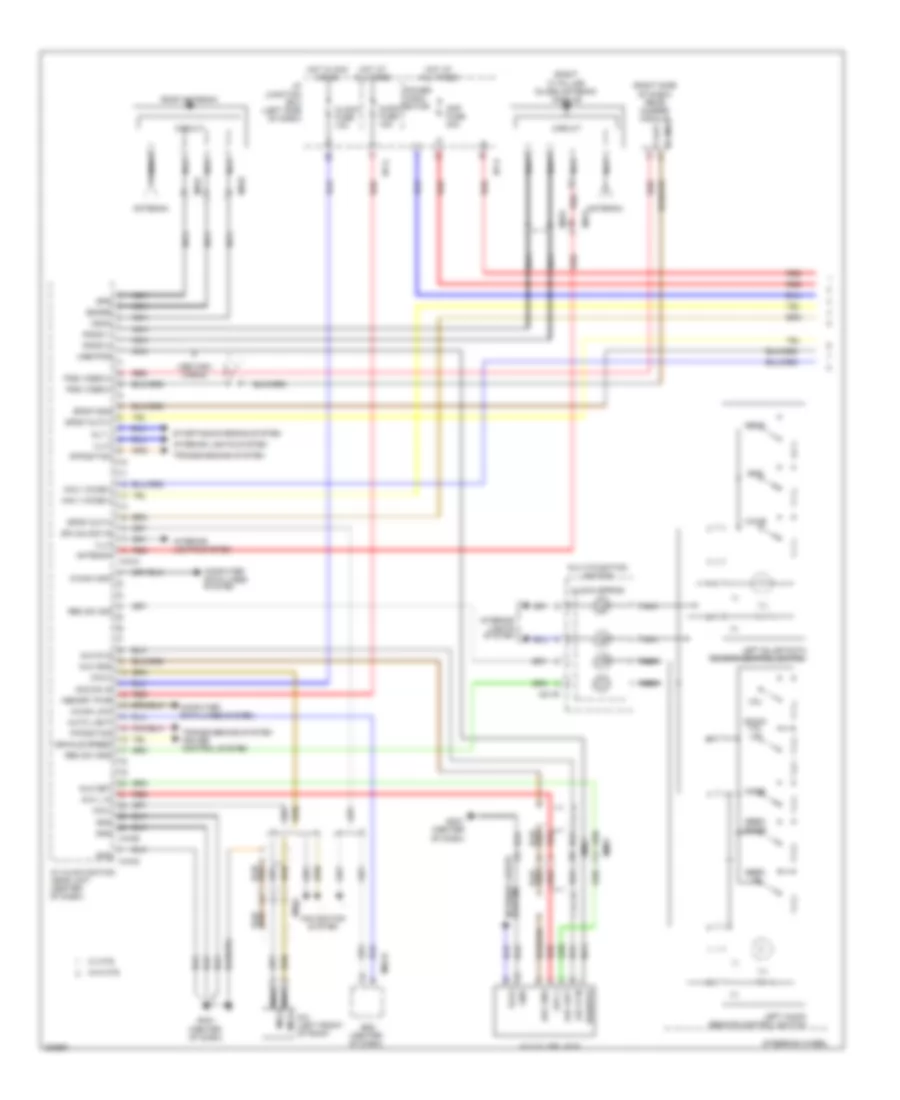
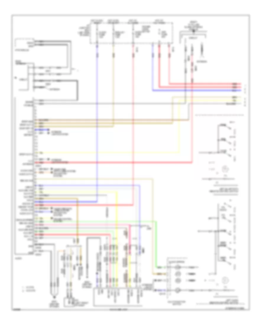
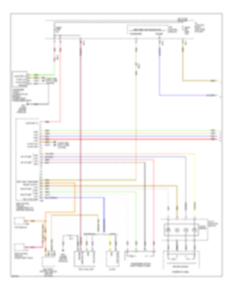
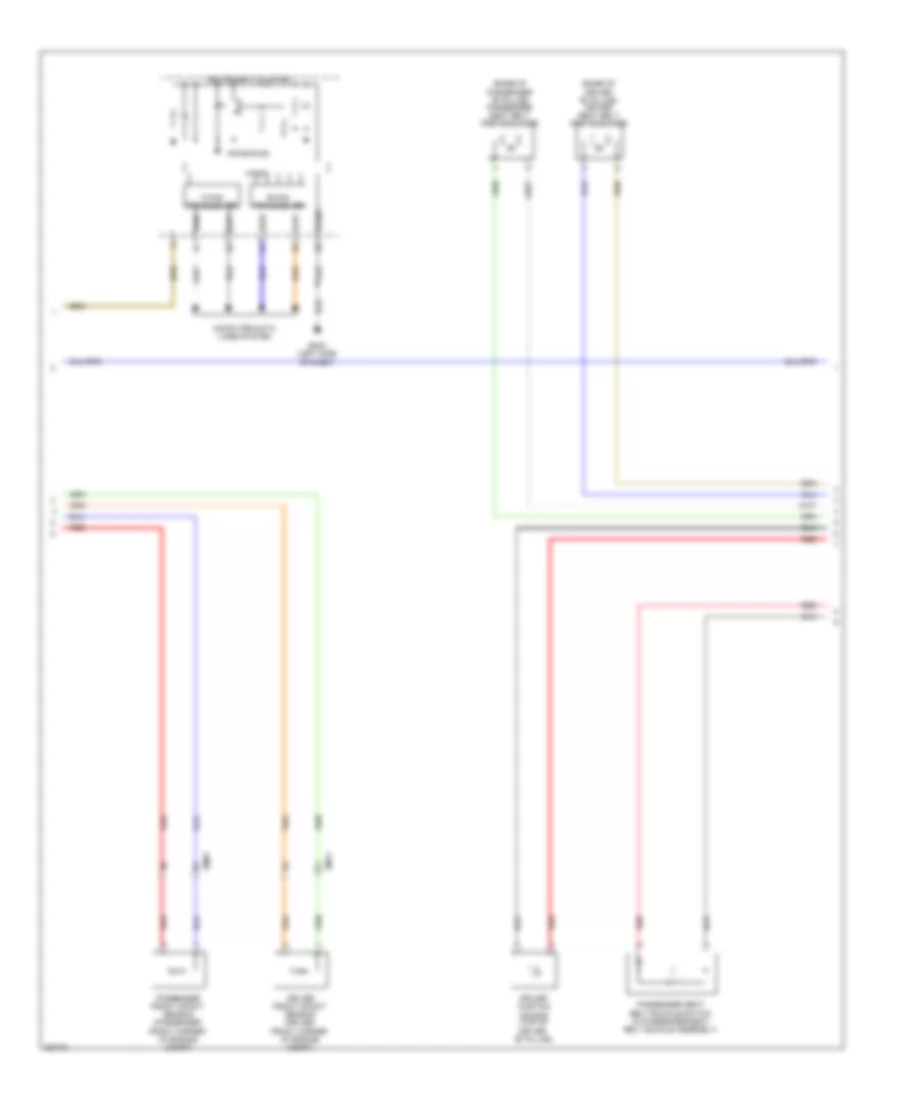
2.0L, Automatic A/C Wiring Diagram (1 of 2) for Hyundai Sonata Hybrid Base 2013

List of elements for 2.0L, Automatic A/C Wiring Diagram (1 of 2) for Hyundai Sonata Hybrid Base 2013:
- (not used)
- (right side of dash) j/c jm04
- A/c control module (center of dash)
- A/con fuse 10a
- A/con fuse 7.5a
- Ambient sens (+)
- Ambient temperature sensor (lower center front of radiator)
- Blower motor (+)
- Blower motor (right side of dash)
- Blower relay
- C-can hi
- C-can lo
- Clock
- Close
- Computer data lines system
- Defogger actuator
- Defogger system
- Detent out
- Driver temperature actuator (left side of hvac unit)
- Drv temp actr cool
- Drv temp actr f/b
- Drv temp actr warm
- E/r fuse & relay box
- Ecv gnd
- Ecv power
- Ee01
- Em61
- Evap sensor (+)
- Evaporator sensor (right side of hvac unit)
- F/b
- Fet (d)
- Fet (field effect) transistor (behind right side of dash)
- Fet (g)
- Ge01 (left front of engine compt)
- Gm02 (right end of dash)
- Gm03 (left side of dash)
- Ground
- Hot at all times
- Hot in on
- I/p junction box (left side of dash)
- I/p-b
- I/p-e
- I/p-g
- Ill (+)
- Ill (-)
- In actr f/b
- In actr fre
- In actr rec
- Intake actuator (top left side of hvac unit)
- Interior lights system
- K-line
- M-can hi
- M-can lo
- M20-a
- M20-b
- M21
- Memory power
- Mode actr def
- Mode actr f/b
- Mode actr vent
- Mode actuator (left side of hvac unit)
- Multi fuse
- On input
- Open
- Passenger temperature actuator (right side of hvac unit)
- Photo sens dri
- Photo sens pass
- Pnk
- Power connector
- Rear defogger ind
- Rear defogger sw
- Red
- Room lp fuse 10a
- Sens ground
- Sens ref (+5v)
- Temp actr cool
- Temp actr f/b
- Temp actr warm
- Temp(+)
- Temp(-)
- W/ navi
- W/o navi
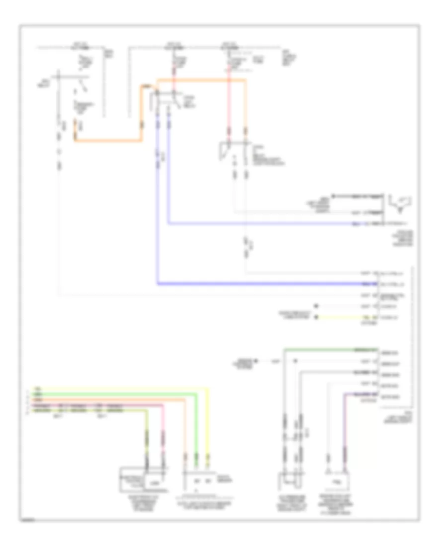
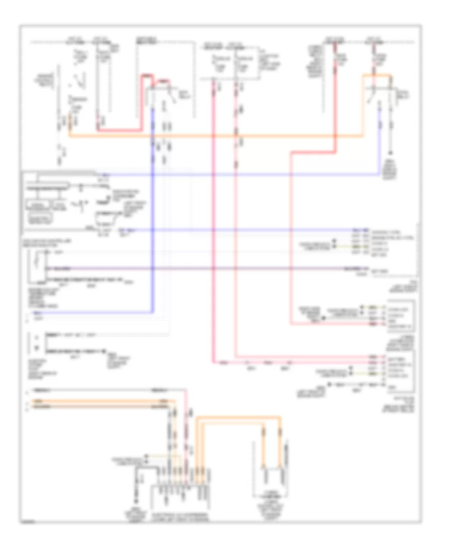
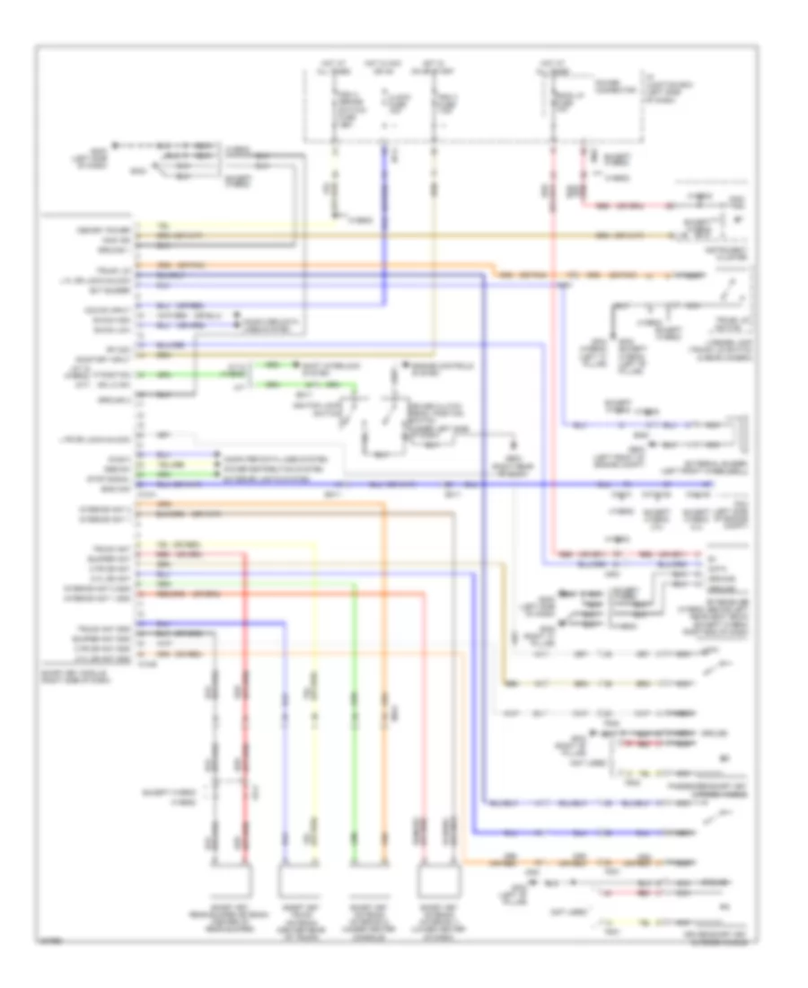
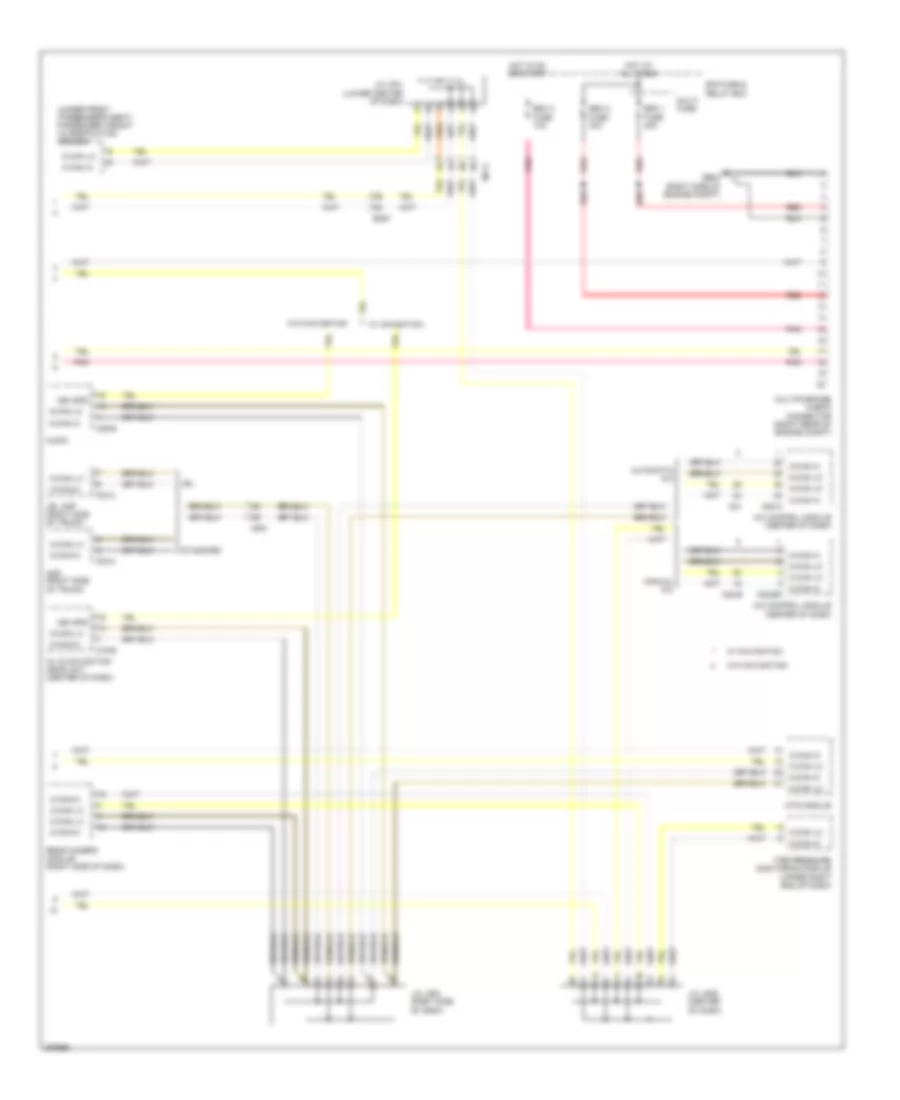
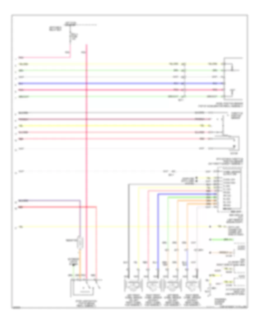
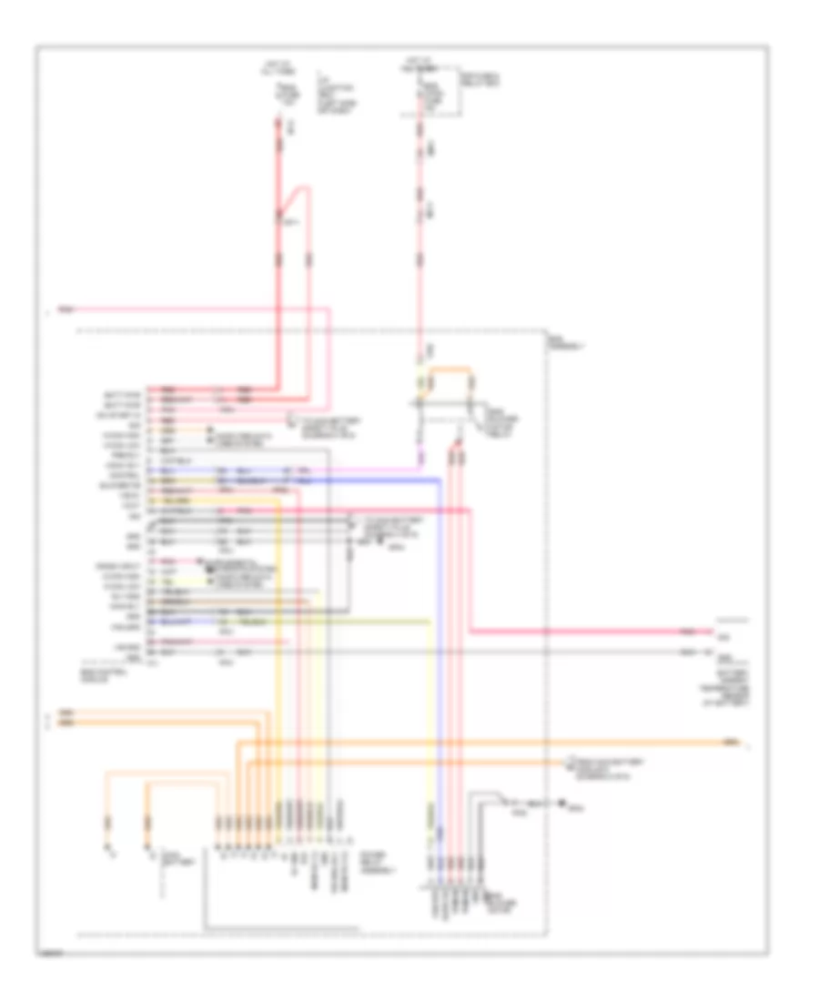
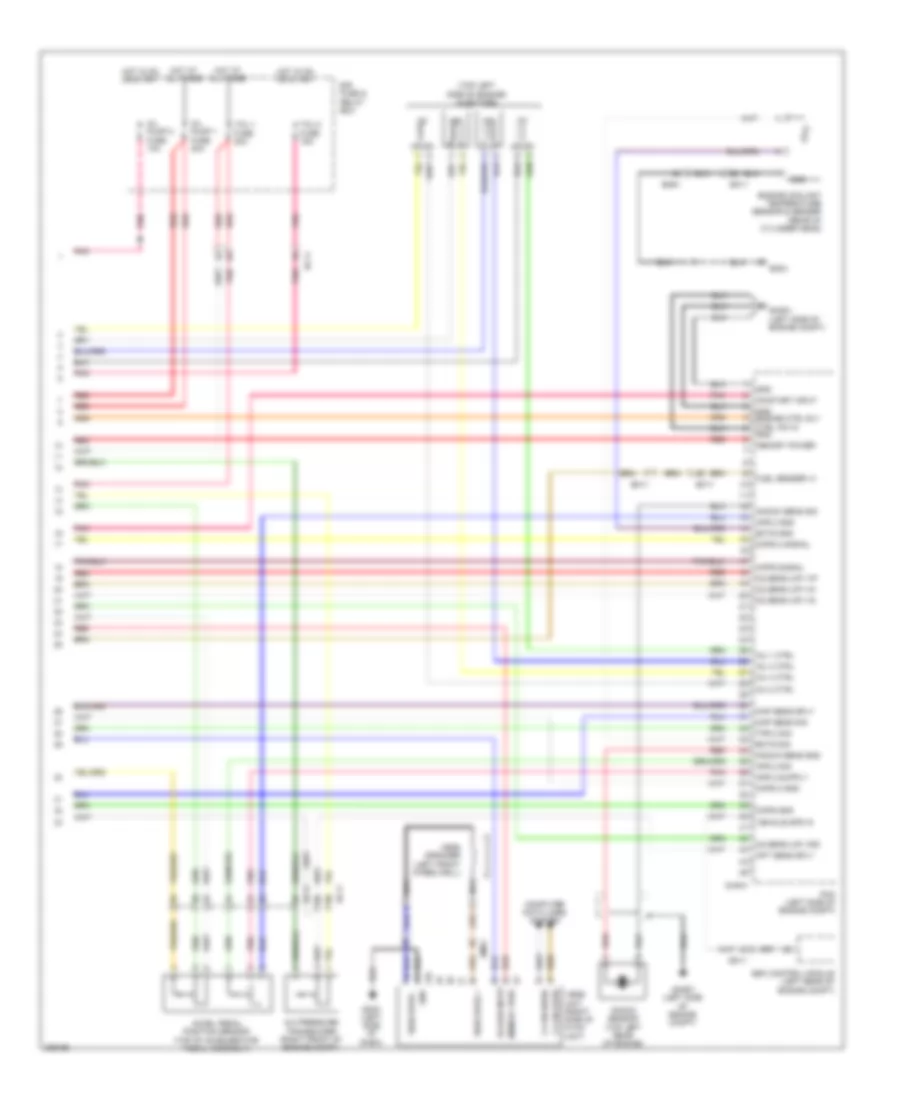
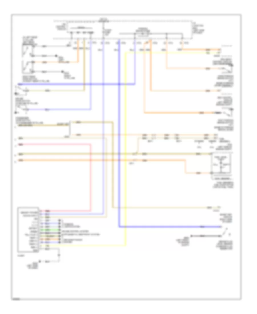
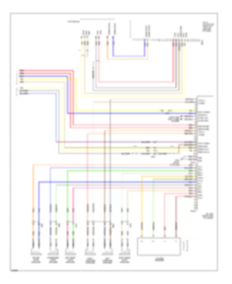
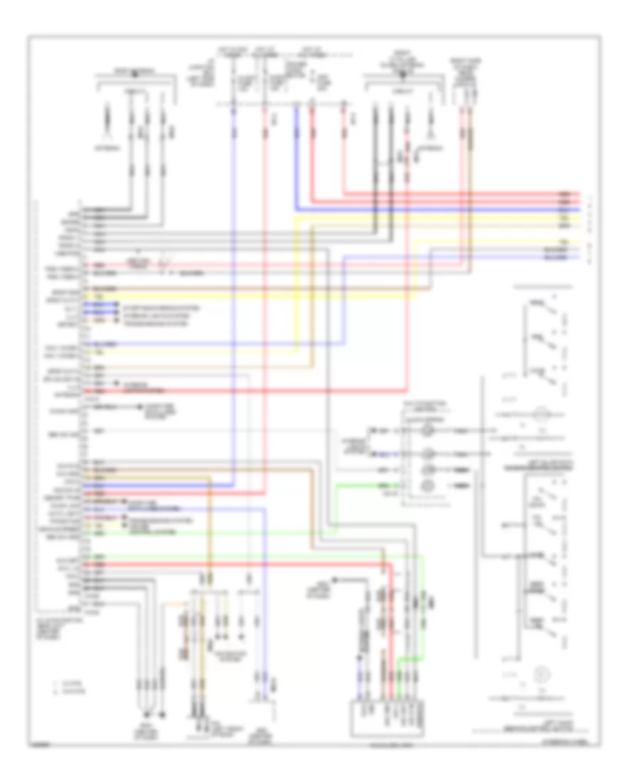
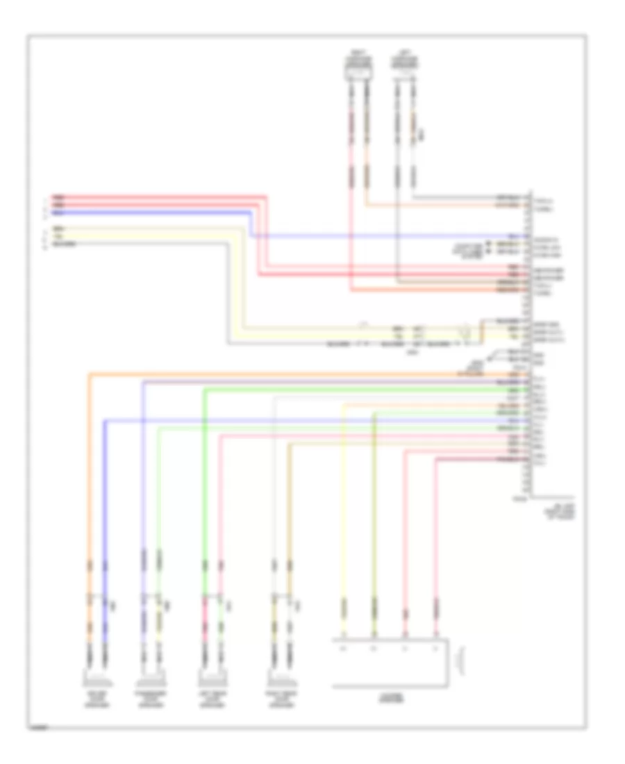
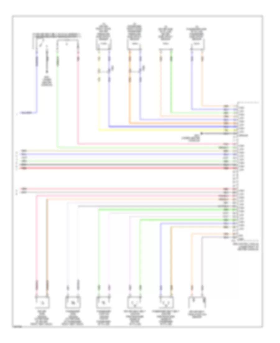
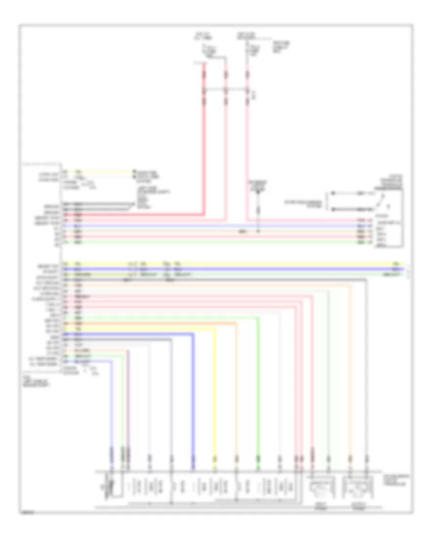
2.0L, Automatic A/C Wiring Diagram (2 of 2) for Hyundai Sonata Hybrid Base 2013
List of elements for 2.0L, Automatic A/C Wiring Diagram (2 of 2) for Hyundai Sonata Hybrid Base 2013:
- A/c pressure transducer (right front of engine compt)
- Auto light & photo sensor (top center of dash)
- C-can hi
- C-can lo
- C/fan fuse 40a
- C/fan hi fuse 60a
- C/fan hi relay (engine compt junction block)
- C/fan low relay
- Chtg-ag
- Chtg-bg
- Computer data lines system
- Cooling fan motor (behind radiator)
- E/r fuse & relay box
- E/r-a
- E/r-b
- Ec11
- Ects gnd
- Ects sig
- Ecu 1 fuse 30a
- Ecu relay
- Electrical control valve
- Electronic a/c compressor (left front of engine)
- Em11
- Ems box
- Engine controls system
- Engine coolant temperature sensor & sender (rear of cylinder head)
- Engine ctrl rly ctrl
- Ge02 (left front of engine compt)
- Hot at all times
- Multi fuse
- Nca
- Pcm (left side of engine compt)
- Photo sensor
- Red
- Rly ctrl hi
- Rly ctrl lo
- Sens gnd
- Sens sig
- Sens sup
- Sensor 1 fuse 15a
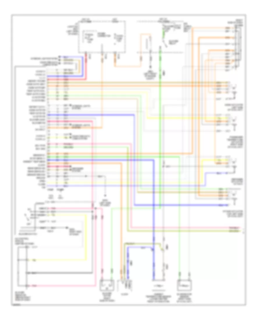
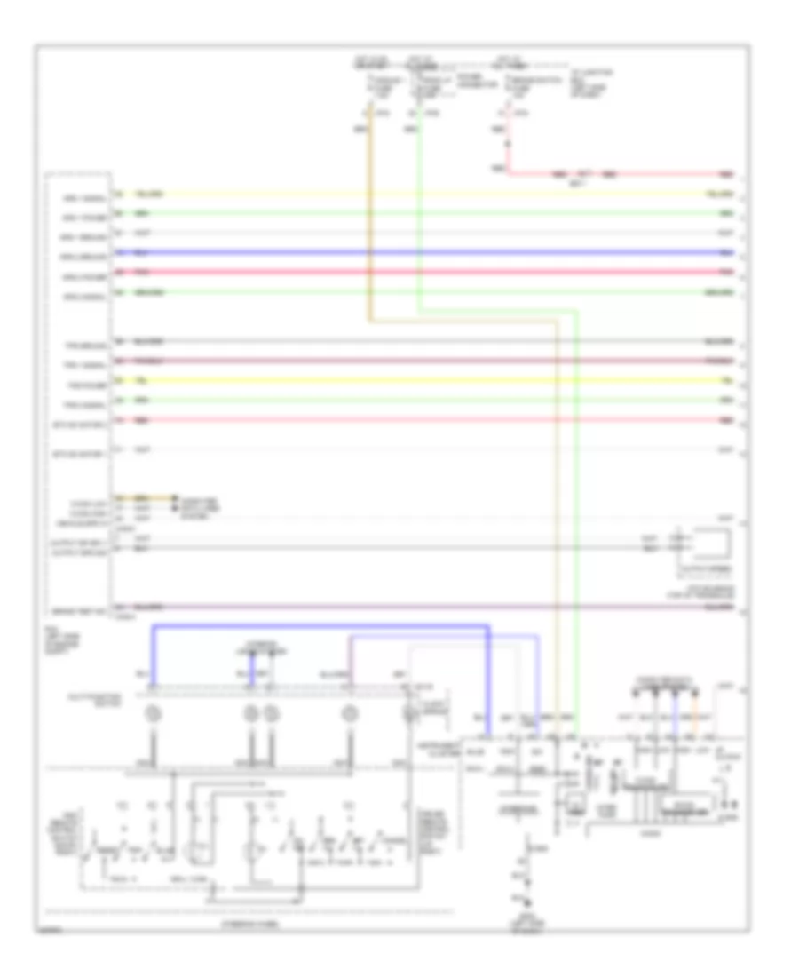
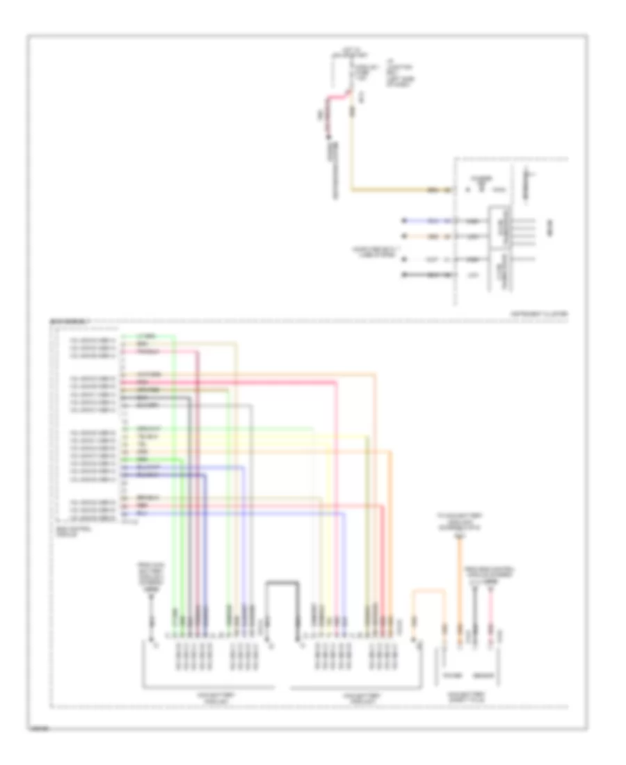
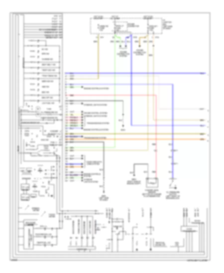
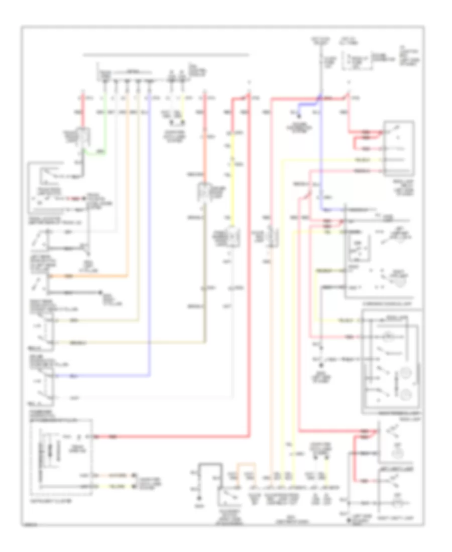
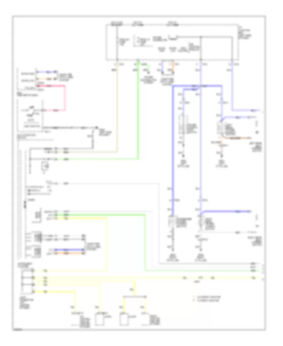
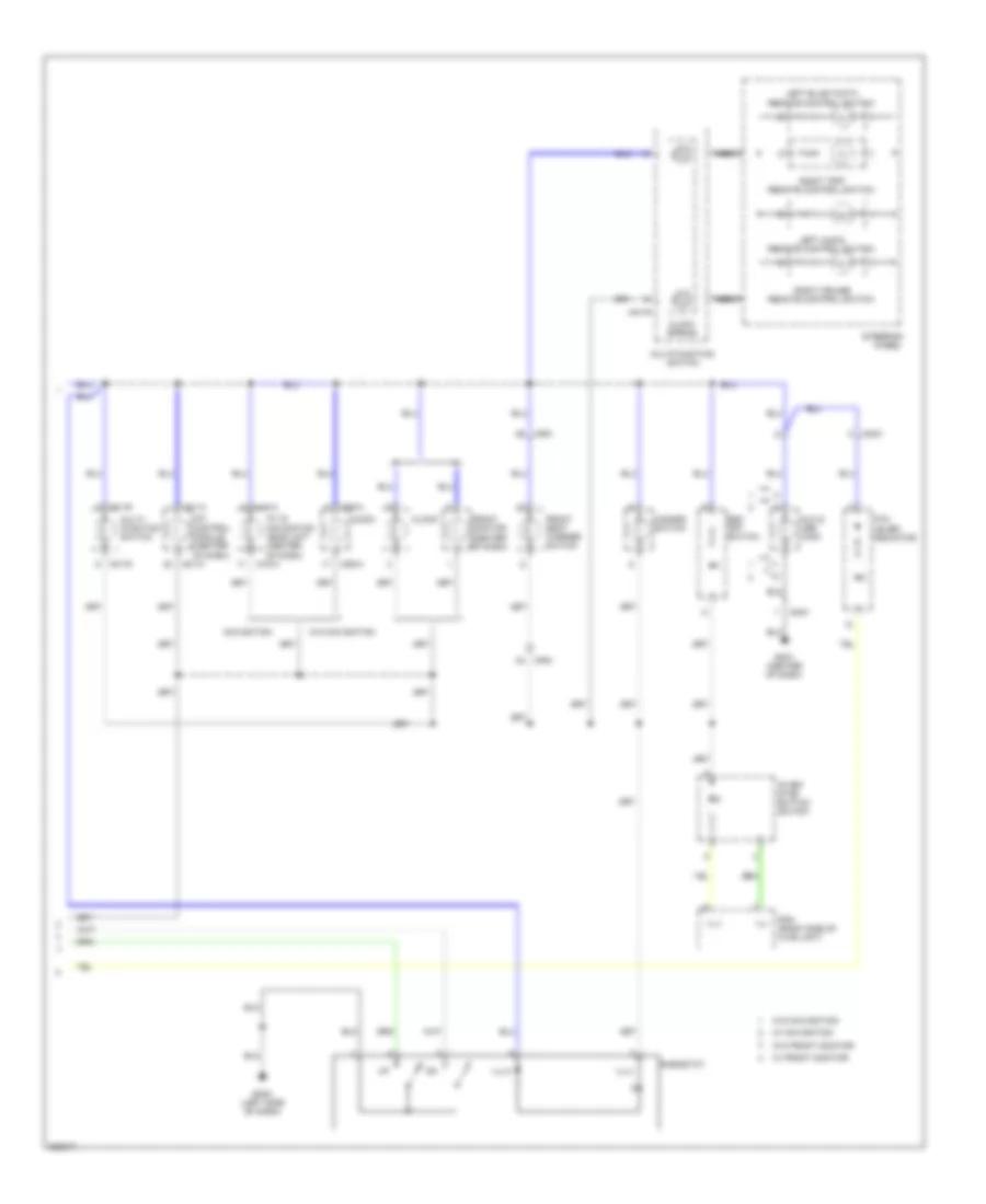
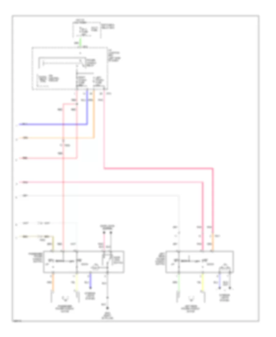
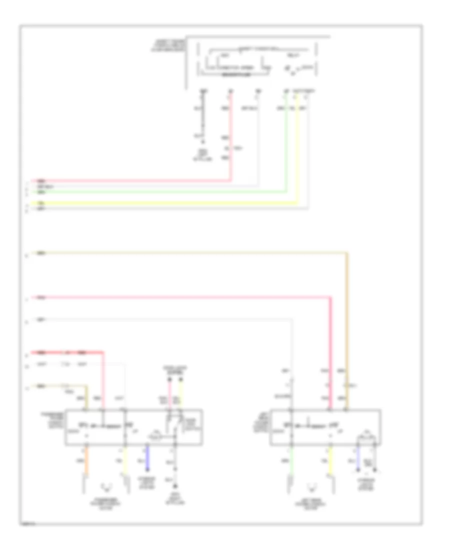
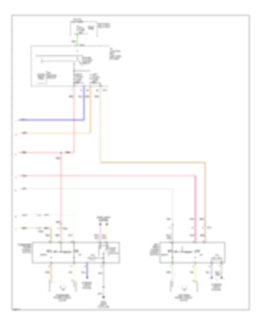
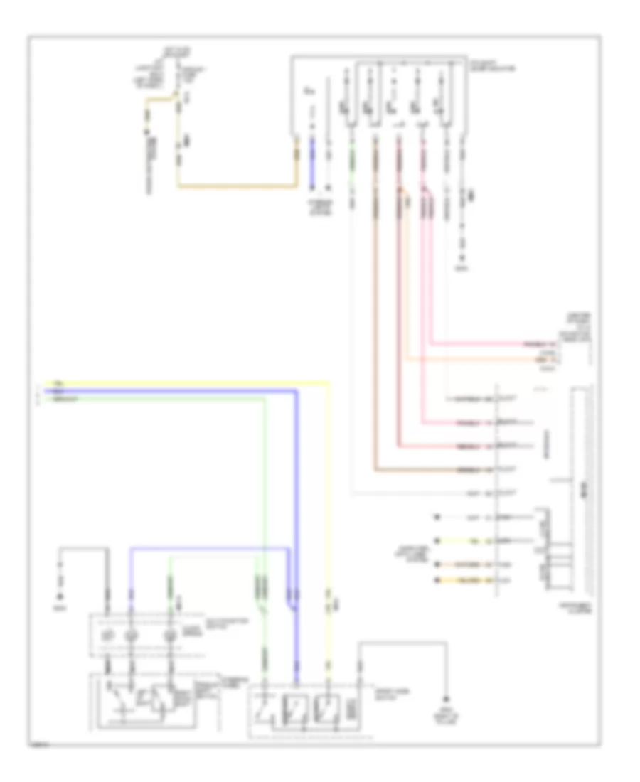
2.0L, Manual A/C Wiring Diagram (1 of 2) for Hyundai Sonata Hybrid Base 2013
List of elements for 2.0L, Manual A/C Wiring Diagram (1 of 2) for Hyundai Sonata Hybrid Base 2013:
- (right side of dash) j/c jm04
- A/c control module (center of dash)
- A/con fuse 7.5a
- Ambient temp sens
- Ambient temperature sensor (lower center front of radiator)
- Blower comm
- Blower f/b
- Blower motor (right side of dash)
- Blower relay
- Blower resistor (behind right side of dash)
- Blower switch
- C-can hi
- C-can lo
- Clock
- Close
- Common
- Computer data lines system
- Defogger actuator (w/ navi)
- Defogger system
- Detent out(+)
- E/r fuse & relay box
- Ecv gnd
- Ecv pwr
- Ee01
- Em61
- Evap sens (+)
- Evaporator sensor (right side of hvac unit)
- F/b
- Ge01 (left front of engine compt)
- Gm02 (right end of dash)
- Gm03 (left side of dash)
- Gnd
- Ground
- High
- Hot at all times
- Hot in on
- I off
- I/p junction box (left side of dash)
- I/p-b
- I/p-e
- I/p-g
- Iii
- Iiii
- Ill (+)
- Ill (-)
- In actr f/b
- In actr fre
- In actr rec
- Intake actuator (top left side of hvac unit)
- Interior lights system
- Low
- M-can hi
- M-can lo
- M/hi
- M/low
- M22-a
- M22-b
- M22-bn
- Memory power
- Mode actr def
- Mode actr f/b
- Mode actr vent
- Mode actuator (left side of hvac unit)
- Multi fuse
- On input
- Open
- Passenger temperature actuator (right side of hvac unit)
- Pnk
- Power connector
- Rear defog ind
- Rear defog sw
- Red
- Room lp fuse 10a
- Sensor 5v
- Sensor ground
- Temp actr cool
- Temp actr f/b
- Temp actr warm
- Temp(+)
- Temp(-)
- W/ navi
- W/o navi
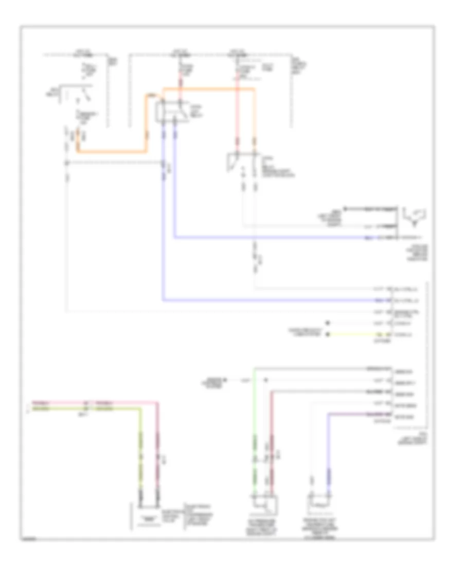
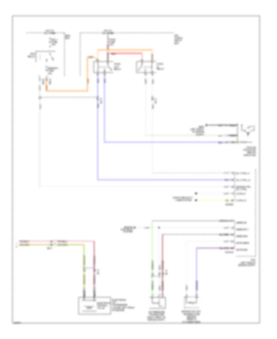
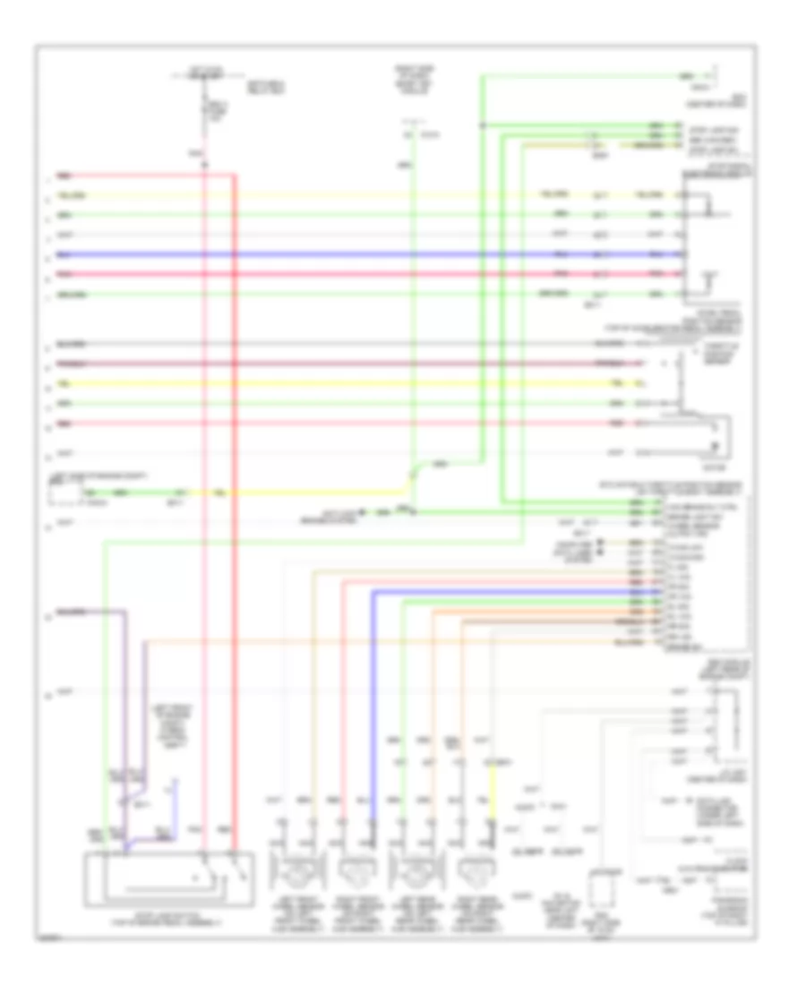
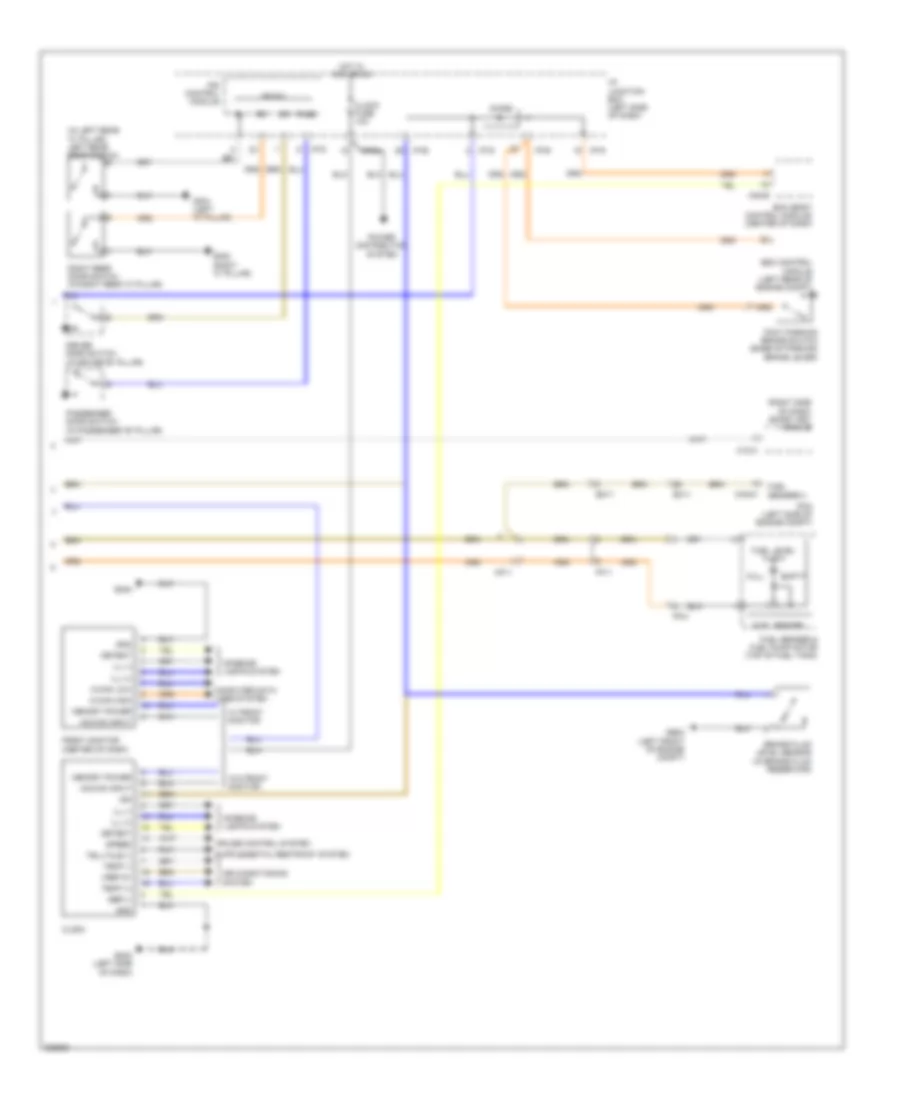
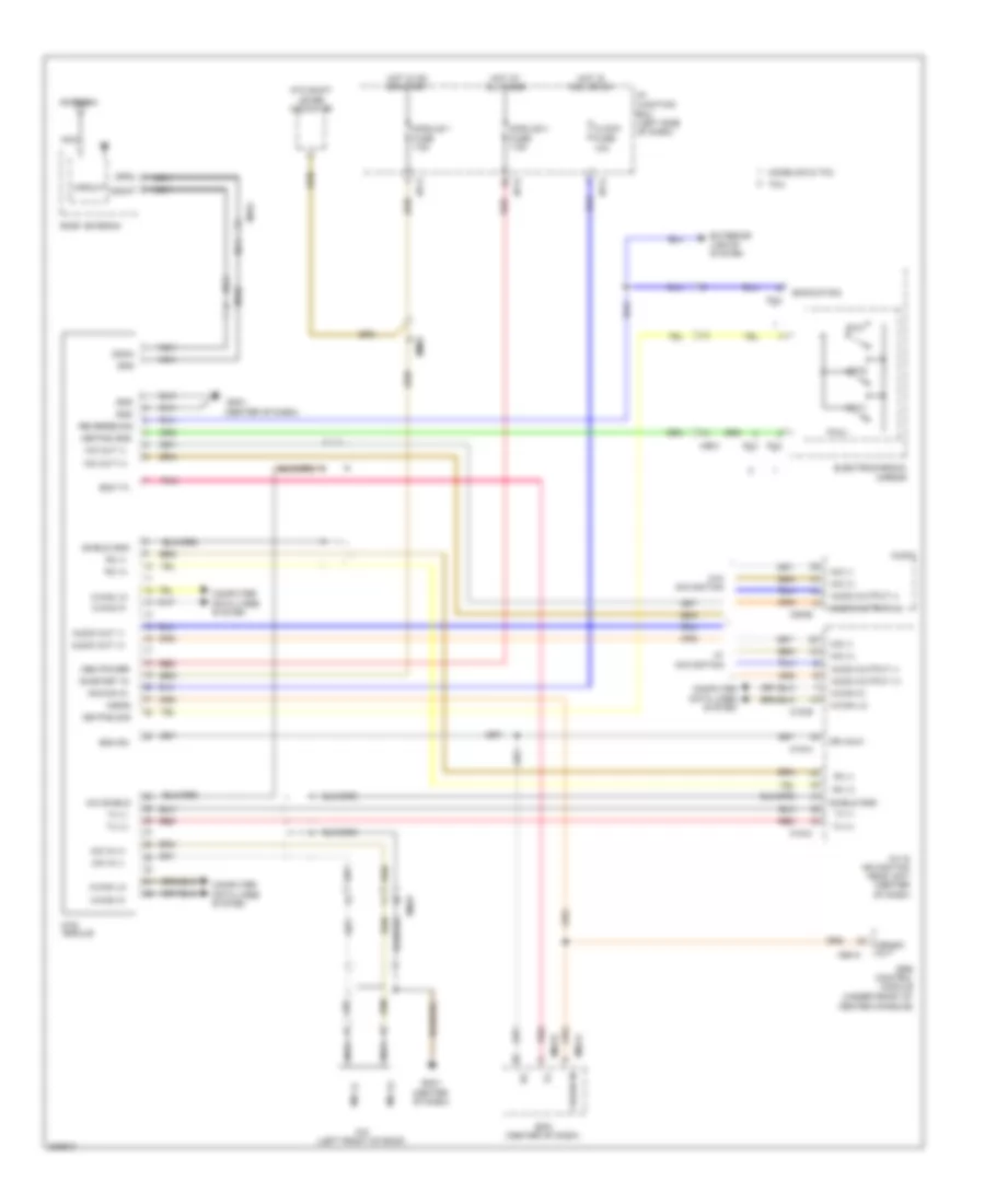
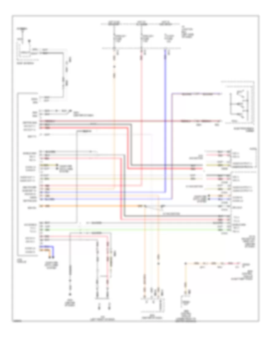
2.0L, Manual A/C Wiring Diagram (2 of 2) for Hyundai Sonata Hybrid Base 2013
List of elements for 2.0L, Manual A/C Wiring Diagram (2 of 2) for Hyundai Sonata Hybrid Base 2013:
- A/c pressure transducer (right front of engine compt)
- C-can hi
- C-can lo
- C/fan fuse 40a
- C/fan hi fuse 60a
- C/fan hi relay (engine compt junction block)
- C/fan low relay
- Chtg-ag
- Chtg-bg
- Computer data lines system
- Cooling fan motor (behind radiator)
- E/r fuse & relay box
- E/r-a
- E/r-b
- Ec11
- Ects gnd
- Ects sens
- Ecu 1 fuse 30a
- Ecu relay
- Electrical control valve
- Electronic a/c compressor (left front of engine)
- Em11
- Ems box
- Engine controls system
- Engine coolant temperature sensor & sender (rear of cylinder head)
- Engine ctrl rly ctrl
- Ge02 (left front of engine compt)
- Hot at all times
- Multi fuse
- Nca
- Pcm (left side of engine compt)
- Red
- Rly ctrl hi
- Rly ctrl lo
- Sens gnd
- Sens sig
- Sens sply
- Sensor 1 fuse 15a
2.4L
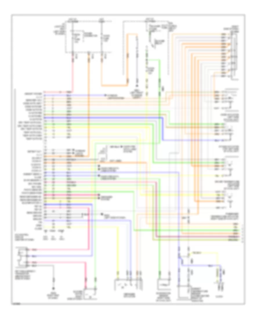
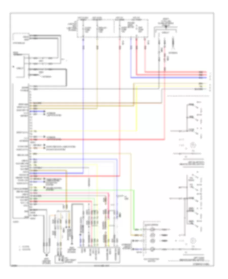
2.4L, Automatic A/C Wiring Diagram, Except Hybrid (1 of 2) for Hyundai Sonata Hybrid Base 2013
List of elements for 2.4L, Automatic A/C Wiring Diagram, Except Hybrid (1 of 2) for Hyundai Sonata Hybrid Base 2013:
- (not used)
- (right side of dash) j/c jm04
- A/c control module (center of dash)
- A/con fuse 10a
- A/con fuse 7.5a
- Ambient sens (+)
- Ambient temperature sensor (lower center front of radiator)
- Blower motor (+)
- Blower motor (right side of dash)
- Blower relay
- C-can hi
- C-can lo
- Clock
- Clock 5v
- Close
- Computer data lines system
- Defogger actuator
- Defogger system
- Detent out
- Driver temperature actuator (left side of hvac unit)
- Drv temp actr cool
- Drv temp actr f/b
- Drv temp actr warm
- E/r fuse & relay box
- Ecv gnd
- Ecv power
- Ee01
- Em61
- Evap sensor (+)
- Evaporator sensor (right side of hvac unit)
- F/b
- Fet (d)
- Fet (field effect) transistor (behind right side of dash)
- Fet (g)
- Ge01 (left front of engine compt)
- Gm02 (right end of dash)
- Gm03 (left side of dash)
- Ground
- Hot at all times
- Hot in on
- I/p junction box (left side of dash)
- I/p-b
- I/p-e
- I/p-g
- Ill (+)
- Ill (-)
- In actr f/b
- In actr fre
- In actr rec
- Intake actuator (top left side of hvac unit)
- Interior lights system
- K-line
- M-can hi
- M20-a
- M20-b
- M21
- Memory power
- Mode actr def
- Mode actr f/b
- Mode actr vent
- Mode actuator (left side of hvac unit)
- Multi fuse
- On input
- Open
- Passenger temperature actuator (right side of hvac unit)
- Photo sens dri
- Photo sens pass
- Pnk
- Power connector
- Rear defogger ind
- Rear defogger sw
- Red
- Room lp fuse 10a
- Sens ground
- Sens ref (+5v)
- Temp actr cool
- Temp actr f/b
- Temp actr warm
- Temp(+)
- Temp(-)
- W/ navi
- W/o navi
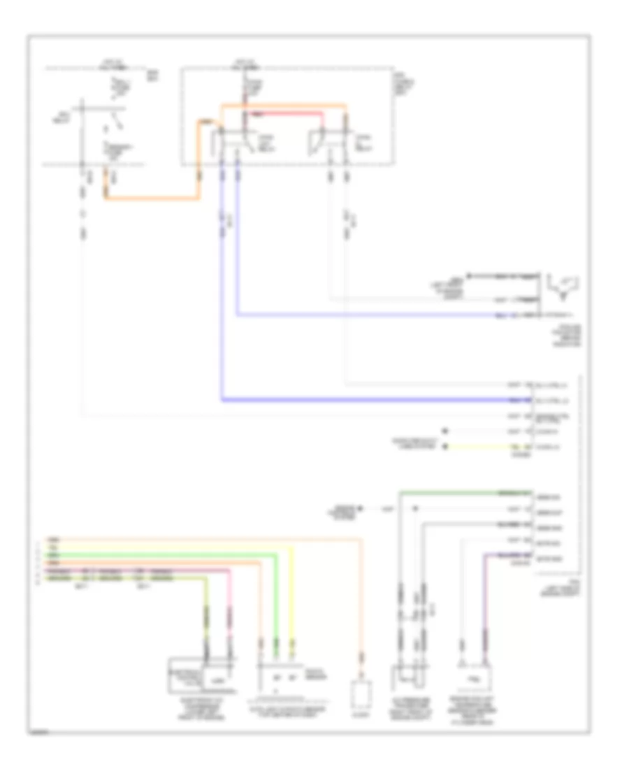
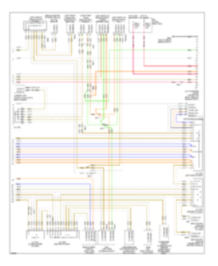
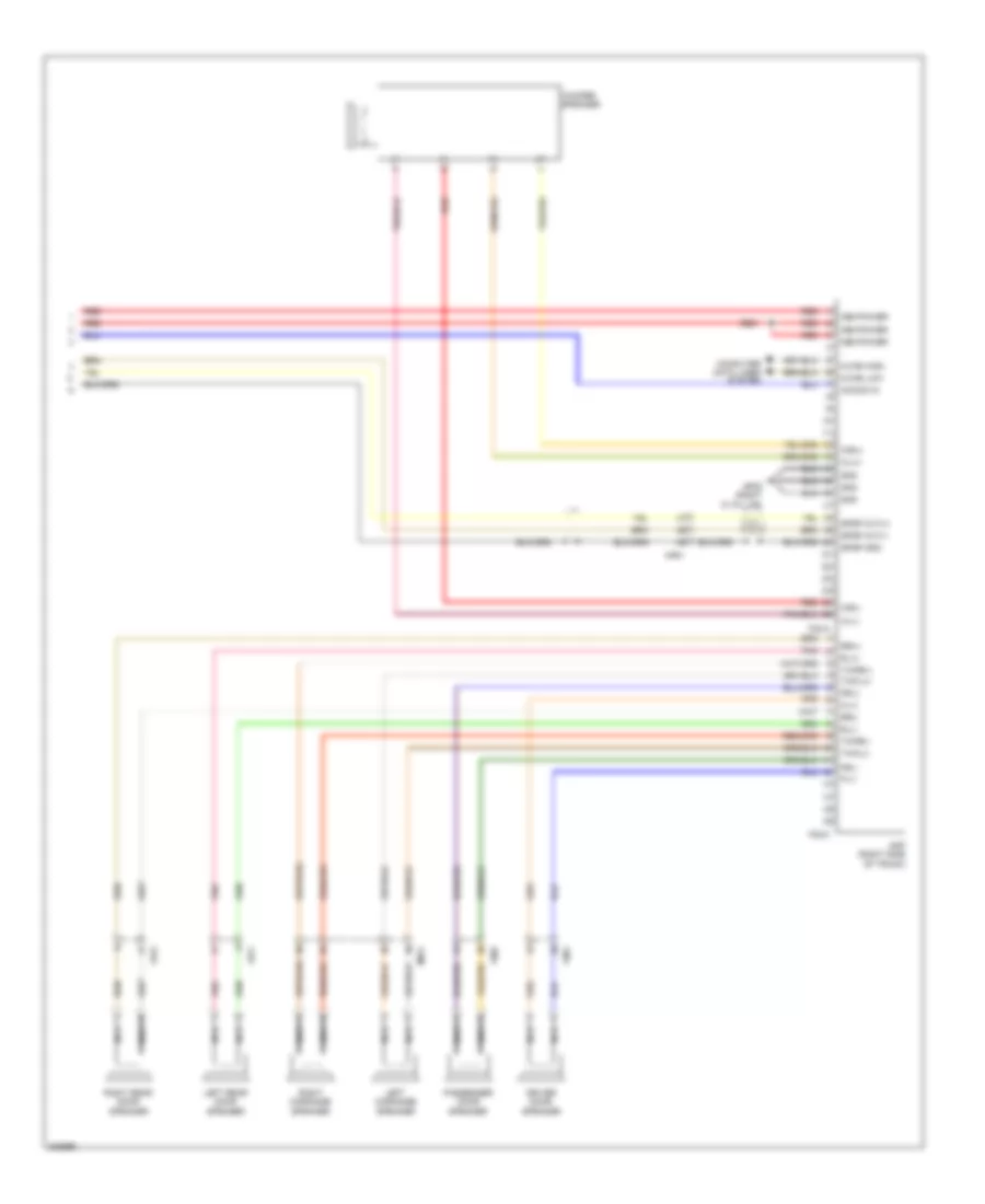
2.4L, Automatic A/C Wiring Diagram, Except Hybrid (2 of 2) for Hyundai Sonata Hybrid Base 2013
List of elements for 2.4L, Automatic A/C Wiring Diagram, Except Hybrid (2 of 2) for Hyundai Sonata Hybrid Base 2013:
- A/c pressure transducer (right front of engine compt)
- Auto light & photo sensor (top center of dash)
- C-can hi
- C-can lo
- C/fan fuse 40a red
- C/fan hi relay
- C/fan low relay
- Chg-ag
- Chg-bg
- Clock
- Computer data lines system
- Cooling fan motor (behind radiator)
- E/r fuse & relay box
- E/r-a
- E/r-b
- Ec11
- Ects gnd
- Ects sig
- Ecu 1 fuse 30a
- Ecu relay
- Electrical control valve
- Electronic a/c compressor (lower left front of engine)
- Em11
- Ems box
- Engine controls system
- Engine coolant temperature sensor & sender (rear of cylinder head)
- Engine ctrl rly ctrl
- Ge02 (left front of engine compt)
- Hot at all times
- Nca
- Pcm (left side of engine compt)
- Photo sensor
- Red
- Rly ctrl hi
- Rly ctrl lo
- Sens gnd
- Sens sig
- Sens sup
- Sensor 1 fuse 15a
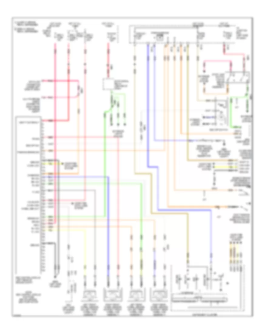
2.4L, Automatic A/C Wiring Diagram, Hybrid (1 of 2) for Hyundai Sonata Hybrid Base 2013
List of elements for 2.4L, Automatic A/C Wiring Diagram, Hybrid (1 of 2) for Hyundai Sonata Hybrid Base 2013:
- (+)
- (-)
- (left side of dash) gm03
- (right side of dash) j/c jm04
- A/c control module (center of dash)
- A/con fuse 7.5a
- Ambient sensor (+)
- Ambient temperature sensor (lower center front of radiator)
- Auto def act cool
- Auto def act f/b
- Auto def act warm
- Auto defogger actuator
- Auto light & photo sensor (top center of dash)
- Blower motor (right side of dash)
- Blower motor control module (right side of hvac unit)
- Blower relay
- C-can hi
- C-can lo
- Clock
- Clock 5v
- Comp can hi
- Comp can low
- Computer data lines system
- Defogger system
- Detent out (+)
- Driver temperature actuator (left side of hvac unit)
- Drv temp actr cool
- Drv temp actr f/b
- Drv temp actr warm
- E/r fuse & relay box
- Ee01
- Em61
- Evap sensor (+)
- Evaporator sensor (right side of hvac unit)
- Ewp rly ctrl
- Ewp rly f/b
- Ge02 (left front of engine compt)
- Gm02 (right end of dash)
- Gm04
- Gnd
- Hot at all times
- Hot in on
- Hot in on or start
- I/p junction box (left side of dash)
- I/p-b
- I/p-e
- I/p-g
- Ill (+)
- Ill (-)
- In actr f/b
- In actr fre
- In actr rec
- Inh
- Intake actuator (top left side of hvac unit)
- Interior lights system
- Interlock in
- Interlock out
- M-can hi
- M-can lo
- M21-a
- M21-b
- M27-p
- M27-s
- Memory power
- Mode actr def
- Mode actr f/b
- Mode actr vent
- Mode actuator (left side of hvac unit)
- Module fuse 7.5a
- Monitor
- Multi fuse
- On input
- On/start input
- Pass temp actr cool
- Pass temp actr f/b
- Pass temp actr warm
- Passenger temperature actuator (right side of hvac unit)
- Photo sens dri
- Photo sens pass
- Photo sensor
- Pnk
- Power connector
- Pwn in
- Rear defogger ind
- Rear defogger sw
- Red
- Room lp fuse 10a
- Sens ground
- Sensor (5v)
- Temp(+)
- Temp(-)
- W/o front
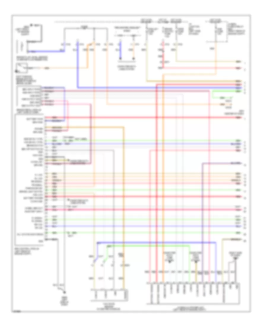
2.4L, Automatic A/C Wiring Diagram, Hybrid (2 of 2) for Hyundai Sonata Hybrid Base 2013
List of elements for 2.4L, Automatic A/C Wiring Diagram, Hybrid (2 of 2) for Hyundai Sonata Hybrid Base 2013:
- (left front of engine compt) ge01
- (right side of engine compt) ge04
- Active air flap (behind center of front grille)
- Battery
- C-can hi
- C-can lo
- C-can low
- C/fan fuse 60a
- C/fan relay
- C/fan rly ctrl
- Chg-k
- Chg32-p
- Chg32-s
- Chg34-comp
- Comp hi
- Comp low
- Computer data lines system
- Cooling fan controller (behind radiator)
- E/r fuse & relay box
- E/r-a
- E/r-b
- E11-a
- E11-b
- Ec11
- Ect gnd
- Ect sig
- Ecu 1 fuse 30a
- Ee01
- Ef01
- Electric detecting
- Electric water pump (right rear of engine)
- Electronic a/c compressor (lower left front of engine)
- Em11
- Em61
- Ems box
- Engine control relay
- Engine coolant temperature sensor (rear of cylinder head)
- Engine ctrl rly ctrl
- Ewp fuse 10a
- Ewp relay
- Fan
- Ge04 (right side of engine compt)
- Ge08 (left front of engine compt)
- Gm04
- Gnd
- Hot at all times
- Hot at all times red
- Hot in on or start
- Hot in on or start red
- Hybrid control unit (left front of engine compt)
- Hybrid fuse & relay box (right rear of engine compt)
- Hybrid inverter
- Hybrid water pump (right side of engine compt)
- I/p junction box (left side of dash)
- I/p-e
- I/p-g
- Module fuse 7.5a
- Nca
- On/start in
- Out
- Pcm (left side of engine compt)
- Pnk
- Power
- Power conditioning
- Pwn driver
- Radiator fan condenser m
- Red
- Sensor fuse 15a
- Signal processing
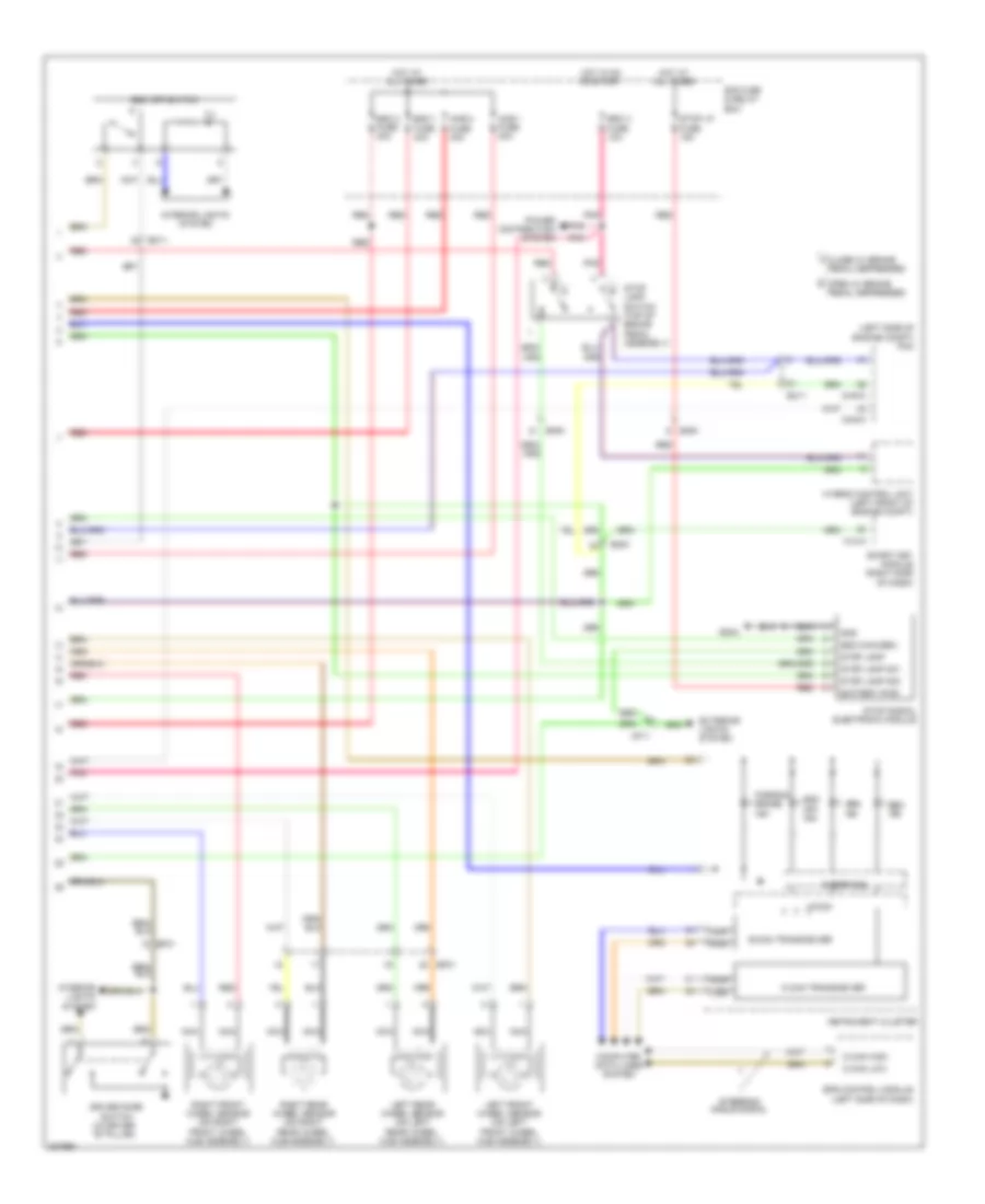
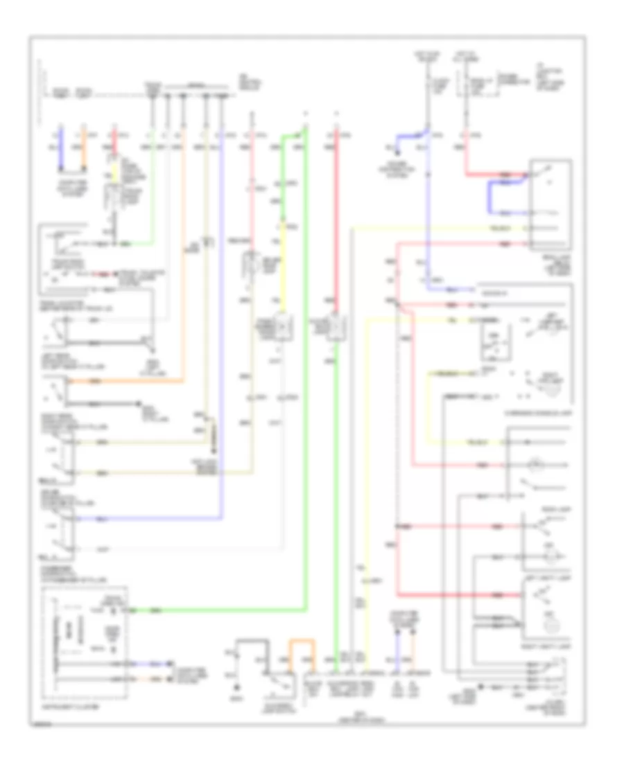
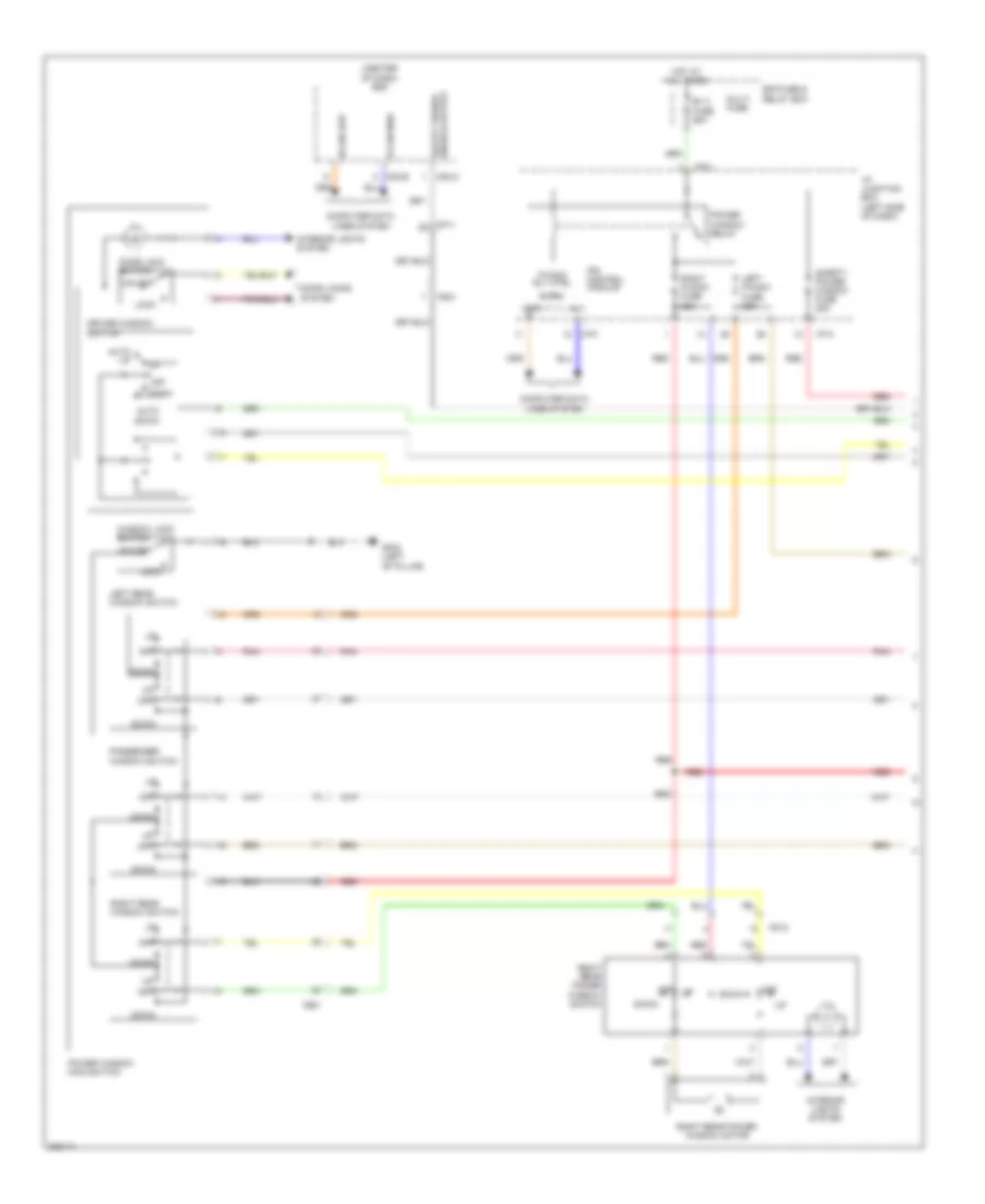
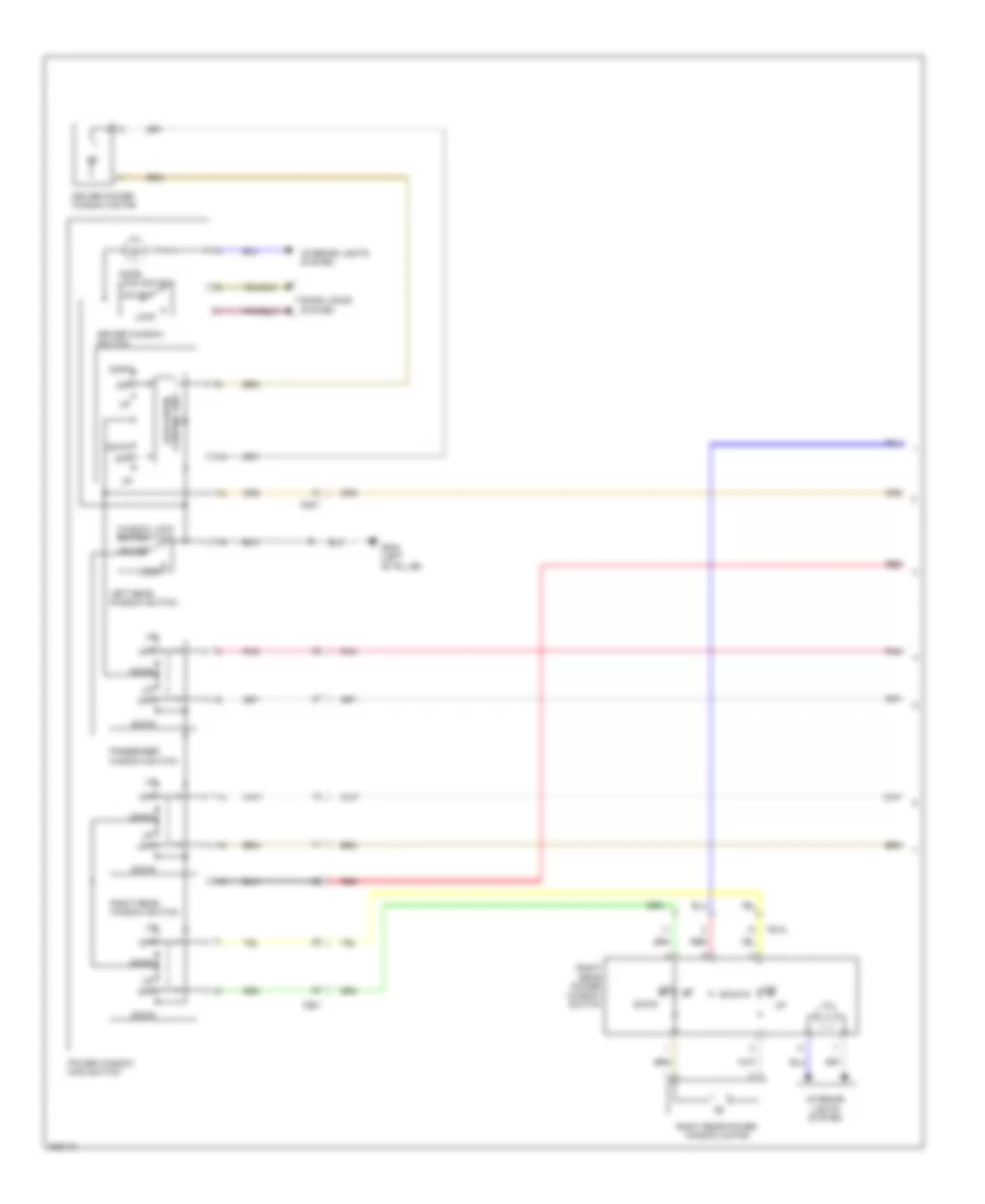
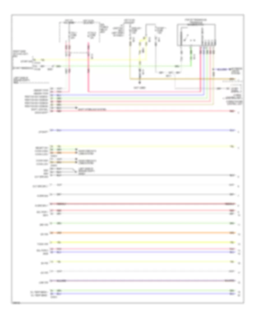
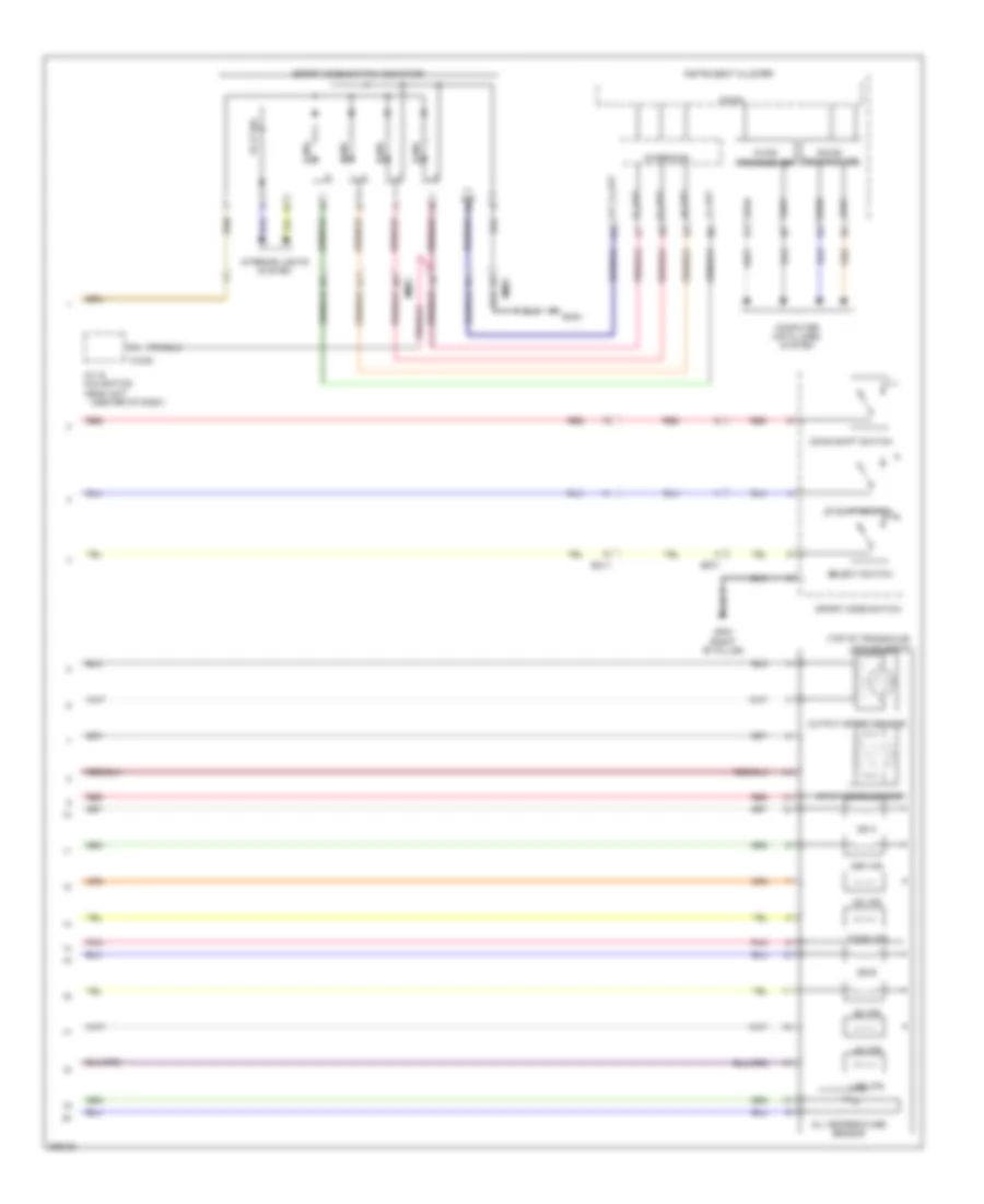
2.4L, Manual A/C Wiring Diagram (1 of 2) for Hyundai Sonata Hybrid Base 2013
List of elements for 2.4L, Manual A/C Wiring Diagram (1 of 2) for Hyundai Sonata Hybrid Base 2013:
- (right side of dash) j/c jm04
- A/c control module (center of dash)
- A/con fuse 7.5a
- Ambient temp sens
- Ambient temperature sensor (lower center front of radiator)
- Blower comm
- Blower f/b
- Blower motor (right side of dash)
- Blower relay
- Blower resistor (behind right side of dash)
- Blower switch
- C-can hi
- C-can lo
- Clock
- Close
- Common
- Computer data lines system
- Defogger actuator (w/ navi)
- Defogger system
- Detent out(+)
- E/r fuse & relay box
- Ecv gnd
- Ecv pwr
- Ee01
- Em61
- Evap sens (+)
- Evaporator sensor (right side of hvac unit)
- F/b
- Ge01 (left front of engine compt)
- Gm02 (right end of dash)
- Gm03 (left side of dash)
- Gnd
- Ground
- High
- Hot at all times
- Hot in on
- I off
- I/p junction box (left side of dash)
- I/p-b
- I/p-e
- I/p-g
- Iii
- Iiii
- Ill (+)
- Ill (-)
- In actr f/b
- In actr fre
- In actr rec
- Intake actuator (top left side of hvac unit)
- Interior lights system
- Low
- M-can hi
- M-can lo
- M/hi
- M/low
- M22-a
- M22-b
- M22-bn
- Memory power
- Mode actr def
- Mode actr f/b
- Mode actr vent
- Mode actuator (left side of hvac unit)
- Multi fuse
- On input
- Open
- Passenger temperature actuator (right side of hvac unit)
- Pnk
- Power connector
- Rear defog ind
- Rear defog sw
- Red
- Room lp fuse 10a
- Sensor 5v
- Sensor ground
- Temp actr cool
- Temp actr f/b
- Temp actr warm
- Temp(+)
- Temp(-)
- W/ navi
- W/o navi
2.4L, Manual A/C Wiring Diagram (2 of 2) for Hyundai Sonata Hybrid Base 2013
List of elements for 2.4L, Manual A/C Wiring Diagram (2 of 2) for Hyundai Sonata Hybrid Base 2013:
- A/c pressure transducer (right front of engine compt)
- C-can hi
- C-can lo
- C/fan fuse 40a red
- C/fan hi relay
- C/fan low relay
- Chg-ag
- Chg-bg
- Computer data lines system
- Cooling fan motor (behind radiator)
- E/r fuse & relay box
- E/r-a
- E/r-b
- Ec11
- Ects gnd
- Ects sens
- Ecu 1 fuse 30a
- Ecu relay
- Electrical control valve
- Electronic a/c compressor (lower left front of engine)
- Em11
- Ems box
- Engine controls system
- Engine coolant temperature sensor (rear of cylinder head)
- Engine ctrl rly ctrl
- Ge02 (left front of engine compt)
- Hot at all times
- Nca
- Pcm (left side of engine compt)
- Red
- Rly ctrl hi
- Rly ctrl lo
- Sens gnd
- Sens sig
- Sens sply
- Sensor 1 fuse 15a
ANTI-LOCK BRAKES
Anti-lock Brakes Wiring Diagram, Except Hybrid for Hyundai Sonata Hybrid Base 2013
List of elements for Anti-lock Brakes Wiring Diagram, Except Hybrid for Hyundai Sonata Hybrid Base 2013:
- (base of brake lever assembly) hand parking brake switch
- (in center console) yaw rate sensor
- +ecu
- 2.0l
- 2.4l
- A/t
- Abs ind
- B-can transceiver
- Bcm (center of dash)
- Brake fluid level sensor (in brake fluid reservoir)
- Brake ind
- Brake sw
- C-can high
- C-can low
- C-can transceiver
- Can high
- Can low
- Chg-bg
- Chtg-bg
- Close w/ brake a
- Computer data lines system
- Data link connector (under left side of dash)
- Diagnosis
- E/r fuse & relay box
- Ec11
- Ef01
- Em11
- Esc
- Esc 1 fuse 40a
- Esc 2 fuse 30a
- Esc 3 fuse 10a
- Esc control module (left rear of engine compt)
- Esc off
- Esc off sw
- Esc off switch
- Exterior lights system
- Fl sig
- Fl vcc
- Foot parking brake switch (base of parking brake lever)
- Fr sig
- Fr vcc
- Ge02 (left front of engine compt)
- Ge06 (left side of dash)
- Gm04
- Ground
- High
- Hot at all times
- Hot in on or start
- I/p junction box (left side of dash)
- I/p-a
- I/p-b
- I/p-e
- I/p-g
- Ill
- Instrument cluster
- Interface
- Interior lights system
- Left front wheel sensor (on left front wheel hub assembly)
- Left rear wheel sensor (on left rear wheel hub assembly)
- Low
- M/t
- M02-a
- M02-b
- Mdps fuse 10a
- Micom
- Module 1 fuse 7.5a
- Multi fuse
- Multipurpose check connector (right rear of engine compt)
- Nca
- Note: esc control module contains: esc solenoids, esc pump motor
- Off
- On/st in
- Open w/ brake b
- Parking brake diode
- Parking brake sig
- Pcm (left side of engine compt)
- Pdm 2 fuse 7.5a
- Pedal depressed
- Pnk
- Red
- Right front wheel sensor (on right front wheel hub assembly)
- Right rear wheel sensor (on right rear wheel hub assembly)
- Rl sig
- Rl vcc
- Rr sig
- Rr vcc
- Stop lamp switch (top of brake pedal assembly)
- Stop lp fuse 15a
- Stop signal relay (center of dash)
- Val block
- Vbatt motor rly
- Wheel sen out
Anti-lock Brakes Wiring Diagram, Hybrid (1 of 2) for Hyundai Sonata Hybrid Base 2013
List of elements for Anti-lock Brakes Wiring Diagram, Hybrid (1 of 2) for Hyundai Sonata Hybrid Base 2013:
- (not used)
- (right side of dash) ge09
- Ahb fuse 10a
- Ahb gnd
- Ahb input pwr
- Ahb output sig
- B-can
- Battery power
- Battery pwr
- Bcm (center of dash)
- Bpm gnd
- Bpm pwr
- Bpm sig
- Brake fluid level sensor (in brake fluid reservoir)
- Brake light switch
- Brake pedal module (left side of dash)
- Brake switch
- Brake switch fuse 7.5a
- Brk lt sw
- C-can hi
- C-can high
- C-can low
- Can hi
- Can high
- Can lo
- Can low
- Computer data lines system
- Diode
- Driver door sw
- Ec11
- Em11
- Em61
- Esc control module (left rear of engine compt)
- Esc gnd
- Esc input pwr
- Esc off switch on
- Esc output sig
- Ess bk rly ctrl
- Fl signal
- Fl vcc
- Foot parking brake switch (base of parking brake lever)
- Fr signal
- Fr vcc
- Ge02 (left front of engine compt)
- Ge06 (left side of dash)
- Gnd
- Hac bk rly ctrl
- High
- Hot at all times
- Hot in on or start
- Hybrid fuse & relay box (right rear of engine compt)
- Hydraulic power unit (left rear of engine compt)
- I/p junction box (left side of dash)
- I/p-b
- I/p-e
- I/p-f
- I/p-g
- Ips control module
- Low
- M02-a
- M02-b
- Mdps fuse 10a
- Module 1 fuse 7.5a
- Nca
- On/start in
- On/start input
- Parking bk sw
- Pnk
- Power
- Red
- Rl signal
- Rl vcc
- Rly state monitoring
- Rr signal
- Rr vcc
- Wheel sen out
- Yaw rate sensor (in center console)
Anti-lock Brakes Wiring Diagram, Hybrid (2 of 2) for Hyundai Sonata Hybrid Base 2013
List of elements for Anti-lock Brakes Wiring Diagram, Hybrid (2 of 2) for Hyundai Sonata Hybrid Base 2013:
- (left side of engine compt) pcm
- Abs ind
- Ahb 1 fuse 40a
- Ahb 2 fuse 30a
- B-can transceiver
- Battery pwr
- C-can high
- C-can low
- C-can transceiver
- Chg-a
- Chg-k
- Close w/ brake a
- Computer data lines system
- Driver door switch (in driver "b" pillar)
- E/r fuse & relay box
- Ec11
- Ef01
- Em11
- Em61
- Eps control module (left side of dash)
- Esc (hac/dbc)
- Esc 1 fuse 40a
- Esc 2 fuse 30a
- Esc 3 fuse 10a
- Esc ind
- Esc off ind
- Esc off switch
- Exterior lights system
- Gm04
- Gnd
- High
- Hot at all times
- Hot in on or start
- Hybrid control unit (left front of engine compt)
- Ill
- Instrument cluster
- Interface
- Interior lights system
- Left front wheel sensor (on left front wheel hub assembly)
- Left rear wheel sensor (on left rear wheel hub assembly)
- Low
- M12-a
- Mf11
- Micom
- Nca
- Open w/ brake b
- Parking brake ind
- Pedal depressed
- Pnk
- Power distribution system
- Red
- Right front wheel sensor (on right front wheel hub assembly)
- Right rear wheel sensor (on right rear wheel hub assembly)
- Smart key module (right side of dash)
- Steering angle signal
- Stop lamp
- Stop lamp sig
- Stop lamp sw
- Stop lamp switch (top of brake pedal assembly)
- Stop lp fuse 15a
- Stop signal electronic module
ANTI-THEFT
Forced Entry Wiring Diagram, Except Hybrid (1 of 2) for Hyundai Sonata Hybrid Base 2013
List of elements for Forced Entry Wiring Diagram, Except Hybrid (1 of 2) for Hyundai Sonata Hybrid Base 2013:
- B-can
- B/a horn rly ctrl
- Burglar alarm relay ctrl
- Computer data lines system
- Door lock
- Door lock relay
- Door lock relay ctrl
- Door lock sw lock
- Door lock sw unlock
- Door lock switch
- Door unlock
- Door unlock relay
- Door unlock relay control
- Dr lk
- Dr lock fuse 20a
- Dr unlk
- Driver door key unlock signal
- Driver door lock actuator
- Driver door lock/ unlock signal
- Driver/ pass door key lock signal
- Fd01
- Fd02
- Fd11
- Fd12
- Gf02 (left "b" pillar)
- Gf03 (right "b" pillar)
- Gf04 (left "c" pillar)
- Gf05 (right "c" pillar)
- Gm03 (left side of dash)
- High
- Hood sw
- Hot at all times
- I/p junction box (left side of dash)
- I/p-a
- I/p-b
- I/p-d
- I/p-e
- I/p-f
- Ips control module
- Key lk
- Key unlk
- Left rear door lock actuator
- Left rear door lock/ unlock signal
- Low
- Mf11
- Pass door key unlock signal
- Pass door lock/ unlock signal
- Passenger door lock actuator
- Passenger power window switch
- Pnk
- Power conne- ctor
- Power window main switch
- Red
- Right rear door lock actuator
- Right rear door lock/ unlock signal
- Room lp fuse 10a
- Starting/ charging system
- Two turn control relay control
Forced Entry Wiring Diagram, Except Hybrid (2 of 2) for Hyundai Sonata Hybrid Base 2013
List of elements for Forced Entry Wiring Diagram, Except Hybrid (2 of 2) for Hyundai Sonata Hybrid Base 2013:
- (left side of dash)
- Auto light & photo sensor (top center of dash)
- B-can hi
- B-can low
- B/a horn relay
- Bcm (center of dash)
- Burglar alarm horn
- Computer data lines system
- E/r fuse & relay box
- E/r-b
- Ems box
- Ge04 (right side of engine compt)
- Gm03 (left side of dash)
- Hood switch (right side of engine compt)
- Horn fuse 15a
- Hot at all times
- M02-b ind security
- Nca
- Red
- Two turn unlock relay
Forced Entry Wiring Diagram, Hybrid (1 of 2) for Hyundai Sonata Hybrid Base 2013
List of elements for Forced Entry Wiring Diagram, Hybrid (1 of 2) for Hyundai Sonata Hybrid Base 2013:
- B-can
- B/ horn rly ctrl
- Computer data lines system
- Door lock
- Door lock relay
- Door lock relay ctrl
- Door lock switch
- Door unlock
- Door unlock relay
- Door unlock relay control
- Dr lk
- Dr lock fuse 20a
- Dr unlk
- Driver door key unlock signal
- Driver door lock actuator
- Driver door lock/ unlock signal
- Driver/ pass door key lock signal
- Ef01
- Em11
- Fd01
- Fd02
- Fd11
- Fd12
- Gf02 (left "b" pillar)
- Gf03 (right "b" pillar)
- Gf04 (left "c" pillar)
- Gf05 (right "c" pillar)
- Gm03 (left side of dash)
- High
- Hood sw
- Hot at all times
- I/p junction box (left side of dash)
- I/p-a
- I/p-b
- I/p-d
- I/p-e
- I/p-f
- Ips control module
- Key lk
- Key unlk
- Left rear door lock actuator
- Left rear door lock/ unlock signal
- Lock
- Low
- Pass door key unlock signal
- Pass door lock/ unlock signal
- Passenger door lock actuator
- Passenger power window switch
- Pnk
- Power conne- ctor
- Power window main switch
- Red
- Right rear door lock actuator
- Right rear door lock/ unlock signal
- Room lamp fuse 10a
- Two turn control relay control
- Unlock
Forced Entry Wiring Diagram, Hybrid (2 of 2) for Hyundai Sonata Hybrid Base 2013
List of elements for Forced Entry Wiring Diagram, Hybrid (2 of 2) for Hyundai Sonata Hybrid Base 2013:
- Auto light & photo sensor (top center of dash)
- B-can hi
- B-can low
- Bcm (center of dash)
- Burglar horn (right rear of engine compt)
- Burglar horn relay
- Computer data lines system
- E/r fuse & relay box
- E/r-b
- Em11
- Ems box
- Ge03 (right rear of dash)
- Ge04 (right side of engine compt)
- Ge08 (left front of engine compt)
- Hood switch (right side of engine compt)
- Horn fuse 15a
- Hot at all times
- M02-b ind security
- Nca
- Red
- T/turn door unlock relay
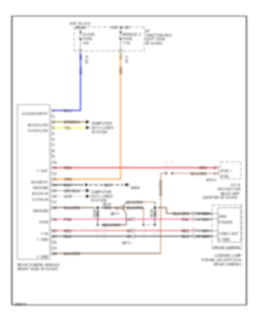
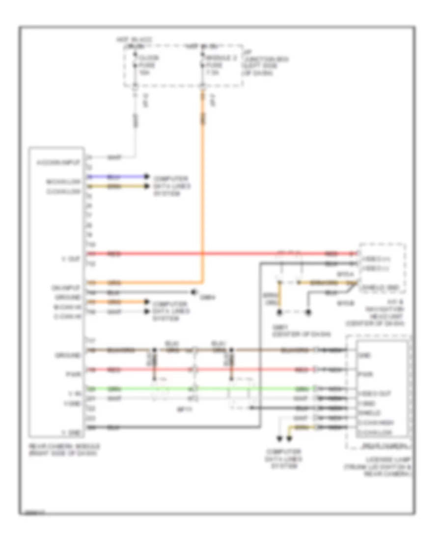
Immobilizer Wiring Diagram, with Smart Key System for Hyundai Sonata Hybrid Base 2013
List of elements for Immobilizer Wiring Diagram, with Smart Key System for Hyundai Sonata Hybrid Base 2013:
- (a/t & hybrid)
- (m/t)
- (not used)
- (or pnk)
- (or red)
- A/t & hybrid
- Acc/on input
- B-can high
- B-can low
- Bumper ant
- Bumper ant gnd
- Chg-ag
- Chg-k
- Chtg-ag
- Clock fuse 10a
- Computer data lines system
- Console)
- Cruise clutch pedal position switch (under left side of dash)
- Data
- Diag k
- Driver smart key outside handle
- Ec11
- Em11
- Em61
- Ems com
- Engine controls system
- Except hybrid
- Except hybrid 2.0l
- Except hybrid 2.4l
- Ext buzzer
- Exterior lights system
- External buzzer (left front wheelwell)
- Fd01
- Fd02
- Fr11
- Ge02 (left front of engine compt)
- Ge03 (right rear of dash)
- Gf02 (except hybrid) (left "b" pillar)
- Gf02 (left "b" pillar)
- Gf03 (right "b" pillar)
- Gf04 (hybrid) (left "c" pillar)
- Gf05 (right "c" pillar)
- Gm03 (left side of dash)
- Gm04
- Ground
- Ground 1
- Ground 2
- Hot at all times
- Hot in acc or on
- Hot in on or start
- Hybrid
- I/p junction box (left side of dash)
- I/p-e
- I/p-g
- Ign lk sw
- Ignition lock switch
- Immo ind
- Instrument cluster
- Interior ant 1
- Interior ant 1 gnd
- Interior ant 2
- Interior ant 2 gnd
- L fl dr lock/unlock
- L fr dr lock/unlock
- License lamp (trunk lid switch & rear camera)
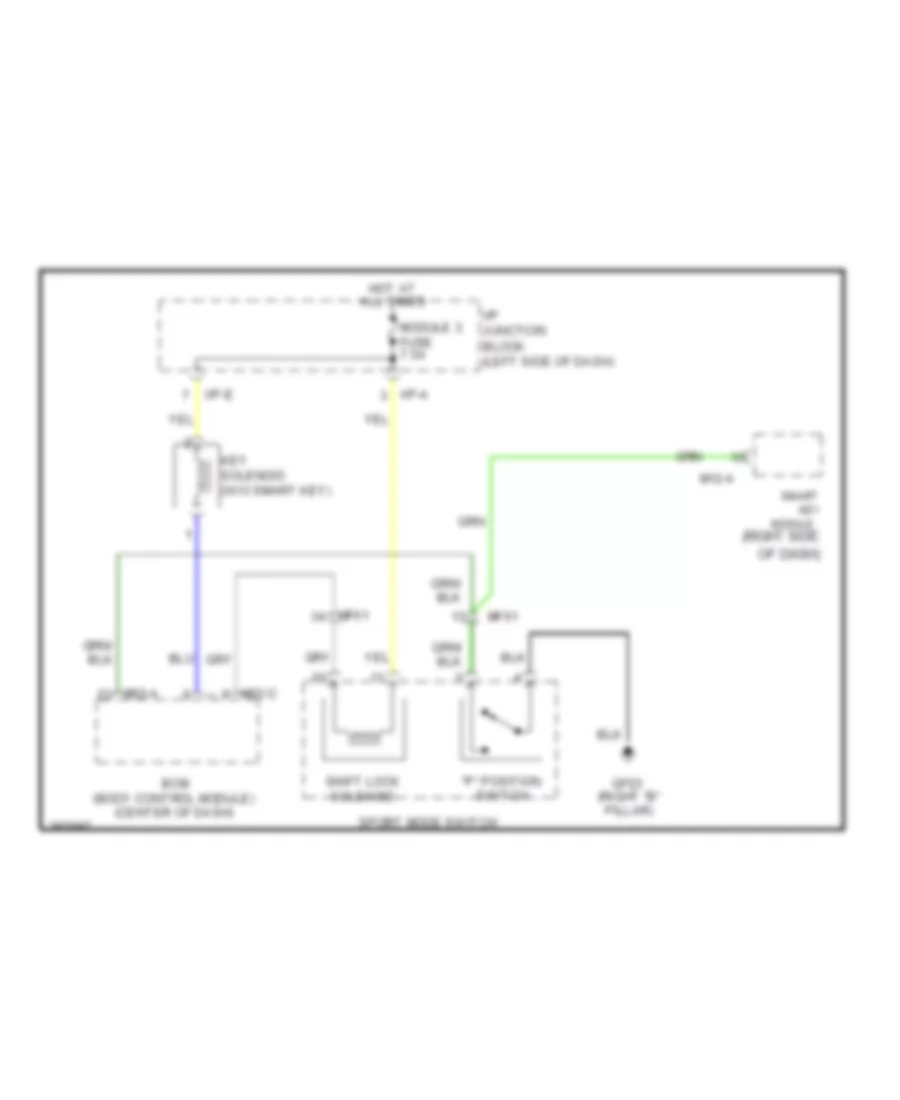
- Lock
- M/t
- M12-a
- M12-b
- Memory power
- Mf61
- Nca
- O fl dr ant
- O fl dr ant gnd
- O fr dr ant
- O fr dr ant gnd
- Of dash)
- On/start input
- P position
- Passenger smart key outside handle
- Pcm (left side of engine compt)
- Pdm 2 (brake switch) fuse 7.5a
- Pdm 3 fuse 7.5a
- Power connector
- Power distribution system
- Red
- Rf com
- Rf receiver (hybrid: behind left rear seat back) (except hybrid: right end of dash)
- Room lp fuse 10a
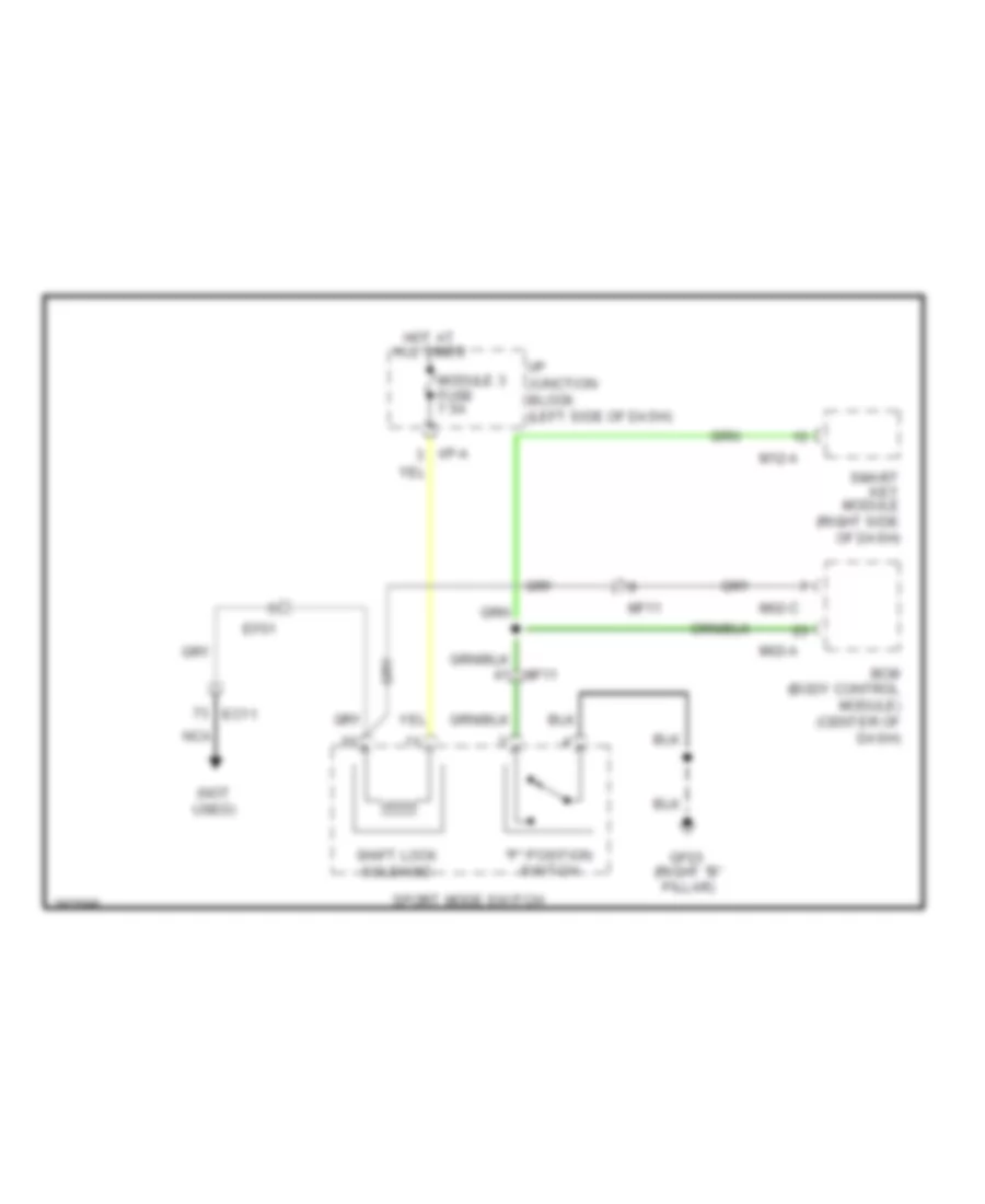
- Shift interlock system
- Smart key antenna (interior 1) (lower center
- Smart key antenna (interior 2) (under center
- Smart key module (right side of dash)
- Smart key rear bumper antenna (center of rear bumper)
- Smart key trunk antenna (center rear of trunk)
- Ssb sw
- Stop signal
- Trunk ant
- Trunk ant gnd
- Trunk lid
- Trunk lid switch
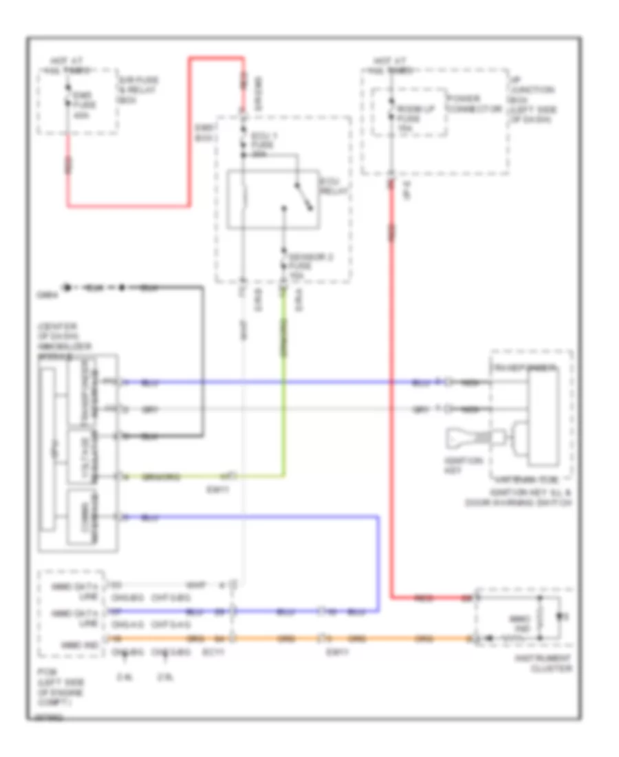
Immobilizer Wiring Diagram, without Smart Key System for Hyundai Sonata Hybrid Base 2013
List of elements for Immobilizer Wiring Diagram, without Smart Key System for Hyundai Sonata Hybrid Base 2013:
- (+)
- (-)
- (center of dash) immobilizer module
- 2.0l
- 2.4l
- Antenna coil
- Chg-ag
- Chg-bg
- Chtg-ag
- Chtg-bg
- Cpu
- E/r fuse & relay box
- E/r-a
- E/r-b
- E/r-ems
- Ec11
- Ecu 1 fuse 30a
- Ecu relay
- Em11
- Ems box
- Ems fuse 40a
- Gm04
- Hot at all times
- I/p junction box (left side of dash)
- I/p-e
- Ignition key
- Ignition key ill & door warning switch
- Immo data line
- Immo ind
- Instrument cluster
- Interface comms
- Interface transponder
- Nca
- Pcm (left side of engine compt)
- Power connector
- Red
- Regulator voltage
- Room lp fuse 15a
- Sensor 2 fuse 15a
- Transponder
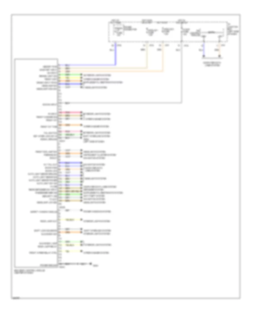
BODY CONTROL MODULES
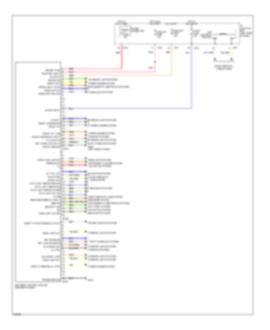
Body Control Module Wiring Diagram, Except Hybrid for Hyundai Sonata Hybrid Base 2013
List of elements for Body Control Module Wiring Diagram, Except Hybrid for Hyundai Sonata Hybrid Base 2013:
- 'r' input
- A/v tail out
- Acc/on input
- Anti-theft system
- Auto light senor ground
- Auto light senor power
- Auto light senor sig
- Auto light sw 'on'
- B-can
- B-can high
- B-can low
- Bcm (body control module) (center of dash)
- Brake sw
- Clock fuse 10a
- Computer data
- Computer data lines system
- Control module
- Crash input (pwm)
- Defogger system
- Door warning sw input
- Exterior lights system
- Front fog lamp sw
- Front int
- Front int time
- Front mist
- Front washer sig
- Front wiper relay ctrl
- Glove box lamp
- Glove box sw
- Gm03 (left side of dash)
- Gm04
- Headlamp high sw
- Headlamp low sig
- Headlamp sw
- Headlights system
- High
- Hot at all times
- Hot in acc or on
- Hot in on
- I/p junction box (left side of dash)
- I/p-e
- I/p-f
- I/p-g
- Ill ctrl
- Instrument cluster system
- Interior lights system
- Ips
- K-line
- Key inter lock sw in
- Key lock solenoid
- Key solenoid
- Lines system
- Low
- M02-a
- M02-b
- M02-c
- Memory pwr
- Module 1 fuse 7.5a
- Module 2 fuse 7.5a
- Navigation system
- On input
- On/start input
- Or start
- P/brake sw
- Pnk
- Power connector
- Power ground
- Power windows system
- Rear defogger sw input
- Red
- Room lamp out
- Room lamp rly
- Room lp fuse 10a
- Safety p/wdw enable output
- Sbr ind
- Security ind
- Shift interlock system
- Signal ground
- Tail switch
- Warning systems
- Wiper/washer system
Body Control Module Wiring Diagram, Hybrid for Hyundai Sonata Hybrid Base 2013
List of elements for Body Control Module Wiring Diagram, Hybrid for Hyundai Sonata Hybrid Base 2013:
- 'r' input
- (left side of dash)
- A/v tail out
- Acc/on input
- Anti-theft system
- Auto light senor ground
- Auto light senor power
- Auto light senor sig
- Auto light sw 'on'
- B-can
- B-can high
- B-can low
- Bcm (body control module) (center of dash)
- Brake light sw
- Clock fuse 10a
- Computer data
- Computer data lines system
- Control module
- Crash input (pwm)
- Defogger system
- Exterior lights system
- Front fog lamp sw
- Front int
- Front int time
- Front mist
- Front washer sig
- Front wiper relay ctrl
- Glove box lamp
- Glove box sw
- Gm03
- Gm04
- Headlamp high sw
- Headlamp low sig
- Headlamp sw
- Headlights system
- High
- Hot at all times
- Hot in acc or on
- Hot in on
- I/p junction box (left side of dash)
- I/p-e
- I/p-f
- I/p-g
- Instrument cluster system
- Interior lights system
- Ips
- K-line
- Key inter lock sw in
- Lines system
- Low
- M02-a
- M02-b
- M02-c
- Memory pwr
- Module 1 fuse 7.5a
- Module 2 fuse 7.5a
- Navigation system
- On input
- On/start input
- Or start
- P/brake sw
- Passenger sbr ind
- Pnk
- Power connector
- Power ground
- Power windows system
- Rear defogger sw input
- Room lamp out
- Room lamp relay
- Room lp fuse 10a
- Rxout
- Safety window module
- Security ind
- Shift interlock system
- Shift lock solenoid
- Signal ground
- Tail switch
- Tx out
- Wiper/washer system
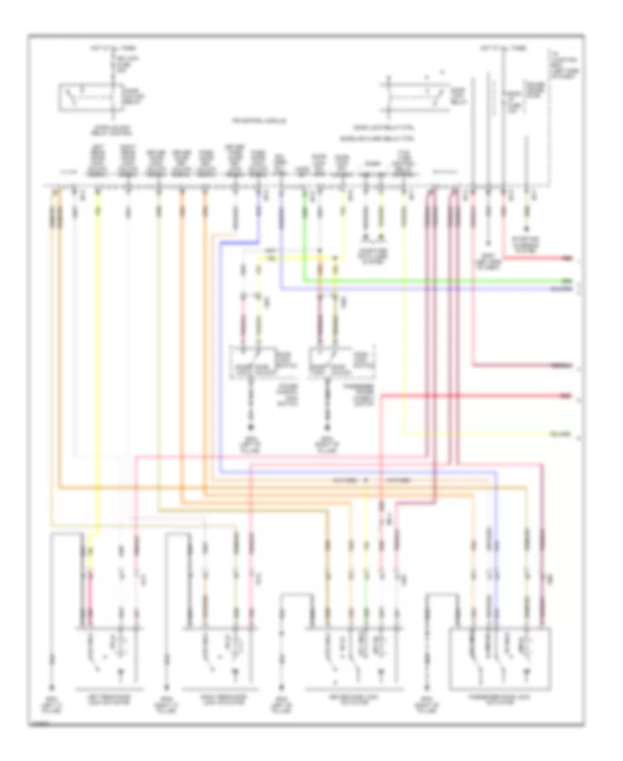
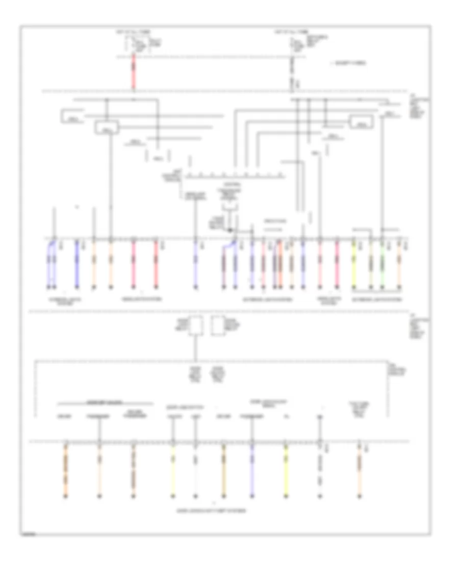
IPS Control Module Wiring Diagram (1 of 2) for Hyundai Sonata Hybrid Base 2013
List of elements for IPS Control Module Wiring Diagram (1 of 2) for Hyundai Sonata Hybrid Base 2013:
- (or pnk)
- (or red)
- B+2 fuse 50a
- B+4 fuse 60a
- Control
- Door key unlock
- Door lock relay
- Door lock relay ctrl
- Door lock switch
- Door lock/unlock signal
- Door locks & anti-theft systems
- Door unlock relay
- Door unlock relay ctrl
- Driver
- Driver/ passenger
- E/r fuse & relay box
- Except hybrid
- Exterior lights system
- Headlamp low signal
- Headlights system
- Hot at all times
- I/p junction box (left side of dash)
- I/p-a
- I/p-b
- I/p-c
- I/p-d
- I/p-f
- I/p-g
- Interior lights system
- Ips 1
- Ips 2
- Ips 3
- Ips 4
- Ips 5
- Ips 6
- Ips 7
- Ips 8
- Ips 9 (twin)
- Ips control module
- Lock
- Multi fuse
- Passenger
- Pnk
- Red
- T/sig sound relay
- T/sig sound relay control
- Two turn unlock relay ctrl
- Unlock
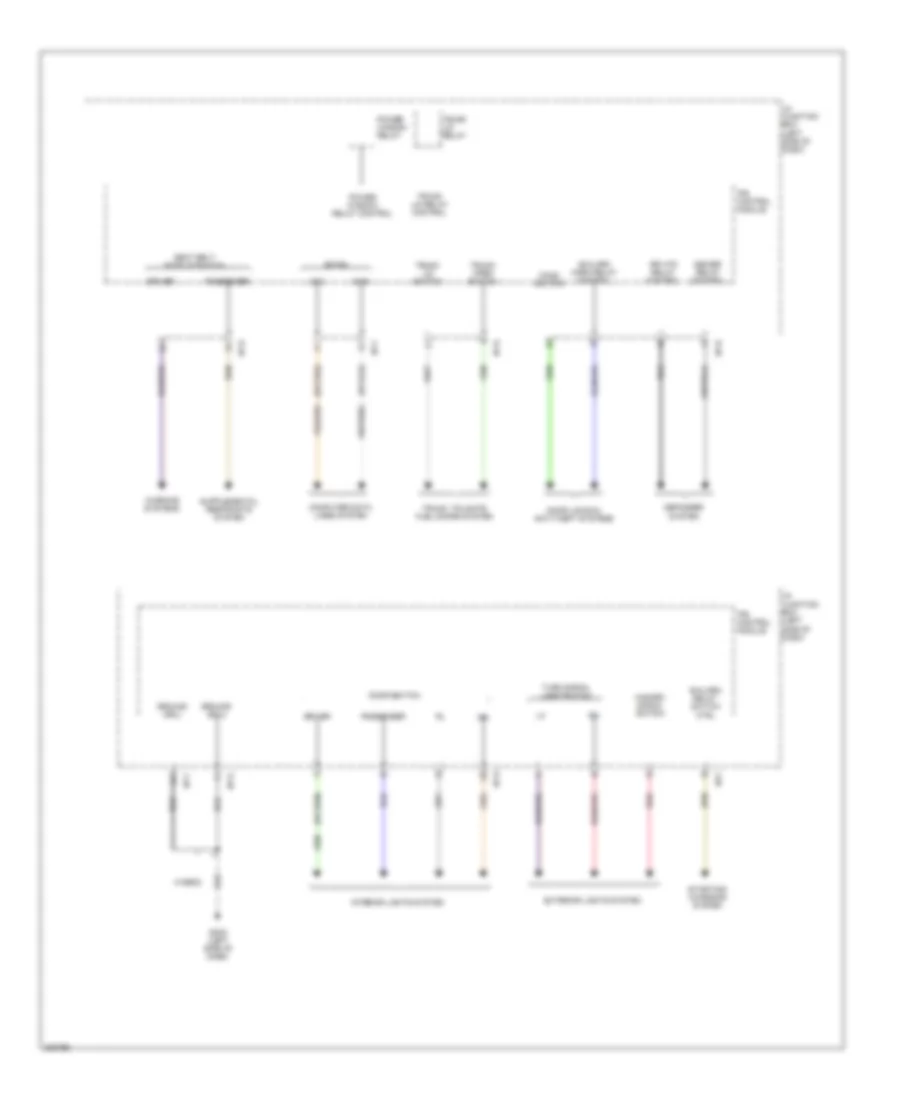
IPS Control Module Wiring Diagram (2 of 2) for Hyundai Sonata Hybrid Base 2013
List of elements for IPS Control Module Wiring Diagram (2 of 2) for Hyundai Sonata Hybrid Base 2013:
- B-can
- B/alarm horn relay control
- B/alarm relay switch ctrl
- Computer data lines system
- Defogger system
- Deicer relay control
- Door locks & anti-theft systems
- Door switch
- Driver
- Exterior lights system
- Gm03 (left side of dash)
- Ground (drl)
- Ground (ecu)
- Hazard signal switch
- High
- Hood switch
- Hybrid
- I/p junction box (left side of dash)
- I/p-b
- I/p-d
- I/p-f
- I/p-g
- Interior lights system
- Ips control module
- Low
- Passenger
- Power window relay
- Power window relay control
- Red
- Rr htd relay control
- Seat belt buckle switch
- Starting/ charging system
- Trunk lid relay
- Trunk lid relay control
- Trunk lid switch
- Trunk open switch
- Trunk, tailgate, fuel doors system
- Turn signal lamp switch
- Warning systems
COMPUTER DATA LINES
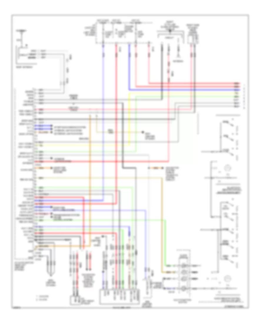
Computer Data Lines Wiring Diagram, Except Hybrid (1 of 2) for Hyundai Sonata Hybrid Base 2013
List of elements for Computer Data Lines Wiring Diagram, Except Hybrid (1 of 2) for Hyundai Sonata Hybrid Base 2013:
- (left side of dash)
- (w/ smart key) (right side of dash)
- 2.0l
- 2.4l
- 4p out
- A/c control module (auto a/c) (center of dash)
- B-can hi
- B-can hi m02-b
- B-can hi m12-a
- B-can lo
- Bcm (center of dash)
- C-can hi
- C-can lo
- Chg-bg
- Chtg-bg
- Clock (audio)
- Data link connector (under left side of dash)
- Diag-k
- Ec11
- Em11
- Eps control module (left side of dash)
- Esc module (left rear of engine compt)
- Gm03
- Hot at all times
- I/p junction box (left side of dash)
- I/p-e
- I/p-f
- Instrument cluster
- Ips control module
- J/c je01 (right side of dash)
- J/c jm02 (left side of dash)
- J/c jm05 (center of dash)
- K-line
- M13-b
- M20-a
- M21
- M26
- M60-a
- Module
- Mr01
- Panorama sunroof motor (top of right "a" pillar)
- Pcm (left side of engine compt)
- Pdm (w/ smart key) (right side of hvac unit)
- Pnk
- Power connector
- Power distribution system
- Red
- Resister
- Room lp fuse 10a
- Smart key
- Srs control module (under front of center console)
- Vacuum pump (2.0l)
- Veh spd
- W/ navigation
- W/o navigation
- Yaw rate sensor (in center console)
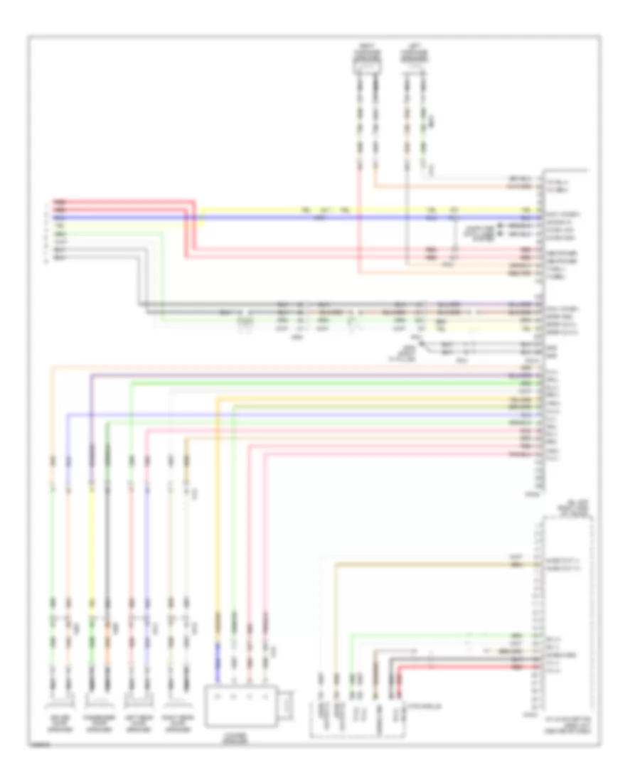
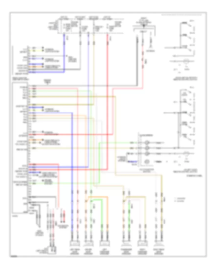
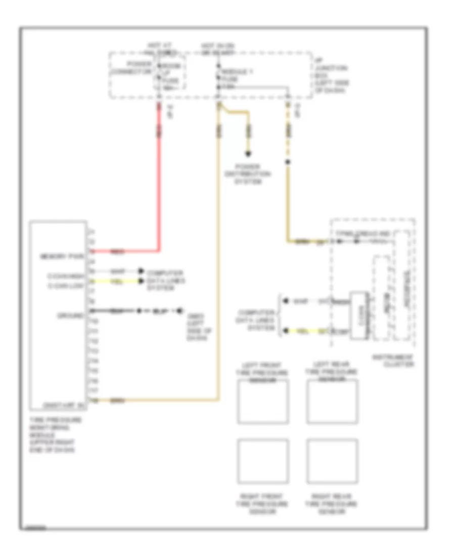
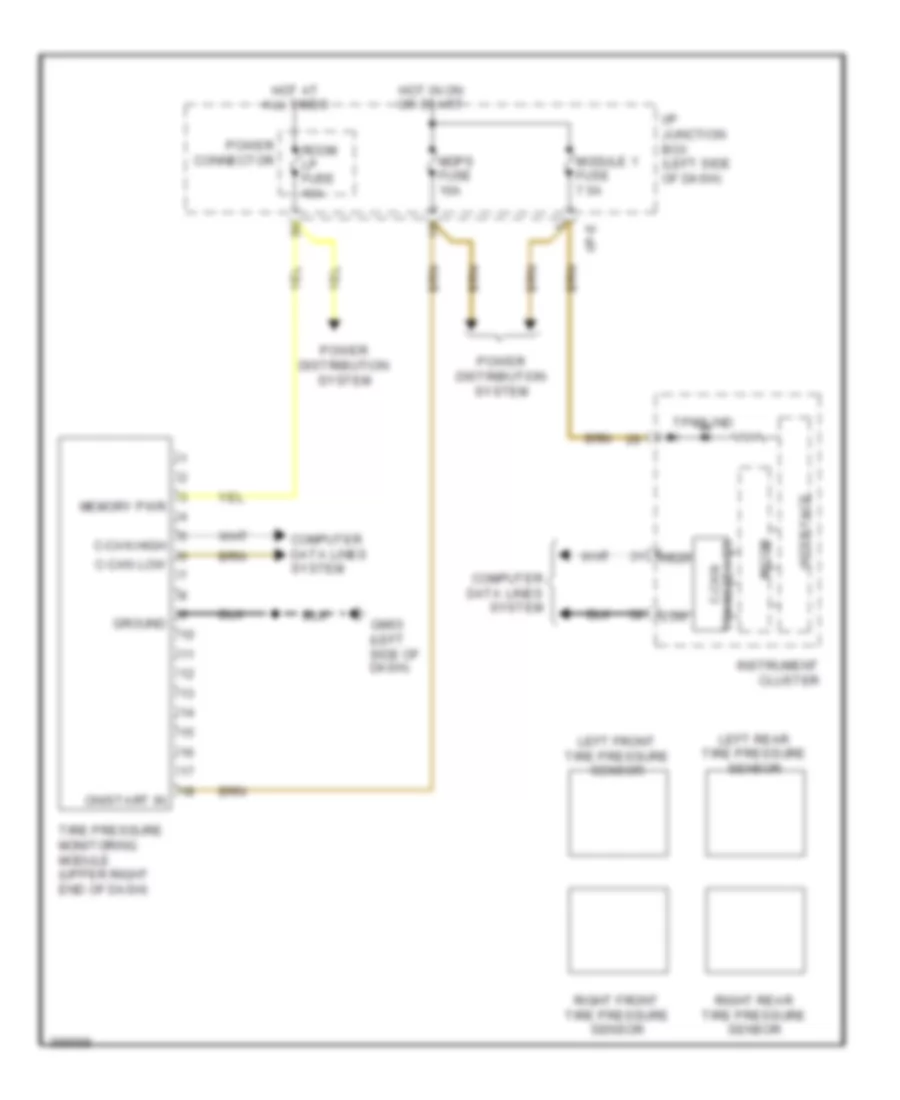
Computer Data Lines Wiring Diagram, Except Hybrid (2 of 2) for Hyundai Sonata Hybrid Base 2013
List of elements for Computer Data Lines Wiring Diagram, Except Hybrid (2 of 2) for Hyundai Sonata Hybrid Base 2013:
- (under front passenger's seat) passenger weight classification sensor
- A/c control module (center of dash)
- A/v & navigation head unit (center of dash)
- Amp (right side of trunk)
- Audio
- Automatic a/c
- C-can hi
- C-can lo
- E/r fuse & relay box
- Em61
- Esc 1 fuse 40a
- Esc 2 fuse 30a
- Esc 3 fuse 10a
- F02-a
- F03-a
- Ge04 (right side of engine compt)
- Hot at all times
- Hot in on or start
- J/c jf01 (lower center of dash)
- J/c jm03 (right side of dash)
- J/c jm06 (center of dash)
- Jbl
- Jbl amp (right side of trunk)
- M-can hi
- M-can lo
- M09-b
- M15-b
- M20-a
- M21
- M22-b
- M22-bn
- Manual a/c
- Mf11
- Mf61
- Mts module
- Multi fuse
- Multipurpose check connector (right rear of engine compt)
- Pnk
- Rear camera module (right side of dash)
- Red
- Standard
- Tire pressure monitoring module (upper right end of dash)
- Veh spd
- W/ navigation
- W/o navigation
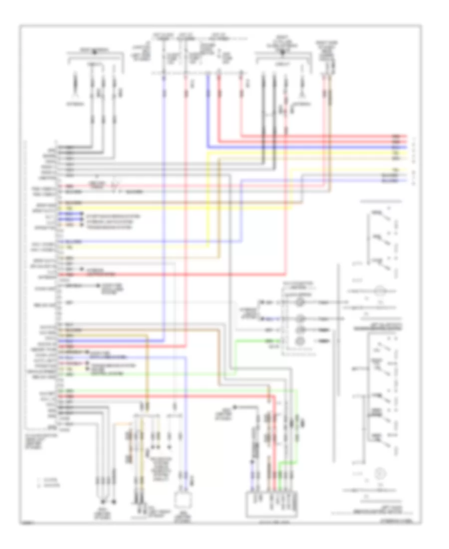
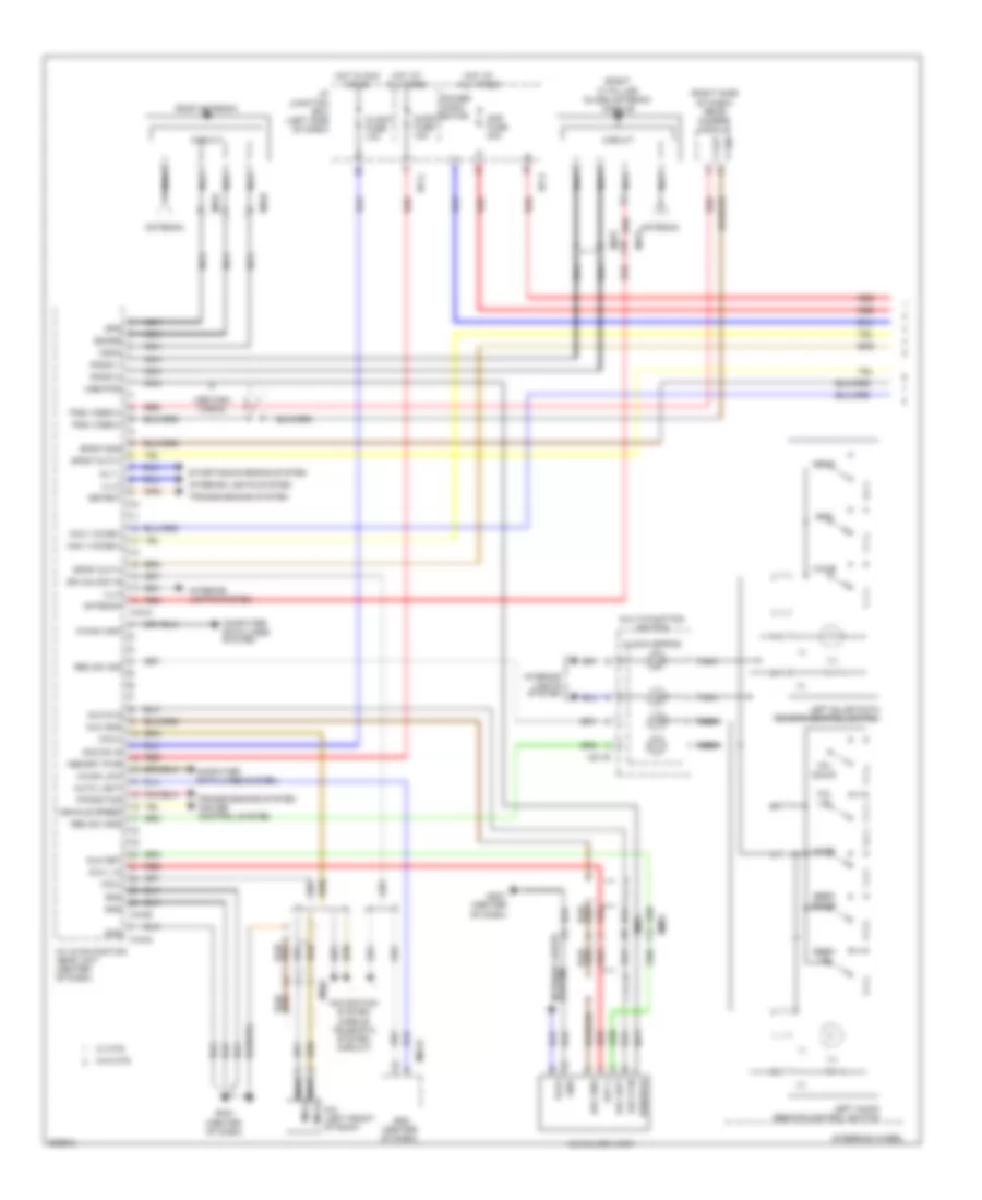
Computer Data Lines Wiring Diagram, Hybrid (1 of 2) for Hyundai Sonata Hybrid Base 2013
List of elements for Computer Data Lines Wiring Diagram, Hybrid (1 of 2) for Hyundai Sonata Hybrid Base 2013:
- "a" pillar) panorama sunroof
- (center of dash) j/c jm01
- (left front of engine compt) low voltage dc-dc converter
- (left side of dash)
- (left side of engine compt) j/c je04
- (right side of dash)
- (right side of dash) j/c jm03
- (top of right
- A/c control module (center of dash)
- A/v & navigation head unit (center of dash)
- Audio
- B-can hi
- B-can lo
- B-can lo m12-a
- Bcm (center of dash)
- C-can hi
- C-can high
- C-can lo
- C-can low
- Clock
- Data link connector (under left side of dash)
- Em61
- Esc module (left rear of engine compt)
- Ff31
- Front monitor (center of dash)
- Gm03
- Hot at all times
- Hybrid water pump (right side of engine compt)
- Hydraulic power unit (left rear of engine compt)
- I/p junction box
- I/p-e
- I/p-f
- Ips control module
- J/c je01 (right side of dash)
- J/c je02 (left end of dash)
- Jbl amp (right side of trunk)
- K-line
- M-can hi
- M-can hi f03-a
- M-can hi veh spd m09-b
- M-can high
- M-can lo
- M-can low
- M02-b
- M13-b
- M15-b
- M21-a
- Mf61
- Module
- Mr01
- Mts module
- Pdm (right side of hvac unit)
- Pnk
- Power connector
- Power distribution system
- Room lp fuse 10a
- Smart key
- Veh spd
- W/ navigation
- W/o front monitor
- W/o navigation
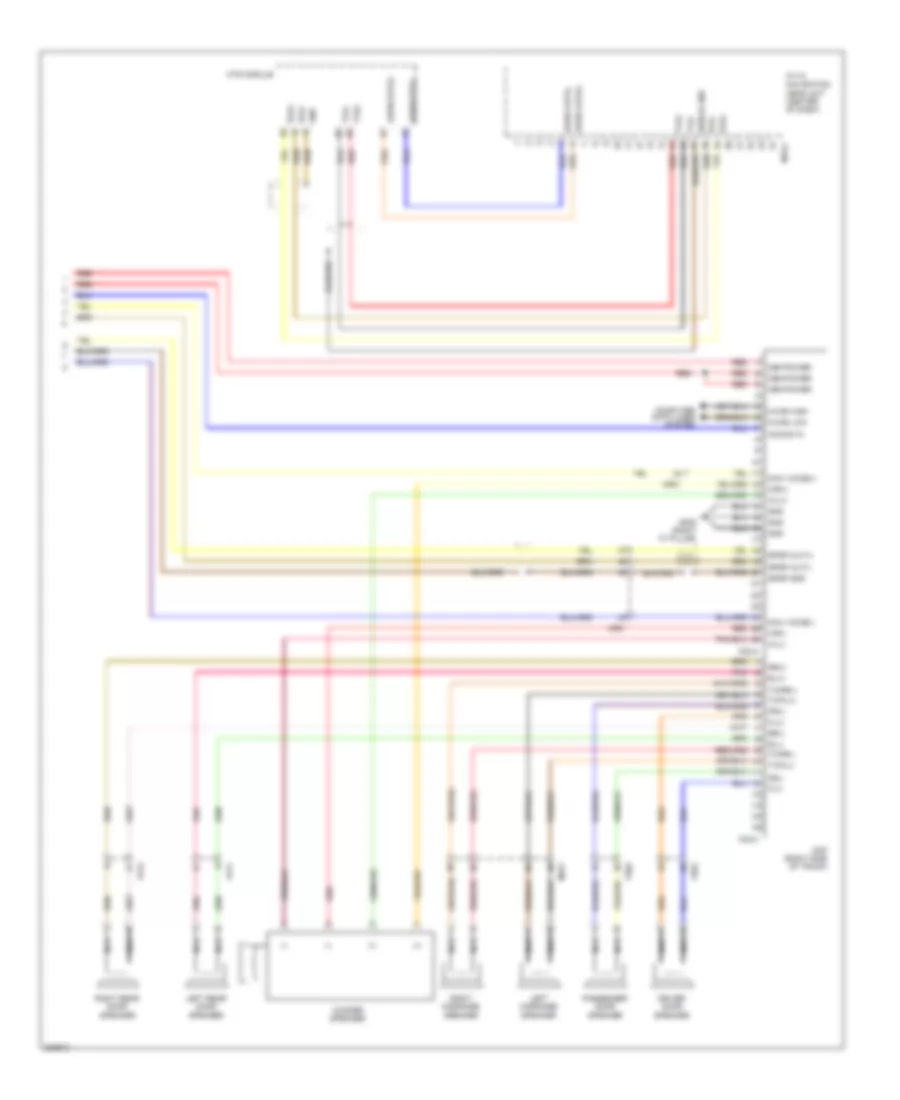
Computer Data Lines Wiring Diagram, Hybrid (2 of 2) for Hyundai Sonata Hybrid Base 2013
List of elements for Computer Data Lines Wiring Diagram, Hybrid (2 of 2) for Hyundai Sonata Hybrid Base 2013:
- (behind center of front grille)
- (in battery pack) bms control module
- (left front of engine compt) hybrid control unit
- (left front of engine compt) mcu
- (left front wheelwell) electric oil pump unit
- (left side of engine compt)
- (right side of
- (upper right end of dash)
- 4p out
- Active air flap
- B-can hi
- B-can low
- C-can hi
- C-can high
- C-can lo
- C-can low
- Chg-a
- Chg-k
- Chg34-s
- E/r fuse & relay box
- E64-b
- Ec11
- Ee01
- Em11
- Em61
- Eps control module (left side of dash)
- Esc 2 fuse 30a
- Esc 3 fuse 10a
- Ff01
- Ge04 (right side of engine compt)
- H-can hi
- H-can high
- H-can lo
- H-can low
- Hot at all times
- Hot in on or start
- Hvac unit)
- Instrument cluster
- J/c je03
- J/c jf01 (lower center of dash)
- J/c jf02
- J/c jm02 (left side of dash)
- J/c jm05 (center of dash)
- J/c jm06 (center of dash)
- License lamp (trunk lid switch & rear camera)
- M-can high
- M-can low
- M26
- M60-a
- Mf11
- Mf61
- Monitoring module
- Multipurpose check connector (right rear of engine compt)
- Nca c-can hi nca c-can lo
- Passenger weight classification sensor (under front passenger's seat)
- Pcm (left side of engine compt)
- Pnk
- Rear camera module (right side of dash)
- Red
- Srs control module (under front of center console)
- Tire pressure
- Vess unit
COOLING FAN
2.0L
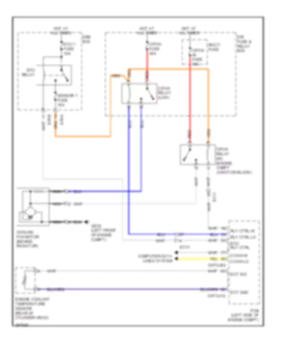
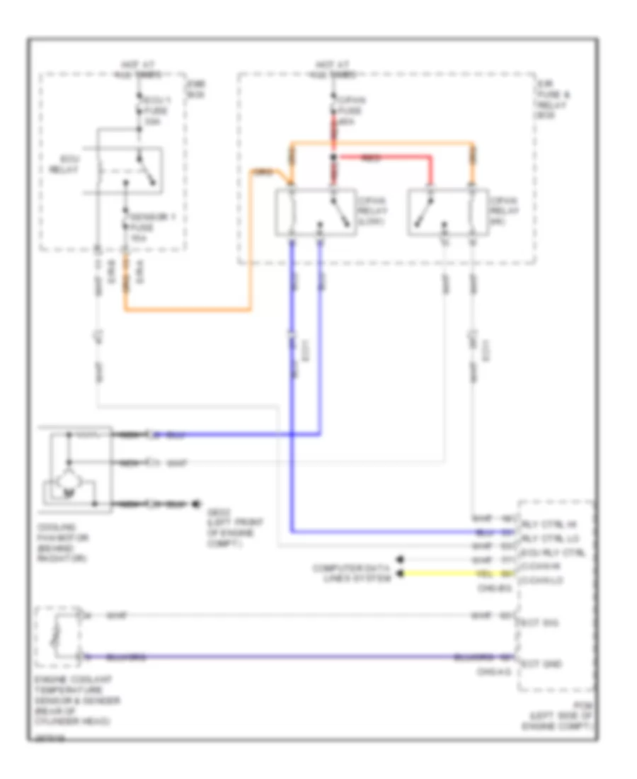
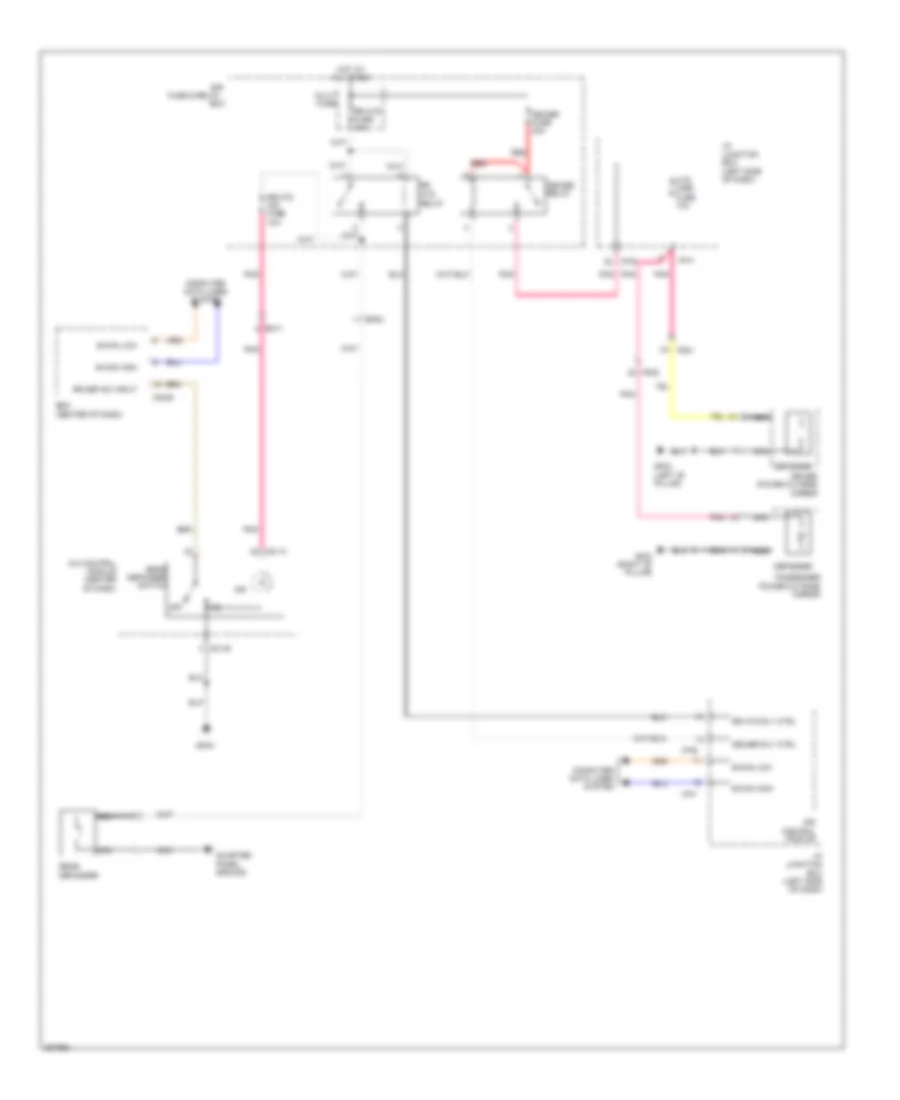
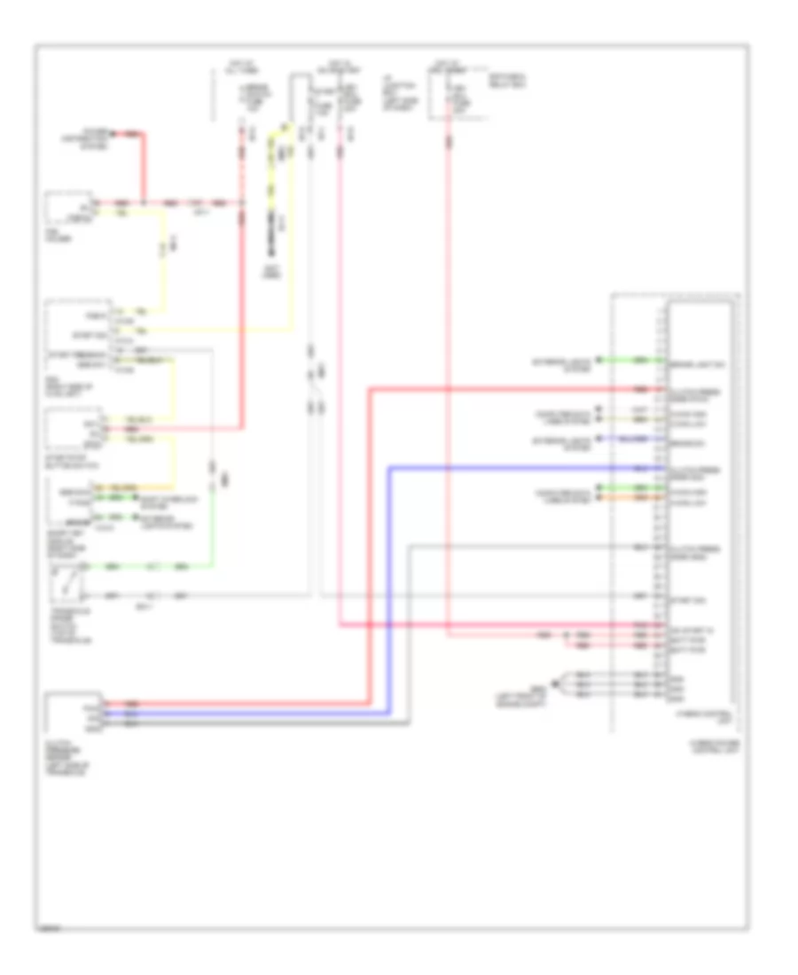
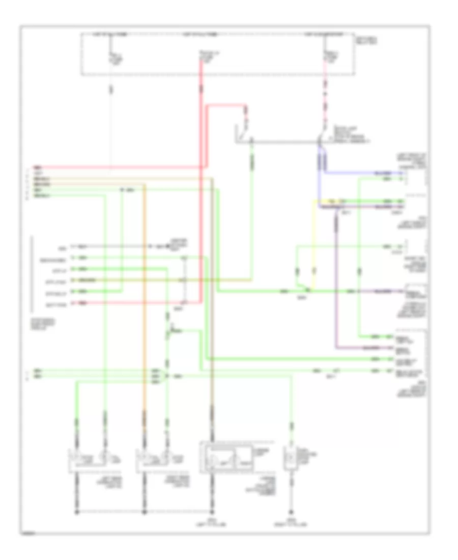
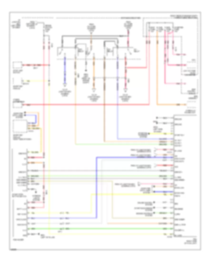
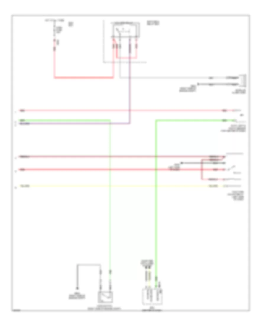
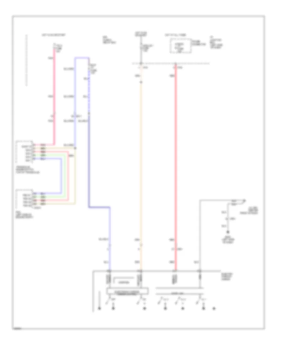
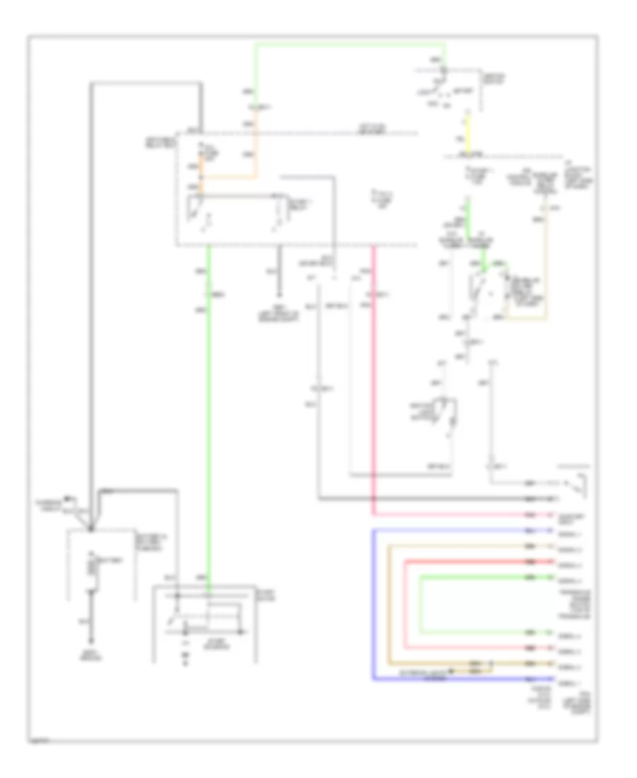
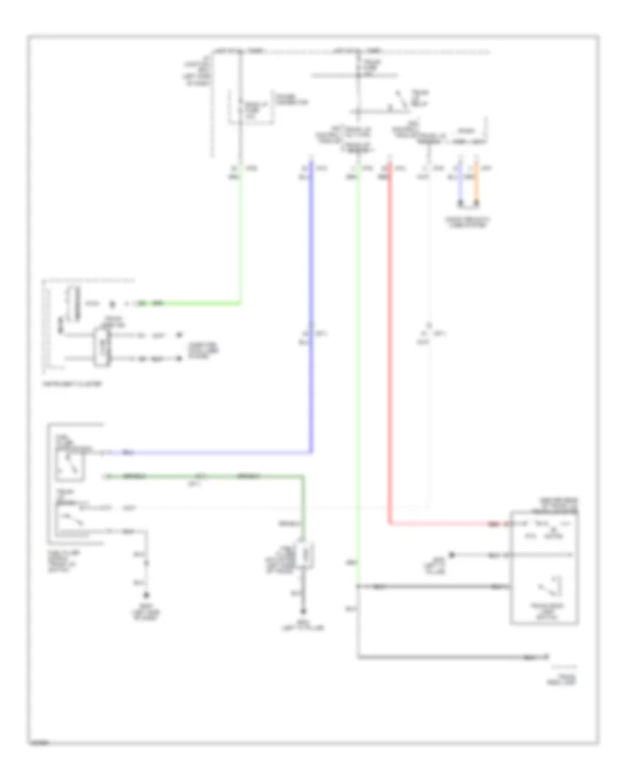
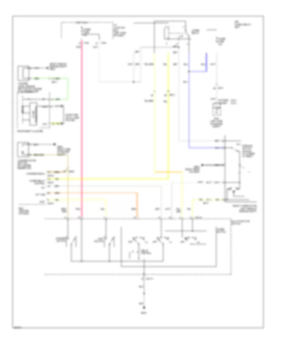
2.0L, Cooling Fan Wiring Diagram for Hyundai Sonata Hybrid Base 2013
List of elements for 2.0L, Cooling Fan Wiring Diagram for Hyundai Sonata Hybrid Base 2013:
- C-can hi
- C-can lo
- C/fan fuse 40a
- C/fan hi fuse 60a
- C/fan relay (hi) (engine compt junction block)
- C/fan relay (low)
- Chtg-ag
- Chtg-bg
- Computer data lines system
- Cooling fan motor (behind radiator)
- E/r fuse & relay box
- E/r-a
- E/r-b
- Ec11
- Ect gnd
- Ect sig
- Ecu 1 fuse 30a
- Ecu relay
- Ecu rly ctrl
- Ems box
- Engine coolant temperature sensor (rear of cylinder head)
- Ge02 (left front of engine compt)
- Hot at all times
- Multi fuse
- Nca
- Pcm (left side of engine compt)
- Red
- Rly ctrl hi
- Rly ctrl lo
- Sensor 1 fuse 15a
2.4L
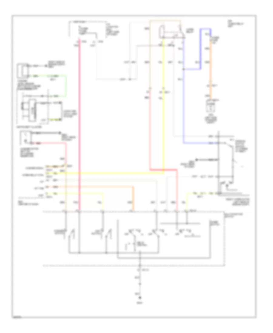
2.4L, Cooling Fan Wiring Diagram, Except Hybrid for Hyundai Sonata Hybrid Base 2013
List of elements for 2.4L, Cooling Fan Wiring Diagram, Except Hybrid for Hyundai Sonata Hybrid Base 2013:
- C-can hi
- C-can lo
- C/fan fuse 40a red
- C/fan relay (hi)
- C/fan relay (low)
- Chg-ag
- Chg-bg
- Computer data lines system
- Cooling fan motor (behind radiator)
- E/r fuse & relay box
- E/r-a
- E/r-b
- Ec11
- Ect gnd
- Ect sig
- Ecu 1 fuse 30a
- Ecu relay
- Ecu rly ctrl
- Ems box
- Engine coolant temperature sensor & sender (rear of cylinder head)
- Ge02 (left front of engine compt)
- Hot at all times
- Nca
- Pcm (left side of engine compt)
- Red
- Rly ctrl hi
- Rly ctrl lo
- Sensor 1 fuse 15a
2.4L, Cooling Fan Wiring Diagram, Hybrid for Hyundai Sonata Hybrid Base 2013
List of elements for 2.4L, Cooling Fan Wiring Diagram, Hybrid for Hyundai Sonata Hybrid Base 2013:
- (left front of engine compt) ge01
- (right side of engine compt) ge04
- A/c control module (center of dash)
- Active air flap (behind center of front grille)
- Battery
- C-can hi
- C-can lo
- C-can low
- C/fan fuse 60a
- C/fan relay
- C/fan rly ctrl
- Chg-k
- Computer data lines system
- Cooling fan controller (behind radiator)
- E/r fuse & relay box
- E/r-a
- E/r-b
- E11-a
- E11-b
- Ec11
- Ect gnd
- Ect sig
- Ecu 1 fuse 30a
- Ee01
- Ef01
- Electric detecting
- Electric water pump (right rear of engine)
- Em11
- Em61
- Ems box
- Engine control relay
- Engine coolant temperature sensor (rear of cylinder head)
- Engine ctrl rly ctrl
- Ewp fuse 10a
- Ewp fuse 60a
- Ewp relay
- Ewp rly ctrl
- Ewp rly f/b
- Fan
- Fuse 7.5a
- Ge04 (right side of engine compt)
- Ge08 (left front of engine compt)
- Gm04
- Gnd
- Hot at all times
- Hot in on or start
- Hot in on or start red
- Hybrid fuse & relay box (right rear of engine compt)
- Hybrid water pump (right side of engine compt)
- I/p junction box (left side of dash)
- I/p-e
- I/p-g
- M21-a
- Module
- Module fuse 7.5a
- Nca
- On/start in
- Pcm (left side of engine compt)
- Pnk
- Power conditioning
- Pwn driver
- Radiator fan condenser m
- Red
- Sensor fuse 15a
- Signal processing
CRUISE CONTROL
2.0L
2.0L, Cruise Control Wiring Diagram (1 of 2) for Hyundai Sonata Hybrid Base 2013
List of elements for 2.0L, Cruise Control Wiring Diagram (1 of 2) for Hyundai Sonata Hybrid Base 2013:
- (+)
- (-)
- 4p output
- 5v reg
- Aps 1 ground
- Aps 1 signal
- Aps 2 ground
- Aps 2 signal
- Atm solenoid (a/t) (top of transaxle)
- B-can transceiver
- Brake light sw
- Brake test sw
- C-can high
- C-can low
- C-can transceiver
- Cancel
- Chtg-ag
- Chtg-bg
- Clock spring
- Computer data lines system
- Cruise ind
- Ec11
- Em11
- Etc output (+)
- Etc output (-)
- Exterior lights system
- Gm03 (left side of dash)
- High
- Hot at all times
- Hot in on or start
- I/p junction box (left side of dash)
- I/p-e
- I/p-g
- Ill
- Instrument cluster
- Inter face
- Interior lights system
- Low
- M01-r
- Micom
- Module 1 fuse 7.5a
- Multi-function switch
- Nca
- On/ off
- On/start input
- Output sp sply
- Output spd sig
- Output speed
- Pcm (left side of engine compt)
- Pdm 2 fuse 7.5a
- Pnk
- Power connector
- Red
- Res (+)
- Reset
- Right cruise remote control switch
- Right trip remote control switch
- Room lp fuse 10a
- S gnd
- Set (-)
- Set ind
- Steering wheel
- Tps 1 signal
- Tps 2 signal
- Tps ground
- Trip
- Trip sw(+)
- Trip sw(-)
- Vehicle spd in
2.0L, Cruise Control Wiring Diagram (2 of 2) for Hyundai Sonata Hybrid Base 2013
List of elements for 2.0L, Cruise Control Wiring Diagram (2 of 2) for Hyundai Sonata Hybrid Base 2013:
- A/v & navigation head unit (center of dash)
- Accel position sensor (top of accelerator pedal assembly)
- Audio
- C-can high
- C-can low
- Clock (audio)
- Computer data lines system
- Data link connector (under left side of dash)
- E/r fuse & relay box
- Ec11
- Ecu 4 fuse 10a
- Ef01
- Esc module (a/t) (left rear of engine compt)
- Esc unit
- Etc motor & throttle position sensor (on throttle body assembly)
- Exterior lights system
- Fl sig
- Fl vcc
- Fr sig
- Fr vcc
- Hot in on or start
- Left front wheel sensor (on left front wheel hub assembly)
- Left rear wheel sensor (on left rear wheel hub assembly)
- M09-b
- M13-b
- M15-b
- Motor
- Mr01
- Navi
- Nca
- Panorama sunroof motor (top of right "a" pillar)
- Pdm (w/ smart key) (right side of hvac unit)
- Pnk
- Red
- Resistor
- Right front wheel sensor (on right front wheel hub assembly)
- Right rear wheel sensor (on right rear wheel hub assembly)
- Rl sig
- Rl vcc
- Rr sig
- Rr vcc
- Stop lamp switch (top of brake pedal assembly)
- Throttle position sensor
- Wheel sensor output (fr)
2.4L
2.4L, Cruise Control Wiring Diagram, Except Hybrid (1 of 2) for Hyundai Sonata Hybrid Base 2013
List of elements for 2.4L, Cruise Control Wiring Diagram, Except Hybrid (1 of 2) for Hyundai Sonata Hybrid Base 2013:
- (+)
- (-)
- 4p output
- 5v reg
- Aps 1 ground
- Aps 1 signal
- Aps 2 ground
- Aps 2 signal
- B-can transceiver
- Brake light sw
- Brake test sw
- C-can high
- C-can low
- C-can transceiver
- Cancel
- Chg-ag
- Chg-bg
- Clock spring
- Computer data lines system
- Cruise ind
- Ec11
- Em11
- Etc output (+)
- Etc output (-)
- Exterior lights system
- Gm03 (left side of dash)
- High
- Hot at all times
- Hot in on or start
- I/p junction box (left side of dash)
- I/p-e
- I/p-g
- Ill
- Instrument cluster
- Inter face
- Interior lights system
- Low
- M01-r
- Micom
- Module 1 fuse 7.5a
- Multi-function switch
- Nca
- On/ off
- On/start input
- Pcm (left side of engine compt)
- Pdm 2 fuse 7.5a
- Pnk
- Power connector
- Red
- Res (+)
- Reset
- Right cruise remote control switch
- Right trip remote control switch
- Room lp fuse 10a
- S gnd
- Set (-)
- Set ind
- Steering wheel
- Tps 1 signal
- Tps 2 signal
- Tps ground
- Trip
- Trip sw(+)
- Trip sw(-)
- Vehicle spd in
2.4L, Cruise Control Wiring Diagram, Except Hybrid (2 of 2) for Hyundai Sonata Hybrid Base 2013
List of elements for 2.4L, Cruise Control Wiring Diagram, Except Hybrid (2 of 2) for Hyundai Sonata Hybrid Base 2013:
- (right side of hvac unit)
- (top of right "a" pillar)
- A/v & navigation head unit (center of dash)
- Accel position sensor (top of accelerator pedal assembly)
- Audio
- C-can high
- C-can low
- Clock (audio)
- Computer data lines system
- Data link connector (under left side of dash)
- E/r fuse & relay box
- Ec11
- Ecu 4 fuse 10a
- Ef01
- Esc module (a/t) (left rear of engine compt)
- Esc unit
- Etc motor & throttle position sensor (on throttle body assembly)
- Exterior lights system
- Fl sig
- Fl vcc
- Fr sig
- Fr vcc
- Hot in on or start
- Left front wheel sensor (on left front wheel hub assembly)
- Left rear wheel sensor (on left rear wheel hub assembly)
- M09-b
- M13-b
- M15-b
- Motor
- Mr01
- Navi
- Nca
- Panorama sunroof motor
- Pdm (w/ smart key)
- Pnk
- Red
- Resistor
- Right front wheel sensor (on right front wheel hub assembly)
- Right rear wheel sensor (on right rear wheel hub assembly)
- Rl sig
- Rl vcc
- Rr sig
- Rr vcc
- Stop lamp switch (top of brake pedal assembly)
- Throttle position sensor
- Wheel sensor output (fr)
2.4L, Cruise Control Wiring Diagram, Hybrid (1 of 2) for Hyundai Sonata Hybrid Base 2013
List of elements for 2.4L, Cruise Control Wiring Diagram, Hybrid (1 of 2) for Hyundai Sonata Hybrid Base 2013:
- (+)
- (-)
- (gnd)
- 4p output
- 5v reg
- Aps 1 ground
- Aps 1 power
- Aps 1 signal
- Aps 2 ground
- Aps 2 power
- Aps 2 signal
- Atm solenoid (top of transaxle)
- B-can transceiver
- Brake switch fuse 10a
- Brake test sw
- C-can high
- C-can low
- C-can transceiver
- Cancel
- Chg-a
- Chg-k
- Clock spring
- Computer data lines system
- Cruise ind
- Cruise remote control switch (up- right)
- Em11
- Etc dc motor 1
- Etc dc motor 2
- Gm03 (left side of dash)
- High
- Hot at all times
- Hot in on or start
- I/p junction box (left side of dash)
- I/p-e
- I/p-g
- Ill
- Instrument cluster
- Inter face
- Interface
- Interior lights system
- Low
- M01-r
- Micom
- Module 1 fuse 7.5a
- Multi-function switch
- Nca
- On/ off
- Output sp sply
- Output spd sig
- Output speed
- Pcm (left side of engine compt)
- Pnk
- Power connector
- Red
- Res (+)
- Reset
- Room lp fuse 10a
- S gnd
- Set (-)
- Set ind
- Steering wheel
- Sw(+)
- Tps 1 signal
- Tps 2 signal
- Tps ground
- Tps power
- Trip
- Trip remote control switch (down- right)
- Vehicle spd in
2.4L, Cruise Control Wiring Diagram, Hybrid (2 of 2) for Hyundai Sonata Hybrid Base 2013
List of elements for 2.4L, Cruise Control Wiring Diagram, Hybrid (2 of 2) for Hyundai Sonata Hybrid Base 2013:
- (left front of engine compt) hybrid control unit
- (left side of engine compt) pcm
- (right side of dash) smart key module
- A/v & navigation head unit (center of dash)
- Accel pedal position sensor (top of accelerator pedal assembly)
- Anti-lock brakes system
- Audio
- Bcm (center of dash)
- Brake light sw
- Brake sw
- C-can high
- C-can low
- Chg-a
- Clock (w/o front monitor)
- Computer data lines system
- Data link connector (under left side of dash)
- E/r fuse & relay box
- Ec11
- Ef01
- Em61
- Esc (hac/dbc)
- Esc 3 fuse 10a
- Esc module (left rear of engine compt)
- Etc motor & throttle position sensor (on throttle body assembly)
- Fl sig
- Fl vcc
- Fr sig
- Fr vcc
- Hac brake rly ctrl
- Hot in on or start
- J/c jm01 (center of dash)
- Left front wheel sensor (on left front wheel hub assembly)
- Left rear wheel sensor (on left rear wheel hub assembly)
- M02-a
- M09-b
- M12-a
- M13-b
- M15-b
- Motor
- Mr01
- Navi
- Nca
- Panorama sunroof (top of right "a" pillar)
- Pdm (right side of hvac unit)
- Pnk
- Red
- Right front wheel sensor (on right front wheel hub assembly)
- Right rear wheel sensor (on right rear wheel hub assembly)
- Rl sig
- Rl vcc
- Rr sig
- Rr vcc
- Stop lamp sig
- Stop lamp sw
- Stop lamp switch (top of brake pedal assembly)
- Stop signal electronic module
- Throttle position sensor
- Wheel sensor output (fr)
DEFOGGERS
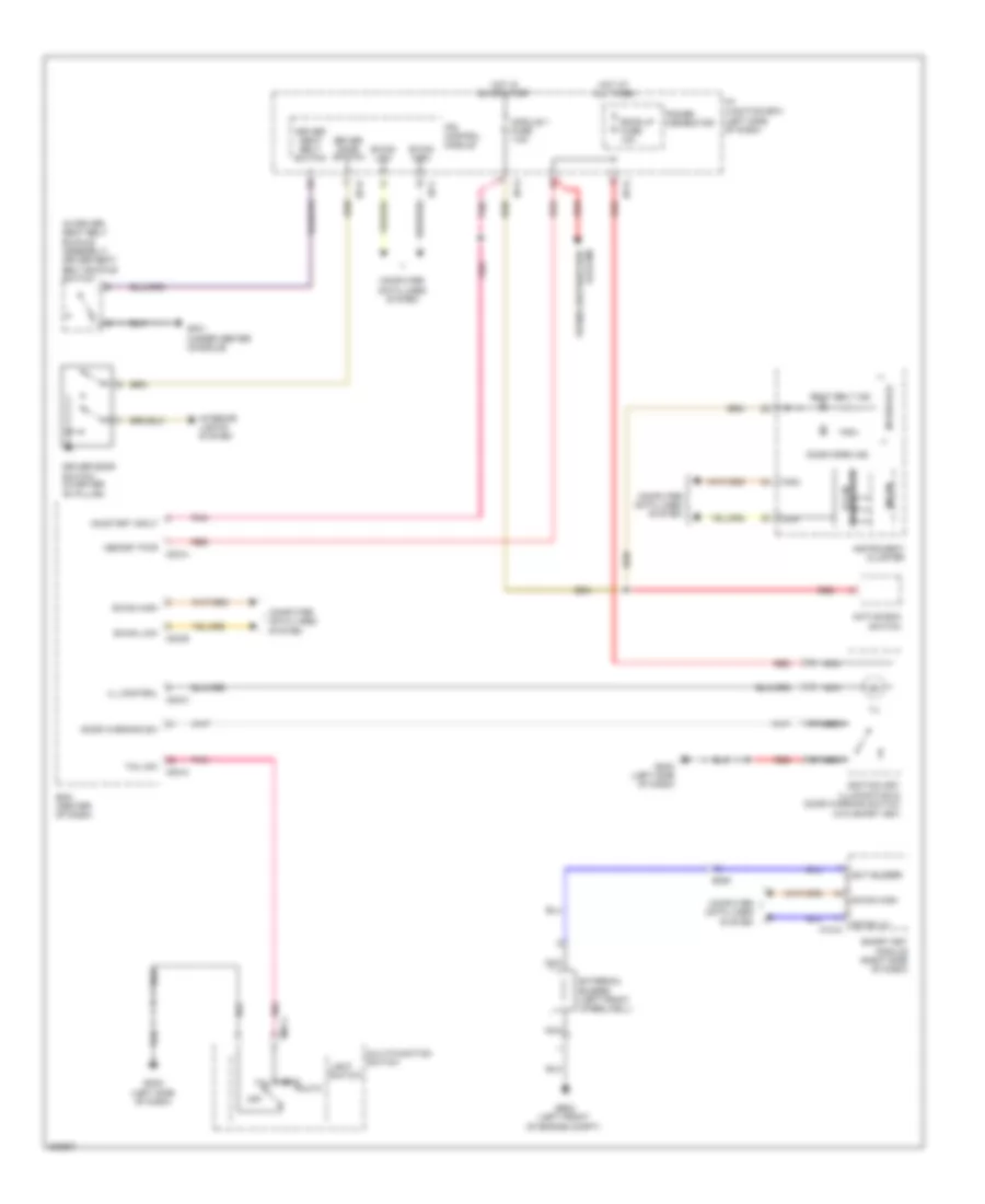
Defoggers Wiring Diagram, Except Hybrid for Hyundai Sonata Hybrid Base 2013
List of elements for Defoggers Wiring Diagram, Except Hybrid for Hyundai Sonata Hybrid Base 2013:
- 2.4l
- A/c control module (center of dash)
- Automatic a/c w/ navigation
- Automatic a/c w/o navigation
- B-can high
- B-can low
- Bcm (center of dash)
- Box
- Computer data lines system
- Control
- Defogger
- Deicer fuse 20a
- Deicer relay
- Deicer rly ctrl
- Driver power outside mirror
- E/r
- Ef02
- Em11
- Fd01
- Fd02
- Front wiper deicer (left rear of engine compt)
- Fuse & relay
- Ge03 (right rear of dash)
- Gf02 (left "b" pillar)
- Gf03 (right "b" pillar)
- Gm03 (left side of dash)
- Ground
- Hot at all times
- Htd mirr fuse 10a
- I/p junction box (left side of dash)
- I/p-a
- I/p-b
- I/p-f
- Ind
- Ips
- M02-b
- M20-a
- M20-b
- M21
- M22-b
- M22-bn
- Manual a/c w/ navigation
- Manual a/c w/o navigation
- Module
- Multi fuse
- Nca
- Panel
- Passenger power outside mirror
- Pnk
- Quarter
- Rear
- Red
- Relay
- Rr def sw input
- Rr htd
- Rr htd fuse 40a
- Rr htd ind fuse 10a
- Rr htd rly ctrl
- Switch
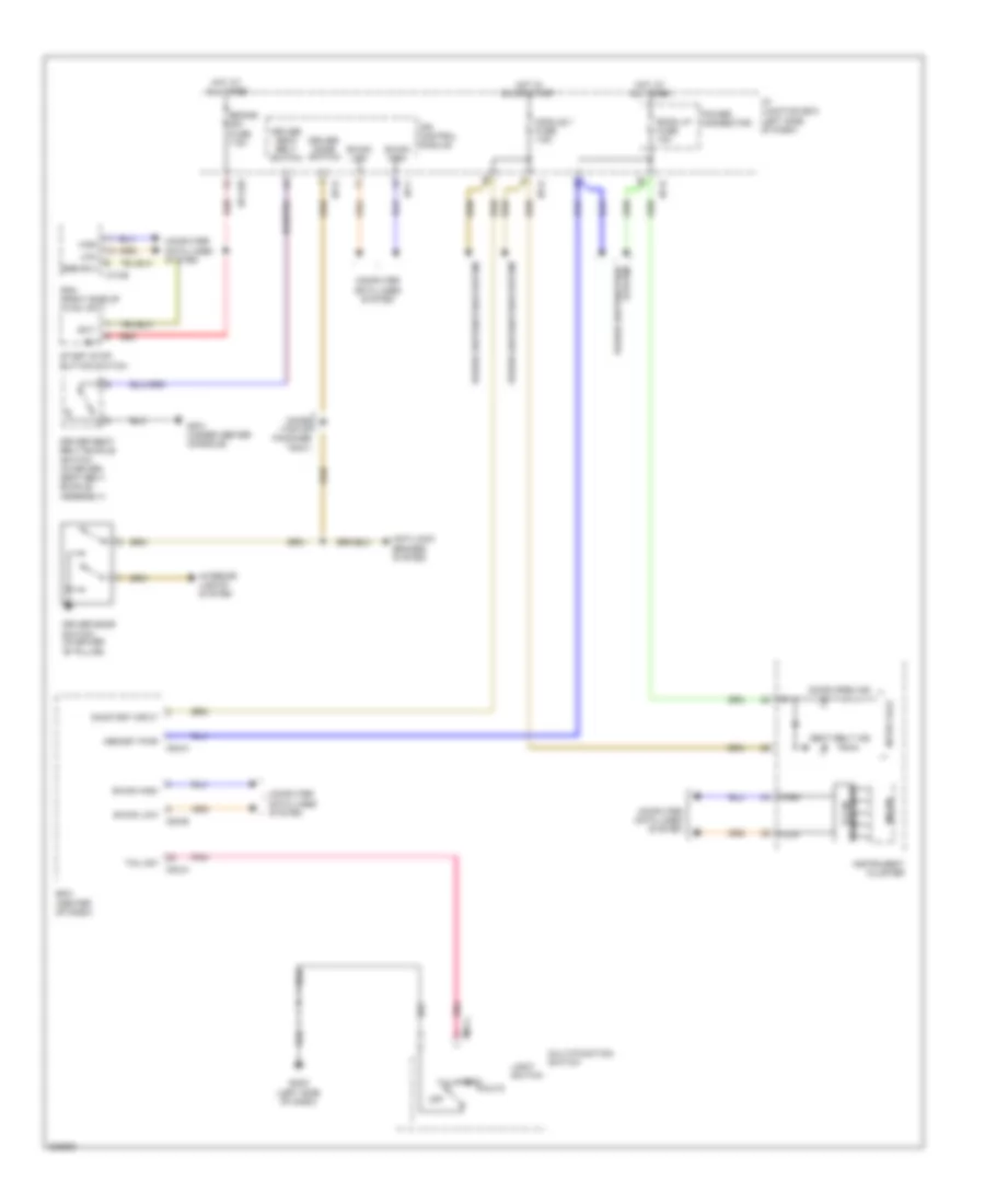
Defoggers Wiring Diagram, Hybrid for Hyundai Sonata Hybrid Base 2013
List of elements for Defoggers Wiring Diagram, Hybrid for Hyundai Sonata Hybrid Base 2013:
- A/c control module (center of dash)
- B-can high
- B-can low
- Bcm (center of dash)
- Box
- Computer data lines
- Computer data lines system
- Control
- Defogger
- Deicer fuse 20a
- Deicer relay
- Deicer rly ctrl
- Driver power outside mirror
- E/r
- Ef02
- Em11
- Fd01
- Fd02
- Fuse & relay
- Gf02 (left "b" pillar)
- Gf03 (right "b" pillar)
- Gm04
- Hot at all times
- Htd mirr fuse 10a
- I/p junction box (left side of dash)
- I/p-a
- I/p-b
- I/p-f
- Ind
- Ips
- M02-b
- M21-a
- M21-b
- Module
- Multi fuse
- Nca
- Off
- Passenger power outside mirror
- Pnk
- Quarter panel ground
- Rear
- Rear defogger
- Red
- Relay
- Rr def sw input
- Rr htd
- Rr htd fuse 40a
- Rr htd ind fuse 10a
- Rr htd rly ctrl
- Switch
- System
ELECTRONIC POWER STEERING
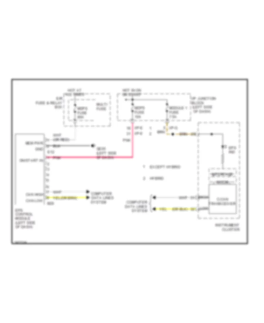
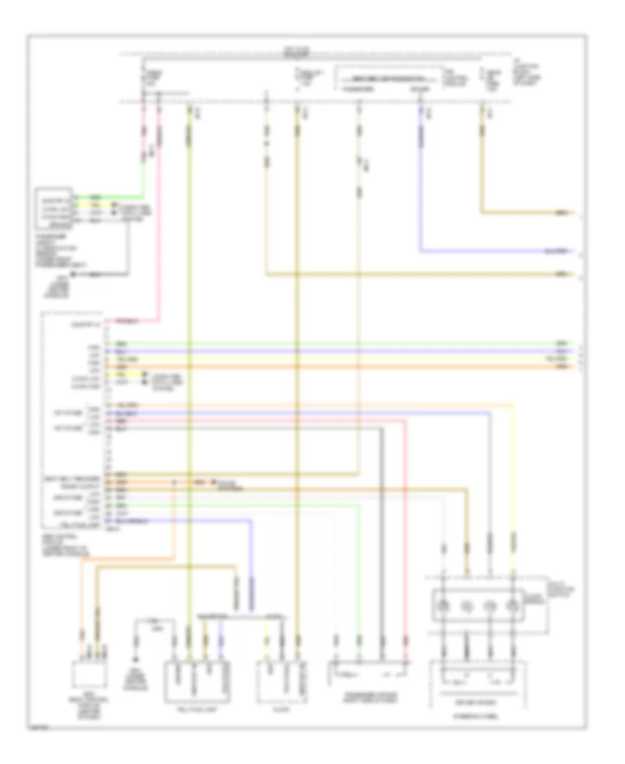
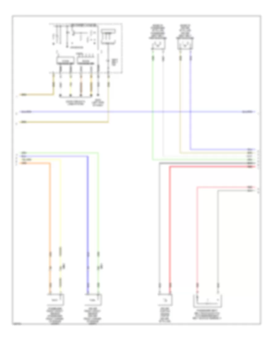
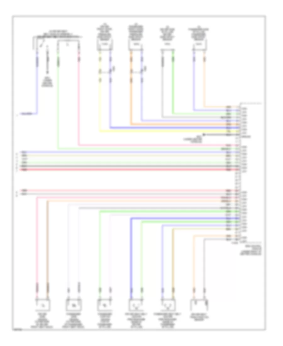
Electronic Power Steering Wiring Diagram for Hyundai Sonata Hybrid Base 2013
List of elements for Electronic Power Steering Wiring Diagram for Hyundai Sonata Hybrid Base 2013:
- (left side
- C-can transceiver
- Can high
- Can low
- Computer data lines
- Computer data lines system
- E/r fuse & relay box
- E12
- Eps control module (left side of dash)
- Eps ind
- Except hybrid
- Ge05 (left side of dash)
- Gnd
- High
- Hot at all times
- Hot in on or start
- Hybrid
- I/p junction block
- I/p-e
- I/p-g
- Instrument cluster
- Interface
- Low
- M26
- Mdps fuse 10a
- Mdps fuse 80a
- Mem pwr
- Micom
- Module 1 fuse 7.5a
- Multi fuse
- Of dash)
- On/start in
- Pnk
- System
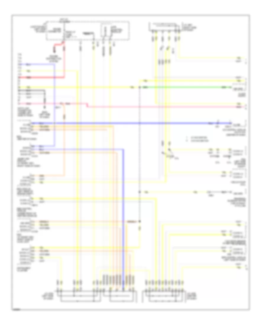
ENGINE PERFORMANCE
2.0L
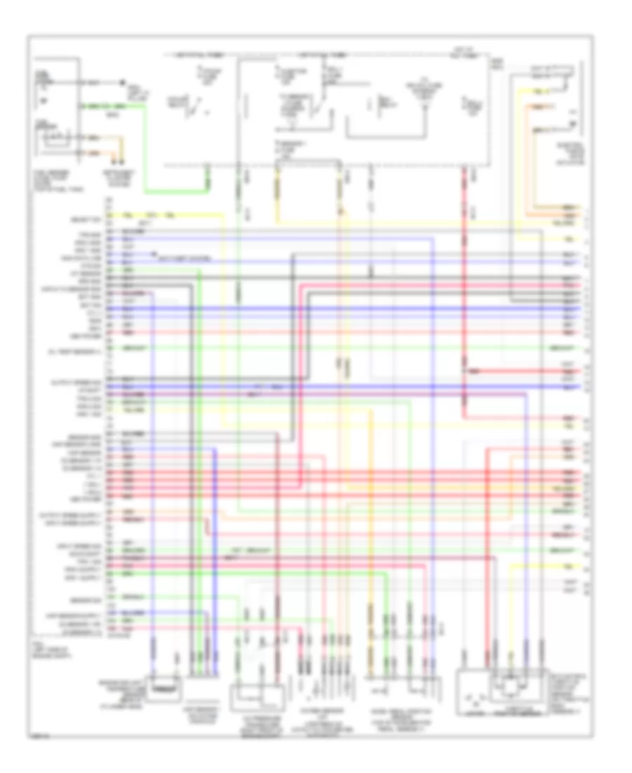
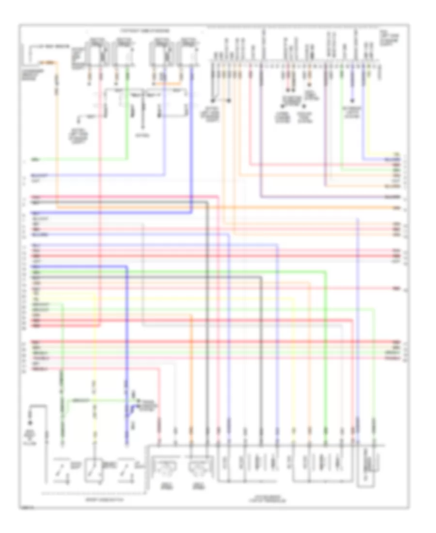
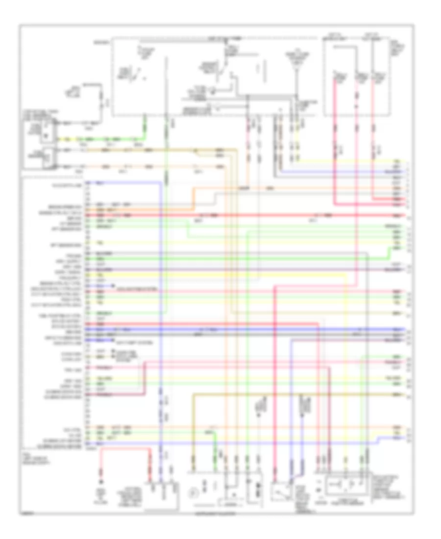
2.0L, Engine Performance Wiring Diagram (1 of 5) for Hyundai Sonata Hybrid Base 2013
List of elements for 2.0L, Engine Performance Wiring Diagram (1 of 5) for Hyundai Sonata Hybrid Base 2013:
- (diagram 4 of 5)
- (up)
- (upstream of catalytic converter, in exhaust)
- 2 fuse
- A/c pressure transducer (right front of engine compt)
- Accel pedal position sensor (top of accelerator pedal assembly)
- Actuator
- Anti-theft system
- Aps 1 gnd
- Aps 1 sig
- Aps 2 gnd
- Aps 2 sig
- Body assembly)
- Chtg-ag
- Cyl 1
- Cyl 3
- Cylinder head)
- Down shift
- E/r-a
- E/r-b
- Ec11
- Ect gnd
- Ect sig
- Ecu 1 fuse 30a
- Ecu 3 fuse 10a
- Ecu relay
- Ef02
- Electric
- Ems box
- Engine coolant
- Etc motor & throttle position sensor (on throttle
- F/pump fuse 20a
- F/pump relay
- Fuel pump motor
- Fuel sender
- Fuel sender & fuel pump motor (top of fuel tank)
- Gate
- Gf04 (left "c" pillar)
- Hot at all times
- Iat sensor
- Immo data line
- Injector fuse 15a
- Input speed sig
- Instrument cluster system
- Map & tia sensor gnd
- Map sensor
- Map sensor 1 (on intake manifold)
- Map sensor 2 gnd
- Mem power
- Motor
- Nca
- O2 sensor v g
- O2 sensor v ip
- O2 sensor v n
- O2 sensor v rc
- Oil temp sensor (+)
- Ots sig
- Output speed sig
- Oxygen sensor
- Pcm (left side of engine compt)
- Pnk
- Red
- Rps gnd
- Select sw
- Sensor
- Sensor (rear of
- Sensor 1 fuse 15a
- Sensor gnd
- Sensor sig
- Ss-a
- Ss-b
- Temperature
- Throttle position sensor
- To ign coil fuse (diagram 4 of 5)
- To sensor
- Tps 1 sig
- Tps 2 sig
- Tps gnd
- Up shift
- V sol1
- V sol2
- Waste
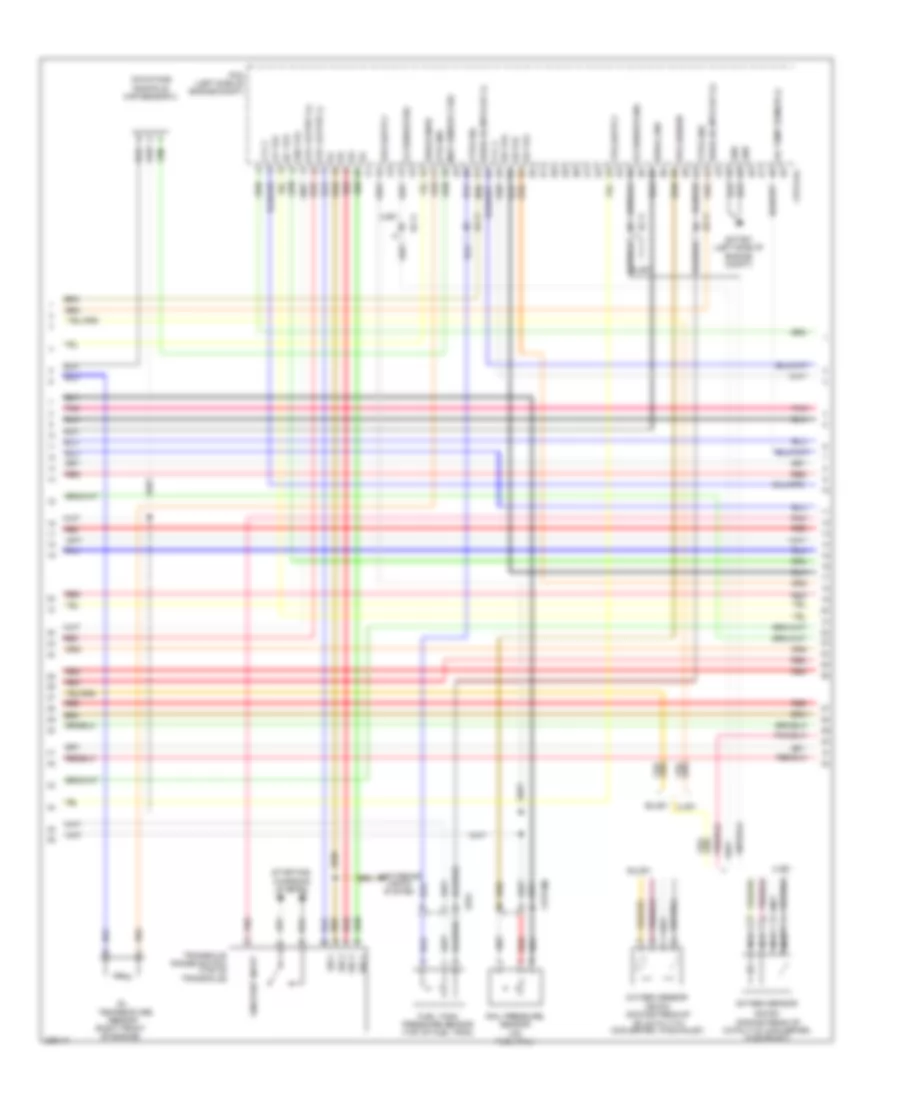
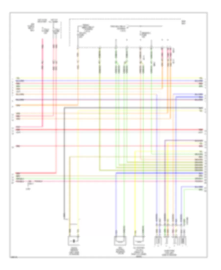
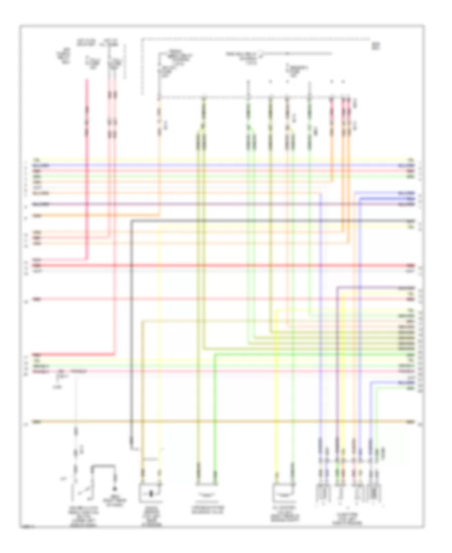
2.0L, Engine Performance Wiring Diagram (2 of 5) for Hyundai Sonata Hybrid Base 2013
List of elements for 2.0L, Engine Performance Wiring Diagram (2 of 5) for Hyundai Sonata Hybrid Base 2013:
- (down)
- (down) (downstream of of catalytic converter, in exhaust)
- (downstream of catalytic converter, in exhaust)
- (on fuel rail)
- (on intake manifold) map sensor 2
- (right front of engine)
- 26 vfs
- 35r vfs
- Chtg-ag
- Chtginj
- Cyl 2
- Cyl 4
- Dc vfs
- Ec11
- Ef01
- Etc output (+)
- Etc output (-)
- Ewga dc mtr out (+)
- Ewga dc mtr out (-)
- Ewga gnd
- Ewga snsr
- Exterior lights system
- Ftps gnd
- Ftps sig
- Fuel tank pressure sensor (top of fuel tank)
- Ghtg01 (left side of engine compt)
- Gnd
- Lp vfs
- Map sensor 2 sig
- Nca
- O2 sensor gnd
- O2 sensor sig
- Od vfs
- Oil
- Oil temp sensor (-)
- On/start input
- Ots gnd
- Oxygen sensor
- Pcm (left side of engine compt)
- Pnk
- Rail pressure sensor
- Red
- Rps sensor
- Sensor
- Sig 1
- Sig 2
- Sig 3
- Sig 4
- Starting/ charging system
- Sulev
- Temperature
- Transaxle range switch (top of transaxle)
- Ud vfs
- Ulev
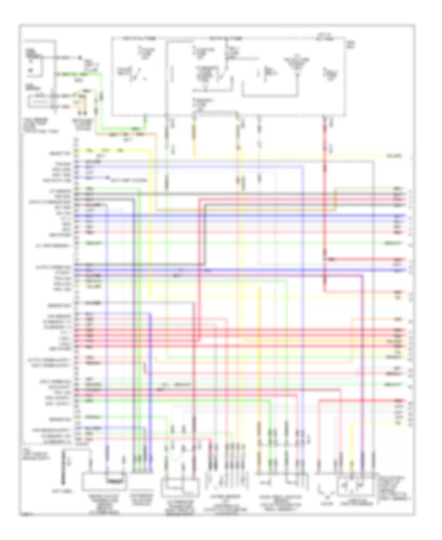
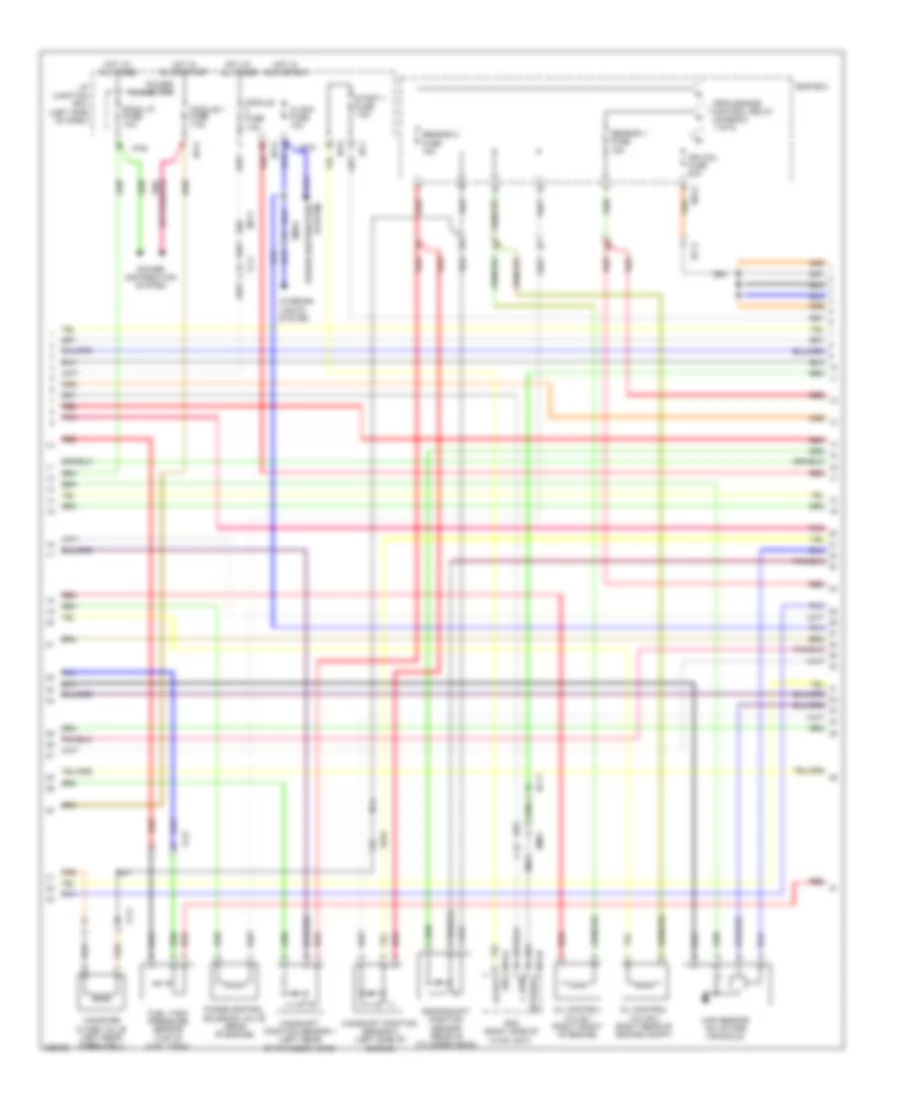
2.0L, Engine Performance Wiring Diagram (3 of 5) for Hyundai Sonata Hybrid Base 2013
List of elements for 2.0L, Engine Performance Wiring Diagram (3 of 5) for Hyundai Sonata Hybrid Base 2013:
- (top right side of engine)
- 26 vfs
- 35r vfs
- Alt output
- Alt sig
- Anti- theft system
- Atm solenoid (top of transaxle)
- Brake light sw
- Brake test sw
- C/fan hi
- Chtg-bg
- Ckp gnd
- Ckp sig
- Cmp 1 sig
- Cmp 2 sig
- Condenser (rear of engine)
- Cooling
- Dc vfs
- Down shift
- Ecu rly on
- Em61
- Exterior lights
- Fans system
- Gf03 (right "b" pillar)
- Ghtg01 (left side of engine compt)
- Ghtg02
- Gnd
- Ignition coil 1
- Ignition coil 2
- Ignition coil 3
- Ignition coil 4
- Immo ind
- Injector 2 hi
- Injector 2 lo
- Input speed
- Lp vfs
- Mf61
- Missions
- Od vfs
- Of engine compt)
- Pcm (left side
- Pnk
- Red
- Select switch
- Sensor oil temperature
- Sport mode switch
- Ss-a
- Ss-b
- Starting/ charging system
- System
- Trans-
- Ud vfs
- Up shift
- Wiper "p" in
- Wiper/ washer system
2.0L, Engine Performance Wiring Diagram (4 of 5) for Hyundai Sonata Hybrid Base 2013
List of elements for 2.0L, Engine Performance Wiring Diagram (4 of 5) for Hyundai Sonata Hybrid Base 2013:
- (diagram 1 of 5)
- (front of right cylinder bank)
- (top left side of engine)
- All times
- Chtginj
- E/r fuse & relay box
- E/r-a
- Ec11
- Em11
- Ems box
- From ecu relay a (diagram 1 of 5)
- From ecu relay b
- Hot at
- Hot in on or start
- Ign coil fuse 20a
- Injectors
- Knock sensor (left side of engine)
- Oil control valve 2
- Pnk
- Rcv control solenoid valve
- Red
- Sensor 2 fuse 15a
- Tcu 1 fuse 20a
- Tcu 2 fuse 15a
- Ulev
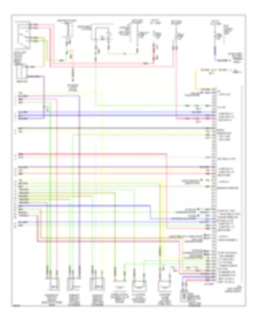
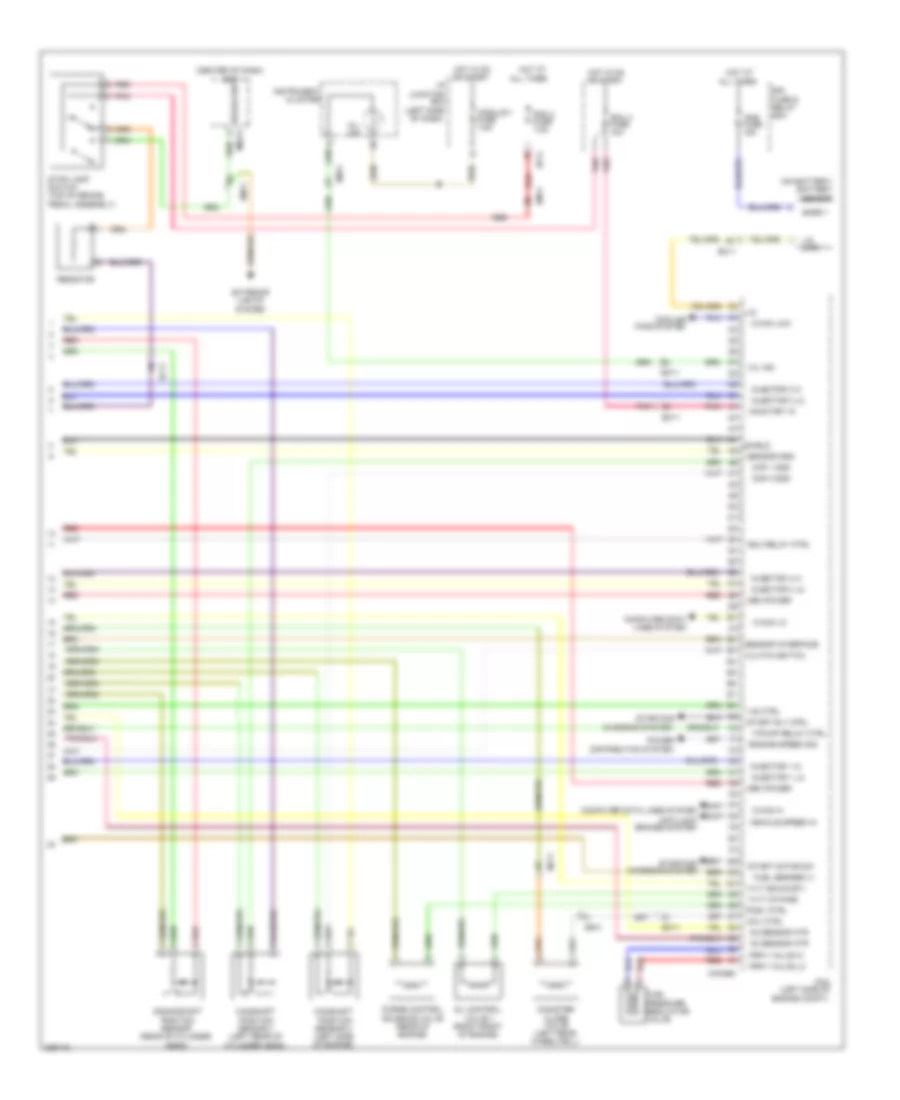
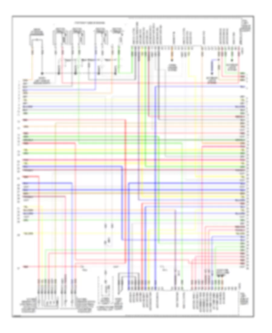
2.0L, Engine Performance Wiring Diagram (5 of 5) for Hyundai Sonata Hybrid Base 2013
List of elements for 2.0L, Engine Performance Wiring Diagram (5 of 5) for Hyundai Sonata Hybrid Base 2013:
- (center of dash) bcm
- (left side of
- (left side of dash)
- (on battery) battery sensor
- (right side of engine)
- All times
- Ams fuse 15a
- Anti-lock brakes system
- Brake sw
- Bypass valve
- C-can hi
- C-can lo
- C/fan low
- Camshaft position sensor 1 (top rear of engine)
- Camshaft position sensor 2 (left side of engine)
- Canister close valve (left rear wheelwell)
- Ccv ctrl
- Charging system
- Chtg-bg
- Cluster system
- Cmp 1 gnd
- Cmp 2 gnd
- Computer data
- Computer data lines system
- Cooling
- Crankshaft position sensor (rear of cylinder head)
- Distribution system
- E/r fuse & relay box
- Ec11
- Ecu 4 fuse 10a
- Ecu relay ctrl
- Ef01
- Em11
- Engine compt)
- Engine speed sig
- Exterior lights
- F/pump relay ctrl
- Fans system
- Frpv valve hi
- Frpv valve lo
- Fuel
- Fuel sender +
- Hot at
- Hot at all times
- Hot in on or start
- I/p junction box
- I/p-g
- Injector 1 hi
- Injector 1 lo
- Injector 3 hi
- Injector 3 lo
- Injector 4 hi
- Injector 4 lo
- Instrument
- Instrument cluster
- Ivvt (exhaust)
- Ivvt (intake)
- Lin
- Lin line
- Lines system
- M02-a
- Mem power
- Mf11
- Mil ind
- Module 1 fuse 7.5a
- O2 sensor htr
- Oil control valve 1 (right front of engine)
- On/start in
- Pcm
- Pdm 2 fuse 7.5a
- Pnk
- Power
- Pressure regulator
- Purge control solenoid valve (rear of engine)
- Purge solenoid
- Red
- Resistor
- Sensor gnd
- Sensor interface
- Shield
- Snsr +
- Start motor sw
- Start rly ctrl
- Starting/
- Stop lamp switch (top of brake pedal assembly)
- System
- Valve
- Vehicle speed in
2.4L
2.4L, Engine Performance Wiring Diagram (1 of 5) for Hyundai Sonata Hybrid Base 2013
List of elements for 2.4L, Engine Performance Wiring Diagram (1 of 5) for Hyundai Sonata Hybrid Base 2013:
- (diagram 4 of 5)
- (not used)
- (up)
- (upstream of catalytic converter, in exhaust)
- 2 fuse
- A/c pressure transducer (right front of engine compt)
- Accel pedal position sensor (top of accelerator pedal assembly)
- Anti-theft system
- Aps 1 gnd
- Aps 1 sig
- Aps 2 gnd
- Aps 2 sig
- Body assembly)
- Chg-ag
- Cyl 1
- Cyl 3
- Down shift
- E/r-a
- E/r-b
- Ec11
- Ect gnd
- Ect sig
- Ecu 1 fuse 30a
- Ecu 3 fuse 10a
- Ecu relay
- Ef02
- Em11
- Ems box
- Engine coolant temperature sensor (rear of cylinder head)
- Etc motor & throttle position sensor (on throttle
- F/pump fuse 20a
- F/pump relay
- Fuel pump motor
- Fuel sender
- Fuel sender & fuel pump motor (top of fuel tank)
- Gf04 (left "c"
- Hot at all times
- Iat sensor
- Immo data line
- Injector fuse 15a
- Input speed sig
- Instrument cluster system
- Map & tia sensor gnd
- Map sensor
- Map sensor (on intake manifold)
- Mem power
- Mf11
- Motor
- Nca
- O2 sensor v g
- O2 sensor v ip
- O2 sensor v n
- O2 sensor v rc
- Oil temp sensor +
- Output speed sig
- Oxygen sensor
- Pcm (left side of engine compt)
- Pillar)
- Pnk
- Red
- Rps gnd
- Select sw
- Sensor
- Sensor 1 fuse 15a
- Sensor gnd
- Sensor sig
- Ss-a
- Ss-b
- Throttle position sensor
- To ign coil fuse (diagram 4 of 5)
- To sensor
- Tps 1 sig
- Tps 2 sig
- Tps gnd
- Up shift
- V sol1
- V sol2
2.4L, Engine Performance Wiring Diagram (2 of 5) for Hyundai Sonata Hybrid Base 2013
List of elements for 2.4L, Engine Performance Wiring Diagram (2 of 5) for Hyundai Sonata Hybrid Base 2013:
- (down)
- (downstream of catalytic converter, in exhaust)
- (downstream of of catalytic converter, in exhaust)
- (left side
- 26 vfs
- 35r vfs
- Chg-ag
- Chginj
- Cyl 2
- Cyl 4
- Dc vfs
- Ec11
- Ef01
- Etc output (+)
- Etc output (-)
- Exterior lights system
- Ftps gnd
- Ftps sig
- Fuel tank pressure sensor (top of fuel tank)
- Ghg01
- Gnd
- Lp vfs
- Nca
- O2 sensor gnd
- O2 sensor sig
- Od vfs
- Of engine compt)
- Oil temp sensor -
- On/start input
- Oxygen sensor
- Pcm (left side of engine compt)
- Pnk
- Rail pressure sensor
- Red
- Rps sig
- Sensor gnd
- Sig 1
- Sig 2
- Sig 3
- Sig 4
- Starting/ charging system
- Sulev
- Transaxle range switch (top of transaxle)
- Ud vfs
- Ulev
2.4L, Engine Performance Wiring Diagram (3 of 5) for Hyundai Sonata Hybrid Base 2013
List of elements for 2.4L, Engine Performance Wiring Diagram (3 of 5) for Hyundai Sonata Hybrid Base 2013:
- (left side
- (rear of engine)
- (top right side of engine)
- 26 vfs
- 35r vfs
- Alt output
- Alt sig
- Anti- theft system
- Atm solenoid (top of transaxle)
- Brake light sw
- Brake test sw
- C/can hi
- Chg-bg
- Ckp gnd
- Ckp sig
- Cmp 1 sig
- Cmp 2 sig
- Compt)
- Condenser
- Cooling
- Dc vfs
- Down shift
- Ecu rly on
- Em61
- Exterior lights
- Fans system
- Gf03 (right "b" pillar)
- Ghg01
- Ghg01 (left side of engine compt)
- Ghg02
- Gnd
- Ignition coil 1
- Ignition coil 2
- Ignition coil 3
- Ignition coil 4
- Immo ind
- Injector 2 hi
- Injector 2 lo
- Input speed
- Lp vfs
- Mf61
- Od vfs
- Of engine
- Of engine compt)
- Of engine)
- Output speed
- Pcm (left side
- Pnk
- Red
- Select switch
- Sensor oil temperature
- Sport mode switch
- Ss-a
- Ss-b
- Starting/ charging system
- System
- Trans- missions system
- Ud vfs
- Up shift
- Wiper "p" in
- Wiper/ washer system
2.4L, Engine Performance Wiring Diagram (4 of 5) for Hyundai Sonata Hybrid Base 2013
List of elements for 2.4L, Engine Performance Wiring Diagram (4 of 5) for Hyundai Sonata Hybrid Base 2013:
- (diagram 1 of 5)
- (top left side of engine)
- All times
- Chginj
- Cruise clutch pedal position switch (under left side of dash)
- E/r fuse & relay box
- E/r-a
- Ec11
- Em11
- Ems box
- From ecu relay a (diagram 1 of 5)
- From ecu relay b
- Ge03 (right rear of dash)
- Hot at
- Hot in on or start
- Ign coil fuse 20a
- Injectors
- Knock sensor (top left rear of engine)
- M/t
- Oil control valve 2 (right rear of engine compt)
- Pnk
- Red
- Sensor 2 fuse 15a
- Tcu 1 fuse 20a
- Tcu 2 fuse 15a
- Ulev
- Variable intake solenoid valve
2.4L, Engine Performance Wiring Diagram (5 of 5) for Hyundai Sonata Hybrid Base 2013
List of elements for 2.4L, Engine Performance Wiring Diagram (5 of 5) for Hyundai Sonata Hybrid Base 2013:
- (center of dash) bcm
- (left side
- (left side of
- (on battery) battery sensor
- All times
- Ams fuse 15a
- Anti-lock brakes system
- Brake sw
- C-can hi
- C-can lo
- C/can low
- Camshaft position sensor 1 (left rear of cylinder head)
- Camshaft position sensor 2 (left side of engine)
- Canister close valve (left rear wheelwell)
- Ccv ctrl
- Charging system
- Chg-bg
- Clutch switch
- Cmp 1 gnd
- Cmp 2 gnd
- Computer data
- Computer data lines system
- Cooling
- Crankshaft position sensor (rear of cylinder head)
- Distribution system
- E/r fuse & relay box
- Ec11
- Ecu 4 fuse 10a
- Ecu relay ctrl
- Ef01
- Em11
- Engine compt)
- Engine speed sig
- Exterior lights
- F/pump relay ctrl
- Fans system
- Frpv valve hi
- Frpv valve lo
- Fuel
- Fuel sender (+)
- Hot at
- Hot in on or start
- I/p junction box
- I/p-g
- Injector 1 hi
- Injector 1 lo
- Injector 3 hi
- Injector 3 lo
- Injector 4 hi
- Injector 4 lo
- Instrument cluster
- Ivvt (exhaust)
- Ivvt (intake)
- Lin
- Lin line
- Lines system
- M02-a
- Mem power
- Mf11
- Mil ind
- Module 1 fuse 7.5a
- O2 sensor htr
- Of dash)
- Oil control valve 1 (right front of engine)
- On/start in
- Pcm
- Pcsv ctrl
- Pdm 2 fuse 7.5a
- Pnk
- Power
- Pressure regulator
- Purge control solenoid valve (rear of engine)
- Red
- Resistor
- Sensor gnd
- Sensor interface
- Shield
- Snsr +
- Start motor sw
- Start rly ctrl
- Starting/
- Stop lamp switch (top of brake pedal assembly)
- System
- Valve
- Vehicle speed in
- Vis ctrl
2.4L HYBRID
2.4L Hybrid, Hybrid Control Wiring Diagram (1 of 6) for Hyundai Sonata Hybrid Base 2013
List of elements for 2.4L Hybrid, Hybrid Control Wiring Diagram (1 of 6) for Hyundai Sonata Hybrid Base 2013:
- Batt pwr
- Bms fuse 10a
- C-can high
- C-can low
- Chg34-mtr
- Chg34-s
- Chg35-p
- Chg35-s
- Computer data lines system
- E/r fuse & relay box
- Ec11
- Ef01
- F81
- Ff01
- Ge02 (left front of engine compt)
- Ge08 (left front of engine compt)
- Ghg01 (left side of engine compt)
- Gnd
- H-can high
- H-can low
- Hot at all times
- Hot in on or start
- Hybrid fuse & relay box (right rear of engine compt)
- Hybrid inverter
- Hybrid motor (left front of engine compt)
- Hybrid power control unit
- Inverter fuse 10a
- Low voltage dc-dc converter
- Mcu
- Memory power
- On/ start in
- Pnk
- Pwr rly asly (+)
- Pwr rly asly (-)
- Pwr-u
- Pwr-v
- Pwr-w
- Red
- Rslver shield
- Rslver snsr 1
- Rslver snsr 2
- Rslver snsr 3
- Rslver snsr 4
- Rslvr (+)
- Rslvr (-)
- Rslvr (snsr 1)
- Rslvr (snsr 2)
- Rslvr (snsr 3)
- Rslvr (snsr 4)
- Rslvr shield
- Temp snsr shield
- Temp snsr sig
- Temp snsr-gnd
- Temp snsr-sh
- Temp snsr-sig
2.4L Hybrid, Hybrid Control Wiring Diagram (2 of 6) for Hyundai Sonata Hybrid Base 2013
List of elements for 2.4L Hybrid, Hybrid Control Wiring Diagram (2 of 6) for Hyundai Sonata Hybrid Base 2013:
- (+)
- (-)
- B+ gnd
- Batt pwr
- Battery ambient temperature sensor (at battery)
- Blower f/b
- Blwr f/b
- Bms assembly
- Bms blower motor relay
- Bms c/fan fuse 15a
- Bms control module
- Bms fuse 10a
- C-can high
- C-can low
- Computer data lines system
- Control
- Crash input
- E/r fuse & relay box
- Em11
- F71
- Fan spd
- Ff01
- Ff02
- From main battery module 9 (diagram 5 of 6)
- Gf02
- Gf04
- Gnd
- Gnd bms blower motor
- H-can high
- H-can low
- Hot at all times
- I/p junction box (left side of dash)
- I/p-g
- Main battery
- Main rly
- Main rly (+)
- Main rly (-)
- Main+ rly
- Mf11
- On/ start in
- P5v
- Pnk
- Power relay assembly
- Prchrg rly
- Pre rly
- Pwm in
- Red
- Rly gnd
- Sig
- To main battery safety plug (diagram 4 of 6)
- Vib 5v
- Vib gnd
- Vout
2.4L Hybrid, Hybrid Control Wiring Diagram (3 of 6) for Hyundai Sonata Hybrid Base 2013
List of elements for 2.4L Hybrid, Hybrid Control Wiring Diagram (3 of 6) for Hyundai Sonata Hybrid Base 2013:
- (+)
- (-)
- Bms assembly
- Bms control module
- F71-t
- F71-v1
- F75-t1
- F75-v1
- F75-v2
- F75-v3
- Gnd
- Main battery module 1
- Main battery module 2
- Main battery module 3
- Main battery thermistor
- Nca
- Pnk
- Red
- Sig
- Temp sig (gnd 1)
- Temp sig (gnd 7)
- Temp sig (gnd)
- Temp sig (mbm 1)
- Temp sig (mbm 7)
- Temp sig (sig)
- Thermistor gnd
- Thermistor sig
- To main battery module 4 (diagram 4 of 6)
- To main battery module 7 (diagram 5 of 6)
- Vol sig c0
- Vol sig c1
- Vol sig c2
- Vol sig c3
- Vol sig c4
- Vol sig c5
- Vol sig c6
- Vol sig c7
- Vol sig c8
- Vol sig-c0 (mbm 1)
- Vol sig-c0 (mbm 2)
- Vol sig-c0 (mbm 3)
- Vol sig-c1 (mbm 1)
- Vol sig-c1 (mbm 2)
- Vol sig-c1 (mbm 3)
- Vol sig-c2 (mbm 1)
- Vol sig-c2 (mbm 2)
- Vol sig-c2 (mbm 3)
- Vol sig-c3 (mbm 1)
- Vol sig-c3 (mbm 2)
- Vol sig-c3 (mbm 3)
- Vol sig-c4 (mbm 1)
- Vol sig-c4 (mbm 2)
- Vol sig-c4 (mbm 3)
- Vol sig-c5 (mbm 1)
- Vol sig-c5 (mbm 2)
- Vol sig-c5 (mbm 3)
- Vol sig-c6 (mbm 1)
- Vol sig-c6 (mbm 2)
- Vol sig-c6 (mbm 3)
- Vol sig-c7 (mbm 1)
- Vol sig-c7 (mbm 2)
- Vol sig-c7 (mbm 3)
- Vol sig-c8 (mbm 1)
- Vol sig-c8 (mbm 2)
- Vol sig-c8 (mbm 3)
2.4L Hybrid, Hybrid Control Wiring Diagram (4 of 6) for Hyundai Sonata Hybrid Base 2013
List of elements for 2.4L Hybrid, Hybrid Control Wiring Diagram (4 of 6) for Hyundai Sonata Hybrid Base 2013:
- (+)
- (-)
- B-can transceiver
- Bms assembly
- Bms control module
- C-can transceiver
- Charge ind
- Computer data lines system
- F71-v2
- F73-p
- F73-s
- F75-v4
- F75-v5
- From bms control module (diagram 2 of 6)
- From main battery module 3 (diagram 3 of 6)
- High
- Hot in on or start
- I/p junction box (left side of dash)
- I/p-g
- Instrument cluster
- Interface
- Low
- Main battery module 4
- Main battery module 5
- Main battery safety plug
- Micom
- Module 1 fuse 7.5a
- Nca
- Pnk
- Power
- Power distribution system
- Red
- Sensor
- To main battery module 6 (diagram 5 of 6)
- Vol sig c0
- Vol sig c1
- Vol sig c2
- Vol sig c3
- Vol sig c4
- Vol sig c5
- Vol sig c6
- Vol sig c7
- Vol sig c8
- Vol sig-c0 (mbm 4)
- Vol sig-c0 (mbm 5)
- Vol sig-c1 (mbm 4)
- Vol sig-c1 (mbm 5)
- Vol sig-c2 (mbm 4)
- Vol sig-c2 (mbm 5)
- Vol sig-c3 (mbm 4)
- Vol sig-c3 (mbm 5)
- Vol sig-c4 (mbm 4)
- Vol sig-c4 (mbm 5)
- Vol sig-c5 (mbm 4)
- Vol sig-c5 (mbm 5)
- Vol sig-c6 (mbm 4)
- Vol sig-c6 (mbm 5)
- Vol sig-c7 (mbm 4)
- Vol sig-c7 (mbm 5)
- Vol sig-c8 (mbm 4)
- Vol sig-c8 (mbm 5)
2.4L Hybrid, Hybrid Control Wiring Diagram (5 of 6) for Hyundai Sonata Hybrid Base 2013
List of elements for 2.4L Hybrid, Hybrid Control Wiring Diagram (5 of 6) for Hyundai Sonata Hybrid Base 2013:
- (+)
- (-)
- Bms assembly
- Bms control module
- F71-v3
- F71-v4
- F75-t7
- F75-v6
- F75-v7
- F75-v8
- F75-v9
- From bms control module (diagram 3 of 6)
- From main battery safety plug (diagram 4 of 6)
- Main battery module 6
- Main battery module 7
- Main battery module 8
- Main battery module 9
- Nca
- Red
- Temp sig (gnd)
- Temp sig (sig)
- To power relay assembly (diagram 2 of 6)
- Vol sig-c0
- Vol sig-c0 (mbm 6)
- Vol sig-c0 (mbm 7)
- Vol sig-c0 (mbm 8)
- Vol sig-c0 (mbm 9)
- Vol sig-c1
- Vol sig-c1 (mbm 6)
- Vol sig-c1 (mbm 7)
- Vol sig-c1 (mbm 8)
- Vol sig-c1 (mbm 9)
- Vol sig-c2
- Vol sig-c2 (mbm 6)
- Vol sig-c2 (mbm 7)
- Vol sig-c2 (mbm 8)
- Vol sig-c2 (mbm 9)
- Vol sig-c3
- Vol sig-c3 (mbm 6)
- Vol sig-c3 (mbm 7)
- Vol sig-c3 (mbm 8)
- Vol sig-c3 (mbm 9)
- Vol sig-c4
- Vol sig-c4 (mbm 6)
- Vol sig-c4 (mbm 7)
- Vol sig-c4 (mbm 8)
- Vol sig-c4 (mbm 9)
- Vol sig-c5
- Vol sig-c5 (mbm 6)
- Vol sig-c5 (mbm 7)
- Vol sig-c5 (mbm 8)
- Vol sig-c5 (mbm 9)
- Vol sig-c6
- Vol sig-c6 (mbm 6)
- Vol sig-c6 (mbm 7)
- Vol sig-c6 (mbm 8)
- Vol sig-c6 (mbm 9)
- Vol sig-c7
- Vol sig-c7 (mbm 6)
- Vol sig-c7 (mbm 7)
- Vol sig-c7 (mbm 8)
- Vol sig-c7 (mbm 9)
- Vol sig-c8
- Vol sig-c8 (mbm 6)
- Vol sig-c8 (mbm 7)
- Vol sig-c8 (mbm 8)
- Vol sig-c8 (mbm 9)
2.4L Hybrid, Hybrid Control Wiring Diagram (6 of 6) for Hyundai Sonata Hybrid Base 2013
List of elements for 2.4L Hybrid, Hybrid Control Wiring Diagram (6 of 6) for Hyundai Sonata Hybrid Base 2013:
- (not used)
- Batt pwr
- Brake
- Brake light sw
- Brake sw
- Brake switch fuse 10a
- C-can high
- C-can low
- Clutch press snsr (gnd)
- Clutch press snsr (pwm)
- Clutch press snsr (sig)
- Clutch pressure sensor (left side of transaxle)
- Computer data lines system
- E/r fuse & relay box
- Ec11
- Em11
- Em31
- Em61
- Exterior lights system
- Fob holder
- Fob-in
- Ge08 (left front of engine compt)
- Gnd
- H-can high
- H-can low
- Hev ecu fuse 20a
- Hot at all times
- Hot in on or start
- Hybrid control unit
- Hybrid power control unit
- I/p junction box (left side of dash)
- I/p-b
- I/p-e
- I/p-f
- I/p-g
- M12-a
- M13-a
- M13-b
- Mf11
- Nca
- On/ start in
- P pos
- Pdm (right side of hvac unit)
- Pnk
- Power distribution system
- Pwm
- Red
- Shift interlock system
- Sig
- Smart key module (right side of dash)
- Ssb sw1
- Ssb sw2
- Start feedback
- Start fuse 7.5a
- Start sig
- Start stop button switch
- Sw1
- Sw2
- Transaxle range switch (top of transaxle)
2.4L Hybrid, MFI Control Wiring Diagram (1 of 5) for Hyundai Sonata Hybrid Base 2013
List of elements for 2.4L Hybrid, MFI Control Wiring Diagram (1 of 5) for Hyundai Sonata Hybrid Base 2013:
- (top of fuel tank) fuel sender & fuel pump motor
- Anti-theft system
- Aps 1 gnd
- Aps 1 sig
- Apt sensor gnd
- Apt sensor sig
- C-can high
- C-can low
- Ccv ctrl
- Chg-k
- Cmps 1 gnd
- Cmps 1 signal
- Computer data lines system
- Cooling fan rly ctrl(low)
- Cooling fans system
- Cvvt actuator ctrl sig 1
- Cvvt actuator ctrl sig 2
- Data i/o
- E/r fuse & relay box
- E/r-a
- E/r-b
- Ec11
- Ecu 1 fuse 30a
- Ecu 2 fuse 20a
- Ecu 4 fuse 10a
- Ef01
- Ef02
- Em11
- Ems box
- Engine control relay
- Engine ctrl rly 'on' in
- Engine ctrl rly ctrl
- Engine speed sig
- Esc 3 fuse 10a
- Etc dc motor 1
- Etc dc motor 2
- Etc motor & throttle position sensor (on throttle body assembly)
- F/pump fuse 20a
- Ff11
- Ff21
- Fuel pump motor
- Fuel pump relay
- Fuel pump relay ctrl
- Fuel sender
- Gf02 (left "b" pillar)
- Gf04 (left "c" pillar)
- Gnd
- Hot at all times
- Hot in on or start
- Iat sensor
- Immo data line
- Immo ind
- Injector fuse 15a
- Instrument cluster
- Map & tia sens gnd
- Mf11
- Micom
- Mil ind
- Motor
- Natural vacuum leak detection (left rear wheelwell)
- Nvld data line
- O2 sens (down) gnd
- O2 sens (down) heater
- O2 sens (down) sig
- O2 sens (up) heater
- Pcm (left side of engine compt)
- Pcsv ctrl
- Pnk
- Pwr
- Red
- Sen gnd
- Sen sig
- Stop lamp switch (top of brake pedal assembly)
- System lights exterior
- System theft anti-
- Throttle position sensor
- To ign coil fuse (diagram 2 of 5)
- To sensor 2 fuse (diagram 2 of 5)
- To snsr 1 fuse (diagram 2 of 5)
- Tps 1 sig
- Tps gnd
2.4L Hybrid, MFI Control Wiring Diagram (2 of 5) for Hyundai Sonata Hybrid Base 2013
List of elements for 2.4L Hybrid, MFI Control Wiring Diagram (2 of 5) for Hyundai Sonata Hybrid Base 2013:
- Camshaft position sensor 1 (left rear of cylinder head)
- Camshaft position sensor 2 (left side of engine)
- Canister close valve (left rear wheelwell)
- Clock fuse 10a
- Crankshaft position sensor (rear of cylinder head)
- E/r-a
- Ec11
- Ef01
- Em11
- Em61
- Ems box
- Ff11
- Ff21
- From engine control relay (diagram 1 of 5)
- Fuel tank pressure sensor (top of fuel tank)
- F_rpm
- Hot at all times
- Hot in acc or run
- Hot in on or start
- I/p junction box (left side of dash)
- I/p-e
- I/p-f
- I/p-g
- Ign coil fuse 20a
- Interior lights system
- M13-a sig start
- M13-b
- Map sensor (on intake manifold)
- Mf11
- Module 1 fuse 7.5a
- Module fuse 7.5a
- Mr01
- Oil control valve 1 (right front of engine)
- Oil control valve 2 (right rear of engine compt)
- Pdm (right side of hvac unit)
- Power connector
- Power distribution system
- Purge control solenoid valve (rear of engine)
- Red
- Reverse
- Room lp fuse 10a
- Sensor 1 fuse 15a
- Sensor 2 fuse 15a
- Start 1 fuse 7.5a
- System power distribution
2.4L Hybrid, MFI Control Wiring Diagram (3 of 5) for Hyundai Sonata Hybrid Base 2013
List of elements for 2.4L Hybrid, MFI Control Wiring Diagram (3 of 5) for Hyundai Sonata Hybrid Base 2013:
- (a/t) 26 vfs
- (a/t) 35r vfs
- (a/t) dn shift
- (a/t) gnd
- (a/t) in spd sig
- (a/t) in spd sply
- (a/t) line vfs
- (a/t) memory pwr
- (a/t) od vfs
- (a/t) out spd sig
- (a/t) out spd sply
- (a/t) ps sw s1
- (a/t) ps sw s2
- (a/t) ps sw s3
- (a/t) ps sw s4
- (a/t) select sw
- (a/t) sol pwr 1
- (a/t) sol pwr 2
- (a/t) ss-a
- (a/t) ss-b
- (a/t) t/con vfs
- (a/t) ud vfs
- (a/t) up shift
- (rear of engine) condenser
- (top right side of engine)
- A/t temp sens+
- A/t temp sens-
- Brk lt sw
- Brk test sw
- Chg-a
- Computer data lines system
- Ec11
- Em11
- Exterior lights system
- Ff11
- Ff21
- Ghg01 (left side of engine compt)
- H-can high
- H-can low
- Hybrid control unit
- Hybrid power control unit
- Ign coil shield gnd
- Ign cyl 1 ctrl
- Ign cyl 2 ctrl
- Ign cyl 3 ctrl
- Ign cyl 4 ctrl
- Ignition coil 1
- Ignition coil 2
- Ignition coil 3
- Ignition coil 4
- Nca
- Oil pump mtr spd
- Oil pump opu spd
- Oxygen sensor (down) (downstream of catalytic converter, in exhaust)
- Oxygen sensor (up) (upstream of catalytic converter, in exhaust)
- Pcm (left side of engine compt)
- Pnk
- Red
- Sig
- Start
- Vip
- Vrc
- Wiper 'p' in
- Wiper/ washer system
2.4L Hybrid, MFI Control Wiring Diagram (4 of 5) for Hyundai Sonata Hybrid Base 2013
List of elements for 2.4L Hybrid, MFI Control Wiring Diagram (4 of 5) for Hyundai Sonata Hybrid Base 2013:
- (left front of engine compt)
- (left side of transaxle) electric oil pump
- (right rear of engine compt) hybrid fuse & relay box
- (top of transaxle) transaxle range switch
- 26 vfs
- 35r vfs
- Atm solenoid (top of transaxle)
- Batt pwr
- C-can (high)
- C-can (low)
- Command mtr sp
- Computer data lines system
- Down shift switch
- E62-a
- E62-b
- E64-a
- E64-b
- Ec11
- Ef01
- Electric oil pump unit (left front wheel- well)
- Ge07 (left front of engine compt)
- Ge08
- Gf03 (right "b" pillar)
- Gnd
- Hall sens sig-a
- Hall sens sig-b
- Hall sens sig-c
- Hall sens-gnd
- Hall sens-pwr
- Hot at all times
- Input speed sensor
- Line vfs
- Od vfs
- Oil pump unit (u)
- Oil pump unit (v)
- Oil pump unit (w)
- Oil temperature sensor
- On/start input
- Opcu fuse 80a red
- Opcu relay
- Opcu rly ctrl
- Opcu rly input
- Opu status
- Output speed sensor
- P/n switch
- Pnk
- Pump pwr-u
- Pump pwr-v
- Pump pwr-w
- Red
- Select switch
- Sig 1
- Sig 2
- Sig 3
- Sig 4
- Sport mode switch
- Ss-a
- Ss-b
- T/con vfs
- Ud vfs
- Up shift switch
2.4L Hybrid, MFI Control Wiring Diagram (5 of 5) for Hyundai Sonata Hybrid Base 2013
List of elements for 2.4L Hybrid, MFI Control Wiring Diagram (5 of 5) for Hyundai Sonata Hybrid Base 2013:
- (top left side of engine) injectors
- A/c pressure transducer (right front of engine compt)
- Acc/on input
- Accel pedal position sensor (top of accelerator pedal assembly)
- Aps 2 gnd
- Aps 2 sig
- Apt sens sply
- C-can (high)
- C-can (low)
- Chg-k
- Ckps gnd
- Ckps signal
- Cmps 2 gnd
- Cmps 2 signal
- Computer data lines system
- E/r fuse & relay box
- Ec11
- Ects gnd
- Ects sig
- Em11
- Em61
- Engine coolant temperature sensor & sender (rear of cylinder head)
- Esc control module (left rear of engine compt)
- Fuel sender (+)
- Ghg01 (left side of engine compt)
- Gm03 (left side of dash)
- Gm04
- Gnd
- Gnd engine ctrl rly ctrl 'on' in gnd
- Hot at all times
- Hot in on or start
- Inj 1 ctrl
- Inj 2 ctrl
- Inj 3 ctrl
- Inj 4 ctrl
- Knock sens gnd
- Knock sens sig
- Knock sensor (top left rear of engine)
- Map sens sig
- Map sens sply
- Memory power
- Memory pwr
- Nca
- O2 sens (up) vg
- O2 sens (up) vip
- O2 sens (up) vn
- O2 sens (up) vrc
- Oil pump 1 fuse 20a
- Oil pump 2 fuse 10a
- On/start input
- Pcm (left side of engine compt)
- Pnk
- Red
- Tcu 1 fuse 20a
- Tcu 2 fuse 15a
- Tps 2 sig
- Vehicle spd in
- Vess speaker (left front wheelwell)
- Vess spek +
- Vess spek -
- Vess unit (right side of hvac unit)
2.4L Hybrid, Virtual Engine Sound System Wiring Diagram for Hyundai Sonata Hybrid Base 2013
List of elements for 2.4L Hybrid, Virtual Engine Sound System Wiring Diagram for Hyundai Sonata Hybrid Base 2013:
- (+)
- (-)
- Acc/on input
- C-can
- Clock fuse 10a
- Computer data lines system
- Em61
- Gm03 (left side of dash)
- Gnd
- High
- Hot at all times
- Hot in acc or on
- I/p junction box (left side of dash)
- I/p-e
- I/p-g
- Low
- Memory power
- Module 3 fuse 7.5a
- Mr01
- Nca
- Power distribution system
- Red
- Vess speaker (left front wheelwell)
- Vess unit (right side of hvac unit)
EXTERIOR LIGHTS
Backup Lamps Wiring Diagram, Except Hybrid for Hyundai Sonata Hybrid Base 2013
List of elements for Backup Lamps Wiring Diagram, Except Hybrid for Hyundai Sonata Hybrid Base 2013:
- (left "c" pillar) gf04
- (top of transaxle) transaxle range switch
- 2.0l
- 2.4l
- B/up lp fuse 10a
- Backup lamp
- Bcm (center of dash)
- Chg-ag
- Chtg-ag
- E/r fuse & relay box
- Ec11
- Electro- chromic mirror
- Em11
- Hot in on or start
- Left rear combination lamp (in)
- M02-a
- Mf11
- Mr01
- Mts module
- Nca
- On/st in
- Pcm (left side of engine compt)
- Pnk
- Red
- Right rear combination lamp (in)
- Sig 1
- Sig 2
- Sig 3
- Sig 4
- Sw s1
- Sw s2
- Sw s3
- Sw s4
- Tcu 2 fuse 15a
Backup Lamps Wiring Diagram, Hybrid for Hyundai Sonata Hybrid Base 2013
List of elements for Backup Lamps Wiring Diagram, Hybrid for Hyundai Sonata Hybrid Base 2013:
- (left "c" pillar) gf04
- (top of transaxle) transaxle range switch
- A/v & navigation head unit (center of dash)
- B/up lp fuse 10a
- Backup lamp
- Bcm (center of dash)
- Chg-a
- E/r fuse & relay box
- Ec11
- Electro- chromic mirror
- Em11
- Hot in on or start
- Left rear combination lamp (in)
- M02-a
- M15-a
- Mf11
- Mr01
- Nca
- On/st in
- Pcm (left side of engine compt)
- Pnk
- Red
- Right rear combination lamp (in)
- Sig 1
- Sig 2
- Sig 3
- Sig 4
- Sw s1
- Sw s2
- Sw s3
- Sw s4
- Tcu 2 fuse 15a
Exterior Lamps Wiring Diagram, Except Hybrid (1 of 2) for Hyundai Sonata Hybrid Base 2013
List of elements for Exterior Lamps Wiring Diagram, Except Hybrid (1 of 2) for Hyundai Sonata Hybrid Base 2013:
- (left "b" pillar) gf02
- (left "c" pillar) gf04
- (left side
- (right "b" pillar) gf03
- (right "c" pillar) gf05
- (right side of engine compt) ge04
- Auto
- B-can high
- B-can low
- B-can transceiver
- Bcm (center of dash)
- Brake sw
- Computer data lines system
- Driver power outside mirror
- Except hybrid
- Fd01
- Fd02
- Ge01 (left front of engine compt)
- Gm03 (left side of dash)
- Gm04
- Hazard sw
- Hazard switch
- Head
- High
- Hot at all times
- Hybrid
- I/p junction box (left side of dash)
- I/p-a
- I/p-b
- I/p-c
- I/p-e
- I/p-f
- I/p-g
- Ill
- Instrument cluster
- Interface
- Interior lights
- Ips 6
- Ips 6 ctrl
- Ips 7
- Ips 7 ctrl
- Ips 9 (twin)
- Ips 9 ctrl
- Ips control module
- Left
- Left headlamp
- Left rear combination lamp (out)
- Left turn ind
- Lh turn lamp
- Light switch
- Low
- M01-l
- M02-a
- M02-b
- Micom
- Multi-function switch
- Nca
- Of dash) gm03
- Off
- P gnd
- Passenger power outside mirror
- Pnk
- Power connector
- Red
- Rh turn lamp
- Right
- Right headlamp
- Right rear combination lamp (out)
- Right turn ind
- Room lp fuse 10a
- Stop lamp
- System
- T/sig sound
- T/sig sound relay
- Tail
- Tail lamp
- Tail lamp ind
- Tail sw
- Turn lamp
- Turn signal lamp switch
Exterior Lamps Wiring Diagram, Except Hybrid (2 of 2) for Hyundai Sonata Hybrid Base 2013
List of elements for Exterior Lamps Wiring Diagram, Except Hybrid (2 of 2) for Hyundai Sonata Hybrid Base 2013:
- (left "c" pillar)
- (right "c" pillar)
- 2.0l
- 2.4l
- B+ 2 fuse 50a
- Backup lamp
- Backup lamps circuit
- Brake light sw
- Brake test sw
- Chg-bg
- Chtg-bg
- E/r fuse & relay box
- Ec11
- Ecu 4 fuse 10a
- Em11
- Esc module (left rear of engine compt)
- Gf04
- Gf05
- Gm03 (left side of dash)
- High- mounted stop lamp
- Hot at all times
- Hot in on or start
- I/p junction box (left side of dash)
- I/p-g
- Ips
- Lamp
- Left
- Left rear combination lamp (in)
- License
- License lamp (trunk lid switch & rear camera)
- M12-a
- Mf11
- Nca
- Pcm (left side of engine compt)
- Pdm 2 fuse 7.5a
- Pnk
- Red
- Resistor
- Right
- Right rear combination lamp (in)
- Smart key module (right side of dash)
- Stop lamp switch (top of brake pedal assembly)
- Stop lp fuse 15a
- Stop signal relay (center of dash)
- Tail lamp
Exterior Lamps Wiring Diagram, Hybrid (1 of 2) for Hyundai Sonata Hybrid Base 2013
List of elements for Exterior Lamps Wiring Diagram, Hybrid (1 of 2) for Hyundai Sonata Hybrid Base 2013:
- (left "b" pillar) gf02
- (left side
- (right "b" pillar) gf03
- Auto
- B-can high
- B-can low
- B-can transceiver
- Bcm (center of dash)
- Brake sw fuse 7.5a
- Brk sw
- Computer data lines system
- Driver power outside mirror
- Em11
- Except hybrid
- Fd01
- Fd02
- Ge02 (left front of engine compt)
- Ge04 (right side of engine compt)
- Gf04 (left "c" pillar)
- Gf05 (right "c" pillar)
- Gm04
- Hazard sw
- Hazard switch
- Head
- High
- Hot at all times
- Hybrid
- I/p junction box (left side of dash)
- I/p-a
- I/p-b
- I/p-c
- I/p-e
- I/p-f
- I/p-g
- Ill
- Instrument cluster
- Interface
- Interior lights
- Ips 6
- Ips 6 ctrl
- Ips 7
- Ips 7 ctrl
- Ips 9 (twin)
- Ips 9 ctrl
- Ips control module
- Left
- Left headlamp
- Left rear combination lamp (out)
- Left turn ind
- Lh turn lamp
- Light switch
- Low
- M01-l
- M02-a
- M02-b
- Micom
- Multi-function switch
- Nca
- Of dash) gm03
- Off
- Passenger power outside mirror
- Pnk
- Power connector
- Red
- Rh turn lamp
- Right
- Right headlamp
- Right rear combination lamp (out)
- Right turn ind
- Room lp fuse 10a
- Stop lamp
- System
- T/sig sound
- T/sig sound relay
- Tail
- Tail lamp
- Tail lamp ind
- Tail sw
- Turn lamp
- Turn signal lamp switch
Exterior Lamps Wiring Diagram, Hybrid (2 of 2) for Hyundai Sonata Hybrid Base 2013
List of elements for Exterior Lamps Wiring Diagram, Hybrid (2 of 2) for Hyundai Sonata Hybrid Base 2013:
- (center of dash) gm01
- (left "c" pillar)
- (left front of engine compt) hybrid control unit
- (right "c" pillar)
- B+ 2 fuse 50a
- Batt pwr
- Break light sw
- Break switch
- Chg-a
- E/r fuse & relay box
- Ec11
- Em11
- Em61
- Esc 3 fuse 10a
- Esc module (left rear of engine compt)
- Esc(hac/dbc)
- Gf04
- Gf05
- Gnd
- Hac relay control
- High- mounted stop lamp
- Hot at all times
- Hot in on or start
- Hydraulic power unit (left rear of engine compt)
- Lamp
- Left
- Left rear combination lamp (in)
- License
- License lamp (trunk lid switch & rear camera)
- M12-a
- Nca
- Pcm (left side of engine compt)
- Pnk
- Red
- Relay state monitoring
- Right
- Right rear combination lamp (in)
- Smart key module (right side of dash)
- Stop lamp
- Stop lamp switch (top of brake pedal assembly)
- Stop lp fuse 15a
- Stop signal electronic module
- Stp lp
- Stp lp sw
- Stp sig lp
- Tail lamp
GROUND DISTRIBUTION
Ground Distribution Wiring Diagram, Except Hybrid (1 of 3) for Hyundai Sonata Hybrid Base 2013
List of elements for Ground Distribution Wiring Diagram, Except Hybrid (1 of 3) for Hyundai Sonata Hybrid Base 2013:
- (w/
- (w/ smart key)
- A/c
- A/c control module
- A/v & navigation head unit
- A/v & navigation heat unit (gnd)
- Amp
- Atm shift level indicator
- Audio
- Audio (gnd)
- Automatic a/c
- Aux & usb jack
- Bcm
- F02-a
- F03-a
- Fd02
- Fd12
- Fet (field effect transistor)
- Front power outlet 1
- Front power outlet 2
- Fs02
- Gf03 (right "b" pillar)
- Gf05 (right "c" pillar)
- Glove box switch
- Gm01 (center of dash)
- Gm02 (right end of dash)
- Gm04
- Hazard switch
- High mounted stop lamp
- Immobilizer module
- Jbl
- Jbl amp
- M01-l
- M01-r
- M01-w
- M02-c
- M09-b
- M09-g
- M12-a
- M13-a
- M15-b
- M15-g
- M22-a
- Manual
- Mic shield
- Mm01
- Mts module
- Mts module shield
- Multifunction switch
- Navigation
- Nca
- Passenger door lock actuator
- Passenger power outside mirror
- Passenger power window switch
- Passenger seat warmer module
- Passenger smart key outside handle
- Pdm
- Rear camera module
- Right front seat warmer switch
- Right rear combination lamp (out)
- Right rear door lock actuator
- Right rear door switch
- Right rear power window switch
- Right rear seat warmer
- Right rear seat warmer switch
- Smart key module
- Smart key)
- Sport mode switch
- Standard
- W/ navigation
- W/o navigation
- Yaw rate sensor
Ground Distribution Wiring Diagram, Except Hybrid (2 of 3) for Hyundai Sonata Hybrid Base 2013
List of elements for Ground Distribution Wiring Diagram, Except Hybrid (2 of 3) for Hyundai Sonata Hybrid Base 2013:
- (left side of dash) i/p junction box
- (w/ smart
- (w/ smart key) rf receiver
- 2.0l
- 2.4l
- A/c control module
- Acc relay
- Active eco switch
- Automatic a/c
- Bcm
- Blower relay
- Brake fluid level sensor
- Burglar alarm horn
- Clock
- Cooling fan motor
- Data link connector
- Door lock relay
- Door unlock relay
- E/r fuse & relay box
- Ee01
- Electro chromic mirror
- Eps control module
- Esc module
- External buzzer
- Front wiper deicer
- Front wiper motor
- Fuel filler door & trunk lid switch
- Ge01 (left front of engine compt)
- Ge02 (left front of engine compt)
- Ge03 (right rear of dash)
- Ge04 (right side of engine compt)
- Ge05 (left side of dash)
- Ge06 (left side of dash)
- Gm03 (left side of dash)
- Gnd (ecu)
- Hood switch
- I/p-e
- I/p-g
- Ig 1 relay
- Ig 2 relay
- Ignition key ill & door warmer switch
- Instrument cluster
- Ips control module
- Key)
- Left front fog lamp
- Left headlamp
- Left horn
- Left vanity lamp
- M01-l
- M02-a
- M20-b
- M22-b
- M22-bn
- Manual a/c
- Mr01
- Multifunction switch
- Multipurpose check connector
- Nca
- Overhead console lamp
- Panorama sunroof motor
- Panorama sunroof switch
- Red
- Rheostat
- Right front fog lamp
- Right headlamp
- Right horn
- Right vanity lamp
- Room lamp
- Start 1 relay
- Stop signal relay
- Sunroof motor
- Sunroof switch
- Tire pressure monitoring module
- Two turn unlock relay
- W/ navigation
- W/ panorama sunroof
- W/ smart key
- W/o navigation
- W/o panorama sunroof
- W/o smart key
- Washer level sensor
- Washer motor
Ground Distribution Wiring Diagram, Except Hybrid (3 of 3) for Hyundai Sonata Hybrid Base 2013
List of elements for Ground Distribution Wiring Diagram, Except Hybrid (3 of 3) for Hyundai Sonata Hybrid Base 2013:
- (w/ smart key)
- 2.0l
- 2.4l
- Chg-ag
- Chg-bg
- Chtg-ag
- Chtg-bg
- Condenser
- Driver door lock actuator
- Driver manual switch
- Driver power outside mirror
- Driver reclining limit switch
- Driver seat belt buckle switch
- Driver seat warmer module
- Driver smart key outside handle
- F15-b
- Fd01
- Fd11
- Fob holder
- Fs01
- Fuel filler actuator
- Fuel sender & fuel pump motor
- Gf01 (under center console)
- Gf02 (left "b" pillar)
- Gf04 (left "c" pillar)
- Ghg01 (2.4l) ghtg01 (2.0l) (left side of engine compt)
- Ghg02 (2.4l) (left side of engine)
- Ghtgo2 (2.0l)
- Ignition coil 1 shield
- Ignition coil 2 shield
- Ignition coil 3 shield
- Ignition coil 4 shield
- Joint connector js01 (under driver's seat)
- Left front seat warmer switch
- Left rear combination lamp (in)
- Left rear combination lamp (out)
- Left rear door lock actuator
- Left rear door switch
- Left rear power window switch
- Left rear seat warmer
- Left rear seat warmer switch
- License lamp (trunk lid switch & rear camera)
- Mf61
- Nca
- Passenger weight classification sensor
- Pcm
- Power outside mirror switch
- Power window main switch
- Right rear combination lamp (in)
- Safety power window module
- Srs control module
- Telltale lamp
- Trunk lid motor
- Vacuum pump
Ground Distribution Wiring Diagram, Hybrid (1 of 4) for Hyundai Sonata Hybrid Base 2013
List of elements for Ground Distribution Wiring Diagram, Hybrid (1 of 4) for Hyundai Sonata Hybrid Base 2013:
- A/c control module
- A/v & navigation head unit
- A/v & navigation head unit (gnd)
- A/v & navigation head unit shield
- Acc relay
- Atm lever indicator
- Audio
- Audio (gnd)
- Audio shield
- Aux & usb jack
- Bcm
- Blower motor control module
- Blower relay
- Brake fluid level sensor
- Burglar horn
- C/fan relay
- E/r fuse & relay box
- E72-l
- Ec11
- Ee01
- Em61
- Engine coolant temperature sensor & sender
- External buzzer
- Front monitor
- Front wiper deicer
- Front wiper motor
- Ge02 (left front of engine compt)
- Ge03 (right rear of dash)
- Ge04 (right side of engine compt)
- Glove box lamp switch
- Gm01 (center of dash)
- Gm02 (right end of dash)
- Gm04
- Hazard switch
- Hood switch
- Horn (high)
- Horn (low)
- Hybrid fuse & relay box
- Hybrid power control unit
- Hybrid water pump
- Ig 1 relay
- Ig 2 relay
- Instrument cluster
- Left front fog lamp
- Left front power outlet
- Left headlamp
- Low voltage dc-dc converter
- M01-w
- M02-c
- M09-b
- M09-g
- M12-a
- M13-a
- M15-b
- M15-g
- M21-b
- M27-p
- Mm01
- Mts module
- Mts module shield
- Multi- function switch
- Multipurpose check connector
- Navigation
- Nca
- Pdm
- Rear camera module
- Rear camera module shield
- Right front fog lamp
- Right front power outlet
- Right headlamp
- Smart key module
- Stop signal electronic module
- W/ navigation
- W/o navigation
- Washer level sensor
- Washer motor
Ground Distribution Wiring Diagram, Hybrid (2 of 4) for Hyundai Sonata Hybrid Base 2013
List of elements for Ground Distribution Wiring Diagram, Hybrid (2 of 4) for Hyundai Sonata Hybrid Base 2013:
- (left side of dash)
- (left side of dash) i/p junction box
- 87a
- A/c control module
- Active air flap
- Bcm
- Chg32-s
- Clock
- Data link connector
- Door lock relay
- Door unlock relay
- E/r fuse & relay box
- E64-a
- E64-b
- Ec11
- Ee01
- Electric oil pump shield
- Electric oil pump unit
- Electric water pump
- Electro chromic mirror
- Electronic a/c compressor
- Eps control module
- Esc module
- Fuel filler door & trunk lid switch
- Ge05 (left side of dash)
- Ge06 (left side of dash)
- Ge07 (left front of engine compt)
- Ge08 (left front of engine compt)
- Ge09 (right side of dash)
- Gm03
- Gnd (drl)
- Gnd (ecu)
- Hybrid control unit
- Hybrid power control unit
- Hydraulic power unit
- I/p-e
- I/p-f
- I/p-g
- Instrument cluster
- Ips control module
- Joint connector jr01 (center front of roof)
- Left vanity lamp
- Low voltage dc-dc converter
- M01-l
- M02-a
- M12-a
- M13-a
- M21-b
- Mr01
- Multifunction switch
- Overhead console lamp
- Panorama sunroof
- Panorama sunroof switch
- Pdm
- Rheostat
- Right vanity lamp
- Room lamp
- Smart key module
- T/turn door unlock relay
- Tire pressure monitoring module
- Vess unit
Ground Distribution Wiring Diagram, Hybrid (3 of 4) for Hyundai Sonata Hybrid Base 2013
List of elements for Ground Distribution Wiring Diagram, Hybrid (3 of 4) for Hyundai Sonata Hybrid Base 2013:
- Bms assembly
- Bms blower motor
- Cooling fan controller
- Driver door lock actuator
- Driver manual switch
- Driver power outside mirror
- Driver reclining limit switch
- Driver seat belt buckle switch
- Driver seat warmer module
- Driver smart key outside handle
- E11-b
- Fd01
- Fd02
- Ff02
- Ff11
- Fob holder
- Front seat warmer switch
- Fs01
- Fs02
- Ge01 (left front of engine compt)
- Gf01 (under center console)
- Gf02 (left "b" pillar)
- Gf03 (right "b" pillar)
- Joint connector js01 (under driver's seat)
- Left rear seat warmer
- Mf11
- Natural vacuum leak detection
- Nca
- Passenger door lock actuator
- Passenger power outside mirror
- Passenger power window switch
- Passenger seat warmer module
- Passenger smart key outside handle
- Passenger weight classification sensor
- Power outside mirror switch
- Power window main switch
- Red
- Right rear seat warmer
- Safety power window module
- Sport mode switch
- Srs control module
- Telltale lamp
Ground Distribution Wiring Diagram, Hybrid (4 of 4) for Hyundai Sonata Hybrid Base 2013
List of elements for Ground Distribution Wiring Diagram, Hybrid (4 of 4) for Hyundai Sonata Hybrid Base 2013:
- (not used)
- Bms assembly
- Bms control module
- Chg-a
- Chg-k
- Chg34-s
- Condenser
- F03-a
- F73-s
- Fd11
- Fd12
- Ff01
- Ff21
- Ff31
- Fuel filler actuator
- Fuel sender & fuel pump motor
- Gf04 (left "c" pillar)
- Gf05 (right "c" pillar)
- Ghg01 (left side of engine compt)
- High- mounted stop lamp
- Ignition coil 1 shield
- Ignition coil 2 shield
- Ignition coil 3 shield
- Ignition coil 4 shield
- Jbl amp
- Knock sensor shield
- Left rear combination lamp (in)
- Left rear combination lamp (out)
- Left rear door lock actuator
- Left rear door switch
- Left rear power window switch
- Left rear seat warmer switch
- License lamp (trunk lid switch & rear camera)
- Main battery safety plug
- Mcu
- Nca
- Pcm
- Rf receiver
- Right rear combination lamp (in)
- Right rear combination lamp (out)
- Right rear door lock actuator
- Right rear door switch
- Right rear power window switch
- Right rear seat warmer switch
- Trunk lid motor
HEADLIGHTS
Autolamps Wiring Diagram for Hyundai Sonata Hybrid Base 2013
List of elements for Autolamps Wiring Diagram for Hyundai Sonata Hybrid Base 2013:
- Auto
- Auto light & photo sensor (top center of dash)
- Auto light sensor
- Auto light snsr gnd
- Auto light snsr pwr
- Auto light snsr sig
- Auto light sw 'on'
- B+2 fuse 50a
- B+4 fuse 60a
- B-can
- B-can high
- B-can low
- B-can transceiver
- Bcm (center of dash)
- Computer data lines system
- Control
- Dimmer/passing switch
- E/r fuse & relay box
- Except hybrid
- Front fog ind
- Front fog lamp sw
- Front fog lamp switch
- Ge01 (except hybrid) ge02 (hybrid) (left front of engine compt)
- Ge01 (left front of engine compt)
- Ge02 (left front of engine compt)
- Ge04 (right side of engine compt)
- Gm03 (left side of dash)
- Head
- Head lamp low signal
- Headlamp hi switch
- Headlamp lo signal
- Headlamp switch
- High
- High beam ind
- Hot at all times
- Hybrid
- I/p junction box (left side of dash)
- I/p-b
- I/p-c
- I/p-e
- I/p-f
- Instrument cluster
- Interface
- Ips 1
- Ips 2
- Ips 3
- Ips 4
- Ips 5
- Ips control module
- Left front fog lamp
- Left headlamp
- Light switch
- Low
- Low pass
- M01-l
- M02-a
- M02-b
- Micom
- Multi fuse
- Multi-function switch
- Nca
- Off
- Pass
- Pnk
- Power connector
- Red
- Right front fog lamp
- Right headlamp
- Room lp fuse 10a
- Tail
- Tail lamp switch
Headlamps Wiring Diagram for Hyundai Sonata Hybrid Base 2013
List of elements for Headlamps Wiring Diagram for Hyundai Sonata Hybrid Base 2013:
- Auto
- B+2 fuse 50a
- B+4 fuse 60a
- B-can
- B-can high
- B-can low
- B-can transceiver
- Bcm (center of dash)
- Cluster
- Computer data lines system
- Control
- Dimmer/passing switch
- E/r fuse & relay box
- Except hybrid
- Front fog ind
- Front fog lamp sw
- Front fog lamp switch
- Ge01 (except hybrid) ge02 (hybrid) (left front of engine compt)
- Ge01 (left front of engine compt)
- Ge02 (left front of engine compt)
- Ge04 (right side of engine compt)
- Gm03 (left side of dash)
- Head
- Head lamp low signal
- Head tail
- Headlamp hi switch
- Headlamp lo signal
- Headlamp switch
- High
- High beam ind
- Hot at all times
- Hybrid
- I/p junction box (left side of dash)
- I/p-b
- I/p-c
- I/p-e
- I/p-f
- Instrument
- Interface
- Ips 1
- Ips 2
- Ips 3
- Ips 4
- Ips 5
- Ips control module
- Left front fog lamp
- Left headlamp
- Light switch
- Low
- Low pass
- M01-l
- M02-a
- M02-b
- Micom
- Multi fuse
- Multi-function switch
- Nca
- Off
- Pass
- Pnk
- Power connector
- Red
- Right front fog lamp
- Right headlamp
- Room lp fuse 10a
- Tail
- Tail lamp switch
HORN
Horn Wiring Diagram, Except Hybrid for Hyundai Sonata Hybrid Base 2013
List of elements for Horn Wiring Diagram, Except Hybrid for Hyundai Sonata Hybrid Base 2013:
- Clock spring
- E/r-b
- Ee01
- Em11
- Ems box
- Ge01 (left front of engine compt)
- Ge04 (right side of engine compt)
- Horn fuse 15a
- Horn relay
- Horn switch
- Hot at all times
- Left horn
- M01-r
- Multi-function switch
- Nca
- Right horn
- Steering wheel
Horn Wiring Diagram, Hybrid for Hyundai Sonata Hybrid Base 2013
List of elements for Horn Wiring Diagram, Hybrid for Hyundai Sonata Hybrid Base 2013:
- Clock spring
- E/r-b
- Ee01
- Em11
- Ems box
- Ge02 (left front of engine compt)
- Ge04 (right side of engine compt)
- Horn (high) (right front of engine compt)
- Horn (low) (center front of engine compt)
- Horn fuse 15a
- Horn relay
- Horn switch
- Hot at all times
- M01-r
- Multi-function switch
- Nca
- Steering wheel
INSTRUMENT CLUSTER
Instrument Cluster Wiring Diagram, Except Hybrid (1 of 2) for Hyundai Sonata Hybrid Base 2013
List of elements for Instrument Cluster Wiring Diagram, Except Hybrid (1 of 2) for Hyundai Sonata Hybrid Base 2013:
- (m/t)
- 2.0l
- 4p output
- 5v reg
- A/bag ind fuse 7.5a
- Abs ind
- Active eco switch
- Air bag ind
- B-can
- Brake ind
- Buzzer
- C-can
- Charge ind
- Charging
- Check engine ind
- Chtginj
- Computer data lines system
- Constant current circuit
- Cruise control system
- Cruise ind
- D out
- Detent out
- Dial ill ind
- Door open ind
- Ec11
- Eco ind
- Em11
- Engine controls system
- Eps ind
- Esc ind
- Esc off ind
- Exterior lights system
- Front fog ind
- Fuel (+)
- Fuel (-)
- Fuel lcd
- Fuel/at indi lcd
- Ge04 (right side of engine compt)
- Gm03 (left side of dash)
- High
- High beam ind
- Hot at all times
- Hot in on or start
- I/f
- I/p junction box (left side of dash)
- I/p-e
- I/p-f
- I/p-g
- Ill
- Ill (-)
- Immo ind
- Ind
- Instrument cluster
- Interface
- Interior lights system
- Left turn ind
- Low
- Low fuel ind
- Micom
- Module 1 fuse 7.5a
- N out
- Oil pressure ind
- Oil pressure switch (left front of engine block)
- P out
- Pnk
- Pointer ind
- Power connector
- Power distribution system
- R out
- R-in
- Red
- Rheostat dn
- Rheostat up
- Right turn ind
- Room lp fuse 10a
- S gnd
- S out
- Seat belt ind
- Set ind
- Speed in
- Speedo- meter
- Starting/charging system
- Tacho- meter
- Tail on ind
- Temp high ind
- Temp lcd
- Temp/door open lcd
- Tpms tread ind
- Transceiver
- Transmissions system
- Trip sw (+)
- Trip sw (-)
- Trunk open ind
- Vfd
- Washer
- Washer level sensor (bottom of washer fluid reservoir)
Instrument Cluster Wiring Diagram, Except Hybrid (2 of 2) for Hyundai Sonata Hybrid Base 2013
List of elements for Instrument Cluster Wiring Diagram, Except Hybrid (2 of 2) for Hyundai Sonata Hybrid Base 2013:
- (in left rear "c" pillar) left rear door switch
- 2.0l
- 2.4l
- Acc/on input
- Air conditioning system
- Bcm (body control module) (center of dash)
- Brake fluid level sensor (in brake fluid reservoir)
- Chg-bg
- Chtg-bg
- Clock
- Clock fuse 10a
- Cruise control system
- Detent
- Dr sw
- Driver door switch (in driver "b" pillar)
- Ec11
- Em11
- Empty
- Esc control module (left rear of engine compt)
- Foot parking brake switch (a/t) (base of parking brake lever)
- Fuel level float
- Fuel sender
- Fuel sender & fuel pump motor (top of fuel tank)
- Fuel sender(+)
- Full
- Ge02 (left front of engine compt)
- Gf04 (left "c" pillar)
- Gf05 (right "c" pillar)
- Gm03 (left side of dash)
- Gnd
- Hand parking brake switch (m/t) (base of brake lever assembly)
- Hot in acc or on
- I/p junction box (left side of dash)
- I/p-a
- I/p-b
- I/p-d
- I/p-g
- Ign
- Ill (+)
- Ill (-)
- Immo
- Interior lights system
- Ips control module
- M02-b
- M12-a
- Memory power
- Mf11
- Nca
- Parking brake diode
- Pass
- Passenger door switch (in passenger "b" pillar)
- Pcm (left side of engine compt)
- Red
- Right rear door switch (in right rear "c" pillar)
- Sbr (-)
- Smart key
- Smart key module (right side of dash)
- Speed
- Telltale (-)
- Temp (+)
- Temp (-)
- Vref 5v
Instrument Cluster Wiring Diagram, Hybrid (1 of 2) for Hyundai Sonata Hybrid Base 2013
List of elements for Instrument Cluster Wiring Diagram, Hybrid (1 of 2) for Hyundai Sonata Hybrid Base 2013:
- 3v reg
- 4p output
- 5v reg
- A/bag ind
- A/bag ind fuse 7.5a
- Abs ind
- Amp
- Ats
- B-can
- C-can
- Charge ind
- Check engine ind
- Computer data lines system
- Constant current circuit
- Cruise control system
- D out
- Detent out
- Dial ill
- Door open ind
- Driver
- Ec11
- Eco guide meter
- Em11
- Engine controls system
- Eps ind
- Esc ind
- Esc off ind
- Ev ind
- Fuel (+)
- Fuel (-)
- Ge04 (right side of engine compt)
- Gm03 (left side of dash)
- Gm04
- High
- High beam ind
- Hot at all times
- Hot in on or start
- I/f
- I/p junction box (left side of dash)
- I/p-e
- I/p-f
- I/p-g
- Ill (-)
- Immo ind
- Instrument cluster
- Interface
- Interior lights system
- Left turn ind
- Low
- Low fuel ind
- Micom
- Module 1 fuse 7.5a
- N out
- Odo lcd
- Oil pressure ind
- Oil pressure switch (left front of engine block)
- P gnd
- P out
- Pannel
- Parking brake ind
- Pointer/odo lcd
- Power connector
- Power distribution system
- R out
- Red
- Rheostat dn
- Rheostat up
- Right turn ind
- Rom
- Room lp fuse 10a
- S gnd
- Seat belt ind
- Service ind
- Speaker
- Speedo- meter
- Sw gnd
- Sw in (mode reset)
- Tacho- meter
- Temp high ind
- Temp/fuel gauge lcd
- Temp/fuel lcd
- Tft lcd
- Tpms tread ind
- Transceiver
- Transmissions system
- Trunk open ind
- Washer
- Washer level sensor (bottom of washer fluid reservoir)
Instrument Cluster Wiring Diagram, Hybrid (2 of 2) for Hyundai Sonata Hybrid Base 2013
List of elements for Instrument Cluster Wiring Diagram, Hybrid (2 of 2) for Hyundai Sonata Hybrid Base 2013:
- (in left rear "c" pillar) left rear door switch
- (right side of dash) smart key module
- Acc/on input
- Air conditioning system
- Bcm (body control module) (center of dash)
- Brake fluid level sensor (in brake fluid reservoir)
- Chg-k
- Clock
- Clock fuse 10a
- Computer data lines system
- Cruise control system
- Detent
- Diode
- Dr sw
- Driver door switch (in driver "b" pillar)
- Ec11
- Em11
- Empty
- Esc control module (left rear of engine compt)
- Ff11
- Ff21
- Foot parking brake switch (base of parking brake lever)
- Front monitor (center of dash)
- Fuel level float
- Fuel sender
- Fuel sender & fuel pump motor (top of fuel tank)
- Fuel sender(+)
- Full
- Ge02 (left front of engine compt)
- Gf04 (left "c" pillar)
- Gf05 (right "c" pillar)
- Gm03 (left side of dash)
- Gm04
- Gnd
- Hot in acc or on
- I/p junction box (left side of dash)
- I/p-b
- I/p-d
- I/p-g
- Ign
- Ill (+)
- Ill (-)
- Interior lights system
- Ips control module
- M-can high
- M-can low
- M02-b
- M12-a
- Memory power
- Mf11
- Pass
- Passenger door switch (in passenger "b" pillar)
- Pcm (left side of engine compt)
- Power distribution system
- Right rear door switch (in right rear "c" pillar)
- Sbr (-)
- Speed
- Telltale (-)
- Temp (+)
- Temp (-)
- Vref 5v
- W/ front monitor
- W/o front monitor
INTERIOR LIGHTS
Courtesy Lamps Wiring Diagram, Except Hybrid for Hyundai Sonata Hybrid Base 2013
List of elements for Courtesy Lamps Wiring Diagram, Except Hybrid for Hyundai Sonata Hybrid Base 2013:
- (center of dash)
- (left side of dash) gm03
- Acc/on in
- B- can high
- B- can low
- B-can transceiver
- Bcm
- Clock fuse 10a
- Computer data lines system
- Door(-)
- Dr sw
- Driver door lamp
- Driver door switch (in driver "b" pillar)
- Fd01
- Fd02
- Gf04 (left "c" pillar)
- Gf05 (right "c" pillar)
- Glove box lamp
- Glove box sw
- Glove box switch (right side of glove box)
- Gm03 (left side of dash)
- Gm04
- Gnd
- High
- Hot at all times
- Hot in on or acc
- I/p junction box (left side of dash)
- I/p-a
- I/p-d
- I/p-e
- I/p-f
- I/p-g
- Instrument cluster
- Interface
- Ips control module
- Left lamp map
- Left rear door switch (in left rear "c" pillar)
- Left vanity lamp
- Low
- M02-b
- M02-c
- Mf61
- Micom
- Mood lamp
- Mr01
- Off
- Overhead console lamp
- Pass
- Pass- enger door lamp
- Passenger door switch (in passenger "b" pillar)
- Power connector
- Power distribution system
- Rear personal lamp
- Red
- Right map lamp
- Right rear door switch (in right rear "c" pillar)
- Right vanity lamp
- Room (+)
- Room lamp
- Room lamp out
- Room lamp relay
- Room lamp relay (left side of dash)
- Room lp fuse 10a
- Trunk lid motor (center rear of trunk lid)
- Trunk open ind
- Trunk open sw
- Trunk room lamp
- Trunk room lamp switch
- Trunk, tailgate & fuel doors system
Courtesy Lamps Wiring Diagram, Hybrid for Hyundai Sonata Hybrid Base 2013
List of elements for Courtesy Lamps Wiring Diagram, Hybrid for Hyundai Sonata Hybrid Base 2013:
- (center of dash)
- Acc/on in
- Anti-lock brakes system
- B- can high
- B- can low
- B-can high
- B-can low
- B-can transceiver
- Bcm
- Clock fuse 10a
- Computer data lines system
- Door open ind
- Door(-)
- Dr sw
- Driver door lamp
- Driver door switch (in driver "b" pillar)
- Fd01
- Fd02
- Gf04 (left "c" pillar)
- Gf05 (right "c" pillar)
- Glove box lamp
- Glove box lamp switch
- Glove box sw
- Gm03 (left side of dash)
- Gm04
- Gnd
- High
- Hot at all times
- Hot in on or acc
- I/p junction box (left side of dash)
- I/p-a
- I/p-d
- I/p-e
- I/p-f
- I/p-g
- Instrument cluster
- Interface
- Ips control module
- J/c jr01 (center front of roof)
- Left lamp map
- Left rear door switch (in left rear "c" pillar)
- Left vanity lamp
- Low
- M02-b
- M02-c
- Mf61
- Micom
- Mr01
- Off
- Overhead console lamp
- Pass
- Pass- enger door lamp
- Passenger door switch (in passenger "b" pillar)
- Power connector
- Power distribution system
- Red
- Right map lamp
- Right rear door switch (in right rear "c" pillar)
- Right vanity lamp
- Room (+)
- Room lamp
- Room lamp out
- Room lamp relay
- Room lamp relay (left side of dash)
- Room lp fuse 10a
- Trunk lid motor (center rear of trunk lid)
- Trunk open ind
- Trunk open sw
- Trunk room lamp
- Trunk room lamp switch
- Trunk, tailgate & fuel doors system
- Z01 diode (top of package tray)
- Z02 diode
Instrument Illumination Wiring Diagram, Except Hybrid (1 of 2) for Hyundai Sonata Hybrid Base 2013
List of elements for Instrument Illumination Wiring Diagram, Except Hybrid (1 of 2) for Hyundai Sonata Hybrid Base 2013:
- 5v reg
- A/c control module (center of dash)
- Audio
- Auto
- Automatic a/c
- B-can
- B-can high
- B-can low
- Bcm (center of dash)
- C-can
- Clock
- Computer data lines
- Computer data lines system
- Down
- Fd01
- Fd02
- Fd11
- Fd12
- Gf02 (left "b" pillar)
- Gf03 (right "b" pillar)
- Gf04 (left "c" pillar)
- Gf05 (right "c" pillar)
- Gm03 (left side of dash)
- Head
- Hot at all times
- Hot in on or start
- I/p junction box (left side of dash)
- I/p-a
- I/p-e
- I/p-f
- I/p-g
- Ill (-)
- Instrument cluster
- Inter- face
- Ips 8
- Ips 8 control
- Ips control module
- Joint connector jm01 (center of dash)
- Left rear power window switch
- Left rear seat warmer switch
- Light sw
- Low
- M01-l
- M02-a
- M02-b
- M09-a
- M20-a
- M21
- M22-b
- M22-bn
- Manual a/c
- Micom
- Mm01
- Module 1 fuse 7.5a
- Multifunction switch
- Off
- Out
- Passenger power window switch
- Pnk
- Power connector
- Power distribution system
- Power window main switch
- Red
- Right rear power window switch
- Right rear seat warmer switch
- Room lp fuse 10a
- S gnd
- S-gnd
- System
- Tail
- Tail sw
- Trans- ceiver
- W/ navigation
- W/o navigation
Instrument Illumination Wiring Diagram, Except Hybrid (2 of 2) for Hyundai Sonata Hybrid Base 2013
List of elements for Instrument Illumination Wiring Diagram, Except Hybrid (2 of 2) for Hyundai Sonata Hybrid Base 2013:
- (not used)
- A/c control module (center of dash)
- A/v & navigation head unit (center of dash)
- Active eco switch
- Atm shift lever indic- ator
- Audio
- Automatic a/c
- Aux & usb jack
- Clock
- Clock spring
- Down
- Esc off switch
- Gm01 (center of dash)
- Gm03 (left side of dash)
- Hazard switch
- Ill(+)
- Ill(-)
- Left audio remote control switch
- Left front seat warmer switch
- M01-r
- M09-a
- M15-a
- M20-a
- M21
- M22-b
- M22-bn
- Manual a/c
- Mf11
- Mm01
- Mr01
- Multi- function switch
- Navigation
- Nca
- Power distribution system
- Rheostat
- Right cruise remote control switch
- Right front seat warmer switch
- Right trip remote control switch
- Start stop button switch
- Steering
- W/ navigation
- W/o navigation
- Wheel
Instrument Illumination Wiring Diagram, Hybrid (1 of 2) for Hyundai Sonata Hybrid Base 2013
List of elements for Instrument Illumination Wiring Diagram, Hybrid (1 of 2) for Hyundai Sonata Hybrid Base 2013:
- 5v reg
- A/c control module (center of dash)
- Audio
- Auto
- B-can
- B-can high
- B-can low
- Bcm (center of dash)
- C-can
- Clock
- Computer data lines system
- Down
- Fd01
- Fd02
- Fd11
- Fd12
- Front monitor (center of dash)
- Gf02 (left "b" pillar)
- Gf03 (right "b" pillar)
- Gf04 (left "c" pillar)
- Gf05 (right "c" pillar)
- Gm03 (left side of dash)
- Head
- Hot at all times
- Hot in on or start
- I/p junction box (left side of dash)
- I/p-a
- I/p-e
- I/p-f
- I/p-g
- Ill (-)
- Instrument cluster
- Inter face
- Ips 8
- Ips 8 control
- Ips control module
- Joint connector jm01 (center of dash)
- Left rear power window switch
- Left rear seat warmer switch
- Light switch
- Low
- M01-l
- M02-a
- M02-b
- M09-a
- M21-a
- Micom
- Mm01
- Module 1 fuse 7.5a
- Multi-function switch
- Off
- Out
- Passenger power window switch
- Pnk
- Power connector
- Power distribution system
- Power window main switch
- Right rear power window switch
- Right rear seat warmer switch
- Room lp fuse 10a
- S-gnd
- Tail
- Tail sw
- Trans- ceiver
- W/ front monitor
- W/o front monitor
Instrument Illumination Wiring Diagram, Hybrid (2 of 2) for Hyundai Sonata Hybrid Base 2013
List of elements for Instrument Illumination Wiring Diagram, Hybrid (2 of 2) for Hyundai Sonata Hybrid Base 2013:
- A/c control module (center of dash)
- A/v & navigation head unit (center of dash)
- Atm lever indicator
- Audio
- Aux & usb jack
- Clock
- Clock spring
- Esc off switch
- Front monitor (center of dash)
- Front seat warmer switch
- Gm01 (center of dash)
- Gm03 (left side of dash)
- Hazard switch
- Ill(+)
- Ill(-)
- Ill+
- Ill-
- Left audio remote control switch
- M01-r
- M09-a
- M15-a
- M21-a
- Mf61
- Mm01
- Multi- function switch
- Multi-function switch
- Navigation
- Nca
- Pdm (right side of hvac unit)
- Rheostat
- Right cruise remote control switch
- Right trip remote control switch
- Start stop button switch
- Steering
- W/ front monitor
- W/ navigation
- W/o front monitor
- W/o navigation
- Wheel
NAVIGATION
Mobile Telematic System Wiring Diagram, Except Hybrid for Hyundai Sonata Hybrid Base 2013
List of elements for Mobile Telematic System Wiring Diagram, Except Hybrid for Hyundai Sonata Hybrid Base 2013:
- (center of dash)
- (under front of center console)
- A/bag
- A/v & navigation head unit (center of dash)
- Acc/on in
- Antenna
- Atm shift lever indicator
- Audio
- Audio out (+)
- Audio out (-)
- Audio output (+)
- Audio output (-)
- Backup sig
- Bcm
- Bcm rx
- Bcm tx
- C-can hi
- C-can lo
- Cdma
- Circuit
- Clock
- Computer data lines system
- Crash
- Crash in
- Dr unlk
- Electrochromic mirror
- Exterior lights system
- Fuse 10a
- Gm01
- Gnd
- Gps
- Homelink & tmu
- Hot at all times
- Hot in acc or on
- Hot in on or start
- I/p junction box (left side of dash)
- I/p-e
- I/p-g
- Keypad gnd
- Keypad sig
- M-can hi
- M-can lo
- M02-a
- M02-b
- M09-b
- M15-a
- M15-b
- M15-c
- M60-a
- Mem power
- Mf01
- Mf02
- Mic (+)
- Mic (-)
- Mic (left front of roof)
- Mic in (+)
- Mic in (-)
- Mic out (+)
- Mic out (-)
- Mic shield
- Mm01
- Module
- Module 1 fuse 7.5a
- Module 3 fuse 7.5a
- Mr01
- Mts
- Nca
- On/start in
- Out
- Pnk
- R12
- R13
- Red
- Reverse sig
- Roof antenna
- Rx (+)
- Rx (-)
- Shield gnd
- Srs control module
- Sw1
- Sw2
- Sw3
- Tmu
- Tx (+)
- Tx (-)
- W/ navigation
- W/o navigation
Mobile Telematic System Wiring Diagram, Hybrid for Hyundai Sonata Hybrid Base 2013
List of elements for Mobile Telematic System Wiring Diagram, Hybrid for Hyundai Sonata Hybrid Base 2013:
- (center of dash)
- A/bag
- A/v & navigation head unit (center of dash)
- Acc/on in
- Antenna
- Audio
- Audio out (+)
- Audio out (-)
- Audio output (+)
- Audio output (-)
- Bcm
- Bcm rx
- Bcm tx
- Bms control module (in battery pack)
- C-can hi
- C-can lo
- Cdma
- Circuit
- Clock
- Computer data lines system
- Crash in
- Crash out
- Dr unlk
- Electrochromic mirror
- F71
- Ff01
- Fuse 10a
- Gm01
- Gm01 (center of dash)
- Gnd
- Gps
- Hot at all times
- Hot in acc or on
- Hot in on or start
- I/p junction box (left side of dash)
- I/p-e
- I/p-g
- Keypad gnd
- Keypad sig
- M-can hi
- M-can lo
- M02-a
- M02-b
- M09-b
- M15-a
- M15-b
- M15-c
- M60
- Mem power
- Mf01
- Mf02
- Mf11
- Mic (+)
- Mic (-)
- Mic (left front of roof)
- Mic in (+)
- Mic in (-)
- Mic out (+)
- Mic out (-)
- Mic shield
- Module
- Module 1 fuse 7.5a
- Module 3 fuse 7.5a
- Mr01
- Mts
- Nca
- On/start in
- Pnk
- R02
- Red
- Roof antenna
- Rx (+)
- Rx (-)
- Shield gnd
- Srs control module (under front of center console)
- Sw1
- Sw2
- Sw3
- Tx (+)
- Tx (-)
- W/ navigation
- W/o navigation
Navigation Wiring Diagram, Except Hybrid with JBL Amplifier (1 of 2) for Hyundai Sonata Hybrid Base 2013
List of elements for Navigation Wiring Diagram, Except Hybrid with JBL Amplifier (1 of 2) for Hyundai Sonata Hybrid Base 2013:
- (+)
- (-)
- (center of dash)
- (right "c" pillar) glass antenna module
- (right side of dash) rear camera module
- A/v & navigation head unit (center of dash)
- Acc/on in
- Alt l
- Amp fuse 30a
- Antenna
- Audio fuse 15a
- Auto light
- Aux & usb jack
- Aux det
- Aux gnd
- Aux l
- Aux l in
- Aux r in
- Bcm
- Cdma
- Circuit
- Clock fuse 10a
- Clock spring
- Computer data lines system
- Down vol up
- Dr unlock in
- End
- Gm01 (center of dash)
- Gnd
- Gps
- Hot at all times
- Hot in acc or on
- I/p junction box (left side of dash)
- I/p-a
- I/p-g
- Ill
- Ill(+)
- Ill(-)
- Interior lights system
- Left audio remote control switch
- M-can high
- M-can low
- M01-r
- M02-b
- M15-a
- M15-b
- M15-g
- Memory pwr
- Mf01
- Mf02
- Mf61
- Mic (left front of roof)
- Mic(+)
- Mic(-)
- Mm01
- Mode
- Mr01
- Multi-function switch
- Navi voice(+)
- Navi voice(-)
- Navigation system (mobile telematic system circuit)
- Nca
- Nca mic(+)
- Nca mic(-)
- P/position
- Pgs video(+)
- Pgs video(-)
- Power conn- ector
- R/position
- Radio 1
- Radio 2
- Red
- Rem sw gnd
- Rem sw sig
- Roof antenna
- Sdars
- Seek down
- Seek up
- Send
- Spdif gnd
- Spdif out(+)
- Spdif out(-)
- Starting/charging system
- Steering wheel
- System interior lights
- Transmissions system
- Transmissions system cruise control system
- Usb high cable
- Usb/ipod
- V gnd
- V out
- Vehicle speed
- Voice
- Vol
- W/ mts
- W/o mts
Navigation Wiring Diagram, Except Hybrid with JBL Amplifier (2 of 2) for Hyundai Sonata Hybrid Base 2013
List of elements for Navigation Wiring Diagram, Except Hybrid with JBL Amplifier (2 of 2) for Hyundai Sonata Hybrid Base 2013:
- (+)
- (-)
- A/v & navigation head unit (center of dash)
- Acc/on in
- Audio out(+)
- Audio out(-)
- Computer data lines system
- Driver door speaker
- F03-a
- F03-b
- Fd01
- Fd02
- Fd11
- Fd12
- Fl(+)
- Fl(-)
- Fr(+)
- Fr(-)
- Gf05 (right "c" pillar)
- Gnd
- Jbl amp (right side of trunk)
- Left midrange speaker
- Left rear door speaker
- M-can high
- M-can low
- M15-c
- Mem power
- Mf61
- Mts module
- Navi voice(+)
- Navi voice(-)
- Nca
- Passenger door speaker
- Pnk
- Red
- Right midrange speaker
- Right rear door speaker
- Rl(+)
- Rl(-)
- Rr(+)
- Rr(-)
- Rx(+)
- Rx(-)
- Shield gnd
- Spdif gnd
- Spdif out(+)
- Spdif out(-)
- Twfl(+)
- Twfl(-)
- Twfr(+)
- Twfr(-)
- Tx(+)
- Tx(-)
- Wl(+)
- Wl(-)
- Woofer speaker
- Wr(+)
- Wr(-)
Navigation Wiring Diagram, Except Hybrid with Standard Amplifier (1 of 2) for Hyundai Sonata Hybrid Base 2013
List of elements for Navigation Wiring Diagram, Except Hybrid with Standard Amplifier (1 of 2) for Hyundai Sonata Hybrid Base 2013:
- (+)
- (-)
- (center of dash)
- (right "c" pillar) glass antenna module
- (right side of dash) rear camera module
- A/v & navigation head unit (center of dash)
- Acc/on in
- Alt l
- Amp fuse 30a
- Antenna
- Audio fuse 15a
- Auto light
- Aux & usb jack
- Aux det
- Aux gnd
- Aux l
- Aux l in
- Aux r in
- Bcm
- Cdma
- Circuit
- Clock fuse 10a
- Clock spring
- Computer data lines system
- Detent
- Dr unlock in
- End
- Gm01 (center of dash)
- Gnd
- Gps
- Hot at all times
- Hot in acc or on
- I/p junction box (left side of dash)
- I/p-a
- I/p-g
- Ill
- Ill(+)
- Ill(-)
- Interior lights system
- Left audio remote control switch
- M-can high
- M-can low
- M01-r
- M02-b
- M15-a
- M15-b
- M15-g
- Memory pwr
- Mf01
- Mf02
- Mf61
- Mic (left front of roof)
- Mic(+)
- Mic(-)
- Mm01
- Mode
- Mr01
- Multi-function switch
- Navi voice(+)
- Navi voice(-)
- Navigation system (mobile telematic system circuit)
- Nca
- Nca mic(+)
- Nca mic(-)
- P/position
- Pgs video(+)
- Pgs video(-)
- Power conn- ector
- Radio 1
- Radio 2
- Red
- Rem sw gnd
- Rem sw sig
- Roof antenna
- Sdars
- Seek down
- Seek up
- Send
- Spdif gnd
- Spdif out(+)
- Spdif out(-)
- Starting/charging system
- Steering wheel
- System interior lights
- Transmissions system
- Transmissions system cruise control system
- Usb high cable
- Usb/ipod
- V gnd
- V out
- Vehicle speed
- Voice
- Vol down
- Vol up
- W/ mts
- W/o mts
Navigation Wiring Diagram, Except Hybrid with Standard Amplifier (2 of 2) for Hyundai Sonata Hybrid Base 2013
List of elements for Navigation Wiring Diagram, Except Hybrid with Standard Amplifier (2 of 2) for Hyundai Sonata Hybrid Base 2013:
- (+)
- (-)
- A/v &
- Acc/on in
- Amp (right side of trunk)
- Audio out(+)
- Audio out(-)
- Computer data lines system
- Driver door speaker
- F02-a
- F02-c
- Fd01
- Fd02
- Fd11
- Fd12
- Fl(+)
- Fl(-)
- Fr(+)
- Fr(-)
- Gf05 (right "c" pillar)
- Gnd
- Left midrange speaker
- Left rear door speaker
- M-can high
- M-can low
- M15-c
- Mem power
- Mf61
- Mts module
- Navi voice(+)
- Navi voice(-)
- Navigation head unit (center of dash)
- Nca
- Passenger door speaker
- Pnk
- Red
- Right midrange speaker
- Right rear door speaker
- Rl(+)
- Rl(-)
- Rr(+)
- Rr(-)
- Rx(+)
- Rx(-)
- Shield gnd
- Spdif gnd
- Spdif out(+)
- Spdif out(-)
- Twfl(+)
- Twfl(-)
- Twfr(+)
- Twfr(-)
- Tx(+)
- Tx(-)
- Wl(+)
- Wl(-)
- Woofer speaker
- Wr(+)
- Wr(-)
Navigation Wiring Diagram, Hybrid with JBL Amplifier (1 of 2) for Hyundai Sonata Hybrid Base 2013
List of elements for Navigation Wiring Diagram, Hybrid with JBL Amplifier (1 of 2) for Hyundai Sonata Hybrid Base 2013:
- (+)
- (-)
- (center of dash)
- (right "c" pillar) glass antenna module
- (right side of dash) rear camera module
- A/v & navigation head unit (center of dash)
- A/v tail out
- Acc/on in
- Alt l
- Amp fuse 30a
- Antenna
- Audio fuse 15a
- Audio remote control switch (up-left)
- Auto light
- Aux & usb jack
- Aux det
- Aux gnd
- Aux l in
- Aux r in
- Aux v gnd
- Aux v in
- Back up sig
- Bcm
- Cdma
- Circuit
- Clock fuse 10a
- Clock spring
- Computer data lines system
- Dr unlock in
- End
- Exterior lights system
- F/cable
- Feeder cable
- Gm01 (center of dash)
- Gnd
- Gps
- Hot at all times
- Hot in acc or on
- I/p junction box (left side of dash)
- I/p-a
- I/p-g
- Ill
- Ill(+)
- Ill(-)
- Interior lights system
- M-can high
- M-can low
- M01-r
- M02-b
- M15-a
- M15-b
- M15-g
- Memory pwr
- Mf01
- Mf02
- Mf61
- Mic (left front of roof)
- Mic(+)
- Mic(-)
- Mm01
- Mode
- Mr01
- Multi-function switch
- Navi voice(+)
- Navi voice(-)
- Navigation system (mobile telematic system circuit)
- Nca
- Nca mic(+)
- Nca mic(-)
- P/brake sig
- Pgs video(+)
- Pgs video(-)
- Power conn- ector
- Red
- Rem sw gnd
- Rem sw sig
- Remote control
- Roof antenna
- Sdars
- Seek down
- Seek up
- Send
- Spdif gnd
- Spdif out(+)
- Spdif out(-)
- Starting/charging system
- Steering wheel
- Switch (down-left)
- System interior lights
- Transmissions system cruise control system
- Tx out
- Usb high cable
- Usb/ipod
- V gnd
- V out
- Vehicle speed
- Vod
- Voice
- Vol down
- Vol up
- W/ mts
- W/o mts
Navigation Wiring Diagram, Hybrid with JBL Amplifier (2 of 2) for Hyundai Sonata Hybrid Base 2013
List of elements for Navigation Wiring Diagram, Hybrid with JBL Amplifier (2 of 2) for Hyundai Sonata Hybrid Base 2013:
- (+)
- (-)
- A/v & navigation head unit (center of dash)
- Acc/on in
- Audio
- Audio out (+)
- Audio out (-)
- Computer data lines system
- Driver door speaker
- F03-a
- F03-b
- Fd01
- Fd02
- Fd11
- Fd12
- Ff31
- Ff41
- Fl(+)
- Fl(-)
- Fr(+)
- Fr(-)
- Gf05 (right "c" pillar)
- Gnd
- Jbl amp (right side of trunk)
- Left midrange speaker
- Left rear door speaker
- M-can high
- M-can low
- M15-c
- Mem power
- Mf61
- Mts module
- Navi voice(+)
- Navi voice(-)
- Nca
- Output (+)
- Output (-)
- Passenger door speaker
- Pnk
- Red
- Right midrange speaker
- Right rear door speaker
- Rl(+)
- Rl(-)
- Rr(+)
- Rr(-)
- Rx (+)
- Rx (-)
- Shield gnd
- Spdif gnd
- Spdif out(+)
- Spdif out(-)
- Tw rl(+)
- Tw rr(+)
- Twrl(-)
- Twrr(-)
- Tx (+)
- Tx (-)
- Wl(+)
- Wl(-)
- Woofer speaker
- Wr(+)
- Wr(-)
Rear Camera Wiring Diagram, Except Hybrid for Hyundai Sonata Hybrid Base 2013
List of elements for Rear Camera Wiring Diagram, Except Hybrid for Hyundai Sonata Hybrid Base 2013:
- (center of dash)
- A/v & navigation head unit
- Acc/on input
- C-can hi
- C-can low
- Clock fuse 10a
- Computer data lines system
- Gm04
- Gnd
- Ground
- Hot in acc or on
- Hot in on
- I/p junction box (left side of dash)
- I/p-f
- I/p-g
- License lamp (trunk lid switch & rear camera)
- M-can hi
- M-can low
- M15-a
- Mf11
- Module 2 fuse 7.5a
- Nca
- On input
- Pgs +
- Pgs -
- Pnk
- Power
- Pwr
- Rear camera
- Rear camera module (right side of dash)
- Red
- V gnd
- V in
- V out
- Video out
Rear Camera Wiring Diagram, Hybrid for Hyundai Sonata Hybrid Base 2013
List of elements for Rear Camera Wiring Diagram, Hybrid for Hyundai Sonata Hybrid Base 2013:
- A/v & navigation head unit (center of dash)
- Acc/on input
- C-can hi
- C-can high
- C-can low
- Clock fuse 10a
- Computer data lines system
- Gm01 (center of dash)
- Gm04
- Gnd
- Ground
- Hot in acc or on
- Hot in on
- I/p junction box (left side of dash)
- I/p-f
- I/p-g
- License lamp (trunk lid switch & rear camera)
- M-can hi
- M-can low
- M15-a
- M15-b
- Mf11
- Module 2 fuse 7.5a
- Nca
- On input
- Pwr
- Rear camera
- Rear camera module (right side of dash)
- Red
- Shield
- Shield gnd
- V gnd
- V in
- V out
- Vgnd
- Video (+)
- Video (-)
- Video out
POWER DISTRIBUTION
Power Distribution Wiring Diagram, Except Hybrid (1 of 6) for Hyundai Sonata Hybrid Base 2013
List of elements for Power Distribution Wiring Diagram, Except Hybrid (1 of 6) for Hyundai Sonata Hybrid Base 2013:
- (2.4l)
- (diagram 2 of 6)
- (diagram 3 of 6)
- (diagram 4 of 6)
- (diagram 5 of 6)
- (diagram 6 of 6)
- (left side of dash) i/p junction box
- 2.0l
- 2.4l
- A/c control module
- A/con fuse 7.5a
- Alt fuse 150a
- Alternator
- Ams fuse 15a
- Automatic a/c
- B+2 fuse 50a
- B+3 fuse 60a
- B+4 fuse 60a
- Battery
- Battery & battery fuse box
- Bcm
- Blower fuse 40a
- Blower relay
- Body ground
- Box
- C/fan fuse 40a red
- C/fan hi
- C/fan hi fuse 60a (2.0l)
- C/fan hi relay
- C/fan lo fuse 40a (2.0l)
- C/fan low
- Check connector
- Chg-ag
- Chg-bg
- Chtg-ag
- Chtg-bg
- Deicer fuse 20a
- Deicer relay
- E/r fuse & real box
- E/r fuse & relay box
- Ec11
- Electro chromic mirror
- Em11
- Ems fuse 40a
- Esc 1 fuse 40a
- Esc 2 fuse 30a
- Esc module
- Esp control module
- Fd11
- Fd12
- From battery (diagram 1 of 6)
- From i/p junction box (diagram 2 of 6)
- Front wiper motor
- I/p-b
- I/p-e
- I/p-f
- I/p-g
- Ig 1 fuse 40a
- Ig 2 fuse 30a
- Junction
- Key
- Left rear seat warmer switch
- Lin line
- Lp fuse (diagram 1 of 6)
- M01-w
- M02-a
- M20-b
- M21
- M22-b
- M22-bn
- Manual a/c
- Mdps fuse 80a
- Mf11 smart
- Mf61
- Module 2 fuse 7.5a
- Module 5 fuse 7.5a
- Mr01
- Multi fuse
- Multi- function switch
- Multipurpose
- Multipurpose check connector
- Pano- rama
- Panorama sunroof motor
- Pcm
- Pnk
- Rear camera module
- Red
- Relay
- Right rear seat warmer switch
- Rr htd fuse 40a (2.0l)
- Rr htd fuse 40a (2.4l)
- Rr htd relay
- S/heater rr fuse 20a
- Sensor
- Smart
- Snsr +
- Start
- Start motor
- Stop lp fuse 15a
- Stop signal relay
- Sunroof motor
- Switch (diagram 2 of 6)
- Tcu 1 fuse 20a
- To ems box (diagram 5 of 6)
- To i/p
- To i/p junction
- To ig 1 relay (diagram 6 of 6)
- To ig 2 relay
- To ignition
- To ignition switch
- To pdm
- To stop
- W/ navigation
- W/o
- W/o navigation
- W/o smart key
- Wiper fuse 25a
- Wiper relay
Power Distribution Wiring Diagram, Except Hybrid (2 of 6) for Hyundai Sonata Hybrid Base 2013
List of elements for Power Distribution Wiring Diagram, Except Hybrid (2 of 6) for Hyundai Sonata Hybrid Base 2013:
- & relay box (diagram 5 of 6)
- (audio)
- (diagram 1 of 6)
- (diagram 2 of 6)
- (diagram 6 of 6)
- (left side of dash)
- (left side of dash) i/p junction box
- A/bag fuse 15a
- A/bag ind fuse 7.5a
- A/v & navigation head unit
- Acc
- Active eco switch
- Amp
- Ard
- Atm shift lever indicator
- Audio
- Bcm
- Box
- Clock
- Clock fuse 10a
- Driver seat warmer module
- Electro chromic mirror
- Eps control module
- Esc off switch
- F02-a
- F03-a
- Fd01
- From acc relay (diagram 6 of 6)
- From ig 1 fuse (diagram 1 of 6)
- From ig 1 relay (diagram 6 of 6)
- From ig 2 relay
- From ign 2 fuse (diagram 1 of 6)
- From ignition switch w (diagram 2 of 6)
- Front power
- Fs01
- Fs02
- Gm04
- I/p junction box
- I/p-a
- I/p-b
- I/p-e
- I/p-f
- I/p-g
- Ig 1 fuse 20a
- Ignition
- Instrument cluster
- Jbl
- Jbl amp
- Key
- Lock
- M02-a
- M09-a
- M09-b
- M12-a
- M15-b
- M60-a
- Mdps fuse 10a
- Mf11
- Mm01
- Module 1 fuse 7.5a
- Mr01
- Mts module
- Navigation
- Nca
- Outlet 1
- Outlet 2
- Overhead console lamp
- Passenger seat warmer module
- Passenger weight classification sensor
- Pdm 3 fuse 7.5a
- Pnk
- Power outlet 1 fuse 15a
- Power outlet 2 fuse 15a
- Power outside mirror switch
- Rear camera module
- Red
- Smart
- Smart key module
- Srs control module
- Stand-
- Start
- Starting/ charging system
- Switch
- Telltale lamp
- Tire pressure monitoring module
- To e/r fuse
- To i/p junction
- To pdm
- W/o
- Yaw rate sensor
Power Distribution Wiring Diagram, Except Hybrid (3 of 6) for Hyundai Sonata Hybrid Base 2013
List of elements for Power Distribution Wiring Diagram, Except Hybrid (3 of 6) for Hyundai Sonata Hybrid Base 2013:
- (left side of dash)
- (left side of dash) i/p junction box
- A/c control module
- Audio light & photo sensor
- Automatic a/c
- Bcm
- Clock
- Control
- Data link connector
- Door lock relay
- Door unlock relay
- Dr lock fuse 20a
- Driver door lamp
- Driver power outside mirror
- Electro chromic mirror
- Fd01
- Fd02
- From b+2 fuse (diagram 1 of 6)
- From dr lock fuse s (diagram 3 of 6)
- Glove box lamp
- I/p junction box
- I/p-a
- I/p-b
- I/p-c
- I/p-e
- I/p-g
- Ignition key ill & door warning switch
- Instrument cluster
- Ips 1
- Ips 4
- Ips 6
- Ips 7
- Ips 9
- Ips 9 (twin)
- Ips control module
- Left headlamp
- Left rear combination lamp (in)
- Left rear combination lamp (out)
- License lamp (trunk lid switch & rear camera)
- M02-a
- M20-b
- M21
- M22-b
- M22-bn
- Manual a/c
- Mf61
- Mr01
- Nca
- Pano- rama
- Panorama sunroof motor
- Passenger door lamp
- Passenger power outside mirror
- Pnk
- Power connector
- Red
- Rf receiver
- Right head lamp
- Right rear combination lamp (in)
- Right rear combination lamp (out)
- Rly ctrl
- Room lamp relay
- Room lp fuse 10a
- Sunroof fuse 20a
- Sunroof motor
- T/sig sound
- T/sig sound relay
- Tire pressure monitoring module
- To room lp fuse (diagram 3 of 6)
- Trunk room lamp
- Two turn unlock relay
- W/ navigation
- W/ smart key
- W/o
- W/o navigation
- W/o smart key
Power Distribution Wiring Diagram, Except Hybrid (4 of 6) for Hyundai Sonata Hybrid Base 2013
List of elements for Power Distribution Wiring Diagram, Except Hybrid (4 of 6) for Hyundai Sonata Hybrid Base 2013:
- (left side of dash)
- (left side of dash) i/p junction box
- (not used)
- A/c
- A/c control module
- A/v & navigation head unit
- Active eco switch
- Amp
- Amp fuse 30a
- Atm shift lever indictor
- Audio
- Automatic a/c
- Aux & usb jack
- Clock
- Control
- Driver manual switch
- Esc off switch
- F02-a
- F03-a
- Fd01
- Fd02
- Fd11
- Fd12
- From amp fuse (diagram n 4 of 6)
- From b+4 fuse (diagram 1 of 6)
- Fs01
- Hazard switch
- I/p junction box
- I/p-a
- I/p-b
- I/p-c
- I/p-g
- Ips 2
- Ips 3
- Ips 5
- Ips 8
- Ips control control
- Ips control module
- Jbl
- Jbl amp
- Left front fog lamp
- Left front seat warmer switch
- Left rear power window switch
- Left rear seat warmer switch
- M01-r
- M09-a
- M15-a
- M20-b
- M21
- M22-b
- M22-bn
- Manual
- Mf11
- Mm01
- Module
- Mr01
- Multi- function switch
- Navigation
- Nca
- P/seat drv fuse 30a
- Passenger power window switch
- Pnk
- Power window main switch
- Red
- Rheostat
- Right front fog lamp
- Right front seat warmer switch
- Right headlamp
- Right rear power window switch
- Right rear seat warmer switch
- Stand- ard
- To ips 8 (diagram 4 of 6)
- To pdm 2 fuse (diagram 6 of 6)
- W/ navigation
- W/o navigation
Power Distribution Wiring Diagram, Except Hybrid (5 of 6) for Hyundai Sonata Hybrid Base 2013
List of elements for Power Distribution Wiring Diagram, Except Hybrid (5 of 6) for Hyundai Sonata Hybrid Base 2013:
- (diagram 2 of 6)
- (left side of dash) i/p junction box
- 2.0l
- 2.4l
- 2.4l 2.0l
- A/v & navigation head unit
- Audio
- Audio fuse 15a
- B/a horn relay
- Chg-bg
- Chtg-bg
- Connector
- Driver seat warmer module
- E/r
- E/r fuse & relay box
- E/r-b
- E/r-ems
- Ec11
- Ecu 1 fuse 30a
- Ecu 3 fuse 10a
- Ecu 4 fuse 10a
- Ecu relay
- Ems box
- Esc 3 fuse 10a
- Esc module
- F/pump fuse 20a
- F/pump relay
- Fd01
- From b+3 fuse (diagram 1 of 6)
- From e/r fuse & relay box o (diagram 1 of 6)
- From i/p junction box l
- Fs01
- Fs02
- Fuel filler door & trunk lid switch
- Fuse & relay box
- Horn fuse 15a
- Horn relay
- I/p-a
- I/p-c
- I/p-e
- I/p-g
- Key solenoid
- M09-b
- M15-b
- Mf11
- Module 3 fuse 7.5a
- Mts module
- Multipurpose check connector
- Navigation
- Passenger seat warmer module
- Pcm
- Pdm fuse 25a
- Pnk
- Power
- Power window relay
- Red
- S/heater frt fuse 15a
- Safety power window fuse 25a
- Safety power window module
- Sport mode switch
- Stop lamp switch
- Tcu 2 fuse 10a
- To pdm (diagram 6 of 6)
- Transaxle range switch
- Trunk fuse 10a
- Trunk lid relay
- W/o
- W/o smart key
Power Distribution Wiring Diagram, Except Hybrid (6 of 6) for Hyundai Sonata Hybrid Base 2013
List of elements for Power Distribution Wiring Diagram, Except Hybrid (6 of 6) for Hyundai Sonata Hybrid Base 2013:
- (left
- Acc
- Acc relay
- Acc rly
- B+ load
- B-can high
- B-can low
- Batt ill(+)
- Computer data lines system
- Cruise control system
- E/r fuse & relay box
- Em11
- Engine compt)
- Engine controls system
- Esc
- Fob holder
- Fob in
- From amp fuse m (diagram 4 of 6)
- From i/p junction box p (diagram 2 of 6)
- From i/p junction box x (diagram 5 of 6)
- From i/p junction box y (diagram 1 of 6)
- From i/p junction box z (diagram 2 of 6)
- From ig 1 fuse g (diagram 1 of 6)
- From ig 2 fuse (diagram 1 of 6)
- Front of
- F_rpm
- Ge02
- Gf02 (left "b" pillar)
- Gm04
- Gnd
- Ground
- Holder ill
- I/p junction box (left side of dash)
- I/p-g
- Ig 1 relay
- Ig 2 relay
- Ig1
- Ig2
- Ign 1 rly
- Ign 2 rly
- Ill gnd
- Ill(+)
- Ill(-)
- Immo clock
- Immo data
- Interior lights system
- Key in sw
- M12-a
- M13-a
- M13-b
- Mf61
- Pdm (w/ smart key) (right side of hvac unit)
- Pdm 2 fuse 7.5a
- Pnk
- Red
- Reverse
- Smart key control module (right side of dash)
- Ssb amber
- Ssb green
- Ssb ill pwr
- Ssb sw1
- Ssb sw2
- Start rly
- Start stop button switch
- Starting/ charging system
- Starting/charging system
- Stop lamp switch
- To i/p junction box (diagram 2 of 6)
Power Distribution Wiring Diagram, Hybrid (1 of 6) for Hyundai Sonata Hybrid Base 2013
List of elements for Power Distribution Wiring Diagram, Hybrid (1 of 6) for Hyundai Sonata Hybrid Base 2013:
- (diagram
- (diagram 4 of 6)
- (diagram 5 of 6)
- (diagram 6 of 6)
- (left side of dash) i/p junction box
- (right rear of engine compt)
- 6 of 6)
- A/c control module
- A/con fuse 7.5a
- Ahb 1 fuse 40a
- Ahb 2 fuse 30a
- Alt fuse 150a
- B+2 fuse 50a
- B+3 fuse 60a
- B+4 fuse 60a
- Battery
- Battery &
- Battery fuse box
- Bcm
- Blower fuse 40a
- Blower relay
- Bms blower motor relay
- Bms c/fan fuse 15a
- Body ground
- Box
- C/fan fuse 60a
- C/fan relay
- Chg-a
- Chg-k
- Chg32-s
- Deicer fuse 20a
- Deicer relay
- E/r fuse & real box
- E/r fuse & relay box
- E12
- Ec11
- Ecu 2 fuse 20a
- Electro chromic mirror
- Electronic a/c compressor
- Em11
- Em61
- Ems fuse 40a
- Esc 1 fuse 40a
- Esc 2 fuse 30a
- Esc module
- Esp control module
- Fd11
- Fd12
- Ff02
- From battery (diagram 1 of 6)
- From ig 2
- From oil pump 2
- Front wiper motor
- Fuse
- Fuse (diagram 1 of 6)
- Fuse (diagram 5 of 6)
- Hev ecu fuse 20a
- Hybrid control
- Hybrid fuse &
- Hybrid power control unit
- Hydraulic power unit
- I/p-b
- I/p-e
- I/p-f
- I/p-g
- Ig 1 fuse 40a
- Ig 2 fuse 30a
- Junction
- Left rear seat warmer switch
- Low voltage dc-dc converter
- M01-w
- M02-a
- M21-b
- Mdps fuse 80a
- Mf11
- Mf61
- Module 2 fuse 7.5a
- Module 5 fuse 7.5a
- Mr01
- Multi fuse
- Multifunction switch
- Multipurpose check connector
- Opcu
- Opcu fuse 80a
- Panorama sunroof
- Pcm
- Pnk
- Rear camera module
- Red
- Relay
- Relay (diagram 6 of 6)
- Right rear seat warmer switch
- Rr htd fuse 40a
- Rr htd relay
- S/htr rr fuse 20a
- Stop lp fuse 15a
- Stop signal electronic module
- Tcu 1 fuse 20a
- To ems
- To i/p
- To i/p junction
- To i/p junction box (diagram 3 of 6)
- To ig 1
- To ig 2
- To inverter
- To pdm
- Unit
- Wiper fuse 25a
- Wiper relay
Power Distribution Wiring Diagram, Hybrid (2 of 6) for Hyundai Sonata Hybrid Base 2013
List of elements for Power Distribution Wiring Diagram, Hybrid (2 of 6) for Hyundai Sonata Hybrid Base 2013:
- & relay box (diagram 5 of 6)
- (diagram 6 of 6)
- (left side of dash)
- (left side of dash) i/p junction box
- 1 fuse (diagram 2 of 6)
- A/bag fuse 15a
- A/bag ind fuse 7.5a
- A/c
- A/v & navigation head unit
- Active air flap
- Atm lever indicator
- Audio
- Bcm
- Clock
- Clock fuse 10a
- Control module
- Driver seat warmer module
- Ee01
- Ef01
- Electro chromic mirror
- Eps control module
- Esc off switch
- F03-a
- Fd01
- From acc relay (diagram 6 of 6)
- From ig 1 relay n
- From module
- Front
- Front monitor
- Fs01
- Fs02
- Gm04
- Hev ecu fuse 20a
- Hybrid control unit
- I/p junction box
- I/p-a
- I/p-b
- I/p-e
- I/p-f
- I/p-g
- Ig 1 fuse 20a
- Instrument cluster
- Jbl amp
- Left front power outlet
- M02-a
- M09-a
- M09-b
- M12-a
- M15-b
- M21-b
- M26
- Mdps fuse 10a
- Mf11
- Mm01
- Module 1 fuse 7.5a
- Monitor
- Mr01
- Mts module
- Nca
- Overhead console lamp
- Passenger seat warmer module
- Passenger weight classification sensor
- Pdm 3 fuse 7.5a
- Pnk
- Power outlet 1 fuse 15a
- Power outlet 2 fuse 15a
- Power outside mirror switch
- Rear camera module
- Red
- Right front power outlet
- Smart key module
- Srs control module
- Telltale lamp
- Tire pressure monitoring module
- To e/r fuse
- To hev ecu fuse (diagram 2 of 6)
- To pdm (diagram 6 of 6)
- Vess unit
- W/ navigation
- W/o front monitor
- W/o navigation
Power Distribution Wiring Diagram, Hybrid (3 of 6) for Hyundai Sonata Hybrid Base 2013
List of elements for Power Distribution Wiring Diagram, Hybrid (3 of 6) for Hyundai Sonata Hybrid Base 2013:
- (left side of dash)
- (left side of dash) i/p junction box
- A/c control module
- Auto light & photo sensor
- Bcm
- Clock
- Control
- Data link connector
- Door lock relay
- Door unlock relay
- Dr lock fuse 20a
- Driver door lamp
- Driver power outside mirror
- E/r fuse &
- Electro chromic mirror
- Em11
- Fd01
- Fd02
- From b+2 fuse (diagram 1 of 6)
- From dr lock fuse l (diagram 3 of 6)
- Front
- Front monitor
- Glove box lamp
- I/p junction box
- I/p-a
- I/p-b
- I/p-c
- I/p-e
- I/p-g
- Instrument cluster
- Ips 1
- Ips 4
- Ips 6
- Ips 7
- Ips 9
- Ips 9 (twin)
- Ips control module
- Left headlamp
- Left rear combination lamp (in)
- Left rear combination lamp (out)
- License lamp (trunk lid switch & rear camera)
- M02-a
- M21-b
- Mf61
- Monitor
- Mr01
- Nca
- Panorama sunroof
- Passenger door lamp
- Passenger power outside mirror
- Pnk
- Power connector
- Red
- Red/
- Relay box
- Rf receiver
- Right head lamp
- Right rear combination lamp (in)
- Right rear combination lamp (out)
- Rly ctrl
- Room lamp relay
- Room lp fuse 10a
- Sunroof fuse 20a
- T/sig sound
- T/sig sound relay
- T/turn door unlock relay
- Tire pressure monitoring module
- To room lp fuse (diagram 3 of 6)
- Trunk room lamp
- W/o
- Z01 diode
Power Distribution Wiring Diagram, Hybrid (4 of 6) for Hyundai Sonata Hybrid Base 2013
List of elements for Power Distribution Wiring Diagram, Hybrid (4 of 6) for Hyundai Sonata Hybrid Base 2013:
- (diagram 1 of 6)
- (left side of dash)
- (left side of dash) i/p junction box
- (not used)
- A/c control module
- A/v & navigation head unit
- Amp fuse 30a
- Atm lever indicator
- Audio
- Aux & usb jack
- Bms control module
- Bms fuse 10a
- Clock
- Control
- Driver manual switch
- Esc off switch
- F03-a
- Fd01
- Fd02
- Fd11
- Fd12
- Ff01
- Ff31
- From amp fuse (diagram y 4 of 6)
- From b+4 fuse
- Front monitor
- Front seat warmer switch
- Fs01
- Hazard switch
- I/p junction box
- I/p-a
- I/p-b
- I/p-c
- I/p-g
- Ips 2
- Ips 3
- Ips 5
- Ips 8
- Ips control control
- Ips control module
- Jbl amp
- Left front fog lamp
- Left rear power window switch
- Left rear seat warmer switch
- M01-r
- M09-a
- M15-a
- M21-a
- Mf11
- Mf61
- Mm01
- Module
- Multi- function switch
- Navigation
- Nca
- P/seat drv fuse 30a
- Passenger power window switch
- Pnk
- Power window main switch
- Red
- Rheostat
- Right front fog lamp
- Right headlamp
- Right rear power window switch
- Right rear seat warmer switch
- To brake switch fuse (diagram 6 of 6)
- To ips 8 (diagram 4 of 6)
- W/ front monitor
- W/ navigation
- W/o front monitor
- W/o navigation
Power Distribution Wiring Diagram, Hybrid (5 of 6) for Hyundai Sonata Hybrid Base 2013
List of elements for Power Distribution Wiring Diagram, Hybrid (5 of 6) for Hyundai Sonata Hybrid Base 2013:
- (diagram 1 of 6)
- (diagram 2 of 6)
- (left side of dash) i/p junction box
- A/v & navigation head unit
- Active air flap
- Audio
- Audio fuse 15a
- B/up lp fuse 10a
- Burglar
- Chg-k
- Chg34-s
- Connector
- Driver seat warmer module
- E/r
- E/r fuse & relay box
- E/r-b
- E/r-ems
- E64-b
- Ec11
- Ecu 1 fuse 30a
- Ecu 4 fuse 10a
- Ee01
- Electric oil pump unit
- Em11
- Em61
- Ems box
- Engine control
- Esc 3 fuse 10a
- Esc module
- Ewp fuse 10a
- Ewp relay
- Exterior lights
- F/pump
- F/pump fuse 20a
- Fd01
- Ff11
- From b+3
- From e/r fuse & relay box c (diagram 1 of 6)
- From hev ecu fuse (diagram 1 of 6)
- From i/p junction box x
- Frt fuse 15a
- Fs01
- Fs02
- Fuel filler door & trunk lid switch
- Fuse
- Fuse & relay box
- Hac relay
- Horn fuse 15a
- Horn relay
- Hydraulic power unit
- I/p-a
- I/p-c
- I/p-e
- I/p-g
- Inverter fuse 10a
- Low voltage dc-dc converter
- M09-b
- M15-b
- Mcu
- Mf11
- Module 3 fuse 7.5a
- Mts module
- Multipurpose check connector
- Natural vacuum leak detection
- Navigation
- Oil pump 1 fuse 20a
- Oil pump 2 fuse 10a
- Passenger seat warmer module
- Pcm
- Pdm fuse 25a
- Pnk
- Power
- Power window relay
- Red
- Relay
- S/heater
- Safety power window fuse 25a
- Safety power window module
- Sport mode switch
- Stop lamp switch
- System
- Tcu 2 fuse 15a
- To opcu relay (diagram 1 of 6)
- To pdm (diagram 6 of 6)
- Transaxle range switch
- Trunk fuse 10a
- Trunk lid relay
- Vess unit
Power Distribution Wiring Diagram, Hybrid (6 of 6) for Hyundai Sonata Hybrid Base 2013
List of elements for Power Distribution Wiring Diagram, Hybrid (6 of 6) for Hyundai Sonata Hybrid Base 2013:
- (diagram 1 of 6)
- (diagram 2 of 6)
- (diagram 5 of 6)
- (left side
- (right rear of engine compt) hybrid fuse & relay box
- Acc
- Acc relay
- Acc rly
- Ahb fuse 10a
- B+ load
- B-can high
- B-can low
- Batt ill(+)
- Bms assembly
- Bms control module
- Bms fuse 10a
- Brake switch fuse 10a
- Computer data lines system
- Cruise control system
- E/r fuse & relay box
- Ec11
- Ef01
- Em11
- Em12-a
- Engine controls system
- Esc
- Ewp fuse 10a
- Ff01
- Fob holder
- Fob in
- From amp fuse z (diagram 4 of 6)
- From i/p junction box
- From ig 1 fuse (diagram 1 of 6)
- From ig 2 fuse (diagram 1 of 6)
- F_rpm
- Ge02 (left front of engine compt)
- Gf03 (left "b" pillar)
- Gm03
- Gm04
- Gnd
- Ground
- Holder ill
- Hybraulic power unit
- Hybrid water pump
- I/p junction box (left side of dash)
- I/p-g
- Ig 1 relay
- Ig 1 rly
- Ig 2 relay
- Ig 2 rly
- Ig1
- Ig2
- Ill gnd
- Ill(+)
- Ill(-)
- Immo clock
- Immo data
- Interior lights system
- Inverter fuse 10a
- Key in sw
- Low voltage dc-dc converter
- M12-a
- M13-a
- M13-b
- Mcu
- Mf11
- Of dash)
- Pdm (right side of hvac unit)
- Pnk
- Red
- Reverse
- S pnk
- Smart key module
- Smart key module (right side of dash)
- Ssb amber
- Ssb green
- Ssb ill pwr
- Ssb sw1
- Ssb sw2
- Start rly
- Start stop button switch
- Starting/ charging system
- Starting/charging system
- Stop lamp switch
- To i/p junction box (diagram 1 of 6)
- To i/p junction box (diagram 2 of 6)
POWER DOOR LOCKS
Power Door Locks Wiring Diagram, Except Hybrid (1 of 2) for Hyundai Sonata Hybrid Base 2013
List of elements for Power Door Locks Wiring Diagram, Except Hybrid (1 of 2) for Hyundai Sonata Hybrid Base 2013:
- B-can
- B/a horn rly ctrl
- Burglar alarm relay ctrl
- Computer data lines system
- Door lock
- Door lock relay
- Door lock relay ctrl
- Door lock sw lock
- Door lock sw unlock
- Door lock switch
- Door unlock
- Door unlock relay
- Door unlock relay control
- Dr lk
- Dr lock fuse 20a
- Dr unlk
- Driver door key unlock signal
- Driver door lock actuator
- Driver door lock/ unlock signal
- Driver/ pass door key lock signal
- Fd01
- Fd02
- Fd11
- Fd12
- Gf02 (left "b" pillar)
- Gf03 (right "b" pillar)
- Gf04 (left "c" pillar)
- Gf05 (right "c" pillar)
- Gm03 (left side of dash)
- High
- Hood sw
- Hot at all times
- I/p junction box (left side of dash)
- I/p-a
- I/p-b
- I/p-d
- I/p-e
- I/p-f
- Ips control module
- Key lk
- Key unlk
- Left rear door lock actuator
- Left rear door lock/ unlock signal
- Low
- Mf11
- Pass door key unlock signal
- Pass door lock/ unlock signal
- Passenger door lock actuator
- Passenger power window switch
- Pnk
- Power conne- ctor
- Power window main switch
- Red
- Right rear door lock actuator
- Right rear door lock/ unlock signal
- Room lp fuse 10a
- Starting/ charging system
- Two turn control relay control
Power Door Locks Wiring Diagram, Except Hybrid (2 of 2) for Hyundai Sonata Hybrid Base 2013
List of elements for Power Door Locks Wiring Diagram, Except Hybrid (2 of 2) for Hyundai Sonata Hybrid Base 2013:
- (left side of dash)
- Auto light & photo sensor (top center of dash)
- B-can hi
- B-can low
- B/a horn relay
- Bcm (center of dash)
- Burglar alarm horn
- Computer data lines system
- E/r fuse & relay box
- E/r-b
- Ems box
- Ge04 (right side of engine compt)
- Gm03 (left side of dash)
- Hood switch (right side of engine compt)
- Horn fuse 15a
- Hot at all times
- M02-b ind security
- Nca
- Red
- Two turn unlock relay
Power Door Locks Wiring Diagram, Hybrid (1 of 2) for Hyundai Sonata Hybrid Base 2013
List of elements for Power Door Locks Wiring Diagram, Hybrid (1 of 2) for Hyundai Sonata Hybrid Base 2013:
- B-can
- B/ horn rly ctrl
- Computer data lines system
- Door lock
- Door lock relay
- Door lock relay ctrl
- Door lock switch
- Door unlock
- Door unlock relay
- Door unlock relay control
- Dr lk
- Dr lock fuse 20a
- Dr unlk
- Driver door key unlock signal
- Driver door lock actuator
- Driver door lock/ unlock signal
- Driver/ pass door key lock signal
- Ef01
- Em11
- Fd01
- Fd02
- Fd11
- Fd12
- Gf02 (left "b" pillar)
- Gf03 (right "b" pillar)
- Gf04 (left "c" pillar)
- Gf05 (right "c" pillar)
- Gm03 (left side of dash)
- High
- Hood sw
- Hot at all times
- I/p junction box (left side of dash)
- I/p-a
- I/p-b
- I/p-d
- I/p-e
- I/p-f
- Ips control module
- Key lk
- Key unlk
- Left rear door lock actuator
- Left rear door lock/ unlock signal
- Lock
- Low
- Pass door key unlock signal
- Pass door lock/ unlock signal
- Passenger door lock actuator
- Passenger power window switch
- Pnk
- Power conne- ctor
- Power window main switch
- Red
- Right rear door lock actuator
- Right rear door lock/ unlock signal
- Room lamp fuse 10a
- Two turn control relay control
- Unlock
Power Door Locks Wiring Diagram, Hybrid (2 of 2) for Hyundai Sonata Hybrid Base 2013
List of elements for Power Door Locks Wiring Diagram, Hybrid (2 of 2) for Hyundai Sonata Hybrid Base 2013:
- Auto light & photo sensor (top center of dash)
- B-can hi
- B-can low
- Bcm (center of dash)
- Burglar horn (right rear of engine compt)
- Burglar horn relay
- Computer data lines system
- E/r fuse & relay box
- E/r-b
- Em11
- Ems box
- Ge03 (right rear of dash)
- Ge04 (right side of engine compt)
- Ge08 (left front of engine compt)
- Hood switch (right side of engine compt)
- Horn fuse 15a
- Hot at all times
- M02-b ind security
- Nca
- Red
- T/turn door unlock relay
POWER MIRRORS
Electrochromic Mirror Wiring Diagram, Except Hybrid with Home Link for Hyundai Sonata Hybrid Base 2013
List of elements for Electrochromic Mirror Wiring Diagram, Except Hybrid with Home Link for Hyundai Sonata Hybrid Base 2013:
- Backup signal
- Compass
- Ec mirror control
- Electrochromic mirror
- Exterior lights system
- Gm03 (left side of dash)
- Gnd
- Hl 1
- Hl 2
- Hl 3
- Home link
- Hot at all times
- Hot in on or start
- I/p junction box (left side of dash)
- I/p-e
- I/p-f
- Module 2 fuse 7.5a
- Mr01
- Off
- On input
- Power connector
- Power memory
- Red
- Room lp fuse 10a
Electrochromic Mirror Wiring Diagram, Except Hybrid with TMU & Home Link for Hyundai Sonata Hybrid Base 2013
List of elements for Electrochromic Mirror Wiring Diagram, Except Hybrid with TMU & Home Link for Hyundai Sonata Hybrid Base 2013:
- Backup signal
- Compass
- Ec mirror control
- Electrochromic mirror
- Exterior lights system
- Gm03 (left side of dash)
- Gnd
- Hl 1
- Hl 2
- Hl 3
- Home link
- Homelink
- Hot at all times
- Hot in on or start
- I/p junction box (left side of dash)
- I/p-e
- I/p-g
- Ill (+)
- Keypad
- Module 1 fuse 7.5a
- Mr01
- Mts module
- Off
- Pnk
- Power connector
- Power memory
- Red
- Room lp fuse 10a
- Sig
- Sig input
- Sw1
- Sw2
- Sw3
- Tmu
Electrochromic Mirror Wiring Diagram, Except Hybrid with TMU for Hyundai Sonata Hybrid Base 2013
List of elements for Electrochromic Mirror Wiring Diagram, Except Hybrid with TMU for Hyundai Sonata Hybrid Base 2013:
- Electrochromic mirror
- Gm03 (left side of dash)
- Gnd
- Hot in on or start
- I/p junction box (left side of dash)
- I/p-g
- Ill (+)
- Inside mirror switch
- Keypad
- Module 1 fuse 7.5a
- Mr01
- Mts module
- Pnk
- Sig
- Sig input
- Sw1
- Sw2
- Sw3
Electrochromic Mirror Wiring Diagram, Hybrid with Home Link for Hyundai Sonata Hybrid Base 2013
List of elements for Electrochromic Mirror Wiring Diagram, Hybrid with Home Link for Hyundai Sonata Hybrid Base 2013:
- (left side of dash)
- (top of transaxle)
- B/up lp
- Chg-a
- Compass
- E/r fuse & relay box
- Ec11
- Electro- chromic mirror
- Electronic chrome mirror control
- Fuse 10a
- Fuse 15a
- Gm03 (left side of dash)
- Gnd
- Hl 1
- Hl 2
- Hl 3
- Home link
- Hot at all times
- Hot in on or start
- I/p junction box
- I/p-e
- I/p-g
- Input on/start
- J/c jr01 (center front of roof)
- Module 1 fuse 7.5a
- Mr01
- Off
- On/st in
- Pcm (left side of engine compt)
- Pnk
- Power connector
- Power memory
- Psc s1
- Psc s2
- Psc s3
- Psc s4
- Red
- Room lp fuse 10a
- Sig 1
- Sig 2
- Sig 3
- Sig 4
- Signal backup
- Tcu 2
- Transaxle range switch
Electrochromic Mirror Wiring Diagram, Hybrid without Home Link for Hyundai Sonata Hybrid Base 2013
List of elements for Electrochromic Mirror Wiring Diagram, Hybrid without Home Link for Hyundai Sonata Hybrid Base 2013:
- Electrochromic mirror
- Gm03 (left side of dash)
- Gnd
- Hot in on or start
- I/p junction box (left side of dash)
- I/p-g
- Ill (+)
- Inside mirror switch
- J/c jr01 (center front of roof)
- Keypad
- Module 1 fuse 7.5a
- Mr01
- Mts module
- Sig
- Sig input
- Sw1
- Sw2
- Sw3
Power Mirrors Wiring Diagram for Hyundai Sonata Hybrid Base 2013
List of elements for Power Mirrors Wiring Diagram for Hyundai Sonata Hybrid Base 2013:
- (left side of dash)
- (left ``b" pillar)
- (or
- Clock fuse 10a
- Defogger
- Defogger system
- Down
- Driver power outside mirror
- Except hybrid
- Exterior
- Fd01
- Fd02
- Gf02
- Hot in acc or on
- Hybrid
- I/p junction box
- I/p-a
- Left
- Left/right
- Lights system
- Nca
- Outside mirror
- Outside mirror switch
- Passenger power outside mirror
- Pnk
- Power
- Right
- Selector switch
- Turn lamp
- Up/down
POWER SEATS
Driver Power Seat Wiring Diagram for Hyundai Sonata Hybrid Base 2013
List of elements for Driver Power Seat Wiring Diagram for Hyundai Sonata Hybrid Base 2013:
- Driver front height adjuster motor
- Driver front height adjuster switch
- Driver lumbar support motor
- Driver lumbar support switch
- Driver manual switch
- Driver rear height adjuster motor
- Driver rear height adjuster switch
- Driver reclining limit switch (under driver's seat)
- Driver reclining motor
- Driver reclining switch
- Driver slide motor
- Driver slide switch
- Except hybrid
- Fs01
- Gf02 (left "b" pillar)
- Hot at all times
- Hybrid
- I/p junction box (left side of dash)
- I/p-a
- J/c js01 (under driver's seat)
- Nca
- P/seat driv fuse 30a
- Red
Heated Seats Wiring Diagram, Except Hybrid for Hyundai Sonata Hybrid Base 2013
List of elements for Heated Seats Wiring Diagram, Except Hybrid for Hyundai Sonata Hybrid Base 2013:
- Cushion warmer low
- Driver cushion warmer
- Driver seat warmer module (under driver's front seat)
- Fd11
- Fd12
- Fs01
- Fs02
- Gf02 (left "b" pillar)
- Gf03 (right "b" pillar)
- Gnd
- High ind
- High sig
- High sw
- Hot at all times
- Hot in on
- Hot in on or start
- Htd (+)
- I/p junction box (left side of dash)
- I/p-a
- I/p-e
- Ill
- Ill(+)
- Ill(-)
- Ind
- Ind (-)
- Interior lights system
- Left front seat warmer switch
- Left rear seat warmer
- Left rear seat warmer switch
- Low ind
- Low sig
- Low sw
- Memory pwr
- Mf11
- Mf61
- Module 1 fuse 7.5a
- Nca
- On in
- On/st in
- Out
- Passenger cushion warmer
- Passenger seat warmer module (under passenger's front seat)
- Pnk
- Recline warmer
- Red
- Right front seat warmer switch
- Right rear seat warmer
- Right rear seat warmer switch
- S/heater frt fuse 15a
- S/heater rr fuse 20a
Heated Seats Wiring Diagram, Hybrid for Hyundai Sonata Hybrid Base 2013
List of elements for Heated Seats Wiring Diagram, Hybrid for Hyundai Sonata Hybrid Base 2013:
- Cushion warmer low
- Driver cushion warmer
- Driver seat warmer module (under driver front seat)
- Fd11
- Fd12
- Front seat warmer switch
- Fs01
- Fs02
- Gf02 (left "b" pillar)
- Gf03 (right "b" pillar)
- Gnd
- High ind
- High sig
- High sw
- Hot at all times
- Hot in on
- Hot in on or start
- Htd (+)
- I/p junction box (left side of dash)
- I/p-a
- I/p-e
- Ill
- Ill(+)
- Ill(-)
- Ind
- Ind (-)
- Interior lights system
- Left rear seat warmer
- Left rear seat warmer switch
- Low ind
- Low sig
- Low sw
- Memory pwr
- Mf11
- Mf61
- Module 1 fuse 7.5a
- Nca
- On in
- On/st in
- Out
- Passenger cushion warmer
- Passenger seat warmer module (under passenger front seat)
- Pnk
- Recline warmer
- Red
- Right rear seat warmer
- Right rear seat warmer switch
- S/heater frt fuse 15a
- S/heater rr fuse 20a
POWER TOP/SUNROOF
Power Top/Sunroof Wiring Diagram, Except Hybrid with Panoramic Sunroof for Hyundai Sonata Hybrid Base 2013
List of elements for Power Top/Sunroof Wiring Diagram, Except Hybrid with Panoramic Sunroof for Hyundai Sonata Hybrid Base 2013:
- (left side of dash)
- 1st
- 2nd
- 2nd click
- Close sw
- Close/ tilt down
- Cruise control system
- Gm03
- Ground
- Hot at all times
- Hot in on
- I/p junction box (left side of dash)
- I/p-f
- I/p-g
- Ig2
- Module 2 fuse 7.5a
- Mr01
- Open
- Open sw
- Overhead console
- Panorama roof (top of right "a" pillar)
- Panorama sunroof switch
- Pnk
- Red
- Roller blind motor & slave control
- Spd sig
- Speed sig
- Sunroof fuse 20a
- Sunroof motor & control
- Tilt up
- Tilt up sw
Power Top/Sunroof Wiring Diagram, Except Hybrid without Panoramic Sunroof for Hyundai Sonata Hybrid Base 2013
List of elements for Power Top/Sunroof Wiring Diagram, Except Hybrid without Panoramic Sunroof for Hyundai Sonata Hybrid Base 2013:
- (left side of dash)
- 1st
- 2nd
- Close/ tilt down
- Close/tilt dn (sw2)
- Gm03
- Ground
- Hot at all times
- Hot in on
- I/p junction box (left side of dash)
- I/p-f
- I/p-g
- Ig2
- Module 2 fuse 7.5a
- Mr01
- Open
- Open (sw1)
- Overhead console
- Pnk
- Red
- Sunroof fuse 20a
- Sunroof motor (center front of roof)
- Sunroof switch
- Tilt up
- Tilt up (sw3)
Power Top/Sunroof Wiring Diagram, Hybrid for Hyundai Sonata Hybrid Base 2013
List of elements for Power Top/Sunroof Wiring Diagram, Hybrid for Hyundai Sonata Hybrid Base 2013:
- (left side of dash)
- 1st
- 2nd
- 2nd click
- Close sw
- Close/ tilt down
- Cruise control system
- Gm03
- Ground
- Hot at all times
- Hot in on
- I/p junction box (left side of dash)
- I/p-e
- I/p-g
- Ig2
- Joint connector jr01 (center front of roof)
- Module 5 fuse 7.5a
- Mr01
- Open
- Open sw
- Overhead console
- Panorama roof (top of right "a" pillar)
- Panorama sunroof switch
- Red
- Roller blind motor & slave control
- Spd sig
- Speed sig
- Sunroof fuse 20a
- Sunroof motor & control
- Tilt up
- Tilt up sw
POWER WINDOWS
Power Windows Wiring Diagram, Except Hybrid with Safety Power Windows (1 of 2) for Hyundai Sonata Hybrid Base 2013
List of elements for Power Windows Wiring Diagram, Except Hybrid with Safety Power Windows (1 of 2) for Hyundai Sonata Hybrid Base 2013:
- (center of dash) bcm
- Auto down
- Auto up
- B+ 3 fuse 60a
- B-can
- B-can high
- B-can low
- Computer data lines system
- Door lock switch
- Door locks system
- Down
- Driver window switch
- E/r fuse & relay box
- Fd01
- Gf02 (left "b" pillar)
- Hot at all times
- I/p junction box (left side of dash)
- I/p-a
- I/p-c
- I/p-f
- Ill
- Interior lights system
- Ips control module
- Left p/wdw fuse 25a
- Left rear window switch
- Lock
- Low
- M02-b
- M02-c
- Mf11
- Multi fuse
- Off
- Passenger window switch
- Pnk
- Power window main switch
- Power window relay
- Red
- Relay ctrl
- Right p/wdw fuse 25a
- Right rear power window motor
- Right rear power window switch
- Right rear window switch
- Safety p/wdw enable output
- Safety pwr window fuse 25a
- Unlock
- Window lock switch
Power Windows Wiring Diagram, Except Hybrid with Safety Power Windows (2 of 2) for Hyundai Sonata Hybrid Base 2013
List of elements for Power Windows Wiring Diagram, Except Hybrid with Safety Power Windows (2 of 2) for Hyundai Sonata Hybrid Base 2013:
- Asic
- Auto
- Direction
- Door lock switch
- Door locks system
- Down
- Fd01
- Fd02
- Fd11
- Gf02 (left "b" pillar)
- Gf03 (right "b" pillar)
- Gnd
- Ill
- Interior lights system
- Left rear power window motor
- Left rear power window switch
- Off
- Passenger power window motor
- Passenger power window switch
- Pnk
- Red
- Relay
- Safety power window module (in driver's door)
- Safety window ecu
- Sensor pulse
- Speed
- Vcc
Power Windows Wiring Diagram, Except Hybrid without Safety Power Windows (1 of 2) for Hyundai Sonata Hybrid Base 2013
List of elements for Power Windows Wiring Diagram, Except Hybrid without Safety Power Windows (1 of 2) for Hyundai Sonata Hybrid Base 2013:
- Auto down control unit
- Door lock switch
- Door locks system
- Down
- Driver power window motor
- Driver window switch
- Fd01
- Fd12
- Gf02 (left "b" pillar)
- Ill
- Interior lights system
- Left rear window switch
- Lock
- Off
- Passenger window switch
- Pnk
- Power window main switch
- Red
- Right rear power window motor
- Right rear power window switch
- Right rear window switch
- Unlock
- Window lock switch
Power Windows Wiring Diagram, Except Hybrid without Safety Power Windows (2 of 2) for Hyundai Sonata Hybrid Base 2013
List of elements for Power Windows Wiring Diagram, Except Hybrid without Safety Power Windows (2 of 2) for Hyundai Sonata Hybrid Base 2013:
- B+ 3 fuse 60a
- Door lock switch
- Door locks system
- Down
- E/r fuse & relay box
- Fd02
- Fd11
- Gf03 (right "b" pillar)
- Hot at all times
- I/p junction box (left side of dash)
- I/p-a
- I/p-c
- Ill
- Interior lights system
- Ips control module
- Left p/wdw fuse 25a
- Left rear power window motor
- Left rear power window switch
- Multi fuse
- Off
- P/wdw relay ctrl
- Passenger power window motor
- Passenger power window switch
- Pnk
- Power window relay
- Red
- Right p/wdw fuse 25a
Power Windows Wiring Diagram, Hybrid with Safety Power Windows (1 of 2) for Hyundai Sonata Hybrid Base 2013
List of elements for Power Windows Wiring Diagram, Hybrid with Safety Power Windows (1 of 2) for Hyundai Sonata Hybrid Base 2013:
- (center of dash) bcm
- Auto down
- Auto up
- B+ 3 fuse 60a
- B-can
- B-can high
- B-can low
- Computer data lines system
- Door lock switch
- Door locks system
- Down
- Driver window switch
- E/r fuse & relay box
- Fd01
- Fd12
- Gf02 (left "b" pillar)
- Hot at all times
- I/p junction box (left side of dash)
- I/p-a
- I/p-c
- I/p-f
- Ill
- Interior lights system
- Ips control module
- Left p/wdw fuse 25a
- Left rear window switch
- Lock
- Low
- M02-b
- M02-c
- Mf11
- Multi fuse
- Off
- P/wdw rly ctrl
- Passenger window switch
- Pnk
- Power window main switch
- Power window relay
- Red
- Right p/wdw fuse 25a
- Right rear power window motor
- Right rear power window switch
- Right rear window switch
- Safety p/wdw enable output
- Safety power window fuse 25a
- Unlock
- Window lock switch
Power Windows Wiring Diagram, Hybrid with Safety Power Windows (2 of 2) for Hyundai Sonata Hybrid Base 2013
List of elements for Power Windows Wiring Diagram, Hybrid with Safety Power Windows (2 of 2) for Hyundai Sonata Hybrid Base 2013:
- Asic
- Auto
- Direction
- Door lock switch
- Door locks system
- Down
- Fd01
- Fd02
- Fd11
- Gf02 (left "b" pillar)
- Gf03 (right "b" pillar)
- Gnd
- Ill
- Interior lights system
- Left rear power window motor
- Left rear power window switch
- Off
- Passenger power window motor
- Passenger power window switch
- Pnk
- Red
- Relay
- Safety power window module (in driver's door)
- Safety window ecu
- Sensor pulse
- Speed
- Vcc
Power Windows Wiring Diagram, Hybrid without Safety Power Windows (1 of 2) for Hyundai Sonata Hybrid Base 2013
List of elements for Power Windows Wiring Diagram, Hybrid without Safety Power Windows (1 of 2) for Hyundai Sonata Hybrid Base 2013:
- Auto down control unit
- Door lock switch
- Door locks system
- Down
- Driver power window motor
- Driver window switch
- Fd01
- Fd12
- Gf02 (left "b" pillar)
- Ill
- Interior lights system
- Left rear window switch
- Lock
- Off
- Passenger window switch
- Pnk
- Power window main switch
- Red
- Right rear power window motor
- Right rear power window switch
- Right rear window switch
- Unlock
- Window lock switch
Power Windows Wiring Diagram, Hybrid without Safety Power Windows (2 of 2) for Hyundai Sonata Hybrid Base 2013
List of elements for Power Windows Wiring Diagram, Hybrid without Safety Power Windows (2 of 2) for Hyundai Sonata Hybrid Base 2013:
- B+ 3 fuse 60a
- Door lock switch
- Door locks system
- Down
- E/r fuse & relay box
- Fd02
- Fd11
- Gf03 (right "b" pillar)
- Hot at all times
- I/p junction box (left side of dash)
- I/p-a
- I/p-c
- Ill
- Interior lights system
- Ips control module
- Left p/wdw fuse 25a
- Left rear power window motor
- Left rear power window switch
- Multi fuse
- Off
- P/wdw relay ctrl
- Passenger power window motor
- Passenger power window switch
- Pnk
- Power window relay
- Red
- Right p/wdw fuse 25a
RADIO
Radio Wiring Diagram, Except Hybrid with Navigation & with JBL Amplifier (1 of 2) for Hyundai Sonata Hybrid Base 2013
List of elements for Radio Wiring Diagram, Except Hybrid with Navigation & with JBL Amplifier (1 of 2) for Hyundai Sonata Hybrid Base 2013:
- (+)
- (-)
- (center of dash)
- (right "c" pillar) glass antenna module
- (right side of dash) rear camera module
- A/v & navigation head unit (center of dash)
- Acc/on in
- Alt l
- Amp fuse 30a
- Antenna
- Audio fuse 15a
- Auto light
- Aux & usb jack
- Aux det
- Aux gnd
- Aux l
- Aux l in
- Aux r in
- Bcm
- Cdma
- Circuit
- Clock fuse 10a
- Clock spring
- Computer data lines system
- Down vol up
- Dr unlock in
- End
- Gm01 (center of dash)
- Gnd
- Gps
- Hot at all times
- Hot in acc or on
- I/p junction box (left side of dash)
- I/p-a
- I/p-g
- Ill
- Ill(+)
- Ill(-)
- Interior lights system
- Left audio remote control switch
- M-can high
- M-can low
- M01-r
- M02-b
- M15-a
- M15-b
- M15-g
- Memory pwr
- Mf01
- Mf02
- Mf61
- Mic (left front of roof)
- Mic(+)
- Mic(-)
- Mm01
- Mode
- Mr01
- Multi-function switch
- Navi voice(+)
- Navi voice(-)
- Navigation system
- Nca
- Nca mic(+)
- Nca mic(-)
- P/position
- Pgs video(+)
- Pgs video(-)
- Power conn- ector
- R/position
- Radio 1
- Radio 2
- Red
- Rem sw gnd
- Rem sw sig
- Roof antenna
- Sdars
- Seek down
- Seek up
- Send
- Spdif gnd
- Spdif out(+)
- Spdif out(-)
- Starting/charging system
- Steering wheel
- System interior lights
- Transmissions system
- Transmissions system cruise control system
- Usb high cable
- Usb/ipod
- V gnd
- V out
- Vehicle speed
- Voice
- Vol
- W/ mts
- W/o mts
Radio Wiring Diagram, Except Hybrid with Navigation & with JBL Amplifier (2 of 2) for Hyundai Sonata Hybrid Base 2013
List of elements for Radio Wiring Diagram, Except Hybrid with Navigation & with JBL Amplifier (2 of 2) for Hyundai Sonata Hybrid Base 2013:
- (+)
- (-)
- A/v & navigation head unit (center of dash)
- Acc/on in
- Audio out(+)
- Audio out(-)
- Computer data lines system
- Driver door speaker
- F03-a
- F03-b
- Fd01
- Fd02
- Fd11
- Fd12
- Fl(+)
- Fl(-)
- Fr(+)
- Fr(-)
- Gf05 (right "c" pillar)
- Gnd
- Jbl amp (right side of trunk)
- Left midrange speaker
- Left rear door speaker
- M-can high
- M-can low
- M15-c
- Mem power
- Mf61
- Mts module
- Navi voice(+)
- Navi voice(-)
- Nca
- Passenger door speaker
- Pnk
- Red
- Right midrange speaker
- Right rear door speaker
- Rl(+)
- Rl(-)
- Rr(+)
- Rr(-)
- Rx(+)
- Rx(-)
- Shield gnd
- Spdif gnd
- Spdif out(+)
- Spdif out(-)
- Twfl(+)
- Twfl(-)
- Twfr(+)
- Twfr(-)
- Tx(+)
- Tx(-)
- Wl(+)
- Wl(-)
- Woofer speaker
- Wr(+)
- Wr(-)
Radio Wiring Diagram, Except Hybrid with Navigation & with Standard Amplifier (1 of 2) for Hyundai Sonata Hybrid Base 2013
List of elements for Radio Wiring Diagram, Except Hybrid with Navigation & with Standard Amplifier (1 of 2) for Hyundai Sonata Hybrid Base 2013:
- (+)
- (-)
- (center of dash)
- (right "c" pillar) glass antenna module
- (right side of dash) rear camera module
- A/v & navigation head unit (center of dash)
- Acc/on in
- Alt l
- Amp fuse 30a
- Antenna
- Audio fuse 15a
- Auto light
- Aux & usb jack
- Aux det
- Aux gnd
- Aux l
- Aux l in
- Aux r in
- Bcm
- Cdma
- Circuit
- Clock fuse 10a
- Clock spring
- Computer data lines system
- Detent
- Dr unlock in
- End
- Gm01 (center of dash)
- Gnd
- Gps
- Hot at all times
- Hot in acc or on
- I/p junction box (left side of dash)
- I/p-a
- I/p-g
- Ill
- Ill(+)
- Ill(-)
- Interior lights system
- Left audio remote control switch
- M-can high
- M-can low
- M01-r
- M02-b
- M15-a
- M15-b
- M15-g
- Memory pwr
- Mf01
- Mf02
- Mf61
- Mic (left front of roof)
- Mic(+)
- Mic(-)
- Mm01
- Mode
- Mr01
- Multi-function switch
- Navi voice(+)
- Navi voice(-)
- Navigation system
- Nca
- Nca mic(+)
- Nca mic(-)
- P/position
- Pgs video(+)
- Pgs video(-)
- Power conn- ector
- Radio 1
- Radio 2
- Red
- Rem sw gnd
- Rem sw sig
- Roof antenna
- Sdars
- Seek down
- Seek up
- Send
- Spdif gnd
- Spdif out(+)
- Spdif out(-)
- Starting/charging system
- Steering wheel
- System interior lights
- Transmissions system
- Transmissions system cruise control system
- Usb high cable
- Usb/ipod
- V gnd
- V out
- Vehicle speed
- Voice
- Vol down
- Vol up
- W/ mts
- W/o mts
Radio Wiring Diagram, Except Hybrid with Navigation & with Standard Amplifier (2 of 2) for Hyundai Sonata Hybrid Base 2013
List of elements for Radio Wiring Diagram, Except Hybrid with Navigation & with Standard Amplifier (2 of 2) for Hyundai Sonata Hybrid Base 2013:
- (+)
- (-)
- A/v &
- Acc/on in
- Amp (right side of trunk)
- Audio out(+)
- Audio out(-)
- Computer data lines system
- Driver door speaker
- F02-a
- F02-c
- Fd01
- Fd02
- Fd11
- Fd12
- Fl(+)
- Fl(-)
- Fr(+)
- Fr(-)
- Gf05 (right "c" pillar)
- Gnd
- Left midrange speaker
- Left rear door speaker
- M-can high
- M-can low
- M15-c
- Mem power
- Mf61
- Mts module
- Navi voice(+)
- Navi voice(-)
- Navigation head unit (center of dash)
- Nca
- Passenger door speaker
- Pnk
- Red
- Right midrange speaker
- Right rear door speaker
- Rl(+)
- Rl(-)
- Rr(+)
- Rr(-)
- Rx(+)
- Rx(-)
- Shield gnd
- Spdif gnd
- Spdif out(+)
- Spdif out(-)
- Twfl(+)
- Twfl(-)
- Twfr(+)
- Twfr(-)
- Tx(+)
- Tx(-)
- Wl(+)
- Wl(-)
- Woofer speaker
- Wr(+)
- Wr(-)
Radio Wiring Diagram, Except Hybrid without Navigation & with JBL Amplifier (1 of 2) for Hyundai Sonata Hybrid Base 2013
List of elements for Radio Wiring Diagram, Except Hybrid without Navigation & with JBL Amplifier (1 of 2) for Hyundai Sonata Hybrid Base 2013:
- (+)
- (-)
- (right "c" pillar) glass antenna module
- Acc/on in
- Amp fuse 30a
- Antenna
- Audio
- Audio fuse 15a
- Audio out(+)
- Audio out(-)
- Aux & usb jack
- Aux det
- Aux detect
- Aux l
- Aux l in
- Aux r
- Aux r in
- Aux ref
- Aux/usb gnd
- Aux/usb vod
- Cdma
- Circuit
- Clock fuse 10a
- Clock spring
- Computer data lines system navigation system
- Cruise control system
- Detent
- End
- F/cable
- Gm01 (center of dash)
- Gnd
- Gps
- Hot at all times
- Hot in acc or on
- Hot in on or start
- I/p junction box (left side of dash)
- I/p-a
- I/p-g
- Ill
- Ill(+)
- Ill(-)
- Interior lights system
- Left audio remote control switch
- M-can high
- M-can low
- M01-r
- M09-a
- M09-b
- M09-g
- Memory pwr
- Mf01
- Mf02
- Mf61
- Mic (left front of dash)
- Mic(+)
- Mic(-)
- Mm01
- Mode
- Module 1 fuse 7.5a
- Mr01
- Mts module
- Multi-function switch
- Nca
- Nca mic(+)
- Nca mic(-)
- On/start in
- Pnk
- Power conn- ector
- Red
- Rem sw gnd
- Rem sw sig
- Roof antenna
- Sdars
- Seek down
- Seek up
- Send
- Spdif gnd
- Spdif out(+)
- Spdif out(-)
- Steering wheel
- System interior lights
- System navigation
- Usb d+
- Usb d-
- Vehicle speed
- Voice
- Vol down
- Vol up
- W/ mts
- W/ usb
- W/o mts
Radio Wiring Diagram, Except Hybrid without Navigation & with JBL Amplifier (2 of 2) for Hyundai Sonata Hybrid Base 2013
List of elements for Radio Wiring Diagram, Except Hybrid without Navigation & with JBL Amplifier (2 of 2) for Hyundai Sonata Hybrid Base 2013:
- (+)
- (-)
- Acc/on in
- Computer data lines system
- Driver door speaker
- F03-a
- F03-b
- Fd01
- Fd02
- Fd11
- Fd12
- Fl(+)
- Fl(-)
- Fr(+)
- Fr(-)
- Gf05 (right "c" pillar)
- Gnd
- Jbl amp (right side of trunk)
- Left midrange speaker
- Left rear door speaker
- M-can high
- M-can low
- Mem power
- Mf61
- Nca
- Passenger door speaker
- Pnk
- Red
- Right midrange speaker
- Right rear door speaker
- Rl(+)
- Rl(-)
- Rr(+)
- Rr(-)
- Spdif gnd
- Spdif out(+)
- Spdif out(-)
- Twfl(+)
- Twfl(-)
- Twfr(+)
- Twfr(-)
- Wl(+)
- Wl(-)
- Woofer speaker
- Wr(+)
- Wr(-)
Radio Wiring Diagram, Except Hybrid without Navigation with Standard Amplifier (1 of 2) for Hyundai Sonata Hybrid Base 2013
List of elements for Radio Wiring Diagram, Except Hybrid without Navigation with Standard Amplifier (1 of 2) for Hyundai Sonata Hybrid Base 2013:
- (+)
- (-)
- (right "c" pillar) glass antenna module
- Acc/on in
- Amp fuse 30a
- Antenna
- Audio
- Audio fuse 15a
- Audio out(+)
- Audio out(-)
- Aux & usb jack
- Aux det
- Aux detect
- Aux l
- Aux l in
- Aux r
- Aux r in
- Aux ref
- Aux/usb gnd
- Aux/usb vod
- Cdma
- Circuit
- Clock fuse 10a
- Clock spring
- Computer data lines system
- Computer data lines system navigation system
- Cruise control system
- Detent
- End
- F/cable
- Gm01 (center of dash)
- Gnd
- Gps
- Hot at all times
- Hot in acc or on
- Hot in on or start
- I/p junction box (left side of dash)
- I/p-a
- I/p-g
- Ill
- Ill(+)
- Ill(-)
- Interior lights system
- Left audio remote control switch
- M-can high
- M-can low
- M01-r
- M09-a
- M09-b
- M09-g
- Memory pwr
- Mf01
- Mf02
- Mf61
- Mic (left front of roof)
- Mic(+)
- Mic(-)
- Mm01
- Mode
- Module 1 fuse 7.5a
- Mr01
- Mts module
- Multi-function switch
- Navigation system
- Nca
- Nca mic(+)
- Nca mic(-)
- On/start in
- Pnk
- Power conn- ector
- Red
- Rem sw gnd
- Rem sw sig
- Roof antenna
- Sdars
- Seek down
- Seek up
- Send
- Spdif gnd
- Spdif out(+)
- Spdif out(-)
- Steering wheel
- System interior lights
- System navigation
- Usb d+
- Usb d-
- Vehicle speed
- Voice
- Vol down
- Vol up
- W/ mts
- W/ usb
- W/o mts
Radio Wiring Diagram, Except Hybrid without Navigation with Standard Amplifier (2 of 2) for Hyundai Sonata Hybrid Base 2013
List of elements for Radio Wiring Diagram, Except Hybrid without Navigation with Standard Amplifier (2 of 2) for Hyundai Sonata Hybrid Base 2013:
- (+)
- (-)
- Acc/on in
- Amp (right side of trunk)
- Computer data lines system
- Driver door speaker
- F02-a
- F02-c
- Fd01
- Fd02
- Fd11
- Fd12
- Fl(+)
- Fl(-)
- Fr(+)
- Fr(-)
- Gf05 (right "c" pillar)
- Gnd
- Left midrange speaker
- Left rear door speaker
- M-can high
- M-can low
- Mem power
- Mf61
- Nca
- Passenger door speaker
- Pnk
- Red
- Right midrange speaker
- Right rear door speaker
- Rl(+)
- Rl(-)
- Rr(+)
- Rr(-)
- Spdif gnd
- Spdif out(+)
- Spdif out(-)
- Twfl(+)
- Twfl(-)
- Twfr(+)
- Twfr(-)
- Wl(+)
- Wl(-)
- Woofer speaker
- Wr(+)
- Wr(-)
Radio Wiring Diagram, Except Hybrid without Navigation without Standard Amplifier & JBL Amplifier for Hyundai Sonata Hybrid Base 2013
List of elements for Radio Wiring Diagram, Except Hybrid without Navigation without Standard Amplifier & JBL Amplifier for Hyundai Sonata Hybrid Base 2013:
- (+)
- (-)
- (center
- (right "c" pillar) glass antenna module
- Acc/on in
- Antenna
- Audio
- Audio fuse 15a
- Audio out(+)
- Audio out(-)
- Aux & usb jack
- Aux det
- Aux detect
- Aux l
- Aux l in
- Aux r
- Aux r in
- Aux ref
- Aux/usb gnd
- Aux/usb vod
- Cdma
- Circuit
- Clock fuse 10a
- Clock spring
- Cruise control system
- Detent
- Driver door speaker
- End
- F/cable
- Fd01
- Fd02
- Fd11
- Fd12
- Fl(+)
- Fl(-)
- Fr(+)
- Fr(-)
- Gm01
- Gm01 (center of dash)
- Gnd
- Gps
- Hot at all times
- Hot in acc or on
- Hot in on or start
- I/p junction box (left side of dash)
- I/p-g
- Ill
- Ill(+)
- Ill(-)
- Interior lights system
- Left audio remote control switch
- Left midrange speaker
- Left rear door speaker
- M01-r
- M09-a
- M09-b
- M09-g
- Memory pwr
- Mf01
- Mf02
- Mf11
- Mf61
- Mic (left front of roof)
- Mic(+)
- Mic(-)
- Mm01
- Mode
- Module 1 fuse 7.5a
- Mr01
- Mts module
- Multi-function switch
- Navigation system
- Nca
- Nca mic(+)
- Nca mic(-)
- Of dash)
- On/start in
- Passenger door speaker
- Pnk
- Power connector
- Red
- Rem sw gnd
- Rem sw sig
- Right midrange speaker
- Right rear door speaker
- Rl(+)
- Rl(-)
- Roof antenna
- Rr(+)
- Rr(-)
- Sdars
- Seek down
- Seek up
- Send
- Steering wheel
- System interior lights
- System navigation
- Usb d+
- Usb d-
- Vehicle speed
- Voice
- Vol down
- Vol up
- W/ mts
- W/ usb
- W/o mts
Radio Wiring Diagram, Hybrid with Navigation & with JBL Amplifier (1 of 2) for Hyundai Sonata Hybrid Base 2013
List of elements for Radio Wiring Diagram, Hybrid with Navigation & with JBL Amplifier (1 of 2) for Hyundai Sonata Hybrid Base 2013:
- (+)
- (-)
- (center of dash)
- (right "c" pillar) glass antenna module
- (right side of dash) rear camera module
- A/v & navigation head unit (center of dash)
- A/v tail out
- Acc/on in
- Alt l
- Amp fuse 30a
- Antenna
- Audio fuse 15a
- Audio remote control switch (up-left)
- Auto light
- Aux & usb jack
- Aux det
- Aux gnd
- Aux l in
- Aux r in
- Aux v gnd
- Aux v in
- Back up sig
- Bcm
- Cdma
- Circuit
- Clock fuse 10a
- Clock spring
- Computer data lines system
- Dr unlock in
- End
- Exterior lights system
- F/cable
- Feeder cable
- Gm01 (center of dash)
- Gnd
- Gps
- Hot at all times
- Hot in acc or on
- I/p junction box (left side of dash)
- I/p-a
- I/p-g
- Ill
- Ill(+)
- Ill(-)
- Interior lights system
- M-can high
- M-can low
- M01-r
- M02-b
- M15-a
- M15-b
- M15-g
- Memory pwr
- Mf01
- Mf02
- Mf61
- Mic (left front of roof)
- Mic(+)
- Mic(-)
- Mm01
- Mode
- Mr01
- Multi-function switch
- Navi voice(+)
- Navi voice(-)
- Navigation system
- Nca
- Nca mic(+)
- Nca mic(-)
- P/brake sig
- Pgs video(+)
- Pgs video(-)
- Power conn- ector
- Red
- Rem sw gnd
- Rem sw sig
- Remote control
- Roof antenna
- Sdars
- Seek down
- Seek up
- Send
- Spdif gnd
- Spdif out(+)
- Spdif out(-)
- Starting/charging system
- Steering wheel
- Switch (down-left)
- System interior lights
- Transmissions system cruise control system
- Tx out
- Usb high cable
- Usb/ipod
- V gnd
- V out
- Vehicle speed
- Vod
- Voice
- Vol down
- Vol up
- W/ mts
- W/o mts
Radio Wiring Diagram, Hybrid with Navigation & with JBL Amplifier (2 of 2) for Hyundai Sonata Hybrid Base 2013
List of elements for Radio Wiring Diagram, Hybrid with Navigation & with JBL Amplifier (2 of 2) for Hyundai Sonata Hybrid Base 2013:
- (+)
- (-)
- A/v & navigation head unit (center of dash)
- Acc/on in
- Audio
- Audio out (+)
- Audio out (-)
- Computer data lines system
- Driver door speaker
- F03-a
- F03-b
- Fd01
- Fd02
- Fd11
- Fd12
- Ff31
- Ff41
- Fl(+)
- Fl(-)
- Fr(+)
- Fr(-)
- Gf05 (right "c" pillar)
- Gnd
- Jbl amp (right side of trunk)
- Left midrange speaker
- Left rear door speaker
- M-can high
- M-can low
- M15-c
- Mem power
- Mf61
- Mts module
- Navi voice(+)
- Navi voice(-)
- Nca
- Output (+)
- Output (-)
- Passenger door speaker
- Pnk
- Red
- Right midrange speaker
- Right rear door speaker
- Rl(+)
- Rl(-)
- Rr(+)
- Rr(-)
- Rx (+)
- Rx (-)
- Shield gnd
- Spdif gnd
- Spdif out(+)
- Spdif out(-)
- Tw rl(+)
- Tw rr(+)
- Twrl(-)
- Twrr(-)
- Tx (+)
- Tx (-)
- Wl(+)
- Wl(-)
- Woofer speaker
- Wr(+)
- Wr(-)
Radio Wiring Diagram, Hybrid without Navigation & with JBL Amplifier (1 of 2) for Hyundai Sonata Hybrid Base 2013
List of elements for Radio Wiring Diagram, Hybrid without Navigation & with JBL Amplifier (1 of 2) for Hyundai Sonata Hybrid Base 2013:
- (+)
- (-)
- (right "c" pillar) glass antenna module
- Acc/on in
- Amp fuse 30a
- Antenna
- Audio
- Audio fuse 15a
- Aux & usb jack
- Aux det
- Aux detect
- Aux l
- Aux l in
- Aux r
- Aux r in
- Aux ref
- Circuit
- Clock fuse 10a
- Clock spring
- Computer data lines system
- Cruise control system
- Detent
- End
- F/cable
- Feeder cable
- Front monitor (center of dash)
- Gm01 (center of dash)
- Gnd
- Hot at all times
- Hot in acc or on
- Hot in on or start
- I/p junction box (left side of dash)
- I/p-a
- I/p-e
- I/p-g
- Ill
- Ill(+)
- Ill(-)
- Interior lights system
- M-can high
- M-can low
- M01-r
- M09-a
- M09-b
- M09-g
- Memory pwr
- Mf61
- Mic (left front of roof)
- Mic(+)
- Mic(-)
- Mm01
- Mode
- Module 1 fuse 7.5a
- Mr01
- Multi-function switch
- Navigation system
- Nca
- Nca mic(+)
- Nca mic(-)
- On/start in
- Power conn- ector
- Red
- Rem sw gnd
- Rem sw sig
- Room lamp fuse 10a
- Seek down
- Seek up
- Send
- Spdif gnd
- Spdif out(+)
- Spdif out(-)
- Steering wheel
- System interior lights
- Tmu audio (+)
- Tmu audio (-)
- Up-left audio remote control switch
- Usb d+
- Usb d-
- Usb gnd
- Usb vod
- Usb/ipod gnd
- Usb/ipod vod
- Vehicle speed
- Voice
- Vol down
- Vol up
- W/ mts
- W/o mts
Radio Wiring Diagram, Hybrid without Navigation & with JBL Amplifier (2 of 2) for Hyundai Sonata Hybrid Base 2013
List of elements for Radio Wiring Diagram, Hybrid without Navigation & with JBL Amplifier (2 of 2) for Hyundai Sonata Hybrid Base 2013:
- (+)
- (-)
- Acc/on in
- Computer data lines system
- Driver door speaker
- F03-a
- F03-b
- Fd01
- Fd02
- Fd11
- Fd12
- Ff31
- Ff41
- Fl(+)
- Fl(-)
- Fr(+)
- Fr(-)
- Gf05 (right "c" pillar)
- Gnd
- Jbl amp (right side of trunk)
- Left midrange speaker
- Left rear door speaker
- M-can high
- M-can low
- Mem power
- Mf61
- Nca
- Passenger door speaker
- Pnk
- Red
- Right midrange speaker
- Right rear door speaker
- Rl(+)
- Rl(-)
- Rr(+)
- Rr(-)
- Spdif gnd
- Spdif out(+)
- Spdif out(-)
- Tw rl(+)
- Tw rl(-)
- Tw rr(+)
- Tw rr(-)
- Wl(+)
- Wl(-)
- Woofer speaker
- Wr(+)
- Wr(-)
Radio Wiring Diagram, Hybrid without Standard Amplifier & JBL Amplifier for Hyundai Sonata Hybrid Base 2013
List of elements for Radio Wiring Diagram, Hybrid without Standard Amplifier & JBL Amplifier for Hyundai Sonata Hybrid Base 2013:
- (+)
- (-)
- (right "c" pillar) glass antenna module
- Acc/on in
- Antenna
- Audio
- Audio fuse 15a
- Circuit
- Clock fuse 10a
- Clock spring
- Computer data lines system
- Cruise control system
- Detent
- Driver door speaker
- End
- F/cable
- Fd01
- Fd02
- Fd11
- Fd12
- Feeder cable
- Fl(+)
- Fl(-)
- Fr(+)
- Fr(-)
- Front monitor (center of dash)
- Gm01 (center of dash)
- Gnd
- Hot at all times
- Hot in acc or on
- Hot in on or start
- I/p junction box (left side of dash)
- I/p-e
- I/p-g
- Ill
- Ill(+)
- Ill(-)
- Interior lights system
- Left midrange speaker
- Left rear door speaker
- M-can high
- M-can low
- M01-r
- M09-a
- M09-b
- M09-g
- Memory pwr
- Mf11
- Mf61
- Mic (left front of roof)
- Mic(+)
- Mic(-)
- Mode
- Module 1 fuse 7.5a
- Mr01
- Multi-function switch
- Navigation system
- Nca
- Nca mic(+)
- Nca mic(-)
- On/start in
- Passenger door speaker
- Power conn- ector
- Red
- Rem sw gnd
- Rem sw sig
- Right midrange speaker
- Right rear door speaker
- Rl(+)
- Rl(-)
- Room lamp fuse 10a
- Rr(+)
- Rr(-)
- Seek down
- Seek up
- Send
- Steering wheel
- Tmu audio (+)
- Tmu audio (-)
- Up-left audio remote control switch
- Vehicle speed
- Voice
- Vol down
- Vol up
- W/ mts
- W/o mts
SHIFT INTERLOCK
Shift Interlock Wiring Diagram, Except Hybrid for Hyundai Sonata Hybrid Base 2013
List of elements for Shift Interlock Wiring Diagram, Except Hybrid for Hyundai Sonata Hybrid Base 2013:
- "p" position switch
- (right "b" pillar)
- (right side
- Bcm (body control module) (center of dash)
- Block (left side of dash)
- Gf03
- Hot at all times
- I/p junction
- I/p-a
- I/p-e
- Key
- Key solenoid (w/o smart key)
- M02-a
- M02-c
- M12-a
- Mf61
- Module
- Module 3 fuse 7.5a
- Of dash)
- Shift lock solenoid
- Smart
- Sport mode switch
Shift Interlock Wiring Diagram, Hybrid for Hyundai Sonata Hybrid Base 2013
List of elements for Shift Interlock Wiring Diagram, Hybrid for Hyundai Sonata Hybrid Base 2013:
- "p" position switch
- (not used)
- (right "b" pillar)
- Bcm (body control module) (center of dash)
- Block (left side of dash)
- Ec11
- Ef01
- Gf03
- Hot at all times
- I/p junction
- I/p-a
- M02-a
- M02-c
- M12-a
- Mf11
- Module 3 fuse 7.5a
- Nca
- Shift lock solenoid
- Smart key module (right side of dash)
- Sport mode switch
STARTING/CHARGING
Charging Wiring Diagram for Hyundai Sonata Hybrid Base 2013
List of elements for Charging Wiring Diagram for Hyundai Sonata Hybrid Base 2013:
- (2.0l) chtg-bg (2.4l) chg-bg
- (or red)
- A/v & navigation head unit (center of dash)
- Acc
- Alt fuse 150a
- Alternator
- Ams fuse 15a
- Battery
- Battery & battery fuse box
- Battery sensor (on battery)
- Body ground
- Charge ind
- Com
- Computer data lines system
- E/r fuse & relay box
- Ec11
- Em11
- Face inter
- High
- I/p junction block (left side of dash)
- I/p-e
- I/p-g
- Ig 1 fuse 40a
- Ig 1 relay
- Ignition switch
- Instrument cluster
- Lamp
- Lin line
- Lock
- Low
- M15-a
- Micom
- Module 1 fuse 7.5a
- Multi fuse
- Pcm (left side of engine compt)
- Pnk
- Power distribution system
- Snsr
- Start
- Starting circuit
- Transceiver b-can
- Transceiver c-can
- W/ smart key
- W/o smart key
Starting Wiring Diagram, with Smart Key for Hyundai Sonata Hybrid Base 2013
List of elements for Starting Wiring Diagram, with Smart Key for Hyundai Sonata Hybrid Base 2013:
- A/t
- Battery
- Battery & battery fuse box
- Body ground
- Charging circuit
- Chg-bg (2.4l) chtg-bg (2.0l)
- E/r fuse & relay box
- Ec11
- Ee02
- Em11
- Em61
- Fob holder
- Fob-in
- Ge01 (left front of engine compt)
- Hot at all times
- I/p junction block (left side of dash)
- I/p-e
- I/p-f
- I/p-g
- Ig 2 fuse 30a
- M/t
- M12-a
- M13-a
- M13-b
- Mf61
- P/n switch (p/n position: sw close)
- Pcm (left side of engine compt)
- Pdm (right side of hvac unit)
- Pdm 2 fuse 7.5a
- Power distribution system
- Red
- Smart key module (right side of dash)
- Ssb sw1
- Ssb sw2
- St mtr ctrl sw
- Start 1 fuse 7.5a
- Start 1 relay
- Start 1 rly ctrl
- Start feedback sig
- Start motor
- Start rly
- Start solenoid
- Start stop button switch
- Sw1
- Sw2
- Transaxle range switch (top of transaxle)
Starting Wiring Diagram, without Smart Key for Hyundai Sonata Hybrid Base 2013
List of elements for Starting Wiring Diagram, without Smart Key for Hyundai Sonata Hybrid Base 2013:
- A/t
- Acc
- Battery
- Battery & battery fuse box
- Body ground
- Burglar alarm relay (left side of dash)
- Burglar alarm relay control
- Charging circuit
- Chg-ag (2.4l) chtg-ag (2.0l)
- E/r fuse & relay box
- Ec11
- Ee02
- Em11
- Exterior lights system
- Ge01 (left front of engine compt)
- Hot in on or start
- I/p junction block (left side of dash)
- I/p-e
- I/p-f
- Ig 2 fuse 30a
- Ignition lock switch
- Ignition switch
- Ips control module
- Lock
- M/t
- On/start input
- Pcm (left side of engine compt)
- Pnk
- Red
- Signal 1
- Signal 2
- Signal 3
- Signal 4
- Start
- Start 1 fuse 7.5a
- Start 1 relay
- Start motor
- Start solenoid
- Tcu 2 fuse 15a
- Transaxle range switch (top of transaxle)
- W/ burglar alarm
- W/o burglar alarm
SUPPLEMENTAL RESTRAINTS
Supplemental Restraints Wiring Diagram, Except Hybrid (1 of 3) for Hyundai Sonata Hybrid Base 2013
List of elements for Supplemental Restraints Wiring Diagram, Except Hybrid (1 of 3) for Hyundai Sonata Hybrid Base 2013:
- 1st stage
- 2nd stage
- A/bag fuse 15a
- A/bag ind fuse 7.5a
- Audio
- Bcm (body control module) (center of dash)
- C-can high
- C-can low
- Clock
- Clock spring
- Computer data lines system
- Crash output
- Driver
- Driver air bag
- Gf01 (under center console)
- Ground
- High
- Hot in on or start
- I/p junction block (left side of dash)
- I/p-d
- I/p-e
- I/p-f
- I/p-g
- Ips control module
- Low
- M02-a
- M02-b
- M60-a
- Mf11
- Mf61
- Module 1 fuse 7.5a
- Multi- function switch
- Navigation
- Nca
- On/start in
- On/strt in
- Passenger
- Passenger air bag (right side of dash)
- Passenger weight classification sensor (under front passenger's seat)
- Pnk
- Red
- Sbr
- Seat belt buckle switch
- Seat belt reminder
- Sound systems
- Srs control module (under front of center console)
- Steering wheel
- Telltale lamp
- Telltale(-)
Supplemental Restraints Wiring Diagram, Except Hybrid (2 of 3) for Hyundai Sonata Hybrid Base 2013
List of elements for Supplemental Restraints Wiring Diagram, Except Hybrid (2 of 3) for Hyundai Sonata Hybrid Base 2013:
- (base of driver "b" pillar) driver seat belt pretensioner
- (base of passenger "b" pillar) passenger seat belt pretensioner
- Air bag ind
- B-can transceiver
- C-can transceiver
- Computer data lines system
- Driver curtain air bag (top of driver "b" pillar)
- Driver front impact sensor (driver front corner of engine compt)
- Em11
- Em61
- Gm03 (left side of dash)
- High
- Instrument cluster
- Interface
- Low
- Micom
- Passenger front impact sensor (passenger front corner of engine compt)
- Passenger seat belt buckle switch (in passenger seat belt buckle assembly)
- Red
- S-gnd
- Seat belt ind
Supplemental Restraints Wiring Diagram, Except Hybrid (3 of 3) for Hyundai Sonata Hybrid Base 2013
List of elements for Supplemental Restraints Wiring Diagram, Except Hybrid (3 of 3) for Hyundai Sonata Hybrid Base 2013:
- (in driver front door) driver
- (in driver seat belt buckle assembly) driver seat belt buckle switch
- (in driver side "b" pillar) driver side impact sensor
- (in passenger front door) passenger
- (in passenger side "b" pillar) passenger side impact sensor
- Driver seat belt anchor pretensioner (base of driver "b" pillar)
- Driver seat track position sensor
- Driver side air bag (outer side of driver front seat back)
- F15-b
- Fd01
- Fd02
- Gf01 (under center console)
- Gnd
- Ground
- High
- Low
- Passenger curtain air bag (top of passenger "b" pillar)
- Passenger seat belt anchor pretensioner (base of passenger "b" pillar)
- Passenger side air bag (outer side of passenger front seat back)
- Pnk
- Pressure side impact sensor
- Red
- Sig
- Srs control module (under front of center console)
Supplemental Restraints Wiring Diagram, Hybrid (1 of 3) for Hyundai Sonata Hybrid Base 2013
List of elements for Supplemental Restraints Wiring Diagram, Hybrid (1 of 3) for Hyundai Sonata Hybrid Base 2013:
- 1st stage
- 2nd stage
- A/bag fuse 15a
- A/bag ind fuse 7.5a
- Audio
- Bcm (body control module) (center of dash)
- Bms control module (in battery pack)
- C-can high
- C-can low
- Clock
- Clock spring
- Computer data lines system
- Crash output
- Driver
- Driver air bag
- F71
- Ff01
- Gf01 (under center console)
- Ground
- High
- Hot in on or start
- I/p junction block (left side of dash)
- I/p-d
- I/p-e
- I/p-f
- Ips control module
- Low
- M02-a
- M02-b
- M60
- M68
- Mf11
- Mts module
- Multi- function switch
- Navigation
- Nca
- On/start in
- Passenger
- Passenger air bag (right side of dash)
- Passenger weight classification sensor (under front passenger's seat)
- Pnk
- Red
- Sbr
- Seat belt buckle switch
- Seat belt reminder
- Srs control module (under front of center console)
- Steering wheel
- Telltale lamp
- Telltale(-)
Supplemental Restraints Wiring Diagram, Hybrid (2 of 3) for Hyundai Sonata Hybrid Base 2013
List of elements for Supplemental Restraints Wiring Diagram, Hybrid (2 of 3) for Hyundai Sonata Hybrid Base 2013:
- (base of driver "b" pillar) driver seat belt pretensioner
- (base of passenger "b" pillar) passenger seat belt pretensioner
- Air bag ind
- B-can transceiver
- C-can transceiver
- Computer data lines system
- Driver curtain air bag (top of driver "b" pillar)
- Driver front impact sensor (driver front corner of engine compt)
- Em11
- Em61
- Gm03 (left side of dash)
- High
- Instrument cluster
- Low
- Micom
- Passenger front impact sensor (passenger front corner of engine compt)
- Passenger seat belt buckle switch (in passenger seat belt buckle assembly)
- Red
- S-gnd
Supplemental Restraints Wiring Diagram, Hybrid (3 of 3) for Hyundai Sonata Hybrid Base 2013
List of elements for Supplemental Restraints Wiring Diagram, Hybrid (3 of 3) for Hyundai Sonata Hybrid Base 2013:
- (in driver front door) driver
- (in driver seat belt buckle assembly) driver seat belt buckle switch
- (in driver side "b" pillar) driver side impact sensor
- (in passenger front door) passenger
- (in passenger side "b" pillar) passenger side impact sensor
- Driver seat belt anchor pretensioner (base of driver "b" pillar)
- Driver seat track position sensor
- Driver side air bag (outer side of driver front seat back)
- F15
- Fd01
- Fd02
- Gf01 (under center console)
- Gnd
- Ground
- High
- Low
- Passenger curtain air bag (top of passenger "b" pillar)
- Passenger seat belt anchor pretensioner (base of passenger "b" pillar)
- Passenger side air bag (outer side of passenger front seat back)
- Pnk
- Pressure side impact sensor
- Red
- Sig
- Srs control module (under front of center console)
TRANSMISSION
Transmission Wiring Diagram, Except Hybrid (1 of 2) for Hyundai Sonata Hybrid Base 2013
List of elements for Transmission Wiring Diagram, Except Hybrid (1 of 2) for Hyundai Sonata Hybrid Base 2013:
- (left side of engine compt) (2.4l) ghg01 (2.0l) ghtg01
- (top of transaxle) transaxle range switch
- 2.0l
- 2.4l
- 26 vfs
- 35r vfs
- Atm solenoid (top of transaxle)
- C-can high
- C-can low
- Chg-ag
- Chg-bg
- Chtg-ag
- Chtg-bg
- Computer
- Data lines
- Dc vfs
- Down shift
- E/r fuse & relay box
- Ec11
- Em61
- Exterior lights system
- Ground
- Hot at all times
- Hot in on or start
- In spd sig
- Input speed
- Lp vfs
- Memory pwr
- Od vfs
- Oil temp snsr +
- Oil temp snsr -
- On/start in
- Out spd pwr
- Out spd sig
- Output speed
- P/n sw
- Pcm (left side of engine compt)
- Pnk
- Red
- Select sw
- Sensor temperature oil
- Sig 1
- Sig 2
- Sig 3
- Sig 4
- Ss-a
- Ss-b
- Starting/charging system
- System
- Tcu 1 fuse 20a
- Tcu 2 fuse 15a
- Ud vfs
- Up shift
- V sol 1
- V sol 2
Transmission Wiring Diagram, Except Hybrid (2 of 2) for Hyundai Sonata Hybrid Base 2013
List of elements for Transmission Wiring Diagram, Except Hybrid (2 of 2) for Hyundai Sonata Hybrid Base 2013:
- (center of dash)
- +/- ind
- A/v & navigation head unit
- Atm shift lever indicator
- B-can transceiver
- C-can transceiver
- Clock spring
- Computer
- D ind
- Data lines
- Down shift
- D_out
- Gf03 (right "b" pillar)
- Gm04
- Gnd
- High
- Hot in on or start
- I/p junction box (left side of dash)
- I/p-g
- Ill.
- Instrument cluster
- Interface
- Interior lights system
- Left up shift
- Low
- M01-r
- M15-a
- M15-b
- Mf61
- Micom
- Mm01
- Module 1 fuse 7.5a
- Multi-function switch
- N ind
- Nca
- N_out
- P ind
- Paddle shift switch
- Power distribution system
- P_out
- R ind
- Right down shift
- R_out
- Select switch
- Sport mode switch
- Steering wheel
- System
- S_out
- Up shift
Transmission Wiring Diagram, Hybrid (1 of 2) for Hyundai Sonata Hybrid Base 2013
List of elements for Transmission Wiring Diagram, Hybrid (1 of 2) for Hyundai Sonata Hybrid Base 2013:
- (left side of engine compt) ghg01
- (left side of engine compt) pcm
- (not used)
- (right side of hvac unit) pdm
- (top of transaxle) transaxle range switch
- 26 vfs
- 35r vfs
- C-can high
- C-can low
- Chg-a
- Chg-k
- Computer data lines system
- Down shift
- E/r fuse & relay box
- Ec11
- Em11
- Em61
- Exterior lights system
- Gnd
- H-can (high)
- H-can (low)
- Hot at all times
- Hot in on or start
- Hybrid control unit
- Hybrid power control unit
- I/p junction box (left side of dash)
- I/p-e
- I/p-f
- I/p-g
- In spd sig
- In spd sply
- Line vfs
- M13-a
- M13-b
- Memory pwr
- Module 1 fuse 7.5a
- Nca
- Od vfs
- Oil temp sens +
- Oil temp sens -
- On/start input
- Out spd sig
- Out spd sply
- P/n switch
- Pnk
- Position sw code-s1
- Position sw code-s2
- Position sw code-s3
- Position sw code-s4
- Red
- Select sw
- Shift interlock system
- Shift lock sol
- Sig 1
- Sig 2
- Sig 3
- Sig 4
- Sol pwr 1
- Sol pwr 2
- Ss-a
- Ss-b
- Start 1 fuse 7.5a
- Start feedback
- Start sig
- Start signal
- T/con vfs
- Tcu 1 fuse 20a
- Tcu 2 fuse 15a
- Ud vfs
- Up shift
Transmission Wiring Diagram, Hybrid (2 of 2) for Hyundai Sonata Hybrid Base 2013
List of elements for Transmission Wiring Diagram, Hybrid (2 of 2) for Hyundai Sonata Hybrid Base 2013:
- (center of dash)
- (top of transaxle) atm solenoid
- +/- ind
- 26 vfs
- 35r vfs
- A/v & navigation head unit
- At_s_out
- B-can transceiver
- C-can transceiver
- Computer data lines system
- D ind
- Down shift switch
- D_out
- Ec11
- Ef01
- Gf03 (right "b" pillar)
- Gm04
- High
- Ill (7 ea)
- Input speed sensor
- Instrument cluster
- Interface
- Interior lights system
- Line vfs
- Low
- M15-b
- Micom
- Mm01
- N ind
- N_out
- Od vfs
- Oil temperature sensor
- Output speed sensor
- P ind
- Pnk
- P_out
- R ind
- Red
- R_out
- Select switch
- Sport mode switch
- Sport mode switch indicator
- Ss a
- Ss b
- T/con vfs
- Ud vfs
- Up shift switch
TRUNK, TAILGATE, FUEL DOOR
Trunk & Fuel Door Release Wiring Diagram, Except Hybrid for Hyundai Sonata Hybrid Base 2013
List of elements for Trunk & Fuel Door Release Wiring Diagram, Except Hybrid for Hyundai Sonata Hybrid Base 2013:
- (left side
- (left side of dash) gm03
- B-can
- C-can transceiver
- Computer data lines system
- Fuel filler actuator (left side of trunk)
- Fuel filler door & trunk lid switch
- Fuel filler door switch
- Gf04 (left "c" pillar)
- High
- Hot at all times
- I/p junction box
- I/p-a
- I/p-d
- I/p-e
- I/p-f
- Instrument cluster
- Interface
- Ips control module
- Low
- Mf11
- Micom
- Motor
- Of dash)
- Pnk
- Power connector
- Ptc
- Red
- Room lp fuse 10a
- Switch
- Trunk fuse 10a
- Trunk lid motor (center rear of trunk lid)
- Trunk lid relay
- Trunk lid rly ctrl
- Trunk lid switch
- Trunk op
- Trunk open ind
- Trunk room lamp
- Trunk room lamp switch
Trunk & Fuel Door Release Wiring Diagram, Hybrid for Hyundai Sonata Hybrid Base 2013
List of elements for Trunk & Fuel Door Release Wiring Diagram, Hybrid for Hyundai Sonata Hybrid Base 2013:
- (center rear of trunk lid) trunk lid motor
- (left side
- B-can
- C-can transceiver
- Computer data lines system
- Control module trunk op
- Fuel filler actuator (left side of trunk)
- Fuel filler door & trunk lid switch
- Fuel filler door switch
- Gf04 (left "c" pillar)
- Gm03 (left side of dash)
- High
- Hot at all times
- I/p junction box
- I/p-a
- I/p-d
- I/p-e
- I/p-f
- Instrument cluster
- Interface
- Ips control module trunk lid switch
- Ips trunk lid rly ctrl
- Low
- Mf11
- Micom
- Motor
- Of dash)
- Power connector
- Ptc
- Red
- Room lp fuse 10a
- Switch
- Trunk fuse 10a
- Trunk lid relay
- Trunk lid switch
- Trunk open ind
- Trunk room lamp
- Trunk room lamp switch
WARNING SYSTEMS
Chime Wiring Diagram, Except Hybrid for Hyundai Sonata Hybrid Base 2013
List of elements for Chime Wiring Diagram, Except Hybrid for Hyundai Sonata Hybrid Base 2013:
- (in driver seat belt buckle assembly) driver seat belt buckle switch
- Active eco switch
- Auto
- B-can high
- B-can lo
- B-can low
- B-can transceiver
- Bcm (center of dash)
- Computer data lines system
- Door open ind
- Door warning sw
- Driver door switch
- Driver door switch (in driver "b" pillar)
- Driver seat belt switch
- Em61
- Ext buzzer
- External buzzer (left front wheelwell)
- Ge02 (left front of engine compt)
- Gf01 (under center console)
- Gm03 (left side of dash)
- Head
- High
- Hot at all times
- Hot in on or start
- I/p junction box (left side of dash)
- I/p-d
- I/p-e
- I/p-f
- I/p-g
- Ignition key illumination & door warning switch (w/o smart key)
- Ill
- Ill control
- Instrument cluster
- Interface
- Interior lights system
- Ips control module
- Light switch
- Low
- M01-l
- M02-a
- M02-b
- M02-c
- M12-a
- Memory pwr
- Micom
- Module 1 fuse 7.5a
- Multi-function switch
- Nca
- Off
- On/start input
- Pnk
- Power connector
- Power distribution system
- Red
- Room lp fuse 10a
- Seat belt ind
- Smart key module (right side of dash)
- Tail
- Tail sw
Chime Wiring Diagram, Hybrid for Hyundai Sonata Hybrid Base 2013
List of elements for Chime Wiring Diagram, Hybrid for Hyundai Sonata Hybrid Base 2013:
- Anti-lock brakes system
- Auto
- B-can high
- B-can low
- B-can transceiver
- Bcm (center of dash)
- Brake sw fuse 7.5a
- Computer data lines system
- Diode (top of package tray)
- Door open ind
- Driver door switch
- Driver door switch (in driver "b" pillar)
- Driver seat belt buckle switch (in driver seat belt buckle assembly)
- Driver seat belt switch
- Gf01 (under center console)
- Gm03 (left side of dash)
- Head
- High
- Hot at all times
- Hot in on or start
- I/p junction box (left side of dash)
- I/p-d
- I/p-e
- I/p-f
- I/p-g
- I/p-lhe
- Instrument cluster
- Inter face
- Interior lights system
- Ips control module
- Light switch
- Low
- M01-l
- M02-a
- M02-b
- M13-b
- Memory pwr
- Micom
- Module 1 fuse 7.5a
- Multi-function switch
- Off
- On/start input
- Pdm (right side of hvac unit)
- Pnk
- Power connector
- Power distribution system
- Red
- Room lp fuse 10a
- Seat belt ind
- Ssb sw1
- Start stop button switch
- Sw1
- System power distribution
- Tail
- Tail sw
Tire Pressure Monitoring Wiring Diagram, Except Hybrid for Hyundai Sonata Hybrid Base 2013
List of elements for Tire Pressure Monitoring Wiring Diagram, Except Hybrid for Hyundai Sonata Hybrid Base 2013:
- (left side of dash)
- C-can high
- C-can low
- Computer data lines system
- Gm03
- Ground
- High
- Hot at all times
- Hot in on or start
- I/p junction box (left side of dash)
- I/p-e
- I/p-g
- Instrument cluster
- Interface
- Left front tire pressure sensor
- Left rear tire pressure sensor
- Low
- Memory pwr
- Micom
- Module 1 fuse 7.5a
- On/start in
- Power connector
- Power distribution system
- Red
- Right front tire pressure sensor
- Right rear tire pressure sensor
- Room lp fuse 10a
- Tire pressure monitoring module (upper right end of dash)
- Tpms tread ind
- Transceiver c-can
Tire Pressure Monitoring Wiring Diagram, Hybrid for Hyundai Sonata Hybrid Base 2013
List of elements for Tire Pressure Monitoring Wiring Diagram, Hybrid for Hyundai Sonata Hybrid Base 2013:
- (left side of dash)
- C-can high
- C-can low
- Computer data lines system
- Gm03
- Ground
- High
- Hot at all times
- Hot in on or start
- I/p junction box (left side of dash)
- I/p-e
- Instrument cluster
- Inter face
- Left front tire pressure sensor
- Left rear tire pressure sensor
- Low
- Mdps fuse 10a
- Memory pwr
- Micom
- Module 1 fuse 7.5a
- On/start in
- Power connector
- Power distribution system
- Right front tire pressure sensor
- Right rear tire pressure sensor
- Room lp fuse 10a
- Tire pressure monitoring module (upper right end of dash)
- Tpms ind
- Transceiver c-can
WIPER/WASHER
Wiper/Washer Wiring Diagram, Except Hybrid for Hyundai Sonata Hybrid Base 2013
List of elements for Wiper/Washer Wiring Diagram, Except Hybrid for Hyundai Sonata Hybrid Base 2013:
- (2.0l)
- (2.4l)
- (right side of engine compt) ge04
- Bcm (center of dash)
- C-can transseiver
- Chg-bg
- Computer data lines system
- Delay control
- E/r fuse & relay box
- Ec11
- Em11
- Em61
- Front wiper motor (left rear of engine compt)
- Ge03 (right rear of dash)
- Ge04 (right side of engine compt)
- Gm04
- High
- Hot in on
- I/p junction box (left side of dash)
- I/p-b
- I/p-e
- Instrument cluster
- Int
- Int time
- Low
- M01-w
- M02-a
- M02-c
- Micom
- Mist
- Mist switch
- Multi-function switch
- Off
- Parking switch (shown w/ wipers at rest)
- Pcm (left side of engine compt)
- Pnk
- Washer level sensor (bottom of washer fluid reservoir)
- Washer motor (bottom of washer reservoir)
- Washer signal
- Washer switch
- Wiper 'p' in
- Wiper fuse 10a
- Wiper fuse 25a
- Wiper relay
- Wiper relay control
- Wiper switch
Wiper/Washer Wiring Diagram, Hybrid for Hyundai Sonata Hybrid Base 2013
List of elements for Wiper/Washer Wiring Diagram, Hybrid for Hyundai Sonata Hybrid Base 2013:
- (right side of engine compt) ge04
- Bcm (center of dash)
- C-can transseiver
- Chg-a
- Computer data lines system
- Delay control
- E/r fuse & relay box
- Ec11
- Em11
- Em61
- Front wiper motor (left rear of engine compt)
- Ge03 (right rear of dash)
- Gm04
- High
- Hot in on
- I/p junction box (left side of dash)
- I/p-b
- I/p-e
- Instrument cluster
- Int
- Int time
- Low
- M01-w
- M02-a
- M02-c
- Micom
- Mist
- Mist switch
- Multi-function switch
- Off
- Parking switch (shown w/ wipers at rest)
- Pcm (left side of engine compt)
- Pnk
- Red
- Washer level sensor (bottom of washer fluid reservoir)
- Washer motor (bottom of washer reservoir)
- Washer signal
- Washer switch
- Wiper "p" in
- Wiper fuse 10a
- Wiper fuse 25a
- Wiper relay
- Wiper relay ctrl
- Wiper switch