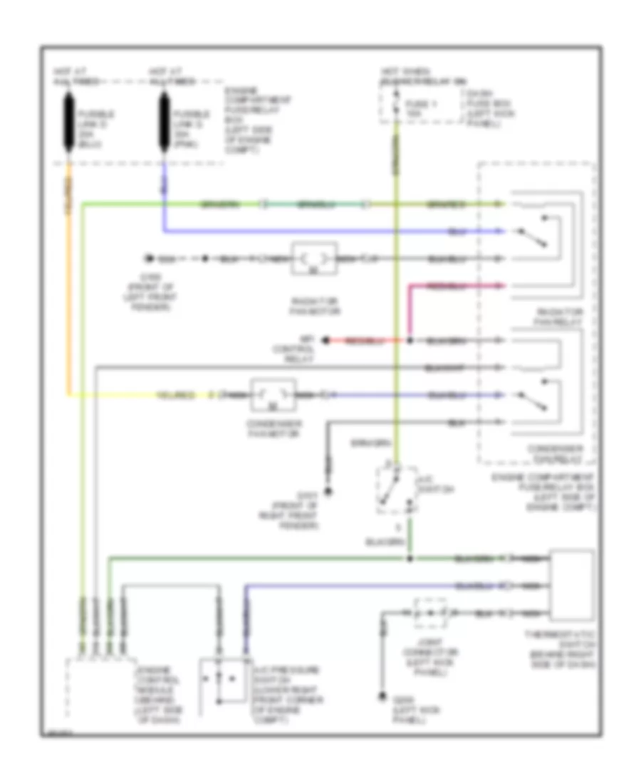
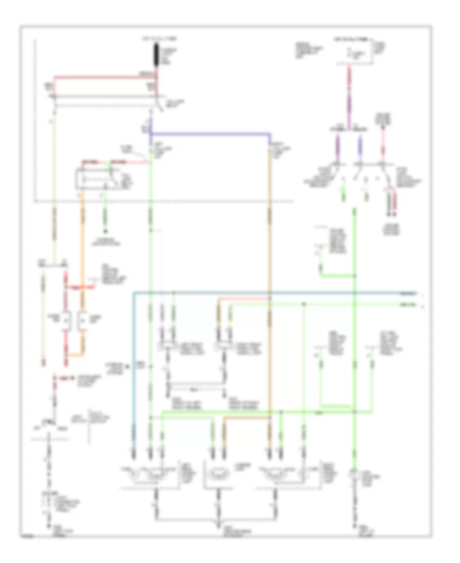
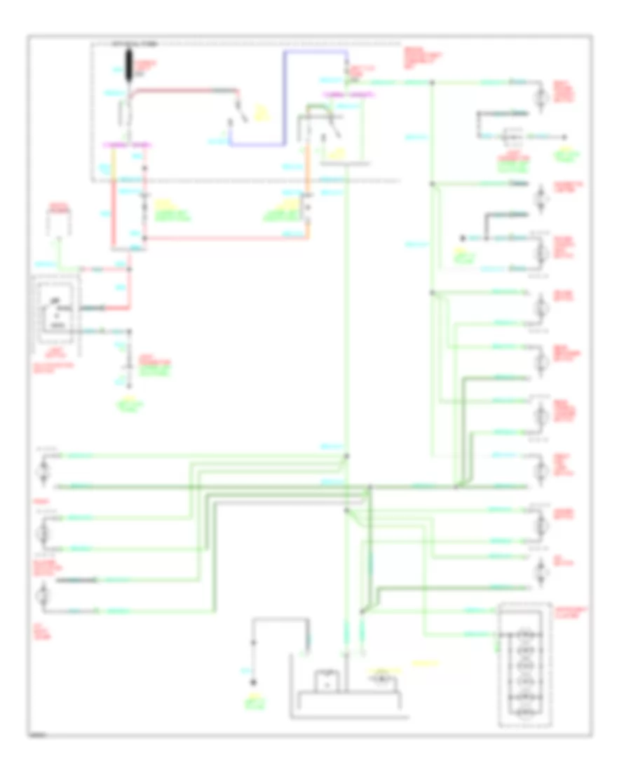
AIR CONDITIONING
A/C Wiring Diagram for Hyundai Tiburon 1997

List of elements for A/C Wiring Diagram for Hyundai Tiburon 1997:
- (left kick panel)
- (right front
- (right kick panel)
- (right side
- A/c compressor clutch
- A/c dual pressure
- A/c fuse 10a
- A/c relay
- A/c switch
- Blower actuator switch
- Blower motor
- Blower relay (in engine compartment relay box)
- Blower resistors (behind right side of i/p)
- Blower switch
- Compt)
- Condenser fan motor
- Condenser fan relay
- Dash fuse box
- Diode
- Engine compartment fuse/relay box
- Engine control module (behind left side of i/p)
- Fresh
- Fuse 10a
- Fusible link b 20a
- Fusible link d 20a
- Fusible link g 30a
- Fusible link k 30a
- G100 (left front of engine compt)
- G101 (right front of engine compt)
- G120
- G200
- G203
- G203 (right kick panel)
- Hot at all times
- Hot in on
- Illumination
- Interior lights system
- J/c (m58) (below left side of i/p)
- Mfi control relay (above left kick panel)
- Nca
- Of engine
- Of engine)
- Off
- Radiator fan motor
- Radiator fan relay
- Rec
- Red
- Switch
- Thermostatic switch (right side of i/p)
- Transaxle control module
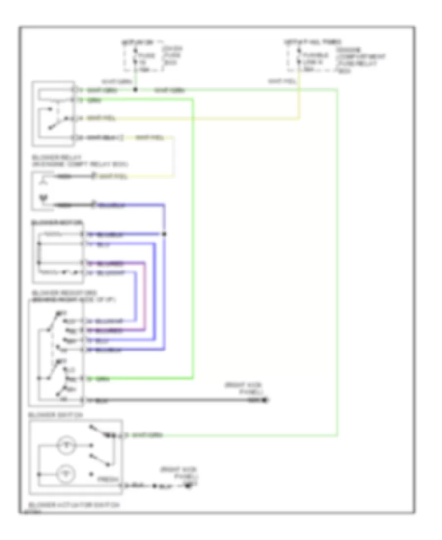
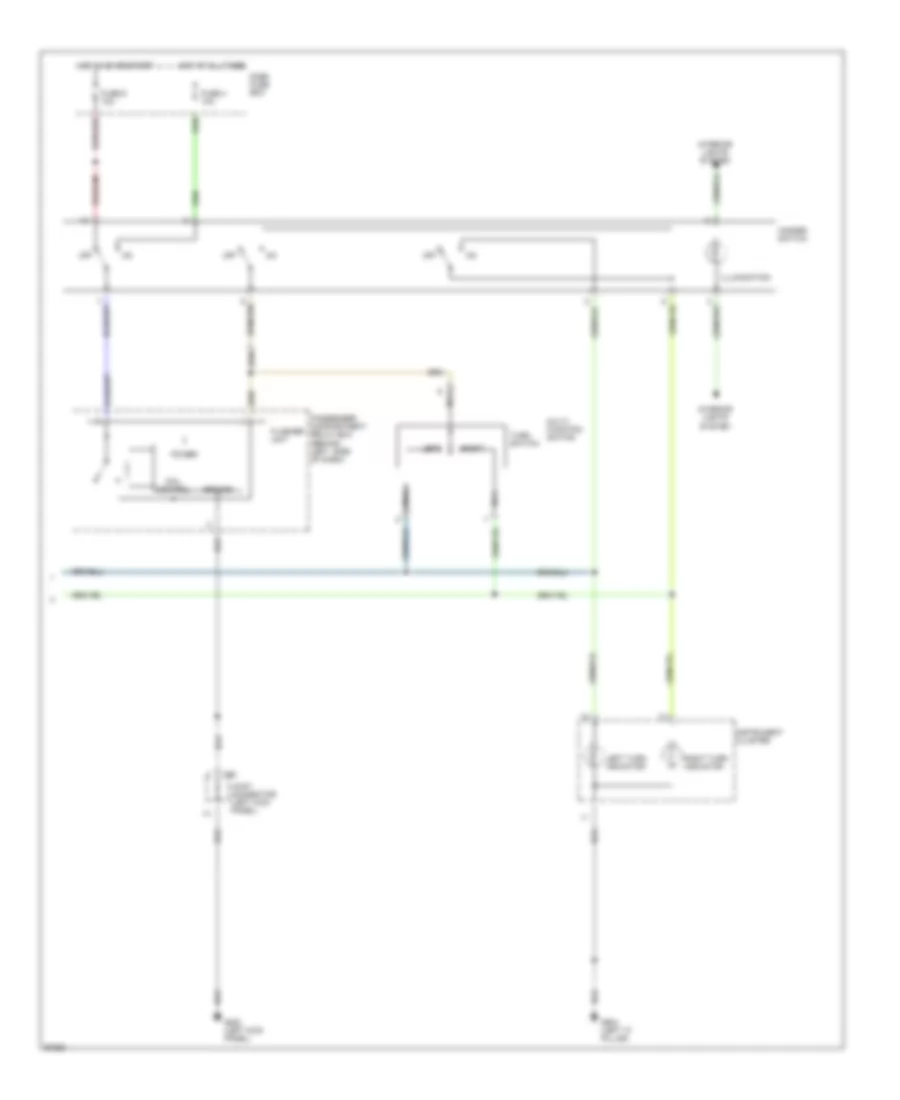
Heater Wiring Diagram for Hyundai Tiburon 1997
List of elements for Heater Wiring Diagram for Hyundai Tiburon 1997:
- (right kick panel) g203
- Blower actuator switch
- Blower motor
- Blower relay (in engine compt relay box)
- Blower resistors (behind right side of i/p)
- Blower switch
- Dash fuse box
- Engine compartment fuse/relay box
- Fresh
- Fuse 10a
- Fusible link k 30a
- Hot at all times
- Hot in on
- Nca
- Off
- Rec
ANTI-LOCK BRAKES
Anti-lock Brake Wiring Diagrams for Hyundai Tiburon 1997
List of elements for Anti-lock Brake Wiring Diagrams for Hyundai Tiburon 1997:
- (w/ cruise)
- (w/o cruise)
- Abs control module (right side of trunk, behind trim)
- Abs ind
- Abs modulator (right front corner of engine compt)
- Abs relay box (right front corner of engine compt)
- Cruise control system
- Dash fuse box (left kick panel)
- Data link connector (left side of dash)
- E58
- Engine compartment fuse/relay box (left side of engine compt)
- Exterior lights system
- Fail safe relay
- Fuse 10 10a
- Fuse 11 10a
- Fuse 3 15a
- Fusible link h 30a (pnk)
- G105 (rear of right front fender)
- G203 (right kick panel)
- Hot at all times
- Hot in on or start
- Instrument cluster
- Left front sol
- Left front wheel sensor
- Left rear sol
- Left rear wheel sensor
- M62
- Motor relay
- Nca
- Pump motor (right front corner of engine compt)
- Red
- Right front sol
- Right front wheel sensor
- Right rear sol
- Right rear wheel sensor
- Stop lamp switch (brake pedal support)
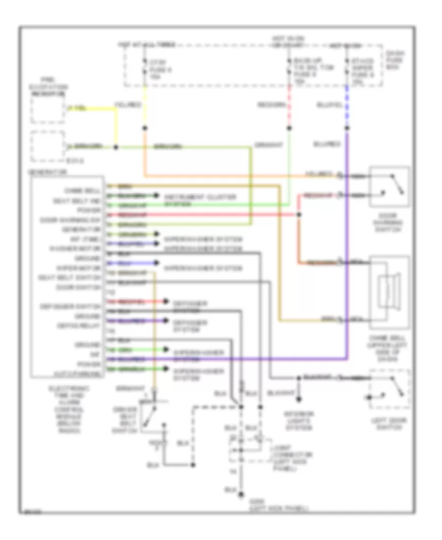
BODY COMPUTER
ETACS ECU Wiring Diagram for Hyundai Tiburon 1997
List of elements for ETACS ECU Wiring Diagram for Hyundai Tiburon 1997:
- Auto parking
- Back-up, t/s sig, tcm fuse 9 10a
- Chime bell
- Chime bell (upper left side of dash)
- Ctsy fuse 6 15a
- Dash fuse box
- Defog relay
- Defogger switch
- Defogger system
- Door switch
- Door warning sw
- Door warning switch
- Driver seat belt switch
- E31-2
- Electronic time and alarm control module (below radio)
- Etacs wiper fuse 8 15a
- G200 (left kick panel)
- Generator
- Ground
- Hot at all times
- Hot in on
- Hot in on or start
- Instrument cluster system
- Int
- Int (time)
- Interior lights system
- Joint connector (left kick panel)
- Left door switch
- Nca
- Power
- Pre- excitation resistor
- Seat belt ind
- Seat belt switch
- Washer motor
- Wiper motor
- Wiper/washer system
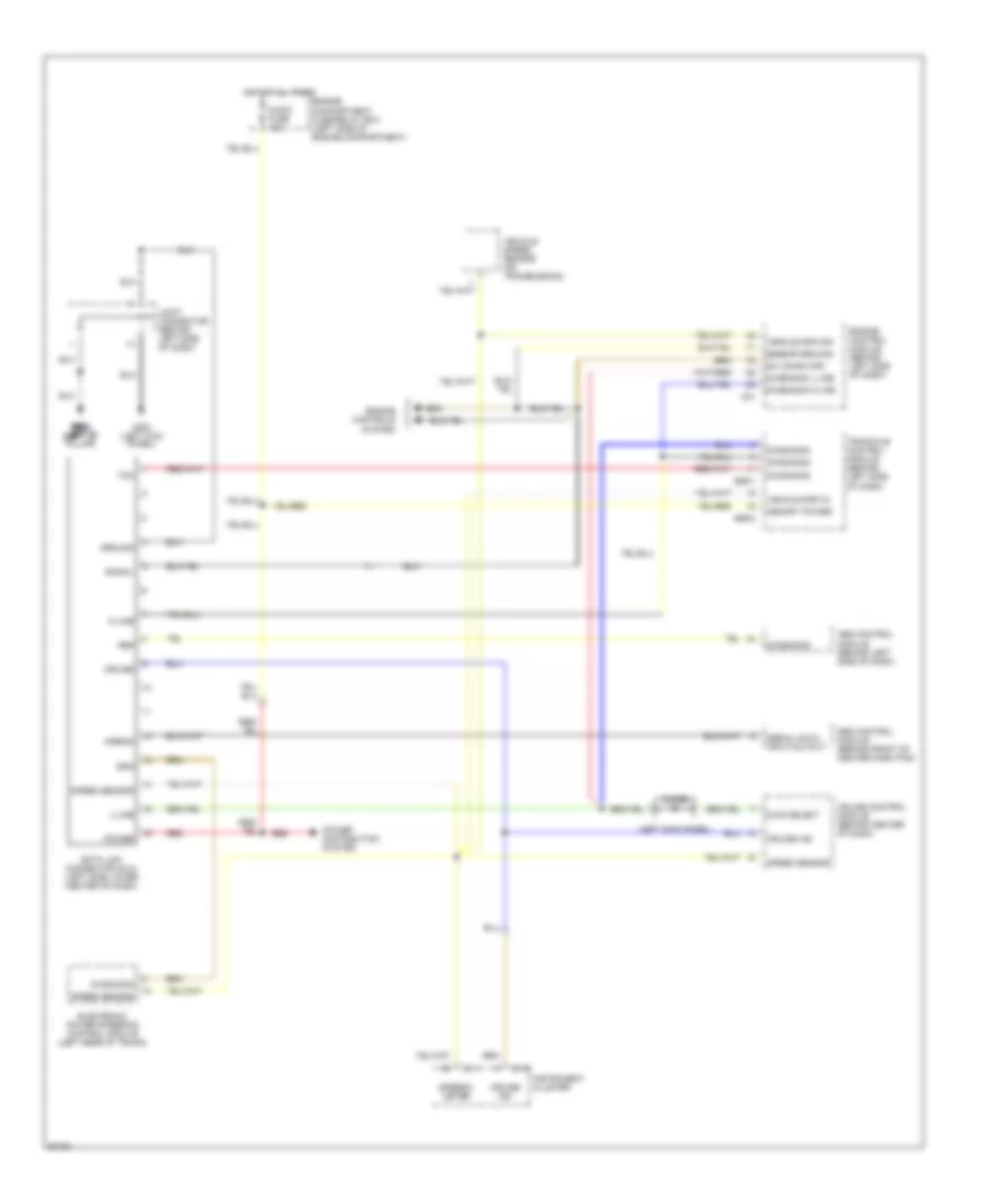
COMPUTER DATA LINES
Computer Data Lines for Hyundai Tiburon 1997
List of elements for Computer Data Lines for Hyundai Tiburon 1997:
- (left kick panel)
- Abs
- Abs control module (behind left side of dash)
- Airbag
- Audio fuse 10a
- C01
- Cruise
- Cruise control module (behind center of dash)
- Cruise ind
- Data link connector (dlc) (left side lower center of dash)
- Diag select
- Diagnosis
- Diagnosis k-line
- Diagnosis l-line
- Diode
- E59-1
- E59-2
- Electronic power steering control module (left rear of trunk)
- Engine compartment fuse/relay box (left side of engine compartment)
- Engine control module (behind left side of dash)
- Engine controls system
- Eps
- G200 (left kick panel)
- G904 g904 (left "c" (left "c" pillar)
- Ground
- Hot at all times
- I01-1
- I01-2
- Instrument cluster
- Joint connector (behind left side of dash)
- K-line
- L-line
- Memory power
- Power
- Power distribution system
- Red
- Sensor ground
- Serial data input/output
- Signal
- Speed sensor
- Speedo- meter
- Srs control module (behind front of center dash pad)
- Sw (char map)
- Tcm
- Tranaxle control module (behind left side of dash)
- Vehicle spd in
- Vehicle spd sig
- Vehicle speed sensor (on transmission)
COOLING FAN
Cooling Fan Wiring Diagram for Hyundai Tiburon 1997
List of elements for Cooling Fan Wiring Diagram for Hyundai Tiburon 1997:
- A/c pressure switch (lower right front corner of engine compt)
- A/c switch
- Condenser fan motor
- Condenser fan relay
- Dash fuse box (left kick panel)
- Engine compartment fuse/relay box (left side of engine compt)
- Engine control module (behind left side of dash)
- Fuse 1 10a
- Fusible link g 30a (pnk)
- G100 (front of left front fender)
- G101 (front of right front fender)
- G200 (left kick panel)
- Hot at all times
- Hot when blower relay on
- Joint connector (left kick panel)
- Mfi control relay
- Nca
- Radiator fan motor
- Radiator fan relay
- Thermostatic switch (behind right side of dash)
CRUISE CONTROL
Cruise Control Wiring Diagram for Hyundai Tiburon 1997
List of elements for Cruise Control Wiring Diagram for Hyundai Tiburon 1997:
- (w/ eps)
- (w/o eps)
- A/t shift lever
- Automatic transaxle
- C01
- Control valve
- Cruise clutch pedal position switch
- Cruise control actuator (top rear center of engine)
- Cruise control module (below center of dash, in front of console)
- Cruise control switch
- Cruise ctl ind
- Cruise ind
- Cruise on in
- Cruise on ind
- Cruise switch
- Dash fuse box (left kick panel)
- Data link connector (left side of dash)
- Diagnosis
- Diode z09
- Driver seat belt switch
- E59-1
- E59-2
- Engine control module (ecm) (left side of dash)
- Engine controls system
- Exterior lights system
- Fuse 10 10a
- Fuse 15 10a
- Fuse 16 10a
- Fuse 3 15a
- G200 (left kick panel)
- G904 (left "c" pillar)
- Ground
- Hot at all times
- Hot in on
- Hot in on or start
- Ignition switch
- Instrument cluster
- Interior lights system
- Joint connector (left kick panel)
- M-06
- Manual transaxle
- Multifunction switch
- N d
- Nca
- O/d off ind
- O/d on in
- Off
- Overdrive switch
- Power
- Prk/neutral in (a/t) cltch postion in (m/t)
- Red
- Release valve
- Resume/ accel
- Resume/accel
- Set/ coast
- Set/coast in
- Starting/charging system
- Stop lamp sw
- Stop lamp switch
- Transaxle control module (tcm) (left side of dash)
- Transaxle range switch (on top of transaxle)
- Vacuum motor
- Vehicle spd in
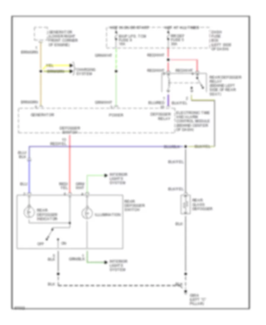
DEFOGGERS
Defogger Wiring Diagram for Hyundai Tiburon 1997
List of elements for Defogger Wiring Diagram for Hyundai Tiburon 1997:
- B/up lps, tcm fuse 9 10a
- Charging system
- Dash fuse box (left side of dash)
- Defogger relay
- Defogger switch
- Electronic time and alarm control module (behind center of dash)
- G904 (left "c" pillar)
- Generator
- Generator (lower right front corner of engine)
- Hot at all times
- Hot in on or start
- Illumination
- Interior lights system
- Off
- Power
- Rear defogger indicator
- Rear defogger relay (behind left side of rear seat)
- Rear defogger switch
- Rear glass defogger
- Rr def fuse 5 30a
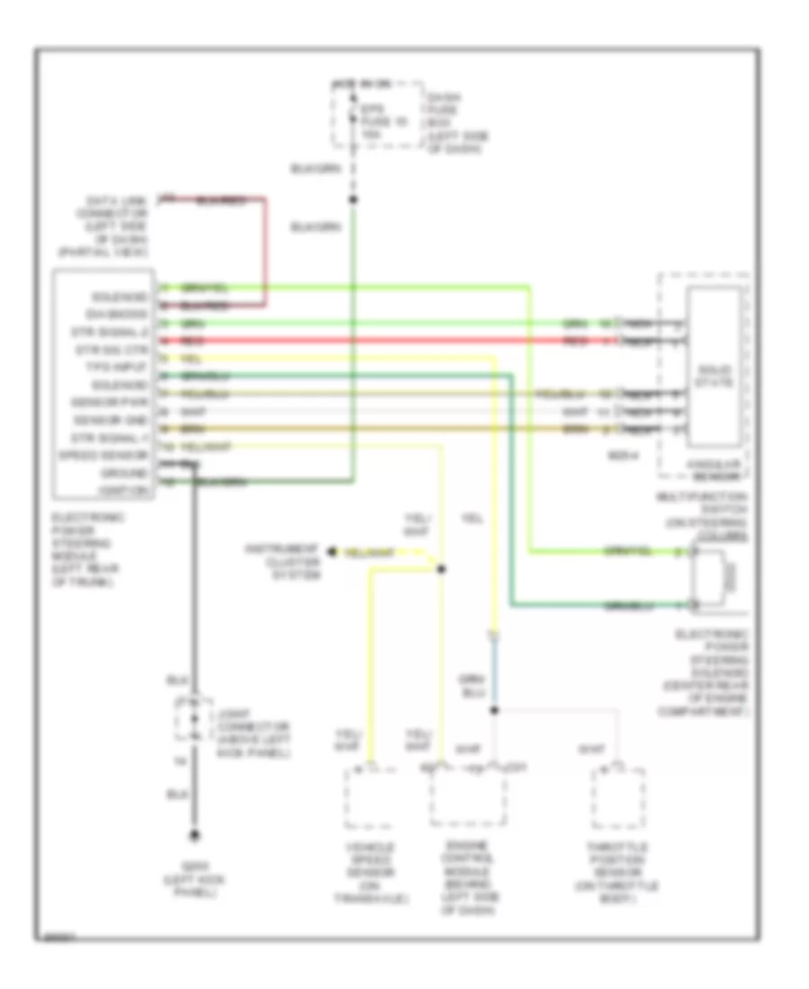
ELECTRONIC POWER STEERING
Electronic Power Steering Wiring Diagram for Hyundai Tiburon 1997
List of elements for Electronic Power Steering Wiring Diagram for Hyundai Tiburon 1997:
- Angular sensor
- C01
- Dash fuse box (left side of dash)
- Data link connector (left side of dash) (partial view)
- Diagnosis
- Electronic power steering module (left rear of trunk)
- Electronic power steering solenoid (center rear of engine compartment)
- Engine control module (behind left side of dash)
- Eps fuse 15 10a
- G200 (left kick panel)
- Ground
- Hot in on
- Ignition
- Instrument cluster system
- Joint connector (above left kick panel)
- M26-4
- Multifunction switch (on steering column)
- Nca
- Red
- Sensor gnd
- Sensor pwr
- Solenoid
- Solid state
- Speed sensor
- Str sig ctr
- Str signal-1
- Str signal-2
- Throttle position sensor (on throttle body)
- Tps input
- Vehicle speed sensor (on transaxle)
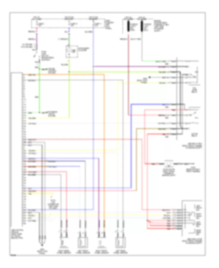
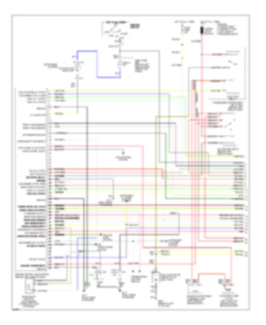
ENGINE PERFORMANCE
1.8L
1.8L, Engine Performance Wiring Diagrams (1 of 3) for Hyundai Tiburon 1997
List of elements for 1.8L, Engine Performance Wiring Diagrams (1 of 3) for Hyundai Tiburon 1997:
- (1.8l)
- (2.0l)
- A/c relay cntrl a/c relay cntrl a/c relay cntrl a/c relay cntrl a/c relay cntrl a/c relay cntrl
- Acc
- Air conditioning system
- Audio fuse 10a
- Batt backup
- C31
- C32
- Can close valve cntrl
- Canister close valve (left front of engine compt, behind bumper)
- Cluster
- Cmp sensor input
- Cond fan rel cntrl
- Cooling fans system
- Crankshaft pos sens a
- Crankshaft pos sens b
- Crankshaft position (ckp) sensor (lower left side of engine)
- Dash fuse box (behind left side of dash, above kick panel)
- Ecm rel power input ecm rel power input ecm rel power input ecm rel power input ecm rel power input ecm rel power input
- Eng speed sig output
- Engine compartment fuse/relay box (left side of engine compt)
- Engine compartment fuse/relay box (left side of of engine compt)
- Engine control module (ecm) (behind left side of dash)
- Front ho2s htr cntrl front ho2s htr cntrl front ho2s htr cntrl front ho2s htr cntrl front ho2s htr cntrl front ho2s htr cntrl
- Front ho2s sensor
- Fuel inj 1 cntrl
- Fuel inj 2 cntrl fuel inj 2 cntrl fuel inj 2 cntrl fuel inj 2 cntrl fuel inj 2 cntrl fuel inj 2 cntrl
- Fuel inj 3 cntrl
- Fuel inj 4 cntrl
- Fuel pump motor (inside top of fuel tank)
- Fuel pump relay
- Fuel pump relay cntrl
- Fuse 10 10a
- G117 (right rear of engine)
- G904 (base of left "c" pillar)
- Ground
- Ground ground ground ground ground ground
- Hot at all times
- Hot at all times hot at all times hot at all times hot at all times hot at all times hot at all times
- I01-1
- I01-2
- Idle speed cntrl open
- Idle speed ctrl close
- Ig1
- Ign coil cntrl
- Ignition ignition ignition ignition ignition ignition switch switch switch switch switch switch
- Instrument
- Instrument cluster system
- J/c
- Lock
- Maf sensor ground
- Maf sensor input maf sensor input maf sensor input maf sensor input maf sensor input maf sensor input
- Malfunction indicator
- Mfi cntrl relay mfi cntrl relay mfi cntrl relay mfi cntrl relay mfi cntrl relay mfi cntrl relay
- Mil indicator
- Nca
- Passenger compartment relay box (behind left side of dash)
- Purge cntrl sol valve purge cntrl sol valve purge cntrl sol valve purge cntrl sol valve purge cntrl sol valve purge cntrl sol valve
- Radiator fan rel cntrl radiator fan rel cntrl radiator fan rel cntrl radiator fan rel cntrl radiator fan rel cntrl radiator fan rel cntrl
- Rear ho2s htr cntrl
- Rear ho2s sensor
- Rear ho2s sensor rear ho2s sensor rear ho2s sensor rear ho2s sensor rear ho2s sensor rear ho2s sensor
- Red
- Sfi control relay (behind left side of dash)
- Start
- Tp sensor output
- Transmission control module
- Vehicle speed input vehicle speed input vehicle speed input vehicle speed input vehicle speed input vehicle speed input
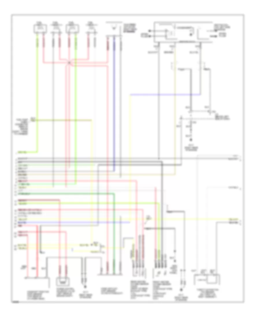
1.8L, Engine Performance Wiring Diagrams (2 of 3) for Hyundai Tiburon 1997
List of elements for 1.8L, Engine Performance Wiring Diagrams (2 of 3) for Hyundai Tiburon 1997:
- (right rear of engine)
- 1.8l
- 1.8l only
- 2.0l
- C32
- Camshaft position (cmp) sensor (top rear of cylinder head)
- Condenser
- Front heated oxygen sensor (ho2s) (in exhaust pipe) (1.8l) (in exhaust manifold) (2.0l)
- Fuel inj 1
- Fuel inj 2
- Fuel inj 3
- Fuel inj 4
- Fuel pump check connector (rear of engine compt, taped to harness)
- G117
- G203 (right kick panel)
- Idle speed actuator (right rear of engine) of engine) of engine)
- Ignition coil (top left side of engine)
- Ignition coils
- J/c (behind left side of dash)
- Mass air flow (maf) sensor (in air intake duct)
- Nca
- Purge control solenoid valve (left rear of engine compt)
- Rear heated oxygen sensor (ho2s) (front of rear exhaust pipe) (1.8l) (in exhaust pipe) (2.0l)
- Red
- Spark plugs
- Throttle position (tp) sensor (on throttle body assembly)
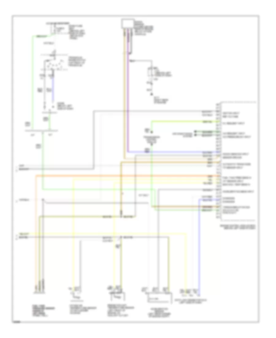
1.8L, Engine Performance Wiring Diagrams (3 of 3) for Hyundai Tiburon 1997
List of elements for 1.8L, Engine Performance Wiring Diagrams (3 of 3) for Hyundai Tiburon 1997:
- (left side of dash)
- A/c pressure sw input
- A/c request input
- A/t
- A/t only
- Acceleration sens input
- Acceleration sensor (left rear corner of engine compt)
- Air conditioning system
- Automatic trans mode
- C32
- Dash fuse box (behind left side of dash, above kick panel)
- Data link connector (dlc)
- Diagnosis
- Diode (below left side of dash)
- Eng cool temp sens in
- Engine control module (ecm) (behind left side of dash)
- Engine coolant temperature sensor (left front of engine, on coolant outlet)
- Fuel tank fuel tank pressure sensor pressure sensor (inside of (inside of left rear left rear wheel well)
- Fuel tank pres sens in
- Fuse 9 10a
- G117 (right rear of engine)
- Hot in on or start
- Iat sensor input
- Ignition input
- Intake air temperature sensor (in air cleaner housing)
- J/c (behind left side of dash)
- Knock sens sig input
- Knock sensor (lower center rear of engine, below intake manifold)
- M/t
- Mil request input
- Nca
- P/n in (a/t) or pwr in (m/t)
- Ref voltage
- Sensor ground
- Torque reduction sig
- Tp sensor input
- Transaxle range switch (top front of transaxle)
- Transmission control module
2.0L
2.0L, Engine Performance Wiring Diagrams (1 of 3) for Hyundai Tiburon 1997
List of elements for 2.0L, Engine Performance Wiring Diagrams (1 of 3) for Hyundai Tiburon 1997:
- (1.8l)
- (2.0l)
- A/c relay cntrl a/c relay cntrl a/c relay cntrl a/c relay cntrl a/c relay cntrl a/c relay cntrl
- Acc
- Air conditioning system
- Audio fuse 10a
- Batt backup
- C31
- C32
- Can close valve cntrl
- Canister close valve (left front of engine compt, behind bumper)
- Cluster
- Cmp sensor input
- Cond fan rel cntrl
- Cooling fans system
- Crankshaft pos sens a
- Crankshaft pos sens b
- Crankshaft position (ckp) sensor (lower left side of engine)
- Dash fuse box (behind left side of dash, above kick panel)
- Ecm rel power input ecm rel power input ecm rel power input ecm rel power input ecm rel power input ecm rel power input
- Eng speed sig output
- Engine compartment fuse/relay box (left side of engine compt)
- Engine compartment fuse/relay box (left side of of engine compt)
- Engine control module (ecm) (behind left side of dash)
- Front ho2s htr cntrl front ho2s htr cntrl front ho2s htr cntrl front ho2s htr cntrl front ho2s htr cntrl front ho2s htr cntrl
- Front ho2s sensor
- Fuel inj 1 cntrl
- Fuel inj 2 cntrl fuel inj 2 cntrl fuel inj 2 cntrl fuel inj 2 cntrl fuel inj 2 cntrl fuel inj 2 cntrl
- Fuel inj 3 cntrl
- Fuel inj 4 cntrl
- Fuel pump motor (inside top of fuel tank)
- Fuel pump relay
- Fuel pump relay cntrl
- Fuse 10 10a
- G117 (right rear of engine)
- G904 (base of left "c" pillar)
- Ground
- Ground ground ground ground ground ground
- Hot at all times
- Hot at all times hot at all times hot at all times hot at all times hot at all times hot at all times
- I01-1
- I01-2
- Idle speed cntrl open
- Idle speed ctrl close
- Ig1
- Ign coil cntrl
- Ignition ignition ignition ignition ignition ignition switch switch switch switch switch switch
- Instrument
- Instrument cluster system
- J/c
- Lock
- Maf sensor ground
- Maf sensor input maf sensor input maf sensor input maf sensor input maf sensor input maf sensor input
- Malfunction indicator
- Mfi cntrl relay mfi cntrl relay mfi cntrl relay mfi cntrl relay mfi cntrl relay mfi cntrl relay
- Mil indicator
- Nca
- Passenger compartment relay box (behind left side of dash)
- Purge cntrl sol valve purge cntrl sol valve purge cntrl sol valve purge cntrl sol valve purge cntrl sol valve purge cntrl sol valve
- Radiator fan rel cntrl radiator fan rel cntrl radiator fan rel cntrl radiator fan rel cntrl radiator fan rel cntrl radiator fan rel cntrl
- Rear ho2s htr cntrl
- Rear ho2s sensor
- Rear ho2s sensor rear ho2s sensor rear ho2s sensor rear ho2s sensor rear ho2s sensor rear ho2s sensor
- Red
- Sfi control relay (behind left side of dash)
- Start
- Tp sensor output
- Transmission control module
- Vehicle speed input vehicle speed input vehicle speed input vehicle speed input vehicle speed input vehicle speed input
2.0L, Engine Performance Wiring Diagrams (2 of 3) for Hyundai Tiburon 1997
List of elements for 2.0L, Engine Performance Wiring Diagrams (2 of 3) for Hyundai Tiburon 1997:
- (right rear of engine)
- 1.8l
- 1.8l only
- 2.0l
- C32
- Camshaft position (cmp) sensor (top rear of cylinder head)
- Condenser
- Front heated oxygen sensor (ho2s) (in exhaust pipe) (1.8l) (in exhaust manifold) (2.0l)
- Fuel inj 1
- Fuel inj 2
- Fuel inj 3
- Fuel inj 4
- Fuel pump check connector (rear of engine compt, taped to harness)
- G117
- G203 (right kick panel)
- Idle speed actuator (right rear of engine) of engine) of engine)
- Ignition coil (top left side of engine)
- Ignition coils
- J/c (behind left side of dash)
- Mass air flow (maf) sensor (in air intake duct)
- Nca
- Purge control solenoid valve (left rear of engine compt)
- Rear heated oxygen sensor (ho2s) (front of rear exhaust pipe) (1.8l) (in exhaust pipe) (2.0l)
- Red
- Spark plugs
- Throttle position (tp) sensor (on throttle body assembly)
2.0L, Engine Performance Wiring Diagrams (3 of 3) for Hyundai Tiburon 1997
List of elements for 2.0L, Engine Performance Wiring Diagrams (3 of 3) for Hyundai Tiburon 1997:
- (left side of dash)
- A/c pressure sw input
- A/c request input
- A/t
- A/t only
- Acceleration sens input
- Acceleration sensor (left rear corner of engine compt)
- Air conditioning system
- Automatic trans mode
- C32
- Dash fuse box (behind left side of dash, above kick panel)
- Data link connector (dlc)
- Diagnosis
- Diode (below left side of dash)
- Eng cool temp sens in
- Engine control module (ecm) (behind left side of dash)
- Engine coolant temperature sensor (left front of engine, on coolant outlet)
- Fuel tank fuel tank pressure sensor pressure sensor (inside of (inside of left rear left rear wheel well)
- Fuel tank pres sens in
- Fuse 9 10a
- G117 (right rear of engine)
- Hot in on or start
- Iat sensor input
- Ignition input
- Intake air temperature sensor (in air cleaner housing)
- J/c (behind left side of dash)
- Knock sens sig input
- Knock sensor (lower center rear of engine, below intake manifold)
- M/t
- Mil request input
- Nca
- P/n in (a/t) or pwr in (m/t)
- Ref voltage
- Sensor ground
- Torque reduction sig
- Tp sensor input
- Transaxle range switch (top front of transaxle)
- Transmission control module
EXTERIOR LIGHTS
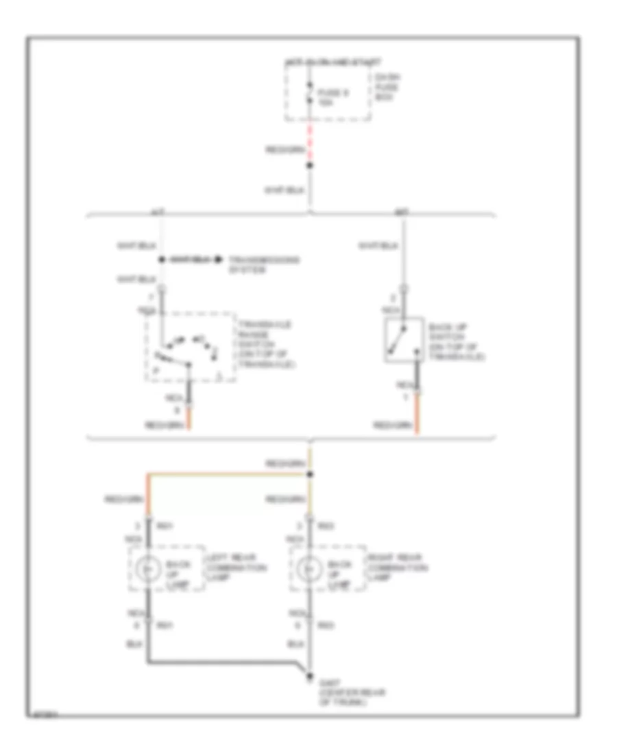
Back-up Lamps Wiring Diagram for Hyundai Tiburon 1997
List of elements for Back-up Lamps Wiring Diagram for Hyundai Tiburon 1997:
- A/t
- Back up lamp
- Back up switch (on top of transaxle)
- Dash fuse box
- Fuse 9 10a
- G407 (center rear of trunk)
- Hot in on and start
- Left rear combination lamp
- M/t
- Nca
- R01
- R03
- Right rear combination lamp
- Transaxle range switch (on top of transaxle)
- Transmissions system
Exterior Lamps Wiring Diagram (1 of 2) for Hyundai Tiburon 1997
List of elements for Exterior Lamps Wiring Diagram (1 of 2) for Hyundai Tiburon 1997:
- (front of left front fender)
- (front of right front fender)
- A/t and key lock control module (right kick panel)
- Abs control module (right side of trunk)
- Cruise control module (below center of dash)
- Cruise control system
- Dash fuse box
- Diode z05
- Diode z06
- Drl control module (behind left headlight)
- Engine compartment fuse/relay box
- Fuse 3 15a
- G100
- G101
- G200 (left kick panel)
- G407 (center rear of trunk)
- G904 (left "c" pillar)
- Head
- High mounted stop lamp
- Hot at all times
- Instrument cluster (clock)
- Interior lights system
- Joint connector (left kick panel)
- Left front park/turn signal lamp
- Left rear combin- ation lamp
- Left taillamp fuse 10a
- License lamp
- Light switch
- M58
- Multi- function switch
- Nca
- Nca nca
- Off
- Park
- Red
- Right front park/turn signal lamp
- Right rear combin- ation lamp
- Right taillamp fuse 10a
- Stop
- Stop lamp switch (on support bracket)
- Tail
- Tail- lamp relay (drl)
- Taillamp relay
- Turn
- W/ cruise
- W/ drl
- W/ drl only
- W/o cruise
- W/o drl
Exterior Lamps Wiring Diagram (2 of 2) for Hyundai Tiburon 1997
List of elements for Exterior Lamps Wiring Diagram (2 of 2) for Hyundai Tiburon 1997:
- Coil control
- Dash fuse box
- Flasher unit
- Fuse 4 10a
- Fuse 9 10a
- G200 (left kick panel)
- G904 (left "c" pillar)
- Ground
- Hazard switch
- Hot at all times
- Hot in on or start
- Illumination
- Instrument cluster
- Interior lights system
- Joint connector (left kick panel)
- Left
- Left turn indicator
- M58
- Multi- function switch
- Nca
- Off
- Passenger compartment relay box (behind left side of dash)
- Power
- Right
- Right turn indicator
- Turn switch
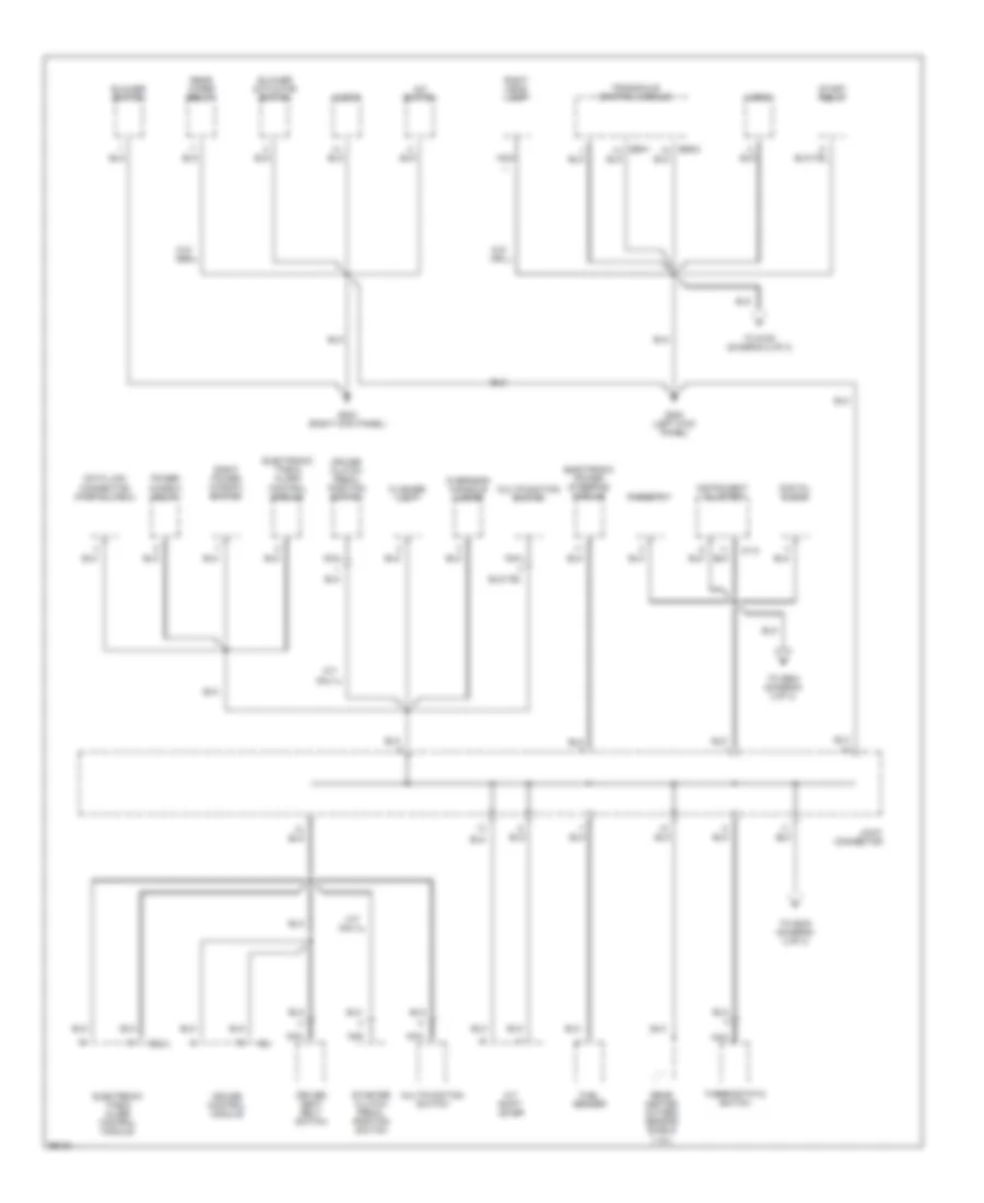
GROUND DISTRIBUTION
Ground Distribution Wiring Diagram (1 of 3) for Hyundai Tiburon 1997
List of elements for Ground Distribution Wiring Diagram (1 of 3) for Hyundai Tiburon 1997:
- A/c switch
- A/t shift lever
- Audio
- Blower actuator switch
- Blower switch
- Cruise clutch pedal position switch
- Cruise control module
- Data link connector (partial view)
- Digital clock
- Driver seat belt switch
- Electronic power steering module
- Electronic time & alarm control module
- Flasher unit
- Fuel sender
- G200 (left kick panel)
- G203 (right kick panel)
- Horn
- I01-2
- Instrument cluster
- Joint connector
- M/t only
- M21
- M38-3
- Multifunction switch
- Nca
- Overhead console lamps
- Power window relay
- Rear heated oxygen sensor shield (1.8l)
- Rear wiper relay
- Rheostat
- Right head lamp
- Right power window switch
- Start relay
- Starter clutch pedal position switch
- Thermostatic switch
- To g100 (diagram 2 of 3)
- To g203 (diagram 2 of 3)
- To g904 (diagram 2 0f 3)
- Transaxle control module
- W/o abs
- W/o drl
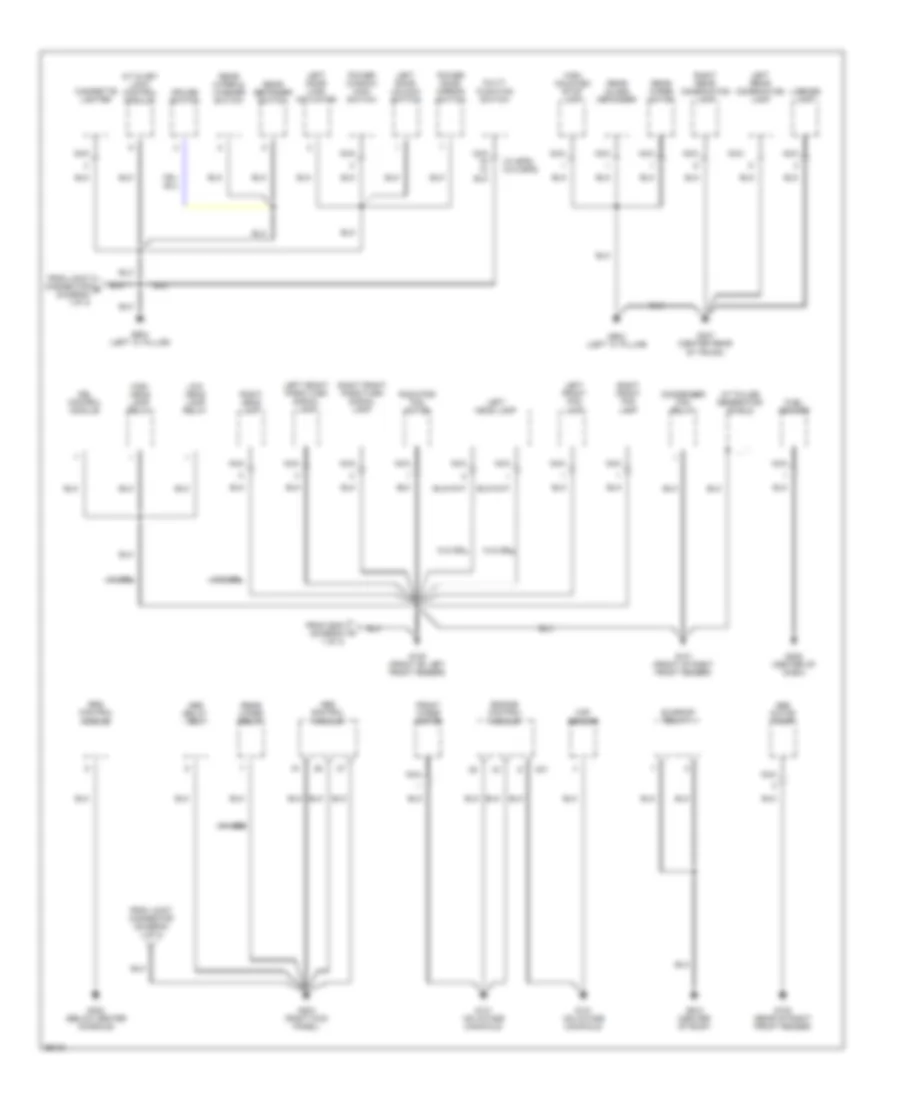
Ground Distribution Wiring Diagram (2 of 3) for Hyundai Tiburon 1997
List of elements for Ground Distribution Wiring Diagram (2 of 3) for Hyundai Tiburon 1997:
- (w/ eps) (w/o eps)
- A/t & key lock control module
- A/t pulse generator shield
- Abs control module
- Abs motor pump
- Abs relay box
- C01
- Cigarette lighter
- Condenser fan relay
- Cruise switch
- Drl control module
- Engine control module
- From g200 (diagram 1 of 3)
- From joint connector (diagram 1 of 3)
- From joint connector b (diagram 1 0f 3)
- Front wiper motor
- Fuel sender
- G100 (front of left front fender)
- G101 (front of right front fender)
- G105 (rear of right front fender)
- G131 (on intake manifold)
- G203 (right kick panel)
- G206 (center of dash)
- G302 (below center console)
- G407 (center rear of trunk)
- G904 (left "c" pillar)
- G910 (center of roof)
- High head lamp relay
- High mounted stop lamp
- Left door lock actuator
- Left door unlock switch
- Left front fog lamp
- Left front park/turn signal lamp
- Left head lamp
- Left rear combination lamp
- License lamp
- Low head lamp relay
- Maf sensor
- Multi- function switch
- Nca
- Power door mirror switch
- Power window main switch
- Radiator fan motor
- Rear defogger switch
- Rear glass defogger
- Rear wiper & washer switch
- Rear wiper motor
- Rear wiper relay
- Right front fog lamp
- Right front park/turn signal lamp
- Right head lamp
- Right rear combination lamp
- Srs control module
- Sunroof relay 1
- W/ abs
- W/ drl
- W/o drl
Ground Distribution Wiring Diagram (3 of 3) for Hyundai Tiburon 1997
List of elements for Ground Distribution Wiring Diagram (3 of 3) for Hyundai Tiburon 1997:
- A/c compressor
- A/c relay
- Brake fluid level sensor
- Ckp sensor
- Ckp sensor shield
- Cmp sensor
- Cmp sensor shield
- Diode (for a/c)
- E59-1
- Front heated oxygen sensor shield
- G131 (on intake manifold)
- Ignition coil shield 1
- Ignition coil shield 2
- Joint connector
- Knock sensor
- Knock sensor shield
- Nca
- Rear heated oxygen sensor shield (2.0l)
- Transaxle control module
- Vehicle speed sensor
HEADLIGHTS
Headlamps/Fog Lamps Wiring Diagram, with DRL (1 of 2) for Hyundai Tiburon 1997
List of elements for Headlamps/Fog Lamps Wiring Diagram, with DRL (1 of 2) for Hyundai Tiburon 1997:
- Dimmer/ passing switch
- Diode z05
- Diode z06
- Drl resistor (left front corner of engine compt)
- Engine compartment fuse/relay box
- Exterior lights system
- Flash
- G200 (left kick panel)
- Head
- High
- High beam ind
- High headlamp fuse 15a
- Hot at all times
- Instru- ment cluster
- Joint connector (left kick panel)
- Left headlamp
- Left taillamp fuse 10a
- Light switch
- Low
- Low headlamp fuse 15a
- M26-2
- M26-3
- M58
- Multi- function switch
- Nca
- Off
- Park
- Red
- Right headlamp
- Tail- lamp relay
- Tail- lamp relay (drl)
- To drl control module (diagram 2 of 2)
- To front fog fuse (diagram 2 of 2)
- To front foglamp switch (diagram 2 of 2)
- To headlamp relay (high) (diagram 2 of 2)
- To headlamp relay (low) (diagram 2 of 2)
Headlamps/Fog Lamps Wiring Diagram, with DRL (2 of 2) for Hyundai Tiburon 1997
List of elements for Headlamps/Fog Lamps Wiring Diagram, with DRL (2 of 2) for Hyundai Tiburon 1997:
- Charging system
- Dash fuse box
- Daytime running lamp control module (behind left head- lamp)
- Diode z10
- Diode z11
- Engine compartment fuse/relay box
- From dimmer/ passing switch (diagram 1 of 2)
- From drl resistor (diagram 1 of 2)
- From instrument cluster (diagram 1 of 2)
- From left headlamp (diagram 1 of 2)
- From light switch (diagram 1 of 2)
- From right headlamp (diagram 1 of 2)
- From taillamp relay (diagram 1 of 2)
- Front fog fuse 15a
- Front fog- lamp relay
- Front foglamp switch
- Fuse 10a
- G100 (front of left front fender)
- G101 (front of right front fender)
- Generator
- Headlamp relay (high)
- Headlamp relay (low)
- Hot in on
- Ill
- Ind
- Interior lights system
- Left front foglamp
- Nca
- Parking brake switch
- Power and control circuit
- Red
- Right front foglamp
- Warning systems
Headlamps/Fog Lamps Wiring Diagram, without DRL for Hyundai Tiburon 1997
List of elements for Headlamps/Fog Lamps Wiring Diagram, without DRL for Hyundai Tiburon 1997:
- Dash fuse box
- Dimmer/ passing switch
- Diode z07 (near tcm)
- Diode z11
- Engine compartment fuse/relay box
- Flash
- Front fog fuse 15a
- Front fog- lamp relay
- Front foglamp switch
- Fuse 10a
- G100 (front of left front fender)
- G101 (front of right front fender)
- G200 (left kick panel)
- Head
- Head- lamp relay (high)
- Head- lamp relay (low)
- High
- High beam ind
- High headlamp fuse 15a
- Hot at all times
- Hot in on
- Ill
- Ind
- Instru- ment cluster
- Interior lights system
- Joint connector (left kick panel)
- Left front foglamp
- Left head- lamp
- Light switch
- Low
- Low headlamp fuse 15a
- M26-2
- M26-3
- M58
- Multi- function switch
- Nca
- Off
- Park
- Red
- Right front foglamp
- Right head- lamp
- Tail- lamp relay
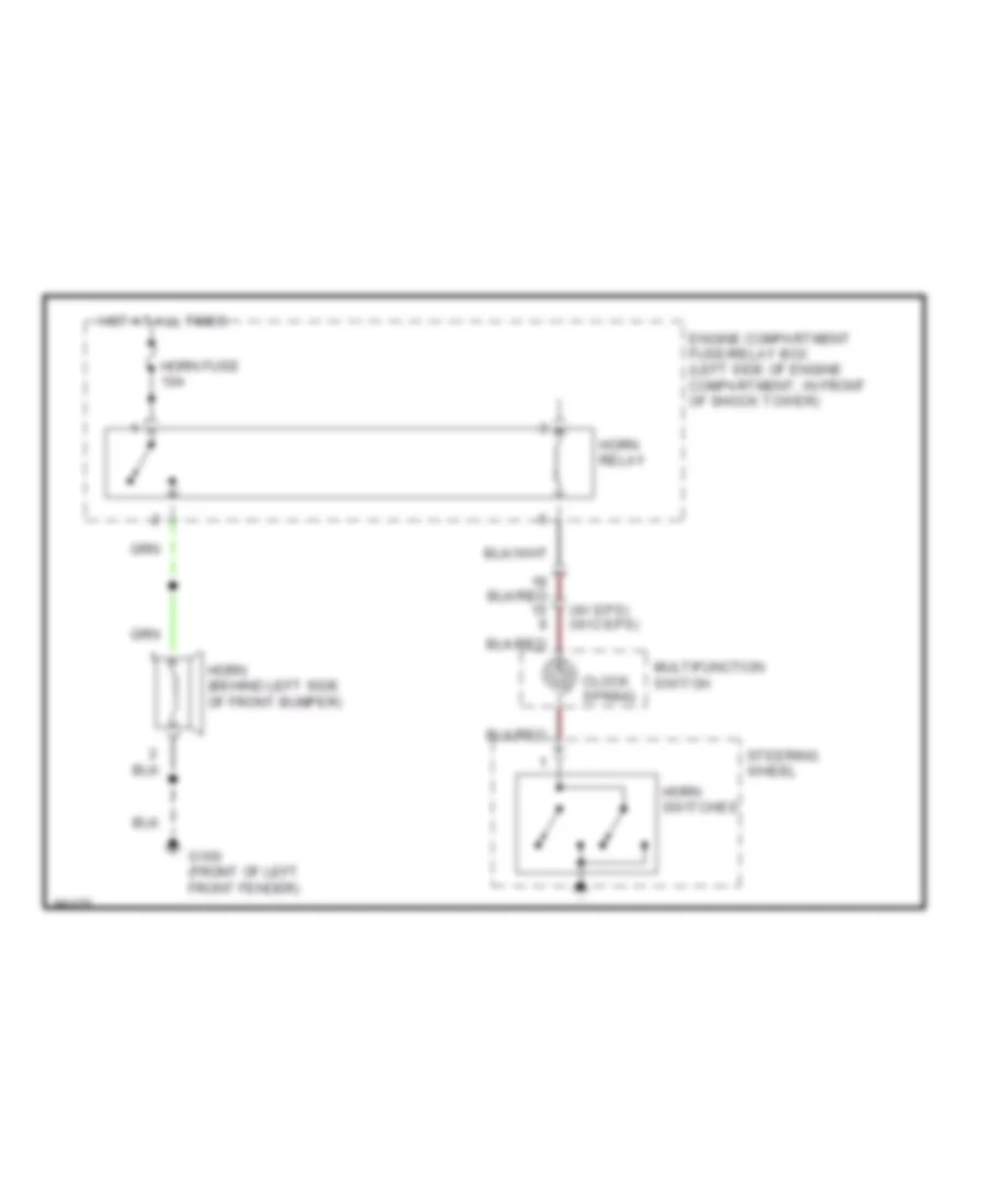
HORN
Horn Wiring Diagram for Hyundai Tiburon 1997
List of elements for Horn Wiring Diagram for Hyundai Tiburon 1997:
- (w/ eps) (w/o eps)
- Clock spring
- Engine compartment fuse/relay box (left side of engine compartment, in front of shock tower)
- G100 (front of left front fender)
- Horn (behind left side of front bumper)
- Horn fuse 10a
- Horn relay
- Horn switches
- Hot at all times
- Multifunction switch
- Steering wheel
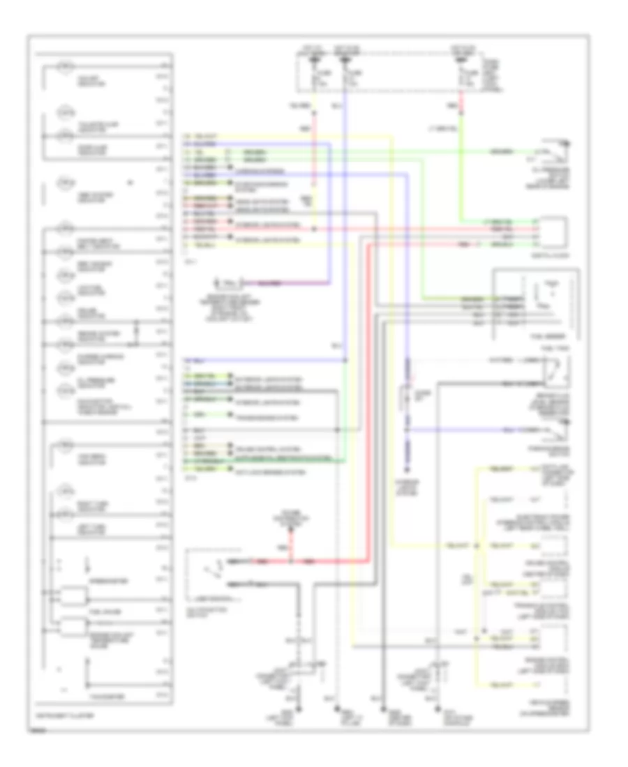
INSTRUMENT CLUSTER
Instrument Cluster Wiring Diagram for Hyundai Tiburon 1997
List of elements for Instrument Cluster Wiring Diagram for Hyundai Tiburon 1997:
- "abs" system indicator
- "brake" system indicator
- "o/d off" indicator
- Anti-lock brakes system
- Brake fluid level sensor (in brake fluid reservoir)
- C11
- C31
- Charge warning indicator
- Cruise control module (center of dash)
- Cruise control system
- Cruise indicator
- Dash fuse box (left kick panel)
- Data link connector (left side of dash)
- Digital clock
- Diode z01
- Door ajar indicator
- Electronic power steering control module (left rear wheel well)
- Engine control module (ecm) (left side of dash)
- Engine coolant temperature gauge
- Engine coolant temperature sender (right front of engine, on coolant outlet)
- Exterior lights system
- Fasten seat belt indicator
- Fuel gauge
- Fuel sender
- Fuel tank
- Fuse 10a
- Fuse 15a
- G131 (on intake manifold)
- G200 (left kick panel)
- G206 (center of dash)
- G904 (left "c" pillar)
- Headlights system
- High beam indicator
- Hot at all times
- Hot in on or acc
- Hot in on or start
- I01-1
- I01-2
- Instrument cluster
- Interior lights system
- Joint connector (left kick panel)
- Left turn indicator
- Light switch
- Low fuel indicator
- M58
- Malfunction indicator lamp (mil) "check engine"
- Multifunction switch
- Nca
- Oil pressure indicator
- Oil pressure switch (lower left rear of engine)
- Parking brake switch
- Power distribution system
- Red
- Right turn indicator
- Speedometer
- Srs "air bag" indicator
- Starting/charging system
- Tachometer
- Tailgate ajar indicator
- Transaxle control module (tcm) (left side of dash)
- Transmissions system
- Vehicle speed sensor (on speedometer)
- Warning systems
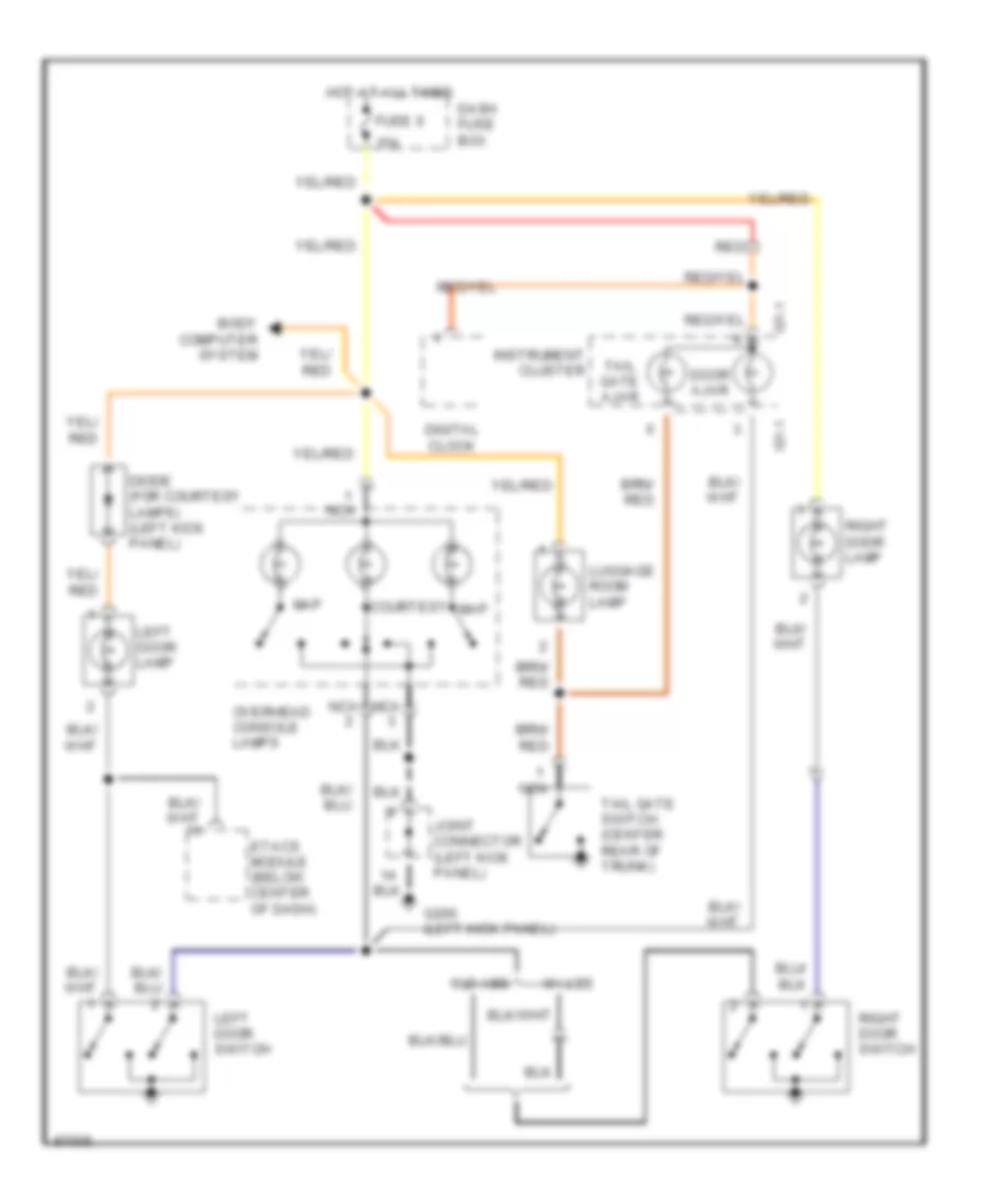
INTERIOR LIGHTS
Courtesy Lamps Wiring Diagram, with Sunroof for Hyundai Tiburon 1997
List of elements for Courtesy Lamps Wiring Diagram, with Sunroof for Hyundai Tiburon 1997:
- 15a
- Body computer system
- Courtesy
- Dash fuse box
- Digital clock
- Diode (for courtesy lamps) (left kick panel)
- Door ajar
- Etacs module (below center of dash)
- Fuse 6
- G200 (left kick panel)
- Hot at all times
- I01-1
- Instrument cluster
- Joint connector (left kick panel)
- Left door lamp
- Left door switch
- Luggage room lamp
- Map
- Nca
- Overhead console lamps
- Red
- Right door lamp
- Right door switch
- Tail gate ajar
- Tail gate switch (center rear of trunk)
- W/ abs
- W/o abs
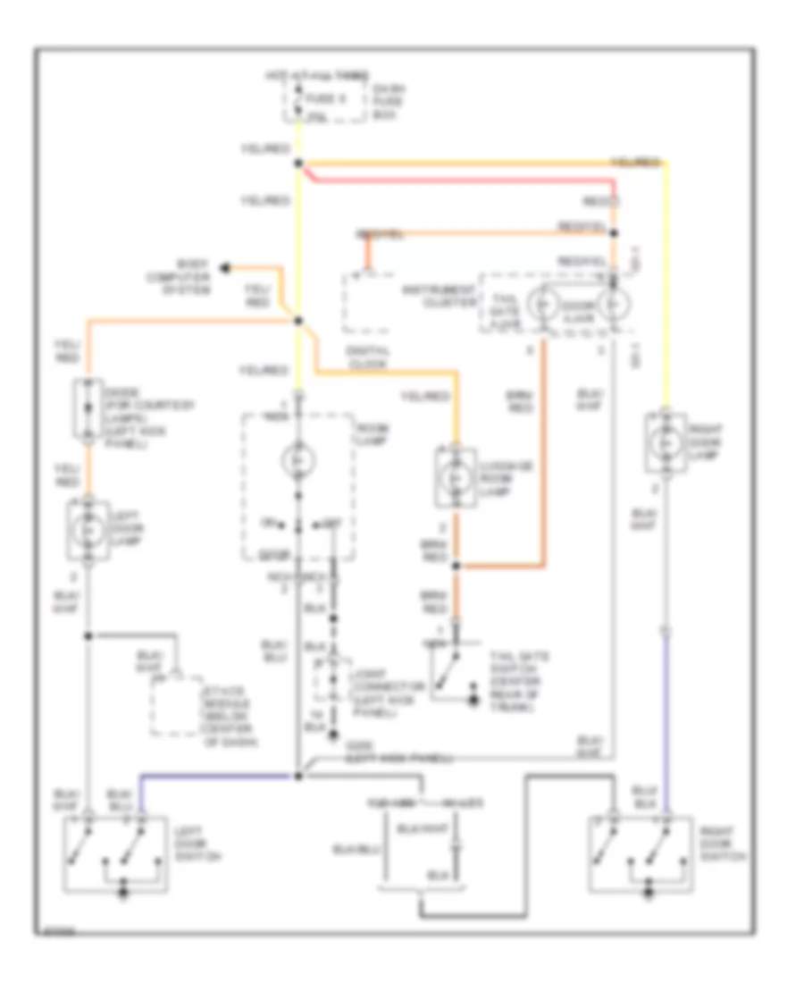
Courtesy Lamps Wiring Diagram, without Sunroof for Hyundai Tiburon 1997
List of elements for Courtesy Lamps Wiring Diagram, without Sunroof for Hyundai Tiburon 1997:
- 15a
- Body computer system
- Dash fuse box
- Digital clock
- Diode (for courtesy lamps) (left kick panel)
- Door
- Door ajar
- Etacs module (below center of dash)
- Fuse 6
- G200 (left kick panel)
- Hot at all times
- I01-1
- Instrument cluster
- Joint connector (left kick panel)
- Left door lamp
- Left door switch
- Luggage room lamp
- Nca
- Off
- Red
- Right door lamp
- Right door switch
- Room lamp
- Tail gate ajar
- Tail gate switch (center rear of trunk)
- W/ abs
- W/o abs
Instrument Illumination Wiring Diagram for Hyundai Tiburon 1997
List of elements for Instrument Illumination Wiring Diagram for Hyundai Tiburon 1997:
- (w/ drl)
- (w/o drl)
- A/c switch
- A/t shift lever
- Blower actuator switch
- Cigarette lighter
- Cruise switch
- Digital clock
- Diode (for drl) (under left side of dash)
- Drl relay
- Engine compartment fuse/relay box
- Front fog lamp switch
- Fusible link f 40a
- G200 (left kick panel)
- G904 (left "c" pillar)
- Hazard switch
- Head
- Hot at all times
- Illumination
- Instrument cluster
- Io1-2
- Joint connector (upper left kick panel)
- Left t/lp fuse 10a
- Light switch
- Multifunction switch
- Nca
- Off
- Park
- Power window main switch
- Radio
- Rear defogger switch
- Rear wiper & washer switch
- Red
- Rheostat
- Right power window switch
- Tail lamp relay
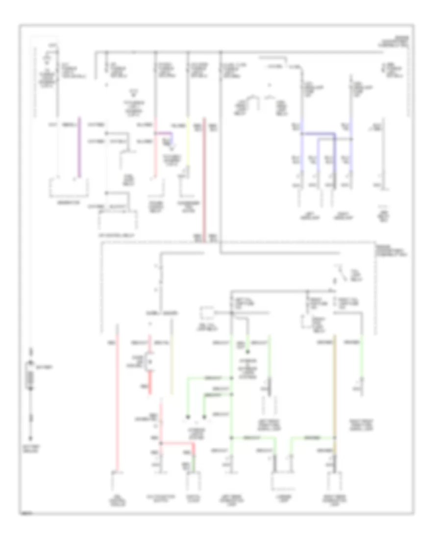
POWER DISTRIBUTION
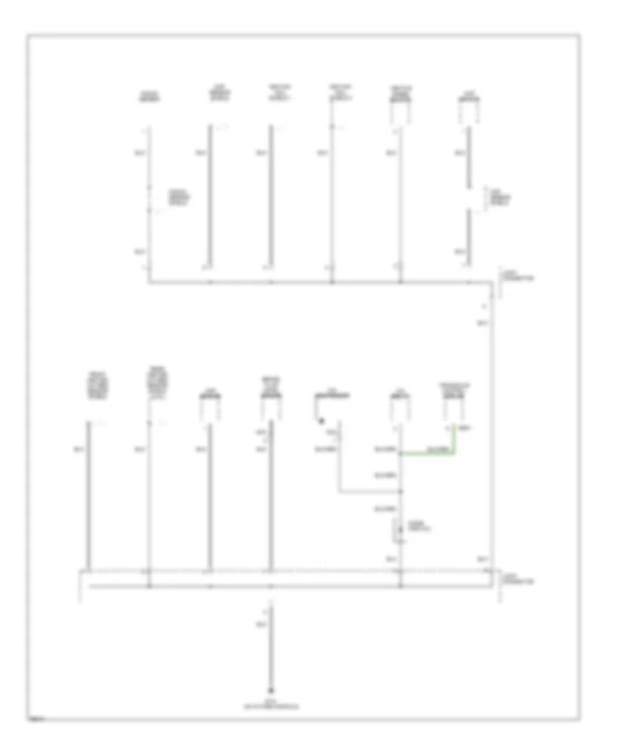
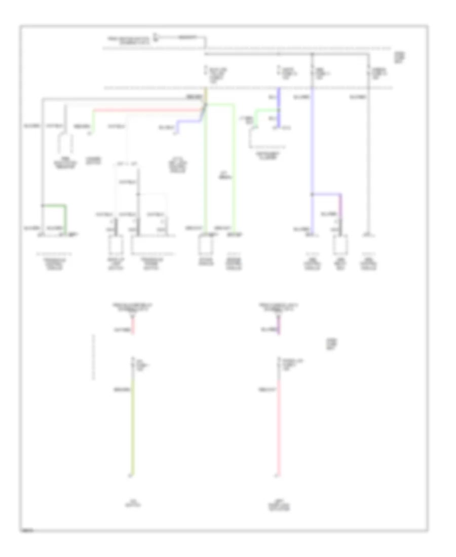
Power Distribution Wiring Diagram (1 of 4) for Hyundai Tiburon 1997
List of elements for Power Distribution Wiring Diagram (1 of 4) for Hyundai Tiburon 1997:
- Abs relay box
- Battery
- Battery ground
- Condenser fan motor
- Digital clock
- Diode z05 (for drl)
- Drl control module
- Drl tail lamp relay
- Engine compartment fuse/relay box
- Front fog fuse 15a
- Front fog lamp relay
- Fuel pump relay
- Generator
- High head- lamp relay
- High headlamp fuse 15a
- Interior & exterior lamps systems
- Interior lights system
- Left front park/turn signal lamp
- Left headlamp
- Left rear combination lamp
- Left tail lamp fuse 10a
- License lamp
- Low head- lamp relay
- Low headlamp fuse 15a
- Mfi control relay
- Multifunction switch
- Nca
- P/wdw fusible link c 30a (pnk)
- Power window relay
- Red
- Right front park/turn signal lamp
- Right headlamp
- Right rear combination lamp
- Right tail lamp fuse 10a
- Tail lamp relay
- To fuse 2 (diagram 4 of 4)
- To fusible link e (diagram 2 of 4)
- To fusible link j (diagram 2 of 4)
- W/ drl
- W/o drl
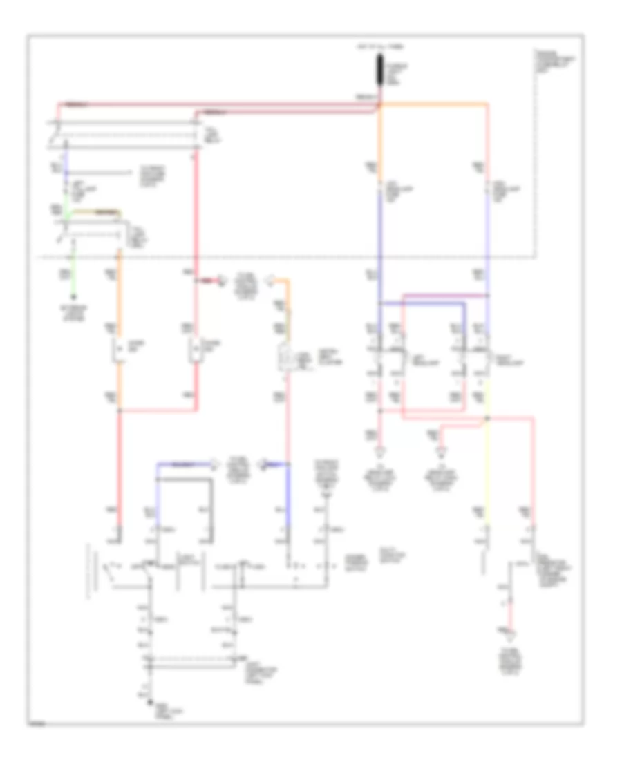
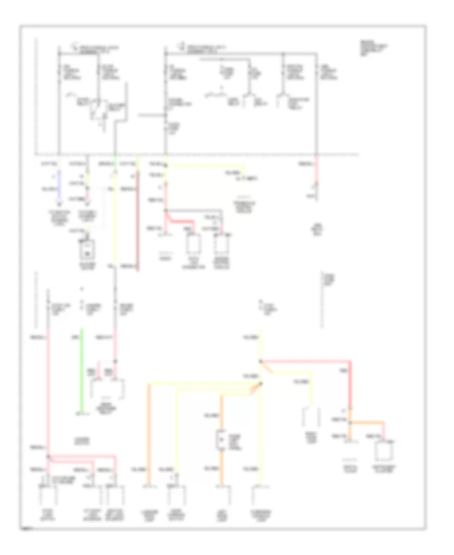
Power Distribution Wiring Diagram (2 of 4) for Hyundai Tiburon 1997
List of elements for Power Distribution Wiring Diagram (2 of 4) for Hyundai Tiburon 1997:
- (w/o cruise) (w/ cruise)
- A/c fuse 10a
- A/c relay
- A/t shift lock solenoid
- Abs fusible link h 30a (pnk)
- Abs relay box
- Audio fuse 10a
- B+ fusible link e 50a (red)
- Blower motor
- Blower relay
- Blwr fusible link k 30a (pnk)
- C01
- Ctsy fuse 6 15a
- Dash fuse box
- Data link connector
- Digital clock
- Diode (left kick panel)
- Door warning switch
- E59-2
- Engine compartment fuse/relay box
- Engine control module
- From fusible link a (diagram 1 of 4)
- From fusible link b (diagram 1 of 4)
- Hazard fuse 4 10a
- Hazard switch
- Horn fuse 10a
- Horn relay
- I01-1
- Ign fusible link j 30a (pnk)
- Ignition key lock solenoid
- Instrument cluster
- Left door lamp
- Luggage room lamp
- Nca
- Overhead console lamp
- Power connector (l)
- Rad fan fusible link g 30a (pnk)
- Radiator fan relay
- Radio
- Rear defogger relay
- Red
- Right door lamp
- Rr def fuse 5 30a
- Start relay
- Stop lamp switch
- Stop lps fuse 3 15a
- To fuse 1 (diagram 4 of 4)
- To ignition switch (diagram 3 of4)
- Transaxle control module
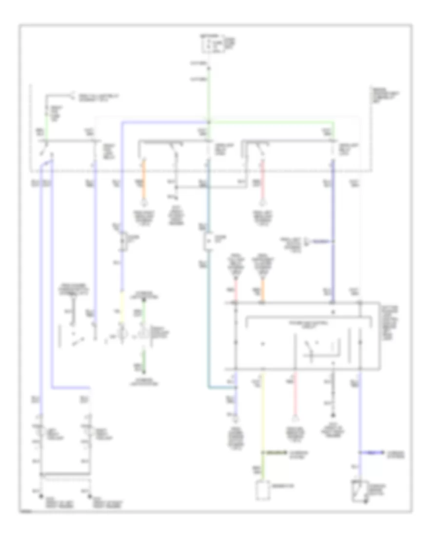
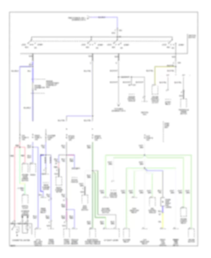
Power Distribution Wiring Diagram (3 of 4) for Hyundai Tiburon 1997
List of elements for Power Distribution Wiring Diagram (3 of 4) for Hyundai Tiburon 1997:
- (diagram 2 of 4)
- A/t
- A/t & key lock control module
- A/t shift lever
- Acc
- Blower actuator switch
- Blower relay
- C01
- Cig fuse 13 15a
- Cigarette lighter
- Cruise control module
- Cruise control module (w/ a/t)
- Cruise switch
- Dash fuse box
- Digital clock
- Diode (for front fog lamps)
- Drl control module
- Electronic power steering control module
- Engine compartment fuse/relay box
- Engine control module
- Etacs fuse 8 15a
- Etacs module
- From fusible link j e
- Front fog lamp switch
- Front front front fog fog fog lamp relay
- Front washer motor
- Front wiper motor
- H/lp fuse 16 10a
- High headlamp relay
- Ignition coil
- Ignition switch
- Interior lights system
- Lock
- Low headlamp relay
- M/t
- M24
- M38-3
- Nca
- Power connector (m)
- Power door mirror switch
- Power window relay
- Radio
- Radio fuse 14 10a
- Rear washer motor
- Rear wiper motor
- Rear wiper relay
- Red
- S/roof fuse 15 10a
- Start
- Start relay
- Sun roof switch
- To fuse 9 (diagram 4 of 4)
- Transaxle range switch
- Vehicle speed sensor
- W/wiper fuse 7 15a
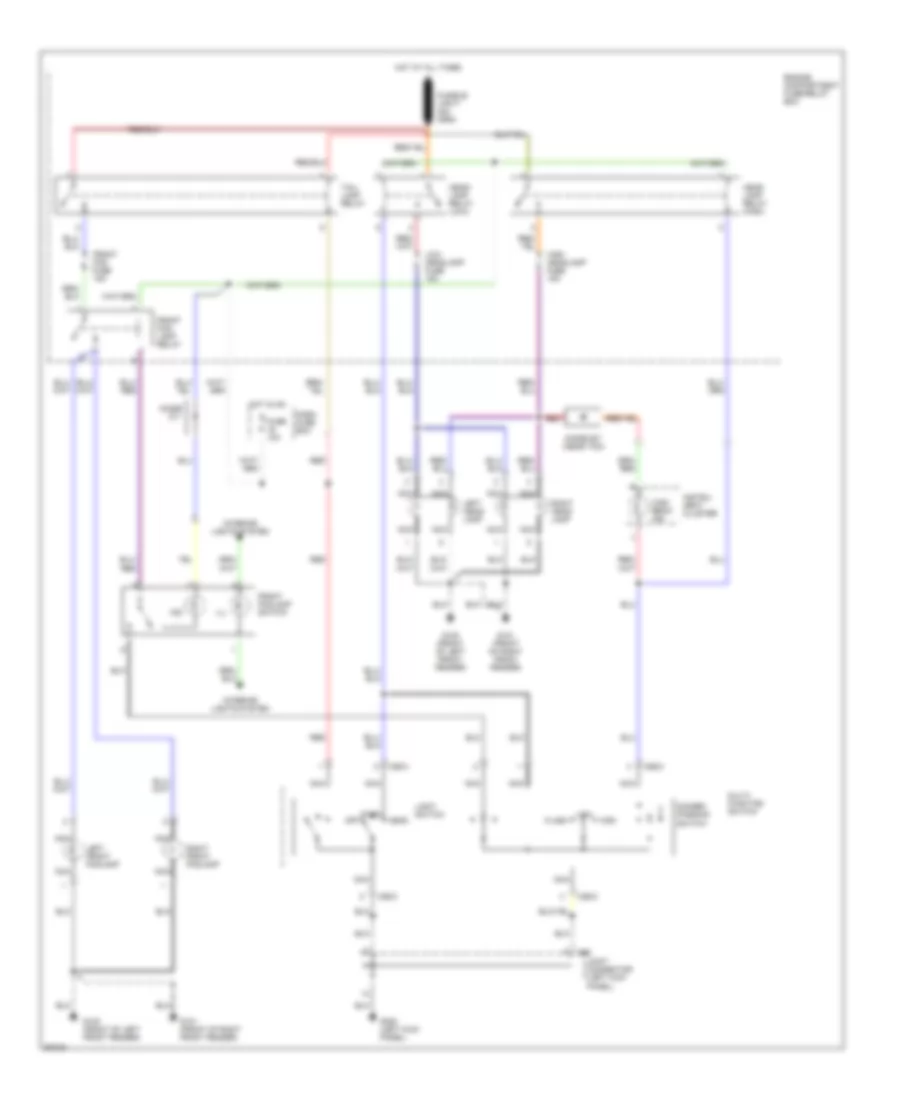
Power Distribution Wiring Diagram (4 of 4) for Hyundai Tiburon 1997
List of elements for Power Distribution Wiring Diagram (4 of 4) for Hyundai Tiburon 1997:
- A/c fuse 1 10a
- A/c switch
- A/t
- A/t & key lock control module
- Abs control module
- Abs fuse 11 10a
- Abs relay box
- Airbag fuse 12 15a
- B/up lps, t/s lps fuse 9 10a
- Back up lamp switch
- C01
- Dash fuse box
- E59-1
- Engine control module
- Etacs module
- From blower relay (diagram 2 of 4)
- From fusible link c (diagram 1 of 4)
- From ignition switch (diagram 3 of 4)
- Hazard switch
- I01-2
- Instr fuse 10 10a
- Instrument cluster
- Left door lock actuator
- M/t
- M/t only
- M38-3
- Nca
- Pre- excitation resistor
- Pwr/d lck fuse 2 15a
- Srs control module
- Transaxle control module
- Transaxle range switch
POWER DOOR LOCKS
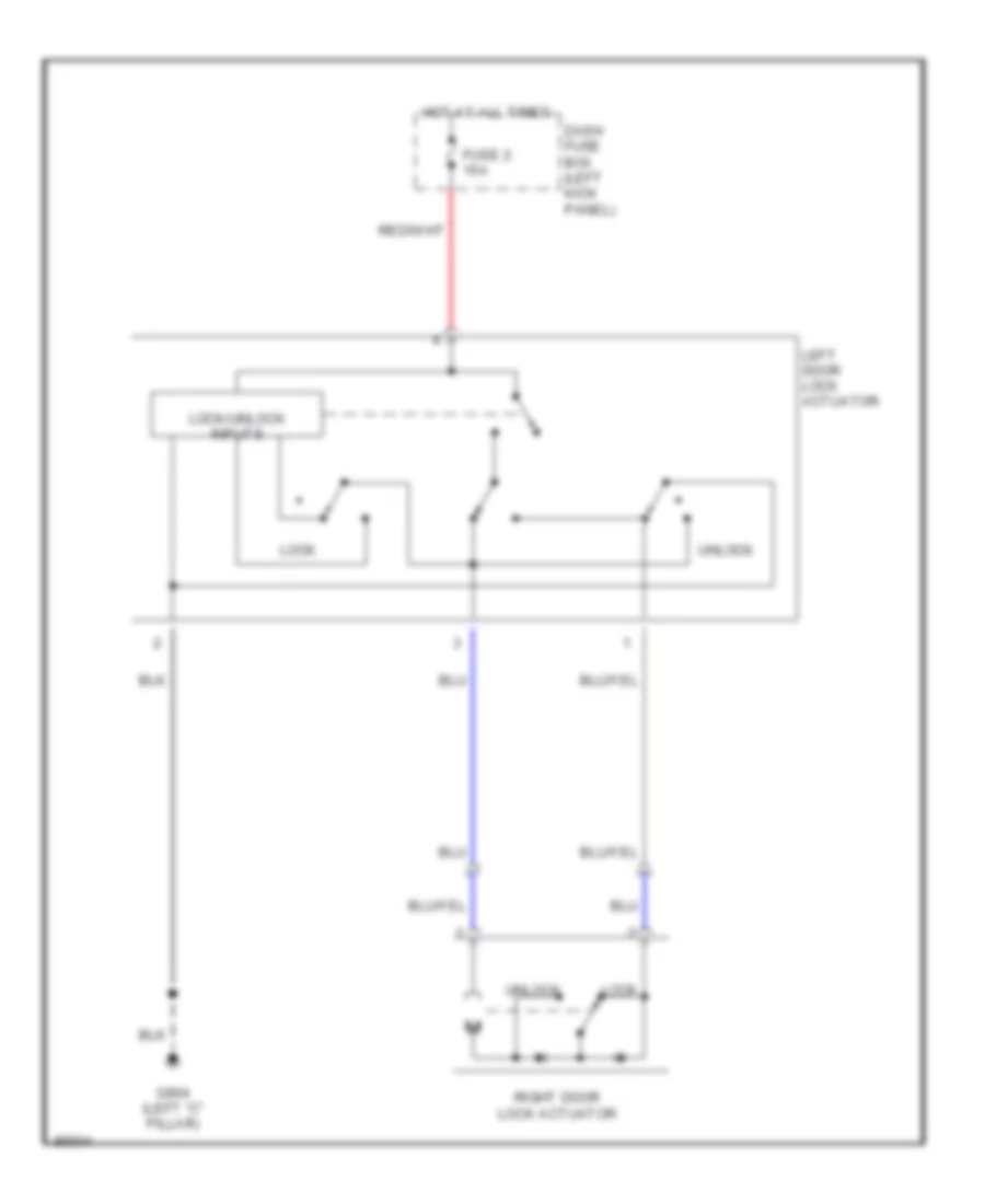
Power Door Lock Wiring Diagram for Hyundai Tiburon 1997
List of elements for Power Door Lock Wiring Diagram for Hyundai Tiburon 1997:
- Dash fuse box (left kick panel)
- Fuse 2 15a
- G904 (left "c" pillar)
- Hot at all times
- Left door lock actuator
- Lock
- Lock/unlock inputs
- Right door lock actuator
- Unlock
POWER MIRRORS
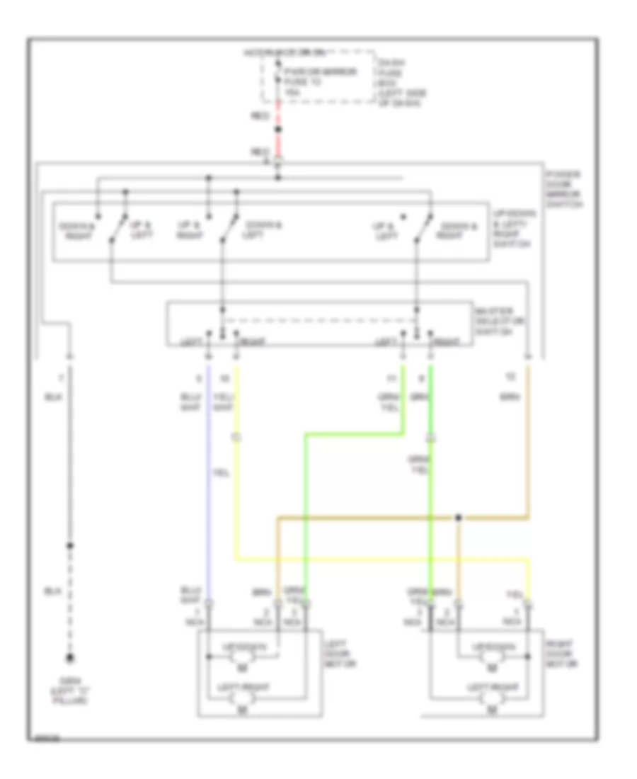
Power Mirror Wiring Diagram for Hyundai Tiburon 1997
List of elements for Power Mirror Wiring Diagram for Hyundai Tiburon 1997:
- Dash fuse box (left side of dash)
- Down &
- Down & right
- G904 (left "c" pillar)
- Hot in acc or on
- Left
- Left door motor
- Left/right
- Master selector switch
- Nca
- Power door mirror switch
- Pwr dr mirror fuse 13 15a
- Red
- Right
- Right door motor
- Up &
- Up & left
- Up/down
- Up/down & left/ right switch
POWER TOP/SUNROOF
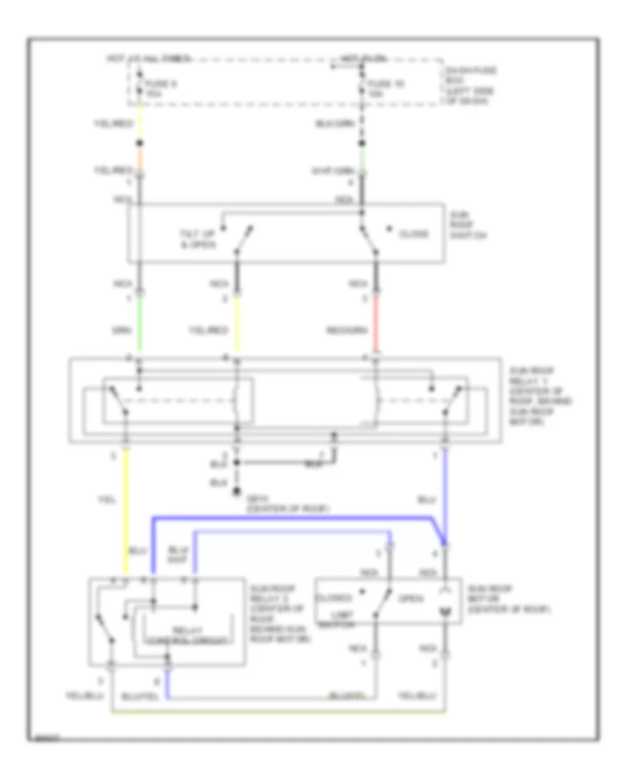
Sunroof Wiring Diagram for Hyundai Tiburon 1997
List of elements for Sunroof Wiring Diagram for Hyundai Tiburon 1997:
- Close
- Closed
- Dash fuse box (left side of dash)
- Fuse 15 10a
- Fuse 6 15a
- G910 (center of roof)
- Hot at all times
- Hot in on
- Limit switch
- Nca
- Open
- Relay control circuit
- Sun roof motor (center of roof)
- Sun roof relay 1 (center of roof, behind sun roof motor)
- Sun roof relay 2 (center of roof, behind sun roof motor)
- Sun roof switch
- Tilt up & open
POWER WINDOWS
Power Window Wiring Diagram for Hyundai Tiburon 1997
List of elements for Power Window Wiring Diagram for Hyundai Tiburon 1997:
- Control unit
- Dash fuse box (left kick panel)
- Down
- Engine compartment relay box (left side of engine compt)
- Fuse 16 10a
- Fusible link c 30a (pnk)
- G200 (left kick panel)
- G904 (left "c" pillar)
- Hot at all times
- Hot in on
- Interior lights system
- Joint connector (left kick panel)
- Left power window motor
- Left power window switch
- Lock
- Lock switch
- M58
- Nca
- Off
- Passenger compartment relay box (behind left side of dash, left of steering column)
- Power window main switch
- Power window relay
- Right power window motor
- Right power window switch
- Un- lock
RADIO
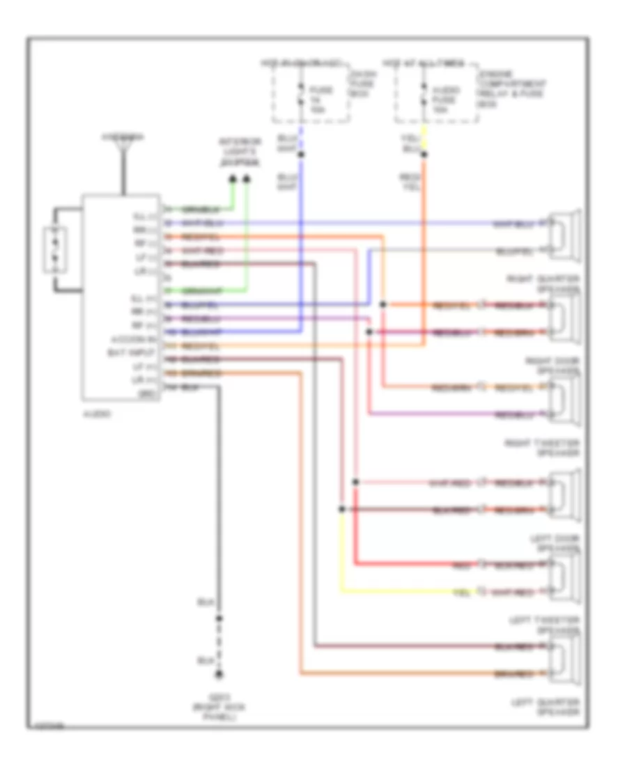
Radio Wiring Diagrams for Hyundai Tiburon 1997
List of elements for Radio Wiring Diagrams for Hyundai Tiburon 1997:
- Acc/on in
- Antenna
- Audio
- Audio fuse 10a
- Bat input
- Dash fuse box
- Engine compartment relay & fuse box
- Fuse 10a
- G203 (right kick panel)
- Grd
- Hot at all times
- Hot in on or acc
- Ill (+)
- Ill (-)
- Interior lights system
- Left door speaker
- Left quarter speaker
- Left tweeter speaker
- Lf (+)
- Lf (-)
- Lr (+)
- Lr (-)
- Red
- Rf (+)
- Rf (-)
- Right door speaker
- Right quarter speaker
- Right tweeter speaker
- Rr (+)
- Rr (-)
SHIFT INTERLOCKS
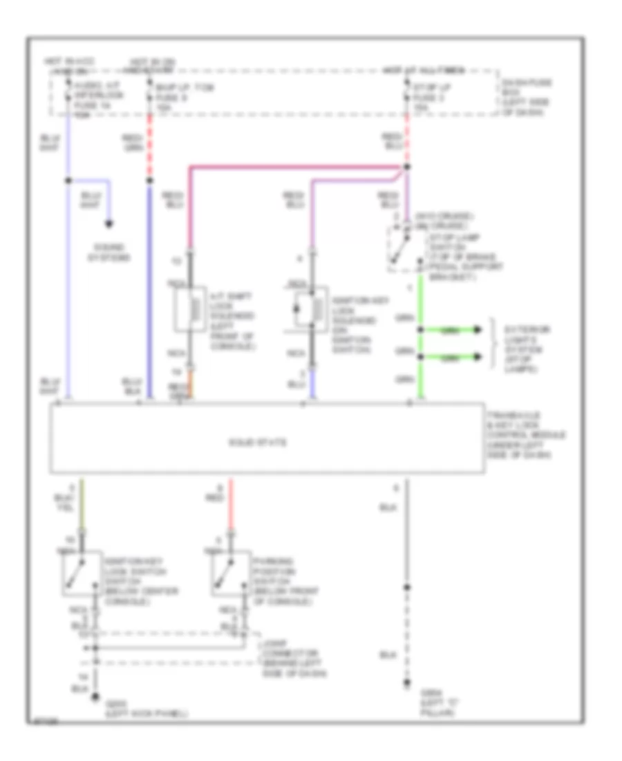
Shift Interlock Wiring Diagram for Hyundai Tiburon 1997
List of elements for Shift Interlock Wiring Diagram for Hyundai Tiburon 1997:
- (w/o cruise) (w/ cruise)
- A/t shift lock solenoid (left front of console)
- And on
- Audio, a/t interlock fuse 14 10a
- B/up lp, tcm fuse 9 10a
- Dash fuse box (left side of dash)
- Exterior lights system (stop lamps)
- G200 (left kick panel)
- G904 (left "c" pillar)
- Hot at all times
- Hot in acc
- Hot in on and start
- Ignition key lock solenoid (on ignition switch)
- Ignition key lock switch switch (below center console)
- Joint connector (behind left side of dash)
- Nca
- Parking position switch (below front of console)
- Red
- Solid state
- Sound systems
- Stop lamp switch (top of brake pedal support bracket)
- Stop lp fuse 3 15a
- Transaxle & key lock control module (under left side of dash)
STARTING/CHARGING
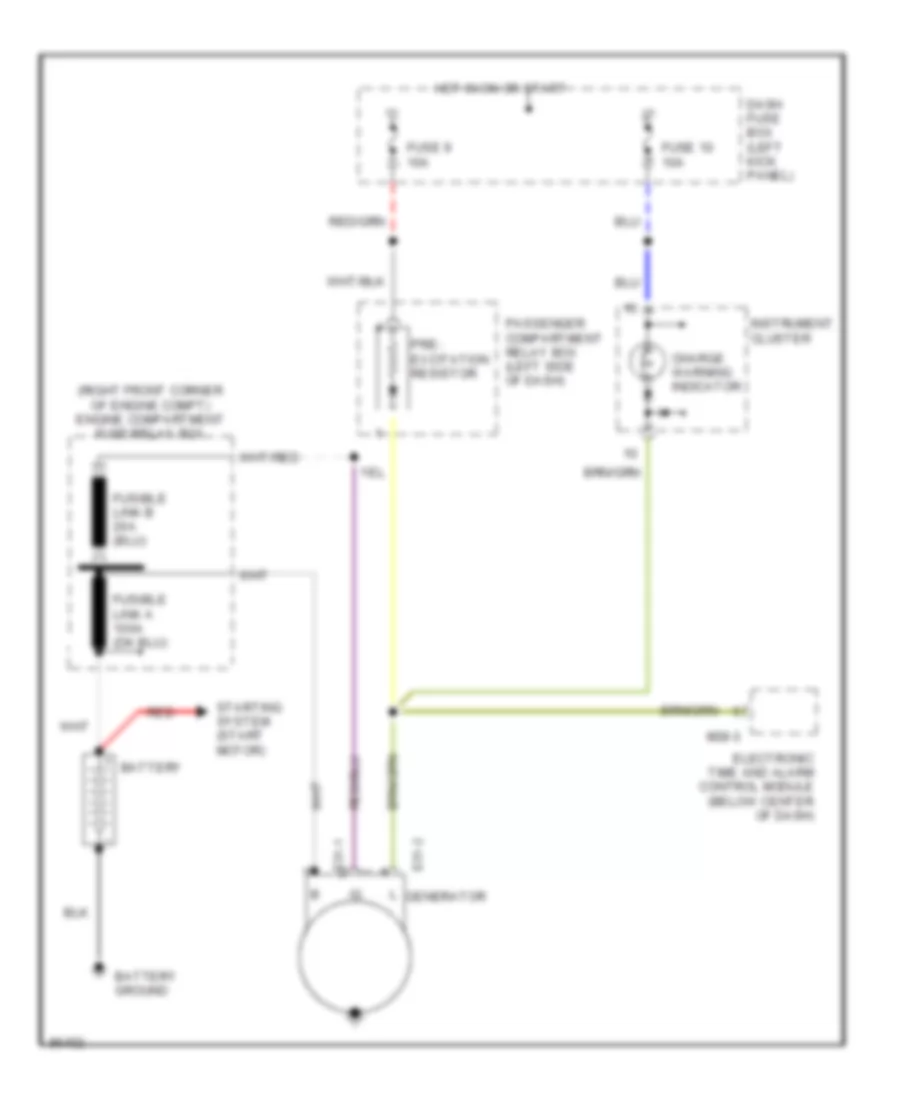
Charging Wiring Diagram for Hyundai Tiburon 1997
List of elements for Charging Wiring Diagram for Hyundai Tiburon 1997:
- (right front corner of engine compt) engine compartment fuse/relay box
- Battery
- Battery ground
- Charge warning indicator
- Dash fuse box (left kick panel)
- E31-1
- E31-2
- Electronic time and alarm control module (below center of dash)
- Fuse 10 10a
- Fuse 9 10a
- Generator
- Hot in on or start
- Instrument cluster
- M38-3
- Passenger compartment relay box (left side of dash)
- Pre- excitation resistor
- Red
- Starting system (start motor)
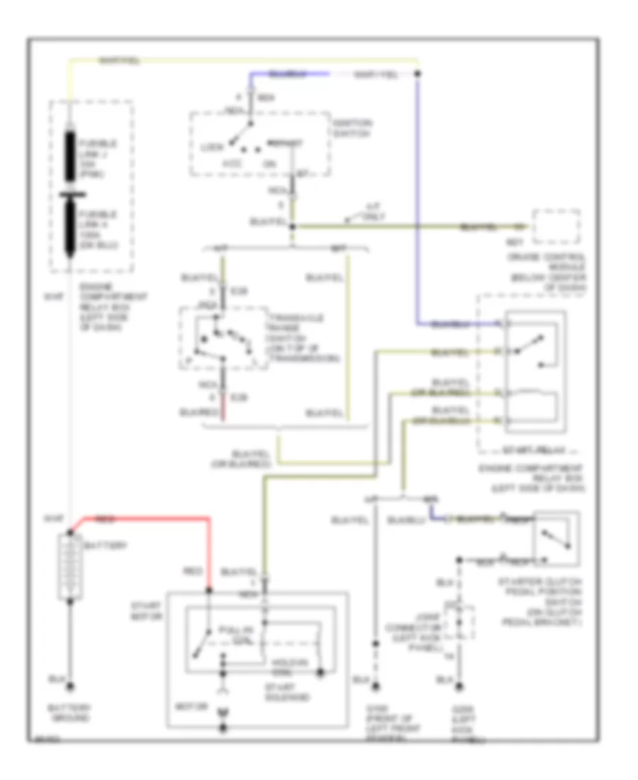
Starting Wiring Diagram for Hyundai Tiburon 1997
List of elements for Starting Wiring Diagram for Hyundai Tiburon 1997:
- A/t
- A/t only
- Acc
- Battery
- Battery ground
- Cruise control module (below center of dash)
- E28
- Engine compartment relay box (left side of dash)
- Fusible link j 30a (pnk)
- G100 (front of left front fender)
- G200 (left kick panel)
- Hold-in coil
- Ignition switch
- Joint connector (left kick panel)
- Lock
- M/t
- M21
- M24
- Motor
- N d
- Nca
- Pull-in coil
- Red
- Start
- Start motor
- Start relay
- Start solenoid
- Starter clutch pedal position switch (on clutch pedal bracket)
- Transaxle range switch (on top of transmission)
SUPPLEMENTAL RESTRAINTS
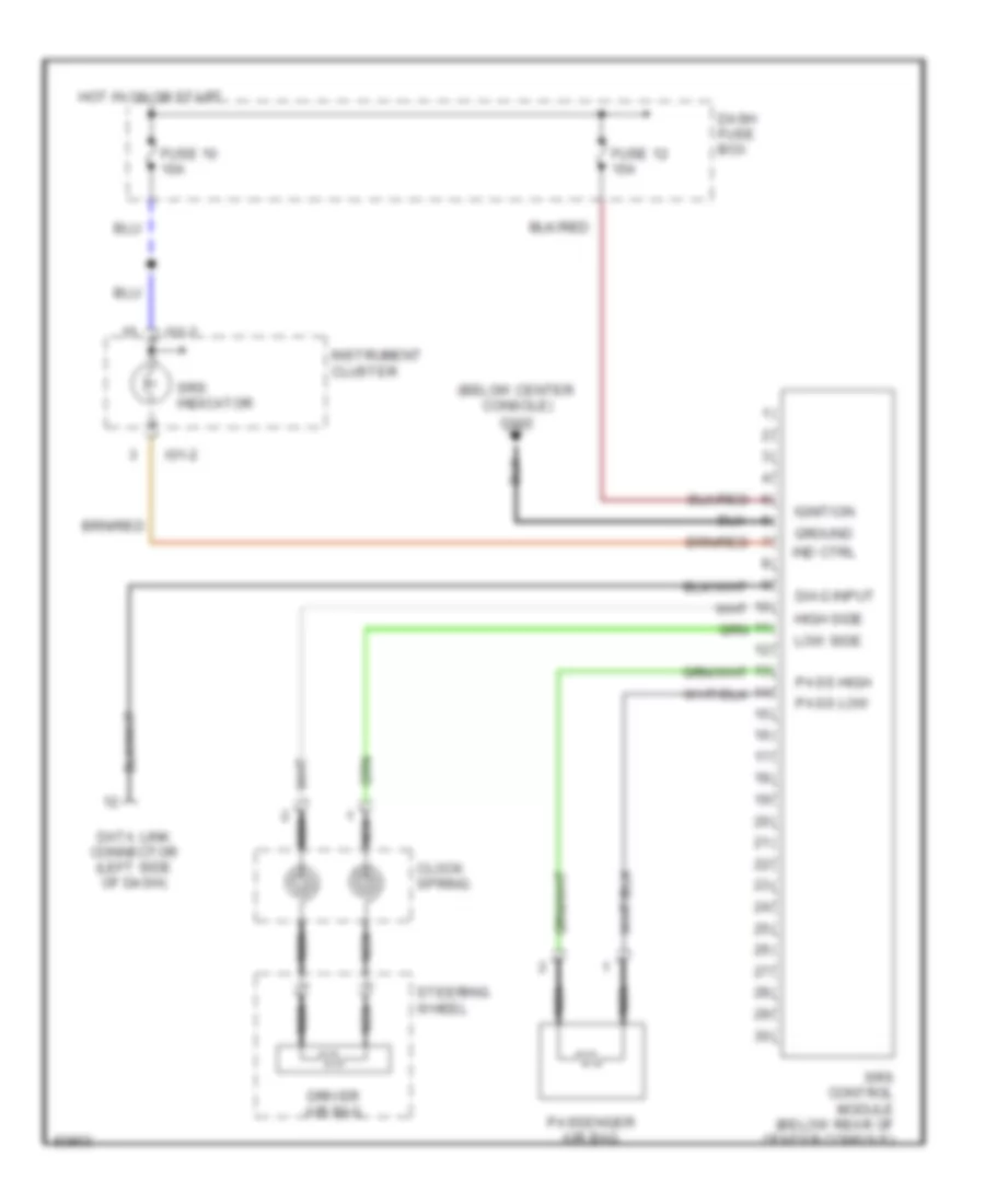
Supplemental Restraint Wiring Diagram for Hyundai Tiburon 1997
List of elements for Supplemental Restraint Wiring Diagram for Hyundai Tiburon 1997:
- (below center
- Clock spring
- Console)
- Dash fuse box
- Data link connector (left side of dash)
- Diag input
- Driver air bag
- Fuse 10 10a
- Fuse 12 15a
- G302
- Ground
- High side
- Hot in on or start
- I01-2
- Ignition
- Ind ctrl
- Instrument cluster
- Low side
- Nca
- Pass high
- Pass low
- Passenger air bag
- Srs control module (below rear of center console)
- Srs indicator
- Steering wheel
TRANSMISSION
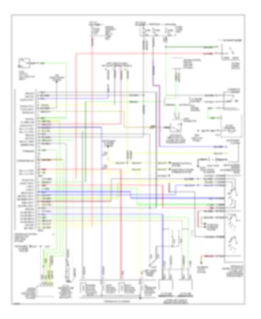
A/T Wiring Diagram for Hyundai Tiburon 1997
List of elements for A/T Wiring Diagram for Hyundai Tiburon 1997:
- a/t pulse generator a
- a/t pulse generator b
- (center of dash)
- (left inner fender panel)
- (left kick panel)
- (left side of dash) data link connector (dlc)
- (lower left side of engine compartment)
- 101-2
- 2 input
- A/c on input
- A/t shift lever
- Air conditioning system
- Audio fuse 10a
- Battery
- Cruise control module
- Damper clutch control solenoid valve
- Dash fuse box
- Diag output
- Drive input
- E59-1
- E59-2
- Econ
- Electronic power steering system
- Eng rpm input
- Engine compart- ment relay/ fuse box
- Engine control module (ecm) (left side of dash)
- Engine controls system
- Exterior lights system
- Fuse 10a
- Fuse 15a
- G100
- G119 (right front
- G200
- Ground
- High oil temp
- Hot at all times
- Hot in on
- Hot in on or start
- Idle sw
- Idle switch (on throttle body)
- Ignition
- Instrument cluster
- Instrument cluster system
- Joint conn
- Joint connector
- Kick down servo switch (lower left side of engine compt)
- Kickdn sw
- L input
- Mil req line
- Nca
- Nca a/t oil temperature sensor (lower left front of eng compt)
- Neutral input
- Norm
- O/d off indicator
- O/d sw input
- Of engine)
- Off
- Oil pressure control solenoid valve
- Overdrive switch
- P-n switch
- Park input
- Power/ normal switch
- Pulse gen a
- Pulse gen b
- Red
- Reverse input
- Sensor gnd
- Shift control solenoid valve a
- Shift control solenoid valve b
- Sol vlv ctrl
- Starting/ charging system
- Torque red sig
- Tp sensor
- Transaxle control module (tcm) (left side of dash)
- Transaxle range (tr) switch
- Transaxle valve body
- Veh spd
- Vehicle speed sensor (on speedometer head)
- W/ cruise control
WARNING SYSTEMS
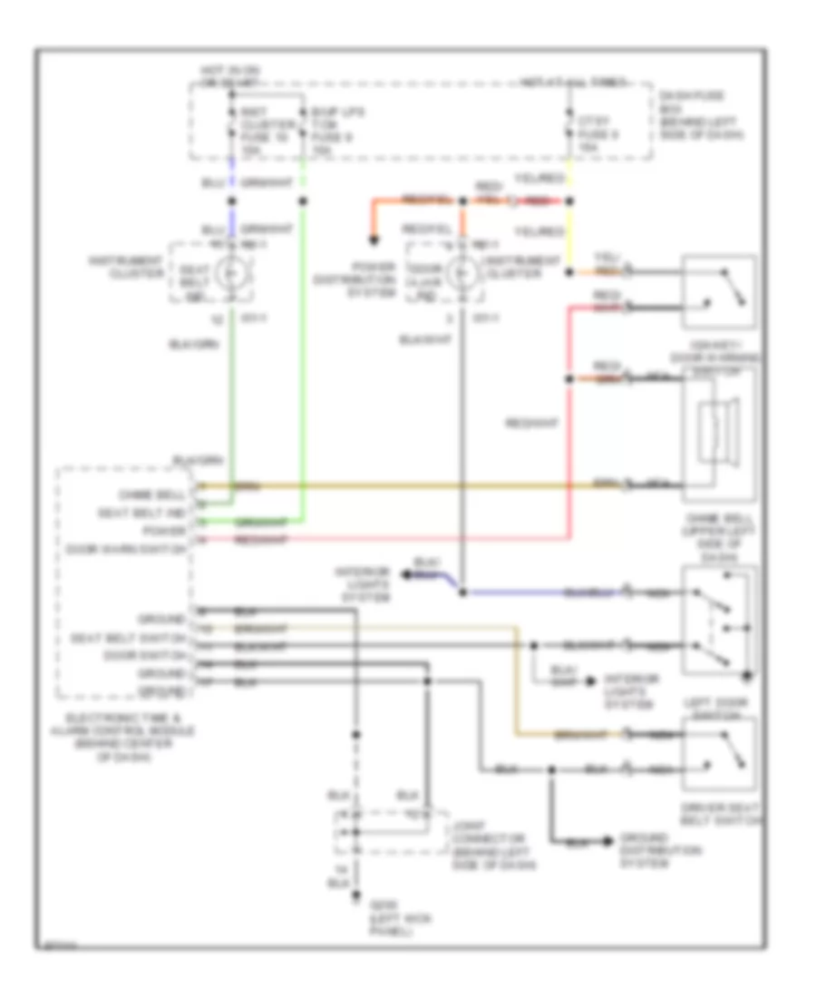
Warning System Wiring Diagrams for Hyundai Tiburon 1997
List of elements for Warning System Wiring Diagrams for Hyundai Tiburon 1997:
- B/up lps tcm fuse 9 10a
- Chime bell
- Chime bell (upper left side of dash)
- Ctsy fuse 6 15a
- Dash fuse box (behind left side of dash)
- Door ajar ind
- Door switch
- Door warn switch
- Driver seat belt switch
- Electronic time & alarm control module (behind center of dash)
- G200 (left kick panel)
- Ground
- Ground distribution system
- Hot at all times
- Hot in on or start
- I01-1
- Ign key/ door warning switch
- Inst cluster fuse 10 10a
- Instrument cluster
- Interior lights system
- Joint connector (behind left side of dash)
- Left door switch
- Nca
- Power
- Power distribution system
- Red
- Seat belt ind
- Seat belt switch
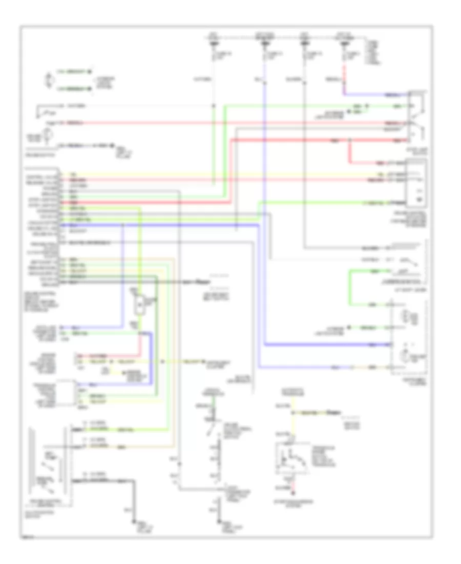
WIPER/WASHER
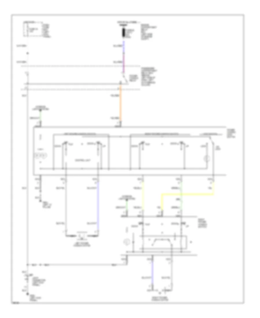
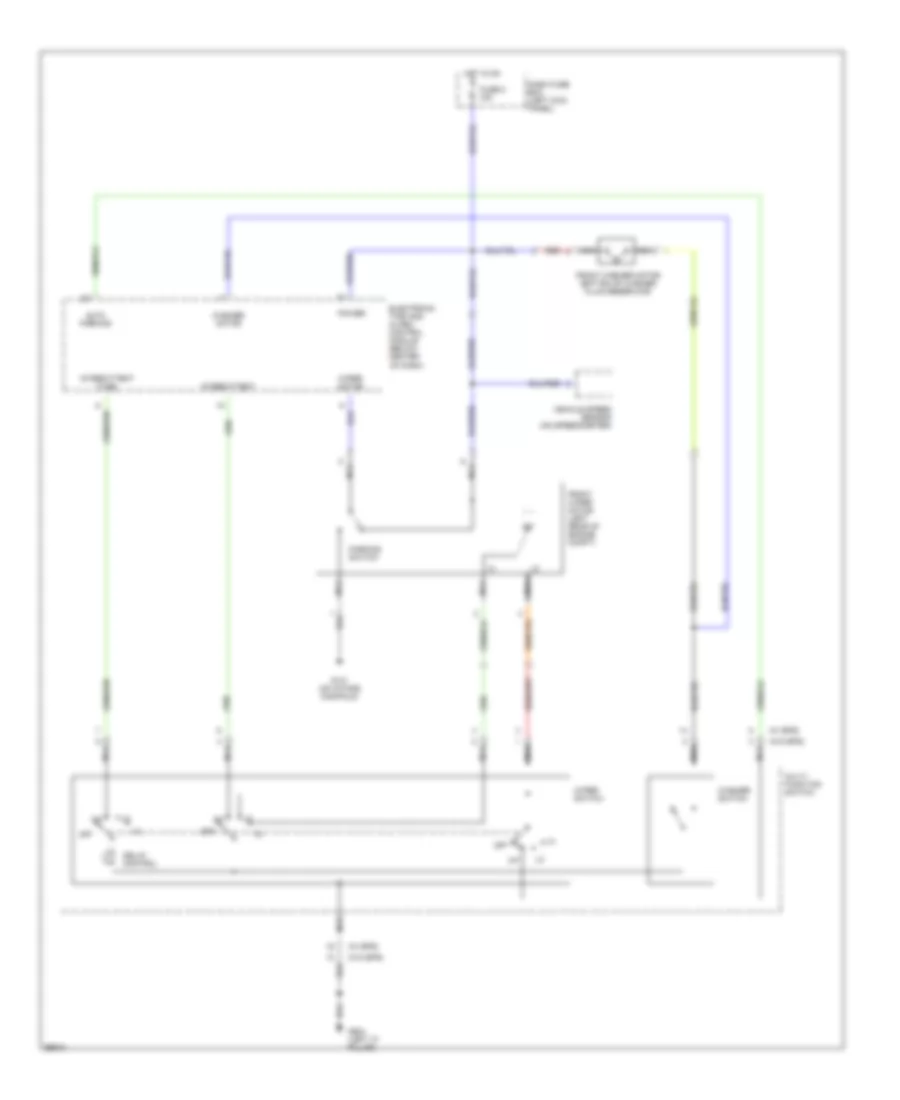
Front Wiper/Washer Wiring Diagram for Hyundai Tiburon 1997
List of elements for Front Wiper/Washer Wiring Diagram for Hyundai Tiburon 1997:
- (w/ eps)
- (w/o eps)
- Auto parking
- Dash fuse box (left kick panel)
- Delay control
- Electronic time and alarm control module (below center of dash)
- Front washer motor (bottom of washer fluid reservoir)
- Front wiper motor (left rear of engine compt)
- Fuse 8 15a
- G131 (on intake manifold)
- G904 (left "c" pillar)
- Hot in on
- Int
- Intermittent
- Intermittent (time)
- Multi- function switch
- Nca
- Off
- Parking switch
- Power
- Red
- Vehicle speed sensor (on speedometer)
- Washer motor
- Washer switch
- Wiper motor
- Wiper switch
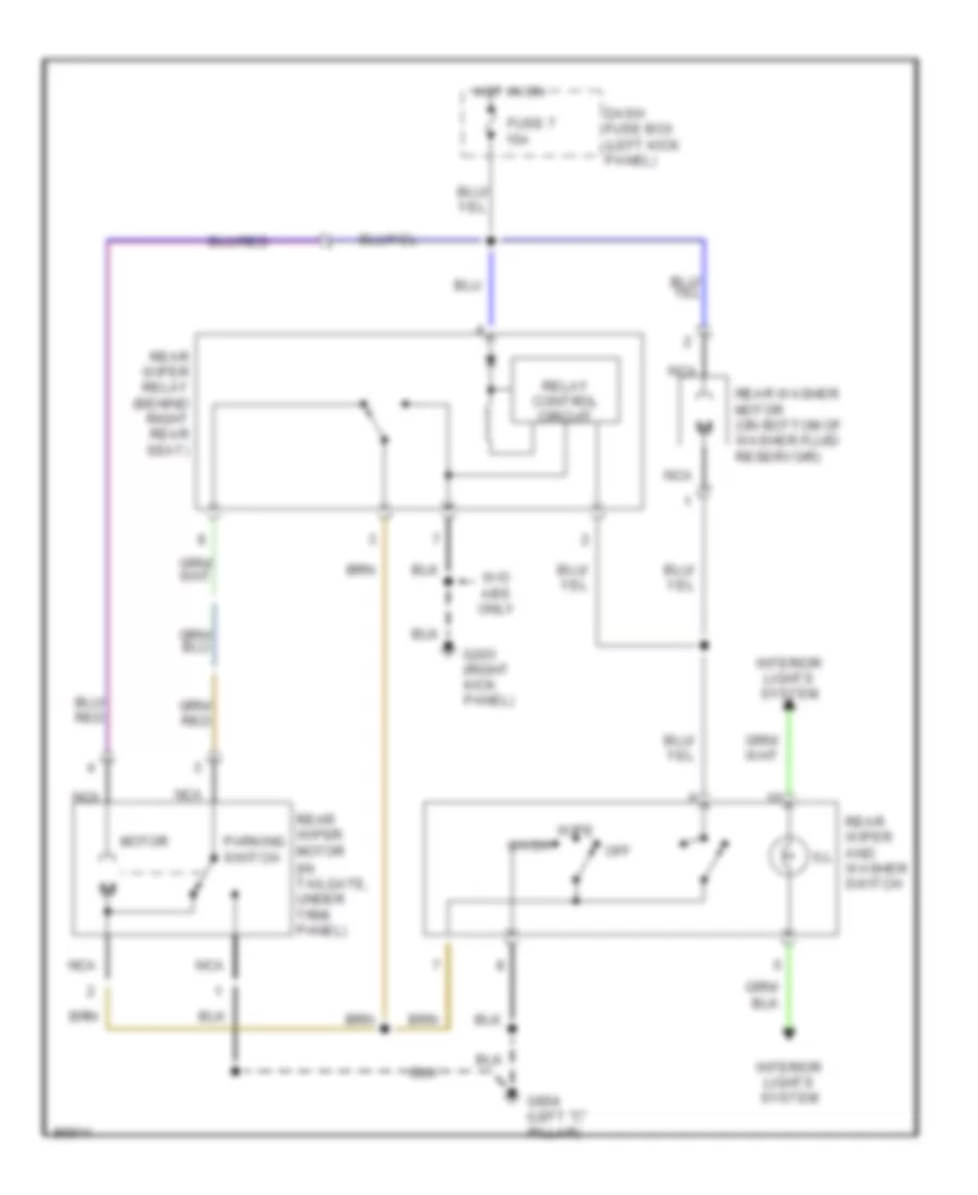
Rear Wiper/Washer Wiring Diagram for Hyundai Tiburon 1997
List of elements for Rear Wiper/Washer Wiring Diagram for Hyundai Tiburon 1997:
- (in tailgate, under trim panel)
- Dash fuse box (left kick panel)
- Fuse 7 15a
- G203 (right kick panel)
- G904 (left "c" pillar)
- Hot in on
- Ill
- Interior lights system
- Motor
- Nca
- Off
- Parking switch
- Rear washer motor (on bottom of washer fluid reservoir)
- Rear wiper and washer switch
- Rear wiper motor
- Rear wiper relay (behind right rear seat)
- Relay control circuit
- W/o abs only
- Wash
- Wipe