AIR CONDITIONING
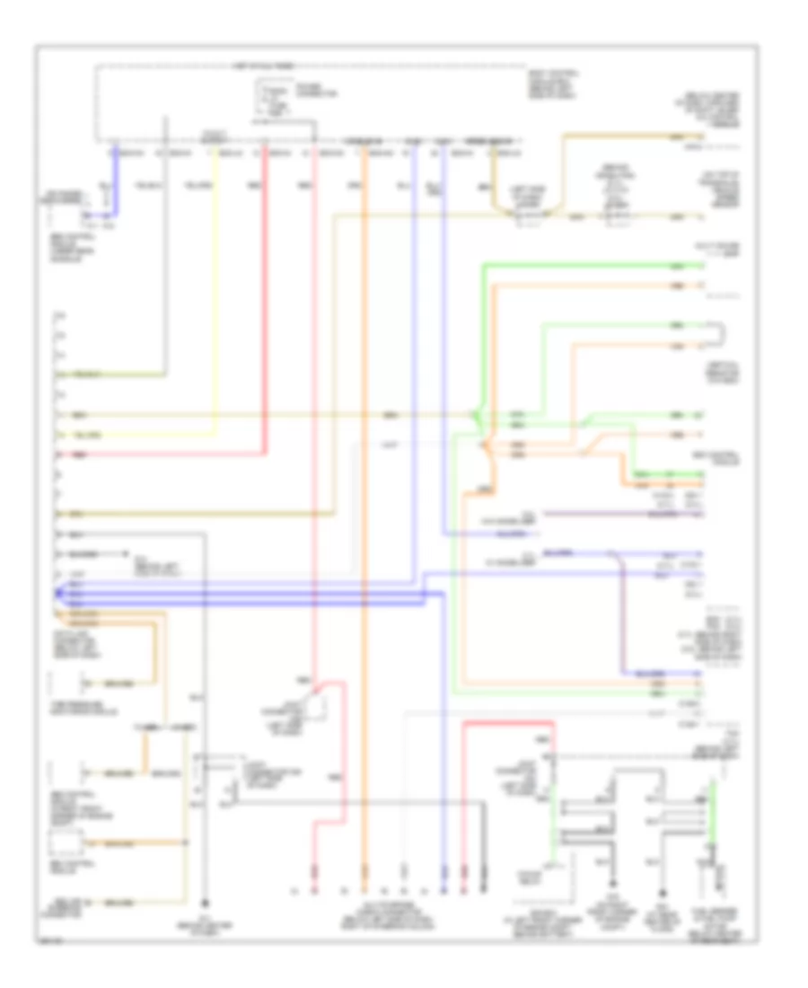
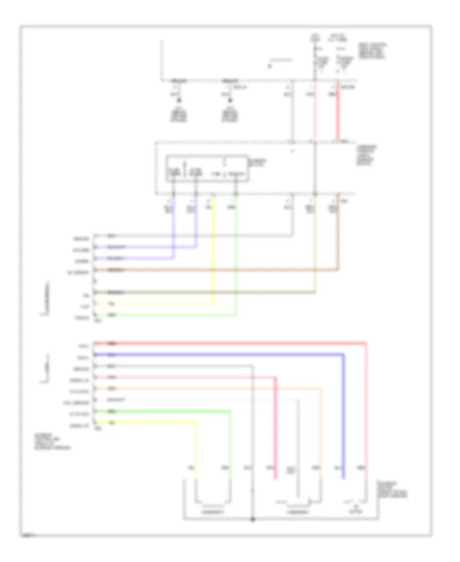
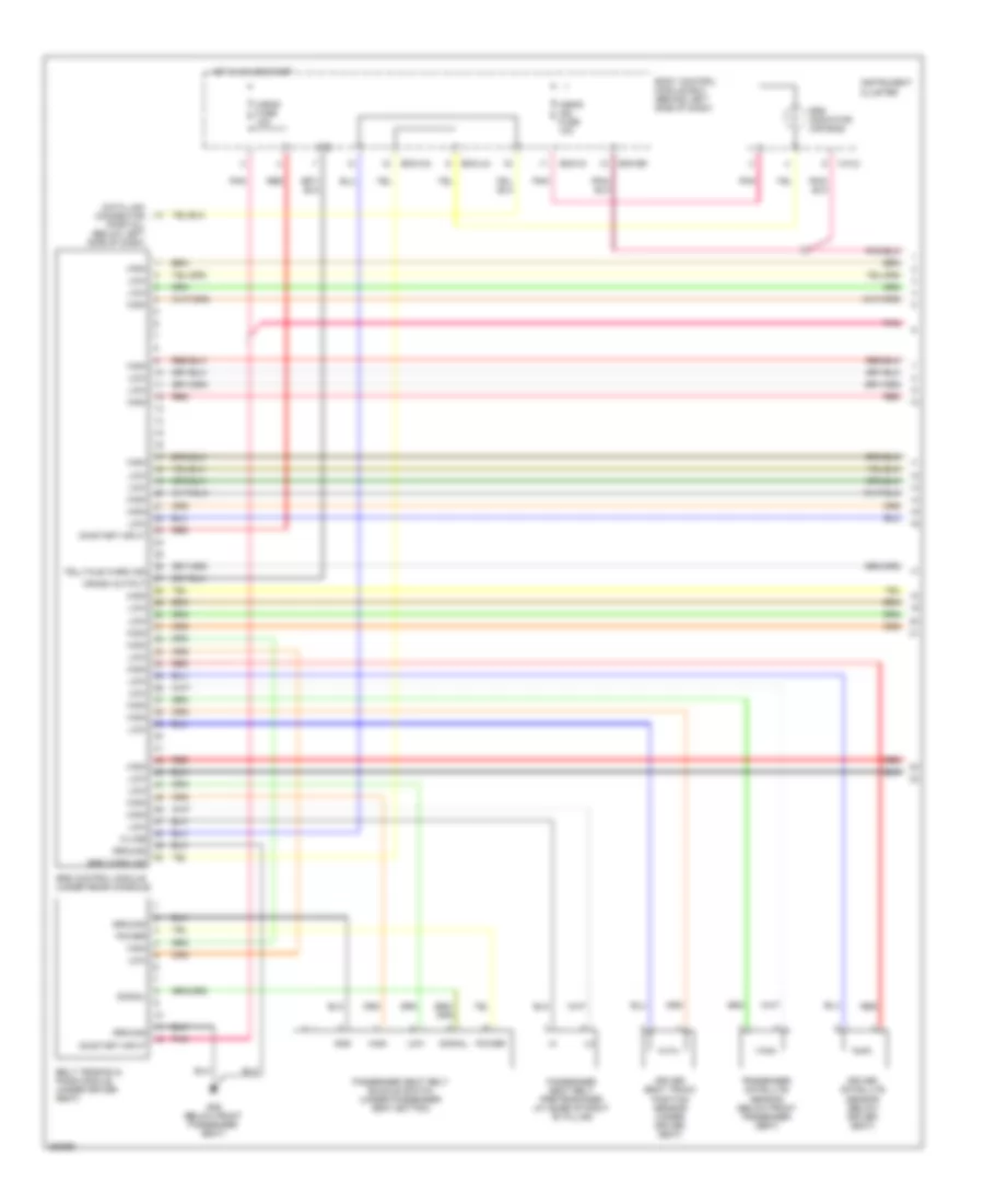
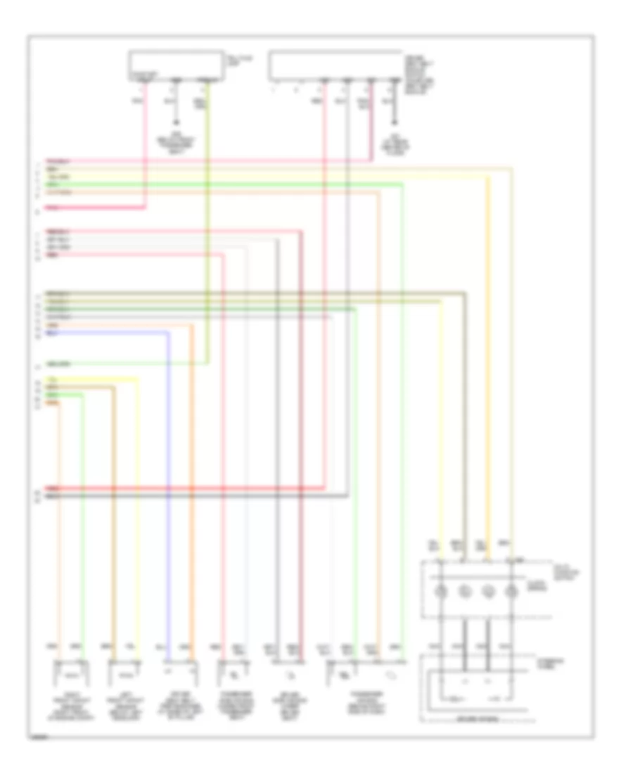
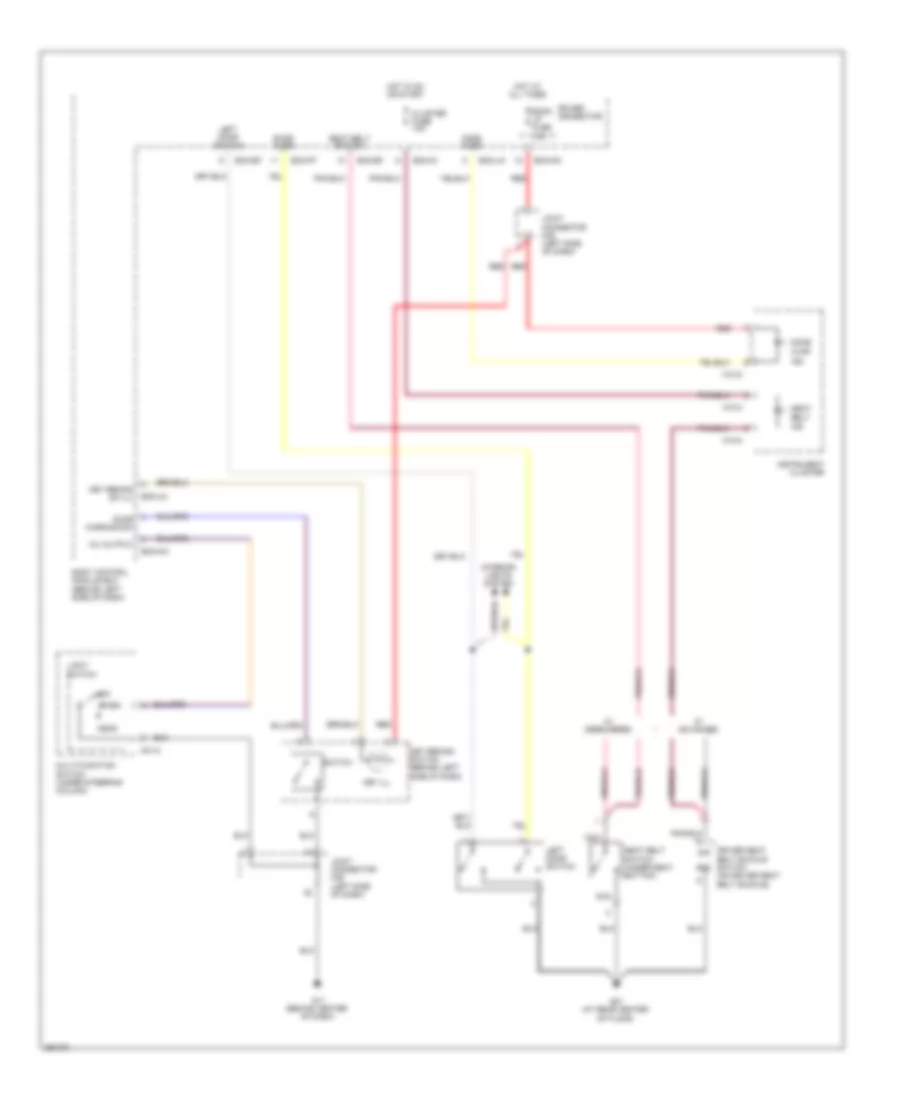
Automatic A/C Wiring Diagram (1 of 2) for Hyundai Tiburon SE 2008

List of elements for Automatic A/C Wiring Diagram (1 of 2) for Hyundai Tiburon SE 2008:
- (beside blower motor, below right side of dash) blower relay
- (left front of engine compt) aqs sensor
- (left side of dash) j/c m36
- (on left front corner of engine compt) g15
- A/c control module (below center of dash, forward of shift lever)
- A/c output
- A/c select sig
- A/con fuse 10a
- Amb sig
- Ambient temperature sensor (behind center of front bumper)
- Aqs sig
- Bcm-ce
- Bcm-im
- Bcm-km
- Blend door actuator (behind right center of dash)
- Blower fusible link 30a
- Blower motor (under right side of dash)
- Blower rly on in
- Body control module box (behind left side of dash)
- Cool actuator
- Cruise control system
- Def actuator
- Defogger
- Defogger ind
- Defogger sw
- E/r box (in left front corner of engine compt, behind battery)
- Fe (field effect) transistor
- Feed back sig
- Fet (drain)
- Fet (gate)
- Fre actuator
- G11 (behind center of dash)
- G12 (behind center of dash)
- Gnd
- Hot at all times
- Hot in on
- Ign fuse 10a
- Ill +
- Ill -
- Intake actuator (behind upper right side of dash)
- Interior lights system
- J/c e56
- Joint connector m35 (left side of dash)
- M19-1
- M19-2
- Memory pwr
- Nca
- On input
- Photo sens gnd
- Photo sensor (on top left side of dash, near defroster vent)
- Pnk
- Power connector
- Rec actuator
- Red
- Room lp fuse 10a
- Sens gnd
- Sens pwr (5v)
- Sens sig
- System
- Temperature actuator (behind lower right center of dash)
- Thermostatic switch (behind right center of dash)
- Vehicle speed sig
- Vent actuator
- Warm actuator
- Water temperature sensor
- Wts +
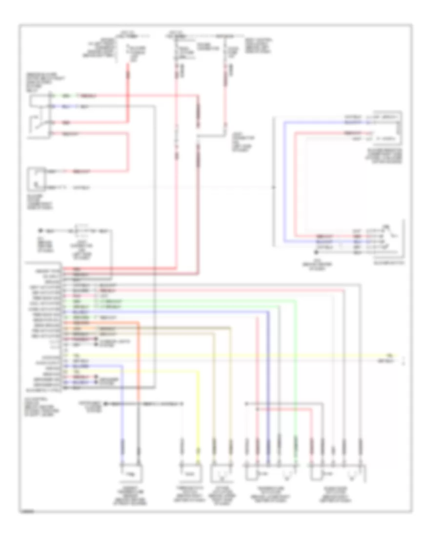
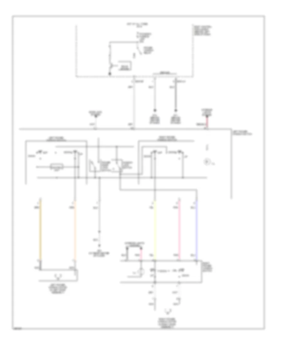
Automatic A/C Wiring Diagram (2 of 2) for Hyundai Tiburon SE 2008
List of elements for Automatic A/C Wiring Diagram (2 of 2) for Hyundai Tiburon SE 2008:
- (on left front of engine compt) radiator fan motor
- (on right front corner of engine compt) g16
- (on right front of engine compt) condenser fan motor
- 2.0l
- 2.7l
- A/c compressor (front of engine)
- A/con on in
- A/con relay
- A/con rly ctrl
- A/con sig in
- A/con sw in
- C133-2
- C133-3
- C133-4
- C33-1
- Cond 1 relay
- Cond 2 relay
- Cond fusible link 30a
- E/r box (in left front corner of engine compt, behind battery)
- Ec01
- Ec02
- Ec101
- Ec102
- Ect sens gnd
- Ect sens sig
- Ecu fusible link 30a
- Engine coolant temperature sensor & sender (2.7l: on top left rear of cylinder head, near coolant outlet) (2.0l: on rear of engine, near coolant outlet)
- Fan rly (hi)
- Fan rly (low)
- G15 (on left front corner of engine compt)
- High
- Horn & a/con fuse 15a
- Hot at all times
- Joint connector e56
- Low
- Main relay
- Main rly ctrl
- Mid
- Nca
- Pcm (2.0l) ecm (2.7l) (2.0l: behind left side of dash) (2.7l: behind right side of dash)
- Pnk
- Rad fusible link 30a
- Rad relay
- Red
- Sensor
- Triple switch (2.0l: on a/c line, near right front strut tower) (2.7l: on a/c line, at front of engine compt)
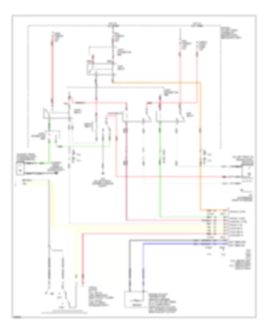
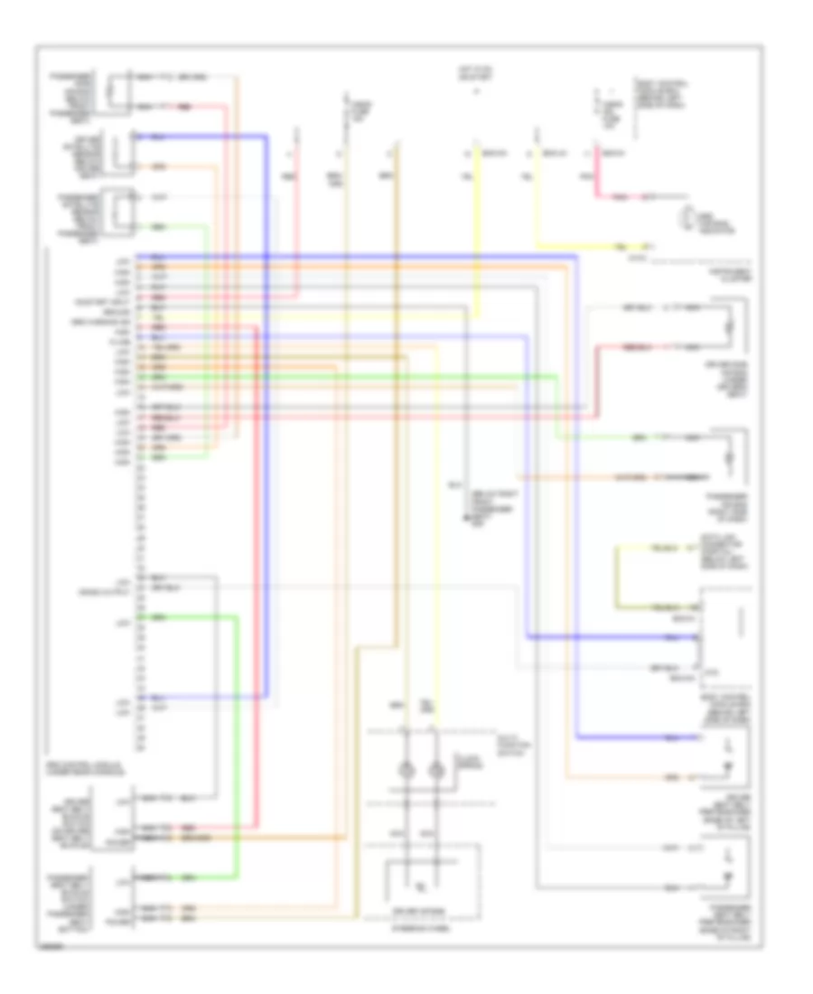
Manual A/C Wiring Diagram (1 of 2) for Hyundai Tiburon SE 2008
List of elements for Manual A/C Wiring Diagram (1 of 2) for Hyundai Tiburon SE 2008:
- (beside blower motor, below right side of dash) blower relay
- A/c control module (below center of dash, forward of shift lever)
- A/con fuse 10a
- A/con ouput
- A/con sig
- Amb sig
- Ambient temperature sensor (behind center of front bumper)
- Bcm-im
- Bcm-km
- Blend door actuator (behind right center of dash)
- Blower fusible link 30a
- Blower motor (under right side of dash)
- Blower resistor (under right side of dash, in blower motor housing)
- Blower rly ctrl
- Blower switch
- Body control module box (behind left side of dash)
- Cool actuator
- Def actuator
- Defogger ind
- Defogger sw
- Defogger system
- E/r box (in left front corner of engine compt, behind battery)
- Feed back sig
- Fre actuator
- G11 (behind center of dash)
- G12 (behind center of dash)
- Ground
- Hot at all times
- Hot in on
- Iii
- Iiii
- Ill (+)
- Ill (-)
- Instrument cluster system
- Intake actuator (behind upper right side of dash)
- Interior lights system
- Joint connector m35 (left side of dash)
- Joint connector m36 (left side of dash)
- Memory pwr
- Nca
- Off
- On input
- Pnk
- Power connector
- Rec actuator
- Red
- Room lp fuse 10a
- Sens ground
- Sens pwr (5v)
- Sens sig
- Temperature actuator (behind lower right center of dash)
- Thermostatic switch (behind right center of dash)
- Vent actuator
- Warm actuator
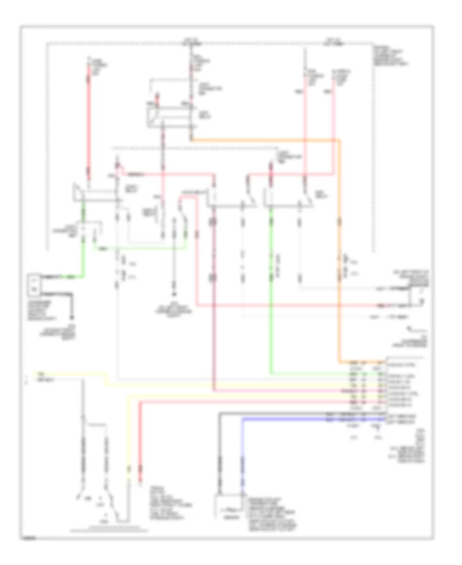
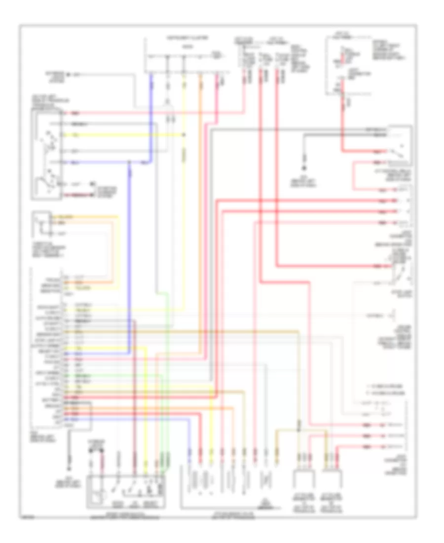
Manual A/C Wiring Diagram (2 of 2) for Hyundai Tiburon SE 2008
List of elements for Manual A/C Wiring Diagram (2 of 2) for Hyundai Tiburon SE 2008:
- (on left front of engine compt) radiator fan motor
- 2.0l
- 2.7l
- 30a
- A/c compressor (front of engine)
- A/con on in
- A/con relay
- A/con rly ctrl
- A/con sig in
- A/con sw in
- C133-2
- C133-3
- C133-4
- C33-1
- Cond 1 relay
- Cond 2 relay
- Cond fusible link 30a
- Condenser fan motor (on right front of engine compt)
- E/r box (in left front corner of engine compt, behind battery)
- Ec01
- Ec02
- Ec101
- Ec102
- Ect sens gnd
- Ect sens sig
- Ecu fusible link red
- Engine coolant temperature sensor & sender (2.7l: on top left rear of cylinder head, near coolant outlet) (2.0l: on rear of engine, near coolant outlet)
- Fan rly (hi)
- Fan rly (low)
- G15 (on left front corner of engine compt)
- G16 (on right front corner of engine compt)
- High
- Horn & a/con fuse 15a
- Hot at all times
- Joint connector e56
- Low
- Main relay
- Main rly ctrl
- Mid
- Nca
- Pcm (2.0l) ecm (2.7l) (2.0l: behind left side of dash) (2.7l: behind right side of dash)
- Pnk
- Rad fusible link 30a
- Rad relay
- Red
- Sensor
- Triple switch (2.0l: on a/c line, near right front strut tower) (2.7l: on a/c line, at front of engine compt)
ANTI-LOCK BRAKES
Anti-lock Brakes Wiring Diagram, with ESP for Hyundai Tiburon SE 2008
List of elements for Anti-lock Brakes Wiring Diagram, with ESP for Hyundai Tiburon SE 2008:
- (2.0l) (2.7l)
- (behind right side of dash) ecm
- 2.0l
- 2.7l
- Abs 1 fusible link 40a
- Abs 2 fusible link 40a
- Abs fuse 10a
- Abs ind
- Abs pump motor
- Abs solenoid
- B/up lamp fuse 10a
- Bcm-ce
- Bcm-im
- Bcm-km
- Body control module box (behind left side of dash)
- Brake ind
- Brake switch
- C133-4
- C141 (behind crash pad)
- C33-1
- Can hi
- Can low
- Cluster fuse 10a
- Computer data lines system
- Data link connector (below left side of dash)
- Diagnosis
- E/r box (in left front corner of engine compt, behind battery)
- Esc air bleeding connector
- Esc control module
- Esc ind
- Esc off ind
- Esc switch
- Esc switch on
- G sensor sig
- G-yaw sensor (under center console)
- G11 (behind center of dash)
- G17 (on right front corner of engine compartment)
- Ground
- Hot at all times
- Hot in on or start
- Ind ctrl abs
- Ind ctrl esc
- Ind ctrl esc off
- Instrument cluster
- Interior lights system
- Joint connector c41
- Left front wheel sensor (left front hub assembly)
- Left rear wheel sensor (left rear hub assembly)
- M10-2
- M10-3
- Nca
- Note: esc control module contains: esc solenoids, abs solenoids & abs pump motor
- On/start input
- Pcm (behind left side of dash)
- Power
- Pressure sensor
- Red
- Right front wheel sensor (right front hub assembly)
- Right rear wheel sensor (right rear hub assembly)
- Self test
- Signal
- Steering ang sens 1
- Steering ang sens 2
- Steering ang sens gnd
- Steering ang sens n
- Steering angle sensor
- Stop fuse 15a
- Stop lamp switch
- Wheel speed input
- Wheel speed output
- Yaw sensor power
- Yaw sensor sig
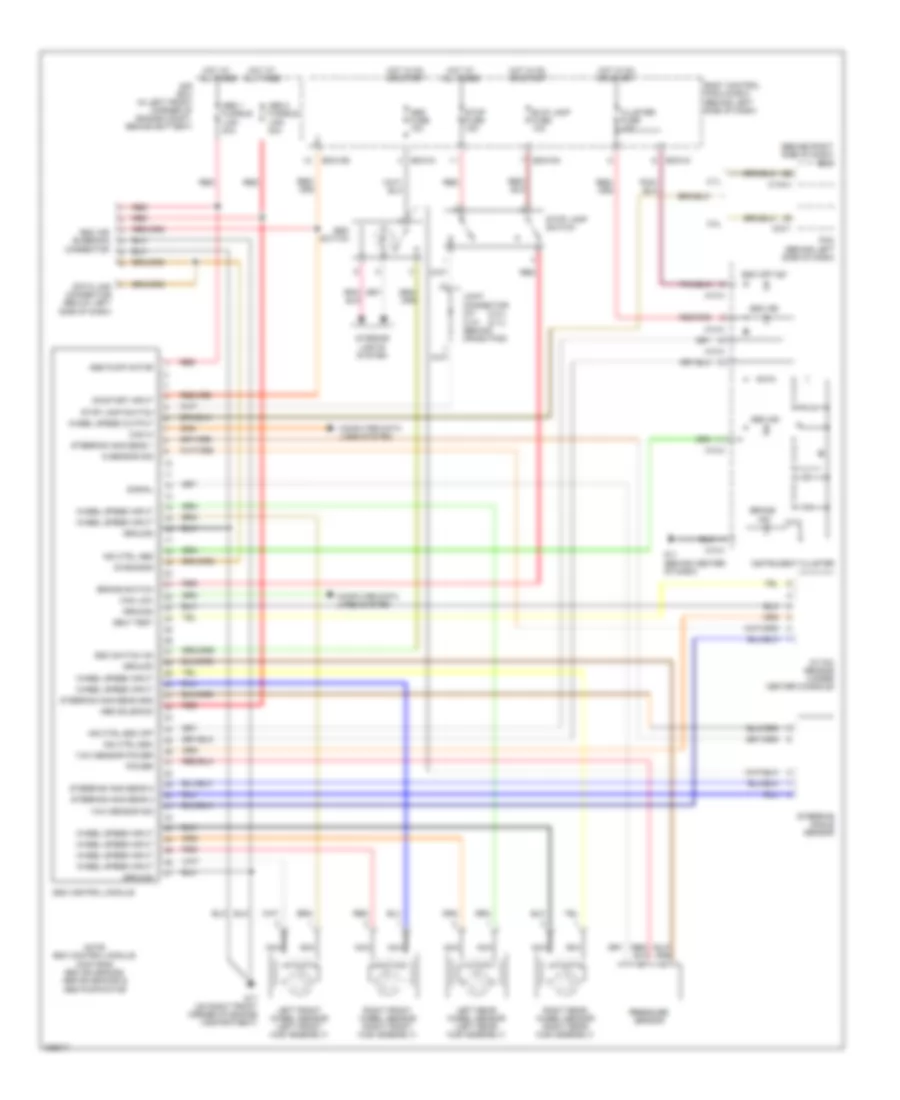
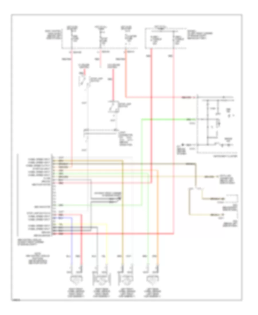
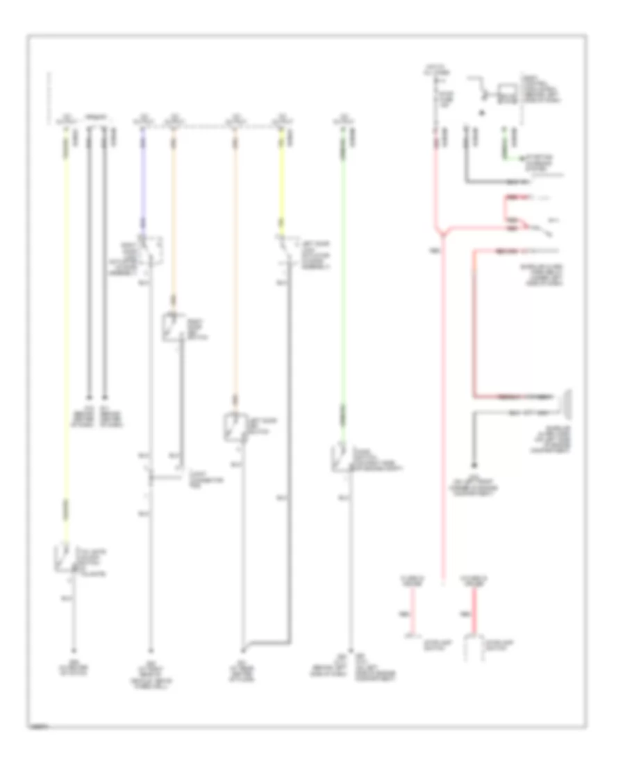
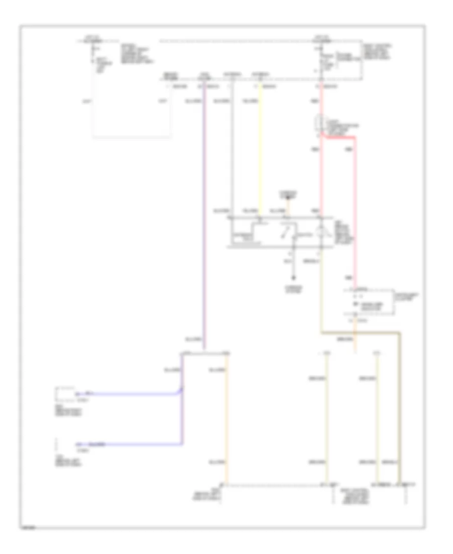
Anti-lock Brakes Wiring Diagram, without ESP for Hyundai Tiburon SE 2008
List of elements for Anti-lock Brakes Wiring Diagram, without ESP for Hyundai Tiburon SE 2008:
- (2.0l)
- (2.7l)
- (on right front corner of engine compt) g17
- 2.0l
- 2.7l
- Abs 1 fusible link 40a
- Abs 2 fusible link 40a
- Abs control module (in right front corner of engine compt)
- Abs fuse 10a
- Abs ind
- Abs indicator
- Abs pump motor
- Abs solenoids
- Bcm-ce
- Bcm-im
- Bcm-km
- Body control module box (behind left side of dash)
- Brake ind
- C133-4
- C141 (behind crash pad)
- C33-1
- Cluster fuse 10a
- Connector (below left side of dash)
- Data link
- E/r box (in left front corner of engine compt, behind battery)
- Ecm (behind right side of dash)
- G11 (behind center of dash)
- Ground
- Hot at all times
- Hot in on or start
- Instrument cluster
- Joint connector c41
- K-line
- Left front wheel sensor (left front hub assembly)
- Left rear wheel sensor (left rear hub assembly)
- M10-2
- M10-3
- Nca
- Note: abs control module contains: abs solenoids & abs pump motor
- Pcm (behind left side of dash)
- Red
- Right front wheel sensor (right front hub assembly)
- Right rear wheel sensor (right rear hub assembly)
- Start/on input
- Stop fuse 15a
- Stop lamp switch
- Stop lamp switch in
- W/ cruise control
- W/o cruise control
- Wheel speed input
- Wheel speed output
ANTI-THEFT
Forced Entry Wiring Diagram for Hyundai Tiburon SE 2008
List of elements for Forced Entry Wiring Diagram for Hyundai Tiburon SE 2008:
- 12v output
- Bcm-ef
- Bcm-hm
- Bcm-jm
- Bcm-km
- Bcm-lm
- Body control module box (behind left side of dash)
- Burglar alarm horn (on left side of engine compartment)
- Burglar alarm horn relay (under left side of dash)
- Door lock actuator (in door assembly)
- G01 (at rear center of floor)
- G02 (at right rear of vehicle, above wheelwell)
- G06 (in center of hatch)
- G11 (behind center of dash)
- G12 (behind center of dash)
- G15 (on left front corner of engine compartment)
- G20 (2.0l) (on left side of engine compartment)
- G23 (2.7l) (behind left side of dash)
- Ground
- Hood switch (on right side of engine compt)
- Hot at all times
- Joint connector f09
- Left door key switch
- Left door lock actuator (in door assembly)
- Nca
- Red
- Right
- Right door key switch
- Solid state
- Starting/ charging system
- Stop fuse 15a
- Stoplamp switch
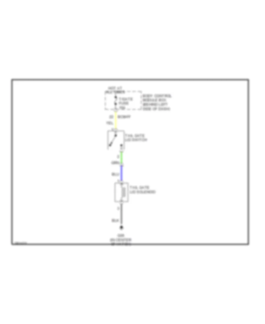
- Tail gate unlock switch (in tailgate)
- W/ esc & cruise
- W/o esc & cruise
Immobilizer Wiring Diagram for Hyundai Tiburon SE 2008
List of elements for Immobilizer Wiring Diagram for Hyundai Tiburon SE 2008:
- 2.0l
- 2.7l
- Antenna (+)
- Antenna (-)
- Antenna coil
- Batt fusible link 50a
- Bcm-de
- Bcm-hm
- Bcm-im
- Bcm-jm
- Bcm-km
- Body control module box (behind left side of dash)
- C133-1
- C136-3
- C33-1
- E/r box (in left front corner of engine compt, behind battery)
- Ecm (behind right side of dash)
- Hot at all times
- Ill
- Immo w-line
- Immobilizer
- Indicator
- Instrument cluster
- Joint connector m35 (left side of dash)
- Key remind switch (behind left side of dash)
- M10-2
- Memory power
- Pcm (behind left side of dash)
- Power connector
- Red
- Room lp fuse 10a
- Switch
- Tcm (behind left side of dash)
- Warning system
BODY CONTROL MODULES
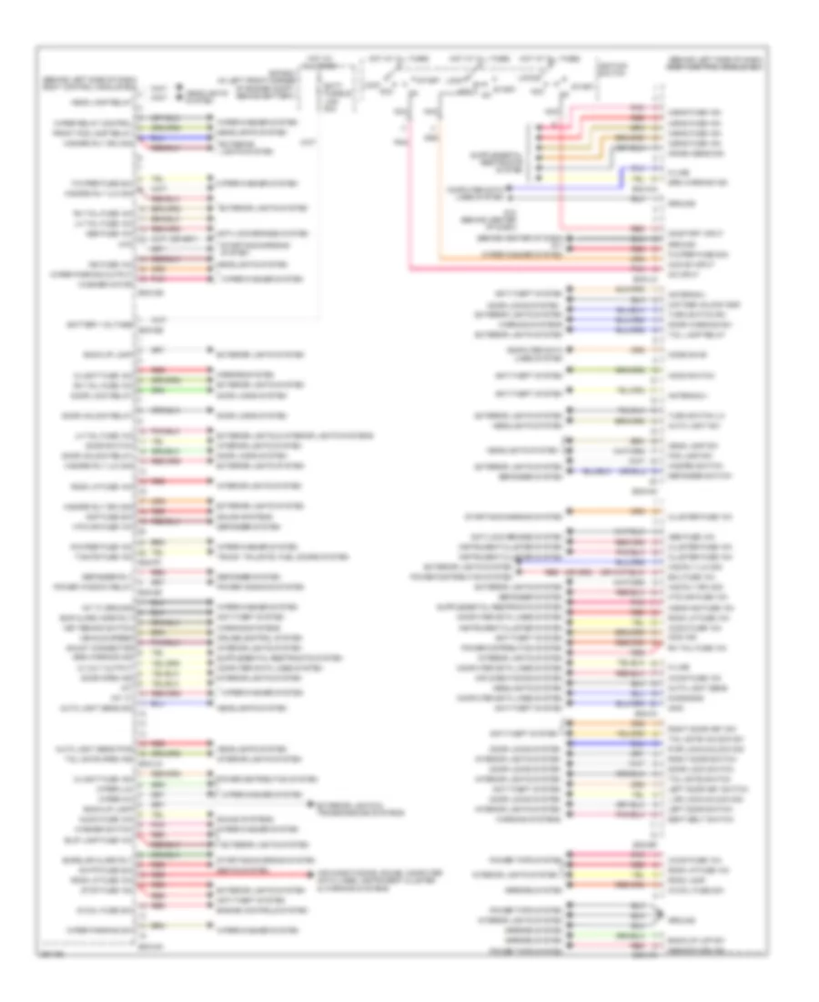
Body Control Modules Wiring Diagram for Hyundai Tiburon SE 2008
List of elements for Body Control Modules Wiring Diagram for Hyundai Tiburon SE 2008:
- (behind center of dash) g11
- (behind left side of dash) body control module box
- 12 volt output
- 2-stage unlock gnd
- A/bag fuse 15a
- A/bag ind fuse 10a
- A/con fuse 10a
- Abs fuse 10a
- Acc
- Acc/on input
- Air conditioning system
- Air conditioning, sound, computer data lines, instrument cluster & warning systems
- Amp fuse 20a
- Antenna(+)
- Antenna(-)
- Anti-lock brakes system
- Anti-theft system
- Atd
- Audio fuse 10a
- Auto light sens
- Auto light sens pwr
- Auto light sens sig
- Auto light sw
- B/up lamp fuse 10a
- Back-up lamp
- Back-up lmp sw
- Batt fusible link 50a
- Battery voltage
- Bcm-aa
- Bcm-ce
- Bcm-de
- Bcm-ef
- Bcm-ff
- Bcm-gf
- Bcm-hm
- Bcm-im
- Bcm-jm
- Bcm-km
- Bcm-lm
- Bcm-mr
- Bur alarm horn rly
- Burglar alarm rly
- C/light fuse 15a
- Cluster fuse 10a
- Code save
- Computer data lines system
- Conputer data lines system
- Crash sens sig
- Cruise control system
- Defogger rly
- Defogger switch
- Defogger system
- Diagnosis
- Door lock relay
- Door lock switch
- Door locks system
- Door open ind
- Door switch
- Door unlock relay
- Door warning sw
- E/r box (in left front corner of engine compt, behind battery)
- Ecu fuse 10a
- Engine controls system
- Exterior lights & interior lights systems
- Exterior lights & transmissions systems
- Exterior lights system
- F/wiper fuse 20a
- Fog lamp sw
- Front fog lamp relay
- G12 (behind center of dash)
- Ground
- Haz rly (lh) sig
- Haz rly (rh) sig
- Hazard rly (lh) sig
- Hazard rly (rh) sig
- Hazard switch
- Head lamp relay
- Head lamp sw
- Headlights system
- Hood switch
- Hot at all times
- Htd mir fuse 10a
- Ig coil fuse 20a
- Ign fuse 10a
- Ignition switch
- Immo
- Immo ind
- Instrument cluster system
- Int
- Int (t)
- Int (t) ground
- Interior lights system
- K-line
- Key remind switch
- L dr lock/unlock sig
- Left door key switch
- Left door switch
- Lh tail fuse 10a
- Lock
- Mirrors system
- Nca
- On input
- On/start input
- Pnk
- Power distribution system
- Power tops system
- Power window relay
- Power windows system
- R dr lock/unlock sig
- R/wiper fuse 15a
- Red
- Rh tail fuse 10a
- Right door key sw
- Right door switch
- Room lamp
- Room lp fuse 10a
- S/htr fuse 20a
- S/roof fuse 15a
- Seat belt switch
- Seats system
- Shunt connector
- Sound systems
- Srs warning ind
- Start
- Starting/charging system
- Stop fuse 15a
- T/gate fuse 15a
- Tail gate open ind
- Tail gate switch
- Tail gate unlock sw
- Tail lamp relay
- Trunk, tailgate, fuel doors system
- Turn switch lh
- Turn switch rh
- Vehicle speed
- Warning systems
- Washer motor
- Washer switch
- Wiper (hi)
- Wiper (lo)
- Wiper parking output
- Wiper parking sw
- Wiper relay control
- Wiper/washer system
COMPUTER DATA LINES
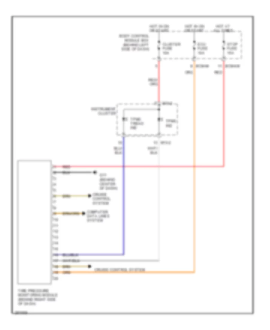
Computer Data Lines Wiring Diagram for Hyundai Tiburon SE 2008
List of elements for Computer Data Lines Wiring Diagram for Hyundai Tiburon SE 2008:
- (2.0l)
- (2.7l)
- (2.7l) (2.0l) (2.7l: behind right side of dash) (2.0l: behind left side of dash)
- (behind crash pad) (2.7l) j/c c141 (2.0l) j/c c41
- (below center of dash, forward of shift lever) a/c control module
- (left side of dash) j/c m34
- (on top of transaxle) vehicle speed sensor
- 12volt output
- 2.0l w/o immobilizer
- 2.7l w/ immobilizer
- A11
- A12
- Abs control module (in right front corner of engine compt)
- Advanced depowered
- Bcm-aa
- Bcm-hm
- Bcm-im
- Bcm-jm
- Bcm-km
- Body control module box (behind left side of dash)
- C133-1
- C133-4
- C136-1
- C136-3
- C33-1
- Code save
- Data link connector (below left side of dash)
- Diag
- E/r box (in left front corner of engine compt, behind battery)
- Ecm pcm
- Esc air bleeding connector
- Esc control module
- F/pump relay
- Fuel sender & fuel pump motor (below center of rear seat)
- G04 (at rear center of floor)
- G11 (behind center of dash)
- G14 (behind left side of dash)
- G16 (on right front corner of engine compt)
- Hot at all times
- Immo
- Joint connector m34 (left side of dash)
- Joint connector m35 (left side of dash)
- Joint connector m36 (left side of dash)
- M19-2
- Motor
- Multi gauge unit
- Multipurpose check connector (below left side of dash, right of steering column)
- Nca
- Power connector
- Red
- Room lp fuse 10a
- Speed senor
- Srs control module (under rear console)
- Tcm (2.7l) (behind left side of dash)
- Tire pressure monitoring module
- Vertical resistor (w/o esc)
- W/ abs
- W/ esc
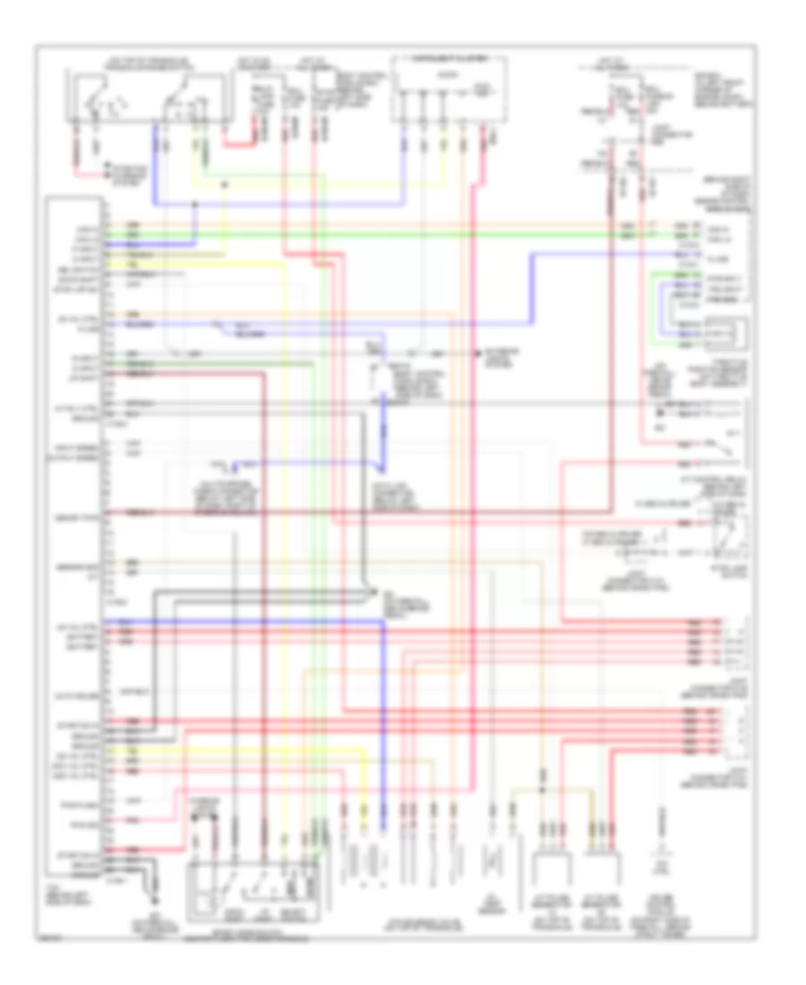
COOLING FAN
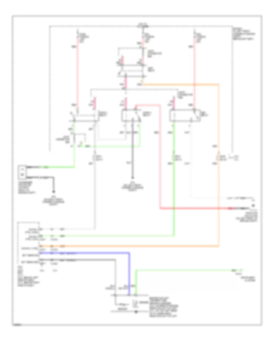
Cooling Fan Wiring Diagram for Hyundai Tiburon SE 2008
List of elements for Cooling Fan Wiring Diagram for Hyundai Tiburon SE 2008:
- 2.0l
- 2.7l
- C133-2
- C133-3
- C133-4
- Cond 1 relay
- Cond 2 relay
- Cond fusible link 30a
- Condenser fan motor (on right front of engine compt)
- E/r box (in left front corner of engine compt, behind battery)
- Ec01
- Ec02
- Ec101
- Ec102
- Ect sens gnd c33-1
- Ect sens sig
- Ecu fusible link 30a
- Engine coolant temperature sensor & sender (2.0l: on rear of engine, near coolant outlet) (2.7l: on top left rear of cylinder head, near coolant outlet)
- Fan rly ctrl (high)
- Fan rly ctrl (low) c33-1
- G15 (on left front corner of engine compt)
- G16 (on right front corner of engine compt)
- Hot at all times
- Instrument cluster
- Joint connector e56
- M10-3
- Main relay
- Main rly ctrl c33-1
- Nca
- Pcm (2.0l) ecm (2.7l) (2.0l: behind left side of dash) (2.7l: behind right side of dash)
- Pnk
- Rad fusible link 30a
- Rad relay
- Radiator fan motor (on left front of engine compt)
- Red
- Sender
- Sensor
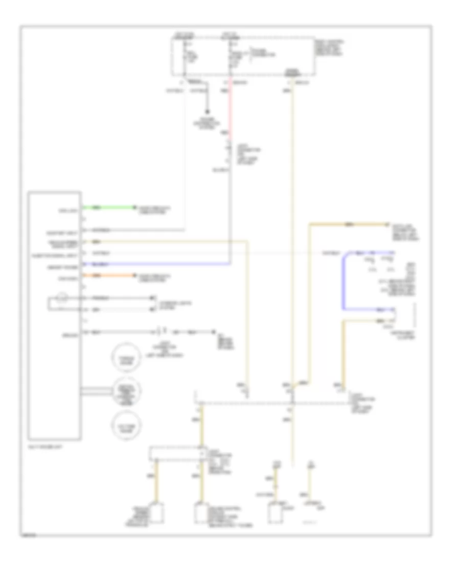
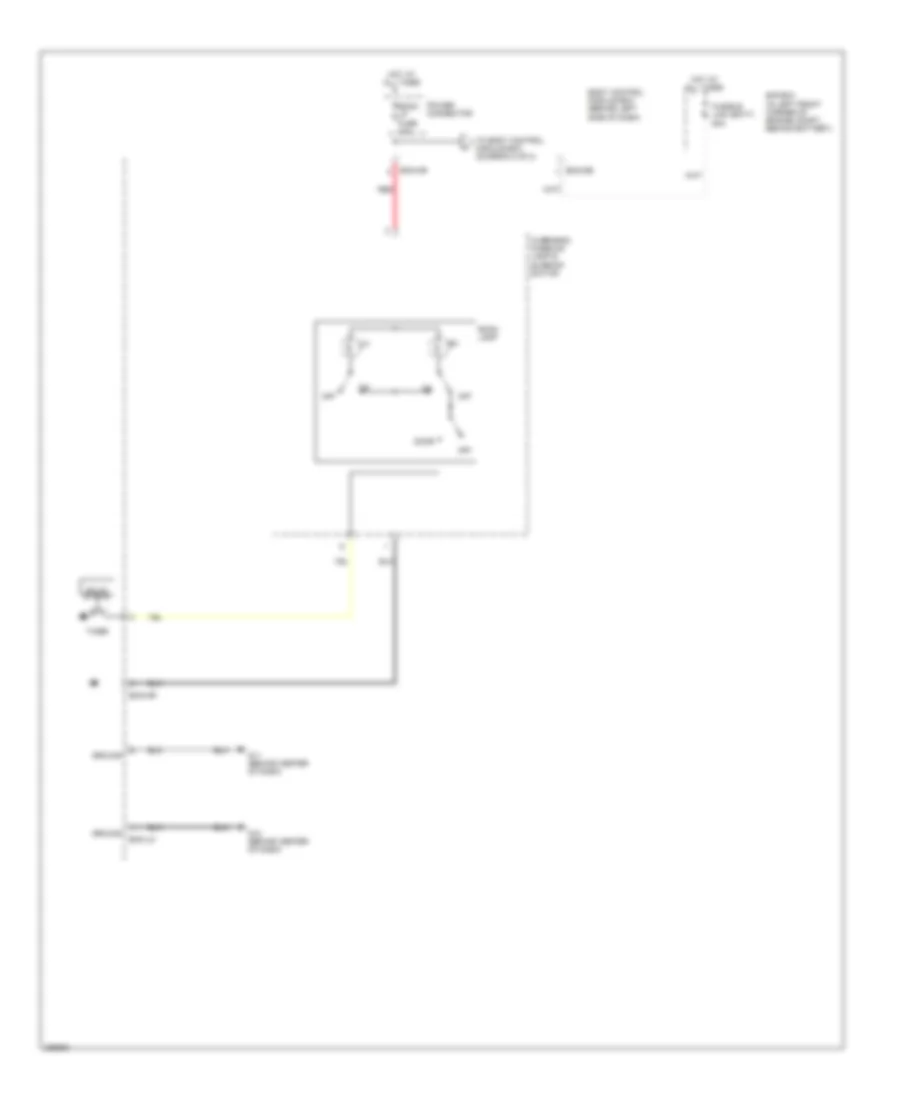
CRUISE CONTROL
Cruise Control Wiring Diagram for Hyundai Tiburon SE 2008
List of elements for Cruise Control Wiring Diagram for Hyundai Tiburon SE 2008:
- "cruise" ind on
- (2.0l)
- (2.0l) (2.7l)
- (2.7l)
- (on left side of engine compartment) (2.0l) g20
- (or pnk)
- 5 m/t
- A/c control module (automatic a/c) (below center of dash, forward of shift lever)
- A/t
- A/t & 6 m/t
- Acc
- Actuator clutch
- Amp (high) (behind left quarter trim)
- Audio
- B/up lamp fuse 10a
- Bcm-im
- Bcm-jm
- Bcm-km
- Body control module box (behind left side of dash)
- Burglar alarm horn relay (under left side of dash)
- C01
- C101
- C136-1 (2.7l)
- C33-2 (2.0l)
- Cancel
- Clock & switch module
- Clock spring
- Cluster fuse 10a
- Cruise clutch pedal position switch (near clutch pedal bracket)
- Cruise control module (on right side of firewall, behind strut tower)
- Cruise ind
- Cruise remote control switch
- E/r box (in left front corner of engine compartment, behind battery)
- Ecu fuse 10a
- Esc control module
- F08-2
- G15 (on left front corner of engine compartment)
- G20 (2.0l) (on left side of engine compartment)
- G23 (2.7l) (behind left side of dash)
- Ground
- Hall ic
- Hot at all times
- Hot in on or start
- Ignition switch
- Instrument cluster
- Joint connector c41 c141 (behind crash pad)
- Joint connector m34 (left side of dash)
- Lock
- M/t
- M01-3
- M01-4
- M10-3
- M16-1
- M19-2
- Main switch
- Micom
- Multi gauge unit
- Multi- function switch (under steering column)
- Nca
- O/d control
- On/start input
- Park/neutral input
- Pcm (2.0l) tcm (2.7l) (behind left side of dash)
- Pnk
- Red
- Resume/ accel
- Set ind
- Set/ coast
- Speed sensor
- Start
- Start relay
- Steering wheel
- Stop fuse 15a
- Stop lamp sw input
- Stop lamp switch
- Switch input
- Tire pressure monitoring module
- Transaxle range switch (2.0l: on top left side of transaxle) (2.7l: on top of transaxle)
- Vehicle speed input
- Vehicle speed sensor (on top of transaxle)
- W/ advanced
- W/ amp
- W/ depowered
- W/ immobilizer
- W/o amp
- W/o immobilizer
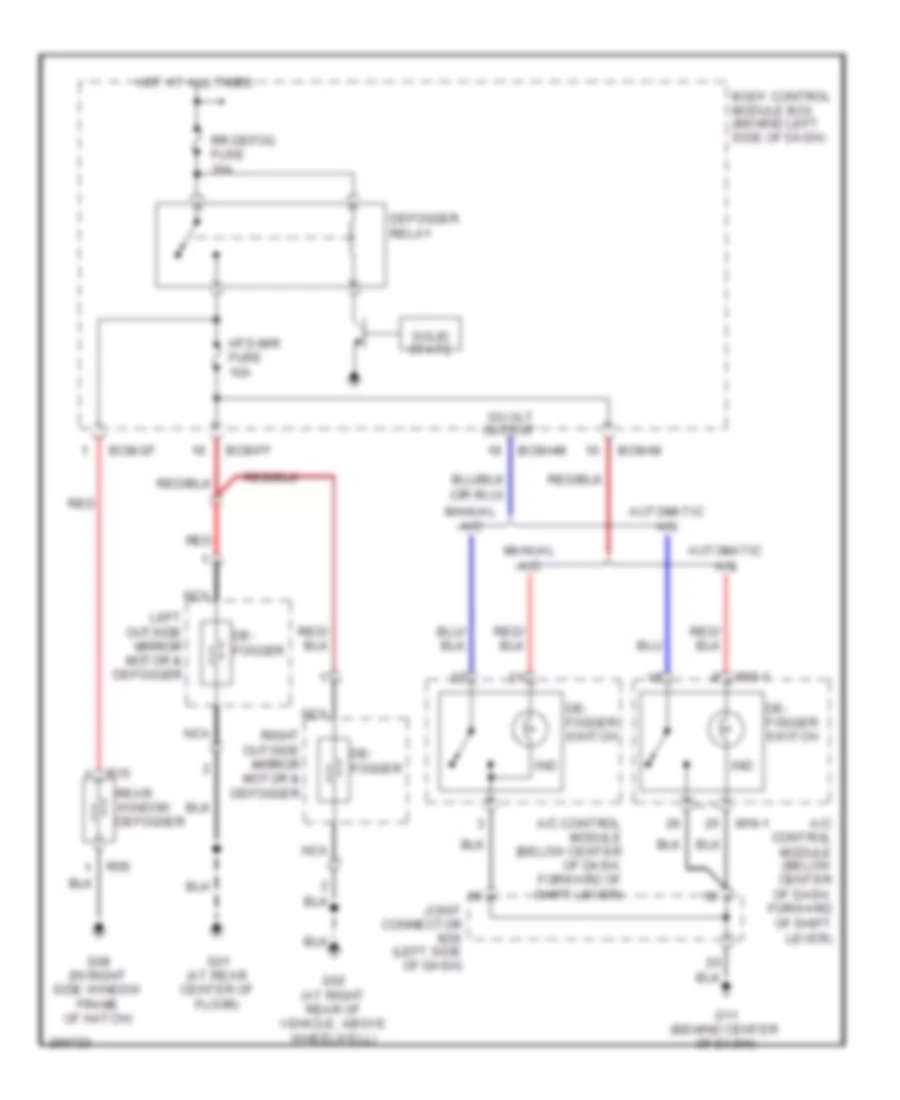
DEFOGGERS
Defoggers Wiring Diagram for Hyundai Tiburon SE 2008
List of elements for Defoggers Wiring Diagram for Hyundai Tiburon SE 2008:
- 12volt output
- A/c control module (below center of dash, forward of shift lever)
- Automatic a/c
- Bcm-ff
- Bcm-gf
- Bcm-hm
- Bcm-im
- Body control module box (behind left side of dash)
- De- fogger
- De- fogger switch
- Defogger relay
- G01 (at rear center of floor)
- G02 (at right rear of vehicle, above wheelwell)
- G08 (in right side window frame of hatch)
- G11 (behind center of dash)
- Hot at all times
- Htd mir fuse 10a
- Ind
- Joint connector m36 (left side of dash)
- Left outside mirror motor & defogger
- M19-1
- Manual a/c
- Nca
- R06
- R15
- Rear
- Red
- Right outside mirror motor & defogger
- Rr defog fuse 30a
- Solid state
- Window defogger
ENGINE PERFORMANCE
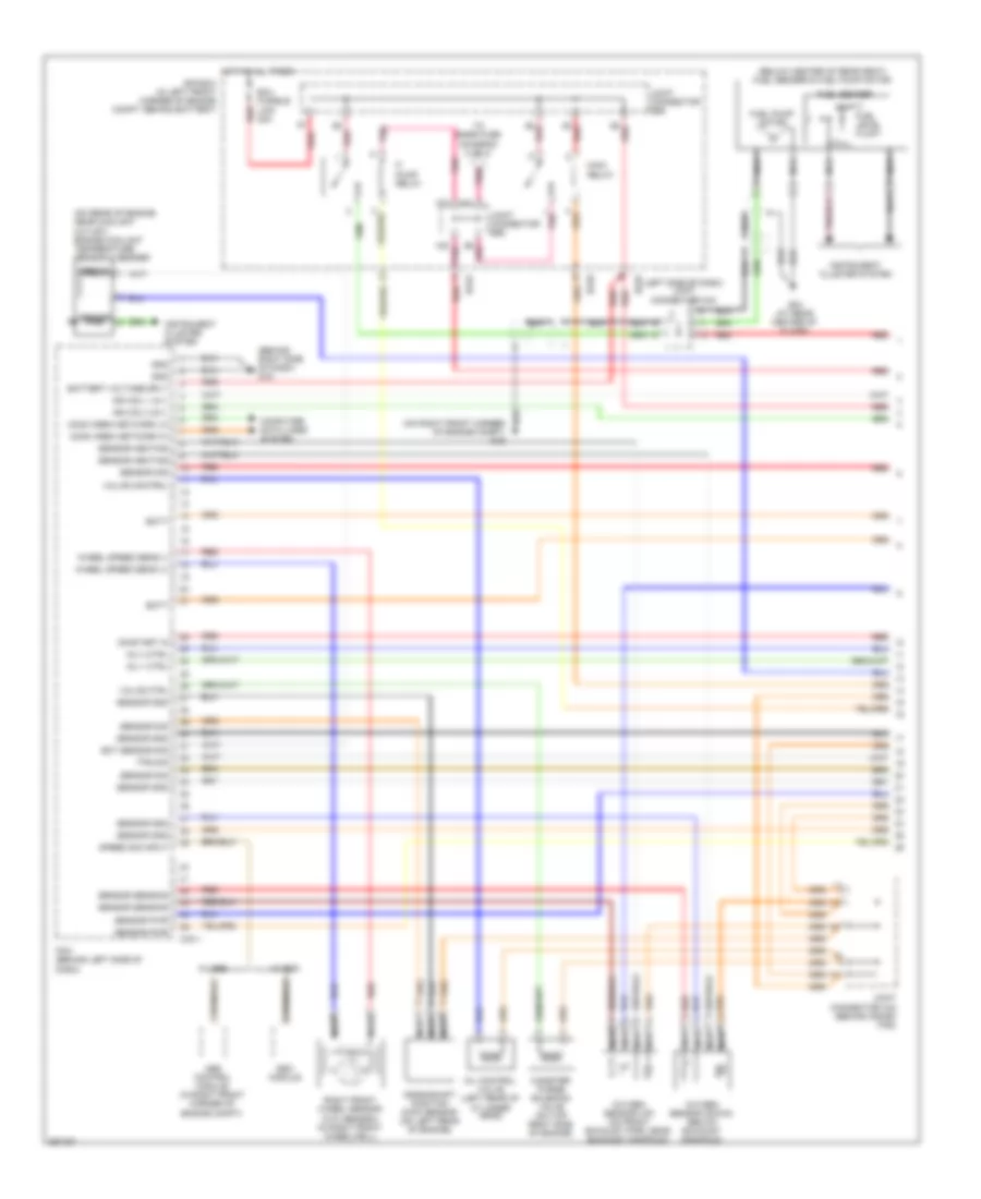
2.0L
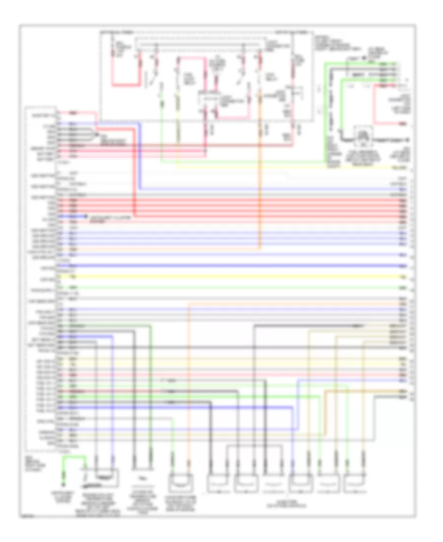
2.0L, Engine Performance Wiring Diagram (1 of 4) for Hyundai Tiburon SE 2008
List of elements for 2.0L, Engine Performance Wiring Diagram (1 of 4) for Hyundai Tiburon SE 2008:
- (behind right side of dash) g19
- (below center of rear seat) fuel sender & fuel pump motor
- (left side of dash) joint connector m34
- (on rear of engine, near coolant outlet) engine coolant temperature sensor & sender
- (on right front corner of engine compt) g16
- Abs control module (in right front corner of engine compt)
- Batt
- Battery voltage sply
- C33-1
- Canister purge solenoid valve (on top right side of engine)
- Comm area network hi
- Comm area network lo
- Computer data lines system
- Crankshaft position (ckp) sensor (on left rear of engine)
- E/r box (in left front corner of engine compt, behind battery)
- Ec01
- Ec02
- Ect sensor sig
- Ecu fusible link 30a
- Empty
- Esc module
- F/ pump relay
- Fuel level float
- Fuel pump motor
- Fuel sender
- Full
- G04 (at rear center of floor)
- Gnd
- Hot at all times
- Ign coil 1 & 4
- Ign coil 2 & 3
- Inj 1 ctrl
- Inj 4 ctrl
- Instrument cluster system
- Joint connector c42 (behind crash pad)
- Joint connector e56
- Main relay
- Nca
- Oil control valve (left rear of cylinder head)
- On/start in
- Oxygen sensor (down) (below exhaust manifold)
- Oxygen sensor (up) (on front exhaust pipe, near exhaust manifold)
- Pcm (behind left side of dash)
- Pnk
- Red
- Right front wheel sensor (w/o abs/esc) (in right front wheelwell)
- Sender
- Sensor
- Sensor gnd
- Sensor heating
- Sensor pwr
- Sensor sensing
- Sensor sig
- Speed sig input
- To snsr fuse (diagram 2 of 4)
- Tps sig
- Valve control
- Valve ctrl
- W/ abs
- W/ esc
- Wheel speed sens (+)
- Wheel speed sens (-)
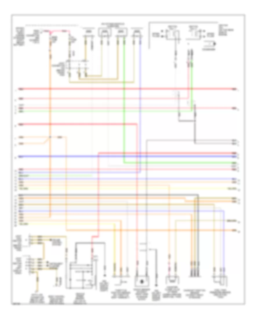
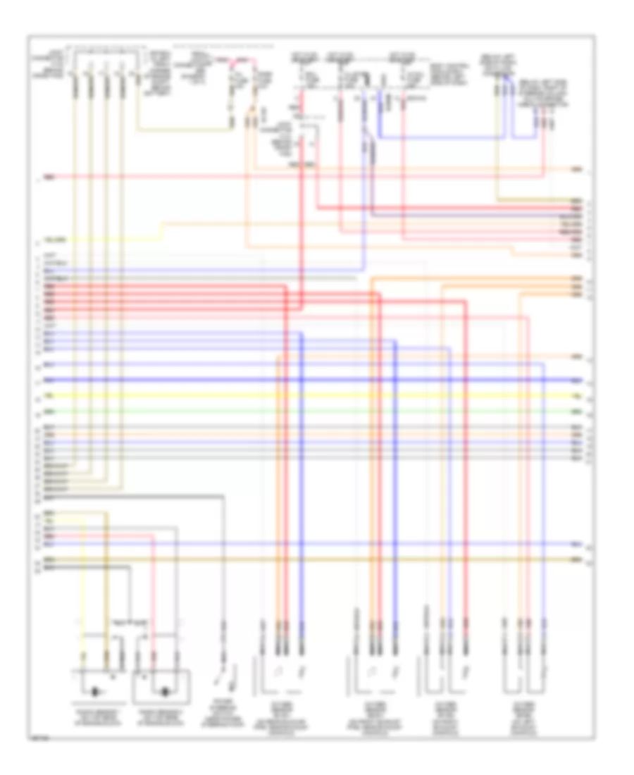
2.0L, Engine Performance Wiring Diagram (2 of 4) for Hyundai Tiburon SE 2008
List of elements for 2.0L, Engine Performance Wiring Diagram (2 of 4) for Hyundai Tiburon SE 2008:
- (a/t)
- (m/t)
- (on intake manifold) injectors
- Bcm-jm
- Body control module box (behind left side of dash)
- Camshaft position sensor (on right front of engine)
- Canister close valve (at rear under-carriage, near fuel tank)
- Condenser
- Cruise control system
- Data link connector (below left side of dash)
- E/r box (in left front corner of engine compt, behind battery)
- Ec01
- From a joint connector e56 (diagram 1 of 4)
- Fuel tank pressure sensor (above fuel tank)
- G20 (on left side of engine compt)
- Hall ic
- Ignition coil (on top rear side of engine)
- Ignition coil 1
- Ignition coil 2
- Inj fuse 15a
- Instrument cluster system
- Joint con- nector c41 (behind crash pad)
- Joint con- nector m34 (left side of dash)
- Joint connector c42 (behind crash pad)
- Knock sensor (on right front side of engine block)
- Nca
- Pnk
- Red
- Snsr fuse 10a
- Spark plugs
- Throttle position sensor (on throttle body assembly)
- Vehicle speed sensor (on top of transaxle)
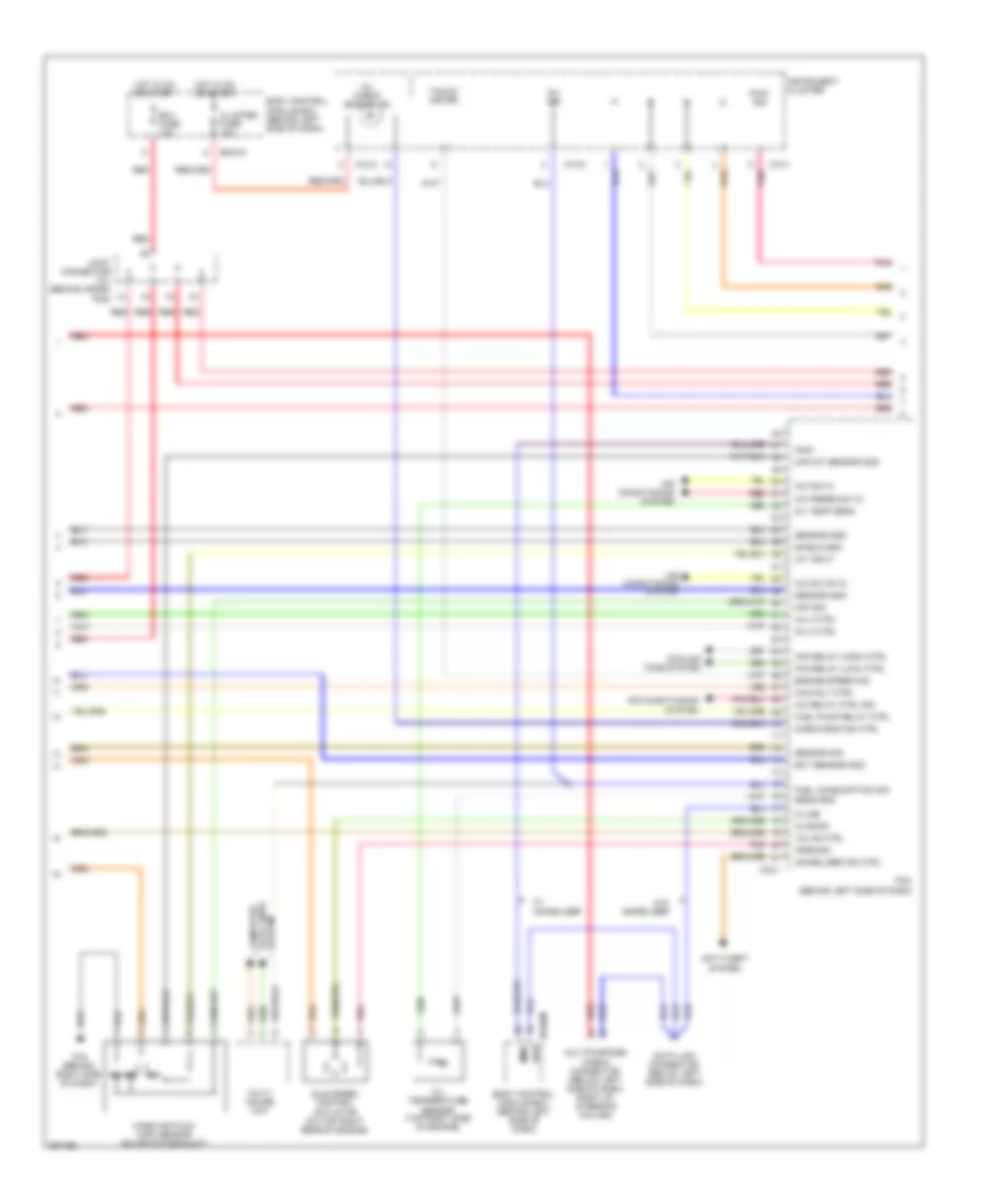
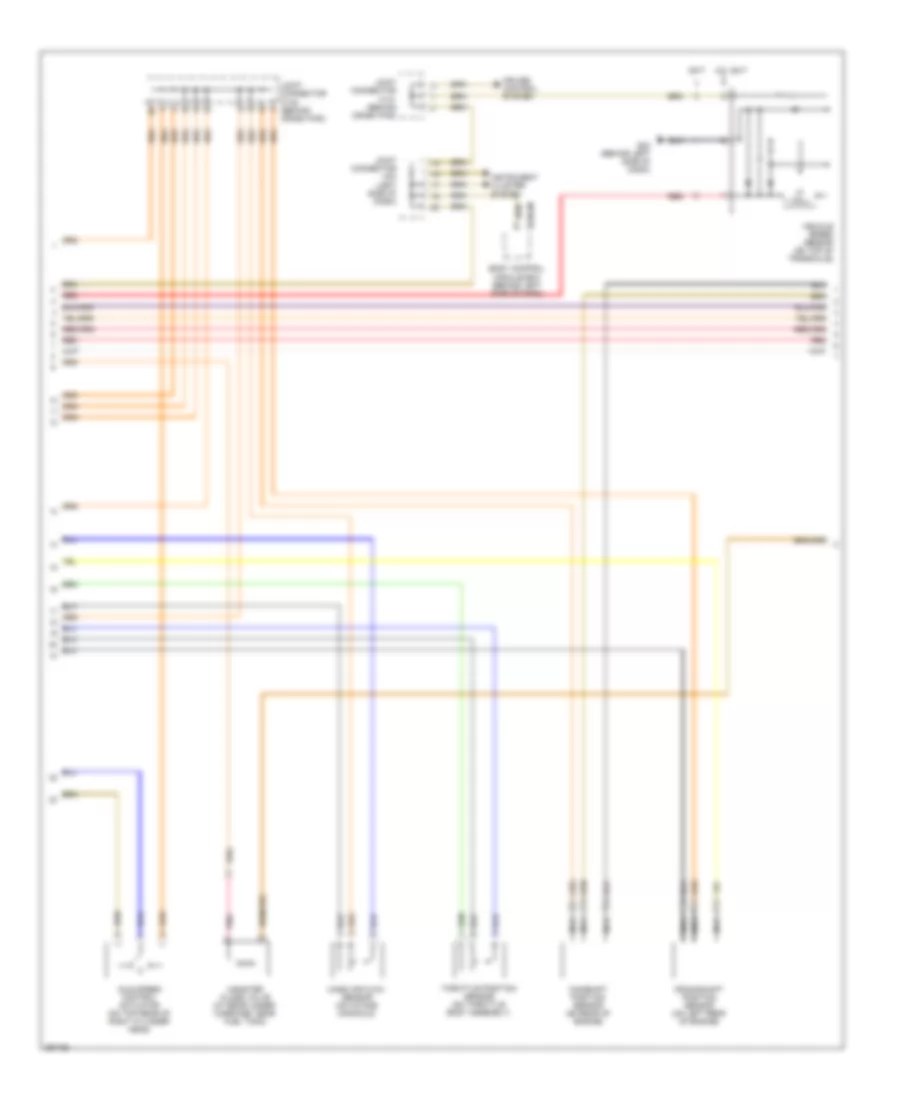
2.0L, Engine Performance Wiring Diagram (3 of 4) for Hyundai Tiburon SE 2008
List of elements for 2.0L, Engine Performance Wiring Diagram (3 of 4) for Hyundai Tiburon SE 2008:
- A/c press sw in
- A/c relay ctrl sig
- A/c sig in
- A/c sw on in
- Air conditioning system
- Anti-theft system
- Bcm-im
- Body control module box (behind left side of dash)
- C33-1
- Check eng ind ctrl
- Closing
- Cluster fuse 10a
- Cooling fans system
- Data link connector (below left side of dash)
- Diag
- Ect sensor gnd
- Ecu fuse 10a
- Engine speed sig
- Fan relay (high) ctrl
- Fan relay (low) ctrl
- Fuel consumption sig
- Fuel pump relay ctrl
- G19 (behind right side of dash)
- Hot in on or start
- Iat input
- Idle speed control actuator (on top right rear of engine)
- Immo
- Immobilizer ind ctrl
- Inj 2 ctrl
- Inj 3 ctrl
- Inj sig
- Instrument cluster
- Joint connector c41 (behind crash
- K-line
- M10-1
- M10-2
- M10-3
- Maf sig
- Maf/iat sensor gnd
- Main rly ctrl
- Mass air flow (maf) sensor (on air intake duct)
- Mil check engine ind
- Multi gauge unit
- Multipurpose check connector (below left side of dash, right of steering column)
- Oil temp sens
- Oil temperature sensor (top right side of engine)
- Opening
- Pad)
- Pcm (behind left side of dash)
- Pnk
- Pwm sig
- Red
- Sens gnd
- Sensor gnd
- Sensor sig
- Shield gnd
- System data lines computer
- Tacho- meter
- Valve ctrl
- W/ immobilizer
- W/o immobilizer
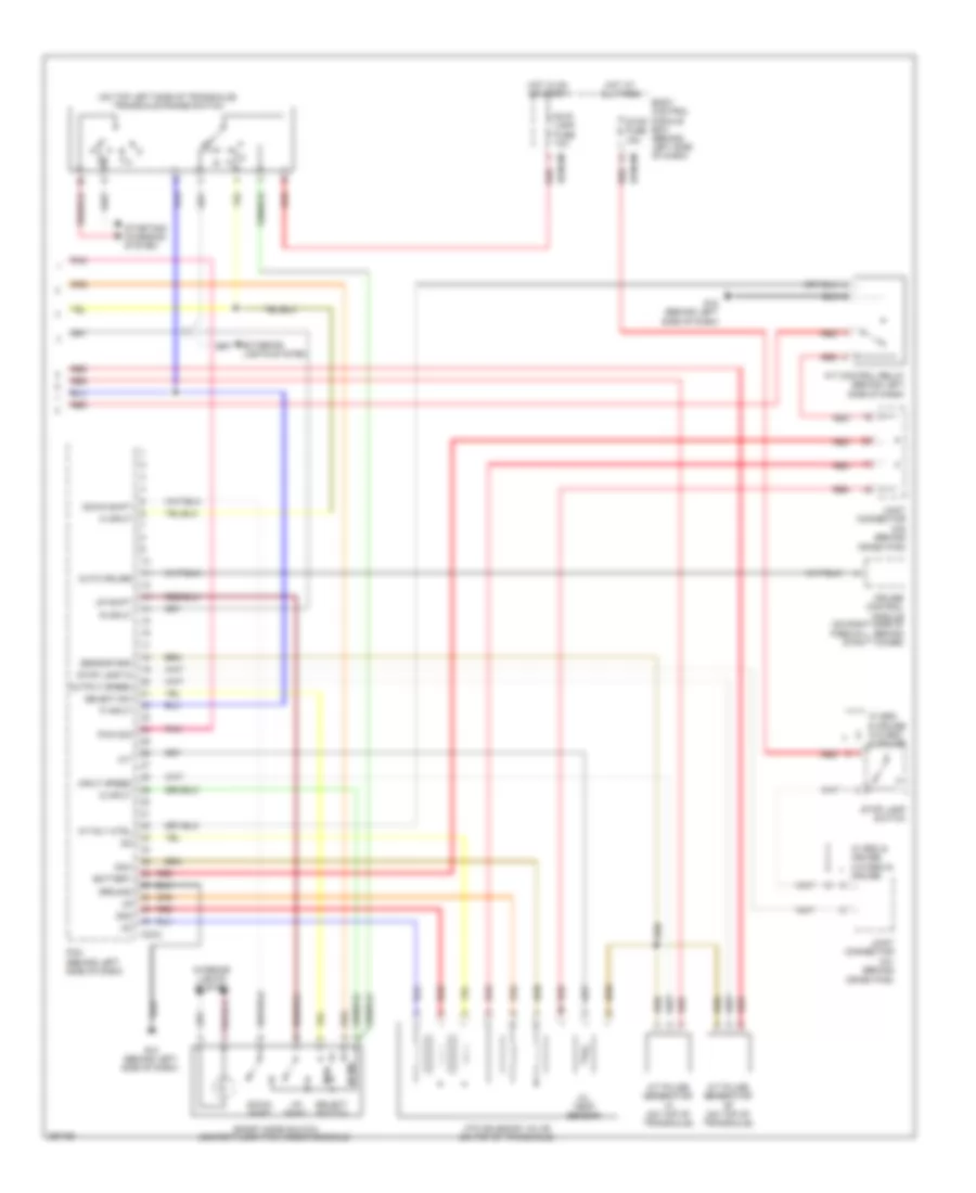
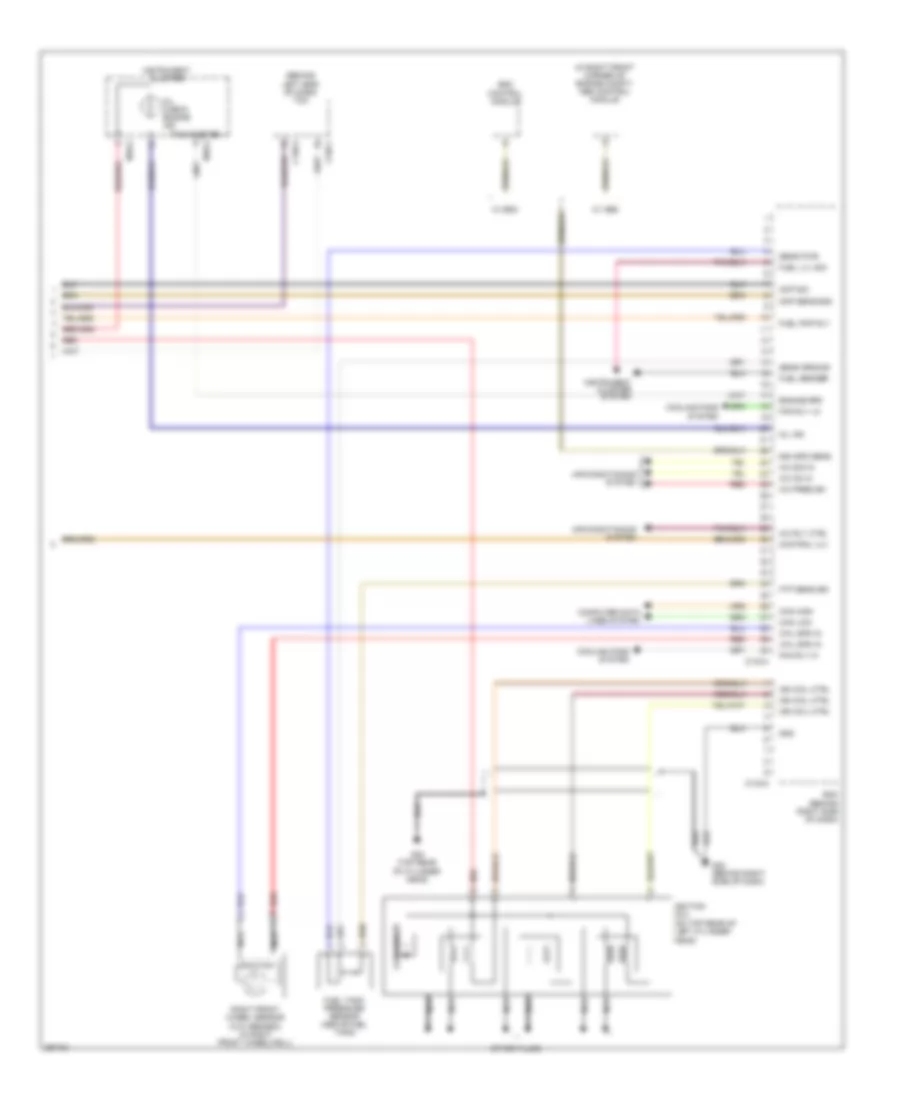
2.0L, Engine Performance Wiring Diagram (4 of 4) for Hyundai Tiburon SE 2008
List of elements for 2.0L, Engine Performance Wiring Diagram (4 of 4) for Hyundai Tiburon SE 2008:
- (on top left side of transaxle) transaxle range switch
- 2nd
- A/t control relay (behind left side of dash)
- A/t pulse generator "a" (on top of transaxle)
- A/t pulse generator "b" (on top of transaxle)
- A/t rly ctrl
- Atm solenoid valve (on top of transaxle)
- Auto cruise
- B/up lamp fuse 10a
- Battery
- Bcm-km
- Body control module box (behind left side of dash)
- C33-2
- C41 (behind crash pad)
- C42 (behind crash pad)
- Cruise control module (on right side of firewall, behind strut tower)
- D input
- Dcc
- Down shift
- Exterior lights system
- G18 (behind left side of dash)
- Ground
- Hot at all times
- Hot in on or start
- Input speed
- Interior lights system
- Joint connector
- Man
- N input
- Norm
- O/t
- Oil temp sensor
- Output speed
- P input
- Pcm (behind left side of dash)
- Pnk
- Pwm sig
- R input
- Red
- Select sw
- Select switch
- Sensor gnd
- Sport mode switch (center floor pan, under console)
- Starting/ charging system
- Stop fuse 15a
- Stop lamp in
- Stop lamp switch
- Up shift
- W/ esc & cruise w/o esc & cruise
2.7L
2.7L, Engine Performance Wiring Diagram (1 of 4) for Hyundai Tiburon SE 2008
List of elements for 2.7L, Engine Performance Wiring Diagram (1 of 4) for Hyundai Tiburon SE 2008:
- (at rear center of floor) g04
- (pins 11-16)
- (pins 2-6)
- (pins 2-7)
- (pins 27-28)
- (pins 39-41)
- (pins 43-45)
- (pins 49-52)
- (pins 8-12)
- Ats gnd
- Ats sig
- Battery
- C133-1
- C133-2
- C133-3
- Canister purge solenoid valve (on top right side of engine)
- Ckp sens gnd
- Ckp sig
- Closing
- Cps ctrl
- E/r box (in left front corner of engine compt, behind battery)
- Ec101
- Ec102
- Ecm (behind right side of dash)
- Ect sens gnd
- Ect sens in
- Ecu fuse 10a
- Ecu fusible link 30a
- Engine coolant temperature sensor & sender (on top left rear of cylinder head, near coolant outlet)
- Fuel inj 1
- Fuel inj 2
- Fuel inj 3
- Fuel inj 4
- Fuel inj 5
- Fuel inj 6
- Fuel pump motor
- Fuel pump relay
- Fuel sender & fuel pump motor (below center of
- G04 (at rear center of floor)
- G16 (on right front corner of engine compt)
- G22 (behind right side of dash)
- Gnd
- Hot at all times
- Inj sig
- Injectors (on intake manifold)
- Instrument cluster system
- Intake air temperature sensor (on intake manifold surge tank)
- Joint connector e56
- Joint connector m34 (left side of dash)
- K-line
- Ks1 sig in
- Ks2 sig in
- Maf sens gnd
- Maf sig
- Main ctrl rly
- Main relay
- Memory pwr
- Nca
- O2s
- O2s ground
- O2s heating
- On/start in
- Opening
- Pnk
- Ps sw in
- Rear seat)
- Red
- Sender
- Sensor
- To inj fuse (diagram 2 of 4)
- Tps gnd
- Tps input
2.7L, Engine Performance Wiring Diagram (2 of 4) for Hyundai Tiburon SE 2008
List of elements for 2.7L, Engine Performance Wiring Diagram (2 of 4) for Hyundai Tiburon SE 2008:
- (below left side of dash) data link connector
- (below left side of dash, right of steering column) multipurpose check connector
- Bcm-im
- Bcm-km
- Body control module box (behind left side of dash)
- Cluster fuse 10a
- Diag
- E/r box (in left front corner of engine compt, behind battery)
- Ec101
- Ecu fuse 10a
- From joint a connector e56 (diagram 1 of 4)
- Hot in on or start
- Ig coil fuse 20a
- Immo
- Inj fuse 15a
- Joint connector c141 (behind crash pad)
- Joint connector c142 (behind crash pad)
- Knock sensor 1 (on top rear of engine block)
- Knock sensor 2 (on top rear of engine block)
- Nca
- Oxygen sensor (b1/s1) (on rear exhaust pipe, near exhaust manifold)
- Oxygen sensor (b1/s2) (on right exhaust manifold)
- Oxygen sensor (b2/s1) (on front exhaust pipe, near exhaust manifold)
- Oxygen sensor (b2/s2) (on left exhaust manifold)
- Pnk
- Power steering switch (near power steering pump)
- Red
- Snsr fuse 10a
2.7L, Engine Performance Wiring Diagram (3 of 4) for Hyundai Tiburon SE 2008
List of elements for 2.7L, Engine Performance Wiring Diagram (3 of 4) for Hyundai Tiburon SE 2008:
- 5m/t
- A/t, 6m/t
- Bcm-jm
- Body control module box (behind left side of dash)
- Camshaft position sensor (on rear of engine)
- Canister close valve (at rear under- carriage, near fuel tank)
- Crankshaft position sensor (on left rear of engine)
- Cruise control system
- G23 (behind left side of dash)
- Ic hall
- Idle speed control actuator (on top rear of right cylinder head)
- Instrument cluster system
- Joint connector c141 (behind crash pad)
- Joint connector c142 (behind crash pad)
- Joint connector m34 (left side of dash)
- Mass air flow sensor (on intake manifold)
- Nca
- Pnk
- Red
- Throttle position sensor (on throttle body assembly)
- Vehicle speed sensor (on top of transaxle)
2.7L, Engine Performance Wiring Diagram (4 of 4) for Hyundai Tiburon SE 2008
List of elements for 2.7L, Engine Performance Wiring Diagram (4 of 4) for Hyundai Tiburon SE 2008:
- (behind left side of dash) tcm
- (in right front corner of engine compt) abs control module
- (on top rear of left cylinder head)
- A/c on in
- A/c pres sw
- A/c rly ctrl
- A/c sig in
- Air conditioning system
- C133-4
- C133-5
- C136-1
- C136-3
- Can high
- Can low
- Cmp sens gnd
- Cmp sig
- Computer data lines system
- Condenser
- Control vlv
- Cooling fans system
- Ecm (behind right side of dash)
- Engine rpm
- Esc control module
- Fan rly hi
- Fan rly lo
- Ftp sens sig
- Fuel lvl sig
- Fuel pmp rly
- Fuel sender
- Fuel tank pressure sensor (above fuel tank)
- G22 (behind right side of dash)
- G24 (top rear of cylinder head)
- Gnd
- Ign coil ctrl
- Ignition coil
- Instrument cluster
- Instrument cluster system
- M10-2
- M10-3
- Mil check engine ind
- Mil ind
- Nca
- Red
- Right front wheel sensor (w/o abs/esc) (in right front wheelwell)
- Sens ground
- Sens pwr
- Spark plugs
- Tachometer
- Veh spd sens
- W/ abs
- W/ esc
- Whl spd in
EXTERIOR LIGHTS
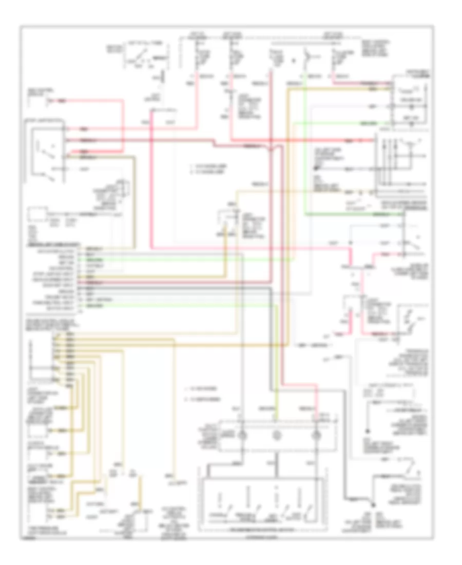
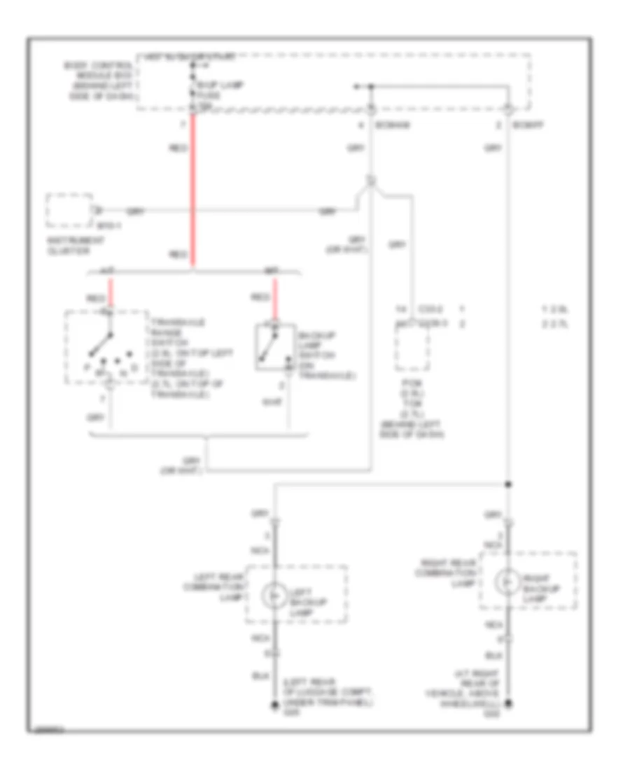
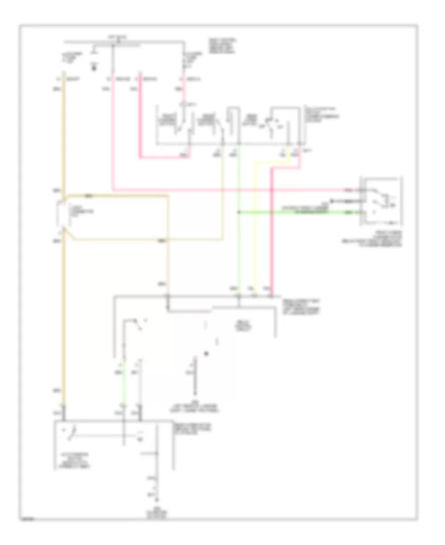
Backup Lamps Wiring Diagram for Hyundai Tiburon SE 2008
List of elements for Backup Lamps Wiring Diagram for Hyundai Tiburon SE 2008:
- (at right rear of vehicle, above wheelwell) g02
- (left rear of luggage compt, under trim panel) g05
- 2.0l
- 2.7l
- A/t
- B/up lamp fuse 10a
- Backup lamp switch (on transaxle)
- Bcm-ff
- Bcm-km
- Body control module box (behind left side of dash)
- C136-3
- C33-2
- Hot in on or start
- Instrument cluster
- Left backup lamp
- Left rear combination lamp
- M/t
- M10-1
- Nca
- Pcm (2.0l) tcm (2.7l) (behind left side of dash)
- Red
- Right backup lamp
- Right rear combination lamp
- Transaxle range switch (2.0l: on top left side of transaxle) (2.7l: on top of transaxle)
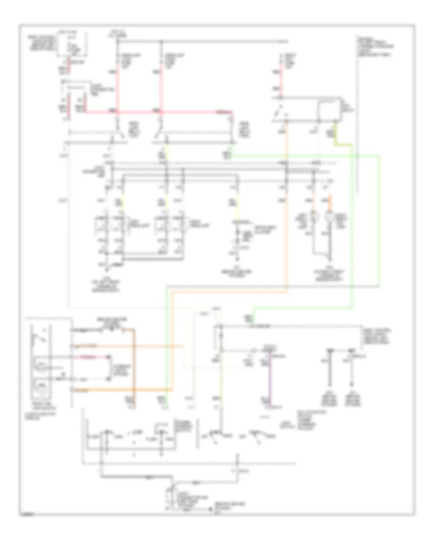
Exterior Lamps Wiring Diagram for Hyundai Tiburon SE 2008
List of elements for Exterior Lamps Wiring Diagram for Hyundai Tiburon SE 2008:
- (2.0l) (2.7l)
- (in center of hatch) g06
- (left side of dash) joint connector m36
- 12 volt out
- Batt fusible link 50a
- Bcm-ce
- Bcm-de
- Bcm-ff
- Bcm-hm
- Bcm-im
- Bcm-km
- Bcm-lm
- Body control module box (behind left side of dash)
- Clock & switch module
- E/r box (in left front corner of engine compartment, behind battery)
- E/r box (in left front corner of engine compt, behind battery)
- G02 (at right rear of vehicle, above wheelwell)
- G05 (left rear of luggage compt, under trim panel)
- G11 (behind center of dash)
- G12 (behind center of dash)
- G15 (on left front corner of engine compt)
- G16 (on right front corner of engine compt)
- Ground
- Hazard fuse 10a
- Hazard relay
- Hazard switch
- Head
- High mounted stoplamp
- Hot at all times
- Ill
- Instrument cluster
- Interior lights system
- Joint connector c41 c141 (behind crash pad)
- Joint connector e56
- Joint connector f09
- Joint connector f10
- Left
- Left head lamp
- Left rear combination lamp
- Left side re- peater lamp
- Left turn ind
- License lamp
- Light switch
- M01-2
- M10-2
- M10-3
- Multifunction switch (under steering column)
- Nca
- Off
- P/tray
- Park
- Power distribution system
- Red
- Right
- Right head lamp
- Right rear combination lamp
- Right side re- peater lamp
- Right turn ind
- Side mar- ker
- Side marker
- Solid state
- Spoiler
- Stop
- Stop fuse 15a
- Stop lamp switch
- Tail
- Tail lamp relay
- Tail-lh fuse 10a
- Tail-rh fuse 10a
- Turn
- Turn signal switch
- W/ esc & cruise
- W/o esc & cruise
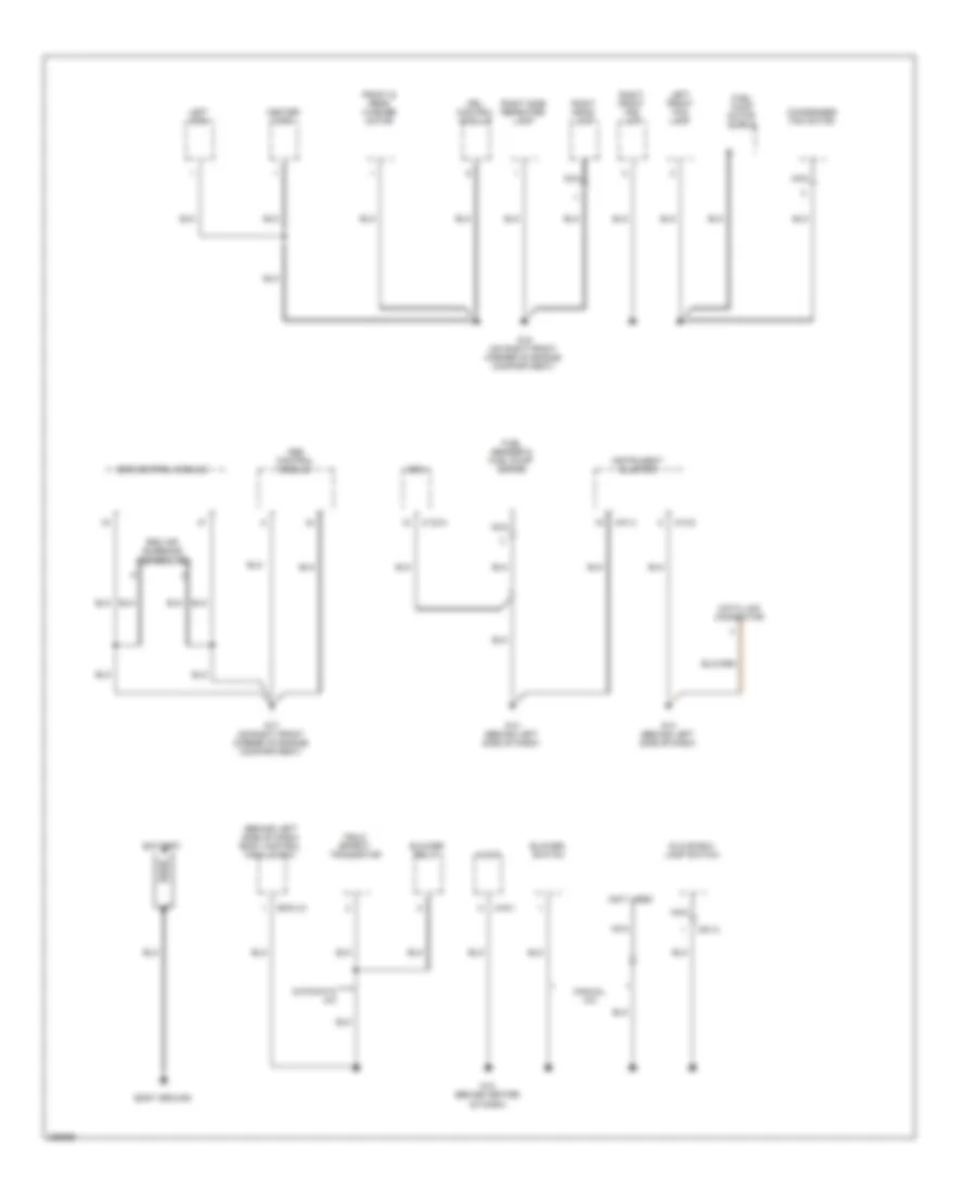
GROUND DISTRIBUTION
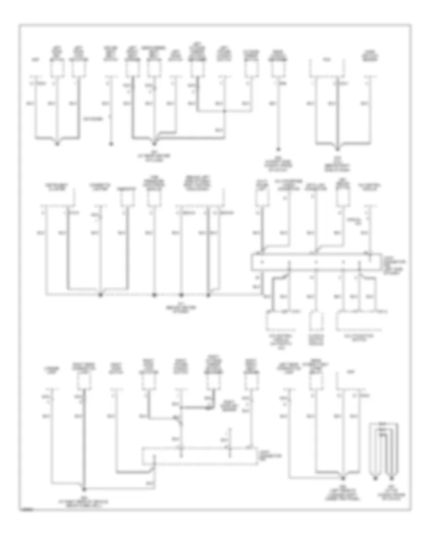
Ground Distribution Wiring Diagram (1 of 3) for Hyundai Tiburon SE 2008
List of elements for Ground Distribution Wiring Diagram (1 of 3) for Hyundai Tiburon SE 2008:
- (behind left side of dash) body control module box
- (depowered) seat belt switch
- A/c control module
- A/c control module (automatic a/c)
- Advanced
- Amp
- Bcm-hm
- Bcm-lm
- C33-1
- Cigarette lighter
- Clock & switch module
- Data link connector
- Driver seat belt switch
- F08-2
- G01 (at rear center of floor)
- G02 (at right rear of vehicle, above wheelwell)
- G05 (left rear of luggage compt, under trim panel)
- G07 (in top window frame of hatch)
- G08 (in right side window frame of hatch)
- G11 (behind center of dash)
- G19 (2.0l) (behind right side of dash)
- Instrument cluster
- Joint connector f09
- Joint connector m36 (left side of dash)
- Key remind switch
- Left door key switch
- Left door lock actuator
- Left door switch
- Left front seat warmer
- Left outside mirror motor & defogger
- Left power window switch
- Left rear combination lamp
- License lamp
- M01-2
- M10-3
- M19-1
- Manual a/c
- Mass air flow sensor
- Multi gauge unit
- Multi-function switch
- Multipurpose check connector
- Nca
- Outside mirror switch
- Pcm
- R06
- Rear intermittent wiper relay
- Rear window defogger
- Rheostat
- Right door key switch
- Right door lock actuator
- Right door switch
- Right front seat warmer
- Right outside mirror motor & defogger
- Right power window switch
- Right rear combination lamp
- Tire pressure monitoring module
Ground Distribution Wiring Diagram (2 of 3) for Hyundai Tiburon SE 2008
List of elements for Ground Distribution Wiring Diagram (2 of 3) for Hyundai Tiburon SE 2008:
- (2.0l) knock sensor shield
- (advanced)
- (advanced) belt tension sensor & pods module
- (advanced) telltale lamp
- (depowered)
- (in left front corner of engine compt, behind battery) e/r box
- 5 m/t
- A/t & 6 m/t
- A/t control relay
- Aqs sensor
- Brake fluid level sensor
- Burglar alarm horn
- C133-1
- C133-5
- C136-1
- C136-3
- C33-2
- Cond 2 relay
- Cruise clutch pedal position switch
- Cruise control module
- Ecm
- Front wiper motor
- Fuel pump motor shield
- Fuel sender & fuel pump motor
- G04 (at rear center of floor)
- G06 (in center of hatch)
- G09 (below right front passenger seat)
- G15 (on left front corner of engine compt)
- G18 (2.0l) (behind left side of dash)
- G20 (2.0l) (on left side of engine compt)
- G21 (2.7l) (on firewall, above brake pedal)
- G22 (2.7l) (behind right side of dash)
- G23 (2.7l) (behind left side of dash)
- G24 (2.7l) (top rear of cylinder head)
- High mounted stop lamp
- Hood switch
- Ignition coil shield
- Left headlamp
- Left side repeater lamp
- Luggage room lamp switch
- Nca
- P/ tray
- Pcm
- Rear wiper motor
- Right headlamp
- Spoiler
- Srs control module
- Start relay
- Tail gate lid solenoid
- Tail gate unlock switch
- Tcm
- Vehicle speed sensor
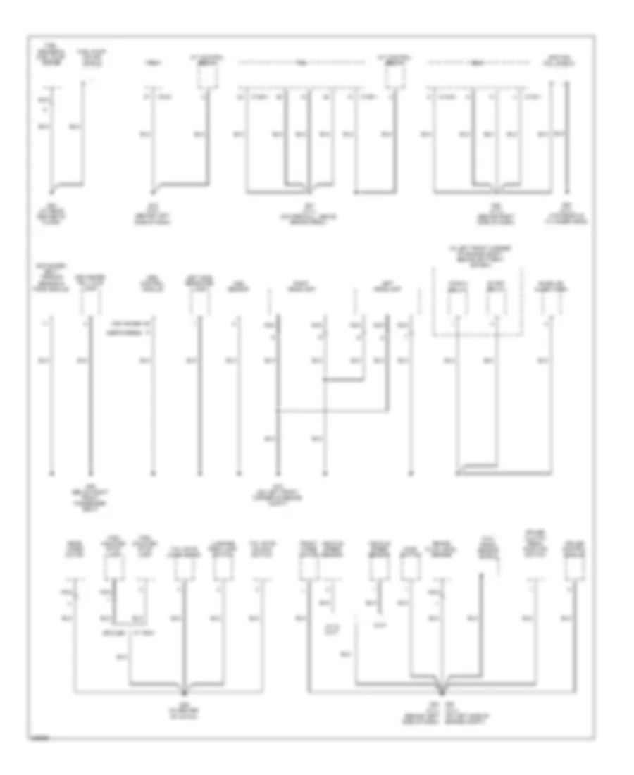
Ground Distribution Wiring Diagram (3 of 3) for Hyundai Tiburon SE 2008
List of elements for Ground Distribution Wiring Diagram (3 of 3) for Hyundai Tiburon SE 2008:
- (behind left side of dash) body control module box
- (not used)
- Abs control module
- Audio
- Automatic a/c
- Battery
- Bcm-lm
- Blower relay
- Blower switch
- Body ground
- C133-4
- Center horn
- Condenser fan motor
- Data link connector
- Drl control module
- Ecm
- Esc air bleeding connector
- Esc control module
- Field effect transistor
- Front & rear washer motor
- Fuel pump motor shield
- Fuel sender & fuel pump motor
- G12 (behind center of dash)
- G13 (behind left side of dash)
- G14 (behind left side of dash)
- G16 (on right front corner of engine compartment)
- G17 (on right front corner of engine compartment)
- Glove box lamp switch
- Instrument cluster
- Left front fog lamp
- Left horn
- M10-2
- M10-3
- M16-1
- M51-2
- Manual a/c
- Nca
- Right front fog lamp
- Right head- lamp
- Right side repeater lamp
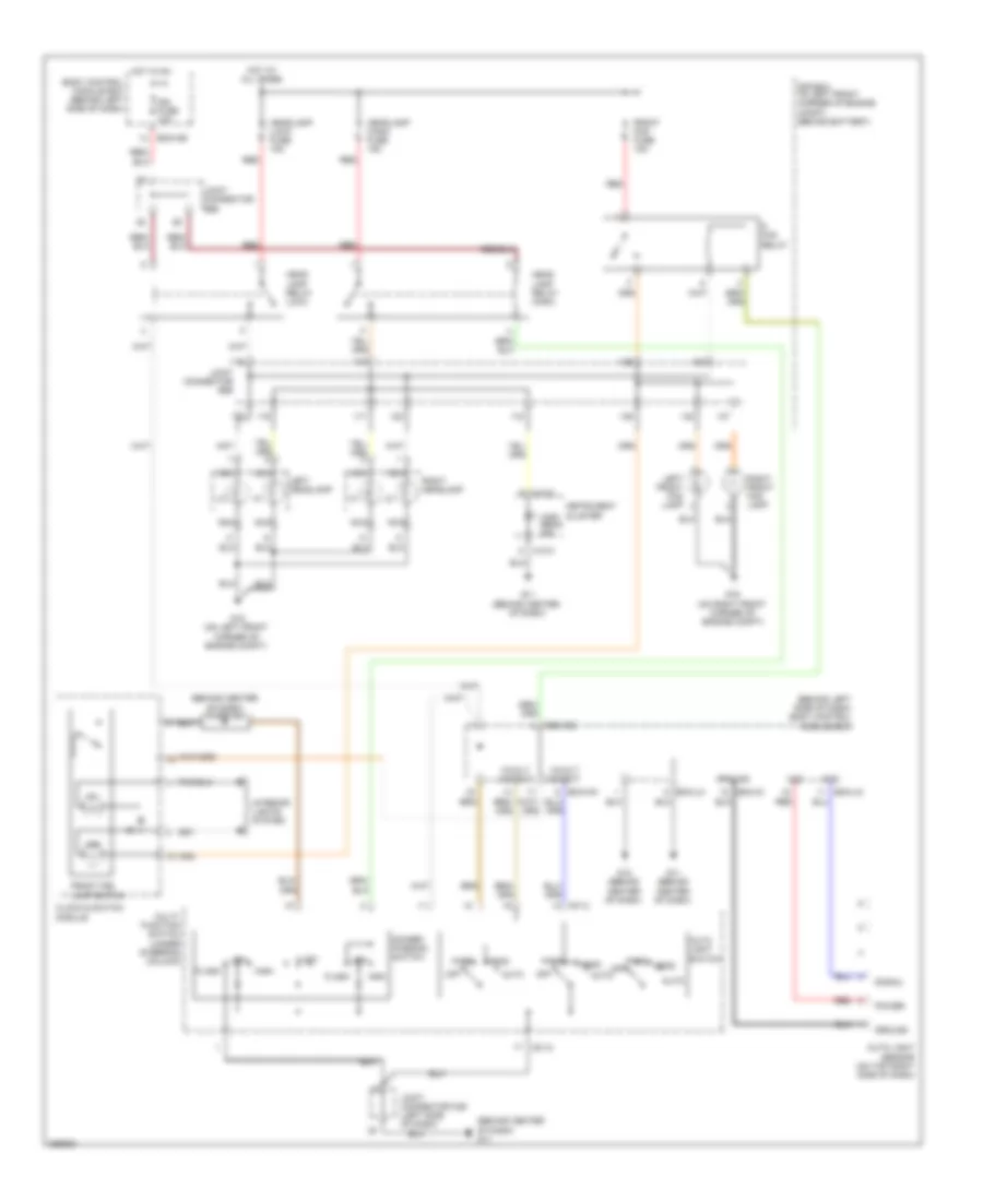
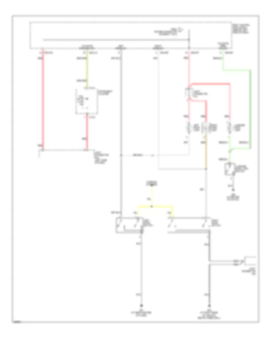
HEADLIGHTS
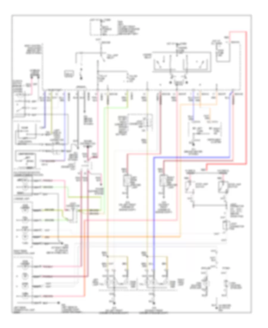
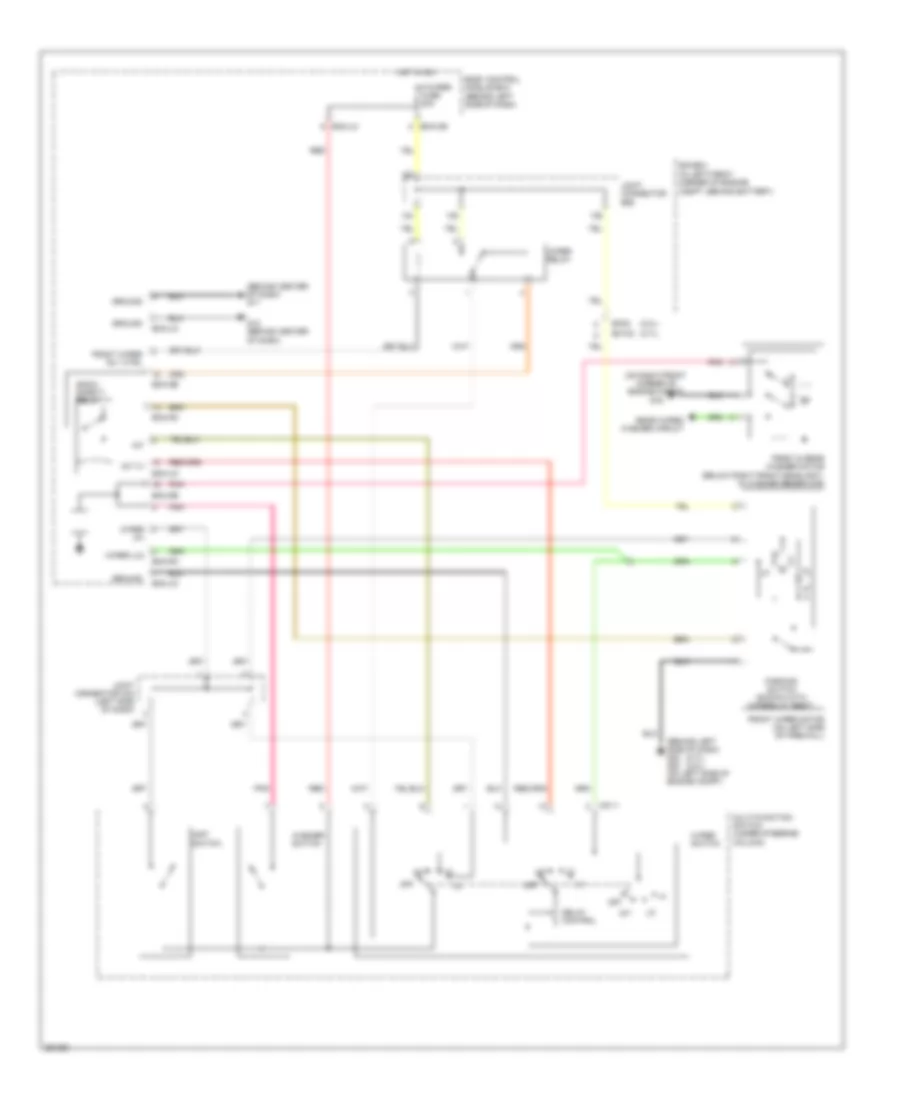
Headlights Wiring Diagram, with Autolamps for Hyundai Tiburon SE 2008
List of elements for Headlights Wiring Diagram, with Autolamps for Hyundai Tiburon SE 2008:
- (behind center of dash) diode z02
- (behind center of dash) g11
- (behind left side of dash) body control module box
- 12volt output
- Atd
- Auto
- Auto light sensor (on top right side of dash)
- Auto light switch
- Bcm-ce
- Bcm-hm
- Bcm-im
- Bcm-jm
- Bcm-lm
- Body control module box (behind left side of dash)
- Clock & switch module
- Dimmer/ passing switch
- E/r box (in left front corner of engine compt, behind battery)
- F/ fog relay
- Flash
- Front fog fuse 15a
- Front fog lamp switch
- G11 (behind center of dash)
- G12 (behind center of dash)
- G15 (on left front corner of engine compt)
- G16 (on right front corner of engine compt)
- Ground
- Head
- Head lamp relay (high)
- Head lamp relay (low)
- Headlamp (high) fuse 15a
- Headlamp (low) fuse 15a
- High
- High beam ind
- Hot at all times
- Hot in on
- Ign fuse 10a
- Ill
- Ind
- Instrument cluster
- Interior lights system
- Joint connector e56
- Joint connector m36 (left side of dash)
- Left front fog lamp
- Left headlamp
- Low
- M01-2
- M10-3
- Multi- function switch (under steering column)
- Nca
- Off
- Park
- Park off
- Power
- Red
- Right front fog lamp
- Right headlamp
- Signal
- Vcc
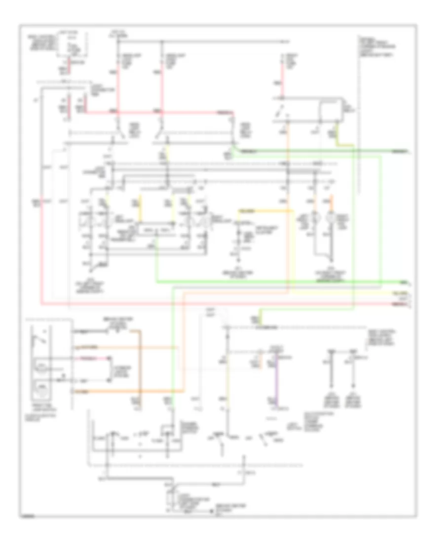
Headlights Wiring Diagram, with DRL (1 of 2) for Hyundai Tiburon SE 2008
List of elements for Headlights Wiring Diagram, with DRL (1 of 2) for Hyundai Tiburon SE 2008:
- (behind center of dash) diode z02
- (behind center of dash) g11
- 12volt output
- Bcm-ce
- Bcm-hm
- Bcm-lm
- Body control module box (behind left side of dash)
- Clock & switch module
- Dimmer/ passing switch
- Drl resistor (on left fenderwell)
- E/r box (in left front corner of engine compt, behind battery)
- F/ fog relay
- Flash
- Front fog fuse 15a
- Front fog lamp switch
- G11 (behind center of dash)
- G12 (behind center of dash)
- G15 (on left front corner of engine compt)
- G16 (on right front corner of engine compt)
- Gnd
- Head
- Head lamp relay (high)
- Head lamp relay (low)
- Headlamp (high) fuse 15a
- Headlamp (low) fuse 15a
- High
- High beam ind
- Hot at all times
- Hot in on
- Ign fuse 10a
- Ill
- Ind
- Instrument cluster
- Interior lights system
- Joint connector e56
- Joint connector m36 (left side of dash)
- Left front fog lamp
- Left headlamp
- Light switch
- Low
- M01-2
- M10-3
- Multi-function switch (under steering column)
- Nca
- Off
- Park
- Red
- Right front fog lamp
- Right headlamp
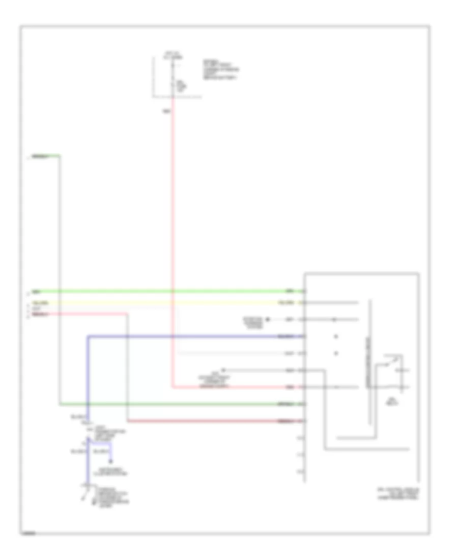
Headlights Wiring Diagram, with DRL (2 of 2) for Hyundai Tiburon SE 2008
List of elements for Headlights Wiring Diagram, with DRL (2 of 2) for Hyundai Tiburon SE 2008:
- Drl control module (on left front inner fender panel)
- Drl fuse 15a
- Drl relay
- E/r box (in left front corner of engine compt, behind battery)
- G16 (on right front corner of engine compt)
- Hot at all times
- Instrument cluster system
- Joint connector m35 (left side of dash)
- Parking brake switch (on base of parking brake lever)
- Power & control circuit
- Red
- Starting/ charging system
Headlights Wiring Diagram, without DRL for Hyundai Tiburon SE 2008
List of elements for Headlights Wiring Diagram, without DRL for Hyundai Tiburon SE 2008:
- (behind center of dash) diode z02
- (behind center of dash) g11
- 12volt output
- Bcm-ce
- Bcm-hm
- Bcm-lm
- Body control module box (behind left side of dash)
- Clock & switch module
- Dimmer/ passing switch
- E/r box (in left front corner of engine compt, behind battery)
- F/ fog relay
- Flash
- Front fog fuse 15a
- Front fog lamp switch
- G11 (behind center of dash)
- G12 (behind center of dash)
- G15 (on left front corner of engine compt)
- G16 (on right front corner of engine compt)
- Gnd
- Head
- Head lamp relay (high)
- Head lamp relay (low)
- Headlamp (high) fuse 15a
- Headlamp (low) fuse 15a
- High
- High beam ind
- Hot at all times
- Hot in on
- Ign fuse 10a
- Ill
- Ind
- Instrument cluster
- Interior lights system
- Joint connector e56
- Joint connector m36 (left side of dash)
- Left front fog lamp
- Left headlamp
- Light switch
- Low
- M01-2
- M10-3
- Multi-function switch (under steering column)
- Nca
- Off
- Park
- Red
- Right front fog lamp
- Right headlamp
HORN
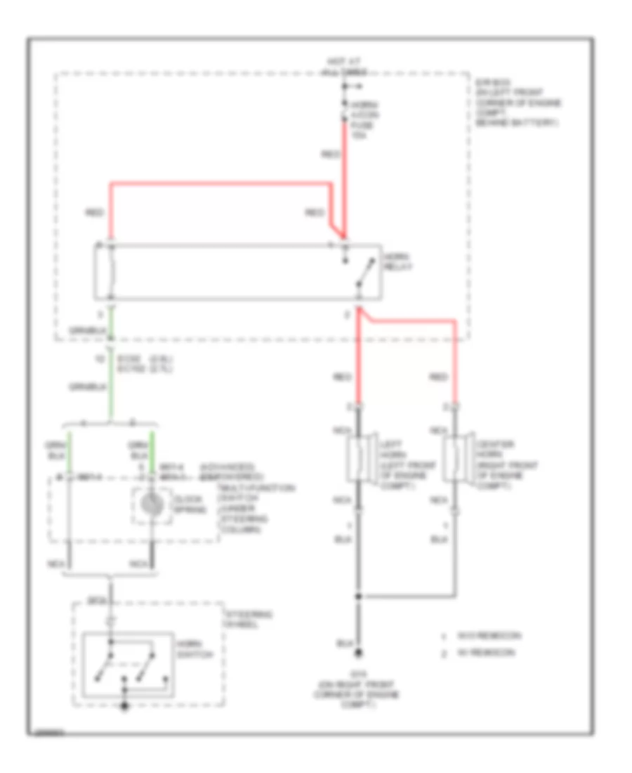
Horn Wiring Diagram for Hyundai Tiburon SE 2008
List of elements for Horn Wiring Diagram for Hyundai Tiburon SE 2008:
- (2.0l) (2.7l)
- (advanced) (depowered)
- Center horn (right front of engine compt)
- Clock spring
- E/r box (in left front corner of engine compt, behind battery)
- Ec02 ec102
- G16 (on right front corner of engine compt)
- Horn relay
- Horn switch
- Horn/ a/con fuse 15a
- Hot at all times
- Left horn (left front of engine compt)
- M01-1
- M01-4 m01-3
- Multi-function switch (under steering column)
- Nca
- Red
- Steering wheel
- W/ remocon
- W/o remocon
INSTRUMENT CLUSTER
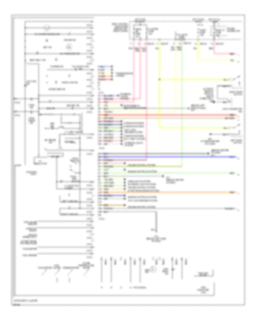
Instrument Cluster Wiring Diagram (1 of 2) for Hyundai Tiburon SE 2008
List of elements for Instrument Cluster Wiring Diagram (1 of 2) for Hyundai Tiburon SE 2008:
- (at right rear of vehicle, above wheelwell)
- (behind center of dash) g11
- (behind left side of dash) g14
- 5v regulator
- A/bag ind fuse 10a
- Abs ind
- Abs/ebd
- Anti-lock brakes system
- Anti-theft system
- Audio fuse 10a
- Bcm-ff
- Bcm-im
- Bcm-jm
- Bcm-km
- Body control module box (behind left side of dash)
- Brake ind
- Charge ind
- Cluster fuse 10a
- Cruise control system
- Cruise ind
- Door ajar ind
- Engine controls system
- Esc ind
- Esc off ind
- Exterior lights system
- Fuel gauge
- Fuel gauge ground
- Fuel sender
- G01 (at rear center of floor)
- G02
- G11 (behind center of dash)
- G13 (behind left side of dash)
- Headlights system
- High beam ind
- Hot at all times
- Hot in acc or on
- Hot in on or start
- Illumination (4 leds)
- Immobilizer ind
- Injection signal
- Instrument cluster
- Interior lights system
- Joint connector f09
- Lcd led
- Left door switch
- Left turn ind
- Low fuel ind
- M10-1
- M10-2
- M10-3
- Micom
- Mil (check engine) ind
- Odo/ trip switch
- Oil pressure ind
- On/start input
- Pnk
- Power connector
- Pwm signal
- Red
- Right door switch
- Right turn ind
- Room lp fuse 10a
- Seat belt ind
- Set ind
- Speedometer
- Srs ind
- Starting/charging system
- Tachometer
- Tail gate ajar ind
- Tail gate open switch
- Tpms ind
- Tpms tread ind
- Transmissions system
- Trip computer (lcd)
- Trip/ odo meter
- Trip/c switch
- Vehicle speed input
- Warning systems
- Water tempe- rature gauge
- Water temperature gauge
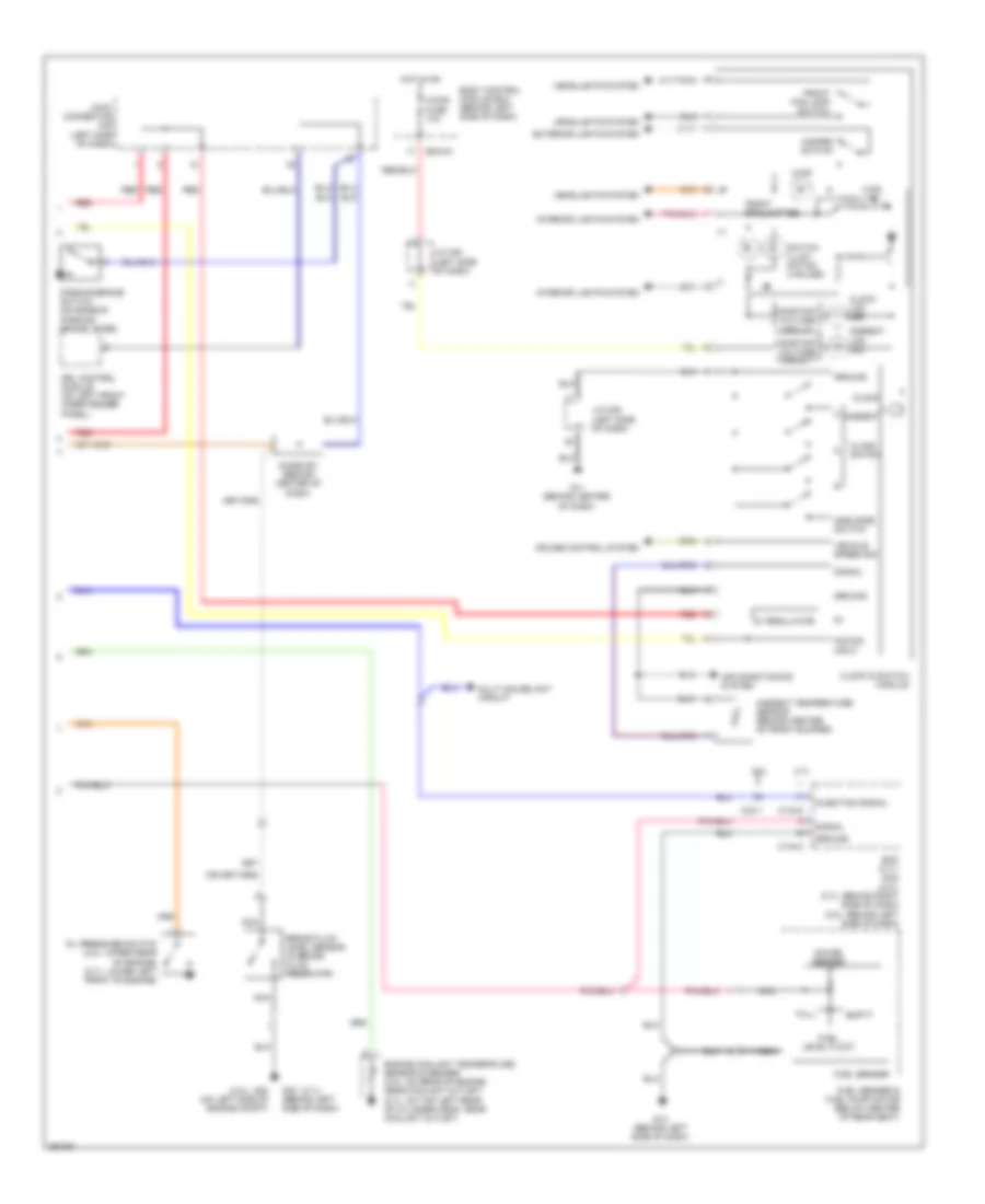
Instrument Cluster Wiring Diagram (2 of 2) for Hyundai Tiburon SE 2008
List of elements for Instrument Cluster Wiring Diagram (2 of 2) for Hyundai Tiburon SE 2008:
- (+)
- (-)
- (2.0l)
- (2.7l)
- 2.0l
- 2.7l
- 5v regulator
- A/con fuse 10a
- Acc/on input
- Air conditioning system
- Amb mode switch
- Ambient
- Ambient lcd led
- Ambient temperature sensor (behind center of front bumper)
- Bcm-im
- Body control module box (behind left side of dash)
- Brake fluid level sensor (in brake fluid reservoir)
- C133-2
- C133-4
- C33-1
- Clock
- Clock & switch module
- Clock lcd led
- Clock switch
- Constant voltage circuit
- Cruise control system
- Diode z01 (behind center of dash)
- Drl control module (on left front inner fender panel)
- Ecm (2.7l) pcm (2.0l) (2.7l: behind right side of dash) (2.0l: behind left side of dash)
- Empty
- Engine coolant temperature sensor & sender (2.0l: on rear of engine, near coolant outlet) (2.7l: on top left rear of cylinder head, near coolant outlet)
- Exterior lights system
- Front fog lamp ind
- Front fog lamp switch
- Fuel level float
- Fuel sender
- Fuel sender & fuel pump motor (below center of rear seat)
- Full
- G11 (behind center of dash)
- G13 (behind left side of dash)
- G20 (on left side of engine compt)
- G23 (behind left side of dash)
- Gauge sender
- Ground
- Hazard switch
- Headlights system
- Hot in on
- Injection signal
- Interior lights system
- J/c m35 (left side of dash)
- J/c m36 (left side of dash)
- Joint connector m35 (left side of dash)
- Multi gauge unit circuit
- Nca
- Oil pressure switch (2.0l: upper rear of engine) (2.7l: lower left front of engine)
- Parking brake switch (on base of parking brake lever)
- Red
- Signal
- Switch illum- nation (3 bulbs)
- Vehicle speed sig
Multi-Gauge Unit Wiring Diagram for Hyundai Tiburon SE 2008
List of elements for Multi-Gauge Unit Wiring Diagram for Hyundai Tiburon SE 2008:
- (2.0l) (2.7l)
- 2.0l
- 2.7l
- Amp
- Audio
- Bcm-im
- Bcm-jm
- Bcm-km
- Body control module box (behind left side of dash)
- C133-2
- C33-1
- Can (high)
- Can (low)
- Computer data lines system
- Cruise control module (on right side of firewall, behind strut tower)
- Data link connector (below left side of dash)
- Ecm (2.7l) pcm (2.0l) (2.7l: behind right side of dash) (2.0l: behind left side of dash)
- Ecu fuse 10a
- F08-2
- G11 (behind center of dash)
- Ground
- Hot at all times
- Hot in on or start
- Ill
- Injection signal input
- Instan- taneous fuel consump- tion gauge
- Instrument cluster
- Interior lights system
- Joint connector c41 c141 (behind crash pad)
- Joint connector m34 (left side of dash)
- Joint connector m35 (left side of dash)
- Joint connector m36 (left side of dash)
- M10-3
- M16-1
- Memory power
- Multi gauge unit
- On/start input
- Power connector
- Power distribution system
- Red
- Room lp fuse 10a
- Speed sensor
- Torque gauge
- Vehicle speed sensor (on top of transaxle)
- Vehicle speed signal input
- Voltage gauge
- W/ amp
- W/o amp
INTERIOR LIGHTS
Courtesy Lamps Wiring Diagram (1 of 2) for Hyundai Tiburon SE 2008
List of elements for Courtesy Lamps Wiring Diagram (1 of 2) for Hyundai Tiburon SE 2008:
- Bcm-de
- Bcm-lm
- Bcm-mr
- Body control module box (behind left side of dash)
- Door
- E/r box (in left front corner of engine compt, behind battery)
- Fusible link (batt) 50a
- G11 (behind center of dash)
- G12 (behind center of dash)
- Ground
- Hot at all times
- Off
- Overhead console lamp & sunroof switch
- Power connector
- Red
- Room lamp
- Room lp fuse 10a
- Solid state
- Timer
- To body control module box (diagram 2 of 2)
Courtesy Lamps Wiring Diagram (2 of 2) for Hyundai Tiburon SE 2008
List of elements for Courtesy Lamps Wiring Diagram (2 of 2) for Hyundai Tiburon SE 2008:
- Ajar
- Bcm-ef
- Bcm-ff
- Bcm-jm
- Bcm-km
- Body control module box (behind left side of dash)
- From power connector (diagram 1 of 2)
- G01 (at rear center of floor)
- G02 (at right rear of vehicle, above wheelwell)
- G06 (in center of hatch)
- Ind
- Instrument cluster
- Joint connector f09
- Joint connector f10
- Joint connector m35 (left side of dash)
- Left door lamp
- Left door sw
- Left door switch
- Luggage room lamp
- Luggage room lamp switch
- M10-2
- M10-3
- Red
- Right door lamp
- Right door sw
- Right door switch
- Tail gate
- Tailgate open switch
- Warning systems
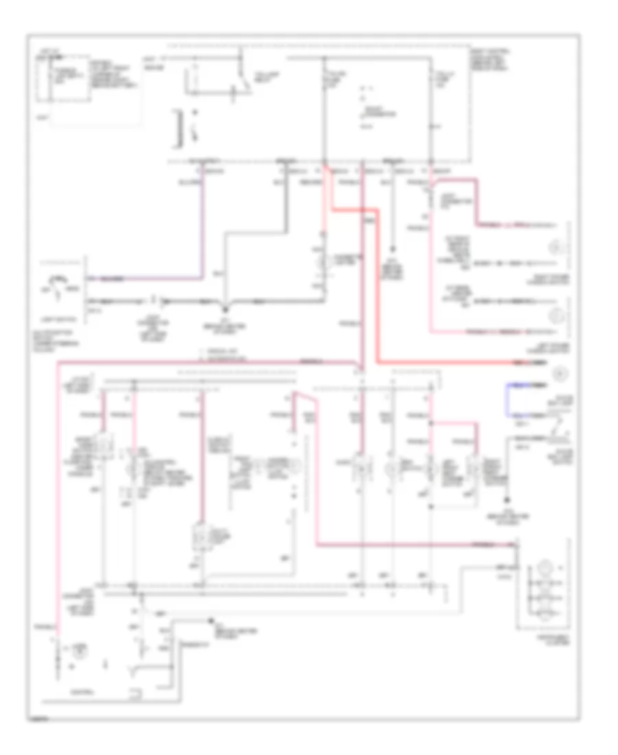
Instrument Illumination Wiring Diagram for Hyundai Tiburon SE 2008
List of elements for Instrument Illumination Wiring Diagram for Hyundai Tiburon SE 2008:
- (-)
- (at rear
- (at right rear of vehicle, above wheelwell)
- 12v output
- A/c control module (below center of dash, forward of shift lever)
- Audio
- Automatic a/c
- Bcm-de
- Bcm-ff
- Bcm-hm
- Bcm-im
- Bcm-jm
- Bcm-lm
- Body control module box (behind left side of dash)
- Center
- Cigarette lighter
- Clock & switch module
- Control
- E/r box (in left front corner of engine compt, behind battery)
- Esc
- Front fog lamp switch illumi- nation
- Fusible link (batt) 50a
- G01
- G02
- G11 (behind center of dash)
- G12 (behind center of dash)
- Glove box lamp
- Glove box lamp switch
- Gnd
- Ground
- Hazard switch illum- ination
- Head
- Hot at all times
- Illum (+)
- Instrument cluster
- J/c m33 (left side of dash)
- Joint connector f10
- Joint connector m33 (left side of dash)
- Joint connector m36 (left side of dash)
- Left front seat warmer switch
- Left power window switch
- Light switch
- M01-2
- M10-2
- M19-1 m20
- M20 m19-1
- M51-1
- M51-2
- Manual a/c
- Multi gauge unit
- Multifunction switch (under steering column)
- Nca
- Of floor)
- Off
- Park
- Pnk
- Red
- Rheostat
- Right front seat warmer switch
- Right power window switch
- Shunt connector
- Solid state
- Sport mode switch (center floor pan, under console)
- Switch
- Tail-lh fuse 10a
- Tail-rh fuse 10a
- Taillamp relay
POWER DISTRIBUTION
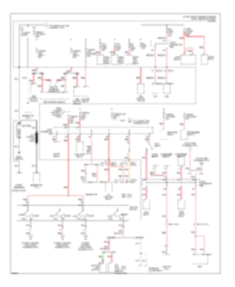
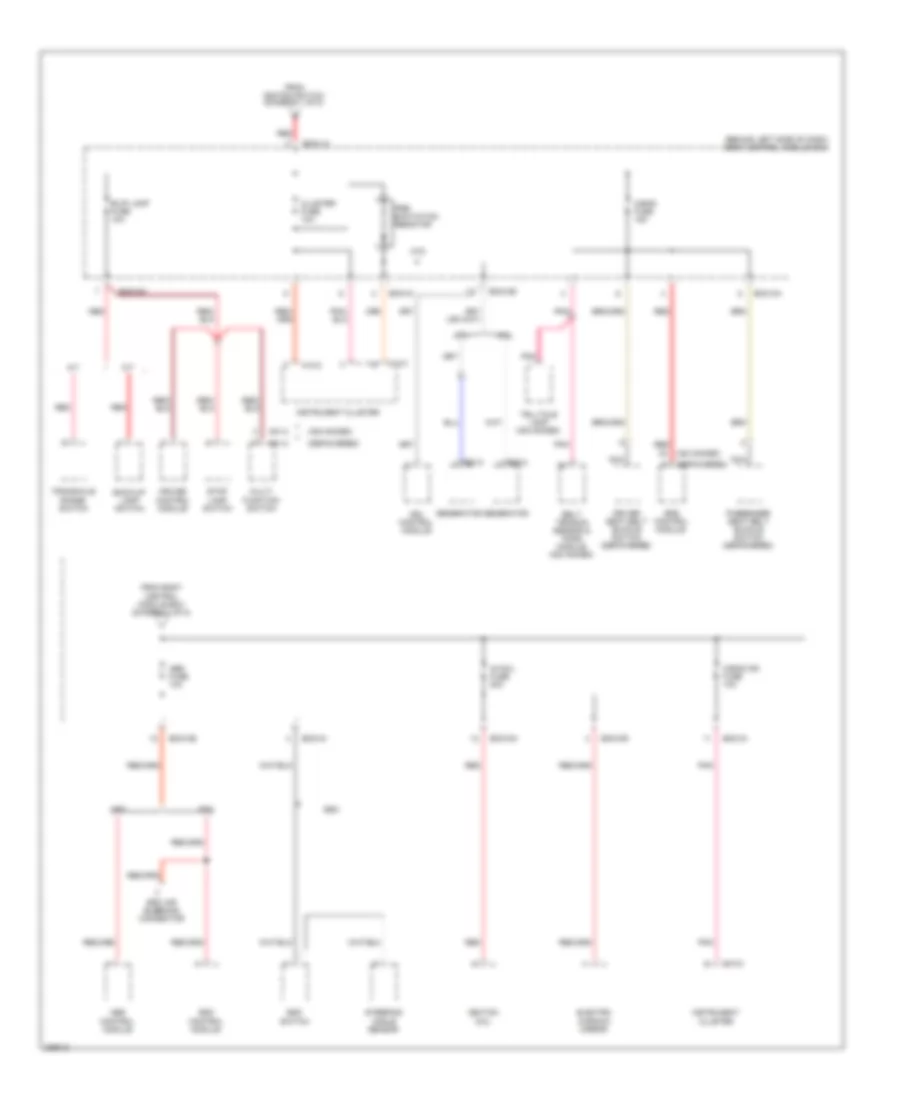
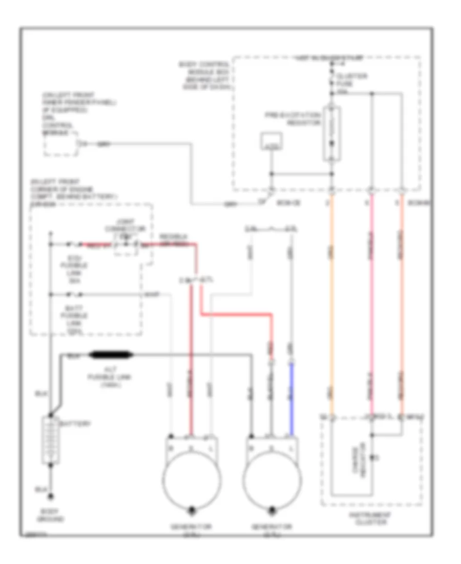
Power Distribution Wiring Diagram (1 of 8) for Hyundai Tiburon SE 2008
List of elements for Power Distribution Wiring Diagram (1 of 8) for Hyundai Tiburon SE 2008:
- (2.0l)
- (2.0l) (2.7l)
- (2.7l)
- (in left front corner of engine compt, behind battery) e/r box
- 2.0l
- 2.0l 2.7l
- 2.7l
- 2.7l 2.0l
- A/con relay
- A/t
- A/t control relay
- Abs
- Abs control module
- Acc
- Alt fusible link (140a)
- Battery
- Blower relay
- Body ground
- Burglar alarm relay
- C133-1
- C133-2 c33-1
- C136-2
- Condenser relay 1
- Condenser relay 2
- Drl control module
- Drl fuse 15a
- E20-2
- E61-2
- Ec01
- Ec01 ec101
- Ec02 ec102
- Ec101
- Ec102
- Ecm
- Ecu fuse (2.7l) 10a
- Esc
- Esc air bleeding connector
- Esc control module
- From fusible link (batt) a (diagram 1 of 8)
- Front fog lamp relay
- Frt fog fuse 15a
- Fuel pump relay
- Fusible link (abs 1) 40a
- Fusible link (abs 2) 40a
- Fusible link (batt) 120a
- Fusible link (batt) 50a
- Fusible link (blower) 30a
- Fusible link (cond) 30a
- Fusible link (ecu) 30a
- Fusible link (ign) 30a
- Fusible link (rad) 30a
- Generator
- Generator (2.0l)
- Generator (2.7l)
- H/lp (high) fuse 15a
- H/lp (low) fuse 15a
- Head- lamp relay (high)
- Head- lamp relay (low)
- Horn & a/con fuse 15a
- Horn relay
- Ignition coil
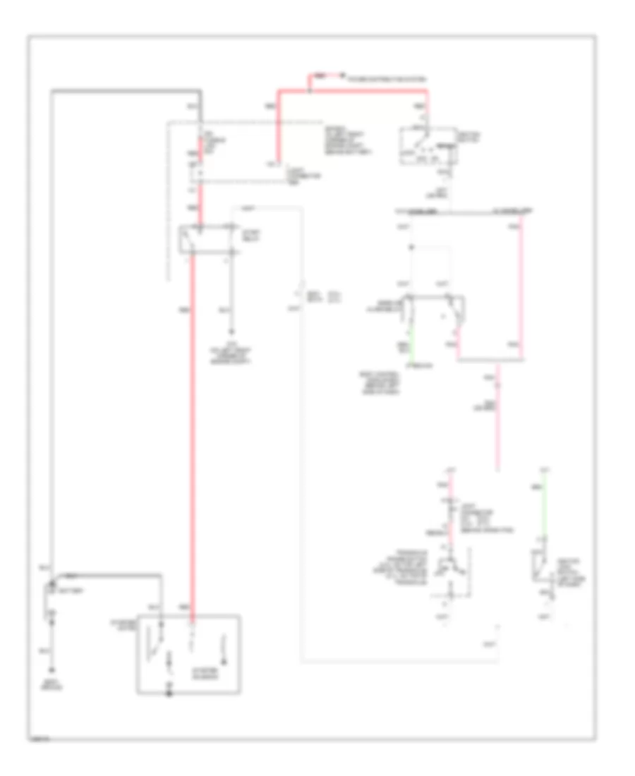
- Ignition lock switch
- Ignition switch
- J/c c41 c141 (behind crash pad)
- Joint connector e56
- Lock
- M/t
- Main relay
- Nca
- Pcm ecm
- Pnk
- Rad relay
- Radiator relay
- Red
- Short bar
- Start
- Start motor
- Start relay
- Start solenoid
- Tcm
- To body control module box (diagram 2 of 8)
- To body control module box (diagram 4 of 8)
- To body control module box (diagram 5 of 8)
- To fusible link (ign) (diagram 1 0f 8)
- To hazard fuse (diagram 6 of 8)
- To inj fuse (diagram 2 of 8)
- To inj fuse (diagram 3 of 8)
- W/o immo
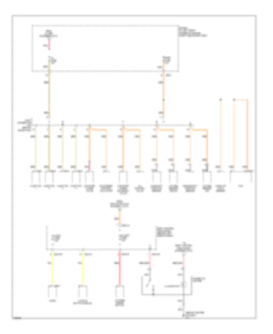
Power Distribution Wiring Diagram (2 of 8) for Hyundai Tiburon SE 2008
List of elements for Power Distribution Wiring Diagram (2 of 8) for Hyundai Tiburon SE 2008:
- (behind center of dash) g11
- Audio
- Audio fuse 10a
- Bcm-ff
- Bcm-im
- Bcm-km
- Bcm-lm
- Body control module box (behind left side of dash)
- C/light fuse 15a
- C24-1
- C24-2
- C24-3
- C24-4
- C33-1
- Camshaft position sensor
- Canister close valve
- Canister purge solenoid valve
- Cigarette lighter
- Clock & switch module
- Crankshaft position sensor
- E/r box (in left front corner of engine compt, behind battery)
- Ec01
- From ignition switch (diagram 1 of 8)
- From j/c e56 (diagram 1 of 8)
- Idle speed control actuator
- Illumination
- Inj fuse 15a
- Injector
- Joint connector c42 (behind crash pad)
- M16-1
- Mass air flow sensor
- Nca
- Oil control valve
- Outside mirror switch
- Oxygen sensor (down)
- Oxygen sensor (up)
- Pcm
- Pnk
- Red
- Snsr fuse 10a
- To body control module box (diagram 8 of 8)
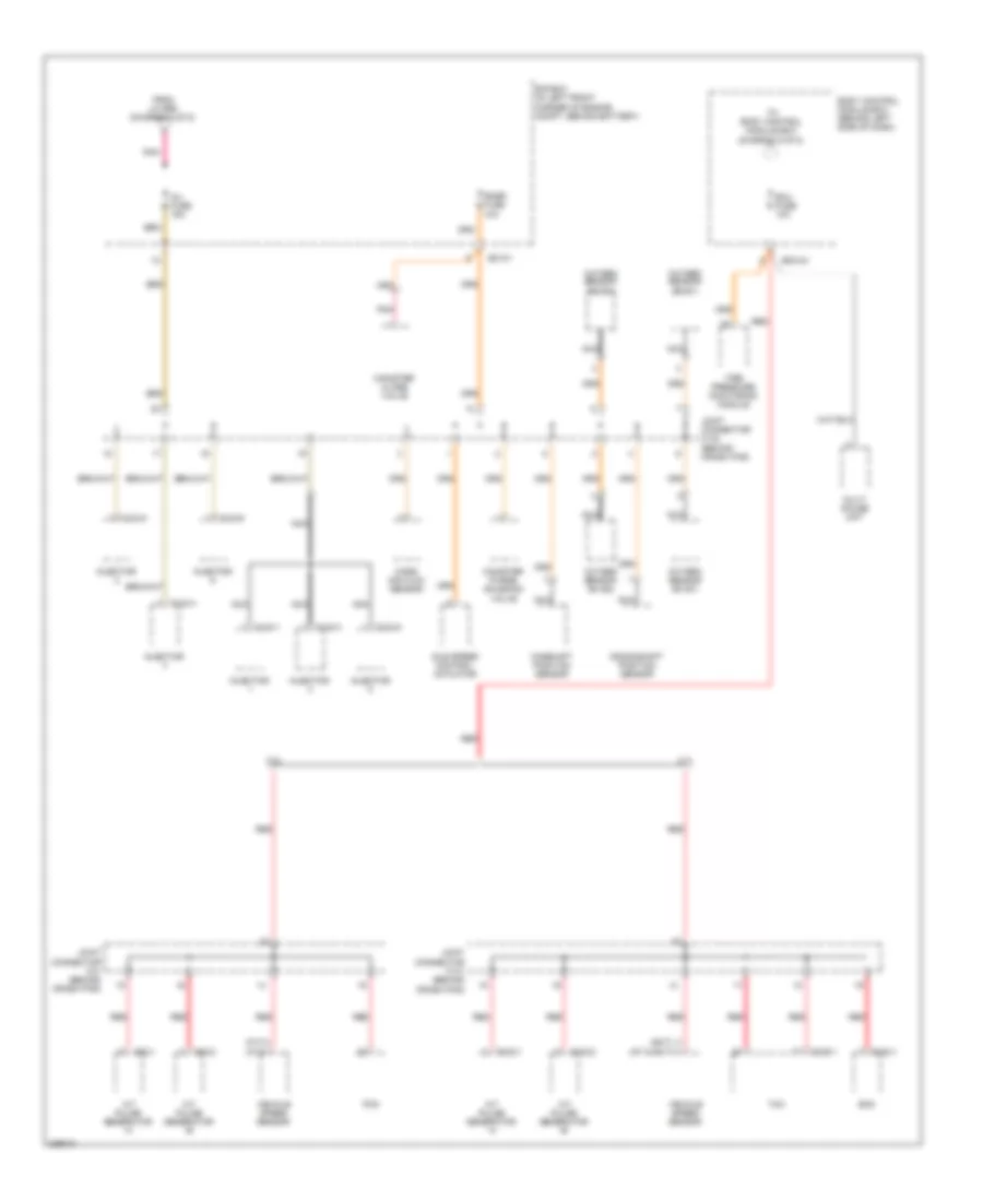
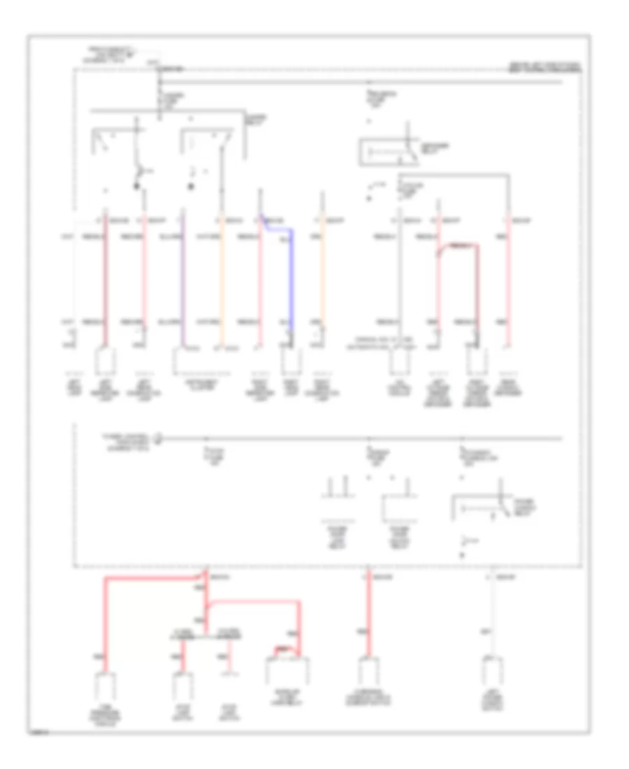
Power Distribution Wiring Diagram (3 of 8) for Hyundai Tiburon SE 2008
List of elements for Power Distribution Wiring Diagram (3 of 8) for Hyundai Tiburon SE 2008:
- (5m/t) (a/t & 6m/t)
- (m/t) (a/t)
- 2.0l
- 2.7l
- A/t pulse generator 'a'
- A/t pulse generator 'b'
- Bcm-im
- Body control module box (behind left side of dash)
- C02-1
- C02-2
- C102-1
- C102-2
- C124-1
- C124-2
- C124-3
- C124-4
- C124-5
- C124-6
- C133-1
- C136-1
- Camshaft position sensor
- Canister close valve
- Canister purge solenoid valve
- Crankshaft position sensor
- E/r box (in left front corner of engine compt, behind battery)
- Ec101
- Ecm
- Ecu fuse 10a
- From j/c e56 (diagram 1 of 8)
- Idle speed control actuator
- Inj fuse 15a
- Injector
- Joint connector c141 (behind crash pad)
- Joint connector c142 (behind crash pad)
- Joint connector c41 (behind crash pad)
- Mass air flow sensor
- Multi gauge unit
- Nca
- Oxygen sensor (b1/s1)
- Oxygen sensor (b1/s2)
- Oxygen sensor (b2/s1)
- Oxygen sensor (b2/s2)
- Pcm
- Pnk
- Red
- Snsr fuse 10a
- Tcm
- Tire pressure monitoring module
- To body control module box (diagram 5 of 8)
- Vehicle speed sensor
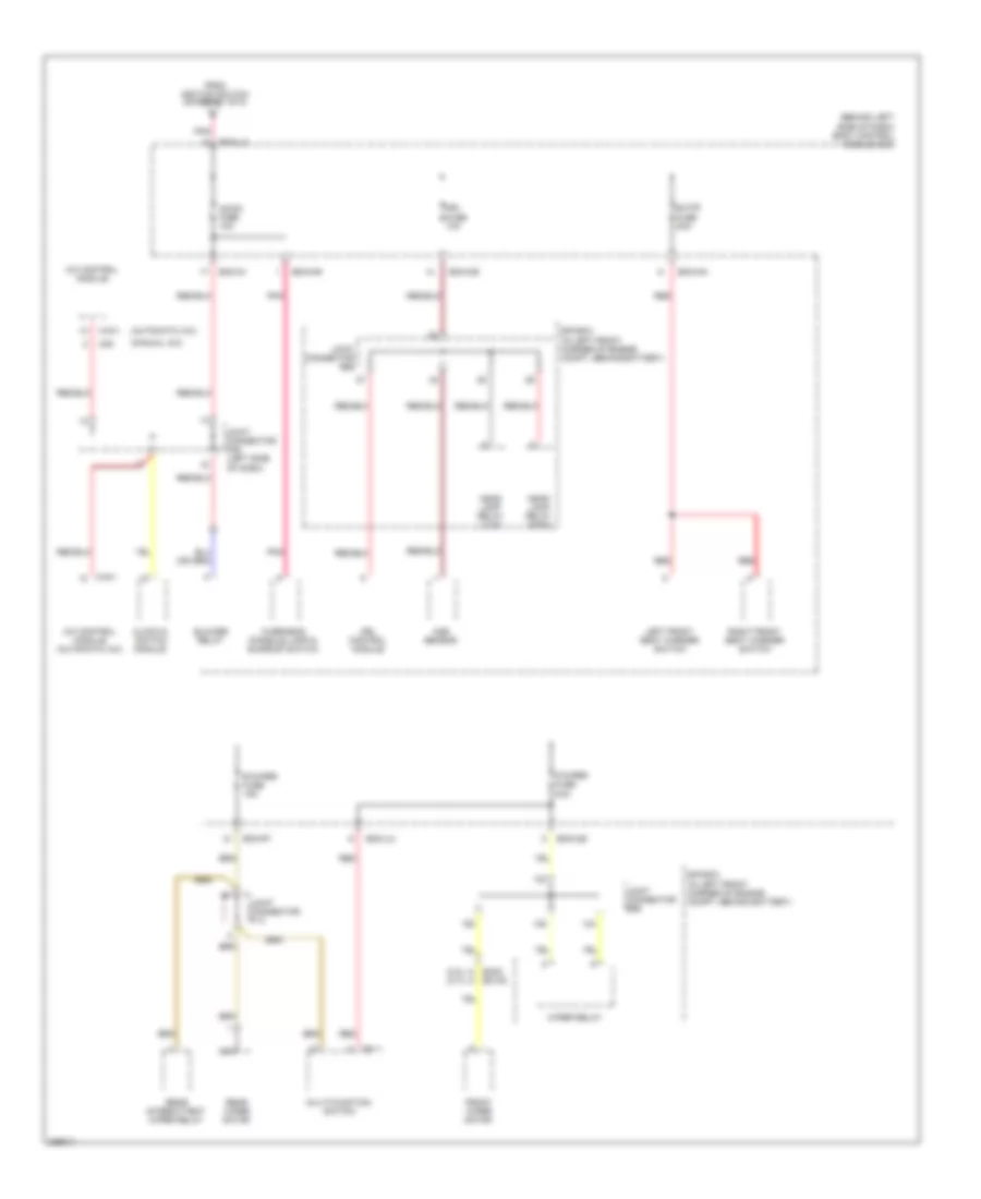
Power Distribution Wiring Diagram (4 of 8) for Hyundai Tiburon SE 2008
List of elements for Power Distribution Wiring Diagram (4 of 8) for Hyundai Tiburon SE 2008:
- (2.0l) (2.7l)
- (automatic a/c)
- (behind left side of dash) body control module box
- (manual a/c)
- A/c control module
- A/c control module (automatic a/c)
- A/con fuse 10a
- Aqs sensor
- Bcm-ce
- Bcm-ff
- Bcm-im
- Bcm-km
- Bcm-lm
- Bcm-mr
- Blower relay
- Clock & switch module
- Drl control module
- E/r box (in left front corner of engine compt, behind battery)
- Ec02 ec102
- F/wiper fuse 2oa
- From ignition switch (diagram 1 of 8)
- Front wiper motor
- Head lamp relay (high)
- Head lamp relay (low)
- Ign fuse 10a
- Joint connector e56
- Joint connector f10
- Joint connector m35 (left side of dash)
- Left front seat warmer switch
- M01-1
- M19-1
- M20
- Multi-function switch
- Nca
- Overhead console lamp & sunroof switch
- Pnk
- R/wiper fuse 15a
- Rear intermittent wiper relay
- Rear wiper motor
- Red
- Right front seat warmer switch
- S/htr fuse 2oa
- Wiper relay
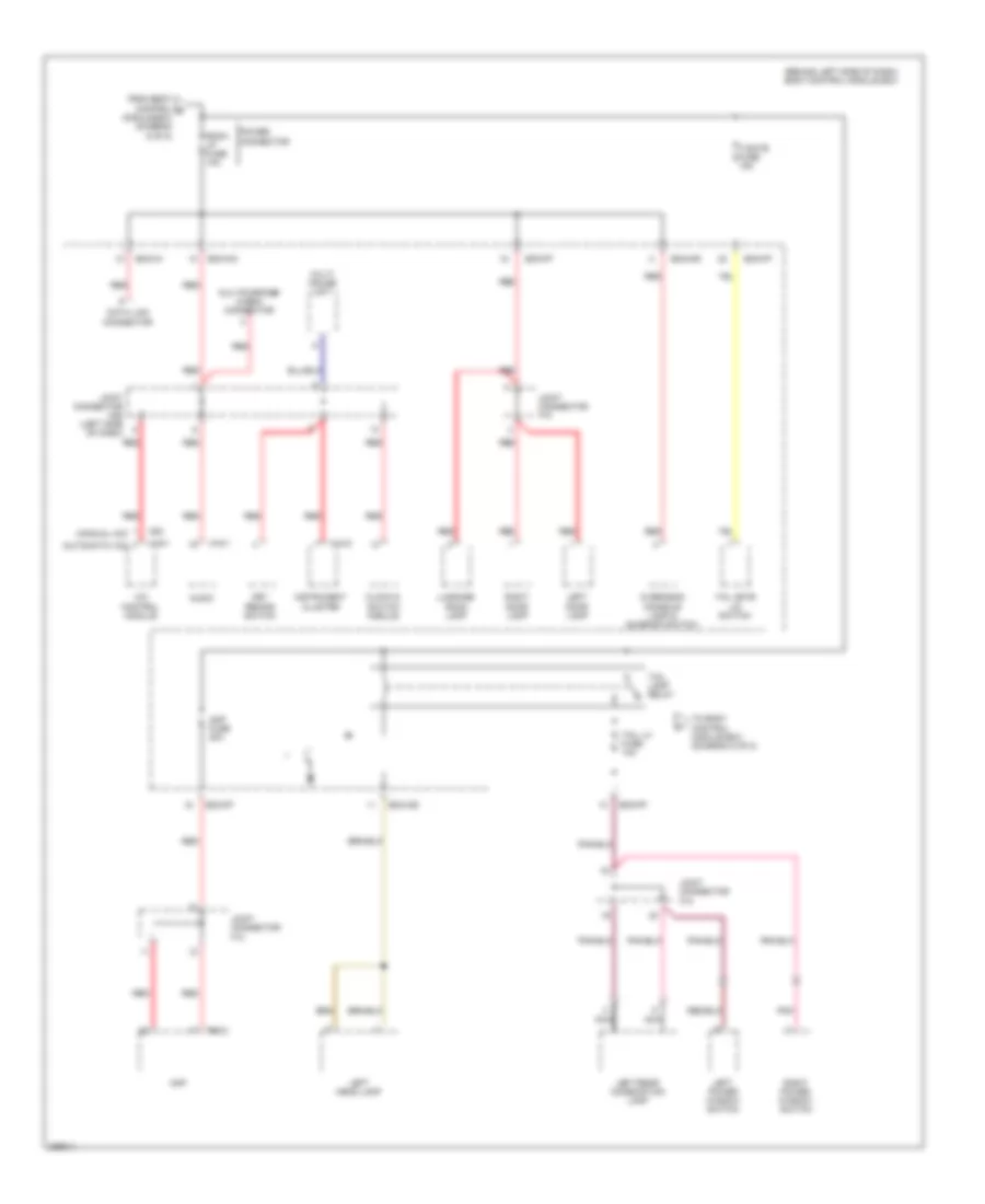
Power Distribution Wiring Diagram (5 of 8) for Hyundai Tiburon SE 2008
List of elements for Power Distribution Wiring Diagram (5 of 8) for Hyundai Tiburon SE 2008:
- (advanced)
- (behind left side of dash) body control module box
- (depowered)
- 2.0l
- 2.7l
- A/bag fuse 15a
- A/bag ind fuse 10a
- A/t
- Abs
- Abs control module
- Abs fuse 10a
- Atd
- B/up lamp fuse 10a
- Back-up lamp switch
- Bcm-aa
- Bcm-ce
- Bcm-im
- Bcm-km
- Bcm-lm
- Bcm-mr
- Belt tension sensor & pods module (advanced)
- Cluster fuse 10a
- Cruise control module
- Driver seat belt buckle switch (depowered)
- Drl control module
- E20-2
- E61-2
- Electro chromic mirror
- Esc
- Esc air bleeding connector
- Esc control module
- Esc switch
- From body control module box (diagram 3 of 8)
- From ignition switch (diagram 1 of 8)
- Generator
- Ig coil fuse 20a
- Ignition coil
- Instrument cluster
- M/t
- M01-3
- M01-4
- M10-2
- M10-3
- Multi- function switch
- Nca
- Passenger seat belt buckle switch (depowered)
- Pnk
- Pre- excitation resistor
- Red
- Srs control module
- Steering angle sensor
- Stop lamp switch
- Telltale lamp (advanced)
- Transaxle range switch
Power Distribution Wiring Diagram (6 of 8) for Hyundai Tiburon SE 2008
List of elements for Power Distribution Wiring Diagram (6 of 8) for Hyundai Tiburon SE 2008:
- (automatic a/c)
- (behind left side of dash) body control module box
- (diagram 1 of 8)
- (manual a/c)
- A/c control module
- Bcm-ce
- Bcm-de
- Bcm-ff
- Bcm-gf
- Bcm-im
- Bcm-km
- Bcm-mr
- Burglar alarm horn relay
- Defogger relay
- From fusible link (batt) b
- Hazard fuse 10a
- Hazard relay
- Htd mir fuse 10a
- Instrument cluster
- Left head lamp
- Left outside mirror motor & defogger
- Left power window switch
- Left rear combination lamp
- Left side repeater lamp
- M10-2
- M10-3
- M19-1
- M20
- Nca
- Overhead console lamp & sunroof switch
- P/window fusible link 30a
- Power door lock relay
- Power door unlock relay
- Power window relay
- Rear window defogger
- Red
- Right head lamp
- Right outside mirror motor & defogger
- Right rear combination lamp
- Right side repeater lamp
- Rr defog fuse 30a
- S/roof fuse 15a
- Stop fuse 15a
- Stop lamp switch
- Tire pressure monitoring module
- To body control module box (diagram 7 of 8)
- W/ esc & cruise
- W/o esc & cruise
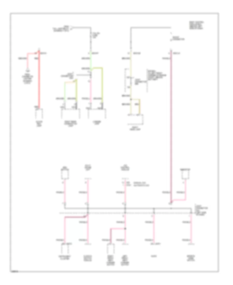
Power Distribution Wiring Diagram (7 of 8) for Hyundai Tiburon SE 2008
List of elements for Power Distribution Wiring Diagram (7 of 8) for Hyundai Tiburon SE 2008:
- (automatic a/c)
- (behind left side of dash) body control module box
- (manual a/c)
- A/c control module
- Amp
- Amp fuse 20a
- Audio
- Bcm-ce
- Bcm-ff
- Bcm-im
- Bcm-km
- Bcm-mr
- Clock & switch module
- Data link connector
- F08-2
- From body control g module box (diagram 6 of 8)
- Instrument cluster
- Joint connector f10
- Joint connector m35 (left side of dash)
- Key remind switch
- Left door lamp
- Left head lamp
- Left power window switch
- Left rear combination lamp
- Luggage room lamp
- M10-2
- M16-1
- M19-1
- M20
- Multi gauge unit
- Multipurpose check connector
- Nca
- Overhead console lamp & sunroof switch
- Pnk
- Power connector
- Red
- Right door lamp
- Right power window switch
- Room lp fuse 10a
- T/gate fuse 15a
- Tail gate lid switch
- Tail lamp relay
- Tail lh fuse 10a
- To body control module box (diagram 8 of 8)
Power Distribution Wiring Diagram (8 of 8) for Hyundai Tiburon SE 2008
List of elements for Power Distribution Wiring Diagram (8 of 8) for Hyundai Tiburon SE 2008:
- (automatic a/c)
- (manual a/c)
- A/c control module
- Audio
- Bcm-ce
- Bcm-ff
- Bcm-im
- Bcm-jm
- Body control module box (behind left side of dash)
- Clock & switch module
- E/r box (in left front corner of engine compt, behind battery)
- Esc switch
- From cigarette lighter (diagram 2 of 8)
- From tail lamp relay h (diagram 7 of 8)
- Glove box lamp
- Instrument cluster
- Joint connector e56
- Joint connector f09
- Joint connector m33 (left side of dash)
- Left front seat warmer switch
- License lamp
- M10-2
- M16-1
- M19-1
- M20
- Multi gauge unit
- Nca
- Red
- Rheostat
- Right front seat warmer switch
- Right head lamp
- Right rear combination lamp
- Shunt connector
- Sports mode switch
- Tail rh fuse 10a
POWER DOOR LOCKS
Power Door Locks Wiring Diagram for Hyundai Tiburon SE 2008
List of elements for Power Door Locks Wiring Diagram for Hyundai Tiburon SE 2008:
- 12volt output
- Bcm-ef
- Bcm-ff
- Bcm-lm
- Body control module box (behind left side of dash)
- G01 (at rear center of floor)
- G02 (at right rear of vehicle, above wheelwell)
- G11 (behind center of dash)
- G12 (behind center of dash)
- Gnd
- Hot at all times
- Joint connector f09
- Left door key switch
- Left door lock actuator (in door assembly)
- Left power window switch
- Lock
- Power door lock relay
- Power door lock switch
- Power door unlock relay
- Right door key switch
- Right door lock actuator (in door assembly)
- S/roof fuse 15a
- Solid state
- Unlock
POWER MIRRORS
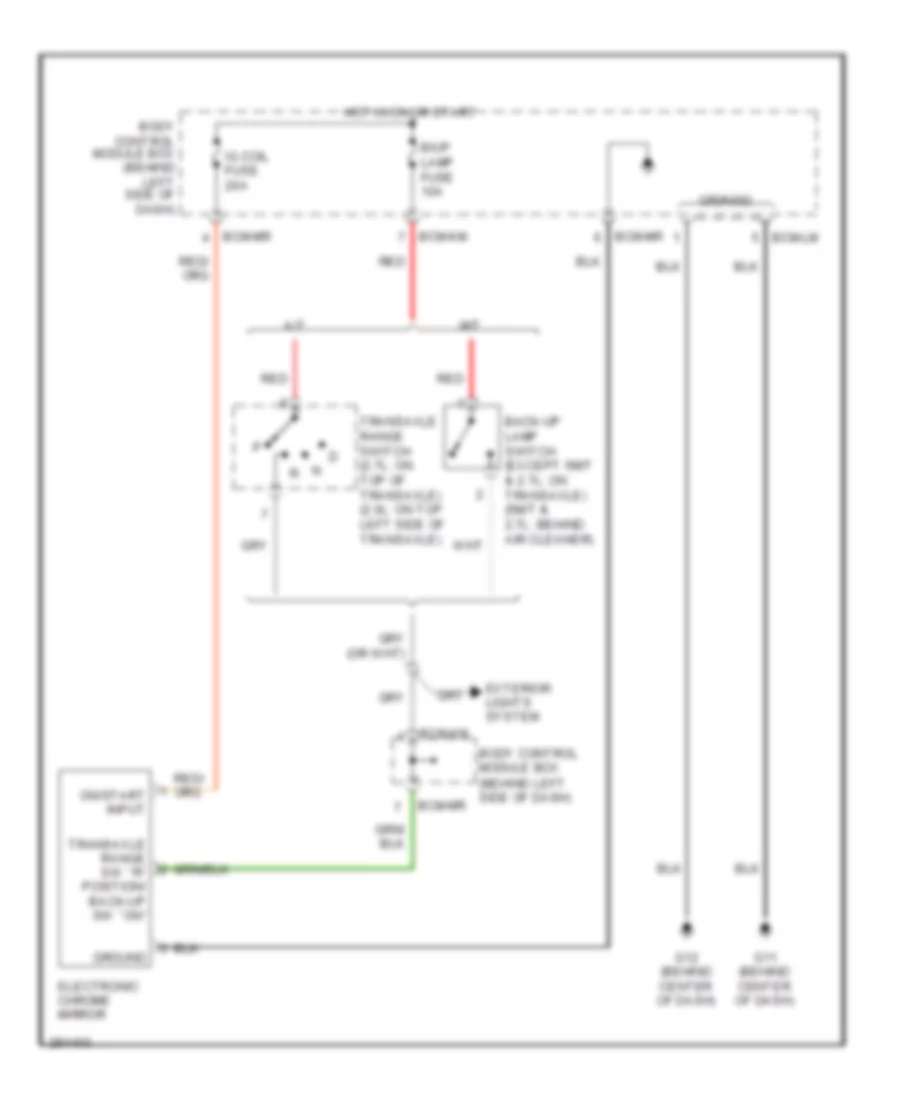
Electrochromic Mirror Wiring Diagram for Hyundai Tiburon SE 2008
List of elements for Electrochromic Mirror Wiring Diagram for Hyundai Tiburon SE 2008:
- A/t
- B/up lamp fuse 10a
- Back-up lamp switch (except 5m/t & 2.7l: on transaxle) (5m/t & 2.7l: behind air cleaner)
- Bcm-km
- Bcm-lm
- Bcm-mr
- Body control module box (behind left side of dash)
- Electronic chrome mirror
- Exterior lights system
- G11 (behind center of dash)
- G12 (behind center of dash)
- Ground
- Hot in on or start
- Ig coil fuse 20a
- M/t
- On/start input
- Red
- Transaxle range sw ``r" position/ back-up sw ``on"
- Transaxle range switch (2.7l: on top of transaxle) (2.0l: on top left side of transaxle)
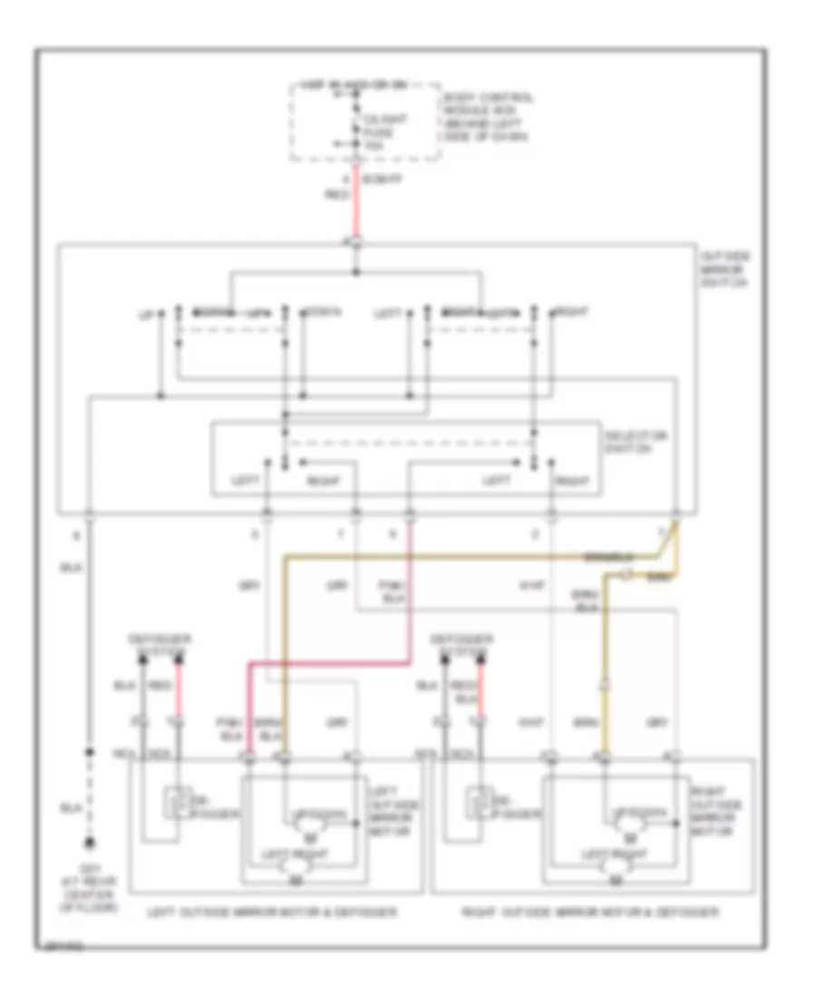
Power Mirror Wiring Diagram for Hyundai Tiburon SE 2008
List of elements for Power Mirror Wiring Diagram for Hyundai Tiburon SE 2008:
- Bcm-ff
- Body control module box (behind left side of dash)
- C/light fuse 15a
- De- fogger
- Defogger system
- Down
- G01 (at rear center of floor)
- Hot in acc or on
- Left
- Left outside mirror motor
- Left outside mirror motor & defogger
- Left/right
- Nca
- Outside mirror switch
- Red
- Right
- Right outside mirror motor
- Right outside mirror motor & defogger
- Selector switch
- Up/down
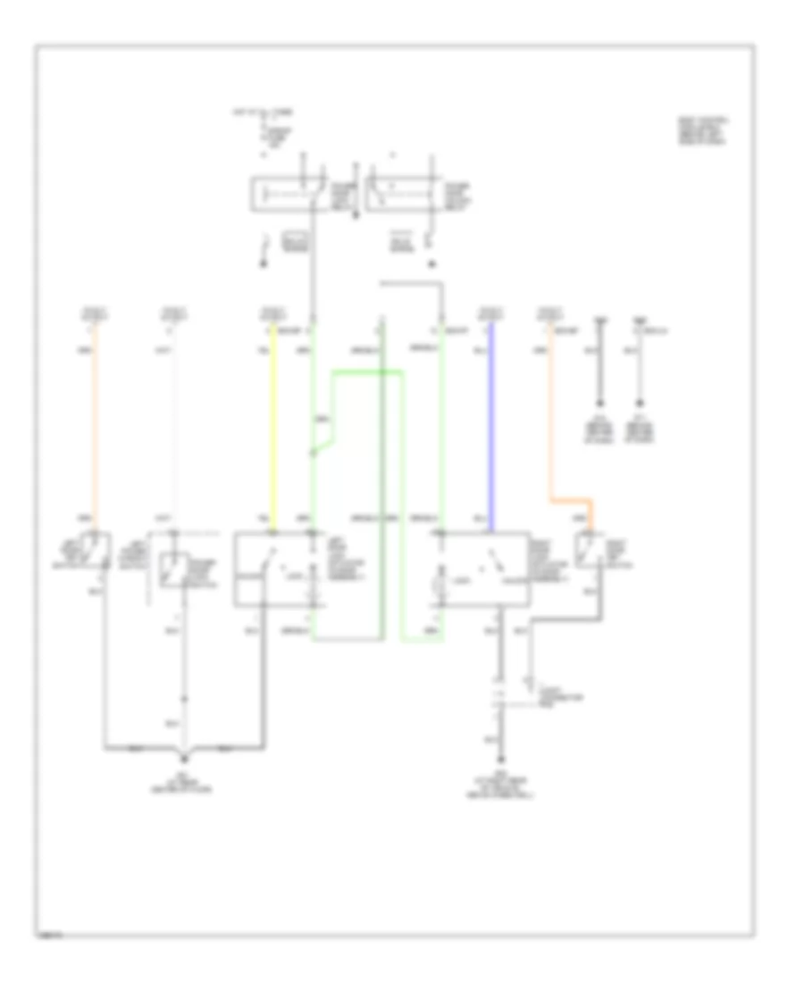
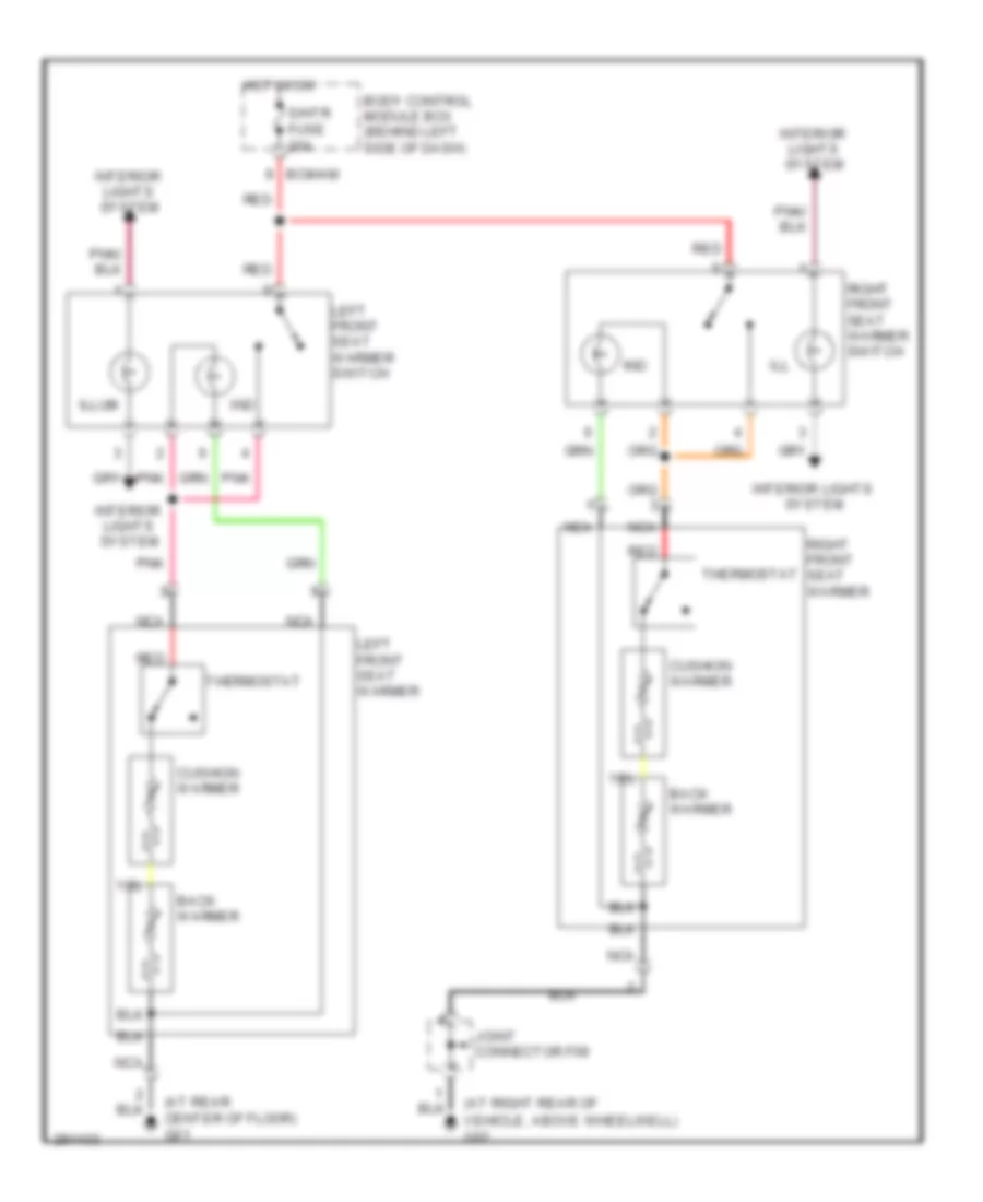
POWER SEATS
Power Seats Wiring Diagram for Hyundai Tiburon SE 2008
List of elements for Power Seats Wiring Diagram for Hyundai Tiburon SE 2008:
- (at rear center of floor) g01
- (at right rear of
- Back warmer
- Bcm-km
- Body control module box (behind left side of dash)
- Cushion warmer
- Hot in on
- Ill
- Illum
- Ind
- Interior lights system
- Joint connector f09
- Left front seat warmer
- Left front seat warmer switch
- Nca
- Pnk
- Red
- Right front seat warmer
- Right front seat warmer switch
- S/htr fuse 20a
- Thermostat
- Vehicle, above wheelwell) g02
POWER TOP/SUNROOF
Power Top/Sunroof Wiring Diagram for Hyundai Tiburon SE 2008
List of elements for Power Top/Sunroof Wiring Diagram for Hyundai Tiburon SE 2008:
- 5v (h-vcc)
- 5v (p-vcc)
- A/con fuse 10a
- B+ (s/roof)
- Bcm-lm
- Bcm-mr
- Body control module box (behind left side of dash)
- Ccw(-)
- Cf-12v relay
- Cpu
- Cw(+)
- G11 (behind center of dash)
- G12 (behind center of dash)
- Ground
- H/sensor h
- H/sensor p
- Hall ground
- Hot at all times
- Hot in on
- Ig2
- Motor
- Overhead console lamp & sunroof switch
- Pnk
- R22
- R23
- R24
- R25
- Red
- S/close
- S/open
- S/roof fuse 15a
- Signal (h)
- Signal (p)
- Slide close
- Slide open
- Sunroof controller (front of sunroof opening)
- Sunroof motor (front of sun roof opening)
- Sunroof switch
- T/down
- T/up
POWER WINDOWS
Power Windows Wiring Diagram for Hyundai Tiburon SE 2008
List of elements for Power Windows Wiring Diagram for Hyundai Tiburon SE 2008:
- Bcm-gf
- Bcm-lm
- Body control module box (behind left side of dash)
- Control unit
- Door lock system
- Down
- G01 (at rear center of floor)
- G11 (behind center of dash)
- G12 (behind center of dash)
- Ground
- Hot at all times
- Ill
- Interior lights system
- Left power window motor (in left door assembly)
- Left power window switch
- Nca
- Off
- Off down
- P/window fusible link 30a
- Pnk
- Power door lock switch
- Power window relay
- Right power window motor (in right door assembly)
- Right power window switch
- Solid state
- Window lock switch
RADIO
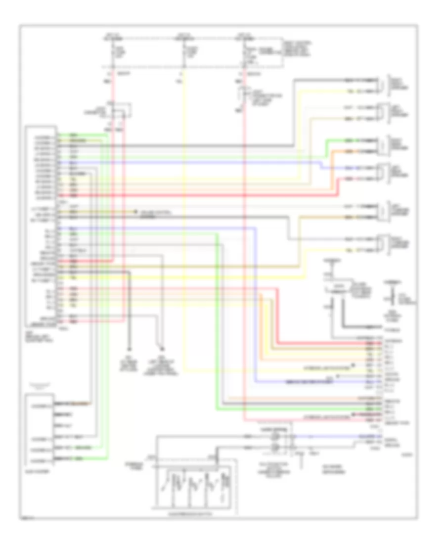
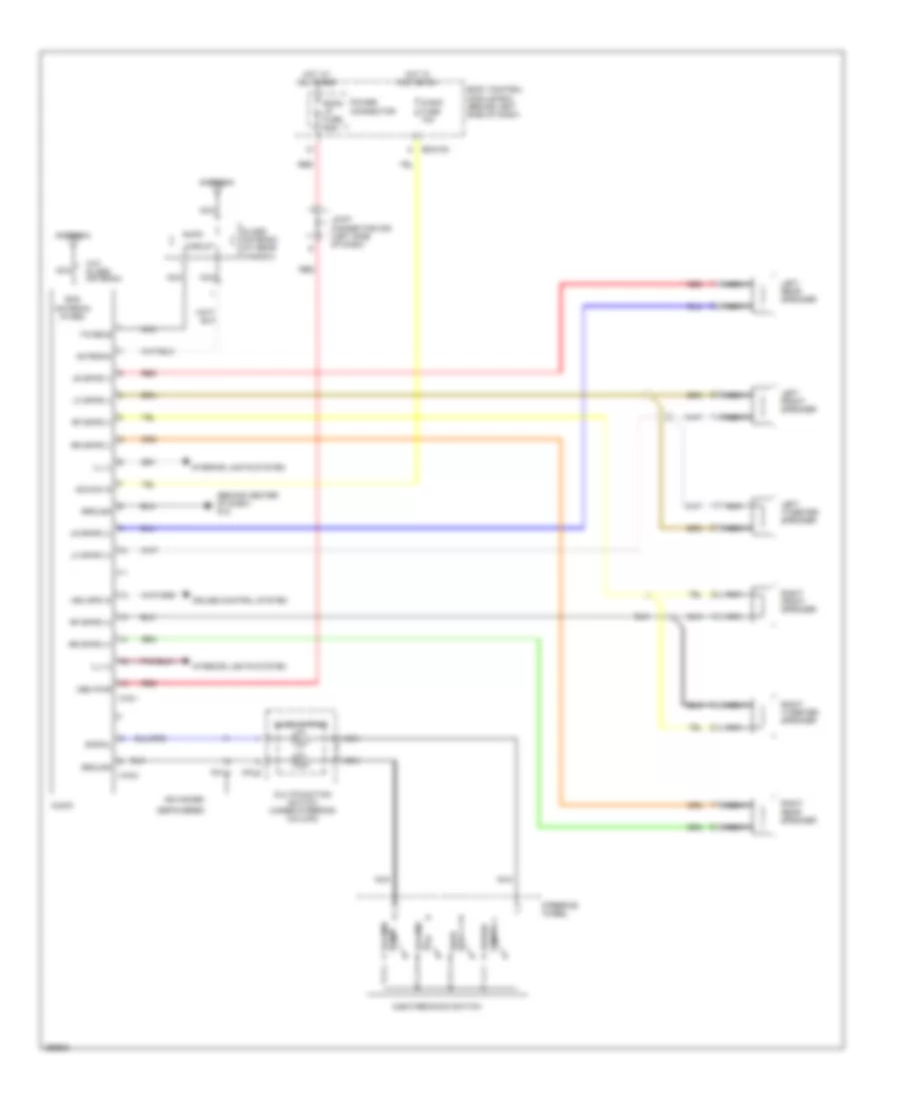
Radio Wiring Diagram, with Amplifier for Hyundai Tiburon SE 2008
List of elements for Radio Wiring Diagram, with Amplifier for Hyundai Tiburon SE 2008:
- Acc/on
- Advanced
- Am/fm
- Amp (behind left quarter trim)
- Amp fuse 20a
- Antenna
- Audio
- Audio fuse 10a
- Audio remocon switch
- Bcm-ff
- Bcm-km
- Body control module box (behind left side of dash)
- Circuit
- Clock spring
- Cruise control system
- Depowered
- Down volume
- F/cable
- F08-1
- F08-2
- Fl (+)
- Fl (-)
- Fr (+)
- Fr (-)
- G01 (at rear center of floor)
- G05 (left rear of luggage compartment, under trim panel)
- G12 (behind center of dash)
- Glass antenna (at rear window)
- Ground
- Ground(eq)
- Hot at all times
- Hot in acc or on
- Ill (+)
- Ill (-)
- Interior lights system
- Joint connector f10
- Joint connector m35 (left side of dash)
- Left front speaker
- Left rear speaker
- Left tweeter speaker
- Lf spkr (+)
- Lf spkr (-)
- Lh tweet (+)
- Lh tweet (-)
- Lr spkr (+)
- Lr spkr (-)
- M01-3
- M01-4
- M16-1
- M16-2
- Memory pwr
- Multifunction switch (under steering column)
- Nca
- Nca woofer 1(+)
- Nca woofer 1(-)
- Nca woofer 2(+)
- Nca woofer 2(-)
- On/off power
- Power connector
- Red
- Remote
- Rf spkr (+)
- Rf spkr (-)
- Rh tweet (+)
- Rh tweet (-)
- Right front speaker
- Right rear speaker
- Right tweeter speaker
- Rl (+)
- Rl (-)
- Rod antenna (fixed)
- Room lp fuse 10a
- Rr (+)
- Rr (-)
- Rr spkr (+)
- Rr spkr (-)
- Signal
- Steering wheel
- Sub woofer
- Up seek
- Up volume
- Veh spd in
- W/o glass antenna
- Woofer (+)
- Woofer (-)
Radio Wiring Diagram, without Amplifier for Hyundai Tiburon SE 2008
List of elements for Radio Wiring Diagram, without Amplifier for Hyundai Tiburon SE 2008:
- (behind center of dash) g12
- Acc/on in
- Advanced
- Am/fm
- Antenna
- Audio
- Audio fuse 10a
- Audio remocon switch
- Bcm-km
- Body control module box (behind left side of dash)
- Circuit
- Clock spring
- Cruise control system
- Depowered
- Down volume
- F/cable
- Glass antenna (at rear window)
- Ground
- Hot at all times
- Hot in acc or on
- Ill (+)
- Ill (-)
- Interior lights system
- Joint connector m35 (left side of dash)
- Left front speaker
- Left rear speaker
- Left tweeter speaker
- Lf spkr (+)
- Lf spkr (-)
- Lr spkr (+)
- Lr spkr (-)
- M01-3
- M01-4
- M16-1
- M16-2
- Mem pwr
- Multifunction switch (under steering column)
- Nca
- On/off power
- Power connector
- Red
- Rf spkr (+)
- Rf spkr (-)
- Right front speaker
- Right rear speaker
- Right tweeter speaker
- Rod antenna (fixed)
- Room lp fuse 10a
- Rr spkr (+)
- Rr spkr (-)
- Signal
- Steering
- Up seek
- Up volume
- Veh spd in
- W/o glass antenna
- Wheel
STARTING/CHARGING
Charging Wiring Diagram for Hyundai Tiburon SE 2008
List of elements for Charging Wiring Diagram for Hyundai Tiburon SE 2008:
- (in left front corner of engine compt, behind battery) e/r box
- (on left front inner fender panel) (if equipped) drl control module
- 2.0l
- 2.7l
- Alt fusible link (140a)
- Atd
- Batt fusible link 120a
- Battery
- Bcm-ce
- Bcm-im
- Body control module box (behind left side of dash)
- Body ground
- Charge indicator
- Cluster fuse 10a
- Ecu fusible link 30a
- Generator (2.0l)
- Generator (2.7l)
- Hot in on or start
- Instrument cluster
- Joint connector e56
- M10-2
- M10-3
- Pre-excitation resistor
- Red
Starting Wiring Diagram for Hyundai Tiburon SE 2008
List of elements for Starting Wiring Diagram for Hyundai Tiburon SE 2008:
- (2.0l)
- (2.0l) (2.7l)
- (2.7l)
- A/t
- Battery
- Bcm-km
- Body control module box (behind left side of dash)
- Body ground
- Burglar alarm relay
- E/r box (in left front corner of engine compt, behind battery)
- Ec01 ec101
- G15 (on left front corner of engine compt)
- Ign fusible link 30a red
- Ignition lock switch (left side of dash)
- Ignition switch
- Joint connector c41 c141 (behind crash pad)
- Joint connector e56
- Lock acc
- M/t
- N d
- Nca
- Pnk
- Power distribution system
- Red
- Start
- Start relay
- Starter motor
- Starter solenoid
- Transaxle range switch (2.0l: on top left side of transaxle) (2.7l: on top of transaxle)
- W/ immobilizer
- W/o immobilizer
SUPPLEMENTAL RESTRAINTS
Supplemental Restraints Wiring Diagram, Advanced (1 of 2) for Hyundai Tiburon SE 2008
List of elements for Supplemental Restraints Wiring Diagram, Advanced (1 of 2) for Hyundai Tiburon SE 2008:
- A/bag fuse 10a
- A/bag ind fuse 10a
- Atd
- Bcm-aa
- Bcm-ef
- Bcm-im
- Bcm-jm
- Belt tension & pods module (under driver seat)
- Body control module box (behind left side of dash)
- Crash output
- Data link connector (partial) (below left side of dash)
- Driver satellite sensor (below driver seat)
- Driver seat track position sensor (under driver seat)
- G09 (below front passenger seat)
- Gnd
- Ground
- High
- Hot in on or start
- Instrument cluster
- K-line
- Low
- M10-2
- On/start input
- Passenger satellite sensor (below front passenger seat)
- Passenger seat belt buckle switch (under passenger seat bottom)
- Passenger seat belt pretensioner (at base of right "b" pillar)
- Pnk
- Power
- Red
- Signal
- Srs control module (under rear console)
- Srs indicator (air bag)
- Srs warn ind
- Telltale warn ind
Supplemental Restraints Wiring Diagram, Advanced (2 of 2) for Hyundai Tiburon SE 2008
List of elements for Supplemental Restraints Wiring Diagram, Advanced (2 of 2) for Hyundai Tiburon SE 2008:
- A02
- Clock- spring
- Driver air bag
- Driver seat belt buckle switch (on driver seat belt buckle)
- Driver seat belt pretensioner (at base of left "b" pillar)
- Driver side air bag (under driver seat)
- G01 (at rear center of floor)
- G09 (below front passenger seat)
- Gnd
- High
- Left front impact sensor (below left headlamp)
- Low
- Module
- Multi- function switch
- Nca
- On/start input
- Passenger air bag (behind right side of dash)
- Passenger side air bag (under front passenger seat)
- Pnk
- Red
- Right front impact sensor (right front of engine compt)
- Sig
- Steering wheel
- Telltale lamp
Supplemental Restraints Wiring Diagram, Base for Hyundai Tiburon SE 2008
List of elements for Supplemental Restraints Wiring Diagram, Base for Hyundai Tiburon SE 2008:
- (below right front passenger seat) g09
- A/bag fuse 15a
- A/bag ind fuse 10a
- Atd
- Bcm-aa
- Bcm-im
- Bcm-jm
- Body control module box (behind left side of dash)
- Clock spring
- Crash output
- Data link connector (partial) (below left side of dash)
- Driver air bag
- Driver satellite sensor (below driver seat)
- Driver seat belt buckle switch (on driver seat belt buckle)
- Driver seat belt pretensioner (base of left ``b" pillar)
- Driver side air bag (under driver's seat)
- Ground
- High
- Hot in on or start
- Instrument cluster
- K-line
- Low
- M10-2
- Multi- function switch
- Nca
- On/start input
- Passenger air bag (right side of dash)
- Passenger satellite sensor (below front passenger seat)
- Passenger seat belt buckle switch (under passenger seat bottom)
- Passenger seat belt pretensioner (base of right ``b" pillar)
- Passenger side air bag (below front passenger seat)
- Pnk
- Power
- Red
- Srs (air bag) indicator
- Srs control module (under rear console)
- Srs warning ind
- Steering wheel
TRANSMISSION
2.0L
2.0L, Transmission Wiring Diagram for Hyundai Tiburon SE 2008
List of elements for 2.0L, Transmission Wiring Diagram for Hyundai Tiburon SE 2008:
- (on top left side of transaxle) transaxle range switch
- 2nd
- A/t control relay (behind left side of dash)
- A/t pulse generator "a" (on top of transaxle)
- A/t pulse generator "b" (on top of transaxle)
- A/t rly ctrl
- Atm solenoid valve (on top of transaxle)
- Auto cruise
- B/up lamp fuse 10a
- Battery
- Bcm-im
- Bcm-km
- Body control module box (behind left side of dash)
- C33-1
- C33-2
- C41 (behind crash pad)
- C42 (behind crash pad)
- Cruise control module (on right side of firewall, behind strut tower)
- D input
- Dcc
- Down shift
- E/r box (in left front corner of engine compt, behind battery)
- Ec01
- Ecu fuse 10a
- Ecu fusible link 30a
- Exterior lights system
- G18 (behind left side of dash)
- Ground
- Hot at all times
- Hot in on or start
- Ill
- Input speed
- Instrument cluster
- Interior lights system
- Joint connector
- Joint connector e56
- M10-1
- Man
- Micom
- N input
- Norm
- O/t
- Oil temp sensor
- Output speed
- P input
- Pcm (behind left side of dash)
- Pnk
- Pwm sig
- R input
- Red
- Select sw
- Select switch
- Sens gnd
- Sens pwr
- Sensor gnd
- Sport mode switch (center floor pan, under console)
- Starting/ charging system
- Stop fuse 15a
- Stop lamp in
- Stop lamp switch
- Throttle position sensor (on throttle body assembly)
- Tps sig
- Up shift
- W/ esc & cruise
- W/ esc & cruise w/o esc & cruise
- W/o esc & cruise
2.7L
2.7L, Transmission Wiring Diagram for Hyundai Tiburon SE 2008
List of elements for 2.7L, Transmission Wiring Diagram for Hyundai Tiburon SE 2008:
- (behind right side of of dash) engine control module (ecm)
- (on firewall, above brake pedal)
- (on top of transaxle) transaxle range switch
- 2nd val ctrl
- A/t control relay (behind left side of dash)
- A/t pulse generator "a" (on top of transaxle)
- A/t pulse generator "b" (on top of transaxle)
- A/t rly ctrl
- Atm solenoid valve (on top of transaxle)
- Auto cruise
- B/up lamp fuse 10a
- Battery
- Bcm-im
- Bcm-km
- Body control module box (behind left side of dash)
- C133-1
- C133-3
- C133-4
- C136-1
- C136-2
- C136-3
- Can hi
- Can lo
- Cruise control module (on right side of firewall, behind strut tower)
- D input
- Data link connector (below left side of dash)
- Dcc val ctrl
- Down shift
- E/r box (in left front corner of engine compt, behind battery)
- Ec101
- Ec102
- Ecu fuse 10a
- Ecu fusible link 30a red
- Exterior lights system
- G21
- G21 (on firewall, above brake pedal)
- Ground
- Hot at all times
- Hot in on or start
- Ill
- Input speed
- Instrument cluster
- Interior lights system
- Joint connector c141 (behind crash pad)
- Joint connector c142 (behind crash pad)
- Joint connector e56
- K-line
- Lr val ctrl
- M10-1
- Man
- Memory pwr
- Micom
- Multipurpose check connector (below left side of dash, right of steering column)
- N input
- Norm
- O/d ctrl
- O/t
- Od val ctrl
- Oil temp sensor
- Output speed
- P input
- Pnk
- Pwm sig
- Pwr flash
- Pwr sply
- R input
- Red
- Sel switch
- Select switch
- Sensor gnd
- Sport mode switch (center floor pan, under console)
- Start/on in
- Starting/ charging system
- Stop fuse 15a
- Stop lamp switch
- Stop lmp sw
- Tcm (behind left side of dash)
- Throttle position sensor (on throttle body assembly)
- Tps gnd
- Tps input
- Ud val ctrl
- Up shift
- W/ esc & cruise
- W/o esc & cruise
TRUNK, TAILGATE, FUEL DOOR
Tailgate Release Wiring Diagram for Hyundai Tiburon SE 2008
List of elements for Tailgate Release Wiring Diagram for Hyundai Tiburon SE 2008:
- Bcm-ff
- Body control module box (behind left side of dash)
- G06 (in center of hatch)
- Hot at all times
- T/gate fuse 15a
- Tail gate lid solenoid
- Tail gate lid switch
WARNING SYSTEMS
Chime Wiring Diagram for Hyundai Tiburon SE 2008
List of elements for Chime Wiring Diagram for Hyundai Tiburon SE 2008:
- 12v output
- Ajar
- Bcm-ef
- Bcm-ff
- Bcm-hm
- Bcm-im
- Bcm-jm
- Bcm-km
- Belt
- Body control module box (behind left side of dash)
- Cluster fuse 10a
- Door
- Door ajar
- Door warning sw
- Driver seat belt buckle switch (on driver seat belt buckle)
- G01 (at rear center of floor)
- G11 (behind center of dash)
- Gnd
- Head
- Hot at all times
- Hot in on or start
- Ind
- Instrument cluster
- Interior lights system
- Joint connector m35 (left side of dash)
- Joint connector m36 (left side of dash)
- Key ill
- Key remind sw ill
- Key remind switch (behind left side of dash)
- Left door switch
- Light switch
- M01-2
- M10-2
- M10-3
- Multi-function switch (under steering column)
- Nca
- Off
- Park
- Power connector
- Red
- Room lp fuse 10a
- Seat
- Seat belt switch
- Seat belt switch (under seat bottom)
- Sig
- Switch
- W/ advanced
- W/ depowered
Tire Pressure Monitoring Wiring Diagram for Hyundai Tiburon SE 2008
List of elements for Tire Pressure Monitoring Wiring Diagram for Hyundai Tiburon SE 2008:
- Bcm-im
- Bcm-km
- Body control module box (behind left side of dash)
- Cluster fuse 10a
- Computer data lines system
- Cruise control system
- Ecu fuse 10a
- G11 (behind center of dash)
- Hot at all times
- Hot in on or start
- Instrument cluster
- M10-2
- Red
- Stop fuse 15a
- Tire pressure monitoring module (behind right side of dash)
- Tpms ind
- Tpms tread ind
WIPER/WASHER
Front Wiper/Washer Wiring Diagram for Hyundai Tiburon SE 2008
List of elements for Front Wiper/Washer Wiring Diagram for Hyundai Tiburon SE 2008:
- (2.0l)
- (2.7l)
- (2.7l) (2.0l)
- (behind center of dash) g11
- (behind left side of dash) g23 g20 (on left side of engine compt)
- (in left front corner of engine compt, behind battery)
- (on right front corner of engine compt)
- Bcm-ce
- Bcm-jm
- Bcm-km
- Bcm-lm
- Body control module box (behind left side of dash)
- Delay control
- E/r box
- Ec02
- Ec102
- F/wiper fuse 20a
- Front & rear washer motor (below right front headlight, in washer reservoir)
- Front wiper motor (on left side of firewall)
- Front wiper rly ctrl
- G12 (behind center of dash)
- G16
- Ground
- Hot in on
- Int
- Int (t)
- Joint connector e56
- Joint connector m34 (left side of dash)
- M01-1
- Mist switch
- Multi-function switch (under steering column)
- Off
- Parking switch (shown with wipers at rest)
- Pnk
- Rear wiper/ washer circuit
- Red
- Snow safety relay
- Washer switch
- Wiper (hi)
- Wiper (lo)
- Wiper relay
- Wiper switch
Rear Wiper/Washer Wiring Diagram for Hyundai Tiburon SE 2008
List of elements for Rear Wiper/Washer Wiring Diagram for Hyundai Tiburon SE 2008:
- Auto parking switch (shown with wipers at rest)
- Bcm-ce
- Bcm-ff
- Bcm-km
- Bcm-lm
- Body control module box (behind left side of dash)
- F/wiper fuse 20a
- Front & rear washer motor (below right front headlight, in washer reservoir)
- Front washer switch
- G05 (left rear of luggage compt, under trim panel)
- G06 (in center of hatch)
- G16 (on right front corner of engine compt)
- Hot in on
- Int
- Joint connector f10
- M01-1
- Multi-function switch (under steering column)
- Nca
- Off
- Pnk
- R/wiper fuse 15a
- Rear intermittent wiper relay (left rear corner of luggage compt)
- Rear washer switch
- Rear wiper motor (behind trim panel, in liftgate)
- Rear wiper switch
- Red
- Relay control circuit