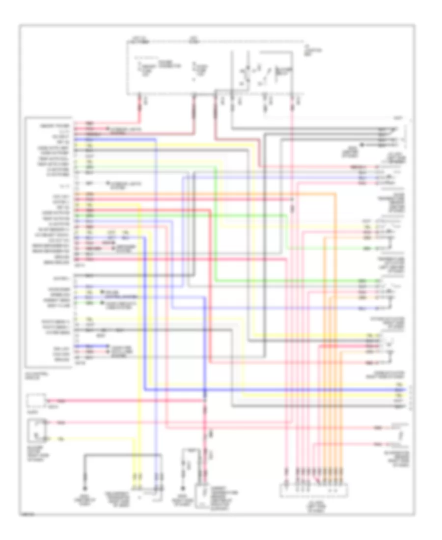
AIR CONDITIONING
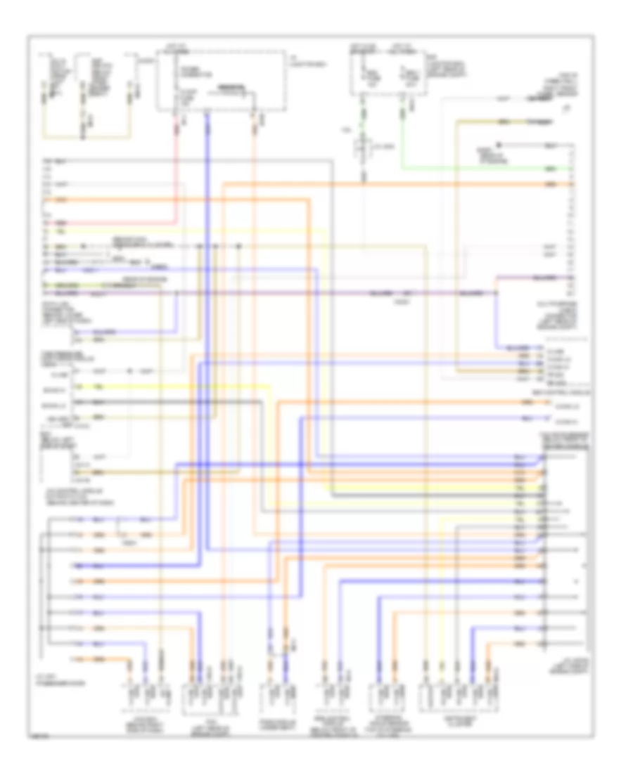
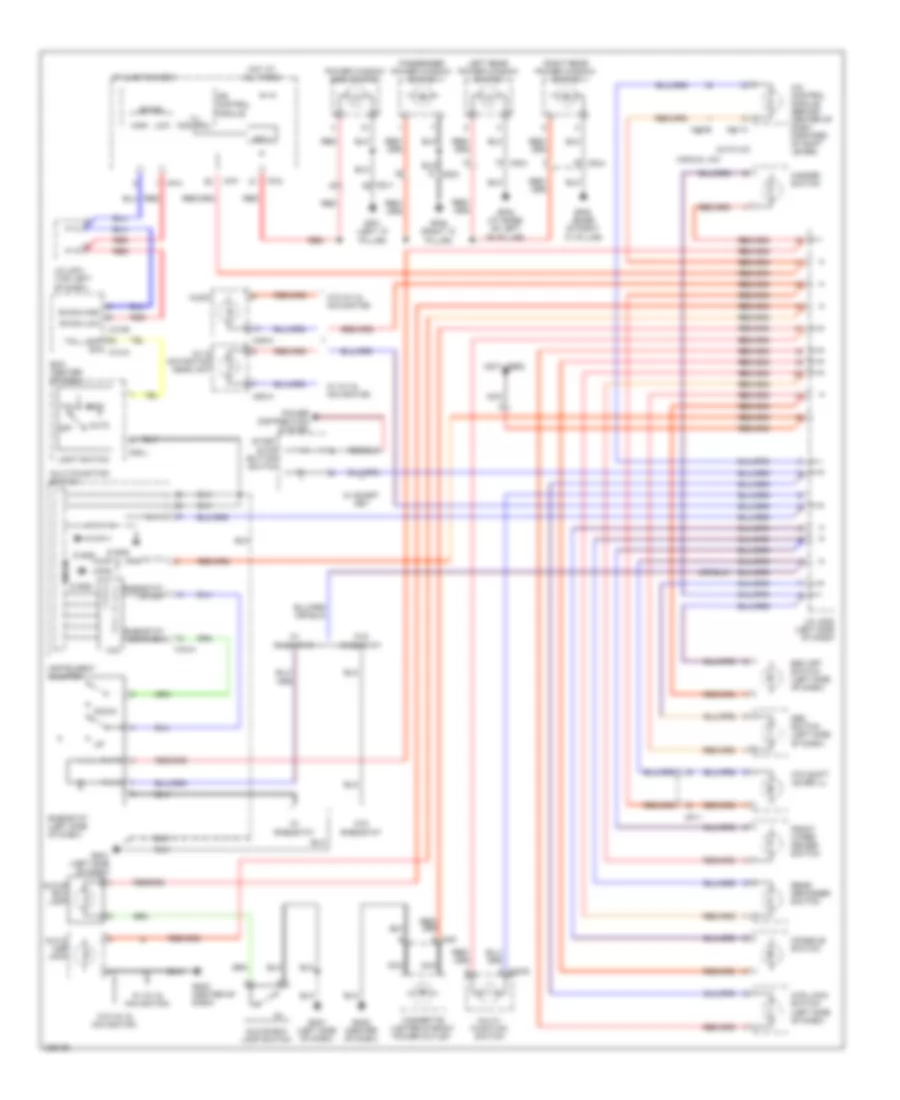
Automatic A/C Wiring Diagram (1 of 2) for Hyundai XG350 2002

List of elements for Automatic A/C Wiring Diagram (1 of 2) for Hyundai XG350 2002:
- (behind right end of dash) blower relay
- (not used)
- A w/ immobilizer
- A/c compressor
- A/c compressor fuse 10a
- A/c control module (center of dash)
- A/c output
- A/c relay
- A/c relay cntrl
- Actuator
- Amb temp sensor
- Aqs sensor
- Aqs sensor (behind right center of front bumper)
- B w/o immobilizer
- B/l
- B12 jc01
- Blend door actuator (behind left center of dash)
- Blower fuse 30a
- Blower motor (right side of dash)
- Blr feed back
- C11 jm09
- C44-1
- C44-2
- C44-3
- D12
- Def
- Defogger sw
- Defogger system
- E7 je01
- Ect sensor
- Egr fuse 15a
- Engine compartment junction block
- Engine compartment junction block (left front of engine compt)
- Engine coolant temperature sensor & sender (on rear of engine)
- Evap sensor in
- Floor
- Fre
- From condenser fan relay (diagram 2 of 2)
- Fuse 10a
- G02 (behind left headlamp)
- G05 (right side of dash)
- Ground
- Hi speed cntrl
- High blower relay (below right side of dash)
- Hot at all times
- Hot at on
- Humidity sensor
- I17-1
- I17-2
- Ill+
- Ill-
- In-car sens in
- In-car sens out
- Intake actuator (behind right end of dash)
- Interior lights system
- J/c c42 (behind lower center of dash)
- J/c i20 (left side of dash)
- J/c i20 (left side) of dash)
- Je01 f1
- Je01 f11
- Ji01
- Ji02
- Jm01
- Jm02
- Jm04
- Jm04 d4
- Jm09 d1
- Memory power
- Mix
- Nca
- On input
- Passenger compartment junction block (behind left end of dash)
- Pcm (behind lower center of dash)
- Photo sens +
- Photo sensor (on top center of dash)
- Pnk
- Power transistor
- Power transistor (behind right side of dash)
- R vent actuator
- Rear vent actuator (below left center of dash)
- Rec
- Red
- Sensor ground
- Short connector "a"
- Temp act ccw
- Temp actuator
- Temp feed back
- Temperature
- Vent
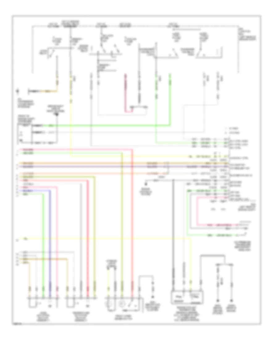
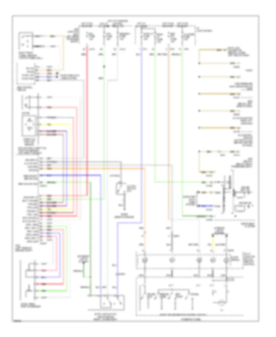
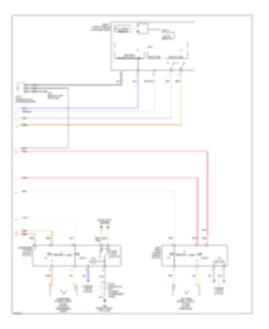
Automatic A/C Wiring Diagram (2 of 2) for Hyundai XG350 2002
List of elements for Automatic A/C Wiring Diagram (2 of 2) for Hyundai XG350 2002:
- (center of dash)
- (left center of dash)
- (left side of dash)
- (right side of dash)
- A/c control module
- A/c out (hi)
- A/c select sig (hi)
- A/con fuse 7.5a
- Ambient sens
- Ambient temperature sensor (center of radiator support)
- Audio
- Blower motor (right side of dash)
- Blower relay
- Body k-line
- Can high
- Can low
- Computer data lines system
- Cruise control system
- Defogger system
- Ee11
- Em51
- Evap sensor (+)
- Evaporator sensor (right side of dash)
- Fet (d)
- Fet (g)
- Field effect transistor (right side of dash)
- Gm03
- Gm04
- Gm05
- Ground
- Hot at all times
- Hot in on
- I/p junction box
- I/p-b
- I/p-c
- I/p-d
- I/p-e
- I/p-h
- Ill (+)
- Ill (-)
- In actr f/b
- In actr fre
- In actr red
- Incar snsr
- Incar temperature sensor (center of dash)
- Intake actuator (right side of dash)
- Interior lights system
- J/c jm01
- J/c jm04 (left side of dash)
- M03-a
- M07-a
- M07-b
- Memory fuse 10a
- Memory power
- Mode actr def
- Mode actr f/b
- Mode actr vent
- Mode actuator (right side of dash)
- Motor (-)
- On input
- Photo sens (+)
- Photo sens (-)
- Pnk
- Pnk pnk
- Power connector
- Rear defogger ind
- Rear defogger sw
- Red
- Sens ground
- Speed sig
- Temp actr cool
- Temp actr f/b
- Temp actr warm
- Temperature actuator
- Vcc (+5v)
- Water sens
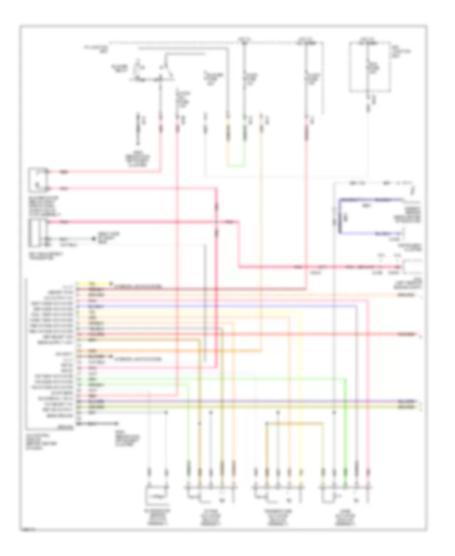
Manual A/C Wiring Diagram (1 of 2) for Hyundai XG350 2002
List of elements for Manual A/C Wiring Diagram (1 of 2) for Hyundai XG350 2002:
- (behind right side of front bumper) ge02
- (front of engine compt) condenser fan motor
- (or pnk)
- 2.4l
- 3.5l
- A/c comp sw
- A/c compressor (lower front of engine)
- A/c pressure transducer (behind right headlamp)
- A/c request sw
- A/con fuse 10a
- A/con relay
- A/con rly ctrl
- Apt gnd
- Apt sig
- Blower max sw in
- C130-b
- C30-b
- Chg-a
- Chg-k
- Clg-a
- Clg-b
- Con fan 1 fuse 40a
- Con fan 2 fuse 50a
- Condenser fan relay (high)
- Condenser fan relay (low)
- Cooling fuse 10a
- E/r junction box (left rear of engine compt)
- Ects gnd
- Ects sig
- Ecu main fuse 40a
- Engine control relay
- Engine controls system
- Engine coolant temperature sensor & sender (2.4l: on rear of left cylinder head) (3.5l: rear of engine)
- Front wiper deicer switch
- Ghg04 (rear of engine)
- Gm01 (behind main instrument cluster)
- Gm03 (behind center of dash)
- Hot at all times
- Hot in on or start
- Hot w/ engine control relay energized
- Ill
- Ind
- Interior lights system
- Mc221
- Mc241
- Mode actuator (on hvac assembly)
- Nca
- Pcm (left rear of engine compt)
- Pnk
- Red
- Rly ctrl
- Rly ctrl (high)
- Rly ctrl (low)
- Sender
- Sensor
- Sensor 1 fuse 10a
- Temperature actuator (on hvac assembly)
- U/h-c
- U/h-d
- W/ immo
- W/o immo
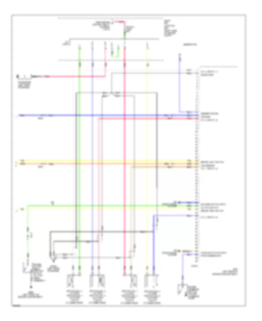
Manual A/C Wiring Diagram (2 of 2) for Hyundai XG350 2002
List of elements for Manual A/C Wiring Diagram (2 of 2) for Hyundai XG350 2002:
- (right side of dash) gm05
- 2.4l
- 3.5l
- A/c control module (behind center of dash)
- A/c output (hi)
- A/c select (hi)
- A/con fuse 10a
- A/con sw fuse 10a
- Ambient sensor (near center of radiator)
- Blower fuse 30a
- Blower motor (below right side of dash, on bottom of hvac assembly)
- Blower relay
- Blower rly on in
- Blr fuse 40a
- Chg-k
- Clg-b
- Clock fuse 15a
- Cool temp actuator
- Def ind output
- Def mode actuator
- Def select sig
- E/r junction box
- Ee01
- Em11
- Evap sens
- Evaporator sensor (on hvac assembly)
- F/b intake actuator
- F/b mode actuator
- F/b temp actuator
- Fet (field effect transistor)
- Fet(d)
- Fet(g)
- Fre intake actuator
- Gm02 (behind main instrument cluster)
- Ground
- Hot at all times
- Hot in on
- I/p junction box
- I/p-a
- I/p-j
- I/p-k
- I/p-m
- Ill (+)
- Ill (-)
- Instrument cluster
- Intake actuator (on hvac assembly)
- Interior lights system
- M15-b
- Mc241
- Memory pwr
- Mode actuator (on hvac assembly)
- On input
- Pcm (left rear of engine compt)
- Pnk
- Rec intake actuator
- Red
- Sens ground
- Temperature actuator (on hvac assembly)
- U/h-b
- Vent mode actuator
- Warm temp actuator
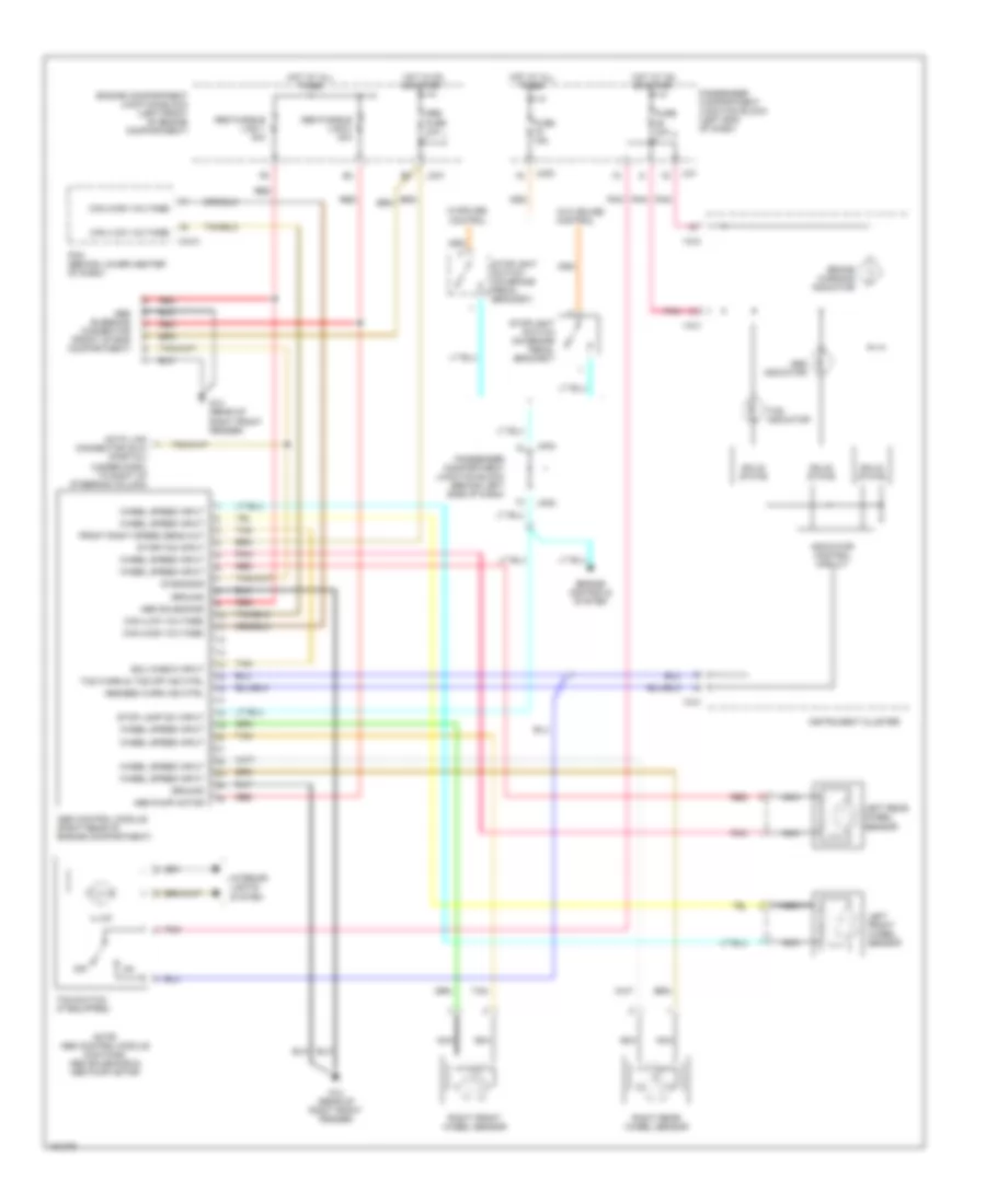
ANTI-LOCK BRAKES
Anti-lock Brake Wiring Diagrams for Hyundai XG350 2002
List of elements for Anti-lock Brake Wiring Diagrams for Hyundai XG350 2002:
- Abs bleeding connector (front of eng compartment)
- Abs control module (right rear of engine compartment)
- Abs fuse 10a
- Abs fusible link 1 30a
- Abs fusible link 2 30a
- Abs indicator
- Abs pump motor
- Abs solenoids
- Abs/ebd warn ind ctrl
- Brake warning indicator
- C44-3
- Can (high voltage)
- Can (low voltage)
- Data link connector (dlc) (partial) (under dash, to right of steering column)
- Diagnosis
- Ecu check input
- Engine compartment junction block (left front of engine compartment)
- Engine controls system
- Front right speed sens out
- Fuse 10a
- Fuse 15a
- G12 (rear of right front fender)
- Ground
- Hot at all times
- Hot at on or start
- Hot in on or start
- I18-2
- I18-3
- Illum
- Indicator control circuit
- Instrument cluster
- Interior lights system
- Jc01
- Ji01
- Jm02
- Jm04
- Left front wheel sensor
- Left rear wheel sensor
- Nca
- Note: abs control module contains: abs solenoids & abs pump motor
- Off
- Passenger compartment junction block (behind left side of dash)
- Passenger compartment junction block (left end of dash)
- Pcm (behind lower center of dash)
- Pnk
- Red
- Right front wheel sensor
- Right rear wheel sensor
- Solid state
- Start/on input
- Stop lamp sw input
- Stoplight switch (on brake pedal bracket)
- Tan
- Tcs indicator
- Tcs switch (if equipped)
- Tcs warn & tcs off ind ctrl
- W/cruise control
- W/o cruise control
- Wheel speed input
ANTI-THEFT
Anti-theft Wiring Diagram for Hyundai XG350 2002
List of elements for Anti-theft Wiring Diagram for Hyundai XG350 2002:
- Abs 1 fusible link 40a
- Abs 2 fusible link 40a
- Abs fuse 10a
- Abs ind
- Abs pump motor
- Abs, tcs & esc sol
- Brake warning ind
- Can (high)
- Can (low)
- Can high
- Can low
- Can transceiver
- Clg-a
- Cluster fuse 10a
- Computer data lines system
- Data link connector (lower left end of dash)
- Diode
- E/r junction box
- E/r-clg
- E/r-frta
- E/r-frtb
- Ecm (right front corner of engine compt)
- Engine control system
- Esc control module (left rear of engine compt)
- Esc ind
- Esc off ind
- Esc sw on
- Esc switch
- Foot brake switch (on base of parking brake lever)
- Ge02 (under left end of dash)
- Gnd
- Ground
- Hot at all times
- Hot in on or start
- I/p junction box
- I/p-h
- I/p-j
- I/p-k
- Ill
- Instrument cluster
- Interior lights system
- K-line
- Left front wheel sensor (top of left wheelwell)
- Left rear wheel sensor (above left rear wheelwell)
- M01-a
- M01-b
- M01-c
- Micom
- Multipurpose check connector (at e/r junction box)
- Nca
- Note: esc control module contains: esc solenoids, abs solenoids, tcs solenoids & abs pump motor
- On/start in
- Parking
- Pnk
- Power
- Right front wheel sensor (top of right wheelwell)
- Right rear wheel sensor (above right rear wheelwell)
- St1
- St2
- Steering angle sensor (top of steering column)
- Stn
- Stop lamp sw sig l
- Stop lamp sw sig s
- Stop lamp switch (above brake pedal, on bracket)
- Stop lp fuse 15a
- Tcu 2 fuse 10a
- Wheel sens fl (wp)
- Wheel sens fl (ws)
- Wheel sens fr (wp)
- Wheel sens fr (ws)
- Wheel sens out (fr)
- Wheel sens rl (wp)
- Wheel sens rl (ws)
- Wheel sens rr (wp)
- Wheel sens rr (ws)
- Yaw rate sensor
BODY COMPUTER
Body Computer Wiring Diagrams (1 of 2) for Hyundai XG350 2002
List of elements for Body Computer Wiring Diagrams (1 of 2) for Hyundai XG350 2002:
- (behind right headlamp) g01
- (below left front seat) g07
- (left side of rear shelf) g08
- Anti-theft system
- Buzzer (behind left side of dash)
- Buzzer control ground
- Code save
- Data
- Door locks/anti-theft system
- Door warning switch input
- Down (rl)
- Down (rr)
- Drl
- Electronic time & alarm control module (etacm)
- Engine compartment junction block (at left front corner of engine compt)
- Exterior lights system
- Fuse 20 10a
- Hazard relay control
- Headlights system (drl circuit)
- Hood switch (at right front corner of engine compartment)
- Hood switch input
- Hot at all times
- Ignition key illumination & door warning switch
- Illum
- Int
- J/c m39 (behind left side of dash)
- J/c m99 (left front of trunk)
- Je01
- Jm02
- Jm09
- Key hole illum control
- Light switch (park)
- M33-1
- M33-2
- Multipurpose check connector
- Nca
- Not used
- P/w (lock)
- Passenger compartment junction block (behind left side of dash)
- Power windows system
- Seat belt switch
- Seat belt switch (in driver's seat belt buckle)
- Short conn "b"
- Signal ground
- Siren control
- Trunk lid solenoid (center rear of trunk lid)
- Trunk unlock switch
- Up (rl)
- Up (rr)
- Washer input
- Wiper
- Wiper/washer system
Body Computer Wiring Diagrams (2 of 2) for Hyundai XG350 2002
List of elements for Body Computer Wiring Diagrams (2 of 2) for Hyundai XG350 2002:
- "b" pillar)
- (3 door:
- (4 door) (3 door)
- (4 door: base of
- (left center of dash)
- Air bag crash signal input
- All door switch
- Anti-theft system
- B/alarm relay control
- Bcm
- Behind left kick panel)
- Blower fuse 10a
- Box
- Burglar alarm horn relay ctrl
- Canada
- Chime bell (behind right side of dash)
- Chime bell control
- Cluster fuse 10a
- Code save
- Computer data lines system
- Cruise control system
- Defogger system
- Door lock actuator
- Door lock relay control
- Door locks system
- Door unlock relay control
- Door warning switch
- Driver door key unlock switch
- Driver door lock actuator
- Driver door switch
- Driver seat buckle switch
- Engine running input
- Exterior lights system
- Gf02 (3 door: at base of right kick panel) (4 door: base of right "b" pillar)
- Gf05
- Gi01 (under front of center console)
- Gm02 (left center of dash)
- Gm03 (behind left center of dash)
- Gr01 (center of tailgate)
- Ground
- Hazard relay control
- Hood switch
- Hot at all times
- Hot in on
- Hot in on or start
- I/p
- I/p junction box (behind left center of dash)
- I/p-g
- I/p-j
- I/p-k
- I/p-n
- Instrument cluster
- Interior lights system
- J/c gm03
- Junction
- Lock
- Lock un
- M09-1
- M14-1
- M14-2
- Memory power
- Mult b/up fuse 10a
- Nca
- On input
- On/start input
- Passenger door key unlock switch (in right door)
- Passenger door lock actuator
- Passenger door switch
- Pnk
- Power connector
- Power distribution system
- Power windows system
- Rear defogger relay control
- Rear defogger switch input
- Rear window relay control
- Red
- Room lamp control
- Seat belt ind
- Seat belt switch
- Seat belt switch (canada: under driver's seat)
- Starting/charging system
- Steering lock input
- Tail gate key unlock switch (right side of tailgate)
- Tail lamp relay control
- Tail lamp switch signal input
- Trunk sw tailgate sw
- Trunk unlock switch
- Unlock
- Unlock actuator
- Unlock relay (b+)
- Usa
- Vehicle speed sensor input
- W/ b/alarm
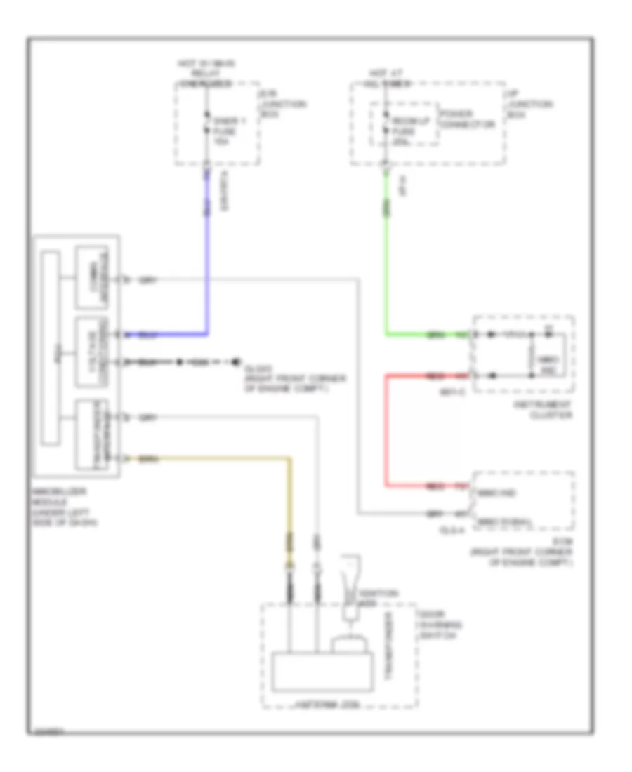
COMPUTER DATA LINES
Computer Data Lines for Hyundai XG350 2002
List of elements for Computer Data Lines for Hyundai XG350 2002:
- Antenna coil
- Clg-a
- Comms interface
- Door warning switch
- E/r junction box
- E/r-frta
- Ecm (right front corner of engine compt)
- Glg03 (right front corner of engine compt)
- Hot at all times
- Hot w/ main relay energized
- I/p junction box
- I/p-h
- Ignition key
- Immo ind
- Immo signal
- Immobilizer module (under left side of dash)
- Instrument cluster
- M01-c
- Nca
- Pcu
- Power connector
- Red
- Room lp fuse 15a
- Snsr 1 fuse 15a
- Transponder
- Transponder interface
- Voltage conditioning
COOLING FAN
Cooling Fan Wiring Diagram for Hyundai XG350 2002
List of elements for Cooling Fan Wiring Diagram for Hyundai XG350 2002:
- (automatic a/c)
- (behind center of dash)
- (behind main instrument cluster)
- (below front of center console)
- (passenger door)
- (rear of
- (rear of engine)
- (top of steering
- (top of wheelwell)
- (usa)
- 3.5l
- 4wd ecm (behind right side of dash)
- A/c control module
- A/v & navi- gation head unit m62-e (w/
- A/v)
- Amp (delphi) (below front pass- f37-a enger seat)
- Angle sensor
- Audio
- B-can
- B-can hi
- B-can lo
- Bcm (below left side of dash)
- C-can
- C-can hi
- C-can lo
- Ccp-can
- Center console)
- Chg-a
- Chg-k
- Clock fuse 15a
- Cluster
- Column)
- Data link connector (behind lower left end of dash)
- E/r junction box (left rear of engine compt)
- Esc 1 fuse 40a
- Esc control module
- Esc fuse 10a
- Fr sig
- Fr vcc
- Ghg01
- Ghg02
- Gm01
- High
- Hot at all times
- Hot in on or start
- I/p
- I/p-j
- I/p-m
- I01-a
- Instrument
- J/c jc01
- J/c jc02
- J/c jmcan (left side of engine compt)
- Junction box
- K-line
- Low
- M13-c
- M15-a
- M41-a
- M41-b
- M45-e
- Mc211
- Mc231
- Mc241
- Mf11
- Mf31
- Multipurpose check connector (left rear of engine compt)
- Nca
- Of engine)
- Output
- P/t
- Pcm (left rear of engine compt)
- Pods module (under seat)
- Power connector
- Red
- Resistor
- Right front wheel sensor
- Sig
- Srs control module
- Steering
- Tire pressure monitoring module
- U/h-u
- Veh spd
- Yaw rate sensor (below front of
DEFOGGERS
Defogger Wiring Diagram for Hyundai XG350 2002
List of elements for Defogger Wiring Diagram for Hyundai XG350 2002:
- (+)
- (-)
- A/c control module (automatic a/c) (behind center of dash)
- A/v & navigation head unit (with a/v)
- Accel pedal position sensor
- Amp (delphi) (below front passenger seat)
- Aps 1 gnd
- Aps 1 sig
- Aps 1 sply
- Aps 2 gnd
- Aps 2 sig
- Aps 2 sply
- Atm fuse 15a
- Audio
- Batt power
- Bcm (below left side of dash)
- Brk main sw sig
- Brk sw sig
- C-can high
- C-can low
- C-can transceiver
- Cancel
- Ccs gnd
- Ccs sig
- Chg-a
- Chg-k
- Clock spring
- Cluster fuse 10a
- Clutch sw
- Clutch switch (m/t)
- Computer data lines system
- Cruise ind
- Cruise main
- Cruise set ind
- Data link connector (behind lower left end of dash)
- E/r junction box (left rear of engine compt)
- Ecu fuse 10a
- Esc control module
- Esc sw fuse 10a
- Etc motor & throttle position sensor (on throttle body)
- Etc motor 1
- Etc motor 2
- Exterior lights system
- F37-a
- Fr sig
- Fr vcc
- Ghg02 (rear of engine)
- High
- Hot at all times
- Hot in on or start
- Hot with engine control relay on
- I/p junction box
- I/p-j
- I/p-k
- I/p-m
- Ill
- Instrument cluster
- Interior lights system
- Low
- M13-c
- M15-a
- M15-b
- M20-r
- M41-b
- M45-e
- M62-e
- Mc221
- Mc231
- Mf31
- Micom
- Motor
- Multi- function switch (remote control)
- Nca
- On/start in
- Pcm (left rear of engine compt)
- Pnk
- Red
- Redundant
- Regulator 5v
- Resume/ accel
- Right cruise remote control switch
- Right front wheel sensor (top of wheelwell)
- Room lp fuse 10a
- Sensor 1 fuse 10a
- Set/ coast
- Steering wheel
- Stop lamp switch (above brake pedal, on bracket)
- Stop lp fuse 15a
- Throttle position sensor
- Tire pressure monitoring module (usa)
- Tps 1 sig
- Tps 2 sig
- Tps gnd
- Tps sply
- U/h-c
- U/h-u
- Veh spd in
ELECTRONIC POWER STEERING
Electronic Power Steering Wiring Diagram for Hyundai XG350 2002
List of elements for Electronic Power Steering Wiring Diagram for Hyundai XG350 2002:
- (behind center of front grille)
- (in battery pack) bms control module
- (left front of engine compt) hybrid control unit
- (left front of engine compt) mcu
- (left front wheelwell) electric oil pump unit
- (left side of engine compt)
- (right side of
- (upper right end of dash)
- 4p out
- Active air flap
- B-can hi
- B-can lo
- B-can low
- C-can hi
- C-can high
- C-can low
- Chg-a
- Chg-k
- Chg34-s
- E/r fuse & relay box
- E64-b
- Ec11
- Ee01
- Em11
- Em61
- Eps control module (left side of dash)
- Esc 2 fuse 30a
- Esc 3 fuse 10a
- Ff01
- Ge04 (right side of engine compt)
- H-can hi
- H-can high
- H-can lo
- H-can low
- Hot at all times
- Hot in on or start
- Hvac unit)
- Instrument cluster
- J/c jm02 (left side of dash)
- J/c jm05 (center of dash)
- Je03
- Jf01 (right kick panel)
- Jm06 (center of dash)
- M-can high
- M-can low
- Mf11
- Mf61
- Monitoring module
- Multipurpose check connector (right rear of engine compt)
- Passenger weight classification sensor (under front passenger's seat)
- Pcm (left side of engine compt)
- Pnk
- Rear camera module (right side of dash)
- Red
- Srs control module (under front of center console)
- Tire pressure
- Vess unit
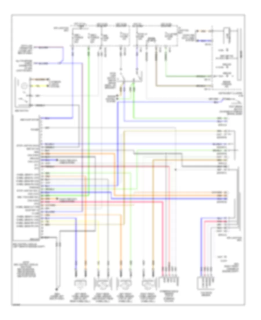
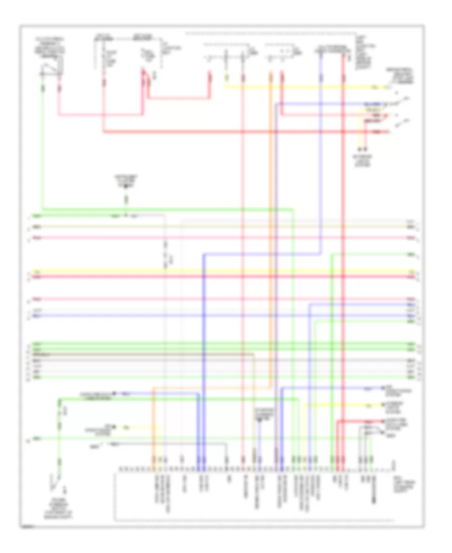
ENGINE PERFORMANCE
3.5L
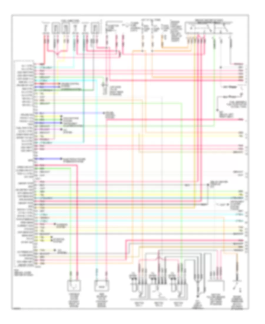
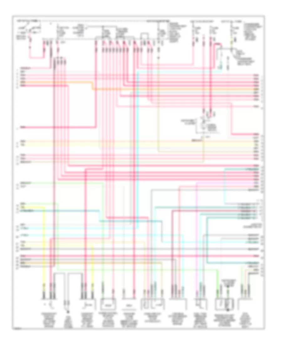
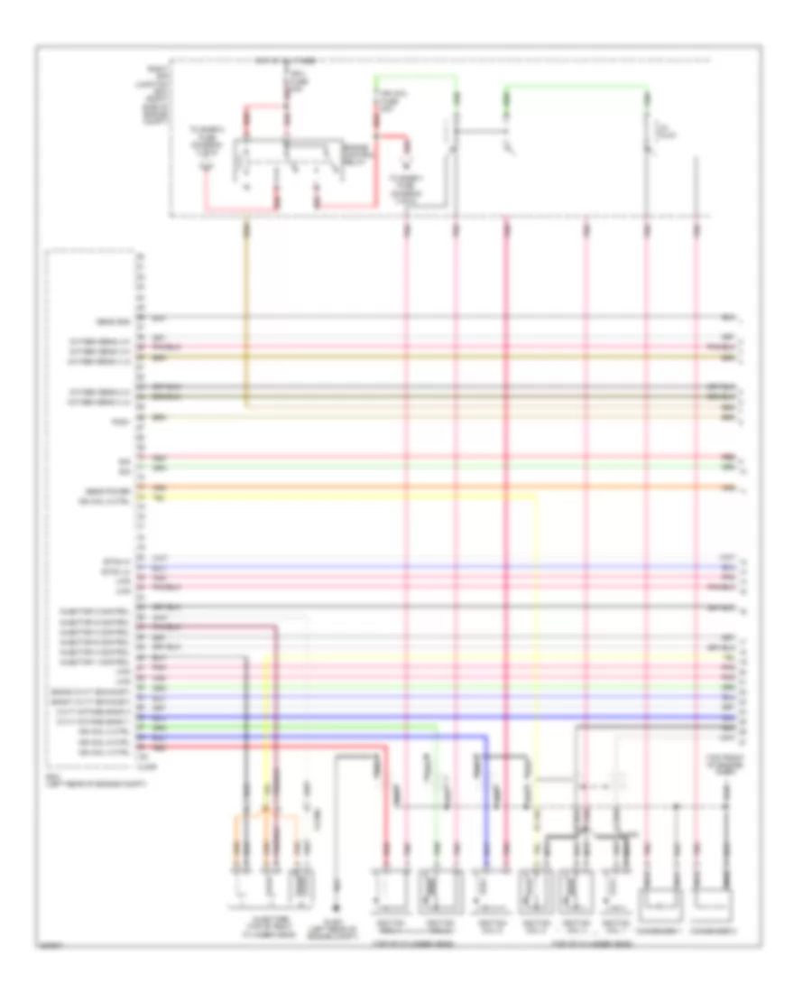
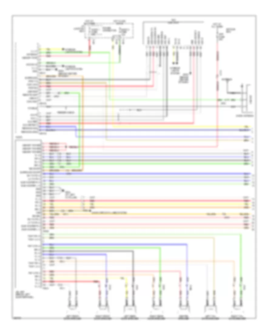
3.5L, Engine Performance Wiring Diagrams (1 of 4) for Hyundai XG350 2002
List of elements for 3.5L, Engine Performance Wiring Diagrams (1 of 4) for Hyundai XG350 2002:
- (behind center of dash) ecm control relay
- (below center console) g13
- A/c press sw
- A/c rly ctrl
- A/c system
- A/t fuse 20a
- A/t rly ctrl
- Afs sig
- Aps source
- Ats sig
- B10
- C11
- C44-1
- C44-2
- Ccv sig
- Charging system
- Check eng ind
- Ckp sens sig
- Close sens
- Close(var int)
- Cmp sens sig
- Com area net
- Cooling fans system
- Cruise control system
- Cruise ind
- Cruise sw ind
- Current mon
- Ecm fuse 10a
- Ecm rly ctrl
- Egr sol vlv
- Egr solenoid valve (top right side of engine)
- Electronic power steering system
- Engine comp- artment junction block (on left front of engine compt)
- Eps
- Etc sens sig
- Ets rly ctrl
- F10
- F11
- Fan rly (hi)
- Fan rly (lo)
- Fuel injectors
- Fuel pmp ctrl
- Fuel sender & fuel pump motor (in fuel tank)
- G07 (below left front seat)
- G11 (left side of firewall)
- Gnd
- Gnd ctrl
- Hot at all times
- Ign coil 1
- Ign coil 2
- Ign coil 3
- Ign detect sig
- Ignition coil 1
- Ignition coil 2
- Ignition coil 3
- Ignition failure sensor (on upper left rear of engine)
- Inj 1 ctrl
- Inj 2 ctrl
- Inj 3 ctrl
- Inj 4 ctrl
- Inj 5 ctrl
- Inj 6 ctrl
- Injector fuse 10a
- Instrument cluster system
- Instrument cluster system (tacho)
- Jc01
- Limp home valve (right rear of engine)
- Limp home vlv
- Main fuse 30a
- Memory pwr
- Nca
- O2s (heat)
- O2s (heating)
- Open sens
- Open(var int)
- P/n in
- Pcm (behind lower center of dash)
- Pcs vlv ctrl
- Pnk
- Power steering pressure switch (on front of engine)
- Pwr steering
- Red
- Sens gnd
- Spark tim adj
- Start sig
- Starting system
- Tan
- To egr fuse (diagram 2 of 4)
- To spark plugs
- Trip
- Variable intake motor (on right front of engine)
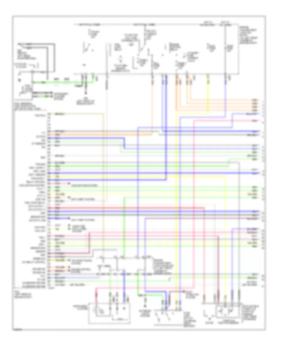
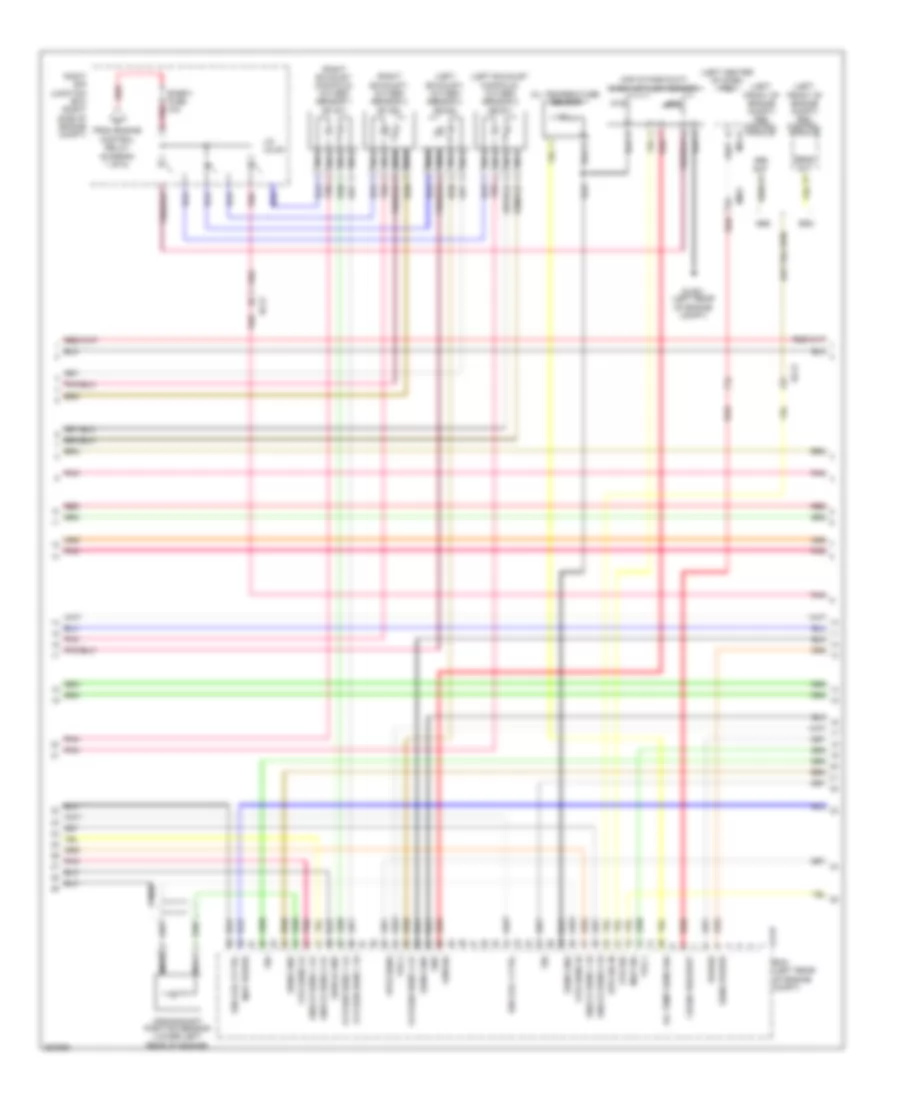
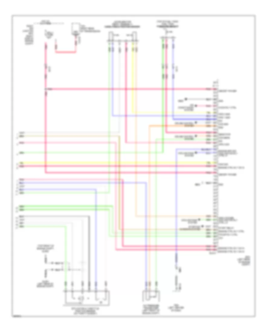
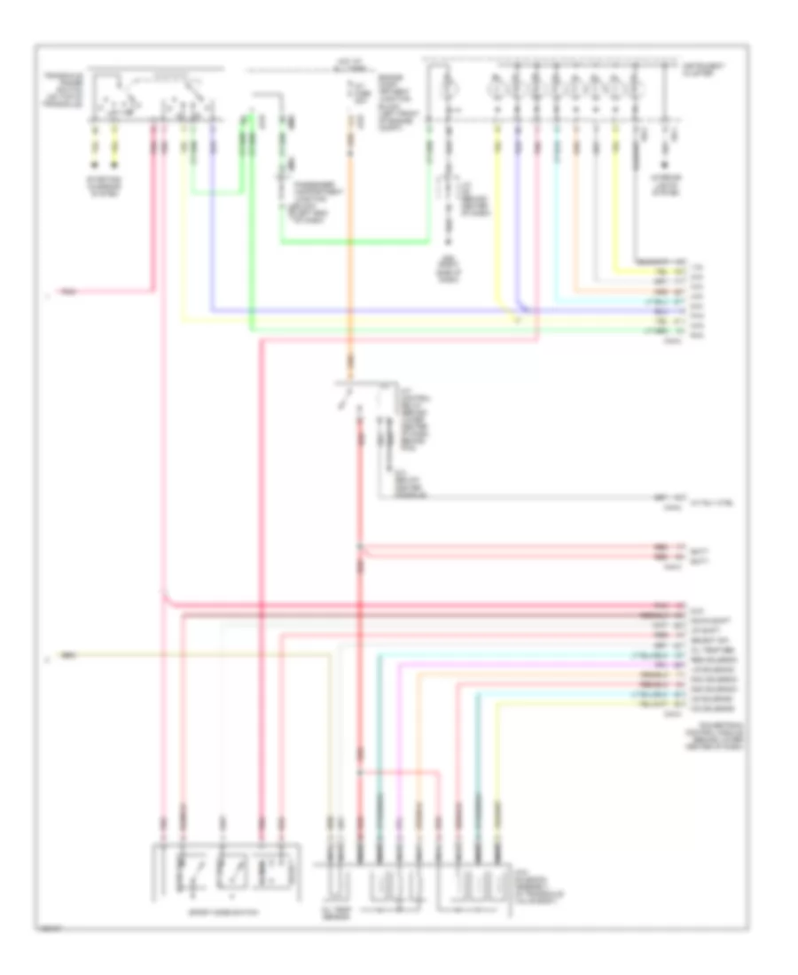
3.5L, Engine Performance Wiring Diagrams (2 of 4) for Hyundai XG350 2002
List of elements for 3.5L, Engine Performance Wiring Diagrams (2 of 4) for Hyundai XG350 2002:
- (mil)
- A11
- Abs fuse 10a
- Acc
- Camshaft position sensor (on front of left cyl head)
- Canister close valve (beneath left rear corner of vehicle)
- Check engine ind
- Crankshaft position sensor (on lower front of engine)
- D10
- D11
- E10
- Egr fuse 15a
- Engine compartment junction block (on left front of engine compt)
- Engine coolant temperature sensor & sender (on rear of engine)
- Ets motor (on right side of throttle body)
- Ets relay (in passenger compartment relay box)
- From injector a fuse (diagram 1 of 4)
- Fuel tank pressure sensor (beneath left rear of vehicle)
- Fuse 10a
- Fuse 15a
- G16 (left front shock tower)
- Hot at all times
- Hot in on or start
- I18-1
- I18-2
- I18-3
- Ignition coil fuse 20a
- Ignition switch
- Instrument cluster
- Instrument cluster system
- Jc01
- Ji01
- Jm01
- Jm04
- Jm09
- Junction connector c41
- Lock
- Mass airflow sensor (in air intake duct)
- Nca
- Oxygen sensor fuse 15a
- Passenger compartment junction block (behind left end of dash)
- Pnk
- Purge control solenoid valve (on rear of intake manifold)
- Red
- Sender
- Sensor
- Start
- Tan
- Variable intake sensor (on right front of engine)
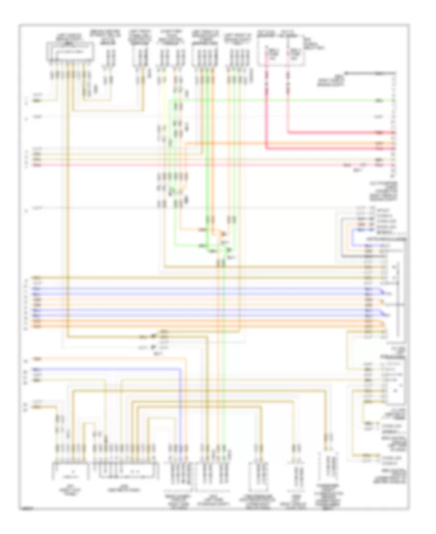
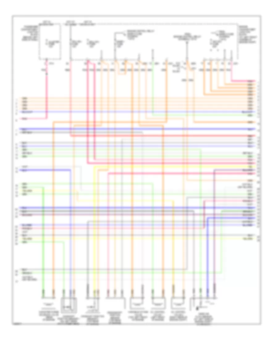
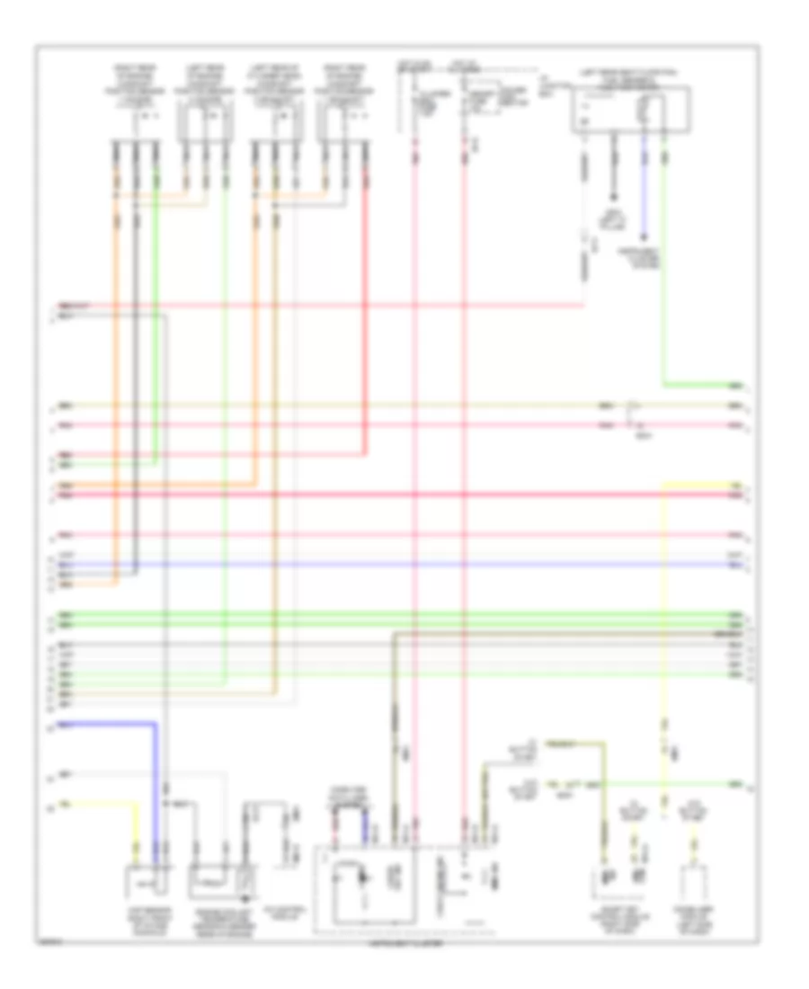
3.5L, Engine Performance Wiring Diagrams (3 of 4) for Hyundai XG350 2002
List of elements for 3.5L, Engine Performance Wiring Diagrams (3 of 4) for Hyundai XG350 2002:
- (not used)
- A/c relay control
- Air conditioning system
- Anti-theft system
- Aps 1
- Aps 1 gnd
- B/up fuse 10a
- C44-k
- Can high
- Can low
- Ccv
- Cmp 1 sensor
- Computer data lines system
- Cooling fan control
- Cooling fans system
- Cpsv
- Cruise control system
- Cruise ind
- Cvvt 1
- Cvvt 2
- Ecu fuse 10a
- Ecu rly fusible link 30a
- Engine compartment junction block (at left front corner of engine compt)
- Engine control relay
- Etc motor & throttle position sensor (left rear of engine)
- Etc output 1
- Etc output 2
- Exterior lights system
- F/pump fuse 20a
- Fuel level float
- Fuel pump relay
- Fuel sender & fuel pump motor (on top of fuel tank)
- G06 (left front of engine compt)
- G26 (behind left rear quarterpanel)
- Gnd
- Hot at all times
- Hot in on or start
- Iat sensor
- Imm data line
- Immo ind
- Instrument cluster
- Instrument cluster system
- Jc01
- Je01
- Je02
- M08-1
- M08-3
- Mcu
- Mil ind
- Motor
- Nca
- O2 sensor heater
- On pwr
- Pcm (left rear of engine compt)
- Pnk
- Red
- Relay control
- Sensor
- Sensor gnd
- Shift interlock system
- Sig
- Snsr 2 fuse 15a
- Snsr 3 fuse 10a
- Speed sig
- Stop fuse 15a
- Stop lamp switch (on brake pedal bracket)
- Throttle position sensor
- To ignition coil fuse (diagram 2 of 5)
- To oxygen sensor (diagram 2 of 5)
- To snsr 1 fuse (diagram 2 of 5)
- Tps 1
- Tps gnd
- Tps pwm
- Viv
- W/ sulev
- W/o sulev
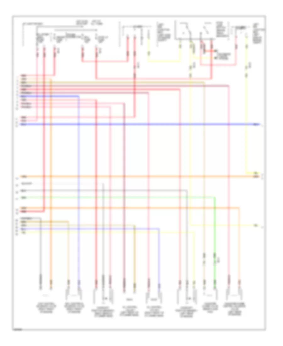
3.5L, Engine Performance Wiring Diagrams (4 of 4) for Hyundai XG350 2002
List of elements for 3.5L, Engine Performance Wiring Diagrams (4 of 4) for Hyundai XG350 2002:
- (diagram 1 of 5)
- Camshaft position sensor 1 (on left rear of cylinder head)
- Camshaft position sensor 2 (top rear of engine)
- Canister purge solenoid valve (rear of engine)
- Cluster fuse 10a
- Crankshaft position sensor (top rear of engine)
- Ecu (b+) fuse 10a
- Ecu (ig1) fuse 10a
- Engine compartment junction block (at left front corner of engine compt)
- Engine control relay snsr 2 fuse (diagram 1 of 5)
- From engine control relay (diagram 1 of 5)
- From snsr 2 fuse b
- Hot at all times
- Hot in on or start
- I/p-a
- Ign coil fuse 20a
- Jc01
- Je01
- Je02
- Mass air flow sensor (at left side of engine compt, in air duct)
- Oil control valve 1 (left front of engine)
- Oil control valve 2 (right rear of engine compt)
- Passenger compartment junction block (behind left side of dash)
- Pnk
- Red
- Snsr 1 fuse 15a
- Variable intake valve (top left front of engine)
- W/ sulev
- W/o sulev
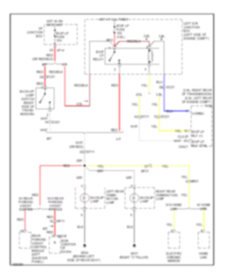
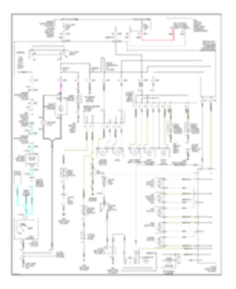
EXTERIOR LIGHTS
Back-up Lamps Wiring Diagram for Hyundai XG350 2002
List of elements for Back-up Lamps Wiring Diagram for Hyundai XG350 2002:
- (left rear of engine)
- (rear floor pan)
- (right front of
- (right front of engine)
- (right rear of cylinder head)
- Camshaft position sensor 1
- Camshaft position sensor 2
- Canister close valve
- Canister purge control solenoid
- Cluster/ escl fuse 7.5a
- Cylinder head)
- Ec11
- Ec21
- Ecu fuse 10a
- Ef11
- Exterior lights system
- Hot at all times
- Hot in on or start
- I/p junction box
- I/p-b
- I/p-h
- J/c je68
- J/c je69
- Left e/r junction box (left side of engine compt)
- Memory fuse 10a
- Oil control valve 1 (left front of cylinder head)
- Oil control valve 2
- Pedal bracket)
- Pnk
- Power connector
- Rcv controls solenoid valve
- Red
- Stop lamp switch (brake
- Stop lp fuse 15a
- Valve (left rear of engine)
- Wgt control solenoid valve
Exterior Lamps Wiring Diagram (1 of 2) for Hyundai XG350 2002
List of elements for Exterior Lamps Wiring Diagram (1 of 2) for Hyundai XG350 2002:
- (right side of engine compt)
- (top of cylinder head)
- A/con switch on input
- Air conditioning system
- Blower switch input
- Brake light switch
- Brake test switch
- Ccs gnd
- Ccs sensor
- Chg-a
- Clutch switch
- Condenser (left rear of engine)
- Cruise clutch pedal position switch (clutch pedal assembly)
- Cyl 1 (or cyl 4)
- Cyl 2 (or cyl 3)
- Cyl 3 (or cyl 2)
- Cyl 4 (or cyl 1)
- Ec11
- Ecm (left rear of engine compartment)
- Em21
- From engine b control relay (diagram 2 of 5)
- Ge06 (left front of engine compartment)
- Generator
- Generator (fr)
- Ghg03 (left rear of engine)
- Ign coil fuse 20a
- Ignition coil 1 (w/ immo) ignition coil 4 (w/o immo)
- Ignition coil 2 (w/ immo) ignition coil 3 (w/o immo)
- Ignition coil 3 (w/ immo) ignition coil 2 (w/o immo)
- Ignition coil 4 (w/ immo) ignition coil 1 (w/o immo)
- J/c
- Jch81
- M/t
- Nca
- Pnk
- Power steering switch (power steering pump)
- Pwr steering sw
- Right e/r junction box
- Shield gnd
Exterior Lamps Wiring Diagram (2 of 2) for Hyundai XG350 2002
List of elements for Exterior Lamps Wiring Diagram (2 of 2) for Hyundai XG350 2002:
- (top front of engine) glg02
- (top of cylinder head)
- Bank1 cvvt (exhaust)
- Bank2 cvvt (exhaust)
- Clg-b
- Clginj
- Condenser 1
- Condenser 2
- Cvvt (intake) bank 1
- Cvvt (intake) bank 2
- Ecm (left rear of engine compt)
- Ecu fuse 30a
- Engine control relay
- Etcm hi
- Etcm lo
- Glg01 (left rear of engine compt)
- Hot at all times
- Htr
- Ign coil 2 ctrl
- Ign coil 4 ctrl
- Ign coil 5 ctrl
- Ign coil 6 ctrl
- Ign coil fuse 20a
- Ignition coil 1
- Ignition coil 2
- Ignition coil 3
- Ignition coil 4
- Ignition coil 5
- Ignition coil 6
- Injector 1 control
- Injector 2 control
- Injector 3 control
- Injector 4 control
- Injector 5 control
- Injector 6 control
- Injectors (top of right cylinder head)
- J/c jcl81
- Nca
- Oxygen sens 2 hi
- Oxygen sens 2 lo
- Oxygen sens 3 hi
- Oxygen sens 3 lo
- Oxygen sens 4 hi
- Pcsv
- Pnk
- Red
- Right e/r junction box (right side of engine compt)
- Sens gnd
- Sens power
- Sig
- To snsr 2 fuse (diagram 2 of 6)
- To snsr-1 fuse (diagram 3 of 6)
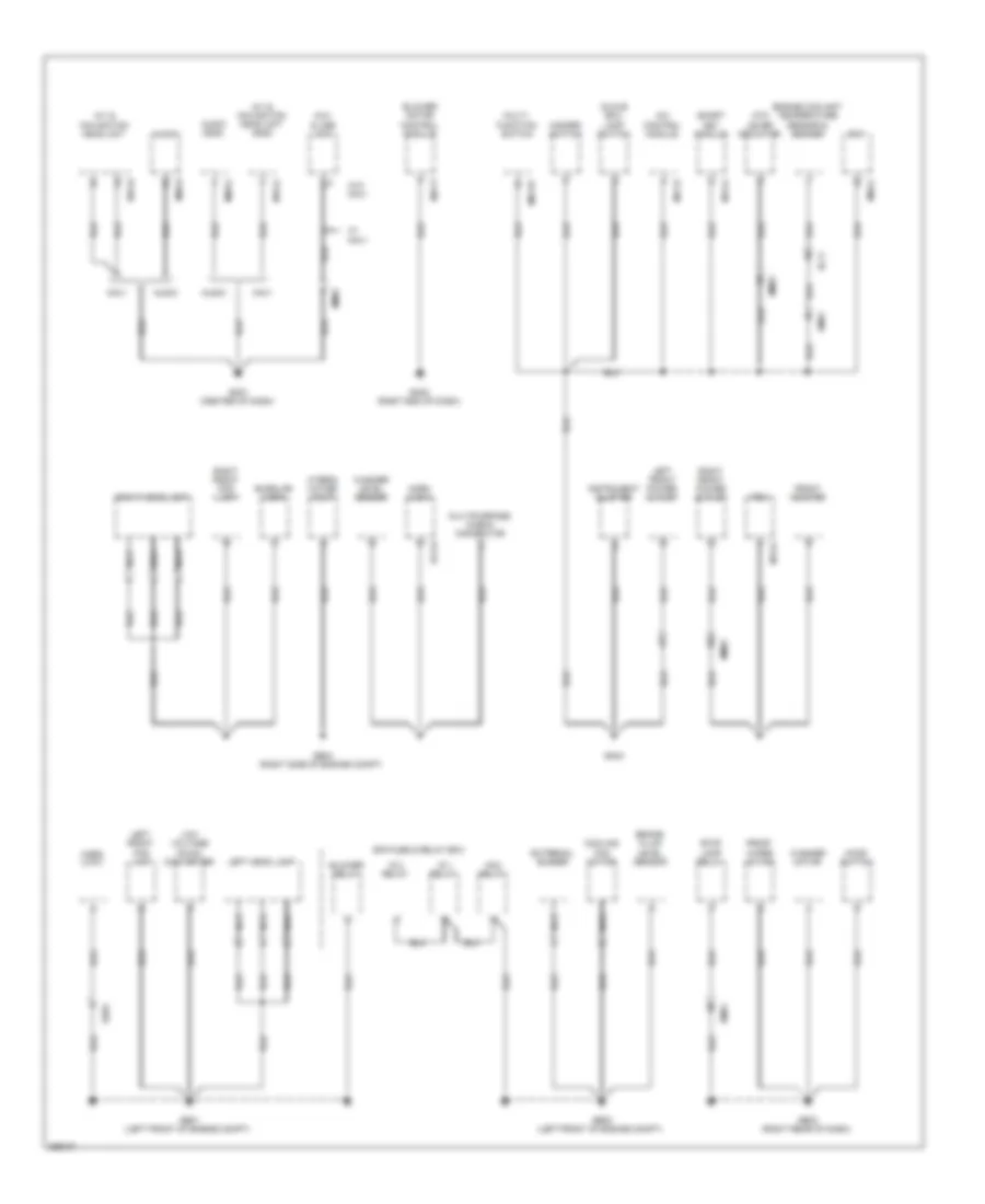
GROUND DISTRIBUTION
Ground Distribution Wiring Diagram (1 of 4) for Hyundai XG350 2002
List of elements for Ground Distribution Wiring Diagram (1 of 4) for Hyundai XG350 2002:
- (air intake duct) mass air flow sensor
- (diagram 1 of 6)
- (left center of dash) pdm
- (left exhaust manifold) oxygen sensor 2 (b2/s1)
- (left exhaust) oxygen sensor 4 (b2/s2)
- (left front of engine compt) abs control module
- (left front of engine compt) esc control module
- (right exhaust manifold) oxygen sensor 1 (b1/s1)
- (right exhaust) oxygen sensor 3 (b1/s2)
- (rr) out
- Abs
- Afm
- Afm sig
- Ats
- Ats sig
- Clg-b
- Cps sens hi
- Cps sens lo
- Crank request
- Crankshaft position sensor (lower left rear of engine)
- Ec21
- Ecm (left rear of engine compt)
- Em21
- Esc
- From engine control relay
- Glg01 (left rear
- Gnd
- Ign coil 1 ctrl
- Ign coil 3 ctrl
- J/c jcl83
- Knock sens 1 hi
- Knock sens 1 lo
- Knock sens 2 hi
- Knock sens 2 lo
- M51-a
- Map power
- Map sig
- Nca
- Of engine compt)
- Oil temp sens sig
- Oil temperature sensor
- Oxygen sens 1 hi
- Oxygen sens 1 lo
- Oxygen sens 4 lo
- Pnk
- Pnk pnk
- Power
- Red
- Right e/r junction box (right side of engine compt)
- Sens gnd
- Sens out
- Sens power
- Shield gnd
- Sig
- Snsr-1 fuse 10a
- Spd sig in
- Tps 1
- Tps 2
- Wts sens
Ground Distribution Wiring Diagram (2 of 4) for Hyundai XG350 2002
List of elements for Ground Distribution Wiring Diagram (2 of 4) for Hyundai XG350 2002:
- (left rear of cylinder head) camshaft position sensor 2 (exhaust)
- (left rear of engine) camshaft position sensor 2 (intake)
- (left rear seat floor pan) fuel sender & fuel pump motor
- (left side of dash)
- (right front of intake manifold)
- (right rear of engine) camshaft position sensor 1 (exhaust)
- (right rear of engine) camshaft position sensor 1 (intake)
- A/c control module
- Check engine ind
- Cluster/ escl fuse 7.5a
- Computer data lines system
- Cruise
- Cruse set ind
- Ec21
- Ef11
- Em21
- Em51
- Ems com
- Engine coolant temperature sensor & sender (rear of engine)
- Gf03 (left "c" pillar)
- Hot at all times
- Hot in on or start
- I/p junction box
- I/p-b
- Immo ind
- Immobilizer module
- Ind
- Instrument cluster
- Instrument cluster system
- M07-b
- M11-a
- M11-b
- M14-a
- Map sensor
- Memory fuse 10a
- Micom
- Nca
- Pnk
- Power con- nector
- Red
- Smart key control module (right side of dash)
- W/ button start
- W/o button start
Ground Distribution Wiring Diagram (3 of 4) for Hyundai XG350 2002
List of elements for Ground Distribution Wiring Diagram (3 of 4) for Hyundai XG350 2002:
- (brake pedal bracket) stop lamp switch
- (clutch pedal assembly) cruise clutch pedal position switch
- A/con sw on in
- Air conditioning system
- Alt sig
- Aps 1 power
- Aps 1 sig
- Blower sw in
- Break pedal sw
- Can 2 hi
- Can 2 lo
- Can hi
- Can low
- Clutch sw
- Computer data lines system
- E45
- Ec21
- Ecm (left rear of engine compt)
- Ecu fuse 10a
- Ef11
- Elg-a
- Engine check ind
- Exterior lights system
- Fuel lev sig middle
- Fuel lev sig total
- Ge08
- Gnd
- Hot at all times
- Hot in on or start
- I/p junction box
- I/p-h
- Immobilizer mil
- Instrument cluster system
- Interior lights system
- J/c je68
- J/c je69
- Left e/r junction box (left side of engine compt)
- Multipurpose check connector
- On/start in
- Pnk
- Power (5v)
- Power steering switch (top front of engine compt)
- Pwr steering sw
- Red
- Starting/ charging system
- Stop lamp sw
- Stop lp fuse 15a
Ground Distribution Wiring Diagram (4 of 4) for Hyundai XG350 2002
List of elements for Ground Distribution Wiring Diagram (4 of 4) for Hyundai XG350 2002:
- (accelerator pedal assembly) accel pedal position sensor
- (right rear of transmission)
- (top front of
- (top of fuel tank) fuel tank pressure sensor
- A/c pressure transducer (left front of engine compt)
- A/con rly ctrl
- Air conditioning system
- Aps 1 gnd
- Aps 2 gnd
- Aps 2 power cooling fan rly ctrl lo
- Aps 2 sig
- Ccs gnd
- Ccs sens
- Ccv
- Clg-zf
- Cooling fans system
- Cruise control system
- Ec21
- Ecm (left rear of engine compt)
- Ecu-1 fuse 10a
- Ef11
- Elg-a
- Em51
- Engine compt) glg02
- Engine ctrl rly ctrl
- Engine ctrl rly on in
- Engine spd sig cooling fan rly ctrl hi
- Etc motor & throttle position sensor (on throttle body)
- F/pump rly ctrl
- Ge08
- Glg01 (left rear of engine compt)
- Gnd
- Hot at all times
- Immo sig
- M51-b
- Mem pwr
- Memory power
- Pdm (left center of dash)
- Pnk
- Red
- Right e/r junction box (right side of engine compt)
- Sens pwr
- Sig
- Start relay
- Starting/ charging system
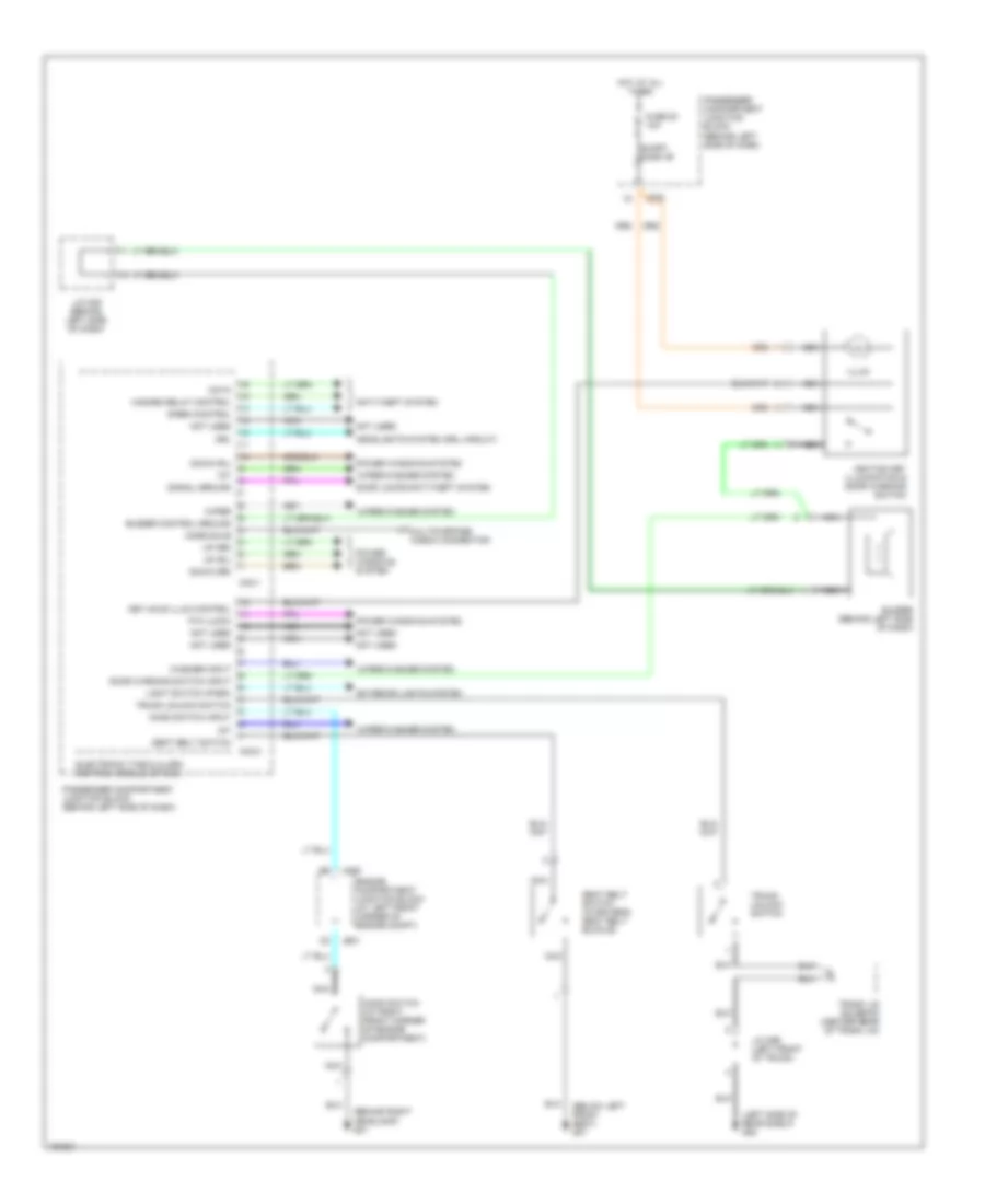
- Tcm
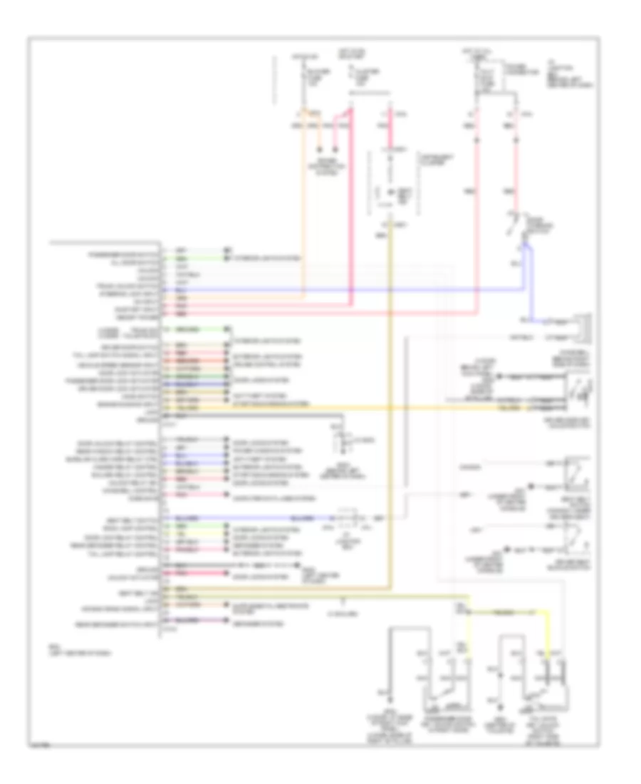
HEADLIGHTS
Headlight Wiring Diagram, with Autolamps (1 of 2) for Hyundai XG350 2002
List of elements for Headlight Wiring Diagram, with Autolamps (1 of 2) for Hyundai XG350 2002:
- (2.0l: left rear of engine compt)
- (3.8l: right rear of transmission)
- 2.0l
- 3.8l
- A/t
- B/up lp
- B/up lp fuse 10a
- B/up lp fuse 10a (3.8l)
- B/up lp relay
- Back-up lamp switch (right side of trans- mission)
- Backup lamp
- Bcm (center of dash)
- Ec11
- Ec21
- Ef11
- Electro chromic mirror
- Gf04 (behind left side of rear seat)
- Gf07 (right "c" pillar)
- Home link
- Hot at all times
- Hot in on or start
- I/p junction box
- I/p-h
- Left e/r junction box (left side of engine compt)
- Left rear combi- nation lamp
- M/t
- M02-b
- Mf11
- Mf31
- Mr01
- Rear parking assist control module (left quarter panel)
- Red
- Right rear combination lamp
- Rly (+) clg-zf
- Rly ctrl chg-t
- Tcm
- U-drmu
- W/ home link
- W/ rear parking assist system
- W/o home link
- W/o rear parking assist system
Headlight Wiring Diagram, with Autolamps (2 of 2) for Hyundai XG350 2002
List of elements for Headlight Wiring Diagram, with Autolamps (2 of 2) for Hyundai XG350 2002:
- Auto light sensor
- Cpu/sensor
- Drl control module (if equipped)
- Electronic time & alarm control module (etacm) (behind left side of dash)
- Engine compartment junction block (at left front corner of engine compartment)
- From engine compartment junction block (diagram 1 of 2)
- Front fog lamp ind
- Fuse 10a
- G05 (right side of dash)
- High beam ind
- Hot at on or start
- I18-1
- I18-3
- Instru- ment cluster
- Interior lights system
- Je01
- Ji01
- Jm09
- Joint connector i20 (center of dash)
- Joint connector m39 (behind center of dash)
- M33-1
- M33-2
- Passenger compartment junction block (behind left side of dash)
- Pnk
Headlight Wiring Diagram, with DRL (1 of 2) for Hyundai XG350 2002
List of elements for Headlight Wiring Diagram, with DRL (1 of 2) for Hyundai XG350 2002:
- (behind left headlamp)
- (behind right headlamp) g01
- Canada
- D10
- Dimmer/ passing switch
- Diode z04
- Electronic time & alarm control module (etacm) (behind left side of dash)
- Engine compartment junction block (at left front corner of engine compartment)
- Etacm
- Exterior lights system
- Flash
- Front fog lamp fuse 15a
- Front fog lamp ind
- Front foglight relay
- Front foglight switch
- Fuse 10a
- Fuse 26 10a
- G01 (behind right headlamp)
- G02
- G02 (behind left headlamp)
- G03 (left side of dash)
- Head
- Head lamp (high) fuse 15a
- Head lamp (low) fuse 15a
- Head- light relay (high)
- Headlight relay (low)
- High
- Hot at all times
- Hot at on
- I18-1
- Instru- ment cluster
- Interior lights system
- Je01
- Jm01
- Jm04
- Jm05
- Jm09
- Joint connector m08 (center of dash)
- Joint connector m39 (behind center of dash)
- Left front fog lamp
- Left headlamp
- Light switch
- Low
- M01-1
- M33-1
- M33-2
- M33-3
- Multifunction switch
- Off
- Park
- Passenger compartment junction block (behind left side of dash)
- Pnk
- Right front fog lamp
- Right headlamp
- Tail lamp fuse 20a
- Taillight relay
- To drl control module (diagram 2 of 2)
- To engine compartment junction block (diagram 2 of 2)
- Usa
Headlight Wiring Diagram, with DRL (2 of 2) for Hyundai XG350 2002
List of elements for Headlight Wiring Diagram, with DRL (2 of 2) for Hyundai XG350 2002:
- (left center of dash) bcm
- Burglar alarm horn relay (if equipped)
- Clock spring
- E/r
- Ge02
- Horn (front center of engine compt)
- Horn fuse 10a
- Horn relay
- Horn switch
- Hot at all times
- Icm relay box (late production) (behind left center of dash)
- M14-2
- M40
- Multi-function switch
- Nca
- Relay & fuse box
- Steering wheel
Headlight Wiring Diagram, without DRL for Hyundai XG350 2002
List of elements for Headlight Wiring Diagram, without DRL for Hyundai XG350 2002:
- (behind left headlamp) g02
- (behind right headlamp) g01
- Canada
- Dimmer/ passing switch
- Diode z04
- Electronic time & alarm control module (behind left side of dash)
- Engine compartment junction block (at left front corner of engine compartment)
- Etacm
- Exterior lights system
- Flash
- Front fog lamp fuse 15a
- Front fog lamp ind
- Front foglight relay
- Front foglight switch
- Fuse 10a
- Fuse 26 10a
- G01 (behind right headlamp)
- G02 (behind left headlamp)
- G03 (left side of dash)
- G05 (right side of dash)
- Head
- Head lamp (high) fuse 15a
- Head lamp (low) fuse 15a
- Head- light relay (high)
- Headlight relay (low)
- High
- High beam ind
- Hot at all times
- Hot at on
- I18-1
- I18-3
- Instru- ment cluster
- Interior lights system
- Je01
- Jm04
- Jm05
- Jm09
- Joint connector i20 (center of dash)
- Joint connector m08 (center of dash)
- Joint connector m39 (behind center of dash)
- Left front fog lamp
- Left headlamp
- Light switch
- Low
- M01-1
- M33-2
- M33-3
- Multifunction switch
- Off
- Park
- Passenger compartment junction block (behind left side of dash)
- Right front fog lamp
- Right headlamp
- Tail lamp fuse 20a
- Taillight relay
- Usa
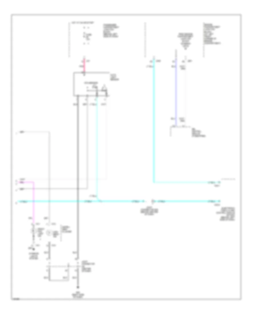
HORN
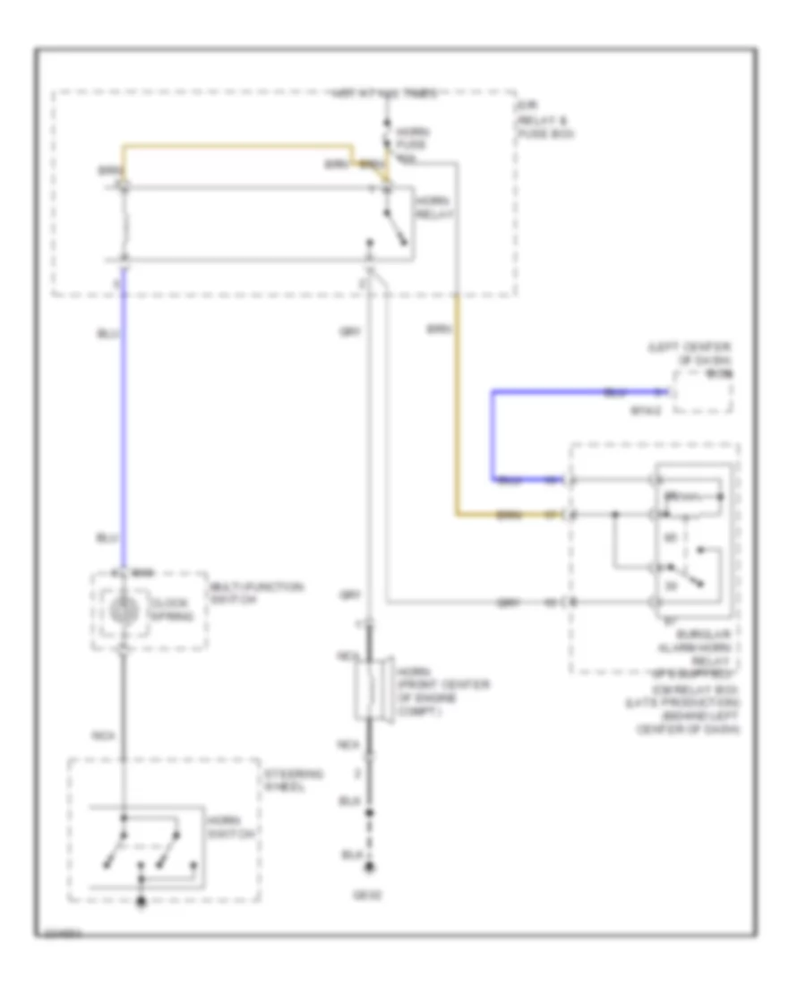
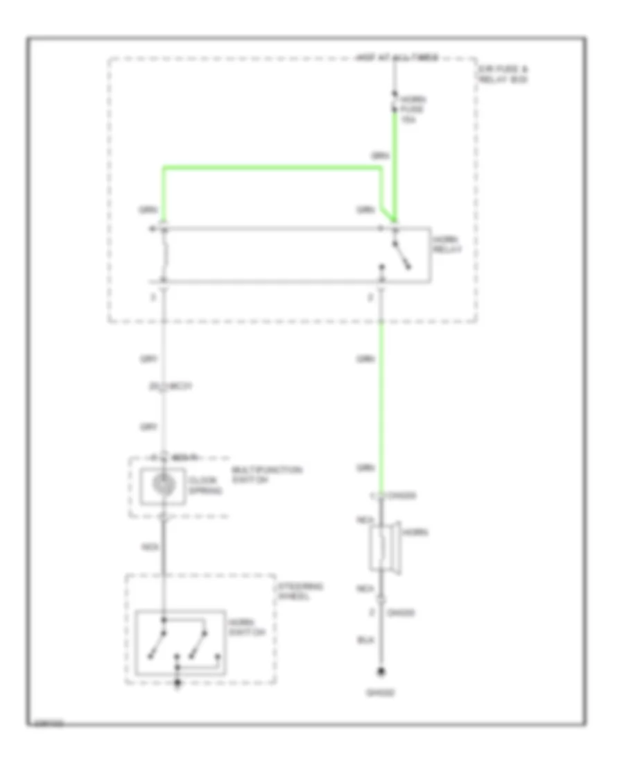
Horn Wiring Diagram for Hyundai XG350 2002
List of elements for Horn Wiring Diagram for Hyundai XG350 2002:
- Chg50
- Clock spring
- E/r fuse & relay box
- Ghg02
- Horn
- Horn fuse 15a
- Horn relay
- Horn switch
- Hot at all times
- M20-r
- Mc31
- Multifunction switch
- Nca
- Steering wheel
INSTRUMENT CLUSTER
Instrument Cluster Wiring Diagram (1 of 2) for Hyundai XG350 2002
List of elements for Instrument Cluster Wiring Diagram (1 of 2) for Hyundai XG350 2002:
- (center of dash) gm03
- Audio / av & navigation head module
- Audio 1 fuse 10a
- Audio 2 fuse 10a
- Digital clock
- Gnd
- Hot at all times
- Hot in acc or on
- I/p junction box
- I/p-g
- I/p-j
- Ill
- Input acc/on
- Interior lights system
- Lcd
- M45-a
- M45-b
- M50-a
- Power connector
- Pwr mem
- Red
- W/ a/v & navigation
- W/o a/v & navigation
Instrument Cluster Wiring Diagram (2 of 2) for Hyundai XG350 2002
List of elements for Instrument Cluster Wiring Diagram (2 of 2) for Hyundai XG350 2002:
- (left side of dash) g06
- (left side of firewall) g11
- (right side of dash) g05
- Brake fluid level sensor (on brake fluid sensor)
- Cluster
- Digital clock (w/o trip computer)
- Dim input
- Diode z01 (behind upper left side of dash)
- Engine compartment junction block (on left front of engine compartment)
- Etacm
- Foot parking brake switch (above parking brake pedal, on bracket)
- Fuel level float
- Fuel sender
- Fuel sender & fuel pump motor
- Fuse 21 10a
- Fuse 23 10a
- Fuse 25 10a
- Fuse 28 10a
- Gauge sender
- Ground
- Hot at all times
- Hot in on or start
- Ims control module (below driver's seat
- Interior lights system
- J/c i20 (left center of dash)
- J/c m09 (behind instrument cluster)
- Jc01 e6
- Ji01
- Ji02
- Jm01
- Jm04
- Jm06
- Jm09 a11
- M110-3
- M33-3
- Memory pwr
- Nca
- Normal
- Parking position
- Passenger compartment junction block (behind left end of dash)
- Pnk
- Red
- Seat belt
- Select
- Select switch
- Short connector "a"
- Sport mode switch
- Start/on in
- Thermistor
- Transaxle range switch (on left side of transaxle)
- Transmissions system
- Trip computer circuit
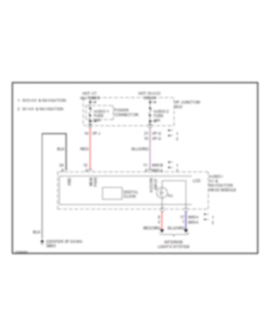
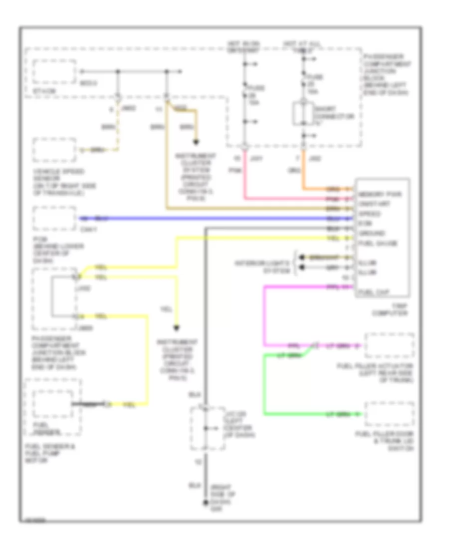
Trip Computer Wiring Diagram for Hyundai XG350 2002
List of elements for Trip Computer Wiring Diagram for Hyundai XG350 2002:
- (right side of dash) g05
- C44-1
- Ecm
- Etacm
- Fuel cap
- Fuel filler actuator (left rear side of trunk)
- Fuel filler door & trunk lid switch
- Fuel gauge
- Fuel sender
- Fuel sender & fuel pump motor
- Fuse 10a
- Ground
- Hot at all times
- Hot in on or start
- Illum
- Instrument cluster (printed circuit: conn i18-3, pin 5)
- Instrument cluster system (printed circuit conn i18-3, pin 9)
- Interior lights system
- J/c i20 (left center of dash)
- Ji01
- Ji02
- Jio2
- Jm02
- Jm06
- M33-3
- Memory pwr
- Nca
- On/start
- Passenger compartment junction block (behind left end of dash)
- Pcm (behind lower center of dash)
- Pnk
- Short connector "a"
- Speed
- Trip computer
- Vehicle speed sensor (on top right side of transaxle)
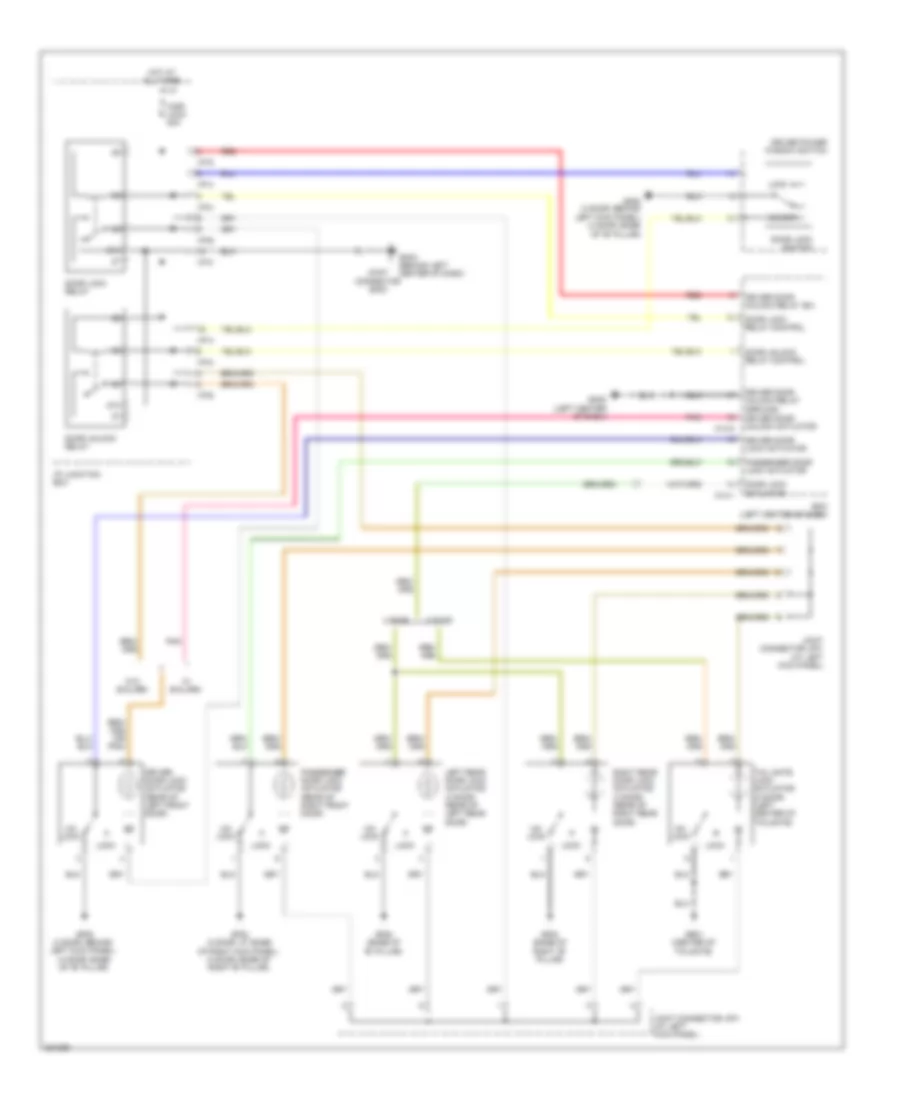
INTERIOR LIGHTS
Courtesy Lamps Wiring Diagram, with Sunroof for Hyundai XG350 2002
List of elements for Courtesy Lamps Wiring Diagram, with Sunroof for Hyundai XG350 2002:
- B-can
- B-can high
- B-can low
- B-can transceiver
- Bcm (center of dash)
- Door
- Door ind
- Door switch
- Dri
- Driver door switch (left "b" pillar)
- Driver vanity lamp
- Fr11
- Gm01 (left side of dash)
- Gm02 (center of dash)
- Gr01 (tail gate)
- High
- Hot at all times
- I/p junction box
- I/p-d
- I/p-h
- I/p-j
- Instrument cluster
- Inter face
- Ips control module
- J/c jm01 (top left of dash)
- Left rear door switch (base of left "c" pillar)
- Low
- Luggage lamp
- M13-b
- M13-c
- M15-a
- Map lamp
- Micom
- Mr01
- Off
- Overhead console
- P gnd
- Pass
- Passenger door switch (right "b" pillar)
- Passenger vanity lamp
- Power connector
- Rear lh
- Rear rh
- Red
- Right rear door switch (right "c" pillar)
- Room lamp
- Room lamp control
- Room lp fuse 10a
- S gnd
- Tail gate latch
- Tail gate open ind
- Tail gate open sw
- Tail gate open switch
- Z01 diode (left side of luggage compt)
Courtesy Lamps Wiring Diagram, without Sunroof for Hyundai XG350 2002
List of elements for Courtesy Lamps Wiring Diagram, without Sunroof for Hyundai XG350 2002:
- (not used)
- 4wd lock switch (left side of dash)
- A/c control module (behind center of dash, forward of shift lever)
- A/v & navigation head unit
- Atm shift lever ill
- Audio
- Auto
- Auto a/c
- Aux & usb jack
- B-can
- B-can high
- B-can low
- Bcm (center of dash)
- Cigarette lighter & front power outlet
- Console switch
- Dbc switch (left side of dash)
- Down
- Esc off switch (left side of dash)
- Fd11
- Fd31
- Fd41
- Front wiper deicer switch
- Gf01 (left "a" pillar)
- Gf02 (at base of left "b" pillar)
- Gf06 (right "a" pillar)
- Gf08 (base of right "c" pillar)
- Glove box lamp
- Glove box lamp switch
- Gm01 (left side of dash)
- Gm02 (center of dash)
- Gm03 (center of dash)
- Hazard switch
- Head
- High
- Hot at all times
- I/p junction box
- I/p-d
- I/p-f
- I/p-h
- Ill (+)
- Ill (-)
- Ill control
- Instrument cluster
- Ips 3
- Ips control module
- J/c jm01 (top left of dash)
- J/c jm02 (left side of dash)
- Left rear power window switch
- Light switch
- Low
- M13-b
- M15-a
- M20-l
- M20-r
- M40
- M41-a
- M43-b
- M45-a
- M50-a
- Manual a/c
- Mf11
- Micom
- Multi- function switch
- Multi-function switch
- Nca
- Off
- Passenger power window switch
- Power distribution system
- Power window main switch
- Rear defogger switch
- Red
- Rheostat (left side of dash)
- Rheostat down sw
- Rheostat up sw
- Right rear power window switch
- S gnd
- Start stop button switch
- Tail
- Tail lamp sw m13-a
- Vcc
- W/ a/v & navigation
- W/ rheostat
- W/ smart key
- W/o a/v & navigation
- W/o rheostat
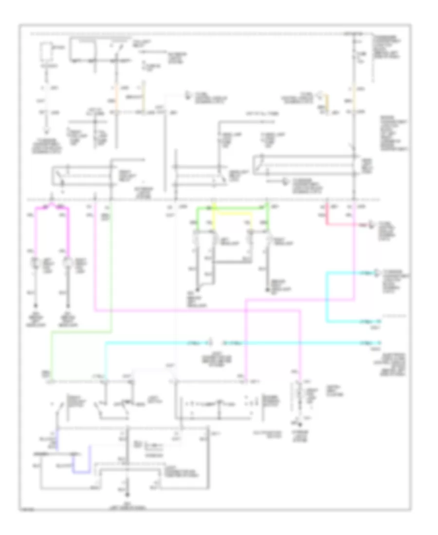
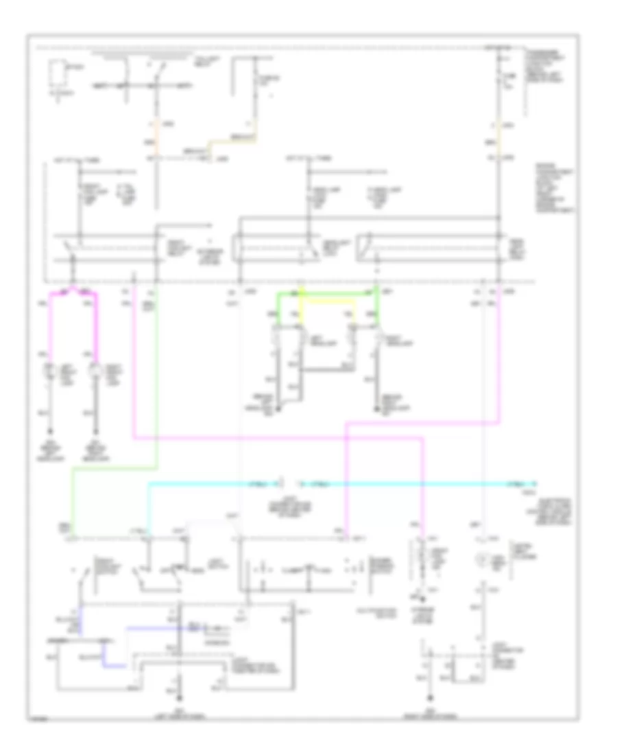
Instrument Illumination Wiring Diagram for Hyundai XG350 2002
List of elements for Instrument Illumination Wiring Diagram for Hyundai XG350 2002:
- (6 bulbs)
- (behind center of dash) j/c m39
- (behind left end of dash) passenger compartment junction block
- (left side of dash) g03
- A/c control module (auto a/c)
- A/c switch (manual a/c)
- Ashtray illum
- Assit door module
- Audio
- Auto cut out
- Cruise control switch
- Digital clock
- Driver door module
- Drl control module (right front of engine compt)
- Drl control module (right side of engine compartment)
- Drl control module inner tail relay control
- Drl fuse 15a
- Engine compartment junction block
- Engine compartment junction block (on left front of engine compt)
- Etacm
- Etacm (left end of dash)
- Exterior lights system
- Front cigarette lighter
- Fuse 26 10a
- Fuse 31 10a
- G03 (left side of dash)
- G05 (right side of dash)
- G07 (below left front seat)
- G09 (right side of rear shelf)
- Glove box lamp
- Glove box switch
- Hazard switch
- Head
- Head- lights system
- Hot at all times
- I18-1
- Illum
- Illumination
- Ims switch
- Instrument cluster
- J/c d12 (in left door)
- J/c d13 (in right door)
- J/c i20 (left side of dash)
- J/c i22 (right side of dash)
- J/c m08 (center of dash)
- J/c m39 (behind center of dash)
- J/c m64 (right front of trunk)
- J/c m78 (under left rear seat)
- Je01
- Ji01
- Ji02
- Jm01
- Jm02
- Jm04
- Jm05
- Jm06
- Jm07
- Jm09
- Left front seat warmer
- Left rear power window switch
- Light switch
- M33-1
- M33-2
- M33-3
- Mirrors system
- Multi- function switch
- Nca
- Off
- Out
- Park
- Rear cigarette lighter
- Red
- Rheostat
- Right front seat warmer
- Right rear power window switch
- Rly on cntrl
- Shift limit switch
- Short connector "c" (w/o drl)
- Tail lamp auto cut cntrl input
- Tail lamp fuse 20a
- Taillight relay
- Tcs switch
- Trip computer
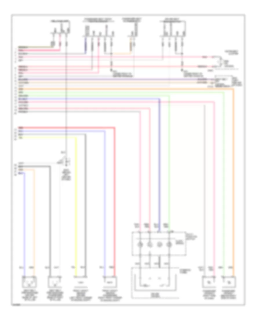
MEMORY SYSTEMS
Memory System Wiring Diagrams (1 of 2) for Hyundai XG350 2002
List of elements for Memory System Wiring Diagrams (1 of 2) for Hyundai XG350 2002:
- (4 door: base of "b" pillar)
- 3 door
- 4 door
- 87a
- Bcm (left center of dash)
- C/dr lock 20a
- Door lock actuator
- Door lock relay
- Door lock relay control
- Door lock switch
- Door unlock relay
- Door unlock relay control
- Driver door lock actuator
- Driver door lock actuator (rear of left front door)
- Driver door unlock actuator
- Driver door unlock relay (b+)
- Driver door unlock relay (ground)
- Driver power window switch
- Gf02 (3 door: at base of right kick panel) (4 door: base of right "b" pillar)
- Gf02 (base of right "b" pillar)
- Gf05 (3 door: behind left kick panel)
- Gf05 (3 door: behind left kick panel) (4 door: base of "b" pillar)
- Gf05 (base of "b" pillar)
- Gm02 (left center of dash)
- Gm03 (behind left center of dash)
- Gr01 (center of tailgate)
- Hot at all times
- I/p junction box
- I/p-a
- I/p-b
- I/p-g
- I/p-k
- I/p-m
- Joint connector gm03
- Joint connector jf01 (at left kick panel)
- Left rear door lock actuator (4 door) (rear of left rear door)
- Lock
- M14-1
- M14-2
- Passenger door lock actuator
- Passenger door lock actuator (rear of right front door)
- Pnk
- Red
- Right rear door lock actuator (4 door) (rear of right rear door)
- Tail gate lock actuator (3 door) (left center of tailgate)
- Un- lock
- Unlock
- W/ b/alarm
- W/o b/alarm
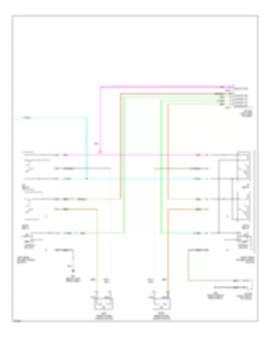
Memory System Wiring Diagrams (2 of 2) for Hyundai XG350 2002
List of elements for Memory System Wiring Diagrams (2 of 2) for Hyundai XG350 2002:
- Acc
- Acc/on in
- Assister door module 1, 2 (on right front door)
- Auto
- Common
- D03
- D05
- D28
- D30
- Data
- Driver door module 1, 2 (on left front door)
- Eta control module (behind left end of dash)
- Fuse 10a
- Fuse 20a
- G03 (left side of dash)
- G05 (right side of dash)
- Gnd cntrl
- Ground
- Hot at acc or on
- Hot at all times
- Ims switch
- Interior lights system
- J/c d12 (in left front door)
- J/c d13 (in right front door)
- Jm02
- Left ims mirror motor
- Left/right
- Lt/rt sensor
- M33-1
- Memory
- Memory pwr
- Nca
- Passenger compartment junction block
- Power
- Red
- Right ims mirror motor
- Signal
- Signal gnd
- Up/dn sensor
- Up/down
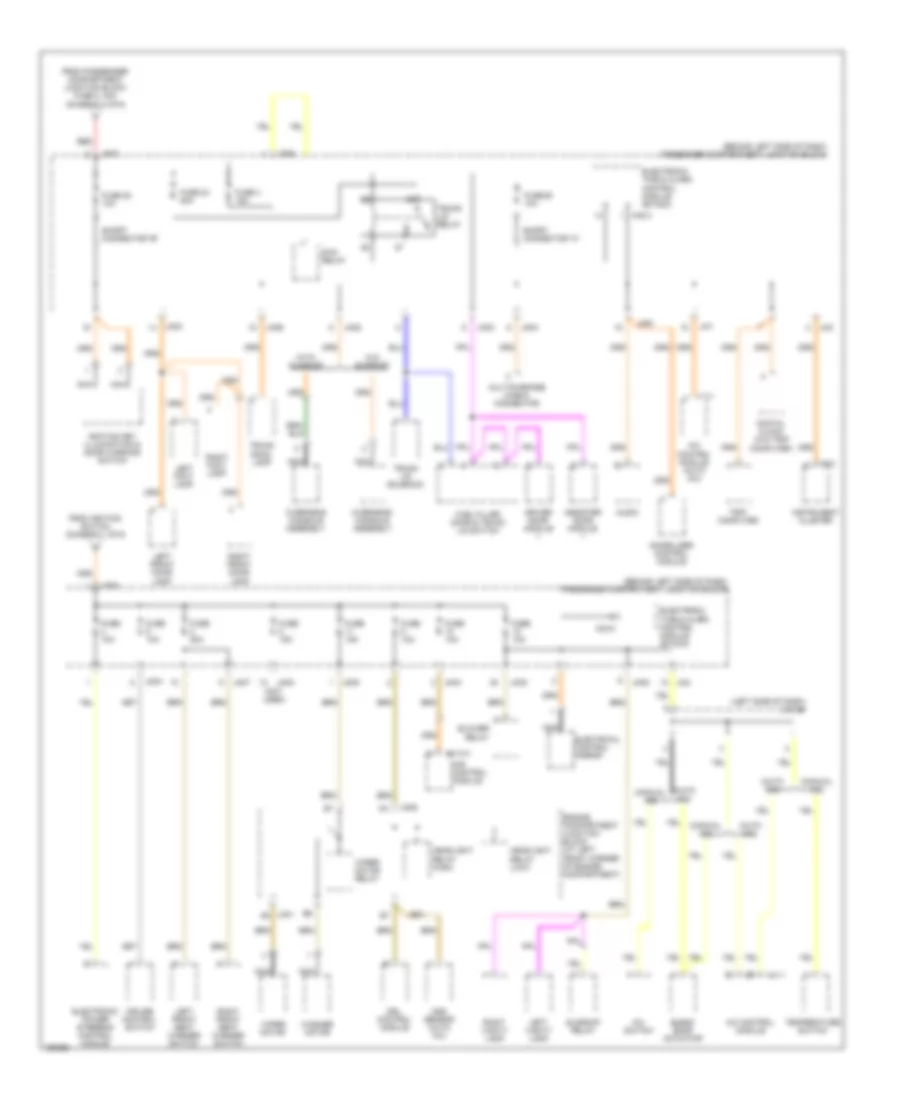
POWER DISTRIBUTION
Power Distribution Wiring Diagram (1 of 6) for Hyundai XG350 2002
List of elements for Power Distribution Wiring Diagram (1 of 6) for Hyundai XG350 2002:
- (+)
- (-)
- Amp fuse 30a
- Center speaker
- Computer data lines system
- E/r sub box
- Eq sel
- F06-a
- F06-b
- Fl (+)
- Fl (-)
- Fr (+)
- Fr (-)
- Frt ctr (+)
- Frt ctr (-)
- Gf04 (at left "c" pillar)
- Ground
- Hot at all times
- Jbl amp (behind left quarterpanel)
- Left front door speaker
- Left front tweeter speaker
- Left rear door speaker
- Left tail gate speaker
- Lh twtr (+)
- Lh twtr (-)
- Mem power
- Nca
- Re on/off
- Red
- Rh twtr (+)
- Rh twtr (-)
- Right front door speaker
- Right front tweeter speaker
- Right rear door speaker
- Right tail gate speaker
- Rl (+)
- Rl (-)
- Rr (+)
- Rr (-)
- Sub wfr l (+)
- Sub wfr l (-)
- Sub wfr r (+)
- Sub woofer speaker
- Surr on/off
- Tgat lh (+)
- Tgat lh (-)
- Tgat rh (+)
- Tgat rh (-)
- Vss
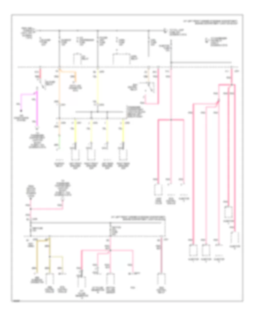
Power Distribution Wiring Diagram (2 of 6) for Hyundai XG350 2002
List of elements for Power Distribution Wiring Diagram (2 of 6) for Hyundai XG350 2002:
- (at left front corner of engine compartment) engine compartment junction block
- (not used)
- A/c compressor fuse 10a
- A/c relay
- A/t pulse generator -a
- A/t pulse generator -b
- Abs bleeding connector
- Abs control module
- Abs fuse 10a
- Air conditioning system
- B10
- Blower fuse 30a
- Blower relay
- C44-3
- D12
- Data link connector (dlc)
- Ecm control relay
- Ets control module
- F10
- F11
- From abs fusible a link 2, 30a (diagram 1 of 6)
- From ignition switch (diagram 1 of 6)
- Horn fuse 15a
- Horn relay
- Ignition coil fuse 20a
- Ignition failure sensor
- Injector
- Injector fuse 10a
- Jc01
- Jm01
- Jm02
- Jm06
- Jm08
- Jm09
- Lamp home valve
- Left front speaker amp
- Left rear speaker amp
- Main fuse 30a
- Nca
- Passenger compartment junction block (behind left side of dash)
- Pcm
- Pnk
- Power amp fuse 20a
- Red
- Right front speaker amp
- Right rear speaker amp
- Sunroof fuse 15a
- Sunroof relay
- To condenser fan relay (high-1) (diagram 4 of 6)
- To passenger compartment junction block (fuse 21, 10a) (diagram 5 of 6)
- To passenger compartment junction block (fuse 6, 10a) (diagram 5 of 6)
- To tail lamp fuse, 20a (diagram 3 of 6)
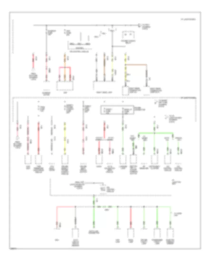
Power Distribution Wiring Diagram (3 of 6) for Hyundai XG350 2002
List of elements for Power Distribution Wiring Diagram (3 of 6) for Hyundai XG350 2002:
- & navi
- (center of dash) gm02
- (not used)
- 4wd lock switch
- A/c
- A/c control module
- A/v & navigation head module
- Atm shift lever ill
- Audio
- Auto a/c
- Aux & usb jack
- Chg26
- Cigarette lighter & front power outlet
- Console switch
- Control
- Dbc switch
- Door lock relay
- Door unlock relay
- Dr lock fuse 15a
- Esc off switch
- F26
- Fd11
- Fd21
- Fd31
- Fd41
- Fr11
- From pdm fuse q (diagram 3 of 6)
- From power window relay r (diagram 5 of 6)
- Front wiper deicer switch
- Glove box lamp
- Hazard switch
- I/p junction box
- I/p-a
- I/p-c
- I/p-d
- I/p-f
- I/p-h
- Icm relay box (top left of dash)
- Instrument cluster
- Ips 3
- Ips 4
- Ips 5
- Ips 6
- Ips 7
- Ips control control
- Ips control module
- J/c jm02
- Left front fog lamp
- Left head lamp
- Left rear combination lamp (out)
- Left rear power window switch
- License lamp
- M04-a
- M15-a
- M20-r
- M40
- M41-a
- M43-b
- M45-a
- M50-a
- Manual
- Mf11
- Module
- Multi- function switch
- Nca
- Passenger power window switch
- Power window main switch
- R12
- R13
- Rear defogger switch
- Red
- Rheostat
- Right front fog lamp
- Right rear combination lamp (in)
- Right rear power window switch
- Tail gate relay
- Two turn unlock relay
- W/ a/v & navi
- W/o a/v
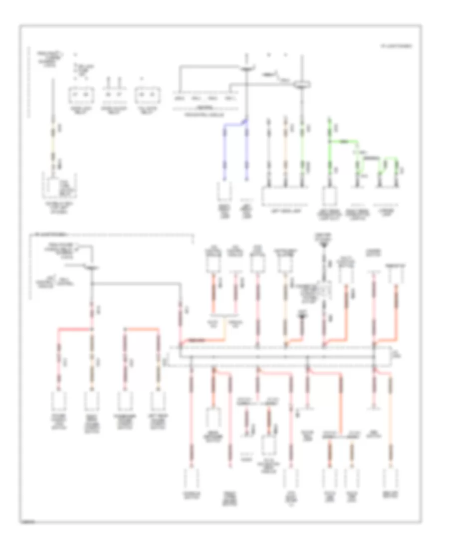
Power Distribution Wiring Diagram (4 of 6) for Hyundai XG350 2002
List of elements for Power Distribution Wiring Diagram (4 of 6) for Hyundai XG350 2002:
- & navi
- 4wd ecm
- A/c
- A/c control module
- A/v & navigation head module
- Amp
- Amp fuse 25a
- Atm shift lever
- Audio
- Audio 1 fuse 10a
- Auto a/c
- Auto light & photo sensor
- Batt pwr
- Bcm
- Cf11
- Chg27
- Control
- Data link connector
- Driver safety power window module
- Driver seat manual switch
- Driver vanity lamp
- Electro chromic mirror
- F03-a
- F27
- Fd11
- From b+2 fuse (diagram 1 of 6)
- From b+3 fuse (diagram 1 of 6)
- From i/p junction box t (diagram 5 of 6)
- Fs11
- I/p junction box
- I/p-a
- I/p-b
- I/p-c
- I/p-d
- I/p-e
- I/p-f
- I/p-j
- Ignition key ill & door warning switch
- Instrument cluster
- Ips 0
- Ips 1
- Ips 2
- Ips control module
- Key
- Luggage lamp
- M09
- M13-a
- M15-a
- M41-a
- M43-b
- M45-b
- M50-a
- Manual
- Map lamp
- Mf21
- Mr01
- Nca
- P/seat (drv) fuse 20a
- Passenger vanity lamp
- Pnk
- Power connector
- Power window relay
- R14
- Red
- Rf receiver
- Right head lamp
- Right rear combination lamp (in)
- Right rear combination lamp (out)
- Room lamp
- Room lp fuse 10a
- Safety power window fuse 20a
- Smart
- Sunroof fuse 15a
- Sunroof motor
- Tire pressure monitoring module
- To i/p junction box (diagram 5 of 6)
- To ips 3 (diagram 4 of 6)
- To smart key fuse (diagram 6 of 6)
- Tpms fuse 7.5a
- W/ a/v & navi
- W/ home link
- W/o
- W/o a/v
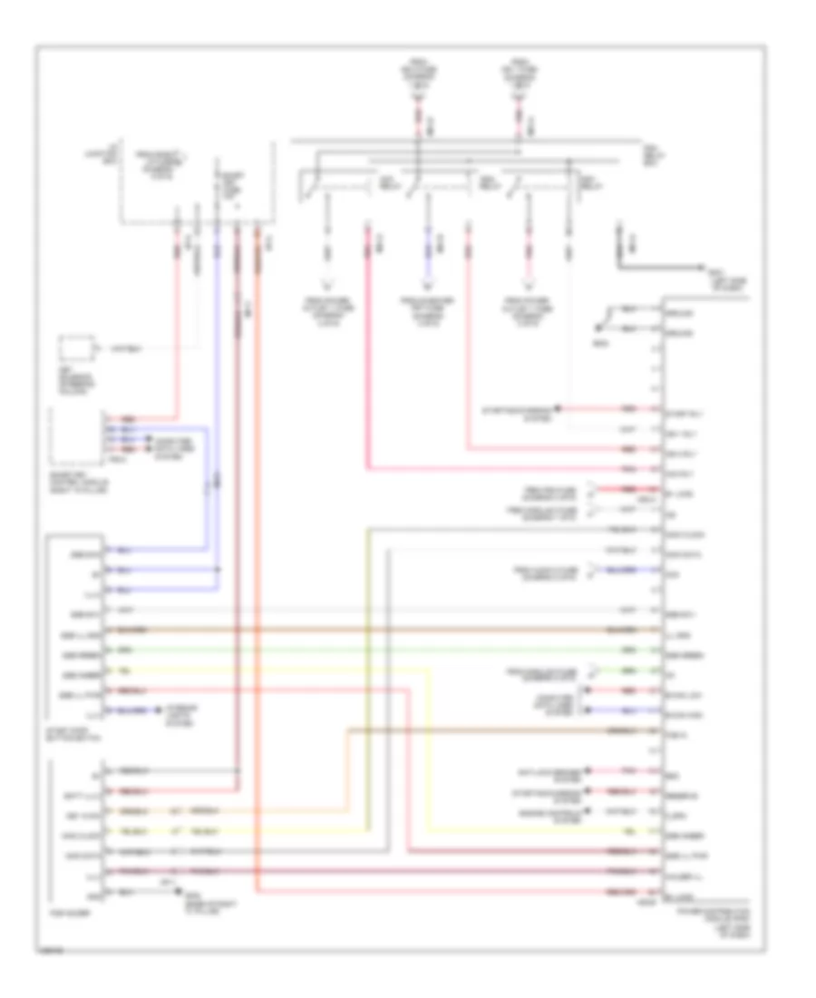
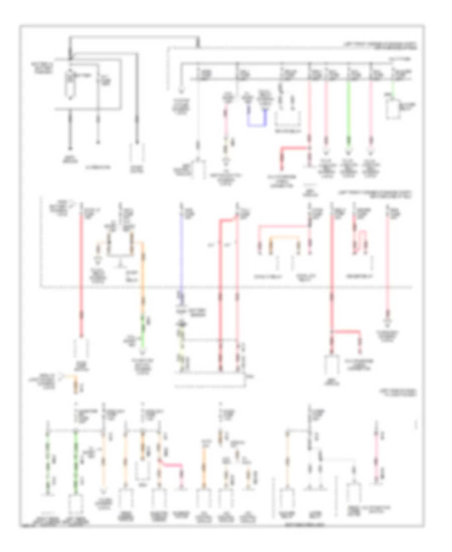
Power Distribution Wiring Diagram (5 of 6) for Hyundai XG350 2002
List of elements for Power Distribution Wiring Diagram (5 of 6) for Hyundai XG350 2002:
- (diagram 1 of 6)
- (diagram 2 of 6)
- (left side
- (left side of dash)
- Acc
- Acc relay
- Acc rly
- Anti-lock brakes system
- B+ load
- B-can high
- B-can low
- Batt ill(+)
- Computer data lines system
- Engine controls system
- Esc
- F06-a
- Fob holder
- Fob in
- From audio 2 fuse
- From ign 1 fuse (diagram 1 of 6)
- From ign 2 fuse (diagram 1 of 6)
- From module 2 fuse
- From module 5 fuse
- From pdm fuse (diagram 3 of 6)
- From power outlet 1 fuse (diagram 2 of 6)
- From room lp fuse s (diagram 5 of 6)
- From s/heater frt fuse (diagram 2 of 6)
- F_rpm
- Gf08 (base of right "c" pillar)
- Gm01
- Gm02
- Gnd
- Ground
- Holder ill
- I/p junction box
- I/p-d
- I/p-g
- Ig1
- Ig2
- Ign 1 rly
- Ign 2 rly
- Ign1 relay
- Ign2 relay
- Ill gnd
- Ill(+)
- Ill(-)
- Immo clock
- Immo data
- Interior lights system
- Key in sw
- Key solenoid (steering column)
- M51-a
- M51-b
- M52-a
- M52-b
- Mf11
- Mf51
- Of dash)
- Pdm relay box
- Pnk
- Power distribution module (pdm)
- Red
- Red red
- Reserve
- Smart key control module (right "a" pillar)
- Smart key fuse 10a
- Ssb amber
- Ssb green
- Ssb ill gnd
- Ssb ill pwr
- Ssb sw1
- Ssb sw2
- Start rly
- Start stop button switch
- Starting/charging system
Power Distribution Wiring Diagram (6 of 6) for Hyundai XG350 2002
List of elements for Power Distribution Wiring Diagram (6 of 6) for Hyundai XG350 2002:
- (auto a/c)
- (behind left side of dash) passenger compartment junction block
- (left side of dash) j/c i20
- (manual a/c)
- (not used)
- A/c control module
- A/c control module (auto a/c)
- A/c switch
- Aqs sensor (auto a/c)
- Assister door module
- Audio
- Blend door actuator
- Blower relay
- Cruise control switch
- Digital clock (w/o trip computer)
- Driver door module
- Drl control module
- Electrical control mirror
- Electronic power steering control module
- Electronic time & alarm control module (etacm)
- Engine compartment junction block (at left front corner of engine compartment)
- Ets relay
- From ignition switch (diagram 1 of 6)
- From passenger compartment junction block fuse 2, 30a (diagram 4 of 6)
- Fuel filler door & trunk lid switch
- Fuse 10a
- Fuse 15a
- Fuse 20 10a
- Fuse 20a
- Fuse 24 20a
- Fuse 25 10a
- Fuse 4 15a
- Headlight relay (high)
- Headlight relay (low)
- I17-1
- I18-3
- Ignition key illumination & door warning switch
- Immobilizer control module
- Ims control module
- Instrument cluster
- Jc01 a6
- Je01
- Ji01
- Ji02
- Jm02
- Jm03
- Jm04
- Jm05
- Jm06
- Jm07
- Jm08
- Jm09
- Left foot lamp
- Left front door lamp
- Left front seat warmer switch
- Left vanity lamp
- M110-4
- M33-3
- Multipurpose check connector
- Nca
- Overhead console assembly
- Red
- Right foot lamp
- Right front door lamp
- Right front seat warmer switch
- Right vanity lamp
- Short connector "a"
- Short connector "b"
- Sunroof relay
- Temperature switch
- Trip computer
- Trunk lid relay
- Trunk lid solenoid
- Trunk room lamp
- W/o sunroof
- Washer motor
- Wiper motor
- Wiper motor relay
- With sunroof
POWER MIRRORS
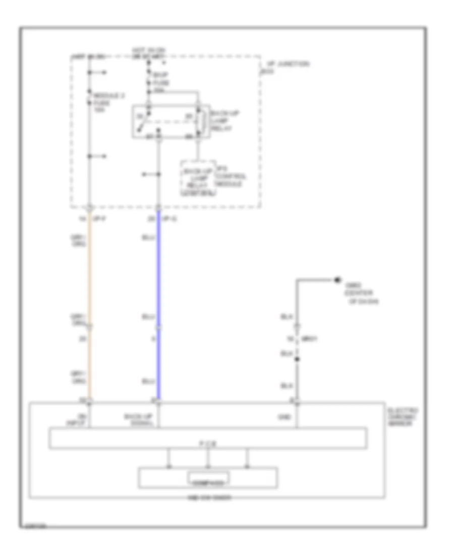
Electrochromic Mirror Wiring Diagram for Hyundai XG350 2002
List of elements for Electrochromic Mirror Wiring Diagram for Hyundai XG350 2002:
- (center
- B/up
- Back-up lamp relay control
- Back-up lamp relay
- Back-up signal
- Box
- Compass
- Electro chromic mirror
- Fuse 10a
- Gm02
- Gnd
- Hot in on
- Hot in on or start
- I/p junction
- I/p-f
- I/p-g
- Ind sw snsr
- Input
- Ips control module
- Module 2 fuse 10a
- Mr01
- Of dash)
- P.c.b
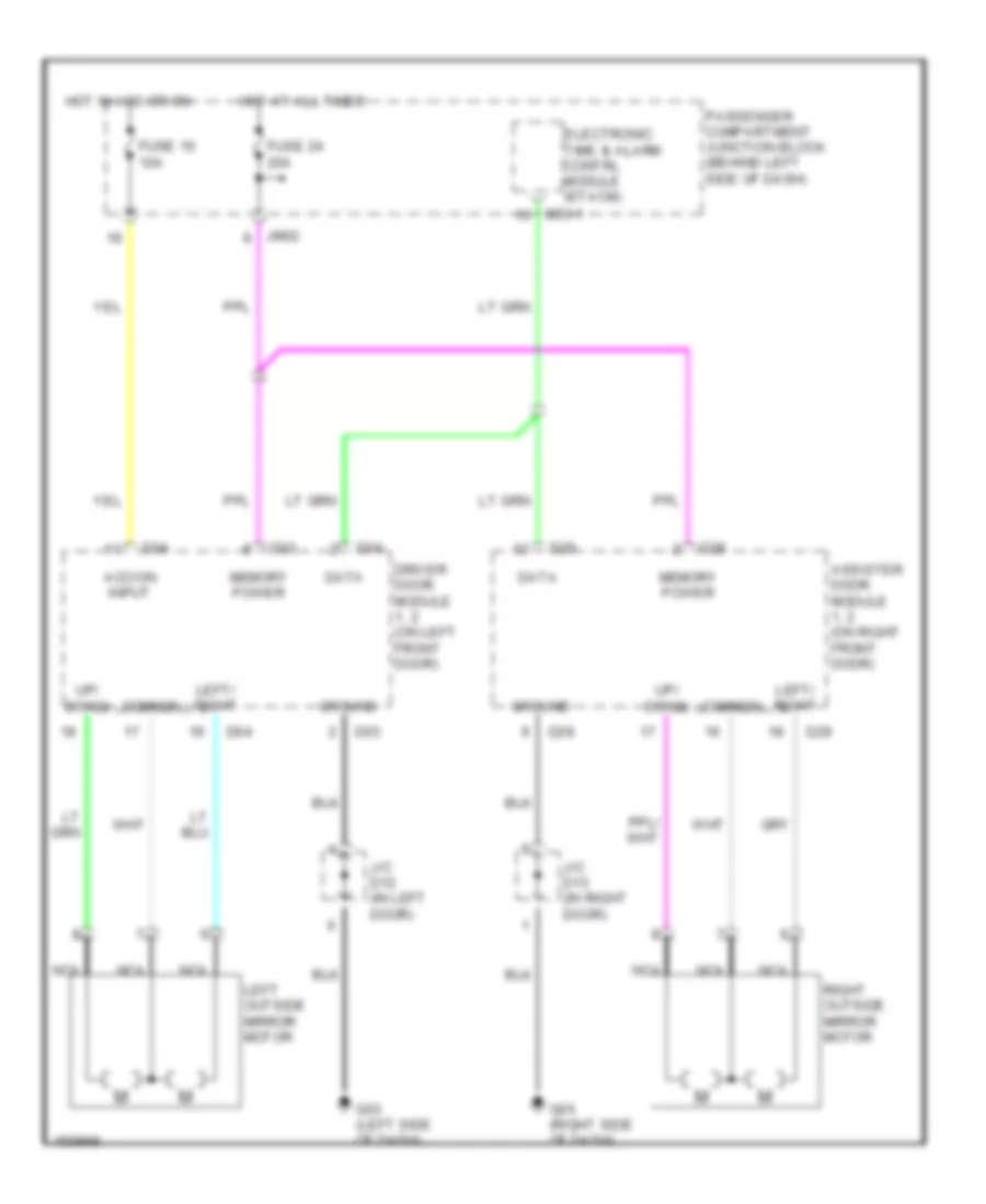
Power Mirror Wiring Diagram for Hyundai XG350 2002
List of elements for Power Mirror Wiring Diagram for Hyundai XG350 2002:
- Acc/on input
- Assister door module 1, 2 (on right front door)
- Common
- D03
- D04
- D28
- D29
- Data
- Driver door module 1, 2 (on left front door)
- Electronic time & alarm contrl module (etacm)
- Fuse 16 10a
- Fuse 24 20a
- G03 (left side of dash)
- G05 (right side of dash)
- Ground
- Hot at all times
- Hot in acc or on
- J/c d12 (in left door)
- J/c d13 (in right door)
- Jm02
- Left outside mirror motor
- Left/ right
- M33-1
- Memory power
- Nca
- Passenger compartment junction block (behind left side of dash)
- Right outside mirror motor
- Up/ down
POWER TOP/SUNROOF
Power Top/Sunroof Wiring Diagrams for Hyundai XG350 2002
List of elements for Power Top/Sunroof Wiring Diagrams for Hyundai XG350 2002:
- A/c control module
- A/v & navigation head unit
- A/v & navigation head unit (gnd)
- Acc relay
- Atm lever indicator
- Audio
- Audio (gnd)
- Aux & usb jack
- Bcm
- Blower motor control module
- Blower relay
- Brake fluid level sensor
- Burglar horn
- Cooling fan motor
- E/r fuse & relay box
- E72-h
- Ec11
- Ee01
- Em61
- Engine coolant temperature sensor & sender
- External buzzer
- Front monitor
- Front wiper motor
- Ge01 (left front of engine compt)
- Ge02 (left front of engine compt)
- Ge03 (right rear of dash)
- Ge04 (right side of engine compt)
- Glove box lamp switch
- Gm01 (center of dash)
- Gm02 (right end of dash)
- Gm04
- Hazard switch
- Hood switch
- Horn (high)
- Horn (low)
- Hybrid water pump
- Ig 1 relay
- Ig 2 relay
- Instrument cluster
- Left front fog lamp
- Left front power outlet
- Left head lamp
- Low voltage dc-dc converter
- M01-w
- M02-c
- M09-b
- M09-g
- M12-a
- M13-a
- M15-b
- M15-g
- M21-b
- M27-p
- Mm01
- Multi- function switch
- Multipurpose check connector
- Navi
- Nca
- Pdm
- Right front fog lamp
- Right front power outlet
- Right head lamp
- Smart key module
- Stop lamp relay
- W/ navi
- W/o navi
- Washer level sensor
- Washer motor
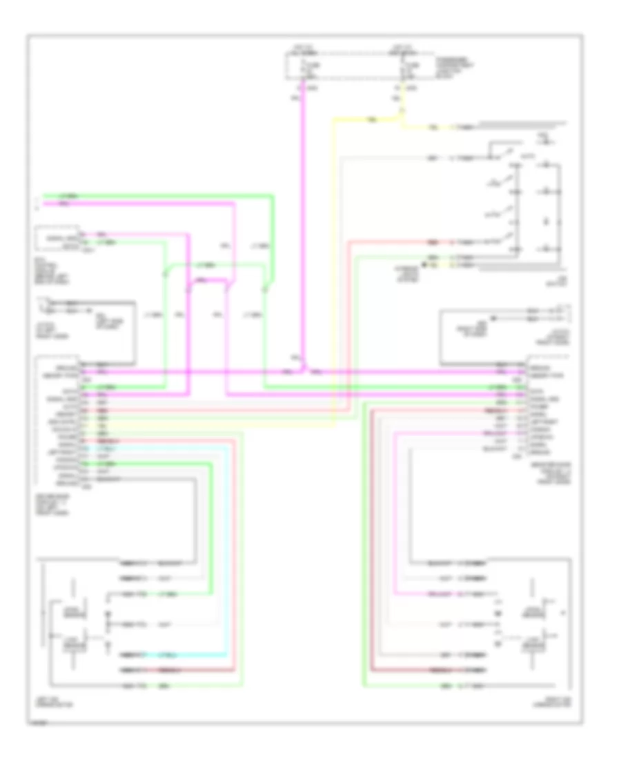
POWER WINDOWS
Power Window Wiring Diagram (1 of 2) for Hyundai XG350 2002
List of elements for Power Window Wiring Diagram (1 of 2) for Hyundai XG350 2002:
- Air bag crash sig in
- Battery voltage
- Bcm (left center of dash)
- Buckle sw
- Clock spring
- Com
- Driver air bag
- Driver seat buckle switch
- Front impact sensor (driver) (left front corner of engine compt)
- Front impact sensor (passenger) (right front corner of engine compt)
- Gi01 (under front of center console)
- Gm03 (behind left center of dash)
- Gnd
- I05
- Instrument cluster
- J/c gm03
- M09-2
- M14-2
- Mod
- Multi- function switch
- Nca
- On/strt in
- Passenger air bag 1 (behind right side of dash)
- Passenger air bag 2 (right side of dash)
- Passenger seat buckle switch
- Passenger seat track position sensor
- Pnk
- Red
- Seat belt pretensioner (driver) (base of left "b" pillar)
- Seat belt pretensioner (passenger) (base of right "b" pillar)
- Seat belt sw
- Sig
- Srs ind (air bag)
- Steering wheel
- Stps gnd
- Telltale lamp
Power Window Wiring Diagram (2 of 2) for Hyundai XG350 2002
List of elements for Power Window Wiring Diagram (2 of 2) for Hyundai XG350 2002:
- Down relay
- Etacm (left side of dash)
- G07 (below left front seat)
- G09 (right side of rear shelf)
- J/c m64 (right front of trunk)
- Left rear power window motor
- Left rear power window switch
- M33-1
- M33-2
- Main sw dn
- Main sw up
- Nca
- Relay ctrl
- Right rear power window motor
- Right rear power window switch
- Up relay
- Up/down switch
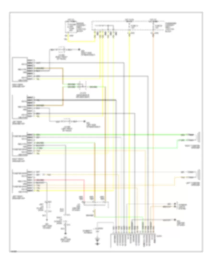
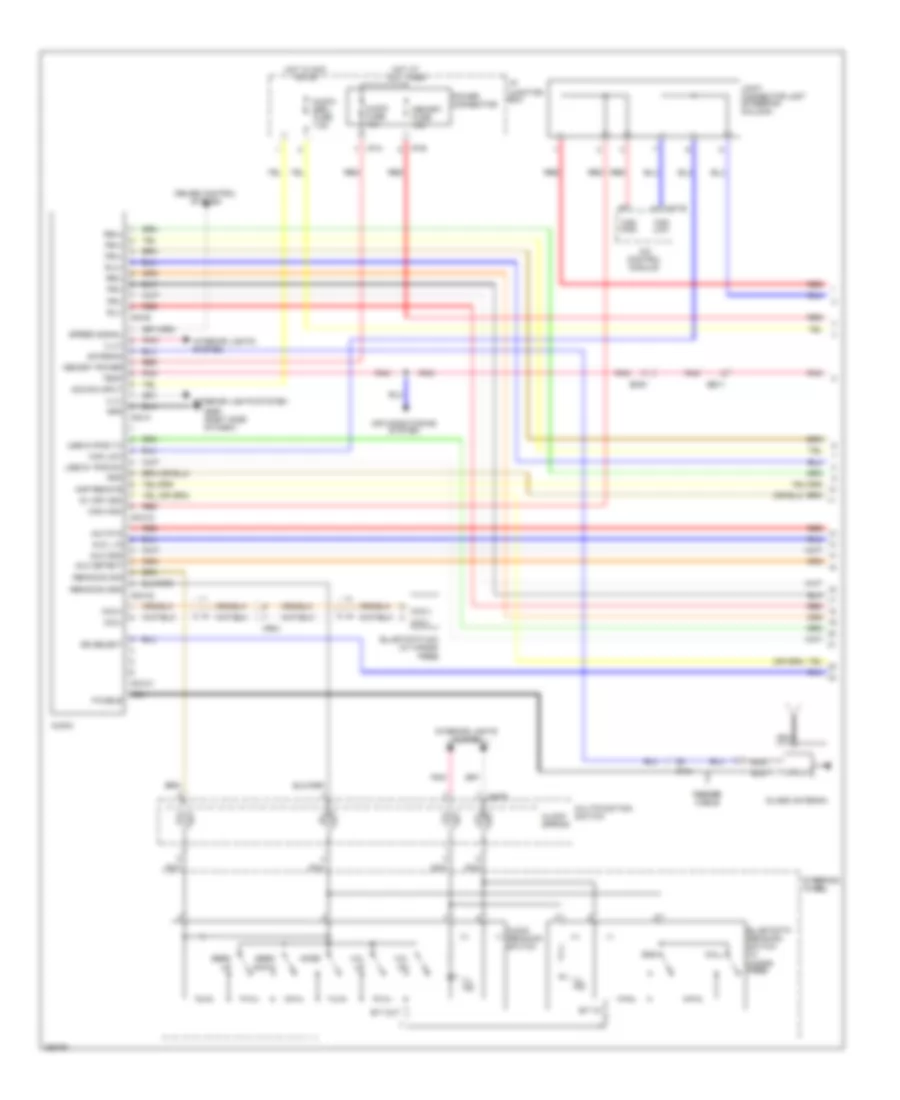
RADIO
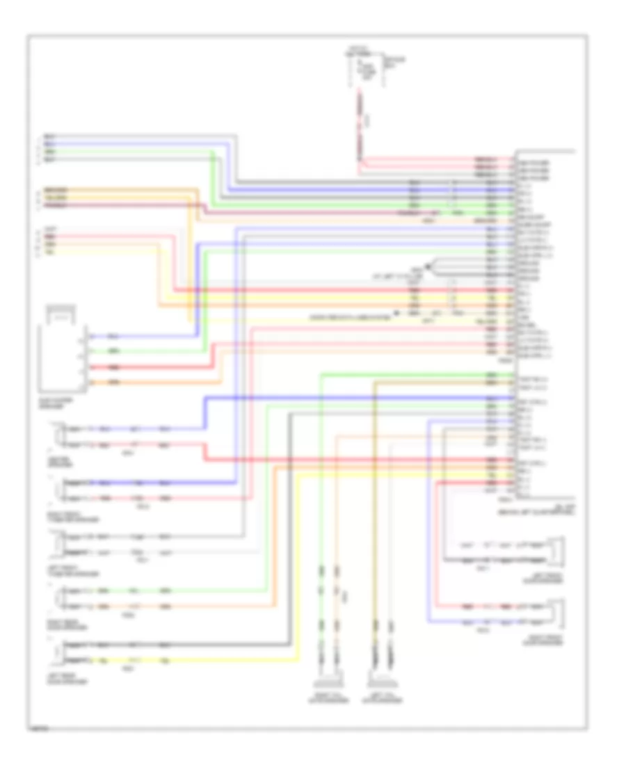
Radio Wiring Diagrams, with Amplifier for Hyundai XG350 2002
List of elements for Radio Wiring Diagrams, with Amplifier for Hyundai XG350 2002:
- Acc/on in
- Antenna
- Audio
- B2 jm09
- D12
- D13
- Diversity antenna
- Engine compart- ment junction block
- Fuse 14 10a
- Fuse 25 10a
- G03 (left side of dash)
- G04 (center of dash)
- G05 (right side of dash)
- G08 (left side of rear shelf)
- G09 (right side of rear shelf)
- Ground
- Hot at all times
- Hot in on or acc
- Ill (+)
- Ill (-)
- Interior lights system
- J/c m64 (right front of trunk)
- J/c m78 (near rear of driver's seat)
- J/c m99 (left front of trunk)
- J/c mo9 (center of dash)
- Left front speaker amp
- Left j/c (in left door)
- Left rear speaker amp
- Left tweeter speaker
- Lf speaker
- Lr speaker
- M77-2
- Mem pwr
- Nca
- Nca rem ctrl nca grd nca
- Nca rem ctrl nca grd nca tweeter spkr nca sig in nca mem pwr
- Nca sig in nca
- Nca sig in nca mem pwr
- Nca tweeter spkr nca sig in nca
- Passenger compart- ment junction block
- Power amp fuse 20a
- Remote ctrl
- Rf speaker
- Right front speaker amp
- Right j/c (in right door)
- Right rear speaker amp
- Right tweeter speaker
- Rr speaker
- Tan
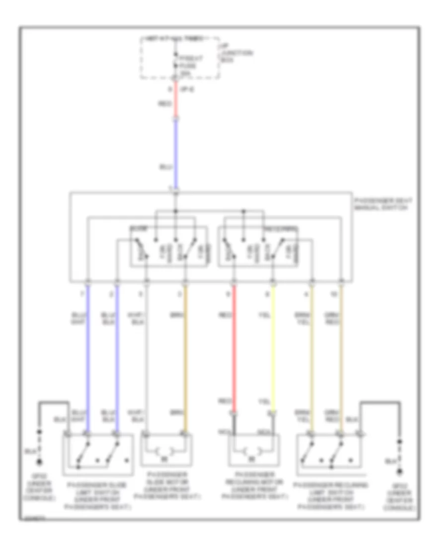
Radio Wiring Diagrams, without Amplifier for Hyundai XG350 2002
List of elements for Radio Wiring Diagrams, without Amplifier for Hyundai XG350 2002:
- Back
- For- ward
- Gf02 (under center console)
- Hot at all times
- I/p junction box
- I/p-e
- Nca
- P/seat fuse 30a
- Passenger reclining limit switch (under front passenger's seat)
- Passenger reclining motor (under front passenger's seat)
- Passenger seat manual switch
- Passenger slide limit switch (under front passenger's seat)
- Passenger slide motor (under front passenger's seat)
- Reclining
- Red
- Slide
- Ward for-
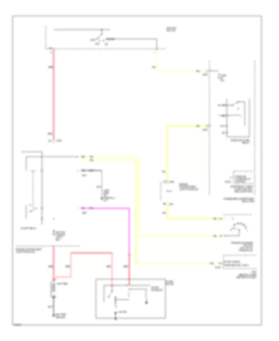
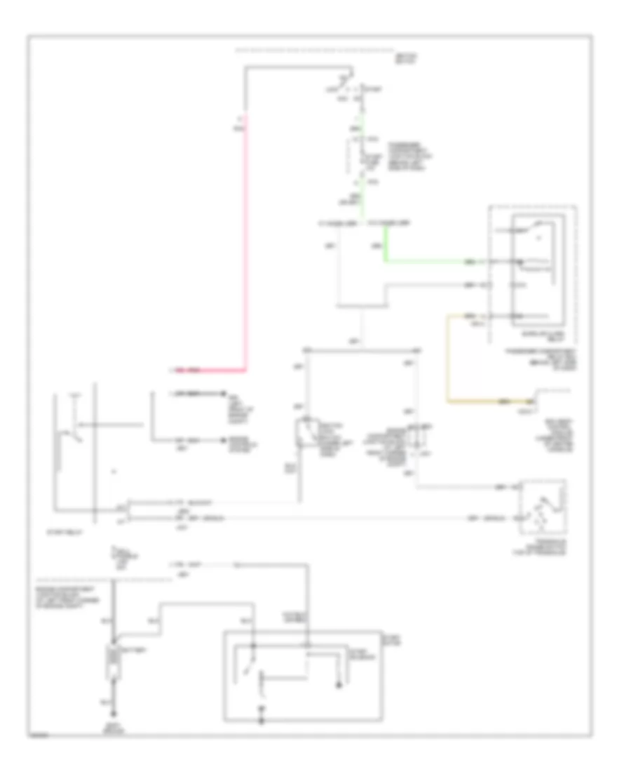
STARTING/CHARGING
Charging Wiring Diagram for Hyundai XG350 2002
List of elements for Charging Wiring Diagram for Hyundai XG350 2002:
- Door lock switch
- Door locks system
- Down
- Ecu
- G25 (base of left "b" pillar)
- G29 (base of right "b" pillar)
- Hall effect sensor
- Ill
- Interior lights system
- Joint connector d11 (in driver's door)
- Joint connector d12 (in front passenger's door)
- Left rear power window motor (in left rear door)
- Left rear power window switch
- Off
- Passenger power window motor (in front passenger's door)
- Passenger power window switch
- Pnk
- Red
- Relay
- Reverse protection & filter
- Safety window module (in driver's door)
- Shunt resistor
- Sig & filter
- Sig filter
Starting Wiring Diagram for Hyundai XG350 2002
List of elements for Starting Wiring Diagram for Hyundai XG350 2002:
- (left side of firewall) g11
- 87a
- Acc
- B5 jc01
- Battery
- Battery ground
- Burglar alarm relay
- Burglar alarm relay control
- C3 jm09
- C44-2
- Electronic time & alarm control module (etacm)
- Engine compartment junction block
- Fuse 10a
- Ignition fusible link 2 30a
- Ignition switch
- Jc01
- Je01
- Jm05
- Jm09
- Lock
- M33-3
- Motor
- N d
- Park/neutral input
- Passenger compartment relay box
- Pcm (behind lower center of dash)
- Red
- Start
- Start motor
- Start relay
- Start signal
- Start solenoid
- Transaxle range switch (on top of transaxle)
SUPPLEMENTAL RESTRAINTS
Supplemental Restraint Wiring Diagram for Hyundai XG350 2002
List of elements for Supplemental Restraint Wiring Diagram for Hyundai XG350 2002:
- (+)
- (-)
- (w/ hands- free)
- 5v (or vdd)
- A/c control module
- Acc/on input
- Air conditioning system
- Amp remote
- Antenna
- Audio
- Audio (-) remocon switch
- Audio fuse 15a
- Audio/ escl fuse 7.5a
- Aux detect
- Aux gnd
- Aux l in
- Aux r in
- B/t in
- B/t out
- Call
- Can high
- Can low
- Circuit
- Clock spring
- Cruise control system
- Down
- Ee11
- Em51
- End
- Eq select
- F/cable
- Feeder cable
- Fr(+)
- Fr(-)
- Glass antenna
- Gm05 (right side of dash)
- Gnd
- Hot at all times
- Hot in acc or on
- I/p junction box
- I/p-a
- I/p-b
- Ill ind
- Ill(+)
- Ill(-)
- Interior lights system
- Joint connector jm07 (steering column)
- M03-a
- M03-b
- M03-c1
- M03-c2
- M03-c3
- M07-b
- M48-r
- Memory fuse 10a
- Memory power
- Mf31
- Mic(+)
- Mic(-)
- Mode
- Mr01
- Multifunction switch
- Nca
- Pnk
- Power connector
- Red
- Remocon gnd
- Remocon sig
- Rl(+)
- Rl(-)
- Rr(+)
- Rr(-)
- Seek
- Speed signal
- Steering wheel
- Temp
- Usb d+ ipod rx
- Usb d-/ipod tx
- Vol
TRANSMISSION
A/T Wiring Diagram (1 of 2) for Hyundai XG350 2002
List of elements for A/T Wiring Diagram (1 of 2) for Hyundai XG350 2002:
- 87a
- A/t
- Battery
- Bcm (body control module) (under front of center console)
- Body ground
- Burglar alarm relay
- Engine compartment junction block (at left front corner of engine compt)
- Engine controls system
- G06 (left front of engine compt)
- I/p-d
- Ign 2 fusible link 40a
- Ignition lock switch (under left side of dash)
- Ignition switch
- Jc01
- Je01
- Je02
- Lock
- M/t
- M33-c
- M91-2
- On acc
- Passenger compartment junction block (behind left side of dash)
- Passenger compartment relay box (behind left side of dash)
- Pnk
- Start
- Start fuse 10a
- Start motor
- Start relay
- Start solenoid
- Transaxle range switch (top of transaxle)
- W/ immobilizer
- W/o immobilizer
A/T Wiring Diagram (2 of 2) for Hyundai XG350 2002
List of elements for A/T Wiring Diagram (2 of 2) for Hyundai XG350 2002:
- (left end of dash)
- 1-in
- 2-in
- 2nd solenoid
- 3-in
- 4-in
- 5-in
- A/t control relay (behind lower center of dash, behind pcm)
- A/t fuse 20a
- A/t rly ctrl
- Atm solenoid assembly (in transaxle valve body)
- Batt
- C44-2
- C44-3
- C44-4
- D-in
- Dcc solenoid
- Down shift
- Engine comp- artment junction block (left front of engine compt)
- G05 (right side of dash)
- G14 (below center console)
- Hot at all times
- I18-1
- I18-2
- Instrument cluster
- Interior lights system
- J/c i20 (behind center of dash)
- Jc01
- Jm04
- Jm09
- L/r solenoid
- N-in
- Nca
- Normal
- O/d solenoid
- Oil temp sen
- Oil temp sensor
- P-in
- Passenger compartment junction block j102
- Pnk
- Powertrain control module (behind lower center of dash)
- R-in
- Red
- Red solenoid
- Select
- Select sw
- Sport mode switch
- Starting/ charging system
- Transaxle range switch (on top of transaxle)
- Ud solenoid
- Up shift
TRUNK, TAILGATE, FUEL DOOR
Trunk, Tailgate, Fuel Door Wiring Diagrams for Hyundai XG350 2002
List of elements for Trunk, Tailgate, Fuel Door Wiring Diagrams for Hyundai XG350 2002:
- (+)
- (-)
- Amp fuse 30a
- Center speaker
- Cf11
- Computer data lines system
- E/r sub box
- Eq sel
- F06-a
- F06-b
- Fd11
- Fd12
- Fd21
- Fd22
- Ff51
- Fl (+)
- Fl (-)
- Fr (+)
- Fr (-)
- Fr41
- Frt ctr (+)
- Frt ctr (-)
- Gf04 (at left "c" pillar)
- Ground
- Hot at all times
- Jbl amp (behind left quarterpanel)
- Left front door speaker
- Left front tweeter speaker
- Left rear door speaker
- Left tail gate speaker
- Lh twtr (+)
- Lh twtr (-)
- Mem power
- Mf11
- Mf21
- Mf41
- Nca
- Re on/off
- Red
- Rh twtr (+)
- Rh twtr (-)
- Right front door speaker
- Right front tweeter speaker
- Right rear door speaker
- Right tail gate speaker
- Rl (+)
- Rl (-)
- Rr (+)
- Rr (-)
- Sub wfr l (+)
- Sub wfr l (-)
- Sub wfr r (+)
- Sub wfr r (-)
- Sub woofer speaker
- Surr on/off
- Tgat lh (+)
- Tgat lh (-)
- Tgat rh (+)
- Tgat rh (-)
- Vss
WARNING SYSTEMS
Warning System Wiring Diagrams for Hyundai XG350 2002
List of elements for Warning System Wiring Diagrams for Hyundai XG350 2002:
- Acc/on in
- Amp fuse 30a
- Antenna
- Audio
- Audio 1 fuse 15a
- Audio 2 fuse 10a
- Aux detect
- Aux l
- Aux r
- Aux ref
- Aux shield
- Aux usb jack
- Can high
- Can low
- Center speaker
- Cf11
- Circuit
- Computer data lines system
- E/r sub box
- Eq sel
- F/cable
- F06-a
- F06-b
- Fd11
- Fd12
- Fd21
- Fd22
- Feeder cable
- Ff51
- Fl (+)
- Fl (-)
- Fr (+)
- Fr (-)
- Fr41
- Frt ctr (+)
- Frt ctr (-)
- Gf04 (at left "c" pillar)
- Gm03 (behind center of dash)
- Gnd
- Hot at all times
- Hot in acc or on
- I/p junction box
- I/p-d
- I/p-g
- I/p-k
- Ill (+)
- Ill (-)
- Interior lights system
- Ipod rx
- Ipod tx
- Jbl amp (behind left quarterpanel)
- Left front door speaker
- Left rear door speaker
- Left tail gate speaker
- Lf twtr (+)
- Lh twtr (-)
- M80-a
- M80-c2
- M80-c3
- Memory power
- Memory pwr
- Mf11
- Mf21
- Mf41
- Mf51
- Micro antenna
- Nca
- Power connector
- Re on/off
- Red
- Remocon gnd
- Remocon sig
- Remote amp
- Rh twtr (+)
- Rh twtr (-)
- Right front door speaker
- Right rear door speaker
- Right tail gate speaker
- Rl (+)
- Rl (-)
- Rr (+)
- Rr (-)
- Sub woofer l (+)
- Sub woofer l (-)
- Sub woofer r (+)
- Sub woofer r (-)
- Surround
- Surround on/off
- Tgat lh (+)
- Tgat lh (-)
- Tgat rh (+)
- Tgat rh (-)
- Usb 5v
- Usb d+/ipod rx
- Usb d-/ipod tx
- Usb gnd
- Usb shield
- Vss
WIPER/WASHER
Wiper/Washer Wiring Diagram for Hyundai XG350 2002
List of elements for Wiper/Washer Wiring Diagram for Hyundai XG350 2002:
- (diagram 2 of 6)
- (diagram 3 of 6)
- (diagram 4 of 6)
- (diagram 5 of 6)
- (diagram 6 of 6)
- (left front corner of engine compt) e/r fuse & relay box
- (left side of dash) i/p junction box
- A/c
- A/c control module
- A/con fuse 7.5a
- A/t
- Alt fuse 150a
- Alternator
- Ams fuse 15a
- Auto
- B+2 fuse 60a
- B+3 fuse 60a
- B+4 fuse 60a
- Battery
- Battery & battery fuse box
- Bcm
- Blower fuse 40a
- Blower relay
- Body ground
- Box
- C/fan fuse 40a red
- C/fan hi relay
- C/fan low
- Check connector
- Chg-ag
- Chg-bg
- Deicer fuse 20a
- Deicer relay
- E/r fuse & real box
- Ec11
- Electro chromic mirror
- Em11
- Ems fuse 40a
- Esc 1 fuse 40a
- Esc 2 fuse 30a
- Esc module
- Esp control module
- Fd11
- Fd12
- From battery (diagram 1 of 6)
- From i/p junction box (diagram 2 of 6)
- Front wiper motor
- I/p-b
- I/p-e
- I/p-f
- I/p-g
- Ign 1 fuse 40a
- Ign 2 fuse 30a
- Junction
- Key
- Left rear seat warmer switch
- Lin line
- Lp fuse (diagram 1 of 6)
- M01-w
- M02-a
- M22-b
- M22-bn
- Manual a/c
- Mdps fuse 80a
- Mf11
- Mf61
- Module 2 fuse 7.5a
- Module 5 fuse 7.5a
- Mr01
- Multi fuse
- Multifunction switch
- Multipurpose
- Multipurpose check connector
- Pcm
- Pnk
- Rear camera module
- Red
- Relay
- Right rear seat warmer switch
- Rr hid fuse 40a
- Rr htd relay
- S/heater rr fuse 20a
- Sensor
- Smart
- Snsr +
- Start
- Start motor
- Stop lamp switch
- Stop lp fuse 15a
- Sunroof motor
- Switch (diagram 2 of 6)
- Tcu 1 fuse 20a
- To ems box (diagram 5 of 6)
- To i/p
- To i/p junction
- To ig 1 relay
- To ig 2 relay
- To ignition
- To ignition switch
- To pdm
- To stop
- W/ navi
- W/o
- W/o navi
- W/o smart key
- Wiper fuse 25a
- Wiper relay