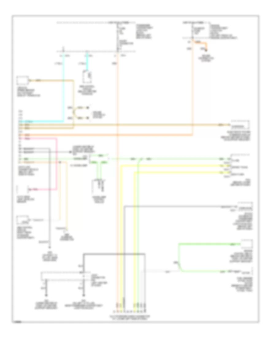
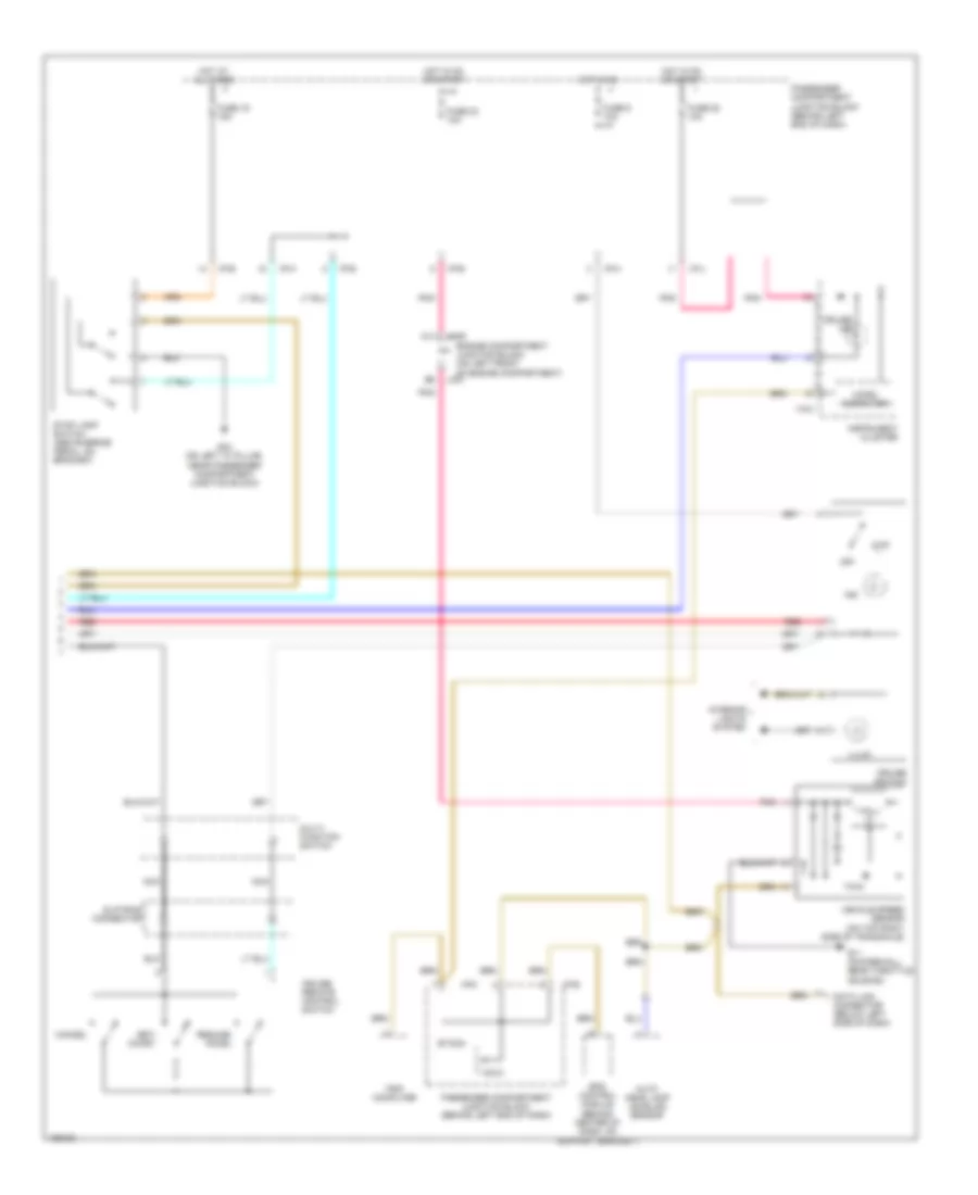
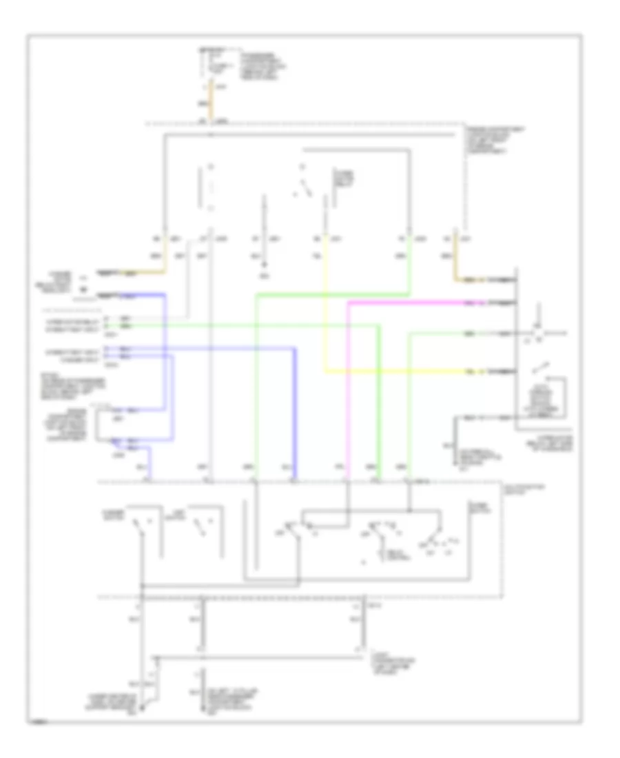
AIR CONDITIONING
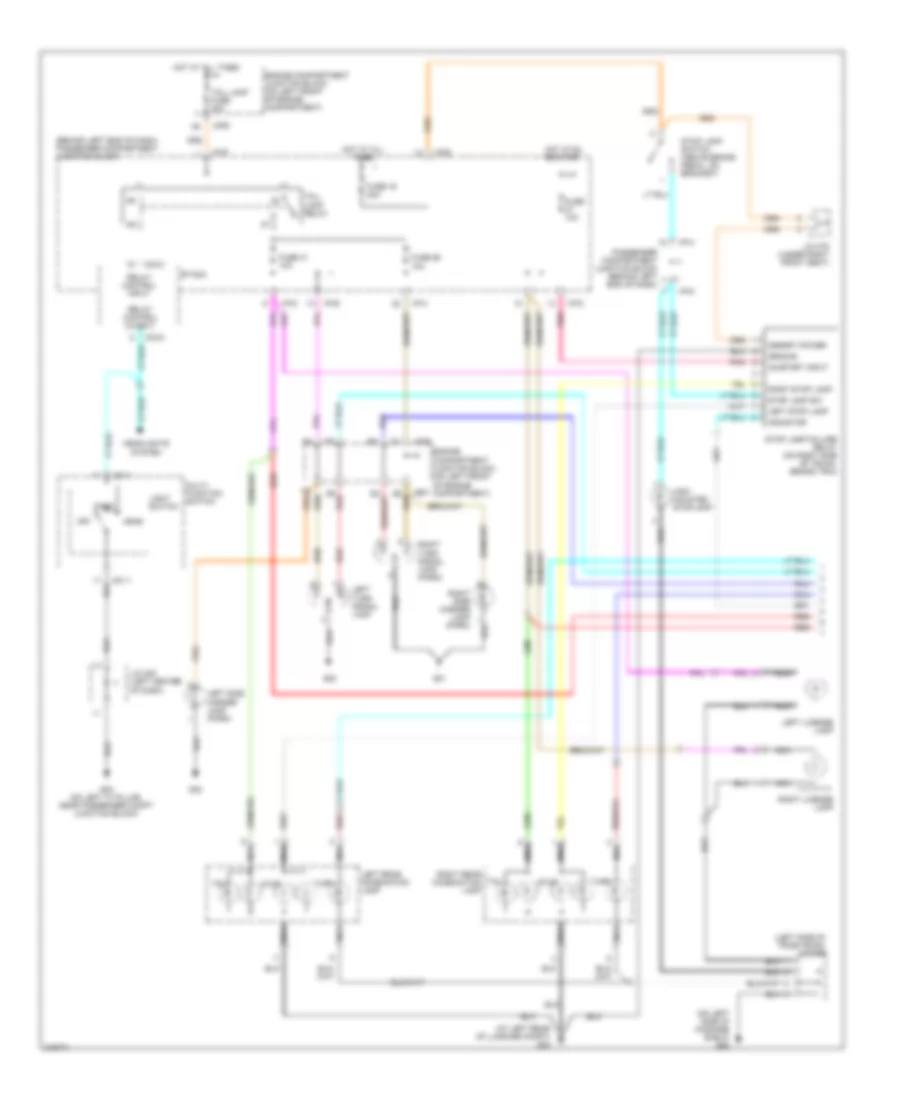
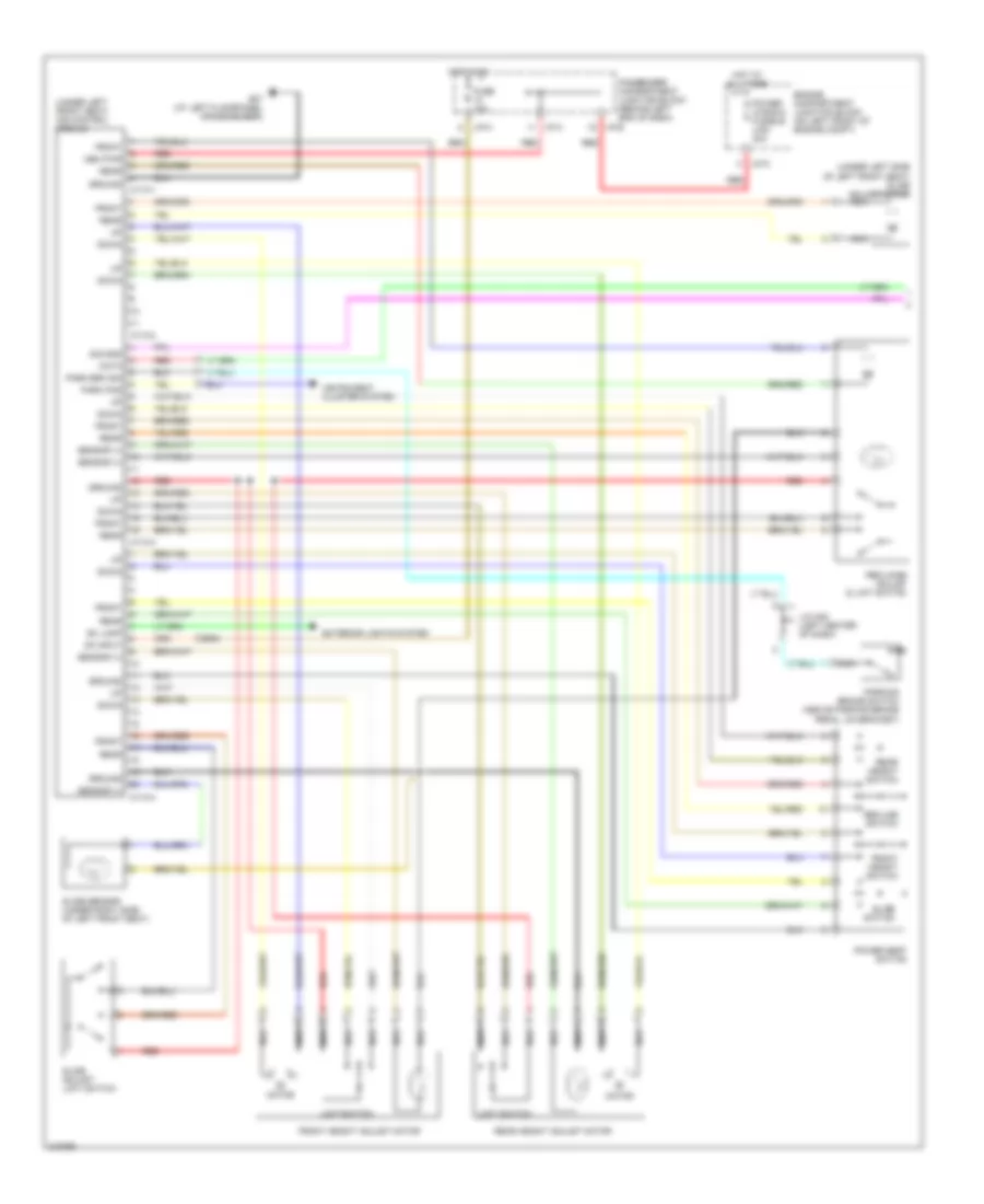
Automatic A/C Wiring Diagram (1 of 2) for Hyundai XG350 2005

List of elements for Automatic A/C Wiring Diagram (1 of 2) for Hyundai XG350 2005:
- (behind right end of dash, above kick panel) blower relay
- (not used)
- (right front of engine compt) a/c compressor
- A/c compressor fuse 10a
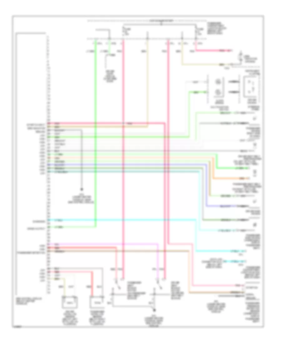
- A/c control module (in center of dash)
- A/c output
- A/c relay
- Actuator
- Amb temp sensor
- Aqs sensor
- B/l
- B12 jc01
- Blower fuse 30a
- Blower motor
- Blr feed back
- C11 jm09
- D12
- Def
- Defogger sw
- Defogger system
- E7 je01
- Egr fuse 15a
- Engine compartment junction block (on left front of engine compt)
- Engine coolant temperature sensor & sender (on rear of engine)
- Evap sensor in
- Floor
- Fre
- From condenser fan relay (diagram 2 of 2)
- Fuse 10a
- G02
- G05 (on right "a" pillar, near crash bar)
- Ground
- Hi speed ctrl
- High blower relay (below right side of dash, on hvac assembly)
- Hot at all times
- Hot in on
- Humidity sensor
- I/p-b
- I/p-e
- I/p-h
- I/p-j
- I/p-k
- I17-1
- I17-2
- Ill+
- Ill-
- In-car sens in
- In-car sens out
- Intake actuator (behind right end of dash, on hvac assembly)
- Interior lights system
- Je01 b9
- Je01 f11
- Jm09 a10
- Jm09 d4
- Joint connector c42 (lower left center of dash)
- Joint connector i20 (left center of dash)
- Joint connector i28 (upper right side of dash)
- Memory power
- Mix
- Mode actuator
- Nca
- On input
- Passenger compartment junction block (behind left end of dash)
- Photo sens +
- Photo sensor (on top center of dash)
- Pnk
- Power transistor
- R vent actuator
- Rear vent actuator (below left center of dash, on hvac assembly)
- Rec
- Red
- Sensor ground
- Short connector "a"
- Temp act ccw
- Temp actuator
- Temp feed back
- Temperature
- Vent
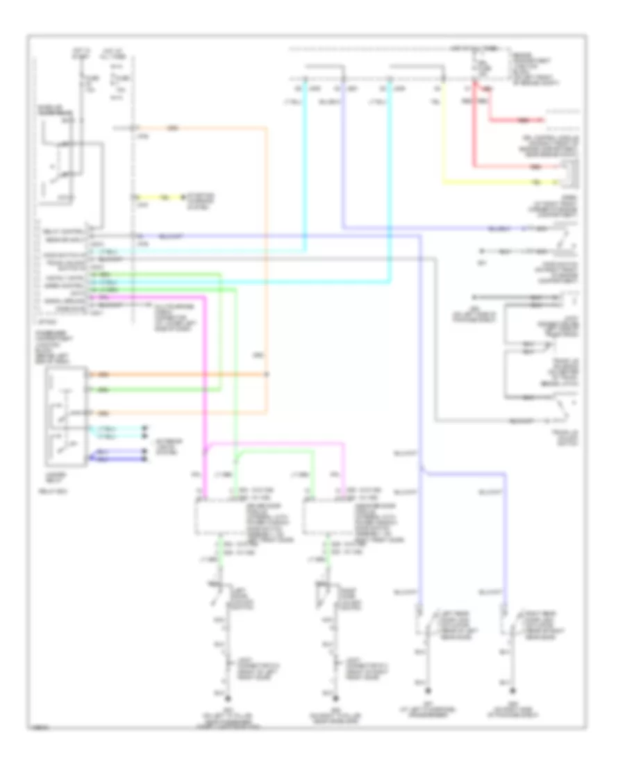
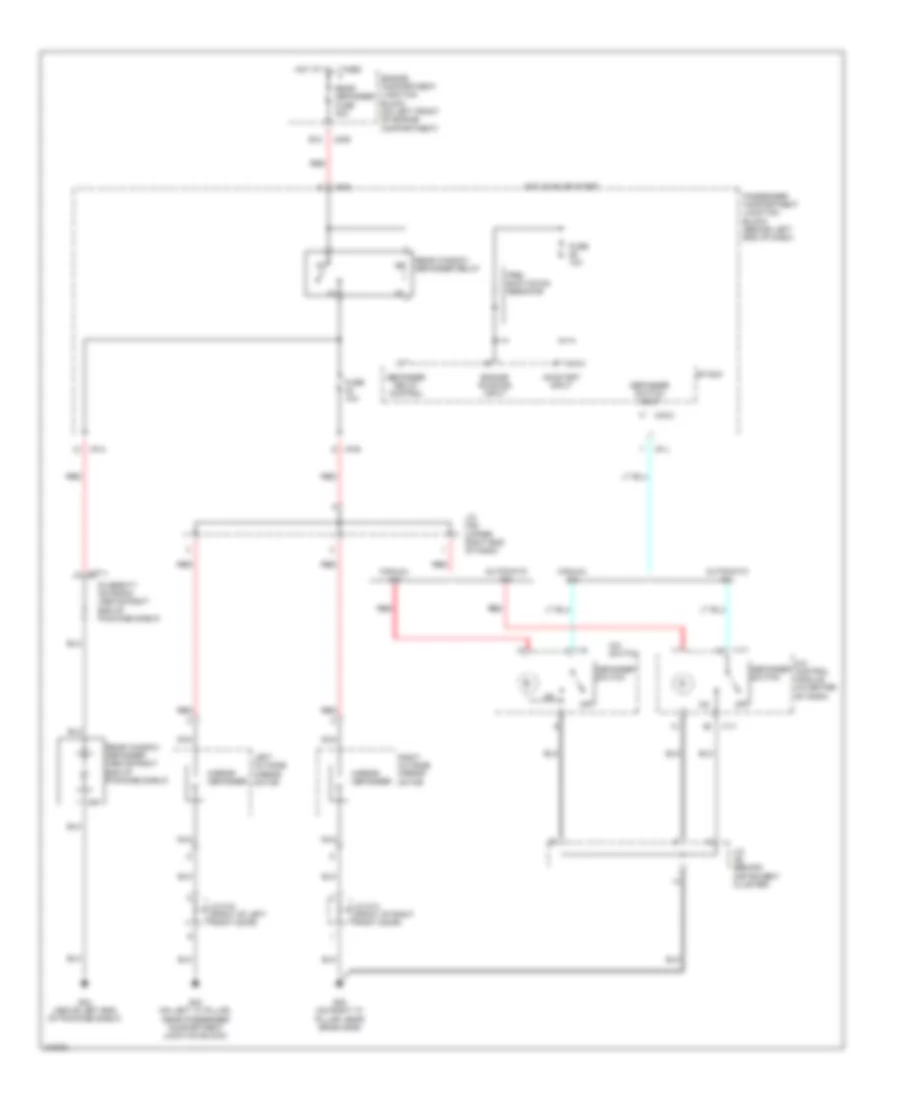
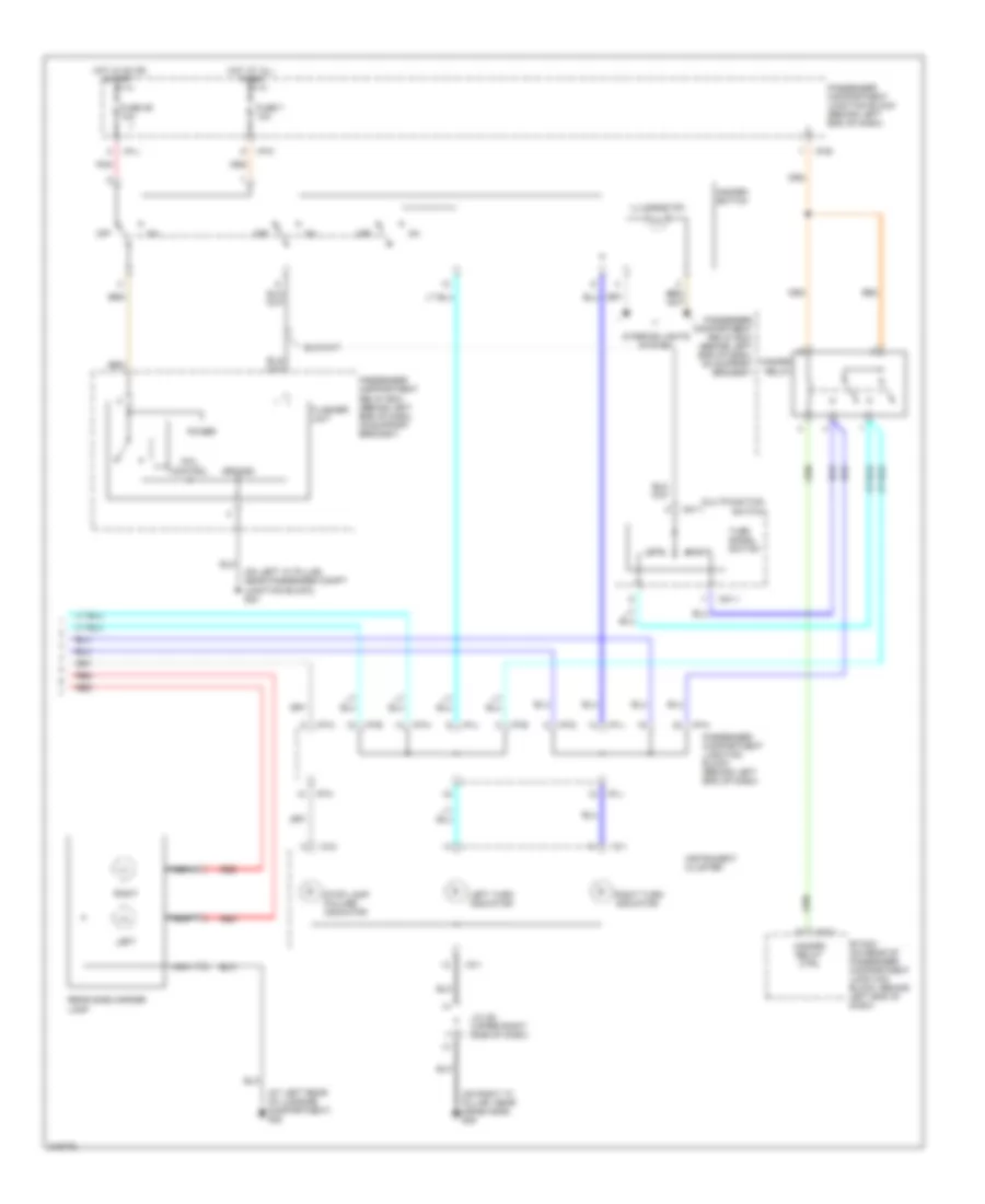
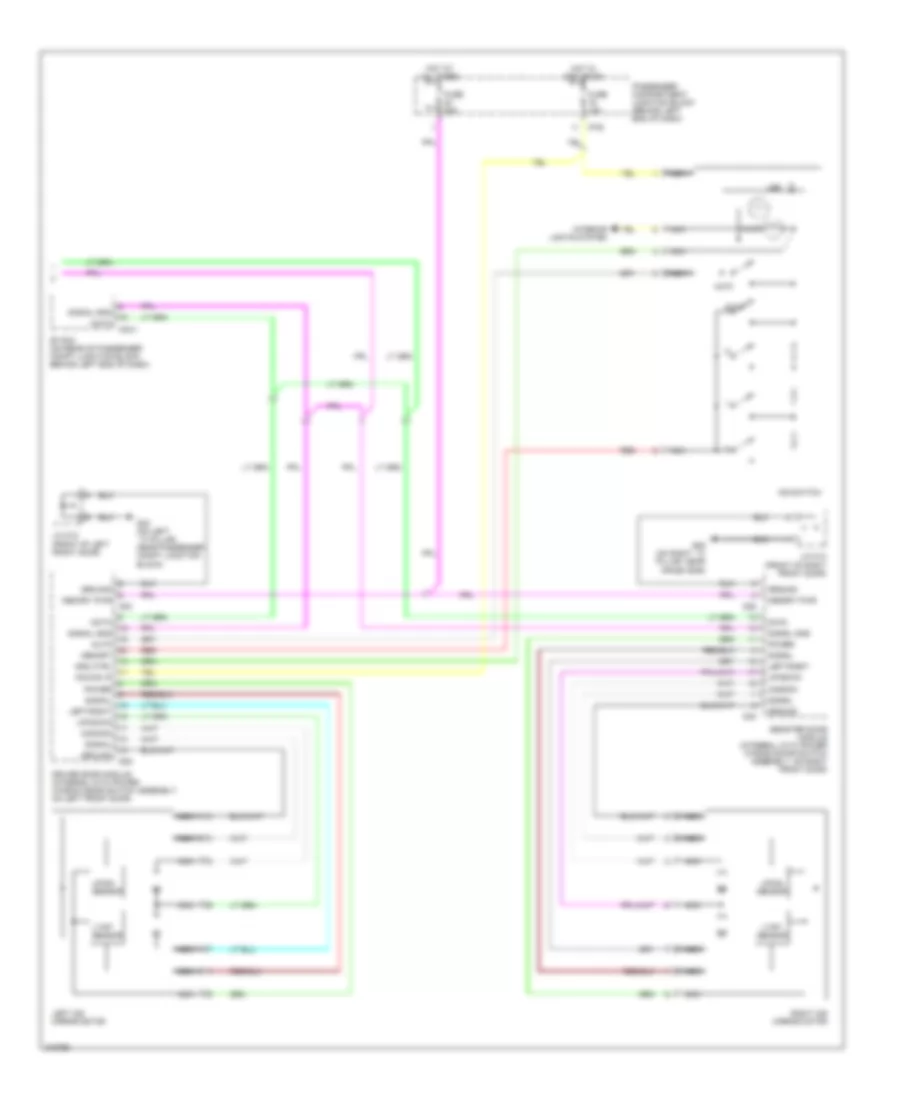
Automatic A/C Wiring Diagram (2 of 2) for Hyundai XG350 2005
List of elements for Automatic A/C Wiring Diagram (2 of 2) for Hyundai XG350 2005:
- (behind center of dash, on center support bracket) engine control relay
- A/c fan relay 1
- A/c fan relay 2
- A/c pressure switch in
- A/c relay ctrl
- A/c sig in
- A12
- Ambient temperature sensor (behind front bumper, on hood latch bracket)
- B10
- B12
- C10
- C11
- C44-1
- C44-2 c44-2
- C44-3
- Condenser fan motor (behind right side of radiator)
- Condenser fusible link 20a
- D11
- E10
- E12
- Ecm relay ctrl
- Ect sensor
- Engine compartment junction block (on left front of engine compt)
- Engine controls system
- Evaporator sensor
- G01
- G02
- Hi speed ctrl
- High
- Hot at all times
- Humidity sensor (near center of rear package shelf)
- Jc01
- Je01
- Je01 f12
- Jm09
- Joint connector i22 (left center of dash)
- Lo speed ctrl
- Low
- Main fuse 30a
- Memory power
- Mid
- Nca
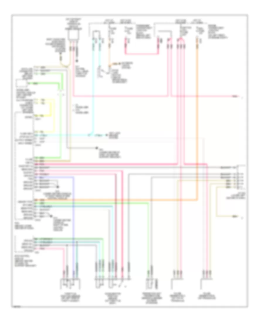
- Pcm (behind lower center of dash)
- Pnk
- Radiator fan motor (behind left side of radiator)
- Radiator fan relay
- Radiator fusible link 30a
- Red
- Sensor ground
- Tan
- Temperature actuator (below right center of dash, on hvac assembly)
- To egr fuse (diagram 1 of 2)
- Triple switch
- W/ immobilizer
- W/o immobilizer
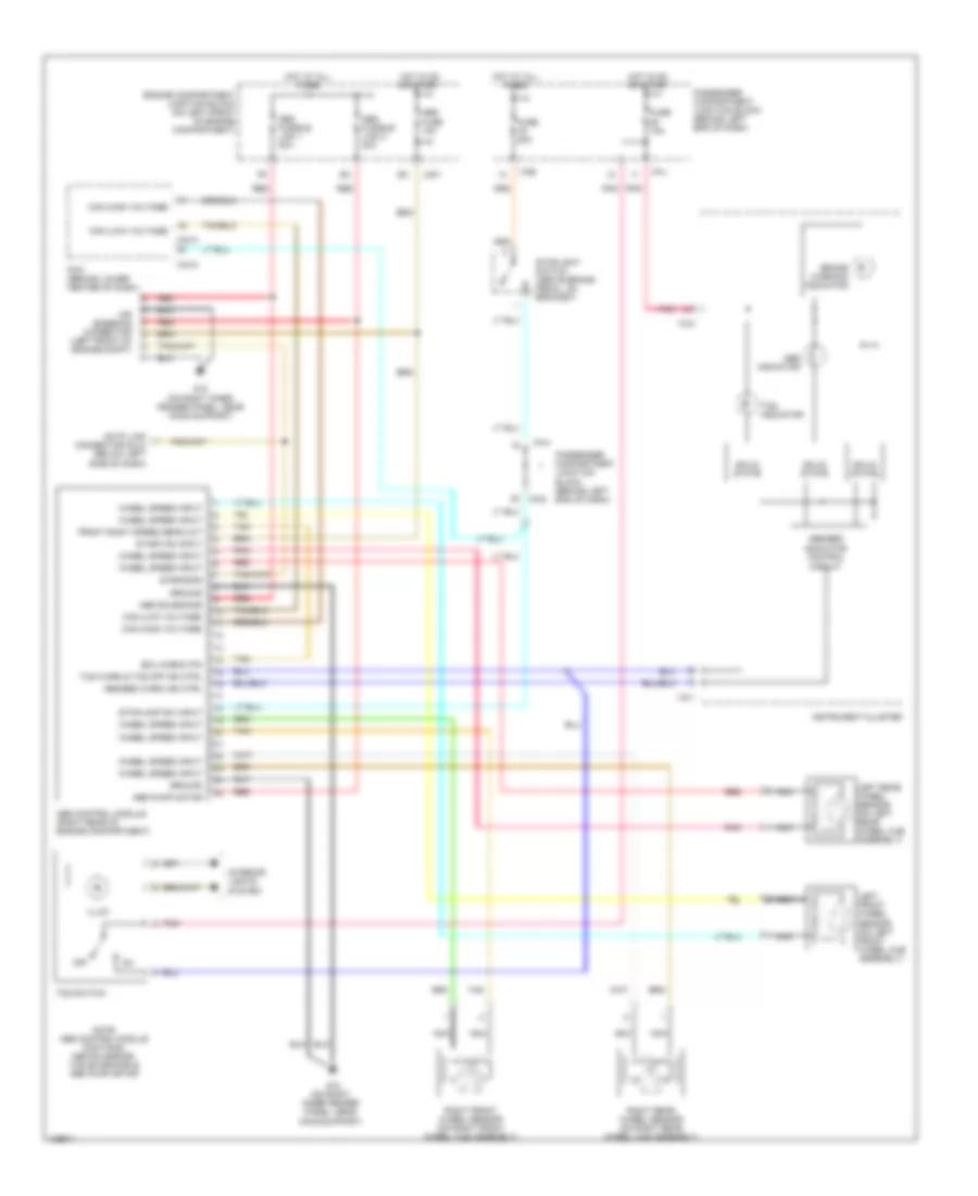
ANTI-LOCK BRAKES
Anti-lock Brakes Wiring Diagram for Hyundai XG350 2005
List of elements for Anti-lock Brakes Wiring Diagram for Hyundai XG350 2005:
- Abs control module (right rear of engine compartment)
- Abs fuse 10a
- Abs fusible link 1 30a
- Abs fusible link 2 30a
- Abs indicator
- Abs pump motor
- Abs solenoids
- Abs/ebd indicator control circuit
- Abs/ebd warn ind ctrl
- Air bleeding connector (left front of engine compt)
- Brake warning indicator
- C44-3
- C44-4
- Can (high voltage)
- Can (low voltage)
- Data link connector (dlc) (below left side of dash)
- Diagnosis
- Ecu check pin
- Engine compartment junction block (on left front of engine compartment)
- Front right speed sens out
- Fuse 10a
- Fuse 20a
- G12 (on right inner fender panel, near hood support)
- Ground
- Hot at all times
- Hot in on or start
- I/p-e
- I/p-h
- I/p-j
- I18-1
- I18-2
- Illum
- Instrument cluster
- Interior lights system
- Jc01
- Left front wheel sensor (on left front wheel hub assembly)
- Left rear wheel sensor (on left rear wheel hub assembly)
- Nca
- Note: abs control module contains: abs solenoids, tcs solenoids & abs pump motor
- Off
- Passenger compartment junction block (behind left end of dash)
- Pcm (behind lower center of dash)
- Pnk
- Red
- Right front wheel sensor (on right front wheel hub assembly)
- Right rear wheel sensor (on right rear wheel hub assembly)
- Solid state
- Start/on input
- Stoplamp sw input
- Stoplight switch (above brake pedal, on bracket)
- Tan
- Tcs indicator
- Tcs switch
- Tcs warn & tcs off ind ctrl
- Wheel speed input
ANTI-THEFT
Forced Entry Wiring Diagram for Hyundai XG350 2005
List of elements for Forced Entry Wiring Diagram for Hyundai XG350 2005:
- (w/ ims)
- (w/o ims)
- 87a
- Assister door module (integral with power window/ door switch assembly, on right front door)
- Burglar alarm relay
- Code save
- D04
- D05
- D29
- D30
- Data
- Driver door module (integral with power window/ door switch assembly, on left front door)
- Drl control module (on right front of engine compartment, near engine mount)
- Drl fuse 15a
- Engine compartment junction block (on left front of engine compt)
- Etacm
- Exterior lights system
- Fuse 10a
- G01
- G03 (on left "a" pillar, near passenger compt junction block)
- G05 (on right "a" pillar, near crash bar)
- G07 (at left floorpanel crossmember)
- G08 (on left side of package shelf)
- G09 (on right side of package shelf)
- Haz rly cntrl
- Hazard relay
- Hood switch (on right front of engine compartment)
- Hood switch in
- Hot at all times
- Hot in start
- I/p-b
- I/p-p
- Je01
- Jm09
- Joint connector d12 (front of left front door)
- Joint connector d13 (front of right front door)
- Joint connector m99 (left side of trunk room)
- Left door unlock switch
- Left rear door lock actuator (rear of left rear door)
- M33-1
- M33-2
- M33-3
- Multipurpose check connector (at lower left side of dash)
- Nca
- Passenger compartment junction block (behind left end of dash)
- Rear dr input
- Red
- Relay box
- Relay control
- Right door unlock switch
- Right rear door lock actuator (rear of right rear door)
- Signal ground
- Siren (at right front corner of engine compartment)
- Siren control
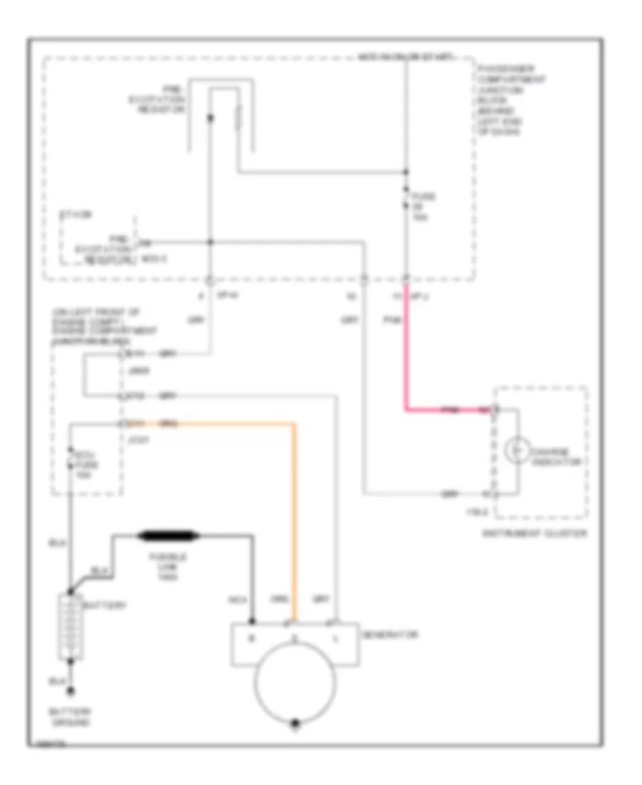
- Starting/ charging system
- Trunk lid solenoid (on center of trunk, beside latch)
- Trunk lid unlock switch
- Trunk unlock switch in
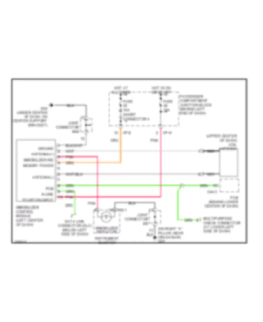
Immobilizer Wiring Diagram for Hyundai XG350 2005
List of elements for Immobilizer Wiring Diagram for Hyundai XG350 2005:
- (upper center of dash) coil antenna
- 118-1
- Antenna(+)
- Antenna(-)
- C44-3
- Crash bar) g05
- Data link connector (dlc) (below left side of dash)
- Fuse 10a
- G04 (under center of dash, on center support bracket)
- Ground
- Hot at all times
- Hot in on or start
- I/p-e
- I/p-h
- Immobilizer control module (left center of dash)
- Immobilizer ind
- Immobilizer indicator
- Instrument cluster
- Joint connector i28
- Joint connector m08
- K-line
- Memory power
- Multipurpose check connector (at lower left side of dash)
- Nca
- Passenger compartment junction block (behind left end of dash)
- Pcm
- Pcm (behind lower center of dash)
- Pnk
- Short connector a
- Start/on input
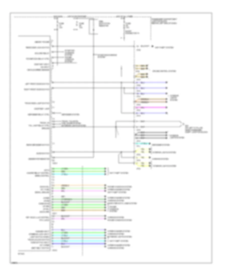
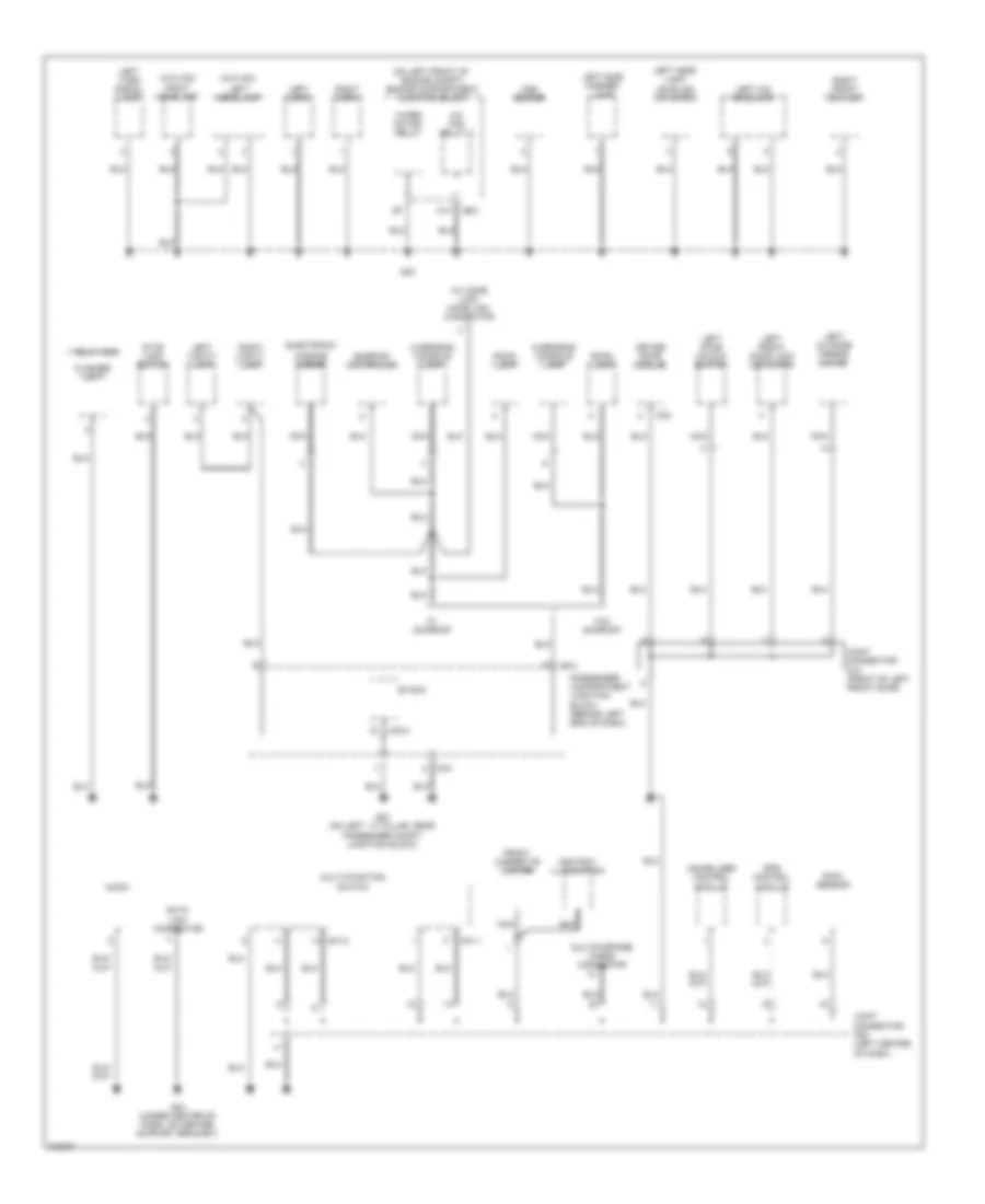
BODY CONTROL MODULES
Body Control Modules Wiring Diagram for Hyundai XG350 2005
List of elements for Body Control Modules Wiring Diagram for Hyundai XG350 2005:
- Anti-theft system
- B/alarm relay
- Chime
- Code save
- Computer data lines system
- Courtesy lamp
- Cruise control system
- Data
- Defogger relay ctrl
- Defogger system
- Door switch
- Down (rl)
- Down (rr)
- Etacm
- Exterior lights system
- Fuse 10a
- G03 (on left "a" pillar, near passenger compt junction block)
- Generator resistor
- Ground
- Hazard relay control
- Hood switch input
- Hot at all times
- Hot in on
- Hot in on or start
- I/p-a
- I/p-b
- I/p-d
- I/p-e
- I/p-h
- I/p-j
- I/p-k
- I/p-m
- I/p-p
- Int (time)
- Int wiper
- Interior lights system
- Key hole illum control
- Left front door switch
- Light switch (park)
- M33-1
- M33-2
- M33-3
- Memory power
- On input
- On/start input
- P/w (lock)
- Passenger compartment junction block (behind left end of dash)
- Power wdo relay ctrl
- Power windows system
- Pre- excitation resistor
- Rear defogger switch
- Rear door lock switch
- Right front door switch
- Seat belt switch
- Short connector "a"
- Signal ground
- Siren control
- Starting/ charging system
- Starting/charging system
- Steering lock input
- Tail lamp relay ctrl
- Trunk lid
- Trunk room lamp switch
- Trunk unlock switch
- Trunk, tailgate, fuel doors system
- Up (rl)
- Up (rr)
- Vehicle speed sensor
- Warning system
- Washer input
- Wiper
- Wiper/washer system
COMPUTER DATA LINES
Computer Data Lines Wiring Diagram for Hyundai XG350 2005
List of elements for Computer Data Lines Wiring Diagram for Hyundai XG350 2005:
- (under center of dash, on center support bracket) g04
- Abs bleeding connector
- Abs control module (right rear of engine compartment)
- Auto head lamp leveling sensor
- C44-1
- C44-3
- C44-4
- Code save
- Cruise controls system
- Data link connector (dlc) (below left side of dash)
- Diag
- Diagnosis
- Ecm flash
- Ecm+tcm
- Electronic power steering module (behind center of dash, on support bracket)
- Engine compartment junction block (on left front of engine compartment)
- Engine control relay (behind center of dash, on center support bracket)
- Etacm (on rear of passenger compartment junction block, behind left end of dash)
- Fuel sender & fuel pump motor (beneath center of rear seat, in fuel tank)
- Fuse 10a
- G03 (on left "a" pillar, near passenger compartment junction block)
- G04 (under center of dash, on center support bracket)
- G05 (on right "a" pillar, near crash bar)
- Hot at all times
- I/p-h
- I/p-l
- Immobilizer control module
- Jm09
- Joint connector m08 (left center of dash)
- K-line
- M33-1
- Motor
- Multipurpose check connector (at lower left side of dash)
- Nca
- Passenger compartment junction block (behind left end of dash)
- Pcm (behind lower center of dash)
- Pnk
- Power distribution system
- Short connector "a"
- Spark timing
- Srs control module (below center console)
- Sunroof fuse 15a
- Vehicle speed sensor (on top right side of transaxle)
- W/ immobilizer
- W/o immobilizer
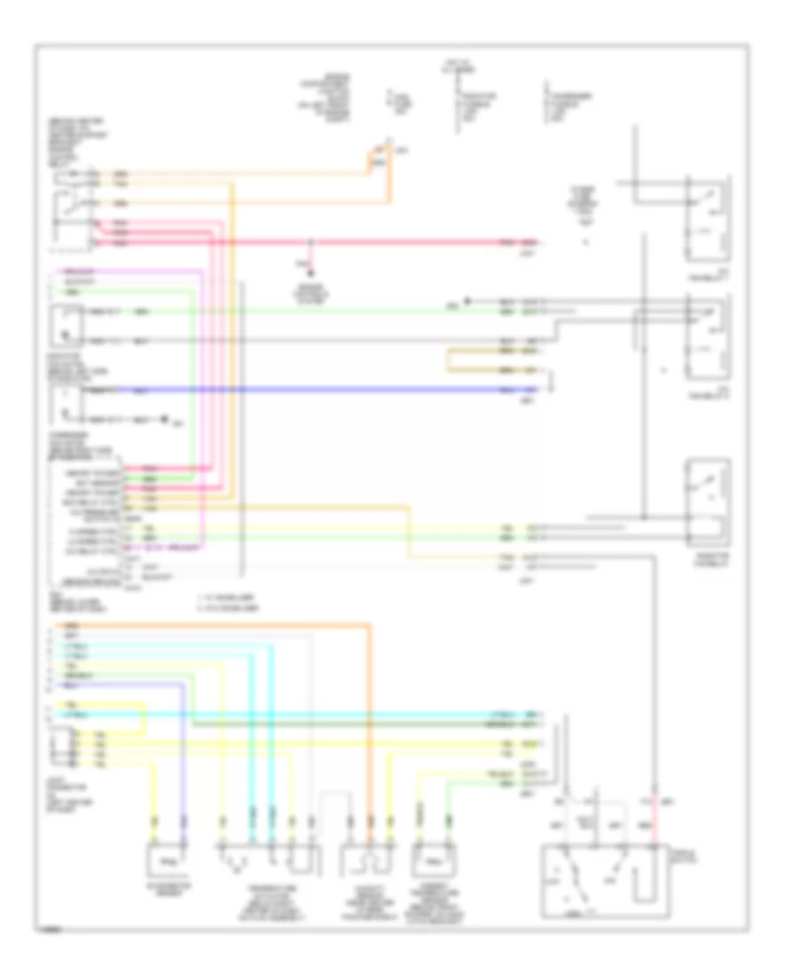
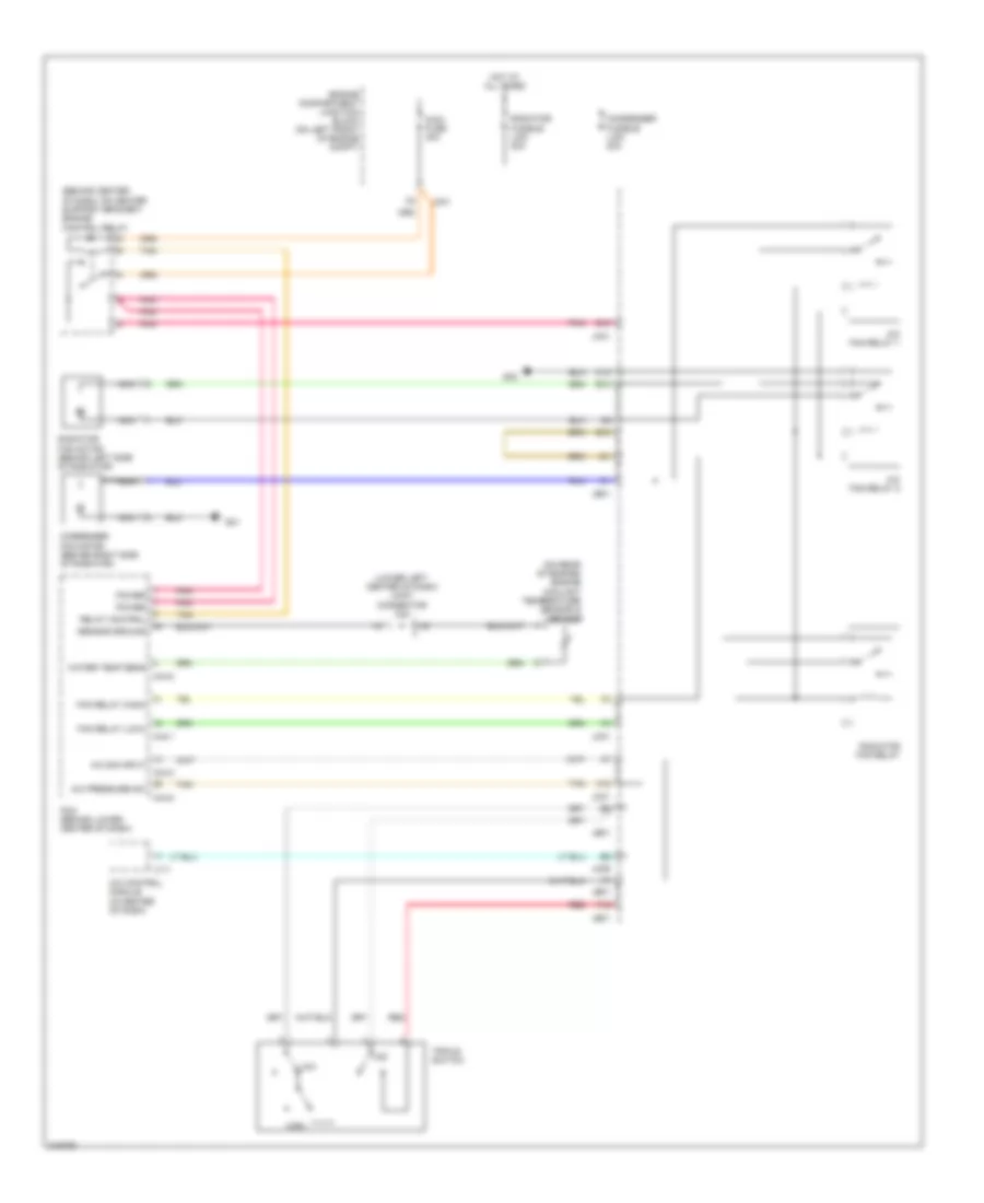
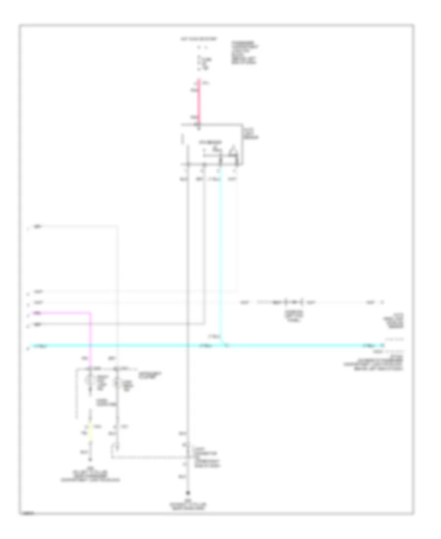
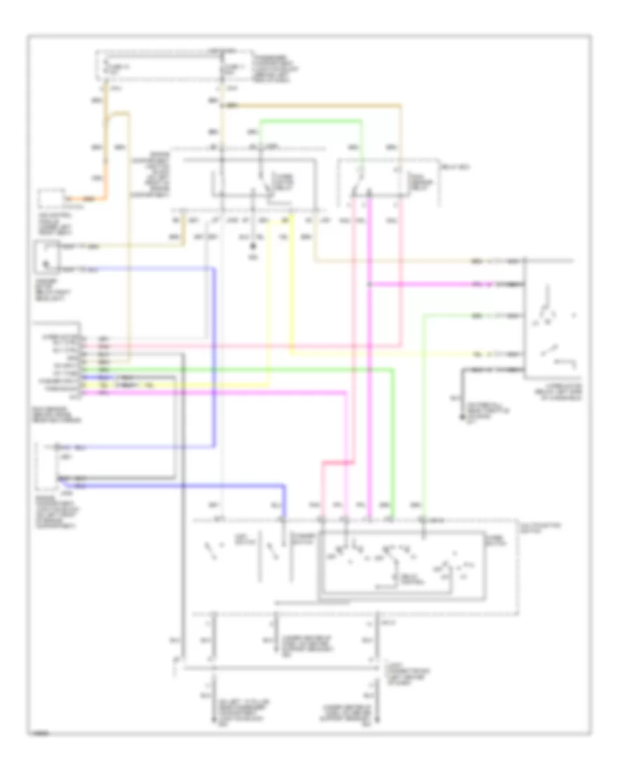
COOLING FAN
Cooling Fan Wiring Diagram for Hyundai XG350 2005
List of elements for Cooling Fan Wiring Diagram for Hyundai XG350 2005:
- (behind center of dash, on center support bracket) engine control relay
- (lower left center of dash) joint connector c42
- (on rear of engine) engine coolant temperature sensor & sender
- A/c control module (in center of dash)
- A/c fan relay 1
- A/c fan relay 2
- A/c pressure sw
- A/c sig input
- A12
- B10
- C10
- C44-1
- C44-2
- C44-3
- Condenser fan motor (behind right side of radiator)
- Condenser fusible link 20a
- E10
- Engine compartment junction block (on left front of engine compt)
- F12
- Fan relay (high)
- Fan relay (low)
- G01
- G02
- High
- Hot at all times
- I17-1
- Jc01
- Je01
- Jm09
- Low
- Main fuse 30a
- Mid
- Nca
- Pcm (behind lower center of dash)
- Pnk
- Power
- Radiator fan motor (behind left side of radiator)
- Radiator fan relay
- Radiator fusible link 30a
- Red
- Relay control
- Sensor ground
- Tan
- Triple switch
- Water temp sens
CRUISE CONTROL
Cruise Control Wiring Diagram (1 of 2) for Hyundai XG350 2005
List of elements for Cruise Control Wiring Diagram (1 of 2) for Hyundai XG350 2005:
- 87a
- Abs fuse 10a
- Accelerator position sensor (on throttle body)
- Aps sig (main)
- Aps sig (sub)
- Brake sig
- Burglar alarm relay
- C11
- C44-1
- C44-2
- C44-3
- Coast switch gnd
- Coast switch in
- Communication
- Ecm rly on
- Ecu fuse 10a
- Engine compartment junction block (on left front of engine compt)
- Etacm
- Ets control module (behind center of dash, on support bracket)
- Ets ind
- Ets motor (on right side of throttle body)
- Ets relay
- Ets rly cntl
- F10
- Fuse 32 10a
- Fuse 4 15a
- G11 (on firewall, near throttle housing)
- G13 (under center console, right of srs control module)
- G15 (under center console, at left rear of srs control module)
- Ground
- Hot at all times
- Hot in on or start
- Hot in start
- Hot with ecm ctrl relay energized
- I/p-h
- I/p-p
- Idle sw
- Idle switch
- Injector fuse 10a
- J/c c42 (lower left center of dash)
- Jc01
- Jm09
- Limp home valve (on right rear of engine, near throttle body)
- Limp home vlv
- M33-3
- Memory pwr
- Motor
- Motor pwr
- On/start
- Oxygen sensor fuse 15a
- P/n input
- Passenger compartment junction block (behind left end of dash)
- Passenger compartment relay box (behind left end of dash, on support bracket)
- Pcm (behind lower center of dash)
- Pnk
- Red
- Sensor pwr (5v)
- Source
- Start relay
- Start sig
- Stop lamp sw in
- Sw ind
- Throttle position sensor (on left side of throttle body)
- Tps sig (1)
- Tps sig (2)
- Transaxle range switch
- Vehicle speed in
Cruise Control Wiring Diagram (2 of 2) for Hyundai XG350 2005
List of elements for Cruise Control Wiring Diagram (2 of 2) for Hyundai XG350 2005:
- A11
- Auto head lamp leveling sensor
- Cancel
- Cruise ind
- Cruise remote control switch
- Cruise switch
- Data link connector (below left side of dash)
- Engine compartment junction block (on left front of engine compartment)
- Eps control module (behind center of dash, on support bracket)
- Etacm
- Fuse 19 15a
- Fuse 23 10a
- Fuse 28 10a
- Fuse 9 10a
- G03 (on left "a" pillar, near passenger compartment junction block)
- G11 (on firewall, near throttle housing)
- Hall ic
- Hot at all times
- Hot in on
- Hot in on or start
- I/p-b
- I/p-e
- I/p-h
- I/p-j
- I/p-k
- I18-2
- Illum
- Ind
- Instrument cluster
- Interior lights system
- Jc01
- Jm09
- M33-3
- Micro computer
- Multi- function switch
- Nca
- Off
- Passenger compartment junction block (behind left end of dash)
- Pnk
- Red
- Resume/ accel
- Set/ coast
- Slip ring connector
- Stop lamp switch (above brake pedal, on bracket)
- Trip computer
- Vehicle speed sensor (on top right side of transaxle)
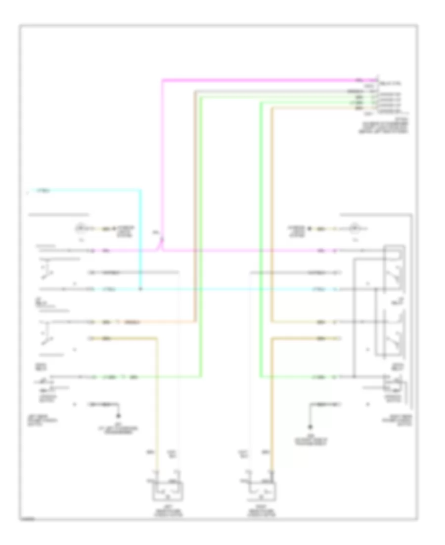
DEFOGGERS
Defoggers Wiring Diagram for Hyundai XG350 2005
List of elements for Defoggers Wiring Diagram for Hyundai XG350 2005:
- A/c control module (in center of dash)
- A/c switch
- Automatic a/c
- B12
- Defogger relay control
- Defogger switch
- Defogger switch input
- Diversity antenna (above right end of package shelf)
- Engine compartment junction block (on left front of engine compartment)
- Engine running input
- Etacm
- Fuse 10a
- G03 (on left "a" pillar, near passenger compartment junction block)
- G05 (on right "a" pillar, near crash bar)
- G24 (above left end of package shelf)
- Hot at all times
- Hot in on or start
- I/p-a
- I/p-b
- I/p-j
- I/p-p
- I15
- I17-1
- J/c d12 (front of left front door)
- J/c d13 (front of right front door)
- J/c i28 (behind instrument cluster)
- J/c m36 (upper right end of dash)
- Jm09
- Left outside mirror motor
- M33-3
- M77-1
- M91
- Manual a/c
- Mirror defogger
- Nca
- Off
- On/start input
- Passenger compartment junction block (behind left end of dash)
- Pre- excitation resistor
- Rear defogger fuse 30a
- Rear window defogger (above right end of package shelf)
- Rear window defogger relay
- Red
- Right outside mirror motor
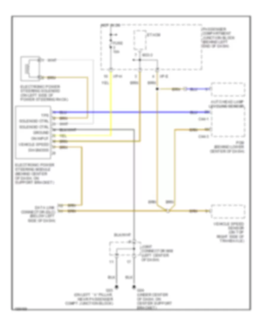
ELECTRONIC POWER STEERING
Electronic Power Steering Wiring Diagram for Hyundai XG350 2005
List of elements for Electronic Power Steering Wiring Diagram for Hyundai XG350 2005:
- (behind center of dash, on support bracket)
- Auto head lamp leveling sensor
- C44-1
- C44-3
- Data link connector (dlc) (below left
- Diagnosis
- Electronic power steering module
- Electronic power steering solenoid (on left side of power steering rack)
- Etacm
- Fuse 10a
- G03 (on left ``a" pillar, near passenger compt junction block)
- G04 (under center of dash, on center support bracket)
- Ground
- Hot in on
- I/p-e
- I/p-h
- Joint connector m08 (left center of dash)
- M33-3
- On input
- Passenger compartment junction block (behind left end of dash)
- Pcm (behind lower center of dash)
- Side of dash)
- Solenoid ctrl
- Tps
- Vehicle speed
- Vehicle speed sensor (on top right side of transaxle)
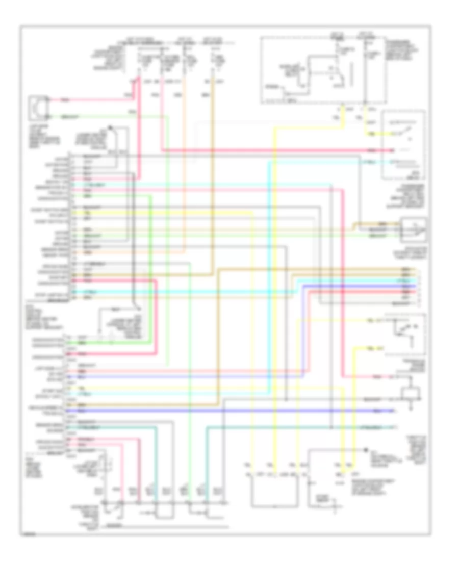
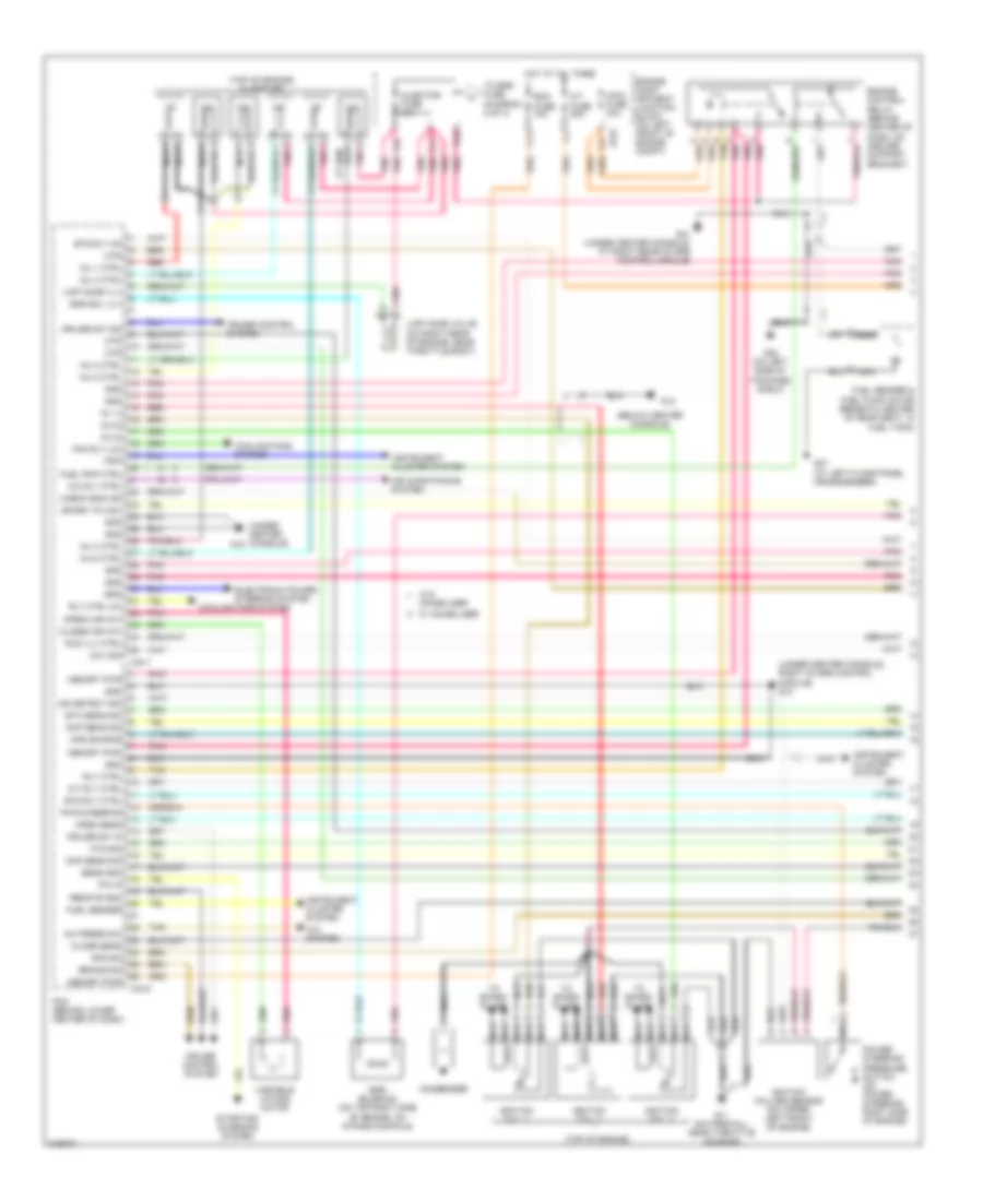
ENGINE PERFORMANCE
3.5L
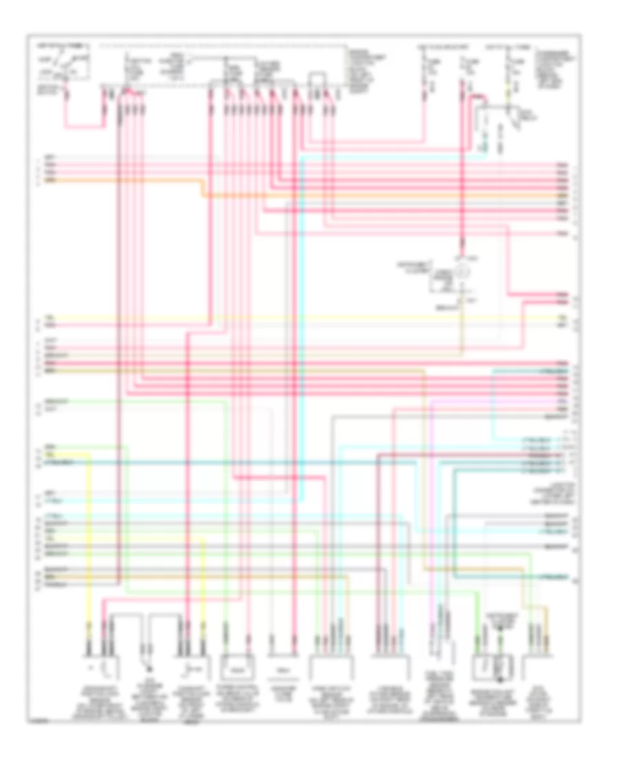
3.5L, Engine Performance Wiring Diagram (1 of 4) for Hyundai XG350 2005
List of elements for 3.5L, Engine Performance Wiring Diagram (1 of 4) for Hyundai XG350 2005:
- (below center console)
- (top of engine)
- (top of engine) injectors
- (under center console)
- (under center console, right of srs control module) g13
- A/c press sw
- A/c rly ctrl
- A/c system
- A/t fuse 20a
- A/t rly ctrl
- Afs sig
- Air conditioning system
- Aps source
- Ats sig
- B10
- Brake sig
- C11
- C44-1
- C44-2
- Ccv sig
- Check eng ind
- Ckp sens sig
- Close sens
- Close(var int)
- Cmp sens sig
- Condenser
- Cooling fans system
- Cruise control system
- Cruise sw in
- Cruise sw ind
- Ecm fuse 10a
- Egr sol vlv
- Egr solenoid (on top right side of engine, on intake manifold)
- Electronic power steering system
- Engine comp- artment junction block (on left front of engine compt)
- Engine control relay (behind center of dash, on center support bracket)
- Eps
- Etc sens sig
- Ets rly ctrl
- Ets rly on
- F10
- F11
- Fan rly (lo)
- Fuel pmp ctrl
- Fuel sender
- Fuel sender & fuel pump motor (beneath center of rear seat, in fuel tank)
- G07 (at left floor panel crossmember)
- G08 (on left side of package shelf)
- G11 (on firewall, near throttle housing)
- G13
- G14 (under center console, at right rear of srs control module)
- G15
- Gnd
- Hot at all times
- Ig 1.4
- Ig 2.5
- Ig 3.6
- Ign detect sig
- Ignition coil 1
- Ignition coil 2
- Ignition coil 3
- Ignition failure sensor (on upper left front of engine)
- Inj 1 ctrl
- Inj 2 ctrl
- Inj 3 ctrl
- Inj 4 ctrl
- Inj 5 ctrl
- Inj 6 ctrl
- Injector fuse 10a
- Instrument cluster system
- Jc01
- Limp home valve (on right rear of engine, near throttle body)
- Limp home vlv
- Main fuse 30a
- Memory pwr
- Mtr
- Nca
- Open sens
- Open(var int)
- P/n in
- Pcm (behind lower center of dash)
- Pcs vlv ctrl
- Pnk
- Power steering pressure switch (on power steering right side of engine)
- Pwr steering
- Red
- Remote gnd
- Rly ctrl
- Rly ctrl (hi)
- Sens gnd
- Spark tim adj
- Starting/ charging system
- Tan
- To egr fuse (diagram 2 of 4)
- To spark plugs
- Trip
- Variable intake motor
- W/ immobilizer
- W/o immobilizer
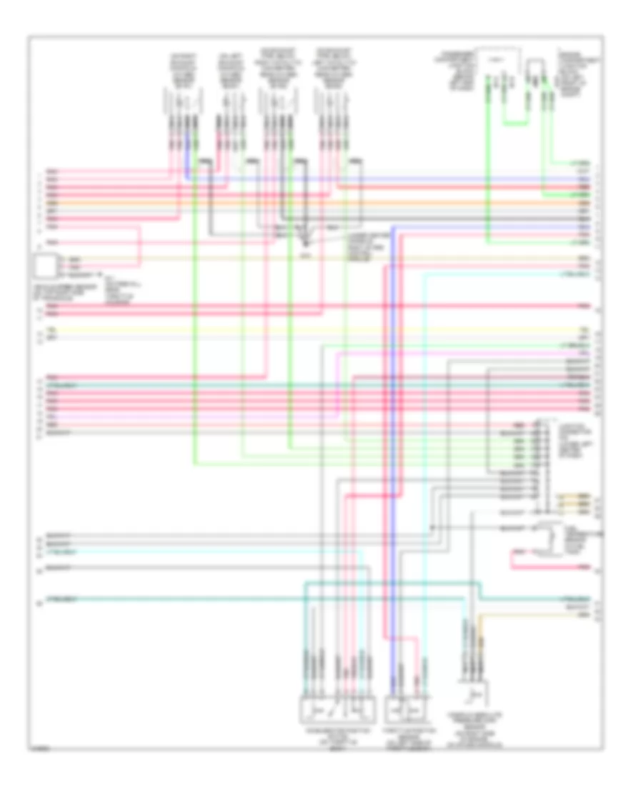
3.5L, Engine Performance Wiring Diagram (2 of 4) for Hyundai XG350 2005
List of elements for 3.5L, Engine Performance Wiring Diagram (2 of 4) for Hyundai XG350 2005:
- A11
- Acc
- Camshaft position (cmp) sensor (on front of left cylinder head)
- Canister close valve
- Check engine ind (mil)
- Crankshaft position (ckp) sensor (on lower front of engine, behind crankshaft pulley)
- D10
- D11
- E10
- Egr fuse 15a
- Engine compartment junction block (on left front of engine compt)
- Engine coolant temperature sensor & sender (on rear of engine)
- Ets motor (on right side of throttle body)
- Ets relay
- From injector a fuse (diagram 1 of 4)
- Fuel tank pressure sensor (beneath left rear of vehicle, above suspension crossmember)
- Fuse 10a
- Fuse 15a
- G16 (in engine compt, between air cleaner & engine compt junction block)
- Hot at all times
- Hot in on or start
- I/p-b
- I/p-h
- I/p-j
- I18-1
- I18-2
- Ignition coil fuse 20a
- Ignition switch
- Instrument cluster
- Instrument cluster system
- Jc01
- Jm09
- Junction connector c41 (lower left center of dash)
- Lock off
- Mass air flow sensor (on left rear of engine compt, in air intake duct)
- Nca
- Oxygen sensor fuse 15a
- Passenger compartment junction block (behind left end of dash)
- Pnk
- Purge control solenoid valve (on rear of intake manifold, on bracket)
- Red
- Sender
- Sensor
- Start
- Variable intake sensor (on right rear of engine, on intake manifold)
3.5L, Engine Performance Wiring Diagram (3 of 4) for Hyundai XG350 2005
List of elements for 3.5L, Engine Performance Wiring Diagram (3 of 4) for Hyundai XG350 2005:
- (on exhaust pipe, below left catalytic converter) rear oxygen sensor (b2/s2)
- (on exhaust pipe, below right catalytic converter) rear oxygen sensor (b1/s2)
- (on left exhaust manifold) oxygen sensor (b2/s1)
- (on right exhaust manifold) oxygen sensor (b1/s1)
- (under center console, right of srs control module)
- Accelerator position switch (on throttle body)
- Engine compartment junction block (on left front of engine compt)
- Fuel temperature sensor (in fuel tank)
- G11 (on firewall, near throttle housing)
- G13
- I/p-h
- I/p-k
- Jc01
- Jm09
- Junction connector c42 (lower left center of dash)
- Manifold absolute pressure (map)
- Nca
- Passenger compartment junction block (behind left end of dash)
- Pnk
- Red
- Sensor (on right side of engine, on intake manifold)
- Throttle position sensor (on left side of throttle body)
- Vehicle speed sensor (on top right side of transaxle)
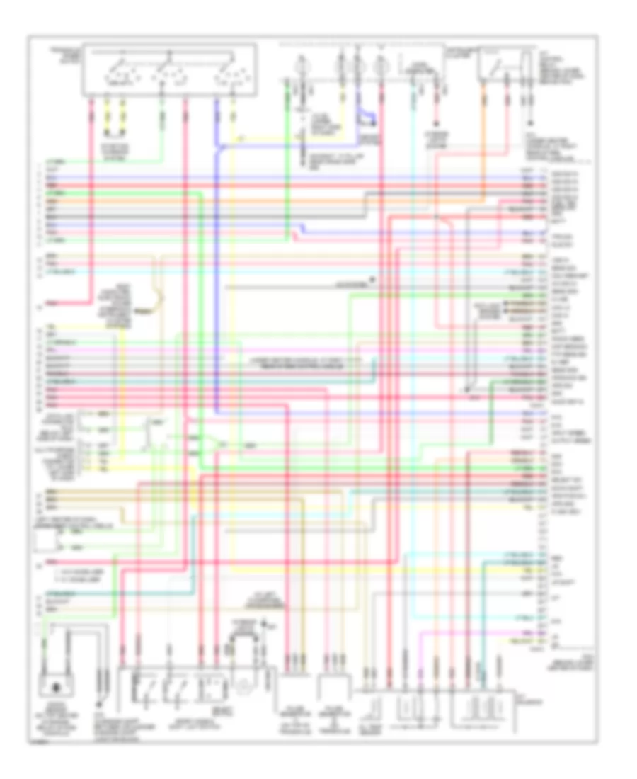
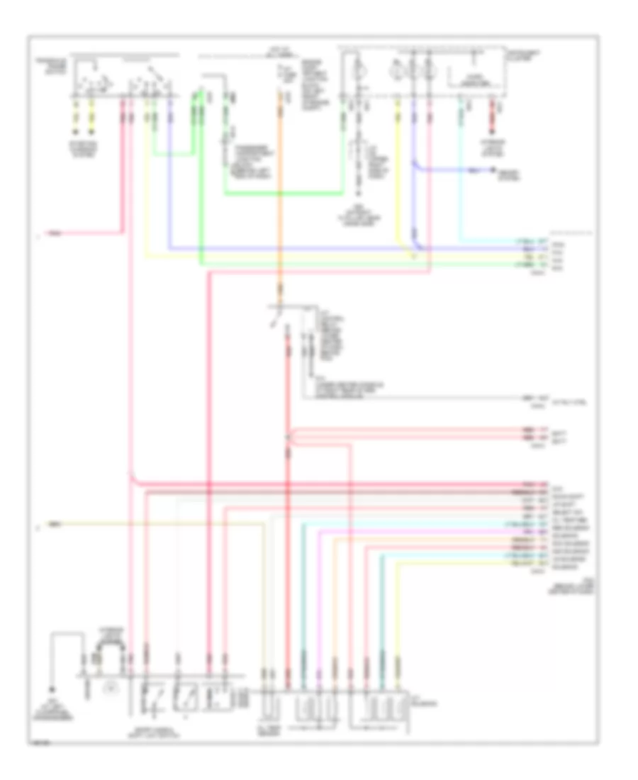
3.5L, Engine Performance Wiring Diagram (4 of 4) for Hyundai XG350 2005
List of elements for 3.5L, Engine Performance Wiring Diagram (4 of 4) for Hyundai XG350 2005:
- (at left floorpanel crossmember)
- (left center of dash) immobilizer control module
- (on right ``a" pillar near crash bar) g05
- (under center console, at right rear of srs control module)
- 2nd
- 5-in
- 5v ref
- A/c sig in
- A/c system
- A/t control relay (behind lower center of dash, behind pcm)
- A/t solenoid
- Anti-lock brakes system
- Aps gnd
- Aps pwr (5v)
- Aps sig
- Aps(main) sig
- Batt
- Body computer, electronic power steering & instrument cluster systems
- C44-3
- C44-4
- Can hi
- Can lo
- Com area net
- D-in
- Data link connector (dlc) (below left side of dash)
- Dcc
- Down shift
- Flash (eci)
- Ftp sens sig
- G07
- G14
- G14 (under center console, at right rear of srs control module)
- G16 (in engine compt between air cleaner & engine compt junction block)
- Gnd
- Ground
- I18-1
- I18-2
- I18-3
- Idle sw
- Input speed
- Instrument cluster
- Interior lights system
- J/c i28 (upper right side of dash)
- K-line
- Knock sens
- Knock sensor (on top center of engine, below intake manifold)
- Map sens sig
- Memory system
- Micro computer
- Multipurpose check connector (at lower left side of dash)
- N-in
- Nca
- Normal
- O/t
- O2s sig in
- O2s sig in fuel tem sens sig gnd
- Oil temp sensor
- On/start in
- Output speed
- P-in
- Pcm (behind lower center of dash)
- Pnk
- Pulse generator a (on top of transaxle)
- Pulse generator b (on transaxle)
- R-in
- Red
- Select
- Select sw
- Select switch
- Sens gnd
- Sens sig
- Sport mode & shift limit switch
- Starting/ charging system
- Tps sig
- Transaxle range switch
- Up shift
- Vss in
- W/ immobilizer
- W/o immobilizer
EXTERIOR LIGHTS
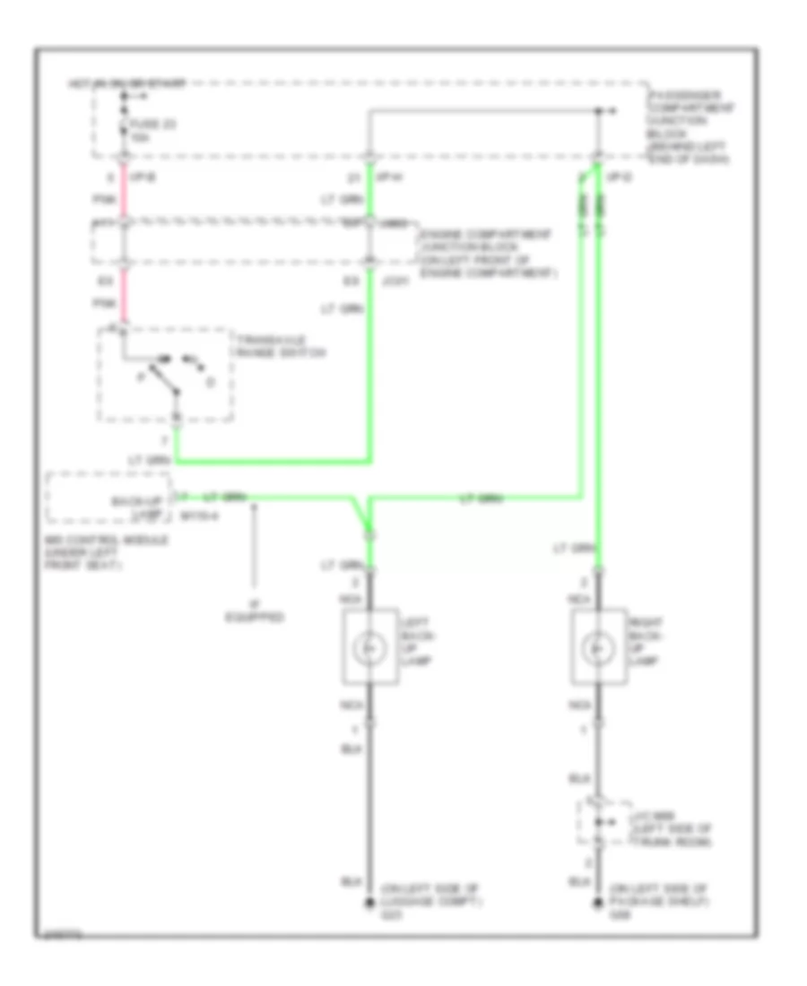
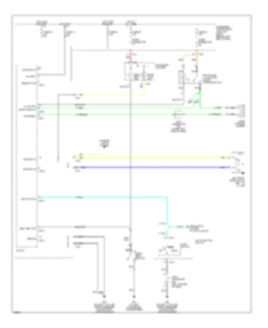
Back-up Lamps Wiring Diagram for Hyundai XG350 2005
List of elements for Back-up Lamps Wiring Diagram for Hyundai XG350 2005:
- (on left side of luggage compt) g23
- (on left side of package shelf) g08
- A11
- Back-up lamp
- Engine compartment junction block (on left front of engine compartment)
- Fuse 23 10a
- Hot in on or start
- I/p-b
- I/p-d
- I/p-h
- If equipped
- Ims control module (under left front seat)
- J/c m99 (left side of trunk room)
- Jc01
- Jm09
- Left back- up lamp
- M110-4
- Nca
- Passenger compartment junction block (behind left end of dash)
- Pnk
- Right back- up lamp
- Transaxle range switch
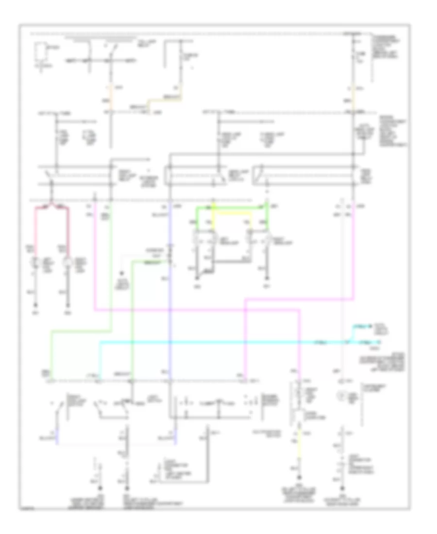
Exterior Lamps Wiring Diagram (1 of 2) for Hyundai XG350 2005
List of elements for Exterior Lamps Wiring Diagram (1 of 2) for Hyundai XG350 2005:
- (at left rear of luggage compt) g23
- (behind left end of dash) passenger compartment junction block
- (left side of trunk room) j/c m99
- (on left side of package shelf) g08
- D9 red
- Engine compartment junction block (on left front of engine compartment)
- Etacm
- Fuse 10a
- Fuse 19 20a
- Fuse 26 10a
- Fuse 31 10a
- G01
- G02
- G03 (on left "a" pillar, near passenger compt junction block)
- Ground
- Head
- Headlights system
- High mounted stoplamp
- Hot at all times
- Hot in on or start
- I/p-d
- I/p-e
- I/p-h
- I/p-p
- Indicator
- J/c m08 (left center of dash)
- J/c m78 (under right front seat)
- Je01
- Jm09
- Left license lamp
- Left rear combination lamp
- Left side marker lamp (park)
- Left stop lamp
- Left turn signal lamp
- Light switch
- M01-1
- M33-2
- M33-3
- Memory power
- Multi- function switch
- Nca
- Nca nca
- Off
- On/start input
- Park
- Passenger compartment junction block (behind left end of dash)
- Pnk
- Red
- Relay control input
- Relay control output
- Right license lamp
- Right rear combination lamp
- Right side marker lamp (park)
- Right stop lamp
- Right turn signal lamp (park)
- Stop
- Stop lamp failure relay (on right side of trunk, behind trim)
- Stop lamp sw
- Stop lamp switch (above brake pedal, on bracket)
- Tail
- Tail lamp fuse 20a
- Tail lamp relay
- Turn
Exterior Lamps Wiring Diagram (2 of 2) for Hyundai XG350 2005
List of elements for Exterior Lamps Wiring Diagram (2 of 2) for Hyundai XG350 2005:
- (at left rear of luggage compartment) g23
- (on left "a" pillar, near passenger compt junction block) g03
- (on right "a" pillar, near crash bar) g05
- Coil control
- Etacm (on rear of passenger compartment junction block, behind left end of dash)
- Flasher unit
- Fuse 29 10a
- Fuse 7 10a
- Ground
- Hazard relay
- Hazard relay ctrl
- Hazard switch
- Hot at all times
- Hot in on or start
- I/p-a
- I/p-b
- I/p-d
- I/p-h
- I/p-j
- I/p-k
- I18-1
- I18-2
- Illumination
- Instrument cluster
- Interior lights system
- J/c i28 (upper right side of dash)
- Left
- Left turn indicator
- M01-1
- M33-1
- Multifunction switch
- Nca
- Off
- Passenger compartment junction block (behind left end of dash)
- Passenger compartment relay box (behind left end of dash, on support bracket)
- Pnk
- Power
- Rear side marker lamp
- Red
- Right
- Right turn indicator
- Stop lamp failure indicator
- Turn signal switch
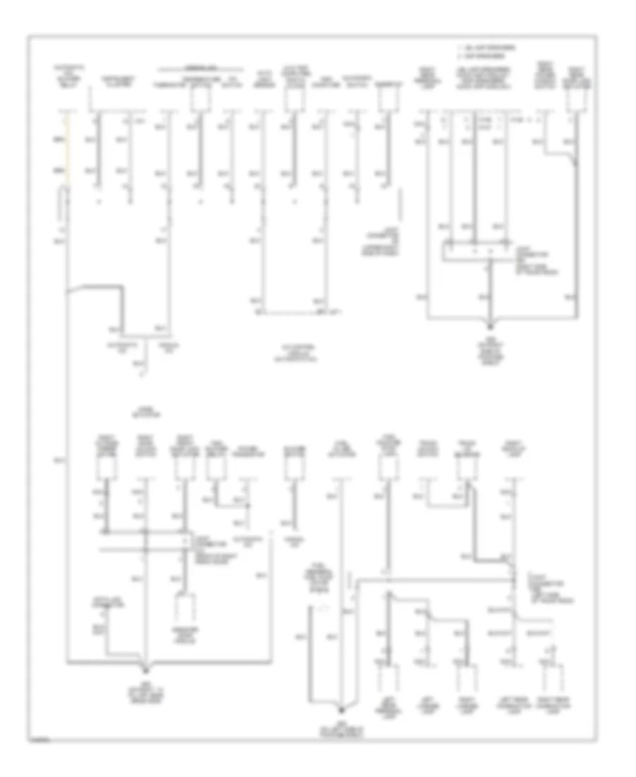
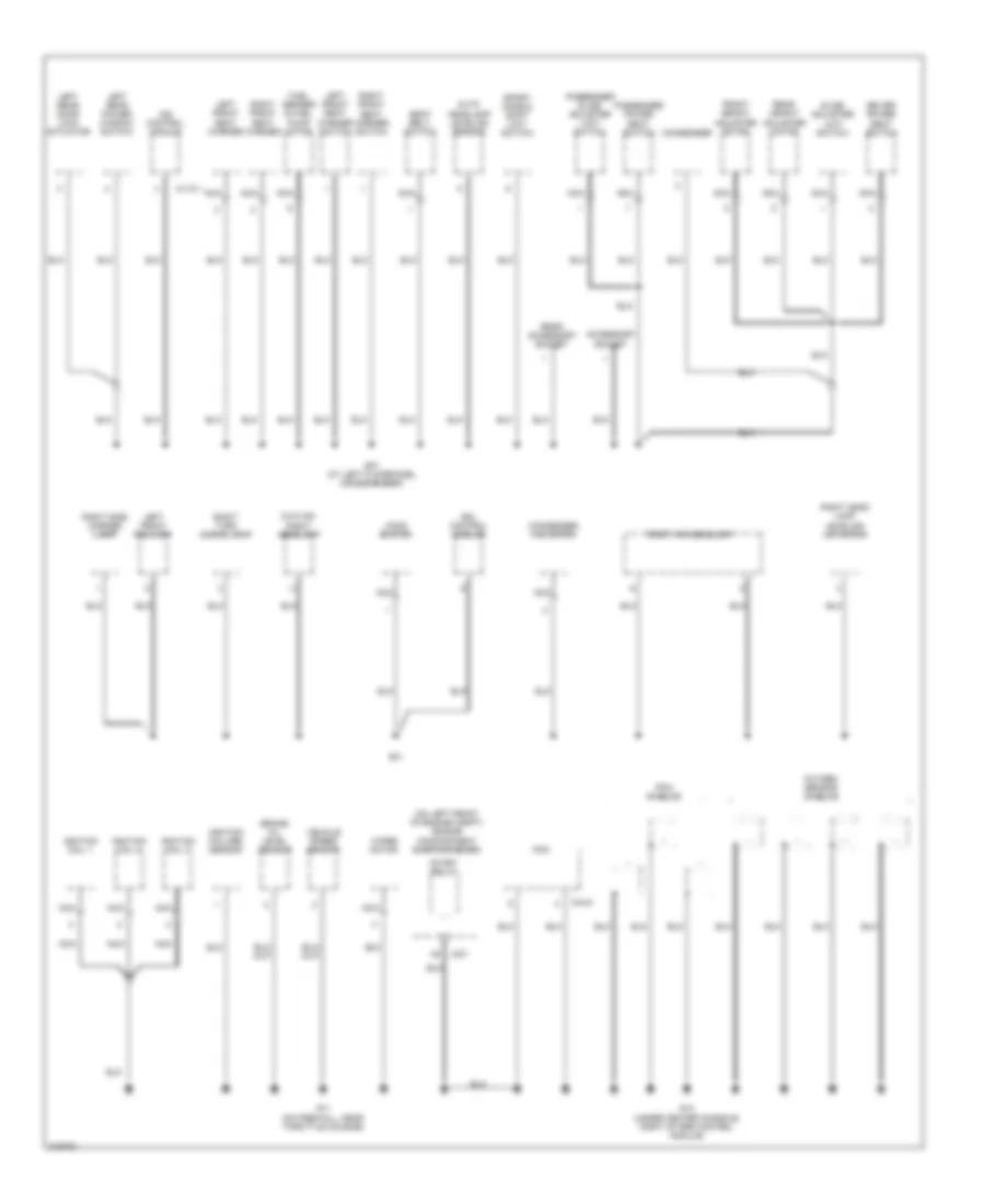
GROUND DISTRIBUTION
Ground Distribution Wiring Diagram (1 of 4) for Hyundai XG350 2005
List of elements for Ground Distribution Wiring Diagram (1 of 4) for Hyundai XG350 2005:
- (on left front of engine compt) engine compartment junction block
- (w/ home link) home link connector
- (w/o hid)
- (w/o hid) right headlamp
- A/c fan relay 2
- Aqs sensor
- Ashtray illumination
- Audio
- C10
- Chrome mirror
- D03
- Data link connector
- Driver door module
- Electronic
- Eps control module
- Etacm
- Flasher unit
- Front cigarette lighter
- G02
- G03 (on left ``a" pillar, near passenger compt junction block)
- G04 (under center of dash, on center support bracket)
- Immobilizer control module
- Ip-m
- Ip-p
- Je01
- Joint connector d12 (front of left front door)
- Joint connector m08 (left center of dash)
- Left door unlock switch
- Left front door lock actuator
- Left head lamp leveling actuator
- Left headlamp
- Left hid headlamp
- Left horn
- Left outside mirror motor
- Left side marker lamp
- Left turn signal lamp
- Left vanity lamp
- M01-1
- M01-2
- M33-3
- Multi-function switch
- Multipurpose check connector
- Nca
- Overhead console lamp
- Passenger compartment junction block (behind left end of dash)
- Rain sensor
- Relay box
- Right front fog lamp
- Right horn
- Right vanity lamp
- Room lamp
- Stop lamp switch
- Sunroof controller
- W/ sunroof
- W/o sunroof
- Wiper motor relay
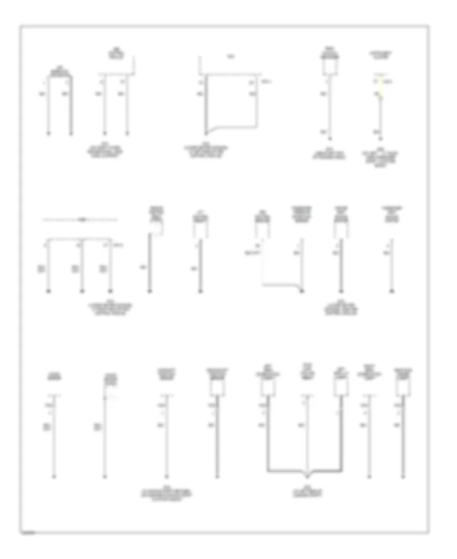
Ground Distribution Wiring Diagram (2 of 4) for Hyundai XG350 2005
List of elements for Ground Distribution Wiring Diagram (2 of 4) for Hyundai XG350 2005:
- (automatic a/c)
- (automatic a/c) blower relay
- (jbl amp speakers) audio amp module 1 (amp speakers) audio amp module 2
- (right side of trunk room)
- (w/o trip computer) digital clock
- A/c control module
- A/c switch
- Amp speakers
- Assister door module
- Auto light sensor
- Automatic a/c
- Blower switch
- Data link connector
- Fuel filler actuator
- Fuel sender & fuel pump motor shield
- G05 (on right ``a" pillar, near crash bar)
- G08 (on left side of package shelf)
- G09 (on right side of package shelf)
- Glove box
- High blower relay
- High mounted stop lamp
- I17-1
- I18-1
- Instrument cluster
- Jbl amp speakers
- Joint connector d13 (front of right front door)
- Joint connector i28 (upper right side of dash)
- Joint connector m64
- Joint connector m99 (left side of trunk room)
- Left license lamp
- Left rear combination lamp
- Left rear personal lamp
- M135
- M136
- M137
- Manual a/c
- Mode actuator
- Nca
- Power transistor
- Rheostat
- Right back-up lamp
- Right door unlock switch
- Right front door lock actuator
- Right license lamp
- Right outside mirror motor
- Right rear combination lamp
- Right rear door lock actuator
- Right rear personal lamp
- Right rear power window switch
- Switch
- Temperature switch
- Thermistor
- Trip computer
- Trunk lid solenoid
- Trunk unlock switch
Ground Distribution Wiring Diagram (3 of 4) for Hyundai XG350 2005
List of elements for Ground Distribution Wiring Diagram (3 of 4) for Hyundai XG350 2005:
- (on left front of engine compt) engine compartment junction block
- (w/o hid)
- Accessory socket
- Auto headlamp leveling sensor
- Brake oil level sensor
- C44-2
- Condenser
- Condenser fan motor
- Driver power seat switch
- Drl control module
- Front height adjuster motor
- Fuel sender & fuel pump motor
- G01
- G07 (at left floorpanel crossmember)
- G11 (on firewall, near throttle housing)
- G13 (under center console, right of srs control module)
- Hood switch
- Ignition coil 1
- Ignition coil 2
- Ignition coil 3
- Ignition failure sensor
- Ims control module
- Jc01
- Left front fog lamp
- Left front seat warmer
- Left front seat warmer switch
- Left rear door lock actuator
- Left rear power window switch
- M110-1
- Nca
- Oxygen sensor shields
- Passenger power seat switch
- Passenger slide adjuster limit switch
- Pcm
- Pcm shields
- Rear accessory socket
- Rear height adjuster motor
- Right front seat warmer
- Right front seat warmer switch
- Right head lamp leveling actuator
- Right headlamp
- Right hid headlamp
- Right side marker lamp
- Right turn signal lamp
- Seat belt switch
- Slide adjuster limit switch
- Sport mode & shift limit switch
- Start relay
- Vehicle speed sensor
- Wiper motor
Ground Distribution Wiring Diagram (4 of 4) for Hyundai XG350 2005
List of elements for Ground Distribution Wiring Diagram (4 of 4) for Hyundai XG350 2005:
- A/t control relay
- Abs control module
- Air bleeding connector
- C44-1
- C44-3
- Camshaft position sensor
- Crankshaft position sensor
- Driver seat buckle switch
- Engine control relay shield
- G06 (on left ``a" pillar, near passenger compt, junction block)
- G10 (under center console, near srs control module)
- G12 (on right inner fender panel, near hood support)
- G14 (under center console, at right rear of srs control module)
- G15 (under center console, at left rear of srs control module)
- G16 (in engine compt between air cleaner & engine compt junction block)
- G23 (at left rear of luggage compt)
- G24 (above left end of package shelf)
- I18-2
- Instrument cluster
- Knock sensor
- Knock sensor shield
- Left back-up lamp
- Left rear combination lamp
- Nca
- Passenger presence detection sensor
- Passenger seat buckle switch
- Pcm
- Rear
- Rear side marker lamp
- Right rear combination lamp
- Srs control module
- Stop lamp failure relay
- Window defogger
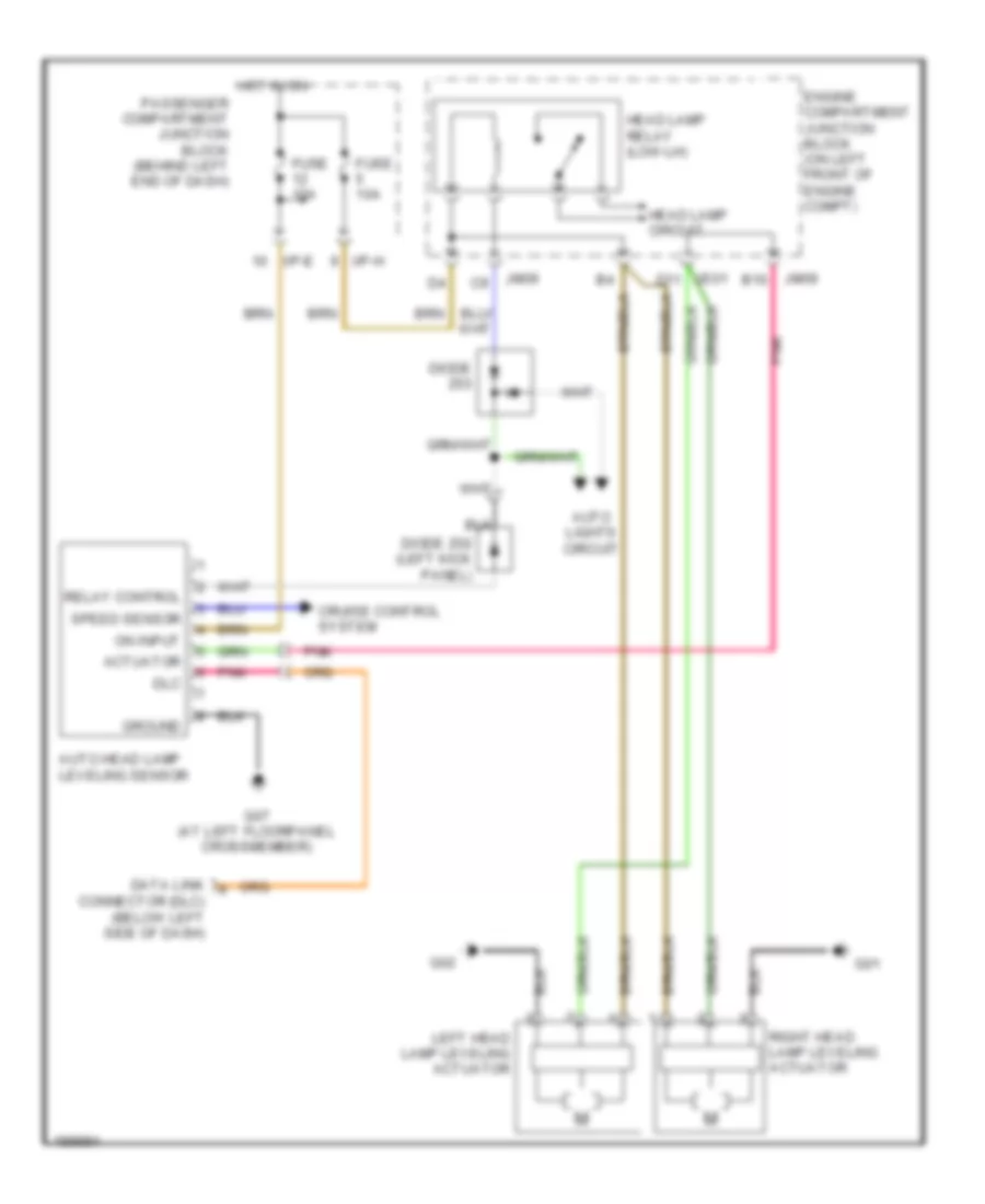
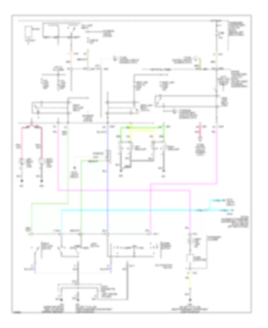
HEADLIGHTS
Headlamps Leveling Wiring Diagram for Hyundai XG350 2005
List of elements for Headlamps Leveling Wiring Diagram for Hyundai XG350 2005:
- Actuator
- Auto head lamp leveling sensor
- Auto lights circuit
- B10
- Connector (dlc) (below left side of dash)
- Cruise control system
- Data link
- Diode z02 (left kick panel)
- Diode z03
- Dlc
- Engine compartment junction block (on left front of engine compt)
- Fuse 10a
- G01
- G02
- G07 (at left floorpanel crossmember)
- Ground
- Head lamp circuit
- Head lamp relay (low-lh)
- Hot in on
- I/p-e
- I/p-h
- Je01 d11
- Jm09
- Left head lamp leveling actuator
- On input
- Passenger compartment junction block (behind left end of dash)
- Pnk
- Relay control
- Right head lamp leveling actuator
- Speed sensor
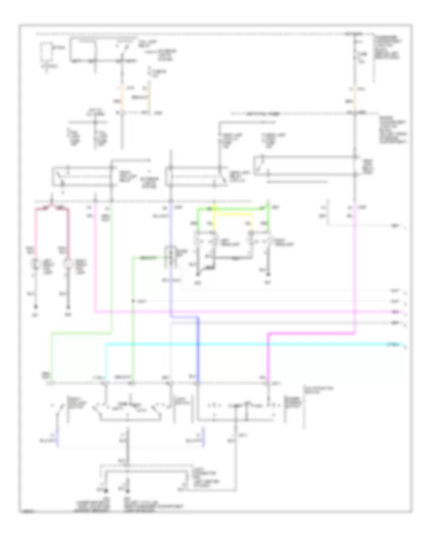
Headlights Wiring Diagram, with Autolamps (1 of 2) for Hyundai XG350 2005
List of elements for Headlights Wiring Diagram, with Autolamps (1 of 2) for Hyundai XG350 2005:
- Auto
- Dimmer/ passing switch
- Diode z03
- Engine compartment junction block (on left front of engine compartment)
- Etacm
- Exterior lights system
- Flash
- Fog lamp fuse 15a
- Front fog lamp relay
- Front fog lamp switch
- Fuse 10a
- Fuse 26 10a
- G01
- G02
- G03 (on left "a" pillar, near passenger compartment junction block)
- G04 (under center of dash, on center support bracket)
- Head
- Head lamp (high) fuse 15a
- Head lamp (low-lh) fuse 15a
- Head lamp relay (high)
- Head lamp relay (low-lh)
- High
- Hot at all times
- Hot in on
- I/p-h
- I/p-p
- Je01
- Jm09
- Joint connector m08 (left center of dash)
- Left front fog lamp
- Left headlamp
- Light switch
- Low
- M01-1
- M33-3
- Multifunction switch
- Off
- Park
- Passenger compartment junction block (behind left end of dash)
- Right front fog lamp
- Right headlamp
- Tail lamp fuse 20a
- Tail lamp relay
Headlights Wiring Diagram, with Autolamps (2 of 2) for Hyundai XG350 2005
List of elements for Headlights Wiring Diagram, with Autolamps (2 of 2) for Hyundai XG350 2005:
- Auto head lamp leveling sensor
- Auto light sensor
- Cpu/sensor
- Diode z02 (left kick panel)
- Etacm (on rear of passenger compartment junction block, behind left end of dash)
- Front fog lamp ind
- Fuse 10a
- G05 (on right "a" pillar, near crash bar)
- G06 (on left "a" pillar, near passenger compartment junction block)
- High beam ind
- Hot in on or start
- I/p-j
- I18-1
- I18-2
- Instrument cluster
- Joint connector i28 (upper right side of dash)
- M33-2
- Micro computer
- Passenger compartment junction block (behind left end of dash)
- Pnk
Headlights Wiring Diagram, with DRL (1 of 2) for Hyundai XG350 2005
List of elements for Headlights Wiring Diagram, with DRL (1 of 2) for Hyundai XG350 2005:
- Auto head lamp leveling circuit
- Auto lights circuit
- D10
- Dimmer/ passing switch
- Diode z03
- Engine compartment junction block (on left front of engine compartment)
- Etacm
- Etacm (on rear of passenger compartment junction block, behind left end of dash)
- Exterior lights system
- Flash
- Fog lamp fuse 15a
- Front fog lamp ind
- Front fog lamp relay
- Front fog lamp switch
- Fuse 10a
- Fuse 26 10a
- G01
- G02
- G03 (on left "a" pillar, near passenger compartment junction block)
- G04 (under center of dash, on center support bracket)
- G06 (on left "a" pillar, near passenger compartment junction block)
- Head
- Head lamp (high) fuse 15a
- Head lamp (low-lh) fuse 15a
- Head lamp relay (high)
- Head lamp relay (low-lh)
- High
- Hot at all times
- Hot in on
- I/p-h
- I/p-p
- I18-2
- Instrument cluster
- Je01
- Jm09
- Joint connector m08 (left center of dash)
- Left front fog lamp
- Left headlamp
- Light switch
- Low
- M01-1
- M33-2
- M33-3
- Micro computer
- Multifunction switch
- Off
- Park
- Passenger compartment junction block (behind left end of dash)
- Pnk
- Right front fog lamp
- Right headlamp
- Tail lamp fuse 20a
- Tail lamp relay
- To drl control module (diagram 2 of 2)
- To engine compartment junction block (diagram 2 of 2)
Headlights Wiring Diagram, with DRL (2 of 2) for Hyundai XG350 2005
List of elements for Headlights Wiring Diagram, with DRL (2 of 2) for Hyundai XG350 2005:
- (on right front of engine compt, near engine mount)
- C12
- Drl control module
- Drl fuse 15a
- Drl relay
- Drl resistor (on right front of engine compt, near engine mount)
- E11
- E12
- Engine compartment junction block (on left front of engine compartment)
- From headlamp relay (high) (diagram 1 of 2)
- From headlamp relay (low-lh) (diagram 1 of 2)
- G01
- G05 (on right "a" pillar, near crash bar)
- Generator
- High beam ind
- Hot at all times
- I18-1
- Instrument cluster
- Jc01
- Je01
- Jm09
- Joint connector i28 (upper right side of dash)
- Joint connector m35 (left center of dash)
- Nca
- Parking brake switch (above parking brake pedal, on bracket)
- Pnk
- Power & control circuit
- Red
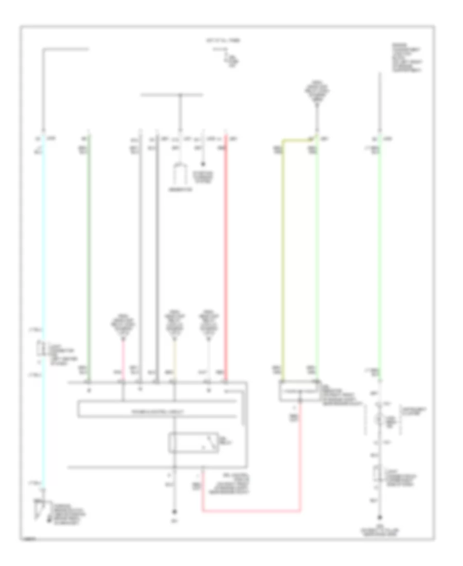
- Starting/ charging system
Headlights Wiring Diagram, with High Intensity Gas Discharge Lamps for Hyundai XG350 2005
List of elements for Headlights Wiring Diagram, with High Intensity Gas Discharge Lamps for Hyundai XG350 2005:
- Auto lights circuit
- D10
- Dimmer/ passing switch
- Diode z03
- Engine compartment junction block (on left front of engine compartment)
- Flash
- Fuse 10a
- G01
- G02
- G03 (on left "a" pillar, near passenger compartment junction block)
- G04 (under center of dash, on center support bracket)
- G05 (on right "a" pillar, near crash bar)
- Head
- Head lamp (high) fuse 15a
- Head lamp (low-lh) fuse 15a
- Head lamp (low-rh) fuse 15a
- Head lamp relay (high)
- Head lamp relay (low-lh)
- Hid head lamp relay (right front corner of engine compt)
- High
- High beam ind
- Hot at all times
- Hot in on
- I/p-h
- I18-1
- Instrument cluster
- Je01
- Jm09
- Joint connector i28 (upper right side of dash)
- Joint connector m08 (left center of dash)
- Left hid head lamp
- Light switch
- Low
- M01-1
- Multifunction switch
- Off
- Park
- Passenger compartment junction block (behind left end of dash)
- Right hid head lamp
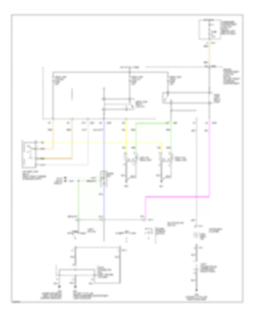
Headlights Wiring Diagram, without DRL for Hyundai XG350 2005
List of elements for Headlights Wiring Diagram, without DRL for Hyundai XG350 2005:
- Auto head lamp leveling circuit
- Auto lights circuit
- Dimmer/ passing switch
- Diode z03
- Engine compartment junction block (on left front of engine compartment)
- Etacm
- Etacm (on rear of passenger compartment junction block, behind left end of dash)
- Exterior lights system
- Flash
- Fog lamp fuse 15a
- Front fog lamp ind
- Front fog lamp relay
- Front fog lamp switch
- Fuse 10a
- Fuse 26 10a
- G01
- G02
- G03 (on left "a" pillar, near passenger compartment junction block)
- G04 (under center of dash, on center support bracket)
- G05 (on right "a" pillar, near crash bar)
- G06 (on left "a" pillar, near passenger compartment junction block)
- Head
- Head lamp (high) fuse 15a
- Head lamp (low-lh) fuse 15a
- Head lamp relay (high)
- Head lamp relay (low-lh)
- High
- High beam ind
- Hot at all times
- Hot in on
- I/p-h
- I/p-p
- I18-1
- I18-2
- Instrument cluster
- Je01
- Jm09
- Joint connector i28 (upper right side of dash)
- Joint connector m08 (left center of dash)
- Left front fog lamp
- Left headlamp
- Light switch
- Low
- M01-1
- M33-2
- M33-3
- Micro computer
- Multifunction switch
- Off
- Park
- Passenger compartment junction block (behind left end of dash)
- Right front fog lamp
- Right headlamp
- Tail lamp fuse 20a
- Tail lamp relay
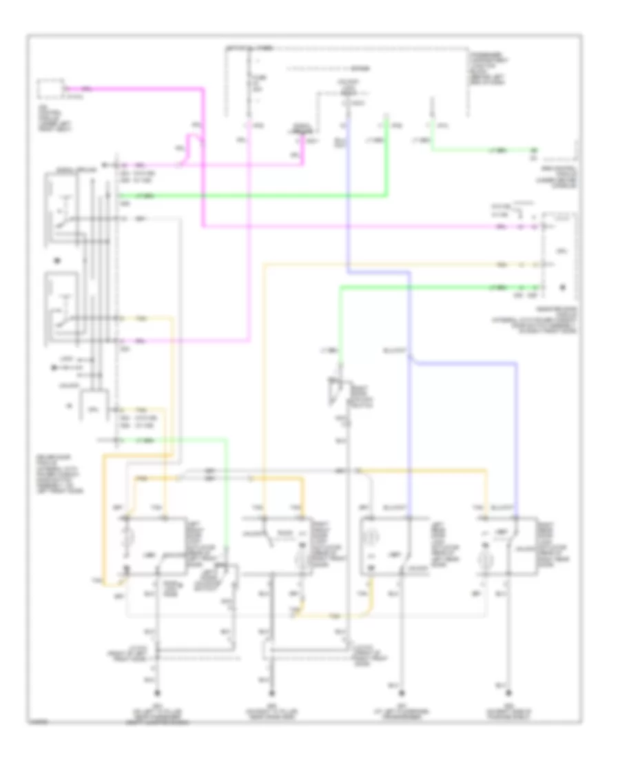
HORN
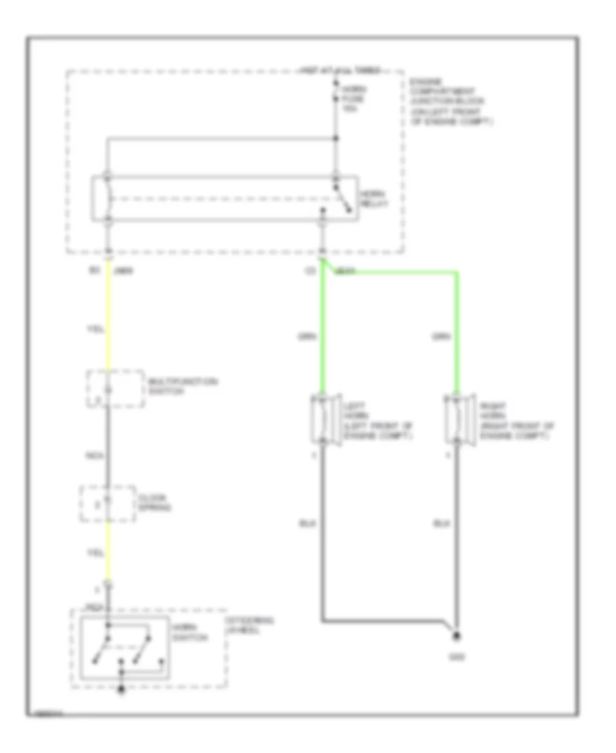
Horn Wiring Diagram for Hyundai XG350 2005
List of elements for Horn Wiring Diagram for Hyundai XG350 2005:
- Clock spring
- Engine compartment junction block (on left front of engine compt)
- G02
- Horn fuse 15a
- Horn relay
- Horn switch
- Hot at all times
- Je01
- Jm09
- Left horn (left front of engine compt)
- Multifunction switch
- Nca
- Right horn (right front of engine compt)
- Steering wheel
INSTRUMENT CLUSTER
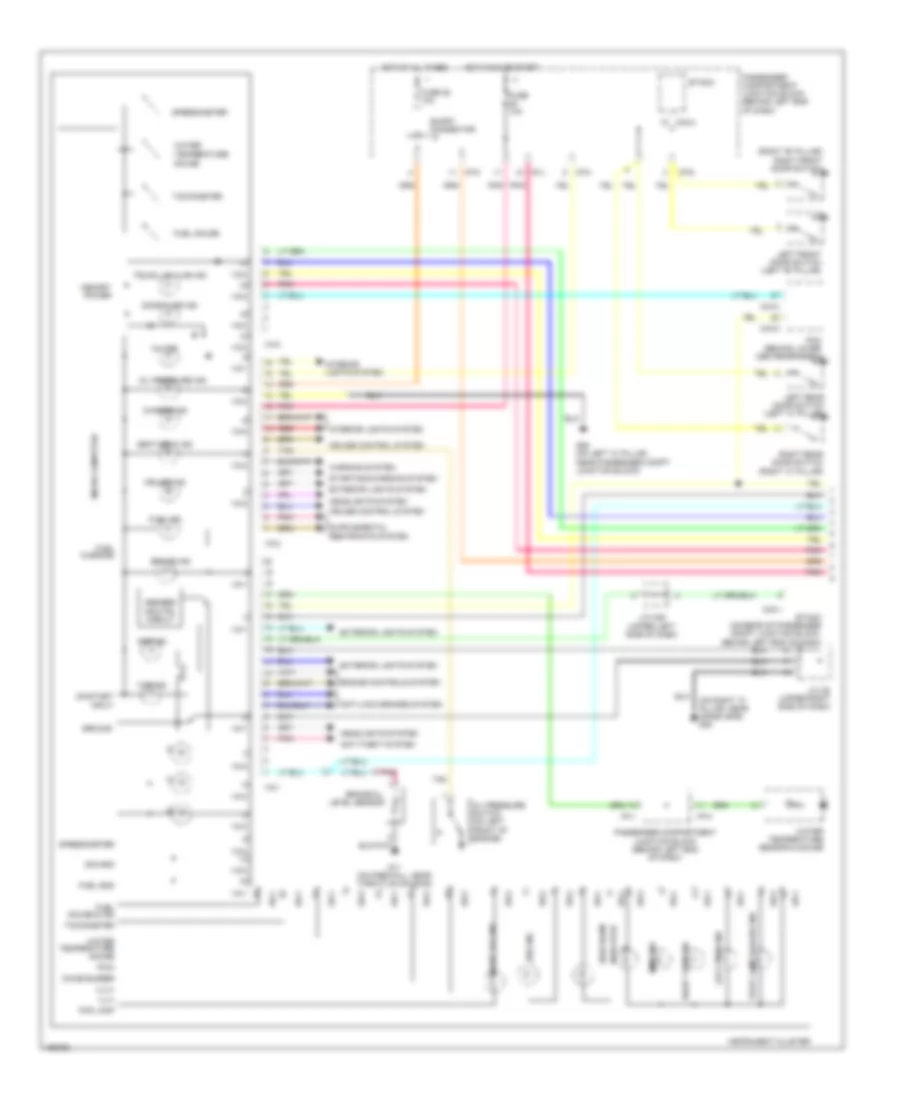
Instrument Cluster Wiring Diagram (1 of 2) for Hyundai XG350 2005
List of elements for Instrument Cluster Wiring Diagram (1 of 2) for Hyundai XG350 2005:
- (on right "a" pillar, near crash bar) g05
- (right "b" pillar) right front door switch
- Abs ind
- Abs/ebd ind ctrl circuit
- Anti-lock brakes system
- Anti-theft system
- Brake ind
- Brake oil level sensor
- C44-2
- C44-4
- Charge ind
- Chime buzzer
- Cruise control system
- Cruise ind
- Door ajar ind
- Engine controls system
- Etacm
- Etacm (on rear of passenger compt junction block, behind left end of dash)
- Exterior lights system
- Fog lamp
- Front fog ind
- Fuel gauge
- Fuel gauge & ind
- Fuel gnd
- Fuel ind
- Fuel warning
- Fuse 10a
- Fuse 25 10a
- G06 (on left "a" pillar, near passenger compt junction block)
- G11 (on firewall, near throttle housing)
- Gauge
- Ground
- Headlights system
- High beam
- Hot at all times
- Hot in on or start
- I/p-d
- I/p-h
- I/p-j
- I/p-k
- I18-1
- I18-2
- I18-3
- Ill(+)
- Ill(-)
- Immo ind
- Indicator
- Instrument cluster
- Interior lights system
- J/c i28 (upper right side of dash)
- J/c m39 (upper left side of dash)
- Left front door switch (left "b" pillar)
- Left rear door switch (left "c" pillar)
- Left turn ind
- M33-1
- M33-3
- Memory power
- Micro computer
- Mil ind
- Oil pressure ind
- Oil pressure switch (on left front of engine)
- On/start input
- Passenger compartment junction block (behind left end of dash)
- Pcm (behind lower center of dash)
- Pnk
- Pwm
- Red
- Right rear door switch (right "c" pillar)
- Right turn ind
- Seat belt ind
- Short connector "a"
- Sig gnd
- Speedometer
- Srs ind
- Starting/charging system
- Stop lamp failure ind
- Tachometer
- Tan
- Tcs ind
- Temperature
- Trunk lid ajar ind
- Warning system
- Water
- Water temperature gauge
- Water temperature sensor & gauge
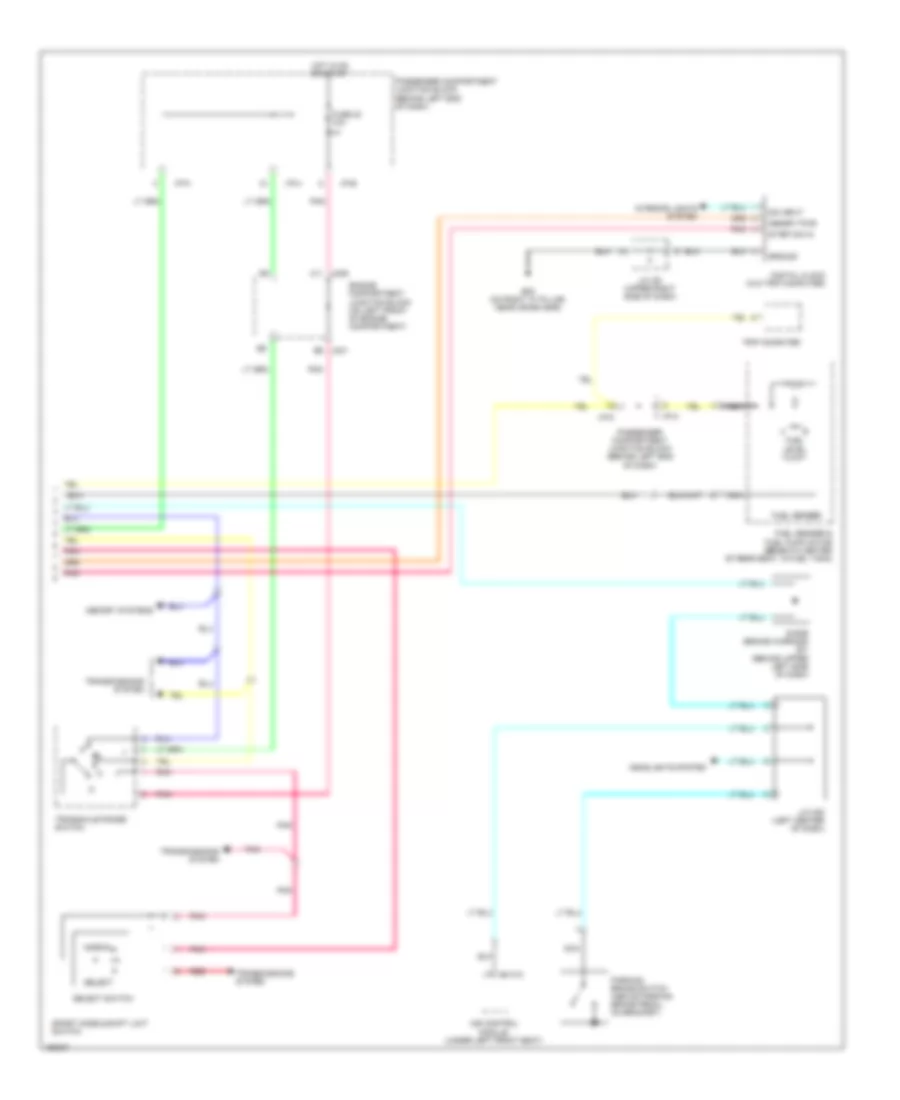
Instrument Cluster Wiring Diagram (2 of 2) for Hyundai XG350 2005
List of elements for Instrument Cluster Wiring Diagram (2 of 2) for Hyundai XG350 2005:
- Digital clock (w/o trip computer)
- Dim input
- Diode (brake warning) z01 (behind upper left side of dash)
- Engine compartment junction block (on left front of engine compartment)
- Fuel level float
- Fuel sender
- Fuel sender & fuel pump motor (beneath center of rear seat, in fuel tank)
- Fuse 23 10a
- G05 (on right "a" pillar, near crash bar)
- Ground
- Headlights system
- Hot in on or start
- I/p-a
- I/p-b
- I/p-h
- I/p-k
- Ims control module (under left front seat)
- Interior lights system
- J/c i28 (upper right side of dash)
- J/c m35 (left center of dash)
- Jc01 e6
- Jm09 a11
- M110-3
- Memory pwr
- Memory systems
- Nca
- Normal
- Parking brake switch (above parking brake pedal, on bracket)
- Passenger compartment junction block (behind left end of dash)
- Pnk
- Red
- Select
- Select switch
- Sport mode & shift limit switch
- Start/on in
- Transaxle range switch
- Transmissions system
- Trip computer
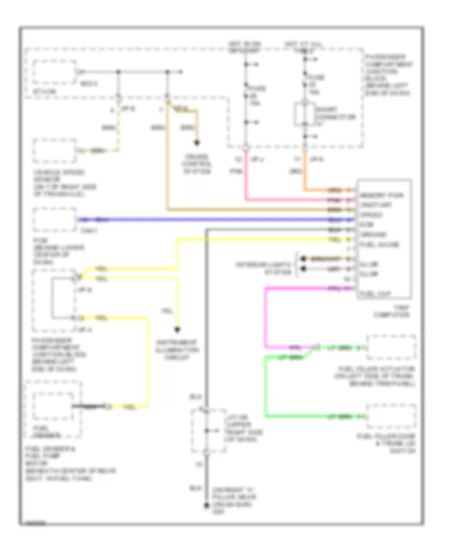
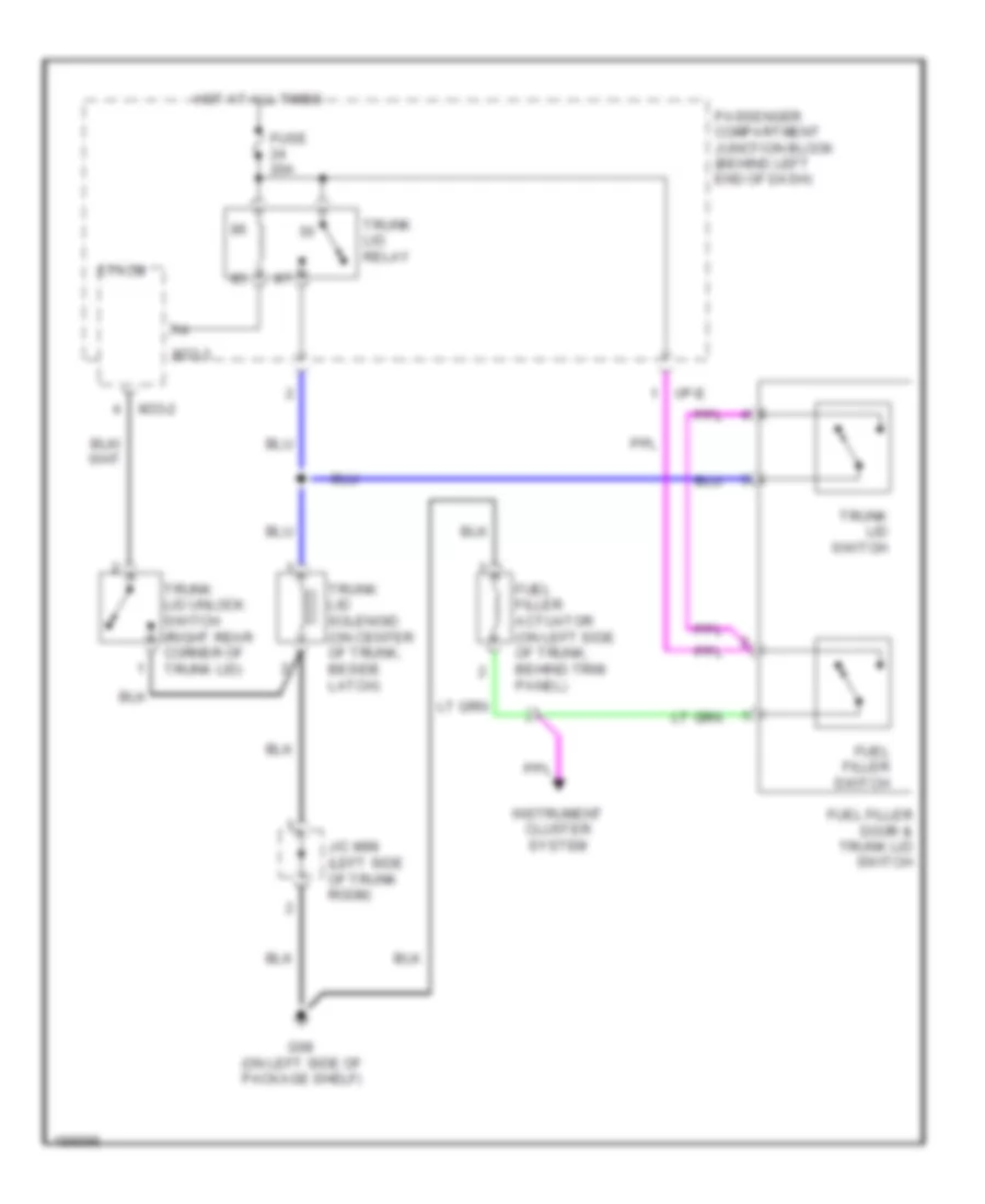
Trip Computer Wiring Diagram for Hyundai XG350 2005
List of elements for Trip Computer Wiring Diagram for Hyundai XG350 2005:
- (on right "a" pillar, near crash bar) g05
- C44-1
- Cruise control system
- Ecm
- Etacm
- Fuel cap
- Fuel filler actuator (on left side of trunk, behind trim panel)
- Fuel filler door & trunk lid switch
- Fuel gauge
- Fuel sender
- Fuel sender & fuel pump motor (beneath center of rear seat, in fuel tank)
- Fuse 10a
- Ground
- Hot at all times
- Hot in on or start
- I/p-a
- I/p-e
- I/p-j
- I/p-k
- Illum
- Instrument illumination circuit
- Interior lights system
- J/c i28 (upper right side of dash)
- M33-3
- Memory pwr
- Nca
- On/start
- Passenger compartment junction block (behind left end of dash)
- Pcm (behind lower center of dash)
- Pnk
- Short connector "a"
- Speed
- Trip computer
- Vehicle speed sensor (on top right side of transaxle)
INTERIOR LIGHTS
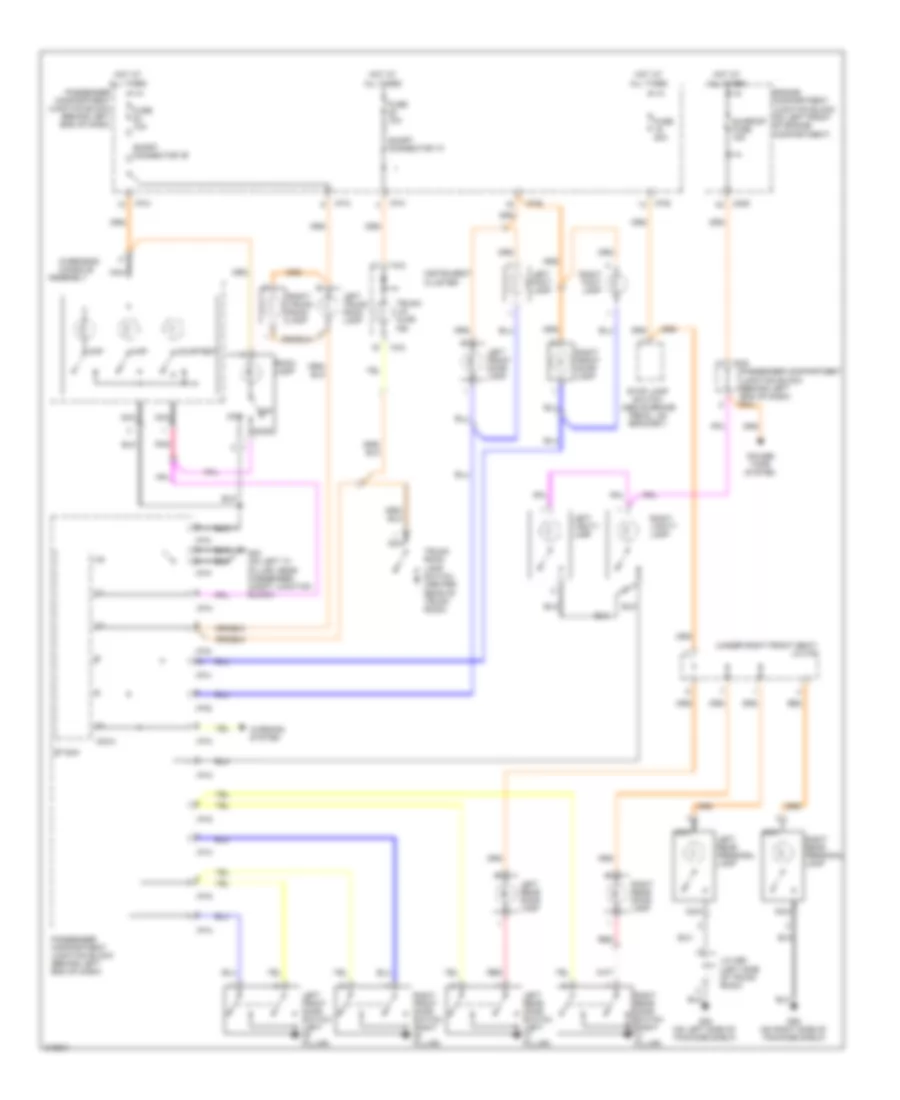
Courtesy Lamps Wiring Diagram, with Sunroof for Hyundai XG350 2005
List of elements for Courtesy Lamps Wiring Diagram, with Sunroof for Hyundai XG350 2005:
- (under right front seat) j/c m78
- Assembly
- Courtesy
- Door
- Engine compartment junction block (on left front of engine compartment)
- Etacm
- Fuse 10a
- Fuse 20a
- G03 (on left "a" pillar, near passenger compt junction block)
- G08 (on left side of package shelf)
- G09 (on right side of package shelf)
- Hot at all times
- I/p-a
- I/p-b
- I/p-d
- I/p-e
- I/p-h
- I/p-k
- I/p-m
- I/p-p
- I18-2
- Instrument cluster
- J/c m99 (left side of trunk room)
- Jm09 a4
- Left foot lamp
- Left front door lamp
- Left front door switch (left "b" pillar)
- Left rear door lamp
- Left rear door switch (left "c" pillar)
- Left rear personal lamp
- Left trunk room lamp
- Left vanity lamp
- M33-3
- Map
- Nca
- Off
- Overhead console
- Passenger compartment junction block (behind left end of dash)
- Passenger compartment junction block (behind left end of dash) i/p-m
- Pnk
- Power tops system
- Red
- Right foot lamp
- Right front door lamp
- Right front door switch (right "b" pillar)
- Right rear door lamp
- Right rear door switch (right "c" pillar)
- Right rear personal lamp
- Right trunk room lamp
- Right vanity lamp
- Room lamp
- Short connector "a"
- Short connector "b"
- Stop lamp switch (above brake pedal, on bracket)
- Sunroof fuse 15a
- Trunk lid ajar ind
- Trunk room lamp switch (center rear of trunk room)
- Warning system
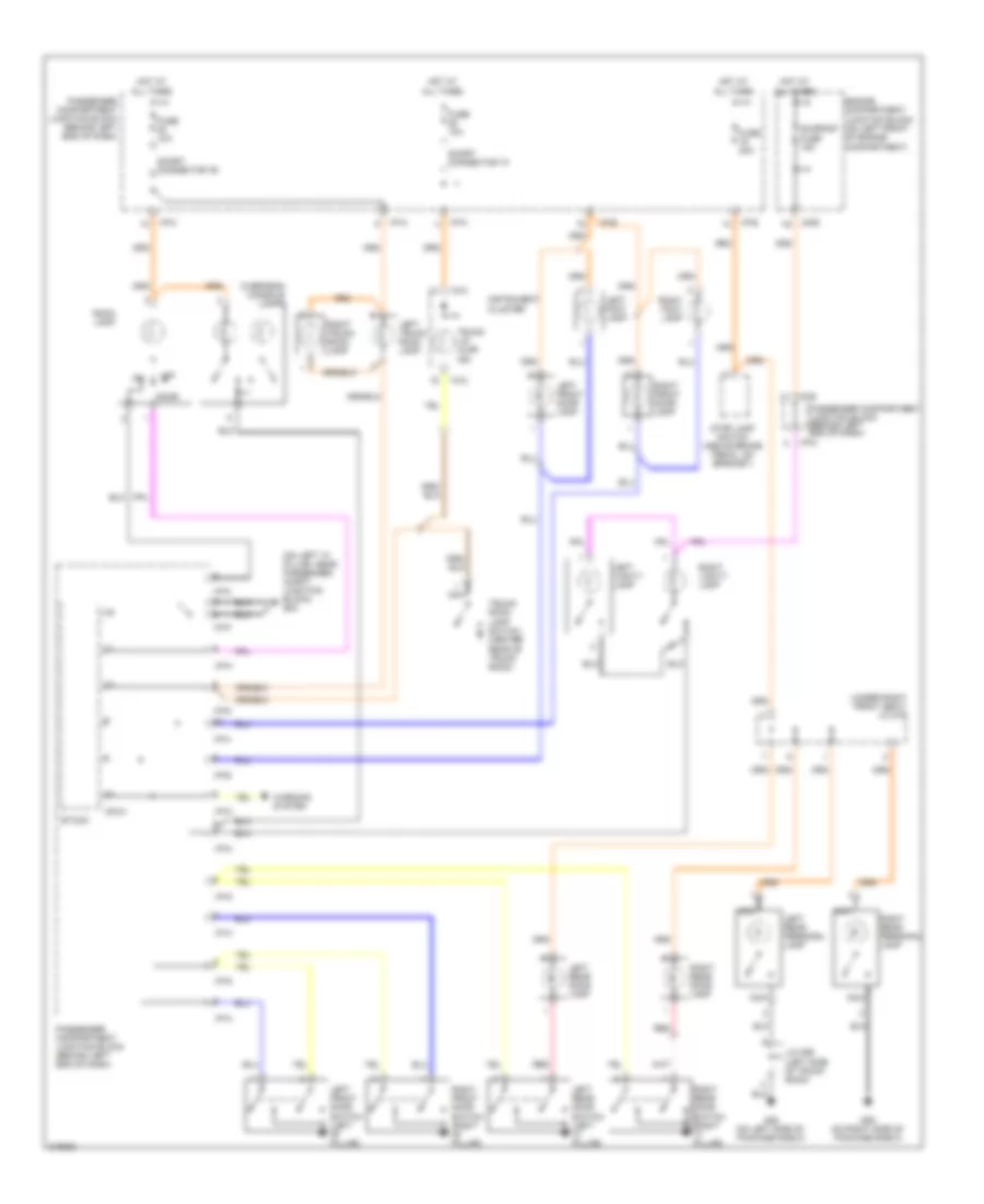
Courtesy Lamps Wiring Diagram, without Sunroof for Hyundai XG350 2005
List of elements for Courtesy Lamps Wiring Diagram, without Sunroof for Hyundai XG350 2005:
- (on left "a" pillar, near passenger compt junction block) g03
- (under right front seat) j/c m78
- Door
- Engine compartment junction block (on left front of engine compartment)
- Etacm
- Fuse 10a
- Fuse 20a
- G08 (on left side of package shelf)
- G09 (on right side of package shelf)
- Hot at all times
- I/p-a
- I/p-b
- I/p-d
- I/p-e
- I/p-h
- I/p-k
- I/p-m
- I/p-p
- I18-2
- Instrument cluster
- J/c m99 (left side of trunk room)
- Jm09 a4
- Left foot lamp
- Left front door lamp
- Left front door switch (left "b" pillar)
- Left rear door lamp
- Left rear door switch (left "c" pillar)
- Left rear personal lamp
- Left trunk room lamp
- Left vanity lamp
- M33-3
- Nca
- Off
- Overhead console lamps
- Passenger compartment junction block (behind left end of dash)
- Red
- Right foot lamp
- Right front door lamp
- Right front door switch (right "b" pillar)
- Right rear door lamp
- Right rear door switch (right "c" pillar)
- Right rear personal lamp
- Right trunk room lamp
- Right vanity lamp
- Room lamp
- Short connector "a"
- Short connector "b"
- Stop lamp switch (above brake pedal, on bracket)
- Sunroof fuse 15a
- Trunk lid ajar ind
- Trunk room lamp switch (center rear of trunk room)
- Warning system
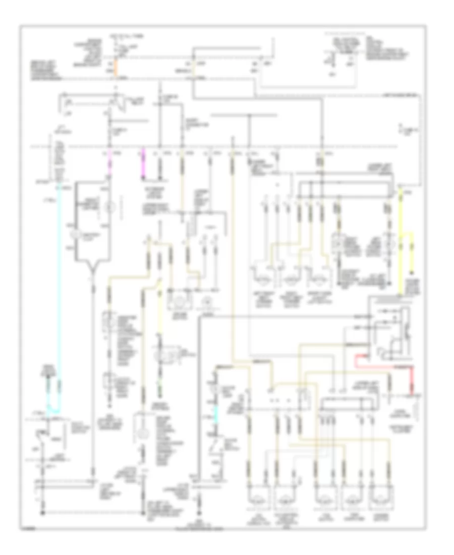
Instrument Illumination Wiring Diagram for Hyundai XG350 2005
List of elements for Instrument Illumination Wiring Diagram for Hyundai XG350 2005:
- (at left floorpanel crossmember) g07
- (behind left end of dash) passenger compartment junction block
- (on left "a" pillar, near passenger compt junction block) g03
- (on right side of package shelf) g09
- (under left front seat) j/c m71
- (under left front seat) j/c m79
- (upper left side of dash) j/c i27
- (upper left side of dash) j/c m38
- (upper right side of dash) j/c m37
- A/c control module (automatic a/c)
- A/c switch (manual a/c)
- Ashtray illum
- Assister door module (integral with power window/ door switch assembly, on right front door)
- Audio
- Auto cut out
- Control
- Cruise switch
- Driver door module (integral with power window/door switch assembly, on left front door)
- Drl control module (on right front of engine compartment, near engine mount)
- Drl control module inner tail relay close
- Engine compartment junction block (on left front of engine compt)
- Etacm
- Exterior lights system
- Front cigarette lighter
- Fuse 16 10a
- Fuse 26 10a
- Fuse 31 10a
- G01
- G05 (on right "a" pillar, near crash bar)
- Glove box lamp
- Glove box switch
- Hazard switch
- Head
- Head- lights system
- Hot at all times
- Hot in acc or on
- I/p-a
- I/p-b
- I/p-d
- I/p-e
- I/p-h
- I/p-j
- I/p-k
- I/p-p
- I17-1
- Ims switch
- Instrument cluster
- J/c d12 (front of left front door)
- J/c d13 (front of right front door)
- J/c i28 (upper right side of dash)
- J/c i29 (right center of dash)
- J/c m08 (left center of dash)
- Je01
- Jm09
- Left front seat warmer switch
- Left rear power window switch
- Light switch
- M01-1
- M33-2
- M33-3
- Memory systems
- Micro computer
- Multi- function switch
- Nca
- Off
- Park
- Power distri- bution system
- Red i18-2
- Relay
- Rheostat
- Right front seat warmer switch
- Right rear power window switch
- Short connector "c"
- Sport mode & shift limit switch
- Tail lamp auto cut ctrl input
- Tail lamp fuse 20a
- Taillamp
- Tcs switch
- Trip computer
MEMORY SYSTEMS
Memory Systems Wiring Diagram (1 of 2) for Hyundai XG350 2005
List of elements for Memory Systems Wiring Diagram (1 of 2) for Hyundai XG350 2005:
- (under left front seat) ims control module
- (under left side of left front seat) slide adjust motor
- Bu lamp
- Data
- Down
- Engine compartment junction block (on left front of engine compt)
- Exterior lights system
- Front
- Front height adjust motor
- Front height switch
- Fuse 10a
- G07 (at left floorpanel crossmember)
- Ground
- Hot at all times
- Hot in on
- I/p-a
- I/p-b
- Instrument cluster system
- J/c m35 (left center of dash)
- J/p-h
- Jm10
- Limit switch
- M110-1
- M110-2
- M110-3
- M110-4
- Mem pwr
- Motor
- Nca
- On input
- Park brk sig
- Park pos
- Parking brake switch (above parking brake pedal, on bracket)
- Passenger compartment junction block (behind left end of dash)
- Power seat switch
- Power window fusible link 40a
- Rear
- Rear height adjust motor
- Rear height switch
- Recline switch
- Reclining adjust & limit switch
- Red
- Sensor (+)
- Sig gnd
- Slide adjust limit switch
- Slide sensor (under right side of left front seat)
- Slide switch
Memory Systems Wiring Diagram (2 of 2) for Hyundai XG350 2005
List of elements for Memory Systems Wiring Diagram (2 of 2) for Hyundai XG350 2005:
- Acc/on in
- Assister door module (integral with power window/door switch assembly, on right front door)
- Auto
- Common
- D03
- D05
- D28
- D30
- Data
- Driver door module (integral with power window/door switch assembly, on left front door)
- Etacm (on rear of passenger compt junction block, behind left end of dash)
- Fuse 10a
- Fuse 20a
- G03 (on left ``a" pillar, near passenger compt junction block)
- G05 (on right ``a" pillar, near crash bar)
- Gnd ctrl
- Ground
- Hot at all times
- Hot in acc or on
- I/p-e
- Illum
- Ims switch
- Interior lights system
- J/c d12 (front of left front door)
- J/c d13 (front of right front door)
- Led
- Left ims mirror motor
- Left/right
- Lt/rt sensor
- M33-1
- Memory
- Memory pwr
- Nca
- Passenger compartment junction block (behind left end of dash)
- Power
- Red
- Right ims mirror motor
- Signal
- Signal gnd
- Stop
- Up/dn sensor
- Up/down
POWER DISTRIBUTION
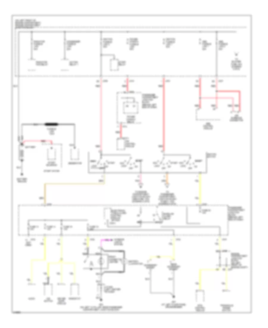
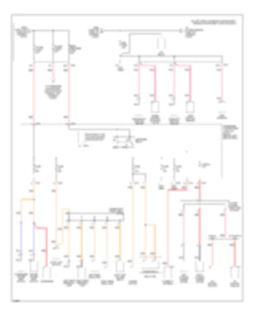
Power Distribution Wiring Diagram (1 of 6) for Hyundai XG350 2005
List of elements for Power Distribution Wiring Diagram (1 of 6) for Hyundai XG350 2005:
- (not used)
- (on left front of engine compartment) engine compartment junction block
- 87a
- A/c fan relay 1
- Abs control module
- Abs fusible link 1 30a
- Abs fusible link 2 30a
- Acc
- Accessory socket
- Air bleeding connector
- Ashtray illumination
- Audio
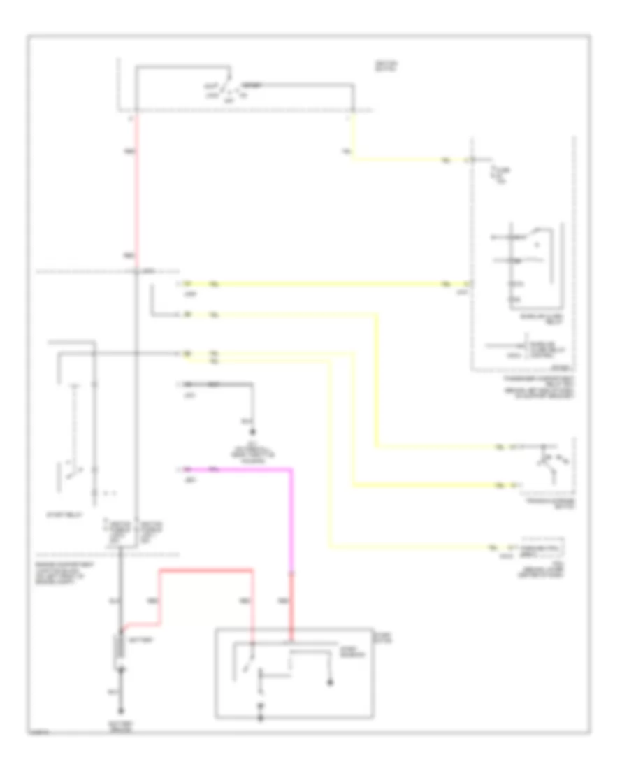
- Battery
- Battery ground
- Burglar alarm relay
- Condenser fusible link 20a
- Driver door module
- Electronic time & alarm control module (etacm)
- Engine compartment junction block (on left front of engine compt)
- Ets control module
- Front cigarette lighter
- Fuse 13 10a
- Fuse 14 10a
- Fuse 15 20a
- Fuse 16 10a
- Fuse 32 10a
- Fusible link 140a
- G03 (on left "a" pillar, near passenger compartment junction block)
- G07 (at left floor panel crossmember)
- Generator
- I/p-a
- I/p-b
- I/p-d
- I/p-e
- I/p-p
- Ignition fusible link 1 30a
- Ignition fusible link 2 30a
- Ignition switch
- Ims control module
- Ims switch
- Interior lights system
- J/c m08 (left center of dash)
- Jc01 b5
- Jco1
- Jm09
- Jm10
- Lock
- M110-1
- M33-3
- Nca
- Off
- Passenger compartment junction block (behind left end of dash)
- Pnk
- Power window fusible link 40a
- Power window relay
- Radiator fan relay
- Radiator fusible link 30a
- Rear accessory socket
- Red
- Rheostat
- Start
- Start motor
- Start relay
- Start solenoid
- To blower fuse, 30a (diagram 2 of 6)
- To engine compartment junction block (abs fuse, 10a) (diagram 2 of 6)
- To passenger compartment junction block (fuse 3, 10a) (diagram 5 of 6)
- Transaxle range switch
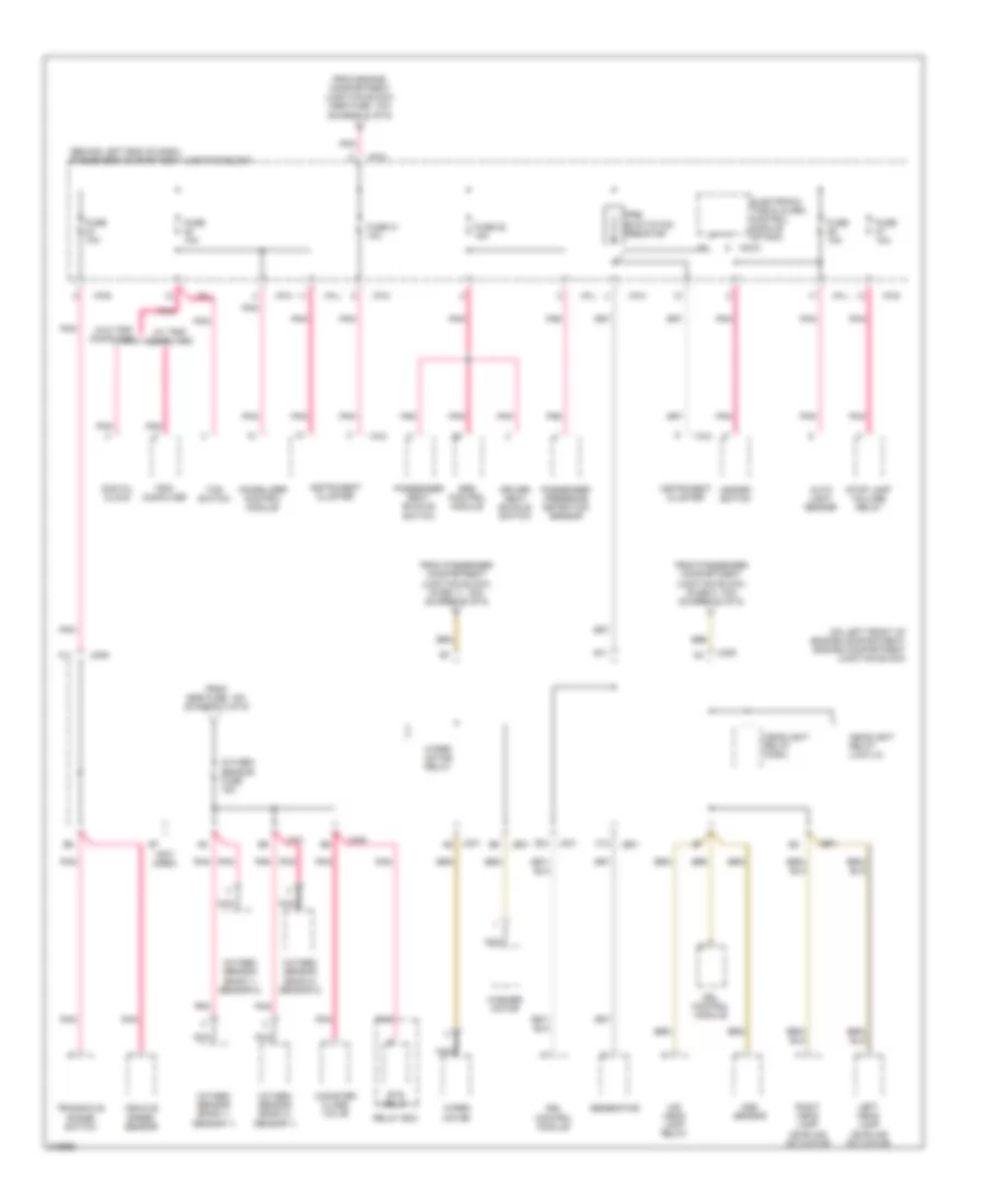
Power Distribution Wiring Diagram (2 of 6) for Hyundai XG350 2005
List of elements for Power Distribution Wiring Diagram (2 of 6) for Hyundai XG350 2005:
- (on left front of engine compartment) engine compartment junction block
- (w/ jbl amp)
- (w/o jbl amp)
- A/c compressor fuse 10a
- A/c fan relay 1
- A/c fan relay 2
- A/c relay
- A/t pulse generator-a
- A/t pulse generator-b
- Abs control module
- Abs fuse 10a
- Air bleeding connector
- Audio amp module 2 (w/o jbl amp) audio amp module 1 (w/ jbl amp)
- B10
- Blower fuse 30a
- Blower relay
- C44-3
- D12
- Data link connector (dlc)
- Engine compartment junction block (on left front of engine compartment)
- Engine control relay
- Engine controls system
- F10
- F11
- From abs fusible a link 2, 30a (diagram 1 of 6)
- From ignition switch (diagram 1 of 6)
- Home link connector (w/ home link)
- Horn fuse 15a
- Horn relay
- I/p-a
- I/p-b
- I/p-e
- I/p-m
- Ignition coil fuse 20a
- Ignition failure sensor
- Injector
- Injector fuse 10a
- Jc01
- Jm09
- Left vanity lamp
- Limp home valve
- M136
- M137
- M98-2
- Main fuse 30a
- Overhead console lamp
- Passenger compartment junction block (behind left end of dash)
- Pcm
- Pnk
- Power amp fuse 20a
- Radiator fan relay
- Red
- Right vanity lamp
- Sunroof controller
- Sunroof fuse 15a
- Tan
- To drl fuse, 15a (diagram 6 of 6)
- To egr fuse, 15a (diagram 3 of 6)
- To passenger compartment junction block (fuse 21, 10a) (diagram 4 of 6)
- W/ sunroof
- W/o sunroof
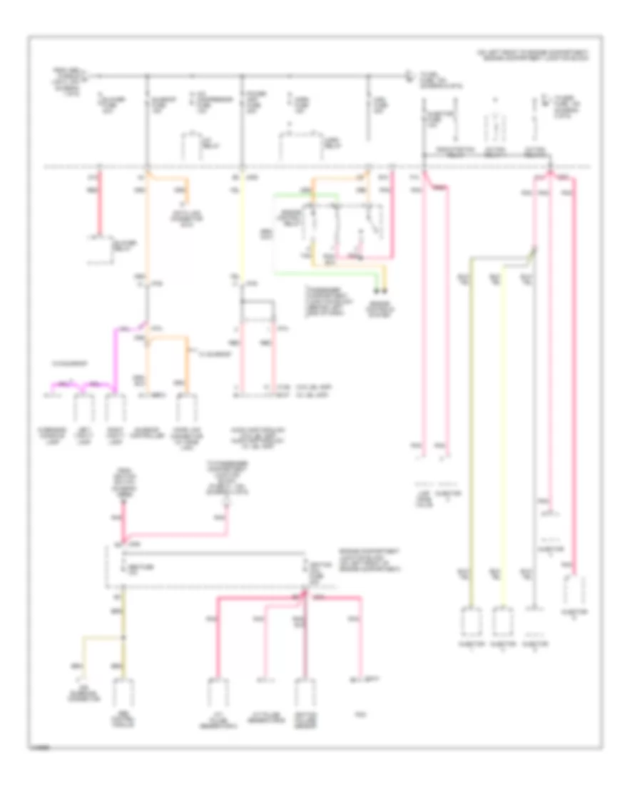
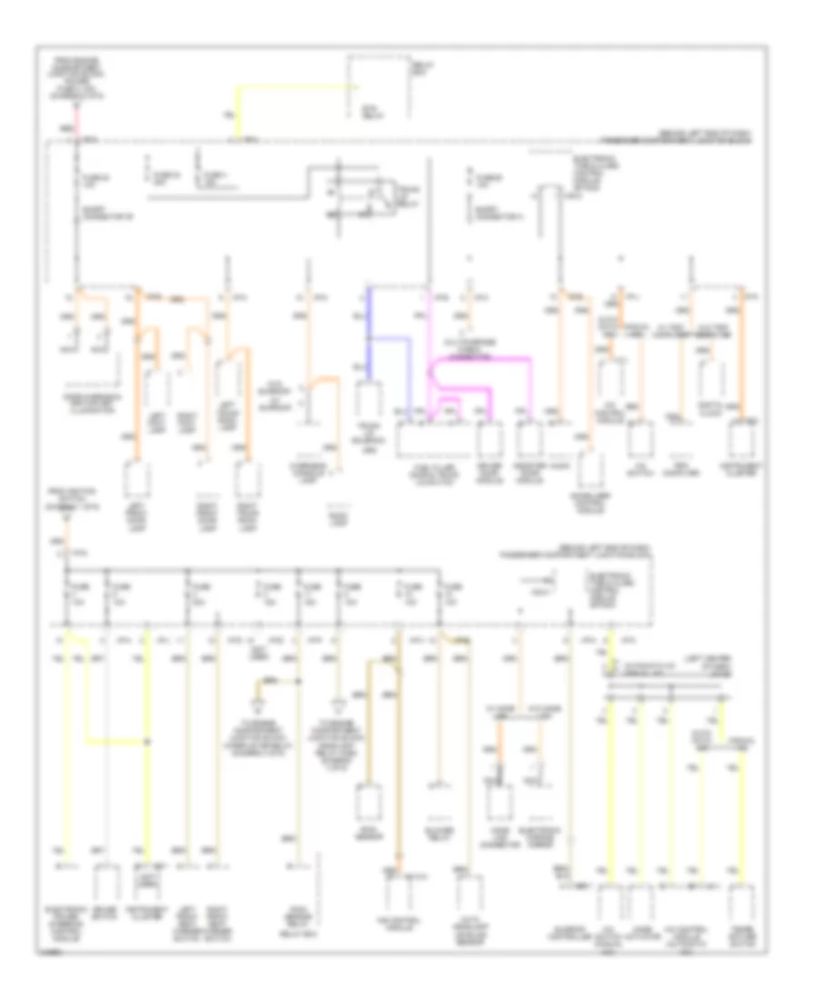
Power Distribution Wiring Diagram (3 of 6) for Hyundai XG350 2005
List of elements for Power Distribution Wiring Diagram (3 of 6) for Hyundai XG350 2005:
- (diagram 6 of 6)
- (not used)
- (on left front of engine compartment) engine compartment junction block
- (under right front seat) j/c m78
- A/c control module
- A/c control switch
- A/c relay
- Automatic a/c
- B12
- C10
- Camshaft position sensor
- Condenser
- Crankshaft position sensor
- D10
- D11
- Defogger relay
- Diversity antenna
- Driver power seat switch
- E10
- Egr fuse 15a
- Egr solenoid
- Electronic time & alarm control module (etacm)
- From fuel pump fuse, 20a h
- From injector fuse, 10a (diagram 2 of 6)
- Fuse 10a
- Fuse 15a
- Fuse 20a
- Fuse 25a
- Fuse 30 10a
- Hazard relay
- Hazard switch
- I/p-a
- I/p-b
- I/p-d
- I/p-e
- I/p-g
- I/p-k
- I/p-p
- I17-1
- J/c m36 (upper right end of dash)
- Jc01
- Jm09
- Left outside mirror motor
- Left rear door lamp
- Left rear personal lamp
- M33-3
- M77-1
- Manual a/c
- Mass air flow sensor
- Nca
- Passenger compartment junction block (behind left end of dash)
- Passenger power seat switch
- Pnk
- Power fuse 1 30a
- Power fuse 2 30a
- Purge control solenoid valve
- Rear defogger fuse 30a
- Red
- Relay box
- Right outside mirror motor
- Right rear door lamp
- Right rear personal lamp
- Stop lamp failure relay
- Stop lamp switch
- To oxygen sensor fuse, 15a (diagram 4 of 6)
- To passenger compartment junction block (fuse 20, 10a) (diagram 5 of 6)
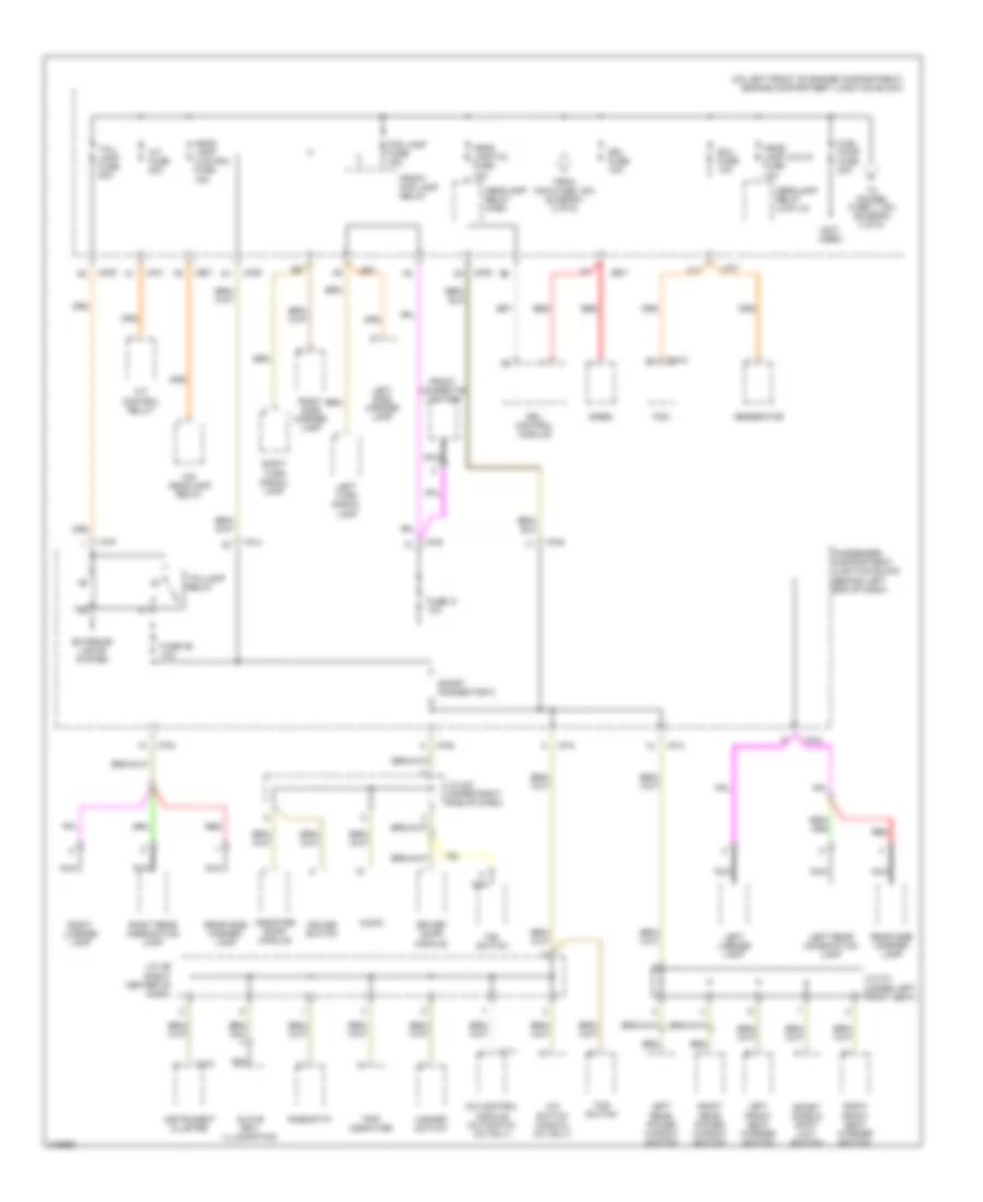
Power Distribution Wiring Diagram (4 of 6) for Hyundai XG350 2005
List of elements for Power Distribution Wiring Diagram (4 of 6) for Hyundai XG350 2005:
- (behind left end of dash) passenger compartment junction block
- (not used)
- (on left front of engine compartment) engine compartment junction block
- (w/ trip computer)
- (w/o trip computer)
- A11
- Aqs sensor
- Auto light sensor
- C12
- Canister close valve
- Digital clock
- Driver seat buckle switch
- Drl control module
- E11
- E12
- Electronic time & alarm control module (etacm)
- Ets relay
- From egr fuse, 15a (diagram 3 of 6)
- From engine compartment junction block (abs fuse, 10a) (diagram 2 of 6)
- From passenger compartment junction block, (fuse 11, 15a) (diagram 5 of 6)
- From passenger compartment junction block, (fuse 5, 10a) (diagram 5 of 6)
- Fuse 10a
- Fuse 21 10a
- Fuse 22 15a
- Generator
- Hazard switch
- Headlight relay (high)
- Headlight relay (low-lh)
- Hid head lamp relay
- I/p-b
- I/p-d
- I/p-g
- I/p-h
- I/p-j
- I/p-k
- I/p-l
- I18-2
- Immobilizer control module
- Instrument cluster
- Jc01
- Jc01 a6
- Je01
- Jm09
- Left head lamp leveling actuator
- M33-3
- Nca
- Oxygen sensor (bank 1/ sensor 1)
- Oxygen sensor (bank 1/ sensor 2)
- Oxygen sensor (bank 2/ sensor 1)
- Oxygen sensor (bank 2/ sensor 2)
- Oxygen sensor fuse 15a
- Passenger presence detection sensor
- Passenger seat buckle switch
- Pnk
- Pre- excitation resistor
- Relay box
- Right head lamp leveling actuator
- Srs control module
- Stop lamp failure relay
- Tcs switch
- Transaxle range switch
- Trip computer
- Vehicle speed sensor
- Washer motor
- Wiper motor
- Wiper motor relay
Power Distribution Wiring Diagram (5 of 6) for Hyundai XG350 2005
List of elements for Power Distribution Wiring Diagram (5 of 6) for Hyundai XG350 2005:
- (behind left end of dash) passenger compartment junction block
- (left center of dash) j/c i20
- (not used)
- (w/ sunroof)
- (w/o sunroof)
- A/c control module
- A/c control module (automatic a/c)
- A/c switch
- A/c switch (manual a/c)
- Assister door module
- Audio
- Auto headlamp leveling sensor
- Auto- matic a/c
- Automatic a/c manual a/c
- Blower relay
- Cruise switch
- Digital clock
- Door warning & ignition key illumination
- Driver door module
- Electronic chrome mirror
- Electronic power steering control module
- Electronic time & alarm control module (etacm)
- Ets relay
- From engine compartment junction block, power fuse 2, 30a (diagram 3 of 6)
- From ignition switch (diagram 1 of 6)
- Fuel filler door & trunk lid switch
- Fuse 10a
- Fuse 15a
- Fuse 20 10a
- Fuse 20a
- Fuse 24 20a
- Fuse 25 10a
- Fuse 4 15a
- Home link connector
- I/p-a
- I/p-d
- I/p-e
- I/p-g
- I/p-h
- I/p-j
- I/p-k
- I/p-m
- I/p-p
- I17-1
- I18-1
- I18-2
- Immobilizer control module
- Ims control module
- Instrument cluster
- Left foot lamp
- Left front door lamp
- Left front seat warmer switch
- Left trunk room lamp
- M110-4
- M33-3
- M98-1
- Manual a/c
- Mode actuator
- Multipurpose check connector
- Nca
- Overhead console lamp
- Rain sensor
- Rain sensor relay
- Red
- Relay box
- Right foot lamp
- Right front door lamp
- Right front seat warmer switch
- Right trunk room lamp
- Room lamp
- Short connector "b"
- Short connector a
- Sunroof controller
- Tempe- rature switch
- To engine compartment junction block, headlight relay (high) (diagram 4 of 6)
- To engine compartment junction block, wiper motor relay (diagram 4 of 6)
- Trip computer
- Trunk lid relay
- Trunk lid solenoid
- W/ home link
- W/ trip computer
- W/o home link
- W/o trip computer
Power Distribution Wiring Diagram (6 of 6) for Hyundai XG350 2005
List of elements for Power Distribution Wiring Diagram (6 of 6) for Hyundai XG350 2005:
- (not used)
- (on left front of engine compartment) engine compartment junction block
- A/c control module (automatic a/c only)
- A/c switch (manual a/c only)
- A/t control relay
- A/t fuse 20a
- Assister door module
- Audio
- C11
- C44-2
- Cruise switch
- Driver door module
- Drl control module
- Drl fuse 15a
- Ecu fuse 10a
- Exterior lights system
- Fog lamp fuse 15a
- From main fuse, 30a (diagram 2 of 6)
- Front cigarette lighter
- Front fog lamp relay
- Fuel pump fuse 20a
- Fuse 26 10a
- Fuse 31 10a
- Generator
- Glove box illumination
- Hazard switch
- Head lamp (hi) fuse 15a
- Head lamp (lo-lh) fuse 15a
- Head lamp (low-rh) fuse 15a
- Headlamp relay (high)
- Headlamp relay (low-lh)
- Hid headlamp relay
- I/p-a
- I/p-b
- I/p-d
- I/p-e
- I/p-h
- I/p-k
- I/p-p
- I17-1
- I18-2
- Ims switch
- Instrument cluster
- J/c i29 (right center of dash)
- J/c m37 (upper right side of dash)
- J/c m71 (under left front seat)
- Jc01
- Je01
- Jm09
- Jm09 c8
- Left front seat warmer switch
- Left license lamp
- Left rear combination lamp
- Left rear power window switch
- Left side marker lamp
- Left turn signal lamp
- Nca
- Passenger compartment junction block (behind left end of dash)
- Pcm
- Rear side marker lamp
- Red
- Rheostat
- Right front seat warmer switch
- Right license lamp
- Right rear combination lamp
- Right rear power window switch
- Right side marker lamp
- Right turn signal lamp
- Short connector c
- Siren
- Sport mode & shift limit switch
- Tail lamp fuse 20a
- Taillamp relay
- Tcs switch
- To power fuse 1, 30a (diagram 3 of 6)
- Trip computer
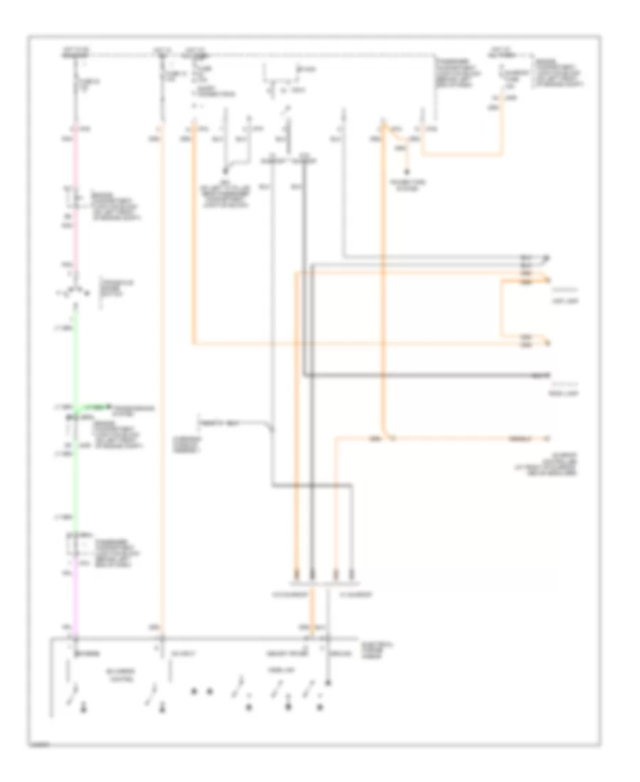
POWER DOOR LOCKS
Power Door Locks Wiring Diagram for Hyundai XG350 2005
List of elements for Power Door Locks Wiring Diagram for Hyundai XG350 2005:
- (w/ ims)
- (w/o ims)
- Assister door module (integral with power window/ door switch assembly, on right front door)
- Cpu
- D03
- D04
- D05
- D29
- D30
- Door lock knob
- Driver door module (integral with power window/ door switch assembly, on left front door)
- Etacm
- Fuse 20a
- G03 (on left "a" pillar, near passenger compt junction block)
- G05 (on right "a" pillar, near crash bar)
- G07 (at left floorpanel crossmember)
- G09 (on right side of package shelf)
- Hot at all times
- I/p-a
- I/p-b
- I/p-e
- I30
- Ims control module (under left front seat)
- J/c d12 (front of left front door)
- J/c d13 (front of right front door)
- Left door unlock switch
- Left front door lock actuator (rear of left front door)
- Left rear door lock actuator (rear of left rear door)
- Lock
- M110-3
- M33-1
- M33-3
- Nca
- Passenger compartment junction block (behind left end of dash)
- Right door unlock switch
- Right front door lock actuator (rear of right front door)
- Right rear door lock actuator (rear of right rear door)
- Signal ground
- Srs control module (under center console)
- Tan
- Unlock
- Unlock/ lock input
- W/ ims
- W/o ims
POWER MIRRORS
Electrochromic Mirror Wiring Diagram, with Home Link for Hyundai XG350 2005
List of elements for Electrochromic Mirror Wiring Diagram, with Home Link for Hyundai XG350 2005:
- 15a
- A11
- A4 jm09
- Control
- Ec mirror
- Electrical chrome mirror
- Engine compartment junction block (on left front of engine compt)
- Etacm
- Fuse
- Fuse 10a
- Fuse 12 10a
- Fuse 23 10a
- G03 (on left "a" pillar, near passenger compartment junction block)
- Ground
- Home link
- Hot at all times
- Hot in on
- Hot in on or start
- I/p-b
- I/p-h
- I/p-m
- I/p-p
- Jc01
- Jm09
- M33-3
- Map lamp
- Memory power
- Nca
- On input
- Overhead console assembly
- Passenger compartment junction block (behind left end of dash)
- Pnk
- Power tops system
- Reverse
- Room lamp
- Short connector b
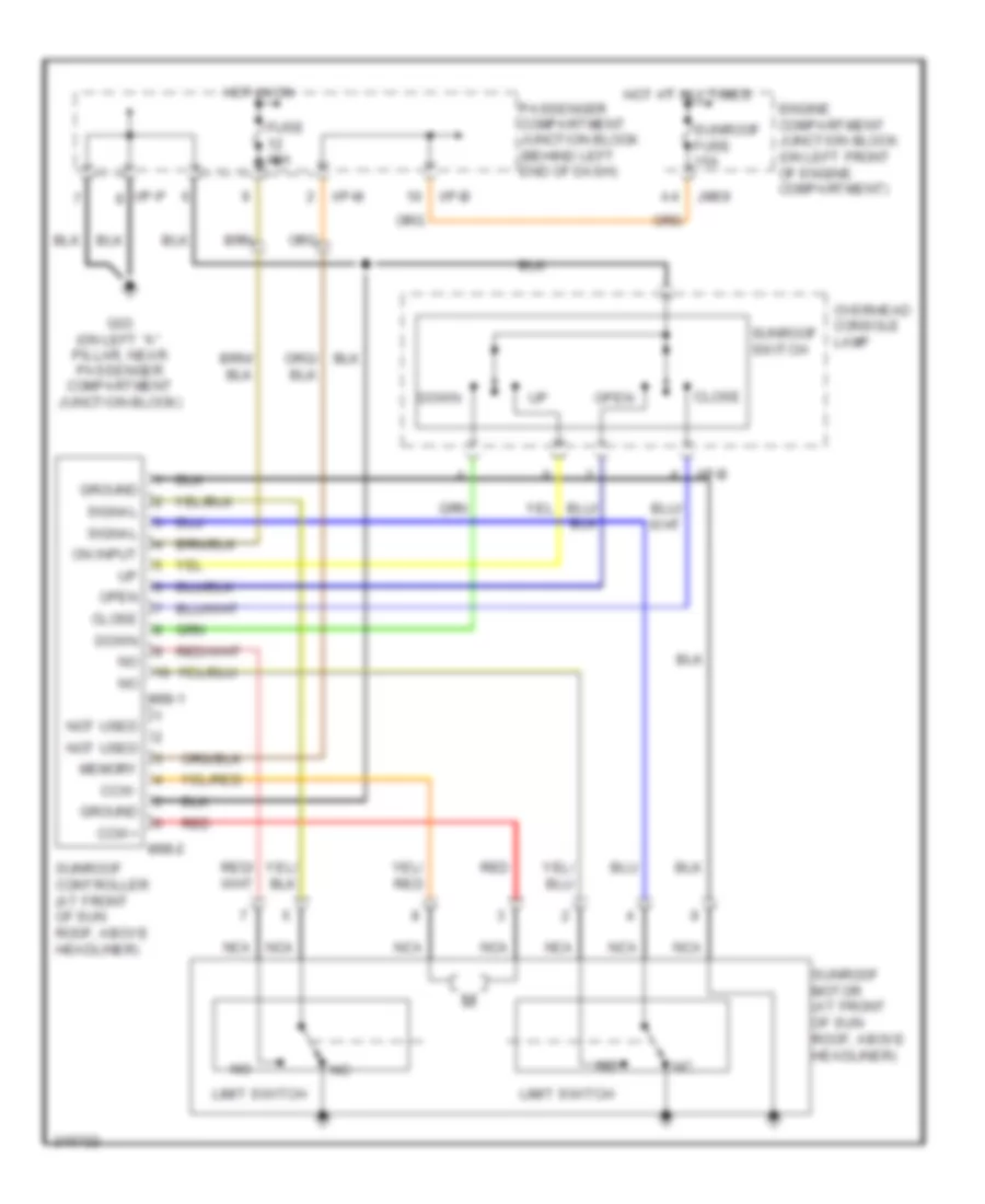
- Sunroof
- Sunroof controller (at front of sunroof, above headliner)
- Transaxle range switch
- Transmissions system
- W/ sunroof
- W/o sunroof
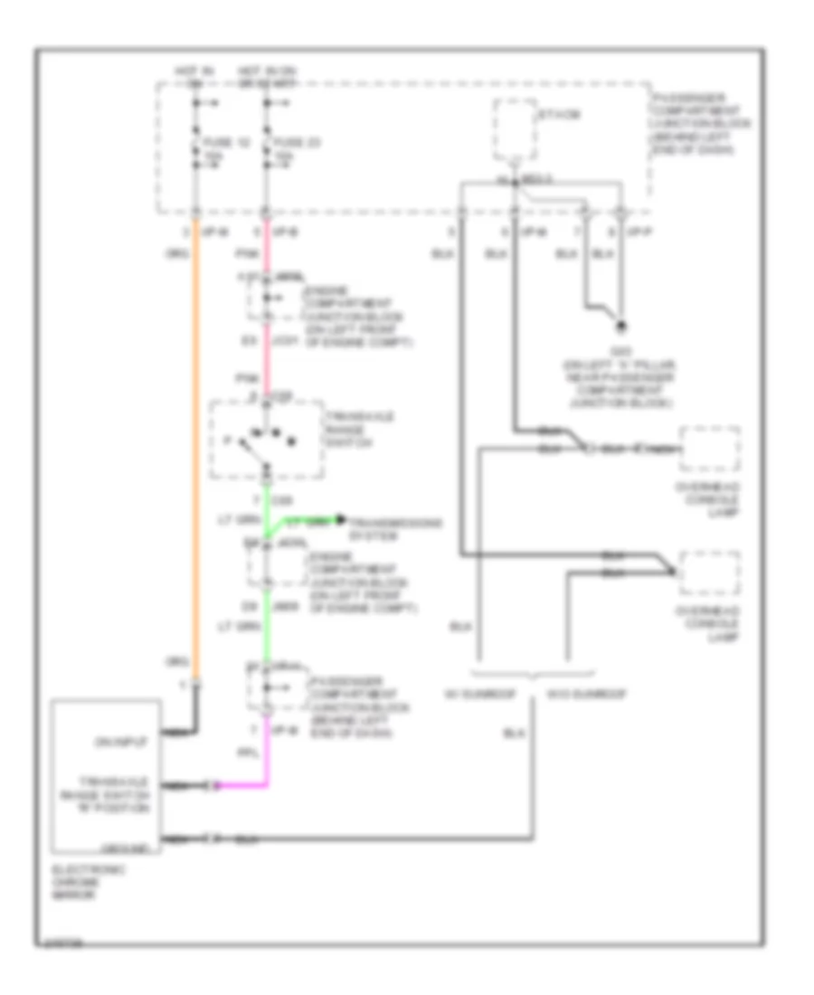
Electrochromic Mirror Wiring Diagram, without Home Link for Hyundai XG350 2005
List of elements for Electrochromic Mirror Wiring Diagram, without Home Link for Hyundai XG350 2005:
- A11
- C09
- Electronic chrome mirror
- Engine compartment junction block (on left front of engine compt)
- Etacm
- Fuse 12 10a
- Fuse 23 10a
- G03 (on left "a" pillar, near passenger compartment junction block)
- Ground
- Hot in on
- Hot in on or start
- I/p-b
- I/p-h
- I/p-m
- I/p-p
- Jc01
- Jm09
- M33-3
- Nca
- On input
- Overhead console lamp
- Passenger compartment junction block (behind left end of dash)
- Pnk
- Transaxle range switch
- Transaxle range switch "r" position
- Transmissions system
- W/ sunroof
- W/o sunroof
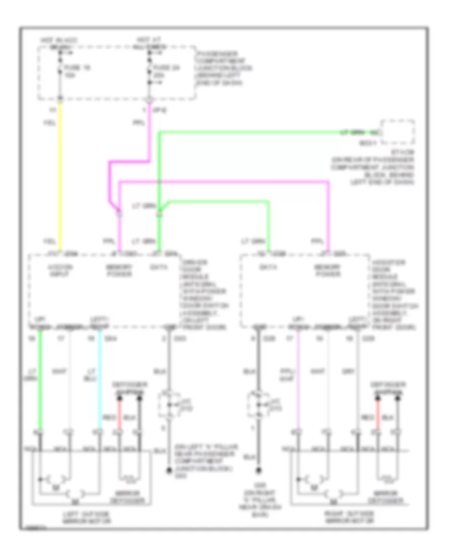
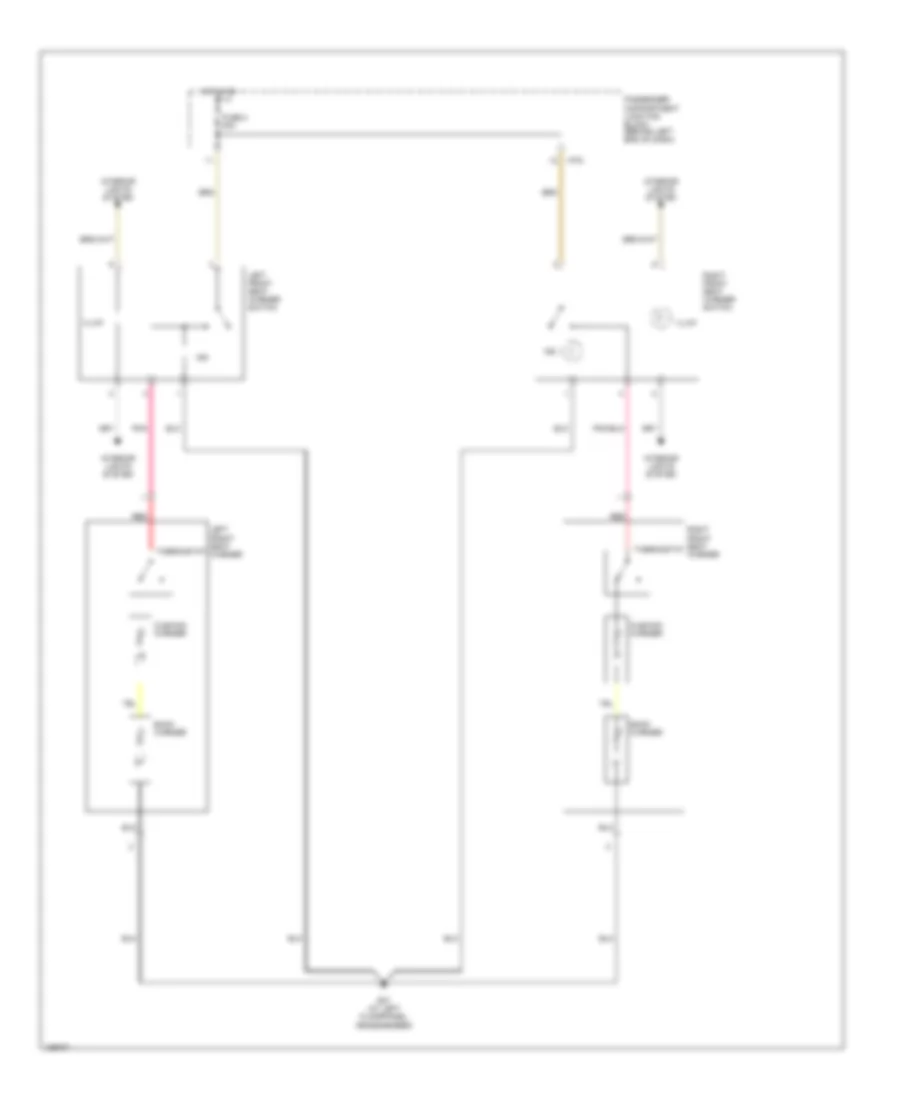
Power Mirrors Wiring Diagram for Hyundai XG350 2005
List of elements for Power Mirrors Wiring Diagram for Hyundai XG350 2005:
- (on left "a" pillar, near passenger compartment junction block) g03
- Acc/on input
- Assister door module (integral with power window/ door switch assembly, on right front door)
- Common
- D03
- D04
- D28
- D29
- Data
- Defogger system
- Driver door module (integral with power window/ door switch assembly, on left front door)
- Etacm (on rear of passenger compartment junction block, behind left end of dash)
- Fuse 16 10a
- Fuse 24 20a
- G05 (on right "a" pillar, near crash bar)
- Gnd
- Hot at all times
- Hot in acc or on
- I/p-e
- J/c d12
- J/c d13
- Left outside mirror motor
- Left/ right
- M33-1
- Memory power
- Mirror defogger
- Nca
- Passenger compartment junction block (behind left end of dash)
- Red
- Right outside mirror motor
- Up/ down
POWER SEATS
Heated Seats Wiring Diagram for Hyundai XG350 2005
List of elements for Heated Seats Wiring Diagram for Hyundai XG350 2005:
- Back warmer
- Cushion warmer
- Fuse 2 20a
- G07 (at left floorpanel crossmember)
- Hot in on
- I/p-d
- Illum
- Ind
- Interior lights system
- Left front seat warmer
- Left front seat warmer switch
- Passenger compartment junction block (behind left end of dash)
- Pnk
- Red
- Right front seat warmer
- Right front seat warmer switch
- Thermostat
Power Seats Wiring Diagram for Hyundai XG350 2005
List of elements for Power Seats Wiring Diagram for Hyundai XG350 2005:
- Back
- Condenser (under left front seat)
- Down
- Driver power seat adjust switch
- Forward
- Front height
- Front height adjust motor
- Fuse 1 25a
- G07 (at left floorpanel crossmember)
- Hot at all times
- I/p-d
- Nca
- Passenger compartment junction block (behind left end of dash)
- Passenger power seat adjust switch
- Rear height
- Rear height adjust motor
- Reclining
- Reclining adjust motor
- Red
- Slide
- Slide adjust limit switch
- Slide adjust motor
- Slide adjust motor (under left side of left front seat)
POWER TOP/SUNROOF
Power Top/Sunroof Wiring Diagram for Hyundai XG350 2005
List of elements for Power Top/Sunroof Wiring Diagram for Hyundai XG350 2005:
- Ccw+
- Ccw-
- Close
- Down
- Engine compartment junction block (on left front of engine compartment)
- Fuse 10a
- G03 (on left "a" pillar, near passenger compartment junction block)
- Ground
- Hot at all times
- Hot in on
- I/p-b
- I/p-m
- I/p-p
- Jm09
- Limit switch
- M98-1
- M98-2
- Memory
- Nca
- Not used
- On input
- Open
- Overhead console lamp
- Passenger compartment junction block (behind left end of dash)
- Red
- Signal
- Sunroof controller (at front of sun roof, above headliner)
- Sunroof fuse 15a
- Sunroof motor (at front of sun roof, above headliner)
- Sunroof switch
POWER WINDOWS
Power Windows Wiring Diagram (1 of 2) for Hyundai XG350 2005
List of elements for Power Windows Wiring Diagram (1 of 2) for Hyundai XG350 2005:
- (on left ``a" pillar, near passenger compt junction block) g03
- (w/ ims)
- (w/o ims)
- Assister door module (integral with power window/ door switch assembly, on right front door)
- Cpu
- D04
- D05
- D29 (w/o ims)
- D30 (w/ ims)
- Data
- Down relay
- Driver door module (integral with power window/ door switch assembly, on left front door)
- Engine compartment junction block (on left front of engine compt)
- Etacm
- Etacm (under left side of dash)
- Fuse 20a
- G05 (on right ``a" pillar, near crash bar)
- Hot at all times
- I/p-a
- I/p-b
- I/p-e
- Ill
- Illumination
- Interior lights system
- Jm10
- Joint connector d12 (front of left front door)
- Joint connector d13 (front of right front door)
- Left front auto switch
- Left front power window motor
- Left rear
- M33-1
- M33-3
- Memory system
- Nca
- Passenger compartment junction block (behind left end of dash)
- Power window fusible link 40a
- Power window relay
- Red
- Right front auto switch
- Right front power window motor
- Right rear
- Unlk
- Up relay
- Up/down switch
- Window lock switch
Power Windows Wiring Diagram (2 of 2) for Hyundai XG350 2005
List of elements for Power Windows Wiring Diagram (2 of 2) for Hyundai XG350 2005:
- Down relay
- Etacm (on rear of passenger compt junction block, behind left end of dash)
- G07 (at left floorpanel crossmember)
- G09 (on right side of package shelf)
- Ill
- Interior lights system
- Left rear power window motor
- Left rear power window switch
- M33-1
- M33-2
- Main sw dn
- Main sw up
- Nca
- Relay ctrl
- Right rear power window motor
- Right rear power window switch
- Up relay
- Up/down switch
RADIO
Radio Wiring Diagram, JBL System for Hyundai XG350 2005
List of elements for Radio Wiring Diagram, JBL System for Hyundai XG350 2005:
- Acc/on input
- Antenna
- Audio
- Audio amplifier module 1 & 2 (right rear side of trunk room)
- Control circuit
- Diversity antenna
- Engine compartment junction block (on left front of engine compartment)
- F/cable
- Feeder cable
- Fuse 14 10a
- Fuse 25 10a
- G04 (under center of dash, on center support bracket)
- G09 (on right side of package shelf)
- Gnd
- Ground
- Hot at all times
- Hot in acc or on
- I/p-a
- I/p-e
- Ill (+)
- Ill (-)
- Interior lights system
- Jm09
- Joint connector m64 (right side of trunk room)
- Left front speaker
- Left front spkr
- Left rear speaker
- Left rear spkr
- Left tweeter speaker
- Lf speaker
- Lr speaker
- M136-1
- M136-2
- M77-2
- Mem pwr
- Memory power
- Nca
- Passenger compartment junction block (behind left end of dash)
- Pnk
- Power amp fuse 20a
- Red
- Remote ctrl
- Rf speaker
- Right front speaker
- Right front spkr
- Right rear speaker
- Right rear spkr
- Right tweeter speaker
- Rr speaker
- Short connector ``a"
- Signal input
- Tan
Radio Wiring Diagram, with Amplified Speakers for Hyundai XG350 2005
List of elements for Radio Wiring Diagram, with Amplified Speakers for Hyundai XG350 2005:
- Acc/on input
- Antenna
- Audio
- Audio amplifier module 1 & 2 (right rear side of trunk room)
- Control circuit
- Diversity antenna
- Engine compartment junction block (on left front of engine compartment)
- F/cable
- Feeder cable
- Fuse 14 10a
- Fuse 25 10a
- G04 (under center of dash, on center support bracket)
- G09 (on right side of package shelf)
- Gnd
- Ground
- Hot at all times
- Hot in acc or on
- I/p-a
- I/p-e
- Ill (+)
- Ill (-)
- Interior lights system
- Jm09
- Joint connector m64 (right side of trunk room)
- Left front speaker
- Left front spkr
- Left rear speaker
- Left rear spkr
- Left tweeter speaker
- Lf speaker
- Lr speaker
- M135-1
- M135-2
- M77-2
- Mem pwr
- Memory power
- Nca
- Passenger compartment junction block (behind left end of dash)
- Pnk
- Power amp fuse 20a
- Red
- Remote ctrl
- Rf speaker
- Right front speaker
- Right front spkr
- Right rear speaker
- Right rear spkr
- Right tweeter speaker
- Rr speaker
- Short connector ``a"
- Signal input
- Tan
Radio Wiring Diagram, without Amplifier for Hyundai XG350 2005
List of elements for Radio Wiring Diagram, without Amplifier for Hyundai XG350 2005:
- Acc/on in
- Ant
- Audio
- Control circuit
- Diversity antenna
- F/cable
- Feeder cable
- Fuse 14 10a
- Fuse 25 10a
- G04 (under center of dash, on center support bracket)
- Ground
- Hot at all times
- Hot in on or acc
- I/p-e
- Ill (+)
- Ill (-)
- Interior lights system
- Left front speaker
- Left rear speaker
- Left tweeter speaker
- Lf speaker
- Lr speaker
- M77-2
- Mem pwr
- Nca
- Passenger compartment junction block (behind left end of dash)
- Rf speaker
- Right front speaker
- Right rear speaker
- Right tweeter speaker
- Rr speaker
- Short connector"a"
- Tan
STARTING/CHARGING
Charging Wiring Diagram for Hyundai XG350 2005
List of elements for Charging Wiring Diagram for Hyundai XG350 2005:
- (on left front of engine compt) engine compartment junction block
- Battery
- Battery ground
- C11
- C12
- Charge indicator
- E11
- Ecu fuse 10a
- Etacm
- Fuse 10a
- Fusible link 140a
- Generator
- Hot in on or start
- I/p-h
- I/p-j
- I18-2
- Instrument cluster
- Jc01
- Jm09
- M33-3
- Nca
- Passenger compartment junction block (behind left end of dash)
- Pnk
- Pre- excitation resistor
Starting Wiring Diagram for Hyundai XG350 2005
List of elements for Starting Wiring Diagram for Hyundai XG350 2005:
- 87a
- Acc
- Battery
- Battery ground
- Burglar alarm relay
- Burglar alarm relay control
- C44-2
- Engine compartment junction block (on left front of engine compt)
- Etacm
- Fuse 10a
- G11 (on firewall, near throttle housing)
- I/p-p
- Ignition fusible link 1 30a
- Ignition fusible link 2 30a
- Ignition switch
- Jc01
- Je01
- Jm09
- Jm10
- Lock
- M33-3
- N d
- Off
- Park/neutral input
- Passenger compartment relay box (behind left end of dash, on support bracket)
- Pcm (behind lower center of dash)
- Red
- Start
- Start motor
- Start relay
- Start solenoid
- Transaxle range switch
SUPPLEMENTAL RESTRAINTS
Supplemental Restraints Wiring Diagram for Hyundai XG350 2005
List of elements for Supplemental Restraints Wiring Diagram for Hyundai XG350 2005:
- (on left "b" pillar,
- (on right "b" pillar,
- Clock spring
- Crash output
- D05
- Data link connector (dlc) (below left side of dash)
- Diagnosis
- Driver air bag
- Driver door module (in drivers door)
- Driver satellite sensor (below left "b" pillar, on floorpan)
- Driver seat belt
- Driver seat buckle switch (on driver seat belt buckle)
- Driver side air bag
- Fuse 10a
- Fuse 15a
- G10 (under center console, near srs control module)
- Ground
- High
- Hot in on or start
- I/p-a
- I/p-b
- I/p-h
- I/p-j
- I/p-k
- I/p-l
- I18-2
- Instrument cluster
- Low
- Multifunction switch
- Nca
- On seat belt reel)
- Passenger air bag (right side of dash)
- Passenger compartment junction block (behind left end of dash)
- Passenger detection
- Passenger presence detection sensor (under right side of passenger seat)
- Passenger satellite sensor (below right "b" pillar, on floorpan)
- Passenger seat belt
- Passenger seat buckle switch (on passenger seat belt buckle)
- Passenger seat)
- Passenger side air bag (under right side of
- Pnk
- Pretensioner
- Red
- Signal
- Srs control module (below center console)
- Srs indicator
- Srs indicator (air bag)
- Start/in input
- Start/on
- Steering wheel
TRANSMISSION
A/T Wiring Diagram (1 of 2) for Hyundai XG350 2005
List of elements for A/T Wiring Diagram (1 of 2) for Hyundai XG350 2005:
- (on top right side of transaxle) vehicle speed sensor
- A11
- Accelerator position sensor (on throttle body)
- Anti lock brakes system
- Aps sig
- Body computer, electronic power steering, instrument cluster systems
- C02
- C11
- C44-1
- C44-2
- C44-3
- C44-4
- Data link connector (below left side of dash)
- Ecm fuse 10a
- Engine compartment junction block (on left front of engine compt)
- Engine coolant temperature sensor & sender (on rear of engine)
- Etc sen
- Ets control module (behind center of dash, on support bracket)
- Exterior lights system
- Flash (eci)
- Fuse 10a
- Fuse 15a
- G04 (under center of dash, on center support bracket)
- G11 (on fire- wall, near throttle housing)
- G13 (under center console, right of srs control module)
- G14 (under center console, at right rear of srs control module)
- Ground
- Hot at all times
- Hot in on or start
- I/p-b
- I/p-e
- I/p-h
- Idle sw
- Ignition coil fuse 20a
- Immobilizer
- Immobilizer control module (left center of dash)
- Input speed
- J/c c42 (lower left center of dash)
- Jc01
- Jm09
- K-line
- Memory pwr
- Multipurpose check connector (at lower left side of dash)
- On/start in
- Output speed
- Passenger compartment junction block (behind left end of dash)
- Pcm (behind lower center of dash)
- Pnk
- Pulse generator a (on top of transaxle)
- Pulse generator b (on transaxle)
- Sens +5v
- Sens gnd
- Sens pwr
- Sensor
- Spark
- Stop lamp switch (above brake pedal, on bracket)
- Stop sw in
- Throttle position sensor (on left side of throttle body)
- Tps
- Tps sig
- Vss in
- W/o
A/T Wiring Diagram (2 of 2) for Hyundai XG350 2005
List of elements for A/T Wiring Diagram (2 of 2) for Hyundai XG350 2005:
- (behind left end of dash)
- 2nd solenoid
- A/t control relay (behind lower center of dash, behind pcm)
- A/t fuse 20a
- A/t rly ctrl
- A/t solenoid
- Batt
- C44-2
- C44-3
- C44-4
- D-in
- Dcc solenoid
- Down shift
- Engine comp- artment junction block (on left front of engine compt)
- G05 (on right "a" pillar, near crash bar)
- G07 (at left floorpanel crossmember)
- G14 (under center console, at right rear of srs control module)
- Ground
- Hot at all times
- I/p-h
- I18-1
- I18-2
- I18-3
- Instrument cluster
- Interior lights system
- J/c i28 (upper right side of dash)
- Jc01
- Jm09
- Memory system
- Micro computer
- N-in
- Normal
- Oil temp sen
- Oil temp sensor
- P-in
- Passenger compartment junction block i/p-k
- Pcm (behind lower center of dash)
- Pnk
- Pwm
- R-in
- Red
- Red solenoid
- Select
- Select sw
- Select switch
- Solenoid
- Sport mode & shift limit switch
- Starting/ charging system
- Transaxle range switch
- Ud solenoid
- Up shift
TRUNK, TAILGATE, FUEL DOOR
Trunk, Tailgate, Fuel Door Wiring Diagram for Hyundai XG350 2005
List of elements for Trunk, Tailgate, Fuel Door Wiring Diagram for Hyundai XG350 2005:
- Etacm
- Fuel filler actuator (on left side of trunk, behind trim panel)
- Fuel filler door & trunk lid switch
- Fuel filler switch
- Fuse 20a
- G08 (on left side of package shelf)
- Hot at all times
- I/p-e
- Instrument cluster system
- J/c m99 (left side of trunk room)
- M33-2
- M33-3
- Passenger compartment junction block (behind left end of dash)
- Trunk lid relay
- Trunk lid solenoid (on center of trunk, beside latch)
- Trunk lid switch
- Trunk lid unlock switch (right rear corner of trunk lid)
WARNING SYSTEMS
Warning Systems Wiring Diagram for Hyundai XG350 2005
List of elements for Warning Systems Wiring Diagram for Hyundai XG350 2005:
- Chime bell
- Door ajar ind
- Door sw in
- Door warn sw
- Door warning buzzer
- Etacm
- Fuse 12 10a
- Fuse 20 10a
- Fuse 25 10a
- Fuse 28 10a
- Fuse 29 10a
- G03 (on left "a" pillar, near passenger compartment junction block)
- G07 (at left floorpanel crossmember)
- Ground
- Head
- Headlights system (w/ auto lights)
- Hot at all times
- Hot in on
- Hot in on or start
- I/p-a
- I/p-d
- I/p-e
- I/p-j
- I/p-k
- I/p-p
- I18-2
- Ignition key illumination & door warning switch
- Ill
- Illum ctrl
- Instrument cluster
- Interior lights system
- Joint connector m08 (left center of dash)
- Joint connector m39 (upper left side of dash)
- Left front door switch (left ``b" pillar)
- Light switch
- M01-1
- M33-1
- M33-2
- M33-3
- Memory pwr
- Multifunction switch
- Nca
- Off
- On input
- Park
- Passenger compartment junction block (behind left end of dash)
- Pnk
- Seat belt ind
- Seat belt sw
- Seat belt switch
- Short connector "a"
- Short connector "b"
- Start/on in
WIPER/WASHER
Wiper/Washer Wiring Diagram, with Rain Sensor for Hyundai XG350 2005
List of elements for Wiper/Washer Wiring Diagram, with Rain Sensor for Hyundai XG350 2005:
- (on firewall, near throttle housing) g11
- (on left ``a" pillar, near passenger compartment junction block) g03
- (under center of dash, on center support bracket) g04
- A12
- Delay control
- Engine compartment junction block (on left front of engine compartment)
- F12
- Fuse 10 10a
- Fuse 11 20a
- G02
- Gnd
- Hot in on
- I/p-h
- I/p-p
- Ims control module (under left front seat)
- Int
- Int (time)
- Jc01
- Je01
- Jm09
- Joint connector m08 (left center of dash)
- M01-2
- M110-4
- Mist switch
- Multifunction switch
- Nca
- Off
- On input
- Parking sw
- Passenger compartment junction block (behind left end of dash)
- Pnk
- Rain sensor (behind inside rearview mirror)
- Rain sensor relay
- Relay box
- Rly ctrl
- Washer input
- Washer motor (below right headlight)
- Washer switch
- Wiper motor
- Wiper motor (below left side of windshield)
- Wiper motor relay
- Wiper switch
Wiper/Washer Wiring Diagram, without Rain Sensor for Hyundai XG350 2005
List of elements for Wiper/Washer Wiring Diagram, without Rain Sensor for Hyundai XG350 2005:
- (on firewall, near throttle housing) g11
- (on left ``a" pillar, near passenger compartment junction block) g03
- (under center of dash, on center support bracket) g04
- A12
- Auto parking switch (shown with wipers at rest)
- Delay control
- Engine compartment junction block (on left front of engine compartment)
- Etacm (on rear of passenger compartment junction block, behind left end of dash)
- F12
- Fuse 11 20a
- G02
- Hot in on
- I/p-p
- Int
- Intermittent input
- Jc01
- Je01
- Jm09
- Joint connector m08 (left center of dash)
- M01-2
- M33-1
- M33-2
- Mist switch
- Multifunction switch
- Nca
- Off
- Passenger compartment junction block (behind left end of dash)
- Washer input
- Washer motor (below right headlight)
- Washer switch
- Wiper motor (below left side of windshield)
- Wiper motor relay
- Wiper switch