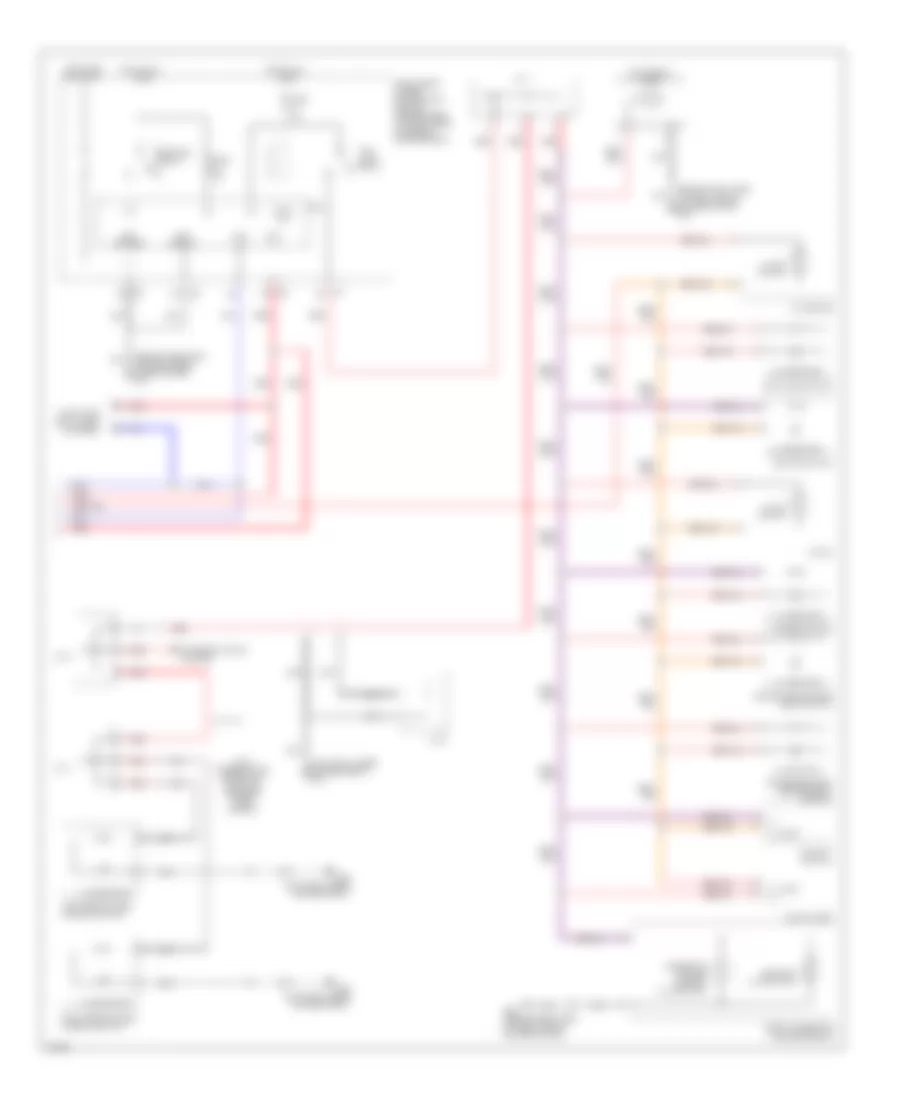
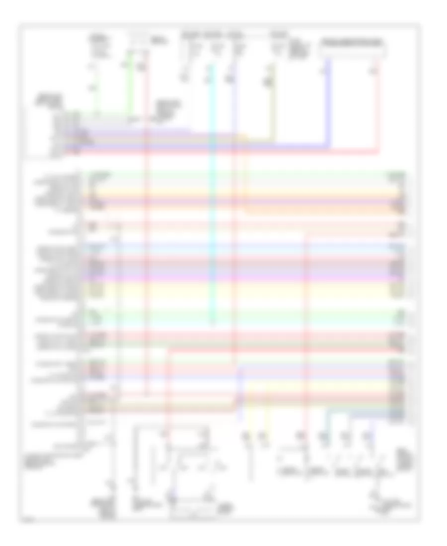
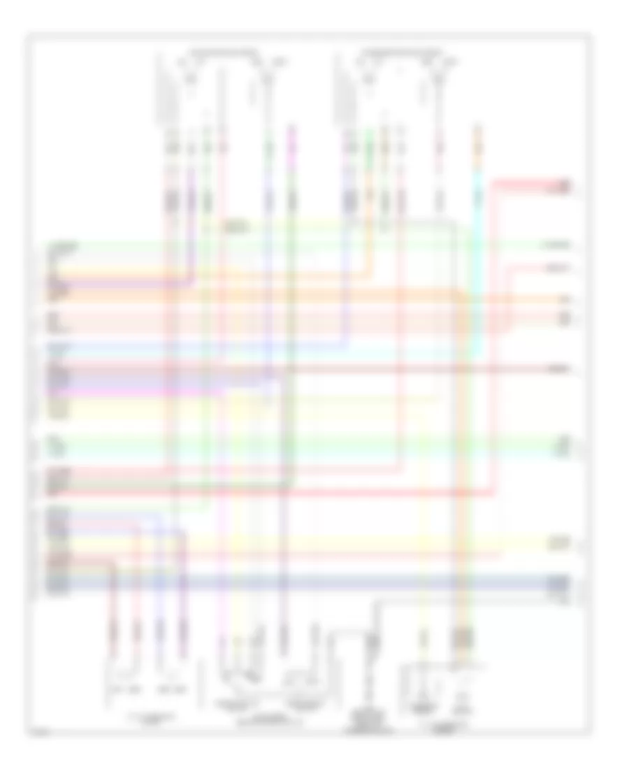
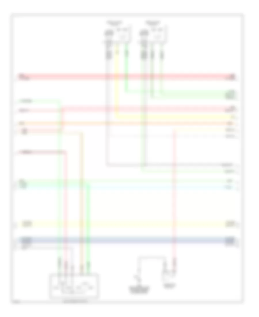
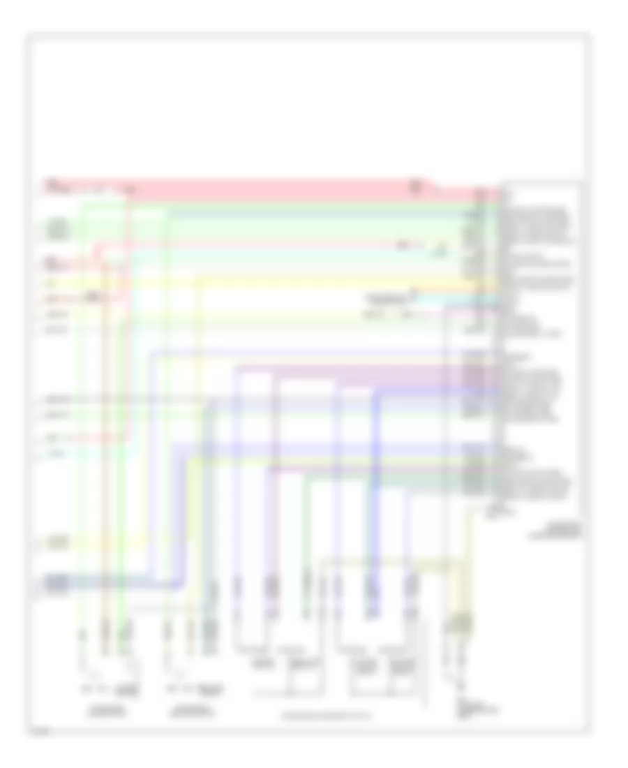
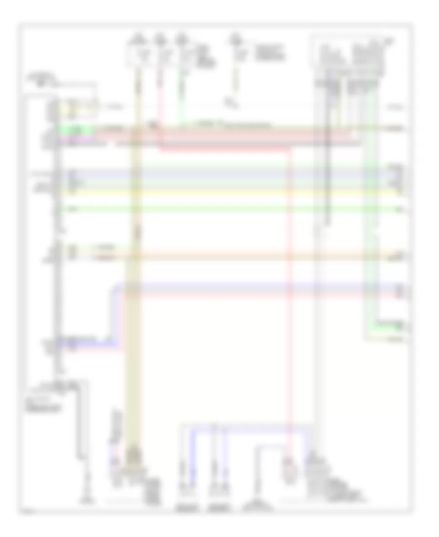
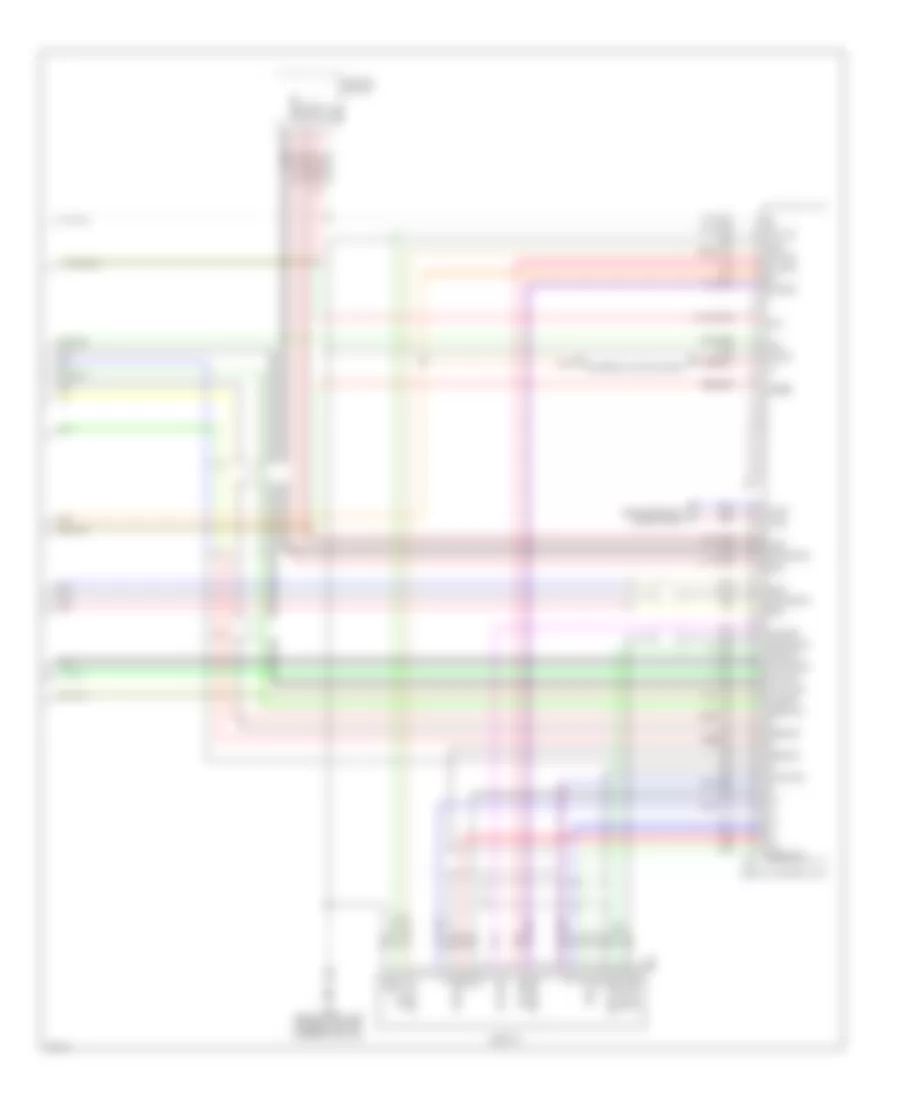
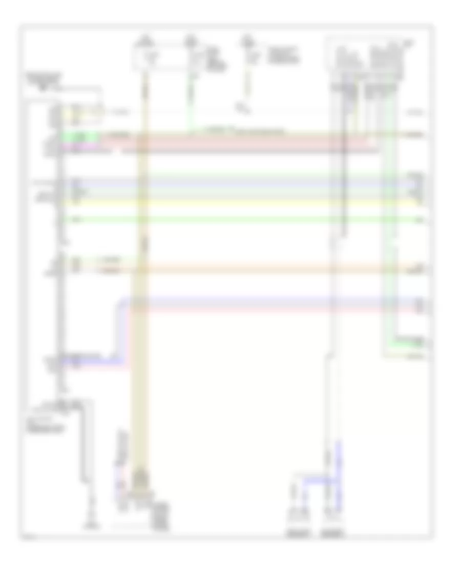
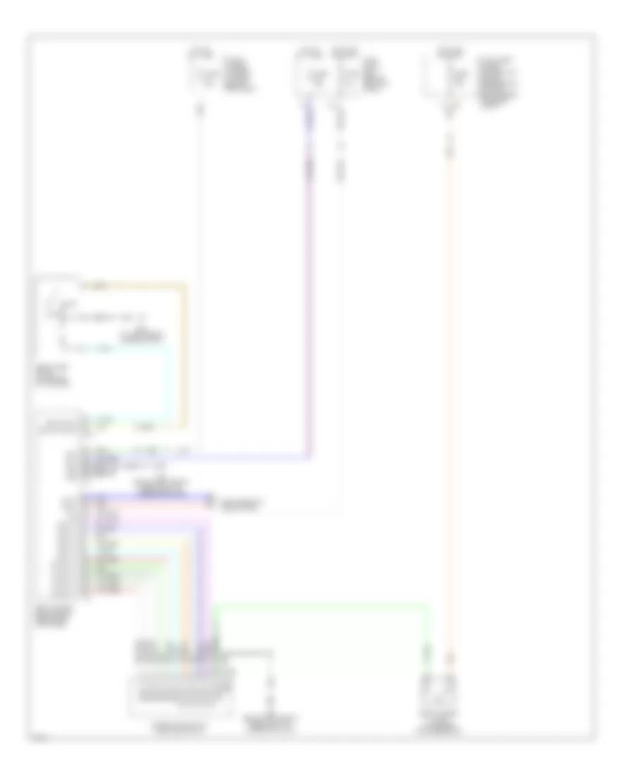
Diagram sections — 31 (73 total)
AIR CONDITIONING ANTI-LOCK BRAKES ANTI-THEFT BODY CONTROL MODULES COMPUTER DATA LINES COOLING FAN CRUISE CONTROL DEFOGGERS ENGINE PERFORMANCE EXTERIOR LIGHTS GROUND DISTRIBUTION HEADLIGHTS HORN INSTRUMENT CLUSTER INTERIOR LIGHTS MEMORY SYSTEMS NAVIGATION POWER DISTRIBUTION POWER DOOR LOCKS POWER MIRRORS POWER SEATS POWER TOP/SUNROOF POWER WINDOWS RADIO SHIFT INTERLOCK STARTING/CHARGING SUPPLEMENTAL RESTRAINTS TRANSMISSION TRUNK, TAILGATE, FUEL DOOR WARNING SYSTEMS WIPER/WASHER
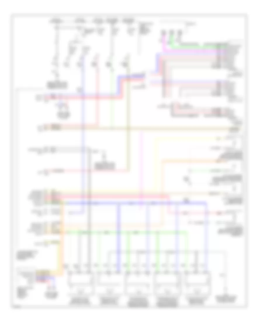
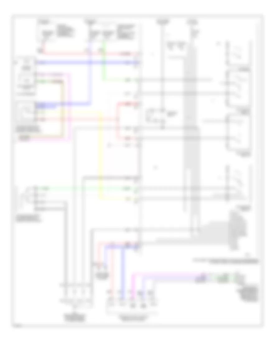
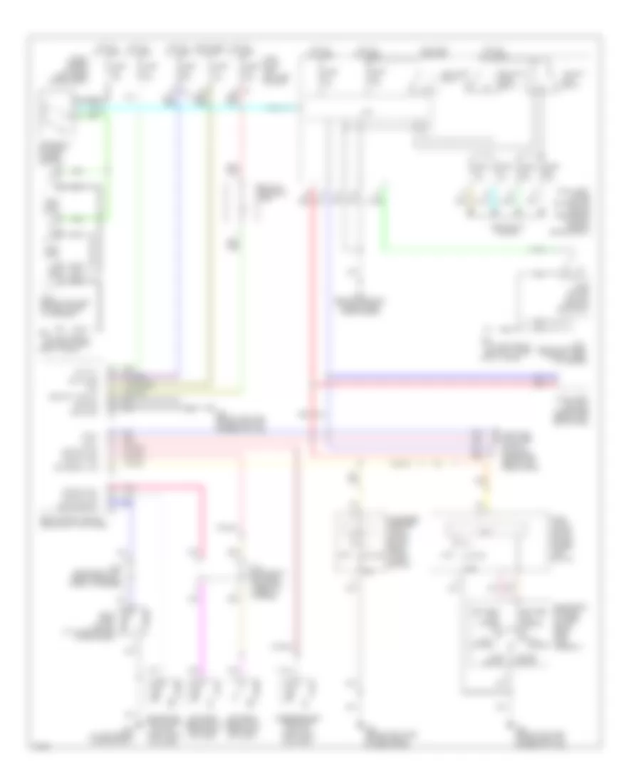
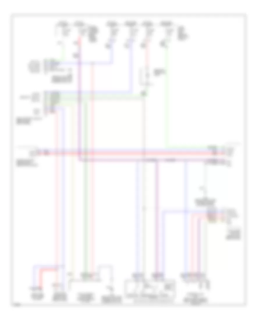
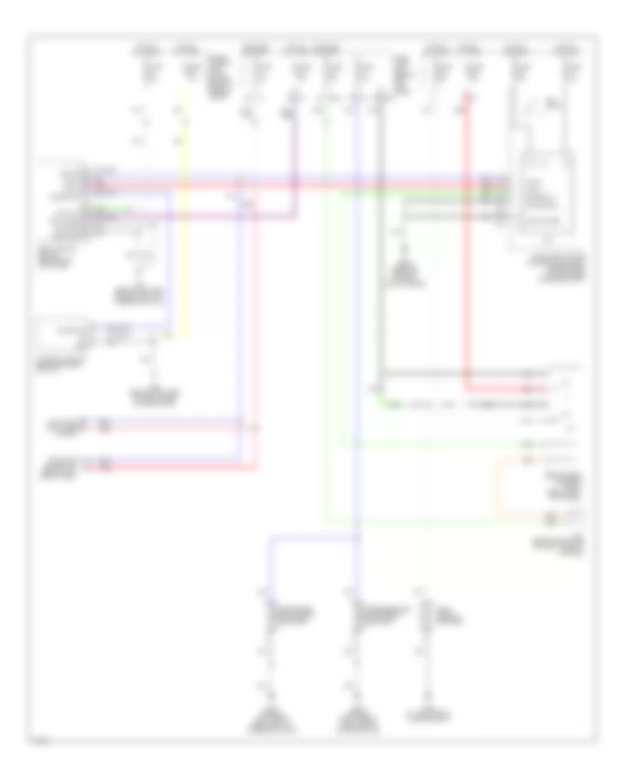
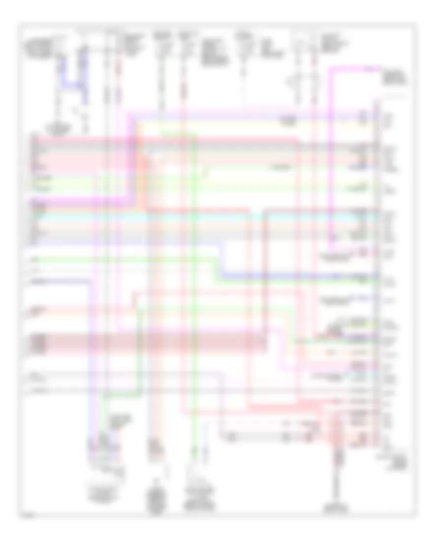
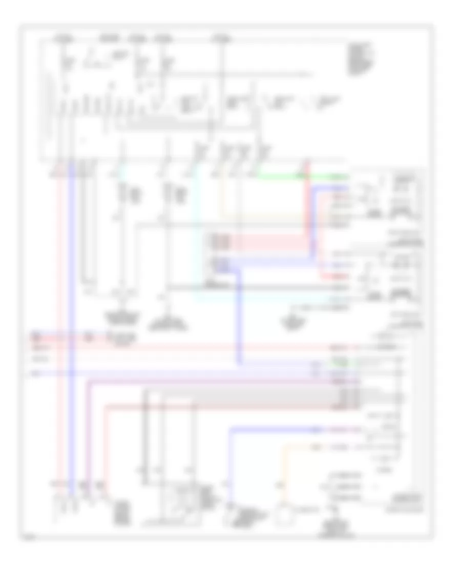
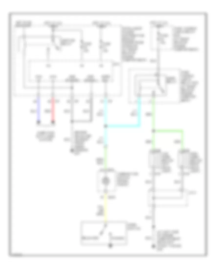
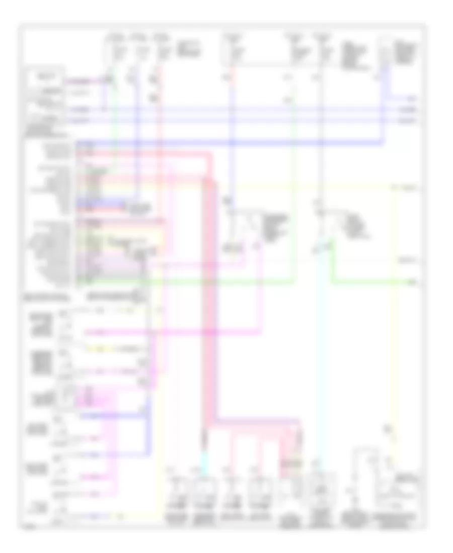
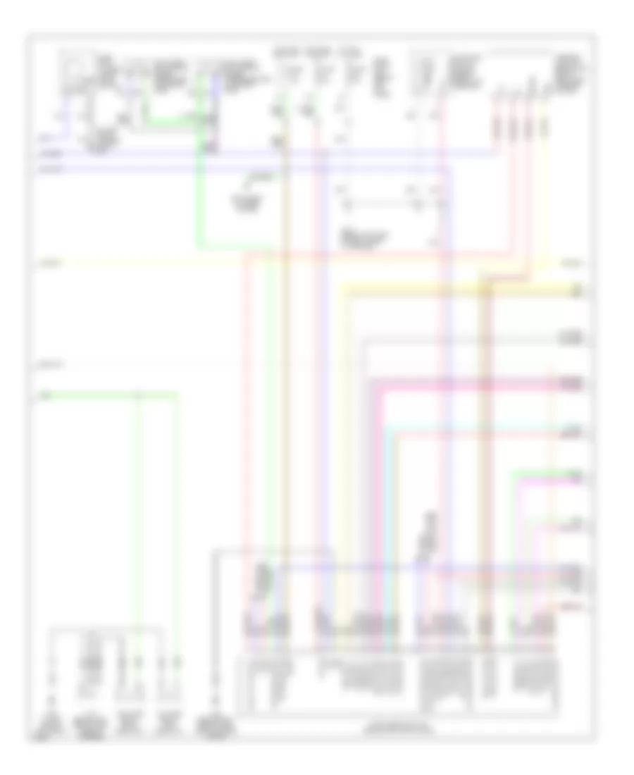
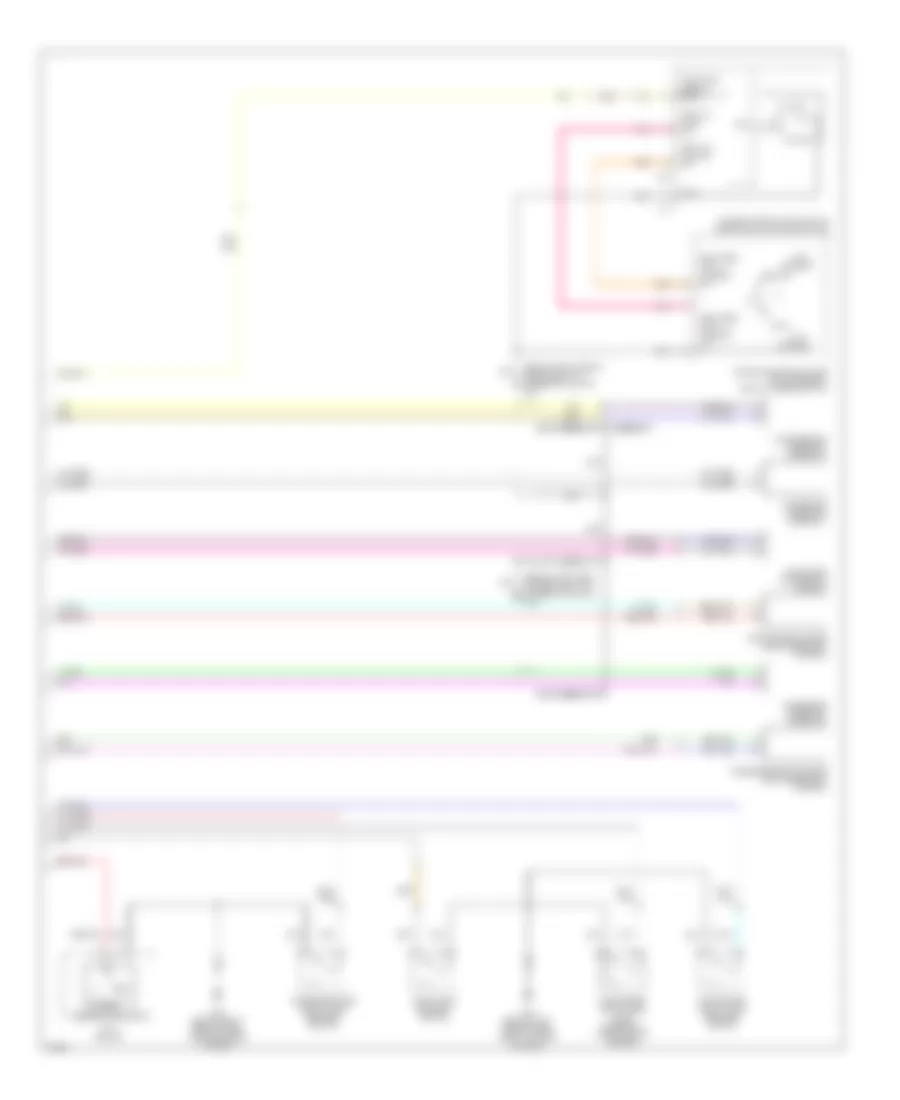
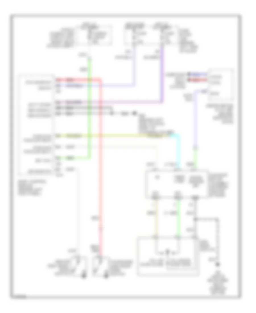
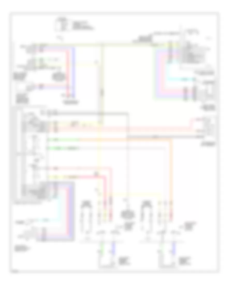
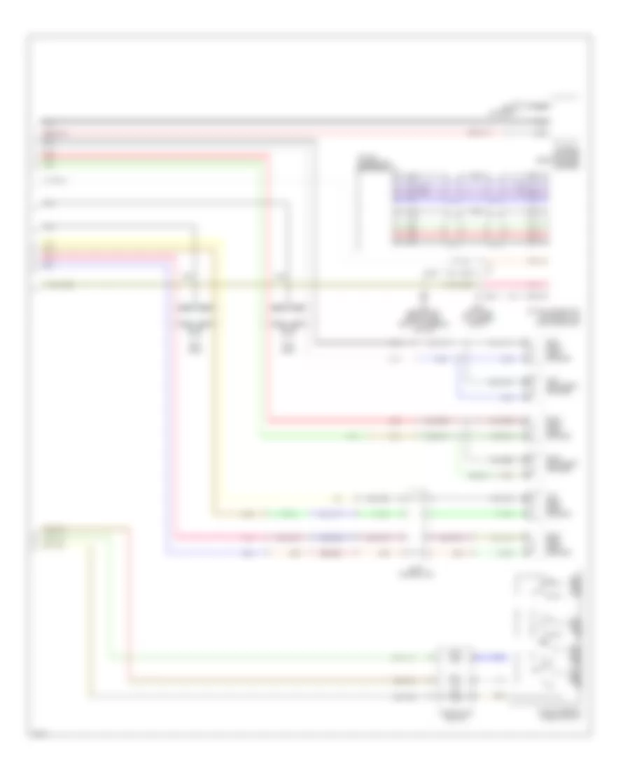
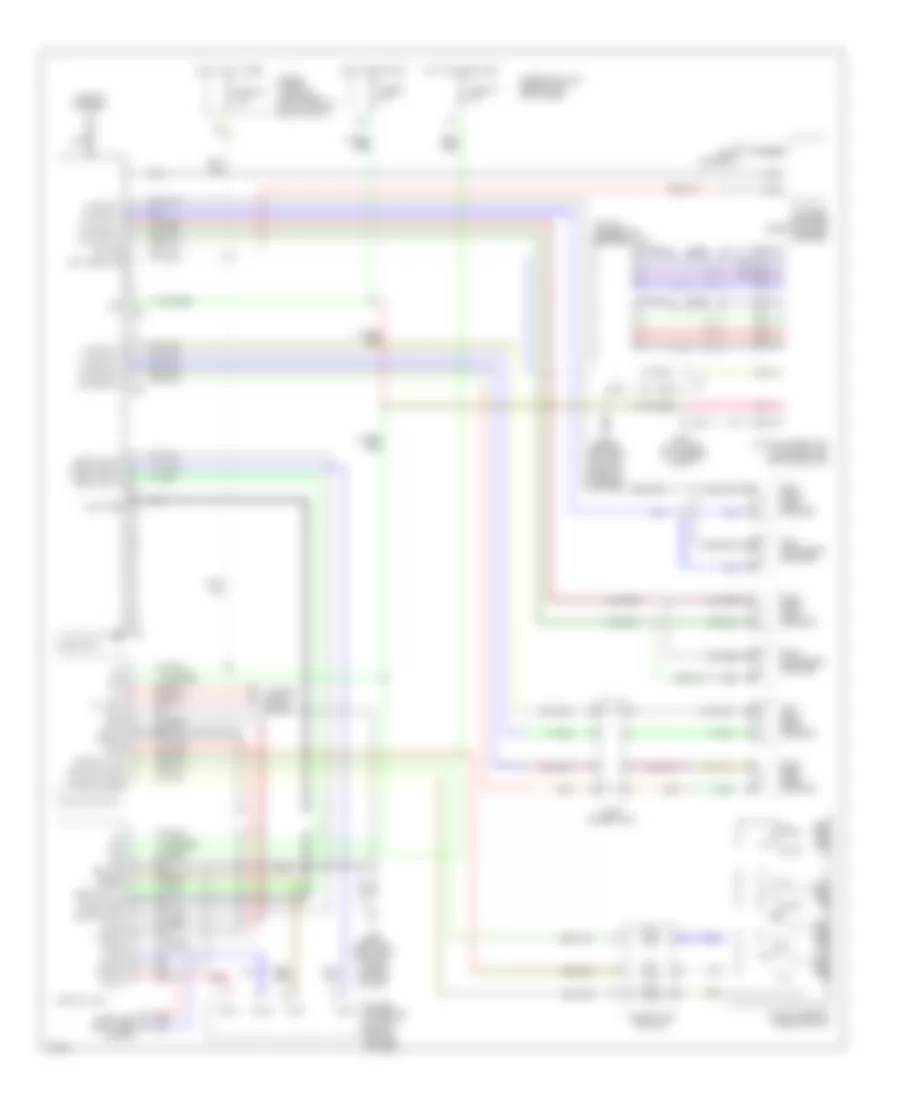
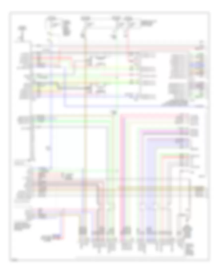
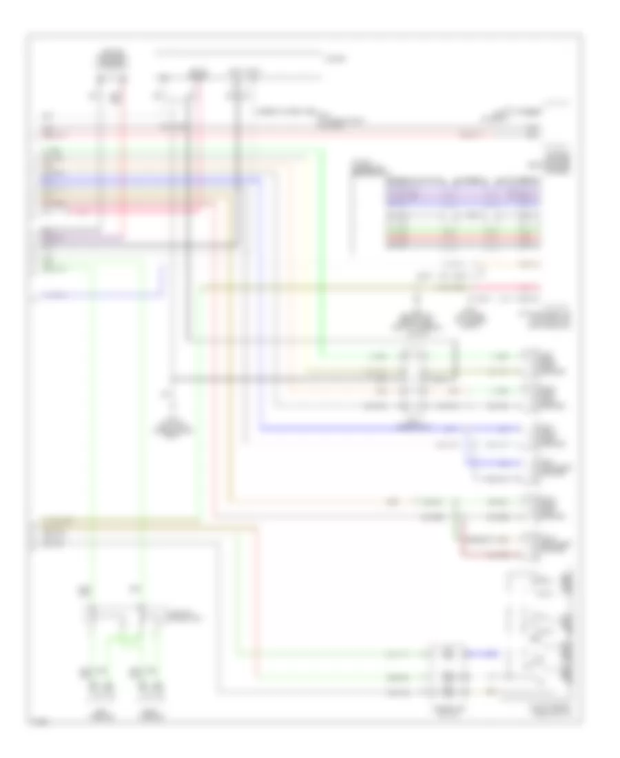
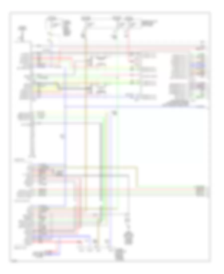
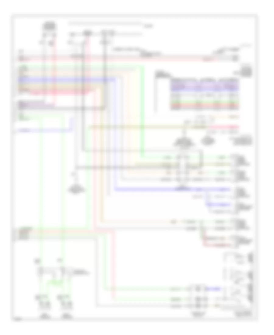
AIR CONDITIONING Automatic A/C Wiring Diagram (1 of 2) for Infiniti FX35 2003 List of elements for Automatic A/C Wiring Diagram (1 of 2) for Infiniti FX35 2003: 65 (power) gnd 12a A/c and av switch Acc Aircon sw Amb sens Ambient sensor (below lower left side of front grille) Bat Blower motor (behind lower right side of dash) Blower relay Blwr fan sw Body control module (behind left kick panel) Bus+ Bus- Can-h Can-l Comp ecv Comp on Computer data lines system Dcu- dsp Display Display control unit Display unit Driver side air mix door motor (behind lower left center of dash) Dsp gnd Dsp shield Dsp- dcu Dsp-dcu Dsu-dsp Fan on Fan pwm out Fuse 10a Fuse 15a Fuse block (j/b) (behind left kick panel) Gnd Hot at all times Hot in acc and on Hot in acc or start Hot in run or start Ign Ign2 In-vehicle sensor (behind left center of dash) Incar sens Intake door motor (behind right side of dash) Intake sens Intake sensor (behind right side of dash, on evaporator assembly) Lan sig M45 (behind left side of dash, right of steering column) M56 M57 M64 M85 (behind right side of dash, above blower motor) Mode door motor (behind left center of dash) Nca Passenger side air mix door motor (behind lower right center of dash) Pnk Red Sens gnd Shield Sun sens Sunload sensor (upper right side of dash, near base of windshield) Unified meter and a/c amplifier (behind center of dash) Vactr W/ navigation W/o navigation Automatic A/C Wiring Diagram (2 of 2) for Infiniti FX35 2003 List of elements for Automatic A/C Wiring Diagram (2 of 2) for Infiniti FX35 2003: 37 +batt +ign A/c compressor A/c relay Air comp Avcc gnd Can-h Can-l Computer data lines system Cooling fan motor 1 (at right front of engine compartment) Cooling fan motor 2 (at left front of engine compartment) Cooling fan relay-1 Cooling fan relay-2 Cooling fan relay-3 Cpu E21 (behind headlamp, on front right of inner fender) Ecv solenoid valve Engine control module (behind glove box) Fuse & fusible link & relay box (at right rear of engine compartment) Fuse 10a Fuse 15a Fusible link e 80a Fusible link g 40a Fusible link h 40a Fusible link holder (at right rear of engine compartment) Gnd-a Hot at all times Hot in run or start Ignition relay Intelligent power distribution module (engine room) (at right front of engine compartment) Magnet clutch Motor fan-1 Motor fan-2 Motor fan-3 Pd- pres Red Refrigerant pressure sensor (right front of engine compt, near radiator filler neck)
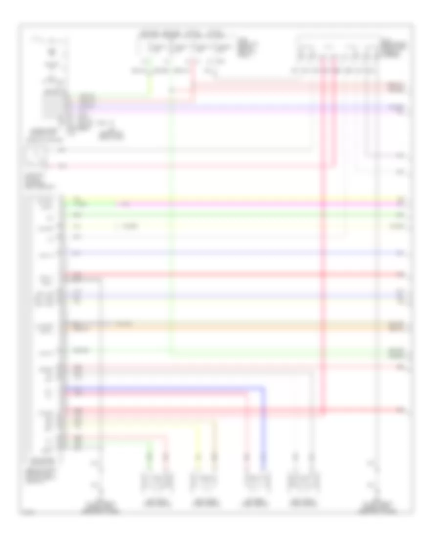
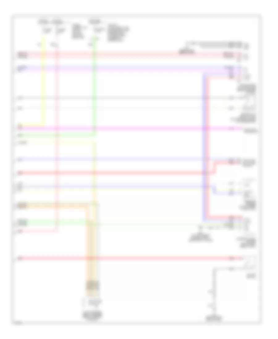
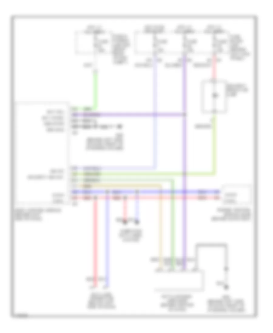
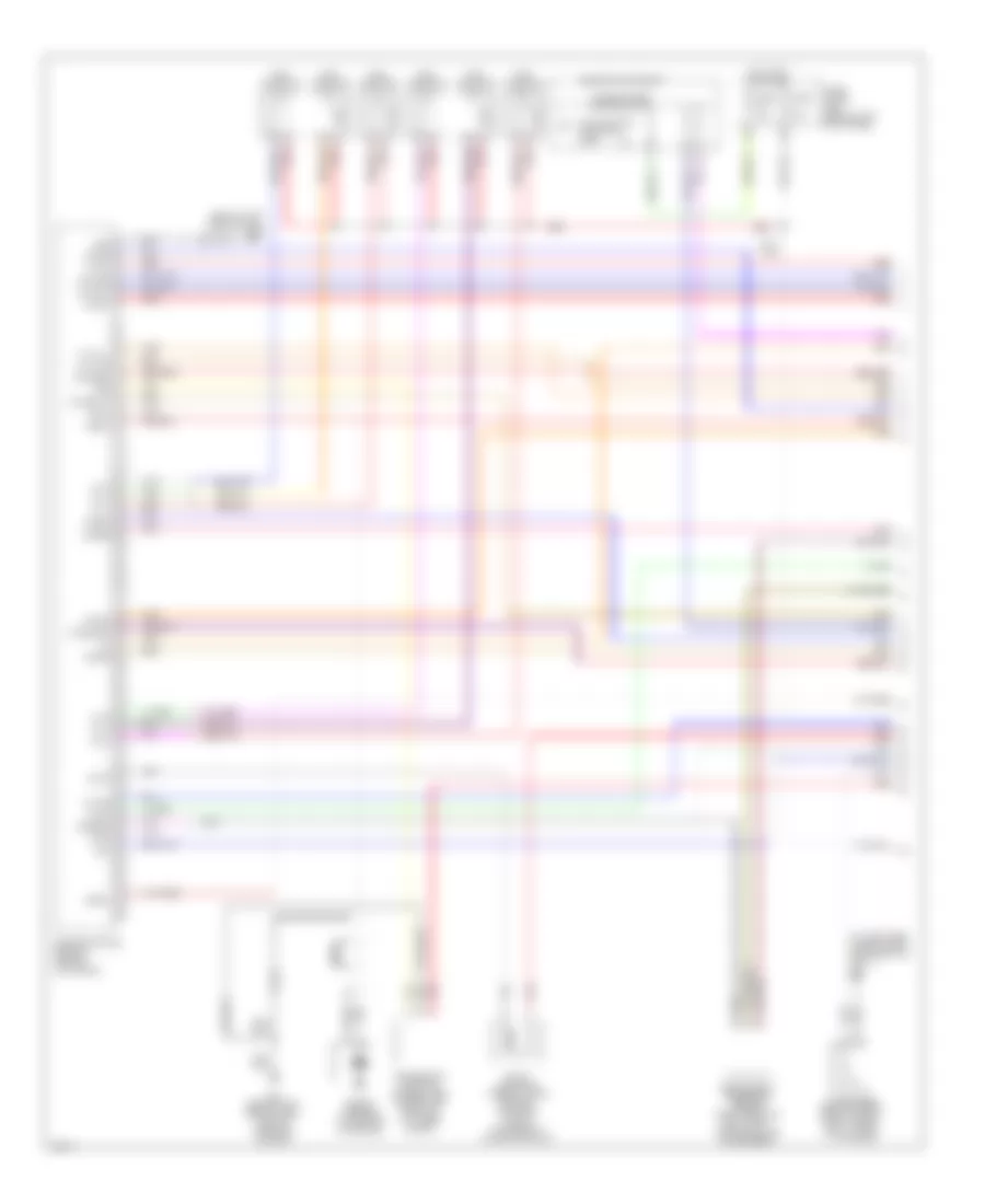
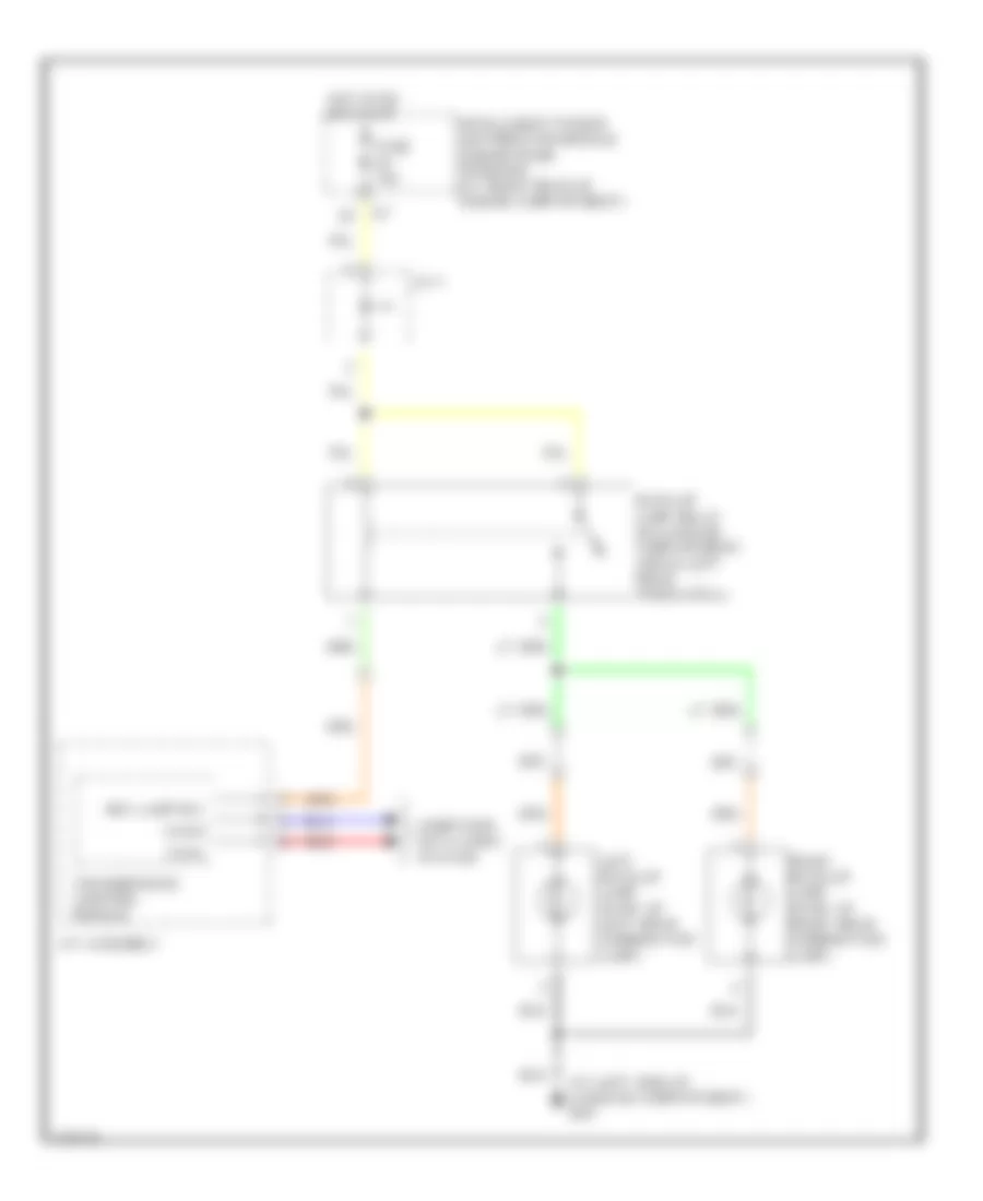
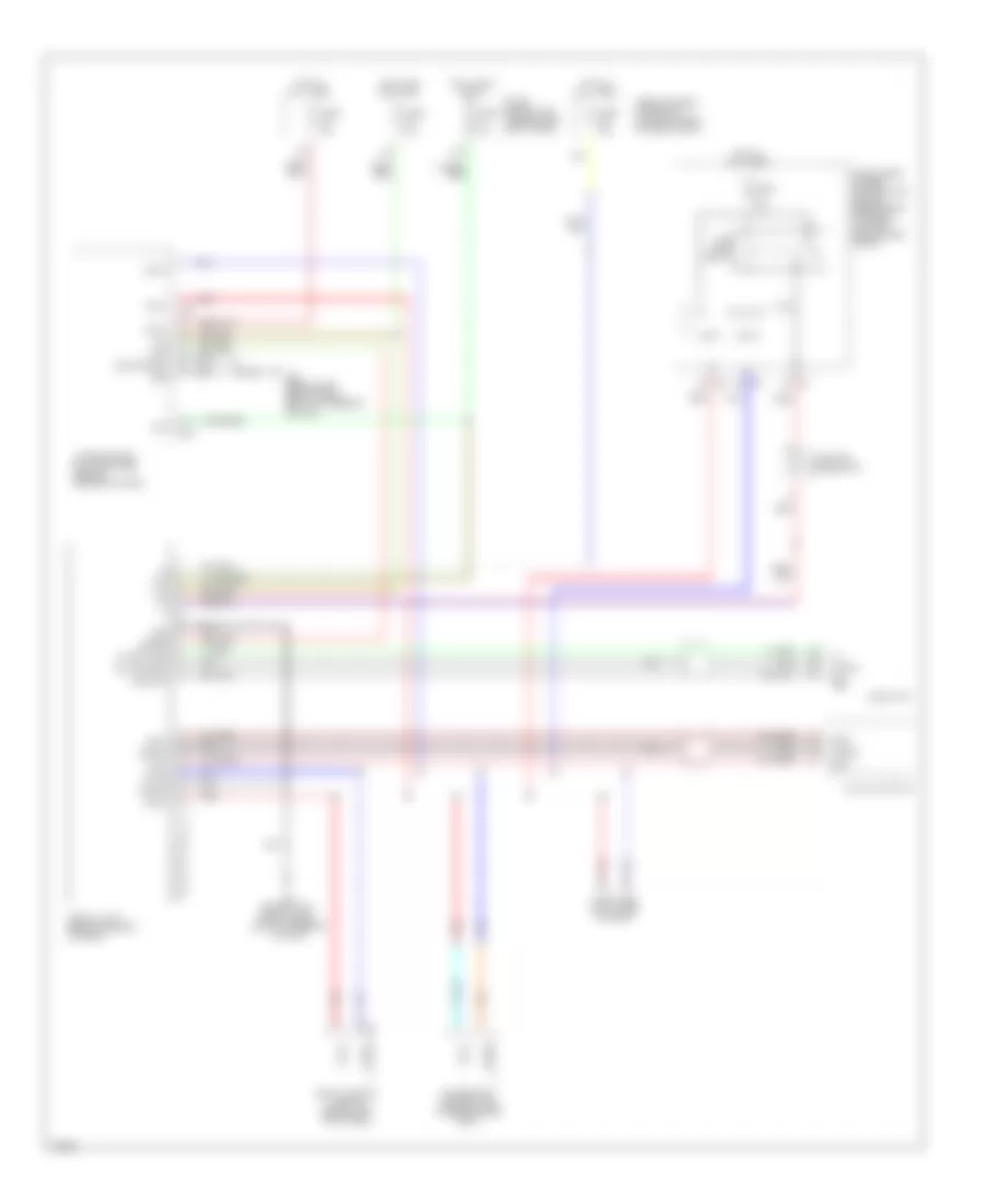
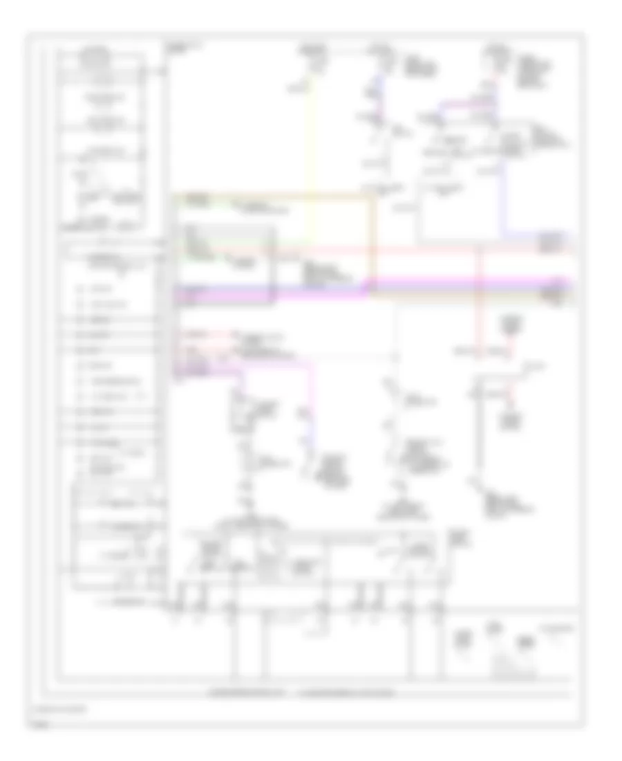
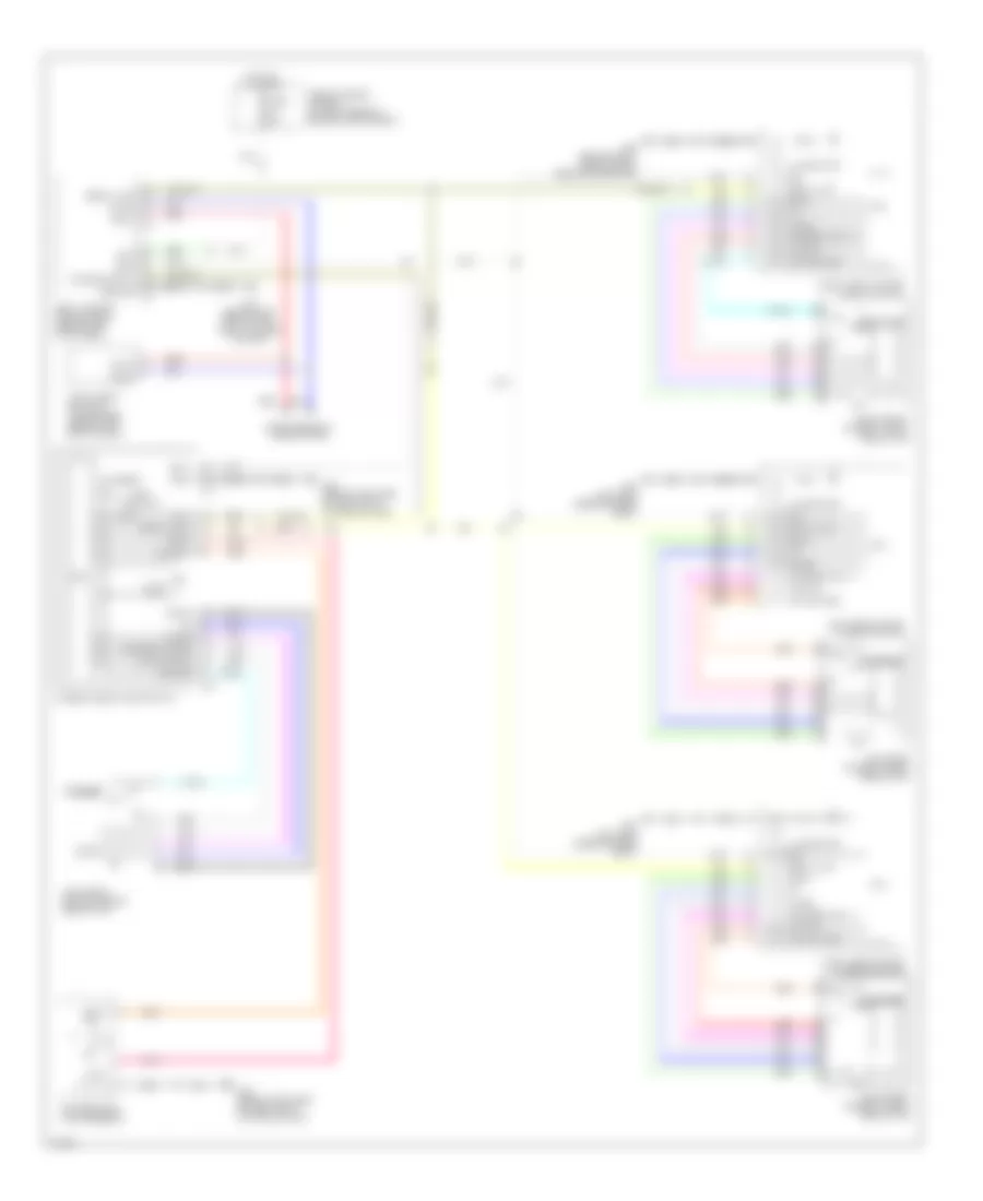
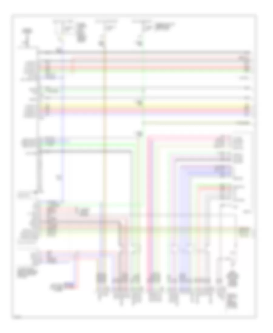
ANTI-LOCK BRAKES Anti-Lock Brakes Wiring Diagram (1 of 2) for Infiniti FX35 2003 List of elements for Anti-Lock Brakes Wiring Diagram (1 of 2) for Infiniti FX35 2003: 55 Abs Abs actuator & electric unit (at left side of fire wall) Brake Brl Can 1-h Can 1-l Can 2-h Can 2-l Clus gnd Clus sp Combination meter Control unit Diag k Drv 1 gnd Drv 1 sig Drv 1 ss E201 E49 (at left side of engine compt, near strut tower) E50 (at left side of engine compt, near strut tower) Es bat Fl + Fl - Fr + Fr - Fuse 12 10a Fuse 14 10a Fuse 19 10a Fuse 20 20a Fuse block (j/b) (behind left kick panel) Gnd p Gnd v Hot at all times Hot in on or start Ign J/c 2 (behind right side of dash, taped to harness) Left front wheel sensor Left rear wheel sensor Lis M20 M45 (behind left side of dash) Mot bat Pedal bracket) Pnk Red Right front wheel sensor Right rear wheel sensor Rl + Rl - Rr + Rr - Slip Stoplight switch (on brake Unified meter Vdc off Vdc/tcs/abs control unit Anti-Lock Brakes Wiring Diagram (2 of 2) for Infiniti FX35 2003 List of elements for Anti-Lock Brakes Wiring Diagram (2 of 2) for Infiniti FX35 2003: 31 Bat Brake fluid level switch (on master cylinder fluid reservoir) Can h Can l Can-h Can-l Computer data lines system Data link connector E49 (at left side of engine compt, near strut tower) Fuse & fusible link block (at left front of eng comp) Fuse 82 10a Fuse i 50a Fuse l 30a Gnd Grd Hot at all times Hot in on or start Ign Ipdm e/r (intelligent pwr distribution mod engine room) (at right rear corner of engine comp) M45 (behind left side of dash) M55 M56 M78 (behind right end of dash) Pressure sensor (at left rear of eng comp) Pwr Red Sig out Steering angle sensor (below left side of dash) Unified meter & a/c amplifier (behind center of dash) Vdc off switch Yaw rate/side/ decel g sensor (below center console)
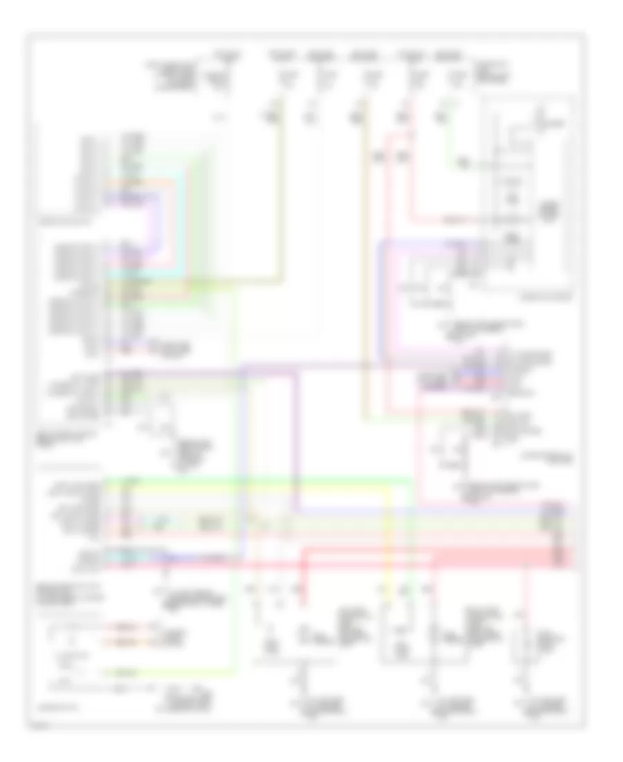
ANTI-THEFT Forced Entry Wiring Diagram for Infiniti FX35 2003 List of elements for Forced Entry Wiring Diagram for Infiniti FX35 2003: 71 (at left side of eng compt, near (behind left side 12a 1b m2 8a m1 Acc B14 B45 (at left side of luggage compt) Back door sw Back door switch (at lower center of back door) Bat (f/l) Bat (fuse) Between full stroke & n Body control module (behind left kick panel) Can-h Can-l Closed Computer data lines system data link connector (below left side of dash) Cpu Door lock & unlock switch (power window main switch) Door sw (as) Door sw (dr) Door sw (rl) Door sw (rr) Driver side door key cylinder switch (front door lock assembly) Driver side front door switch (front door lock assy) E21 (behind headlight, on right front inner fender) E50 Full stroke Fuse & fusible link box (right rear of eng compt) Fuse 10a Fuse 15a Fuse block (j/b) left side of dash) Fuse m 50a Gnd Gnd (pwr) Gnd (sig) Hdlight high relay Hdlight low relay Headlights system Hood switch (at left front of eng compt) Horn (high) Horn relay (in fuse & fusible link box) Hot at all times Hot in accy or start Hot in on or start Ignition relay Intelligent key unit (if equipped) (behind left end of dash) Intelligent power distribution module engine room (at right rear of engine compt) J/c 2 J/c 2 (behind left side of dash, taped to harness) J/c 4 (forward of left rear wheelwell, taped to harness) J/c 6 (forward of left rear wheelwell, taped to harness) Left rear door switch (rear door lock assy) Lock Lock switch M45 (behind left side of dash, right of steering column) M85 (behind right side of dash, above blower motor) Of dash, taped Open Passenger side door lock & unlock switch (front power window switch) Passenger side front door switch (front door lock assy) Pnk Pwd serial link Red Security ind out Security indicator lamp Strut tower) To harness) Unlock Unlock switch Immobilizer Wiring Diagram (NATS), with Intelligent Key Unit for Infiniti FX35 2003 List of elements for Immobilizer Wiring Diagram (NATS), with Intelligent Key Unit for Infiniti FX35 2003: 46 +12 1b m2 2a m2 5v output 8a m1 Bat Bat (f/l) Bat (fuse) Body control module (behind left end of dash) Can-h Can-l Computer data lines system Data link connector (below left side of dash) Drawn Earth Engine control module (ecm) (behind glove box) Fuse & fusible link box (right rear of eng compt) Fuse 10a Fuse 15a Fuse block (j/b) (behind left kick panel) Fuse m 50a Gnd Gnd (pwr) Gnd (sig) Hot at all times Hot in on or start Ign sw Ignition knob switch Inserted removed Intelligent key unit (behind left end of dash) Key sw Key switch Key switch & ignition knob switch M2 15a M45 (behind left side of dash, right of steering column) M45 (behind left side of dash, right of steering column) M85 (behind right side of dash, above blower motor) Nats antenna amplifier (behind center of dash) Push sw Red Security ind out Security indicator lamp Sig Signal Steering lock unit (behind left side of dash, near steering column) With- pushed Immobilizer Wiring Diagram (NATS), without Intelligent Key Unit for Infiniti FX35 2003 List of elements for Immobilizer Wiring Diagram (NATS), without Intelligent Key Unit for Infiniti FX35 2003: 27 1b m2 8a m1 Bat (f/l) Bat (fuse) Body control module (behind left end of dash) Can-h Can-l Computer data lines system Data link connector (below left side of dash) Engine control module (ecm) (behind glove box) Fuse & fusible link box (right rear of eng compt) Fuse 10a Fuse 15a Fuse block (j/b) (behind left kick panel) Fuse m 50a Gnd (pwr) Gnd (sig) Hot at all times Hot in on or start Ign sw M2 15a M45 (behind left side of dash, right of steering column) M45 (behind left side of dash, right of steering column) Nats antenna amplifier (behind center of dash) Red Security ind out Security indicator lamp
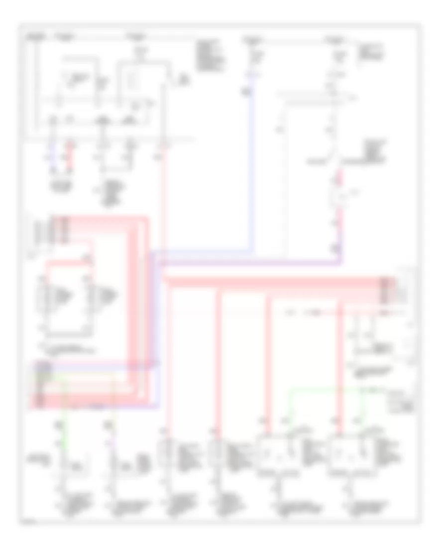
BODY CONTROL MODULES Body Control Modules Wiring Diagram for Infiniti FX35 2003 List of elements for Body Control Modules Wiring Diagram for Infiniti FX35 2003: 74 (behind left side of dash, right of steering column) 12a 15a Acc sw Air conditioning system Aircon sw Anti-theft system Auto lt gnd Auto lt in Auto lt pwr B14 Back door sw Bat (f/l) Bat (fuse) Bat saver output Blwr fan sw Body control module (bcm) (behind left kick panel) Can-h Can-l Computer data lines system Defoggers system Door lock output (all) Door locks system Door locks, interior lights or anti-theft system Door locks, interior lights or power windows system Door locks, power tops or power windows system Door locks, power windows, or interior lights system Door locks, warning, interior lights, power windows or anti-theft system Door unlock output (dr) Door unlock output (other) Exterior lights system Fl door sw Flasher out (left) Flasher out (right) Fr door sw Fuse & fusible link & relay box (right rear of eng compt) Fuse 10a Fuse 15a Fuse 50a Fuse block (j/b) (behind left kick panel) Fuse m 50a Gnd (power) Gnd (signal) Hazard sw Headlights system Headlights, interior lights, exterior lights, or wiper/washer system Hot at all times Hot in acc or on Hot in on or start Ign sw Interior lights or warning system Interior lights system Key ring output Key sw M45 Nats antenna amp Output 1 Output 2 Output 3 Output 4 Output 5 Pnk Power tops or power windows system Pwr wdo serial link Rear wiper auto stop Rear wiper mtr out Red Rl door sw Room lamp output Rr def sw Rr door sw Security ind out Step lamp output Wiper/washer system
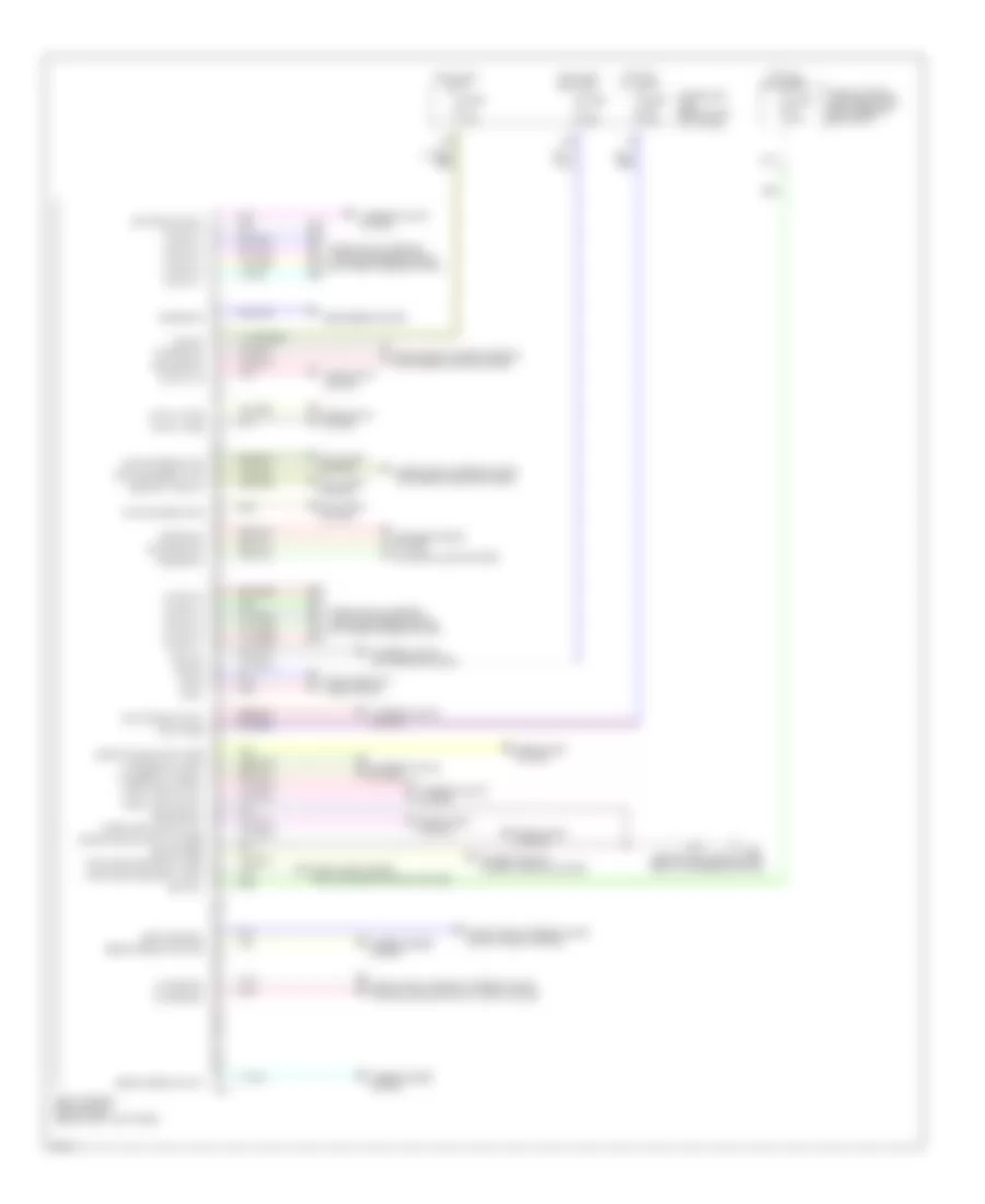
COMPUTER DATA LINES Computer Data Lines Wiring Diagram for Infiniti FX35 2003 List of elements for Computer Data Lines Wiring Diagram for Infiniti FX35 2003: 52 (4 doors) (behind left side of dash, right of steering column) A/c & av switch Abs actuator & electric unit (at left rear of eng compt) Air bag diagnosis sensor unit (under center console, behind gear selector) Awd control unit (behind right kick panel) Body control module (behind left kick panel) Bus + Bus - Bus shield Can-h Can-l Combination meter Cpu Data link connector (lower left side of dash) Diag-k Display control unit (w/navigation) (behind center of dash) Display unit (behind center of dash) Driver seat control unit (under driver seat) Engine control module (behind right kick panel) Front power window switch (passenger side) Fuse 19 10a Fuse 89 10a Fuse block (j/b) (behind left kick panel) Hot at all times Hot in on or start Icc sensor (behind center of front bumper) Icc unit (behind glove box) Intelligent key unit (behind left end of dash) Intelligent power distribution module engine room (at eight rear corner of engine compartment) Intelligent power distribution module engine room (at right rear of eng compt) K-line Left rear power window Low tire pressure warning control unit (behind right side of dash) M20 M45 M76 Nca Power window main switch (driver side) Pwr wdo serial link Red Right rear power window Rx (comb meter) Shield Steering angle sensor (below left side of dash, near steering column) Transmission control module Tx (comb meter) Unified meter & a/c amplifier (behind center of dash) Unified meter control unit Vdc/tcs/abs control unit W/ navigation W/o navigation
COOLING FAN Cooling Fan Wiring Diagram for Infiniti FX35 2003 List of elements for Cooling Fan Wiring Diagram for Infiniti FX35 2003: 32 +batt +ign Avcc gnd Can-h Can-l Computer data lines system Cooling fan motor 1 (at right front of engine compartment) Cooling fan motor 2 (at left front of engine compartment) Cooling fan relay-1 Cooling fan relay-2 Cooling fan relay-3 Cpu E21 (behind headlamp, on front right of inner fender) Engine control module (behind glove box) Fuse & fusible link & relay box (at right rear of engine compartment) Fuse 10a Fuse 15a Fusible link e 80a Fusible link g 40a Fusible link h 40a Fusible link holder (at right rear of engine compartment) Gnd-a Hot at all times Hot in run or start Ignition relay Intelligent power distribution module (engine room) (at right front of engine compartment) Motor fan-1 Motor fan-2 Motor fan-3 Pd- pres Red Refrigerant pressure sensor (right front of engine compt, near radiator filler neck)
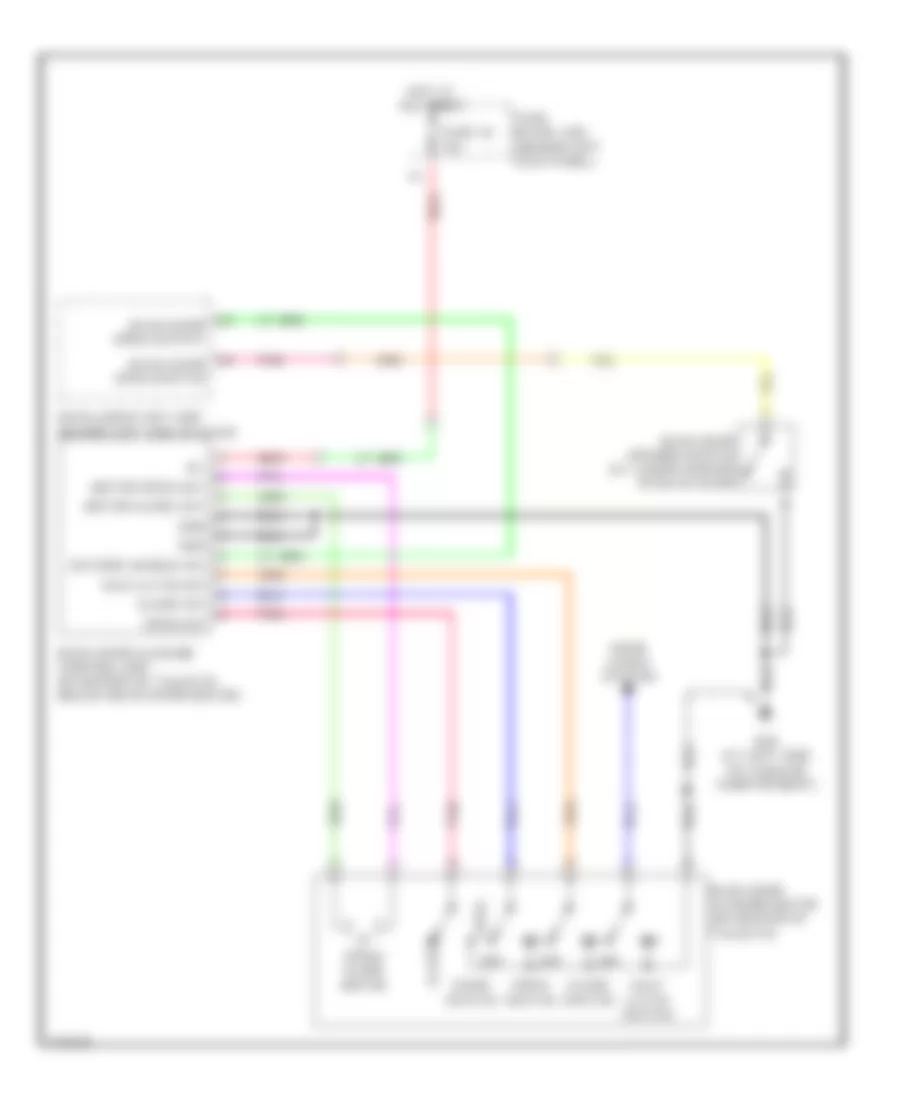
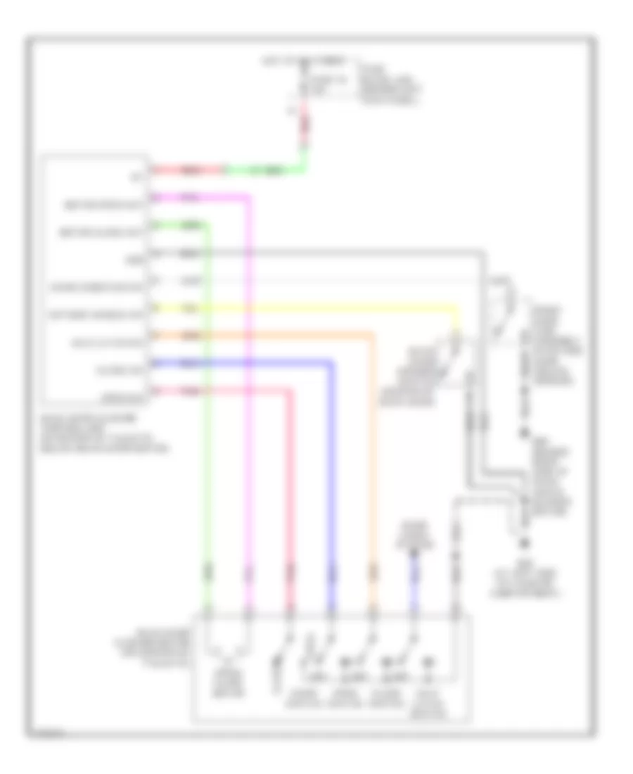
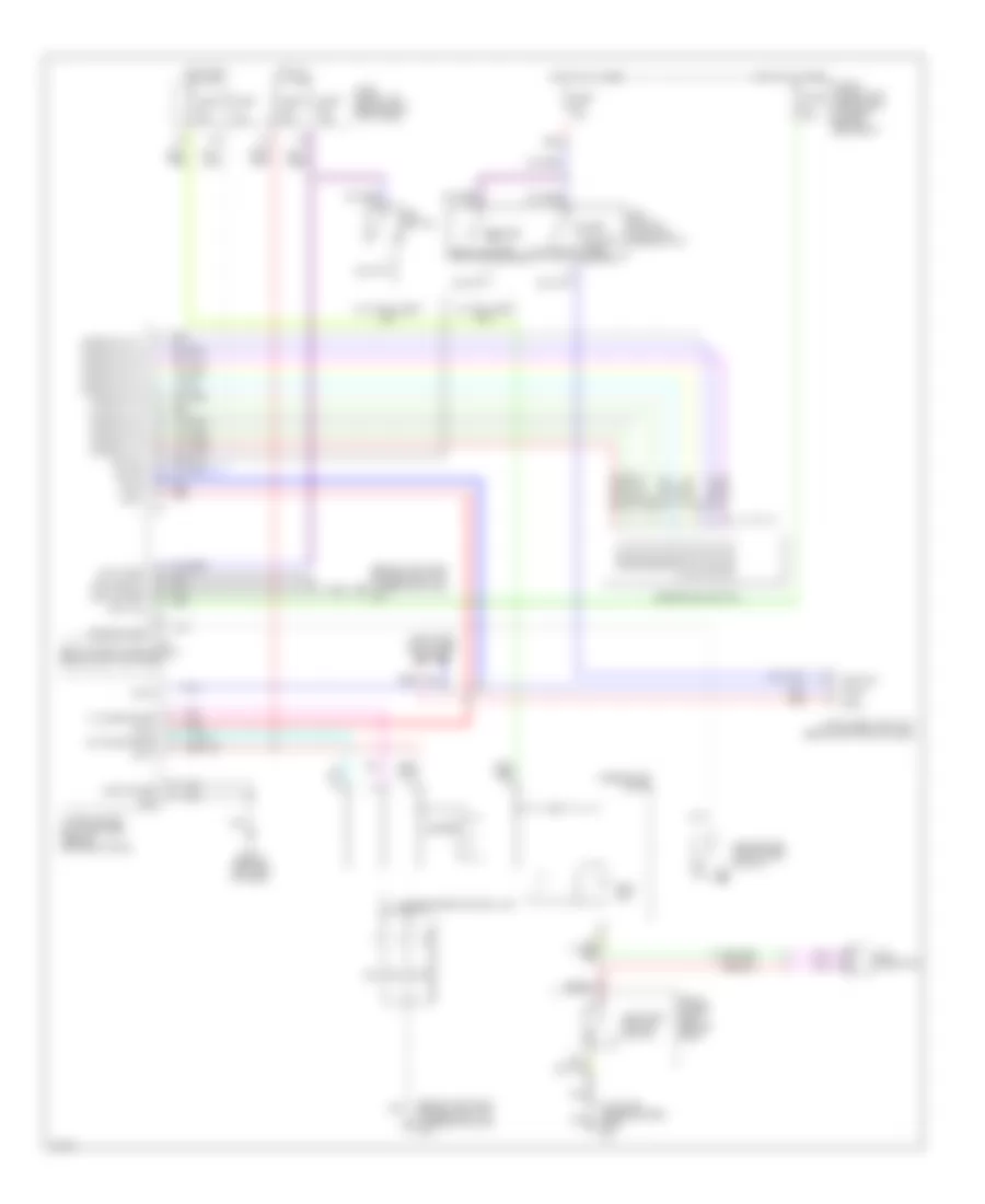
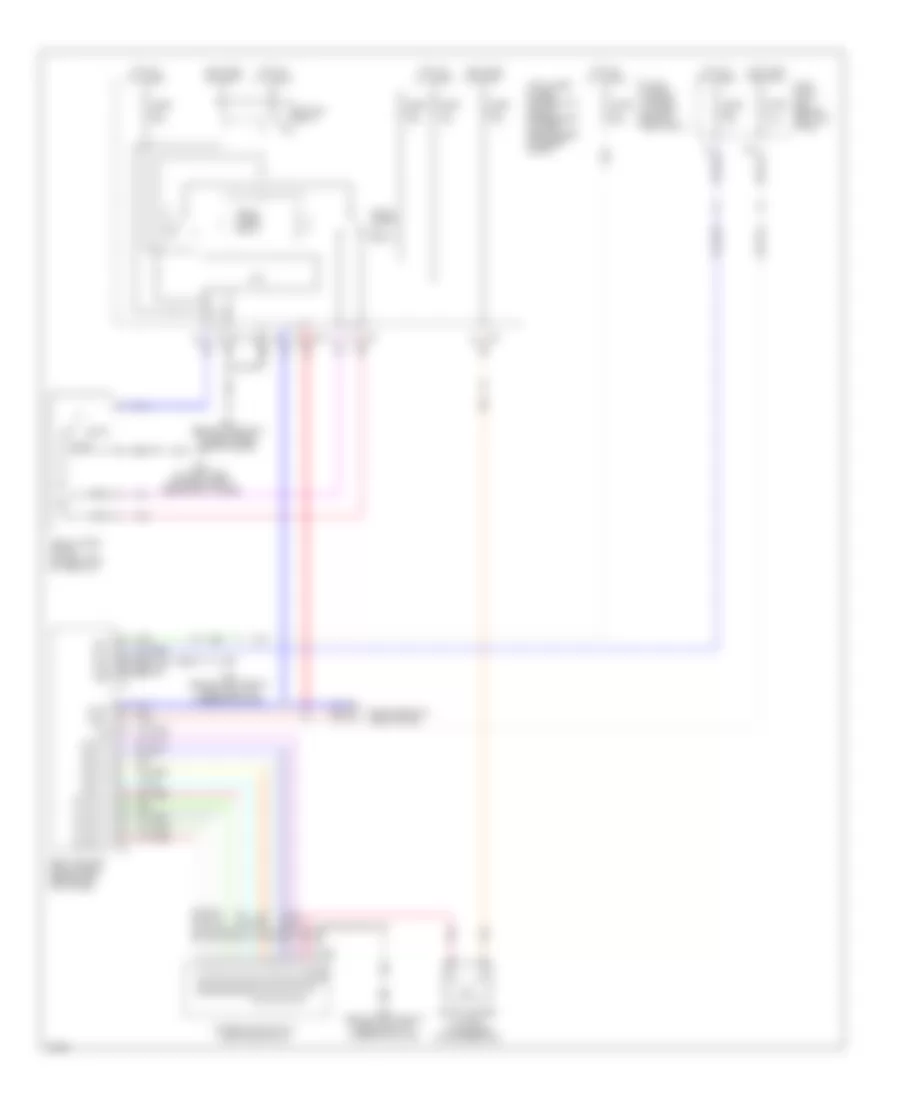
CRUISE CONTROL Cruise Control Wiring Diagram for Infiniti FX35 2003 List of elements for Cruise Control Wiring Diagram for Infiniti FX35 2003: 46 (behind left side of dash, left of steering column) 10a Ascd brake switch (on brake pedal bracket) Ascd ctrl sw Ascd steering switch Ascd sw Avcc2 Brake sw (close) Brake sw (open) Can-h Can-l Cancel switch Combination meter Computer data lines system Cruise Electric throttle control actuator (on throttle body) Engine control module (ecm) (behind glove box) Fuse 12 10a Fuse 14 10a Fuse 20 10a Fuse block (j/b) (behind left side of dash) Gnd-a2 Hot at all times Hot in on or start J/c 3 (upper right end of dash) Joint connector 2 M15 M203 M25 M35 M45 (behind left side of dash, right of steering column) Main switch Motor 1 Motor 2 Nca Pnk Red Resume/ accel switch Set Set/ coast switch Spiral cable Stop lamp switch (on brake pedal bracket) Tps1 Tps2 Unified meter & a/c amp (behind center of dash) Unified meter control unit Intelligent Cruise Control Wiring Diagram for Infiniti FX35 2003 List of elements for Intelligent Cruise Control Wiring Diagram for Infiniti FX35 2003: 81 A/t assembly Abs actuator and electric unit (left rear of engine compt) Accel/ resume switch Ascdsw Bat-1 Bat-2 Batt Bnc-sw Bncsw Bno-sw Body control module (behind left kick panel) Brake booster Brake pressure sensor (left rear of engine compartment) Can-h Can-l Cancel switch Combination meter Combination switch (spiral cable) Computer data lines system Data link connector (below left side of dash) Ddl-rx Ddl-tx Distance switch E21 (behind headlamp, on right front inner fender) Engine control module (behind glove box) Fuse 12 10a Fuse 14 10a Fuse 19 10a Fuse 20 10a Fuse 35 10a Fuse block (j/b) (behind left kick panel) Fuse fusible link & relay box (at right rear of engine compartment) Gnd Gnd-1 Gnd-2 Gnd-3 Gnd-a Hot at all times Hot in on or start Icc brake hold relay (in relay box, located in right rear of engine compartment) Icc brake switch (above brake pedal, on bracket) Icc sensor (behind center of front bumper) Icc steering switch Icc unit (behind glove box) Ign Ign-1 Ign-2 Joint conn 2 M15 M20 M203 M35 (behind left side of dash) M45 (behind left side of dash, right of steering column) M88 M89 Main switch (on/off) Neut-sw Parking brake switch (behind left side of dash) Pkb-sw Pnk Psen-gnd Psen-pwr Psen-sig Pwr gnd Red Rls-nc Rls-no Rls-pwr Set Set/ coast switch Sol+ Sol- Start-rly Stoplight switch (above brake pedal, on bracket) Stp-lmp Tcm Unified meter and a/c amp (behind center of dash) Unified meter control unit V out V pwr Vdc/tcs/abs control unit
DEFOGGERS Rear Defogger & Heated Mirrors Wiring Diagram for Infiniti FX35 2003 List of elements for Rear Defogger & Heated Mirrors Wiring Diagram for Infiniti FX35 2003: 43 +ig 15a m1 1b m2 2c e201 2d e202 5b m2 A/c and av switch (rear defogger switch) B45 (at left side of luggage compt) Bat (f/l) Bat (fuse) Body control module (behind left kick panel) Can-h Can-l Computer data lines system Cpu Data link connector (below left side of dash) Driver side door mirror defogger E21 (behind headlight, on right front fender) Fuse & fusible link block (on left front of engine compt) Fuse 10a Fuse 15a Fuse 20a Fuse block (j/b) (behind left kick panel) Fuse m 50a Gnd Gnd (power) Gnd (pwr) Gnd (sig) Gnd (signal) Hot at all times Hot in on or start Ign relay Ign sw Intelligent power distribution module (engine room) (at right rear of engine compt) J/c 1 (behind right side of dash, taped to harness) M45 (behind left side of dash, right of steering column) M85 (behind right side of dash, above blower motor) Passenger side door mirror defogger Rear window defogger Rear window defogger relay (behind left kick panel) Red Rr def rly Rr def sw
ENGINE PERFORMANCE
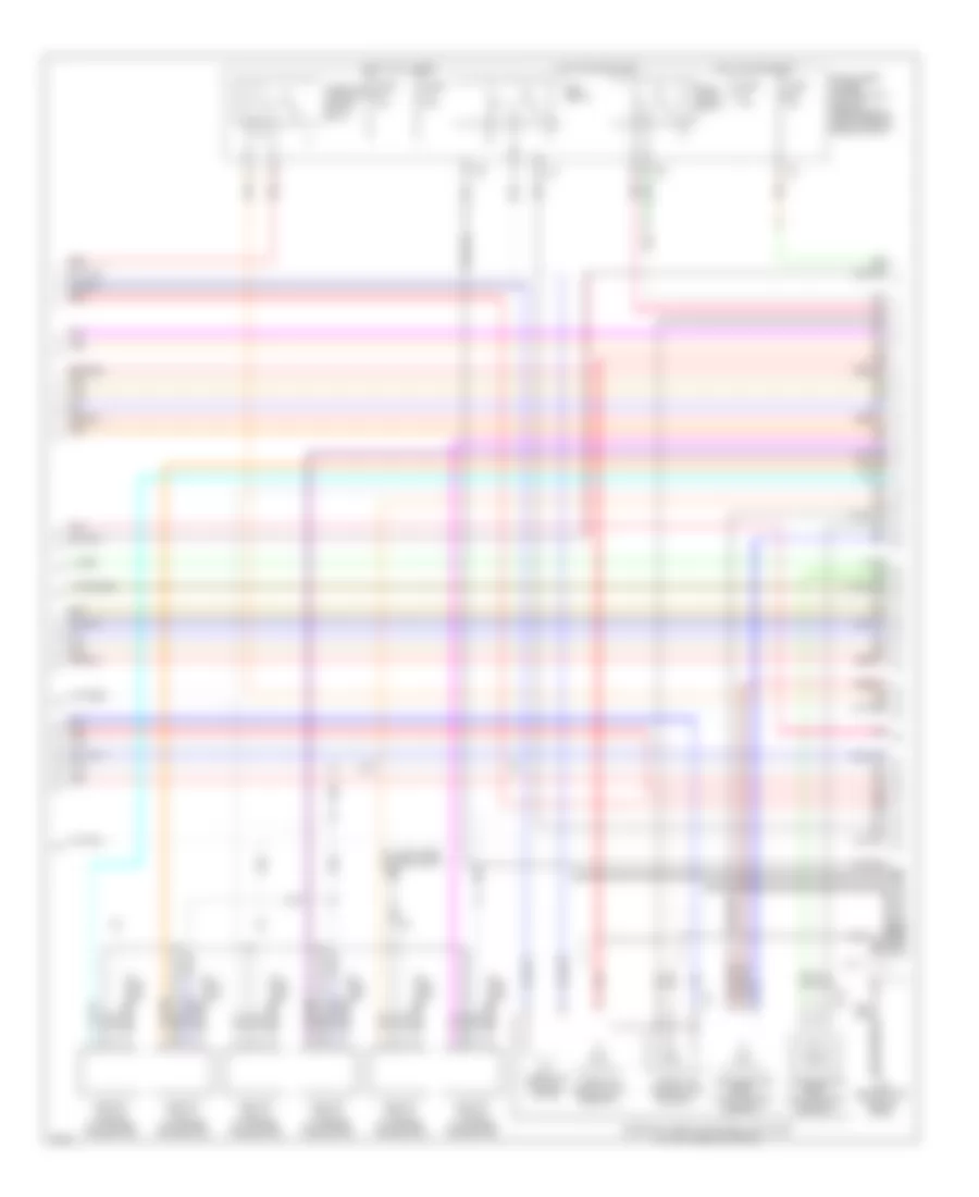
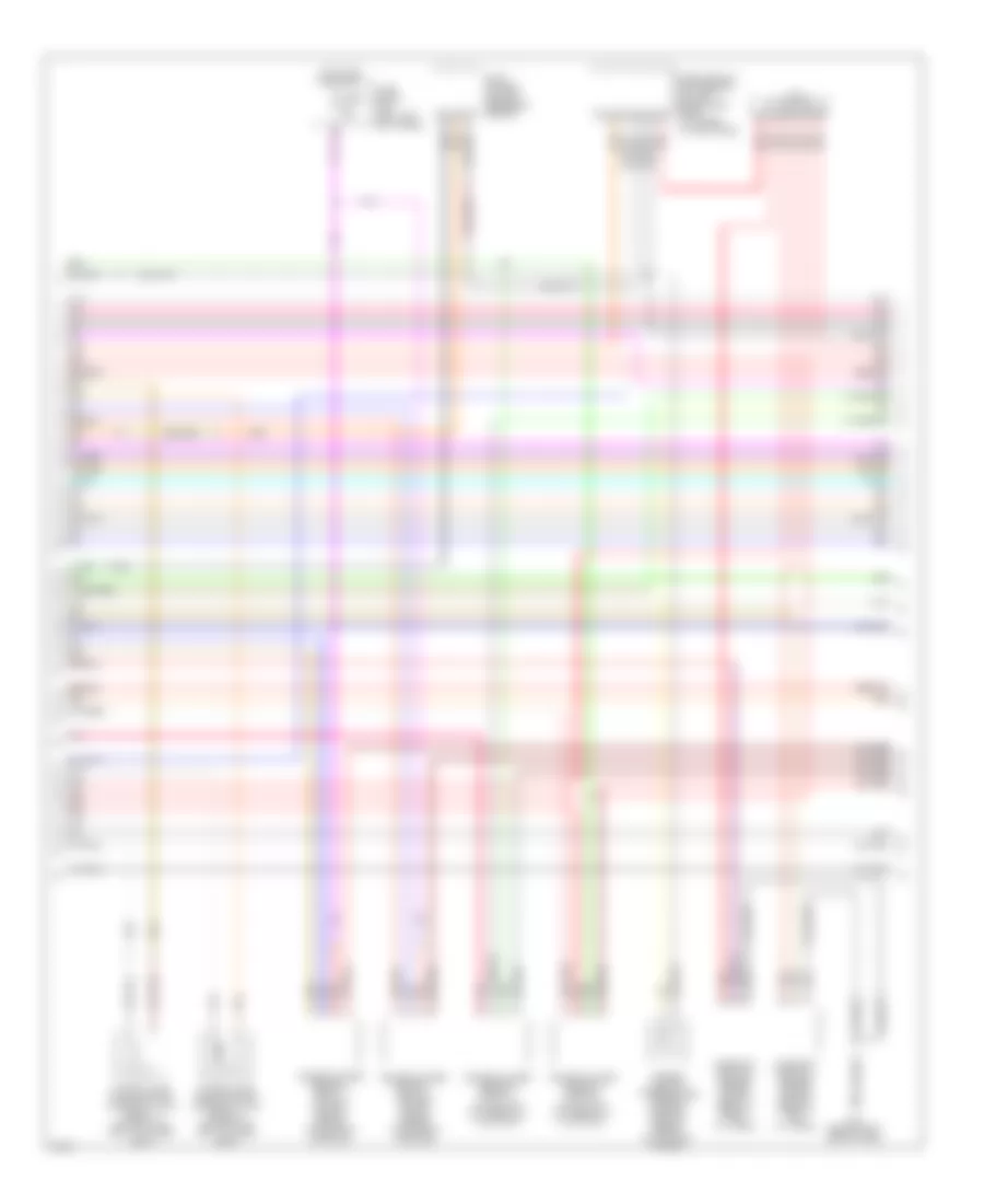
3.5L 3.5L, Engine Performance Wiring Diagram (1 of 4) for Infiniti FX35 2003 List of elements for 3.5L, Engine Performance Wiring Diagram (1 of 4) for Infiniti FX35 2003: 51 (at left side of eng compt, near ignition coil 1) f11 (behind left side of dash) m35 15a Avcc Avcc2 C-ivc (l) C-ivc (r) Combination meter Condenser (behind upper right side of dash, taped to harness) Crankshaft position sensor (pos) (lower left front of cylinder block) Engine control module (behind glove box) Evap Evap canister purge volume control solenoid valve (on rear of intake manifold) Ftrps Fuel injector Fuse 10a Fuse 15a Fuse block (j/b) (behind left kick panel) Gnd Hot in on or start Inj 1 Inj 2 Inj 3 Inj 4 Inj 5 Inj 6 Knk1 Knock sensor (on center of engine) M35 (behind left side of dash, left of steering column) Malfunction indicator lamp Motor1 Motor2 Nca O2hfr O2hrl O2hrr O2sfl O2sfr O2srl Pdpres Phase lh Phase rh Pnk Pos Ps pres Qa+ Red Refrigerant pressure sensor (right front of eng compt, near radiator filler neck) Tps1 Unified meter control unit V mot 3.5L, Engine Performance Wiring Diagram (2 of 4) for Infiniti FX35 2003 List of elements for 3.5L, Engine Performance Wiring Diagram (2 of 4) for Infiniti FX35 2003: 32 (at left side of eng compt) f11 Accelerator pedal position (app) sensor 1 Accelerator pedal position (app) sensor 2 E213 Ecm relay Electric throttle control actuator (on left rear of engine) F19 Fuel pump relay Fuse 10a Fuse 15a Fuse 20a Hot at all times Hot in on or start Ignition coil 1 (w/ power transistor) Ignition coil 2 (w/ power transistor) Ignition coil 3 (w/ power transistor) Ignition coil 4 (w/ power transistor) Ignition coil 5 (w/ power transistor) Ignition coil 6 (w/ power transistor) Intelligent power distribution module (engine room) (right rear of engine compt) J/c 3 M35 (behind left side of dash) Nca Nca nca Plug spark Pnk Red Spark plug Throttle control motor Throttle control motor relay Throttle position (tp) sensor 1 Throttle position (tp) sensor 2 3.5L, Engine Performance Wiring Diagram (3 of 4) for Infiniti FX35 2003 List of elements for 3.5L, Engine Performance Wiring Diagram (3 of 4) for Infiniti FX35 2003: 18 Camshaft position sensor (phase) (bank 1) (rear of right cyl head) Camshaft position sensor (phase) (bank 2) (rear of left cyl head) Engine coolant temperature sensor (on right rear of engine, on coolant outlet) Evap control system pressure sensor Fuse 10a Fuse block (j/b) (left left kick panel) Heated oxygen sensor 1 (bank 1) (on right side of engine, on exhaust manifold) Heated oxygen sensor 1 (bank 2) (on left side of engine, on exhaust manifold) Heated oxygen sensor 2 (bank 1) (on outlet of three way catalyst) Heated oxygen sensor 2 (bank 2) (on outlet of three way catalyst) Hot in on or start Intake valve timing control solenoid valve (bank 1) (on front of right cylinder head) Intake valve timing control solenoid valve (bank 2) (on front of left cylinder head) J/c 3 M35 (behind left side of dash) Mass airflow (maf) sensor (on left side of eng, compt, attached to air intake) Pnk Red 3.5L, Engine Performance Wiring Diagram (4 of 4) for Infiniti FX35 2003 List of elements for 3.5L, Engine Performance Wiring Diagram (4 of 4) for Infiniti FX35 2003: 54 Aps1 Aps2 Ascdsw Avcc Avcc2 B45 (at left side of luggage compt) Batt Bncsw Brake Can l Can-h Can-l Cdcv Computer data lines system Condenser (behind upper right side of dash, taped to harness) Cruise control system Data link connector (below left side of dash) Ecm Engine control module (behind glove box) Evap canister vent control valve (below right rear of vehicle, behind bumper) Fpr Fuel level sensor unit & fuel pump (in fuel tank) Fuse 10a Fuse 20a Fuse block (j/b) (behind left kick panel) Gnd Gnd 02 Gnd a Gnd a2 Grd Hot at all times Hot in on or start Ign 1 Ign 2 Ign 3 Ign 4 Ign 5 Ign 6 Ign sw Intelligent power distribution module (engine room) (right rear of engine compt) J/c Kline M35 (behind left side of dash) Moyrly Neut O2srr Pdpres Pnk Power steering pressure sensor (on power steering pump) Red Ssoff Stoplight switch (above brake pedal, on bracket) Tps2 Unified meter & a/c amp (behind center of dash)
EXTERIOR LIGHTS Back-up Lamps Wiring Diagram for Infiniti FX35 2003 List of elements for Back-up Lamps Wiring Diagram for Infiniti FX35 2003: 15 (at left side of luggage compartment) b45 A/t assembly Back-up lamp relay (in luggage compartment, above left rear wheelwell) Can-h Can-l Computer data lines system Fuse 10a Hot in on or start Intelligent power distribution module engine room (ipdm e/r) (at right rear of engine compartment) J/c 1 Left back-up lamp (part of left rear combination lamp) Red Rev lamp rly Right back-up lamp (part of right rear combination lamp) Transmission control module Exterior Lamps Wiring Diagram (1 of 2) for Infiniti FX35 2003 List of elements for Exterior Lamps Wiring Diagram (1 of 2) for Infiniti FX35 2003: 85 (at left side of luggage compartment) b45 (behind left side of dash, right of steering column) m45 12a 15a Acc sw Bat (f/l) Bat (fuse) Battery Body control module (behind left kick panel) Brake sw Buzzer Can-h Can-l Combi sw input 1 Combi sw input 2 Combi sw input 3 Combi sw input 4 Combi sw input 5 Combi sw output 1 Combi sw output 2 Combi sw output 3 Combi sw output 4 Combi sw output 5 Combination meter Combination switch Computer data lines system Flasher out (left) Flasher out (right) Fuse 10a Fuse 15a Fuse block (j/b) (behind left kick panel) Fuse, fusible link & relay box (at right rear of engine compartment) Fusible link m 50a Gnd Gnd (power) Gnd (signal) Ground Hazard sw Hazard switch High mounted stop lamp Hot at all times Hot in acc or on Hot in on or start Ign sw Ignition Illumination Input 1 Input 2 Input 3 Input 4 Input 5 Interior lights system Left flasher Left led anode Left led cathode Left rear combination lamp (part of left rear combination lamp) Left turn M20 M45 (behind left side of dash, right of steering column) M55 M56 Off Output 1 Output 2 Output 3 Output 4 Output 5 Pnk Power Rear combination lamp control unit (at left side of luggage compartment) Red Right flasher Right led anode Right led cathode Right rear combination lamp (part of right rear combination lamp) Right turn Rx (comb meter) Side marker Stop lamp Tail Tail/ stop/ turn Tx (comb meter) Unified meter & a/c amplifier Unified meter control unit Warning Exterior Lamps Wiring Diagram (2 of 2) for Infiniti FX35 2003 List of elements for Exterior Lamps Wiring Diagram (2 of 2) for Infiniti FX35 2003: 45 (at left side of engine compartment, near strut tower) e50 (at left side of luggage compartment) b45 (behind headlamp, on right front inner fender) e21 (behind headlamp, on right front inner fendr) e21 (on floor, under driver's seat) b15 +ig Can -h Can -l Computer data lines system Contact Cpu Daytime Daytime light relay (in relay box) Depressed E201 Fuse 10a Fuse 15a Fuse block (j/b) (behind left kick panel) Gnd (power) Gnd (signal) Hot at all times Hot in on or start If equipped Ignition relay Intelligent power distribution module (engine room) (at right rear of engine compartment) J/c 1 J/c 2 J/c 5 J/c 6 Left clearance lamp (part of left front combination lamp) Left front combination lamp Left front side marker lamp (part of left front combination lamp) Left license plate lamp Parking Pnk Red Released Right clearance lamp (part of right front combination lamp) Right front combi- nation lamp Right front side marker lamp (part of right front combination lamp) Right license plate lamp Stop lamp switch (above brake pedal, on bracket) Tail lamp relay Tail/l rly Turn signal
GROUND DISTRIBUTION Ground Distribution Wiring Diagram (1 of 3) for Infiniti FX35 2003 List of elements for Ground Distribution Wiring Diagram (1 of 3) for Infiniti FX35 2003: 14 (accessory relay) (blower relay), bcm (terminals: 49 & 52), data link connector (terminals: 4 & 5), adp steering switch, combination switch, door mirror remote control switch (with memory mirror), door mirror remote control switch (without memory mirror), combination meter (terminals: 5, 6 & 15), nats antenna amplifier B203 (on floor, under passenger seat) B210 (at base of right "c" pillar) Ecm (engine control module) (terminals: 1, 115 & 116), shield wire (knock sensor), crankshaft position sensor, intake valve timing control position sensor (bank 1) (fx45), shield wire (electric throttle control actuator) (throttle position sensor) (terminals: 1, 2, 4 & 5), shield wire (electric throttle control actuator) (throttle control motor) (terminals: 3 & 6), camshaft position sensor (phase) (fx45), camshaft position sensor (phase) (bank 1) (fx35), camshaft position sensor (phase) (bank 2) (fx35) Fuse block (j/b) (terminal: 7b) Intelligent key unit, rear view camera control unit, front cigarette lighter socket (lighter & ashtray illumination), display unit (terminals: 6 & 15) (without navigation), display (with navigation), a/c & av switch, display control unit (terminal: 13) (with navigation), display control unit (terminal: 3), a/t device (detent switch) (mode select switch) (position select switch) (terminals: 2 & 9), icc unit (terminals: 19, 20 & 46), heated seat switch (driver side), heated seat switch (passenger side), awd control unit (terminals: 10 & 11), air bag diagnosis sensor unit (terminal: 2), glove box lamp, low tire pressure warning control unit, intake door motor, mode door motor, air mix door motor (driver side), front power window switch (lock/unlock switch) (cpu) (illumination) (passenger side), door mirror (defogger) (passenger side), front door lock assembly (unlock sensor) (passenger side), front door request switch (passenger side), air mix door motor (passenger side) J/c 3 (behind right side of dash, taped to harness) M35 (behind left side of dash, left of steering column) M45 (behind left side of dash, right of steering column) M85 (behind right side of dash, above blower motor) Navi control unit (terminals: 1 & 4) R6 (above headliner, near sunroof motor assembly) Shield wire (woofer), bose speaker amplifier Vdc off switch, awd lock switch, hazard switch, clock, blower motor, map lamp, shield wire (inside key antenna 1) (dashboard), shield wire (inside key antenna 2) (dashboard), shield wire (inside key antenna 3) (luggage room), sunroof motor assembly, shield wire (automatic drive positioner control unit), automatic drive positioner control unit (terminals: 40 & 48), unified meter & a/c amp (terminals: 29 & 30), shield wire (option connector 2 for satellite radio receiver), vanity mirror lamp (driver side), vanity mirror lamp (passenger side), interior room lamp, sunroof switch, personal lamp (left), personal lamp (right), front door request switch (driver side), auto anti-dazzling inside mirror (with universal transceiver) (compass & transceiver), auto anti-dazzling inside mirror (without universal transceiver) (compass), door mirror (defogger) (driver side), power window main switch (window lock switch) (door lock/unlock switch) (cpu) (illumination), front door lock assembly (door unlock sensor) (key cylinder switch) (driver side) Ground Distribution Wiring Diagram (2 of 3) for Infiniti FX35 2003 List of elements for Ground Distribution Wiring Diagram (2 of 3) for Infiniti FX35 2003: 15 Alternator B15 (on floor, under driver seat) B25 (on left "b" pillar) B35 (on right "b" pillar) B45 (at left side of luggage compt) Dvd player, front power socket, rear power socket, driver seat control unit (terminals: 16a & 61e), power seat switch (driver side) (with auto drive positioner) (terminals: 61b & 61d), power seat switch (driver side) (without auto drive positioner) (terminals: 16 & 16a), power seat switch (passenger side), seat cushion heater (driver side), seat cushion heater (passenger side), seat memory switch & lumbar support switch (terminals: 16b & 61), seat belt buckle switch (driver side), seat belt buckle switch (passenger side), shield wire (driver seat control unit), rear power window switch (left) (illumination) (cpu), rear power window switch (right) (illumination) (cpu) E304 (at right side of engine compt, near reservoir tank) E314 (at right side of engine compt, near reservoir tank) E315 (on engine, near timing chain case) E316 (on engine, near alternator) Fuel level sensor unit & fuel pump (main), condenser, woofer, luggage room power socket, luggage room lamp (back door side), rear combination lamp (left side marker), rear combination lamp (right side marker), option connector 2 for satellite radio receiver, high-mounted stop lamp, rear wiper motor, back-up lamp (left), back-up lamp (right), rear view camera, back door opener switch, back door closure control unit (terminal: 5) (with intelligent key), back door closure control unit (terminal: 4), back door closure motor (door switch) (open/close switch) (half latch switch), license plate lamp (left), license plate lamp (right), back door request switch, rear window defogger Fx35 Fx45 Shield wire (air bag diagnosis sensor unit) (terminal: 40) Shield wire (air bag diagnosis sensor unit) (terminal: 44) Ground Distribution Wiring Diagram (3 of 3) for Infiniti FX35 2003 List of elements for Ground Distribution Wiring Diagram (3 of 3) for Infiniti FX35 2003: 13 E21 (behind headlamp, on right front inner fender) E31 (at right side of engine compt, near reservoir tank) E49 (at left side of engine compt, near strut tower) E50 (at left side of engine compt) E51 (at left side of engine compt, near strut tower) F11 (at left side of engine compt, near ignition coil no. 1) Front wiper motor, fog lamp (right) Hood switch, washer level sensor, brake fluid level switch, horn low, horn high, front combination lamp (right) (terminal: 3) (headlamp aiming motor), front side marker lamp (left), clearance lamp (left) (parking) (daytime), rear combination lamp control unit, front combination lamp (left) (terminals: 3, 7 & 8) (headlamp) (headlamp aiming motor) (high beam solenoid) (turn signal) Ignition coil no. 1, ignition coil no. 2, ignition coil no. 3, ignition coil no. 4, ignition coil no. 5, ignition coil no. 6, ignition coil no. 7 (fx45), ignition coil no. 8 (fx45), condenser, a/t assembly (terminals: 5 & 10) Ipdm e/r (intelligent power distribution module engine room) (terminal: 15) (cooling fan relay 1) (cooling fan relay 3) (fx35), ipdm e/r (intelligent power distribution module engine room) (terminals: 38, 50 & 60) (cpu) (ignition relay) (front wiper relay), accessory relay 2, icc brake hold relay, icc sensor, front side marker lamp (right), fog lamp (left), cooling fan motor (terminals: 3 & 4) (fx45), cooling fan motor 2 (terminals: 3 & 4) (fx35), clearance lamp (parking) (daytime), front combination lamp (right) (terminals: 7 & 8) (headlamp) (high beam solenoid) (turn signal) J/c 2 (behind left side of dash, taped to harness) Shield wire (air bag diagnosis sensor unit) (terminal: 16) Steering angle sensor, abs actuator & electric unit (control unit) (terminals: 16 & 47)
HEADLIGHTS Headlights Wiring Diagram (1 of 2) for Infiniti FX35 2003 List of elements for Headlights Wiring Diagram (1 of 2) for Infiniti FX35 2003: 74 (in relay box) (j/b) (behind left kick panel) 12a 15a Acc sw Auto lt gnd Auto lt in Auto lt pwr B45 (at left side of luggage compt) Back door closure motor (door switch) Back door sw Bat Body control module (bcm) (behind left kick panel) Can-hi Can-lo Comb sw in 1 Comb sw in 2 Comb sw in 3 Comb sw in 4 Comb sw in 5 Comb sw out 1 Comb sw out 2 Comb sw out 3 Comb sw out 4 Comb sw out 5 Combination switch Daytime light relay Driver side front door switch E21 (behind headlamp, on right front inner fender) E50 (at left side of engine compt) Fl door sw Fr door sw Fuse & fusible link box (right rear of engine compt) Fuse 1 15a Fuse 14 10a Fuse 19 10a Fuse 22 15a Fuse 36 50a Fuse 6 10a Fuse block Fuse m 50a Gnd Hot at all times Hot in acc or on Hot in on or start Ign Input 1 Input 2 Input 3 Input 4 Input 5 Interior light system Junction connector 4 Junction connector 6 Left clearance lamp Left rear door switch M45 (behind left side of dash, right of steering column) Optical sensor (at top left side of dash) Output Output 1 Output 2 Output 3 Output 4 Output 5 Pass- enger side front door switch Pnk Power gnd Pwr Red Right clearance lamp Right rear door switch Rl door sw Rr door sw Signal gnd Headlights Wiring Diagram (2 of 2) for Infiniti FX35 2003 List of elements for Headlights Wiring Diagram (2 of 2) for Infiniti FX35 2003: 49 Aiming motor Alternator Amp Batt Brake Can-hi Can-lo Charge Combination meter Computer data lines system Cpu E21 (behind headlamp, on right front inner fender) E50 (at left side of engine compt) E51 (at left side of engine compt, near strut tower) Fog Front fog lamp relay Fuse 10a Fuse 15a H/lp hi H/lp lo Headlamp high relay Headlamp low relay Hid cont High & low High beam High beam solenoid Hot at all times Hot in on or start Ign Ignition relay Intelligent power distribution module engine room (right rear of engine compt) Joint connector 1 Left front combination lamp Left front fog lamp Left headlamp M45 (behind left side of dash, right of steering column) Meter side switch (headlamp aiming switch Nca Parking brake switch (behind left side of dash) Pwr gnd Red Right front combination lamp Right front fog lamp Right headlamp Sig gnd Tail/l rly Taillight relay Unified meter & a/c amp (behind center of dash) Unified meter control unit
HORN Horn Wiring Diagram for Infiniti FX35 2003 List of elements for Horn Wiring Diagram for Infiniti FX35 2003: 33 (at left side of engine compartment, near left strut tower) e50 (behind headlamp, on right front inner fender) e21 +ig Can -h Can -l Combination switch (spiral cable) Computer data lines system Cpu E35 E36 E37 E38 Fuse 10a Fuse 15a Fuse, fusible link & relay box (at right rear of engine compart- ment) Fuse, fusible link & relay box (at right rear of engine compartment) Gnd (power) Gnd (signal) High horn (below right head- light) Horn relay Horn rly Horn switch Hot at all times Hot in on or start Ignition relay Intelligent power distribution module engine room (ipdm e/r) (at right rear of engine compartment) J/c 2 Low horn (below left head- light) M15 M203 Pushed Red Released
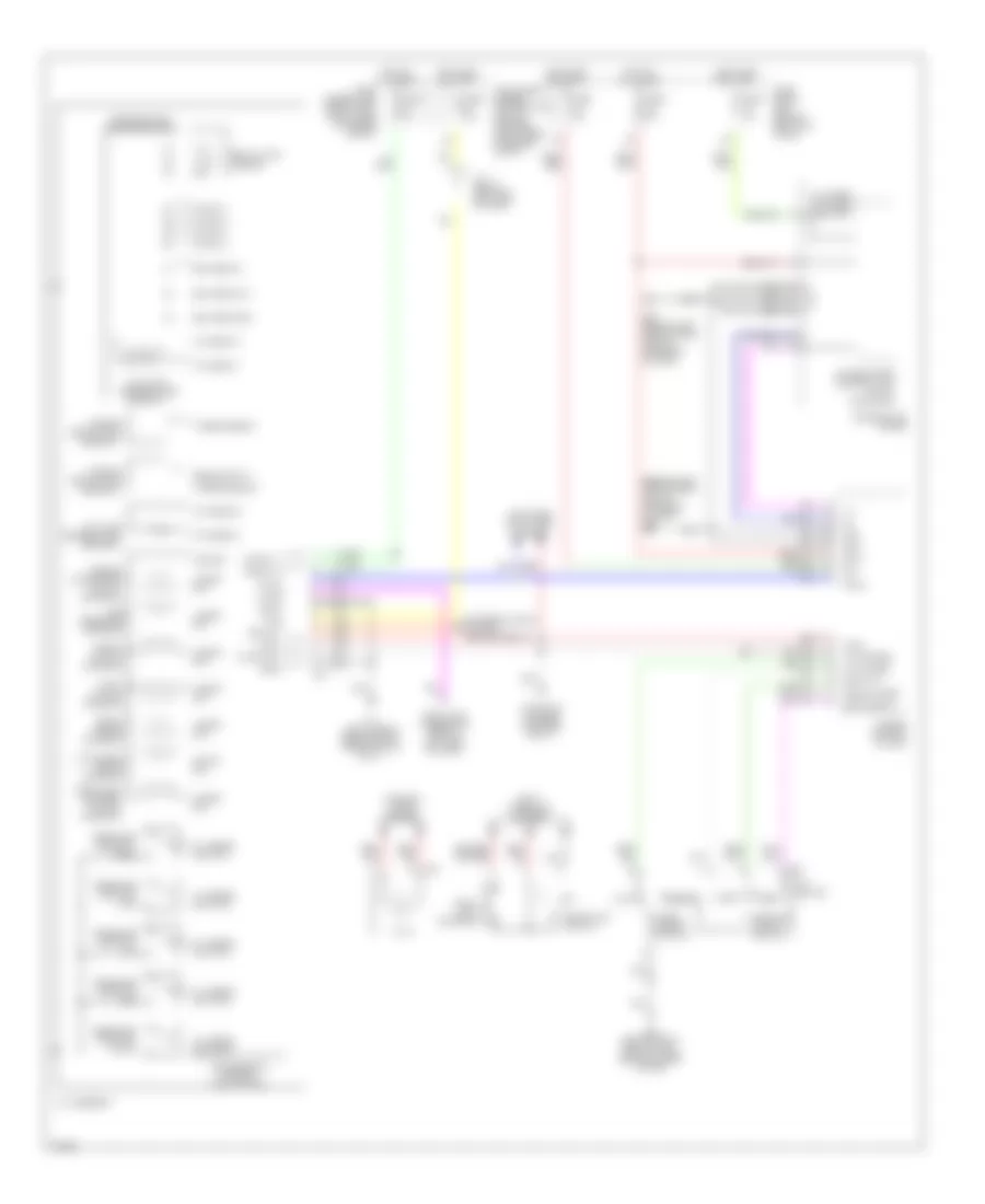
INSTRUMENT CLUSTER Display Wiring Diagram for Infiniti FX35 2003 List of elements for Display Wiring Diagram for Infiniti FX35 2003: 42 12a 8 p/r A/c & av switch Acc Audio rx Audio unit Batt Body control module (behind left kick panel) Bus+ Bus- Can-h Can-l Computer data lines system Cpu Display unit (behind center of dash) Driver seat control unit (under driver's seat) Fuse & fusible link block (at right front of engine comp) Fuse 10a Fuse 15a Fuse block (j/b) (behind left kick panel) Gnd Gnd (power) Hot at all times Hot in acc or on Hot in on or start Ign Ill Intelligent power distribution module engine room (ipdm e/r) (at right rear of eng compt) Junction connector M35 (behind left side of dash, left of steering column) M45 (behind left side of dash, right of steering column) M55 M56 Nca Red Rx (aud-dsp) Shield Speed Tail lamp relay Tail/l rly Tx (dsp-aud) Unified meter & a/c amplifier (behind center of dash) Gauges & Indicators Wiring Diagram (1 of 2) for Infiniti FX35 2003 List of elements for Gauges & Indicators Wiring Diagram (1 of 2) for Infiniti FX35 2003: 77 (2) (a/t) (green) (red) key (w/ ascd) (w/ odo/trip meter, a/t ind, icc ind) A/t check ind Abs ind Air bag ind Awd ind Awd lock ind Belt ind Brake Brake fluid level switch (on master cylinder fluid reservoir) Buzzer Charge ind Charging/ starting system Clock Combination meter Cruise ind Door ind E50 (at left side of eng compt, near strut tower) E50 (at left side of eng compt, near strut tower) Fuel gauge Fuel ind Fuse & fusible link & relay box (at right rear of eng compt) Fuse 10a Fuse block (j/b) (behind left kick panel) Headlamp aiming switch High High beam ind Hot at all times Hot in on or start Ignition knob switch Illum Illum control switch Inserted Interior lights system Join connector Joint connector Key Key switch Key switch & ignition knob switch Left turn ind Low M20 M45 (behind left side of dash, right of steering column) Malfunction ind lamp Meter illum Meter side switch Nca Odo/trip meter illum Odo/trip meter switch Oil ind P-shift Parking brake switch (behind left side of dash) Pushed Red Removed Right turn ind Set ind Slip Speed- meter Tachometer Tire pressure ind Trip reset Trip transfer Unified meter control unit Vdc off W/ intelligent key W/ intelligent key only W/o intelligent key Warning system Washer ind Washer level switch Water temp gauge Withdrawn Gauges & Indicators Wiring Diagram (2 of 2) for Infiniti FX35 2003 List of elements for Gauges & Indicators Wiring Diagram (2 of 2) for Infiniti FX35 2003: 80 (3.5l: at front of eng compt, 4.5l: at leff front of eng compt) (w/ icc) 8p/r A/t device Abs/actuator & electric unit (control unit) (at left rear of eng compt) At-p range Auto Auto mode sw Awd control unit (behind right kick panel) Awd lock Awd lock switch B14 Back door sw Back door switch (at lower center of back door) Bat Bat saver out Batt Body control module (bcm) (behind left kick panel) Can-h Can-h can-l Can-hi Can-l Compass (auto-anti-dazzling inside mirror) Computer data lines system Door sw (as) Door sw (dr) Door sw (rl) Door sw (rr) Driver side front door switch Engine control module (behind glove box) Fuel level sensor unit & fuel pump (main) Fuel level sensor unit (sub) Fuel sens Fuel sens gnd Fuse 10a Fuse 15a Fuse block (j/b) (behind left kick panel) Gnd Gnd (power) Hot at all times Hot in on or start Icc unit (behind glove box) Ign Ign 2 Intelligent key unit (behind left end of dash) Intelligent power distribution module eng room (at right rear corner of eng compt) Interior lights system Joint connector Key sw Left rear door switch Lis Low tire pressure warning control unit (behind right side of dash) M45 (behind left side of dash, right of steering column) M55 M56 M57 M85 (behind right side of dash, above blower motor) Manual Manual mode sw Off Oil pressure switch Passenger side front door switch Pnk Position select switch Push sw Red Right rear door switch Rx (comb meter) Shift down sw Shift up sw Starter rly Steering angle sensor (below left side of dash, near steering column) Transmission control module Tx (comb meter) Unified meter & a/c amplifer (behind center of dsh) Vdc off sw Vdc off switch Vdc/tcs abs control unit W/ homelink universal transceiver W/o homelink universal transceiver
INTERIOR LIGHTS Courtesy Lamps Wiring Diagram (1 of 2) for Infiniti FX35 2003 List of elements for Courtesy Lamps Wiring Diagram (1 of 2) for Infiniti FX35 2003: 67 (behind left side of dash, right of steering column) m45 (behind right side of dash, above blower motor) m85 15a 1b m2 B14 Back door sw Bat (f/l) Bat (fuse) Bat saver output Between full stroke & n Body control module (bcm) (behind left kick panel) Can-h Can-l Closed Combination meter Computer data lines system Cpu Door sw (as) Door sw (dr) Door sw (rl) Door sw (rr) Driver side front door switch Front door lock assembly (driver side) key cylinder switch) Front power window switch (passenger side) (door lock & unlock switch) Full stroke Fuse 10a Fuse 15a Fuse block (j/b) (behind left kick panel) Fuse, fusible link & relay box (at right rear of engine compartment) Gnd Gnd (power) Gnd (signal) Hot at all times Hot in on or start Ignition knob switch Ignition switch Inserted Instrument illumination circuit J/c 4 Key cyl lock switch Key cyl unlock switch Key ring output Key sw Key switch Key switch & ignition knob switch Left rear door switch Lock Lock switch M20 Open Passenger side front door switch Pnk Power window main switch (door lock & unlock switch) Power window serial link Pushed Pwr wdo serial link Red Removed Right rear door switch Room lamp output Step lamp output Unified meter control unit Unlock Unlock switch W/intelligent key system W/o intelligent key system With- drawn Courtesy Lamps Wiring Diagram (2 of 2) for Infiniti FX35 2003 List of elements for Courtesy Lamps Wiring Diagram (2 of 2) for Infiniti FX35 2003: 43 (behind left side of dash, right of steering column) m45 (not used) B45 (at left side of luggage compartment) Back door closure motor (door switch) Can-h Can-l Closed Computer data lines system Diode (b67) Diode (b79) Diode (m10) Diode (m7) Diode (m9) Door Door (push off) Driver side front door inside handle illumination Driver side front step lamp Driver side vanity mirror lamp Fuse, fusible link & relay box (at right rear of engine compartment) Fusible link m 50a Hot at all times If equipped Ignition keyhole illumination Intelligent key unit (behind left end of dash) Interior room lamp (w/o dvd player) J/c 6 Left personal lamp Left rear step lamp Luggage room lamp (back door side) Luggage room lamp (body side) M45 (behind left side of dash, right of steering column) Map lamp Off On (push on) Open Passenger side front door inside handle illumination Passenger side front step lamp Passenger side vanity mirror lamp Pnk Push sw Red Right personal lamp Right rear step lamp Instrument Illumination Wiring Diagram (1 of 2) for Infiniti FX35 2003 List of elements for Instrument Illumination Wiring Diagram (1 of 2) for Infiniti FX35 2003: 62 (behind left side of dash, right of steering column) m45 12a 15a Acc sw Bat (f/l) Bat (fuse) Battery Body control module (behind left kick panel) Can-h Can-l Combi sw input 1 Combi sw input 2 Combi sw input 3 Combi sw input 4 Combi sw input 5 Combi sw output 1 Combi sw output 2 Combi sw output 3 Combi sw output 4 Combi sw output 5 Combination meter Combination switch Diode (m12) Fuse 10a Fuse 15a Fuse block (j/b) (behind left kick panel) Fuse, fusible link & relay box (at right rear of engine compartment) Fusible link m 50a Gnd Gnd (power) Gnd (signal) Hot at all times Hot in acc or on Hot in on or start Ign sw Ignition Illumi- nation Input 1 Input 2 Input 3 Input 4 Input 5 M20 M200 M55 M56 Meter illumi- nation Meter side switch (illumination control switch) Nca Odo/trip meter illumination Output 1 Output 2 Output 3 Output 4 Output 5 Pushed Red Released Rx (comb meter) Tx (comb meter) Unified meter & a/c amp Unified meter control unit Instrument Illumination Wiring Diagram (2 of 2) for Infiniti FX35 2003 List of elements for Instrument Illumination Wiring Diagram (2 of 2) for Infiniti FX35 2003: 47 (behind headlamp, on right front inner fender) e21 (behind right side of dash, above blower motor) m85 (on floor, under driver's seat) b15 +ig A/c & av switch A/t device Ashtray illumination Awd lock switch B15 (on floor, under driver's seat) Can -h Can -l Cigarette lighter socket illumination Clock Computer data lines systems Cpu Driver side heated seat switch Dvd player Exterior lights system Front cigarette lighter socket Fuse 10a Fuse 15a Glove box lamp Gnd (power) Gnd (signal) Hazard switch Hot at all times Hot in on or start Ignition relay Ill Ill cont Illumi- nation Illumination Intelligent power distribution module (engine room) (at right rear of engine compartment) J/c 1 J/c 4 J/c 5 J/c 6 Left rear power window switch M85 (behind right side of dash, above blower motor) Nca Passenger side heated seat switch Red Right rear power window switch Tail lamp relay Tail/l rly Vdc off switch W/o interruption detection function for rear door window
MEMORY SYSTEMS Memory Systems Wiring Diagram (1 of 4) for Infiniti FX35 2003 List of elements for Memory Systems Wiring Diagram (1 of 4) for Infiniti FX35 2003: 67 (behind left side of dash) body control module (behind left side of dash, right of steering column) m45 (behind lower center of dash) unified meter & a/c amplifier (on floor, under driver's seat) b15 12a 15a 16b Acc Automatic driver positioner control unit (behind center console) B15 (on floor, under driver's seat) Bak Bat Batt Can-h Can-l Circuit breaker Cm49 Cm50 Fuse 10a Fuse 15a Fuse block (j/b) (behind left side of dash) Fuse m 50a Fwd Gnd Gnd (power) Gnd (sens) Gnd (sig) Hot at all times Hot in on or acc Hot in on or start Ign Lumbar support motor M45 (behind left side of dash, right of steering column) Memory indicator Memory switch-1 Memory switch-2 Mirror motor (rh com) Mirror mtr (lh com) Mirror mtr (lh horiz) Mirror mtr (lh vert) Mirror mtr (rh horiz) Mirror mtr (rh vert) Mirror select sw (lh) Mirror select sw (rh) Mirror sens (lh horiz) Mirror sens (lh vert) Mirror sens (rh horiz) Mirror sens (rh vert) Mirror sw (dwn) Mirror sw (left) Mirror sw (right) Mirror sw (up) Pnk Red Seat memory switch & lumbar support switch Set switch Start sw Telescopic motor (fwd) Telescopic motor (rev) Telescopic sensor Telescopic sw Telescopic sw (back) Tilt motor (dwn) Tilt motor (up) Tilt sensor Tilt sw (down) Tilt sw (upward) Memory Systems Wiring Diagram (2 of 4) for Infiniti FX35 2003 List of elements for Memory Systems Wiring Diagram (2 of 4) for Infiniti FX35 2003: 17 Door mirror remote control switch Driver side door mirror Dwn Fwd Left M45 (behind left side of dash, right of steering column) Mirror position switch Mirror select switch Passenger side door mirror Pnk Red Rev Right Telescopic sensor Tilt & telescopic motor Tilt & telescopic sensor Tilt sensor Memory Systems Wiring Diagram (3 of 4) for Infiniti FX35 2003 List of elements for Memory Systems Wiring Diagram (3 of 4) for Infiniti FX35 2003: 11 28a 28b Adp steering switch Bak Detention switch Front lifting motor Fwd Lifting sensor M85 (behind right side of dash, above blower motor) Rear lifting motor Red Memory Systems Wiring Diagram (4 of 4) for Infiniti FX35 2003 List of elements for Memory Systems Wiring Diagram (4 of 4) for Infiniti FX35 2003: 52 11a 16a 28c 61b 61d 61e Address 1 Address 2 B15 (on floor, under driver's seat) B152 Bat Can-h Can-l Computer data lines system Driver seat control unit (under driver seat) Driver side power seat switch Driver side reclining motor Driver side sliding motor Front lifter motor (up) Front lifter mtr (down) Front lifter sw (down) Front lifter sw (up) Gnd Gnd (sensor gnd) Ind 1 Ind 2 Lifting switch (front) Lifting switch (rear) P range sw Pnk Pulse (front lifter) Pulse (rear lifter) Pulse (recliner) Pulse (slide) Rear lifter motor (down) Rear lifter motor (up) Rear lifter sw (down) Rear lifter sw (up) Recliner mtr (backward) Recliner mtr (forward) Recliner sw (backward) Reclining sensor Reclining switch Red Set sw Slide motor (backward) Slide motor (forward) Slide sw (backward) Slide sw (forward) Sliding sensor Sliding switch Start switch
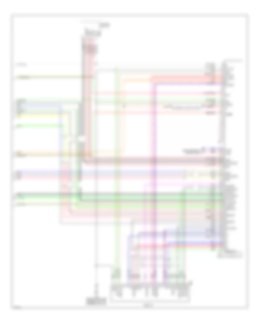
NAVIGATION Navigation Wiring Diagram, with Bose System (1 of 2) for Infiniti FX35 2003 List of elements for Navigation Wiring Diagram, with Bose System (1 of 2) for Infiniti FX35 2003: 66 (at base of right "c" pillar) b210 12a 16a 8 p/r Acc Audio unit B207 B208 B209 B210 (at base of right "c" pillar) B212 B213 Back-up Bat Body computer system Bose speaker amplifier (at right side of luggage compt, behind wheel well) Bus+ Bus- Can-h Can-l Computer data Data gnd Earth Fr lh ch1+ Fr lh ch1- Fr lh spk+ Fr lh spk- Fr sp lh (+) Fr sp lh (-) Front door speaker lh Fuse & fusible link block (at right front of engine comp) Fuse 10a Fuse 15a Fuse 20a Fuse block (j/b) (behind left side of dash) Gnd Gps ant gnd Gps antenna Gps sig Hot at all times Hot in acc or on Hot in on or start Ign Instrument speaker lh Lines system M55 M56 M58 M59 Navi control unit (under right front passenger's seat) Navi gnd Navi input+ Navi input- Nca Pnk Red Rgb shield Rgb sync Rx (dcu-aud) Shield Speed Sync shield Tx (aud-dcu) Unified meter & a/c amp (behind lower center of dash) Voice + Voice - Navigation Wiring Diagram, with Bose System (2 of 2) for Infiniti FX35 2003 List of elements for Navigation Wiring Diagram, with Bose System (2 of 2) for Infiniti FX35 2003: 42 A/c & av switch Acc Aud shield Aud-dcu Bat Bus shield Bus+ Bus- Can-h Can-l Computer data lines system Dcu-aud Dcu-dsp Display Display control unit Dsp gnd Dsp shield Dsp-dcu Exterior lights system Gnd Ign Ill Inv gnd Inv vcc M35 (behind left side of dash, left of steering column) M63 M75 M76 Nca Pnk Red Rgb gnd Rgb sy Rgb sync Shield Sig gnd Sig vcc Sign gnd Sign vcc Speed Sync gnd Sysco Navigation Wiring Diagram, without Bose System (1 of 2) for Infiniti FX35 2003 List of elements for Navigation Wiring Diagram, without Bose System (1 of 2) for Infiniti FX35 2003: 56 (behind right side of dash, above blower motor) m85 12a 8 p/r Acc Audio unit B207 B208 B209 Back-up Bat Body computer system Bus+ Bus- Can-h Can-l Computer data Data gnd Earth Fr sp lh (+) Fr sp lh (-) Front door speaker lh Fuse & fusible link block (at right front of engine comp) Fuse 10a Fuse 15a Fuse block (j/b) (behind left side of dash) Gnd Gps ant gnd Gps antenna Gps sig Hot at all times Hot in acc or on Hot in on or start Ign Instrument speaker lh Lines system M55 M56 M58 M59 Navi control unit (under right front passenger's seat) Navi gnd Navi input+ Navi input- Nca Pnk Red Rgb shield Rgb sync Rx (dcu-aud) Shield Speed Sync shield Tx (aud-dcu) Unified meter & a/c amp (behind lower center of dash) Voice + Voice - Navigation Wiring Diagram, without Bose System (2 of 2) for Infiniti FX35 2003 List of elements for Navigation Wiring Diagram, without Bose System (2 of 2) for Infiniti FX35 2003: 42 A/c & av switch Acc Aud shield Aud-dcu Bat Bus shield Bus+ Bus- Can-h Can-l Computer data lines system Dcu-aud Dcu-dsp Display Display control unit Dsp gnd Dsp shield Dsp-dcu Exterior lights system Gnd Ign Ill Inv gnd Inv vcc M35 (behind left side of dash, left of steering column) M63 M75 M76 Nca Pnk Red Rgb gnd Rgb sy Rgb sync Shield Sig gnd Sig vcc Sign gnd Sign vcc Speed Sync gnd Sysco Rear Camera Wiring Diagram for Infiniti FX35 2003 List of elements for Rear Camera Wiring Diagram for Infiniti FX35 2003: 37 (behind right side of dash, above blower motor) m85 Acc B45 (at left side of luggage compt) Back-up lamp relay (in luggage compartment, above left rear wheelwell) Camera Camera 6v Camera+ Camera- Compo sync Compo+ Compo- Control 1 Data link connector (below left side of dash) Ddl Display Display control unit (behind center of dash) Exterior lights system Fuse 10a Fuse block (j/b) (behind left kick panel) Fuse fuse 10a Gnd Hot at all times Hot in on or start Intelligent power distribution module engine room (right rear of eng compt) Joint connector Nca Rear view camera Rear view camera control unit (behind center console) Rev Rev lamp rly Rv cam Sync Transmission control module Tv+/ Tv-/ Vtr+ Vtr-
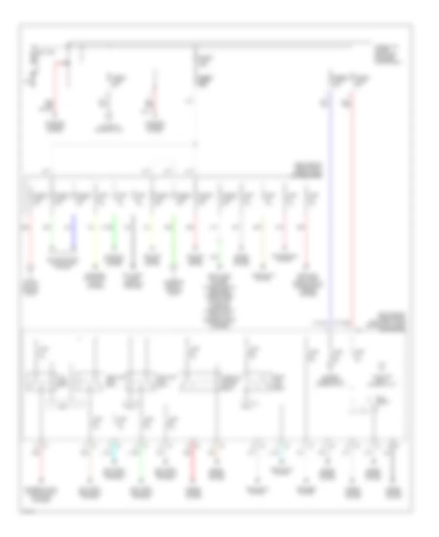
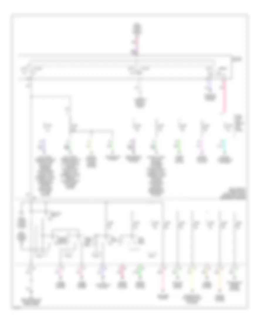
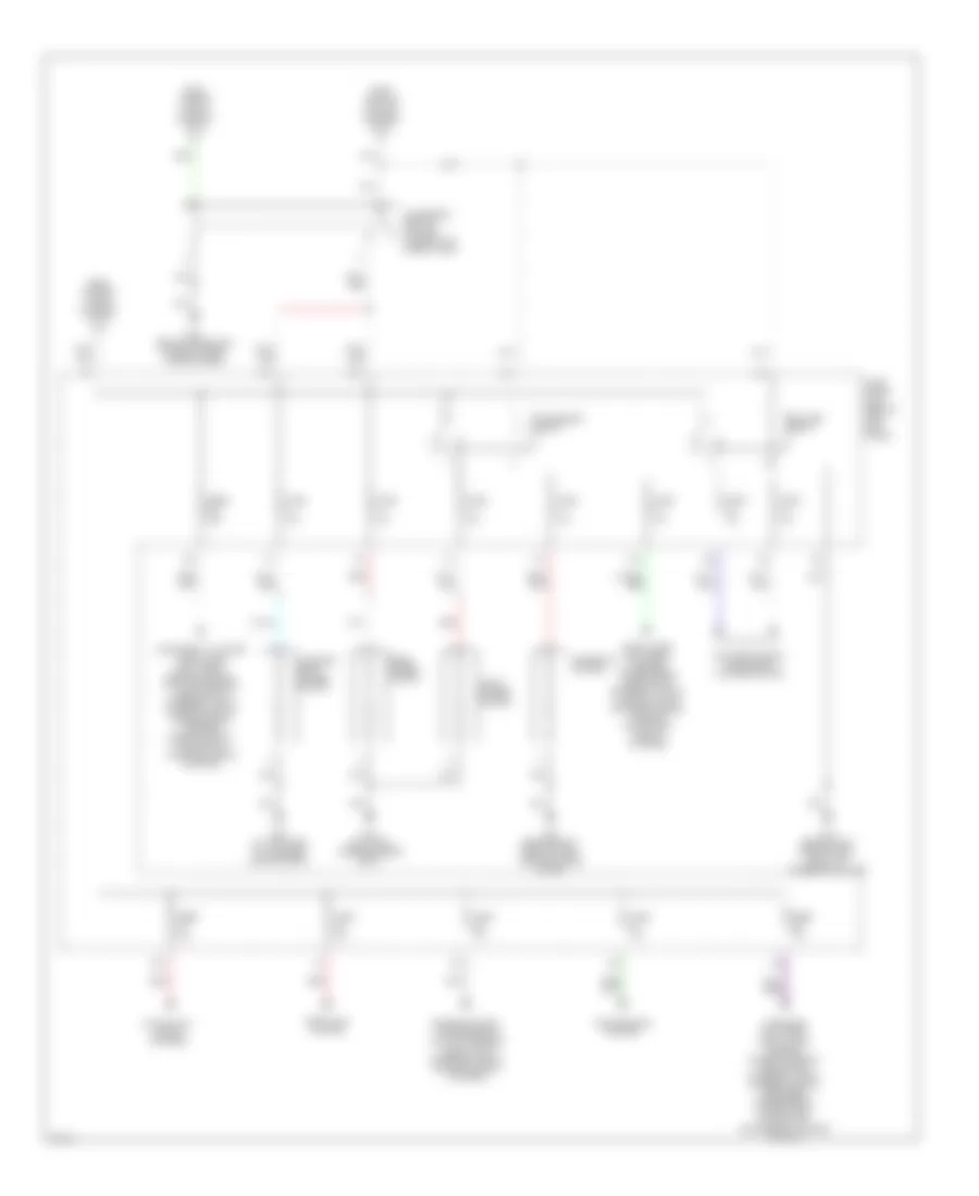
POWER DISTRIBUTION Power Distribution Wiring Diagram (1 of 3) for Infiniti FX35 2003 List of elements for Power Distribution Wiring Diagram (1 of 3) for Infiniti FX35 2003: 50 (right rear of engine compt) fuse & fusible link & relay box (right rear of engine compt) intelligent power distribuiton module (engine room) Air conditioning, cooling fans system Anti-theft, headlights systems Anti-theft, horns, door lock systems Antilock brake system Awd Battery Cpu Cruise control system Defogger system Defogger, navigation, sound systems Door lock, anti-theft, interior lights, power seats, warning systems Door locks, anti-theft, mirrors, power windows, defogger, wiper/washer, power tops, navigation, warnings, interior lights, headlamps, exterior lights, power seats systems Ecm relay Engine control system Exterior lights, interior lights, navigation systems Front fog lamp relay Fuse 10a Fuse 15a Fuse 20a Fuse 30a Fusible fusible link c 80a Fusible fusible link e link b 100a 100a Fusible link a 120a Fusible link d 60a Fusible link e 80a Fusible link f 40a Fusible link g 40a Fusible link h 40a Fusible link holder (right rear of engine compartment) Fusible link i 50a Fusible link k 30a Fusible link l 40a Fusible link m 50a Headlamp high relay Headlamp low relay Headlights system Nca Pnk Red Starting/ charging system Tail lamp relay Throttle control motor relay To accessory relay-2 (diagram 3 of 3) To front wiper relay (diagram 2 of 3) To fuse 19 (diagram 2 of 3) To ignition relay (diagram 2 of 3) To ignition switch (diagram 2 of 2) Transmission system Power Distribution Wiring Diagram (2 of 3) for Infiniti FX35 2003 List of elements for Power Distribution Wiring Diagram (2 of 3) for Infiniti FX35 2003: 39 (right rear of engine compt) intelligent power distribuiton module engine room (ipdm e/r) 15a A/c relay Acc Air conditioning system Anti-theft, engine controls, power window, power top, defogger, warning, wiper/washer, navigation, interior lights, exterior lights, headlights, power seats, mirrors, door locks, instrument cluster system Anti-theft, engine controls, transmission, antilock brake, warning, sound system, navigation, interior lights, exterior lights, mirrors, air conditioning, instrument cluster system Antilock brake system Cpu Defogger system E21 (behind headlamp, on right front inner fender) Engine control system Engine controls system Engine controls, cruise control system From fuse 73 (diagram 1 of 3) From fusible link e (diagram 1 of 3) From fusible link f (diagram 1 of 3) Front wiper high relay Front wiper relay Fuel pump relay Fuse 10a Fuse 15a Fuse 20a Fuse block (j/b) (behind left kick panel) Ig1 Ignition relay Ignition switch Mirrors, power seats systems Off Pnk Power seats system Red Start Starting/ charging system To accessory relay-2 (diagram 3 of 3) Transmission system Transmission, engine control systems Transmission, exterior lights, navigation systems Wiper/ washer system Power Distribution Wiring Diagram (3 of 3) for Infiniti FX35 2003 List of elements for Power Distribution Wiring Diagram (3 of 3) for Infiniti FX35 2003: 36 11a 12a 13a 14a 16a 8a 8a Accessory relay Accessory relay-2 (in fuse, fusible link & relay box) Air conditioning, instrument cluster system B15 (on floor, under driver's seat) B45 (at left side of luggage compartment) Blower relay Cigarette lighter Door lock system Door locks, anti-theft, mirrors, power seats, headlights, exterior lights, interior lights, air conditioning, warning, navigation, sound systems E21 (behind headlamp, on right front inner fender) Engine control, transmission, antilock brakes, door locks, exterior lights, cruise control systems From fusible link d (diagram 1 of 3) From fusible link k (diagram 1 of 3) From ignition switch (diagram 2 of 3) Front power socket Fuse 10a Fuse 15a Fuse block (j/b) (behind left kick panel) Fuse fuse 10a 10a Fuse fuse 15a Fuse fuse 20a Instrument cluster, door locks anti-theft, engine control, antilock brakes, headlights, exterior lights, interior lights, transmission, warning, cruise control, navigation, air conditioning systems Luggage room power socket M45 (behind left side of dash, right of steering column) M85 (behind right side of dash, above blower motor) Navigation, sound systems Rear power socket Red Transmission system Warnings, anti-theft, door locks mirrors, power windows, headlights, exterior lights, interior lights, defogger, power seats, power tops, navigation, instrument cluster system
POWER DOOR LOCKS Power Door Locks Wiring Diagram, with Intelligent Key Unit (1 of 3) for Infiniti FX35 2003 List of elements for Power Door Locks Wiring Diagram, with Intelligent Key Unit (1 of 3) for Infiniti FX35 2003: 71 (behind left side of dash, right of steering column) m45 12a 15a Acc sw B14 Back door sw Bat (f/l) Bat (fuse) Bat saver output Body control module (behind left kick panel) Can-h Can-l Closed Computer data lines system Cpu Door sw (as) Door sw (dr) Door sw (rl) Door sw (rr) Dr lock out (all) Dr unlock out Dr unlock out (dr) Driver side front door lock assembly (door lock actuator) Driver side front door switch Exterior lights system Fuel lid lock actuator Fuse 10a Fuse 15a Fuse block (j/b) (behind left kick panel) Fuse, fusible link & relay box (at right rear of engine compartment) Fusible link m 50a Gnd Gnd (power) Gnd (signal) Horn relay Horn relay (in fuse, fusible link & relay box) Hot at all times Ign knob sw Ign sw Inserted Intelligent power distribution module (engine room) Interior lights system J/c 4 (forward of left rear wheelwell) J/c 4 (forward of left rear wheelwell) J/c 5 (forward of left rear wheelwell, taped to harness) Key ring output Key sw Key switch Key switch & ignition knob switch Left flasher output Left rear door lock actuator Left rear door switch Lock M85 (behind right side of dash, above blower motor) Open Passenger side front door lock assembly (door lock actuator) Passenger side front door switch Passenger side front power window switch (door lock & unlock switch) Passenger side select unlock relay (under left side of dash) Pnk Pushed Pwr wdo serial link Red Removed Right flasher output Right rear door lock actuator Right rear door switch Room lamp output Step lamp output Unlock Withdrawn Power Door Locks Wiring Diagram, with Intelligent Key Unit (2 of 3) for Infiniti FX35 2003 List of elements for Power Door Locks Wiring Diagram, with Intelligent Key Unit (2 of 3) for Infiniti FX35 2003: 62 (at left side of luggage compt) b45 +12 12a Acc sw As door ant+ As door ant- As request sw As unlock output Back door closure motor (door open Back dr ant+ Back dr ant- Bat Bk dr open output Bk dr open switch Bk dr request sw Can h Can l Closed Doors system tailgate, fuel Dr buzzer output Dr door ant+ Dr door ant- Dr lk cond sw Dr request sw E50 (at left side of eng compt) Fuse 10a Fuse block (j/b) (behind left kick panel) Gnd High horn (below right headlight) Hot at all times Hot in on or start Ign sw Instrument cluster system Intelligent key unit (behind left end of dash) Intelligent key warning buzzer (driver side) (in driver's door) Intelligent key warning buzzer (passenger side) (in driver's door) J/c 2 (behind left side of dash, taped to harness) J/c 2 (behind left side of dash, taped to harness) Low horn (below left headlight) Lugg ant 1+ Lugg ant 1- M85 (behind right side of dash, above blower motor) P range sw Pnk Push switch Red Released Room ant 1+ Room ant 1- Room ant 2+ Room ant 2- Signal Steering lock unit (behind left side of dash, near steering column) Stop lamp sw Stoplight depressed Strg lk 5v output Strg lock gnd Strg lock sig Switch (above brake pedal, on bracket) Switch) System data lines computer Trunk, Power Door Locks Wiring Diagram, with Intelligent Key Unit (3 of 3) for Infiniti FX35 2003 List of elements for Power Door Locks Wiring Diagram, with Intelligent Key Unit (3 of 3) for Infiniti FX35 2003: 29 (behind left side of dash, right of steering column) m45 A/t device Back door outside key antenna Back door request switch Between full stroke & n Cpu Dashboard inside key antenna-1 Dashboard inside key antenna-2 Detention switch Driver side front door lock assembly (door unlock sensor) Driver side front door lock assembly (key cylinder switch) Driver side front door request switch Driver side outside door mirror key antenna Full stroke Gnd Key cyl lock sw Key cyl unlock sw Lock Luggage room inside key antenna-3 M45 (behind left side of dash, right of strg column) M85 (behind right side of dash, above blower motor) Nca Others Passenger side front door request switch Passenger side outside door mirror key antenna Pnk Power window main switch (door lock & unlock switch) Pwr wdo serial link Unlock Power Door Locks Wiring Diagram, without Intelligent Key Unit for Infiniti FX35 2003 List of elements for Power Door Locks Wiring Diagram, without Intelligent Key Unit for Infiniti FX35 2003: 75 (at left side of engine compartment) e50 (behind left side of dash, right of steering column) m45 (behind right side of dash, above blower motor) m85 12a 15a Acc sw B14 Back door closure motor (door switch) Back door sw Bat (f/l) Bat (fuse) Between full stroke & n Body control module (behind left kick panel) Can-h Can-l Closed Computer data lines system Cpu Door sw (as) Door sw (dr) Door sw (rl) Door sw (rr) Dr lock out (all) Dr unlock out Dr unlock out (dr) Driver side front door lock assembly (door lock actuator) Driver side front door lock assembly (key cylinder switch) Driver side front door switch Exterior lights system Fuel lid lock actuator Full stroke Fuse 10a Fuse 15a Fuse block (j/b) (behind left kick panel) Fuse, fusible link & relay box (at right rear of engine compartment) Fusible link m 50a Gnd Gnd (power) Gnd (signal) High horn (below right headlight) Horn relay Horn relay (in fuse, fusible link & relay box) Hot at all times Ign sw Inserted Intelligent power distribution module (engine room) Interior lights system J/c 2 J/c 4 J/c 6 Key cyl lock sw Key cyl unlock sw Key ring output Key sw Key switch Left flasher output Left rear door lock actuator Left rear door switch Lock Low horn (below left headlight) Open Passenger side front door lock assembly (door lock actuator) Passenger side front door switch Passenger side front power window switch (door lock & unlock switch) Pnk Power window main switch (door lock & unlock switch) Pwr wdo serial link Red Removed Right flasher output Right rear door lock actuator Right rear door switch Room lamp output Step lamp output Unlock
POWER MIRRORS Power Mirrors Wiring Diagram for Infiniti FX35 2003 List of elements for Power Mirrors Wiring Diagram for Infiniti FX35 2003: 15 12a Change over switch Defogger system Door mirror remote control switch Fuse 6 10a Fuse block (j/b) (behind left kick panel) Hot in acc or on Left door mirror Left/right motor M45 (behind left side of dash, right of steering column) Mirror switch Off Pnk Right door mirror Up/down motor
POWER SEATS Heated Seats Wiring Diagram for Infiniti FX35 2003 List of elements for Heated Seats Wiring Diagram for Infiniti FX35 2003: 21 16a B15 (on floor, under driver's seat) Driver side front power seat Driver side heated seat switch Fuse 15 10a Fuse block (j/b) (behind left kick panel) High Hot in on or start Illumination Indicator Interior lights system Low M85 (behind right side of dash) Main heater Nca Passenger side front power seat Passenger side heated seat switch Red Seat back heater Seat cushion heater Sub- heater Power Seats Wiring Diagram for Infiniti FX35 2003 List of elements for Power Seats Wiring Diagram for Infiniti FX35 2003: 20 16a B15 (on floor, under driver's seat) Circuit breaker (behind left side of dash) Driver side front power seat Fuse & fusible link & relay box (right rear of eng compt) Fuse m 50a Hot at all times Lifting Lifting motor (front) Lifting motor (rear) Lifting switch (front) Passenger side front power seat Power seat switch Reclining Reclining motor Red Sliding motor Sliding switch Switch Switch (rear)
POWER TOP/SUNROOF Power Top/Sunroof Wiring Diagram for Infiniti FX35 2003 List of elements for Power Top/Sunroof Wiring Diagram for Infiniti FX35 2003: 37 15a 2p/r B14 Bat (f/l) Batt (fuse) Body control module (behind left kick panel) Can-h Can-l Computer data lines system Dr door sw Driver side front door switch Fuse & fusible link & relay box (right rear of eng compt) Fuse 15a Fuse block (j/b) (behind left side of dash) Fusible link m 50a Gnd Gnd (power) Gnd (signal) Hot at all times Hot in on or start Ign sw M45 (behind left side of dash, right of steering column) Pas door sw Passenger side front door switch Pwr wdo pwr sup (bat) Pwr wdo pwr sup (rap) R6 (above headliner, near sunroof motor) Red Speed sensor (2p) Sun roof motor assembly (on front center of roof) Sun roof switch Sw- bit3 Sw- bit4 Till down/ slide open Till up/ slide close Timer (+ign) Unified meter & a/c amp (behind center of dash)
POWER WINDOWS Power Windows Wiring Diagram, Base for Infiniti FX35 2003 List of elements for Power Windows Wiring Diagram, Base for Infiniti FX35 2003: 42 Bat Body control module (bcm) (behind left kick panel) Can-h Can-l Computer data lines system Cpu Down Drivers door lock assembly Encoder Encoder power Encoder pwr Fuse & fusible link box (at right rear of engine compartment) Fuse m 50a Gnd Ground Hot at all times Illum Illumination Intelligent key unit (if equipped) (behind left end of dash) Interior lights system Left front power window regulator Left rear power window regulator Left rear power window switch Limit sw Limit sw gnd Limit switch Lock Lock switch M45 (behind left side of dash, right of strg column) M85 (behind right side of dash, above blower mtr) Pnk Power window main switch Pulse Rap Red Right front power window regulator Right front power window switch Right rear power window regulator Right rear power window switch Serial link Unlk Unlock Power Windows Wiring Diagram, Up Level for Infiniti FX35 2003 List of elements for Power Windows Wiring Diagram, Up Level for Infiniti FX35 2003: 44 B15 (on floor under driver's seat) Bat Body control module (bcm) (behind left kick panel) Can-h Can-l Computer data lines system Cpu Down Drivers door Encoder Encoder power Encoder pwr Fuse & fusible link box (at right rear of engine compartment) Fuse m 50a Gnd Ground Hot at all times Illum Illumination Intelligent key unit (if equipped) (behind left end of dash) Left front power window regulator Left rear power window regulator Left rear power window switch Limit sw Limit sw gnd Limit switch Link Lock Lock assembly Lock switch M45 (behind left side of dash, right of strg column) M85 (behind right side of dash, above blower mtr) Pnk Power window main switch Pulse Rap Red Right front power window regulator Right front power window switch Right rear power window regulator Right rear power window switch Serial link Unlk Unlock
RADIO Base Model Wiring Diagram, with Navigation (1 of 2) for Infiniti FX35 2003 List of elements for Base Model Wiring Diagram, with Navigation (1 of 2) for Infiniti FX35 2003: 79 (dsp-aud) rx (dsp-aud) tx 12a 2p/r 8p/r A/c & av switch Acc Ant sig Aud shield Aud-dcu Audio unit B+ Bat (back-up) Bus gnd Bus shield Bus+ Bus- Can-h Can-h Can-l Can-l Computer data lines system Data gnd Dcu-aud Dcu-dsp Display Display control unit (behind center of dash) Dsp shield Dsp-dcu Earth Earth Fuse & fusible link block (right rear of engine compt) Fuse 12 10a Fuse 32 15a Fuse 6 10a Fuse block (j/b) (behind left kick panel) Gnd Hot at all times Hot in on or acc Hot in on or start Ign Ill Ill cont Interior lights system Inv gnd Inv vcc Lh fr sp (+) Lh fr sp (-) Lh rr sp (+) Lh rr sp (-) M58 M59 M60 M75 M76 M85 (behind right side of dash, above blower motor) Nca Pnk Red Rgb gnd Rgb sync Rh fr sp (+) Rh fr sp (-) Rh rr sp (+) Rh rr sp (-) Shield Sig gnd Sig vcc Sign gnd Sign vcc Speed Speed signal Str sw a up Str sw b dwn Str sw c gnd Sync gnd Sysco Unified meter and a/c amplifier (behind center of dash) Window antenna Base Model Wiring Diagram, with Navigation (2 of 2) for Infiniti FX35 2003 List of elements for Base Model Wiring Diagram, with Navigation (2 of 2) for Infiniti FX35 2003: 25 Antenna amplifier (behind center of dash) Audio steering wheel switch B45 (left side of luggage compt) Combination switch Down Joint connector 5 Left front door speaker Left instrument speaker Left rear door speaker M45 (behind left side of dash, right of steering column) Nca Not used Off Option connector for audio unit Option connector for satellite radio receiver Pnk Red Right front door speaker Right instrument speaker Right rear door speaker Rod antenna Switch mode Switch power Switch seek Switch volume Base Model Wiring Diagram, without Navigation for Infiniti FX35 2003 List of elements for Base Model Wiring Diagram, without Navigation for Infiniti FX35 2003: 79 (dsp-aud) rx (dsp-aud) tx 12a 2p/r 8p/r A/c & av switch Acc Acc Ant sig Antenna amplifier (behind center of dash) Audio steering wheel switch Audio unit B+ B45 (left side of luggage compt) Bat (back-up) Bus+ Bus- Bus- Can-h Can-l Combination switch Computer data lines system Data gnd Display unit Down Fuse & fusible link block (right rear of engine compt) Fuse 12 10a Fuse 32 15a Fuse 6 10a Fuse block (j/b) (behind left kick panel) Gnd Ground Hot at all times Hot in on or acc Hot in on or start Ign Ill Ill cont Interior lights system Joint connector 5 Left front door speaker Left instrument speaker Left rear door speaker Lh fr sp (+) Lh fr sp (-) Lh rr sp (+) Lh rr sp (-) M45 (behind left side of dash, right of steering column) M58 M59 M60 M85 (behind right side of dash, above blower motor) Nca Off Option connector for audio unit Option connector for satellite radio receiver Pnk Red Rh fr sp (+) Rh fr sp (-) Rh rr sp (+) Rh rr sp (-) Right front door speaker Right instrument speaker Right rear door speaker Rod antenna Shield Shield gnd Speed Speed signal Str sw a up Str sw b dwn Str sw c gnd Switch mode Switch power Switch seek Switch volume Unified meter and a/c amp (behind center of dash) Window antenna Premium AM/FM Stereo Radio Wiring Diagram, with Navigation (2 of 2) for Infiniti FX35 2003 List of elements for Premium AM/FM Stereo Radio Wiring Diagram, with Navigation (2 of 2) for Infiniti FX35 2003: 34 Amp on signal Antenna amplifier (behind center of dash) Audio steering wheel switch B15 (on floor, under driver's seat) B210 (at base of right "c' pillar) B45 (left side of luggage compt) Center instrument speaker Combination switch Down Input (+) Input (-) Joint connector 5 Junction connector 6 Left front door speaker Left instrument speaker Left rear door speaker Left tweeter M45 (behind left side of dash, right of steering column) Nca Off Option connector for audio unit Option connector for satellite radio receiver Pnk Red Right front door speaker Right instrument speaker Right rear door speaker Right tweeter Rod antenna Switch mode Switch power Switch seek Switch volume Woofer Premium AM/FM Stereo Radio Wiring Diagram, without Navigation (1 of 2) for Infiniti FX35 2003 List of elements for Premium AM/FM Stereo Radio Wiring Diagram, without Navigation (1 of 2) for Infiniti FX35 2003: 89 (dsp-aud) rx b+ acc (dsp-aud) rx (dsp-aud) tx 12a 16a 2p/r 8p/r A/c & av switch Acc Amp on Ant sig Audio unit B+ acc ign B212 B213 Bat (back-up) Bose speaker amp (right side of luggage compt, behind wheel well) Bus+ Bus- Bus- can-h Can-h Can-l Center sp 5 out (+) Center sp 5 out (-) Computer data lines system Control (swb +) Data gnd Display unit Earth Earth Ext amp ctrl out Fuse & fusible link block (right rear of engine compt) Fuse 12 10a Fuse 17 20a Fuse 32 15a Fuse 6 10a Fuse block (j/b) (behind left kick panel) Gnd Ground Hot at all times Hot in on or acc Hot in on or start Ill Ill cont Interior lights system Lh fr ch 1 in (+) Lh fr ch 1 in (-) Lh fr sp (+) Lh fr sp (-) Lh fr sp 1 out (+) Lh fr sp 1 out (-) Lh rr ch 3 in (+) Lh rr ch 3 in (-) Lh rr sp (+) Lh rr sp (-) Lh rr sp 3 out (+) Lh rr sp 3 out (-) M58 M59 M60 M85 (behind right side of dash, above blower motor) Nca Pnk Red Rh fr ch 2 in (+) Rh fr ch 2 in (-) Rh fr sp (+) Rh fr sp (-) Rh fr sp 2 out (+) Rh fr sp 2 out (-) Rh rr ch 4 in (+) Rh rr ch 4 in (-) Rh rr sp (+) Rh rr sp (-) Rh rr sp 4 out (+) Rh rr sp 4 out (-) Rr tw sp 7 (+) Rr tw sp 7 (-) Shield Shield gnd Speed Speed signal (dsp-aud) tx Str sw a up Str sw b dwn str sw c gnd Unified meter and a/c amp (behind center of dash) Window antenna Woofer sp 6 out (+) Woofer sp 6 out (-) Premium AM/FM Stereo Radio Wiring Diagram, without Navigation (2 of 2) for Infiniti FX35 2003 List of elements for Premium AM/FM Stereo Radio Wiring Diagram, without Navigation (2 of 2) for Infiniti FX35 2003: 34 Amp on signal Antenna amplifier (behind center of dash) Audio steering wheel switch B15 (on floor, under driver's seat) B210 (at base of right "c' pillar) B45 (left side of luggage compt) Center instrument speaker Combination switch Down Input (+) Input (-) Joint connector 5 Junction connector 6 Left front door speaker Left instrument speaker Left rear door speaker Left tweeter M45 (behind left side of dash, right of steering column) Nca Off Option connector for audio unit Option connector for satellite radio receiver Pnk Red Right front door speaker Right instrument speaker Right rear door speaker Right tweeter Rod antenna Switch mode Switch power Switch seek Switch volume Woofer
SHIFT INTERLOCK Shift Interlock Wiring Diagram for Infiniti FX35 2003 List of elements for Shift Interlock Wiring Diagram for Infiniti FX35 2003: 12 (behind right side of dash, above blower motor) m85 A/t device (at bottom of) transmission) Depressed Detent switch Diode Door locks system Fuse 10a Fuse block (j/b) (behind left side of dash) Hot in on or start Released Shift lock solenoid Stop lamp switch (above brake pedal, on bracket)
STARTING/CHARGING Charging Wiring Diagram for Infiniti FX35 2003 List of elements for Charging Wiring Diagram for Infiniti FX35 2003: 15 (fusible link holder (right rear of eng compt) 3.5l w/ 2wd 4.5l & 3.5l w/ awd Alternator Battery Charge indicator Combination meter E304 (at right side of eng compt near reservoir tank) Fuse & fusible link relay box (right rear of eng compt) Fuse 10a Fuse 14 10a Fuse block (j/b) (behind left kick panel) Fusible link a 120a Hot at all times Hot in on or start Starting Wiring Diagram for Infiniti FX35 2003 List of elements for Starting Wiring Diagram for Infiniti FX35 2003: 28 A/t assembly Acc Battery Computer data lines system Cpu E21 (behind headlamp, on right front inner fender) Fuse & fusible link relay box (right rear of eng compt) Fuse 10a Fuse 15a Fuse link f 40a Gnd (power) Gnd (signal) Hot at all times Hot in on or start Ign Ignition relay Ignition switch Intelligent power distribution module engine room (right rear of eng compt Nca Off Pnp sw or gnd Red Start Start rly Starter Starter motor Starter relay Transmission control module
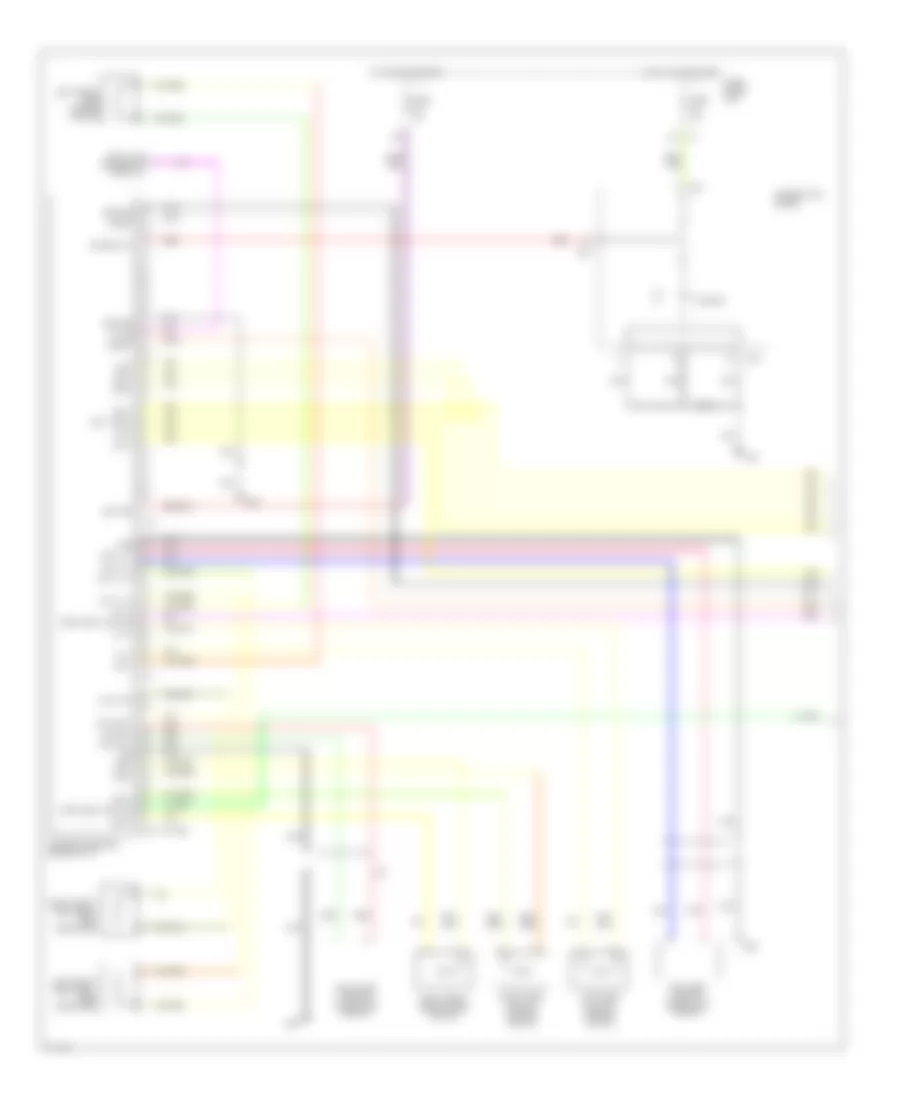
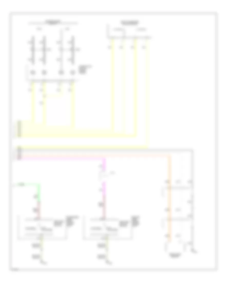
SUPPLEMENTAL RESTRAINTS Supplemental Restraints Wiring Diagram (1 of 2) for Infiniti FX35 2003 List of elements for Supplemental Restraints Wiring Diagram (1 of 2) for Infiniti FX35 2003: 58 Air bag Air bag diagnosis sensor unit Air bag w/l As1 + As1 - As2 + As2 - Aux1 lh + Aux1 lh - Aux1 rh + Aux1 rh - B17 B18 B20 B25 B35 Clh + Clh - Combination meter Crh + Crh - Data link connector (partial) Dr1 + Dr1 - (dr2 -) Dr2 + Eczs + Eczs - Fuse 10a Fuse block (j/b) Gnd Ground Hot in on or start Ignition K-line Left front seat belt pre- tensioner Left front side air bag module Left side air bag (satellite) sensor Left side curtain air bag module M20 M45 M72 M85 Nca Pnk Red Right front seat belt pre- tensioner Right front side air bag module Right side air bag (satellite) sensor Right side curtain air bag module Sat lh + Sat lh - Sat rh + Sat rh - Seat belt switch Slh + Slh - Srh + Srh - Supplemental Restraints Wiring Diagram (2 of 2) for Infiniti FX35 2003 List of elements for Supplemental Restraints Wiring Diagram (2 of 2) for Infiniti FX35 2003: 16 61a B15 Combination switch (spiral cable) Crash zone sensor Driver air bag module Driver side front power seat E31 Fastened Front passenger air bag module J/c 4 M201 M202 Nca Passenger side front power seat Seat belt buckle switch Un- fastened
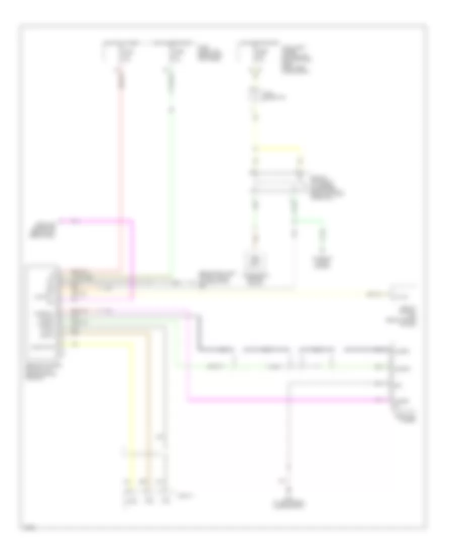
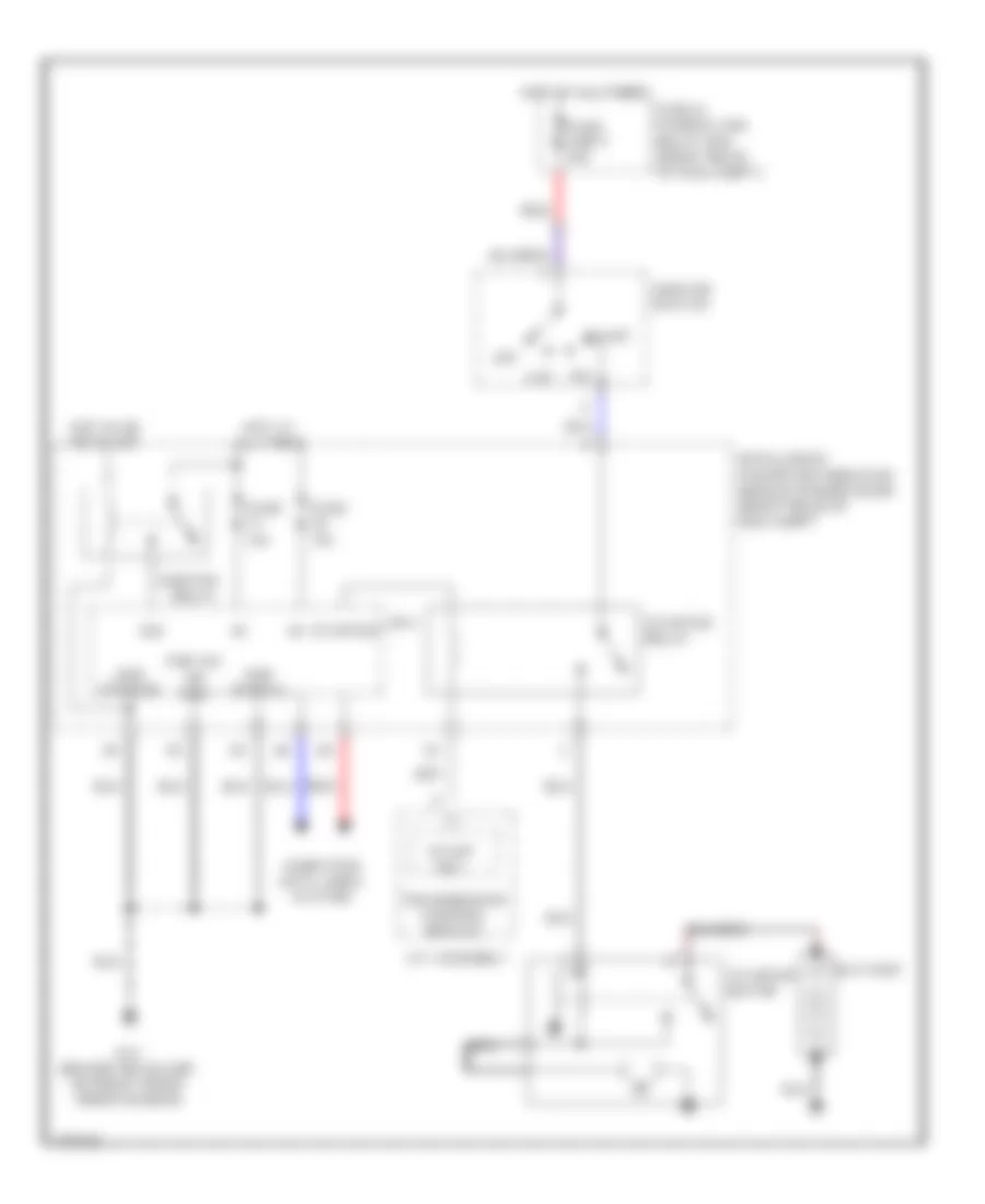
TRANSMISSION A/T Wiring Diagram for Infiniti FX35 2003 List of elements for A/T Wiring Diagram for Infiniti FX35 2003: 92 (behind left side of dash, left of steering column) m45 A/t assembly A/t check indicator A/t device A/t fluid temperature sensor 1 A/t fluid temperature sensor 2 At-p range Atf sens 1+ Atf sens 1- Atf sens 2+ Atf sens 2- Auto Auto mode Batt Can-h Can-l Combination meter Common Computer data lines system Data link connector (below left side of dash) Detection switch Direct clutch solenoid Exterior lights system (backup relay) F11 (left side of engine compt, near ignition coil 1) F44 Front brake solenoid Fuse 10a Fuse block (j/b) (behind left kick panel) Fuse, fusible link & relay box (right rear of engine compt) Gnd Gnd-1 Gnd-2 High & low reverse clutch solenoid Hot at all times Hot in on or start Ign Illum Inh sw 1 Inh sw 2 Inh sw 3 Inh sw 4 Input clutch solenoid Intelligent power distribution module (ipdm e/r) (right rear of engine compt) Interior lights system J/c 1 (below left side of dash) K-line Line pressure solenoid Linear sol Low coast brake solenoid M35 (behind left side of dash, left of steering column) M54 M67 M85 (behind right side of dash, above blower motor) Manual Manual mode Mode select switch Oil press switch 1 Oil press switch 2 Oil press switch 3 Oil press switch 5 Oil press switch 6 On/off sol Park/neutral position switch Position select switch Pressure switch 1 (fr/b) Pressure switch 2 (lc/b) Pressure switch 3 (i/c) Pressure switch 5 (d/c) Pressure switch 6 (hlr/c) Red Rev rly Rev sens gnd Rev sens in Rev sens out Revolution sensor Shift down Shift interlock system Shift lock solenoid Shift up Start rly Starting system (starter relay) Torque converter clutch solenoid Transmission control module (tcm) Turbine revolution sensor 1 Turbine revolution sensor 2 Turbine sens 1 Turbine sens 2 Unified meter & a/c amp Unified meter control unit (w/ a/t indicator) V in V out Vign
TRUNK, TAILGATE, FUEL DOOR Power Liftgate Wiring Diagram, with Intelligent Key Unit for Infiniti FX35 2003 List of elements for Power Liftgate Wiring Diagram, with Intelligent Key Unit for Infiniti FX35 2003: 28 B45 (at left side of luggage compartment) Back door closure control unit (in center of tailgate, below rear wiper motor) Back door closure motor (on center of tailgate) Back door open output Back door open switch Back door opener switch (at lower center of back door) Close sw Close switch Closed Door locks system Door switch Fuse 18 15a Fuse block (j/b) (behind left kick panel) Gnd Half latch sw Half latch switch Hot at all times Intelligent key unit (behind left end of dash) Motor close out Motor open out Off Open Open sw Open switch Open/ close motor Outside handle sw Pnk Red Power Liftgate Wiring Diagram, without Intelligent Key Unit for Infiniti FX35 2003 List of elements for Power Liftgate Wiring Diagram, without Intelligent Key Unit for Infiniti FX35 2003: 28 B45 (at left side of luggage compartment) Back door closure control unit (in center of tailgate, below rear wiper motor) Back door closure motor (on center of tailgate) Back door opener switch (center of back door) Close sw Close switch Closed Door condition sw Door locks system Door switch Front door lock assembly (pass side door unlock sensor) Fuse 18 15a Fuse block (j/b) (behind left kick panel) Gnd Half latch sw Half latch switch Hot at all times M85 (behind right side of dash, above blower motor) Motor close out Motor open out Off Open Open sw Open switch Open/ close motor Outside handle sw Pnk Red
WARNING SYSTEMS Warning Systems Wiring Diagram for Infiniti FX35 2003 List of elements for Warning Systems Wiring Diagram for Infiniti FX35 2003: 70 (behind left side of dash, right of steering column) m45 (on floor, under driver's seat) b15 15a 61a B14 Bat (f/l) Bat (fuse) Batt Belt ind Body control module (bcm) (behind left kick panel) Buzzer Can-h Can-l Comb sw in 1 Comb sw in 2 Comb sw in 3 Comb sw in 4 Comb sw in 5 Comb sw out 1 Comb sw out 2 Comb sw out 3 Comb sw out 4 Comb sw out 5 Combination meter Combination switch Computer data lines system Door sw (dr) Driver side front door switch Front power seat (driver side) Fuse & fusible link & relay box (at right rear of eng compt) Fuse 10a Fuse 15a Fuse block (j/b) (behind left kick panel) Fuse m 50a Gnd Gnd (power) Gnd (signal) Hot at all times Hot in on or start Ign sw Ignition knob switch Input 1 Input 2 Input 3 Input 4 Input 5 Inserted Intelligent ket unit (behind left eng of dash) Joint connector Key sw Key switch Key switch & ignition knob switch M14 (behind left end of dash) Output 1 Output 2 Output 3 Output 4 Output 5 Push sw Pushed Red Removed Rx (comb meter) Seat belt buckle switch Tx (comb meter) Unified meter & a/c amplifier (behind center of dash) Unified meter control unit W/ intelligent key W/o intelligent key Withdrawn
WIPER/WASHER Front Wiper/Washer Wiring Diagram for Infiniti FX35 2003 List of elements for Front Wiper/Washer Wiring Diagram for Infiniti FX35 2003: 44 Bat Body control module (bcm) (behind left kick panel) Can-h Can-l Combination switch (lighting switch) Computer data lines system Cpu E21 (behind headlight, on right front inner fender) E51 (at left side of engine compt, near strut tower) Fr mtr Front washer motor (on washer fluid reservoir) Front wiper hi relay Front wiper motor (on left side of firewall) Front wiper relay Fuse & fusible link box (at right rear of eng compt) Fuse 10a Fuse 15a Fuse 30a Fuse block (j/b) (behind left kick panel) Fuse m 50a Gnd High Hot at all times Hot in on or start Ign Ignition relay Input 1 Input 2 Input 3 Input 4 Input 5 Intelligent power distribution module (engine room) (at right rear corner of engine compt) Low M17 M45 (behind left side of dash, right of steering column) Move Output 1 Output 2 Output 3 Output 4 Output 5 Pnk Red Stop Rear Washer/Wiper Wiring Diagram for Infiniti FX35 2003 List of elements for Rear Washer/Wiper Wiring Diagram for Infiniti FX35 2003: 38 B14 B45 (at left side of luggage compt) Bat Body control module (bcm) (behind left kick panel) Can-h Can-l Combination switch (lighting switch) Computer data lines system Fuse & fusible link box (at right rear of eng compt) Fuse 10a Fuse 15a Fuse block (j/b) (behind left kick panel) Fuse m 50a Gnd Hot at all times Hot in on or start Ign Input 1 Input 2 Input 3 Input 4 Input 5 Intelligent power distribution module (engine room) (at right rear corner of engine compt) M17 M45 (behind left side of dash, right of steering column) Move Output 1 Output 2 Output 3 Output 4 Output 5 Rear washer motor (on washer fluid reservoir) Rear wiper motor (on center of tailgate) Red Rr auto stop Rr mtr Rr mtr out Stop