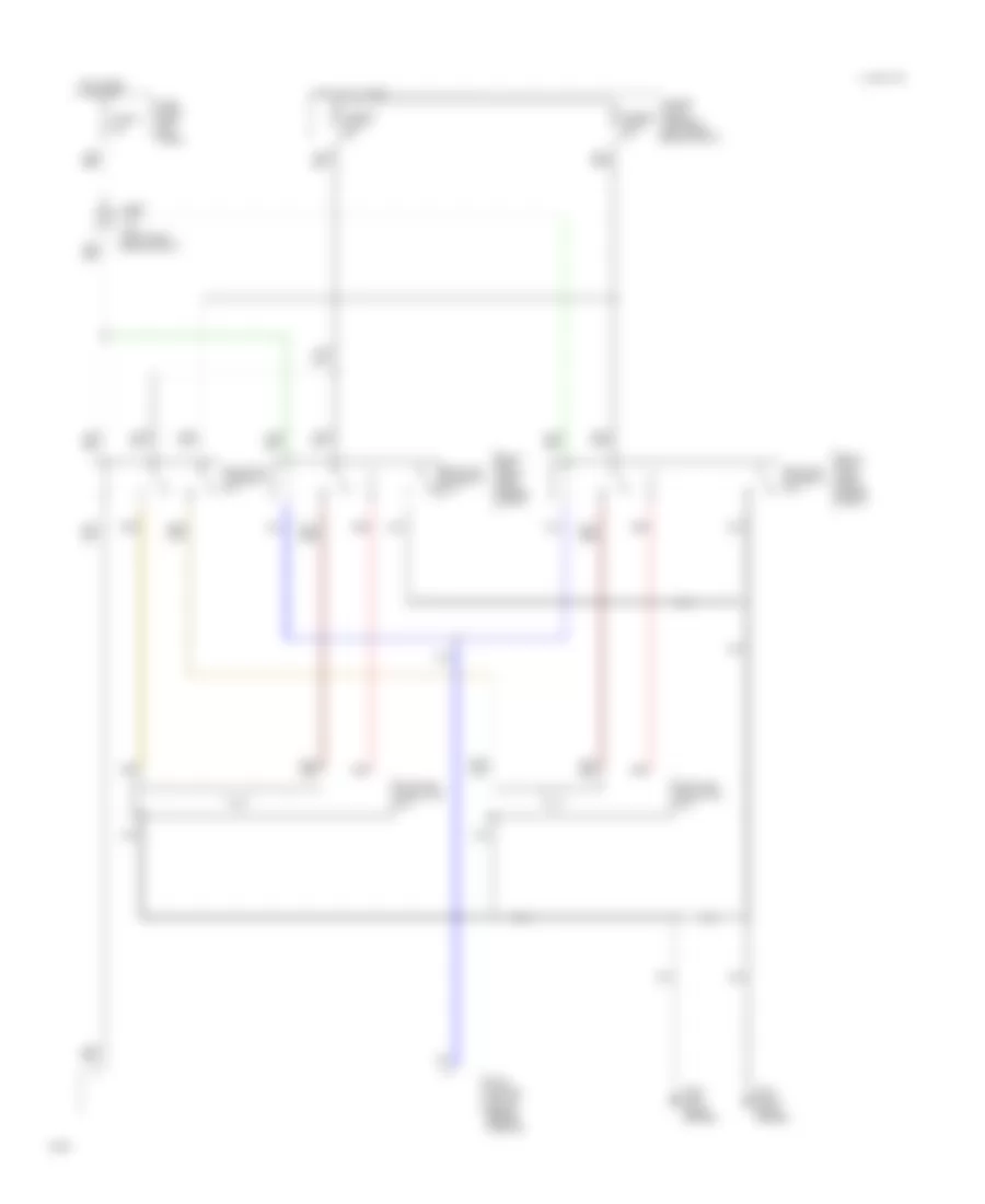
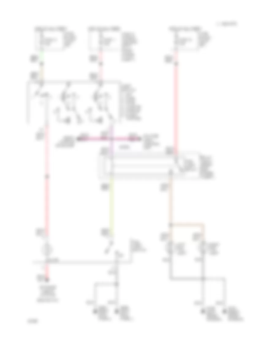
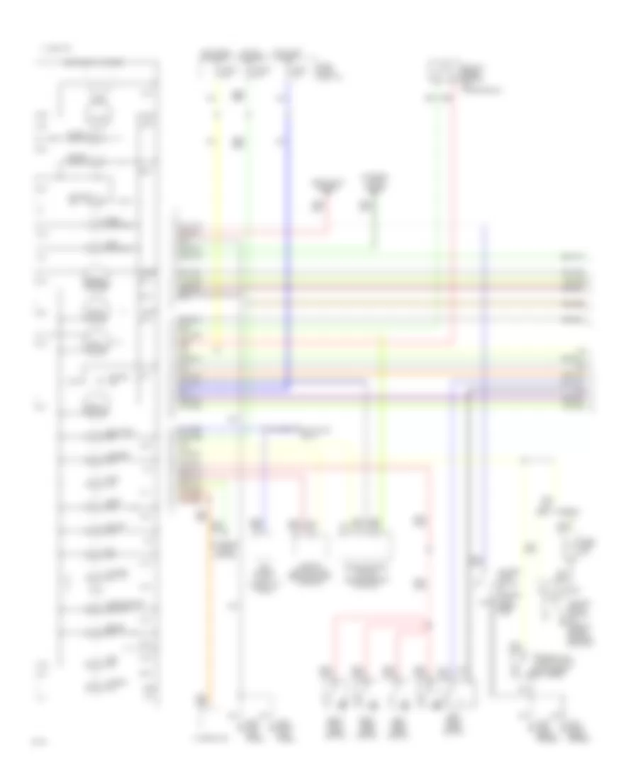
AIR CONDITIONING
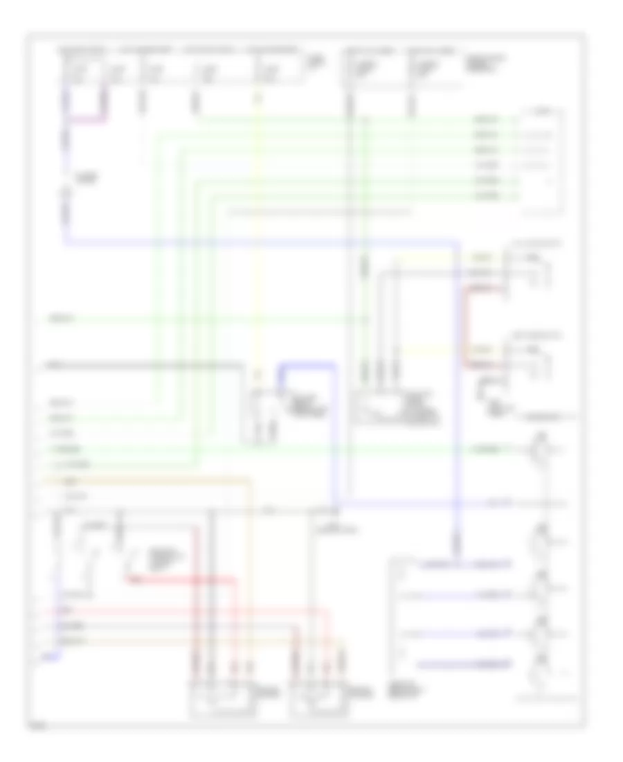
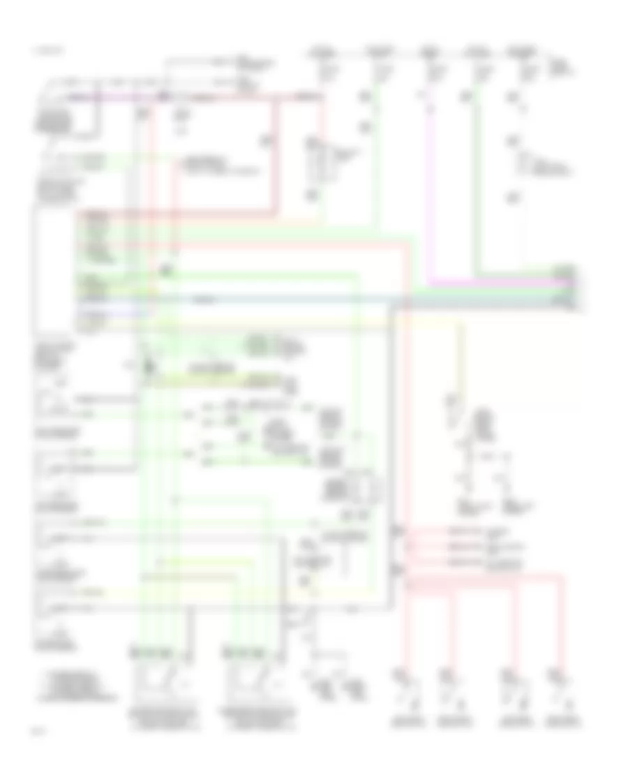
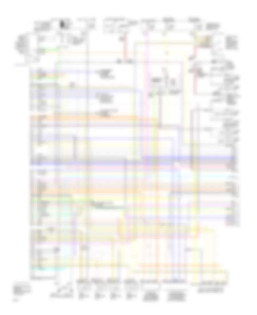
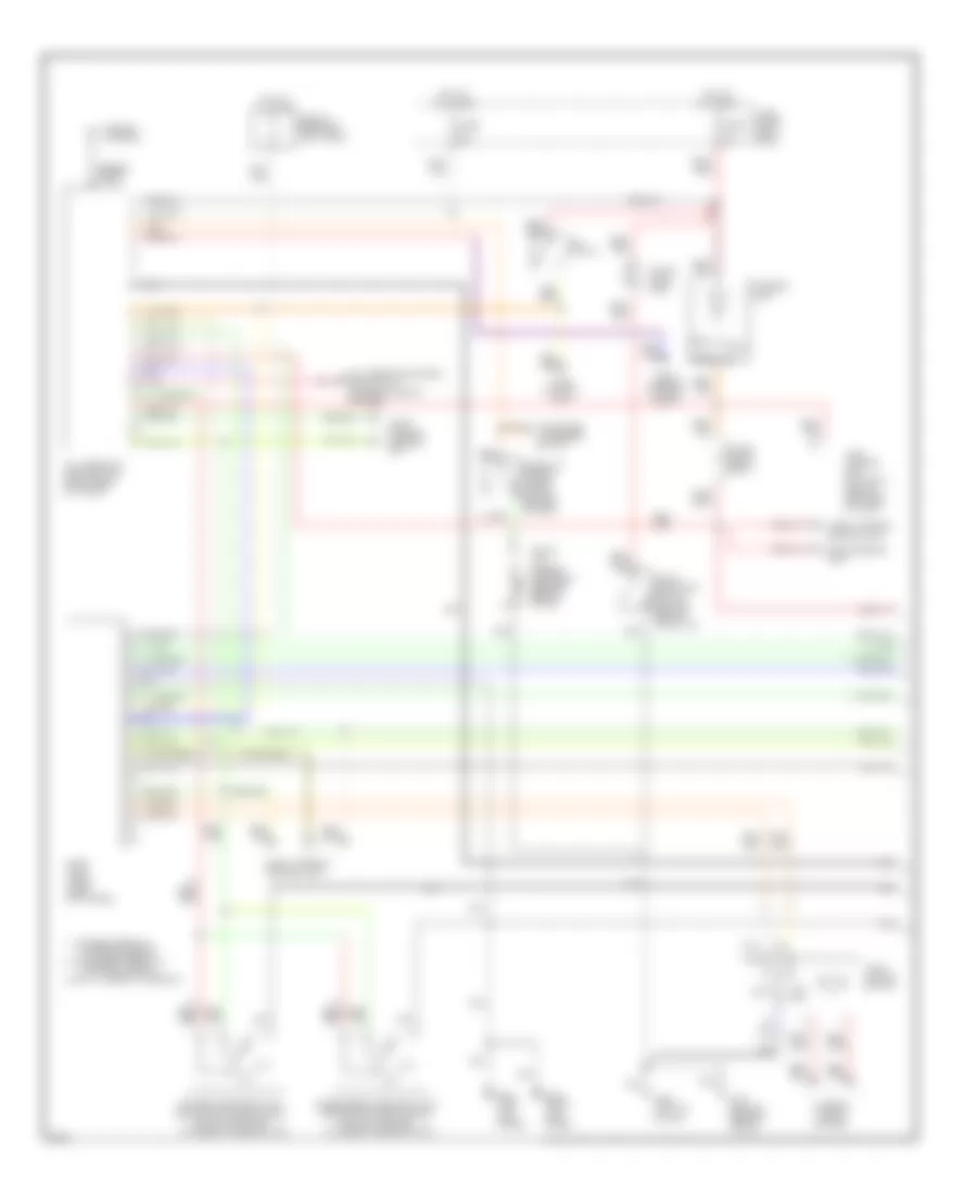
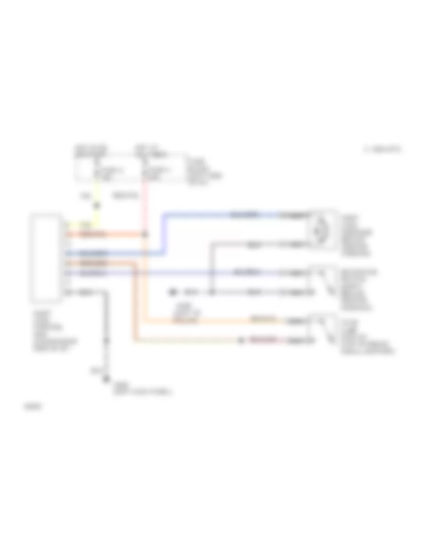
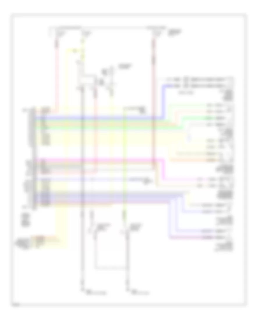
Air Conditioning Wiring Diagrams, A/T (1 of 2) for Infiniti G20 1994

List of elements for Air Conditioning Wiring Diagrams, A/T (1 of 2) for Infiniti G20 1994:
- (attached to front of heater unit)
- (in relay box 2)
- (left front of engine comp., on receiver-drier)
- (left kick panel)
- (near battery)
- A/c comp- ressor clutch
- A/c relay (in relay box 1)
- Acrly
- Arcon
- B/l
- Def
- Eccs control unit (behind center console)
- Except 1996
- F.i.c.d. solenoid valve
- F/d
- Foot
- G101
- G200
- Heater & a/c selector switch
- Intake door motor
- Interior lights system
- Mode door motor
- Nca
- Pdsw
- Push control module
- Radiator fan relay #1 (in relay box 1)
- Radiator fan relay #2
- Red
- Rfrl
- Rfrn
- Thermal protector
- Thermistor
- Thermo control amp (behind center of i/p)
- Triple pressure switch
- Usa only
- Vent
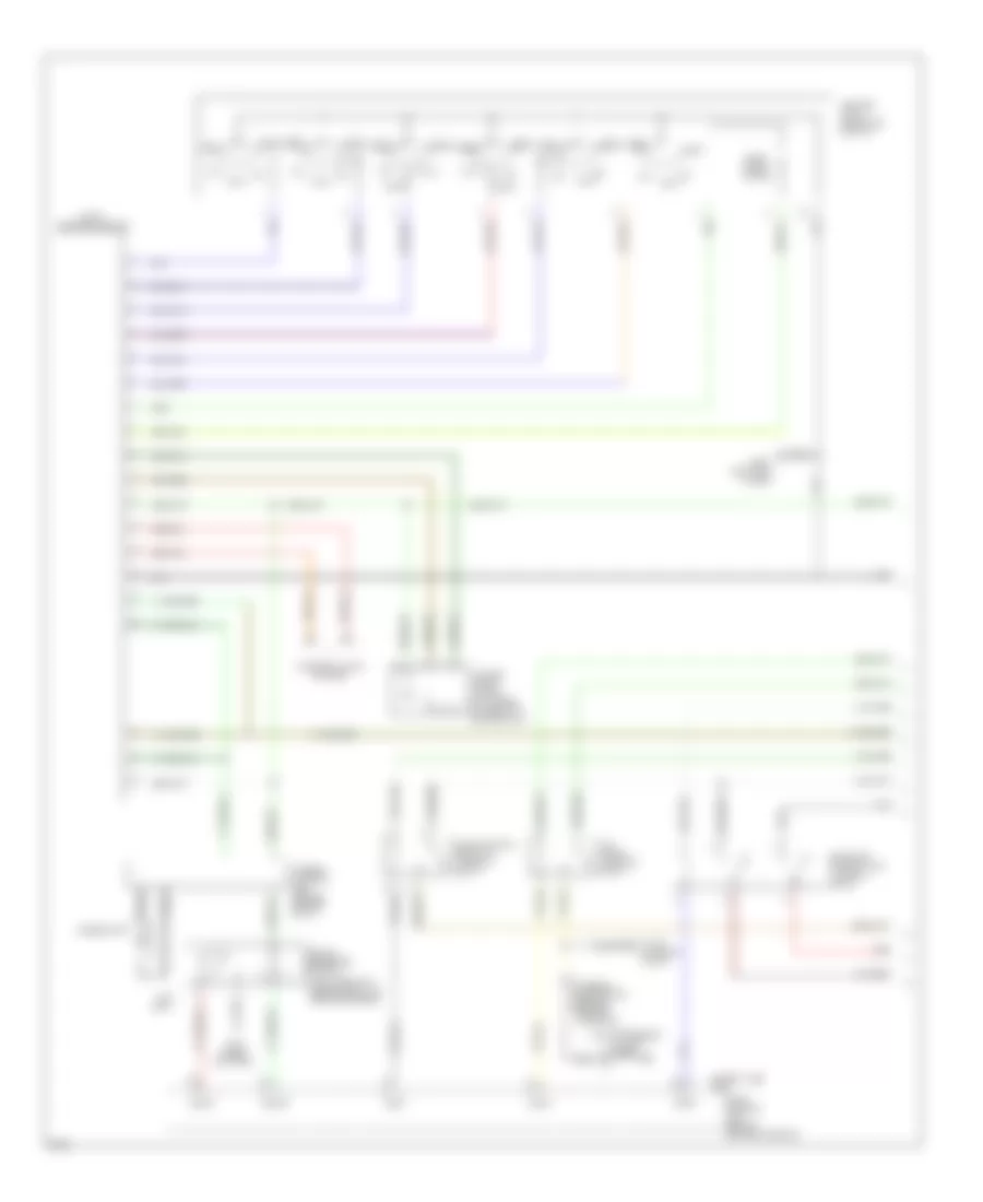
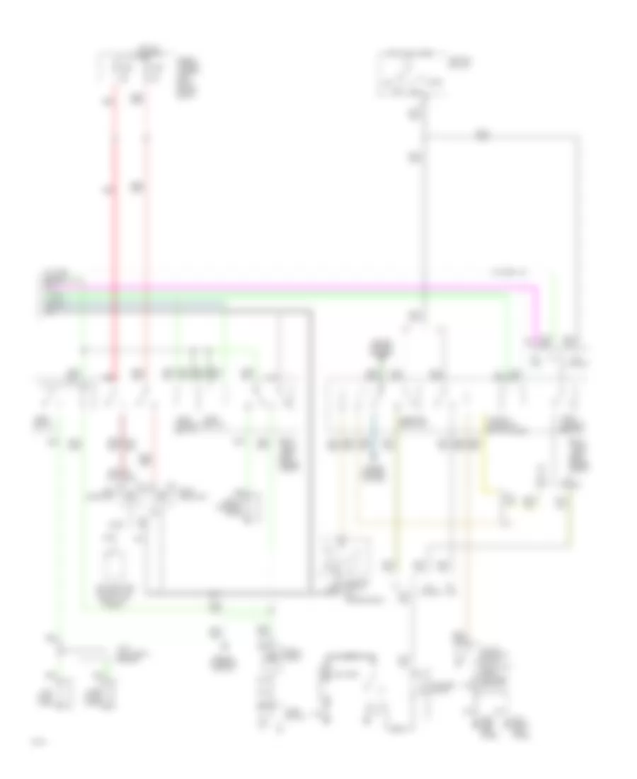
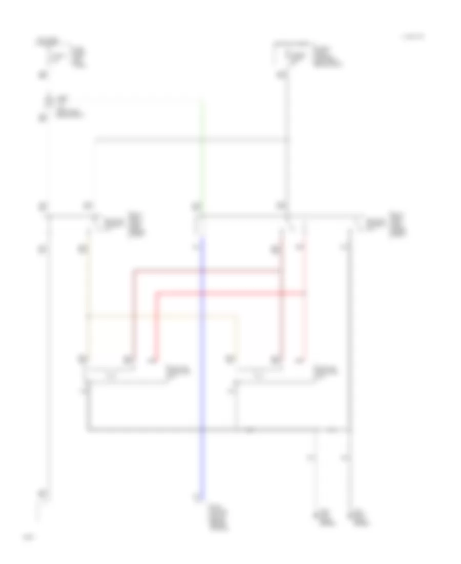
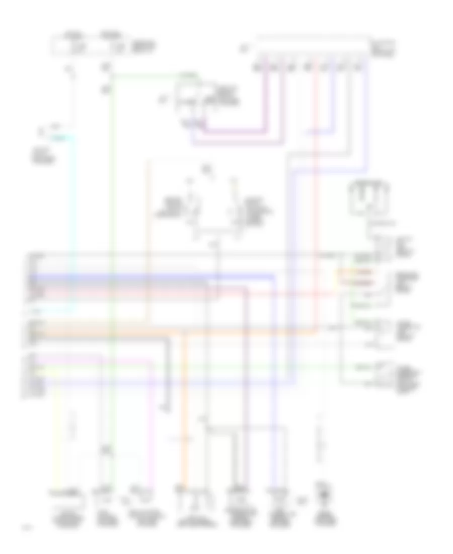
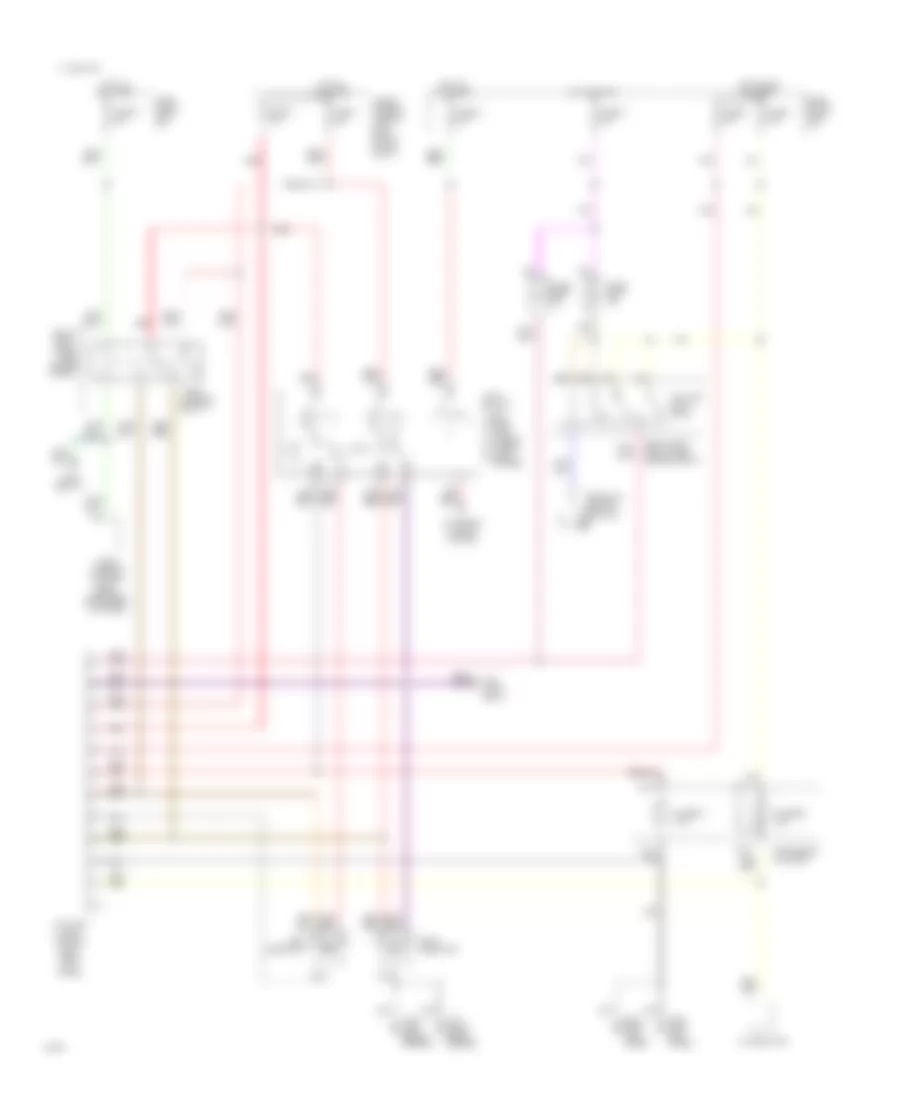
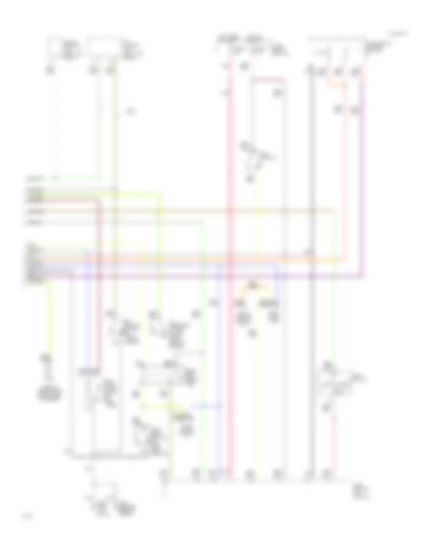
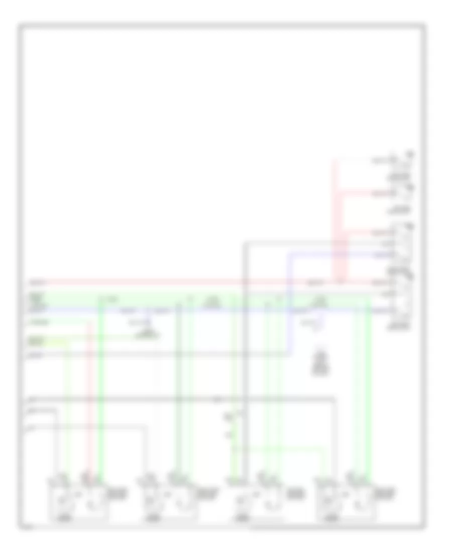
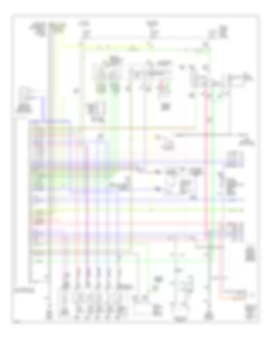
Air Conditioning Wiring Diagrams, A/T (2 of 2) for Infiniti G20 1994
List of elements for Air Conditioning Wiring Diagrams, A/T (2 of 2) for Infiniti G20 1994:
- (attached to front of heater unit)
- (behind right side of i/p)
- (in relay box 1)
- (near battery)
- Blower motor
- Blower relay (behind left kick panel)
- Fan switch
- Full cold switch
- Fuse & fusible link box: underhood
- Fuse 10a
- Fuse 15a
- Fuse block: i/p
- Fusible link b 30a
- Fusible link c 30a
- G101
- G200 (left kick panel)
- Hot at all times
- Hot in accy or on
- Hot in on or start
- J/c #4
- Max cold door motor
- Off
- Rad fan motor #1
- Rad fan motor #2
- Radiator fan relay #3
- Red
- Resistor
- Vent mode switch
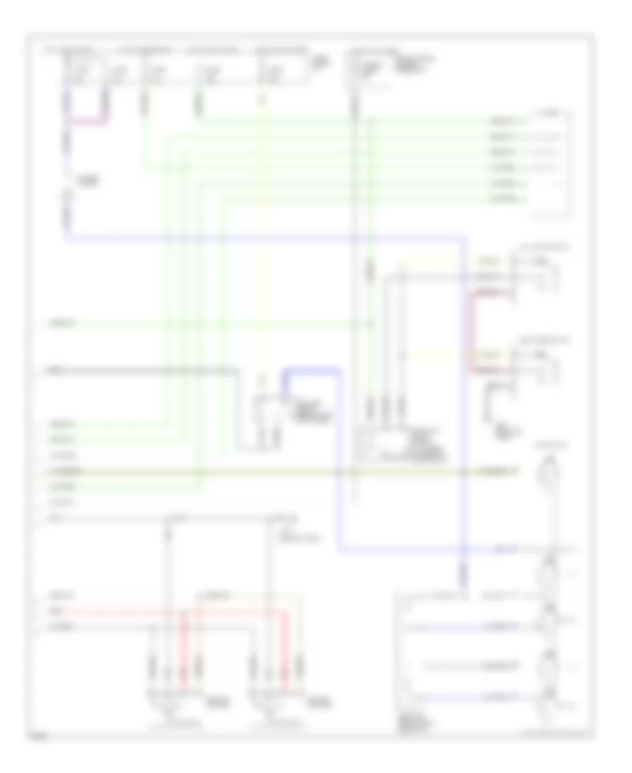
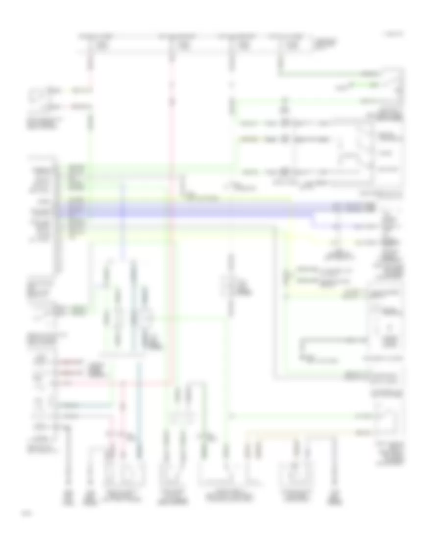
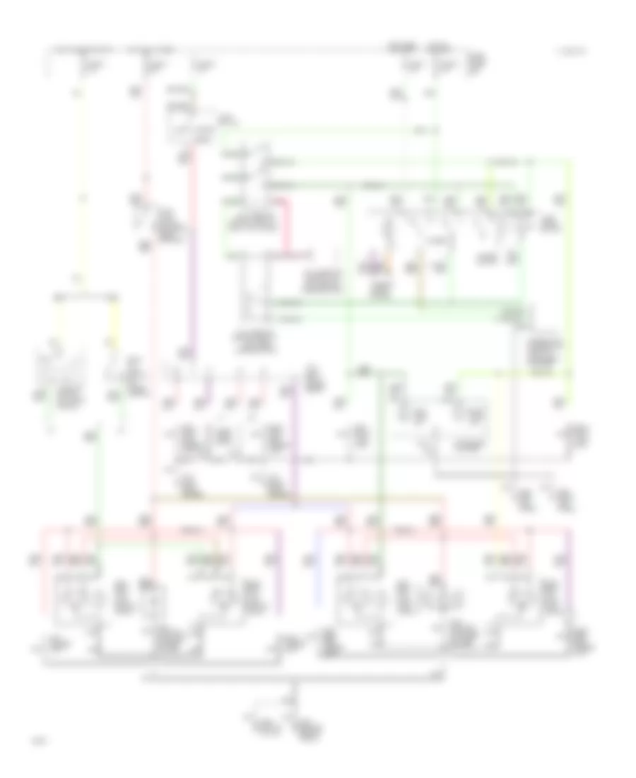
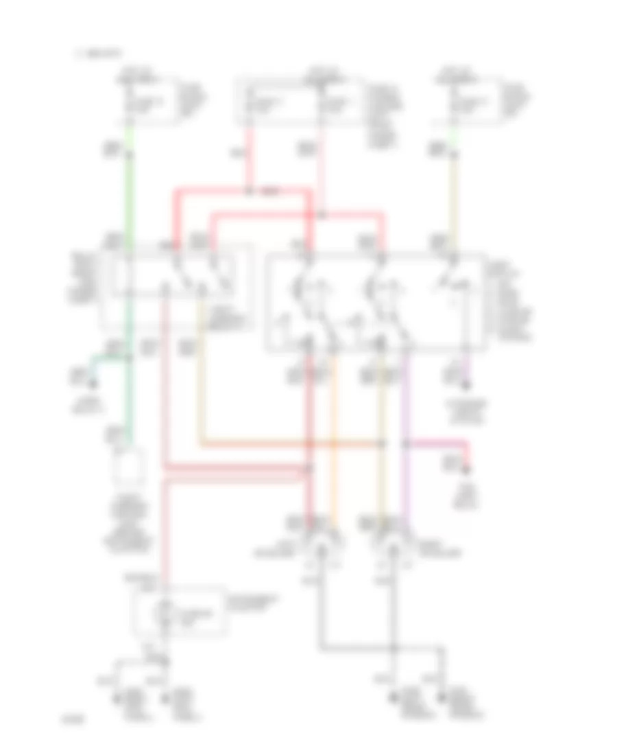
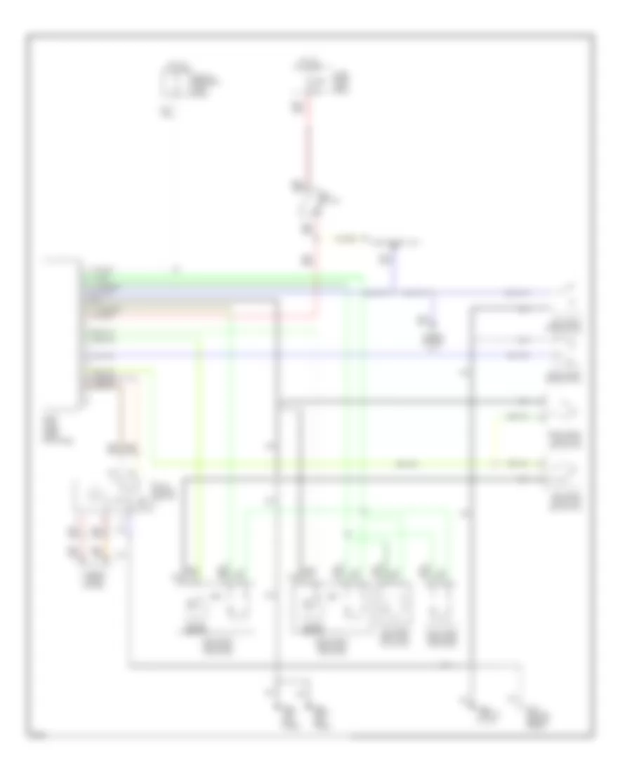
Air Conditioning Wiring Diagrams, M/T (1 of 2) for Infiniti G20 1994
List of elements for Air Conditioning Wiring Diagrams, M/T (1 of 2) for Infiniti G20 1994:
- (attached to front of heater unit)
- (in relay box 2)
- (left front of engine comp., on receiver-drier)
- (left kick panel)
- (near battery)
- A/c compressor clutch
- A/c relay (in relay box 1)
- Acrly
- Arcon
- B/l
- Def
- Eccs control unit (behind center console)
- Except 1996
- F.i.c.d. solenoid valve
- F/d
- Foot
- G101
- G200
- Heater & a/c selector switch
- Intake door motor
- Interior lights system
- Mode door motor
- Nca
- Pdsw
- Push control module
- Radiator fan relay #1 (in relay box 1)
- Radiator fan relay #2
- Red
- Rfrh
- Rfrl
- Thermal protector (behind center of grille)
- Thermistor
- Thermo control amp (behind center of i/p)
- Triple pressure switch
- Usa only
- Vent
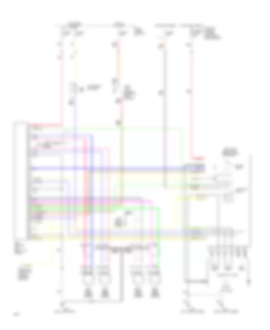
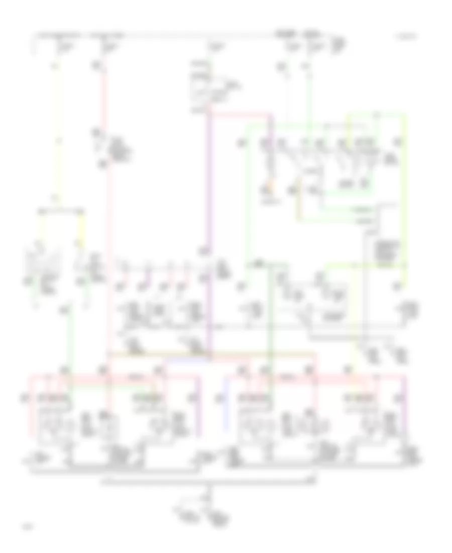
Air Conditioning Wiring Diagrams, M/T (2 of 2) for Infiniti G20 1994
List of elements for Air Conditioning Wiring Diagrams, M/T (2 of 2) for Infiniti G20 1994:
- (attached to front of heater unit)
- (behind right side of i/p)
- (near battery)
- Blower motor
- Blower relay (behind left kick panel)
- Fan switch
- Full cold switch
- Fuse & fusible link box: underhood
- Fuse 10a
- Fuse 15a
- Fuse block: i/p
- Fusible link b 30a
- G101
- G200 (left kick panel)
- Hot at all times
- Hot in accy or on
- Hot in on or start
- J/c #4
- Max cold door motor
- Off
- Rad fan motor #1
- Rad fan motor #2
- Red
- Resistor
- Vent mode switch
ANTI-LOCK BRAKES
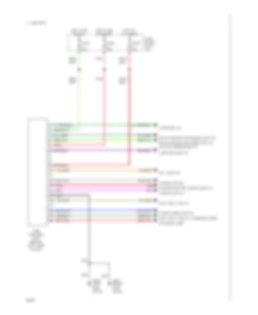
Anti-lock Brake Wiring Diagrams for Infiniti G20 1994
List of elements for Anti-lock Brake Wiring Diagrams for Infiniti G20 1994:
- (left front fender)
- (left shock
- (right front engine compt)
- (right front fender)
- (right kick panel)
- (right shock tower)
- Abs control
- Abs ind.
- Actuator
- Actuator relay
- All times
- Data link connector (left of steering column)
- Fuse 4 20a
- Fuse and fusible link box (left front engine compt)
- Fuse block (left i/p)
- Fuse u 10a
- Fuse x 20a
- Fuse z 10a
- Fusible link g 30a
- G100
- G101
- G102
- G103
- G203
- Hot at
- Hot at all times
- Hot in run or start
- Instrument cluster
- Left front wheel sensor
- Left rear wheel sensor
- Motor
- Motor relay
- Nca
- Pnk
- Red
- Relay box
- Right front wheel sensor
- Right rear wheel sensor
- Solenoid valves
- Stop lamp switch (on brake pedal support)
- Tower)
- Unit (right kick panel)
ANTI-THEFT
Anti-theft Wiring Diagram (1 of 2) for Infiniti G20 1994
List of elements for Anti-theft Wiring Diagram (1 of 2) for Infiniti G20 1994:
- stroke & normal
- stroke & normal unlock-between full
- (behind center
- (center rear
- (center rear of trunk lid)
- (front left
- (front right
- (left "b"
- (right front shock tower)
- (right of instrument
- (right of instrument cluster)
- 1994 vftc c
- Between full
- Cluster)
- Console)
- Control unit
- Cylinder tamper switch
- Diode
- Diodes
- Door lock timer
- Door switch
- Door warning light
- Driver's door unlock sensor
- Driver's side door lock key switch, door unlock
- Fender)
- Fuse block (left i/p)
- Fuse g 10a
- Fuse j 15a
- Fuse p 10a
- Fuse r 15a
- Fuse y 10a
- G100
- G101
- G200 (left kick panel)
- G203 (right kick panel)
- G308
- G407
- Hood
- Hot at all times
- Hot in acc or run
- Hot in run or start
- Hot in start
- Interior light
- J/c-4 (left front engine compt)
- Key cylinder withdrawn
- Key switch & key
- Key switch, door unlock
- Lamp
- Left front
- Left rear
- Left rear door unlock sensor
- Lock
- Lock-between full
- Multi- remote control unit
- Multi-remote control unit
- Of trunk)
- Passenger's door unlock sensor
- Passenger's side door lock
- Pillar)
- Right front door switch
- Right rear door switch
- Right rear door unlock sensor
- Security lamp
- Switch
- Theft warning
- Trunk lid unlock key switch & key cylinder tamper switch
- Trunk room
- Trunk room lamp switch
- Unlock
- W/ multi- remote control system
- W/ multi-remote control system
- W/o multi- remote control system
Anti-theft Wiring Diagram (2 of 2) for Infiniti G20 1994
List of elements for Anti-theft Wiring Diagram (2 of 2) for Infiniti G20 1994:
- (a/t)
- (left front engine compt)
- (m/t-usa)
- (on
- (on clutch pedal mounting bracket)
- (right kick
- (w/
- (w/o
- 15a
- A.s.c.d. steering switch
- A/t
- Acc
- Battery
- Canada
- Clutch
- Clutch interlock relay
- Compt)
- Cruise control system
- Daytime light control unit
- Drl)
- Engine
- Engine compt)
- Front
- Fuse
- Fuse & fusible link box (left
- G101 (right kick panel)
- G203 (left kick panel)
- Headlamp
- High
- Horn relay-1
- Horn relay-2
- Horn switch
- Hot at all times
- Ignition switch
- Inhibitor relay
- Inhibitor switch
- Interlock
- J/c-3 (left front fender)
- Left
- Low
- M/t
- M/t usa
- Nca
- Off
- Panel)
- Pitch horn
- Red
- Relay box-1 (right
- Relay box-2
- Right headlamp
- Run
- Side
- Spiral cable
- Start
- Starter motor
- Switch
- Theft warning horn
- Theft warning relay-1
- Theft warning relay-2
- Transmission)
- W/drl
- W/o drl
BODY COMPUTER
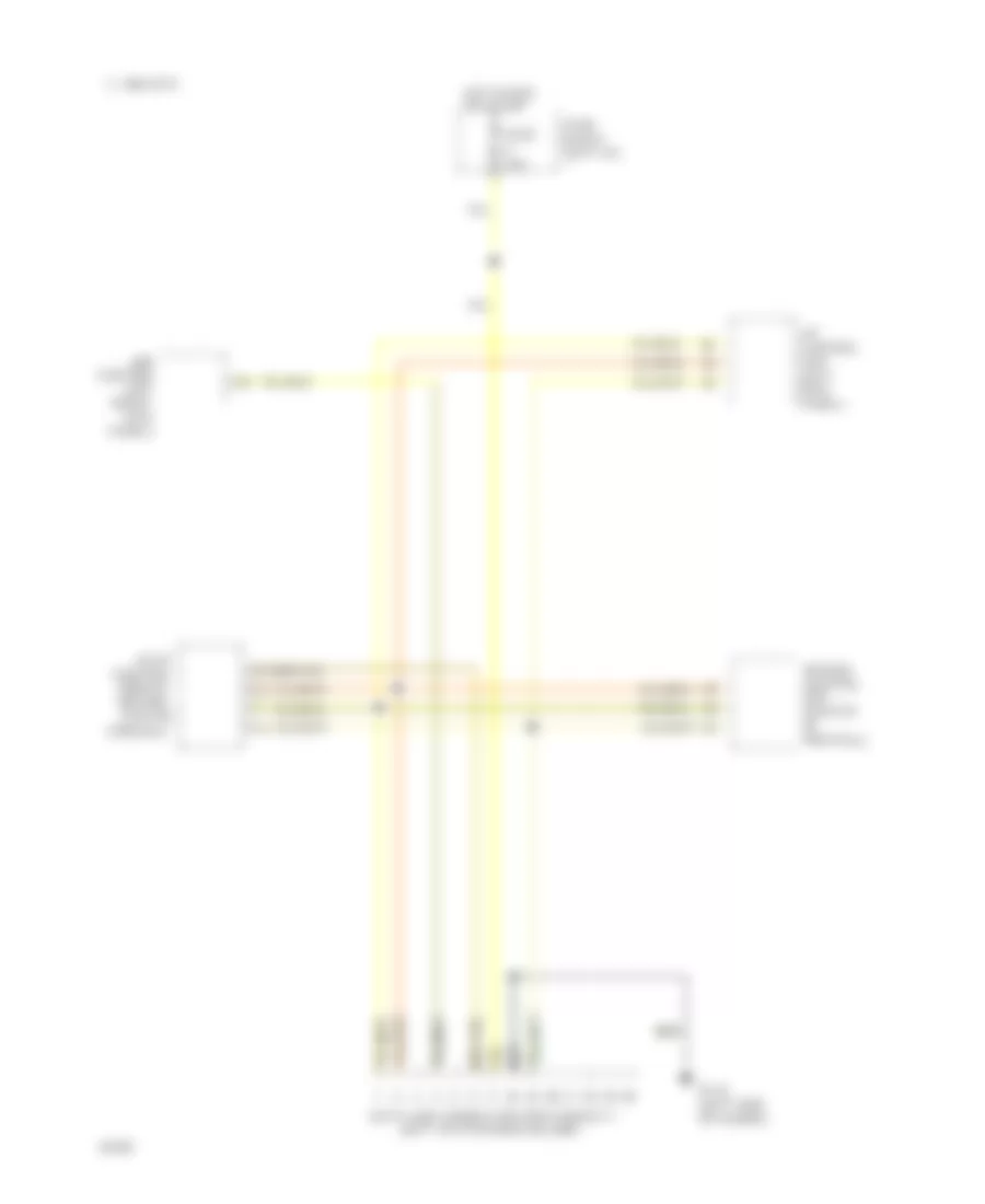
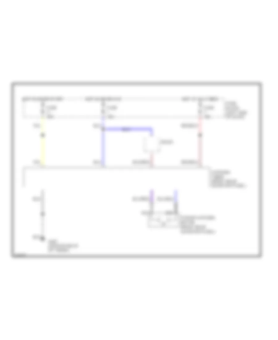
Time Control Unit Wiring Diagram for Infiniti G20 1994
List of elements for Time Control Unit Wiring Diagram for Infiniti G20 1994:
- 1995 vftc c
- Front door switch
- Fuse block (left i/p)
- Fuse j 10a
- Fuse y 10a
- Fuse z 10a
- G201 (right
- G202 (left
- Heated mirror relay
- Hot at all times
- Hot in on or acc
- Hot in on or start
- Interior lamp
- Key switch
- Lighting switch
- Pnk
- Rear window defogger relay,
- Rear window defogger switch
- Seat belt relay
- Seat belt relay, warning chime
- Side of i/p)
- Time control unit (behind left side of i/p)
- Washer motor, wiper switch
- Wiper relay
- Wiper switch
COMPUTER DATA LINES
Data Link Connector Wiring Diagram for Infiniti G20 1994
List of elements for Data Link Connector Wiring Diagram for Infiniti G20 1994:
- (left of steering column)
- (right
- 1994 vftc c
- A/t control unit (left kick panel)
- Abs
- Air bag control unit (center of firewall)
- Center
- Console)
- Control
- Data link connector (for consult)
- Eccs
- Fuse block (left i/p)
- Fuse u 10a
- G112 (left side of engine)
- Hot in run or start
- Kick
- Module (behind
- Panel)
- Unit
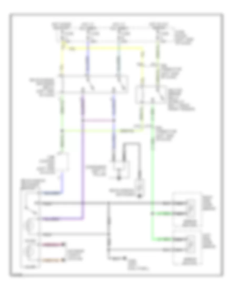
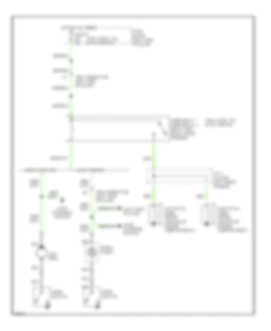
COOLING FAN
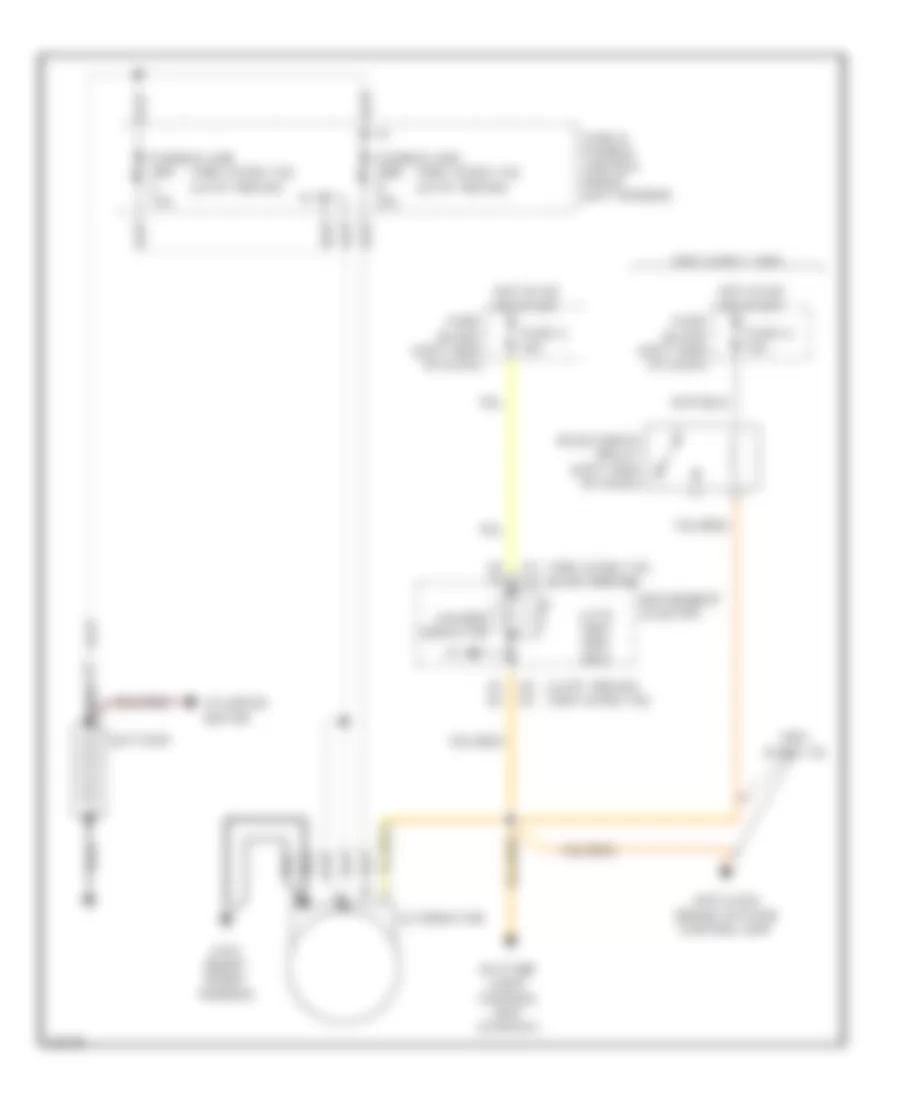
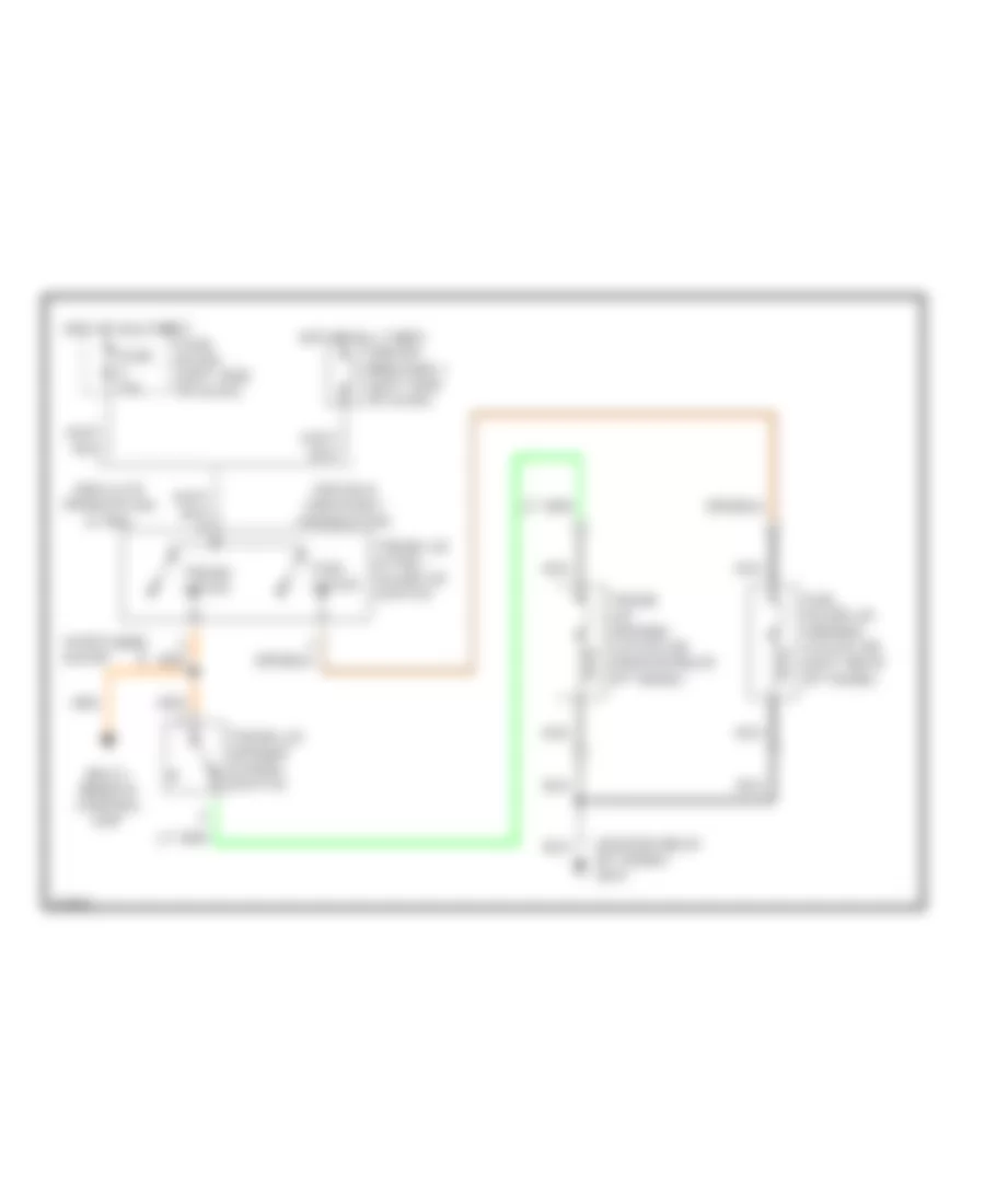
Cooling Fan Wiring Diagram, A/T for Infiniti G20 1994
List of elements for Cooling Fan Wiring Diagram, A/T for Infiniti G20 1994:
- 10a
- 1994 vftc c
- Eccs control module (behind center console)
- Fuse block (left kick panel)
- Fuse g
- Fusible link & fuse box (left front engine compt)
- Fusible link b 30a
- Fusible link c 30a
- G100 (left front fender)
- G101 (right front fender)
- Hot at all times
- Hot in run
- J/c-4 (left front engine compt)
- Or start
- Radiator fan motor no.1
- Radiator fan motor no.2
- Radiator fan relay no.1
- Radiator fan relay no.2
- Radiator fan relay no.3
- Red
- Relay box-1 (right side engine compt)
- Relay box-2 (left front engine compt)
Cooling Fan Wiring Diagram, M/T for Infiniti G20 1994
List of elements for Cooling Fan Wiring Diagram, M/T for Infiniti G20 1994:
- 10a
- 1994 vftc c
- Eccs control module (behind center console)
- Fuse block (left kick panel)
- Fuse g
- Fusible link & fuse box (left front engine compt)
- Fusible link b 30a
- G100 (left front fender)
- G101 (right front fender)
- Hot at all times
- Hot in run
- J/c-4 (left front engine compt)
- Or start
- Radiator fan motor no.1
- Radiator fan motor no.2
- Radiator fan relay no.1
- Radiator fan relay no.2
- Red
- Relay box-1 (right side engine compt)
- Relay box-2 (left front engine compt)
CRUISE CONTROL
Cruise Control Wiring Diagram for Infiniti G20 1994
List of elements for Cruise Control Wiring Diagram for Infiniti G20 1994:
- (left front fender)
- 1995 vftc c
- A/t
- A/t control unit (a/t only)
- A/t control unit (left kick panel)
- Act. cntrl
- Actuator control
- Air valve solenoid
- Ascd actuator (left rear of engine compartment)
- Ascd cancel switch (top of brake pedal support)
- Ascd clutch switch (top of clutch pedal support)
- Ascd control unit (below left side of i/p)
- Ascd hold relay (relay box 1, right front fender)
- Ascd steering switch
- Ascd sw.
- Ascd switch (left side of i/p)
- Cancel
- Crs. cancl
- Cruise
- Cruise indicator
- Cruise signal
- Engine control module
- Fuse block (left side of i/p)
- Fuse g 10 amp
- Fuse r 15 amp
- Fuse x 20 amp
- Fuse z 10 amp
- G10
- G100
- G100 (left front fender)
- G200 (left kick panel)
- Ground
- Horn relay-1 (relay box-1, right front fender)
- Horn switch
- Horns
- Hot at all times
- Hot in on or start
- Illum.
- Inhibitor relay (relay box 2, left front of engine compartment)
- Inhibitor switch (left side transmission)
- Instrument cluster
- Interior lights system
- Interior lights system (rheostat)
- J/c 2
- J/c 4
- M/t
- Nca
- Od cut signal
- On ind.
- Pnk
- Release valve solenoid
- Resume/ accelerate
- Set/coast
- Smj conn.
- Smj connector
- Smj connector (left side of i/p)
- Speed
- Spiral cable
- Steering switch
- Stop lamp switch (top of brake pedal support)
- Stop lamp switch od cut
- Theft warning relay 2 (relay box-2, left front of engine compartment)
- Vacuum motor
- Vehicle speed output
DEFOGGERS
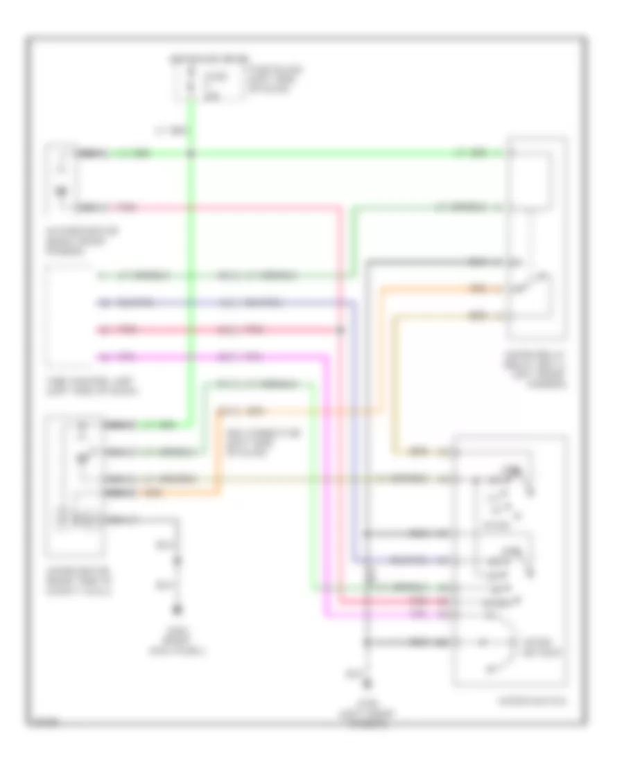
Defogger Wiring Diagram for Infiniti G20 1994
List of elements for Defogger Wiring Diagram for Infiniti G20 1994:
- (left side of dash)
- Condenser (left "c" pillar)
- Fuse a 20a
- Fuse b 20a
- Fuse block (left side of dash)
- Fuse k 10a
- G200 (left kick panel)
- H11
- H12
- Heated mirror relay (in relay box 1, right front fender)
- Hot at all times
- Hot in acc or run
- Hot in run or start
- Illum
- Interior lights system
- Left side door mirror
- Mirror heater
- Nca
- On ind
- Rear window defogger
- Rear window defogger relay (left side of dash)
- Rear window defogger switch
- Right side door mirror
- Smj connector
- Time control unit (left side of dash)
ENGINE PERFORMANCE
2.0L
2.0L, Engine Performance Wiring Diagrams (1 of 2) for Infiniti G20 1994
List of elements for 2.0L, Engine Performance Wiring Diagrams (1 of 2) for Infiniti G20 1994:
- (center rear of trunk)
- (left front
- (left front door)
- (left kick panel)
- (left rear of engine)
- (left side of engine compt)
- (radiator
- (right front fender)
- (right kick panel)
- (right rear of engine)
- Acc
- Air conditioning system (a/c relay)
- Air conditioning system (triple-pressure switch)
- Calif. only
- Compt)
- Cooling fans system
- Crankshaft position sensor (lower left front of engine)
- Data link connector (behind left side of i/p)
- Eccs relay (left front of engine compt, in
- Electric speedo
- Engine compt)
- Engine control module (behind center console)
- Fan relays)
- Fuel injector no. 1
- Fuel injector no. 2
- Fuel injector no. 3
- Fuel injector no. 4
- Fuel pump (in fuel tank)
- Fuel pump relay left front of engine compt, in relay box)
- Fuse & fusible link box (left front of
- Fuse 10a
- Fuse 15a
- Fuse block (behind left
- G101
- G102
- G114
- G200
- G203
- G406
- G500
- Hot at all times
- Hot in on or start
- Hot in start
- Iacv-air regulator
- Ignition switch
- Instrument cluster
- Instrument cluster system (tachometer)
- J/c 3
- M/t only
- Malf. ind. lamp
- Mass air flow sensor (left side of engine compt)
- Of engine
- Off
- Red
- Relay box)
- Side of i/p)
- Start
2.0L, Engine Performance Wiring Diagrams (2 of 2) for Infiniti G20 1994
List of elements for 2.0L, Engine Performance Wiring Diagrams (2 of 2) for Infiniti G20 1994:
- (closed in park & neutral)
- (left rear of engine)
- (left side of engine)
- (on top of
- (right rear of engine)
- A/t
- A/t control unit (behind left
- Calif. only
- Closed
- Distributor
- Egr
- Egr & canister control solenoid
- Engine coolant
- Fuse 10a
- Fuse block (behind left
- Heated oxygen sensor (center front of engine)
- Hot at all times
- Hot in on or start
- Iacv-aac valve
- Ignition coil (left front of engine)
- Inhibitor switch
- Kick panel)
- Knock sensor
- M/t
- M/t only
- Neutral position
- Only
- Pairc solenoid
- Position sensor
- Power steering oil pressure switch (right rear of engine compt)
- Power transistor (left front of engine)
- Red
- Resistor & condenser (left rear of engine)
- Sensor
- Side of i/p)
- Spark plugs
- Switch (on top of
- Temperature
- Throttle
- Throttle position switch
- Transmission)
- Wide open
EXTERIOR LIGHTS
Exterior Light Wiring Diagram, with Remote Control System for Infiniti G20 1994
List of elements for Exterior Light Wiring Diagram, with Remote Control System for Infiniti G20 1994:
- (left front engine compt)
- (left front fender)
- (left rear
- (right front fender)
- (w/ rear spoiler)
- (w/o rear spoiler)
- 1994 vftc c
- A-6
- A/t
- B-19
- Back- up light switch (on trans- mission)
- C-32
- Clear- ance lights
- Combination flasher unit (right of instrument cluster)
- Control relay-1
- Control relay-2 (right kick panel)
- Fuse block (left i/p)
- Fuse q 10a
- Fuse s 10a
- Fuse u 10a
- Fuse v 10a
- Fuse x 20a
- G100
- G101
- G200 (left kick panel)
- G203 (right kick panel)
- G308 (left "b" pillar)
- G407 (center rear of trunk)
- Hazard
- Hazard switch
- Head
- High
- Hot at all times
- Hot in run or start
- Ill.
- Inhibitor switch (on trans- mission)
- Instrument cluster
- Interior lights system
- J/c-1
- Left front side marker light
- Left front turn light
- Left license light
- Left rear side marker light
- Left rear tail/ stop/ back-up lights
- Left rear tail/ stop/ turn lights
- Left turn ind.
- Light switch
- Luggage compt)
- M/t
- Mounted
- Multi-remote
- Multi-remote control unit (left rear of
- Nca
- Off
- Park
- Pnk
- Right front side marker light
- Right front turn light
- Right license light
- Right rear side marker light
- Right rear tail/ stop/ back-up lights
- Right rear tail/ stop/ turn lights
- Right turn ind.
- Stop lamp switch (on brake pedal bracket)
- Stop light
- Turn signal switch
Exterior Light Wiring Diagram, without Remote Control System for Infiniti G20 1994
List of elements for Exterior Light Wiring Diagram, without Remote Control System for Infiniti G20 1994:
- (left front engine compt)
- (left front fender)
- (right front fender)
- (w/ rear spoiler)
- (w/o rear spoiler)
- 1994 vftc c
- A-6
- A/t
- B-19
- Back- up light switch (on trans- mission)
- C-32
- Clear- ance lights
- Combination flasher unit (right of instrument cluster)
- Fuse block (left i/p)
- Fuse q 10a
- Fuse s 10a
- Fuse u 10a
- Fuse v 10a
- Fuse x 20a
- G100
- G101
- G200 (left kick panel)
- G203 (right kick panel)
- G308 (left "b" pillar)
- G407 (center rear of trunk)
- Hazard
- Hazard switch
- Head
- High
- Hot at all times
- Hot in run or start
- Ill.
- Inhibitor switch (on trans- mission)
- Instrument cluster
- J/c-1
- Left front side marker light
- Left front turn light
- Left license light
- Left rear side marker light
- Left rear tail/ stop/ back-up lights
- Left rear tail/ stop/ turn lights
- Left turn ind.
- Light switch
- M/t
- Mounted
- Nca
- Off
- Park
- Rheostat
- Right front side marker light
- Right front turn light
- Right license light
- Right rear side marker light
- Right rear tail/ stop/ back-up lights
- Right rear tail/ stop/ turn lights
- Right turn ind.
- Stop lamp switch (on brake pedal bracket)
- Stop light
- Turn signal switch
GROUND DISTRIBUTION
Ground Distribution Wiring Diagram (1 of 4) for Infiniti G20 1994
List of elements for Ground Distribution Wiring Diagram (1 of 4) for Infiniti G20 1994:
- Abs control unit
- Alternator
- Crankshaft position sensor
- Crankshaft position sensor shield
- Data link connector (for consult)
- Ecm
- G100 (left front fender)
- G101 (right front fender)
- G119 (right front of engine)
- G203 (right side kick panel)
- Heated oxygen sensor shield
- Knock sensor shield
- Left front wheel sensor shield
- Left rear wheel sensor shield
- Mass air flow sensor shield
- Nca
- Power steering oil level switch
- Power transistor
- Resistor and condenser
- Right front wheel sensor shield
- Right rear wheel sensor shield
- Smj connector
- Throttle position sensor shield
Ground Distribution Wiring Diagram (2 of 4) for Infiniti G20 1994
List of elements for Ground Distribution Wiring Diagram (2 of 4) for Infiniti G20 1994:
- A/t models
- Actuator
- Ascd hold relay
- Brake fluid level switch
- E213
- E221
- G100 (left front fender)
- G101 (right front fender)
- Iacv- air regulator
- Iacv- ficd solenoid valve
- Inhibitor switch
- Left clearance lamp
- Left front fog lamp
- Left front side marker lamp
- Left headlamp
- Left turn signal lamp
- M/t models
- Neutral position switch
- Radiator fan motor-1
- Radiator fan motor-2
- Radiator fan relay-2
- Radiator fan relay-3
- Relay
- Relay box
- Right clearance lamp
- Right front fog lamp
- Right front side marker lamp
- Right headlamp
- Right turn signal lamp
- Triple pressure switch
- Washer level switch
- Wiper switch
Ground Distribution Wiring Diagram (3 of 4) for Infiniti G20 1994
List of elements for Ground Distribution Wiring Diagram (3 of 4) for Infiniti G20 1994:
- A/t control unit
- Accessory
- Ascd control unit
- Ascd switch
- Ashtray illumination
- Blower relay
- Bulb check relay
- Cigarette lighter
- Clutch interlock switch
- Combination flasher unit
- Daytime light control unit
- Door lock timer
- Door mirror switch
- Front fog lamp switch
- Fuse block
- G200 (left side kick panel)
- G203 (right side kick panel)
- Glove box lamp switch
- Ignition relay-1
- Instrument cluster
- Left door latch switch
- Left door mirror heater
- Left front door lock actuator
- Left front door lock key switch
- Left front limit switch
- Left front power window switch
- Left lock knob switch
- M/t models
- Mode door motor
- Power window amplifier
- Power window relay
- Push control unit
- Rear window defogger switch
- Relay-1
- Right door latch switch
- Right door mirror heater
- Right front door lock actuator
- Right front door lock key switch
- Right front limit switch
- Right lock knob switch
- Shift lock control unit
- Srs control unit
- Theft warning control unit
- Time control unit
- Vent mode switch
- Wiper motor
Ground Distribution Wiring Diagram (4 of 4) for Infiniti G20 1994
List of elements for Ground Distribution Wiring Diagram (4 of 4) for Infiniti G20 1994:
- A/t mode switch
- Automatic seat belt control unit
- Detention switch
- Elr control unit
- Fuel filler lid opener actuator
- Fuel pump
- Fuel tank gauge unit
- G308 (left side "b" pillar)
- G407 (center rear of trunk)
- High-mounted stop lamp
- Left front door switch
- Left front power seat switch
- Left license lamp
- Left rear combination lamp (back-up)
- Left rear combination lamp (stop and tail)
- Left rear door unlock sensor
- Left rear side marker lamp
- Left shoulder belt buckle switch
- Left shoulder belt locking canceler
- Lock and unlock switch
- Multi- remote control unit
- Overdrive cancel switch
- Overdrive control switch
- Overdrive switch
- Power antenna timer
- Power window main switch
- Right front door switch
- Right front power seat switch
- Right license lamp
- Right rear combination lamp (back-up)
- Right rear combination lamp (stop and tail)
- Right rear door unlock sensor
- Right rear limit switch
- Right rear side marker lamp
- Right shoulder belt buckle switch
- Right shoulder belt locking canceler
- Seat belt buckle switch
- Shift lock solenoid
- Trunk lid opener actuator
- Trunk lid unlock key switch and key cylinder tamper switch
- Trunk room lamp switch
HEADLIGHTS
Fog Lamp Wiring Diagram for Infiniti G20 1994
List of elements for Fog Lamp Wiring Diagram for Infiniti G20 1994:
- (rheostat)
- 1994 vftc c
- Compt)
- Daytime light control unit
- Engine
- Engine compt)
- Fog light relay
- Fog light switch
- Front
- Fuse & fusible link box (left
- Fuse 1 15a
- Fuse block (left i/p)
- Fuse m 15a
- Fuse s 10a
- G100 (left front fender)
- G101 (right front fender)
- G200 (left kick panel)
- G203 right kick panel)
- Hot at all times
- Illum.
- Interior lights system
- Left fog light
- Light switch
- Off
- Park head lo beam hi beam flash- to-pass
- Relay box-1 (right
- Right fog light
- Right lo beam headlamp
- Side
- W/drl
Headlamps Wiring Diagram, with DRL for Infiniti G20 1994
List of elements for Headlamps Wiring Diagram, with DRL for Infiniti G20 1994:
- 1994 vftc c
- A-5
- Alternator
- B-17
- C-34
- Charge ind.
- Compt)
- Daytime light control unit (right kick panel)
- Daytime light relay
- Diode (left i/p)
- Engine
- Exterior lights system
- Fog light relay
- Front
- Fuse & fusible link box (left
- Fuse 1 15a
- Fuse 2 15a
- Fuse block (left i/p)
- Fuse p 10a
- Fuse r 15a
- Fuse s 10a
- Fuse u 10a
- Fuse z 10a
- G100 (left front fender)
- G101 (right front fender)
- G200 (left kick panel)
- G203 right kick panel)
- Headlamp
- Hi beam ind.
- Horn
- Hot at all times
- Hot in run or start
- Hot in start
- Instrument cluster
- Left
- Light switch
- Off
- Park head lo beam hi beam flash- to-pass
- Parking brake switch
- Pnk
- Red
- Relay box-1 (right side engine compt)
- Relay-1
- Right headlamp
- Theft warning control unit (behind instrument cluster)
- Theft warning relay-1
Headlamps Wiring Diagram, without DRL for Infiniti G20 1994
List of elements for Headlamps Wiring Diagram, without DRL for Infiniti G20 1994:
- 1994 vftc c
- A-4
- A-5
- Compt)
- Engine
- Exterior lights system
- Fog light relay
- Front
- Fuse & fusible link box (left
- Fuse 1 15a
- Fuse 2 15a
- Fuse block (left i/p)
- Fuse r 15a
- Fuse s 10a
- G100 (left front fender)
- G101 (right front fender)
- G200 (left kick panel)
- G203 right kick panel)
- Headlamp
- Hi beam ind.
- Horn
- Hot at all times
- Instrument cluster
- Left
- Light switch
- Off
- Park head lo beam hi beam flash- to-pass
- Red
- Relay box-1 (right side engine compt)
- Relay-1
- Right headlamp
- Theft warning control unit (behind instrument cluster)
- Theft warning relay-1
HORN
Horn Wiring Diagram for Infiniti G20 1994
List of elements for Horn Wiring Diagram for Infiniti G20 1994:
- (1991- early 93)
- (1991- early 93) (late 1993-94)
- (late 1993-94)
- Anti-theft system
- Ascd steering switch
- Fuse block (left side of dash)
- Fuse r 10a 15a
- High pitch horn (front center of engine compartment)
- Horn relay horn relay-1 (relay box, right front fender)
- Horn switch
- Hot at all times
- J/c 3 (j/c box, left front fender)
- Low pitch horn (front center of engine compartment)
- Nca
- Slip ring
- Smj connector (left side of dash)
- Spiral cable
INSTRUMENT CLUSTER
Instrument Cluster & Warning System Wiring Diagram (1 of 2) for Infiniti G20 1994
List of elements for Instrument Cluster & Warning System Wiring Diagram (1 of 2) for Infiniti G20 1994:
- (behind center console)
- (mil)
- 1994 vftc c
- A-10
- A-11
- A-12
- A-3
- A-4
- A-5
- A-6
- A-7
- A-9
- Abs control unit (right kick panel)
- Abs ind.
- Actuator relay
- Air bag control unit (behind center console)
- Air bag ind.
- Alternator
- B-13
- B-14
- B-15
- B-16
- B-17
- B-18
- B-19
- B-20
- B-21
- B-22
- B-23
- B-24
- B-25
- Bat
- Brake fluid level switch (on master cylinder)
- Brake ind.
- C-26
- C-27
- C-28
- C-29
- C-30
- C-31
- C-32
- C-33
- C-34
- Canada
- Charge ind.
- Check engine ind.
- Chime
- Clock
- Clock illum.
- Cruise ind.
- Diode (left i/p)
- Door ind.
- Engine control module
- Exterior lights system
- Fuel gauge
- Fuel ind.
- Fuse block (left i/p)
- Fuse i 10a
- Fuse s 10a
- Fuse u 10a
- G100 (left front fender)
- G101 (right front fender)
- G200 (left kick panel)
- G203 (right kick panel)
- Gnd
- Grd
- Headlights system
- Hi beam ind.
- Hot at all times
- Hot in acc or run
- Hot in run or start
- Ign
- Instrument cluster
- Left front door switch
- Left rear door switch
- Left turn ind.
- Meter illum.
- O/d off ind.
- Oil ind.
- Parking brake switch (on parking brake support bracket)
- Red
- Right front door switch
- Right rear door switch
- Right turn ind.
- Seat belt ind.
- Speed- ometer
- Tach- ometer
- Temp. gauge
- Usa
- Vehicle speed sensor (on transmission)
- Washer ind.
- Washer level switch (in washer fluid reser- voir)
Instrument Cluster & Warning System Wiring Diagram (2 of 2) for Infiniti G20 1994
List of elements for Instrument Cluster & Warning System Wiring Diagram (2 of 2) for Infiniti G20 1994:
- "b"
- (left i/p)
- (left kick
- (lower right rear of engine)
- (on trans- mission)
- 1994 vftc c
- A.s.c.d. control unit
- A/t control unit
- A/t only
- Airbag control unit
- Door lock timer
- Fuel tank gauge unit (in fuel tank)
- Fuse block (left i/p)
- Fuse y 10a
- Fuse z 10a
- G308 (left
- G407 (center rear of trunk)
- Head
- Hot at all times
- Hot in run or start
- Illumination control switch
- Key switch
- Light switch
- Multi- remote control unit
- O/d control switch
- Off
- Oil pressure switch
- Panel)
- Park
- Pillar)
- Pnk
- Seat belt relay (left i/p)
- Seat belt switch (in seat belt buckle)
- Thermal transmitter (right rear of engine)
- Time control unit
INTERIOR LIGHTS
Courtesy Lamps Wiring Diagram for Infiniti G20 1994
List of elements for Courtesy Lamps Wiring Diagram for Infiniti G20 1994:
- (behind left side of i/p)
- (center rear
- (left "b"
- (left rear of trunk)
- (right i/p)
- (right of instrument cluster)
- 1994 vftc c
- Diode
- Door
- Door warning light
- Driver's side door switch
- Fuse block (left i/p)
- Fuse y 10a
- G203 (right kick panel)
- G20o (left kick panel)
- G308
- G407
- Hot at all times
- Interior light
- Left rear door switch
- Multi- remote control unit (optional)
- Of trunk)
- Off
- Passenger's side door switch
- Pillar)
- Right rear door switch
- Spot lights
- Theft warning control unit (optional)
- Time control unit (optional)
- Trunk room lamp
- Trunk room lamp switch
Instrument Illumination Wiring Diagram for Infiniti G20 1994
List of elements for Instrument Illumination Wiring Diagram for Infiniti G20 1994:
- 1994 vftc c
- A.s.d.c. switch
- A/t indicator illum.
- Ashtray illum.
- B-20
- B-22
- B-23
- Cigarette lighter illum.
- Clock
- Door lock/ unlock switch
- Driver's side power window main switch
- Driver's side power window switch
- Front fog light switch
- Fuse block (left i/p)
- Fuse i 10a
- Fuse s 10a
- G200 (left kick panel)
- G203 (right kick panel)
- Glove box lamp
- Glove box lamp switch
- Hazard switch
- Head
- Hot at all times
- Hot in run or acc
- Ill.
- Illumination control switch
- Instrument cluster
- J/c-1 (right of instrument cluster)
- Key illum.
- Light switch
- Off
- Park
- Passenger's side power window main switch
- Passenger's side power window switch
- Power window & door lock/ unlock switch
- Push control unit
- Radio
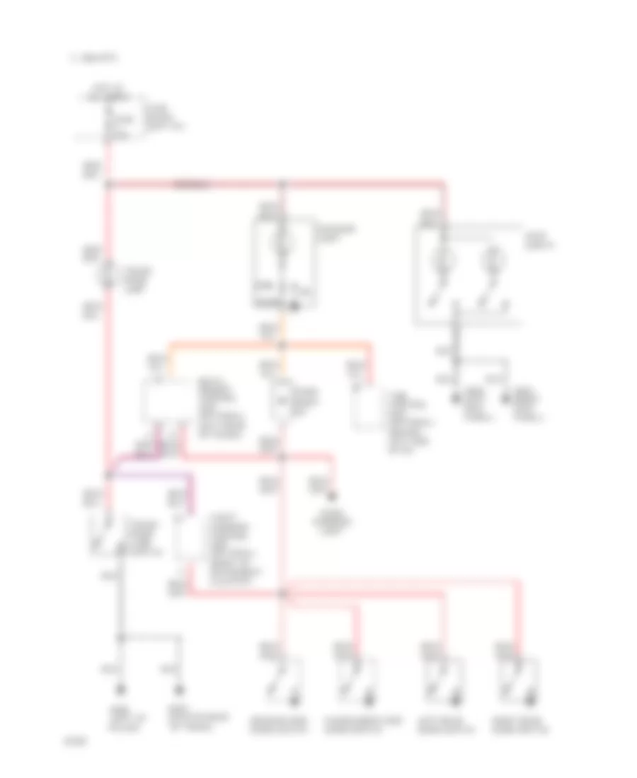
POWER ANTENNA
Power Antenna Wiring Diagram for Infiniti G20 1994
List of elements for Power Antenna Wiring Diagram for Infiniti G20 1994:
- Antenna timer (right rear quarter panel)
- Fuse block (left side of dash)
- Fuse i 10a
- Fuse u 10a
- Fuse y 10a
- G407 (center rear of trunk)
- Hot at all times
- Hot in on or acc
- Hot in on or start
- Nca
- Power antenna motor (right rear quarter panel)
- Radio
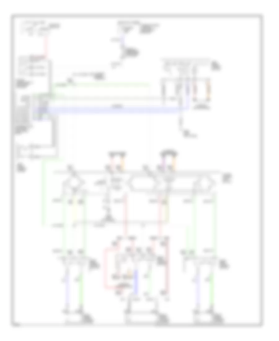
POWER DISTRIBUTION
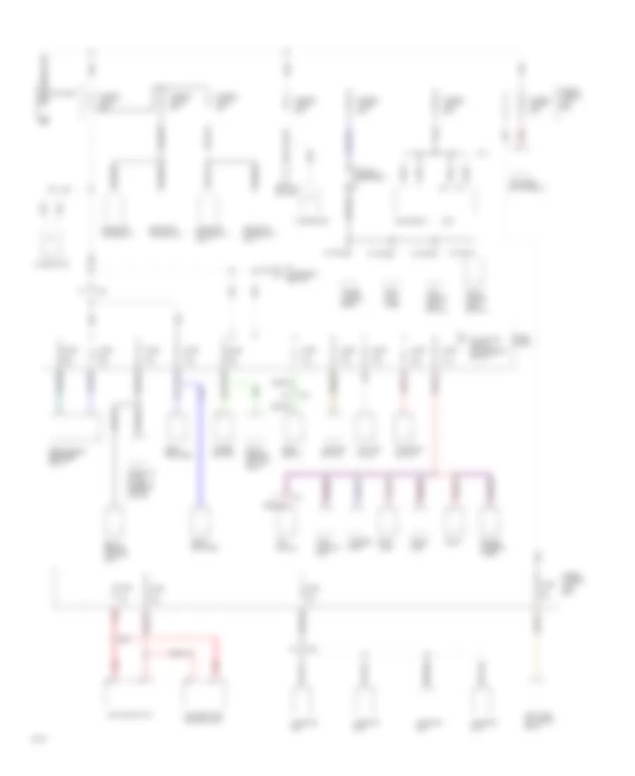
Power Distribution Wiring Diagram (1 of 3) for Infiniti G20 1994
List of elements for Power Distribution Wiring Diagram (1 of 3) for Infiniti G20 1994:
- Accessory relay-2
- Alternator
- Anti-lock actuator relay
- Anti-lock motor relay
- Battery
- Circuit breaker-1
- Daytime light control unit
- Door lock timer
- Eccs relay
- Ecm
- F11
- Front amplifier
- Fuse 15a
- Fuse a 20a
- Fuse c 10a
- Fuse w 10a
- Fuse y 10a
- Fuse & fusible link box
- Fuse 10a
- Fuse 20a
- Fuse b 20a
- Fuse block
- Fuse n 15a
- Fuse q 10a
- Fuse s 10a
- Fuse t 15a
- Fuse x 20a
- Fusible link a 75a
- Fusible link b 30a
- Fusible link c 30a
- Fusible link d 30a
- Fusible link e 30a
- Fusible link f 25a
- Fusible link g 30a
- Hazard switch
- Horn relay-1
- I11
- Iacv-aac valve
- Ignition switch
- Injector no.1
- Injector no.2
- Injector no.3
- Injector no.4
- Interior lamp
- J/c-3
- Key switch
- Left power seat switch
- Lighting switch
- Multi- remote control relay
- Multi- remote control unit
- Nca
- Power antenna timer
- Power window relay
- Radiator fan relay-1
- Radiator fan relay-1 (a/t)
- Radiator fan relay-2
- Radiator fan relay-3 (a/t)
- Radio
- Rear amplifier
- Rear window defogger relay
- Red
- Right power seat switch
- Smj
- Spot lamp
- Stoplamp switch
- Time control unit
- To ignition relay-1 & accessory relay-1
- Trunk lamp
- Trunk lid & fuel filler lid opener switch
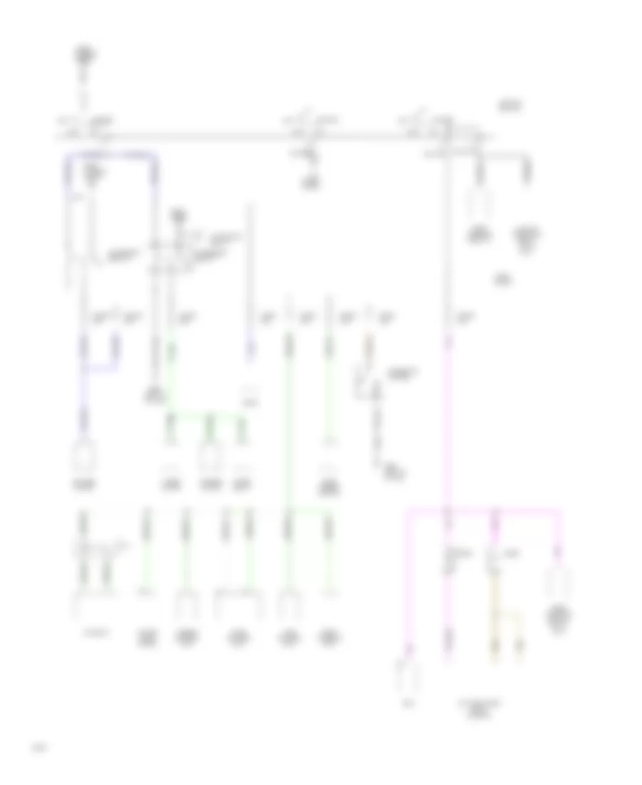
Power Distribution Wiring Diagram (2 of 3) for Infiniti G20 1994
List of elements for Power Distribution Wiring Diagram (2 of 3) for Infiniti G20 1994:
- A/c relay
- Acc
- Accessory relay-1
- Accessory relay-2
- Blower motor
- Cigarette lighter
- Clutch interlock relay (u.s.a.) (m/t)
- Daytime lamps relay (canada)
- Diode
- Door mirror switch
- Ecm
- From fuse y
- From fusible link a
- From fusible link d
- Fuse block
- Fuse d 15a
- Fuse e 15a
- Fuse f 20a
- Fuse i 10a
- Fuse j 10a
- Fuse k 10a
- Fuse l 15a
- Fuse p 10a
- Fuses g,h,&o
- G900 (left "a" pillar)
- Ignition switch
- Intake door motor
- J/c 4
- Off
- Push control unit
- Radio
- Start
- Theft warning relay-2
- Theft warning relay-2 (u.s.a.) (m/t)
- Theft warning unit
- Thermo control amp
- Time control unit
- To ignition relay-1
- Washer motor
- Wiper motor
- Wiper relay
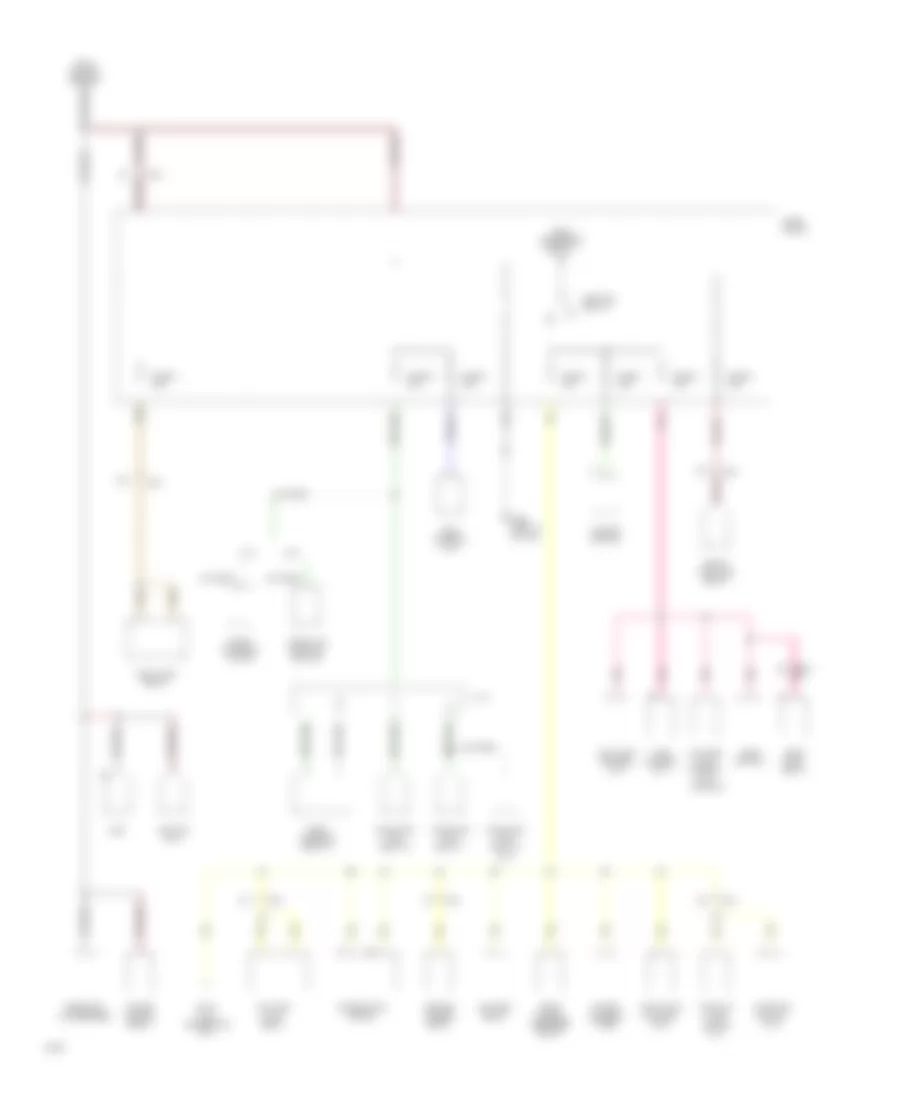
Power Distribution Wiring Diagram (3 of 3) for Infiniti G20 1994
List of elements for Power Distribution Wiring Diagram (3 of 3) for Infiniti G20 1994:
- (a/t)
- (canada)
- (m/t)
- Anti-lock control unit
- Ascd hold relay
- Ascd switch
- Back-up lamp switch (m/t)
- Blower relay
- Combination meter
- Data link connector (a/t)
- Daytime light control unit
- Daytime light relay
- Ecm
- From accessory relay-1
- From ignition switch
- Front fog lamp relay
- Fuel pump relay
- Fuse block
- Fuse g 10a
- Fuse h 10a
- Fuse m 15a
- Fuse o 15a
- Fuse u 10a
- Fuse v 10a
- Fuse z 10a
- G11
- G12
- G900 (left "a" pillar)
- Hazard switch
- Heated mirror relay
- Ignition coil
- Ignition relay-1
- Inhibitor switch (a/t)
- J/c 4
- Pairc- solenoid valve
- Pnk
- Power antenna timer
- Power window relay
- Radiator fan relay-1
- Radiator fan relay-2
- Radiator fan relay-3
- Rear window defogger relay
- Resistor & condenser
- Shiftlock control unit
- Smj
- Srs control unit
- Theft warning relay-2
- Throttle position switch
- Time control unit
POWER DOOR LOCKS
Power Door Lock Wiring Diagram, with Keyless Entry (1 of 2) for Infiniti G20 1994
List of elements for Power Door Lock Wiring Diagram, with Keyless Entry (1 of 2) for Infiniti G20 1994:
- stroke & normal
- stroke & normal unlock-between full
- (behind left side of dash)
- (center rear of trunk lid)
- (center rear of trunk)
- (left "b"
- (right dash)
- Circuit breaker-1 (left dash)
- Control
- Cylinder tamper switch
- Diode
- Door
- Door lock timer (right kick panel)
- Door warning light
- Driver's side door lock key switch, door unlock
- Feeder cable
- Fuse block (left dash)
- Fuse c 10a
- Fuse y 10a
- G200 (left
- G203 (right
- G308
- G407
- Hot at all times
- Interior light
- Interior lights system
- Key
- Key cylinder withdrawn
- Key switch & key
- Key switch, door unlock
- Kick panel)
- Lock
- Lock-between full
- Lock/ unlock switch
- Multi-remote control relays 1 & 2 (exterior lights system)
- Multi-remote control unit (right rear of trunk)
- Off
- Passenger's side door lock
- Pillar)
- Pnk
- Switch
- Switch (center of dash)
- Theft
- Theft warning control unit
- Time
- Time control unit (optional)
- Trunk lid opener actuator (center rear of trunk)
- Trunk lid opener cancel
- Trunk room lamp
- Trunk room lamp switch
- Trunk/fuel lid opener switch
- Un- lock
- Unit
- Warning control
- Window antenna
Power Door Lock Wiring Diagram, with Keyless Entry (2 of 2) for Infiniti G20 1994
List of elements for Power Door Lock Wiring Diagram, with Keyless Entry (2 of 2) for Infiniti G20 1994:
- Airbag control unit
- Left front door lock actuator
- Left front door switch
- Left rear door lock actuator
- Left rear door switch
- Lock
- Right front door lock actuator
- Right front door switch
- Right rear door lock actuator
- Right rear door switch
- Time control unit (behind left side of dash)
- Un- lock
- Unlock sensor
Power Door Lock Wiring Diagram, without Keyless Entry for Infiniti G20 1994
List of elements for Power Door Lock Wiring Diagram, without Keyless Entry for Infiniti G20 1994:
- (center rear of trunk)
- (left "b"
- Airbag control unit
- Circuit breaker 1 (left dash)
- Door lock timer (right kick panel)
- Fuse block (left dash)
- Fuse y 10a
- G200 (left
- G203 (right
- G308
- G407
- Hot at all times
- Interior lights system
- Key
- Kick panel)
- Left front door lock actuator
- Left front door lock key switch
- Left front door switch
- Left rear door lock actuator
- Lock
- Lock/ unlock switch
- Pillar)
- Right front door lock actuator
- Right front door lock key switch
- Right front door switch
- Right rear door lock actuator
- Switch
- Time control unit
- Un- lock
- Unlock sensor
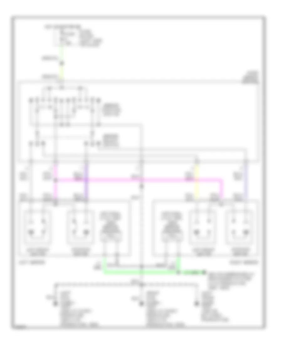
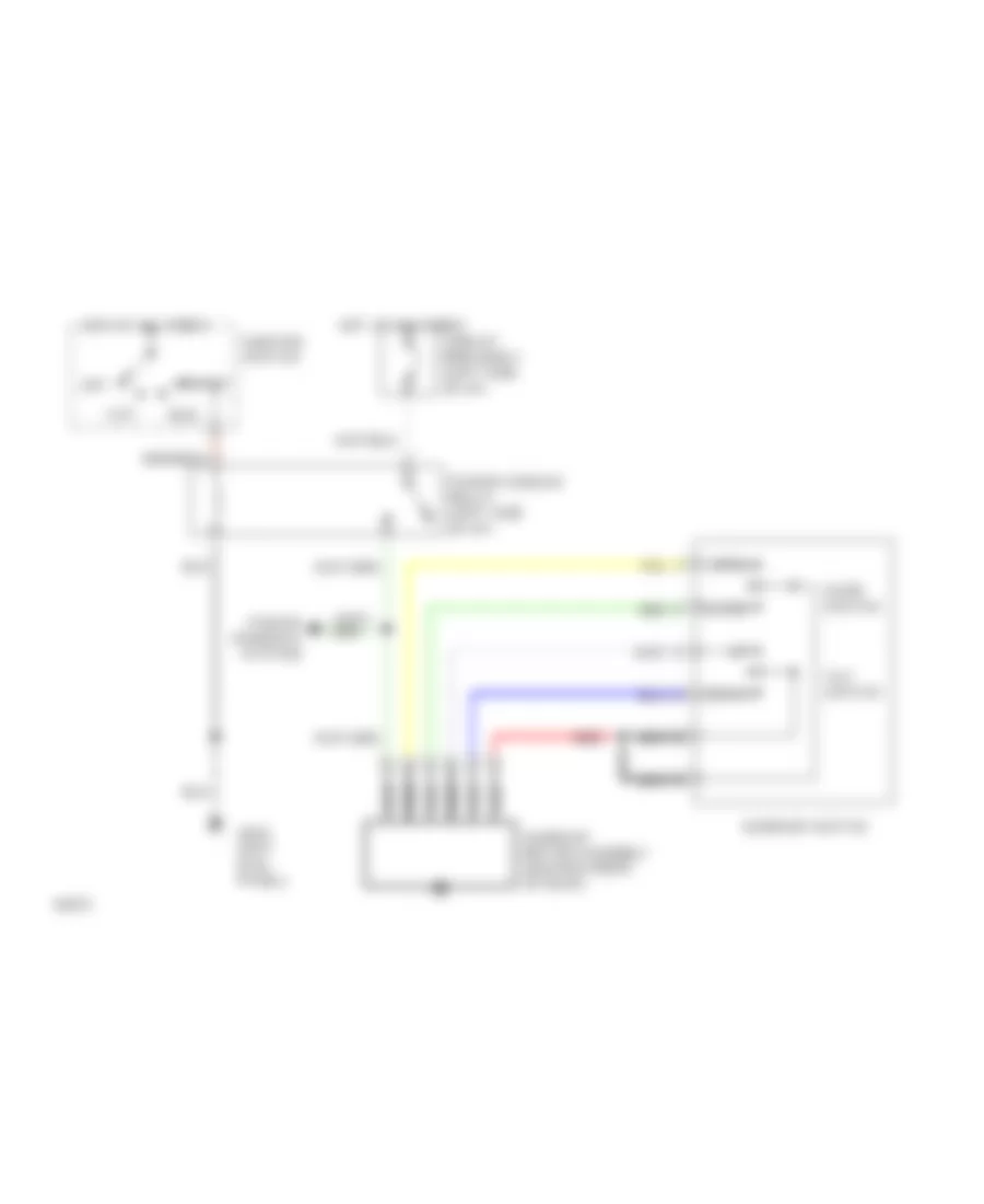
POWER MIRRORS
Power Mirror Wiring Diagram for Infiniti G20 1994
List of elements for Power Mirror Wiring Diagram for Infiniti G20 1994:
- (left front door) g500 (1991-92, m/t early production)
- (left kick panel) g20o (1993 a/t early prodution, 1993 late production, 1994)
- (optional late 1993, 1994) mirror heater
- (right kick panel) g203 (1993 a/t early prodution, 1993 late production, 1994)
- Door mirror switch
- Fuse block (left side of dash)
- Fuse k 10a
- Heated mirror relay (defoggers system late production 1993, 1994)
- Hot in acc or on
- Left mirror
- Left/right motor
- Mirror position switch
- Mirror select switch
- Right mirror
- Up/down motor
POWER SEATS
Power Seat Wiring Diagrams for Infiniti G20 1994
List of elements for Power Seat Wiring Diagrams for Infiniti G20 1994:
- Circuit breaker-1 (left side of dash)
- G308 (left "b" pillar)
- G407 (center rear of trunk)
- Hot at all times
- Left front power seat
- Left power seat switch
- Left reclining motor
- Left sliding motor
- Red
- Right front power seat
- Right power seat switch
- Right reclining motor
- Right sliding motor
POWER TOP/SUNROOF
Power Top/Sunroof Wiring Diagrams for Infiniti G20 1994
List of elements for Power Top/Sunroof Wiring Diagrams for Infiniti G20 1994:
- Acc
- Circuit breaker 1 (left side of i/p)
- Close
- Down
- G200 (left kick panel)
- Hot at all times
- Ignition switch
- Nca
- Off
- Open
- Power window relay (left side of i/p)
- Power windows system
- Red
- Run
- Slide switch
- Start
- Sunroof motor assembly (center front of roof)
- Sunroof switch
- Tilt switch
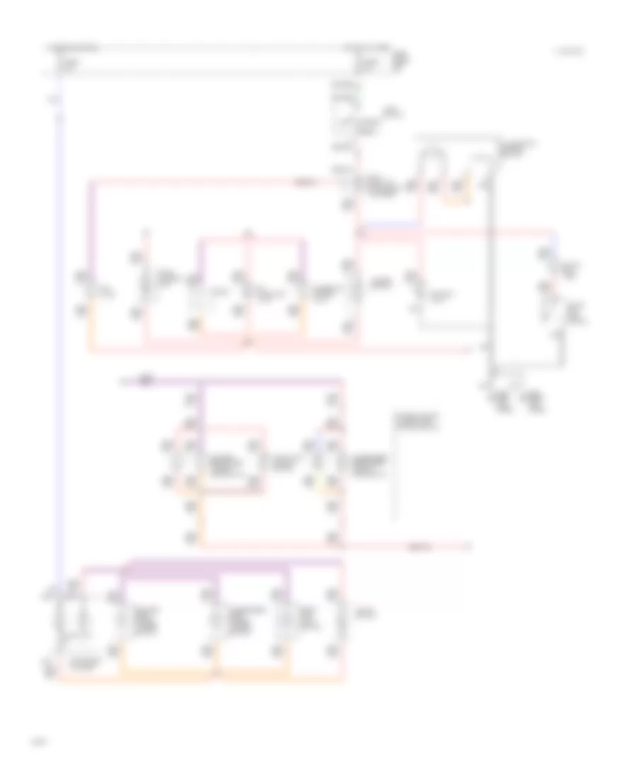
POWER WINDOWS
Power Window Wiring Diagram for Infiniti G20 1994
List of elements for Power Window Wiring Diagram for Infiniti G20 1994:
- 1992-94
- Acc
- Auto
- Auto pwr
- Circuit breaker-1 (left side of dash)
- Dn manual
- Dn window
- Fuse & fusible link box (left front fender)
- Fusible link 30a
- G200 (left kick panel)
- Ground
- Hot at all times
- Ign
- Ignition switch
- Interior
- Interior lights system
- Interior lights system
- Left front window motor
- Left front window switch
- Left rear window motor
- Left rear window switch
- Lights system
- Lock
- Lock switch
- Man
- Nca
- Power
- Power window amplifier (left front door)
- Power window main switch
- Power window relay (left side of dash)
- Right front window motor
- Right front window switch
- Right rear window motor
- Right rear window switch
- Run
- Start
- Sunroof motor assembly
- Up manual
- Up window
RADIO
Radio Wiring Diagrams for Infiniti G20 1994
List of elements for Radio Wiring Diagrams for Infiniti G20 1994:
- Acc
- Amp on signal
- Amp on/off
- Antenna
- Antenna in
- Battery
- Fr lh (+) amp
- Fr lh (+) in
- Fr lh (+) out
- Fr lh (-) amp
- Fr lh (-) in
- Fr lh (-) out
- Fr rh (+) amp
- Fr rh (+) in
- Fr rh (+) out
- Fr rh (-) amp
- Fr rh (-) in
- Fr rh (-) out
- Front amplifier (center front of trunk)
- Fuse 10a
- Fuse 15a
- Fuse block
- Ground
- Hot at all times
- Hot in acc or on
- Illum
- Interior lights system
- Left front speaker
- Left rear speaker
- Left tweeter
- Nca
- Pnk
- Power antenna system
- Pwr antenna
- Radio
- Rear amplifier (center front of trunk)
- Red
- Right front speaker
- Right rear speaker
- Right tweeter
- Rr lh (+) amp
- Rr lh (+) in
- Rr lh (+) out
- Rr lh (-) amp
- Rr lh (-) in
- Rr lh (-) out
- Rr rh (+) amp
- Rr rh (+) in
- Rr rh (+) out
- Rr rh (-) amp
- Rr rh (-) in
- Rr rh (-) out
SHIFT INTERLOCKS
Shift Interlock Wiring Diagram for Infiniti G20 1994
List of elements for Shift Interlock Wiring Diagram for Infiniti G20 1994:
- (left "b"
- 1994 vftc c
- Detention switch (shift) (below center console)
- Fuse block (left side of i/p)
- Fuse u 10a
- Fuse x 20a
- G200 (left kick panel)
- G308
- Hot at all times
- Hot in on or start
- Nca
- Pillar)
- Shift lock control unit (lower right side of i/p)
- Shift lock solenoid (below center console
- Stop lamp switch (top of brake pedal support)
STARTING/CHARGING
Charging Wiring Diagram for Infiniti G20 1994
List of elements for Charging Wiring Diagram for Infiniti G20 1994:
- (1991- early 93) (late 1993-94)
- (late 1993-94) (1991- early 93)
- 1991- early 1993
- 1991- early 93
- Alternator
- Anti-lock brake system control unit
- Battery
- Bulb check relay (left side of dash)
- C2 c3
- C3 c1
- Charge indicator
- Daytime light control unit (canada)
- Fuse & fusible link box (front left fender)
- Fuse block (left side of dash)
- Fuse g 10a
- Fuse u 10a
- G101 (right front fender)
- Hot in on or start
- Instrument cluster
- Late 1993- only
- Nca
- Starter motor
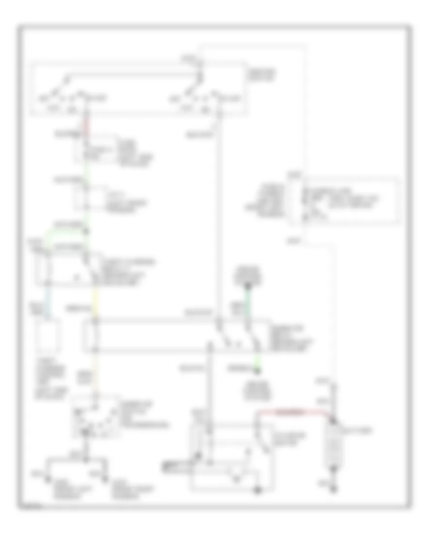
Starting Wiring Diagram, A/T for Infiniti G20 1994
List of elements for Starting Wiring Diagram, A/T for Infiniti G20 1994:
- (1991- early 93) (late 1993-94)
- (left front fender)
- (left side of dash)
- Acc
- Battery
- Cruise control system
- Fuse & fusible link box (front left fender)
- Fuse bock (left side of dash)
- Fuse g 10a
- G100 (front left fender)
- G101 (front right fender)
- Ignition switch
- Inhibitor relay (behind left headlamp)
- Inhibitor switch (on transmission)
- J/c 4
- Nca
- Off
- Start
- Starter motor
- Theft warning control unit
- Theft warning relay 2 (behind left headlamp)
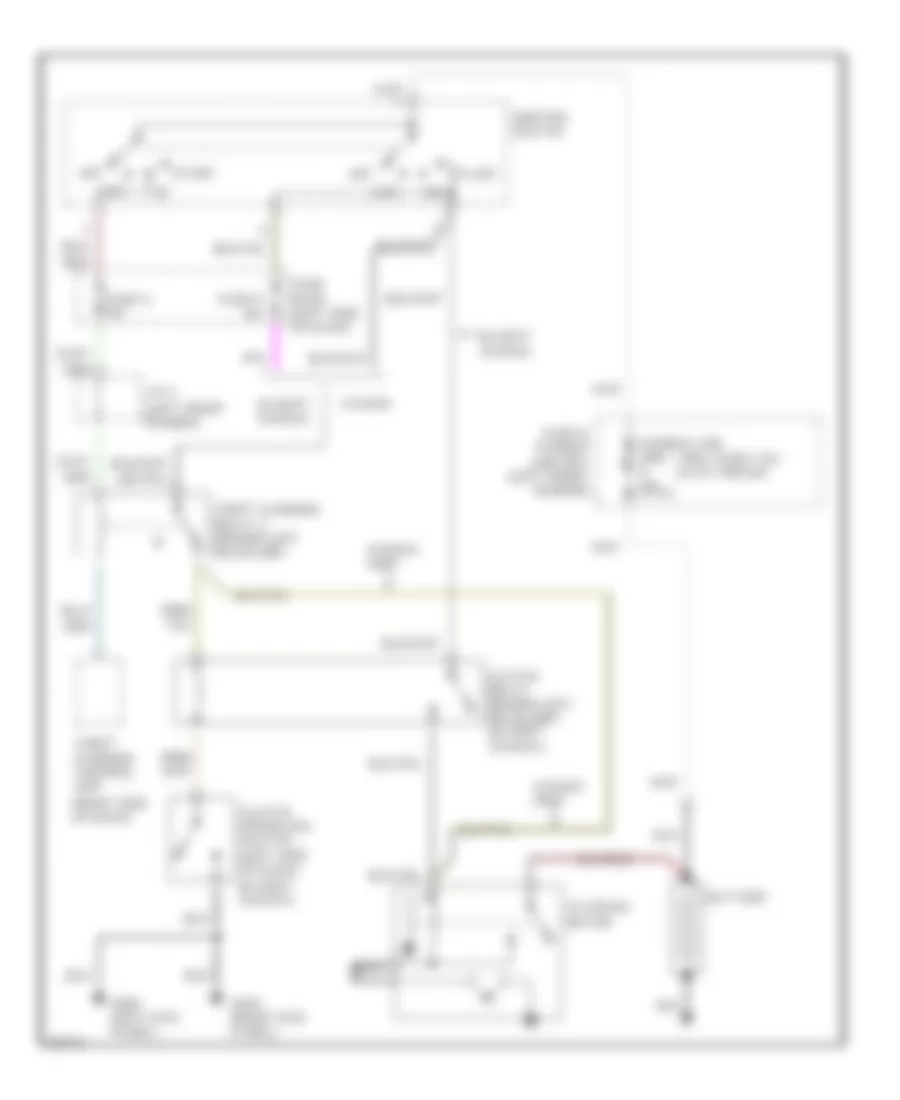
Starting Wiring Diagram, M/T for Infiniti G20 1994
List of elements for Starting Wiring Diagram, M/T for Infiniti G20 1994:
- (1991- early 93) (late 1993-94)
- (except canada)
- (left front fender)
- (right side of dash)
- Acc
- Battery
- Canada
- Canada only
- Clutch interlock switch (left side of dash)
- Clutch relay (behind left headlamp) (except canada)
- Except canada
- Fuse & fusible link box (left front fender)
- Fuse bock (left side of dash)
- Fuse g 10a
- Fuse p 10a
- G200 (left kick panel)
- G203 (right kick panel)
- Ignition switch
- J/c 4
- Nca
- Off
- Red
- Start
- Starter motor
- Theft warning control unit
- Theft warning relay 2 (behind left headlamp)
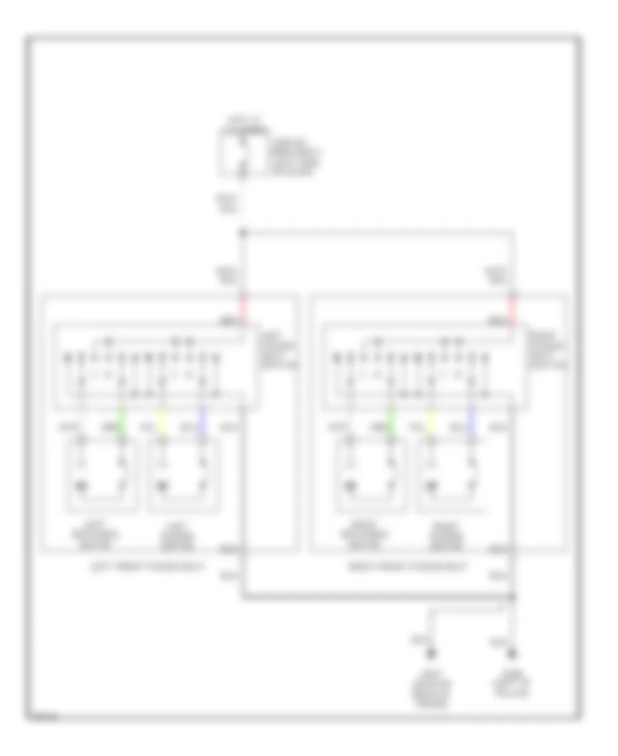
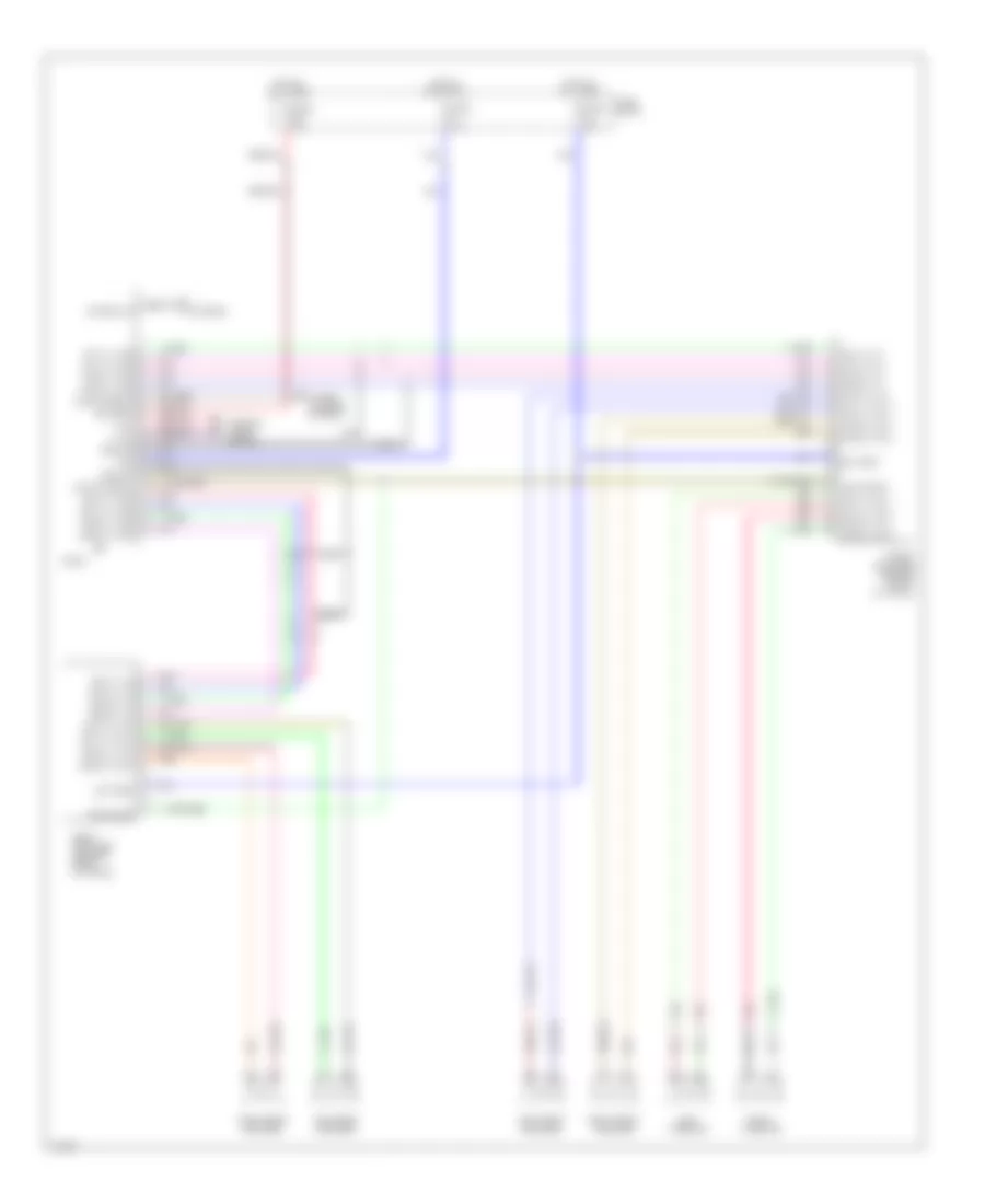
SUPPLEMENTAL RESTRAINTS
Supplemental Restraint Wiring Diagram for Infiniti G20 1994
List of elements for Supplemental Restraint Wiring Diagram for Infiniti G20 1994:
- 10a
- Air bag ind.
- Airbag control unit (below center of i/p)
- B-17
- Bat+
- Belt sw
- Belt w/l
- Czsc+
- Czsc-
- Data link connector for consult (left side of i/p)
- Dr sw
- Front crash zone sensor (center front of radiator)
- Fuse block (left side of i/p)
- Fuse h
- Fuse u
- Fuse y
- G203 (right kick panel)
- G308 (left "b" pillar)
- Gnd
- Hot at all times
- Hot in on or start
- Ign
- Ind lp
- Instrument cluster
- Left airbag module (top of steering column)
- Left front door switch
- Left pretensioner (bottom of left "b" pillar)
- Nca
- P/t+
- P/t-
- Right airbag module (right side of i/p)
- Right pretensioner (bottom of right "b" pillar)
- Seat belt buckle switch
- Seat belt ind.
- Seat belt relay
- Spiral cable
- Sq+
- Sq-
- Ss+
- Ss-
- Sss clk
- Sss rx
- Sss tx
- Time control unit
- Ts+
- Ts-
- Tunnel and safing sensor (below center console)
TRANSMISSION
Transmission Wiring Diagram for Infiniti G20 1994
List of elements for Transmission Wiring Diagram for Infiniti G20 1994:
- (side of transaxle) inhibitor switch
- A/t control unit (left kick panel)
- A/t fluid temp. sensor
- A/t mode switch
- All times
- Ascd control unit (behind left i/p)
- Automatic transaxle
- Closed throttle
- Cmfrt
- Comfort
- Cruise control
- Data link connector (for consult) (below left side of i/p)
- Diodes (1994 & 95) (left i/p)
- Dropping resistor (left side of engine compt)
- Eccs control module (behind center console)
- Engine coolant temperature sensor (left rear of engine)
- Exterior lights (backup)
- Fuse block (left kick panel)
- Fuse g 10a
- Fuse u 10a
- Fuse w 10a
- G114 (left rear of engine)
- G200 (left kick panel)
- G305 (bottom of left b pillar)
- Hot at
- Hot in on or start
- Instrument cluster
- Instrument cluster (tachometer)
- Line press. sol. valve
- Nca
- O.d. control
- O.d. off ind.
- Over- run clutch sol.
- Pnk
- Power
- Pwr
- Red
- Revolution sensor
- Shift sol. valve a
- Shift sol. valve b
- Speedometer
- Switch
- Tcc sol. valve
- Throttle position sensor (on throttle body)
- Throttle position switch (on throttle body)
- Vehicle speed sensor
- Wot
TRUNK, TAILGATE, FUEL DOOR
Trunk & Fuel Door Release Wiring Diagram for Infiniti G20 1994
List of elements for Trunk & Fuel Door Release Wiring Diagram for Infiniti G20 1994:
- (center rear of trunk) g407
- 1991-92 & 1993 early production
- 1993 late production & 1994
- Fuel filler lid opener actuator (left rear of trunk)
- Fuel lid sw
- Fuse block (left side of dash)
- Fuse c 10a
- Hot at all times
- Hot at all times circuit breaker 1 (left side of dash)
- Multi- remote control unit
- Nca
- Trunk lid & fuel filler lid switch
- Trunk lid opener actuator (center rear of trunk)
- Trunk lid opener cancel switch
- Trunk lid sw
- W/keyless entry
WIPER/WASHER
Wiper/Washer Wiring Diagram for Infiniti G20 1994
List of elements for Wiper/Washer Wiring Diagram for Infiniti G20 1994:
- Fuse block (left side of dash)
- Fuse f 20a
- G100 (left front fender)
- G203 (right kick panel)
- Hot in acc or on
- Int
- Inter- mittent
- Nca
- Off
- Pnk
- Smj connector (left side of dash)
- Time control unit (left side of dash)
- Wash
- Washer motor (right front fender)
- Wiper motor (right side of safety wall)
- Wiper relay (relay box 2, left front fender)
- Wiper switch