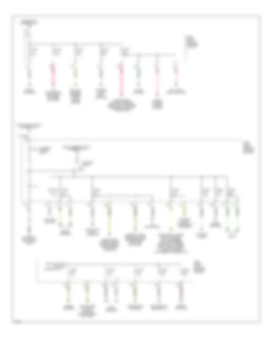
AIR CONDITIONING
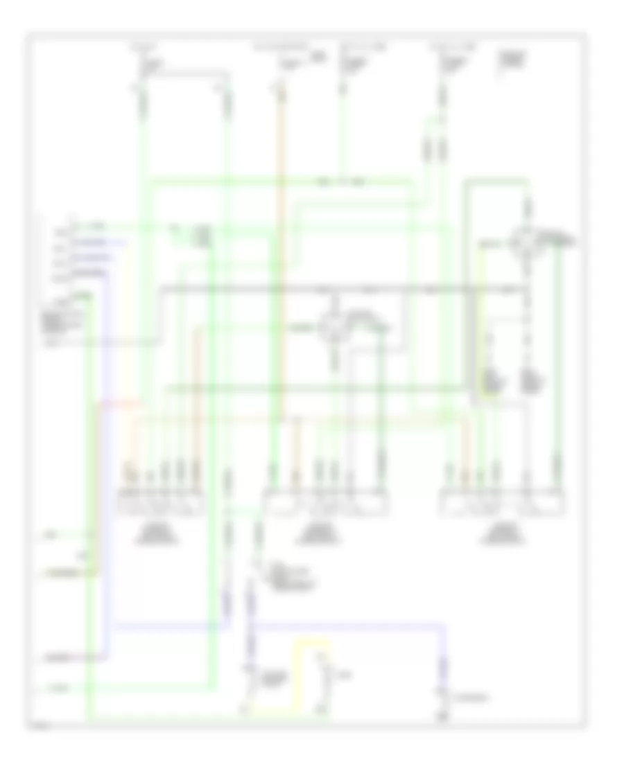
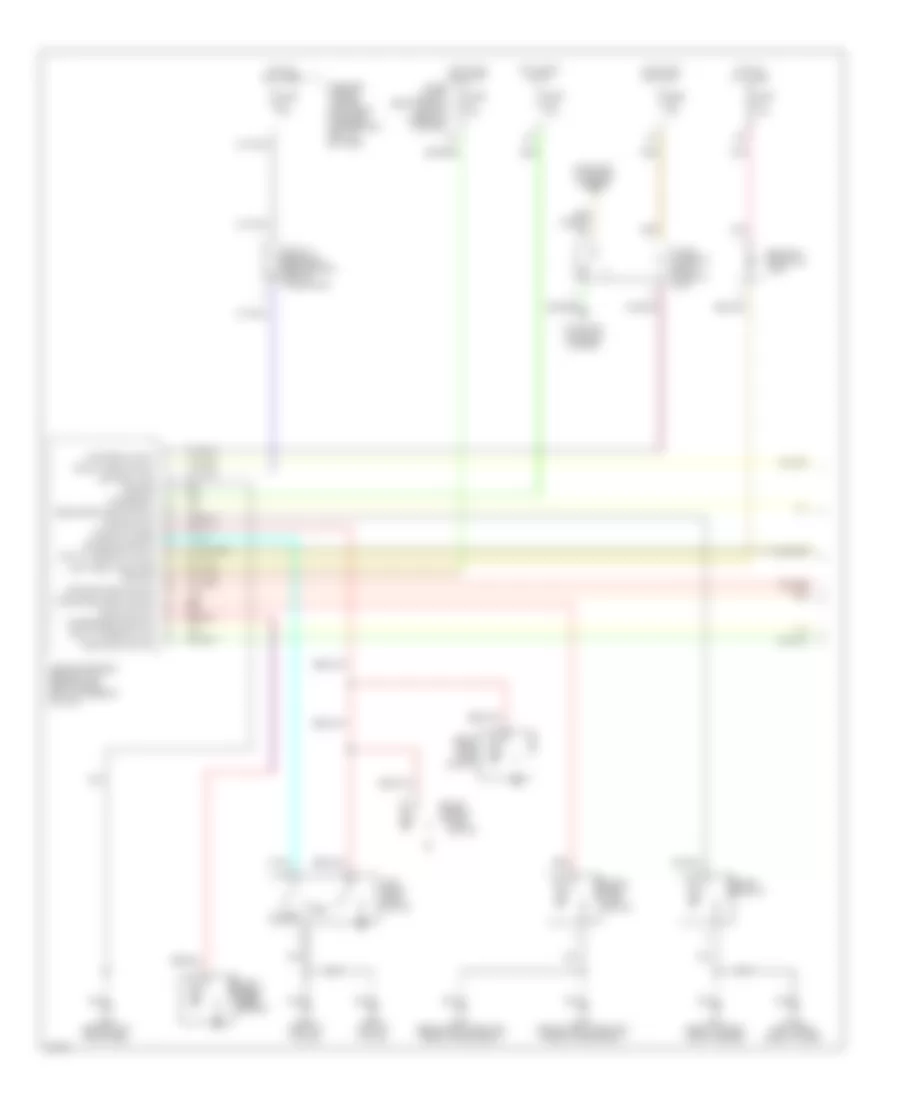
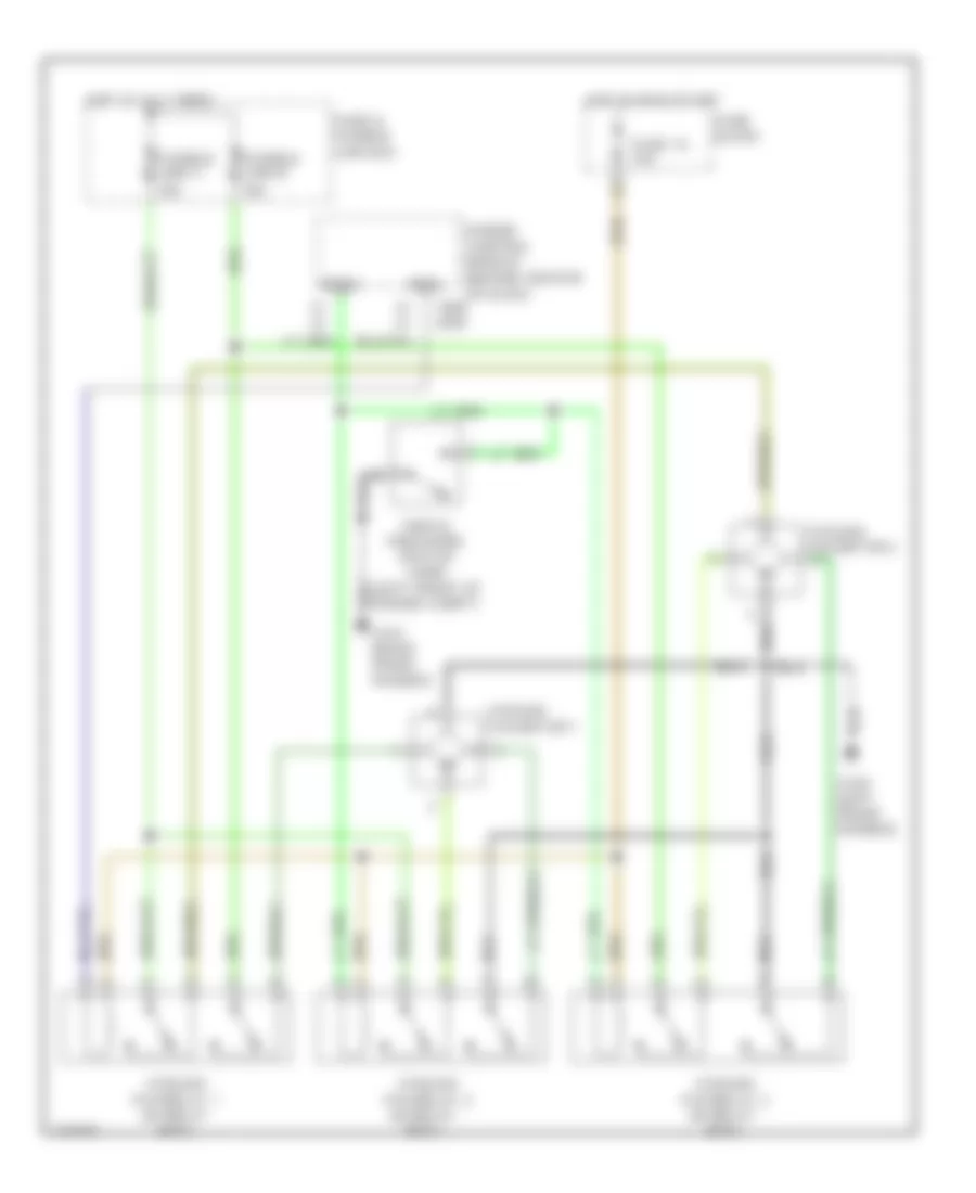
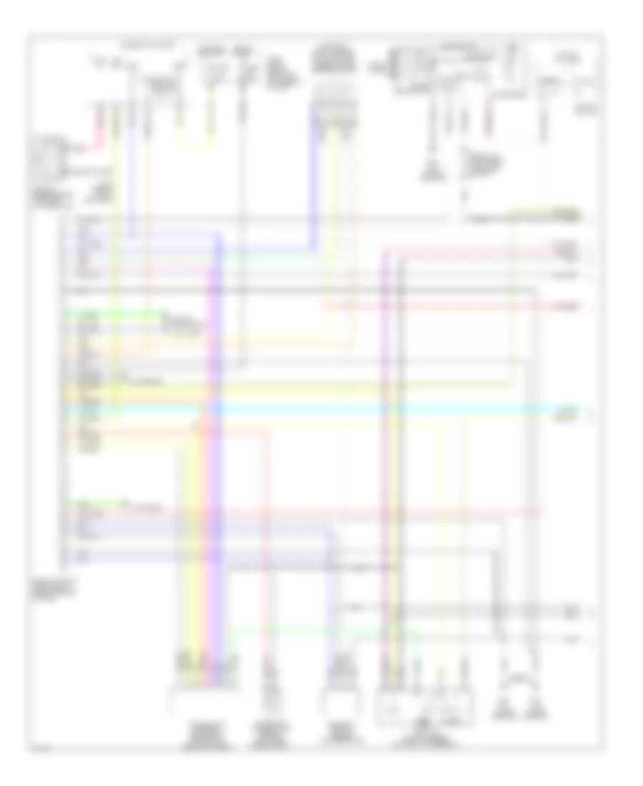
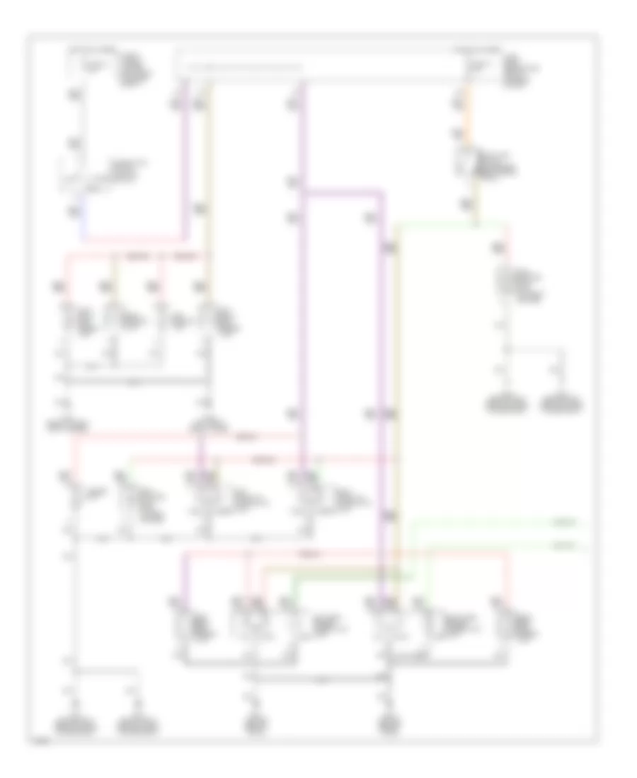
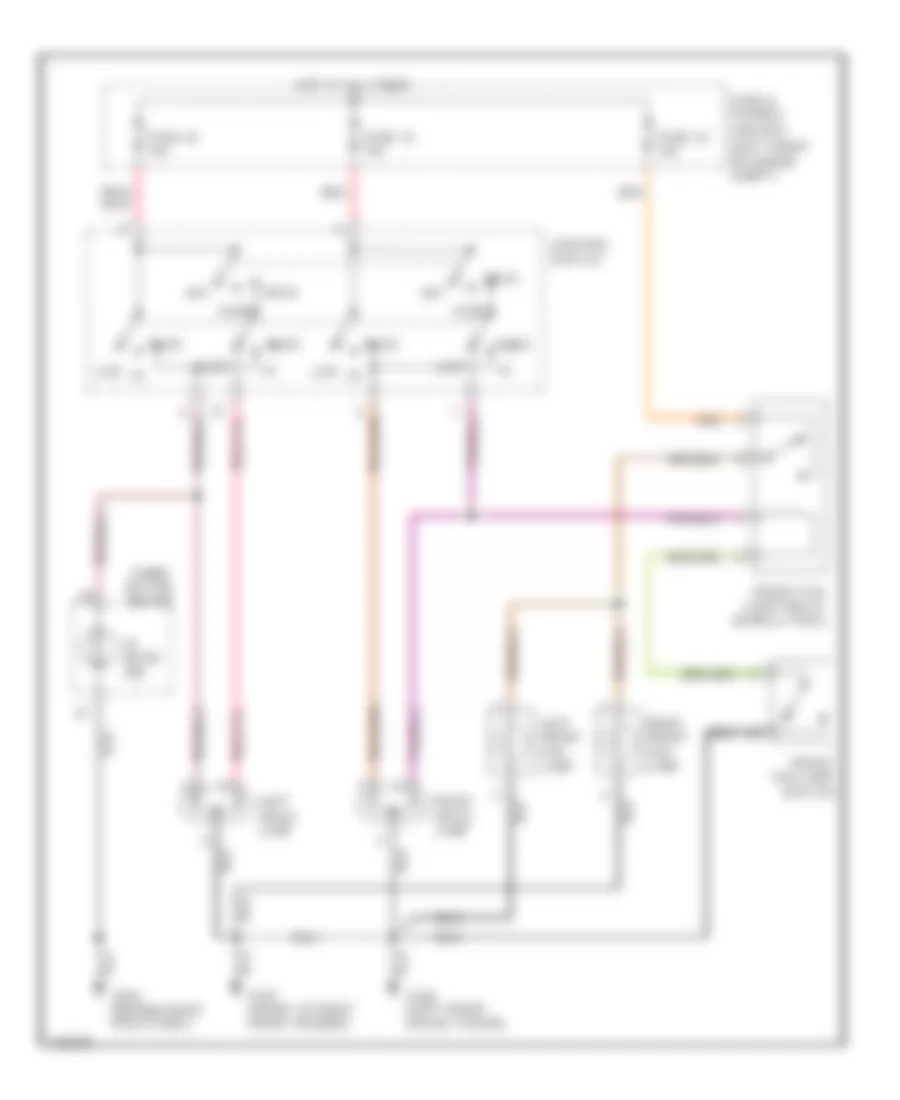
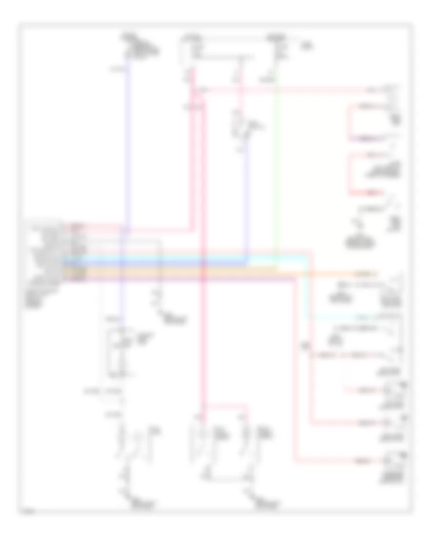
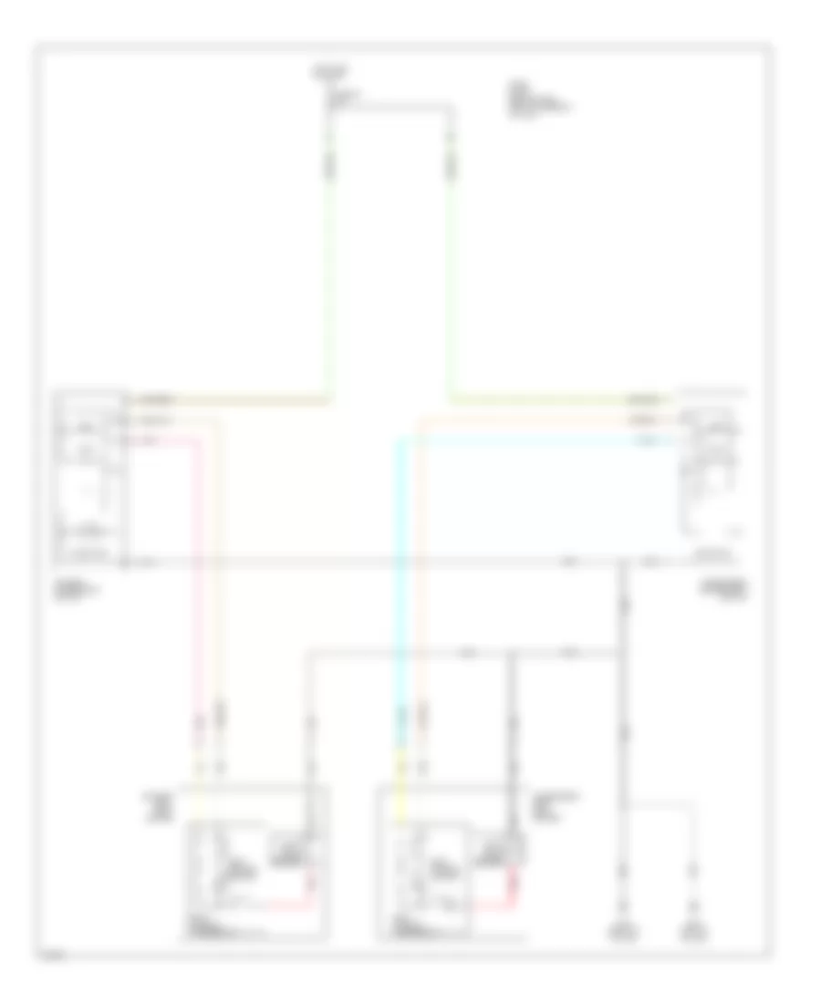
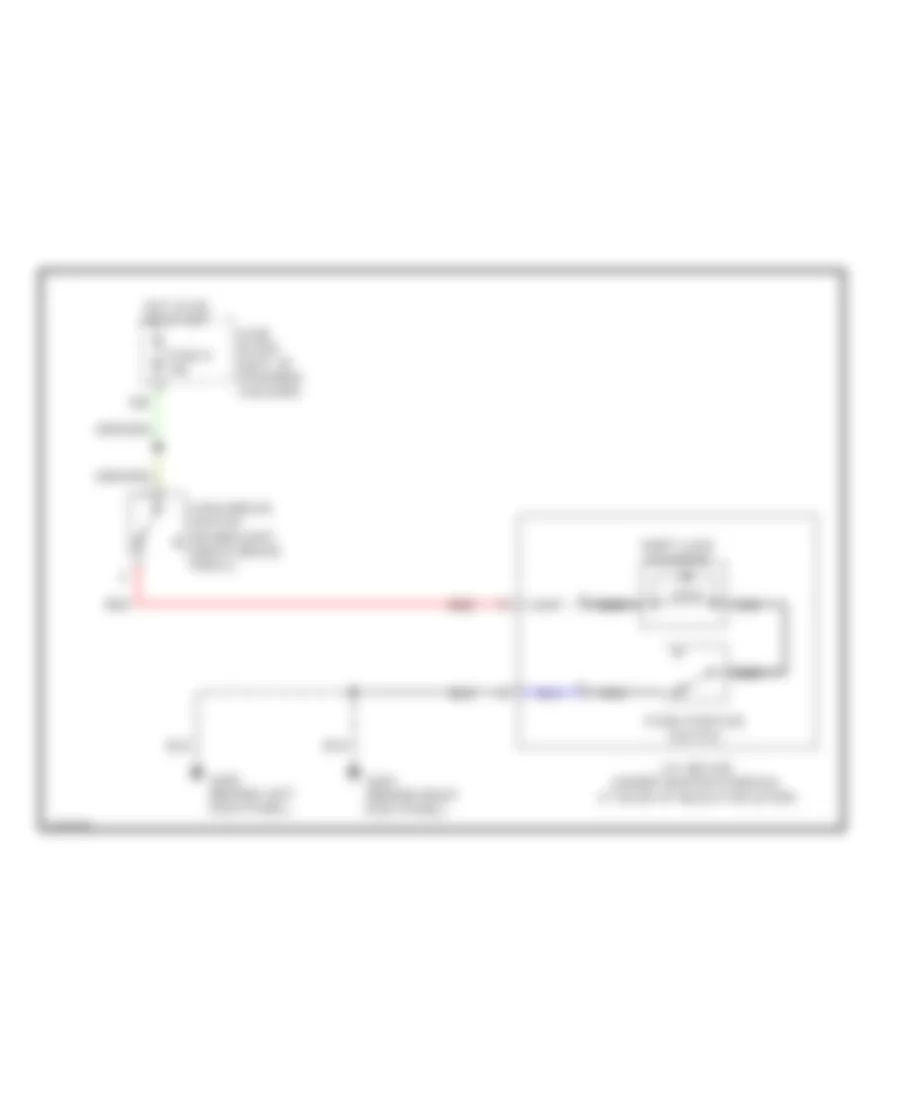
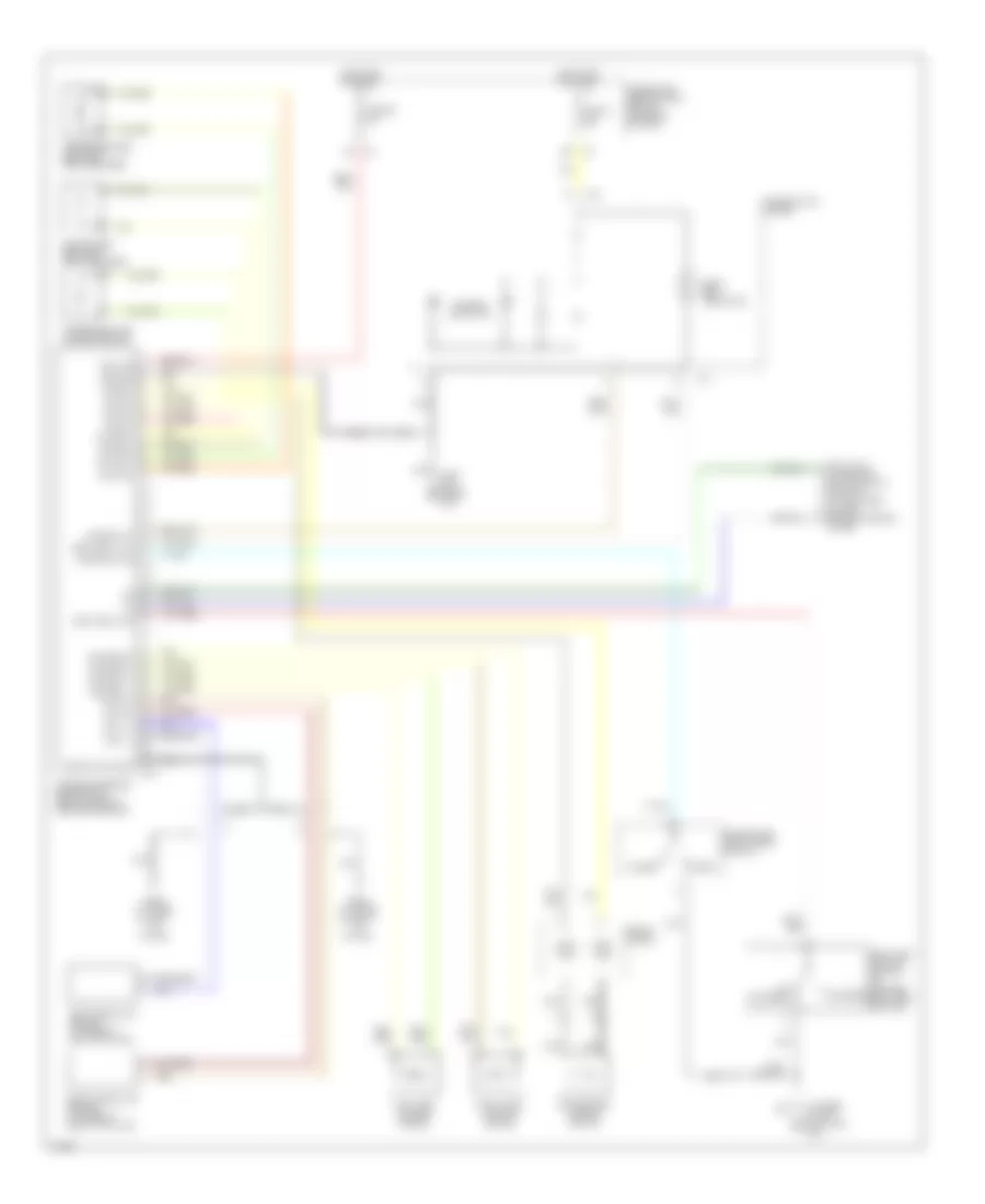
Automatic A/C Wiring Diagram (1 of 2) for Infiniti G20 t 1999

List of elements for Automatic A/C Wiring Diagram (1 of 2) for Infiniti G20 t 1999:
- "c1" fin
- (center front
- (center of
- (left front of engine compt)
- (left side
- (right de-
- (right side
- (right side kick panel)
- A/c auto amp
- Air mix door motor (center of dash)
- Amb sens
- Bat
- Blower motor (right side of dash)
- Comp on
- Dash) in vehicle sensor
- Fan cate
- Fan control amp (right side of dash)
- Fan f/b
- Fascia) ambient sensor
- Ficd
- Froster grille)
- Fuse 10a
- Fuse 15a
- Fuse 7.5a
- Fuse block
- G202
- G203
- Grd
- High
- Hot at all times
- Hot in on
- Ign
- Ign 2
- Ill
- Incar sens
- Intake actr +
- Intake actr -
- Intake code 1
- Intake code 2
- Intake door motor (right side of dash)
- Intake sens
- Intake sensor
- Interior lights system
- Lan-sig
- Light
- Low
- Mode door motor (center of dash)
- Of dash)
- Or start
- Pnk
- Position switch
- Sense grd
- Sun sens
- Sunload sensor
- Thermal transmitter (left front of engine)
- Thermo control amp
- Triple pressure switch
- Vactr
- W/t sens
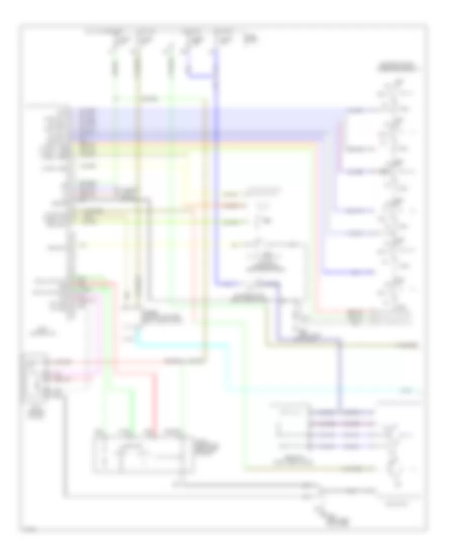
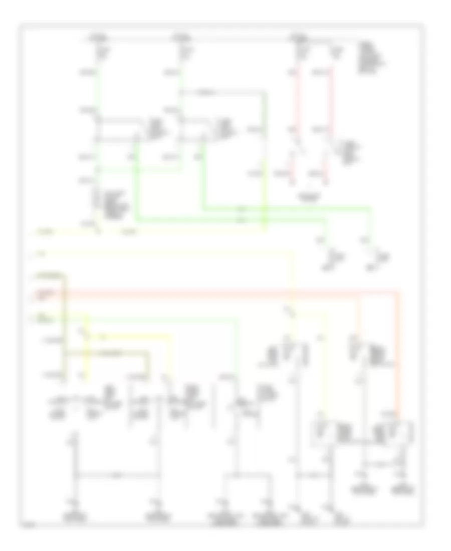
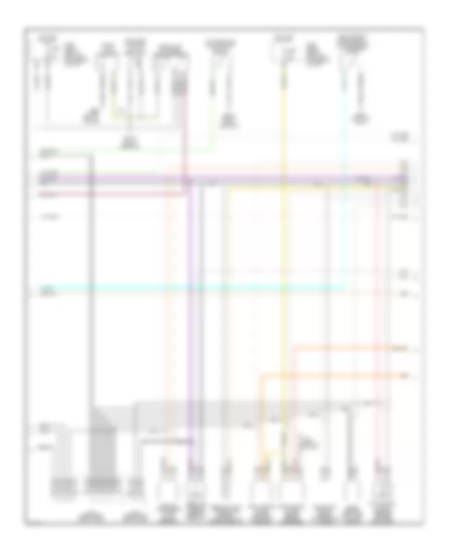
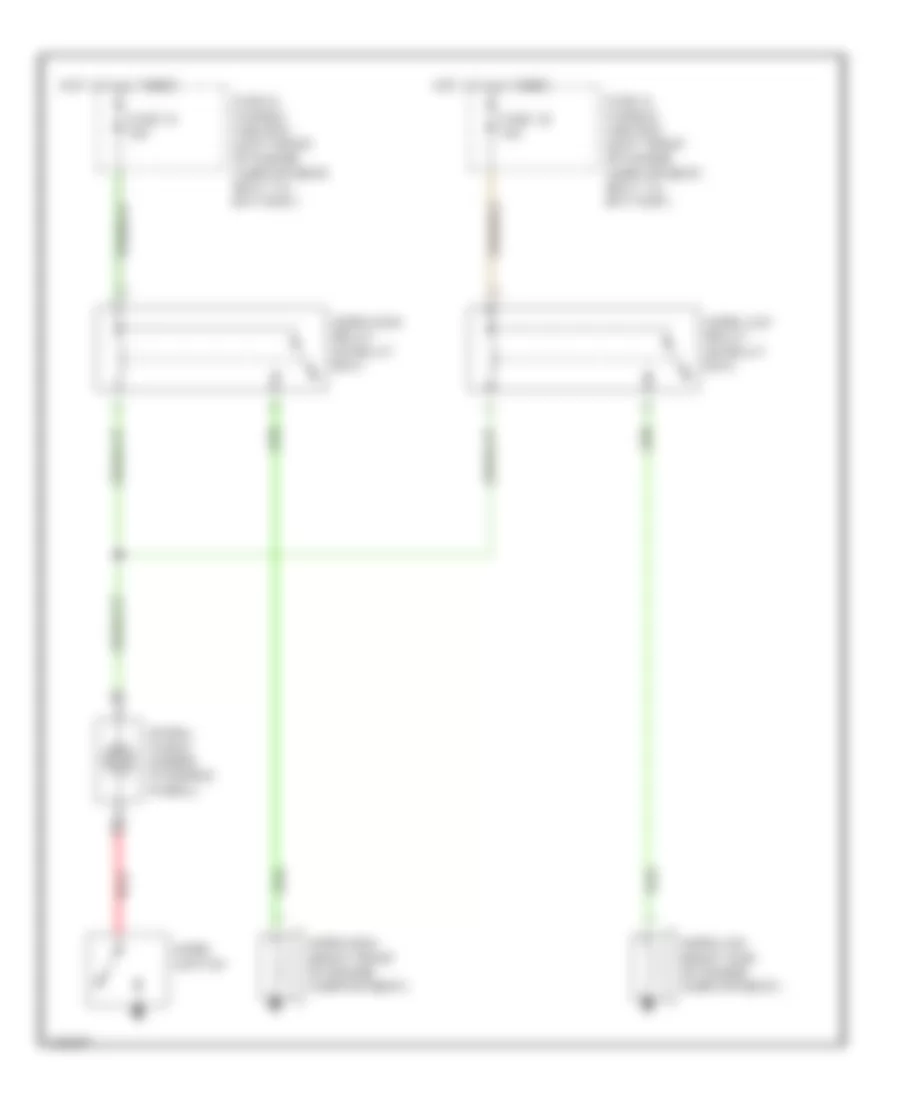
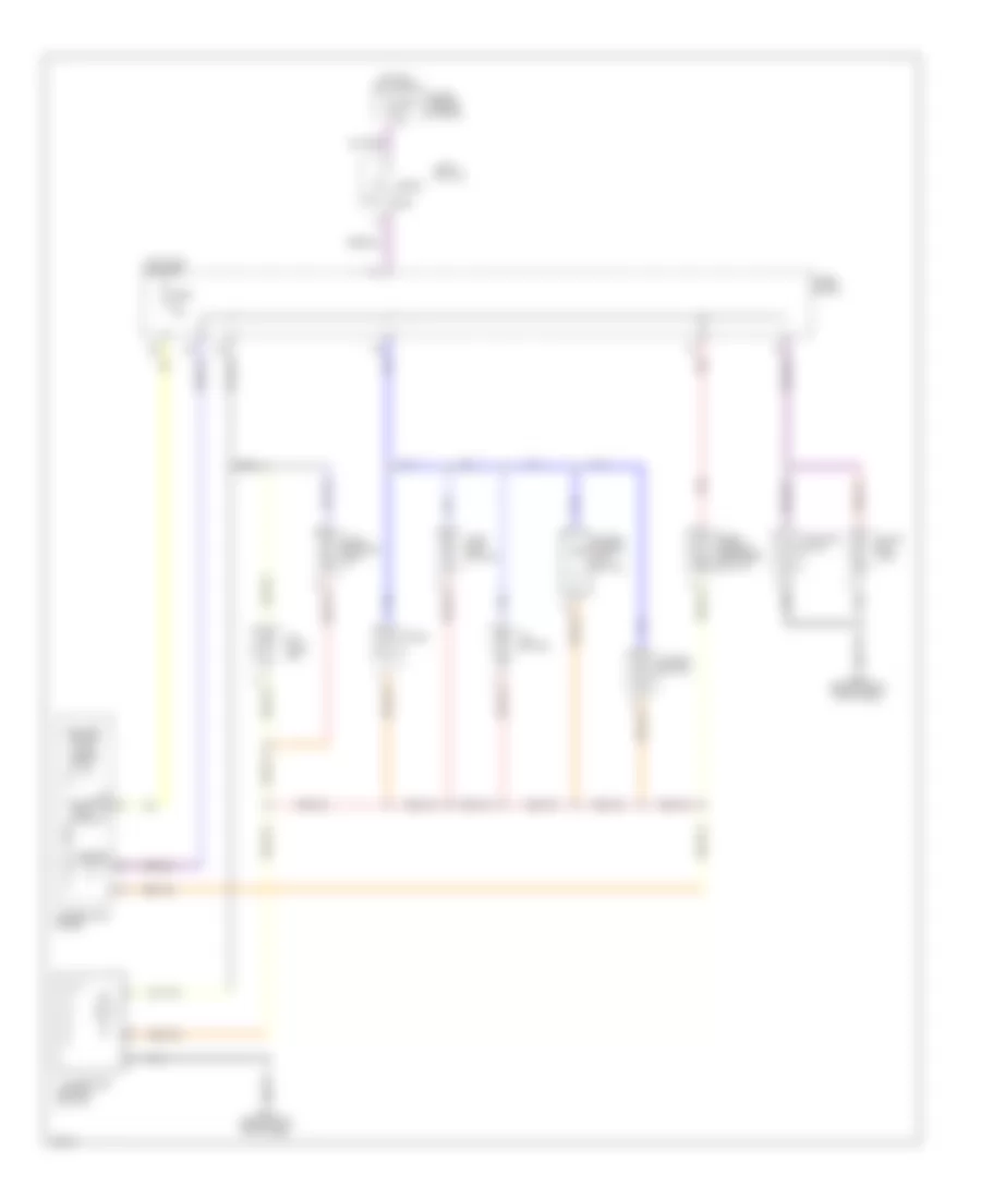
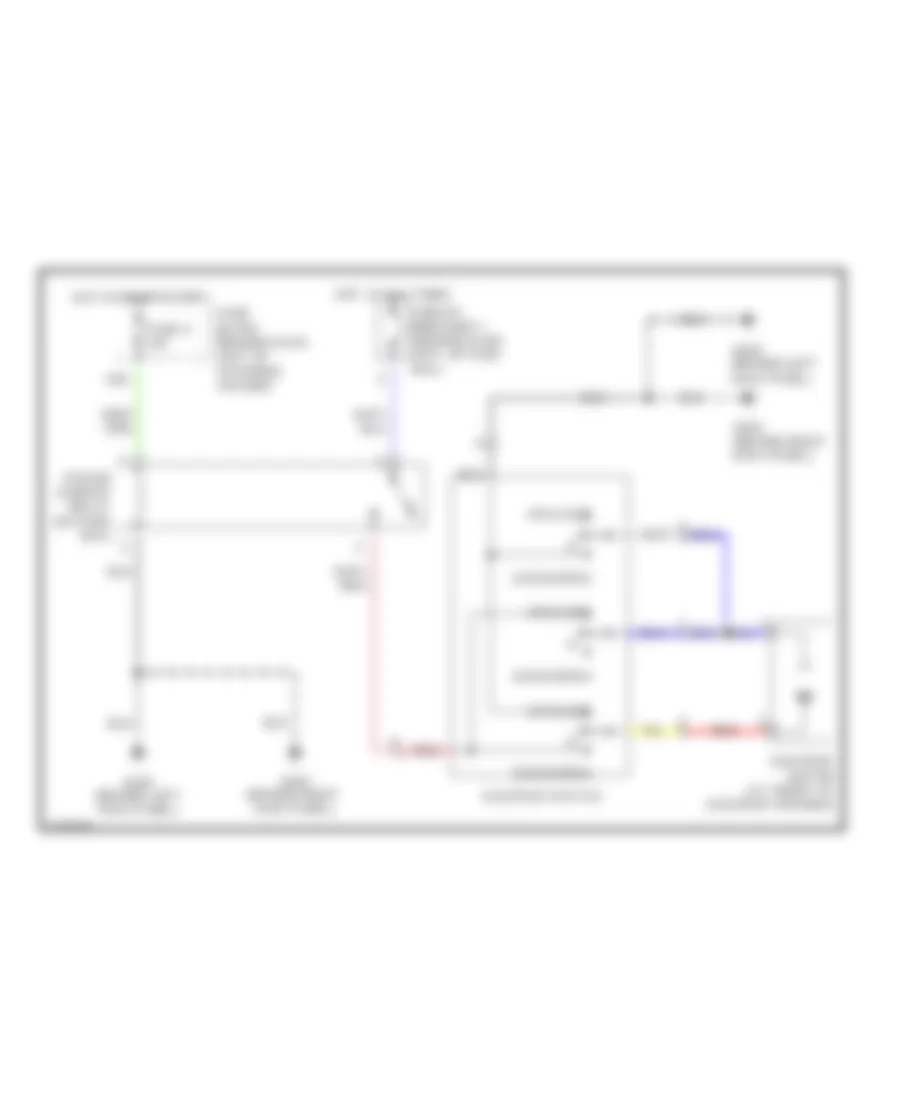
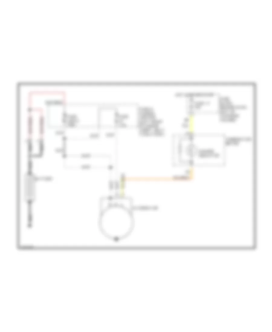
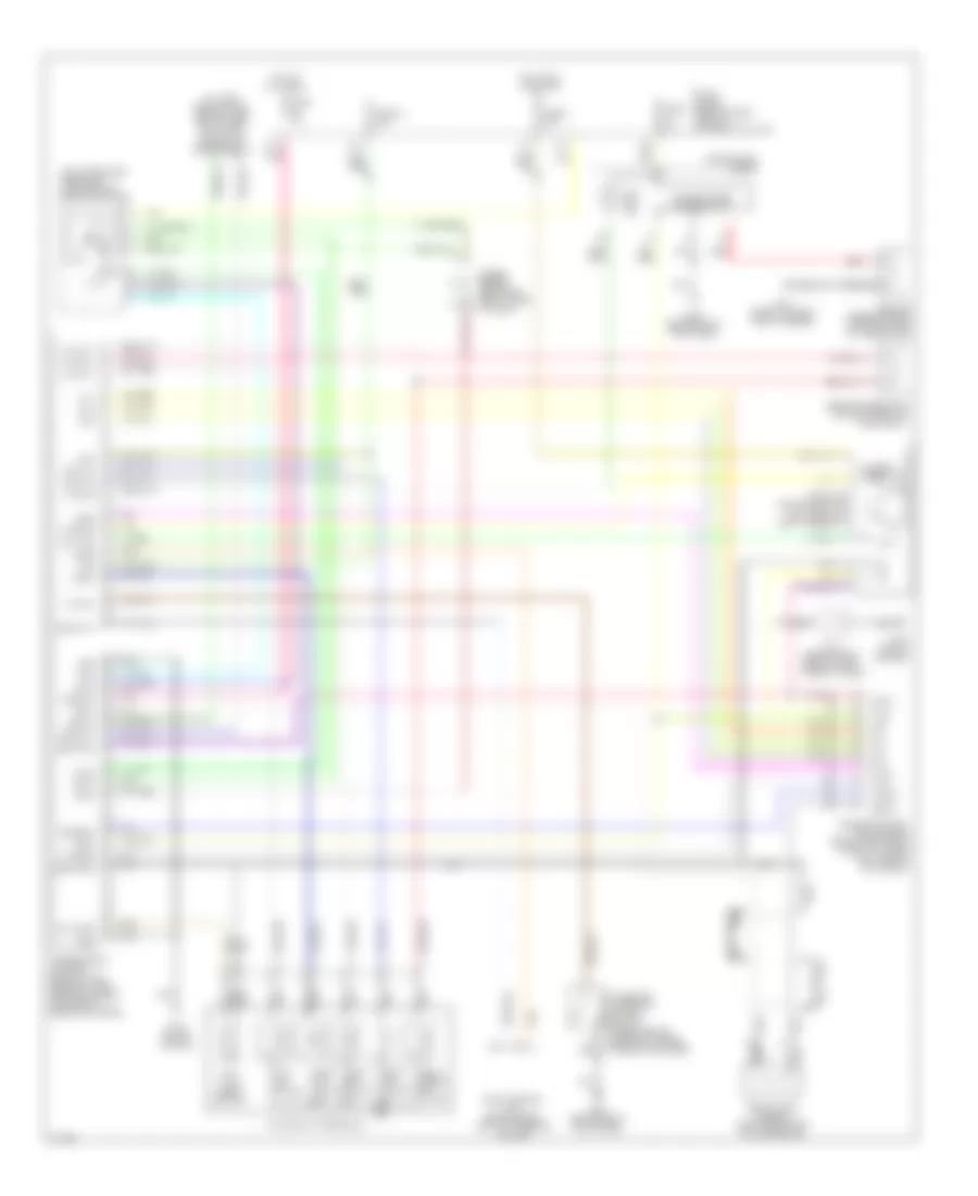
Automatic A/C Wiring Diagram (2 of 2) for Infiniti G20 t 1999
List of elements for Automatic A/C Wiring Diagram (2 of 2) for Infiniti G20 t 1999:
- 16h
- Acrly
- Air conditioner relay (right front of engine compt)
- Arcon
- Compressor
- Cooling fan motor 1
- Cooling fan motor 2
- Cooling fan relay 1 (left front of engine compt)
- Cooling fan relay 2 (left front of engine compt)
- Cooling fan relay 3 (left front of engine compt)
- Diode
- Engine control module (under center console)
- Fuse 16 10a
- Fuse 6 10a
- Fuse and fusible link box
- Fuse block
- Fusible link b 40a
- Fusible link c 40a
- G100 (left front of engine compt)
- G101 (right front of engine compt)
- Hot at all times
- Hot in on
- Hot in on and start
- Iacv-ficd solenoid valve
- Rfrh
- Rfrl
- Tasw
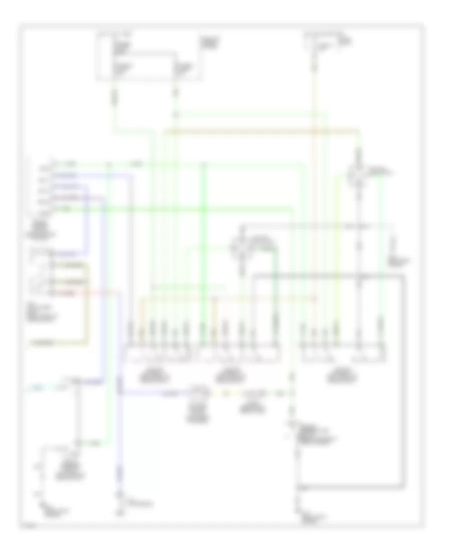
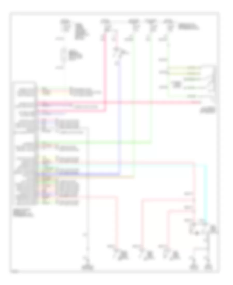
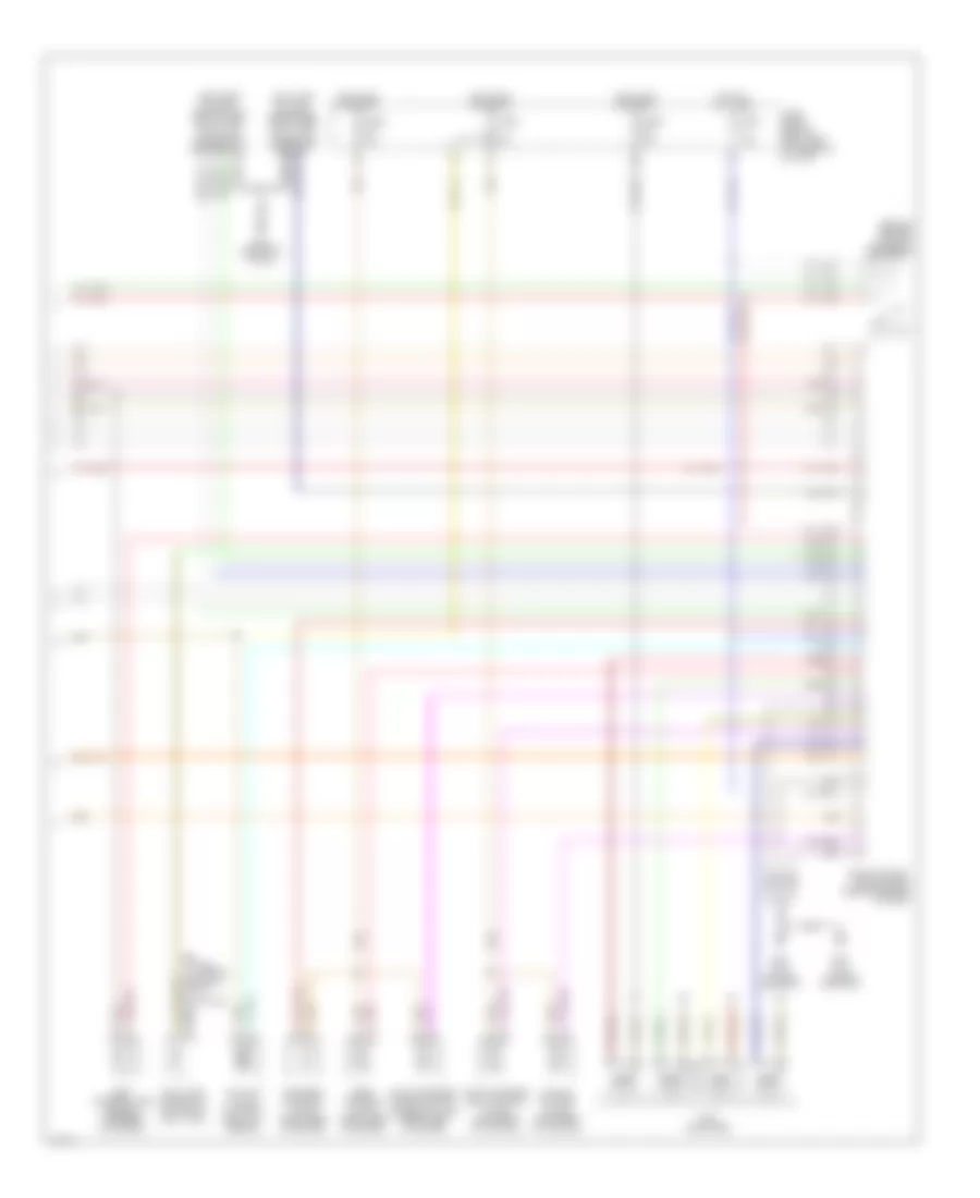
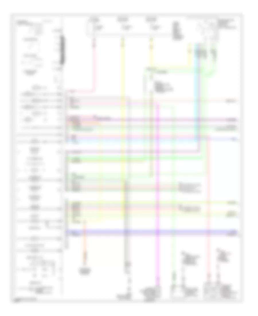
Manual A/C Wiring Diagram (1 of 2) for Infiniti G20 t 1999
List of elements for Manual A/C Wiring Diagram (1 of 2) for Infiniti G20 t 1999:
- (+) face, (-) def
- (+) fre, (-) rec
- (-) fre, (+) rec
- (-) vent, (+) def
- (center
- (center of dash)
- (right side of dash)
- 16h
- 3m 3c
- A/c switch
- Air mix door motor (right side of dash)
- Air mix mtr (cold)
- Air mix mtr (hot)
- B/l
- B/l input
- Blower motor
- Def
- Def input
- F/d
- F/d input
- Face
- Face input
- Fan switch
- Foot
- Foot input
- Fre
- Fre input
- Fuse 1 fuse 1 15a 15a
- Fuse 2 15a
- Fuse 6 10a
- Fuse 8 10a
- Fuse block
- G203 (right side
- G203 (right side kick panel)
- Ground
- Hot in on
- Hot in on, or start
- Ign
- Ill
- Intake door motor (right side of dash)
- Interior lights system
- Kick panel)
- Mode door motor
- Of dash)
- Off
- Pbr
- Ptc
- Ptc led+
- Ptc led-
- Push control unit
- Rec
- Rec input
- Red
- Resistor
- Thermo amp
- Thermo control amplifier
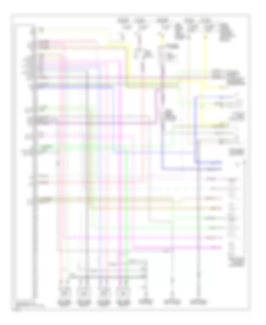
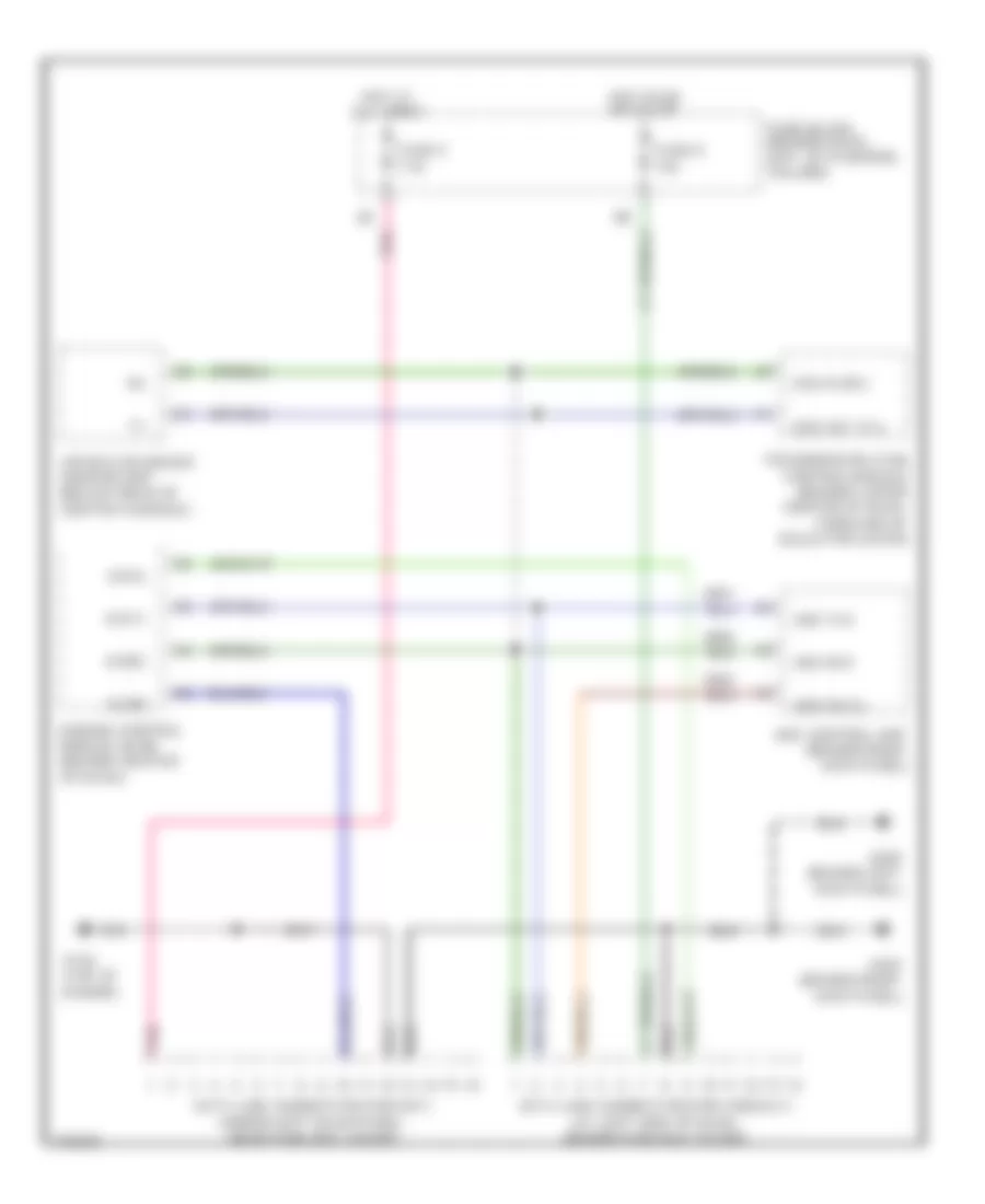
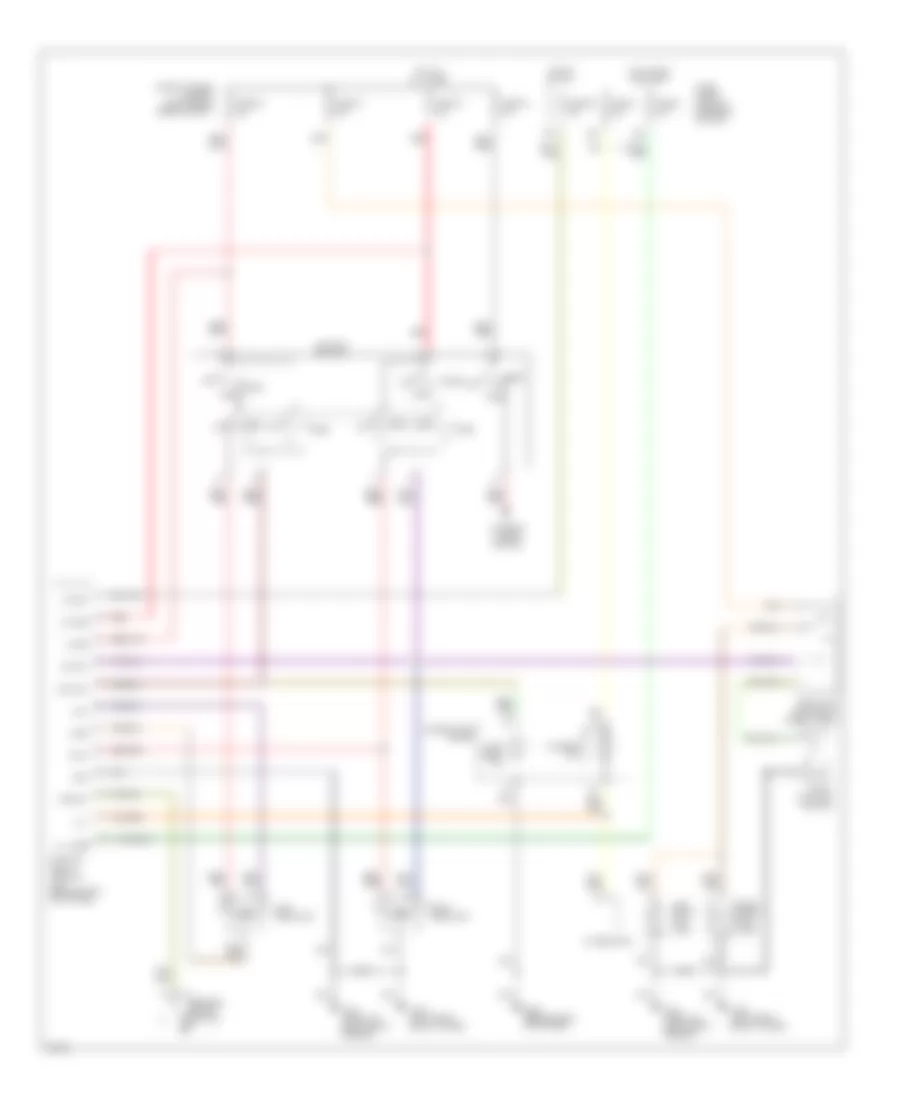
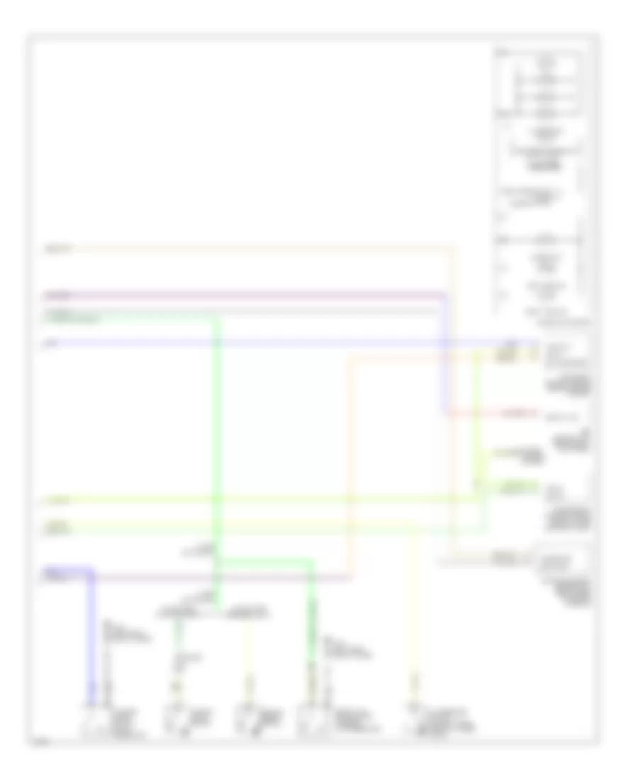
Manual A/C Wiring Diagram (2 of 2) for Infiniti G20 t 1999
List of elements for Manual A/C Wiring Diagram (2 of 2) for Infiniti G20 t 1999:
- A/c compressor
- Acrly
- Air conditioner relay (right front of engine compt)
- Ambient temperature switch (behind center of front bumper)
- Arcon
- Cooling fan motor 1
- Cooling fan motor 2
- Cooling fan relay 1 (right front of engine compt)
- Cooling fan relay 2 (right front of engine compt)
- Cooling fan relay 3 (right front of engine compt)
- Diode (behind left side of dash)
- Engine control module (behind center of dash)
- Fuse 16 10a
- Fuse and fusible link box
- Fuse block
- Fusible link b 40a
- Fusible link c 40a
- Fusible link e 100a
- G100 (left front fender)
- G101 (right front fender)
- Hot at all times
- Hot in on and start
- Iacv-ficd solenoid valve (right rear of engine)
- Rfrh
- Rfrl
- Tasw
- Triple pressure switch (left front of engine compt)
ANTI-LOCK BRAKES
Anti-lock Brake Wiring Diagrams for Infiniti G20 t 1999
List of elements for Anti-lock Brake Wiring Diagrams for Infiniti G20 t 1999:
- (consult) (at left side of dash, behind fuse box cover)
- Abs actuator (right front corner of engine compt)
- Abs control unit (behind right kick panel)
- Abs motor relay (in relay box)
- Abs solenoid valve relay (in relay box)
- Abs warning lamp
- Bls
- Data link connector
- Diag l
- Diode (abs) (behind left side of dash)
- Ecu gnd
- Fl in
- Fl out
- Fl ss
- Fl ss gnd
- Fr in
- Fr out
- Fr ss
- Fr ss gnd
- Fuse & fusible link box (left front of engine compartment, next to battery)
- Fuse 11 10a
- Fuse 14 15a
- Fuse 3 7.5a
- Fuse block (behind dash, left of steering column)
- Fusible link f 40a
- Fusible link h 40a
- G100 (front of left front fender)
- G101 (front of right front fender)
- G203 (behind right kick panel)
- Gnd1
- Gnd2
- Hot at all times
- Hot in on or start
- Instrument cluster
- Left front wheel speed sensor
- Left rear wheel speed sensor
- Nca
- Pnk
- Red
- Right front wheel speed sensor
- Right rear wheel speed sensor
- Rl in
- Rl out
- Rl ss
- Rl ss gnd
- Rr in
- Rr out
- Rr ss
- Rr ss gnd
- Rxd
- Sila
- Stop lamp switch
- Txd
ANTI-THEFT
Anti-theft Wiring Diagram (1 of 2) for Infiniti G20 t 1999
List of elements for Anti-theft Wiring Diagram (1 of 2) for Infiniti G20 t 1999:
- Accessory
- Anti-theft indicator
- Battery (c/b)
- Circuit breaker 1 (behind dash, left of fuse block)
- Closed
- Door switches
- Dr door condition sw
- Driver's door sw
- Fuse 10a
- Fuse 7.5a
- Fuse and fusible link box (left front of engine compartment, next to battery)
- Fuse block (behind dash, left of steering column)
- Fuse d 30a
- G101 (front of right front fender)
- G102 (left front shock tower)
- G200 (behind left kick panel)
- G305 (right "b" pillar)
- G308 (left "b" pillar)
- G310 (behind right side trim panel of rear seat)
- Ground
- Hood switch
- Hot at all times
- Hot in acc or on
- Hot in on or start
- Ignition
- Key cylinder sw lck
- Key cylinder sw unlck
- Left front door switch
- Left rear door switch
- Open
- Panic alarm output
- Pass door condition sw
- Passenger's door sw
- Pnk
- Rear door condition sw
- Red
- Right front front door door switch switch
- Right rear door switch
- Security indicator lamp
- Smart entrance control unit (behind dash, left of steering column)
- Starter cutout
- Starting/ charging system
- Theft warning relay (in relay box)
- Trunk key switch
- Trunk room light switch
- Trunk switch
Anti-theft Wiring Diagram (2 of 2) for Infiniti G20 t 1999
List of elements for Anti-theft Wiring Diagram (2 of 2) for Infiniti G20 t 1999:
- (left front of engine compartment, next to battery)
- Anti-theft system diode (behind left side of dash, taped to harness)
- Full stroke
- Full stroke lock
- Full stroke unlock
- Fuse & fusible link box
- Fuse 10a
- Fuse 15a
- G200 (behind left kick panel)
- G203 (behind right kick panel)
- G305 (right "b" pillar)
- G308 (left "b" pillar)
- G310 (behind right side trim panel of rear seat)
- Headlights system
- Horn high
- Horn high relay (in relay box)
- Horn low
- Horn low relay (in relay box)
- Hot at all times
- Left front door key cylinder switch
- Left front door lock actuator
- Left rear door lock actuator
- Locked
- Mid stroke
- Red
- Right front door key cylinder switch
- Right front door lock actuator
- Right rear door lock actuator
- Theft warning lamp relay (in relay box)
- Trunk lid key cylinder switch
- Unlocked
BODY COMPUTER
Body Computer Wiring Diagrams for Infiniti G20 t 1999
List of elements for Body Computer Wiring Diagrams for Infiniti G20 t 1999:
- 11b
- Accessory
- Anti-theft system
- Batt saver output
- Battery (c/b)
- Battery (fuse)
- Central lock sw
- Central unlck sw
- Circuit breaker 1 (behind dash, left of fuse block)
- Condition switch
- Defogger system
- Door lock output
- Door locks system
- Door switch
- Door unlk output
- Dr door switch
- Dr door unlck
- Exterior lights system
- Fuse & fusible link box (left front of engine compartment, next to battery)
- Fuse 10a
- Fuse 7.5a
- Fuse block (j/b) (behind dash, left of steering column)
- Fuse d 30a
- G200 (behind left kick panel)
- G305 (right "b" pillar)
- G308 (left "b" pillar)
- Ground
- Hazard output
- Hood switch
- Hot at all times
- Hot in accy or on
- Hot in on or start
- Ignition
- Interior lights system
- Key cyl sw lock
- Key cyl sw unlck
- Key switch
- Left front door switch
- Left rear door switch
- Light switch
- Multi-remote control relay (on fuse block)
- Panic alarm out
- Pass door switch
- Pnk
- Red
- Right front door switch
- Right rear door switch
- Room lamp output
- Rr def output
- Rr defggr switch
- Seat belt switch
- Security indicator
- Smart entrance control unit (behind dash, left of steering column)
- Starter cutout
- Starting/charging system
- Trunk key switch
- Trunk switch
- Warning system
COMPUTER DATA LINES
Computer Data Lines for Infiniti G20 t 1999
List of elements for Computer Data Lines for Infiniti G20 t 1999:
- Abs control unit (behind right kick panel)
- Abs diag l
- Abs rxd
- Abs txd
- Air bag diagnosis sensor unit (below rear of center console)
- Data link connector (for consult) (at left side of dash, behind fuse box cover)
- Data link connector (for gst) (under left dash panel, near fuse box cover)
- Engine control module (ecm) (behind center of dash)
- Fuse 5 7.5a
- Fuse 8 10a
- Fuse block (behind dash, left of steering column)
- G134 (top of engine)
- G200 (behind left kick panel)
- G203 (behind right kick panel)
- Hot at all times
- Hot in on or start
- Kline
- Pnk
- Scicl
- Scirx
- Scitx
- Sss in (rx)
- Sss out (tx)
- Transmission (tcm) control module (behind lower center of dash, forward of selector lever)
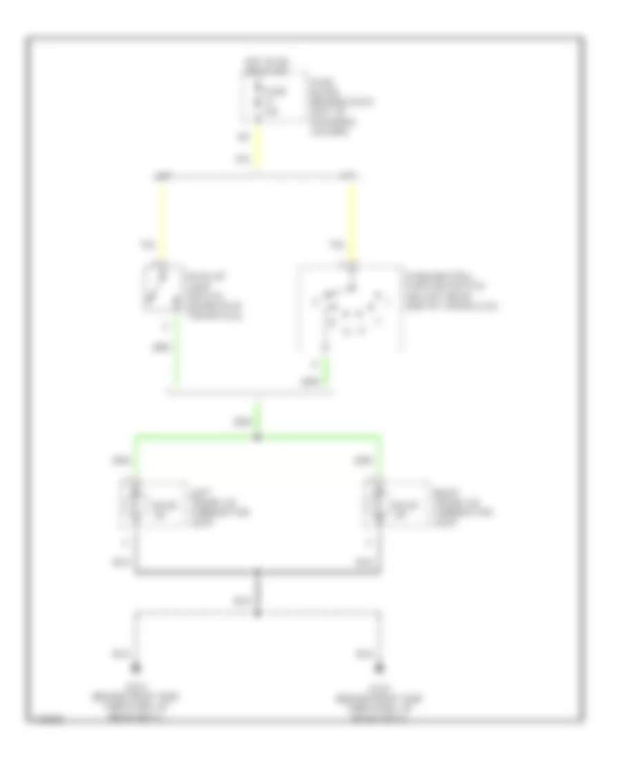
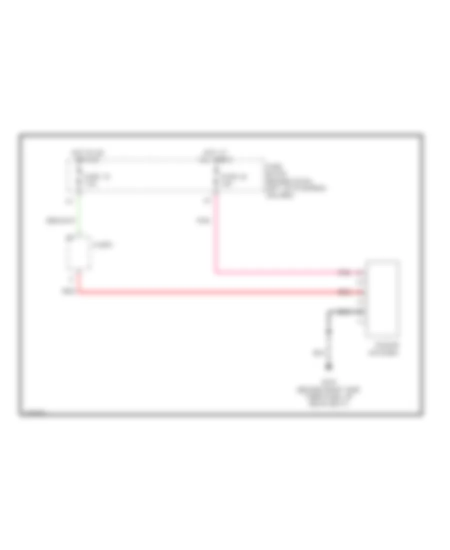
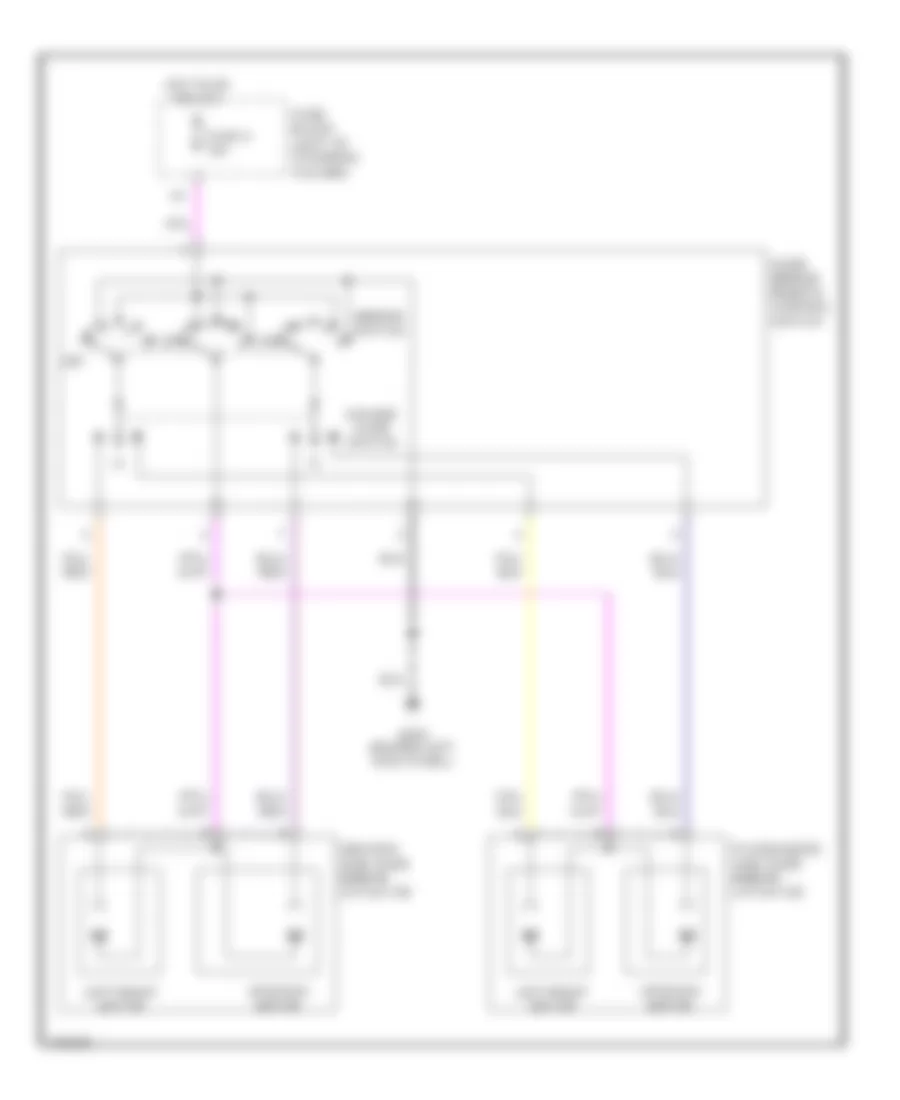
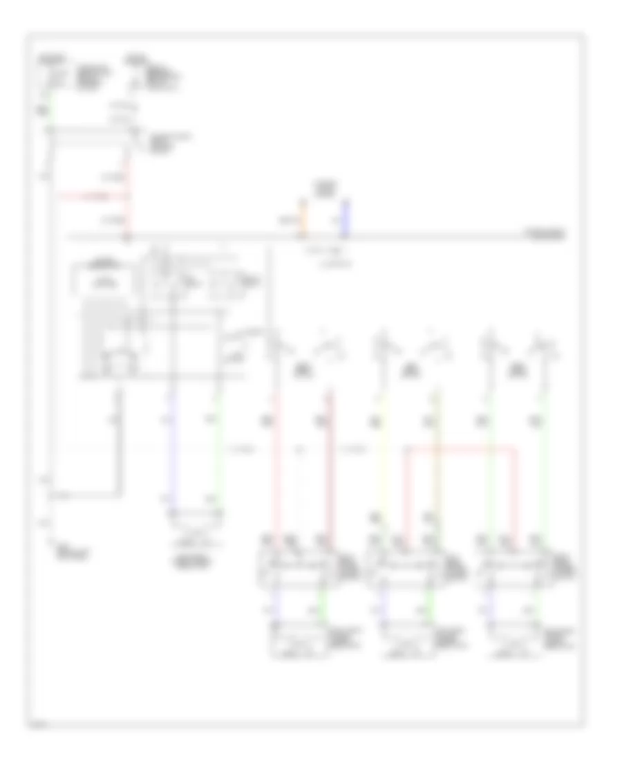
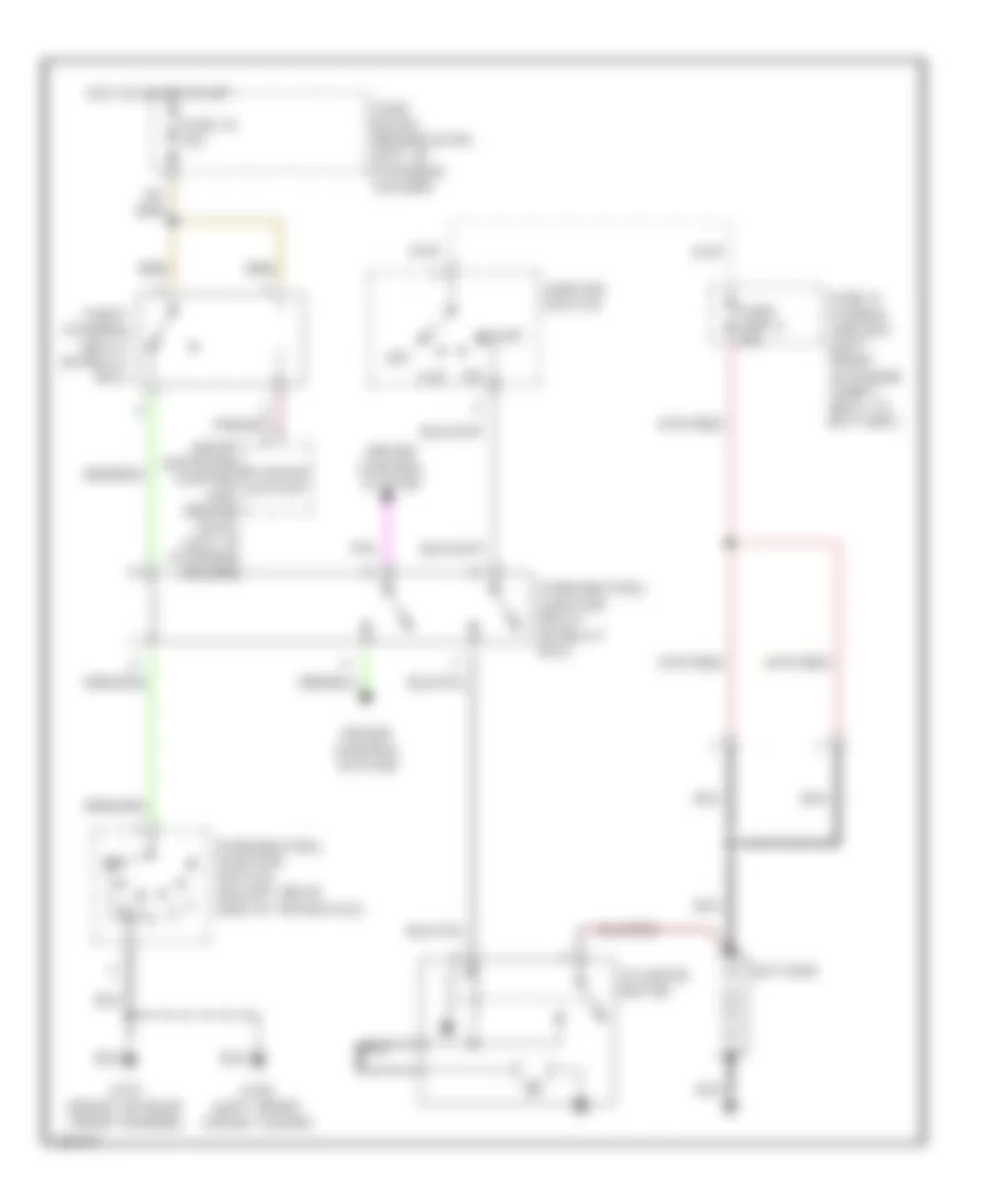
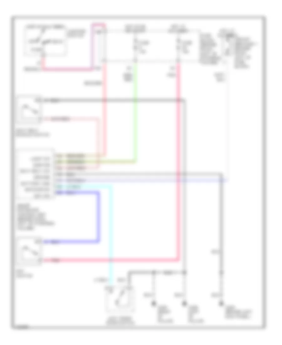
COOLING FAN
Cooling Fan Wiring Diagram for Infiniti G20 t 1999
List of elements for Cooling Fan Wiring Diagram for Infiniti G20 t 1999:
- Cooling fan motor 1
- Cooling fan motor 2
- Cooling fan relay 1 (in relay box)
- Cooling fan relay 2 (in relay box)
- Cooling fan relay 3 (in relay box)
- Engine control module (behind center of dash)
- Fuse & fusible link box
- Fuse 16 10a
- Fuse block
- Fusible link b 40a
- Fusible link c 40a
- G100 (left front fender)
- G101 (right front fender)
- Hot at all times
- Hot in on & start
- Rfrh
- Rfrl
- Triple pressure switch (1999) (left front of engine compt)
CRUISE CONTROL
Cruise Control Wiring Diagram, with A/T for Infiniti G20 t 1999
List of elements for Cruise Control Wiring Diagram, with A/T for Infiniti G20 t 1999:
- 10a
- 15d
- Air valve
- Air valve solenoid
- Anti-theft system
- Ascd brake switch (on bracket, above brake pedal)
- Ascd control unit (behind dash, left of steering column)
- Ascd hold relay (behind left side of dash)
- Ascd main switch
- Ascd pump (right rear corner of engine compt)
- Ascd steering switch
- Brake nc sw
- Cancel
- Cruise indicator
- Cruise lamp
- Cruise signal
- Fuse & fusible link block
- Fuse 14 15a
- Fuse 16 10a
- Fuse 36 10a
- Fuse 8 10a
- Fuse block
- G101 (front of right front fender)
- G200 (behind left kick panel)
- G203 (behind right kick panel
- Ground
- Horn high relay (in relay box)
- Horn low relay (in relay box)
- Horn system
- Hot at all times
- Hot in on or start
- Illum.
- Instrument cluster
- Interior lights system
- Main switch
- Nca
- Od cancel sig
- Od cut signal
- Off
- On ind.
- Park/neutral position relay (in relay box)
- Park/neutral position switch (on left rear side of transaxle)
- Pnk
- Pump common
- Red
- Release valve
- Release valve solenoid
- Res/acc sw
- Resume/ accelerate
- Set/coast
- Set/coast sw
- Speed sensor
- Spiral cable
- Stop lamp
- Stoplight switch (on bracket above brake pedal)
- Theft warning relay (in relay box)
- Transmission control module (behind lower center of dash)
- Vacuum motor
- Vehicle speed output
Cruise Control Wiring Diagram, with M/T for Infiniti G20 t 1999
List of elements for Cruise Control Wiring Diagram, with M/T for Infiniti G20 t 1999:
- 10a
- 15d
- Air valve
- Air valve solenoid
- Ascd brake switch (on bracket, above brake pedal)
- Ascd clutch switch (on bracket, above clutch pedal)
- Ascd control unit (behind dash, left of steering column)
- Ascd hold relay (behind left side of dash)
- Ascd main switch
- Ascd pump (right rear corner of engine compt)
- Ascd steering switch
- Brake nc sw
- Cancel
- Cruise indicator
- Cruise lamp
- Fuse & fusible link block
- Fuse 14 15a
- Fuse 36 10a
- Fuse 8 10a
- Fuse block
- G200 (behind left kick panel)
- G203 (behind right kick panel
- Ground
- Horn high relay (in relay box)
- Horn low relay (in relay box)
- Horn system
- Hot at all times
- Hot in on or start
- Illum.
- Instrument cluster
- Interior lights system
- Main switch
- Nca
- Off
- On ind.
- Pnk
- Pump common
- Release valve
- Release valve solenoid
- Res/acc sw
- Resume/ accelerate
- Set/coast
- Set/coast sw
- Speed sensor
- Spiral cable
- Stop lamp
- Stoplight switch (on bracket above brake pedal)
- Vacuum motor
- Vehicle speed output
DEFOGGERS
Defogger Wiring Diagram for Infiniti G20 t 1999
List of elements for Defogger Wiring Diagram for Infiniti G20 t 1999:
- (behind dash, left of steering column) smart entrance control unit
- Condenser
- Def out
- Def sw
- Door mirror defogger relay (behind left kick panel)
- Fuse & fusible link box (left front of engine compt, next to battery)
- Fuse 10a
- Fuse 10a
- Fuse 20a
- Fuse block (behind dash, left of steering column)
- G200 (behind left kick panel)
- G203 (behind right kick panel)
- G313 (right side of rear shelf)
- Hot at all times
- Hot in acc or on
- Hot in on or start
- Ignition
- Illum
- Interior lights system
- Left door mirror defogger
- Nca
- On ind
- Rear window defogger
- Rear window defogger relay (behind left kick panel)
- Rear window defogger switch
- Red
- Right door mirror defogger
ENGINE PERFORMANCE
2.0L
2.0L, Engine Performance Wiring Diagrams (1 of 3) for Infiniti G20 t 1999
List of elements for 2.0L, Engine Performance Wiring Diagrams (1 of 3) for Infiniti G20 t 1999:
- (top right side of engine) evap canister purge volume control valve
- A/c system
- Camshaft position sensor (in distributor)
- Closed
- Combination meter
- Condenser
- Cooling fans system
- Distributor
- Engine control module (ecm) (behind center of dash)
- Fuse 10a
- Fuse block (behind dash, left of steering column)
- G107 (behind right headlamp)
- G131 (on intake manifold)
- Hot at all times
- Hot in on or start
- Hot in start
- Ignition coil
- Ignition switch
- Intake air temperature sensor (left front of eng compt)
- Lock
- Malfunction indicator
- Nca
- Power transistor
- Pwr
- Red
- Resistor (left front of engine compt)
- Spark plugs
- Start
- Tach
- Throttle position sensor (on throttle assembly)
- Transmission control module (tcm) (forward of selector lever)
- Vehicle speed sensor (top right of transaxle)
- Vss in
- Vss out
- Wide open
2.0L, Engine Performance Wiring Diagrams (2 of 3) for Infiniti G20 t 1999
List of elements for 2.0L, Engine Performance Wiring Diagrams (2 of 3) for Infiniti G20 t 1999:
- (behind
- (behind left kick panel) fuel pump relay
- (in fuel tank) fuel pump
- (on transaxle) park/ neutral position switch
- (right rear of engine compt) power steering oil pressure switch
- (right side of engine) iacv-air regulator
- 10d
- 15b
- Absolute pressure sensor (center of firewall)
- Crankshaft position sensor (on transaxle housing)
- Engine coolant temperature sensor (lower front of intake manifold)
- Evap control system pressure sensor (left rear of vehicle)
- Front heated oxygen sensor (on exhaust manifold)
- Fuse 10a
- Fuse 15a
- Fuse block (behind dash, left of steering column)
- G107
- G107 (behind
- G200 (left kick panel)
- G308 (left "b" pillar)
- G905 (lower
- Hot in on or start
- J/c 1 (under right side of dash)
- J/c 2 (under right side of dash)
- Knock sensor (right side of engine block)
- Mass air- flow sensor (on air intake assembly)
- Nca
- Rear heated oxygen sensor (rear of converter)
- Right "c" pillar)
- Right headlamp)
2.0L, Engine Performance Wiring Diagrams (3 of 3) for Infiniti G20 t 1999
List of elements for 2.0L, Engine Performance Wiring Diagrams (3 of 3) for Infiniti G20 t 1999:
- (behind center of dash) ecm relay
- (left side of dash, behind fuse box cover)
- (left side of dash, near fuse box cover) data link connector (for gst)
- 13d
- Data link connector (for consult)
- Eccs control module (ecm) (behind center of dash)
- Egr temperature sensor (top rear of engine)
- Egrc solenoid valve (right side of engine)
- Evap canister purge control solenoid valve (right side of engine)
- Evap canister vent control valve (left rear of vehicle)
- Fuel injectors
- Fuel tank gauge unit (on top of fuel tank)
- Fuse 10a
- Fuse 7.5a
- Fuse block (behind dash, left of steering column)
- G131 (on intake manifold)
- G200 (left kick panel)
- G905 (lower right "c" pillar)
- Hot at all times
- Hot in on or start
- Iacv-aac valve (top right front of engine)
- Map/baro solenoid valve (right side of engine)
- Pnk
- Vacuum by-pass valve (left rear of vehicle)
EXTERIOR LIGHTS
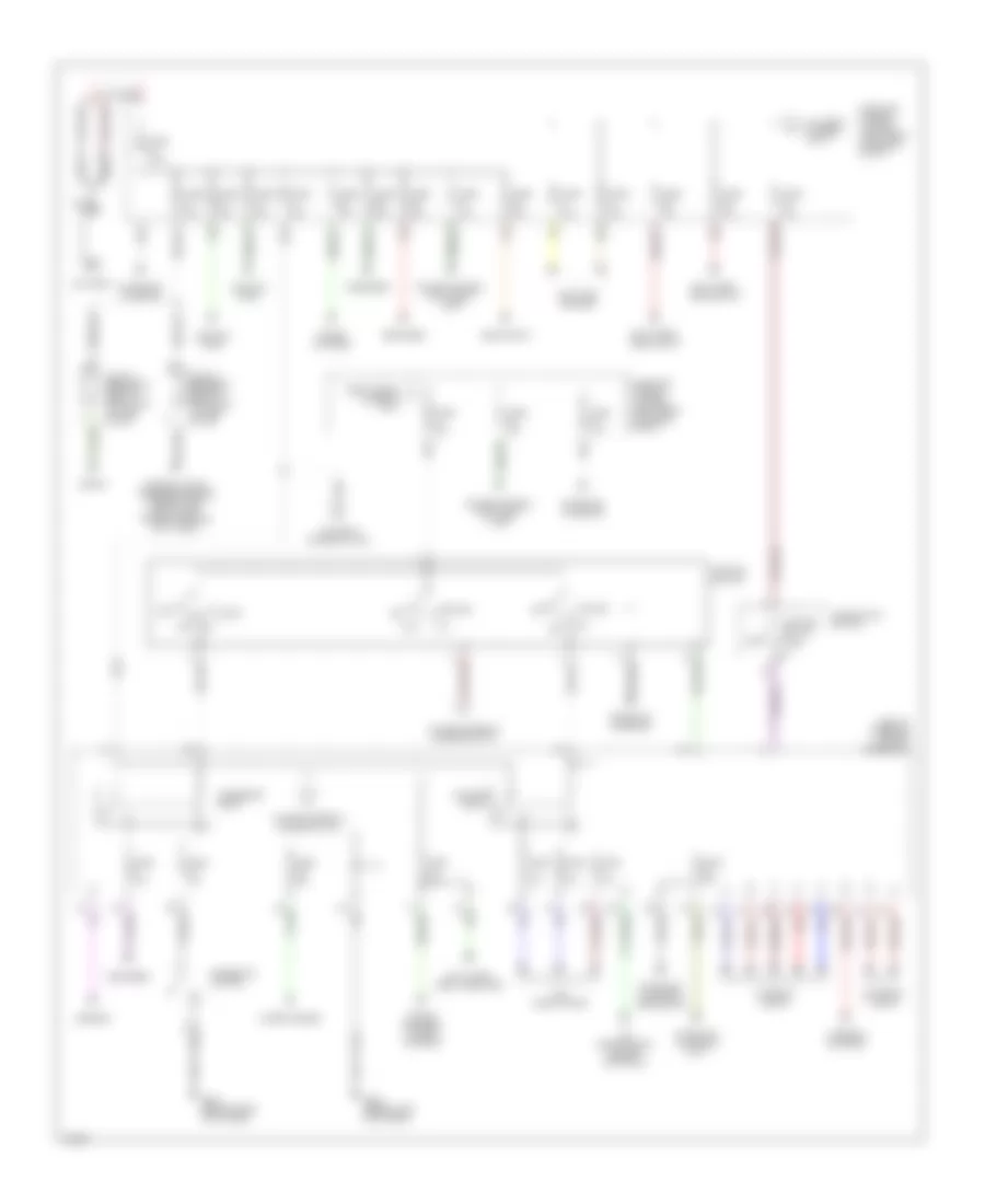
Backup Lamps Wiring Diagram for Infiniti G20 t 1999
List of elements for Backup Lamps Wiring Diagram for Infiniti G20 t 1999:
- A/t
- Back up
- Back-up light switch (on rear of transaxle)
- Fuse 10a
- Fuse block (behind dash, left of steering column)
- G310 (behind right side trim panel of rear seat)
- Hot in on or start
- Left trunk lid combination light
- M/t
- Park/neutral position switch (on left rear side of transaxle)
- Right trunk lid combination light
Exterior Lamps Wiring Diagram (1 of 2) for Infiniti G20 t 1999
List of elements for Exterior Lamps Wiring Diagram (1 of 2) for Infiniti G20 t 1999:
- 13h
- 14h
- 15d
- Combination switch (lighting switch)
- Fuse & fusible link box (left front of engine compt)
- Fuse 14 15a
- Fuse 34 10a
- Fuse block (behind dash, left of steering column)
- G101 (front of right front fender)
- G102 (left front shock tower)
- G310 (behind right side trim panel of rear seat)
- G407 (center rear of trunk)
- Head
- High- mounted stop light (w/ rear spoiler)
- High- mounted stop light (w/o rear spoiler)
- Hot at all times
- Left front side marker lamp
- Left parking lamp
- Left rear fender combination light
- Left rear side marker lamp
- Left trunk lid combination light
- License lamp
- Off
- Park
- Right front side marker lamp
- Right parking lamp
- Right rear fender combination light
- Right rear side marker lamp
- Right trunk lid combination light
- Stop
- Stop lamp switch (on bracket, above brake pedal)
- Tail
- Turn
Exterior Lamps Wiring Diagram (2 of 2) for Infiniti G20 t 1999
List of elements for Exterior Lamps Wiring Diagram (2 of 2) for Infiniti G20 t 1999:
- Combination flasher unit (behind left side of dash)
- Combination switch (turn signal switch)
- Fuse 12 7.5a
- Fuse 20 10a
- Fuse block (behind dash, left of steering column)
- G101 (front of right front fender)
- G102 (left front shock tower)
- G200 (behind left kick panel)
- G203 (behind right kick panel)
- Hazard
- Hazard switch
- Hot at all times
- Hot in on or start
- Ill
- Instrument cluster
- Interior lights system
- Left front turn signal lamp
- Left side turn signal lamp
- Left turn ind
- Multi- remote control relay (on fuse block)
- Pnk
- Right front turn signal lamp
- Right side turn signal lamp
- Right turn ind
- Smart entrance control unit (behind dash, left of steering column)
GROUND DISTRIBUTION
Ground Distribution Wiring Diagram for Infiniti G20 t 1999
List of elements for Ground Distribution Wiring Diagram for Infiniti G20 t 1999:
- A/c auto amp, brake fluid level switch, hood
- A/t device, rear window defogger switch, sunroof
- Abs control unit
- Air bag diagnosis sensor unit shield wire
- Ascd hold relay, ascd control unit, data link
- Camshaft position sensor shield wire, crankshaft
- Camshaft position sensor, evap control system
- Combination light, left rear side
- Connector for consult, data link connector for gst, clutch interlock switch, combination flasher
- Control unit, a/c auto amp, power steering oil pressure switch, mode door motor, air mix door
- Control unit, power window main switch, driver's
- Cooling fan relay 3, abs solenoid valve relay,
- Data link connector for gst, mass airflow
- Daytime light control unit, park/neutral position
- Diagnosis sensor unit, glove box light, cigarette lighter, intake door motor, fan control amp, air
- Distributor, engine control module
- Door key cylinder switch, driver's door lock actuator, ascd main switch, accessory relay,
- Door key cylinder switch, passenger's door mirror actuator, front wiper motor, ashtray
- Door lock actuator
- Driver's heated seat switch,
- Driver's power seat, driver's heated
- Fan relay 2, left side turn signal light, left
- Front side marker light, left front turn signal
- Front turn signal light, right front fog light,
- Fuel tank gauge unit, fuel pump,
- G100 (front of left front fender)
- G101 (front of right front fender)
- G102 (left front shock tower)
- G134 (top of engine)
- G200 (behind left kick panel)
- G203 (behind right kick panel)
- G305 (right "b" pillar)
- G308 (left "b" pillar)
- G310 (behind right side trim panel of rear seat)
- G313 (right side of rear shelf)
- G407 (center rear of trunk)
- Gauge, tachometer, odo/trip meter, speedometer,
- Heated oxygen sensor, driver's door
- High-mounted stop light, power antenna, trunk lid key cylinder
- Iacv-air regulator
- Ignition relay, blower relay
- Illumination, a/t device, fan switch, push
- Indicator, a/t indicators, high beam indicator,
- Left front wheel sensor shield wire, right front
- License light, trunk room light
- Light, right rear combination light
- Light, triple pressure switch, front fog lamp
- Map light, integrated homelink transmitter
- Marker light
- Mirror remote control switch, smart entrance
- Mix door motor, passenger's vanity mirror light,
- Motor, potentio temperature control (ptc), cruise
- Passenger's door lock actuator, passenger's
- Passenger's heated seat switch, left rear door lock actuator, right rear
- Position sensor shield wire, throttle position sensor shield wire, knock sensor shield wire, engine control module, engine control module
- Pressure sensor shield wire
- Rear window defogger
- Relay, driver's door mirror actuator, door
- Right front side marker light, ambient air temperature switch, vehicle speed sensor,
- Right rear side marker light, left rear combination light, right rear
- Seat, passenger's heated seat, rear
- Sensor
- Sensor shield wire, absolute pressure sensor shield wire, rear heated oxygen sensor shield wire, front heated oxygen sensor shield wire,
- Sensor, right rear wheel
- Shield wire, transmission control module,
- Switch, bose speaker amp,
- Switch, cooling fan motor 1, cooling fan motor 2, right headlight, left front fog lamp, cooling
- Switch, driver's seat buckle switch,
- Switch, driver's vanity mirror light, air bag
- Switch, front wiper switch, washer level switch
- Switch, left parking light, left headlight, right parking light, right side turn signal light, right
- Switch, left rear combination
- Turn signal indicator, air bag warning light, fuel
- Unit, illumination control switch, power window
- Water temperature gauge
- Wheel sensor shield
- Wire, left rear wheel
HEADLIGHTS
Headlight Wiring Diagram, with DRL for Infiniti G20 t 1999
List of elements for Headlight Wiring Diagram, with DRL for Infiniti G20 t 1999:
- Alt
- Alternator
- Charge ind
- Combination meter
- Daytime light control unit (behind right kick panel)
- Dim sw
- Front fog lamp switch
- Front fog light relay (in relay box)
- Fuse & fusible link box (left side of engine compt)
- Fuse 11 10a
- Fuse 26 10a
- Fuse 32 15a
- Fuse 33 15a
- Fuse 34 10a
- Fuse 43 15a
- Fuse 8 10a
- Fuse block (left of steering column)
- G101 (front of right front fender)
- G102 (left front shock tower)
- G203 (behind right kick panel)
- Gnd
- Head
- High beam ind
- Hot at all times
- Hot in run or start
- Hot in start
- Ign
- Interior lights system
- L fuse
- L grd
- L sw
- Left front fog lamp
- Left headlamp
- Lighting switch
- Low
- Main sw
- Off
- Park
- Parking brake switch
- Pass
- Pkb sw
- R fuse
- R sw
- Red
- Right front fog lamp
- Right headlamp
- Start
Headlight Wiring Diagram, without DRL for Infiniti G20 t 1999
List of elements for Headlight Wiring Diagram, without DRL for Infiniti G20 t 1999:
- (left front of engine compt)
- Combi- nation meter
- Front fog lamp switch
- Front fog- light relay (in relay box)
- Fuse & fusible
- Fuse 32 15a
- Fuse 33 15a
- Fuse 43 15a
- G101 (front of right front fender)
- G102 (left front shock tower)
- G203 (behind right kick panel)
- Head
- Hi beam ind
- Hot at all times
- Left front fog lamp
- Left head- lamp
- Lighting switch
- Link box
- Low
- Low hi
- Off
- Park
- Pass
- Red
- Right front fog lamp
- Right head- lamp
HORN
Horn Wiring Diagram for Infiniti G20 t 1999
List of elements for Horn Wiring Diagram for Infiniti G20 t 1999:
- Fuse & fusible link box (left front of engine compartment, next to battery)
- Fuse 36 10a
- Fuse 41 10a
- Horn high (right front of engine compartment)
- Horn high relay (in relay box)
- Horn low (right side of engine compartment)
- Horn low relay (in relay box)
- Horn switch
- Hot at all times
- Red
- Spiral cable (under steering wheel)
INSTRUMENT CLUSTER
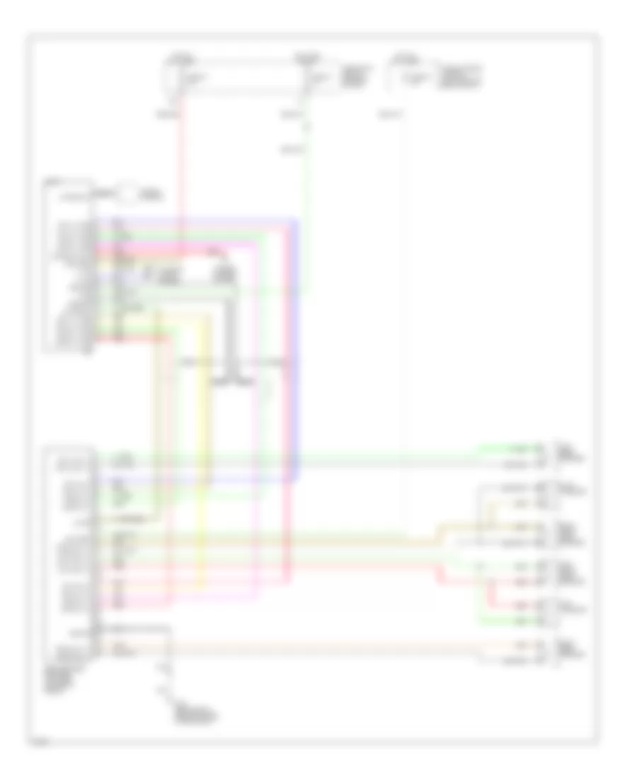
Instrument Cluster Wiring Diagram (1 of 2) for Infiniti G20 t 1999
List of elements for Instrument Cluster Wiring Diagram (1 of 2) for Infiniti G20 t 1999:
- Abs ind
- Airbag ind
- Brake ind
- Charge ind
- Combination meter
- Door ind
- Door locks
- Exterior lights
- Flexible *
- Fuel gauge
- Fuel ind
- Fuel tank gauge unit (top of fuel tank)
- Fuse 11 10a
- Fuse 5 7.5a
- Fuse block (j/b) (behind dash, left of steering column)
- G101 (front of right front fender)
- G203 (behind right kick panel)
- G310 (behind right side trim panel of rear seat)
- Headlights
- Hot at all times
- Hot in on or start
- Interior lights
- Joint connector 3 (diode) (behind center of dash)
- Malfunction ind
- O/d off ind
- Odometer/trip meter) (with speedometer and
- Oil press ind
- Park/neutral position switch (on transaxle)
- Pnk
- Print circuit
- Red
- Seat belt ind
- Starting/ charging system
- Tachometer
- Thermal transmitter (on lower front of intake manifold)
- To combination meter (diagram 2 of 2)
- Unified meter control unit
- Vehicle speed sensor (on top right side of transaxle)
- Washer ind
- Water temp gauge
Instrument Cluster Wiring Diagram (2 of 2) for Infiniti G20 t 1999
List of elements for Instrument Cluster Wiring Diagram (2 of 2) for Infiniti G20 t 1999:
- 43k
- Abs control unit (behind right kick panel)
- Abs fail ind
- Air bag diagnosis sensor unit (below rear of center console)
- Air bag ind
- Brake fluid level switch (in brake fluid reservoir)
- Combination meter
- Cruise control system
- Diode
- Ecm (eccs) control module (behind center of dash)
- From combination meter (diagram 1 of 2)
- G102 (left front shock tower)
- Hi beam ind
- Illumination
- Left turn ind
- Mal ind driver
- O/d off
- Odo/trip illumination
- Oil pressure switch (on right front side of cylinder block)
- Parking brake switch
- Right turn ind
- Seat belt
- Tach out
- Transmission control module (behind lower center of dash)
- Voltage regulator
- Vsp in
- W/ daytime running lights
- W/o daytime running lights
- Washer level switch (fluid reservoir)
INTERIOR LIGHTS
Courtesy Lamps Wiring Diagram for Infiniti G20 t 1999
List of elements for Courtesy Lamps Wiring Diagram for Infiniti G20 t 1999:
- 11b
- Bat saver out
- Battery
- Circuit breaker 1 (behind dash, left of fuse block)
- Condition sw
- Diode (left front of luggage compt, taped to harness)
- Door
- Door sw (all)
- Door sw (dr)
- Door sw (pass)
- Fuse 10a
- Fuse block
- G200 (behind left kick panel)
- G203 (behind right kick panel)
- G308 (left "b" pillar)
- G310 (behind right side trim panel of rear seat)
- Ground
- Hot at all times
- Hot in on or start
- Ignition
- Interior room lamp
- Key switch
- Left front door lock actuator
- Left front door switch
- Left rear door switch
- Left vanity mirror
- Map lamp
- Off
- Passenger side front door switch
- Pnk
- Red
- Right rear door switch
- Right vanity mirror
- Room lamp out
- Smart entrance contrl unit (left of steering column)
- Trunk room lamp
- Trunk room lamp switch
Instrument Illumination Wiring Diagram for Infiniti G20 t 1999
List of elements for Instrument Illumination Wiring Diagram for Infiniti G20 t 1999:
- 11d
- 13h
- 4 bulbs
- A/c auto amp
- A/t device
- Ascd main switch
- Ashtray illum
- Audio
- Combination meter
- Fuse & fusible link box
- Fuse 10a
- Fuse block
- G200 (behind left kick panel)
- G203 (behind right kick panel)
- Glove box lamp
- Hazard switch
- Head
- Hot at all times
- Hot in on or start
- Illumination control switch
- Light switch
- Nca
- Od0/trip meter illumi- nation
- Off
- Park
- Power window main switch
- Push control unit
- Rear window defogger switch
- Red
- Voltage reg- ulator
POWER ANTENNA
Power Antenna Wiring Diagram for Infiniti G20 t 1999
List of elements for Power Antenna Wiring Diagram for Infiniti G20 t 1999:
- Audio
- Fuse 10 7.5a
- Fuse 24 10a
- Fuse block (behind dash, left of steering column)
- G310 (behind right side trim panel of rear seat)
- Hot at all times
- Hot in on or acc
- Pnk
- Power antenna
- Red
POWER DISTRIBUTION
Power Distribution Wiring Diagram (1 of 2) for Infiniti G20 t 1999
List of elements for Power Distribution Wiring Diagram (1 of 2) for Infiniti G20 t 1999:
- (left of steering column) fuse block
- 11d
- 12d
- 14h
- 1st
- 2nd
- Acc
- Accessory relay
- Air conditioning
- Air conditioning, engine controls
- Anti-lock brakes
- Anti-theft body computer
- Anti-theft, headlights
- Battery
- Blower relay
- Cigarette lighter
- Circuit breaker 1 (behind dash, left of fuse block)
- Circuit breaker 2 (behind dash, left of fuse block)
- Combinaton switch
- Cooling fans
- Cruise control anti-theft horn
- Cruise control, anti-theft, horn
- Defogger
- Exterior lights
- From fuse 34 a (diagram 1 of 1)
- Fuse 10a
- Fuse 15a
- Fuse 20a
- Fuse 7.5a
- Fuse a 80a
- Fuse and fusible link box (left front of engine compt)
- Fuse b 40a
- Fuse c 40a
- Fuse d 30a
- Fuse e 100a
- Fuse f 40a
- Fuse g 40a
- Fuse h 40a
- G200 (behind left kick panel)
- G203 (behind right kick panel)
- Headlights
- Ignition switch
- Interior lights
- Interor lights, warning systems, power tops, door locks, power windows, anti-theft
- Lighting switch
- Mirrors
- Nca
- Off
- Red
- Seats
- Sound systems
- Sound systems, power antenna
- Start
- Starting/ charging
- Starting/ charging (m/t)
- Starting/ charging, headlights
- To fuse 4 (diagram 2 of 2)
- To fuse g (diagram 1 of 1)
- To ignition relay (diagram 2 of 2)
- Warning systems
- Wiper/washer
Power Distribution Wiring Diagram (2 of 2) for Infiniti G20 t 1999
List of elements for Power Distribution Wiring Diagram (2 of 2) for Infiniti G20 t 1999:
- 11b
- 12b
- 15d
- Air conditioning
- Air conditioning, instrument cluster, anti-theft
- Anti-lock brakes
- Anti-lock brakes, exterior lights, cruise control
- Anti-theft, body computer
- Cooling fans, starting/ charging, cruise control anti-theft
- Engine controls
- Exterior lights
- Exterior lights, body computer
- Exterior lights, transmission controls
- From accessory relay (diagram 1 of 2)
- From fuse a (diagram 1 of 2)
- From ignition e relay (diagram 2 of 2)
- From ignition switch (diagram 1 of 2)
- Fuse 10a
- Fuse 15a
- Fuse 7.5a
- Fuse block (left of steering column)
- G200 (behind left kick panel) dash)
- Headlights, body computer
- Ignition relay
- Interior lights, warning systems, defogger, body computer, anti-theft
- Pnk
- Power tops, power windows, cruise control, transmission controls
- Seats
- Sound systems
- Sound systems. power antenna
- To fuse 16 (diagram 2 of 2)
- Transmission controls
- Transmission controls, interior lights, body computer, integrated homelink transmitter
POWER DOOR LOCKS
Power Door Lock Wiring Diagram for Infiniti G20 t 1999
List of elements for Power Door Lock Wiring Diagram for Infiniti G20 t 1999:
- (2000)
- 11b
- Accessory
- Anti-theft system
- Battery (c/b)
- Battery (fuse)
- Battery saver out
- Between full stroke and n
- Central lock sw
- Central unlock sw
- Circuit breaker 1 (behind dash, left of fuse block)
- Door lock output
- Door switch
- Door unlock out
- Dr condition sw
- Dr door switch
- Dr door unlock out
- Exterior lights system
- Full stroke
- Fuse 10a
- Fuse 7.5a
- Fuse block (behind dash, left of steering column)
- G200 (behind left kick panel)
- G203 (behind right kick panel)
- G305 (right "b" pillar)
- G308 (left "b" pillar)
- Ground
- Hazard output
- Hot at all times
- Hot in acc or on
- Hot in on or start
- Ignition
- Interior lights system
- Key cyl sw lock
- Key cyl sw unlock
- Key switch
- Left front door key cylinder switch
- Left front door lock actuator
- Left front door switch
- Left rear door lock actuator
- Left rear door open switch
- Lock
- Locked
- Main power window & door lock switch
- Off
- Open
- Panic alarm output
- Pass condition sw
- Pass door switch
- Pnk
- Rear condition sw
- Right front door key cylinder switch
- Right front door lock actuator
- Right front door open switch
- Right rear door lock actuator
- Right rear door open switch
- Room lamp output
- Smart entrance control unit (behind dash, left of steering column)
- Unlock
- Unlocked
POWER MIRRORS
Power Mirror Wiring Diagram for Infiniti G20 t 1999
List of elements for Power Mirror Wiring Diagram for Infiniti G20 t 1999:
- Change over switch
- Door mirror remote control switch
- Driver's side door mirror actuator
- Fuse 9 10a
- Fuse block (left of steering column)
- G200 (behind left kick panel)
- Hot in on or acc
- Left/right motor
- Mirror switch
- Off
- Passenger's side door mirror actuator
- Up/down motor
POWER SEATS
Driver Power Seat Wiring Diagram for Infiniti G20 t 1999
List of elements for Driver Power Seat Wiring Diagram for Infiniti G20 t 1999:
- Circuit breaker 2 (behind dash, left of fuse block)
- Driver's power seat
- Driver's power seat switch
- Fwd
- G305 (right "b" pillar)
- G308 (left "b" pillar)
- Hot at all times
- Nca
- Reclining motor
- Reclining switch
- Red
- Rev
- Sliding motor
- Sliding switch
Heated Seats Wiring Diagram for Infiniti G20 t 1999
List of elements for Heated Seats Wiring Diagram for Infiniti G20 t 1999:
- 10f
- 11f
- Driver's heated seat switch
- Driver's seat back heater
- Fuse 28 10a
- Fuse block (behind dash, left of steering column)
- G305 (right "b" pillar)
- G308 (left "b" pillar)
- High
- Hot in on or start
- Indicator
- Low
- Nca
- Passenger's heated seat switch
- Passenger's seat back heater
- Pnk
- Red
- Seat back heater
- Seat cushion heater
- Seat cushion thermostat
POWER TOP/SUNROOF
Power Top/Sunroof Wiring Diagrams for Infiniti G20 t 1999
List of elements for Power Top/Sunroof Wiring Diagrams for Infiniti G20 t 1999:
- 10b
- Circuit breaker 1 (behind dash, left of fuse box)
- Down/open
- Fuse 8 10a
- Fuse block (behind dash, left of steering column)
- G200 (behind left kick panel)
- G203 (behind right kick panel)
- Hot at all times
- Hot in on or start
- Power window relay (on fuse box)
- Red
- Sun roof motor (at front of sun roof opening)
- Sun roof switch
- Up/close
POWER WINDOWS
Power Window Wiring Diagram for Infiniti G20 t 1999
List of elements for Power Window Wiring Diagram for Infiniti G20 t 1999:
- 10b
- Auto amplifier
- Auto dn
- Auto up
- Circuit breaker 1 (behind dash, left of fuse block)
- Down
- Down relay
- Driver side switch
- Fuse 10a
- Fuse block (behind dash, left of steering column)
- G200 (behind left kick panel)
- Hot at all times
- Hot in on or start
- Illuminaton
- Interior lights system
- Left front power window regulator
- Left rear power window regulator
- Left rear power window switch
- Left rear switch
- Lock
- Lock switch
- Power window main switch
- Power window relay (on fuse block)
- Right front power window regulator
- Right front power window switch
- Right front switch
- Right rear power window regulator
- Right rear power window switch
- Right rear switch
- Unlock
- Up relay
RADIO
Radio Wiring Diagrams for Infiniti G20 t 1999
List of elements for Radio Wiring Diagrams for Infiniti G20 t 1999:
- 12b
- Acc
- Antenna ctrl
- Antenna in
- Audio
- Battery
- Battery
- Bose speaker amplifier (top front center of trunk)
- Fr lh (+) amp
- Fr lh (-) amp
- Fr lh in (+)
- Fr lh in (-)
- Fr lh out (+)
- Fr lh out (-)
- Fr rh (+) amp
- Fr rh (-) amp
- Fr rh in (+)
- Fr rh in (-)
- Fr rh out (+)
- Fr rh out (-)
- Fuse & fusible link box (left front of engine compt)
- Fuse 10 7.5
- Fuse 24 10a
- Fuse 38 15a
- Fuse block (left of steering column)
- G310 (behnd right side trim panel of rear seat)
- Ground
- Ground
- Hot at all times
- Hot in on or acc
- Illum
- Illum
- Interior lights system
- Left front door speaker
- Left rear speaker
- Left tweeter
- Nca
- On sig
- On signal
- Pnk
- Power antenna system
- Red
- Right front door speaker
- Right rear speaker
- Right tweeter
- Rr lh (+) amp
- Rr lh (-) amp
- Rr lh in (+)
- Rr lh in (-)
- Rr lh out (+)
- Rr lh out (-)
- Rr rh (+) amp
- Rr rh (-) amp
- Rr rh in (+)
- Rr rh in (-)
- Rr rh out (+)
- Rr rh out (-)
- Window antenna
SHIFT INTERLOCKS
Shift Interlock Wiring Diagram for Infiniti G20 t 1999
List of elements for Shift Interlock Wiring Diagram for Infiniti G20 t 1999:
- 10b
- A/t device (under center console, at base of selector lever)
- Ascd brake switch (on bracket, above brake pedal)
- Fuse 8 10a
- Fuse block (left of steering colulmn)
- G200 (behind left kick panel)
- G203 (behind right kick panel)
- Hot in on or start
- Nca
- Park position switch
- Red
- Shift lock solenoid
STARTING/CHARGING
Charging Wiring Diagram for Infiniti G20 t 1999
List of elements for Charging Wiring Diagram for Infiniti G20 t 1999:
- Alternator
- Battery
- Charge indicator
- Combination meter
- Fuse & fusible link box (left front of engine compt, next to battery)
- Fuse 11 10a
- Fuse 7.5a
- Fuse block (behind dash, left of steering column)
- Fuse link e 100a
- Hot in on or start
- Nca
Starting Wiring Diagram, A/T for Infiniti G20 t 1999
List of elements for Starting Wiring Diagram, A/T for Infiniti G20 t 1999:
- Acc
- Battery
- Cruise control system
- Fuse & fusible link box (left front of engine compt, next to battery)
- Fuse 16 10a
- Fuse block (behind dash, left of steering column)
- Fuse link g 40a
- G101 (front of right front fender)
- G102 (left front shock tower)
- Hot in on or start
- Ignition switch
- Nca
- Off
- Park/neutral position relay (in relay box)
- Park/neutral position switch (on left rear side of transaxle)
- Smart entrance control unit (behind dash, left of steering column)
- Start
- Starter cutout
- Starter motor
- Theft warning relay (in relay box)
Starting Wiring Diagram, M/T for Infiniti G20 t 1999
List of elements for Starting Wiring Diagram, M/T for Infiniti G20 t 1999:
- 11h
- Acc
- Battery
- Clutch interlock relay (in relay box)
- Clutch interlock switch (on bracket, above clutch pedal)
- Depressed
- Fuse & fusible link box (left front of engine compt, next to battery)
- Fuse 16 10a
- Fuse 26 10a
- Fuse block (behind dash, left of steering column)
- Fuse link g 40a
- G200 (behind left kick panel)
- G203 (behind right kick panel)
- Hot in on or start
- Hot in start
- Ignition switch
- Nca
- Off
- Released
- Smart entrance control unit (behind dash, left of steering column)
- Start
- Starter cutout
- Starter motor
- Theft warning relay (in relay box)
SUPPLEMENTAL RESTRAINTS
Supplemental Restraint Wiring Diagram for Infiniti G20 t 1999
List of elements for Supplemental Restraint Wiring Diagram for Infiniti G20 t 1999:
- (at base of left "b" pillar) g308
- (left kick panel) g200
- Air bag diagnosis sensor unit (below rear of center console)
- Air bag indicator
- Air bag w/l
- B19
- Closed
- Combination meter
- Data link connector (dlc) (consult) (partial) (at left side of dash, behind fuse box cover)
- Detection conn
- Door switch
- Driver side air bag module
- Driver side front door switch
- Driver side seat belt pre-tensioner
- Fastened
- Fuse 11 10a
- Fuse 22 10a
- Fuse block (behind dash, left of steering column)
- G305 (at base of right "b" pillar)
- G308 (at base of left "b" pillar)
- Ground
- Hot in on or start
- Ignition
- Left satellite sensor (at base of left "b" pillar)
- Left side air bag module
- M40
- M41
- Nca
- Open
- Passenger side air bag module
- Passenger side seat belt pre-tensioner
- Right satellite sensor (at base of right "b" pillar)
- Right side air bag module
- Sat l +
- Sat l -
- Sat r +
- Sat r -
- Seat belt buckle switch (in driver's seat belt buckle)
- Seat belt indicator
- Seat belt sw
- Seat belt w/l
- Spiral cable
- Sq as +
- Sq as -
- Sq dr +
- Sq dr -
- Sq pas +
- Sq pas -
- Sq pdr +
- Sq pdr -
- Sq side l +
- Sq side l -
- Sq side r +
- Sq side r -
- Un- fastened
TRANSMISSION
A/T Wiring Diagram for Infiniti G20 t 1999
List of elements for A/T Wiring Diagram for Infiniti G20 t 1999:
- (at left side of dash, behind fuse box cover) data link connector (for consult)
- (left rear side trnsaxle) park/neutral position switch
- 1-sw
- 10h
- 11b
- 2-sw
- A/t device (overdrive control switch) (under center console, at base of selector lever)
- A/t fluid temp sensor
- Acsd
- Acsd 4th
- All times
- Ascd control unit (behind dash, left of steering column)
- Atck
- Automatic transaxle
- Avcc
- Closed throttle
- Combination meter
- D-sw
- Diodes (behind center of dash, taped to harn)
- Dropping resistor (on left front of eng compt)
- Dt1
- Dt2
- Dt3
- Eng/rev
- Engine control module (ecm) (behind center of dash, at lower left side of glove box)
- Fld temp
- Full sw
- Fuse 10a
- Fuse 21 10a
- Fuse 7 10a
- Fuse block (behind dash, left of steering column)
- G101 (front of right front fender)
- G134 (top of engine)
- G203 (behind right kick panel)
- Gnd
- Gnd-a
- Hot at
- Hot in on or start
- Idle sw
- J/c 1 (behind right side of dash, taped to harn)
- Line press sol valve
- Lu duty
- Mem b/u
- N-sw
- Nca
- O/d ind
- O/d off ind
- O/d sw
- Odb2
- Over- run clutch sol
- Ovr/c
- Pl duty
- Pnk
- R-sw
- Red
- Revolution sensor (right rear side of transaxle)
- Sen pwr
- Sens gnd
- Shift a
- Shift b
- Shift sol valve a
- Shift sol valve b
- Sss in
- Sss out
- Tacho
- Tcc sol valve
- Th sens
- Throttle position switch (on throttle body assembly)
- Transmission control module (tcm) (behind lower center of dash, forward of selector lever)
- Tvo1
- Tvoo
- Unified meter control unit
- Vehicle speed sensor (top right side of transaxle)
- Vign
- Vsp
- Vsp-1
- Vsp-2
- Wot
WARNING SYSTEMS
Warning System Wiring Diagrams for Infiniti G20 t 1999
List of elements for Warning System Wiring Diagrams for Infiniti G20 t 1999:
- 12d
- 13h
- Battery (c/b)
- Circuit breaker 1 (behind dash, left of fuse block)
- Dr door sw
- Fuse 10a
- Fuse block (behind dash, left of steering column)
- G200 (behind left kick panel)
- G305 (right "b" pillar)
- G308 (left "b" pillar)
- Ground
- Head
- Hot at all times
- Hot in on or start
- Ignition
- Key sw
- Key switch
- Left front door switch
- Light sw
- Lighting switch
- Off
- Park
- Pnk
- Seat belt buckle switch
- Seat belt sw
- Smart entrance control unit (behind dash, left of steering column)
WIPER/WASHER
Wiper/Washer Wiring Diagram for Infiniti G20 t 1999
List of elements for Wiper/Washer Wiring Diagram for Infiniti G20 t 1999:
- Front washer motor (on washer fluid reservoir)
- Front wiper motor (right side of firewall)
- Front wiper switch
- Fuse 19 20a
- Fuse block (left of steering column)
- G102 (left front shock tower)
- G203 (behind right kick panel)
- High
- Hot in run or accy
- Int
- Low
- Off
- Pnk
- Variable intermittent wiper control
- Wash
- Wiper amplifier