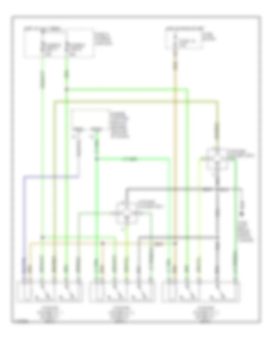
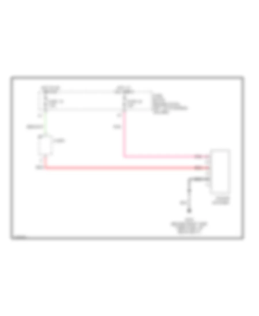
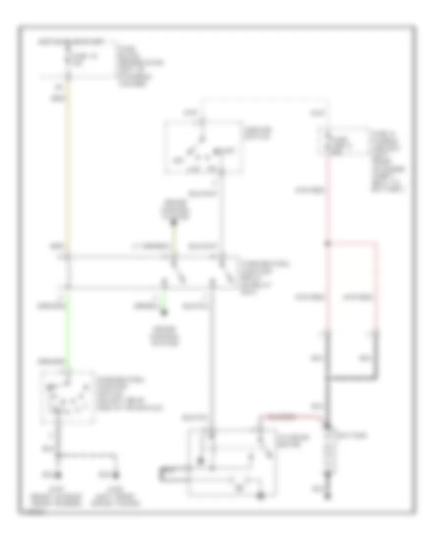
AIR CONDITIONING
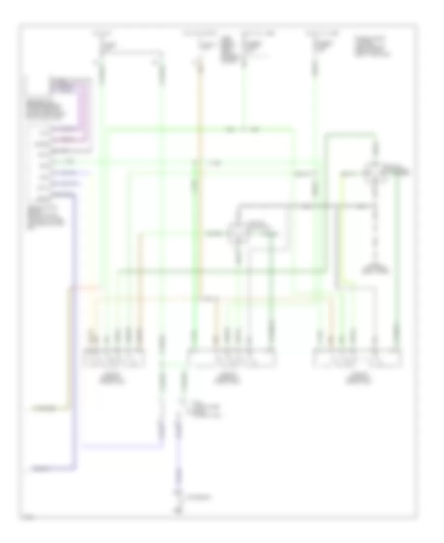
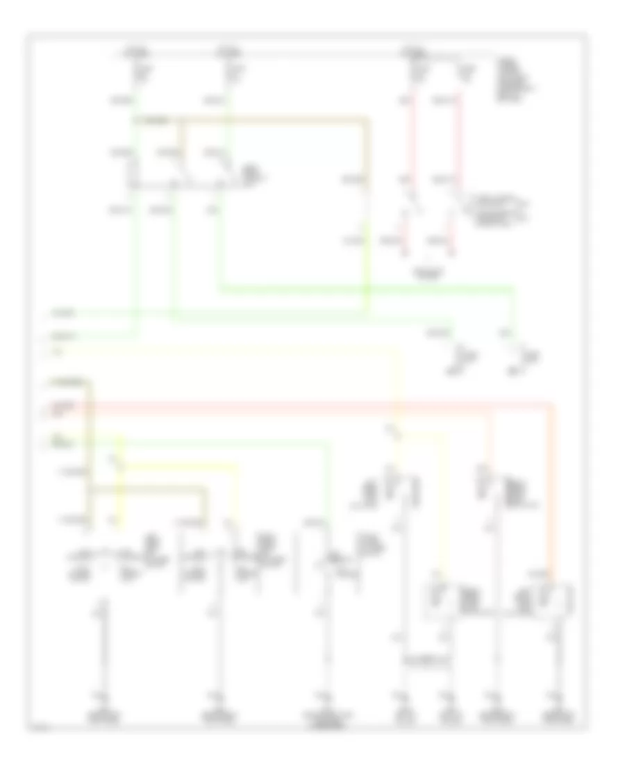
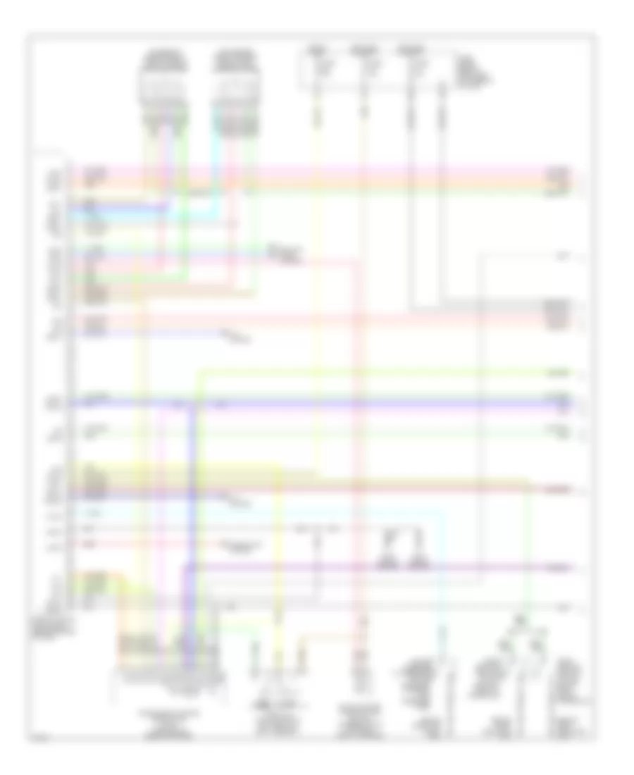
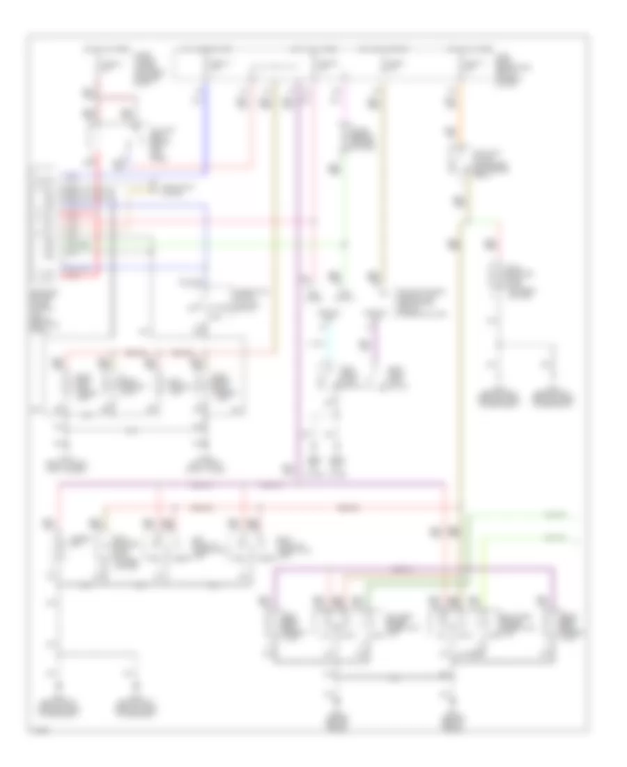
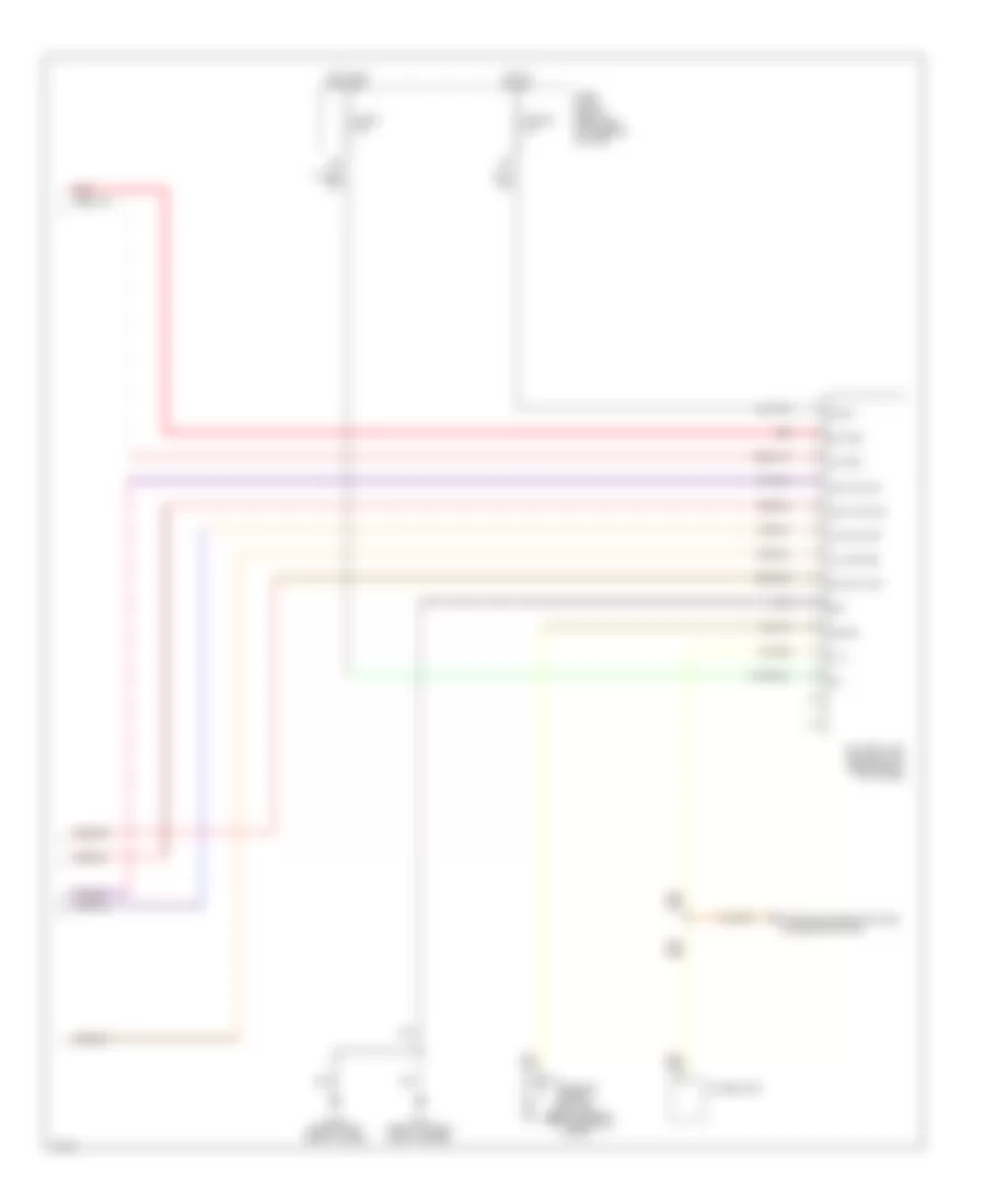
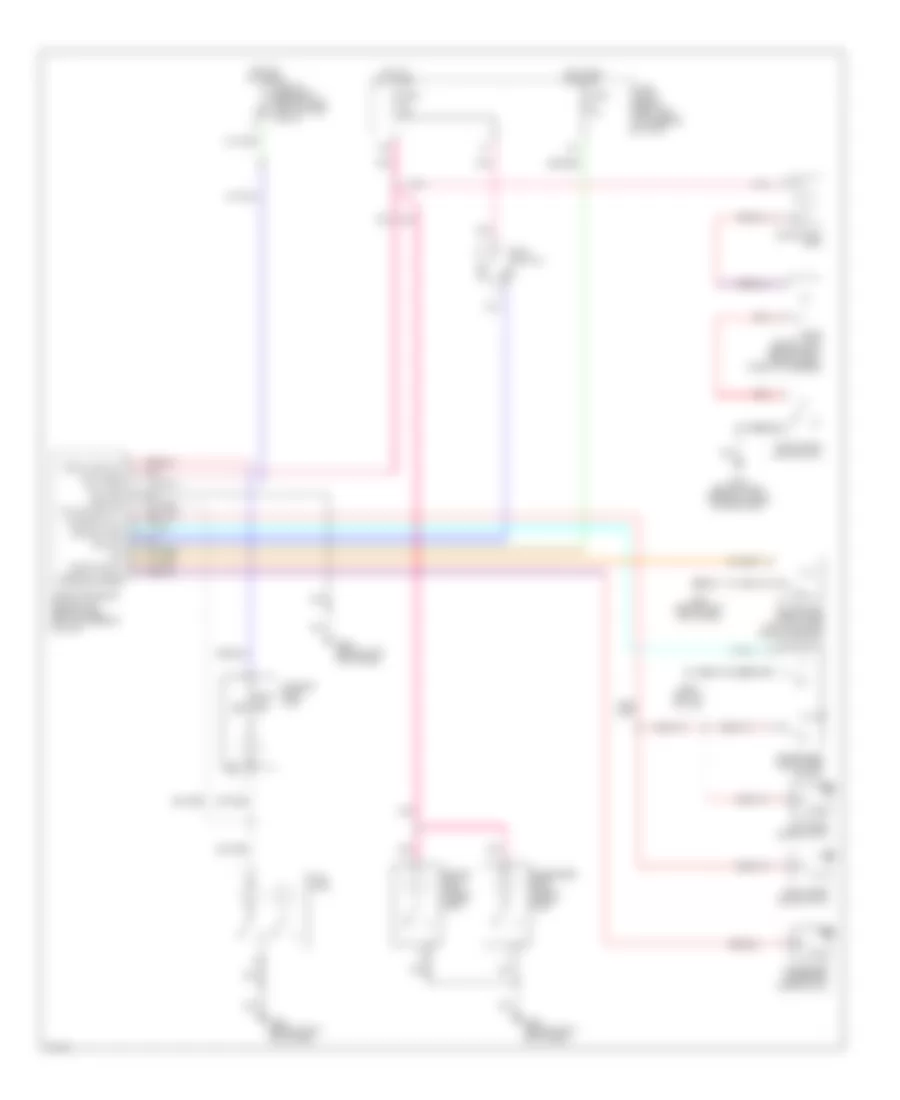
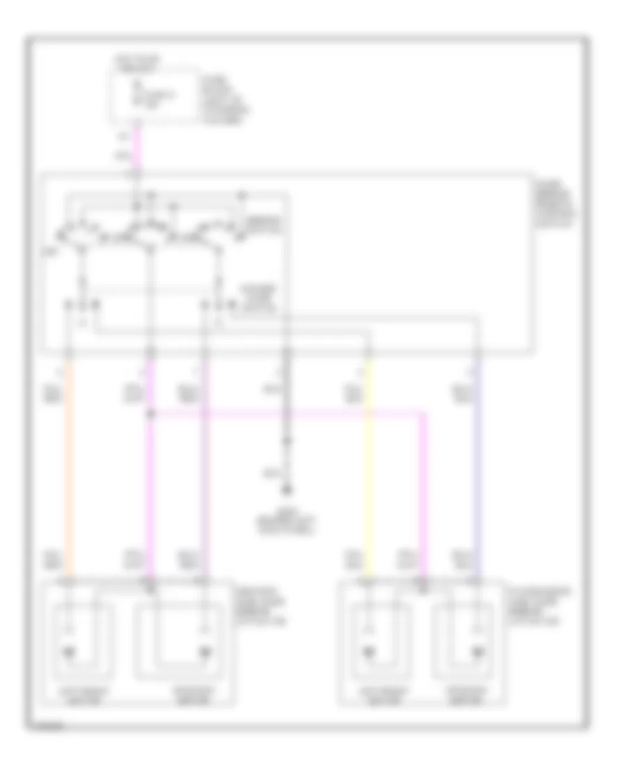
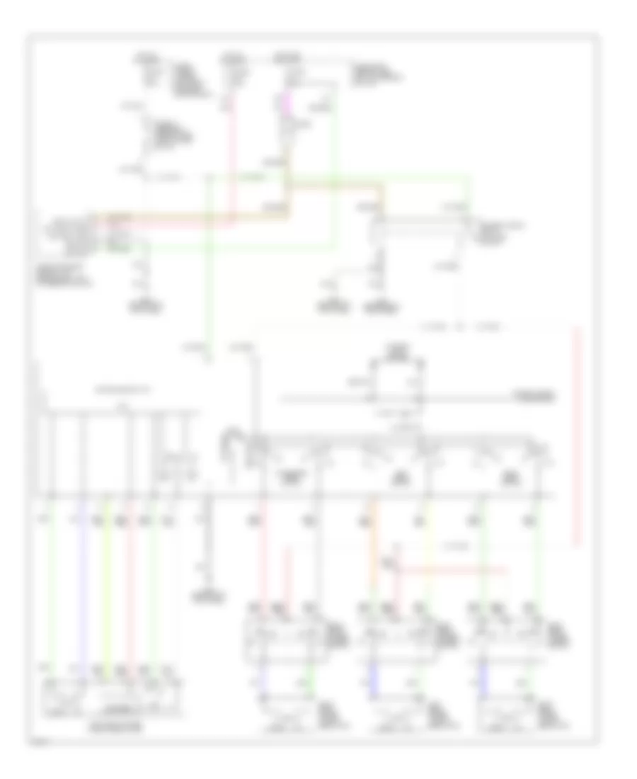
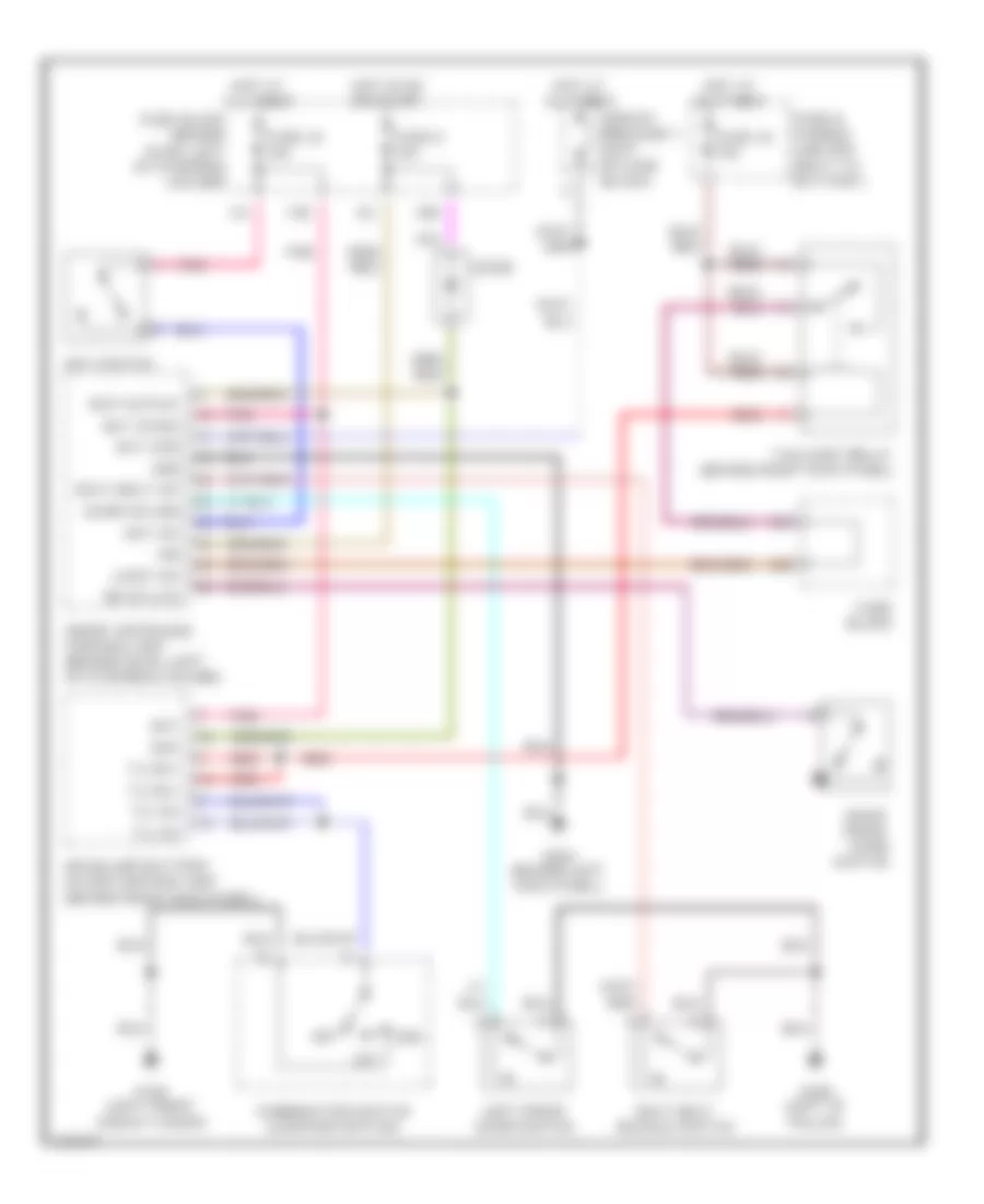
Automatic A/C Wiring Diagram (1 of 2) for Infiniti G20 t 2001

List of elements for Automatic A/C Wiring Diagram (1 of 2) for Infiniti G20 t 2001:
- "c1" fin
- (in a/c
- (on left
- (right
- (right of
- A/c auto amp
- Air mix door motor (behind center of dash, on bottom of heater unit)
- Amb sens
- Bat
- Blower motor (below right side of dash)
- Comp on
- Cooling
- Defroster grille) sunload sensor
- Fan control amplifier (behind right side of dash, left of blower motor)
- Fan f/b
- Fan gate
- Fre (+) rec (-)
- Fre (-) rec (+)
- Front of a/c cond) ambient sensor
- Fuse 10a
- Fuse 15a
- Fuse 7.5a
- Fuse block (behind dash, left of steering column)
- G101 (front of right front fender)
- G102 (left front shock tower)
- G200 (behind left kick panel)
- G203 (behind right kick panel)
- Grd
- Hot at all times
- Hot in on
- Ign
- Ign 2
- Ill
- Incar sens
- Intake code 1
- Intake code 2
- Intake code 3
- Intake door motor (behind right side of dash, on left side of air intake unit)
- Intake sens
- Interior lights system
- Lan-sig
- Light
- Mode door motor (left end of heater unit)
- Or start
- Pnk
- Position switch
- Sens grd
- Steering column) in-vehicle sensor
- Sun sens
- Thermal transmitter (on lower front of intake manifold)
- Thermo control amplifier (behind right side of dash)
- Unit, on evap core) intake sensor
- Vactr
- W/t sens
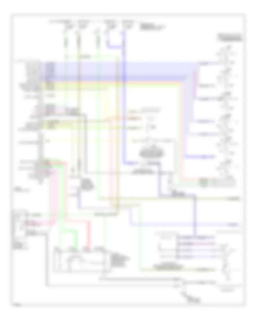
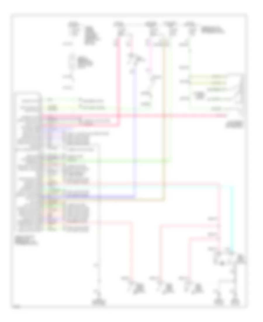
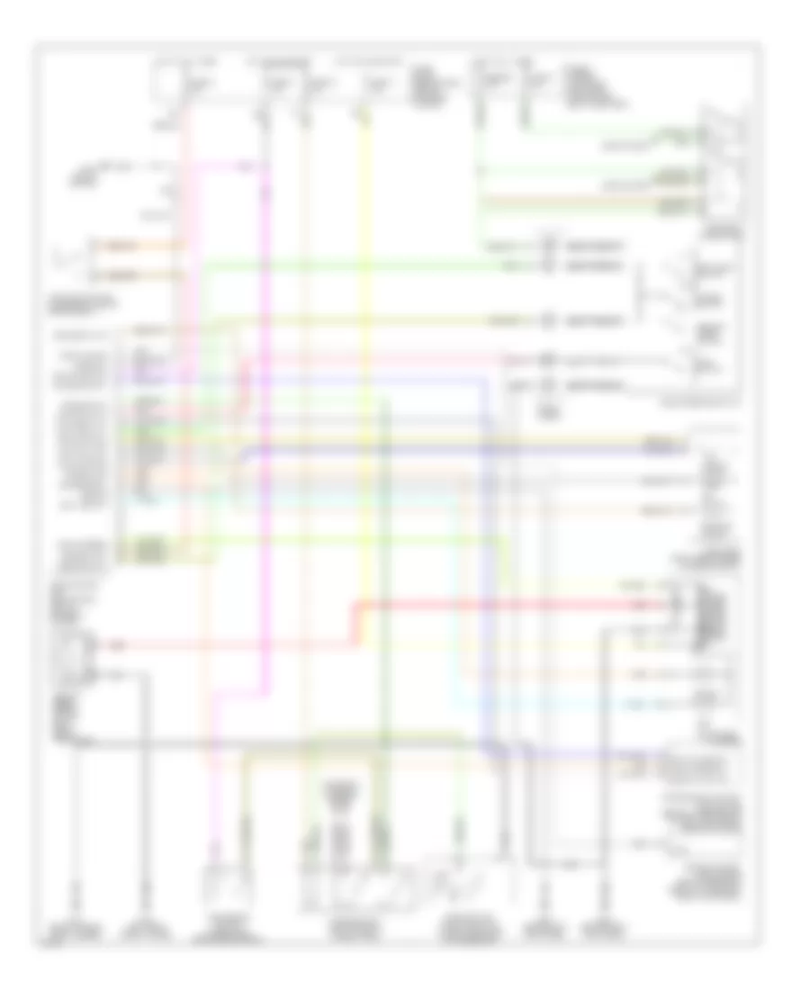
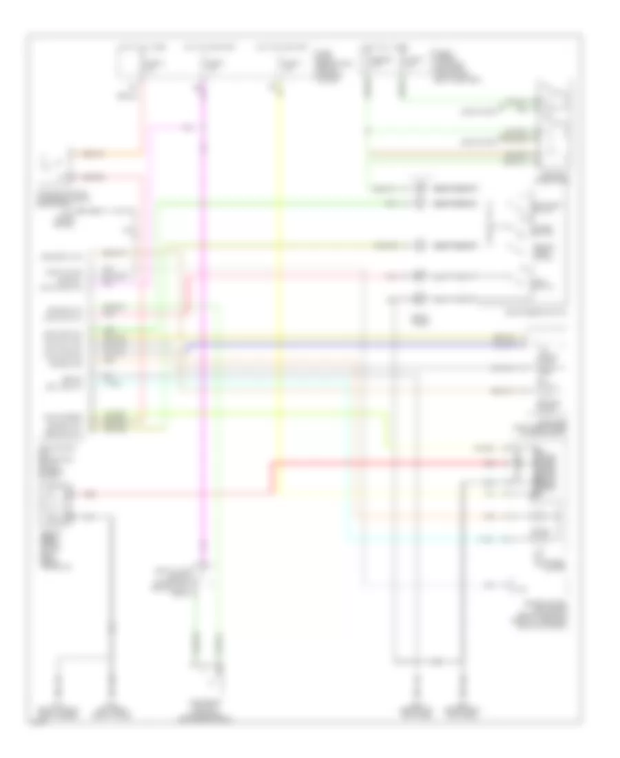
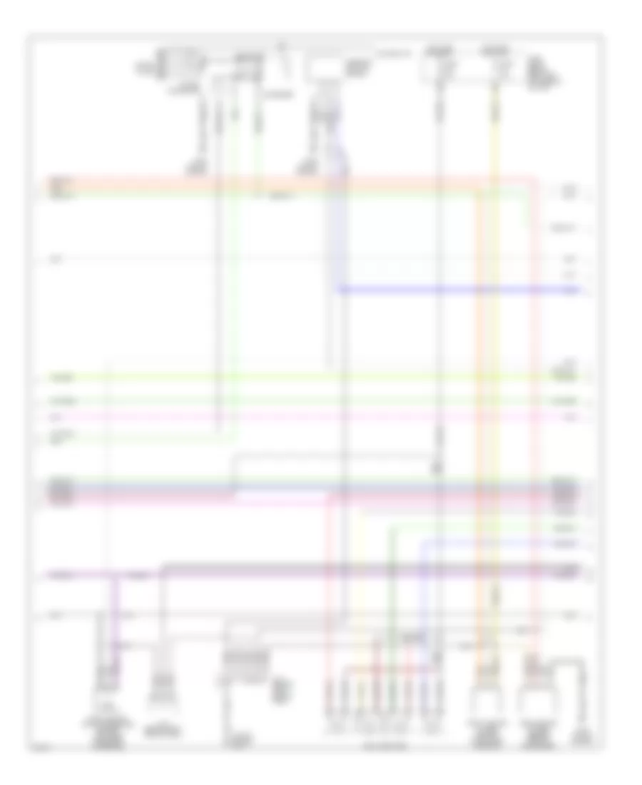
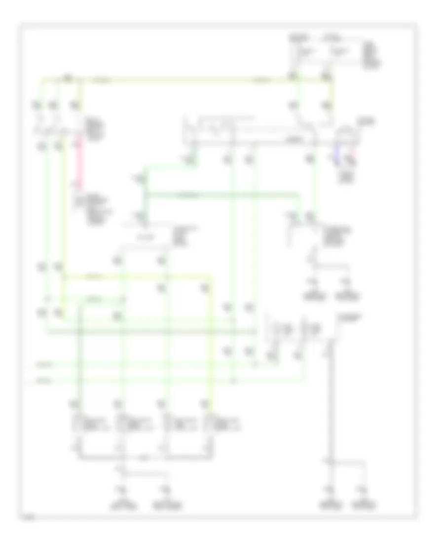
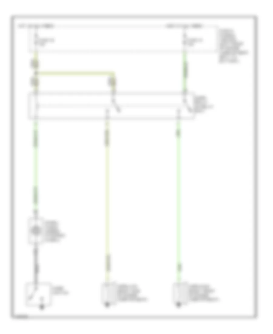
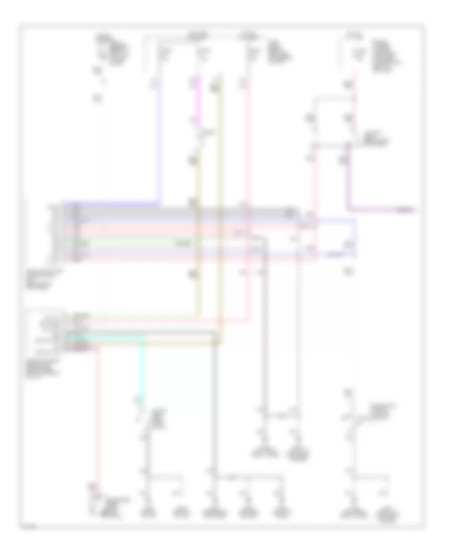
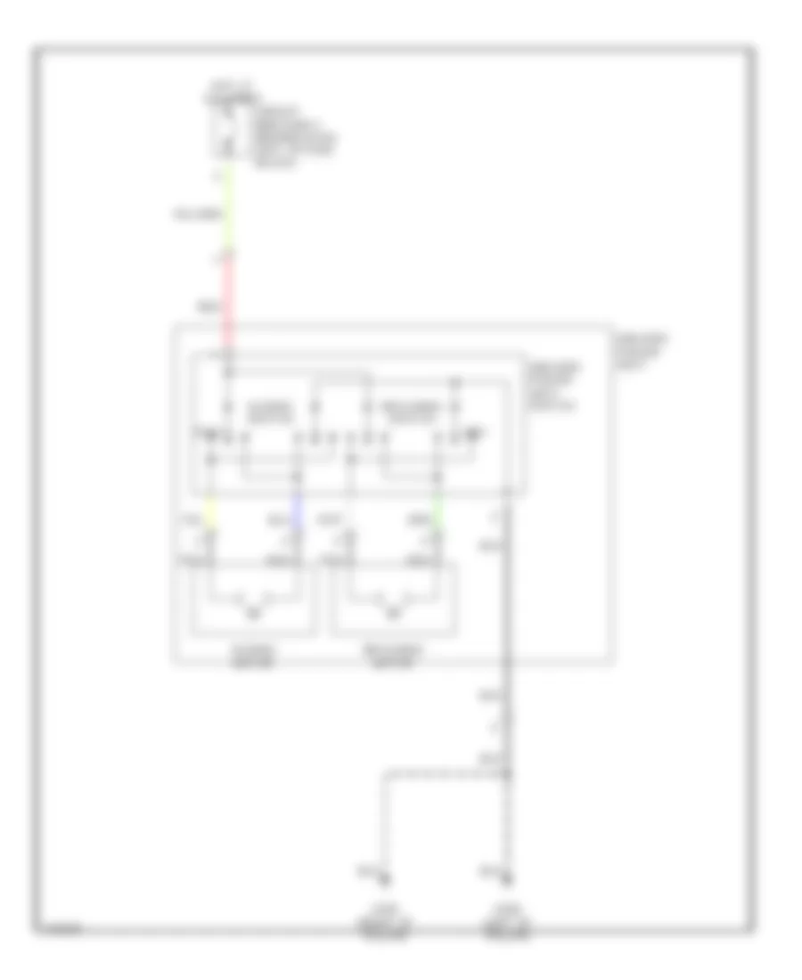
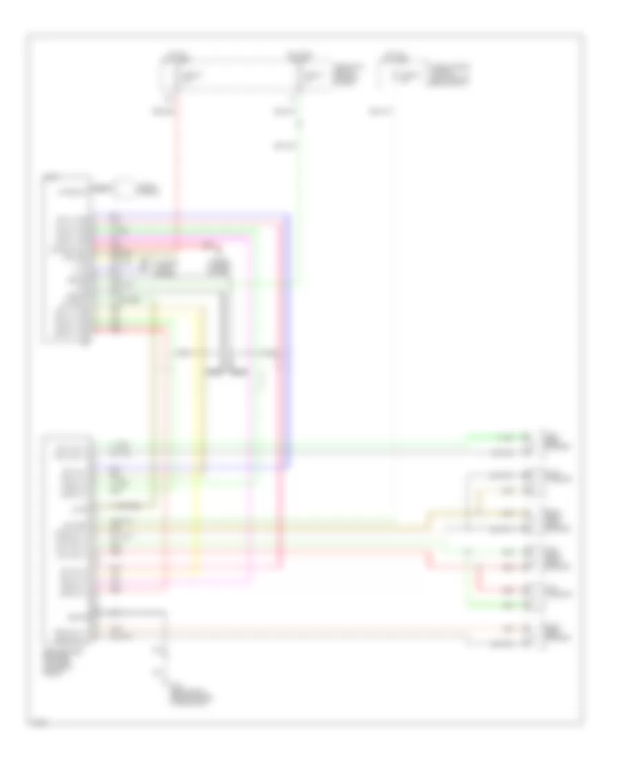
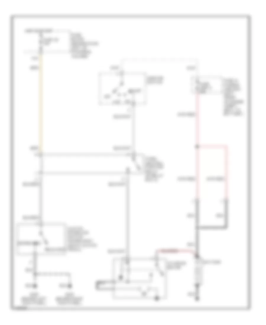
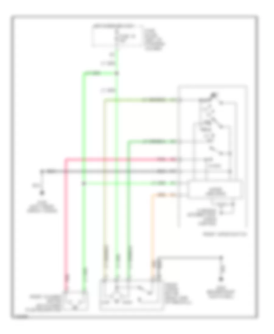
Automatic A/C Wiring Diagram (2 of 2) for Infiniti G20 t 2001
List of elements for Automatic A/C Wiring Diagram (2 of 2) for Infiniti G20 t 2001:
- 16h
- Acrly
- Air conditioner relay (in relay box)
- Arcon
- Avcc
- Compressor
- Cooling fan motor 1
- Cooling fan motor 2
- Cooling fan relay 1 (in relay box)
- Cooling fan relay 2 (in relay box)
- Cooling fan relay 3 (in relay box)
- Engine control module (behind center of dash, at lower left side of glove box)
- Fuse & fusible link box (left front of engine compt, next to battery)
- Fuse 16 10a
- Fuse 6 10a
- Fuse block (behind dash, left of steering column)
- Fusible link b 40a
- Fusible link c 40a
- G102 (left front shock tower)
- Gnd-a
- Hot at all times
- Hot in on
- Hot in on & start
- Pdpres
- Refrigerator pressure sensor (at left front of engine compartment, on a/c liquid tank)
- Rfrh
- Rfrl
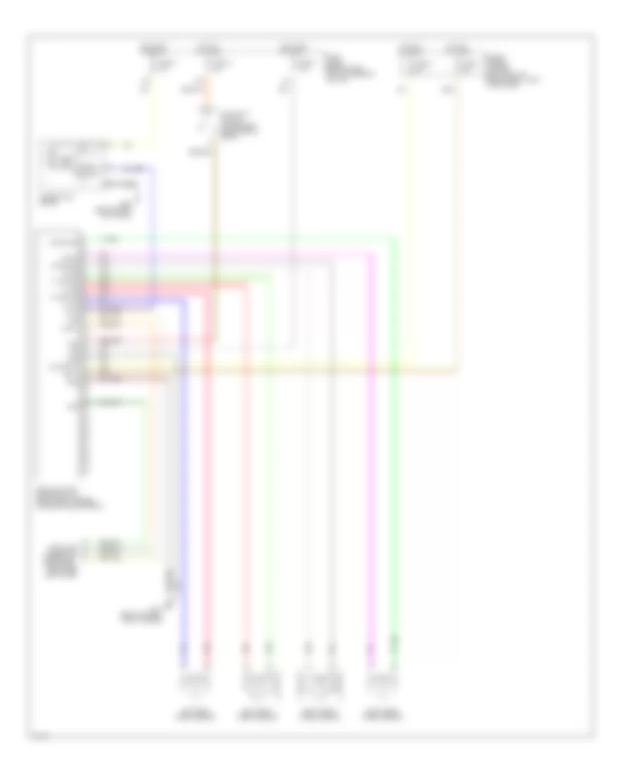
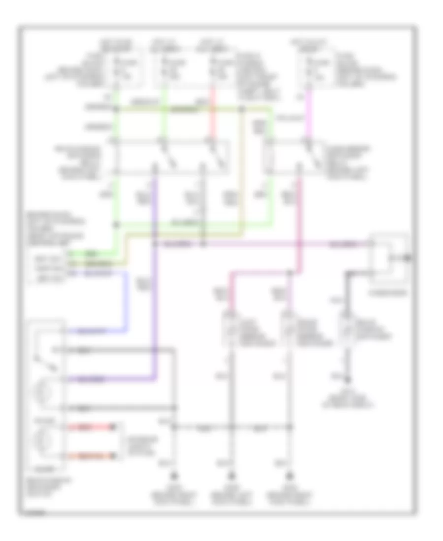
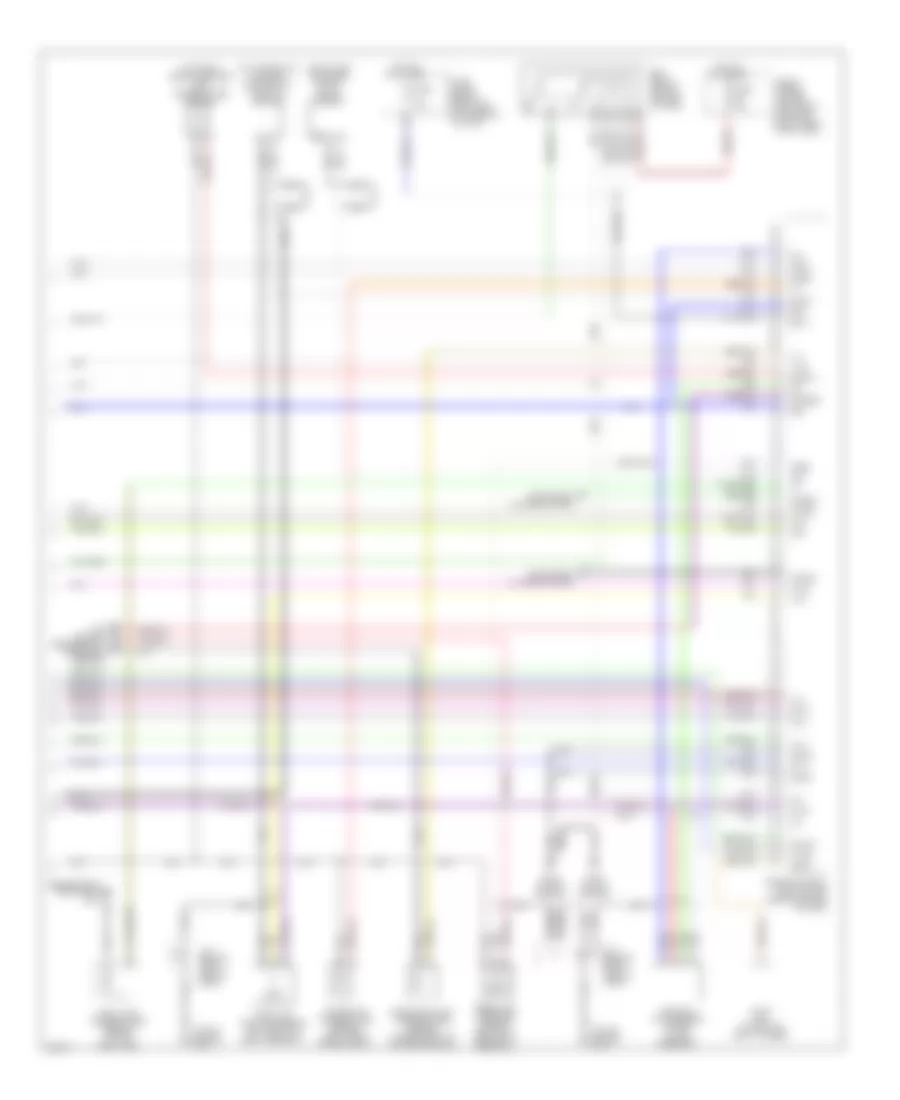
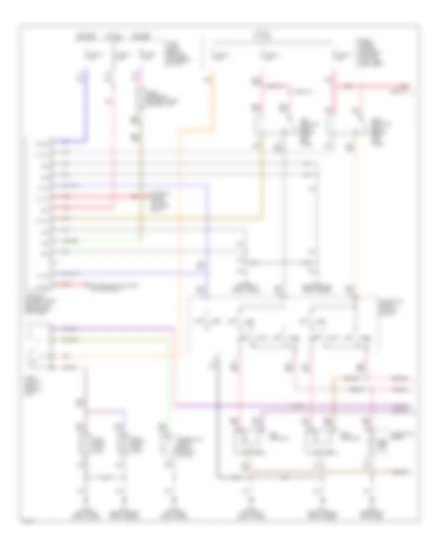
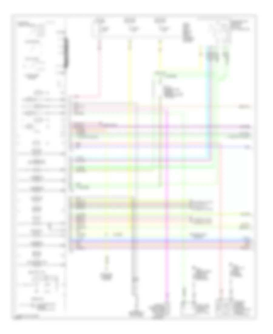
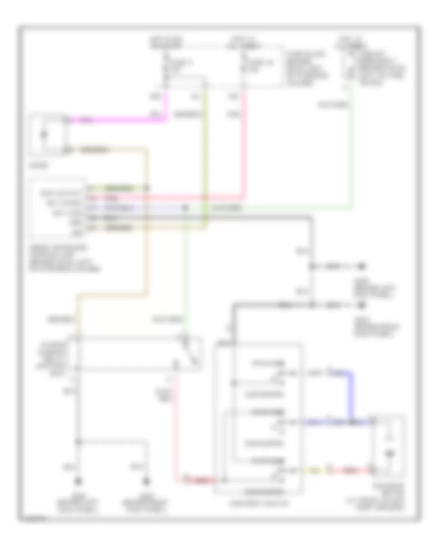
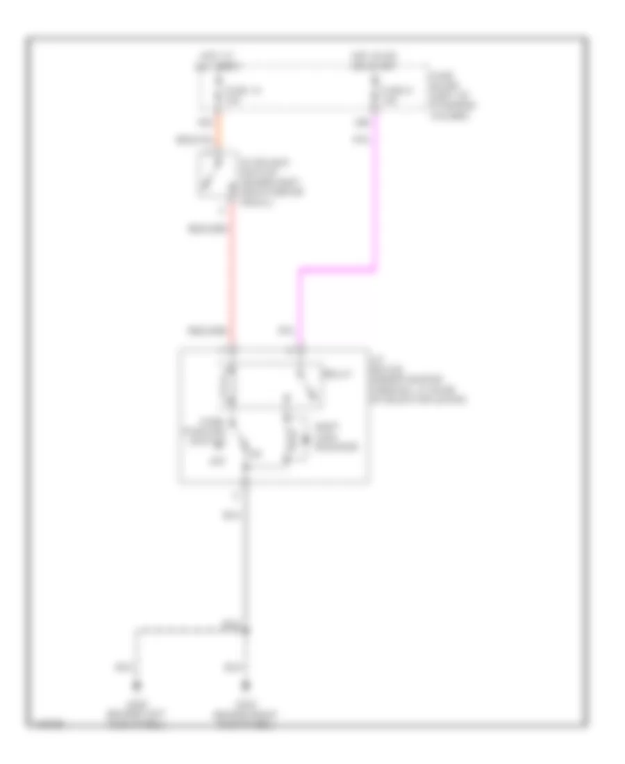
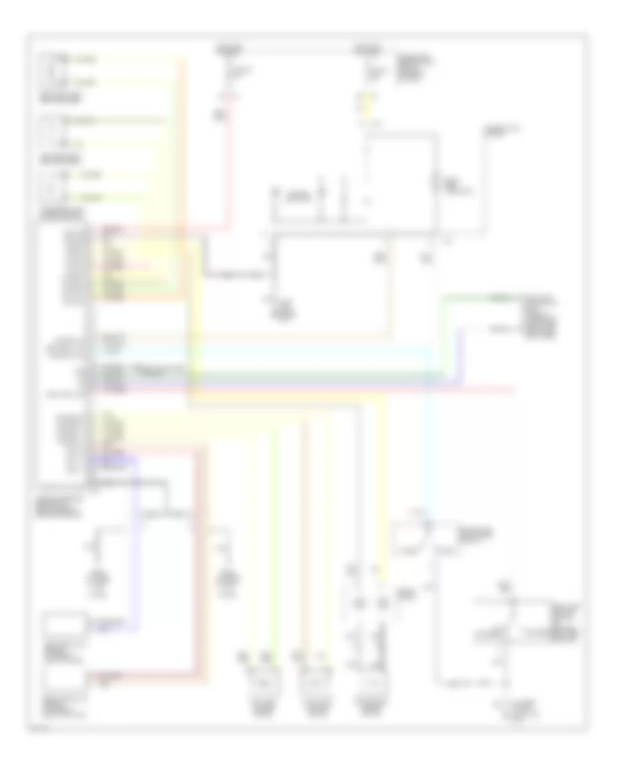
Manual A/C Wiring Diagram (1 of 2) for Infiniti G20 t 2001
List of elements for Manual A/C Wiring Diagram (1 of 2) for Infiniti G20 t 2001:
- (+) fre, (-) rec
- (-) fre, (+) rec
- (behind dash, on left
- (behind right side of dash, near blower motor)
- (integral to
- (right side of dash)
- 16h
- A/c push control unit)
- A/c switch
- Air mix door motor (behind center of dash, on bottom of heater unit)
- Air mix mtr (cold)
- Air mix mtr (hot)
- Amplifier (right side of dash)
- B/l
- B/l input
- Blower motor
- D/f
- D/f input
- Def
- Def input
- End of heater unit) mode door motor
- Fan resistor
- Fan switch
- Foot
- Foot input
- Fre
- Fuse 1 fuse 1 15a 15a
- Fuse 2 15a
- Fuse 6 10a
- Fuse 8 10a
- Fuse block (behind dash, left of steering column)
- G203 (right side kick panel)
- Ground
- Hot in on
- Hot in on, or start
- Ign
- Ill (+)
- Ill (-)
- Intake code (fre)
- Intake code (rec)
- Intake door motor (behind right side of dash, on left side of air intake unit)
- Interior lights system
- Mode actr (def)
- Mode actr (vent)
- Off
- Pbr
- Ptc
- Ptc led+
- Ptc led-
- Push control unit
- Rec
- Red
- Thermo amp
- Thermo control
- Vent
- Vent input
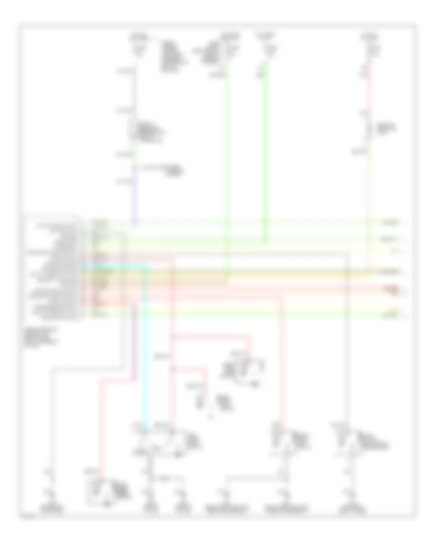
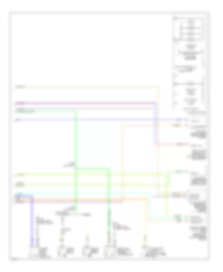
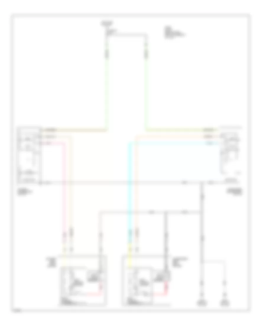
Manual A/C Wiring Diagram (2 of 2) for Infiniti G20 t 2001
List of elements for Manual A/C Wiring Diagram (2 of 2) for Infiniti G20 t 2001:
- A/c compressor
- Acrly
- Air conditioner relay (in relay box)
- Arcon
- Avcc
- Cooling fan motor 1
- Cooling fan motor 2
- Cooling fan relay 1 (in relay box)
- Cooling fan relay 2 (in relay box)
- Cooling fan relay 3 (in relay box)
- Engine control module (behind center of dash)
- Fuse & fusible link box (left front of engine compartment near battery)
- Fuse 16 10a
- Fuse block (behind dash, left of steering column)
- Fusible link b 40a
- Fusible link c 40a
- Fusible link e 100a
- G100 (left front fender)
- G107 (behind right headlight)
- Gnd-a
- Hot at all times
- Hot in on & start
- Pdpres
- Refrigerant pressure sensor (at left front of engine compartment, on a/c liquid tank)
- Rfrh
- Rfrl
ANTI-LOCK BRAKES
Anti-lock Brake Wiring Diagrams for Infiniti G20 t 2001
List of elements for Anti-lock Brake Wiring Diagrams for Infiniti G20 t 2001:
- 15d
- Abs actuator & electric unit (right front corner of engine compartment)
- Abs ind
- Batt
- Bls
- Combination meter
- Data link connector (under left dash panel, near fuse box cover)
- Diag l
- Fl ss
- Fl ss gnd
- Fr ss
- Fr ss gnd
- Fuse & fusible link box (left front of engine compt, next to battery)
- Fuse 11 10a
- Fuse 14 15a
- Fuse 3 7.5a
- Fuse block (behind dash, left of steering column)
- Fuse f 40a
- Fuse h 40a
- G101 (front of right front fender)
- G203 (behind right kick panel)
- Gnd
- Hot at all times
- Hot in on or start
- Ign
- Left front wheel sensor
- Left rear wheel sensor
- Motor rly
- Pnk
- Red
- Right front wheel sensor
- Right rear wheel sensor
- Rl ss
- Rl ss gnd
- Rr ss
- Rr ss gnd
- Rxd
- Sila
- Solid state
- Stoplight switch (on bracket, above brake pedal)
- Txd
ANTI-THEFT
Anti-theft Wiring Diagram (1 of 2) for Infiniti G20 t 2001
List of elements for Anti-theft Wiring Diagram (1 of 2) for Infiniti G20 t 2001:
- Accessory
- Battery (c/b)
- Circuit breaker 1 (behind dash, left of fuse block)
- Closed
- Door switches
- Dr door condition sw
- Driver's door sw
- Fuse & fusible link box (left front of engine compartment, next to battery)
- Fuse 10a
- Fuse 7.5a
- Fuse block (behind dash, left of steering column)
- Fuse d 30a
- G102 (left front shock tower)
- G200 (behind left kick panel)
- G305 (right "b" pillar)
- G308 (left "b" pillar)
- G310 (behind right side trim panel of rear seat)
- Ground
- Hood switch
- Hood switch (left side of engine compt)
- Horn chirp
- Hot at all times
- Hot in acc or on
- Hot in on or start
- Ignition
- Key cylinder sw lock
- Key cylinder sw unlck
- Left front door switch
- Left rear door switch
- Open
- Panic alarm output
- Pass door condition sw
- Passenger's door sw
- Pnk
- Power windows system
- Rear door condition sw
- Red
- Right front front door door switch switch
- Right rear door switch
- Security indicator
- Security indicator lamp
- Smart entrance control unit (behind dash, left of steering column)
- Trunk key switch
- Trunk room light switch
- Trunk switch
Anti-theft Wiring Diagram (2 of 2) for Infiniti G20 t 2001
List of elements for Anti-theft Wiring Diagram (2 of 2) for Infiniti G20 t 2001:
- (2000)
- (2001)
- (left front of engine compartment, next to battery)
- Full stroke
- Full stroke lock
- Full stroke unlock
- Fuse & fusible link box
- Fuse 10a
- Fuse 15a
- G200 (behind left kick panel)
- G203 (behind right kick panel)
- G305 (right "b" pillar)
- G308 (left "b" pillar)
- G310 (behind right side trim panel of rear seat)
- Headlights system
- Horn high
- Horn low
- Horn relay (in relay box)
- Hot at all times
- Left front door key cylinder switch
- Left front door lock actuator
- Left rear door lock actuator
- Locked
- Mid stroke
- Red
- Right front door key cylinder switch
- Right front door lock actuator
- Right rear door lock actuator
- Theft warning lamp relay
- Trunk lid key cylinder switch
- Unlocked
- Vehicle security lamp relay (in relay box)
Immobilizer Wiring Diagram (NATS) for Infiniti G20 t 2001
List of elements for Immobilizer Wiring Diagram (NATS) for Infiniti G20 t 2001:
- Engine control module (ecm) (behind center of dash, lower left side of glove box)
- Fuse 4 7.5a
- Fuse 5 7.5a
- Fuse 8 10a
- Fuse block (j/b) (behind dash, left of steering column)
- G134 (top of engine)
- Hot at all times
- Hot in on or start
- Nats immu (on ignition key cylinder)
- Pnk
- Security ind out
- Security indicator
- Smart entrance control unit (behind dash, left of steering column)
BODY COMPUTER
Body Computer Wiring Diagrams for Infiniti G20 t 2001
List of elements for Body Computer Wiring Diagrams for Infiniti G20 t 2001:
- 10b
- 11b
- Accessory
- Anti-theft system
- Batt saver output
- Battery (c/b)
- Battery (fuse)
- Central lock sw
- Central unlck sw
- Circuit breaker 1 (behind dash, left of fuse block)
- Computer data lines system
- Condition switch
- Defogger system
- Diode
- Door lock output
- Door locks system
- Door switch
- Door unlk output
- Dr door switch
- Dr door unlck
- Exterior lights system
- Fuse & fusible link box (left front of engine compartment, next to battery)
- Fuse 10a
- Fuse 7.5a
- Fuse block (j/b) (behind dash, left of steering column)
- Fuse d 30a
- G200 (behind left kick panel)
- G305 (right "b" pillar)
- G308 (left "b" pillar)
- Ground
- Hazard output
- Hood switch
- Horn chirp
- Horns system
- Hot at all times
- Hot in accy or on
- Hot in on or start
- Ignition
- Interior lights system
- Ivcs door input
- Ivcs output
- Ivcs unit
- Key cyl sw lock
- Key cyl sw unlck
- Key switch
- Left front door switch
- Left rear door switch
- Light switch
- Multi-remote control relay (on fuse block)
- Panic alarm out
- Pass door switch
- Pnk
- Rap output
- Red
- Right front door switch
- Right rear door switch
- Room lamp output
- Rr def output
- Rr defggr switch
- Seat belt switch
- Security indicator
- Smart entrance control unit (behind dash, left of steering column)
- Trunk key switch
- Trunk output
- Trunk switch
- Trunk, tailgate, fuel doors system
- Warning system
COMPUTER DATA LINES
Computer Data Lines for Infiniti G20 t 2001
List of elements for Computer Data Lines for Infiniti G20 t 2001:
- Abs actuator & electric unit (right front corner of engine compt)
- Adjsw
- Air bag diagnosis sensor unit (below rear of center console)
- Data link connector (dlc) (under left dash panel, near fuse box cover)
- Diag l
- Engine control module (ecm) (behind center of dash)
- Fuse 5 7.5a
- Fuse 8 10a
- Fuse block (behind dash, left of steering column)
- G134 (top of engine)
- G200 (behind left kick panel)
- Hot at all times
- Hot in on or start
- Ivcs unit (under right side of rear package shelf)
- Kline
- Pnk
- Rxd
- Smart entrance control unit (behind dash, left of steering column)
- Sss in (rx)
- Sss out (tx)
- Transmission control module (behind lower center of dash, forward of selector lever)
- Txd
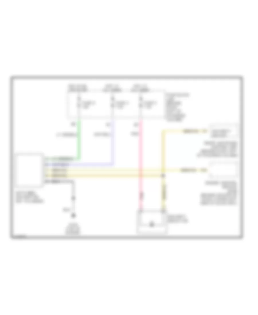
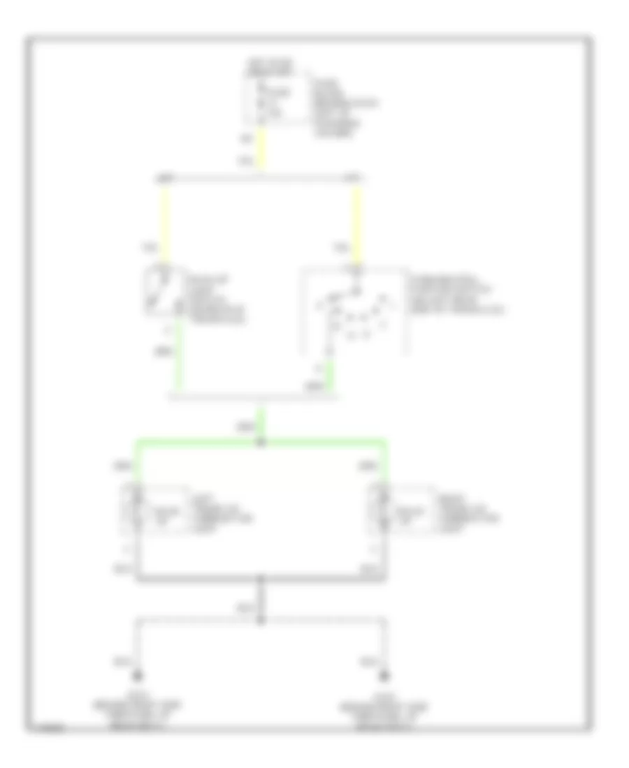
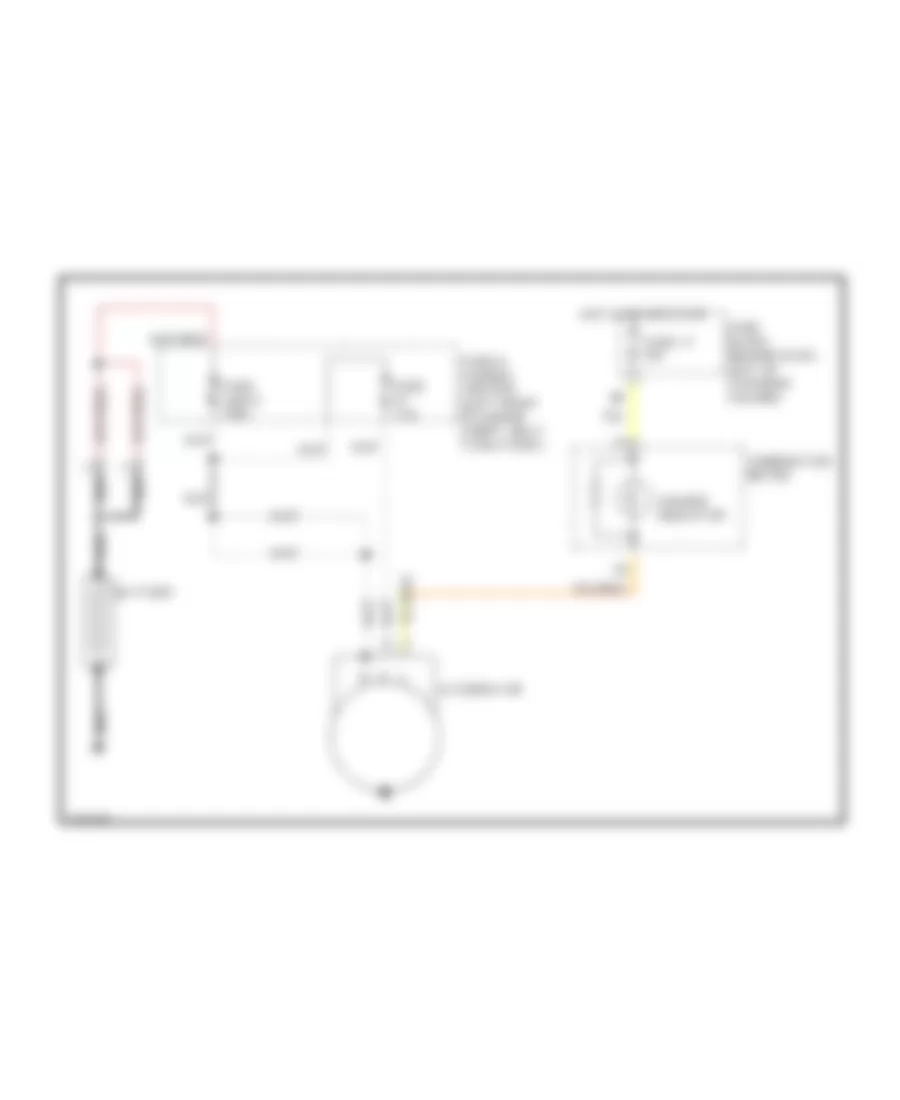
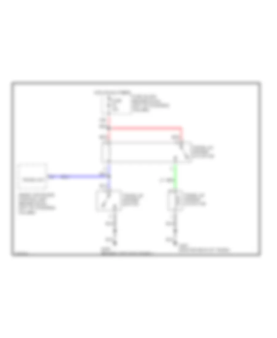
COOLING FAN
Cooling Fan Wiring Diagram for Infiniti G20 t 2001
List of elements for Cooling Fan Wiring Diagram for Infiniti G20 t 2001:
- Cooling fan motor 1
- Cooling fan motor 2
- Cooling fan relay 1 (in relay box)
- Cooling fan relay 2 (in relay box)
- Cooling fan relay 3 (in relay box)
- Engine control module (behind center of dash)
- Fuse & fusible link box
- Fuse 16 10a
- Fuse block
- Fusible link b 40a
- Fusible link c 40a
- G102 (left front shock tower)
- Hot at all times
- Hot in on & start
- Rfrh
- Rfrl
CRUISE CONTROL
Cruise Control Wiring Diagram, A/T for Infiniti G20 t 2001
List of elements for Cruise Control Wiring Diagram, A/T for Infiniti G20 t 2001:
- (w/ speedometer & odo/trip meter)
- 15d
- Actr out high
- Air valve
- Air valve low
- Ascd 4th cut sw
- Ascd brake switch (on bracket, above brake pedal)
- Ascd control unit (behind dash, left of steering column)
- Ascd cruise sw
- Ascd pump (right rear corner of engine compt)
- Ascd steering switch
- Brake nc sw
- Cancel switch
- Control unit unified meter
- Cruise
- Cruise lamp
- Cruise signal
- Engine control module (ecm) (behind center of dash, at lower left side of glove box)
- Fpc connector
- Fuse & fusible link block (left front of eng compt, next to battery)
- Fuse 11 10a
- Fuse 14 15a
- Fuse 16 10a
- Fuse 36 fuse 36 10a
- Fuse 41 10a
- Fuse 8 10a
- Fuse block (behind dash, left of steering column)
- G101 (front of right front fender)
- G102 (left front shock tower)
- G134 (top of engine)
- G200 (behind left kick panel)
- G203 (behind right kick panel)
- Ground
- Ground-c
- Horn relay (in relay box)
- Horn system
- Hot at all times
- Hot in on or start
- Ignition switch
- Instrument cluster
- Main switch
- Main switch in
- Nca
- Od cancel out
- Park/neutral position relay (in relay box)
- Park/neutral position switch (on left rear side of transaxle)
- Pnk
- Red
- Release valve
- Res/acc sw in
- Resume/ accel switch
- Set
- Set lamp out
- Set/coast sw
- Set/coast switch
- Shift solenoid a
- Solenoid input
- Spiral cable
- Starting/ charging system
- Stoplight switch (on bracket above brake pedal)
- Throttle pos
- Transmission control module (tcm) (behind lower center of dash, forward of selector lever)
- Tvo0
- Vacuum motor
- Vehicle speed
- Vehicle speed sensor (on top right side of transaxle)
Cruise Control Wiring Diagram, M/T for Infiniti G20 t 2001
List of elements for Cruise Control Wiring Diagram, M/T for Infiniti G20 t 2001:
- (w/ speedometer & odo/trip meter)
- 15d
- Actr out high
- Air valve
- Air valve low
- Ascd brake switch (on bracket, above brake pedal)
- Ascd clutch switch (on bracket, above clutch pedal)
- Ascd control unit (behind dash, left of steering column)
- Ascd pump (right rear corner of engine compt)
- Ascd steering switch
- Brake nc sw
- Cancel switch
- Control unit unified meter
- Cruise
- Cruise lamp
- Engine control module (ecm) (behind center of dash, at lower left side of glove box)
- Fpc connector
- Fuse & fusible link block (left front of eng compt, next to battery)
- Fuse 11 10a
- Fuse 14 15a
- Fuse 36 fuse 36 10a
- Fuse 41 10a
- Fuse 8 10a
- Fuse block (behind dash, left of steering column)
- G101 (front of right front fender)
- G102 (left front shock tower)
- G134 (top of engine)
- G200 (behind left kick panel)
- G203 (behind right kick panel)
- Ground
- Ground-c
- Horn relay (in relay box)
- Horn system
- Hot at all times
- Hot in on or start
- Ignition switch
- Instrument cluster
- Main switch
- Main switch in
- Nca
- Pnk
- Red
- Release valve
- Res/acc sw in
- Resume/ accel switch
- Set
- Set lamp out
- Set/coast sw
- Set/coast switch
- Spiral cable
- Stoplight switch (on bracket above brake pedal)
- Throttle pos
- Tvo0
- Vacuum motor
- Vehicle speed
- Vehicle speed sensor (on top right side of transaxle)
DEFOGGERS
Defogger Wiring Diagram for Infiniti G20 t 2001
List of elements for Defogger Wiring Diagram for Infiniti G20 t 2001:
- (behind dash, left of steering column) smart entrance control unit
- Condenser
- Def out
- Def sw
- Door mirror defogger relay (behind left kick panel)
- Fuse & fusible link box (left front of engine compt, next to battery)
- Fuse 10a
- Fuse 10a
- Fuse 20a
- Fuse block (behind dash, left of steering column)
- G200 (behind left kick panel)
- G203 (behind right kick panel)
- G313 (right side of rear shelf)
- Hot at all times
- Hot in acc or on
- Hot in on or start
- Ignition
- Illum
- Interior lights system
- Left door mirror defogger
- Nca
- On ind
- Rear window defogger
- Rear window defogger relay (behind left kick panel)
- Rear window defogger switch
- Red
- Right door mirror defogger
ENGINE PERFORMANCE
2.0L
2.0L, Engine Performance Wiring Diagrams (1 of 4) for Infiniti G20 t 2001
List of elements for 2.0L, Engine Performance Wiring Diagrams (1 of 4) for Infiniti G20 t 2001:
- (behind right headlamp) g107
- (behind right kick panel) g203
- (on rear of engine, below throttle body) iacv-aac valve
- (top center rear of engine) egr volume control valve
- 10d
- A/c system
- A/t
- Acrly
- Arcon
- Closed
- Cooling fans system
- Cvbv
- Dt1
- Dt2
- Dt3
- Dt4
- Dt5
- Egr 1
- Egr 2
- Egr 3
- Egr 4
- Eng rev
- Engine control module (ecm) (behind center of dash)
- Evap
- Evap canister purge volume control solenoid valve (top right front of engine)
- Fpr
- Full sw
- Fuse 10a
- Fuse 15a
- Fuse block (behind dash, left of steering column)
- G134 (top of engine)
- Gnd
- Gnd-a
- Gnd-c
- Headlights system
- Hot in on or start
- Hot in start
- Idle
- Idle sw
- Ign
- Ignck
- Ignsw
- Isc 1
- Isc 2
- Isc 3
- Isc 4
- Led
- Loadh
- M/t
- Neut
- O2hfl
- O2hrl
- Obd2
- Park/ neutral position switch (on left rear side of transaxle)
- Park/ neutral position switch (on right front of transaxle)
- Pnk
- Power steering oil pressure switch (on power steering high pressure tube)
- Pwst
- Red
- Rfrh
- Rfrl
- Sens pw
- Ssoff
- Stsw
- Tacho
- Th sens
- Throttle position switch (on throttle body assembly)
- Transmission control module (tcm) (w/a/t) (forward of selector lever)
- Vsp-2
- Wide open
2.0L, Engine Performance Wiring Diagrams (2 of 4) for Infiniti G20 t 2001
List of elements for 2.0L, Engine Performance Wiring Diagrams (2 of 4) for Infiniti G20 t 2001:
- (top right side of transaxle) vehicle speed sensor
- Ascd control unit (behind dash, left of steering column)
- Combination meter
- Data link connector (dlc) (under left dash panel, near fuse box cover)
- Evap canister vent control valve (left rear underside of vehicle)
- Fpc connector
- Fuel pump (in fuel tank)
- Fuel pump relay 1 (behind center of dash)
- Fuel pump relay 2 (behind left kick panel)
- Fuse & fusible link box (left front of engine compt, next to battery)
- Fuse 10a
- Fuse 15a
- Fuse block (behind dash, left of steering column)
- G107 (behind right headlamp)
- G200 (behind left kick panel)
- G310 (behind right rear seat)
- Hot at all times
- Hot in on or start
- Malfunction indicator
- Pwr
- Red
- Tach
- Vacuum cut valve by-pass valve (left rear underside of vehicle)
- Vss in
- Vss out
2.0L, Engine Performance Wiring Diagrams (3 of 4) for Infiniti G20 t 2001
List of elements for 2.0L, Engine Performance Wiring Diagrams (3 of 4) for Infiniti G20 t 2001:
- (top of engine) g134
- 13d
- 15b
- Camshaft position sensor
- Condenser
- Distributor
- Evap control system pressure sensor (left rear underside of vehicle)
- Front heated oxygen sensor (on exhaust manifold)
- Fuel injectors
- Fuse 10a
- Fuse block (behind dash, left of steering column)
- G134 (top of engine)
- Hot in on or start
- Ignition coil
- J/c 1 (behind right side of dash)
- J/c 2 (behind right side of dash)
- Nca
- Power transistor
- Rear heated oxygen sensor (rear of converter)
- Spark plugs
2.0L, Engine Performance Wiring Diagrams (4 of 4) for Infiniti G20 t 2001
List of elements for 2.0L, Engine Performance Wiring Diagrams (4 of 4) for Infiniti G20 t 2001:
- (2000 only)
- (behind right rear seat) g310
- (on transaxle housing) crankshaft position sensor
- (right side of engine block) knock sensor
- (top of engine) g134
- (top right rear of engine) egr temperature sensor
- A/c system (refrigerant pressure sensor)
- Absolute pressure sensor (2000 only) (center of firewall)
- Adjsw
- Atck
- Avcc
- Batt
- Cdcv
- Ecm relay (behind center of dash)
- Egrts
- Engine control module (ecm) (behind center of dash)
- Engine coolant temperature sensor (lower front of intake manifold)
- Fgage+
- Fgage-
- Ftprs
- Fuel tank temperature sensor (top of fuel tank)
- Fuse & fusible link box (left front of engine compt, next to battery)
- Fuse 15a
- Fuse 7.5a
- Fuse block (behind dash, left of steering column)
- G134 (top of engine)
- Gnd-e
- Hot at all times
- Inj 1
- Inj 2
- Inj 3
- Inj 4
- Instrument cluster system
- Intake air temperature sensor (left front of eng compt)
- J/c 1 (behind right side of dash)
- Kline
- Knk
- Mass air- flow sensor (on air intake assembly)
- Nats
- Nats immu (on ignition key cylinder)
- Nca
- O2sfl
- O2srl
- Pdpres
- Pos
- Pres
- Qa+
- Qa-
- Red
- Ref
- Rgc/s
- Throttle position sensor (on throttle body assembly)
- Tv00
- Tvo
- Vsp
EXTERIOR LIGHTS
Backup Lamps Wiring Diagram for Infiniti G20 t 2001
List of elements for Backup Lamps Wiring Diagram for Infiniti G20 t 2001:
- A/t
- Back up
- Back-up light switch (on rear of transaxle)
- Fuse 10a
- Fuse block (behind dash, left of steering column)
- G310 (behind right side trim panel of rear seat)
- Hot in on or start
- Left trunk lid combination light
- M/t
- Park/neutral position switch (on left rear side of transaxle)
- Right trunk lid combination light
Exterior Lamps Wiring Diagram (1 of 2) for Infiniti G20 t 2001
List of elements for Exterior Lamps Wiring Diagram (1 of 2) for Infiniti G20 t 2001:
- 10b
- 11b
- 13h
- 14h
- 15d
- Bat
- Bat (fuse)
- Combination switch (lighting switch)
- Diode (behind center of dash)
- Door sw (as)
- Door sw (dr)
- Fuse & fusible link box (left front of engine compt)
- Fuse 14 15a
- Fuse 16 10a
- Fuse 24 10a
- Fuse 34 10a
- Fuse 8 10a
- Fuse block (behind dash, left of steering column)
- G101 (front of right front fender)
- G102 (left front shock tower)
- G305 (right b pillar)
- G308 (left b pillar)
- G310 (behind right side trim panel of rear seat)
- G407 (center rear of trunk)
- Gnd
- H/l rly
- Head
- Headlamp battery saver control unit (behind right kick panel)
- Headlights system
- High- mounted stop lamp (w/ rear spoiler)
- High- mounted stop lamp (w/o rear spoiler)
- Hot at all times
- Hot in on or start
- Ign
- Ign sw
- Left front door switch
- Left front side marker lamp
- Left parking lamp
- Left rear fender combination lamp
- Left rear side marker lamp
- Left trunk lid combination lamp
- License lamp
- Off
- Park
- Pnk
- Rap
- Rap output
- Red
- Right front door switch
- Right front side marker lamp
- Right parking lamp
- Right rear fender combination lamp
- Right rear side marker lamp
- Right trunk lid combination lamp
- Smart entrance control unit (behind dash, left of steering column)
- Stop
- Stoplight switch (on bracket, above brake pedal)
- T/l rly
- T/l sw
- Tail
- Taillight relay (behind right kick panel)
- Turn
Exterior Lamps Wiring Diagram (2 of 2) for Infiniti G20 t 2001
List of elements for Exterior Lamps Wiring Diagram (2 of 2) for Infiniti G20 t 2001:
- Combination flasher unit (behind left side of dash)
- Combination switch (turn signal switch)
- Fuse 12 7.5a
- Fuse 20 10a
- Fuse block (behind dash, left of steering column)
- G101 (front of right front fender)
- G102 (left front shock tower)
- G200 (behind left kick panel)
- G203 (behind right kick panel)
- Haz out- put
- Hazard
- Hazard switch
- Hot at all times
- Hot in on or start
- Ill
- Instrument cluster
- Interior lights system
- Left front turn signal lamp
- Left side turn signal lamp
- Left turn ind
- Multi- remote control relay (on fuse block)
- Pnk
- Right front turn signal lamp
- Right side turn signal lamp
- Right turn ind
- Smart entrance control unit (behind dash, left of steering column)
GROUND DISTRIBUTION
Ground Distribution Wiring Diagram for Infiniti G20 t 2001
List of elements for Ground Distribution Wiring Diagram for Infiniti G20 t 2001:
- A/c auto amp, hood switch, cooling fan motor 1, cooling fan motor 2, right headlight, left front fog lamp, cooling fan relay 2, left front side marker light, front fog lamp switch, front wiper switch, headlamp battery saver control unit, washer level switch
- A/t device, rear window defogger switch, sunroof
- A/t indicators, high beam indicator, turn signal indicator, air bag warning light, fuel
- Abs actuator & electric unit
- Air bag diagnosis sensor unit shield wire
- Ascd control unit, data link connector for gst, clutch interlock switch, combination flasher unit, illumination control switch, power window
- Control unit, a/c auto amp, power steering oil pressure switch, mode door motor, air mix door
- Control unit, power window main switch, driver's
- Data link connector for gst, mass airflow sensor shield wire, absolute pressure sensor shield wire, rear heated oxygen sensor shield wire, front heated oxygen sensor shield wire, camshaft position sensor shield wire, crankshaft position sensor shield wire, throttle position sensor shield wire, ascd control unit, engine control module, rear heated oxygen sensor, transmission control module, camshaft position sensor, evap control system pressure sensor shield wire, nats immu,
- Distributor, engine control module
- Door key cylinder switch, driver's door lock actuator, accessory relay, fuse block, ignition relay, blower relay, fuel pump relay 2, trunk lid opener switch
- Door key cylinder switch, passenger's door mirror actuator, front wiper motor, ashtray
- Driver's heated seat switch,
- Driver's power seat, driver's heated
- Driver's seat buckle switch,
- Fuel level sensor unit, fuel pump, license light, trunk room light switch, bose speaker amp, high-mounted stop light, power antenna, trunk lid key cylinder switch, left rear combination light, right rear combination light, engine control module
- G101 (front of right front fender)
- G102 (left front shock tower)
- G134 (top of engine)
- G200 (behind left kick panel)
- G203 (behind right kick panel)
- G305 (right "b" pillar)
- G308 (left "b" pillar)
- G310 (behind right side trim panel of rear seat)
- G313 (right side of rear shelf)
- G407 (center rear of trunk)
- Gauge, tachometer, odo/trip meter, speedometer, water temperature gauge
- Illumination, a/t device, fan switch, push
- Ivcs unit, driver's door switch
- Left front turn signal light, left side turn signal light, daytime light control unit
- Mix door motor, passenger's vanity mirror light, map light, integrated homelink transmitter, ivcs switch
- Motor, potentio temperature control (ptc),
- Park/neutral position switch, left parking light, left headlight, right parking light, right side turn signal light, right front turn signal light, right front fog light, right front side marker light, headlamp battery saver control unit, vehicle speed sensor, brake fluid level switch, cooling fan relay 3
- Passenger's door lock actuator, passenger's
- Passenger's heated seat switch, left rear door lock actuator, right rear door lock actuator
- Rear window defogger
- Relay, driver's door mirror actuator, door mirror remote control switch, smart entrance
- Right rear side marker light, left rear combination light, right rear combination light, left rear side marker light, trunk lid opener actuator
- Seat, passenger's heated seat,
- Switch, driver's vanity mirror light, air bag diagnosis sensor unit, glove box light, cigarette lighter, intake door motor, fan control amp, air
HEADLIGHTS
Headlight Wiring Diagram, with DRL (1 of 2) for Infiniti G20 t 2001
List of elements for Headlight Wiring Diagram, with DRL (1 of 2) for Infiniti G20 t 2001:
- (behind dash, left of steering column)
- 10b
- 11b
- 1st
- 2nd
- Bat
- Combination meter
- Combination switch (front foglight switch)
- Combination switch (lighting switch)
- Diode (headlamp battery saver control unit)
- Exterior lights system (taillamp relay)
- Front foglight relay (in relay box)
- Fuse & fusible link box (left front of engine compt, next to battery)
- Fuse 16 10a
- Fuse 24 7.5a
- Fuse 32 15a
- Fuse 33 15a
- Fuse 43 15a
- Fuse 8 10a
- Fuse block
- G101 (front of right front fender)
- G102 (left front shock tower)
- G200 (behind left kick panel)
- Gnd
- H/l rly
- Headlamp battery saver control unit (behind right kick panel)
- High
- High beam ind
- Hot at all times
- Hot in on or start
- Ign sw
- Left front fog lamp
- Left headlamp
- Left headlamp relay (behind right kick panel)
- Low
- Off
- Pass
- Pnk
- Rap
- Red
- Right front fog lamp
- Right headlamp
- Right headlamp relay (behind right kick panel)
- T/l rly
- T/l sw
Headlight Wiring Diagram, with DRL (2 of 2) for Infiniti G20 t 2001
List of elements for Headlight Wiring Diagram, with DRL (2 of 2) for Infiniti G20 t 2001:
- (behind dash, left of steering column)
- Alt-l
- Alternator
- Daytime light control unit (behind right kick panel)
- Fuse 26 10a
- Fuse 8 10a
- Fuse block
- G101 (front of right front fender)
- G102 (behind left shock tower)
- Gnd
- Hot in on or start
- Hot in start
- Ign
- Lh fuse
- Lh lamp gnd
- Lh main lamp
- Light dim sw
- Light main sw
- Parking brake switch (on base of park brake lever)
- Pkb sw
- Red
- Rh fuse
- Rh main lamp
- Start
- Starting/charging system (charge indicator)
Headlight Wiring Diagram, without DRL for Infiniti G20 t 2001
List of elements for Headlight Wiring Diagram, without DRL for Infiniti G20 t 2001:
- (behind
- 10b
- 11b
- 1st
- 2nd
- Bat
- Combination meter
- Combination switch (front foglight switch)
- Combination switch (lighting switch)
- Dash, left of steering column)
- Diode (headlamp battery saver control unit)
- Exterior lights system (taillamp relay)
- Front foglight relay (in relay box)
- Fuse & fusible link box (left front of engine compt, next to battery)
- Fuse 16 10a
- Fuse 24 7.5a
- Fuse 32 15a
- Fuse 33 15a
- Fuse 43 15a
- Fuse 8 10a
- Fuse block
- G101 (front of right front fender)
- G102 (left front shock tower)
- G200 (behind left kick panel)
- Gnd
- H/l rly
- Headlamp battery saver control unit (behind right kick panel)
- High
- High beam ind
- Hot at all times
- Hot in on or start
- Ign sw
- Left front fog lamp
- Left headlamp
- Left headlamp relay (behind right kick panel)
- Low
- Off
- Pass
- Pnk
- Rap
- Red
- Right front fog lamp
- Right headlamp
- Right headlamp relay (behind right kick panel)
- T/l rly
- T/l sw
HORN
Horn Wiring Diagram for Infiniti G20 t 2001
List of elements for Horn Wiring Diagram for Infiniti G20 t 2001:
- Fuse & fusible link box (left front of engine compartment, next to battery)
- Fuse 36 10a
- Fuse 41 10a
- Horn high (right front of engine compartment)
- Horn low (right side of engine compartment)
- Horn relay (in relay box)
- Horn switch
- Hot at all times
- Nca
- Spiral cable (under steering wheel)
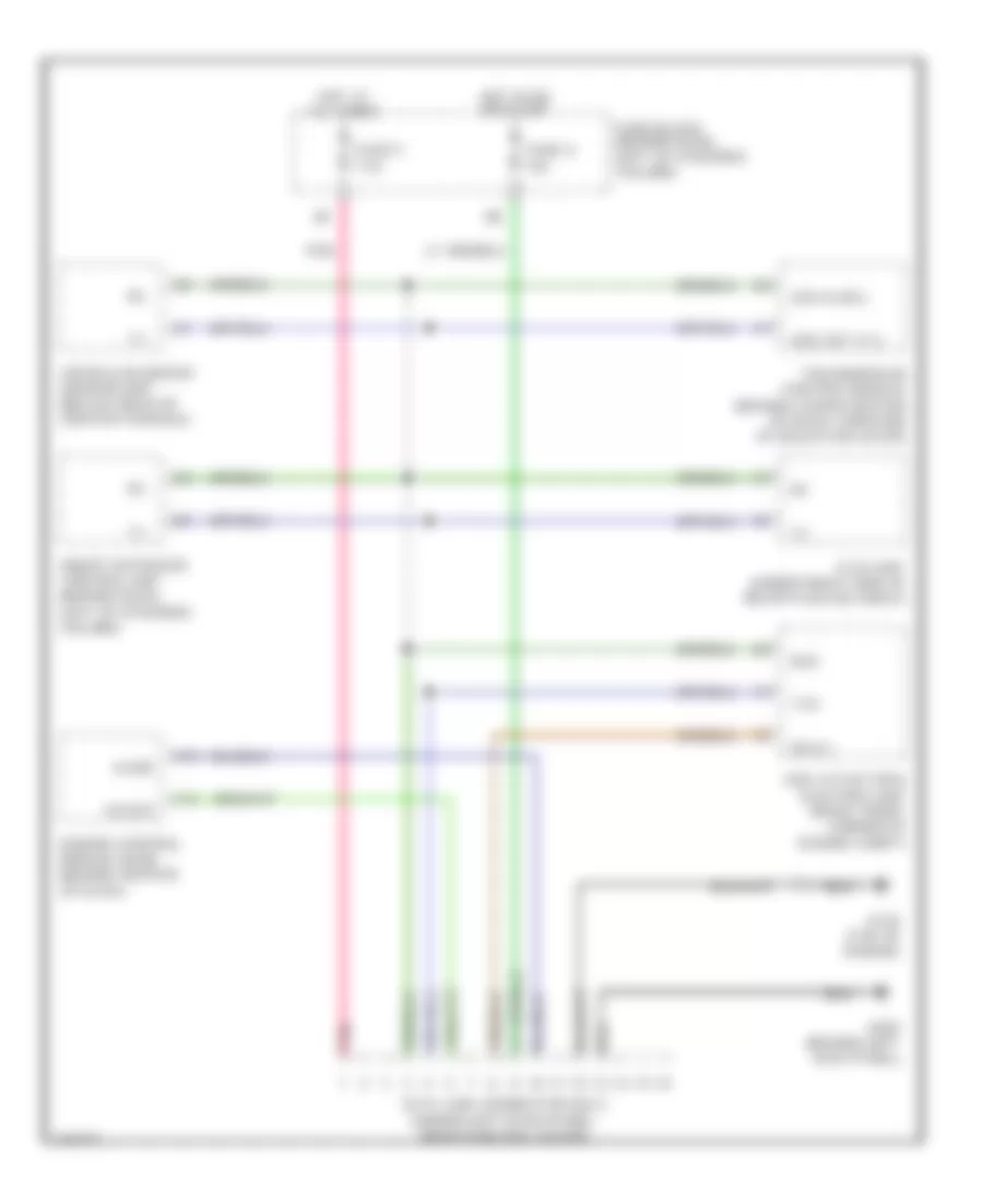
INSTRUMENT CLUSTER
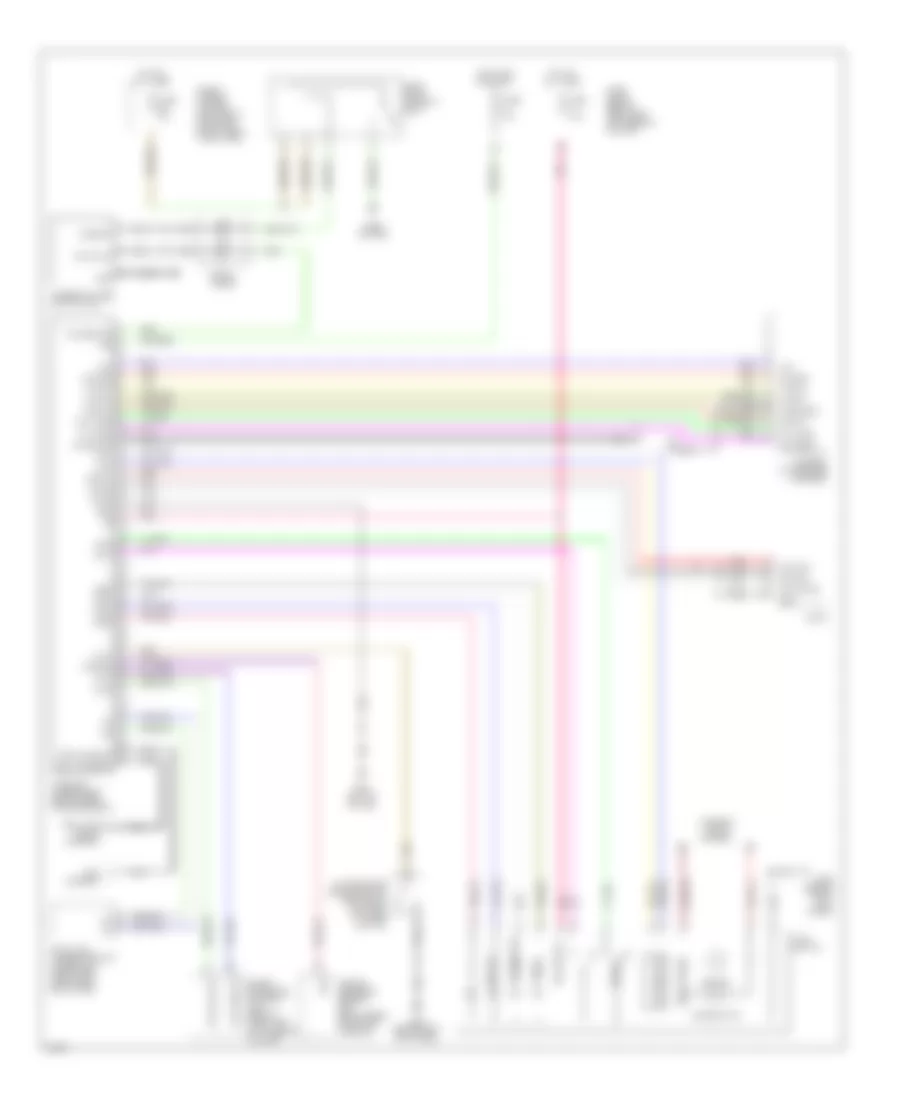
Instrument Cluster Wiring Diagram (1 of 2) for Infiniti G20 t 2001
List of elements for Instrument Cluster Wiring Diagram (1 of 2) for Infiniti G20 t 2001:
- Abs ind
- Airbag ind
- Brake ind
- Charge ind
- Combination meter
- Cruise ind
- Door ind
- Door locks
- Exterior lights
- Flexible print circuit
- Fuel gauge
- Fuel ind
- Fuel tank gauge unit (top of fuel tank)
- Fuse 11 10a
- Fuse 5 7.5a
- Fuse block (j/b) (behind dash, left of steering column)
- G101 (front of right front fender)
- G203 (behind right kick panel)
- G310 (behind right side trim panel of rear seat)
- Headlights
- Headlights (canada)
- Hot at all times
- Hot in on or start
- Interior lights
- Joint connector 3 (diode) (behind center of dash)
- M39
- M40
- M41
- Malfunction ind
- O/d off ind
- Odometer/trip meter) (with speedometer and
- Oil press ind
- Park/neutral position switch (on transaxle)
- Pnk
- Red
- Seat belt ind
- Set ind
- Starting/ charging system
- Tachometer
- Thermal transmitter (on lower front of intake manifold)
- To combination meter (diagram 2 of 2)
- Unified meter control unit
- Vehicle speed sensor (on top right side of transaxle)
- Washer ind
- Water temp gauge
Instrument Cluster Wiring Diagram (2 of 2) for Infiniti G20 t 2001
List of elements for Instrument Cluster Wiring Diagram (2 of 2) for Infiniti G20 t 2001:
- (canada or m/t w/ auto a/c)
- (others)
- 43k
- Abs actuator &electric unit (control unit) (rt front corner of engine compt)
- Abs fail ind
- Air bag diagnosis sensor unit (below rear of center console)
- Air bag ind
- Automatic speed control device (ascd) control unit (behind dash, left of steering column)
- Brake fluid level switch (in brake fluid reservoir)
- Combination meter
- Cruise lamp
- Diode
- Ecm (eccs) control module (behind center of dash)
- From combination meter (diagram 1 of 2)
- G102 (left front shock tower)
- Hi beam ind
- Illumination
- Left turn ind
- Mal ind driver
- O/d off
- Odo/trip illumination
- Oil pressure switch (on right front side of cylinder block)
- Parking brake switch
- Right turn ind
- Seat belt
- Set lamp out
- Tach out
- Transmission control module (behind lower center of dash)
- Voltage regulator
- Vsp input
- Washer level switch (fluid reservoir)
INTERIOR LIGHTS
Courtesy Lamps Wiring Diagram for Infiniti G20 t 2001
List of elements for Courtesy Lamps Wiring Diagram for Infiniti G20 t 2001:
- 11b
- Bat (c/b)
- Bat (fuse)
- Bat saver out
- Circuit breaker 1 (behind dash, left of fuse block)
- Condition sw
- Diode (trunk lamp) (behind right side of dash, taped to harness)
- Door
- Door sw (all)
- Door sw (dr)
- Door sw (pass)
- Driver side front door lock actuator (unlock sensor)
- Driver side front door switch
- Driver side vanity mirror lamp
- Fuse 10a
- Fuse block (behind dash, left of steering column)
- G200 (behind left kick panel)
- G203 (behind right kick panel)
- G308 (left "b" pillar)
- G310 (behind right side trim panel of rear seat)
- Ground
- Hot at all times
- Hot in on or start
- Ign
- Interior room lamp
- Key sw
- Key switch
- Left rear door switch
- Map lamp
- Off
- Passenger side front door switch
- Passenger side vanity mirror lamp
- Pnk
- Red
- Right rear door switch
- Room lamp out
- Smart entrance contrl unit (behind dash, left of steering column)
- Trunk room lamp
- Trunk room lamp switch
Instrument Illumination Wiring Diagram (1 of 2) for Infiniti G20 t 2001
List of elements for Instrument Illumination Wiring Diagram (1 of 2) for Infiniti G20 t 2001:
- 10b
- 11b
- 1st
- 2nd
- Bat
- Bat (c/b)
- Bat (fuse)
- Circuit breaker 1 (behind dash, left of fuse block)
- Combination switch (lighting switch)
- Diode
- Door sw (as)
- Door sw (dr)
- Driver side front door switch
- Fuse 10a
- Fuse & fusible link box (left front of engine compartment, next to battery)
- Fuse block (behind dash, left of steering column)
- G101 (front of right front fender)
- G102 (left front shock tower)
- G200 (behind left kick panel)
- G200 (left kick panel)
- G202 (left side of dash)
- G305 (right "b" pillar)
- G308 (left "b" pillar)
- Gnd
- Headlamp battery saver control unit (behind right kick panel)
- Hot at all times
- Hot in on or start
- Ign
- Ign sw
- Off
- Passenger side front door switch
- Pnk
- Rap
- Rap out
- Red
- Smart entrance control unit (behind dash, left of steering column)
- T/l rly
- T/l sw
- Taillamp relay (behind right kick panel)
Instrument Illumination Wiring Diagram (2 of 2) for Infiniti G20 t 2001
List of elements for Instrument Illumination Wiring Diagram (2 of 2) for Infiniti G20 t 2001:
- 11d
- 13h
- A/c auto amp. (illum) (w/ auto a/c)
- A/t device (illum) (w/a/t)
- Ashtray illumination
- Audio (illum)
- Combination meter
- Fuse 10a
- Fuse block (behind dash, left of steering column)
- G200 (behind left kick panel)
- G203 (behind right kick panel)
- Glove box lamp
- Hazard switch (illum)
- Hot in on or start
- Illumination control switch
- Information
- Ivcs switch (illum)
- Mayday
- Meter illum- ination
- Odo/trip meter illum- ination
- Power window main switch (illum)
- Push control unit (illum) (w/ manual a/c)
- Rear window defogger switch (illum)
- Red
- Voltage regulator
NAVIGATION
Navigation Wiring Diagram for Infiniti G20 t 2001
List of elements for Navigation Wiring Diagram for Infiniti G20 t 2001:
- +9.5
- Air bag
- Air bag diagnosis sensor unit (below rear of center console)
- Audio
- Audio+
- C data
- Cell antenna
- Cellular phone antenna
- Data link connector (dlc) (under left dash panel, near fuse box cover)
- Data/out
- Fuse & fusible link box (left front of engine compt, next to battery)
- Fuse 10a
- Fuse 7.5a
- Fuse block (behind dash, left of steering column)
- G200 (behind left kick panel)
- G203 (behind right kick panel)
- G308 (left "b" pillar)
- Gnd
- Gps antenna
- H/s gnd
- Handset (to adapter harness)
- Horn relay (in relay box)
- Horn system
- Horn/ry
- Hot at all times
- Hot in on or start
- Ign
- Information
- Interior lights system
- Ivcs
- Ivcs output
- Ivcs switch
- Ivcs unit (under right side of rear package shelf)
- Ivcs unlock
- Lcu1
- Lcu2
- Lcu3
- Led1
- Led2
- Led3
- Led4
- Mayday
- Mic+
- Mic-
- Microphone
- Mute
- Nca
- No service
- Outside door handle switch (left front door key cylinder switch)
- Pnk
- R data
- Red
- Redial
- Rx voice
- Smart entrance control unit (behind dash, left of steering column)
- Spiral cable
- Steering wheel switch (tel)
- Sw1
- Sw2
- T data
- Tel on sig
- Tel remote
- Tel sig +
- Tel sig -
- Tx voice
- Voice gnd
POWER ANTENNA
Power Antenna Wiring Diagram for Infiniti G20 t 2001
List of elements for Power Antenna Wiring Diagram for Infiniti G20 t 2001:
- Audio
- Fuse 10 7.5a
- Fuse 24 10a
- Fuse block (behind dash, left of steering column)
- G310 (behind right side trim panel of rear seat)
- Hot at all times
- Hot in on or acc
- Pnk
- Power antenna
- Red
POWER DISTRIBUTION
Power Distribution Wiring Diagram (1 of 2) for Infiniti G20 t 2001
List of elements for Power Distribution Wiring Diagram (1 of 2) for Infiniti G20 t 2001:
- (left of steering column) fuse block
- 11d
- 12d
- 13h
- 14h
- Acc
- Accessory relay
- Air conditioning
- Air conditioning, engine controls
- Anti-lock brakes
- Anti-theft body computer
- Anti-theft, headlights
- Battery
- Blower relay
- Cigarette lighter
- Circuit breaker 1 (behind dash, left of fuse block)
- Circuit breaker 2 (behind dash, left of fuse block)
- Cooling fans
- Cruise control, anti-theft, horn
- Cruise control, anti-theft, navigation, horn
- Defogger
- Engine controls
- Engine controls system
- Exterior lights
- From fuse 34 a (diagram 1 of 1)
- Fuse & fusible link box (left front of engine compt)
- Fuse 10a
- Fuse 15a
- Fuse 20a
- Fuse 7.5a
- Fuse a 80a
- Fuse b 40a
- Fuse c 40a
- Fuse d 30a
- Fuse e 100a
- Fuse f 40a
- Fuse g 40a
- Fuse h 40a
- G200 (behind left kick panel)
- G203 (behind right kick panel)
- Headlights
- Headlights, exterior lights, interior lights, warning systems
- Ignition switch
- Interior lights
- Interor lights, warning systems, power tops, door locks, power windows, anti-theft, headlights, exterior lights
- Kick panel)
- Mirrors
- Nca
- Off
- Red
- Seats
- Sound systems
- Sound systems, power antenna
- Start
- Starting/ charging
- Starting/ charging (m/t)
- Starting/ charging, headlights
- Taillight relay (behind right
- To fuse 4 (diagram 2 of 2)
- To fuse g (diagram 1 of 1)
- To ignition relay (diagram 2 of 2)
- Warning systems
- Wiper/washer
Power Distribution Wiring Diagram (2 of 2) for Infiniti G20 t 2001
List of elements for Power Distribution Wiring Diagram (2 of 2) for Infiniti G20 t 2001:
- 10h red
- 11b
- 12b
- 13b
- 15d
- Air conditioning
- Air conditioning, instrument cluster, anti-theft, engine controls
- Anti-lock brakes
- Anti-lock brakes, exterior lights, cruise control
- Antitheft, trunk, tailgate, fuel doors
- Cooling fans, starting/ charging, cruise control
- Engine controls
- Engine controls, transmission controls
- Exterior lights
- Exterior lights, antitheft
- Exterior lights, transmission controls
- From accessory relay (diagram 1 of 2)
- From fuse a (diagram 1 of 2)
- From ignition e relay (diagram 2 of 2)
- From ignition switch (diagram 1 of 2)
- Fuse 10a
- Fuse 15a
- Fuse 7.5a
- Fuse block (left of steering column)
- G200 (behind left kick panel)
- Headlights, body computer
- Headlights, exterior lights, interior lights, warning systems
- Ignition relay
- Interior lights, warning system, door locks, antitheft
- Interior lights, warning systems, defogger, body computer, anti-theft, headlights, exterior lights, power windows, power tops
- Pnk
- Power antenna
- Power tops, power windows, cruise control, transmission controls, headlights, warning systems, interior lights, exterior lights
- Red
- Seats
- Sound systems
- To fuse 16 (diagram 2 of 2)
- Transmission controls (a/t)
- Transmission controls, interior lights, body computer, integrated homelink transmitter
POWER DOOR LOCKS
Power Door Lock Wiring Diagram for Infiniti G20 t 2001
List of elements for Power Door Lock Wiring Diagram for Infiniti G20 t 2001:
- (2000)
- 11b
- Accessory
- Anti-theft system
- Battery (c/b)
- Battery (fuse)
- Battery saver out
- Between full stroke and n
- Central lock sw
- Central unlock sw
- Circuit breaker 1 (behind dash, left of fuse block)
- Door lock output
- Door switch
- Door unlock out
- Dr condition sw
- Dr door switch
- Dr door unlock out
- Exterior lights system
- Full stroke
- Fuse 10a
- Fuse 7.5a
- Fuse block (behind dash, left of steering column)
- G200 (behind left kick panel)
- G203 (behind right kick panel)
- G305 (right "b" pillar)
- G308 (left "b" pillar)
- Ground
- Hazard output
- Hot at all times
- Hot in acc or on
- Hot in on or start
- Ignition
- Interior lights system
- Key cyl sw lock
- Key cyl sw unlock
- Key switch
- Left front door key cylinder switch
- Left front door lock actuator
- Left front door switch
- Left rear door lock actuator
- Left rear door open switch
- Lock
- Locked
- Main power window & door lock switch
- Off
- Open
- Panic alarm output
- Pass condition sw
- Pass door switch
- Pnk
- Rear condition sw
- Right front door key cylinder switch
- Right front door lock actuator
- Right front door open switch
- Right rear door lock actuator
- Right rear door open switch
- Room lamp output
- Smart entrance control unit (behind dash, left of steering column)
- Unlock
- Unlocked
POWER MIRRORS
Power Mirror Wiring Diagram for Infiniti G20 t 2001
List of elements for Power Mirror Wiring Diagram for Infiniti G20 t 2001:
- Change over switch
- Door mirror remote control switch
- Driver's side door mirror actuator
- Fuse 9 10a
- Fuse block (left of steering column)
- G200 (behind left kick panel)
- Hot in on or acc
- Left/right motor
- Mirror switch
- Off
- Passenger's side door mirror actuator
- Up/down motor
POWER SEATS
Driver Power Seat Wiring Diagram for Infiniti G20 t 2001
List of elements for Driver Power Seat Wiring Diagram for Infiniti G20 t 2001:
- Circuit breaker 2 (behind dash, left of fuse block)
- Driver's power seat
- Driver's power seat switch
- Fwd
- G305 (right "b" pillar)
- G308 (left "b" pillar)
- Hot at all times
- Nca
- Reclining motor
- Reclining switch
- Red
- Rev
- Sliding motor
- Sliding switch
Heated Seats Wiring Diagram for Infiniti G20 t 2001
List of elements for Heated Seats Wiring Diagram for Infiniti G20 t 2001:
- 10f
- 11f
- Driver's heated seat switch
- Driver's seat back heater
- Fuse 28 10a
- Fuse block (behind dash, left of steering column)
- G305 (right "b" pillar)
- G308 (left "b" pillar)
- High
- Hot in on or start
- Indicator
- Low
- Nca
- Passenger's heated seat switch
- Passenger's seat back heater
- Pnk
- Red
- Seat back heater
- Seat cushion heater
- Seat cushion thermostat
POWER TOP/SUNROOF
Power Top/Sunroof Wiring Diagrams for Infiniti G20 t 2001
List of elements for Power Top/Sunroof Wiring Diagrams for Infiniti G20 t 2001:
- 10b
- 11b
- Bat (c/b)
- Bat (fuse)
- Circuit breaker 1 (behind dash, left of fuse block)
- Diode
- Down/open
- Fuse 24 10a
- Fuse 8 10a
- Fuse block (behind dash, left of steering column)
- G200 (behind left kick panel)
- G203 (behind right kick panel)
- Gnd
- Hot at all times
- Hot in on or start
- Ign
- Pnk
- Power window relay (on fuse box)
- Rap output
- Red
- Smart entrance control unit (behind dash, left of steering column)
- Sun roof motor (at front of sun roof opening)
- Sun roof switch
- Up/close
POWER WINDOWS
Power Window Wiring Diagram for Infiniti G20 t 2001
List of elements for Power Window Wiring Diagram for Infiniti G20 t 2001:
- 10b
- 11b
- Auto dn
- Auto up
- Battery (c/b)
- Battery (fuse)
- Circuit breaker 1 (behind dash, left of fuse block)
- Cpu
- Diode
- Down
- Driver side switch
- Encoder
- Fuse & fusible link box (left front of engine compartment)
- Fuse 10a
- Fuse block (behind dash, left of steering column)
- Fuse d 30a
- G200 (behind left kick panel)
- G203 (behind right kick panel)
- Ground
- Hot at all times
- Hot in on or start
- Ignition
- Illuminaton
- Interior lights system
- Left front power window regulator
- Left rear power window regulator
- Left rear power window switch
- Left rear switch
- Lock switch
- Locked
- Passenger side switch
- Pnk
- Power window main switch
- Power window relay (on fuse block)
- Rap output
- Right front power window regulator
- Right front power window switch
- Right rear power window regulator
- Right rear power window switch
- Right rear switch
- Smart entrance control unit (behind dash, left of steering column)
- Unlocked
RADIO
Radio Wiring Diagrams for Infiniti G20 t 2001
List of elements for Radio Wiring Diagrams for Infiniti G20 t 2001:
- 12b
- Acc
- Antenna ctrl
- Antenna in
- Audio
- Battery
- Battery
- Bose speaker amplifier (top front center of trunk)
- Fr lh (+) amp
- Fr lh (-) amp
- Fr lh in (+)
- Fr lh in (-)
- Fr lh out (+)
- Fr lh out (-)
- Fr rh (+) amp
- Fr rh (-) amp
- Fr rh in (+)
- Fr rh in (-)
- Fr rh out (+)
- Fr rh out (-)
- Fuse & fusible link box (left front of engine compt)
- Fuse 10 7.5
- Fuse 24 10a
- Fuse 38 15a
- Fuse block (left of steering column)
- G310 (behnd right side trim panel of rear seat)
- Ground
- Ground
- Hot at all times
- Hot in on or acc
- Illum
- Illum
- Interior lights system
- Left front door speaker
- Left rear speaker
- Left tweeter
- Nca
- On sig
- On signal
- Pnk
- Power antenna system
- Red
- Right front door speaker
- Right rear speaker
- Right tweeter
- Rr lh (+) amp
- Rr lh (-) amp
- Rr lh in (+)
- Rr lh in (-)
- Rr lh out (+)
- Rr lh out (-)
- Rr rh (+) amp
- Rr rh (-) amp
- Rr rh in (+)
- Rr rh in (-)
- Rr rh out (+)
- Rr rh out (-)
- Window antenna
SHIFT INTERLOCKS
Shift Interlock Wiring Diagram for Infiniti G20 t 2001
List of elements for Shift Interlock Wiring Diagram for Infiniti G20 t 2001:
- 10b
- 15d
- A/t device (under center console, at base of selector lever)
- Fuse 14 15a
- Fuse 8 10a
- Fuse block (left of steering column)
- G200 (behind left kick panel)
- G203 (behind right kick panel)
- Hot at all times
- Hot in on or start
- Off
- Park position switch
- Relay
- Shift lock solenoid
- Stoplight switch (on bracket, above brake pedal)
STARTING/CHARGING
Charging Wiring Diagram for Infiniti G20 t 2001
List of elements for Charging Wiring Diagram for Infiniti G20 t 2001:
- Alternator
- Battery
- Charge indicator
- Combination meter
- Fuse & fusible link box (left front of engine compt, next to battery)
- Fuse 11 10a
- Fuse 7.5a
- Fuse block (behind dash, left of steering column)
- Fuse link e 100a
- Hot in on or start
- Nca
Starting Wiring Diagram, A/T for Infiniti G20 t 2001
List of elements for Starting Wiring Diagram, A/T for Infiniti G20 t 2001:
- Acc
- Battery
- Cruise control system
- Fuse & fusible link box (left front of engine compt, next to battery)
- Fuse 16 10a
- Fuse block (behind dash, left of steering column)
- Fuse link g 40a
- G101 (front of right front fender)
- G102 (left front shock tower)
- Hot in on or start
- Ignition switch
- Nca
- Off
- Park/neutral position relay (in relay box)
- Park/neutral position switch (on left rear side of transaxle)
- Start
- Starter motor
Starting Wiring Diagram, M/T for Infiniti G20 t 2001
List of elements for Starting Wiring Diagram, M/T for Infiniti G20 t 2001:
- 11h
- Acc
- Battery
- Clutch interlock switch (on bracket, above clutch pedal)
- Depressed
- Fuse & fusible link box (left front of engine compt, next to battery)
- Fuse 26 10a
- Fuse block (behind dash, left of steering column)
- Fuse link g 40a
- G200 (behind left kick panel)
- G203 (behind right kick panel)
- Hot in start
- Ignition switch
- Nca
- Off
- Park/ neutral position relay (in relay box 2)
- Released
- Start
- Starter motor
SUPPLEMENTAL RESTRAINTS
Supplemental Restraint Wiring Diagram for Infiniti G20 t 2001
List of elements for Supplemental Restraint Wiring Diagram for Infiniti G20 t 2001:
- (at base of left b pillar) g308
- (left kick panel) g200
- Air bag diagnosis sensor unit (below rear of center console)
- Air bag indicator
- Air bag w/l
- B19
- Body computer system
- Closed
- Combination meter
- Connector (dlc) (partial) (under left dash panel, near fuse box cover)
- Data link
- Detection conn
- Door switch
- Driver side air bag module
- Driver side front door switch
- Fastened
- Fuse 11 10a
- Fuse 22 10a
- Fuse block (behind dash, left of steering column)
- G305 (at base of right b pillar)
- G308 (at base of left b pillar)
- Ground
- Hot in on or start
- Ignition
- Ivcs
- Left satellite sensor (at base of left b pillar)
- Left seat belt pre-tensioner
- Left side air bag module
- M40
- M41
- Nca
- Open
- Passenger side air bag module
- Right satellite sensor (at base of right b pillar)
- Right seat belt pre-tensioner
- Right side air bag module
- Sat l +
- Sat l -
- Sat r +
- Sat r -
- Seat belt buckle switch (in driver's seat belt buckle)
- Seat belt indicator
- Seat belt sw
- Seat belt w/l
- Spiral cable
- Sq as +
- Sq as -
- Sq dr +
- Sq dr -
- Sq pas +
- Sq pas -
- Sq pdr +
- Sq pdr -
- Sq side l +
- Sq side l -
- Sq side r +
- Sq side r -
- Un- fastened
TRUNK, TAILGATE, FUEL DOOR
Trunk Release Wiring Diagram for Infiniti G20 t 2001
List of elements for Trunk Release Wiring Diagram for Infiniti G20 t 2001:
- 13b
- Fuse 15a
- Fuse block (behind dash, left of steering column)
- G200 (behind left kick panel)
- G407 (center rear of trunk)
- Hot at all times
- Red
- Smart entrance control unit (behind dash, left of steering column)
- Trunk lid opener actuator
- Trunk lid opener switch
- Trunk out
WARNING SYSTEMS
Warning System Wiring Diagrams for Infiniti G20 t 2001
List of elements for Warning System Wiring Diagrams for Infiniti G20 t 2001:
- 10b
- 11b
- 12d
- 13h
- 1st
- 2nd
- Bat
- Bat (c/b)
- Bat (fuse)
- Circuit breaker 1 (left of fuse block)
- Combination switch (lighting switch)
- Diode
- Door sw (dr)
- Dr sw (as)
- Fuse & fusible link box (next to battery)
- Fuse 24 10a
- Fuse 34 10a
- Fuse 8 10a
- Fuse block
- Fuse block (behind dash, left of steering column)
- G102 (left front shock tower)
- G200 (behind left kick panel)
- G308 (left "b" pillar)
- Gnd
- Headlamp battery saver control unit (behind right kick panel)
- Hot at all times
- Hot in on or start
- Ign
- Key sw
- Key switch
- Left front door switch
- Light sw
- Off
- Pnk
- Rap
- Rap output
- Red
- Right front door switch
- Seat belt buckle switch
- Seat belt sw
- Smart entrance control unit (behind dash, left of steering column)
- T/l rly
- T/l sw
- Taillight relay (behind right kick panel)
WIPER/WASHER
Wiper/Washer Wiring Diagram for Infiniti G20 t 2001
List of elements for Wiper/Washer Wiring Diagram for Infiniti G20 t 2001:
- Front washer motor (on washer fluid reservoir)
- Front wiper motor (right side of firewall)
- Front wiper switch
- Fuse 19 20a
- Fuse block (left of steering column)
- G102 (left front shock tower)
- G203 (behind right kick panel)
- High
- Hot in run or accy
- Int
- Low
- Off
- Pnk
- Variable intermittent wiper control
- Wash
- Wiper amplifier