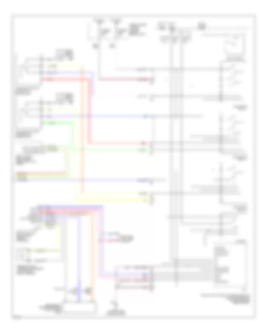
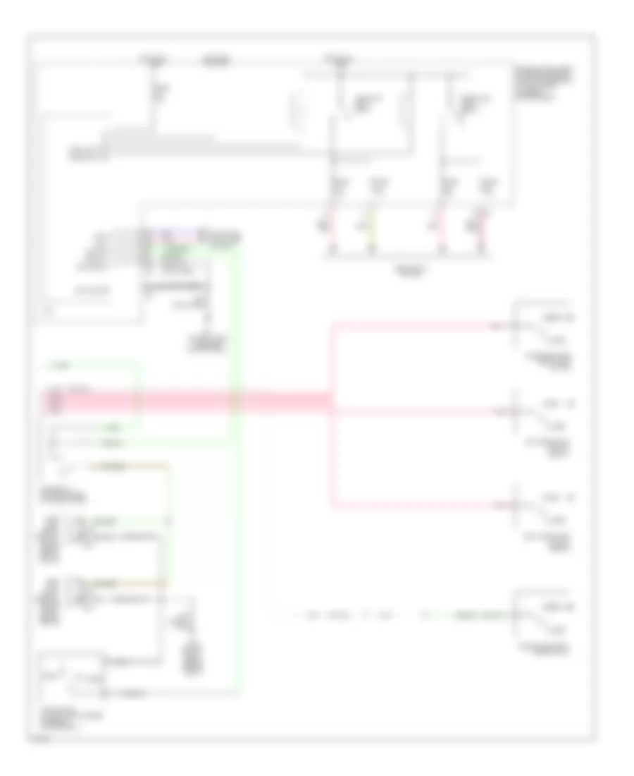
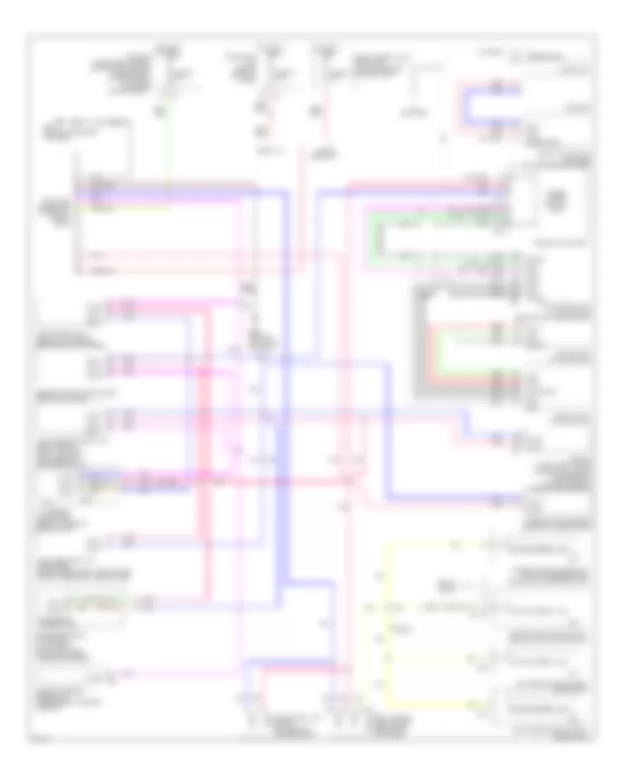
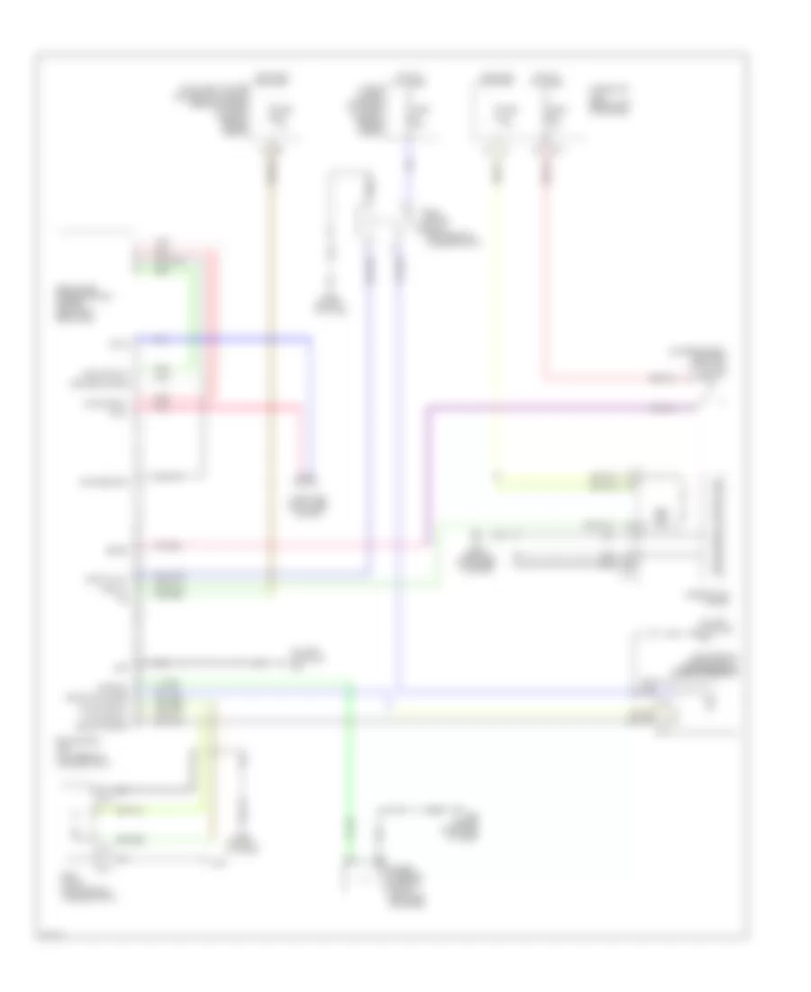
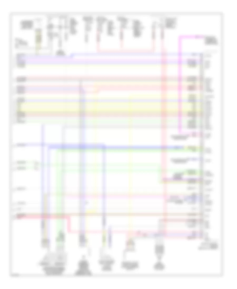
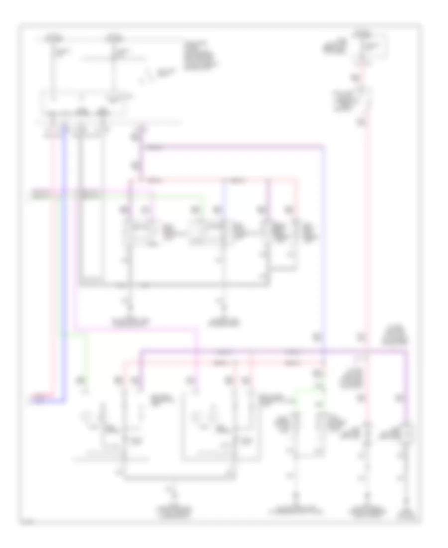
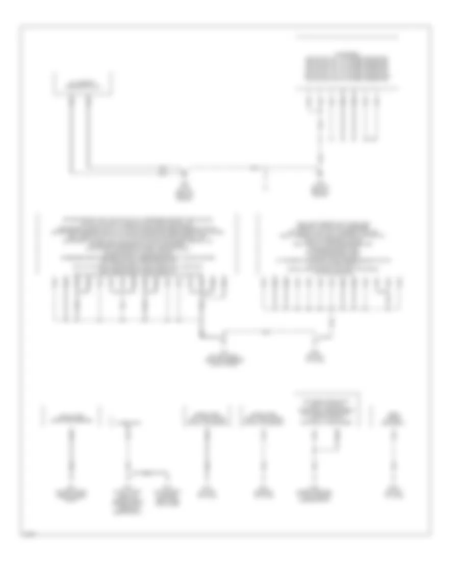
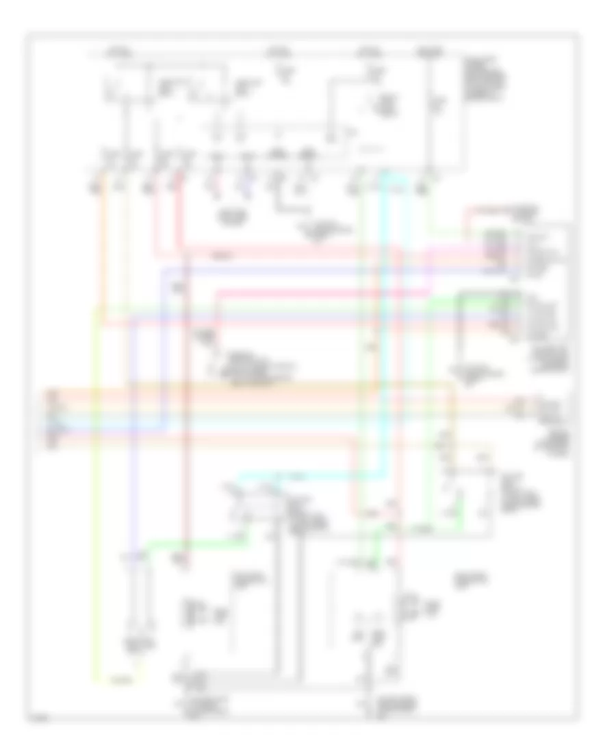
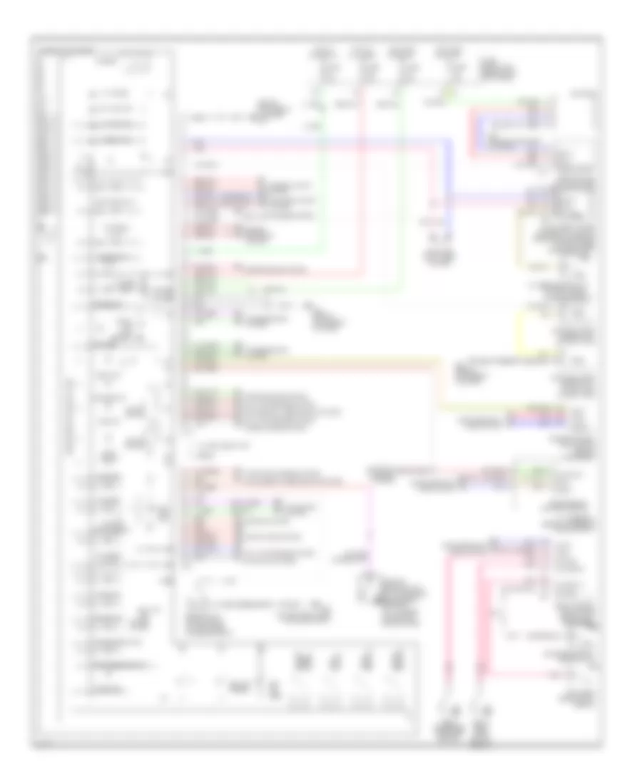
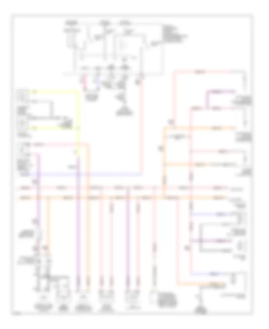
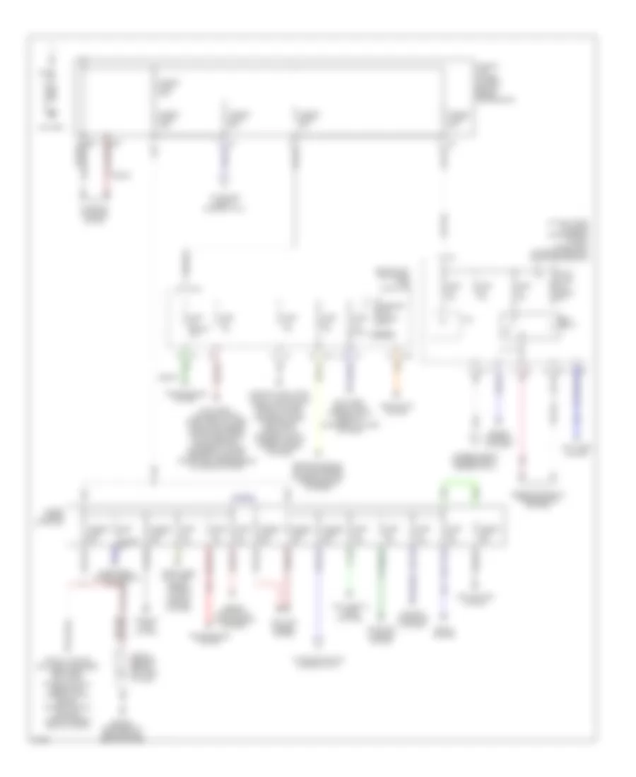
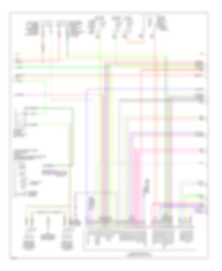
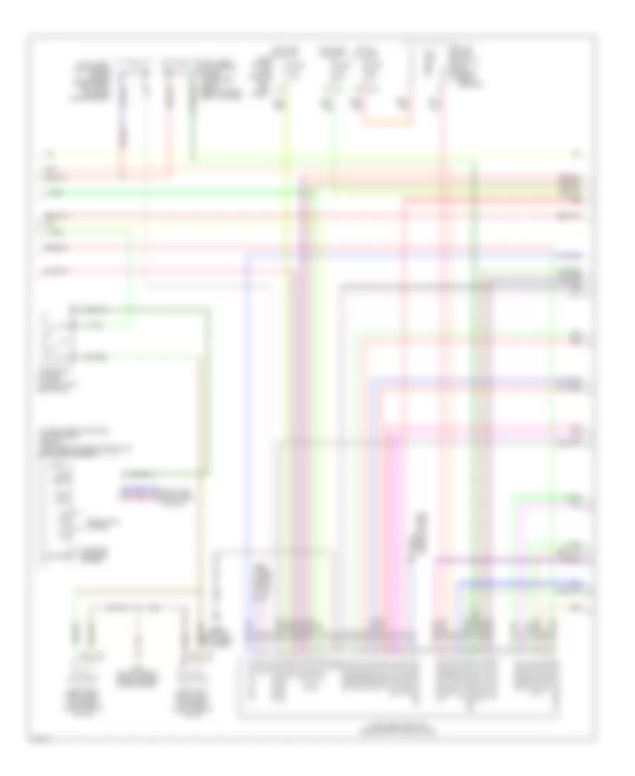
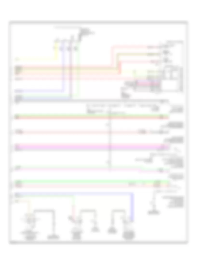
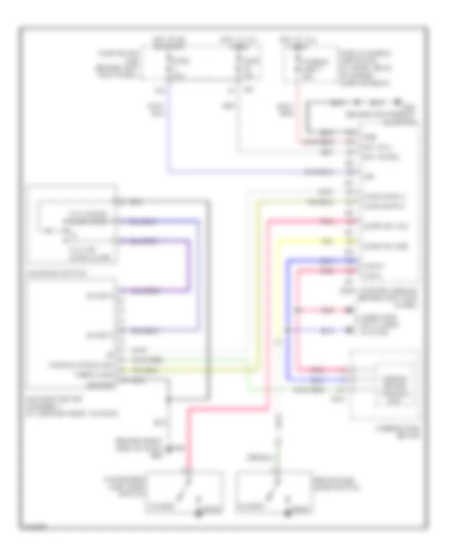
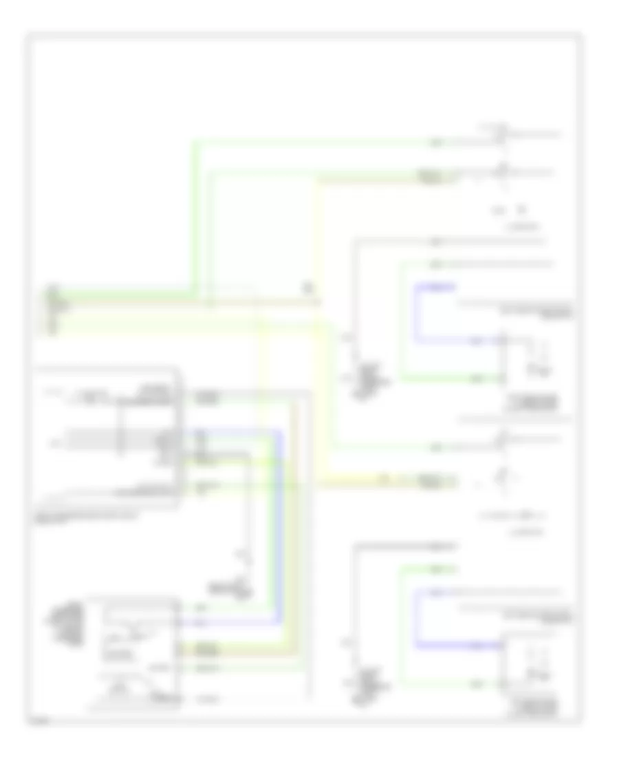
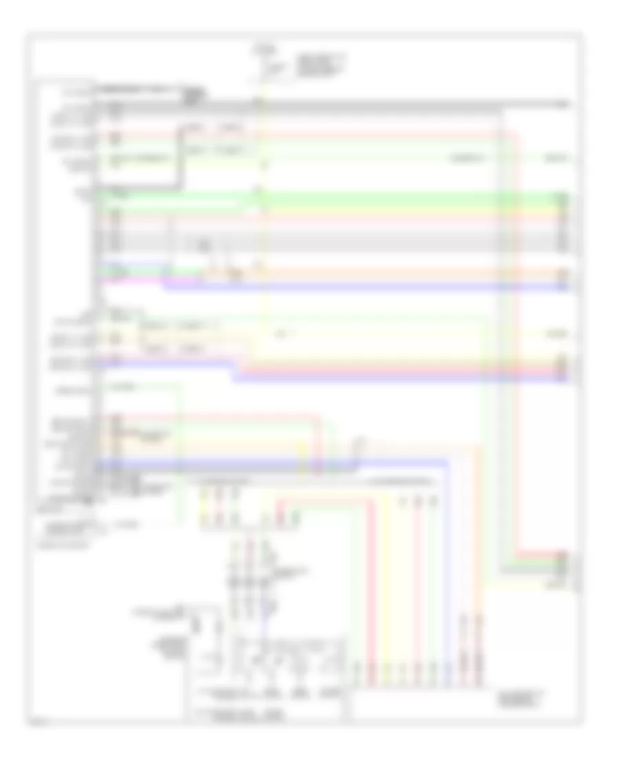
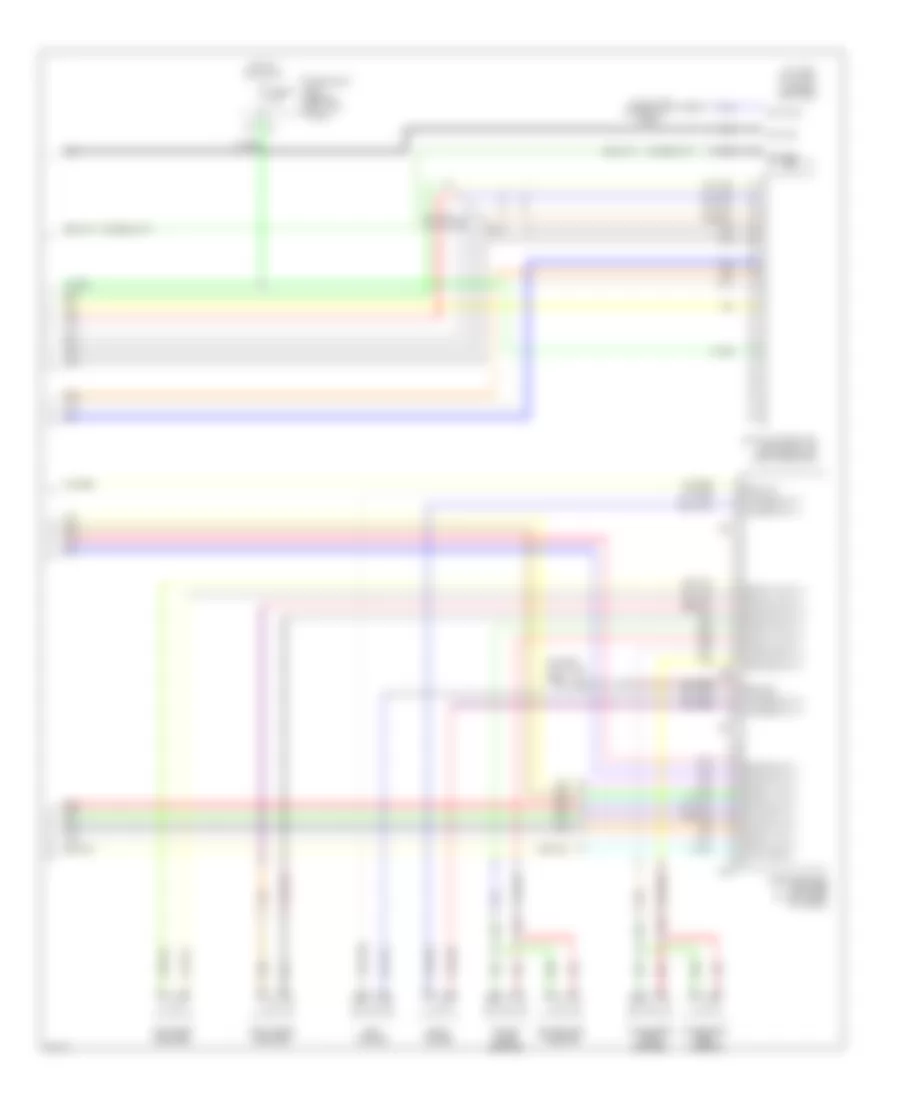
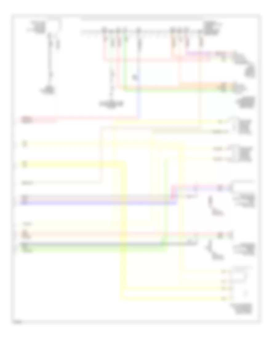
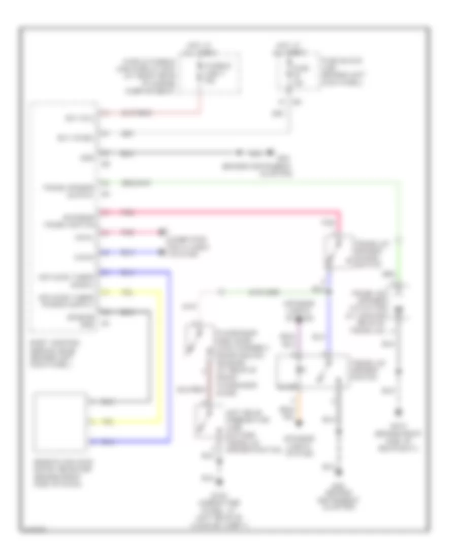
AIR CONDITIONING
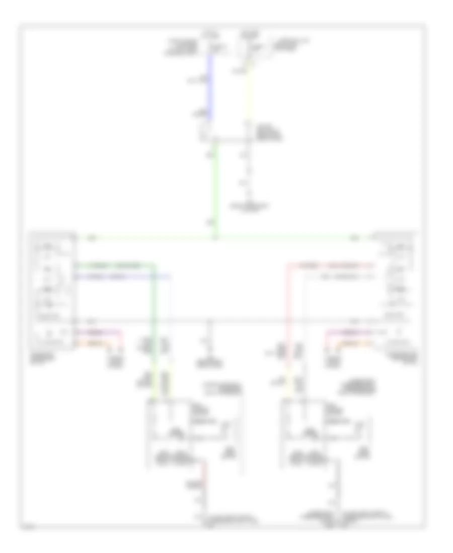
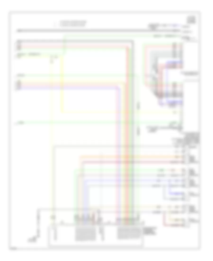
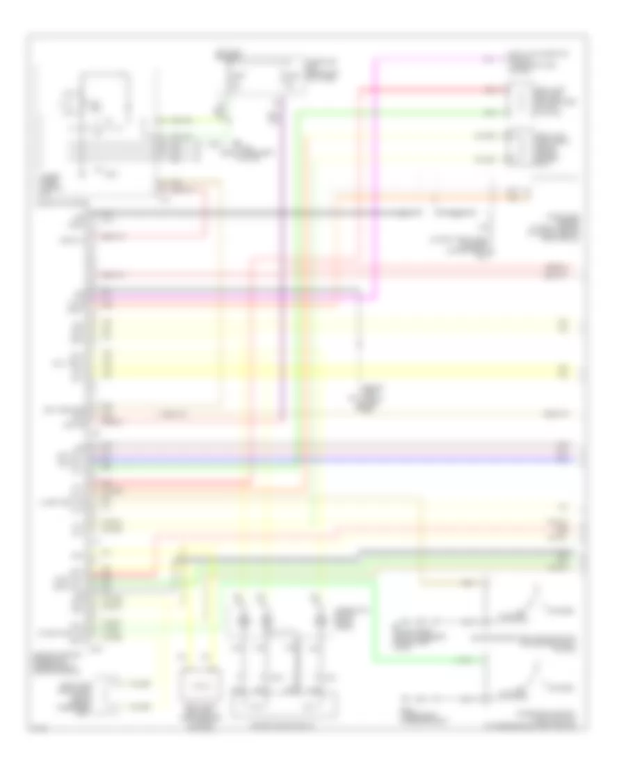
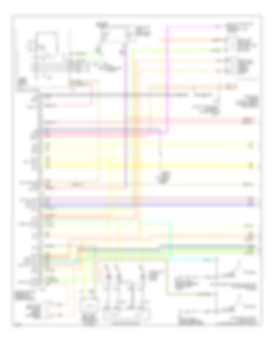
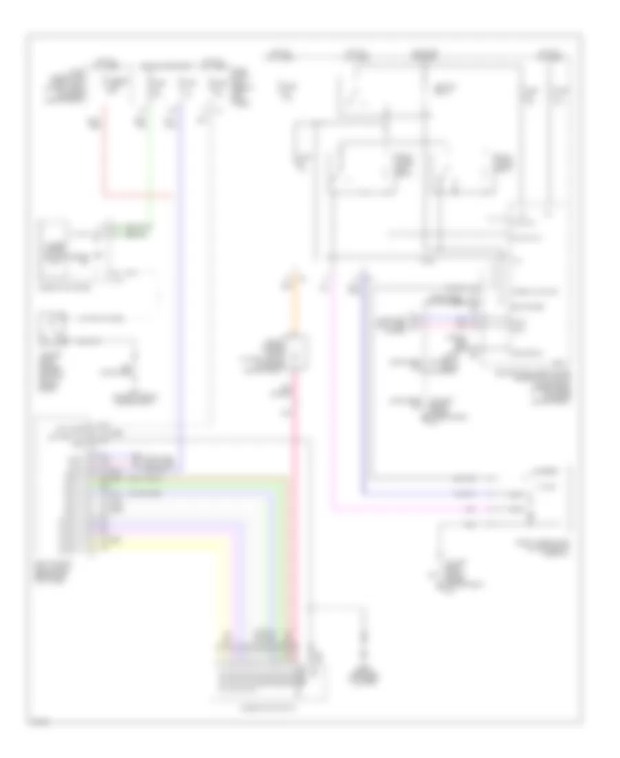
Automatic A/C Wiring Diagram (1 of 2) for Infiniti G35 2006

List of elements for Automatic A/C Wiring Diagram (1 of 2) for Infiniti G35 2006:
- (behind right side of dash) m66
- (canada)
- 12a
- A/c & audio controller
- Acc
- Air bag ind (+)
- Air bag ind (-)
- Air mix door motor (driver side)
- Air mix door motor (passenger side) (w/ left & right ventilation temperature separately control system)
- Amb sens
- Ambient sensor (near right front corner of vehicle)
- Bat
- Blower motor (behind right side of dash)
- Bus +
- Bus -
- Clk
- Clk (amp-sw)
- Combination meter
- Comp on
- Compass
- Compressor (at rear of engine)
- Defogger system
- Display & a/c auto amplifier (at top center of dash)
- E43 (on left front side of engine compt)
- Ecm comp
- Ecv
- F24
- F34
- Fan on
- Fan pwm
- Fuse 10a
- Fuse 15a
- Fuse block (j/b) (behind left kick panel)
- Gnd
- Hot at all times
- Hot in acc or on
- Hot in on or start
- Ign
- Ill (+)
- Ill (-)
- Ill cont
- In-vehicle sensor (behind left center of dash)
- Incar sens
- Intake door motor
- Intake sens
- Intake sensor
- Interior lights system
- Lan sig
- Light +
- Light -
- M19
- M30 (behind instrument cluster)
- M66 (behind right side of dash)
- Magnet clutch
- Mode door motor
- Red
- Rr def f/b
- Rr def on
- Rx (sw-amp)
- Sens gnd
- Speed sens
- Sun sens
- Sunload sensor (at top left side of dash)
- Tx (amp-sw)
- Unified meter control unit
- Vactr
- W/t sens
- °c/°f
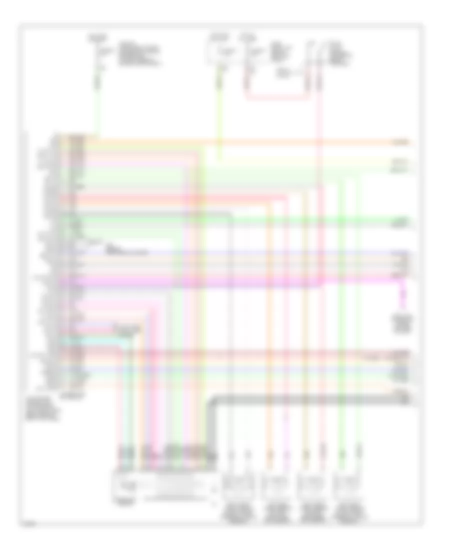
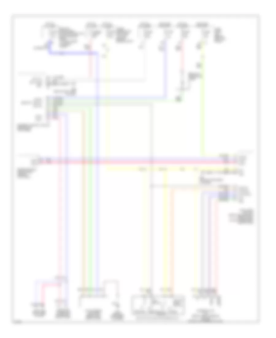
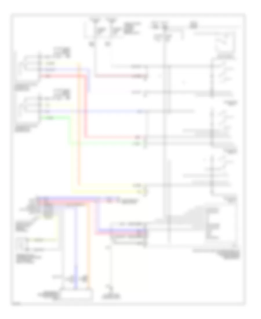
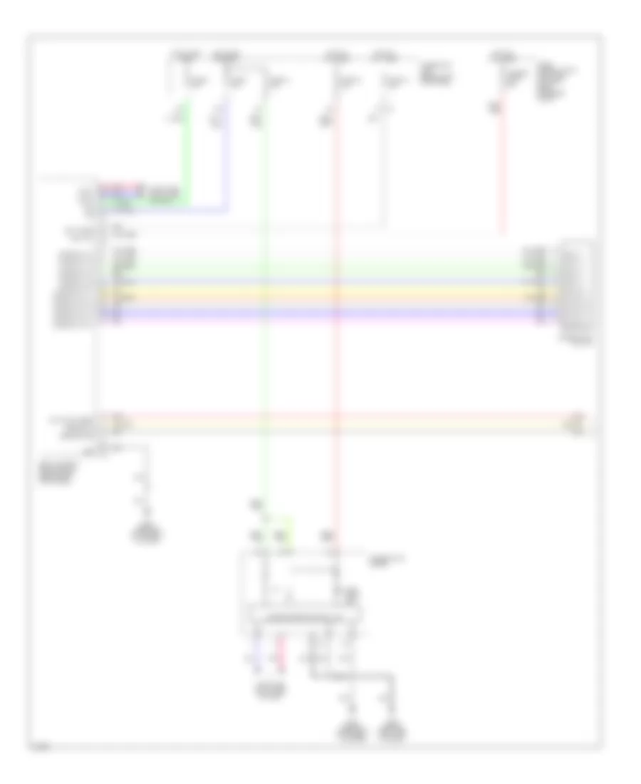
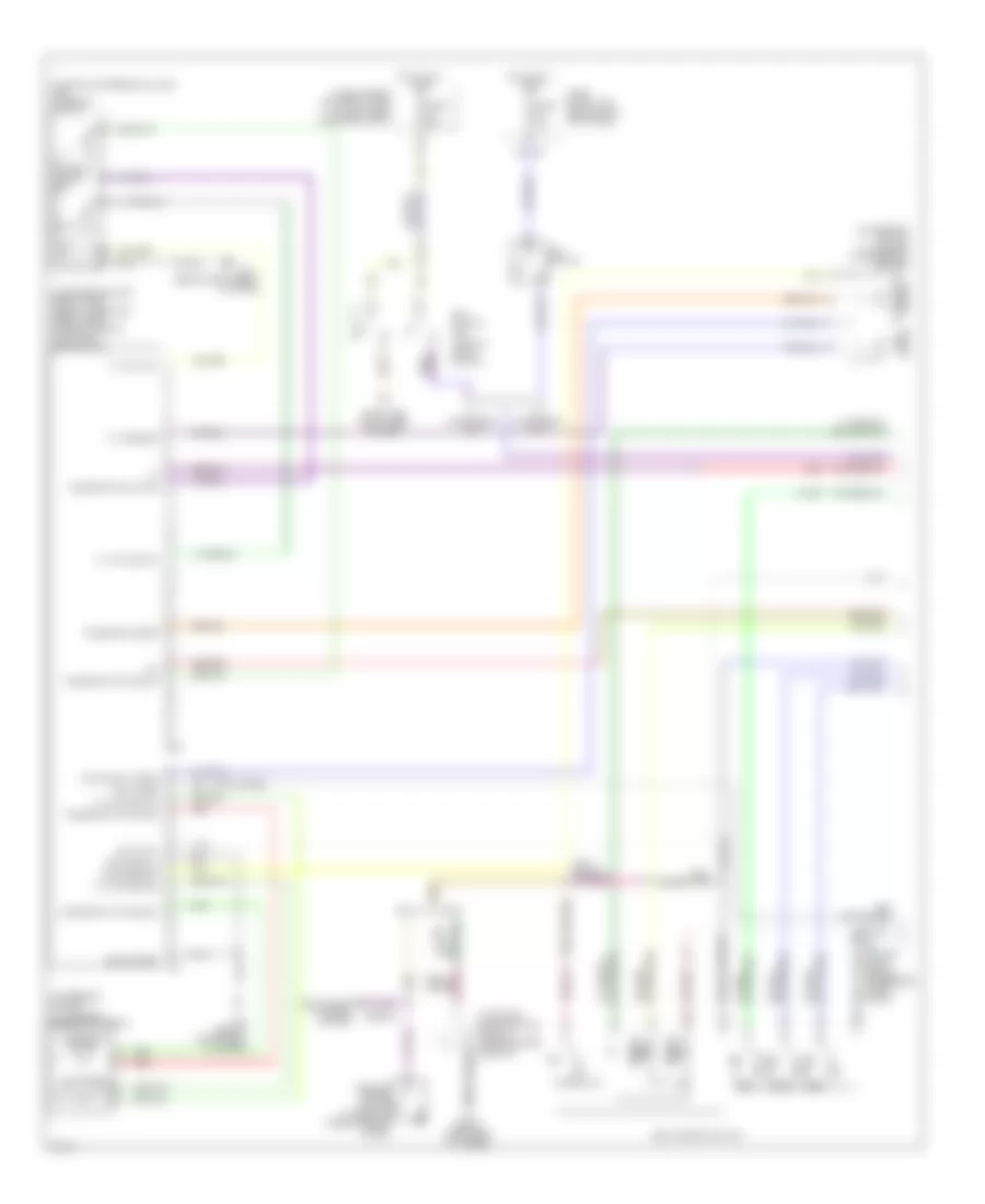
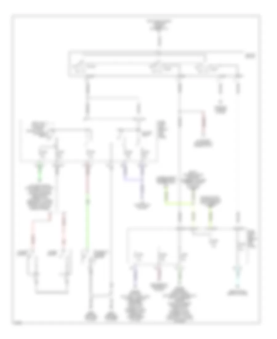
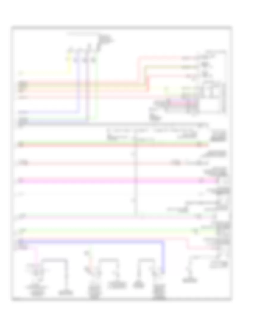
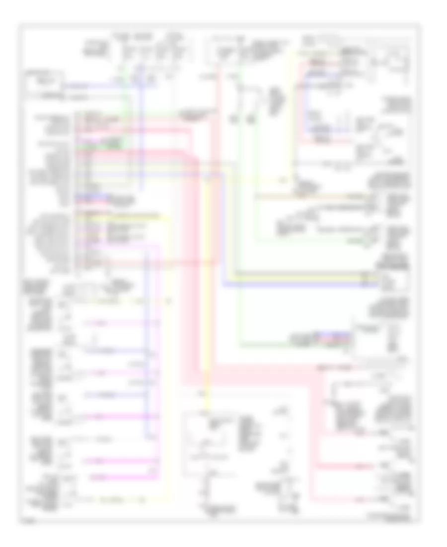
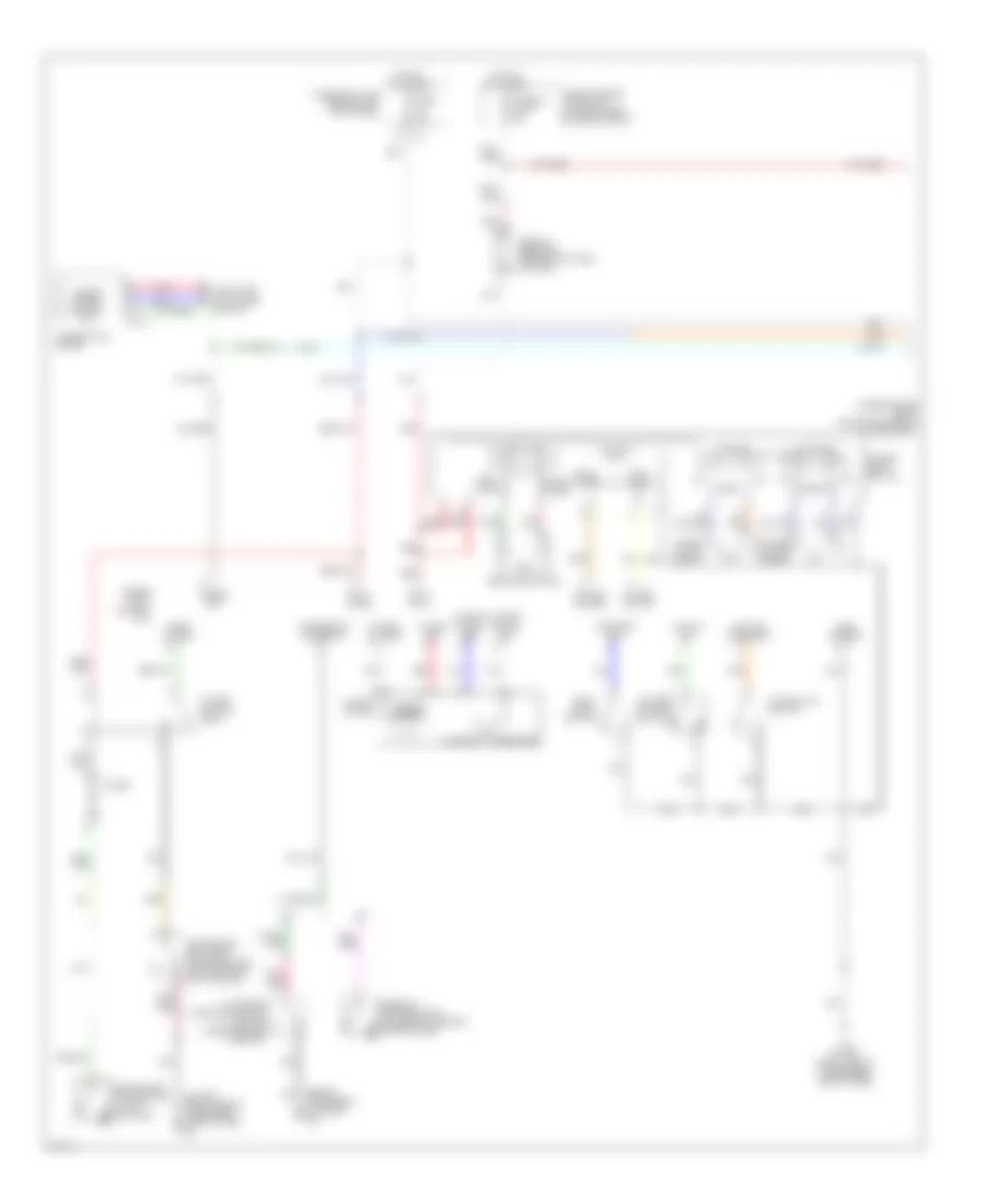
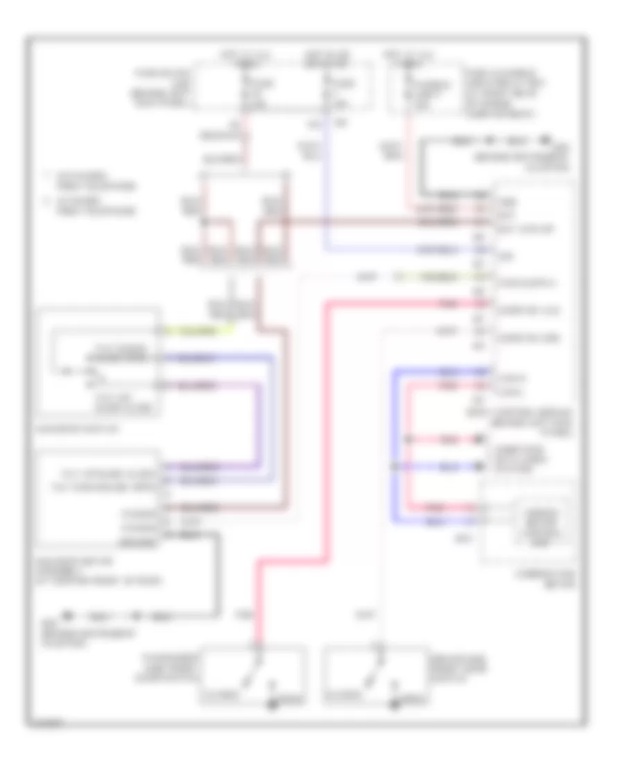
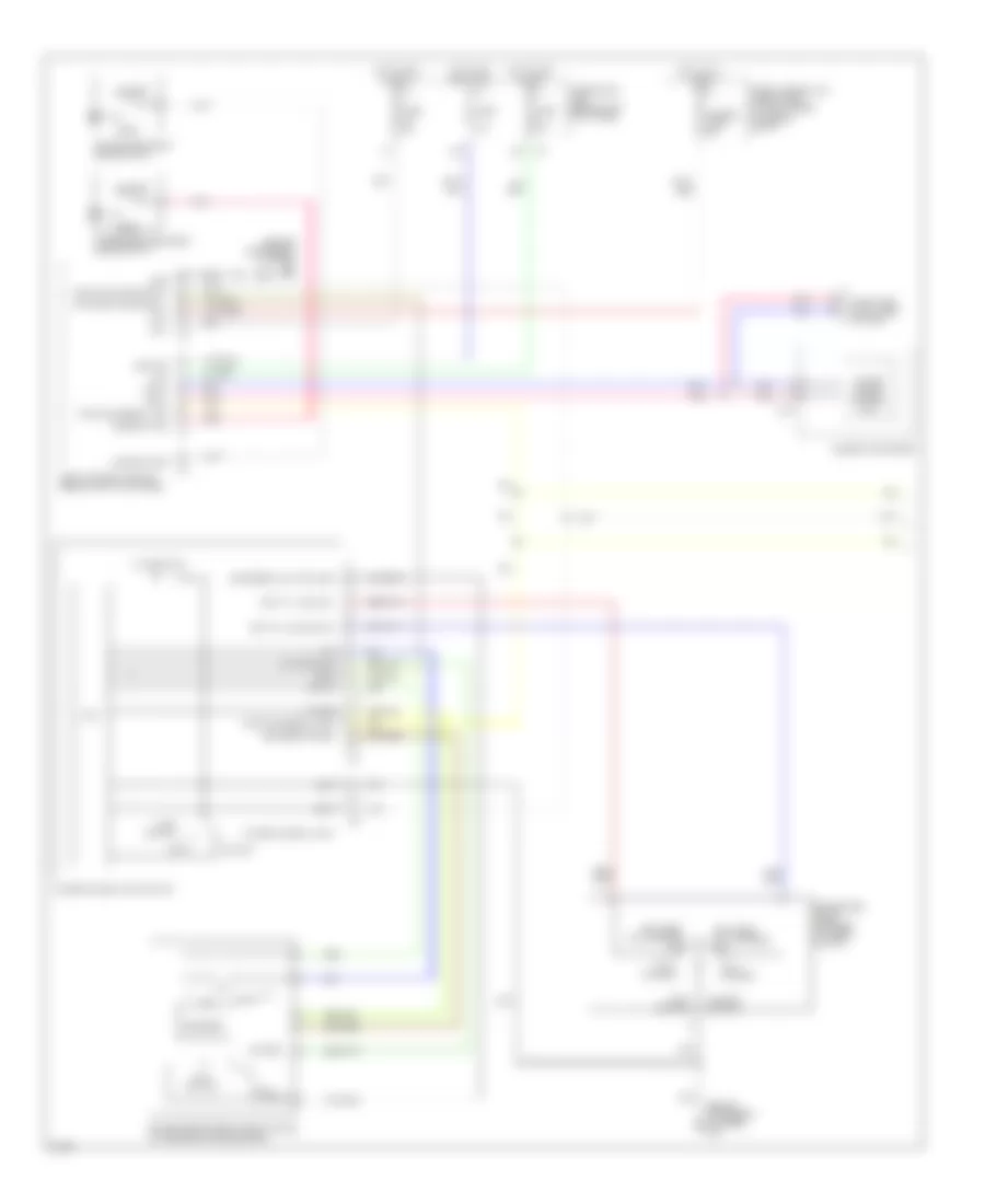
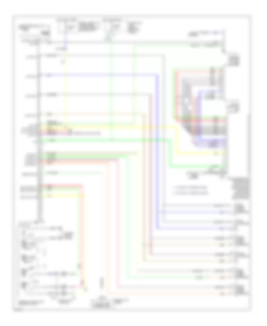
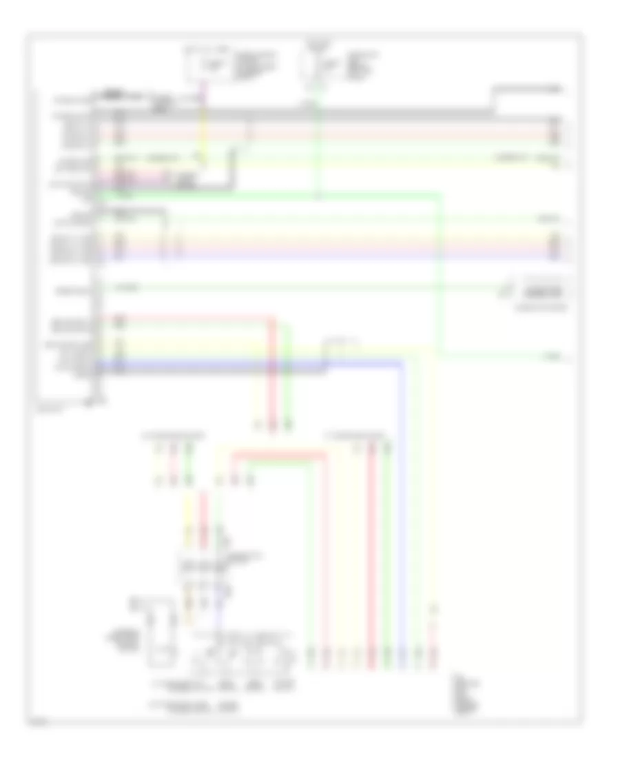
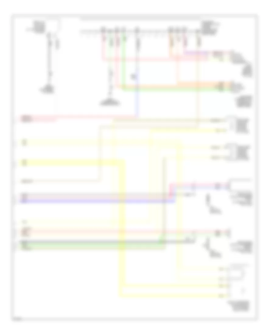
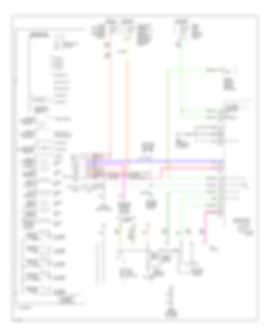
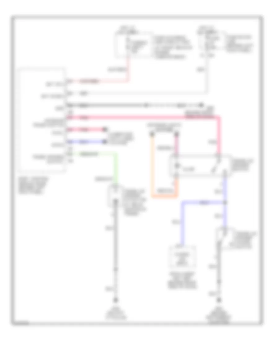
Automatic A/C Wiring Diagram (2 of 2) for Infiniti G35 2006
List of elements for Automatic A/C Wiring Diagram (2 of 2) for Infiniti G35 2006:
- (on left front side of engine compt) e43
- +ig
- A/c relay
- Air comp
- Avcc (pdpres)
- Body control module (bcm) (behind left kick panel)
- Can-h
- Can-l
- Comp on signal
- Computer data lines system
- Cooling fan motor 1 (at front of engine compt)
- Cooling fan motor 2 (at front of engine compt)
- Cooling fan relay 1
- Cooling fan relay 2
- Cooling fan relay 3
- Cpu
- E17 (on right side of engine compt)
- Engine control module (ecm) (behind glove box)
- Engine coolant temperature sensor (on top right rear of engine)
- Fan on signal
- Fuse & fusible link box (at right rear of engine compt)
- Fuse 10a
- Fuse 15a
- Fusible link h 40a
- Fusible link i 40a
- Gnd (power)
- Gnd (signal)
- Gnd-a
- Hot at all times
- Hot in on or start
- Ignition relay
- Ipdm e/r (intelligent power distribution module engine room) (at right rear of engine compt)
- Motor fan 1
- Motor fan 2
- Motor fan 3
- Pdpres
- Pnk
- Red
- Refrigerant pressure sensor (on a/c liquid tank)
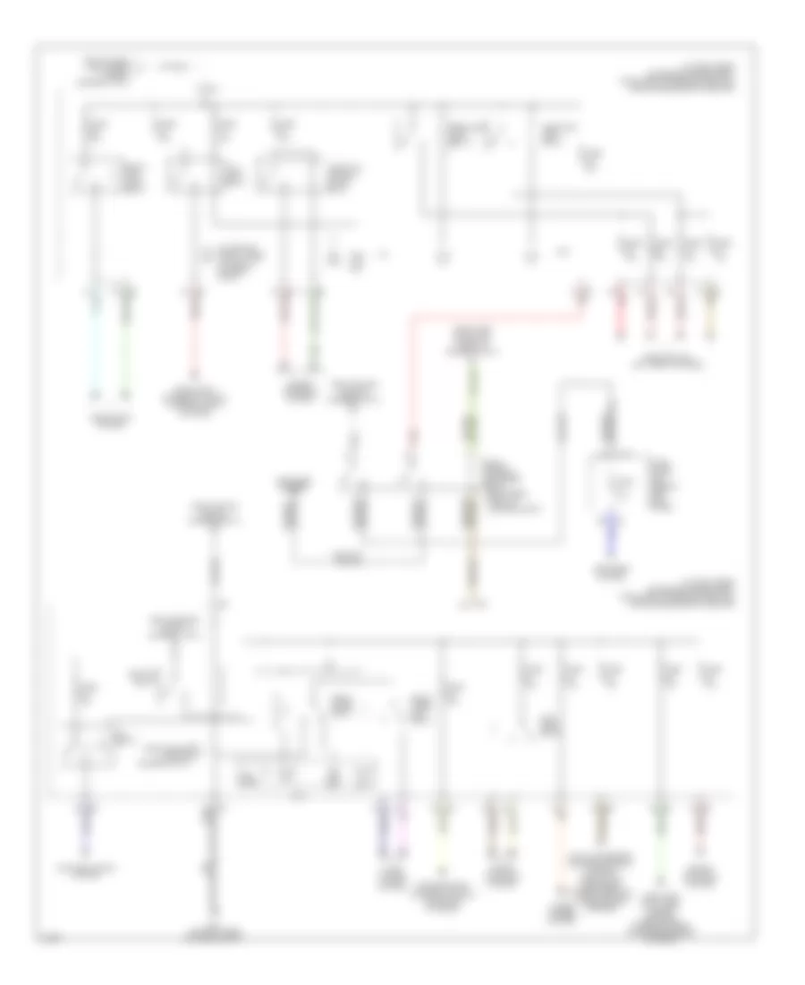
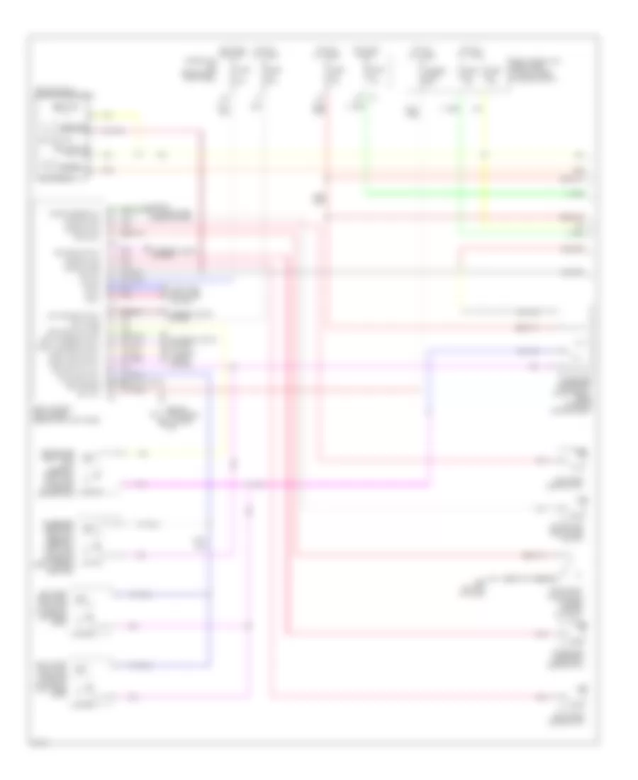
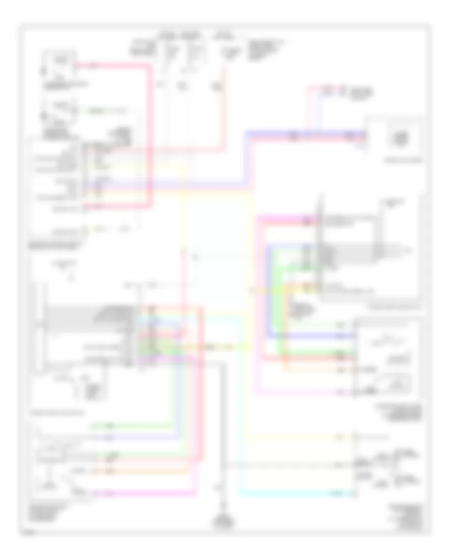
ANTI-LOCK BRAKES
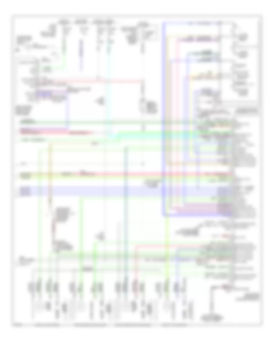
Anti-lock Brakes Wiring Diagram (1 of 2) for Infiniti G35 2006
List of elements for Anti-lock Brakes Wiring Diagram (1 of 2) for Infiniti G35 2006:
- (unused pins not shown)
- Abs w/l
- Bls
- Can-h
- Can-l
- Computer data lines system
- Coupe
- Data link connector (lower left side of dash)
- Diag-k
- Dp fl
- Dp fr
- Dp rl
- Dp rr
- Ds fl
- Ds fr
- Ds rl
- Ds rr
- E101
- Fl hsv
- Fl mv-av
- Fl mv-ev
- Fl usv
- Fr hsv
- Fr mv-av
- Fr mv-ev
- Fr usv
- Fuse 14 10a
- Fuse 20 10a
- Fuse 82 10a
- Fuse block (j/b) (behind left kick panel)
- Gnd
- Gnd1
- Gnd2
- Hot at all times
- Hot in on or start
- Ipdm e/r (intelligent power distribution module engine room) (at right rear of engine compartment)
- Left front wheel sensor (on left front steering knuckle assembly)
- Left rear wheel sensor (on left rear wheel hub assembly)
- Lis
- M30 (behind instrument cluster)
- Nca
- Pkb sw
- Pnk
- Pressure sensor
- Psm
- Pss
- Psu
- Right front wheel sensor (on right front steering knuckle assembly)
- Right rear wheel sensor (on right rear wheel hub assembly)
- Rl mv-av
- Rl mv-ev
- Rr mv-av
- Rr mv-ev
- Sedan
- Slip lamp
- Stop lamp switch (on brake pedal bracket)
- Vcc
- Vdc off lamp
- Vdc off sw
- Vdc/tcs/abs control unit (coupe: behind left side of dash) (sedan: behind right kick panel)
- Vout
- Yrsm
- Yrsref
- Yrss
- Yrst
- Yrsu
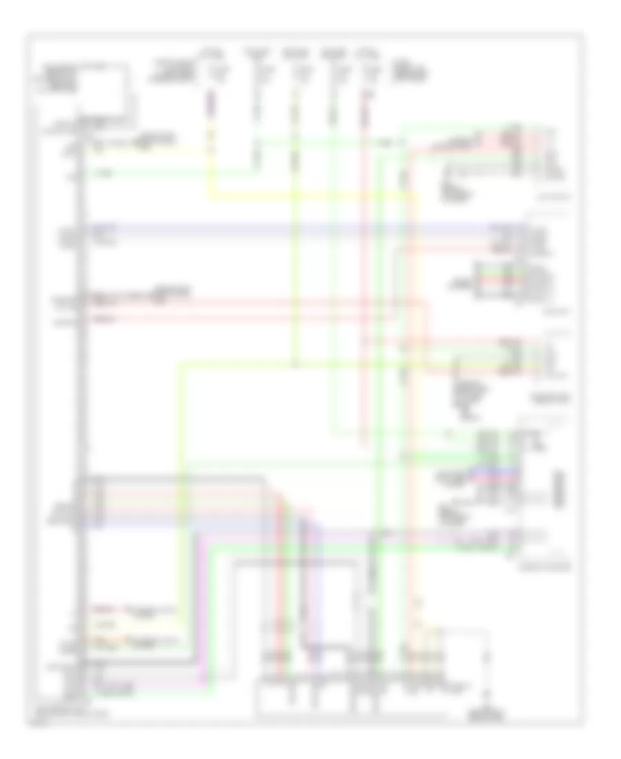
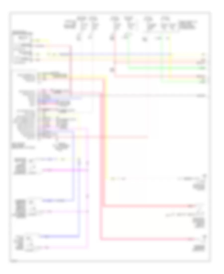
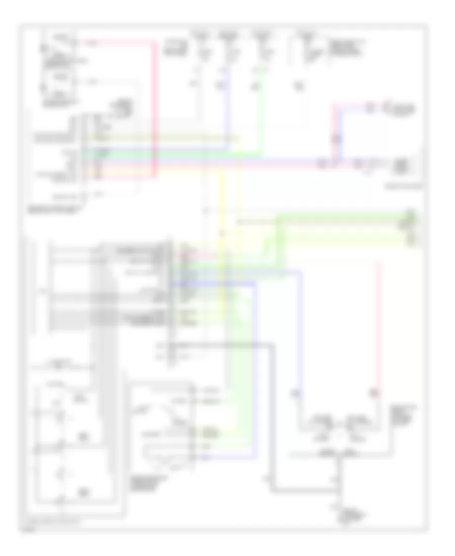
Anti-lock Brakes Wiring Diagram (2 of 2) for Infiniti G35 2006
List of elements for Anti-lock Brakes Wiring Diagram (2 of 2) for Infiniti G35 2006:
- (behind instrument cluster) m30
- 12v
- Abs ind
- Bite
- Brake fluid level switch (at left rear of engine compartment)
- Can-h
- Can-l
- Combination meter
- Computer data lines system
- E43 (on left front side of engine compartment)
- Fuse, fusible link & relay box (at right rear of engine compartment)
- Fusible link j 50a
- Fusible link k 30a
- Gnd
- Ground
- Hot at all times
- Ill
- Interior lights system
- M19
- M20
- M66 (behind right side of dash)
- Motor relay
- Nca
- Output bs
- Output drs
- Parking brake switch (m/t: at base of parking brake lever) (a/t: on parking brake pedal bracket)
- Pnk
- Reference
- Slip ind
- Solenoid valve relay
- Steering angle sensor (under left side of dash)
- Unified meter control unit
- Vdc off
- Vdc off switch
- Vdc relay box (at left rear of engine compartment)
- Yaw rate/ side g sensor (under center console, forward of shift selector lever)
ANTI-THEFT
Forced Entry Wiring Diagram (1 of 2) for Infiniti G35 2006
List of elements for Forced Entry Wiring Diagram (1 of 2) for Infiniti G35 2006:
- (behind instrument cluster)
- (coupe)
- (or red)
- (sedan)
- 12a
- 15a
- Acc
- B29 (coupe: behind right side of rear seat) (sedan: on left "c" pillar)
- B413
- Battery
- Between full stroke & n
- Body control module (bcm) (behind left kick panel)
- Can-h
- Can-l
- Closed
- Computer data lines system
- Coupe
- Cpu
- Door sw (as)
- Door sw (dr)
- Door sw (rr lh)
- Door sw (rr rh)
- Driver side door lock assembly (key cylinder switch) (at rear of driver door)
- Engine control module (ecm) (behind glove box)
- Full stroke
- Fuse 10a
- Fuse 15a
- Fuse block (j/b) (behind left kick panel)
- Fuse, fusible link & relay box (at right rear of engine compt)
- Fusible link f 50a
- Gnd
- Ground
- Hot at all times
- Hot in acc or on
- Hot in on or start
- Ignition
- Intelligent key unit (if equipped) (sedan: behind right side of dash) (coupe: under right side of dash)
- Key cyl lock sw
- Key cyl unlock sw
- Keyless tuner power sig
- Keyless tuner sig
- Lock
- M30
- M30 (behind instrument cluster)
- M66 (behind right side of dash)
- Open
- Pnk
- Power wdo serial link
- Power window main switch (door lock & unlock switch)
- Power window sub-switch (front passenger side) (door lock & unlock switch)
- Pwr wdo serial link
- Pwr window serial link
- Remote keyless entry receiver (w/o intelligent key) (behind right side of dash)
- Sedan
- Sensor ground
- Trunk room lamp switch (coupe: at center rear of trunk lid) (sedan: at rear center of trunk)
- Trunk switch
- Unlock
Forced Entry Wiring Diagram (2 of 2) for Infiniti G35 2006
List of elements for Forced Entry Wiring Diagram (2 of 2) for Infiniti G35 2006:
- (on right side of engine compartment)
- Can-h
- Can-l
- Closed
- Computer data lines system
- Cpu
- Driver side front door switch
- E17
- E32
- E33
- E35
- E36
- E43 (on left front side of engine compt)
- Fuse 10a
- Fuse 15a
- Gnd (power)
- Gnd (signal)
- Headlamp high
- Headlamp high relay
- Headlamp low
- Headlamp low relay
- Headlights system
- Hood sw
- Hood switch (at left front corner of engine compartment)
- Horn (high) (right front of engine compt, behind grille)
- Horn (low) (right front of engine compt, behind grille)
- Horn relay (in fuse, fusible link & relay box)
- Horn rly
- Hot at all times
- Hot in on or start
- Ig+
- Ipdm e/r (intelligent power distribution module engine room) (at right rear of engine compartment)
- Left rear door switch (sedan)
- Open
- Passenger side front door switch
- Pnk
- Red
- Right rear door switch (sedan)
Immobilizer Wiring Diagram (NATS), with Intelligent Key Unit for Infiniti G35 2006
List of elements for Immobilizer Wiring Diagram (NATS), with Intelligent Key Unit for Infiniti G35 2006:
- (behind instrument cluster)
- +12
- 15a
- 2a m4
- 5v output
- Bat
- Bat (f/l)
- Bat (fuse)
- Bcm(body control module) (behind left kick panel)
- Can-h
- Can-l
- Computer data lines system
- Data link connector (lower left side of dash)
- Drawn
- Earth
- Engine control module (ecm) (behind glove box)
- Fuse & fusible link relay box (at right rear of engine compt)
- Fuse 10a
- Fuse 15a
- Fuse block (j/b) (behind left kick panel)
- Fusible link f 50a
- Gnd
- Gnd
- Hot at all times
- Hot in on or start
- Ign sw
- Ignition knob switch
- Inserted removed
- Intelligent key unit (sedan: behind right side of dash) (coupe: under right side of dash)
- Ipdm e/r (intelligent power distribution module engine room) (at right rear of engine compt)
- Key sw
- Key switch
- Key switch & ignition knob switch
- M30
- M30 (behind instrument cluster)
- M66 (behind right side of dash)
- Nats antenna amplifier (behind left side of dash)
- Pnk
- Push sw
- Security ind out
- Security indicator lamp
- Sig
- Signal
- Steering lock unit (sedan: near steering column) (coupe: on steering column)
- With- pushed
Immobilizer Wiring Diagram (NATS), without Intelligent Key Unit for Infiniti G35 2006
List of elements for Immobilizer Wiring Diagram (NATS), without Intelligent Key Unit for Infiniti G35 2006:
- 15a
- 8a m4
- Bat (f/l)
- Bat (fuse)
- Bcm(body control module) (behind left kick panel)
- Can-h
- Can-l
- Computer data lines system
- Data link connector (lower left side of dash)
- Ecm module (ecm) (behind right kick panel)
- Fuse & fusible link relay box (at right rear of engine compt)
- Fuse 10a
- Fuse 15a
- Fuse block (j/b) (behind left kick panel)
- Fusible link f 50a
- Gnd
- Hot at all times
- Hot in on or start
- Ign sw
- Ipdm e/r (intelligent power distribution module engine room) (at right rear of engine compt)
- M30 (behind instrument cluster)
- M66 (behind right side of dash)
- Nats antenna amplifier (behind left side of dash)
- Pnk
- Security ind out
- Security indicator lamp
BODY CONTROL MODULES
Body Control Modules Wiring Diagram for Infiniti G35 2006
List of elements for Body Control Modules Wiring Diagram for Infiniti G35 2006:
- (comp on sig)
- (fan on sig)
- (sedan)
- 12a
- 15a
- Acc
- Air conditioning system
- Aircon sw
- Anti-theft system
- Anti-theft, door locks & interior lights systems
- Anti-theft, door locks & power windows systems
- Auto light sens in
- Auto light sens pwr
- Bat
- Bat (f/l)
- Bat (fuse)
- Bat saver output
- Blower fan sw
- Body control module (bcm) (behind left kick panel)
- Can-h
- Can-l
- Combi sw input 1
- Combi sw input 2
- Combi sw input 3
- Combi sw input 4
- Combi sw input 5
- Combi sw output 1
- Combi sw output 2
- Combi sw output 3
- Combi sw output 4
- Combi sw output 5
- Computer data lines system
- Coupe
- Defogger system
- Door lock output (all)
- Door locks system
- Door locks, anti-theft, warning & headlights systems
- Door sw (as)
- Door sw (dr)
- Door sw (rr lh)
- Door sw (rr rh)
- Door unlock output
- Door unlock output (dr)
- Exterior lights system
- Exterior lights systems
- Fuse 10a
- Fuse 15a
- Fuse block (j/b) (behind left kick panel)
- Fuse, fusible link & relay box (at right rear of engine compt)
- Fusible link f 50a
- Gnd
- Hazard sw
- Headlights system
- Headlights, anti-theft & door locks systems
- Hot at all times
- Hot in acc or on
- Hot in on or start
- Ign
- Interior lights system
- Interior lights, headlights, exterior lights & warning systems
- Interior trunk sw
- Key ring ill
- Key sw
- Key switch
- Key switch & ignition knob switch
- Keyless tuner pwr
- Keyless tuner sig
- Lh flasher output
- M30 (behind instrument cluster)
- Nats antenna amp
- P/warn check tpms mode trigger sw
- Pnk
- Power tops & power windows systems
- Power tops, power windows & seats systems
- Pwr window serial
- Rap
- Red
- Rh flasher output
- Room lamp output
- Rr def sw
- Security ind output
- Sedan
- Sens gnd
- Step lamp output
- Trunk lamp output
- Trunk opener output
- Trunk sw
- Trunk, tailgate, fuel doors system
- W/ intelligent key
- W/o intelligent key
- Warning system
- Warning, interior lights, headlights & exterior lights systems
COMPUTER DATA LINES
Computer Data Lines Wiring Diagram for Infiniti G35 2006
List of elements for Computer Data Lines Wiring Diagram for Infiniti G35 2006:
- (or red)
- A/t assembly (if equipped) (sedan: at rear of engine compt)
- Air bag diagnosis sensor unit (under rear of center console)
- Audio unit
- Awd control unit (sedan: awd models) (behind right kick panel)
- Body control module (bcm) (behind left kick panel)
- Bus +
- Bus -
- Bus shield
- Bus+
- Can-h
- Can-l
- Combination meter
- Compass
- Coupe
- Coupe, sedan m/t
- Cpu
- D55
- D75
- Data link connector (lower left side of dash)
- Diag-k
- Display & a/c auto amplifier (at top center of dash)
- Display unit (w/ navigation)
- Driver seat control unit
- Driver side front power seat (w/ automatic drive positioner) (under driver seat)
- Engine control module (ecm) (behind glove box)
- F502
- Fuse 19 10a
- Fuse 34 15a
- Fuse 89 10a
- Fuse block (j/b) (behind left kick panel)
- Fuse, fusible link & relay box (at right rear of engine compt)
- Hot at all times
- Hot in on or start
- If equipped
- Intelligent key unit (if equipped) (sedan: behind right side of dash) (coupe: under right side of dash)
- Ipdm e/r (intelligent power distribution module engine room) (at right rear of engine compartment)
- K-line
- Left rear power window (sub-switch)
- M19
- M20
- M30 (behind instrument cluster)
- M39
- M55
- M58
- M66 (behind right side of dash)
- Navi control unit (w/ navigation) (behind right side of dash)
- Navi switch (w/ navigation)
- Nca
- Pnk
- Power window main switch (door lock & unlock switch)
- Power window sub-switch (front passenger side) (door lock & unlock switch)
- Pwr lk
- Pwr wdo serial link
- Ras control unit (coupe) (left rear of luggage compt)
- Red
- Right rear power window (sub-switch)
- Sedan
- Sedan a/t
- Shield
- Speed sens
- Speed signal
- Steering angle sensor (under left side of dash)
- Tcm
- Unified meter control unit
- Vdc/tcs/abs control unit (sedan: behind right kick panel) (coupe: behind left side of dash)
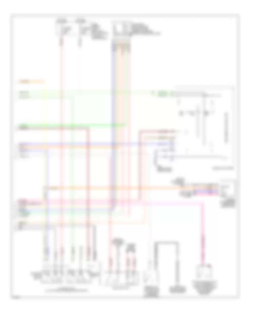
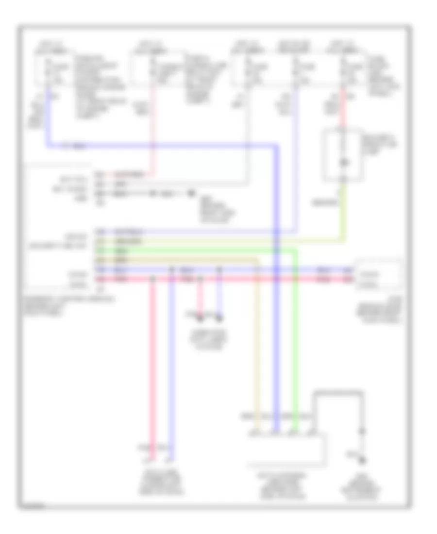
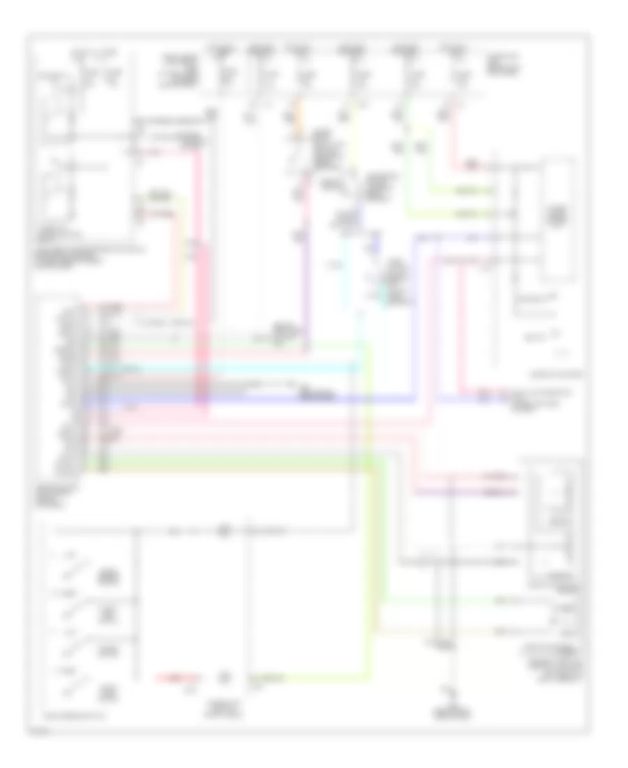
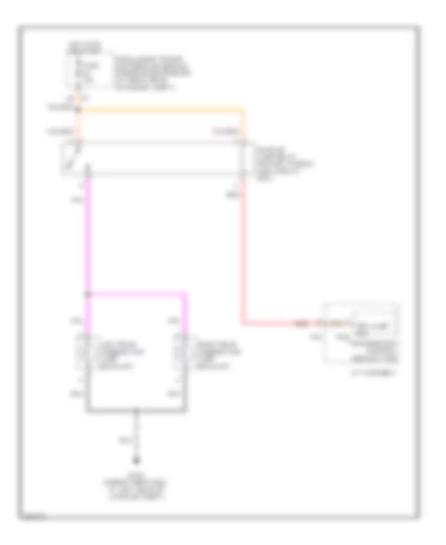
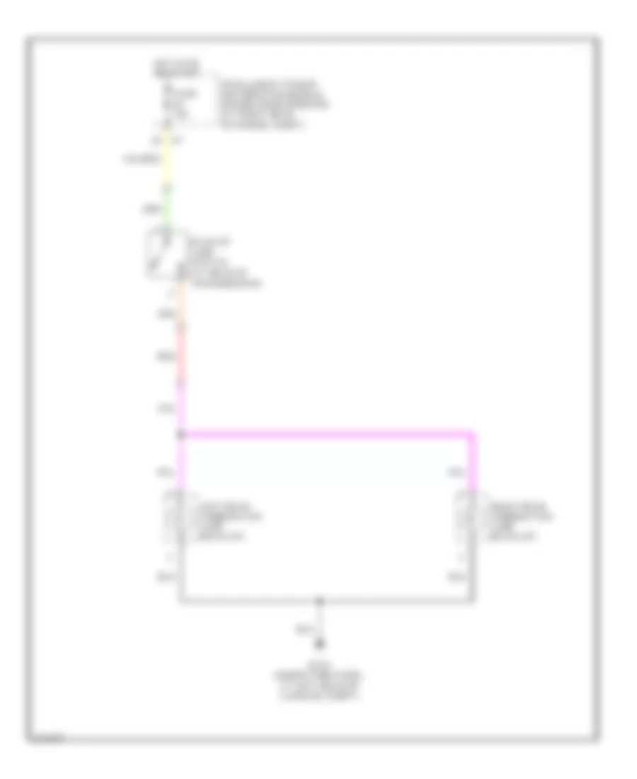
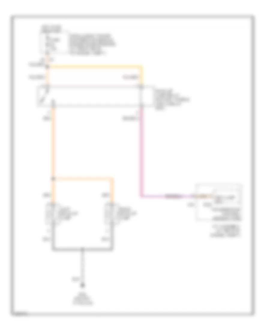
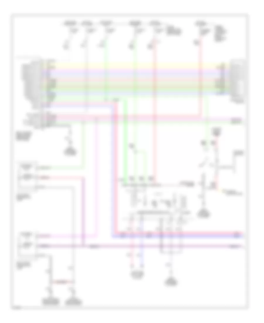
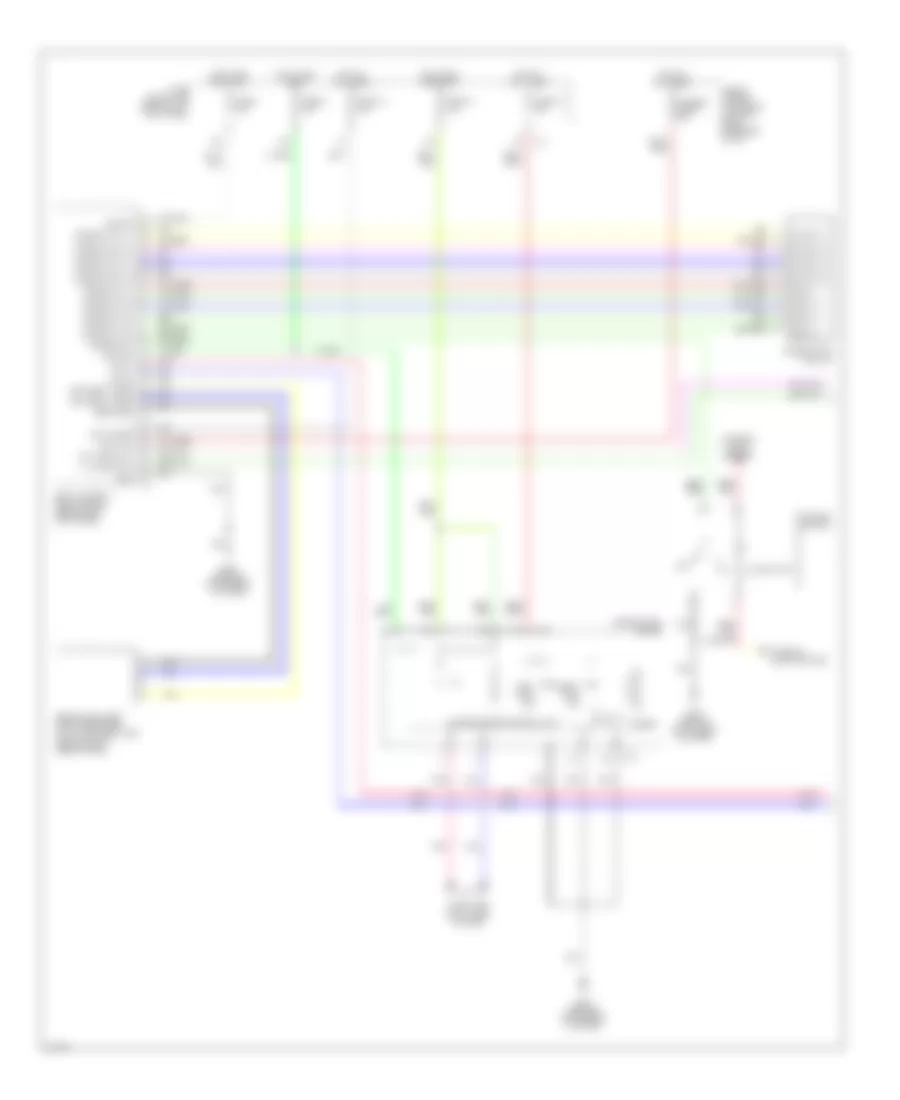
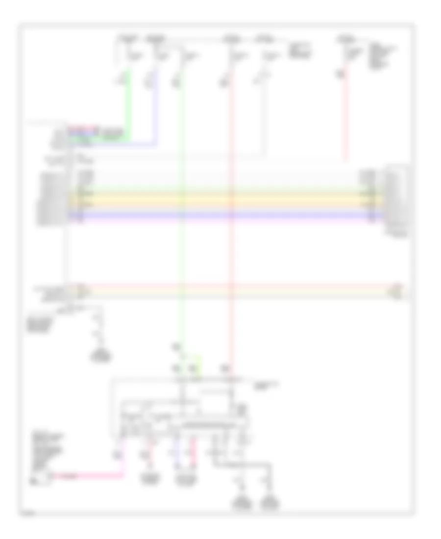
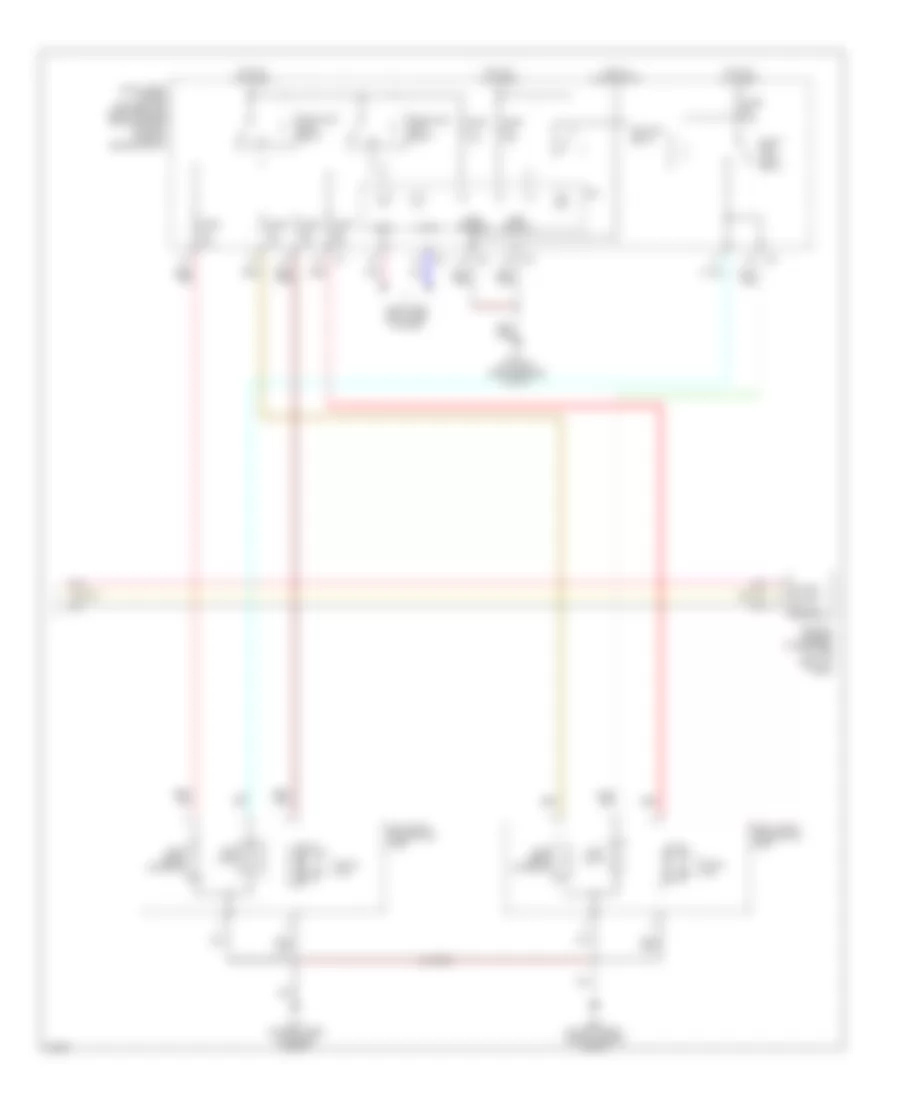
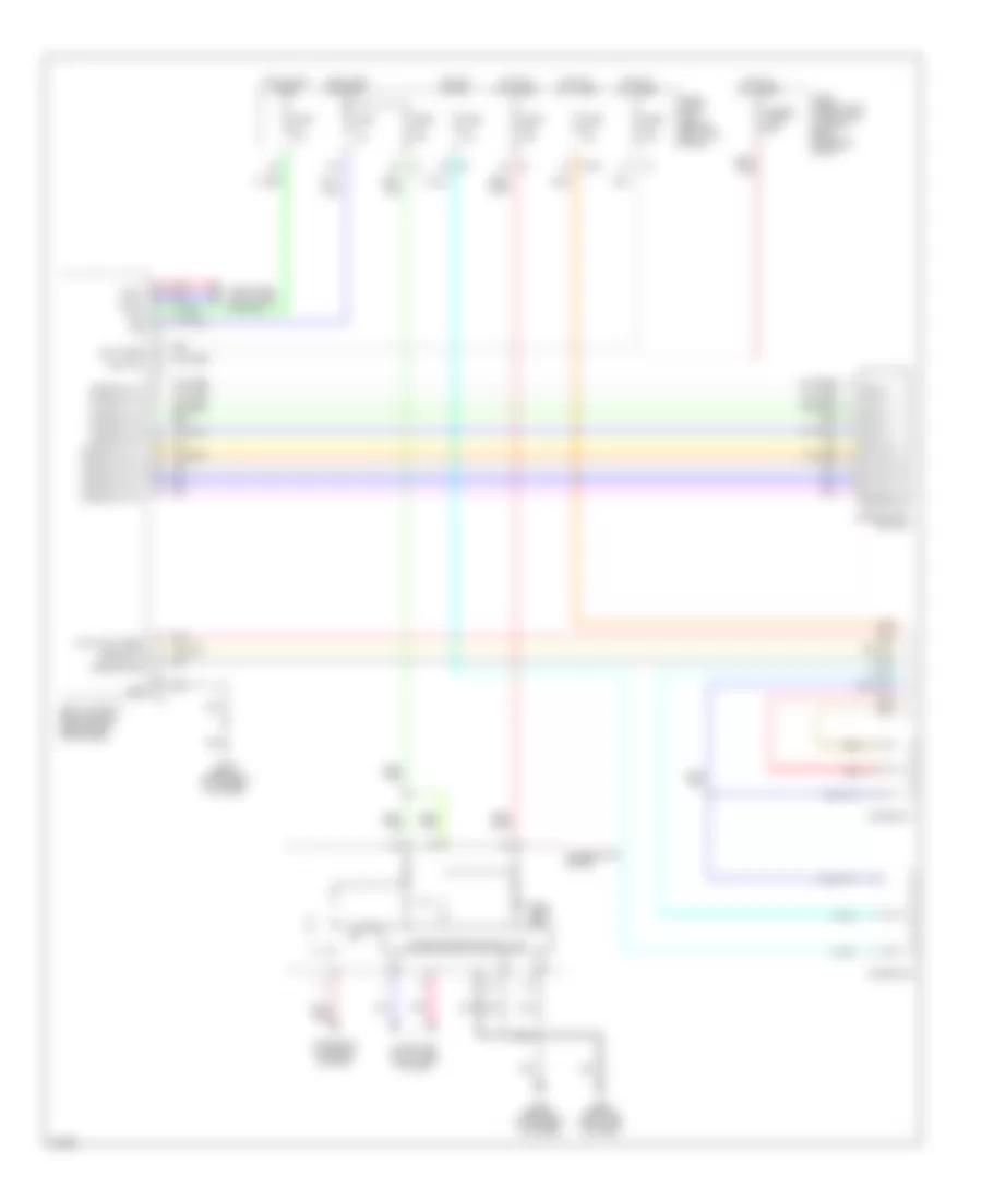
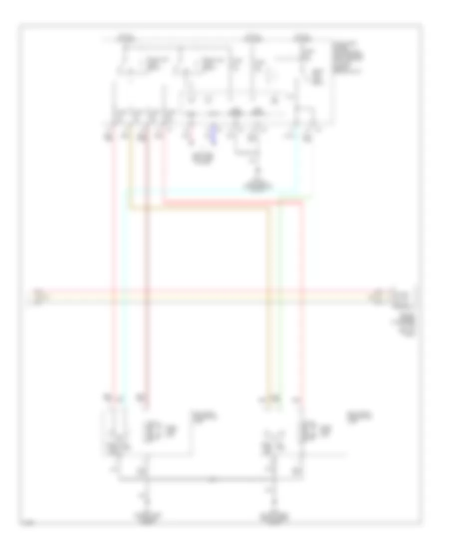
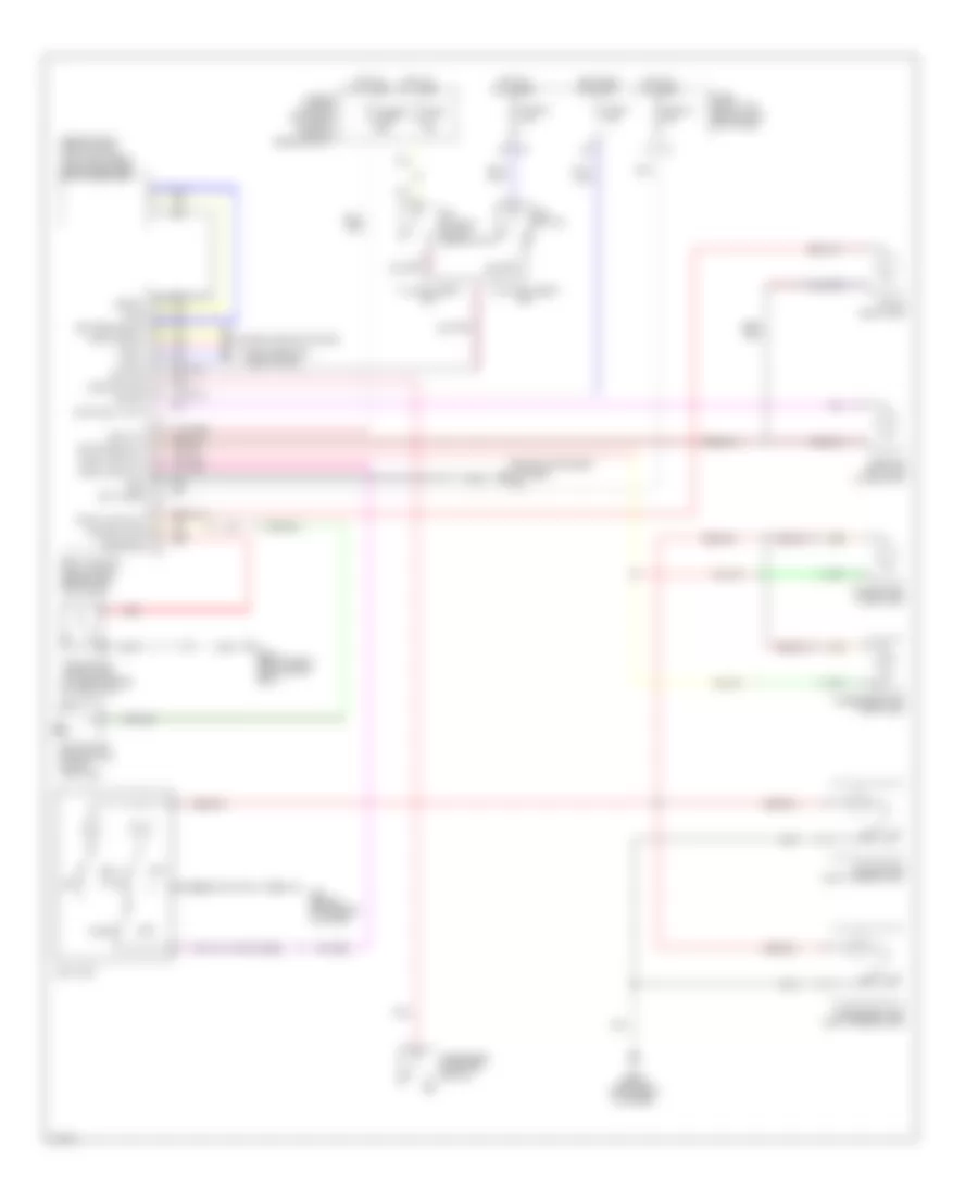
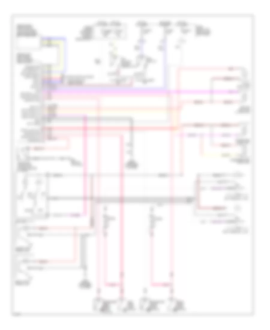
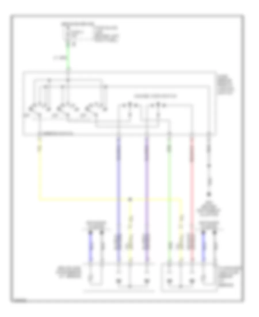
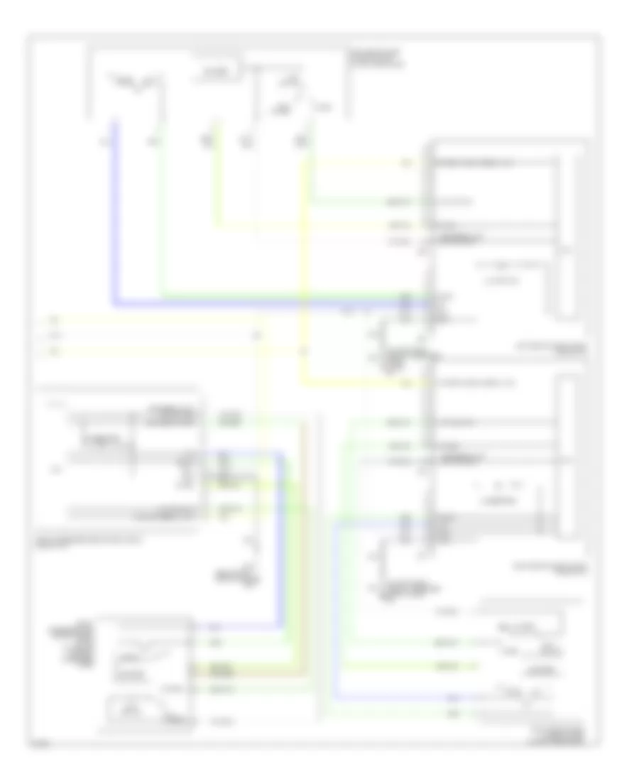
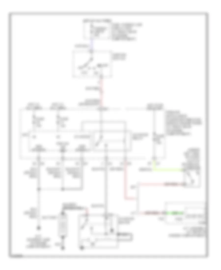
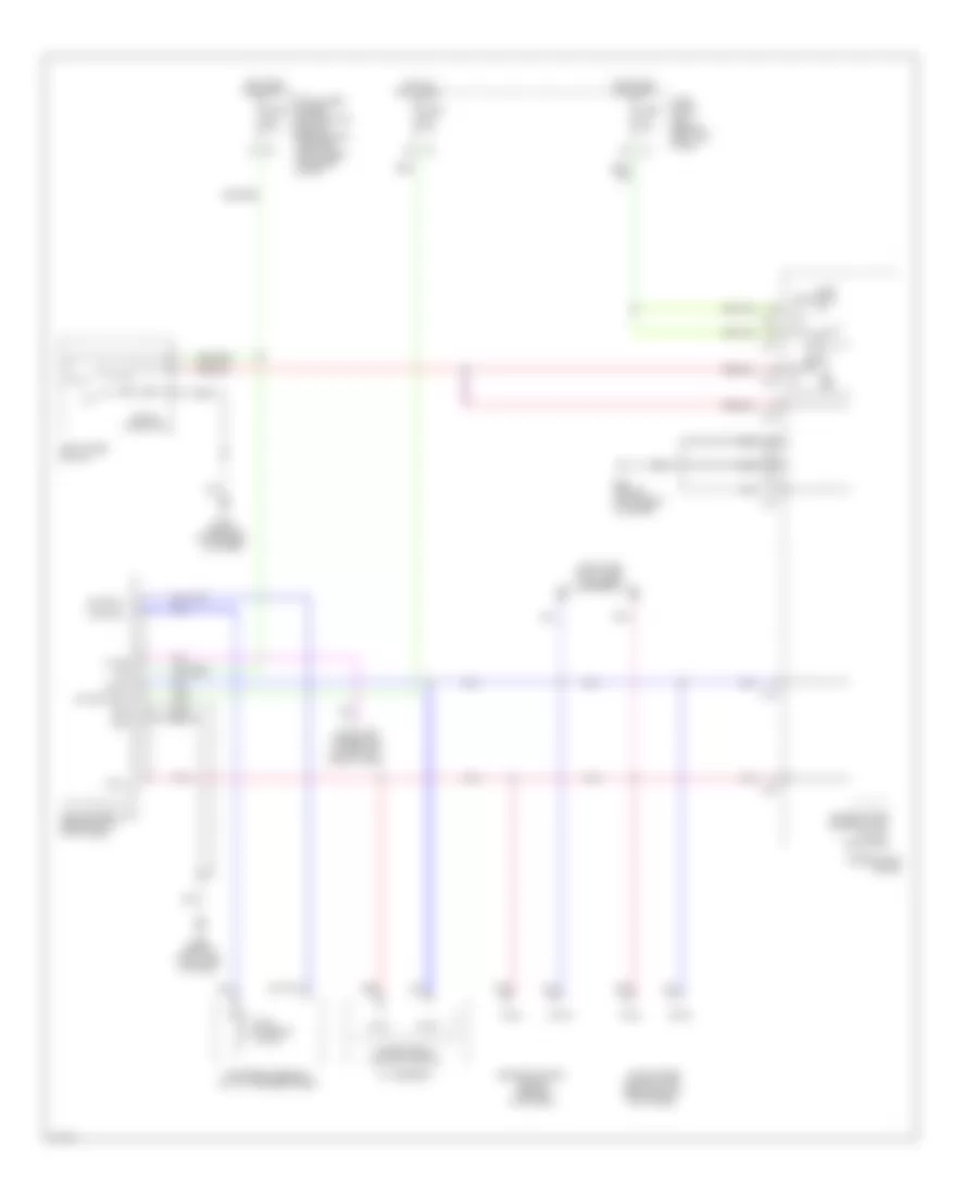
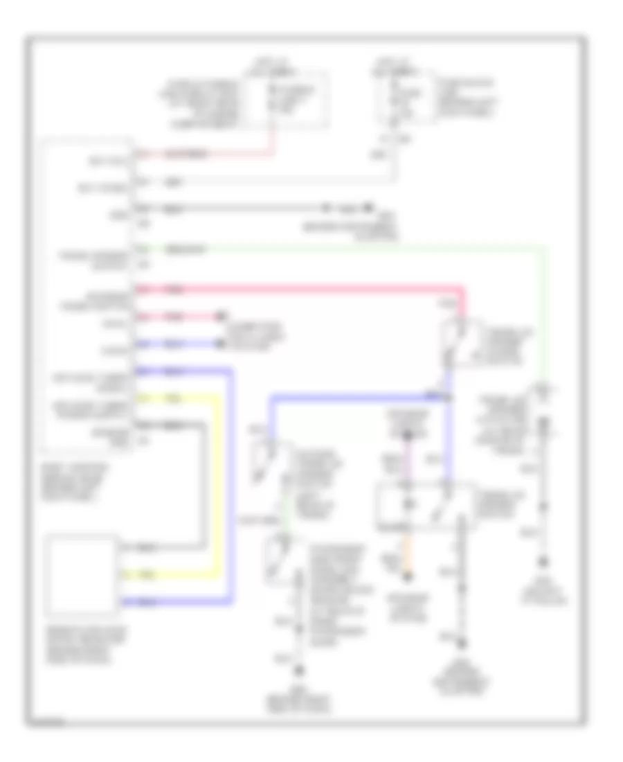
COOLING FAN
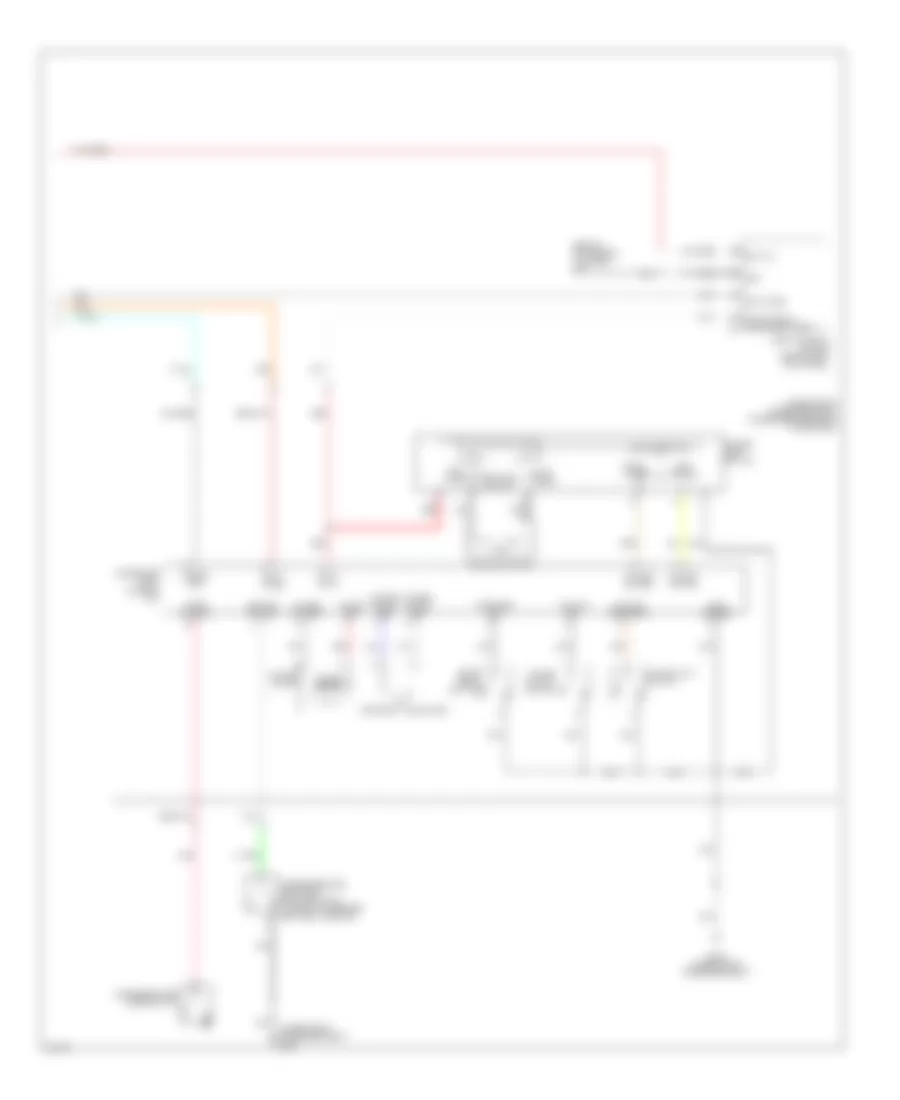
Cooling Fan Wiring Diagram for Infiniti G35 2006
List of elements for Cooling Fan Wiring Diagram for Infiniti G35 2006:
- (on left front side of engine compt) e43
- +ig
- Avcc (pdpres)
- Can-h
- Can-l
- Computer data lines system
- Cooling fan motor 1 (at front of engine compt)
- Cooling fan motor 2 (at front of engine compt)
- Cooling fan relay 1
- Cooling fan relay 2
- Cooling fan relay 3
- Cpu
- E17 (on right side of engine compt)
- Engine control module (ecm) (behind glove box)
- Engine coolant temperature sensor (on top right rear of engine)
- Fuse & fusible link box (at right rear of engine compt)
- Fuse 10a
- Fuse 15a
- Fusible link h 40a
- Fusible link i 40a
- Gnd (power)
- Gnd (signal)
- Gnd-a
- Hot at all times
- Hot in on or start
- Ignition relay
- Ipdm e/r (intelligent power distribution module engine room) (at right rear of engine compt)
- Motor fan 1
- Motor fan 2
- Motor fan 3
- Pdpres
- Pnk
- Red
- Refrigerant pressure sensor (on a/c liquid tank)
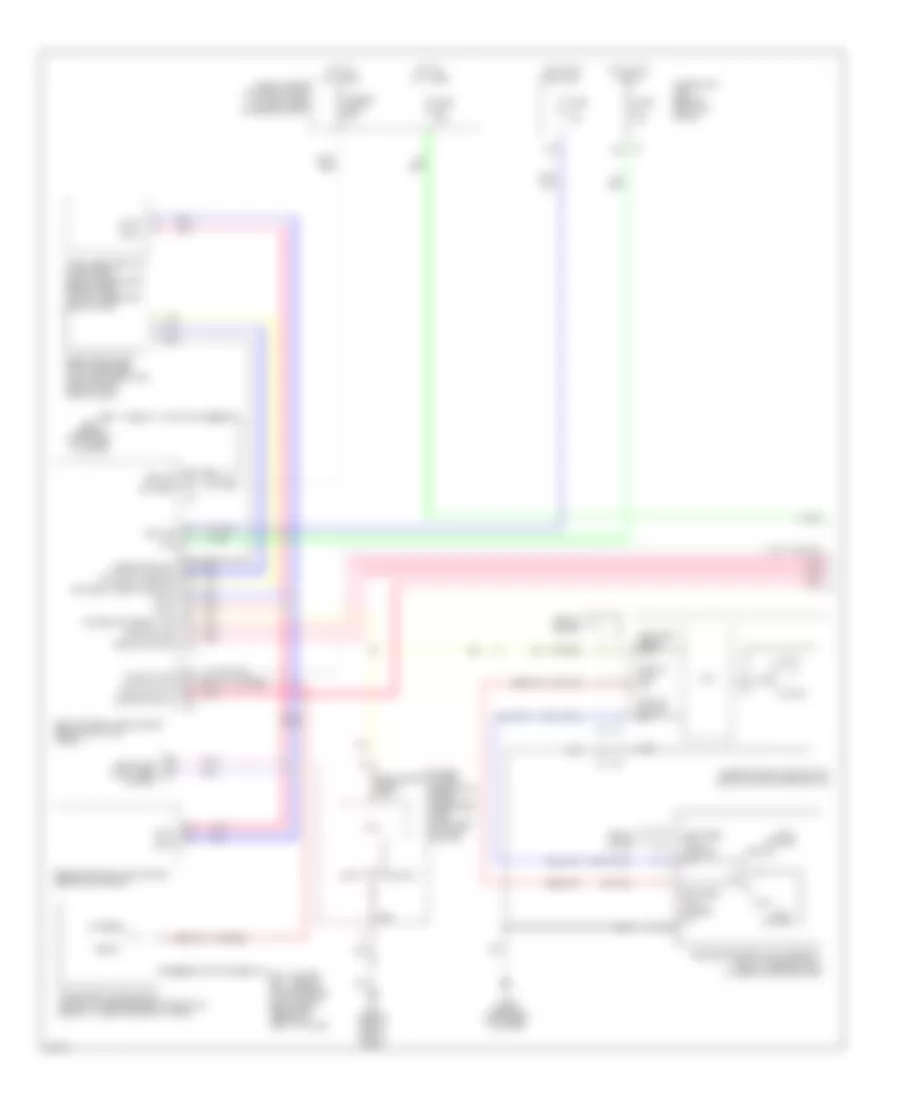
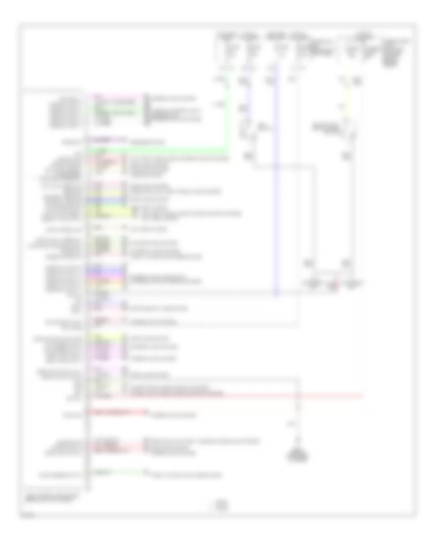
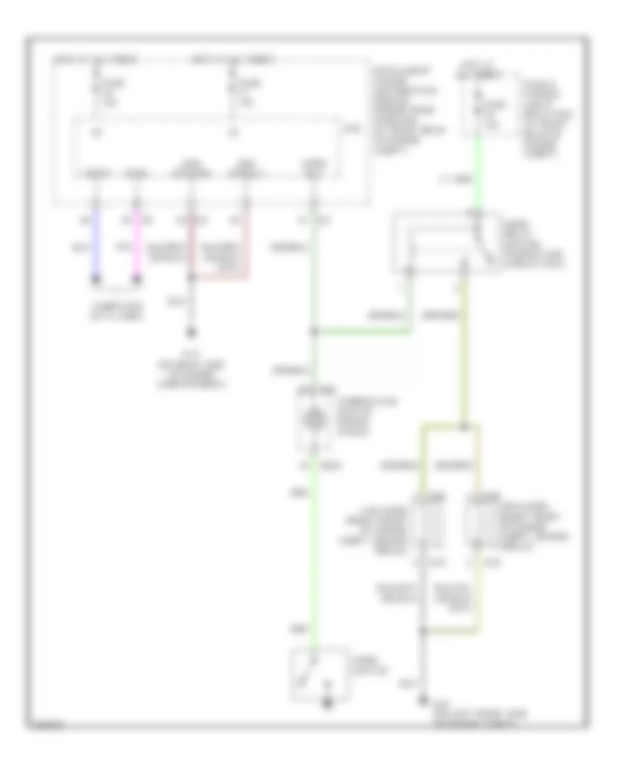
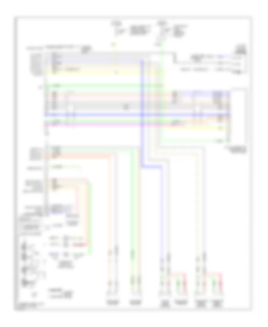
CRUISE CONTROL
Cruise Control Wiring Diagram for Infiniti G35 2006
List of elements for Cruise Control Wiring Diagram for Infiniti G35 2006:
- (behind right side of dash) m66
- 15a
- A/t
- Accel/ resume switch
- Ascd brake switch (on brake pedal bracket)
- Ascd clutch switch (sedan: (on clutch pedal bracket)
- Ascd steering switch
- Ascdsw
- Avcc 2
- Batt
- Bncsw
- Brake
- Can-h
- Can-l
- Cancel switch
- Close
- Coast/ set switch
- Combination meter
- Combination switch (spiral cable)
- Coupe sedan
- Cruise ind
- Data link connector (dlc) (lower left side of dash)
- E101
- Ecm relay
- Electric throttle control actuator (on throttle body assembly)
- Engine control module (ecm) (behind glove box)
- Engine controls system
- Fuse 10a
- Fuse 15a
- Fuse block (j/b) (behind left kick panel)
- Fuse, fusible link & relay box (at right rear of engine compartment)
- Gnd
- Gnd-a
- Gnd-a2
- Hot at all times
- Hot in on or start
- Ign sw
- Intelligent power distribution module engine room (ipdm e/r) (at right rear of engine compartment)
- M/t
- M19
- M203
- M23
- M66 (behind right side of dash)
- Motor
- Motor 1
- Motor 2
- Motrly
- Nca
- Off
- On/off (main) switch
- Open
- Pnk
- Red
- Sedan coupe
- Sensor
- Sensor 1
- Sensor 2
- Set ind
- Ssoff
- Stop lamp switch (on brake pedal bracket)
- Throttle control
- Throttle control motor relay
- Throttle position
- Tps 1
- Tps 2
- Unified meter control unit
- Vmot
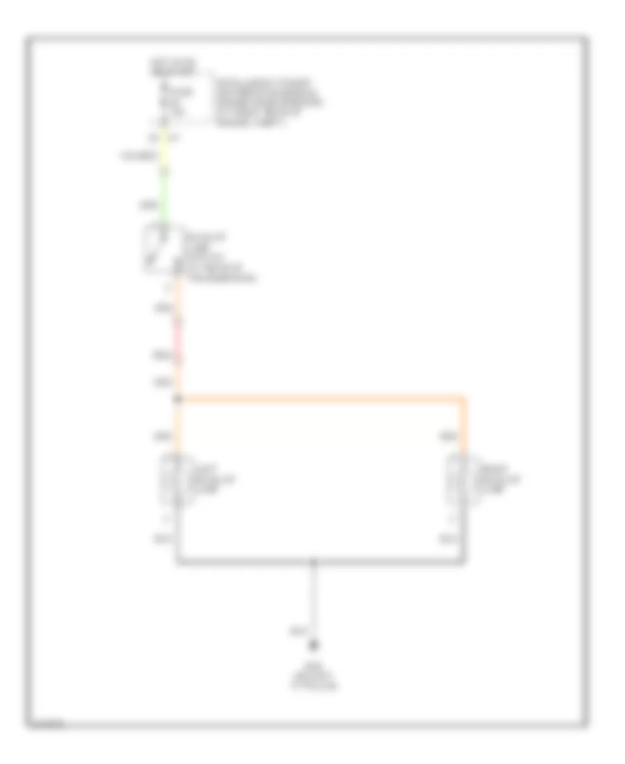
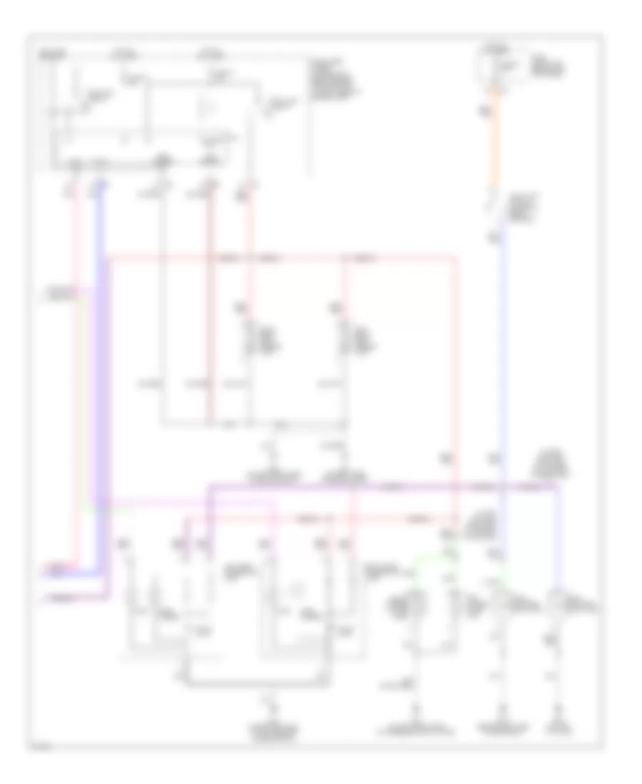
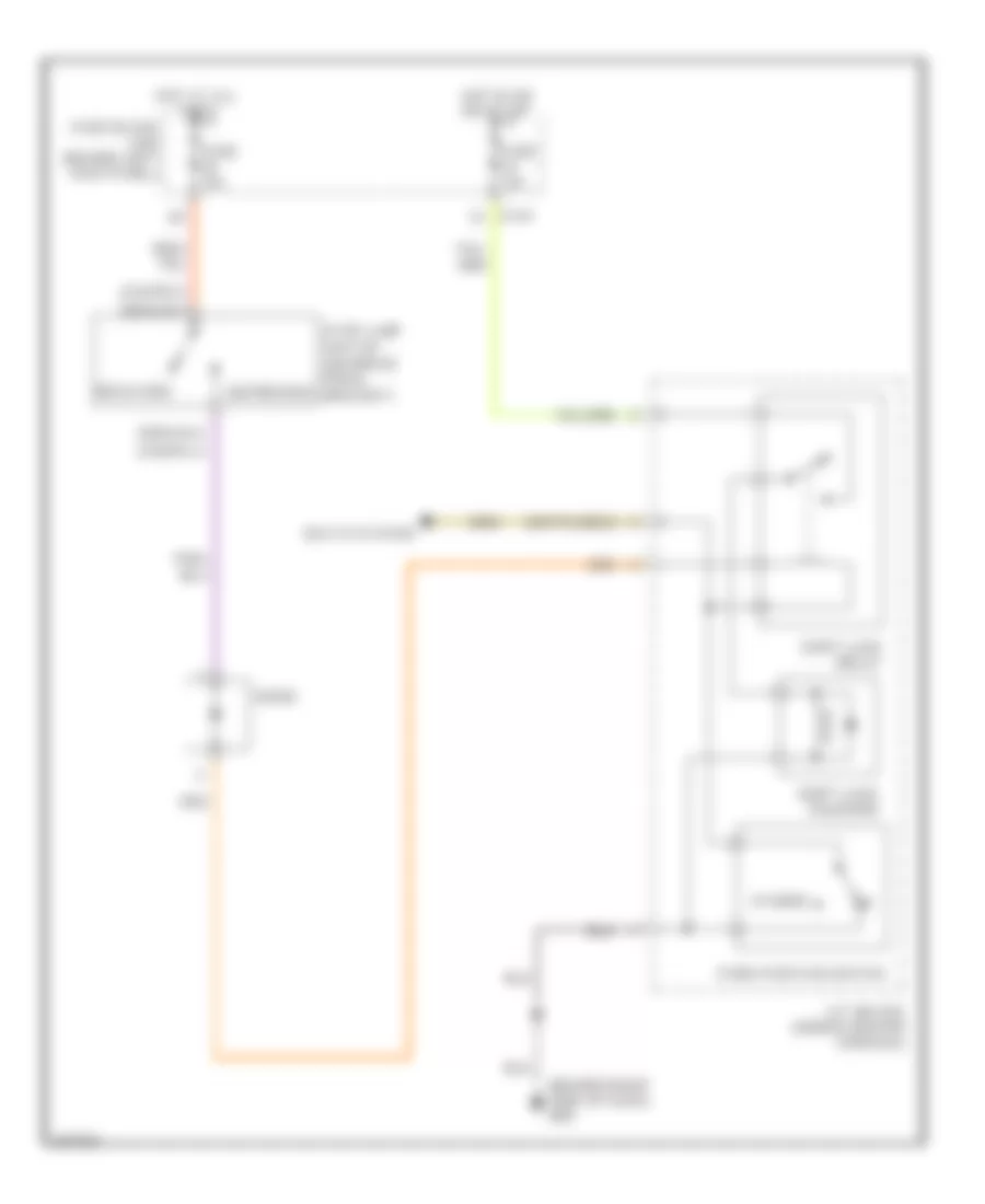
DEFOGGERS
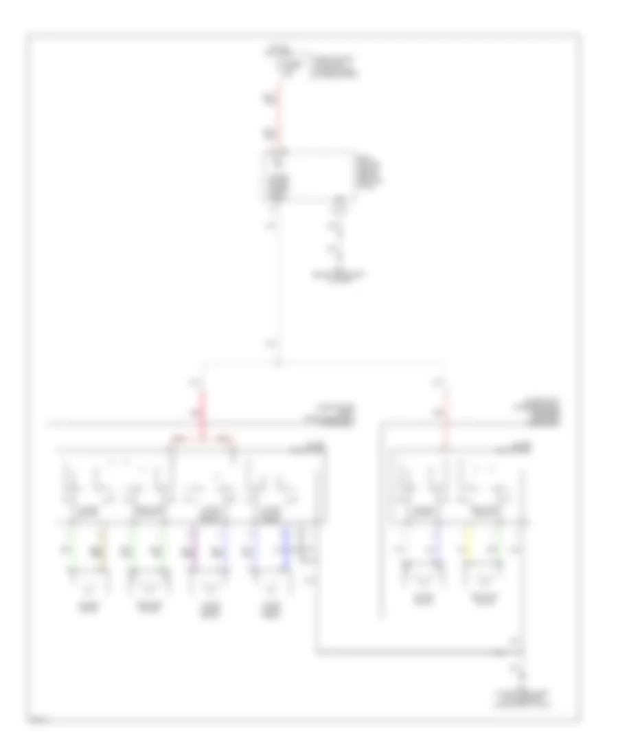
Defoggers Wiring Diagram for Infiniti G35 2006
List of elements for Defoggers Wiring Diagram for Infiniti G35 2006:
- (at left "c" pillar) (coupe) b452
- (behind instrument cluster) m30
- (behind right side of dash) m66
- (coupe)
- (on left "c" pillar) (sedan) b242
- (on right side of engine compartment) e17
- (sedan)
- 15a
- A/c & audio controller
- B241
- B301
- B451
- B471
- Battery
- Body control module (behind left kick panel)
- Can-h
- Can-l
- Computer data lines system
- Condenser (rear window defogger) (at right "c" pillar)
- Cpu
- Driver side door mirror defogger
- E101
- Fuse 10a
- Fuse 15a
- Fuse 20a
- Fuse 8 10a
- Fuse block (j/b) (behind left kick panel)
- Fuse, fusible link & relay box (at right rear of engine compartment)
- Fusible link f 50a
- Gnd (power)
- Gnd (signal)
- Ground
- Hot at all times
- Hot in on or start
- Ign
- Ignition
- Ipdm e/r (intelligent power distribution module engine room) (at right rear of engine compartment)
- M30 (behind instrument cluster)
- M38
- Nca
- Passenger side door mirror defogger
- Pnk
- Rear window defogger
- Rear window defogger relay (sedan: right rear panel of luggage compt) (coupe: at right front of spare tire well)
- Red
- Rr def f/b
- Rr def on
- Rr def rly
- Rr def sw
ELECTRONIC POWER STEERING
Electronic Power Steering Wiring Diagram for Infiniti G35 2006
List of elements for Electronic Power Steering Wiring Diagram for Infiniti G35 2006:
- (left rear of luggage compt) noise suppressor
- (on brake pedal bracket) stop lamp switch
- (on left "c" pillar) b29
- B134
- B135
- B137
- B138
- B181
- B182
- B29 (on left "c" pillar)
- Brake
- Can-h
- Can-l
- Combination meter
- Computer data lines system
- E101 8c
- Fuse & fusible link block (at right rear of engine compt)
- Fuse 10a
- Fuse 20a
- Fuse block (j/b) (behind left kick panel)
- Gnd
- Hot at all times
- Hot in on or start
- Ign
- Intelligent power distribution module engine (ipdm e/r) (at right rear of engine compt)
- Lh motor out
- M19
- M30 (behind instrument cluster)
- M4 5a
- M66 (behind right side of dash)
- Pnk
- Power steering solenoid valve (left side of engine)
- Ras control unit (left rear of luggage compt)
- Ras ind
- Ras main out
- Ras motor (right side of luggage compt)
- Ras motor gnd
- Ras motor power
- Ras motor relay (left rear of luggage compt)
- Ras rly out
- Ras sens gnd
- Ras sens power
- Ras sub out
- Ras w/l
- Rear wheel steering angle sensor (center of rear axle)
- Red
- Rh motor out
- Tops sol
- Unified meter control unit
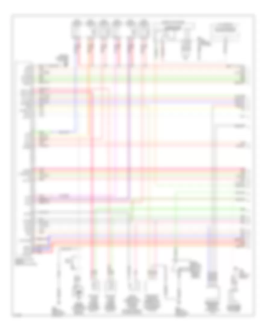
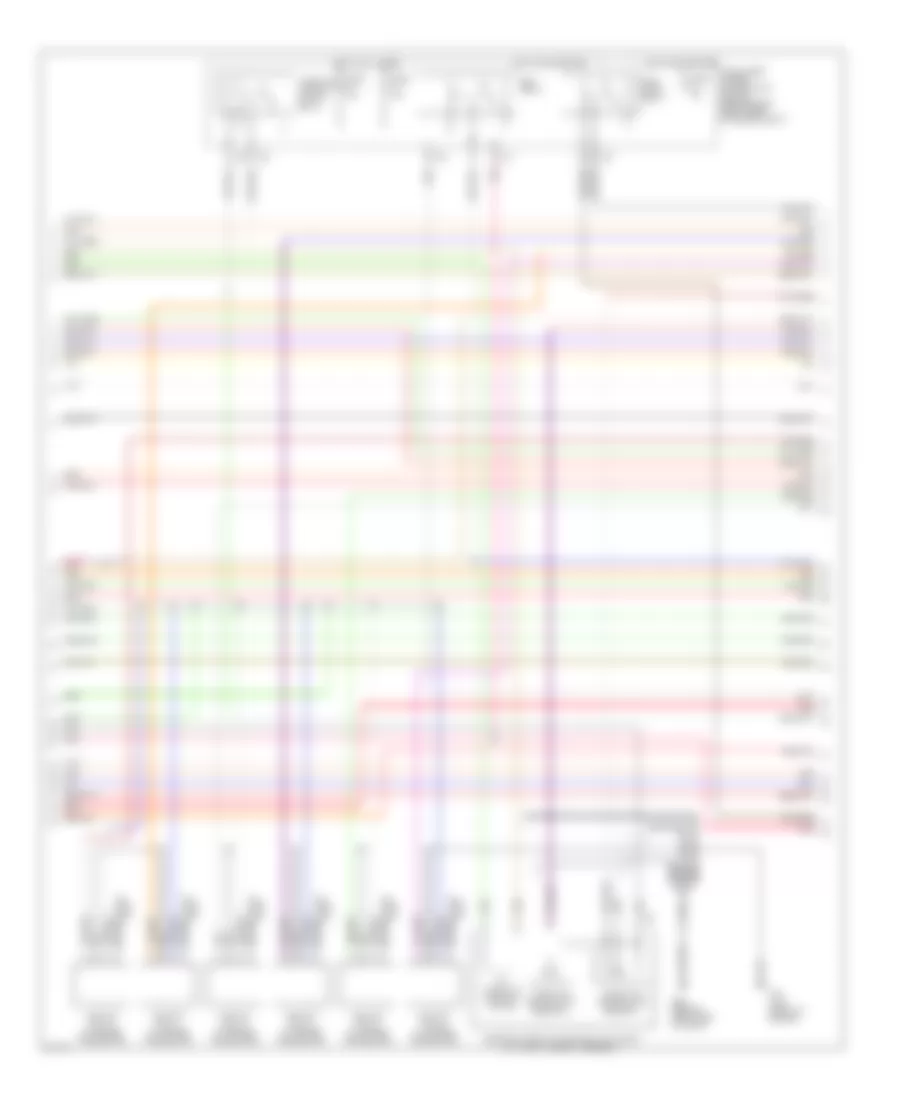
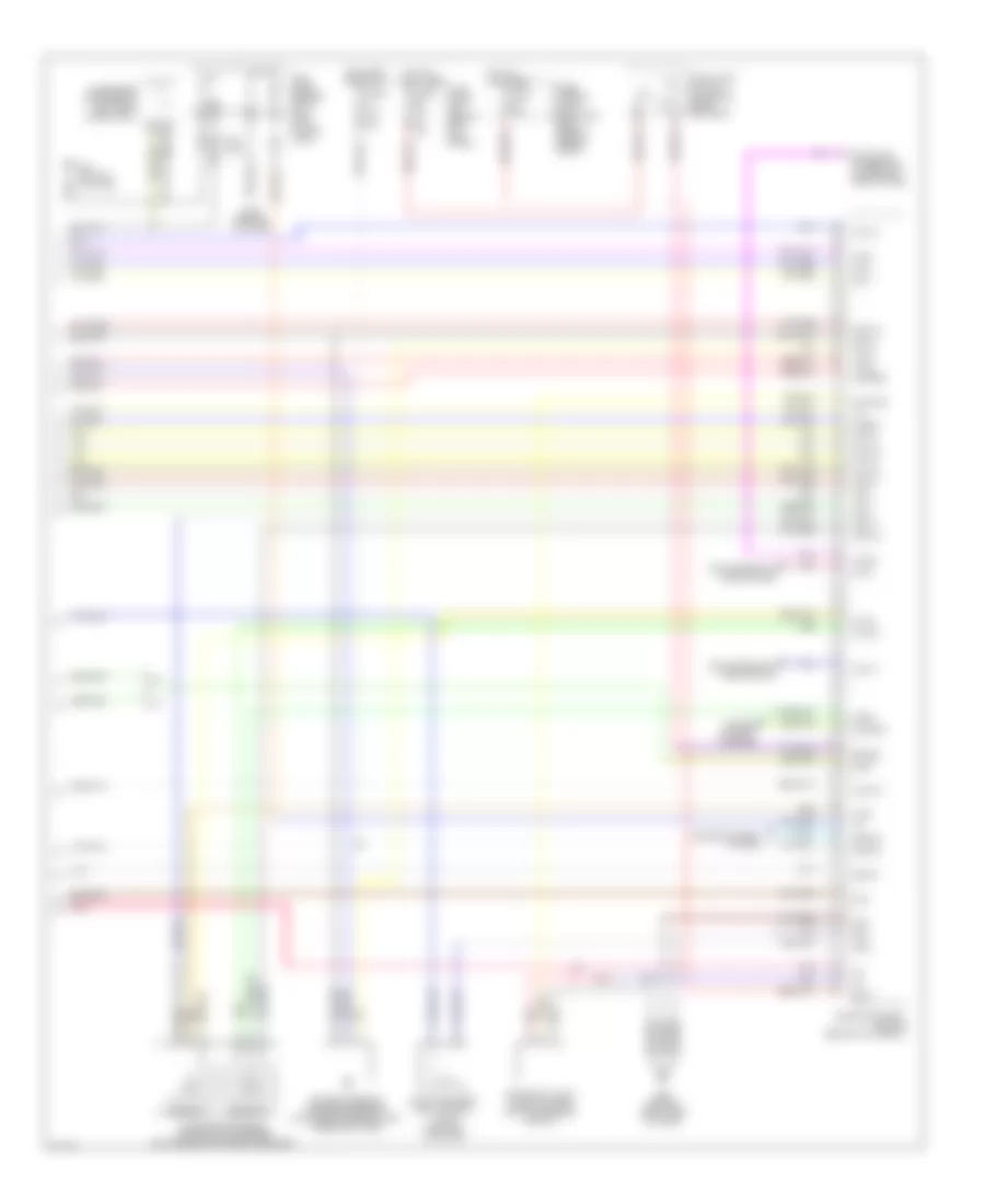
ENGINE PERFORMANCE
3.5L
3.5L, Engine Performance Wiring Diagram, Coupe (1 of 4) for Infiniti G35 2006
List of elements for 3.5L, Engine Performance Wiring Diagram, Coupe (1 of 4) for Infiniti G35 2006:
- (behind right side of dash)
- A/t assembly
- Af-h1
- Af-h2
- Af-ip1
- Af-un1
- Af-vm1
- Af-vm2
- Avcc
- Avcc2
- C-evc (l)
- C-evc (r)
- C-ivc (l)
- C-ivc (r)
- Combination meter
- Condenser (right rear of engine)
- Crankshaft position sensor (pos) (on front of oil pan, below crankshaft pulley)
- Engine control module (behind glove box)
- Evap
- Evap canister purge volume control solenoid valve (on right side of intake manifold)
- Evcpusr
- Exhaust valve timing control magnet retarder (bank 1)
- Exhaust valve timing control magnet retarder (bank 2)
- F23 (top front of engine)
- Ftrps
- Fuel injector
- Gnd
- Inj 1
- Inj 2
- Inj 3
- Inj 4
- Inj 5
- Inj 6
- Knk1
- Knock sensor (top center front of engine)
- M30 (behind cluster)
- M66
- M66 (behind right side of dash)
- Motor1
- Motor2
- Nca
- Neutral
- O2hrl
- O2hrr
- O2srl
- Park/ neutral position switch (rear of trans- mission)
- Phase lh
- Phase rh
- Pnk
- Pos
- Ps pres
- Qa+
- Red
- Refrigerant pressure sensor (on a/c liquid tank)
- Tcm (transmission control module)
- Tps1
- Unified meter control unit
- V mot
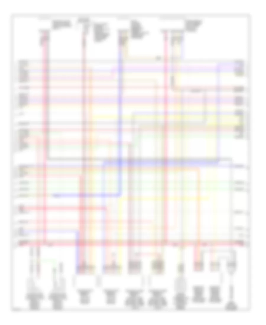
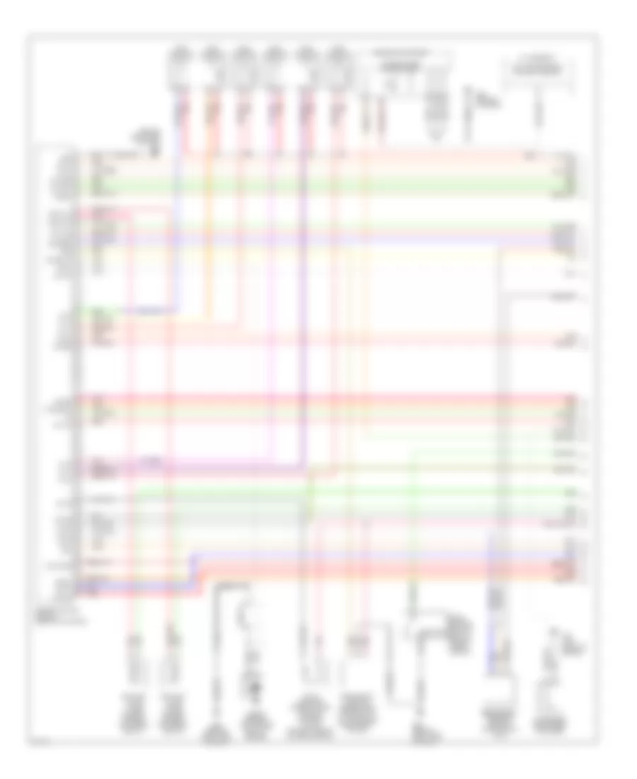
3.5L, Engine Performance Wiring Diagram, Coupe (2 of 4) for Infiniti G35 2006
List of elements for 3.5L, Engine Performance Wiring Diagram, Coupe (2 of 4) for Infiniti G35 2006:
- Ecm relay
- Electric throttle control actuator (on throttle body assembly)
- F23 (top front of engine)
- F31
- Fuel pump relay
- Fuse 15a
- Hot at all times
- Hot in on or start
- Ignition coil 1 (w/ power transistor)
- Ignition coil 2 (w/ power transistor)
- Ignition coil 3 (w/ power transistor)
- Ignition coil 4 (w/ power transistor)
- Ignition coil 5 (w/ power transistor)
- Ignition coil 6 (w/ power transistor)
- Intelligent power distribution module (engine room) (right rear of engine compt)
- M66 (behind right side of dash)
- Nca
- Nca nca
- Plug spark
- Pnk
- Red
- Spark plug
- Throttle control motor
- Throttle control motor relay
- Throttle position (tp) sensor 1
- Throttle position (tp) sensor 2
3.5L, Engine Performance Wiring Diagram, Coupe (3 of 4) for Infiniti G35 2006
List of elements for 3.5L, Engine Performance Wiring Diagram, Coupe (3 of 4) for Infiniti G35 2006:
- Air fuel ratio sensor 1 (bank 1) (at top right of engine)
- Air fuel ratio sensor 1 (bank 2) (at top left of engine)
- Camshaft position sensor (phase) (bank 1) (right rear of engine)
- Camshaft position sensor (phase) (bank 2) (left rear of engine)
- Engine coolant temperature sensor (on top right rear of engine)
- Evap control system pressure sensor (under vehicle, near evap canister)
- Exhaust valve timing control position sensor (bank 1)
- Fuse 15a
- Heated oxygen sensor 2 (bank 1) (on right side exhaust pipe, between three way catalysts 1 and 2)
- Heated oxygen sensor 2 (bank 2) (on left side exhaust pipe, between three way catalysts 1 and 2)
- Hot in on or start
- Intake valve timing control solenoid valve (bank 1) (on right front of engine)
- Intake valve timing control solenoid valve (bank 2) (on left front of engine)
- Intelligent power distribution module (engine room) (right rear of engine compt)
- M66 (behind right side of dash)
- Mass airflow (maf) sensor (on intake air duct housing)
- Pnk
- Red
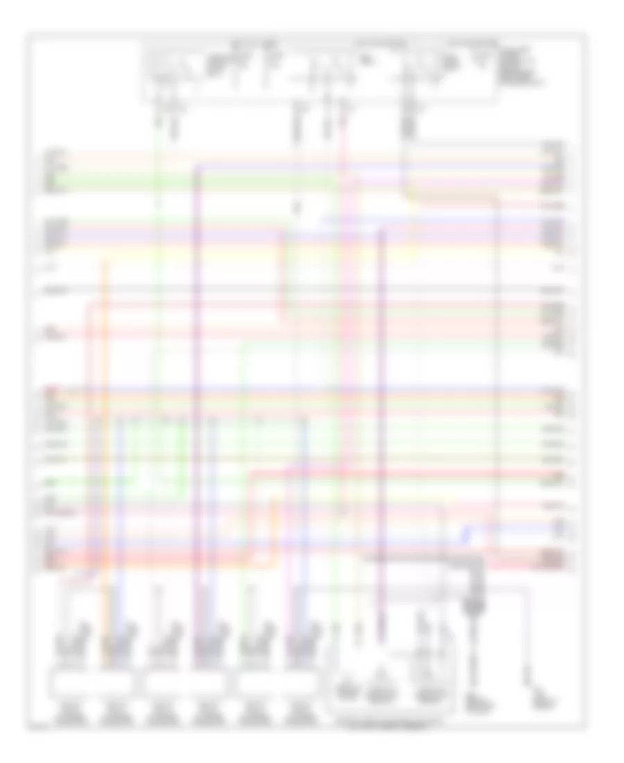
3.5L, Engine Performance Wiring Diagram, Coupe (4 of 4) for Infiniti G35 2006
List of elements for 3.5L, Engine Performance Wiring Diagram, Coupe (4 of 4) for Infiniti G35 2006:
- 15a
- A/t
- Accelerator pedal position (app) sensor (on accelerator pedal bracket)
- Af-ia1
- Af-ia2
- Af-ip2
- Af-un2
- Aps1
- Aps2
- Ascdsw
- Avcc
- Avcc2
- B29 (on left c pillar)
- Batt
- Bncsw
- Brake
- Can l
- Can-h
- Cdcv
- Computer data lines system
- Condenser (forward of left rear wheelwell)
- Cruise control system
- Data link connector (lower left side of dash)
- E101
- Engine control module (behind glove box)
- Evap canister vent control valve (on evap canister)
- Evcpusl
- Exhaust valve timing control position sensor (bank 2)
- Fpr
- Fuel level sensor unit & fuel pump (in fuel tank)
- Fuse 10a
- Fuse 15a
- Fuse block (j/b) (behind left kick panel)
- Fuse, fusible link & relay box (right rear of engine compt)
- Gnd
- Gnd 02
- Gnd a
- Gnd a2
- Hot at all times
- Hot in on or start
- Ign 1
- Ign 2
- Ign 3
- Ign 4
- Ign 5
- Ign 6
- Ign sw
- Kline
- M/t
- M30 (behind cluster)
- M66 (behind right side of dash)
- Motrly
- Neut
- O2srr
- Pdpres
- Pnk
- Power steering pressure sensor (on power steering high pressure tube)
- Sensor 1
- Sensor 2
- Ssoff
- Stop lamp switch (on brake pedal bracket)
- Tps2
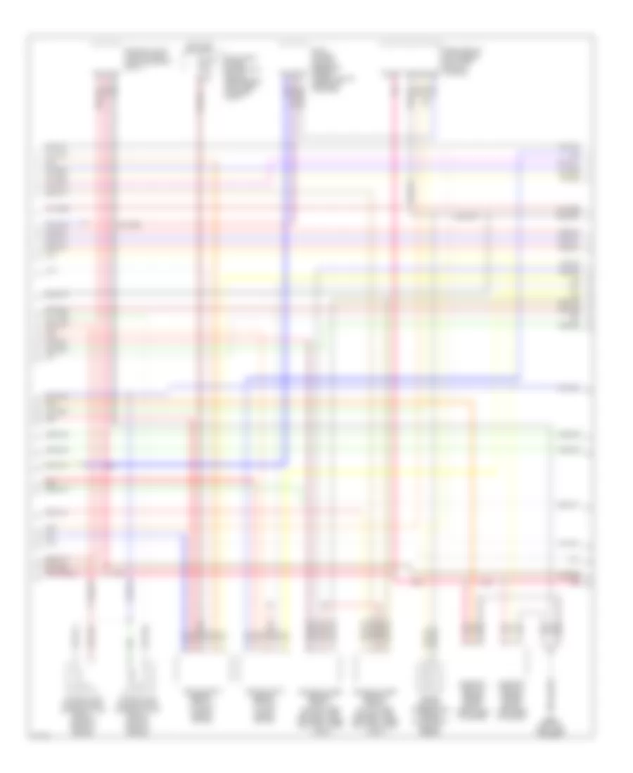
3.5L, Engine Performance Wiring Diagram, Sedan (1 of 4) for Infiniti G35 2006
List of elements for 3.5L, Engine Performance Wiring Diagram, Sedan (1 of 4) for Infiniti G35 2006:
- (behind right side of dash)
- A/t assembly
- Af-h1
- Af-h2
- Af-ip1
- Af-un1
- Af-vm1
- Af-vm2
- Avcc
- Avcc2
- C-evc (l)
- C-evc (r)
- C-ivc (l)
- C-ivc (r)
- Combination meter
- Condenser (right rear of engine)
- Crankshaft position sensor (pos) (on front of oil pan, below crankshaft pulley)
- Engine control module (behind glove box)
- Evap
- Evap canister purge volume control solenoid valve (on right side of intake manifold)
- Evcpusr
- Exhaust valve timing control magnet retarder (bank 1)
- Exhaust valve timing control magnet retarder (bank 2)
- F23 (top front of engine)
- Ftrps
- Fuel injector
- Gnd
- Inj 1
- Inj 2
- Inj 3
- Inj 4
- Inj 5
- Inj 6
- Knk1
- Knock sensor (top center front of engine)
- M30 (behind cluster)
- M66
- M66 (behind right side of dash)
- Motor1
- Motor2
- Nca
- Neutral
- O2hrl
- O2hrr
- O2srl
- Park/ neutral position switch (rear of trans- mission)
- Phase lh
- Phase rh
- Pnk
- Pos
- Ps pres
- Qa+
- Red
- Refrigerant pressure sensor (on a/c liquid tank)
- Tcm (transmission control module)
- Tps1
- Unified meter control unit
- V mot
3.5L, Engine Performance Wiring Diagram, Sedan (2 of 4) for Infiniti G35 2006
List of elements for 3.5L, Engine Performance Wiring Diagram, Sedan (2 of 4) for Infiniti G35 2006:
- Ecm relay
- Electric throttle control actuator (on throttle body assembly)
- F23 (top front of engine)
- F31
- Fuel pump relay
- Fuse 15a
- Hot at all times
- Hot in on or start
- Ignition coil 1 (w/ power transistor)
- Ignition coil 2 (w/ power transistor)
- Ignition coil 3 (w/ power transistor)
- Ignition coil 4 (w/ power transistor)
- Ignition coil 5 (w/ power transistor)
- Ignition coil 6 (w/ power transistor)
- Intelligent power distribution module (engine room) (right rear of engine compt)
- M66 (behind right side of dash)
- Nca
- Nca nca
- Plug spark
- Pnk
- Red
- Spark plug
- Throttle control motor
- Throttle control motor relay
- Throttle position (tp) sensor 1
- Throttle position (tp) sensor 2
3.5L, Engine Performance Wiring Diagram, Sedan (3 of 4) for Infiniti G35 2006
List of elements for 3.5L, Engine Performance Wiring Diagram, Sedan (3 of 4) for Infiniti G35 2006:
- Air fuel ratio sensor 1 (bank 1) (at right side of engine)
- Air fuel ratio sensor 1 (bank 2) (at left side of engine)
- Camshaft position sensor (phase) (bank 1) (right rear of engine)
- Camshaft position sensor (phase) (bank 2) (left rear of engine)
- Engine coolant temperature sensor (on top right rear of engine)
- Evap control system pressure sensor (under vehicle, near evap canister)
- Exhaust valve timing control position sensor (bank 1)
- Fuse 15a
- Heated oxygen sensor 2 (bank 1) (on right side exhaust pipe, between three way catalysts 1 and 2)
- Heated oxygen sensor 2 (bank 2) (on left side exhaust pipe, between three way catalysts 1 and 2)
- Hot in on or start
- Intake valve timing control solenoid valve (bank 1) (on right front of engine)
- Intake valve timing control solenoid valve (bank 2) (on left front of engine)
- Intelligent power distribution module (engine room) (right rear of engine compt)
- M66 (behind right side of dash)
- Mass airflow (maf) sensor (on intake air duct housing)
- Pnk
- Red
3.5L, Engine Performance Wiring Diagram, Sedan (4 of 4) for Infiniti G35 2006
List of elements for 3.5L, Engine Performance Wiring Diagram, Sedan (4 of 4) for Infiniti G35 2006:
- 15a
- A/t
- Accelerator pedal position (app) sensor (on accelerator pedal bracket)
- Af-ia1
- Af-ia2
- Af-ip2
- Af-un2
- Aps1
- Aps2
- Ascdsw
- Avcc
- Avcc2
- B29 (on left c pillar)
- Batt
- Bncsw
- Brake
- Can l
- Can-h
- Cdcv
- Computer data lines system
- Condenser (forward of left rear wheelwell)
- Cruise control system
- Data link connector (lower left side of dash)
- E101
- Engine control module (behind glove box)
- Evap canister vent control valve (on evap canister)
- Evcpusl
- Exhaust valve timing control position sensor (bank 2)
- Fpr
- Fuel level sensor unit & fuel pump (in fuel tank)
- Fuse 10a
- Fuse 15a
- Fuse block (j/b) (behind left kick panel)
- Fuse, fusible link & relay box (right rear of engine compt)
- Gnd
- Gnd 02
- Gnd a
- Gnd a2
- Hot at all times
- Hot in on or start
- Ign 1
- Ign 2
- Ign 3
- Ign 4
- Ign 5
- Ign 6
- Ign sw
- Kline
- M/t
- M30 (behind cluster)
- M66 (behind right side of dash)
- Motrly
- Neut
- O2srr
- Pdpres
- Pnk
- Power steering pressure sensor (on power steering high pressure tube)
- Sensor 1
- Sensor 2
- Ssoff
- Stop lamp switch (on brake pedal bracket)
- Tps2
EXTERIOR LIGHTS
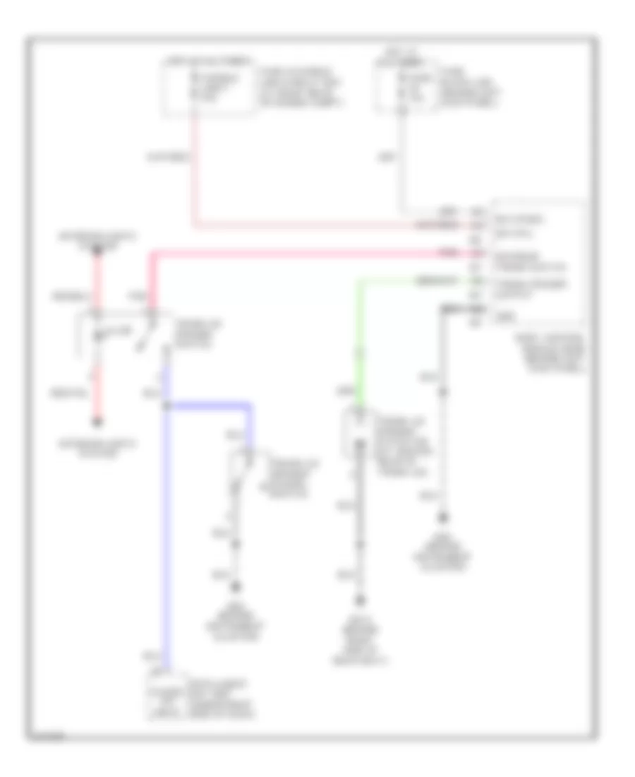
Back-up Lamps Wiring Diagram, Coupe A/T for Infiniti G35 2006
List of elements for Back-up Lamps Wiring Diagram, Coupe A/T for Infiniti G35 2006:
- A/t assembly
- B103 (under trim panel, at left rear of luggage compt)
- Back-up lamp relay (in fuse, fusible link & relay box)
- F40
- F502
- Fuse 10a
- Hot in on or start
- Intelligent power distribution module engine room (ipdm e/r) (at right rear of engine compt)
- Left rear combination lamp (back-up)
- Red
- Rev-lamp rly
- Right rear combination lamp (back-up)
- Transmission control module (tcm)
Back-up Lamps Wiring Diagram, Coupe M/T for Infiniti G35 2006
List of elements for Back-up Lamps Wiring Diagram, Coupe M/T for Infiniti G35 2006:
- B103 (under trim panel, at left rear of luggage compt)
- Back-up lamp switch (at rear of transmission)
- Fuse 10a
- Hot in on or start
- Intelligent power distribution module engine room (ipdm e/r) (at right rear of engine compt)
- Left rear combination lamp (back-up)
- Red
- Right rear combination lamp (back-up)
Back-up Lamps Wiring Diagram, Sedan A/T for Infiniti G35 2006
List of elements for Back-up Lamps Wiring Diagram, Sedan A/T for Infiniti G35 2006:
- A/t assembly (at rear of engine compt)
- B29 (on left "c" pillar)
- Back-up lamp relay (in fuse, fusible link & relay box)
- F42
- F502
- Fuse 10a
- Hot in on or start
- Intelligent power distribution module engine room (ipdm e/r) (at right rear of engine compt)
- Left back-up lamp
- Rev-lamp rly
- Right back-up lamp
- Transmission control module (tcm)
Back-up Lamps Wiring Diagram, Sedan M/T for Infiniti G35 2006
List of elements for Back-up Lamps Wiring Diagram, Sedan M/T for Infiniti G35 2006:
- B29 (on left "c" pillar)
- Back-up lamp switch (at rear of transmission)
- Fuse 10a
- Hot in on or start
- Intelligent power distribution module engine room (ipdm e/r) (at right rear of engine compt)
- Left back-up lamp
- Red
- Right back-up lamp
Exterior Lamps Wiring Diagram, Coupe (1 of 2) for Infiniti G35 2006
List of elements for Exterior Lamps Wiring Diagram, Coupe (1 of 2) for Infiniti G35 2006:
- 12a
- 15a
- Acc sw
- Bat (f/l)
- Bat (fuse)
- Body control module (bcm) (behind left kick panel)
- Buzzer
- Can-h
- Can-l
- Comb sw in 1
- Comb sw in 2
- Comb sw in 3
- Comb sw in 4
- Comb sw in 5
- Comb sw out 1
- Comb sw out 2
- Comb sw out 3
- Comb sw out 4
- Comb sw out 5
- Combination meter
- Combination switch
- Computer data lines
- E17 (on right side of engine compartment)
- E43 (on left front side of engine compartment)
- Fuse & fusible link block (at right rear of engine compt)
- Fuse 1 10a
- Fuse 14 10a
- Fuse 18 10a
- Fuse 19 10a
- Fuse 6 10a
- Fuse block (j/b) (behind left kick panel)
- Fusible link f 50a
- Gnd
- Hazard sw
- Hazard switch
- Hot at all times
- Hot in acc or on
- Hot in on or start
- Ign sw
- Illumination
- Input 1
- Input 2
- Input 3
- Input 4
- Input 5
- Interior lights system
- Left front combination lamp
- Left turn ind
- Lt flash out
- M19
- M30 (behind instrument cluster)
- Off
- Output 1
- Output 2
- Output 3
- Output 4
- Output 5
- Parking
- Pnk
- Right front combination lamp
- Right turn ind
- Rt flash out
- System
- Turn signal
- Unified meter control unit
Exterior Lamps Wiring Diagram, Coupe (2 of 2) for Infiniti G35 2006
List of elements for Exterior Lamps Wiring Diagram, Coupe (2 of 2) for Infiniti G35 2006:
- +ig
- 8c e101
- B103 (under trim panel, at left rear of luggage compt)
- B29 (on left "c" pillar)
- B413 (behind right side of rear seat)
- B5 (on left front side of passenger compt floor)
- Can-h
- Can-l
- Cpu
- E17 (on right side of engine compt)
- E43 (on left front side of engine compt)
- Fuse 20 10a
- Fuse 71 10a
- Fuse 78 15a
- Fuse block (j/b) (behind left kick panel)
- Gnd (power)
- Gnd (signal)
- High mounted stop lamp
- Hot at all times
- Hot in on or start
- Ignition relay
- Intelligent power distribution module engine room (ipdm e/r) (at right rear of engine compt)
- Left front side marker lamp
- Left license plate lamp
- Left rear combination lamp
- Pnk
- Right front side marker lamp
- Right license plate lamp
- Right rear combination lamp
- Side marker
- Stop lamp switch (on brake pedal bracket)
- Tail & stop
- Taillamp relay
- Taillamp rly
- Turn
- W/ high mounted stop lamp in the rear air spoiler
- W/ high mounted stop lamp on the rear parcel shelf
Exterior Lamps Wiring Diagram, Sedan (1 of 2) for Infiniti G35 2006
List of elements for Exterior Lamps Wiring Diagram, Sedan (1 of 2) for Infiniti G35 2006:
- 12a
- 15a
- Acc sw
- Bat (f/l)
- Bat (fuse)
- Body control module (bcm) (behind left kick panel)
- Buzzer
- Can-h
- Can-l
- Comb sw in 1
- Comb sw in 2
- Comb sw in 3
- Comb sw in 4
- Comb sw in 5
- Comb sw out 1
- Comb sw out 2
- Comb sw out 3
- Comb sw out 4
- Comb sw out 5
- Combination meter
- Combination switch
- Computer data lines system
- Fuse & fusible link block (at right rear of engine compt)
- Fuse 1 10a
- Fuse 14 10a
- Fuse 18 10a
- Fuse 19 10a
- Fuse 6 10a
- Fuse block (j/b) (behind left kick panel)
- Fusible link f 50a
- Gnd
- Hazard sw
- Hazard switch
- Hot at all times
- Hot in acc or on
- Hot in on or start
- Ign sw
- Illumination
- Input 1
- Input 2
- Input 3
- Input 4
- Input 5
- Interior lights system
- Keyless tuner
- Left turn ind
- Lt flash out
- M19
- M30 (behind instrument cluster)
- Off
- Output 1
- Output 2
- Output 3
- Output 4
- Output 5
- Pnk
- Remote keyless entry receiver (w/o intelligent key) (behind right side of dash)
- Right turn ind
- Rt flash out
- Sens gnd
- Unified meter control unit
Exterior Lamps Wiring Diagram, Sedan (2 of 2) for Infiniti G35 2006
List of elements for Exterior Lamps Wiring Diagram, Sedan (2 of 2) for Infiniti G35 2006:
- B103 (under trim panel, at left rear of luggage compt)
- B29 (on left "c" pillar)
- B5 (on left front side of passenger compt floor)
- Can-h
- Can-l
- Cpu
- E101
- E17 (on right side of engine compt)
- E43 (on left front side of engine compt)
- Fuse 20 10a
- Fuse 71 10a
- Fuse 78 15a
- Fuse block (j/b) (behind left kick panel)
- Gnd (power)
- Gnd (signal)
- High mounted stop lamp
- Hot at all times
- Intelligent power distribution module engine room (ipdm e/r) (at right rear of engine compt)
- Left front combination lamp
- Left front side marker lamp
- Left license plate lamp
- Left rear combination lamp
- Parking
- Pnk
- Right front combination lamp
- Right front side marker lamp
- Right license plate lamp
- Right rear combination lamp
- Side marker
- Stop lamp switch (on brake pedal bracket)
- Tail & stop
- Taillamp relay
- Taillamp rly
- Turn
- W/ high mounted stop lamp in the rear air spoiler
- W/ high mounted stop lamp on the rear parcel shelf
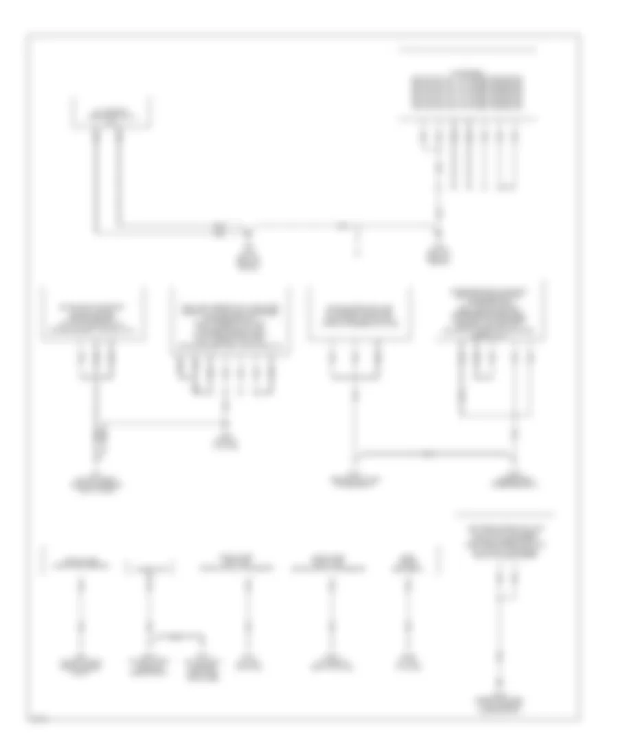
GROUND DISTRIBUTION
Ground Distribution Wiring Diagram, Coupe (1 of 2) for Infiniti G35 2006
List of elements for Ground Distribution Wiring Diagram, Coupe (1 of 2) for Infiniti G35 2006:
- Bcm (body control module), navi switch, a/t device (terminal: 1) (shift lock solenoid & park position switch), power socket (floor console box) (a/t), upper glove box lamp, power socket (right side instrument panel) (m/t), up & down unit (display unit), driver side heated seat switch (m/t), passenger side heated seat switch (m/t), map lamp, hazard switch, nats antenna amp, passenger side vanity mirror lamp, auto anti dazzling inside mirror (homelink universal transceiver), sunroof motor assembly, sunroof switch, driver side vanity mirror lamp, data link connector (terminal: 5), driver side air mix door motor, passenger side air mix door motor, mode door motor blower motor, navi control unit (terminals: 1 & 4), display unit (terminals: 22 & 24), display & a/c auto amp (terminal: 5), automatic drive positioner control unit (terminals: 40 & 48), adp steering switch, glove box lamp, intake door motor
- Camshaft position sensor (phase) (bank 1), crankshaft position sensor (pos), shield wire ((electric throttle control actuator) throttle position sensor 1) (for circuit from terminal: 1)), shield wire ((electric throttle control actuator) throttle position sensor 1 & 2) (for circuit from terminals: 2, 4 & 5)), shield wire ((electric throttle control actuator) throttle control motor) for circuit from terminals: 3 & 6)), camshaft position sensor (phase) (bank 2), park/neutral position switch (m/t), shield wire (knock sensor), exhaust valve timing control position sensor (bank 1) (m/t), exhaust valve timing control position sensor (bank 2) (m/t), ecm (terminals: 1, 115 & 116), passenger side door mirror (door mirror defogger), power window sub-switch (cpu & door lock & unlock switch)
- Display & a/c auto lamp (terminal: 36) (canada), ipdm e/r (terminal: 38, 50 & 60), brake fluid level switch, hood switch, horn (low), horn (high), right front combination lamp (terminal: 8) (headlamp (high) & fog), cooling fan motor 1, left front side marker lamp, right front side marker lamp, left front combination lamp (terminal: 4) (headlamp (low),turn signal/parking & parking), front wiper motor, cooling fan motor 2
- E17 (on right side of engine compt)
- E43 (on left front side of engine compt)
- Fuse block (j/b), (terminal: 7b) (accessory relay & blower relay), illumination control switch, data link connector (terminal: 4), vdc off switch, combination meter (terminals: 1, 24 & 25), steering angle sensor, door mirror remote control switch, combination switch, a/c & audio controller, cigarette lighter socket, display & a/c auto amp (terminal: 24), a/t device (terminal: 9) (mode select switch), ashtray illumination, passenger side heated seat switch (a/t), compass, driver side heated seat switch (a/t), air bag diagnosis sensor unit, trunk lid opener switch, heated seat relay, cigarette lighter socket illumination, vdc/tcs/abs control unit (terminals: 28 & 29), fuel level sensor unit & fuel pump (terminal: 5) (fuel level sensor (main) & fuel tank temperature sensor), driver side door mirror (door mirror defogger), power window main switch (cpu, power window lock switch, door lock & unlock switch & illumination), driver side door lock assembly (door key cylinder switch)
- Ipdm e/r (terminal: 14), daytime light relay 1, daytime light relay 2, right front combination lamp (terminal: 4) (head lamp (low), turn signal/parking & parking), daytime light control unit, washer level sensor, left front combination lamp (terminal: 8) (head lamp (high) & fog lamp) (usa),
- M30 (behind instrument cluster)
- M66 (behind right side of dash)
Ground Distribution Wiring Diagram, Coupe (2 of 2) for Infiniti G35 2006
List of elements for Ground Distribution Wiring Diagram, Coupe (2 of 2) for Infiniti G35 2006:
- A/t
- A/t assembly (terminals: 5 & 10) (a/t)
- Alternator (e)
- B103 (under trim panel, at left rear of luggage compt)
- B18 (on left "b" pillar)
- B29 (on left "c" pillar)
- B402 (under front passenger seat)
- B407 (at base of right "b" pillar)
- B413 (behind right side of rear seat)
- B452 (at left "c" pillar)
- B5 (on left front side of passenger compt floor)
- Condenser, ignition coil no. 1 (w/ power transistor), ignition coil no. 2 (w/ power transistor), ignition coil no. 3 (w/ power transistor), ignition coil no. 4 (w/ power transistor), ignition coil no. 5 (w/ power transistor), ignition coil no. 6 (w/ power transistor)
- Driver side power seat cushion heater, driver side seat switch (sliding switch), driver side seat control unit
- E212 (on right front corner of engine compt)
- E213 (on top front of engine, near timing chain case)
- E22 (on right front side of engine compt)
- F22 (a/t) (on top front of engine)
- F23 (on top front of engine)
- Fuel level sensor unit & fuel pump (terminal: 3) (fuel pump), condenser, bose speaker amp, right license plate lamp, high-mounted stop lamp (on the rear parcel shelf), left license plate lamp, driver side seat belt buckle switch
- High-mounted stop lamp (in the rear air spoiler), trunk room lamp switch, trunk lid opener actuator
- Left rear combination lamp (tail & stop, turn signal, back-up & side marker), right rear combination lamp (tail & stop, turn signal, back-up & side marker)
- Passenger side power seat switch (sliding switch), passenger side seat cushion heater, passenger side seat belt buckle switch, passenger side seat control unit, occupant classification system control unit,
- Rear window defogger (-)
- Shield wire (crash zone sensor)
- Shield wire (left side air bag (satellite) sensor)
- Shield wire (right side air bag (satellite) sensor)
Ground Distribution Wiring Diagram, Sedan (1 of 2) for Infiniti G35 2006
List of elements for Ground Distribution Wiring Diagram, Sedan (1 of 2) for Infiniti G35 2006:
- Bcm (body control module), power socket (a/t), hazard switch (w/ m/t) hazard switch, awd control unit (terminals: 10 & 11) (awd models), a/t device (park position switch) (shift lock solenoid), passenger side heated seat switch (a/t), driver side heated seat switch (a/t), map lamp, left personal lamp, right personal lamp, nats antenna amp, sunroof motor assembly, left vanity mirror lamp, right vanity mirror lamp, auto anti-dazzling inside mirror (homelink universal transceiver), a/t device (terminal: 9) (mode select switch), now mode switch (awd models) (snow indicator lamp), shield wire (inside key antenna (dashboard)) (w/ intelligent key), shield wire (inside key antenna (center console)) (w/ intelligent key), up- & -down unit (display unit), adp steering switch (w/ automatic drive positioner), intelligent key unit (w/ intelligent key), heated seat relay, navi switch, shield wire (inside key antenna (trunk room)) (w/ intelligent key), passenger side heated seat switch (m/t), driver side heated seat switch (m/t), automatic drive positioner control unit (w/ automatic drive positioner) (terminals: 40 & 48) passenger side outside key antenna & front door request switch (w/ intelligent key),
- Data link connector (terminal: 5), driver side air mix door motor, display & a/c auto amp (terminals: 5 & 24), navi control unit (terminals: 1 & 4), blower motor, glove box lamp, intake door motor, upper glove box lamp, mode door motor, passenger side air mix door motor camshaft position sensor (phase) (bank 1), crankshaft position sensor (pos), camshaft position sensor (phase) (bank 2), shield wire (electric throttle control actuator (throttle position sensor 1) (terminal: 1), shield wire (electric throttle control actuator (throttle position sensor 1 & 2) (terminals: 2, 4 & 5), shield wire (electric throttle control actuator (throttle control motor) (terminals: 3 & 6), display unit (terminals: 22 & 24), park/neutral position switch (m/t), ecm (terminal: 1, 115 & 116), exhaust valve timing control position sensor (bank 2) (m/t), exhaust valve timing control position sensor (bank 1) (m/t), front passenger side door lock assembly (w/o intelligent key) (door unlock sensor), shield wire (knock sensor), passenger side door mirror (door mirror defogger) & front passenger side power window sub-switch (cpu, door lock & unlock switch, illumination)
- Display & a/c auto amp (terminal: 36) (canada), right front combination lamp (terminal: 8) (head lamp (high), fog lamp, turn signal & parking), right front side marker lamp, horn (low), horn (high), left front side marker lamp, left front combination lamp (terminal: 4) (headlamp) cooling fan motor 1, brake fluid level switch, front wiper motor & cooling fan motor 2
- E17 (on right side of engine compt)
- E43 (on left front side of engine compt)
- Fuse block (j/b) (terminal: 7b, accessory relay & blower relay), illumination control switch, data link connector (terminal: 4), vdc off switch, combination meter (terminals: 1, 24 & 25), door mirror remote control switch, combination switch, fuel level sensor unit & fuel pump (terminal: 5) (fuel level sensor (main) & fuel tank temperature sensor), steering angle sensor, a/c & audio controller, compass, trunk lid opener cancel switch (w/ intelligent key), cigarette lighter socket illumination, ashtray illumination, vdc/tcs/abs control unit (terminals: 28 & 29), cigarette lighter socket, trunk lid opener switch (w/o intelligent key), driver side door mirror (door mirror defogger), driver side front door key cylinder switch, power window main switch (cpu, power window lock switch, door lock & unlock switch & illumination), driver side front door lock assembly (w/ intelligent key) (door unlock sensor), driver side outside key antenna & front door request switch (w/ intelligent key) air bag diagnosis sensor unit & tel adapter unit (terminal 4 & 23) (w/ telephone system)
- Ipdm e/r (terminal: 14) (cooling fan relay 2), ipdm e/r (terminal: 38) (cpu) (ignition relay) (front wiper relay), daytime light relay 1, hood switch, ipdm e/r (terminal: 60) (cpu), ipdm e/r (terminal: 50) (cpu), daytime light control unit, day time light relay 2 washer level sensor, left front combination lamp (terminal: 8) (head lamp (high), fog lamp, turn signal & parking) (usa), right front combination lamp (terminal: 4) (head lamp)
- M30 (behind instrument cluster)
- M66 (behind right side of dash)
Ground Distribution Wiring Diagram, Sedan (2 of 2) for Infiniti G35 2006
List of elements for Ground Distribution Wiring Diagram, Sedan (2 of 2) for Infiniti G35 2006:
- A/t
- A/t assembly (terminals: 5 & 10)
- Alternator (e)
- B103 (under trim panel, at left rear of luggage compt)
- B18 (on left "b" pillar)
- B24 (on right "b" pillar)
- B242 (on left "c" pillar)
- B29 (on left "c" pillar)
- B5 (on left front side of passenger compt floor)
- Condenser, ignition coil no. 1 (w/ power transistor), ignition coil no. 2 (w/ power transistor), ignition coil no. 3 (w/ power transistor), ignition coil no. 4 (w/ power transistor), ignition coil no. 5 (w/ power transistor) & ignition coil no. 6 (w/ power transistor)
- Driver side seat belt buckle switch, passenger side seat belt buckle switch, occupant classification system control unit, driver seat control unit (w/ automatic drive positioner) (terminals: 32 & 48), driver side power seat switch (w/ automatic drive positioner) (terminals: 32 & 32d), seat memory switch (w/ automatic drive positioner) (terminal: 32b), driver seat control unit (w/o automatic drive positioner) (terminal: 48), driver side power seat switch (w/ power seat w/o automatic driver positioner) (terminals: 2 & 8), driver side seat cushion heater passenger side power seat switch, passenger side seat cushion heater, left rear power window sub-switch (cpu (w/ anti-pinch system for all door window) & illumination), right rear power window sub-switch (cpu (w/ anti-pinch system for all door window) & illumination)
- E212 (awd: at right front of engine compt) (on right front corner of engine compt)
- E213 (on top front of engine, near timing chain case)
- E22 (on right front side of engine compt)
- F22 (a/t) (on top front of engine)
- F23 (on top front of engine)
- Fuel level sensor unit & fuel pump (terminal: 3) (fuel lamp), condenser, left back-up lamp, left license plate lamp, right license plate lamp, trunk room lamp switch, trunk lid opener actuator, right back-up lamp, bose speaker amp, high-mounted stop lamp (on the rear parcel shelf), high-mounted stop lamp (in the rear air spoiler), trunk opener request switch (with intelligent key) & shield wire (inside key antenna (turn room)) (w/ intelligent key)
- Left rear combination lamp (tail & stop, turn signal, side marker) & right rear combination lamp (tail & stop, turn signal, side marker)
- Rear window defogger (-)
- Shield wire (crash zone sensor)
- Shield wire (left side air bag (satellite) sensor)
- Shield wire (right side air bag (satellite) sensor)
HEADLIGHTS
Headlights Wiring Diagram, Coupe (1 of 2) for Infiniti G35 2006
List of elements for Headlights Wiring Diagram, Coupe (1 of 2) for Infiniti G35 2006:
- (m/t : at base of parking brake lever) (a/t : on parking brake pedal bracket) (w/o xenon) parking brake switch
- 12a
- 15a
- Acc sw
- Autolight sens
- Bat (f/l)
- Bat (fuse)
- Body control module (bcm) (behind left kick panel)
- Brake ind
- Can-h
- Can-l
- Charge ind
- Comb sw in 1
- Comb sw in 2
- Comb sw in 3
- Comb sw in 4
- Comb sw in 5
- Comb sw out 1
- Comb sw out 2
- Comb sw out 3
- Comb sw out 4
- Comb sw out 5
- Combination meter
- Combination switch
- Computer data lines system
- Fuse 1 10a
- Fuse 14 10a
- Fuse 18 10a
- Fuse 19 10a
- Fuse 6 10a
- Fuse block (j/b) (behind left kick panel)
- Fuse, fusible link & relay box (at right rear of engine compt)
- Fusible link f 50a
- Gnd
- High beam ind
- Hot at all times
- Hot in acc or on
- Hot in on or start
- Ign sw
- Input 1
- Input 2
- Input 3
- Input 4
- Input 5
- M19
- M20
- M30 (behind instrument cluster)
- M66 (behind right side of dash)
- Output 1
- Output 2
- Output 3
- Output 4
- Output 5
- Pnk
- Sensor gnd
- Sensor in
- Starting/ charging system
- Unified meter control unit
Headlights Wiring Diagram, Coupe (2 of 2) for Infiniti G35 2006
List of elements for Headlights Wiring Diagram, Coupe (2 of 2) for Infiniti G35 2006:
- +ig
- Can-h
- Can-l
- Computer data lines system
- Cpu
- E17 (on right side of engine compt)
- E43 (on left front side of engine compt)
- Fog lamp
- Fr fog
- Front fog lamp relay
- Fuse 10a
- Fuse 15a
- Gnd (power)
- Gnd (signal)
- Ground
- H/lp hi
- H/lp lo
- Headlamp high relay
- Headlamp low relay
- Hid cont
- High & low
- High beam solenoid
- Hot at all times
- Hot in on or start
- Ignition relay
- Intelligent power distribution module engine room (ipdm e/r) (at right rear of engine compt)
- Left front combination lamp
- Optical sensor (if equipped) (at top right of dash)
- Output
- Pnk
- Power
- Red
- Right front combination lamp
Headlights Wiring Diagram, Sedan with DRL (1 of 2) for Infiniti G35 2006
List of elements for Headlights Wiring Diagram, Sedan with DRL (1 of 2) for Infiniti G35 2006:
- 12a
- 15a
- 2b m5
- 5a m4
- 8a m4
- Acc
- Autolight sens
- Bat (f/l)
- Bat (fuse)
- Body control module (bcm) (behind left kick panel)
- Can-h
- Can-l
- Charge ind
- Comb sw in 1
- Comb sw in 2
- Comb sw in 3
- Comb sw in 4
- Comb sw in 5
- Comb sw out 1
- Comb sw out 2
- Comb sw out 3
- Comb sw out 4
- Comb sw out 5
- Combination meter
- Combination switch
- Computer data lines system
- Diode e116
- Diode e117
- E102
- Fuse 10a
- Fuse block (j/b) (behind left kick panel)
- Fuse, fusible link & relay box (at right rear of engine compt)
- Fusible link f 50a
- Gnd
- High beam ind
- Hot at all times
- Hot in acc or on
- Hot in on or start
- Hot in start
- Ign
- Input 1
- Input 2
- Input 3
- Input 4
- Input 5
- M30 (behind instrument cluster)
- M66 (behind right side of dash)
- Output 1
- Output 2
- Output 3
- Output 4
- Output 5
- Pnk
- Red
- Sensor gnd
- Sensor in
- Starting/ charging system
- Unified meter control unit
Headlights Wiring Diagram, Sedan with DRL (2 of 2) for Infiniti G35 2006
List of elements for Headlights Wiring Diagram, Sedan with DRL (2 of 2) for Infiniti G35 2006:
- (on left front side of engine compartment) e43
- (on right side of engine compartment) e17
- (on right side of engine compt) e17
- Alt-l
- Can-h
- Can-l
- Computer data lines system
- Cpu
- Daytime light control unit (at right front corner of engine compt)
- Daytime light relay 1 (in relay box, at right rear side of engine compt)
- Daytime light relay 2 (in relay box, at right rear side of engine compt)
- Dimmer switch
- E25
- E26
- Fog lamp
- Fr fog
- Front fog lamp relay
- Fuse 10a
- Fuse 15a
- Gnd
- Gnd (power)
- Gnd (signal)
- Ground
- H/lp hi
- H/lp lo
- Head- fog lamp
- Head- lamp high
- Head- lamp low
- Headlamp high relay
- Headlamp low relay
- Hid cont
- Hot at all times
- Hot in on or start
- Ignition
- Intelligent power distribution module engine room (ipdm e/r) (at right rear corner of engine compt)
- Lamp high
- Left front combination lamp
- Lh fuse
- Lh lmp gnd
- Lh main lmp
- Main switch
- Optical sensor (if equipped) (at top right of dash)
- Output
- Parking brake switch (m/t: at base of parking brake lever) (a/t: on parking brake pedal bracket)
- Pkb switch
- Pnk
- Power
- Red
- Rh fuse
- Rh main lmp
- Right front combination lamp
- Start
- Starting/ charging system
Headlights Wiring Diagram, Sedan without DRL (1 of 2) for Infiniti G35 2006
List of elements for Headlights Wiring Diagram, Sedan without DRL (1 of 2) for Infiniti G35 2006:
- 12a
- 15a
- Acc
- Autolight sens
- Bat (f/l)
- Bat (fuse)
- Body control module (bcm) (behind left kick panel)
- Can-h
- Can-l
- Comb sw in 1
- Comb sw in 2
- Comb sw in 3
- Comb sw in 4
- Comb sw in 5
- Comb sw out 1
- Comb sw out 2
- Comb sw out 3
- Comb sw out 4
- Comb sw out 5
- Combination meter
- Combination switch
- Computer data lines system
- Fuse 1 10a
- Fuse 14 10a
- Fuse 18 10a
- Fuse 19 10a
- Fuse 6 10a
- Fuse block (j/b) (behind left kick panel)
- Fuse, fusible link & relay box (at right rear of engine compt)
- Fusible link f 50a
- Gnd
- High beam ind
- Hot at all times
- Hot in acc or on
- Hot in on or start
- Ign
- Input 1
- Input 2
- Input 3
- Input 4
- Input 5
- M30 (behind instrument cluster)
- M66 (behind right side of dash)
- Output 1
- Output 2
- Output 3
- Output 4
- Output 5
- Pnk
- Sensor gnd
- Sensor in
- Unified meter control unit
Headlights Wiring Diagram, Sedan without DRL (2 of 2) for Infiniti G35 2006
List of elements for Headlights Wiring Diagram, Sedan without DRL (2 of 2) for Infiniti G35 2006:
- Can-h
- Can-l
- Computer data lines system
- Cpu
- E17 (on right side of engine compt)
- E43 (on left front side of engine compt)
- Fr fog
- Front fog lamp relay
- Fuse 10a
- Fuse 15a
- Gnd (power)
- Gnd (signal)
- Ground
- H/lp hi
- H/lp lo
- Head- fog lamp
- Head- fog lamp lamp high
- Head- lamp low
- Headlamp high relay
- Headlamp low relay
- Hid cont
- Hot at all times
- Intelligent power distribution module engine room (ipdm e/r) (at right rear of engine compt)
- Lamp high
- Left front combination lamp
- Optical sensor (if equipped) (at top right of dash)
- Output
- Pnk
- Power
- Red
- Right front combination lamp
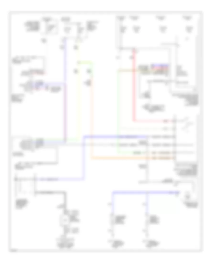
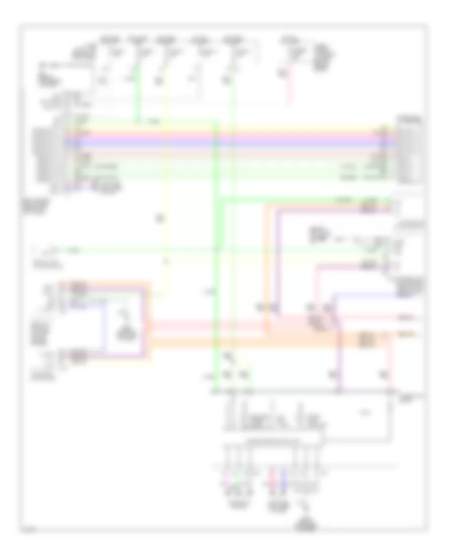
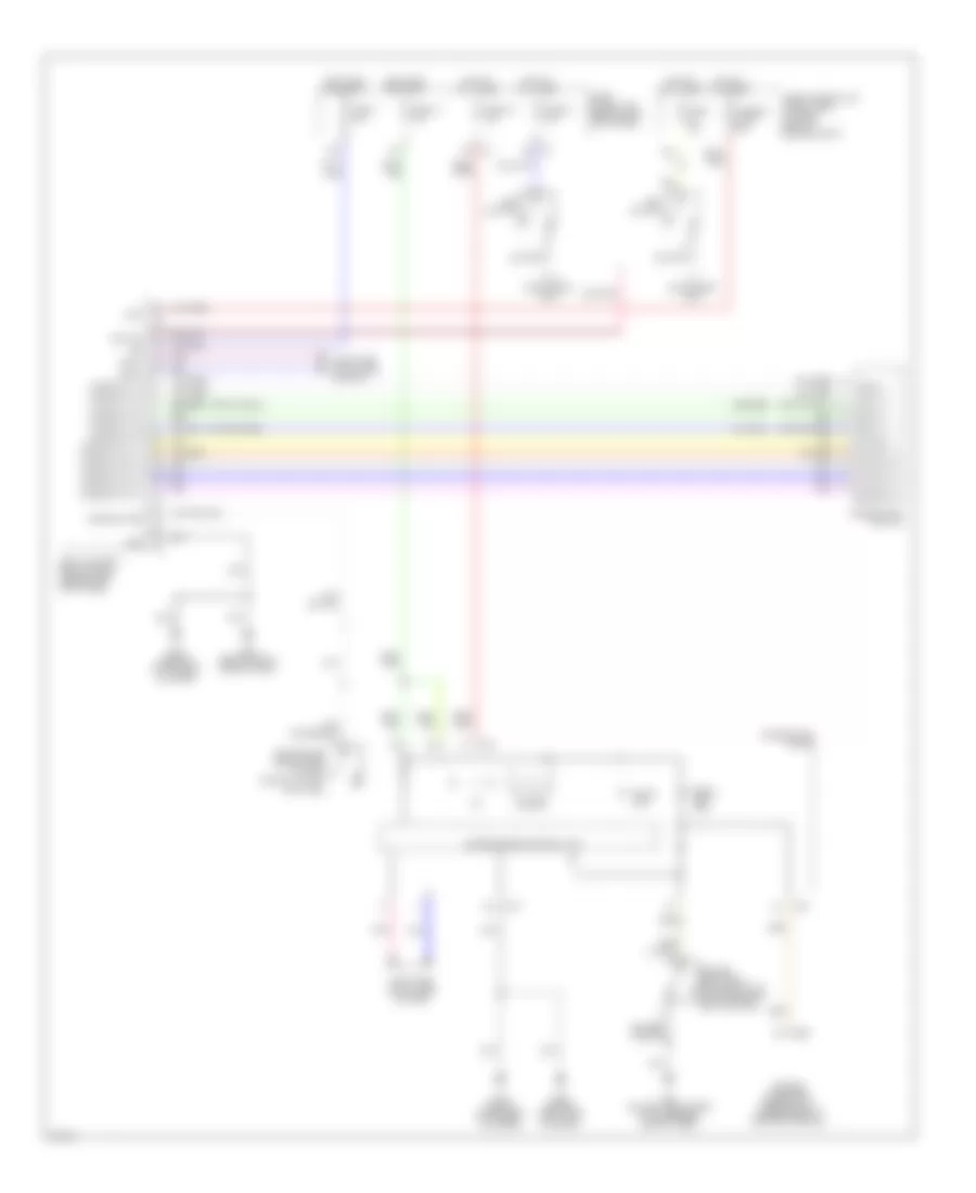
HORN
Horn Wiring Diagram for Infiniti G35 2006
List of elements for Horn Wiring Diagram for Infiniti G35 2006:
- Can-h
- Can-l
- Combination switch (spiral cable)
- Computer data lines
- Cpu
- E17 (on right side of engine compartment)
- E32
- E33
- E35
- E36
- E43 (on left front side of engine compt)
- Fuse & fusible link & relay box (at right rear of engine compt)
- Fuse 10a
- Fuse 15a
- Gnd (power)
- Gnd (signal)
- High horn (right front of engine compt, behind grille)
- Horn relay (in fuse, fusible link & relay box)
- Horn rly
- Horn switch
- Hot at all times
- Intelligent power distribution module engine room (ipdm e/r) (at right rear of engine compt)
- Low horn (right front of engine compt, behind grille)
- M203
- M23
INSTRUMENT CLUSTER
Instrument Cluster Wiring Diagram for Infiniti G35 2006
List of elements for Instrument Cluster Wiring Diagram for Infiniti G35 2006:
- (behind instrument cluster) m30
- (or red)
- 12a
- A/t assembly (sedan : at rear of engine compt)
- A/t check (w/ a/t)
- A/t ind ill
- A/t ind ill (w/ a/t)
- Abs ind
- Air bag ind
- Air conditioning system
- Anti-lock brakes system
- Awd ind (awd models)
- Belt ind
- Body control module (bcm) (behind left kick panel)
- Brake fluid level switch (at left rear of engine compt)
- Brake ind
- Bus (+)
- Bus (-)
- Buzzer
- Can-h
- Can-l
- Cellular phones system
- Charge ind
- Combination meter
- Compass
- Computer data lines system
- Cruise ind
- Display & a/c auto amplifier (at top center of dash)
- Door ind
- Door locks system
- Driver side front door switch
- E43 (on left front side of engine compt)
- Engine control module (ecm) (behind glove box)
- Engine controls system
- Front passenger side door switch
- Fuel gauge
- Fuel ind
- Fuse 10a
- Fuse block (j/b) (behind left kick panel)
- Gauge
- Hi beam ind
- Hot at all times
- Hot in acc or on
- Hot in on or start
- Intelligent power distribution module engine room (ipdm e/r) (at right rear of engine compt)
- Interior lights system
- Key ind (green)
- Key ind (red)
- Left rear door switch (sedan)
- Lh turn ind
- M19
- M20
- M30 (behind instrument cluster)
- M31
- M4 2a
- Main fuel level sensor unit & fuel pump (in fuel tank)
- Malfunction ind
- Meter ind ill
- Navigation system
- Nca
- Neut
- Odo/trip ind ill
- Oil ind
- Oil pres
- Oil pressure switch (at right front side of engine)
- Parking brake switch (a/t: on parking brake pedal bracket) (m/t: at base of parking brake lever)
- Pnk
- Ras ind (coupe w/ ras)
- Red
- Rh turn ind
- Right rear door switch (sedan)
- Sedan
- Set ind
- Slip ind
- Snow ind (awd models)
- Solid state
- Speed sense
- Speed- ometer
- Start-rly
- Starting/ charging system
- Starting/charging system
- Sub fuel level sensor unit (at fuel tank)
- Sw (as)
- Sw (dr)
- Sw (rr lh)
- Sw (rr rh)
- Tach- ometer
- Temp water
- Tire pressure ind
- Transmission control module
- Transmissions system
- Unified meter control unit
- Vdc off ind
- W/ intelligent key
- Warning system
- Washer ind
- Wiper/washer system
INTERIOR LIGHTS
Courtesy Lamps Wiring Diagram, Coupe for Infiniti G35 2006
List of elements for Courtesy Lamps Wiring Diagram, Coupe for Infiniti G35 2006:
- (behind instrument cluster) m30
- (behind right side of dash) (w/o intelligent) remote keyless entry receiver
- 15a
- 1a m4
- 4b m5
- B413 (behind right side of rear seat)
- Bat (f/l)
- Bat (fuse)
- Bat saver out
- Body control module (bcm) (behind left kick panel)
- Can-h
- Can-l
- Computer data lines system
- Door
- Door sw (as)
- Door sw (dr)
- Driver side door switch (in left "b" pillar)
- Driver side step lamp
- Driver side vanity mirror lamp
- Fuse & fusible link block (at right rear of engine compt)
- Fuse 1 10a
- Fuse 15a
- Fuse 18 10a
- Fuse 21 10a
- Fuse block (j/b) (behind left kick panel)
- Fusible link f 50a
- Gnd
- Hot at all times
- Hot in on or start
- Ign sw
- Ignition key hole illumination
- Key ring ill out
- Key sw
- Key switch
- Key switch & ignition knob switch
- Keyless signal
- M30 (behind instrument cluster)
- Map lamp
- Off
- Passenger side door switch
- Passenger side step lamp
- Passenger side vanity mirror lamp
- Pnk
- Power windows system
- Pwr
- Pwr window
- Red
- Room lamp out
- Signal
- Step lamp out
- Trunk lamp out
- Trunk room lamp
- Trunk room lamp switch (at center rear of trunk lid)
- Trunk sw
- W/ intelligent key
- W/o intelligent key
Courtesy Lamps Wiring Diagram, Sedan for Infiniti G35 2006
List of elements for Courtesy Lamps Wiring Diagram, Sedan for Infiniti G35 2006:
- (behind left kick panel) body control module (bcm)
- (behind right side of dash) (w/o intelligent) remote keyless entry receiver
- 15a
- 1a m4
- 4b m5
- B29 (on left "c" pillar)
- Bat (f/l)
- Bat (fuse)
- Bat saver out
- Can-h
- Can-l
- Computer data lines system
- Diode
- Door
- Door sw (as)
- Door sw (dr)
- Door sw (rr lh)
- Door sw (rr rh)
- Driver side front door switch
- Driver side step lamp
- Driver vanity mirror lamp
- Fuse & fusible link block (at right rear of engine compt)
- Fuse 1 10a
- Fuse 15a
- Fuse 18 10a
- Fuse 21 10a
- Fuse block (j/b) (behind left kick panel)
- Fusible link f 50a
- Gnd
- Hot at all times
- Hot in on or start
- Ign
- Ignition key hole illumination
- Key ring ill out
- Key sw
- Key switch
- Key switch & ignition knob switch
- Keyless signal
- Keyless sply
- Left personal lamp
- Left rear door switch
- M30 (behind instrument cluster)
- Map lamp
- Off
- Passenger side front door switch
- Passenger side step lamp
- Pnk
- Power windows system
- Pwr window
- Red
- Right personal lamp
- Right rear door switch
- Right vanity mirror lamp
- Room lamp out
- Sensor gnd
- Step lamp out
- Trunk lamp out
- Trunk room lamp
- Trunk room lamp switch (at rear center of trunk)
- Trunk sw
- W/ intelligent key
- W/o intelligent key
Instrument Illumination Wiring Diagram (1 of 2) for Infiniti G35 2006
List of elements for Instrument Illumination Wiring Diagram (1 of 2) for Infiniti G35 2006:
- (behind right side of dash) m66
- (coupe)
- 12a
- 15a
- 5a m4
- A/c & audio controller
- A/t ind illum
- Acc
- Bat (f/l)
- Bat (fuse)
- Body control module (bcm) (behind left kick panel)
- Can-h
- Can-l
- Comb sw in 1
- Comb sw in 2
- Comb sw in 3
- Comb sw in 4
- Comb sw in 5
- Comb sw out 1
- Comb sw out 2
- Comb sw out 3
- Comb sw out 4
- Comb sw out 5
- Combination meter
- Combination switch
- Computer data lines system
- Display & a/c auto amplifier (at top center of dash)
- Display unit (w/ navigation)
- Fuse & fusible link block (at right rear of engine compt)
- Fuse 1 10a
- Fuse 12 10a
- Fuse 14 10a
- Fuse 18 10a
- Fuse 6 10a
- Fuse block (j/b) (behind left kick panel)
- Fusible link f 50a
- Gnd
- Hot at all times
- Hot in acc or on
- Hot in on or start
- Ign
- Ill
- Ill (+)
- Ill (-)
- Ill cont
- Ill+
- Ill-
- Input 1
- Input 2
- Input 3
- Input 4
- Input 5
- Light+
- Light-
- M19
- M20
- M30 (behind instrument cluster)
- M31
- M38
- M57
- M58
- M66 (behind right side of dash)
- Meter illum (x9 bulbs)
- Mode
- Navi control unit (w/ navigation) (behind right side of dash)
- Navi switch (w/ navigation)
- Navigation system
- Nca
- Odo/trip meter illum
- Output 1
- Output 2
- Output 3
- Output 4
- Output 5
- Pnk
- Unified meter control unit
Instrument Illumination Wiring Diagram (2 of 2) for Infiniti G35 2006
List of elements for Instrument Illumination Wiring Diagram (2 of 2) for Infiniti G35 2006:
- +ig
- A/t illumination
- Ascd steering switch
- Ashtray illumination
- Audio unit (sedan)
- Can-h
- Can-l
- Cigarette lighter socket illumination
- Combination switch (spiral cable)
- Computer data lines system
- Coupe
- Cpu
- E43 (on left front side of engine compt)
- Fuse 71 10a
- Fuse 78 15a
- Glove box lamp
- Gnd (power)
- Gnd (signal)
- Hazard switch (illumination)
- Heated seat switch (driver side) (illumination)
- Heated seat switch (passenger side) (illumination)
- Hot at all times
- Hot in on or start
- Ignition relay
- Illum ctrl
- Illumination control switch
- Ipdm e/r (intelligent power distribution module engine room) (at right rear of engine compt)
- Lighting sw
- M30 (behind instrument cluster)
- Microphone (w/ telephone) (coupe: front center of roof) (sedan: center front of roof)
- Nca
- Pnk
- Resistor (behind left side of dash)
- Sedan
- Snow mode switch (illumination) (sedan: awd model)
- Steering wheel audio control switch
- Tail/l rly
- Taillamp relay
- Trunk lid opener switch (illumination)
- Upper glove box lamp (w/o navigation)
- Vdc off switch (illumination)
- W/ heated seat
MEMORY SYSTEMS
Memory Systems Wiring Diagram (1 of 2) for Infiniti G35 2006
List of elements for Memory Systems Wiring Diagram (1 of 2) for Infiniti G35 2006:
- (behind instrument cluster)
- (coupe)
- (coupe: behind left side of dash) (sedan: under left side of dash) automatic drive positioner control unit
- (coupe: on steering column) adp steering switch
- (in steering column) tilt motor & telescopic motor
- (in steering column) tilt sensor & telescopic sensor
- (sedan)
- 32b
- 40a
- A/t
- A/t device (park position switch) (under center console)
- B5 (on left front side of passenger compt floor)
- Bat (fuse)
- Bat (ptc)
- Cancel sw
- Computer data lines system
- Fuse 10a
- Fuse 15a
- Fuse block (j/b) (behind left kick panel)
- Fuse, fusible link & relay box (at right rear of engine compt)
- Gnd (power)
- Gnd (sensor)
- Gnd (signal)
- Hot at all times
- Ignition knob switch
- Ind 2 memory
- Instrument cluster system
- Key switch
- Key switch and
- M/t
- M30
- M30 (behind instrument cluster)
- M96
- M97
- Mem1
- Mem2
- Memory ind 1
- Off
- Off off
- Parking brake switch (at base of parking brake lever)
- Red
- Seat memory switch
- Sensor tilt
- Set
- Teles- copic sw
- Telescopic motor
- Telescopic mtr (back)
- Telescopic mtr (fwd)
- Telescopic sens
- Telescopic sensor
- Telescopic sw (back)
- Telescopic sw (fwd)
- Tilt motor
- Tilt motor (dn)
- Tilt motor (up)
- Tilt sensor
- Tilt sw
- Tilt sw (down)
- Tilt sw (up)
- W/ intelligent key
- W/o intelligent key
Memory Systems Wiring Diagram (2 of 2) for Infiniti G35 2006
List of elements for Memory Systems Wiring Diagram (2 of 2) for Infiniti G35 2006:
- (coupe)
- (coupe) p r sw
- (on left front side of passenger compt floor) (sedan) b5
- (on left front side of passenger compt floor) b5
- (or pnk)
- (or red)
- (sedan) c sw
- 12a
- 15a
- 31a
- 31b
- 31c
- 32d
- Acc
- B324
- B325
- B326
- B327
- B5 (on left front side of passenger compt floor)
- Back
- Backward
- Bat (f/l)
- Bat (fuse)
- Bat (ptc)
- Body control module (bcm) (behind left kick panel)
- C sw
- Can-h
- Can-l
- Circuit breaker (behind left side of dash)
- Computer data lines system
- Computer lines data system
- Door sw (dr)
- Down
- Driver seat control unit (under driver seat)
- Driver side front door switch
- Driver side front power seat switch
- Driver side reclining motor
- Driver side seat belt buckle switch (in driver seat belt buckle)
- Driver side sliding motor
- Forward
- Fr lift mtr (dn)
- Fr lift mtr (up)
- Front lift sw (dn)
- Front lift sw (up)
- Front lifting motor
- Fuse 10a
- Fuse block (j/b) (behind left kick panel)
- Fuse, fusible link & relay box (at right rear of engine compt)
- Fusible link f 50a
- Fwd
- Gnd
- Gnd (power)
- Gnd (sensor gnd)
- Gnd (signal)
- Hot at all times
- Hot in acc or on
- Hot in on or start
- Hot in start
- Ign
- Key sw
- Lifting motor
- Lifting sensor
- Lifting switch (front)
- Lifting switch (rear)
- M30 (behind instrument cluster)
- Memory ind 1
- Memory ind 2
- Memory sw 1
- Memory sw 2
- Motor reclining
- P b sw
- Pnk
- Pulse sw
- Rear lift sw (dn)
- Rear lift sw (up)
- Rear lifting motor
- Reclining mtr (fr)
- Reclining mtr (rr)
- Reclining sw (fr)
- Reclining sw (rr)
- Reclining switch
- Red
- Rr lift mtr (dn)
- Rr lift mtr (up)
- Seat belt sw
- Sensor lifting
- Sensor reclining
- Set sw
- Sliding motor
- Sliding mtr (fr)
- Sliding mtr (rr)
- Sliding sensor
- Sliding sw (fr)
- Sliding sw (rr)
- Sliding switch
- Start sw
NAVIGATION
Navigation Wiring Diagram for Infiniti G35 2006
List of elements for Navigation Wiring Diagram for Infiniti G35 2006:
- (behind right side of dash) (coupe) m66 m60 (sedan)
- (behind right side of dash) m66
- 12a
- Acc
- Audio unit
- Batt
- Bus shield
- Bus+
- Bus-
- Combination meter
- Computer data lines system
- Display unit
- Earth
- Exterior lights system
- Fr sp lh +
- Fr sp lh -
- Fr sp rh +
- Fr sp rh -
- Fuse & fusible link block (at right rear of engine compt)
- Fuse 10a
- Fuse 15a
- Fuse block (j/b) (behind left kick panel)
- Gnd
- Gps ant
- Gps ant shd
- Gps antenna (behind top center of dash, behind a/c auto amplifier)
- Guide on
- Hot at all times
- Hot in acc or on
- Hot in on or start
- Ign
- Ill
- Ill +
- Ill -
- Interior lights system
- Limit sw
- M19
- M20
- M204
- M30 (behind instrument cluster)
- M39
- M40
- M57
- M58
- M66 (behind right side of dash)
- Mode gnd
- Navi control unit (behind right side of dash)
- Navi switch
- Nca
- Pnk
- Red
- Rgb gnd
- Rgb shield
- Rgb sync
- Rv sig
- Shield
- Sig gnd
- Sound
- Speed
- Sync gnd
- Systems
- Unified meter control unit
- Up & down unit (display unit)
- Voice +
- Voice -
POWER DISTRIBUTION
Power Distribution Wiring Diagram (1 of 3) for Infiniti G35 2006
List of elements for Power Distribution Wiring Diagram (1 of 3) for Infiniti G35 2006:
- (at right rear of engine compartment) ipdm e/r (intelligent power distribution module engine room)
- (behind left kick panel) fuse block (j/b)
- (ignition relay) (diagram 3 of 3)
- (sedan) (sedan)
- Anti-lock brakes system
- Anti-theft & horns systems
- Anti-theft system
- Anti-theft, air conditioning, computer data lines, door locks, engine controls, exterior lights, headlights, cruise control, instrument cluster, mirrors, navigation, power tops, transmissions & warning systems
- Anti-theft, door locks, interior lights, memory & instrument cluster systems
- Battery
- Circuit breaker (behind left side of dash)
- Cooling fans system
- Cpu
- Door locks, anti-theft, memory, interior lights & warning systems
- E101
- E102
- E103
- E201
- E204
- E7 pnk
- Ecm relay
- Electronic power steering system
- Engine controls & transmissions systems
- Engine controls systems
- Engine controls, anti-lock brakes, exterior lights & transmissions systems
- Fuse & fusible link block
- Fuse (coupe) 20a
- Fuse (sedan) 10a
- Fuse 10a
- Fuse 15a
- Fuse 20a
- Fusible link a 120a
- Fusible link b 100a
- Fusible link c 80a
- Fusible link d 60a
- Fusible link e 80a
- Fusible link f 50a
- Fusible link h 40a
- Fusible link holder (at right rear of engine compartment)
- Fusible link i 40a
- Fusible link j 50a
- Fusible link k 30a
- Fusible link m 40a
- Headlights system
- Nca
- Pnk
- Red
- Seats system
- Sedan
- Sound & navigation systems
- Starting/ charging system
- To accessory relay (diagram 2 of 3)
- To ignition switch (diagram 2 of 3)
- To ipdm e/r
- To ipdm e/r (fuse 71) (diagram 3 of 3)
- To rear window defogger relay (diagram 3 of 3)
- Transmissions system
- Trunk, tailgate, fuel doors, defogger, door locks, anti-theft, exterior lights, headlights, interior lights, memory, power windows, warning, wiper/washer & seats systems
- Warning, door locks, trunk, tailgate, fuel doors, anti-theft, power windows, defogger, power tops, seats, headlights, exterior lights, interior lights & wiper/washer systems
Power Distribution Wiring Diagram (2 of 3) for Infiniti G35 2006
List of elements for Power Distribution Wiring Diagram (2 of 3) for Infiniti G35 2006:
- 15a
- A/t
- Acc
- Accessory relay
- Air conditioning
- Air conditioning, door locks, anti-theft, exterior lights, warning, defogger, headlights, interior lights, instrument cluster, mirrors, navigation, power windows & sound systems
- Blower relay
- Cigarette lighter socket
- Cruise control, transmissions & shift interlock systems
- E101
- E102
- E104
- Engine controls, anti-theft, door locks, power windows, defogger, power tops, headlights, exterior lights interior lights warning & wiper/washer systems
- From fuse & fusible link block (fuse m) (diagram 1 of 3)
- From fuse i block (j/b) (fuse 21) (diagram 1 of 3)
- Fuse 10a
- Fuse 15a
- Fuse block (j/b) (behind left kick panel)
- Headlights & memory systems
- Ign
- Ignition switch
- M/t
- M30 (behind instrument cluster)
- M66 (behind right side of dash)
- Off
- Power socket
- Red
- Seats, air conditioning, defogger, instrument cluster, interior lights & navigation systems
- Start
- Starting/ charging system
- System
- To ipdm e/r (ignition relay) (diagram 3 of 3)
- To rear window defogger relay (diagram 3 of 3)
Power Distribution Wiring Diagram (3 of 3) for Infiniti G35 2006
List of elements for Power Distribution Wiring Diagram (3 of 3) for Infiniti G35 2006:
- (at right rear of engine compartment) intelligent power distribution module engine room (ipdm e/r)
- +ig
- A/c relay
- Air comp
- Air conditioning system
- Anti-lock brakes, engine controls, warning, headlights, electronic power steering & transmissions systems
- Computer data lines, engine controls, transmissions & starting/charging systems
- Cpu
- Defogger system
- E101
- E17 (on right side of engine compt)
- Engine controls system
- F/wip hi rly
- F/wip rly
- Fr fog
- From (ipdm e/r) (fuse 77) (diagram 1 of 3)
- From fuse block (j/b) (fuse 12) (diagram 2 of 3)
- From fusible link holder a (fuse c) (diagram 1 of 3)
- From ignition switch (diagram 2 of 3)
- From ipdm e/r (fuse 80) (diagram 1 of 3)
- From ipdm e/r h (fuse 73) (diagram 3 of 3)
- Front fog lamp relay
- Front wiper high relay
- Front wiper relay
- Fuel pump relay
- Fuse 10a
- Fuse 15a
- Fuse 20a
- Fuse block (j/b) (behind left kick panel)
- H/lp hi
- H/lp lo
- Headlamp high relay
- Headlamp low relay
- Headlights & anti-theft systems
- Headlights system
- Headlights, exterior lights & interior lights systems
- Ignition relay
- Rear window defogger relay (right rear panel of luggage compt)
- Red
- Rr def rly
- Tail- lamp relay
- Tail- lmp rly
- Throttle control motor relay
- To ipdm e/r (front wiper low relay) (diagram 3 of 3)
- Transmissions, exterior lights & navigation systems
- Wiper/ washer system
POWER DOOR LOCKS
Power Door Locks Wiring Diagram, Coupe with Intelligent Key Unit (1 of 3) for Infiniti G35 2006
List of elements for Power Door Locks Wiring Diagram, Coupe with Intelligent Key Unit (1 of 3) for Infiniti G35 2006:
- (behind instrument cluster) m30
- 12a
- 15a
- B14
- B413
- Bat (f/l)
- Bat (fuse)
- Bat saver output
- Body control module (bcm) (behind left kick panel)
- Can-h
- Can-l
- Computer data lines system
- Door sw (as)
- Door sw (dr)
- Dr lock out (all)
- Dr unlock out
- Dr unlock out (dr)
- Driver side front door lock assembly (door lock actuator) (at rear of driver door)
- Driver side front door switch
- Exterior lights system
- Fuel lid lock actuator (at right rear vehicle fender)
- Fuse 10a
- Fuse 15a
- Fuse block (j/b) (behind left kick panel)
- Fuse, fusible link & relay box (at right rear of engine compt)
- Fusible link f 50a
- Gnd (power)
- Hot at all times
- Hot in on or acc
- Hot in on or start
- Ign knob sw
- Ign sw
- Inserted
- Interior lights system
- Key ring output
- Key sw
- Key switch
- Key switch & ignition knob switch
- Left flasher output
- Lock
- Passenger side front door lock assembly (door lock actuator) (at rear of front passen- ger door)
- Passenger side front door switch
- Pnk
- Pushed
- Red
- Removed
- Right flasher output
- Room lamp output
- Step lamp output
- Trunk opener out
- Trunk room lamp switch (at center rear of trunk lid)
- Trunk sw
- Trunk, tailgate, fuel doors system
- Unlock
- Withdrawn
Power Door Locks Wiring Diagram, Coupe with Intelligent Key Unit (2 of 3) for Infiniti G35 2006
List of elements for Power Door Locks Wiring Diagram, Coupe with Intelligent Key Unit (2 of 3) for Infiniti G35 2006:
- (at right rear of engine compartment) ipdm e/r (intelligent power distribution module engine room)
- 5a m4
- Acc sw
- As door ant+
- As door ant-
- As request sw
- Bat
- Buzzer output
- Can h
- Can l
- Can-h
- Can-l
- Cancel sw input
- Computer data lines system
- Cpu
- Depressed
- Doors system
- Dr door ant+
- Dr door ant-
- Dr lk cond sw
- Dr request sw
- E101
- E32
- E33
- E35
- E36
- E43 (on left front side of engine compartment)
- Fuse 10a
- Fuse block (j/b) (behind left kick panel)
- Gnd
- Headlights system
- High
- Hl/p
- Horn (high) (right front of engine compt, behind grille)
- Horn (low) (right front of engine compt, behind grille)
- Horn relay
- Horn relay (in fuse, fusible link & relay box)
- Hot at all times
- Hot in on or start
- Ign sw
- Intelligent key unit (under right side of dash)
- Intelligent key warning buzzer (engine room) (left front of engine compartment)
- Intelligent key warning buzzer (instrument panel) (coupe: behind left side of dash)
- Key ind led
- Key sw
- Knob ind out
- Low
- M30 (behind instrument cluster)
- P range sw
- Pnk
- Push switch
- Red
- Released
- Room ant1+
- Room ant1-
- Room ant2+
- Room ant2-
- Room ant3+
- Room ant3-
- Starter
- Starting/ charging system
- Stop lamp sw
- Stop lamp switch (on brake pedal bracket)
- Strg lk 5v out
- Strg lock gnd
- Strg lock sig
- Tailgate, fuel trunk,
- Trunk ant+
- Trunk ant-
- Trunk request sw
Power Door Locks Wiring Diagram, Coupe with Intelligent Key Unit (3 of 3) for Infiniti G35 2006
List of elements for Power Door Locks Wiring Diagram, Coupe with Intelligent Key Unit (3 of 3) for Infiniti G35 2006:
- (behind right
- (green) key ind
- (red)
- +12
- A/t device (under center console)
- B103 (under trim panel, at left rear of luggage compt)
- B413
- Buzzer
- Center console inside key antenna (under center console)
- Combination meter
- Computer data lines system
- Dashboard inside key antenna (behind right side of dash)
- Driver side door lock assembly (door unlock sensor) (at rear of driver door)
- Driver side door request switch
- Driver side outside key antenna (in driver's door)
- Earth
- Key ind
- Left rear combination switch trunk opener request switch
- M19
- M20
- M30 (behind instrument cluster)
- M66 (behind right side of dash)
- Nca
- Others
- P-shift ind
- Park position sw
- Passenger side door request switch
- Passenger side outside key antenna (in passenger's door)
- Pnk
- Rear bumper outside key antenna (behind left corner of rear bumper)
- Red
- Side of rear seat)
- Signal
- Steering lock unit (on steering column)
- Trunk inside key antenna (right rear of luggage compt)
- Unified meter control unit
Power Door Locks Wiring Diagram, Sedan with Intelligent Key Unit (1 of 3) for Infiniti G35 2006
List of elements for Power Door Locks Wiring Diagram, Sedan with Intelligent Key Unit (1 of 3) for Infiniti G35 2006:
- (behind instrument cluster) m30
- 12a
- 15a
- B14
- B29 (on left "c" pillar)
- Bat (f/l)
- Bat (fuse)
- Bat saver output
- Body control module (bcm) (behind left kick panel)
- Can-h
- Can-l
- Computer data lines system
- Door sw (as)
- Door sw (dr)
- Door sw (rl)
- Door sw (rr)
- Dr lock out (all)
- Dr unlock out
- Dr unlock out (dr)
- Driver side front door lock assembly (door lock actuator) (at rear of driver door)
- Driver side front door switch
- Exterior lights system
- Fuse 10a
- Fuse 15a
- Fuse block (j/b) (behind left kick panel)
- Fuse, fusible link & relay box (at right rear of engine compt)
- Fusible link f 50a
- Gnd (power)
- Hot at all times
- Hot in on or acc
- Hot in on or start
- Ign knob sw
- Ign sw
- Inserted
- Interior lights system
- Key ring output
- Key sw
- Key switch
- Key switch & ignition knob switch
- Left flasher output
- Left rear door lock actuator (at rear of left rear door)
- Left rear door switch
- Lock
- Passenger side front door lock assembly (door lock actuator) (at rear of front passen- ger door)
- Passenger side front door switch
- Passenger side select unlock relay (rear of engine compartment)
- Pnk
- Pushed
- Removed
- Right flasher output
- Right rear door lock actuator (at rear of right rear door)
- Right rear door switch
- Room lamp output
- Step lamp output
- Trunk opener out
- Trunk room lamp switch (at rear center of trunk)
- Trunk sw
- Trunk, tailgate, fuel doors system
- Unlock
- Withdrawn
Power Door Locks Wiring Diagram, Sedan with Intelligent Key Unit (2 of 3) for Infiniti G35 2006
List of elements for Power Door Locks Wiring Diagram, Sedan with Intelligent Key Unit (2 of 3) for Infiniti G35 2006:
- (at right rear of engine compartment) ipdm e/r (intelligent power distribution module engine room)
- Acc sw
- As door ant+
- As door ant-
- As request sw
- As unlock output
- Bat
- Buzzer output
- Can h
- Can l
- Can-h
- Can-l
- Cancel sw input
- Computer data lines system
- Cpu
- Depressed
- Dr door ant+
- Dr door ant-
- Dr lk cond sw
- Dr request sw
- E101
- E32
- E33
- E35
- E36
- E43 (on left front side of engine compartment)
- Fuse 10a
- Fuse block (j/b) (behind left kick panel)
- Gnd
- Headlights system
- High
- Hl/p
- Horn (high) (right front of engine compt, behind grille)
- Horn (low) (right front of engine compt, behind grille)
- Horn relay
- Horn relay (in fuse, fusible link & relay box)
- Hot at all times
- Hot in on or start
- Ign sw
- Intelligent key unit (behind right side of dash)
- Intelligent key warning buzzer (engine room) (left front of engine compartment)
- Intelligent key warning buzzer (instrument panel) (behind instru- ment cluster)
- Key ind led
- Key sw
- Knob ind out
- Low
- M30 (behind instrument cluster)
- M4 5a
- P range sw
- Pnk
- Push switch
- Red
- Released
- Room ant1+
- Room ant1-
- Room ant2+
- Room ant2-
- Room ant3+
- Room ant3-
- Starter
- Starting/ charging system
- Stop lamp sw
- Stop lamp switch (on brake pedal bracket)
- Strg lk 5v out
- Strg lock gnd
- Strg lock sig
- System data lines computer
- Trunk ant+
- Trunk ant-
- Trunk request sw
- Trunk, tailgate, fuel doors system
Power Door Locks Wiring Diagram, Sedan with Intelligent Key Unit (3 of 3) for Infiniti G35 2006
List of elements for Power Door Locks Wiring Diagram, Sedan with Intelligent Key Unit (3 of 3) for Infiniti G35 2006:
- (green) key ind
- (red)
- +12
- A/t device (under center console)
- B29 (on left "c" pillar)
- Buzzer
- Center console inside key antenna (rear of center console)
- Combination meter
- Computer data lines system
- Dashboard inside key antenna
- Driver side front door lock assembly (door unlock sensor)
- Driver side outside key antenna & front door request switch (in top of driver's door)
- Ground
- Key ind
- M19
- M20
- M30 (behind instrument cluster)
- M66 (behind right side of dash)
- Nca
- Others
- P-shift ind
- Park position sw
- Passenger side outside key antenna & front door request switch (in top of passenger's door)
- Pnk
- Rear bumper outside key antenna (left rear of vehicle)
- Red
- Signal
- Steering lock unit (near steering column)
- Trunk inside key antenna (front of trunk)
- Trunk opener request switch (left rear of trunk)
- Unified meter control unit
Power Door Locks Wiring Diagram, without Intelligent Key Unit for Infiniti G35 2006
List of elements for Power Door Locks Wiring Diagram, without Intelligent Key Unit for Infiniti G35 2006:
- (at right rear of engine compt) ipdm e/r (intelligent power distribution module engine room)
- (behind instrument cluster) m30
- (behind right side of dash) m66
- (behind right side of dash) remote keyless entry receiver
- (coupe)
- (or red)
- (sedan)
- 12a
- 15a m4
- 1a m4
- 4b m5
- Acc sw
- B29 (coupe: behind right side of rear seat) (sedan: on left "c" pillar)
- B413
- Bat (f/l)
- Bat (fuse)
- Bat saver out
- Between full stroke & n
- Body control module (bcm) (behind left kick panel)
- Can-h
- Can-l
- Can-l horn relay
- Closed
- Computer data lines system
- Coupe
- Cpu
- D12
- D15
- Door sw (as)
- Door sw (dr)
- Door sw (rl)
- Door sw (rr)
- Dr lock out (all)
- Dr unlock out
- Dr unlock out (dr)
- Driver side front door lock assembly (door lock actuator) (at rear of driver door)
- Driver side front door lock assembly (key cylinder switch) (rear of driver door)
- Driver side front door switch
- E32
- E33
- E35
- E36
- E43 (on left front side of engine compt)
- Exterior lights system
- Fuel lid lock actuator (sedan: on right rear inner fender) (coupe: at right rear vehicle fender)
- Full stroke
- Fuse 10a
- Fuse 15a
- Fuse block (j/b) (behind left kick panel)
- Fuse, fusible link & relay box (at right rear of engine compt)
- Fusible link f 50a
- Gnd
- Gnd (power)
- H/lp hi
- H/lp lo
- Headlights system
- Horn (high) (right front of engine compt, behind grille)
- Horn (low) (right front of engine compt, behind grille)
- Horn relay (in fuse, fusible link & relay box)
- Hot at all times
- Hot in on or acc
- Hot in on or start
- Ign sw
- Inserted
- Interior lights system
- Key cyl lock sw
- Key cyl unlock sw
- Key ring output
- Key sw
- Key switch
- Keyless turner pwr
- Keyless turner sig
- Left flasher output
- Left rear door lock actuator (sedan) (at rear of left rear door)
- Left rear door switch (sedan)
- Lock
- Open
- Passenger side front door lock assembly (door lock actuator) (at rear of front passenger door)
- Passenger side front door switch
- Pnk
- Power
- Power window main switch (door lock & unlock switch)
- Power window sub-switch (front passenger side) (door lock & unlock switch)
- Pwr wdo serial link
- Pwr window serial link
- Removed
- Right flasher output
- Right rear door lock actuator (sedan) (at rear of right rear door)
- Right rear door switch (sedan)
- Room lamp output
- Sedan
- Sensor gnd
- Signal
- Step lamp output
- Trunk opener out
- Trunk room lamp switch (sedan: at rear center of trunk) (coupe: at center rear of trunk lid)
- Trunk sw
- Trunk, tailgate, fuel doors system
- Unlock
POWER MIRRORS
Auto Anti-dazzling Inside Mirror Wiring Diagram for Infiniti G35 2006
List of elements for Auto Anti-dazzling Inside Mirror Wiring Diagram for Infiniti G35 2006:
- +12v
- Auto anti- dazzling inside mirror
- Fuse 14 10a
- Fuse 19 10a
- Fuse block (j/b) (behind left kick panel)
- Gnd
- Hot at all times
- Hot in on or start
- Ign
- M30 (behind instrument cluster)
- M4 5a
Power Mirrors Wiring Diagram for Infiniti G35 2006
List of elements for Power Mirrors Wiring Diagram for Infiniti G35 2006:
- 12a
- Change over switch
- Defogger system
- Door mirror remote control switch
- Driver side door mirror (at mirror)
- Fuse 6 10a
- Fuse block (j/b) (behind left kick panel)
- Hot in on or acc
- M30 (behind instrument cluster)
- Mirror switch
- Off
- Passenger side door mirror (at mirror)
POWER SEATS
Heated Seats Wiring Diagram for Infiniti G35 2006
List of elements for Heated Seats Wiring Diagram for Infiniti G35 2006:
- (behind left
- (on left front side of passenger compt floor) (sedan) b5
- (on left front side of passenger compt floor) b5
- (under driver seat) driver side front power seat
- (under front passenger seat) (coupe) b402
- (under front passenger seat) passenger side front power seat
- 2a m4
- Driver side heated seat switch
- Fuse & fusible link block (at right rear of engine compt)
- Fuse 12 10a
- Fuse 38 10a
- Fuse block (j/b)
- Heated seat relay (behind left side of dash)
- High
- Hot at all times
- Hot in on or start
- Illumination
- Indicator
- Interior lights system
- Kick panel)
- Low
- M30 (behind instrument cluster)
- M66 (behind right side of dash)
- Main heater
- Nca
- Passenger side heated seat switch
- Seat back heater
- Seat cushion heater
- Sub- heater
Power Seats Wiring Diagram, Coupe (1 of 2) for Infiniti G35 2006
List of elements for Power Seats Wiring Diagram, Coupe (1 of 2) for Infiniti G35 2006:
- (on left front side of passenger compt floor) b5
- (under driver seat) driver side front power seat
- A/t
- A/t device (parking position switch) (under center console)
- B5 (on left front side of passenger compt floor)
- Back- ward
- Backward
- Batt (fuse)
- Batt (ptc)
- Circuit breaker (behind left side of dash)
- Combination meter
- Computer data lines system
- Diode
- Door sw (dr)
- Driver seat control unit
- Driver side door switch (in left 'b' pillar)
- Driver side seat belt buckle switch (in driver seat belt buckle)
- For- ward
- Forward
- Forward sw
- Front
- Fuse & fusible link block (at right rear of engine compt)
- Fuse 10a
- Fuse block (j/b) (behind left kick panel)
- Fusible link f 50a
- Gnd (power)
- Hot at all times
- Instrument cluster) m30
- Lifting
- Lifting motor (front)
- Lifting motor (rear)
- Limit sw (forward)
- M/t
- M19
- P range sw or pkb sw
- Parking brake switch (at base of parking brake lever)
- Pnk
- Power seat switch
- Power walk-in relay
- Power walk-in switch
- Pulse sw
- Pulse sw (gnd)
- Rear
- Reclining
- Reclining motor
- Red
- Seat back switch
- Sliding
- Sliding limit switch
- Sliding motor
- Sliding motor (fr)
- Sliding motor (rr)
- Sliding sensor
- Sliding sw (fr)
- Sliding sw (rr)
- Speed sig
- Unified meter control unit
- Walk-in sw
Power Seats Wiring Diagram, Coupe (2 of 2) for Infiniti G35 2006
List of elements for Power Seats Wiring Diagram, Coupe (2 of 2) for Infiniti G35 2006:
- (behind instrument cluster) m30
- (under front passenger seat) b402
- (under front passenger seat) passenger side front power seat
- B402 (under front passenger seat)
- Back- ward
- Backward
- Bat (f/l)
- Bat (fuse)
- Batt (fuse)
- Batt (ptc)
- Body control module (behind left kick panel)
- Buckle sw (as)
- Door sw (as)
- For- ward
- Forward
- Forward sw
- Gnd
- Gnd (power)
- Limit sw (forward)
- Nca
- Passenger seat control unit
- Passenger side door switch
- Passenger side seat belt buckle switch (in front passenger seat belt buckle)
- Pnk
- Power seat switch
- Power walk-in switch
- Pulse sw
- Pulse sw (gnd)
- Reclining motor
- Reclining switch
- Red
- Seat back switch
- Sliding limit switch
- Sliding motor
- Sliding motor (fr)
- Sliding motor (rr)
- Sliding sensor
- Sliding sw (fr)
- Sliding sw (rr)
- Sliding switch
- Speed sig
- Walk-in sw
Power Seats Wiring Diagram, Sedan for Infiniti G35 2006
List of elements for Power Seats Wiring Diagram, Sedan for Infiniti G35 2006:
- (under driver seat) driver side front power seat
- (under front passenger seat) passenger side front power seat
- B5 (on left front side of passenger compartment floor)
- Bat (f/l)
- Body control module (behind left kick panel)
- Fuse & fusible link block (at right rear of engine compt)
- Fusible link f 50a
- Gnd
- Hot at all times
- Lifting motor (front)
- Lifting motor (rear)
- Lifting switch (front)
- Lifting switch (rear)
- M30 (behind instrument cluster)
- Power seat switch
- Reclining motor
- Reclining switch
- Red
- Sliding motor
- Sliding switch
POWER TOP/SUNROOF
Power Top/Sunroof Wiring Diagram, Coupe for Infiniti G35 2006
List of elements for Power Top/Sunroof Wiring Diagram, Coupe for Infiniti G35 2006:
- (behind right side of dash) m66
- 15a
- Bat (f/l)
- Bat (fuse)
- Body control module (behind left kick panel)
- Can-h
- Can-l
- Closed
- Combination meter
- Computer data lines system
- Door sw (as)
- Door sw (dr)
- Driver side door switch
- Fuse & fusible link block (at right rear of engine compartment)
- Fuse 10a
- Fuse block (j/b) (behind left kick panel)
- Fusible link f 50a
- Gnd
- Ground
- Hot at all times
- Hot in on or start
- Ign
- M19
- M30 (behind instrument cluster)
- Open
- Passenger side door switch
- Pnk
- Sun roof motor assembly (at center front of roof)
- Sun roof switch
- Sw-bit3
- Sw-bit4
- Tilt down/ slide open
- Tilt up/ slide close
- Timer (+ign)
- Unified meter control unit
- Vehicle speed (2p)
Power Top/Sunroof Wiring Diagram, Sedan for Infiniti G35 2006
List of elements for Power Top/Sunroof Wiring Diagram, Sedan for Infiniti G35 2006:
- 15a
- Bat
- Bat svr o/p
- Body control module (behind left kick panel)
- Can-h
- Can-l
- Closed
- Combination meter
- Computer data lines system
- Door sw (as)
- Door sw (dr)
- Driver side front door switch
- Free telephone
- Fuse & fusible link & relay box (at right rear of engine compartment)
- Fuse 10a
- Fuse block (j/b) (behind left kick panel)
- Fusible link f 50a
- Gnd
- Ground
- Hot at all times
- Hot in on or start
- Ign
- M19
- M30 (behind instrument cluster)
- Open
- Passenger side front door switch
- Pnk
- Power
- Sun roof motor assembly (at center front of roof)
- Sun roof switch
- Tilt down/ slide open
- Tilt down/slide open
- Tilt up/ slide close
- Tilt up/slide close
- Unified meter control unit
- W/ hands
- W/o hands free telephone
POWER WINDOWS
Power Windows Wiring Diagram, Coupe for Infiniti G35 2006
List of elements for Power Windows Wiring Diagram, Coupe for Infiniti G35 2006:
- (behind instrument cluster) m30
- (behind right side of dash) m66
- 15a
- Bat
- Bat (f/l)
- Bat (fuse)
- Bcm (body control module) (behind left kick panel)
- Between full stroke & n
- Can-h
- Can-l
- Closed
- Combination meter
- Computer data lines system
- Cpu
- Door sw (as)
- Door sw (dr)
- Down
- Driver side door lock assembly (door key cylinder switch) (at rear of driver door)
- Driver side door switch (in left "b" pillar)
- Driver side power window motor (at center of driver door)
- Encoder
- Encoder & limit sw gnd
- Encoder pwr
- Full
- Full closed
- Full stroke
- Fuse 10a
- Fuse block (j/b) (behind left kick panel)
- Fuse, fusible link & relay box (at right rear of engine compt)
- Fusible link f 50a
- Gnd
- Hot at all times
- Hot in on or start
- Ignition sw
- Illumination
- Key cyl lock sw
- Key cyl unlock sw
- Limit sw
- Limit switch
- Lock
- Lock switch
- M19
- M30 (behind instrument cluster)
- Open
- Other
- Passenger side front door switch
- Passenger side power window motor (at center of front passenger door)
- Pnk
- Power window lock switch
- Power window main switch
- Power window sub-switch
- Pulse
- Pwr wdo serial link
- Pwr window serial link
- Rap
- Red
- Unified meter control unit
- Unlock
- Unlock switch
Power Windows Wiring Diagram, Sedan Base (1 of 2) for Infiniti G35 2006
List of elements for Power Windows Wiring Diagram, Sedan Base (1 of 2) for Infiniti G35 2006:
- (behind instrument cluster) m30
- 12a
- 15a
- Acc
- Bat
- Bcm (body control module) (behind left kick panel)
- Between full stroke & n
- Can-h
- Can-l
- Closed
- Combination meter
- Computer data lines system
- Cpu
- Door sw (as)
- Door sw (dr)
- Down
- Driver side front door key cylinder switch
- Driver side front door switch
- Driver side power window motor (at center of driver door)
- Encoder
- Encoder & limit sw gnd
- Encoder power
- Full closed
- Full stroke
- Fuse 10a
- Fuse block (j/b) (behind left kick panel)
- Fuse, fusible link & relay box (at right rear of engine compt)
- Fusible link f 50a
- Gnd
- Hot at all times
- Hot in acc or on
- Hot in on or start
- Ignition
- Illumination
- Key cyl lock sw
- Key cyl unlock sw
- Left rear
- Limit switch
- Lock
- Lock switch
- M19
- Open
- Other
- Passenger side front door switch
- Pnk
- Power window main switch
- Pulse
- Pwr wdo serial link
- Rap
- Red
- Right rear
- Unified meter control unit
- Unlock
- Unlock switch
Power Windows Wiring Diagram, Sedan Base (2 of 2) for Infiniti G35 2006
List of elements for Power Windows Wiring Diagram, Sedan Base (2 of 2) for Infiniti G35 2006:
- (behind right side of dash) m66
- (on left front side of passenger compt floor) b5
- Bat
- Cpu
- Down
- Encoder
- Encoder & limit sw gnd
- Encoder power
- Front passenger side power window motor (at center of front passenger door)
- Front passenger side power window sub-switch
- Full closed
- Gnd
- Illumination
- Left rear power window motor (in left rear door)
- Left rear power window sub-switch
- Limit switch
- Other
- Pulse
- Pwr wdo serial link
- Right rear power window motor (in right rear door)
- Right rear power window sub-switch
Power Windows Wiring Diagram, Sedan Premium (1 of 2) for Infiniti G35 2006
List of elements for Power Windows Wiring Diagram, Sedan Premium (1 of 2) for Infiniti G35 2006:
- (behind instrument cluster) m30
- 12a
- 15a
- Acc
- Bat
- Between full stroke & n
- Body control module (behind left kick panel)
- Can-h
- Can-l
- Closed
- Combination meter
- Computer data lines system
- Cpu
- Door sw (as)
- Door sw (dr)
- Down
- Driver side front door key cylinder switch
- Driver side front door switch
- Driver side power window motor (at center of driver door)
- Encoder
- Encoder & limit sw gnd
- Encoder power
- Full closed
- Full stroke
- Fuse 10a
- Fuse block (j/b) (behind left kick panel)
- Fuse, fusible link & relay box (at right rear of engine compt)
- Fusible link f 50a
- Gnd
- Hot at all times
- Hot in acc or on
- Hot in on or start
- Ignition
- Illumination
- Key cyl lock sw
- Key cyl unlock sw
- Limit switch
- Lock
- Lock switch
- M19
- Open
- Other
- Passenger side front door switch
- Pnk
- Power window lock
- Power window main switch
- Pulse
- Pwr wdo serial link
- Rap
- Unified meter control unit
- Unlock
- Unlock switch
Power Windows Wiring Diagram, Sedan Premium (2 of 2) for Infiniti G35 2006
List of elements for Power Windows Wiring Diagram, Sedan Premium (2 of 2) for Infiniti G35 2006:
- (behind right side of dash) m66
- (on left front side of passenger compt floor) b5
- Bat
- Cpu
- D54
- D55
- D74
- D75
- Down
- Encoder
- Encoder & limit switch gnd
- Encoder power
- Front passenger side power window motor (at center of front passenger door)
- Front passenger side power window sub-switch
- Full closed
- Gnd
- Illumination
- Illumination illumination
- Left rear power window motor (in left rear door)
- Left rear power window sub-switch
- Limit switch
- Other
- Power window serial link
- Pulse
- Pwr wdo serial link
- Right rear power window motor (in right rear door)
- Right rear power window sub-switch
RADIO
Radio Wiring Diagram, Coupe with Base System for Infiniti G35 2006
List of elements for Radio Wiring Diagram, Coupe with Base System for Infiniti G35 2006:
- (at left "c" pillar) antenna amplifier
- 12a
- Acc
- Ant main
- Ant sig
- Ant signal
- Antenna (sub)
- Audio unit
- Back-up
- Combination meter
- Combination switch (spiral cable)
- Down
- Driver door speaker
- Driver side tweeter
- Feeder cable
- Fr sp lh (+)
- Fr sp lh (-)
- Fr sp rh (+)
- Fr sp rh (-)
- Fuse 37 15a
- Fuse 6 10a
- Fuse block (j/b) (behind left kick panel)
- Fuse, fusible link & relay box (at right rear of engine compt)
- Guide on
- Hot at all times
- Hot in acc or on
- Illum
- Interior lights system
- Left rear speaker
- M19
- M203
- M23
- M39
- M40
- M41
- M90
- Mode
- Navigation system
- Nca
- Off
- Option connector (for satellite radio tuner)
- Passenger door speaker
- Passenger side tweeter
- Red
- Rem control a
- Rem control b
- Rem control gnd
- Right rear speaker
- Rr sp lh (+)
- Rr sp lh (-)
- Rr sp rh (+)
- Rr sp rh (-)
- Shield
- Speed signal
- Steering wheel audio control switch
- Switch
- Switch power
- Switch seek
- Unified meter control unit
- Voice guidance+
- Voice guidance-
- Volume switch
- Window antenna (main)
- Window antenna (sub)
Radio Wiring Diagram, Coupe with Bose System (1 of 2) for Infiniti G35 2006
List of elements for Radio Wiring Diagram, Coupe with Bose System (1 of 2) for Infiniti G35 2006:
- Acc
- Amp on signal
- Ant signal
- Audio unit
- Back-up
- Combination meter
- Combination switch
- Earth
- Feeder cable
- Fr sp lh (+) amp
- Fr sp lh (-) amp
- Fr sp rh (+) amp
- Fr sp rh (-) amp
- Fuse 37 15a
- Fuse, fusible link & relay box (at right rear of engine compt)
- Gnd
- Guide on
- Hot at all times
- Illum
- Interior lights system
- M19
- M203
- M23
- M39
- M40
- M41
- M90
- Mode (w/o telephone system)
- Mode switch
- Navigation system
- Nca
- Off
- Pnk
- Power switch
- Ptt (w/ telephone switch system)
- Red
- Rem control a
- Rem control b
- Rem control gnd
- Rr sp lh (+) amp
- Rr sp lh (-) amp
- Rr sp rh (+) amp
- Rr sp rh (-) amp
- Seek switch
- Shield
- Speed signal
- Steering wheel audio control switch
- Switch
- Tel adapter unit (left side of luggage compt)
- Tel on signal
- Tel voice(+)
- Tel voice(-)
- Unified meter control unit
- Voice guidance+
- Voice guidance-
- Volume switch
- W/ telephone system
- W/o telephone system
- Window window antenna antenna (sub)
Radio Wiring Diagram, Coupe with Bose System (2 of 2) for Infiniti G35 2006
List of elements for Radio Wiring Diagram, Coupe with Bose System (2 of 2) for Infiniti G35 2006:
- (at left "c" pillar) antenna amplifier
- (on left "c" pillar) b29
- 12a
- Ant main
- Ant sig
- B122
- B122 b122
- B123
- Back up
- Bose speaker amplifier (at left rear of trunk)
- Ctrl (swb +)
- Driver door speaker
- Driver side tweeter
- Fr sp lh in (+)
- Fr sp lh in (-)
- Fr sp lh out (+)
- Fr sp lh out (-)
- Fr sp rh in (+)
- Fr sp rh in (-)
- Fr sp rh out (+)
- Fr sp rh out (-)
- Fuse 6 10a
- Fuse block (j/b) (behind left kick panel)
- Ground
- Hot in acc or on
- Left rear speaker
- Left woofer
- Nca
- Option connector (for satellite radio receiver)
- Passenger door speaker
- Passenger side tweeter
- Pnk
- Red
- Right rear speaker
- Right woofer
- Rr sp lh in (+)
- Rr sp lh in (-)
- Rr sp lh out (+)
- Rr sp lh out (-)
- Rr sp rh in (+)
- Rr sp rh in (-)
- Rr sp rh out (+)
- Rr sp rh out (-)
- Window antenna (main)
- Woofer out (+)
- Woofer out (-)
Radio Wiring Diagram, Sedan with Base Audio for Infiniti G35 2006
List of elements for Radio Wiring Diagram, Sedan with Base Audio for Infiniti G35 2006:
- 12a
- Acc
- Ant sig
- Antenna (sub)
- Antenna amplifier (at left "c" pillar)
- Audio unit
- B423
- B425
- B452
- Bat (back-up)
- Combination meter
- Combination switch
- Down
- Feeder cable
- Fuse 37 15a
- Fuse 6 10a
- Fuse block (j/b) (behind left kick panel)
- Fuse, fusible link & relay box (at right rear of engine compt)
- Hot at all times
- Hot in on or acc
- Illum
- Illumi control
- Interior lights system
- Left front door speaker
- Left rear door speaker
- Left tweeter
- Lh fr sp (+)
- Lh fr sp (-)
- Lh rr sp (+)
- Lh rr sp (-)
- Light sw
- M19
- M203
- M23
- M39
- M40
- M41
- Nca
- Off
- Option connector for audio unit
- Option connector for satellite radio tuner (w/o satellite radio system) satellite radio tuner (w/ satellite radio system)
- Red
- Rem cntrl gnd
- Rem control a
- Rem control b
- Rh fr sp (+)
- Rh fr sp (-)
- Rh rr sp (+)
- Rh rr sp (-)
- Right front door speaker
- Right rear door speaker
- Right tweeter
- Satellite radio antenna
- Speed signal
- Steering wheel audio control switch
- Switch mode
- Switch power
- Switch seek
- Switch volume
- Unified meter control unit
- W/ satellite radio system
- W/o satellite radio system
- Window antenna
- Window antenna (sub)
Radio Wiring Diagram, Sedan with Bose Audio (1 of 2) for Infiniti G35 2006
List of elements for Radio Wiring Diagram, Sedan with Bose Audio (1 of 2) for Infiniti G35 2006:
- 12a
- Acc
- Amp on signal
- Antenna (main)
- Antenna (sub)
- Antenna sig
- Audio unit
- Bat (back-up)
- Combination meter
- Combination switch
- Feeder cable
- Fr sp lh (+)
- Fr sp lh (-)
- Fr sp rh (+)
- Fr sp rh (-)
- Fuse & fusible link box (at right rear of engine compt)
- Fuse 37 15a
- Fuse 6 10a
- Fuse block (j/b) (behind left kick panel)
- Ground
- Hot at all times
- Hot in on or acc
- Illum
- Interior lights system
- Lighting switch
- M19
- M203
- M23
- M39
- M40
- M41
- Mode (w/o telephone system)
- Mode switch
- Nca
- Off
- Pnk
- Power switch
- Ptt (w/ telephone switch system)
- Red
- Rem control a
- Rem control b
- Rem control gnd
- Rr sp lh (+) amp
- Rr sp lh (-) amp
- Rr sp rh (+) amp
- Rr sp rh (-) amp
- Seek switch
- Shield
- Speed signal
- Steering wheel audio control switch
- Switch
- Tel adapter unit (left side of luggage compt)
- Tel on signal
- Tel voice (+)
- Tel voice (-)
- Unified meter control unit
- Volume switch
- W/ telephone system
- W/o telephone system
- Window antenna (sub)
Radio Wiring Diagram, Sedan with Bose Audio (2 of 2) for Infiniti G35 2006
List of elements for Radio Wiring Diagram, Sedan with Bose Audio (2 of 2) for Infiniti G35 2006:
- (at left "c" pillar) antenna amplifier
- Ant sig
- Antenna
- Antenna in
- B122
- B123
- B29 (on left "c" pillar)
- B423
- B425
- B452
- Bose speaker amplifier (under rear parcel shelf)
- Ctrl (swb +)
- Fr sp lh in (+)
- Fr sp lh in (-)
- Fr sp lh out (+)
- Fr sp lh out (-)
- Fr sp rh in (+)
- Fr sp rh in (-)
- Fr sp rh out (+)
- Fr sp rh out (-)
- Ground
- Left front door speaker
- Left rear door speaker
- Left tweeter
- Nca
- Option connector for audio unit
- Option connector for satellite radio receiver (w/o satellite radio system) satellite radio tuner (w/ satellite radio system)
- Pnk
- Red
- Right front door speaker
- Right rear door speaker
- Right tweeter
- Rr sp lh in (+)
- Rr sp lh in (-)
- Rr sp lh out (+)
- Rr sp lh out (-)
- Rr sp rh in (+)
- Rr sp rh in (-)
- Rr sp rh out (+)
- Rr sp rh out (-)
- Satellite radio antenna
- W/ satellite radio system
- W/o satellite radio system
- Window antenna (main)
- Woofer out (+)
- Woofer out (-)
- Woofer woofer
SHIFT INTERLOCK
Shift Interlock Wiring Diagram for Infiniti G35 2006
List of elements for Shift Interlock Wiring Diagram for Infiniti G35 2006:
- (behind right side of dash) m66
- (coupe)
- (sedan)
- A/t device (under center console)
- Depressed
- Diode
- E101 1c
- Fuse 10a
- Fuse block (j/b) (behind left kick panel)
- Hot at all times
- Hot in on or start
- Others
- Park position switch
- Released
- Seats system
- Shift lock relay
- Shift lock solenoid
- Stop lamp switch (on brake pedal bracket)
STARTING/CHARGING
Charging Wiring Diagram, Coupe for Infiniti G35 2006
List of elements for Charging Wiring Diagram, Coupe for Infiniti G35 2006:
- (at right rear of engine compt)
- (on right front corner of engine compt) e212
- Alternator
- Battery
- Charge indicator
- Combination meter
- E202
- E211
- F20
- Fuse 14 10a
- Fuse 36 10a
- Fuse block (j/b) (behind left kick panel)
- Fuse, fusible link & relay box)
- Fusible link holder (at right e201 rear of engine compt)
- Hot at all times
- Hot in on or start
- M19
- M20
- Nca
Charging Wiring Diagram, Sedan with 2WD for Infiniti G35 2006
List of elements for Charging Wiring Diagram, Sedan with 2WD for Infiniti G35 2006:
- (at right rear of engine compt)
- (on right front corner of engine compt) e212
- Alternator
- Battery
- Charge indicator
- Combination meter
- E202
- E211
- F20
- Fuse 14 10a
- Fuse 36 10a
- Fuse block (j/b) (behind left kick panel)
- Fuse, fusible link & relay box)
- Fusible link holder (at right e201 rear of engine compt)
- Hot at all times
- Hot in on or start
- M19
- M20
- Nca
Charging Wiring Diagram, Sedan with AWD for Infiniti G35 2006
List of elements for Charging Wiring Diagram, Sedan with AWD for Infiniti G35 2006:
- (at right rear of engine compt)
- Alternator
- Battery
- Charge ind
- Combination meter
- E204
- E205
- E211
- E212 (at right front of engine compt)
- F20
- Fuse 10a
- Fuse 14 10a
- Fuse block (j/b) (behind left kick panel)
- Fuse, fusible link & relay box
- Fusible link a 120a
- Fusible link b 100a
- Fusible link holder (at right rear of engine compt)
- Hot in on or start
- M19
- M20
- Nca
Starting Wiring Diagram for Infiniti G35 2006
List of elements for Starting Wiring Diagram for Infiniti G35 2006:
- (under left side of dash) clutch interlock switch
- A/t
- A/t assembly (at rear of engine compartment)
- Acc
- Battery
- Cpu
- E17 (on right side of engine compartment)
- F42
- F502
- Fuse 10a
- Fuse 15a
- Fuse, fusible link & relay box (at right rear of engine compartment)
- Fusible link m 40a
- Gnd (power)
- Gnd (signal)
- Hot at all times
- Hot in on or start
- Ignition switch
- Ipdm e/r (intelligent power distribution module engine room) (at right rear of engine compartment)
- M/t
- Nca
- Off
- Pnp sw or gnd
- Start
- Start rly
- Starter
- Starter motor
- Starter relay
- Tcm
SUPPLEMENTAL RESTRAINTS
Supplemental Restraints Wiring Diagram, Coupe (1 of 2) for Infiniti G35 2006
List of elements for Supplemental Restraints Wiring Diagram, Coupe (1 of 2) for Infiniti G35 2006:
- belt reminder
- (behind right side of dash) m66
- (lower left side of dash)
- (on right front side of engine compartment) e22
- A/bag w/l
- Air bag
- Air bag diagnosis sensor unit (under rear of center console)
- As1 +
- As1 -
- As2 +
- As2 -
- B13
- B402 (under front passenger seat)
- B403
- B5 (on left front side of passenger compartment floor)
- Belt
- Clh +
- Clh -
- Combination meter
- Combination switch (spiral cable)
- Comm
- Crash zone sensor (at front center of vehicle, behind front grille)
- Crh +
- Crh -
- Data link connector (partial)
- Dr1 (-) dr2 (-)
- Dr1 +
- Dr2 +
- Driver air bag module
- Driver side seat belt buckle switch (in driver seat belt buckle)
- Eczs +
- Eczs -
- Fastened
- Front left seat belt pre-tensioner (at left "b" pillar)
- Front left side air bag module (side of driver's seat)
- Front right
- Front right seat belt pre-tensioner (at right "b" pillar)
- Fuse 10a
- Fuse block (j/b) (behind left kick panel)
- Gnd
- Hot in on or start
- Ignition
- K-line
- Left sat +
- Left sat -
- Lh seat belt sw
- M19
- M201
- M202
- M30 (behind instrument cluster)
- M55
- Nca
- Passenger side seat buckle switch (in passenger seat belt buckle)
- Plh +
- Plh -
- Pnk
- Prh +
- Prh -
- Red
- Rh seat belt sw
- Right sat +
- Right sat -
- Side air bag module (side of passenger's seat)
- Slh +
- Slh -
- Srh +
- Srh -
- Un- fastened
- Unified meter control unit
Supplemental Restraints Wiring Diagram, Coupe (2 of 2) for Infiniti G35 2006
List of elements for Supplemental Restraints Wiring Diagram, Coupe (2 of 2) for Infiniti G35 2006:
- (behind instrument cluster)
- (on left "b" pillar)
- (on right "b" pillar)
- B18
- B402 (under front passenger seat)
- B407
- Belt tension sensor (right "b" pillar)
- Bts 5v
- Bts gnd
- Bts sig
- Bts signal
- Classification
- Com
- Display & a/c auto amplifier (at top center of dash)
- Front passenger air bag module (at top right side of dash)
- Gnd
- Left side curtain air bag module (at left "c" pillar)
- M30
- Nca
- Occupant
- Occupant classification system control unit (under right front seat)
- Pnk
- Ps 5v
- Ps gnd
- Ps ign
- Ps sig
- Ps signal
- Red
- Right side curtain air bag module (at right "c" pillar)
- Side air bag satellite sensor (left) (at base of left "b" pillar)
- Side air bag satellite sensor (right) (at base of right "b" pillar)
- System unit (under right front seat)
Supplemental Restraints Wiring Diagram, Sedan (1 of 2) for Infiniti G35 2006
List of elements for Supplemental Restraints Wiring Diagram, Sedan (1 of 2) for Infiniti G35 2006:
- belt reminder
- (behind right side of dash) m66
- (lower left side of dash)
- (on right front side of engine compartment) e22
- A/bag w/l
- Air bag
- Air bag diagnosis sensor unit (under rear of center console)
- As1 +
- As1 -
- As2 +
- As2 -
- B13
- B403
- B5 (on left front side of passenger compartment floor)
- B5 (on left front side of passenger compartment floor)
- Belt
- Clh +
- Clh -
- Combination meter
- Combination switch (spiral cable)
- Comm
- Crash zone sensor (at front center of vehicle, behind front grille)
- Crh +
- Crh -
- Data link connector (partial)
- Dr1 (-) dr2 (-)
- Dr1 +
- Dr2 +
- Driver air bag module
- Driver side seat belt buckle switch (in driver seat belt buckle)
- Eczs +
- Eczs -
- Fastened
- Front left seat belt pre-tensioner (at left "b" pillar)
- Front left side air bag module (side of driver's seat)
- Front right
- Front right seat belt pre-tensioner (at right "b" pillar)
- Fuse 10a
- Fuse block (j/b) (behind left kick panel)
- Gnd
- Hot in on or start
- Ignition
- K-line
- Left ext lock -
- Left sat +
- Left sat -
- Lh seat belt sw
- M19
- M201
- M202
- M30 (behind instrument cluster)
- M55
- Nca
- Passenger side seat buckle switch (in passenger seat belt buckle)
- Plh +
- Plh -
- Pnk
- Prh +
- Prh -
- Red
- Rh seat belt sw
- Right ext lock -
- Right sat +
- Right sat -
- Side air bag module (side of passenger's seat)
- Slh +
- Slh -
- Srh +
- Srh -
- Un- fastened
- Unified meter control unit
Supplemental Restraints Wiring Diagram, Sedan (2 of 2) for Infiniti G35 2006
List of elements for Supplemental Restraints Wiring Diagram, Sedan (2 of 2) for Infiniti G35 2006:
- (behind instrument cluster)
- (on left "b" pillar)
- (on right "b" pillar)
- B18
- B24
- B5 (on left front side of passenger comp floor)
- Belt tension sensor (right "b" pillar)
- Bts 5v
- Bts gnd
- Bts sig
- Bts signal
- Classification
- Com
- Display and a/c auto amplifier (at top center of dash)
- Front passenger air bag module (at top right side of dash)
- Gnd
- Left side curtain air bag module (at left "c" pillar)
- M30
- Nca
- Occupant
- Occupant classification system control unit (under right front seat)
- Pnk
- Ps 5v
- Ps gnd
- Ps ign
- Ps sig
- Ps signal
- Red
- Right side curtain air bag module (at right "c" pillar)
- Side air bag satellite sensor (left) (at base of left "b" pillar)
- Side air bag satellite sensor (right) (at base of right "b" pillar)
- System sensor (under right front seat)
TRANSMISSION
A/T Wiring Diagram for Infiniti G35 2006
List of elements for A/T Wiring Diagram for Infiniti G35 2006:
- (or pnk)
- (or red)
- A/t assembly
- A/t check indicator
- A/t device
- A/t fluid temperature sensor 1
- A/t fluid temperature sensor 2
- Atf sens 1+
- Atf sens 1-
- Atf sens 2+
- Atf sens 2-
- Auto
- Batt-1
- Batt-2
- Can-h
- Can-l
- Combination meter
- Common
- Computer data lines system
- Data link connector (lower left side of dash)
- Direct clutch solenoid
- Engine control module (behind glove box)
- Exterior lights system (backup relay)
- F22 (on top front engine)
- F42
- Front brake solenoid
- Fuse 10a
- Fuse block (j/b) (behind left kick panel)
- Fuse, fusible link block (right rear of engine compt)
- Gnd
- Gnd-1
- Gnd-2
- High & low reverse clutch solenoid
- Hot at all times
- Hot in on or start
- Inh sw 1
- Inh sw 2
- Inh sw 3
- Inh sw 4
- Input clutch solenoid
- Intelligent power distribution module engine room (ipdm e/r) (right rear of engine compt)
- K-line
- Line pressure solenoid
- Linear sol
- Low coast brake solenoid
- M19
- M30 (behind instrument cluster)
- Manual
- Mode select switch
- Neut
- Oil press switch 1
- Oil press switch 2
- Oil press switch 3
- Oil press switch 5
- Oil press switch 6
- On/off sol
- Park position switch p
- Park/neutral position switch
- Pnk
- Position select switch
- Pressure switch 1 (fr/b)
- Pressure switch 2 (lc/b)
- Pressure switch 3 (i/c)
- Pressure switch 5 (d/c)
- Pressure switch 6 (hlr/c)
- Red
- Rev lamp rly
- Rev sen gnd
- Rev sen vin
- Rev sen vout
- Revolution sensor
- Shift interlock system
- Shift lock relay
- Shift lock solenoid
- Start rly
- Starting system (starter relay)
- Torque converter clutch solenoid
- Transmission control module (tcm)
- Turbine revolution sensor 1
- Turbine revolution sensor 2
- Turbine sens 1
- Turbine sens 2
- Unified meter control unit (w/ a/t indicator)
- V in
- V out
- Vign
AWD Wiring Diagram for Infiniti G35 2006
List of elements for AWD Wiring Diagram for Infiniti G35 2006:
- A/t assembly
- Awd control unit (behind right kick panel)
- Awd indicator
- Awd sol +
- Awd sol -
- Awd sol bat
- Awd solenoid valve
- Can-h
- Can-l
- Combination meter
- Computer data lines system
- Data link connector (lower left side of dash)
- Engine control module (behind glove box)
- Fuse 10a
- Fuse block (j/b) (behind left kick panel)
- Gnd
- Hot at all times
- Hot in on or start
- Ign
- Intelligent power distribution module engine room (ipdm e/r) (right rear of engine compt)
- K-line
- M19
- M30 (behind instrument cluster)
- M66 (behind right side of dash)
- Off
- Pnk
- Red
- Snow
- Snow indicator
- Snow mode switch
- Transfer assembly (at a/t transfer case)
- Transmission control module
- Unified meter control unit (w/ a/t indicator)
- Vdc/tcs/abs control unit (behind right kick panel)
TRUNK, TAILGATE, FUEL DOOR
Trunk Release Wiring Diagram, Coupe with Intelligent Key Unit for Infiniti G35 2006
List of elements for Trunk Release Wiring Diagram, Coupe with Intelligent Key Unit for Infiniti G35 2006:
- B413 (behind right side of rear seat)
- Bat(f/l)
- Bat(fuse)
- Body control module (bcm) (behind left kick panel)
- Cancel sw
- Fuse & fusible link & relay box (at right rear of engine compt)
- Fuse 10a
- Fuse block (j/b) (behind left kick panel)
- Fusible link f 50a
- Gnd
- Hot at all times
- Illum
- Input
- Intelligent key unit (under right side of dash)
- Interior lights system
- Interior trunk switch
- M30 (behind instrument cluster)
- Pnk
- Trunk lid opener actuator (at center rear of trunk lid)
- Trunk lid opener cancel switch
- Trunk lid opener switch
- Trunk opener output
Trunk Release Wiring Diagram, Coupe without Intelligent Key Unit for Infiniti G35 2006
List of elements for Trunk Release Wiring Diagram, Coupe without Intelligent Key Unit for Infiniti G35 2006:
- (at center rear of trunk lid)
- (behind instrument cluster)
- 1a m4
- B103 (under trim panel, at left rear of luggage compt)
- B413 (behind right side of rear seat)
- Bat (f/l)
- Bat (fuse)
- Body control module (bcm) (behind left kick panel)
- Can-h
- Can-l
- Computer data lines system
- Fuse & fusible link & relay box (at right rear of engine compartment)
- Fuse 10a
- Fuse block (j/b) (behind left kick panel)
- Fusible link f 50a
- Gnd
- Hot at all times
- Illum
- Interior lights system
- Interior trunk switch
- Keyless tuner signal
- Left rear combination lamp (outside trunk lid opener switch)
- M30
- M30 (behind instrument cluster)
- Passenger side door lock assembly (door unlock sensor) (at rear of front passenger door)
- Pnk
- Remote keyless entry receiver (behind right side of dash)
- Sensor gnd
- Trunk lid opener actuator
- Trunk lid opener cancel switch
- Trunk lid opener switch
- Trunk opener output
Trunk Release Wiring Diagram, Sedan with Intelligent Key Unit for Infiniti G35 2006
List of elements for Trunk Release Wiring Diagram, Sedan with Intelligent Key Unit for Infiniti G35 2006:
- (at rear center of trunk)
- (at right rear of engine compartment)
- B29 (on left "c" pillar)
- Bat (f/l)
- Bat (fuse)
- Body control module (bcm) (behind left kick panel)
- Can-h
- Can-l
- Cancel sw input
- Computer data lines system
- Fuse & fusible link & relay box
- Fuse 10a
- Fuse block (j/b) (behind left kick panel)
- Fusible link f 50a
- Gnd
- Hot at all times
- Illum
- Intelligent key unit (behind right side of dash)
- Interior lights system
- Interior trunk switch
- M30 (behind instrument cluster)
- M66 (behind right side of dash)
- Pnk
- Trunk lid opener actuator
- Trunk lid opener cancel switch
- Trunk lid opener switch
- Trunk opener output
Trunk Release Wiring Diagram, Sedan without Intelligent Key Unit for Infiniti G35 2006
List of elements for Trunk Release Wiring Diagram, Sedan without Intelligent Key Unit for Infiniti G35 2006:
- (at rear center of trunk)
- (at rear of front passenger
- (behind instrument cluster)
- (left rear of trunk)
- 1a m4
- B29 (on left "c" pillar)
- Bat (f/l)
- Bat (fuse)
- Body control module (bcm) (behind left kick panel)
- Can-h
- Can-l
- Computer data lines system
- Door)
- Fuse & fusible link & relay box (at right rear of engine compartment)
- Fuse 10a
- Fuse block (j/b) (behind left kick panel)
- Fusible link f 50a
- Gnd
- Hot at all times
- Illum
- Interior lights system
- Interior trunk switch
- Keyless tuner signal
- M30
- M30 (behind instrument cluster)
- M66 (behind right side of dash)
- Outside trunk lid opener switch
- Passenger side front door lock assembly (door unlock sensor)
- Pnk
- Remote keyless entry receiver (behind right side of dash)
- Sensor gnd
- Trunk lid opener actuator
- Trunk lid opener cancel switch
- Trunk lid opener switch
- Trunk opener output
WARNING SYSTEMS
Warning Systems Wiring Diagram for Infiniti G35 2006
List of elements for Warning Systems Wiring Diagram for Infiniti G35 2006:
- 15a
- 4b m5
- 8a m4
- Air bag diagnosis sensor unit (under rear of center console)
- B5 (on left front side of passenger compt floor)
- Bat
- Body control module (bcm) (behind left kick panel)
- Buzzer
- Can-h
- Can-l
- Comb sw in 1
- Comb sw in 2
- Comb sw in 3
- Comb sw in 4
- Comb sw in 5
- Comb sw out 1
- Comb sw out 2
- Comb sw out 3
- Comb sw out 4
- Comb sw out 5
- Combination meter
- Combination switch
- Computer data lines system
- Door ind
- Door sw (dr)
- Driver seat belt buckle switch (in driver seat belt buckle)
- Driver side front door switch (coupe : in left "b" pillar)
- Fuse 1 10a
- Fuse 14 10a
- Fuse 15a
- Fuse 19 10a
- Fuse 21 10a
- Fuse block (j/b) (behind left kick panel)
- Fuse, fusible link & relay box (at right rear of engine compt)
- Fusible link f 50a
- Gnd
- Hot at all times
- Hot in on or start
- Ign
- Input 1
- Input 2
- Input 3
- Input 4
- Input 5
- Key sw
- Key switch
- M19
- M20
- M30 (behind instrument cluster)
- M55
- M66 (behind right side of dash)
- Output 1
- Output 2
- Output 3
- Output 4
- Output 5
- Pnk
- Seat belt ind
- Unified meter control unit
- W/ intelligent key
- W/o intelligent key
WIPER/WASHER
Wiper/Washer Wiring Diagram for Infiniti G35 2006
List of elements for Wiper/Washer Wiring Diagram for Infiniti G35 2006:
- (on left front side of engine compartment) e43
- (on right side of engine compartment) e17
- (or
- +ig
- 15a
- Bat (fuse)
- Battery (f/l)
- Body control module (bcm) (behind left kick panel)
- Can-h
- Can-l
- Combination meter
- Combination switch
- Computer data lines system
- Cpu
- E17 (on right side of engine compt)
- F/wip hi rly
- F/wip rly
- Front washer motor (at right front of engine compartment)
- Front wiper high relay
- Front wiper motor (on left side of firewall)
- Front wiper relay
- Fuse 10a
- Fuse 15a
- Fuse 20a
- Fuse block (j/b) (behind left kick panel)
- Fuse, fusible link & relay box (at right rear of engine compartment)
- Fusible link f 50a
- Gnd
- Gnd (power)
- Gnd (signal)
- High
- Hot at all times
- Hot in on or start
- Ign sw
- Ignition relay
- Input 1
- Input 2
- Input 3
- Input 4
- Input 5
- Ipdm e/r (intelligent power distribution module engine room) (at right rear of engine compartment)
- Low
- M19
- M29
- M30 (behind instrument cluster)
- Motor fr washer
- Move
- Output 1
- Output 2
- Output 3
- Output 4
- Output 5
- Pnk
- Pnk (or red)
- Stop
- Unified meter control unit
- Washer ind
- Washer level sensor (at right front of engine compt)
- Wiper auto stop